
Nokia 7705 SAR Interface Configuration Guide R20.4.R1
988
Nokia — Proprietary and confidential. Use pursuant to applicable agreements. 7705 SERVICE AGGREGATION ROUTER | RELEASE 20.4.R1 Interface Configuration Guide 3HE 16301 AAAA TQZZA Edition: 01 April 2020 Interface Configuration Guide
-
Upload
khangminh22 -
Category
Documents
-
view
0 -
download
0
Transcript of Nokia 7705 SAR Interface Configuration Guide R20.4.R1
Nokia — Proprietary and confidential.Use pursuant to applicable agreements.
7705 SERVICE AGGREGATION ROUTER | RELEASE 20.4.R1
Interface Configuration Guide
3HE 16301 AAAA TQZZA
Edition: 01
April 2020
Interface Configuration Guide

2
Interface Configuration Guide
3HE 16301 AAAA TQZZA Edition: 01
Nokia is a registered trademark of Nokia Corporation. Other products and company names mentioned herein may be trademarks or tradenames of their respective owners.
The information presented is subject to change without notice. No responsibility is assumed for inaccuracies contained herein.
© 2020 Nokia.
Contains proprietary/trade secret information which is the property of Nokia and must not be made available to, or copied or used by anyone outside Nokia without its written authorization. Not to be used or disclosed except in accordance with applicable agreements.
Interface Configuration Guide
Edition: 01 3HE 16301 AAAA TQZZA 3
Table of Contents1 Preface...........................................................................................151.1 About This Guide.......................................................................................151.1.1 Audience....................................................................................................161.1.2 Technical Support......................................................................................16
2 7705 SAR Interface Configuration Process................................17
3 7705 SAR Interfaces .....................................................................193.1 Configuration Overview .............................................................................203.1.1 Configuring the IOM and Card Slot ...........................................................203.1.2 Configuring Adapter Cards and Modules ..................................................213.1.2.1 Provisioning Chassis Slots for Adapter Cards...........................................213.1.2.2 Maximum Number of Adapter Cards in a Chassis ....................................223.1.2.3 Evolution of Ethernet Adapter Cards, Modules, and Platforms .................253.1.2.4 Channelized Adapter Card Support...........................................................263.1.3 Configuring Ports.......................................................................................273.1.3.1 Ethernet .....................................................................................................283.1.3.2 TDM...........................................................................................................353.1.3.3 DSL............................................................................................................403.1.3.4 GNSS Receiver .........................................................................................403.1.3.5 GPON........................................................................................................413.1.3.6 Multilink Bundles........................................................................................413.1.3.7 IMA ............................................................................................................423.1.3.8 SONET/SDH..............................................................................................423.1.3.9 Voice..........................................................................................................423.1.3.10 Microwave Link..........................................................................................463.1.3.11 CLI Identifiers for Adapter Cards, Modules and Platforms ........................473.1.3.12 Access, Network, and Hybrid Ports ...........................................................523.1.4 Configuring SCADA Bridges......................................................................643.2 Port Features.............................................................................................653.2.1 Multilink Point-to-Point Protocol.................................................................663.2.1.1 MLPPP Overview ......................................................................................663.2.1.2 Protocol Field (PID) ...................................................................................683.2.1.3 B&E Bits ....................................................................................................683.2.1.4 Sequence Number.....................................................................................683.2.1.5 Information Field........................................................................................683.2.1.6 Padding .....................................................................................................693.2.1.7 FCS ...........................................................................................................693.2.1.8 LCP............................................................................................................693.2.1.9 T1/E1 Link Hold Timers .............................................................................703.2.2 Multi-Class MLPPP....................................................................................703.2.2.1 QoS in MC-MLPPP....................................................................................713.2.3 cHDLC ......................................................................................................733.2.3.1 SLARP ......................................................................................................743.2.4 Inverse Multiplexing Over ATM (IMA)........................................................74
4
Interface Configuration Guide
3HE 16301 AAAA TQZZA Edition: 01
3.2.5 Network Synchronization on Ports and Circuits ........................................753.2.5.1 Network Synchronization on T1/E1, Ethernet, GPON, and DSL
Ports ..........................................................................................................753.2.5.2 Network Synchronization on SONET/SDH Ports ......................................773.2.5.3 Network Synchronization on DS3/E3 Ports ...............................................783.2.5.4 Network Synchronization on DS3 CES Circuits ........................................783.2.5.5 Network Synchronization on T1/E1 Ports and Circuits..............................783.2.6 Node Synchronization From GNSS Receiver Ports ..................................793.2.7 Flow Control on Ethernet Ports .................................................................803.2.8 Ethernet OAM............................................................................................803.2.8.1 Ethernet OAM Overview............................................................................813.2.8.2 CRC (Cyclic Redundancy Check) Monitoring............................................833.2.8.3 Remote Loopback .....................................................................................843.2.8.4 802.3ah OAMPDU Tunneling and Termination for Epipe Service.............853.2.8.5 Dying Gasp................................................................................................863.2.9 Ethernet Loopbacks...................................................................................863.2.9.1 Line and Internal Ethernet Loopbacks.......................................................873.2.9.2 CFM Loopbacks for OAM on Ethernet Ports .............................................893.2.10 Ethernet Port Down-When-Looped ...........................................................923.2.11 Ethernet Ring (Adapter Card and Module) ................................................933.2.12 MTU Configuration Guidelines ..................................................................943.2.12.1 MTU Configuration Overview ....................................................................943.2.12.2 IP Fragmentation .......................................................................................963.2.12.3 Jumbo Frames...........................................................................................963.2.12.4 Default Port MTU Values...........................................................................993.2.13 LAG .........................................................................................................1023.2.13.1 LAG Overview .........................................................................................1023.2.13.2 LACP and Active/Standby Operation ......................................................1053.2.13.3 QoS Adaptation for LAG on Access ........................................................1073.2.13.4 QoS for LAG on Network.........................................................................1103.2.13.5 Access Ingress Fabric Shaping ...............................................................1113.2.13.6 Hold-down Timers ...................................................................................1113.2.13.7 Multi-Chassis LAG...................................................................................1123.2.13.8 Static LAG (Active/Standby LAG Operation without LACP) ....................1123.2.13.9 LAG Support on Mixed-Generation Hardware.........................................1133.2.14 LAG and ECMP Hashing.........................................................................1193.2.14.1 Per-Flow Hashing ....................................................................................1193.2.14.2 Per-Service Hashing................................................................................1223.2.14.3 LSR Hashing ...........................................................................................1233.2.14.4 Layer 4 Load Balancing...........................................................................1253.2.14.5 TEID Hashing for GTP-encapsulated Traffic ...........................................1263.2.14.6 Entropy Labels.........................................................................................1263.2.14.7 Security Parameter Index (SPI) Load Balancing .....................................1273.2.15 SONET/SDH............................................................................................1283.2.15.1 SONET ....................................................................................................1293.2.15.2 SDH.........................................................................................................1303.2.15.3 SONET/SDH Path Support......................................................................1313.2.16 Automatic Protection Switching ...............................................................1343.2.16.1 APS Overview .........................................................................................134
Interface Configuration Guide
Edition: 01 3HE 16301 AAAA TQZZA 5
3.2.16.2 SC-APS ...................................................................................................1353.2.16.3 MC-APS...................................................................................................1363.2.16.4 K1 and K2 Bytes......................................................................................1393.2.16.5 Revertive Mode .......................................................................................1413.2.16.6 APS Tools Commands ............................................................................1423.2.16.7 APS Failure Codes..................................................................................1443.2.17 T1/E1 Line Card Redundancy .................................................................1463.2.17.1 T1/E1 LCR Overview...............................................................................1463.2.17.2 SC-LCR ...................................................................................................1473.2.17.3 MC-LCR...................................................................................................1473.2.17.4 Revertive Mode .......................................................................................1483.2.17.5 LCR Tools Commands ............................................................................1493.2.18 Deploying Preprovisioned Components ..................................................1503.2.19 Microwave Link........................................................................................1503.2.19.1 Microwave Link Overview........................................................................1503.2.19.2 Standalone Mode ....................................................................................1513.2.19.3 Single NE Mode.......................................................................................1523.2.19.4 Frequency Synchronization .....................................................................1603.2.19.5 RSL History .............................................................................................1613.2.20 DSL Bonding ...........................................................................................1623.2.20.1 DSL Bonding Overview ...........................................................................1623.2.20.2 ATM Bonding...........................................................................................1633.2.20.3 PTM Bonding...........................................................................................1643.2.20.4 Pairs Within a Bonded Group..................................................................1653.2.20.5 Configuration ...........................................................................................1663.2.20.6 Layer 3 Protocol Support and Service Provisioning ................................1673.2.21 Custom Alarms on Ethernet Ports ...........................................................1683.3 802.1x Network Access Control ..............................................................1693.3.1 802.1x Basics ..........................................................................................1703.3.2 802.1x Modes..........................................................................................1723.3.3 802.1x Timers..........................................................................................1733.3.4 802.1x Tunneling .....................................................................................1743.3.5 802.1x Configuration and Limitations ......................................................1753.4 MAC Authentication.................................................................................1763.5 Link Layer Discovery Protocol (LLDP).....................................................1783.5.1 LLDP Protocol Features ..........................................................................1803.6 Surveillance, Control, and Data Acquisition (SCADA) Support ...............1833.6.1 Multidrop Data Bridge..............................................................................1833.6.2 PCM Multidrop Bridge .............................................................................1853.6.3 Redundant Masters .................................................................................1873.6.4 Squelch Functionality ..............................................................................1873.6.5 Voice Conference Bridge.........................................................................1883.6.5.1 VCB Applications.....................................................................................1893.6.5.2 Gain .........................................................................................................1893.6.6 Serial Transport Over Raw Sockets ........................................................1903.6.6.1 Raw Socket Configuration .......................................................................1923.6.6.2 Raw Socket Packet Processing...............................................................1923.6.6.3 Raw Socket Squelch Functionality ..........................................................1943.7 Configuration Notes.................................................................................195
6
Interface Configuration Guide
3HE 16301 AAAA TQZZA Edition: 01
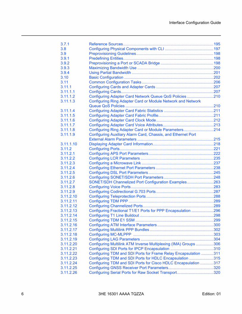
3.7.1 Reference Sources..................................................................................1953.8 Configuring Physical Components with CLI ............................................1973.9 Preprovisioning Guidelines......................................................................1983.9.1 Predefining Entities..................................................................................1983.9.2 Preprovisioning a Port or SCADA Bridge ................................................1983.9.3 Maximizing Bandwidth Use .....................................................................2003.9.4 Using Partial Bandwidth ..........................................................................2013.10 Basic Configuration .................................................................................2023.11 Common Configuration Tasks .................................................................2063.11.1 Configuring Cards and Adapter Cards ....................................................2073.11.1.1 Configuring Cards....................................................................................2073.11.1.2 Configuring Adapter Card Network Queue QoS Policies ........................2103.11.1.3 Configuring Ring Adapter Card or Module Network and Network
Queue QoS Policies ................................................................................2103.11.1.4 Configuring Adapter Card Fabric Statistics .............................................2113.11.1.5 Configuring Adapter Card Fabric Profile..................................................2113.11.1.6 Configuring Adapter Card Clock Mode....................................................2123.11.1.7 Configuring Adapter Card Voice Attributes..............................................2133.11.1.8 Configuring Ring Adapter Card or Module Parameters...........................2143.11.1.9 Configuring Auxiliary Alarm Card, Chassis, and Ethernet Port
External Alarm Parameters .....................................................................2153.11.1.10 Displaying Adapter Card Information.......................................................2183.11.2 Configuring Ports.....................................................................................2213.11.2.1 Configuring APS Port Parameters...........................................................2223.11.2.2 Configuring LCR Parameters ..................................................................2353.11.2.3 Configuring a Microwave Link .................................................................2373.11.2.4 Configuring Ethernet Port Parameters ....................................................2383.11.2.5 Configuring DSL Port Parameters ...........................................................2453.11.2.6 Configuring SONET/SDH Port Parameters .............................................2483.11.2.7 SONET/SDH Channelized Port Configuration Examples........................2633.11.2.8 Configuring Voice Ports...........................................................................2833.11.2.9 Configuring Codirectional G.703 Ports ....................................................2873.11.2.10 Configuring Teleprotection Ports .............................................................2883.11.2.11 Configuring TDM PPP .............................................................................2893.11.2.12 Configuring Channelized Ports................................................................2893.11.2.13 Configuring Fractional T1/E1 Ports for PPP Encapsulation ....................2963.11.2.14 Configuring T1 Line Buildout ...................................................................2983.11.2.15 Configuring TDM E1 SSM .......................................................................2993.11.2.16 Configuring ATM Interface Parameters ...................................................3003.11.2.17 Configuring Multilink PPP Bundles ..........................................................3023.11.2.18 Configuring MC-MLPPP .........................................................................3033.11.2.19 Configuring LAG Parameters ..................................................................3043.11.2.20 Configuring Multilink ATM Inverse Multiplexing (IMA) Groups ................3063.11.2.21 Configuring SDI Ports for IPCP Encapsulation .......................................3103.11.2.22 Configuring TDM and SDI Ports for Frame Relay Encapsulation ...........3113.11.2.23 Configuring TDM and SDI Ports for HDLC Encapsulation ......................3153.11.2.24 Configuring TDM and SDI Ports for Cisco HDLC Encapsulation ............3173.11.2.25 Configuring GNSS Receiver Port Parameters.........................................3203.11.2.26 Configuring Serial Ports for Raw Socket Transport.................................320
Interface Configuration Guide
Edition: 01 3HE 16301 AAAA TQZZA 7
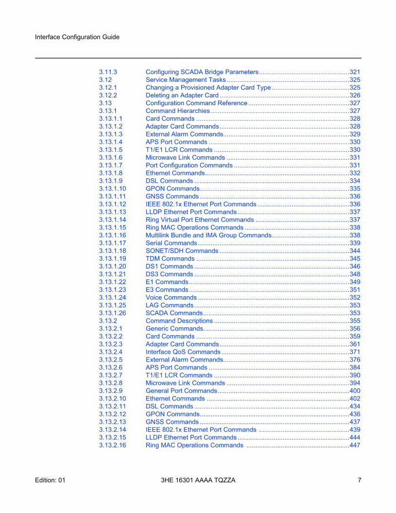
3.11.3 Configuring SCADA Bridge Parameters..................................................3213.12 Service Management Tasks ....................................................................3253.12.1 Changing a Provisioned Adapter Card Type ...........................................3253.12.2 Deleting an Adapter Card ........................................................................3263.13 Configuration Command Reference ........................................................3273.13.1 Command Hierarchies.............................................................................3273.13.1.1 Card Commands .....................................................................................3283.13.1.2 Adapter Card Commands........................................................................3283.13.1.3 External Alarm Commands......................................................................3293.13.1.4 APS Port Commands ..............................................................................3303.13.1.5 T1/E1 LCR Commands ...........................................................................3303.13.1.6 Microwave Link Commands ....................................................................3313.13.1.7 Port Configuration Commands ................................................................3313.13.1.8 Ethernet Commands................................................................................3323.13.1.9 DSL Commands ......................................................................................3343.13.1.10 GPON Commands...................................................................................3353.13.1.11 GNSS Commands...................................................................................3363.13.1.12 IEEE 802.1x Ethernet Port Commands ...................................................3363.13.1.13 LLDP Ethernet Port Commands ..............................................................3373.13.1.14 Ring Virtual Port Ethernet Commands ....................................................3373.13.1.15 Ring MAC Operations Commands ..........................................................3383.13.1.16 Multilink Bundle and IMA Group Commands...........................................3383.13.1.17 Serial Commands ....................................................................................3393.13.1.18 SONET/SDH Commands ........................................................................3443.13.1.19 TDM Commands .....................................................................................3453.13.1.20 DS1 Commands ......................................................................................3463.13.1.21 DS3 Commands ......................................................................................3483.13.1.22 E1 Commands.........................................................................................3493.13.1.23 E3 Commands.........................................................................................3513.13.1.24 Voice Commands ....................................................................................3523.13.1.25 LAG Commands......................................................................................3533.13.1.26 SCADA Commands.................................................................................3533.13.2 Command Descriptions ...........................................................................3553.13.2.1 Generic Commands.................................................................................3563.13.2.2 Card Commands .....................................................................................3593.13.2.3 Adapter Card Commands........................................................................3613.13.2.4 Interface QoS Commands .......................................................................3713.13.2.5 External Alarm Commands......................................................................3763.13.2.6 APS Port Commands ..............................................................................3843.13.2.7 T1/E1 LCR Commands ...........................................................................3903.13.2.8 Microwave Link Commands ....................................................................3943.13.2.9 General Port Commands.........................................................................4003.13.2.10 Ethernet Commands ...............................................................................4023.13.2.11 DSL Commands ......................................................................................4343.13.2.12 GPON Commands...................................................................................4363.13.2.13 GNSS Commands...................................................................................4373.13.2.14 IEEE 802.1x Ethernet Port Commands ..................................................4393.13.2.15 LLDP Ethernet Port Commands ..............................................................4443.13.2.16 Ring MAC Operations Commands .........................................................447
8
Interface Configuration Guide
3HE 16301 AAAA TQZZA Edition: 01
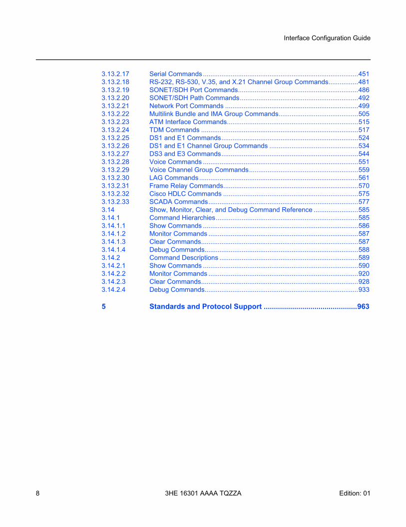
3.13.2.17 Serial Commands ....................................................................................4513.13.2.18 RS-232, RS-530, V.35, and X.21 Channel Group Commands................4813.13.2.19 SONET/SDH Port Commands.................................................................4863.13.2.20 SONET/SDH Path Commands................................................................4923.13.2.21 Network Port Commands ........................................................................4993.13.2.22 Multilink Bundle and IMA Group Commands...........................................5053.13.2.23 ATM Interface Commands.......................................................................5153.13.2.24 TDM Commands .....................................................................................5173.13.2.25 DS1 and E1 Commands..........................................................................5243.13.2.26 DS1 and E1 Channel Group Commands ................................................5343.13.2.27 DS3 and E3 Commands..........................................................................5443.13.2.28 Voice Commands ....................................................................................5513.13.2.29 Voice Channel Group Commands...........................................................5593.13.2.30 LAG Commands......................................................................................5613.13.2.31 Frame Relay Commands.........................................................................5703.13.2.32 Cisco HDLC Commands .........................................................................5753.13.2.33 SCADA Commands.................................................................................5773.14 Show, Monitor, Clear, and Debug Command Reference ........................5853.14.1 Command Hierarchies.............................................................................5853.14.1.1 Show Commands ....................................................................................5863.14.1.2 Monitor Commands .................................................................................5873.14.1.3 Clear Commands.....................................................................................5873.14.1.4 Debug Commands...................................................................................5883.14.2 Command Descriptions ...........................................................................5893.14.2.1 Show Commands ....................................................................................5903.14.2.2 Monitor Commands .................................................................................9203.14.2.3 Clear Commands.....................................................................................9283.14.2.4 Debug Commands...................................................................................933
5 Standards and Protocol Support ..............................................963
Interface Configuration Guide
Edition: 01 3HE 16301 AAAA TQZZA 9
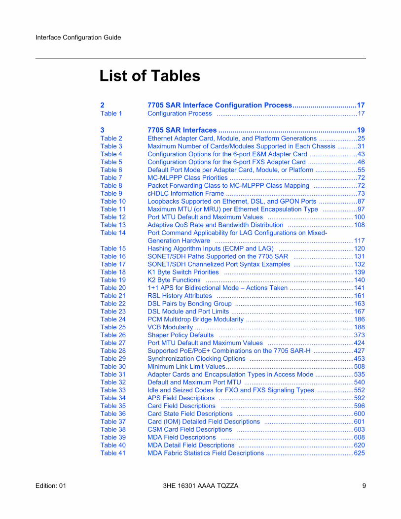
List of Tables2 7705 SAR Interface Configuration Process................................17Table 1 Configuration Process .............................................................................17
3 7705 SAR Interfaces .....................................................................19Table 2 Ethernet Adapter Card, Module, and Platform Generations .....................25Table 3 Maximum Number of Cards/Modules Supported in Each Chassis ...........31Table 4 Configuration Options for the 6-port E&M Adapter Card ..........................43Table 5 Configuration Options for the 6-port FXS Adapter Card ...........................46Table 6 Default Port Mode per Adapter Card, Module, or Platform .......................55Table 7 MC-MLPPP Class Priorities ......................................................................72Table 8 Packet Forwarding Class to MC-MLPPP Class Mapping ........................72Table 9 cHDLC Information Frame ........................................................................73Table 10 Loopbacks Supported on Ethernet, DSL, and GPON Ports .....................87Table 11 Maximum MTU (or MRU) per Ethernet Encapsulation Type ...................97Table 12 Port MTU Default and Maximum Values ...............................................100Table 13 Adaptive QoS Rate and Bandwidth Distribution ....................................108Table 14 Port Command Applicability for LAG Configurations on Mixed-
Generation Hardware ............................................................................117Table 15 Hashing Algorithm Inputs (ECMP and LAG) .........................................120Table 16 SONET/SDH Paths Supported on the 7705 SAR .................................131Table 17 SONET/SDH Channelized Port Syntax Examples .................................132Table 18 K1 Byte Switch Priorities .......................................................................139Table 19 K2 Byte Functions .................................................................................140Table 20 1+1 APS for Bidirectional Mode – Actions Taken ...................................141Table 21 RSL History Attributes ...........................................................................161Table 22 DSL Pairs by Bonding Group .................................................................163Table 23 DSL Module and Port Limits ...................................................................167Table 24 PCM Multidrop Bridge Modularity ...........................................................186Table 25 VCB Modularity .......................................................................................188Table 26 Shaper Policy Defaults ..........................................................................373Table 27 Port MTU Default and Maximum Values ...............................................424Table 28 Supported PoE/PoE+ Combinations on the 7705 SAR-H ......................427Table 29 Synchronization Clocking Options .........................................................453Table 30 Minimum Link Limit Values......................................................................508Table 31 Adapter Cards and Encapsulation Types in Access Mode .....................535Table 32 Default and Maximum Port MTU ............................................................540Table 33 Idle and Seized Codes for FXO and FXS Signaling Types ....................552Table 34 APS Field Descriptions ..........................................................................592Table 35 Card Field Descriptions .........................................................................596Table 36 Card State Field Descriptions ................................................................600Table 37 Card (IOM) Detailed Field Descriptions .................................................601Table 38 CSM Card Field Descriptions ................................................................603Table 39 MDA Field Descriptions .........................................................................608Table 40 MDA Detail Field Descriptions ...............................................................620Table 41 MDA Fabric Statistics Field Descriptions ................................................625
10
Interface Configuration Guide
3HE 16301 AAAA TQZZA Edition: 01
Table 42 MDA Fabric IP-Transport Statistics Field Descriptions ...........................631Table 43 MDA Fabric Cflowd Statistics Field Descriptions ....................................632Table 44 MDA Fabric Mirror Statistics Field Descriptions .....................................633Table 45 MDA Fabric Security Encryption Statistics Field Descriptions ................635Table 46 MDA Fabric Security Firewall Statistics Field Descriptions ....................638Table 47 MDA With Fabric Statistics Field Descriptions .......................................638Table 48 MDA Aggregate Statistics Field Descriptions .........................................645Table 49 MDA Ring FDB Field Descriptions .........................................................649Table 50 Specific Alarm Field Descriptions ..........................................................653Table 51 External Alarm Input Field Descriptions ................................................656Table 52 External Alarm Input Detail Field Descriptions ......................................657Table 53 External Alarm Field Descriptions .........................................................659Table 54 External Alarm Output Detail Field Descriptions ...................................660Table 55 External Alarm Name Field Descriptions ...............................................661Table 56 LCR Field Descriptions ..........................................................................664Table 57 LCR Detail Field Descriptions ................................................................665Table 58 Microwave Link Detail Field Descriptions ..............................................670Table 59 MPR-e Radio Detail Field Descriptions .................................................673Table 60 MPR-e Radio Power Measurement Field Descriptions .........................675Table 61 MPR-e Radio Software State Field Descriptions ...................................676Table 62 MWA Performance Monitoring Field Descriptions ..................................682Table 63 General Port Field Descriptions .............................................................690Table 64 Port Statistics Field Descriptions ...........................................................692Table 65 Specific Port Field Descriptions (GigE Port with Optical SFP) ...............695Table 66 PoE Port Field Descriptions (Ethernet) ...................................................707Table 67 Specific Port Field Descriptions (Serial Port) ..........................................715Table 68 Specific Port Field Descriptions (SONET/SDH Port) ..............................717Table 69 Specific Port Field Descriptions (E&M Voice Port) .................................721Table 70 Specific Port Field Descriptions (FXO Voice Port) .................................723Table 71 Specific Port Field Descriptions (FXS Voice Port) ..................................725Table 72 Specific Port Field Descriptions (DS0 Voice Channel Group) ................727Table 73 Port Detail Field Descriptions (SONET/SDH Port) ................................730Table 74 Port Detail Field Descriptions (Ethernet, Access Mode) .........................737Table 75 Port Detail Field Descriptions (Ethernet, Network Mode) .......................749Table 76 Port Detail Field Descriptions (DSL) .......................................................751Table 77 Port Detail Field Descriptions (GPON) ...................................................759Table 78 Port Detail Field Descriptions (Ring Ethernet) ........................................769Table 79 Port Detail Field Descriptions (v-port) .....................................................779Table 80 Port Detail Field Descriptions (TDM DS1 Interface) ..............................790Table 81 Port Serial Channel Field Descriptions ...................................................797Table 82 Port Voice Channel Field Descriptions ...................................................807Table 83 Port Channel Group Field Descriptions .................................................814Table 84 Port Channelized DS3 Field Descriptions .............................................818Table 85 Port Clear Channel DS3 Field Descriptions ..........................................821Table 86 Port ACR Detail Field Descriptions .........................................................823Table 87 Port dot1x Field Descriptions .................................................................826Table 88 Port Description Field Descriptions ........................................................832Table 89 Port Associations Field Descriptions .....................................................832Table 90 Port IMA Link Field Descriptions ............................................................833
Interface Configuration Guide
Edition: 01 3HE 16301 AAAA TQZZA 11
Table 91 Port PPP Field Descriptions ...................................................................836Table 92 Port CEM Field Descriptions ..................................................................837Table 93 Port Frame Relay Field Descriptions ......................................................838Table 94 Port Frame Relay DLCI Field Descriptions .............................................841Table 95 Port Field Descriptions (TDM Codirectional or TPIF) .............................846Table 96 Port Field Descriptions (GNSS) ..............................................................849Table 97 Port Field Descriptions (APS) ................................................................851Table 98 Port Field Descriptions (With APS ID) ...................................................853Table 99 Port Field Descriptions (LCR) ................................................................857Table 100 Port Field Descriptions (With LCR Port ID) ..........................................858Table 101 DSL Port Field Descriptions ...................................................................861Table 102 Port LLDP Field Descriptions .................................................................865Table 103 Port LLDP Detail Field Descriptions ......................................................867Table 104 Port ATM Field Descriptions ..................................................................870Table 105 Port ATM Connections Field Descriptions ..............................................872Table 106 Port ATM PVC Field Descriptions ..........................................................873Table 107 Port ATM PVC VPI/VCI Field Descriptions .............................................874Table 108 Port ATM PVC VPI/VCI Detail Field Descriptions ..................................875Table 109 Port ATM PVP Field Descriptions ..........................................................877Table 110 Port ATM PVP Detail Field Descriptions ...............................................878Table 111 Port-tree Field Descriptions ...................................................................881Table 112 LAG Summary Field Descriptions .........................................................883Table 113 LAG Detailed Field Descriptions ............................................................885Table 114 LAG Statistics Field Descriptions ..........................................................888Table 115 LAG Associations Field Descriptions .....................................................889Table 116 LAG Description Field Descriptions .......................................................889Table 117 LAG LACP Partner Field Descriptions ...................................................890Table 118 LAG Detailed LACP Partner Field Descriptions ....................................892Table 119 LAG Port Field Descriptions ..................................................................893Table 120 Multilink Bundle Field Descriptions ........................................................896Table 121 Multilink Bundle IMA Group Field Descriptions .....................................898Table 122 Multilink Bundle IMA Group Detailed Field Descriptions .......................900Table 123 Multilink Bundle MLPPP Field Descriptions ...........................................904Table 124 Multilink Bundle MLPPP Detail Field Descriptions ................................906Table 125 Multilink Bundle IMA ATM Field Descriptions .........................................911Table 126 Multilink Bundle IMA ATM Connections Field Descriptions ....................911Table 127 Multilink Bundle IMA ATM PVC Field Descriptions ...............................913Table 128 Multilink-bundle IMA ATM PVP Field Descriptions ................................914Table 129 SCADA Bridge Detail Field Descriptions ...............................................916Table 130 Specific SCADA Bridge Detail Field Descriptions .................................917
4 List of Acronyms ........................................................................935Table 131 Acronyms ...............................................................................................935
5 Standards and Protocol Support ..............................................963Table 132 EMC Industrial Standards Compliance ...................................................964Table 133 EMC Regulatory and Customer Standards Compliance ........................965Table 134 Environmental Standards Compliance ...................................................967Table 135 Safety Standards Compliance ................................................................969

12
Interface Configuration Guide
3HE 16301 AAAA TQZZA Edition: 01
Table 136 Telecom Interface Compliance ...............................................................970Table 137 Directives, Regional Approvals and Certifications Compliance ..............971
Interface Configuration Guide
Edition: 01 3HE 16301 AAAA TQZZA 13
List of Figures3 7705 SAR Interfaces .....................................................................19Figure 1 Hybrid Port Application ..............................................................................64Figure 2 MLPPP 24-bit Fragment Format................................................................67Figure 3 MLPPP 12-bit Fragment Format................................................................67Figure 4 Original MLPPP Header Format................................................................71Figure 5 MC-MLPPP Header Format ......................................................................71Figure 6 EFM Capability on the 7705 SAR..............................................................86Figure 7 CFM Loopback on Ethernet Ports .............................................................90Figure 8 MTU Points on the 7705 SAR ...................................................................95Figure 9 LAG on Access Interconnection ..............................................................106Figure 10 LAG on Access Failure Switchover .........................................................106Figure 11 SONET Hierarchy at STS-12 ..................................................................129Figure 12 SDH Hierarchy at STM-4 ........................................................................130Figure 13 SC-APS with Physical Port and Adapter Card Protection .......................135Figure 14 SC-APS Application.................................................................................136Figure 15 MC-APS with Physical Port, Adapter Card and Node Protection ............137Figure 16 MC-APS Application ................................................................................138Figure 17 MC-APS with Pseudowire Redundancy and ICB ....................................138Figure 18 1+1 HSB with SD Deployment ................................................................158Figure 19 Example of a TDA Application.................................................................159Figure 20 802.1x Architecture..................................................................................170Figure 21 Authentication Scenario...........................................................................171Figure 22 802.1x EAPOL Timers and RADIUS Timers ...........................................173Figure 23 LLDP Internal Architecture for a Network Node ......................................179Figure 24 Network Example For LLDP....................................................................180Figure 25 LLDPDU Format ......................................................................................181Figure 26 SCADA MDDB Network ..........................................................................185Figure 27 SCADA PCM Multidrop Bridge Network..................................................186Figure 28 Serial Transport Over Raw Socket Application .......................................191Figure 29 Raw Socket Packet Processing...............................................................193Figure 30 OC3 Channelization using SONET and SDH..........................................264Figure 31 Configuring SONET/SDH Network Port ..................................................278

14
Interface Configuration Guide
3HE 16301 AAAA TQZZA Edition: 01
Interface Configuration Guide Preface
Edition: 01 3HE 16301 AAAA TQZZA 15
1 Preface
1.1 About This Guide
This guide describes system concepts and provides configuration examples to provision CSM cards, adapter cards, modules and ports for the 7705 SAR.
This guide is organized into functional chapters and provides concepts and descriptions of the implementation flow, as well as Command Line Interface (CLI) syntax and command usage.
Note: This manual generically covers Release 20.x content and may contain some content that will be released in later maintenance loads. Please refer to the 7705 SAR 20.x.Rx Software Release Notes, part number 3HE16192000xTQZZA, for information on features supported in each load of the Release 20.x software.
Note:
As of Release 7.0, support for the following hardware has been deprecated:
• CSMv1• 7705 SAR-F• 8-port Ethernet Adapter card, version 1• 16-port T1/E1 ASAP Adapter card, version 1
These components are no longer recognized in the release.
Preface
16
Interface Configuration Guide
3HE 16301 AAAA TQZZA Edition: 01
1.1.1 Audience
This guide is intended for network administrators who are responsible for configuring the 7705 SAR routers. It is assumed that the network administrators have an understanding of networking principles and configurations. Concepts described in this guide include the following:
• CLI concepts• adapter card and port configuration• QoS policies• services
1.1.2 Technical Support
If you purchased a service agreement for your 7705 SAR router and related products from a distributor or authorized reseller, contact the technical support staff for that distributor or reseller for assistance. If you purchased a Nokia service agreement, follow this link to contact a Nokia support representative and to access product manuals and documentation updates:
Product Support Portal
Interface Configuration Guide 7705 SAR Interface Configuration Process
Edition: 01 3HE 16301 AAAA TQZZA 17
2 7705 SAR Interface Configuration Process
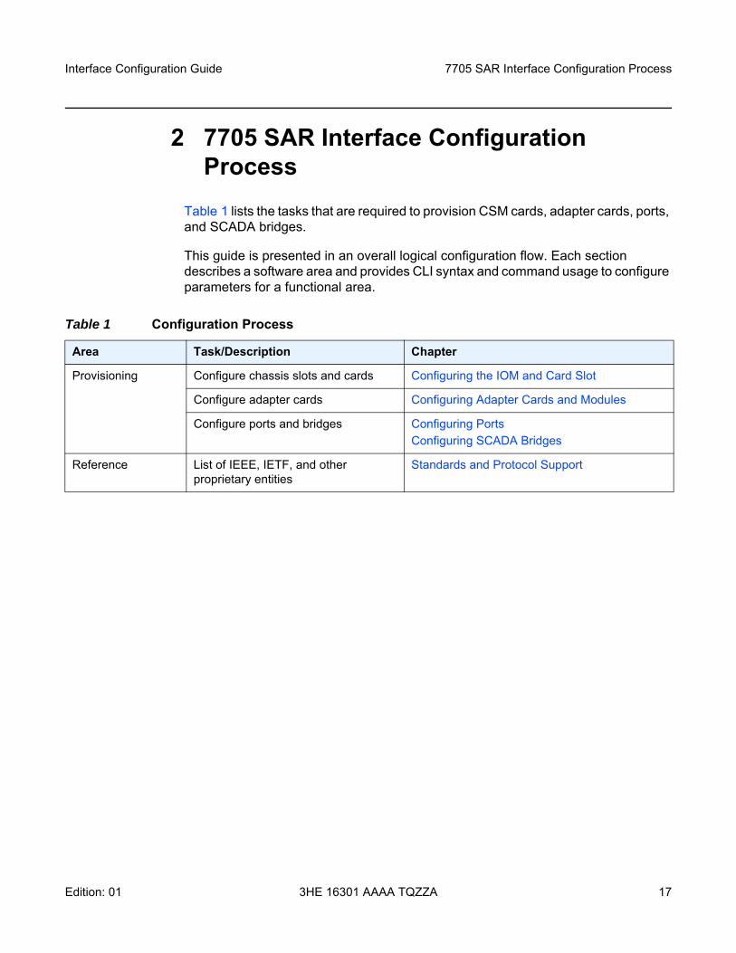
Table 1 lists the tasks that are required to provision CSM cards, adapter cards, ports, and SCADA bridges.
This guide is presented in an overall logical configuration flow. Each section describes a software area and provides CLI syntax and command usage to configure parameters for a functional area.
Table 1 Configuration Process
Area Task/Description Chapter
Provisioning Configure chassis slots and cards Configuring the IOM and Card Slot
Configure adapter cards Configuring Adapter Cards and Modules
Configure ports and bridges Configuring PortsConfiguring SCADA Bridges
Reference List of IEEE, IETF, and other proprietary entities
Standards and Protocol Support

7705 SAR Interface Configuration Process
18
Interface Configuration Guide
3HE 16301 AAAA TQZZA Edition: 01
Interface Configuration Guide 7705 SAR Interfaces
Edition: 01 3HE 16301 AAAA TQZZA 19
3 7705 SAR InterfacesThis chapter provides information about configuring chassis slots, cards, and ports.
Topics in this chapter include:
• Configuration Overview• Port Features• 802.1x Network Access Control• MAC Authentication• Link Layer Discovery Protocol (LLDP)• Surveillance, Control, and Data Acquisition (SCADA) Support• Configuration Notes• Configuring Physical Components with CLI• Configuration Command Reference• Show, Monitor, Clear, and Debug Command Reference
7705 SAR Interfaces
20
Interface Configuration Guide
3HE 16301 AAAA TQZZA Edition: 01
3.1 Configuration Overview
This guide uses the term “preprovisioning” in the context of preparing or preconfiguring entities such as chassis slots, the IOM, adapter cards, ports, and interfaces, prior to hardware actually being installed in the chassis. These entities can be installed but not enabled. When the entity is in a no shutdown state (administratively enabled), the entity is considered to be provisioned.
Nokia 7705 SAR routers provide the capability to configure chassis slots to accept specific adapter card types and set the relevant configurations before the equipment is actually installed. The preprovisioning ability allows you to plan your configurations as well as monitor and manage your router hardware inventory. Ports and interfaces can also be preprovisioned. When the functionality is needed, the cards can be inserted into the appropriate chassis slots as required.
The following sections are discussed:
• Configuring the IOM and Card Slot• Configuring Adapter Cards and Modules• Configuring Ports• Configuring SCADA Bridges
3.1.1 Configuring the IOM and Card Slot
The 7705 SAR card slot ID is always 1 and the card type for the IOM is always iom-sar.
On the 7705 SAR-8 and 7705 SAR-18, the CSM, which can only be installed in slot A or B of the chassis, does not need to be provisioned. However, the IOM, which is virtualized in the 7705 SAR software, must be activated before the adapter cards, ports, and SCADA bridges can be preprovisioned and configured. The IOM is activated by designating it a card slot ID and card type. This enables the chassis slots to accept the adapter cards.
Note: On the 7705 SAR-8, the CSM is called the CSMv2; both terms are used interchangeably in these guides. The CSMv2 supports bandwidth of 10 Gb/s, 2.5 Gb/s and 1 Gb/s in the first two adapter card slots and 2.5 Gb/s and 1 Gb/s in the remaining four adapter card slots. Support for 2.5 Gb/s and 10 Gb/s adapter cards by the CSMv2 is only available on the 7705 SAR-8 Shelf V2.
Interface Configuration Guide 7705 SAR Interfaces
Edition: 01 3HE 16301 AAAA TQZZA 21
The 7705 SAR-M (all variants), 7705 SAR-H, 7705 SAR-Hc, 7705 SAR-A (both variants), 7705 SAR-Ax, 7705 SAR-W, 7705 SAR-Wx (all variants), and 7705 SAR-X have a fixed physical configuration and each router uses only one control and switching functional block, which is referred to on the CLI as CSM A. The CSM and IOM do not need to be provisioned in order to provision the interface at the adapter card level.
The slot ID (1) is used as part of the adapter card and port identifier on the CLI.
3.1.2 Configuring Adapter Cards and Modules
This section contains information on the following topics:
• Provisioning Chassis Slots for Adapter Cards • Maximum Number of Adapter Cards in a Chassis • Evolution of Ethernet Adapter Cards, Modules, and Platforms • Channelized Adapter Card Support
3.1.2.1 Provisioning Chassis Slots for Adapter Cards
A chassis slot and card type must be specified and provisioned before an adapter card can be provisioned. A chassis slot is a physical slot designated with an MDA ID. On the 7705 SAR-8, the MDA ID is from 1 to 6. On the 7705 SAR-18, the MDA ID is from 1 to 12 for the MDA slots and from X1 to X4 for the XMDA slots. An adapter card is provisioned when a card designated from the allowed adapter card types is inserted. A preprovisioned adapter card slot can remain empty without conflicting with populated slots.
The adapter cards can be installed in the chassis in any combination that does not exceed the maximum number. However, network applications require at least one network-capable adapter card to be installed as part of the mix.
Once installed and enabled, the system verifies that the installed adapter card type matches the configured parameters. If the parameters do not match, the adapter card remains offline.
7705 SAR Interfaces
22
Interface Configuration Guide
3HE 16301 AAAA TQZZA Edition: 01
3.1.2.2 Maximum Number of Adapter Cards in a Chassis
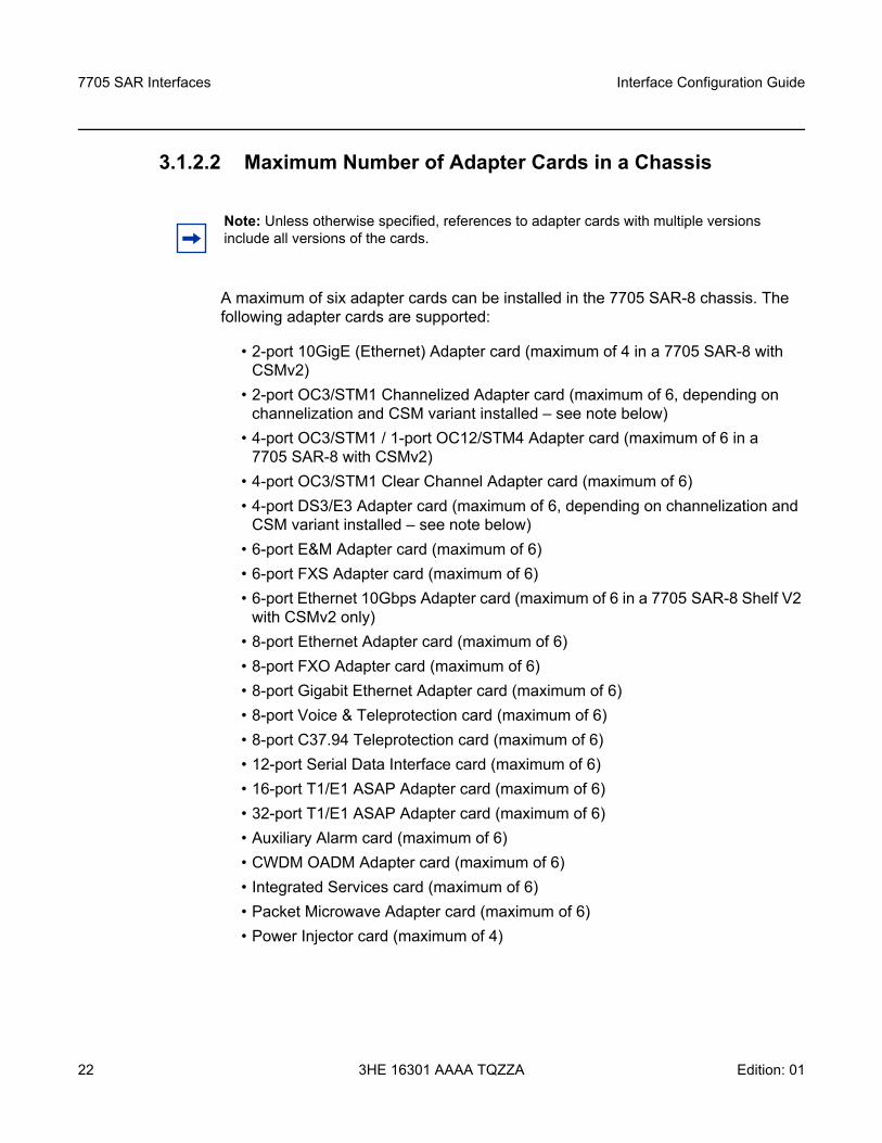
A maximum of six adapter cards can be installed in the 7705 SAR-8 chassis. The following adapter cards are supported:
• 2-port 10GigE (Ethernet) Adapter card (maximum of 4 in a 7705 SAR-8 with CSMv2)
• 2-port OC3/STM1 Channelized Adapter card (maximum of 6, depending on channelization and CSM variant installed – see note below)
• 4-port OC3/STM1 / 1-port OC12/STM4 Adapter card (maximum of 6 in a 7705 SAR-8 with CSMv2)
• 4-port OC3/STM1 Clear Channel Adapter card (maximum of 6)• 4-port DS3/E3 Adapter card (maximum of 6, depending on channelization and
CSM variant installed – see note below)• 6-port E&M Adapter card (maximum of 6)• 6-port FXS Adapter card (maximum of 6)• 6-port Ethernet 10Gbps Adapter card (maximum of 6 in a 7705 SAR-8 Shelf V2
with CSMv2 only)• 8-port Ethernet Adapter card (maximum of 6)• 8-port FXO Adapter card (maximum of 6)• 8-port Gigabit Ethernet Adapter card (maximum of 6) • 8-port Voice & Teleprotection card (maximum of 6)• 8-port C37.94 Teleprotection card (maximum of 6)• 12-port Serial Data Interface card (maximum of 6)• 16-port T1/E1 ASAP Adapter card (maximum of 6)• 32-port T1/E1 ASAP Adapter card (maximum of 6)• Auxiliary Alarm card (maximum of 6)• CWDM OADM Adapter card (maximum of 6)• Integrated Services card (maximum of 6)• Packet Microwave Adapter card (maximum of 6)• Power Injector card (maximum of 4)
Note: Unless otherwise specified, references to adapter cards with multiple versions include all versions of the cards.
Interface Configuration Guide 7705 SAR Interfaces
Edition: 01 3HE 16301 AAAA TQZZA 23
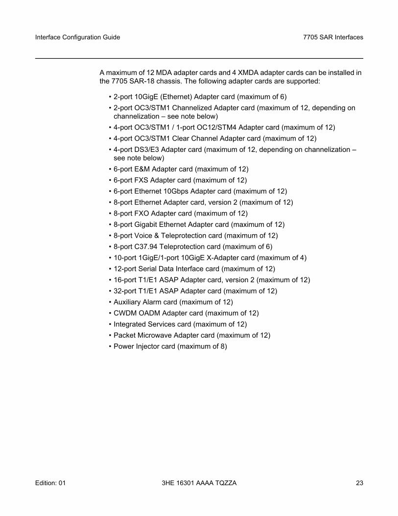
A maximum of 12 MDA adapter cards and 4 XMDA adapter cards can be installed in the 7705 SAR-18 chassis. The following adapter cards are supported:
• 2-port 10GigE (Ethernet) Adapter card (maximum of 6) • 2-port OC3/STM1 Channelized Adapter card (maximum of 12, depending on
channelization – see note below)• 4-port OC3/STM1 / 1-port OC12/STM4 Adapter card (maximum of 12)• 4-port OC3/STM1 Clear Channel Adapter card (maximum of 12)• 4-port DS3/E3 Adapter card (maximum of 12, depending on channelization –
see note below)• 6-port E&M Adapter card (maximum of 12)• 6-port FXS Adapter card (maximum of 12)• 6-port Ethernet 10Gbps Adapter card (maximum of 12)• 8-port Ethernet Adapter card, version 2 (maximum of 12)• 8-port FXO Adapter card (maximum of 12)• 8-port Gigabit Ethernet Adapter card (maximum of 12) • 8-port Voice & Teleprotection card (maximum of 12)• 8-port C37.94 Teleprotection card (maximum of 6)• 10-port 1GigE/1-port 10GigE X-Adapter card (maximum of 4) • 12-port Serial Data Interface card (maximum of 12)• 16-port T1/E1 ASAP Adapter card, version 2 (maximum of 12)• 32-port T1/E1 ASAP Adapter card (maximum of 12)• Auxiliary Alarm card (maximum of 12)• CWDM OADM Adapter card (maximum of 12)• Integrated Services card (maximum of 12)• Packet Microwave Adapter card (maximum of 12)• Power Injector card (maximum of 8)
7705 SAR Interfaces
24
Interface Configuration Guide
3HE 16301 AAAA TQZZA Edition: 01
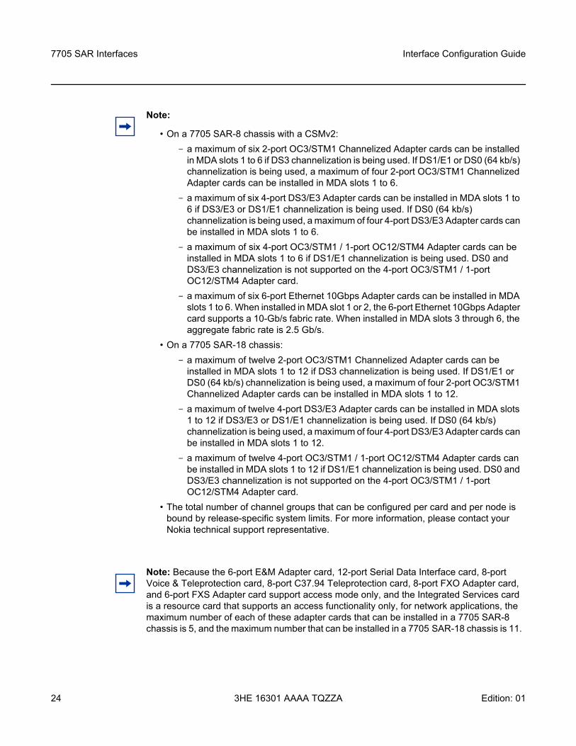
Note:
• On a 7705 SAR-8 chassis with a CSMv2:- a maximum of six 2-port OC3/STM1 Channelized Adapter cards can be installed
in MDA slots 1 to 6 if DS3 channelization is being used. If DS1/E1 or DS0 (64 kb/s) channelization is being used, a maximum of four 2-port OC3/STM1 Channelized Adapter cards can be installed in MDA slots 1 to 6.
- a maximum of six 4-port DS3/E3 Adapter cards can be installed in MDA slots 1 to 6 if DS3/E3 or DS1/E1 channelization is being used. If DS0 (64 kb/s) channelization is being used, a maximum of four 4-port DS3/E3 Adapter cards can be installed in MDA slots 1 to 6.
- a maximum of six 4-port OC3/STM1 / 1-port OC12/STM4 Adapter cards can be installed in MDA slots 1 to 6 if DS1/E1 channelization is being used. DS0 and DS3/E3 channelization is not supported on the 4-port OC3/STM1 / 1-port OC12/STM4 Adapter card.
- a maximum of six 6-port Ethernet 10Gbps Adapter cards can be installed in MDA slots 1 to 6. When installed in MDA slot 1 or 2, the 6-port Ethernet 10Gbps Adapter card supports a 10-Gb/s fabric rate. When installed in MDA slots 3 through 6, the aggregate fabric rate is 2.5 Gb/s.
• On a 7705 SAR-18 chassis:- a maximum of twelve 2-port OC3/STM1 Channelized Adapter cards can be
installed in MDA slots 1 to 12 if DS3 channelization is being used. If DS1/E1 or DS0 (64 kb/s) channelization is being used, a maximum of four 2-port OC3/STM1 Channelized Adapter cards can be installed in MDA slots 1 to 12.
- a maximum of twelve 4-port DS3/E3 Adapter cards can be installed in MDA slots 1 to 12 if DS3/E3 or DS1/E1 channelization is being used. If DS0 (64 kb/s) channelization is being used, a maximum of four 4-port DS3/E3 Adapter cards can be installed in MDA slots 1 to 12.
- a maximum of twelve 4-port OC3/STM1 / 1-port OC12/STM4 Adapter cards can be installed in MDA slots 1 to 12 if DS1/E1 channelization is being used. DS0 and DS3/E3 channelization is not supported on the 4-port OC3/STM1 / 1-port OC12/STM4 Adapter card.
• The total number of channel groups that can be configured per card and per node is bound by release-specific system limits. For more information, please contact your Nokia technical support representative.
Note: Because the 6-port E&M Adapter card, 12-port Serial Data Interface card, 8-port Voice & Teleprotection card, 8-port C37.94 Teleprotection card, 8-port FXO Adapter card, and 6-port FXS Adapter card support access mode only, and the Integrated Services card is a resource card that supports an access functionality only, for network applications, the maximum number of each of these adapter cards that can be installed in a 7705 SAR-8 chassis is 5, and the maximum number that can be installed in a 7705 SAR-18 chassis is 11.
Interface Configuration Guide 7705 SAR Interfaces
Edition: 01 3HE 16301 AAAA TQZZA 25
3.1.2.3 Evolution of Ethernet Adapter Cards, Modules, and Platforms
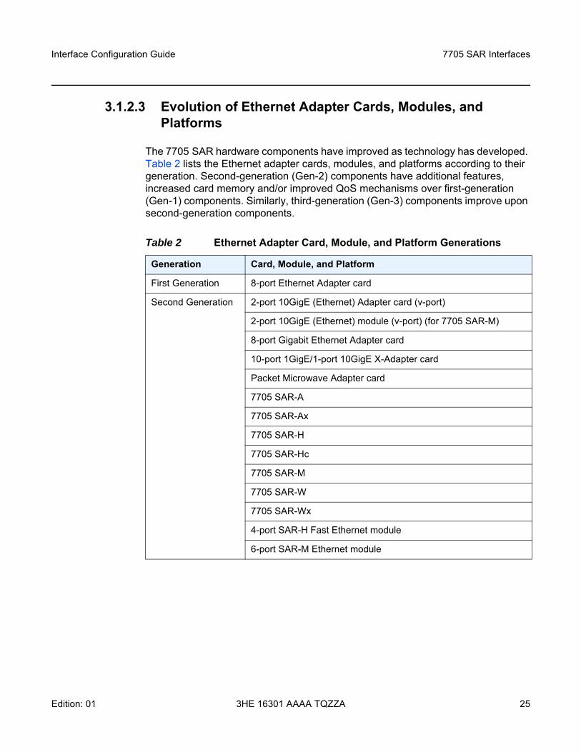
The 7705 SAR hardware components have improved as technology has developed. Table 2 lists the Ethernet adapter cards, modules, and platforms according to their generation. Second-generation (Gen-2) components have additional features, increased card memory and/or improved QoS mechanisms over first-generation (Gen-1) components. Similarly, third-generation (Gen-3) components improve upon second-generation components.
Table 2 Ethernet Adapter Card, Module, and Platform Generations
Generation Card, Module, and Platform
First Generation 8-port Ethernet Adapter card
Second Generation 2-port 10GigE (Ethernet) Adapter card (v-port)
2-port 10GigE (Ethernet) module (v-port) (for 7705 SAR-M)
8-port Gigabit Ethernet Adapter card
10-port 1GigE/1-port 10GigE X-Adapter card
Packet Microwave Adapter card
7705 SAR-A
7705 SAR-Ax
7705 SAR-H
7705 SAR-Hc
7705 SAR-M
7705 SAR-W
7705 SAR-Wx
4-port SAR-H Fast Ethernet module
6-port SAR-M Ethernet module
7705 SAR Interfaces
26
Interface Configuration Guide
3HE 16301 AAAA TQZZA Edition: 01
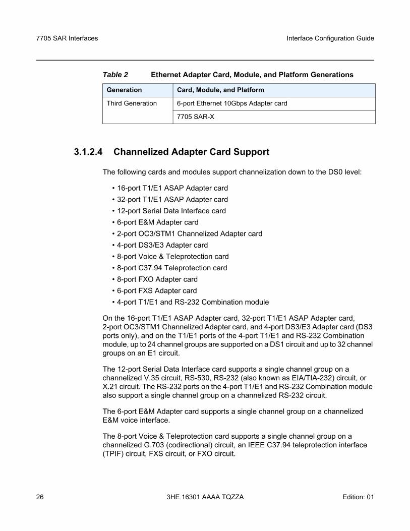
3.1.2.4 Channelized Adapter Card Support
The following cards and modules support channelization down to the DS0 level:
• 16-port T1/E1 ASAP Adapter card• 32-port T1/E1 ASAP Adapter card• 12-port Serial Data Interface card• 6-port E&M Adapter card• 2-port OC3/STM1 Channelized Adapter card• 4-port DS3/E3 Adapter card• 8-port Voice & Teleprotection card• 8-port C37.94 Teleprotection card• 8-port FXO Adapter card• 6-port FXS Adapter card• 4-port T1/E1 and RS-232 Combination module
On the 16-port T1/E1 ASAP Adapter card, 32-port T1/E1 ASAP Adapter card, 2-port OC3/STM1 Channelized Adapter card, and 4-port DS3/E3 Adapter card (DS3 ports only), and on the T1/E1 ports of the 4-port T1/E1 and RS-232 Combination module, up to 24 channel groups are supported on a DS1 circuit and up to 32 channel groups on an E1 circuit.
The 12-port Serial Data Interface card supports a single channel group on a channelized V.35 circuit, RS-530, RS-232 (also known as EIA/TIA-232) circuit, or X.21 circuit. The RS-232 ports on the 4-port T1/E1 and RS-232 Combination module also support a single channel group on a channelized RS-232 circuit.
The 6-port E&M Adapter card supports a single channel group on a channelized E&M voice interface.
The 8-port Voice & Teleprotection card supports a single channel group on a channelized G.703 (codirectional) circuit, an IEEE C37.94 teleprotection interface (TPIF) circuit, FXS circuit, or FXO circuit.
Third Generation 6-port Ethernet 10Gbps Adapter card
7705 SAR-X
Table 2 Ethernet Adapter Card, Module, and Platform Generations
Generation Card, Module, and Platform
Interface Configuration Guide 7705 SAR Interfaces
Edition: 01 3HE 16301 AAAA TQZZA 27
The 8-port C37.94 Teleprotection card supports a single channel group on an IEEE C37.94 teleprotection interface (TPIF) circuit.
The 8-port FXO Adapter card supports a single channel group on an FXO circuit.
The 6-port FXS Adapter card supports a single channel group on an FXS circuit.
The 4-port OC3/STM1 / 1-port OC12/STM4 Adapter card supports channelization at the DS1/E1 level only.
3.1.2.4.1 PPP Over Fractional T1/E1
The 16-port T1/E1 ASAP Adapter card, 32-port T1/E1 ASAP Adapter card, and the T1/E1 ports on the 4-port T1/E1 and RS-232 Combination module each support fractional T1/E1 on a PPP channel group in network mode. Fractional T1/E1 allows one or more DS0 channels to be bundled together (up to the maximum bandwidth of the network link), allowing the customer to use only that portion of the link that is needed. This means that the PPP service can use a selected number of timeslots (octets) in the network T1 or E1 link, thus reducing the amount of T1 or E1 bandwidth that must be leased or purchased from the attached carrier. This leads to multiplexing efficiencies in the transport network.
Only one channel group can be configured per port. When the channel group is configured for ppp-auto encapsulation and network mode, all timeslots (channels) are automatically allocated to the channel group. The user can then configure the number of timeslots needed. Timeslots not selected cannot be used.
3.1.3 Configuring Ports
A port can be configured after the IOM is activated (the card slot and card type are designated) and the adapter card slot is preprovisioned with an allowed adapter card type.
The 7705 SAR supports the port types listed below:
• Ethernet• TDM• DSL• GNSS Receiver• GPON• Multilink Bundles
7705 SAR Interfaces
28
Interface Configuration Guide
3HE 16301 AAAA TQZZA Edition: 01
• IMA• SONET/SDH• Voice• Microwave Link
In addition, this section contains information on the following topics:
• CLI Identifiers for Adapter Cards, Modules and Platforms• Access, Network, and Hybrid Ports
3.1.3.1 Ethernet
Ethernet ports are supported on the following cards, modules, and platforms:
• 6-port Ethernet 10Gbps Adapter Card• 8-port Ethernet Adapter Card• 8-port Gigabit Ethernet Adapter Card• 10-port 1GigE/1-port 10GigE X-Adapter Card• 2-port 10GigE (Ethernet) Adapter Card/Module• Packet Microwave Adapter Card• 4-port SAR-H Fast Ethernet Module• 6-port SAR-M Ethernet Module• 7705 SAR-A• 7705 SAR-Ax• 7705 SAR-H• 7705 SAR-Hc• 7705 SAR-M• 7705 SAR-W• 7705 SAR-Wx• 7705 SAR-X
Interface Configuration Guide 7705 SAR Interfaces
Edition: 01 3HE 16301 AAAA TQZZA 29
3.1.3.1.1 6-port Ethernet 10Gbps Adapter Card
The 6-port Ethernet 10Gbps Adapter card has four SFP ports for 1-Gb/s fiber or copper SFP transceivers and two SFP+ ports for 10-Gb/s fiber or copper SFP+ transceivers. The card also supports synchronous Ethernet timing. The 6-port Ethernet 10Gbps Adapter card is designed to complement or replace the 8-port Ethernet Adapter card or the 8-port Gigabit Ethernet Adapter card in situations where greater processing power and higher throughput capacity are required.
There are two versions of this card: 6-port Ethernet 10Gbps Adapter card and 6-port Ethernet 10Gbps Adapter card-E. The versions have identical functionality except that the 6-port Ethernet 10Gbps Adapter card-E does not have encryption functionality.
The ports and features on the 6-port Ethernet 10Gbps Adapter card are identical to the ports and features on the 8-port Gigabit Ethernet Adapter card, version 3, except that the 6-port Ethernet 10Gbps Adapter card uses only 4-priority schedulers for QoS instead of 4-priority or 16-priority schedulers.
3.1.3.1.2 8-port Ethernet Adapter Card
The 8-port Ethernet Adapter card (the 7705 SAR-18 only supports version 2) has six RJ-45 ports for 10/100Base-T (Ethernet and Fast Ethernet) connections. The card also has two SFP ports for fiber or copper SFPs. Fast Ethernet and Gigabit (100 Mb/s and 1000 Mb/s) fiber connections and 10/100/1000Base-T copper connections are supported. This variety of connections enables the 8-port Ethernet Adapter card to be connected to different devices at the customer site, including wireless base stations, DSL modems, microwave boxes, and other auxiliary equipment. As well, with fiber connections, the adapter card can be directly connected to the Metro Ethernet Provider (MEP) central office. Version 2 of the 8-port Ethernet Adapter card also supports synchronous Ethernet timing.
3.1.3.1.3 8-port Gigabit Ethernet Adapter Card
The 8-port Gigabit Ethernet Adapter card has eight SFP ports for fiber or copper SFPs. The card supports dual rate (100 Mb/s and 1000 Mb/s) and Gigabit (1000 Mb/s) fiber connections and 10/100/1000Base-T copper connections. The card also supports synchronous Ethernet timing. The 8-port Gigabit Ethernet Adapter card is designed to complement or replace the 8-port Ethernet Adapter card in situations where greater processing power and higher throughput capacity are required.
7705 SAR Interfaces
30
Interface Configuration Guide
3HE 16301 AAAA TQZZA Edition: 01
There are three versions of the 8-port Gigabit Ethernet Adapter card. Version 1 and version 2 are identical except that version 2 provides larger table space for FIBs, ACLs, and so on. Version 2 also supports the full IPv6 subnet range for IPv6 static routes and interface IP addresses. The static route range is from /1 to /128, and the default route is ::/0. Supported interface IP address prefixes are from /4 to /127, and /128 on system or loopback interfaces. Version 3 is identical to version 2 except that it is equipped with a hardware-based encryption engine to support features such as IPSec.
Higher limits and full subnet ranges are supported only when all the adapter cards in a particular node are equipped with hardware for larger table support.
Gigabit Ethernet optical ports offer significant advantages over fast Ethernet ports, even where lower-speed services are currently offered. With Gigabit Ethernet, service providers have the opportunity to standardize access infrastructure, ensure that capacity is available to accommodate growing bandwidth requirements, and minimize the operational costs associated with future service upgrades to hardware and software.
3.1.3.1.4 10-port 1GigE/1-port 10GigE X-Adapter Card
There are two versions of the 10-port 1GigE/1-port 10GigE X-Adapter card. Both versions are identical except that version 2 is equipped with a hardware-based encryption engine to support features such as IPSec. The card is supported only on the 7705 SAR-18.
When the 10-port 1GigE/1-port 10GigE X-Adapter card is configured in 10-port GigE mode, 10 SFP ports are available for fiber SFP transceivers. In this mode, the card supports dual-rate (100 Mb/s and 1000 Mb/s) and Gigabit (1000 Mb/s) fiber connections. The card also supports synchronous Ethernet timing.
When the 10-port 1GigE/1-port 10GigE X-Adapter card is configured in 1-port GigE mode, only one SFP+ (port 1) of the 10 ports is active and available for use with fiber SFP+ transceivers. The card supports 10-Gb/s fiber connections. The card also supports synchronous Ethernet timing. The 1-port GigE mode is designed for use in situations where greater processing power and higher throughput capacity are required.
The 10-port 1GigE/1-port 10GigE X-Adapter card also provides larger table space for FIBs, ACLs, and so on. The card also supports the full IPv6 subnet range for IPv6 static routes and interface IP addresses. The static route range is from /1 to /128, and the default route is ::/0. Supported interface IP address prefixes are from /4 to /127, and /128 on system or loopback interfaces.
Interface Configuration Guide 7705 SAR Interfaces
Edition: 01 3HE 16301 AAAA TQZZA 31
Higher limits and full subnet ranges are supported only when all the adapter cards in a particular node are equipped with hardware for larger table support.
3.1.3.1.5 2-port 10GigE (Ethernet) Adapter Card/Module
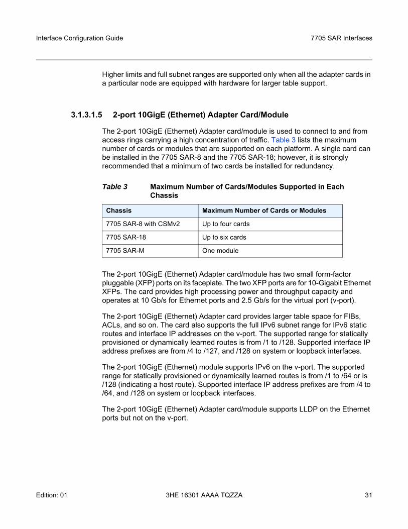
The 2-port 10GigE (Ethernet) Adapter card/module is used to connect to and from access rings carrying a high concentration of traffic. Table 3 lists the maximum number of cards or modules that are supported on each platform. A single card can be installed in the 7705 SAR-8 and the 7705 SAR-18; however, it is strongly recommended that a minimum of two cards be installed for redundancy.
The 2-port 10GigE (Ethernet) Adapter card/module has two small form-factor pluggable (XFP) ports on its faceplate. The two XFP ports are for 10-Gigabit Ethernet XFPs. The card provides high processing power and throughput capacity and operates at 10 Gb/s for Ethernet ports and 2.5 Gb/s for the virtual port (v-port).
The 2-port 10GigE (Ethernet) Adapter card provides larger table space for FIBs, ACLs, and so on. The card also supports the full IPv6 subnet range for IPv6 static routes and interface IP addresses on the v-port. The supported range for statically provisioned or dynamically learned routes is from /1 to /128. Supported interface IP address prefixes are from /4 to /127, and /128 on system or loopback interfaces.
The 2-port 10GigE (Ethernet) module supports IPv6 on the v-port. The supported range for statically provisioned or dynamically learned routes is from /1 to /64 or is /128 (indicating a host route). Supported interface IP address prefixes are from /4 to /64, and /128 on system or loopback interfaces.
The 2-port 10GigE (Ethernet) Adapter card/module supports LLDP on the Ethernet ports but not on the v-port.
Table 3 Maximum Number of Cards/Modules Supported in Each Chassis
Chassis Maximum Number of Cards or Modules
7705 SAR-8 with CSMv2 Up to four cards
7705 SAR-18 Up to six cards
7705 SAR-M One module
7705 SAR Interfaces
32
Interface Configuration Guide
3HE 16301 AAAA TQZZA Edition: 01
3.1.3.1.6 Packet Microwave Adapter Card
The Packet Microwave Adapter card has two RJ-45 ports (ports 1 and 2) and six SFP ports (ports 3 through 8). All ports provide 10/100/1000 Mb/s connections (when connected to an MPR-e radio, they are always in Gigabit Ethernet (1-Gb/s) mode). Ports 1 through 4 support Microwave Awareness (MWA) and Ethernet/IP/MPLS networking; ports 5 through 8 support Ethernet/IP/MPLS networking only.
All Gigabit Ethernet ports provide the same networking feature capability as the 8-port Gigabit Ethernet Adapter card. For frequency synchronization, synchronous Ethernet and SSM are the mechanisms that are applied when using optical 1000Base-SX to connect to an MPR-e radio. When using electrical 1000Base-T to connect the Packet Microwave Adapter card and an MPR-e radio, Proprietary Clock Recovery (PCR) is used (a copper SFP is mandatory on ports 3 and 4).
3.1.3.1.7 4-port SAR-H Fast Ethernet Module
The 4-port SAR-H Fast Ethernet module has four RJ-45 Fast Ethernet ports (10/100 Mb/s) on its faceplate. Any functionality supported on the 7705 SAR-H Ethernet ports is also supported on the 4-port SAR-H Fast Ethernet module, with the exception of hierarchical QoS (H-QoS) functionality and hybrid mode.
3.1.3.1.8 6-port SAR-M Ethernet Module
The 6-port SAR-M Ethernet module has six Ethernet ports:
• two SFP Fast Ethernet ports (10/100 Mb/s) (ports 1 and 2)• two XOR (combination) SFP/RJ point five Gigabit Ethernet ports
(10/100/1000 Mb/s) (ports 3a/3b and 4a/4b)• two PoE-capable RJ point five copper Gigabit Ethernet ports
(10/100/1000 Mb/s) (ports 5 and 6)
Ports 5 and 6 can each support Power over Ethernet (PoE). Port 5 can also support PoE+, but if it is configured for PoE+, then port 6 cannot support PoE power.
Any functionality supported on the 7705 SAR-M Ethernet ports is also supported on the 6-port SAR-M Ethernet module, with the exception of half-duplex mode (all ports) and hybrid mode (Fast Ethernet ports only).
Interface Configuration Guide 7705 SAR Interfaces
Edition: 01 3HE 16301 AAAA TQZZA 33
3.1.3.1.9 7705 SAR-A
The 7705 SAR-A has two variants with fixed physical configurations. One variant supports both Ethernet and T1/E1 ports. The other variant supports only Ethernet ports. Both variants of the 7705 SAR-A have 12 Ethernet ports:
• four XOR (combination) Gigabit Ethernet ports, either 10/100/1000Base-T RJ-45 (ports 1A to 4A) or 100/1000 Mb/s SFP (ports 1B to 4B)
• four SFP Gigabit Ethernet ports (100/1000 Mb/s) (ports 5 to 8)• four RJ-45 Fast Ethernet ports (10/100 Mb/s) (ports 9 to 12)
3.1.3.1.10 7705 SAR-Ax
The 7705 SAR-Ax has a fixed physical configuration that has 12 Ethernet ports:
• four XOR (combination) Gigabit Ethernet ports, either 10/100/1000Base-T RJ-45 (ports 1A to 4A) or 100/1000 Mb/s SFP (ports 1B to 4B)
• eight SFP Gigabit Ethernet ports (100/1000 Mb/s) (ports 5 to 12)
3.1.3.1.11 7705 SAR-H
The 7705 SAR-H has a fixed physical configuration that has eight Ethernet ports:
• two SFP Gigabit Ethernet ports (10/100/1000 Mb/s) (ports 1 and 2)• two XOR (combination) RJ-45/SFP Gigabit Ethernet ports (10/100/1000 Mb/s)
(ports 3 and 4)• four PoE-capable RJ-45 Gigabit Ethernet ports (10/100/1000 Mb/s) (ports 5 to 8)
The 7705 SAR-H also has two module slots.
If a PoE Power Supply is connected, it increases the number of Ethernet ports that can supply PoE to a connected device.
7705 SAR Interfaces
34
Interface Configuration Guide
3HE 16301 AAAA TQZZA Edition: 01
3.1.3.1.12 7705 SAR-Hc
The 7705 SAR-Hc has a fixed physical configuration that has six Ethernet ports:
• two SFP Gigabit Ethernet ports (10/100/1000 Mb/s) (ports 1 and 2)• two Gigabit Ethernet RJ-45 ports (10/100/1000 Mb/s) (ports 3 and 4)• two PoE-capable RJ-45 Gigabit Ethernet ports (10/100/1000 Mb/s) (ports 5 and
6)
3.1.3.1.13 7705 SAR-M
The 7705 SAR-M has a fixed physical configuration that has four variants. All variants of the 7705 SAR-M have seven Ethernet ports:
• four SFP Gigabit Ethernet ports (10/100/1000 Mb/s) (ports 1 to 4)• three Gigabit Ethernet RJ-45 ports (10/100/1000 Mb/s) (ports 5 to 7)
Two variants of the 7705 SAR-M also have a module slot.
3.1.3.1.14 7705 SAR-W
The 7705 SAR-W has a fixed physical configuration that has five Ethernet ports:
• three SFP Gigabit Ethernet ports (10/100/1000 Mb/s) (ports 1 to 3)• two PoE+ capable Gigabit Ethernet RJ-45 ports (10/100/1000 Mb/s) (ports 4 and
5)
3.1.3.1.15 7705 SAR-Wx
The 7705 SAR-Wx has six variants with fixed physical configurations that provide the following Ethernet interfaces.
Two variants have five Gigabit Ethernet ports:
• three SFP Gigabit Ethernet ports (10/100/1000 Mb/s) (ports 1 to 3)• two Gigabit Ethernet RJ-45 ports (10/100/1000 Mb/s) (ports 4 and 5)
Two variants have five Gigabit Ethernet ports:
• three SFP Gigabit Ethernet ports (10/100/1000 Mb/s) (ports 1 to 3)
Interface Configuration Guide 7705 SAR Interfaces
Edition: 01 3HE 16301 AAAA TQZZA 35
• one Gigabit Ethernet RJ-45 port (10/100/1000 Mb/s) (port 4)• one PoE+ Gigabit Ethernet RJ-45 port (10/100/1000 Mb/s) (port 5)
Two variants have four Gigabit Ethernet ports:
• three SFP Gigabit Ethernet ports (10/100/1000 Mb/s) (ports 1 to 3)• one Gigabit Ethernet RJ-45 port (10/100/1000 Mb/s) (port 4)
3.1.3.1.16 7705 SAR-X
The 7705 SAR-X has a fixed physical configuration that has 14 Ethernet ports:
• four XOR (combination) RJ-45/SFP Gigabit Ethernet ports (10/100/1000 Mb/s) (ports 2/1A, 2/2A, 3/1A, 3/2A for RJ-45 and 2/1B, 2/2B, 3/1B, 3/2B for SFP)
• eight SFP Gigabit Ethernet ports (10/100/1000 Mb/s) (ports 2/3 to 2/6 and 3/3 to 3/6)
• two SFP+ 10-Gigabit Ethernet ports (ports 2/7 and 3/7)
3.1.3.2 TDM
TDM ports are supported on the following cards, modules, and platforms:
• 16-port T1/E1 ASAP Adapter Card• 32-port T1/E1 ASAP Adapter Card• 2-port OC3/STM1 Channelized Adapter Card• 4-port OC3/STM1 / 1-port OC12/STM4 Adapter Card• 4-port DS3/E3 Adapter Card• 8-port Voice & Teleprotection Card• 8-port C37.94 Teleprotection Card• 12-port Serial Data Interface Card• 4-port T1/E1 and RS-232 Combination Module• 7705 SAR-A• 7705 SAR-Hc• 7705 SAR-M• 7705 SAR-X
7705 SAR Interfaces
36
Interface Configuration Guide
3HE 16301 AAAA TQZZA Edition: 01
3.1.3.2.1 16-port T1/E1 ASAP Adapter Card
There are two versions of the 16-port T1/E1 ASAP Adapter card. The 7705 SAR-18 only supports version 2.
Channelization is supported down to the DS0 level. To change port types, all ports must first be shut down. The ports can be configured for DS1 (T1) or E1 operation. All ports on the card must be either T1 or E1; there cannot be a mix of the two types. When the first port is configured on a card, all other ports on the card must be set to the same type.
The 16-port T1/E1 ASAP Adapter card supports fractional T1/E1 on network ports configured for PPP. Fractional T1/E1 allows a portion of the link to be used for traffic (up to the full link bandwidth).
DS1 ports on the 16-port T1/E1 ASAP Adapter card, version 2, can be configured for either B8ZS (bipolar with eight-zero substitution) zero code suppression or AMI (alternate mark inversion). B8ZS and AMI are line coding techniques.
3.1.3.2.2 32-port T1/E1 ASAP Adapter Card
On the 32-port T1/E1 ASAP Adapter card, channelization is supported down to the DS0 level. To change port types, all ports must first be shut down. The ports can be configured for DS1 (T1) or E1 operation. All ports on the card must be either T1 or E1; there cannot be a mix of the two types. When the first port is configured on a card, all other ports on the card must be set to the same type.
The 32-port T1/E1 ASAP Adapter card supports fractional T1/E1 on network ports configured for PPP. Fractional T1/E1 allows a portion of the link to be used for traffic (up to the full link bandwidth).
DS1 ports on the card can be configured for either B8ZS (bipolar with eight-zero substitution) zero code suppression or AMI (alternate mark inversion). B8ZS and AMI are line coding techniques.
3.1.3.2.3 2-port OC3/STM1 Channelized Adapter Card
On the 2-port OC3/STM1 Channelized Adapter card, channelization is supported down to the DS0 level. To change port types, all ports must first be shut down. The ports can be configured for DS1 (T1) or E1 channelization. All ports on the card must be either SONET or SDH; there cannot be a mix of the two types. When the first port is configured on a card, all other ports on the card must be set to the same type.
Interface Configuration Guide 7705 SAR Interfaces
Edition: 01 3HE 16301 AAAA TQZZA 37
The 2-port OC3/STM1 Channelized Adapter card also supports DS3 channelization on access for TDM services as well as network mode with PPP.
3.1.3.2.4 4-port OC3/STM1 / 1-port OC12/STM4 Adapter Card
The 4-port OC3/STM1 / 1-port OC12/STM4 Adapter card can be configured to be in 4-port OC3/STM1 mode or 1-port OC12/STM4 mode (using the mda-mode command).
When the 4-port OC3/STM1 / 1-port OC12/STM4 Adapter card is configured in 4-port OC3/STM1 mode, four SFP ports are available for optical and electrical SFP transceivers. In this mode, the card supports OC3 SONET or STM1 SDH transmission.
When the 4-port OC3/STM1 / 1-port OC12/STM4 Adapter card is configured in 4-port OC3/STM1 mode, channelization is supported down to the DS1 level. To change port types, all ports must first be shut down. The ports can be configured for DS1 (T1) or E1 channelization in access mode, or PPP/MLPPP or POS in network mode. All ports on the card must be either SONET or SDH; there cannot be a mix of the two types. When the first port is configured on a card, all other ports on the card must be set to the same type. Switching between port types causes the adapter card to reset.
When the 4-port OC3/STM1 / 1-port OC12/STM4 Adapter card is configured in 1-port OC12/STM4 mode, SFP port 1 is available for optical SFP transceivers. Ports 2 through 4 are not available. In this mode, the card supports OC12 SONET and STM4 SDH transmission. The 1-port OC12/STM4 mode is designed for use in situations where greater bandwidth is required on a single port.
3.1.3.2.5 4-port DS3/E3 Adapter Card
The 4-port DS3/E3 Adapter card has four TDM DS3/E3 ports. The port type must be configured to be either DS3 or E3. Each DS3 port can be clear channel or channelized down to DS0 (64 kb/s). E3 ports can be clear channel only. Once the first port type has been configured, all other ports on the same 4-port DS3/E3 Adapter card must be set to the same type.
To change between types, the ports must first be deleted. DS3 ports provide B3ZS (bipolar with three-zero substitution) zero code suppression and E3 ports provide HDB3 (high density bipolar of order 3) zero code suppression. B3ZS and HDB3 zero code suppression are line coding techniques.
7705 SAR Interfaces
38
Interface Configuration Guide
3HE 16301 AAAA TQZZA Edition: 01
Channelization is supported down to the DS0 level (for DS3 ports only). To change port types, all ports must first be shut down. The ports can be configured for DS1 (T1) or E1 operation. All ports on the card must be either T1 or E1; there cannot be a mix of the two types. When the first port is configured on a card, all other ports on the card must be set to the same type.
3.1.3.2.6 8-port Voice & Teleprotection Card
On the 8-port Voice & Teleprotection card, channelization is supported down to the DS0 level. To change port types, all ports must first be shut down. The ports can be configured for DS1 (T1) or E1 operation. All ports on the card must be either T1 or E1; there cannot be a mix of the two types. When the first port is configured on a card, all other ports on the card must be set to the same type.
Channelization is supported on the two codirectional G.703 ports and two IEEE C37.94 teleprotection interface ports.
3.1.3.2.7 8-port C37.94 Teleprotection Card
On the 8-port C37.94 Teleprotection card, channelization is supported down to the DS0 level on the eight IEEE C37.94 teleprotection interface (TPIF) ports.
3.1.3.2.8 12-port Serial Data Interface Card
The 12-port Serial Data Interface card, version 1 and version 2, has four connectors, which support three serial data ports each. Each port grouping can be configured for V.35, RS-232, or X.21 operation. When a port has been configured for a specific interface type, the other two ports in that same grouping must be configured for the same type. The card also supports an RS-530 interface with the use of an adapter cable that connects to a DB15 connector on the front of the X.21 distribution panel. There is no configuration specifically for the RS-530 interface; configuration is done in X.21 mode and applies to the RS-530 interface when it is physically enabled through hardware. All X.21 functionality is available on the RS-530 interface, except that only DCE operation is supported for RS-530. However, because X.21 does not support all the control leads available for RS-530, only a subset of the RS-530 control leads are supported.
The 12-port Serial Data Interface card, version 3, has six connectors, which support two data ports each. Each port grouping can be configured for V.35, RS-232, X.21, or RS-530 operation. When a port has been configured for a specific interface type, the other port in the group must be configured for the same type.
Interface Configuration Guide 7705 SAR Interfaces
Edition: 01 3HE 16301 AAAA TQZZA 39
Channelization on the 12-port Serial Data Interface card is supported down to the DS0 level.
3.1.3.2.9 4-port T1/E1 and RS-232 Combination Module
T1/E1 ports on the 4-port T1/E1 and RS-232 Combination module (supported on the 7705 SAR-H) support channelization down to the DS0 level. To change port types, all ports must first be shut down. The ports can be configured for DS1 (T1) or E1 operation. All ports on the module must be either T1 or E1; there cannot be a mix of the two types. When the first port is configured on a module, all other ports on the card must be set to the same type.
3.1.3.2.10 7705 SAR-A
The 7705 SAR-A has two variants with fixed physical configurations. One variant supports both Ethernet and T1/E1 ports. The other variant supports only Ethernet ports. The variant that supports T1/E1 ports includes eight RJ-45 T1/E1 ports. All ports must be configured as either T1 or E1 ports; a mix of T1 and E1 ports is not allowed.
DS1 (T1) ports on the chassis can be configured for either B8ZS (bipolar with eight-zero substitution) zero code suppression or AMI (alternate mark inversion). B8ZS and AMI are line coding techniques.
3.1.3.2.11 7705 SAR-Hc
The 7705 SAR-Hc has a fixed physical configuration that includes two RS-232 RJ-45 ports. The chassis also includes Gigabit Ethernet/Ethernet support via SFP and RJ-45 ports.
3.1.3.2.12 7705 SAR-M
The 7705 SAR-M has a fixed physical configuration that has four variants. Two variants have 16 RJ-45 T1/E1 ports. All ports must be configured as either T1 or E1 ports; a mix of T1 and E1 ports is not allowed.
DS1 (T1) ports on the chassis can be configured for either B8ZS (bipolar with eight-zero substitution) zero code suppression or AMI (alternate mark inversion). B8ZS and AMI are line coding techniques.
7705 SAR Interfaces
40
Interface Configuration Guide
3HE 16301 AAAA TQZZA Edition: 01
3.1.3.2.13 7705 SAR-X
The 7705 SAR-X has a fixed physical configuration that provides TDM pseudowire services via eight T1/E1 RJ-45 ports.
3.1.3.3 DSL
The 6-port DSL Combination module and the 8-port xDSL module (supported on the 7705 SAR-M), and two variants of the 7705 SAR-Wx support DSL.
The 6-port DSL Combination module has six RJ-11 ports on its faceplate. Four of the RJ-11 ports support G.SHDSL.bis pairs, and two RJ-11 ports support xDSL operating in ADSL2,ADSL2+, or VDSL2 mode with no intermixing of DSL types.
The 8-port xDSL module has eight RJ-11 ports on its faceplate that support ADSL2, ADSL2+, or VDSL2 mode with no intermixing of DSL types.
The 7705 SAR-M views the Ethernet link on a DSL module as an Ethernet port. Any services on the 7705 SAR that are supported on an Ethernet port are also supported on the Ethernet link on a DSL module.
Two variants of the 7705 SAR-Wx support one 4-pair xDSL port.
3.1.3.4 GNSS Receiver
The 7705 SAR-H GPS Receiver module is equipped with a GPS RF port for retrieval and recovery of GPS and GLONASS signals. The 7705 SAR-Ax and some variants of the 7705 SAR-Wx are equipped with an integrated GNSS receiver and a GNSS RF port for retrieval and recovery of GPS and GLONASS signals.
The GNSS Receiver card installed in the 7705 SAR-8 or 7705 SAR-18 is equipped with a GNSS RF port for retrieval and recovery of both GPS and GLONASS signals.
Note: GLONASS-only signal recovery is not supported in this release.
Interface Configuration Guide 7705 SAR Interfaces
Edition: 01 3HE 16301 AAAA TQZZA 41
3.1.3.5 GPON
The GPON module is a single-port optical network terminal (ONT) that integrates passive optical network (PON) capabilities into the 7705 SAR-M. The GPON module serves as an Ethernet Layer 2 connection point for receiving data from and transmitting data into a GPON network.
The GPON module connects to the 7705 SAR-M as a Gigabit Ethernet port. From an operational perspective, the 7705 SAR-M views the module as one of its Ethernet ports.
3.1.3.6 Multilink Bundles
A multilink bundle is a collection of channels on channelized ports that physically reside on the same adapter card. Multilink bundles are used by providers who offer either bandwidth-on-demand services or fractional bandwidth (DS3) services. Multilink bundles are supported over PPP channels (MLPPP). All member links of an MLPPP group must be of the same type (either E1 or DS1).
The following cards, modules, and platforms support multilink bundles:
• T1/E1 ports on the 7705 SAR-A (variants with T1/E1 ports)• T1/E1 ports on the 7705 SAR-M (variants with T1/E1 ports)• T1/E1 ports on the 7705 SAR-X
The following must have all member links of an MLPPP bundle configured on the same card or module:- 16-port T1/E1 ASAP Adapter card- 32-port T1/E1 ASAP Adapter card- T1/E1 ports on the 4-port T1/E1 and RS-232 Combination module (on
7705 SAR-H)The following must have all member links of an MLPPP bundle configured on the same card or module, and on the same port:- 2-port OC3/STM1 Channelized Adapter card- 4-port OC3/STM1 / 1-port OC12/STM4 Adapter card
7705 SAR Interfaces
42
Interface Configuration Guide
3HE 16301 AAAA TQZZA Edition: 01
3.1.3.7 IMA
The 16-port T1/E1 ASAP Adapter card, 32-port T1/E1 ASAP Adapter card, and the 2-port OC3/STM1 Channelized Adapter card support Inverse Multiplexing over ATM (IMA). IMA is a standard developed to address the increasing need for bandwidth greater than the DS1 or E1 link speeds (1.544 or 2.048 Mb/s, respectively) but less than higher link speeds such as DS3 (44.736 Mb/s). IMA combines the transport bandwidth of multiple DS1 or E1 channels in a logical link (called an IMA group) to provide scalable bandwidth.
3.1.3.8 SONET/SDH
The 4-port OC3/STM1 Clear Channel Adapter card has four hot-pluggable, SFP-based ports that can be independently configured to be SONET (OC3) or SDH (STM1).
The 2-port OC3/STM1 Channelized Adapter card has two hot-pluggable, SFP-based ports that can be configured to be SONET (OC3) or SDH (STM1). All ports on the 2-port OC3/STM1 Channelized Adapter card must be of the same type (either SONET or SDH).
The 4-port OC3/STM1 / 1-port OC12/STM4 Adapter card has four hot-pluggable, SFP-based ports that can be configured to be SONET (OC3 or OC12) or SDH (STM1 or STM4). The card can be configured to be in either 4-port mode or 1-port mode (using the mda-mode command). In 4-port mode, all four ports can be configured as OC3 or STM1. In 1-port mode, only port 1 can be configured as OC12 or STM4. All ports on the 4-port OC3/STM1 / 1-port OC12/STM4 Adapter card must be of the same type (either SONET or SDH).
3.1.3.9 Voice
Voice ports are supported on the following cards:
• 6-port E&M Adapter Card• 8-port Voice & Teleprotection Card• 8-port FXO Adapter Card• 6-port FXS Adapter Card
Interface Configuration Guide 7705 SAR Interfaces
Edition: 01 3HE 16301 AAAA TQZZA 43
3.1.3.9.1 6-port E&M Adapter Card
The 6-port E&M Adapter card has six RJ-45 ports that support the transport of an analog voiceband signal between two analog devices over a digital network. The analog signals are converted into a 64 kb/s digital Pulse Code Modulation (PCM) format using either Mu-Law (North America) or A-Law (Rest of World) companding. The type of companding is selectable on a per-card basis. Companding conversion (that is, Mu-Law to A-Law or vice versa) is not supported.
The signaling type is selectable on a per-card basis. When either A-Law or Mu-Law companding is configured, Type I, Type II, or Type V signaling can be selected. However, the only supported configurations are both ends of the connection operating in the same mode (for example, Type I to Type I) or one end operating in Type I mode and the other in Type V mode. The default signaling type for Mu-Law is Type I and the default signaling type for A-Law is Type V.
Each voice port can be configured to operate in either a two-wire or four-wire (default) mode. The ports (in groups of three – ports 1 to 3 and ports 4 to 6) can also be configured to operate in transmission-only mode, which provides a four-wire audio path with no signaling. A transmit and receive transmission level point (the analog-to-digital decibel level) can be configured for each port. See Table 4 for the signaling type, companding law, and audio wires configuration options on the 6-port E&M Adapter card.
3.1.3.9.2 8-port Voice & Teleprotection Card
The 8-port Voice & Teleprotection card supports the transport of an analog voiceband signal between two analog devices over a digital network.
The card has two FXS RJ-45 ports and two FXO RJ-45 ports that support analog voiceband signals. The analog signals are converted into a 64 kb/s digital Pulse Code Modulation (PCM) format using either Mu-Law (North America) or A-Law (Rest of World) companding. The type of companding is selectable on a per-card basis. Companding conversion (that is, Mu-Law to A-Law or vice versa) is not supported.
The signaling type is selectable at the port level on a per-port basis depending on companding type.
Table 4 Configuration Options for the 6-port E&M Adapter Card
Signaling Type Companding Type Number of Wires
Type I, Type II, Type V Mu-Law or A-Law Two-wire or four-wire
Transmission-only (no signaling) Mu-Law or A-Law Four-wire
7705 SAR Interfaces
44
Interface Configuration Guide
3HE 16301 AAAA TQZZA Edition: 01
FXO supports:
• 1511profile1 (1511 Loop Start) – A-Law companding• 3600ls (Loop Start) – Mu-Law companding• 3600re (Remote Extension) – A-Law companding• 1511sn137 (1511 profile 137) – A-Law companding
FXS supports:
• 3600plar (Private Line Automatic Ringdown) – A-Law and Mu-Law companding• 1511plar – A-Law companding• 1511profile1 (Loop Start) – A-Law companding• 3600ls (Loop Start) – Mu-Law companding• 3600re (Remote Extension) – A-Law companding• 1511sn137 (1511 profile 137) – A-Law companding
The default signaling type for FXO and FXS is 3600ls for Mu-Law companding and 3600re for A-Law companding.
3.1.3.9.3 8-port FXO Adapter Card
The 8-port FXO Adapter card supports the transport of an analog voiceband signal between two analog devices over a digital network.
The card supports analog voiceband signals through four RJ-45 connectors that provide eight Foreign Exchange Office (FXO) ports, with two ports supported per connector. The analog signals are converted into a 64 kb/s digital Pulse Code Modulation (PCM) format using either Mu-Law (North America) or A-Law (Rest of World) companding. The type of companding is selectable on a per-card basis. Companding conversion (that is, Mu-Law to A-Law or vice versa) is not supported.
The signaling type is selectable at the port level on a per-port basis depending on companding type.
FXO supports:
• 1511profile1 (1511 loop start) – A-Law companding• 3600ls (loop start) – Mu-Law companding• 3600re (remote extension) – A-Law companding• 1511sn137 (1511 profile 137) – A-Law companding
Interface Configuration Guide 7705 SAR Interfaces
Edition: 01 3HE 16301 AAAA TQZZA 45
The default signaling type is 3600ls for Mu-Law companding and 3600re for A-Law companding.
3.1.3.9.4 6-port FXS Adapter Card
The 6-port FXS Adapter card provides the capability of transporting a large number of voice circuits from one 7705 SAR location and terminating them at another 7705 SAR location that is connected to a PBX.
The card can also be configured for a Private Line Automatic Ringdown (PLAR) application, which is typically used outside of a PBX network, in order to provide a site-to-site or remote site-to-control center hotline functionality.
The card has six Foreign Exchange Subscriber (FXS) ports. Each port provides a short-reach, on-premises analog interface to an analog telephone set. After an incoming analog signal from a set is terminated on one of the FXS interfaces, it is converted into a digital 64 kb/s Pulse Code Modulation (PCM) format using either Mu-Law companding (North America) or A-Law companding (Rest of World).
The signal is then mapped into the E1 Channel Associated Signaling (CAS) transport scheme for A-Law or the T1 Robbed Bit Signaling (RBS) transport scheme for Mu-Law and transmitted using a Cpipe over any 7705 SAR network interface that supports the Cpipe service. For standard TDM, the network interface can be a T1/E1 or OC3/STM1 channelized interface. For MPLS, an Ethernet, T1/E1, OC3/STM1 channelized MLPPP, or OC3/STM1 clear channel interface can be used.
For a PBX application, the signal is terminated at the 7705 SAR hub location that is connected to a PBX by either an FXO interface or a T1/E1 interface (assuming the signaling formats are compatible). The FXO interface can be provided by either an 8-port FXO Adapter card or 8-port Voice & Teleprotection card that is installed in a 7705 SAR-8 or 7705 SAR-18 chassis at the 7705 SAR hub location.
For a PLAR application, the signal is terminated on an FXS interface on either another 6-port FXS Adapter card or an 8-port Voice & Teleprotection card that is installed in a 7705 SAR-8 or 7705 SAR-18 chassis that is located at a remote location, or terminated on a 3600 MainStreet or 1511 MAX. The connection is made over an E1 interface ⌠(3600 MainStreet or 1511 MAX) or a T1 interface (3600 MainStreet). A hotline call can originate from a 3600 MainStreet or 1511 MAX and terminate on an FXS interface on a 6-port FXS Adapter card (or on an FXS interface on an 8-port Voice & Teleprotection card).
Table 5 shows the configuration options available on a 6-port FXS Adapter card. The companding law type is configured at the card level; the other options are configured at the voice port level.
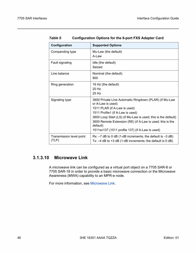
7705 SAR Interfaces
46
Interface Configuration Guide
3HE 16301 AAAA TQZZA Edition: 01
3.1.3.10 Microwave Link
A microwave link can be configured as a virtual port object on a 7705 SAR-8 or 7705 SAR-18 in order to provide a basic microwave connection or the Microwave Awareness (MWA) capability to an MPR-e node.
For more information, see Microwave Link.
Table 5 Configuration Options for the 6-port FXS Adapter Card
Configuration Supported Options
Companding type Mu-Law (the default)A-Law
Fault signaling Idle (the default)Seized
Line balance Nominal (the default)800
Ring generation 16 Hz (the default)20 Hz25 Hz
Signaling type 3600 Private Line Automatic Ringdown (PLAR) (if Mu-Law or A-Law is used)1511 PLAR (if A-Law is used)1511 Profile1 (if A-Law is used)3600 Loop Start (LS) (if Mu-Law is used; this is the default)3600 Remote Extension (RE) (if A-Law is used; this is the default)1511sn137 (1511 profile 137) (if A-Law is used)
Transmission level point (TLP)
Rx: –7 dB to 0 dB (1-dB increments; the default is –3 dB)Tx: –4 dB to +3 dB (1-dB increments; the default is 0 dB)
Interface Configuration Guide 7705 SAR Interfaces
Edition: 01 3HE 16301 AAAA TQZZA 47
3.1.3.11 CLI Identifiers for Adapter Cards, Modules and Platforms
On the CLI, the adapter cards are referred to as MDAs. A port is identified using the format slot/mda/port, where slot identifies the IOM card slot ID (always 1), mda identifies the physical slot in the chassis for the adapter card, and port identifies the physical port on the adapter card; for example, 1/5/1. Adapter cards are configured at the card and port level.
On the fixed platforms, no configuration is required at the adapter card level in order to provision the ports.
On the CLI for the 7705 SAR-A, the slot/mda identifier for T1/E1 ports is 1/2 and for Ethernet ports is 1/1. T1/E1 ports are identified as 1/2/1 through 1/2/8 for the variant of the chassis with T1/E1 ports. Ethernet ports for both variants of the 7705 SAR-A are identified as 1/1/1 through 1/1/12.
On the CLI for the 7705 SAR-Ax, the slot/mda identifier for Ethernet ports is 1/1 and for the GNSS RF port is 1/2.
On the CLI for the 7705 SAR-H, the slot/mda identifier for Ethernet ports is 1/1. The chassis has two slots for modules (the 4-port T1/E1 and RS-232 Combination module, the GPS Receiver module, and the 4-port SAR-H Fast Ethernet module). On the CLI, the slot/mda identifier for a module installed in the first slot position is 1/2 and for a module installed in the second slot position is 1/3. Ethernet ports are identified as 1/1/1 through 1/1/8. Module ports are identified as 1/2/port-num for modules installed in the first slot position and 1/3/port-num for modules installed in the second slot position.
On the CLI for the 7705 SAR-Hc, the slot/mda identifier for Ethernet ports is 1/1 and for RS-232 ports is 1/2. Ethernet ports are identified as 1/1/1 through 1/1/6 and RS-232 ports are identified as 1/2/1 and 1/2/2.
On the CLI for the 7705 SAR-M, the slot/mda identifier for T1/E1 ports is 1/2 and for Ethernet ports is 1/1. For those variants of the chassis that have a module slot, the slot/mda identifier for the module on the CLI is 1/3. The 7705 SAR-M variants with module slots support the following modules: GPON module, 6-port DSL Combination module, 8-port xDSL module, CWDM OADM module, 2-port 10GigE (Ethernet) module, and 6-port SAR-M Ethernet module. T1/E1 ports are identified as 1/2/1 through 1/2/16 for those variants of the chassis with T1/E1 ports. Ethernet ports for all variants of the 7705 SAR-M are identified as 1/1/1 through 1/1/7. Those variants of the chassis that have module slots identify module ports as 1/3/port-num.
On the CLI for the 7705 SAR-W, the slot/mda identifier for the Ethernet ports is 1/1. Ethernet ports are identified as 1/1/1 through 1/1/5. The 7705 SAR-W also has an internal (virtual) port used for in-band Ethernet management connection. The virtual port is identified as vrtl-mgmt on the CLI and as 1/1/6 via SNMP.
7705 SAR Interfaces
48
Interface Configuration Guide
3HE 16301 AAAA TQZZA Edition: 01
On the CLI for the 7705 SAR-Wx, the slot/mda identifier for the Ethernet ports is 1/1 and 1/2 for the xDSL port. Ethernet ports for the Ethernet-only variant and the Ethernet and PoE+ variant are identified as 1/1/1 through 1/1/5. For the variant supporting Ethernet ports and an xDSL port, the Ethernet ports are identified as 1/1/1 through 1/1/4 and the DSL port is identified as 1/2/1 through 1/2/4.
On the CLI for the 7705 SAR-X, the slot/mda identifier is specified as 1 for T1/E1 ports and 2 or 3 for Ethernet ports. The port number is specified as a variable that can have a value from 1 to 8 for T1/E1 ports or 1 to 7 for Ethernet ports, depending on how the port is configured.
For the 16-port T1/E1 ASAP Adapter card, 32-port T1/E1 ASAP Adapter card, and 4-port DS3/E3 Adapter card, the channel-group-id identifies the DS1 or E1 channel group; for example, 1/5/1.20. For the 2-port OC3/STM1 Channelized Adapter card, the channel-group-id identifies the DS1, E1, or DS3 channel group. For the 4-port OC3/STM1 / 1-port OC12/STM4 Adapter card, the channel-group-id identifies the DS1 or E1 channel group. For the 12-port Serial Data Interface card, the channel-group-id identifies the V.35, RS-530, RS-232, or X.21 channel group; only one channel group per port is supported on the card, so the format would be 1/1/1.1.
For the 6-port E&M Adapter card, the channel-group-id identifies the E&M voice channel group; only one channel group per port is supported on the card, so the format would be 1/1/1.1. For the 8-port Voice & Teleprotection card, the 8-port C37.94 Teleprotection card, the 8-port FXO Adapter card, and the 6-port FXS Adapter card, the channel-group-id identifies the DS0 channel group; only one channel group per port is supported on the card, so the format would be 1/1/1.1.
For the 4-port T1/E1 and RS-232 Combination module, the channel-group-id identifies the DS1 or E1 channel group for the T1/E1 ports (for example, 1/2/3.5) or the channel group for the RS-232 ports (for example, 1/2/2.1).
On the CLI for the 2-port 10GigE (Ethernet) Adapter card or 2-port 10GigE (Ethernet) module, for virtual-port configuration, an Ethernet port is identified as v-port.
The following output examples display the administrative and operational states of adapter cards for all platforms.
For the 7705 SAR-8 with a CSMv2:
ALU-1>show card state==============================================================================Card State==============================================================================Slot/ Provisioned Type Admin Operational Num Num CommentsId Equipped Type (if different) State State Ports MDA------------------------------------------------------------------------------1 iom-sar up up 61/1 a12-sdiv2 up provisioned 121/2 a4-oc3 up provisioned 4
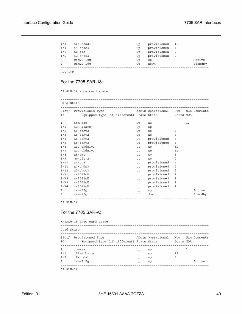
Interface Configuration Guide 7705 SAR Interfaces
Edition: 01 3HE 16301 AAAA TQZZA 49
1/3 a16-chds1 up provisioned 161/4 a4-chds3 up provisioned 41/5 a8-eth up provisioned 81/6 a2-choc3 up provisioned 2A csmv2-10g up up ActiveB csmv2-10g up down Standby==============================================================================ALU-1>#
For the 7705 SAR-18:
*A:ALU-1# show card state
==============================================================================Card State==============================================================================Slot/ Provisioned Type Admin Operational Num Num CommentsId Equipped Type (if different) State State Ports MDA------------------------------------------------------------------------------1 iom-sar up up 121/1 aux-alarm up up1/2 a8-ethv2 up up 81/3 a8-ethv2 up up 81/4 a8-ethv2 up provisioned 81/5 a8-ethv2 up provisioned 81/6 a32-chds1v2 up up 321/7 a32-chds1v2 up up 321/8 a8-pmc up up 81/9 mw-pic-2 up up 21/10 a4-oc3 up provisioned 41/11 a4-chds3 up provisioned 41/12 a2-choc3 up provisioned 21/X1 x-10GigE up provisioned 11/X2 x-10GigE up provisioned 11/X3 x-10GigE up provisioned 11/X4 x-10GigE up provisioned 1A csm-10g up up ActiveB csm-10g up down Standby==============================================================================*A:ALU-1#
For the 7705 SAR-A:
*A:ALU-1# show card state==============================================================================Card State==============================================================================Slot/ Provisioned Type Admin Operational Num Num CommentsId Equipped Type (if different) State State Ports MDA------------------------------------------------------------------------------1 iom-sar up up 21/1 i12-eth-xor up up 121/2 i8-chds1 up up 8A csm-2.5g up up Active==============================================================================*A:ALU-1#
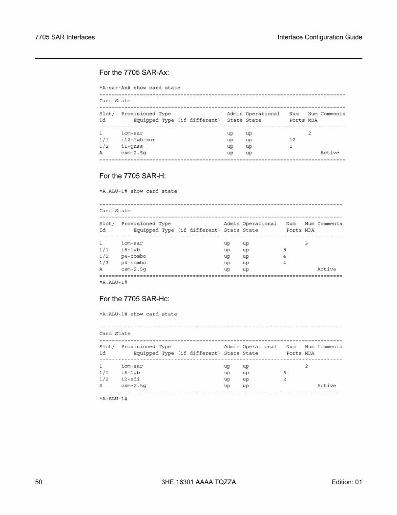
7705 SAR Interfaces
50
Interface Configuration Guide
3HE 16301 AAAA TQZZA Edition: 01
For the 7705 SAR-Ax:
*A:sar-Ax# show card state===============================================================================Card State===============================================================================Slot/ Provisioned Type Admin Operational Num Num CommentsId Equipped Type (if different) State State Ports MDA-------------------------------------------------------------------------------1 iom-sar up up 21/1 i12-1gb-xor up up 121/2 i1-gnss up up 1A csm-2.5g up up Active===============================================================================
For the 7705 SAR-H:
*A:ALU-1# show card state
==============================================================================Card State==============================================================================Slot/ Provisioned Type Admin Operational Num Num CommentsId Equipped Type (if different) State State Ports MDA------------------------------------------------------------------------------1 iom-sar up up 31/1 i8-1gb up up 81/2 p4-combo up up 41/3 p4-combo up up 4A csm-2.5g up up Active==============================================================================*A:ALU-1#
For the 7705 SAR-Hc:
*A:ALU-1# show card state
==============================================================================Card State==============================================================================Slot/ Provisioned Type Admin Operational Num Num CommentsId Equipped Type (if different) State State Ports MDA------------------------------------------------------------------------------1 iom-sar up up 21/1 i6-1gb up up 61/2 i2-sdi up up 2A csm-2.5g up up Active==============================================================================*A:ALU-1#
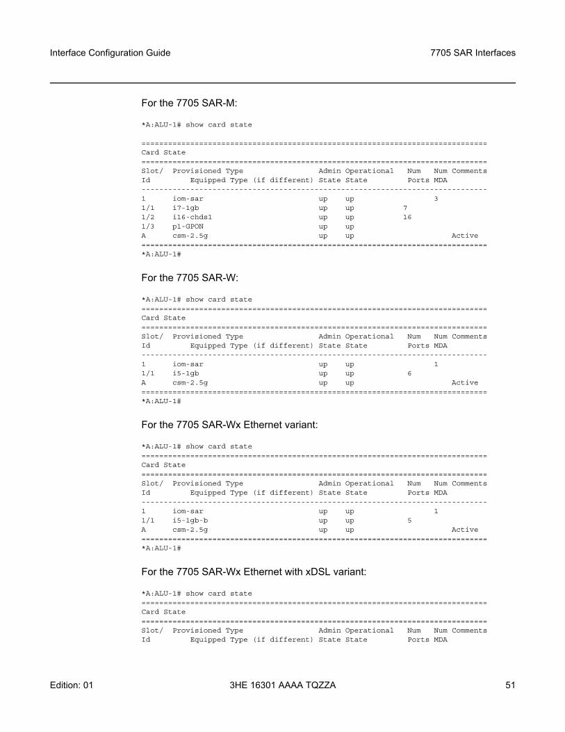
Interface Configuration Guide 7705 SAR Interfaces
Edition: 01 3HE 16301 AAAA TQZZA 51
For the 7705 SAR-M:
*A:ALU-1# show card state
==============================================================================Card State==============================================================================Slot/ Provisioned Type Admin Operational Num Num CommentsId Equipped Type (if different) State State Ports MDA------------------------------------------------------------------------------1 iom-sar up up 31/1 i7-1gb up up 71/2 i16-chds1 up up 161/3 p1-GPON up upA csm-2.5g up up Active==============================================================================*A:ALU-1#
For the 7705 SAR-W:
*A:ALU-1# show card state==============================================================================Card State==============================================================================Slot/ Provisioned Type Admin Operational Num Num CommentsId Equipped Type (if different) State State Ports MDA------------------------------------------------------------------------------1 iom-sar up up 11/1 i5-1gb up up 6A csm-2.5g up up Active==============================================================================*A:ALU-1#
For the 7705 SAR-Wx Ethernet variant:
*A:ALU-1# show card state==============================================================================Card State==============================================================================Slot/ Provisioned Type Admin Operational Num Num CommentsId Equipped Type (if different) State State Ports MDA------------------------------------------------------------------------------1 iom-sar up up 11/1 i5-1gb-b up up 5A csm-2.5g up up Active==============================================================================*A:ALU-1#
For the 7705 SAR-Wx Ethernet with xDSL variant:
*A:ALU-1# show card state==============================================================================Card State==============================================================================Slot/ Provisioned Type Admin Operational Num Num CommentsId Equipped Type (if different) State State Ports MDA
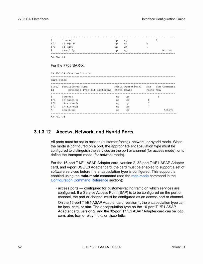
7705 SAR Interfaces
52
Interface Configuration Guide
3HE 16301 AAAA TQZZA Edition: 01
------------------------------------------------------------------------------1 iom-sar up up 21/1 i4-1gb-b up up 41/2 i4-xdsl up up 1A csm-2.5g up up Active==============================================================================*A:ALU-1#
For the 7705 SAR-X:
*A:ALU-1# show card state==============================================================================Card State==============================================================================Slot/ Provisioned Type Admin Operational Num Num CommentsId Equipped Type (if different) State State Ports MDA------------------------------------------------------------------------------1 iom-sar up up 31/1 i8-chds1-x up up 81/2 i7-mix-eth up up 71/3 i7-mix-eth up up 7A csm-2.5g up up Active===============================================================================*A:ALU-1#
3.1.3.12 Access, Network, and Hybrid Ports
All ports must be set to access (customer-facing), network, or hybrid mode. When the mode is configured on a port, the appropriate encapsulation type must be configured to distinguish the services on the port or channel (for access mode), or to define the transport mode (for network mode).
For the 16-port T1/E1 ASAP Adapter card, version 2, 32-port T1/E1 ASAP Adapter card, and 4-port DS3/E3 Adapter card, the card must be enabled to support a set of software services before the encapsulation type is configured. This support is enabled using the mda-mode command (see the mda-mode command in the Configuration Command Reference section):
• access ports — configured for customer-facing traffic on which services are configured. If a Service Access Point (SAP) is to be configured on the port or channel, the port or channel must be configured as an access port or channel.On the 16-port T1/E1 ASAP Adapter card, version 1, the encapsulation type can be ipcp, cem, or atm. The encapsulation type on the 16-port T1/E1 ASAP Adapter card, version 2, and the 32-port T1/E1 ASAP Adapter card can be ipcp, cem, atm, frame-relay, hdlc, or cisco-hdlc.
Interface Configuration Guide 7705 SAR Interfaces
Edition: 01 3HE 16301 AAAA TQZZA 53
On the 12-port Serial Data Interface card, the encapsulation type can be cem, ipcp, frame-relay, hdlc, or cisco-hdlc, depending on the interface type. V.35 ports and X.21 ports at super-rate speeds (64 kb/s and above) support all of the above encapsulation types. RS-232 ports and X.21 ports operating at subrate speeds support only cem encapsulation. RS-530 ports support only cem encapsulation.On the 4-port T1/E1 and RS-232 Combination module, the encapsulation type for T1/E1 ports can be ipcp or cem. RS-232 ports operating at subrate speeds support only cem encapsulation.On the 6-port E&M Adapter card, 8-port Voice & Teleprotection card, 8-port C37.94 Teleprotection card, 8-port FXO Adapter card, and 6-port FXS Adapter card, the encapsulation type must be cem.On the 8-port Ethernet Adapter card, the 8-port Gigabit Ethernet Adapter card, the 6-port Ethernet 10Gbps Adapter card, the 10-port 1GigE/1-port 10GigE X-Adapter card, the Packet Microwave Adapter card, the 4-port SAR-H Fast Ethernet module, the 6-port SAR-M Ethernet module, the xDSL ports on the 7705 SAR-Wx, and the Ethernet ports on all fixed platforms with Ethernet ports, the encapsulation type can be set as null, dot1q, or qinq.
On the 4-port OC3/STM1 Clear Channel Adapter card, the encapsulation type must be atm.On the 4-port DS3/E3 Adapter card, the encapsulation type for DS3/E3 clear channel ports can be atm, cem, or frame-relay. The encapsulation type for DS3 channelized ports can be cem or frame-relay.On the 2-port OC3/STM1 Channelized Adapter card, the encapsulation type can be ipcp, cem, or atm.On the 4-port OC3/STM1 / 1-port OC12/STM4 Adapter card, the encapsulation type must be cem.
• network ports — configured for network-facing traffic. Network ports are used as uplinks for Ethernet, ATM, PPP, and TDM pseudowires. On the Ethernet cards, the Packet Microwave Adapter card, the 2-port 10GigE (Ethernet) Adapter card, and 2-port 10GigE (Ethernet) module, the encapsulation type can be set as null or dot1q.
Note:
• The 10-port 1GigE/1-port 10GigE X-Adapter card supports qinq only when it is in 10-port 1GigE mode.
• The Packet Microwave Adapter card supports qinq only when the port is not in mw-link mode.
7705 SAR Interfaces
54
Interface Configuration Guide
3HE 16301 AAAA TQZZA Edition: 01
The encapsulation type must be ppp-auto for PPP/MLPPP bundles on the following:- T1/E1 ports on the 7705 SAR-A (variants with T1/E1 ports)- T1/E1 ports on the 7705 SAR-M (variants with T1/E1 ports)- T1/E1 ports on the 7705 SAR-X- 16-port T1/E1 ASAP Adapter card- 32-port T1/E1 ASAP Adapter card- 2-port OC3/STM1 Channelized Adapter card- 4-port OC3/STM1 / 1-port OC12/STM4 Adapter card- T1/E1 ports on the 4-port T1/E1 and RS-232 Combination module (on
7705 SAR-H)Network PPP (encapsulation type ppp-auto) can be configured to use some with fractional ppp or all the timeslots on T1/E1 ports on the following cards: - T1/E1 ports on the 7705 SAR-A (variants with T1/E1 ports)- T1/E1 ports on the 7705 SAR-M (variants with T1/E1 ports)- T1/E1 ports on the 7705 SAR-X- 16-port T1/E1 ASAP Adapter card- 32-port T1/E1 ASAP Adapter card- T1/E1 ports on the 4-port T1/E1 and RS-232 Combination module (on
7705 SAR-H)On the 4-port OC3/STM1 Clear Channel Adapter card, 4-port OC3/STM1 / 1-port OC12/STM4 Adapter card, 4-port DS3/E3 Adapter card, and 2-port OC3/STM1 Channelized Adapter card, the encapsulation type must be ppp-auto. Fractional PPP is not supported on these cards; all timeslots of the DS1 channel will be used.
• hybrid ports — configured for access (customer-facing) and network-facing traffic. Hybrid ports can support access and network modes simultaneously over different VLANs. Within the span of a port, some of the VLANs can be in access mode and associated with SAPs for various services, while other VLANs can be in network mode and support any of the network-side operations, including label switching, IP forwarding (GRT IP routing), GRE SDPs, and so on.
Note: QinQ encapsulation is not supported on a port in network mode.
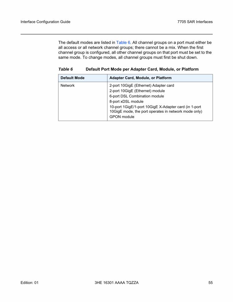
Interface Configuration Guide 7705 SAR Interfaces
Edition: 01 3HE 16301 AAAA TQZZA 55
The default modes are listed in Table 6. All channel groups on a port must either be all access or all network channel groups; there cannot be a mix. When the first channel group is configured, all other channel groups on that port must be set to the same mode. To change modes, all channel groups must first be shut down.
Table 6 Default Port Mode per Adapter Card, Module, or Platform
Default Mode Adapter Card, Module, or Platform
Network 2-port 10GigE (Ethernet) Adapter card 2-port 10GigE (Ethernet) module6-port DSL Combination module8-port xDSL module10-port 1GigE/1-port 10GigE X-Adapter card (in 1-port 10GigE mode, the port operates in network mode only)GPON module
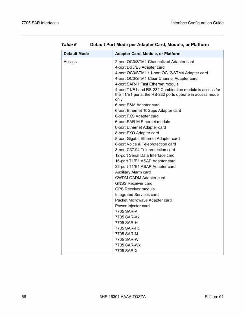
7705 SAR Interfaces
56
Interface Configuration Guide
3HE 16301 AAAA TQZZA Edition: 01
Access 2-port OC3/STM1 Channelized Adapter card4-port DS3/E3 Adapter card4-port OC3/STM1 / 1-port OC12/STM4 Adapter card4-port OC3/STM1 Clear Channel Adapter card4-port SAR-H Fast Ethernet module4-port T1/E1 and RS-232 Combination module is access for the T1/E1 ports; the RS-232 ports operate in access mode only6-port E&M Adapter card6-port Ethernet 10Gbps Adapter card6-port FXS Adapter card6-port SAR-M Ethernet module8-port Ethernet Adapter card8-port FXO Adapter card8-port Gigabit Ethernet Adapter card8-port Voice & Teleprotection card8-port C37.94 Teleprotection card12-port Serial Data Interface card16-port T1/E1 ASAP Adapter card32-port T1/E1 ASAP Adapter cardAuxiliary Alarm cardCWDM OADM Adapter cardGNSS Receiver cardGPS Receiver moduleIntegrated Services cardPacket Microwave Adapter cardPower Injector card7705 SAR-A7705 SAR-Ax7705 SAR-H7705 SAR-Hc7705 SAR-M7705 SAR-W7705 SAR-Wx7705 SAR-X
Table 6 Default Port Mode per Adapter Card, Module, or Platform
Default Mode Adapter Card, Module, or Platform
Interface Configuration Guide 7705 SAR Interfaces
Edition: 01 3HE 16301 AAAA TQZZA 57
3.1.3.12.1 Rate Limiting
The 7705 SAR supports egress-rate limiting and ingress-rate limiting on Ethernet ports.
The egress rate is set at the port level in the config>port>ethernet context.
Egress-rate limiting sets a limit on the amount of traffic that can leave the port to control the total bandwidth on the interface. If the egress-rate limit is reached, the port applies backpressure on the queues, which stops the flow of traffic until the queue buffers are emptied. This feature is useful in scenarios where there is a fixed amount of bandwidth; for example, a mobile operator who has leased a fixed amount of bandwidth from the service provider.
The ingress-rate command configures a policing action to rate-limit the ingress traffic. Ingress-rate enforcement uses dedicated hardware for rate limiting; however, software configuration is required at the port level (ingress-rate limiter) to ensure that the network processor or the adapter card or port never receives more traffic than they are optimized for.
The configured ingress rate ensures that the network processor does not receive traffic greater than this configured value on a per-port basis. Once the ingress-rate value is reached, all subsequent frames are dropped. The ingress-rate limiter drops excess traffic without determining whether the traffic has a higher or lower priority.
3.1.3.12.2 Access Ports
Access ports on the following can be configured for PPP/MLPPP channel groups:
• 2-port OC3/STM1 Channelized Adapter card• 4-port OC3/STM1 / 1-port OC12/STM4 Adapter Card• 12-port Serial Data Interface Card• 16-port T1/E1 ASAP Adapter card• 32-port T1/E1 ASAP Adapter card• T1/E1 ports on the 4-port T1/E1 and RS-232 Combination module (on
7705 SAR-H)• T1/E1 ports on the 7705 SAR-A (variants with T1/E1 ports)• T1/E1 ports on the 7705 SAR-M (variants with T1/E1 ports)• T1/E1 ports on the 7705 SAR-X
7705 SAR Interfaces
58
Interface Configuration Guide
3HE 16301 AAAA TQZZA Edition: 01
Customer IP traffic can be transported directly over PPP or MLPPP links. Access ports on the following can also be configured for TDM to transport 2G traffic from BTSs or ATM/IMA to transport 3G UMTS traffic from Node Bs:
• 2-port OC3/STM1 Channelized Adapter card• 16-port T1/E1 ASAP Adapter card• 32-port T1/E1 ASAP Adapter card• T1/E1 ports on the 7705 SAR-M (variants with T1/E1 ports)
In access mode, PPP channels can be associated with n × DS0 channel groups. Although multiple PPP channel groups are supported per T1/E1 port, all the channel groups must be the same encapsulation type. For example, if one channel group on a given port is set for ipcp encapsulation, another channel group on the same port cannot be set to cem. If MLPPP channels are used, an MLPPP channel group fills up an entire DS1 or E1 link.
The 2-port OC3/STM1 Channelized Adapter card supports ipcp encapsulation of PPP/MLPPP packets for transport over an Ipipe.
The data ports on the 12-port Serial Data Interface card and the RS-232 ports on the 4-port T1/E1 and RS-232 Combination module provide transport between two data devices. Each data stream that is transported across the network can be mapped into a TDM pseudowire (Cpipe) for transport across an MPLS network. The other end can terminate either on another 7705 SAR or a multiplexer capable of terminating the pseudowire.
The 12-port Serial Data Interface card supports frame-relay encapsulation of data on V.35 and X.21 channel groups for transport over a frame relay pseudowire (Fpipe) or IP interworking pseudowire (Ipipe). The 12-port Serial Data Interface card also supports ipcp and cisco-hdlc encapsulation of PPP and Cisco HDLC packets, respectively, for transport over an Ipipe.
The 12-port Serial Data Interface card and the 4-port T1/E1 and RS-232 Combination module can also be part of a system architecture where a circuit originates on an SDI port on the 7705 SAR, transits over an MPLS network, and terminates on a 3600 MainStreet node connected to a 7705 SAR over a T1/E1 connection. In addition to the MPLS network functionality, the 12-port Serial Data Interface card and the 4-port T1/E1 and RS-232 Combination modulec can also operate in a TDM SAP-to-SAP mode where the other SAP can be another port on the 12-port Serial Data Interface card or on a T1/E1 ASAP card.
Interface Configuration Guide 7705 SAR Interfaces
Edition: 01 3HE 16301 AAAA TQZZA 59
Access ports on the 8-port Ethernet Adapter card, 8-port Gigabit Ethernet Adapter card, 6-port Ethernet 10Gbps Adapter card, 10-port 1GigE/1-port 10GigE X-Adapter card (10-port 1GigE mode only), the Packet Microwave Adapter card, and the xDSL ports on the 7705 SAR-Wx, can transport traffic from sources such as e911 locators, site surveillance equipment, VoIP phones, and video cameras. The Ethernet traffic is transported over the PSN using Ethernet VLLs.
A microwave link from a Packet Microwave Adapter card port in access mode can peer with user equipment such as a node B or MPR-e radio. The 7705 SAR-8 and the 7705 SAR-18 treat the microwave access link as a normal SAP into a service such as Epipe, Ipipe, or VPLS/VPRN.
Voice ports on the 6-port E&M Adapter card, 8-port Voice & Teleprotection card, and 8-port FXO Adapter card provide voiceband transmission between two analog devices over a digital network. A 7705 SAR-8 or 7705 SAR-18 terminates the voice circuit and then transmits the data over a TDM-based network interface (SAP-to-SAP) or an MPLS packet-based network interface (SAP-to-SDP). For standard TDM, a T1 or E1 interface is used to transmit the data across the network.
For MPLS, any network interface (that is, Ethernet, T1/E1 MLPPP, or OC3/STM1) can be used. The traffic originating from the 6-port E&M Adapter card, 8-port Voice & Teleprotection card, or 8-port FXO Adapter card can be mapped into a TDM pseudowire (Cpipe) for transport across the MPLS network. The 6-port E&M Adapter card, and 8-port FXO Adapter card support one TDM pseudowire per port.
The voice circuit can terminate on another 7705 SAR-8 or 7705 SAR-18 over the MPLS or T1/E1 TDM connection, on other TDM-capable equipment (such as a 3600 MainStreet node) over a T1/E1 TDM connection, or on other MPLS-capable equipment over an MPLS pseudowire emulation (PWE) connection. A 3600 MainStreet or 1511 MAX can also connect to an FXO port on the 8-port Voice & Teleprotection card.
Voice ports on a 6-port FXS Adapter card can be configured for a PBX application or a PLAR (hotline) application. For a PBX application, the voice circuits are terminated on an FXO interface at a 7705 SAR hub location that is connected to a PBX. The FXO interface can be provided by either an 8-port FXO Adapter card or 8-port Voice & Teleprotection card that is installed in a 7705 SAR-8 or 7705 SAR-18 chassis at the 7705 SAR hub location.
Note: For information on VLLs, refer to the 7705 SAR Services Guide, “VLL Services”.
7705 SAR Interfaces
60
Interface Configuration Guide
3HE 16301 AAAA TQZZA Edition: 01
For a PLAR application, voice circuits are terminated on an FXS interface on either another 6-port FXS Adapter card or an 8-port Voice & Teleprotection card that is installed in a 7705 SAR-8 or 7705 SAR-18 chassis located at a remote location, or terminated on a 3600 MainStreet or 1511 MAX. A hotline call can also originate from a 3600 MainStreet or 1511 MAX and terminate on an FXS interface on a 6-port FXS Adapter card (or on an FXS interface on an 8-port Voice & Teleprotection card.
On an 8-port C37.94 Teleprotection card, access traffic over the TPIF interfaces can be mapped into a TDM pseudowire (Cpipe) for transport across an MPLS network. The TPIF interfaces connect teleprotection relays used by utilities.They can also be used with a relay to connect to a TPIF interface on an 8-port Voice & Teleprotection card or to a TPIF interface on a 1511 Media Access Cross-Connect (1511 MAX).
SONET/SDH ports in access mode on a 4-port OC3/STM1 Clear Channel Adapter card can be configured for ATM (such as for 3G UMTS Node Bs).
The DS3/E3 clear channel access ports on the 4-port DS3/E3 Adapter card can be configured for ATM PW services (categories CBR, VBR-rt, VBR-nrt, UBR, and UBR+MCR), for TDM PW services to transport 2G traffic from BTSs, and for frame relay PW service.
Access ports on the 2-port OC3/STM1 Channelized Adapter card can be configured for TDM to transport 2G traffic from BTSs or ATM/IMA to transport 3G UMTS traffic from Node Bs. Access ports on the 4-port OC3/STM1 / 1-port OC12/STM4 Adapter card can only be configured for TDM.
All member links of the IMA group must reside on the same card. The 2G traffic is transported across the PSN encapsulated in a TDM VLL. The 3G traffic is transported using ATM VLLs.
For PPP/MLPPP channel groups, the encapsulation type must be ipcp. For Ethernet VLLs, the encapsulation type can be null, dot1q, or qinq. For TDM VLLs, the encapsulation type must be cem. For ATM VLLs, the encapsulation type must be atm.
H-QoS for Access Egress Ethernet Ports
To support hierarchical QoS (H-QoS) on second-generation Ethernet adapter cards, the 7705 SAR supports the configuration of one aggregate CIR rate for all the unshaped 4-priority access egress Ethernet SAPs on a port, thereby ensuring that all the unshaped SAPs can compete with the shaped SAPs on the port for fabric bandwidth. Use the config>port>ethernet>access>egress>unshaped-sap-cir command to set the aggregate CIR rate.
Interface Configuration Guide 7705 SAR Interfaces
Edition: 01 3HE 16301 AAAA TQZZA 61
Third-generation (Gen-3) Ethernet adapter cards and platforms have 4-priority schedulers, and all SAPs are shaped SAPs. See Table 2 for a list of first-, second-, and third-generation adapter cards, modules, and platforms. Refer to the “QoS for Gen-3 Adapter Cards and Platforms” section in the 7705 SAR Quality of Service Guide for more information on 4-priority schedulers for Gen-3 hardware.
Ports on the 4-port SAR-H Fast Ethernet module do not support H-QoS.
For more information on H-QoS and on shaped and unshaped Ethernet SAPs, refer to the “Per-SAP Aggregate Shapers (H-QoS)” section in the 7705 SAR Quality of Service Guide.
3.1.3.12.3 Network Ports
Network uplinks can be configured as standalone PPP ports, or MLPPP can be configured on T1/E1 ports or channels. All member links of an MLPPP group must be of the same type (either E1 or Ds1).
The following cards, modules, and platforms support multilink bundles:
• T1/E1 ports on the 7705 SAR-A (variants with T1/E1 ports)• T1/E1 ports on the 7705 SAR-M (variants with T1/E1 ports)• T1/E1 ports on the 7705 SAR-X
The following must have all member links of an MLPPP bundle configured on the same card or module:- 16-port T1/E1 ASAP Adapter card- 32-port T1/E1 ASAP Adapter card- T1/E1 ports on the 4-port T1/E1 and RS-232 Combination module (on
7705 SAR-H)The following must have all member links of an MLPPP bundle configured on the same card or module, and on the same port:- 2-port OC3/STM1 Channelized Adapter card- 4-port OC3/STM1 / 1-port OC12/STM4 Adapter card
Ethernet ports on the 8-port Ethernet Adapter card, 8-port Gigabit Ethernet Adapter card, 6-port Ethernet 10Gbps Adapter card, 10-port 1GigE/1-port 10GigE X-Adapter card, and Packet Microwave Adapter card can be configured for network mode. Ethernet uplinks can be used as a cost-effective alternative to T1/E1 links.
On the 2-port 10GigE (Ethernet) Adapter card and 2-port 10GigE (Ethernet) module, the Ethernet ports and the v-port can be configured for network mode only.
7705 SAR Interfaces
62
Interface Configuration Guide
3HE 16301 AAAA TQZZA Edition: 01
A microwave link from a Packet Microwave Adapter card port in network mode provides a network uplink to an MPR-e radio. The 7705 SAR-8 or 7705 SAR-18 treats the microwave link as a Gigabit Ethernet network link with MPLS always running over it. All standard MPLS/IP functions available on a network port or SDP are also available on the microwave link.
For network uplinks on the 4-port OC3/STM1 Clear Channel Adapter card and 4-port OC3/STM1 / 1-port OC12/STM4 Adapter card, a clear channel port can be configured for POS to connect to the packet network. PPP can be enabled on a port by setting the encapsulation type to ppp-auto.
On the 2-port OC3/STM1 Channelized Adapter card, DS3 clear channels within OC3 or STM1 can be configured for PPP as the network uplink. The encapsulation type must be set to ppp-auto.
On the 4-port DS3/E3 Adapter card, a DS3/E3 clear channel port can be configured for PPP as the network uplink. The encapsulation type must be set to ppp-auto.
The 7705 SAR supports both copper and fiber uplinks.
Aggregate CIR for Unshaped VLANs on Network Egress Ethernet Ports
The 7705 SAR supports the configuration of one aggregate CIR rate for all the unshaped network egress Ethernet VLANs on a port, thereby ensuring that all the unshaped VLANs can compete with the shaped VLANs (that is, network interfaces) at the port level for egress bandwidth. Use the config>port>ethernet> network>egress>unshaped-if-cir command to set the aggregate CIR rate.
For more information on shaped and unshaped Ethernet VLANs, refer to the “Per-VLAN Network Egress Shapers” and “QoS for Gen-3 Adapter Cards and Platforms” sections in the 7705 SAR Quality of Service Guide.
3.1.3.12.4 Hybrid Ports
Hybrid ports are supported on Ethernet ports, where they provide the capabilities and features of access and network mode ports on a per-VLAN basis. The following services support hybrid port functionality: Epipe PW, Ipipe PW, IP-VPN, VPLS, and IES.
Note: The unshaped-if-cir command does not apply to Gen-3 Ethernet adapter cards and platforms, except for network egress in hybrid mode. In this case, the shaper-if-cir command applies.
Interface Configuration Guide 7705 SAR Interfaces
Edition: 01 3HE 16301 AAAA TQZZA 63
For ingress traffic, QoS and traffic management on a hybrid port behaves in the same way for access and network port modes. Refer to the 7705 SAR Quality of Service Guide, “QoS for Hybrid Ports on Gen-2 Hardware” and “QoS for Gen-3 Adapter Cards and Platforms” for details.
Network VLANs on a hybrid port provide OAM down MEP support, as well as port loopback support (in line mode with latched timers only).
The following hardware supports hybrid ports:
• 6-port SAR-M Ethernet module (except for the Fast Ethernet ports (ports 1 and 2))
• 6-port Ethernet 10Gbps Adapter card • 8-port Gigabit Ethernet Adapter card• 10-port 1GigE/1-port 10GigE X-Adapter card (only in 10-port 1GigE mode)• Packet Microwave Adapter card (only in Ethernet port mode (not mw-link mode))• 7705 SAR-A Ethernet ports (except for the Fast Ethernet ports (ports 9 to 12))• 7705 SAR-Ax Ethernet ports• 7705 SAR-M Ethernet ports• 7705 SAR-H Ethernet ports• 7705 SAR-Hc Ethernet ports• 7705 SAR-W Ethernet ports• 7705 SAR-Wx Ethernet ports• 7705 SAR-X Ethernet ports
In some scenarios, combining the access and network capabilities under the same port is beneficial. A typical scenario is shown in Figure 1, where a single port hosts both access-side services and a traffic management model together with network-side IP/MPLS routing and switching capabilities simultaneously.
In this scenario, a network interface is configured to ensure connectivity between the cell site 7705 SAR and the aggregation site 7705 SAR. The network interface is used for all IP/MPLS traffic and is bound to VLAN-1. Another VLAN (VLAN-2) is configured to bind the management traffic of a microwave radio (an MPR-e) to an access-side service such as an Ethernet PW or VPLS. For security reasons, many mobile operators prefer to transport management traffic of network elements under a service construct as opposed to basic GRT-based routing. To accommodate this preference, an access-side service and a network interface can be configured to coexist on the same port when the port is configured for hybrid mode.
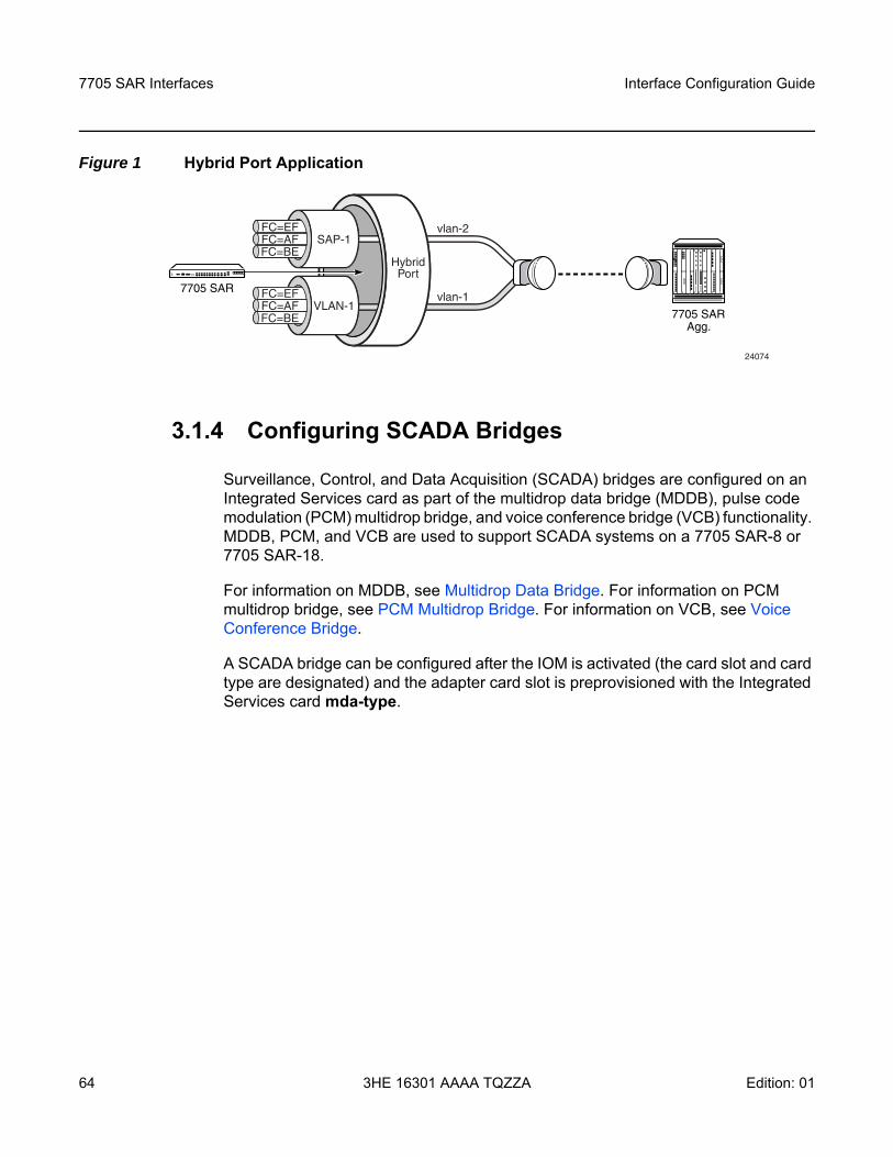
7705 SAR Interfaces
64
Interface Configuration Guide
3HE 16301 AAAA TQZZA Edition: 01
Figure 1 Hybrid Port Application
3.1.4 Configuring SCADA Bridges
Surveillance, Control, and Data Acquisition (SCADA) bridges are configured on an Integrated Services card as part of the multidrop data bridge (MDDB), pulse code modulation (PCM) multidrop bridge, and voice conference bridge (VCB) functionality. MDDB, PCM, and VCB are used to support SCADA systems on a 7705 SAR-8 or 7705 SAR-18.
For information on MDDB, see Multidrop Data Bridge. For information on PCM multidrop bridge, see PCM Multidrop Bridge. For information on VCB, see Voice Conference Bridge.
A SCADA bridge can be configured after the IOM is activated (the card slot and card type are designated) and the adapter card slot is preprovisioned with the Integrated Services card mda-type.
FC=EFFC=AF SAP-1
HybridPort
FC=BE
FC=EFFC=AF VLAN-1FC=BE
7705 SAR
7705 SARAgg.
vlan-2
vlan-1
24074
Interface Configuration Guide 7705 SAR Interfaces
Edition: 01 3HE 16301 AAAA TQZZA 65
3.2 Port Features
This section contains information on the following topics:
• Multilink Point-to-Point Protocol• Multi-Class MLPPP• cHDLC • Inverse Multiplexing Over ATM (IMA)• Network Synchronization on Ports and Circuits• Node Synchronization From GNSS Receiver Ports• Flow Control on Ethernet Ports• Ethernet OAM• Ethernet Loopbacks• Ethernet Port Down-When-Looped• Ethernet Ring (Adapter Card and Module)• MTU Configuration Guidelines• LAG• LAG and ECMP Hashing• SONET/SDH• Automatic Protection Switching• T1/E1 Line Card Redundancy • Deploying Preprovisioned Components• Microwave Link• DSL Bonding• Custom Alarms on Ethernet Ports
7705 SAR Interfaces
66
Interface Configuration Guide
3HE 16301 AAAA TQZZA Edition: 01
3.2.1 Multilink Point-to-Point Protocol
This section contains information on the following topics:
• MLPPP Overview• Protocol Field (PID)• B&E Bits• Sequence Number• Information Field• Padding• FCS• LCP• T1/E1 Link Hold Timers
3.2.1.1 MLPPP Overview
Multilink point-to-point protocol (MLPPP) is a method of splitting, recombining, and sequencing packets across multiple logical data links. MLPPP is defined in the IETF RFC 1990, The PPP Multilink Protocol (MP).
MLPPP allows multiple PPP links to be bundled together, providing a single logical connection between two routers. Data can be distributed across the multiple links within a bundle to achieve high bandwidth. As well, MLPPP allows for a single frame to be fragmented and transmitted across multiple links. This capability allows for lower latency and also for a higher maximum receive unit (MRU).
Multilink protocol is negotiated during the initial LCP option negotiations of a standard PPP session. A system indicates to its peer that it is willing to perform MLPPP by sending the MP option as part of the initial LCP option negotiation.
The system indicates the following capabilities.
• The system offering the option is capable of combining multiple physical links into one logical link.
• The system is capable of receiving upper layer protocol data units (PDUs) that are fragmented using the MP header and then reassembling the fragments back into the original PDU for processing.
• The system is capable of receiving PDUs of size N octets, where N is specified as part of the option, even if N is larger than the maximum receive unit (MRU) for a single physical link.
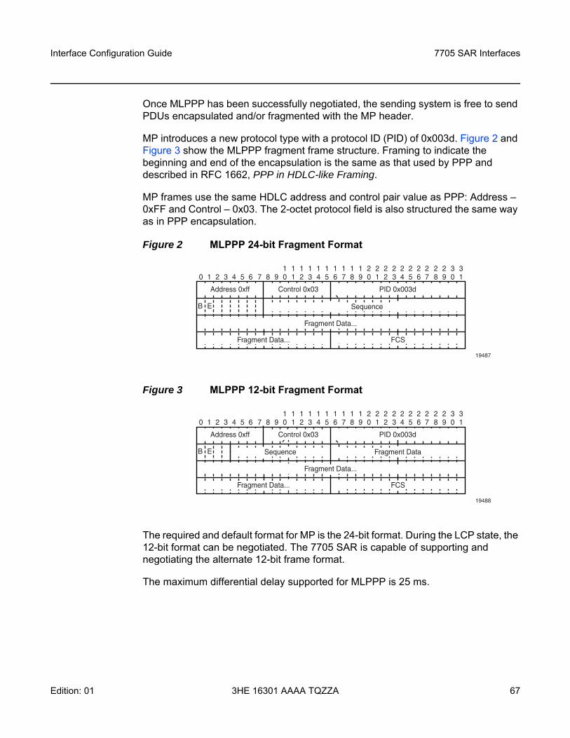
Interface Configuration Guide 7705 SAR Interfaces
Edition: 01 3HE 16301 AAAA TQZZA 67
Once MLPPP has been successfully negotiated, the sending system is free to send PDUs encapsulated and/or fragmented with the MP header.
MP introduces a new protocol type with a protocol ID (PID) of 0x003d. Figure 2 and Figure 3 show the MLPPP fragment frame structure. Framing to indicate the beginning and end of the encapsulation is the same as that used by PPP and described in RFC 1662, PPP in HDLC-like Framing.
MP frames use the same HDLC address and control pair value as PPP: Address – 0xFF and Control – 0x03. The 2-octet protocol field is also structured the same way as in PPP encapsulation.
Figure 2 MLPPP 24-bit Fragment Format
Figure 3 MLPPP 12-bit Fragment Format
The required and default format for MP is the 24-bit format. During the LCP state, the 12-bit format can be negotiated. The 7705 SAR is capable of supporting and negotiating the alternate 12-bit frame format.
The maximum differential delay supported for MLPPP is 25 ms.
0 1 2 3 4 5 6 7 8 9 0 1 2 3 4 5 6 7 8 9 0 1 2 3 4 5 6 7 8 9 0 11 1 1 1 1 1 1 1 1 1 2 2 2 2 2 2 2 2 2 2 3 3
Address 0xff
B E
Control 0x03 PID 0x003d
Sequence
Fragment Data...
Fragment Data... FCS
19487
0 1 2 3 4 5 6 7 8 9 0 1 2 3 4 5 6 7 8 9 0 1 2 3 4 5 6 7 8 9 0 11 1 1 1 1 1 1 1 1 1 2 2 2 2 2 2 2 2 2 2 3 3
Address 0xff
B E
Control 0x03 PID 0x003d
Sequence Fragment Data
Fragment Data...
Fragment Data... FCS
19488
7705 SAR Interfaces
68
Interface Configuration Guide
3HE 16301 AAAA TQZZA Edition: 01
3.2.1.2 Protocol Field (PID)
The protocol field is two octets. Its value identifies the datagram encapsulated in the Information field of the packet. In the case of MP, the PID also identifies the presence of a 4-octet MP header (or 2-octet, if negotiated).
A PID of 0x003d identifies the packet as MP data with an MP header.
The LCP packets and protocol states of the MLPPP session follow those defined by PPP in RFC 1661. The options used during the LCP state for creating an MLPPP NCP session are described in the sections that follow.
3.2.1.3 B&E Bits
The B&E bits are used to indicate the start and end of a packet. Ingress packets to the MLPPP process will have an MTU, which may or may not be larger than the maximum received reconstructed unit (MRRU) of the MLPPP network. The B&E bits manage the fragmentation of ingress packets when the packet exceeds the MRRU.
The B-bit indicates the first (or beginning) packet of a given fragment. The E-bit indicates the last (or ending) packet of a fragment. If there is no fragmentation of the ingress packet, both B&E bits are set to true (=1).
3.2.1.4 Sequence Number
Sequence numbers can be either 12 or 24 bits long. The sequence number is 0 for the first fragment on a newly constructed bundle and increments by one for each fragment sent on that bundle. The receiver keeps track of the incoming sequence numbers on each link in a bundle and reconstructs the desired unbundled flow through processing of the received sequence numbers and B&E bits. For a detailed description of the algorithm, refer to RFC 1990.
3.2.1.5 Information Field
The Information field is zero or more octets. The Information field contains the datagram for the protocol specified in the protocol field.
The MRRU will have the same default value as the MTU for PPP. The MRRU is always negotiated during LCP.
Interface Configuration Guide 7705 SAR Interfaces
Edition: 01 3HE 16301 AAAA TQZZA 69
3.2.1.6 Padding
On transmission, the Information field of the ending fragment may be padded with an arbitrary number of octets up to the MRRU. It is the responsibility of each protocol to distinguish padding octets from real information. Padding must only be added to the last fragment (E-bit set to true).
3.2.1.7 FCS
The FCS field of each MP packet is inherited from the normal framing mechanism from the member link on which the packet is transmitted. There is no separate FCS applied to the reconstituted packet as a whole if it is transmitted in more than one fragment.
3.2.1.8 LCP
The Link Control Protocol (LCP) is used to establish the connection through an exchange of configure packets. This exchange is complete, and the LCP opened state entered, once a Configure-Ack packet has been both sent and received.
LCP allows for the negotiation of multiple options in a PPP session. MP is somewhat different from PPP, and therefore the following options are set for MP and are not negotiated:
• no async control character map• no magic number• no link quality monitoring• address and control field compression• protocol field compression• no compound frames• no self-describing padding
Any non-LCP packets received during this phase must be silently discarded.
7705 SAR Interfaces
70
Interface Configuration Guide
3HE 16301 AAAA TQZZA Edition: 01
3.2.1.9 T1/E1 Link Hold Timers
T1/E1 link hold timers (or MLPPP link flap dampening) guard against the node reporting excessive interface transitions. Timers can be set to determine when link up and link down events are advertised; that is, up-to-down and down-to-up transitions of the interface are not advertised to upper layer protocols (are dampened) until the configured timer has expired.
3.2.2 Multi-Class MLPPP
The 7705 SAR supports multi-class MLPPP (MC-MLPPP) to address end-to-end delay caused by low-speed links transporting a mix of small and large packets. With MC-MLPPP, large, low-priority packets are fragmented to allow opportunities to send high-priority packets. QoS for MC-MLPPP is described in QoS in MC-MLPPP.
MC-MLPPP allows for the prioritization of multiple types of traffic flowing over MLPPP links, such as traffic between the cell site routers and the mobile operator’s aggregation routers. MC-MLPPP, as defined in RFC 2686, The Multi-Class Extension to Multi-Link PPP, is an extension of the MLPPP standard. MC-MLPPP is supported on access ports wherever PPP/MLPPP is supported, except on the 2-port OC3/STM1 Channelized Adapter card. It allows multiple classes of fragments to be transmitted over an MLPPP bundle, with each class representing a different priority level mapped to a forwarding class. The highest-priority traffic is transmitted over the MLPPP bundle with minimal delay regardless of the order in which packets are received.
Figure 4 shows the original MLPPP header format that allowed only two implied classes. The two classes were created by transmitting two interleaving flows of packets; one with MLPPP headers and one without. This resulted in two levels of priority sent over the physical link, even without the implementation of multi-class support.
Figure 5 shows the short and long sequence number fragment format MC-MLPPP headers. The short sequence number fragment format header includes two class bits to allow for up to four classes of service. Four class bits are available in the long sequence number fragment format header, but a maximum of four classes are still supported. This extension to the MLPPP header format is detailed in RFC 2686.
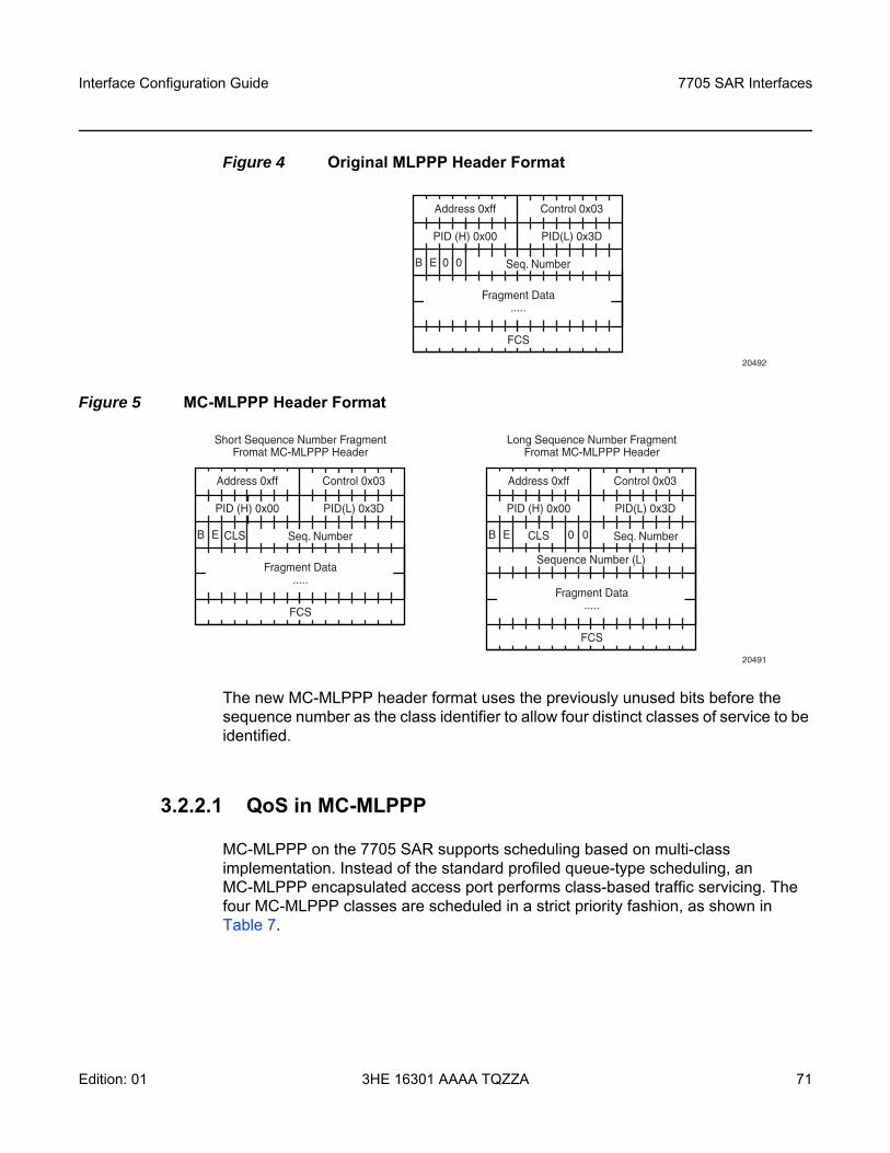
Interface Configuration Guide 7705 SAR Interfaces
Edition: 01 3HE 16301 AAAA TQZZA 71
Figure 4 Original MLPPP Header Format
Figure 5 MC-MLPPP Header Format
The new MC-MLPPP header format uses the previously unused bits before the sequence number as the class identifier to allow four distinct classes of service to be identified.
3.2.2.1 QoS in MC-MLPPP
MC-MLPPP on the 7705 SAR supports scheduling based on multi-class implementation. Instead of the standard profiled queue-type scheduling, an MC-MLPPP encapsulated access port performs class-based traffic servicing. The four MC-MLPPP classes are scheduled in a strict priority fashion, as shown in Table 7.
20492
Address 0xff
B E 0 0
Control 0x03
PID (H) 0x00 PID(L) 0x3D
Seq. Number
Fragment Data.....
FCS
20491
Address 0xff
B E
Control 0x03
PID (H) 0x00 PID(L) 0x3D
CLS Seq. Number
Fragment Data.....
FCS
Address 0xff
B E 0 0
Control 0x03
PID (H) 0x00 PID(L) 0x3D
CLS Seq. Number
Sequence Number (L)
Fragment Data.....
Short Sequence Number FragmentFromat MC-MLPPP Header
Long Sequence Number FragmentFromat MC-MLPPP Header
FCS
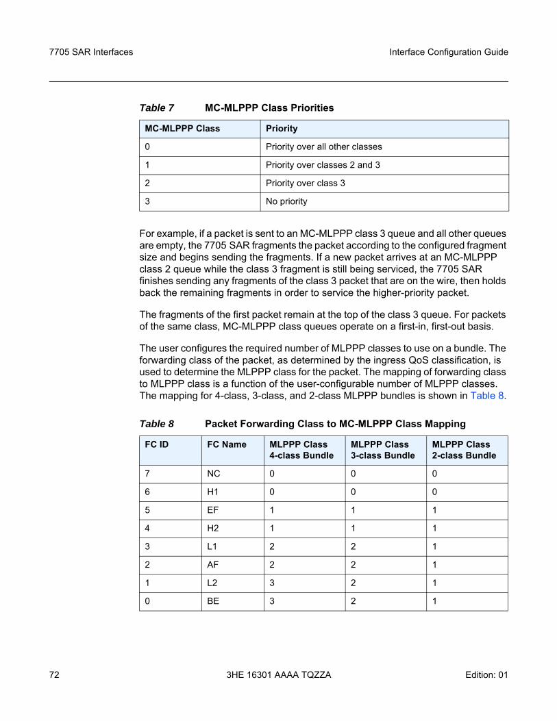
7705 SAR Interfaces
72
Interface Configuration Guide
3HE 16301 AAAA TQZZA Edition: 01
For example, if a packet is sent to an MC-MLPPP class 3 queue and all other queues are empty, the 7705 SAR fragments the packet according to the configured fragment size and begins sending the fragments. If a new packet arrives at an MC-MLPPP class 2 queue while the class 3 fragment is still being serviced, the 7705 SAR finishes sending any fragments of the class 3 packet that are on the wire, then holds back the remaining fragments in order to service the higher-priority packet.
The fragments of the first packet remain at the top of the class 3 queue. For packets of the same class, MC-MLPPP class queues operate on a first-in, first-out basis.
The user configures the required number of MLPPP classes to use on a bundle. The forwarding class of the packet, as determined by the ingress QoS classification, is used to determine the MLPPP class for the packet. The mapping of forwarding class to MLPPP class is a function of the user-configurable number of MLPPP classes. The mapping for 4-class, 3-class, and 2-class MLPPP bundles is shown in Table 8.
Table 7 MC-MLPPP Class Priorities
MC-MLPPP Class Priority
0 Priority over all other classes
1 Priority over classes 2 and 3
2 Priority over class 3
3 No priority
Table 8 Packet Forwarding Class to MC-MLPPP Class Mapping
FC ID FC Name MLPPP Class4-class Bundle
MLPPP Class3-class Bundle
MLPPP Class2-class Bundle
7 NC 0 0 0
6 H1 0 0 0
5 EF 1 1 1
4 H2 1 1 1
3 L1 2 2 1
2 AF 2 2 1
1 L2 3 2 1
0 BE 3 2 1
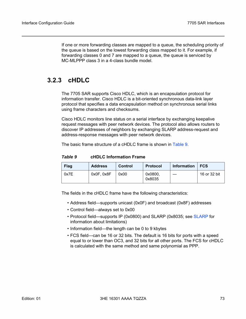
Interface Configuration Guide 7705 SAR Interfaces
Edition: 01 3HE 16301 AAAA TQZZA 73
If one or more forwarding classes are mapped to a queue, the scheduling priority of the queue is based on the lowest forwarding class mapped to it. For example, if forwarding classes 0 and 7 are mapped to a queue, the queue is serviced by MC-MLPPP class 3 in a 4-class bundle model.
3.2.3 cHDLC
The 7705 SAR supports Cisco HDLC, which is an encapsulation protocol for information transfer. Cisco HDLC is a bit-oriented synchronous data-link layer protocol that specifies a data encapsulation method on synchronous serial links using frame characters and checksums.
Cisco HDLC monitors line status on a serial interface by exchanging keepalive request messages with peer network devices. The protocol also allows routers to discover IP addresses of neighbors by exchanging SLARP address-request and address-response messages with peer network devices.
The basic frame structure of a cHDLC frame is shown in Table 9.
The fields in the cHDLC frame have the following characteristics:
• Address field—supports unicast (0x0F) and broadcast (0x8F) addresses • Control field—always set to 0x00 • Protocol field—supports IP (0x0800) and SLARP (0x8035; see SLARP for
information about limitations) • Information field—the length can be 0 to 9 kbytes • FCS field—can be 16 or 32 bits. The default is 16 bits for ports with a speed
equal to or lower than OC3, and 32 bits for all other ports. The FCS for cHDLC is calculated with the same method and same polynomial as PPP.
Table 9 cHDLC Information Frame
Flag Address Control Protocol Information FCS
0x7E 0x0F, 0x8F 0x00 0x0800, 0x8035
— 16 or 32 bit
7705 SAR Interfaces
74
Interface Configuration Guide
3HE 16301 AAAA TQZZA Edition: 01
3.2.3.1 SLARP
The 7705 SAR supports only the SLARP keepalive protocol.
For the SLARP keepalive protocol, each system sends the other a keepalive packet at a user configurable interval. The default interval is 10 seconds. Both systems must use the same interval to ensure reliable operation. Each system assigns sequence numbers to the keepalive packets it sends, starting with zero, independent of the other system. These sequence numbers are included in the keepalive packets sent to the other system. Also included in each keepalive packet is the sequence number of the last keepalive packet received from the other system, as assigned by the other system. This number is called the returned sequence number. Each system keeps track of the last returned sequence number it has received. Immediately before sending a keepalive packet, the system compares the sequence number of the packet it is about to send with the returned sequence number in the last keepalive packet it has received. If the two differ by 3 or more, it considers the line to have failed, and will not route higher-level data across it until an acceptable keepalive response is received.
3.2.4 Inverse Multiplexing Over ATM (IMA)
IMA is a cell-based protocol where an ATM cell stream is inverse-multiplexed and demultiplexed in a cyclical fashion among ATM-supporting channels to form a higher bandwidth logical link. This logical link is called an IMA group. By grouping channels into an IMA group, customers gain bandwidth management capability at in-between rates (for example, between DS1 and DS3 or between E1 and E3) through the addition or removal of channels to or from the IMA group. The 7705 SAR supports the IMA protocol as specified by the Inverse Multiplexing for ATM (IMA) Specification version 1.1.
In the ingress direction, traffic coming over multiple ATM channels configured as part of a single IMA group is converted into a single ATM stream and passed for further processing to the ATM layer, where service-related functions (for example, Layer 2 traffic management or feeding into a pseudowire) are applied. In the egress direction, a single ATM stream (after service functions are applied) is distributed over all paths that are part of an IMA group after ATM layer processing takes place.
An IMA group interface compensates for differential delay and allows for only a minimal cell delay variation. The maximum differential delay supported for IMA is 75 ms on 16-port T1/E1 ASAP Adapter cards and 32-port T1/E1 ASAP Adapter cards and 50 ms on 2-port OC3/STM1 Channelized Adapter cards.
Interface Configuration Guide 7705 SAR Interfaces
Edition: 01 3HE 16301 AAAA TQZZA 75
The interface deals with links that are added or deleted, or that fail. The higher layers see only an IMA group and not individual links; therefore, service configuration and management is done using IMA groups, and not individual links that are part of it.
The IMA protocol uses an IMA frame as the unit of control. An IMA frame consists of a series of 128 consecutive cells. In addition to ATM cells received from the ATM layer, the IMA frame contains IMA OAM cells. Two types of cells are defined: IMA Control Protocol (ICP) cells and IMA filler cells. ICP cells carry information used by the IMA protocol at both ends of an IMA group (for example, IMA frame sequence number, link stuff indication, status and control indication, IMA ID, Tx and Rx test patterns, version of the IMA protocol). A single ICP cell is inserted at the ICP cell offset position (the offset may be different on each link of the group) of each frame. Filler cells are used by the transmitting side to fill up each IMA frame in case there are not enough ATM stream cells from the ATM layer, so a continuous stream of cells is presented to the physical layer. Those cells are then discarded by the receiving end. IMA frames are transmitted simultaneously on all paths of an IMA group, and when they are received out of sync at the other end of the IMA group link, the receiver compensates for differential link delays among all paths.
3.2.5 Network Synchronization on Ports and Circuits
The 7705 SAR provides network synchronization on the following ports and CES circuits:
• Network Synchronization on T1/E1, Ethernet, GPON, and DSL Ports• Network Synchronization on SONET/SDH Ports• Network Synchronization on DS3/E3 Ports• Network Synchronization on DS3 CES Circuits• Network Synchronization on T1/E1 Ports and Circuits
3.2.5.1 Network Synchronization on T1/E1, Ethernet, GPON, and DSL Ports
Line timing mode provides physical layer timing (Layer 1) that can be used as an accurate reference for nodes in the network. This mode is immune to any packet delay variation (PDV) occurring on a Layer 2 or Layer 3 link. Physical layer timing provides the best synchronization performance through a synchronization distribution network.
7705 SAR Interfaces
76
Interface Configuration Guide
3HE 16301 AAAA TQZZA Edition: 01
On the 7705 SAR-A variant with T1/E1 ports, line timing is supported on T1/E1 ports. Line timing is also supported on all synchronous Ethernet ports on both 7705 SAR-A variants. Synchronous Ethernet is supported on the XOR ports (1 to 4), configured as either RJ-45 ports or SFP ports. Synchronous Ethernet is also supported on SFP ports 5 to 8. Ports 9 to 12 do not support synchronous Ethernet and, therefore, do not support line timing.
On the 7705 SAR-Ax, line timing is supported on all Ethernet ports.
On the 7705 SAR-H, line timing is supported on:
• all Ethernet ports• T1/E1 ports on a chassis equipped with a 4-port T1/E1 and RS-232 Combination
module
On the 7705 SAR-Hc, line timing is supported on all Ethernet ports.
On the 7705 SAR-M (variants with T1/E1 ports), line timing is supported on T1/E1 ports. Line timing is also supported on all RJ-45 Ethernet ports and SFP ports on the 7705 SAR-M (all variants).
On the 7705 SAR-W, line timing is supported on:
• RJ-45 Ethernet ports and optical SFP ports (these ports support synchronous Ethernet and IEEE 1588v2 PTP)
On the 7705 SAR-Wx, line timing is supported on:
• RJ-45 Ethernet ports and optical SFP ports (these ports support synchronous Ethernet and IEEE 1588v2 PTP)
On the 7705 SAR-X, line timing is supported on T1/E1 ports and Ethernet ports.
In addition, line timing is supported on the following modules when they are installed in chassis variants with module slots:
• GPON module• 8-port xDSL module (NTR over ADSL2, ADSL2+, or VDSL2)• 6-port DSL Combination module (two references are available: NTR over
SHDSL and NTR over ADSL2, ADSL2+, or VDSL2)• 2-port 10GigE (Ethernet) module• 6-port SAR-M Ethernet module
Interface Configuration Guide 7705 SAR Interfaces
Edition: 01 3HE 16301 AAAA TQZZA 77
On the 7705 SAR-8 and 7705 SAR-18, line timing is supported on:
• 16-port T1/E1 ASAP Adapter card (version 1 is not supported on the 7705 SAR-18)
• 32-port T1/E1 ASAP Adapter card• 8-port Ethernet Adapter card, version 2, on the two Ethernet SFP ports with
SFPs that support synchronous Ethernet• 6-port Ethernet 10Gbps Adapter card• 8-port Gigabit Ethernet Adapter card (dual-rate and copper SFPs do not support
synchronous Ethernet)• 2-port 10GigE (Ethernet) Adapter card• 10-port 1GigE/1-port 10GigE X-Adapter card (not supported on the
7705 SAR-8)• 4-port DS3/E3 Adapter card• 2-port OC3/STM1 Channelized Adapter card• 4-port OC3/STM1 / 1-port OC12/STM4 Adapter card• 4-port OC3/STM1 Clear Channel Adapter card• Packet Microwave Adapter card on ports that support synchronous Ethernet and
on ports that support PCR
Synchronous Ethernet is a variant of line timing and is automatically enabled on ports and SFPs that support it. The operator can select a synchronous Ethernet port as a candidate for the timing reference. The recovered timing from this port is then used to time the system. This ensures that any of the system outputs are locked to a stable, traceable frequency source.
3.2.5.2 Network Synchronization on SONET/SDH Ports
Each SONET/SDH port can be independently configured to be loop-timed (recovered from an Rx line) or node-timed (recovered from the SSU in the active CSM).
A SONET/SDH port’s receive clock rate can be used as a synchronization source for the node.
7705 SAR Interfaces
78
Interface Configuration Guide
3HE 16301 AAAA TQZZA Edition: 01
3.2.5.3 Network Synchronization on DS3/E3 Ports
Each clear channel DS3/E3 port on a 4-port DS3/E3 Adapter card can be independently configured to be loop-timed (recovered from an Rx line), node-timed (recovered from the SSU in the active CSM), or differential-timed (derived from the comparison of a common clock to the received RTP timestamp in TDM pseudowire packets). When a DS3 port is channelized, each DS1 or E1 channel can be independently configured to be loop-timed, node-timed, or differential-timed (differential timing on DS1/E1 channels is supported only on the first three ports of the card). When not configured for differential timing, a DS3/E3 port can be configured to be a timing source for the node.
3.2.5.4 Network Synchronization on DS3 CES Circuits
Each DS3 CES circuit on a 2-port OC3/STM1 Channelized Adapter card card can be loop-timed (recovered from an Rx line) or free-run (timing source is from its own clock). A DS3 circuit can be configured to be a timing source for the node.
3.2.5.5 Network Synchronization on T1/E1 Ports and Circuits
Each T1/E1 port can be independently configured for loop-timing (recovered from an Rx line) or node-timing (recovered from the SSU in the active CSM).
In addition, T1/E1 CES circuits on the following can be independently configured for adaptive timing (clocking is derived from incoming TDM pseudowire packets):
• 16-port T1/E1 ASAP Adapter card• 32-port T1/E1 ASAP Adapter card• 7705 SAR-M (variants with T1/E1 ports)• 7705 SAR-X• 7705 SAR-A (variant with T1/E1 ports) • T1/E1 ports on the 4-port T1/E1 and RS-232 Combination module
T1/E1 CES circuits on the following can be independently configured for differential timing (recovered from RTP in TDM pseudowire packets):
• 16-port T1/E1 ASAP Adapter card, version 2• 32-port T1/E1 ASAP Adapter card• 4-port OC3/STM1 / 1-port OC12/STM4 Adapter card (DS1/E1 channels)
Interface Configuration Guide 7705 SAR Interfaces
Edition: 01 3HE 16301 AAAA TQZZA 79
• 4-port DS3/E3 Adapter card (DS1/E1 channels on DS3 ports; E3 ports cannot be channelized); differential timing on DS1/E1 channels is supported only on the first three ports of the card
• 7705 SAR-M (variants with T1/E1 ports)• 7705 SAR-X• 7705 SAR-A (variant with T1/E1 ports) • T1/E1 ports on the 4-port T1/E1 and RS-232 Combination module
A T1/E1 port can be configured to be a timing source for the node.
3.2.6 Node Synchronization From GNSS Receiver Ports
The GNSS receiver port on the 7705 SAR-Ax, 7705 SAR-Wx, and 7705 SAR-H GPS Receiver module, and the GNSS Receiver card installed in a 7705 SAR-8 or 7705 SAR-18, can provide a synchronization clock to the SSU in the router with the corresponding QL for SSM. This frequency can then be distributed to the rest of the router from the SSU as configured with the ref-order and ql-selection commands; refer to the 7705 SAR Basic System Configuration Guide for information. The GNSS reference is qualified only if the GNSS receiver port is operational, has sufficient satellites locked, and has a frequency successfully recovered. A PTP master/boundary clock can also use this frequency reference with PTP peers.
In the event of GNSS signal loss or jamming resulting in the unavailability of timing information, the GNSS receiver automatically prevents output of clock or synchronization data to the system, and the system can revert to alternate timing sources.
A 7705 SAR using GNSS or IEEE 1588v2 PTP for time of day/phase recovery can perform high-accuracy OAM timestamping and measurements. Refer to the 7705 SAR Basic System Configuration Guide for information about node timing sources.
Note: Adaptive timing and differential timing are not supported on DS1 or E1 channels that have CAS signaling enabled.
7705 SAR Interfaces
80
Interface Configuration Guide
3HE 16301 AAAA TQZZA Edition: 01
3.2.7 Flow Control on Ethernet Ports
IEEE 802.3x Flow Control, which is the process of pausing the transmission based on received pause frames, is supported on Fast Ethernet, Gigabit Ethernet, and 10-Gigabit Ethernet (SFP+) ports. In the transmit direction, the Ethernet ports generate pause frames if the buffer occupancy reaches critical values or if port FIFO buffers are overloaded. Pause frame generation is automatically handled by the Ethernet Adapter card when the system-wide constant thresholds are exceeded. The generation of pause frames ensures that newly arriving frames still can be processed and queued, mainly to maintain the SLA agreements.
If autonegotiation is on for an Ethernet port, enabling and disabling of IEEE 802.3x Flow Control is autonegotiated for receive and transmit directions separately. If autonegotiation is turned off, the reception and transmission of IEEE 802.3x Flow Control is enabled by default and cannot be disabled.
Ingress flow control for the 6-port SAR-M Ethernet module is Ethernet link-based and not port-based. When IEEE 802.3x Flow Control is enabled on the 6-port SAR-M Ethernet module, pause frames are multicast to all ports on the Ethernet link. There are two Ethernet links on the 6-port SAR-M Ethernet module: one for ports 1, 3, and 5, and one for ports 2, 4, and 6. Pause frames are sent to either ports 1, 3, and 5, or to ports 2, 4, and 6, depending on which link the pause frame originates.
3.2.8 Ethernet OAM
This section contains information on the following topics:
• Ethernet OAM Overview• CRC (Cyclic Redundancy Check) Monitoring• Remote Loopback• 802.3ah OAMPDU Tunneling and Termination for Epipe Service• Dying Gasp
For more information on Ethernet OAM, refer to the 7705 SAR OAM and Diagnostics Guide, “Ethernet OAM Capabilities”.
Interface Configuration Guide 7705 SAR Interfaces
Edition: 01 3HE 16301 AAAA TQZZA 81
3.2.8.1 Ethernet OAM Overview
802.3ah Clause 57 (EFM OAM) defines the Operations, Administration, and Maintenance (OAM) sublayer, which is a link level Ethernet OAM. It provides mechanisms for monitoring link operations such as remote fault indication and remote loopback control.
Ethernet OAM gives network operators the ability to monitor the status of Ethernet links and quickly determine the location of failing links or fault conditions.
Because some of the sites where the 7705 SAR will be deployed will only have Ethernet uplinks, this OAM functionality is mandatory. For example, mobile operators must be able to request remote loopbacks from the peer router at the Ethernet layer in order to debug any connectivity issues. EFM OAM provides this capability.
EFM OAM is supported on network and access Ethernet and DSL ports and is configured at the port level. The access ports can be configured to tunnel the OAM traffic originated by the far-end devices. EFM OAM is not supported on the 7705 SAR-M GPON module.
EFM OAM has the following characteristics.
• All EFM OAM, including loopbacks, operate on point-to-point links only.• EFM loopbacks are always line loopbacks (line Rx to line Tx). Line loopbacks
are not supported on DSL ports.• When a port is in loopback, all frames (except EFM frames) are discarded. If
dynamic signaling and routing is used (dynamic LSPs, OSPF, IS-IS, or BGP routing), all services also go down. If all signaling and routing protocols are static (static routes, LSPs, and service labels), the frames are discarded but services stay up.
The following EFM OAM functions are supported:
• OAM capability discovery• configurable transmit interval with an Information OAMPDU• active or passive mode• OAM loopback• OAMPDU tunneling and termination (for Epipe service)• dying gasp at network and access ports• non-zero vendor-specific information field — the 32-bit field is encoded using the
format 00:PP:CC:CC and references TIMETRA-CHASSIS-MIB - 00 — must be zeros- PP — the platform type from tmnxHwEquippedPlatform
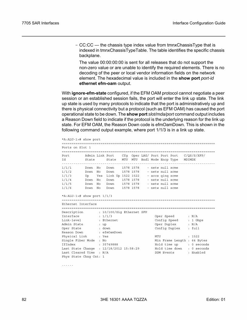
7705 SAR Interfaces
82
Interface Configuration Guide
3HE 16301 AAAA TQZZA Edition: 01
- CC:CC — the chassis type index value from tmnxChassisType that is indexed in tmnxChassisTypeTable. The table identifies the specific chassis backplane.The value 00:00:00:00 is sent for all releases that do not support the non-zero value or are unable to identify the required elements. There is no decoding of the peer or local vendor information fields on the network element. The hexadecimal value is included in the show port port-id ethernet efm-oam output.
With ignore-efm-state configured, if the EFM OAM protocol cannot negotiate a peer session or an established session fails, the port will enter the link up state. The link up state is used by many protocols to indicate that the port is administratively up and there is physical connectivity but a protocol (such as EFM OAM) has caused the port operational state to be down. The show port slot/mda/port command output includes a Reason Down field to indicate if the protocol is the underlying reason for the link up state. For EFM OAM, the Reason Down code is efmOamDown. This is shown in the following command output example, where port 1/1/3 is in a link up state.
*A:ALU-1># show port===============================================================================Ports on Slot 1===============================================================================Port Admin Link Port Cfg Oper LAG/ Port Port Port C/QS/S/XFP/Id State State MTU MTU Bndl Mode Encp Type MDIMDX-------------------------------------------------------------------------------1/1/1 Down No Down 1578 1578 - netw null xcme1/1/2 Down No Down 1578 1578 - netw null xcme1/1/3 Up Yes Link Up 1522 1522 - accs qinq xcme1/1/4 Down No Down 1578 1578 - netw null xcme1/1/5 Down No Down 1578 1578 - netw null xcme1/1/6 Down No Down 1578 1578 - netw null xcme
*A:ALU-1># show port 1/1/3===============================================================================Ethernet Interface===============================================================================Description : 10/100/Gig Ethernet SFPInterface : 1/1/3 Oper Speed : N/ALink-level : Ethernet Config Speed : 1 GbpsAdmin State : up Oper Duplex : N/AOper State : down Config Duplex : fullReason Down : efmOamDownPhysical Link : Yes MTU : 1522Single Fiber Mode : No Min Frame Length : 64 BytesIfIndex : 35749888 Hold time up : 0 secondsLast State Change : 12/18/2012 15:58:29 Hold time down : 0 secondsLast Cleared Time : N/A DDM Events : EnabledPhys State Chng Cnt: 1
......
Interface Configuration Guide 7705 SAR Interfaces
Edition: 01 3HE 16301 AAAA TQZZA 83
The EFM OAM protocol can be decoupled from the port state and operational state. In cases where an operator wants to remove the protocol, monitor only the protocol, migrate, or make changes, the ignore-efm-state command can be configured under the config>port>ethernet>efm-oam context.
When the ignore-efm-state command is configured on a port, the protocol behavior is normal. However, any failure in the EFM protocol state (discovery, configuration, time-out, loops, and so on) will not affect the port. Only a protocol warning message will be raised to indicate issues with the protocol. When the ignore-efm-state command is not configured on a port, the default behavior is that the port state will be affected by any EFM OAM protocol fault or clear conditions.
Enabling and disabling this command will immediately affect the port state and operating state based on the active configuration, and this will be displayed in the show port command output. For example, if the ignore-efm-state command is configured on a port that is exhibiting a protocol error, that protocol error does not affect the port state or operational state and there is no Reason Down code in the output. If the ignore-efm-state command is disabled on a port with an existing EFM OAM protocol error, the port will transition to port state link up, operational state down with reason code efmOamDown.
If the port is a member of a microwave link, the ignore-efm-state command must be enabled before the EFM OAM protocol can be activated. This restriction is required because EFM OAM is not compatible with microwave links.
3.2.8.2 CRC (Cyclic Redundancy Check) Monitoring
CRC errors typically occur when Ethernet links are compromised due to optical fiber degradation, weak optical signals, bad optical connections, or problems on a third-party networking element. As well, higher-layer OAM options such as EFM and BFD may not detect errors and trigger appropriate alarms and switchovers if the errors are intermittent, since this does not affect the continuous operation of other OAM functions.
CRC error monitoring on Ethernet ports allows degraded links to be alarmed or failed in order to detect network infrastructure issues, trigger necessary maintenance, or switch to redundant paths. This is achieved through monitoring ingress error counts and comparing them to the configured error thresholds. The rate at which CRC errors are detected on a port can trigger two alarm states. Crossing the configured signal degrade (SD) threshold (sd-threshold) causes an event to be logged and an alarm to be raised, which alerts the operator to a potential issue on a link. Crossing the configured signal failure (SF) threshold (sf-threshold) causes the affected port to enter the operationally down state, and causes an event to be logged and an alarm to be raised.
7705 SAR Interfaces
84
Interface Configuration Guide
3HE 16301 AAAA TQZZA Edition: 01
The CRC error rates are calculated as M×10E-N, which is the ratio of errored frames allowed for total frames received. The operator can configure both the threshold (N) and a multiplier (M). If the multiplier is not configured, the default multiplier (1) is used.
For example, setting the SD threshold to 3 results in a signal degrade error rate threshold of 1×10E-3 (1 errored frame per 1000 frames). Changing the configuration to an SD threshold of 3 and a multiplier of 5 results in a signal degrade error rate threshold of 5×10E-3 (5 errored frames per 1000 frames). The signal degrade error rate threshold must be lower than the signal failure error rate threshold because it is used to notify the operator that the port is operating in a degraded but not failed condition.
A sliding window (window-size) is used to calculate a statistical average of CRC error statistics collected every second. Each second, the oldest statistics are dropped from the calculation. For example, if the default 10-s sliding window is configured, at the 11th second the oldest second of statistical data is dropped and the 11th second is included. This sliding average is compared against the configured SD and SF thresholds to determine if the error rate over the window exceeds one or both of the thresholds, which will generate an alarm and log event.
When a port enters the failed condition as a result of crossing an SF threshold, the port is not automatically returned to service. Because the port is operationally down without a physical link, error monitoring stops. The operator can enable the port by using the shutdown and no shutdown port commands or by using other port transition functions such as clearing the MDA (clear mda command) or removing the cable. A port that is down due to crossing an SF threshold can also be re-enabled by changing or disabling the SD threshold. The SD state is self-clearing, and it clears if the error rate drops below 1/10th of the configured SD rate.
3.2.8.3 Remote Loopback
EFM OAM provides a link-layer frame loopback mode, which can be controlled remotely.
To initiate a remote loopback, the local EFM OAM client sends a loopback control OAMPDU by enabling the OAM remote loopback command. After receiving the loopback control OAMPDU, the remote OAM client puts the remote port into local loopback mode.
Note: CRC monitoring is not supported on GPON or DSL ports.
Interface Configuration Guide 7705 SAR Interfaces
Edition: 01 3HE 16301 AAAA TQZZA 85
OAMPDUs are slow protocol frames that contain appropriate control and status information used to monitor, test, and troubleshoot OAM-enabled links.
To exit a remote loopback, the local EFM OAM client sends a loopback control OAMPDU by disabling the OAM remote loopback command. After receiving the loopback control OAMPDU, the remote OAM client puts the port back into normal forwarding mode.
When a port is in local loopback mode (the far end requested an Ethernet OAM loopback), any packets received on the port will be looped back, except for EFM OAMPDUs. No data will be transmitted from the node; only data that is received on the node will be sent back out.
When the node is in remote loopback mode, local data from the CSM is transmitted, but any data received on the node is dropped, except for EFM OAMPDUs.
Remote loopbacks should be used with caution; if dynamic signaling and routing protocols are used, all services go down when a remote loopback is initiated. If only static signaling and routing is used, the services stay up. On the 7705 SAR, the Ethernet port can be configured to accept or reject the remote-loopback command.
3.2.8.4 802.3ah OAMPDU Tunneling and Termination for Epipe Service
Customers who subscribe to Epipe service might have customer equipment running 802.3ah at both ends. The 7705 SAR can be configured to tunnel EFM OAMPDUs received from a customer device to the other end through the existing network using MPLS or GRE, or to terminate received OAMPDUs at a network or an access Ethernet port.
While tunneling offers the ability to terminate and process the OAM messages at the head-end, termination on the first access port at the cell site can be used to detect immediate failures or can be used to detect port failures in a timelier manner. The user can choose either tunneling or termination, but not both at the same time.
Note: This feature applies only to port-based Epipe SAPs because 802.3ah runs at port level, not at VLAN level.
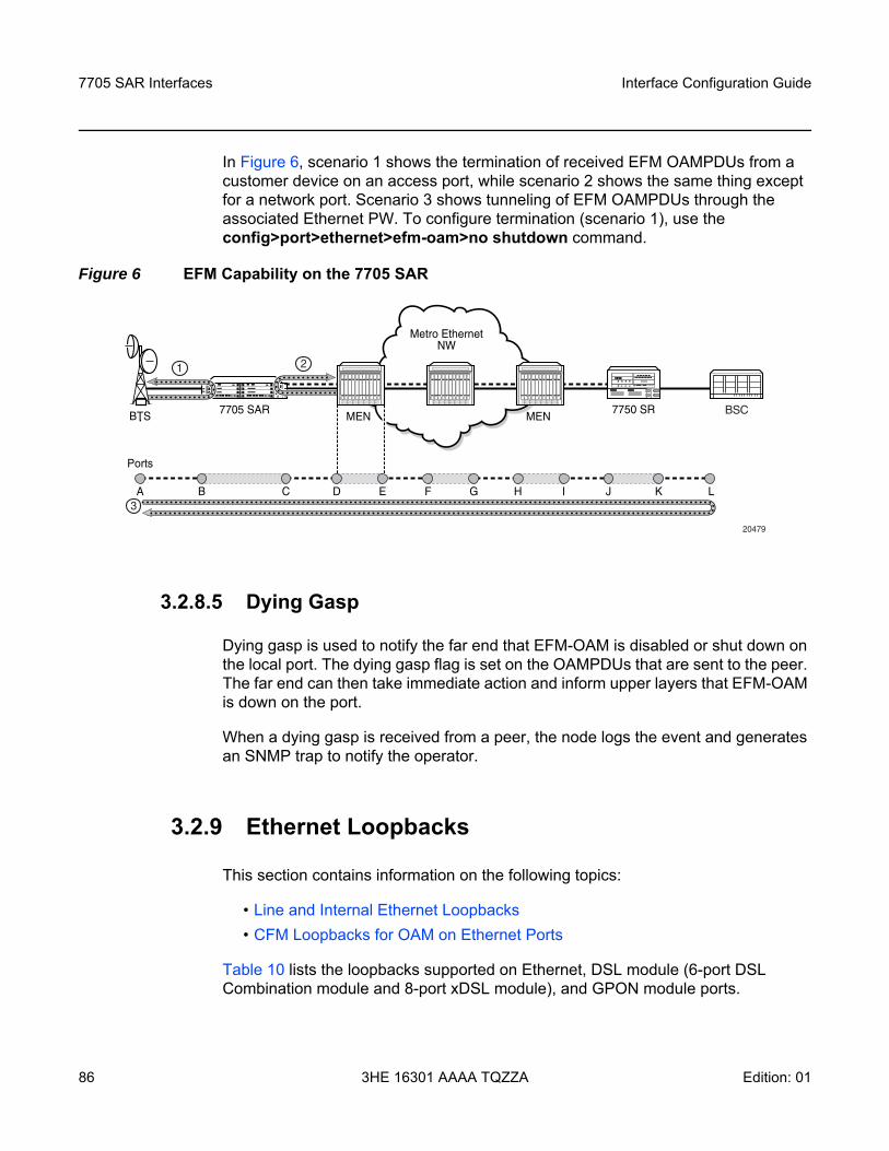
7705 SAR Interfaces
86
Interface Configuration Guide
3HE 16301 AAAA TQZZA Edition: 01
In Figure 6, scenario 1 shows the termination of received EFM OAMPDUs from a customer device on an access port, while scenario 2 shows the same thing except for a network port. Scenario 3 shows tunneling of EFM OAMPDUs through the associated Ethernet PW. To configure termination (scenario 1), use the config>port>ethernet>efm-oam>no shutdown command.
Figure 6 EFM Capability on the 7705 SAR
3.2.8.5 Dying Gasp
Dying gasp is used to notify the far end that EFM-OAM is disabled or shut down on the local port. The dying gasp flag is set on the OAMPDUs that are sent to the peer. The far end can then take immediate action and inform upper layers that EFM-OAM is down on the port.
When a dying gasp is received from a peer, the node logs the event and generates an SNMP trap to notify the operator.
3.2.9 Ethernet Loopbacks
This section contains information on the following topics:
• Line and Internal Ethernet Loopbacks• CFM Loopbacks for OAM on Ethernet Ports
Table 10 lists the loopbacks supported on Ethernet, DSL module (6-port DSL Combination module and 8-port xDSL module), and GPON module ports.
Metro EthernetNW
20479
7705 SARMEN BSC7750 SR
A
Ports
B C D E F G H I J K L
BTS MEN
1
3
2
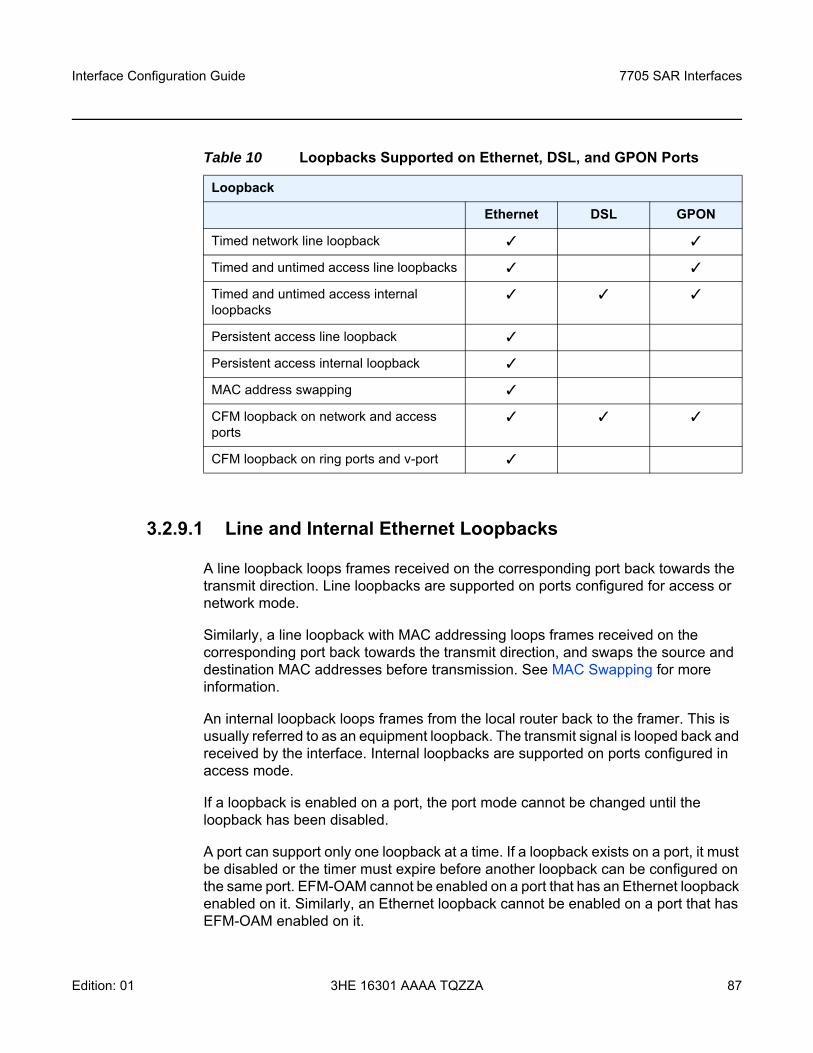
Interface Configuration Guide 7705 SAR Interfaces
Edition: 01 3HE 16301 AAAA TQZZA 87
3.2.9.1 Line and Internal Ethernet Loopbacks
A line loopback loops frames received on the corresponding port back towards the transmit direction. Line loopbacks are supported on ports configured for access or network mode.
Similarly, a line loopback with MAC addressing loops frames received on the corresponding port back towards the transmit direction, and swaps the source and destination MAC addresses before transmission. See MAC Swapping for more information.
An internal loopback loops frames from the local router back to the framer. This is usually referred to as an equipment loopback. The transmit signal is looped back and received by the interface. Internal loopbacks are supported on ports configured in access mode.
If a loopback is enabled on a port, the port mode cannot be changed until the loopback has been disabled.
A port can support only one loopback at a time. If a loopback exists on a port, it must be disabled or the timer must expire before another loopback can be configured on the same port. EFM-OAM cannot be enabled on a port that has an Ethernet loopback enabled on it. Similarly, an Ethernet loopback cannot be enabled on a port that has EFM-OAM enabled on it.
Table 10 Loopbacks Supported on Ethernet, DSL, and GPON Ports
Loopback
Ethernet DSL GPON
Timed network line loopback
Timed and untimed access line loopbacks
Timed and untimed access internal loopbacks
Persistent access line loopback
Persistent access internal loopback
MAC address swapping
CFM loopback on network and access ports
CFM loopback on ring ports and v-port
7705 SAR Interfaces
88
Interface Configuration Guide
3HE 16301 AAAA TQZZA Edition: 01
When an internal loopback is enabled on a port, autonegotiation is turned off silently. This is to allow an internal loopback when the operational status of a port is down. Any user modification to autonegotiation on a port configured with an internal Ethernet loopback will not take effect until the loopback is disabled.
The loopback timer can be configured from 30 s to 86400 s. All non-zero timed loopbacks are turned off automatically under the following conditions: an adapter card reset, DSL module reset, GPON module reset, an activity switch, or timer expiry. Line or internal loopback timers can also be configured as a latched loopback by setting the timer to 0 s, or as a persistent loopback with the persistent keyword. Latched and persistent loopbacks are enabled indefinitely until turned off by the user. Latched loopbacks survive adapter card resets and activity switches, but are lost if there is a system restart. Persistent loopbacks survive adapter card resets and activity switches and can survive a system restart if the admin-save or admin-save-detail command was executed prior to the restart. Latched loopbacks (untimed) and persistent loopbacks can be enabled only on Ethernet access ports.
Persistent loopbacks are the only Ethernet loopbacks saved to the database by the admin-save and admin-save-detail commands.
An Ethernet port loopback may interact with other features. See Interaction of Ethernet Port Loopback with Other Features for more information.
3.2.9.1.1 MAC Swapping
Typically, an Ethernet port loopback only echoes back received frames. That is, the received source and destination MAC addresses are not swapped. However, not all Ethernet equipment supports echo mode, where the original sender of the frame must support receiving its own port MAC address as the destination MAC address.
The MAC swapping feature on the 7705 SAR is an optional feature that will swap the received destination MAC address with the source MAC address when an Ethernet port is in loopback mode. After the swap, the FCS is recalculated to ensure the validity of the Ethernet frame and to ensure that the frame is not dropped by the original sender due to a CRC error.
MAC swapping is not supported on the GPON module, 6-port DSL Combination module, or 8-port xDSL module.
3.2.9.1.2 Interaction of Ethernet Port Loopback with Other Features
EFM OAM and line loopback are mutually exclusive. If one of these functions is enabled, it must be disabled before the other can be used.
Interface Configuration Guide 7705 SAR Interfaces
Edition: 01 3HE 16301 AAAA TQZZA 89
However, a line loopback precedes the dot1x behavior. That is, if the port is already dot1x-authenticated it will remain so. If it is not, EAP authentication will fail.
Ethernet port-layer line loopback and Ethernet port-layer internal loopback can be enabled on the same port with the down-when-looped feature. EFM OAM cannot be enabled on the same port with the down-when-looped feature. For more information, see Ethernet Port Down-When-Looped.
3.2.9.2 CFM Loopbacks for OAM on Ethernet Ports
This section contains information on the following topics:
• CFM Loopback Overview• CFM Loopback Mechanics
3.2.9.2.1 CFM Loopback Overview
Connectivity fault management (CFM) loopback support for loopback messages (LBMs) on Ethernet ports allows operators to run standards-based Layer 1 and Layer 2 OAM tests on ports receiving unlabeled packets.
The 7705 SAR supports CFM MEPs associated with different endpoints (that is, spoke SDP Down MEPs, network interface facility MEPs, and SAP Up and SAP Down MEPs). In addition, for traffic received from an uplink (network ingress), the 7705 SAR supports CFM LBM for both labeled and unlabeled packets. CFM loopbacks are applied to the Ethernet port.
Refer to the 7705 SAR OAM and Diagnostics Guide, “Ethernet OAM Capabilities”, for information on CFM MEPs.
Figure 7 shows an application where an operator leases facilities from a transport network provider in order to transport traffic from a cell site to their MTSO. The operator leases a certain amount of bandwidth between the two endpoints (the cell site and the MTSO) from the transport provider, who offers Ethernet Virtual Private Line (EVPL) or Ethernet Private Line (EPL) PTP service. Before the operator offers services on the leased bandwidth, the operator runs OAM tests to verify the SLA. Typically, the transport provider (MEN provider) requires that the OAM tests be run in the direction of (towards) the first Ethernet port that is connected to the transport network. This is done in order to eliminate the potential effect of queuing, delay, and jitter that may be introduced by a spoke SDP or SAP.

7705 SAR Interfaces
90
Interface Configuration Guide
3HE 16301 AAAA TQZZA Edition: 01
Figure 7 CFM Loopback on Ethernet Ports
Figure 7 shows an Ethernet verifier at the MTSO that is directly connected to the transport network (in front of the 7750 SR). Thus, the Ethernet OAM frames are not label-encapsulated. Given that Ethernet verifiers do not support label operations and the transport provider mandates that OAM tests be run between the two hand-off Ethernet ports, the verifier cannot be relocated behind the 7750 SR node at the MTSO. Therefore, CFM loopback frames received are not MPLS-encapsulated, but are simple Ethernet frames where the type is set to CFM (dot1ag or Y.1731).
3.2.9.2.2 CFM Loopback Mechanics
The following list contains important facts to consider when working with CFM loopbacks:
• CFM loopbacks can be enabled on a per-port basis, and: - the port can be in access or network mode- once enabled on a port, all received LBM frames are processed, regardless
of the VLAN and the service that the VLAN or SAP is bound to
Metro EthernetNW
21212
DO, LTE
1x
Ethernet EVPL
Cell Site
MTSOEthernet
nxT1
7705 SAR
EthernetVerifier
DSC
2
1
7750 SR
DA=SAR1 SA=Verif LBM
LBM 2SA=SAR DA=VerifDO = Evolution Data OnlyLTE = Long Term EvolutionEVPL = Ethernet Virtual Private LineDSC = Digital Cross-ConnectDA = Destination MAC AddressSA = Source MAC AddressLBM = Loopback Message
Legend:
Interface Configuration Guide 7705 SAR Interfaces
Edition: 01 3HE 16301 AAAA TQZZA 91
- there is no associated MEP creation involved with this feature; therefore, no domain, association, or similar checks are performed on the received frame
- upon finding a destination address MAC match, the LBM frame is sent to the CFM process
• CFM loopback support on a physical ring port on the 2-port 10GigE (Ethernet) Adapter card or 2-port 10GigE (Ethernet) module differs from other Ethernet ports. For these ports, cfm-loopback is configured, optionally, using dot1p and match-vlan to create a list of up to 16 VLANs. The null VLAN is always applied. The CFM Loopback Message will be processed if it does not contain a VLAN header, or if it contains a VLAN header with a VLAN ID that matches one in the configured match-vlan list.
• received LBM frames undergo no queuing or scheduling in the ingress direction • at egress, loopback reply (LBR) frames are stored in their own queue; that is, a
separate new queue is added exclusively for LBR frames • users can configure the way a response frame is treated among other user traffic
stored in network queues; the configuration options are high-priority, low-priority, or dot1p, where dot1p applies only to physical ring ports
• for network egress, where profiled scheduling is enabled, the following conditions apply: - high-priority: either cir = port_speed, which applies to all frames that are
scheduled via an in-profile scheduler; or round-robin (RR) for all other (network egress queue) frames that are in-profile
- low-priority: either cir = 0, pir = port_speed, which applies to all frames that are scheduled as out-of-profile, or RR for all other frames that are out-of-profile
• for network egress or access egress, where 4-priority scheduling is enabled:- high-priority: either cir = port_speed, which applies to all frames that are
scheduled via an expedited in-profile scheduler, or RR for all other (network egress queue) frames that reside in expedited queues and are in an in-profile state
- low-priority: either cir = 0, pir = port_speed, which applies to all frames that are scheduled via a best effort out-of-profile scheduler, or RR for all other frames that reside in best-effort queues and are in an out-of-profile state
• for the 8-port Gigabit Ethernet Adapter card, the 10-port 1GigE/1-port 10GigE X-Adapter card, and the v-port on the 2-port 10GigE (Ethernet) Adapter card and 2-port 10GigE (Ethernet) module, for network egress, where 16-priority scheduling is enabled:- high-priority: has higher priority than any user frames - low-priority: has lower priority than any user frames
7705 SAR Interfaces
92
Interface Configuration Guide
3HE 16301 AAAA TQZZA Edition: 01
• for the physical ring ports on the 2-port 10GigE (Ethernet) Adapter card and 2-port 10GigE (Ethernet) module, which can only operate as network egress, the priority of the LBR frame is derived from the dot1p setting of the received LBM frame. Based on the assigned ring-type network queue policy, dot1p-to-queue mapping is handled using the same mapping rule that applies to all other user frames.
• the above queue parameters and scheduler mappings are all preconfigured and cannot be altered. The desired QoS treatment is selected by enabling the CFM loopback and specifying high-priority, low-priority, or dot1p.
3.2.10 Ethernet Port Down-When-Looped
Newly provisioned circuits are often put into loopback with a physical loopback cable for testing and to ensure the ports meet the SLA. If loopbacks are not cleared, or physically removed, by the operator when the testing is completed, they can adversely affect the performance of all other SDPs and customer interfaces (SAPs). This is especially problematic for point-to-multipoint services such as VPLS, since Ethernet does not support TTL, which is essential in terminating loops.
The down-when-looped feature is used on the 7705 SAR to detect loops within the network and to ensure continued operation of other ports. When the down-when-looped feature is activated, a keepalive loop PDU is transmitted periodically toward the network. The Ethernet port then listens for returning keepalive loop PDUs. In unicast mode, a loop is detected if any of the received PDUs have an Ethertype value of 9000, which indicates a loopback (Configuration Test Protocol), and the source (SRC) and destination (DST) MAC addresses are identical to the MAC address of the Ethernet port. In broadcast mode, a loop is detected if any of the received PDUs have an Ethertype value of 9000 and the SRC MAC address matches the MAC address of the Ethernet port and the DST MAC address matches the broadcast MAC address. When a loop is detected, the Ethernet port is immediately brought down. Down-when-looped is supported on Ethernet ports, DSL module ports, and GPON module ports.
Ethernet port-layer line loopbacks and the down-when-looped feature can be enabled on the same port. The keepalive loop PDU is still transmitted; however, if the port receives its own keepalive loop PDU, the keepalive PDU is extracted and processed to avoid infinite looping.
Interface Configuration Guide 7705 SAR Interfaces
Edition: 01 3HE 16301 AAAA TQZZA 93
Ethernet port-layer internal loopbacks and the down-when-looped feature can also be enabled on the same port. When the keepalive PDU is internally looped back, it is extracted and processed as usual. If the SRC MAC address matches the port MAC address, the port is disabled due to detection of a loop. If the SRC MAC address is a broadcast MAC address because the swap-src-dst-mac option in the loopback command is enabled, then there is no change to port status and it remains operationally up.
EFM OAM and down-when-looped cannot be enabled on the same port.
3.2.11 Ethernet Ring (Adapter Card and Module)
The 2-port 10GigE (Ethernet) Adapter card can be installed in a 7705 SAR-8 or 7705 SAR-18 chassis and the 2-port 10GigE (Ethernet) module can be installed in a 7705 SAR-M to connect to and from access rings carrying a high concentration of traffic. For the maximum number of cards or modules supported per chassis, see Table 3.
A number of 7705 SAR nodes in a ring typically aggregate traffic from customer sites, map the traffic to a service, and connect to an SR node. The SR node acts as a gateway point out of the ring. A 10GigE ring allows for higher bandwidth services and aggregation on a per-7705 SAR basis. The 2-port 10GigE (Ethernet) Adapter card/module increases the capacity of backhaul networks by providing 10GigE support on the aggregation nodes, thus increasing the port capacity.
In a deployment of a 2-port 10GigE (Ethernet) Adapter card/module, each 7705 SAR node in the ring is connected to the east and west side of the ring over two different 10GigE ports. If 10GigE is the main uplink, the following are required for redundancy:
• two cards per 7705 SAR-8• two cards per 7705 SAR-18• two 7705 SAR-M nodes, each equipped with 2-port 10GigE (Ethernet) module
With two cards per 7705 SAR-8 or 7705 SAR-18 node, for example, east and west links of the ring can be terminated on two different adapter cards, reducing the impact of potential hardware failure.
The physical ports on the 2-port 10GigE (Ethernet) Adapter card/module boot up in network mode and this network setting cannot be disabled or altered. At boot-up, the MAC address of the virtual port (v-port) is programmed automatically for efficiency and security reasons.
7705 SAR Interfaces
94
Interface Configuration Guide
3HE 16301 AAAA TQZZA Edition: 01
There is native built-in Ethernet bridging among the ring ports and the v-port. Bridging destinations for traffic received from one of the ring ports include the 10GigE ring port and the network interfaces on the v-port. Bridging destinations for traffic received from the v-port include one or both of the 10GigE ring ports.
With bridging, broadcast and multicast frames are forwarded over all ports except the received one. Unknown frames are forwarded to both 10GigE ports if received from the v-port or forwarded to the other 10GigE port only if received from one of the 10GigE ports (the local v-port MAC address is always programmed).
The bridge traffic of the physical 10GigE ports is based on learned and programmed MAC addresses.
3.2.12 MTU Configuration Guidelines
This section contains information on the following topics:
• MTU Configuration Overview• IP Fragmentation• Jumbo Frames• Default Port MTU Values
3.2.12.1 MTU Configuration Overview
Because of the services overhead (that is, pseudowire/VLL, MPLS tunnel, dot1q/qinq and dot1p overhead), it is crucial that configurable variable frame size be supported for end-to-end service delivery.
Observe the following general rules when planning your service and physical Maximum Transmission Unit (MTU) configurations.
• The 7705 SAR must contend with MTU limitations at many service points. The physical (access and network) port, service, and SDP MTU values must be individually defined. Figure 8 identifies the various MTU points on the 7705 SAR.
• The ports that will be designated as network ports intended to carry service traffic must be identified.
• MTU values should not be modified frequently. • MTU values must conform to both of the following conditions:
- the service MTU must be less than or equal to the SDP path MTU
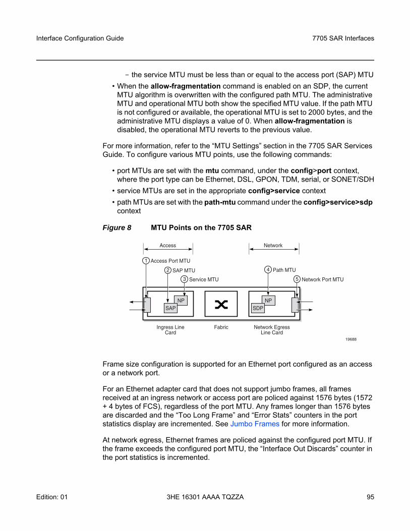
Interface Configuration Guide 7705 SAR Interfaces
Edition: 01 3HE 16301 AAAA TQZZA 95
- the service MTU must be less than or equal to the access port (SAP) MTU• When the allow-fragmentation command is enabled on an SDP, the current
MTU algorithm is overwritten with the configured path MTU. The administrative MTU and operational MTU both show the specified MTU value. If the path MTU is not configured or available, the operational MTU is set to 2000 bytes, and the administrative MTU displays a value of 0. When allow-fragmentation is disabled, the operational MTU reverts to the previous value.
For more information, refer to the “MTU Settings” section in the 7705 SAR Services Guide. To configure various MTU points, use the following commands:
• port MTUs are set with the mtu command, under the config>port context, where the port type can be Ethernet, DSL, GPON, TDM, serial, or SONET/SDH
• service MTUs are set in the appropriate config>service context • path MTUs are set with the path-mtu command under the config>service>sdp
context
Figure 8 MTU Points on the 7705 SAR
Frame size configuration is supported for an Ethernet port configured as an access or a network port.
For an Ethernet adapter card that does not support jumbo frames, all frames received at an ingress network or access port are policed against 1576 bytes (1572 + 4 bytes of FCS), regardless of the port MTU. Any frames longer than 1576 bytes are discarded and the “Too Long Frame” and “Error Stats” counters in the port statistics display are incremented. See Jumbo Frames for more information.
At network egress, Ethernet frames are policed against the configured port MTU. If the frame exceeds the configured port MTU, the “Interface Out Discards” counter in the port statistics is incremented.
19688
NPSAP
NPSDP
Access Port MTU
SAP MTU
Service MTU3 Network Port MTU5
Path MTU4
1
2
Ingress LineCard
Network EgressLine Card
Fabric
Access Network
7705 SAR Interfaces
96
Interface Configuration Guide
3HE 16301 AAAA TQZZA Edition: 01
When the network group encryption (NGE) feature is used, additional bytes due to NGE packet overhead must be considered. Refer to the “NGE Packet Overhead and MTU Considerations” section in the 7705 SAR Services Guide for more information.
3.2.12.2 IP Fragmentation
IP fragmentation is used to fragment a packet that is larger than the MTU of the egress interface, so that the packet can be transported over that interface.
For IPv4, the router fragments or discards the IP packets based on whether the DF (Do not fragment) bit is set in the IP header. If the packet that exceeds the MTU cannot be fragmented, the packet is discarded and an ICMP message “Fragmentation Needed and Don’t Fragment was Set” is sent back to the source IP address.
For IPv6, the router cannot fragment the packet so must discard it. An ICMP message “Packet too big” is sent back to the source node.
As a source of self-generated traffic, the 7705 SAR can perform packet fragmentation.
Fragmentation can be enabled for GRE tunnels. Refer to the “GRE Fragmentation” section in the 7705 SAR Services Guide for more information.
3.2.12.3 Jumbo Frames
Jumbo frames are supported on Ethernet ports except on the 8-port Ethernet Adapter card (version 1).
The maximum MTU size for a jumbo frame on the 7705 SAR is 9732 bytes. The maximum MTU for a jumbo frame may vary depending on the Ethernet encapsulation type, as shown in Table 11. The calculations of the other MTU values (service MTU, path MTU, and so on) are based on the port MTU. The values in Table 11 are also maximum receive unit (MRU) values. MTU values are user-configured values. MRU values are the maximum MTU value that a user can configure on an adapter card that supports jumbo frames.
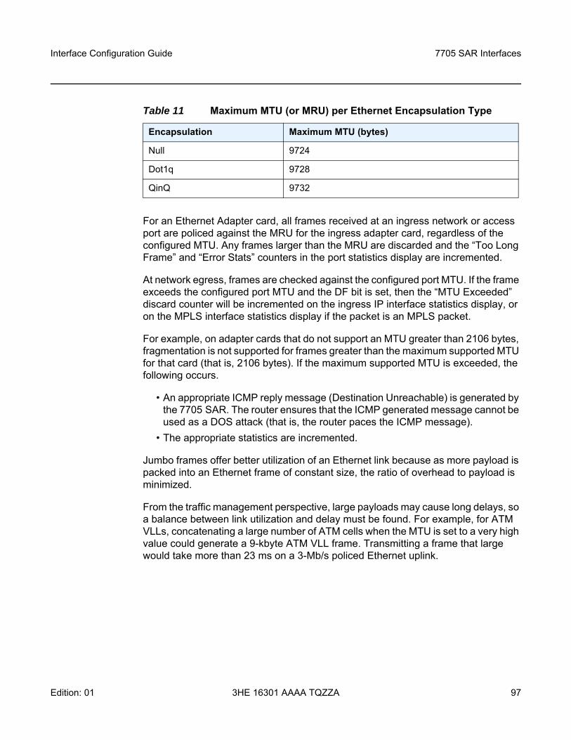
Interface Configuration Guide 7705 SAR Interfaces
Edition: 01 3HE 16301 AAAA TQZZA 97
For an Ethernet Adapter card, all frames received at an ingress network or access port are policed against the MRU for the ingress adapter card, regardless of the configured MTU. Any frames larger than the MRU are discarded and the “Too Long Frame” and “Error Stats” counters in the port statistics display are incremented.
At network egress, frames are checked against the configured port MTU. If the frame exceeds the configured port MTU and the DF bit is set, then the “MTU Exceeded” discard counter will be incremented on the ingress IP interface statistics display, or on the MPLS interface statistics display if the packet is an MPLS packet.
For example, on adapter cards that do not support an MTU greater than 2106 bytes, fragmentation is not supported for frames greater than the maximum supported MTU for that card (that is, 2106 bytes). If the maximum supported MTU is exceeded, the following occurs.
• An appropriate ICMP reply message (Destination Unreachable) is generated by the 7705 SAR. The router ensures that the ICMP generated message cannot be used as a DOS attack (that is, the router paces the ICMP message).
• The appropriate statistics are incremented.
Jumbo frames offer better utilization of an Ethernet link because as more payload is packed into an Ethernet frame of constant size, the ratio of overhead to payload is minimized.
From the traffic management perspective, large payloads may cause long delays, so a balance between link utilization and delay must be found. For example, for ATM VLLs, concatenating a large number of ATM cells when the MTU is set to a very high value could generate a 9-kbyte ATM VLL frame. Transmitting a frame that large would take more than 23 ms on a 3-Mb/s policed Ethernet uplink.
Table 11 Maximum MTU (or MRU) per Ethernet Encapsulation Type
Encapsulation Maximum MTU (bytes)
Null 9724
Dot1q 9728
QinQ 9732
7705 SAR Interfaces
98
Interface Configuration Guide
3HE 16301 AAAA TQZZA Edition: 01
3.2.12.3.1 Behavior of Adapter Cards Not Supporting Jumbo Frames on 7705 SAR-8 and 7705 SAR-18 only
The 7705 SAR-8 (with CSMv2) and the 7705 SAR-18 do not support ingress fragmentation, and this is true for jumbo frames. Therefore, any jumbo frame packet arriving on one of these routers that gets routed to an adapter card that does not support jumbo frame MTU (for example, a 16-port T1/E1 ASAP Adapter card or a 4-port OC3/STM1 / 1-port OC12/STM4 Adapter card) is discarded if the packet size is greater than the TDM port’s maximum supported MTU. If the maximum-supported MTU is exceeded, the following occurs.
• An appropriate ICMP reply message (Destination Unreachable) is generated by the 7705 SAR. The router ensures that the ICMP-generated message cannot be used as a DOS attack (that is, the router paces the ICMP message).
• The port statistics show IP or MPLS Interface MTU discards, for IP or MPLS traffic, respectively. MTU Exceeded Packets and Bytes counters exist separately for IPv4/6 and MPLS under the IP interface hierarchy for all discarded packets where ICMP Error messages are not generated.
For example, if a packet arrives on an 8-port Gigabit Ethernet Adapter card and is to be forwarded to a 16-port T1/E1 ASAP Adapter card with a maximum port MTU of 2090 bytes and a channel group configured for PPP with the port MTU of 1000 bytes, the following may occur.
• If the arriving packet is 800 bytes, then forward the packet. • If the arriving packet is 1400 bytes, then forward the packet, which will be
fragmented by the egress adapter card.• If the arriving packet is fragmented and the fragments are 800 bytes, then
forward the packet.• If the arriving packet is 2500 bytes, then send an ICMP error message (because
the egress adapter card has a maximum port MTU of 2090 bytes).• If the arriving packet is fragmented and the fragment size is 2500 bytes, then
there is an ICMP error.
3.2.12.3.2 Jumbo Frame Behavior on the Fixed Platforms
The 7705 SAR-A, 7705 SAR-Ax, 7705 SAR-H, 7705 SAR-Hc, 7705 SAR-M, 7705 SAR-W, 7705 SAR-Wx, and 7705 SAR-X are able to fragment packets between Ethernet ports (which support jumbo frames) and TDM ports (which do not support jumbo frames). In this case, when a packet arrives from a port that supports jumbo frames and is routed to a port that does not support jumbo frames (that is, a TDM port) the packet will get fragmented to the port MTU of the TDM port.
Interface Configuration Guide 7705 SAR Interfaces
Edition: 01 3HE 16301 AAAA TQZZA 99
For example, if a packet arrives on a 7705 SAR-A and is to be forwarded to a TDM port that has a maximum port MTU of 2090 bytes and a channel group configured for PPP with the port MTU of 1000 bytes (PPP port MTU), the following may occur.
• If the arriving packet is 800 bytes, then forward the packet.• If the arriving packet is 1400 bytes and the DF bit is 0, then forward the packet,
which will be fragmented to the PPP port MTU size.• If the arriving packet is 2500 bytes and the DF bit is 0, then forward the packet,
which will be fragmented to the PPP port MTU size.
3.2.12.3.3 Multicast Support for Jumbo Frames
Jumbo frames are supported in a multicast configuration as long as all adapter cards in the multicast group support jumbo frames. If an adapter card that does not support jumbo frames is present in the multicast group, the replicated multicast jumbo frame packet will be discarded by the fabric because of an MRU error of the fabric port (Rx).
The multicast group replicates the jumbo frame for all adapter cards, regardless of whether they support jumbo frames, only when forwarding the packet through the fabric. The replicated jumbo frame packet is discarded on adapter cards that do not support jumbo frames.
3.2.12.3.4 PMC Jumbo Frame Support
For the Packet Microwave Adapter card (PMC), ensure that the microwave hardware installed with the card supports the corresponding jumbo frame MTU. If the microwave hardware does not support the jumbo frame MTU, it is recommended that the MTU of the PMC port be set to the maximum frame size that is supported by the microwave hardware.
3.2.12.4 Default Port MTU Values
Table 12 displays the default and maximum port MTU values that are dependent upon the port type, mode, and encapsulation type.
Note: The 7705 SAR now supports a lower IP MTU value of 128 bytes (from the original 512-byte minimum). The IP MTU is derived from the port MTU configuration for network ports. This lower IP MTU is supported only on Ethernet encapsulated ports. Refer to the 7705 SAR Services Guide, “Bandwidth Optimization for Low-speed Links” for information.
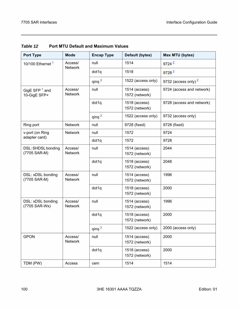
7705 SAR Interfaces
100
Interface Configuration Guide
3HE 16301 AAAA TQZZA Edition: 01
Table 12 Port MTU Default and Maximum Values
Port Type Mode Encap Type Default (bytes) Max MTU (bytes)
10/100 Ethernet 1 Access/ Network
null 1514 9724 2
dot1q 1518 9728 2
qinq 3 1522 (access only) 9732 (access only) 2
GigE SFP 1 and 10-GigE SFP+
Access/ Network
null 1514 (access)1572 (network)
9724 (access and network)
dot1q 1518 (access)1572 (network)
9728 (access and network)
qinq 3 1522 (access only) 9732 (access only)
Ring port Network null 9728 (fixed) 9728 (fixed)
v-port (on Ring adapter card)
Network null 1572 9724
dot1q 1572 9728
DSL: SHDSL bonding (7705 SAR-M)
Access/ Network
null 1514 (access)1572 (network)
2044
dot1q 1518 (access)1572 (network)
2048
DSL: xDSL bonding (7705 SAR-M)
Access/ Network
null 1514 (access)1572 (network)
1996
dot1q 1518 (access)1572 (network)
2000
DSL: xDSL bonding (7705 SAR-Wx)
Access/ Network
null 1514 (access)1572 (network)
1996
dot1q 1518 (access)1572 (network)
2000
qinq 3 1522 (access only) 2000 (access only)
GPON Access/ Network
null 1514 (access)1572 (network)
2000
dot1q 1518 (access)1572 (network)
2000
TDM (PW) Access cem 1514 1514
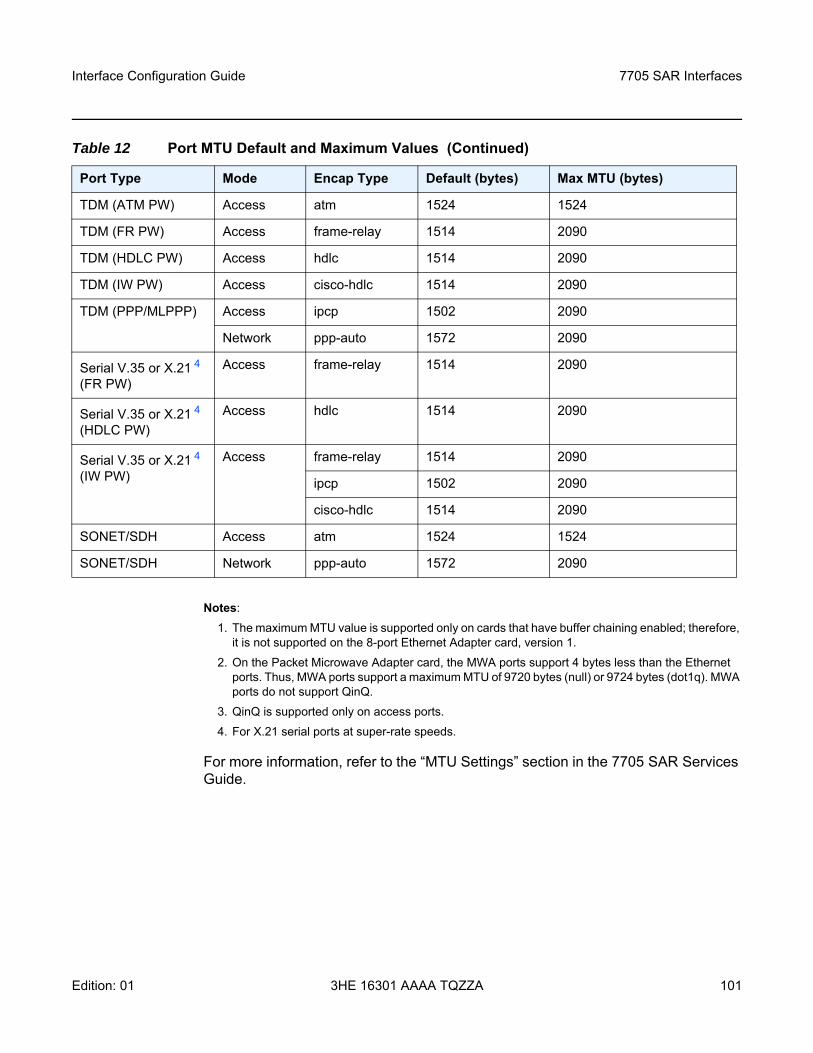
Interface Configuration Guide 7705 SAR Interfaces
Edition: 01 3HE 16301 AAAA TQZZA 101
Notes:1. The maximum MTU value is supported only on cards that have buffer chaining enabled; therefore,
it is not supported on the 8-port Ethernet Adapter card, version 1.2. On the Packet Microwave Adapter card, the MWA ports support 4 bytes less than the Ethernet
ports. Thus, MWA ports support a maximum MTU of 9720 bytes (null) or 9724 bytes (dot1q). MWA ports do not support QinQ.
3. QinQ is supported only on access ports.4. For X.21 serial ports at super-rate speeds.
For more information, refer to the “MTU Settings” section in the 7705 SAR Services Guide.
TDM (ATM PW) Access atm 1524 1524
TDM (FR PW) Access frame-relay 1514 2090
TDM (HDLC PW) Access hdlc 1514 2090
TDM (IW PW) Access cisco-hdlc 1514 2090
TDM (PPP/MLPPP) Access ipcp 1502 2090
Network ppp-auto 1572 2090
Serial V.35 or X.21 4 (FR PW)
Access frame-relay 1514 2090
Serial V.35 or X.21 4 (HDLC PW)
Access hdlc 1514 2090
Serial V.35 or X.21 4 (IW PW)
Access frame-relay 1514 2090
ipcp 1502 2090
cisco-hdlc 1514 2090
SONET/SDH Access atm 1524 1524
SONET/SDH Network ppp-auto 1572 2090
Table 12 Port MTU Default and Maximum Values (Continued)
Port Type Mode Encap Type Default (bytes) Max MTU (bytes)
7705 SAR Interfaces
102
Interface Configuration Guide
3HE 16301 AAAA TQZZA Edition: 01
3.2.13 LAG
This section contains information on the following topics:
• LAG Overview• LACP and Active/Standby Operation• QoS Adaptation for LAG on Access• QoS for LAG on Network• Access Ingress Fabric Shaping• Hold-down Timers• Multi-Chassis LAG• Static LAG (Active/Standby LAG Operation without LACP)• LAG Support on Mixed-Generation Hardware
3.2.13.1 LAG Overview
The 7705 SAR supports Link Aggregation Groups (LAGs) based on the IEEE 802.1ax standard (formerly 802.3ad). Link aggregation provides:
• increased bandwidth by combining multiple links into one logical link (in active/active mode)
• load sharing by distributing traffic across multiple links (in active/active mode)• redundancy and increased resiliency between devices by having a standby link
to act as backup if the active link fails (in active/standby mode)
In the 7705 SAR implementation, all links must operate at the same speed.
Packet sequencing must be maintained for any given session. The hashing algorithm deployed by Nokia routers is based on the type of traffic transported to ensure that all traffic in a flow remains in sequence while providing effective load sharing across the links in the LAG. See LAG and ECMP Hashing for more information.
LAGs must be statically configured or formed dynamically with Link Aggregation Control Protocol (LACP). See LACP and Active/Standby Operation for information on LACP.
All Ethernet-based supported services can benefit from LAG, including:
• network interfaces and SDPs• spoke SDPs, mesh SDPs, and EVPN endpoints
Interface Configuration Guide 7705 SAR Interfaces
Edition: 01 3HE 16301 AAAA TQZZA 103
• IES and VPRN interfaces and SAPs• Ethernet and IP pseudowire SAPs• routed VPLS (r-VPLS) SAPs
LAGs are supported on access, network, and hybrid ports. A LAG can be in active/active mode or in active/standby mode for access, network, or hybrid ports. Active/standby mode is a subset of active/active mode if subgroups are enabled.
LAGs are supported on access ports on the following:
• 8-port Ethernet Adapter card, version 2• 8-port Gigabit Ethernet Adapter card• 10-port 1GigE/1-port 10GigE X-Adapter card (10-port GigE mode)• 6-port Ethernet 10Gbps Adapter card• 4-port SAR-H Fast Ethernet module• 6-port SAR-M Ethernet module• Packet Microwave Adapter card (for ports not in a microwave link)• all fixed platforms
LAGs are supported on network ports on the following:
• 8-port Ethernet Adapter card, version 2• 8-port Gigabit Ethernet Adapter card• 10-port 1GigE/1-port 10GigE X-Adapter card• 6-port Ethernet 10Gbps Adapter card• 4-port SAR-H Fast Ethernet module• 6-port SAR-M Ethernet module• Packet Microwave Adapter card (for ports not in a microwave link and ports in a
1+0 network microwave link; LAGs are not supported on ports in a 1+1 HSB microwave link)
• all fixed platforms
LAGs are supported on hybrid ports on the following:
• 8-port Gigabit Ethernet Adapter card• 10-port 1GigE/1-port 10GigE X-Adapter card (10-port GigE mode)• 6-port Ethernet 10Gbps Adapter card• 6-port SAR-M Ethernet module• Packet Microwave Adapter card (for ports not in a microwave link)• all fixed platforms
7705 SAR Interfaces
104
Interface Configuration Guide
3HE 16301 AAAA TQZZA Edition: 01
On access ports, a LAG supports active/active and active/standby operation. For active/standby operation the links must be in different subgroups. Links can be on the same platform or adapter card/module or distributed over multiple components. Load sharing is supported among the active links in a LAG group.
On network ports, a LAG supports active/active and active/standby operation. For active/standby operation the links must be in different subgroups. Links can be on the same platform or adapter card/module or distributed over multiple components. Load sharing is supported among the active links in a LAG group. Any tunnel type (for example, IP, GRE, or MPLS) transporting any service type, any IP traffic, or any labeled traffic (LER, LSR) can use the LAG load-sharing, active/active, and active/standby functionality.
LAGs are supported on network 1+0 microwave links. Ports that are in a microwave link can be added to the same LAG as ports that are not in a microwave link. Ports belonging to a microwave link must have limited autonegotiation enabled before the link can be added to a LAG.
A LAG that contains ports in a microwave link must have LACP enabled for active/standby operation. Static LAG configuration (without LACP) is not supported for active/standby LAGs with microwave-enabled ports.
On hybrid ports, a LAG supports active/active and active/standby operation. For active/standby operation the links must be in different subgroups. Links can be on the same platform or adapter card/module or distributed over multiple components. Load sharing is supported among the active links in a LAG group.
A LAG group with assigned members can be converted from one mode to another as long as the number of member ports are supported in the new mode and the ports all support the new mode, none of the members belong to a microwave link, and the LAG group is not associated with a network interface or a SAP.
A subgroup is a group of links within a LAG. On access, network, or hybrid ports, a LAG can have a maximum of four subgroups and a subgroup can have links up to the maximum number supported on the LAG. The LAG is active/active if there is only one sub-group and is active/standby if there is more than one subgroup.
When configuring a LAG, most port features (port commands) can only be configured on the primary member port. The configuration, or any change to the configuration, is automatically propagated to any remaining ports within the same LAG. Operators cannot modify the configurations on non-primary ports. For more information, see Configuring LAG Parameters.
Note: For details on LAG scale per platform or adapter card, contact your Nokia Technical support representative.
Interface Configuration Guide 7705 SAR Interfaces
Edition: 01 3HE 16301 AAAA TQZZA 105
If the LAG has one member link on a first- or second-generation (Gen-1 or Gen-2) Ethernet adapter card, and the other link on a third-generation (Gen-3) Ethernet adapter card or platform, a mix-and-match scenario exists for traffic management on the LAG SAP. In this case, all QoS parameters for the LAG SAP are configured but only those parameters applicable to the active member link are used. See LAG Support on Mixed-Generation Hardware for more information.
Configuring a multiservice site (MSS) aggregate rate can restrict the use of LAG SAPs. For more information, refer to the “MSS and LAG Interaction on the 7705 SAR-8 and 7705 SAR-18” section in the 7705 SAR Quality of Service Guide.
3.2.13.2 LACP and Active/Standby Operation
On access, network, and hybrid ports, where multiple links in a LAG can be active at the same time, normal operation is that all non-failing links are active and traffic is load-balanced across all the active links. In some cases, however, it is desirable to have only some of the links active and the other links kept in standby mode. The Link Aggregation Control Protocol (LACP) is used to make the selection of the active links in a LAG predictable and compatible with any vendor equipment. The mechanism is based on the IEEE 802.1ax standard so that interoperability is ensured.
LACP is disabled by default and therefore must be enabled on the LAG if required. LACP can be used in either active mode or passive mode. The mode must match with connected CE devices for proper operation. For example, if the LAG on the 7705 SAR end is configured to be active, the CE end must be passive.
Figure 9 shows the interconnection between a DSLAM and a LAG aggregation node. In this configuration, LAG is used to protect against hardware failure. If the active link goes down, the link on standby takes over (see Figure 10). The links are distributed across two different adapter cards to eliminate a single point of failure.
Note: LACP cannot be configured for static LAG. For more information on static LAG, see Static LAG (Active/Standby LAG Operation without LACP).
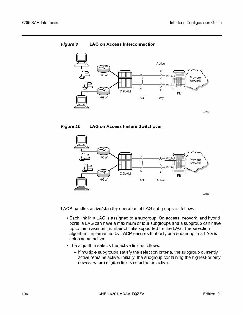
7705 SAR Interfaces
106
Interface Configuration Guide
3HE 16301 AAAA TQZZA Edition: 01
Figure 9 LAG on Access Interconnection
Figure 10 LAG on Access Failure Switchover
LACP handles active/standby operation of LAG subgroups as follows.
• Each link in a LAG is assigned to a subgroup. On access, network, and hybrid ports, a LAG can have a maximum of four subgroups and a subgroup can have up to the maximum number of links supported for the LAG. The selection algorithm implemented by LACP ensures that only one subgroup in a LAG is selected as active.
• The algorithm selects the active link as follows.- If multiple subgroups satisfy the selection criteria, the subgroup currently
active remains active. Initially, the subgroup containing the highest-priority (lowest value) eligible link is selected as active.
Providernetwork
22319
HGW
Stby
Active
LAG
PEDSLAM
MDA-B
MDA-A
HGW
Providernetwork
22320
HGW
ActiveLAG
PEDSLAM
MDA-B
MDA-A
HGW
X
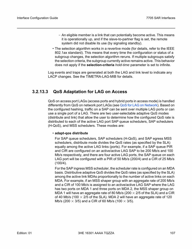
Interface Configuration Guide 7705 SAR Interfaces
Edition: 01 3HE 16301 AAAA TQZZA 107
- An eligible member is a link that can potentially become active. This means it is operationally up, and if the slave-to-partner flag is set, the remote system did not disable its use (by signaling standby).
• The selection algorithm works in a revertive mode (for details, refer to the IEEE 802.1ax standard). This means that every time the configuration or status of a subgroup changes, the selection algorithm reruns. If multiple subgroups satisfy the selection criteria, the subgroup currently active remains active. This behavior does not apply if the selection-criteria hold-time parameter is set to infinite.
Log events and traps are generated at both the LAG and link level to indicate any LACP changes. See the TIMETRA-LAG-MIB for details.
3.2.13.3 QoS Adaptation for LAG on Access
QoS on access port LAGs (access ports and hybrid ports in access mode) is handled differently from QoS on network port LAGs (see QoS for LAG on Network). Based on the configured hashing, traffic on a SAP can be sent over multiple LAG ports or can use a single port of a LAG. There are two user-selectable adaptive QoS modes (distribute and link) that allow the user to determine how the configured QoS rate is distributed to each of the active LAG port SAP queue schedulers, SAP schedulers (H-QoS), and MSS schedulers. These modes are:
• adapt-qos distribute For SAP queue schedulers, SAP schedulers (H-QoS), and SAP egress MSS schedulers, distribute mode divides the QoS rates (as specified by the SLA) equally among the active LAG links (ports). For example, if a SAP queue PIR and CIR are configured on an active/active LAG SAP to be 200 Mb/s and 100 Mb/s respectively, and there are four active LAG ports, the SAP queue on each LAG port will be configured with a PIR of 50 Mb/s (200/4) and a CIR of 25 Mb/s (100/4).For the SAP ingress MSS scheduler, the scheduler rate is configured on an MDA basis. Distributive adaptive QoS divides the QoS rates (as specified by the SLA) among the active link MDAs proportionally to the number of active links on each MDA. For example, if an MSS shaper group with an aggregate rate of 200 Mb/s and a CIR of 100 Mb/s is assigned to an active/active LAG SAP where the LAG has two ports on MDA 1 and three ports on MDA 2, the MSS shaper group on MDA 1 will have an aggregate rate of 80 Mb/s (200 × 2/5 of the SLA) and a CIR of 40 Mb/s (100 × 2/5 of the SLA). MDA 2 will have an aggregate rate of 120 Mb/s (200 × 3/5) and a CIR of 60 Mb/s (100 × 3/5).
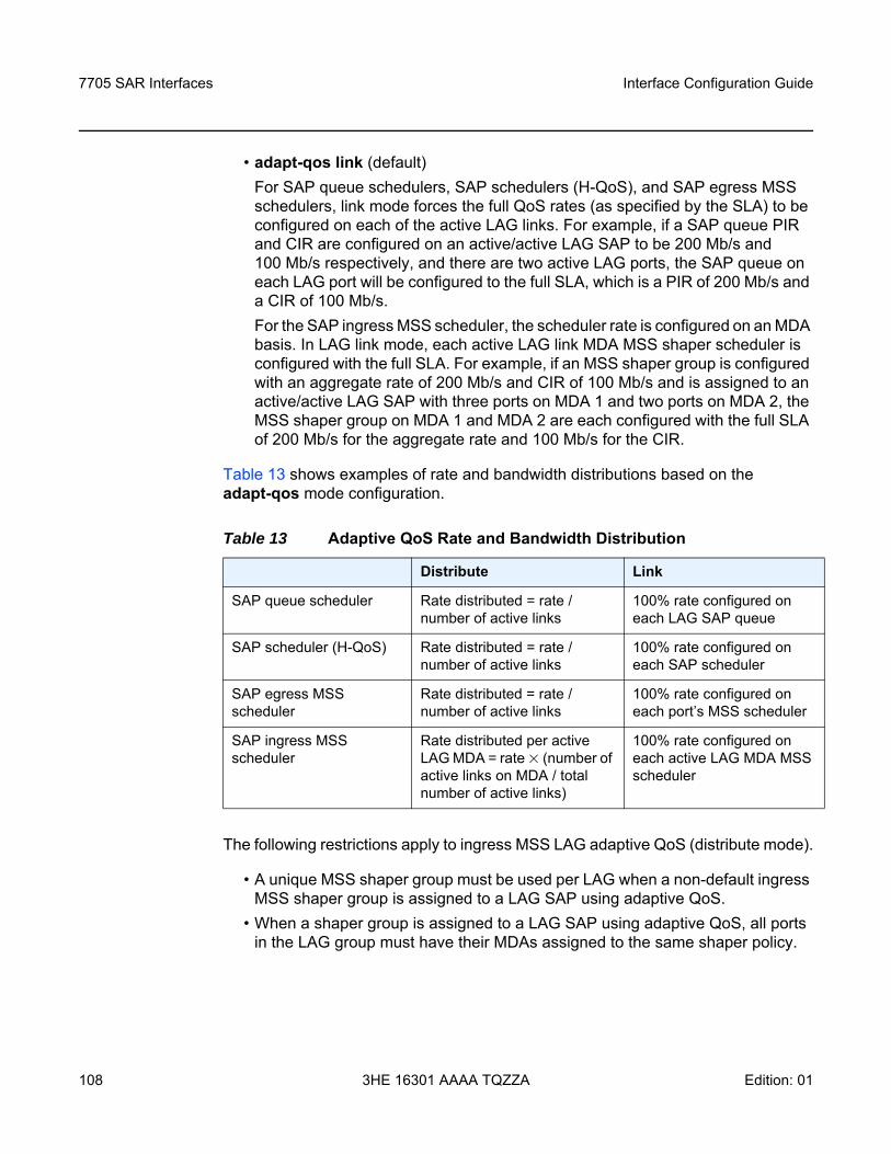
7705 SAR Interfaces
108
Interface Configuration Guide
3HE 16301 AAAA TQZZA Edition: 01
• adapt-qos link (default)For SAP queue schedulers, SAP schedulers (H-QoS), and SAP egress MSS schedulers, link mode forces the full QoS rates (as specified by the SLA) to be configured on each of the active LAG links. For example, if a SAP queue PIR and CIR are configured on an active/active LAG SAP to be 200 Mb/s and 100 Mb/s respectively, and there are two active LAG ports, the SAP queue on each LAG port will be configured to the full SLA, which is a PIR of 200 Mb/s and a CIR of 100 Mb/s. For the SAP ingress MSS scheduler, the scheduler rate is configured on an MDA basis. In LAG link mode, each active LAG link MDA MSS shaper scheduler is configured with the full SLA. For example, if an MSS shaper group is configured with an aggregate rate of 200 Mb/s and CIR of 100 Mb/s and is assigned to an active/active LAG SAP with three ports on MDA 1 and two ports on MDA 2, the MSS shaper group on MDA 1 and MDA 2 are each configured with the full SLA of 200 Mb/s for the aggregate rate and 100 Mb/s for the CIR.
Table 13 shows examples of rate and bandwidth distributions based on the adapt-qos mode configuration.
The following restrictions apply to ingress MSS LAG adaptive QoS (distribute mode).
• A unique MSS shaper group must be used per LAG when a non-default ingress MSS shaper group is assigned to a LAG SAP using adaptive QoS.
• When a shaper group is assigned to a LAG SAP using adaptive QoS, all ports in the LAG group must have their MDAs assigned to the same shaper policy.
Table 13 Adaptive QoS Rate and Bandwidth Distribution
Distribute Link
SAP queue scheduler Rate distributed = rate / number of active links
100% rate configured on each LAG SAP queue
SAP scheduler (H-QoS) Rate distributed = rate / number of active links
100% rate configured on each SAP scheduler
SAP egress MSS scheduler
Rate distributed = rate / number of active links
100% rate configured on each port’s MSS scheduler
SAP ingress MSS scheduler
Rate distributed per active LAG MDA = rate × (number of active links on MDA / total number of active links)
100% rate configured on each active LAG MDA MSS scheduler
Interface Configuration Guide 7705 SAR Interfaces
Edition: 01 3HE 16301 AAAA TQZZA 109
The following restrictions apply to egress MSS LAG.
• The shaper policy for all LAG ports in a LAG must be the same and can only be configured on the primary LAG port member.
The following limitations apply to adaptive QoS (distribute mode).
• The QoS rates for an ingress LAG using adaptive QoS are only distributed among the active links when a non-default shaper group is used. If a default shaper group is used, the full QoS rates are configured for each port in the LAG as if link mode is being used.
• The QoS rates for an ingress or egress LAG using adaptive QoS will not be distributed among the active links when a user sets the PIR/CIR on a SAP queue, or aggregate rate/CIR on a SAP scheduler or MSS scheduler, to the default values (max and 0).
• A port on an 8-port Ethernet Adapter card, version 2, can be added to a LAG group but does not support H-QoS or MSS. If distributed mode is applied to a LAG SAP with a port on an 8-port Ethernet Adapter card, version 2, the H-QoS and MSS bandwidth distribution is determined based on all active links including the 8-port Ethernet Adapter card, version 2 port. However, the H-QoS or MSS bandwidth share for this port cannot be configured. Ports on other adapter cards, modules, or platforms will have their H-QoS or MSS bandwidth share configured.
3.2.13.3.1 Adaptive QoS Examples (Distribute Mode)
The following examples can be used as guidelines for configuring adapt-qos distribute.
SLA distribution for SAP queue-level PIR/CIR configuration
• Configure a qos sap-ingress policy with a queue ID of 2, a PIR of 200 Mb/s, and a CIR of 100 Mb/s. Assign it to an active/active LAG SAP with five active ports.
• For each port, the PIR/CIR configuration of SAP queue 2 is calculated so thatthe PIR = 40 Mb/s and CIR = 20 Mb/s.
• If one link goes down, the PIR/CIR configuration of SAP queue 2 on each active port is recalculated so that the PIR = 50 Mb/s and CIR = 25 Mb/s.
SLA distribution for ingress/egress (H-QoS)
• Create a LAG SAP with two different ports (for example, port 1/1/1 and port 1/1/2) in a LAG subgroup.
7705 SAR Interfaces
110
Interface Configuration Guide
3HE 16301 AAAA TQZZA Edition: 01
• Configure a LAG SAP aggregate rate of 200 Mb/s and a CIR of 100 Mb/s.• To maintain the SLA, the SAP aggregate rate and CIR must be divided by the
number of operational links in the LAG group.• Because there are two active ports (links) in this LAG, the H-QoS aggregate rate
and CIR are divided evenly between the two ports.• The port 1/1/1 SAP scheduler (H-QoS) aggregate rate is 100 Mb/s and the CIR
is 50 Mb/s.• The port 1/1/2 SAP scheduler (H-QoS) aggregate rate is 100 Mb/s and the CIR
is 50 Mb/s.
SLA distribution for Ingress MSS
• Configure a shaper group with an ID of 2 with an aggregate rate of 200 Mb/s and a CIR of 100 Mb/s.
• Create a LAG SAP using shaper group 2 that has two ports from one MDA (for example, ports 1/1/1 and 1/1/2) and three ports from a different MDA (for example, ports 1/2/1, 1/2/2, and 1/2/3) in its LAG group.
• The ingress MSS scheduler rate is configured on an MDA basis. Adaptive QoS divides the QoS rates among the active link MDAs, proportionally to the number of active links on each MDA.
• For MDA 1, the MSS shaper group aggregate rate is 80 Mb/s and the CIR is 40 Mb/s (2/5 of the bandwidth with two active links on MDA 1).
• For MDA 2, the MSS shaper group aggregate rate is 120 Mb/s and the CIR is 60 Mb/s (3/5 of the bandwidth with three active links on MDA 2).
3.2.13.4 QoS for LAG on Network
QoS on network port LAGs is handled differently from QoS on access port LAGs. The adapt-qos command is not supported on network port LAGs. However, QoS behavior on network port LAGs is similar to QoS on access port LAGs configured for adapt-qos link mode.
For network queue and per-VLAN shapers, the full QoS rates are configured on each of the active LAG links. For example, if a per-VLAN shaper agg-rate-limit aggregate rate (PIR) and CIR are configured on an active/active LAG interface to be 200 Mb/s and100 Mb/s respectively, and there are two active LAG ports, the per-VLAN shaper on each LAG port will be configured to an aggregate rate of 200 Mb/s and a CIR of 100 Mb/s.
Interface Configuration Guide 7705 SAR Interfaces
Edition: 01 3HE 16301 AAAA TQZZA 111
3.2.13.5 Access Ingress Fabric Shaping
In order to avoid traffic congestion and ease the effects of possible bursts, a fabric shaper is implemented on each adapter card. Traffic being switched to a LAG SAP on an access interface goes through fabric shapers that are either in aggregate mode or destination mode. When in destination mode, the multipoint shaper is used to set the rate on all adapter cards. For more information on the modes used in fabric shaping, refer to the 7705 SAR Quality of Service Guide, “Configurable Ingress Shaping to Fabric (Access and Network)”.
3.2.13.6 Hold-down Timers
Hold-down timers control how quickly a LAG responds to operational port state changes. The following timers are supported:
• port-level hold-time (up/down) timerThis timer controls the delay before a port is added to or removed from a LAG when the port comes up or goes down. Each port in the LAG has the same timer value, which is configured on the primary LAG link (port). The timer is set with the config>port>ethernet>hold-time command.
• subgroup-level hold-down timerThis timer controls the delay before a switch from the current subgroup to a new candidate subgroup, selected by the LAG subgroup selection algorithm. The timer is set with the config>lag>selection-criteria command. The timer can be configured to never expire, which prevents a switch from an operationally up subgroup to a new candidate subgroup. This setting can be manually overridden by using the tools>perform>force>lag-id command (refer to the 7705 SAR OAM and Diagnostics Guide, “Tools Command Reference”, for information on this command).If the port-level timer is set, it must expire before the subgroup selection occurs and this timer is started. The subgroup-level timer is supported only for LAGs running LACP.
Note: Even though the multipoint shaper is used to set the fabric shaping rate for traffic switched to a LAG SAP, it is the per-destination unicast counters that are incremented to show the fabric statistics rather than the multipoint counter. Only the fabric statistics of the active port of the LAG are incremented, not the standby port.
7705 SAR Interfaces
112
Interface Configuration Guide
3HE 16301 AAAA TQZZA Edition: 01
• LAG-level hold-down timerThis timer controls the delay before a LAG is declared operationally down when the available links fall below the required port or bandwidth minimum. This timer is recommended for MC-LAG operation. The timer prevents a LAG from being brought down when an MC-LAG switchover executes a make-before-break switch. The LAG-level timer is set with the config>lag>hold-time down command.If the port-level timer is set, it must expire before the LAG operational status is processed and this timer is started.
3.2.13.7 Multi-Chassis LAG
Multi-chassis LAG (MC-LAG) is a redundancy feature on the 7705 SAR, useful for nodes that are taken out of service for maintenance, upgrades, or relocation. MC-LAG also provides redundancy for incidents of peer nodal failure. Refer to the “Multi-Chassis LAG Redundancy” section in the 7705 SAR Basic System Configuration Guide.
3.2.13.8 Static LAG (Active/Standby LAG Operation without LACP)
Some Layer 2 capable network equipment devices support LAG protected links in an active/standby mode but without LACP. This is commonly referred to as static LAG. In order to interwork with these products, the 7705 SAR supports configuring LAG without LACP.
LACP provides a standard means of communicating health and status information between LAG peers. If LACP is not used, the peers must be initially configured in a way that ensures that the ports on each end are connected and communicating. Otherwise, LAG will not be active. Which LAG peer is made active is a local decision. If the port priority settings are the same for all ports, it is possible that the two ends will select ports on different physical links and LAG will not be active. Decide the primary link by setting the port priority for the LAG on each peer to ensure that the active ports on each end coincide with the same physical link.
Interface Configuration Guide 7705 SAR Interfaces
Edition: 01 3HE 16301 AAAA TQZZA 113
The key parameters for configuring static LAG are selection-criteria (set to best-port) and standby-signaling (set to power-off). The selection criteria is used to determine which selection algorithm decides the primary port (the active port in a no-fault condition). It is always the subgroup with the best-port (the highest-priority port - lowest configured value) that is chosen as the active subgroup. The selection criteria must be set to best-port before standby signaling can be placed in power-off mode. Once the selection criteria is set to best-port, setting the standby-signaling parameter to power-off causes the transmitters on the standby ports to be powered down.
After a switchover caused by a failure on the active link, the transmitters on the standby link are powered on. The switch time for static LAG is typically longer than it is with LACP, due to the time it takes for the transmitters to come up and transmission to be established. When the fault is restored, static LAG causes a revertive switch to take place. The revertive switch is of shorter duration than the initial switchover since the system is able to prepare the other side for the switch and initiate the switchover once it is ready.
3.2.13.9 LAG Support on Mixed-Generation Hardware
This section contains information on the following topics:
• LAG Configuration at SAP Level• LAG Configuration at Port Level
3.2.13.9.1 LAG Configuration at SAP Level
The 6-port Ethernet 10Gbps Adapter card and the 7705 SAR-X are third-generation (Gen-3) hardware components. All other Ethernet cards are second-generation (Gen-2) adapter cards, except the 8-port Ethernet Adapter card, which is a first-generation (Gen-1) adapter card. See Table 2 for a list of first-, second-, and third-generation Ethernet adapter cards, ports, and platforms.
Note: Since the transmitters on the standby link are off, it is not possible for the LAG to respond to a physical disconnect (fault) on the standby link. This means that it is possible to have a failure on the active link result in a switch to a failed standby link.
7705 SAR Interfaces
114
Interface Configuration Guide
3HE 16301 AAAA TQZZA Edition: 01
The 7705 SAR supports mix-and-match traffic management (TM) across LAG members, where one member is a port on a Gen-3 adapter card or platform and the other member is a port on either a Gen-2 or Gen-1 adapter card or platform. Mix-and-match LAG does not apply to the 7705 SAR-X because it has only Gen-3 Ethernet ports.
For mix-and-match LAG TM scenarios, the 7705 SAR supports a generic QoS configuration, where the operator can configure all the settings available on each generation adapter card, but it is the card responsible for transporting traffic that determines which settings are applicable. That is, only the settings that apply to the active member port are used. The only exception is if there is a Gen-1 adapter card in the mix. In this case scheduling-mode cannot be changed to 16-priority scheduling. Only 4-priority scheduling is applicable.
For example, configuring scheduling-mode applies to Gen-2 adapter card SAPs but does not apply to the Gen-3 adapter card SAPs because Gen-3 cards support only one scheduling mode (4-priority), which is its implicit (default) scheduler mode and is not configurable. In another example, although per-SAP (second-tier) shaper rates can be configured for Gen-2 and Gen-3 cards, they will not be applied to Gen-1 cards.
Since it cannot be known whether SAP traffic rides over a Gen-2 or a Gen-3 adapter card and whether both adapter cards support H-QoS (tier 2, per-SAP shapers), the operator can choose to configure per-SAP aggregate CIR and PIR shaper rates. When the active link is on a Gen-2- or Gen-3-based port, per-SAP aggregate CIR and PIR rates are both used to enforce shaper rates, except when the active link is on a Gen-3-based port and traffic is in the network egress direction. In this case, only the PIR portion of the per-SAP aggregate rate is used to enforce shaper rates.
In the following descriptions of LAG configuration, scheduler-mode, agg-rate, and cir-rate refer to SAP configuration, as shown below for an Epipe SAP. Similar commands exist for SAPs in other services as well as for egress traffic.
config>service>epipe>sap lag-id>ingress#scheduler-mode 4-priority | 16-priorityagg-rate-limit agg-rate [cir cir-rate]
Note:
• The SAP identifier in the previous command has a lag-id (LAG SAP), not a port-id (regular SAP). A LAG SAP references two ports (one active and one standby), but only one port at a time carries traffic.
• The agg-rate is a PIR rate.
Interface Configuration Guide 7705 SAR Interfaces
Edition: 01 3HE 16301 AAAA TQZZA 115
For information on traffic management for Gen-3 adapter cards and platforms, refer to the “QoS for Gen-3 Adapter Cards and Platforms” section in the 7705 SAR Quality of Service Guide.
For mix-and-match LAG configurations, the following behaviors apply.
• The configured aggregate rate on the LAG SAP is used to dictate the per-SAP aggregate rate on the active LAG port, regardless of which generation of adapter card is used (Gen-3 or Gen-2) or the configured scheduler mode. On a Gen-2 adapter card, the aggregate rate only applies when the port is in 16-priority scheduler mode. This behavior implies the following points.- The scheduler mode can be set to 16-priority or 4-priority. When servicing
packets, the Gen-2-based datapath uses the configured scheduler mode (16-priority or 4-priority), while the Gen-3-based datapath always uses 4-priority scheduling.
- When the traffic is transported over a Gen-3-based port (that is, the active link is on a Gen-3-based adapter card), the aggregate rate (agg-rate) is used to enforce a maximum shaper rate, as is the aggregate rate CIR (cir-rate).
- When the active link is on a Gen-2-based adapter card, both aggregate rate CIR and PIR (cir-rate and agg-rate) are used. The aggregate rate (PIR) enforces the per-SAP bandwidth limit, and the CIR is used to identify in-profile and out-of-profile packets for aggregate scheduling purposes.
- When the active link is on a Gen-1-based adapter card, aggregate rate CIR and PIR do not apply.
In addition, the following items describe mix-and-match LAG configuration behavior (that is, how the LAG SAP settings are applied or ignored depending on the active member port).
• For a LAG SAP, scheduler-mode, agg-rate, and cir-rate are all configurable on a per-SAP basis, regardless of the LAG member port combination (that is, both Gen-2 ports, both Gen-3 ports, or a Gen-2-/Gen-3 port mix).
• Scheduler-mode can be set to 4-priority or 16-priority, regardless of the LAG member port combination, except when one member is a port on a Gen-1 adapter card. In this case, only 4-priority scheduling is available.
• Agg-rate and cir-rate can be set whether scheduler-mode is set to 4-priority or 16-priority.
• The configured scheduler-mode applies to Gen-2-based LAG member ports only, and is not used for Gen-3-based LAG member ports. Gen-3 cards always use 4-priority scheduler mode and Gen-1 cards always use 4-priority scheduler mode. The unshaped-sap-cir keyword does not apply to Gen-3 SAPs because Gen-3 SAPs are all shaped SAPs.
7705 SAR Interfaces
116
Interface Configuration Guide
3HE 16301 AAAA TQZZA Edition: 01
• If scheduler-mode is 4-priority on the LAG SAP, where the LAG has one Gen-1-based or Gen-2-based port member and one Gen-3-based port member, the following points apply.- The Gen-1-based or Gen-2-based adapter card is configured with 4-priority
scheduling, while agg-rate and cir-rate are not applied, and H-QoS is not enabled.
- The Gen-3-based adapter card is configured with agg-rate and cir-rate, while scheduler-mode is ignored.
- When LAG active/standby switching occurs from an active Gen-3-based port to an active Gen-1-based or Gen-2-based port, traffic management is changed from a 4-priority scheduler with H-QoS to a 4-priority scheduler without H-QoS that behaves like an unshaped SAP.
- For the reverse case, when LAG active/standby switching occurs from an active Gen-1-based or Gen-2-based port to an active Gen-3-based port, traffic management is changed from a 4-priority scheduler without H-QoS to a 4-priority scheduler with H-QoS.
• If scheduler-mode is 16-priority on the LAG SAP, where the LAG has one Gen-2-based port member and one Gen-3-based port member, the following points apply.- The Gen-2-based adapter card is configured with 16-priority scheduling
mode, agg-rate and cir-rate. This means that H-QoS is enabled.- The Gen-3-based adapter card is configured with agg-rate and cir-rate,
while scheduler-mode is ignored.- When LAG active/standby switching occurs from an active Gen-3-based
port to an active Gen-2-based port, traffic management is changed from a 4-priority scheduler with H-QoS using the agg-rate and cir-rate, to a 16-priority scheduler with H-QoS using the agg-rate and the cir-rate (that is, from 4-priority (Gen-3) mode to 16-priority mode for shaped SAPs).
- For the reverse case, when LAG active/standby switching occurs from an active Gen-2-based port to an active Gen-3-based port, traffic management is changed from a 16-priority scheduler with H-QoS using the agg-rate and the cir-rate, to a 4-priority (Gen-3) scheduler with H-QoS enabled using the agg-rate and the cir-rate.
• If scheduler-mode is 16-priority mode on the LAG SAP, the combination of a Gen-1-based port with a Gen-2-based or Gen-3-based port is blocked because Gen-1 adapter cards do not support 16-priority mode. The only valid option for this combination of ports is 4-priority scheduling mode.
Interface Configuration Guide 7705 SAR Interfaces
Edition: 01 3HE 16301 AAAA TQZZA 117
Lastly, for LAG on access ports, the primary port configuration settings are applied to both the primary and secondary LAG ports. Therefore, in order to support unshaped SAPs when the primary port is a Gen-3-based port and the secondary port is a Gen-2-based port, configuring the unshaped-sap-cir on the Gen-3-based port is allowed, even though it does not apply to the Gen-3-based port. This is because unshaped-sap-cir is needed by the secondary Gen-2-based port when it becomes the active port. The full command is config>port>ethernet>access>egress> unshaped-sap-cir cir-rate.
3.2.13.9.2 LAG Configuration at Port Level
The 7705 SAR allows all configurations on Gen-1, Gen-2, and Gen-3 ports, even if some or all of the configuration is not applicable to all the ports. The software uses only the settings that are applicable to the particular port and ignores those that are not applicable. Any change to the primary LAG member configuration propagates to all non-primary ports.
Table 14 lists the port commands that can be affected by LAG configuration, indicates the command’s applicability to Gen-1, Gen-2, and Gen-3 ports, and describes the LAG behavior for mixed LAG configuration.
Note: For LAG on network ports, the egress-rate, unshaped-if-cir, and network-queue policy can only be configured on the primary LAG port and this configuration is propagated to the other LAG members.
Table 14 Port Command Applicability for LAG Configurations on Mixed-Generation Hardware
CLI Command Gen-1 Port Gen-2 Port Gen-2 Port on Module 1
Gen-3 Port Configuration Behavior
unshaped-if-cir Supported 2 Supported 2 Supported 2 Supported 3 Allowed on Gen-1, Gen-2, and Gen-3 hardware, but not on Fast Ethernet ports. All port members of the same LAG must have the same value.
unshaped-sap-cir N/A Supported Supported N/A Allowed on Gen-2 and Gen-3 hardware, but not on Gen-1 hardware. This means LAGs with Gen-1 members and Gen-2 or Gen-3 members do not allow the unshaped-sap-cir command to be configured to a non-zero value on Gen-2 or Gen-3 ports. LAGs with Gen-2 and Gen-3 members are allowed if all member ports have the same unshaped-sap-cir value. Change the value only on the primary member. The value is propagated to all other members.
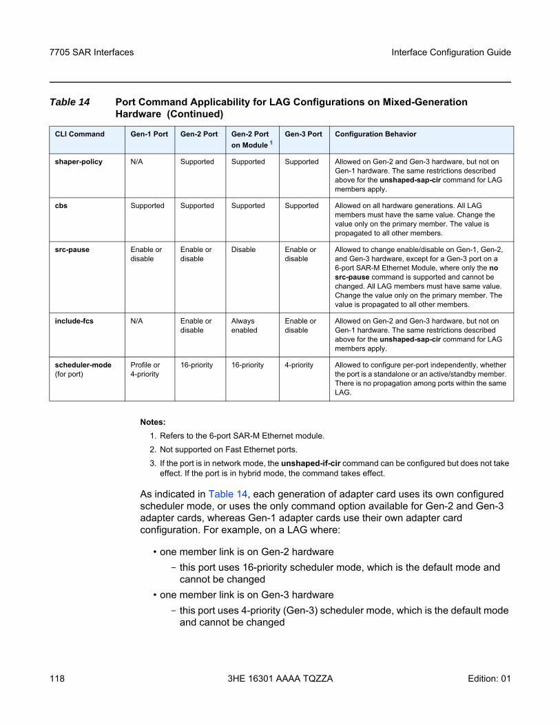
7705 SAR Interfaces
118
Interface Configuration Guide
3HE 16301 AAAA TQZZA Edition: 01
Notes:1. Refers to the 6-port SAR-M Ethernet module. 2. Not supported on Fast Ethernet ports. 3. If the port is in network mode, the unshaped-if-cir command can be configured but does not take
effect. If the port is in hybrid mode, the command takes effect.
As indicated in Table 14, each generation of adapter card uses its own configured scheduler mode, or uses the only command option available for Gen-2 and Gen-3 adapter cards, whereas Gen-1 adapter cards use their own adapter card configuration. For example, on a LAG where:
• one member link is on Gen-2 hardware- this port uses 16-priority scheduler mode, which is the default mode and
cannot be changed • one member link is on Gen-3 hardware
- this port uses 4-priority (Gen-3) scheduler mode, which is the default mode and cannot be changed
shaper-policy N/A Supported Supported Supported Allowed on Gen-2 and Gen-3 hardware, but not on Gen-1 hardware. The same restrictions described above for the unshaped-sap-cir command for LAG members apply.
cbs Supported Supported Supported Supported Allowed on all hardware generations. All LAG members must have the same value. Change the value only on the primary member. The value is propagated to all other members.
src-pause Enable or disable
Enable or disable
Disable Enable or disable
Allowed to change enable/disable on Gen-1, Gen-2, and Gen-3 hardware, except for a Gen-3 port on a 6-port SAR-M Ethernet Module, where only the no src-pause command is supported and cannot be changed. All LAG members must have same value. Change the value only on the primary member. The value is propagated to all other members.
include-fcs N/A Enable or disable
Always enabled
Enable or disable
Allowed on Gen-2 and Gen-3 hardware, but not on Gen-1 hardware. The same restrictions described above for the unshaped-sap-cir command for LAG members apply.
scheduler-mode (for port)
Profile or 4-priority
16-priority 16-priority 4-priority Allowed to configure per-port independently, whether the port is a standalone or an active/standby member. There is no propagation among ports within the same LAG.
Table 14 Port Command Applicability for LAG Configurations on Mixed-Generation Hardware (Continued)
CLI Command Gen-1 Port Gen-2 Port Gen-2 Port on Module 1
Gen-3 Port Configuration Behavior
Interface Configuration Guide 7705 SAR Interfaces
Edition: 01 3HE 16301 AAAA TQZZA 119
• one member link is on Gen-1 hardware- this port uses its configured scheduler mode (profiled or 4-priority), which is
dictated via the configuration applied to the port
3.2.14 LAG and ECMP Hashing
If it is necessary to increase the available bandwidth for a logical link that exceeds the physical bandwidth or to add redundancy for a physical link, typically one of two methods is applied: LAG or ECMP. A system can also deploy both at the same time using ECMP of two or more LAGs and/or single links.
The 7705 SAR supports per-flow and per-service hashing, as described in the following sections:
• Per-Flow Hashing• Per-Service Hashing• LSR Hashing• Layer 4 Load Balancing• TEID Hashing for GTP-encapsulated Traffic• Entropy Labels• Security Parameter Index (SPI) Load Balancing
3.2.14.1 Per-Flow Hashing
The 7705 SAR supports per-flow hashing for LAG and ECMP. Per-flow hashing uses information in a packet as an input to the hash function, ensuring that any given traffic flow maps to the same egress LAG port or ECMP path.
Depending on the type of traffic that needs to be distributed in an ECMP or LAG path, different variables are used as the input to the hashing algorithm that determines the selection of the next hop (ECMP) or port (LAG). The hashing result can be changed using the options described in Per-Service Hashing, LSR Hashing, Layer 4 Load Balancing, TEID Hashing for GTP-encapsulated Traffic, and Entropy Labels.
Note: For general information on LAG, see LAG. For general information on ECMP, refer to the 7705 SAR Router Configuration Guide, “Static Routes, Dynamic Routes, and ECMP”.
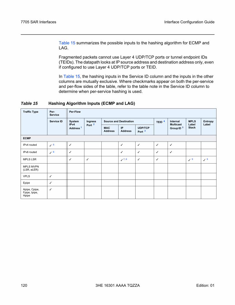
7705 SAR Interfaces
120
Interface Configuration Guide
3HE 16301 AAAA TQZZA Edition: 01
Table 15 summarizes the possible inputs to the hashing algorithm for ECMP and LAG.
Fragmented packets cannot use Layer 4 UDP/TCP ports or tunnel endpoint IDs (TEIDs). The datapath looks at IP source address and destination address only, even if configured to use Layer 4 UDP/TCP ports or TEID.
In Table 15, the hashing inputs in the Service ID column and the inputs in the other columns are mutually exclusive. Where checkmarks appear on both the per-service and per-flow sides of the table, refer to the table note in the Service ID column to determine when per-service hashing is used.
Table 15 Hashing Algorithm Inputs (ECMP and LAG)
Traffic Type Per- Service
Per-Flow
Service ID System IPv4 Address 1
Ingress Port 2
Source and Destination TEID 4 Internal Multicast Group ID 5
MPLS Label Stack
Entropy Label
MAC Address
IP Address
UDP/TCP Port 3
ECMP
IPv4 routed 6
IPv6 routed 6
MPLS LSR 7, 8 9 9
MPLS MVPN (LSR, eLER)
VPLS
Epipe
Apipe, Cpipe, Fpipe, Ipipe, Hpipe

Interface Configuration Guide 7705 SAR Interfaces
Edition: 01 3HE 16301 AAAA TQZZA 121
Notes:1. The system IP address can be included as a hashing input for both IP and LDP ECMP using the
system-ip-load-balancing command at the system level. 2. Optional hashing input that is included when the use-ingress-port command is enabled.3. Optional hashing input that is included when the l4-load-balancing command is enabled (for IP
ECMP) or when the hashing algorithm is configured as lbl-ip-l4-teid in the lsr-load-balancing command (for LDP ECMP). Layer 4 load balancing at the service level is not affected by Layer 4 load balancing at the system, router interface, or service interface levels (IES and VPRN).
4. Optional hashing input that is included when the teid-load-balancing command is enabled (for IP ECMP) or when the hashing algorithm is configured as lbl-ip-l4-teid in the lsr-load-balancing command (for LDP ECMP). TEID load balancing at the service level is not affected by TEID load balancing at the router interface or service interface levels (IES and VPRN).
5. Only applies to multicast traffic. The internal multicast group ID is generated from either the (S,G) record (IGMP snooping, MLD snooping, and PIM snooping), the point-to-multipoint label binding, or the VPLS service creation.
6. Only for Layer 3 traffic going to a Layer 3 spoke SDP interface.7. Only included when the first nibble after the bottom of stack (BoS) bit is “4”, in which case the next
header encapsulation is considered to be an IPv4 header. 8. Optional hashing input that is included when LSR hashing is configured as label-ip.9. MPLS label stack and entropy label are mutually exclusive hashing inputs. When an entropy label
indicator (ELI) and entropy label (EL) are found in the label stack, the MPLS labels are not used as hashing inputs.
10. Optional hashing input that is included when the per-service-hashing command is enabled in a service (VPLS or Epipe). The default setting is disabled, which should be changed to enabled if pre-Release 8.0.R4 behavior is needed.
LAG
IPv4 routed
IPv6 routed
MPLS LSR 7, 8 9 9
MPLS MVPN (LSR, eLER)
VPLS 10
Epipe 10
Apipe, Cpipe, Fpipe, Ipipe, Hpipe
Table 15 Hashing Algorithm Inputs (ECMP and LAG) (Continued)
Traffic Type Per- Service
Per-Flow
Service ID System IPv4 Address 1
Ingress Port 2
Source and Destination TEID 4 Internal Multicast Group ID 5
MPLS Label Stack
Entropy Label
MAC Address
IP Address
UDP/TCP Port 3
7705 SAR Interfaces
122
Interface Configuration Guide
3HE 16301 AAAA TQZZA Edition: 01
3.2.14.2 Per-Service Hashing
The 7705 SAR supports load balancing based on service ID, as shown in Table 15, The 7705 SAR uses the service ID as the input to the hash function. Per-service and per-flow hashing are mutually exclusive features.
For IPv4 and IPv6 routed traffic under ECMP operation, the service ID is used as the hashing input for Layer 3 traffic going to a Layer 3 spoke SDP interface. Otherwise, per-flow load balancing is used.
For Epipe and VPLS services under LAG operation, the per-service-hashing command and the l4-load-balancing and teid-load-balancing commands are mutually exclusive. Load balancing via per-service hashing is configured under the config>service> epipe>load-balancing and config>service>vpls> load-balancing contexts.
Note:
• Prior to Release 8.0.R4 of the 7705 SAR, load balancing for an Epipe service was implicitly defaulted to be enabled (that is, hashing was always on the service ID). Release 8.0.R4 adds the per-service-hashing command, which is disabled by default. The per-service-hashing command must be explicitly enabled if pre-Release 8.0.R4 behavior is needed.
• Starting with Release 8.0.R4, unless per-service-hashing is enabled, a 4-byte hash value will be appended to internal overhead for VPLS multicast traffic at ingress. The egress internal hash value is discarded at egress before scheduling. Therefore, shaping rates at access and network ingress and for fabric policies may need to be adjusted accordingly. In addition, the 4-byte internal hash value may be included in any affected statistics counters.
• Starting with Release 9.0.R4, support for multiple LSPs (RSVP-TE or segment routing TE (SR-TE)) in the same SDP is added as part of the mixed-LSP SDP feature (refer to the “Mixed-LSP SDPs” section in the 7705 SAR Services Guide for details). When an SDP is configured with multiple LSPs of the same type, it allows load balancing of the traffic in a similar manner as load-balancing for LDP ECMP, but only at the iLER point. Therefore, the per-flow hashing and per-service hashing behavior described in this section for LDP ECMP at the iLER also applies to multiple LSPs (RSVP-TE or SR-TE) in the same SDP.
Interface Configuration Guide 7705 SAR Interfaces
Edition: 01 3HE 16301 AAAA TQZZA 123
3.2.14.3 LSR Hashing
LSR hashing operates on the label stack and can also include hashing on the IP header if the packet is an IPv4 packet. The label-IP hashing algorithm can also include the Layer 4 header and the TEID field. The default hash is on the label stack only. IPv4 is the only IP hashing supported on a 7705 SAR LSR.
When a 7705 SAR is acting as an LSR, it considers a packet to be IP if the first nibble following the bottom of the label stack is 4 (IPv4). This allows the user to include an IP header in the hashing routine at an LSR in order to spray labeled IP packets over multiple equal-cost paths in ECMP in an LDP LSP and/or over multiple links of a LAG group in all types of LSPs.
Other LSR hashing options include label stack profile options on the significance of the bottom-of-stack label (VC label), the inclusion or exclusion of the ingress port, and the inclusion or exclusion of the system IP address.
LSR load balancing is configured using the config>system>lsr-load-balancing or config>router>if>load-balancing>lsr-load-balancing command. Configuration at the router interface level overrides the system-level configuration for the specified interface.
If an ELI is found in the label stack, the entropy label is used as the hash result. Hashing continues based on the configuration of label-only (lbl-only), label-IP (lbl-ip), or label-IP with Layer 4 header and TEID (lbl-ip-l4-teid) options.
3.2.14.3.1 LSR Label-only Hashing
ECMP operation consists of an initial hash based on the system IP address, then on the global port number if the use-ingress-port option is enabled.
Each label in the stack is then hashed separately with the result of the previous hash, up to a maximum of 16 labels. The net result is used to select which LDP FEC next hop to send the packet to using a threshold hashing operation of the net result with the number of next hops. Threshold hashing is described in RFC 2992, Analysis of an Equal-Cost Multi-Path Algorithm.
Note: The global IF index is no longer a hash input for LSR ECMP load balancing. It has been replaced with the use-ingress-port configurable option in the lsr-load-balancing command. As well, the default treatment of the MPLS label stack has changed to focus on the bottom-of-stack label (VC label). In previous releases, all labels had equal influence.
7705 SAR Interfaces
124
Interface Configuration Guide
3HE 16301 AAAA TQZZA Edition: 01
If an ELI is found in the label stack, the entropy label replaces the MPLS label stack hashing result and hashing continues.
If the selected LDP FEC or LSP has its NHLFE programmed with a LAG interface, a second round of hashing is needed, using the net result of the first round of hashing as the hashing input.
3.2.14.3.2 LSR Label-IP Hashing
In the first round of hashing for LSR label IP hashing, the algorithm parses down the label stack as described in LSR Label-only Hashing.
When the algorithm reaches the bottom of the stack, it checks the next nibble. If the nibble value is 4, the packet is assumed to be an IPv4 packet and the result of the label hash is fed into another hash along with the source and destination address fields in the IP packet header. If the nibble value is not 4, the algorithm will just use the label stack hash already calculated for the ECMP path selection.
The second round of hashing for LAG reuses the net result of the first round of hashing.
3.2.14.3.3 LSR Label-IP Hashing with Layer 4 Header and TEID
If the lbl-ip-l4-teid option is configured, the Layer 4 source and destination UDP or TCP port fields and the TEID field in the GTP header are included in the label-IP hashing calculation. See Layer 4 Load Balancing and TEID Hashing for GTP-encapsulated Traffic for more information.
3.2.14.3.4 Label Stack Profile Options
The lsr-load-balancing command includes a bottom-of-stack option that determines the significance of the bottom-of-stack label (VC label) based on which label stack profile option is specified. The profiles are:
• profile 1: favors better load balancing for pseudowires when the VC label distribution is contiguous (default)
• profile 2: similar to profile 1 where the VC labels are contiguous, but provides an alternate distribution
• profile 3: all labels have equal influence in hash key generation
Interface Configuration Guide 7705 SAR Interfaces
Edition: 01 3HE 16301 AAAA TQZZA 125
3.2.14.3.5 Ingress Port
The use-ingress-port option, when enabled, specifies that the ingress port will be used by the hashing algorithm at the LSR. This option should be enabled for ingress LAG ports because packets with the same label stack can arrive on all ports of a LAG interface. In this case, using the ingress port in the hashing algorithm will result in better egress load balancing, especially for pseudowires.
The option should be disabled for LDP ECMP so that the ingress port is not used by the hashing algorithm. For ingress LDP ECMP, if the ingress port is used by the hashing algorithm, the hash distribution could be biased, especially for pseudowires.
3.2.14.4 Layer 4 Load Balancing
The IP Layer 4 load-balancing option includes the TCP/UDP source and destination port numbers in addition to the source and destination IP addresses in per-flow hashing of IP packets. By including the Layer 4 information, a source address/destination address default hash flow can be subdivided into multiple finer-granularity flows if the ports used between a source address and destination address vary.
Layer 4 load balancing is configured at the system level using the config>system>l4-load-balancing command. It can also be configured at the router interface level or the service interface level (IES and VPRN). Configuration at the router interface or service interface level overrides the system-level configuration for the specified interface or service.
For LSR LDP ECMP, Layer 4 load balancing is configured using the lbl-ip-l4-teid option in the lsr-load-balancing command at the system level or router interface level. Configuration at the router interface level overrides the system-level configuration for the specified interface.
Layer 4 load balancing can also be configured at the service level for Epipe and VPLS services. Layer 4 load balancing at the service level is not impacted by Layer 4 load balancing at the system, router interface, or service interface levels.
7705 SAR Interfaces
126
Interface Configuration Guide
3HE 16301 AAAA TQZZA Edition: 01
3.2.14.5 TEID Hashing for GTP-encapsulated Traffic
GTP is the GPRS (general packet radio service) tunneling protocol. The tunnel endpoint identifier (TEID) is a field in the GTP header. TEID hashing can be enabled on Layer 3 interfaces. The hash algorithm identifies the GTP-U protocol by checking the UDP destination port (2152) of an IP packet to be hashed. If the value of the port matches, the packet is assumed to be GTP-U. For GTPv1 packets, the TEID value from the expected header location is then included in the hash. For GTPv2 packets, the TEID flag value in the expected header is additionally checked to verify whether the TEID is present. If the TEID is present, it is included in the hash algorithm inputs.
TEID load balancing is configured at the router interface level using the config> router>if>teid-load-balancing command. It can also be configured at the IES or VPRN service interface level.
For LSR LDP ECMP, TEID load balancing is configured using the lbl-ip-l4-teid option in the lsr-load-balancing command at the system level or router interface level. Configuration at the router interface level overrides the system-level configuration for the specified interface.
TEID load balancing can also be configured at the service level for Epipe and VPLS services. TEID load balancing at the service level is not impacted by TEID load balancing at the router interface or service interface levels.
3.2.14.6 Entropy Labels
The 7705 SAR supports MPLS entropy labels on RSVP-TE and SR-TE LSPs, as per RFC 6790. The entropy label provides greater granularity for load balancing on an LSR where load balancing is typically based on the MPLS label stack.
If an ELI is found in the label stack, the entropy label is used as the hash result and hashing continues based on the configuration of label-only (lbl-only) or label-IP (lbl-ip) options. For information on the behavior of LSR hashing when entropy label is enabled, see LSR Hashing.
To support entropy labels on RSVP-TE and SR-TE LSPs:
• the eLER must signal to the ingress node that entropy label capability (ELC) is enabled, meaning that the eLER can receive and process an entropy label for an LSP tunnel. Entropy labels are supported on RSVP-TE and SR-TE tunnels. Entropy labels are not supported on point-to-multipoint LSPs, BGP tunnels, or LDP FECs.
Interface Configuration Guide 7705 SAR Interfaces
Edition: 01 3HE 16301 AAAA TQZZA 127
• the iLER must receive the entropy label capability signal and be configured to enable the insertion of entropy labels for the spoke SDP, mesh SDP, or EVPN endpoint. Inserting an entropy label adds two labels in the MPLS label stack: the entropy label itself and the ELI.
At the eLER, use the config>router>rsvp>entropy-label-capability command to enable entropy label capability on RSVP-TE LSPs.
At the iLER, use the entropy-label command to enable the insertion of the entropy label into the label stack. The command is found under the following services and protocols:
• Epipe and VPLS- config>service>epipe>spoke-sdp- config>service>epipe>bgp-evpn>mpls- config>service>vpls>spoke-sdp- config>service>vpls>mesh-sdp- config>service>vpls>bgp-evpn>mpls
• IS-IS, OSPF, and MPLS- config>router>isis>segment-routing- config>router>ospf>segment-routing- config>router>mpls
For details on entropy labels, refer to the “MPLS Entropy Labels” section in the 7705 SAR MPLS Guide.
3.2.14.7 Security Parameter Index (SPI) Load Balancing
SPI load balancing provides a mechanism to improve the hashing performance of IPSec encrypted traffic. IPSec-tunneled traffic transported over a LAG typically relies on IP header hashing only. For example, in LTE deployments, TEID hashing cannot be performed because of encryption, and the system performs IP-only tunnel-level hashing. Because each SPI in the IPSec header identifies a unique SA, and therefore a unique flow, these flows can be hashed individually without impacting packet ordering. In this way,
7705 SAR Interfaces
128
Interface Configuration Guide
3HE 16301 AAAA TQZZA Edition: 01
The 7705 SAR allows enabling SPI hashing per Layer 3 interface (this is the incoming interface for hash on system egress) or per Layer 2 VPLS service. When SPI hashing is enabled, an SPI value from the ESP/AH header is used in addition to any other IP hash input based on the per-flow hash configuration: source/destination IPv4/IPv6 addresses and Layer 4 source/destination ports in case NAT traversal is required and Layer 4 load balancing is enabled. If the ESP/AH header is not present in a packet received on a given interface, the SPI will not be part of the hash inputs and the packet is hashed as per other hashing configurations. SPI hashing is not used for fragmented traffic in order to ensure that first and subsequent fragments use the same hash inputs.
SPI hashing is supported for IPv4 and IPv6 tunnel unicast traffic.
3.2.15 SONET/SDH
This section contains information on the following topics:
• SONET• SDH• SONET/SDH Path Support
The 7705 SAR supports SONET/SDH ports on the following adapter cards:
• 4-port OC3/STM1 Clear Channel Adapter card• 2-port OC3/STM1 Channelized Adapter card• 4-port OC3/STM1 / 1-port OC12/STM4 Adapter card
SONET/SDH ports can be clear channel (non-channelized) and channelized. The 4-port OC3/STM1 Clear Channel Adapter card supports only clear channel ports. The 2-port OC3/STM1 Channelized Adapter card supports channelized ports. The 4-port OC3/STM1 / 1-port OC12/STM4 Adapter card is a mixed-use adapter card that supports clear channel and channelized ports. The mda-mode command is used to configure the 4-port OC3/STM1 / 1-port OC12/STM4 Adapter card for 4-port or 1-port mode. See Configuring Cards for details.
Clear channel ports use the whole port—other than overhead bytes—as a single stream of bits. Channelized ports use various channel hierarchies to split the larger bandwidth into smaller channels, such as DS1, E1, DS3, or E3. Figure 11 and Figure 12 show the standards-based channel mapping for SONET and SDH, respectively. Channelized ports on the 2-port OC3/STM1 Channelized Adapter card and the 4-port OC3/STM1 / 1-port OC12/STM4 Adapter card support a subset of the standards-based mapping options, as shown in Table 16.
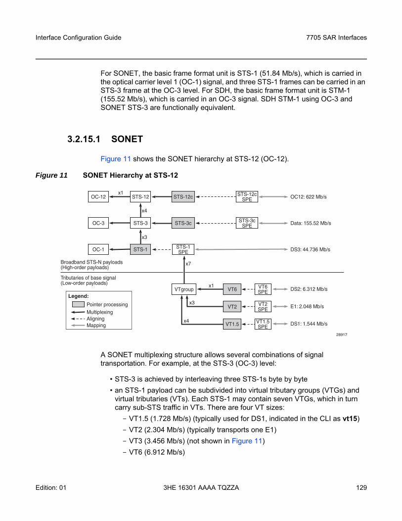
Interface Configuration Guide 7705 SAR Interfaces
Edition: 01 3HE 16301 AAAA TQZZA 129
For SONET, the basic frame format unit is STS-1 (51.84 Mb/s), which is carried in the optical carrier level 1 (OC-1) signal, and three STS-1 frames can be carried in an STS-3 frame at the OC-3 level. For SDH, the basic frame format unit is STM-1 (155.52 Mb/s), which is carried in an OC-3 signal. SDH STM-1 using OC-3 and SONET STS-3 are functionally equivalent.
3.2.15.1 SONET
Figure 11 shows the SONET hierarchy at STS-12 (OC-12).
Figure 11 SONET Hierarchy at STS-12
A SONET multiplexing structure allows several combinations of signal transportation. For example, at the STS-3 (OC-3) level:
• STS-3 is achieved by interleaving three STS-1s byte by byte • an STS-1 payload can be subdivided into virtual tributary groups (VTGs) and
virtual tributaries (VTs). Each STS-1 may contain seven VTGs, which in turn carry sub-STS traffic in VTs. There are four VT sizes:- VT1.5 (1.728 Mb/s) (typically used for DS1, indicated in the CLI as vt15) - VT2 (2.304 Mb/s) (typically transports one E1) - VT3 (3.456 Mb/s) (not shown in Figure 11)- VT6 (6.912 Mb/s)
Broadband STS-N payloads(High-order payloads)
Tributaries of base signal(Low-order payloads)
OC12: 622 Mb/sOC-12 STS-12c STS-12cSPESTS-12
Data: 155.52 Mb/sOC-3 STS-3c
DS2: 6.312 Mb/s
E1: 2.048 Mb/s
DS1: 1.544 Mb/s
STS-3cSPESTS-3
DS3: 44.736 Mb/sOC-1 STS-1SPESTS-1
28917
VT6SPE
Multiplexing
Pointer processing
AligningMapping
Legend:
VT2SPE
VT1.5SPE
VTgroupx1
x1
x7
x3
x3
x4
x4
VT6
VT2
VT1.5
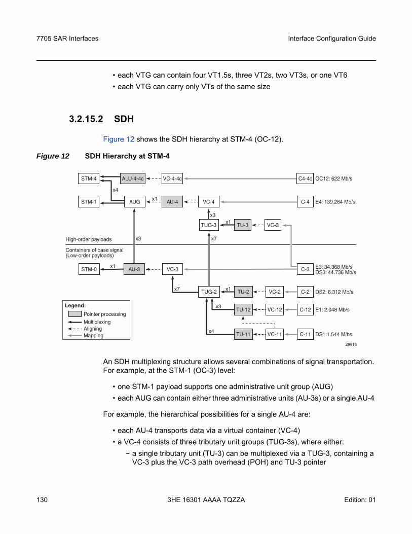
7705 SAR Interfaces
130
Interface Configuration Guide
3HE 16301 AAAA TQZZA Edition: 01
• each VTG can contain four VT1.5s, three VT2s, two VT3s, or one VT6 • each VTG can carry only VTs of the same size
3.2.15.2 SDH
Figure 12 shows the SDH hierarchy at STM-4 (OC-12).
Figure 12 SDH Hierarchy at STM-4
An SDH multiplexing structure allows several combinations of signal transportation. For example, at the STM-1 (OC-3) level:
• one STM-1 payload supports one administrative unit group (AUG) • each AUG can contain either three administrative units (AU-3s) or a single AU-4
For example, the hierarchical possibilities for a single AU-4 are:
• each AU-4 transports data via a virtual container (VC-4) • a VC-4 consists of three tributary unit groups (TUG-3s), where either:
- a single tributary unit (TU-3) can be multiplexed via a TUG-3, containing a VC-3 plus the VC-3 path overhead (POH) and TU-3 pointer
x7
x7 x1
x3
x4
x3
x1
OC12: 622 Mb/s
E4: 139.264 Mb/s
E3: 34.368 Mb/sDS3: 44.736 Mb/s
DS2: 6.312 Mb/s
E1: 2.048 Mb/s
DS1:1.544 M/bs
STM-4 VC-4-4c C4-4cALU-4-4c
C-2VC-2
STM-1 AU-4 VC-4 C-4AUG
STM-0 VC-3
TU-3 VC-3TUG-3
TU-2
C-12VC-12
High-order payloads
Containers of base signal(Low-order payloads)
x4
x3x1
x1
C-3AU-3
TU-12
TU-11
28916
VC-11 C-11
TUG-2
Multiplexing
Pointer processing
AligningMapping
Legend:
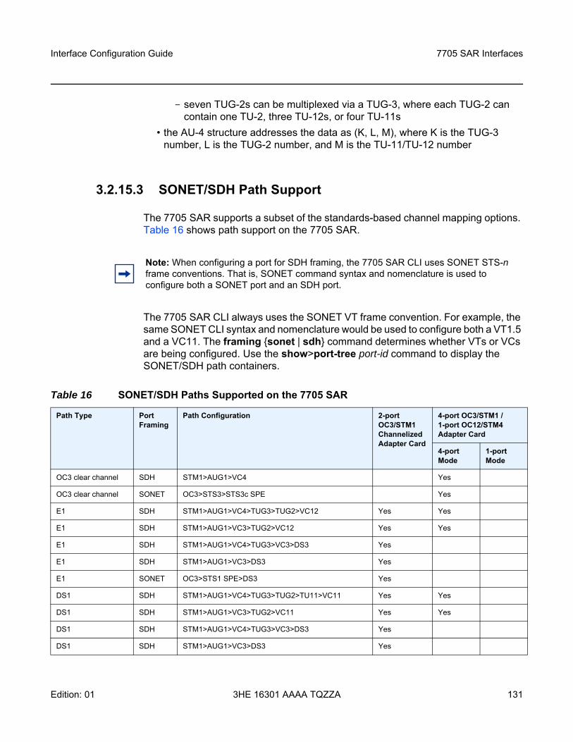
Interface Configuration Guide 7705 SAR Interfaces
Edition: 01 3HE 16301 AAAA TQZZA 131
- seven TUG-2s can be multiplexed via a TUG-3, where each TUG-2 can contain one TU-2, three TU-12s, or four TU-11s
• the AU-4 structure addresses the data as (K, L, M), where K is the TUG-3 number, L is the TUG-2 number, and M is the TU-11/TU-12 number
3.2.15.3 SONET/SDH Path Support
The 7705 SAR supports a subset of the standards-based channel mapping options. Table 16 shows path support on the 7705 SAR.
The 7705 SAR CLI always uses the SONET VT frame convention. For example, the same SONET CLI syntax and nomenclature would be used to configure both a VT1.5 and a VC11. The framing sonet | sdh command determines whether VTs or VCs are being configured. Use the show>port-tree port-id command to display the SONET/SDH path containers.
Note: When configuring a port for SDH framing, the 7705 SAR CLI uses SONET STS-n frame conventions. That is, SONET command syntax and nomenclature is used to configure both a SONET port and an SDH port.
Table 16 SONET/SDH Paths Supported on the 7705 SAR
Path Type Port Framing
Path Configuration 2-port OC3/STM1 Channelized Adapter Card
4-port OC3/STM1 / 1-port OC12/STM4 Adapter Card
4-port Mode
1-port Mode
OC3 clear channel SDH STM1>AUG1>VC4 Yes
OC3 clear channel SONET OC3>STS3>STS3c SPE Yes
E1 SDH STM1>AUG1>VC4>TUG3>TUG2>VC12 Yes Yes
E1 SDH STM1>AUG1>VC3>TUG2>VC12 Yes Yes
E1 SDH STM1>AUG1>VC4>TUG3>VC3>DS3 Yes
E1 SDH STM1>AUG1>VC3>DS3 Yes
E1 SONET OC3>STS1 SPE>DS3 Yes
DS1 SDH STM1>AUG1>VC4>TUG3>TUG2>TU11>VC11 Yes Yes
DS1 SDH STM1>AUG1>VC3>TUG2>VC11 Yes Yes
DS1 SDH STM1>AUG1>VC4>TUG3>VC3>DS3 Yes
DS1 SDH STM1>AUG1>VC3>DS3 Yes
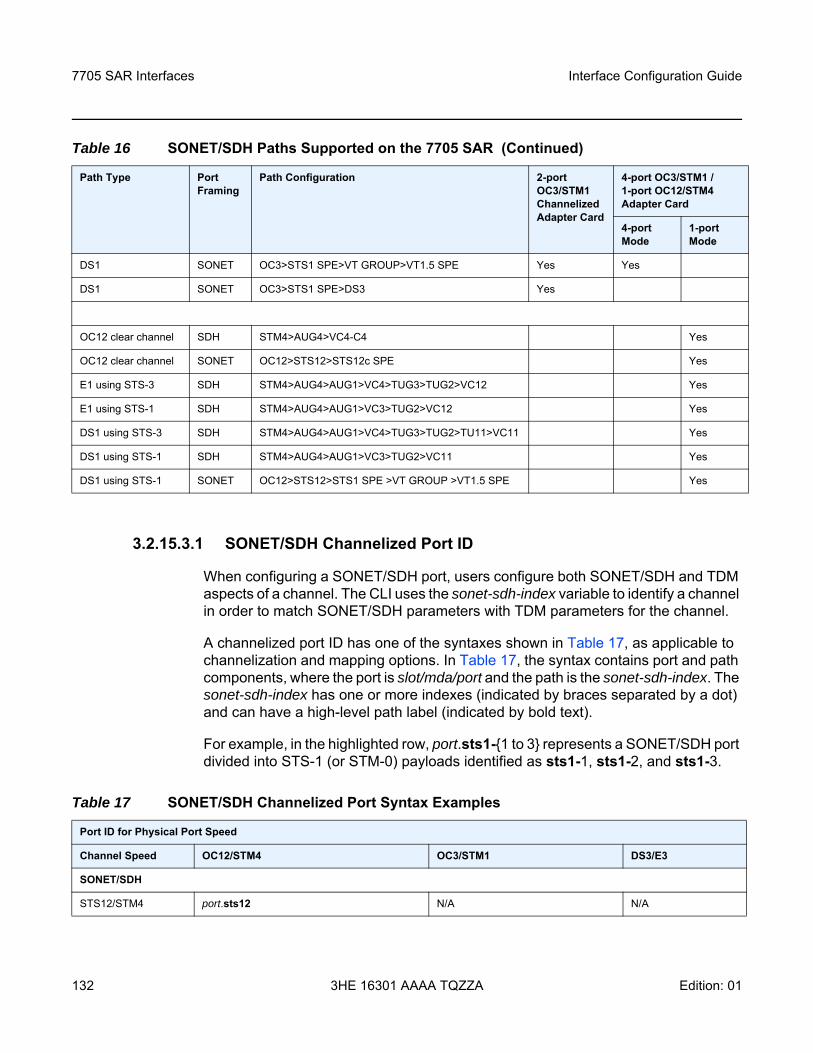
7705 SAR Interfaces
132
Interface Configuration Guide
3HE 16301 AAAA TQZZA Edition: 01
3.2.15.3.1 SONET/SDH Channelized Port ID
When configuring a SONET/SDH port, users configure both SONET/SDH and TDM aspects of a channel. The CLI uses the sonet-sdh-index variable to identify a channel in order to match SONET/SDH parameters with TDM parameters for the channel.
A channelized port ID has one of the syntaxes shown in Table 17, as applicable to channelization and mapping options. In Table 17, the syntax contains port and path components, where the port is slot/mda/port and the path is the sonet-sdh-index. The sonet-sdh-index has one or more indexes (indicated by braces separated by a dot) and can have a high-level path label (indicated by bold text).
For example, in the highlighted row, port.sts1-1 to 3 represents a SONET/SDH port divided into STS-1 (or STM-0) payloads identified as sts1-1, sts1-2, and sts1-3.
DS1 SONET OC3>STS1 SPE>VT GROUP>VT1.5 SPE Yes Yes
DS1 SONET OC3>STS1 SPE>DS3 Yes
OC12 clear channel SDH STM4>AUG4>VC4-C4 Yes
OC12 clear channel SONET OC12>STS12>STS12c SPE Yes
E1 using STS-3 SDH STM4>AUG4>AUG1>VC4>TUG3>TUG2>VC12 Yes
E1 using STS-1 SDH STM4>AUG4>AUG1>VC3>TUG2>VC12 Yes
DS1 using STS-3 SDH STM4>AUG4>AUG1>VC4>TUG3>TUG2>TU11>VC11 Yes
DS1 using STS-1 SDH STM4>AUG4>AUG1>VC3>TUG2>VC11 Yes
DS1 using STS-1 SONET OC12>STS12>STS1 SPE >VT GROUP >VT1.5 SPE Yes
Table 16 SONET/SDH Paths Supported on the 7705 SAR (Continued)
Path Type Port Framing
Path Configuration 2-port OC3/STM1 Channelized Adapter Card
4-port OC3/STM1 / 1-port OC12/STM4 Adapter Card
4-port Mode
1-port Mode
Table 17 SONET/SDH Channelized Port Syntax Examples
Port ID for Physical Port Speed
Channel Speed OC12/STM4 OC3/STM1 DS3/E3
SONET/SDH
STS12/STM4 port.sts12 N/A N/A
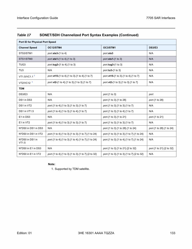
Interface Configuration Guide 7705 SAR Interfaces
Edition: 01 3HE 16301 AAAA TQZZA 133
Note:1. Supported by TDM satellite.
STS3/STM1 port.sts3-1 to 4 port.sts3 N/A
STS1/STM0 port.sts1-1 to 4.1 to 3 port.sts1-1 to 3 N/A
TUG3 port.tug3-1 to 4.1 to 3 port.tug3-1 to 3 N/A
TU3 N/A port.tu3-1 to 3 N/A
VT1.5/VC1.1 1 port.vt15-1 to 4.1 to 3.1 to 4.1 to 7 port.vt15-1 to 3.1 to 4.1 to 7 N/A
VT2/VC12 1 port.vt2-1 to 4.1 to 3.1 to 3.1 to 7 port.vt2-1 to 3.1 to 3.1 to 7 N/A
TDM
DS3/E3 N/A port.1 to 3 port
DS1 in DS3 N/A port.1 to 3.1 to 28 port.1 to 28
DS1 in VT2 port.1 to 4.1 to 3.1 to 3.1 to 7 port.1 to 3.1 to 3.1 to 7 N/A
DS1 in VT1.5 port.1 to 4.1 to 3.1 to 4.1 to 7 port.1 to 3.1 to 4.1 to 7 N/A
E1 in DS3 N/A port.1 to 3.1 to 21 port.1 to 21
E1 in VT2 port.1 to 4.1 to 3.1 to 3.1 to 7 port.1 to 3.1 to 3.1 to 7 N/A
N*DS0 in DS1 in DS3 N/A port.1 to 3.1 to 28.1 to 24 port.1 to 28.1 to 24
N*DS0 in DS1 in VT2 port.1 to 4.1 to 3.1 to 3.1 to 7.1 to 24 port.1 to 3.1 to 3.1 to 7.1 to 24 N/A
N*DS0 in DS1 in VT1.5
port.1 to 4.1 to 3.1 to 4.1 to 7.1 to 24 port.1 to 3.1 to 4.1 to 7.1 to 24 N/A
N*DS0 in E1 in DS3 N/A port.1 to 3.1 to 21.2 to 32 port.1 to 21.2 to 32
N*DS0 in E1 in VT2 port.1 to 4.1 to 3.1 to 3.1 to 7.2 to 32 port.1 to 3.1 to 3.1 to 7.2 to 32 N/A
Table 17 SONET/SDH Channelized Port Syntax Examples (Continued)
Port ID for Physical Port Speed
Channel Speed OC12/STM4 OC3/STM1 DS3/E3
7705 SAR Interfaces
134
Interface Configuration Guide
3HE 16301 AAAA TQZZA Edition: 01
3.2.16 Automatic Protection Switching
This section contains information on the following topics:
• APS Overview• SC-APS• MC-APS• K1 and K2 Bytes• Revertive Mode• APS Tools Commands• APS Failure Codes
3.2.16.1 APS Overview
Automatic Protection Switching (APS) allows users to protect a SONET/SDH port or link with a backup (protection) facility of the same speed but from a different adapter card. APS provides protection against a port, signal, or adapter card failure. The 7705 SAR supports 1+1 APS protection in compliance with GR-253-CORE and ITU-T Recommendation G.841 to provide SONET/SDH carrier-grade reliability. All SONET/SDH paths and channels within a SONET/SDH port are protected.
When APS is enabled, the 7705 SAR constantly monitors the health of the APS links, APS ports, and APS-equipped adapter cards. If the signal on the active (working) port degrades or fails, the network proceeds through a predefined sequence of steps to transfer (or switch over) traffic processing to the protection port. This switchover is done very quickly to minimize traffic loss. Traffic is streamed from the protection port until the fault on the working port is cleared, at which time the traffic may optionally revert to the working port.
The 7705 SAR supports 1+1 single-chassis APS (SC-APS) and 1+1 multi-chassis APS (MC-APS). In an SC-APS group, both the working and protection circuit must be configured on the same node. In an MC-APS group, the working and protection circuits are configured on two separate nodes, providing protection from node failure in addition to protection from link and hardware failure.
Unidirectional and bidirectional modes are supported:
• unidirectional APS (Uni-1Plus1) — in unidirectional mode, only the port in the failed direction switches to the protection port. Unidirectional mode is supported only on SC-APS.
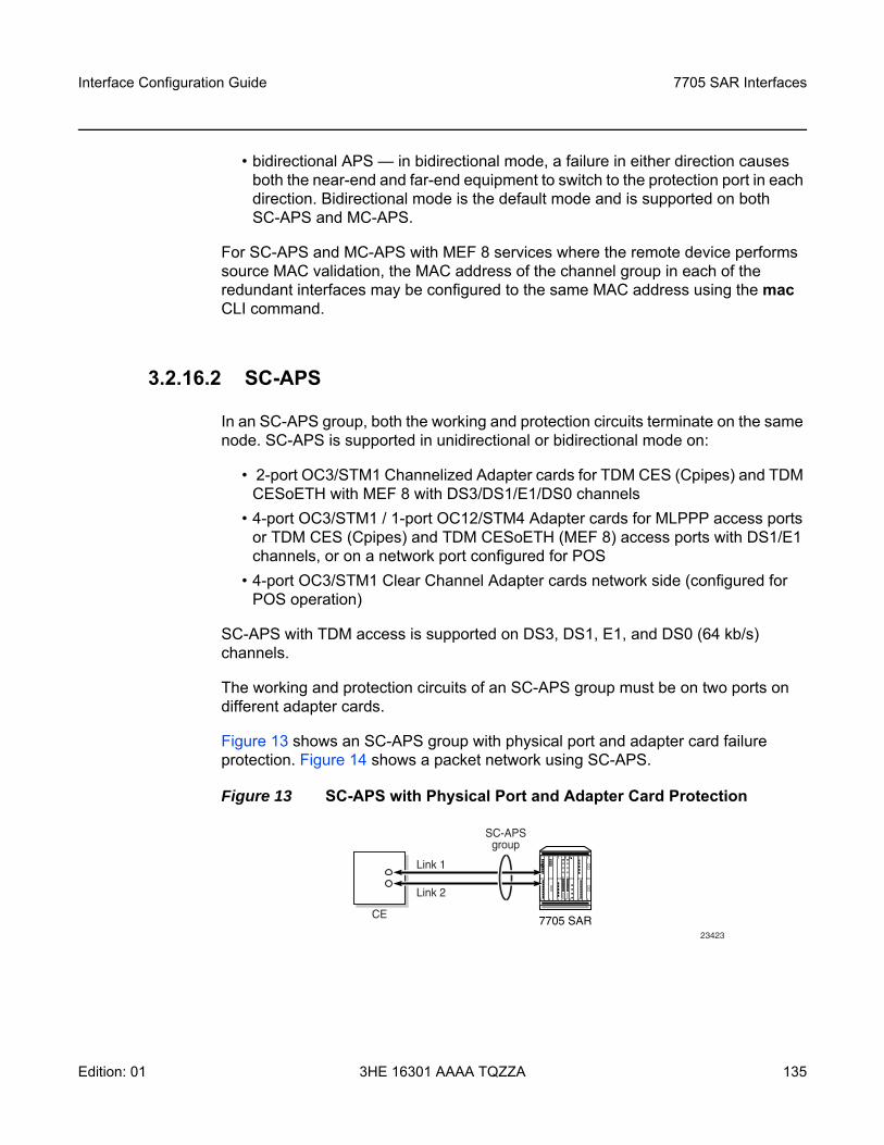
Interface Configuration Guide 7705 SAR Interfaces
Edition: 01 3HE 16301 AAAA TQZZA 135
• bidirectional APS — in bidirectional mode, a failure in either direction causes both the near-end and far-end equipment to switch to the protection port in each direction. Bidirectional mode is the default mode and is supported on both SC-APS and MC-APS.
For SC-APS and MC-APS with MEF 8 services where the remote device performs source MAC validation, the MAC address of the channel group in each of the redundant interfaces may be configured to the same MAC address using the mac CLI command.
3.2.16.2 SC-APS
In an SC-APS group, both the working and protection circuits terminate on the same node. SC-APS is supported in unidirectional or bidirectional mode on:
• 2-port OC3/STM1 Channelized Adapter cards for TDM CES (Cpipes) and TDM CESoETH with MEF 8 with DS3/DS1/E1/DS0 channels
• 4-port OC3/STM1 / 1-port OC12/STM4 Adapter cards for MLPPP access ports or TDM CES (Cpipes) and TDM CESoETH (MEF 8) access ports with DS1/E1 channels, or on a network port configured for POS
• 4-port OC3/STM1 Clear Channel Adapter cards network side (configured for POS operation)
SC-APS with TDM access is supported on DS3, DS1, E1, and DS0 (64 kb/s) channels.
The working and protection circuits of an SC-APS group must be on two ports on different adapter cards.
Figure 13 shows an SC-APS group with physical port and adapter card failure protection. Figure 14 shows a packet network using SC-APS.
Figure 13 SC-APS with Physical Port and Adapter Card Protection
23423
7705 SAR
SC-APSgroup
CE
Link 1
Link 2
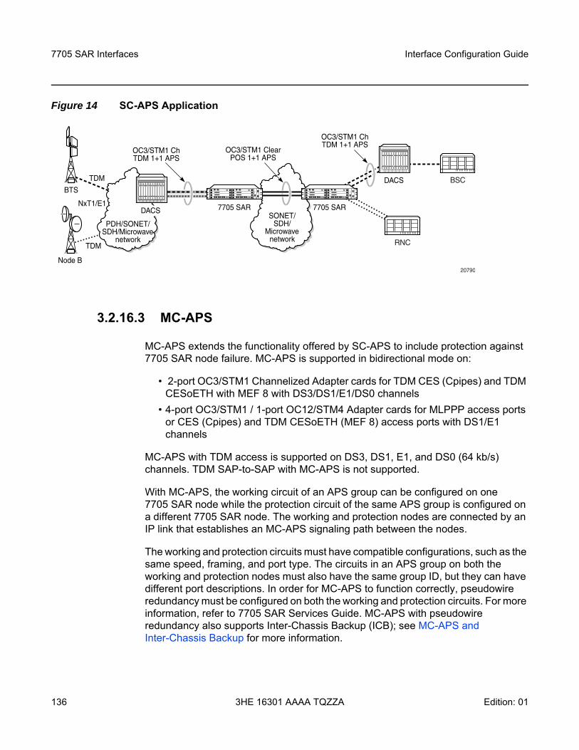
7705 SAR Interfaces
136
Interface Configuration Guide
3HE 16301 AAAA TQZZA Edition: 01
Figure 14 SC-APS Application
3.2.16.3 MC-APS
MC-APS extends the functionality offered by SC-APS to include protection against 7705 SAR node failure. MC-APS is supported in bidirectional mode on:
• 2-port OC3/STM1 Channelized Adapter cards for TDM CES (Cpipes) and TDM CESoETH with MEF 8 with DS3/DS1/E1/DS0 channels
• 4-port OC3/STM1 / 1-port OC12/STM4 Adapter cards for MLPPP access ports or CES (Cpipes) and TDM CESoETH (MEF 8) access ports with DS1/E1 channels
MC-APS with TDM access is supported on DS3, DS1, E1, and DS0 (64 kb/s) channels. TDM SAP-to-SAP with MC-APS is not supported.
With MC-APS, the working circuit of an APS group can be configured on one 7705 SAR node while the protection circuit of the same APS group is configured on a different 7705 SAR node. The working and protection nodes are connected by an IP link that establishes an MC-APS signaling path between the nodes.
The working and protection circuits must have compatible configurations, such as the same speed, framing, and port type. The circuits in an APS group on both the working and protection nodes must also have the same group ID, but they can have different port descriptions. In order for MC-APS to function correctly, pseudowire redundancy must be configured on both the working and protection circuits. For more information, refer to 7705 SAR Services Guide. MC-APS with pseudowire redundancy also supports Inter-Chassis Backup (ICB); see MC-APS and Inter-Chassis Backup for more information.
OC3/STM1 ClearATM 1+1 APS
BTS
PDH/SONET/SDH/Microwave
network
TDM
TDM
NxT1/E1
20790
RNC
Node B
DACSSONET/
SDH/Microwave
network
7705 SAR7705 SAR
BSCDACS
OC3/STM1 ChTDM 1+1 APS
OC3/STM1 ChTDM 1+1 APS
OC3/STM1 ClearPOS 1+1 APS
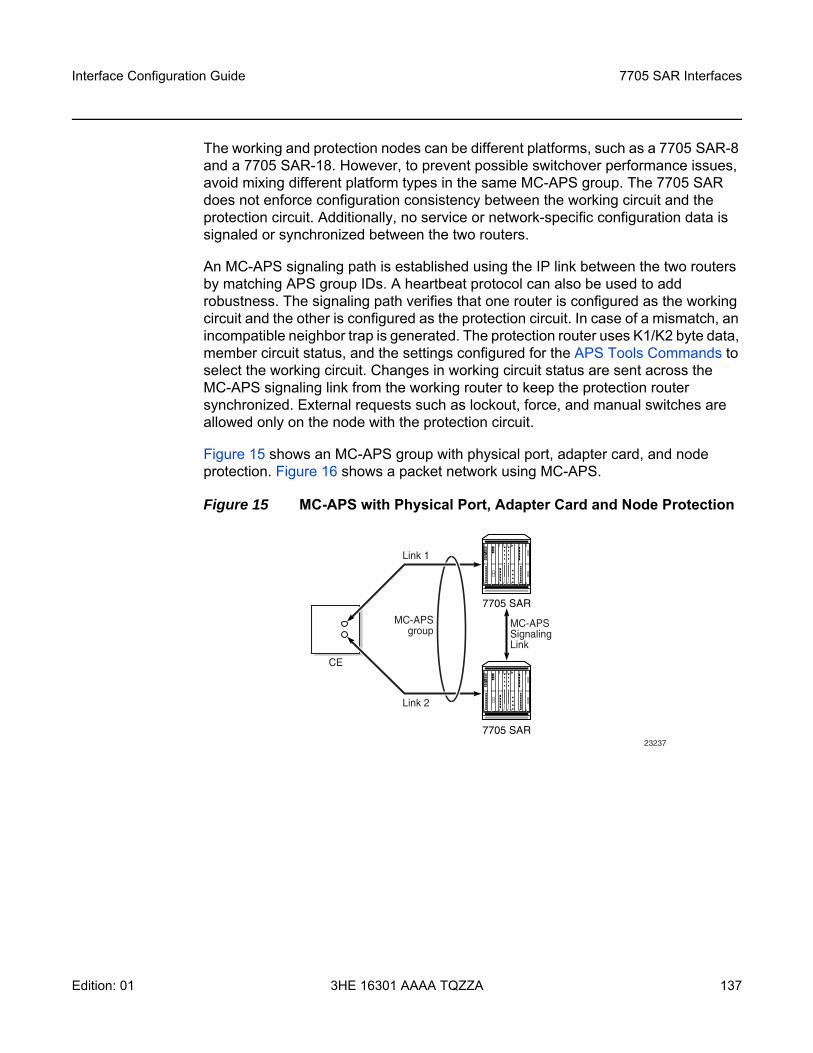
Interface Configuration Guide 7705 SAR Interfaces
Edition: 01 3HE 16301 AAAA TQZZA 137
The working and protection nodes can be different platforms, such as a 7705 SAR-8 and a 7705 SAR-18. However, to prevent possible switchover performance issues, avoid mixing different platform types in the same MC-APS group. The 7705 SAR does not enforce configuration consistency between the working circuit and the protection circuit. Additionally, no service or network-specific configuration data is signaled or synchronized between the two routers.
An MC-APS signaling path is established using the IP link between the two routers by matching APS group IDs. A heartbeat protocol can also be used to add robustness. The signaling path verifies that one router is configured as the working circuit and the other is configured as the protection circuit. In case of a mismatch, an incompatible neighbor trap is generated. The protection router uses K1/K2 byte data, member circuit status, and the settings configured for the APS Tools Commands to select the working circuit. Changes in working circuit status are sent across the MC-APS signaling link from the working router to keep the protection router synchronized. External requests such as lockout, force, and manual switches are allowed only on the node with the protection circuit.
Figure 15 shows an MC-APS group with physical port, adapter card, and node protection. Figure 16 shows a packet network using MC-APS.
Figure 15 MC-APS with Physical Port, Adapter Card and Node Protection
23237
7705 SAR
7705 SAR
MC-APSSignalingLink
MC-APSgroup
CE
Link 1
Link 2
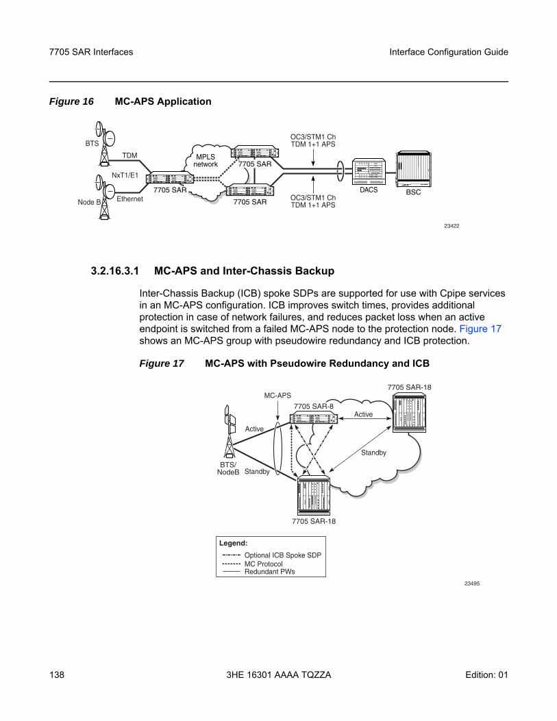
7705 SAR Interfaces
138
Interface Configuration Guide
3HE 16301 AAAA TQZZA Edition: 01
Figure 16 MC-APS Application
3.2.16.3.1 MC-APS and Inter-Chassis Backup
Inter-Chassis Backup (ICB) spoke SDPs are supported for use with Cpipe services in an MC-APS configuration. ICB improves switch times, provides additional protection in case of network failures, and reduces packet loss when an active endpoint is switched from a failed MC-APS node to the protection node. Figure 17 shows an MC-APS group with pseudowire redundancy and ICB protection.
Figure 17 MC-APS with Pseudowire Redundancy and ICB
MPLSnetwork
7705 SAR DACS BSC
7705 SAR
7705 SAR
TDM
BTS
Node B
NxT1/E1
Ethernet
OC3/STM1 ChTDM 1+1 APS
OC3/STM1 ChTDM 1+1 APS
23422
23495
Standby
Standby
Active
Active
MC-APS
Optional ICB Spoke SDP
Redundant PWs MC Protocol
Legend:
BTS/ NodeB
7705 SAR-8
7705 SAR-18
7705 SAR-18
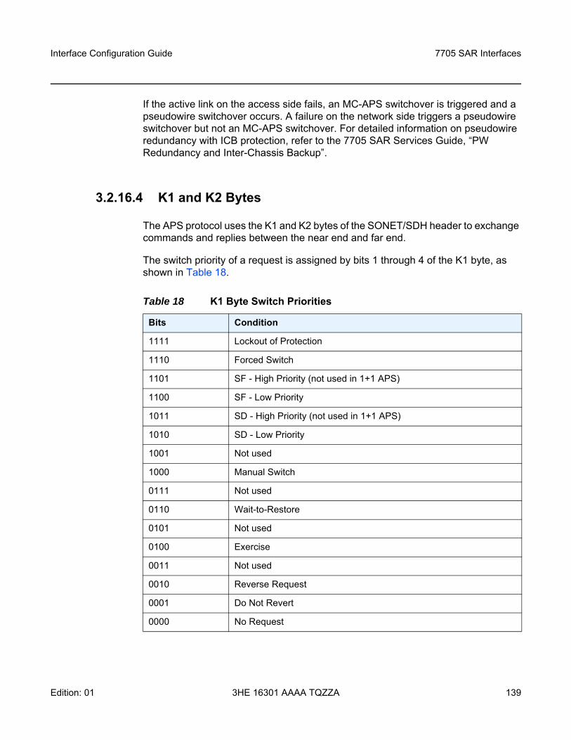
Interface Configuration Guide 7705 SAR Interfaces
Edition: 01 3HE 16301 AAAA TQZZA 139
If the active link on the access side fails, an MC-APS switchover is triggered and a pseudowire switchover occurs. A failure on the network side triggers a pseudowire switchover but not an MC-APS switchover. For detailed information on pseudowire redundancy with ICB protection, refer to the 7705 SAR Services Guide, “PW Redundancy and Inter-Chassis Backup”.
3.2.16.4 K1 and K2 Bytes
The APS protocol uses the K1 and K2 bytes of the SONET/SDH header to exchange commands and replies between the near end and far end.
The switch priority of a request is assigned by bits 1 through 4 of the K1 byte, as shown in Table 18.
Table 18 K1 Byte Switch Priorities
Bits Condition
1111 Lockout of Protection
1110 Forced Switch
1101 SF - High Priority (not used in 1+1 APS)
1100 SF - Low Priority
1011 SD - High Priority (not used in 1+1 APS)
1010 SD - Low Priority
1001 Not used
1000 Manual Switch
0111 Not used
0110 Wait-to-Restore
0101 Not used
0100 Exercise
0011 Not used
0010 Reverse Request
0001 Do Not Revert
0000 No Request
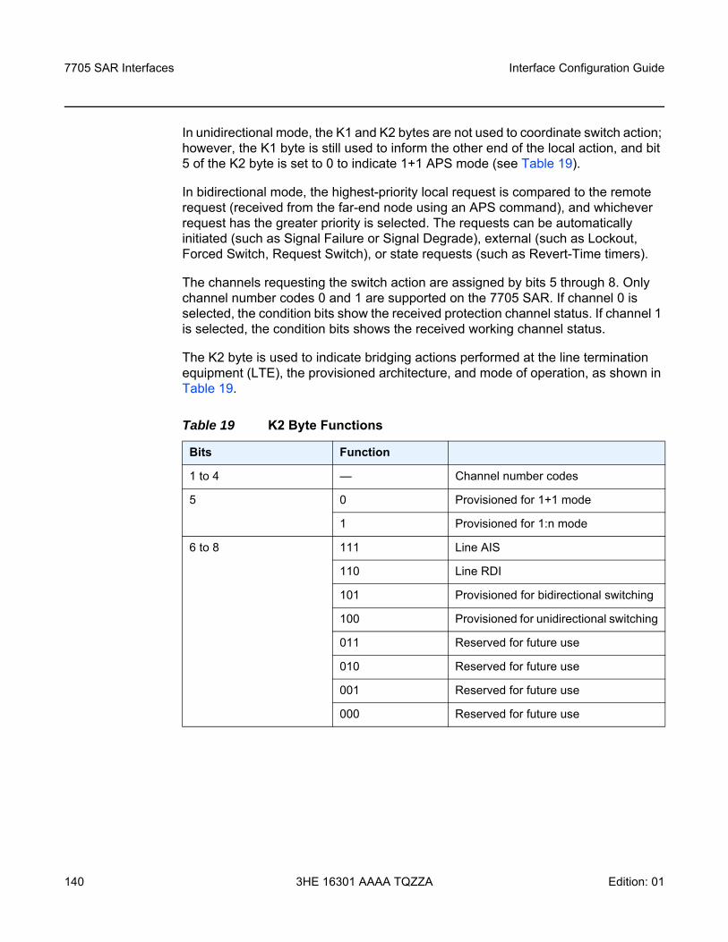
7705 SAR Interfaces
140
Interface Configuration Guide
3HE 16301 AAAA TQZZA Edition: 01
In unidirectional mode, the K1 and K2 bytes are not used to coordinate switch action; however, the K1 byte is still used to inform the other end of the local action, and bit 5 of the K2 byte is set to 0 to indicate 1+1 APS mode (see Table 19).
In bidirectional mode, the highest-priority local request is compared to the remote request (received from the far-end node using an APS command), and whichever request has the greater priority is selected. The requests can be automatically initiated (such as Signal Failure or Signal Degrade), external (such as Lockout, Forced Switch, Request Switch), or state requests (such as Revert-Time timers).
The channels requesting the switch action are assigned by bits 5 through 8. Only channel number codes 0 and 1 are supported on the 7705 SAR. If channel 0 is selected, the condition bits show the received protection channel status. If channel 1 is selected, the condition bits shows the received working channel status.
The K2 byte is used to indicate bridging actions performed at the line termination equipment (LTE), the provisioned architecture, and mode of operation, as shown in Table 19.
Table 19 K2 Byte Functions
Bits Function
1 to 4 — Channel number codes
5 0 Provisioned for 1+1 mode
1 Provisioned for 1:n mode
6 to 8 111 Line AIS
110 Line RDI
101 Provisioned for bidirectional switching
100 Provisioned for unidirectional switching
011 Reserved for future use
010 Reserved for future use
001 Reserved for future use
000 Reserved for future use
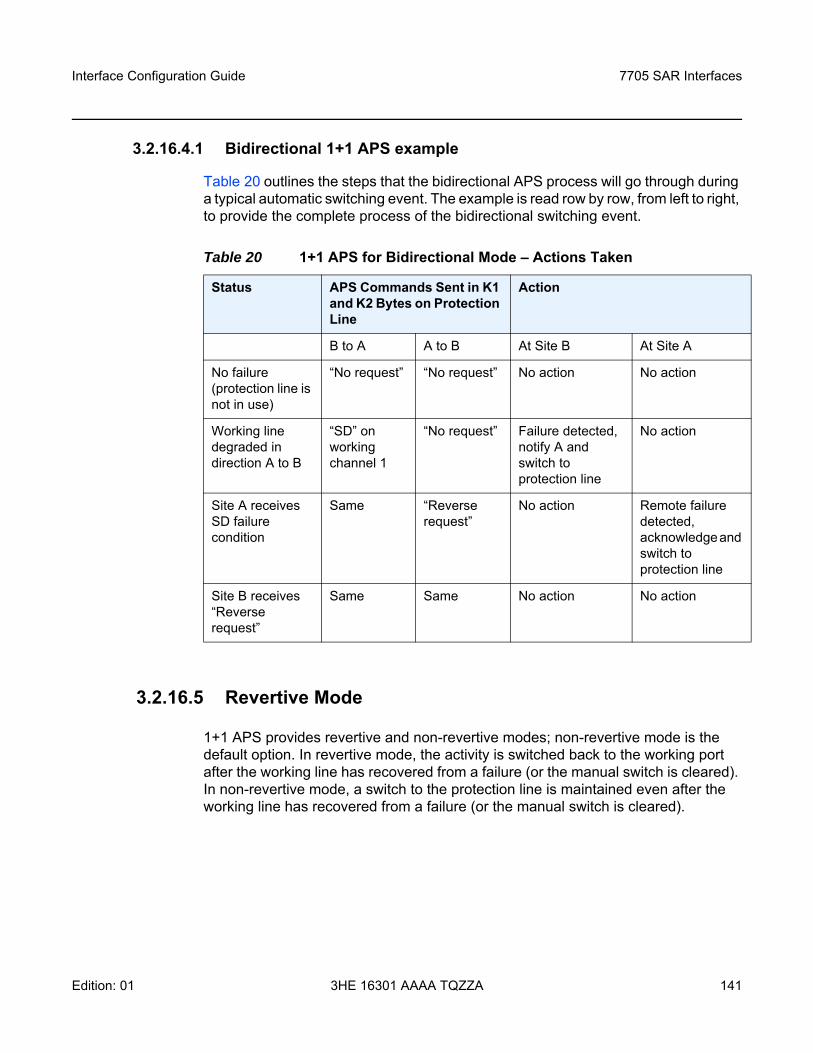
Interface Configuration Guide 7705 SAR Interfaces
Edition: 01 3HE 16301 AAAA TQZZA 141
3.2.16.4.1 Bidirectional 1+1 APS example
Table 20 outlines the steps that the bidirectional APS process will go through during a typical automatic switching event. The example is read row by row, from left to right, to provide the complete process of the bidirectional switching event.
3.2.16.5 Revertive Mode
1+1 APS provides revertive and non-revertive modes; non-revertive mode is the default option. In revertive mode, the activity is switched back to the working port after the working line has recovered from a failure (or the manual switch is cleared). In non-revertive mode, a switch to the protection line is maintained even after the working line has recovered from a failure (or the manual switch is cleared).
Table 20 1+1 APS for Bidirectional Mode – Actions Taken
Status APS Commands Sent in K1 and K2 Bytes on Protection Line
Action
B to A A to B At Site B At Site A
No failure (protection line is not in use)
“No request” “No request” No action No action
Working line degraded in direction A to B
“SD” on working channel 1
“No request” Failure detected, notify A and switch to protection line
No action
Site A receives SD failure condition
Same “Reverse request”
No action Remote failure detected, acknowledge and switch to protection line
Site B receives “Reverse request”
Same Same No action No action
7705 SAR Interfaces
142
Interface Configuration Guide
3HE 16301 AAAA TQZZA Edition: 01
To prevent frequent automatic switches that result from intermittent failures, a revert-time is defined for revertive switching. The revert-time is configurable from 0 to 60 min in increments of 1 min; the default value is 5 min. In some scenarios, performance issues can occur if the revert-time is set to 0; therefore, it is recommended that the revert-time always be set to a value of 1 or higher. Any change in the revert-time value takes effect upon the next initiation of the wait-to-restore (WTR) timer. The change does not modify the duration of a WTR timer that has already been started. The WTR timer of a non-revertive switch can be assumed to be infinite.
If both working and protection lines fail, the line that has less-severe errors will be active. If there is signal degradation on both ports, the active port that failed last will stay active. If there is signal failure on both ports, the working port will always be active because signal failure on the protection line is a higher priority than on the working line.
3.2.16.6 APS Tools Commands
3.2.16.6.1 Lockout Protection
The lockout protection command (tools>perform>aps>lockout) disables use of the protection line. Since the command has the highest priority, a failed working line using the protection line is switched back to itself even if it is in a fault condition. No switches to the protection line are allowed when the line is locked out. Refer to the 7705 SAR OAM and Diagnostics Guide, “Tools”, for information on the APS lockout command.
3.2.16.6.2 Request Switch of Active to Protection
The request or manual switch of active to protection command (tools>perform>aps> request) switches the active line to use the protection line (by issuing a manual switch request) unless a request of equal or higher priority is already in effect. If the active line is already on the protection line, no action takes place. Refer to the 7705 SAR OAM and Diagnostics Guide, “Tools”, for information on the APS request command.
Interface Configuration Guide 7705 SAR Interfaces
Edition: 01 3HE 16301 AAAA TQZZA 143
3.2.16.6.3 Request Switch of Active to Working
The request or manual switch of active to working command (tools>perform>aps> request) switches the active line back from the protection line to the working line (by issuing a manual switch request) unless a request of equal or higher priority is already in effect. If the active line is already on the working line, no action takes place. Refer to the 7705 SAR OAM and Diagnostics Guide, “Tools”, for information on the APS request command.
3.2.16.6.4 Forced Switch from Working to Protection
The command tools>perform>aps>force>working forces an activity switch away from the working line to the protection line unless a request of equal or higher priority is already in effect. When the forced switch of working to protection command is in effect, it may be overridden either by a lockout command or by a signal fault on the protection line. If the active line is already on the protection line, no action takes place. Refer to the 7705 SAR OAM and Diagnostics Guide, “Tools”, for information on the APS force command.
3.2.16.6.5 Forced Switch from Protection to Working
The command tools>perform>aps>force>protect forces an activity switch away from the protection line and back to the working line unless a request of equal or higher priority is already in effect. Refer to the 7705 SAR OAM and Diagnostics Guide, “Tools”, for information on the APS force command.
3.2.16.6.6 Exercise
The exercise command (tools>perform>aps>exercise) is only supported in 1+1 APS bidirectional mode. The Exercise command exercises the protection line by sending an exercise request over the protection line to the far end and expecting a reverse request response back. The switch is not completed during the exercise routine. Refer to the 7705 SAR OAM and Diagnostics Guide, “Tools”, for information on the APS exercise command.
7705 SAR Interfaces
144
Interface Configuration Guide
3HE 16301 AAAA TQZZA Edition: 01
3.2.16.7 APS Failure Codes
3.2.16.7.1 Protection Switching Byte Failure (APS-PSB)
This failure indicates that the received K1 byte is either invalid or inconsistent. An invalid code defect occurs if the same K1 value is received for three consecutive frames and is either an unused code or irrelevant for the specific switching operation. An inconsistent code defect occurs when no 3 consecutive received K1 bytes of the last 12 frames are the same.
If the failure persists for 2.5 s, a Protection Switching Byte alarm is raised. When this failure is declared, the protection line is treated as if it were in the SF state. The received signal is then selected from the working line.
When the failure is absent for 10 s, the alarm is cleared and the SF state of the protection line is removed.
This alarm can only be raised by the active port operating in bidirectional mode.
3.2.16.7.2 Channel Mismatch Failure (APS-CM)
This failure indicates that there is a channel mismatch between the transmitted K1 bytes and the received K2 bytes. A defect is declared when the received K2 channel number differs from the transmitted K1 channel number for more than 50 ms after 3 identical K1 bytes are sent. The monitoring for this condition is continuous, not just when the transmitted value of K1 changes.
If the failure persists for 2.5 s, a Channel Mismatch Failure alarm is raised. When this failure is declared, the protection line is treated as if it were in the SF state. The received signal is then selected from the working line.
When the failure is absent for 10 s, the alarm is cleared and the SF state of the protection line is removed.
This alarm can only be raised by the active port operating in bidirectional mode.
Interface Configuration Guide 7705 SAR Interfaces
Edition: 01 3HE 16301 AAAA TQZZA 145
3.2.16.7.3 APS Mode Mismatch Failure (APS-MM)
This failure can occur for two reasons. The first reason is that the received K2 byte indicates that 1:N protection switching is being used by the far end of the OC-N line, rather than 1+1 protection switching. The second reason is that the received K2 byte indicates that unidirectional mode is being used by the far end while the near end is using bidirectional mode. This defect is detected within 100 ms of receiving a K2 byte that indicates either of these conditions.
If the failure persists for 2.5 s, a Mode Mismatch Failure alarm is raised. When this failure is declared, if the defect indicates that the far end is configured for unidirectional mode, then the OC-N port reverts from its current bidirectional mode to unidirectional mode. However, the port continues to monitor the received K2 byte, and if the K2 byte indicates that the far end has switched to bidirectional mode, the OC-N port then reverts to bidirectional mode as well. The monitoring stops if the user explicitly reconfigures the local port to operate in unidirectional mode.
When the failure is absent for 10 s, the alarm is cleared, and the configured mode, which is 1+1 bidirectional, is used.
This alarm can only be raised by the active port operating in bidirectional mode.
3.2.16.7.4 Far-End Protection Line Failure (APS-FEPL)
This failure occurs when a K1 byte is received in three consecutive frames that indicates a signal fail (SF) at the far end of the protection line. This failure forces the received signal to be selected from the working line.
If the failure persists for 2.5 s, a Far-End Protection Line Failure alarm is raised. This alarm can only be raised by the active port operating in bidirectional mode. When the failure is absent for 10 s, the alarm is cleared.
7705 SAR Interfaces
146
Interface Configuration Guide
3HE 16301 AAAA TQZZA Edition: 01
3.2.17 T1/E1 Line Card Redundancy
This section contains information on the following topics:
• T1/E1 LCR Overview • SC-LCR • MC-LCR • Revertive Mode• LCR Tools Commands
3.2.17.1 T1/E1 LCR Overview
T1/E1 Line Card Redundancy (LCR) uses redundant adapter cards to protect T1/E1 services in case of hardware failures. T1/E1 LCR provides protection against adapter card or node failures. When T1/E1 LCR is used in conjunction with pseudowire redundancy, the network path between the endpoints is also protected. Protection is provided specifically for Cpipe services at the clear channel level and at the channelized level.
When T1/E1 LCR is enabled, the 7705 SAR constantly monitors the health of the adapter cards. If the active (working) adapter card fails (for example, because a card has been removed or due to a bus error), the system proceeds through a predefined sequence of steps to transfer (or switch over) traffic processing to the protection MDA. This switchover is done very quickly to minimize traffic loss. Traffic is moved to the protection adapter card until the fault on the working adapter card is cleared, at which time the traffic may optionally revert to the working adapter card.
T1/E1 LCR is supported on the following cards on 7705 SAR-8 (with CSMv2) and the 7705 SAR-18:
• 16-port T1/E1 ASAP Adapter card, version 2• 32-port T1/E1 ASAP Adapter card
T1/E1 LCR includes support for single-chassis LCR (SC-LCR) and multi-chassis LCR (MC-LCR). In an SC-LCR group, both the working and protection adapter cards must be configured on the same node. In an MC-LCR group, the working adapter card and protection adapter card are configured on two separate nodes, providing protection from node failure in addition to protection from adapter card hardware failure.
Interface Configuration Guide 7705 SAR Interfaces
Edition: 01 3HE 16301 AAAA TQZZA 147
3.2.17.2 SC-LCR
In an SC-LCR group, both the working and protection adapter cards are configured with the same LCR group ID on the same node. The working and protection adapter cards are required to be the same type.
SC-LCR is supported for TDM CES (Cpipes). SC-LCR with TDM access is supported on DS1, E1, and DS0 (64 kb/s) channels.
SC-LCR supports TDM SAP-to-SAP connections when both SAPs are configured as LCR SAPs.
SC-LCR also supports TDM SAP-to-spoke SDP connections over an MPLS network. In this configuration, the far-end connection may or may not be configured for LCR.
3.2.17.3 MC-LCR
MC-LCR extends the functionality offered by SC-LCR to include protection against 7705 SAR node failure. With MC-LCR, the working adapter card of an LCR group is configured on one 7705 SAR node while the protection adapter card of the same LCR group is configured on a different 7705 SAR node. The working and protection nodes are connected by an IP link (directly or indirectly) that establishes a multi-chassis protocol (MCP) link between the nodes.
MC-LCR is supported for TDM CES (Cpipes). MC-LCR with TDM access is supported on DS1, E1, and DS0 (64 kb/s) channels.
MC-LCR supports TDM SAP-to-SAP connections when both LCR SAPs are configured using the same adapter card on each node.
MC-LCR also supports TDM SAP-to-spoke SDP connections over an MPLS network. In this configuration, the far-end connection may or may not be configured for LCR.
The working and protection adapter cards must be the same type and must have compatible configurations, such as the same speed, framing, and port type. The adapter cards in an LCR group on both the working and protection nodes must also have the same group ID. The LCR groups can have different descriptions. In order for MC-LCR to function correctly, pseudowire redundancy must be configured on both the working and protection adapter cards. For information about pseudowire redundancy, refer to the 7705 SAR Services Guide, “Pseudowire Redundancy”. MC-LCR with pseudowire redundancy also supports Inter-Chassis Backup (ICB); see MC-LCR and Inter-Chassis Backup for more information.
7705 SAR Interfaces
148
Interface Configuration Guide
3HE 16301 AAAA TQZZA Edition: 01
An MCP link can be established using the IP link between the two nodes by matching LCR group IDs. The signaling path verifies that one node is configured as the working adapter card and the other is configured as the protection adapter card. In case of a mismatch, an incompatible neighbor trap is generated. The protection node uses member adapter card status and the settings configured in the LCR Tools Commands to select the working adapter card. Changes in working adapter card status are sent across the MC-LCR signaling link from the working node to keep the protection node synchronized. External requests such as lockout and force switch are allowed only on the node with the protection adapter card.
3.2.17.3.1 MC-LCR and Inter-Chassis Backup
ICB spoke SDPs are supported for use with Cpipe services in an MC-LCR configuration. ICB improves switch times, provides additional protection in case of network failures, and reduces packet loss when an active endpoint is switched from a failed MC-LCR node to the protection node.
If the active link on the access side fails, an MC-LCR switchover is triggered and a pseudowire switchover is subsequently triggered. A failure on the network side triggers a pseudowire switchover but not an MC-LCR switchover. For detailed information on pseudowire redundancy with ICB protection, refer to the 7705 SAR Services Guide, “PW Redundancy and Inter-Chassis Backup”.
3.2.17.4 Revertive Mode
T1/E1 LCR provides revertive and non-revertive modes; non-revertive mode is the default option. In revertive mode, the activity is switched back to the working adapter card after it has recovered from a failure. In non-revertive mode, a switch to the protection adapter card is maintained even after the working adapter card has recovered from a failure.
Note: The working and protection nodes can be different platforms, such as a 7705 SAR-8 and a 7705 SAR-18. However, to prevent possible switchover performance issues, avoid mixing different adapter card types in the same MC-LCR group. The 7705 SAR does not enforce configuration consistency between the working adapter card and the protection adapter card. Additionally, no service or network-specific configuration data is signaled or synchronized between the two nodes.
Interface Configuration Guide 7705 SAR Interfaces
Edition: 01 3HE 16301 AAAA TQZZA 149
To prevent frequent automatic switches that result from intermittent failures, a revert-time is defined for revertive switching. The revert-time is configurable from 0 to 60 min in increments of 1 min; the default value is 5 min. In some scenarios, performance issues can occur if the revert-time is set to 0; therefore, it is recommended that the revert-time always be set to a value of 1 or higher. Any change in the revert-time value takes effect upon the next initiation of the wait-to-restore (WTR) timer. The change does not modify the duration of a WTR timer that has already been started. The WTR timer of a non-revertive switch can be assumed to be infinite.
3.2.17.5 LCR Tools Commands
The LCR tools commands can only be executed on the node used in an SC-LCR group or on the protection node of an MC-LCR group. The commands can not be executed on the working node of an MC-LCR group.
3.2.17.5.1 Force Activity from Working Card
The tools>perform>lcr>force>working command forces activity away from the working adapter card to the protection adapter card so that the protection adapter card becomes active unless an internal request of equal or higher priority is already in effect. When this command is in effect, it can be overridden either by a tools>perform>lcr>lockout command or by a signal fault on the protection adapter card. If the protection adapter card is already the active adapter card, no action takes place. Refer to the 7705 SAR OAM and Diagnostics Guide, “Tools”, for information on the LCR force command.
3.2.17.5.2 Force Activity from Protection Card
The tools>perform>lcr>force>protect command forces activity away from the protection adapter card to the working adapter card so that the working adapter card becomes active unless an internal request of equal or higher priority is already in effect. Refer to the 7705 SAR OAM and Diagnostics Guide, “Tools”, for information on the LCR force command.
7705 SAR Interfaces
150
Interface Configuration Guide
3HE 16301 AAAA TQZZA Edition: 01
3.2.18 Deploying Preprovisioned Components
When a CSM or adapter card is installed in a preprovisioned slot, the system tests for discrepancies between the preprovisioned card and card type configurations and the types actually installed. Error messages are displayed if there are inconsistencies, and the card will not initialize. When the proper preprovisioned cards are installed into the appropriate chassis slot, then alarm, status, and performance details will be displayed on the CLI.
3.2.19 Microwave Link
This section contains information on the following topics:
• Microwave Link Overview• Standalone Mode• Single NE Mode• Frequency Synchronization• RSL History
3.2.19.1 Microwave Link Overview
A microwave link allows a 7705 SAR-8 or 7705 SAR-18 to be connected to a 9500 MPR-e radio node. The MPR-e is the zero-footprint (outdoor) microwave solution offered by Nokia that allows customers to migrate from TDM microwave to pure packet microwave. The following MPR-e radio variants are supported:
• MPT-MC - Microwave Packet Transport, Medium Capacity (ODU)• MPT-HC V2/9558HC - Microwave Packet Transport, High Capacity Version 2
(ODU)• MPT-XP - Microwave Packet Transport, High Capacity (very high power version
of the MPT-HC V2/9558HC) (ODU)• MPT-HQAM - Microwave Packet Transport, High Capacity (MPT-HC-QAM) or
Extended Power (MPT-XP-QAM) with 512/1024 QAM (ODU)• MPT-HLC and MPT-HLC plus - Microwave Packet Transport, High-Capacity
Long-Haul Cubic (ANSI) (IDU)
Interface Configuration Guide 7705 SAR Interfaces
Edition: 01 3HE 16301 AAAA TQZZA 151
A microwave link is configured on a 7705 SAR-8 or 7705 SAR-18 as a virtual port object (not as a physical port) using the CLI command mw-link-id (for more information on how to configure a microwave link, see Microwave Link Commands).
The supported microwave link types are 1+0 and 1+1 Hot Standby (HSB). To deploy an N+0 link (with N ≥ 2), multiple links of 1+0 can be configured separately.
A microwave link connection is made from ports 1 through 4 on a Packet Microwave Adapter card to an MPR-e radio using one of the methods described in the 7705 SAR Packet Microwave Adapter Card Installation Guide, “Delivering Data to an MPR-e Radio”. The radio can be configured in standalone mode to provide a basic microwave connection as described in Standalone Mode or in Single Network Element (Single NE) mode to provide the advanced networking capabilities described in Single NE Mode. The default configuration is Single NE mode.
When connected to an MPR-e radio, these ports, with microwave link configured, operate as Gigabit Ethernet ports and provide the same features as the other ports (ports 5 through 8), except for the following:
• 802.1x authentication• active/standby operation on Ethernet access ports configured as LAGs• hard policing on Ethernet ports
If a microwave link is not configured on ports 1 through 4, they provide all of the same features as the other Gigabit Ethernet ports (ports 5 through 8).
3.2.19.2 Standalone Mode
A microwave link from ports 1 through 4 on a Packet Microwave Adapter card to an MPR-e radio that is configured in standalone mode provides a basic microwave connection to the MPR-e radio. In standalone mode, each MPR-e radio that is connected to a 7705 SAR-8 or 7705 SAR-18 is managed as a separate standalone NE by the MPT Craft Terminal (MCT) Element Manager.
Note: Before a microwave link can be configured, the current 7705 SAR software package that includes the MPR-e radio software must be downloaded from OLCS to the 7705 SAR-8 or 7705 SAR-18. See MPR-e Radio Software and Upgrade Management for more information.
7705 SAR Interfaces
152
Interface Configuration Guide
3HE 16301 AAAA TQZZA Edition: 01
3.2.19.3 Single NE Mode
A microwave link from ports 1 through 4 on a Packet Microwave Adapter card to an MPR-e radio that is configured in Single NE mode provides the following networking capabilities to the radio over the microwave link:
• Single NE Management• Microwave Link Fast Fault Detection (FFD)• 1+1 HSB• 1+1 Switching Operation
3.2.19.3.1 Single NE Management
MWA allows the 7705 SAR-8 or 7705 SAR-18 and the MPR-e radios to which it is connected to be integrated and managed as a Single NE. The following features are part of Single NE management:
• One Management IP Address• MPR-e Radio Configuration Management• MPR-e Radio Alarm Management• MPR-e Radio Software and Upgrade Management• MPR-e Radio Configuration Database File Management• MPR-e Radio Inventory and Microwave Link Performance Statistics• MPR-e Radio Reset Control• MPR-e Radio Mute Control
One Management IP Address
The individual management and IP address of the MPR-e radios are no longer required for network management. When managing a microwave network (consisting of a 7705 SAR-8 or 7705 SAR-18 that is connected to one or more MPR-e radios) using an element/network manager, only the IP address of the 7705 SAR-8 or 7705 SAR-18 needs to be entered. This capability optimizes the microwave network’s IP addressing plan.
Interface Configuration Guide 7705 SAR Interfaces
Edition: 01 3HE 16301 AAAA TQZZA 153
MPR-e Radio Configuration Management
For an MPR-e configuration, the required MWA-specific parameters are configured on the 7705 SAR side using the CLI and the required non-MWA parameters are configured on the MPR-e side using the MCT.
The following MWA-specific parameters are configured on the 7705 SAR side:
• 1+1 HSB parameters• Epipe VLAN SAP parameters (in a mixed microwave link scenario, where there
is interworking between a 7705 SAR MPR-e system and a Wavence MSS system using a TDM2Ethernet service, specific MPR-e system parameters are configured under the Epipe VLAN SAP; for more information, refer to the 7705 SAR Services Guide, “Configuring Epipe SAP Microwave Link Parameters for Interworking with TDM2 Ethernet”).
The following parameters are configured on the MPR-e side:
• radio link parameters• QoS classification parameters
Configuration done on the MPR-e side is collected in a configuration file; this file can be saved to a 7705 SAR-8 or 7705 SAR-18 using the Commit button function on the MCT or an admin>save CLI command on the 7705 SAR-8 or 7705 SAR-18.
MPR-e Radio Alarm Management
An MPR-e radio generates alarms for fault conditions pertaining to the MPR-e hardware and to the microwave link over which it is connected. The alarms are sent to the 7705 SAR-8 or 7705 SAR-18, which turns the alarm notifications into SNMP traps and log events. These log events are controlled in the same way as all other events on the 7705 SAR-8 and 7705 SAR-18 and can be displayed using the show>log>event-control>mwmgr command. Refer to the 7705 SAR System Management Guide, “Event and Accounting Logs”, for more information.
MPR-e Radio Software and Upgrade Management
The Single NE capability optimizes the MPR-e radio software installation and upgrade process. The MPR-e radio software is bundled with the 7705 SAR software as one package, there is no need to look for and download the MPR-e radio software separately. The 7705 SAR software package containing the MPR-e radio software can be downloaded from a directory on OLCS. The operator can copy the software package onto a compact flash or network store on the 7705 SAR-8 or 7705 SAR-18.
7705 SAR Interfaces
154
Interface Configuration Guide
3HE 16301 AAAA TQZZA Edition: 01
MPR-e Radio Configuration Database File Management
An MPR-e radio’s database file is stored and backed up on a 7705 SAR-8 or 7705 SAR-18. If an old MPR-e radio is replaced by a new one, the new MPR-e radio downloads the MPR-e radio software from the 7705 SAR-8 or 7705 SAR-18, along with the backed-up database file of the old MPR-e radio. This means that the MPR-e radio does not need to be reconfigured after a radio hardware replacement.
A separate database file is required for each managed MPR-e radio. The user specifies the filename of the database file to be used during provisioning of the radio on the 7705 SAR-8 or 7705 SAR-18 using the config>port>mw>radio>database CLI command.
MPR-e Radio Inventory and Microwave Link Performance Statistics
The following MPR-e radio system information and microwave link information and statistics can be accessed through a CLI session on the 7705 SAR-8 or 7705 SAR-18:
• MPR-e radio system information- equipment type- inventory information- radio frequency band- temperature- radio transmit status
• microwave link statistics- MPR-e radio Ethernet statistics- local Tx power- local Rx power- remote Tx power- remote Rx power
Note: There are two TiMOS .zip files on OLCS that contain the current 7705 SAR software package; the file that contains the MPR-e radio software has the .MWA annotation in the filename. Only the MPR-e radio software that is bundled with this 7705 SAR software package is recognized as being valid by the 7705 SAR-8 or 7705 SAR-18.
Interface Configuration Guide 7705 SAR Interfaces
Edition: 01 3HE 16301 AAAA TQZZA 155
MPR-e Radio Reset Control
MPR-e radio reset control is provided on the 7705 SAR-8 or 7705 SAR-18. During an MPR-e radio reset, the microwave link is brought down and an upper layer applications action is triggered, such as message rerouting and clock source switching by the System Synchronization Unit (SSU).
MPR-e Radio Mute Control
MPR-e radio mute control can be enabled through the CLI/SNMP or by using the MCT. The MCT and CLI are synchronized to show the current state of the MPR-e radio mute function.
3.2.19.3.2 Microwave Link Fast Fault Detection (FFD)
The microwave link Fast Fault Detection (FFD) capability allows a 7705 SAR-8 or 7705 SAR-18 to directly detect MPR-e radio or microwave link faults using proprietary messaging. The following fault types are detected by FFD:
• a radio signal failure• an MPR-e radio hardware failure • an incompatible MPR-e radio setting• a High Bit Error Rate (HBER) condition• a Remote Defect Indication (RDI) condition
Note: Local/remote Rx power monitoring and local/remote Tx power monitoring are also known as Receive Signal Level (RSL) monitoring and Transmit Signal Level (TSL) monitoring, respectively.
Note: Administratively disabling the microwave link with which the MPR-e radio is associated (using the config>port>mw-link-id>shutdown command) causes the main and spare MPR-e radios to be muted.
7705 SAR Interfaces
156
Interface Configuration Guide
3HE 16301 AAAA TQZZA Edition: 01
If microwave link faults are detected, an event is logged and the link is disabled. Some detected faults may be selectively suppressed using the suppress-faults command. When faults are suppressed, the event is still logged, but the microwave link is not disabled. Operators can suppress HBER faults, RSL threshold crossing faults, and/or RDI faults. By default, the system does not suppress faults for FFD.
3.2.19.3.3 1+1 HSB
MWA uses 1+1 HSB to protect against microwave link, MPR-e radio, and Packet Microwave Adapter card failures, as well as frequency channel selective fading. Additionally, hitless (errorless) switching provides zero packet loss if a switchover occurs from a main to a spare MPR-e radio.
The following are required for 1+1 HSB:
• one frequency channel• two MWA Gigabit Ethernet ports (configured in network mode) on two different
Packet Microwave Adapter cards installed in adjacent slots (for example, slot 1/2 or slot 5/6); port 1 on one card protects port 1 on the adjacent card, port 2 protects port 2 on the adjacent card, and so on.
• two MPR-e radios (one main and one spare), each connected to one of the MWA Gigabit Ethernet ports on a Packet Microwave Adapter card
The following protection schemes make up 1+1 HSB:
• 1+1 Equipment Protection Switching (EPS)• 1+1 Transmission Protection Switching (TPS) • 1+1 Radio Protection Switching (RPS)
Note:
• FFD does not cause the SSU to disqualify the microwave link as a clock source if a fault condition is detected; SSM must be enabled in order to provide this function.
• The microwave link hold time (hold-up time and hold-down time) must be configured in order to suppress link flapping. The hold-up and hold-down times delay advertising the transition of the microwave link status to the upper layer applications, including IP/MPLS and SSU. The hold-time range is between 0 and 900 s.
Note: An MPR-e radio that is connected to an odd-numbered port on the Packet Microwave Adapter card must be configured as the main radio.
Interface Configuration Guide 7705 SAR Interfaces
Edition: 01 3HE 16301 AAAA TQZZA 157
• 1+1 HSB Transmit Diversity Antenna (TDA)
These protection schemes are enabled using the config>port>mw>protection command, with the exception of Transmit Diversity Antenna, which is enabled via the MCT. They interwork with each other as described in the sections that follow.
1+1 Equipment Protection Switching (EPS)
EPS protects against MPR-e radio, MWA Gigabit Ethernet link, and Packet Microwave Adapter card failures. After the radio frames are processed by the active EPS MPR-e radio, the radio sends the Ethernet traffic down to the 7705 SAR-8 or 7705 SAR-18. The standby EPS MPR-e radio does not send any Ethernet traffic down to the 7705 SAR-8 or 7705 SAR-18.
The switching criteria for EPS are:
• an MPR-e radio hardware failure• an MWA Gigabit Ethernet link failure between the 7705 SAR-8 or 7705 SAR-18
and an MPR-e radio• a Packet Microwave Adapter card connected to an active EPS MPR-e going into
a missing or failure state
1+1 Transmission Protection Switching (TPS)
In a 1+1 HSB configuration, TPS protects against a microwave link transmission failure by ensuring that only one MPR-e radio at a time uses the antenna for signaling. The 7705 SAR-8 or 7705 SAR-18 sends traffic to both the active and standby TPS MPR-e radios. Upon receiving the baseband traffic, both radios modulate it and up-convert it to signals. However, only the active TPS MPR-e radio transmits the RF signals; the standby TPS MPR-e radio suppresses the signals. When the active TPS MPR-e radio fails, standby radio becomes active and restores the microwave link channel.
The switching criteria for TPS are identical to EPS.
Note:
• The state of the EPS and TPS MPR-e radios are linked to each other. If an alarm occurs, an automatic switchover for EPS and TPS is activated simultaneously. However, if a manual switchover is configured, the switchover is decoupled and the state of the EPS and TPS MPR-e radios is no longer identical.
• A manual switchover can be configured for EPS but not for TPS.
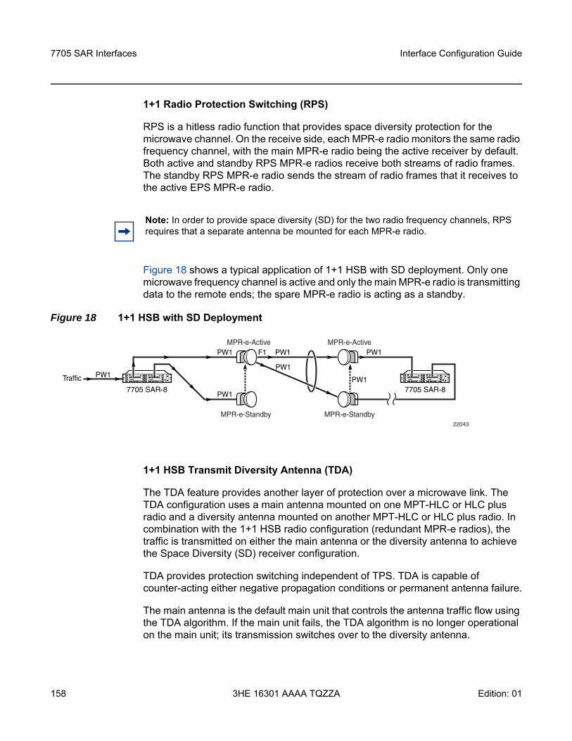
7705 SAR Interfaces
158
Interface Configuration Guide
3HE 16301 AAAA TQZZA Edition: 01
1+1 Radio Protection Switching (RPS)
RPS is a hitless radio function that provides space diversity protection for the microwave channel. On the receive side, each MPR-e radio monitors the same radio frequency channel, with the main MPR-e radio being the active receiver by default. Both active and standby RPS MPR-e radios receive both streams of radio frames. The standby RPS MPR-e radio sends the stream of radio frames that it receives to the active EPS MPR-e radio.
Figure 18 shows a typical application of 1+1 HSB with SD deployment. Only one microwave frequency channel is active and only the main MPR-e radio is transmitting data to the remote ends; the spare MPR-e radio is acting as a standby.
Figure 18 1+1 HSB with SD Deployment
1+1 HSB Transmit Diversity Antenna (TDA)
The TDA feature provides another layer of protection over a microwave link. The TDA configuration uses a main antenna mounted on one MPT-HLC or HLC plus radio and a diversity antenna mounted on another MPT-HLC or HLC plus radio. In combination with the 1+1 HSB radio configuration (redundant MPR-e radios), the traffic is transmitted on either the main antenna or the diversity antenna to achieve the Space Diversity (SD) receiver configuration.
TDA provides protection switching independent of TPS. TDA is capable of counter-acting either negative propagation conditions or permanent antenna failure.
The main antenna is the default main unit that controls the antenna traffic flow using the TDA algorithm. If the main unit fails, the TDA algorithm is no longer operational on the main unit; its transmission switches over to the diversity antenna.
Note: In order to provide space diversity (SD) for the two radio frequency channels, RPS requires that a separate antenna be mounted for each MPR-e radio.
7705 SAR-8
MPR-e-Active MPR-e-Active
MPR-e-StandbyMPR-e-Standby
Traffic PW1
PW1
PW1
PW1 PW1
PW1
PW1
22043
F1
7705 SAR-8
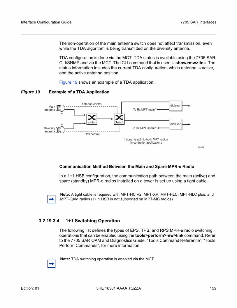
Interface Configuration Guide 7705 SAR Interfaces
Edition: 01 3HE 16301 AAAA TQZZA 159
The non-operation of the main antenna switch does not affect transmission, even while the TDA algorithm is being transmitted on the diversity antenna.
TDA configuration is done via the MCT. TDA status is available using the 7705 SAR CLI/SNMP and via the MCT. The CLI command that is used is show>mw>link. The status information includes the current TDA configuration, which antenna is active, and the active antenna position.
Figure 19 shows an example of a TDA application.
Figure 19 Example of a TDA Application
Communication Method Between the Main and Spare MPR-e Radio
In a 1+1 HSB configuration, the communication path between the main (active) and spare (standby) MPR-e radios installed on a tower is set up using a tight cable.
3.2.19.3.4 1+1 Switching Operation
The following list defines the types of EPS, TPS, and RPS MPR-e radio switching operations that can be enabled using the tools>perform>mw>link command. Refer to the 7705 SAR OAM and Diagnostics Guide, “Tools Command Reference”, “Tools Perform Commands”, for more information.
diplexerTo Rx MPT main*
diplexerTo Rx MPT spare*
SwitchSwitch
Mainantenna
Diversityantenna
Antenna control
TPS control
25879
*signal is split to both MPT radiosin controller applications
Note: A tight cable is required with MPT-HC V2, MPT-XP, MPT-HLC, MPT-HLC plus, and MPT-QAM radios (1+ 1 HSB is not supported on MPT-MC radios).
Note: TDA switching operation is enabled via the MCT.
7705 SAR Interfaces
160
Interface Configuration Guide
3HE 16301 AAAA TQZZA Edition: 01
• lockout—prevents the spare MPR-e radio from ever becoming the main radio, even when the main MPR-e radio fails; this operation overrides any forced, automatic, or manual operation
• forced —forces the spare MPR-e radio to become the main MPR-e radio, even though it might not be in a fit state to assume the role. A forced switch operation overrides any automatic or manual switch operation that is in place.
• automatic—allows an MPR-e radio to perform an automatic switchover if a fault condition exists. An automatic switch operation overrides any manual switch operation that is in place.
• manual—attempts to switch the main/spare status of an MPR-e radio; however, if port failures, equipment failures, and reception failures do not allow the switchover, an automatic switch operation is triggered.
You can also configure revertive switching for RPS and EPS/TPS (when revertive switching is configured for EPS, it is also applied to TPS; revertive switching for TPS cannot be configured separately). Revertive switching occurs when the MPR-e radio operation switches from the spare radio back to the main radio after a fault condition is cleared.
3.2.19.4 Frequency Synchronization
Depending on the type of Gigabit Ethernet microwave link used to connect the Packet Microwave Adapter card and an MPR-e radio, different frequency synchronization mechanisms can be used.
When using optical 1000Base-SX to connect the Packet Microwave Adapter card and an MPR-e radio, synchronous Ethernet and SSM are the frequency synchronization mechanisms that are used. SSM is used as the mechanism to detect a microwave link failure, including loss of frame and MPR-e radio hardware failure.
When using electrical 1000Base-T to connect the Packet Microwave Adapter card and an MPR-e radio, PCR is the frequency synchronization mechanism that is used (a copper SFP is mandatory on ports 3 and 4).
For more information on PCR, synchronous Ethernet, and SSM, refer to the 7705 SAR Basic System Configuration Guide, “Node Timing”.
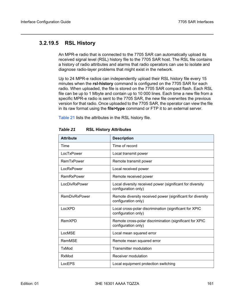
Interface Configuration Guide 7705 SAR Interfaces
Edition: 01 3HE 16301 AAAA TQZZA 161
3.2.19.5 RSL History
An MPR-e radio that is connected to the 7705 SAR can automatically upload its received signal level (RSL) history file to the 7705 SAR host. The RSL file contains a history of radio attributes and alarms that radio operators can use to isolate and diagnose radio-layer problems that might exist in the network.
Up to 24 MPR-e radios can independently upload their RSL history file every 15 minutes when the rsl-history command is configured on the 7705 SAR for each radio. When uploaded, the file is stored on the 7705 SAR compact flash. Each RSL file can be up to 1 Mbyte and contain up to 10 000 lines. Each time a new file from a specific MPR-e radio is sent to the 7705 SAR, the new file overwrites the previous version for that radio. Once uploaded to the 7705 SAR, the operator can view the file in its raw format using the file>type command or FTP it to an external server.
Table 21 lists the attributes in the RSL history file.
Table 21 RSL History Attributes
Attribute Description
Time Time of record
LocTxPower Local transmit power
RemTxPower Remote transmit power
LocRxPower Local received power
RemRxPower Remote received power
LocDivRxPower Local diversity received power (significant for diversity configuration only)
RemDivRxPower Remote diversity received power (significant for diversity configuration only)
LocXPD Local cross-polar discrimination (significant for XPIC configuration only)
RemXPD Remote cross-polar discrimination (significant for XPIC configuration only)
LocMSE Local mean squared error
RemMSE Remote mean squared error
TxMod Transmitter modulation
RxMod Receiver modulation
LocEPS Local equipment protection switching
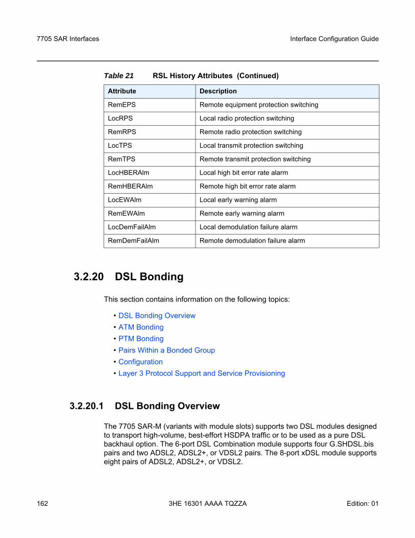
7705 SAR Interfaces
162
Interface Configuration Guide
3HE 16301 AAAA TQZZA Edition: 01
3.2.20 DSL Bonding
This section contains information on the following topics:
• DSL Bonding Overview• ATM Bonding• PTM Bonding• Pairs Within a Bonded Group• Configuration• Layer 3 Protocol Support and Service Provisioning
3.2.20.1 DSL Bonding Overview
The 7705 SAR-M (variants with module slots) supports two DSL modules designed to transport high-volume, best-effort HSDPA traffic or to be used as a pure DSL backhaul option. The 6-port DSL Combination module supports four G.SHDSL.bis pairs and two ADSL2, ADSL2+, or VDSL2 pairs. The 8-port xDSL module supports eight pairs of ADSL2, ADSL2+, or VDSL2.
RemEPS Remote equipment protection switching
LocRPS Local radio protection switching
RemRPS Remote radio protection switching
LocTPS Local transmit protection switching
RemTPS Remote transmit protection switching
LocHBERAlm Local high bit error rate alarm
RemHBERAlm Remote high bit error rate alarm
LocEWAlm Local early warning alarm
RemEWAlm Remote early warning alarm
LocDemFailAlm Local demodulation failure alarm
RemDemFailAlm Remote demodulation failure alarm
Table 21 RSL History Attributes (Continued)
Attribute Description
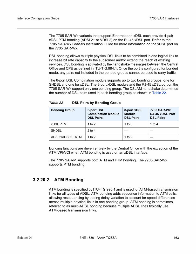
Interface Configuration Guide 7705 SAR Interfaces
Edition: 01 3HE 16301 AAAA TQZZA 163
The 7705 SAR-Wx variants that support Ethernet and xDSL each provide 4-pair xDSL PTM bonding (ADSL2+ or VDSL2) on the RJ-45 xDSL port. Refer to the 7705 SAR-Wx Chassis Installation Guide for more information on the xDSL port on the 7705 SAR-Wx.
DSL bonding allows multiple physical DSL links to be combined in one logical link to increase bit rate capacity to the subscriber and/or extend the reach of existing services. DSL bonding is activated by the handshake messages between the Central Office and CPE as defined in ITU-T G.994.1. Once the port is configured for bonded mode, any pairs not included in the bonded groups cannot be used to carry traffic.
The 6-port DSL Combination module supports up to two bonding groups, one for SHDSL and one for xDSL. The 8-port xDSL module and the RJ-45 xDSL port on the 7705 SAR-Wx support only one bonding group. The DSLAM handshake determines the number of DSL pairs used in each bonding group as shown in Table 22.
Bonding functions are driven entirely by the Central Office with the exception of the ATM VPI/VCI when ATM bonding is used on an xDSL interface.
The 7705 SAR-M supports both ATM and PTM bonding. The 7705 SAR-Wx supports PTM bonding.
3.2.20.2 ATM Bonding
ATM bonding is specified by ITU-T G.998.1 and is used for ATM-based transmission links for all types of ADSL. ATM bonding adds sequence information to ATM cells, allowing resequencing by adding delay variation to account for speed differences across multiple physical links in one bonding group. ATM bonding is sometimes referred to as multi-ADSL bonding because multiple ADSL lines typically use ATM-based transmission links.
Table 22 DSL Pairs by Bonding Group
Bonding Group 6-port DSL Combination Module DSL Pairs
8-port xDSL Module DSL Pairs
7705 SAR-Wx RJ-45 xDSL Port DSL Pairs
xDSL PTM 1 to 2 1 to 8 1 to 4
SHDSL 2 to 4 — —
ADSL2/ADSL2+ ATM 1 to 2 1 to 2 —
7705 SAR Interfaces
164
Interface Configuration Guide
3HE 16301 AAAA TQZZA Edition: 01
ATM bonding acts as an alternative to IMA as a method of logically combining multiple lines transmitting ATM cells. ATM bonding differs from IMA in the following ways:
• ATM links can run at different rates• differential delay does not need to be constant, but should be controlled to
minimize buffering requirements• the traffic header of transported ATM cells is modified to carry a sequence ID• traffic is distributed to the links at the discretion of the transmitter, rather than
strict round-robin order
The 8-port xDSL module and the xDSL interface of the 6-port DSL Combination module support 2-pair ATM bonding for ADSL2 and ADSL2+. When operating in ATM bonded mode, the remaining 6 pairs on the 8-port xDSL module cannot be used. Additionally, the only protocol stack supported is Ethernet over ATM with RFC 2684 LLC/SNAP bridged ATM packets. In ATM bonded mode, cell scrambling is always enabled and ATM CLP is disregarded (it is not set or inspected for priority loss indications). Any packet priority marking must be done at the Ethernet, MPLS, or IP layers.
In ATM channel-bonding schemes, the end-user packets are split into 53-byte cells. Each cell is tagged with a sequence ID by replacing bits in the ATM header with sequence ID (SID) bits between bonding entities. The ATM bonding implementation on the 7705 SAR-M currently only supports a 12-bit SID, although G.998.1 specifies support for either an 8-bit or 12-bit SID bound by the aggregate rate, differential delay, and number of links.
For ATM bonding, all bridged PDUs are sent without an FCS field. However, if an attached DSLAM does send bridged PDUs with an FCS field attached, the FCS is honored and is not removed or regenerated.
3.2.20.3 PTM Bonding
PTM bonding is specified by ITU-T G.998.2 and is supported on VDSL2, ADSL2, and ADSL2+ interfaces on the 6-port DSL Combination module and 8-port xDSL module, and on SHDSL on the 6-port DSL Combination module. The 7705 SAR-Wx variants that support Ethernet and xDSL provide 4-pair xDSL PTM bonding (ADSL2+ or VDSL2) on the RJ-45 xDSL port.
Interface Configuration Guide 7705 SAR Interfaces
Edition: 01 3HE 16301 AAAA TQZZA 165
PTM bonding and EFM bonding are sometimes used interchangeably, with EFM bonding generally used in conjunction with SHDSL. The SHDSL interface on a 6-port DSL Combination module complies with both PTM specified in ITU-T G.998.2, and EFM specified in IEEE 802.3ah-2004.
PTM bonding applies to DSL links with or without identical transmission speeds. Since PTM implies the use of variable-size PDUs, it makes the use of IMA techniques impossible. PTM bonding combines EFM-based transmission links with limited, or reach-dependent, bandwidth, specifically VDSL2, SHDSL, or ADSL2+ on the 7705 SAR-M and ADSL2+ or VDSL2 on the 7705 SAR-Wx. PTM bonding adds sequence information to transmitted frames or frame fragments, allowing resequencing by adding delay variation to account for speed and PDU size differences across multiple physical links in one bonding group.
In PTM channel-bonding schemes, the end-user packets are split into small fragments of up to 512 bytes. The PTM bonding implementation on xDSL ports uses a fixed fragment size of 204 bytes, which is not user-configurable. The PTM fragment size on the SHDSL ports is set to 256 bytes. When PTM bonding is active on a DSL bundle, fragments are distributed over individual DSL lines. At the receiving end, the fragments are realigned to recover from differential delays in the transmission path, then reassembled into packets.
In order to realign correctly, each fragment is prefixed with a header containing a sequence identifier (SID), a start of packet (SOP) indicator, and an end of packet (EOP) indicator. The receiver side uses the SID to rearrange the incoming cells in the correct order, while the SOP and EOP indications are used to reassemble the stream of cells into complete data packets. If transmitted Ethernet packets are smaller than the PTM fragment size, they are transmitted inside a single fragment.
3.2.20.4 Pairs Within a Bonded Group
Pairs within a bonded group must start with pair 1 and are then sequentially added into each module or port. For example, if a 4-pair bonded group is desired on an interface capable of supporting 4 or more pairs, pairs 1 through 4 should be connected to the DSLAM and configured by the DSLAM into the bonded group. For pinout diagrams, refer to the 7705 SAR DSL Module Installation Guide for RJ-11 pinouts and the 7705 SAR-Wx Chassis Installation Guide for RJ-45 pinouts.
On the ISAM, bonding makes use of either chipset or LT-level (Line Termination card-level) bonding. For LT-level bonding, the interworking function on the LT board allows non-contiguous ports on the same LT to be bonded. LT-level bonding is used to configure 8-pair bonding on the ISAM, which is also handled by dedicated hardware that incorporates both bonding and xDSL interworking functions. SHDSL bonding functions are provided on the ISAM via chipset level bonding.
7705 SAR Interfaces
166
Interface Configuration Guide
3HE 16301 AAAA TQZZA Edition: 01
Within a bonding group, the line used to identify the whole group is referred to as the primary link. The other lines in the bonding group are referred to as secondary or slave links. The supported bit rate over the bonding group is the sum of the actual net bit rates on all lines in the group.
3.2.20.5 Configuration
All DSL ports are considered the functional equivalent of an Ethernet port and support many of the same features and configuration commands. Data from the router’s central network processor transmit and receive Ethernet packets to and from the 7705 SAR-M module slot or 7705 SAR-Wx port.
If xDSL lines train in ATM bonding mode over ADSL2/2+, the VPI/VCI configured on that port is used by the module or platform to interwork Ethernet packets into AAL5 LLC snap-bridged PDUs without user intervention.
All lines for both the 6-port DSL Combination module and the 8-port xDSL module are configured from the ISAM via the G.994.1 (G.hs) handshake. All lines operate in auto-detect mode; therefore, there are no individual line configurations required with the exception of the configuration of VPI/VCI for ATM bonding and the configuration of ADSL2/2+ Annex B support if ISDN support is required, on an xDSL interface.
DSL modules and ports automatically detect any existing configuration and will attempt to bring pairs into service. For PTM bonding, the underlying transport mechanism is Ethernet. For ADSL2+ ATM bonding, the underlying transport mechanism is ATM, which requires a configured VPI/VCI. The default VPI/VCI on the 7705 SAR-M is 8/35, and only a single VC can be configured.
The only mode of operation for all SHDSL and xDSL pairs on the 7705 SAR-M is bonded mode. On the 7705 SAR-Wx, the only mode for xDSL pairs is PTM bonded mode.
Log files are created to record critical events during xDSL and SHDSL chipset initialization and for any DSL-related operational events. The log file can be viewed through the CLI or the NSP NFM-P for debugging and troubleshooting. The event data can be directed to the default log file or to a specific user-configured log file.
The CLI commands to configure DSL are found under the config>port>dsl context.
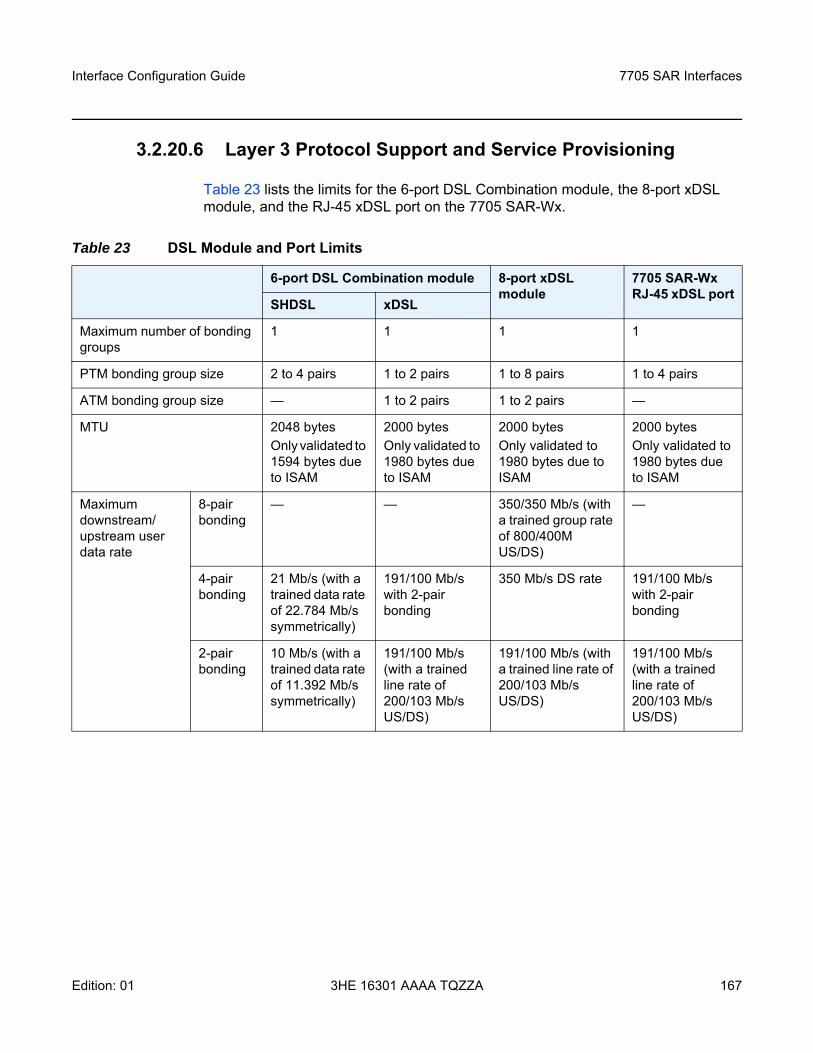
Interface Configuration Guide 7705 SAR Interfaces
Edition: 01 3HE 16301 AAAA TQZZA 167
3.2.20.6 Layer 3 Protocol Support and Service Provisioning
Table 23 lists the limits for the 6-port DSL Combination module, the 8-port xDSL module, and the RJ-45 xDSL port on the 7705 SAR-Wx.
Table 23 DSL Module and Port Limits
6-port DSL Combination module 8-port xDSL module
7705 SAR-Wx RJ-45 xDSL port
SHDSL xDSL
Maximum number of bonding groups
1 1 1 1
PTM bonding group size 2 to 4 pairs 1 to 2 pairs 1 to 8 pairs 1 to 4 pairs
ATM bonding group size — 1 to 2 pairs 1 to 2 pairs —
MTU 2048 bytesOnly validated to 1594 bytes due to ISAM
2000 bytesOnly validated to 1980 bytes due to ISAM
2000 bytesOnly validated to 1980 bytes due to ISAM
2000 bytesOnly validated to 1980 bytes due to ISAM
Maximum downstream/ upstream user data rate
8-pair bonding
— — 350/350 Mb/s (with a trained group rate of 800/400M US/DS)
—
4-pair bonding
21 Mb/s (with a trained data rate of 22.784 Mb/s symmetrically)
191/100 Mb/s with 2-pair bonding
350 Mb/s DS rate 191/100 Mb/s with 2-pair bonding
2-pair bonding
10 Mb/s (with a trained data rate of 11.392 Mb/s symmetrically)
191/100 Mb/s (with a trained line rate of 200/103 Mb/s US/DS)
191/100 Mb/s (with a trained line rate of 200/103 Mb/s US/DS)
191/100 Mb/s (with a trained line rate of 200/103 Mb/s US/DS)
7705 SAR Interfaces
168
Interface Configuration Guide
3HE 16301 AAAA TQZZA Edition: 01
3.2.21 Custom Alarms on Ethernet Ports
The 7705 SAR supports custom alarms on Ethernet ports without the need to deploy a dry-contact alarm aggregator. Custom alarms can be created and assigned to any RJ-45 port; the port must be configured for 100Base-Tx operation with autonegotiation disabled. One alarm input can be configured for each port with the following:
• name• description• association with a user-defined alarm
Alarm inputs must be associated with an alarm in order for them to be triggered. Alarm inputs consist of an Ethernet LOS event caused by breaking contact loops between pins 1 and 3 or 2 and 6 on the Ethernet port. Breaking either loop will trigger the port alarm, and reconnecting the loops will clear the alarm.
For information on configuring the alarm inputs, see Configuring Auxiliary Alarm Card, Chassis, and Ethernet Port External Alarm Parameters.
Interface Configuration Guide 7705 SAR Interfaces
Edition: 01 3HE 16301 AAAA TQZZA 169
3.3 802.1x Network Access Control
The 7705 SAR supports network access control over client devices on an Ethernet network using the IEEE 802.1x standard. 802.1x is a standard for authenticating Ethernet devices before they can access the network. In the case of the 7705 SAR, authentication is performed using Extensible Authentication Protocol (EAP) over LAN (EAPOL).
802.1x provides protection against unauthorized access by forcing the device connected to the 7705 SAR to go through an authentication phase before it is able to send any non-EAP packets. Only EAPOL frames can be exchanged between the aggregation device (called the authenticator; for example, the 7705 SAR) and the customer device (called the supplicant) until authentication is successfully completed. The 7705 SAR enables the port after successful authentication. While the port is unauthenticated, the port will be “down” to all upper layer protocols or services.
A typical use for EAPOL would involve a 7705 SAR and some type of Ethernet device, such as a laptop, a set-top box, or a Node B. An authentication server would negotiate with the Ethernet device through the 7705 SAR (whose role is authenticator). For example, a technician using a laptop to gain access to his or her network at a cell site would have his or her laptop subject to the 802.1x access control, just as the Node B would. In every case, the Ethernet device connected to the 7705 SAR must negotiate for network access. Essentially, with EAPOL in use, any Ethernet device that connects to the 7705 SAR must negotiate for permission to send traffic through the 7705 SAR Ethernet port.
The 7705 SAR supports the following EAP methods: MD5, TLS, TTLS, and PEAPv0.
MAC authentication can be used to authenticate client devices that do not support EAP. For more information, see MAC Authentication.
This section describes the following:
• 802.1x Basics• 802.1x Modes• 802.1x Timers• 802.1x Tunneling• 802.1x Configuration and Limitations
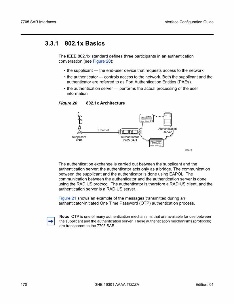
7705 SAR Interfaces
170
Interface Configuration Guide
3HE 16301 AAAA TQZZA Edition: 01
3.3.1 802.1x Basics
The IEEE 802.1x standard defines three participants in an authentication conversation (see Figure 20):
• the supplicant — the end-user device that requests access to the network• the authenticator — controls access to the network. Both the supplicant and the
authenticator are referred to as Port Authentication Entities (PAEs).• the authentication server — performs the actual processing of the user
information
Figure 20 802.1x Architecture
The authentication exchange is carried out between the supplicant and the authentication server; the authenticator acts only as a bridge. The communication between the supplicant and the authenticator is done using EAPOL. The communication between the authenticator and the authentication server is done using the RADIUS protocol. The authenticator is therefore a RADIUS client, and the authentication server is a RADIUS server.
Figure 21 shows an example of the messages transmitted during an authenticator-initiated One Time Password (OTP) authentication process.
SupplicanteNB
Ethernet Authenticationserver
Authenticator7705 SAR
21373
Note: OTP is one of many authentication mechanisms that are available for use between the supplicant and the authentication server. These authentication mechanisms (protocols) are transparent to the 7705 SAR.
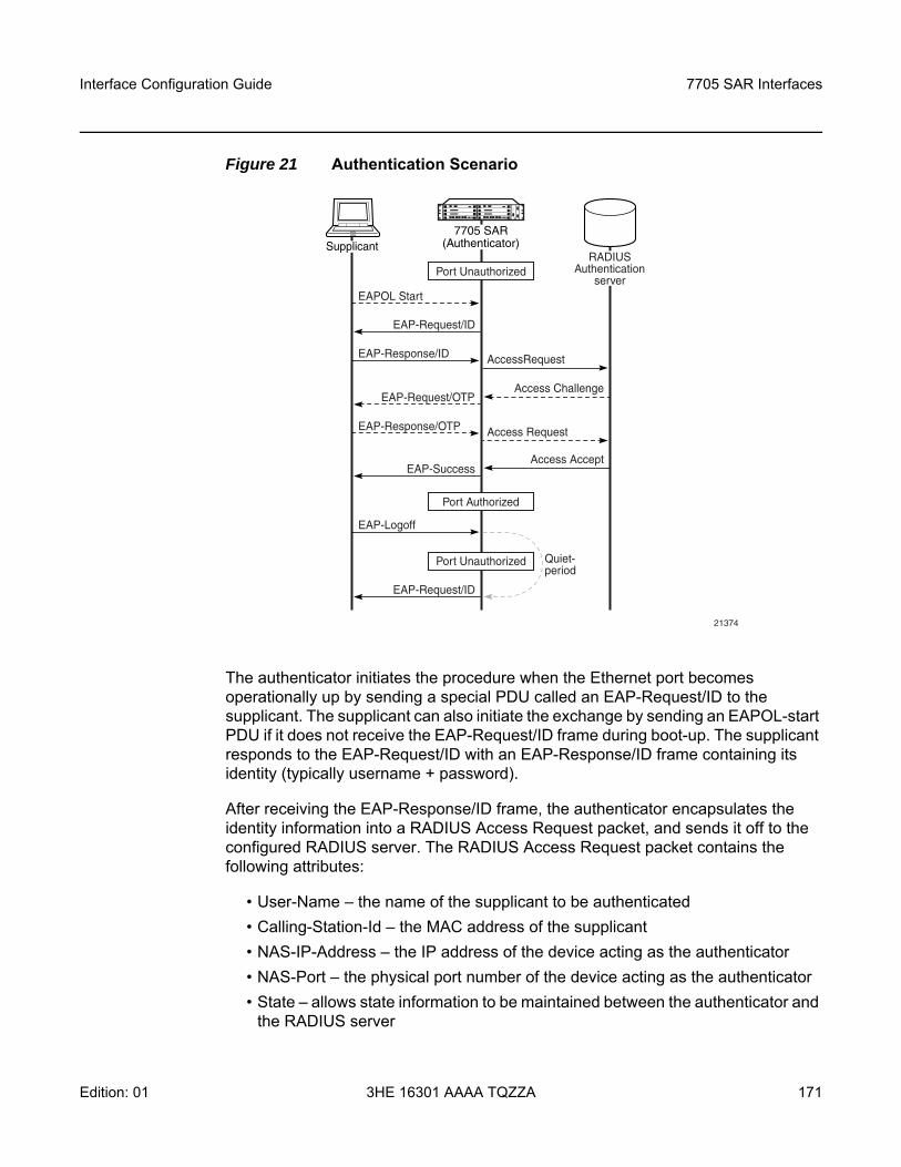
Interface Configuration Guide 7705 SAR Interfaces
Edition: 01 3HE 16301 AAAA TQZZA 171
Figure 21 Authentication Scenario
The authenticator initiates the procedure when the Ethernet port becomes operationally up by sending a special PDU called an EAP-Request/ID to the supplicant. The supplicant can also initiate the exchange by sending an EAPOL-start PDU if it does not receive the EAP-Request/ID frame during boot-up. The supplicant responds to the EAP-Request/ID with an EAP-Response/ID frame containing its identity (typically username + password).
After receiving the EAP-Response/ID frame, the authenticator encapsulates the identity information into a RADIUS Access Request packet, and sends it off to the configured RADIUS server. The RADIUS Access Request packet contains the following attributes:
• User-Name – the name of the supplicant to be authenticated• Calling-Station-Id – the MAC address of the supplicant• NAS-IP-Address – the IP address of the device acting as the authenticator• NAS-Port – the physical port number of the device acting as the authenticator• State – allows state information to be maintained between the authenticator and
the RADIUS server
AccessRequest
Access Request
Access Challenge
Access Accept
EAPOL Start
EAP-Response/ID
EAP-Request/ID
EAP-Response/OTP
EAP-Logoff
EAP-Request/OTP
EAP-Success
EAP-Request/ID
21374
Supplicant7705 SAR
(Authenticator)RADIUS
Authenticationserver
Quiet-period
Port Unauthorized
Port Authorized
Port Unauthorized
7705 SAR Interfaces
172
Interface Configuration Guide
3HE 16301 AAAA TQZZA Edition: 01
• EAP-Message – used to encapsulate EAP packets for transmission from the authenticator to the RADIUS server
• Message-Authenticator – used to authenticate and protect the integrity of Access Request messages in order to prevent spoofing attacks
The RADIUS server checks the supplied credentials using an authentication algorithm to verify the supplicant’s identity. If approved, the RADIUS server returns an Access Accept message to the authenticator. The authenticator notifies the supplicant with an EAP-Success message and puts the port in the authorized state.
If the supplicant sends an EAP-Logoff message, the authenticator puts the supplicant in an unauthorized state and continues searching for supplicants to authenticate.
After sending an EAP-Failure message, the authenticator puts the supplicant in an unauthorized state, waits for the number of seconds defined by the quiet-period timer, then continues searching for supplicants to authenticate.
The 7705 SAR conforms to the relevant sections of the 802.1X-2001 implementation.
3.3.2 802.1x Modes
The 7705 SAR supports port-based network access control for Ethernet ports only. Each Ethernet port can be configured to operate in one of three different modes, controlled by the port-control command:
• auto — enables 802.1x authentication. The port starts in the unauthorized state, allowing only EAPOL frames to be sent and received through the port. Both the authenticator and the host (supplicant) can initiate an authentication process as described earlier. The port will remain in the unauthorized state until the first supplicant is authenticated successfully. After this, traffic is allowed on the port for all connected hosts.
• force-auth — disables 802.1x authentication and causes the port to transition to the authorized state without requiring any authentication exchange. The port transmits and receives normal traffic without requiring 802.1x-based host authentication. This is the default setting.
• force-unauth — causes the port to remain in the unauthorized state, ignoring all attempts by the hosts to authenticate. The authenticator cannot provide authentication services to the host through the interface.
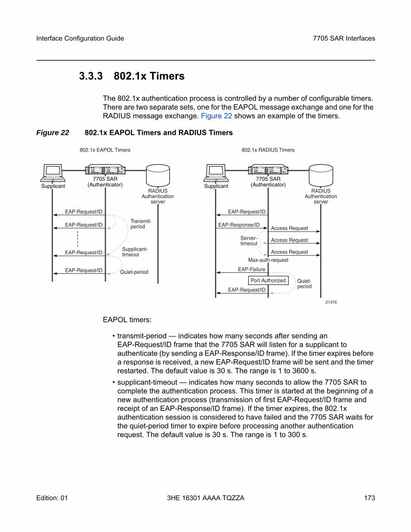
Interface Configuration Guide 7705 SAR Interfaces
Edition: 01 3HE 16301 AAAA TQZZA 173
3.3.3 802.1x Timers
The 802.1x authentication process is controlled by a number of configurable timers. There are two separate sets, one for the EAPOL message exchange and one for the RADIUS message exchange. Figure 22 shows an example of the timers.
Figure 22 802.1x EAPOL Timers and RADIUS Timers
EAPOL timers:
• transmit-period — indicates how many seconds after sending an EAP-Request/ID frame that the 7705 SAR will listen for a supplicant to authenticate (by sending a EAP-Response/ID frame). If the timer expires before a response is received, a new EAP-Request/ID frame will be sent and the timer restarted. The default value is 30 s. The range is 1 to 3600 s.
• supplicant-timeout — indicates how many seconds to allow the 7705 SAR to complete the authentication process. This timer is started at the beginning of a new authentication process (transmission of first EAP-Request/ID frame and receipt of an EAP-Response/ID frame). If the timer expires, the 802.1x authentication session is considered to have failed and the 7705 SAR waits for the quiet-period timer to expire before processing another authentication request. The default value is 30 s. The range is 1 to 300 s.
Quiet-period
Supplicant-timeout
Transmit-period
EAP-Request/ID
EAP-Request/ID
EAP-Request/ID
EAP-Request/ID
21376
Quiet-period
Server-timeout
Supplicant7705 SAR
(Authenticator)RADIUS
Authenticationserver
EAP-Request/ID
EAP-Response/IDAccess Request
Access Request
Access Request
EAP-Failure
EAP-Request/ID
Supplicant7705 SAR
(Authenticator)RADIUS
Authenticationserver
Port Authorized
Max-auth-request
802.1x EAPOL Timers 802.1x RADIUS Timers
7705 SAR Interfaces
174
Interface Configuration Guide
3HE 16301 AAAA TQZZA Edition: 01
• quiet-period — indicates the number of seconds that the authenticator will not search for clients after an unsuccessful EAP authentication. The timer is started after sending an EAP-Failure message or after expiry of the supplicant timeout timer. The default value is 60 s. The range is 1 to 3600 s.
RADIUS timers:
• max-auth-req — indicates the maximum number of times that the authenticator will send an authentication request to the RADIUS server before the process is considered as to have failed. The default value is 2. The range is 1 to 10.
• server-timeout — indicates how many seconds the authenticator will wait for a RADIUS response message. If the timer expires, the access request message is sent again, up to the max-auth-req value, and the timer is reset. The default value is 30 s. The range is 1 to 300 s.
The authenticator can also be configured to periodically trigger the authentication process automatically. This is controlled by the enable reauthentication and reauthentication period parameters. Re-auth-period indicates the time in seconds (since the last time that the authorization state was confirmed) before a new authentication process is started. The range of re-auth-period is 1 to 9000 s (the default is 3600 s). The port stays in an authorized state during the reauthentication process.
3.3.4 802.1x Tunneling
The 7705 SAR supports tunneling of untagged 802.1x frames received on a port for both Epipe and VPLS services using either null or default SAPs (for example1/1/1:0 or 1/1/1:*) when the port-control command is set to force-auth.
When tunneling is enabled on a port, untagged 802.1x frames are treated like user frames and are switched into Epipe or VPLS services that have a corresponding null SAP or default SAP on that port. If a port has a default SAP, other non-default SAPs could also be on the port. When received on a spoke SDP or mesh SDP, untagged 802.1x frames are tunneled by default. Untagged 802.1x frames received on other service types, or on network ports, are dropped.
802.1x tunneling must be enabled consistently across all ports in the LAG where 802.1x frames are expected. This is not enforced by the system.
Interface Configuration Guide 7705 SAR Interfaces
Edition: 01 3HE 16301 AAAA TQZZA 175
3.3.5 802.1x Configuration and Limitations
Configuration of 802.1x network access control on the authenticator consists of two parts:
• generic parameters, which are configured under config>system>security>dot1xRefer to the Basic System Configuration Guide, “System Command Reference”.
• port-specific parameters, which are configured under config>port>ethernet>dot1x
802.1x provides access to the port for any device, even if only a single client has been authenticated. Additionally, it can only be used to gain access to a predefined Service Access Point (SAP). It is not possible to dynamically select a service (such as a VPLS service) depending on the 802.1x authentication information.
7705 SAR Interfaces
176
Interface Configuration Guide
3HE 16301 AAAA TQZZA Edition: 01
3.4 MAC Authentication
The 7705 SAR supports the 802.1x EAP standard for authenticating Ethernet devices before they can access the network. However, if a client device does not support 802.1x EAP, MAC authentication can be used to prevent unauthorized traffic from being transmitted through the 7705 SAR.
802.1x EAP must be enabled for MAC authentication to be used, as MAC authentication is a fallback mechanism. To authenticate a port using MAC authentication, 802.1x authentication must first be configured on the 7705 SAR by enabling port-control auto, and then mac-auth must be configured on the 7705 SAR to enable MAC authentication.
When a port becomes operationally up with MAC authentication enabled, the following steps are performed by the 7705 SAR (as the authenticator):
1. After transmission of the first EAP-Request/ID PDU, the 7705 SAR starts the mac-auth-wait timer and begins listening on the port for EAP-Response/ID PDUs. At this point, the 7705 SAR only listens to EAPOL frames. If EAPOL frames are received, 802.1x authentication is chosen.
2. If the mac-auth-wait timer expires, and no EAPOL frames have been received, the 7705 SAR begins listening on the port for any Ethernet frames.
3. If the 7705 SAR receives an Ethernet frame, the 7705 SAR scans the client source MAC address in the frame and transmits the MAC address to the configured RADIUS server for comparison against the MAC addresses configured in its database.The following attributes are contained in the RADIUS message:- User-Name – the source MAC address of the client device- User-Password – the source MAC address of the client device in an
encrypted format- Service-Type – the type of service that the client has requested; the value
is set to 10 (call-check) for MAC authentication requests- Calling-Station-Id – the source MAC address of the client device- NAS-IP-Address – the IP address of the device acting as the authenticator- NAS-Port – the physical port of the device acting as the authenticator
Note: If it is known that the attached equipment does not support EAP, no mac-auth-wait can be configured so that MAC authentication can be used as soon as the port is operationally up.
Interface Configuration Guide 7705 SAR Interfaces
Edition: 01 3HE 16301 AAAA TQZZA 177
- Message-Authenticator – used to authenticate and protect the integrity of Access Request messages in order to prevent spoofing attacks
4. If the MAC address is approved by the RADIUS server, the 7705 SAR enables the port for traffic transmission.If the MAC address is rejected by the RADIUS server, the 7705 SAR enters a quiet period, configured using the quiet-period command, and will not authenticate the port via either 802.1x or MAC authentication. After the quiet period expires, the 7705 SAR returns to step 1.
5. If a port that was previously authenticated with MAC authentication receives an EAPOL-Start frame, the port will reauthenticate using 802.1x EAPOL.
While the port is unauthenticated, the port will be “down” to all upper layer protocols or services.
7705 SAR Interfaces
178
Interface Configuration Guide
3HE 16301 AAAA TQZZA Edition: 01
3.5 Link Layer Discovery Protocol (LLDP)
The IEEE 802.1ab Link Layer Discovery Protocol (LLDP) allows stations that are attached to the same IEEE 802 LAN (emulation) to advertise information for the purpose of populating physical or logical topology and device discovery management information databases. In other words, IEEE 802.1ab Link Layer Discovery Protocol allows an LLDP agent to learn connectivity and management information from adjacent stations. The information obtained via this protocol is stored in standard MIBs which can be accessed via management protocols such as SNMP.
LAN emulation and logical topology is applicable to customer bridge scenarios (enterprise or carrier of carrier) connected to a provider network offering a transparent LAN emulation service to their customers. LAN emulation helps customers detect intermediate provider misconnections by offering a view of the customer topology where the provider service is represented as a LAN interconnecting customer bridges.
The IEEE 802.1ab standard defines a protocol that:
• advertises connectivity and management information about the local station to adjacent stations on the same IEEE 802 LAN
• receives network management information from adjacent stations on the same IEEE 802 LAN
• operates with all IEEE 802 access protocols and network media• establishes a network management information schema and object definitions
that are suitable for storing connection information about adjacent stations• provides compatibility with a number of MIBs as shown in Figure 23
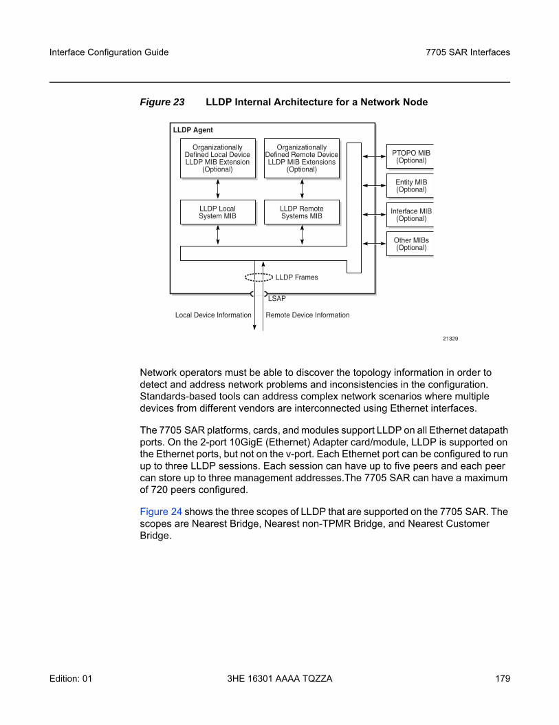
Interface Configuration Guide 7705 SAR Interfaces
Edition: 01 3HE 16301 AAAA TQZZA 179
Figure 23 LLDP Internal Architecture for a Network Node
Network operators must be able to discover the topology information in order to detect and address network problems and inconsistencies in the configuration. Standards-based tools can address complex network scenarios where multiple devices from different vendors are interconnected using Ethernet interfaces.
The 7705 SAR platforms, cards, and modules support LLDP on all Ethernet datapath ports. On the 2-port 10GigE (Ethernet) Adapter card/module, LLDP is supported on the Ethernet ports, but not on the v-port. Each Ethernet port can be configured to run up to three LLDP sessions. Each session can have up to five peers and each peer can store up to three management addresses.The 7705 SAR can have a maximum of 720 peers configured.
Figure 24 shows the three scopes of LLDP that are supported on the 7705 SAR. The scopes are Nearest Bridge, Nearest non-TPMR Bridge, and Nearest Customer Bridge.
21329
OrganizationallyDefined Local DeviceLLDP MIB Extension
(Optional)
LLDP LocalSystem MIB
OrganizationallyDefined Remote DeviceLLDP MIB Extensions
(Optional)
LLDP RemoteSystems MIB
PTOPO MIB(Optional)
Entity MIB(Optional)
Interface MIB(Optional)
Other MIBs(Optional)
LLDP Frames
LLDP Agent
Local Device Information Remote Device Information
LSAP
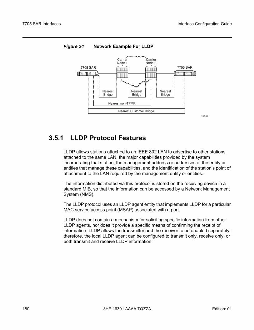
7705 SAR Interfaces
180
Interface Configuration Guide
3HE 16301 AAAA TQZZA Edition: 01
Figure 24 Network Example For LLDP
3.5.1 LLDP Protocol Features
LLDP allows stations attached to an IEEE 802 LAN to advertise to other stations attached to the same LAN, the major capabilities provided by the system incorporating that station, the management address or addresses of the entity or entities that manage these capabilities, and the identification of the station's point of attachment to the LAN required by the management entity or entities.
The information distributed via this protocol is stored on the receiving device in a standard MIB, so that the information can be accessed by a Network Management System (NMS).
The LLDP protocol uses an LLDP agent entity that implements LLDP for a particular MAC service access point (MSAP) associated with a port.
LLDP does not contain a mechanism for soliciting specific information from other LLDP agents, nor does it provide a specific means of confirming the receipt of information. LLDP allows the transmitter and the receiver to be enabled separately; therefore, the local LLDP agent can be configured to transmit only, receive only, or both transmit and receive LLDP information.
7705 SAR
NearestBridge
NearestBridge
NearestBridge
Nearest non-TPMR
Nearest Customer Bridge
7705 SAR
21544
CarrierNode 1
CarrierNode 2
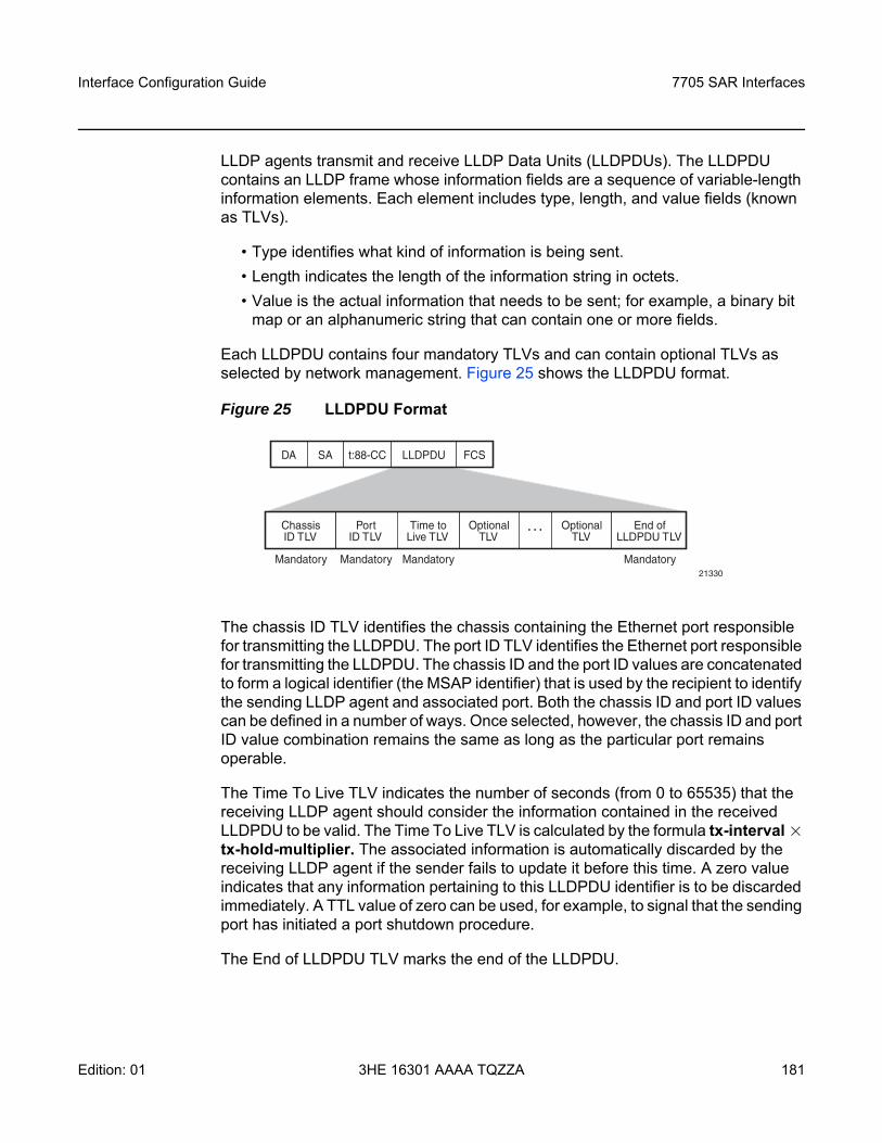
Interface Configuration Guide 7705 SAR Interfaces
Edition: 01 3HE 16301 AAAA TQZZA 181
LLDP agents transmit and receive LLDP Data Units (LLDPDUs). The LLDPDU contains an LLDP frame whose information fields are a sequence of variable-length information elements. Each element includes type, length, and value fields (known as TLVs).
• Type identifies what kind of information is being sent.• Length indicates the length of the information string in octets.• Value is the actual information that needs to be sent; for example, a binary bit
map or an alphanumeric string that can contain one or more fields.
Each LLDPDU contains four mandatory TLVs and can contain optional TLVs as selected by network management. Figure 25 shows the LLDPDU format.
Figure 25 LLDPDU Format
The chassis ID TLV identifies the chassis containing the Ethernet port responsible for transmitting the LLDPDU. The port ID TLV identifies the Ethernet port responsible for transmitting the LLDPDU. The chassis ID and the port ID values are concatenated to form a logical identifier (the MSAP identifier) that is used by the recipient to identify the sending LLDP agent and associated port. Both the chassis ID and port ID values can be defined in a number of ways. Once selected, however, the chassis ID and port ID value combination remains the same as long as the particular port remains operable.
The Time To Live TLV indicates the number of seconds (from 0 to 65535) that the receiving LLDP agent should consider the information contained in the received LLDPDU to be valid. The Time To Live TLV is calculated by the formula tx-interval × tx-hold-multiplier. The associated information is automatically discarded by the receiving LLDP agent if the sender fails to update it before this time. A zero value indicates that any information pertaining to this LLDPDU identifier is to be discarded immediately. A TTL value of zero can be used, for example, to signal that the sending port has initiated a port shutdown procedure.
The End of LLDPDU TLV marks the end of the LLDPDU.
DA SA FCSLLDPDUt:88-CC
ChassisID TLV
OptionalTLV
OptionalTLV
PortID TLV
Time toLive TLV
End ofLLDPDU TLV
Mandatory Mandatory Mandatory Mandatory
. . .
21330
7705 SAR Interfaces
182
Interface Configuration Guide
3HE 16301 AAAA TQZZA Edition: 01
The implementation defaults to setting the port-id field in the LLDP OAMPDU to tx-local. This encodes the port-id field as ifindex (subtype 7) of the associated port, which is required to support some releases of the NSP NFM-P. The NSP NFM-P may use the ifindex value to properly build the Layer 2 topology network map. However, this numerical value is difficult to interpret or readily identify the LLDP peer when reading the CLI or MIB value without using the NSP NFM-P. Including the port-desc option as part of the tx-tlv configuration allows a Nokia remote peer supporting port-desc preferred display logic to display the value in the port description TLV instead of the port-id field value. This does not change the encoding of the port-id field. The port-id field value continues to represent the ifindex. In some environments, it may be important to select the specific port information that is carried in the port-id field. The operator has the ability to control the encoding of the port-id information and the associated subtype using the port-id-subtype option. Three options are supported for the port-id-subtype:
• tx-if-alias — transmits the ifAlias string (subtype 1) that describes the port as stored in the IF-MIB, either a user-configured description or the default entry (that is, 10/100/Gig Ethernet SFP)
• tx-if-name — transmits the ifName string (subtype 5) that describes the port as stored in the IF-MIB, ifName information
• tx-local — the interface ifindex value (subtype 7)
IPv6 (address subtype 2) and IPv4 (address subtype 1) LLDP system management addresses are supported.
Interface Configuration Guide 7705 SAR Interfaces
Edition: 01 3HE 16301 AAAA TQZZA 183
3.6 Surveillance, Control, and Data Acquisition (SCADA) Support
SCADA systems are used in many strategic industry networks, such as utility and transportation, to monitor and maintain the networks from remote monitoring locations. SCADA systems use a master/slave architecture with a single master that supports multiple slave remote terminal units (RTUs).
Nokia addresses the needs of SCADA customers with the Integrated Services card. The Integrated Services card is a resource card that is capable of supporting software applications that specifically meet the requirements of TDM-based SCADA systems. The card is supported on the 7705 SAR-8 and the 7705 SAR-18.
The Integrated Services card supports the following SCADA applications:
• multidrop data bridge (MDDB)• pulse code modulation (PCM) multidrop bridge• voice conference bridge (VCB)
Only one application can be active on the card at a time.
The MDDB and PCM multidrop bridge applications feature similar architecture and functionality, with the main exception being that the MDDB application uses a serial RS-232, RS-530, or X.21 interface, while the PCM multidrop bridge application uses an E&M analog interface. The VCB application builds on the PCM architecture, using A-Law or Mu-Law encoding and an E&M analog interface.
3.6.1 Multidrop Data Bridge
The MDDB application provides a centralized digital bridging functionality that allows a SCADA bridge to be configured between a master and remote slaves. The bridge allows a single data message stream to be broadcast from a master to multiple slaves and allows a single slave to communicate back to the master.
In a SCADA network, the 7705 SAR provides the communications infrastructure to connect the central masters to multiple RTUs at remote locations, where the masters and RTUs communicate over serial RS-232, RS-530, or X.21 links (synchronous or asynchronous). The 7705 SAR-8 or 7705 SAR-18 located at the master site contains the Integrated Services card, which provides the MDDB bridge functionality and acts as the MDDB master. Remote 7705 SAR nodes connected to RTUs are referred to as MDDB slaves.
7705 SAR Interfaces
184
Interface Configuration Guide
3HE 16301 AAAA TQZZA Edition: 01
For both master and slave applications, the 7705 SAR must be physically connected to the SCADA device by one of the following:
• a 7705 SAR-8 or 7705 SAR-18 using the 12-port Serial Data Interface card (supports RS-232, RS-530, and X.21 links)
• a 7705 SAR-H using the 4-port T1/E1 and RS-232 Combination module (supports RS-232 links only)
• a 7705 SAR-Hc using an on-board RS-232 serial port (supports RS-232 links only)
The 12-port Serial Data Interface card, version 1 and version 2, supports the RS-530/RS-422 interface with the use of an adapter cable that connects to a DB15 connector on the front of the X.21 distribution panel. There is no configuration specifically for the RS-530/RS-422 interface; configuration is done in X.21 mode and applies to the RS-530/RS-422 interface when it is physically enabled through hardware. The 12-port Serial Data Interface card, version 3, provides RS-530 interface capability without the need for an adapter cable. For information about 12-port Serial Data Interface card adapter cables, refer to the 7705 SAR Serial Data Interface Card Installation Guide.
The remote nodes are connected to the SCADA bridge over an IP/MPLS network.
An Integrated Services card supports up to 16 SCADA bridges. Each bridge supports 32 branches. Two branches (branch 1 and branch 2) are dedicated connections to the SCADA masters; the other 30 branches connect to the slaves. An MDDB SCADA bridge is created using the config>scada bridge-id command and a branch is created using the config>scada>branch branch-id command.
Figure 26 shows a typical SCADA MDDB network. A Cpipe SAP is configured for each master and slave branch in order to transmit data to the bridge. The RS-232/X.21 traffic is converted to a 64 kb/s Cpipe using high capacity multiplexing (HCM). The Integrated Services card terminates the Cpipe (the slaves send data back over the IP/MPLS network), recovers the data directly from the Cpipe as an HCM frame, and sends the data to the bridge.
Note: Larger bridges can be built by cascading individual bridges internally within a single Integrated Services card and using the master output from one bridge as the slave input to another bridge. Larger bridges can be cascaded across multiple Integrated Services cards by using an RS-232, RS-530, or X.21 link.
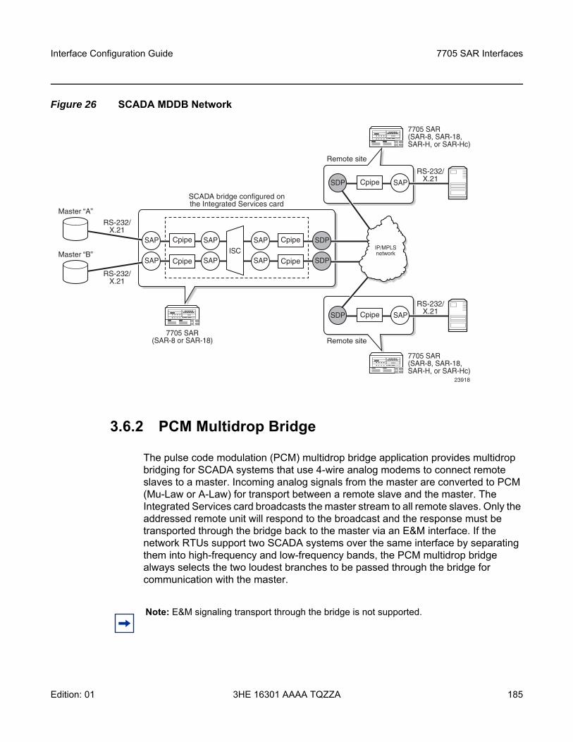
Interface Configuration Guide 7705 SAR Interfaces
Edition: 01 3HE 16301 AAAA TQZZA 185
Figure 26 SCADA MDDB Network
3.6.2 PCM Multidrop Bridge
The pulse code modulation (PCM) multidrop bridge application provides multidrop bridging for SCADA systems that use 4-wire analog modems to connect remote slaves to a master. Incoming analog signals from the master are converted to PCM (Mu-Law or A-Law) for transport between a remote slave and the master. The Integrated Services card broadcasts the master stream to all remote slaves. Only the addressed remote unit will respond to the broadcast and the response must be transported through the bridge back to the master via an E&M interface. If the network RTUs support two SCADA systems over the same interface by separating them into high-frequency and low-frequency bands, the PCM multidrop bridge always selects the two loudest branches to be passed through the bridge for communication with the master.
23918
Master “A”
Master “B”
SAP
SAP
SAP
SAP
SAP
SAPISC
Cpipe
Cpipe
Cpipe
Cpipe
7705 SAR(SAR-8 or SAR-18)
SAPCpipe
7705 SAR(SAR-8, SAR-18,SAR-H, or SAR-Hc)
Remote site
SDP
SDP
RS-232/X.21
RS-232/X.21
RS-232/X.21
SDP
SAPCpipe
7705 SAR(SAR-8, SAR-18,SAR-H, or SAR-Hc)
Remote site
RS-232/X.21SDP
IP/MPLSnetwork
SCADA bridge configured onthe Integrated Services card
Note: E&M signaling transport through the bridge is not supported.
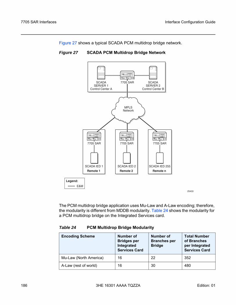
7705 SAR Interfaces
186
Interface Configuration Guide
3HE 16301 AAAA TQZZA Edition: 01
Figure 27 shows a typical SCADA PCM multidrop bridge network.
Figure 27 SCADA PCM Multidrop Bridge Network
The PCM multidrop bridge application uses Mu-Law and A-Law encoding; therefore, the modularity is different from MDDB modularity. Table 24 shows the modularity for a PCM multidrop bridge on the Integrated Services card.
Table 24 PCM Multidrop Bridge Modularity
Encoding Scheme Number of Bridges per Integrated Services Card
Number of Branches per Bridge
Total Number of Branches per Integrated Services Card
Mu-Law (North America) 16 22 352
A-Law (rest of world) 16 30 480
SCADA IED 1
Remote 1
SCADA IED 2
Remote 2
SCADA IED 255
Remote n
SCADASERVER 1
Control Center A
SCADASERVER 2
Control Center B
7705 SAR
7705 SAR 7705 SAR7705 SAR
MPLSNetwork
25433
E&M
Legend:
Interface Configuration Guide 7705 SAR Interfaces
Edition: 01 3HE 16301 AAAA TQZZA 187
A PCM SCADA bridge is created using the config>scada bridge-id command and a branch is created using the config>scada>branch branch-id command.
3.6.3 Redundant Masters
The MDDB and PCM multidrop bridge applications support redundant masters, where both masters listen to all traffic that is being transmitted from the slaves but only the active master broadcasts data to the slaves.
There are two modes for master redundancy:
• manual (default mode)In manual mode, if a master branch fails, the second master branch must be made active manually with the force-active command in order to receive data from the master input. The bridge always broadcasts to both master branches.
• autoIn auto mode, both master branch inputs are received simultaneously. This requires the master input behavior to be similar to an RTU; that is, only the active master transmits data and the standby master transmits either all 1s (MDDB) or no data (PCM). If the bridge is in auto mode, the force-active command cannot be used.
3.6.4 Squelch Functionality
A condition may occur where a single slave continues to send data to the master after the normal response period has expired. This condition locks up the bridge so that no other slave can transmit data back to the master. To resolve this condition, the squelch command can be enabled on a bridge or on an individual slave or master branch. Squelch is enabled by configuring a timeout period that, once expired, raises an alarm and triggers the squelching function. A normal quiescent traffic pattern (all 1s for MDDB and low volume for PCM multidrop) is inserted towards the bridge. This blocks the problematic slave so that other slaves can continue to use the bridge.
Note: Larger bridges can be built by cascading individual bridges internally within a single Integrated Services card and using the master output from one bridge as the slave input to another bridge. Larger bridges can be cascaded across multiple Integrated Services cards by using an E&M link.
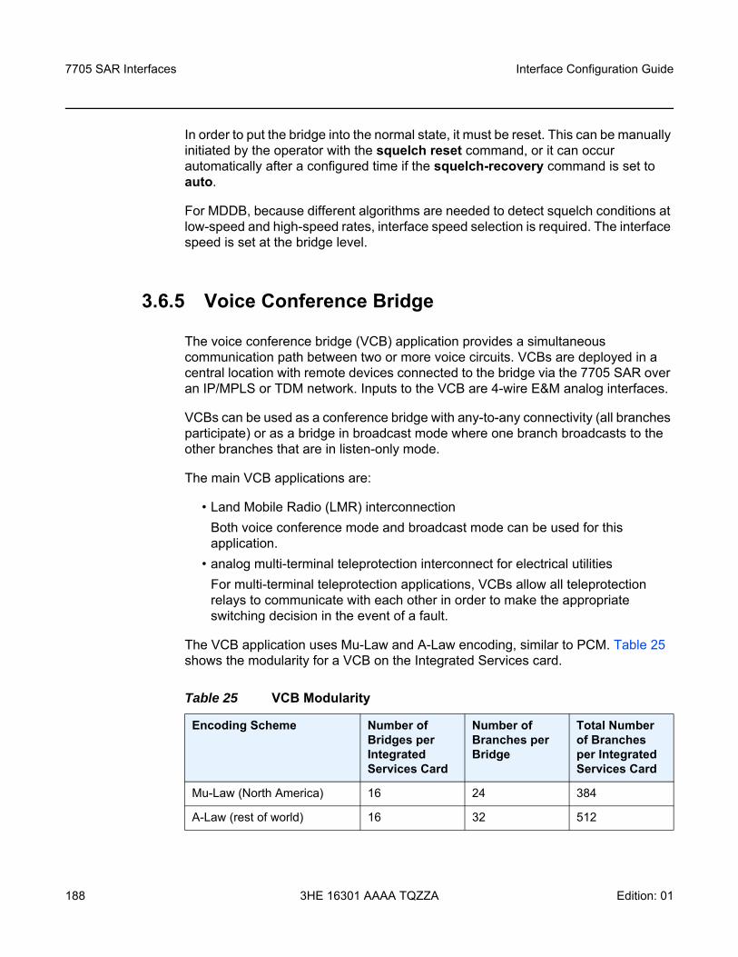
7705 SAR Interfaces
188
Interface Configuration Guide
3HE 16301 AAAA TQZZA Edition: 01
In order to put the bridge into the normal state, it must be reset. This can be manually initiated by the operator with the squelch reset command, or it can occur automatically after a configured time if the squelch-recovery command is set to auto.
For MDDB, because different algorithms are needed to detect squelch conditions at low-speed and high-speed rates, interface speed selection is required. The interface speed is set at the bridge level.
3.6.5 Voice Conference Bridge
The voice conference bridge (VCB) application provides a simultaneous communication path between two or more voice circuits. VCBs are deployed in a central location with remote devices connected to the bridge via the 7705 SAR over an IP/MPLS or TDM network. Inputs to the VCB are 4-wire E&M analog interfaces.
VCBs can be used as a conference bridge with any-to-any connectivity (all branches participate) or as a bridge in broadcast mode where one branch broadcasts to the other branches that are in listen-only mode.
The main VCB applications are:
• Land Mobile Radio (LMR) interconnectionBoth voice conference mode and broadcast mode can be used for this application.
• analog multi-terminal teleprotection interconnect for electrical utilitiesFor multi-terminal teleprotection applications, VCBs allow all teleprotection relays to communicate with each other in order to make the appropriate switching decision in the event of a fault.
The VCB application uses Mu-Law and A-Law encoding, similar to PCM. Table 25 shows the modularity for a VCB on the Integrated Services card.
Table 25 VCB Modularity
Encoding Scheme Number of Bridges per Integrated Services Card
Number of Branches per Bridge
Total Number of Branches per Integrated Services Card
Mu-Law (North America) 16 24 384
A-Law (rest of world) 16 32 512
Interface Configuration Guide 7705 SAR Interfaces
Edition: 01 3HE 16301 AAAA TQZZA 189
A VCB SCADA bridge is created using the config>scada bridge-id command and a branch is created using the config>scada>branch branch-id command.
3.6.5.1 VCB Applications
VCB can be configured in one of four applications. These applications are set at the card level. Each application uses a bridging algorithm that determines which branches control the management of the bridge and transmission of signals:
• VCBOne branch talks and all other branches on the bridge can hear.
• broadcastOnly one branch on the bridge (fixed as branch 1) has control of the bridge to transmit, and all other branches are in listen-only mode.
• VCB branch initiateBranches on the bridge are only enabled (unmuted) when the attached base station signals its presence by grounding the M-lead on the interface connected to the bridge. Upon receiving the grounded M-lead via T1/E1 ABCD bits or TDM PW signaling, the bridge unmutes the associated branch. When the ground is removed, the branch is muted again.
• teleprotectionEach teleprotection relay transmits state information on discrete frequencies so that each relay can both hear what the other relays are transmitting as well as transmit its own information to the other relays.
3.6.5.2 Gain
Gain is the increase or decrease in signal power or voltage that occurs in transmitting a signal from one point to another. The two types of gain are:
• input• output
Gain is configured at the branch level.
Note: Larger bridges can be built by cascading individual bridges internally within a single Integrated Services card. Larger bridges can be cascaded across multiple Integrated Services cards by using an E&M link or a channel group encapsulated for cem (TDM).
7705 SAR Interfaces
190
Interface Configuration Guide
3HE 16301 AAAA TQZZA Edition: 01
The input gain defines the magnitude of the increase or decrease of the signal transmitted into the bridge. The input gain range is –16 to +9 dB in 1-dB increments (the default is 0 dB).
The output gain defines the magnitude of the increase or decrease of the signal received from the bridge. The output gain range is –16 to +9 dB in 1-dB increments (the default is 0 dB).
3.6.6 Serial Transport Over Raw Sockets
Serial transport over raw sockets provides the capability of transporting serial data, in the form of characters, over an IP transport service within a Layer 3 IP/MPLS service (IES or VPRN). A raw socket allows direct sending and receiving of IP packets without any protocol-specific transport layer formatting. For information about raw socket IP transport services, refer to the 7705 SAR Services Guide, Service Overview chapter, “Raw Socket IP Transport Service”.
The feature provides the functionality for a local host to listen to and open raw socket sessions from remote hosts, and for a remote host to initiate and open raw socket sessions to local hosts. The local and remote host functions support TCP or UDP sessions (but not both concurrently) over the IP transport service.
Raw sockets are supported on the following hardware:
• RS-232 ports on the 12-port Serial Data Interface card, version 2 and version 3• RS-232 ports on the 7705 SAR-Hc• RS-232 ports on the 4-port T1/E1 and RS-232 Combination module
Figure 28 shows an example of a raw socket application, where serial data is transferred between RTUs and a utility’s SCADA management system using an IP transport service across a Layer 3 service (IES or VPRN), that includes 7705 SAR-H/Hc and 7705 SAR-8/18 nodes.
Note:
• RS-232 serial data can be carried over Cpipes or over raw sockets using IP transport. To use Cpipes, the RS-232 port must be configured with a channel ID. To use raw sockets, the RS-232 port must be configured with a socket ID.
• The 12-port Serial Data Interface card, version 2 and version 3, support a mix of Cpipes and raw socket serial links on the same card.
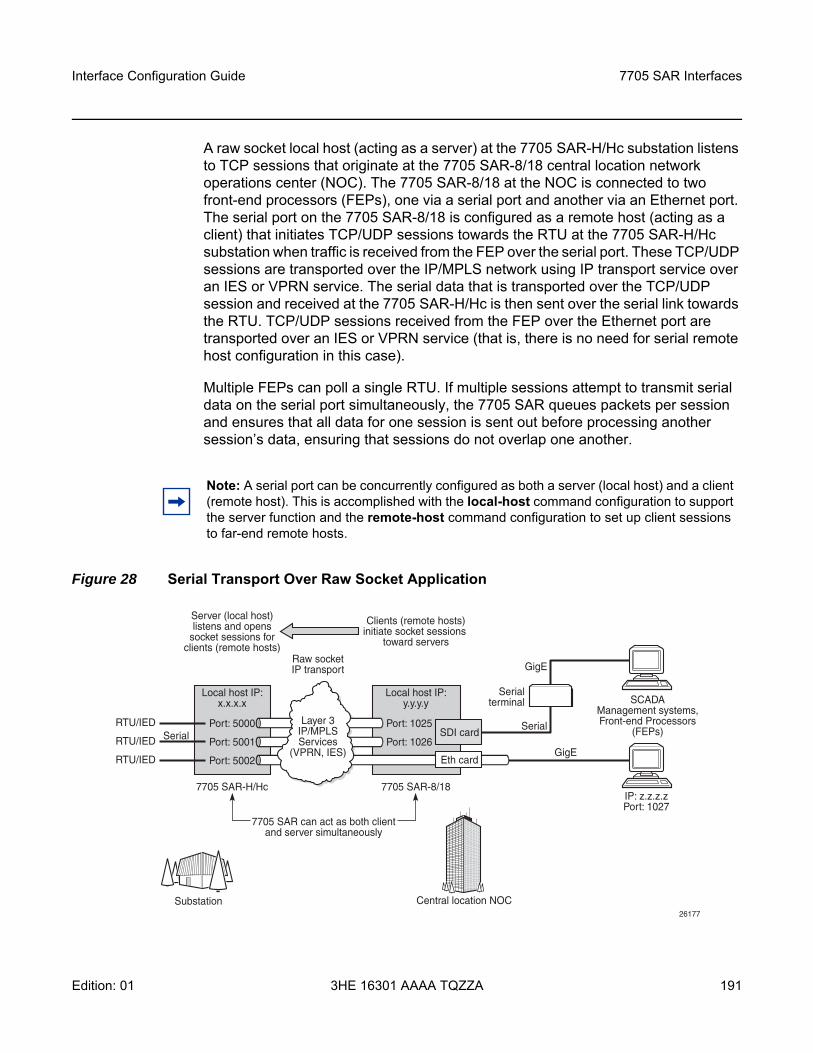
Interface Configuration Guide 7705 SAR Interfaces
Edition: 01 3HE 16301 AAAA TQZZA 191
A raw socket local host (acting as a server) at the 7705 SAR-H/Hc substation listens to TCP sessions that originate at the 7705 SAR-8/18 central location network operations center (NOC). The 7705 SAR-8/18 at the NOC is connected to two front-end processors (FEPs), one via a serial port and another via an Ethernet port. The serial port on the 7705 SAR-8/18 is configured as a remote host (acting as a client) that initiates TCP/UDP sessions towards the RTU at the 7705 SAR-H/Hc substation when traffic is received from the FEP over the serial port. These TCP/UDP sessions are transported over the IP/MPLS network using IP transport service over an IES or VPRN service. The serial data that is transported over the TCP/UDP session and received at the 7705 SAR-H/Hc is then sent over the serial link towards the RTU. TCP/UDP sessions received from the FEP over the Ethernet port are transported over an IES or VPRN service (that is, there is no need for serial remote host configuration in this case).
Multiple FEPs can poll a single RTU. If multiple sessions attempt to transmit serial data on the serial port simultaneously, the 7705 SAR queues packets per session and ensures that all data for one session is sent out before processing another session’s data, ensuring that sessions do not overlap one another.
Figure 28 Serial Transport Over Raw Socket Application
Note: A serial port can be concurrently configured as both a server (local host) and a client (remote host). This is accomplished with the local-host command configuration to support the server function and the remote-host command configuration to set up client sessions to far-end remote hosts.
Local host IP:x.x.x.x
Local host IP:y.y.y.y
RTU/IED
RTU/IED
RTU/IED
7705 SAR-H/Hc
Port: 5002
Port: 5001
Port: 5000 Layer 3IP/MPLSServices
(VPRN, IES)
Serial
7705 SAR-8/18
Port: 1025
Port: 1026
IP: z.z.z.zPort: 1027
SCADAManagement systems,Front-end Processors
(FEPs)SDI card
Eth card
Serialterminal
Serial
GigE
GigE
Raw socketIP transport
7705 SAR can act as both clientand server simultaneously
Server (local host)listens and opens
socket sessions forclients (remote hosts)
Clients (remote hosts)initiate socket sessions
toward servers
Substation26177
Central location NOC
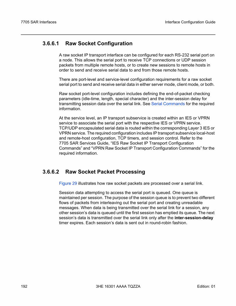
7705 SAR Interfaces
192
Interface Configuration Guide
3HE 16301 AAAA TQZZA Edition: 01
3.6.6.1 Raw Socket Configuration
A raw socket IP transport interface can be configured for each RS-232 serial port on a node. This allows the serial port to receive TCP connections or UDP session packets from multiple remote hosts, or to create new sessions to remote hosts in order to send and receive serial data to and from those remote hosts.
There are port-level and service-level configuration requirements for a raw socket serial port to send and receive serial data in either server mode, client mode, or both.
Raw socket port-level configuration includes defining the end-of-packet checking parameters (idle-time, length, special character) and the inter-session delay for transmitting session data over the serial link. See Serial Commands for the required information.
At the service level, an IP transport subservice is created within an IES or VPRN service to associate the serial port with the respective IES or VPRN service. TCP/UDP encapsulated serial data is routed within the corresponding Layer 3 IES or VPRN service. The required configuration includes IP transport subservice local-host and remote-host configuration, TCP timers, and session control. Refer to the 7705 SAR Services Guide, “IES Raw Socket IP Transport Configuration Commands” and “VPRN Raw Socket IP Transport Configuration Commands” for the required information.
3.6.6.2 Raw Socket Packet Processing
Figure 29 illustrates how raw socket packets are processed over a serial link.
Session data attempting to access the serial port is queued. One queue is maintained per session. The purpose of the session queue is to prevent two different flows of packets from interleaving out the serial port and creating unreadable messages. When data is being transmitted over the serial link for a session, any other session’s data is queued until the first session has emptied its queue. The next session’s data is transmitted over the serial link only after the inter-session-delay timer expires. Each session’s data is sent out in round-robin fashion.
Interface Configuration Guide 7705 SAR Interfaces
Edition: 01 3HE 16301 AAAA TQZZA 193
Figure 29 Raw Socket Packet Processing
3.6.6.2.1 Raw Socket Processing for UDP Sessions
When the local host receives a UDP packet from a remote host, it queues the packet and sends it over the serial link. The local host remembers the UDP session while there is still data to send from the serial link. If further packets are received for the same session, they are queued behind the already queued packet. After all the queued data has been sent over the serial link, the session is removed from the system. An associated UDP remote host for the serial link must be configured to have serial data sent back to the remote host from the serial port.
When a packet is received from the serial link based on end-of-packet (EOP) requirements, the data is copied and sent in a UDP packet to each configured remote host.
3.6.6.2.2 Raw Socket Processing for TCP Sessions
An open TCP session from a remote host to a raw socket’s local host is kept open until either the remote host terminates the session or the TCP inactivity timer expires. When a TCP session is open, all packets received from the remote host are queued for the raw socket serial link and sent over the serial link until no packets remain in the queue.
26210
RTU(1)
7705 SAR-18/8/H/Hc
Serialport
Substation Central location NOC
Configurable inter-sessiontime between each
queued data stream fromeach socket session
Packets are queued foreach group of socket sessionsuntil the serial line becomes
free to transmit
Round robin allsession queues(flush eachqueue beforeproceedingto next)
Src: Z, Dest: X, sPort: Bp, dPort: 5000
Src: Z, Dest: X, sPort: Ap, dPort: 5000
Src: C, Dest: X, sPort: Cp, dPort: 5000
Server (local host) sessions
Layer 3IP/MPLSservices
Ethport
7705 SAR Interfaces
194
Interface Configuration Guide
3HE 16301 AAAA TQZZA Edition: 01
If multiple sessions are open towards the local host, and each is receiving data, each session’s data is queued and then sent over the serial link in round-robin fashion for each session until no packets remain. When a packet is received over the serial link, it is copied to each open TCP session and transmitted to the remote host.
3.6.6.3 Raw Socket Squelch Functionality
A condition may occur where the end device connected to the serial port continues to send out a continuous stream of data after the normal response period has expired. This can prevent the far-end remote host or master equipment from receiving data from other end devices in the network. To resolve this condition, the squelch command can be used on the raw socket at the port level (it is disabled by default). This stops the socket from receiving any more data from the problematic device.
If the command is enabled, the 7705 SAR will monitor the serial port for a constant character stream. A configurable squelch delay period, using the squelch-delay command, is used to determine how long to measure the constant character stream before initiating the squelch function. If the squelch function is initiated, the port is considered locked up and an alarm is raised indicating the lock-up and that the squelching function has been triggered.
The serial port can be forced out of squelch and put back to normal, either manually using the squelch-reset command or automatically using the unsquelch-delay command. The unsquelch-delay command defines the time to wait after squelch is initiated before it is removed.
Interface Configuration Guide 7705 SAR Interfaces
Edition: 01 3HE 16301 AAAA TQZZA 195
3.7 Configuration Notes
The following information describes provisioning guidelines and caveats.
• The IOM can only be designated slot 1 of the chassis.• An IOM must be preprovisioned to accept specific adapter card types; the card
type is always iom-sar.If an adapter card type is installed in a slot provisioned for a different type, the card will not initialize.
• An adapter card installed in an unprovisioned slot remains administratively and operationally down until the IOM software is activated and the MDA slot and type is specified.
• Ports cannot be provisioned until the IOM software is activated and the MDA type is specified.
3.7.1 Reference Sources
For information on supported IETF drafts and standards as well as standard and proprietary MIBs, refer to Standards and Protocol Support.

7705 SAR Interfaces
196
Interface Configuration Guide
3HE 16301 AAAA TQZZA Edition: 01
Interface Configuration Guide 7705 SAR Interfaces
Edition: 01 3HE 16301 AAAA TQZZA 197
3.8 Configuring Physical Components with CLI
This section provides information to configure cards, adapter cards, and ports.
Topics in this section include:
• Preprovisioning Guidelines• Basic Configuration• Common Configuration Tasks• Service Management Tasks
7705 SAR Interfaces
198
Interface Configuration Guide
3HE 16301 AAAA TQZZA Edition: 01
3.9 Preprovisioning Guidelines
The 7705 SAR platforms each have two ports on the chassis to connect terminals for management access: a console port for a terminal connection and a management port for a Telnet connection.
The console port is used to configure parameters locally through a direct connection from a system console. The management port is used to configure parameters remotely through a connection to a remote workstation, using Telnet or SSH to open a secure shell connection.
For more information about management connections, refer to the appropriate chassis installation guide, in the section on router management connections.
3.9.1 Predefining Entities
In order to initialize an adapter card, the IOM type and adapter card type must match the preprovisioned parameters. In this context, preprovisioning means to configure the entity type (IOM type, adapter card type, port, and interface) that is planned for an adapter card. Preprovisioned entities can be installed but not enabled, or the slots can be configured but remain empty until populated. Provisioning means that the preprovisioned entity is installed and enabled.
You can preprovision ports and interfaces after the IOM is activated (card slot and card type are designated) and adapter card types are specified.
3.9.2 Preprovisioning a Port or SCADA Bridge
Before a port or SCADA bridge can be configured, the adapter card slot must be preprovisioned with an allowed adapter card type (for a SCADA bridge, the only type allowed is isc, for the Integrated Services card).
Preprovisioning recommendations (for ports only) include:
• Ethernet- Configure an access port for customer-facing traffic on which services are
configured. - Configure a network port for uplink traffic.
Interface Configuration Guide 7705 SAR Interfaces
Edition: 01 3HE 16301 AAAA TQZZA 199
An encapsulation type must be specified in order to distinguish services on the access port. Encapsulation types must also be specified for network ports. By default, the encapsulation type for Ethernet ports in network mode is null.
• SONET/SDH- SONET/SDH can be used only when configuring an OC-3 or OC-12 SONET
path on an appropriate adapter card.- Configure a network port or channel to participate in the service provider
transport or infrastructure network. To configure a SONET path, see Configuring SONET/SDH Port Parameters.
• Channelized- Channelized ports can be configured on the 16-port T1/E1 ASAP Adapter
card, 32-port T1/E1 ASAP Adapter card, 2-port OC3/STM1 Channelized Adapter card, 4-port OC3/STM1 / 1-port OC12/STM4 Adapter card, 8-port Voice & Teleprotection card (access mode only), 8-port C37.94 Teleprotection card (access mode only), 8-port FXO Adapter card (access mode only), 6-port FXS Adapter card (access mode only), 4-port DS3/E3 Adapter card (DS3 ports only), 12-port Serial Data Interface card (access mode only), 6-port E&M Adapter card (access mode only) and 4-port T1/E1 and RS-232 Combination module.
- Configure an access port for customer-facing traffic on which services are configured.
- Configure a network port for uplink traffic.An encapsulation type must be specified in order to distinguish services on the access port or channel. For network mode, the encapsulation type is set to ppp-auto and cannot be changed.
7705 SAR Interfaces
200
Interface Configuration Guide
3HE 16301 AAAA TQZZA Edition: 01
3.9.3 Maximizing Bandwidth Use
After ports are preprovisioned, multilink bundles (MLPPP) or IMA groups can be configured to increase the bandwidth available between two nodes.
The following cards, modules, and platforms support multilink bundles:
• 16-port T1/E1 ASAP Adapter card• 32-port T1/E1 ASAP Adapter card• 2-port OC3/STM1 Channelized Adapter card• 4-port OC3/STM1 / 1-port OC12/STM4 Adapter card• T1/E1 ports on the 4-port T1/E1 and RS-232 Combination module (on
7705 SAR-H)• T1/E1 ports on the 7705 SAR-A (variants with T1/E1 ports)• T1/E1 ports on the 7705 SAR-M (variants with T1/E1 ports)• T1/E1 ports on the 7705 SAR-X
The following cards, modules, and platforms support IMA groups:
• 2-port OC3/STM1 Channelized Adapter card• 16-port T1/E1 ASAP Adapter card• 32-port T1/E1 ASAP Adapter card• T1/E1 ports on the 7705 SAR-M (variants with T1/E1 ports)
All physical links or channels in a bundle or group combine to form one logical connection. A bundle or group also provides redundancy in case one or more links that participate in the bundle fail. For command syntax, see Configuring Multilink PPP Bundles. To configure channelized ports for TDM, see Configuring Channelized Ports.
For 12-port Serial Data Interface cards and the RS-232 ports on the 4-port T1/E1 and RS-232 Combination module, some or all of a port bandwidth can be dedicated to a channel by aggregating a number of DS0s into a single bundle. Serial data transmission rates below the rate of a single DS0, that is, less than 64 kb/s, are achieved using the High Capacity Multiplexing (HCM) proprietary protocol. These rates are known as subrates, and are supported only when operating in RS-232 mode or X.21 mode.
Note: A DS0 channel operating at a rate less than 64 kb/s still uses a full 64 kb/s timeslot.
Interface Configuration Guide 7705 SAR Interfaces
Edition: 01 3HE 16301 AAAA TQZZA 201
3.9.4 Using Partial Bandwidth
Fractional T1/E1 allows one or more DS0 channels to be bundled together (up to the maximum bandwidth of the network link), allowing the customer to use only that portion of the link that is needed. This means that the PPP service can use a selected number of timeslots (octets) in the network T1 or E1 link, thus reducing the amount of T1 or E1 bandwidth that must be leased or purchased from the attached carrier. This leads to multiplexing efficiencies in the transport network.
The following cards and platforms support fractional T1/E1 on a PPP channel group (encapsulation type ppp-auto), or all timeslots on T1/E1 ports, in network mode:
• 16-port T1/E1 ASAP Adapter card• 32-port T1/E1 ASAP Adapter card• T1/E1 ports on the 4-port T1/E1 and RS-232 Combination module (on
7705 SAR-H)• T1/E1 ports on the 7705 SAR-A (variants with T1/E1 ports)• T1/E1 ports on the 7705 SAR-M (variants with T1/E1 ports)• T1/E1 ports on the 7705 SAR-X
Only one channel group can be configured per port. When the channel group is configured for ppp-auto encapsulation and network mode, all timeslots (channels) are automatically allocated to the channel group. The user can then configure the number of timeslots needed. Timeslots not selected cannot be used.
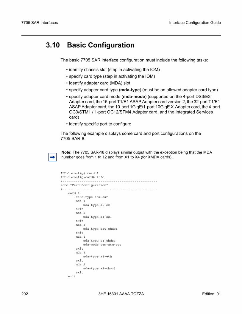
7705 SAR Interfaces
202
Interface Configuration Guide
3HE 16301 AAAA TQZZA Edition: 01
3.10 Basic Configuration
The basic 7705 SAR interface configuration must include the following tasks:
• identify chassis slot (step in activating the IOM)• specify card type (step in activating the IOM)• identify adapter card (MDA) slot• specify adapter card type (mda-type) (must be an allowed adapter card type) • specify adapter card mode (mda-mode) (supported on the 4-port DS3/E3
Adapter card, the 16-port T1/E1 ASAP Adapter card version 2, the 32-port T1/E1 ASAP Adapter card, the 10-port 1GigE/1-port 10GigE X-Adapter card, the 4-port OC3/STM1 / 1-port OC12/STM4 Adapter card, and the Integrated Services card)
• identify specific port to configure
The following example displays some card and port configurations on the 7705 SAR-8.
ALU-1>config# card 1ALU-1>config>card# info#--------------------------------------------------echo "Card Configuration"#--------------------------------------------------
card 1card-type iom-sarmda 1
mda-type a6-emexitmda 2
mda-type a4-oc3exitmda 3
mda-type a16-chds1exitmda 4
mda-type a4-chds3mda-mode cem-atm-ppp
exitmda 5
mda-type a8-ethexitmda 6
mda-type a2-choc3exit
exit
Note: The 7705 SAR-18 displays similar output with the exception being that the MDA number goes from 1 to 12 and from X1 to X4 (for XMDA cards).
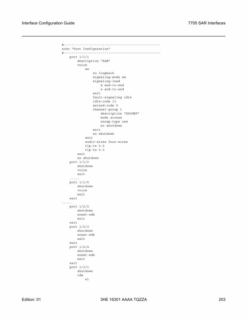
Interface Configuration Guide 7705 SAR Interfaces
Edition: 01 3HE 16301 AAAA TQZZA 203
#--------------------------------------------------echo "Port Configuration"#--------------------------------------------------
port 1/1/1description "E&M"voice
emno loopbacksignaling-mode emsignaling-lead
m end-to-ende end-to-end
exitfault-signaling idleidle-code 13seized-code 5channel-group 1
description "DS0GRP"mode accessencap-type cemno shutdown
exitno shutdown
exitaudio-wires four-wirestlp-rx 0.0tlp-tx 0.0
exitno shutdown
port 1/1/2shutdownvoiceexit
.....port 1/1/6
shutdownvoiceexit
exit.....
port 1/2/2shutdownsonet-sdhexit
exitport 1/2/3
shutdownsonet-sdhexit
exitport 1/2/4
shutdownsonet-sdhexit
exitport 1/3/1
shutdowntdm
e1
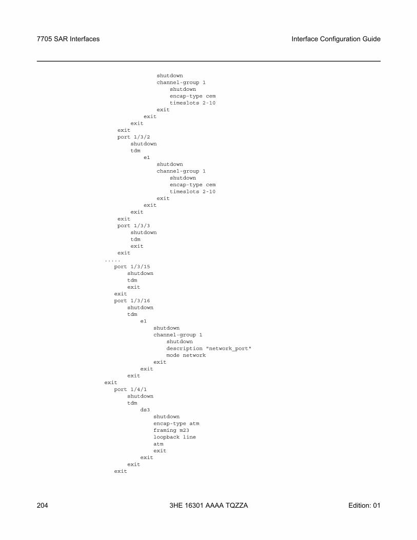
7705 SAR Interfaces
204
Interface Configuration Guide
3HE 16301 AAAA TQZZA Edition: 01
shutdownchannel-group 1
shutdownencap-type cemtimeslots 2-10
exitexit
exitexitport 1/3/2
shutdowntdm
e1shutdownchannel-group 1
shutdownencap-type cemtimeslots 2-10
exitexit
exitexitport 1/3/3
shutdowntdmexit
exit.....
port 1/3/15shutdowntdmexit
exitport 1/3/16
shutdowntdm
e1shutdownchannel-group 1
shutdowndescription "network_port"mode network
exitexit
exitexit
port 1/4/1shutdowntdm
ds3shutdownencap-type atmframing m23loopback lineatmexit
exitexit
exit
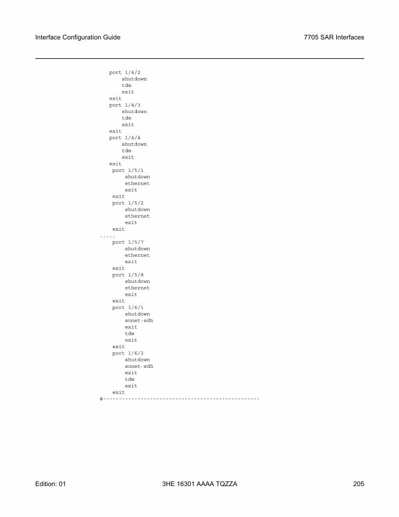
Interface Configuration Guide 7705 SAR Interfaces
Edition: 01 3HE 16301 AAAA TQZZA 205
port 1/4/2shutdowntdmexit
exitport 1/4/3
shutdowntdmexit
exitport 1/4/4
shutdowntdmexit
exitport 1/5/1
shutdownethernetexit
exitport 1/5/2
shutdownethernetexit
exit.....
port 1/5/7shutdownethernetexit
exitport 1/5/8
shutdownethernetexit
exitport 1/6/1
shutdownsonet-sdhexittdmexit
exitport 1/6/2
shutdownsonet-sdhexittdmexit
exit#--------------------------------------------------
7705 SAR Interfaces
206
Interface Configuration Guide
3HE 16301 AAAA TQZZA Edition: 01
3.11 Common Configuration Tasks
The following basic system tasks are performed, as required:
• Configuring Cards and Adapter Cards• Configuring Ports• Configuring SCADA Bridge Parameters
Interface Configuration Guide 7705 SAR Interfaces
Edition: 01 3HE 16301 AAAA TQZZA 207
3.11.1 Configuring Cards and Adapter Cards
This section contains the following topics:
• Configuring Cards• Configuring Adapter Card Network Queue QoS Policies• Configuring Ring Adapter Card or Module Network and Network Queue QoS
Policies• Configuring Adapter Card Fabric Statistics• Configuring Adapter Card Fabric Profile• Configuring Adapter Card Clock Mode• Configuring Adapter Card Voice Attributes• Configuring Ring Adapter Card or Module Parameters• Configuring Auxiliary Alarm Card, Chassis, and Ethernet Port External Alarm
Parameters• Displaying Adapter Card Information
3.11.1.1 Configuring Cards
Card configurations must include a chassis slot designation. A slot must be preconfigured with the type of card and adapter cards that are allowed to be provisioned.
The mda-mode command is used on the following adapter cards to configure the appropriate encapsulation methods (cem-atm-ppp or cem-fr-hdlc-ppp) that are required to support pseudowire services:
• 4-port DS3/E3 Adapter card• 16-port T1/E1 ASAP Adapter card, version 2• 32-port T1/E1 ASAP Adapter card
The mda-mode command is used on the 10-port 1GigE/1-port 10GigE X-Adapter card to configure the card for either 10-port 1GigE mode or 1-port 10GigE mode (x10-1gb-sfp or x1-10gb-sf+).
The mda-mode command is used on the 4-port OC3/STM1 / 1-port OC12/STM4 Adapter card to configure the card for either 4-port OC3/STM1 mode or 1-port OC12/STM4 mode (p4-oc3 or p1-oc12).
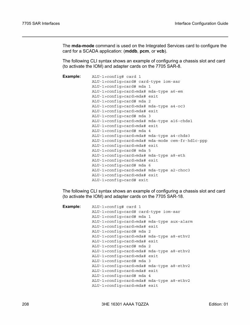
7705 SAR Interfaces
208
Interface Configuration Guide
3HE 16301 AAAA TQZZA Edition: 01
The mda-mode command is used on the Integrated Services card to configure the card for a SCADA application: (mddb, pcm, or vcb).
The following CLI syntax shows an example of configuring a chassis slot and card (to activate the IOM) and adapter cards on the 7705 SAR-8.
Example: ALU-1>config# card 1ALU-1>config>card# card-type iom-sarALU-1>config>card# mda 1ALU-1>config>card>mda# mda-type a6-emALU-1>config>card>mda# exitALU-1>config>card# mda 2ALU-1>config>card>mda# mda-type a4-oc3ALU-1>config>card>mda# exitALU-1>config>card# mda 3ALU-1>config>card>mda# mda-type a16-chds1ALU-1>config>card>mda# exitALU-1>config>card# mda 4ALU-1>config>card>mda# mda-type a4-chds3ALU-1>config>card>mda# mda-mode cem-fr-hdlc-pppALU-1>config>card>mda# exitALU-1>config>card# mda 5ALU-1>config>card>mda# mda-type a8-ethALU-1>config>card>mda# exitALU-1>config>card# mda 6ALU-1>config>card>mda# mda-type a2-choc3ALU-1>config>card>mda# exitALU-1>config>card# exit
The following CLI syntax shows an example of configuring a chassis slot and card (to activate the IOM) and adapter cards on the 7705 SAR-18.
Example: ALU-1>config# card 1ALU-1>config>card# card-type iom-sarALU-1>config>card# mda 1ALU-1>config>card>mda# mda-type aux-alarmALU-1>config>card>mda# exitALU-1>config>card# mda 2ALU-1>config>card>mda# mda-type a8-ethv2ALU-1>config>card>mda# exitALU-1>config>card# mda 2ALU-1>config>card>mda# mda-type a8-ethv2ALU-1>config>card>mda# exitALU-1>config>card# mda 3ALU-1>config>card>mda# mda-type a8-ethv2ALU-1>config>card>mda# exitALU-1>config>card# mda 4ALU-1>config>card>mda# mda-type a8-ethv2ALU-1>config>card>mda# exit
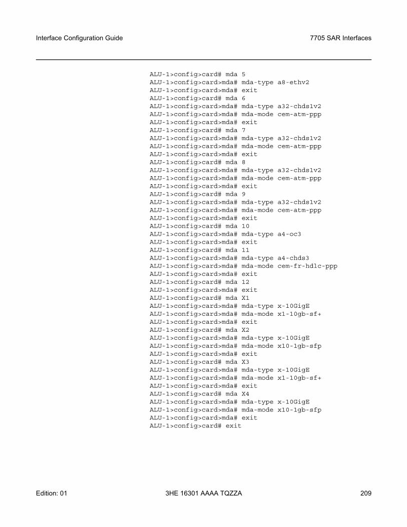
Interface Configuration Guide 7705 SAR Interfaces
Edition: 01 3HE 16301 AAAA TQZZA 209
ALU-1>config>card# mda 5ALU-1>config>card>mda# mda-type a8-ethv2ALU-1>config>card>mda# exitALU-1>config>card# mda 6ALU-1>config>card>mda# mda-type a32-chds1v2ALU-1>config>card>mda# mda-mode cem-atm-pppALU-1>config>card>mda# exitALU-1>config>card# mda 7ALU-1>config>card>mda# mda-type a32-chds1v2ALU-1>config>card>mda# mda-mode cem-atm-pppALU-1>config>card>mda# exitALU-1>config>card# mda 8ALU-1>config>card>mda# mda-type a32-chds1v2ALU-1>config>card>mda# mda-mode cem-atm-pppALU-1>config>card>mda# exitALU-1>config>card# mda 9ALU-1>config>card>mda# mda-type a32-chds1v2ALU-1>config>card>mda# mda-mode cem-atm-pppALU-1>config>card>mda# exitALU-1>config>card# mda 10ALU-1>config>card>mda# mda-type a4-oc3ALU-1>config>card>mda# exitALU-1>config>card# mda 11ALU-1>config>card>mda# mda-type a4-chds3ALU-1>config>card>mda# mda-mode cem-fr-hdlc-pppALU-1>config>card>mda# exitALU-1>config>card# mda 12ALU-1>config>card>mda# exitALU-1>config>card# mda X1ALU-1>config>card>mda# mda-type x-10GigEALU-1>config>card>mda# mda-mode x1-10gb-sf+ALU-1>config>card>mda# exitALU-1>config>card# mda X2ALU-1>config>card>mda# mda-type x-10GigEALU-1>config>card>mda# mda-mode x10-1gb-sfpALU-1>config>card>mda# exitALU-1>config>card# mda X3ALU-1>config>card>mda# mda-type x-10GigEALU-1>config>card>mda# mda-mode x1-10gb-sf+ALU-1>config>card>mda# exitALU-1>config>card# mda X4ALU-1>config>card>mda# mda-type x-10GigEALU-1>config>card>mda# mda-mode x10-1gb-sfpALU-1>config>card>mda# exitALU-1>config>card# exit
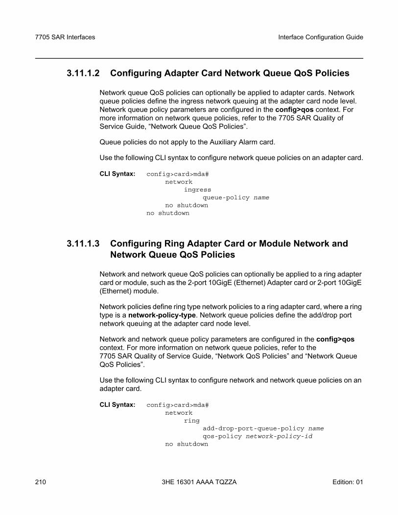
7705 SAR Interfaces
210
Interface Configuration Guide
3HE 16301 AAAA TQZZA Edition: 01
3.11.1.2 Configuring Adapter Card Network Queue QoS Policies
Network queue QoS policies can optionally be applied to adapter cards. Network queue policies define the ingress network queuing at the adapter card node level. Network queue policy parameters are configured in the config>qos context. For more information on network queue policies, refer to the 7705 SAR Quality of Service Guide, “Network Queue QoS Policies”.
Queue policies do not apply to the Auxiliary Alarm card.
Use the following CLI syntax to configure network queue policies on an adapter card.
CLI Syntax: config>card>mda# network
ingressqueue-policy name
no shutdownno shutdown
3.11.1.3 Configuring Ring Adapter Card or Module Network and Network Queue QoS Policies
Network and network queue QoS policies can optionally be applied to a ring adapter card or module, such as the 2-port 10GigE (Ethernet) Adapter card or 2-port 10GigE (Ethernet) module.
Network policies define ring type network policies to a ring adapter card, where a ring type is a network-policy-type. Network queue policies define the add/drop port network queuing at the adapter card node level.
Network and network queue policy parameters are configured in the config>qos context. For more information on network queue policies, refer to the 7705 SAR Quality of Service Guide, “Network QoS Policies” and “Network Queue QoS Policies”.
Use the following CLI syntax to configure network and network queue policies on an adapter card.
CLI Syntax: config>card>mda# network
ringadd-drop-port-queue-policy nameqos-policy network-policy-id
no shutdown
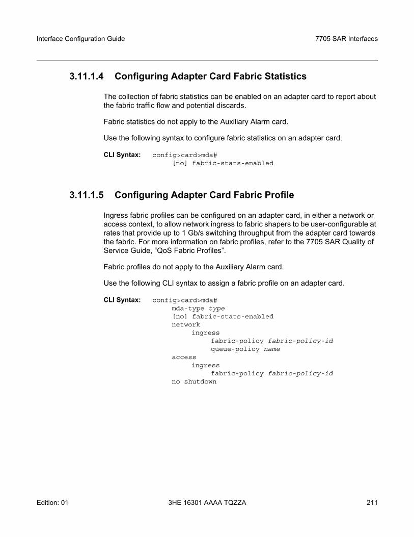
Interface Configuration Guide 7705 SAR Interfaces
Edition: 01 3HE 16301 AAAA TQZZA 211
3.11.1.4 Configuring Adapter Card Fabric Statistics
The collection of fabric statistics can be enabled on an adapter card to report about the fabric traffic flow and potential discards.
Fabric statistics do not apply to the Auxiliary Alarm card.
Use the following syntax to configure fabric statistics on an adapter card.
CLI Syntax: config>card>mda# [no] fabric-stats-enabled
3.11.1.5 Configuring Adapter Card Fabric Profile
Ingress fabric profiles can be configured on an adapter card, in either a network or access context, to allow network ingress to fabric shapers to be user-configurable at rates that provide up to 1 Gb/s switching throughput from the adapter card towards the fabric. For more information on fabric profiles, refer to the 7705 SAR Quality of Service Guide, “QoS Fabric Profiles”.
Fabric profiles do not apply to the Auxiliary Alarm card.
Use the following CLI syntax to assign a fabric profile on an adapter card.
CLI Syntax: config>card>mda#mda-type type[no] fabric-stats-enablednetwork
ingressfabric-policy fabric-policy-idqueue-policy name
accessingress
fabric-policy fabric-policy-idno shutdown
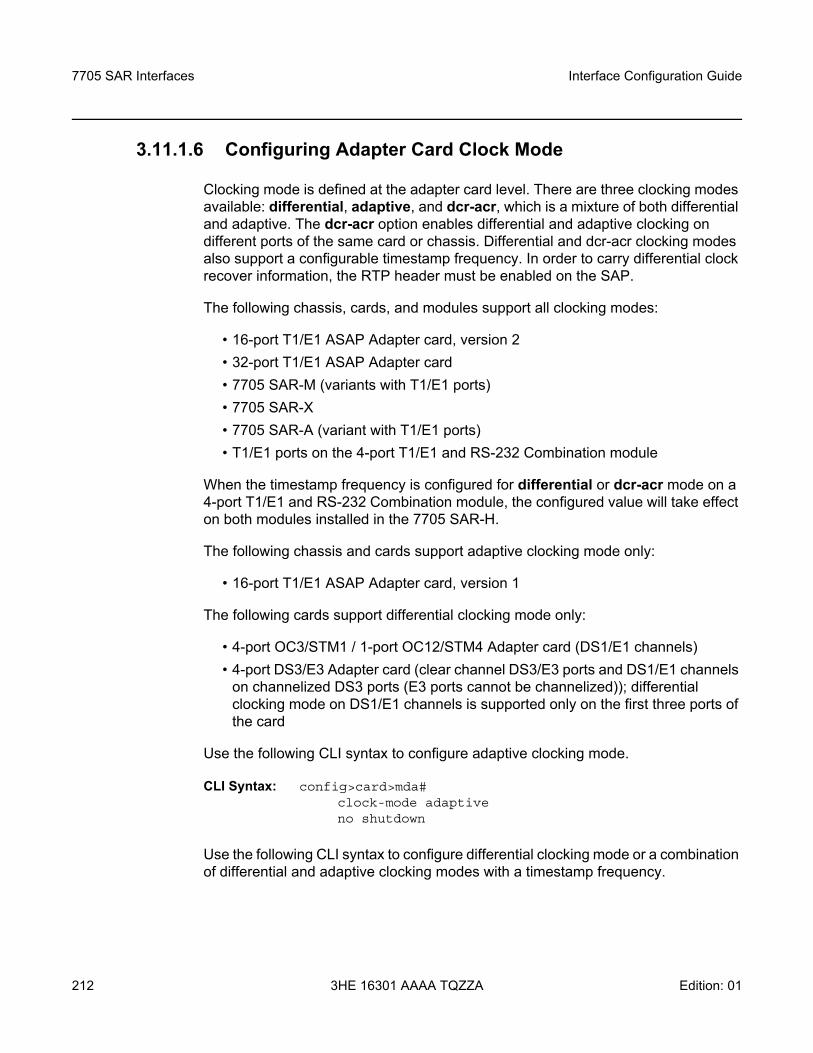
7705 SAR Interfaces
212
Interface Configuration Guide
3HE 16301 AAAA TQZZA Edition: 01
3.11.1.6 Configuring Adapter Card Clock Mode
Clocking mode is defined at the adapter card level. There are three clocking modes available: differential, adaptive, and dcr-acr, which is a mixture of both differential and adaptive. The dcr-acr option enables differential and adaptive clocking on different ports of the same card or chassis. Differential and dcr-acr clocking modes also support a configurable timestamp frequency. In order to carry differential clock recover information, the RTP header must be enabled on the SAP.
The following chassis, cards, and modules support all clocking modes:
• 16-port T1/E1 ASAP Adapter card, version 2• 32-port T1/E1 ASAP Adapter card• 7705 SAR-M (variants with T1/E1 ports)• 7705 SAR-X• 7705 SAR-A (variant with T1/E1 ports)• T1/E1 ports on the 4-port T1/E1 and RS-232 Combination module
When the timestamp frequency is configured for differential or dcr-acr mode on a 4-port T1/E1 and RS-232 Combination module, the configured value will take effect on both modules installed in the 7705 SAR-H.
The following chassis and cards support adaptive clocking mode only:
• 16-port T1/E1 ASAP Adapter card, version 1
The following cards support differential clocking mode only:
• 4-port OC3/STM1 / 1-port OC12/STM4 Adapter card (DS1/E1 channels)• 4-port DS3/E3 Adapter card (clear channel DS3/E3 ports and DS1/E1 channels
on channelized DS3 ports (E3 ports cannot be channelized)); differential clocking mode on DS1/E1 channels is supported only on the first three ports of the card
Use the following CLI syntax to configure adaptive clocking mode.
CLI Syntax: config>card>mda# clock-mode adaptiveno shutdown
Use the following CLI syntax to configure differential clocking mode or a combination of differential and adaptive clocking modes with a timestamp frequency.
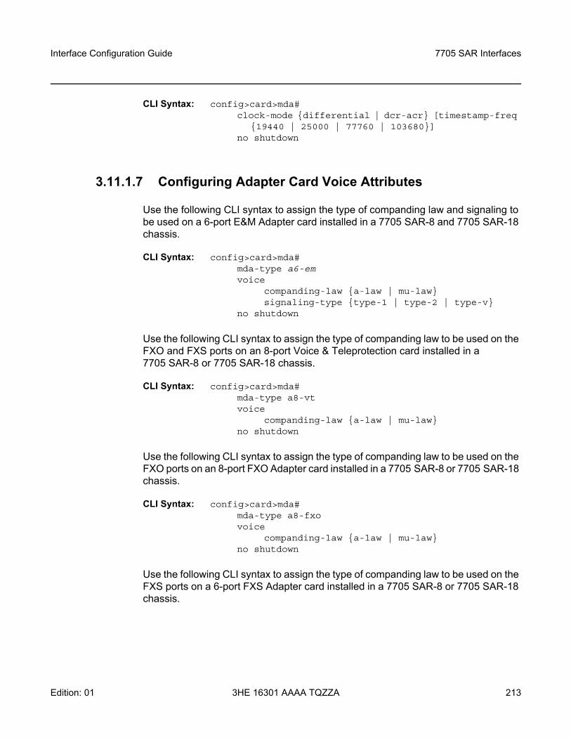
Interface Configuration Guide 7705 SAR Interfaces
Edition: 01 3HE 16301 AAAA TQZZA 213
CLI Syntax: config>card>mda# clock-mode differential | dcr-acr [timestamp-freq
19440 | 25000 | 77760 | 103680]no shutdown
3.11.1.7 Configuring Adapter Card Voice Attributes
Use the following CLI syntax to assign the type of companding law and signaling to be used on a 6-port E&M Adapter card installed in a 7705 SAR-8 and 7705 SAR-18 chassis.
CLI Syntax: config>card>mda#mda-type a6-emvoice
companding-law a-law | mu-lawsignaling-type type-1 | type-2 | type-v
no shutdown
Use the following CLI syntax to assign the type of companding law to be used on the FXO and FXS ports on an 8-port Voice & Teleprotection card installed in a 7705 SAR-8 or 7705 SAR-18 chassis.
CLI Syntax: config>card>mda#mda-type a8-vtvoice
companding-law a-law | mu-lawno shutdown
Use the following CLI syntax to assign the type of companding law to be used on the FXO ports on an 8-port FXO Adapter card installed in a 7705 SAR-8 or 7705 SAR-18 chassis.
CLI Syntax: config>card>mda#mda-type a8-fxovoice
companding-law a-law | mu-lawno shutdown
Use the following CLI syntax to assign the type of companding law to be used on the FXS ports on a 6-port FXS Adapter card installed in a 7705 SAR-8 or 7705 SAR-18 chassis.
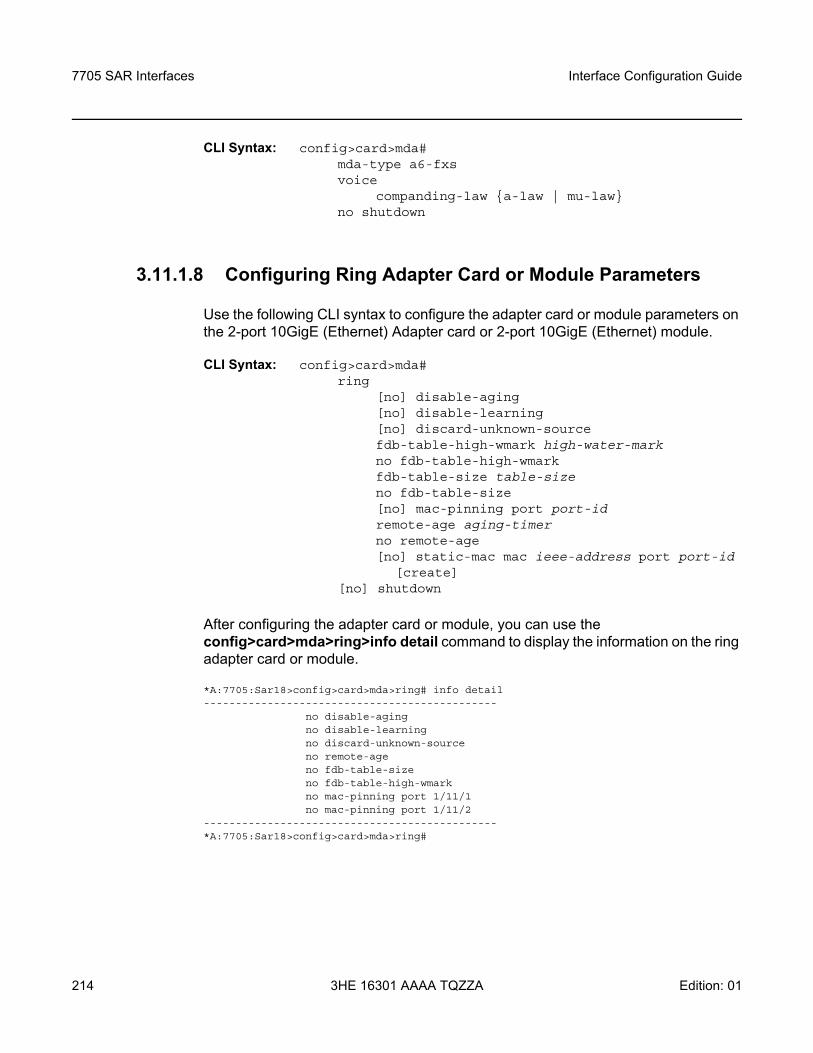
7705 SAR Interfaces
214
Interface Configuration Guide
3HE 16301 AAAA TQZZA Edition: 01
CLI Syntax: config>card>mda#mda-type a6-fxsvoice
companding-law a-law | mu-lawno shutdown
3.11.1.8 Configuring Ring Adapter Card or Module Parameters
Use the following CLI syntax to configure the adapter card or module parameters on the 2-port 10GigE (Ethernet) Adapter card or 2-port 10GigE (Ethernet) module.
CLI Syntax: config>card>mda#ring
[no] disable-aging [no] disable-learning [no] discard-unknown-source fdb-table-high-wmark high-water-mark no fdb-table-high-wmark fdb-table-size table-size no fdb-table-size [no] mac-pinning port port-idremote-age aging-timer no remote-age [no] static-mac mac ieee-address port port-id
[create][no] shutdown
After configuring the adapter card or module, you can use the config>card>mda>ring>info detail command to display the information on the ring adapter card or module.
*A:7705:Sar18>config>card>mda>ring# info detail----------------------------------------------
no disable-agingno disable-learningno discard-unknown-sourceno remote-ageno fdb-table-sizeno fdb-table-high-wmarkno mac-pinning port 1/11/1no mac-pinning port 1/11/2
----------------------------------------------*A:7705:Sar18>config>card>mda>ring#
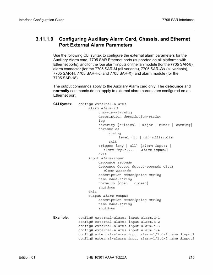
Interface Configuration Guide 7705 SAR Interfaces
Edition: 01 3HE 16301 AAAA TQZZA 215
3.11.1.9 Configuring Auxiliary Alarm Card, Chassis, and Ethernet Port External Alarm Parameters
Use the following CLI syntax to configure the external alarm parameters for the Auxiliary Alarm card, 7705 SAR Ethernet ports (supported on all platforms with Ethernet ports), and for the four alarm inputs on the fan module (for the 7705 SAR-8), alarm connector (for the 7705 SAR-M (all variants), 7705 SAR-Wx (all variants), 7705 SAR-H, 7705 SAR-Hc, and 7705 SAR-X), and alarm module (for the 7705 SAR-18).
The output commands apply to the Auxiliary Alarm card only. The debounce and normally commands do not apply to external alarm parameters configured on an Ethernet port.
CLI Syntax: config# external-alarmsalarm alarm-id
chassis-alarmingdescription description-stringlogseverity critical | major | minor | warningthresholds
analoglevel lt | gt millivolts
exittrigger [any | all] alarm-input1 |
alarm-input2... | alarm-input8 exit
input alarm-inputdebounce secondsdebounce detect detect-seconds clear
clear-secondsdescription description-stringname name-stringnormally open | closedshutdown
exitoutput alarm-output
description description-stringname name-stringshutdown
Example: config# external-alarms input alarm.d-1 config# external-alarms input alarm.d-2 config# external-alarms input alarm.d-3 config# external-alarms input alarm.d-4config# external-alarms input alarm-1/1.d-1 name dinput1config# external-alarms input alarm-1/1.d-2 name dinput2
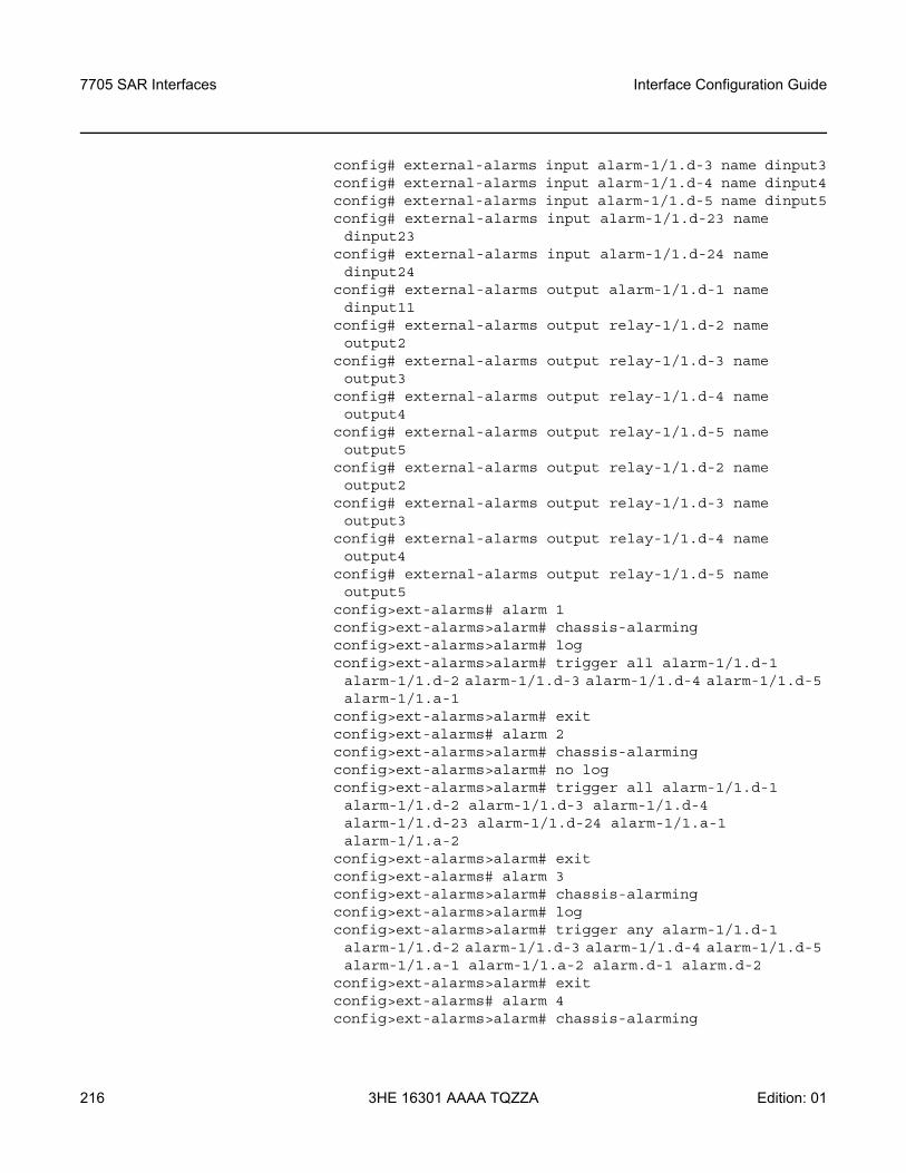
7705 SAR Interfaces
216
Interface Configuration Guide
3HE 16301 AAAA TQZZA Edition: 01
config# external-alarms input alarm-1/1.d-3 name dinput3config# external-alarms input alarm-1/1.d-4 name dinput4config# external-alarms input alarm-1/1.d-5 name dinput5config# external-alarms input alarm-1/1.d-23 name dinput23
config# external-alarms input alarm-1/1.d-24 name dinput24
config# external-alarms output alarm-1/1.d-1 name dinput11
config# external-alarms output relay-1/1.d-2 name output2
config# external-alarms output relay-1/1.d-3 name output3
config# external-alarms output relay-1/1.d-4 name output4
config# external-alarms output relay-1/1.d-5 name output5
config# external-alarms output relay-1/1.d-2 name output2
config# external-alarms output relay-1/1.d-3 name output3
config# external-alarms output relay-1/1.d-4 name output4
config# external-alarms output relay-1/1.d-5 name output5
config>ext-alarms# alarm 1config>ext-alarms>alarm# chassis-alarmingconfig>ext-alarms>alarm# logconfig>ext-alarms>alarm# trigger all alarm-1/1.d-1 alarm-1/1.d-2 alarm-1/1.d-3 alarm-1/1.d-4 alarm-1/1.d-5 alarm-1/1.a-1
config>ext-alarms>alarm# exitconfig>ext-alarms# alarm 2config>ext-alarms>alarm# chassis-alarmingconfig>ext-alarms>alarm# no logconfig>ext-alarms>alarm# trigger all alarm-1/1.d-1 alarm-1/1.d-2 alarm-1/1.d-3 alarm-1/1.d-4 alarm-1/1.d-23 alarm-1/1.d-24 alarm-1/1.a-1 alarm-1/1.a-2
config>ext-alarms>alarm# exitconfig>ext-alarms# alarm 3config>ext-alarms>alarm# chassis-alarmingconfig>ext-alarms>alarm# logconfig>ext-alarms>alarm# trigger any alarm-1/1.d-1 alarm-1/1.d-2 alarm-1/1.d-3 alarm-1/1.d-4 alarm-1/1.d-5 alarm-1/1.a-1 alarm-1/1.a-2 alarm.d-1 alarm.d-2
config>ext-alarms>alarm# exitconfig>ext-alarms# alarm 4config>ext-alarms>alarm# chassis-alarming
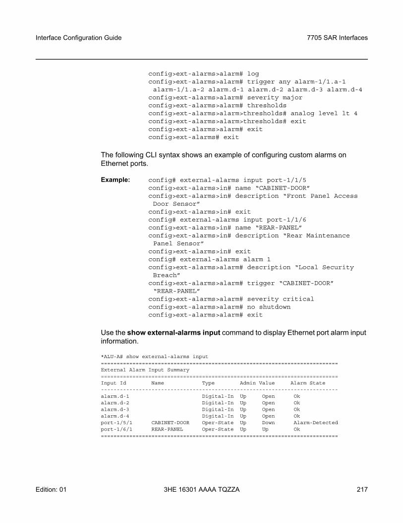
Interface Configuration Guide 7705 SAR Interfaces
Edition: 01 3HE 16301 AAAA TQZZA 217
config>ext-alarms>alarm# logconfig>ext-alarms>alarm# trigger any alarm-1/1.a-1 alarm-1/1.a-2 alarm.d-1 alarm.d-2 alarm.d-3 alarm.d-4
config>ext-alarms>alarm# severity majorconfig>ext-alarms>alarm# thresholdsconfig>ext-alarms>alarm>thresholds# analog level lt 4config>ext-alarms>alarm>thresholds# exitconfig>ext-alarms>alarm# exitconfig>ext-alarms# exit
The following CLI syntax shows an example of configuring custom alarms on Ethernet ports.
Example: config# external-alarms input port-1/1/5config>ext-alarms>in# name “CABINET-DOOR”config>ext-alarms>in# description “Front Panel Access Door Sensor”
config>ext-alarms>in# exitconfig# external-alarms input port-1/1/6config>ext-alarms>in# name “REAR-PANEL”config>ext-alarms>in# description “Rear Maintenance Panel Sensor”
config>ext-alarms>in# exitconfig# external-alarms alarm 1config>ext-alarms>alarm# description “Local Security Breach”
config>ext-alarms>alarm# trigger “CABINET-DOOR” “REAR-PANEL”
config>ext-alarms>alarm# severity criticalconfig>ext-alarms>alarm# no shutdownconfig>ext-alarms>alarm# exit
Use the show external-alarms input command to display Ethernet port alarm input information.
*ALU-A# show external-alarms input===========================================================================External Alarm Input Summary===========================================================================Input Id Name Type Admin Value Alarm State---------------------------------------------------------------------------alarm.d-1 Digital-In Up Open Okalarm.d-2 Digital-In Up Open Okalarm.d-3 Digital-In Up Open Okalarm.d-4 Digital-In Up Open Okport-1/5/1 CABINET-DOOR Oper-State Up Down Alarm-Detectedport-1/6/1 REAR-PANEL Oper-State Up Up Ok===========================================================================
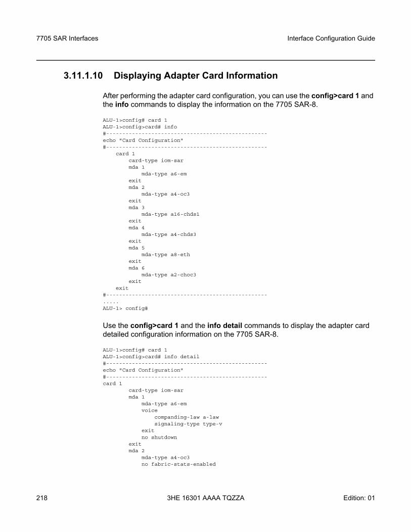
7705 SAR Interfaces
218
Interface Configuration Guide
3HE 16301 AAAA TQZZA Edition: 01
3.11.1.10 Displaying Adapter Card Information
After performing the adapter card configuration, you can use the config>card 1 and the info commands to display the information on the 7705 SAR-8.
ALU-1>config# card 1ALU-1>config>card# info#--------------------------------------------------echo "Card Configuration"#--------------------------------------------------
card 1card-type iom-sarmda 1
mda-type a6-emexitmda 2
mda-type a4-oc3exitmda 3
mda-type a16-chds1exitmda 4
mda-type a4-chds3exitmda 5
mda-type a8-ethexitmda 6
mda-type a2-choc3exit
exit#--------------------------------------------------.....ALU-1> config#
Use the config>card 1 and the info detail commands to display the adapter card detailed configuration information on the 7705 SAR-8.
ALU-1>config# card 1ALU-1>config>card# info detail#--------------------------------------------------echo "Card Configuration"#--------------------------------------------------card 1
card-type iom-sarmda 1
mda-type a6-emvoice
companding-law a-lawsignaling-type type-v
exitno shutdown
exitmda 2
mda-type a4-oc3no fabric-stats-enabled
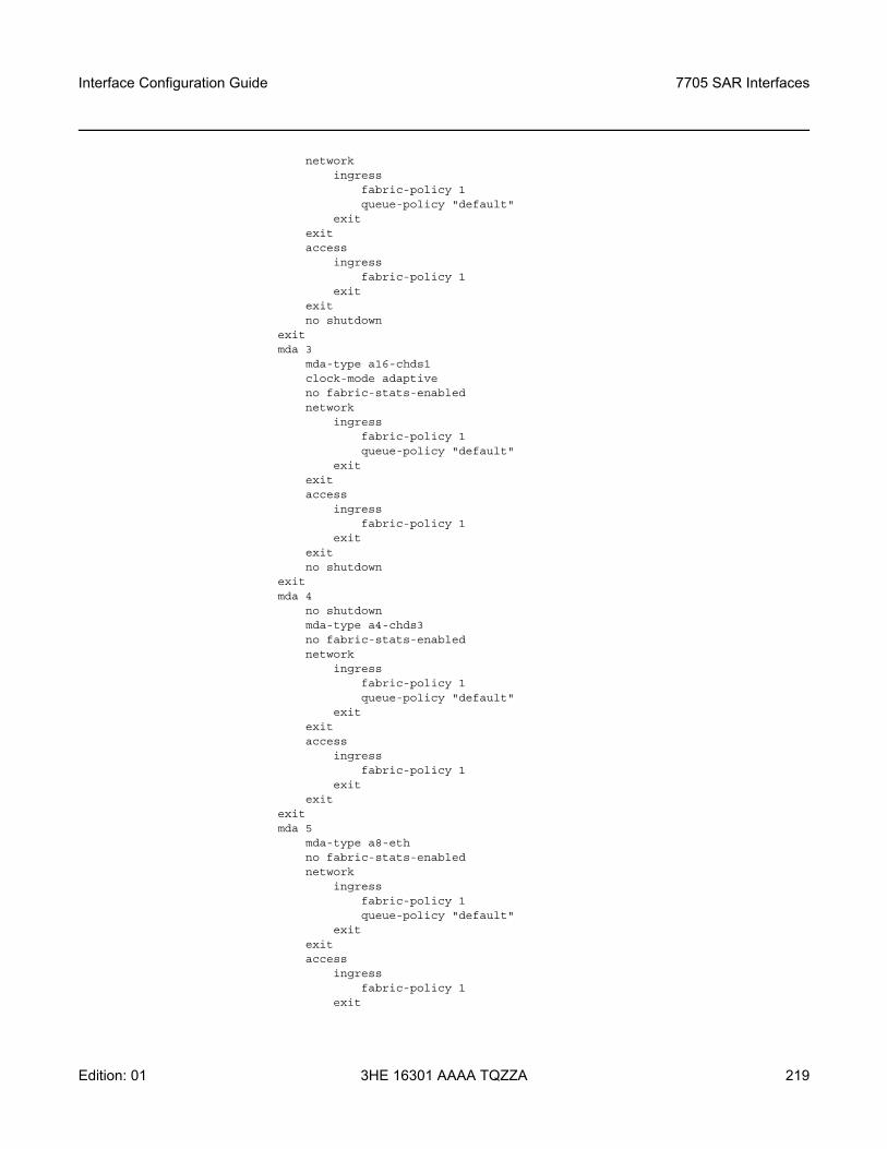
Interface Configuration Guide 7705 SAR Interfaces
Edition: 01 3HE 16301 AAAA TQZZA 219
networkingress
fabric-policy 1queue-policy "default"
exitexitaccess
ingressfabric-policy 1
exitexitno shutdown
exitmda 3
mda-type a16-chds1clock-mode adaptiveno fabric-stats-enablednetwork
ingressfabric-policy 1queue-policy "default"
exitexitaccess
ingressfabric-policy 1
exitexitno shutdown
exitmda 4
no shutdownmda-type a4-chds3no fabric-stats-enablednetwork
ingressfabric-policy 1queue-policy "default"
exitexitaccess
ingressfabric-policy 1
exitexit
exitmda 5
mda-type a8-ethno fabric-stats-enablednetwork
ingressfabric-policy 1queue-policy "default"
exitexitaccess
ingressfabric-policy 1
exit
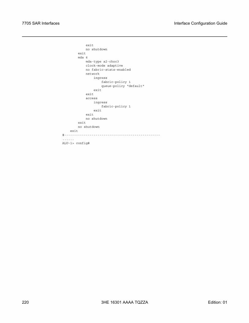
7705 SAR Interfaces
220
Interface Configuration Guide
3HE 16301 AAAA TQZZA Edition: 01
exitno shutdown
exitmda 6
mda-type a2-choc3clock-mode adaptiveno fabric-stats-enablednetwork
ingressfabric-policy 1queue-policy "default"
exitexitaccess
ingressfabric-policy 1
exitexitno shutdown
exitno shutdown
exit#-------------------------------------------------......ALU-1> config#
Interface Configuration Guide 7705 SAR Interfaces
Edition: 01 3HE 16301 AAAA TQZZA 221
3.11.2 Configuring Ports
This section provides the CLI syntax and examples to configure the following:
• Configuring APS Port Parameters• Configuring LCR Parameters • Configuring a Microwave Link• Configuring Ethernet Port Parameters• Configuring DSL Port Parameters• Configuring SONET/SDH Port Parameters• SONET/SDH Channelized Port Configuration Examples• Configuring Voice Ports• Configuring Codirectional G.703 Ports• Configuring Teleprotection Ports• Configuring TDM PPP• Configuring Channelized Ports• Configuring Fractional T1/E1 Ports for PPP Encapsulation• Configuring T1 Line Buildout• Configuring TDM E1 SSM• Configuring ATM Interface Parameters• Configuring Multilink PPP Bundles• Configuring MC-MLPPP• Configuring LAG Parameters• Configuring Multilink ATM Inverse Multiplexing (IMA) Groups• Configuring SDI Ports for IPCP Encapsulation • Configuring TDM and SDI Ports for Frame Relay Encapsulation • Configuring TDM and SDI Ports for HDLC Encapsulation • Configuring TDM and SDI Ports for Cisco HDLC Encapsulation • Configuring GNSS Receiver Port Parameters• Configuring Serial Ports for Raw Socket Transport
7705 SAR Interfaces
222
Interface Configuration Guide
3HE 16301 AAAA TQZZA Edition: 01
3.11.2.1 Configuring APS Port Parameters
APS has the following configuration rules.
• A working port must be added first. Then a protection port can be added or removed at any time.
• The protection port must be removed from the configuration before the working port is removed.
• A protection port or working port must be shut down in the config>port port-id context before being removed from an APS group.
• A path cannot be configured on a port before the port is added to an APS group. • A working port cannot be removed from an APS group until the APS port path is
removed.• When ports are added to an APS group, all path-level configurations are
available only at the APS port level and configuration on the physical member ports is blocked.
• When a port is a protection circuit of an APS group, the configuration options available in the config>port port-id>sonet-sdh context are not allowed for that port unless they are in the following exception list:- clock-source- [no] loopback- [no] report-alarm- section-trace- [no] threshold
SC-APS is supported in unidirectional or bidirectional mode on:
• 2-port OC3/STM1 Channelized Adapter cards for TDM CES (Cpipes) and TDM CESoETH with MEF 8 with DS3/DS1/E1/DS0 channels
• 4-port OC3/STM1 / 1-port OC12/STM4 Adapter cards for MLPPP access ports or TDM CES (Cpipes) and TDM CESoETH (MEF 8) access ports with DS1/E1 channels, or on a network port configured for POS
• 4-port OC3/STM1 Clear Channel Adapter cards network side (configured for POS operation).
SC-APS with TDM access is supported on DS3, DS1, E1, and DS0 (64 kb/s) channels.
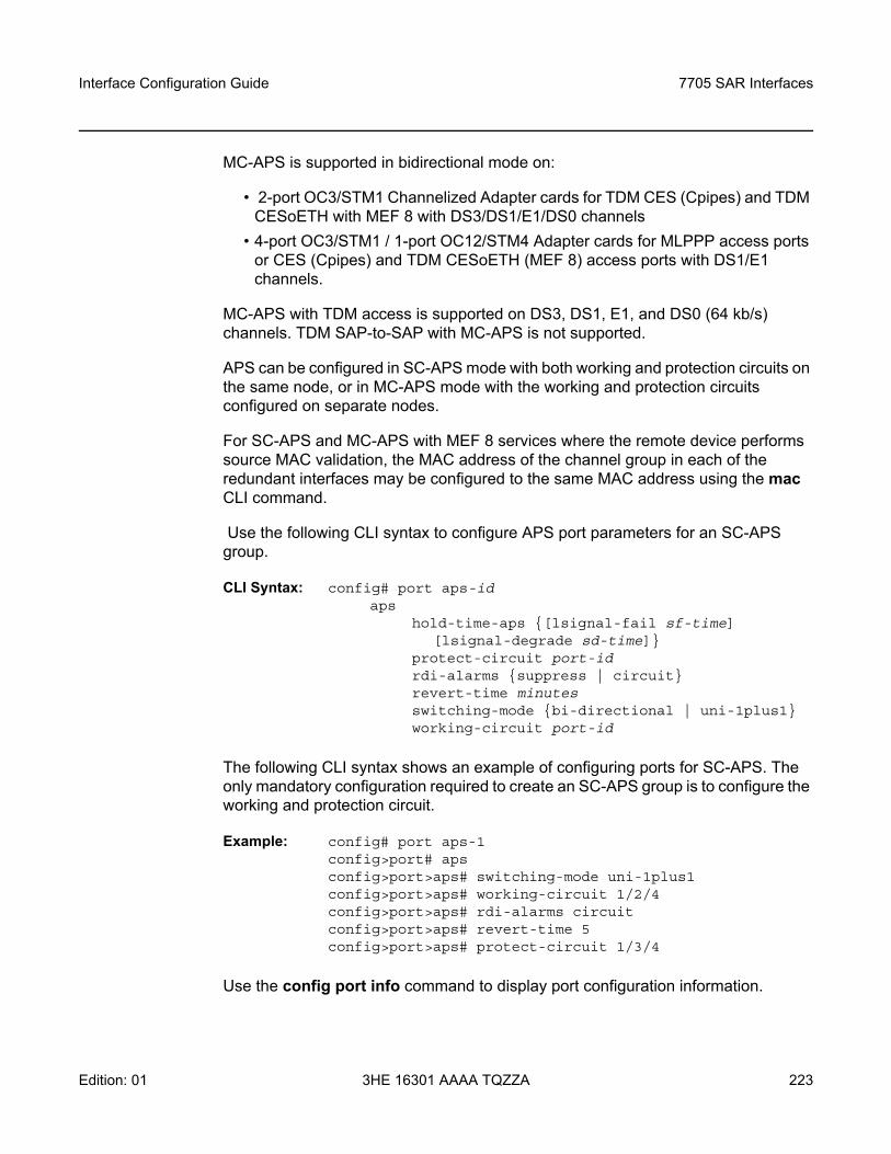
Interface Configuration Guide 7705 SAR Interfaces
Edition: 01 3HE 16301 AAAA TQZZA 223
MC-APS is supported in bidirectional mode on:
• 2-port OC3/STM1 Channelized Adapter cards for TDM CES (Cpipes) and TDM CESoETH with MEF 8 with DS3/DS1/E1/DS0 channels
• 4-port OC3/STM1 / 1-port OC12/STM4 Adapter cards for MLPPP access ports or CES (Cpipes) and TDM CESoETH (MEF 8) access ports with DS1/E1 channels.
MC-APS with TDM access is supported on DS3, DS1, E1, and DS0 (64 kb/s) channels. TDM SAP-to-SAP with MC-APS is not supported.
APS can be configured in SC-APS mode with both working and protection circuits on the same node, or in MC-APS mode with the working and protection circuits configured on separate nodes.
For SC-APS and MC-APS with MEF 8 services where the remote device performs source MAC validation, the MAC address of the channel group in each of the redundant interfaces may be configured to the same MAC address using the mac CLI command.
Use the following CLI syntax to configure APS port parameters for an SC-APS group.
CLI Syntax: config# port aps-id aps
hold-time-aps [lsignal-fail sf-time] [lsignal-degrade sd-time]
protect-circuit port-idrdi-alarms suppress | circuitrevert-time minutesswitching-mode bi-directional | uni-1plus1working-circuit port-id
The following CLI syntax shows an example of configuring ports for SC-APS. The only mandatory configuration required to create an SC-APS group is to configure the working and protection circuit.
Example: config# port aps-1config>port# apsconfig>port>aps# switching-mode uni-1plus1config>port>aps# working-circuit 1/2/4config>port>aps# rdi-alarms circuitconfig>port>aps# revert-time 5config>port>aps# protect-circuit 1/3/4
Use the config port info command to display port configuration information.
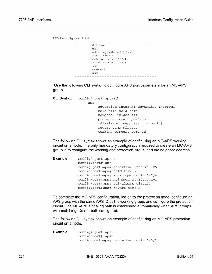
7705 SAR Interfaces
224
Interface Configuration Guide
3HE 16301 AAAA TQZZA Edition: 01
ALU-B>config>port# info-------------------------------------------------
shutdownapsswitching-mode uni-1plus1revert-time 5working-circuit 1/2/4protect-circuit 1/3/4exitsonet-sdhexit
-------------------------------------------------
Use the following CLI syntax to configure APS port parameters for an MC-APS group.
CLI Syntax: config# port aps-id aps
advertise-interval advertise-intervalhold-time hold-timeneighbor ip-addressprotect-circuit port-idrdi-alarms suppress | circuitrevert-time minutesworking-circuit port-id
The following CLI syntax shows an example of configuring an MC-APS working circuit on a node. The only mandatory configuration required to create an MC-APS group is to configure the working and protection circuit, and the neighbor address.
Example: config# port aps-2config>port# apsconfig>port>aps# advertise-interval 25config>port>aps# hold-time 75config>port>aps# working-circuit 1/2/4config>port>aps# neighbor 10.10.10.101config>port>aps# rdi-alarms circuitconfig>port>aps# revert-time 5
To complete the MC-APS configuration, log on to the protection node, configure an APS group with the same APS ID as the working group, and configure the protection circuit. The MC-APS signaling path is established automatically when APS groups with matching IDs are both configured.
The following CLI syntax shows an example of configuring an MC-APS protection circuit on a node.
Example: config# port aps-2config>port# apsconfig>port>aps# protect-circuit 1/3/2
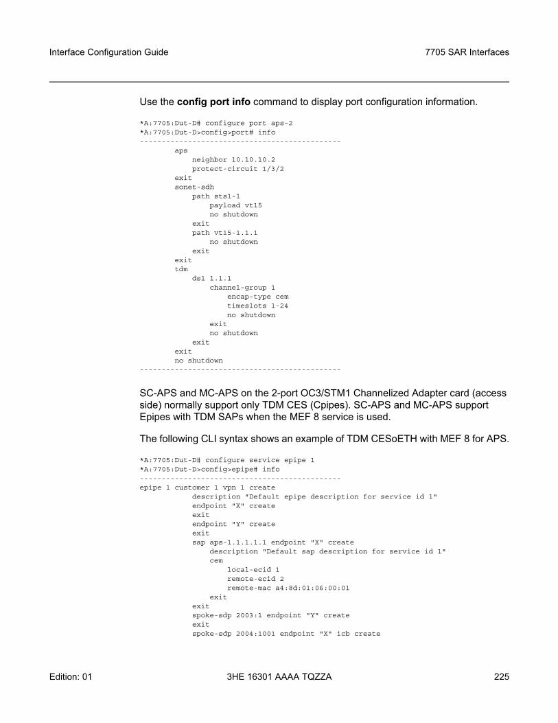
Interface Configuration Guide 7705 SAR Interfaces
Edition: 01 3HE 16301 AAAA TQZZA 225
Use the config port info command to display port configuration information.
*A:7705:Dut-D# configure port aps-2*A:7705:Dut-D>config>port# info----------------------------------------------
apsneighbor 10.10.10.2protect-circuit 1/3/2
exitsonet-sdh
path sts1-1payload vt15no shutdown
exitpath vt15-1.1.1
no shutdownexit
exittdm
ds1 1.1.1channel-group 1
encap-type cemtimeslots 1-24no shutdown
exitno shutdown
exitexitno shutdown
----------------------------------------------
SC-APS and MC-APS on the 2-port OC3/STM1 Channelized Adapter card (access side) normally support only TDM CES (Cpipes). SC-APS and MC-APS support Epipes with TDM SAPs when the MEF 8 service is used.
The following CLI syntax shows an example of TDM CESoETH with MEF 8 for APS.
*A:7705:Dut-D# configure service epipe 1*A:7705:Dut-D>config>epipe# info----------------------------------------------epipe 1 customer 1 vpn 1 create
description "Default epipe description for service id 1"endpoint "X" createexitendpoint "Y" createexitsap aps-1.1.1.1.1 endpoint "X" create
description "Default sap description for service id 1"cem
local-ecid 1remote-ecid 2remote-mac a4:8d:01:06:00:01
exitexitspoke-sdp 2003:1 endpoint "Y" createexitspoke-sdp 2004:1001 endpoint "X" icb create
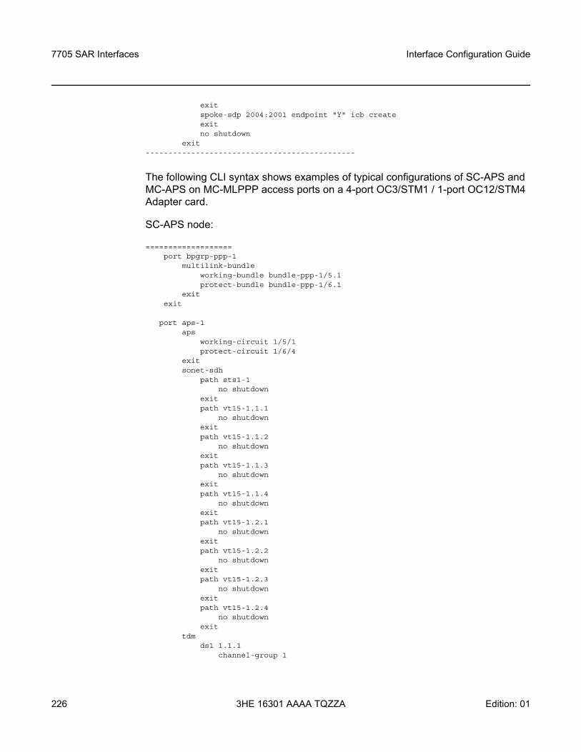
7705 SAR Interfaces
226
Interface Configuration Guide
3HE 16301 AAAA TQZZA Edition: 01
exitspoke-sdp 2004:2001 endpoint "Y" icb createexitno shutdown
exit----------------------------------------------
The following CLI syntax shows examples of typical configurations of SC-APS and MC-APS on MC-MLPPP access ports on a 4-port OC3/STM1 / 1-port OC12/STM4 Adapter card.
SC-APS node:
===================port bpgrp-ppp-1
multilink-bundleworking-bundle bundle-ppp-1/5.1protect-bundle bundle-ppp-1/6.1
exitexit
port aps-1aps
working-circuit 1/5/1protect-circuit 1/6/4
exitsonet-sdh
path sts1-1no shutdown
exitpath vt15-1.1.1
no shutdownexitpath vt15-1.1.2
no shutdownexitpath vt15-1.1.3
no shutdownexitpath vt15-1.1.4
no shutdownexitpath vt15-1.2.1
no shutdownexitpath vt15-1.2.2
no shutdownexitpath vt15-1.2.3
no shutdownexitpath vt15-1.2.4
no shutdownexit
tdmds1 1.1.1
channel-group 1

Interface Configuration Guide 7705 SAR Interfaces
Edition: 01 3HE 16301 AAAA TQZZA 227
encap-type ipcpno shutdown
exitno shutdown
exitds1 1.1.2
channel-group 1encap-type ipcpno shutdown
exitno shutdown
exitds1 1.1.3
channel-group 1encap-type ipcpno shutdown
exitno shutdown
exitds1 1.1.4
channel-group 1encap-type ipcpno shutdown
exitno shutdown
exitds1 1.2.1
channel-group 1encap-type ipcpno shutdown
exitno shutdown
exitds1 1.2.2
channel-group 1encap-type ipcp
no shutdownexitno shutdown
exitds1 1.2.3
channel-group 1encap-type ipcpno shutdown
exitno shutdown
exitds1 1.2.4
channel-group 1encap-type ipcpno shutdown
exitno shutdown
exit
port bpgrp-ppp-1multilink-bundle
mlpppendpoint-discriminator class ip-address discriminator-id 1.2.3.4
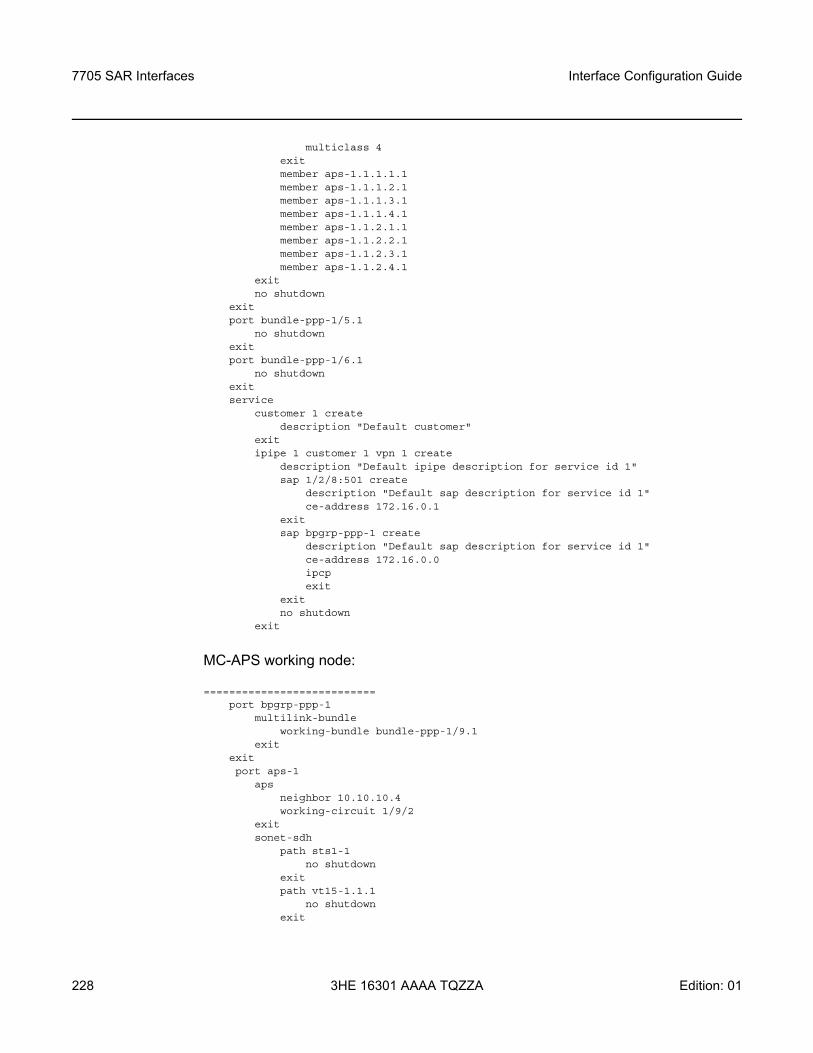
7705 SAR Interfaces
228
Interface Configuration Guide
3HE 16301 AAAA TQZZA Edition: 01
multiclass 4exitmember aps-1.1.1.1.1member aps-1.1.1.2.1member aps-1.1.1.3.1member aps-1.1.1.4.1member aps-1.1.2.1.1member aps-1.1.2.2.1member aps-1.1.2.3.1member aps-1.1.2.4.1
exitno shutdown
exitport bundle-ppp-1/5.1
no shutdownexitport bundle-ppp-1/6.1
no shutdownexitservice
customer 1 createdescription "Default customer"
exitipipe 1 customer 1 vpn 1 create
description "Default ipipe description for service id 1"sap 1/2/8:501 create
description "Default sap description for service id 1"ce-address 172.16.0.1
exitsap bpgrp-ppp-1 create
description "Default sap description for service id 1"ce-address 172.16.0.0ipcpexit
exitno shutdown
exit
MC-APS working node:
===========================port bpgrp-ppp-1
multilink-bundleworking-bundle bundle-ppp-1/9.1
exitexitport aps-1
apsneighbor 10.10.10.4working-circuit 1/9/2
exitsonet-sdh
path sts1-1no shutdown
exitpath vt15-1.1.1
no shutdownexit
Interface Configuration Guide 7705 SAR Interfaces
Edition: 01 3HE 16301 AAAA TQZZA 229
path vt15-1.1.2no shutdown
exitpath vt15-1.1.3
no shutdownexitpath vt15-1.1.4
no shutdownexitpath vt15-1.2.1
no shutdownexitpath vt15-1.2.2
no shutdownexitpath vt15-1.2.3
no shutdownexitpath vt15-1.2.4
no shutdownexit
tdmds1 1.1.1
channel-group 1encap-type ipcpno shutdown
exitno shutdown
exitds1 1.1.2
channel-group 1encap-type ipcpno shutdown
exitno shutdown
exitds1 1.1.3
channel-group 1encap-type ipcpno shutdown
exitno shutdown
exitds1 1.1.4
channel-group 1encap-type ipcpno shutdown
exitno shutdown
exitds1 1.2.1
channel-group 1encap-type ipcpno shutdown
exitno shutdown
exitds1 1.2.2
channel-group 1
7705 SAR Interfaces
230
Interface Configuration Guide
3HE 16301 AAAA TQZZA Edition: 01
encap-type ipcpno shutdown
exitno shutdown
exitds1 1.2.3
channel-group 1encap-type ipcpno shutdown
exitno shutdown
exitds1 1.2.4
channel-group 1encap-type ipcpno shutdown
exitno shutdown
exitport bpgrp-ppp-1
multilink-bundlemlppp
endpoint-discriminator class ip-address discriminator-id 1.2.3.4multiclass 4
exitmember aps-1.1.1.1.1member aps-1.1.1.2.1member aps-1.1.1.4.1member aps-1.1.1.3.1member aps-1.1.2.1.1member aps-1.1.2.2.1member aps-1.1.2.3.1member aps-1.1.2.4.1
exitno shutdown
exitport bundle-ppp-1/9.1
no shutdownexitservice
sdp 3001 createdescription "LDP_SdpToDut-A"far-end 10.10.10.1ldpkeep-alive
shutdownexitno shutdown
exitsdp 3004 create
description "LDP_SdpToDut-D"far-end 10.10.10.4ldpkeep-alive
shutdownexitno shutdown
exitcustomer 1 create
Interface Configuration Guide 7705 SAR Interfaces
Edition: 01 3HE 16301 AAAA TQZZA 231
description "Default customer"exitipipe 1 customer 1 vpn 1 create
description "Default ipipe description for service id 1"endpoint "X" createexitendpoint "Y" createexitsap bpgrp-ppp-1 endpoint "X" create
description "Default sap description for service id 1"ce-address 172.16.0.1ipcpexit
exitspoke-sdp 3001:1 endpoint "Y" create
ce-address 172.16.0.0no shutdown
exitspoke-sdp 3004:1001 endpoint "X" icb create
no shutdownexitspoke-sdp 3004:2001 endpoint "Y" icb create
no shutdownexitno shutdown
exit
MC-APS protection node:
===========================port bpgrp-ppp-1
multilink-bundleprotect-bundle bundle-ppp-1/9.1
exitexitport aps-1
apsneighbor 10.10.10.3protect-circuit 1/9/4
exitsonet-sdh
path sts1-1no shutdown
exitpath vt15-1.1.1
no shutdownexitpath vt15-1.1.2
no shutdownexitpath vt15-1.1.3
no shutdownexitpath vt15-1.1.4
no shutdownexitpath vt15-1.2.1
no shutdown

7705 SAR Interfaces
232
Interface Configuration Guide
3HE 16301 AAAA TQZZA Edition: 01
exitpath vt15-1.2.2
no shutdownexitpath vt15-1.2.3
no shutdownexitpath vt15-1.2.4
no shutdownexit
tdmds1 1.1.1
channel-group 1encap-type ipcpno shutdown
exitno shutdown
exitds1 1.1.2
channel-group 1encap-type ipcpno shutdown
exitno shutdown
exitds1 1.1.3
channel-group 1encap-type ipcpno shutdown
exitno shutdown
exitds1 1.1.4
channel-group 1encap-type ipcpno shutdown
exitno shutdown
exitds1 1.2.1
channel-group 1encap-type ipcpno shutdown
exitno shutdown
exitds1 1.2.2
channel-group 1encap-type ipcpno shutdown
exitno shutdown
exitds1 1.2.3
channel-group 1encap-type ipcpno shutdown
exitno shutdown
Interface Configuration Guide 7705 SAR Interfaces
Edition: 01 3HE 16301 AAAA TQZZA 233
exitds1 1.2.4
channel-group 1encap-type ipcpno shutdown
exitno shutdown
exitport bpgrp-ppp-1
multilink-bundlemlppp
endpoint-discriminator class ip-address discriminator-id 1.2.3.4multiclass 4
exitmember aps-1.1.1.1.1member aps-1.1.1.2.1member aps-1.1.1.3.1member aps-1.1.1.4.1member aps-1.1.2.1.1member aps-1.1.2.2.1member aps-1.1.2.3.1member aps-1.1.2.4.1
exitno shutdown
exitport bundle-ppp-1/9.1
no shutdownexitservice
sdp 4001 createdescription "LDP_SdpToDut-A"far-end 10.10.10.1ldpkeep-alive
shutdownexitno shutdown
exitsdp 4003 create
description "LDP_SdpToDut-C"far-end 10.10.10.3ldpkeep-alive
shutdownexitno shutdown
exitcustomer 1 create
description "Default customer"exitipipe 1 customer 1 vpn 1 create
description "Default ipipe description for service id 1"endpoint "X" createexitendpoint "Y" createexitsap bpgrp-ppp-1 endpoint "X" create
description "Default sap description for service id 1"ce-address 172.16.0.1
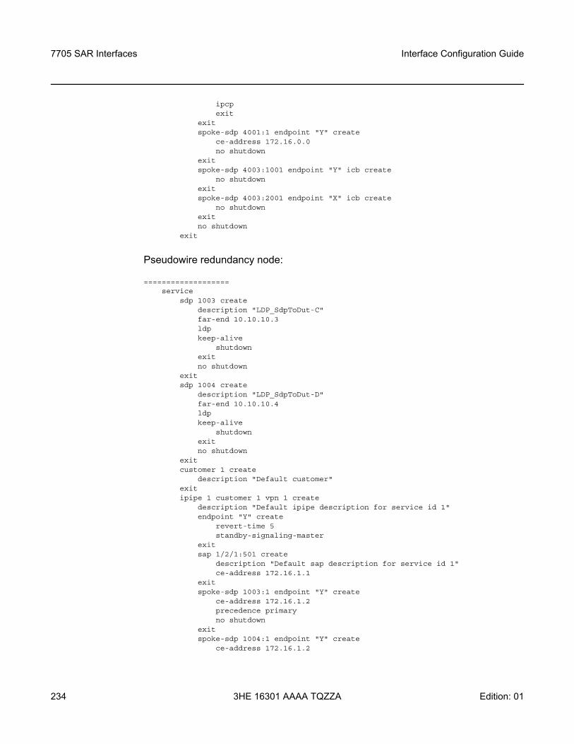
7705 SAR Interfaces
234
Interface Configuration Guide
3HE 16301 AAAA TQZZA Edition: 01
ipcpexit
exitspoke-sdp 4001:1 endpoint "Y" create
ce-address 172.16.0.0no shutdown
exitspoke-sdp 4003:1001 endpoint "Y" icb create
no shutdownexitspoke-sdp 4003:2001 endpoint "X" icb create
no shutdownexitno shutdown
exit
Pseudowire redundancy node:
===================service
sdp 1003 createdescription "LDP_SdpToDut-C"far-end 10.10.10.3ldpkeep-alive
shutdownexitno shutdown
exitsdp 1004 create
description "LDP_SdpToDut-D"far-end 10.10.10.4ldpkeep-alive
shutdownexitno shutdown
exitcustomer 1 create
description "Default customer"exitipipe 1 customer 1 vpn 1 create
description "Default ipipe description for service id 1"endpoint "Y" create
revert-time 5standby-signaling-master
exitsap 1/2/1:501 create
description "Default sap description for service id 1"ce-address 172.16.1.1
exitspoke-sdp 1003:1 endpoint "Y" create
ce-address 172.16.1.2precedence primaryno shutdown
exitspoke-sdp 1004:1 endpoint "Y" create
ce-address 172.16.1.2
Interface Configuration Guide 7705 SAR Interfaces
Edition: 01 3HE 16301 AAAA TQZZA 235
precedence 1no shutdown
exitno shutdown
exit
3.11.2.2 Configuring LCR Parameters
LCR has the following configuration rules.
• The working and protection adapter cards in an LCR group must be configured with the same setting for the mda-mode command. In addition, the clock-mode for each card must be set to dcr-acr before the adapter card can be added to an LCR group.
• In an SC-LCR group, both the working and protection adapter cards are configured with the same LCR group ID on the same node. The working and protection adapter cards must be the same type.
• In an MC-LCR group, the working and protection adapter cards are configured on separate nodes. Users must ensure that the working and protection adapter cards are the same type.
• A working adapter card must be created first in an LCR group. Then a protection adapter card can be added to or removed from an LCR group at any time.
• The protection adapter card must be removed from the configuration before the working adapter card is removed.
• A protection adapter card or working adapter card must be shut down in the config>card>mda mda-slot context before being removed from an LCR group.
• A channel cannot be configured on a T1/E1 port before its associated adapter card is added to an LCR group.
• A working adapter card cannot be removed from an LCR group until the associated T1/E1 channel is removed.
• When adapter cards are added to an LCR group, all channel-level configurations are available only on the associated LCR ports and configuration on the physical member ports is blocked.
LCR is supported on the following cards on the 7705 SAR-8 (with CSMv2) and the 7705 SAR-18:
• 16-port T1/E1 ASAP Adapter card, version 2 • 32-port T1/E1 ASAP Adapter card
To create an SC-LCR group, it is mandatory to configure a group ID and the working and protection adapter cards. Use the following CLI syntax to configure SC-LCR.
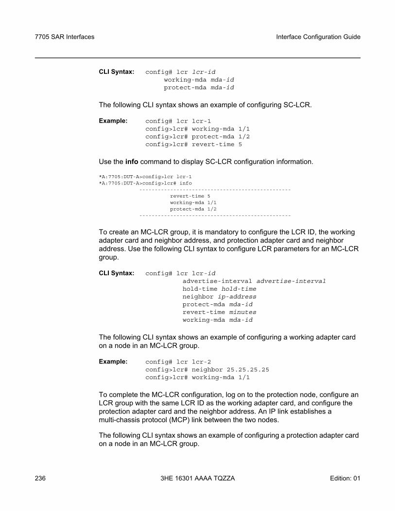
7705 SAR Interfaces
236
Interface Configuration Guide
3HE 16301 AAAA TQZZA Edition: 01
CLI Syntax: config# lcr lcr-id working-mda mda-idprotect-mda mda-id
The following CLI syntax shows an example of configuring SC-LCR.
Example: config# lcr lcr-1config>lcr# working-mda 1/1config>lcr# protect-mda 1/2config>lcr# revert-time 5
Use the info command to display SC-LCR configuration information.
*A:7705:DUT-A>config>lcr lcr-1*A:7705:DUT-A>config>lcr# info
-------------------------------------------------revert-time 5working-mda 1/1protect-mda 1/2
-------------------------------------------------
To create an MC-LCR group, it is mandatory to configure the LCR ID, the working adapter card and neighbor address, and protection adapter card and neighbor address. Use the following CLI syntax to configure LCR parameters for an MC-LCR group.
CLI Syntax: config# lcr lcr-id advertise-interval advertise-intervalhold-time hold-timeneighbor ip-addressprotect-mda mda-idrevert-time minutesworking-mda mda-id
The following CLI syntax shows an example of configuring a working adapter card on a node in an MC-LCR group.
Example: config# lcr lcr-2config>lcr# neighbor 25.25.25.25config>lcr# working-mda 1/1
To complete the MC-LCR configuration, log on to the protection node, configure an LCR group with the same LCR ID as the working adapter card, and configure the protection adapter card and the neighbor address. An IP link establishes a multi-chassis protocol (MCP) link between the two nodes.
The following CLI syntax shows an example of configuring a protection adapter card on a node in an MC-LCR group.
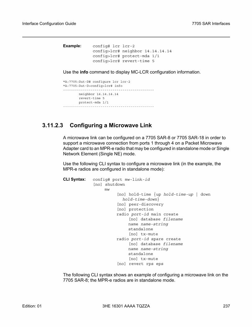
Interface Configuration Guide 7705 SAR Interfaces
Edition: 01 3HE 16301 AAAA TQZZA 237
Example: config# lcr lcr-2config>lcr# neighbor 14.14.14.14config>lcr# protect-mda 1/1config>lcr# revert-time 5
Use the info command to display MC-LCR configuration information.
*A:7705:Dut-D# configure lcr lcr-2*A:7705:Dut-D>config>lcr# info----------------------------------------------
neighbor 14.14.14.14revert-time 5protect-mda 1/1
----------------------------------------------
3.11.2.3 Configuring a Microwave Link
A microwave link can be configured on a 7705 SAR-8 or 7705 SAR-18 in order to support a microwave connection from ports 1 through 4 on a Packet Microwave Adapter card to an MPR-e radio that may be configured in standalone mode or Single Network Element (Single NE) mode.
Use the following CLI syntax to configure a microwave link (in the example, the MPR-e radios are configured in standalone mode):
CLI Syntax: config# port mw-link-id[no] shutdown
mw[no] hold-time up hold-time-up | down
hold-time-down[no] peer-discovery[no] protection radio port-id main create
[no] database filenamename name-stringstandalone[no] tx-mute
radio port-id spare create[no] database filenamename name-stringstandalone[no] tx-mute
[no] revert rps eps
The following CLI syntax shows an example of configuring a microwave link on the 7705 SAR-8; the MPR-e radios are in standalone mode.
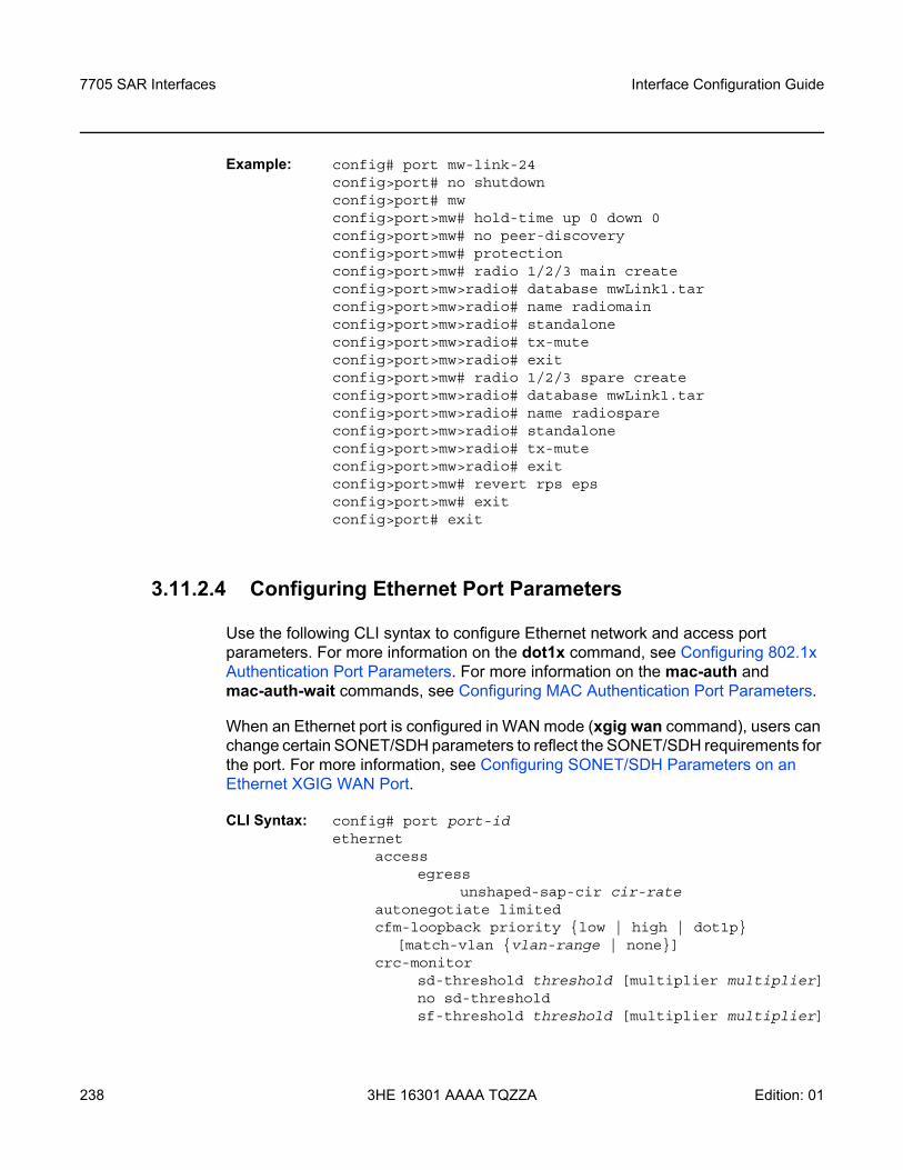
7705 SAR Interfaces
238
Interface Configuration Guide
3HE 16301 AAAA TQZZA Edition: 01
Example: config# port mw-link-24config>port# no shutdownconfig>port# mwconfig>port>mw# hold-time up 0 down 0config>port>mw# no peer-discoveryconfig>port>mw# protectionconfig>port>mw# radio 1/2/3 main createconfig>port>mw>radio# database mwLink1.tarconfig>port>mw>radio# name radiomainconfig>port>mw>radio# standaloneconfig>port>mw>radio# tx-muteconfig>port>mw>radio# exitconfig>port>mw# radio 1/2/3 spare createconfig>port>mw>radio# database mwLink1.tarconfig>port>mw>radio# name radiospareconfig>port>mw>radio# standaloneconfig>port>mw>radio# tx-muteconfig>port>mw>radio# exitconfig>port>mw# revert rps epsconfig>port>mw# exitconfig>port# exit
3.11.2.4 Configuring Ethernet Port Parameters
Use the following CLI syntax to configure Ethernet network and access port parameters. For more information on the dot1x command, see Configuring 802.1x Authentication Port Parameters. For more information on the mac-auth and mac-auth-wait commands, see Configuring MAC Authentication Port Parameters.
When an Ethernet port is configured in WAN mode (xgig wan command), users can change certain SONET/SDH parameters to reflect the SONET/SDH requirements for the port. For more information, see Configuring SONET/SDH Parameters on an Ethernet XGIG WAN Port.
CLI Syntax: config# port port-id ethernet
access egress
unshaped-sap-cir cir-rateautonegotiate limitedcfm-loopback priority low | high | dot1p
[match-vlan vlan-range | none]crc-monitor
sd-threshold threshold [multiplier multiplier]no sd-thresholdsf-threshold threshold [multiplier multiplier]
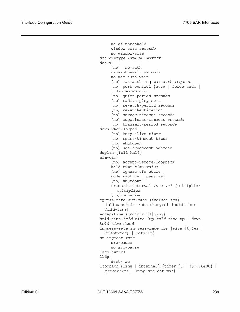
Interface Configuration Guide 7705 SAR Interfaces
Edition: 01 3HE 16301 AAAA TQZZA 239
no sf-thresholdwindow-size secondsno window-size
dot1q-etype 0x0600..0xffff dot1x
[no] mac-authmac-auth-wait secondsno mac-auth-wait[no] max-auth-req max-auth-request[no] port-control auto | force-auth |
force-unauth [no] quiet-period seconds [no] radius-plcy name [no] re-auth-period seconds [no] re-authentication [no] server-timeout seconds [no] supplicant-timeout seconds [no] transmit-period seconds
down-when-looped [no] keep-alive timer [no] retry-timeout timer [no] shutdown[no] use-broadcast-address
duplex full|halfefm-oam
[no] accept-remote-loopbackhold-time time-value[no] ignore-efm-statemode active | passive[no] shutdowntransmit-interval interval [multiplier
multiplier][no]tunneling
egress-rate sub-rate [include-fcs] [allow-eth-bn-rate-changes] [hold-time hold-time]
encap-type dot1q|null|qinqhold-time hold-time [up hold-time-up | down hold-time-down]ingress-rate ingress-rate cbs size [bytes |
kilobytes] | default no ingress-rate
src-pauseno src-pause
lacp-tunnellldp
dest-macloopback line | internal timer 0 | 30..86400 |
persistent [swap-src-dst-mac]

7705 SAR Interfaces
240
Interface Configuration Guide
3HE 16301 AAAA TQZZA Edition: 01
no loopbackmac ieee-addressmode access | network | hybrid mtu mtu-bytesnetwork
accounting-policy policy-id[no] collect-stats queue-policy namescheduler-mode profile | 4-priority |
16-priorityphy-tx-clock auto-pref-master | auto-pref-slave |
slave | master no phy-tx-clockpoe plus no poeptp-asymmetry nano-seconds no ptp-asymmetry qinq-etype 0x0600..0xffff report-alarm [signal-fail] [remote] [local]
[no-frame-lock] [high-ber]speed 10|100|1000ssm
code-type sonet | sdh[no] shutdown[no] tx-dus
vlan-filter filter-idno vlan-filter xgig lan | wanxor-mode rj45 | sfp
3.11.2.4.1 Configuring an Ethernet Network Port
A network port is network facing and participates in the service provider transport or infrastructure network processes.
Use the following basic CLI syntax to configure Ethernet network mode port parameters.
CLI Syntax: port port-id ethernet
mode networknetwork
accounting-policy policy-id[no] collect-stats queue-policy namescheduler-mode profile | 4-priority |
16-priority
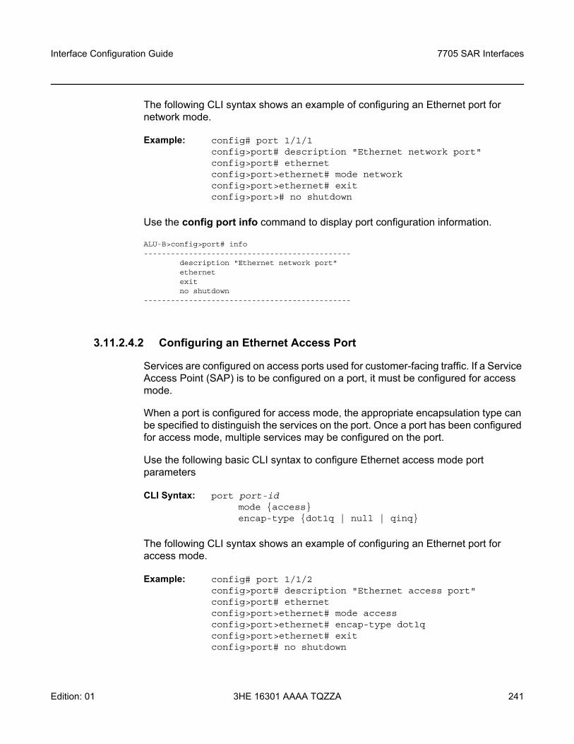
Interface Configuration Guide 7705 SAR Interfaces
Edition: 01 3HE 16301 AAAA TQZZA 241
The following CLI syntax shows an example of configuring an Ethernet port for network mode.
Example: config# port 1/1/1config>port# description "Ethernet network port"config>port# ethernetconfig>port>ethernet# mode networkconfig>port>ethernet# exitconfig>port># no shutdown
Use the config port info command to display port configuration information.
ALU-B>config>port# info----------------------------------------------
description "Ethernet network port"ethernetexitno shutdown
----------------------------------------------
3.11.2.4.2 Configuring an Ethernet Access Port
Services are configured on access ports used for customer-facing traffic. If a Service Access Point (SAP) is to be configured on a port, it must be configured for access mode.
When a port is configured for access mode, the appropriate encapsulation type can be specified to distinguish the services on the port. Once a port has been configured for access mode, multiple services may be configured on the port.
Use the following basic CLI syntax to configure Ethernet access mode port parameters
CLI Syntax: port port-id mode accessencap-type dot1q | null | qinq
The following CLI syntax shows an example of configuring an Ethernet port for access mode.
Example: config# port 1/1/2config>port# description "Ethernet access port"config>port# ethernetconfig>port>ethernet# mode access config>port>ethernet# encap-type dot1qconfig>port>ethernet# exitconfig>port# no shutdown
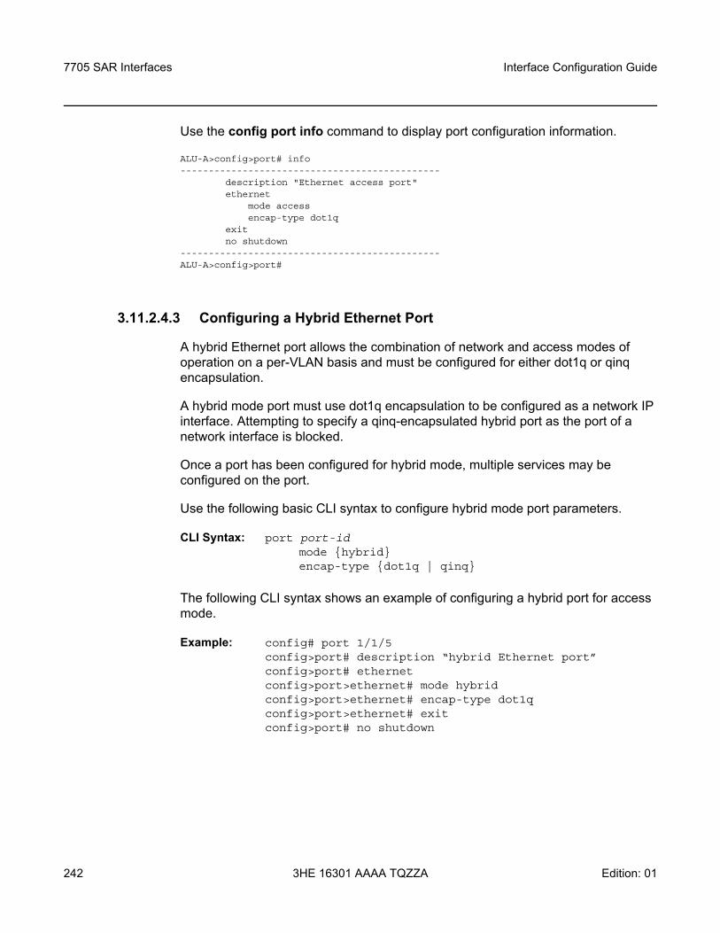
7705 SAR Interfaces
242
Interface Configuration Guide
3HE 16301 AAAA TQZZA Edition: 01
Use the config port info command to display port configuration information.
ALU-A>config>port# info----------------------------------------------
description "Ethernet access port"ethernet
mode accessencap-type dot1q
exitno shutdown
----------------------------------------------ALU-A>config>port#
3.11.2.4.3 Configuring a Hybrid Ethernet Port
A hybrid Ethernet port allows the combination of network and access modes of operation on a per-VLAN basis and must be configured for either dot1q or qinq encapsulation.
A hybrid mode port must use dot1q encapsulation to be configured as a network IP interface. Attempting to specify a qinq-encapsulated hybrid port as the port of a network interface is blocked.
Once a port has been configured for hybrid mode, multiple services may be configured on the port.
Use the following basic CLI syntax to configure hybrid mode port parameters.
CLI Syntax: port port-id mode hybridencap-type dot1q | qinq
The following CLI syntax shows an example of configuring a hybrid port for access mode.
Example: config# port 1/1/5config>port# description “hybrid Ethernet port”config>port# ethernetconfig>port>ethernet# mode hybrid config>port>ethernet# encap-type dot1qconfig>port>ethernet# exitconfig>port# no shutdown
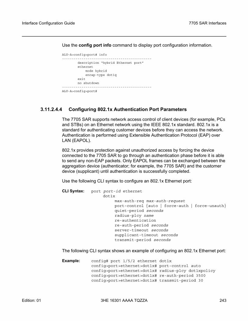
Interface Configuration Guide 7705 SAR Interfaces
Edition: 01 3HE 16301 AAAA TQZZA 243
Use the config port info command to display port configuration information.
ALU-A>config>port# info----------------------------------------------
description “hybrid Ethernet port”ethernet
mode hybridencap-type dot1q
exitno shutdown
----------------------------------------------ALU-A>config>port#
3.11.2.4.4 Configuring 802.1x Authentication Port Parameters
The 7705 SAR supports network access control of client devices (for example, PCs and STBs) on an Ethernet network using the IEEE 802.1x standard. 802.1x is a standard for authenticating customer devices before they can access the network. Authentication is performed using Extensible Authentication Protocol (EAP) over LAN (EAPOL).
802.1x provides protection against unauthorized access by forcing the device connected to the 7705 SAR to go through an authentication phase before it is able to send any non-EAP packets. Only EAPOL frames can be exchanged between the aggregation device (authenticator; for example, the 7705 SAR) and the customer device (supplicant) until authentication is successfully completed.
Use the following CLI syntax to configure an 802.1x Ethernet port:
CLI Syntax: port port-id ethernetdot1x
max-auth-req max-auth-requestport-control auto | force-auth | force-unauthquiet-period secondsradius-plcy namere-authenticationre-auth-period secondsserver-timeout secondssupplicant-timeout secondstransmit-period seconds
The following CLI syntax shows an example of configuring an 802.1x Ethernet port:
Example: config# port 1/5/2 ethernet dot1xconfig>port>ethernet>dot1x# port-control autoconfig>port>ethernet>dot1x# radius-plcy dot1xpolicyconfig>port>ethernet>dot1x# re-auth-period 3500config>port>ethernet>dot1x# transmit-period 30
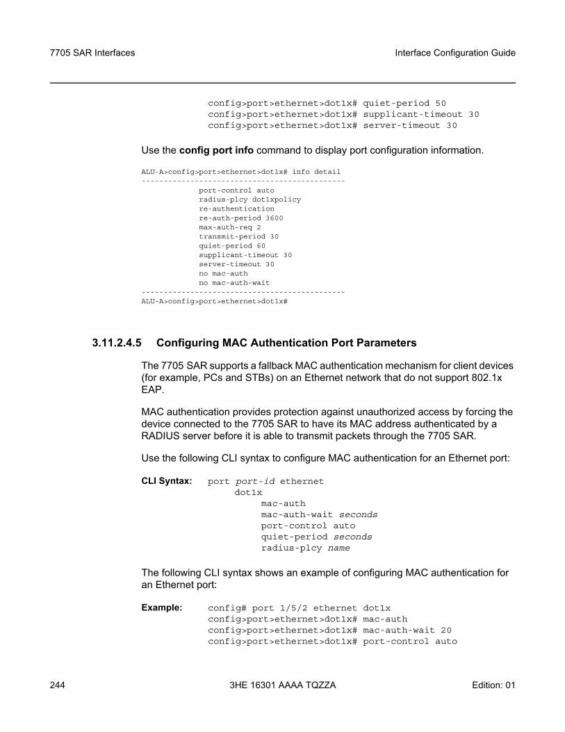
7705 SAR Interfaces
244
Interface Configuration Guide
3HE 16301 AAAA TQZZA Edition: 01
config>port>ethernet>dot1x# quiet-period 50config>port>ethernet>dot1x# supplicant-timeout 30config>port>ethernet>dot1x# server-timeout 30
Use the config port info command to display port configuration information.
ALU-A>config>port>ethernet>dot1x# info detail----------------------------------------------
port-control autoradius-plcy dot1xpolicyre-authenticationre-auth-period 3600max-auth-req 2transmit-period 30quiet-period 60supplicant-timeout 30server-timeout 30no mac-authno mac-auth-wait
----------------------------------------------ALU-A>config>port>ethernet>dot1x#
3.11.2.4.5 Configuring MAC Authentication Port Parameters
The 7705 SAR supports a fallback MAC authentication mechanism for client devices (for example, PCs and STBs) on an Ethernet network that do not support 802.1x EAP.
MAC authentication provides protection against unauthorized access by forcing the device connected to the 7705 SAR to have its MAC address authenticated by a RADIUS server before it is able to transmit packets through the 7705 SAR.
Use the following CLI syntax to configure MAC authentication for an Ethernet port:
CLI Syntax: port port-id ethernetdot1x
mac-authmac-auth-wait secondsport-control autoquiet-period secondsradius-plcy name
The following CLI syntax shows an example of configuring MAC authentication for an Ethernet port:
Example: config# port 1/5/2 ethernet dot1xconfig>port>ethernet>dot1x# mac-authconfig>port>ethernet>dot1x# mac-auth-wait 20config>port>ethernet>dot1x# port-control auto
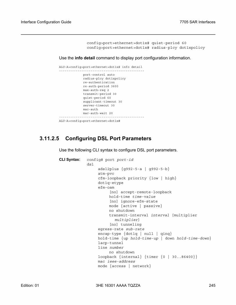
Interface Configuration Guide 7705 SAR Interfaces
Edition: 01 3HE 16301 AAAA TQZZA 245
config>port>ethernet>dot1x# quiet-period 60config>port>ethernet>dot1x# radius-plcy dot1xpolicy
Use the info detail command to display port configuration information.
ALU-A>config>port>ethernet>dot1x# info detail----------------------------------------------
port-control autoradius-plcy dot1xpolicyre-authenticationre-auth-period 3600max-auth-req 2transmit-period 30quiet-period 60supplicant-timeout 30server-timeout 30mac-authmac-auth-wait 20
----------------------------------------------ALU-A>config>port>ethernet>dot1x#
3.11.2.5 Configuring DSL Port Parameters
Use the following CLI syntax to configure DSL port parameters.
CLI Syntax: config# port port-id dsl
adsl2plus g992-5-a | g992-5-batm-pvccfm-loopback priority low | highdot1q-etypeefm-oam
[no] accept-remote-loopbackhold-time time-value[no] ignore-efm-statemode active | passiveno shutdowntransmit-interval interval [multiplier
multiplier][no] tunneling
egress-rate sub-rateencap-type dot1q | null | qinqhold-time up hold-time-up | down hold-time-downlacp-tunnelline number
no shutdownloopback internal timer 0 | 30..86400mac ieee-addressmode access | network
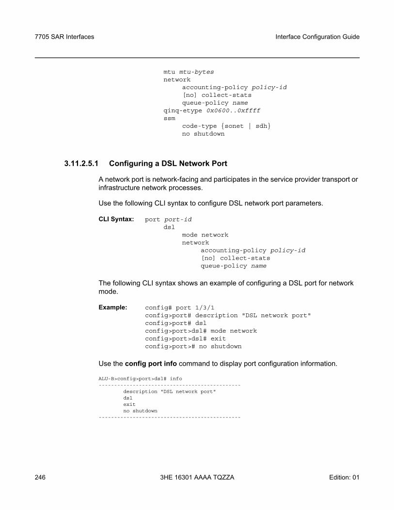
7705 SAR Interfaces
246
Interface Configuration Guide
3HE 16301 AAAA TQZZA Edition: 01
mtu mtu-bytesnetwork
accounting-policy policy-id[no] collect-stats queue-policy name
qinq-etype 0x0600..0xffff ssm
code-type sonet | sdhno shutdown
3.11.2.5.1 Configuring a DSL Network Port
A network port is network-facing and participates in the service provider transport or infrastructure network processes.
Use the following CLI syntax to configure DSL network port parameters.
CLI Syntax: port port-id dsl
mode networknetwork
accounting-policy policy-id[no] collect-stats queue-policy name
The following CLI syntax shows an example of configuring a DSL port for network mode.
Example: config# port 1/3/1config>port# description "DSL network port"config>port# dslconfig>port>dsl# mode networkconfig>port>dsl# exitconfig>port># no shutdown
Use the config port info command to display port configuration information.
ALU-B>config>port>dsl# info----------------------------------------------
description "DSL network port"dslexitno shutdown
----------------------------------------------
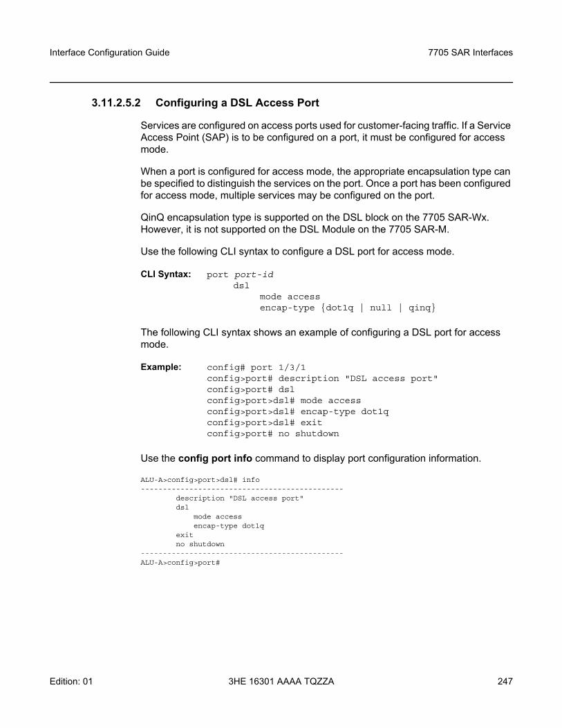
Interface Configuration Guide 7705 SAR Interfaces
Edition: 01 3HE 16301 AAAA TQZZA 247
3.11.2.5.2 Configuring a DSL Access Port
Services are configured on access ports used for customer-facing traffic. If a Service Access Point (SAP) is to be configured on a port, it must be configured for access mode.
When a port is configured for access mode, the appropriate encapsulation type can be specified to distinguish the services on the port. Once a port has been configured for access mode, multiple services may be configured on the port.
QinQ encapsulation type is supported on the DSL block on the 7705 SAR-Wx. However, it is not supported on the DSL Module on the 7705 SAR-M.
Use the following CLI syntax to configure a DSL port for access mode.
CLI Syntax: port port-id dsl
mode accessencap-type dot1q | null | qinq
The following CLI syntax shows an example of configuring a DSL port for access mode.
Example: config# port 1/3/1config>port# description "DSL access port"config>port# dslconfig>port>dsl# mode access config>port>dsl# encap-type dot1qconfig>port>dsl# exitconfig>port# no shutdown
Use the config port info command to display port configuration information.
ALU-A>config>port>dsl# info----------------------------------------------
description "DSL access port"dsl
mode accessencap-type dot1q
exitno shutdown
----------------------------------------------ALU-A>config>port#
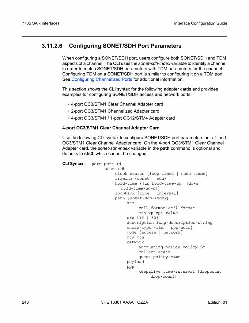
7705 SAR Interfaces
248
Interface Configuration Guide
3HE 16301 AAAA TQZZA Edition: 01
3.11.2.6 Configuring SONET/SDH Port Parameters
When configuring a SONET/SDH port, users configure both SONET/SDH and TDM aspects of a channel. The CLI uses the sonet-sdh-index variable to identify a channel in order to match SONET/SDH parameters with TDM parameters for the channel. Configuring TDM on a SONET/SDH port is similar to configuring it on a TDM port. See Configuring Channelized Ports for additional information.
This section shows the CLI syntax for the following adapter cards and provides examples for configuring SONET/SDH access and network ports:
• 4-port OC3/STM1 Clear Channel Adapter card• 2-port OC3/STM1 Channelized Adapter card• 4-port OC3/STM1 / 1-port OC12/STM4 Adapter card
4-port OC3/STM1 Clear Channel Adapter Card
Use the following CLI syntax to configure SONET/SDH port parameters on a 4-port OC3/STM1 Clear Channel Adapter card. On the 4-port OC3/STM1 Clear Channel Adapter card, the sonet-sdh-index variable in the path command is optional and defaults to sts3, which cannot be changed.
CLI Syntax: port port-idsonet-sdh
clock-source loop-timed | node-timedframing sonet | sdhhold-time [up hold-time-up] [down
hold-time-down]loopback line | internalpath [sonet-sdh-index]
atmcell-format cell-formatmin-vp-vpi value
crc 16 | 32description long-description-stringencap-type atm | ppp-automode access | networkmtu mtunetwork
accounting-policy policy-idcollect-stats queue-policy name
payloadppp
keepalive time-interval [dropcount drop-count]
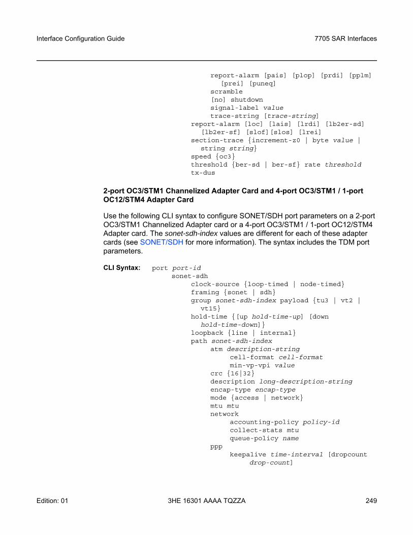
Interface Configuration Guide 7705 SAR Interfaces
Edition: 01 3HE 16301 AAAA TQZZA 249
report-alarm [pais] [plop] [prdi] [pplm] [prei] [puneq]
scramble[no] shutdownsignal-label valuetrace-string [trace-string]
report-alarm [loc] [lais] [lrdi] [lb2er-sd] [lb2er-sf] [slof][slos] [lrei]
section-trace increment-z0 | byte value | string string
speed oc3threshold ber-sd | ber-sf rate thresholdtx-dus
2-port OC3/STM1 Channelized Adapter Card and 4-port OC3/STM1 / 1-port OC12/STM4 Adapter Card
Use the following CLI syntax to configure SONET/SDH port parameters on a 2-port OC3/STM1 Channelized Adapter card or a 4-port OC3/STM1 / 1-port OC12/STM4 Adapter card. The sonet-sdh-index values are different for each of these adapter cards (see SONET/SDH for more information). The syntax includes the TDM port parameters.
CLI Syntax: port port-idsonet-sdh
clock-source loop-timed | node-timedframing sonet | sdhgroup sonet-sdh-index payload tu3 | vt2 |
vt15hold-time [up hold-time-up] [down
hold-time-down]loopback line | internalpath sonet-sdh-index
atm description-stringcell-format cell-formatmin-vp-vpi value
crc 16|32description long-description-stringencap-type encap-type mode access | networkmtu mtu network
accounting-policy policy-id collect-stats mtu queue-policy name
ppp keepalive time-interval [dropcount
drop-count]
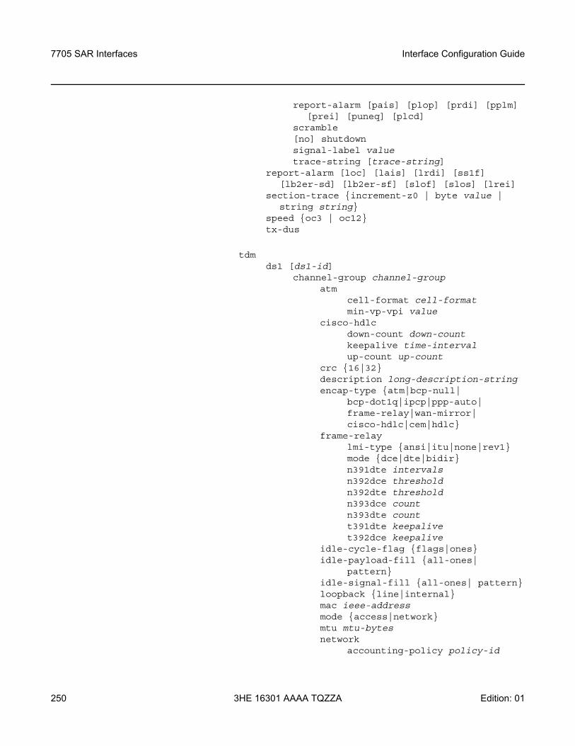
7705 SAR Interfaces
250
Interface Configuration Guide
3HE 16301 AAAA TQZZA Edition: 01
report-alarm [pais] [plop] [prdi] [pplm] [prei] [puneq] [plcd]
scramble[no] shutdownsignal-label valuetrace-string [trace-string]
report-alarm [loc] [lais] [lrdi] [ss1f] [lb2er-sd] [lb2er-sf] [slof] [slos] [lrei]
section-trace increment-z0 | byte value | string string
speed oc3 | oc12tx-dus
tdmds1 [ds1-id]
channel-group channel-groupatm
cell-format cell-formatmin-vp-vpi value
cisco-hdlcdown-count down-count keepalive time-intervalup-count up-count
crc 16|32description long-description-string encap-type atm|bcp-null|
bcp-dot1q|ipcp|ppp-auto| frame-relay|wan-mirror| cisco-hdlc|cem|hdlc
frame-relaylmi-type ansi|itu|none|rev1mode dce|dte|bidirn391dte intervals n392dce threshold n392dte threshold n393dce count n393dte count t391dte keepalive t392dce keepalive
idle-cycle-flag flags|onesidle-payload-fill all-ones|
patternidle-signal-fill all-ones| patternloopback line|internalmac ieee-address mode access|networkmtu mtu-bytes network
accounting-policy policy-id
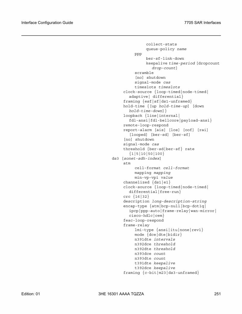
Interface Configuration Guide 7705 SAR Interfaces
Edition: 01 3HE 16301 AAAA TQZZA 251
collect-statsqueue-policy name
pppber-sf-link-downkeepalive time-period [dropcount
drop-count] scramble[no] shutdownsignal-mode cas timeslots timeslots
clock-source loop-timed|node-timed| adaptive| differential
framing esf|sf|ds1-unframedhold-time [up hold-time-up] [down
hold-time-down]loopback line|internal|
fdl-ansi|fdl-bellcore|payload-ansiremote-loop-respondreport-alarm [ais] [los] [oof] [rai]
[looped] [ber-sd] [ber-sf][no] shutdownsignal-mode cas threshold ber-sd|ber-sf rate
1|5|10|50|100ds3 [sonet-sdh-index]
atmcell-format cell-format mapping mappingmin-vp-vpi value
channelized ds1|e1clock-source loop-timed|node-timed|
differential|free-runcrc 16|32description long-description-string encap-type atm|bcp-null|bcp-dot1q|
ipcp|ppp-auto|frame-relay|wan-mirror| cisco-hdlc|cem
feac-loop-respondframe-relay
lmi-type ansi|itu|none|rev1mode dce|dte|bidirn391dte intervals n392dce threshold n392dte threshold n393dce count n393dte count t391dte keepalive t392dce keepalive
framing c-bit|m23|ds3-unframed
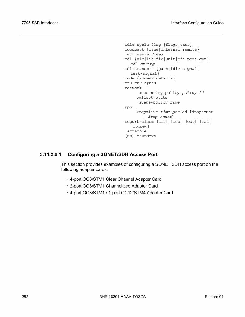
7705 SAR Interfaces
252
Interface Configuration Guide
3HE 16301 AAAA TQZZA Edition: 01
idle-cycle-flag flags|onesloopback line|internal|remotemac ieee-address mdl eic|lic|fic|unit|pfi|port|gen
mdl-string mdl-transmit path|idle-signal|
test-signalmode access|networkmtu mtu-bytes network
accounting-policy policy-id collect-stats queue-policy name
pppkeepalive time-period [dropcount
drop-count]report-alarm [ais] [los] [oof] [rai]
[looped] scramble[no] shutdown
3.11.2.6.1 Configuring a SONET/SDH Access Port
This section provides examples of configuring a SONET/SDH access port on the following adapter cards:
• 4-port OC3/STM1 Clear Channel Adapter Card• 2-port OC3/STM1 Channelized Adapter Card• 4-port OC3/STM1 / 1-port OC12/STM4 Adapter Card
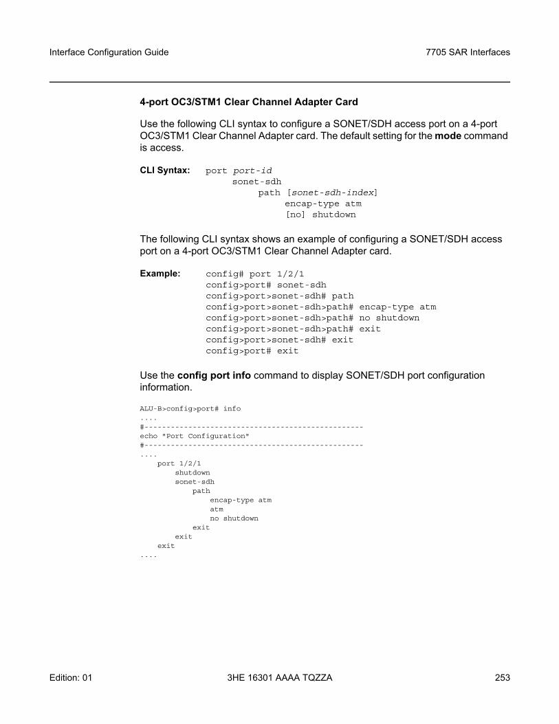
Interface Configuration Guide 7705 SAR Interfaces
Edition: 01 3HE 16301 AAAA TQZZA 253
4-port OC3/STM1 Clear Channel Adapter Card
Use the following CLI syntax to configure a SONET/SDH access port on a 4-port OC3/STM1 Clear Channel Adapter card. The default setting for the mode command is access.
CLI Syntax: port port-idsonet-sdh
path [sonet-sdh-index]encap-type atm[no] shutdown
The following CLI syntax shows an example of configuring a SONET/SDH access port on a 4-port OC3/STM1 Clear Channel Adapter card.
Example: config# port 1/2/1config>port# sonet-sdhconfig>port>sonet-sdh# pathconfig>port>sonet-sdh>path# encap-type atmconfig>port>sonet-sdh>path# no shutdownconfig>port>sonet-sdh>path# exitconfig>port>sonet-sdh# exitconfig>port# exit
Use the config port info command to display SONET/SDH port configuration information.
ALU-B>config>port# info....#--------------------------------------------------echo "Port Configuration"#--------------------------------------------------....
port 1/2/1shutdownsonet-sdh
pathencap-type atmatmno shutdown
exitexit
exit....
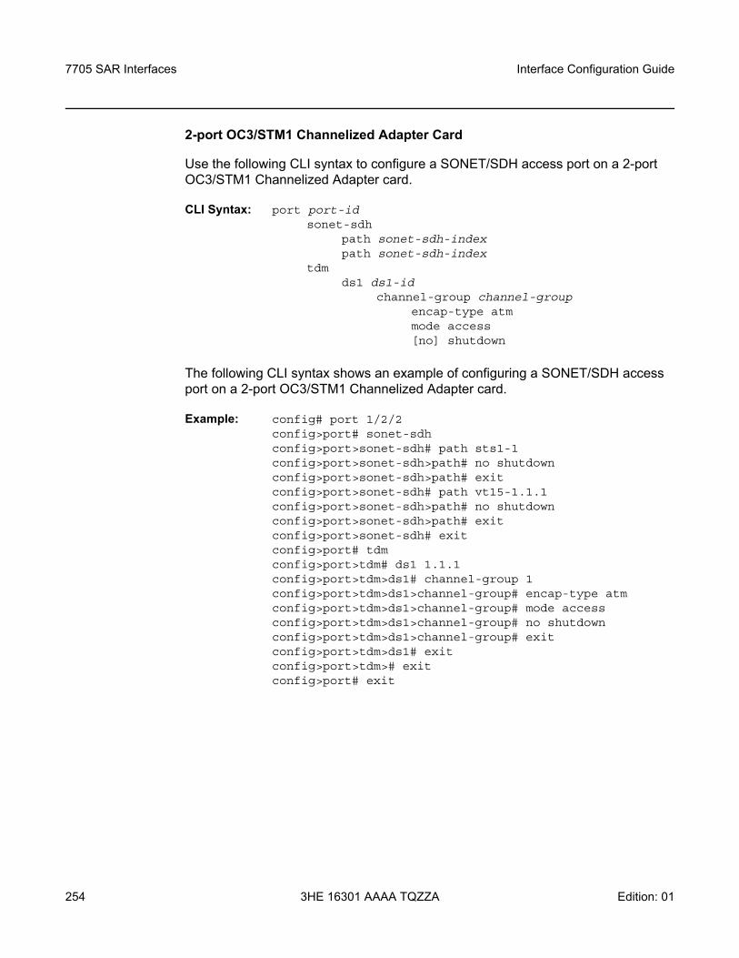
7705 SAR Interfaces
254
Interface Configuration Guide
3HE 16301 AAAA TQZZA Edition: 01
2-port OC3/STM1 Channelized Adapter Card
Use the following CLI syntax to configure a SONET/SDH access port on a 2-port OC3/STM1 Channelized Adapter card.
CLI Syntax: port port-idsonet-sdh
path sonet-sdh-index path sonet-sdh-index
tdmds1 ds1-id
channel-group channel-groupencap-type atmmode access[no] shutdown
The following CLI syntax shows an example of configuring a SONET/SDH access port on a 2-port OC3/STM1 Channelized Adapter card.
Example: config# port 1/2/2config>port# sonet-sdhconfig>port>sonet-sdh# path sts1-1config>port>sonet-sdh>path# no shutdownconfig>port>sonet-sdh>path# exitconfig>port>sonet-sdh# path vt15-1.1.1config>port>sonet-sdh>path# no shutdownconfig>port>sonet-sdh>path# exitconfig>port>sonet-sdh# exitconfig>port# tdmconfig>port>tdm# ds1 1.1.1 config>port>tdm>ds1# channel-group 1 config>port>tdm>ds1>channel-group# encap-type atmconfig>port>tdm>ds1>channel-group# mode accessconfig>port>tdm>ds1>channel-group# no shutdownconfig>port>tdm>ds1>channel-group# exitconfig>port>tdm>ds1# exitconfig>port>tdm># exitconfig>port# exit
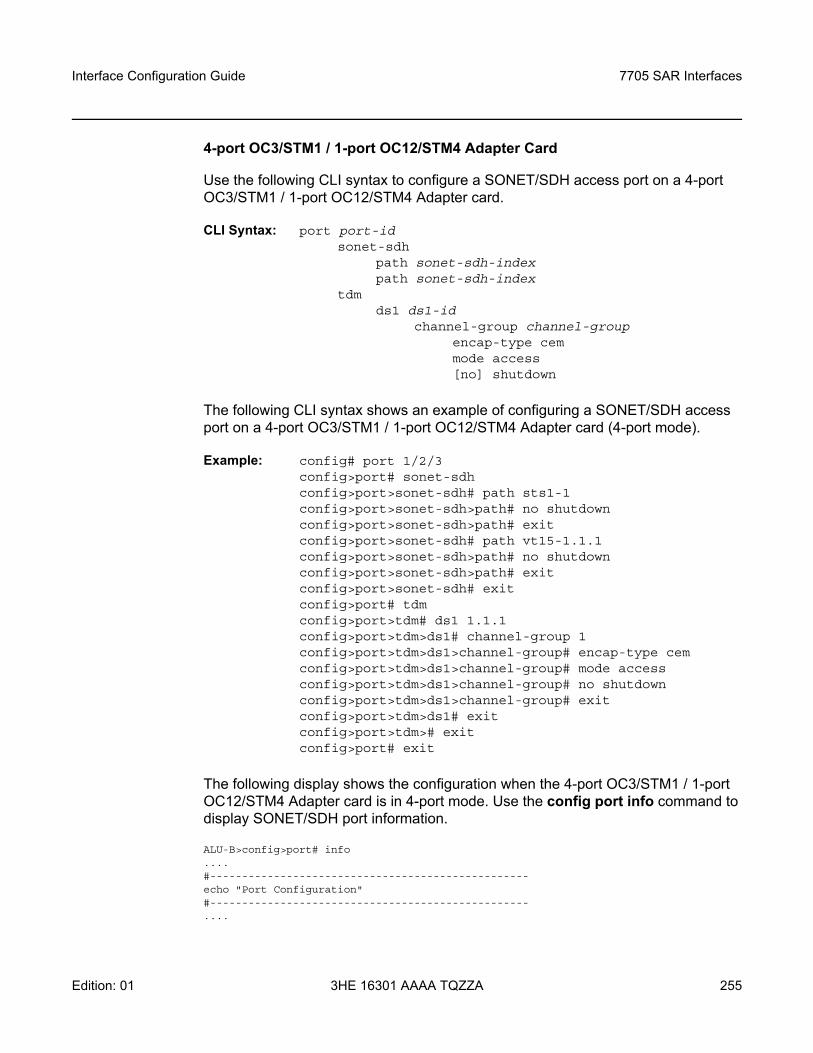
Interface Configuration Guide 7705 SAR Interfaces
Edition: 01 3HE 16301 AAAA TQZZA 255
4-port OC3/STM1 / 1-port OC12/STM4 Adapter Card
Use the following CLI syntax to configure a SONET/SDH access port on a 4-port OC3/STM1 / 1-port OC12/STM4 Adapter card.
CLI Syntax: port port-idsonet-sdh
path sonet-sdh-index path sonet-sdh-index
tdmds1 ds1-id
channel-group channel-groupencap-type cemmode access[no] shutdown
The following CLI syntax shows an example of configuring a SONET/SDH access port on a 4-port OC3/STM1 / 1-port OC12/STM4 Adapter card (4-port mode).
Example: config# port 1/2/3config>port# sonet-sdhconfig>port>sonet-sdh# path sts1-1config>port>sonet-sdh>path# no shutdownconfig>port>sonet-sdh>path# exitconfig>port>sonet-sdh# path vt15-1.1.1config>port>sonet-sdh>path# no shutdownconfig>port>sonet-sdh>path# exitconfig>port>sonet-sdh# exitconfig>port# tdmconfig>port>tdm# ds1 1.1.1 config>port>tdm>ds1# channel-group 1 config>port>tdm>ds1>channel-group# encap-type cem config>port>tdm>ds1>channel-group# mode accessconfig>port>tdm>ds1>channel-group# no shutdownconfig>port>tdm>ds1>channel-group# exitconfig>port>tdm>ds1# exitconfig>port>tdm># exitconfig>port# exit
The following display shows the configuration when the 4-port OC3/STM1 / 1-port OC12/STM4 Adapter card is in 4-port mode. Use the config port info command to display SONET/SDH port information.
ALU-B>config>port# info....#--------------------------------------------------echo "Port Configuration"#--------------------------------------------------....
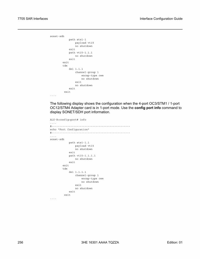
7705 SAR Interfaces
256
Interface Configuration Guide
3HE 16301 AAAA TQZZA Edition: 01
sonet-sdhpath sts1-1
payload vt15no shutdown
exitpath vt15-1.1.1
no shutdownexit
exittdm
ds1 1.1.1channel-group 1
encap-type cemno shutdown
exitno shutdown
exitexit
....
The following display shows the configuration when the 4-port OC3/STM1 / 1-port OC12/STM4 Adapter card is in 1-port mode. Use the config port info command to display SONET/SDH port information.
ALU-B>config>port# info....#--------------------------------------------------echo "Port Configuration"#--------------------------------------------------....sonet-sdh
path sts1-1.1payload vt15no shutdown
exitpath vt15-1.1.1.1
no shutdownexit
exittdm
ds1 1.1.1.1channel-group 1
encap-type cemno shutdown
exitno shutdown
exitexit
....
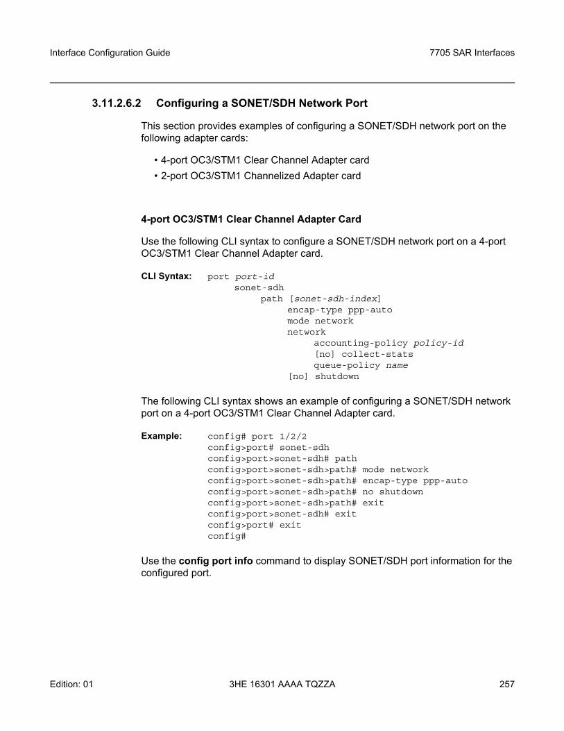
Interface Configuration Guide 7705 SAR Interfaces
Edition: 01 3HE 16301 AAAA TQZZA 257
3.11.2.6.2 Configuring a SONET/SDH Network Port
This section provides examples of configuring a SONET/SDH network port on the following adapter cards:
• 4-port OC3/STM1 Clear Channel Adapter card• 2-port OC3/STM1 Channelized Adapter card
4-port OC3/STM1 Clear Channel Adapter Card
Use the following CLI syntax to configure a SONET/SDH network port on a 4-port OC3/STM1 Clear Channel Adapter card.
CLI Syntax: port port-idsonet-sdh
path [sonet-sdh-index]encap-type ppp-automode networknetwork
accounting-policy policy-id[no] collect-stats queue-policy name
[no] shutdown
The following CLI syntax shows an example of configuring a SONET/SDH network port on a 4-port OC3/STM1 Clear Channel Adapter card.
Example: config# port 1/2/2config>port# sonet-sdhconfig>port>sonet-sdh# pathconfig>port>sonet-sdh>path# mode networkconfig>port>sonet-sdh>path# encap-type ppp-autoconfig>port>sonet-sdh>path# no shutdownconfig>port>sonet-sdh>path# exitconfig>port>sonet-sdh# exitconfig>port# exitconfig#
Use the config port info command to display SONET/SDH port information for the configured port.
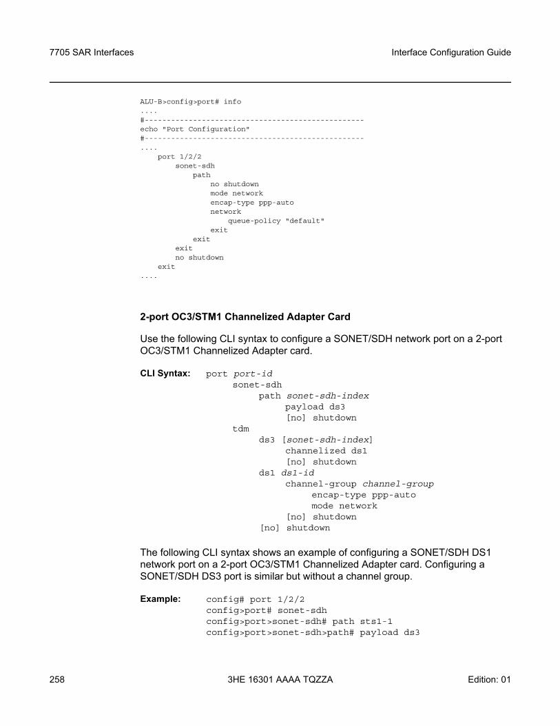
7705 SAR Interfaces
258
Interface Configuration Guide
3HE 16301 AAAA TQZZA Edition: 01
ALU-B>config>port# info....#--------------------------------------------------echo "Port Configuration"#--------------------------------------------------....
port 1/2/2sonet-sdh
pathno shutdownmode networkencap-type ppp-autonetwork
queue-policy "default"exit
exitexitno shutdown
exit....
2-port OC3/STM1 Channelized Adapter Card
Use the following CLI syntax to configure a SONET/SDH network port on a 2-port OC3/STM1 Channelized Adapter card.
CLI Syntax: port port-idsonet-sdh
path sonet-sdh-indexpayload ds3[no] shutdown
tdmds3 [sonet-sdh-index]
channelized ds1[no] shutdown
ds1 ds1-idchannel-group channel-group
encap-type ppp-automode network
[no] shutdown[no] shutdown
The following CLI syntax shows an example of configuring a SONET/SDH DS1 network port on a 2-port OC3/STM1 Channelized Adapter card. Configuring a SONET/SDH DS3 port is similar but without a channel group.
Example: config# port 1/2/2config>port# sonet-sdhconfig>port>sonet-sdh# path sts1-1 config>port>sonet-sdh>path# payload ds3
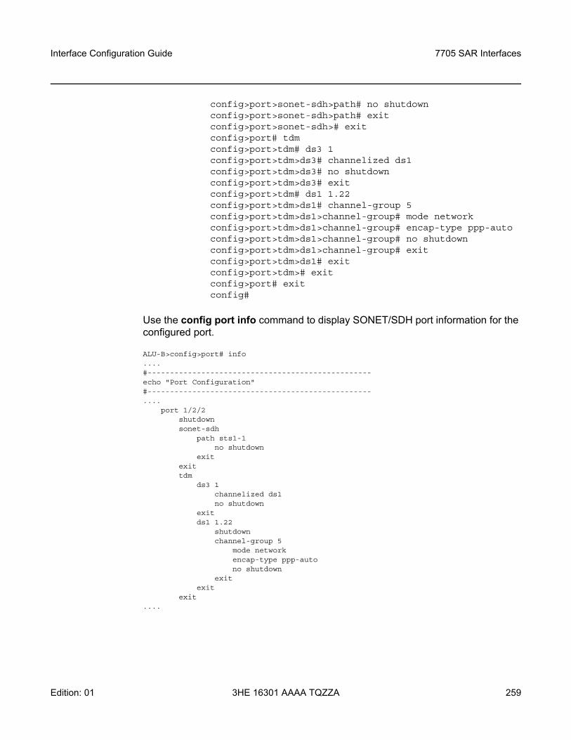
Interface Configuration Guide 7705 SAR Interfaces
Edition: 01 3HE 16301 AAAA TQZZA 259
config>port>sonet-sdh>path# no shutdownconfig>port>sonet-sdh>path# exitconfig>port>sonet-sdh># exitconfig>port# tdmconfig>port>tdm# ds3 1config>port>tdm>ds3# channelized ds1config>port>tdm>ds3# no shutdownconfig>port>tdm>ds3# exitconfig>port>tdm# ds1 1.22config>port>tdm>ds1# channel-group 5 config>port>tdm>ds1>channel-group# mode networkconfig>port>tdm>ds1>channel-group# encap-type ppp-autoconfig>port>tdm>ds1>channel-group# no shutdownconfig>port>tdm>ds1>channel-group# exitconfig>port>tdm>ds1# exitconfig>port>tdm># exitconfig>port# exitconfig#
Use the config port info command to display SONET/SDH port information for the configured port.
ALU-B>config>port# info....#--------------------------------------------------echo "Port Configuration"#--------------------------------------------------....
port 1/2/2shutdownsonet-sdh
path sts1-1no shutdown
exitexittdm
ds3 1channelized ds1no shutdown
exitds1 1.22
shutdownchannel-group 5
mode networkencap-type ppp-autono shutdown
exitexit
exit....
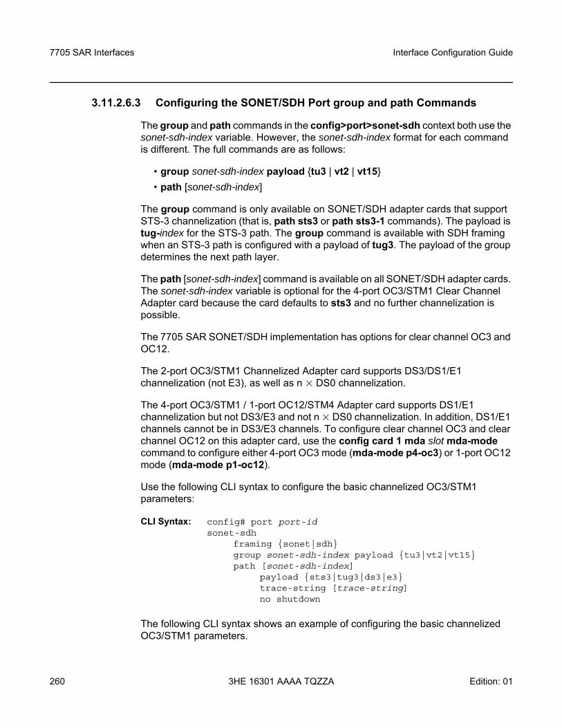
7705 SAR Interfaces
260
Interface Configuration Guide
3HE 16301 AAAA TQZZA Edition: 01
3.11.2.6.3 Configuring the SONET/SDH Port group and path Commands
The group and path commands in the config>port>sonet-sdh context both use the sonet-sdh-index variable. However, the sonet-sdh-index format for each command is different. The full commands are as follows:
• group sonet-sdh-index payload tu3 | vt2 | vt15 • path [sonet-sdh-index]
The group command is only available on SONET/SDH adapter cards that support STS-3 channelization (that is, path sts3 or path sts3-1 commands). The payload is tug-index for the STS-3 path. The group command is available with SDH framing when an STS-3 path is configured with a payload of tug3. The payload of the group determines the next path layer.
The path [sonet-sdh-index] command is available on all SONET/SDH adapter cards. The sonet-sdh-index variable is optional for the 4-port OC3/STM1 Clear Channel Adapter card because the card defaults to sts3 and no further channelization is possible.
The 7705 SAR SONET/SDH implementation has options for clear channel OC3 and OC12.
The 2-port OC3/STM1 Channelized Adapter card supports DS3/DS1/E1 channelization (not E3), as well as n × DS0 channelization.
The 4-port OC3/STM1 / 1-port OC12/STM4 Adapter card supports DS1/E1 channelization but not DS3/E3 and not n × DS0 channelization. In addition, DS1/E1 channels cannot be in DS3/E3 channels. To configure clear channel OC3 and clear channel OC12 on this adapter card, use the config card 1 mda slot mda-mode command to configure either 4-port OC3 mode (mda-mode p4-oc3) or 1-port OC12 mode (mda-mode p1-oc12).
Use the following CLI syntax to configure the basic channelized OC3/STM1 parameters:
CLI Syntax: config# port port-idsonet-sdh
framing sonet|sdhgroup sonet-sdh-index payload tu3|vt2|vt15path [sonet-sdh-index]
payload sts3|tug3|ds3|e3trace-string [trace-string]no shutdown
The following CLI syntax shows an example of configuring the basic channelized OC3/STM1 parameters.
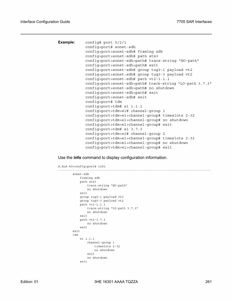
Interface Configuration Guide 7705 SAR Interfaces
Edition: 01 3HE 16301 AAAA TQZZA 261
Example: config# port 5/2/1config>port# sonet-sdhconfig>port>sonet-sdh# framing sdhconfig>port>sonet-sdh# path sts3config>port>sonet-sdh>path# trace-string "HO-path"config>port>sonet-sdh>path# exitconfig>port>sonet-sdh# group tug3-1 payload vt2config>port>sonet-sdh# group tug3-3 payload vt2config>port>sonet-sdh# path vt2-1.1.1config>port>sonet-sdh>path# trace-string "LO-path 3.7.3"config>port>sonet-sdh>path# no shutdownconfig>port>sonet-sdh>path# exitconfig>port>sonet-sdh# exitconfig>port# tdmconfig>port>tdm# e1 1.1.1config>port>tdm>e1# channel-group 1config>port>tdm>e1>channel-group# timeslots 2-32config>port>tdm>e1>channel-group# no shutdownconfig>port>tdm>e1>channel-group# exitconfig>port>tdm# e1 3.7.3config>port>tdm>e1# channel-group 2config>port>tdm>e1>channel-group# timeslots 2-32config>port>tdm>e1>channel-group# no shutdownconfig>port>tdm>e1>channel-group# exit
Use the info command to display configuration information.
A:ALA-49>config>port# info------------------------------------------------------------------------------------
sonet-sdhframing sdhpath sts3
trace-string "HO-path"no shutdown
exitgroup tug3-1 payload vt2group tug3-3 payload vt2path vt2-1.1.1
trace-string "LO-path 3.7.3"no shutdown
exitpath vt2-3.7.3
no shutdownexit
exittdm
e1 1.1.1channel-group 1
timeslots 2-32no shutdown
exitno shutdown
exit
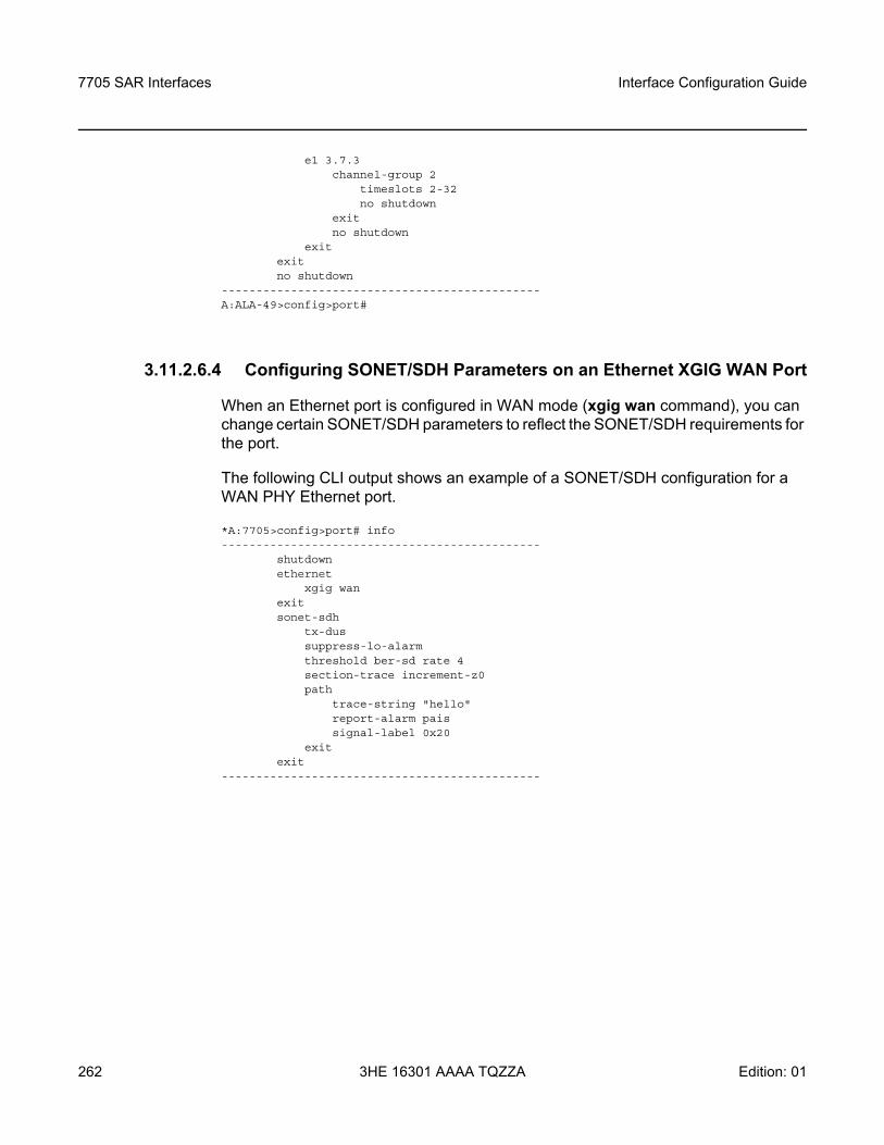
7705 SAR Interfaces
262
Interface Configuration Guide
3HE 16301 AAAA TQZZA Edition: 01
e1 3.7.3channel-group 2
timeslots 2-32no shutdown
exitno shutdown
exitexitno shutdown
----------------------------------------------A:ALA-49>config>port#
3.11.2.6.4 Configuring SONET/SDH Parameters on an Ethernet XGIG WAN Port
When an Ethernet port is configured in WAN mode (xgig wan command), you can change certain SONET/SDH parameters to reflect the SONET/SDH requirements for the port.
The following CLI output shows an example of a SONET/SDH configuration for a WAN PHY Ethernet port.
*A:7705>config>port# info----------------------------------------------
shutdownethernet
xgig wanexitsonet-sdh
tx-dussuppress-lo-alarmthreshold ber-sd rate 4section-trace increment-z0path
trace-string "hello"report-alarm paissignal-label 0x20
exitexit
----------------------------------------------
Interface Configuration Guide 7705 SAR Interfaces
Edition: 01 3HE 16301 AAAA TQZZA 263
3.11.2.7 SONET/SDH Channelized Port Configuration Examples
This section contains information on the following topics:
• OC3 Channelization using SONET and SDH• Configuring DS1/E1 on a Channelized OC3 Port with STS1 Path• Configuring DS1/E1 on a Channelized OC3 Port with STM Path• Configuring DS1/E1 on a Channelized OC3 Port with STS3 Path• Configuring a SONET/SDH Port with Multiple DS1s in an MLPPP Bundle
3.11.2.7.1 OC3 Channelization using SONET and SDH
In SONET, the base signal is referred to as synchronous transport signal–level 1 (STS-1), which operates at 51.84 Mb/s. Higher-level signals are integer multiples of STS-1, for example, STS-3/OC3 = 3 x STS-1 = 155.52 Mb/s. The SDH equivalent of the SONET STS-1 and STS-3 frames are STM-0 and STM-1, respectively.
In addition to the STS-1 base format, SONET also defines synchronous formats at sub-STS-1 levels. The STS-1 payload can be subdivided into virtual tributaries (VTs) for SONET or virtual containers (VCs) for SDH. VTs and VCs are synchronous signals used to transport lower-speed transmissions. Two VTs are VT1.5 and VT2, where:
• VT1.5 = 1.728 Mb/s (enough to carry a T1)• VT2 = 2.304 Mb/s (enough to carry an E1)
The SDH equivalents to VT1.5 and VT2 are VC11 and VC12, respectively.
Figure 30 shows various possibilities for OC3 channelization using SONET and SDH framing. The VT1.5 and VT2 labels under the SDH STS1 path illustrate that SONET conventions are used for SDH configuration.
Note: The following sections show examples of OC3 configurations. Similar examples for OC12 configurations would require an extra level in the sonet-sdh-index. See Table 17 in SONET/SDH Channelized Port ID for port syntax examples.
Note: The 7705 SAR CLI always uses the SONET command syntax and nomenclature, even when configuring an SDH port. For example, the same SONET CLI syntax and nomenclature would be used to configure both a VT1.5 and a VC11. The framing sonet | sdh command determines whether VTs or VCs are being configured. Use the show>port-tree command to display SONET/SDH containers.
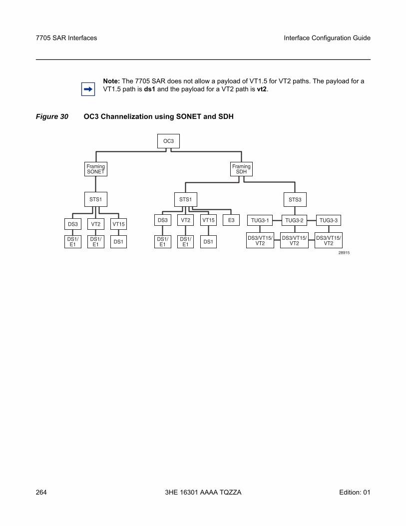
7705 SAR Interfaces
264
Interface Configuration Guide
3HE 16301 AAAA TQZZA Edition: 01
Figure 30 OC3 Channelization using SONET and SDH
Note: The 7705 SAR does not allow a payload of VT1.5 for VT2 paths. The payload for a VT1.5 path is ds1 and the payload for a VT2 path is vt2.
DS1/E1 DS1
STS3
TUG3-2TUG3-1 TUG3-3
DS3/VT15/VT2
DS3/VT15/VT2
DS3/VT15/VT2
DS1/E1
VT2 VT15DS3
STS1
FramingSDH
OC3
DS1/E1 DS1DS1/
E1
VT2 VT15 E3DS3
STS1
FramingSONET
28915
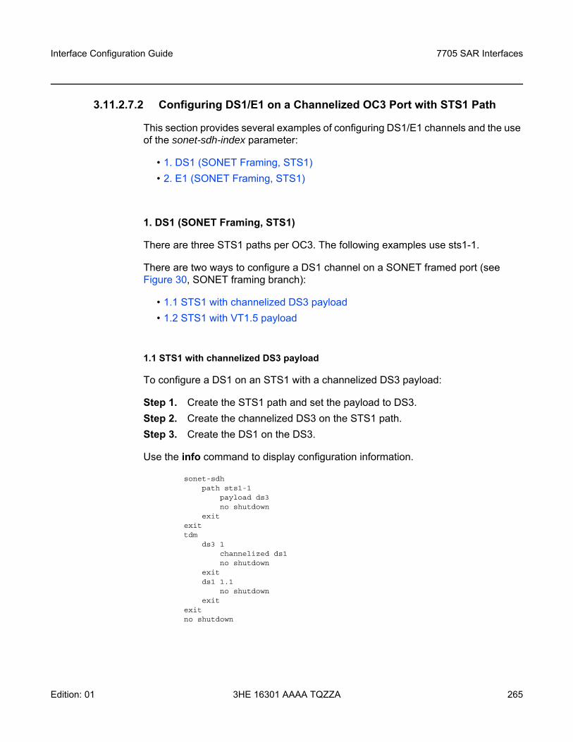
Interface Configuration Guide 7705 SAR Interfaces
Edition: 01 3HE 16301 AAAA TQZZA 265
3.11.2.7.2 Configuring DS1/E1 on a Channelized OC3 Port with STS1 Path
This section provides several examples of configuring DS1/E1 channels and the use of the sonet-sdh-index parameter:
• 1. DS1 (SONET Framing, STS1)• 2. E1 (SONET Framing, STS1)
1. DS1 (SONET Framing, STS1)
There are three STS1 paths per OC3. The following examples use sts1-1.
There are two ways to configure a DS1 channel on a SONET framed port (see Figure 30, SONET framing branch):
• 1.1 STS1 with channelized DS3 payload • 1.2 STS1 with VT1.5 payload
1.1 STS1 with channelized DS3 payload
To configure a DS1 on an STS1 with a channelized DS3 payload:
Step 1. Create the STS1 path and set the payload to DS3.Step 2. Create the channelized DS3 on the STS1 path.Step 3. Create the DS1 on the DS3.
Use the info command to display configuration information.
sonet-sdhpath sts1-1
payload ds3no shutdown
exitexittdm
ds3 1channelized ds1no shutdown
exitds1 1.1
no shutdownexit
exitno shutdown
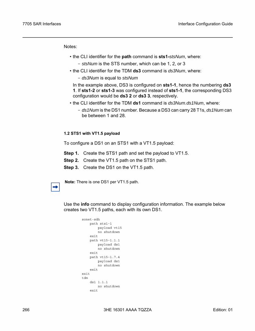
7705 SAR Interfaces
266
Interface Configuration Guide
3HE 16301 AAAA TQZZA Edition: 01
Notes:
• the CLI identifier for the path command is sts1-stsNum, where: - stsNum is the STS number, which can be 1, 2, or 3
• the CLI identifier for the TDM ds3 command is ds3Num, where: - ds3Num is equal to stsNum
In the example above, DS3 is configured on sts1-1, hence the numbering ds3 1. If sts1-2 or sts1-3 was configured instead of sts1-1, the corresponding DS3 configuration would be ds3 2 or ds3 3, respectively.
• the CLI identifier for the TDM ds1 command is ds3Num.ds1Num, where:- ds1Num is the DS1 number. Because a DS3 can carry 28 T1s, ds1Num can
be between 1 and 28.
1.2 STS1 with VT1.5 payload
To configure a DS1 on an STS1 with a VT1.5 payload:
Step 1. Create the STS1 path and set the payload to VT1.5.Step 2. Create the VT1.5 path on the STS1 path.Step 3. Create the DS1 on the VT1.5 path.
Use the info command to display configuration information. The example below creates two VT1.5 paths, each with its own DS1.
sonet-sdhpath sts1-1
payload vt15no shutdown
exitpath vt15-1.1.1
payload ds1no shutdown
exitpath vt15-1.7.4
payload ds1no shutdown
exitexittdm
ds1 1.1.1no shutdown
exit
Note: There is one DS1 per VT1.5 path.
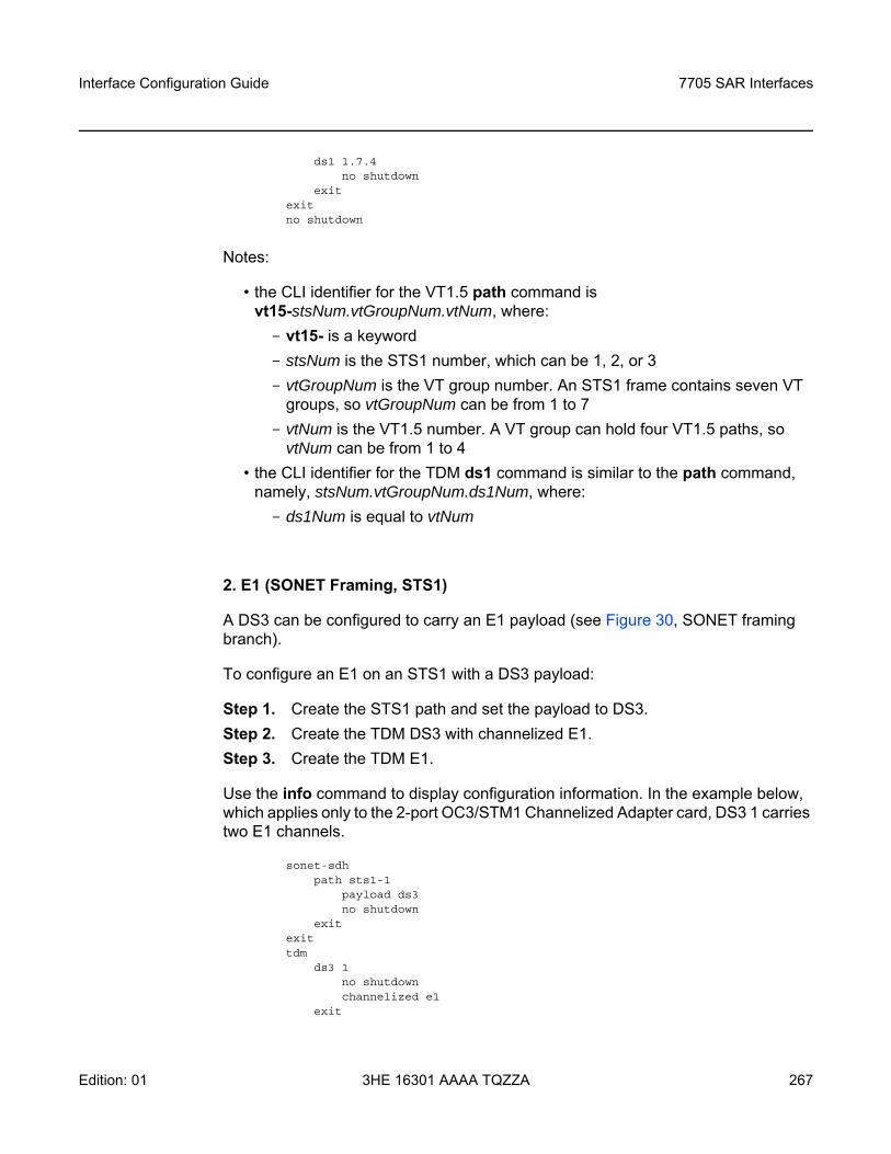
Interface Configuration Guide 7705 SAR Interfaces
Edition: 01 3HE 16301 AAAA TQZZA 267
ds1 1.7.4no shutdown
exitexitno shutdown
Notes:
• the CLI identifier for the VT1.5 path command is vt15-stsNum.vtGroupNum.vtNum, where:- vt15- is a keyword - stsNum is the STS1 number, which can be 1, 2, or 3- vtGroupNum is the VT group number. An STS1 frame contains seven VT
groups, so vtGroupNum can be from 1 to 7- vtNum is the VT1.5 number. A VT group can hold four VT1.5 paths, so
vtNum can be from 1 to 4• the CLI identifier for the TDM ds1 command is similar to the path command,
namely, stsNum.vtGroupNum.ds1Num, where: - ds1Num is equal to vtNum
2. E1 (SONET Framing, STS1)
A DS3 can be configured to carry an E1 payload (see Figure 30, SONET framing branch).
To configure an E1 on an STS1 with a DS3 payload:
Step 1. Create the STS1 path and set the payload to DS3. Step 2. Create the TDM DS3 with channelized E1. Step 3. Create the TDM E1.
Use the info command to display configuration information. In the example below, which applies only to the 2-port OC3/STM1 Channelized Adapter card, DS3 1 carries two E1 channels.
sonet-sdhpath sts1-1
payload ds3no shutdown
exitexittdm
ds3 1no shutdownchannelized e1
exit
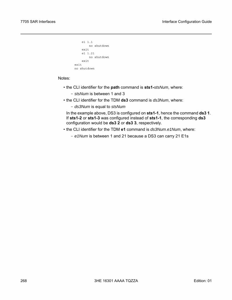
7705 SAR Interfaces
268
Interface Configuration Guide
3HE 16301 AAAA TQZZA Edition: 01
e1 1.1no shutdown
exite1 1.21
no shutdownexit
exitno shutdown
Notes:
• the CLI identifier for the path command is sts1-stsNum, where:- stsNum is between 1 and 3
• the CLI identifier for the TDM ds3 command is ds3Num, where: - ds3Num is equal to stsNum
In the example above, DS3 is configured on sts1-1, hence the command ds3 1. If sts1-2 or sts1-3 was configured instead of sts1-1, the corresponding ds3 configuration would be ds3 2 or ds3 3, respectively.
• the CLI identifier for the TDM e1 command is ds3Num.e1Num, where:- e1Num is between 1 and 21 because a DS3 can carry 21 E1s
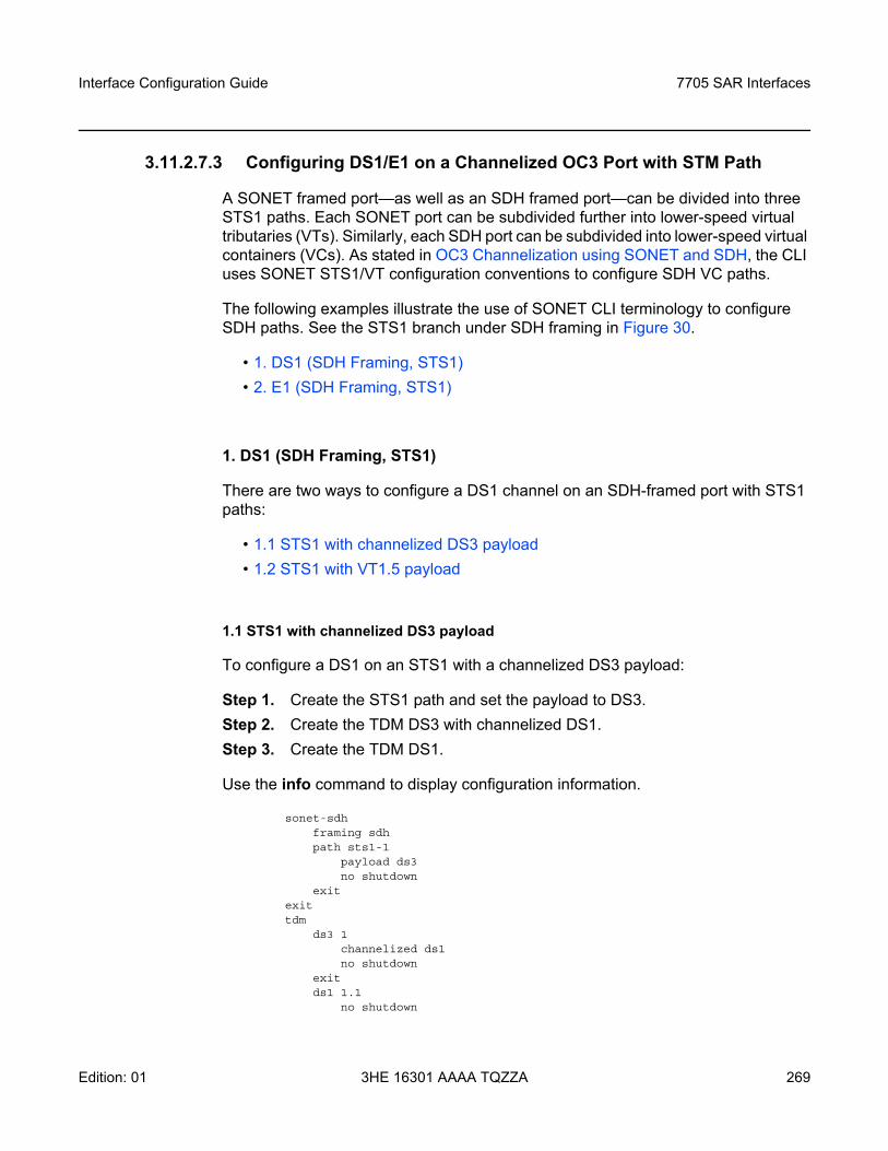
Interface Configuration Guide 7705 SAR Interfaces
Edition: 01 3HE 16301 AAAA TQZZA 269
3.11.2.7.3 Configuring DS1/E1 on a Channelized OC3 Port with STM Path
A SONET framed port—as well as an SDH framed port—can be divided into three STS1 paths. Each SONET port can be subdivided further into lower-speed virtual tributaries (VTs). Similarly, each SDH port can be subdivided into lower-speed virtual containers (VCs). As stated in OC3 Channelization using SONET and SDH, the CLI uses SONET STS1/VT configuration conventions to configure SDH VC paths.
The following examples illustrate the use of SONET CLI terminology to configure SDH paths. See the STS1 branch under SDH framing in Figure 30.
• 1. DS1 (SDH Framing, STS1)• 2. E1 (SDH Framing, STS1)
1. DS1 (SDH Framing, STS1)
There are two ways to configure a DS1 channel on an SDH-framed port with STS1 paths:
• 1.1 STS1 with channelized DS3 payload• 1.2 STS1 with VT1.5 payload
1.1 STS1 with channelized DS3 payload
To configure a DS1 on an STS1 with a channelized DS3 payload:
Step 1. Create the STS1 path and set the payload to DS3. Step 2. Create the TDM DS3 with channelized DS1. Step 3. Create the TDM DS1.
Use the info command to display configuration information.
sonet-sdhframing sdhpath sts1-1
payload ds3no shutdown
exitexittdm
ds3 1channelized ds1no shutdown
exitds1 1.1
no shutdown
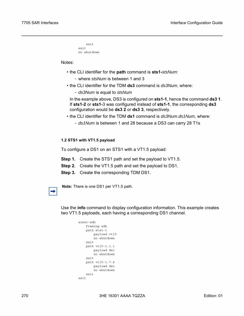
7705 SAR Interfaces
270
Interface Configuration Guide
3HE 16301 AAAA TQZZA Edition: 01
exitexitno shutdown
Notes:
• the CLI identifier for the path command is sts1-stsNum:- where stsNum is between 1 and 3
• the CLI identifier for the TDM ds3 command is ds3Num, where: - ds3Num is equal to stsNum
In the example above, DS3 is configured on sts1-1, hence the command ds3 1. If sts1-2 or sts1-3 was configured instead of sts1-1, the corresponding ds3 configuration would be ds3 2 or ds3 3, respectively.
• the CLI identifier for the TDM ds1 command is ds3Num.ds1Num, where:- ds1Num is between 1 and 28 because a DS3 can carry 28 T1s
1.2 STS1 with VT1.5 payload
To configure a DS1 on an STS1 with a VT1.5 payload:
Step 1. Create the STS1 path and set the payload to VT1.5. Step 2. Create the VT1.5 path and set the payload to DS1. Step 3. Create the corresponding TDM DS1.
Use the info command to display configuration information. This example creates two VT1.5 payloads, each having a corresponding DS1 channel.
sonet-sdhframing sdhpath sts1-1
payload vt15no shutdown
exitpath vt15-1.1.1
payload ds1no shutdown
exitpath vt15-1.7.4
payload ds1no shutdown
exitexit
Note: There is one DS1 per VT1.5 path.
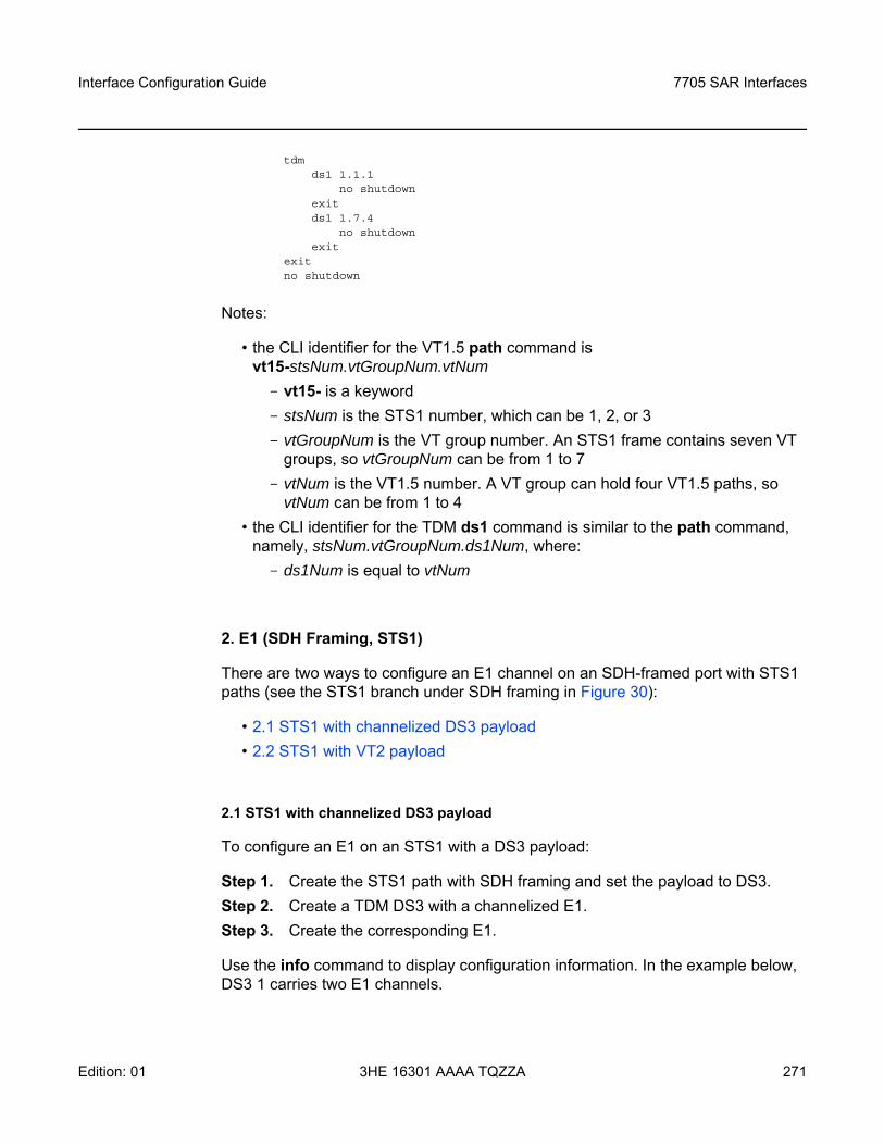
Interface Configuration Guide 7705 SAR Interfaces
Edition: 01 3HE 16301 AAAA TQZZA 271
tdmds1 1.1.1
no shutdownexitds1 1.7.4
no shutdownexit
exitno shutdown
Notes:
• the CLI identifier for the VT1.5 path command is vt15-stsNum.vtGroupNum.vtNum - vt15- is a keyword- stsNum is the STS1 number, which can be 1, 2, or 3- vtGroupNum is the VT group number. An STS1 frame contains seven VT
groups, so vtGroupNum can be from 1 to 7- vtNum is the VT1.5 number. A VT group can hold four VT1.5 paths, so
vtNum can be from 1 to 4• the CLI identifier for the TDM ds1 command is similar to the path command,
namely, stsNum.vtGroupNum.ds1Num, where: - ds1Num is equal to vtNum
2. E1 (SDH Framing, STS1)
There are two ways to configure an E1 channel on an SDH-framed port with STS1 paths (see the STS1 branch under SDH framing in Figure 30):
• 2.1 STS1 with channelized DS3 payload• 2.2 STS1 with VT2 payload
2.1 STS1 with channelized DS3 payload
To configure an E1 on an STS1 with a DS3 payload:
Step 1. Create the STS1 path with SDH framing and set the payload to DS3.Step 2. Create a TDM DS3 with a channelized E1.Step 3. Create the corresponding E1.
Use the info command to display configuration information. In the example below, DS3 1 carries two E1 channels.
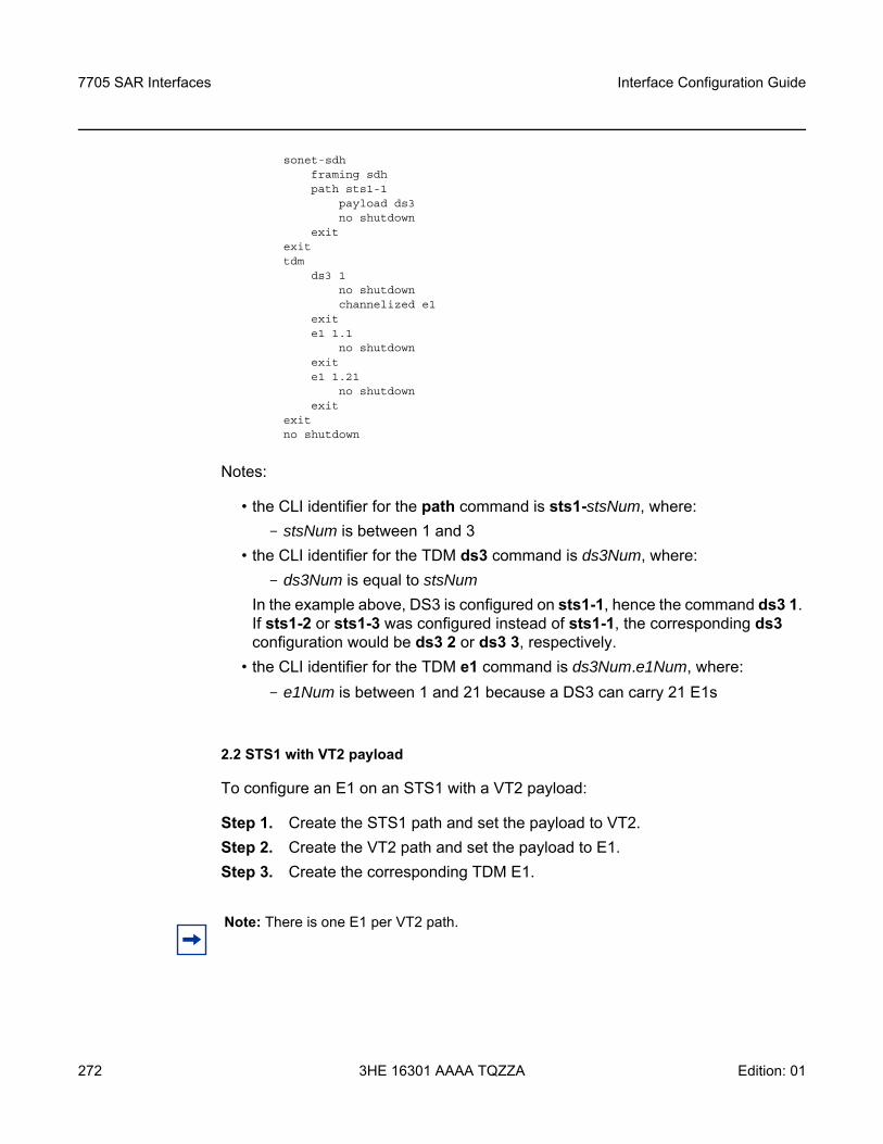
7705 SAR Interfaces
272
Interface Configuration Guide
3HE 16301 AAAA TQZZA Edition: 01
sonet-sdhframing sdhpath sts1-1
payload ds3no shutdown
exitexittdm
ds3 1no shutdownchannelized e1
exite1 1.1
no shutdownexite1 1.21
no shutdownexit
exitno shutdown
Notes:
• the CLI identifier for the path command is sts1-stsNum, where:- stsNum is between 1 and 3
• the CLI identifier for the TDM ds3 command is ds3Num, where: - ds3Num is equal to stsNum
In the example above, DS3 is configured on sts1-1, hence the command ds3 1. If sts1-2 or sts1-3 was configured instead of sts1-1, the corresponding ds3 configuration would be ds3 2 or ds3 3, respectively.
• the CLI identifier for the TDM e1 command is ds3Num.e1Num, where:- e1Num is between 1 and 21 because a DS3 can carry 21 E1s
2.2 STS1 with VT2 payload
To configure an E1 on an STS1 with a VT2 payload:
Step 1. Create the STS1 path and set the payload to VT2. Step 2. Create the VT2 path and set the payload to E1. Step 3. Create the corresponding TDM E1.
Note: There is one E1 per VT2 path.
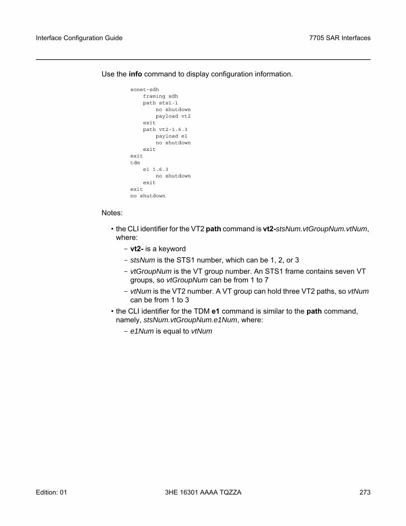
Interface Configuration Guide 7705 SAR Interfaces
Edition: 01 3HE 16301 AAAA TQZZA 273
Use the info command to display configuration information.
sonet-sdhframing sdhpath sts1-1
no shutdownpayload vt2
exitpath vt2-1.6.3
payload e1no shutdown
exitexittdm
e1 1.6.3no shutdown
exitexitno shutdown
Notes:
• the CLI identifier for the VT2 path command is vt2-stsNum.vtGroupNum.vtNum, where:- vt2- is a keyword- stsNum is the STS1 number, which can be 1, 2, or 3- vtGroupNum is the VT group number. An STS1 frame contains seven VT
groups, so vtGroupNum can be from 1 to 7- vtNum is the VT2 number. A VT group can hold three VT2 paths, so vtNum
can be from 1 to 3• the CLI identifier for the TDM e1 command is similar to the path command,
namely, stsNum.vtGroupNum.e1Num, where:- e1Num is equal to vtNum
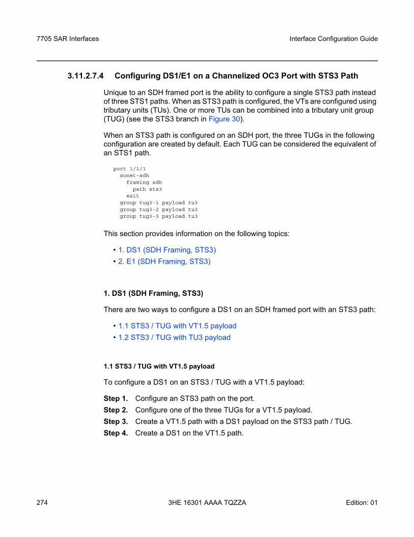
7705 SAR Interfaces
274
Interface Configuration Guide
3HE 16301 AAAA TQZZA Edition: 01
3.11.2.7.4 Configuring DS1/E1 on a Channelized OC3 Port with STS3 Path
Unique to an SDH framed port is the ability to configure a single STS3 path instead of three STS1 paths. When as STS3 path is configured, the VTs are configured using tributary units (TUs). One or more TUs can be combined into a tributary unit group (TUG) (see the STS3 branch in Figure 30).
When an STS3 path is configured on an SDH port, the three TUGs in the following configuration are created by default. Each TUG can be considered the equivalent of an STS1 path.
port 1/1/1sonet-sdh
framing sdhpath sts3
exitgroup tug3-1 payload tu3group tug3-2 payload tu3group tug3-3 payload tu3
This section provides information on the following topics:
• 1. DS1 (SDH Framing, STS3)• 2. E1 (SDH Framing, STS3)
1. DS1 (SDH Framing, STS3)
There are two ways to configure a DS1 on an SDH framed port with an STS3 path:
• 1.1 STS3 / TUG with VT1.5 payload• 1.2 STS3 / TUG with TU3 payload
1.1 STS3 / TUG with VT1.5 payload
To configure a DS1 on an STS3 / TUG with a VT1.5 payload:
Step 1. Configure an STS3 path on the port. Step 2. Configure one of the three TUGs for a VT1.5 payload. Step 3. Create a VT1.5 path with a DS1 payload on the STS3 path / TUG. Step 4. Create a DS1 on the VT1.5 path.
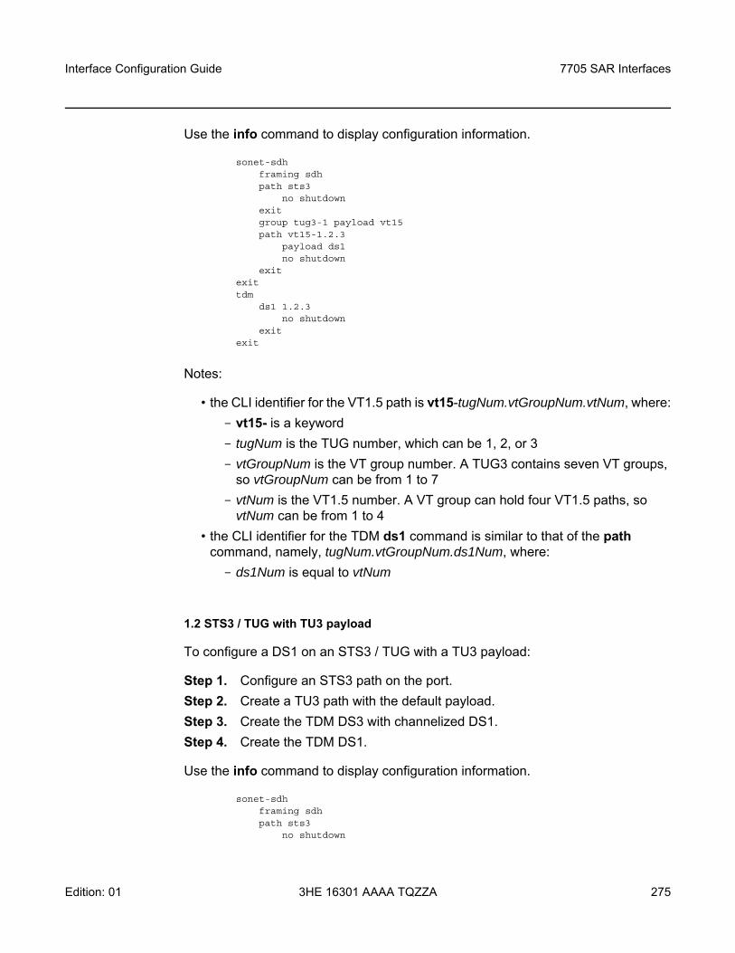
Interface Configuration Guide 7705 SAR Interfaces
Edition: 01 3HE 16301 AAAA TQZZA 275
Use the info command to display configuration information.
sonet-sdhframing sdhpath sts3
no shutdownexitgroup tug3-1 payload vt15path vt15-1.2.3
payload ds1no shutdown
exitexittdm
ds1 1.2.3no shutdown
exitexit
Notes:
• the CLI identifier for the VT1.5 path is vt15-tugNum.vtGroupNum.vtNum, where:- vt15- is a keyword - tugNum is the TUG number, which can be 1, 2, or 3- vtGroupNum is the VT group number. A TUG3 contains seven VT groups,
so vtGroupNum can be from 1 to 7- vtNum is the VT1.5 number. A VT group can hold four VT1.5 paths, so
vtNum can be from 1 to 4• the CLI identifier for the TDM ds1 command is similar to that of the path
command, namely, tugNum.vtGroupNum.ds1Num, where:- ds1Num is equal to vtNum
1.2 STS3 / TUG with TU3 payload
To configure a DS1 on an STS3 / TUG with a TU3 payload:
Step 1. Configure an STS3 path on the port. Step 2. Create a TU3 path with the default payload. Step 3. Create the TDM DS3 with channelized DS1. Step 4. Create the TDM DS1.
Use the info command to display configuration information.
sonet-sdhframing sdhpath sts3
no shutdown
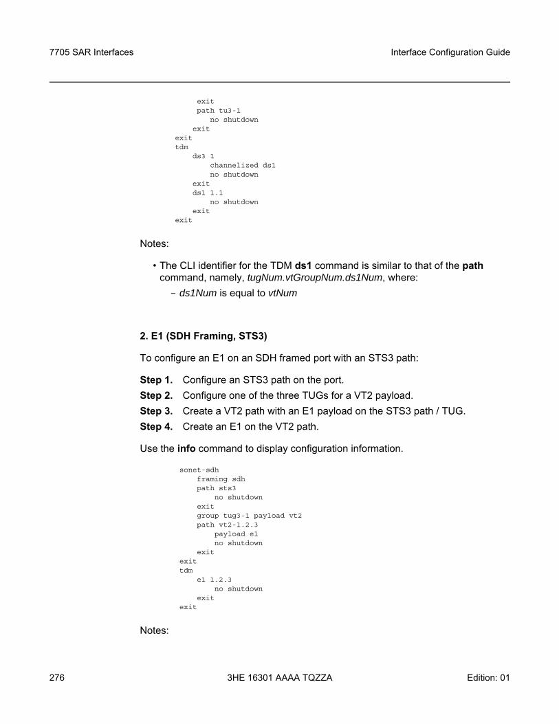
7705 SAR Interfaces
276
Interface Configuration Guide
3HE 16301 AAAA TQZZA Edition: 01
exitpath tu3-1
no shutdownexit
exittdm
ds3 1channelized ds1no shutdown
exitds1 1.1
no shutdownexit
exit
Notes:
• The CLI identifier for the TDM ds1 command is similar to that of the path command, namely, tugNum.vtGroupNum.ds1Num, where:- ds1Num is equal to vtNum
2. E1 (SDH Framing, STS3)
To configure an E1 on an SDH framed port with an STS3 path:
Step 1. Configure an STS3 path on the port. Step 2. Configure one of the three TUGs for a VT2 payload. Step 3. Create a VT2 path with an E1 payload on the STS3 path / TUG. Step 4. Create an E1 on the VT2 path.
Use the info command to display configuration information.
sonet-sdhframing sdhpath sts3
no shutdownexitgroup tug3-1 payload vt2path vt2-1.2.3
payload e1no shutdown
exitexittdm
e1 1.2.3no shutdown
exitexit
Notes:
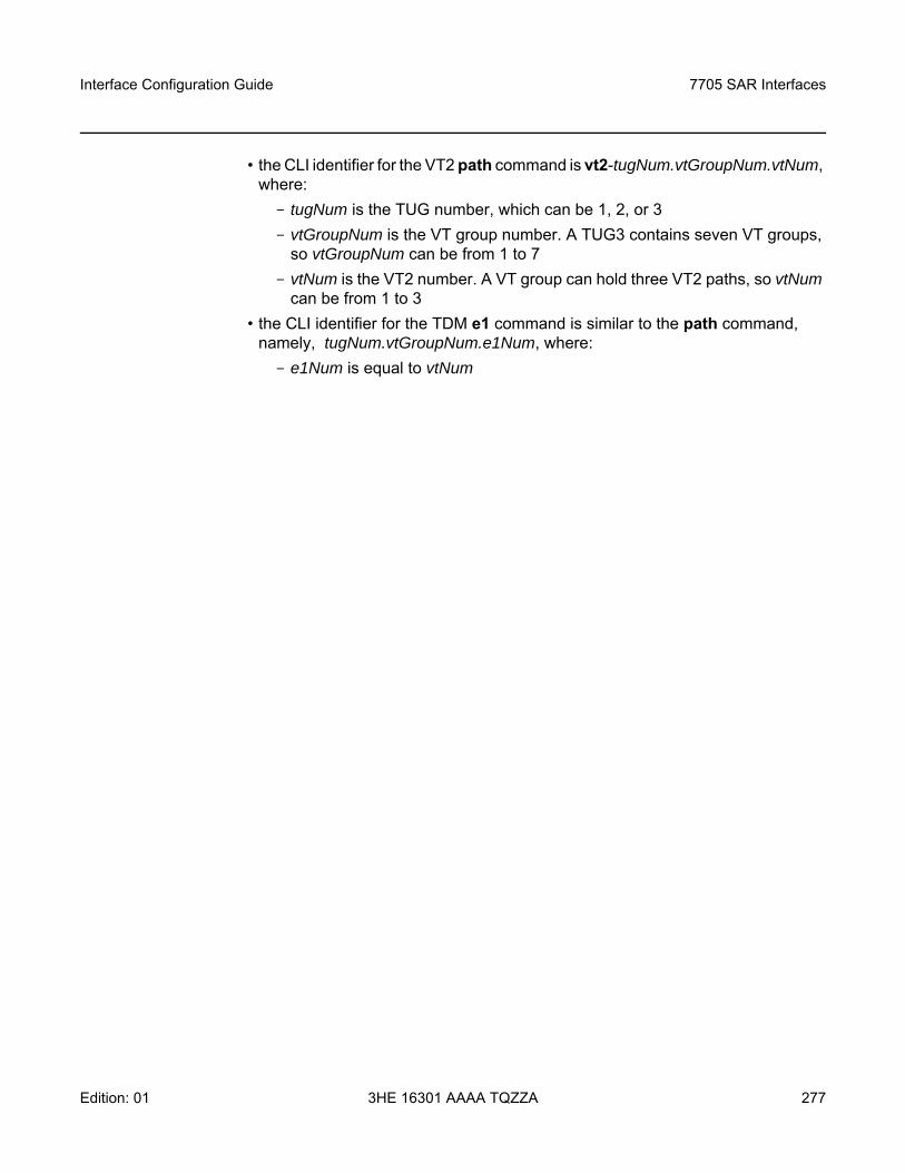
Interface Configuration Guide 7705 SAR Interfaces
Edition: 01 3HE 16301 AAAA TQZZA 277
• the CLI identifier for the VT2 path command is vt2-tugNum.vtGroupNum.vtNum, where:- tugNum is the TUG number, which can be 1, 2, or 3- vtGroupNum is the VT group number. A TUG3 contains seven VT groups,
so vtGroupNum can be from 1 to 7- vtNum is the VT2 number. A VT group can hold three VT2 paths, so vtNum
can be from 1 to 3• the CLI identifier for the TDM e1 command is similar to the path command,
namely, tugNum.vtGroupNum.e1Num, where:- e1Num is equal to vtNum
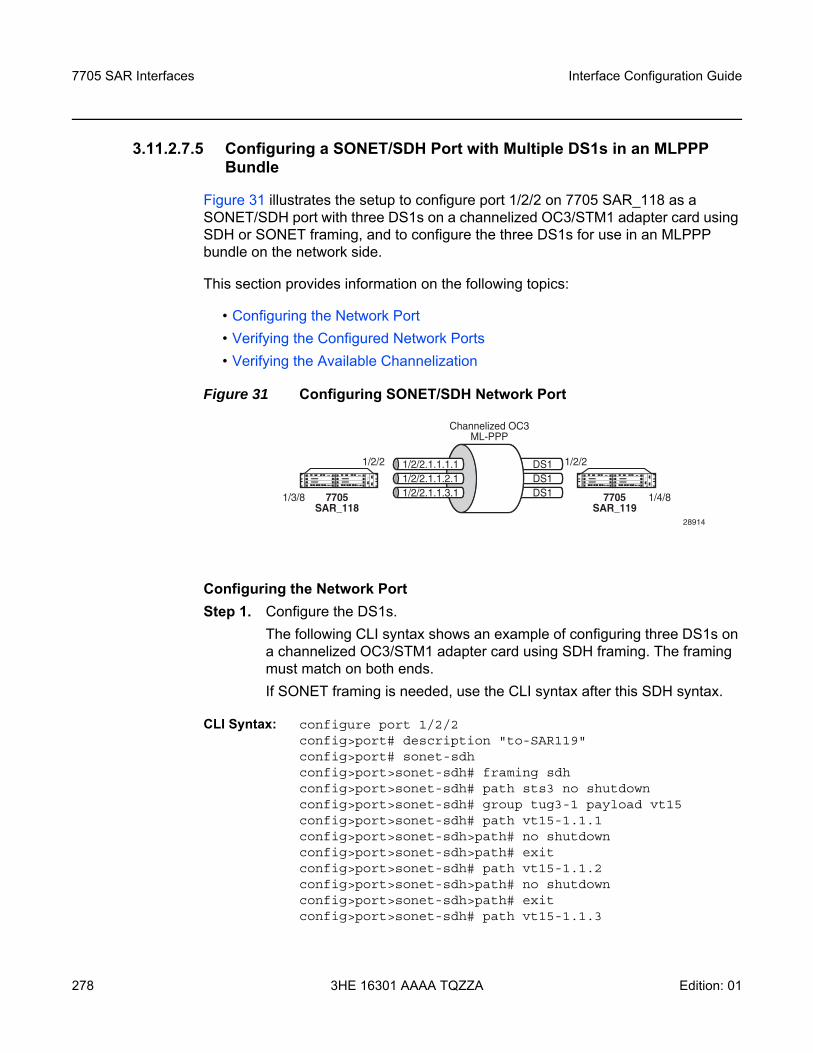
7705 SAR Interfaces
278
Interface Configuration Guide
3HE 16301 AAAA TQZZA Edition: 01
3.11.2.7.5 Configuring a SONET/SDH Port with Multiple DS1s in an MLPPP Bundle
Figure 31 illustrates the setup to configure port 1/2/2 on 7705 SAR_118 as a SONET/SDH port with three DS1s on a channelized OC3/STM1 adapter card using SDH or SONET framing, and to configure the three DS1s for use in an MLPPP bundle on the network side.
This section provides information on the following topics:
• Configuring the Network Port• Verifying the Configured Network Ports• Verifying the Available Channelization
Figure 31 Configuring SONET/SDH Network Port
Configuring the Network PortStep 1. Configure the DS1s.
The following CLI syntax shows an example of configuring three DS1s on a channelized OC3/STM1 adapter card using SDH framing. The framing must match on both ends. If SONET framing is needed, use the CLI syntax after this SDH syntax.
CLI Syntax: configure port 1/2/2config>port# description "to-SAR119"config>port# sonet-sdhconfig>port>sonet-sdh# framing sdhconfig>port>sonet-sdh# path sts3 no shutdownconfig>port>sonet-sdh# group tug3-1 payload vt15config>port>sonet-sdh# path vt15-1.1.1config>port>sonet-sdh>path# no shutdownconfig>port>sonet-sdh>path# exitconfig>port>sonet-sdh# path vt15-1.1.2config>port>sonet-sdh>path# no shutdownconfig>port>sonet-sdh>path# exitconfig>port>sonet-sdh# path vt15-1.1.3
DS1DS1DS17705
SAR_118
1/2/2.1.1.1.11/2/2.1.1.2.11/2/2.1.1.3.1
Channelized OC3ML-PPP
1/2/2
1/3/8 7705SAR_119
1/2/2
1/4/8
28914
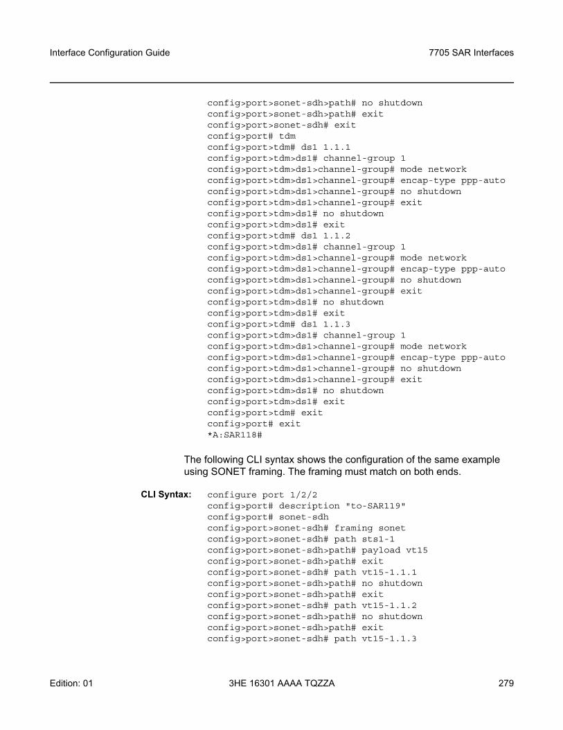
Interface Configuration Guide 7705 SAR Interfaces
Edition: 01 3HE 16301 AAAA TQZZA 279
config>port>sonet-sdh>path# no shutdownconfig>port>sonet-sdh>path# exitconfig>port>sonet-sdh# exitconfig>port# tdmconfig>port>tdm# ds1 1.1.1config>port>tdm>ds1# channel-group 1config>port>tdm>ds1>channel-group# mode networkconfig>port>tdm>ds1>channel-group# encap-type ppp-autoconfig>port>tdm>ds1>channel-group# no shutdownconfig>port>tdm>ds1>channel-group# exitconfig>port>tdm>ds1# no shutdownconfig>port>tdm>ds1# exitconfig>port>tdm# ds1 1.1.2config>port>tdm>ds1# channel-group 1config>port>tdm>ds1>channel-group# mode networkconfig>port>tdm>ds1>channel-group# encap-type ppp-autoconfig>port>tdm>ds1>channel-group# no shutdownconfig>port>tdm>ds1>channel-group# exitconfig>port>tdm>ds1# no shutdownconfig>port>tdm>ds1# exitconfig>port>tdm# ds1 1.1.3config>port>tdm>ds1# channel-group 1config>port>tdm>ds1>channel-group# mode networkconfig>port>tdm>ds1>channel-group# encap-type ppp-autoconfig>port>tdm>ds1>channel-group# no shutdownconfig>port>tdm>ds1>channel-group# exitconfig>port>tdm>ds1# no shutdownconfig>port>tdm>ds1# exitconfig>port>tdm# exitconfig>port# exit*A:SAR118#
The following CLI syntax shows the configuration of the same example using SONET framing. The framing must match on both ends.
CLI Syntax: configure port 1/2/2config>port# description "to-SAR119"config>port# sonet-sdhconfig>port>sonet-sdh# framing sonetconfig>port>sonet-sdh# path sts1-1config>port>sonet-sdh>path# payload vt15config>port>sonet-sdh>path# exitconfig>port>sonet-sdh# path vt15-1.1.1config>port>sonet-sdh>path# no shutdownconfig>port>sonet-sdh>path# exitconfig>port>sonet-sdh# path vt15-1.1.2config>port>sonet-sdh>path# no shutdownconfig>port>sonet-sdh>path# exitconfig>port>sonet-sdh# path vt15-1.1.3
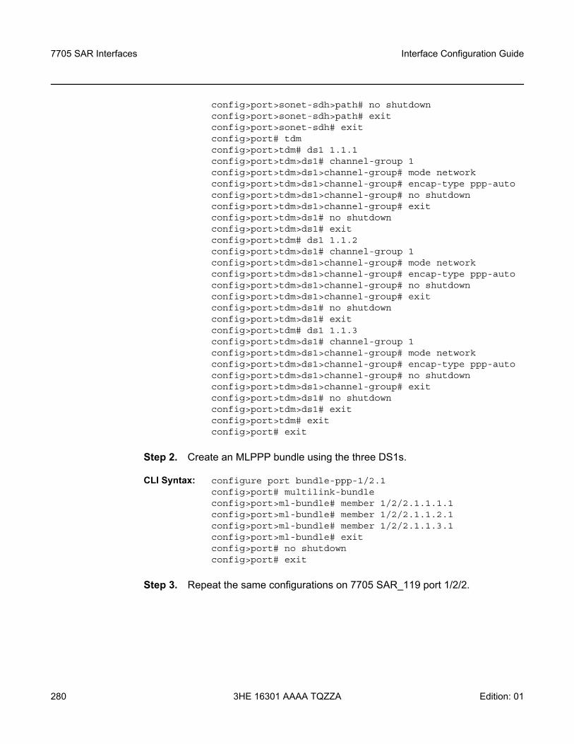
7705 SAR Interfaces
280
Interface Configuration Guide
3HE 16301 AAAA TQZZA Edition: 01
config>port>sonet-sdh>path# no shutdownconfig>port>sonet-sdh>path# exitconfig>port>sonet-sdh# exitconfig>port# tdmconfig>port>tdm# ds1 1.1.1config>port>tdm>ds1# channel-group 1config>port>tdm>ds1>channel-group# mode networkconfig>port>tdm>ds1>channel-group# encap-type ppp-autoconfig>port>tdm>ds1>channel-group# no shutdownconfig>port>tdm>ds1>channel-group# exitconfig>port>tdm>ds1# no shutdownconfig>port>tdm>ds1# exitconfig>port>tdm# ds1 1.1.2config>port>tdm>ds1# channel-group 1config>port>tdm>ds1>channel-group# mode networkconfig>port>tdm>ds1>channel-group# encap-type ppp-autoconfig>port>tdm>ds1>channel-group# no shutdownconfig>port>tdm>ds1>channel-group# exitconfig>port>tdm>ds1# no shutdownconfig>port>tdm>ds1# exitconfig>port>tdm# ds1 1.1.3config>port>tdm>ds1# channel-group 1config>port>tdm>ds1>channel-group# mode networkconfig>port>tdm>ds1>channel-group# encap-type ppp-autoconfig>port>tdm>ds1>channel-group# no shutdownconfig>port>tdm>ds1>channel-group# exitconfig>port>tdm>ds1# no shutdownconfig>port>tdm>ds1# exitconfig>port>tdm# exitconfig>port# exit
Step 2. Create an MLPPP bundle using the three DS1s.
CLI Syntax: configure port bundle-ppp-1/2.1config>port# multilink-bundleconfig>port>ml-bundle# member 1/2/2.1.1.1.1config>port>ml-bundle# member 1/2/2.1.1.2.1config>port>ml-bundle# member 1/2/2.1.1.3.1config>port>ml-bundle# exitconfig>port# no shutdownconfig>port# exit
Step 3. Repeat the same configurations on 7705 SAR_119 port 1/2/2.
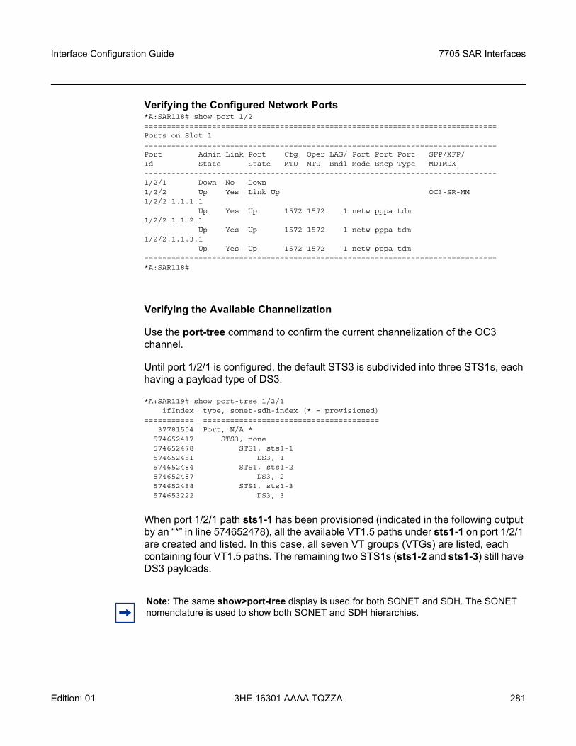
Interface Configuration Guide 7705 SAR Interfaces
Edition: 01 3HE 16301 AAAA TQZZA 281
Verifying the Configured Network Ports*A:SAR118# show port 1/2==============================================================================Ports on Slot 1==============================================================================Port Admin Link Port Cfg Oper LAG/ Port Port Port SFP/XFP/Id State State MTU MTU Bndl Mode Encp Type MDIMDX------------------------------------------------------------------------------1/2/1 Down No Down1/2/2 Up Yes Link Up OC3-SR-MM1/2/2.1.1.1.1
Up Yes Up 1572 1572 1 netw pppa tdm1/2/2.1.1.2.1
Up Yes Up 1572 1572 1 netw pppa tdm1/2/2.1.1.3.1
Up Yes Up 1572 1572 1 netw pppa tdm==============================================================================*A:SAR118#
Verifying the Available Channelization
Use the port-tree command to confirm the current channelization of the OC3 channel.
Until port 1/2/1 is configured, the default STS3 is subdivided into three STS1s, each having a payload type of DS3.
*A:SAR119# show port-tree 1/2/1ifIndex type, sonet-sdh-index (* = provisioned)
=========== =======================================37781504 Port, N/A *
574652417 STS3, none574652478 STS1, sts1-1574652481 DS3, 1574652484 STS1, sts1-2574652487 DS3, 2574652488 STS1, sts1-3574653222 DS3, 3
When port 1/2/1 path sts1-1 has been provisioned (indicated in the following output by an “*” in line 574652478), all the available VT1.5 paths under sts1-1 on port 1/2/1 are created and listed. In this case, all seven VT groups (VTGs) are listed, each containing four VT1.5 paths. The remaining two STS1s (sts1-2 and sts1-3) still have DS3 payloads.
Note: The same show>port-tree display is used for both SONET and SDH. The SONET nomenclature is used to show both SONET and SDH hierarchies.
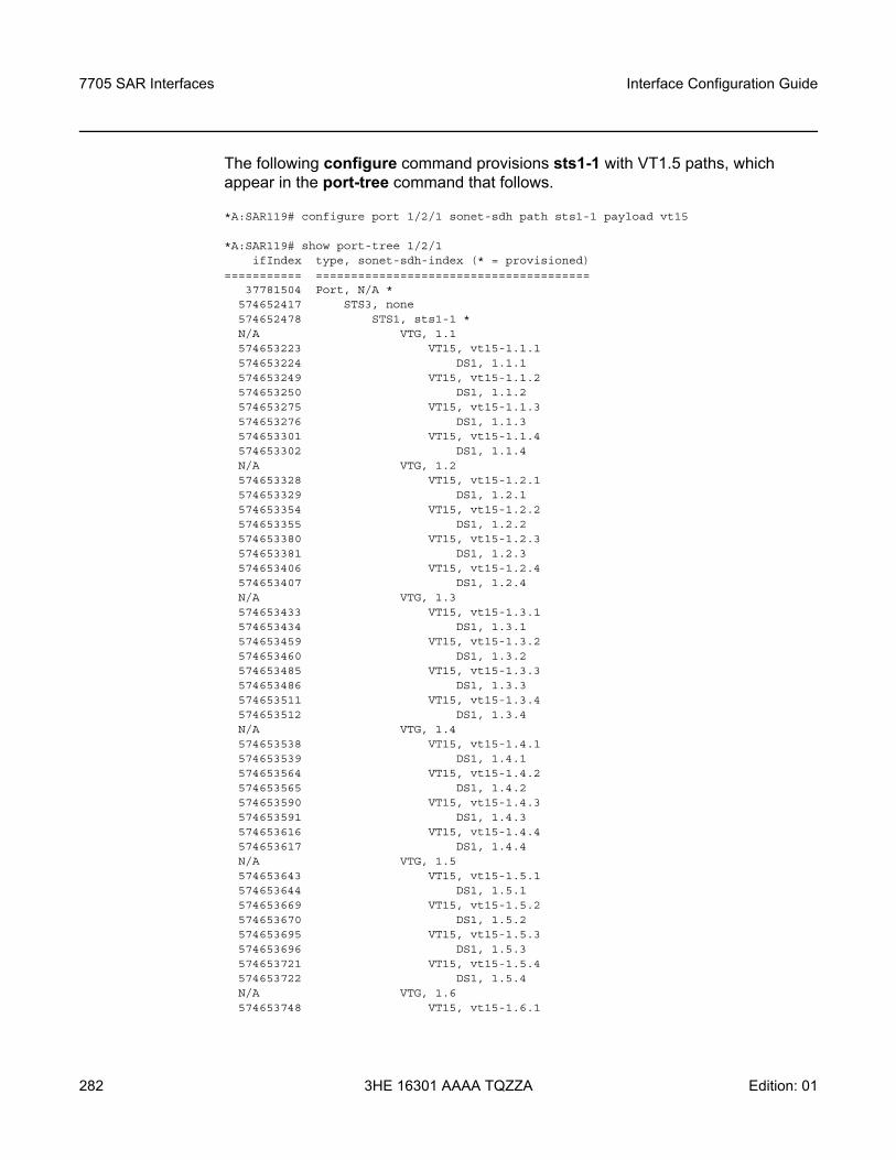
7705 SAR Interfaces
282
Interface Configuration Guide
3HE 16301 AAAA TQZZA Edition: 01
The following configure command provisions sts1-1 with VT1.5 paths, which appear in the port-tree command that follows.
*A:SAR119# configure port 1/2/1 sonet-sdh path sts1-1 payload vt15
*A:SAR119# show port-tree 1/2/1ifIndex type, sonet-sdh-index (* = provisioned)
=========== =======================================37781504 Port, N/A *
574652417 STS3, none574652478 STS1, sts1-1 *N/A VTG, 1.1574653223 VT15, vt15-1.1.1574653224 DS1, 1.1.1574653249 VT15, vt15-1.1.2574653250 DS1, 1.1.2574653275 VT15, vt15-1.1.3574653276 DS1, 1.1.3574653301 VT15, vt15-1.1.4574653302 DS1, 1.1.4N/A VTG, 1.2574653328 VT15, vt15-1.2.1574653329 DS1, 1.2.1574653354 VT15, vt15-1.2.2574653355 DS1, 1.2.2574653380 VT15, vt15-1.2.3574653381 DS1, 1.2.3574653406 VT15, vt15-1.2.4574653407 DS1, 1.2.4N/A VTG, 1.3574653433 VT15, vt15-1.3.1574653434 DS1, 1.3.1574653459 VT15, vt15-1.3.2574653460 DS1, 1.3.2574653485 VT15, vt15-1.3.3574653486 DS1, 1.3.3574653511 VT15, vt15-1.3.4574653512 DS1, 1.3.4N/A VTG, 1.4574653538 VT15, vt15-1.4.1574653539 DS1, 1.4.1574653564 VT15, vt15-1.4.2574653565 DS1, 1.4.2574653590 VT15, vt15-1.4.3574653591 DS1, 1.4.3574653616 VT15, vt15-1.4.4574653617 DS1, 1.4.4N/A VTG, 1.5574653643 VT15, vt15-1.5.1574653644 DS1, 1.5.1574653669 VT15, vt15-1.5.2574653670 DS1, 1.5.2574653695 VT15, vt15-1.5.3574653696 DS1, 1.5.3574653721 VT15, vt15-1.5.4574653722 DS1, 1.5.4N/A VTG, 1.6574653748 VT15, vt15-1.6.1
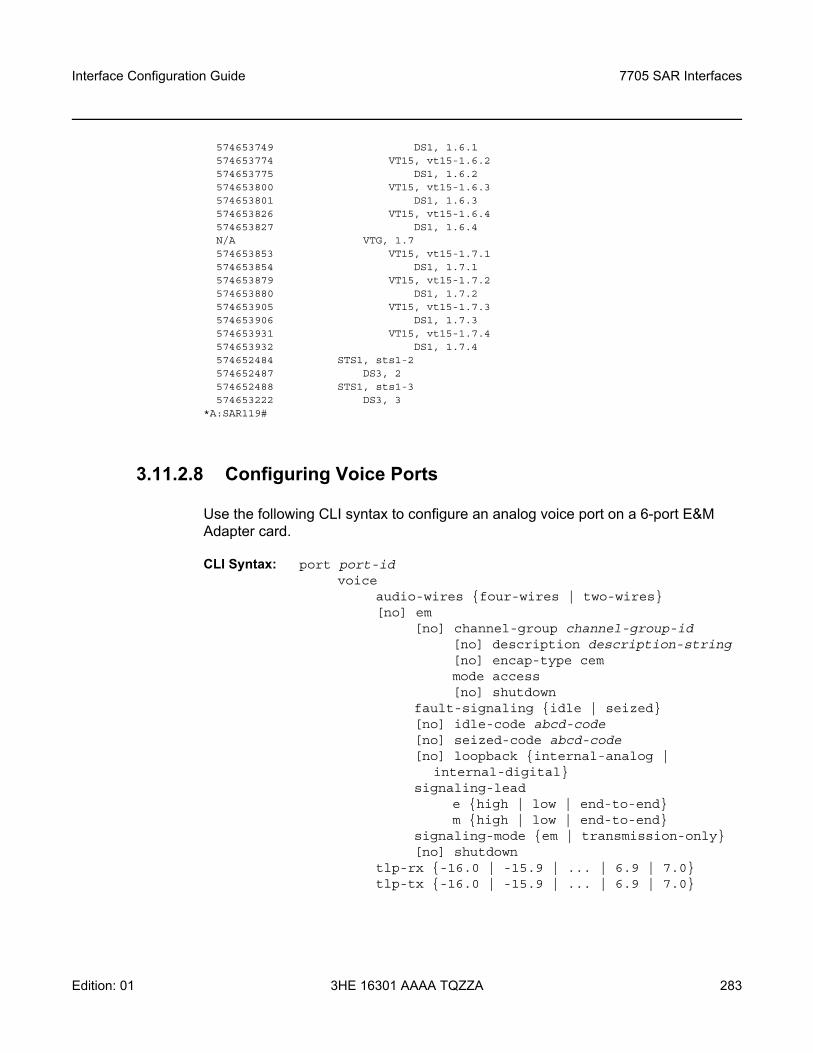
Interface Configuration Guide 7705 SAR Interfaces
Edition: 01 3HE 16301 AAAA TQZZA 283
574653749 DS1, 1.6.1574653774 VT15, vt15-1.6.2574653775 DS1, 1.6.2574653800 VT15, vt15-1.6.3574653801 DS1, 1.6.3574653826 VT15, vt15-1.6.4574653827 DS1, 1.6.4N/A VTG, 1.7574653853 VT15, vt15-1.7.1574653854 DS1, 1.7.1574653879 VT15, vt15-1.7.2574653880 DS1, 1.7.2574653905 VT15, vt15-1.7.3574653906 DS1, 1.7.3574653931 VT15, vt15-1.7.4574653932 DS1, 1.7.4574652484 STS1, sts1-2574652487 DS3, 2574652488 STS1, sts1-3574653222 DS3, 3
*A:SAR119#
3.11.2.8 Configuring Voice Ports
Use the following CLI syntax to configure an analog voice port on a 6-port E&M Adapter card.
CLI Syntax: port port-idvoice
audio-wires four-wires | two-wires[no] em
[no] channel-group channel-group-id[no] description description-string[no] encap-type cemmode access[no] shutdown
fault-signaling idle | seized[no] idle-code abcd-code[no] seized-code abcd-code[no] loopback internal-analog |
internal-digitalsignaling-lead
e high | low | end-to-endm high | low | end-to-end
signaling-mode em | transmission-only[no] shutdown
tlp-rx -16.0 | -15.9 | ... | 6.9 | 7.0tlp-tx -16.0 | -15.9 | ... | 6.9 | 7.0
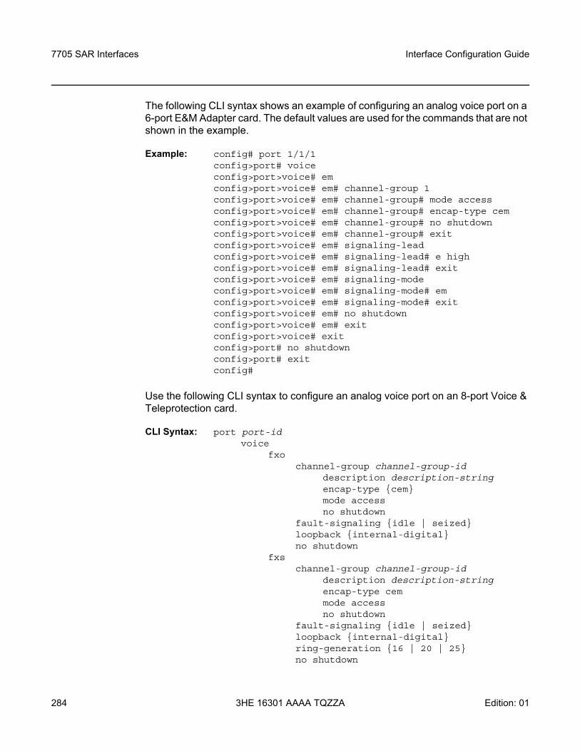
7705 SAR Interfaces
284
Interface Configuration Guide
3HE 16301 AAAA TQZZA Edition: 01
The following CLI syntax shows an example of configuring an analog voice port on a 6-port E&M Adapter card. The default values are used for the commands that are not shown in the example.
Example: config# port 1/1/1config>port# voiceconfig>port>voice# emconfig>port>voice# em# channel-group 1config>port>voice# em# channel-group# mode accessconfig>port>voice# em# channel-group# encap-type cemconfig>port>voice# em# channel-group# no shutdownconfig>port>voice# em# channel-group# exitconfig>port>voice# em# signaling-leadconfig>port>voice# em# signaling-lead# e highconfig>port>voice# em# signaling-lead# exitconfig>port>voice# em# signaling-modeconfig>port>voice# em# signaling-mode# emconfig>port>voice# em# signaling-mode# exitconfig>port>voice# em# no shutdownconfig>port>voice# em# exitconfig>port>voice# exitconfig>port# no shutdownconfig>port# exitconfig#
Use the following CLI syntax to configure an analog voice port on an 8-port Voice & Teleprotection card.
CLI Syntax: port port-idvoice
fxochannel-group channel-group-id
description description-stringencap-type cemmode accessno shutdown
fault-signaling idle | seizedloopback internal-digitalno shutdown
fxschannel-group channel-group-id
description description-stringencap-type cemmode accessno shutdown
fault-signaling idle | seizedloopback internal-digitalring-generation 16 | 20 | 25no shutdown
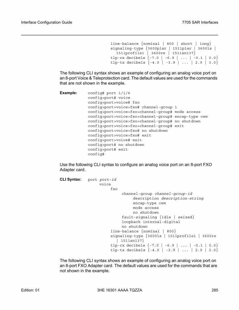
Interface Configuration Guide 7705 SAR Interfaces
Edition: 01 3HE 16301 AAAA TQZZA 285
line-balance nominal | 800 | short | longsignaling-type 3600plar | 1511plar | 3600ls |
1511profile1 | 3600re | 1511sn137tlp-rx decibels -7.0 | -6.9 | ... | -0.1 | 0.0tlp-tx decibels -4.0 | -3.9 | ... | 2.9 | 3.0
The following CLI syntax shows an example of configuring an analog voice port on an 8-port Voice & Teleprotection card. The default values are used for the commands that are not shown in the example.
Example: config# port 1/1/6config>port# voiceconfig>port>voice# fxoconfig>port>voice>fxo# channel-group 1config>port>voice>fxo>channel-group# mode accessconfig>port>voice>fxo>channel-group# encap-type cemconfig>port>voice>fxo>channel-group# no shutdownconfig>port>voice>fxo>channel-group# exitconfig>port>voice>fxo# no shutdownconfig>port>voice>fxo# exitconfig>port>voice# exitconfig>port# no shutdownconfig>port# exitconfig#
Use the following CLI syntax to configure an analog voice port on an 8-port FXO Adapter card.
CLI Syntax: port port-idvoice
fxochannel-group channel-group-id
description description-stringencap-type cemmode accessno shutdown
fault-signaling idle | seizedloopback internal-digitalno shutdown
line-balance nominal | 800signaling-type 3600ls | 1511profile1 | 3600re
| 1511sn137tlp-rx decibels -7.0 | -6.9 | ... | -0.1 | 0.0tlp-tx decibels -4.0 | -3.9 | ... | 2.9 | 3.0
The following CLI syntax shows an example of configuring an analog voice port on an 8-port FXO Adapter card. The default values are used for the commands that are not shown in the example.
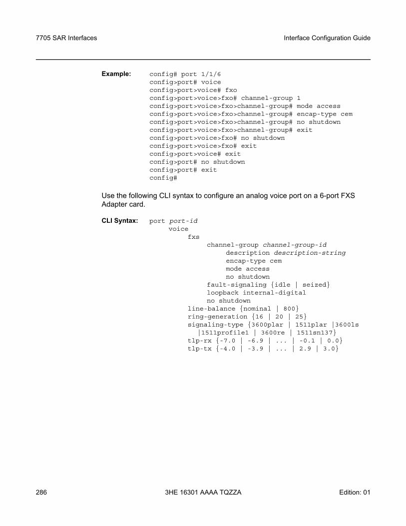
7705 SAR Interfaces
286
Interface Configuration Guide
3HE 16301 AAAA TQZZA Edition: 01
Example: config# port 1/1/6config>port# voiceconfig>port>voice# fxoconfig>port>voice>fxo# channel-group 1config>port>voice>fxo>channel-group# mode accessconfig>port>voice>fxo>channel-group# encap-type cemconfig>port>voice>fxo>channel-group# no shutdownconfig>port>voice>fxo>channel-group# exitconfig>port>voice>fxo# no shutdownconfig>port>voice>fxo# exitconfig>port>voice# exitconfig>port# no shutdownconfig>port# exitconfig#
Use the following CLI syntax to configure an analog voice port on a 6-port FXS Adapter card.
CLI Syntax: port port-idvoice
fxschannel-group channel-group-id
description description-stringencap-type cemmode accessno shutdown
fault-signaling idle | seizedloopback internal-digitalno shutdown
line-balance nominal | 800ring-generation 16 | 20 | 25signaling-type 3600plar | 1511plar |3600ls
|1511profile1 | 3600re | 1511sn137tlp-rx -7.0 | -6.9 | ... | -0.1 | 0.0tlp-tx -4.0 | -3.9 | ... | 2.9 | 3.0
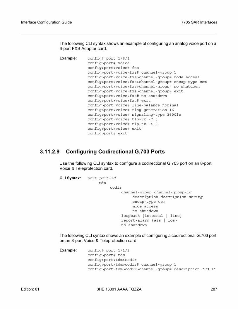
Interface Configuration Guide 7705 SAR Interfaces
Edition: 01 3HE 16301 AAAA TQZZA 287
The following CLI syntax shows an example of configuring an analog voice port on a 6-port FXS Adapter card.
Example: config# port 1/6/1config>port# voiceconfig>port>voice# fxsconfig>port>voice>fxs# channel-group 1config>port>voice>fxs>channel-group# mode accessconfig>port>voice>fxs>channel-group# encap-type cemconfig>port>voice>fxs>channel-group# no shutdownconfig>port>voice>fxs>channel-group# exitconfig>port>voice>fxs# no shutdownconfig>port>voice>fxs# exitconfig>port>voice# line-balance nominalconfig>port>voice# ring-generation 16config>port>voice# signaling-type 3600lsconfig>port>voice# tlp-rx -7.0config>port>voice# tlp-tx -4.0config>port>voice# exitconfig>port# exit
3.11.2.9 Configuring Codirectional G.703 Ports
Use the following CLI syntax to configure a codirectional G.703 port on an 8-port Voice & Teleprotection card.
CLI Syntax: port port-idtdm
codirchannel-group channel-group-id
description description-stringencap-type cemmode accessno shutdown
loopback internal | linereport-alarm ais | losno shutdown
The following CLI syntax shows an example of configuring a codirectional G.703 port on an 8-port Voice & Teleprotection card.
Example: config# port 1/1/2config>port# tdmconfig>port>tdm>codirconfig>port>tdm>codir# channel-group 1config>port>tdm>codir>channel-group# description “CG 1”
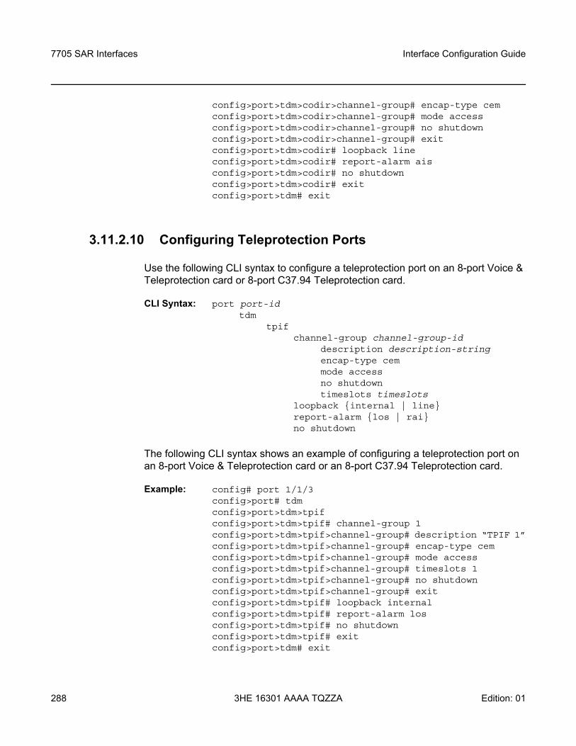
7705 SAR Interfaces
288
Interface Configuration Guide
3HE 16301 AAAA TQZZA Edition: 01
config>port>tdm>codir>channel-group# encap-type cemconfig>port>tdm>codir>channel-group# mode accessconfig>port>tdm>codir>channel-group# no shutdownconfig>port>tdm>codir>channel-group# exitconfig>port>tdm>codir# loopback lineconfig>port>tdm>codir# report-alarm aisconfig>port>tdm>codir# no shutdownconfig>port>tdm>codir# exitconfig>port>tdm# exit
3.11.2.10 Configuring Teleprotection Ports
Use the following CLI syntax to configure a teleprotection port on an 8-port Voice & Teleprotection card or 8-port C37.94 Teleprotection card.
CLI Syntax: port port-idtdm
tpifchannel-group channel-group-id
description description-stringencap-type cemmode accessno shutdowntimeslots timeslots
loopback internal | linereport-alarm los | raino shutdown
The following CLI syntax shows an example of configuring a teleprotection port on an 8-port Voice & Teleprotection card or an 8-port C37.94 Teleprotection card.
Example: config# port 1/1/3config>port# tdmconfig>port>tdm>tpifconfig>port>tdm>tpif# channel-group 1config>port>tdm>tpif>channel-group# description “TPIF 1”config>port>tdm>tpif>channel-group# encap-type cemconfig>port>tdm>tpif>channel-group# mode accessconfig>port>tdm>tpif>channel-group# timeslots 1config>port>tdm>tpif>channel-group# no shutdownconfig>port>tdm>tpif>channel-group# exitconfig>port>tdm>tpif# loopback internalconfig>port>tdm>tpif# report-alarm losconfig>port>tdm>tpif# no shutdownconfig>port>tdm>tpif# exitconfig>port>tdm# exit
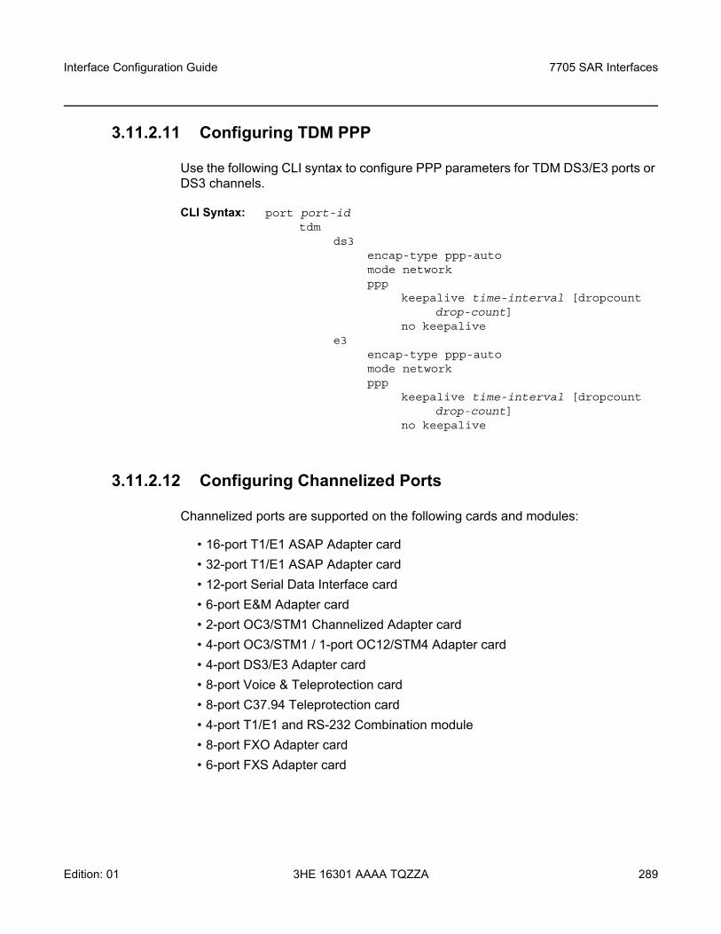
Interface Configuration Guide 7705 SAR Interfaces
Edition: 01 3HE 16301 AAAA TQZZA 289
3.11.2.11 Configuring TDM PPP
Use the following CLI syntax to configure PPP parameters for TDM DS3/E3 ports or DS3 channels.
CLI Syntax: port port-idtdm
ds3encap-type ppp-automode networkppp
keepalive time-interval [dropcount drop-count]
no keepalivee3
encap-type ppp-automode networkppp
keepalive time-interval [dropcount drop-count]
no keepalive
3.11.2.12 Configuring Channelized Ports
Channelized ports are supported on the following cards and modules:
• 16-port T1/E1 ASAP Adapter card• 32-port T1/E1 ASAP Adapter card• 12-port Serial Data Interface card• 6-port E&M Adapter card• 2-port OC3/STM1 Channelized Adapter card• 4-port OC3/STM1 / 1-port OC12/STM4 Adapter card• 4-port DS3/E3 Adapter card• 8-port Voice & Teleprotection card• 8-port C37.94 Teleprotection card• 4-port T1/E1 and RS-232 Combination module• 8-port FXO Adapter card• 6-port FXS Adapter card
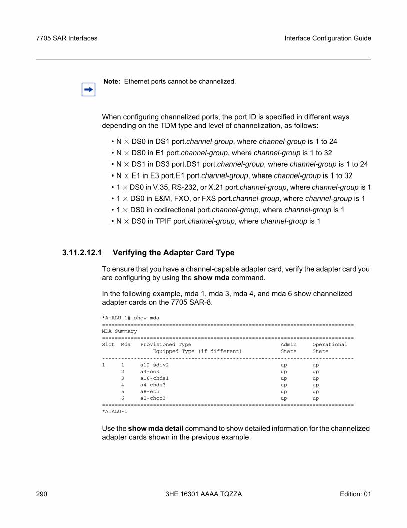
7705 SAR Interfaces
290
Interface Configuration Guide
3HE 16301 AAAA TQZZA Edition: 01
When configuring channelized ports, the port ID is specified in different ways depending on the TDM type and level of channelization, as follows:
• N × DS0 in DS1 port.channel-group, where channel-group is 1 to 24• N × DS0 in E1 port.channel-group, where channel-group is 1 to 32• N × DS1 in DS3 port.DS1 port.channel-group, where channel-group is 1 to 24• N × E1 in E3 port.E1 port.channel-group, where channel-group is 1 to 32• 1 × DS0 in V.35, RS-232, or X.21 port.channel-group, where channel-group is 1• 1 × DS0 in E&M, FXO, or FXS port.channel-group, where channel-group is 1• 1 × DS0 in codirectional port.channel-group, where channel-group is 1• N × DS0 in TPIF port.channel-group, where channel-group is 1
3.11.2.12.1 Verifying the Adapter Card Type
To ensure that you have a channel-capable adapter card, verify the adapter card you are configuring by using the show mda command.
In the following example, mda 1, mda 3, mda 4, and mda 6 show channelized adapter cards on the 7705 SAR-8.
*A:ALU-1# show mda===============================================================================MDA Summary===============================================================================Slot Mda Provisioned Type Admin Operational
Equipped Type (if different) State State-------------------------------------------------------------------------------1 1 a12-sdiv2 up up
2 a4-oc3 up up3 a16-chds1 up up4 a4-chds3 up up5 a8-eth up up6 a2-choc3 up up
===============================================================================*A:ALU-1
Use the show mda detail command to show detailed information for the channelized adapter cards shown in the previous example.
Note: Ethernet ports cannot be channelized.
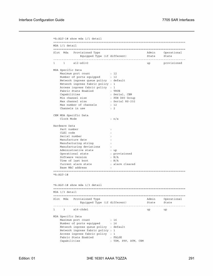
Interface Configuration Guide 7705 SAR Interfaces
Edition: 01 3HE 16301 AAAA TQZZA 291
*A:ALU-1# show mda 1/1 detail===============================================================================MDA 1/1 detail===============================================================================Slot Mda Provisioned Type Admin Operational
Equipped Type (if different) State State-------------------------------------------------------------------------------1 1 a12-sdiv2 up provisioned
MDA Specific DataMaximum port count : 12Number of ports equipped : 12Network ingress queue policy : defaultNetwork ingress fabric policy : 1Access ingress fabric policy : 1Fabric Stats Enabled : TRUECapabilities : Serial, CEMMin channel size : PDH DS0 GroupMax channel size : Serial RS-232Max number of channels : 12Channels in use : 2
CEM MDA Specific DataClock Mode : n/a
Hardware DataPart number :CLEI code :Serial number :Manufacture date :Manufacturing string :Manufacturing deviations :Administrative state : upOperational state : provisionedSoftware version : N/ATime of last boot : N/ACurrent alarm state : alarm clearedBase MAC address :
===============================================================================*A:ALU-1#
*A:ALU-1# show mda 1/3 detail===============================================================================MDA 1/3 detail===============================================================================Slot Mda Provisioned Type Admin Operational
Equipped Type (if different) State State-------------------------------------------------------------------------------1 3 a16-chds1 up up
MDA Specific DataMaximum port count : 16Number of ports equipped : 16Network ingress queue policy : defaultNetwork ingress fabric policy : 1Access ingress fabric policy : 1Fabric Stats Enabled : FALSECapabilities : TDM, PPP, ATM, CEM
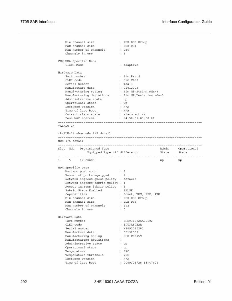
7705 SAR Interfaces
292
Interface Configuration Guide
3HE 16301 AAAA TQZZA Edition: 01
Min channel size : PDH DS0 GroupMax channel size : PDH DS1Max number of channels : 256Channels in use : 3
CEM MDA Specific DataClock Mode : adaptive
Hardware DataPart number : Sim Part#CLEI code : Sim CLEISerial number : mda-3Manufacture date : 01012003Manufacturing string : Sim MfgString mda-3Manufacturing deviations : Sim MfgDeviation mda-3Administrative state : upOperational state : upSoftware version : N/ATime of last boot : N/ACurrent alarm state : alarm activeBase MAC address : a4:58:01:03:00:01
===============================================================================*A:ALU-1#
*A:ALU-1# show mda 1/5 detail===============================================================================MDA 1/5 detail===============================================================================Slot Mda Provisioned Type Admin Operational
Equipped Type (if different) State State-------------------------------------------------------------------------------1 5 a2-choc3 up up
MDA Specific DataMaximum port count : 2Number of ports equipped : 2Network ingress queue policy : defaultNetwork ingress fabric policy : 1Access ingress fabric policy : 1Fabric Stats Enabled : FALSECapabilities : Sonet, TDM, PPP, ATMMin channel size : PDH DS0 GroupMax channel size : PDH DS3Max number of channels : 512Channels in use : 0
Hardware DataPart number : 3HE03127AAAB0102CLEI code : IPU3AFPEAASerial number : NS092040281Manufacture date : 05192009Manufacturing string : ECO C03759Manufacturing deviations :Administrative state : upOperational state : upTemperature : 37CTemperature threshold : 75CSoftware version : N/ATime of last boot : 2009/06/28 18:47:04
Interface Configuration Guide 7705 SAR Interfaces
Edition: 01 3HE 16301 AAAA TQZZA 293
Current alarm state : alarm clearedBase MAC address : a4:58:01:03:00:01
===============================================================================*A:ALU-1#
On the 16-port T1/E1 ASAP Adapter card, 32-port T1/E1 ASAP Adapter card, 2-port OC3/STM1 Channelized Adapter card, 4-port DS3/E3 Adapter card, and T1/E1 ports on the 4-port T1/E1 and RS-232 Combination module, DS0 channel groups and their parameters are configured in the DS1 or E1 context. For a DS1 channel group, up to 24 timeslots can be assigned (numbered 1 to 24). For an E1 channel group, up to 31 timeslots can be assigned (numbered 2 to 32). For ATM, all timeslots are auto-configured when a channel group gets created. The 4-port OC3/STM1 / 1-port OC12/STM4 Adapter card supports channelization at the DS1/E1 level only.
On the 6-port E&M Adapter card, a single DS0 channel group and its parameters are configured in the E&M context.
On the 12-port Serial Data Interface card and RS-232 ports of the 4-port T1/E1 and RS-232 Combination module, DS0 channel groups and their parameters are configured in the V.35, RS-232, RS-530, or X.21 context. For RS-232, a single timeslot is auto-configured when a channel group is created. For V.35 and X.21, the number of timeslots auto-configured when a channel group is created depends on the interface speed.
On the 8-port Voice & Teleprotection card, a single DS0 channel group and its parameters are configured in the codirectional, FXO, FXS, or TPIF context and up to 12 timeslots can be assigned in the TPIF context.
On the 8-port C37.94 Teleprotection card, a single DS0 channel group and its parameters are configured in the TPIF context and up to 12 timeslots can be assigned in the TPIF context.
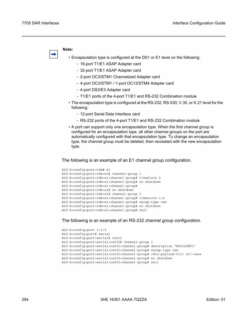
7705 SAR Interfaces
294
Interface Configuration Guide
3HE 16301 AAAA TQZZA Edition: 01
The following is an example of an E1 channel group configuration.
ALU-A>config>port>tdm# e1ALU-A>config>port>tdm>e1# channel-group 1ALU-A>config>port>tdm>e1>channel-group# timeslots 2ALU-A>config>port>tdm>e1>channel-group# no shutdownALU-A>config>port>tdm>e1>channel-group#ALU-A>config>port>tdm>e1# no shutdownALU-A>config>port>tdm>e1# channel-group 2ALU-A>config>port>tdm>e1>channel-group# timeslots 3,4ALU-A>config>port>tdm>e1>channel-group# encap-type cemALU-A>config>port>tdm>e1>channel-group# no shutdownALU-A>config>port>tdm>e1>channel-group# exit
The following is an example of an RS-232 channel group configuration.
ALU-A>config>port 1/1/2ALU-A>config>port# serialALU-A>config>port>serial# rs232ALU-A>config>port>serial>rs232# channel-group 1ALU-A>config>port>serial>rs232>channel-group# description "RS232GRP1"ALU-A>config>port>serial>rs232>channel-group# encap-type cemALU-A>config>port>serial>rs232>channel-group# idle-payload-fill all-onesALU-A>config>port>serial>rs232>channel-group# no shutdownALU-A>config>port>serial>rs232>channel-group# exit
Note:
• Encapsulation type is configured at the DS1 or E1 level on the following: - 16-port T1/E1 ASAP Adapter card- 32-port T1/E1 ASAP Adapter card- 2-port OC3/STM1 Channelized Adapter card- 4-port OC3/STM1 / 1-port OC12/STM4 Adapter card- 4-port DS3/E3 Adapter card- T1/E1 ports of the 4-port T1/E1 and RS-232 Combination module
• The encapsulation type is configured at the RS-232, RS-530, V.35, or X.21 level for the following:- 12-port Serial Data Interface card- RS-232 ports of the 4-port T1/E1 and RS-232 Combination module
• A port can support only one encapsulation type. When the first channel group is configured for an encapsulation type, all other channel groups on the port are automatically configured with that encapsulation type. To change an encapsulation type, the channel group must be deleted, then recreated with the new encapsulation type.
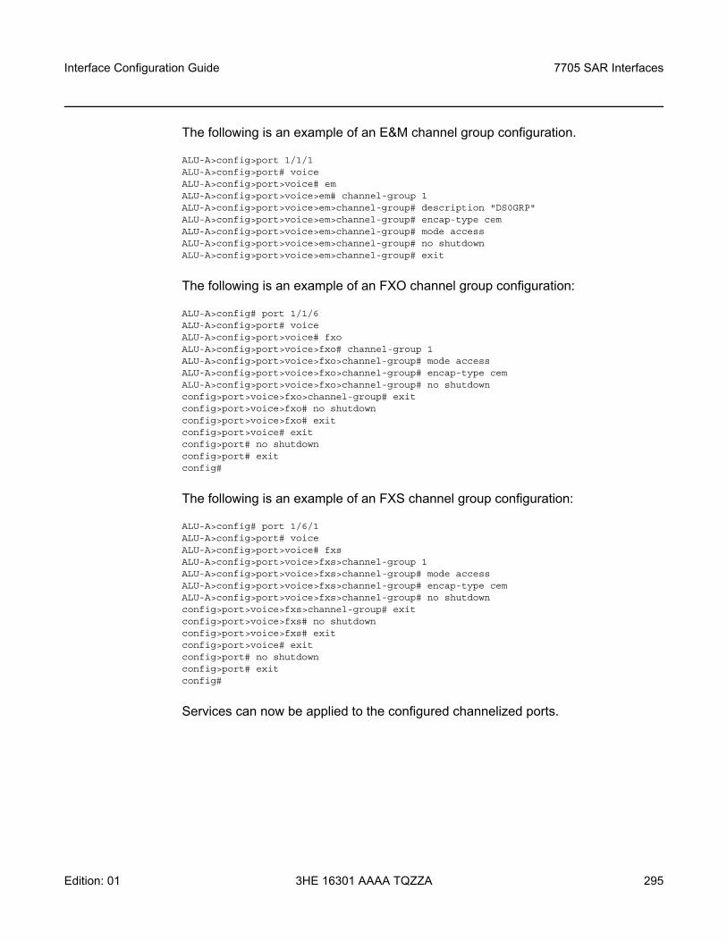
Interface Configuration Guide 7705 SAR Interfaces
Edition: 01 3HE 16301 AAAA TQZZA 295
The following is an example of an E&M channel group configuration.
ALU-A>config>port 1/1/1ALU-A>config>port# voiceALU-A>config>port>voice# emALU-A>config>port>voice>em# channel-group 1ALU-A>config>port>voice>em>channel-group# description "DS0GRP"ALU-A>config>port>voice>em>channel-group# encap-type cemALU-A>config>port>voice>em>channel-group# mode accessALU-A>config>port>voice>em>channel-group# no shutdownALU-A>config>port>voice>em>channel-group# exit
The following is an example of an FXO channel group configuration:
ALU-A>config# port 1/1/6ALU-A>config>port# voiceALU-A>config>port>voice# fxoALU-A>config>port>voice>fxo# channel-group 1ALU-A>config>port>voice>fxo>channel-group# mode accessALU-A>config>port>voice>fxo>channel-group# encap-type cemALU-A>config>port>voice>fxo>channel-group# no shutdownconfig>port>voice>fxo>channel-group# exitconfig>port>voice>fxo# no shutdownconfig>port>voice>fxo# exitconfig>port>voice# exitconfig>port# no shutdownconfig>port# exitconfig#
The following is an example of an FXS channel group configuration:
ALU-A>config# port 1/6/1ALU-A>config>port# voiceALU-A>config>port>voice# fxsALU-A>config>port>voice>fxs>channel-group 1ALU-A>config>port>voice>fxs>channel-group# mode accessALU-A>config>port>voice>fxs>channel-group# encap-type cemALU-A>config>port>voice>fxs>channel-group# no shutdownconfig>port>voice>fxs>channel-group# exitconfig>port>voice>fxs# no shutdownconfig>port>voice>fxs# exitconfig>port>voice# exitconfig>port# no shutdownconfig>port# exitconfig#
Services can now be applied to the configured channelized ports.
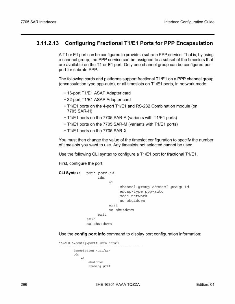
7705 SAR Interfaces
296
Interface Configuration Guide
3HE 16301 AAAA TQZZA Edition: 01
3.11.2.13 Configuring Fractional T1/E1 Ports for PPP Encapsulation
A T1 or E1 port can be configured to provide a subrate PPP service. That is, by using a channel group, the PPP service can be assigned to a subset of the timeslots that are available on the T1 or E1 port. Only one channel group can be configured per port for subrate PPP.
The following cards and platforms support fractional T1/E1 on a PPP channel group (encapsulation type ppp-auto), or all timeslots on T1/E1 ports, in network mode:
• 16-port T1/E1 ASAP Adapter card• 32-port T1/E1 ASAP Adapter card• T1/E1 ports on the 4-port T1/E1 and RS-232 Combination module (on
7705 SAR-H)• T1/E1 ports on the 7705 SAR-A (variants with T1/E1 ports)• T1/E1 ports on the 7705 SAR-M (variants with T1/E1 ports)• T1/E1 ports on the 7705 SAR-X
You must then change the value of the timeslot configuration to specify the number of timeslots you want to use. Any timeslots not selected cannot be used.
Use the following CLI syntax to configure a T1/E1 port for fractional T1/E1.
First, configure the port:
CLI Syntax: port port-idtdm
e1channel-group channel-group-idencap-type ppp-automode networkno shutdown
exitno shutdown
exitexitno shutdown
Use the config port info command to display port configuration information:
*A:ALU-A>config>port# info detail----------------------------------------------
description "DS1/E1"tdm
e1shutdownframing g704
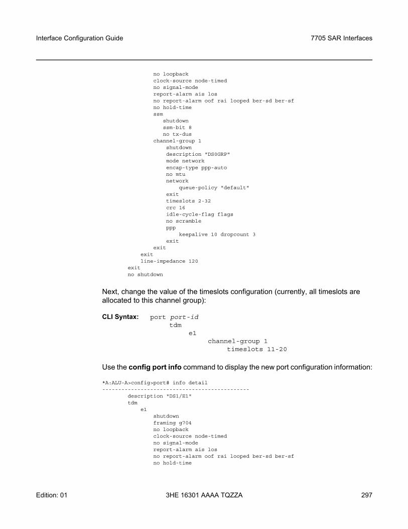
Interface Configuration Guide 7705 SAR Interfaces
Edition: 01 3HE 16301 AAAA TQZZA 297
no loopbackclock-source node-timedno signal-modereport-alarm ais losno report-alarm oof rai looped ber-sd ber-sfno hold-timessm
shutdownssm-bit 8no tx-dus
channel-group 1shutdowndescription "DS0GRP"mode networkencap-type ppp-autono mtunetwork
queue-policy "default"exittimeslots 2-32crc 16idle-cycle-flag flagsno scrambleppp
keepalive 10 dropcount 3exit
exitexitline-impedance 120
exitno shutdown
Next, change the value of the timeslots configuration (currently, all timeslots are allocated to this channel group):
CLI Syntax: port port-idtdm
e1channel-group 1
timeslots 11-20
Use the config port info command to display the new port configuration information:
*A:ALU-A>config>port# info detail----------------------------------------------
description "DS1/E1"tdm
e1shutdownframing g704no loopbackclock-source node-timedno signal-modereport-alarm ais losno report-alarm oof rai looped ber-sd ber-sfno hold-time
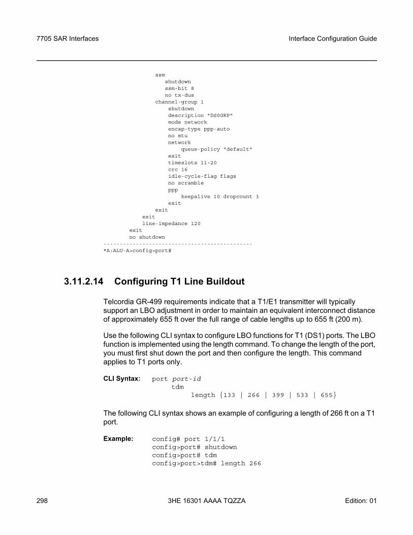
7705 SAR Interfaces
298
Interface Configuration Guide
3HE 16301 AAAA TQZZA Edition: 01
ssmshutdownssm-bit 8no tx-dus
channel-group 1shutdowndescription "DS0GRP"mode networkencap-type ppp-autono mtunetwork
queue-policy "default"exittimeslots 11-20crc 16idle-cycle-flag flagsno scrambleppp
keepalive 10 dropcount 3exit
exitexitline-impedance 120
exitno shutdown
----------------------------------------------*A:ALU-A>config>port#
3.11.2.14 Configuring T1 Line Buildout
Telcordia GR-499 requirements indicate that a T1/E1 transmitter will typically support an LBO adjustment in order to maintain an equivalent interconnect distance of approximately 655 ft over the full range of cable lengths up to 655 ft (200 m).
Use the following CLI syntax to configure LBO functions for T1 (DS1) ports. The LBO function is implemented using the length command. To change the length of the port, you must first shut down the port and then configure the length. This command applies to T1 ports only.
CLI Syntax: port port-idtdm
length 133 | 266 | 399 | 533 | 655
The following CLI syntax shows an example of configuring a length of 266 ft on a T1 port.
Example: config# port 1/1/1config>port# shutdownconfig>port# tdmconfig>port>tdm# length 266
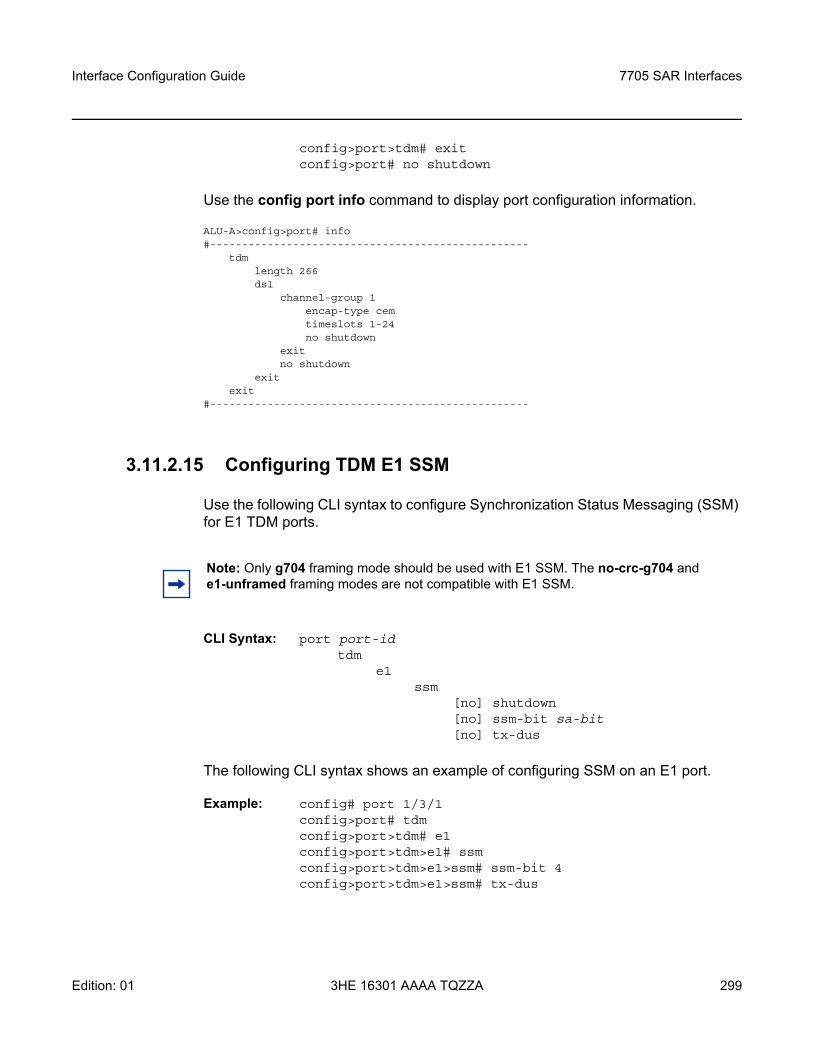
Interface Configuration Guide 7705 SAR Interfaces
Edition: 01 3HE 16301 AAAA TQZZA 299
config>port>tdm# exitconfig>port# no shutdown
Use the config port info command to display port configuration information.
ALU-A>config>port# info#--------------------------------------------------
tdmlength 266ds1
channel-group 1encap-type cemtimeslots 1-24no shutdown
exitno shutdown
exitexit
#--------------------------------------------------
3.11.2.15 Configuring TDM E1 SSM
Use the following CLI syntax to configure Synchronization Status Messaging (SSM) for E1 TDM ports.
CLI Syntax: port port-idtdm
e1ssm
[no] shutdown[no] ssm-bit sa-bit[no] tx-dus
The following CLI syntax shows an example of configuring SSM on an E1 port.
Example: config# port 1/3/1config>port# tdmconfig>port>tdm# e1config>port>tdm>e1# ssmconfig>port>tdm>e1>ssm# ssm-bit 4config>port>tdm>e1>ssm# tx-dus
Note: Only g704 framing mode should be used with E1 SSM. The no-crc-g704 and e1-unframed framing modes are not compatible with E1 SSM.
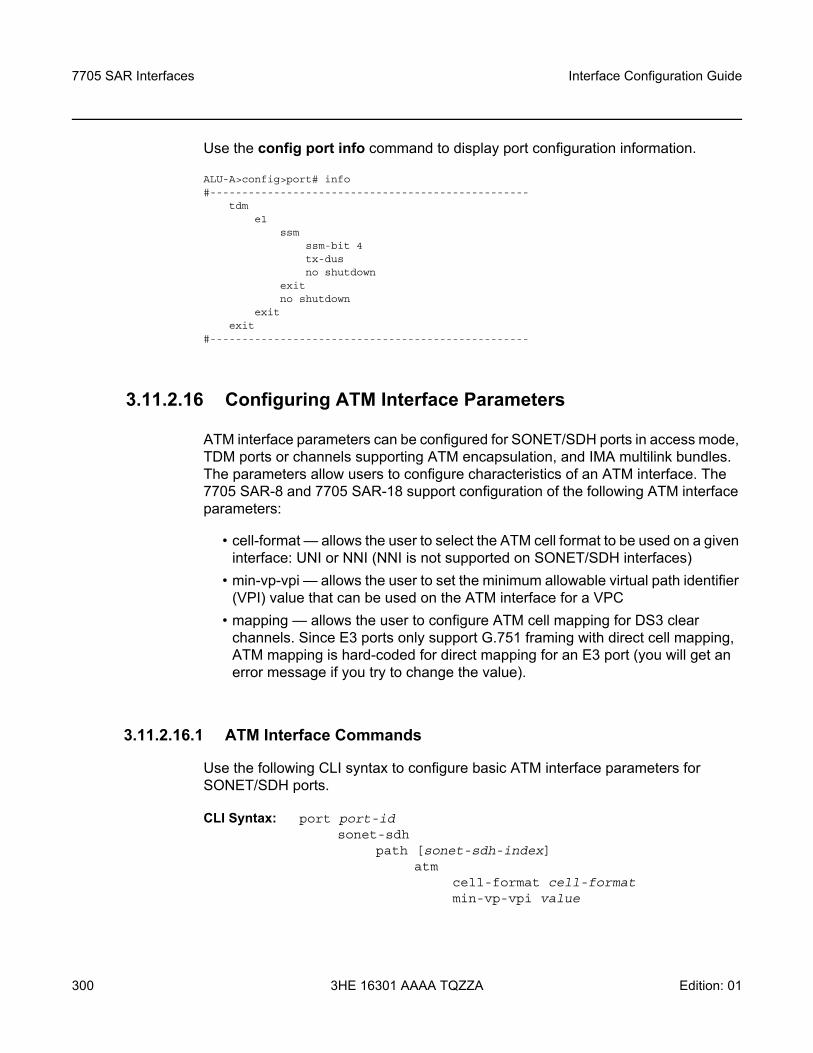
7705 SAR Interfaces
300
Interface Configuration Guide
3HE 16301 AAAA TQZZA Edition: 01
Use the config port info command to display port configuration information.
ALU-A>config>port# info#--------------------------------------------------
tdme1
ssmssm-bit 4tx-dusno shutdown
exitno shutdown
exitexit
#--------------------------------------------------
3.11.2.16 Configuring ATM Interface Parameters
ATM interface parameters can be configured for SONET/SDH ports in access mode, TDM ports or channels supporting ATM encapsulation, and IMA multilink bundles. The parameters allow users to configure characteristics of an ATM interface. The 7705 SAR-8 and 7705 SAR-18 support configuration of the following ATM interface parameters:
• cell-format — allows the user to select the ATM cell format to be used on a given interface: UNI or NNI (NNI is not supported on SONET/SDH interfaces)
• min-vp-vpi — allows the user to set the minimum allowable virtual path identifier (VPI) value that can be used on the ATM interface for a VPC
• mapping — allows the user to configure ATM cell mapping for DS3 clear channels. Since E3 ports only support G.751 framing with direct cell mapping, ATM mapping is hard-coded for direct mapping for an E3 port (you will get an error message if you try to change the value).
3.11.2.16.1 ATM Interface Commands
Use the following CLI syntax to configure basic ATM interface parameters for SONET/SDH ports.
CLI Syntax: port port-idsonet-sdh
path [sonet-sdh-index]atm
cell-format cell-formatmin-vp-vpi value
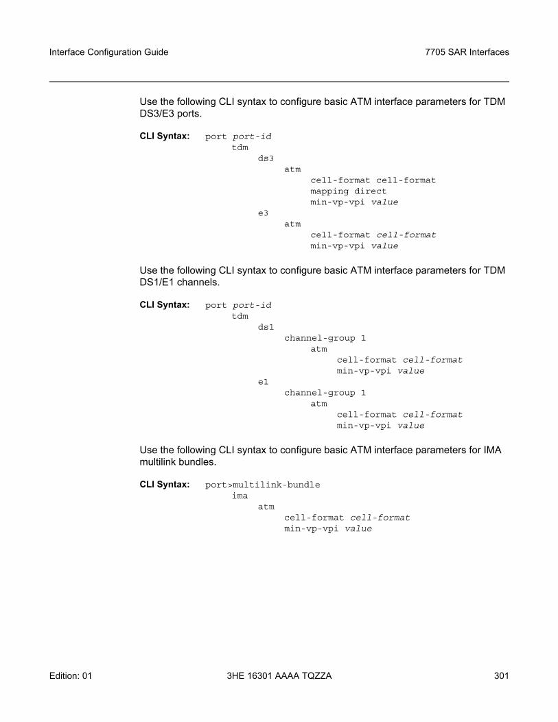
Interface Configuration Guide 7705 SAR Interfaces
Edition: 01 3HE 16301 AAAA TQZZA 301
Use the following CLI syntax to configure basic ATM interface parameters for TDM DS3/E3 ports.
CLI Syntax: port port-idtdm
ds3atm
cell-format cell-formatmapping directmin-vp-vpi value
e3atm
cell-format cell-formatmin-vp-vpi value
Use the following CLI syntax to configure basic ATM interface parameters for TDM DS1/E1 channels.
CLI Syntax: port port-idtdm
ds1 channel-group 1
atmcell-format cell-formatmin-vp-vpi value
e1channel-group 1
atmcell-format cell-formatmin-vp-vpi value
Use the following CLI syntax to configure basic ATM interface parameters for IMA multilink bundles.
CLI Syntax: port>multilink-bundleima
atmcell-format cell-formatmin-vp-vpi value
7705 SAR Interfaces
302
Interface Configuration Guide
3HE 16301 AAAA TQZZA Edition: 01
3.11.2.17 Configuring Multilink PPP Bundles
The following cards, modules, and platforms support multilink bundles:
• T1/E1 ports on the 7705 SAR-A (variants with T1/E1 ports)• T1/E1 ports on the 7705 SAR-M (variants with T1/E1 ports)• T1/E1 ports on the 7705 SAR-X
The following must have all member links of an MLPPP bundle configured on the same card or module:- 16-port T1/E1 ASAP Adapter card- 32-port T1/E1 ASAP Adapter card- T1/E1 ports on the 4-port T1/E1 and RS-232 Combination module (on
7705 SAR-H)The following must have all member links of an MLPPP bundle configured on the same card or module, and on the same port:- 2-port OC3/STM1 Channelized Adapter card- 4-port OC3/STM1 / 1-port OC12/STM4 Adapter card
Multilink bundling is based on a link control protocol (LCP) option negotiation that permits a system to indicate to its peer that it is capable of combining multiple physical links into a bundle. Each bundle represents a single connection between two routers. The bundles aggregate channelized ports to define the bandwidth between the routers over the DS1 links.
Multilink bundling operations are modeled after a virtual PPP link-layer entity where packets received over different physical link-layer entities are identified as belonging to a separate PPP network protocol (the Multilink Protocol, or MP) and recombined and sequenced according to information present in a multilink fragmentation header. All packets received over links identified as belonging to the multilink arrangement are presented to the same network-layer protocol processing machine, whether they have multilink headers or not.
When you configure multilink bundles, consider the following guidelines.
• A multilink bundle configuration should include at least 2 ports.• Multilink bundles can only be aggregated on a single adapter card.• All member links of an MLPPP group must be of the same type (either E1 or
Ds1). • When you configure a channel group on the network side with ppp-auto
encapsulation, the system automatically allocates all timeslots to the channel group.
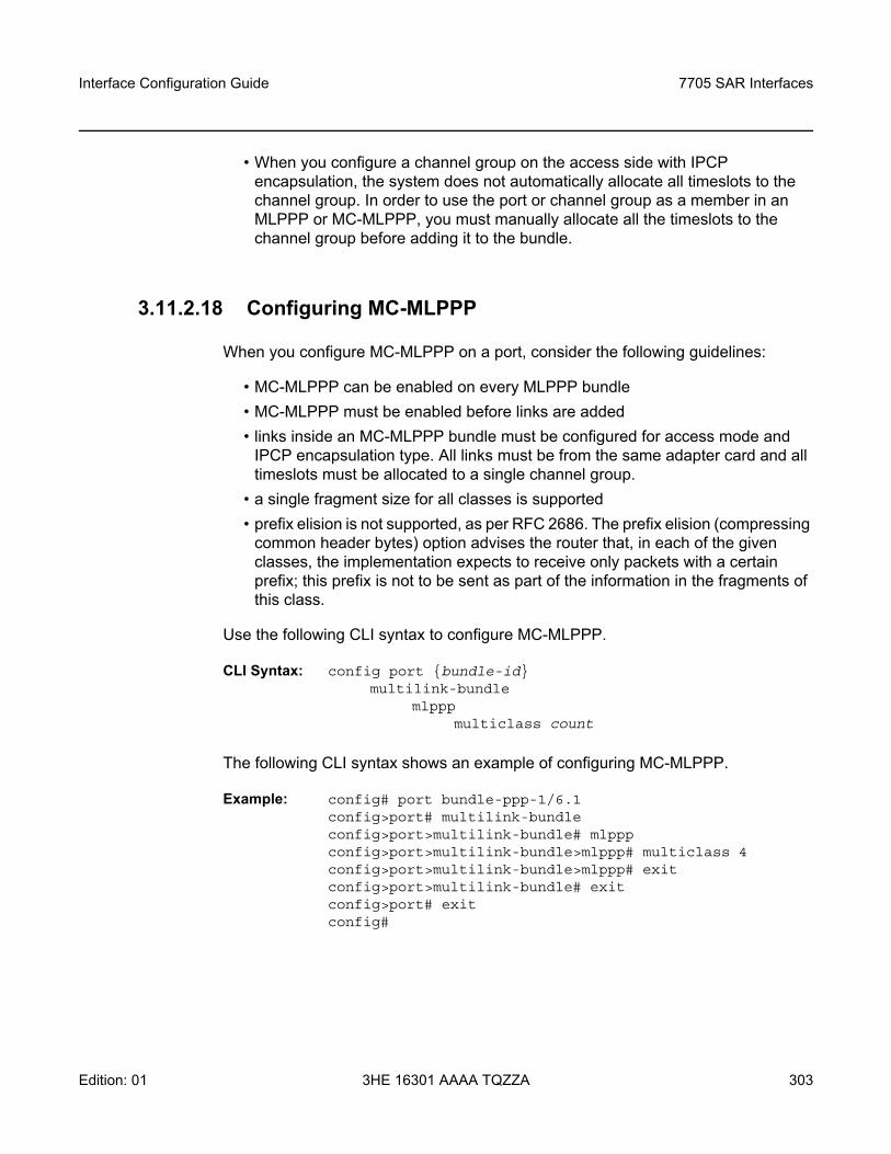
Interface Configuration Guide 7705 SAR Interfaces
Edition: 01 3HE 16301 AAAA TQZZA 303
• When you configure a channel group on the access side with IPCP encapsulation, the system does not automatically allocate all timeslots to the channel group. In order to use the port or channel group as a member in an MLPPP or MC-MLPPP, you must manually allocate all the timeslots to the channel group before adding it to the bundle.
3.11.2.18 Configuring MC-MLPPP
When you configure MC-MLPPP on a port, consider the following guidelines:
• MC-MLPPP can be enabled on every MLPPP bundle• MC-MLPPP must be enabled before links are added• links inside an MC-MLPPP bundle must be configured for access mode and
IPCP encapsulation type. All links must be from the same adapter card and all timeslots must be allocated to a single channel group.
• a single fragment size for all classes is supported• prefix elision is not supported, as per RFC 2686. The prefix elision (compressing
common header bytes) option advises the router that, in each of the given classes, the implementation expects to receive only packets with a certain prefix; this prefix is not to be sent as part of the information in the fragments of this class.
Use the following CLI syntax to configure MC-MLPPP.
CLI Syntax: config port bundle-idmultilink-bundle
mlpppmulticlass count
The following CLI syntax shows an example of configuring MC-MLPPP.
Example: config# port bundle-ppp-1/6.1config>port# multilink-bundleconfig>port>multilink-bundle# mlpppconfig>port>multilink-bundle>mlppp# multiclass 4config>port>multilink-bundle>mlppp# exitconfig>port>multilink-bundle# exitconfig>port# exitconfig#
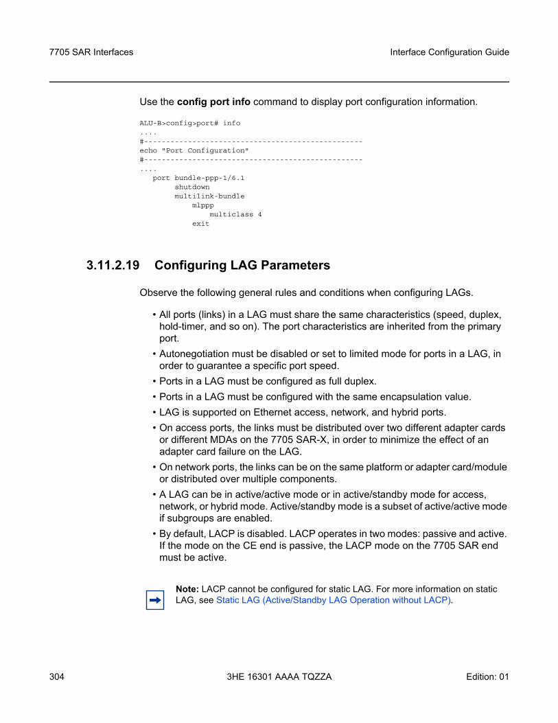
7705 SAR Interfaces
304
Interface Configuration Guide
3HE 16301 AAAA TQZZA Edition: 01
Use the config port info command to display port configuration information.
ALU-B>config>port# info....#--------------------------------------------------echo "Port Configuration"#--------------------------------------------------....
port bundle-ppp-1/6.1shutdownmultilink-bundle
mlpppmulticlass 4
exit
3.11.2.19 Configuring LAG Parameters
Observe the following general rules and conditions when configuring LAGs.
• All ports (links) in a LAG must share the same characteristics (speed, duplex, hold-timer, and so on). The port characteristics are inherited from the primary port.
• Autonegotiation must be disabled or set to limited mode for ports in a LAG, in order to guarantee a specific port speed.
• Ports in a LAG must be configured as full duplex.• Ports in a LAG must be configured with the same encapsulation value.• LAG is supported on Ethernet access, network, and hybrid ports.• On access ports, the links must be distributed over two different adapter cards
or different MDAs on the 7705 SAR-X, in order to minimize the effect of an adapter card failure on the LAG.
• On network ports, the links can be on the same platform or adapter card/module or distributed over multiple components.
• A LAG can be in active/active mode or in active/standby mode for access, network, or hybrid mode. Active/standby mode is a subset of active/active mode if subgroups are enabled.
• By default, LACP is disabled. LACP operates in two modes: passive and active. If the mode on the CE end is passive, the LACP mode on the 7705 SAR end must be active.
Note: LACP cannot be configured for static LAG. For more information on static LAG, see Static LAG (Active/Standby LAG Operation without LACP).
Interface Configuration Guide 7705 SAR Interfaces
Edition: 01 3HE 16301 AAAA TQZZA 305
• Each link in a LAG must be a member of a subgroup. On access, network or hybrid ports, a LAG can have a maximum of four subgroups and a subgroup can have links up to the maximum number supported on the LAG. LAG is active/active if there is only one sub-group. LAG is active/standby if there is more than one subgroup.
• The port with the highest priority is the primary port. If multiple ports have the same priority, the port with the lowest port ID becomes the primary port.
• A port on standby can be replaced while the active port in the LAG is operational.• When one port is on a first- or second-generation Ethernet adapter card and the
other port is on a third-generation Ethernet adapter card, mix-and-match traffic management occurs. The LAG SAP uses a generic QoS configuration where scheduler-mode, agg-rate, and cir-rate are configured for the SAP, but only those applicable parameters needed by the active adapter card are used to set the QoS values of the active port. See LAG Support on Mixed-Generation Hardware for details. See Table 2 for a list of adapter card generations.
• The primary port configuration settings are applied to both the primary and secondary LAG ports. Thus in order to support unshaped SAPs when the primary port is a Gen-3-based port and the secondary port is a Gen-2-based port, configuring the unshaped-sap-cir on the Gen-3-based port is allowed, even though it does not apply to the Gen-3-based port. This is because unshaped-sap-cir is needed by the (secondary) Gen-2-based port when it becomes the active port. The full command is config>port>ethernet>access>egress>unshaped-sap-cir cir-rate.
• When a LAG contains a port on a first-generation Ethernet adapter card, the scheduler mode can only be 4-priority.
Additional general rules for LAG configuration are as follows.
• Most port features (port commands) can only be configured on the primary member port. The configuration, or any change to the configuration, is automatically propagated to any remaining ports within the same LAG. Operators cannot modify the configurations on non-primary ports.
• When adding the first port member to a LAG group, its port configuration becomes the configuration of the LAG group.
• Once a LAG group has been created, new ports can be added to the LAG group only if their port configurations match with the LAG group configurations inherited from the group’s existing primary port. A newly added port may become the primary port or a non-primary port, depending on the setting of the LAG selection criteria, priorities, and so on.
• Not all configurations follow the conventions above. Some exceptions include the commands loopback (internal or line), cfm-loopback, mac, lldp, dot1x, efm-oam, and so on.
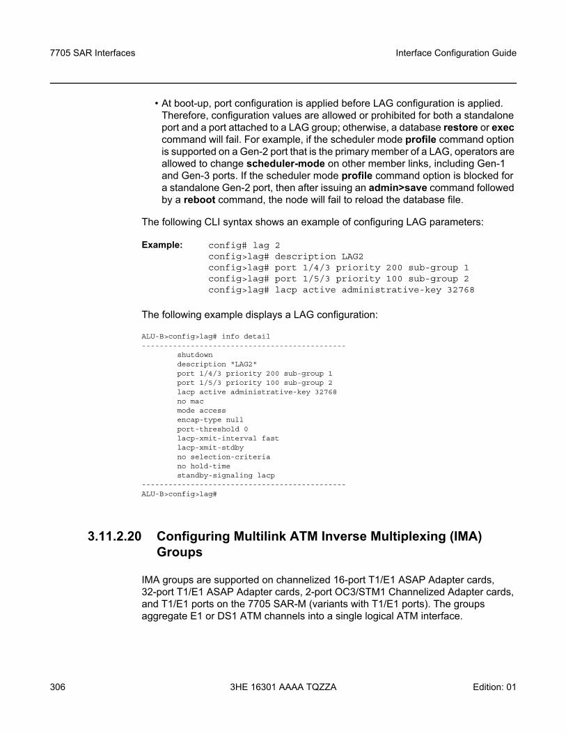
7705 SAR Interfaces
306
Interface Configuration Guide
3HE 16301 AAAA TQZZA Edition: 01
• At boot-up, port configuration is applied before LAG configuration is applied. Therefore, configuration values are allowed or prohibited for both a standalone port and a port attached to a LAG group; otherwise, a database restore or exec command will fail. For example, if the scheduler mode profile command option is supported on a Gen-2 port that is the primary member of a LAG, operators are allowed to change scheduler-mode on other member links, including Gen-1 and Gen-3 ports. If the scheduler mode profile command option is blocked for a standalone Gen-2 port, then after issuing an admin>save command followed by a reboot command, the node will fail to reload the database file.
The following CLI syntax shows an example of configuring LAG parameters:
Example: config# lag 2config>lag# description LAG2config>lag# port 1/4/3 priority 200 sub-group 1config>lag# port 1/5/3 priority 100 sub-group 2config>lag# lacp active administrative-key 32768
The following example displays a LAG configuration:
ALU-B>config>lag# info detail----------------------------------------------
shutdowndescription "LAG2"port 1/4/3 priority 200 sub-group 1port 1/5/3 priority 100 sub-group 2lacp active administrative-key 32768no macmode accessencap-type nullport-threshold 0lacp-xmit-interval fastlacp-xmit-stdbyno selection-criteriano hold-timestandby-signaling lacp
----------------------------------------------ALU-B>config>lag#
3.11.2.20 Configuring Multilink ATM Inverse Multiplexing (IMA) Groups
IMA groups are supported on channelized 16-port T1/E1 ASAP Adapter cards, 32-port T1/E1 ASAP Adapter cards, 2-port OC3/STM1 Channelized Adapter cards, and T1/E1 ports on the 7705 SAR-M (variants with T1/E1 ports). The groups aggregate E1 or DS1 ATM channels into a single logical ATM interface.
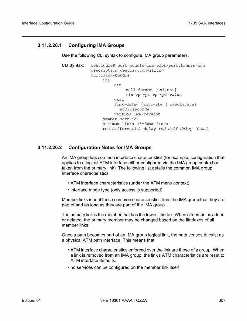
Interface Configuration Guide 7705 SAR Interfaces
Edition: 01 3HE 16301 AAAA TQZZA 307
3.11.2.20.1 Configuring IMA Groups
Use the following CLI syntax to configure IMA group parameters.
CLI Syntax: configure# port bundle-ima-slot/port.bundle-numdescription description-stringmultilink-bundle
imaatm
cell-format uni|nnimin-vp-vpi vp-vpi-value
exitlink-delay activate | deactivate
millisecondsversion IMA-version
member port-idminimum-links minimum-linksred-differential-delay red-diff-delay [down]
3.11.2.20.2 Configuration Notes for IMA Groups
An IMA group has common interface characteristics (for example, configuration that applies to a logical ATM interface either configured via the IMA group context or taken from the primary link). The following list details the common IMA group interface characteristics:
• ATM interface characteristics (under the ATM menu context)• interface mode type (only access is supported)
Member links inherit these common characteristics from the IMA group that they are part of and as long as they are part of the IMA group.
The primary link is the member that has the lowest ifindex. When a member is added or deleted, the primary member may be changed based on the ifindexes of all member links.
Once a path becomes part of an IMA group logical link, the path ceases to exist as a physical ATM path interface. This means that:
• ATM interface characteristics enforced over the link are those of a group. When a link is removed from an IMA group, the link's ATM characteristics are reset to ATM interface defaults.
• no services can be configured on the member link itself
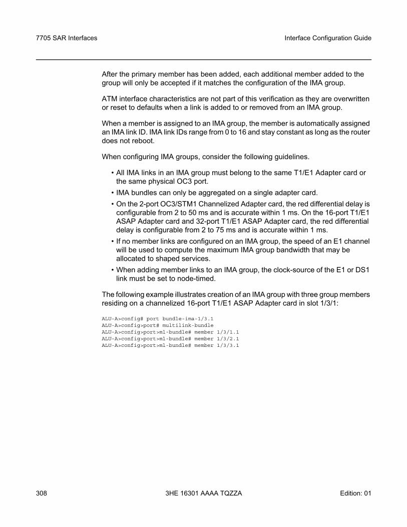
7705 SAR Interfaces
308
Interface Configuration Guide
3HE 16301 AAAA TQZZA Edition: 01
After the primary member has been added, each additional member added to the group will only be accepted if it matches the configuration of the IMA group.
ATM interface characteristics are not part of this verification as they are overwritten or reset to defaults when a link is added to or removed from an IMA group.
When a member is assigned to an IMA group, the member is automatically assigned an IMA link ID. IMA link IDs range from 0 to 16 and stay constant as long as the router does not reboot.
When configuring IMA groups, consider the following guidelines.
• All IMA links in an IMA group must belong to the same T1/E1 Adapter card or the same physical OC3 port.
• IMA bundles can only be aggregated on a single adapter card.• On the 2-port OC3/STM1 Channelized Adapter card, the red differential delay is
configurable from 2 to 50 ms and is accurate within 1 ms. On the 16-port T1/E1 ASAP Adapter card and 32-port T1/E1 ASAP Adapter card, the red differential delay is configurable from 2 to 75 ms and is accurate within 1 ms.
• If no member links are configured on an IMA group, the speed of an E1 channel will be used to compute the maximum IMA group bandwidth that may be allocated to shaped services.
• When adding member links to an IMA group, the clock-source of the E1 or DS1 link must be set to node-timed.
The following example illustrates creation of an IMA group with three group members residing on a channelized 16-port T1/E1 ASAP Adapter card in slot 1/3/1:
ALU-A>config# port bundle-ima-1/3.1ALU-A>config>port# multilink-bundleALU-A>config>port>ml-bundle# member 1/3/1.1ALU-A>config>port>ml-bundle# member 1/3/2.1ALU-A>config>port>ml-bundle# member 1/3/3.1
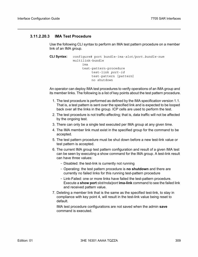
Interface Configuration Guide 7705 SAR Interfaces
Edition: 01 3HE 16301 AAAA TQZZA 309
3.11.2.20.3 IMA Test Procedure
Use the following CLI syntax to perform an IMA test pattern procedure on a member link of an IMA group.
CLI Syntax: configure# port bundle-ima-slot/port.bundle-nummultilink-bundle
imatest-pattern-procedure
test-link port-idtest-pattern [pattern]no shutdown
An operator can deploy IMA test procedures to verify operations of an IMA group and its member links. The following is a list of key points about the test pattern procedure.
1. The test procedure is performed as defined by the IMA specification version 1.1. That is, a test pattern is sent over the specified link and is expected to be looped back over all the links in the group. ICP cells are used to perform the test.
2. The test procedure is not traffic-affecting; that is, data traffic will not be affected by the ongoing test.
3. There can only be a single test executed per IMA group at any given time. 4. The IMA member link must exist in the specified group for the command to be
accepted. 5. The test pattern procedure must be shut down before a new test-link value or
test pattern is accepted.6. The current IMA group test pattern configuration and result of a given IMA test
can be seen by executing a show command for the IMA group. A test-link result can have three values:- Disabled: the test-link is currently not running- Operating: the test pattern procedure is no shutdown and there are
currently no failed links for this running test-pattern procedure- Link-Failed: one or more links have failed the test-pattern procedure.
Execute a show port slot/mda/port ima-link command to see the failed link and received pattern value.
7. Deleting a member link that is the same as the specified test-link, to stay in compliance with key point 4, will result in the test-link value being reset to default.IMA test procedure configurations are not saved when the admin save command is executed.
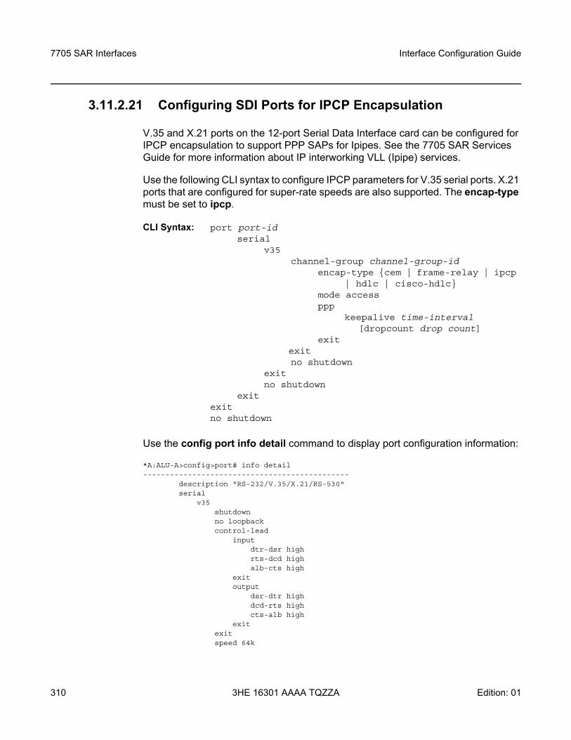
7705 SAR Interfaces
310
Interface Configuration Guide
3HE 16301 AAAA TQZZA Edition: 01
3.11.2.21 Configuring SDI Ports for IPCP Encapsulation
V.35 and X.21 ports on the 12-port Serial Data Interface card can be configured for IPCP encapsulation to support PPP SAPs for Ipipes. See the 7705 SAR Services Guide for more information about IP interworking VLL (Ipipe) services.
Use the following CLI syntax to configure IPCP parameters for V.35 serial ports. X.21 ports that are configured for super-rate speeds are also supported. The encap-type must be set to ipcp.
CLI Syntax: port port-id serial
v35channel-group channel-group-id
encap-type cem | frame-relay | ipcp | hdlc | cisco-hdlc
mode accessppp
keepalive time-interval [dropcount drop count]
exit exit
no shutdown exit no shutdown
exit exit no shutdown
Use the config port info detail command to display port configuration information:
*A:ALU-A>config>port# info detail----------------------------------------------
description "RS-232/V.35/X.21/RS-530"serial
v35shutdownno loopbackcontrol-lead
inputdtr-dsr highrts-dcd highalb-cts high
exitoutput
dsr-dtr highdcd-rts highcts-alb high
exitexitspeed 64k
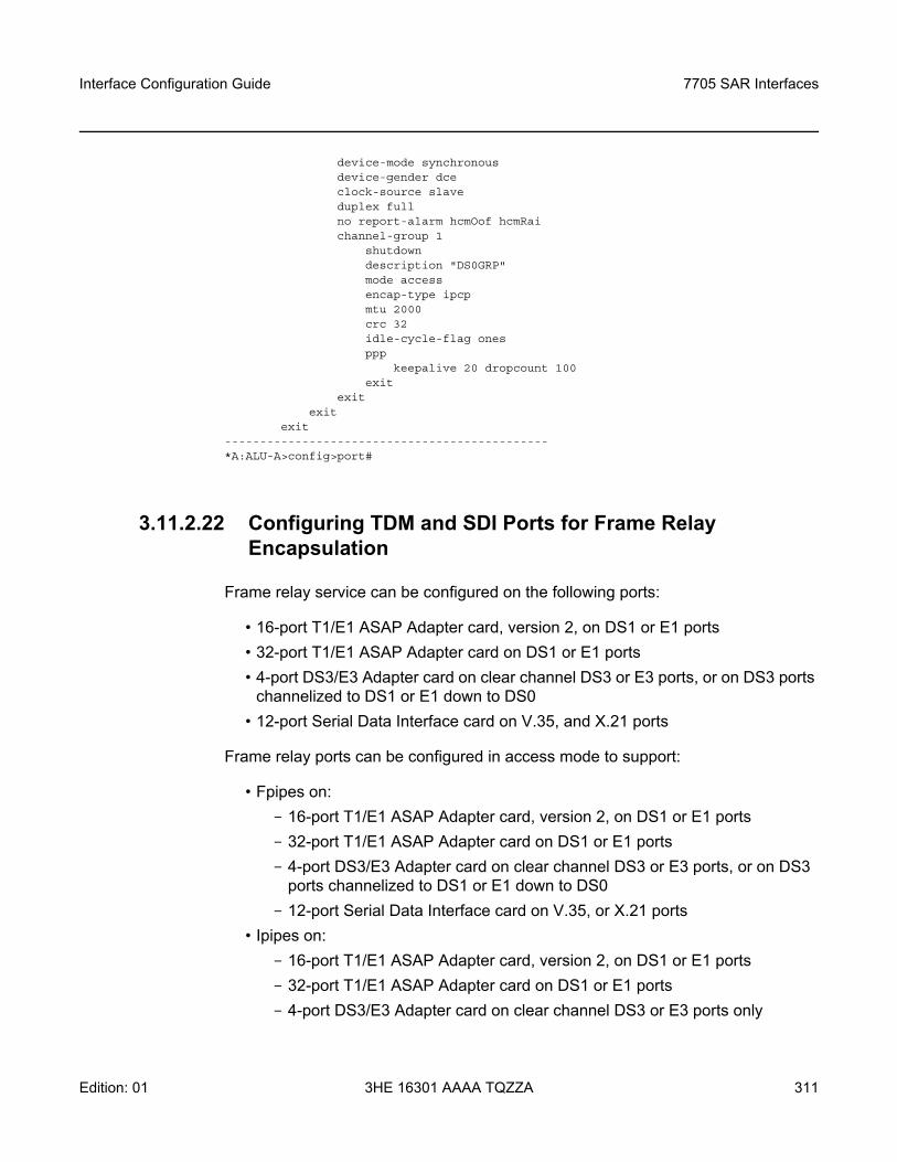
Interface Configuration Guide 7705 SAR Interfaces
Edition: 01 3HE 16301 AAAA TQZZA 311
device-mode synchronousdevice-gender dceclock-source slaveduplex fullno report-alarm hcmOof hcmRaichannel-group 1
shutdowndescription "DS0GRP"mode accessencap-type ipcpmtu 2000crc 32idle-cycle-flag onesppp
keepalive 20 dropcount 100exit
exitexit
exit----------------------------------------------*A:ALU-A>config>port#
3.11.2.22 Configuring TDM and SDI Ports for Frame Relay Encapsulation
Frame relay service can be configured on the following ports:
• 16-port T1/E1 ASAP Adapter card, version 2, on DS1 or E1 ports • 32-port T1/E1 ASAP Adapter card on DS1 or E1 ports • 4-port DS3/E3 Adapter card on clear channel DS3 or E3 ports, or on DS3 ports
channelized to DS1 or E1 down to DS0 • 12-port Serial Data Interface card on V.35, and X.21 ports
Frame relay ports can be configured in access mode to support:
• Fpipes on:- 16-port T1/E1 ASAP Adapter card, version 2, on DS1 or E1 ports- 32-port T1/E1 ASAP Adapter card on DS1 or E1 ports- 4-port DS3/E3 Adapter card on clear channel DS3 or E3 ports, or on DS3
ports channelized to DS1 or E1 down to DS0- 12-port Serial Data Interface card on V.35, or X.21 ports
• Ipipes on:- 16-port T1/E1 ASAP Adapter card, version 2, on DS1 or E1 ports- 32-port T1/E1 ASAP Adapter card on DS1 or E1 ports- 4-port DS3/E3 Adapter card on clear channel DS3 or E3 ports only
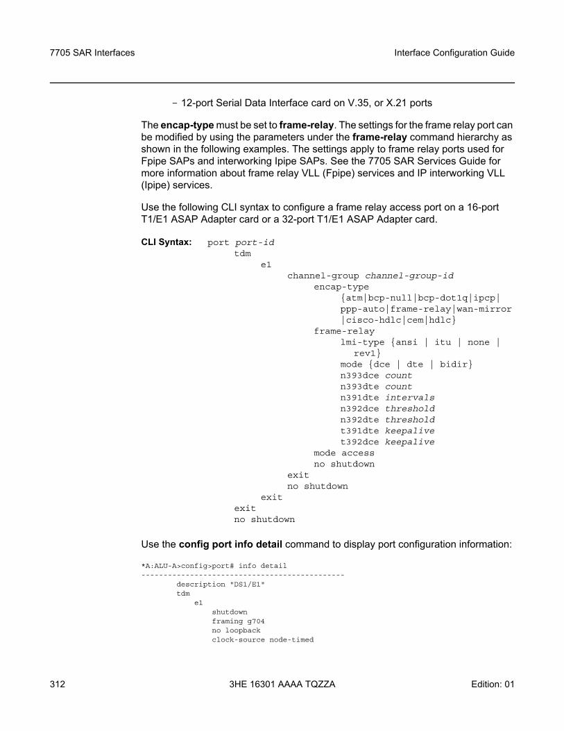
7705 SAR Interfaces
312
Interface Configuration Guide
3HE 16301 AAAA TQZZA Edition: 01
- 12-port Serial Data Interface card on V.35, or X.21 ports
The encap-type must be set to frame-relay. The settings for the frame relay port can be modified by using the parameters under the frame-relay command hierarchy as shown in the following examples. The settings apply to frame relay ports used for Fpipe SAPs and interworking Ipipe SAPs. See the 7705 SAR Services Guide for more information about frame relay VLL (Fpipe) services and IP interworking VLL (Ipipe) services.
Use the following CLI syntax to configure a frame relay access port on a 16-port T1/E1 ASAP Adapter card or a 32-port T1/E1 ASAP Adapter card.
CLI Syntax: port port-id tdm
e1channel-group channel-group-id
encap-type atm|bcp-null|bcp-dot1q|ipcp| ppp-auto|frame-relay|wan-mirror|cisco-hdlc|cem|hdlc
frame-relay lmi-type ansi | itu | none |
rev1 mode dce | dte | bidir n393dce count n393dte countn391dte intervalsn392dce thresholdn392dte thresholdt391dte keepalivet392dce keepalive
mode access no shutdown
exit no shutdown
exit exit no shutdown
Use the config port info detail command to display port configuration information:
*A:ALU-A>config>port# info detail----------------------------------------------
description "DS1/E1"tdm
e1shutdownframing g704no loopbackclock-source node-timed
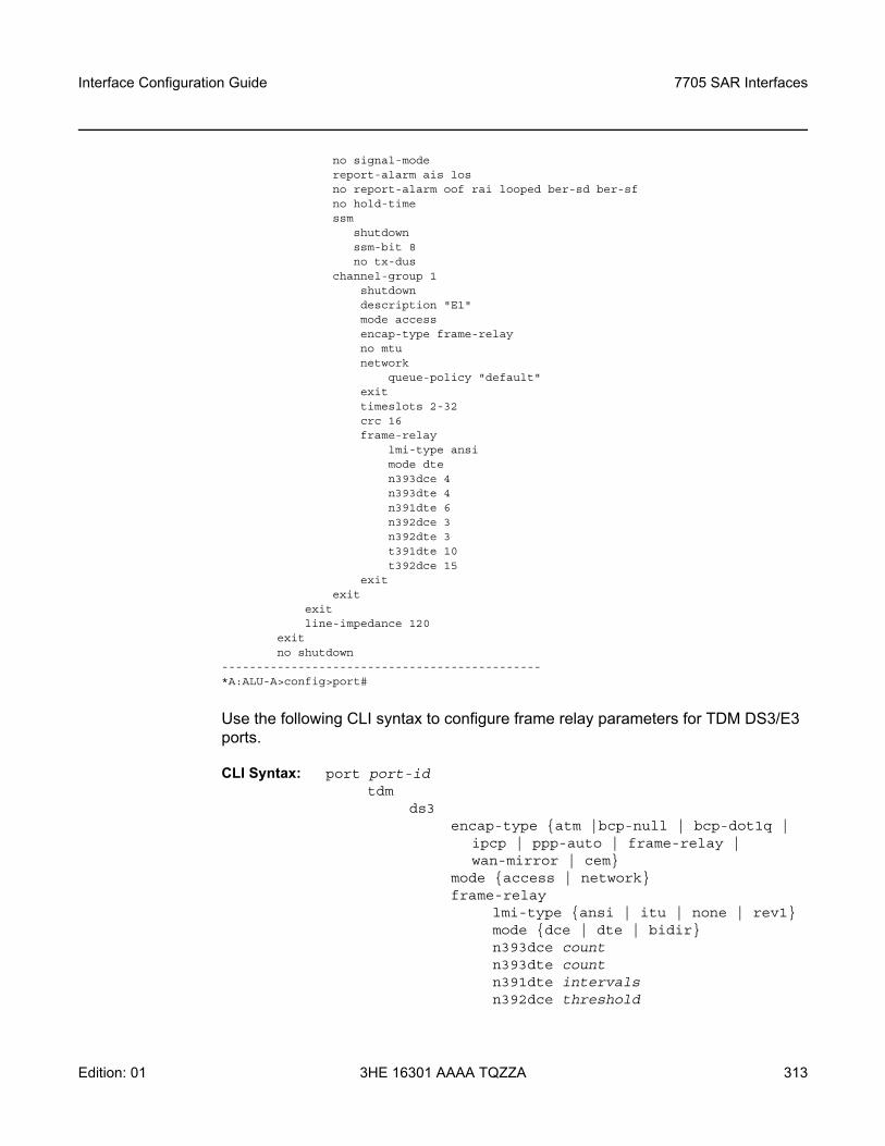
Interface Configuration Guide 7705 SAR Interfaces
Edition: 01 3HE 16301 AAAA TQZZA 313
no signal-modereport-alarm ais losno report-alarm oof rai looped ber-sd ber-sfno hold-timessm
shutdownssm-bit 8no tx-dus
channel-group 1shutdowndescription "E1"mode accessencap-type frame-relayno mtunetwork
queue-policy "default"exittimeslots 2-32crc 16frame-relay
lmi-type ansimode dten393dce 4n393dte 4n391dte 6n392dce 3n392dte 3t391dte 10t392dce 15
exitexit
exitline-impedance 120
exitno shutdown
----------------------------------------------*A:ALU-A>config>port#
Use the following CLI syntax to configure frame relay parameters for TDM DS3/E3 ports.
CLI Syntax: port port-id tdm
ds3 encap-type atm |bcp-null | bcp-dot1q |
ipcp | ppp-auto | frame-relay | wan-mirror | cem
mode access | networkframe-relay
lmi-type ansi | itu | none | rev1 mode dce | dte | bidir n393dce countn393dte countn391dte intervalsn392dce threshold
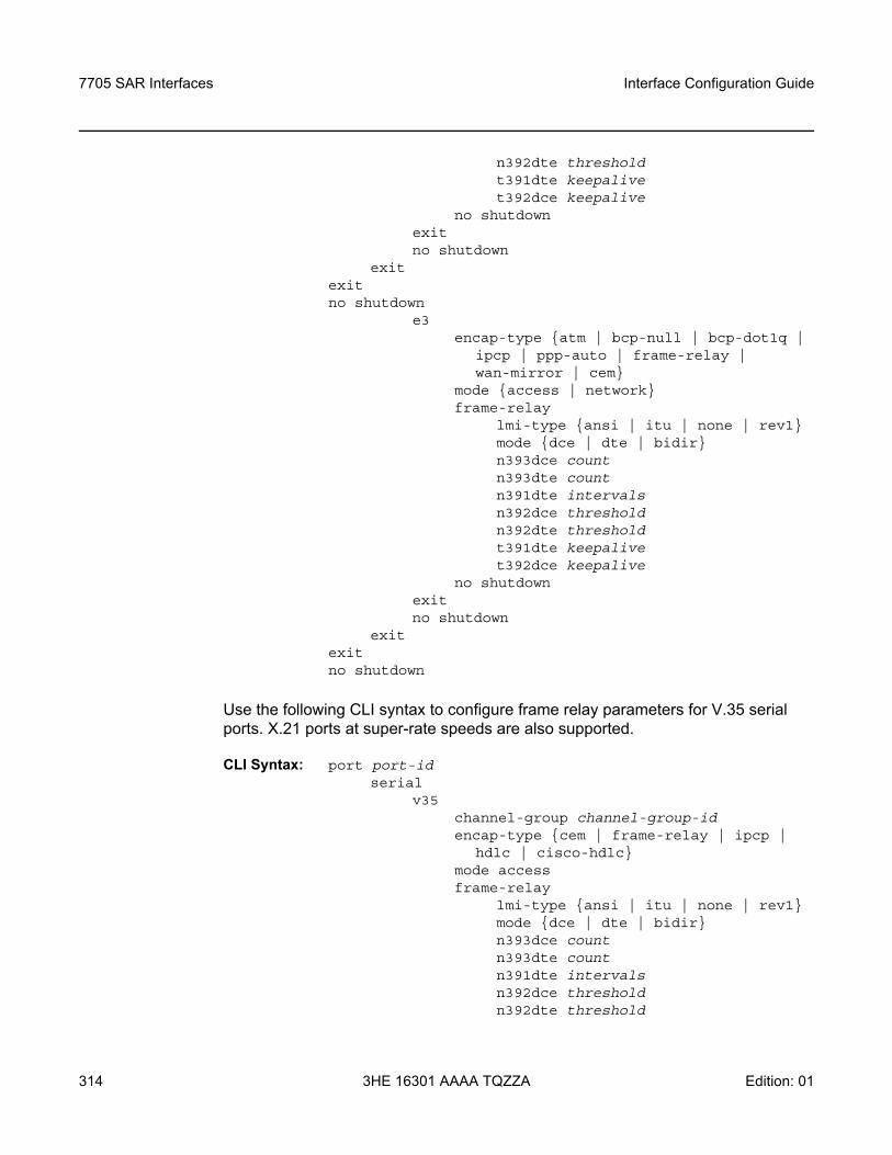
7705 SAR Interfaces
314
Interface Configuration Guide
3HE 16301 AAAA TQZZA Edition: 01
n392dte thresholdt391dte keepalivet392dce keepalive
no shutdown exit no shutdown
exit exit no shutdown
e3 encap-type atm | bcp-null | bcp-dot1q |
ipcp | ppp-auto | frame-relay | wan-mirror | cem
mode access | networkframe-relay
lmi-type ansi | itu | none | rev1 mode dce | dte | bidir n393dce countn393dte countn391dte intervalsn392dce thresholdn392dte thresholdt391dte keepalivet392dce keepalive
no shutdown exit no shutdown
exit exit no shutdown
Use the following CLI syntax to configure frame relay parameters for V.35 serial ports. X.21 ports at super-rate speeds are also supported.
CLI Syntax: port port-id serial
v35channel-group channel-group-idencap-type cem | frame-relay | ipcp |
hdlc | cisco-hdlcmode accessframe-relay
lmi-type ansi | itu | none | rev1 mode dce | dte | bidir n393dce countn393dte count n391dte intervalsn392dce thresholdn392dte threshold
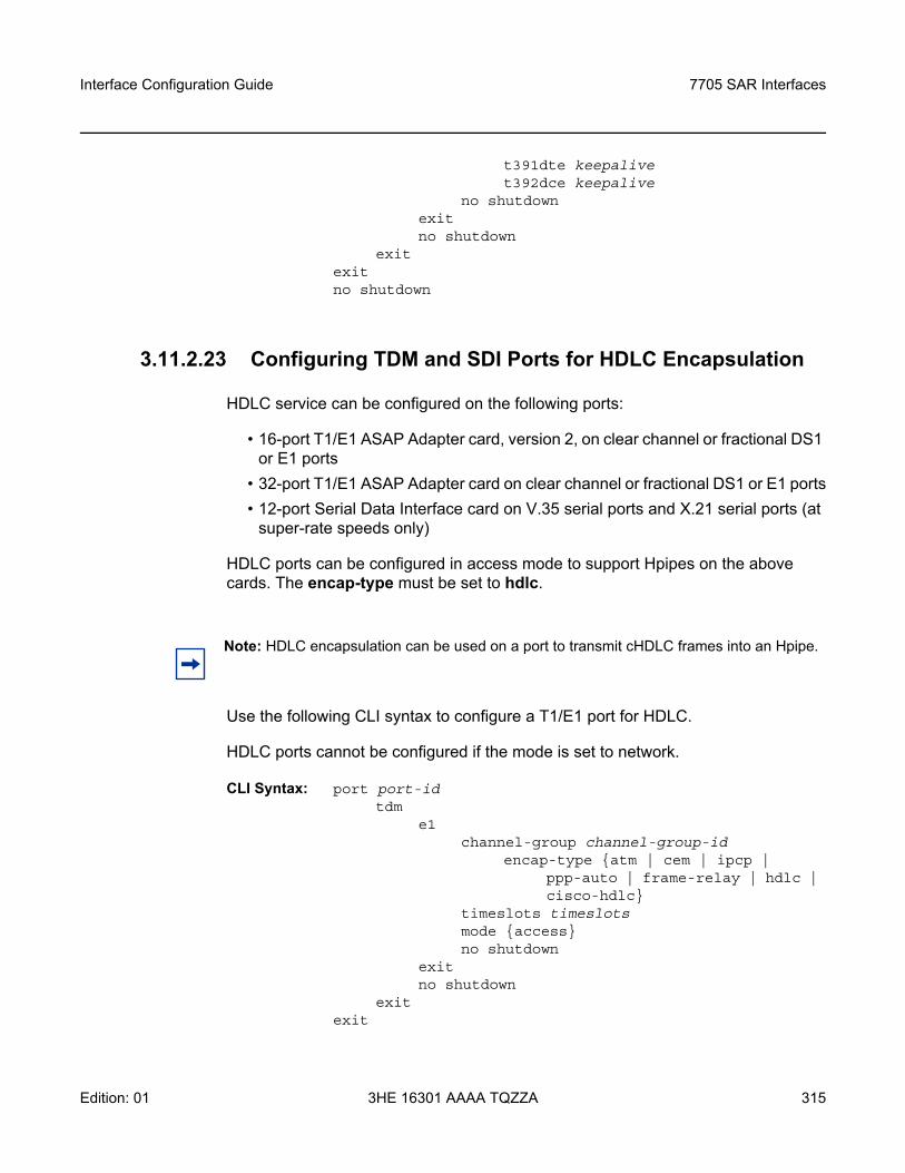
Interface Configuration Guide 7705 SAR Interfaces
Edition: 01 3HE 16301 AAAA TQZZA 315
t391dte keepalivet392dce keepalive
no shutdown exit no shutdown
exit exit no shutdown
3.11.2.23 Configuring TDM and SDI Ports for HDLC Encapsulation
HDLC service can be configured on the following ports:
• 16-port T1/E1 ASAP Adapter card, version 2, on clear channel or fractional DS1 or E1 ports
• 32-port T1/E1 ASAP Adapter card on clear channel or fractional DS1 or E1 ports• 12-port Serial Data Interface card on V.35 serial ports and X.21 serial ports (at
super-rate speeds only)
HDLC ports can be configured in access mode to support Hpipes on the above cards. The encap-type must be set to hdlc.
Use the following CLI syntax to configure a T1/E1 port for HDLC.
HDLC ports cannot be configured if the mode is set to network.
CLI Syntax: port port-id tdm
e1channel-group channel-group-id
encap-type atm | cem | ipcp | ppp-auto | frame-relay | hdlc | cisco-hdlc
timeslots timeslotsmode accessno shutdown
exit no shutdown
exit exit
Note: HDLC encapsulation can be used on a port to transmit cHDLC frames into an Hpipe.
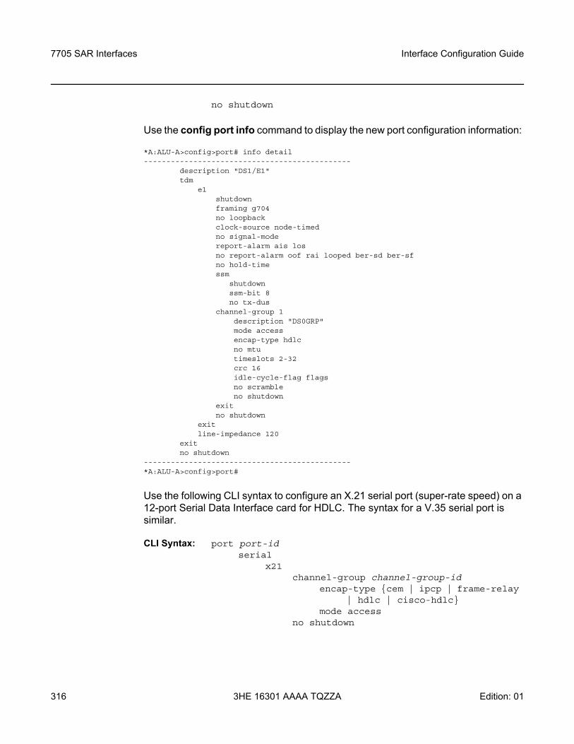
7705 SAR Interfaces
316
Interface Configuration Guide
3HE 16301 AAAA TQZZA Edition: 01
no shutdown
Use the config port info command to display the new port configuration information:
*A:ALU-A>config>port# info detail----------------------------------------------
description "DS1/E1"tdm
e1shutdownframing g704no loopbackclock-source node-timedno signal-modereport-alarm ais losno report-alarm oof rai looped ber-sd ber-sfno hold-timessm
shutdownssm-bit 8no tx-dus
channel-group 1description "DS0GRP"mode accessencap-type hdlcno mtutimeslots 2-32crc 16idle-cycle-flag flagsno scrambleno shutdown
exitno shutdown
exitline-impedance 120
exitno shutdown
----------------------------------------------*A:ALU-A>config>port#
Use the following CLI syntax to configure an X.21 serial port (super-rate speed) on a 12-port Serial Data Interface card for HDLC. The syntax for a V.35 serial port is similar.
CLI Syntax: port port-id serial
x21channel-group channel-group-id
encap-type cem | ipcp | frame-relay | hdlc | cisco-hdlc
mode accessno shutdown
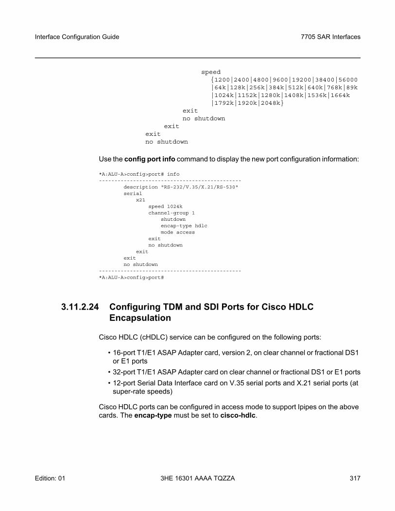
Interface Configuration Guide 7705 SAR Interfaces
Edition: 01 3HE 16301 AAAA TQZZA 317
speed 1200|2400|4800|9600|19200|38400|56000|64k|128k|256k|384k|512k|640k|768k|89k|1024k|1152k|1280k|1408k|1536k|1664k |1792k|1920k|2048k
exit no shutdown
exit exit no shutdown
Use the config port info command to display the new port configuration information:
*A:ALU-A>config>port# info----------------------------------------------
description "RS-232/V.35/X.21/RS-530"serial
x21speed 1024kchannel-group 1
shutdownencap-type hdlcmode access
exitno shutdown
exitexitno shutdown
----------------------------------------------*A:ALU-A>config>port#
3.11.2.24 Configuring TDM and SDI Ports for Cisco HDLC Encapsulation
Cisco HDLC (cHDLC) service can be configured on the following ports:
• 16-port T1/E1 ASAP Adapter card, version 2, on clear channel or fractional DS1 or E1 ports
• 32-port T1/E1 ASAP Adapter card on clear channel or fractional DS1 or E1 ports• 12-port Serial Data Interface card on V.35 serial ports and X.21 serial ports (at
super-rate speeds)
Cisco HDLC ports can be configured in access mode to support Ipipes on the above cards. The encap-type must be set to cisco-hdlc.
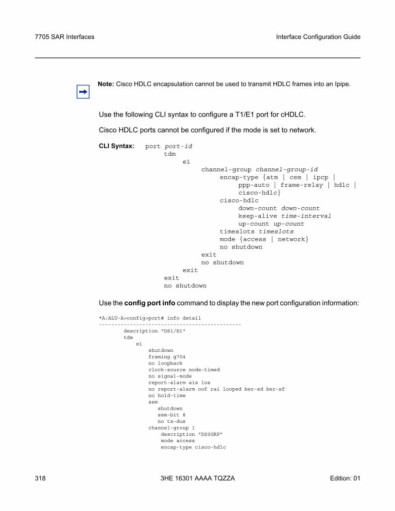
7705 SAR Interfaces
318
Interface Configuration Guide
3HE 16301 AAAA TQZZA Edition: 01
Use the following CLI syntax to configure a T1/E1 port for cHDLC.
Cisco HDLC ports cannot be configured if the mode is set to network.
CLI Syntax: port port-idtdm
e1channel-group channel-group-id
encap-type atm | cem | ipcp | ppp-auto | frame-relay | hdlc | cisco-hdlc
cisco-hdlc down-count down-count keep-alive time-interval up-count up-count
timeslots timeslotsmode access | networkno shutdown
exit no shutdown
exit exit no shutdown
Use the config port info command to display the new port configuration information:
*A:ALU-A>config>port# info detail----------------------------------------------
description "DS1/E1"tdm
e1shutdownframing g704no loopbackclock-source node-timedno signal-modereport-alarm ais losno report-alarm oof rai looped ber-sd ber-sfno hold-timessm
shutdownssm-bit 8no tx-dus
channel-group 1description "DS0GRP"mode accessencap-type cisco-hdlc
Note: Cisco HDLC encapsulation cannot be used to transmit HDLC frames into an Ipipe.
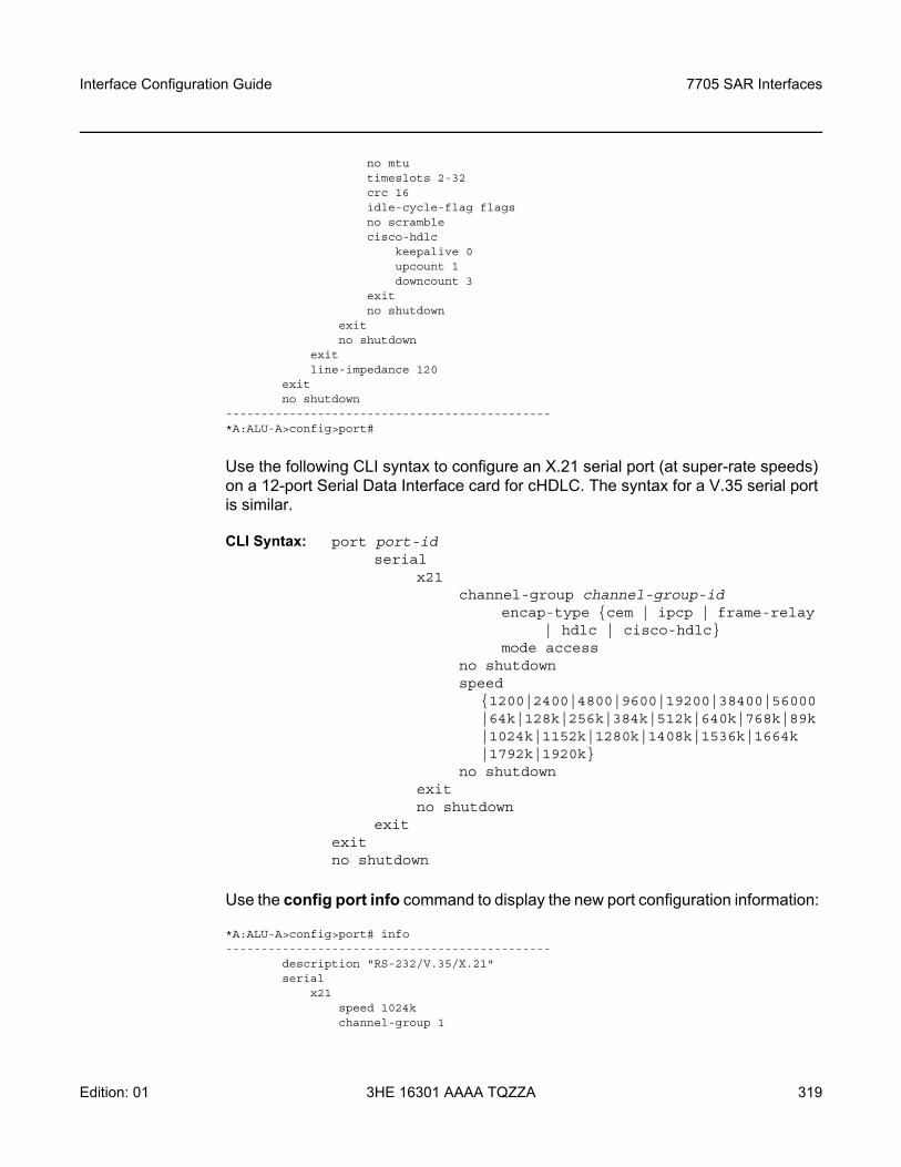
Interface Configuration Guide 7705 SAR Interfaces
Edition: 01 3HE 16301 AAAA TQZZA 319
no mtutimeslots 2-32crc 16idle-cycle-flag flagsno scramblecisco-hdlc
keepalive 0upcount 1downcount 3
exitno shutdown
exitno shutdown
exitline-impedance 120
exitno shutdown
----------------------------------------------*A:ALU-A>config>port#
Use the following CLI syntax to configure an X.21 serial port (at super-rate speeds) on a 12-port Serial Data Interface card for cHDLC. The syntax for a V.35 serial port is similar.
CLI Syntax: port port-id serial
x21channel-group channel-group-id
encap-type cem | ipcp | frame-relay | hdlc | cisco-hdlc
mode access no shutdown speed
1200|2400|4800|9600|19200|38400|56000|64k|128k|256k|384k|512k|640k|768k|89k|1024k|1152k|1280k|1408k|1536k|1664k |1792k|1920k
no shutdown exit no shutdown
exit exit no shutdown
Use the config port info command to display the new port configuration information:
*A:ALU-A>config>port# info----------------------------------------------
description "RS-232/V.35/X.21"serial
x21speed 1024kchannel-group 1
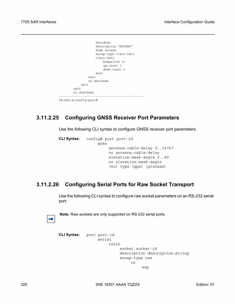
7705 SAR Interfaces
320
Interface Configuration Guide
3HE 16301 AAAA TQZZA Edition: 01
shutdowndescription "DS0GRP"mode accessencap-type cisco-hdlccisco-hdlc
keepalive 10up-count 1down-count 3
exitexitno shutdown
exitexitno shutdown
----------------------------------------------*A:ALU-A>config>port#
3.11.2.25 Configuring GNSS Receiver Port Parameters
Use the following CLI syntax to configure GNSS receiver port parameters.
CLI Syntax: config# port port-id gnss
antenna-cable-delay 0..32767no antenna-cable-delayelevation-mask-angle 0..89no elevation-mask-angle[no] type [gps] [glonass]
3.11.2.26 Configuring Serial Ports for Raw Socket Transport
Use the following CLI syntax to configure raw socket parameters on an RS-232 serial port.
CLI Syntax: port port-id serial
rs232socket socket-iddescription description-stringencap-type raw
rxeop
Note: Raw sockets are only supported on RS-232 serial ports.
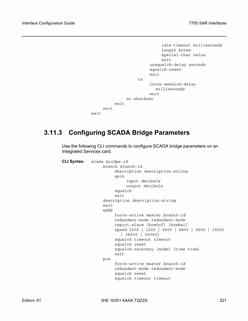
Interface Configuration Guide 7705 SAR Interfaces
Edition: 01 3HE 16301 AAAA TQZZA 321
idle-timeout millisecondslength bytesspecial-char valueexit
unsquelch-delay secondssquelch-resetexit
txinter-session-delay
millisecondsexit
no shutdownexit
exitexit
3.11.3 Configuring SCADA Bridge Parameters
Use the following CLI commands to configure SCADA bridge parameters on an Integrated Services card.
CLI Syntax: scada bridge-idbranch branch-id
description description-stringgain
input decibelsoutput decibels
squelchexit
description description-stringexit mddb
force-active master branch-idredundant-mode redundant-modereport-alarm [hcmOof] [hcmRai]speed 600 | 1200 | 2400 | 4800 | 9600 | 19200
| 38400 | 56000squelch timeout timeoutsquelch resetsquelch-recovery [mode] [time time]exit
pcmforce-active master branch-idredundant-mode redundant-modesquelch resetsquelch timeout timeout
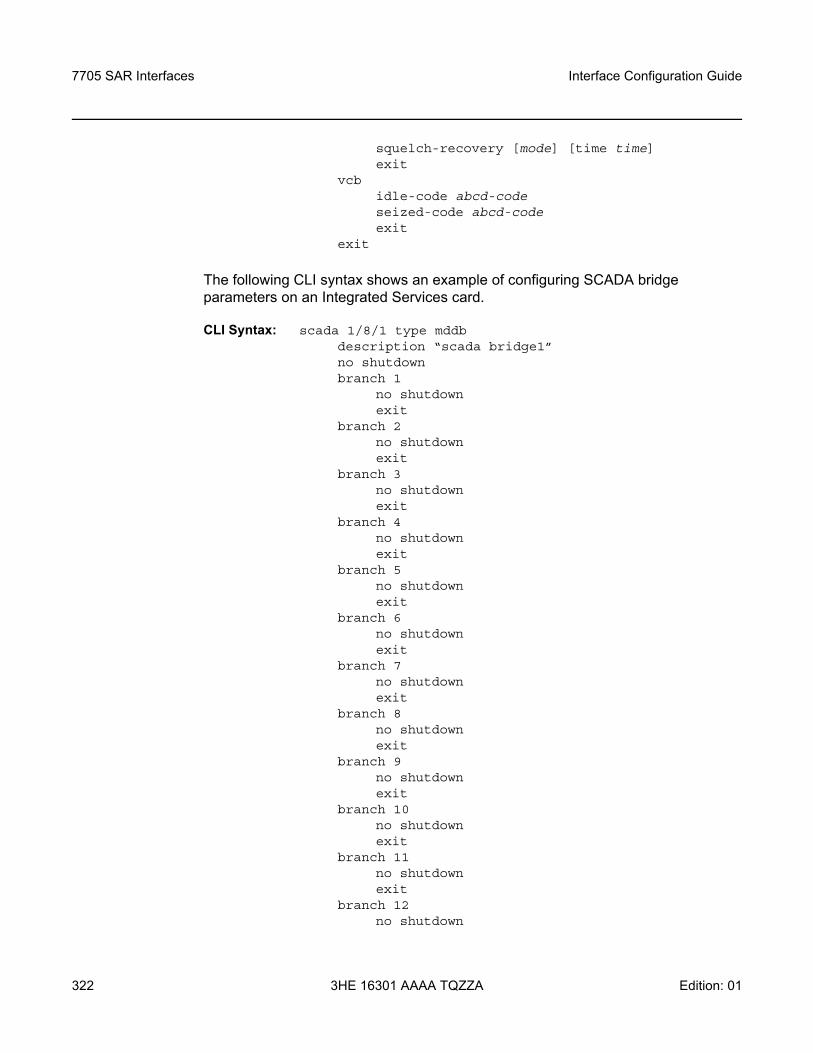
7705 SAR Interfaces
322
Interface Configuration Guide
3HE 16301 AAAA TQZZA Edition: 01
squelch-recovery [mode] [time time]exit
vcbidle-code abcd-codeseized-code abcd-codeexit
exit
The following CLI syntax shows an example of configuring SCADA bridge parameters on an Integrated Services card.
CLI Syntax: scada 1/8/1 type mddbdescription “scada bridge1”no shutdownbranch 1
no shutdownexit
branch 2no shutdownexit
branch 3no shutdownexit
branch 4no shutdownexit
branch 5no shutdownexit
branch 6no shutdownexit
branch 7no shutdownexit
branch 8no shutdownexit
branch 9no shutdownexit
branch 10no shutdownexit
branch 11no shutdownexit
branch 12no shutdown
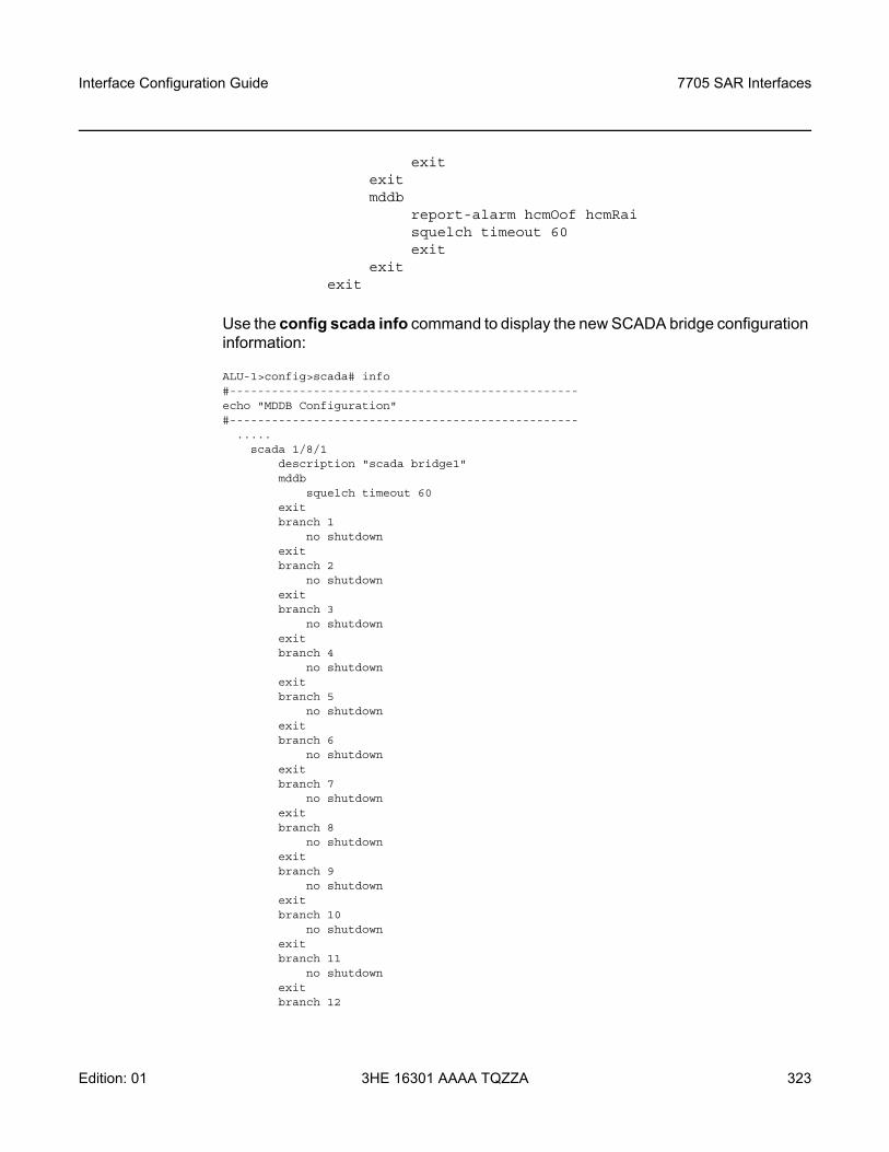
Interface Configuration Guide 7705 SAR Interfaces
Edition: 01 3HE 16301 AAAA TQZZA 323
exit exitmddb
report-alarm hcmOof hcmRaisquelch timeout 60exit
exit exit
Use the config scada info command to display the new SCADA bridge configuration information:
ALU-1>config>scada# info#--------------------------------------------------echo "MDDB Configuration"#--------------------------------------------------
.....scada 1/8/1
description "scada bridge1"mddb
squelch timeout 60exitbranch 1
no shutdownexitbranch 2
no shutdownexitbranch 3
no shutdownexitbranch 4
no shutdownexitbranch 5
no shutdownexitbranch 6
no shutdownexitbranch 7
no shutdownexitbranch 8
no shutdownexitbranch 9
no shutdownexitbranch 10
no shutdownexitbranch 11
no shutdownexitbranch 12

7705 SAR Interfaces
324
Interface Configuration Guide
3HE 16301 AAAA TQZZA Edition: 01
no shutdownexit
exit.....
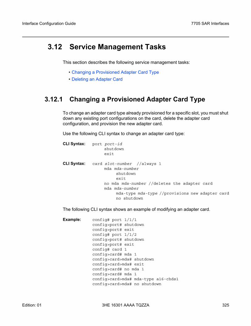
Interface Configuration Guide 7705 SAR Interfaces
Edition: 01 3HE 16301 AAAA TQZZA 325
3.12 Service Management Tasks
This section describes the following service management tasks:
• Changing a Provisioned Adapter Card Type• Deleting an Adapter Card
3.12.1 Changing a Provisioned Adapter Card Type
To change an adapter card type already provisioned for a specific slot, you must shut down any existing port configurations on the card, delete the adapter card configuration, and provision the new adapter card.
Use the following CLI syntax to change an adapter card type:
CLI Syntax: port port-idshutdownexit
CLI Syntax: card slot-number //always 1mda mda-number
shutdownexit
no mda mda-number //deletes the adapter cardmda mda-number
mda-type mda-type //provisions new adapter cardno shutdown
The following CLI syntax shows an example of modifying an adapter card.
Example: config# port 1/1/1 config>port# shutdownconfig>port# exitconfig# port 1/1/2 config>port# shutdownconfig>port# exitconfig# card 1config>card# mda 1config>card>mda# shutdownconfig>card>mda# exitconfig>card# no mda 1config>card# mda 1config>card>mda# mda-type a16-chds1config>card>mda# no shutdown
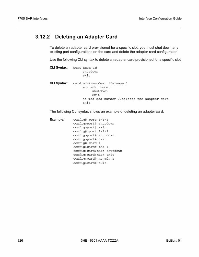
7705 SAR Interfaces
326
Interface Configuration Guide
3HE 16301 AAAA TQZZA Edition: 01
3.12.2 Deleting an Adapter Card
To delete an adapter card provisioned for a specific slot, you must shut down any existing port configurations on the card and delete the adapter card configuration.
Use the following CLI syntax to delete an adapter card provisioned for a specific slot.
CLI Syntax: port port-idshutdownexit
CLI Syntax: card slot-number //always 1mda mda-number
shutdownexit
no mda mda-number //deletes the adapter cardexit
The following CLI syntax shows an example of deleting an adapter card.
Example: config# port 1/1/1 config>port# shutdownconfig>port# exitconfig# port 1/1/2 config>port# shutdownconfig>port# exitconfig# card 1config>card# mda 1config>card>mda# shutdownconfig>card>mda# exit config>card# no mda 1
config>card# exit
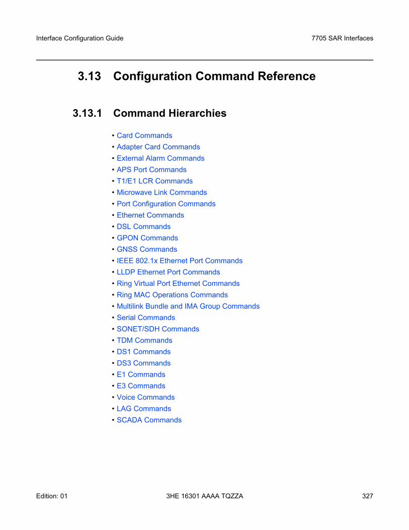
Interface Configuration Guide 7705 SAR Interfaces
Edition: 01 3HE 16301 AAAA TQZZA 327
3.13 Configuration Command Reference
3.13.1 Command Hierarchies
• Card Commands• Adapter Card Commands• External Alarm Commands• APS Port Commands• T1/E1 LCR Commands • Microwave Link Commands• Port Configuration Commands• Ethernet Commands• DSL Commands• GPON Commands• GNSS Commands• IEEE 802.1x Ethernet Port Commands• LLDP Ethernet Port Commands• Ring Virtual Port Ethernet Commands• Ring MAC Operations Commands• Multilink Bundle and IMA Group Commands• Serial Commands• SONET/SDH Commands• TDM Commands• DS1 Commands• DS3 Commands• E1 Commands• E3 Commands• Voice Commands• LAG Commands• SCADA Commands
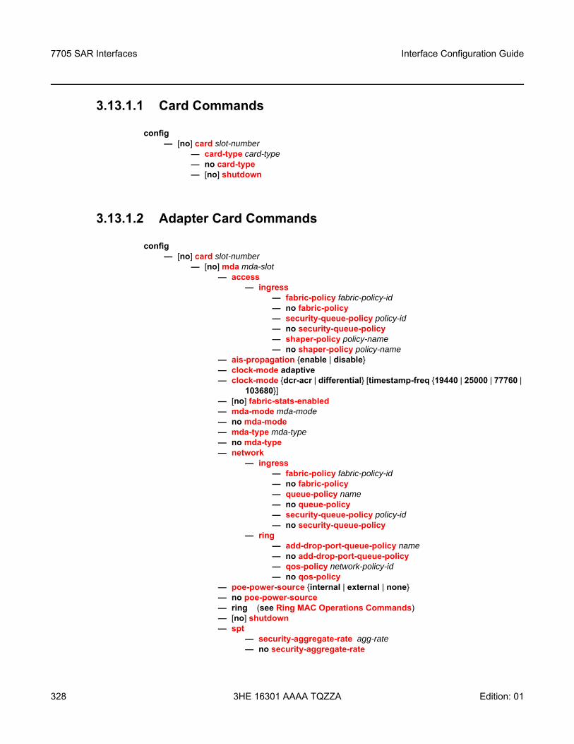
7705 SAR Interfaces
328
Interface Configuration Guide
3HE 16301 AAAA TQZZA Edition: 01
3.13.1.1 Card Commands
config— [no] card slot-number
— card-type card-type— no card-type— [no] shutdown
3.13.1.2 Adapter Card Commands
config— [no] card slot-number
— [no] mda mda-slot— access
— ingress— fabric-policy fabric-policy-id— no fabric-policy— security-queue-policy policy-id— no security-queue-policy — shaper-policy policy-name — no shaper-policy policy-name
— ais-propagation enable | disable— clock-mode adaptive— clock-mode dcr-acr | differential [timestamp-freq 19440 | 25000 | 77760 |
103680]— [no] fabric-stats-enabled— mda-mode mda-mode — no mda-mode — mda-type mda-type— no mda-type— network
— ingress— fabric-policy fabric-policy-id— no fabric-policy— queue-policy name— no queue-policy— security-queue-policy policy-id— no security-queue-policy
— ring— add-drop-port-queue-policy name— no add-drop-port-queue-policy— qos-policy network-policy-id— no qos-policy
— poe-power-source internal | external | none— no poe-power-source— ring (see Ring MAC Operations Commands)— [no] shutdown— spt
— security-aggregate-rate agg-rate — no security-aggregate-rate
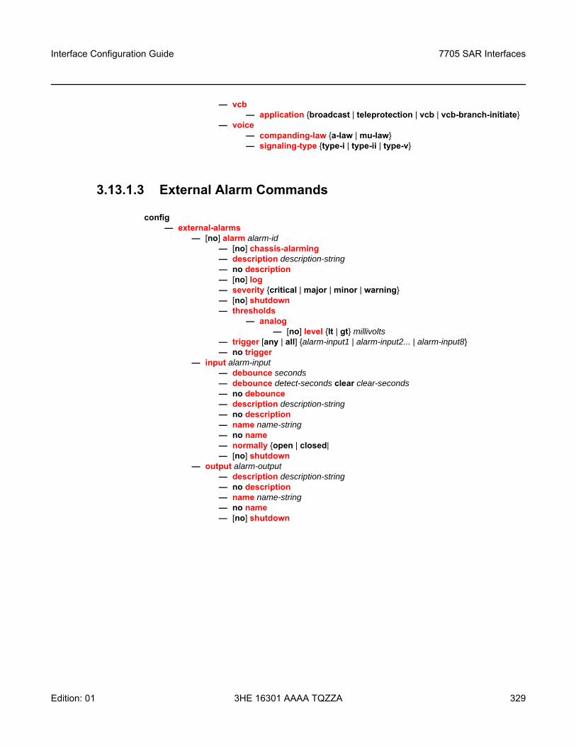
Interface Configuration Guide 7705 SAR Interfaces
Edition: 01 3HE 16301 AAAA TQZZA 329
— vcb— application broadcast | teleprotection | vcb | vcb-branch-initiate
— voice— companding-law a-law | mu-law— signaling-type type-i | type-ii | type-v
3.13.1.3 External Alarm Commands
config— external-alarms
— [no] alarm alarm-id— [no] chassis-alarming— description description-string— no description — [no] log— severity critical | major | minor | warning— [no] shutdown— thresholds
— analog— [no] level lt | gt millivolts
— trigger [any | all] alarm-input1 | alarm-input2... | alarm-input8— no trigger
— input alarm-input— debounce seconds— debounce detect-seconds clear clear-seconds— no debounce— description description-string— no description— name name-string— no name— normally open | closed|— [no] shutdown
— output alarm-output— description description-string— no description— name name-string— no name— [no] shutdown
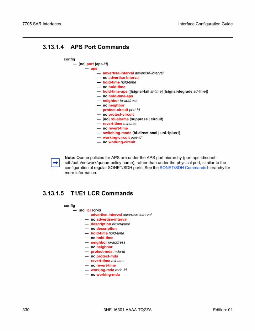
7705 SAR Interfaces
330
Interface Configuration Guide
3HE 16301 AAAA TQZZA Edition: 01
3.13.1.4 APS Port Commands
config— [no] port aps-id
— aps— advertise-interval advertise-interval— no advertise-interval — hold-time hold-time— no hold-time — hold-time-aps ([lsignal-fail sf-time] [lsignal-degrade sd-time]— no hold-time-aps— neighbor ip-address— no neighbor— protect-circuit port-id— no protect-circuit— [no] rdi-alarms suppress | circuit — revert-time minutes— no revert-time— switching-mode bi-directional | uni-1plus1— working-circuit port-id— no working-circuit
3.13.1.5 T1/E1 LCR Commands
config— [no] lcr lcr-id
— advertise-interval advertise-interval— no advertise-interval — description description— no description — hold-time hold-time— no hold-time — neighbor ip-address— no neighbor— protect-mda mda-id— no protect-mda— revert-time minutes— no revert-time— working-mda mda-id— no working-mda
Note: Queue policies for APS are under the APS port hierarchy (port aps-id/sonet-sdh/path/network/queue-policy name), rather than under the physical port, similar to the configuration of regular SONET/SDH ports. See the SONET/SDH Commands hierarchy for more information.
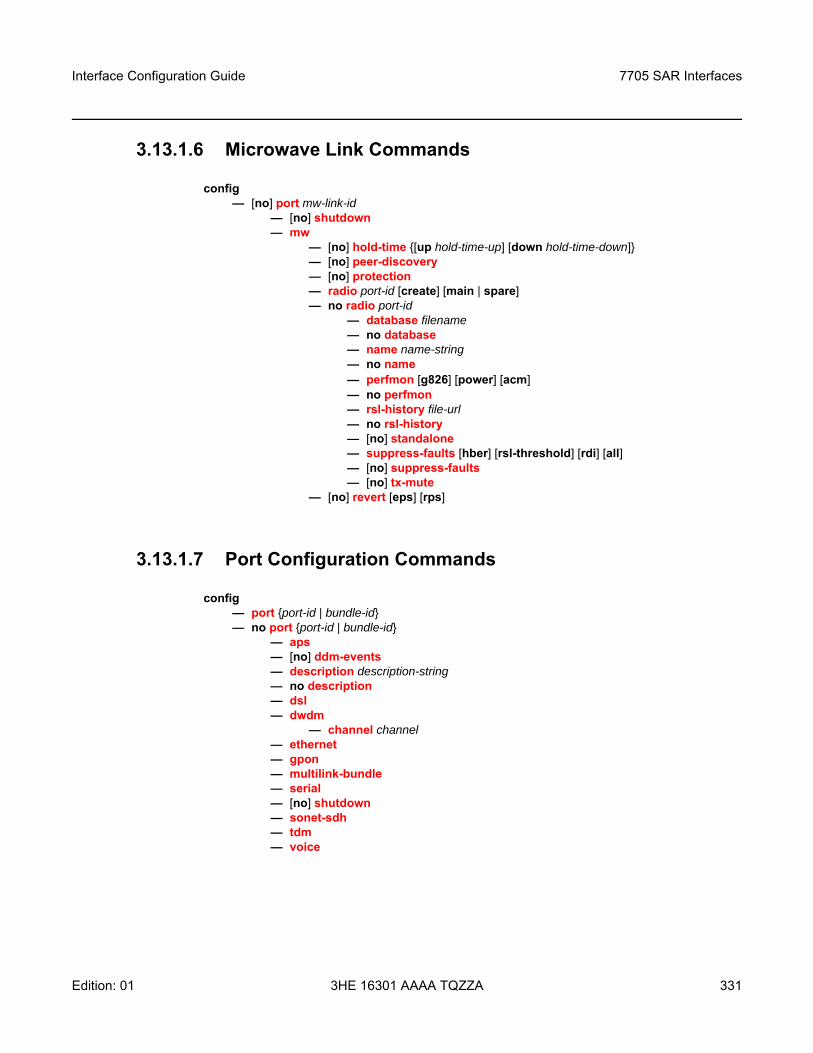
Interface Configuration Guide 7705 SAR Interfaces
Edition: 01 3HE 16301 AAAA TQZZA 331
3.13.1.6 Microwave Link Commands
config— [no] port mw-link-id
— [no] shutdown— mw
— [no] hold-time [up hold-time-up] [down hold-time-down]— [no] peer-discovery— [no] protection— radio port-id [create] [main | spare]— no radio port-id
— database filename— no database— name name-string— no name— perfmon [g826] [power] [acm] — no perfmon — rsl-history file-url— no rsl-history — [no] standalone — suppress-faults [hber] [rsl-threshold] [rdi] [all]— [no] suppress-faults — [no] tx-mute
— [no] revert [eps] [rps]
3.13.1.7 Port Configuration Commands
config — port port-id | bundle-id— no port port-id | bundle-id
— aps — [no] ddm-events— description description-string— no description— dsl — dwdm
— channel channel— ethernet— gpon — multilink-bundle— serial— [no] shutdown— sonet-sdh— tdm— voice
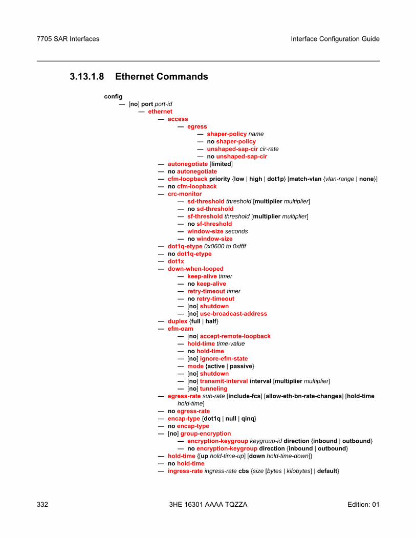
7705 SAR Interfaces
332
Interface Configuration Guide
3HE 16301 AAAA TQZZA Edition: 01
3.13.1.8 Ethernet Commands
config — [no] port port-id
— ethernet— access
— egress — shaper-policy name — no shaper-policy— unshaped-sap-cir cir-rate — no unshaped-sap-cir
— autonegotiate [limited]— no autonegotiate— cfm-loopback priority low | high | dot1p [match-vlan vlan-range | none] — no cfm-loopback — crc-monitor
— sd-threshold threshold [multiplier multiplier]— no sd-threshold— sf-threshold threshold [multiplier multiplier]— no sf-threshold— window-size seconds— no window-size
— dot1q-etype 0x0600 to 0xffff— no dot1q-etype— dot1x— down-when-looped
— keep-alive timer— no keep-alive— retry-timeout timer— no retry-timeout— [no] shutdown— [no] use-broadcast-address
— duplex full | half— efm-oam
— [no] accept-remote-loopback— hold-time time-value— no hold-time— [no] ignore-efm-state— mode active | passive— [no] shutdown— [no] transmit-interval interval [multiplier multiplier]— [no] tunneling
— egress-rate sub-rate [include-fcs] [allow-eth-bn-rate-changes] [hold-time hold-time]
— no egress-rate— encap-type dot1q | null | qinq— no encap-type— [no] group-encryption
— encryption-keygroup keygroup-id direction inbound | outbound— no encryption-keygroup direction inbound | outbound
— hold-time [up hold-time-up] [down hold-time-down]— no hold-time— ingress-rate ingress-rate cbs size [bytes | kilobytes] | default
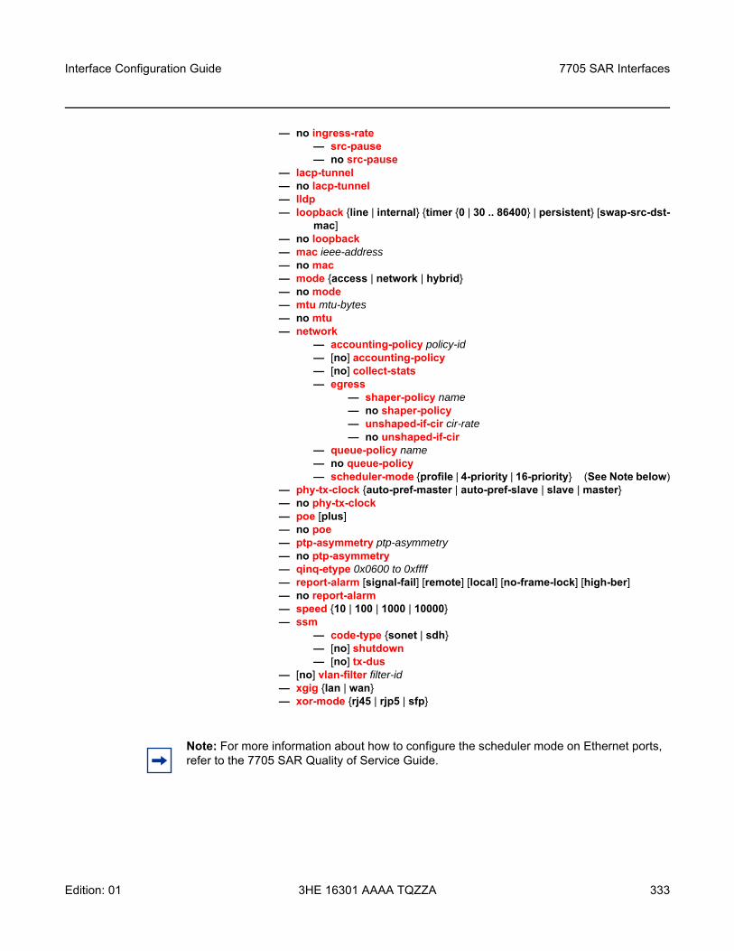
Interface Configuration Guide 7705 SAR Interfaces
Edition: 01 3HE 16301 AAAA TQZZA 333
— no ingress-rate— src-pause— no src-pause
— lacp-tunnel— no lacp-tunnel— lldp— loopback line | internal timer 0 | 30 .. 86400 | persistent [swap-src-dst-
mac] — no loopback— mac ieee-address— no mac— mode access | network | hybrid— no mode— mtu mtu-bytes— no mtu— network
— accounting-policy policy-id — [no] accounting-policy — [no] collect-stats — egress
— shaper-policy name— no shaper-policy— unshaped-if-cir cir-rate— no unshaped-if-cir
— queue-policy name— no queue-policy— scheduler-mode profile | 4-priority | 16-priority (See Note below)
— phy-tx-clock auto-pref-master | auto-pref-slave | slave | master — no phy-tx-clock — poe [plus]— no poe — ptp-asymmetry ptp-asymmetry — no ptp-asymmetry — qinq-etype 0x0600 to 0xffff— report-alarm [signal-fail] [remote] [local] [no-frame-lock] [high-ber]— no report-alarm — speed 10 | 100 | 1000 | 10000— ssm
— code-type sonet | sdh— [no] shutdown— [no] tx-dus
— [no] vlan-filter filter-id— xgig lan | wan— xor-mode rj45 | rjp5 | sfp
Note: For more information about how to configure the scheduler mode on Ethernet ports, refer to the 7705 SAR Quality of Service Guide.
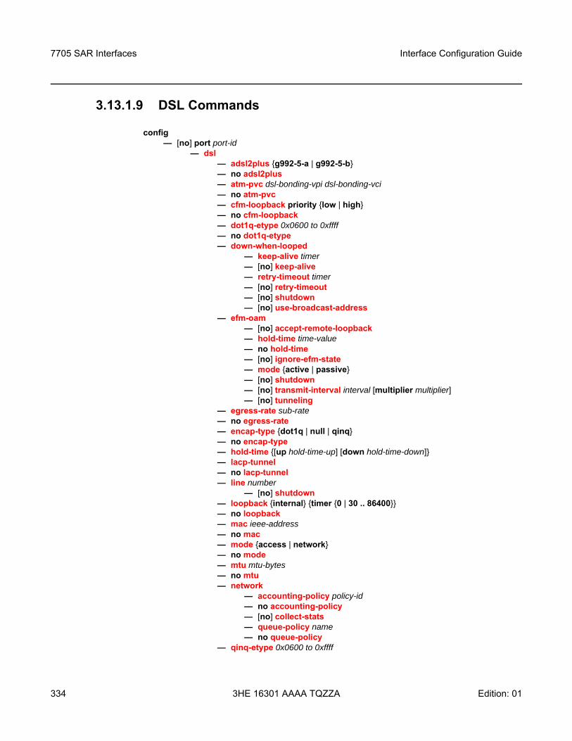
7705 SAR Interfaces
334
Interface Configuration Guide
3HE 16301 AAAA TQZZA Edition: 01
3.13.1.9 DSL Commands
config — [no] port port-id
— dsl— adsl2plus g992-5-a | g992-5-b— no adsl2plus— atm-pvc dsl-bonding-vpi dsl-bonding-vci — no atm-pvc — cfm-loopback priority low | high— no cfm-loopback — dot1q-etype 0x0600 to 0xffff— no dot1q-etype— down-when-looped
— keep-alive timer— [no] keep-alive— retry-timeout timer— [no] retry-timeout— [no] shutdown— [no] use-broadcast-address
— efm-oam— [no] accept-remote-loopback— hold-time time-value— no hold-time— [no] ignore-efm-state— mode active | passive— [no] shutdown— [no] transmit-interval interval [multiplier multiplier]— [no] tunneling
— egress-rate sub-rate— no egress-rate— encap-type dot1q | null | qinq— no encap-type— hold-time [up hold-time-up] [down hold-time-down]— lacp-tunnel— no lacp-tunnel— line number
— [no] shutdown— loopback internal timer 0 | 30 .. 86400 — no loopback— mac ieee-address— no mac— mode access | network— no mode— mtu mtu-bytes— no mtu— network
— accounting-policy policy-id — no accounting-policy — [no] collect-stats — queue-policy name— no queue-policy
— qinq-etype 0x0600 to 0xffff
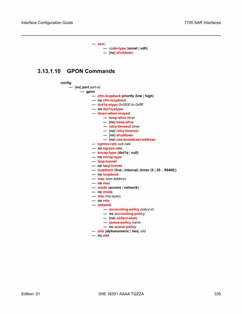
Interface Configuration Guide 7705 SAR Interfaces
Edition: 01 3HE 16301 AAAA TQZZA 335
— ssm— code-type sonet | sdh— [no] shutdown
3.13.1.10 GPON Commands
config — [no] port port-id
— gpon— cfm-loopback priority low | high — no cfm-loopback — dot1q-etype 0x0600 to 0xffff— no dot1q-etype— down-when-looped
— keep-alive timer— [no] keep-alive— retry-timeout timer— [no] retry-timeout— [no] shutdown— [no] use-broadcast-address
— egress-rate sub-rate— no egress-rate— encap-type dot1q | null— no encap-type— lacp-tunnel— no lacp-tunnel— loopback line | internal timer 0 | 30 .. 86400— no loopback— mac ieee-address— no mac— mode access | network— no mode— mtu mtu-bytes— no mtu— network
— accounting-policy policy-id — no accounting-policy — [no] collect-stats — queue-policy name— no queue-policy
— slid alphanumeric | hex slid— no slid
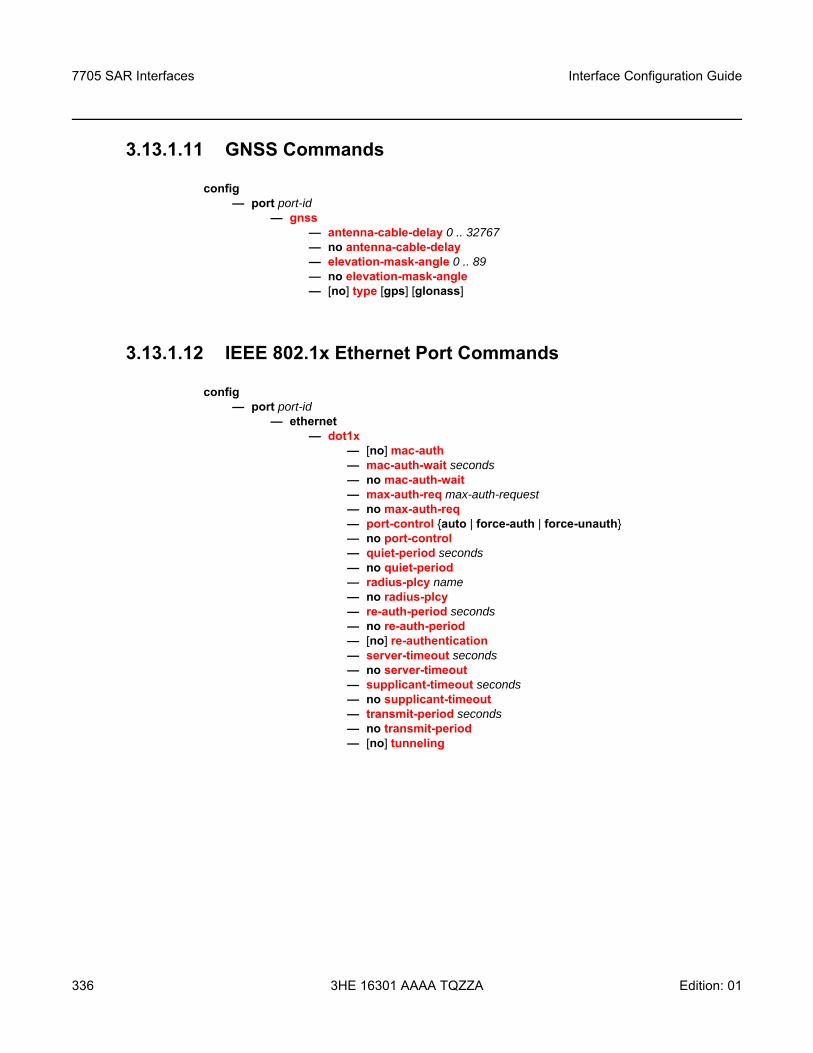
7705 SAR Interfaces
336
Interface Configuration Guide
3HE 16301 AAAA TQZZA Edition: 01
3.13.1.11 GNSS Commands
config— port port-id
— gnss— antenna-cable-delay 0 .. 32767— no antenna-cable-delay— elevation-mask-angle 0 .. 89— no elevation-mask-angle— [no] type [gps] [glonass]
3.13.1.12 IEEE 802.1x Ethernet Port Commands
config— port port-id
— ethernet— dot1x
— [no] mac-auth— mac-auth-wait seconds— no mac-auth-wait— max-auth-req max-auth-request— no max-auth-req— port-control auto | force-auth | force-unauth— no port-control — quiet-period seconds— no quiet-period— radius-plcy name— no radius-plcy— re-auth-period seconds— no re-auth-period— [no] re-authentication— server-timeout seconds— no server-timeout— supplicant-timeout seconds— no supplicant-timeout— transmit-period seconds— no transmit-period— [no] tunneling
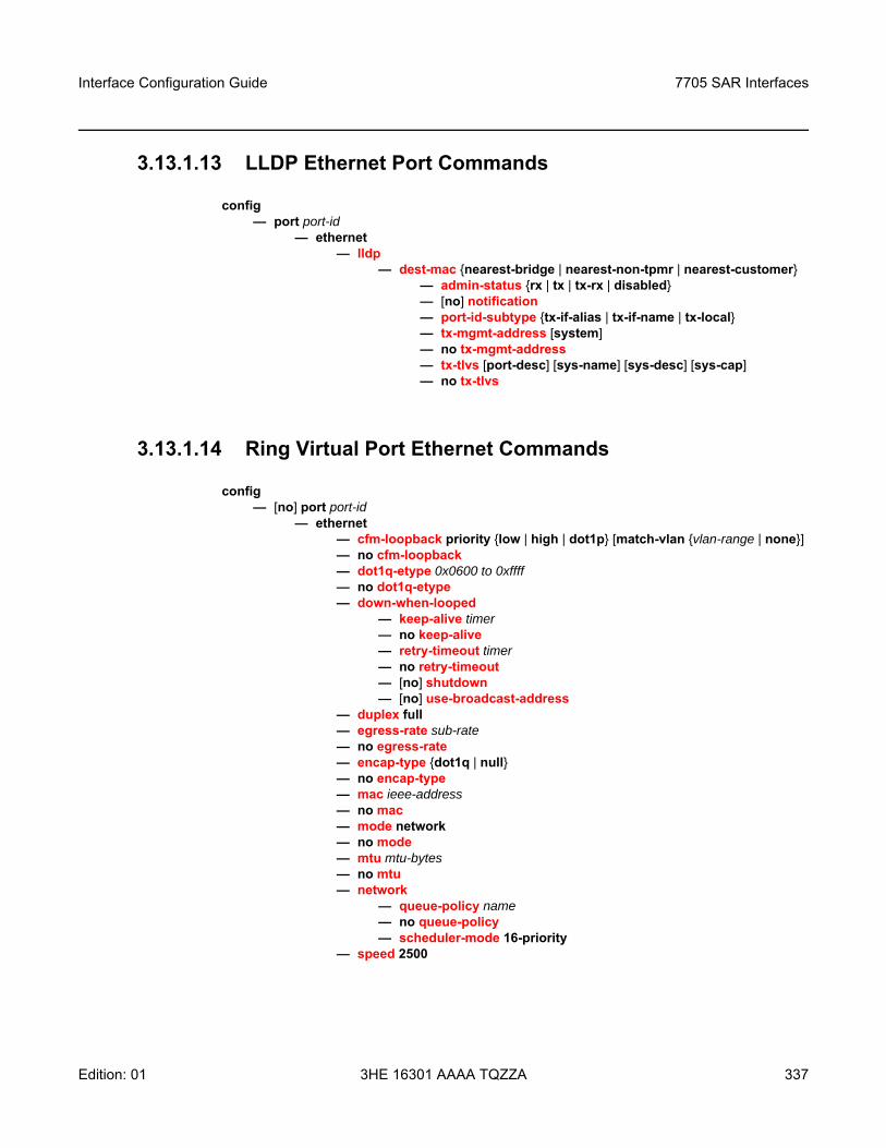
Interface Configuration Guide 7705 SAR Interfaces
Edition: 01 3HE 16301 AAAA TQZZA 337
3.13.1.13 LLDP Ethernet Port Commands
config— port port-id
— ethernet— lldp
— dest-mac nearest-bridge | nearest-non-tpmr | nearest-customer— admin-status rx | tx | tx-rx | disabled— [no] notification— port-id-subtype tx-if-alias | tx-if-name | tx-local— tx-mgmt-address [system]— no tx-mgmt-address— tx-tlvs [port-desc] [sys-name] [sys-desc] [sys-cap]— no tx-tlvs
3.13.1.14 Ring Virtual Port Ethernet Commands
config — [no] port port-id
— ethernet— cfm-loopback priority low | high | dot1p [match-vlan vlan-range | none] — no cfm-loopback — dot1q-etype 0x0600 to 0xffff— no dot1q-etype— down-when-looped
— keep-alive timer— no keep-alive— retry-timeout timer— no retry-timeout— [no] shutdown— [no] use-broadcast-address
— duplex full — egress-rate sub-rate— no egress-rate— encap-type dot1q | null— no encap-type— mac ieee-address— no mac— mode network— no mode— mtu mtu-bytes— no mtu— network
— queue-policy name— no queue-policy— scheduler-mode 16-priority
— speed 2500
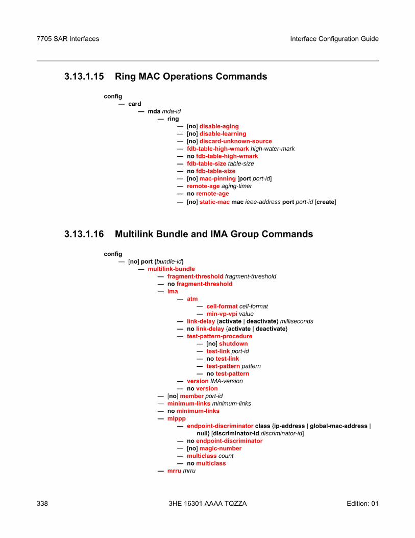
7705 SAR Interfaces
338
Interface Configuration Guide
3HE 16301 AAAA TQZZA Edition: 01
3.13.1.15 Ring MAC Operations Commands
config — card
— mda mda-id— ring
— [no] disable-aging— [no] disable-learning— [no] discard-unknown-source — fdb-table-high-wmark high-water-mark— no fdb-table-high-wmark — fdb-table-size table-size— no fdb-table-size — [no] mac-pinning [port port-id]— remote-age aging-timer— no remote-age— [no] static-mac mac ieee-address port port-id [create]
3.13.1.16 Multilink Bundle and IMA Group Commands
config— [no] port bundle-id
— multilink-bundle— fragment-threshold fragment-threshold— no fragment-threshold— ima
— atm— cell-format cell-format— min-vp-vpi value
— link-delay activate | deactivate milliseconds— no link-delay activate | deactivate— test-pattern-procedure
— [no] shutdown— test-link port-id— no test-link— test-pattern pattern— no test-pattern
— version IMA-version— no version
— [no] member port-id— minimum-links minimum-links— no minimum-links— mlppp
— endpoint-discriminator class ip-address | global-mac-address | null [discriminator-id discriminator-id]
— no endpoint-discriminator — [no] magic-number — multiclass count— no multiclass
— mrru mrru
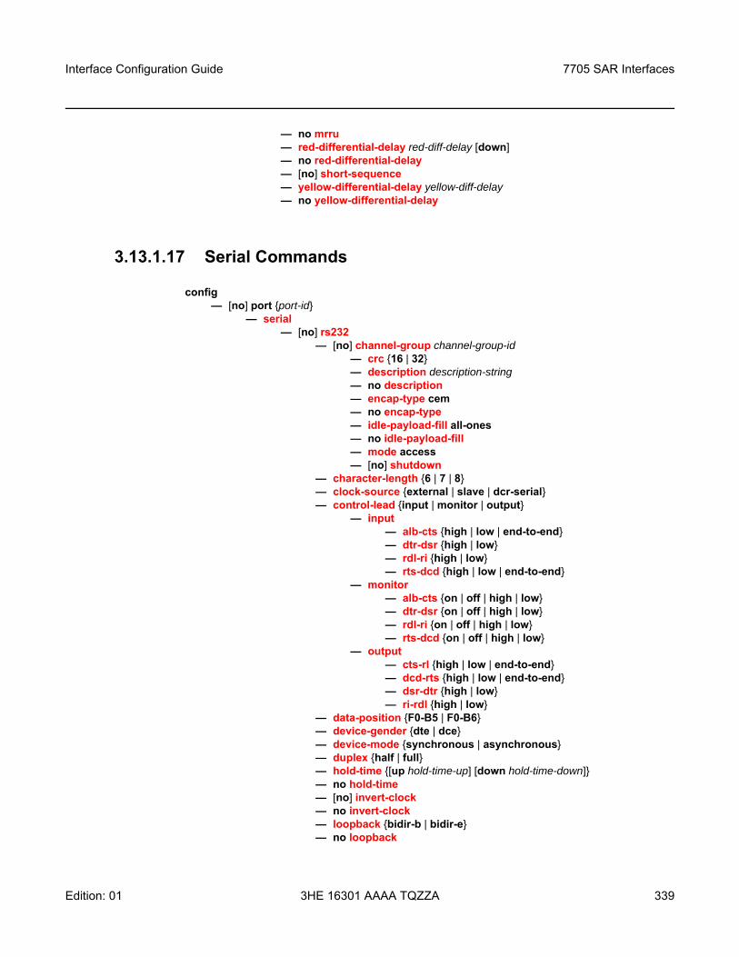
Interface Configuration Guide 7705 SAR Interfaces
Edition: 01 3HE 16301 AAAA TQZZA 339
— no mrru— red-differential-delay red-diff-delay [down]— no red-differential-delay— [no] short-sequence— yellow-differential-delay yellow-diff-delay— no yellow-differential-delay
3.13.1.17 Serial Commands
config — [no] port port-id
— serial— [no] rs232
— [no] channel-group channel-group-id— crc 16 | 32— description description-string— no description — encap-type cem— no encap-type— idle-payload-fill all-ones — no idle-payload-fill— mode access — [no] shutdown
— character-length 6 | 7 | 8— clock-source external | slave | dcr-serial— control-lead input | monitor | output
— input— alb-cts high | low | end-to-end— dtr-dsr high | low— rdl-ri high | low— rts-dcd high | low | end-to-end
— monitor— alb-cts on | off | high | low— dtr-dsr on | off | high | low— rdl-ri on | off | high | low— rts-dcd on | off | high | low
— output— cts-rl high | low | end-to-end— dcd-rts high | low | end-to-end— dsr-dtr high | low— ri-rdl high | low
— data-position F0-B5 | F0-B6— device-gender dte | dce— device-mode synchronous | asynchronous— duplex half | full— hold-time [up hold-time-up] [down hold-time-down]— no hold-time— [no] invert-clock— no invert-clock— loopback bidir-b | bidir-e— no loopback
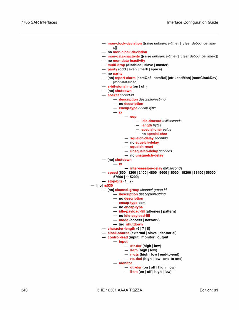
7705 SAR Interfaces
340
Interface Configuration Guide
3HE 16301 AAAA TQZZA Edition: 01
— mon-clock-deviation [raise debounce-time-r] [clear debounce-time-c]
— no mon-clock-deviation— mon-data-inactivity [raise debounce-time-r] [clear debounce-time-c]— no mon-data-inactivity— multi-drop disabled | slave | master— parity odd | even | mark | space— no parity— [no] report-alarm [hcmOof | hcmRai] [ctrlLeadMon] [monClockDev]
[monDataInac]— s-bit-signaling on | off— [no] shutdown— socket socket-id
— description description-string— no description — encap-type encap-type— rx
— eop— idle-timeout milliseconds— length bytes— special-char value— no special-char
— squelch-delay seconds— no squelch-delay — squelch-reset— unsquelch-delay seconds— no unsquelch-delay
— [no] shutdown— tx
— inter-session-delay milliseconds— speed 600 | 1200 | 2400 | 4800 | 9600 |16000 | 19200 | 38400 | 56000 |
57600 | 115200— stop-bits 1 | 2
— [no] rs530— [no] channel-group channel-group-id
— description description-string— no description — encap-type cem— no encap-type— idle-payload-fill all-ones | pattern— no idle-payload-fill— mode access | network — [no] shutdown
— character-length 6 | 7 | 8— clock-source external | slave | dcr-serial — control-lead input | monitor | output
— input— dtr-dsr high | low— ll-tm high | low— rl-cts high | low | end-to-end— rts-dcd high | low | end-to-end
— monitor— dtr-dsr on | off | high | low— ll-tm on | off | high | low
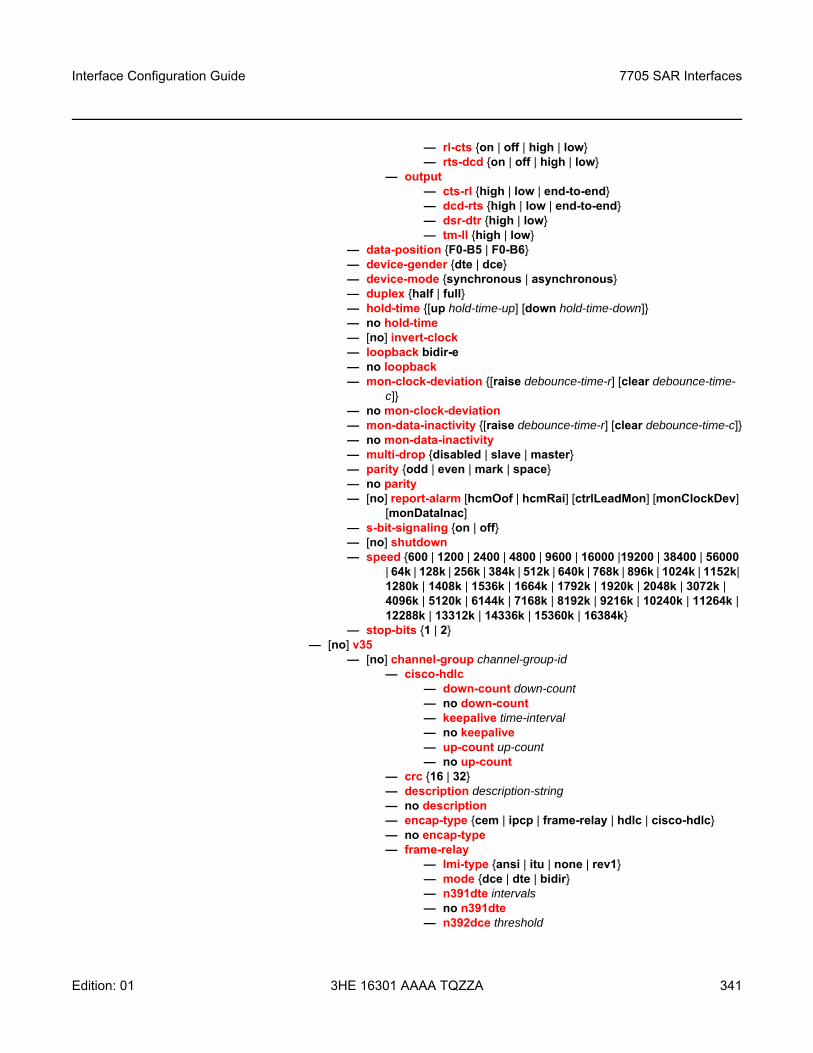
Interface Configuration Guide 7705 SAR Interfaces
Edition: 01 3HE 16301 AAAA TQZZA 341
— rl-cts on | off | high | low— rts-dcd on | off | high | low
— output— cts-rl high | low | end-to-end— dcd-rts high | low | end-to-end— dsr-dtr high | low— tm-ll high | low
— data-position F0-B5 | F0-B6— device-gender dte | dce— device-mode synchronous | asynchronous— duplex half | full— hold-time [up hold-time-up] [down hold-time-down]— no hold-time— [no] invert-clock— loopback bidir-e— no loopback— mon-clock-deviation [raise debounce-time-r] [clear debounce-time-
c]— no mon-clock-deviation— mon-data-inactivity [raise debounce-time-r] [clear debounce-time-c]— no mon-data-inactivity— multi-drop disabled | slave | master— parity odd | even | mark | space— no parity— [no] report-alarm [hcmOof | hcmRai] [ctrlLeadMon] [monClockDev]
[monDataInac]— s-bit-signaling on | off— [no] shutdown— speed 600 | 1200 | 2400 | 4800 | 9600 | 16000 |19200 | 38400 | 56000
| 64k | 128k | 256k | 384k | 512k | 640k | 768k | 896k | 1024k | 1152k| 1280k | 1408k | 1536k | 1664k | 1792k | 1920k | 2048k | 3072k | 4096k | 5120k | 6144k | 7168k | 8192k | 9216k | 10240k | 11264k | 12288k | 13312k | 14336k | 15360k | 16384k
— stop-bits 1 | 2— [no] v35
— [no] channel-group channel-group-id— cisco-hdlc
— down-count down-count— no down-count — keepalive time-interval— no keepalive — up-count up-count— no up-count
— crc 16 | 32— description description-string— no description — encap-type cem | ipcp | frame-relay | hdlc | cisco-hdlc— no encap-type— frame-relay
— lmi-type ansi | itu | none | rev1— mode dce | dte | bidir— n391dte intervals— no n391dte— n392dce threshold
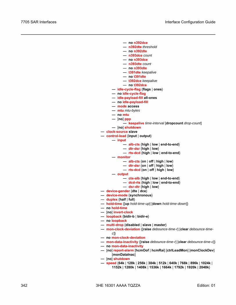
7705 SAR Interfaces
342
Interface Configuration Guide
3HE 16301 AAAA TQZZA Edition: 01
— no n392dce— n392dte threshold— no n392dte— n393dce count— no n393dce— n393dte count— no n393dte— t391dte keepalive— no t391dte— t392dce keepalive— no t392dce
— idle-cycle-flag flags | ones— no idle-cycle-flag— idle-payload-fill all-ones— no idle-payload-fill— mode access — mtu mtu-bytes— no mtu— [no] ppp
— keepalive time-interval [dropcount drop-count]— [no] shutdown
— clock-source slave — control-lead input | output
— input— alb-cts high | low | end-to-end— dtr-dsr high | low— rts-dcd high | low | end-to-end
— monitor— alb-cts on | off | high | low— dtr-dsr on | off | high | low— rts-dcd on | off | high | low
— output— cts-alb high | low | end-to-end— dcd-rts high | low | end-to-end— dsr-dtr high | low
— device-gender dte | dce— device-mode synchronous— duplex half | full— hold-time [up hold-time-up] [down hold-time-down]— no hold-time— [no] invert-clock— loopback bidir-b | bidir-e— no loopback— multi-drop disabled | slave | master— mon-clock-deviation [raise debounce-time-r] [clear debounce-time-
c]— no mon-clock-deviation— mon-data-inactivity [raise debounce-time-r] [clear debounce-time-c]— no mon-data-inactivity— [no] report-alarm [hcmOof | hcmRai] [ctrlLeadMon] [monClockDev]
[monDataInac]— [no] shutdown— speed 64k | 128k | 256k | 384k | 512k | 640k | 768k | 896k | 1024k |
1152k | 1280k | 1408k | 1536k | 1664k | 1792k | 1920k | 2048k
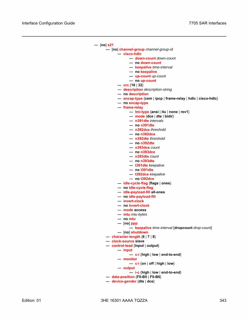
Interface Configuration Guide 7705 SAR Interfaces
Edition: 01 3HE 16301 AAAA TQZZA 343
— [no] x21— [no] channel-group channel-group-id
— cisco-hdlc— down-count down-count— no down-count — keepalive time-interval— no keepalive— up-count up-count— no up-count
— crc 16 | 32— description description-string— no description — encap-type cem | ipcp | frame-relay | hdlc | cisco-hdlc— no encap-type— frame-relay
— lmi-type ansi | itu | none | rev1— mode dce | dte | bidir— n391dte intervals— no n391dte— n392dce threshold— no n392dce— n392dte threshold— no n392dte— n393dce count— no n393dce— n393dte count— no n393dte— t391dte keepalive— no t391dte— t392dce keepalive— no t392dce
— idle-cycle-flag flags | ones— no idle-cycle-flag— idle-payload-fill all-ones— no idle-payload-fill— invert-clock— no invert-clock— mode access — mtu mtu-bytes— no mtu— [no] ppp
— keepalive time-interval [dropcount drop-count]— [no] shutdown
— character-length 6 | 7 | 8— clock-source slave — control-lead input | output
— input— c-i high | low | end-to-end
— monitor— c-i on | off | high | low
— output— i-c high | low | end-to-end
— data-position F0-B5 | F0-B6— device-gender dte | dce
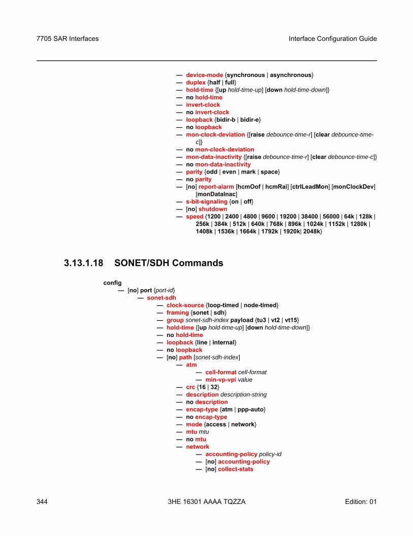
7705 SAR Interfaces
344
Interface Configuration Guide
3HE 16301 AAAA TQZZA Edition: 01
— device-mode synchronous | asynchronous— duplex half | full— hold-time [up hold-time-up] [down hold-time-down]— no hold-time— invert-clock— no invert-clock— loopback bidir-b | bidir-e— no loopback— mon-clock-deviation [raise debounce-time-r] [clear debounce-time-
c]— no mon-clock-deviation— mon-data-inactivity [raise debounce-time-r] [clear debounce-time-c]— no mon-data-inactivity— parity odd | even | mark | space— no parity— [no] report-alarm [hcmOof | hcmRai] [ctrlLeadMon] [monClockDev]
[monDataInac]— s-bit-signaling on | off— [no] shutdown— speed 1200 | 2400 | 4800 | 9600 | 19200 | 38400 | 56000 | 64k | 128k |
256k | 384k | 512k | 640k | 768k | 896k | 1024k | 1152k | 1280k | 1408k | 1536k | 1664k | 1792k | 1920k| 2048k
3.13.1.18 SONET/SDH Commands
config — [no] port port-id
— sonet-sdh— clock-source loop-timed | node-timed— framing sonet | sdh— group sonet-sdh-index payload tu3 | vt2 | vt15— hold-time [up hold-time-up] [down hold-time-down]— no hold-time— loopback line | internal— no loopback— [no] path [sonet-sdh-index]
— atm— cell-format cell-format— min-vp-vpi value
— crc 16 | 32— description description-string— no description— encap-type atm | ppp-auto— no encap-type— mode access | network— mtu mtu— no mtu— network
— accounting-policy policy-id — [no] accounting-policy — [no] collect-stats
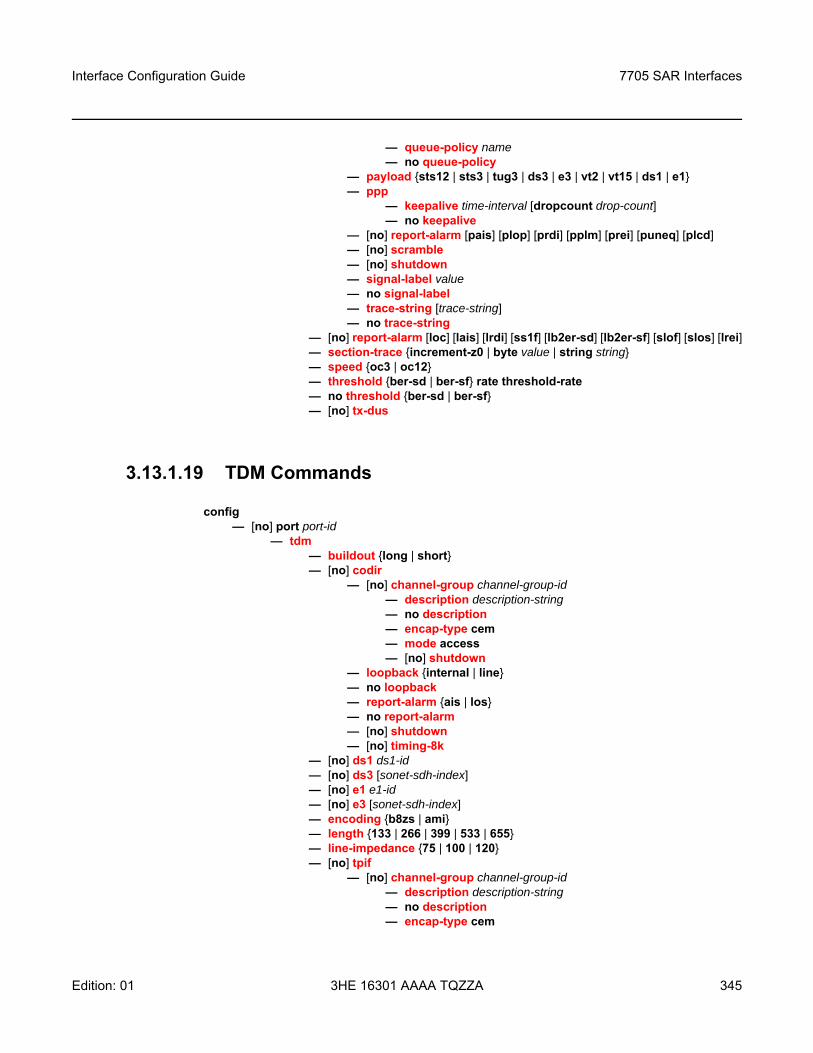
Interface Configuration Guide 7705 SAR Interfaces
Edition: 01 3HE 16301 AAAA TQZZA 345
— queue-policy name— no queue-policy
— payload sts12 | sts3 | tug3 | ds3 | e3 | vt2 | vt15 | ds1 | e1— ppp
— keepalive time-interval [dropcount drop-count]— no keepalive
— [no] report-alarm [pais] [plop] [prdi] [pplm] [prei] [puneq] [plcd] — [no] scramble — [no] shutdown— signal-label value— no signal-label— trace-string [trace-string]— no trace-string
— [no] report-alarm [loc] [lais] [lrdi] [ss1f] [lb2er-sd] [lb2er-sf] [slof] [slos] [lrei]— section-trace increment-z0 | byte value | string string— speed oc3 | oc12— threshold ber-sd | ber-sf rate threshold-rate— no threshold ber-sd | ber-sf— [no] tx-dus
3.13.1.19 TDM Commands
config — [no] port port-id
— tdm — buildout long | short— [no] codir
— [no] channel-group channel-group-id— description description-string— no description— encap-type cem— mode access— [no] shutdown
— loopback internal | line— no loopback— report-alarm ais | los— no report-alarm— [no] shutdown— [no] timing-8k
— [no] ds1 ds1-id— [no] ds3 [sonet-sdh-index]— [no] e1 e1-id— [no] e3 [sonet-sdh-index]— encoding b8zs | ami— length 133 | 266 | 399 | 533 | 655— line-impedance 75 | 100 | 120 — [no] tpif
— [no] channel-group channel-group-id— description description-string— no description — encap-type cem
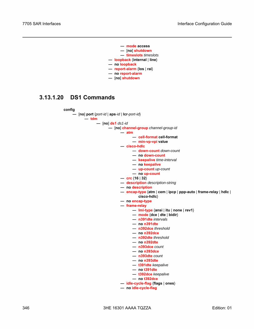
7705 SAR Interfaces
346
Interface Configuration Guide
3HE 16301 AAAA TQZZA Edition: 01
— mode access— [no] shutdown— timeslots timeslots
— loopback internal | line— no loopback— report-alarm los | rai— no report-alarm— [no] shutdown
3.13.1.20 DS1 Commands
config — [no] port port-id | aps-id | lcr-port-id
— tdm— [no] ds1 ds1-id
— [no] channel-group channel-group-id— atm
— cell-format cell-format— min-vp-vpi value
— cisco-hdlc— down-count down-count— no down-count— keepalive time-interval— no keepalive— up-count up-count— no up-count
— crc 16 | 32— description description-string— no description— encap-type atm | cem | ipcp | ppp-auto | frame-relay | hdlc |
cisco-hdlc— no encap-type— frame-relay
— lmi-type ansi | itu | none | rev1— mode dce | dte | bidir— n391dte intervals— no n391dte— n392dce threshold— no n392dce— n392dte threshold— no n392dte— n393dce count— no n393dce— n393dte count— no n393dte— t391dte keepalive— no t391dte— t392dce keepalive— no t392dce
— idle-cycle-flag flags | ones— no idle-cycle-flag
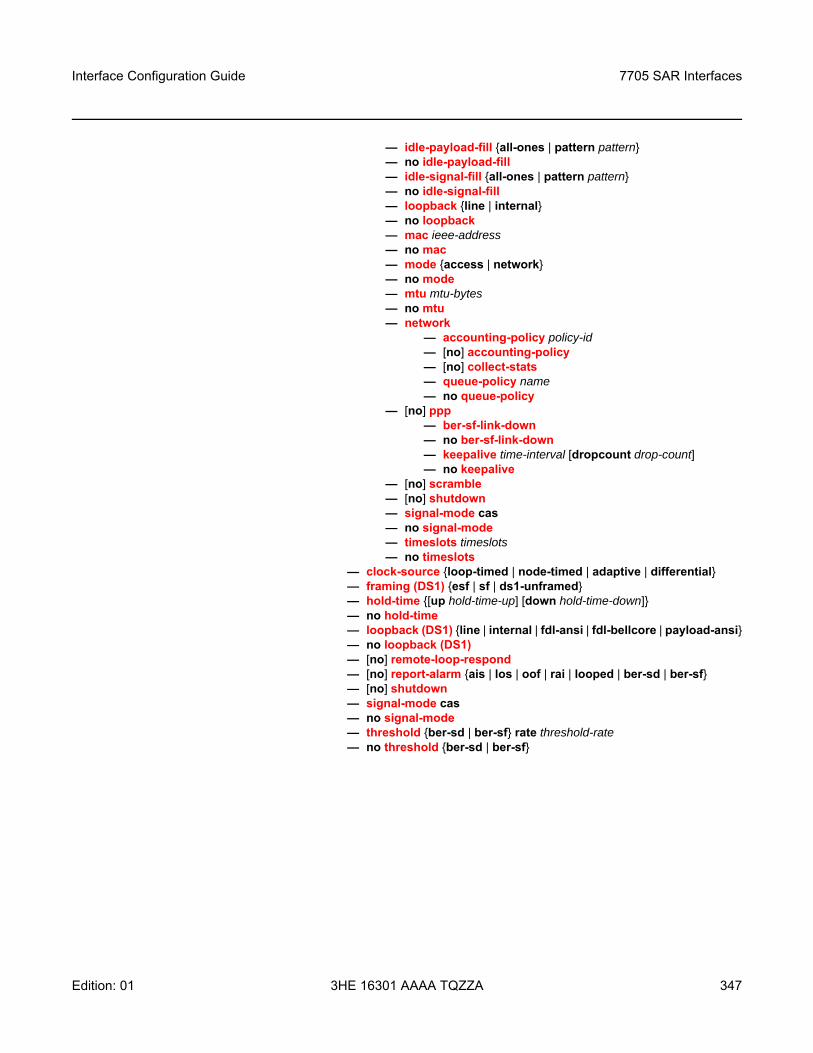
Interface Configuration Guide 7705 SAR Interfaces
Edition: 01 3HE 16301 AAAA TQZZA 347
— idle-payload-fill all-ones | pattern pattern— no idle-payload-fill— idle-signal-fill all-ones | pattern pattern— no idle-signal-fill— loopback line | internal— no loopback— mac ieee-address— no mac— mode access | network— no mode— mtu mtu-bytes— no mtu— network
— accounting-policy policy-id — [no] accounting-policy — [no] collect-stats — queue-policy name— no queue-policy
— [no] ppp— ber-sf-link-down — no ber-sf-link-down— keepalive time-interval [dropcount drop-count]— no keepalive
— [no] scramble— [no] shutdown— signal-mode cas— no signal-mode— timeslots timeslots— no timeslots
— clock-source loop-timed | node-timed | adaptive | differential — framing (DS1) esf | sf | ds1-unframed— hold-time [up hold-time-up] [down hold-time-down]— no hold-time— loopback (DS1) line | internal | fdl-ansi | fdl-bellcore | payload-ansi— no loopback (DS1)— [no] remote-loop-respond— [no] report-alarm ais | los | oof | rai | looped | ber-sd | ber-sf— [no] shutdown— signal-mode cas— no signal-mode— threshold ber-sd | ber-sf rate threshold-rate— no threshold ber-sd | ber-sf
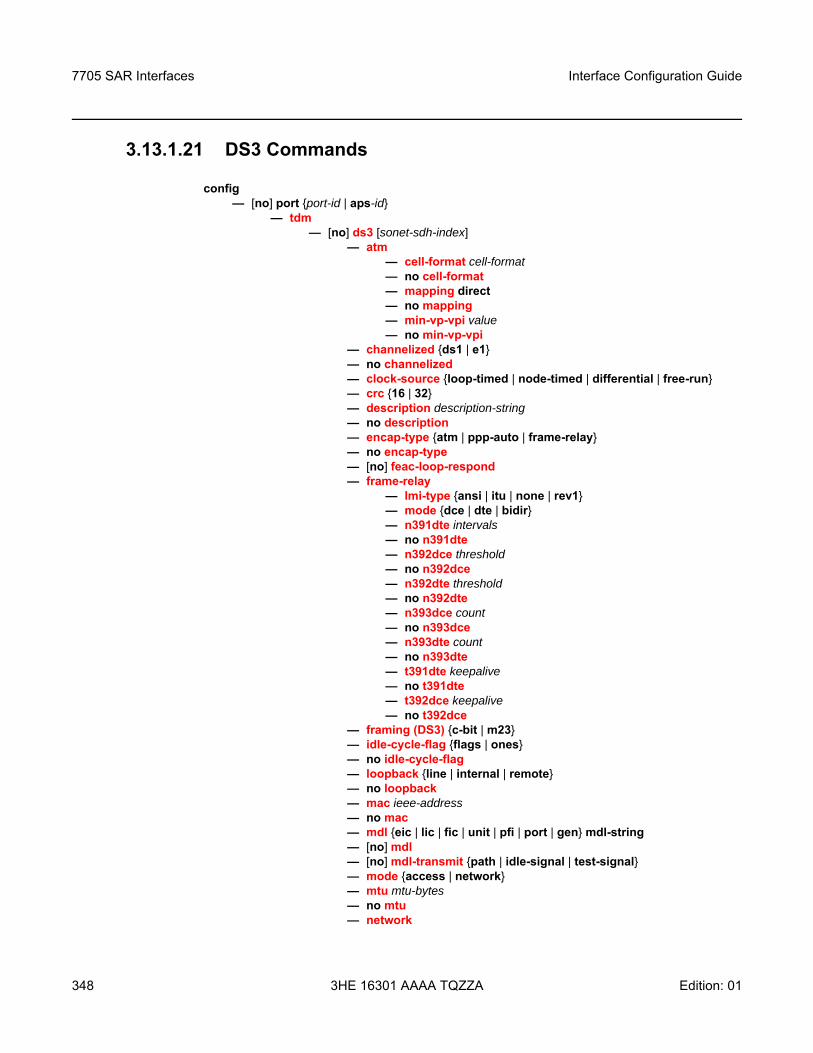
7705 SAR Interfaces
348
Interface Configuration Guide
3HE 16301 AAAA TQZZA Edition: 01
3.13.1.21 DS3 Commands
config — [no] port port-id | aps-id
— tdm— [no] ds3 [sonet-sdh-index]
— atm— cell-format cell-format— no cell-format — mapping direct — no mapping— min-vp-vpi value— no min-vp-vpi
— channelized ds1 | e1— no channelized— clock-source loop-timed | node-timed | differential | free-run — crc 16 | 32 — description description-string— no description— encap-type atm | ppp-auto | frame-relay— no encap-type— [no] feac-loop-respond— frame-relay
— lmi-type ansi | itu | none | rev1— mode dce | dte | bidir— n391dte intervals— no n391dte— n392dce threshold— no n392dce— n392dte threshold— no n392dte— n393dce count— no n393dce— n393dte count— no n393dte— t391dte keepalive— no t391dte— t392dce keepalive— no t392dce
— framing (DS3) c-bit | m23— idle-cycle-flag flags | ones— no idle-cycle-flag— loopback line | internal | remote— no loopback— mac ieee-address— no mac— mdl eic | lic | fic | unit | pfi | port | gen mdl-string— [no] mdl— [no] mdl-transmit path | idle-signal | test-signal— mode access | network— mtu mtu-bytes— no mtu— network
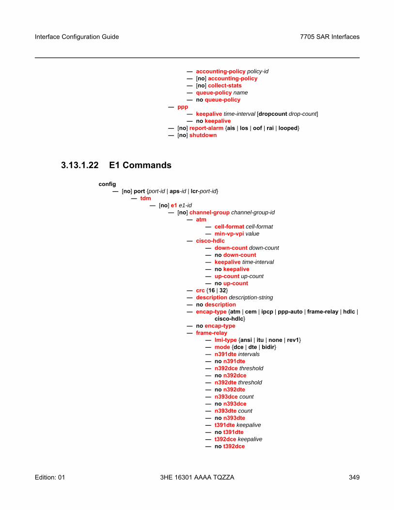
Interface Configuration Guide 7705 SAR Interfaces
Edition: 01 3HE 16301 AAAA TQZZA 349
— accounting-policy policy-id — [no] accounting-policy — [no] collect-stats — queue-policy name— no queue-policy
— ppp— keepalive time-interval [dropcount drop-count]— no keepalive
— [no] report-alarm ais | los | oof | rai | looped— [no] shutdown
3.13.1.22 E1 Commands
config — [no] port port-id | aps-id | lcr-port-id
— tdm— [no] e1 e1-id
— [no] channel-group channel-group-id— atm
— cell-format cell-format— min-vp-vpi value
— cisco-hdlc— down-count down-count— no down-count— keepalive time-interval— no keepalive— up-count up-count— no up-count
— crc 16 | 32— description description-string— no description— encap-type atm | cem | ipcp | ppp-auto | frame-relay | hdlc |
cisco-hdlc— no encap-type— frame-relay
— lmi-type ansi | itu | none | rev1— mode dce | dte | bidir— n391dte intervals— no n391dte— n392dce threshold— no n392dce— n392dte threshold— no n392dte— n393dce count— no n393dce— n393dte count— no n393dte— t391dte keepalive— no t391dte— t392dce keepalive— no t392dce
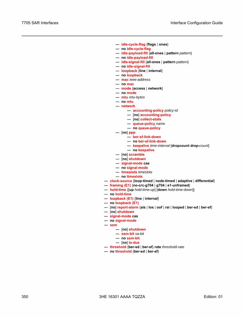
7705 SAR Interfaces
350
Interface Configuration Guide
3HE 16301 AAAA TQZZA Edition: 01
— idle-cycle-flag flags | ones— no idle-cycle-flag— idle-payload-fill all-ones | pattern pattern— no idle-payload-fill— idle-signal-fill all-ones | pattern pattern— no idle-signal-fill— loopback line | internal— no loopback— mac ieee-address— no mac— mode access | network— no mode— mtu mtu-bytes— no mtu— network
— accounting-policy policy-id — [no] accounting-policy — [no] collect-stats — queue-policy name— no queue-policy
— [no] ppp— ber-sf-link-down — no ber-sf-link-down— keepalive time-interval [dropcount drop-count]— no keepalive
— [no] scramble— [no] shutdown— signal-mode cas— no signal-mode— timeslots timeslots— no timeslots
— clock-source loop-timed | node-timed | adaptive | differential— framing (E1) no-crc-g704 | g704 | e1-unframed— hold-time [up hold-time-up] [down hold-time-down]— no hold-time— loopback (E1) line | internal— no loopback (E1)— [no] report-alarm ais | los | oof | rai | looped | ber-sd | ber-sf— [no] shutdown— signal-mode cas— no signal-mode— ssm
— [no] shutdown— ssm-bit sa-bit— no ssm-bit— [no] tx-dus
— threshold ber-sd | ber-sf rate threshold-rate— no threshold ber-sd | ber-sf
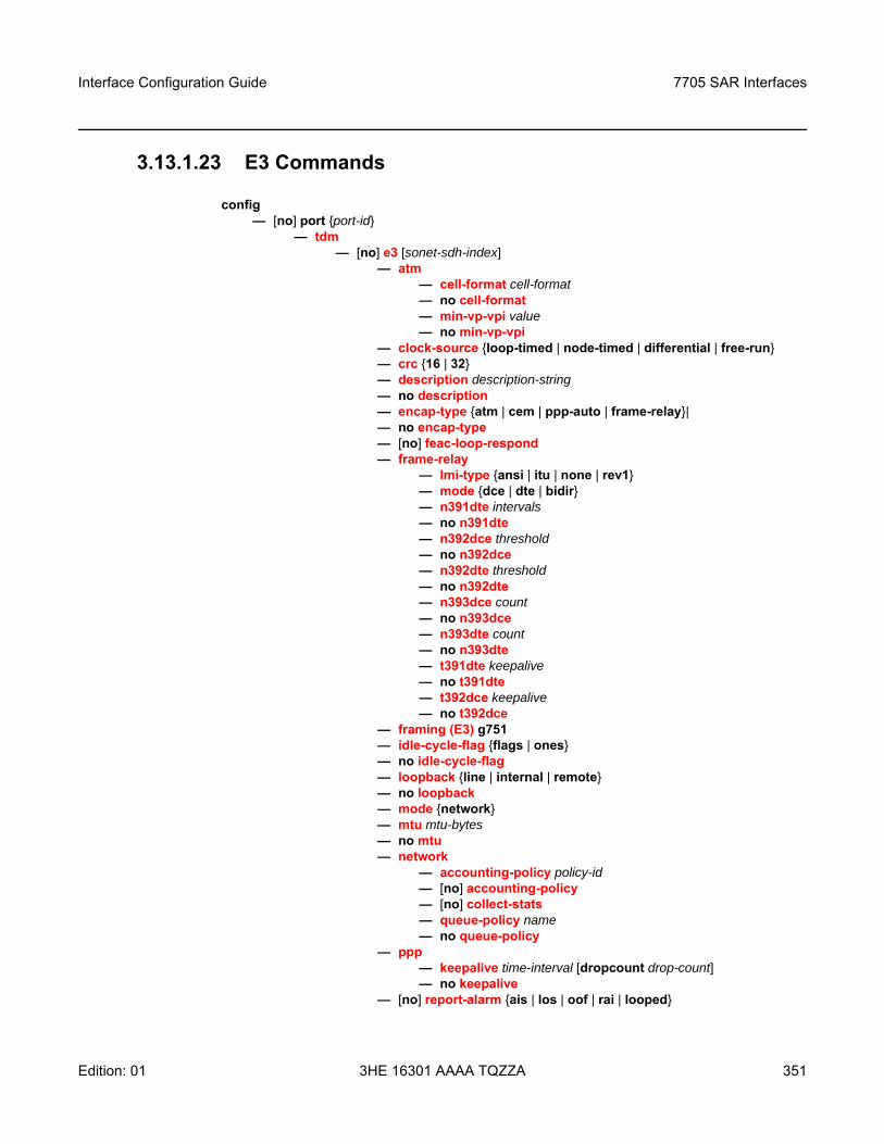
Interface Configuration Guide 7705 SAR Interfaces
Edition: 01 3HE 16301 AAAA TQZZA 351
3.13.1.23 E3 Commands
config— [no] port port-id
— tdm— [no] e3 [sonet-sdh-index]
— atm— cell-format cell-format— no cell-format — min-vp-vpi value— no min-vp-vpi
— clock-source loop-timed | node-timed | differential | free-run— crc 16 | 32 — description description-string— no description— encap-type atm | cem | ppp-auto | frame-relay|— no encap-type— [no] feac-loop-respond— frame-relay
— lmi-type ansi | itu | none | rev1— mode dce | dte | bidir— n391dte intervals— no n391dte— n392dce threshold— no n392dce— n392dte threshold— no n392dte— n393dce count— no n393dce— n393dte count— no n393dte— t391dte keepalive— no t391dte— t392dce keepalive— no t392dce
— framing (E3) g751— idle-cycle-flag flags | ones— no idle-cycle-flag— loopback line | internal | remote— no loopback— mode network— mtu mtu-bytes— no mtu— network
— accounting-policy policy-id — [no] accounting-policy — [no] collect-stats — queue-policy name— no queue-policy
— ppp— keepalive time-interval [dropcount drop-count]— no keepalive
— [no] report-alarm ais | los | oof | rai | looped
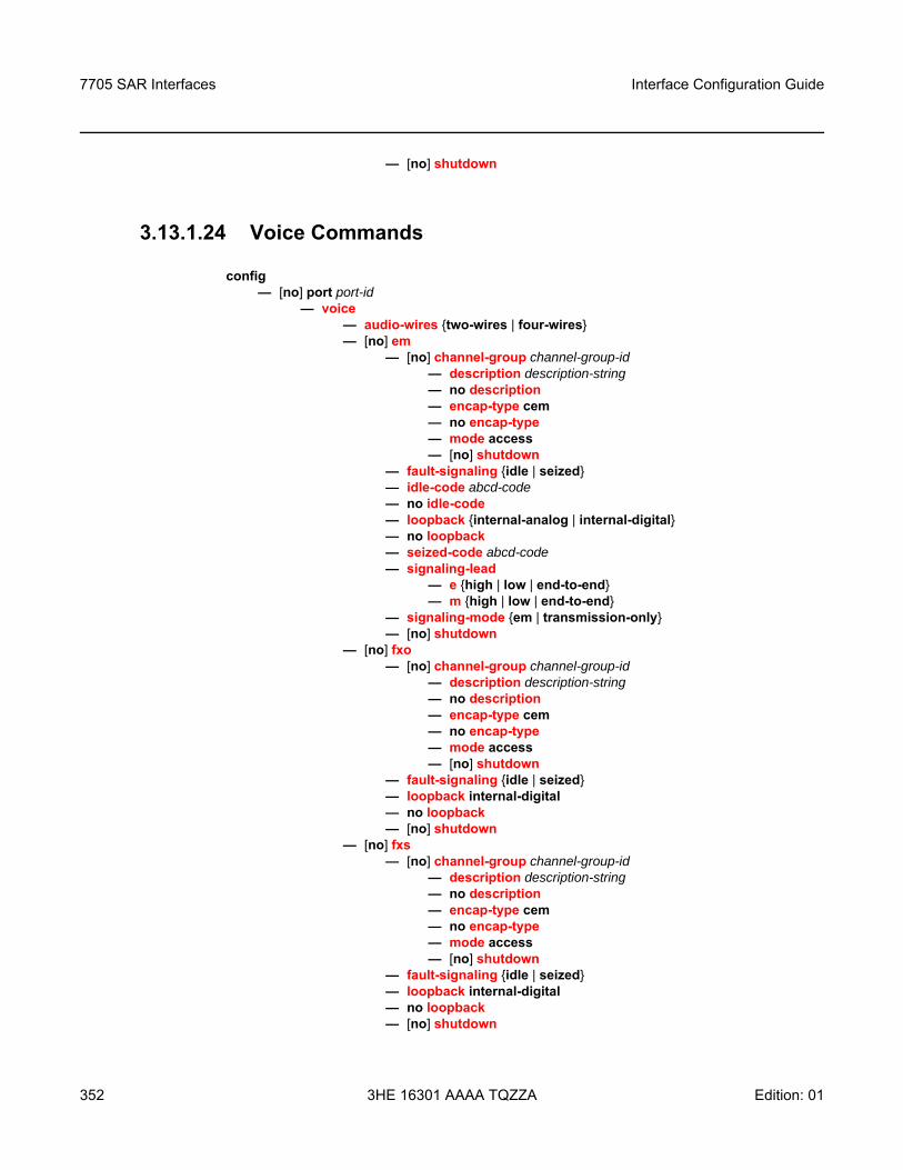
7705 SAR Interfaces
352
Interface Configuration Guide
3HE 16301 AAAA TQZZA Edition: 01
— [no] shutdown
3.13.1.24 Voice Commands
config— [no] port port-id
— voice— audio-wires two-wires | four-wires— [no] em
— [no] channel-group channel-group-id— description description-string— no description— encap-type cem— no encap-type — mode access— [no] shutdown
— fault-signaling idle | seized— idle-code abcd-code— no idle-code— loopback internal-analog | internal-digital— no loopback— seized-code abcd-code— signaling-lead
— e high | low | end-to-end— m high | low | end-to-end
— signaling-mode em | transmission-only— [no] shutdown
— [no] fxo— [no] channel-group channel-group-id
— description description-string— no description— encap-type cem— no encap-type — mode access— [no] shutdown
— fault-signaling idle | seized— loopback internal-digital— no loopback— [no] shutdown
— [no] fxs— [no] channel-group channel-group-id
— description description-string— no description— encap-type cem— no encap-type — mode access— [no] shutdown
— fault-signaling idle | seized— loopback internal-digital— no loopback— [no] shutdown
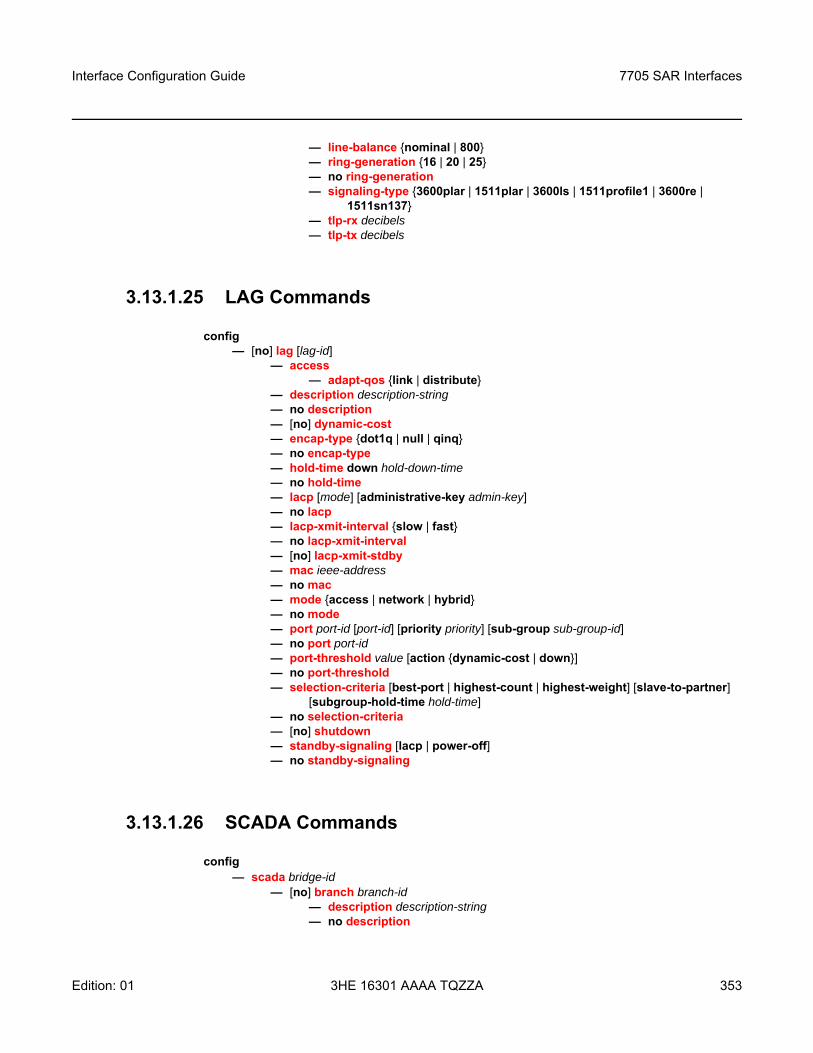
Interface Configuration Guide 7705 SAR Interfaces
Edition: 01 3HE 16301 AAAA TQZZA 353
— line-balance nominal | 800— ring-generation 16 | 20 | 25— no ring-generation— signaling-type 3600plar | 1511plar | 3600ls | 1511profile1 | 3600re |
1511sn137— tlp-rx decibels— tlp-tx decibels
3.13.1.25 LAG Commands
config— [no] lag [lag-id]
— access— adapt-qos link | distribute
— description description-string— no description— [no] dynamic-cost— encap-type dot1q | null | qinq— no encap-type— hold-time down hold-down-time— no hold-time— lacp [mode] [administrative-key admin-key]— no lacp— lacp-xmit-interval slow | fast— no lacp-xmit-interval— [no] lacp-xmit-stdby— mac ieee-address— no mac— mode access | network | hybrid— no mode— port port-id [port-id] [priority priority] [sub-group sub-group-id]— no port port-id— port-threshold value [action dynamic-cost | down]— no port-threshold— selection-criteria [best-port | highest-count | highest-weight] [slave-to-partner]
[subgroup-hold-time hold-time]— no selection-criteria— [no] shutdown— standby-signaling [lacp | power-off]— no standby-signaling
3.13.1.26 SCADA Commands
config— scada bridge-id
— [no] branch branch-id— description description-string— no description
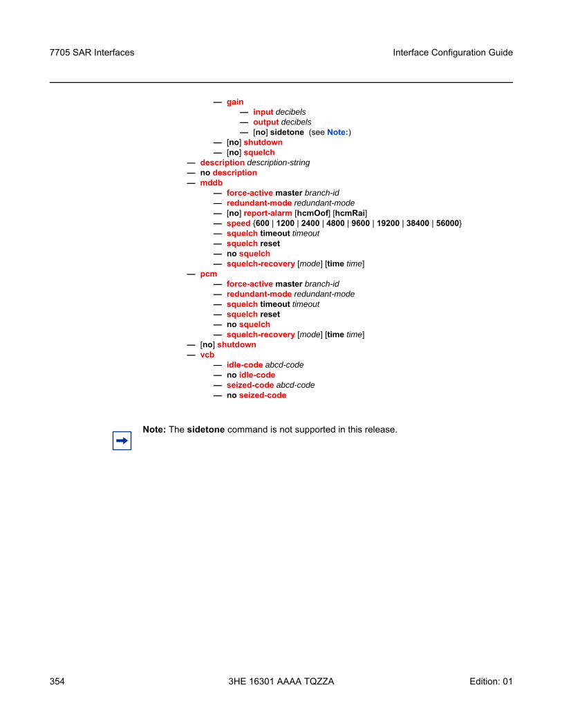
7705 SAR Interfaces
354
Interface Configuration Guide
3HE 16301 AAAA TQZZA Edition: 01
— gain— input decibels— output decibels— [no] sidetone (see Note:)
— [no] shutdown— [no] squelch
— description description-string— no description— mddb
— force-active master branch-id— redundant-mode redundant-mode— [no] report-alarm [hcmOof] [hcmRai] — speed 600 | 1200 | 2400 | 4800 | 9600 | 19200 | 38400 | 56000— squelch timeout timeout— squelch reset— no squelch— squelch-recovery [mode] [time time]
— pcm— force-active master branch-id— redundant-mode redundant-mode— squelch timeout timeout— squelch reset— no squelch— squelch-recovery [mode] [time time]
— [no] shutdown— vcb
— idle-code abcd-code— no idle-code— seized-code abcd-code— no seized-code
Note: The sidetone command is not supported in this release.
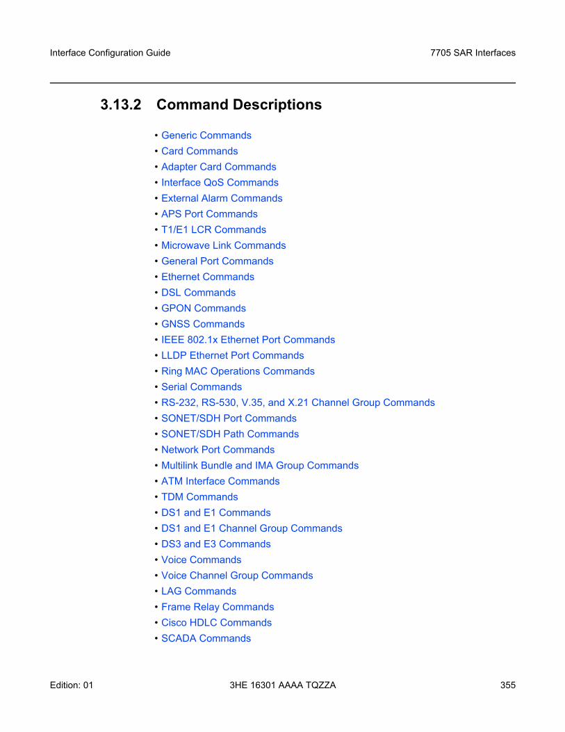
Interface Configuration Guide 7705 SAR Interfaces
Edition: 01 3HE 16301 AAAA TQZZA 355
3.13.2 Command Descriptions
• Generic Commands• Card Commands• Adapter Card Commands• Interface QoS Commands• External Alarm Commands• APS Port Commands• T1/E1 LCR Commands • Microwave Link Commands• General Port Commands• Ethernet Commands• DSL Commands• GPON Commands• GNSS Commands• IEEE 802.1x Ethernet Port Commands• LLDP Ethernet Port Commands• Ring MAC Operations Commands• Serial Commands• RS-232, RS-530, V.35, and X.21 Channel Group Commands• SONET/SDH Port Commands• SONET/SDH Path Commands• Network Port Commands• Multilink Bundle and IMA Group Commands• ATM Interface Commands• TDM Commands• DS1 and E1 Commands• DS1 and E1 Channel Group Commands• DS3 and E3 Commands• Voice Commands• Voice Channel Group Commands• LAG Commands• Frame Relay Commands• Cisco HDLC Commands• SCADA Commands
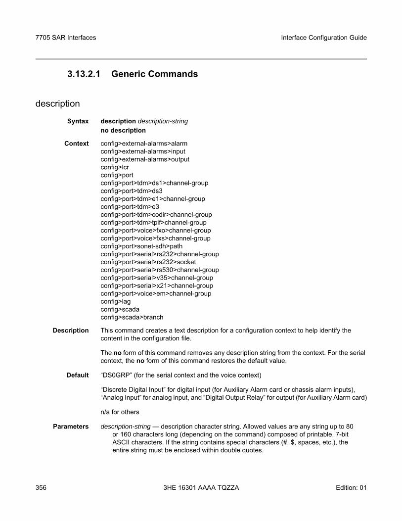
7705 SAR Interfaces
356
Interface Configuration Guide
3HE 16301 AAAA TQZZA Edition: 01
3.13.2.1 Generic Commands
description
Syntax description description-stringno description
Context config>external-alarms>alarmconfig>external-alarms>inputconfig>external-alarms>outputconfig>lcrconfig>portconfig>port>tdm>ds1>channel-groupconfig>port>tdm>ds3config>port>tdm>e1>channel-groupconfig>port>tdm>e3config>port>tdm>codir>channel-groupconfig>port>tdm>tpif>channel-groupconfig>port>voice>fxo>channel-groupconfig>port>voice>fxs>channel-groupconfig>port>sonet-sdh>pathconfig>port>serial>rs232>channel-groupconfig>port>serial>rs232>socketconfig>port>serial>rs530>channel-groupconfig>port>serial>v35>channel-groupconfig>port>serial>x21>channel-groupconfig>port>voice>em>channel-groupconfig>lagconfig>scadaconfig>scada>branch
Description This command creates a text description for a configuration context to help identify the content in the configuration file.
The no form of this command removes any description string from the context. For the serial context, the no form of this command restores the default value.
Default “DS0GRP” (for the serial context and the voice context)
“Discrete Digital Input” for digital input (for Auxiliary Alarm card or chassis alarm inputs), “Analog Input” for analog input, and “Digital Output Relay” for output (for Auxiliary Alarm card)
n/a for others
Parameters description-string — description character string. Allowed values are any string up to 80 or 160 characters long (depending on the command) composed of printable, 7-bit ASCII characters. If the string contains special characters (#, $, spaces, etc.), the entire string must be enclosed within double quotes.
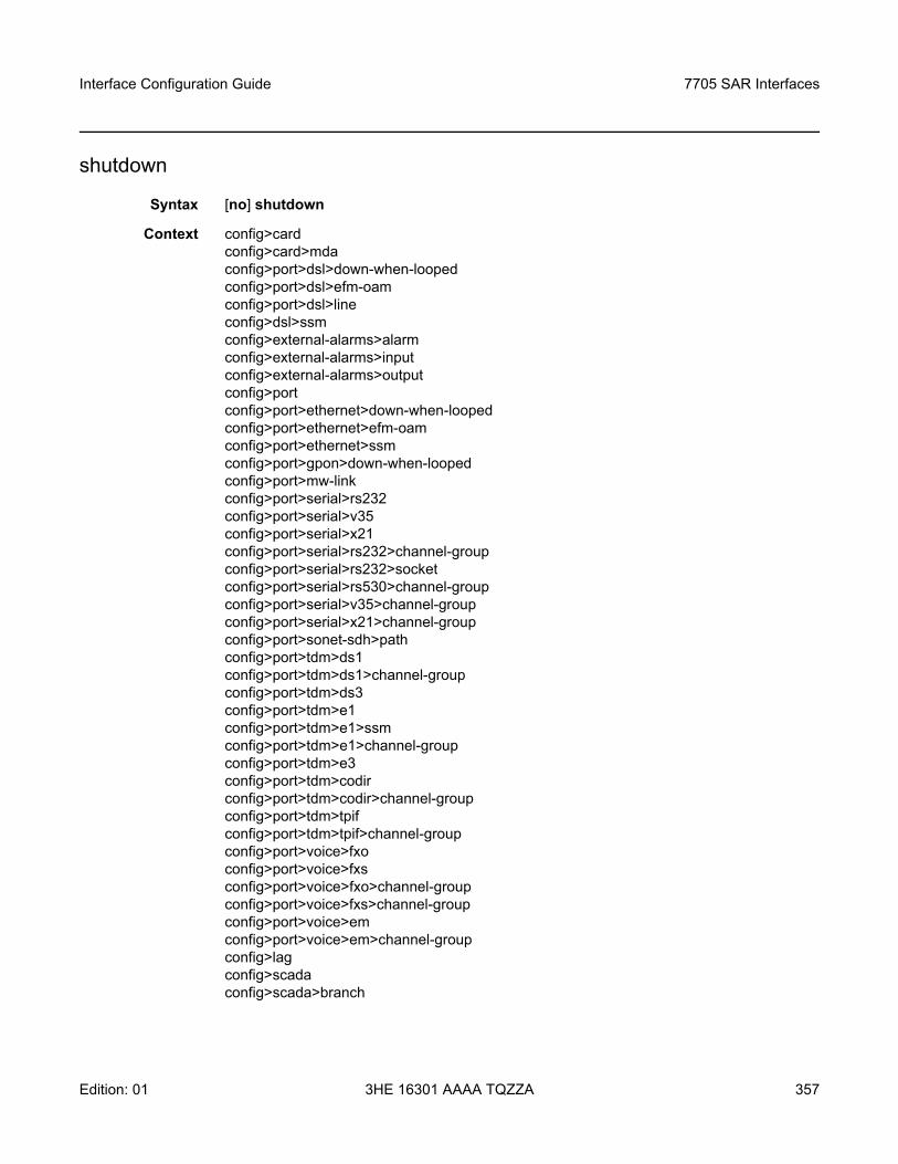
Interface Configuration Guide 7705 SAR Interfaces
Edition: 01 3HE 16301 AAAA TQZZA 357
shutdown
Syntax [no] shutdown
Context config>cardconfig>card>mdaconfig>port>dsl>down-when-loopedconfig>port>dsl>efm-oamconfig>port>dsl>lineconfig>dsl>ssmconfig>external-alarms>alarmconfig>external-alarms>inputconfig>external-alarms>outputconfig>portconfig>port>ethernet>down-when-loopedconfig>port>ethernet>efm-oamconfig>port>ethernet>ssmconfig>port>gpon>down-when-loopedconfig>port>mw-linkconfig>port>serial>rs232config>port>serial>v35config>port>serial>x21config>port>serial>rs232>channel-groupconfig>port>serial>rs232>socketconfig>port>serial>rs530>channel-groupconfig>port>serial>v35>channel-groupconfig>port>serial>x21>channel-groupconfig>port>sonet-sdh>pathconfig>port>tdm>ds1config>port>tdm>ds1>channel-groupconfig>port>tdm>ds3config>port>tdm>e1config>port>tdm>e1>ssmconfig>port>tdm>e1>channel-groupconfig>port>tdm>e3config>port>tdm>codirconfig>port>tdm>codir>channel-groupconfig>port>tdm>tpifconfig>port>tdm>tpif>channel-groupconfig>port>voice>fxoconfig>port>voice>fxsconfig>port>voice>fxo>channel-groupconfig>port>voice>fxs>channel-groupconfig>port>voice>emconfig>port>voice>em>channel-groupconfig>lagconfig>scadaconfig>scada>branch
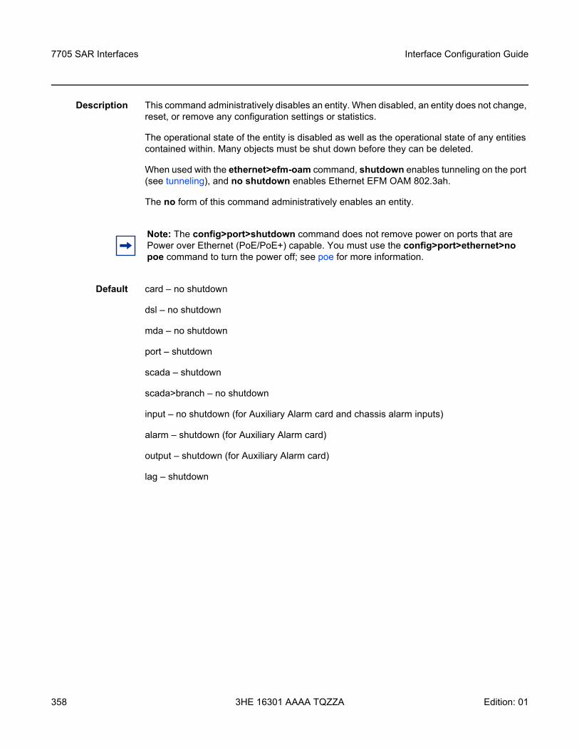
7705 SAR Interfaces
358
Interface Configuration Guide
3HE 16301 AAAA TQZZA Edition: 01
Description This command administratively disables an entity. When disabled, an entity does not change, reset, or remove any configuration settings or statistics.
The operational state of the entity is disabled as well as the operational state of any entities contained within. Many objects must be shut down before they can be deleted.
When used with the ethernet>efm-oam command, shutdown enables tunneling on the port (see tunneling), and no shutdown enables Ethernet EFM OAM 802.3ah.
The no form of this command administratively enables an entity.
Default card – no shutdown
dsl – no shutdown
mda – no shutdown
port – shutdown
scada – shutdown
scada>branch – no shutdown
input – no shutdown (for Auxiliary Alarm card and chassis alarm inputs)
alarm – shutdown (for Auxiliary Alarm card)
output – shutdown (for Auxiliary Alarm card)
lag – shutdown
Note: The config>port>shutdown command does not remove power on ports that are Power over Ethernet (PoE/PoE+) capable. You must use the config>port>ethernet>no poe command to turn the power off; see poe for more information.
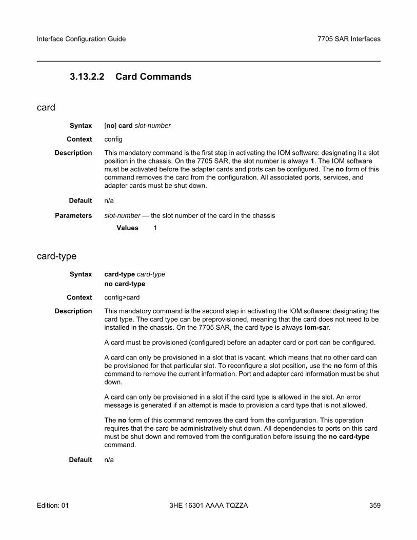
Interface Configuration Guide 7705 SAR Interfaces
Edition: 01 3HE 16301 AAAA TQZZA 359
3.13.2.2 Card Commands
card
Syntax [no] card slot-number
Context config
Description This mandatory command is the first step in activating the IOM software: designating it a slot position in the chassis. On the 7705 SAR, the slot number is always 1. The IOM software must be activated before the adapter cards and ports can be configured. The no form of this command removes the card from the configuration. All associated ports, services, and adapter cards must be shut down.
Default n/a
Parameters slot-number — the slot number of the card in the chassis
Values 1
card-type
Syntax card-type card-typeno card-type
Context config>card
Description This mandatory command is the second step in activating the IOM software: designating the card type. The card type can be preprovisioned, meaning that the card does not need to be installed in the chassis. On the 7705 SAR, the card type is always iom-sar.
A card must be provisioned (configured) before an adapter card or port can be configured.
A card can only be provisioned in a slot that is vacant, which means that no other card can be provisioned for that particular slot. To reconfigure a slot position, use the no form of this command to remove the current information. Port and adapter card information must be shut down.
A card can only be provisioned in a slot if the card type is allowed in the slot. An error message is generated if an attempt is made to provision a card type that is not allowed.
The no form of this command removes the card from the configuration. This operation requires that the card be administratively shut down. All dependencies to ports on this card must be shut down and removed from the configuration before issuing the no card-type command.
Default n/a

7705 SAR Interfaces
360
Interface Configuration Guide
3HE 16301 AAAA TQZZA Edition: 01
Parameters card-type — the type of card to be configured and installed in the slot
Values iom-sar
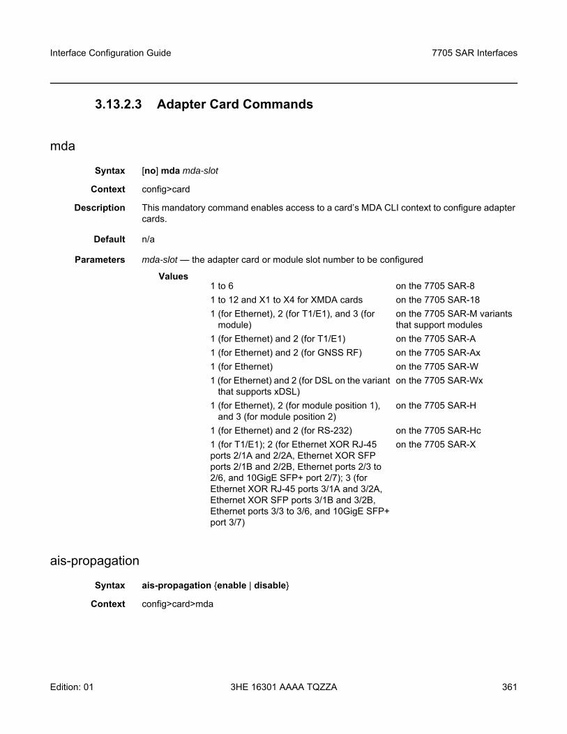
Interface Configuration Guide 7705 SAR Interfaces
Edition: 01 3HE 16301 AAAA TQZZA 361
3.13.2.3 Adapter Card Commands
mda
Syntax [no] mda mda-slot
Context config>card
Description This mandatory command enables access to a card’s MDA CLI context to configure adapter cards.
Default n/a
Parameters mda-slot — the adapter card or module slot number to be configured
Values
ais-propagation
Syntax ais-propagation enable | disable
Context config>card>mda
1 to 6 on the 7705 SAR-81 to 12 and X1 to X4 for XMDA cards on the 7705 SAR-181 (for Ethernet), 2 (for T1/E1), and 3 (for
module) on the 7705 SAR-M variants that support modules
1 (for Ethernet) and 2 (for T1/E1) on the 7705 SAR-A1 (for Ethernet) and 2 (for GNSS RF) on the 7705 SAR-Ax1 (for Ethernet) on the 7705 SAR-W1 (for Ethernet) and 2 (for DSL on the variant
that supports xDSL) on the 7705 SAR-Wx
1 (for Ethernet), 2 (for module position 1), and 3 (for module position 2)
on the 7705 SAR-H
1 (for Ethernet) and 2 (for RS-232) on the 7705 SAR-Hc1 (for T1/E1); 2 (for Ethernet XOR RJ-45 ports 2/1A and 2/2A, Ethernet XOR SFP ports 2/1B and 2/2B, Ethernet ports 2/3 to 2/6, and 10GigE SFP+ port 2/7); 3 (for Ethernet XOR RJ-45 ports 3/1A and 3/2A, Ethernet XOR SFP ports 3/1B and 3/2B, Ethernet ports 3/3 to 3/6, and 10GigE SFP+ port 3/7)
on the 7705 SAR-X
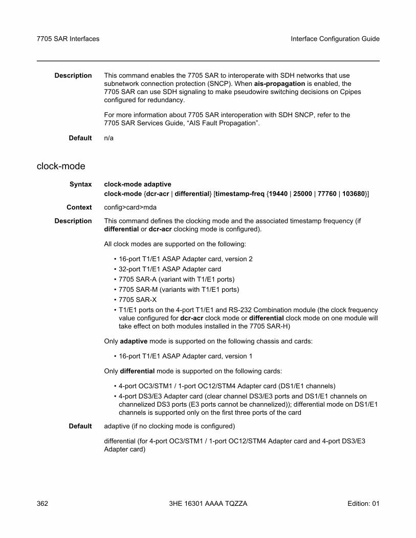
7705 SAR Interfaces
362
Interface Configuration Guide
3HE 16301 AAAA TQZZA Edition: 01
Description This command enables the 7705 SAR to interoperate with SDH networks that use subnetwork connection protection (SNCP). When ais-propagation is enabled, the 7705 SAR can use SDH signaling to make pseudowire switching decisions on Cpipes configured for redundancy.
For more information about 7705 SAR interoperation with SDH SNCP, refer to the 7705 SAR Services Guide, “AIS Fault Propagation”.
Default n/a
clock-mode
Syntax clock-mode adaptiveclock-mode dcr-acr | differential [timestamp-freq 19440 | 25000 | 77760 | 103680]
Context config>card>mda
Description This command defines the clocking mode and the associated timestamp frequency (if differential or dcr-acr clocking mode is configured).
All clock modes are supported on the following:
• 16-port T1/E1 ASAP Adapter card, version 2• 32-port T1/E1 ASAP Adapter card• 7705 SAR-A (variant with T1/E1 ports)• 7705 SAR-M (variants with T1/E1 ports)• 7705 SAR-X• T1/E1 ports on the 4-port T1/E1 and RS-232 Combination module (the clock frequency
value configured for dcr-acr clock mode or differential clock mode on one module will take effect on both modules installed in the 7705 SAR-H)
Only adaptive mode is supported on the following chassis and cards:
• 16-port T1/E1 ASAP Adapter card, version 1
Only differential mode is supported on the following cards:
• 4-port OC3/STM1 / 1-port OC12/STM4 Adapter card (DS1/E1 channels)• 4-port DS3/E3 Adapter card (clear channel DS3/E3 ports and DS1/E1 channels on
channelized DS3 ports (E3 ports cannot be channelized)); differential mode on DS1/E1 channels is supported only on the first three ports of the card
Default adaptive (if no clocking mode is configured)
differential (for 4-port OC3/STM1 / 1-port OC12/STM4 Adapter card and 4-port DS3/E3 Adapter card)
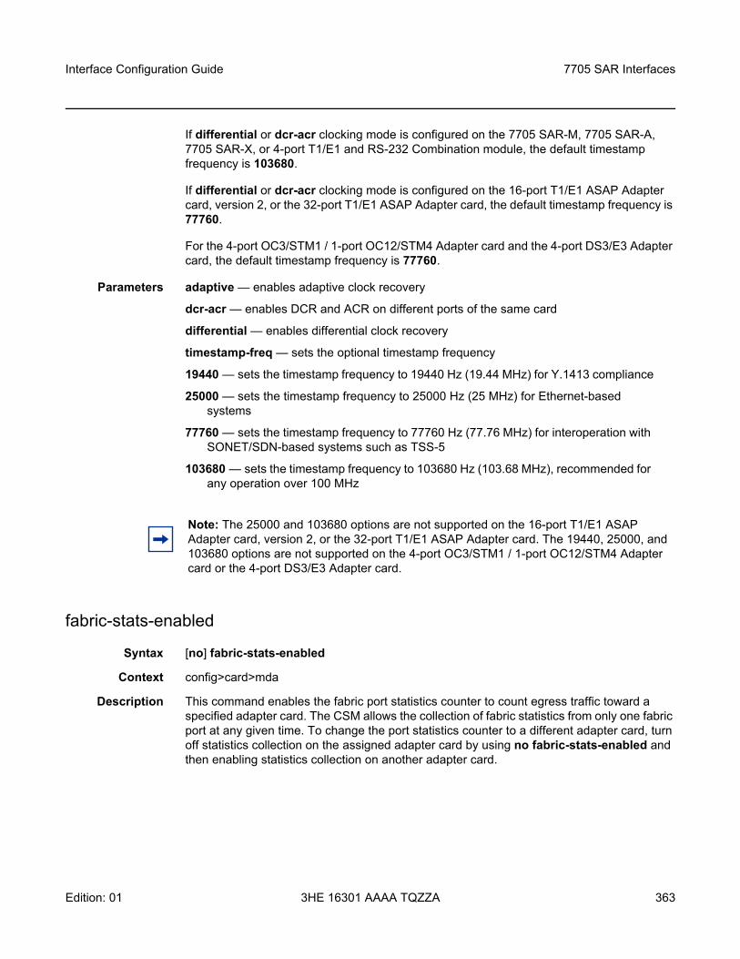
Interface Configuration Guide 7705 SAR Interfaces
Edition: 01 3HE 16301 AAAA TQZZA 363
If differential or dcr-acr clocking mode is configured on the 7705 SAR-M, 7705 SAR-A, 7705 SAR-X, or 4-port T1/E1 and RS-232 Combination module, the default timestamp frequency is 103680.
If differential or dcr-acr clocking mode is configured on the 16-port T1/E1 ASAP Adapter card, version 2, or the 32-port T1/E1 ASAP Adapter card, the default timestamp frequency is 77760.
For the 4-port OC3/STM1 / 1-port OC12/STM4 Adapter card and the 4-port DS3/E3 Adapter card, the default timestamp frequency is 77760.
Parameters adaptive — enables adaptive clock recovery
dcr-acr — enables DCR and ACR on different ports of the same card
differential — enables differential clock recovery
timestamp-freq — sets the optional timestamp frequency
19440 — sets the timestamp frequency to 19440 Hz (19.44 MHz) for Y.1413 compliance
25000 — sets the timestamp frequency to 25000 Hz (25 MHz) for Ethernet-based systems
77760 — sets the timestamp frequency to 77760 Hz (77.76 MHz) for interoperation with SONET/SDN-based systems such as TSS-5
103680 — sets the timestamp frequency to 103680 Hz (103.68 MHz), recommended for any operation over 100 MHz
fabric-stats-enabled
Syntax [no] fabric-stats-enabled
Context config>card>mda
Description This command enables the fabric port statistics counter to count egress traffic toward a specified adapter card. The CSM allows the collection of fabric statistics from only one fabric port at any given time. To change the port statistics counter to a different adapter card, turn off statistics collection on the assigned adapter card by using no fabric-stats-enabled and then enabling statistics collection on another adapter card.
Note: The 25000 and 103680 options are not supported on the 16-port T1/E1 ASAP Adapter card, version 2, or the 32-port T1/E1 ASAP Adapter card. The 19440, 25000, and 103680 options are not supported on the 4-port OC3/STM1 / 1-port OC12/STM4 Adapter card or the 4-port DS3/E3 Adapter card.
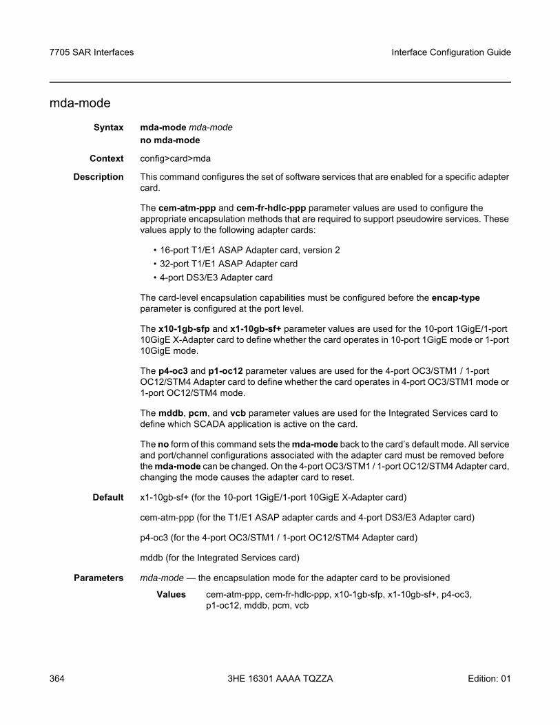
7705 SAR Interfaces
364
Interface Configuration Guide
3HE 16301 AAAA TQZZA Edition: 01
mda-mode
Syntax mda-mode mda-mode no mda-mode
Context config>card>mda
Description This command configures the set of software services that are enabled for a specific adapter card.
The cem-atm-ppp and cem-fr-hdlc-ppp parameter values are used to configure the appropriate encapsulation methods that are required to support pseudowire services. These values apply to the following adapter cards:
• 16-port T1/E1 ASAP Adapter card, version 2• 32-port T1/E1 ASAP Adapter card• 4-port DS3/E3 Adapter card
The card-level encapsulation capabilities must be configured before the encap-type parameter is configured at the port level.
The x10-1gb-sfp and x1-10gb-sf+ parameter values are used for the 10-port 1GigE/1-port 10GigE X-Adapter card to define whether the card operates in 10-port 1GigE mode or 1-port 10GigE mode.
The p4-oc3 and p1-oc12 parameter values are used for the 4-port OC3/STM1 / 1-port OC12/STM4 Adapter card to define whether the card operates in 4-port OC3/STM1 mode or 1-port OC12/STM4 mode.
The mddb, pcm, and vcb parameter values are used for the Integrated Services card to define which SCADA application is active on the card.
The no form of this command sets the mda-mode back to the card’s default mode. All service and port/channel configurations associated with the adapter card must be removed before the mda-mode can be changed. On the 4-port OC3/STM1 / 1-port OC12/STM4 Adapter card, changing the mode causes the adapter card to reset.
Default x1-10gb-sf+ (for the 10-port 1GigE/1-port 10GigE X-Adapter card)
cem-atm-ppp (for the T1/E1 ASAP adapter cards and 4-port DS3/E3 Adapter card)
p4-oc3 (for the 4-port OC3/STM1 / 1-port OC12/STM4 Adapter card)
mddb (for the Integrated Services card)
Parameters mda-mode — the encapsulation mode for the adapter card to be provisioned
Values cem-atm-ppp, cem-fr-hdlc-ppp, x10-1gb-sfp, x1-10gb-sf+, p4-oc3, p1-oc12, mddb, pcm, vcb
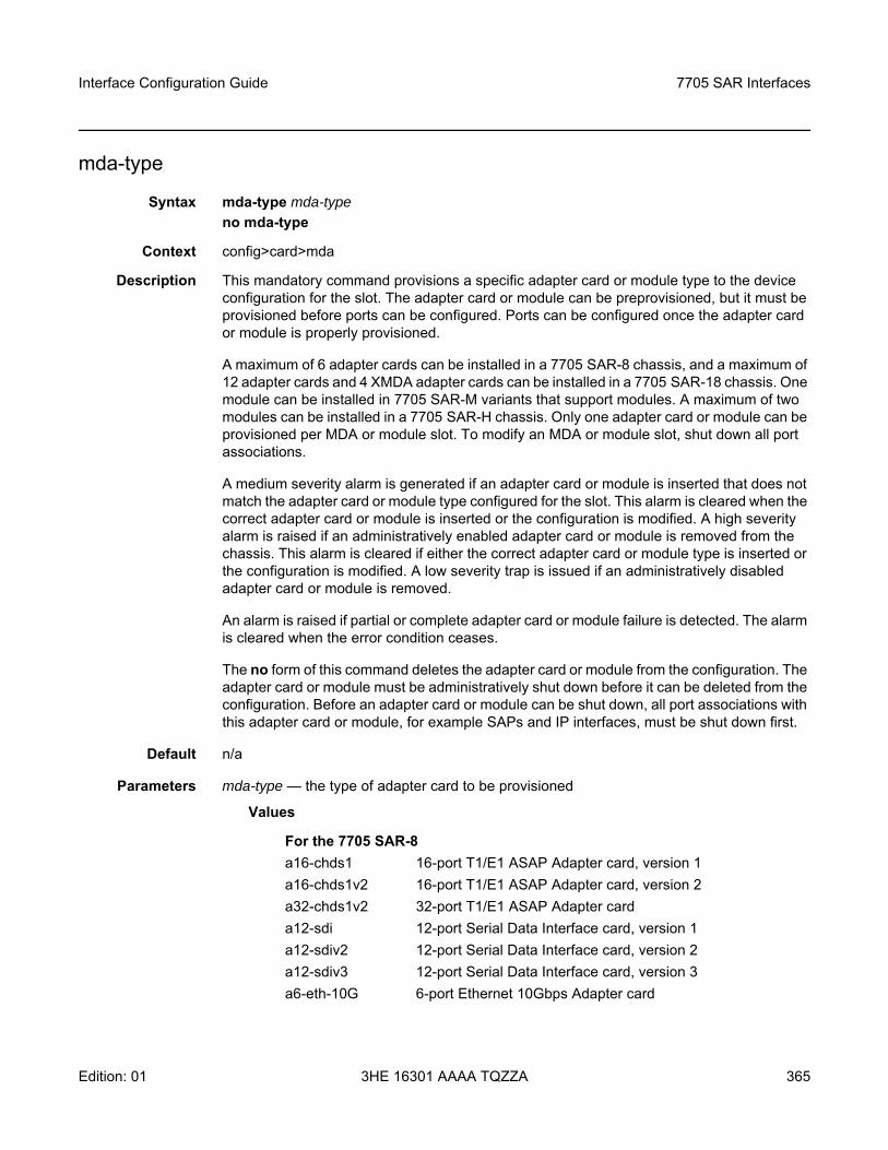
Interface Configuration Guide 7705 SAR Interfaces
Edition: 01 3HE 16301 AAAA TQZZA 365
mda-type
Syntax mda-type mda-typeno mda-type
Context config>card>mda
Description This mandatory command provisions a specific adapter card or module type to the device configuration for the slot. The adapter card or module can be preprovisioned, but it must be provisioned before ports can be configured. Ports can be configured once the adapter card or module is properly provisioned.
A maximum of 6 adapter cards can be installed in a 7705 SAR-8 chassis, and a maximum of 12 adapter cards and 4 XMDA adapter cards can be installed in a 7705 SAR-18 chassis. One module can be installed in 7705 SAR-M variants that support modules. A maximum of two modules can be installed in a 7705 SAR-H chassis. Only one adapter card or module can be provisioned per MDA or module slot. To modify an MDA or module slot, shut down all port associations.
A medium severity alarm is generated if an adapter card or module is inserted that does not match the adapter card or module type configured for the slot. This alarm is cleared when the correct adapter card or module is inserted or the configuration is modified. A high severity alarm is raised if an administratively enabled adapter card or module is removed from the chassis. This alarm is cleared if either the correct adapter card or module type is inserted or the configuration is modified. A low severity trap is issued if an administratively disabled adapter card or module is removed.
An alarm is raised if partial or complete adapter card or module failure is detected. The alarm is cleared when the error condition ceases.
The no form of this command deletes the adapter card or module from the configuration. The adapter card or module must be administratively shut down before it can be deleted from the configuration. Before an adapter card or module can be shut down, all port associations with this adapter card or module, for example SAPs and IP interfaces, must be shut down first.
Default n/a
Parameters mda-type — the type of adapter card to be provisioned
Values
For the 7705 SAR-8a16-chds1 16-port T1/E1 ASAP Adapter card, version 1a16-chds1v2 16-port T1/E1 ASAP Adapter card, version 2a32-chds1v2 32-port T1/E1 ASAP Adapter card a12-sdi 12-port Serial Data Interface card, version 1a12-sdiv2 12-port Serial Data Interface card, version 2a12-sdiv3 12-port Serial Data Interface card, version 3a6-eth-10G 6-port Ethernet 10Gbps Adapter card
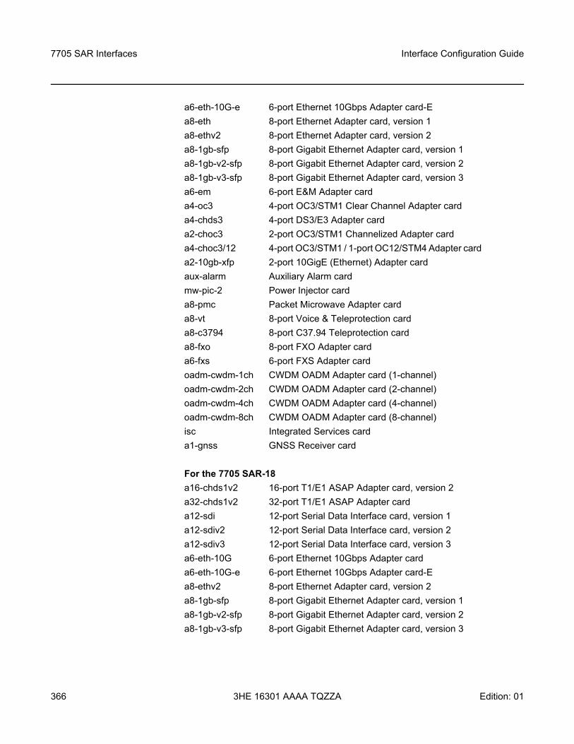
7705 SAR Interfaces
366
Interface Configuration Guide
3HE 16301 AAAA TQZZA Edition: 01
a6-eth-10G-e 6-port Ethernet 10Gbps Adapter card-Ea8-eth 8-port Ethernet Adapter card, version 1 a8-ethv2 8-port Ethernet Adapter card, version 2 a8-1gb-sfp 8-port Gigabit Ethernet Adapter card, version 1 a8-1gb-v2-sfp 8-port Gigabit Ethernet Adapter card, version 2 a8-1gb-v3-sfp 8-port Gigabit Ethernet Adapter card, version 3 a6-em 6-port E&M Adapter card a4-oc3 4-port OC3/STM1 Clear Channel Adapter card a4-chds3 4-port DS3/E3 Adapter card a2-choc3 2-port OC3/STM1 Channelized Adapter card a4-choc3/12 4-port OC3/STM1 / 1-port OC12/STM4 Adapter card a2-10gb-xfp 2-port 10GigE (Ethernet) Adapter card aux-alarm Auxiliary Alarm card mw-pic-2 Power Injector card a8-pmc Packet Microwave Adapter card a8-vt 8-port Voice & Teleprotection card a8-c3794 8-port C37.94 Teleprotection card a8-fxo 8-port FXO Adapter card a6-fxs 6-port FXS Adapter card oadm-cwdm-1ch CWDM OADM Adapter card (1-channel)oadm-cwdm-2ch CWDM OADM Adapter card (2-channel) oadm-cwdm-4ch CWDM OADM Adapter card (4-channel) oadm-cwdm-8ch CWDM OADM Adapter card (8-channel) isc Integrated Services card a1-gnss GNSS Receiver card
For the 7705 SAR-18 a16-chds1v2 16-port T1/E1 ASAP Adapter card, version 2 a32-chds1v2 32-port T1/E1 ASAP Adapter card a12-sdi 12-port Serial Data Interface card, version 1a12-sdiv2 12-port Serial Data Interface card, version 2a12-sdiv3 12-port Serial Data Interface card, version 3a6-eth-10G 6-port Ethernet 10Gbps Adapter carda6-eth-10G-e 6-port Ethernet 10Gbps Adapter card-Ea8-ethv2 8-port Ethernet Adapter card, version 2 a8-1gb-sfp 8-port Gigabit Ethernet Adapter card, version 1 a8-1gb-v2-sfp 8-port Gigabit Ethernet Adapter card, version 2 a8-1gb-v3-sfp 8-port Gigabit Ethernet Adapter card, version 3
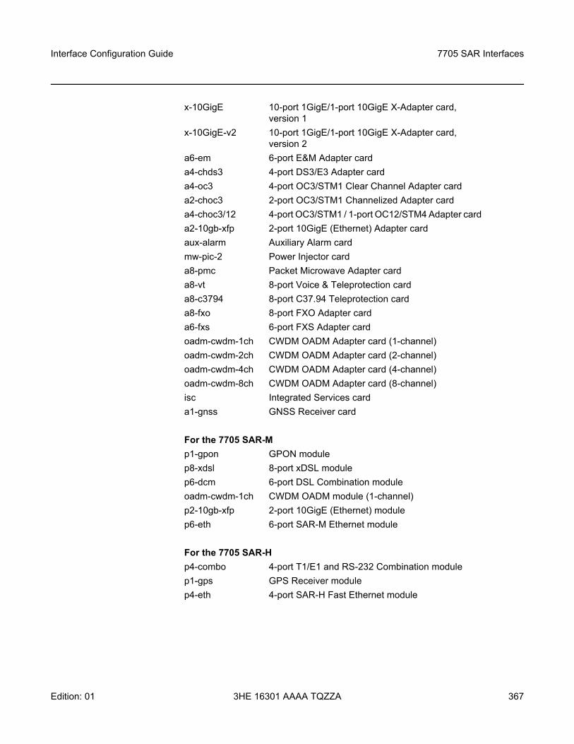
Interface Configuration Guide 7705 SAR Interfaces
Edition: 01 3HE 16301 AAAA TQZZA 367
x-10GigE 10-port 1GigE/1-port 10GigE X-Adapter card, version 1
x-10GigE-v2 10-port 1GigE/1-port 10GigE X-Adapter card, version 2
a6-em 6-port E&M Adapter card a4-chds3 4-port DS3/E3 Adapter card a4-oc3 4-port OC3/STM1 Clear Channel Adapter card a2-choc3 2-port OC3/STM1 Channelized Adapter card a4-choc3/12 4-port OC3/STM1 / 1-port OC12/STM4 Adapter card a2-10gb-xfp 2-port 10GigE (Ethernet) Adapter card aux-alarm Auxiliary Alarm card mw-pic-2 Power Injector card a8-pmc Packet Microwave Adapter card a8-vt 8-port Voice & Teleprotection card a8-c3794 8-port C37.94 Teleprotection card a8-fxo 8-port FXO Adapter card a6-fxs 6-port FXS Adapter card oadm-cwdm-1ch CWDM OADM Adapter card (1-channel) oadm-cwdm-2ch CWDM OADM Adapter card (2-channel) oadm-cwdm-4ch CWDM OADM Adapter card (4-channel) oadm-cwdm-8ch CWDM OADM Adapter card (8-channel) isc Integrated Services card a1-gnss GNSS Receiver card
For the 7705 SAR-M p1-gpon GPON modulep8-xdsl 8-port xDSL module p6-dcm 6-port DSL Combination module oadm-cwdm-1ch CWDM OADM module (1-channel) p2-10gb-xfp 2-port 10GigE (Ethernet) module p6-eth 6-port SAR-M Ethernet module
For the 7705 SAR-H p4-combo 4-port T1/E1 and RS-232 Combination module p1-gps GPS Receiver modulep4-eth 4-port SAR-H Fast Ethernet module
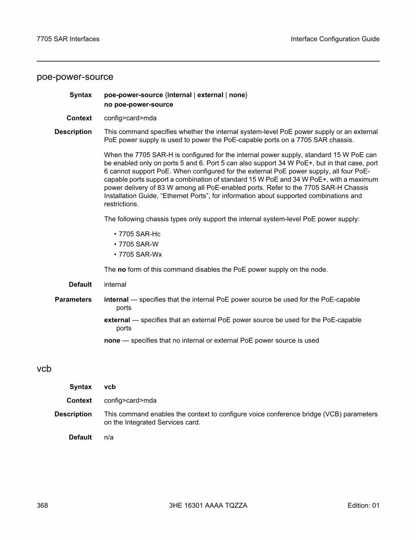
7705 SAR Interfaces
368
Interface Configuration Guide
3HE 16301 AAAA TQZZA Edition: 01
poe-power-source
Syntax poe-power-source internal | external | noneno poe-power-source
Context config>card>mda
Description This command specifies whether the internal system-level PoE power supply or an external PoE power supply is used to power the PoE-capable ports on a 7705 SAR chassis.
When the 7705 SAR-H is configured for the internal power supply, standard 15 W PoE can be enabled only on ports 5 and 6. Port 5 can also support 34 W PoE+, but in that case, port 6 cannot support PoE. When configured for the external PoE power supply, all four PoE-capable ports support a combination of standard 15 W PoE and 34 W PoE+, with a maximum power delivery of 83 W among all PoE-enabled ports. Refer to the 7705 SAR-H Chassis Installation Guide, “Ethernet Ports”, for information about supported combinations and restrictions.
The following chassis types only support the internal system-level PoE power supply:
• 7705 SAR-Hc• 7705 SAR-W• 7705 SAR-Wx
The no form of this command disables the PoE power supply on the node.
Default internal
Parameters internal — specifies that the internal PoE power source be used for the PoE-capable ports
external — specifies that an external PoE power source be used for the PoE-capable ports
none — specifies that no internal or external PoE power source is used
vcb
Syntax vcb
Context config>card>mda
Description This command enables the context to configure voice conference bridge (VCB) parameters on the Integrated Services card.
Default n/a
Interface Configuration Guide 7705 SAR Interfaces
Edition: 01 3HE 16301 AAAA TQZZA 369
application
Syntax application broadcast | teleprotection | vcb | vcb-branch-initiate
Context config>card>mda>vcb
Description This command specifies the operating mode for the VCB application. The mode is set at the card level and applies to all bridges configured on the card.
Default vcb
Parameters broadcast — only one branch on the bridge (fixed as branch 1) has control of the bridge to transmit, and all other branches are in listen-only mode
teleprotection — each teleprotection relay transmits state information on discrete frequencies so that each relay can both hear what the other relays are transmitting as well as transmit its own information to the other relays
vcb — one branch talks and all other branches on the bridge can hear
vcb-branch-initiate — branches on the bridge are only enabled (unmuted) when the attached base station signals its presence by grounding the M-lead on the interface connected to the bridge. Upon receiving the grounded M-lead via T1/E1 ABCD bits or TDM PW signaling, the bridge unmutes the associated branch. When the ground is removed, the branch is muted again.
voice
Syntax voice
Context config>card>mda
Description This command enables the context to configure voice parameters on the 6-port E&M Adapter card, 8-port Voice & Teleprotection card, 8-port FXO Adapter card, 6-port FXS Adapter card, and Integrated Services card (when it is configured for VCB with the mda-mode command).
Default n/a
companding-law
Syntax companding-law a-law | mu-law
Context config>card>mda>voice
Description This command specifies the companding law to be used on the 6-port E&M Adapter card, 8-port Voice & Teleprotection card, 8-port FXO Adapter card, 6-port FXS Adapter card, and Integrated Services card (for VCB).
7705 SAR Interfaces
370
Interface Configuration Guide
3HE 16301 AAAA TQZZA Edition: 01
To change this parameter, all ports associated with the card must be in shutdown mode and no channels can be defined on the card. A change in the companding law results in a corresponding change to the signaling-type default. The signaling-type applies only to the 6-port E&M Adapter card.
Default mu-law
Parameters a-law — A-Law companding
mu-law — Mu-Law companding
signaling-type
Syntax signaling-type type-i | type-ii | type-v
Context config>card>mda>voice
Description This command specifies the signaling type to be used on the 6-port E&M Adapter card.
To change the signaling type, all ports associated with the 6-port E&M Adapter card must be in shutdown mode and no channels can be defined on the card.
The signaling type is selectable on a per-card basis. When either A-Law or Mu-Law companding is configured, Type I, Type II, or Type V signaling can be selected. However, the only supported configurations are both ends of the connection operating in the same mode (for example, Type I to Type I) or one end operating in Type I mode and the other in Type V mode.
Default type-i (for Mu-Law companding)
type-v (for A-Law companding)
Parameters type-i — Type I signaling
type-ii — Type II signaling
type-v — Type V signaling
Interface Configuration Guide 7705 SAR Interfaces
Edition: 01 3HE 16301 AAAA TQZZA 371
3.13.2.4 Interface QoS Commands
access
Syntax access
Context config>card>mda
Description This command enables the access context to configure QoS policy parameters for the specified adapter card.
network
Syntax network
Context config>card>mda
Description This command enables the network context to configure QoS policy parameters for the specified adapter card.
ingress
Syntax ingress
Context config>card>mda>accessconfig>card>mda>network
Description This command enables the context to configure the QoS policy parameters for ingress traffic, in either an access or network context, for the specified adapter card.
fabric-policy
Syntax fabric-policy fabric-policy-idno fabric-policy
Context config>card>mda>access>ingressconfig>card>mda>network>ingress
Description This command configures (applies) the ingress fabric policy, in either an access or network context, for the specified adapter card.
Fabric profiles do not apply to the Auxiliary Alarm card.
The no form of this command resets the fabric-policy-id to the default value.
7705 SAR Interfaces
372
Interface Configuration Guide
3HE 16301 AAAA TQZZA Edition: 01
Default 1
Parameters fabric-policy-id — an existing fabric policy ID
Values 1 to 256
queue-policy
Syntax queue-policy nameno queue-policy
Context config>card>mda>network>ingress
Description This command specifies the network ingress queue policy that defines queue parameters such as CBS, high-priority-only burst size, MBS, CIR, and PIR rates, as well as forwarding class-to-queue mappings. The network queue policy is defined in the config>qos>network-queue context. Refer to the 7705 SAR Quality of Service Guide, “Network Queue QoS Policies”, for more information.
The no form of this command reverts to the default.
Default “default”
Parameters name — specifies an existing network queue policy name
security-queue-policy
Syntax security-queue-policy policy-idno security-queue-policy
Context config>card>mda>access>ingressconfig>card>mda>network>ingress
Description This command applies an existing security queue policy, in either an access or network context, to the specified adapter card.
The no form of this command sets the policy-id back to the default.
Default 1
Parameters policy-id — specifies an existing security queue policy ID
Values 1 to 65535
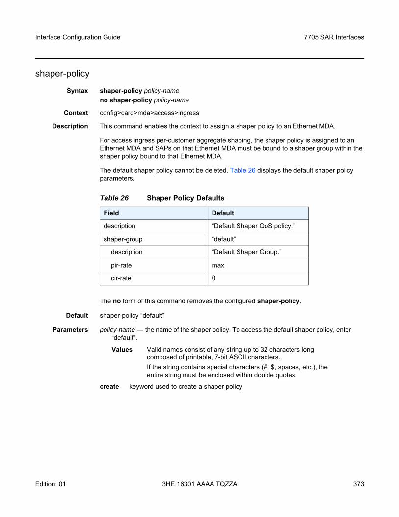
Interface Configuration Guide 7705 SAR Interfaces
Edition: 01 3HE 16301 AAAA TQZZA 373
shaper-policy
Syntax shaper-policy policy-nameno shaper-policy policy-name
Context config>card>mda>access>ingress
Description This command enables the context to assign a shaper policy to an Ethernet MDA.
For access ingress per-customer aggregate shaping, the shaper policy is assigned to an Ethernet MDA and SAPs on that Ethernet MDA must be bound to a shaper group within the shaper policy bound to that Ethernet MDA.
The default shaper policy cannot be deleted. Table 26 displays the default shaper policy parameters.
The no form of this command removes the configured shaper-policy.
Default shaper-policy “default”
Parameters policy-name — the name of the shaper policy. To access the default shaper policy, enter “default”.
Values Valid names consist of any string up to 32 characters long composed of printable, 7-bit ASCII characters. If the string contains special characters (#, $, spaces, etc.), the entire string must be enclosed within double quotes.
create — keyword used to create a shaper policy
Table 26 Shaper Policy Defaults
Field Default
description “Default Shaper QoS policy.”
shaper-group “default”
description “Default Shaper Group.”
pir-rate max
cir-rate 0
7705 SAR Interfaces
374
Interface Configuration Guide
3HE 16301 AAAA TQZZA Edition: 01
ring
Syntax ring
Context config>card>mda>network
Description This command specifies the QoS policy parameters for ring traffic in a network, for the 2-port 10GigE (Ethernet) Adapter card or 2-port 10GigE (Ethernet) module.
add-drop-port-queue-policy
Syntax add-drop-port-queue-policy nameno add-drop-port-queue-policy
Context config>card>mda>network>ring
Description This command specifies the network queue policy to be applied to the add/drop port on the bridging domain side of a ring adapter card. The network queue policy is defined in the config>qos>network-queue context. Refer to the 7705 SAR Quality of Service Guide, “Network Queue QoS Policies”, for more information.
The ring ports and the add/drop port cannot use the same non-default network queue policy that is being used by the v-port and any other port on other cards.
Default no add-drop-port-queue-policy
Parameters name — specifies an existing network queue policy
qos-policy
Syntax qos-policy network-policy-idno qos-policy
Context config>card>mda>network>ring
Description This command specifies the network QoS policy for the ring. Only a ring type network QoS policy can be assigned to a port on the bridging domain side of a ring adapter card.
Default no qos-policy
Parameters network-policy-id — specifies the network QoS policy for the ring ports and the add/drop port on a ring adapter card
Interface Configuration Guide 7705 SAR Interfaces
Edition: 01 3HE 16301 AAAA TQZZA 375
spt
Syntax spt
Context config>card>mdaconfig>system
Description This command enables the context for configuring SPT (self-processed traffic) parameters. The config>card>mda context is used for the 7705 SAR-8, 7705 SAR-18, and 7705 SAR-X. The config>system context is used for the 7705 SAR-Hc, 7705 SAR-H, and 7705 SAR-Wx.
Default n/a
security-aggregate-rate
Syntax security-aggregate-rate agg-rateno security-aggregate-rate
Context config>card>mda>sptconfig>system>spt
Description This command configures the fabric aggregate rate for security queues on the datapath. The command is configured in the config>card>mda>spt context for the 7705 SAR-8, 7705 SAR-18, and 7705 SAR-X, and in the config>system>spt context for the 7705 SAR-Hc, 7705 SAR-H, and 7705 SAR-Wx.
Parameters agg-rate — specifies the aggregate rate for security queues, in kilobits per second
Values 1 to 10000000 | maximum
Default 50000
7705 SAR Interfaces
376
Interface Configuration Guide
3HE 16301 AAAA TQZZA Edition: 01
3.13.2.5 External Alarm Commands
external-alarms
Syntax external-alarms
Context config
Description This command enables access to the context to configure external alarm attributes on 7705 SAR Ethernet ports (supported on all platforms with Ethernet ports), on the Auxiliary Alarm card, and on the four alarm inputs on the fan module (for the 7705 SAR-8), alarm connector (for the 7705 SAR-M (all variants), 7705 SAR-H, 7705 SAR-Hc, and 7705 SAR-X), and alarm module (for the 7705 SAR-18).
When configuring custom alarms for an Ethernet port, the port must be configured for 100Base-Tx operation with autonegotiation disabled.
alarm
Syntax [no] alarm alarm-id
Context config>external-alarms
Description This command creates or removes alarms.
The no form of this command disables the alarm attributes for the specified alarm. The alarm must be in the shutdown state before the no form of the command can be performed.
Default n/a
Parameters alarm-id — specifies the alarm identifier
Values 1 to 2147483647
chassis-alarming
Syntax [no] chassis-alarming
Context config>external-alarms>alarm
Description This command generates output to chassis alarm relays and LEDs for the specified alarm.
The no form of this command disables the generation of output to chassis alarm relays and LEDs.
Default chassis-alarming
Interface Configuration Guide 7705 SAR Interfaces
Edition: 01 3HE 16301 AAAA TQZZA 377
log
Syntax [no] log
Context config>external-alarms>alarm
Description This command generates raise/clear log events for the specified alarm and controls SNMP trap generation for the raise/clear log events.
The no form of this command disables the generation of raise/clear log events.
Default log
severity
Syntax severity critical | major | minor | warning
Context config>external-alarms>alarm
Description This command configures the severity level for the specified alarm.
The alarm must be disabled before the severity level can be modified.
If the alarm generates raise/clear log events and SNMP traps (enabled by the log command), the severity of the raise log events and SNMP traps is controlled by this configuration. The severity level of the clear log events and SNMP traps is warning.
If the alarm generates output to chassis alarm relays and LEDs (enabled by the chassis-alarming command), the severity level of the alarm output is controlled by this configuration. For chassis relay alarms, only the critical, major and minor levels of severity apply. (There are three LEDs that represent each of them.)
Default major
Parameters critical — specifies a critical alarm
major — specifies a major alarm
minor — specifies a minor alarm
warning — specifies a warning (not applicable for chassis relay alarms)
7705 SAR Interfaces
378
Interface Configuration Guide
3HE 16301 AAAA TQZZA Edition: 01
thresholds
Syntax thresholds
Context config>external-alarms>alarm
Description This command enables the context to configure the thresholds for the specified alarm.
Default n/a
analog
Syntax analog
Context config>external-alarms>alarm>thresholds
Description This command enables the context to configure analog trigger thresholds for the specified alarm.
Default n/a
level
Syntax [no] level lt | gt millivolts
Context config>external-alarms>alarm>thresholds>analog
Description This command configures the analog voltage level thresholds for the specified alarm.
The analog input level threshold cannot be changed from no level when there are no analog inputs configured as triggers. When all analog inputs are removed from the trigger list, the level is automatically changed to no level. The analog input level threshold cannot be changed to no level when there is analog input in the trigger list. When the first analog input is added to the alarm trigger, the level is automatically changed to gt 0.
The no form of this command removes the analog voltage level threshold.
Default no level
Parameters lt — specifies a less-than value
gt — specifies a greater-than value
millivolts — specifies the voltage level in millivolts
Values 0 to 75000
Interface Configuration Guide 7705 SAR Interfaces
Edition: 01 3HE 16301 AAAA TQZZA 379
trigger
Syntax trigger [any | all] alarm-input1 | alarm-input2... | alarm-input8no trigger
Context config>external-alarms>alarm
Description This command configures the inputs that will trigger the alarm. An alarm can be configured to trigger on any configured input or only when all enabled configured inputs are active. Administratively disabled inputs are ignored for alarm triggering.
Digital inputs are considered normally open. This means that a digital input becomes active only if it closes. Analog inputs have a customizable voltage threshold. This threshold can be configured using the thresholds command. Analog inputs become active when this threshold is crossed.
The no form of this command removes the trigger.
Default no trigger
Parameters any — specifies that any configured input trigger will raise an alarm
all — specifies that all configured input triggers that are enabled are required to raise an alarm
alarm-input — identifies the input trigger, up to a maximum of eightfor Ethernet ports, the format is:
port-slot/mda/port [name]for the Auxiliary Alarm card, the format is:
alarm-slot/mda.d | a-alarm-num [name]for the four alarm inputs on the fan module (for the 7705 SAR-8), alarm connector (for the 7705 SAR-M (all variants), 7705 SAR-H, 7705 SAR-Hc, and 7705 SAR-X), and alarm module (for the 7705 SAR-18), the format is:
alarm.d-alarm-num [name]where:
slot = card slot number for IOM (always 1 on the 7705 SAR)mda = Ethernet adapter card or Auxiliary Alarm card slot number (for Ethernet
modules or ports on platforms with no card slots, the mda slot number is preconfigured)
port = port number for Ethernet portsd = digital inputa = analog inputalarm-num = alarm port number (1 to 24 for digital on the Auxiliary Alarm card, 1
to 4 for digital on the four chassis alarm inputs, 1 or 2 for analog)name = optional name assigned to the input
for example: alarm-1/3.d-3windowOpen3alarm.d-1
7705 SAR Interfaces
380
Interface Configuration Guide
3HE 16301 AAAA TQZZA Edition: 01
The name option lets users assign a more meaningful name (must be unique) to the alarm input; for example, windowOpen3 might be more meaningful to a user than the identifier alarm-1/3.d-3. Once the name has been configured, it can be used interchangeably with the alarm input identifier; for example, windowOpen3 can be used instead of alarm-1/3.d-3 as an alarm input trigger.
input
Syntax input alarm-input
Context config>external-alarms
Description This command enables the context to configure the external alarm inputs on 7705 SAR Ethernet ports, on the Auxiliary Alarm card, and on the four alarm inputs on the fan module (for the 7705 SAR-8), alarm connector (for the 7705 SAR-M (all variants), 7705 SAR-H, 7705 SAR-Hc, and 7705 SAR-X), and alarm module (for the 7705 SAR-18).
An alarm input must be associated with an alarm in order for the input to be triggered. See the trigger command. An input can be associated with up to four alarms.
Default n/a
Parameters alarm-input — identifies the alarm inputfor Ethernet ports, the format is:
port-slot/mda/port [name]for the Auxiliary Alarm card, the format is:
alarm-slot/mda.d | a-alarm-num [name]for the four alarm inputs on the fan module (for the 7705 SAR-8), alarm connector (for the 7705 SAR-M (all variants), 7705 SAR-H, 7705 SAR-Hc, and 7705 SAR-X), and alarm module (for the 7705 SAR-18), the format is:
alarm.d-alarm-num [name]where:
slot = card slot number for IOM (always 1 on the 7705 SAR)mda = Ethernet adapter card or Auxiliary Alarm card slot number (for Ethernet
modules or ports on platforms with no card slots, the mda slot number is preconfigured)
port = port number for Ethernet portsd = digital inputa = analog inputalarm-num = alarm port number (1 to 24 for digital on the Auxiliary Alarm card, 1
to 4 for digital on the four chassis alarm inputs, 1 or 2 for analog)name = optional name assigned to the input
for example: alarm-1/3.d-3windowOpen3alarm.d-1
Interface Configuration Guide 7705 SAR Interfaces
Edition: 01 3HE 16301 AAAA TQZZA 381
The name option lets users assign a more meaningful name (must be unique) to the alarm input; for example, windowOpen3 might be more meaningful to a user than the identifier alarm-1/3.d-3. Once the name has been configured, it can be used interchangeably with the alarm input identifier; for example, windowOpen3 can be used instead of alarm-1/3.d-3 as an alarm input trigger for the trigger command, or when performing a show>external-alarms>input or show>external-alarms> output command.
debounce
Syntax debounce secondsdebounce detect detect-seconds clear clear-secondsno debounce
Context config>external-alarms>input
Description This command configures the debounce time associated with detecting and clearing an alarm input. Debounce time is not supported on alarm inputs on Ethernet ports.
The no debounce form of the command sets both the detect time and clear time to 0.
Default 2 (for both detect time and clear time)
Parameters seconds — specifies the amount of time that the input must be on or off before it is accepted as changed from on to off (or from off to on)
Values 1 to 60
detect-seconds — specifies the amount of time that the input must be on before it is accepted as on by the system
Values 0 to 60
clear-seconds — specifies the amount of time that the input must be off before it is accepted as off by the system
Values 0 to 60
output
Syntax output alarm-output
Context config>external-alarms
Description This command enables the context to configure the external alarm output relays.
Default n/a
Parameters alarm-output — identifies the output relay, in the following format:relay-slot/mda.d-relay-num [name]
7705 SAR Interfaces
382
Interface Configuration Guide
3HE 16301 AAAA TQZZA Edition: 01
where:slot = slot number of the card in the chassis (always 1 on the 7705 SAR)mda = Auxiliary Alarm card slot numberd = digital outputrelay-num = output relay number (1to 8)name = name assigned to the output relay
for example: relay-1/3.d-5 doorHolder5The name option lets users assign a more meaningful name (must be unique) to the output relay; for example, doorHolder5 might be more meaningful to a user than the output relay identifier relay-1/3.d-5. Once the name has been configured, it can be used interchangeably with the alarm identifier; for example, doorHolder5 can be used instead of relay-1/3.d-5 when performing a show>external-alarms>output command.
name
Syntax name name-stringno name
Context config>external-alarms>inputconfig>external-alarms>output
Description This command configures a name for the alarm input or output relay. The configured name must be unique within the external alarms context; therefore, it must not be the same as an alarm-input name configured for the trigger or input command, or an alarm-output name configured for the output command. For example, alarm-1/3.d-1 or doorOpen1 cannot be used as a name for any alarm input, and relay-1/3.d-5 or doorHolder5 cannot be used as a name for any output relay.
The no form of this command does not associate a name with the alarm input or output relay.
Default no name
Parameters name-string — specifies a unique name for the alarm input or output relay (maximum of 15 characters)
Interface Configuration Guide 7705 SAR Interfaces
Edition: 01 3HE 16301 AAAA TQZZA 383
normally
Syntax normally open | closed
Context config>external-alarms>input
Description This command configures the normal condition of the digital input – either normally open or normally closed. You cannot configure the normal condition on alarm inputs on Ethernet ports.
Default normally open
7705 SAR Interfaces
384
Interface Configuration Guide
3HE 16301 AAAA TQZZA Edition: 01
3.13.2.6 APS Port Commands
port
Syntax [no] port aps-id
Context config
Description This command enables access to the context to configure APS on SONET/SDH ports and assigns an APS group ID. Both working and protection circuits must be configured with the same APS group ID on either the same 7705 SAR node (SC-APS) or on two 7705 SAR nodes (MC-APS).
Parameters aps — keyword
id — 1 to 8
aps
Syntax aps
Context config>port
Description This command configures APS on SONET/SDH ports. An APS group contains a working and protection circuit with the same APS group ID on either a single 7705 SAR node (SC-APS) or on two 7705 SAR nodes (MC-APS).
The working circuit must be connected to the peer working circuit, and the protection circuit must be connected to the peer protection circuit.
The aps command is only available for APS groups, not for physical ports.
advertise-interval
Syntax advertise-interval advertise-intervalno advertise-interval
Context config>port>aps
Description This command specifies the time interval, in 100s of milliseconds, between “I am operational” messages sent by the protection and working circuits to their neighbor in an MC-APS group. The advertise-interval value is valid only for an MC-APS.
Default 10
Interface Configuration Guide 7705 SAR Interfaces
Edition: 01 3HE 16301 AAAA TQZZA 385
Parameters advertise-interval — the time interval, in 100s of milliseconds, between transmitted operational messages
Values 10 to 650
hold-time
Syntax hold-time hold-timeno hold-time
Context config>port>aps
Description This command specifies how much time can pass without the node receiving an advertise packet from its neighbor before the MC-APS signaling link is considered operationally down.
The hold time is in 100s of milliseconds and is usually the advertise-interval value multiplied by 3.
Parameters hold-time — specifies, in 100s of milliseconds, how long to wait for an APS advertise packet before the neighbor in an MC-APS group is considered operationally down.
Values 10 to 650
hold-time-aps
Syntax hold-time-aps [lsignal-fail sf-time] [lsignal-degrade sd-time]no hold-time-aps
Context config>port>aps
Description This command configures hold-down timers to debounce signal failure conditions (lais, b2err-sf) and signal degrade conditions (b2err-sd) for 1+1 unidirectional SC-APS switching mode. If the signal fail or signal degrade conditions exceed the configured hold-down time, APS is activated.
Default no hold-time-aps (values are 0)
Parameters sf-time — the signal failure hold-down time in milliseconds, from 1 to 100
sd-time — the signal degrade hold-down time in milliseconds, from 1 to 100
7705 SAR Interfaces
386
Interface Configuration Guide
3HE 16301 AAAA TQZZA Edition: 01
neighbor
Syntax neighbor ip-addressno neighbor
Context config>port>aps
Description This command specifies the neighbor's IP address in an MC-APS group. When the value of the neighbor IP address is set to 0.0.0.0, or not set, this implies that the APS group is configured as an SC-APS group.
The route to the neighbor must not traverse the MC-APS member (working or protection) circuits. It is recommended that the neighbor IP address configured be on a shared network between the routers that own the working and protection circuits. The node should be connected with a direct interface to ensure optimum failover time.
By default, no neighbor address is configured and both the working and protection circuits should be configured on the same router as an SC-APS group.
Default 0.0.0.0
Parameters ip-address — specifies the neighbor's IP address for MC-APS.
Values ipv4-address: a.b.c.d ipv6-address: x:x:x:x:x:x:x:x (eight 16-bit pieces)
x:x:x:x:x:x:d.d.d.dx: [0 to FFFF]Hd: [0 to 255]D
protect-circuit
Syntax protect-circuit port-idno protect-circuit
Context config>port>aps
Description This command configures a physical port that will act as the protection circuit for this APS group.
The protection circuit port must contain only the default configuration and cannot belong to another APS group. The protection circuit port must be of the same type as the working circuit (SONET/SDH) for the APS group; if it is not, the command will return an error.
A protection circuit can only be added if the working circuit already exists. The protection circuit must be removed from the configuration before the working circuit can be removed.
When a port is a protection circuit of an APS group, the configuration options available in the config>port port-id>sonet-sdh context are not allowed for that port unless they are in the following exception list:
Interface Configuration Guide 7705 SAR Interfaces
Edition: 01 3HE 16301 AAAA TQZZA 387
• clock-source• [no] loopback• [no] report-alarm• section-trace• [no] threshold
When a port is configured as a protection circuit of an APS group, the configurations listed above and all service configurations related to the APS port are operationally inherited by the protection circuit. If the protection circuit cannot inherit the configurations (due to resource limitations), the configuration attempt fails and an error is returned to the user.
The protection circuit must be shut down before it can be removed from the APS group port. The inherited configuration for the circuit and APS operational commands for that circuit are not preserved when the circuit is removed from the APS group.
The no form of this command removes the protection circuit.
Default n/a
Parameters port-id — the physical port that will act as the protection circuit for this APS group in the format slot/mda/port
rdi-alarms
Syntax [no] rdi-alarms suppress | circuit
Context config>port>aps
Description This command configures how RDI alarms (line, path, section) are generated on physical circuits of an APS port. The command is only supported in 1+1 unidirectional SC-APS mode. When you configure RDI alarms on a port on the 2-port OC3/STM1 Channelized Adapter card, the second port is automatically configured with a matching RDI alarms setting. As a consequence, both ports will then support only 1+1 unidirectional SC-APS mode.
Default circuit
Parameters suppress — RDI hardware generation on working and protection circuits is suppressed. No alarms are generated upon an Rx failure of that circuit.
circuit — RDI alarms are hardware-generated independently on each working and protection circuit based on an Rx failure of that circuit, regardless of APS line status
7705 SAR Interfaces
388
Interface Configuration Guide
3HE 16301 AAAA TQZZA Edition: 01
revert-time
Syntax revert-time minutesno revert-time
Context config>port>aps
Description This command configures how long the 7705 SAR waits before switching back to the working circuit after it has been restored to service.
If the minutes value is changed, it takes effect at the next initiation of the wait-to-restore (WTR) timer.
This command does not modify the length of a WTR timer that has already been started. The WTR timer of a non-revertive switch can be assumed to be infinite.
The no form of this command restores the default (non-revertive) mode – the switch back does not occur unless the protection circuit fails or it is manually switched by the operator.
Parameters minutes — the time to wait, in minutes, before reverting to the working circuit after it has been restored to service
Values 0 to 60
Default 5
switching-mode
Syntax switching mode bi-directional | uni-1plus1
Context config>port>aps
Description This command configures the switching mode for the APS port. SC-APS supports both bi-directional and uni-1plus1; MC-APS supports only bi-directional switching mode.
Default bi-directional
Parameters bi-directional — provides protection in both directions
uni-1plus1 — provides protection in one direction
working-circuit
Syntax working-circuit port-idno working-circuit
Context config>port>aps
Description This command configures a physical port that will act as the working circuit for this APS group.
Interface Configuration Guide 7705 SAR Interfaces
Edition: 01 3HE 16301 AAAA TQZZA 389
The working circuit port must contain only the default configuration and cannot be part of another APS group. The working circuit must be created before the protection circuit.
When a port is a working circuit of an APS group, the configuration options available in the config>port port-id>sonet-sdh context are not allowed for that port unless they are in the following exception list:
• clock-source• [no] loopback• [no] report-alarm• section-trace• [no] threshold
When a port is configured as a working circuit of an APS group, the configurations listed above and all service configurations related to the APS port are operationally inherited by the working circuit from the APS group ID. If the working circuit cannot inherit that configuration (for example, due to resource limitations), the configuration attempt fails and an error is returned to the user.
The working circuit must be shut down before it can be removed from an APS group. The inherited configuration for the circuit and APS operational commands for that circuit are not preserved when the circuit is removed from the APS group.
All configurations for the APS group under the config>port context and its submenus and all configuration for services that use this APS group ID are preserved as a non-activated configuration since the APS group no longer has any physical circuits assigned.
The no form of this command removes the working circuit. The working circuit can only be removed from the configuration after the protection circuit has been removed.
Parameters port-id — the physical port that will act as the working circuit for this APS group in the format slot/mda/port
7705 SAR Interfaces
390
Interface Configuration Guide
3HE 16301 AAAA TQZZA Edition: 01
3.13.2.7 T1/E1 LCR Commands
lcr
Syntax [no] lcr lcr-id
Context config
Description This command enables access to the context to configure Line Card Redundancy (LCR) parameters on T1/E1 ports or links. When the lcr-id is specified, this command assigns an LCR group ID. Both working and protection adapter cards must be configured with the same LCR group ID and on the same card type. For SC-LCR, both working and protection adapter cards must be on the same 7705 SAR node. For MC-LCR, the working and protection adapter cards must be on different 7705 SAR nodes.
Parameters lcr — keyword
id — the LCR group ID, from 1 to 6
advertise-interval
Syntax advertise-interval advertise-intervalno advertise-interval
Context config>lcr
Description This command specifies the time interval between “I am operational” messages sent by the protection and working adapter cards to their neighbors in an MC-LCR group. The advertise-interval value is valid only for MC-LCR.
Default 10
Parameters advertise-interval — the time interval, in tenths of a second, between transmitted operational messages
Values 10 to 650
hold-time
Syntax hold-time hold-timeno hold-time
Context config>lcr
Description This command specifies how much time can pass without the node receiving an advertise packet from its neighbor in an MC-LCR group before the neighbor is considered operationally down.
Interface Configuration Guide 7705 SAR Interfaces
Edition: 01 3HE 16301 AAAA TQZZA 391
The hold time is usually the advertise-interval value multiplied by 3.
Parameters hold-time — specifies, in 100s of milliseconds, how long to wait for an LCR advertise packet before the neighbor in an MC-LCR group is considered operationally down
Values 10 to 650
neighbor
Syntax neighbor ip-addressno neighbor
Context config>lcr
Description This command specifies the neighbor IP address in an MC-LCR group. When the value of the neighbor IP address is set to 0.0.0.0, or not set, this implies that the LCR group is configured as an SC-LCR group.
The route to the neighbor must not traverse the MC-LCR member (working or protection) adapter cards. It is recommended that the neighbor be on a shared network between the nodes that are configured with the working and protection cards. The node should be connected with a direct interface to ensure optimum failover time.
By default, no neighbor address is configured and both the working and protection adapter cards should be configured as an SC-LCR group on the same node.
Default 0.0.0.0
Parameters ip-address — specifies the neighbor IP address for MC-LCR
Values ipv4-address: a.b.c.d ipv6-address: x:x:x:x:x:x:x:x (eight 16-bit pieces)
x:x:x:x:x:x:d.d.d.dx: [0 to FFFF]Hd: [0 to 255]D
protect-mda
Syntax protect-mda mda-idno protect-mda
Context config>lcr
Description This command configures an adapter card that will act as the protection card for this LCR group.
7705 SAR Interfaces
392
Interface Configuration Guide
3HE 16301 AAAA TQZZA Edition: 01
The protection adapter card must contain only the default configuration and cannot belong to another LCR group. The protection card must be of the same type as the working adapter card for the LCR group; if it is not, the command will return an error.
A protection card can only be added if the working card already exists in the LCR group. The protection card must be removed from the configuration before the working card can be removed.
The protection card must be shut down before it can be removed from the LCR group. The inherited configuration for the protection card and the configured LCR operational commands for that card are not preserved when it is removed from the LCR group.
The no form of this command removes the protection card from the LCR group.
Default no protect-mda
Parameters mda-id — the adapter card that will act as the protection card for this LCR group in the format slot/mda, where slot is the slot number of the IOM and mda is the slot number of the adapter card
Values slot is 1mda is from 1 to 16
revert-time
Syntax revert-time minutesno revert-time
Context config>lcr
Description This command configures how long the 7705 SAR waits before switching activity back to the working adapter card after it has been restored to service.
If the minutes value is changed, the change takes effect at the next initiation of the wait-to-restore (WTR) timer.
This command does not modify the duration of a WTR timer that has already been started. The WTR timer of a non-revertive switch can be assumed to be infinite.
The no form of this command restores the default (non-revertive) mode. The switch back does not occur unless the protection adapter card fails or activity is manually switched by the operator.
Default no revert-time
Parameters minutes — the time to wait, in minutes, before reverting to the working adapter card after it has been restored to service
Values 0 to 60
Default 5
Interface Configuration Guide 7705 SAR Interfaces
Edition: 01 3HE 16301 AAAA TQZZA 393
working-mda
Syntax working-mda mda-idno working-mda
Context config>lcr
Description This command configures an adapter card that will act as the working card for this LCR group.
The working card must contain only the default configuration and cannot be part of another LCR group. The working card must be created before the protection card.
The working card must be shut down before it can be removed from an LCR group. The inherited configuration for the card and configured LCR operational commands for that card are not preserved when it is removed from the LCR group.
The no form of this command removes the working card from the LCR group. The working card can only be removed from the configuration after the protection card has been removed.
Default no working-mda
Parameters mda-id — the adapter card that will act as the working card for this LCR group in the format slot/mda, where slot is the slot number of the IOM and mda is the slot number of the adapter card
Values slot is 1mda is from 1 to 16
7705 SAR Interfaces
394
Interface Configuration Guide
3HE 16301 AAAA TQZZA Edition: 01
3.13.2.8 Microwave Link Commands
port
Syntax [no] port mw-link-id
Context config
Description This command configure a microwave link on a 7705 SAR-8 or 7705 SAR-18.
The no form of this command removes the microwave link configuration.
Parameters mw-link-id — specifies the microwave link ID number, using the form mw-link-id
Values id = 1 to 24
mw
Syntax mw
Context config>port
Description This command enables the context to configure microwave link parameters.
hold-time
Syntax [no] hold-time [up hold-time-up] [down hold-time-down]
Context config>port>mw
Description This command configures dampening timers on a microwave link. Dampening timers guard against excessive link transitions reported to upper layer protocols.
The no form of this command removes the dampening timers configuration.
Default down 0 or up 0 — no microwave link dampening is enabled; link transitions are immediately reported to upper layer protocols
Parameters hold-time-up — the number of seconds before an up-state to down-state transition is reported to upper layer protocols
Values 0 to 900 s
hold-time-down — the number of seconds before a down-state to up-state transition is reported to upper layer protocols
Values 0 to 900 s
Interface Configuration Guide 7705 SAR Interfaces
Edition: 01 3HE 16301 AAAA TQZZA 395
peer-discovery
Syntax [no] peer-discovery
Context config>port>mw
Description This command enables or disables peer discovery on the microwave link.
Peer discovery is used to discover the IP addresses of remote routers over the microwave link, as well as the physical ports of the remote routers corresponding to the primary radios for the microwave link.
Ports with peer discovery disabled do not send peer discovery packets and ignore any received peer discovery packets. The CLI does not display the IP address of peers when peer discovery is disabled.
protection
Syntax [no] protection
Context config>port>mw
Description This command enables protection switching on a microwave link.
The no form of this command removes the protection switching on a microwave link.
radio
Syntax radio port-id create [main | spare] no radio port-id
Context config>port>mw
Description This command configures an MPR-e radio for a microwave link.
The no form of this command removes an MPR-e spare radio from the specified port
Parameters port-id — specifies a port on a Packet Microwave Adapter card on which an MPR-e radio is configured, in the format slot/mda/port (port = 1 through 4)
Note: You cannot remove an MPR-e main radio that is associated with a microwave link. The microwave link must be deleted and then re-configured with the desired MPR-e radio.
7705 SAR Interfaces
396
Interface Configuration Guide
3HE 16301 AAAA TQZZA Edition: 01
create — creates the MPR-e radio (mandatory)
main — sets the MPR-e radio as the main (active) radio
spare — sets the MPR-e radio as the spare (standby) radio
database
Syntax database filenameno database
Context config>port>mw>radio
Description This command configures the filename of the MPR-e radio database.
The no form of this command removes the MPR-e radio database configuration.
Default n/a
Parameters filename — specifies the name of the MPR-e radio database
Values up to 32 characters
name
Syntax name name-stringno name
Context config>port>mw>radio
Description This command specifies a name to be associated with an MPR-e radio.
The no form of this command removes the name configured for the MPR-e radio.
Default n/a
Parameters name-string — specifies the MPR-e radio name
Values up to 32 characters
Note: • The port must have an encap-type of dot1q and it cannot be used by any service or
interface.• Only a main radio can be configured on an odd-numbered port, that is, port 1 or 3.
Interface Configuration Guide 7705 SAR Interfaces
Edition: 01 3HE 16301 AAAA TQZZA 397
perfmon
Syntax perfmon [g826] [power] [acm]
Context config>port>mw>radio
Description This command enables MWA performance monitoring on microwave links in order to collect G.826, radio power, and Adaptive Coding and Modulation (ACM) level performance statistics.
The no form of this command disables MWA performance monitoring on microwave links.
Default no perfmon
Parameters g826 — enables performance monitoring for G.826 statistics (BBE, ES, SES, and UAS)
power — enables performance monitoring for radio power statistics
acm — enables performance monitoring for ACM level statistics
rsl-history
Syntax rsl-history file-urlno rsl-history
Context config>port>mw>radio
Description This command enables the RSL history file for an MPR-e radio to be uploaded to the 7705 SAR.
The no form of this command removes the configuration.
Default no rsl-history
Parameters file-url — specifies the URL of the RSL history file for the specified radio
Values local-url: [cflash-id/][file-path]; 99 characters maximum
standalone
Syntax [no] standalone
Context config>port>mw>radio
Description This command configures the MPR-e radio to operate in standalone mode.
The no form of this command removes the standalone designation and sets the MPR-e radio in MWA mode.
Default no standalone
7705 SAR Interfaces
398
Interface Configuration Guide
3HE 16301 AAAA TQZZA Edition: 01
suppress-faults
Syntax suppress-faults [hber] [rsl-threshold] [rdi] [all][no] suppress-faults
Context config>port>mw>radio
Description This command suppresses detected faults on microwave links. If microwave link faults are detected, an event is logged and the link is disabled. When faults are suppressed, the event is still logged, but the microwave link is not disabled. By default, the system does not suppress faults for FFD.
The no form of this command removes fault suppression.
Default no suppress-faults
Parameters hber — suppresses High Bit Error Rate faults
rsl-threshold — suppresses RSL threshold crossing faults
rdi — suppresses RDI faults
all — suppresses all faults
tx-mute
Syntax [no] tx-mute
Context config>port>mw>radio
Description This command mutes the transmitter on the radio MPR-e radio.
The no form of this command disables the mute configuration.
revert
Syntax [no] revert [eps] [rps]
Context config>port>mw
Description This command configures the type of revertive switching on the microwave link. Revertive switching occurs when the MPR-e radio operation switches from the spare radio back to the main radio after a fault condition is cleared.
The no form of this command removes the revertive switching configuration.
Default n/a
Parameters eps — sets Equipment Protection Switching as the revertive switching type
Interface Configuration Guide 7705 SAR Interfaces
Edition: 01 3HE 16301 AAAA TQZZA 399
rps — sets Radio Protection Switching as the revertive switching type
Note: If EPS is configured as the revertive switching type, Transmission Protection Switching (TPS) is automatically applied as well; TPS cannot be enabled independently.
7705 SAR Interfaces
400
Interface Configuration Guide
3HE 16301 AAAA TQZZA Edition: 01
3.13.2.9 General Port Commands
port
Syntax port port-id | bundle-idno port port-id | bundle-id
Context config
Description This command enables access to the context to configure ports, multilink bundles, and IMA groups. Before a port can be configured, the chassis slot must be provisioned with a valid card type and the adapter card slot must be provisioned with a valid adapter card type. (See the card and mda commands.)
Default n/a
Parameters port-id — specifies the physical port ID in the slot/mda/port format, or a virtual port (v-port) on the 2-port 10GigE (Ethernet) Adapter card or 2-port 10GigE (Ethernet) module (where port-id for the virtual port is either “v-port” or 3)
bundle-id — specifies the multilink bundle identifierThe command syntax must be configured as follows:
ddm-events
Syntax [no] ddm-events
Context config>port
Description This command enables or disables digital diagnostic monitoring (DDM) events for the port. DDM is supported on Ethernet SFP ports, OC3 SONET SFP ports, and v-ports.
Default no ddm-events
Syntax bundle-type-slot/mda.bundle-numbundle[-ppp]-slot/mda.bundle-num (Creates a multilink PPP bundle)bundle-ima-slot/mda.bundle-num (Creates an IMA group)bundle: keywordslot: card/adapter card slot numbersbundle-num: 1 to 32For example:router1>config# port bundle-1/1.1 (multilink PPP bundle)router1>config# port bundle-ima-1/1.2 (IMA group bundle)
Interface Configuration Guide 7705 SAR Interfaces
Edition: 01 3HE 16301 AAAA TQZZA 401
dwdm
Syntax dwdm
Context config>port
Description This command configures the Dense Wavelength Division Multiplexing (DWDM) parameters.
channel
Syntax channel channel
Context config>port>dwdm
Description This command configures the DWDM ITU channel for a tunable adapter card optical interface. The channel is expressed in a form that is derived from the laser's operational frequency. For example, 193.40 THz corresponds to DWDM ITU channel 34 in the 100 GHz grid and 193.45 THz corresponds to DWDM ITU channel 345 in the 50 GHz grid. The provisioned adapter card must support DWDM tunable optics. For a complete list of supported optics and associated adapter cards, contact your Nokia representative.
The DWDM channel must be set to a non-zero value before the port is set to no shutdown.
The port must be shut down before changing the DWDM channel, and the port must be a physical port to set the DWDM channel.
Parameters channel — specifies the channel
Values 0: valid on disabled ports17 to 61 inclusive: 100 GHz channels175, 185 to 605: 50 GHz channels
7705 SAR Interfaces
402
Interface Configuration Guide
3HE 16301 AAAA TQZZA Edition: 01
3.13.2.10 Ethernet Commands
ethernet
Syntax ethernet
Context config>port
Description This command enables access to the context to configure Ethernet port attributes on all cards, modules, and chassis that support Ethernet. For the Packet Microwave Adapter card, this command does not apply to ports that support microwave awareness.
access
Syntax access
Context config>port>ethernet
Description This command enables access to the context to configure access mode parameters.
egress
Syntax egress
Context config>port>ethernet>access
Description This command enables access to the context to configure the CIR rate for the aggregate of all the unshaped 4-priority SAPs on the port and to configure the shaper policy.
shaper-policy
Syntax shaper-policy name no shaper-policy
Context config>port>ethernet>access>egress
Description This command assigns a shaper policy to the specified hybrid port.
For hybrid ports, the shaper policy is independently assigned to access or network egress traffic. When the Ethernet port mode is changed to hybrid mode, the default policy is assigned to access and network traffic. To change an access or network policy, use the commands config>port>ethernet> access>egress>shaper-policy and config>port>ethernet> network>egress>shaper-policy.
Interface Configuration Guide 7705 SAR Interfaces
Edition: 01 3HE 16301 AAAA TQZZA 403
For access egress per-customer aggregate shaping, the shaper policy is assigned to a port and SAPs on that port must be bound to a shaper group within the shaper policy bound to that port.
The shaper policy defines shaper parameters such as shaper group, and PIR and CIR rates. The shaper policy is defined in the config>qos>shaper-policy context. Refer to the 7705 SAR Quality of Service Guide, “QoS for Hybrid Ports” and “Per-Customer Aggregate shapers (Multiservice Site)”, for more information.
The no form of this command reverts to the default.
Default “default”
Parameters name — specifies an existing shaper policy name
unshaped-sap-cir
Syntax unshaped-sap-cir cir-rate no unshaped-sap-cir
Context config>port>ethernet>access>egress
Description This command sets the CIR rate for the aggregate of all the unshaped 4-priority SAPs on the port. The default cir-rate is 0 kb/s. When the cir-rate is set to max, the CIR rate adopts the maximum rate of the port, which is set using the egress-rate sub-rate command.
If the cir-rate is higher than the sub-rate, the cir-rate is stored in the configuration database but the sub-rate limit is used.
On a Gen-3-based port, this command can be set for mix-and-match LAG SAP purposes, but is not applied to the Gen-3-based port. See LAG Support on Mixed-Generation Hardware for more information.
The no form of the command sets the unshaped-sap-cir CIR rate to 0 kb/s.
Note: • The port shaper rate applies to the bulk of access and network traffic. Thus, once the
configured egress shaper rate is reached, both the access and network traffic scheduling pauses.
• For hybrid ports, there can be a single shaper policy on access egress and a single shaper policy on network egress. Therefore, all the SAP traffic and all the network traffic is each bound to its own shaper group in the shaper policy (access and network shaper policy, respectively). In other words, shaped SAPs and the bulk/aggregate of unshaped SAPs are shaped together as per the shaper policy assigned to the access egress. A similar behavior applies to network traffic, where the shaped interfaces and the bulk/aggregate of unshaped interfaces are shaped together as per the shaper policy assigned to the network egress.
7705 SAR Interfaces
404
Interface Configuration Guide
3HE 16301 AAAA TQZZA Edition: 01
Default no unshaped-sap-cir
Parameters cir-rate — the CIR rate for the aggregate of all the unshaped 4-priority SAPs on the port
Values 0 to 100000000 kb/s, or max
Default 0 kb/s
autonegotiate
Syntax autonegotiate [limited]no autonegotiate
Context config>port>ethernet
Description For the 8-port Ethernet Adapter card, this command enables speed autonegotiation and duplex autonegotiation on Ethernet 10/100Base-T RJ-45 ports. The command enables speed autonegotiation on the two SFP ports (10, 100, or 1000 Mb/s). Duplex autonegotiation is only supported on SFP ports using 100 Mb/s fiber SFPs or 10/100/1000Base-T copper SFPs. Duplex autonegotiation is not supported on optical Gigabit Ethernet SFPs; the mode is always full duplex.
The 8-port Gigabit Ethernet Adapter card, 10-port 1GigE/1-port 10GigE X-Adapter card in x10-1gb-sfp mode, and Packet Microwave Adapter card support speed autonegotiation and duplex autonegotiation on all SFP ports. Each port can run in full-duplex mode or in half-duplex mode at 10 or 100 Mb/s.
The 6-port Ethernet 10Gbps Adapter card and the 7705 SAR-X support speed autonegotiation and duplex autonegotiation on all SFP ports; SFP+ ports do not support autonegotiation. Each SFP port can run in full-duplex mode or half-duplex mode at 10 Mb/s or 100 Mb/s, and in full-duplex mode at 1 Gb/s. Each SFP+ port can run in full-duplex mode at 10 Gb/s.
Speed autonegotiation takes place automatically — all ports are configured for speed autonegotiation by default. Speed autonegotiation might need to be disabled (for example, if a port must be forced to a certain speed or to avoid speed negotiation loops between the Ethernet Adapter card and other devices). To turn off speed autonegotiation for a port, the user configures the port speed manually.
When autonegotiation is disabled on a port, the port does not attempt to autonegotiate and will only operate at the speed and duplex settings configured for the port. Also, when autonegotiation is disabled, the tx and rx pauses are enabled automatically (the tx and rx pauses are negotiated with the far end if autonegotiation is enabled).
If the autonegotiate limited keyword option is specified, the port will autonegotiate but will only advertise a specific speed and duplex mode. The speed and duplex mode advertised are the settings configured for the port. One use for limited mode is for multispeed gigabit ports to force gigabit operation while keeping autonegotiation enabled for compliance with IEEE 801.3.
Interface Configuration Guide 7705 SAR Interfaces
Edition: 01 3HE 16301 AAAA TQZZA 405
The no form of this command disables autonegotiation on this port.
Default autonegotiate
cfm-loopback
Syntax cfm-loopback priority low | high | dot1p [match-vlan vlan-range | none]no cfm-loopback
Context config>port>ethernetconfig>port>dslconfig>port>gpon
Description This command enables the port to respond to Loopback Messages (LBMs) and sets the queuing and scheduling conditions for handling CFM LBM frames. The user selects the desired QoS treatment by enabling the CFM loopback and including the high or low priority with the high or low keyword. The queue parameters and scheduler mappings associated with the high and low keywords are preconfigured and cannot be altered by the user.
The priority dot1p and match-vlan keywords apply only to physical ring ports on the 2-port 10GigE (Ethernet) Adapter card and 2-port 10GigE (Ethernet) module.
The parameters and mappings have the following settings:
Caution: • Autonegotiation must not be disabled on an Ethernet port if the port is connected to an
MPR-e radio.• For fiber SFP-based Gigabit Ethernet ports, it is recommended that autonegotiation be
enabled. If autonegotiation is disabled and the configured speed does not correctly match the capability of the SFP, then the operational state of the link will remain down. Attempting to configure a speed and duplex mode to 1000 Mb/s, half-duplex, is an invalid combination and will be blocked from CLI.
• For RJ-45 interfaces, autonegotiation is mandatory for 1000Base-T operation (if disabled, the behavior is undefined).
Note: • If autonegotiation is turned off, the reception and transmission of IEEE 802.3x flow
control frames is enabled by default and cannot be disabled. For more information, see Flow Control on Ethernet Ports.
• Ports belonging to a microwave link must have limited autonegotiation enabled before the link can be added to a LAG.
7705 SAR Interfaces
406
Interface Configuration Guide
3HE 16301 AAAA TQZZA Edition: 01
• for network egress, where profiled scheduling is the choice of scheduling:- high-priority: either cir = port_speed, which applies to all frames that are
scheduled via an in-profile scheduler, or round-robin (RR) for all other (network egress queue) frames that are in-profile
- low-priority: either cir = 0, pir = port_speed, which applies to all frames that are scheduled as out-of-profile, or RR for all other frames that are out-of-profile
• for network egress or access egress, where 4-priority scheduling is enabled:- high-priority: either cir = port_speed, which applies to all frames that are
scheduled via an expedited in-profile scheduler, or RR for all other (network egress queue) frames that reside in expedited queues and are in an in-profile state
- low-priority: either cir = 0, pir = port_speed, which applies to all frames that are scheduled via a best effort out-of-profile scheduler, or RR for all other frames that reside in best-effort queues and are in an out-of-profile state
• for the 8-port Gigabit Ethernet Adapter card, the 10-port 1GigE/1-port 10GigE X-Adapter card, and for the v-port on the 2-port 10GigE (Ethernet) Adapter card and 2-port 10GigE (Ethernet) module, for network egress, where 16-priority scheduling is enabled: - high-priority: has higher priority than any user frames - low-priority: has lower priority than any user frames
• for the physical ring ports on the 2-port 10GigE (Ethernet) Adapter card or 2-port 10GigE (Ethernet) module, which can only operate as network egress, the priority of the LBR frame is derived from the dot1p setting of the received LBM frame. Based on the assigned ring-type network queue policy, dot1p-to-queue mapping is handled using the same mapping rule that applies to all other user frames.
CFM loopback support on a physical ring port on the 2-port 10GigE (Ethernet) Adapter card or 2-port 10GigE (Ethernet) module differs from other Ethernet ports. For these ports, cfm-loopback is configured using dot1p and an optional list of up to 16 VLANs. The null VLAN is always applied. The CFM Loopback Message will be processed if it does not contain a VLAN header, or if it contains a VLAN header with a VLAN ID that matches one in the configured match-vlan list.
The no form of the command disables the handling of CFM loopback frames.
Default no cfm-loopback
Parameters low — sets the queue parameters and scheduler mappings, as described above
high — sets the queue parameters and scheduler mappings, as described above
dot1p — sets the queue parameters and scheduler mappings on a physical ring port, as described above
match-vlan — sets the matching VLAN IDs that will allow a CFM loopback on a physical ring port when priority is set to dot1p, as described above
Values vlan-range: 1 to 4094 (for example, 1-10,33,2123) none: only untagged CFM LBMs are accepted
Default none
Interface Configuration Guide 7705 SAR Interfaces
Edition: 01 3HE 16301 AAAA TQZZA 407
crc-monitor
Syntax crc-monitor
Context config>port>ethernet
Description This command enables the context to configure Ethernet CRC monitoring parameters.
sd-threshold
Syntax sd-threshold threshold [multiplier multiplier]no sd-threshold
Context config>port>ethernet>crc-monitor
Description This command configures the error rate threshold at which the signal degrade condition is declared on an Ethernet interface. The error rate threshold value is the ratio of errored frames over total frames received, which is calculated as an average over the time set by the sliding window. The value is calculated as M × 10E-N, where M is the optional multiplier used to increase the error ratio, and N is the rate of errored frames allowed (threshold). For example, 3 × 10E-3 sets the error rate threshold at 3 errored frames per 1000 total frames received. If no window-size is configured, a default of 10-s is used. The CRC errors on the interface are sampled once per second.
The multiplier keyword is optional. If the multiplier keyword is omitted, the default value of 1 is used.
The no form of the command disables sd-threshold monitoring.
Default no sd-threshold
Parameters threshold — specifies the threshold value
Values 1 to 9
multiplier — specifies the multiplier value
Values 1 to 9
Default 1
sf-threshold
Syntax sf-threshold threshold [multiplier multiplier]no sf-threshold
Context config>port>ethernet>crc-monitor
7705 SAR Interfaces
408
Interface Configuration Guide
3HE 16301 AAAA TQZZA Edition: 01
Description This command configures the error rate threshold at which the signal fail condition is declared on an Ethernet interface. The error rate threshold value is the ratio of errored frames over total frames received, which is calculated as an average over the time set by the sliding window. The value is calculated as M × 10E-N, where M is the optional multiplier used to increase the error ratio, and N is the rate of errored frames allowed (threshold). For example, 3 × 10E-3 sets the error rate threshold at 3 errored frames per 1000 total frames received. If no window-size is configured, a default of 10-s is used. The CRC errors on the interface are sampled once per second.
The multiplier keyword is optional. If the multiplier keyword is omitted, the default value of 1 is used.
The no form of the command disables sf-threshold monitoring.
Default no sf-threshold
Parameters threshold — specifies the threshold value
Values 1 to 9
multiplier — specifies the multiplier value
Values 1 to 9
window-size
Syntax window-size secondsno window-size
Context config>port>ethernet>crc-monitor
Description This command configures the sliding window size over which the Ethernet frames are sampled to detect signal fail or signal degrade conditions. The command is used jointly with the sd-threshold and the sf-threshold commands.
A sliding window (window-size) is used to calculate a statistical average of CRC error statistics collected every second. Each second, the oldest statistics are dropped from the calculation. For example, if the default 10-s sliding window is configured, at the 11th second the oldest second of statistical data is dropped and the 11th second is included. This sliding average is compared against the configured SD and SF thresholds to determine if the error rate over the window exceeds one or both of the thresholds, which will generate an alarm and log event.
The no form of the command disables window-size monitoring.
Default 10
Parameters seconds — specifies the size of the sliding window over which the errors are measured
Values 5 to 60
Interface Configuration Guide 7705 SAR Interfaces
Edition: 01 3HE 16301 AAAA TQZZA 409
dot1q-etype
Syntax dot1q-etype 0x0600 to 0xffff no dot1q-etype
Context config>port>ethernetconfig>port>dslconfig>port>gpon
Description This command specifies the Ethertype expected when the port’s encapsulation type is dot1q.
IEEE 802.1q (also known as VLAN tagging) defines a process to channelize a single Ethernet port or v-port into VLANs. Each VLAN can represent a customer or an application. Up to 4096 VLANs can be configured per port. For more information on VLANs and VLAN tagging, refer to “VLL Services” in the 7705 SAR Services Guide.
The Ethertype specifies the protocol being carried in an Ethernet frame. In 802.1q, the Ethertype is set to the Tag Protocol Identifier (TPID) value of 0x8100, which identifies the frame as an IEE 802.1Q-tagged frame. As well, 2 bytes of Tag Control Information (TCI), followed by 2 bytes containing the frame’s original Ethertype are added to the frame. Together, the TPID and TCI make up the VLAN tag.
For Ethernet ports, when the port encap-type is qinq, the dot1q-etype value sets the Ethertype for the inner VLAN tag. The qinq encapsulation type is not supported by a v-port, or by DSL or GPON modules on the 7705 SAR-M. However, qinq encapsulation is supported by the DSL block on the 7705 SAR-Wx.
Network ports do not allow dot1q-etype settings.
The no form of this command resets the dot1q-etype value to the default.
Default 0x8100
Parameters 0x0600 to 0xffff — specifies the Ethertype to expect
down-when-looped
Syntax down-when-looped
Context config>port>ethernetconfig>port>dslconfig>port>gpon
Description This command enables the down-when-looped feature on Ethernet ports or v-ports. When the down-when-looped feature is activated, a keepalive loop PDU is transmitted periodically toward the network. The port listens for returning keepalive loop PDUs. A loop is detected if any of the received PDUs have an Ethertype value of 9000 and the source and destination MAC addresses are identical to the MAC address of the port. When a loop is detected, the port is immediately brought down.
7705 SAR Interfaces
410
Interface Configuration Guide
3HE 16301 AAAA TQZZA Edition: 01
Ethernet port-layer line loopbacks and Ethernet port-layer internal loopbacks can be enabled on the same port with the down-when-looped feature. EFM OAM cannot be enabled on the same port with the down-when-looped feature.
keep-alive
Syntax keep-alive timerno keep-alive
Context config>port>ethernet>down-when-loopedconfig>port>dsl>down-when-loopedconfig>port>gpon>down-when-looped
Description This command configures the time interval between the keepalive PDUs transmitted toward the network during loop detection by the down-when-looped feature.
Default 10 s
Parameters timer — the interval between keepalive PDUs
Values 1 to 120 s
retry-timeout
Syntax retry-timeout timerno retry-timeout
Context config>port>ethernet>down-when-loopedconfig>port>dsl>down-when-loopedconfig>port>gpon>down-when-looped
Description This command configures the minimum wait time before re-enabling the Ethernet port or v-port after it is brought down due to a loop detection.
Default 120
Parameters timer — the minimum wait time before re-enabling the Ethernet port or v-port
Values 0 s or 10 to 160 s
Interface Configuration Guide 7705 SAR Interfaces
Edition: 01 3HE 16301 AAAA TQZZA 411
use-broadcast-address
Syntax [no] use-broadcast-address
Context config>port>ethernet>down-when-loopedconfig>port>dsl>down-when-loopedconfig>port>gpon>down-when-looped
Description This command configures the down-when-looped feature to declare a loop when the destination MAC address matches the broadcast MAC address instead of the MAC address of the Ethernet port or v-port. You must enable use-broadcast-address if down-when-looped is enabled on DSL or GPON module ports.
duplex
Syntax duplex full | half
Context config>port>ethernet
Description This command configures the duplex mode of an Ethernet or Fast Ethernet port when autonegotiation is disabled.
The 10-port 1GigE/1-port 10GigE X-Adapter card must be in x10-1gb-sfp mode to support this command.
SFP slots hosting Ethernet or Fast Ethernet SFPs can be configured to full-duplex or half-duplex mode when autonegotiation is disabled. Duplex autonegotiation is automatically turned off when the user sets the mode with this command. SFP slots hosting optical GigE SFPs only support full-duplex mode; duplex autonegotiation is not supported.
On 10 Gb/s ports, the mode is always full duplex and cannot be changed. This includes the ring Ethernet XFP ports and the v-port on the 2-port 10GigE (Ethernet) Adapter card and 2-port 10GigE (Ethernet) module.
Default full
efm-oam
Syntax efm-oam
Context config>port>ethernetconfig>port>dsl
Description This command configures EFM-OAM attributes.
7705 SAR Interfaces
412
Interface Configuration Guide
3HE 16301 AAAA TQZZA Edition: 01
accept-remote-loopback
Syntax [no] accept-remote-loopback
Context config>port>ethernet>efm-oamconfig>port>dsl>efm-oam
Description This command enables reactions to loopback control OAMPDUs from peers.
The no form of this command disables reactions to loopback control OAMPDUs.
Default no accept-remote-loopback
hold-time
Syntax hold-time time-valueno hold-time
Context config>port>ethernet>efm-oamconfig>port>dsl>efm-oam
Description This command sets the amount of time that EFM-OAM will wait before going from a non-operational state to an operational state.
If EFM-OAM goes from an operational state to a non-operational state (other than link-fault), it enters the hold-time period. During this time, EFM-OAM continues to negotiate with the peer if possible, but will not transition to the “up” state until the hold time has expired.
If EFM-OAM goes down due to a lower-level fault (for example, the port goes down and EFM-OAM enters the link-fault state), the hold timer is not triggered. When the lower-level fault is cleared, EFM-OAM immediately starts running on the port and transitions to the operational state as soon as possible.
If EFM-OAM goes down because the user administratively disables the protocol, EFM-OAM immediately transitions to the disabled state. When the user re-enables EFM-OAM, the protocol enters the hold time period and EFM-OAM is not operational until the hold time expires.
A hold-time value of 0 indicates that EFM-OAM returns to the operational state without delay.
The hold time affects only the transition from a non-operational state to an operational state; it does not apply to a transition from an operational state to a non-operational state.
Default no hold-time
Parameters time-value — the number of seconds that EFM-OAM will wait before returning to an operational state from a non-operational state
Values 0 to 50
Default 0
Interface Configuration Guide 7705 SAR Interfaces
Edition: 01 3HE 16301 AAAA TQZZA 413
ignore-efm-state
Syntax [no] ignore-efm-state
Context config>port>ethernet>efm-oamconfig>port>dsl>efm-oam
Description This command decouples the EFM OAM protocol from the port state and operational state.
When this command is configured on the port, any failure in the EFM protocol state (discovery, configuration, time-out, loops, and so on) does not affect the port. Only a protocol warning message is raised to indicate issues with the protocol.
When the command is not configured on a port, the port state is affected by any EFM OAM protocol fault or clear condition.
If the port is a member of a microwave link, the ignore-efm-state command must be enabled before the EFM OAM protocol can be activated. This restriction is required because EFM OAM is not compatible with microwave links.
Default no ignore-efm-state
mode
Syntax mode active | passive
Context config>port>ethernet>efm-oamconfig>port>dsl>efm-oam
Description This command configures the mode of OAM operation for this Ethernet port.
Active mode causes the port to initiate the negotiation process and continually send out efm-oam information PDUs. Passive mode waits for the peer to initiate the negotiation process. A passive mode port cannot initiate monitoring activities (such as loopback) with the peer.
Default active
transmit-interval
Syntax [no] transmit-interval interval [multiplier multiplier]
Context config>port>ethernet>efm-oamconfig>port>dsl>efm-oam
Description This command configures the transmit interval of OAMPDUs.
Default interval 10, multiplier 5
7705 SAR Interfaces
414
Interface Configuration Guide
3HE 16301 AAAA TQZZA Edition: 01
Parameters interval — specifies the transmit interval
Values 1 to 600 (in 100 ms)
multiplier — specifies the multiplier for the transmit-interval to set the local link down timer
Values 2 to 5
tunneling
Syntax [no] tunneling
Context config>port>ethernet>efm-oamconfig>port>dsl>efm-oam
Description This command enables EFM OAMPDU tunneling. OAMPDU tunneling is required when a loopback is initiated from a router end and must be transported over the existing network infrastructure to the other end. Enabling tunneling will allow the PDUs to be mapped to Epipes so that the OAM frames can be tunneled over MPLS to the far end.
To enable Ethernet EFM OAM 802.3ah on the port, use the efm-oam>no shutdown command.
The no form of the command disables tunneling.
Default no tunneling
egress-rate
Syntax egress-rate sub-rateno egress-rate
Context config>port>dslconfig>port>gpon
Description This command configures the rate of traffic leaving the network.
On the 7705 SAR-M GPON module, this command configures the rate of traffic leaving the GPON port. The egress rate for the GPON port must be configured to match the traffic management parameters provisioned across the PON. These parameters can be viewed via TL1 on the OLT.
The no form of this command returns the value to the default.
Default no egress-rate
Parameters sub-rate — the egress rate in kb/s
Values 1 to 1000000
Interface Configuration Guide 7705 SAR Interfaces
Edition: 01 3HE 16301 AAAA TQZZA 415
egress-rate
Syntax egress-rate sub-rate [include-fcs] [allow-eth-bn-rate-changes] [hold-time hold-time]no egress-rate
Context config>port>ethernet
Description This command configures the rate of traffic leaving the network.
With the include-fcs option, the egress rate limit is applied to the traffic rate egressing the port with the 4-byte Ethernet FCS field included. If this option is not configured, the egress rate limit is applied to the traffic rate egressing the port without the 4-byte Ethernet FCS field included, and the actual rate of packets leaving the port is slightly higher than the configured egress rate value.
The include-fcs option is not supported on the 8-port Ethernet Adapter card (version 2), 7705 SAR-A Fast Ethernet ports (ports 9 to 12), or 4-port SAR-H Fast Ethernet module. On the 6-port SAR-M Ethernet module, the include-fcs option is always on and cannot be disabled to compensate for the 4-byte FCS.
The allow-eth-bn-rate-changes option enables the Y.1731 ETH-BN client MEP option on the port. In applications such as a point-to-point microwave link, where degradation on the line can result in reduced link bandwidth, the egress rate can be dynamically changed based on the available bandwidth on the link as indicated by the ETH-BN server. When enabled, the received rate overrides the configured sub-rate for the port. For information on ETH-BN, including which Ethernet ports support this functionality, refer to the 7705 SAR OAM and Diagnostics Guide, “ITU-T Y.1731 Ethernet Bandwidth Notification (ETH-BN)”.
The bandwidth indicated by the ETH-BN server includes the FCS; therefore, the include-fcs option must be selected if the allow-eth-bn-rate-changes option is selected or the dynamically changed bandwidth will not match the intended rate.
The hold-time is used to limit the number of bandwidth changes as requested by the ETH-BN server. After a rate change occurs based on a Bandwidth Notification Message (BNM), any BMN received before the hold timer expires will be ignored.
The no form of this command returns the value to the default.
Default no egress-rate
Parameters sub-rate — the egress rate in kb/s
Values 1 to 10000000
include-fcs — the egress rate limit is applied to the traffic rate egressing the port with the 4-byte Ethernet FCS field included. This option must be selected if the allow-eth-bn-rate-changes option is selected; otherwise, the dynamically changed bandwidth will not match the intended rate.
7705 SAR Interfaces
416
Interface Configuration Guide
3HE 16301 AAAA TQZZA Edition: 01
allow-eth-bn-rate-changes — enables the Y.1731 ETH-BN client MEP option on the port. The egress rate will be dynamically changed to the bandwidth indicated in messages received from an ETH-BN server MEP. When enabled, the received rate overrides the configured sub-rate for the port.
hold-time — configures the hold time for egress rate bandwidth changes based on a received BNM, in seconds
Values 1 to 600
Default 5
encap-type
Syntax encap-type dot1q | null | qinqno encap-type
Context config>port>ethernetconfig>port>dslconfig>port>gpon
Description This command configures the encapsulation method used to distinguish customer traffic on an Ethernet or DSL access port, network v-port, GPON port, or different VLANs on a network port.
Before an MPR-e radio can be configured on an MWA port (see radio), the port must have an encapsulation type of dot1q.
The qinq encapsulation type is not supported by a v-port, or by DSL or GPON modules on the 7705 SAR-M. However, qinq encapsulation is supported by the DSL block on the 7705 SAR-Wx.
The no form of this command restores the default.
See also dot1q-etype and qinq-etype for information on tagging and encapsulation.
Default null
Parameters dot1q — ingress frames carry 802.1Q tags, where each tag signifies a different service
null — ingress frames will not use any tags to delineate a service. As a result, only one service can be configured on a port with a null encapsulation type.
qinq — ingress frames carry two stacked tags, where the outer tag is the service provider tag and the inner tag is the customer service tag as defined in 802.1ad
group-encryption
Syntax [no] group-encryption
Interface Configuration Guide 7705 SAR Interfaces
Edition: 01 3HE 16301 AAAA TQZZA 417
Context config>port>ethernet
Description This command enables network group encryption (NGE) on the Ethernet port. When NGE is enabled on the port, all received Layer 2 IS-IS and LLDP packets are considered to be NGE packets and must be encrypted using a valid set of keys from any preconfigured key group on the system.
The no form of the command disables NGE on the Ethernet port. NGE cannot be disabled unless all key groups and IP exception filters are removed.
Default no group-encryption
encryption-keygroup
Syntax encryption-keygroup keygroup-id direction inbound | outboundno encryption-keygroup direction inbound | outbound
Context config>port>ethernet>group-encryption
Description This command is used to bind a key group to an Ethernet port for inbound or outbound packet processing. When configured in the outbound direction, packets egressing the router use the active-outbound-sa associated with the configured key group. When configured in the inbound direction, received packets must be encrypted using one of the valid security associations configured for the key group.
The no form of the command removes the key group from the Ethernet port in the specified direction.
Default no encryption-keygroup direction inboundno encryption-keygroup direction outbound
Parameters keygroup-id — the ID number of the key group being configured
Values 1 to 127 | keygroup-name (64 characters maximum)
inbound — binds the key group in the inbound direction
outbound — binds the key group in the outbound direction
hold-time
Syntax hold-time [up hold-time-up] [down hold-time-down]no hold-time
Context config>port>ethernetconfig>port>dsl
Description This command configures port link dampening timers, which reduce the number of link transitions reported to upper layer protocols.
7705 SAR Interfaces
418
Interface Configuration Guide
3HE 16301 AAAA TQZZA Edition: 01
The hold-time value is used to dampen interface transitions.
When an interface transitions from an up state to a down state, interface down transitions are not advertised to upper layers until the hold-time-down interval has expired. When an interface transitions from a down state to an up state, interface up transitions are not advertised until the hold-time-up interval has expired.
If the hold-time-down or hold-time-up value is 0, interface down and interface up transitions are immediately reported to upper layer protocols.
The no form of this command reverts to the default values.
Default down 0 or up 0 — no port link dampening is enabled; link transitions are immediately reported to upper layer protocols
Parameters hold-time-up — the interval, in seconds, before an interface transition from a down state to an up state is reported to upper layer protocols
Values 0 to 900
hold-time-down — the interval, in seconds, before an interface transition from an up state to a down state is reported to upper layer protocols
Values 0 to 900
ingress-rate
Syntax ingress-rate ingress-rate cbs size [bytes | kilobytes] no ingress-rate
Context config>port>ethernet
Description This command configures a policing action to rate-limit the ingress traffic. Ingress-rate enforcement uses dedicated hardware for rate limiting, however software configuration is required at the port level (ingress-rate limiter) to ensure that the network processor or adapter card or port never receives more traffic than they are optimized for.
The configured ingress rate ensures that the network processor does not receive traffic greater than this configured value on a per-port basis. Once the ingress-rate value is reached, all subsequent frames are dropped. The ingress-rate limiter drops excess traffic without classifying whether the traffic has a higher or lower priority.
Similar to the egress-rate configuration, the ingress-rate configuration survives port mode changes. If a port mode is changed (for example, from access to network mode), the ingress rate and configured CBS still remain when the port comes back up.
The no form of this command returns the value to the default.
Default no ingress-rate
Interface Configuration Guide 7705 SAR Interfaces
Edition: 01 3HE 16301 AAAA TQZZA 419
Parameters ingress-rate — the ingress rate in Mb/s
Values 1 to 10000
cbs — specifies the committed burst size that the hard policer can accept while complying with the configured ingress rate. Set the cbs value to at least two times the ingress packet size so that the datapath can make a proper policing and forwarding decision.
size — specifies the committed burst size in bytes or kilobytes. If configured in bytes, the committed burst size must be a multiple of 256 bytes and must include the bytes parameter. If configured in kilobytes, the maximum value is 127 and must include the kilobytes parameter. If configured as default, the value is set to 130816 bytes.
Values 256 to 130816 bytes1 to 127 kilobytesdefault
Default 130816
src-pause
Syntax src-pause no src-pause
Context config>port>ethernet>ingress-rate
Description This command sends a notification to slow down the transmission rate when it exceeds the bandwidth limit. If incoming traffic exceeds the configured ingress rate, an src-pause frame is sent to the far end to hold transmission (src-pause delay timer). When the src-pause delay timer expires, the far end resumes transmission. The src-pause delay timer varies based on the difference between the incoming traffic rate and the configured ingress rate on the port. If the difference is large, then the far end must wait for a longer period before resuming transmission. The src-pause frame helps to prioritize far-end traffic so that the ingress-rate limiter does not drop high-priority traffic.
The ingress-rate limiter can be configured with or without src-pause; however, src-pause is disabled whenever the ingress-rate limiter is disabled.
The no form of this command disables the src-pause feature.
This command is blocked for the 6-port SAR-M Ethernet module.
Default no src-pause
Note: CBS is integrated with the ingress-rate command and you must always specify the CBS size every time you configure the ingress rate. If you use the default CBS size, then explicitly indicate that it is the CBS default.
7705 SAR Interfaces
420
Interface Configuration Guide
3HE 16301 AAAA TQZZA Edition: 01
lacp-tunnel
Syntax lacp-tunnelno lacp-tunnel
Context config>port>ethernetconfig>port>dslconfig>port>gpon
Description This command enables LACP packet tunneling for the Ethernet port, DSL port, or GPON port. When tunneling is enabled, the port does not process any LACP packets, but tunnels them instead. A port with LACP packet tunneling enabled cannot be added as a member of a Link Aggregation Group (LAG).
The no form of this command disables LACP packet tunneling for the Ethernet port, DSL port, or GPON port.
Default no lacp-tunnel
loopback
Syntax loopback line | internal timer 0 | 30 .. 86400 | persistent [swap-src-dst-mac] no loopback
Context config>port>ethernetconfig>port>dslconfig>port>gpon
Description This command configures timed line loopbacks on Ethernet and GPON network and access ports, timed line loopbacks on ring Ethernet network ports, untimed line loopbacks on Ethernet and GPON access ports, and timed and untimed internal loopbacks on Ethernet ports, DSL ports, and GPON ports.
For Ethernet and GPON ports, a line loopback loops frames received on the corresponding port back towards the transmit (egress) direction inside the network processor. Line loopbacks are supported on ports configured in network or access mode.
You can swap the source and destination MAC addresses of the received frames using the swap-src-dst-mac keyword. The swap-src-dst-mac keyword is not supported on ring Ethernet ports, GPON ports or DSL ports.
An internal loopback loops the frames that are coming in an egress direction from the fabric towards the framer, back to the fabric. This type of loopback is usually referred to as an equipment loopback. Internal loopbacks are supported on ports configured in access mode.
Interface Configuration Guide 7705 SAR Interfaces
Edition: 01 3HE 16301 AAAA TQZZA 421
Loopback timers can be configured for 30 s to 86400 s. All non-zero timed loopbacks are turned off under the following conditions: an adapter card reset, DSL module reset, GPON module reset, an activity switch, or timer expiry. Line or internal loopbacks can also be configured as a latched loopback by setting the timer to 0 s, or as a persistent loopback with the persistent keyword. The persistent keyword is not supported on GPON ports or DSL ports.
Latched and persistent loopbacks are enabled indefinitely until turned off by the user. Latched loopbacks survive adapter card resets and activity switches, but are lost if there is a system restart. Persistent loopbacks survive adapter card resets and activity switches and can survive a system restart if the admin-save or admin-save-detail command was executed prior to the restart. Latched (untimed) persistent loopbacks can be enabled only on Ethernet access ports.
If a loopback exists on a port, it must be disabled or the timer must expire before another loopback can be configured on the same port. An Ethernet or DSL loopback cannot be configured on a port that has EFM-OAM enabled on it; EFM-OAM cannot be enabled on a port that has an Ethernet loopback enabled on it. EFM-OAM is not supported on GPON ports.
Persistent loopbacks are the only Ethernet loopbacks saved to the database by the admin-save and admin-save-detail commands.
The no form of this command disables the specified type of loopback.
Parameters line — places the associated Ethernet port, ring Ethernet port, or GPON port into line loopback mode; not supported on DSL ports
internal — places the associated Ethernet, DSL, or GPON access port into internal loopback mode; not supported on ring Ethernet ports
persistent — places the associated Ethernet access port or ring Ethernet port into persistent loopback mode; not supported on DSL ports or GPON ports
swap-src-dst-mac — swaps source and destination MAC addresses for Ethernet line loopbacks; not supported on ring Ethernet ports, DSL ports, or GPON ports
timer — the timer set for Ethernet, DSL, or GPON loopbacks, in seconds
Values 0 | 30 to 86400
mac
Syntax mac ieee-addressno mac
Context config>port>ethernetconfig>port>dslconfig>port>gpon
7705 SAR Interfaces
422
Interface Configuration Guide
3HE 16301 AAAA TQZZA Edition: 01
Description This command assigns a specific MAC address to an Ethernet port, ring Ethernet port, v-port, DSL port, or GPON port. When the command is issued while the port is operational, IP will issue an ARP, if appropriate, and BPDUs are sent with the new MAC address.
The no form of this command returns the MAC address to the default value.
Default a default MAC address is assigned by the system
Parameters ieee-address — specifies the 48-bit MAC address in the form aa:bb:cc:dd:ee:ff or aa-bb-cc-dd-ee-ff where aa, bb, cc, dd, ee, and ff are hexadecimal numbers. Allowed values are any non-broadcast, non-multicast MAC, and non-IEEE reserved MAC addresses.
mode
Syntax mode access | network | hybridno mode
Context config>port>ethernetconfig>port>dslconfig>port>gpon
Description This command configures an Ethernet port, DSL port, or GPON port for access, network, or hybrid mode operation, or configures a ring Ethernet port or v-port for network mode. On ring Ethernet ports and the v-port, the mode is always network and cannot be changed.
An access port is used for customer-facing traffic on which services are configured. A Service Access Point (SAP) can only be configured on an access port or channel. Once an Ethernet, DSL, or GPON port has been configured for access mode, multiple services can be configured on it.
A network port participates in the service provider transport or infrastructure network when network mode is selected.
A hybrid Ethernet port allows the combination of network and access modes of operation on a per-VLAN basis and must be configured for either dot1q or qinq encapsulation.
A hybrid port must use dot1q encapsulation to be configured as a network IP interface. Binding a network IP interface to a qinq encapsulation is blocked. In hybrid mode, qinq encapsulation is for access mode use only.
If the hybrid port is configured for dot1q encapsulation, the user configures a SAP inside a service or a network IP interface as follows:
• configure a SAP under config>service by providing the SAP ID, which must include the port-id value of the hybrid port and an unused VLAN tag value. The format is port-id:qtag1. A SAP of format port-id:* is also supported.
Interface Configuration Guide 7705 SAR Interfaces
Edition: 01 3HE 16301 AAAA TQZZA 423
• configure a network IP interface under config>router>if>port by providing the port-name, which consists of the port-id of the hybrid port and an unused VLAN tag value. The format is port-id:qtag1. The user must explicitly enter a valid value for qtag1. The port-id:* value is not supported on a network IP interface. The VLAN tag space on the port (range of 0 to 4094) is shared among VLAN SAPs and VLAN network IP interfaces.
If the hybrid port is configured for qinq encapsulation, the user configures a SAP inside a service as follows:
• configure a SAP under config>service by providing the SAP ID, which must include the port-id value of the hybrid port and the outer and inner VLAN tag values. The format is port-id:qtag1.qtag2. A SAP of format port-id: qtag1.* is also supported. The outer VLAN tag value must not have been used to create an IP network interface on this port. In addition, the qtag1.qtag2 value combination must not have been used by another SAP on this port.
The no form of this command restores the default.
Default access (except as listed below)
network
• 10-port 1GigE/1-port 10GigE X-Adapter card (in 1-port 10GigE mode, the port operates in network mode only)
• 2-port 10GigE (Ethernet) Adapter card• 2-port 10GigE (Ethernet) module• DSL modules• GPON module
Parameters access — configures the port as service access
network — configures the port for transport network use
hybrid — configures the port for hybrid use (transport network and service access per VLAN)
mtu
Syntax mtu mtu-bytesno mtu
Context config>port>ethernetconfig>port>dslconfig>port>gpon
Description This command configures the maximum payload MTU size for an Ethernet port, v-port on Ethernet Ring adapter card, DSL, or GPON port (for ring Ethernet ports, the MTU value is fixed at 9728 bytes).
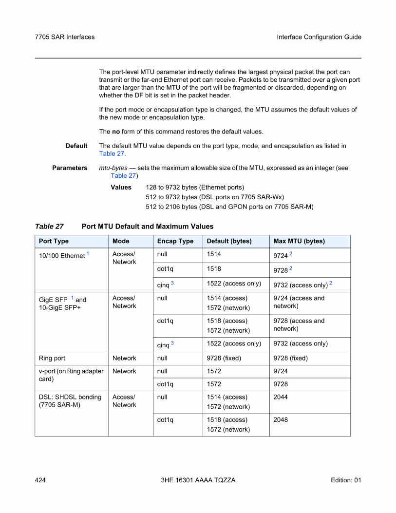
7705 SAR Interfaces
424
Interface Configuration Guide
3HE 16301 AAAA TQZZA Edition: 01
The port-level MTU parameter indirectly defines the largest physical packet the port can transmit or the far-end Ethernet port can receive. Packets to be transmitted over a given port that are larger than the MTU of the port will be fragmented or discarded, depending on whether the DF bit is set in the packet header.
If the port mode or encapsulation type is changed, the MTU assumes the default values of the new mode or encapsulation type.
The no form of this command restores the default values.
Default The default MTU value depends on the port type, mode, and encapsulation as listed in Table 27.
Parameters mtu-bytes — sets the maximum allowable size of the MTU, expressed as an integer (see Table 27)
Values 128 to 9732 bytes (Ethernet ports) 512 to 9732 bytes (DSL ports on 7705 SAR-Wx) 512 to 2106 bytes (DSL and GPON ports on 7705 SAR-M)
Table 27 Port MTU Default and Maximum Values
Port Type Mode Encap Type Default (bytes) Max MTU (bytes)
10/100 Ethernet 1 Access/ Network
null 1514 9724 2
dot1q 1518 9728 2
qinq 3 1522 (access only) 9732 (access only) 2
GigE SFP 1 and 10-GigE SFP+
Access/ Network
null 1514 (access)1572 (network)
9724 (access and network)
dot1q 1518 (access)1572 (network)
9728 (access and network)
qinq 3 1522 (access only) 9732 (access only)
Ring port Network null 9728 (fixed) 9728 (fixed)
v-port (on Ring adapter card)
Network null 1572 9724
dot1q 1572 9728
DSL: SHDSL bonding (7705 SAR-M)
Access/ Network
null 1514 (access)1572 (network)
2044
dot1q 1518 (access)1572 (network)
2048
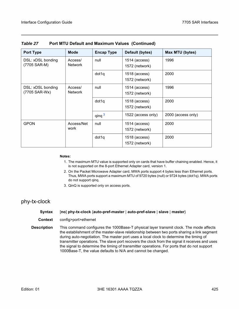
Interface Configuration Guide 7705 SAR Interfaces
Edition: 01 3HE 16301 AAAA TQZZA 425
Notes:1. The maximum MTU value is supported only on cards that have buffer chaining enabled. Hence, it
is not supported on the 8-port Ethernet Adapter card, version 1.2. On the Packet Microwave Adapter card, MWA ports support 4 bytes less than Ethernet ports.
Thus, MWA ports support a maximum MTU of 9720 bytes (null) or 9724 bytes (dot1q). MWA ports do not support qinq.
3. QinQ is supported only on access ports.
phy-tx-clock
Syntax [no] phy-tx-clock auto-pref-master | auto-pref-slave | slave | master
Context config>port>ethernet
Description This command configures the 1000Base-T physical layer transmit clock. The mode affects the establishment of the master-slave relationship between two ports sharing a link segment during auto-negotiation. The master port uses a local clock to determine the timing of transmitter operations. The slave port recovers the clock from the signal it receives and uses the signal to determine the timing of transmitter operations. For ports that do not support 1000Base-T, the value defaults to N/A and cannot be changed.
DSL: xDSL bonding (7705 SAR-M)
Access/ Network
null 1514 (access)1572 (network)
1996
dot1q 1518 (access)1572 (network)
2000
DSL: xDSL bonding (7705 SAR-Wx)
Access/ Network
null 1514 (access)1572 (network)
1996
dot1q 1518 (access)1572 (network)
2000
qinq 3 1522 (access only) 2000 (access only)
GPON Access/Network
null 1514 (access)1572 (network)
2000
dot1q 1518 (access)1572 (network)
2000
Table 27 Port MTU Default and Maximum Values (Continued)
Port Type Mode Encap Type Default (bytes) Max MTU (bytes)
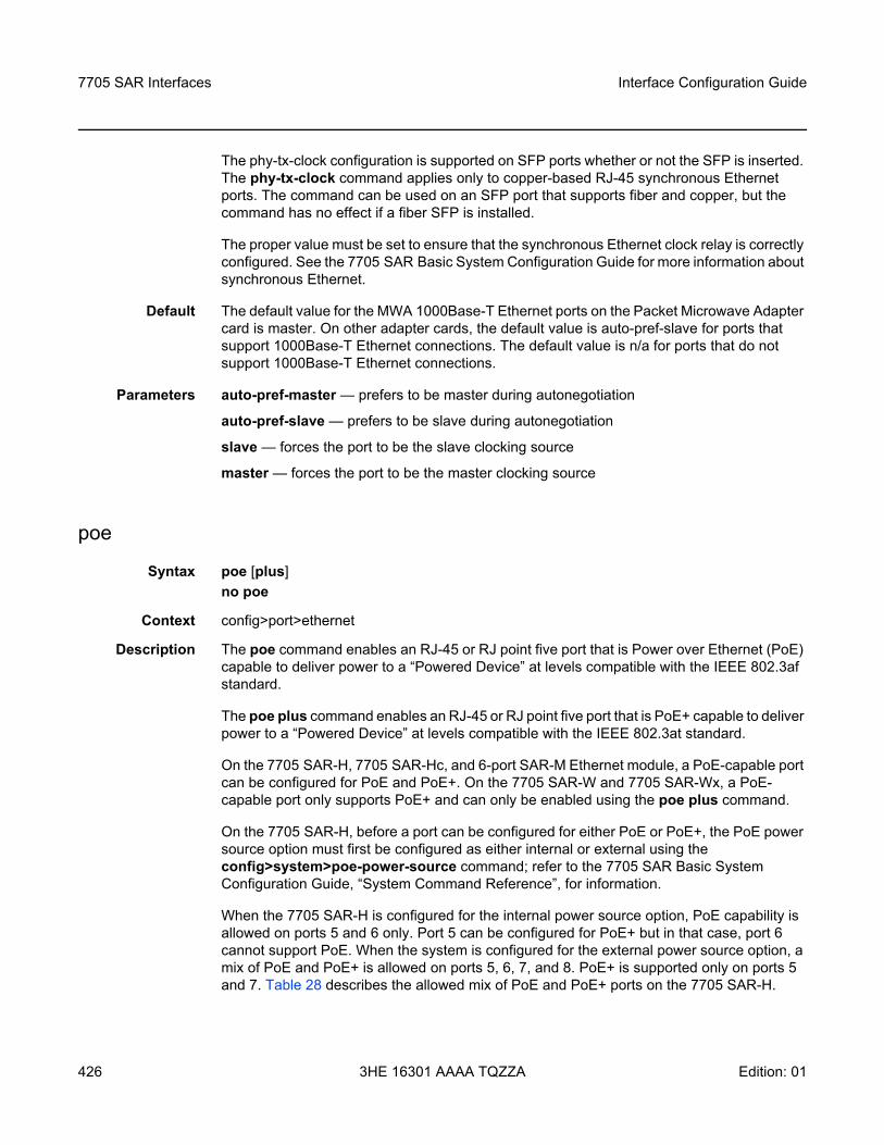
7705 SAR Interfaces
426
Interface Configuration Guide
3HE 16301 AAAA TQZZA Edition: 01
The phy-tx-clock configuration is supported on SFP ports whether or not the SFP is inserted. The phy-tx-clock command applies only to copper-based RJ-45 synchronous Ethernet ports. The command can be used on an SFP port that supports fiber and copper, but the command has no effect if a fiber SFP is installed.
The proper value must be set to ensure that the synchronous Ethernet clock relay is correctly configured. See the 7705 SAR Basic System Configuration Guide for more information about synchronous Ethernet.
Default The default value for the MWA 1000Base-T Ethernet ports on the Packet Microwave Adapter card is master. On other adapter cards, the default value is auto-pref-slave for ports that support 1000Base-T Ethernet connections. The default value is n/a for ports that do not support 1000Base-T Ethernet connections.
Parameters auto-pref-master — prefers to be master during autonegotiation
auto-pref-slave — prefers to be slave during autonegotiation
slave — forces the port to be the slave clocking source
master — forces the port to be the master clocking source
poe
Syntax poe [plus] no poe
Context config>port>ethernet
Description The poe command enables an RJ-45 or RJ point five port that is Power over Ethernet (PoE) capable to deliver power to a “Powered Device” at levels compatible with the IEEE 802.3af standard.
The poe plus command enables an RJ-45 or RJ point five port that is PoE+ capable to deliver power to a “Powered Device” at levels compatible with the IEEE 802.3at standard.
On the 7705 SAR-H, 7705 SAR-Hc, and 6-port SAR-M Ethernet module, a PoE-capable port can be configured for PoE and PoE+. On the 7705 SAR-W and 7705 SAR-Wx, a PoE-capable port only supports PoE+ and can only be enabled using the poe plus command.
On the 7705 SAR-H, before a port can be configured for either PoE or PoE+, the PoE power source option must first be configured as either internal or external using the config>system>poe-power-source command; refer to the 7705 SAR Basic System Configuration Guide, “System Command Reference”, for information.
When the 7705 SAR-H is configured for the internal power source option, PoE capability is allowed on ports 5 and 6 only. Port 5 can be configured for PoE+ but in that case, port 6 cannot support PoE. When the system is configured for the external power source option, a mix of PoE and PoE+ is allowed on ports 5, 6, 7, and 8. PoE+ is supported only on ports 5 and 7. Table 28 describes the allowed mix of PoE and PoE+ ports on the 7705 SAR-H.
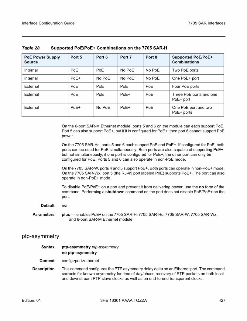
Interface Configuration Guide 7705 SAR Interfaces
Edition: 01 3HE 16301 AAAA TQZZA 427
On the 6-port SAR-M Ethernet module, ports 5 and 6 on the module can each support PoE. Port 5 can also support PoE+, but if it is configured for PoE+, then port 6 cannot support PoE power.
On the 7705 SAR-Hc, ports 5 and 6 each support PoE and PoE+. If configured for PoE, both ports can be used for PoE simultaneously. Both ports are also capable of supporting PoE+ but not simultaneously; if one port is configured for PoE+, the other port can only be configured for PoE. Ports 5 and 6 can also operate in non-PoE mode.
On the 7705 SAR-W, ports 4 and 5 support PoE+. Both ports can operate in non-PoE+ mode. On the 7705 SAR-Wx, port 5 (the RJ-45 port labeled PoE) supports PoE+. The port can also operate in non-PoE+ mode.
To disable PoE/PoE+ on a port and prevent it from delivering power, use the no form of the command. Performing a shutdown command on the port does not disable PoE/PoE+ on the port.
Default n/a
Parameters plus — enables PoE+ on the 7705 SAR-H, 7705 SAR-Hc, 7705 SAR-W, 7705 SAR-Wx, and 6-port SAR-M Ethernet module
ptp-asymmetry
Syntax ptp-asymmetry ptp-asymmetryno ptp-asymmetry
Context config>port>ethernet
Description This command configures the PTP asymmetry delay delta on an Ethernet port. The command corrects for known asymmetry for time of day/phase recovery of PTP packets on both local and downstream PTP slave clocks as well as on end-to-end transparent clocks.
Table 28 Supported PoE/PoE+ Combinations on the 7705 SAR-H
PoE Power Supply Source
Port 5 Port 6 Port 7 Port 8 Supported PoE/PoE+ Combinations
Internal PoE PoE No PoE No PoE Two PoE ports
Internal PoE+ No PoE No PoE No PoE One PoE+ port
External PoE PoE PoE PoE Four PoE ports
External PoE PoE PoE+ PoE Three PoE ports and one PoE+ port
External PoE+ No PoE PoE+ PoE One PoE port and two PoE+ ports
7705 SAR Interfaces
428
Interface Configuration Guide
3HE 16301 AAAA TQZZA Edition: 01
Parameters ptp-asymmetry — the value in nanoseconds that the forward path delay varies from the mean path delay; the value can be a negative number
qinq-etype
Syntax qinq-etype 0x0600 to 0xffff no qinq-etype
Context config>port>ethernetconfig>port>dsl
Description This command specifies the Ethertype expected when the port’s encapsulation type is qinq. The qinq-etype value sets the Ethertype for the outer VLAN tag when qinq encapsulation is used.
IEEE 802.1ad (also known as VLAN stacking) defines a process to channelize a single Ethernet port or v-port into double-tagged VLANs. Each VLAN can represent a customer or an application. Each tag allows for up to 4096 VLANs to be configured on a port (4096 × 4096 total). For more information on VLANs and VLAN tagging, refer to “VLL Services” in the 7705 SAR Services Guide.
The Ethertype specifies the protocol being carried in an Ethernet frame. In 802.1q, the Ethertype is set to the Tag Protocol Identifier (TPID) value of 0x8100, which identifies the frame as an IEEE 802.1Q-tagged frame. As well, 2 bytes of Tag Control Information (TCI), followed by 2 bytes containing the frame’s original Ethertype are added to the frame for each tag (4 bytes total). Together, the TPID and TCI make up a VLAN tag.
The qinq-etype command is not supported by a v-port, or by DSL or GPON modules on the 7705 SAR-M. However, qinq-etype is supported by the DSL block on the 7705 SAR-Wx.
Network ports do not allow qinq-etype settings.
The no form of this command resets the qinq-etype value to the default.
Default 0x8100
Parameters 0x0600 to 0xffff — specifies the Ethertype to expect
report-alarm
Syntax [no] report-alarm [signal-fail] [remote] [local] [no-frame-lock] [high-ber]
Context config>port>ethernet
Description This command specifies when and if to generate alarms and alarm clear notifications for this port.
Interface Configuration Guide 7705 SAR Interfaces
Edition: 01 3HE 16301 AAAA TQZZA 429
The command applies only to the physical 10GigE ports on the 7705 SAR-X, 6-port Ethernet 10Gbps Adapter card, 2-port 10GigE (Ethernet) Adapter card, and 2-port 10GigE (Ethernet) module, and on the 10-port 1GigE/1-port 10GigE X-Adapter card in 1-port 10GigE mode (select x1-10GigE-sf+ with the mda-mode command).
Parameters signal-fail — reports an Ethernet signal lost alarm
remote — reports remote faults
local — reports local faults
no-frame-lock — reports a “not locked on the ethernet framing sequence” alarm
high-ber — reports a high bit error rate alarm
speed
Syntax speed 10 | 100 | 1000 | 2500 | 10000
Context config>port>ethernet
Description This command configures the port speed of an Ethernet port, ring Ethernet port, or v-port when autonegotiation is disabled.
Default 100 (for Fast Ethernet ports on the 8-port Ethernet Adapter card, 7705 SAR-A (ports 9 to 12), 7705 SAR-Hc (ports 3 and 4), 4-port SAR-H Fast Ethernet module, and 6-port SAR-M Ethernet module (ports 1 and 2))
1000 (for Gigabit Ethernet ports on all adapter cards, modules, and fixed platforms)
2500 on a v-port (this default cannot be changed)
10000 (for the 10-port 1GigE/1-port 10GigE X-Adapter card in 1-port 10GigE mode, 2-port 10GigE (Ethernet) Adapter card, 2-port 10GigE (Ethernet) module, 6-port Ethernet 10Gbps Adapter card (ports 5 and 6), 7705 SAR-X (ports 1/2/7 and 1/3/7)
Parameters 10 — sets the link speed to 10 Mb/s
100 — sets the Ethernet port speed to 100 Mb/s
1000 — sets the Ethernet port speed to 1000 Mb/s (only supported on GigE SFPs)
2500 — sets the v-port speed to 2500 Mb/s (only supported on a v-port)
10000 — sets the ring Ethernet port speed (only supported on GigE XFPs) and the SFP+ ports speed on the 6-port Ethernet 10Gbps Adapter card and a 7705 SAR-X to 10 000 Mb/s
7705 SAR Interfaces
430
Interface Configuration Guide
3HE 16301 AAAA TQZZA Edition: 01
ssm
Syntax ssm
Context config>port>ethernetconfig>port>dsl
Description This command enables the Ethernet Synchronization Message Channel (ESMC) capability on a synchronous Ethernet port on the following:
• 2-port 10GigE (Ethernet) Adapter card• 2-port 10GigE (Ethernet) module • 6-port Ethernet 10Gbps Adapter card• 8-port Ethernet Adapter card, version 2• 8-port Gigabit Ethernet Adapter card• 10-port 1GigE/1-port 10GigE X-Adapter card• Packet Microwave Adapter card• 4-port SAR-H Fast Ethernet module• DSL module port on the 7705 SAR-M (variants with a module slot)• 7705 SAR-A • 7705 SAR-Ax • 7705 SAR-H• 7705 SAR-Hc• 7705 SAR-M (all variants)• 7705 SAR-W • 7705 SAR-Wx (all variants)• 7705 SAR-X
The ssm command is enabled and disabled using the no shutdown and shutdown commands.
On the 2-port 10GigE (Ethernet) Adapter card and 2-port 10GigE (Ethernet) module, SSM frames received on the ring Ethernet ports are extracted for processing through the v-port. Therefore, the v-port must be active (that is, in no shutdown mode) in order for SSM to function. The v-port must also be active in order for the 2-port 10GigE (Ethernet) Adapter card or 2-port 10GigE (Ethernet) module to transmit SSM frames. No additional interface or IP configuration is required on the v-port for SSM.
Default shutdown
code-type
Syntax code-type sonet | sdh
Context config>port>ethernet>ssm
Interface Configuration Guide 7705 SAR Interfaces
Edition: 01 3HE 16301 AAAA TQZZA 431
config>port>dsl>ssm
Description This command specifies whether to use SDH or SONET values for the encoding of synchronous status messages on a:
• synchronous ring Ethernet port on the 2-port 10GigE (Ethernet) Adapter card• synchronous ring Ethernet port on the 2-port 10GigE (Ethernet) module • synchronous Ethernet port on the 6-port Ethernet 10Gbps Adapter card• synchronous Ethernet port on the 8-port Ethernet Adapter card, version 2• synchronous Ethernet port on the 8-port Gigabit Ethernet Adapter card• synchronous Ethernet port on the 10-port 1GigE/1-port 10GigE X-Adapter card• synchronous Ethernet port on the Packet Microwave Adapter card• synchronous Ethernet port on the 4-port SAR-H Fast Ethernet module• DSL module port on the 7705 SAR-M (variants with a module slot)• synchronous Ethernet port on the 7705 SAR-A • synchronous Ethernet port on the 7705 SAR-Ax • synchronous Ethernet port on the 7705 SAR-H• synchronous Ethernet port on the 7705 SAR-Hc• synchronous Ethernet port on the 7705 SAR-M (all variants)• synchronous Ethernet port on the 7705 SAR-W • synchronous Ethernet port on the 7705 SAR-Wx (all variants)• synchronous Ethernet port on the 7705 SAR-X
Default sdh
Parameters sonet — specifies the values used on a G.781 option 1 compliant network
sdh — specifies the values used on a G.782 option 1 compliant network
tx-dus
Syntax [no] tx-dus
Context config>port>ssmconfig>port>ethernet>ssm
Description This command sets the quality level value transmitted from the Synchronization Status Messaging (SSM) channel of the following ports to QL-DUS/QL-DNU (do not use for synchronization for timing purposes):
• synchronous Ethernet port on the 2-port 10GigE (Ethernet) Adapter card• synchronous Ethernet port on the 2-port 10GigE (Ethernet) module• synchronous Ethernet port on the 6-port Ethernet 10Gbps Adapter card• synchronous Ethernet port on the 8-port Ethernet Adapter card, version 2• synchronous Ethernet port on the 8-port Gigabit Ethernet Adapter card
7705 SAR Interfaces
432
Interface Configuration Guide
3HE 16301 AAAA TQZZA Edition: 01
• synchronous Ethernet port on the 10-port 1GigE/1-port 10GigE X-Adapter card• synchronous Ethernet port on the Packet Microwave Adapter card• synchronous Ethernet port on the 4-port SAR-H Fast Ethernet module• synchronous Ethernet port on the 7705 SAR-A • synchronous Ethernet port on the 7705 SAR-Ax • synchronous Ethernet port on the 7705 SAR-H• synchronous Ethernet port on the 7705 SAR-Hc• synchronous Ethernet port on the 7705 SAR-M (all variants)• synchronous Ethernet port on the 7705 SAR-W • synchronous Ethernet port on the 7705 SAR-Wx (all variants)• synchronous Ethernet port on the 7705 SAR-X
Default The value depends on whether the port type is copper or fiber. The default value is:
• enabled for fiber ports• disabled (no tx-dus) for copper ports
vlan-filter
Syntax [no] vlan-filter filter-id
Context config>port>ethernet
Description This command associates a VLAN filter policy with an ingress ring port on the 2-port 10GigE (Ethernet) Adapter card or 2-port 10GigE (Ethernet) module.
Filter policies control the forwarding and dropping of packets based on matching criteria. Only one filter policy can be applied to a ring port at a time. The same filter policy can be applied to both ring ports.
The filter-id must already be defined before the vlan-filter command is executed. If the filter policy does not exist, the operation will fail and an error message will be displayed.
The no form of the command removes any configured filter-id association with the ring port. The filter policy cannot be deleted until it is removed from all ring ports where it is applied.
Default n/a
Parameters filter-id — the VLAN filter policy ID number or filter name
Values 1 to 65535 or filter-name (up to 64 characters)
Interface Configuration Guide 7705 SAR Interfaces
Edition: 01 3HE 16301 AAAA TQZZA 433
xgig
Syntax xgig lan | wan
Context config>port>ethernet
Description This command configures the specified 10-Gb/s interface in LAN or WAN mode. When configuring the port for WAN mode, you can change some SONET/SDH parameters to reflect the SONET/SDH requirements for this port. When you configure a port for LAN mode, all SONET/SDH parameters are predetermined and not configurable. The command is supported on the 7705 SAR-X, 6-port Ethernet 10Gbps Adapter card, 10-port 1GigE/1-port 10GigE X-Adapter card, 2-port 10GigE (Ethernet) Adapter card, and 2-port 10GigE (Ethernet) module.
On the 6-port Ethernet 10Gbps Adapter card, both 10-Gb/s interfaces (ports 5 and 6) operate in the same xgig mode, either LAN mode or WAN mode. Setting the xgig mode for either port sets the mode for both ports.
Default lan
Parameters lan — specifies that the port operates in LAN mode
wan — specifies that the port operates in WAN mode
xor-mode
Syntax xor-mode rj45 | rjp5 | sfp
Context config>port>ethernet
Description This command configures the operational mode of Ethernet XOR combination ports. Ethernet XOR ports on the 7705 SAR-A, 7705 SAR-Ax, 7705 SAR-H, and 7705 SAR-X can be configured to operate as either RJ-45 ports or SFP ports. Ethernet XOR ports on the 6-port SAR-M Ethernet module can be configured to operate as either RJ point five ports or SFP ports. The mode can be configured on each port independently. Refer to the individual hardware installation guides for more information.
Default rj45 (for applicable 7705 SAR chassis); rjp5 (for 6-port SAR-M Ethernet module)
Parameters rj45 — specifies that the port operate as a 10/100/1000Base-T electrical RJ-45 port (applicable 7705 SAR chassis only)
rjp5 — specifies that the port operate as a 10/100/1000Base-T electrical RJ point five port (6-port SAR-M Ethernet module only)
sfp — specifies that the port operate as an SFP port
7705 SAR Interfaces
434
Interface Configuration Guide
3HE 16301 AAAA TQZZA Edition: 01
3.13.2.11 DSL Commands
dsl
Syntax dsl
Context config>port
Description This command enables the context to configure DSL port attributes on an 8-port xDSL module, a 6-port DSL Combination module, or an xDSL port on a 7705 SAR-Wx.
adsl2plus
Syntax adsl2plus g992-5-a | g992-5-bno adsl2plus
Context config>port>dsl
Description This command configures a DSL port to support POTS or ISDN non-overlapped spectrum over ADSL2+, in accordance with ITU G.992.5 Annex A and B. This command is supported on the two xDSL ports on the 6-port DSL Combination module, on any port on the 8-port xDSL module configured for xDSL, and on the xDSL port on the 7705 SAR-Wx.
Default g992-5-a
Parameters g992-5-a — configures the DSL port to support POTS non-overlapped spectrum over ADSL2+ in accordance with ITU G.992.5 Annex A
g992-5-b — configures the DSL port to support ISDN non-overlapped spectrum over ADSL2+ in accordance with ITU G.992.5 Annex B
atm-pvc
Syntax atm-pvc dsl-bonding-vpi dsl-bonding-vcino atm-pvc
Context config>port>dsl
Description This command configures an ATM PVC for traffic on DSL lines in ADSL2 or ADSL2+ bonded ATM mode.
Parameters dsl-bonding-vpi — specifies the VPI of the ATM PVC
Values 0 to 255
Default 8
Interface Configuration Guide 7705 SAR Interfaces
Edition: 01 3HE 16301 AAAA TQZZA 435
dsl-bonding-vci — specifies the VCI of the ATM PVC
Values 32 to 65535
Default 35
line
Syntax line number
Context config>port>dsl
Description This command configures a DSL line.
Parameters number — the DSL line number
Values 1, 2, 4, 8
1 Available for any DSL line2 Reserved for xDSL on the 6-port DSL Combination module 4 Reserved for SHDSL on the 6-port DSL Combination module or the
xDSL port on the 7705 SAR-Wx8 Reserved for xDSL on the 8-port xDSL module
7705 SAR Interfaces
436
Interface Configuration Guide
3HE 16301 AAAA TQZZA Edition: 01
3.13.2.12 GPON Commands
gpon
Syntax gpon
Context config>port
Description This command enters the context to perform GPON port configuration.
Default n/a
slid
Syntax slid alphanumeric | hex slidno slid
Context config>port>gpon
Description This command configures a permanent Subscriber Location ID (SLID). SLIDs can be configured in decimal, alphanumeric or hexadecimal format, but the SLID will always be displayed in hexadecimal format.
The no form of the command reverts to the default.
Default 44:45:46:41:55:4C:54:00:00:00 / “DEFAULT”
Parameters alphanumeric — configures the SLID using up to 10 decimal or alphanumeric characters
hex — configures the SLID using up to 20 hexadecimal numbers, separated by colons or dashes in the form aa:bb:cc:dd:ee:ff:gg:hh:ii:jj or aa-bb-cc-dd-ee-ff-gg-hh-ii-jj
slid — sets the Subscriber Location ID in the chosen format
Interface Configuration Guide 7705 SAR Interfaces
Edition: 01 3HE 16301 AAAA TQZZA 437
3.13.2.13 GNSS Commands
gnss
Syntax gnss
Context config>port
Description This command enters the context to perform GNSS receiver port configuration.
Default n/a
antenna-cable-delay
Syntax antenna-cable-delay 0 .. 32767no antenna-cable-delay
Context config>port>gnss
Description This command configures the expected signal delay resulting from the length of the antenna cable.
The no form of this command returns the value to the default.
Default 0
Parameters 0 .. 32767 — the signal delay, in nanoseconds
elevation-mask-angle
Syntax elevation-mask-angle 0 .. 89no elevation-mask-angle
Context config>port>gnss
Description This command configures the elevation mask angle. It provides a method of filtering satellites to be used by the system.
Configuring an elevation mask angle below 10° is not recommended.
The no form of this command returns the value to the default.
Default 10
Parameters 0 .. 89 — the elevation mask angle, in degrees.
7705 SAR Interfaces
438
Interface Configuration Guide
3HE 16301 AAAA TQZZA Edition: 01
type
Syntax [no] type [gps] [glonass]
Context config>port>gnss
Description This command configures which GNSS system or systems will be used by the GNSS receiver.
The no form of this command removes the specified GNSS system or systems.
By default, gps is configured. Configuring glonass does not remove gps; the GNSS receiver will use both GPS and GLONASS systems.
Default gps
Parameters gps — configures the GNSS receiver to use the American GPS GNSS system
glonass — configures the GNSS receiver to use the Russian GLONASS GNSS system
Interface Configuration Guide 7705 SAR Interfaces
Edition: 01 3HE 16301 AAAA TQZZA 439
3.13.2.14 IEEE 802.1x Ethernet Port Commands
dot1x
Syntax dot1x
Context config>port>ethernet
Description This command enables access to the context to configure port-specific 802.1x authentication attributes on an Ethernet port.
mac-auth
Syntax [no] mac-auth
Context config>port>ethernet>dot1x
Description This command enables MAC-based authentication. To use MAC-based authentication, 802.1x authentication must first be enabled using the port-control auto command.
When MAC-based authentication is enabled, and the mac-auth-wait timer expires, the 7705 SAR begins listening on the port for valid Ethernet frames. The source address of a received frame is used for MAC-based authentication.
The no form of this command disables MAC-based authentication.
Default no mac-auth
mac-auth-wait
Syntax mac-auth-wait secondsno mac-auth-wait
Context config>port>ethernet>dot1x
Description This command configures the delay period before MAC authentication is activated and the 7705 SAR searches for a valid client MAC address.
The no form of this command disables the delay and allows MAC authentication to be used immediately.
Default no mac-auth-wait
Parameters seconds — specifies the MAC authentication delay period in seconds
Values 1 to 3600
7705 SAR Interfaces
440
Interface Configuration Guide
3HE 16301 AAAA TQZZA Edition: 01
max-auth-req
Syntax max-auth-req max-auth-requestno max-auth-req
Context config>port>ethernet>dot1x
Description This command configures the maximum number of times that the 7705 SAR will send an access request RADIUS message to the RADIUS server. If a reply is not received from the RADIUS server after the specified number of attempts, the 802.1x authentication process is considered to have failed.
The no form of this command returns the value to the default.
Default 2
Parameters max-auth-req — the maximum number of RADIUS retries
Values 1 to 10
port-control
Syntax port-control auto | force-auth | force-unauthno port-control
Context config>port>ethernet>dot1x
Description This command configures the 802.1x authentication mode.
The no form of this command returns the value to the default.
Default force-auth
Parameters auto — enables 802.1x authentication. The port starts in the unauthorized state, allowing only EAPOL frames to be sent and received through the port. Both the 7705 SAR and the host (supplicant) can initiate an authentication process. The port will remain in the unauthorized state until the first supplicant is authenticated successfully. After this, traffic is allowed on the port for all connected hosts.
force-auth — disables 802.1x authentication and causes the port to transition to the authorized state without requiring any authentication exchange. The port transmits and receives normal traffic without requiring 802.1x-based host authentication.
force-unauth — causes the port to remain in the unauthorized state, ignoring all attempts by the hosts to authenticate. The authenticator cannot provide authentication services to the host through the interface.
Interface Configuration Guide 7705 SAR Interfaces
Edition: 01 3HE 16301 AAAA TQZZA 441
quiet-period
Syntax quiet-period secondsno quiet-period
Context config>port>ethernet>dot1x
Description This command configures the time between two authentication sessions during which no EAPOL frames are sent by the 7705 SAR. The timer is started after sending an EAP-Failure message or after expiry of the supplicant timeout timer.
The no form of this command returns the value to the default.
Default 60
Parameters seconds — specifies the quiet period in seconds
Values 1 to 3600
radius-plcy
Syntax radius-plcy nameno radius-plcy
Context config>port>ethernet>dot1x
Description This command configures the RADIUS policy to be used for 802.1x authentication. An 802.1x RADIUS policy must be configured (under config>system>security>dot1x) before it can be associated with a port. If the RADIUS policy ID does not exist, an error is returned. Only one 802.1x RADIUS policy can be associated with a port at a time.
The no form of this command removes the RADIUS policy association.
Default no radius-plcy
Parameters name — specifies an existing 802.1x RADIUS policy name
re-auth-period
Syntax re-auth-period secondsno re-auth-period
Context config>port>ethernet>dot1x
Description This command configures the number of seconds the system will wait before performing reauthentication. This value is only relevant if reauthentication is enabled with the re-authentication command.
The no form of this command returns the value to the default.
7705 SAR Interfaces
442
Interface Configuration Guide
3HE 16301 AAAA TQZZA Edition: 01
Default 3600
Parameters seconds — specifies the reauthentication delay period in seconds
Values 1 to 9000
re-authentication
Syntax [no] re-authentication
Context config>port>ethernet>dot1x
Description This command enables or disables periodic 802.1x reauthentication.
When reauthentication is enabled, the 7705 SAR will reauthenticate clients on the port after waiting the number of seconds defined by the re-auth-period command.
The no form of this command disables 802.1x reauthentication.
Default no re-authentication
server-timeout
Syntax server-timeout secondsno server-timeout
Context config>port>ethernet>dot1x
Description This command configures the time during which the 7705 SAR waits for the RADIUS server to respond to its access request message. When this timer expires, the 7705 SAR will resend the access request message, up to the number of times specified by the max-auth-req command.
The no form of this command returns the value to the default.
Default 30
Parameters seconds — specifies the server timeout period in seconds
Values 1 to 300
supplicant-timeout
Syntax supplicant-timeout secondsno supplicant-timeout
Context config>port>ethernet>dot1x
Interface Configuration Guide 7705 SAR Interfaces
Edition: 01 3HE 16301 AAAA TQZZA 443
Description This command configures the time the 7705 SAR waits for a client to respond to its EAPOL messages. When the supplicant timeout period expires, the 802.1x authentication session is considered to have failed.
The no form of this command returns the value to the default.
Default 30
Parameters seconds — specifies the supplicant timeout period in seconds
Values 1 to 300
transmit-period
Syntax transmit-period secondsno transmit-period
Context config>port>ethernet>dot1x
Description This command configures the time after which the 7705 SAR sends a new EAPOL request message.
The no form of this command returns the value to the default.
Default 30
Parameters seconds — specifies the server transmit period in seconds
Values 1 to 3600
tunneling
Syntax [no] tunneling
Context config>port>ethernet>dot1x
Description This command enables the tunneling of untagged 802.1x frames received on a port for both Epipe and VPLS services using a null SAP or a default SAP on a dot1q or qinq port. When configured, untagged 802.1x frames are switched into the service with the corresponding supported SAP. 802.1x tunneling is supported only when the port-control command is set to force-auth.
The no form of this command disables tunneling of untagged 802.1x frames.
Default no tunneling
7705 SAR Interfaces
444
Interface Configuration Guide
3HE 16301 AAAA TQZZA Edition: 01
3.13.2.15 LLDP Ethernet Port Commands
Refer to the 7705 SAR Basic System Configuration Guide, “System Management”, for LLDP system commands.
lldp
Syntax lldp
Context config>port>ethernet
Description This command enables the context to configure LLDP parameters on the specified port.
dest-mac
Syntax dest-mac nearest-bridge | nearest-non-tpmr | nearest-customer
Context config>port>ethernet>lldp
Description This command configures destination MAC address parameters.
Parameters nearest-bridge — configures the LLDP to use the nearest bridge
nearest-non-tpmr — configures the LLDP to use the nearest non-two-port MAC relay (TPMR) bridge
nearest-customer — configures the LLDP to use the nearest customer bridge
admin-status
Syntax admin-status rx | tx | tx-rx | disabled
Context config>port>ethernet>lldp>dest-mac
Description This command specifies the administratively desired status of the local LLDP agent.
Default disabled
Parameters rx — specifies that the LLDP agent will receive, but will not transmit, LLDP frames on this port
tx — specifies that the LLDP agent will transmit LLDP frames on this port and will not store any information about the remote systems connected to it
Note: In order for LLDP to be operational on the Ethernet ports on the 2-port 10GigE (Ethernet) Adapter card/module, the v-port must be active (that is, in no shutdown mode).
Interface Configuration Guide 7705 SAR Interfaces
Edition: 01 3HE 16301 AAAA TQZZA 445
tx-rx — specifies that the LLDP agent will transmit and receive LLDP frames on this port
disabled — specifies that the LLDP agent will not transmit or receive LLDP frames on this port. If there is remote system information that was received on this port and stored in other tables before the port’s admin-status was disabled, the information will naturally age out.
notification
Syntax [no] notification
Context config>port>ethernet>lldp>dest-mac
Description This command enables LLDP notifications.
The no form of the command disables LLDP notifications.
Default no notification
port-id-subtype
Syntax port-id-subtype tx-if-alias | tx-if-name | tx-local
Context config>port>ethernet>lldp>destmac
Description This command specifies how to encode the port ID TLV transmit to the peer. The default setting tx-local (ifindex value) is required by some versions of the NSP NFM-P to properly build the Layer 2 topology map using LLDP. Changing this value to transmit the ifName (tx-if-name) or ifAlias (tx-if-alias) in place of the ifindex (tx-local) may affect the ability of the NSP NFM-P to build the Layer 2 topology map using LLDP.
Default tx-local
Parameters tx-if-alias — transmits the ifAlias string (subtype 1) that describes the port as stored in the IF-MIB, either user-configured or the default entry (that is, 10/100/Gig Ethernet SFP)
tx-if-name — transmits the ifName string (subtype 5) that describes the port as stored in the IF-MIB ifName info
tx-local — the interface ifindex value (subtype 7) as the port ID
7705 SAR Interfaces
446
Interface Configuration Guide
3HE 16301 AAAA TQZZA Edition: 01
tx-mgmt-address
Syntax tx-mgmt-address [system] [system-ipv6] no tx-mgmt-address
Context config>port>ethernet>lldp>dest-mac
Description This command specifies which management address to transmit. The 7705 SAR can only be configured to send or not send the system address.
If the no form of the command is used, the port will not include the system management address TLV in any LLDPDUs it transmits.
Default no tx-mgmt-address
Parameters system — specifies to use the system IPv4 address. The system address is only transmitted after it has been configured.
system-ipv6 — specifies to use the system IPv6 address. The system address is only transmitted after it has been configured.
tx-tlvs
Syntax tx-tlvs [port-desc] [sys-name] [sys-desc] [sys-cap]no tx-tlvs
Context config>port>ethernet>lldp>dest-mac
Description This command specifies which LLDP optional TLVs to transmit.
If the no form of the command is used, the port will not include any optional TLVs in any LLDPDUs it transmits.
Default no tx-tlvs
Parameters port-desc — indicates that the LLDP agent should transmit port description TLVs
sys-name — indicates that the LLDP agent should transmit system name TLVs
sys-desc — indicates that the LLDP agent should transmit system description TLVs
sys-cap — indicates that the LLDP agent should transmit system capabilities TLVs
Interface Configuration Guide 7705 SAR Interfaces
Edition: 01 3HE 16301 AAAA TQZZA 447
3.13.2.16 Ring MAC Operations Commands
disable-aging
Syntax [no] disable-aging
Context config>card>mda>ring
Description This command disables MAC address aging across an Ethernet ring.
As is the case for a Layer 2 switch, learned MACs can be aged out if no packets are sourced from the MAC address for a period of time (the aging time). In each ring, there are independent aging timers for local learned MAC and remote learned MAC entries in the FDB. The disable-aging command turns off aging for local and remote learned MAC addresses.
The no form of this command enables aging on the ring.
Default no disable-aging
disable-learning
Syntax [no] disable-learning
Context config>card>mda>ring
Description This command disables learning of new MAC addresses in the ring FDB.
When disable-learning is enabled, new source MAC addresses will not be entered in the ring FDB. This is true for both local and remote MAC addresses.
When disable-learning is disabled, new source MAC addresses will be learned and entered into the ring FDB.
This parameter is mainly used in conjunction with the discard-unknown-source command.
The no form of this command enables learning of MAC addresses.
Default no disable-learning
7705 SAR Interfaces
448
Interface Configuration Guide
3HE 16301 AAAA TQZZA Edition: 01
discard-unknown-source
Syntax [no] discard-unknown-source
Context config>card>mda>ring
Description This command specifies that packets with an unknown source MAC address received on a ring port will be dropped if the source MAC is not already in the FDB (that is, the source MAC was not learned before the discard-unknown-source command was enabled or is not a static entry already created for the packet MAC).
When disabled, the packets are flooded to the other ring port or forwarded to the v-port (if the packets are addressed to the v-port).
The no form of this command disables discard-unknown-source.
Default no discard-unknown-source
fdb-table-high-wmark
Syntax fdb-table-high-wmark high-water-markno fdb-table-high-wmark
Context config>card>mda>ring
Description This command specifies the upper threshold value for learned FDB entries. The high-water-mark is configured as a percentage of the FDB. When the number of FDB entries exceeds the high-water-mark, the system raises a log event.
The no form of this command returns the maximum FDB table high-water-mark to the default (95%).
Default no fdb-table-high-wmark
Parameters high-water-mark — specifies the upper threshold for FDB entries as a percentage of FDB table size, which when exceeded, causes the system to raise a log event
Values 0 to 100
fdb-table-size
Syntax fdb-table-size table-sizeno fdb-table-size
Context config>card>mda>ring
Description This command specifies the maximum number of MAC entries in the dynamic FDB for the ring.
Interface Configuration Guide 7705 SAR Interfaces
Edition: 01 3HE 16301 AAAA TQZZA 449
The no form of this command returns the maximum FDB table size to the default (512).
Default no fdb-table-size
Parameters table-size — the maximum number of learned MAC entries in the FDB for the ring
Values 4 to 512
mac-pinning
Syntax [no] mac-pinning port port-id
Context config>card>mda>ring
Description This command keeps MAC address information that has been learned from a source frame in the FDB until the expiry of the mac-aging timer, which is specified using the remote-age command). If a MAC address is pinned and a frame with an existing source MAC address is received from the other ring port, the FDB entry is not altered—the address that was learned from the first source frame is preserved until the expiry of the aging timer. If the aging timer is disabled, then the MAC address remains pinned until the timer is enabled again.
The no form of this command disables mac-pinning.
Default no mac-pinning
Parameters port-id — specifies the physical ring port
remote-age
Syntax remote-age aging-timerno remote-age
Context config>card>mda>ring
Description This command specifies the aging time for remotely learned MAC addresses in the FDB.
As is the case for a Layer 2 switch, learned MAC addresses can be aged out if no packets are sourced from the MAC address for a period of time (the aging time). The remote-age timer specifies the aging time for remotely learned MAC addresses.
The no form of this command returns the remote aging timer to the default value (900 s).
Default no remote-age
Parameters aging-timer — the aging time for remote MAC addresses, expressed in seconds
Values 60 to 86400
7705 SAR Interfaces
450
Interface Configuration Guide
3HE 16301 AAAA TQZZA Edition: 01
static-mac
Syntax [no] static-mac mac ieee-address port port-id [create]
Context config>card>mda>ring
Description This command creates a local static MAC entry in the FDB for the specified port. The maximum number of static MAC addresses per ring adapter card is 256.
Static MAC definitions on one edge device are not propagated to other edge devices; that is, each edge device has an independent FDB.
Only one static MAC entry (local or remote) can be defined per MAC address per instance.
By default, no static MAC address entries are defined.
The no form of this command deletes the static MAC entry with the specified MAC address associated with the port from the FDB.
Parameters ieee-address — specifies the 48-bit MAC address for the static ARP in the form aa:bb:cc:dd:ee:ff or aa-bb-cc-dd-ee-ff where aa, bb, cc, dd, ee and ff are hexadecimal numbers (cannot be all zeros). Allowed values are any non-broadcast, non-multicast MAC, and non-IEEE reserved MAC addresses.
port-id — specifies the port that is associated with the specified MAC address
create — this keyword is mandatory when specifying a static MAC address
Interface Configuration Guide 7705 SAR Interfaces
Edition: 01 3HE 16301 AAAA TQZZA 451
3.13.2.17 Serial Commands
serial
Syntax serial
Context config>port
Description This command enables the context to configure RS-232, V.35, or X.21 parameters for a port on a channelized 12-port Serial Data Interface card, or to configure RS-232 parameters for an RS-232 port on the 7705 SAR-Hc or on the 4-port T1/E1 and RS-232 Combination module. This context cannot be accessed by any other card.
A serial port configuration allows some or all of the bandwidth to be dedicated to a port by aggregating a number of DS0s into a single bundle.
Serial data transmission rates below the rate of a single DS0, that is, less than 64 kb/s, are achieved using a proprietary protocol called High Capacity Multiplexing (HCM). These speeds, known as subrate speeds, are supported only on RS-232 and X.21 ports.
On the 12-port Serial Data Interface card, version 1 or version 2, if the port has been enabled for an RS-530 interface through the use of an adapter cable, X.21 configuration applies to the RS-530 interface. There is no configuration specifically for RS-530 operation on these card versions. For the 12-port Serial Data Interface card, version 3, there is a separate rs530 command to configure RS-530 channel parameters.
Default n/a
rs232
Syntax [no] rs232
Context config>port>serial
Description This command enables the context to configure RS-232 parameters for a channel. Once one of the ports on a connector has been configured for an RS-232 channel, the other ports on the connector can only be configured for RS-232.
The no form of this command deletes the RS-232 channel.
Default n/a
7705 SAR Interfaces
452
Interface Configuration Guide
3HE 16301 AAAA TQZZA Edition: 01
rs530
Syntax [no] rs530
Context config>port>serial
Description This command enables the context to configure RS-530 parameters for a channel on a 12-port Serial Data Interface card, version 3. Once one of the ports on a connector has been configured for an RS-530 channel, the other port on the connector can only be configured for RS-530.
The no form of this command deletes the RS-530 channel.
Default n/a
v35
Syntax [no] v35
Context config>port>serial
Description This command enables the context to configure V.35 parameters for a channel. Once one of the ports on a connector has been configured for a V.35 channel, the other ports on the connector can only be configured for V.35. The no form of this command deletes the V.35 channel.
The no form of this command deletes the V.35 channel.
Default n/a
x21
Syntax [no] x21
Context config>port>serial
Description This command enables the context to configure X.21 parameters for a channel. Once one of the ports on a connector has been configured for an X.21 channel, the other ports on the connector can only be configured for X.21.
On a 12-port Serial Data Interface card, version 1 or version 2, if the port has been enabled for an RS-530 interface through the use of an adapter cable, X.21 configuration applies to the RS-530 interface. There is no configuration specifically for RS-530 operation. All X.21 functionality is available on the RS-530 interface, except that only DCE operation is supported for RS-530. However, because X.21 does not support all the control leads available for RS-530, only a subset of the RS-530 control leads are supported.
The no form of this command deletes the X.21 channel.
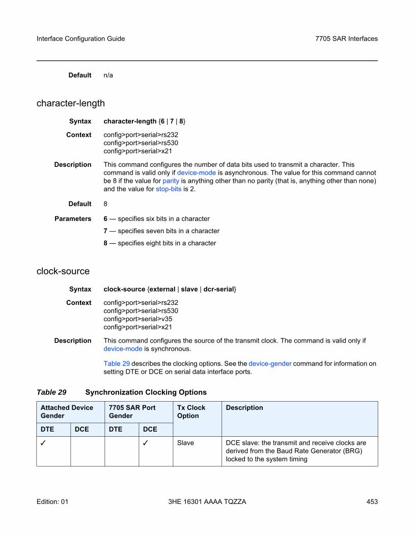
Interface Configuration Guide 7705 SAR Interfaces
Edition: 01 3HE 16301 AAAA TQZZA 453
Default n/a
character-length
Syntax character-length 6 | 7 | 8
Context config>port>serial>rs232config>port>serial>rs530config>port>serial>x21
Description This command configures the number of data bits used to transmit a character. This command is valid only if device-mode is asynchronous. The value for this command cannot be 8 if the value for parity is anything other than no parity (that is, anything other than none) and the value for stop-bits is 2.
Default 8
Parameters 6 — specifies six bits in a character
7 — specifies seven bits in a character
8 — specifies eight bits in a character
clock-source
Syntax clock-source external | slave | dcr-serial
Context config>port>serial>rs232config>port>serial>rs530config>port>serial>v35config>port>serial>x21
Description This command configures the source of the transmit clock. The command is valid only if device-mode is synchronous.
Table 29 describes the clocking options. See the device-gender command for information on setting DTE or DCE on serial data interface ports.
Table 29 Synchronization Clocking Options
Attached Device Gender
7705 SAR Port Gender
Tx Clock Option
Description
DTE DCE DTE DCE
Slave DCE slave: the transmit and receive clocks are derived from the Baud Rate Generator (BRG) locked to the system timing
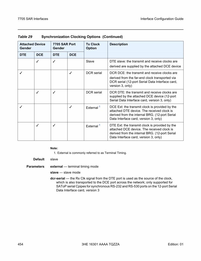
7705 SAR Interfaces
454
Interface Configuration Guide
3HE 16301 AAAA TQZZA Edition: 01
Note:1. External is commonly referred to as Terminal Timing.
Default slave
Parameters external — terminal timing mode
slave — slave mode
dcr-serial — the Rx Clk signal from the DTE port is used as the source of the clock, which is also transported to the DCE port across the network; only supported for SAToP serial Cpipes for synchronous RS-232 and RS-530 ports on the 12-port Serial Data Interface card, version 3
Slave DTE slave: the transmit and receive clocks arederived are supplied by the attached DCE device
DCR serial DCR DCE: the transmit and receive clocks arederived from the far-end clock transported via DCR serial (12-port Serial Data Interface card, version 3, only)
DCR serial DCR DTE: the transmit and receive clocks are supplied by the attached DCE device (12-port Serial Data Interface card, version 3, only)
External 1 DCE Ext: the transmit clock is provided by the attached DTE device. The received clock is derived from the internal BRG. (12-port Serial Data Interface card, version 3, only)
External 1 DTE Ext: the transmit clock is provided by the attached DCE device. The received clock is derived from the internal BRG. (12-port Serial Data Interface card, version 3, only)
Table 29 Synchronization Clocking Options (Continued)
Attached Device Gender
7705 SAR Port Gender
Tx Clock Option
Description
DTE DCE DTE DCE
Interface Configuration Guide 7705 SAR Interfaces
Edition: 01 3HE 16301 AAAA TQZZA 455
control-lead
Syntax control-lead input | monitor | output
Context config>port>serial>rs232config>port>serial>rs530config>port>serial>v35config>port>serial>x21
Description This command enables access to the context to configure the input and output leads that carry control signals. Control signals provide the handshaking for call setup, teardown, and synchronization.
Default n/a
input
Syntax input
Context config>port>serial>rs232>control-leadconfig>port>serial>rs530>control-leadconfig>port>serial>v35>control-leadconfig>port>serial>x21>control-lead
Description This command enables access to the context to configure the input control leads.
Default n/a
alb-cts
Syntax alb-cts high | low | end-to-end
Context config>port>serial>rs232>control-lead>inputconfig>port>serial>v35>control-lead>input
Description This command configures the Analog Loopback (ALB) or Clear To Send (CTS) input control lead. The input signal that is sent depends on the device-gender setting. For a DCE device, the input signal is ALB. For a DTE device, the input signal is CTS.
This command is valid only for RS-232 and V.35 interfaces.
Default high
Parameters high — the input control lead is assumed to be on
low — the input control lead is assumed to be off
end-to-end — the input control lead follows that of the remote end. This parameter is not supported for interface speeds ≥ 64 kb/s.
7705 SAR Interfaces
456
Interface Configuration Guide
3HE 16301 AAAA TQZZA Edition: 01
c-i
Syntax c-i high | low | end-to-end
Context config>port>serial>x21>control-lead>input
Description This command configures the Control (C) or Indication (I) input control lead. The input signal that is sent depends on the device-gender setting. For a DCE device, the input signal is C. For a DTE device, the input signal is I.
This command is valid only for X.21 interfaces.
Default high
Parameters high — the input control lead is forced on
low — the input control lead is forced off
end-to-end — the input control lead follows that of the remote end
dtr-dsr
Syntax dtr-dsr high | low
Context config>port>serial>rs232>control-lead>inputconfig>port>serial>rs530>control-lead>inputconfig>port>serial>v35>control-lead>input
Description This command configures the Data Terminal Ready (DTR) or Data Set Ready (DSR) input control lead. The input signal that is sent depends on the device-gender setting. For a DCE device, the input signal is DTR. For a DTE device, the input signal is DSR.
This command is valid only for RS-232, RS-530, and V.35 interfaces.
Default high
Parameters high — the input control lead is assumed to be on
low — the input control lead is assumed to be off
ll-tm
Syntax ll-tm high | low
Context config>port>serial>rs530>control-lead>input
Description This command configures the Local Loopback (LL) or Test Mode (TM) input control lead. The input signal that is sent depends on the device-gender setting. For a DCE device, the input signal is LL. For a DTE device, the input signal is TM.
Interface Configuration Guide 7705 SAR Interfaces
Edition: 01 3HE 16301 AAAA TQZZA 457
This command is valid only for RS-530 interfaces.
Default on
Parameters high — the input control lead is assumed to be on
low — the input control lead is assumed to be off
rdl-ri
Syntax rdl-ri high | low
Context config>port>serial>rs232>control-lead>input
Description This command configures the Remote Digital Loopback (RDL) or Ring Indicator (RI) input control lead. The input signal that is sent depends on the device-gender setting. For a DCE device, the input signal is RDL. For a DTE device, the input signal is RI.
This command is valid only for RS-232 interfaces.
Default high
Parameters high — the input control lead is assumed to be on
low — the input control lead is assumed to be off
rl-cts
Syntax rl-cts high | low | end-to-end
Context config>port>serial>rs530>control-lead>input
Description This command configures the Remote Loopback (RL) or Clear To Send (CTS) input control lead. The input signal that is sent depends on the device-gender setting. For a DCE device, the input signal is RL. For a DTE device, the input signal is CTS.
This command is valid only for RS-530 interfaces.
Default high
Parameters high — the input control lead is assumed to be on
low — the input control lead is assumed to be off
end-to-end — the input control lead follows that of the remote end
7705 SAR Interfaces
458
Interface Configuration Guide
3HE 16301 AAAA TQZZA Edition: 01
rts-dcd
Syntax rts-dcd high | low | end-to-end
Context config>port>serial>rs232>control-lead>inputconfig>port>serial>rs530>control-lead>inputconfig>port>serial>v35>control-lead>input
Description This command configures the Request To Send (RTS) or Data Carrier Detect (DCD) input control lead. The input signal that is sent depends on the device-gender setting. For a DCE device, the input signal is RTS. For a DTE device, the input signal is DCD.
This command is valid only for RS-232, RS-530, and V.35 interfaces.
Default high
Parameters high — the input control lead is assumed to be on
low — the input control lead is assumed to be off
end-to-end — the input control lead follows that of the remote end. This parameter is not supported for interface speeds ≥ 64 kb/s on RS-232 and V.35 interfaces.
monitor
Syntax monitor
Context config>port>serial>rs232>control-leadconfig>port>serial>rs530>control-leadconfig>port>serial>v35>control-leadconfig>port>serial>x21>control-lead
Description This command enables access to the context to monitor the input control leads. When monitoring is enabled on a control lead, the 7705 SAR polls the status of the control lead every second. Any change in state of the control lead causes an alarm to be raised. This functionality provides an indication to the operator of a problem in the DTE-to-DCE path; for example, it can indicate that the far-end device is disconnected.
Monitoring is enabled on a per-lead basis. The monitoring functionality is supported on ports configured for either DTE or DCE.
Default n/a
Interface Configuration Guide 7705 SAR Interfaces
Edition: 01 3HE 16301 AAAA TQZZA 459
alb-cts
Syntax alb-cts on | off | high | low
Context config>port>serial>rs232>control-lead>monitorconfig>port>serial>v35>control-lead>monitor
Description This command enables monitoring on the Analog Loopback (ALB) or Clear To Send (CTS) input control lead. For a DCE device, the input control lead is ALB. For a DTE device, the input control lead is CTS.
This command is valid only for RS-232 and V.35 interfaces.
Default off
Parameters on — monitoring is enabled on the lead
off — monitoring is disabled on the lead
high — enable monitoring and force link down when lead is high (only supported on 12-port Serial Data Interface card, version 3)
low — enable monitoring and force link down when lead is low (only supported on 12-port Serial Data Interface card, version 3)
c-i
Syntax c-i on | off | high | low
Context config>port>serial>x21>control-lead>monitor
Description This command enables monitoring on the Control (C) or Indication (I) input control lead. For a DCE device, the input control lead is C. For a DTE device, the input control lead is I.
This command is valid only for an X.21 interface.
Default off
Parameters on — monitoring is enabled on the lead
off — monitoring is disabled on the lead
high — enable monitoring and force link down when lead is high (only supported on 12-port Serial Data Interface card, version 3)
low — enable monitoring and force link down when lead is low (only supported on 12-port Serial Data Interface card, version 3)
7705 SAR Interfaces
460
Interface Configuration Guide
3HE 16301 AAAA TQZZA Edition: 01
dtr-dsr
Syntax dtr-dsr on | off | high | low
Context config>port>serial>rs232>control-lead>monitorconfig>port>serial>rs530>control-lead>monitorconfig>port>serial>v35>control-lead>monitor
Description This command enables monitoring on the Data Terminal Ready (DTR) or Data Set Ready (DSR) input control lead. For a DCE device, the input control lead is DTR. For a DTE device, the input control lead is DSR.
This command is valid only for RS-232, RS-530, and V.35 interfaces.
Default off
Parameters on — monitoring is enabled on the lead
off — monitoring is disabled on the lead
high — enable monitoring and force link down when lead is high (only supported on 12-port Serial Data Interface card, version3)
low — enable monitoring and force link down when lead is low (only supported on 12-port Serial Data Interface card, version 3)
ll-tm
Syntax ll-tm on | off | high | low
Context config>port>serial>rs530>control-lead>monitor
Description This command enables monitoring on the Local Loopback (LL) or Test Mode (TM) input control lead. For a DCE device, the input signal is LL. For a DTE device, the input signal is TM.
This command is valid only for RS-530 interfaces.
Default on
Parameters on — monitoring is enabled on the lead
off — monitoring is disabled on the lead
high — enable monitoring and force link down when lead is high
low — enable monitoring and force link down when lead is low
Interface Configuration Guide 7705 SAR Interfaces
Edition: 01 3HE 16301 AAAA TQZZA 461
rl-cts
Syntax rl-cts on | off | high | low
Context config>port>serial>rs530>control-lead>monitor
Description This command enables monitoring on the Remote Loopback (RL) or Clear To Send (CTS) input control lead. For a DCE device, the input signal is RL. For a DTE device, the input signal is CTS.
This command is valid only for RS-530 interfaces.
Default high
Parameters on — monitoring is enabled on the lead
off — monitoring is disabled on the lead
high — enable monitoring and force link down when lead is high
low — enable monitoring and force link down when lead is low
rdl-ri
Syntax rdl-ri on | off | high | low
Context config>port>serial>rs232>control-lead>monitor
Description This command enables monitoring on the Remote Digital Loopback (RDL) or Ring Indicator (RI) input control lead. For a DCE device, the input control lead is RDL. For a DTE device, the input control lead is RI.
This command is valid only for RS-232 interfaces.
Default off
Parameters on — monitoring is enabled on the lead
off — monitoring is disabled on the lead
high — enable monitoring and force link down when lead is high (only supported on 12-port Serial Data Interface card, version 3)
low — enable monitoring and force link down when lead is low (only supported on 12-port Serial Data Interface card, version 3)

7705 SAR Interfaces
462
Interface Configuration Guide
3HE 16301 AAAA TQZZA Edition: 01
rts-dcd
Syntax rts-dcd on | off | high | low
Context config>port>serial>rs232>control-lead>monitorconfig>port>serial>rs530>control-lead>monitorconfig>port>serial>v35>control-lead>monitor
Description This command enables monitoring on the Request To Send (RTS) or Data Carrier Detect (DCD) input control lead. For a DCE device, the input control lead is RTS. For a DTE device, the input control lead is DCD.
This command is valid only for RS-232, RS-530, and V.35 interfaces.
Default off
Parameters on — monitoring is enabled on the lead
off — monitoring is disabled on the lead
high — enable monitoring and force link down when lead is high (only supported on 12-port Serial Data Interface card, version 3)
low — enable monitoring and force link down when lead is low (only supported on 12-port Serial Data Interface card, version 3)
output
Syntax output
Context config>port>serial>rs232>control-leadconfig>port>serial>rs530>control-leadconfig>port>serial>v35>control-leadconfig>port>serial>x21>control-lead
Description This command enables access to the context to configure the output control leads.
Default n/a
cts-alb
Syntax cts-alb high | low | end-to-end
Context config>port>serial>rs232>control-lead>outputconfig>port>serial>v35>control-lead>output
Description This command configures the Clear To Send (CTS) or Analog Loopback (ALB) output control lead. The output signal that is sent depends on the device-gender setting. For a DCE device, the output signal is CTS. For a DTE device, the output signal is ALB.
Interface Configuration Guide 7705 SAR Interfaces
Edition: 01 3HE 16301 AAAA TQZZA 463
This command is valid only for RS-232 and V.35 interfaces.
Default high
Parameters high — the output control lead is forced on
low — the output control lead is forced off
end-to-end — the output control lead follows that of the remote end, except when the output control lead is carrying a CTS signal on an RS-232 port operating at subrate speeds. In this case, the control lead follows the HCM status:
• if the HCM status is Up, the CTS output control lead is 1• if the HCM status is Down, the CTS output control lead is 0
cts-rl
Syntax cts-rl high | low | end-to-end
Context config>port>serial>rs530>control-lead>output
Description This command configures the Clear To Send (CTS) or Remote Loopback (RL) output control lead. The output signal that is sent depends on the device-gender setting. For a DCE device, the output signal is CTS. For a DTE device, the output signal is RL.
This command is valid only for RS-530 interfaces.
Default high
Parameters high — the output control lead is forced on
low — the output control lead is forced off
end-to-end — the output control lead follows that of the remote end
dcd-rts
Syntax dcd-rts high | low | end-to-end
Context config>port>serial>rs232>control-lead>outputconfig>port>serial>rs530>control-lead>outputconfig>port>serial>v35>control-lead>output
Description This command configures the Data Carrier Detect (DCD) or Request To Send (RTS) output control lead. The output signal that is sent depends on the device-gender setting. For a DCE device, the output signal is DCD. For a DTE device, the output signal is RTS.
This command is valid only for RS-232, RS-530, and V.35 interfaces.
Default high
7705 SAR Interfaces
464
Interface Configuration Guide
3HE 16301 AAAA TQZZA Edition: 01
Parameters high — the output control lead is forced on
low — the output control lead is forced off
end-to-end — the output control lead follows that of the remote end
dsr-dtr
Syntax dsr-dtr high | low
Context config>port>serial>rs232>control-lead>outputconfig>port>serial>rs530>control-lead>outputconfig>port>serial>v35>control-lead>output
Description This command configures the Data Set Ready (DSR) or Data Terminal Ready (DTR) output control lead. The output signal that is sent depends on the device-gender setting. For a DCE device, the output signal is DSR. For a DTE device, the output signal is DTR.
This command is valid only for RS-232, RS-530, and V.35 interfaces.
Default high
Parameters high — the output control lead is forced on
low — the output control lead is forced off
tm-ll
Syntax dsr-dtr high | low
Context config>port>serial>rs530>control-lead>output
Description This command configures the Test Mode (TM) or Local Loopback (LL) output control lead. The output signal that is sent depends on the device-gender setting. For a DCE device, the output signal is TM. For a DTE device, the output signal is LL.
This command is valid only for RS-530 interfaces.
Default high
Parameters high — the output control lead is forced on
low — the output control lead is forced off
Interface Configuration Guide 7705 SAR Interfaces
Edition: 01 3HE 16301 AAAA TQZZA 465
i-c
Syntax i-c high | low | end-to-end
Context config>port>serial>x21>control-lead>output
Description This command configures the Indication (I) or Control (C) output control lead. The output signal that is sent depends on the device-gender setting. For a DCE device, the output signal is I. For a DTE device, the output signal is C.
This command is valid only for X.21 interfaces.
Default high
Parameters high — the output control lead is forced on
low — the output control lead is forced off
end-to-end — the output control lead follows that of the remote end
ri-rdl
Syntax ri-rdl high | low
Context config>port>serial>rs232>control-lead>output
Description This command configures the Ring Indicator (RI) or Remote Digital Loopback (RDL) output control lead. The output signal that is sent depends on the device-gender setting. For a DCE device, the output signal is RI. For a DTE device, the output signal is RDL.
This command is valid only for RS-232 interfaces.
Default high
Parameters high — the output control lead is forced on
low — the output control lead is forced off
data-position
Syntax data-position F0-B5 | F0-B6
Context config>port>serial>rs232config>port>serial>rs530config>port>serial>x21
Description This command configures the HCM data start position for an RS-232, RS-530, or X.21 interface.
7705 SAR Interfaces
466
Interface Configuration Guide
3HE 16301 AAAA TQZZA Edition: 01
When s-bit-signaling is on, the F0-B6 option is blocked. When the data position is set to F0-B6, S-bit signaling cannot be turned on.
This command is only valid for ports configured for subrate speeds.
Default F0-B5
Parameters F0-B5 — HCM data start position is F0-B5
F0-B6 — HCM data start position is F0-B6
device-gender
Syntax device-gender dte | dce
Context config>port>serial>rs232config>port>serial>rs530config>port>serial>v35config>port>serial>x21
Description This command configures the gender of the device.
Data and control signals are transmitted and received over wire pairs. The gender of a device indicates which wire in the pair is used to send and receive the signal.
On ports on the 12-port Serial Data Interface card, version 1 and version 2, the data and control signals are electrically wired as DCE. Regardless of the gender configured, the Tx pin on the port is always an input pin and the Rx pin on the port is always an output pin. Changing a port from DCE to DTE does not change the pin orientation. Therefore, when a port is configured as DTE, a crossover cable is required in order to interconnect with some serial devices. If the port has been enabled for an RS-530 interface through the use of an adapter cable, only DCE operation is supported.
Default dce
Parameters dte — the device is performing the role of the data terminal equipment
dce — the device is performing the role of the data communications equipment
Note: The HCM frame (10-row by 8-column matrix) cannot be displayed on the CLI.
Note: On the 12-port Serial Data Interface card, version 3, device-gender must match the cable type being used (either DCE or DTE).
Interface Configuration Guide 7705 SAR Interfaces
Edition: 01 3HE 16301 AAAA TQZZA 467
device-mode
Syntax device-mode synchronous | asynchronous
Context config>port>serial>rs232config>port>serial>rs530config>port>serial>v35config>port>serial>x21
Description This command configures the mode of operation for the device. An RS-232, RS-530, or X.21 channel can be configured for either synchronous or asynchronous mode. Asynchronous mode is not supported on a V.35 or RS-530 channel; these channels can only be configured for synchronous mode.
Asynchronous mode is supported only on channels with subrate speeds of 38 400 b/s or less.
On the 12-port Serial Data Interface Card, version 3, a V.35, X.21, or RS-530 channel operating at a super-rate speed can be configured for synchronous mode.
Default synchronous
Parameters synchronous — transmits data continuously based on timing
asynchronous — transmits data one character at a time
duplex
Syntax duplex half | full
Context config>port>serial>rs232config>port>serial>rs530config>port>serial>v35config>port>serial>x21
Description This command configures the duplex mode.
Half-duplex mode uses a single transmission path.
Full-duplex mode uses two independent transmission paths, one in each direction, allowing two connected devices to transmit and receive data simultaneously.
Half-duplex mode is not user-selectable; an error message is displayed if this option is selected. Half-duplex mode is selected automatically if multidrop data bridge (multi-drop) is configured in slave mode (applies to RS-232 only).
Default full
Parameters half — uses a single transmission path
full — uses two independent transmission paths, one in each direction
7705 SAR Interfaces
468
Interface Configuration Guide
3HE 16301 AAAA TQZZA Edition: 01
hold-time
Syntax hold-time [up hold-time-up] [down hold-time-down]no hold-time
Context config>port>serial>rs232config>port>serial>rs530config>port>serial>v35config>port>serial>x21
Description This command configures the serial link dampening timers in 100s of milliseconds, which guards against reporting excessive interface transitions. Once implemented, subsequent transitions of the interface from one state to another are not advertised to upper layer protocols until the configured timer has expired.
Default no hold-time
Parameters hold-time-up — the hold-timer for link-up event dampening. A value of zero (0) indicates that an up transition is reported immediately.
Values 0 to 100 (in 100s of milliseconds)
hold-time-down — the hold-timer for link-down event dampening. A value of zero (0) indicates that a down transition is reported immediately.
Values 0 to 100 (in 100s of milliseconds)
invert-clock
Syntax [no] invert-clock
Context config>port>serial>rs232config>port>serial>rs530config>port>serial>v35config>port>serial>x21
Description This command enables the inverting of the clock used to sample data.
The no form of this command disables loopback on the inverting of the clock used to sample data.
This command is only supported on the 12-port Serial Data Interface card, version 3.
Default n/a
Interface Configuration Guide 7705 SAR Interfaces
Edition: 01 3HE 16301 AAAA TQZZA 469
loopback
Syntax loopback bidir-b | bidir-eno loopback
Context config>port>serial>rs232config>port>serial>rs530config>port>serial>v35config>port>serial>x21
Description This command puts the specified interface into a loopback mode. The corresponding interface must be in a shutdown state in order for the loopback mode to be enabled.
In the serial context, a bidirectional loopback B or E may be configured. A bidirectional loopback is a circuit loopback that loops traffic from the line back to the line and simultaneously loops traffic from the system back to the system. Bidirectional loopback B takes place on the control card (CSM) side of the adapter card, and is closer to the system. Loopback E takes place on the data device side of the adapter card, and is closer to the line.
This command is not saved in the system configuration between boots.
The no form of this command disables loopback on the interface.
Default no loopback
Parameters bidir-b — specifies that the loopback is bidirectional loopback B (not supported on the 12-port Serial Data Interface card, version 3)
bidir-e — specifies that the loopback is bidirectional loopback E; this is the only option supported on RS-530 interfaces
mon-clock-deviation
Syntax mon-clock-deviation [raise debounce-time-r] [clear debounce-time-c]no mon-clock-deviation
Context config>port>serial>rs232config>port>serial>rs530config>port>serial>v35config>port>serial>x21
Description This command raises or clears the debounce time for monitoring clock deviation.
The no form of this command removes the monitoring clock deviation configuration.
This command is only supported on the 12-port Serial Data Interface card, version 3.
Default no mon-clock-deviation
Parameters raise — raises the debounce time
7705 SAR Interfaces
470
Interface Configuration Guide
3HE 16301 AAAA TQZZA Edition: 01
debounce-time-r — specifies how much debounce time to raise
Values 10 to 100 s, increments of 10 s
clear — clears the debounce time
debounce-time-c — specifies how much debounce time to clear
Values 10 to 100 s, increments of 10 s
mon-data-inactivity
Syntax mon-data-inactivity [raise debounce-time-r] [clear debounce-time-c]no mon-data-inactivity
Context config>port>serial>rs232config>port>serial>rs530config>port>serial>v35config>port>serial>x21
Description This command raises or clears the debounce time for monitoring data inactivity.
The no form of this command removes the monitoring data inactivity configuration.
This command is only supported on the 12-port Serial Data Interface card, version 3.
Default no mon-data-inactivity
Parameters raise — raises the debounce time
debounce-time-r — specifies how much debounce time to raise
Values 10 to 100 s, increments of 10 s
clear — clears the debounce time
debounce-time-c — specifies how much debounce time to clear
Values 10 to 100 s, increments of 10 s
multi-drop
Syntax multi-drop disabled | slave | master
Context config>port>serial>rs232config>port>serial>rs530config>port>serial>x21
Description This command configures the multidrop data bridge (MDDB) mode. MDDB is a polling scheme used on SCADA networks (supervisory or control systems used in utility, oil and gas, and other vertical applications) to communicate with multiple remote terminal units (RTUs) over a single RS-232, RS-530, or X.21 link.
Interface Configuration Guide 7705 SAR Interfaces
Edition: 01 3HE 16301 AAAA TQZZA 471
In an MDDB, several circuits take turns using the same bandwidth to communicate with one circuit. Each slave device transmits data in that bandwidth when requested by the master device. The master device sends polling messages to, and looks for data from, the slave devices in that bandwidth.
One example of a multidrop data bridge is several terminals taking turns to communicate with a host computer. The circuit that all the other circuits communicate with is connected to a master device (a computer) and is designated the master; the rest of the circuits are connected to slave devices (terminals) and are designated slaves.
In a SCADA network, the 7705 SAR provides the communications infrastructure to connect the central masters to multiple RTUs at remote locations, where the masters and RTUs communicate over serial RS-232 and X.21 synchronous or asynchronous links, or serial RS-530 asynchronous links (RS-530 links are only supported on the 12-port Serial Data Interface card, version 3). The 7705 SAR-8 or 7705 SAR-18 located at the master site contains the Integrated Services card, which provides the MDDB bridge functionality and acts as the MDDB master. Remote 7705 SAR nodes connected to RTUs are referred to as MDDB slaves.
For both master and slave applications, the 7705 SAR must be physically connected to the SCADA device by one of the following:
• a 7705 SAR-8 or 7705 SAR-18 using the 12-port Serial Data Interface card• a 7705 SAR-H using the 4-port T1/E1 and RS-232 Combination module (supports
RS-232 links only)• a 7705 SAR-Hc using an on-board RS-232 serial port (supports RS-232 links only)
Multidrop data bridge is supported only at subrate speeds (less than 64 kb/s) on X.21 interfaces.
When an RS-232 interface is configured as an MDDB slave, the duplex mode is automatically set to half-duplex and s-bit-signaling is forced off. When multidrop data bridge is disabled, the duplex mode is set back to the default of full-duplex and S-bit signaling is turned on (but can be set back to off).
Note: The 12-port Serial Data Interface card, version 1 and version 2, supports the RS-530/RS-422 interface with the use of an adapter cable that connects to a DB15 connector on the front of the X.21 distribution panel. There is no configuration specifically for the RS-530/RS-422 interface on this card; configuration is done in X.21 mode and applies to the RS-530/RS-422 interface when it is physically enabled through hardware. For information about 12-port Serial Data Interface card adapter cables, see the 7705 SAR Serial Data Interface Card Installation Guide. The 12-port Serial Data Interface card, version 3, supports the RS-530 interface without the need for an adapter cable.
Note: An X.21 interface configured as an MDDB slave does not change duplex mode; half-duplex is not supported on X.21.
7705 SAR Interfaces
472
Interface Configuration Guide
3HE 16301 AAAA TQZZA Edition: 01
When either an RS-232, RS-530, or X.21 interface is configured as an MDDB master, the duplex mode is automatically set to full-duplex and S-bit signaling is forced off.
Default disabled
Parameters disabled — MDDB mode is off
slave — the port is operating as an MDDB slave device
master — the port is operating as an MDDB master device
parity
Syntax parity odd | even | mark | spaceno parity
Context config>port>serial>rs232config>port>serial>rs530config>port>serial>x21
Description This command configures the parity bit in a character. Parity is an error detection method that adds an extra bit to each character, based on the number of 0s or 1s in the character.
This command is valid only if device-mode is asynchronous. The value for this command must be no parity (that is, none) if the character-length value is 8 and the stop-bits value is 2.
The no form of this command disables the parity bit in a character.
Default no parity
Parameters odd — the parity bit is set to 0 or 1 to make the total number of 1s in the set of bits odd
even — the parity bit is set to 0 or 1 to make the total number of 1s in the set of bits even
mark — the parity bit is present but not used and is always set to 1
space — the parity bit is present but not used and is always set to 0
report-alarm
Syntax [no] report-alarm [hcmOof | hcmRai] [ctrlLeadMon] [monClockDev] [monDataInac]
Context config>port>serial>rs232config>port>serial>rs530config>port>serial>v35config>port>serial>x21
Description This command enables logging of alarms.
The no form of this command disables the logging of the specified alarms.
Interface Configuration Guide 7705 SAR Interfaces
Edition: 01 3HE 16301 AAAA TQZZA 473
Parameters hcmOof — reports local HCM out-of-frame errors. When configured, hcmOof events are raised and cleared.
Default HCM out-of-frame alarms are issued
hcmRai — reports remote HCM alarm indications. When configured, hcmRai events are raised and cleared.
Default HCM alarm indications are issued
ctrlLeadMon — reports input control lead monitoring alarm indications (only supported on the 12-port Serial Data Interface card, version 3)
Default input control lead monitoring alarm indications are issued
monClockDev — reports clock deviation monitoring alarm indications (only supported on the 12-port Serial Data Interface card, version 3)
Default clock deviation monitoring alarm indications are issued
monDataInac — reports data inactivity monitoring alarm indications (only supported on the 12-port Serial Data Interface card, version 3)
Default data inactivity monitoring alarm indications are issued
s-bit-signaling
Syntax s-bit-signaling on | off
Context config>port>serial>rs232config>port>serial>rs530config>port>serial>x21
Description This command configures the S-bit signaling option on the RS-232, RS-530, or X.21 interface.
For RS-232 interfaces only, if multi-drop is configured as slave or master, the system automatically turns S-bit signaling off. The signaling mode cannot then be changed. If multi-drop is configured as disabled, the system automatically turns S-bit signaling on. When multi-drop is in disabled mode, S-bit signaling can be turned off or on.
This command is only valid for ports configured for subrate speeds.
Default on
Parameters on — enables S-bit signaling
off — disables S-bit signaling
7705 SAR Interfaces
474
Interface Configuration Guide
3HE 16301 AAAA TQZZA Edition: 01
socket
Syntax [no] socket socket-id
Context config>port>serial>rs232
Description This command creates a socket on an RS-232 port. When a socket is configured, the RS-232 channel-group command is blocked. If the port is already configured as a channel group before the socket is configured, this command is blocked.
The no form of the command deletes the socket from the serial port.
Default n/a
Parameters socket-id — specifies the raw socket ID number
Values 1
encap-type
Syntax encap-type encap-type
Context config>port>serial>rs232>socket
Description This command specifies the encapsulation type for a socket. When the encapsulation type is set, then the socket is considered operational and the port can be further configured as an IP transport subservice under an IES or VPRN service.
If the serial port has already been configured as an IES or VPRN IP transport subservice, then this command is blocked until the IP transport subservice is deconfigured.
Default raw
Parameters encap-type — specifies the encapsulation type to be used with the socket
Values raw
rx
Syntax rx
Context config>port>serial>rs232>socket
Description This command enables the context to configure parameters for data packets received over a serial port’s raw socket.
Default n/a
Interface Configuration Guide 7705 SAR Interfaces
Edition: 01 3HE 16301 AAAA TQZZA 475
eop
Syntax eop
Context config>port>serial>rs232>socket>rx
Description This command enables the context to configure end-of-packet (EOP) parameters for data packets received over the socket.
Default n/a
idle-timeout
Syntax idle-timeout milliseconds
Context config>port>serial>rs232>socket>rx>eop
Description This command specifies how long a serial port can remain idle before an EOP is declared and the packet is sent over the socket.
Default 50 ms
Parameters milliseconds — specifies the length of time, in milliseconds, that a serial port can remain idle before an EOP is declared
Values 10 to 5000
length
Syntax length bytes
Context config>port>serial>rs232>socket>rx>eop
Description This command specifies the number of characters (converted to bytes) received on the serial port that triggers the node to encapsulate the characters in an IP transport packet and send it over an IES or VPRN service.
Default 1500
Parameters bytes — the number of characters (in bytes) to trigger sending an IP transport packet
Values 1 to 1500
Note: An end of packet will be declared by whichever EOP condition is encountered first.
7705 SAR Interfaces
476
Interface Configuration Guide
3HE 16301 AAAA TQZZA Edition: 01
special-char
Syntax special-char valueno special-char
Context config>port>serial>rs232>socket>rx>eop
Description This command specifies a special character that, if received on the serial port, declares an EOP and triggers the node to encapsulate previously received queued characters in an IP transport packet and send it over an IES or VPRN service.
The no form of the command disables checking for a special character.
Default no special-char
Parameters value — specifies the special character, in a decimal or hexadecimal format, that triggers end of packet
Values 0 to 255, or 0x00 to 0xFF
squelch-delay
Syntax squelch-delay secondsno squelch-delay
Context config>port>serial>rs232>socket>rx
Description This command specifies how long a serial port can receive a continuous data stream before an alarm is raised indicating that the serial port has locked up and triggering the squelching function.
The no form of the command disables the squelching function on the serial port.
Default no squelch-delay
Parameters seconds — the number of seconds that a serial port can receive data before the squelching function is triggered
Values 1 to 120
Note: Other than declaring the EOP, the special character is otherwise treated as regular data; that is, it is added to the packet.
Interface Configuration Guide 7705 SAR Interfaces
Edition: 01 3HE 16301 AAAA TQZZA 477
squelch-reset
Syntax squelch-reset
Context config>port>serial>rs232>socket>rx
Description This command allows an operator to manually clear squelching on a serial port’s raw socket without having to configure a time limit on the squelching function.
Squelching can also be set to clear automatically after a time limit has been reached with the unsquelch-delay command.
Default n/a
unsquelch-delay
Syntax unsquelch-delay secondsno unsquelch-delay
Context config>port>serial>rs232>socket>rx
Description This command clears squelching on a raw socket by setting a limit on the amount of time that squelching can remain active on the port. When the time limit is reached, the auto-clear function is enabled and the serial port’s raw socket is put back into a normal state.
Squelching can also be cleared manually with the squelch-reset command.
The no form of the command disables the auto-clear function on a serial port.
Default no unsquelch-delay
Parameters seconds — the number of seconds before the auto-clear function is activated
Values 1 to 120
tx
Syntax tx
Context config>port>serial>rs232>socket
Description This command enables the context to configure parameters for data packets transmitted over a serial port’s raw socket.
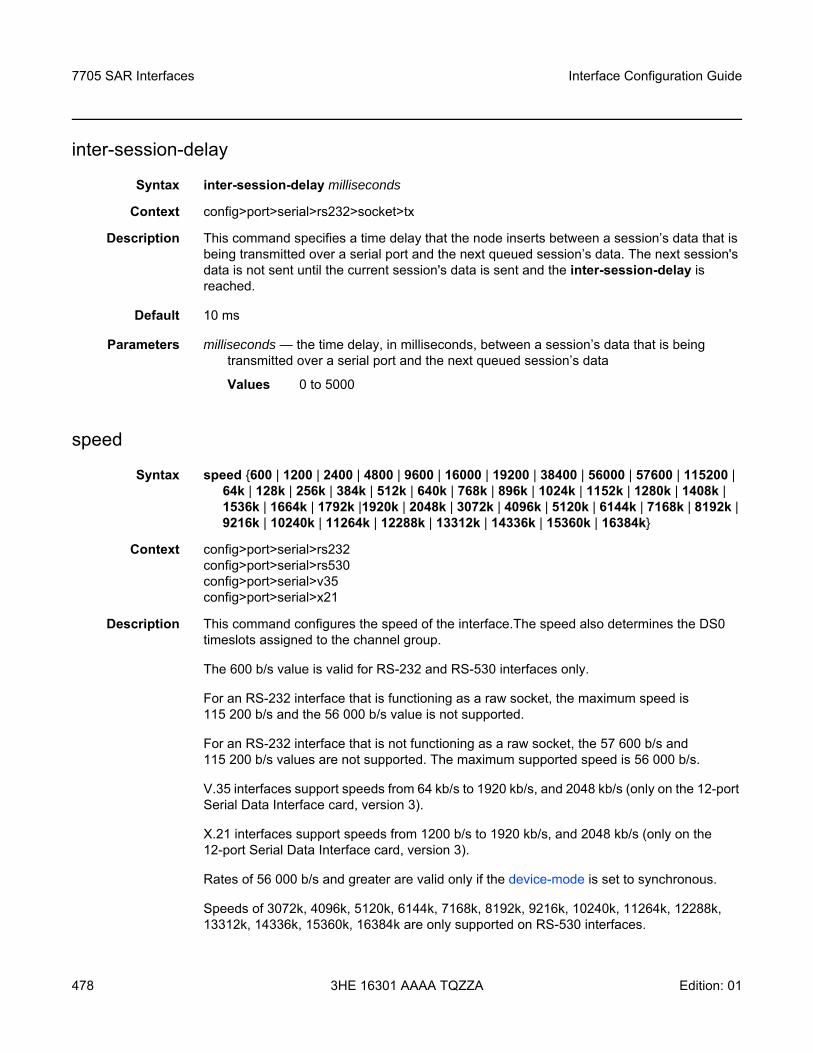
7705 SAR Interfaces
478
Interface Configuration Guide
3HE 16301 AAAA TQZZA Edition: 01
inter-session-delay
Syntax inter-session-delay milliseconds
Context config>port>serial>rs232>socket>tx
Description This command specifies a time delay that the node inserts between a session’s data that is being transmitted over a serial port and the next queued session’s data. The next session's data is not sent until the current session's data is sent and the inter-session-delay is reached.
Default 10 ms
Parameters milliseconds — the time delay, in milliseconds, between a session’s data that is being transmitted over a serial port and the next queued session’s data
Values 0 to 5000
speed
Syntax speed 600 | 1200 | 2400 | 4800 | 9600 | 16000 | 19200 | 38400 | 56000 | 57600 | 115200 | 64k | 128k | 256k | 384k | 512k | 640k | 768k | 896k | 1024k | 1152k | 1280k | 1408k | 1536k | 1664k | 1792k |1920k | 2048k | 3072k | 4096k | 5120k | 6144k | 7168k | 8192k | 9216k | 10240k | 11264k | 12288k | 13312k | 14336k | 15360k | 16384k
Context config>port>serial>rs232config>port>serial>rs530config>port>serial>v35config>port>serial>x21
Description This command configures the speed of the interface.The speed also determines the DS0 timeslots assigned to the channel group.
The 600 b/s value is valid for RS-232 and RS-530 interfaces only.
For an RS-232 interface that is functioning as a raw socket, the maximum speed is 115 200 b/s and the 56 000 b/s value is not supported.
For an RS-232 interface that is not functioning as a raw socket, the 57 600 b/s and 115 200 b/s values are not supported. The maximum supported speed is 56 000 b/s.
V.35 interfaces support speeds from 64 kb/s to 1920 kb/s, and 2048 kb/s (only on the 12-port Serial Data Interface card, version 3).
X.21 interfaces support speeds from 1200 b/s to 1920 kb/s, and 2048 kb/s (only on the 12-port Serial Data Interface card, version 3).
Rates of 56 000 b/s and greater are valid only if the device-mode is set to synchronous.
Speeds of 3072k, 4096k, 5120k, 6144k, 7168k, 8192k, 9216k, 10240k, 11264k, 12288k, 13312k, 14336k, 15360k, 16384k are only supported on RS-530 interfaces.
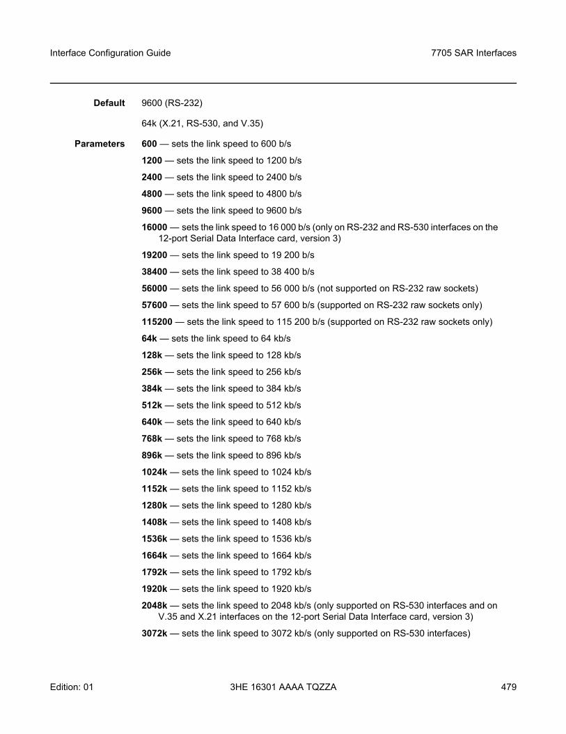
Interface Configuration Guide 7705 SAR Interfaces
Edition: 01 3HE 16301 AAAA TQZZA 479
Default 9600 (RS-232)
64k (X.21, RS-530, and V.35)
Parameters 600 — sets the link speed to 600 b/s
1200 — sets the link speed to 1200 b/s
2400 — sets the link speed to 2400 b/s
4800 — sets the link speed to 4800 b/s
9600 — sets the link speed to 9600 b/s
16000 — sets the link speed to 16 000 b/s (only on RS-232 and RS-530 interfaces on the 12-port Serial Data Interface card, version 3)
19200 — sets the link speed to 19 200 b/s
38400 — sets the link speed to 38 400 b/s
56000 — sets the link speed to 56 000 b/s (not supported on RS-232 raw sockets)
57600 — sets the link speed to 57 600 b/s (supported on RS-232 raw sockets only)
115200 — sets the link speed to 115 200 b/s (supported on RS-232 raw sockets only)
64k — sets the link speed to 64 kb/s
128k — sets the link speed to 128 kb/s
256k — sets the link speed to 256 kb/s
384k — sets the link speed to 384 kb/s
512k — sets the link speed to 512 kb/s
640k — sets the link speed to 640 kb/s
768k — sets the link speed to 768 kb/s
896k — sets the link speed to 896 kb/s
1024k — sets the link speed to 1024 kb/s
1152k — sets the link speed to 1152 kb/s
1280k — sets the link speed to 1280 kb/s
1408k — sets the link speed to 1408 kb/s
1536k — sets the link speed to 1536 kb/s
1664k — sets the link speed to 1664 kb/s
1792k — sets the link speed to 1792 kb/s
1920k — sets the link speed to 1920 kb/s
2048k — sets the link speed to 2048 kb/s (only supported on RS-530 interfaces and on V.35 and X.21 interfaces on the 12-port Serial Data Interface card, version 3)
3072k — sets the link speed to 3072 kb/s (only supported on RS-530 interfaces)
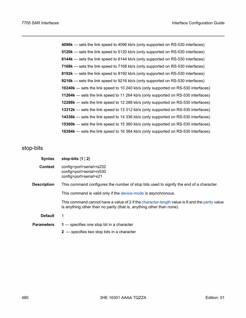
7705 SAR Interfaces
480
Interface Configuration Guide
3HE 16301 AAAA TQZZA Edition: 01
4096k — sets the link speed to 4096 kb/s (only supported on RS-530 interfaces)
5120k — sets the link speed to 5120 kb/s (only supported on RS-530 interfaces)
6144k — sets the link speed to 6144 kb/s (only supported on RS-530 interfaces)
7168k — sets the link speed to 7168 kb/s (only supported on RS-530 interfaces)
8192k — sets the link speed to 8192 kb/s (only supported on RS-530 interfaces)
9216k — sets the link speed to 9216 kb/s (only supported on RS-530 interfaces)
10240k — sets the link speed to 10 240 kb/s (only supported on RS-530 interfaces)
11264k — sets the link speed to 11 264 kb/s (only supported on RS-530 interfaces)
12288k — sets the link speed to 12 288 kb/s (only supported on RS-530 interfaces)
13312k — sets the link speed to 13 312 kb/s (only supported on RS-530 interfaces)
14336k — sets the link speed to 14 336 kb/s (only supported on RS-530 interfaces)
15360k — sets the link speed to 15 360 kb/s (only supported on RS-530 interfaces)
16384k — sets the link speed to 16 384 kb/s (only supported on RS-530 interfaces)
stop-bits
Syntax stop-bits 1 | 2
Context config>port>serial>rs232config>port>serial>rs530config>port>serial>x21
Description This command configures the number of stop bits used to signify the end of a character.
This command is valid only if the device-mode is asynchronous.
This command cannot have a value of 2 if the character-length value is 8 and the parity value is anything other than no parity (that is, anything other than none).
Default 1
Parameters 1 — specifies one stop bit in a character
2 — specifies two stop bits in a character
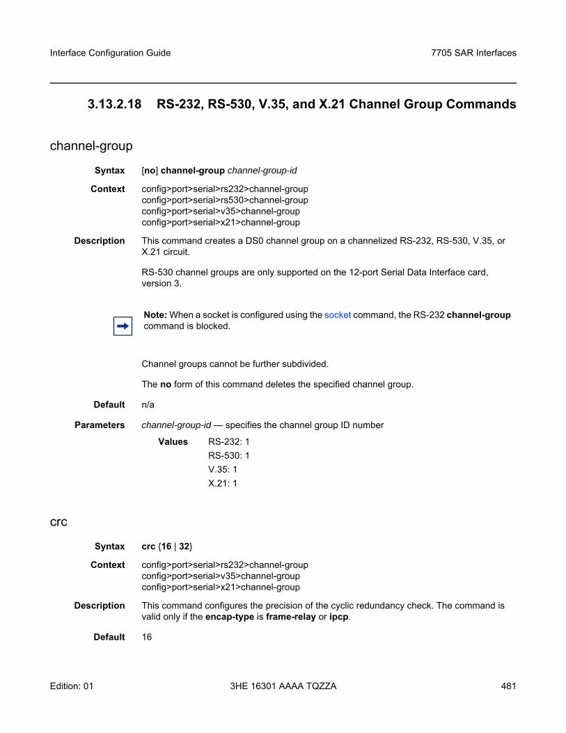
Interface Configuration Guide 7705 SAR Interfaces
Edition: 01 3HE 16301 AAAA TQZZA 481
3.13.2.18 RS-232, RS-530, V.35, and X.21 Channel Group Commands
channel-group
Syntax [no] channel-group channel-group-id
Context config>port>serial>rs232>channel-groupconfig>port>serial>rs530>channel-groupconfig>port>serial>v35>channel-groupconfig>port>serial>x21>channel-group
Description This command creates a DS0 channel group on a channelized RS-232, RS-530, V.35, or X.21 circuit.
RS-530 channel groups are only supported on the 12-port Serial Data Interface card, version 3.
Channel groups cannot be further subdivided.
The no form of this command deletes the specified channel group.
Default n/a
Parameters channel-group-id — specifies the channel group ID number
Values RS-232: 1RS-530: 1V.35: 1X.21: 1
crc
Syntax crc 16 | 32
Context config>port>serial>rs232>channel-groupconfig>port>serial>v35>channel-groupconfig>port>serial>x21>channel-group
Description This command configures the precision of the cyclic redundancy check. The command is valid only if the encap-type is frame-relay or ipcp.
Default 16
Note: When a socket is configured using the socket command, the RS-232 channel-group command is blocked.
7705 SAR Interfaces
482
Interface Configuration Guide
3HE 16301 AAAA TQZZA Edition: 01
Parameters 16 — a 16-bit checksum is used for the channel group
32 — a 32-bit checksum is used for the channel group
encap-type
Syntax encap-type cem | ipcp | frame-relay | hdlc | cisco-hdlcno encap-type
Context config>port>serial>rs232>channel-groupconfig>port>serial>rs530>channel-groupconfig>port>serial>v35>channel-groupconfig>port>serial>x21>channel-group
Description This command configures the encapsulation method used for the channel group.
When encap-type is specified, the channel group must be deleted before encap-type can be changed.
The frame-relay, ipcp, hdlc, and cisco-hdlc encapsulation types are not supported on RS-232 or RS-530 interfaces or on ports with subrate speeds (below 64 kb/s). For RS-232 and RS-530 interfaces, only cem is supported.
The no form of this command restores the default value.
Default no encap-type
Parameters cem — specifies the encapsulation type as circuit emulation mode
frame-relay — specifies the encapsulation type as frame relay mode
ipcp — specifies the encapsulation type as ipcp mode for a PPP channel group in access mode
hdlc — specifies the encapsulation type as hdlc mode
cisco-hdlc — specifies the encapsulation type as cisco-hdlc mode
idle-cycle-flag
Syntax idle-cycle-flag flags | onesno idle-cycle-flag
Context config>port>serial>v35>channel-groupconfig>port>serial>x21>channel-group
Description This command defines the value to be transmitted by the channel group during its idle cycle. The command is valid only if the encap-type is frame-relay or ipcp.
Default flags
Interface Configuration Guide 7705 SAR Interfaces
Edition: 01 3HE 16301 AAAA TQZZA 483
Parameters flags — defines the 8-bit value to be transmitted as 01111110
ones — defines the 8-bit value to be transmitted as 11111111
idle-payload-fill
Syntax idle-payload-fill all-ones | patternno idle-payload-fill
Context config>port>serial>rs232>channel-groupconfig>port>serial>rs530>channel-groupconfig>port>serial>v35>channel-groupconfig>port>serial>x21>channel-group
Description This command defines the data pattern to be transmitted when the circuit emulation service is not operational or temporarily experiences underrun conditions.
This command is valid only if encap-type is cem.
The no form of this command restores the default value.
Default all-ones
Parameters all-ones — defines the 8-bit value to be transmitted as 11111111
pattern — defines the 8-bit value to be transmitted as accepted in decimal, hex or binary format, from 0 to 255
mode
Syntax mode access | network
Context config>port>serial>rs232>channel-groupconfig>port>serial>rs530>channel-groupconfig>port>serial>v35>channel-groupconfig>port>serial>x21>channel-group
Description This command configures a channel group for access mode or network operation. Only access mode is supported on serial channels; if the user selects the network option, the CLI returns an error message.
An access port or channel is used for customer-facing traffic on which services are configured. SAPs can only be configured on an access port or channel. When a serial port is configured for access mode, multiple services can be configured on the port.
Default access
Parameters access — configures the serial channel as service access
network — configures the serial channel for transport network use
7705 SAR Interfaces
484
Interface Configuration Guide
3HE 16301 AAAA TQZZA Edition: 01
mtu
Syntax mtu mtu-bytesno mtu
Context config>port>serial>v35>channel-groupconfig>port>serial>x21>channel-group
Description This command defines the maximum MTU size that the channel group can support. The command is valid only if the encap-type is frame-relay or ipcp.
Default 1514 for frame relay
1502 for ipcp
Parameters mtu-bytes — 578 to 2090
ppp
Syntax [no] ppp
Context config>port>serial>v35>channel-groupconfig>port>serial>x21>channel-group
Description This command enables access to the context to configure the LCP operational parameters for a V.35 or X.21 channel group. This command is available only if the encap-type is set to ipcp and therefore does not apply to RS-232 ports or to X.21 ports configured for subrate speeds.
The no form of the command removes the LCP operational parameters.
Default no ppp
keepalive
Syntax keepalive time-interval [dropcount drop-count]no keepalive
Context config>port>serial>v35>channel-group>pppconfig>port>serial>x21>channel-group>ppp
Description This command enables the sending of keepalive messages and configures the time between messages and how many messages can be missed before the link is brought down.
The no form of this command disables the sending of keepalive messages.
Default keepalive 10 dropcount 3
Interface Configuration Guide 7705 SAR Interfaces
Edition: 01 3HE 16301 AAAA TQZZA 485
Parameters time-interval — the time, in seconds, between keepalive messages
Values 1 to 60
drop-count — the number of consecutive failed keepalive request attempts or remote replies that can be missed before the link is operationally brought down
Values 1 to 255
7705 SAR Interfaces
486
Interface Configuration Guide
3HE 16301 AAAA TQZZA Edition: 01
3.13.2.19 SONET/SDH Port Commands
sonet-sdh
Syntax sonet-sdh
Context config>port
Description This command enables access to the context to configure SONET/SDH ports. This context can only be used when configuring an OC3/OC12 or STM1/STM4 port on an appropriate adapter card.
SONET/SDH ports can be configured on the following adapter cards:
• 4-port OC3/STM1 / 1-port OC12/STM4 Adapter card• 4-port OC3/STM1 Clear Channel Adapter Card• 2-port OC3/STM1 Channelized Adapter card
clock-source
Syntax clock-source loop-timed | node-timed
Context config>port>sonet-sdh
Description This command configures the clock for transmitted data from either the internal clock or from a clock recovered from the line’s receive data stream.
Default node-timed
Parameters loop-timed — the link recovers the clock from the received data stream. The 4-port OC3/STM1 / 1-port OC12/STM4 Adapter card does not support loop timing.
node-timed — the link uses the internal clock when transmitting data
framing
Syntax framing sonet | sdh
Context config>port>sonet-sdh
Description This command specifies the SONET/SDH framing to be either SONET or SDH.
Changing the framing mode on the 4-port OC3/STM1 / 1-port OC12/STM4 Adapter card causes the adapter card to reset.
Default sonet
Interface Configuration Guide 7705 SAR Interfaces
Edition: 01 3HE 16301 AAAA TQZZA 487
Parameters sonet — configures the port for SONET framing
sdh — configures the port for SDH framing
group
Syntax group sonet-sdh-index payload tu3 | vt2 | vt15
Context config>port>sonet-sdh
Description This command configures the SONET/SDH group payload on a 2-port OC3/STM1 Channelized Adapter card or a 4-port OC3/STM1 / 1-port OC12/STM4 Adapter card.
Default n/a
Parameters sonet-sdh-index — specifies the group index for the port on the 2-port OC3/STM1 Channelized Adapter card or 4-port OC3/STM1 / 1-port OC12/STM4 Adapter card configured for OC3. When configured for OC12, the sonet-sdh-index specifies the tug3-index, where index is from 1 to 3.
tu3 — specifies the tributary unit group (TUG3) on a path and configures the port or channel for transport network use (supported only on the 2-port OC3/STM1 Channelized Adapter card)
vt2 — configures the path as a VT2 type virtual tributary group
vt15 — configures the path as a VT1.5 type virtual tributary group
hold-time
Syntax hold-time [up hold-time-up] [down hold-time-down]no hold-time
Context config>port>sonet-sdh
Description This command configures SONET link dampening timers in 100s of milliseconds, to guard against reporting excessive interface transitions. Once implemented, subsequent transitions of the interface from one state to another are not advertised to upper layer protocols until the configured timer has expired.
Default no hold-time
Parameters hold-time-up — the hold-timer for link up event dampening. A value of zero (0) indicates that an up transition is reported immediately.
Values 0 to 100 (in 100 ms)
hold-time-down — the hold-timer for link down event dampening. A value of zero (0) indicates that a down transition is reported immediately.
Values 0 to 100 (in 100 ms)
7705 SAR Interfaces
488
Interface Configuration Guide
3HE 16301 AAAA TQZZA Edition: 01
loopback
Syntax loopback line | internalno loopback
Context config>port>sonet-sdh
Description This command activates a loopback on the SONET/SDH port. The SONET port must be in a shutdown state to activate any type of loopback. The loopback setting is never saved to the generated/saved configuration file.
Default no loopback
Parameters line — sets the port into a line loopback state. A line loopback loops frames received on the corresponding port back towards the transmit (egress) direction. Line loopbacks are supported on ports configured in network mode.
internal — sets the port into an internal loopback state. An internal loopback loops the frames that are coming in an egress direction from the fabric towards the framer, back to the fabric. This type of loopback is usually referred to as an equipment loopback. Internal loopbacks are supported on ports configured in access mode.
report-alarm
Syntax [no] report-alarm [loc] [lais] [lrdi] [ss1f] [lb2er-sd] [lb2er-sf] [slof] [slos] [lrei]
Context config>port>sonet-sdh
Description This command enables logging of SONET/SDH line and section alarms for a SONET/SDH port. When configured, logging is enabled for the raising and clearing of the specified alarms.
The no form of this command disables logging of the specified alarms.
Parameters loc — reports a loss of clock that causes the operational state of the port to be shut down
Default loss of clock alarms are issued
lais — reports line alarm indication signal errors
Default line alarm indication signal alarms are not issued
lrdi — reports line remote defect indication errors. Line remote defect indication errors are caused by remote loss of frame (LOF), loss of clock (LOC), and loss of signal (LOS) conditions.
Default line remote defect indication alarms are issued
Note: Loopback mode changes on a SONET/SDH port can affect traffic on the remaining ports.
Interface Configuration Guide 7705 SAR Interfaces
Edition: 01 3HE 16301 AAAA TQZZA 489
ss1f — reports section synchronization failure, which is detected when the S1 byte is not consistent for eight consecutive frames. When configured, ss1f alarms are raised and cleared. Although this option is shown on the CLI, it is not available for use on the 7705 SAR.
Default section synchronization failure alarms are not issued
lb2er-sd — reports line signal degradation BER (bit interleaved parity) errors
Default line signal degradation BER alarms are not issued
lb2er-sf — reports line signal failure BER errors
Default line signal failure BER alarms are issued
slof — reports section loss of frame errors
Default section loss of frame alarms are issued
slos — reports a section loss of signal error on the transmit side
Default section loss of signal alarms are issued
lrei — reports a line error condition raised by the remote end as a result of b1 errors received from this node. When configured, line error alarms are raised but not cleared.
Default line error alarms are not issued
section-trace
Syntax section-trace increment-z0 | byte value | string string
Context config>port>sonet-sdh
Description This command configures the section trace bytes in the SONET section header to interoperate with some older versions of ADMs or regenerators that require an incremental STM ID. You can explicitly configure an incremental STM value rather than a static one in the SDH overhead by specifying an increment-z0 value.
The increment-z0 parameter is not supported on the 4-port OC3/STM1 / 1-port OC12/STM4 Adapter card.
Default byte 0x1
Parameters increment-z0 — configures an incremental STM ID instead of a static value
value — sets values in SONET header bytes
Values 0 to 255 or 0x00 to 0xFF
Default 0x1
string — specifies a text string that identifies the section
Values a string up to 16 bytes
7705 SAR Interfaces
490
Interface Configuration Guide
3HE 16301 AAAA TQZZA Edition: 01
speed
Syntax speed oc3 | oc12
Context config>port>sonet-sdh
Description This command configures the speed of a SONET/SDH port.
Although the oc3 option is shown in the CLI, it is not configurable. And, although the oc12 option is shown in the CLI, it is not available for use on the 7705 SAR. Users can change between oc3 and oc12 on the 4-port OC3/STM1 / 1-port OC12/STM4 Adapter card by using the mda-mode keyword in the config>card>mda context and selecting either the p4-oc3 or p1-oc12 option. The adapter card automatically reboots to make the change.
The no form of this command reverts to the default value.
Default oc3
Parameters oc3 — sets the speed of the port to OC3
oc12 — sets the speed of the port to OC12 (not available on the 7705 SAR)
threshold
Syntax threshold ber-sd | ber-sf rate threshold-rateno threshold ber-sd | ber-sf
Context config>port>sonet-sdh
Description This command configures the line signal (b2) degradation bit error rate (BER) and line signal failure thresholds.
Alarms are raised if the line signal bit interleaved parity error rates exceed either the degradation or failure thresholds. If the failure threshold is crossed, the link will be set to operationally down.
The no form of this command reverts to the default value.
Default threshold ber-sd 6 - signal degrade BER threshold of 10-6
threshold ber-sf 3 - signal failure BER threshold of 10-3
Parameters ber-sd — specifies the BER for signal degradation
ber-sf — specifies the BER for signal failure
threshold-rate — specifies the BER negative exponent (n in 10-n), expressed as a decimal integer
Values 3 to 9 (10-3 to 10-9)
Interface Configuration Guide 7705 SAR Interfaces
Edition: 01 3HE 16301 AAAA TQZZA 491
tx-dus
Syntax [no] tx-dus
Context config>port>sonet-sdh
Description This command allows the Quality Level (QL) value transmitted from the Synchronization Status Messaging (SSM) channel of a SONET/SDH port to be set to QL-DUS/QL-DNU (do not use for synchronization for timing purposes).
Default no tx-dus

7705 SAR Interfaces
492
Interface Configuration Guide
3HE 16301 AAAA TQZZA Edition: 01
3.13.2.20 SONET/SDH Path Commands
path
Syntax [no] path [sonet-sdh-index]
Context config>port>sonet-sdh
Description This command defines the SONET/SDH path.
The no form of this command removes the specified SONET/SDH path.
Default no index is specified
Parameters sonet-sdh-index — specifies the components making up the SONET/SDH path. Depending on the SONET/SDH adapter card and the type of SONET/SDH port, the sonet-sdh-index must specify one or more path indexes to identify the payload location of the path. The CLI uses the same sonet-sdh-index syntax nomenclature to configure SONET and SDH paths. In addition, the support of virtual tributary circuits adds another level of complexity and several levels of indexes, which means that one or more path commands may be needed to set up the container in the path.On the 4-port OC3/STM1 Clear Channel Adapter card, sonet-sdh-index is optional; if used, the value must be sts3.
Values sts12, sts3, sts1, tu3, vt2, vt15 sonet-sdh-index See SONET/SDH Channelized Port ID, Configuring SONET/SDH Port Parameters and SONET/SDH Channelized Port Configuration Examples for more information and examples.
crc
Syntax crc 16 | 32
Context config>port>sonet-sdh>path
Description This command specifies a cyclic redundancy check on a SONET/SDH path on a SONET/SDH port.
Default 32 (if the encap-type is set to atm; this default cannot be changed)
16 (if the encap-type is set to ppp-auto; port is configured for POS)
Parameters 16 — specifies that a 16-bit checksum be used for the associated port/channel
32 — specifies that a 32-bit checksum be used for the associated port/channel
Interface Configuration Guide 7705 SAR Interfaces
Edition: 01 3HE 16301 AAAA TQZZA 493
encap-type
Syntax encap-type atm | ppp-auto
Context config>port>sonet-sdh>path
Description This command configures the encapsulation method used to distinguish customer traffic on a SONET/SDH path on a SONET/SDH port.
The encap-type of atm is used for access mode (4-port OC3/STM1 Clear Channel Adapter card and 2-port OC3/STM1 Channelized Adapter card), and the encap-type of ppp-auto is used for network mode (4-port OC3/STM1 / 1-port OC12/STM4 Adapter card).
When encap-type is atm, the crc default of 32 cannot be changed.
When encap-type is atm, ATM sublayer verification specified in GR-1248-CORE, Generic Requirements for Operations of ATM Network Elements, is automatically enabled. The result of the verification includes:
• Out of Cell Delineation (OCD) event count — the OCD event count is described in RFC 2515, Definitions of Managed Objects for ATM Management. Multiple events occurring within 1 s will be counted as one event for ATM and ASAP adapter cards as a result of a hardware limit.
• Loss of Cell Delineation (LCD) defect/alarm — the LCD defect/alarm is defined in RFC 2515, Definitions of Managed Objects for ATM Management. When a path is in an LCD defect state, the path’s operational status is down. When a path exits the LCD state, the path’s operational status will change to up (assuming nothing else causes the path to stay down). A trap is raised to indicate the LCD status change, and a Path Remote Defect Indicator (PRDI) is sent to indicate the defect to the remote end.
To change the encap-type, the path must first be removed and then recreated with the new encap-type. For example, to change the encap-type from atm to ppp-auto:
config>port>sonet-sdh>path# backconfig>port>sonet-sdh# no pathconfig>port>sonet-sdh# pathconfig>port>sonet-sdh>path# mode networkconfig>port>sonet-sdh>path# encap-type ppp-autoconfig>port>sonet-sdh>path#
Default no encap-type
Parameters atm — specifies that the encapsulation on the port is ATM
ppp-auto — enables PPP on the associated port or channel. The activation of IPCP and MPLSCP is automatic depending on the protocol configuration.
7705 SAR Interfaces
494
Interface Configuration Guide
3HE 16301 AAAA TQZZA Edition: 01
mode
Syntax mode access | network
Context config>port>sonet-sdh>path
Description This command configures the mode of operation for a SONET/SDH port or channel on a 4-port OC3/STM1 Clear Channel Adapter card or 4-port OC3/STM1 / 1-port OC12/STM4 Adapter card.
An access port or channel is used for customer-facing traffic on which services are configured. A Service Access Point (SAP) can only be configured on an access port or channel. When a port or channel on the 4-port OC3/STM1 Clear Channel Adapter card is configured for access mode, the encap-type must be set to atm. The 4-port OC3/STM1 / 1-port OC12/STM4 Adapter card does not support ATM when configured for access mode.
A network port or channel configured for Packet over SONET (POS) is used as an uplink to connect to the packet network and transport the configured services. When a port or channel is configured for network mode, the encap-type must be set to ppp-auto.
To change the mode, the path must first be removed and then recreated with the new mode. For example, to change the mode from access to network:
config>port>sonet-sdh>path# backconfig>port>sonet-sdh# no pathconfig>port>sonet-sdh# pathconfig>port>sonet-sdh>path# mode networkconfig>port>sonet-sdh>path#
Default access
Parameters access — configures the port or channel for access mode
network — configures the port or channel for network mode
mtu
Syntax mtu mtuno mtu
Context config>port>sonet-sdh>path
Description This command configures the maximum payload MTU size for a SONET/SDH port on a 4-port OC3/STM1 Clear Channel Adapter card. When encap-type is atm, the path MTU value cannot be changed. Refer to the 7705 SAR Services Guide, “Global Service Command Reference”, for information on configuring the path MTU.
The no form of this command restores the default value.
Default 1524 (for access mode)
Interface Configuration Guide 7705 SAR Interfaces
Edition: 01 3HE 16301 AAAA TQZZA 495
1572 (for network mode)
Parameters mtu — sets the maximum allowable size of the MTU, expressed as an integer
Values 578 to 2090 (in bytes)
payload
Syntax payload sts12 | sts3 | tug3 | ds3 | e3 | vt2 | vt15 | ds1 | e1
Context config>port>sonet-sdh>path
Description This command configures the SONET/SDH path on a channelized adapter card (2-port OC3/STM1 Channelized Adapter card or 4-port OC3/STM1 / 1-port OC12/STM4 Adapter card) as an asynchronous circuit or a virtual tributary group.
Default n/a
Parameters sts12 — configures the STS12/STM4 (OC12/OC3) payload as clear channel
sts3 — configures the STS3/STM1 payload as clear channel
tug3 — configures the STS3/STM1 payload as tributary unit group 3 (TUG3)
ds3 — configures the port or channel as D3 STS1/VC3
e3 — configures the VC3 payload as E3
vt2 — configures the STS1 payload as virtual tributary group 2
vt15 — configures the path as virtual tributary group 1.5
ds1 — configures the port or channel VT1.5 or VT2 payload as DS1
e1 — configures the VT2 payload as E1
ppp
Syntax ppp
Context config>port>sonet-sdh>path
Description This command enables access to the context to configure the Link Control Protocol (LCP) operational parameters for a Packet over Sonet (POS) Point-to-Point Protocol (PPP) link on a 4-port OC3/STM1 Clear Channel Adapter card.
Default n/a
7705 SAR Interfaces
496
Interface Configuration Guide
3HE 16301 AAAA TQZZA Edition: 01
keepalive
Syntax keepalive time-interval [dropcount drop-count]no keepalive
Context config>port>sonet-sdh>path>ppp
Description This command enables the sending of keepalive echo messages on a 4-port OC3/STM1 Clear Channel Adapter card and configures the time between messages and how many reports can be missed before the link is brought down.
The no form of this command disables the sending of echo requests.
Default keepalive 10 dropcount 3
Parameters time-interval — the time interval, in seconds, that echo requests are issued
Values 1 to 60
Default 10
drop-count — the number of keepalive messages that can be missed before the link is brought down
Values 1 to 255
Default 3
report-alarm
Syntax [no] report-alarm [pais] [plop] [prdi] [pplm] [prei] [puneq] [plcd]
Context config>port>sonet-sdh>path
Description This command enables logging of SONET/SDH path alarms for a SONET/SDH port.
The no form of this command disables logging of the specified alarms.
Parameters pais — reports path alarm indication signal errors. When configured, path alarm indication signal alarms are raised and cleared.
Default path alarm indication signal alarms are not issued
plop — reports path loss of pointer errors, per tributary. When configured, path loss of pointer alarms are raised but not cleared.
Default path loss of pointer alarms are issued
prdi — reports path remote defect indication errors. When configured, path remote defect indication alarms are raised and cleared.
Default path remote defect indication alarms are not issued
Interface Configuration Guide 7705 SAR Interfaces
Edition: 01 3HE 16301 AAAA TQZZA 497
pplm — reports a path payload mismatch, which places the channel operationally down. When configured, path payload mismatch alarms are raised but not cleared.
Default path payload mismatch alarms are issued
prei — reports a path error condition raised by the remote end as a result of b3 errors received from this node. When configured, path error alarms are raised but not cleared. (This parameter is not supported on the 4-port OC3/STM1 card.)
Default path error alarms are not issued
puneq — reports path unequipped errors
Default path unequipped alarms are issued
plcd — reports path loss of code group delineation errors. It is applicable only when the value of xgig is set to WAN. Although this option is shown on the CLI, it is not available for use on the 7705 SAR.
Default path loss of code traps are not issued
scramble
Syntax [no] scramble
Context config>port>sonet-sdh>path
Description This command enables SONET/SDH payload scrambling on a 4-port OC3/STM1 Clear Channel Adapter card.
Scrambling randomizes the pattern of 1s and 0s carried in a SONET frame. Scrambling, or rearranging, the pattern prevents continuous strings of all 1s or all 0s and meets the needs of physical layer protocols that rely on sufficient transitions between 1s and 0s to maintain clocking.
For ATM, this command enables or disables ATM cell-level payload scrambling or descrambling using the x43+1 polynomial as defined in ITU-T I.432.1. Scrambling is enabled by default for the ATM path or channel. This scrambling is done in addition to SONET/SDH frame scrambling or descrambling, which is always enabled in the framer.
The no form of this command disables scrambling.
Default scramble
signal-label
Syntax signal-label valueno signal-label
Context config>port>sonet-sdh>path
7705 SAR Interfaces
498
Interface Configuration Guide
3HE 16301 AAAA TQZZA Edition: 01
Description This command sets the C2 byte value. The purpose of this byte is to communicate the payload type being encapsulated by SONET framing.
Default 0xcf
Parameters value — specifies the C2 byte value, expressed as a decimal integer or a hexadecimal value
Values 1 to 254 or 0x01 to 0xfe
trace-string
Syntax trace-string [trace-string]no trace-string
Context config>port>sonet-sdh>path
Description This command specifies that a J1-path-trace that identifies the circuit be continuously inserted at source. The specified trace string can be checked against the expected value by the receiver. If no trace string is entered, a null string is used.
The no form of this command resets the string to its default.
Default The default J1 value is ALU 7705 SAR. The value does not change when the encap-type changes. The J1 string contains all zeros for a non-provisioned path.
Parameters trace-string — specifies an alphanumeric string value. If the string contains spaces, enclose it in quotation marks.
Values 1 to 62 bytes for SONET or 1 to 15 bytes for SDH
Interface Configuration Guide 7705 SAR Interfaces
Edition: 01 3HE 16301 AAAA TQZZA 499
3.13.2.21 Network Port Commands
network
Syntax network
Context config>port>dslconfig>port>ethernetconfig>port>gponconfig>port>sonet-sdh>pathconfig>port>tdm>ds1>channel-groupconfig>port>tdm>ds3config>port>tdm>e1>channel-groupconfig>port>tdm>e3
Description This command enables access to the context to configure network port parameters.
Default n/a
accounting-policy
Syntax accounting-policy policy-id no accounting-policy
Context config>port>dsl>networkconfig>port>ethernet>networkconfig>port>gpon>networkconfig>port>sonet-sdh>path>networkconfig>port>tdm>ds1>channel-group>networkconfig>port>tdm>ds3>networkconfig>port>tdm>e1>channel-group>networkconfig>port>tdm>e3>network
Description This command configures an accounting policy that can apply to an interface.
An accounting policy must be configured before it can be associated to an interface. If the accounting policy-id does not exist, an error is returned.
Accounting policies associated with service billing can only be applied to SAPs. Accounting policies associated with network ports can only be associated with interfaces. Only one accounting policy can be associated with an interface at a time.
No accounting policies are specified by default. You must explicitly specify a policy. If configured, the accounting policy configured as the default under the config>log>accounting-policy>default command is used.
7705 SAR Interfaces
500
Interface Configuration Guide
3HE 16301 AAAA TQZZA Edition: 01
The no form of this command removes the accounting policy association from the network interface, and the accounting policy reverts to the default.
Default n/a
Parameters policy-id — specifies the accounting policy-id of an existing policy. Accounting policies record either service (access) or network information. A network accounting policy can only be associated with the network port configurations. Accounting policies are configured in the config>log>accounting-policy context.
Values 1 to 99
collect-stats
Syntax [no] collect-stats
Context config>port>dsl>networkconfig>port>ethernet>networkconfig>port>gpon>networkconfig>port>sonet-sdh>path>networkconfig>port>tdm>ds1>channel-group>networkconfig>port>tdm>ds3>networkconfig>port>tdm>e1>channel-group>networkconfig>port>tdm>e3>network
Description This command enables the collection of accounting and statistical data for the network interface. When applying accounting policies, the data, by default, is collected in the appropriate records and written to the designated billing file.
When the no collect-stats command is issued, the statistics are still accumulated by the adapter cards. However, the CPU does not obtain the results and write them to the billing file. If the collect-stats command is issued again (enabled), then the counters written to the billing file will include the traffic collected while the no collect-stats command was in effect.
Default no collect-stats
egress
Syntax egress
Context config>port>ethernet>network
Description This command enables access to the context to assign network egress parameters.
Default n/a
Interface Configuration Guide 7705 SAR Interfaces
Edition: 01 3HE 16301 AAAA TQZZA 501
shaper-policy
Syntax shaper-policy name no shaper-policy
Context config>port>ethernet>network>egress
Description This command assigns a shaper policy to the specified port.
The shaper policy defines shaper parameters such as shaper group, and PIR and CIR rates. The shaper policy is defined in the config>qos>shaper-policy context. Refer to the 7705 SAR Quality of Service Guide, “QoS for Hybrid Ports”, for more information.
The no form of this command reverts to the default.
Default “default”
Parameters name — specifies an existing shaper policy name
unshaped-if-cir
Syntax unshaped-if-cir cir-rate no unshaped-if-cir
Context config>port>ethernet>network>egress
Description This command sets the CIR rate for the aggregate of all the unshaped VLANs (that is, network interfaces) on the port. The default cir-rate is 0 kb/s. When the cir-rate is set to max, the CIR rate adopts the maximum rate of the port. The actual rate of the port is dictated by the physical port speed, which can be overwritten by the egress-rate sub-rate command.
If the cir-rate is higher than the sub-rate, the cir-rate is stored in the configuration database but the sub-rate limit is used.
Note: • The port shaper rate applies to the bulk of access and network traffic. Thus, once the
configured egress shaper rate is reached, both the access and network traffic scheduling pauses.
• For hybrid ports, there can be a single shaper policy on access egress and a single shaper policy on network egress. Therefore, all the SAP traffic and all the network traffic is each bound to its own shaper group in the shaper policy (access and network shaper policy, respectively). In other words, shaped SAPs and the bulk/aggregate of unshaped SAPs are shaped together as per the shaper policy assigned to the access egress. A similar behavior applies to network traffic, where the shaped interfaces and the bulk/aggregate of unshaped interfaces are shaped together as per the shaper policy assigned to the network egress.
7705 SAR Interfaces
502
Interface Configuration Guide
3HE 16301 AAAA TQZZA Edition: 01
On Gen-3 hardware, the cir-rate for this command can be configured and is applied but has no effect on the network port, except for network traffic in hybrid mode, where the cir-rate value has an effect.
On the 8-port Ethernet Adapter card, version 2, shaped and unshaped VLANs are arbitrated towards the port but the egress-rate cannot be enabled.
The no form of the command sets the unshaped-if-cir CIR rate to 0 kb/s.
Default no unshaped-if-cir
Parameters cir-rate — the CIR rate for the aggregate of all the unshaped VLANs on the port
Values 0 to 10000000 kb/s, or max
Default 0 kb/s
queue-policy
Syntax queue-policy nameno queue-policy
Context config>port>dsl>networkconfig>port>ethernet>networkconfig>port>gpon>networkconfig>port>sonet-sdh>path>networkconfig>port>tdm>ds1>channel-group>networkconfig>port>tdm>ds3>networkconfig>port>tdm>e1>channel-group>networkconfig>port>tdm>e3>network
Description This command specifies the network queue policy that defines queue parameters such as CBS-priority-only burst size, MBS, CIR, and PIR rates, as well as FC-to-queue mappings. The network queue policy is defined in the config>qos>network-queue context. Refer to the 7705 SAR Quality of Service Guide, “Network Queue QoS Policies”, for more information.
The no form of this command reverts to the default.
Default “default”
Parameters name — specifies an existing network queue policy name
Interface Configuration Guide 7705 SAR Interfaces
Edition: 01 3HE 16301 AAAA TQZZA 503
scheduler-mode
Syntax scheduler-mode profile | 4-priority | 16-priority
Context config>port>ethernet>network
Description This command selects the network-side scheduling option for the following:
• 8-port Ethernet Adapter card• 8-port Gigabit Ethernet Adapter card• Packet Microwave Adapter card• 10-port 1GigE/1-port 10GigE X-Adapter card• 2-port 10GigE (Ethernet) Adapter card• 2-port 10GigE (Ethernet) module• Ethernet ports on the 7705 SAR-A, 7705 SAR-Ax, 7705 SAR-H, 7705 SAR-Hc,
7705 SAR-M, 7705 SAR-W, and 7705 SAR-Wx
On the 6-port Ethernet 10Gbps Adapter card and the 7705 SAR-X, scheduler-mode is permanently set to support 4-priority and is not user-configurable.
With profiled (or rate-based) scheduling, both in-profile and out-of-profile scheduling are supported. Packets with a flow rate that is less than or equal to the CIR value of a queue are scheduled as in-profile. Packets with a flow rate that exceeds the CIR value but is less than the PIR value of a queue are scheduled as out-of-profile. In-profile traffic has strict priority over out-of-profile traffic.
Profiled scheduling does not take queue type into consideration. With queue type-based scheduling, queues are divided into two categories – those that are serviced by the Expedited scheduler and those that are serviced by the Best Effort scheduler. The Expedited scheduler has precedence over the Best Effort scheduler.
Four-priority scheduling combines both profiled and queue type-based scheduling. The combination provides four scheduling priorities. Packets are scheduled in the following order, in strict priority fashion:
• Expedited in-profile packets• Best-effort in-profile packets• Expedited out-of-profile packets• Best-effort out-of-profile packets
7705 SAR Interfaces
504
Interface Configuration Guide
3HE 16301 AAAA TQZZA Edition: 01
Default profile —8-port Ethernet Adapter card
16-priority —8-port Gigabit Ethernet Adapter card, 10-port 1GigE/1-port 10GigE X-Adapter card, 2-port 10GigE (Ethernet) Adapter card, 2-port 10GigE (Ethernet) module, Packet Microwave Adapter card, 7705 SAR-A, 7705 SAR-Ax, 7705 SAR-H, 7705 SAR-Hc, 7705 SAR-M, 7705 SAR-W, and 7705 SAR-Wx Ethernet ports (cannot be changed)
Parameters profile — sets the profiled scheduling option for the 8-port Ethernet Adapter card
4-priority — sets the 4-priority scheduling option for the 8-port Ethernet Adapter card
16-priority — sets the 16-priority scheduling option for the 8-port Gigabit Ethernet Adapter card, 10-port 1GigE/1-port 10GigE X-Adapter card, 2-port 10GigE (Ethernet) Adapter card, 2-port 10GigE (Ethernet) module, Packet Microwave Adapter card, 7705 SAR-A, 7705 SAR-Ax, 7705 SAR-H, 7705 SAR-Hc, 7705 SAR-M, 7705 SAR-W, and 7705 SAR-Wx Ethernet ports
Note: 16-priority is the default scheduling option on the 8-port Gigabit Ethernet Adapter card, 10-port 1GigE/1-port 10GigE X-Adapter card, 2-port 10GigE (Ethernet) Adapter card, 2-port 10GigE (Ethernet) module, Packet Microwave Adapter card, 7705 SAR-M, 7705 SAR-H, 7705 SAR-Hc, 7705 SAR-A, 7705 SAR-Ax, 7705 SAR-W, and 7705 SAR-Wx Ethernet ports. These cards, modules, and ports support 16-priority scheduling, but not profiled or 4-priority scheduling. In addition, 16-priority scheduling is not supported on the 8-port Ethernet card. For information on 16-priority scheduling, refer to the 7705 SAR Quality of Service Guide, “QoS Policies“.
Interface Configuration Guide 7705 SAR Interfaces
Edition: 01 3HE 16301 AAAA TQZZA 505
3.13.2.22 Multilink Bundle and IMA Group Commands
multilink-bundle
Syntax [no] multilink-bundle
Context config>port
Description This command enables the context to configure bundle properties for this bundle port.
Default n/a
fragment-threshold
Syntax fragment-threshold fragment-thresholdno fragment-threshold
Context config>port>multilink-bundle
Description This command sets the maximum length (in bytes) of a fragment transmitted across the specified MLPPP bundle or sets the length of a Tx frame across the specified IMA group bundle in ATM cells.
The no form of this command resets the fragment threshold back to the default value.
Default 128
Parameters fragment-threshold — specifies the maximum fragment length in bytes (for MLPPP bundles) or the Tx frame size (for IMA bundles)
Values 128 to 512 bytes (MLPPP)128 bytes (IMA)
Note: Unless otherwise specified, references to multilink bundles refer to both multilink (MLPPP) bundles and IMA groups.
7705 SAR Interfaces
506
Interface Configuration Guide
3HE 16301 AAAA TQZZA Edition: 01
member
Syntax [no] member port-id
Context config>port>multilink-bundle
Description This command binds a channel group to a multilink bundle.
To bind a channel group to a multilink bundle, all the timeslots on the channel group must be allocated.
When you configure a channel group on the network side with ppp-auto encapsulation, the system automatically allocates all timeslots to the channel group. When you configure a channel group on the access side with IPCP encapsulation, the system does not automatically allocate all timeslots to the channel group. In order to use the port or channel group as a member in an multilink bundle, you must manually allocate all the timeslots to the channel group before adding it to the bundle.
The following lists the cards, modules, and platforms that support multilink bundles and the number of channel groups on the network and/or access side that can be bound to an MLPPP bundle:
• T1/E1 ports on the 7705 SAR-A (variants with T1/E1 ports)Network: 8 Access: 8
• T1/E1 ports on the 7705 SAR-M (variants with T1/E1 ports)Network: 16 Access: 8
• T1/E1 ports on the 7705 SAR-XNetwork: 8 Access: 8The following must have all member links of an MLPPP bundle configured on the same card or module:- 16-port T1/E1 ASAP Adapter card
Network: 16 Access: 8- 32-port T1/E1 ASAP Adapter card
Network: 16 Access: 8- T1/E1 ports on the 4-port T1/E1 and RS-232 Combination module (on
7705 SAR-H)Network: 2 Access: 2
The following must have all member links of an MLPPP bundle configured on the same card or module, and on the same port:- 2-port OC3/STM1 Channelized Adapter card
Network: 8 Access: 8- 4-port OC3/STM1 / 1-port OC12/STM4 Adapter card
Network: 8 Access: 8
Interface Configuration Guide 7705 SAR Interfaces
Edition: 01 3HE 16301 AAAA TQZZA 507
The following lists the cards, modules, and platforms that support IMA groups and the number of channel groups on the network and/or access side that can be bound to an IMA group:
• T1/E1 ports on the 7705 SAR-M (variants with T1/E1 ports)IMA: 16The following must have all member links of an IMA bundle configured on the same card or module:- 16-port T1/E1 ASAP Adapter card
IMA: 16- 32-port T1/E1 ASAP Adapter card
IMA: 16The following must have all member links of an IMA bundle configured on the same card or module, and on the same port:- 2-port OC3/STM1 Channelized Adapter card
IMA: 8
The no form of this command removes the specified channel group from the multilink bundle.
Default n/a
Parameters port-id — the physical port IDSyntax: slot/mda/port.channel
minimum-links
Syntax minimum-links minimum-linksno minimum-links
Context config>port>multilink-bundle
Description This command sets the minimum number of links that must be active for the bundle to be active.
If the number of active links drops below the configured minimum, then the multilink bundle will transition to an operationally down state.
The no form of this command removes the minimum link limit.
Default 1
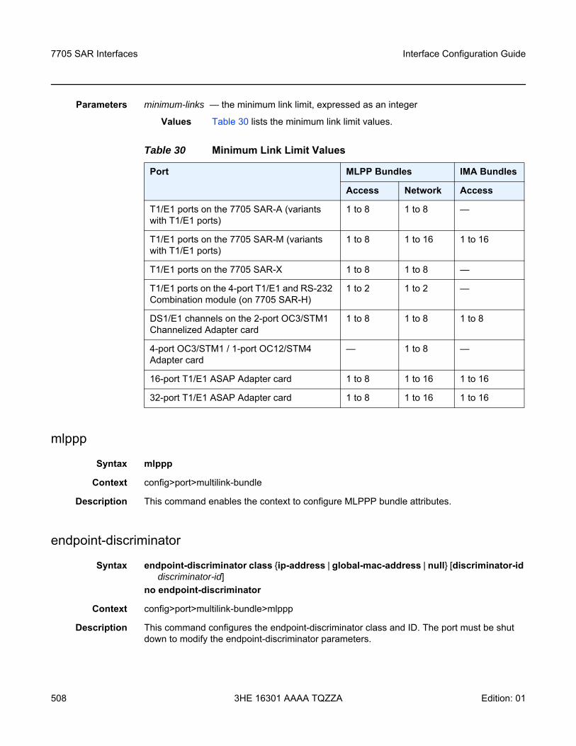
7705 SAR Interfaces
508
Interface Configuration Guide
3HE 16301 AAAA TQZZA Edition: 01
Parameters minimum-links — the minimum link limit, expressed as an integer
Values Table 30 lists the minimum link limit values.
mlppp
Syntax mlppp
Context config>port>multilink-bundle
Description This command enables the context to configure MLPPP bundle attributes.
endpoint-discriminator
Syntax endpoint-discriminator class ip-address | global-mac-address | null [discriminator-id discriminator-id]
no endpoint-discriminator
Context config>port>multilink-bundle>mlppp
Description This command configures the endpoint-discriminator class and ID. The port must be shut down to modify the endpoint-discriminator parameters.
Table 30 Minimum Link Limit Values
Port MLPP Bundles IMA Bundles
Access Network Access
T1/E1 ports on the 7705 SAR-A (variants with T1/E1 ports)
1 to 8 1 to 8 —
T1/E1 ports on the 7705 SAR-M (variants with T1/E1 ports)
1 to 8 1 to 16 1 to 16
T1/E1 ports on the 7705 SAR-X 1 to 8 1 to 8 —
T1/E1 ports on the 4-port T1/E1 and RS-232 Combination module (on 7705 SAR-H)
1 to 2 1 to 2 —
DS1/E1 channels on the 2-port OC3/STM1 Channelized Adapter card
1 to 8 1 to 8 1 to 8
4-port OC3/STM1 / 1-port OC12/STM4 Adapter card
— 1 to 8 —
16-port T1/E1 ASAP Adapter card 1 to 8 1 to 16 1 to 16
32-port T1/E1 ASAP Adapter card 1 to 8 1 to 16 1 to 16
Interface Configuration Guide 7705 SAR Interfaces
Edition: 01 3HE 16301 AAAA TQZZA 509
If the null option is configured, the 7705 SAR will advertise an endpoint-discriminator class value of NULL in link membership negotiations. If the far-end node rejects the NULL object, the 7705 SAR will remove the object from future requests. The null option should only be used if the far-end node cannot support the ip-address or global-mac-address endpoint-discriminator class options, as these options provide more protection from incorrectly adding a link to an MLPPP bundle.
The no form of this command removes the configured parameters.
Parameters class — specifies the link control protocol endpoint-discriminator class field
Default global-mac-address (for physical MLPPP bundle)ip-address (for physical MLPPP bundle protection group)null (when the endpoint-discriminator option is not present in a received configure request)
discriminator-id — specifies the endpoint-discriminator identifier value within the specified endpoint-discriminator class
Values any valid IP address
magic-number
Syntax [no] magic-number
Context config>port>multilink-bundle>mlppp
Description This command allows loopback detection to be enabled and disabled for MLPPP bundles. The command is disabled by default. When the magic number option is disabled, the magic number option will not be requested when a member is trying to bring up the LCP layer on a member link; if the remote peer requests this option, it will be rejected. When transmitting echo-requests, a magic number of 0 is used. When responding to echo-requests, a magic number of 0 is sent.
If the magic-number option is enabled, the option is sent to the remote peer during protocol negotiation. If this option is rejected by the remote peer, the router will bring the link up but will be unable to detect loopbacks since the router will always send a magic number of 0 in the echo messages upon rejection. If this option is accepted by the remote peer, the router will send echo messages with randomly generated (non-zero) magic numbers. If the 7705 SAR receives a config-req with the same magic number that was sent out, the router will calculate a new magic number to use and send out another config-request. If the router persistently sees the randomly generated magic number in the received config-req, the router will declare a loopback.
The no form of the command disables the loopback detection.
Default no magic-number
7705 SAR Interfaces
510
Interface Configuration Guide
3HE 16301 AAAA TQZZA Edition: 01
multiclass
Syntax multiclass countno multiclass
Context config>port>multilink-bundle>mlppp
Description This command enables multi-class MLPPP (MC-MLPPP) as defined by RFC 2686, The Multi-Class Extension to Multi-Link PPP. The 7705 SAR supports MC-MLPPP bundles with 2, 3 or 4 classes. To change the number of classes, all member links must be removed and then the bundle must be shut down.
The packets transmitted on the MC-MLPPP bundle are sent with class values from 0 to one less than the configured class size. For example, a 4-class MLPPP bundle has 4 classes and transmits packets with class numbers 0, 1, 2, and 3. A 4-class bundle transmits packets with class numbers 0, 1 and 2 and a 2-class bundle transmits packets with class numbers 0 and 1. A 0-class MLPPP bundle has the highest priority.
Entries are created and deleted by the system depending on the number of classes being used by a given MLPPP bundle. The no form of the command disables multi-class MLPPP.
Default no multiclass
Parameters count — specifies the number of classes in an MLPPP bundle
Values 2 to 4
mrru
Syntax mrru mrruno mrru
Context config>port>multilink-bundle
Description This command specifies the maximum received reconstructed unit (MRRU), which is similar to a maximum transmission unit (MTU) but applies only to MLPPP multilink bundles. The MRRU is the maximum frame size that can be reconstructed from multilink fragments. This command is only valid for MLPPP bundles.
The no form of this command resets the MRRU to the default.
Default 1524
Parameters mrru — the maximum received reconstructed unit size, expressed as an integer
Values 1500 to 2088 bytes (for MLPPP)1500 to 2090 bytes (for PPP)
Interface Configuration Guide 7705 SAR Interfaces
Edition: 01 3HE 16301 AAAA TQZZA 511
red-differential-delay
Syntax red-differential-delay red-diff-delay [down]no red-differential-delay
Context config>port>multilink-bundle
Description This command sets the maximum acceptable differential delay for individual circuits within a multilink bundle.
The no form of this command restores the red-differential-delay defaults.
Default n/a
Parameters red-diff-delay — the maximum red differential delay value, in milliseconds
Values 0 to 25 ms for MLPPP bundles2 to 75 ms for IMA bundles on the 16-port T1/E1 ASAP Adapter card and 32-port T1/E1 ASAP Adapter card2 to 75 ms for IMA bundles on the 2-port OC3/STM1 Channelized Adapter card
down — transition the circuit that exceeded the differential delay to a down state (for example, remove it from the multilink bundle from an operational perspective). To transition the circuit back to the up state, the user should shutdown, then no shutdown the channel group.
short-sequence
Syntax [no] short-sequence
Context config>port>multilink-bundle
Description This command specifies that the MLPPP bundle should use short (12 bit) sequence numbers instead of the default 24-bit sequence number. This command is only valid for MLPPP bundles.
The no form of this command disables the short-sequence feature.
Default no short-sequence
yellow-differential-delay
Syntax yellow-differential-delay yellow-diff-delay no yellow-differential-delay
Context config>port>multilink-bundle
7705 SAR Interfaces
512
Interface Configuration Guide
3HE 16301 AAAA TQZZA Edition: 01
Description This command sets the yellow warning threshold for the differential delay for members within a multilink bundle. If circuit’s delay exceeds the yellow-differential delay value, a log message and SNMP trap is sent. This command is only valid for MLPPP bundles.
The no form of this command removes the yellow-differential-delay.
Default n/a
Parameters yellow-diff-delay — the maximum yellow differential delay threshold value, in milliseconds
Values 1 to 25
ima
Syntax ima
Context config>port>multilink-bundle
Description This command enables the context to configure parameters for an IMA group. An IMA group is a collection of physical links bundled together and assigned to an ATM port. IMA enables a high-speed channel that is composed of ATM cells to be transported as a number of lower-speed circuits. They are then reassembled as the original high-speed ATM channel.
This command is only valid for IMA bundles.
link-delay
Syntax link-delay activate | deactivate millisecondsno link-delay activate | deactivate
Context config>port>multilink-bundle>ima
Description This command specifies the time delay between detection of a link activation/deactivation condition and acting upon it (going in/out of the Rx failure state on a link).
Parameters activate milliseconds — the time, in milliseconds, used to clear an existing LIF, LODS, or FRI-IMA alarm. The time specified determines how long is needed for member links to stabilize before being activated.
Values 1 to 30000 ms
Default 1000
deactivate milliseconds — the time, in milliseconds, used to raise an LIF, LODS, or FRI-IMA alarm. The time specified determines how long before a member link is declared in error and is deactivated.
Values 1 to 30000 ms
Default 2000
Interface Configuration Guide 7705 SAR Interfaces
Edition: 01 3HE 16301 AAAA TQZZA 513
test-pattern-procedure
Syntax test-pattern-procedure
Context config>port>multilink-bundle>ima
Description This command enables the context to configure IMA test pattern procedures. This command and its sub-commands are not saved in the router configuration between reboots.
test-link
Syntax test-link port-idno test-link
Context config>port>multilink-bundle>ima>test-pattern-procedure
Description This command specifies IMA members on which an IMA test pattern procedure is to be performed.
The no form of this command deletes the link from the test-pattern procedure. The test-pattern procedure must be shut down first.
Default no test-link
Parameters port-id — the port ID to be used to verify link connectivity within an IMA group
test-pattern
Syntax test-pattern patternno test-pattern
Context config>port>multilink-bundle>ima>test-pattern-procedure
Description This command specifies the transmit test pattern in an IMA group loopback operation. This value can only be changed when the test-pattern-procedure command is shut down.
The no form of this command restores the test pattern to the default.
Default 0
Parameters pattern — specifies an integer taking the following values:
Values 0 to 255
shutdown
Syntax [no] shutdown
7705 SAR Interfaces
514
Interface Configuration Guide
3HE 16301 AAAA TQZZA Edition: 01
Context config>port>multilink-bundle>ima>test-pattern-procedure
Description This command enables a configured IMA test pattern procedure.
The no form of this command disables the IMA test pattern procedure.
version
Syntax version IMA-versionno version
Context config>port>multilink-bundle>ima>
Description This command configures the IMA version for the multilink bundle group. If there is a version mismatch between this IMA group and the far-end IMA group, the IMA group will go operationally down. To change the IMA version, you must first remove all member links from the group.
Only IMA version 1.1 is supported.
Default 1-1
Parameters IMA-version — specifies the IMA version for this group
Values 1-1 — IMA version 1.1
Interface Configuration Guide 7705 SAR Interfaces
Edition: 01 3HE 16301 AAAA TQZZA 515
3.13.2.23 ATM Interface Commands
atm
Syntax atm
Context config>port>multilink-bundle>imaconfig>port>tdm>ds1>channel-groupconfig>port>tdm>e1>channel-groupconfig>port>tdm>ds3config>port>tdm>e3config>port>sonet-sdh>path
Description This command enables the context to configure ATM interface properties.
cell-format
Syntax cell-format cell-formatno cell-format
Context config>port>multilink-bundle>ima>atmconfig>port>tdm>ds1>channel-group>atmconfig>port>tdm>e1>channel-group>atmconfig>port>tdm>ds3>atmconfig>port>tdm>e3>atmconfig>port>sonet-sdh>path>atm
Description This command configures the ATM cell format.
The no form of this command restores the default value.
Default uni
Parameters cell-format — the ATM cell format, either UNI or NNI (SONET/SDH ports do not support the NNI format)
Values uni (user-to-network interface cell format)nni (network-to-network interface cell format)
7705 SAR Interfaces
516
Interface Configuration Guide
3HE 16301 AAAA TQZZA Edition: 01
mapping
Syntax mapping direct no mapping
Context config>port>tdm>ds3>atm
Description This command specifies the ATM cell mapping to be used on this DS3 ATM interface.
The no form of this command restores the default value.
Default direct
Parameters direct — specifies direct cell mapping
min-vp-vpi
Syntax min-vp-vpi valueno min-vp-vpi
Context config>port>multilink-bundle>ima>atmconfig>port>tdm>ds1>channel-group>atmconfig>port>tdm>e1>channel-group>atmconfig>port>tdm>ds3>atmconfig>port>tdm>e3>atmconfig>port>sonet-sdh>path>atm
Description This command sets the minimum allowable virtual path identifier (VPI) value that can be used on the ATM interface for a virtual path connection (VPC).
The no form of this command restores the default value.
Default 0
Parameters value — the minimum allowable VPI value that can be used on the ATM interface for a VPC
Values 0 to 4095 (NNI) (not supported on SDH/SONET ports)0 to 255 (UNI)
Note: For an E3 interface, the mapping command does not appear in the CLI; the interface is hard-coded for direct mapping.
Interface Configuration Guide 7705 SAR Interfaces
Edition: 01 3HE 16301 AAAA TQZZA 517
3.13.2.24 TDM Commands
tdm
Syntax tdm
Context config>port
Description This command enables the context to configure:
• DS1/E1 parameters for a port on a channelized 16-port T1/E1 ASAP Adapter card, 32-port T1/E1 ASAP Adapter card, 2-port OC3/STM1 Channelized Adapter card, 4-port OC3/STM1 / 1-port OC12/STM4 Adapter card, or 4-port DS3/E3 Adapter card (DS3 ports only)
• DS3 parameters for a port on a channelized 2-port OC3/STM1 Channelized Adapter card
• DS3/E3 parameters for a port on a 4-port DS3/E3 Adapter card• codirectional and teleprotection interfaces (TPIF) parameters for a port on an 8-port
Voice & Teleprotection card • teleprotection interfaces (TPIF) parameters for a port on an 8-port C37.94
Teleprotection card
TDM is a mechanism that divides the bandwidth of a stream into separate channels or timeslots by assigning each stream a different timeslot in a set. TDM repeatedly transmits a fixed sequence of timeslots over a single transmission channel. Each individual data stream is reassembled at the receiving end based on the timing.
Default n/a
buildout
Syntax buildout long | short
Context config>port>tdm
Description This command specifies the line buildout (cable length) for physical DS1 ports on the 16-port T1/E1 ASAP Adapter card and 32-port T1/E1 ASAP Adapter card, or for physical DS3/E3 ports on the 4-port DS3/E3 Adapter card.
Default short (this is the only option available for the 16-port T1/E1 ASAP Adapter card and 32-port T1/E1 ASAP Adapter card)
Parameters long — sets the line buildout for length runs up to 450 ft (for the 4-port DS3/E3 Adapter card only)
7705 SAR Interfaces
518
Interface Configuration Guide
3HE 16301 AAAA TQZZA Edition: 01
short — sets the line buildout for length runs up to 225 ft (for the 4-port DS3/E3 Adapter card only) or up to 655 ft (for the 16-port T1/E1 ASAP Adapter card and 32-port T1/E1 ASAP Adapter card)
codir
Syntax [no] codir
Context config>port>tdm
Description This command creates a 64 kb/s codirectional G.703 channel on a port on the 8-port Voice & Teleprotection card.
The no form of this command deletes the port’s codirectional channel.
Default n/a
channel-group
Syntax [no] channel-group channel-group-id
Context config>port>tdm>codirconfig>port>tdm>tpif
Description This command creates a DS0 channel group on a TDM interface on the 8-port Voice & Teleprotection card or 8-port C37.94 Teleprotection card.
The no form of this command deletes the port’s codirectional or TPIF channel group.
Default n/a
Parameters channel-group-id — specifies the channel group ID number
Values 1
encap-type
Syntax encap-type cem
Context config>port>tdm>codir>channel-groupconfig>port>tdm>tpif>channel-group
Description This command specifies the encapsulation type. The channel group must be deleted before changing the encapsulation type.
Default no encap-type
Parameters cem — circuit emulation (TDM)
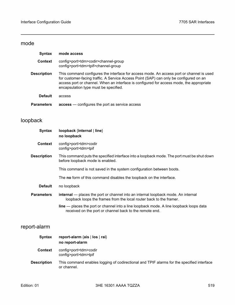
Interface Configuration Guide 7705 SAR Interfaces
Edition: 01 3HE 16301 AAAA TQZZA 519
mode
Syntax mode access
Context config>port>tdm>codir>channel-groupconfig>port>tdm>tpif>channel-group
Description This command configures the interface for access mode. An access port or channel is used for customer-facing traffic. A Service Access Point (SAP) can only be configured on an access port or channel. When an interface is configured for access mode, the appropriate encapsulation type must be specified.
Default access
Parameters access — configures the port as service access
loopback
Syntax loopback internal | lineno loopback
Context config>port>tdm>codirconfig>port>tdm>tpif
Description This command puts the specified interface into a loopback mode. The port must be shut down before loopback mode is enabled.
This command is not saved in the system configuration between boots.
The no form of this command disables the loopback on the interface.
Default no loopback
Parameters internal — places the port or channel into an internal loopback mode. An internal loopback loops the frames from the local router back to the framer.
line — places the port or channel into a line loopback mode. A line loopback loops data received on the port or channel back to the remote end.
report-alarm
Syntax report-alarm ais | los | raino report-alarm
Context config>port>tdm>codirconfig>port>tdm>tpif
Description This command enables logging of codirectional and TPIF alarms for the specified interface or channel.
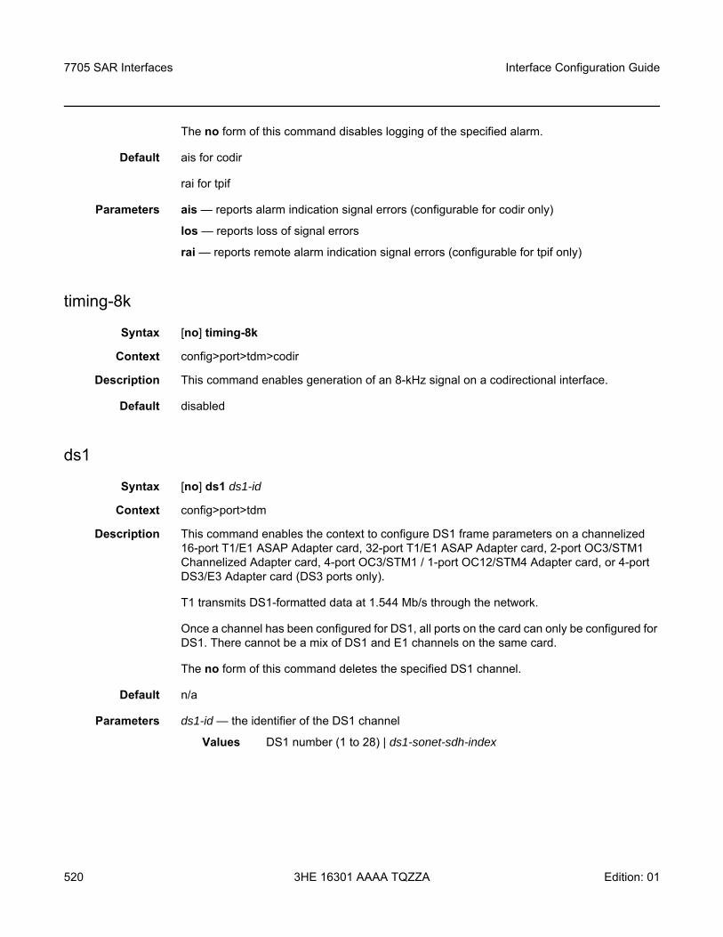
7705 SAR Interfaces
520
Interface Configuration Guide
3HE 16301 AAAA TQZZA Edition: 01
The no form of this command disables logging of the specified alarm.
Default ais for codir
rai for tpif
Parameters ais — reports alarm indication signal errors (configurable for codir only)
los — reports loss of signal errors
rai — reports remote alarm indication signal errors (configurable for tpif only)
timing-8k
Syntax [no] timing-8k
Context config>port>tdm>codir
Description This command enables generation of an 8-kHz signal on a codirectional interface.
Default disabled
ds1
Syntax [no] ds1 ds1-id
Context config>port>tdm
Description This command enables the context to configure DS1 frame parameters on a channelized 16-port T1/E1 ASAP Adapter card, 32-port T1/E1 ASAP Adapter card, 2-port OC3/STM1 Channelized Adapter card, 4-port OC3/STM1 / 1-port OC12/STM4 Adapter card, or 4-port DS3/E3 Adapter card (DS3 ports only).
T1 transmits DS1-formatted data at 1.544 Mb/s through the network.
Once a channel has been configured for DS1, all ports on the card can only be configured for DS1. There cannot be a mix of DS1 and E1 channels on the same card.
The no form of this command deletes the specified DS1 channel.
Default n/a
Parameters ds1-id — the identifier of the DS1 channel
Values DS1 number (1 to 28) | ds1-sonet-sdh-index
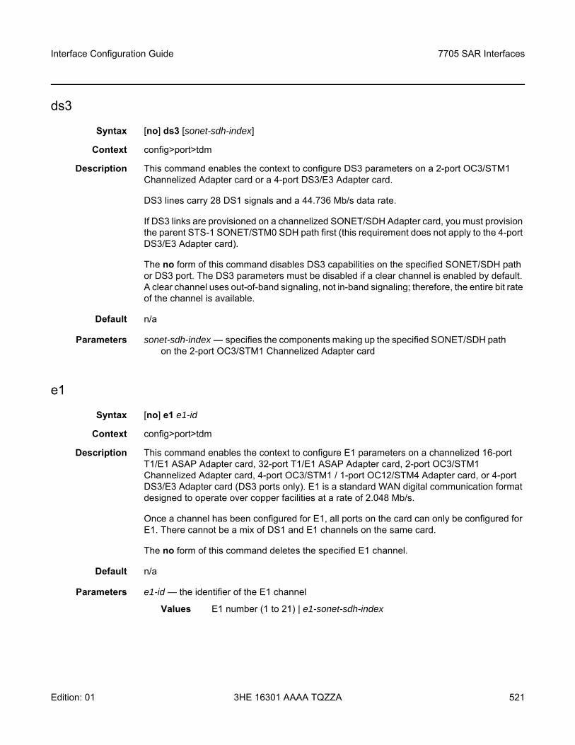
Interface Configuration Guide 7705 SAR Interfaces
Edition: 01 3HE 16301 AAAA TQZZA 521
ds3
Syntax [no] ds3 [sonet-sdh-index]
Context config>port>tdm
Description This command enables the context to configure DS3 parameters on a 2-port OC3/STM1 Channelized Adapter card or a 4-port DS3/E3 Adapter card.
DS3 lines carry 28 DS1 signals and a 44.736 Mb/s data rate.
If DS3 links are provisioned on a channelized SONET/SDH Adapter card, you must provision the parent STS-1 SONET/STM0 SDH path first (this requirement does not apply to the 4-port DS3/E3 Adapter card).
The no form of this command disables DS3 capabilities on the specified SONET/SDH path or DS3 port. The DS3 parameters must be disabled if a clear channel is enabled by default. A clear channel uses out-of-band signaling, not in-band signaling; therefore, the entire bit rate of the channel is available.
Default n/a
Parameters sonet-sdh-index — specifies the components making up the specified SONET/SDH path on the 2-port OC3/STM1 Channelized Adapter card
e1
Syntax [no] e1 e1-id
Context config>port>tdm
Description This command enables the context to configure E1 parameters on a channelized 16-port T1/E1 ASAP Adapter card, 32-port T1/E1 ASAP Adapter card, 2-port OC3/STM1 Channelized Adapter card, 4-port OC3/STM1 / 1-port OC12/STM4 Adapter card, or 4-port DS3/E3 Adapter card (DS3 ports only). E1 is a standard WAN digital communication format designed to operate over copper facilities at a rate of 2.048 Mb/s.
Once a channel has been configured for E1, all ports on the card can only be configured for E1. There cannot be a mix of DS1 and E1 channels on the same card.
The no form of this command deletes the specified E1 channel.
Default n/a
Parameters e1-id — the identifier of the E1 channel
Values E1 number (1 to 21) | e1-sonet-sdh-index
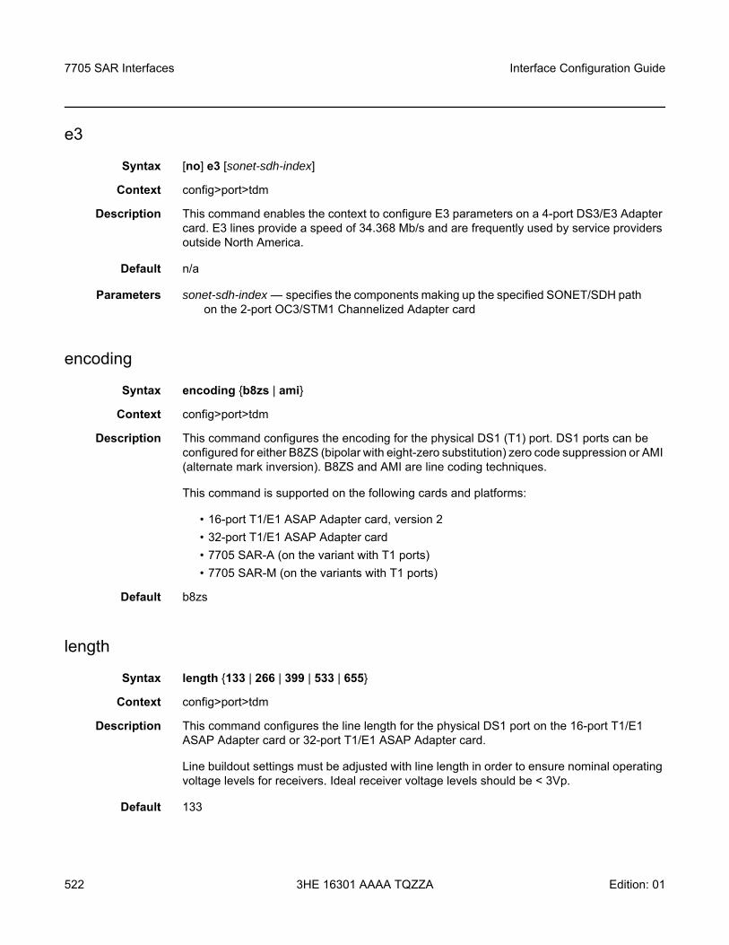
7705 SAR Interfaces
522
Interface Configuration Guide
3HE 16301 AAAA TQZZA Edition: 01
e3
Syntax [no] e3 [sonet-sdh-index]
Context config>port>tdm
Description This command enables the context to configure E3 parameters on a 4-port DS3/E3 Adapter card. E3 lines provide a speed of 34.368 Mb/s and are frequently used by service providers outside North America.
Default n/a
Parameters sonet-sdh-index — specifies the components making up the specified SONET/SDH path on the 2-port OC3/STM1 Channelized Adapter card
encoding
Syntax encoding b8zs | ami
Context config>port>tdm
Description This command configures the encoding for the physical DS1 (T1) port. DS1 ports can be configured for either B8ZS (bipolar with eight-zero substitution) zero code suppression or AMI (alternate mark inversion). B8ZS and AMI are line coding techniques.
This command is supported on the following cards and platforms:
• 16-port T1/E1 ASAP Adapter card, version 2• 32-port T1/E1 ASAP Adapter card• 7705 SAR-A (on the variant with T1 ports)• 7705 SAR-M (on the variants with T1 ports)
Default b8zs
length
Syntax length 133 | 266 | 399 | 533 | 655
Context config>port>tdm
Description This command configures the line length for the physical DS1 port on the 16-port T1/E1 ASAP Adapter card or 32-port T1/E1 ASAP Adapter card.
Line buildout settings must be adjusted with line length in order to ensure nominal operating voltage levels for receivers. Ideal receiver voltage levels should be < 3Vp.
Default 133
Interface Configuration Guide 7705 SAR Interfaces
Edition: 01 3HE 16301 AAAA TQZZA 523
line-impedance
Syntax line-impedance 75 | 100 | 120
Context config>port>tdm
Description This command configures the line impedance of a port. Line impedance is set on a per-port basis and ports on the same card can have different values. Before changing the line impedance of a port, the port must be shut down.
Default 100 for DS1
120 for E1
Parameters 75 — 75 Ω100 — 100 Ω120 — 120 Ω
tpif
Syntax [no] tpif
Context config>port>tdm
Description This command creates an IEEE C37.94 teleprotection interface (TPIF) channel.
The no form of this command deletes the port’s TPIF channel.
Default n/a
timeslots
Syntax timeslots timeslots
Context config>port>tdm>tpif>channel-group
Description This command defines the list of DS0 timeslots to be used in the TPIF channel group.
Default 1
Parameters timeslots — specifies the number of consecutive timeslots to be associated with the channel group. The value must start from the first timeslot. It represents line bandwidth of n x 64 kb/s, where n is the number of timeslots.
Values 1 to 12
7705 SAR Interfaces
524
Interface Configuration Guide
3HE 16301 AAAA TQZZA Edition: 01
3.13.2.25 DS1 and E1 Commands
channelized
Syntax channelized ds1 | e1no channelized
Context config>port>tdm>ds3
Description This command configures the associated DS3 channel as a channelized DS3 with DS1/E1 sub-channels.
The no form of this command disables channelization. The sub-channels must be deleted first before the no command is executed.
Default no channelized
Parameters ds1 — specifies that the channel is DS1
e1 — specifies that the channel is E1
clock-source
Syntax clock-source loop-timed | node-timed | adaptive | differential
Context config>port>tdm>ds1config>port>tdm>e1
Description This command specifies the clock source to be used for the link transmit timing.
The following can be configured for loop timing and node timing:
• T1/E1 CES circuits on the 16-port T1/E1 ASAP Adapter card• T1/E1 CES circuits on the 32-port T1/E1 ASAP Adapter card • T1/E1 CES circuits on the 2-port OC3/STM1 Channelized Adapter card• T1/E1 CES circuits on the 4-port OC3/STM1 / 1-port OC12/STM4 Adapter card• T1/E1 CES circuits on the 4-port DS3/E3 Adapter card
The following can be configured for adaptive timing:
• 16-port T1/E1 ASAP Adapter card• 32-port T1/E1 ASAP Adapter card• T1/E1 ports on the 7705 SAR-M (variants with T1/E1 ports) on T1/E1 CES circuits used
for TDM pseudowires• T1/E1 ports on the 7705 SAR-X on T1/E1 CES circuits used for TDM pseudowires
Interface Configuration Guide 7705 SAR Interfaces
Edition: 01 3HE 16301 AAAA TQZZA 525
• T1/E1 ports on the 7705 SAR-A (variant with T1/E1 ports) on T1/E1 CES circuits used for TDM pseudowires
• T1/E1 ports on the 4-port T1/E1 and RS-232 Combination module
The following can be configured for differential timing:
• 16-port T1/E1 ASAP Adapter card, version 2• 32-port T1/E1 ASAP Adapter card• T1/E1 channels on the 4-port OC3/STM1 / 1-port OC12/STM4 Adapter card• T1/E1 channels on the DS3 ports on the 4-port DS3/E3 Adapter card (E3 ports cannot
be channelized)• T1/E1 ports on the 7705 SAR-M (variants with T1/E1 ports)• T1/E1 ports on the 7705 SAR-X• T1/E1 ports on the 7705 SAR-A (variants with T1/E1 ports)• T1/E1 ports on the 4-port T1/E1 and RS-232 Combination module
The clock source setting also determines the node sync reference if the port is configured as one of the node sync references (config>system>sync-if-timing>ref1 | ref2> source-port command). Refer to the 7705 SAR Basic System Configuration Guide, “Node Timing”, for more information.
Default node-timed
Parameters loop-timed — the link recovers the clock from the received data stream
node-timed — the link uses the internal clock when transmitting data
adaptive — clocking is derived from the incoming pseudowire packets from the MPLS network
differential — clocking is derived from a common clock compared to differential clock recovery (DCR) data in the RTP header in the TDM PW overhead. DCR must also be enabled on the relevant card, module, or chassis with the clock-mode command.
framing (DS1)
Syntax framing esf | sf | ds1-unframed
Context config>port>tdm>ds1
Description This command specifies the DS1 framing to be used for the port.
Note: If a timing reference from an external BITS clock is used on a dedicated T1/E1 port, the port must be configured as loop-timed.
7705 SAR Interfaces
526
Interface Configuration Guide
3HE 16301 AAAA TQZZA Edition: 01
The ds1-unframed parameter allows the configuration of an unstructured DS1 channel on the following:
• 16-port T1/E1 ASAP Adapter card• 32-port T1/E1 ASAP Adapter card• 2-port OC3/STM1 Channelized Adapter card• 4-port OC3/STM1 / 1-port OC12/STM4 Adapter card• 4-port DS3/E3 Adapter card (DS3 ports only)• 4-port T1/E1 and RS-232 Combination module (T1/E1 ports only)
When an unframed DS1 channel is shut down, it sends the AIS pattern to the far-end DS1. The far end does not react to the AIS pattern if the far-end DS1 is configured as unframed. If the far-end DS1 is configured as framed, the far end declares AIS. The operational status remains up and no alarms are generated while the near end is operationally down. This is normal behavior for unframed G.703 mode.
Default esf
Parameters esf — configures the DS1 port for extended superframe framing
sf — configures the DS1 port for superframe framing
ds1-unframed — specifies DS1 unframed (G.703) mode for DS1 interfaces. DS1 unframed mode is only applicable if the encapsulation type is set to cem or ppp-auto.
framing (E1)
Syntax framing no-crc-g704 | g704 | e1-unframed
Context config>port>tdm>e1
Description This command specifies the E1 framing to be used for the port.
The e1-unframed parameter allows the configuration of an unstructured E1 channel on the following:
• 16-port T1/E1 ASAP Adapter card• 32-port T1/E1 ASAP Adapter card• 2-port OC3/STM1 Channelized Adapter card• 4-port OC3/STM1 / 1-port OC12/STM4 Adapter card• 4-port DS3/E3 Adapter card (DS3 ports only)• 4-port T1/E1 and RS-232 Combination module (T1/E1 ports only)
When an unframed E1 channel is shut down, it sends the AIS pattern to the far-end E1. The far end does not react to the AIS pattern if the far-end E1 is configured as unframed. If the far-end E1 is configured as framed, the far end declares AIS. The operational status remains up and no alarms are generated while the near end is operationally down. This is normal behavior for unframed G.703 mode.
Interface Configuration Guide 7705 SAR Interfaces
Edition: 01 3HE 16301 AAAA TQZZA 527
Default g704
Parameters g704 — configures the E1 port for G.704 framing
no-crc-g704 — configures the E1 port for G.704 framing with no CRC4
e1-unframed — specifies E1 unframed (G.703) mode for E1 interfaces. E1 unframed mode is only applicable if the encapsulation type is set to cem.
hold-time
Syntax hold-time [up hold-time-up] [down hold-time-down]no hold-time
Context config>port>tdm>ds1config>port>tdm>e1
Description This command configures the DS1/E1 link dampening timers in 100s of milliseconds, which guards against reporting excessive interface transitions. Once implemented, subsequent transitions of the interface from one state to another are not advertised to upper layer protocols until the configured timer has expired.
Default no hold-time
Parameters hold-time-up — the hold-timer for link-up event dampening. A value of zero (0) indicates that an up transition is reported immediately.
Values 0 to 100 (in 100 ms)
hold-time-down — the hold-timer for link-down event dampening. A value of zero (0) indicates that a down transition is reported immediately.
Values 0 to 100 (in 100 ms)
loopback (DS1)
Syntax loopback line | internal | fdl-ansi | fdl-bellcore | payload-ansino loopback
Context config>port>tdm>ds1
Description This command puts the specified port or channel in a loopback mode.
A line loopback loops frames received on the corresponding port or channel back towards the transmit (egress) direction before reaching the framer. The bit stream is not reframed. The electrical signal is regenerated by the Tx line interface unit (LIU) and the timing is provided by the Rx LIU.
7705 SAR Interfaces
528
Interface Configuration Guide
3HE 16301 AAAA TQZZA Edition: 01
An internal loopback loops the frames that are coming in an egress direction from the fabric towards the framer, back to the fabric. This is usually referred to as an equipment loopback. The Tx signal is looped back and received by the interface.
The fdl-ansi loopback command sends a repeating 16-bit ESF data link code word to the remote end requesting that it enter into a network line loopback. The ansi keyword enables the remote line FDL ANSI bit loopback on the T1 line, in accordance with the ANSI T1.403 specification.
The fdl-bellcore loopback command sends a repeating 16-bit ESF data link code word to the remote end requesting that it enter into a network line loopback. The bellcore keyword enables the remote line FDL Bellcore bit loopback on the T1 line, in accordance with the Bellcore TR-TSY-000312 specification.
The payload-ansi loopback command sends a repeating 16-bit ESF data link code word to the remote end requesting that it enter into a network payload loopback. A payload loopback loops frames back towards the transmit (egress) direction after reaching the framer. The bit stream is reframed. The electrical signal is regenerated by the Tx LIU and the timing is provided by the Rx LIU.
The loopback command is not saved to the system configuration.
The no form of this command disables the specified type of loopback.
Default no loopback
Parameters line — places the associated port or channel into line loopback mode
internal — places the associated port or channel into internal loopback mode
fdl-ansi — requests an FDL line loopback in accordance with the ANSI T1.403 specification
fdl-bellcore — requests an FDL line loopback in accordance with the Bellcore TR-TSY-000312 specification
payload-ansi — requests a payload loopback using ANSI signaling
Note: • The fdl-ansi, fdl-bellcore and payload-ansi options can only be configured if DS1
framing is set to ESF.• The 4-port OC3/STM1 / 1-port OC12/STM4 Adapter card cannot initiate fdl-ansi, fdl-
bellcore, or payload-ansi loopbacks.• The 4-port OC3/STM1 / 1-port OC12/STM4 Adapter card supports up to 16 line
loopbacks and 16 internal loopbacks at a time.
Interface Configuration Guide 7705 SAR Interfaces
Edition: 01 3HE 16301 AAAA TQZZA 529
loopback (E1)
Syntax loopback line | internalno loopback
Context config>port>tdm>e1
Description This command puts the specified port or channel in a loopback mode.
A line loopback loops frames received on the corresponding port or channel back towards the transmit (egress) direction before reaching the framer. The bit stream is not reframed. The electrical signal is regenerated by the Tx line interface unit (LIU) and the timing is provided by the Rx LIU.
An internal loopback loops the frames that are coming in an egress direction from the fabric towards the framer, back to the fabric. This is usually referred to as an equipment loopback. The Tx signal is looped back and received by the interface. The loopback command is not saved to the system configuration.
The no form of this command disables the specified type of loopback.
Default no loopback
Parameters line — places the associated port or channel into line loopback mode
internal — places the associated port or channel into internal loopback mode
remote-loop-respond
Syntax [no] remote-loop-respond
Context config>port>tdm>ds1
Description This command configures the DS1 channel response to remote loopbacks. When enabled, the channel responds to remote loopbacks; when disabled, the channel does not respond.
Default no remote-loop-respond
Note: The 4-port OC3/STM1 / 1-port OC12/STM4 Adapter card cannot respond to fdl-ansi, fdl-bellcore, or payload-ansi loopbacks.
7705 SAR Interfaces
530
Interface Configuration Guide
3HE 16301 AAAA TQZZA Edition: 01
report-alarm
Syntax [no] report-alarm ais | los | oof | rai | looped | ber-sd | ber-sf
Context config>port>tdm>ds1config>port>tdm>e1
Description This command enables logging of DS1 or E1 alarms. When configured, logging is enabled for the raising and clearing of the specified alarms.
The no form of this command disables logging of the specified alarms.
Parameters ais — reports alarm indication signal errors
Default ais alarms are issued
los — reports loss of signal errors
Default los alarms are issued
oof — reports out-of-frame errors
Default oof alarms are not issued
rai — reports remote alarm indication signal errors
Default rai alarms are not issued
looped — reports looped packets errors
Default looped alarms are not issued
ber-sd — reports BER line signal degradation errors on: • the 16-port T1/E1 ASAP Adapter card• the 32-port T1/E1 ASAP Adapter card• T1/E1 ports on the 7705 SAR-M• T1/E1 ports on the 7705 SAR-X• T1/E1 ports on the 7705 SAR-A • T1/E1 ports on the 4-port T1/E1 and RS-232 Combination module
Default line signal degradation alarms are not issued
ber-sf — reports BER line signal failure errors on:• the 16-port T1/E1 ASAP Adapter card• the 32-port T1/E1 ASAP Adapter card• T1/E1 ports on the 7705 SAR-M• T1/E1 ports on the 7705 SAR-X• T1/E1 ports on the 7705 SAR-A • T1/E1 ports on the 4-port T1/E1 and RS-232 Combination module
Default line signal failure alarms are not issued
Interface Configuration Guide 7705 SAR Interfaces
Edition: 01 3HE 16301 AAAA TQZZA 531
signal-mode
Syntax signal-mode casno signal-mode
Context config>port>tdm>ds1config>port>tdm>e1
Description This command enables or disables Channel Associated Signaling (CAS) at the port and circuit levels. When enabled, control signals (such as those for synchronizing and bounding frames) are carried in the same channels as voice and data signals.
If the signal mode for a DS1/E1 port or channel is configured for no signal-mode, all DS0/64 kb/s channels within the DS1 or E1 port will not be enabled for CAS. Individual channel groups within that DS1 or E1 port inherit this state and cannot be changed.
If the signal mode for a DS1/E1 port or channel is configured for signal-mode cas, any new channel groups default to signal-mode cas.
The signal mode must be configured for CAS before creating a Cpipe service that supports T1 or E1 with CAS. Refer to the 7705 SAR Services Guide, “Creating a Cpipe Service”, for information on configuring a Cpipe service.
This command is valid only on the following cards and platforms when DS1 framing is set to esf or sf, or E1 framing is set to g704 or no-crc-g704:
• 16-port T1/E1 ASAP Adapter card• 32-port T1/E1 ASAP Adapter card• 2-port OC3/STM1 Channelized Adapter card• 4-port DS3/E3 Adapter card• 4-port T1/E1 and RS-232 Combination module• 7705 SAR-A• 7705 SAR-M• 7705 SAR-X
Parameters cas — specifies channel associated signaling
ssm
Syntax ssm
Context config>port>tdm>e1
Description This command accesses the context to configure E1 Synchronization Status Messaging (SSM) parameters.
7705 SAR Interfaces
532
Interface Configuration Guide
3HE 16301 AAAA TQZZA Edition: 01
ssm-bit
Syntax ssm-bit sa-bitno ssm-bit
Context config>port>tdm>e1>ssm
Description This command configures which Sa bit in the E1 frame to use for conveying the quality level SSM information.
Default 8
Parameters sa-bit — identifies which Sa bit to use for SSM information
Values 4 to 8
tx-dus
Syntax [no] tx-dus
Context config>port>tdm>e1>ssm
Description This command enables or disables the transmission of 0xF (DUS) (do not use for synchronization) in the SSM channel. The code 0xF is transmitted but it is translated to DNU (do not use) for E1 or SDH and to DUS for SONET or T1.
Default no tx-dus
threshold
Syntax threshold ber-sd | ber-sf rate threshold-rateno threshold ber-sd | ber-sf
Context config>port>tdm>ds1config>port>tdm>e1
Description This command configures the line signal degradation (SD) bit error rate (BER) and line signal failure (SF) thresholds.
PCV error rates are measured and when they cross either the degradation or failure threshold, alarms are raised.
Note: Only g704 framing mode should be used with E1 SSM. The no-crc-g704 and e1-unframed framing modes are not compatible with E1 SSM. See the framing (E1) command for information on E1 framing.
Interface Configuration Guide 7705 SAR Interfaces
Edition: 01 3HE 16301 AAAA TQZZA 533
The no form of this command disables the BER-SD or BER-SF feature.
Default ber-sd - disabled
ber-sf - disabled
Parameters threshold ber-sd — specifies the BER that specifies signal degradation
threshold ber-sf — specifies the BER that specifies signal failure
threshold-rate — specifies the number of errors, in millions
Values 1, 5, 10, 50, 100
7705 SAR Interfaces
534
Interface Configuration Guide
3HE 16301 AAAA TQZZA Edition: 01
3.13.2.26 DS1 and E1 Channel Group Commands
channel-group
Syntax [no] channel-group channel-group-id
Context config>port>tdm>ds1config>port>tdm>e1
Description This command creates n × DS0 (64 kb/s) channel groups in a channelized DS1 or E1 circuit. Channel groups cannot be further subdivided.
The no form of this command deletes the specified DS1 or E1 channel group.
Default n/a
Parameters channel-group-id — identifies the channel group ID number
Values DS1: 1 to 24E1: 1 to 32
crc
Syntax crc 16 | 32
Context config>port>tdm>ds1>channel-groupconfig>port>tdm>e1>channel-group
Description This command configures the precision of the cyclic redundancy check (CRC). Non-ATM channel groups configured under DS1 or E1 support 16-bit checksum. ATM channel groups support a 32-bit checksum.
Default 16
Parameters 16 — use 16-bit checksum for the associated port/channel
32 — use 32-bit checksum for the associated port/channel
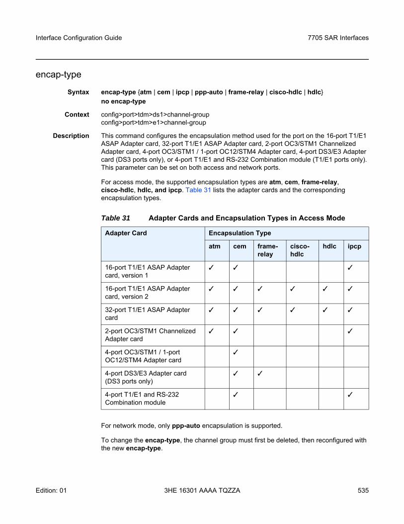
Interface Configuration Guide 7705 SAR Interfaces
Edition: 01 3HE 16301 AAAA TQZZA 535
encap-type
Syntax encap-type atm | cem | ipcp | ppp-auto | frame-relay | cisco-hdlc | hdlc no encap-type
Context config>port>tdm>ds1>channel-groupconfig>port>tdm>e1>channel-group
Description This command configures the encapsulation method used for the port on the 16-port T1/E1 ASAP Adapter card, 32-port T1/E1 ASAP Adapter card, 2-port OC3/STM1 Channelized Adapter card, 4-port OC3/STM1 / 1-port OC12/STM4 Adapter card, 4-port DS3/E3 Adapter card (DS3 ports only), or 4-port T1/E1 and RS-232 Combination module (T1/E1 ports only). This parameter can be set on both access and network ports.
For access mode, the supported encapsulation types are atm, cem, frame-relay, cisco-hdlc, hdlc, and ipcp. Table 31 lists the adapter cards and the corresponding encapsulation types.
For network mode, only ppp-auto encapsulation is supported.
To change the encap-type, the channel group must first be deleted, then reconfigured with the new encap-type.
Table 31 Adapter Cards and Encapsulation Types in Access Mode
Adapter Card Encapsulation Type
atm cem frame-relay
cisco-hdlc
hdlc ipcp
16-port T1/E1 ASAP Adapter card, version 1
16-port T1/E1 ASAP Adapter card, version 2
32-port T1/E1 ASAP Adapter card
2-port OC3/STM1 Channelized Adapter card
4-port OC3/STM1 / 1-port OC12/STM4 Adapter card
4-port DS3/E3 Adapter card (DS3 ports only)
4-port T1/E1 and RS-232 Combination module
7705 SAR Interfaces
536
Interface Configuration Guide
3HE 16301 AAAA TQZZA Edition: 01
Default no encap-type
Parameters atm — specifies the encapsulation type as ATM for ATM pseudowires
cem — specifies the encapsulation type as circuit emulation mode (CEM) for TDM pseudowires
frame-relay — specifies the encapsulation type as frame relay
cisco-hdlc — specifies the encapsulation type as Cisco HDLC
hdlc — specifies the encapsulation type as HDLC
ipcp — specifies the encapsulation type as IPCP for a PPP/MLPPP channel group in access mode on the 2-port OC3/STM1 Channelized Adapter card, 16-port T1/E1 ASAP Adapter card, 32-port T1/E1 ASAP Adapter card, or 4-port T1/E1 and RS-232 Combination module. IPCP is not supported on fractional T1/E1 channels on a 2-port OC3/STM1 Channelized Adapter card.
ppp-auto — specifies the encapsulation type as PPP for PPP/MLPPP bundles in network mode.
idle-cycle-flag
Syntax idle-cycle-flag flags | onesno idle-cycle-flag
Context config>port>tdm>ds1>channel-groupconfig>port>tdm>e1>channel-group
Description This command configures the value that the DS0, DS1, DS3, E1, or TDM interface transmits during idle cycles. This command is applicable only if the encapsulation type is ppp-auto.
The no form of this command changes the idle cycle flag to the default value.
Default flags (0x7E)
Parameters flags — use 0x7E as the idle cycle flag
ones — use 0xFF as the idle cycle flag
idle-payload-fill
Syntax idle-payload-fill all-ones | pattern patternno idle-payload-fill
Context config>port>tdm>ds1>channel-groupconfig>port>tdm>e1>channel-group
Interface Configuration Guide 7705 SAR Interfaces
Edition: 01 3HE 16301 AAAA TQZZA 537
Description This command defines the data pattern to be transmitted (8-bit value) when the circuit emulation service is not operational or temporarily experiences underrun conditions. This command is only valid for CESoPSN services.
Default all-ones
Parameters all-ones — transmits 11111111
pattern — transmits the user-defined pattern
Values 0 to 255 (can be entered in decimal, binary, or hexadecimal format)
idle-signal-fill
Syntax idle-signal-fill all-ones | pattern patternno idle-signal-fill
Context config>port>tdm>ds1>channel-groupconfig>port>tdm>e1>channel-group
Description This command defines the signaling pattern to be transmitted (4-bit value) when the circuit emulation service is not operational or temporarily experiences underrun conditions. This command is only valid for CES with CAS.
Default all-ones
Parameters all-ones — transmits 1111
pattern — transmits the user-defined pattern
Values 0 to 15 (can be entered in decimal, binary, or hexadecimal format)
Note: See the 7705 SAR Services Guide for information on CESoPSN services.
Note: See the 7705 SAR Services Guide for information on CESoPSN services.
7705 SAR Interfaces
538
Interface Configuration Guide
3HE 16301 AAAA TQZZA Edition: 01
loopback
Syntax loopback line | internalno loopback
Context config>port>tdm>ds1>channel-groupconfig>port>tdm>e1>channel-group
Description This command puts the specified n × DS0 (64 kb/s) channel group in a loopback mode. For T1 ports, the channel group can have 1 to 24 channels. For E1 ports, the channel group can have 1 to 31 channels.
When a line loopback is enabled on the channel group:
• frames received on the channel group on the Rx port are looped back toward the Tx (egress) port before reaching the framer. However, if CAS is enabled on the interface, the Tx signaling bits will continue to be sourced from the far end of the Cpipe (not looped back).
• an all-ones pattern is inserted by the framer in the direction of the switch fabric and to the far end of the Cpipe
When an internal loopback (usually referred to as an equipment loopback) is enabled on the channel group:
• frames received on the channel group from the switch fabric toward the framer are looped back to the switch fabric and to the far end of the Cpipe. However, if CAS is enabled on the interface, the Rx signaling bits will continue to be sourced from the local access port (not looped back).
• traffic received on the channel group will continue to be sent out the Tx (egress) port as if no internal loopback was there
N × DS0 (64 kb/s) channel group loopbacks are only supported on the 16-port T1/E1 ASAP Adapter card, version 2, and the 32-port T1/E1 ASAP Adapter card.
Default no loopback
Parameters line — puts the specified channel group in line loopback mode
internal — puts the specified channel group in internal loopback mode
mac
Syntax mac ieee-addressno mac
Context config>port>tdm>ds1>channel-groupconfig>port>tdm>e1>channel-groupconfig>port>tdm>ds3
Interface Configuration Guide 7705 SAR Interfaces
Edition: 01 3HE 16301 AAAA TQZZA 539
Description This command assigns a specific MAC address to an APS port. When the command is issued while the port is operational, IP will issue an ARP, if appropriate, and BPDUs are sent with the new MAC address. Configuring a MAC address using the mac command is only supported for APS channel groups. Physical channel groups do not support the mac command.
The no form of this command removes the configured MAC address. The physical port MAC address will be used instead.
For TDM ports, configuring the MAC address allows the same MAC address to be assigned to ports across two routers in an MC-APS pair for MEF 8.
The mac command is only supported on the 2-port OC3/STM1 Channelized Adapter card and 4-port OC3/STM1 / 1-port OC12/STM4 Adapter card.
Default no mac
Parameters ieee-address — specifies the 48-bit MAC address in the form aa:bb:cc:dd:ee:ff or aa-bb-cc-dd-ee-ff where aa, bb, cc, dd, ee, and ff are hexadecimal numbers. Allowed values are any non-broadcast, non-multicast MAC, and non-IEEE reserved MAC addresses.
mode
Syntax mode access | networkno mode
Context config>port>tdm>ds1>channel-groupconfig>port>tdm>e1>channel-group
Description This command configures a TDM channel for access or network mode operation.
An access port or channel is used for customer-facing traffic on which services are configured. A Service Access Point (SAP) can only be configured on an access port or channel.
When a port is configured for access mode, the appropriate encap-type must be specified to distinguish the services on the port. Once a TDM channel has been configured for access mode, multiple services can be configured on the TDM channel.
A network port or channel participates in the service provider transport or infrastructure network when a network mode is selected. When the network option is configured, only the ppp-auto encap-type can be configured for the port or channel.
The no form of this command restores the default.
Default access
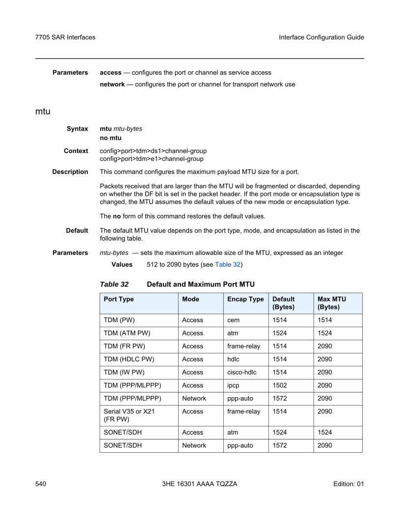
7705 SAR Interfaces
540
Interface Configuration Guide
3HE 16301 AAAA TQZZA Edition: 01
Parameters access — configures the port or channel as service access
network — configures the port or channel for transport network use
mtu
Syntax mtu mtu-bytesno mtu
Context config>port>tdm>ds1>channel-groupconfig>port>tdm>e1>channel-group
Description This command configures the maximum payload MTU size for a port.
Packets received that are larger than the MTU will be fragmented or discarded, depending on whether the DF bit is set in the packet header. If the port mode or encapsulation type is changed, the MTU assumes the default values of the new mode or encapsulation type.
The no form of this command restores the default values.
Default The default MTU value depends on the port type, mode, and encapsulation as listed in the following table.
Parameters mtu-bytes — sets the maximum allowable size of the MTU, expressed as an integer
Values 512 to 2090 bytes (see Table 32)
Table 32 Default and Maximum Port MTU
Port Type Mode Encap Type Default (Bytes)
Max MTU (Bytes)
TDM (PW) Access cem 1514 1514
TDM (ATM PW) Access atm 1524 1524
TDM (FR PW) Access frame-relay 1514 2090
TDM (HDLC PW) Access hdlc 1514 2090
TDM (IW PW) Access cisco-hdlc 1514 2090
TDM (PPP/MLPPP) Access ipcp 1502 2090
TDM (PPP/MLPPP) Network ppp-auto 1572 2090
Serial V35 or X21 (FR PW)
Access frame-relay 1514 2090
SONET/SDH Access atm 1524 1524
SONET/SDH Network ppp-auto 1572 2090
Interface Configuration Guide 7705 SAR Interfaces
Edition: 01 3HE 16301 AAAA TQZZA 541
ppp
Syntax [no] ppp
Context config>port>tdm>ds1>channel-groupconfig>port>tdm>e1>channel-group
Description This command enables access to the context to configure the LCP operational parameters for a DS1 or E1 channel or a DS0 channel.
The no form of the command removes the LCP operational parameters.
Default no ppp
ber-sf-link-down
Syntax ber-sf-link-downno ber-sf-link-down
Context config>port>tdm>ds1>channel-group>pppconfig>port>tdm>e1>channel-group>ppp
Description This command enables the channel-group down on BER-SF alarm.When enabled, the channel-group will be placed out of service once BER-SF is detected.
The no form of this command disables the feature.
Default no ber-sf-link-down
keepalive
Syntax keepalive time-interval [dropcount drop-count]no keepalive
Context config>port>tdm>ds1>channel-group>pppconfig>port>tdm>e1>channel-group>ppp
Description This command sets the keepalive interval.
The no form of this command returns the interval to the default value.
Default keepalive 10 dropcount 3
Parameters time-interval — the time in seconds between keepalive messages, expressed as a decimal integer
Values 1 to 60
7705 SAR Interfaces
542
Interface Configuration Guide
3HE 16301 AAAA TQZZA Edition: 01
drop-count — the number of consecutive keepalive failed request attempts or remote replies that can be missed after which the port is operationally downed
Values 1 to 255
scramble
Syntax [no] scramble
Context config>port>tdm>ds1>channel-groupconfig>port>tdm>e1>channel-group
Description This command enables payload scrambling on channel groups. The command is applicable only if the encapsulation type is atm.
signal-mode
Syntax signal-mode casno signal-mode
Context config>port>tdm>ds1>channel-groupconfig>port>tdm>e1>channel-group
Description This command enables or disables Channel Associated Signaling (CAS) at the channel group level. When enabled, control signals (such as those for synchronizing and bounding frames) are carried in the same channels as voice and data signals.
If the signal mode at the DS1/E1 port level is configured for signal-mode cas, any new channel groups default to signal-mode cas. Any existing channel groups can be individually changed from cas to no signal-mode.
The signal mode must be configured for CAS before creating a Cpipe with CAS. Refer to the 7705 SAR Services Guide, “Creating a Cpipe Service”, for information on configuring a Cpipe service.
This command is valid only on the following cards and platforms when DS1 framing is set to esf or sf, or E1 framing is set to g704 or no-crc-g704:
• 16-port T1/E1 ASAP Adapter card• 32-port T1/E1 ASAP Adapter card• 2-port OC3/STM1 Channelized Adapter card• 4-port DS3/E3 Adapter card• 7705 SAR-A• 7705 SAR-M• 7705 SAR-X
Parameters cas — specifies channel associated signaling
Interface Configuration Guide 7705 SAR Interfaces
Edition: 01 3HE 16301 AAAA TQZZA 543
timeslots
Syntax timeslots timeslotsno timeslots
Context config>port>tdm>ds1>channel-groupconfig>port>tdm>e1>channel-group
Description This command defines the list of DS0 timeslots to be used in the DS1 or E1 channel group. The timeslots do not need to be consecutive. If the encapsulation type is changed to or from atm, the timeslots are reset to the default. If the encapsulation type is set to atm, the timeslot ranges are automatically configured and cannot be changed.
If the port is configured for fractional T1/E1 (see Configuring Fractional T1/E1 Ports for PPP Encapsulation), this command is used to specify the number of timeslots to be used on the port. Only the specified timeslots can be used.
The no form of this command removes DS0 timeslots from a channel group.
Default no timeslots — non-ATM channel groups1 to 24 — channel groups configured under DS1 with atm encapsulation2 to 16, 18 to 32 — channel groups configured under E1 with atm encapsulation2 to 32 — channel groups configured under E1 (ppp-auto)
Parameters timeslots — specifies the timeslots to be associated with the channel group. The value can consist of a list of timeslots. Each member of the list can either be a single timeslot or a range of timeslots.
Values 1 to 24 for DS1 interfaces. The full range is automatically configured for ATM channel groups and cannot be changed.2 to 32 for E1 interfaces. The 2 to 16 and 18 to 32 ranges are automatically configured for ATM channel groups and cannot be changed.
7705 SAR Interfaces
544
Interface Configuration Guide
3HE 16301 AAAA TQZZA Edition: 01
3.13.2.27 DS3 and E3 Commands
clock-source
Syntax clock-source loop-timed | node-timed | differential | free-run
Context config>port>tdm>ds3config>port>tdm>e3
Description This command specifies the clock source to be used for the link transmit timing.
The clock source setting also determines the node sync reference if the port is configured as one of the node synchronization references (config>system>sync-if-timing>ref1 | ref2> source-port command). Refer to the 7705 SAR Basic System Configuration Guide, “Node Timing”, for more information.
Default node-timed (for the 4-port DS3/E3 Adapter card)
loop-timed (for all other applicable adapter cards)
Parameters loop-timed — the link recovers the clock from the received data stream
node-timed — the link uses the internal clock when transmitting data (this parameter does not apply to the 2-port OC3/STM1 Channelized Adapter card)
differential — clocking is derived from a common clock compared to differential clock recovery (DCR) data in the RTP header in the TDM PW overhead. DCR must also be enabled on the relevant card, module, or chassis with the clock-mode command. This parameter applies only to DS3/E3 ports on the 4-port DS3/E3 Adapter card.
free-run — timing source is from its own clock, not an external timing source (this parameter does not apply to the 4-port DS3/E3 Adapter card)
crc
Syntax crc 16 | 32
Context config>port>tdm>ds3config>port>tdm>e3
Description This command configures the precision of the cyclic redundancy check (CRC). Non-ATM ports support a 16-bit checksum and ATM ports support a 32-bit checksum. CRC applies to PPP applications only on the 2-port OC3/STM1 Channelized Adapter card and 4-port DS3/E3 Adapter card.
Default 16 (non-ATM ports)
32 (ATM ports)
Interface Configuration Guide 7705 SAR Interfaces
Edition: 01 3HE 16301 AAAA TQZZA 545
Parameters 16 — use 16-bit checksum for the associated port
32 — use 32-bit checksum for the associated port
encap-type
Syntax encap-type atm | cem | ppp-auto | frame-relayno encap-type
Context config>port>tdm>ds3config>port>tdm>e3
Description This command configures the encapsulation method used on the specified DS3/E3 port.
To change the encap-type, the port must first be deleted, then reconfigured with the new encap-type.
Default no encap-type
Parameters atm — specifies the encapsulation type as ATM
cem — specifies the encapsulation type as circuit emulation mode (CEM) for TDM pseudowires
ppp-auto — specifies the encapsulation type as PPP. The activation of IPCP and MPLSCP is automatically enabled depending on the protocol configuration. This encapsulation type is only valid on DS3 and E3 ports or DS3 channels in network mode.
frame-relay — specifies the encapsulation type as frame relay
feac-loop-respond
Syntax [no] feac-loop-respond
Context config>port>tdm>ds3config>port>tdm>e3
Description This command enables the DS3/E3 interface to respond to remote loop signals. The DS3/E3 far-end alarm and control (FEAC) signal is used to send alarm or status information from the far-end terminal back to the local terminal. DS3/E3 loopbacks at the far-end terminal from the local terminal are initiated.
The no form of this command prevents the DS3/E3 interface from responding to remote loop signals.
Default no feac-loop-respond
7705 SAR Interfaces
546
Interface Configuration Guide
3HE 16301 AAAA TQZZA Edition: 01
framing (DS3)
Syntax framing c-bit | m23
Context config>port>tdm>ds3
Description This command specifies DS3 framing for the associated DS3 port.
Default c-bit
Parameters c-bit — configures the DS3 port for C-bit framing
m23 — configures the DS3 port for M23 framing
framing (E3)
Syntax framing g751
Context config>port>tdm>e3
Description This command specifies E3 framing for the associated E3 port.
Default g751 (this default cannot be changed)
Parameters g751 — configures the E3 port for g751 framing
idle-cycle-flag
Syntax idle-cycle-flag flags | onesno idle-cycle-flag
Context config>port>tdm>ds3config>port>tdm>e3
Description This command configures the value that the DS3/E3 interface transmits during idle cycles. This command is applicable only if the encapsulation type is ppp-auto. For ATM ports, the configuration does not apply and only the no form is accepted.
The no form of this command resets the idle cycle flag to the default value.
Default flags (0x7E)no idle-cycle-flag (for ATM)
Parameters flags — use 0x7E as the idle cycle flag
ones — use 0xFF as the idle cycle flag
Interface Configuration Guide 7705 SAR Interfaces
Edition: 01 3HE 16301 AAAA TQZZA 547
loopback
Syntax loopback line | internal | remoteno loopback
Context config>port>tdm>ds3config>port>tdm>e3
Description This command puts the specified DS3/E3 port into a loopback mode.
A line loopback loops frames received on the corresponding port or channel back towards the transmit (egress) direction before reaching the framer.
An internal loopback loops the frames that are coming in an egress direction from the fabric towards the framer, back to the fabric. This is usually referred to as an equipment loopback.
A remote loopback sends a signal to the remote device to provide a line loopback. To configure a remote loopback, you must enable feac-loop-respond on the far-end DS3/E3 interface, then set the loopback to remote on the near-end DS3/E3 interface. Remote loopback sends a loopback code to the far-end DS3/E3 interface that results in the far end sending out a line loopback.
The loopback command is not saved to the system configuration.
The no form of this command disables loopback on the DS3/E3 port.
Default no loopback
Parameters line — places the associated DS3/E3 port into line loopback mode
internal — places the associated DS3/E3 port into internal loopback mode
remote — places the associated DS3/E3 port into remote loopback mode
mdl
Syntax mdl eic | lic | fic | unit | pfi | port | gen mdl-stringno mdl
Context config>port>tdm>ds3
Description This command configures the maintenance data link (MDL) message for a DS3 port or channel. This command is only applicable if the DS3 port or channel is using C-bit framing, specified using the framing (DS3) command.
The no form of this command removes the mdl-string association and stops the transmission of MDL messages.
Default no mdl
7705 SAR Interfaces
548
Interface Configuration Guide
3HE 16301 AAAA TQZZA Edition: 01
Parameters mdl-string — specifies an MDL message up to 38 characters long
eic — specifies the equipment ID code up to 10 characters long
lic — specifies the line ID code up to 11 characters long
fic — specifies the frame ID code up to 10 characters long
unit — specifies the unit ID code up to 6 characters long
pfi — specifies the facility ID code up to 38 characters long
port — specifies the port ID code up to 38 characters long
gen — specifies the generator number to send in the MDL test signal message, up to 38 characters long
mdl-transmit
Syntax [no] mdl-transmit path | idle-signal | test-signal
Context config>port>tdm>ds3
Description This command enables the transmission of an MDL message on a DS3 port or channel. This command is only applicable if the DS3 port or channel is using C-bit framing, specified using the framing (DS3) command.
The no form of this command prevents the transmission of an MDL message on the DS3 port or channel.
Default no mdl-transmit
Parameters path — specifies the MDL path message
idle-signal — specifies the MDL idle signal message
test-signal — specifies the MDL test signal message
mode
Syntax mode access | networkno mode
Context config>port>tdm>ds3config>port>tdm>e3
Description This command configures a DS3/E3 port for access or network mode of operation.
SAPs can only be configured on access ports. When a DS3/E3 port is configured for access mode, the encap-type can be set to atm, cem, or frame-relay.
Interface Configuration Guide 7705 SAR Interfaces
Edition: 01 3HE 16301 AAAA TQZZA 549
A network port is used as an uplink to connect to the packet network and transport the PPP services. Network mode applies to DS3 and E3 ports. When a DS3/E3 port is configured for network mode, the encap-type must be set to ppp-auto.
The mode can be changed between access and network provided that encap-type has not been configured yet. If encap-type has been configured, the DS3/E3 port must be first deleted and then reconfigured with the required encap-type.
The no form of this command reverts to the default.
Default access
Parameters access — configures the port as service access
network — configures the port as a network uplink
mtu
Syntax mtu mtu-bytesno mtu
Context config>port>tdm>ds3config>port>tdm>e3
Description This command configures the maximum payload MTU size for a DS3/E3 port configured for PPP. Packets that are received larger than the MTU are discarded. Packets that cannot be fragmented at egress and exceed the MTU are also discarded.
The no form of this command restores the default value.
Default 1572 (for ppp-auto)
Parameters mtu-bytes — sets the maximum allowable size of the MTU, expressed as an integer
Values 512 to 2090 (in bytes)
ppp
Syntax ppp
Context config>port>tdm>ds3config>port>tdm>e3
Description This command enables access to the context to configure the LCP operational parameters for a DS3/E3 port.

7705 SAR Interfaces
550
Interface Configuration Guide
3HE 16301 AAAA TQZZA Edition: 01
keepalive
Syntax keepalive time-interval [dropcount drop-count]no keepalive
Context config>port>tdm>ds3>pppconfig>port>tdm>e3>ppp
Description This command sets the interval between keepalive messages.
The no form of this command returns the interval to the default value.
Default keepalive 10 dropcount 3
Parameters time-interval — the time in seconds between keepalive messages, expressed as a decimal integer
Values 1 to 60
drop-count — the number of consecutive keepalive failed request attempts or remote replies that can be missed before the port becomes operationally down
Values 1 to 255
report-alarm
Syntax [no] report-alarm ais | los | oof | rai | looped
Context config>port>tdm>ds3config>port>tdm>e3
Description This command enables logging of DS3 and E3 alarms for a DS3/E3 port or channel. When configured, logging is enabled for the raising and clearing of the specified alarms.
The no form of this command disables logging of the specified alarms.
Parameters ais — reports alarm indication signal errors
Default ais alarms are issued
los — reports loss of signal errors
Default los alarms are issued
oof — reports out-of-frame errors
Default oof alarms are not issued
rai — reports remote alarm indication signal errors
Default rai alarms are not issued
looped — reports looped packets errors
Default looped alarms are not issued
Interface Configuration Guide 7705 SAR Interfaces
Edition: 01 3HE 16301 AAAA TQZZA 551
3.13.2.28 Voice Commands
voice
Syntax voice
Context config>port
Description This command enables the context to configure voice port parameters. This context can only be accessed on the 6-port E&M Adapter card, 8-port Voice & Teleprotection card, 8-port FXO Adapter card, and 6-port FXS Adapter card.
Default n/a
audio-wires
Syntax audio-wires four-wires | two-wires
Context config>port>voice
Description This command configures the number of audio wires to be used for audio transmission for an E&M interface.
A change in the number of audio wires may also require a change in the tlp-rx and tlp-tx values.
Default four-wires
Parameters four-wires — four-wire operation
two-wires — two-wire operation. This parameter is not valid if the corresponding port or channel’s signaling type is 4W transmission.
em
Syntax [no] em
Context config>port>voice
Description This command enables the context to configure channel group parameters for a channelized E&M voice interface.
The no form of this command deletes the E&M channel group.
Default n/a
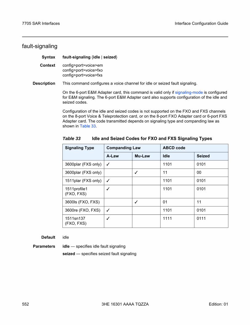
7705 SAR Interfaces
552
Interface Configuration Guide
3HE 16301 AAAA TQZZA Edition: 01
fault-signaling
Syntax fault-signaling idle | seized
Context config>port>voice>emconfig>port>voice>fxoconfig>port>voice>fxs
Description This command configures a voice channel for idle or seized fault signaling.
On the 6-port E&M Adapter card, this command is valid only if signaling-mode is configured for E&M signaling. The 6-port E&M Adapter card also supports configuration of the idle and seized codes.
Configuration of the idle and seized codes is not supported on the FXO and FXS channels on the 8-port Voice & Teleprotection card, or on the 8-port FXO Adapter card or 6-port FXS Adapter card. The code transmitted depends on signaling type and companding law as shown in Table 33.
Default idle
Parameters idle — specifies idle fault signaling
seized — specifies seized fault signaling
Table 33 Idle and Seized Codes for FXO and FXS Signaling Types
Signaling Type Companding Law ABCD code
A-Law Mu-Law Idle Seized
3600plar (FXS only) 1101 0101
3600plar (FXS only) 11 00
1511plar (FXS only) 1101 0101
1511profile1(FXO, FXS)
1101 0101
3600ls (FXO, FXS) 01 11
3600re (FXO, FXS) 1101 0101
1511sn137(FXO, FXS)
1111 0111
Interface Configuration Guide 7705 SAR Interfaces
Edition: 01 3HE 16301 AAAA TQZZA 553
fxo
Syntax [no] fxo
Context config>port>voice
Description This command creates a Foreign Exchange Office (FXO) channel on a channelized voice interface. This command applies to the 8-port FXO Adapter card and the 8-port Voice & Teleprotection Card.
The no form of this command deletes the port’s FXO channel.
Default n/a
fxs
Syntax [no] fxs
Context config>port>voice
Description This command creates a Foreign Exchange Subscriber (FXS) channel on a channelized voice interface. This command applies to the 8-port Voice & Teleprotection card and 6-port FXS Adapter card.
The no form of this command deletes the port’s FXS channel.
Default n/a
idle-code
Syntax idle-code abcd-codeno idle-code
Context config>port>voice>em
Description This command defines the ABCD signaling code to be transmitted when the voice channel is configured to transmit idle fault signaling. The command is also used for driving/scanning the E&M signaling leads.
This command is valid only on the 6-port E&M Adapter card and only if signaling-mode is configured for E&M signaling.
The no form of this command reverts to the default value.
Default 0 (for Mu-Law companding)
13 (for A-Law companding)
7705 SAR Interfaces
554
Interface Configuration Guide
3HE 16301 AAAA TQZZA Edition: 01
Parameters abcd-code — the 4-bit ABCD value to be transmitted
Values 0 to 15 (can be entered in decimal, binary, or hexadecimal format)
line-balance
Syntax line-balance nominal | 800
Context config>port>voice
Description This command configures the line balance for the FXO or FXS voice interface on the 8-port Voice & Teleprotection card, for the FXO voice interface on the 8-port FXO Adapter card, and for the FXS voice interface on the 6-port FXS Adapter card.
Default nominal (for both FXS and FXO)
Parameters nominal — 600 Ω800 — 800 Ω//(100 Ω+50 nF)
loopback
Syntax loopback internal-analog | internal-digitalno loopback
Context config>port>voice>emconfig>port>voice>fxoconfig>port>voice>fxs
Description This command puts the specified port or channel in loopback mode. The internal-digital parameter is the only valid option for FXO and FXS.
The loopback command is not saved to the system configuration between boots.
The no form of this command disables the loopback.
Default no loopback
Parameters internal-analog — places the associated port or channel into an internal analog loopback mode. The internal analog loopback resides in the CODEC, close to the line side. It loops the outgoing analog signals back towards the system. For E&M ports, the loopback analog signal may be looped back at a different signal level due to gain/loss circuits outside of the CODEC being bypassed.
internal-digital — places the associated port or channel into an internal digital loopback mode. The internal digital loopback resides in the CODEC, close to the system side. It loops the outgoing frames back towards the system.
Interface Configuration Guide 7705 SAR Interfaces
Edition: 01 3HE 16301 AAAA TQZZA 555
ring-generation
Syntax ring-generation 16 | 20 | 25no ring-generation
Context config>port>voice
Description This command configures the frequency of the generated ring signal for the specified FXS voice port.
This command does not apply to FXO or E&M ports.
The no form of this command reverts to the default value.
Default 16
Parameters 16 — 16 Hz ring signal
20 — 20 Hz ring signal
25 — 25 Hz ring signal
seized-code
Syntax seized-code abcd-codeno seized-code
Context config>port>voice>em
Description This command defines the ABCD signaling code to be transmitted when the channel is configured to transmit seized fault signaling. The command is also used for driving/scanning the E&M signaling leads.
This command is valid only on the 6-port E&M Adapter card and only if signaling-mode is configured for E&M signaling.
The no form of this command reverts to the default value.
Default 0 (for Mu-Law companding)
13 (for A-Law companding)
Parameters abcd-code — the 4-bit ABCD value to be transmitted
7705 SAR Interfaces
556
Interface Configuration Guide
3HE 16301 AAAA TQZZA Edition: 01
signaling-type
Syntax signaling-type 3600plar | 1511plar | 3600ls | 1511profile1 | 3600re | 1511sn137
Context config>port>voice
Description This command configures how the signaling leads operate to establish a call. To change this parameter, the voice channel must be shut down first.
For FXO, 3600ls, 1511profile1, 3600re, and 1511sn137 are the only valid options; 1511profile1, 3600re, and 1511sn137 support A-Law companding, and 3600ls supports Mu-Law companding.
For FXS, all signaling types are supported; 3600plar supports both A-Law and Mu-Law companding, 1511plar, 1511profile1, 3600re, and 1511sn137 support A-Law companding, and 3600ls supports Mu-Law companding.
Default 3600ls (for Mu-Law companding)
3600re (for A-Law companding)
Parameters 3600plar — private line automatic ringdown
1511plar — private line automatic ringdown
3600ls — loop start
1511profile1 — 1511 loop start
3600re — remote extension
1511sn137 — 1511 profile 137
signaling-lead
Syntax signaling-lead
Context config>port>voice>em
Description This command enables the context to configure the input and output leads, which carry call control signals.
Default n/a
e
Syntax e high | low | end-to-end
Context config>port>voice>em>signaling-lead
Interface Configuration Guide 7705 SAR Interfaces
Edition: 01 3HE 16301 AAAA TQZZA 557
Description This command configures the output signaling lead known as the E-lead (Ear, Earth, or Exchange).
This command is valid only if signaling-mode is configured for E&M signaling.
Default end-to-end
Parameters high — specifies that the output signaling lead is forced on
low — specifies that the output signaling lead is forced off
end-to-end — specifies that the output signaling lead follows that of the remote end
m
Syntax m high | low | end-to-end
Context config>port>voice>em>signaling-lead
Description This command configures the input signaling lead known as the M-lead (Mouth, Magneto, or Multiplexer).
This command is valid only if signaling-mode is configured for E&M signaling.
Default end-to-end
Parameters high — specifies that the input signaling lead is forced on
low — specifies that the input signaling lead is forced off
end-to-end — specifies that the input signaling lead follows that of the connected equipment
signaling-mode
Syntax signaling-mode em | transmission-only
Context config>port>voice>em
Description This command configures the signaling mode for the specified port or channel. This configuration is done for groups of three ports (ports 1 to 3 and ports 4 to 6). The first port to be configured in the group sets the signaling mode for the other ports in the group. For example, if port 1 is set for transmission only, ports 2 and 3 must also be set for transmission only, and if port 4 is set for E&M signaling, ports 5 and 6 must also be set for E&M signaling. To change the signaling mode of a port, all ports in the group must first be deconfigured.
Default em
7705 SAR Interfaces
558
Interface Configuration Guide
3HE 16301 AAAA TQZZA Edition: 01
Parameters em — specifies E&M signaling mode
transmission-only — specifies transmission-only mode. This parameter is not valid if audio-wires is configured for two-wire operation.
tlp-rx
Syntax tlp-rx decibels
Context config>port>voice
Description This command configures the analog-to-digital receive transmission level point (TLP) for the specified port.
Parameters decibels — specifies the transmission level point expressed as an integer (in tenths)
Values –16.0 to +7.0 (for E&M four-wires)–10.0 to +6.0 (for E&M two-wires)–7.0 to 0.0 (for FXO and FXS)
Default 0.0 (for E&M)–3.0 (for FXO and FXS)
tlp-tx
Syntax tlp-tx decibels
Context config>port>voice
Description This command configures the analog-to-digital transmit transmission level point (TLP) for the specified port.
Parameters decibels — specifies the transmission level point expressed as an integer (in tenths)
Values –16.0 to +7.0 (for E&M four-wires)–10.0 to +6.0 (for E&M two-wires)–4.0 to +3.0 (for FXO and FXS)
Default 0.0 (for E&M)0.0 (for FXO and FXS)
Interface Configuration Guide 7705 SAR Interfaces
Edition: 01 3HE 16301 AAAA TQZZA 559
3.13.2.29 Voice Channel Group Commands
channel-group
Syntax [no] channel-group channel-group-id
Context config>port>voice>emconfig>port>voice>fxoconfig>port>voice>fxs
Description This command creates a DS0 channel group for a channelized E&M, FXO, or FXS voice interface.
Channel groups cannot be further subdivided.
The no form of this command deletes the specified channel group.
Default n/a
Parameters channel-group-id — specifies the channel group ID number
Values 1 (only a single DS0 channel group, the first one, can be configured)
encap-type
Syntax encap-type cem
Context config>port>voice>em>channel-groupconfig>port>voice>fxo>channel-groupconfig>port>voice>fxs>channel-group
Description This command configures the encapsulation method used by the channel group.
Default no encap-type
Parameters cem — specifies the encapsulation method as circuit emulation (TDM)
mode
Syntax mode access
Context config>port>voice>em>channel-groupconfig>port>voice>fxo>channel-groupconfig>port>voice>fxs>channel-group
Description This command configures a channelized voice interface for access mode operation. Network mode is not supported.
7705 SAR Interfaces
560
Interface Configuration Guide
3HE 16301 AAAA TQZZA Edition: 01
An access port or channel is used for customer-facing traffic on which services are configured. A Service Access Point (SAP) can only be configured on an access port or channel.
When a port or channel is configured for access mode, the encap-type must be specified (in this case, cem) to distinguish the services on the port.
Default access
Parameters access — specifies the channelized E&M, FXO, or FXS voice port as service access
Interface Configuration Guide 7705 SAR Interfaces
Edition: 01 3HE 16301 AAAA TQZZA 561
3.13.2.30 LAG Commands
lag
Syntax [no] lag lag-id
Context config
Description This command enables the context in which Link Aggregation Group (LAG) attributes are defined.
A LAG groups two or more Ethernet links (ports) into one logical link. The aggregation of multiple physical links adds redundancy and improves resiliency between two network devices, and allows for load sharing.
On access ports, a LAG can have a maximum of two links and can support active/standby operation. If an active link in a LAG fails, traffic gets redistributed to the standby link.
On network ports, a LAG can have a maximum of eight links (depending on the platform or adapter card/module and the Ethernet port type) and can support active/active and active/standby operation. In active/active mode, the links are used for load sharing.
The no form of this command deletes the LAG from the configuration. A LAG can only be deleted while it is administratively shut down. Any dependencies, such as IP interface configurations, must be removed from the LAG before it can be shut down.
Default no lag
Parameters lag-id — the LAG identifier, expressed as a decimal integer
Values 1 to 32
access
Syntax access
Context config>lag
Description This command enables the context to configure access parameters.
Default n/a
adapt-qos
Syntax adapt-qos link | distribute
Context config>lag>access
7705 SAR Interfaces
562
Interface Configuration Guide
3HE 16301 AAAA TQZZA Edition: 01
Description This command specifies how active/active LAG SAP queue scheduler, SAP scheduler (H-QoS), and SAP MSS scheduler QoS rates (as specified by the SLA) are distributed to each of the active LAG ports. This command applies only to access LAGs.
Default link
Parameters link — specifies that the full QoS rates are configured on each of the active LAG links for SAP queue schedulers, SAP schedulers (H-QoS), and SAP MSS schedulers
distribute — specifies that the QoS rates are divided equally among the active LAG links for SAP queue schedulers, SAP schedulers (H-QoS), and egress MSS schedulers. For ingress MSS shaper schedulers, the distribute parameter specifies that the QoS rates are divided proportionally among the active link MDAs based on the number of active links on each MDA.
dynamic-cost
Syntax [no] dynamic-cost
Context config>lag
Description This command enables OSPF or IS-IS costing of a LAG based on the available aggregated, operational bandwidth.
The path cost is dynamically calculated based on the interface bandwidth. OSPF path cost can be changed through the interface metric or the reference bandwidth.
If dynamic cost is configured, costing is applied based on the total number of links configured and the cost advertised is inversely proportional to the number of links available at the time. This requires that the number of links that are up exceeds the configured LAG threshold value; if the number of links that are up falls below the threshold, the configured threshold action determines whether, and at what cost, this LAG will be advertised (see port-threshold).
For example, a physical link in OSPF has a cost associated with it of 100, and the LAG consists of four physical links. The cost associated with the logical link is 25. If one link fails, the cost is automatically adjusted to 33.
If dynamic cost is not configured and OSPF auto-cost is configured, costing is applied based on the total number of links configured. This cost will remain static provided that the number of links that are up exceeds the configured LAG threshold value; if the number of links that are up falls below the threshold, the configured threshold action determines whether, and at what cost, this LAG will be advertised.
If dynamic cost is configured and OSPF auto-cost is not configured, the cost is determined by the cost configured on the OSPF metric, provided that the number of links that are up exceeds the configured LAG threshold value; if the number of links that are up falls below the threshold, the configured threshold action determines whether this LAG will be advertised.
Interface Configuration Guide 7705 SAR Interfaces
Edition: 01 3HE 16301 AAAA TQZZA 563
If neither dynamic cost nor OSPF auto-cost is configured, the cost advertised is determined by the cost configured on the OSPF metric, provided that the number of links that are up exceeds the configured LAG threshold value; if the number of links that are up falls below the threshold, the configured threshold action determines whether this LAG will be advertised.
The no form of this command removes dynamic costing from the LAG.
Default no dynamic-cost
encap-type
Syntax encap-type dot1q | null | qinqno encap-type
Context config>lag
Description This command configures the encapsulation method used to distinguish customer traffic on a LAG.
The encapsulation type of a LAG must match that of its member links. If the encapsulation type of the LAG is changed, the encapsulation type of all its member links also changes.
The encapsulation type can be changed on the LAG only if there is no interface or service associated with it. If the MTU is set to a non-default value, it will be reset to the default value when the encapsulation type is changed.
The no form of this command reverts to the default encapsulation type.
Default null — all traffic on the link belongs to a single service or VLAN
Parameters dot1q — ingress Ethernet frames carry IEEE 802.1Q tags, each tag signifying a different service
null — ingress Ethernet frames do not use any tags to indicate a service. As a result, only one service can be configured on a link with null encapsulation.
qinq — ingress frames carry two tags, where the outer tag is the service provider tag and the inner tag is the customer service tag as defined in 802.1ad
hold-time
Syntax hold-time down hold-down-timeno hold-time
Context config>lag
Description This command specifies the delay between detecting that a LAG is down (all active ports are down) and reporting it to the upper layer protocols.
7705 SAR Interfaces
564
Interface Configuration Guide
3HE 16301 AAAA TQZZA Edition: 01
When a failure in a LAG is detected, it is immediately advertised to the rest of the system, but subsequent failures are not advertised to upper layers until the hold-time down interval has expired.
Specifying a hold time is especially useful in a 1:1 active/standby configuration because the time between detecting that the active link in the LAG is down and the time needed to activate the standby link is very short. The hold time prevents the LAG from being operationally down when switching between the active and standby link.
The no form of this command removes any hold time configured.
Default no hold-time
Parameters hold-down-time — specifies, in tenths of seconds, the hold time before a failure is reported
Values 0 to 2000
lacp
Syntax lacp [mode] [administrative-key admin-key]no lacp
Context config>lag
Description This command specifies the LACP mode of the LAG. By default, the LACP mode is not set.
Per the IEEE 802.1AX-2008 (IEEE 802.3ad) standard, the Link Aggregation Control Protocol (LACP) provides a standardized means for exchanging information between network devices using LAGs. LACP operates in two modes: passive and active. At least one partner must operate in active mode. For example, if the mode on the CE end is passive, the LACP mode on the 7705 SAR end must be active.
The no form of this command disables LACP.
Default no lacp
Parameters mode — specifies the mode in which LACP operates
Values passive — starts transmitting LACP packets only after receiving packetsactive — initiates the transmission of LACP packets
admin-key — specifies an administrative key value to identify the aggregation group on each port configured to use LACP. This value should be configured only in exceptional cases. If it is not specified, a random key is assigned.
Values 1 to 65535
Interface Configuration Guide 7705 SAR Interfaces
Edition: 01 3HE 16301 AAAA TQZZA 565
lacp-xmit-interval
Syntax lacp-xmit-interval slow | fastno lacp-xmit-interval
Context config>lag
Description This command specifies the interval signaled to the peer and tells the peer at which rate it should transmit.
The no form of this command returns the value to the default.
Default fast
Parameters slow — transmits packets every 30 seconds
fast — transmits packets every second
lacp-xmit-stdby
Syntax [no] lacp-xmit-stdby
Context config>lag
Description This command enables LACP message transmission on the standby link.
The no form of this command disables LACP message transmission on the standby link. Disable LACP message transmission on the standby link if the peer does not properly follow the IEEE 802.3ax standard regarding the LACP sync bit.
Default lacp-xmit-stdby
mac
Syntax mac ieee-addressno mac
Context config>lag
Description This command assigns a specific MAC address to the LAG.
The no form of this command returns the MAC address to the default value.
Default a default MAC address is assigned by the system
Parameters ieee-address — specifies the 48-bit MAC address in the form aa:bb:cc:dd:ee:ff or aa-bb-cc-dd-ee-ff where aa, bb, cc, dd, ee, and ff are hexadecimal numbers. Allowed values are any non-broadcast, non-multicast MAC, and non-IEEE reserved MAC addresses.
7705 SAR Interfaces
566
Interface Configuration Guide
3HE 16301 AAAA TQZZA Edition: 01
mode
Syntax mode access | network | hybridno mode
Context config>lag
Description This command configures the LAG for access, network, or hybrid mode operation.
An access port is used for customer-facing traffic on which services are configured. A SAP can only be configured on an access port or channel.
A network port participates in the service provider transport or infrastructure network when network mode is selected.
A hybrid port allows a single port to operate in both access and network modes.
The no form of this command restores the default.
Default network
Parameters access — configures the LAG for access mode operation
network — configures the LAG for network mode operation
hybrid — configures the LAG for hybrid mode operation
port
Syntax port port-id [port-id] [priority priority] [sub-group sub-group-id]no port port-id
Context config>lag
Description This command adds ports (links) to a LAG. Multiple ports can be added in one command as long as the maximum is not exceeded. A LAG can have up to eight links, depending on the platform or adapter card/module and the Ethernet port type.
The port configuration of the first port added to the LAG is used to compare to subsequently added ports. All ports must share the same characteristics (MTU, speed, duplex, and so on) as those of the first port; otherwise, they will not be added to the LAG.
The priority parameter sets the priority of the port, which is used by LACP. The port with the highest priority is the primary port. If two or more ports share the same priority value, the port with the lowest port ID becomes the primary port.
Any configuration changes made to the primary port apply to all member ports of a LAG. For example, port hold-time and MTU settings can be modified directly on the primary port and will be applied to all member ports. Any configuration changes made to non-primary ports are rejected.
Interface Configuration Guide 7705 SAR Interfaces
Edition: 01 3HE 16301 AAAA TQZZA 567
The no form of this command removes ports from the LAG.
Default n/a
Parameters port-id — specifies the physical port ID in the slot/mda/port format
priority — specifies the priority of a port
Values 1 to 65535
sub-group-id — identifies a LAG subgroup. Each port in a LAG must be a member of a subgroup. If no subgroup is specified for an access port, the configuration will fail. If no subgroup is specified for a network port, the port is assigned to subgroup 1. Subgroups should only be configured on one side of a LAG, not both. If you configure the 7705 SAR with subgroups to handle active/standby operation, the partner system should not be configured with subgroups. Only having one side perform active/standby selection guarantees a consistent selection and fast convergence. Active/standby selection is signaled through LACP from one side of the LAG to the other.
Values 1 or 2 (for LAGs on access ports)1 to 8 (for LAGs on network ports; system-dependent)
port-threshold
Syntax port-threshold value [action dynamic-cost | down]no port-threshold
Context config>lag
Description This command sets a threshold value and controls the behavior of the LAG if the number of operational links is equal to or below the threshold value.
The no form of this command returns the value to the default.
Default 0 action down
Parameters value — the number of operational links at or below which the configured action will be invoked for the LAG. When the number of operational links exceeds the port threshold value, any action taken for being below the threshold value will cease.
Values 0 to 7
Note: All ports in a LAG must have autonegotiation disabled or set to limited mode (recommended setting is limited). Autonegotiation can be disabled or set to limited mode using the autonegotiate command under the config>port>ethernet context.
7705 SAR Interfaces
568
Interface Configuration Guide
3HE 16301 AAAA TQZZA Edition: 01
action dynamic-cost — specifies that dynamic costing will be activated if the number of operational links is equal to or below the configured threshold value. The LAG will remain operationally up with a cost relative to the number of operational links. The link will only be regarded as operationally down when all links in the LAG are down.
action down — specifies that the LAG will be brought operationally down if the number of operational links is equal to or below the configured threshold value. The LAG will only be regarded as up when the number of operational links exceeds the configured threshold value.
selection-criteria
Syntax selection-criteria [best-port | highest-count | highest-weight] [slave-to-partner] [subgroup-hold-time hold-time]
no selection-criteria
Context config>lag
Description This command specifies which criteria is used to select the active subgroup (link) of a LAG. Every time the configuration of a link changes, the selection algorithm is applied.
The no form of this command returns the value to the default.
Default highest-count
Parameters best-port — specifies that all standby ports will have their corresponding transmitters disabled. This parameter is used in static LAG configurations.
highest-count — specifies the subgroup with the highest number of eligible member links. An eligible member link of a LAG is a member that can potentially become active.A subgroup can have a maximum of one eligible member link.
highest-weight — specifies the subgroup with the highest aggregate weight
slave-to-partner — selects, together with the selection criteria, the active subgroup. An eligible member link of a LAG is a member that can potentially become active. This means it is operationally up (not disabled) for use by the remote side. The slave-to-partner parameter can be used to control whether this latter condition is taken into account. The slave-to-partner parameter does not apply to static LAG configurations.It is recommended that this parameter be set.
Interface Configuration Guide 7705 SAR Interfaces
Edition: 01 3HE 16301 AAAA TQZZA 569
hold-time — specifies the delay time, in tenths of a second, before switching to a newly selected active subgroup from the existing active subgroup. The timer delay applies only if the existing subgroup remains operationally up. If a value of 0 or no value is specified, the switchover occurs immediately. If a value of infinite is specified, no switchover will occur as long as the subgroup remains up; this setting can be overridden with the tools>perform>force>lag-id command. LACP must be enabled on the LAG.
Values 0 to 2000 | infinite
standby-signaling
Syntax standby-signaling [lacp | power-off]no standby-signaling
Context config>lag
Description This command specifies how the state of a member port is signaled to the remote side when the status corresponding to this member port has a standby value.
The no form of this command turns off standby signaling.
Parameters lacp — specifies that lacp is active
power-off — specifies that the standby port transmitter is disabled
7705 SAR Interfaces
570
Interface Configuration Guide
3HE 16301 AAAA TQZZA Edition: 01
3.13.2.31 Frame Relay Commands
frame-relay
Syntax frame-relay
Context config>port>tdm>ds1>channel-group config>port>tdm>ds3 config>port>tdm>e1>channel-group config>port>tdm>e3 config>port>serial>v35>channel-group config>port>serial>x21>channel-group
Description This command allows access to the context to configure the frame relay LMI operational parameters for a DS1/E1 channel group, a V.35 or X.21 SDI channel group, a DS-3/E-3 clear channel port, or a channelized DS3.
The no form of this command removes the frame relay LMI operational parameters.
lmi-type
Syntax lmi-type ansi | itu | none | rev1 no lmi-type
Context config>port>tdm>ds1>channel-group>frame-relay config>port>tdm>ds3>frame-relay config>port>tdm>e1>channel-group>frame-relay config>port>tdm>e3>frame-relay config>port>serial>v35>channel-group>frame-relay config>port>serial>x21>channel-group>frame-relay
Description This command configures the LMI type for frame relay interfaces. LMIs are sets of enhancements to the basic frame relay specification.
Default itu
Parameters ansi — specifies ANSI T1.617 Annex D
itu — specifies ITU-T Q933 Annex A
none — disable frame relay LMI on the port/channel
rev1 — specifies Rev 1 version of ANSI T1.617 Annex D
Interface Configuration Guide 7705 SAR Interfaces
Edition: 01 3HE 16301 AAAA TQZZA 571
mode
Syntax mode dce | dte | bidir no lmi-type
Context config>port>tdm>ds1>channel-group>frame-relay config>port>tdm>ds3>frame-relay config>port>tdm>e1>channel-group>frame-relay config>port>tdm>e3>frame-relay config>port>serial>v35>channel-group>frame-relay config>port>serial>x21>channel-group>frame-relay
Description This command sets the frame relay interface to the DCE, DTE, or bidirectional mode of LMI operation. The DTE mode causes the router to send status enquiries over the interface. The DCE mode causes the router to respond to status enquiries. In bidirectional mode, the router performs both DTE and DCE operation over the FR interface. The bidirectional mode applies to the ANSI and ITU LMI types only.
This feature is used when two routers are connected back-to-back, running frame relay encapsulation.
Default dce
Parameters dce — specifies the DCE mode
dte — specifies the DTE mode
bidir — the bidirectional mode for LMI types ANSI and ITU
n391dte
Syntax n391dte intervals no n391dte
Context config>port>tdm>ds1>channel-group>frame-relay config>port>tdm>ds3>frame-relay config>port>tdm>e1>channel-group>frame-relay config>port>tdm>e3>frame-relay config>port>serial>v35>channel-group>frame-relay config>port>serial>x21>channel-group>frame-relay
Description This command configures the DTE full status polling interval for the frame relay LMI. The number specifies the frequency at which inquiries expect a full status report.
The no form of this command returns the n391dte counter to the default value.
Default 6
7705 SAR Interfaces
572
Interface Configuration Guide
3HE 16301 AAAA TQZZA Edition: 01
Parameters intervals — sets the number of exchanges to be done before requesting a full-status report. A value of 1 specifies to receive full-status messages only.
Values 1 to 255
n392dce
Syntax n392dce threshold no n392dce
Context config>port>tdm>ds1>channel-group>frame-relay config>port>tdm>ds3>frame-relay config>port>tdm>e1>channel-group>frame-relay config>port>tdm>e3>frame-relay config>port>serial>v35>channel-group>frame-relay config>port>serial>x21>channel-group>frame-relay
Description This command configures the DCE error threshold for the frame relay LMI. The threshold specifies the number of errors needed to bring down a link.
The no form of this command returns the n392dce counter to the default value.
Default 3
Parameters threshold — sets the number of errors that will put the channel in an operationally down state
Values 1 to 10
n392dte
Syntax n392dte thresholdno n392dte
Context config>port>tdm>ds1>channel-group>frame-relay config>port>tdm>ds3>frame-relay config>port>tdm>e1>channel-group>frame-relay config>port>tdm>e3>frame-relay config>port>serial>v35>channel-group>frame-relay config>port>serial>x21>channel-group>frame-relay
Description This command configures the DTE error threshold for the frame relay LMI. The threshold specifies the number of errors needed to bring down a link.
The no form of this command returns the n392dte counter to the default value.
Default 3
Interface Configuration Guide 7705 SAR Interfaces
Edition: 01 3HE 16301 AAAA TQZZA 573
Parameters threshold — sets the number of errors that will put the channel in an operationally down state
Values 1 to 10
n393dce
Syntax n393dce count no n393dce
Context config>port>tdm>ds1>channel-group>frame-relay config>port>tdm>ds3>frame-relayconfig>port>tdm>e1>channel-group>frame-relay config>port>tdm>e3>frame-relay config>port>serial>v35>channel-group>frame-relay config>port>serial>x21>channel-group>frame-relay
Description This command configures the DCE monitored event count for the frame relay LMI.
The no form of this command returns the n393dce counter to the default value.
Default 4
Parameters count — sets the diagnostic window used to verify link integrity on the DCE interface
Values 1 to 10
n393dte
Syntax n393dte countno n393dte
Context config>port>tdm>ds1>channel-group>frame-relay config>port>tdm>ds3>frame-relay config>port>tdm>e1>channel-group>frame-relay config>port>tdm>e3>frame-relay config>port>serial>v35>channel-group>frame-relay config>port>serial>x21>channel-group>frame-relay
Description This command configures the DTE monitored event count for the frame relay LMI.
The no form of this command returns the n393dte counter to the default value.
Default 4
Parameters count — sets the diagnostic window used to verify link integrity on the DTE interface
Values 1 to 10
7705 SAR Interfaces
574
Interface Configuration Guide
3HE 16301 AAAA TQZZA Edition: 01
t391dte
Syntax t391dte keepaliveno t391dte
Context config>port>tdm>ds1>channel-group>frame-relay config>port>tdm>ds3>frame-relay config>port>tdm>e1>channel-group>frame-relay config>port>tdm>e3>frame-relay config>port>serial>v35>channel-group>frame-relay config>port>serial>x21>channel-group>frame-relay
Description This command configures the DTE keepalive timer for the frame relay LMI.
This number specifies the interval at which the DTE sends out a keepalive response request to the DCE.
The no form of this command returns the t391dte keepalive timer to the default value.
Default 10
Parameters keepalive — sets the interval, in seconds, between status inquiries issued by the DTE
Values 5 to 30
t392dce
Syntax t392dce keepaliveno t392dce
Context config>port>tdm>ds1>channel-group>frame-relay config>port>tdm>ds3>frame-relay config>port>tdm>e1>channel-group>frame-relay config>port>tdm>e3>frame-relay config>port>serial>v35>channel-group>frame-relay config>port>serial>x21>channel-group>frame-relay
Description This command configures the DCE keepalive timer for the frame relay LMI.
This number specifies the interval at which the DCE checks for keepalive responses from the DTE.
The no form of this command returns the t392dce keepalive timer to the default value.
Default 15
Parameters keepalive — sets the expected interval, in seconds, between status inquiries issued by the DTE
Values 5 to 30
Interface Configuration Guide 7705 SAR Interfaces
Edition: 01 3HE 16301 AAAA TQZZA 575
3.13.2.32 Cisco HDLC Commands
cisco-hdlc
Syntax cisco-hdlc
Context config>port>tdm>ds1>channel-group config>port>tdm>e1>channel-group config>port>serial>v35>channel-group config>port>serial>x21>channel-group
Description This command enables the context to configure Cisco HDLC parameters. Cisco HDLC is an encapsulation protocol that governs information transfer. The protocol specifies a data encapsulation method on synchronous serial links using frame characters and checksums.
down-count
Syntax down-count down-countno down-count
Context config>port>tdm>ds1>channel-group>cisco-hdlc config>port>tdm>e1>channel-group>cisco-hdlc config>port>serial>v35>channel-group>cisco-hdlc config>port>serial>x21>channel-group>cisco-hdlc
Description This command configures the number of keepalive intervals that must pass without receiving a keepalive packet before the link is declared down. The nodes at the two endpoints of the cHDLC link must be provisioned with the same values.
The no form of this command returns the down-count to the default value.
Default 3
Parameters down-count — sets the number of keepalive intervals that must pass without receiving a keepalive packet before the link is declared down
Values 3 to 16
7705 SAR Interfaces
576
Interface Configuration Guide
3HE 16301 AAAA TQZZA Edition: 01
keepalive
Syntax keepalive time-intervalno keepalive
Context config>port>tdm>ds1>channel-group>cisco-hdlcconfig>port>tdm>e1>channel-group>cisco-hdlc config>port>serial>v35>channel-group>cisco-hdlc config>port>serial>x21>channel-group>cisco-hdlc
Description This command configures the interval, in seconds, used to send periodic keepalive packets. The receiver process expects to receive a keepalive packet every keepalive interval. The link is declared down if the receiver process does not receive a keepalive within the time-out interval. The link is declared up when the number of continual keepalive packets received equals the up-count. The nodes at the two endpoints of the cHDLC link must be provisioned with the same values.
The no form of this command returns the keepalive interval to the default value.
Default 10
Parameters time-interval — sets the interval, in seconds, used to send periodic keepalive packets
Values 0 to 300. A value of 0 means no keepalive packets are sent.
up-count
Syntax up-count up-countno up-count
Context config>port>tdm>ds1>channel-group>cisco-hdlcconfig>port>tdm>e1>channel-group>cisco-hdlc config>port>serial>v35>channel-group>cisco-hdlc config>port>serial>x21>channel-group>cisco-hdlc
Description This command configures the number of continual keepalive packets that have to be received in order to declare the link up. The nodes at the two endpoints of the cHDLC link must be provisioned with the same values.
The no form of this command returns the up-count to the default value.
Default 1
Parameters up-count — sets the number of continual keepalive packets that must be received in order to declare the link up
Values 1 to 3
Interface Configuration Guide 7705 SAR Interfaces
Edition: 01 3HE 16301 AAAA TQZZA 577
3.13.2.33 SCADA Commands
scada
Syntax scada bridge-id
Context config
Description This command configures a SCADA bridge on the Integrated Services card.
Parameters bridge-id — specifies a SCADA bridge, in the format slot/mda/bridge-id where bridge-id is 1 to 16
branch
Syntax [no] branch branch-id
Context config>scada
Description This command configures a branch that is used by the configured bridge.
The no form of the command deletes the specified branch.
Parameters branch-id — the branch identifier
Values 1 to 32; branches 1 and 2 are dedicated as master branches, and branches 3 to 32 are slave branches (MDDB)1 to 30; branches 1 and 2 are dedicated as master branches, and branches 3 to 30 are slave branches (PCM with A-Law encoding)1 to 22; branches 1 and 2 are dedicated as master branches, and branches 3 to 22 are slave branches (PCM with Mu-Law encoding)1 to 32; in broadcast mode, branch 1 is dedicated as the master branch (VCB with A-Law encoding)1 to 24; in broadcast mode, branch 1 is dedicated as the master branch (VCB with Mu-Law encoding)
gain
Syntax gain
Context config>scada>branch
Description This command enables the context to set gain levels for a branch.
7705 SAR Interfaces
578
Interface Configuration Guide
3HE 16301 AAAA TQZZA Edition: 01
input
Syntax input decibels
Context config>scada>branch>gain
Description This command sets the input gain for the branch. The input gain defines the magnitude of the increase or decrease of the signal transmitted into the bridge.
Default 0
Parameters decibels — number of decibels by which the transmitted signal is increased or decreased
Values –16 to +9 dB (in 1-dB increments)
output
Syntax output decibels
Context config>scada>branch>gain
Description This command sets the output gain for the branch. The output gain defines the magnitude of the increase or decrease of the signal received from the bridge.
Default 0
Parameters decibels — number of decibels by which the received signal is increased or decreased
Values –16 to +9 dB (in 1-dB increments)
squelch
Syntax [no] squelch
Context config>scada>branch
Description This command administratively enables the squelching function for the branch. The squelching function can only be enabled on a branch if it is enabled at the bridge level (config>scada>mddb>squelch or config>scada>pcm>squelch).
The no form of this command administratively disables the squelching function on the branch.
The command does not apply to the VCB application.
Default squelch (slave branches)
no squelch (master branches)
Interface Configuration Guide 7705 SAR Interfaces
Edition: 01 3HE 16301 AAAA TQZZA 579
mddb
Syntax mddb
Context config>scada
Description This command enables the context to configure MDDB parameters for a SCADA bridge.
pcm
Syntax pcm
Context config>scada
Description This command enables the context to configure PCM multidrop bridge parameters for a SCADA bridge.
force-active
Syntax force-active master branch-id
Context config>scada>mddbconfig>scada>pcm
Description This command forces a master branch to become active. The command applies only if redundant-mode is set to manual mode.
Default 1
Parameters branch-id — the master branch that is forced to become active
Values 1 or 2
redundant-mode
Syntax redundant-mode redundant-mode
Context config>scada>mddbconfig>scada>pcm
Description This command configures the redundancy mode for the master inputs of the SCADA bridge.
In manual mode, the branch must be made active manually using the force-active command in order to receive data from the master input. The bridge always broadcasts to both master branches.
7705 SAR Interfaces
580
Interface Configuration Guide
3HE 16301 AAAA TQZZA Edition: 01
In auto mode, both the master branch inputs are received simultaneously. This requires the master input behavior to be similar to an RTU, which transmits data when active and transmits either all 1s (MDDB) or no data (PCM) when inactive.
Default manual
Parameters redundant-mode — specifies the redundancy mode for the master inputs of the SCADA bridge
Values manual | auto
report-alarm
Syntax [no] report-alarm [hcmOof] [hcmRai]
Context config>scada>mddb
Description This command enables the logging of alarms.
The no form of the command disables the logging of alarms.
Default no report-alarm
Parameters hcmOof — specifies HCM out-of-frame errors
hcmRai — specifies HCM remote alarm indications
speed
Syntax speed 600 | 1200 | 2400 | 4800 | 9600 | 19200 | 38400 | 56000
Context config>scada>mddb
Description This command configures the SCADA MDDB speed for RS-232 and X.21 interfaces. SCADA MDDB is supported only at subrate speeds (less than 64 kb/s) on X.21 interfaces.
Default 2400
Parameters 600 — sets the SCADA MDDB speed at 600 (supported on RS-232 interfaces only)
1200 — sets the SCADA MDDB speed at 1200
2400 — sets the SCADA MDDB speed at 2400
4800 — sets the SCADA MDDB speed at 4800
9600 — sets the SCADA MDDB speed at 9600
19200 — sets the SCADA MDDB speed at 19200
38400 — sets the SCADA MDDB speed at 38400
56000 — sets the SCADA MDDB speed at 56000
Interface Configuration Guide 7705 SAR Interfaces
Edition: 01 3HE 16301 AAAA TQZZA 581
squelch
Syntax squelch timeout timeoutsquelch resetno squelch
Context config>scada>mddbconfig>scada>pcm
Description This command enables the squelching function for all branches configured on a bridge. This setting takes priority over the setting at the branch level; that is, if squelch is disabled with this command, it cannot be enabled for individual branches.
The no form of this command disables the squelching function on a bridge.
Default no squelch
Parameters timeout — the interval between when an alarm is raised indicating that a branch has locked up and is continuing to send data to the master, and squelching is triggered
Values 1 to 120 s
reset — puts the bridge back into the normal state
squelch-recovery
Syntax squelch-recovery [mode] [time time]
Context config>scada>mddbconfig>scada>pcm
Description This command configures squelch recovery attributes. When the squelch-recovery mode is configured as auto, the branch will automatically be put back into the normal state after the configured time. If the branch remains locked up, the branch will automatically be squelched again.
Configuring the squelch-recovery mode as manual disables automatic squelch recovery. To put the bridge back into the normal state, use the squelch reset command.
Default squelch-recovery manual
Parameters mode — specifies the squelch recovery mode
Values manual | auto
time — the interval after which the branch will automatically be put back into the normal state
Values 1 to 120 s
7705 SAR Interfaces
582
Interface Configuration Guide
3HE 16301 AAAA TQZZA Edition: 01
vcb
Syntax vcb
Context config>scada
Description This command enables the context to configure voice conference bridge parameters for a SCADA bridge.
idle-code
Syntax idle-code abcd-codeno idle-code
Context config>scada>vcb
Description This command defines the ABCD signaling code to be transmitted when the E&M interface is configured to transmit idle fault signaling (see fault-signaling).
The no form of the command reverts to the default value.
This command is supported only when VCB is operating in vcb-branch-initiate mode.
Default 0 (for Mu-Law companding)
13 (for A-Law companding)
Parameters abcd-code — the 4-bit ABCD value to be transmitted
Values 0 to 15 (can be entered in decimal, binary, or hexadecimal format)
seized-code
Syntax seized-code abcd-codeno seized-code
Context config>scada>vcb
Description This command defines the ABCD signaling code to be transmitted when the E&M interface is configured to transmit seized fault signaling (see fault-signaling).
The no form of the command reverts to the default value.
This command is supported only when VCB is operating in vcb-branch-initiate mode.
Default 0 (for Mu-Law companding)
13 (for A-Law companding)

Interface Configuration Guide 7705 SAR Interfaces
Edition: 01 3HE 16301 AAAA TQZZA 583
Parameters abcd-code — the 4-bit ABCD value to be transmitted
Values 0 to 15 (can be entered in decimal, binary, or hexadecimal format)

7705 SAR Interfaces
584
Interface Configuration Guide
3HE 16301 AAAA TQZZA Edition: 01
Interface Configuration Guide 7705 SAR Interfaces
Edition: 01 3HE 16301 AAAA TQZZA 585
3.14 Show, Monitor, Clear, and Debug Command Reference
3.14.1 Command Hierarchies
• Show Commands• Monitor Commands• Clear Commands• Debug Commands
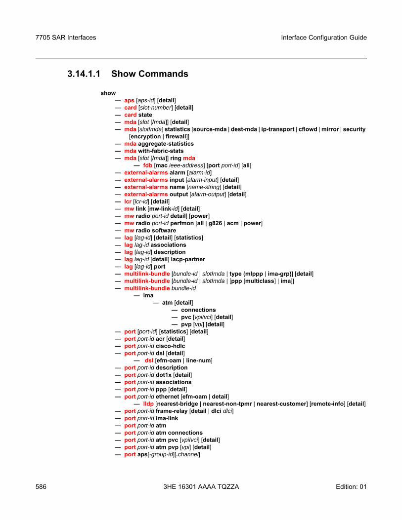
7705 SAR Interfaces
586
Interface Configuration Guide
3HE 16301 AAAA TQZZA Edition: 01
3.14.1.1 Show Commands
show — aps [aps-id] [detail]— card [slot-number] [detail]— card state— mda [slot [/mda]] [detail]— mda [slot/mda] statistics [source-mda | dest-mda | ip-transport | cflowd | mirror | security
[encryption | firewall]]— mda aggregate-statistics— mda with-fabric-stats— mda [slot [/mda]] ring mda
— fdb [mac ieee-address] [port port-id] [all]— external-alarms alarm [alarm-id]— external-alarms input [alarm-input] [detail]— external-alarms name [name-string] [detail]— external-alarms output [alarm-output] [detail]— lcr [lcr-id] [detail]— mw link [mw-link-id] [detail]— mw radio port-id detail] [power]— mw radio port-id perfmon [all | g826 | acm | power]— mw radio software— lag [lag-id] [detail] [statistics]— lag lag-id associations— lag [lag-id] description— lag lag-id [detail] lacp-partner— lag [lag-id] port— multilink-bundle [bundle-id | slot/mda | type mlppp | ima-grp] [detail] — multilink-bundle [bundle-id | slot/mda | [ppp [multiclass] | ima]]— multilink-bundle bundle-id
— ima— atm [detail]
— connections— pvc [vpi/vci] [detail]— pvp [vpi] [detail]
— port [port-id] [statistics] [detail] — port port-id acr [detail]— port port-id cisco-hdlc — port port-id dsl [detail]
— dsl [efm-oam | line-num]— port port-id description— port port-id dot1x [detail]— port port-id associations— port port-id ppp [detail]— port port-id ethernet [efm-oam | detail]
— lldp [nearest-bridge | nearest-non-tpmr | nearest-customer] [remote-info] [detail]— port port-id frame-relay [detail | dlci dlci]— port port-id ima-link — port port-id atm — port port-id atm connections— port port-id atm pvc [vpi/vci] [detail]— port port-id atm pvp [vpi] [detail]— port aps[-group-id][.channel]
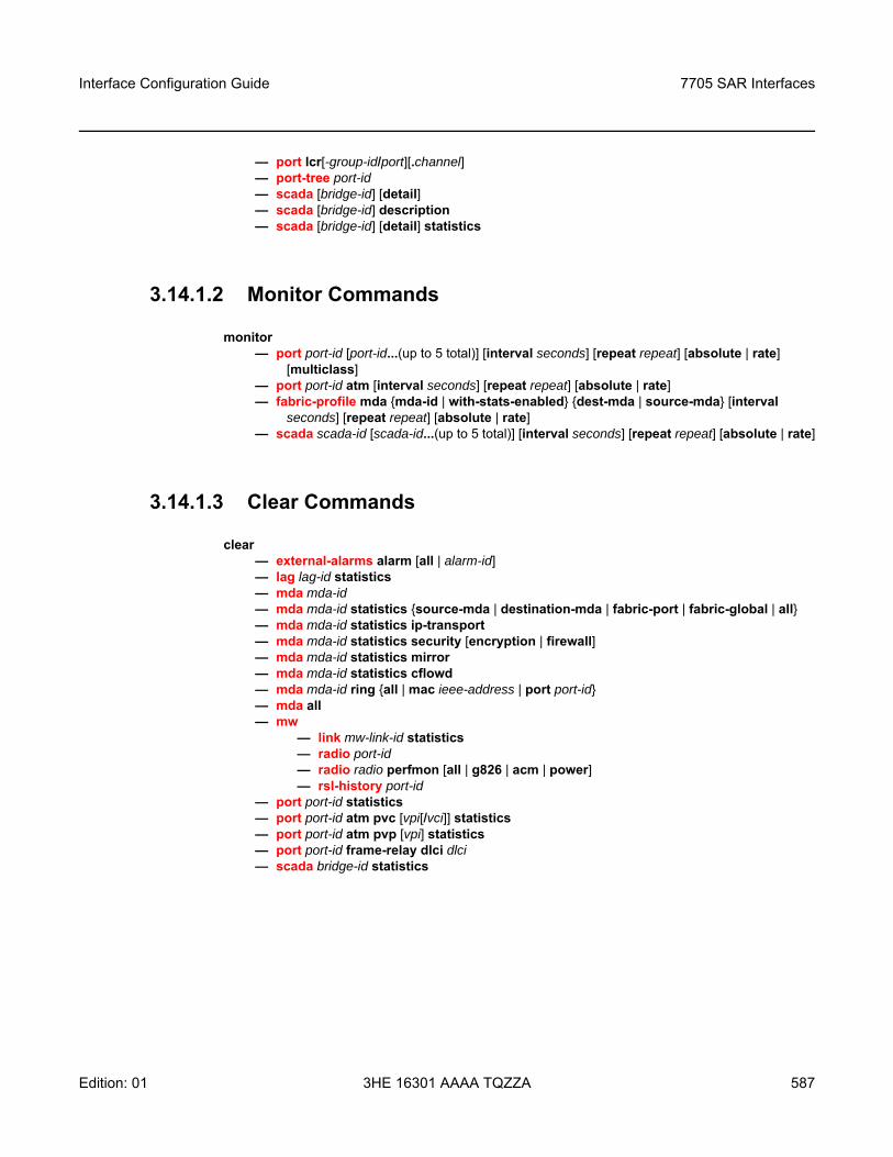
Interface Configuration Guide 7705 SAR Interfaces
Edition: 01 3HE 16301 AAAA TQZZA 587
— port lcr[-group-id/port][.channel] — port-tree port-id— scada [bridge-id] [detail]— scada [bridge-id] description— scada [bridge-id] [detail] statistics
3.14.1.2 Monitor Commands
monitor— port port-id [port-id...(up to 5 total)] [interval seconds] [repeat repeat] [absolute | rate]
[multiclass]— port port-id atm [interval seconds] [repeat repeat] [absolute | rate]— fabric-profile mda mda-id | with-stats-enabled dest-mda | source-mda [interval
seconds] [repeat repeat] [absolute | rate] — scada scada-id [scada-id...(up to 5 total)] [interval seconds] [repeat repeat] [absolute | rate]
3.14.1.3 Clear Commands
clear— external-alarms alarm [all | alarm-id]— lag lag-id statistics— mda mda-id— mda mda-id statistics source-mda | destination-mda | fabric-port | fabric-global | all— mda mda-id statistics ip-transport— mda mda-id statistics security [encryption | firewall] — mda mda-id statistics mirror — mda mda-id statistics cflowd — mda mda-id ring all | mac ieee-address | port port-id— mda all— mw
— link mw-link-id statistics— radio port-id— radio radio perfmon [all | g826 | acm | power]— rsl-history port-id
— port port-id statistics— port port-id atm pvc [vpi[/vci]] statistics— port port-id atm pvp [vpi] statistics— port port-id frame-relay dlci dlci— scada bridge-id statistics
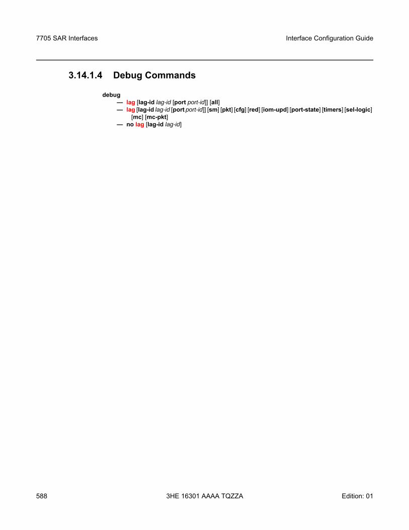
7705 SAR Interfaces
588
Interface Configuration Guide
3HE 16301 AAAA TQZZA Edition: 01
3.14.1.4 Debug Commands
debug— lag [lag-id lag-id [port port-id]] [all]— lag [lag-id lag-id [port port-id]] [sm] [pkt] [cfg] [red] [iom-upd] [port-state] [timers] [sel-logic]
[mc] [mc-pkt]— no lag [lag-id lag-id]
Interface Configuration Guide 7705 SAR Interfaces
Edition: 01 3HE 16301 AAAA TQZZA 589
3.14.2 Command Descriptions
• Show Commands• Monitor Commands• Clear Commands• Debug Commands
7705 SAR Interfaces
590
Interface Configuration Guide
3HE 16301 AAAA TQZZA Edition: 01
3.14.2.1 Show Commands
• Show APS Commands• Show Card Commands• Show External Alarms Commands• Show T1/E1 LCR Commands• Show Microwave Link Commands• Show Port Commands• Show ATM Port Commands• Show Port-tree Commands• Show LAG Commands• Show Multilink Bundle and IMA Group Commands• Show ATM IMA Group Commands• Show SCADA Commands
Note: The following command outputs are examples only; actual displays may differ depending on supported functionality and user configuration.
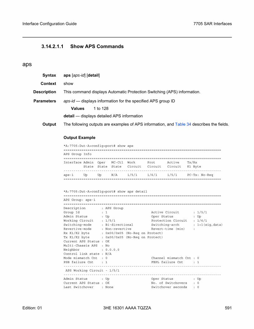
Interface Configuration Guide 7705 SAR Interfaces
Edition: 01 3HE 16301 AAAA TQZZA 591
3.14.2.1.1 Show APS Commands
aps
Syntax aps [aps-id] [detail]
Context show
Description This command displays Automatic Protection Switching (APS) information.
Parameters aps-id — displays information for the specified APS group ID
Values 1 to 128
detail — displays detailed APS information
Output The following outputs are examples of APS information, and Table 34 describes the fields.
Output Example
*A:7705:Dut-A>config>port# show aps===============================================================================APS Group Info===============================================================================Interface Admin Oper MC-Ctl Work Prot Active Tx/Rx
State State State Circuit Circuit Circuit K1 Byte-------------------------------------------------------------------------------aps-1 Up Up N/A 1/5/1 1/6/1 1/5/1 PC-Tx: No-Req===============================================================================
*A:7705:Dut-A>config>port# show aps detail===============================================================================APS Group: aps-1===============================================================================Description : APS GroupGroup Id : 1 Active Circuit : 1/5/1Admin Status : Up Oper Status : UpWorking Circuit : 1/5/1 Protection Circuit : 1/6/1Switching-mode : Bi-directional Switching-arch : 1+1(sig,data)Revertive-mode : Non-revertive Revert-time (min) :Rx K1/K2 byte : 0x00/0x05 (No-Req on Protect)Tx K1/K2 byte : 0x00/0x05 (No-Req on Protect)Current APS Status : OKMulti-Chassis APS : NoNeighbor : 0.0.0.0Control link state : N/AMode mismatch Cnt : 0 Channel mismatch Cnt : 0PSB failure Cnt : 1 FEPL failure Cnt : 1-------------------------------------------------------------------------------APS Working Circuit - 1/5/1
-------------------------------------------------------------------------------Admin Status : Up Oper Status : UpCurrent APS Status : OK No. of Switchovers : 0Last Switchover : None Switchover seconds : 0
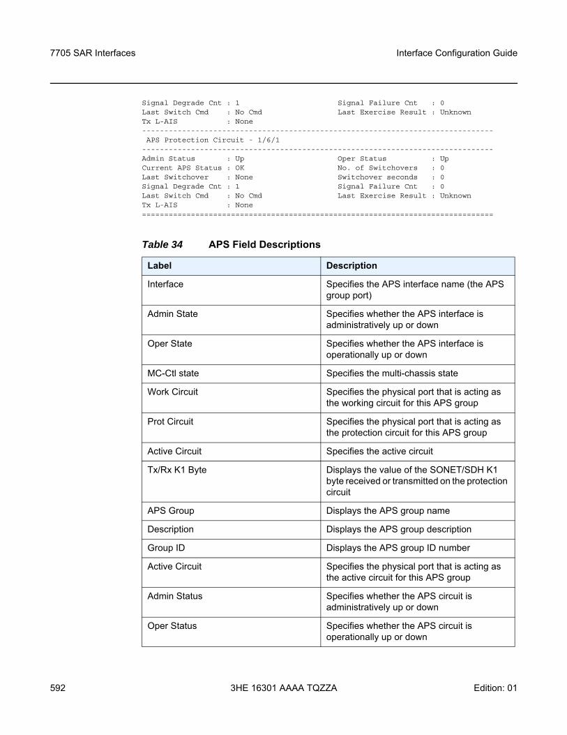
7705 SAR Interfaces
592
Interface Configuration Guide
3HE 16301 AAAA TQZZA Edition: 01
Signal Degrade Cnt : 1 Signal Failure Cnt : 0Last Switch Cmd : No Cmd Last Exercise Result : UnknownTx L-AIS : None-------------------------------------------------------------------------------APS Protection Circuit - 1/6/1
-------------------------------------------------------------------------------Admin Status : Up Oper Status : UpCurrent APS Status : OK No. of Switchovers : 0Last Switchover : None Switchover seconds : 0Signal Degrade Cnt : 1 Signal Failure Cnt : 0Last Switch Cmd : No Cmd Last Exercise Result : UnknownTx L-AIS : None===============================================================================
Table 34 APS Field Descriptions
Label Description
Interface Specifies the APS interface name (the APS group port)
Admin State Specifies whether the APS interface is administratively up or down
Oper State Specifies whether the APS interface is operationally up or down
MC-Ctl state Specifies the multi-chassis state
Work Circuit Specifies the physical port that is acting as the working circuit for this APS group
Prot Circuit Specifies the physical port that is acting as the protection circuit for this APS group
Active Circuit Specifies the active circuit
Tx/Rx K1 Byte Displays the value of the SONET/SDH K1 byte received or transmitted on the protection circuit
APS Group Displays the APS group name
Description Displays the APS group description
Group ID Displays the APS group ID number
Active Circuit Specifies the physical port that is acting as the active circuit for this APS group
Admin Status Specifies whether the APS circuit is administratively up or down
Oper Status Specifies whether the APS circuit is operationally up or down
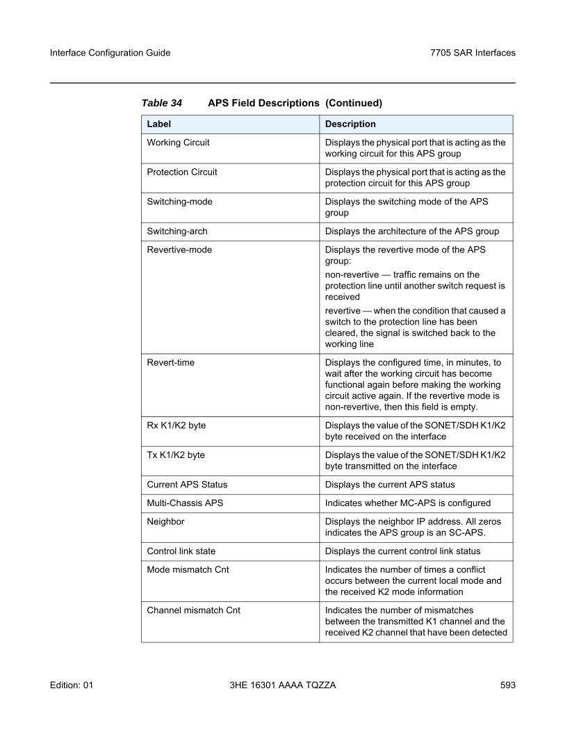
Interface Configuration Guide 7705 SAR Interfaces
Edition: 01 3HE 16301 AAAA TQZZA 593
Working Circuit Displays the physical port that is acting as the working circuit for this APS group
Protection Circuit Displays the physical port that is acting as the protection circuit for this APS group
Switching-mode Displays the switching mode of the APS group
Switching-arch Displays the architecture of the APS group
Revertive-mode Displays the revertive mode of the APS group:non-revertive — traffic remains on the protection line until another switch request is receivedrevertive — when the condition that caused a switch to the protection line has been cleared, the signal is switched back to the working line
Revert-time Displays the configured time, in minutes, to wait after the working circuit has become functional again before making the working circuit active again. If the revertive mode is non-revertive, then this field is empty.
Rx K1/K2 byte Displays the value of the SONET/SDH K1/K2 byte received on the interface
Tx K1/K2 byte Displays the value of the SONET/SDH K1/K2 byte transmitted on the interface
Current APS Status Displays the current APS status
Multi-Chassis APS Indicates whether MC-APS is configured
Neighbor Displays the neighbor IP address. All zeros indicates the APS group is an SC-APS.
Control link state Displays the current control link status
Mode mismatch Cnt Indicates the number of times a conflict occurs between the current local mode and the received K2 mode information
Channel mismatch Cnt Indicates the number of mismatches between the transmitted K1 channel and the received K2 channel that have been detected
Table 34 APS Field Descriptions (Continued)
Label Description
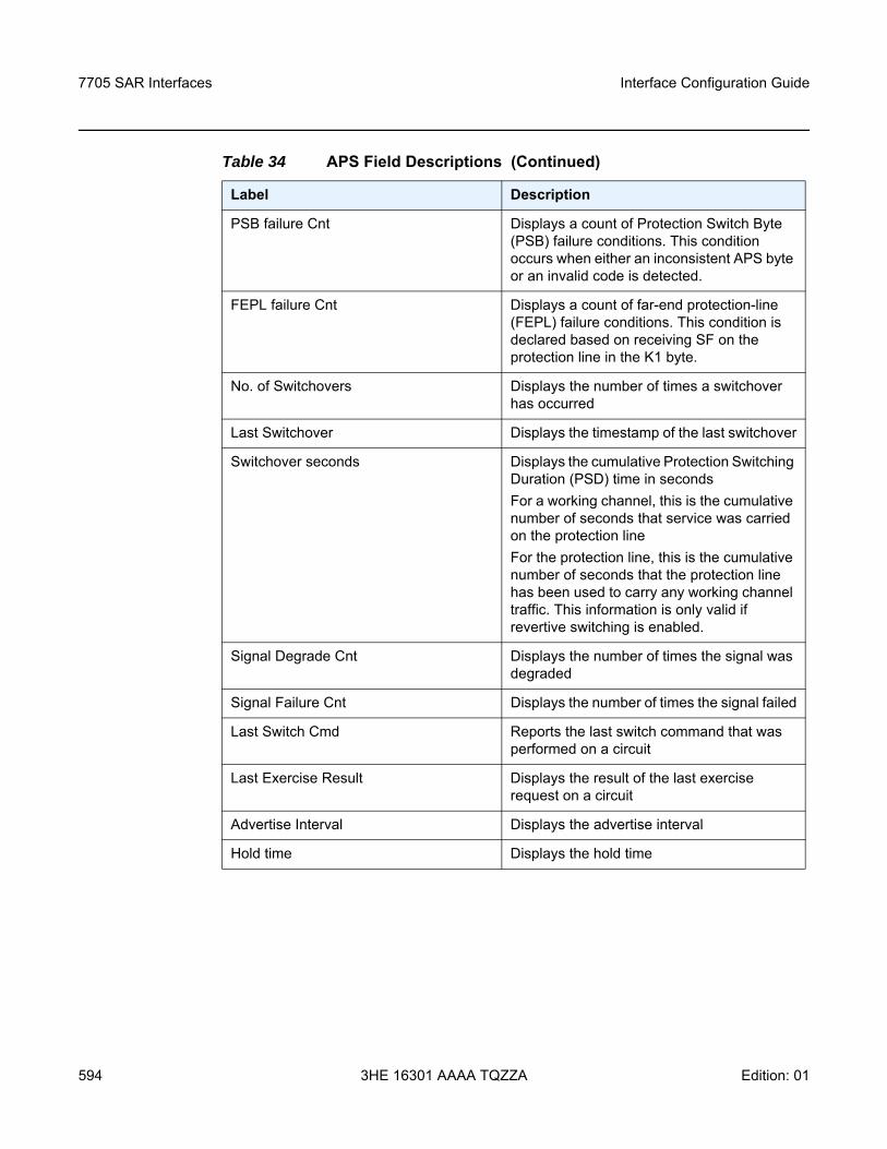
7705 SAR Interfaces
594
Interface Configuration Guide
3HE 16301 AAAA TQZZA Edition: 01
PSB failure Cnt Displays a count of Protection Switch Byte (PSB) failure conditions. This condition occurs when either an inconsistent APS byte or an invalid code is detected.
FEPL failure Cnt Displays a count of far-end protection-line (FEPL) failure conditions. This condition is declared based on receiving SF on the protection line in the K1 byte.
No. of Switchovers Displays the number of times a switchover has occurred
Last Switchover Displays the timestamp of the last switchover
Switchover seconds Displays the cumulative Protection Switching Duration (PSD) time in secondsFor a working channel, this is the cumulative number of seconds that service was carried on the protection lineFor the protection line, this is the cumulative number of seconds that the protection line has been used to carry any working channel traffic. This information is only valid if revertive switching is enabled.
Signal Degrade Cnt Displays the number of times the signal was degraded
Signal Failure Cnt Displays the number of times the signal failed
Last Switch Cmd Reports the last switch command that was performed on a circuit
Last Exercise Result Displays the result of the last exercise request on a circuit
Advertise Interval Displays the advertise interval
Hold time Displays the hold time
Table 34 APS Field Descriptions (Continued)
Label Description
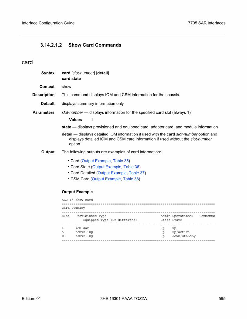
Interface Configuration Guide 7705 SAR Interfaces
Edition: 01 3HE 16301 AAAA TQZZA 595
3.14.2.1.2 Show Card Commands
card
Syntax card [slot-number] [detail]card state
Context show
Description This command displays IOM and CSM information for the chassis.
Default displays summary information only
Parameters slot-number — displays information for the specified card slot (always 1)
Values 1
state — displays provisioned and equipped card, adapter card, and module information
detail — displays detailed IOM information if used with the card slot-number option and displays detailed IOM and CSM card information if used without the slot-number option
Output The following outputs are examples of card information:
• Card (Output Example, Table 35)• Card State (Output Example, Table 36)• Card Detailed (Output Example, Table 37)• CSM Card (Output Example, Table 38)
Output Example
ALU-1# show card===============================================================================Card Summary===============================================================================Slot Provisioned Type Admin Operational Comments
Equipped Type (if different) State State-------------------------------------------------------------------------------1 iom-sar up upA csmv2-10g up up/activeB csmv2-10g up down/standby===============================================================================
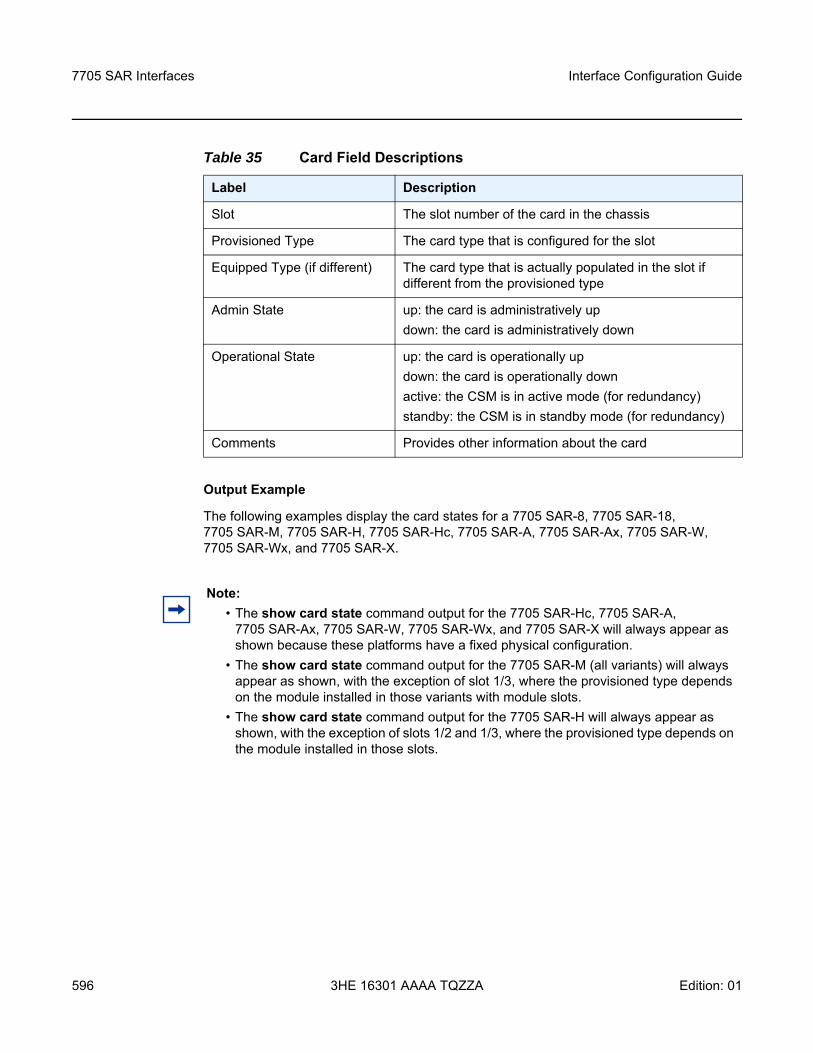
7705 SAR Interfaces
596
Interface Configuration Guide
3HE 16301 AAAA TQZZA Edition: 01
Output Example
The following examples display the card states for a 7705 SAR-8, 7705 SAR-18, 7705 SAR-M, 7705 SAR-H, 7705 SAR-Hc, 7705 SAR-A, 7705 SAR-Ax, 7705 SAR-W, 7705 SAR-Wx, and 7705 SAR-X.
Table 35 Card Field Descriptions
Label Description
Slot The slot number of the card in the chassis
Provisioned Type The card type that is configured for the slot
Equipped Type (if different) The card type that is actually populated in the slot if different from the provisioned type
Admin State up: the card is administratively updown: the card is administratively down
Operational State up: the card is operationally updown: the card is operationally downactive: the CSM is in active mode (for redundancy)standby: the CSM is in standby mode (for redundancy)
Comments Provides other information about the card
Note: • The show card state command output for the 7705 SAR-Hc, 7705 SAR-A,
7705 SAR-Ax, 7705 SAR-W, 7705 SAR-Wx, and 7705 SAR-X will always appear as shown because these platforms have a fixed physical configuration.
• The show card state command output for the 7705 SAR-M (all variants) will always appear as shown, with the exception of slot 1/3, where the provisioned type depends on the module installed in those variants with module slots.
• The show card state command output for the 7705 SAR-H will always appear as shown, with the exception of slots 1/2 and 1/3, where the provisioned type depends on the module installed in those slots.
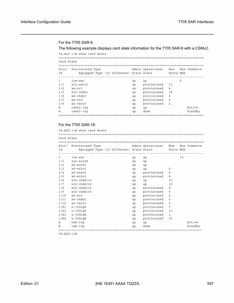
Interface Configuration Guide 7705 SAR Interfaces
Edition: 01 3HE 16301 AAAA TQZZA 597
For the 7705 SAR-8:The following example displays card state information for the 7705 SAR-8 with a CSMv2.*A:ALU-1># show card state===============================================================================Card State===============================================================================Slot/ Provisioned Type Admin Operational Num Num CommentsId Equipped Type (if different) State State Ports MDA-------------------------------------------------------------------------------1 iom-sar up up 61/1 a12-sdiv2 up provisioned 121/2 a4-oc3 up provisioned 41/3 a16-chds1 up provisioned 161/4 a4-chds3 up provisioned 41/5 a8-eth up provisioned 81/6 a2-choc3 up provisioned 2A csmv2-10g up up ActiveB csmv2-10g up down Standby===============================================================================
For the 7705 SAR-18:*A:ALU-1># show card state===============================================================================Card State===============================================================================Slot/ Provisioned Type Admin Operational Num Num CommentsId Equipped Type (if different) State State Ports MDA-------------------------------------------------------------------------------1 iom-sar up up 121/1 aux-alarm up up1/2 a8-ethv2 up up1/3 a8-ethv2 up up 81/4 a8-ethv2 up provisioned 81/5 a8-ethv2 up provisioned 81/6 a32-chds1v2 up up 321/7 a32-chds1v2 up up 321/8 a32-chds1v2 up provisioned 81/9 a32-chds1v2 up provisioned 81/10 a4-oc3 up provisioned 41/11 a4-chds3 up provisioned 41/12 a2-choc3 up provisioned 21/X1 x-10GigE up provisioned 11/X2 x-10GigE up provisioned 101/X3 x-10GigE up provisioned 11/X4 x-10GigE up provisioned 10A csm-10g up up ActiveB csm-10g up down Standby==============================================================================*A:ALU-1>#
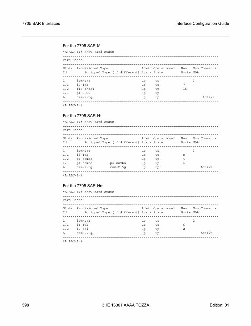
7705 SAR Interfaces
598
Interface Configuration Guide
3HE 16301 AAAA TQZZA Edition: 01
For the 7705 SAR-M:*A:ALU-1># show card state===============================================================================Card State===============================================================================Slot/ Provisioned Type Admin Operational Num Num CommentsId Equipped Type (if different) State State Ports MDA-------------------------------------------------------------------------------1 iom-sar up up 31/1 i7-1gb up up 71/2 i16-chds1 up up 161/3 p1-GPON up upA csm-2.5g up up Active===============================================================================*A:ALU-1>#
For the 7705 SAR-H:*A:ALU-1># show card state===============================================================================Card State===============================================================================Slot/ Provisioned Type Admin Operational Num Num CommentsId Equipped Type (if different) State State Ports MDA-------------------------------------------------------------------------------1 iom-sar up up 31/1 i8-1gb up up 81/2 p4-combo up up 41/3 p4-combo p4-combo up up 4A csm-2.5g csm-2.5g up up Active===============================================================================*A:ALU-1>#
For the 7705 SAR-Hc:*A:ALU-1># show card state===============================================================================Card State===============================================================================Slot/ Provisioned Type Admin Operational Num Num CommentsId Equipped Type (if different) State State Ports MDA-------------------------------------------------------------------------------1 iom-sar up up 21/1 i6-1gb up up 61/2 i2-sdi up up 2A csm-2.5g up up Active===============================================================================*A:ALU-1>#
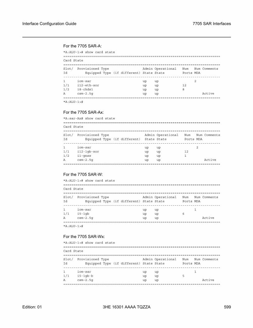
Interface Configuration Guide 7705 SAR Interfaces
Edition: 01 3HE 16301 AAAA TQZZA 599
For the 7705 SAR-A:*A:ALU-1># show card state===============================================================================Card State===============================================================================Slot/ Provisioned Type Admin Operational Num Num CommentsId Equipped Type (if different) State State Ports MDA-------------------------------------------------------------------------------1 iom-sar up up 21/1 i12-eth-xor up up 121/2 i8-chds1 up up 8A csm-2.5g up up Active===============================================================================*A:ALU-1>#
For the 7705 SAR-Ax:*A:sar-Ax# show card state===============================================================================Card State===============================================================================Slot/ Provisioned Type Admin Operational Num Num CommentsId Equipped Type (if different) State State Ports MDA-------------------------------------------------------------------------------1 iom-sar up up 21/1 i12-1gb-xor up up 121/2 i1-gnss up up 1A csm-2.5g up up Active===============================================================================
For the 7705 SAR-W:*A:ALU-1># show card state===============================================================================Card State===============================================================================Slot/ Provisioned Type Admin Operational Num Num CommentsId Equipped Type (if different) State State Ports MDA-------------------------------------------------------------------------------1 iom-sar up up 11/1 i5-1gb up up 6A csm-2.5g up up Active===============================================================================*A:ALU-1>#
For the 7705 SAR-Wx:*A:ALU-1># show card state===============================================================================Card State===============================================================================Slot/ Provisioned Type Admin Operational Num Num CommentsId Equipped Type (if different) State State Ports MDA-------------------------------------------------------------------------------1 iom-sar up up 11/1 i5-1gb-b up up 5A csm-2.5g up up Active===============================================================================
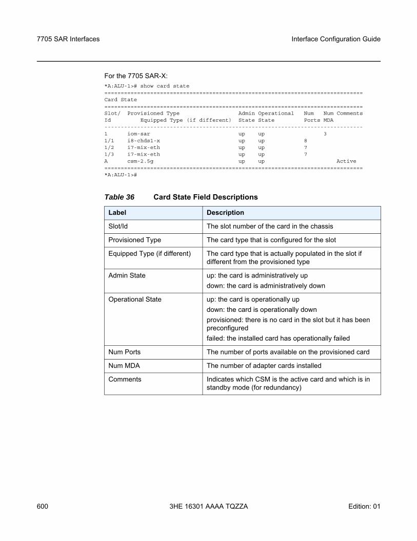
7705 SAR Interfaces
600
Interface Configuration Guide
3HE 16301 AAAA TQZZA Edition: 01
For the 7705 SAR-X:*A:ALU-1># show card state===============================================================================Card State===============================================================================Slot/ Provisioned Type Admin Operational Num Num CommentsId Equipped Type (if different) State State Ports MDA-------------------------------------------------------------------------------1 iom-sar up up 31/1 i8-chds1-x up up 81/2 i7-mix-eth up up 71/3 i7-mix-eth up up 7A csm-2.5g up up Active===============================================================================*A:ALU-1>#
Table 36 Card State Field Descriptions
Label Description
Slot/Id The slot number of the card in the chassis
Provisioned Type The card type that is configured for the slot
Equipped Type (if different) The card type that is actually populated in the slot if different from the provisioned type
Admin State up: the card is administratively updown: the card is administratively down
Operational State up: the card is operationally updown: the card is operationally downprovisioned: there is no card in the slot but it has been preconfiguredfailed: the installed card has operationally failed
Num Ports The number of ports available on the provisioned card
Num MDA The number of adapter cards installed
Comments Indicates which CSM is the active card and which is in standby mode (for redundancy)
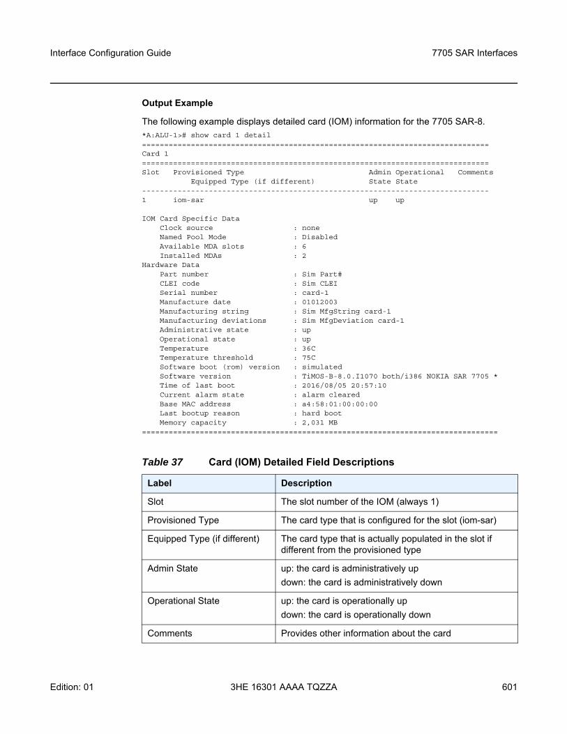
Interface Configuration Guide 7705 SAR Interfaces
Edition: 01 3HE 16301 AAAA TQZZA 601
Output Example
The following example displays detailed card (IOM) information for the 7705 SAR-8.*A:ALU-1># show card 1 detail==============================================================================Card 1==============================================================================Slot Provisioned Type Admin Operational Comments
Equipped Type (if different) State State------------------------------------------------------------------------------1 iom-sar up up
IOM Card Specific DataClock source : noneNamed Pool Mode : DisabledAvailable MDA slots : 6Installed MDAs : 2
Hardware DataPart number : Sim Part#CLEI code : Sim CLEISerial number : card-1Manufacture date : 01012003Manufacturing string : Sim MfgString card-1Manufacturing deviations : Sim MfgDeviation card-1Administrative state : upOperational state : upTemperature : 36CTemperature threshold : 75CSoftware boot (rom) version : simulatedSoftware version : TiMOS-B-8.0.I1070 both/i386 NOKIA SAR 7705 *Time of last boot : 2016/08/05 20:57:10Current alarm state : alarm clearedBase MAC address : a4:58:01:00:00:00Last bootup reason : hard bootMemory capacity : 2,031 MB
================================================================================
Table 37 Card (IOM) Detailed Field Descriptions
Label Description
Slot The slot number of the IOM (always 1)
Provisioned Type The card type that is configured for the slot (iom-sar)
Equipped Type (if different) The card type that is actually populated in the slot if different from the provisioned type
Admin State up: the card is administratively updown: the card is administratively down
Operational State up: the card is operationally updown: the card is operationally down
Comments Provides other information about the card
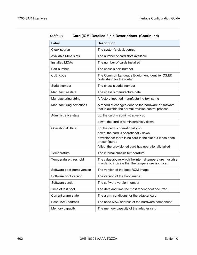
7705 SAR Interfaces
602
Interface Configuration Guide
3HE 16301 AAAA TQZZA Edition: 01
Clock source The system’s clock source
Available MDA slots The number of card slots available
Installed MDAs The number of cards installed
Part number The chassis part number
CLEI code The Common Language Equipment Identifier (CLEI) code string for the router
Serial number The chassis serial number
Manufacture date The chassis manufacture date
Manufacturing string A factory-inputted manufacturing text string
Manufacturing deviations A record of changes done to the hardware or software that is outside the normal revision control process
Administrative state up: the card is administratively up
down: the card is administratively down
Operational State up: the card is operationally updown: the card is operationally downprovisioned: there is no card in the slot but it has been preconfiguredfailed: the provisioned card has operationally failed
Temperature The internal chassis temperature
Temperature threshold The value above which the internal temperature must rise in order to indicate that the temperature is critical
Software boot (rom) version The version of the boot ROM image
Software boot version The version of the boot image
Software version The software version number
Time of last boot The date and time the most recent boot occurred
Current alarm state The alarm conditions for the adapter card
Base MAC address The base MAC address of the hardware component
Memory capacity The memory capacity of the adapter card
Table 37 Card (IOM) Detailed Field Descriptions (Continued)
Label Description
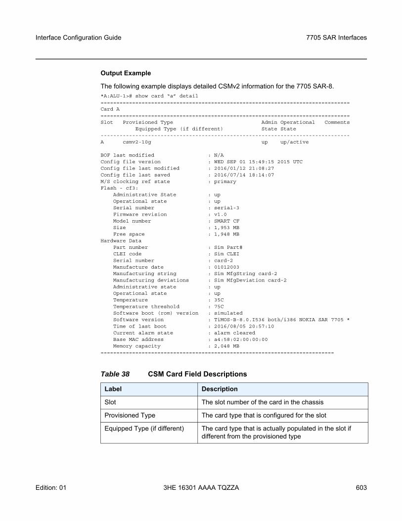
Interface Configuration Guide 7705 SAR Interfaces
Edition: 01 3HE 16301 AAAA TQZZA 603
Output Example
The following example displays detailed CSMv2 information for the 7705 SAR-8.*A:ALU-1># show card “a” detail===============================================================================Card A===============================================================================Slot Provisioned Type Admin Operational Comments
Equipped Type (if different) State State-------------------------------------------------------------------------------A csmv2-10g up up/active
BOF last modified : N/AConfig file version : WED SEP 01 15:49:15 2015 UTCConfig file last modified : 2016/01/12 21:08:27Config file last saved : 2016/07/14 18:14:07M/S clocking ref state : primaryFlash - cf3:
Administrative State : upOperational state : upSerial number : serial-3Firmware revision : v1.0Model number : SMART CFSize : 1,953 MBFree space : 1,948 MB
Hardware DataPart number : Sim Part#CLEI code : Sim CLEISerial number : card-2Manufacture date : 01012003Manufacturing string : Sim MfgString card-2Manufacturing deviations : Sim MfgDeviation card-2Administrative state : upOperational state : upTemperature : 35CTemperature threshold : 75CSoftware boot (rom) version : simulatedSoftware version : TiMOS-B-8.0.I536 both/i386 NOKIA SAR 7705 *Time of last boot : 2016/08/05 20:57:10Current alarm state : alarm clearedBase MAC address : a4:58:02:00:00:00Memory capacity : 2,048 MB
==========================================================================
Table 38 CSM Card Field Descriptions
Label Description
Slot The slot number of the card in the chassis
Provisioned Type The card type that is configured for the slot
Equipped Type (if different) The card type that is actually populated in the slot if different from the provisioned type
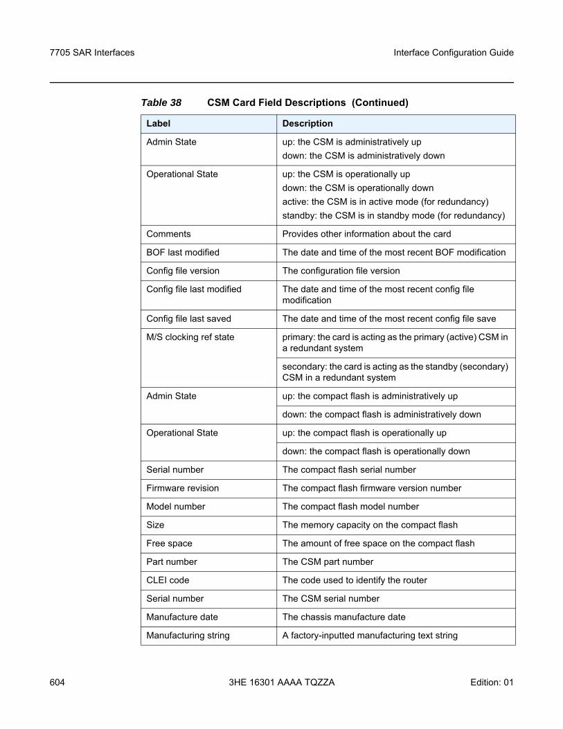
7705 SAR Interfaces
604
Interface Configuration Guide
3HE 16301 AAAA TQZZA Edition: 01
Admin State up: the CSM is administratively updown: the CSM is administratively down
Operational State up: the CSM is operationally updown: the CSM is operationally downactive: the CSM is in active mode (for redundancy)standby: the CSM is in standby mode (for redundancy)
Comments Provides other information about the card
BOF last modified The date and time of the most recent BOF modification
Config file version The configuration file version
Config file last modified The date and time of the most recent config file modification
Config file last saved The date and time of the most recent config file save
M/S clocking ref state primary: the card is acting as the primary (active) CSM in a redundant system
secondary: the card is acting as the standby (secondary) CSM in a redundant system
Admin State up: the compact flash is administratively up
down: the compact flash is administratively down
Operational State up: the compact flash is operationally up
down: the compact flash is operationally down
Serial number The compact flash serial number
Firmware revision The compact flash firmware version number
Model number The compact flash model number
Size The memory capacity on the compact flash
Free space The amount of free space on the compact flash
Part number The CSM part number
CLEI code The code used to identify the router
Serial number The CSM serial number
Manufacture date The chassis manufacture date
Manufacturing string A factory-inputted manufacturing text string
Table 38 CSM Card Field Descriptions (Continued)
Label Description
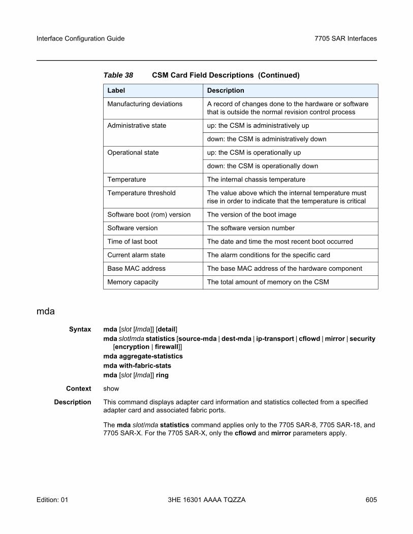
Interface Configuration Guide 7705 SAR Interfaces
Edition: 01 3HE 16301 AAAA TQZZA 605
mda
Syntax mda [slot [/mda]] [detail]mda slot/mda statistics [source-mda | dest-mda | ip-transport | cflowd | mirror | security
[encryption | firewall]]mda aggregate-statisticsmda with-fabric-statsmda [slot [/mda]] ring
Context show
Description This command displays adapter card information and statistics collected from a specified adapter card and associated fabric ports.
The mda slot/mda statistics command applies only to the 7705 SAR-8, 7705 SAR-18, and 7705 SAR-X. For the 7705 SAR-X, only the cflowd and mirror parameters apply.
Manufacturing deviations A record of changes done to the hardware or software that is outside the normal revision control process
Administrative state up: the CSM is administratively up
down: the CSM is administratively down
Operational state up: the CSM is operationally up
down: the CSM is operationally down
Temperature The internal chassis temperature
Temperature threshold The value above which the internal temperature must rise in order to indicate that the temperature is critical
Software boot (rom) version The version of the boot image
Software version The software version number
Time of last boot The date and time the most recent boot occurred
Current alarm state The alarm conditions for the specific card
Base MAC address The base MAC address of the hardware component
Memory capacity The total amount of memory on the CSM
Table 38 CSM Card Field Descriptions (Continued)
Label Description
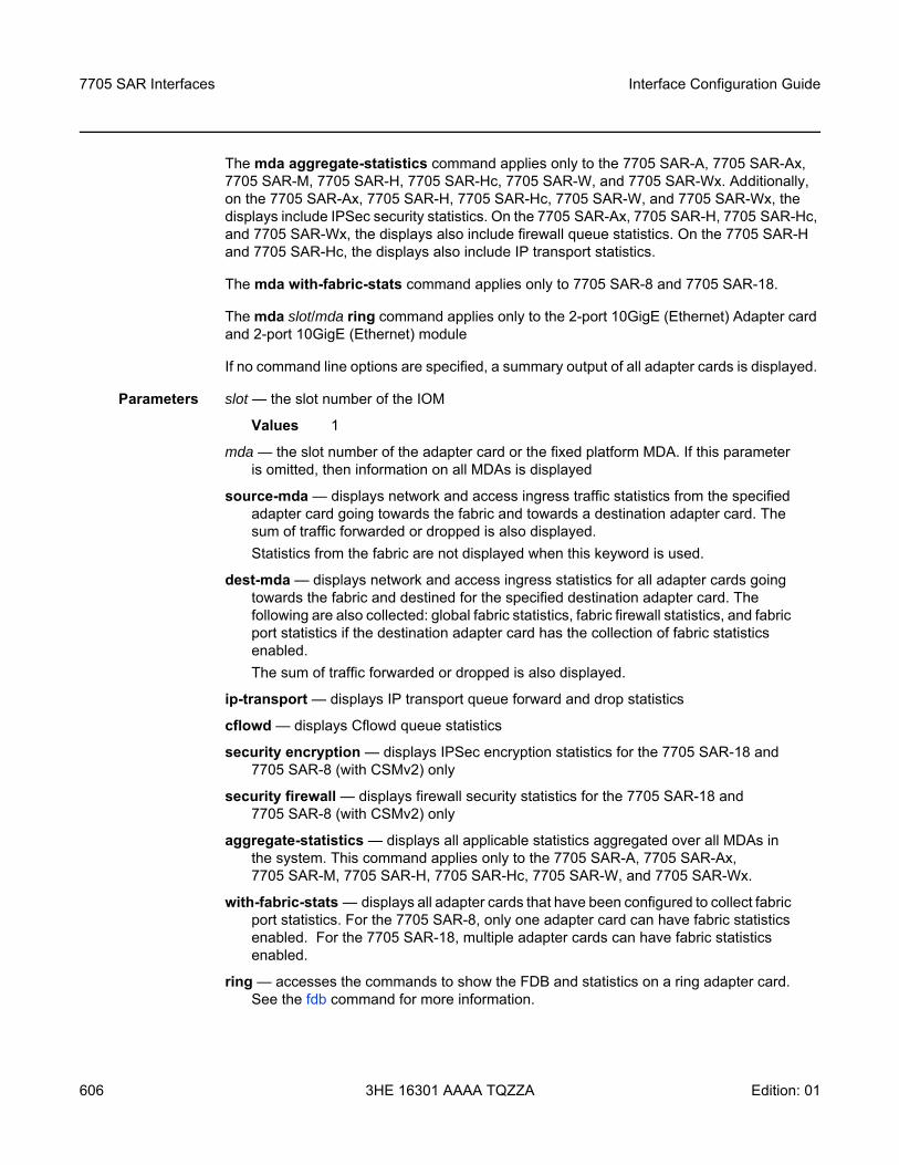
7705 SAR Interfaces
606
Interface Configuration Guide
3HE 16301 AAAA TQZZA Edition: 01
The mda aggregate-statistics command applies only to the 7705 SAR-A, 7705 SAR-Ax, 7705 SAR-M, 7705 SAR-H, 7705 SAR-Hc, 7705 SAR-W, and 7705 SAR-Wx. Additionally, on the 7705 SAR-Ax, 7705 SAR-H, 7705 SAR-Hc, 7705 SAR-W, and 7705 SAR-Wx, the displays include IPSec security statistics. On the 7705 SAR-Ax, 7705 SAR-H, 7705 SAR-Hc, and 7705 SAR-Wx, the displays also include firewall queue statistics. On the 7705 SAR-H and 7705 SAR-Hc, the displays also include IP transport statistics.
The mda with-fabric-stats command applies only to 7705 SAR-8 and 7705 SAR-18.
The mda slot/mda ring command applies only to the 2-port 10GigE (Ethernet) Adapter card and 2-port 10GigE (Ethernet) module
If no command line options are specified, a summary output of all adapter cards is displayed.
Parameters slot — the slot number of the IOM
Values 1
mda — the slot number of the adapter card or the fixed platform MDA. If this parameter is omitted, then information on all MDAs is displayed
source-mda — displays network and access ingress traffic statistics from the specified adapter card going towards the fabric and towards a destination adapter card. The sum of traffic forwarded or dropped is also displayed.Statistics from the fabric are not displayed when this keyword is used.
dest-mda — displays network and access ingress statistics for all adapter cards going towards the fabric and destined for the specified destination adapter card. The following are also collected: global fabric statistics, fabric firewall statistics, and fabric port statistics if the destination adapter card has the collection of fabric statistics enabled.The sum of traffic forwarded or dropped is also displayed.
ip-transport — displays IP transport queue forward and drop statistics
cflowd — displays Cflowd queue statistics
security encryption — displays IPSec encryption statistics for the 7705 SAR-18 and 7705 SAR-8 (with CSMv2) only
security firewall — displays firewall security statistics for the 7705 SAR-18 and 7705 SAR-8 (with CSMv2) only
aggregate-statistics — displays all applicable statistics aggregated over all MDAs in the system. This command applies only to the 7705 SAR-A, 7705 SAR-Ax, 7705 SAR-M, 7705 SAR-H, 7705 SAR-Hc, 7705 SAR-W, and 7705 SAR-Wx.
with-fabric-stats — displays all adapter cards that have been configured to collect fabric port statistics. For the 7705 SAR-8, only one adapter card can have fabric statistics enabled. For the 7705 SAR-18, multiple adapter cards can have fabric statistics enabled.
ring — accesses the commands to show the FDB and statistics on a ring adapter card. See the fdb command for more information.
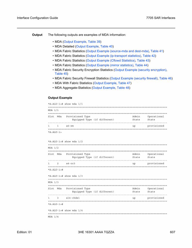
Interface Configuration Guide 7705 SAR Interfaces
Edition: 01 3HE 16301 AAAA TQZZA 607
Output The following outputs are examples of MDA information:
• MDA (Output Example, Table 39)• MDA Detailed (Output Example, Table 40)• MDA Fabric Statistics (Output Example (source-mda and dest-mda), Table 41)• MDA Fabric Statistics (Output Example (ip-transport statistics), Table 42)• MDA Fabric Statistics (Output Example (Cflowd Statistics), Table 43)• MDA Fabric Statistics (Output Example (mirror statistics), Table 44)• MDA Fabric Security Encryption Statistics (Output Example (security encryption),
Table 45)• MDA Fabric Security Firewall Statistics (Output Example (security firewall), Table 46)• MDA With Fabric Statistics (Output Example, Table 47)• MDA Aggregate-Statistics (Output Example, Table 48)
Output Example
*A:ALU-1># show mda 1/1===============================================================================MDA 1/1===============================================================================Slot Mda Provisioned Type Admin Operational
Equipped Type (if different) State State-------------------------------------------------------------------------------1 1 a6-em up provisioned===============================================================================*A:ALU-1>
*A:ALU-1># show mda 1/2===============================================================================MDA 1/2===============================================================================Slot Mda Provisioned Type Admin Operational
Equipped Type (if different) State State-------------------------------------------------------------------------------1 2 a4-oc3 up provisioned===============================================================================*A:ALU-1>#
*A:ALU-1># show mda 1/3===============================================================================MDA 1/3===============================================================================Slot Mda Provisioned Type Admin Operational
Equipped Type (if different) State State-------------------------------------------------------------------------------1 3 a16-chds1 up provisioned===============================================================================*A:ALU-1>#
*A:ALU-1># show mda 1/4===============================================================================MDA 1/4
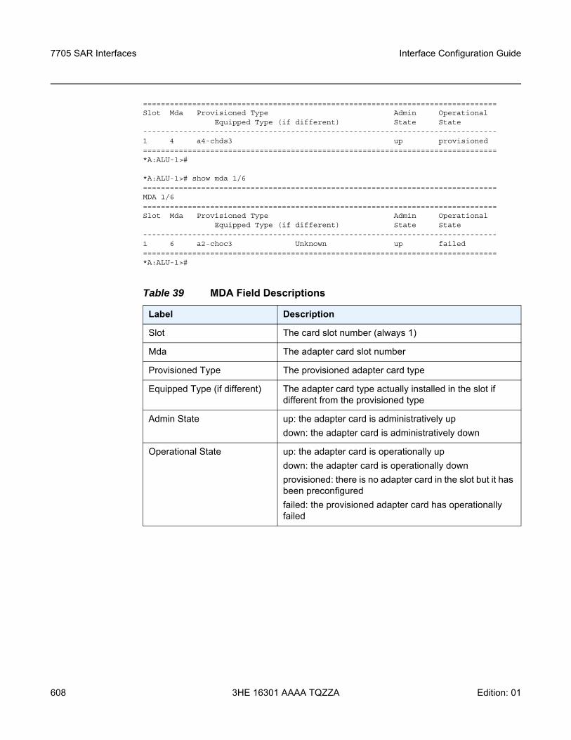
7705 SAR Interfaces
608
Interface Configuration Guide
3HE 16301 AAAA TQZZA Edition: 01
===============================================================================Slot Mda Provisioned Type Admin Operational
Equipped Type (if different) State State-------------------------------------------------------------------------------1 4 a4-chds3 up provisioned===============================================================================*A:ALU-1>#
*A:ALU-1># show mda 1/6===============================================================================MDA 1/6===============================================================================Slot Mda Provisioned Type Admin Operational
Equipped Type (if different) State State-------------------------------------------------------------------------------1 6 a2-choc3 Unknown up failed===============================================================================*A:ALU-1>#
Table 39 MDA Field Descriptions
Label Description
Slot The card slot number (always 1)
Mda The adapter card slot number
Provisioned Type The provisioned adapter card type
Equipped Type (if different) The adapter card type actually installed in the slot if different from the provisioned type
Admin State up: the adapter card is administratively updown: the adapter card is administratively down
Operational State up: the adapter card is operationally updown: the adapter card is operationally downprovisioned: there is no adapter card in the slot but it has been preconfiguredfailed: the provisioned adapter card has operationally failed
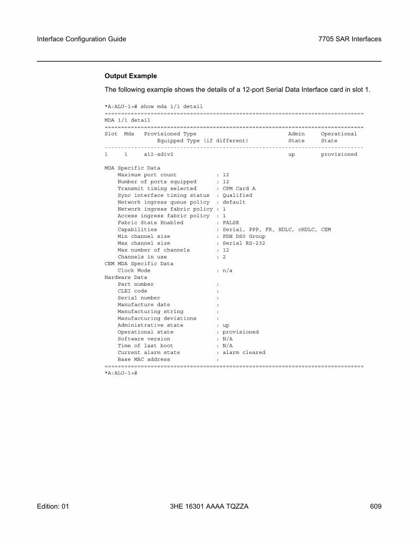
Interface Configuration Guide 7705 SAR Interfaces
Edition: 01 3HE 16301 AAAA TQZZA 609
Output Example
The following example shows the details of a 12-port Serial Data Interface card in slot 1.
*A:ALU-1># show mda 1/1 detail===============================================================================MDA 1/1 detail===============================================================================Slot Mda Provisioned Type Admin Operational
Equipped Type (if different) State State-------------------------------------------------------------------------------1 1 a12-sdiv2 up provisioned
MDA Specific DataMaximum port count : 12Number of ports equipped : 12Transmit timing selected : CPM Card ASync interface timing status : QualifiedNetwork ingress queue policy : defaultNetwork ingress fabric policy : 1Access ingress fabric policy : 1Fabric Stats Enabled : FALSECapabilities : Serial, PPP, FR, HDLC, cHDLC, CEMMin channel size : PDH DS0 GroupMax channel size : Serial RS-232Max number of channels : 12Channels in use : 2
CEM MDA Specific DataClock Mode : n/a
Hardware DataPart number :CLEI code :Serial number :Manufacture date :Manufacturing string :Manufacturing deviations :Administrative state : upOperational state : provisionedSoftware version : N/ATime of last boot : N/ACurrent alarm state : alarm clearedBase MAC address :
===============================================================================*A:ALU-1>#
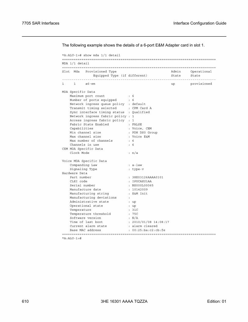
7705 SAR Interfaces
610
Interface Configuration Guide
3HE 16301 AAAA TQZZA Edition: 01
The following example shows the details of a 6-port E&M Adapter card in slot 1.
*A:ALU-1># show mda 1/1 detail===============================================================================MDA 1/1 detail===============================================================================Slot Mda Provisioned Type Admin Operational
Equipped Type (if different) State State-------------------------------------------------------------------------------1 1 a6-em up provisioned
MDA Specific DataMaximum port count : 6Number of ports equipped : 6Network ingress queue policy : defaultTransmit timing selected : CPM Card ASync interface timing status : QualifiedNetwork ingress fabric policy : 1Access ingress fabric policy : 1Fabric Stats Enabled : FALSECapabilities : Voice, CEMMin channel size : PDH DS0 GroupMax channel size : Voice E&MMax number of channels : 6Channels in use : 6
CEM MDA Specific DataClock Mode : n/a
Voice MDA Specific DataCompanding Law : a-lawSignaling Type : type-v
Hardware DataPart number : 3HE03126AAAA0101CLEI code : IPUCAXU1AASerial number : NS000L00065Manufacture date : 10142009Manufacturing string : E&M InitManufacturing deviations :Administrative state : upOperational state : upTemperature : 31CTemperature threshold : 75CSoftware version : N/ATime of last boot : 2010/01/08 14:08:17Current alarm state : alarm clearedBase MAC address : 00:25:ba:c2:cb:fe
===============================================================================*A:ALU-1>#
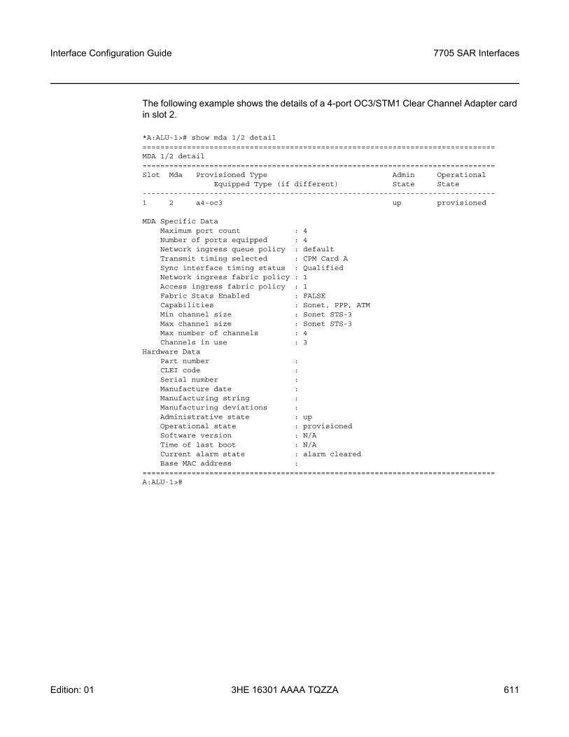
Interface Configuration Guide 7705 SAR Interfaces
Edition: 01 3HE 16301 AAAA TQZZA 611
The following example shows the details of a 4-port OC3/STM1 Clear Channel Adapter card in slot 2.
*A:ALU-1># show mda 1/2 detail===============================================================================MDA 1/2 detail===============================================================================Slot Mda Provisioned Type Admin Operational
Equipped Type (if different) State State-------------------------------------------------------------------------------1 2 a4-oc3 up provisioned
MDA Specific DataMaximum port count : 4Number of ports equipped : 4Network ingress queue policy : defaultTransmit timing selected : CPM Card ASync interface timing status : QualifiedNetwork ingress fabric policy : 1Access ingress fabric policy : 1Fabric Stats Enabled : FALSECapabilities : Sonet, PPP, ATMMin channel size : Sonet STS-3Max channel size : Sonet STS-3Max number of channels : 4Channels in use : 3
Hardware DataPart number :CLEI code :Serial number :Manufacture date :Manufacturing string :Manufacturing deviations :Administrative state : upOperational state : provisionedSoftware version : N/ATime of last boot : N/ACurrent alarm state : alarm clearedBase MAC address :
===============================================================================A:ALU-1>#
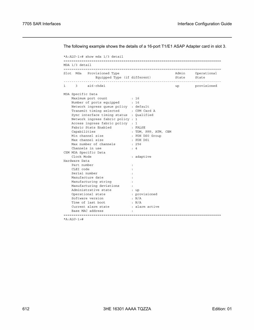
7705 SAR Interfaces
612
Interface Configuration Guide
3HE 16301 AAAA TQZZA Edition: 01
The following example shows the details of a 16-port T1/E1 ASAP Adapter card in slot 3.
*A:ALU-1># show mda 1/3 detail===============================================================================MDA 1/3 detail===============================================================================Slot Mda Provisioned Type Admin Operational
Equipped Type (if different) State State-------------------------------------------------------------------------------1 3 a16-chds1 up provisioned
MDA Specific DataMaximum port count : 16Number of ports equipped : 16Network ingress queue policy : defaultTransmit timing selected : CPM Card ASync interface timing status : QualifiedNetwork ingress fabric policy : 1Access ingress fabric policy : 1Fabric Stats Enabled : FALSECapabilities : TDM, PPP, ATM, CEMMin channel size : PDH DS0 GroupMax channel size : PDH DS1Max number of channels : 256Channels in use : 4
CEM MDA Specific DataClock Mode : adaptive
Hardware DataPart number :CLEI code :Serial number :Manufacture date :Manufacturing string :Manufacturing deviations :Administrative state : upOperational state : provisionedSoftware version : N/ATime of last boot : N/ACurrent alarm state : alarm activeBase MAC address :
===============================================================================*A:ALU-1>#
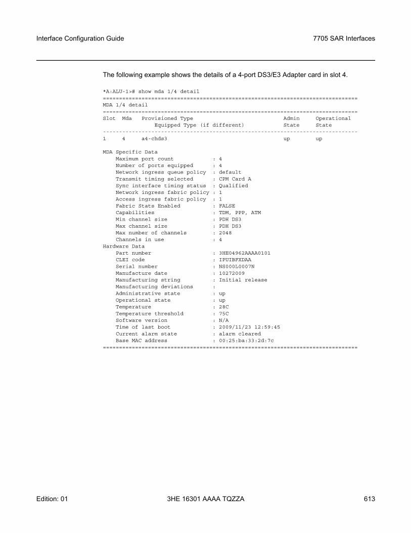
Interface Configuration Guide 7705 SAR Interfaces
Edition: 01 3HE 16301 AAAA TQZZA 613
The following example shows the details of a 4-port DS3/E3 Adapter card in slot 4.
*A:ALU-1># show mda 1/4 detail===============================================================================MDA 1/4 detail===============================================================================Slot Mda Provisioned Type Admin Operational
Equipped Type (if different) State State-------------------------------------------------------------------------------1 4 a4-chds3 up up
MDA Specific DataMaximum port count : 4Number of ports equipped : 4Network ingress queue policy : defaultTransmit timing selected : CPM Card ASync interface timing status : QualifiedNetwork ingress fabric policy : 1Access ingress fabric policy : 1Fabric Stats Enabled : FALSECapabilities : TDM, PPP, ATMMin channel size : PDH DS3Max channel size : PDH DS3Max number of channels : 2048Channels in use : 4
Hardware DataPart number : 3HE04962AAAA0101CLEI code : IPUIBFXDAASerial number : NS000L0007NManufacture date : 10272009Manufacturing string : Initial releaseManufacturing deviations :Administrative state : upOperational state : upTemperature : 28CTemperature threshold : 75CSoftware version : N/ATime of last boot : 2009/11/23 12:59:45Current alarm state : alarm clearedBase MAC address : 00:25:ba:33:2d:7c
===============================================================================
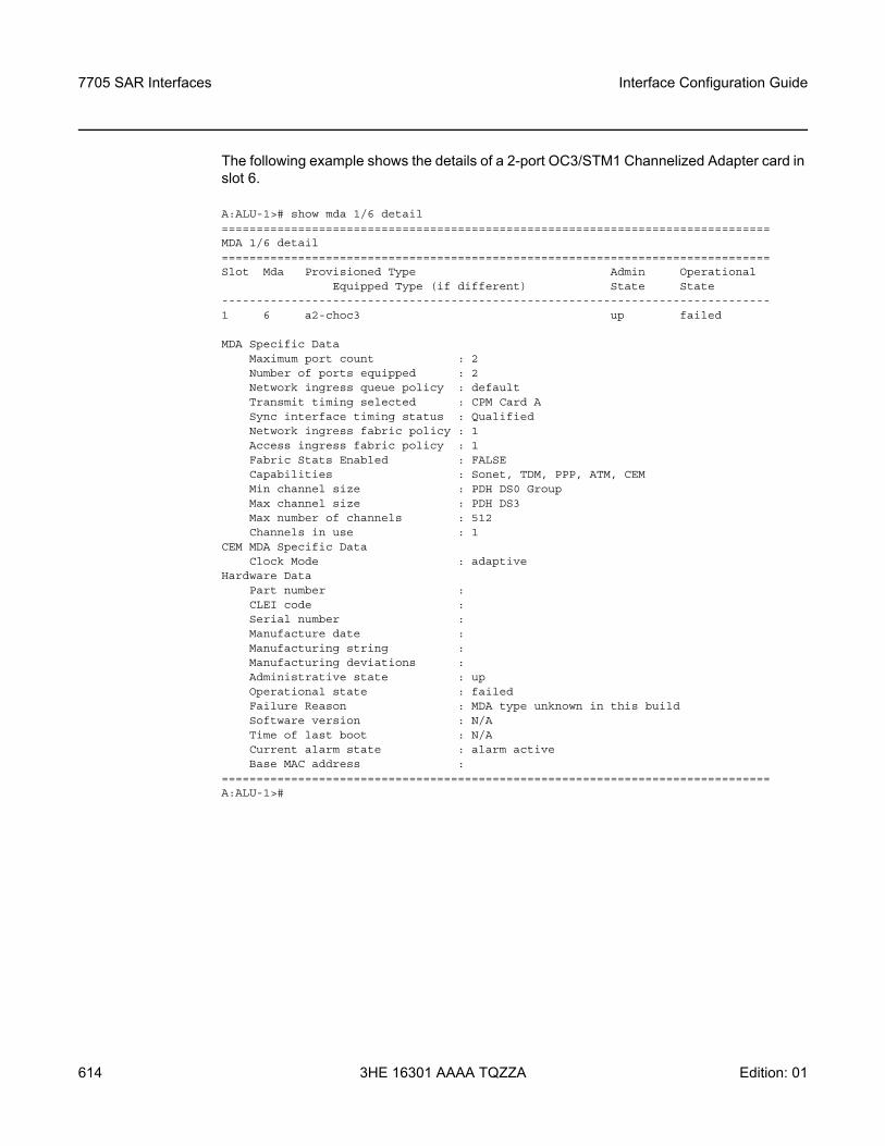
7705 SAR Interfaces
614
Interface Configuration Guide
3HE 16301 AAAA TQZZA Edition: 01
The following example shows the details of a 2-port OC3/STM1 Channelized Adapter card in slot 6.
A:ALU-1># show mda 1/6 detail===============================================================================MDA 1/6 detail===============================================================================Slot Mda Provisioned Type Admin Operational
Equipped Type (if different) State State-------------------------------------------------------------------------------1 6 a2-choc3 up failed
MDA Specific DataMaximum port count : 2Number of ports equipped : 2Network ingress queue policy : defaultTransmit timing selected : CPM Card ASync interface timing status : QualifiedNetwork ingress fabric policy : 1Access ingress fabric policy : 1Fabric Stats Enabled : FALSECapabilities : Sonet, TDM, PPP, ATM, CEMMin channel size : PDH DS0 GroupMax channel size : PDH DS3Max number of channels : 512Channels in use : 1
CEM MDA Specific DataClock Mode : adaptive
Hardware DataPart number :CLEI code :Serial number :Manufacture date :Manufacturing string :Manufacturing deviations :Administrative state : upOperational state : failedFailure Reason : MDA type unknown in this buildSoftware version : N/ATime of last boot : N/ACurrent alarm state : alarm activeBase MAC address :
===============================================================================A:ALU-1>#
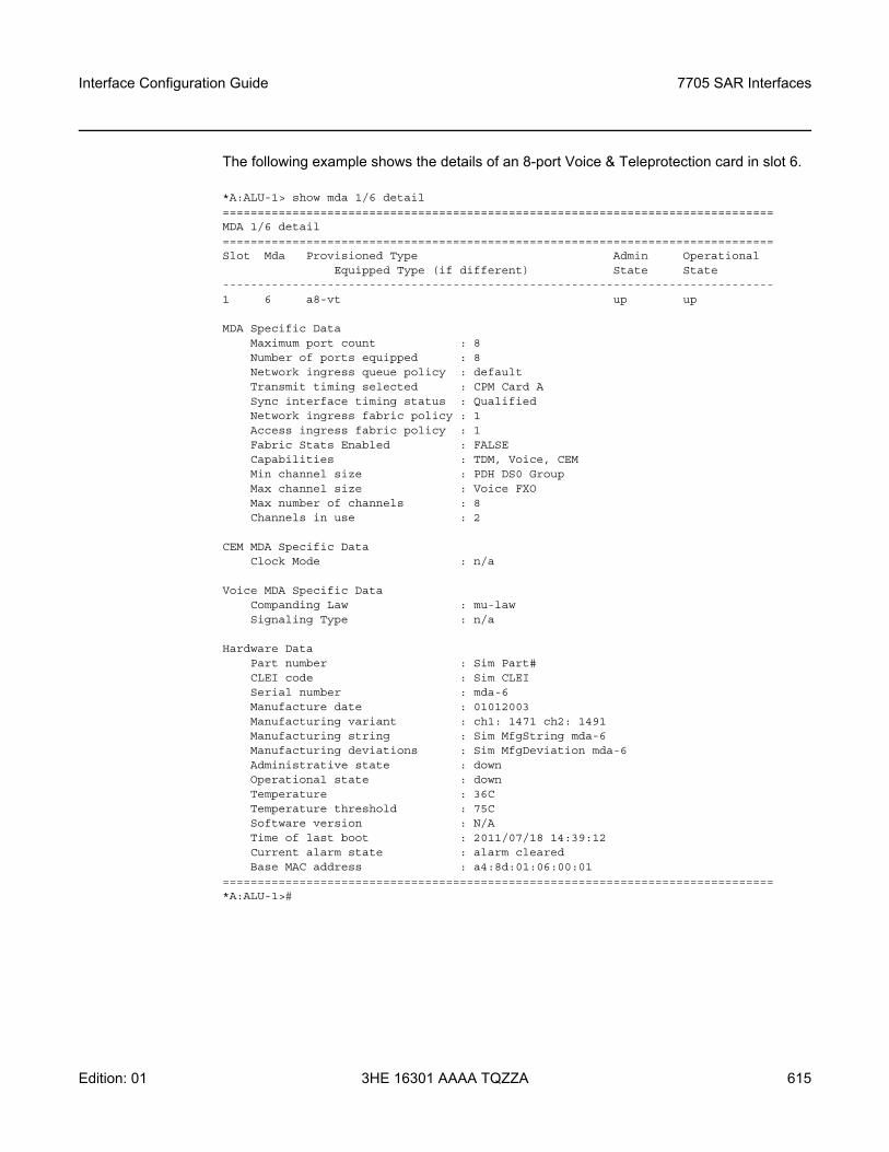
Interface Configuration Guide 7705 SAR Interfaces
Edition: 01 3HE 16301 AAAA TQZZA 615
The following example shows the details of an 8-port Voice & Teleprotection card in slot 6.
*A:ALU-1> show mda 1/6 detail===============================================================================MDA 1/6 detail===============================================================================Slot Mda Provisioned Type Admin Operational
Equipped Type (if different) State State-------------------------------------------------------------------------------1 6 a8-vt up up
MDA Specific DataMaximum port count : 8Number of ports equipped : 8Network ingress queue policy : defaultTransmit timing selected : CPM Card ASync interface timing status : QualifiedNetwork ingress fabric policy : 1Access ingress fabric policy : 1Fabric Stats Enabled : FALSECapabilities : TDM, Voice, CEMMin channel size : PDH DS0 GroupMax channel size : Voice FXOMax number of channels : 8Channels in use : 2
CEM MDA Specific DataClock Mode : n/a
Voice MDA Specific DataCompanding Law : mu-lawSignaling Type : n/a
Hardware DataPart number : Sim Part#CLEI code : Sim CLEISerial number : mda-6Manufacture date : 01012003Manufacturing variant : ch1: 1471 ch2: 1491Manufacturing string : Sim MfgString mda-6Manufacturing deviations : Sim MfgDeviation mda-6Administrative state : downOperational state : downTemperature : 36CTemperature threshold : 75CSoftware version : N/ATime of last boot : 2011/07/18 14:39:12Current alarm state : alarm clearedBase MAC address : a4:8d:01:06:00:01
===============================================================================*A:ALU-1>#
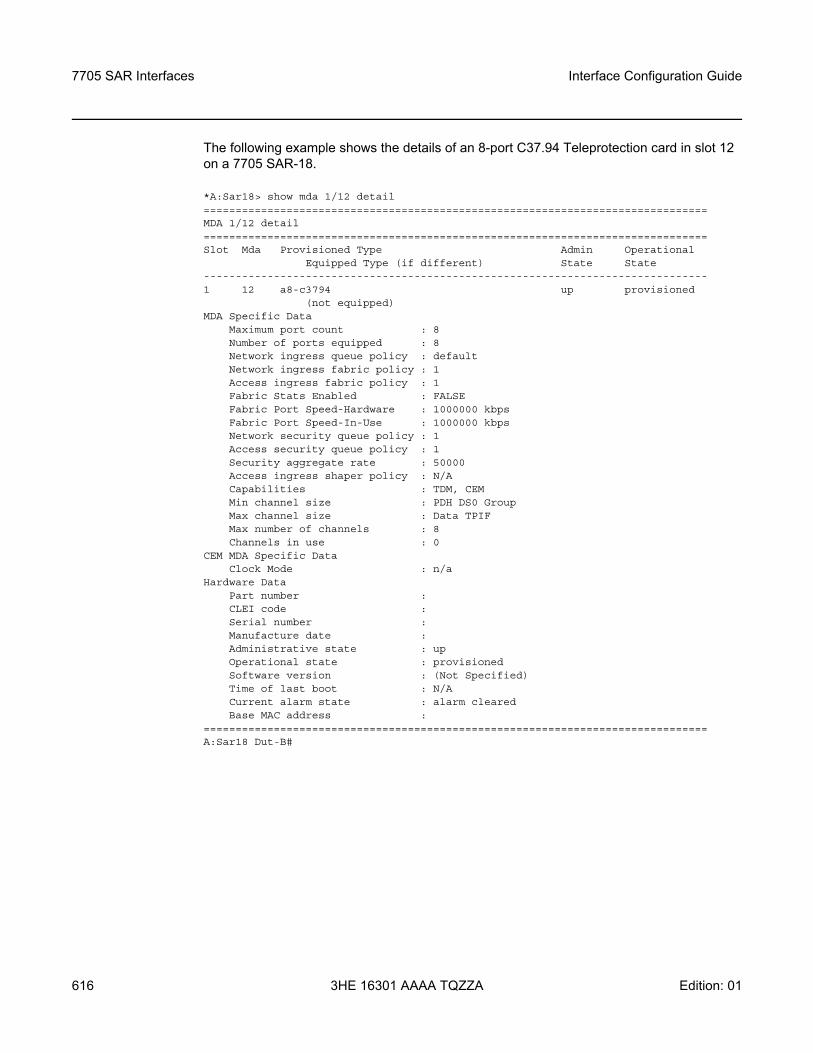
7705 SAR Interfaces
616
Interface Configuration Guide
3HE 16301 AAAA TQZZA Edition: 01
The following example shows the details of an 8-port C37.94 Teleprotection card in slot 12 on a 7705 SAR-18.
*A:Sar18> show mda 1/12 detail===============================================================================MDA 1/12 detail===============================================================================Slot Mda Provisioned Type Admin Operational
Equipped Type (if different) State State-------------------------------------------------------------------------------1 12 a8-c3794 up provisioned
(not equipped)MDA Specific Data
Maximum port count : 8Number of ports equipped : 8Network ingress queue policy : defaultNetwork ingress fabric policy : 1Access ingress fabric policy : 1Fabric Stats Enabled : FALSEFabric Port Speed-Hardware : 1000000 kbpsFabric Port Speed-In-Use : 1000000 kbpsNetwork security queue policy : 1Access security queue policy : 1Security aggregate rate : 50000Access ingress shaper policy : N/ACapabilities : TDM, CEMMin channel size : PDH DS0 GroupMax channel size : Data TPIFMax number of channels : 8Channels in use : 0
CEM MDA Specific DataClock Mode : n/a
Hardware DataPart number :CLEI code :Serial number :Manufacture date :Administrative state : upOperational state : provisionedSoftware version : (Not Specified)Time of last boot : N/ACurrent alarm state : alarm clearedBase MAC address :
===============================================================================A:Sar18 Dut-B#
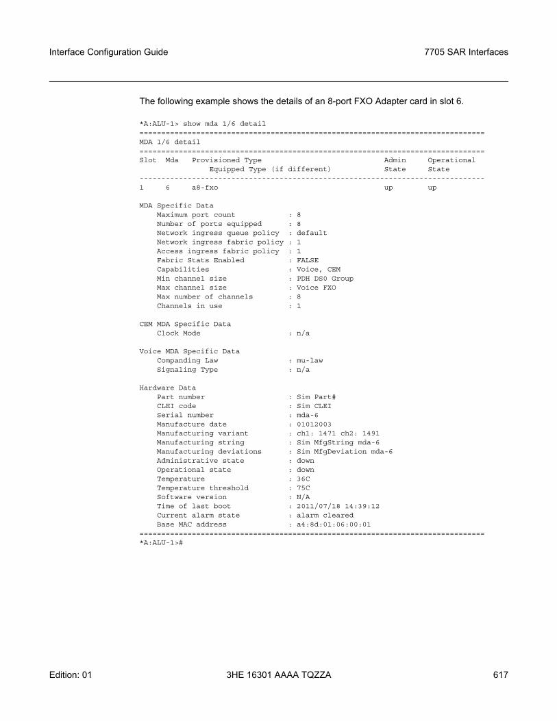
Interface Configuration Guide 7705 SAR Interfaces
Edition: 01 3HE 16301 AAAA TQZZA 617
The following example shows the details of an 8-port FXO Adapter card in slot 6.
*A:ALU-1> show mda 1/6 detail===============================================================================MDA 1/6 detail===============================================================================Slot Mda Provisioned Type Admin Operational
Equipped Type (if different) State State-------------------------------------------------------------------------------1 6 a8-fxo up up
MDA Specific DataMaximum port count : 8Number of ports equipped : 8Network ingress queue policy : defaultNetwork ingress fabric policy : 1Access ingress fabric policy : 1Fabric Stats Enabled : FALSECapabilities : Voice, CEMMin channel size : PDH DS0 GroupMax channel size : Voice FXOMax number of channels : 8Channels in use : 1
CEM MDA Specific DataClock Mode : n/a
Voice MDA Specific DataCompanding Law : mu-lawSignaling Type : n/a
Hardware DataPart number : Sim Part#CLEI code : Sim CLEISerial number : mda-6Manufacture date : 01012003Manufacturing variant : ch1: 1471 ch2: 1491Manufacturing string : Sim MfgString mda-6Manufacturing deviations : Sim MfgDeviation mda-6Administrative state : downOperational state : downTemperature : 36CTemperature threshold : 75CSoftware version : N/ATime of last boot : 2011/07/18 14:39:12Current alarm state : alarm clearedBase MAC address : a4:8d:01:06:00:01
===============================================================================*A:ALU-1>#
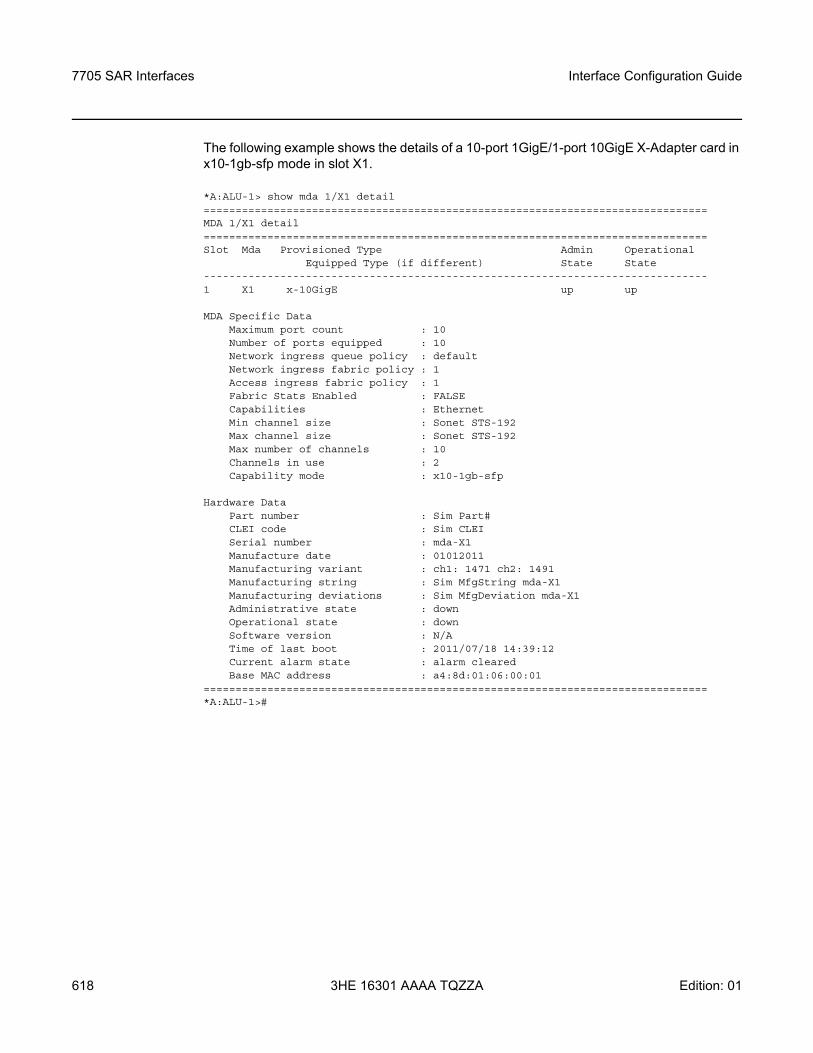
7705 SAR Interfaces
618
Interface Configuration Guide
3HE 16301 AAAA TQZZA Edition: 01
The following example shows the details of a 10-port 1GigE/1-port 10GigE X-Adapter card in x10-1gb-sfp mode in slot X1.
*A:ALU-1> show mda 1/X1 detail===============================================================================MDA 1/X1 detail===============================================================================Slot Mda Provisioned Type Admin Operational
Equipped Type (if different) State State-------------------------------------------------------------------------------1 X1 x-10GigE up up
MDA Specific DataMaximum port count : 10Number of ports equipped : 10Network ingress queue policy : defaultNetwork ingress fabric policy : 1Access ingress fabric policy : 1Fabric Stats Enabled : FALSECapabilities : EthernetMin channel size : Sonet STS-192Max channel size : Sonet STS-192Max number of channels : 10Channels in use : 2Capability mode : x10-1gb-sfp
Hardware DataPart number : Sim Part#CLEI code : Sim CLEISerial number : mda-X1Manufacture date : 01012011Manufacturing variant : ch1: 1471 ch2: 1491Manufacturing string : Sim MfgString mda-X1Manufacturing deviations : Sim MfgDeviation mda-X1Administrative state : downOperational state : downSoftware version : N/ATime of last boot : 2011/07/18 14:39:12Current alarm state : alarm clearedBase MAC address : a4:8d:01:06:00:01
===============================================================================*A:ALU-1>#
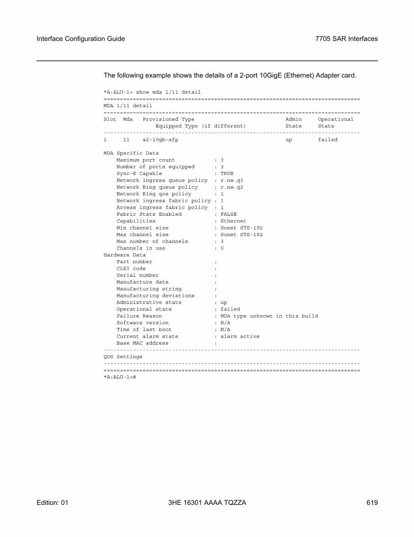
Interface Configuration Guide 7705 SAR Interfaces
Edition: 01 3HE 16301 AAAA TQZZA 619
The following example shows the details of a 2-port 10GigE (Ethernet) Adapter card.
*A:ALU-1> show mda 1/11 detail===============================================================================MDA 1/11 detail===============================================================================Slot Mda Provisioned Type Admin Operational
Equipped Type (if different) State State-------------------------------------------------------------------------------1 11 a2-10gb-xfp up failed
MDA Specific DataMaximum port count : 3Number of ports equipped : 3Sync-E Capable : TRUENetwork ingress queue policy : r.nw.q3Network Ring queue policy : r.nw.q2Network Ring qos policy : 1Network ingress fabric policy : 1Access ingress fabric policy : 1Fabric Stats Enabled : FALSECapabilities : EthernetMin channel size : Sonet STS-192Max channel size : Sonet STS-192Max number of channels : 3Channels in use : 0
Hardware DataPart number :CLEI code :Serial number :Manufacture date :Manufacturing string :Manufacturing deviations :Administrative state : upOperational state : failedFailure Reason : MDA type unknown in this buildSoftware version : N/ATime of last boot : N/ACurrent alarm state : alarm activeBase MAC address :
-------------------------------------------------------------------------------QOS Settings-------------------------------------------------------------------------------===============================================================================*A:ALU-1>#
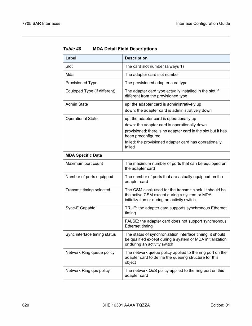
7705 SAR Interfaces
620
Interface Configuration Guide
3HE 16301 AAAA TQZZA Edition: 01
Table 40 MDA Detail Field Descriptions
Label Description
Slot The card slot number (always 1)
Mda The adapter card slot number
Provisioned Type The provisioned adapter card type
Equipped Type (if different) The adapter card type actually installed in the slot if different from the provisioned type
Admin State up: the adapter card is administratively updown: the adapter card is administratively down
Operational State up: the adapter card is operationally updown: the adapter card is operationally downprovisioned: there is no adapter card in the slot but it has been preconfiguredfailed: the provisioned adapter card has operationally failed
MDA Specific Data
Maximum port count The maximum number of ports that can be equipped on the adapter card
Number of ports equipped The number of ports that are actually equipped on the adapter card
Transmit timing selected The CSM clock used for the transmit clock. It should be the active CSM except during a system or MDA initialization or during an activity switch.
Sync-E Capable TRUE: the adapter card supports synchronous Ethernet timing
FALSE: the adapter card does not support synchronous Ethernet timing
Sync interface timing status The status of synchronization interface timing; it should be qualified except during a system or MDA initialization or during an activity switch
Network Ring queue policy The network queue policy applied to the ring port on the adapter card to define the queuing structure for this object
Network Ring qos policy The network QoS policy applied to the ring port on this adapter card
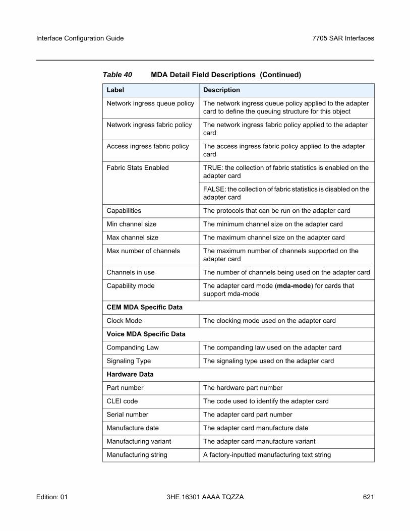
Interface Configuration Guide 7705 SAR Interfaces
Edition: 01 3HE 16301 AAAA TQZZA 621
Network ingress queue policy The network ingress queue policy applied to the adapter card to define the queuing structure for this object
Network ingress fabric policy The network ingress fabric policy applied to the adapter card
Access ingress fabric policy The access ingress fabric policy applied to the adapter card
Fabric Stats Enabled TRUE: the collection of fabric statistics is enabled on the adapter card
FALSE: the collection of fabric statistics is disabled on the adapter card
Capabilities The protocols that can be run on the adapter card
Min channel size The minimum channel size on the adapter card
Max channel size The maximum channel size on the adapter card
Max number of channels The maximum number of channels supported on the adapter card
Channels in use The number of channels being used on the adapter card
Capability mode The adapter card mode (mda-mode) for cards that support mda-mode
CEM MDA Specific Data
Clock Mode The clocking mode used on the adapter card
Voice MDA Specific Data
Companding Law The companding law used on the adapter card
Signaling Type The signaling type used on the adapter card
Hardware Data
Part number The hardware part number
CLEI code The code used to identify the adapter card
Serial number The adapter card part number
Manufacture date The adapter card manufacture date
Manufacturing variant The adapter card manufacture variant
Manufacturing string A factory-inputted manufacturing text string
Table 40 MDA Detail Field Descriptions (Continued)
Label Description
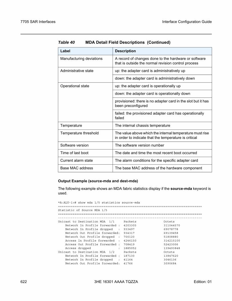
7705 SAR Interfaces
622
Interface Configuration Guide
3HE 16301 AAAA TQZZA Edition: 01
Output Example (source-mda and dest-mda)
The following example shows an MDA fabric statistics display if the source-mda keyword is used.
*A:ALU-1># show mda 1/5 statistics source-mda===============================================================================Statistic of Source MDA 1/5===============================================================================-------------------------------------------------------------------------------Unicast to Destination MDA 1/1 Packets Octets
Network In Profile forwarded : 4203305 311044570Network In Profile dropped : 933497 69078778Network Out Profile forwarded: 934317 69139458Network Out Profile dropped : 700120 51808880Access In Profile forwarded : 4246150 314215100Access Out Profile forwarded : 708419 52423006Access dropped : 1885052 139493848
Unicast to Destination MDA 1/2 Packets OctetsNetwork In Profile forwarded : 187130 13847620Network In Profile dropped : 41164 3046136Network Out Profile forwarded: 41766 3090684
Manufacturing deviations A record of changes done to the hardware or software that is outside the normal revision control process
Administrative state up: the adapter card is administratively up
down: the adapter card is administratively down
Operational state up: the adapter card is operationally up
down: the adapter card is operationally down
provisioned: there is no adapter card in the slot but it has been preconfigured
failed: the provisioned adapter card has operationally failed
Temperature The internal chassis temperature
Temperature threshold The value above which the internal temperature must rise in order to indicate that the temperature is critical
Software version The software version number
Time of last boot The date and time the most recent boot occurred
Current alarm state The alarm conditions for the specific adapter card
Base MAC address The base MAC address of the hardware component
Table 40 MDA Detail Field Descriptions (Continued)
Label Description
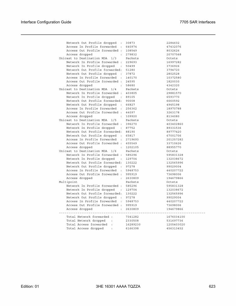
Interface Configuration Guide 7705 SAR Interfaces
Edition: 01 3HE 16301 AAAA TQZZA 623
Network Out Profile dropped : 30873 2284602Access In Profile forwarded : 640974 47432076Access Out Profile forwarded : 108549 8032626Access dropped : 279832 20707568
Unicast to Destination MDA 1/3 Packets OctetsNetwork In Profile forwarded : 229693 16997282Network In Profile dropped : 50499 3736926Network Out Profile forwarded: 51280 3794720Network Out Profile dropped : 37872 2802528Access In Profile forwarded : 140170 10372580Access Out Profile forwarded : 24595 1820030Access dropped : 58680 4342320
Unicast to Destination MDA 1/4 Packets OctetsNetwork In Profile forwarded : 403805 29881570Network In Profile dropped : 89105 6593770Network Out Profile forwarded: 90008 6660592Network Out Profile dropped : 66827 4945198Access In Profile forwarded : 256362 18970788Access Out Profile forwarded : 44097 3263178Access dropped : 109920 8134080
Unicast to Destination MDA 1/5 Packets OctetsNetwork In Profile forwarded : 396270 403402860Network In Profile dropped : 87752 89331536Network Out Profile forwarded: 88190 89777420Network Out Profile dropped : 65817 67001706Access In Profile forwarded : 2719693 201257282Access Out Profile forwarded : 455549 33710626Access dropped : 1202105 88955770
Unicast to Destination MDA 1/6 Packets OctetsNetwork In Profile forwarded : 585296 595831328Network In Profile dropped : 129704 132038672Network Out Profile forwarded: 130222 132565996Network Out Profile dropped : 97278 99029004Access In Profile forwarded : 5948753 440207722Access Out Profile forwarded : 995919 73698006Access dropped : 2630809 194679866
Multipoint Packets OctetsNetwork In Profile forwarded : 585296 595831328Network In Profile dropped : 129704 132038672Network Out Profile forwarded: 130222 132565996Network Out Profile dropped : 97278 99029004Access In Profile forwarded : 5948753 440207722Access Out Profile forwarded : 995919 73698006Access dropped : 2630809 194679866
-------------------------------------------------------------------------------Total Network forwarded : 7341282 1676034100Total Network dropped : 2330508 531697736Total Access forwarded : 16289230 1205403020Total Access dropped : 6166398 456313452
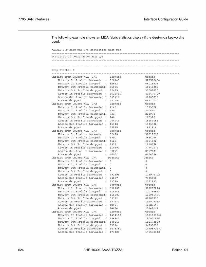
7705 SAR Interfaces
624
Interface Configuration Guide
3HE 16301 AAAA TQZZA Edition: 01
The following example shows an MDA fabric statistics display if the dest-mda keyword is used.
*A:ALU-1># show mda 1/5 statistics dest-mda===============================================================================Statistic of Destination MDA 1/5===============================================================================
-------------------------------------------------------------------------------Drop Events: 0-------------------------------------------------------------------------------Unicast from Source MDA 1/1 Packets Octets
Network In Profile forwarded : 520148 529510664Network In Profile dropped : 64852 66019336Network Out Profile forwarded: 65075 66246350Network Out Profile dropped : 32425 33008650Access In Profile forwarded : 5614550 415476700Access Out Profile forwarded : 661714 48966836Access dropped : 657705 48670170
Unicast from Source MDA 1/2 Packets OctetsNetwork In Profile forwarded : 4146 1733028Network In Profile dropped : 480 200640Network Out Profile forwarded: 531 221958Network Out Profile dropped : 240 100320Access In Profile forwarded : 204744 15151056Access Out Profile forwarded : 15318 1133532Access dropped : 25565 1891810
Unicast from Source MDA 1/3 Packets OctetsNetwork In Profile forwarded : 32470 30617292Network In Profile dropped : 3890 3664068Network Out Profile forwarded: 4127 3894682Network Out Profile dropped : 1933 1818878Access In Profile forwarded : 510301 37762274Access Out Profile forwarded : 34691 2567134Access dropped : 66951 4954374
Unicast from Source MDA 1/4 Packets OctetsNetwork In Profile forwarded : 0 0Network In Profile dropped : 0 0Network Out Profile forwarded: 0 0Network Out Profile dropped : 0 0Access In Profile forwarded : 491695 126976722Access Out Profile forwarded : 24867 7435050Access dropped : 23790 2271932
Unicast from Source MDA 1/5 Packets OctetsNetwork In Profile forwarded : 950101 967202818Network In Profile dropped : 118649 120784682Network Out Profile forwarded: 118803 120941454Network Out Profile dropped : 59322 60389796Access In Profile forwarded : 187631 191008358Access Out Profile forwarded : 12594 12820692Access dropped : 24894 25342092
Unicast from Source MDA 1/6 Packets OctetsNetwork In Profile forwarded : 1494108 1521001944Network In Profile dropped : 186642 190001556Network Out Profile forwarded: 186811 190173598Network Out Profile dropped : 93314 94993652Access In Profile forwarded : 1473381 1499873582Access Out Profile forwarded : 173421 176539142
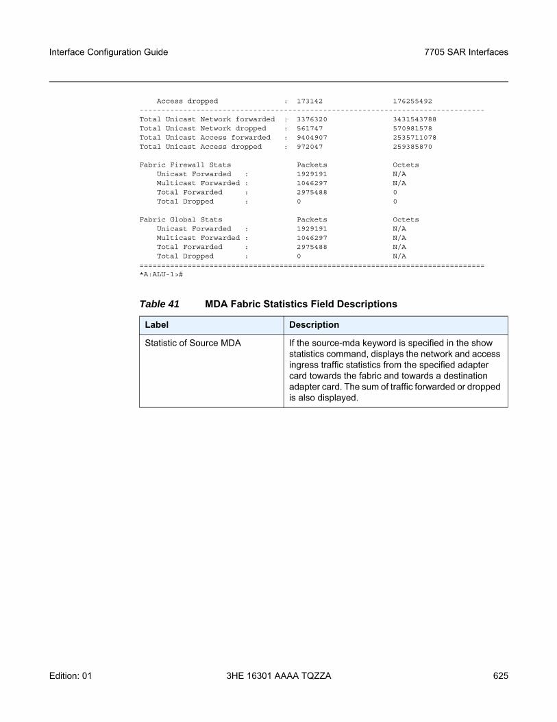
Interface Configuration Guide 7705 SAR Interfaces
Edition: 01 3HE 16301 AAAA TQZZA 625
Access dropped : 173142 176255492-------------------------------------------------------------------------------Total Unicast Network forwarded : 3376320 3431543788Total Unicast Network dropped : 561747 570981578Total Unicast Access forwarded : 9404907 2535711078Total Unicast Access dropped : 972047 259385870
Fabric Firewall Stats Packets OctetsUnicast Forwarded : 1929191 N/AMulticast Forwarded : 1046297 N/ATotal Forwarded : 2975488 0Total Dropped : 0 0
Fabric Global Stats Packets OctetsUnicast Forwarded : 1929191 N/AMulticast Forwarded : 1046297 N/ATotal Forwarded : 2975488 N/ATotal Dropped : 0 N/A
===============================================================================*A:ALU-1>#
Table 41 MDA Fabric Statistics Field Descriptions
Label Description
Statistic of Source MDA If the source-mda keyword is specified in the show statistics command, displays the network and access ingress traffic statistics from the specified adapter card towards the fabric and towards a destination adapter card. The sum of traffic forwarded or dropped is also displayed.
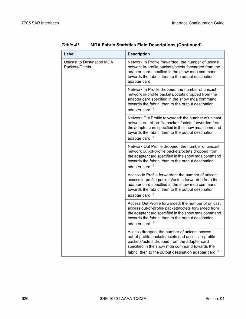
7705 SAR Interfaces
626
Interface Configuration Guide
3HE 16301 AAAA TQZZA Edition: 01
Unicast to Destination MDA Packets/Octets
Network In Profile forwarded: the number of unicast network in-profile packets/octets forwarded from the adapter card specified in the show mda command towards the fabric, then to the output destination adapter card
Network In Profile dropped: the number of unicast network in-profile packets/octets dropped from the adapter card specified in the show mda command towards the fabric, then to the output destination adapter card 1
Network Out Profile forwarded: the number of unicast network out-of-profile packets/octets forwarded from the adapter card specified in the show mda command towards the fabric, then to the output destination adapter card 1
Network Out Profile dropped: the number of unicast network out-of-profile packets/octets dropped from the adapter card specified in the show mda command towards the fabric, then to the output destination adapter card 1
Access In Profile forwarded: the number of unicast access in-profile packets/octets forwarded from the adapter card specified in the show mda command towards the fabric, then to the output destination adapter card 1
Access Out Profile forwarded: the number of unicast access out-of-profile packets/octets forwarded from the adapter card specified in the show mda command towards the fabric, then to the output destination adapter card 1
Access dropped: the number of unicast access out-of-profile packets/octets and access in-profile packets/octets dropped from the adapter card specified in the show mda command towards the fabric, then to the output destination adapter card 1
Table 41 MDA Fabric Statistics Field Descriptions (Continued)
Label Description
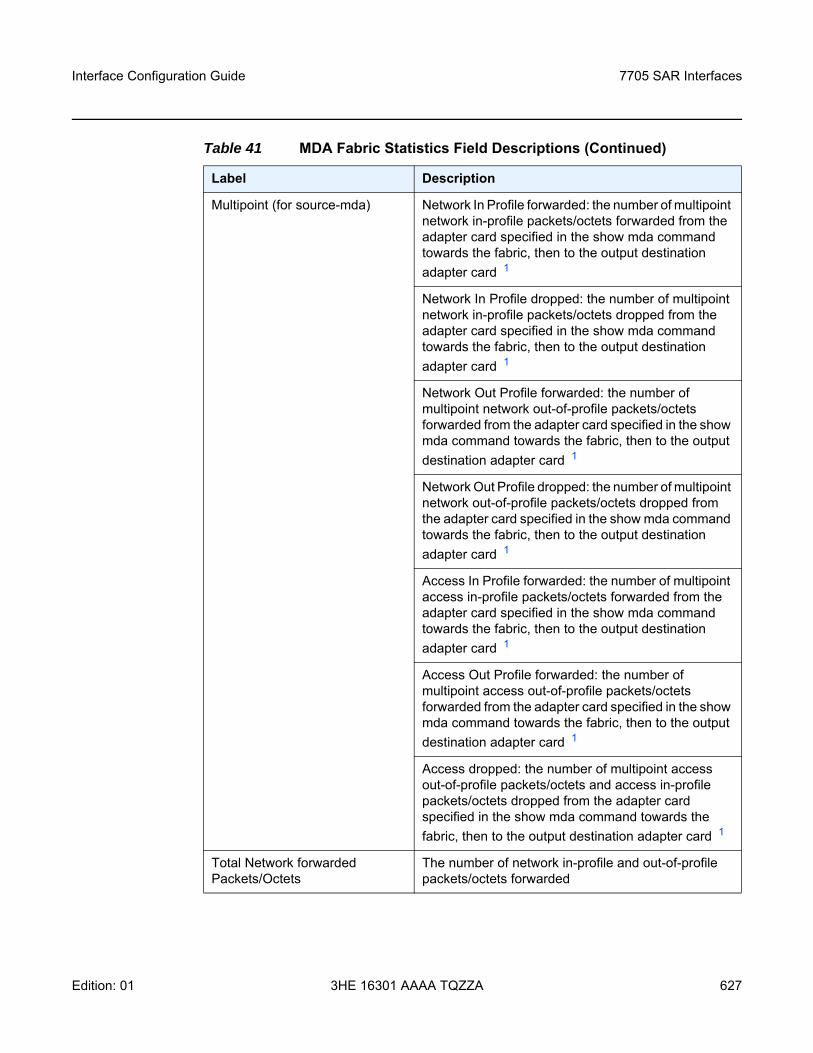
Interface Configuration Guide 7705 SAR Interfaces
Edition: 01 3HE 16301 AAAA TQZZA 627
Multipoint (for source-mda) Network In Profile forwarded: the number of multipoint network in-profile packets/octets forwarded from the adapter card specified in the show mda command towards the fabric, then to the output destination adapter card 1
Network In Profile dropped: the number of multipoint network in-profile packets/octets dropped from the adapter card specified in the show mda command towards the fabric, then to the output destination adapter card 1
Network Out Profile forwarded: the number of multipoint network out-of-profile packets/octets forwarded from the adapter card specified in the show mda command towards the fabric, then to the output destination adapter card 1
Network Out Profile dropped: the number of multipoint network out-of-profile packets/octets dropped from the adapter card specified in the show mda command towards the fabric, then to the output destination adapter card 1
Access In Profile forwarded: the number of multipoint access in-profile packets/octets forwarded from the adapter card specified in the show mda command towards the fabric, then to the output destination adapter card 1
Access Out Profile forwarded: the number of multipoint access out-of-profile packets/octets forwarded from the adapter card specified in the show mda command towards the fabric, then to the output destination adapter card 1
Access dropped: the number of multipoint access out-of-profile packets/octets and access in-profile packets/octets dropped from the adapter card specified in the show mda command towards the fabric, then to the output destination adapter card 1
Total Network forwarded Packets/Octets
The number of network in-profile and out-of-profile packets/octets forwarded
Table 41 MDA Fabric Statistics Field Descriptions (Continued)
Label Description
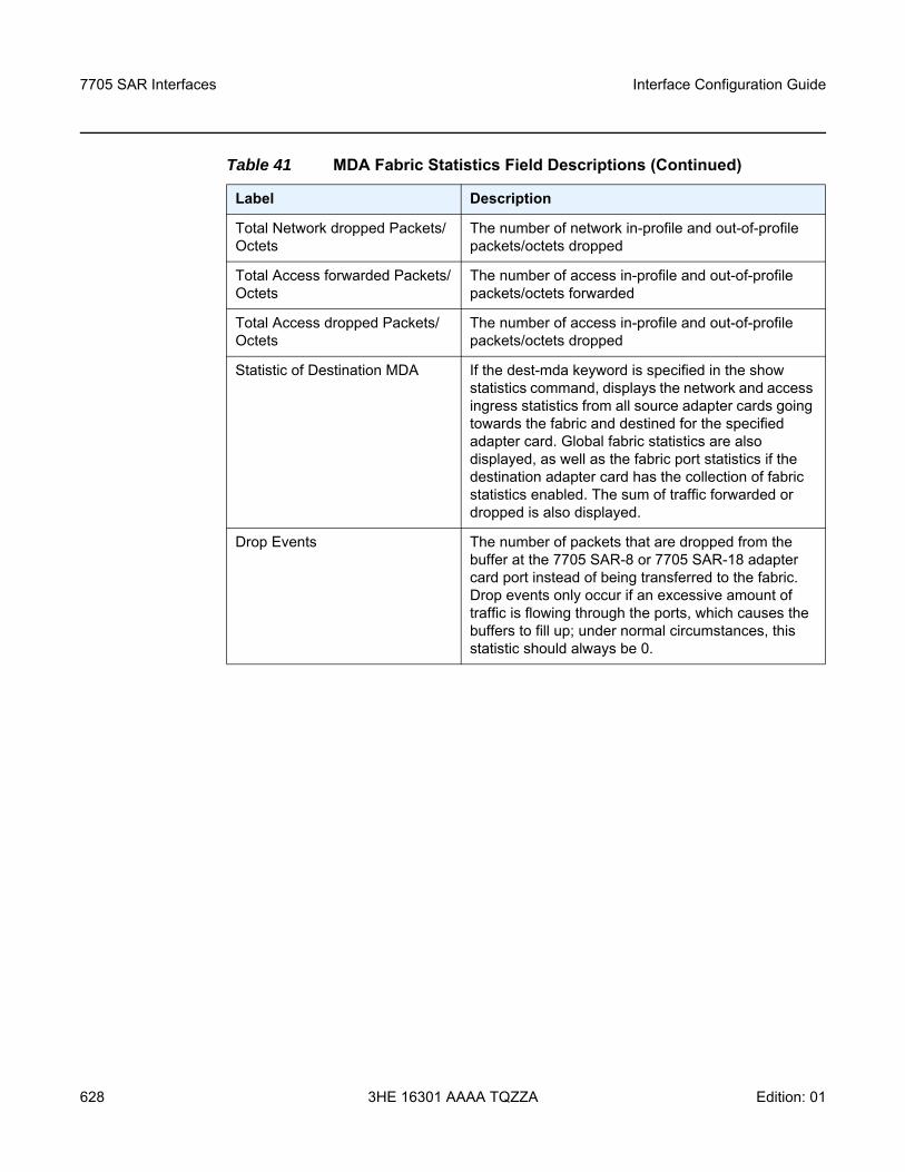
7705 SAR Interfaces
628
Interface Configuration Guide
3HE 16301 AAAA TQZZA Edition: 01
Total Network dropped Packets/Octets
The number of network in-profile and out-of-profile packets/octets dropped
Total Access forwarded Packets/Octets
The number of access in-profile and out-of-profile packets/octets forwarded
Total Access dropped Packets/Octets
The number of access in-profile and out-of-profile packets/octets dropped
Statistic of Destination MDA If the dest-mda keyword is specified in the show statistics command, displays the network and access ingress statistics from all source adapter cards going towards the fabric and destined for the specified adapter card. Global fabric statistics are also displayed, as well as the fabric port statistics if the destination adapter card has the collection of fabric statistics enabled. The sum of traffic forwarded or dropped is also displayed.
Drop Events The number of packets that are dropped from the buffer at the 7705 SAR-8 or 7705 SAR-18 adapter card port instead of being transferred to the fabric. Drop events only occur if an excessive amount of traffic is flowing through the ports, which causes the buffers to fill up; under normal circumstances, this statistic should always be 0.
Table 41 MDA Fabric Statistics Field Descriptions (Continued)
Label Description
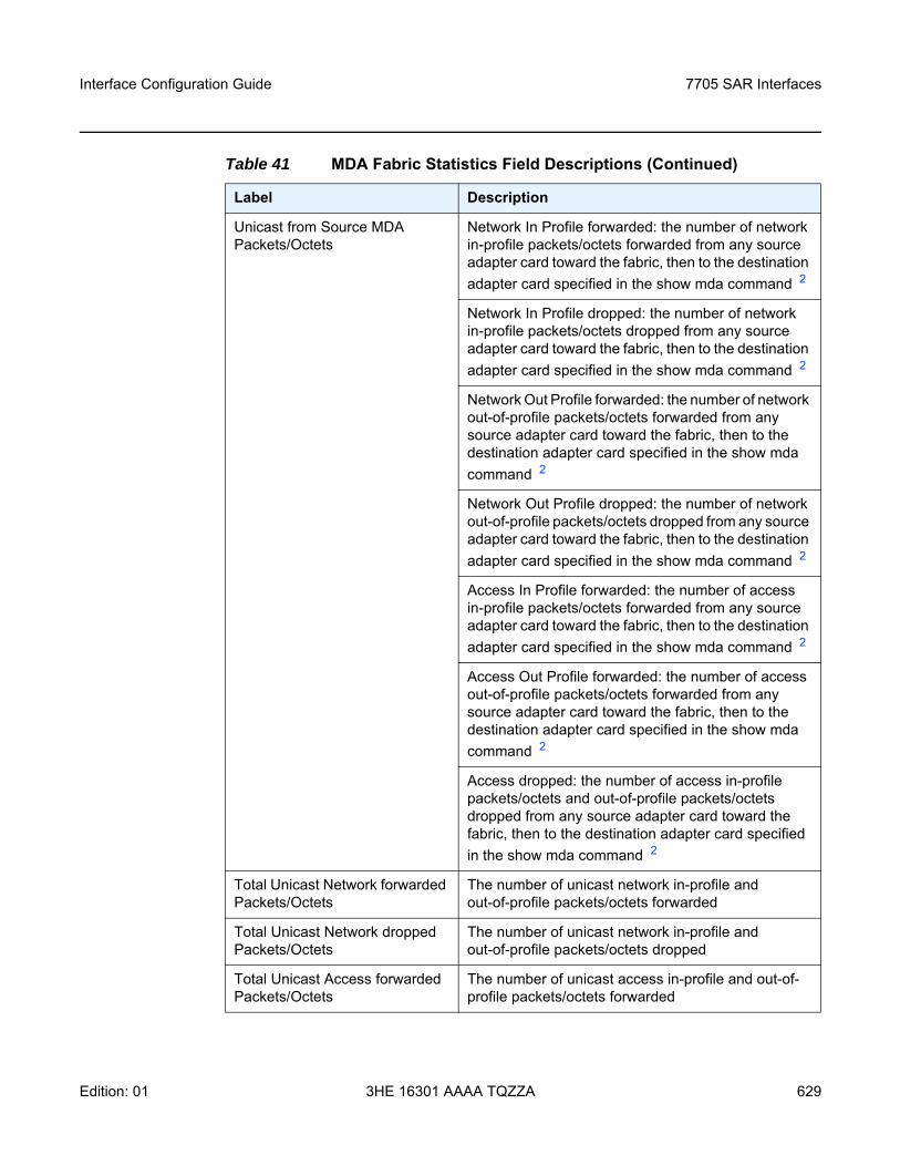
Interface Configuration Guide 7705 SAR Interfaces
Edition: 01 3HE 16301 AAAA TQZZA 629
Unicast from Source MDA Packets/Octets
Network In Profile forwarded: the number of network in-profile packets/octets forwarded from any source adapter card toward the fabric, then to the destination adapter card specified in the show mda command 2
Network In Profile dropped: the number of network in-profile packets/octets dropped from any source adapter card toward the fabric, then to the destination adapter card specified in the show mda command 2
Network Out Profile forwarded: the number of network out-of-profile packets/octets forwarded from any source adapter card toward the fabric, then to the destination adapter card specified in the show mda command 2
Network Out Profile dropped: the number of network out-of-profile packets/octets dropped from any source adapter card toward the fabric, then to the destination adapter card specified in the show mda command 2
Access In Profile forwarded: the number of access in-profile packets/octets forwarded from any source adapter card toward the fabric, then to the destination adapter card specified in the show mda command 2
Access Out Profile forwarded: the number of access out-of-profile packets/octets forwarded from any source adapter card toward the fabric, then to the destination adapter card specified in the show mda command 2
Access dropped: the number of access in-profile packets/octets and out-of-profile packets/octets dropped from any source adapter card toward the fabric, then to the destination adapter card specified in the show mda command 2
Total Unicast Network forwarded Packets/Octets
The number of unicast network in-profile and out-of-profile packets/octets forwarded
Total Unicast Network dropped Packets/Octets
The number of unicast network in-profile and out-of-profile packets/octets dropped
Total Unicast Access forwarded Packets/Octets
The number of unicast access in-profile and out-of-profile packets/octets forwarded
Table 41 MDA Fabric Statistics Field Descriptions (Continued)
Label Description
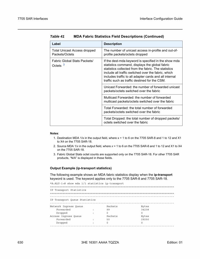
7705 SAR Interfaces
630
Interface Configuration Guide
3HE 16301 AAAA TQZZA Edition: 01
Notes:1. Destination MDA 1/x in the output field, where x = 1 to 6 on the 7705 SAR-8 and 1 to 12 and X1
to X4 on the 7705 SAR-18.2. Source MDA 1/x in the output field, where x = 1 to 6 on the 7705 SAR-8 and 1 to 12 and X1 to X4
on the 7705 SAR-18.3. Fabric Global Stats octet counts are supported only on the 7705 SAR-18. For other 7705 SAR
products, “N/A” is displayed in these fields.
Output Example (ip-transport statistics)
The following example shows an MDA fabric statistics display when the ip-transport keyword is used. The keyword applies only to the 7705 SAR-8 and 7705 SAR-18.*A:ALU-1># show mda 1/1 statistics ip-transport===============================================================================IP Transport Statistics===============================================================================-------------------------------------------------------------------------------IP Transport Queue Statistics-------------------------------------------------------------------------------Network Ingress Queue Packets Bytes
Forwarded : 99 34238Dropped : 0 0
Access Ingress Queue Packets BytesForwarded : 50 29250Dropped : 0 0
-------------------------------------------------------------------------------
Total Unicast Access dropped Packets/Octets
The number of unicast access in-profile and out-of-profile packets/octets dropped
Fabric Global Stats Packets/Octets 3
If the dest-mda keyword is specified in the show mda statistics command, displays the global fabric statistics collected from the fabric. The statistics include all traffic switched over the fabric, which includes traffic to all adapter cards and all internal traffic such as traffic destined for the CSM.
Unicast Forwarded: the number of forwarded unicast packets/octets switched over the fabric
Multicast Forwarded: the number of forwarded multicast packets/octets switched over the fabric
Total Forwarded: the total number of forwarded packets/octets switched over the fabric
Total Dropped: the total number of dropped packets/octets switched over the fabric
Table 41 MDA Fabric Statistics Field Descriptions (Continued)
Label Description
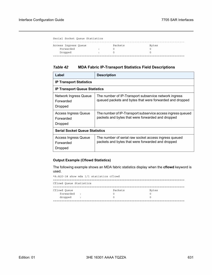
Interface Configuration Guide 7705 SAR Interfaces
Edition: 01 3HE 16301 AAAA TQZZA 631
Serial Socket Queue Statistics-------------------------------------------------------------------------------Access Ingress Queue Packets Bytes
Forwarded : 0 0Dropped : 0 0
===============================================================================
Output Example (Cflowd Statistics)
The following example shows an MDA fabric statistics display when the cflowd keyword is used.*A:ALU-1# show mda 1/1 statistics cflowd===============================================================================Cflowd Queue Statistics===============================================================================Cflowd Queue Packets Bytes
forwarded : 0 0dropped : 0 0
===============================================================================
Table 42 MDA Fabric IP-Transport Statistics Field Descriptions
Label Description
IP Transport Statistics
IP Transport Queue Statistics
Network Ingress QueueForwardedDropped
The number of IP-Transport subservice network ingress queued packets and bytes that were forwarded and dropped
Access Ingress QueueForwardedDropped
The number of IP-Transport subservice access ingress queued packets and bytes that were forwarded and dropped
Serial Socket Queue Statistics
Access Ingress QueueForwardedDropped
The number of serial raw socket access ingress queued packets and bytes that were forwarded and dropped
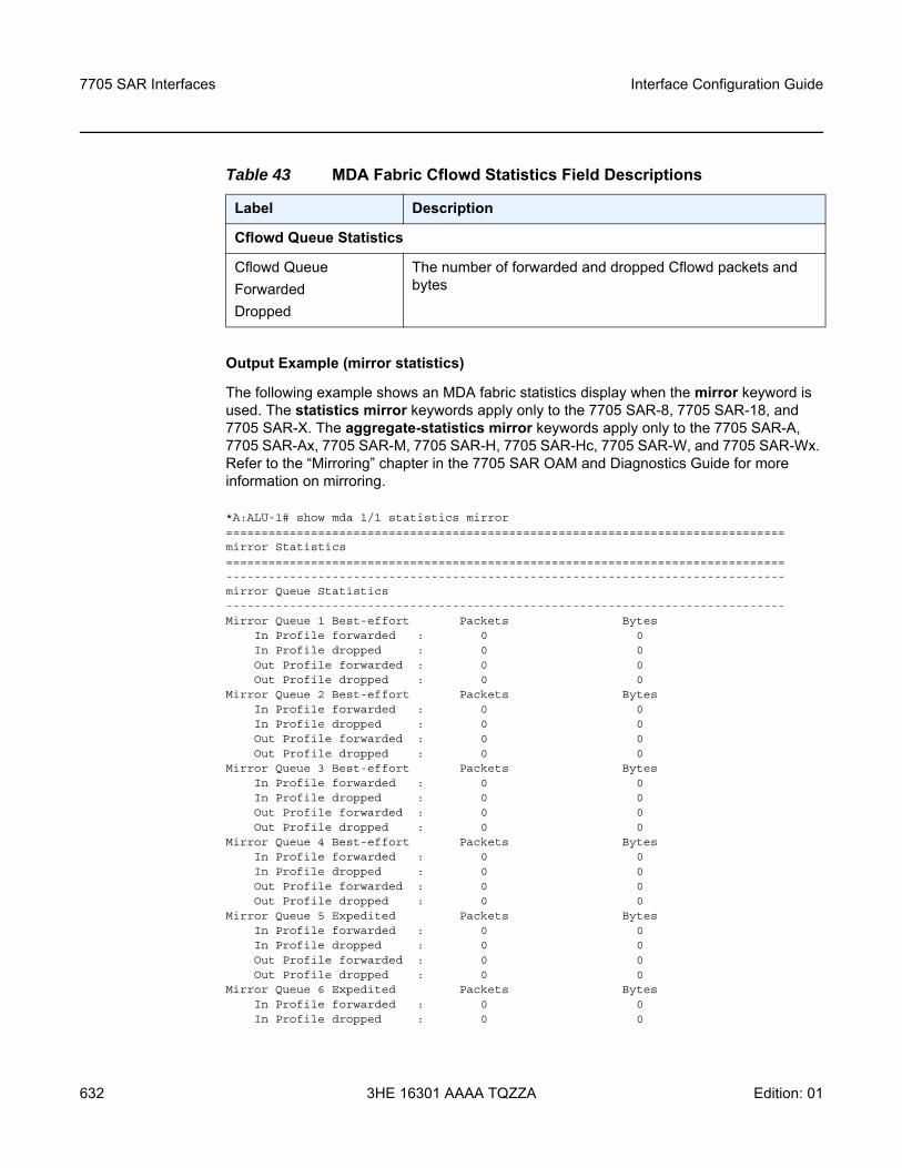
7705 SAR Interfaces
632
Interface Configuration Guide
3HE 16301 AAAA TQZZA Edition: 01
Output Example (mirror statistics)
The following example shows an MDA fabric statistics display when the mirror keyword is used. The statistics mirror keywords apply only to the 7705 SAR-8, 7705 SAR-18, and 7705 SAR-X. The aggregate-statistics mirror keywords apply only to the 7705 SAR-A, 7705 SAR-Ax, 7705 SAR-M, 7705 SAR-H, 7705 SAR-Hc, 7705 SAR-W, and 7705 SAR-Wx. Refer to the “Mirroring” chapter in the 7705 SAR OAM and Diagnostics Guide for more information on mirroring.
*A:ALU-1# show mda 1/1 statistics mirror===============================================================================mirror Statistics===============================================================================-------------------------------------------------------------------------------mirror Queue Statistics-------------------------------------------------------------------------------Mirror Queue 1 Best-effort Packets Bytes
In Profile forwarded : 0 0In Profile dropped : 0 0Out Profile forwarded : 0 0Out Profile dropped : 0 0
Mirror Queue 2 Best-effort Packets BytesIn Profile forwarded : 0 0In Profile dropped : 0 0Out Profile forwarded : 0 0Out Profile dropped : 0 0
Mirror Queue 3 Best-effort Packets BytesIn Profile forwarded : 0 0In Profile dropped : 0 0Out Profile forwarded : 0 0Out Profile dropped : 0 0
Mirror Queue 4 Best-effort Packets BytesIn Profile forwarded : 0 0In Profile dropped : 0 0Out Profile forwarded : 0 0Out Profile dropped : 0 0
Mirror Queue 5 Expedited Packets BytesIn Profile forwarded : 0 0In Profile dropped : 0 0Out Profile forwarded : 0 0Out Profile dropped : 0 0
Mirror Queue 6 Expedited Packets BytesIn Profile forwarded : 0 0In Profile dropped : 0 0
Table 43 MDA Fabric Cflowd Statistics Field Descriptions
Label Description
Cflowd Queue Statistics
Cflowd QueueForwardedDropped
The number of forwarded and dropped Cflowd packets and bytes
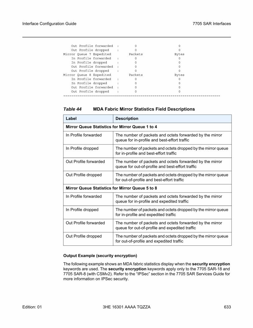
Interface Configuration Guide 7705 SAR Interfaces
Edition: 01 3HE 16301 AAAA TQZZA 633
Out Profile forwarded : 0 0Out Profile dropped : 0 0
Mirror Queue 7 Expedited Packets BytesIn Profile forwarded : 0 0In Profile dropped : 0 0Out Profile forwarded : 0 0Out Profile dropped : 0 0
Mirror Queue 8 Expedited Packets BytesIn Profile forwarded : 0 0In Profile dropped : 0 0Out Profile forwarded : 0 0Out Profile dropped : 0 0
===============================================================================
Output Example (security encryption)
The following example shows an MDA fabric statistics display when the security encryption keywords are used. The security encryption keywords apply only to the 7705 SAR-18 and 7705 SAR-8 (with CSMv2). Refer to the “IPSec” section in the 7705 SAR Services Guide for more information on IPSec security.
Table 44 MDA Fabric Mirror Statistics Field Descriptions
Label Description
Mirror Queue Statistics for Mirror Queue 1 to 4
In Profile forwarded The number of packets and octets forwarded by the mirror queue for in-profile and best-effort traffic
In Profile dropped The number of packets and octets dropped by the mirror queue for in-profile and best-effort traffic
Out Profile forwarded The number of packets and octets forwarded by the mirror queue for out-of-profile and best-effort traffic
Out Profile dropped The number of packets and octets dropped by the mirror queue for out-of-profile and best-effort traffic
Mirror Queue Statistics for Mirror Queue 5 to 8
In Profile forwarded The number of packets and octets forwarded by the mirror queue for in-profile and expedited traffic
In Profile dropped The number of packets and octets dropped by the mirror queue for in-profile and expedited traffic
Out Profile forwarded The number of packets and octets forwarded by the mirror queue for out-of-profile and expedited traffic
Out Profile dropped The number of packets and octets dropped by the mirror queue for out-of-profile and expedited traffic
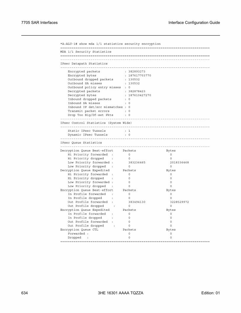
7705 SAR Interfaces
634
Interface Configuration Guide
3HE 16301 AAAA TQZZA Edition: 01
*A:ALU-1# show mda 1/1 statistics security encryption===============================================================================MDA 1/1 Security Statistics===============================================================================-------------------------------------------------------------------------------IPsec Datapath Statistics-------------------------------------------------------------------------------
Encrypted packets : 382893273Encrypted bytes : 187617703770Outbound dropped packets : 130532Outbound SA misses : 130532Outbound policy entry misses : 0Decrypted packets : 382878423Decrypted bytes : 187610427270Inbound dropped packets : 0Inbound SA misses : 0Inbound IP dst/src mismatches : 0Transmit packet errors : 0Drop Too Big/Df-set Pkts : 0
-------------------------------------------------------------------------------IPsec Control Statistics (System Wide)-------------------------------------------------------------------------------
Static IPsec Tunnels : 1Dynamic IPsec Tunnels : 0
-------------------------------------------------------------------------------IPsec Queue Statistics-------------------------------------------------------------------------------Decryption Queue Best-effort Packets Bytes
Hi Priority forwarded : 0 0Hi Priority dropped : 0 0Low Priority forwarded : 383236465 2018336468Low Priority dropped : 0 0
Decryption Queue Expedited Packets BytesHi Priority forwarded : 0 0Hi Priority dropped : 0 0Low Priority forwarded : 0 0Low Priority dropped : 0 0
Encryption Queue Best-effort Packets BytesIn Profile forwarded : 0 0In Profile dropped : 0 0Out Profile forwarded : 383494130 3228529972Out Profile dropped : 0 0
Encryption Queue Expedited Packets BytesIn Profile forwarded : 0 0In Profile dropped : 0 0Out Profile forwarded : 0 0Out Profile dropped : 0 0
Encryption Queue CTL Packets BytesForwarded : 0 0Dropped : 0 0
===============================================================================
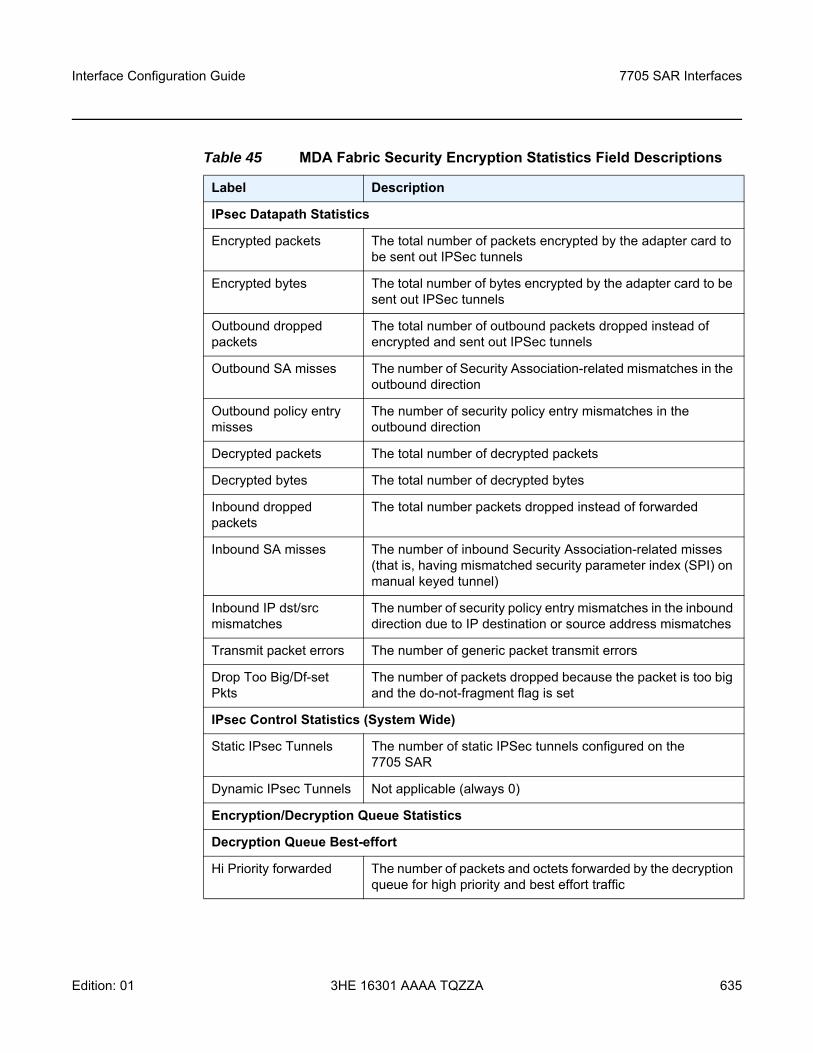
Interface Configuration Guide 7705 SAR Interfaces
Edition: 01 3HE 16301 AAAA TQZZA 635
Table 45 MDA Fabric Security Encryption Statistics Field Descriptions
Label Description
IPsec Datapath Statistics
Encrypted packets The total number of packets encrypted by the adapter card to be sent out IPSec tunnels
Encrypted bytes The total number of bytes encrypted by the adapter card to be sent out IPSec tunnels
Outbound dropped packets
The total number of outbound packets dropped instead of encrypted and sent out IPSec tunnels
Outbound SA misses The number of Security Association-related mismatches in the outbound direction
Outbound policy entry misses
The number of security policy entry mismatches in the outbound direction
Decrypted packets The total number of decrypted packets
Decrypted bytes The total number of decrypted bytes
Inbound dropped packets
The total number packets dropped instead of forwarded
Inbound SA misses The number of inbound Security Association-related misses (that is, having mismatched security parameter index (SPI) on manual keyed tunnel)
Inbound IP dst/src mismatches
The number of security policy entry mismatches in the inbound direction due to IP destination or source address mismatches
Transmit packet errors The number of generic packet transmit errors
Drop Too Big/Df-set Pkts
The number of packets dropped because the packet is too big and the do-not-fragment flag is set
IPsec Control Statistics (System Wide)
Static IPsec Tunnels The number of static IPSec tunnels configured on the 7705 SAR
Dynamic IPsec Tunnels Not applicable (always 0)
Encryption/Decryption Queue Statistics
Decryption Queue Best-effort
Hi Priority forwarded The number of packets and octets forwarded by the decryption queue for high priority and best effort traffic
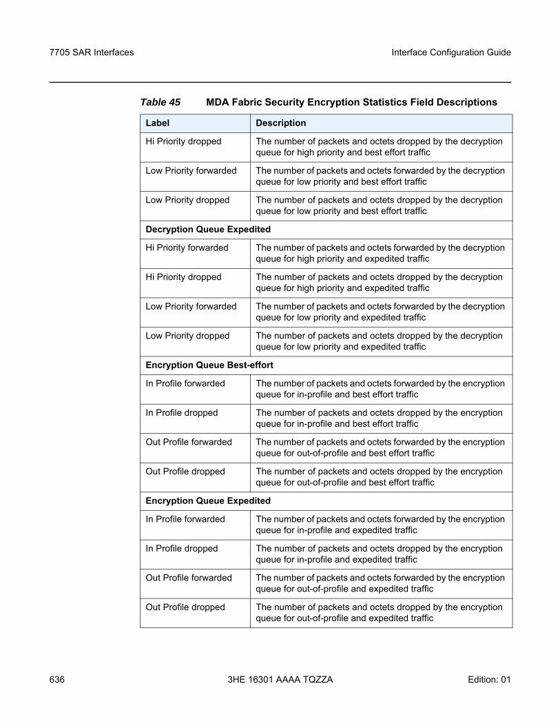
7705 SAR Interfaces
636
Interface Configuration Guide
3HE 16301 AAAA TQZZA Edition: 01
Hi Priority dropped The number of packets and octets dropped by the decryption queue for high priority and best effort traffic
Low Priority forwarded The number of packets and octets forwarded by the decryption queue for low priority and best effort traffic
Low Priority dropped The number of packets and octets dropped by the decryption queue for low priority and best effort traffic
Decryption Queue Expedited
Hi Priority forwarded The number of packets and octets forwarded by the decryption queue for high priority and expedited traffic
Hi Priority dropped The number of packets and octets dropped by the decryption queue for high priority and expedited traffic
Low Priority forwarded The number of packets and octets forwarded by the decryption queue for low priority and expedited traffic
Low Priority dropped The number of packets and octets dropped by the decryption queue for low priority and expedited traffic
Encryption Queue Best-effort
In Profile forwarded The number of packets and octets forwarded by the encryption queue for in-profile and best effort traffic
In Profile dropped The number of packets and octets dropped by the encryption queue for in-profile and best effort traffic
Out Profile forwarded The number of packets and octets forwarded by the encryption queue for out-of-profile and best effort traffic
Out Profile dropped The number of packets and octets dropped by the encryption queue for out-of-profile and best effort traffic
Encryption Queue Expedited
In Profile forwarded The number of packets and octets forwarded by the encryption queue for in-profile and expedited traffic
In Profile dropped The number of packets and octets dropped by the encryption queue for in-profile and expedited traffic
Out Profile forwarded The number of packets and octets forwarded by the encryption queue for out-of-profile and expedited traffic
Out Profile dropped The number of packets and octets dropped by the encryption queue for out-of-profile and expedited traffic
Table 45 MDA Fabric Security Encryption Statistics Field Descriptions
Label Description
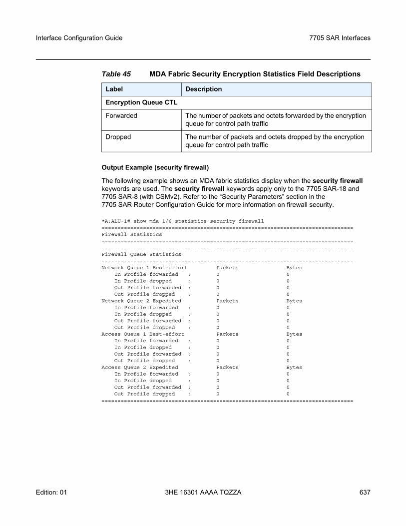
Interface Configuration Guide 7705 SAR Interfaces
Edition: 01 3HE 16301 AAAA TQZZA 637
Output Example (security firewall)
The following example shows an MDA fabric statistics display when the security firewall keywords are used. The security firewall keywords apply only to the 7705 SAR-18 and 7705 SAR-8 (with CSMv2). Refer to the “Security Parameters” section in the 7705 SAR Router Configuration Guide for more information on firewall security.
*A:ALU-1# show mda 1/6 statistics security firewall===============================================================================Firewall Statistics===============================================================================-------------------------------------------------------------------------------Firewall Queue Statistics-------------------------------------------------------------------------------Network Queue 1 Best-effort Packets Bytes
In Profile forwarded : 0 0In Profile dropped : 0 0Out Profile forwarded : 0 0Out Profile dropped : 0 0
Network Queue 2 Expedited Packets BytesIn Profile forwarded : 0 0In Profile dropped : 0 0Out Profile forwarded : 0 0Out Profile dropped : 0 0
Access Queue 1 Best-effort Packets BytesIn Profile forwarded : 0 0In Profile dropped : 0 0Out Profile forwarded : 0 0Out Profile dropped : 0 0
Access Queue 2 Expedited Packets BytesIn Profile forwarded : 0 0In Profile dropped : 0 0Out Profile forwarded : 0 0Out Profile dropped : 0 0
===============================================================================
Encryption Queue CTL
Forwarded The number of packets and octets forwarded by the encryption queue for control path traffic
Dropped The number of packets and octets dropped by the encryption queue for control path traffic
Table 45 MDA Fabric Security Encryption Statistics Field Descriptions
Label Description
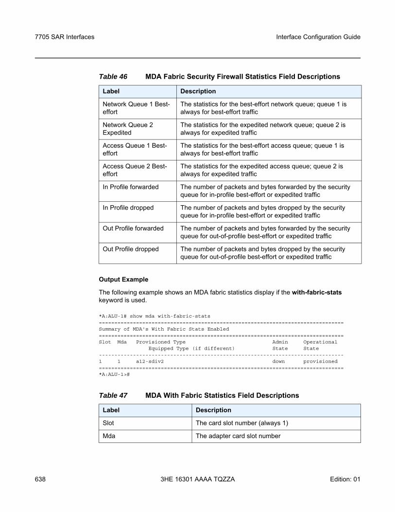
7705 SAR Interfaces
638
Interface Configuration Guide
3HE 16301 AAAA TQZZA Edition: 01
Output Example
The following example shows an MDA fabric statistics display if the with-fabric-stats keyword is used.
*A:ALU-1# show mda with-fabric-stats===============================================================================Summary of MDA's With Fabric Stats Enabled===============================================================================Slot Mda Provisioned Type Admin Operational
Equipped Type (if different) State State-------------------------------------------------------------------------------1 1 a12-sdiv2 down provisioned===============================================================================*A:ALU-1>#
Table 46 MDA Fabric Security Firewall Statistics Field Descriptions
Label Description
Network Queue 1 Best-effort
The statistics for the best-effort network queue; queue 1 is always for best-effort traffic
Network Queue 2 Expedited
The statistics for the expedited network queue; queue 2 is always for expedited traffic
Access Queue 1 Best-effort
The statistics for the best-effort access queue; queue 1 is always for best-effort traffic
Access Queue 2 Best-effort
The statistics for the expedited access queue; queue 2 is always for expedited traffic
In Profile forwarded The number of packets and bytes forwarded by the security queue for in-profile best-effort or expedited traffic
In Profile dropped The number of packets and bytes dropped by the security queue for in-profile best-effort or expedited traffic
Out Profile forwarded The number of packets and bytes forwarded by the security queue for out-of-profile best-effort or expedited traffic
Out Profile dropped The number of packets and bytes dropped by the security queue for out-of-profile best-effort or expedited traffic
Table 47 MDA With Fabric Statistics Field Descriptions
Label Description
Slot The card slot number (always 1)
Mda The adapter card slot number
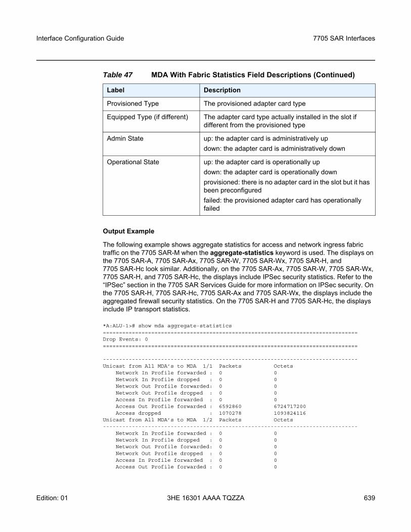
Interface Configuration Guide 7705 SAR Interfaces
Edition: 01 3HE 16301 AAAA TQZZA 639
Output Example
The following example shows aggregate statistics for access and network ingress fabric traffic on the 7705 SAR-M when the aggregate-statistics keyword is used. The displays on the 7705 SAR-A, 7705 SAR-Ax, 7705 SAR-W, 7705 SAR-Wx, 7705 SAR-H, and 7705 SAR-Hc look similar. Additionally, on the 7705 SAR-Ax, 7705 SAR-W, 7705 SAR-Wx, 7705 SAR-H, and 7705 SAR-Hc, the displays include IPSec security statistics. Refer to the “IPSec” section in the 7705 SAR Services Guide for more information on IPSec security. On the 7705 SAR-H, 7705 SAR-Hc, 7705 SAR-Ax and 7705 SAR-Wx, the displays include the aggregated firewall security statistics. On the 7705 SAR-H and 7705 SAR-Hc, the displays include IP transport statistics.
*A:ALU-1># show mda aggregate-statistics===============================================================================Drop Events: 0===============================================================================
-------------------------------------------------------------------------------Unicast from All MDA’s to MDA 1/1 Packets Octets
Network In Profile forwarded : 0 0Network In Profile dropped : 0 0Network Out Profile forwarded: 0 0Network Out Profile dropped : 0 0Access In Profile forwarded : 0 0Access Out Profile forwarded : 6592860 6724717200Access dropped : 1070278 1093824116
Unicast from All MDA’s to MDA 1/2 Packets Octets-------------------------------------------------------------------------------
Network In Profile forwarded : 0 0Network In Profile dropped : 0 0Network Out Profile forwarded: 0 0Network Out Profile dropped : 0 0Access In Profile forwarded : 0 0Access Out Profile forwarded : 0 0
Provisioned Type The provisioned adapter card type
Equipped Type (if different) The adapter card type actually installed in the slot if different from the provisioned type
Admin State up: the adapter card is administratively updown: the adapter card is administratively down
Operational State up: the adapter card is operationally updown: the adapter card is operationally downprovisioned: there is no adapter card in the slot but it has been preconfiguredfailed: the provisioned adapter card has operationally failed
Table 47 MDA With Fabric Statistics Field Descriptions (Continued)
Label Description
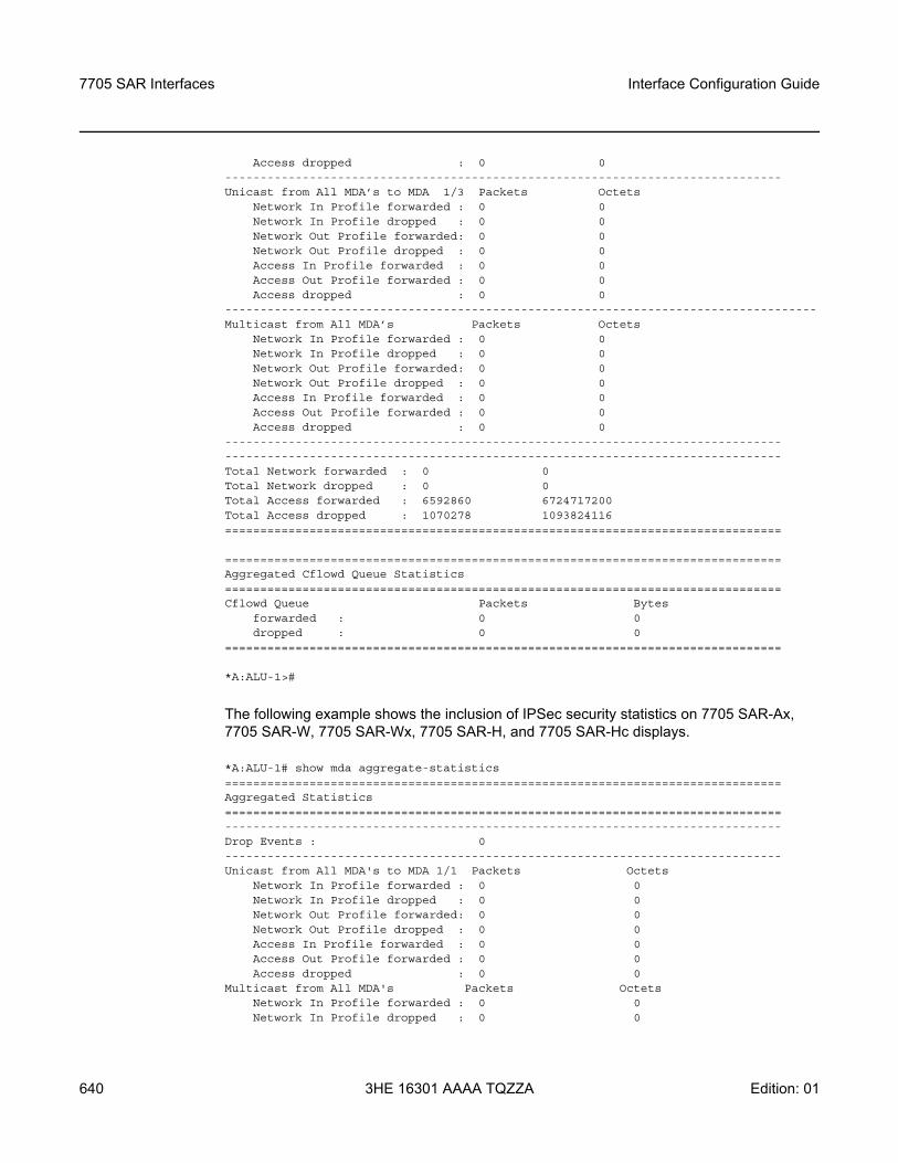
7705 SAR Interfaces
640
Interface Configuration Guide
3HE 16301 AAAA TQZZA Edition: 01
Access dropped : 0 0-------------------------------------------------------------------------------Unicast from All MDA’s to MDA 1/3 Packets Octets
Network In Profile forwarded : 0 0Network In Profile dropped : 0 0Network Out Profile forwarded: 0 0Network Out Profile dropped : 0 0Access In Profile forwarded : 0 0Access Out Profile forwarded : 0 0Access dropped : 0 0
------------------------------------------------------------------------------------Multicast from All MDA’s Packets Octets
Network In Profile forwarded : 0 0Network In Profile dropped : 0 0Network Out Profile forwarded: 0 0Network Out Profile dropped : 0 0Access In Profile forwarded : 0 0Access Out Profile forwarded : 0 0Access dropped : 0 0
--------------------------------------------------------------------------------------------------------------------------------------------------------------Total Network forwarded : 0 0Total Network dropped : 0 0Total Access forwarded : 6592860 6724717200Total Access dropped : 1070278 1093824116===============================================================================
===============================================================================Aggregated Cflowd Queue Statistics===============================================================================Cflowd Queue Packets Bytes
forwarded : 0 0dropped : 0 0
===============================================================================
*A:ALU-1>#
The following example shows the inclusion of IPSec security statistics on 7705 SAR-Ax, 7705 SAR-W, 7705 SAR-Wx, 7705 SAR-H, and 7705 SAR-Hc displays.
*A:ALU-1# show mda aggregate-statistics===============================================================================Aggregated Statistics===============================================================================-------------------------------------------------------------------------------Drop Events : 0-------------------------------------------------------------------------------Unicast from All MDA's to MDA 1/1 Packets Octets
Network In Profile forwarded : 0 0Network In Profile dropped : 0 0Network Out Profile forwarded: 0 0Network Out Profile dropped : 0 0Access In Profile forwarded : 0 0Access Out Profile forwarded : 0 0Access dropped : 0 0
Multicast from All MDA's Packets OctetsNetwork In Profile forwarded : 0 0Network In Profile dropped : 0 0
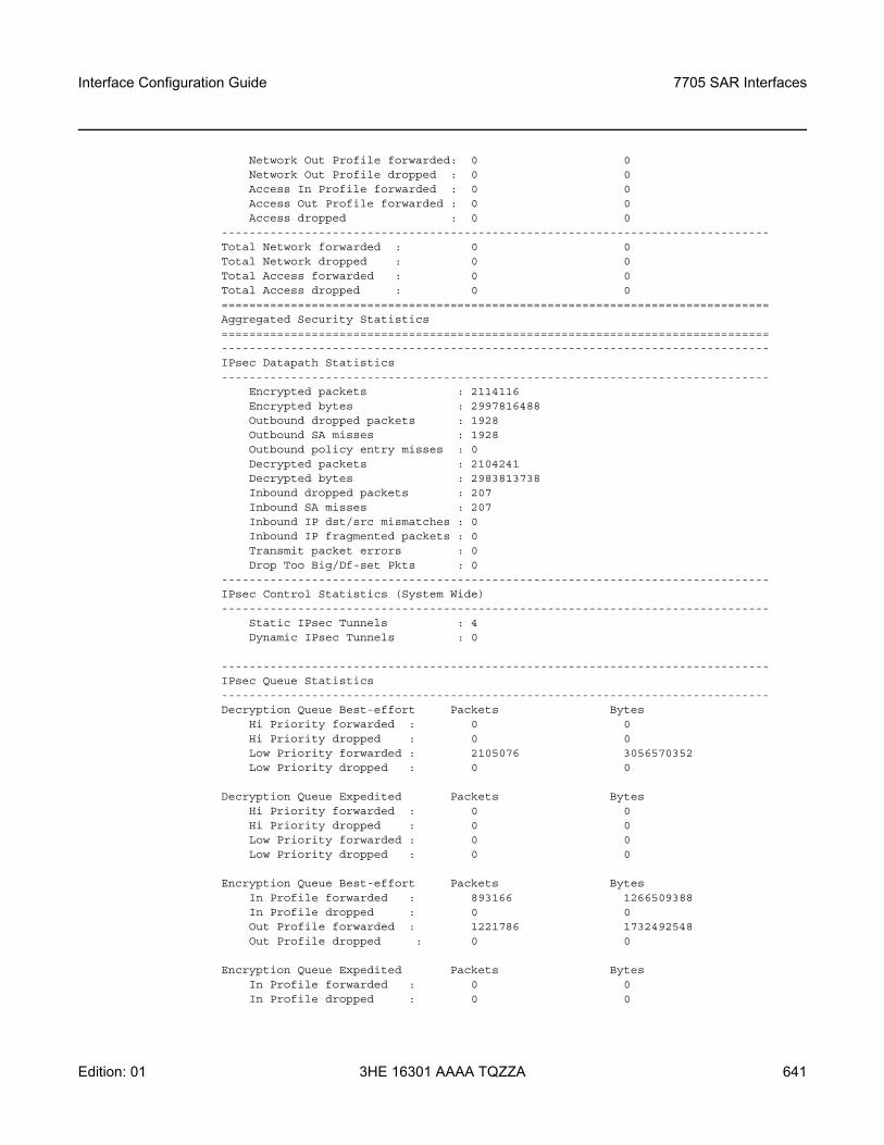
Interface Configuration Guide 7705 SAR Interfaces
Edition: 01 3HE 16301 AAAA TQZZA 641
Network Out Profile forwarded: 0 0Network Out Profile dropped : 0 0Access In Profile forwarded : 0 0Access Out Profile forwarded : 0 0Access dropped : 0 0
-------------------------------------------------------------------------------Total Network forwarded : 0 0Total Network dropped : 0 0Total Access forwarded : 0 0Total Access dropped : 0 0===============================================================================Aggregated Security Statistics===============================================================================-------------------------------------------------------------------------------IPsec Datapath Statistics-------------------------------------------------------------------------------
Encrypted packets : 2114116Encrypted bytes : 2997816488Outbound dropped packets : 1928Outbound SA misses : 1928Outbound policy entry misses : 0Decrypted packets : 2104241Decrypted bytes : 2983813738Inbound dropped packets : 207Inbound SA misses : 207Inbound IP dst/src mismatches : 0Inbound IP fragmented packets : 0Transmit packet errors : 0Drop Too Big/Df-set Pkts : 0
-------------------------------------------------------------------------------IPsec Control Statistics (System Wide)-------------------------------------------------------------------------------
Static IPsec Tunnels : 4Dynamic IPsec Tunnels : 0
-------------------------------------------------------------------------------IPsec Queue Statistics-------------------------------------------------------------------------------Decryption Queue Best-effort Packets Bytes
Hi Priority forwarded : 0 0Hi Priority dropped : 0 0Low Priority forwarded : 2105076 3056570352Low Priority dropped : 0 0
Decryption Queue Expedited Packets BytesHi Priority forwarded : 0 0Hi Priority dropped : 0 0Low Priority forwarded : 0 0Low Priority dropped : 0 0
Encryption Queue Best-effort Packets BytesIn Profile forwarded : 893166 1266509388In Profile dropped : 0 0Out Profile forwarded : 1221786 1732492548Out Profile dropped : 0 0
Encryption Queue Expedited Packets BytesIn Profile forwarded : 0 0In Profile dropped : 0 0
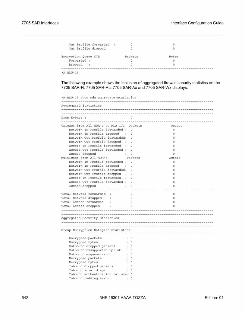
7705 SAR Interfaces
642
Interface Configuration Guide
3HE 16301 AAAA TQZZA Edition: 01
Out Profile forwarded : 0 0Out Profile dropped : 0 0
Encryption Queue CTL Packets BytesForwarded : 0 0Dropped : 0 0
===============================================================================*A:ALU-1#
The following example shows the inclusion of aggregated firewall security statistics on the 7705 SAR-H, 7705 SAR-Hc, 7705 SAR-Ax and 7705 SAR-Wx displays.
*A:ALU-1# show mda aggregate-statistics===============================================================================Aggregated Statistics===============================================================================-------------------------------------------------------------------------------Drop Events : 0-------------------------------------------------------------------------------Unicast from All MDA's to MDA 1/1 Packets Octets
Network In Profile forwarded : 0 0Network In Profile dropped : 0 0Network Out Profile forwarded: 0 0Network Out Profile dropped : 0 0Access In Profile forwarded : 0 0Access Out Profile forwarded : 0 0Access dropped : 0 0
Multicast from All MDA's Packets OctetsNetwork In Profile forwarded : 0 0Network In Profile dropped : 0 0Network Out Profile forwarded: 0 0Network Out Profile dropped : 0 0Access In Profile forwarded : 0 0Access Out Profile forwarded : 0 0Access dropped : 0 0
-------------------------------------------------------------------------------Total Network forwarded : 0 0Total Network dropped : 0 0Total Access forwarded : 0 0Total Access dropped : 0 0==============================================================================================================================================================Aggregated Security Statistics===============================================================================-------------------------------------------------------------------------------Group Encryption Datapath Statistics-------------------------------------------------------------------------------
Encrypted packets : 0Encrypted bytes : 0Outbound dropped packets : 0Outbound unsupported uplink : 0Outbound enqueue error : 0Decrypted packets : 0Decrypted bytes : 0Inbound dropped packets : 0Inbound invalid spi : 0Inbound authentication failure: 0Inbound padding error : 0
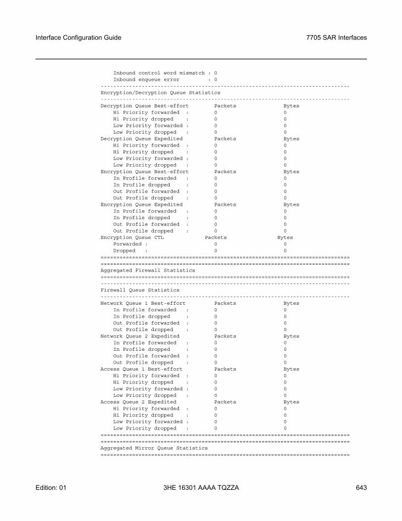
Interface Configuration Guide 7705 SAR Interfaces
Edition: 01 3HE 16301 AAAA TQZZA 643
Inbound control word mismatch : 0Inbound enqueue error : 0
-------------------------------------------------------------------------------Encryption/Decryption Queue Statistics-------------------------------------------------------------------------------Decryption Queue Best-effort Packets Bytes
Hi Priority forwarded : 0 0Hi Priority dropped : 0 0Low Priority forwarded : 0 0Low Priority dropped : 0 0
Decryption Queue Expedited Packets BytesHi Priority forwarded : 0 0Hi Priority dropped : 0 0Low Priority forwarded : 0 0Low Priority dropped : 0 0
Encryption Queue Best-effort Packets BytesIn Profile forwarded : 0 0In Profile dropped : 0 0Out Profile forwarded : 0 0Out Profile dropped : 0 0
Encryption Queue Expedited Packets BytesIn Profile forwarded : 0 0In Profile dropped : 0 0Out Profile forwarded : 0 0Out Profile dropped : 0 0
Encryption Queue CTL Packets BytesForwarded : 0 0Dropped : 0 0
==============================================================================================================================================================Aggregated Firewall Statistics===============================================================================-------------------------------------------------------------------------------Firewall Queue Statistics-------------------------------------------------------------------------------Network Queue 1 Best-effort Packets Bytes
In Profile forwarded : 0 0In Profile dropped : 0 0Out Profile forwarded : 0 0Out Profile dropped : 0 0
Network Queue 2 Expedited Packets BytesIn Profile forwarded : 0 0In Profile dropped : 0 0Out Profile forwarded : 0 0Out Profile dropped : 0 0
Access Queue 1 Best-effort Packets BytesHi Priority forwarded : 0 0Hi Priority dropped : 0 0Low Priority forwarded : 0 0Low Priority dropped : 0 0
Access Queue 2 Expedited Packets BytesHi Priority forwarded : 0 0Hi Priority dropped : 0 0Low Priority forwarded : 0 0Low Priority dropped : 0 0
==============================================================================================================================================================Aggregated Mirror Queue Statistics===============================================================================
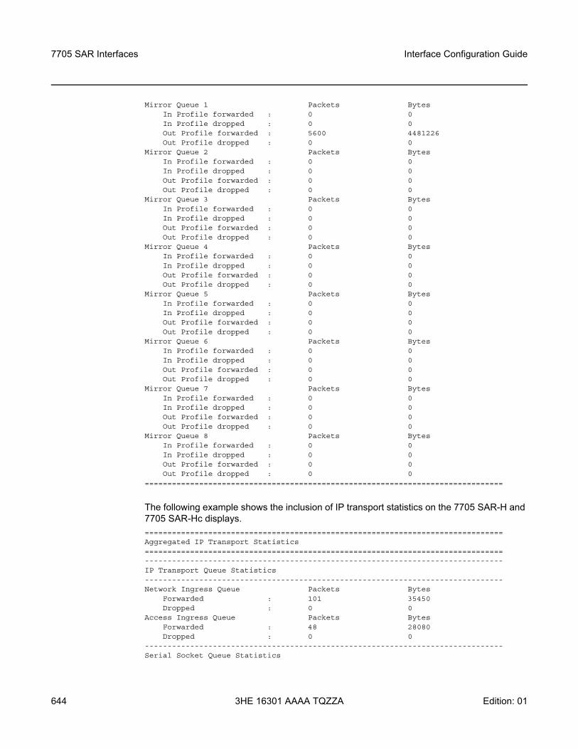
7705 SAR Interfaces
644
Interface Configuration Guide
3HE 16301 AAAA TQZZA Edition: 01
Mirror Queue 1 Packets BytesIn Profile forwarded : 0 0In Profile dropped : 0 0Out Profile forwarded : 5600 4481226Out Profile dropped : 0 0
Mirror Queue 2 Packets BytesIn Profile forwarded : 0 0In Profile dropped : 0 0Out Profile forwarded : 0 0Out Profile dropped : 0 0
Mirror Queue 3 Packets BytesIn Profile forwarded : 0 0In Profile dropped : 0 0Out Profile forwarded : 0 0Out Profile dropped : 0 0
Mirror Queue 4 Packets BytesIn Profile forwarded : 0 0In Profile dropped : 0 0Out Profile forwarded : 0 0Out Profile dropped : 0 0
Mirror Queue 5 Packets BytesIn Profile forwarded : 0 0In Profile dropped : 0 0Out Profile forwarded : 0 0Out Profile dropped : 0 0
Mirror Queue 6 Packets BytesIn Profile forwarded : 0 0In Profile dropped : 0 0Out Profile forwarded : 0 0Out Profile dropped : 0 0
Mirror Queue 7 Packets BytesIn Profile forwarded : 0 0In Profile dropped : 0 0Out Profile forwarded : 0 0Out Profile dropped : 0 0
Mirror Queue 8 Packets BytesIn Profile forwarded : 0 0In Profile dropped : 0 0Out Profile forwarded : 0 0Out Profile dropped : 0 0
===============================================================================
The following example shows the inclusion of IP transport statistics on the 7705 SAR-H and 7705 SAR-Hc displays. ===============================================================================Aggregated IP Transport Statistics===============================================================================-------------------------------------------------------------------------------IP Transport Queue Statistics-------------------------------------------------------------------------------Network Ingress Queue Packets Bytes
Forwarded : 101 35450Dropped : 0 0
Access Ingress Queue Packets BytesForwarded : 48 28080Dropped : 0 0
-------------------------------------------------------------------------------Serial Socket Queue Statistics
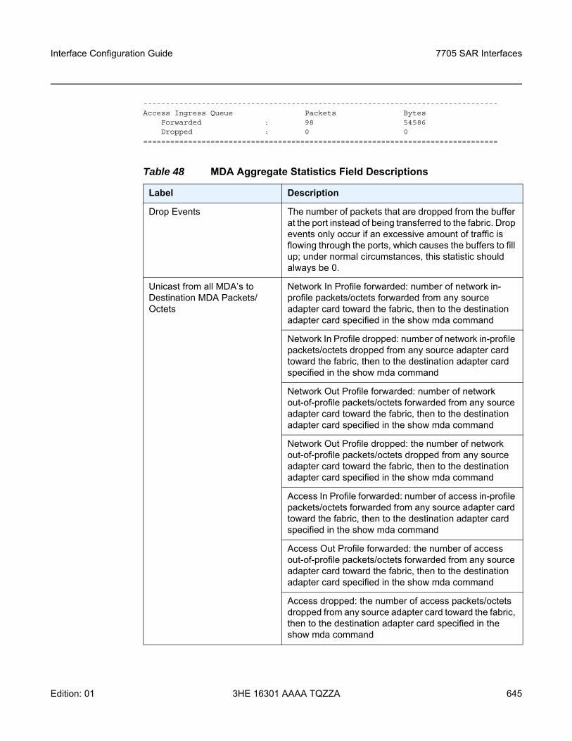
Interface Configuration Guide 7705 SAR Interfaces
Edition: 01 3HE 16301 AAAA TQZZA 645
-------------------------------------------------------------------------------Access Ingress Queue Packets Bytes
Forwarded : 98 54586Dropped : 0 0
===============================================================================
Table 48 MDA Aggregate Statistics Field Descriptions
Label Description
Drop Events The number of packets that are dropped from the buffer at the port instead of being transferred to the fabric. Drop events only occur if an excessive amount of traffic is flowing through the ports, which causes the buffers to fill up; under normal circumstances, this statistic should always be 0.
Unicast from all MDA’s to Destination MDA Packets/Octets
Network In Profile forwarded: number of network in-profile packets/octets forwarded from any source adapter card toward the fabric, then to the destination adapter card specified in the show mda command
Network In Profile dropped: number of network in-profile packets/octets dropped from any source adapter card toward the fabric, then to the destination adapter card specified in the show mda command
Network Out Profile forwarded: number of network out-of-profile packets/octets forwarded from any source adapter card toward the fabric, then to the destination adapter card specified in the show mda command
Network Out Profile dropped: the number of network out-of-profile packets/octets dropped from any source adapter card toward the fabric, then to the destination adapter card specified in the show mda command
Access In Profile forwarded: number of access in-profile packets/octets forwarded from any source adapter card toward the fabric, then to the destination adapter card specified in the show mda command
Access Out Profile forwarded: the number of access out-of-profile packets/octets forwarded from any source adapter card toward the fabric, then to the destination adapter card specified in the show mda command
Access dropped: the number of access packets/octets dropped from any source adapter card toward the fabric, then to the destination adapter card specified in the show mda command
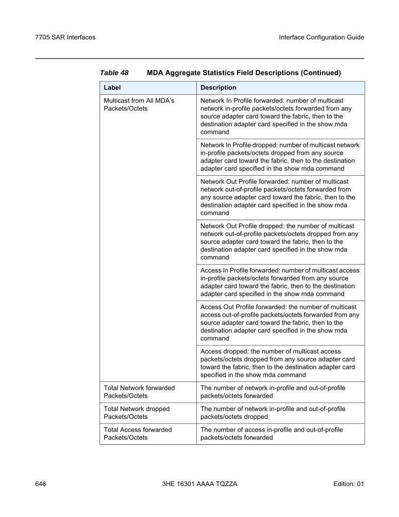
7705 SAR Interfaces
646
Interface Configuration Guide
3HE 16301 AAAA TQZZA Edition: 01
Multicast from All MDA’s Packets/Octets
Network In Profile forwarded: number of multicast network in-profile packets/octets forwarded from any source adapter card toward the fabric, then to the destination adapter card specified in the show mda command
Network In Profile dropped: number of multicast network in-profile packets/octets dropped from any source adapter card toward the fabric, then to the destination adapter card specified in the show mda command
Network Out Profile forwarded: number of multicast network out-of-profile packets/octets forwarded from any source adapter card toward the fabric, then to the destination adapter card specified in the show mda command
Network Out Profile dropped: the number of multicast network out-of-profile packets/octets dropped from any source adapter card toward the fabric, then to the destination adapter card specified in the show mda command
Access In Profile forwarded: number of multicast access in-profile packets/octets forwarded from any source adapter card toward the fabric, then to the destination adapter card specified in the show mda command
Access Out Profile forwarded: the number of multicast access out-of-profile packets/octets forwarded from any source adapter card toward the fabric, then to the destination adapter card specified in the show mda command
Access dropped: the number of multicast access packets/octets dropped from any source adapter card toward the fabric, then to the destination adapter card specified in the show mda command
Total Network forwarded Packets/Octets
The number of network in-profile and out-of-profile packets/octets forwarded
Total Network dropped Packets/Octets
The number of network in-profile and out-of-profile packets/octets dropped
Total Access forwarded Packets/Octets
The number of access in-profile and out-of-profile packets/octets forwarded
Table 48 MDA Aggregate Statistics Field Descriptions (Continued)
Label Description
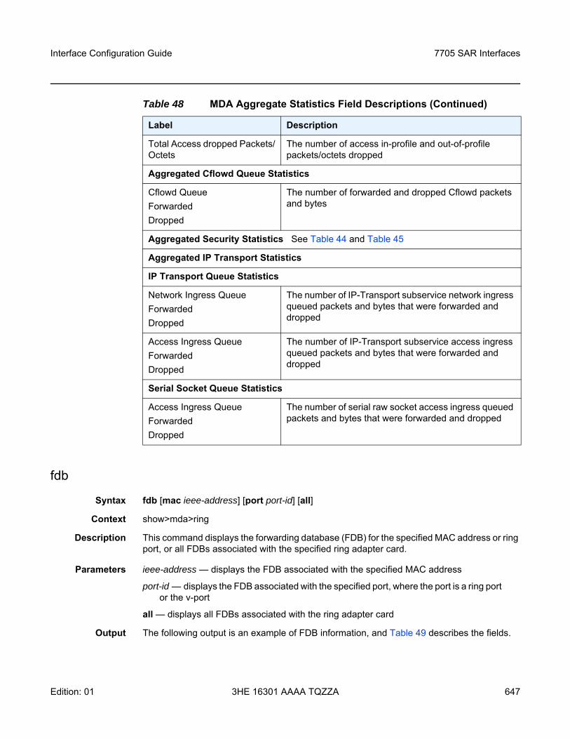
Interface Configuration Guide 7705 SAR Interfaces
Edition: 01 3HE 16301 AAAA TQZZA 647
fdb
Syntax fdb [mac ieee-address] [port port-id] [all]
Context show>mda>ring
Description This command displays the forwarding database (FDB) for the specified MAC address or ring port, or all FDBs associated with the specified ring adapter card.
Parameters ieee-address — displays the FDB associated with the specified MAC address
port-id — displays the FDB associated with the specified port, where the port is a ring port or the v-port
all — displays all FDBs associated with the ring adapter card
Output The following output is an example of FDB information, and Table 49 describes the fields.
Total Access dropped Packets/Octets
The number of access in-profile and out-of-profile packets/octets dropped
Aggregated Cflowd Queue Statistics
Cflowd QueueForwardedDropped
The number of forwarded and dropped Cflowd packets and bytes
Aggregated Security Statistics See Table 44 and Table 45
Aggregated IP Transport Statistics
IP Transport Queue Statistics
Network Ingress QueueForwardedDropped
The number of IP-Transport subservice network ingress queued packets and bytes that were forwarded and dropped
Access Ingress QueueForwardedDropped
The number of IP-Transport subservice access ingress queued packets and bytes that were forwarded and dropped
Serial Socket Queue Statistics
Access Ingress QueueForwardedDropped
The number of serial raw socket access ingress queued packets and bytes that were forwarded and dropped
Table 48 MDA Aggregate Statistics Field Descriptions (Continued)
Label Description
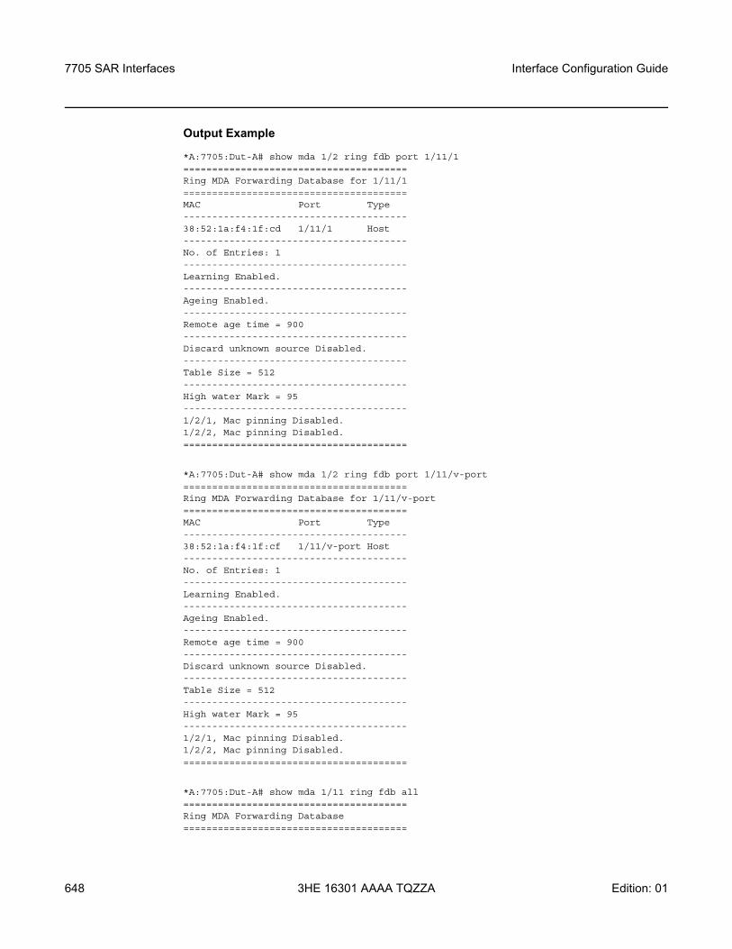
7705 SAR Interfaces
648
Interface Configuration Guide
3HE 16301 AAAA TQZZA Edition: 01
Output Example
*A:7705:Dut-A# show mda 1/2 ring fdb port 1/11/1=======================================Ring MDA Forwarding Database for 1/11/1=======================================MAC Port Type---------------------------------------38:52:1a:f4:1f:cd 1/11/1 Host---------------------------------------No. of Entries: 1---------------------------------------Learning Enabled.---------------------------------------Ageing Enabled.---------------------------------------Remote age time = 900---------------------------------------Discard unknown source Disabled.---------------------------------------Table Size = 512---------------------------------------High water Mark = 95---------------------------------------1/2/1, Mac pinning Disabled.1/2/2, Mac pinning Disabled.=======================================
*A:7705:Dut-A# show mda 1/2 ring fdb port 1/11/v-port=======================================Ring MDA Forwarding Database for 1/11/v-port=======================================MAC Port Type---------------------------------------38:52:1a:f4:1f:cf 1/11/v-port Host---------------------------------------No. of Entries: 1---------------------------------------Learning Enabled.---------------------------------------Ageing Enabled.---------------------------------------Remote age time = 900---------------------------------------Discard unknown source Disabled.---------------------------------------Table Size = 512---------------------------------------High water Mark = 95---------------------------------------1/2/1, Mac pinning Disabled.1/2/2, Mac pinning Disabled.=======================================
*A:7705:Dut-A# show mda 1/11 ring fdb all=======================================Ring MDA Forwarding Database=======================================
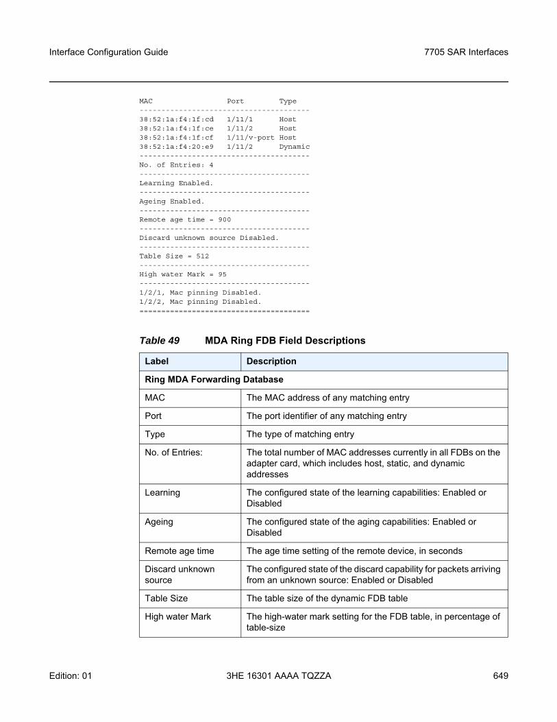
Interface Configuration Guide 7705 SAR Interfaces
Edition: 01 3HE 16301 AAAA TQZZA 649
MAC Port Type---------------------------------------38:52:1a:f4:1f:cd 1/11/1 Host38:52:1a:f4:1f:ce 1/11/2 Host38:52:1a:f4:1f:cf 1/11/v-port Host38:52:1a:f4:20:e9 1/11/2 Dynamic---------------------------------------No. of Entries: 4---------------------------------------Learning Enabled.---------------------------------------Ageing Enabled.---------------------------------------Remote age time = 900---------------------------------------Discard unknown source Disabled.---------------------------------------Table Size = 512---------------------------------------High water Mark = 95---------------------------------------1/2/1, Mac pinning Disabled.1/2/2, Mac pinning Disabled.=======================================
Table 49 MDA Ring FDB Field Descriptions
Label Description
Ring MDA Forwarding Database
MAC The MAC address of any matching entry
Port The port identifier of any matching entry
Type The type of matching entry
No. of Entries: The total number of MAC addresses currently in all FDBs on the adapter card, which includes host, static, and dynamic addresses
Learning The configured state of the learning capabilities: Enabled or Disabled
Ageing The configured state of the aging capabilities: Enabled or Disabled
Remote age time The age time setting of the remote device, in seconds
Discard unknown source
The configured state of the discard capability for packets arriving from an unknown source: Enabled or Disabled
Table Size The table size of the dynamic FDB table
High water Mark The high-water mark setting for the FDB table, in percentage of table-size
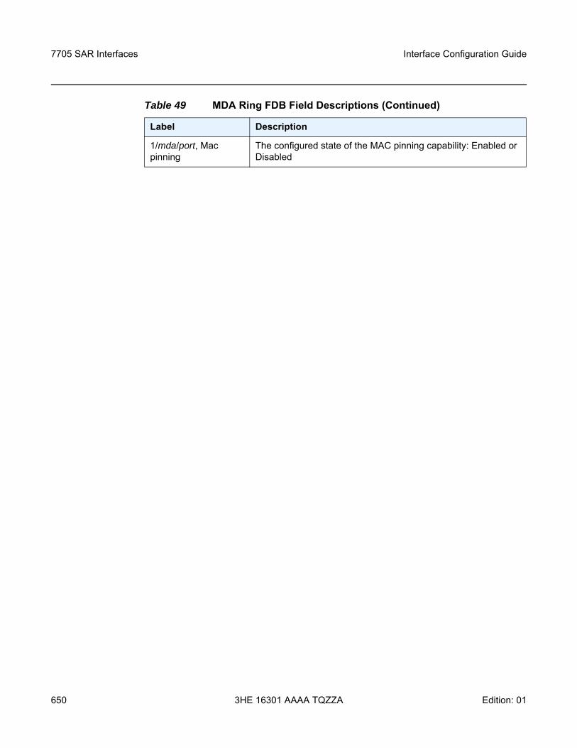
7705 SAR Interfaces
650
Interface Configuration Guide
3HE 16301 AAAA TQZZA Edition: 01
1/mda/port, Mac pinning
The configured state of the MAC pinning capability: Enabled or Disabled
Table 49 MDA Ring FDB Field Descriptions (Continued)
Label Description
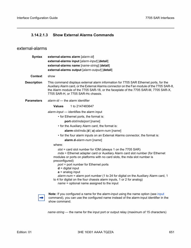
Interface Configuration Guide 7705 SAR Interfaces
Edition: 01 3HE 16301 AAAA TQZZA 651
3.14.2.1.3 Show External Alarms Commands
external-alarms
Syntax external-alarms alarm [alarm-id]external-alarms input [alarm-input] [detail]external-alarms name [name-string] [detail]external-alarms output [alarm-output] [detail]
Context show
Description This command displays external alarm information for 7705 SAR Ethernet ports, for the Auxiliary Alarm card, or the External Alarms connector on the Fan module of the 7705 SAR-8, the Alarm module of the 7705 SAR-18, or the faceplate of the 7705 SAR-M, 7705 SAR-X, 7705 SAR-H, or 7705 SAR-Hc chassis.
Parameters alarm-id — the alarm identifier
Values 1 to 2147483647
alarm-input — identifies the alarm input• for Ethernet ports, the format is:
port-slot/mda/port [name]• for the Auxiliary Alarm card, the format is:
alarm-slot/mda.d | a-alarm-num [name]• for the four alarm inputs on an External Alarms connector, the format is:
alarm.d-alarm-num [name]where:
slot = card slot number for IOM (always 1 on the 7705 SAR)mda = Ethernet adapter card or Auxiliary Alarm card slot number (for Ethernet
modules or ports on platforms with no card slots, the mda slot number is preconfigured)
port = port number for Ethernet portsd = digital inputa = analog inputalarm-num = alarm port number (1 to 24 for digital on the Auxiliary Alarm card, 1
to 4 for digital on the four chassis alarm inputs, 1 or 2 for analog)name = optional name assigned to the input
name-string — the name for the input port or output relay (maximum of 15 characters)
Note: If you configured a name for the alarm-input using the name option (see input command), you can use the configured name instead of the alarm-input identifier in the show command.
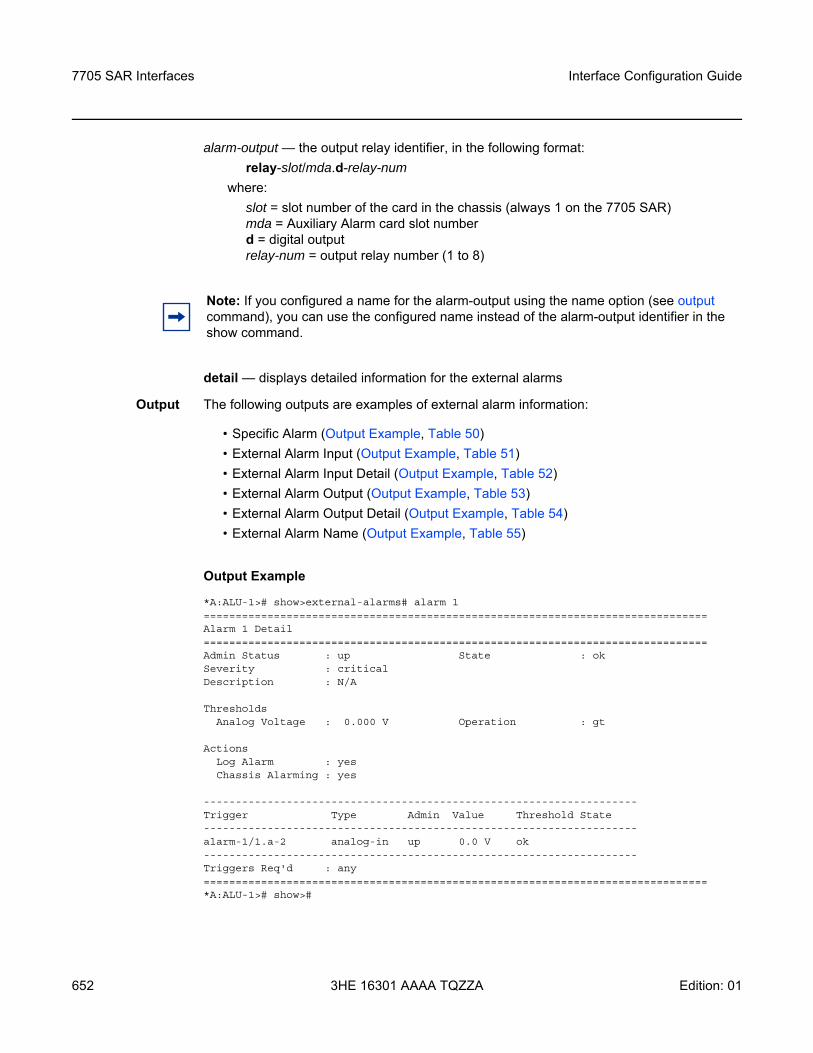
7705 SAR Interfaces
652
Interface Configuration Guide
3HE 16301 AAAA TQZZA Edition: 01
alarm-output — the output relay identifier, in the following format:relay-slot/mda.d-relay-num
where:slot = slot number of the card in the chassis (always 1 on the 7705 SAR)mda = Auxiliary Alarm card slot numberd = digital outputrelay-num = output relay number (1 to 8)
detail — displays detailed information for the external alarms
Output The following outputs are examples of external alarm information:
• Specific Alarm (Output Example, Table 50)• External Alarm Input (Output Example, Table 51)• External Alarm Input Detail (Output Example, Table 52)• External Alarm Output (Output Example, Table 53)• External Alarm Output Detail (Output Example, Table 54)• External Alarm Name (Output Example, Table 55)
Output Example
*A:ALU-1># show>external-alarms# alarm 1===============================================================================Alarm 1 Detail===============================================================================Admin Status : up State : okSeverity : criticalDescription : N/A
ThresholdsAnalog Voltage : 0.000 V Operation : gt
ActionsLog Alarm : yesChassis Alarming : yes
--------------------------------------------------------------------Trigger Type Admin Value Threshold State--------------------------------------------------------------------alarm-1/1.a-2 analog-in up 0.0 V ok--------------------------------------------------------------------Triggers Req'd : any===============================================================================*A:ALU-1># show>#
Note: If you configured a name for the alarm-output using the name option (see output command), you can use the configured name instead of the alarm-output identifier in the show command.
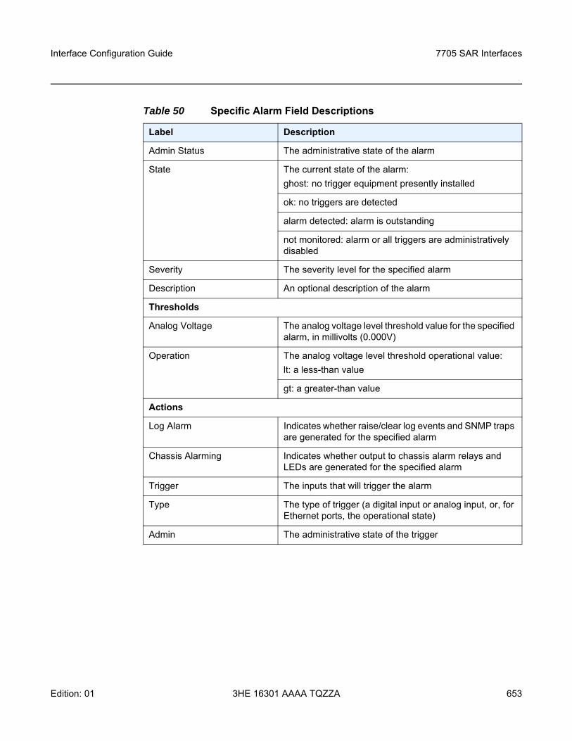
Interface Configuration Guide 7705 SAR Interfaces
Edition: 01 3HE 16301 AAAA TQZZA 653
Table 50 Specific Alarm Field Descriptions
Label Description
Admin Status The administrative state of the alarm
State The current state of the alarm:ghost: no trigger equipment presently installed
ok: no triggers are detected
alarm detected: alarm is outstanding
not monitored: alarm or all triggers are administratively disabled
Severity The severity level for the specified alarm
Description An optional description of the alarm
Thresholds
Analog Voltage The analog voltage level threshold value for the specified alarm, in millivolts (0.000V)
Operation The analog voltage level threshold operational value:lt: a less-than value
gt: a greater-than value
Actions
Log Alarm Indicates whether raise/clear log events and SNMP traps are generated for the specified alarm
Chassis Alarming Indicates whether output to chassis alarm relays and LEDs are generated for the specified alarm
Trigger The inputs that will trigger the alarm
Type The type of trigger (a digital input or analog input, or, for Ethernet ports, the operational state)
Admin The administrative state of the trigger
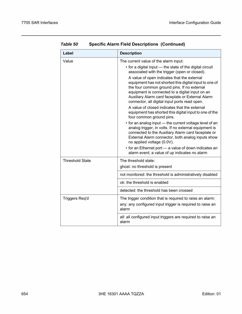
7705 SAR Interfaces
654
Interface Configuration Guide
3HE 16301 AAAA TQZZA Edition: 01
Value The current value of the alarm input:• for a digital input — the state of the digital circuit
associated with the trigger (open or closed). A value of open indicates that the external equipment has not shorted this digital input to one of the four common ground pins. If no external equipment is connected to a digital input on an Auxiliary Alarm card faceplate or External Alarm connector, all digital input ports read open. A value of closed indicates that the external equipment has shorted this digital input to one of the four common ground pins.
• for an analog input — the current voltage level of an analog trigger, in volts. If no external equipment is connected to the Auxiliary Alarm card faceplate or External Alarm connector, both analog inputs show no applied voltage (0.0V).
• for an Ethernet port — a value of down indicates an alarm event; a value of up indicates no alarm
Threshold State The threshold state:ghost: no threshold is present
not monitored: the threshold is administratively disabled
ok: the threshold is enabled
detected: the threshold has been crossed
Triggers Req'd The trigger condition that is required to raise an alarm:any: any configured input trigger is required to raise an alarm
all: all configured input triggers are required to raise an alarm
Table 50 Specific Alarm Field Descriptions (Continued)
Label Description
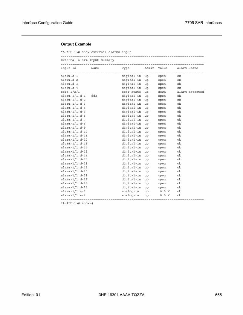
Interface Configuration Guide 7705 SAR Interfaces
Edition: 01 3HE 16301 AAAA TQZZA 655
Output Example
*A:ALU-1># show external-alarms input===========================================================================External Alarm Input Summary===========================================================================Input Id Name Type Admin Value Alarm State---------------------------------------------------------------------------alarm.d-1 digital-in up open okalarm.d-2 digital-in up open okalarm.d-3 digital-in up open okalarm.d-4 digital-in up open okport-1/2/1 oper-state up down alarm-detectedalarm-1/1.d-1 dd3 digital-in up open okalarm-1/1.d-2 digital-in up open okalarm-1/1.d-3 digital-in up open okalarm-1/1.d-4 digital-in up open okalarm-1/1.d-5 digital-in up open okalarm-1/1.d-6 digital-in up open okalarm-1/1.d-7 digital-in up open okalarm-1/1.d-8 digital-in up open okalarm-1/1.d-9 digital-in up open okalarm-1/1.d-10 digital-in up open okalarm-1/1.d-11 digital-in up open okalarm-1/1.d-12 digital-in up open okalarm-1/1.d-13 digital-in up open okalarm-1/1.d-14 digital-in up open okalarm-1/1.d-15 digital-in up open okalarm-1/1.d-16 digital-in up open okalarm-1/1.d-17 digital-in up open okalarm-1/1.d-18 digital-in up open okalarm-1/1.d-19 digital-in up open okalarm-1/1.d-20 digital-in up open okalarm-1/1.d-21 digital-in up open okalarm-1/1.d-22 digital-in up open okalarm-1/1.d-23 digital-in up open okalarm-1/1.d-24 digital-in up open okalarm-1/1.a-1 analog-in up 0.0 V okalarm-1/1.a-2 analog-in up 0.0 V ok===========================================================================*A:ALU-1># show>#
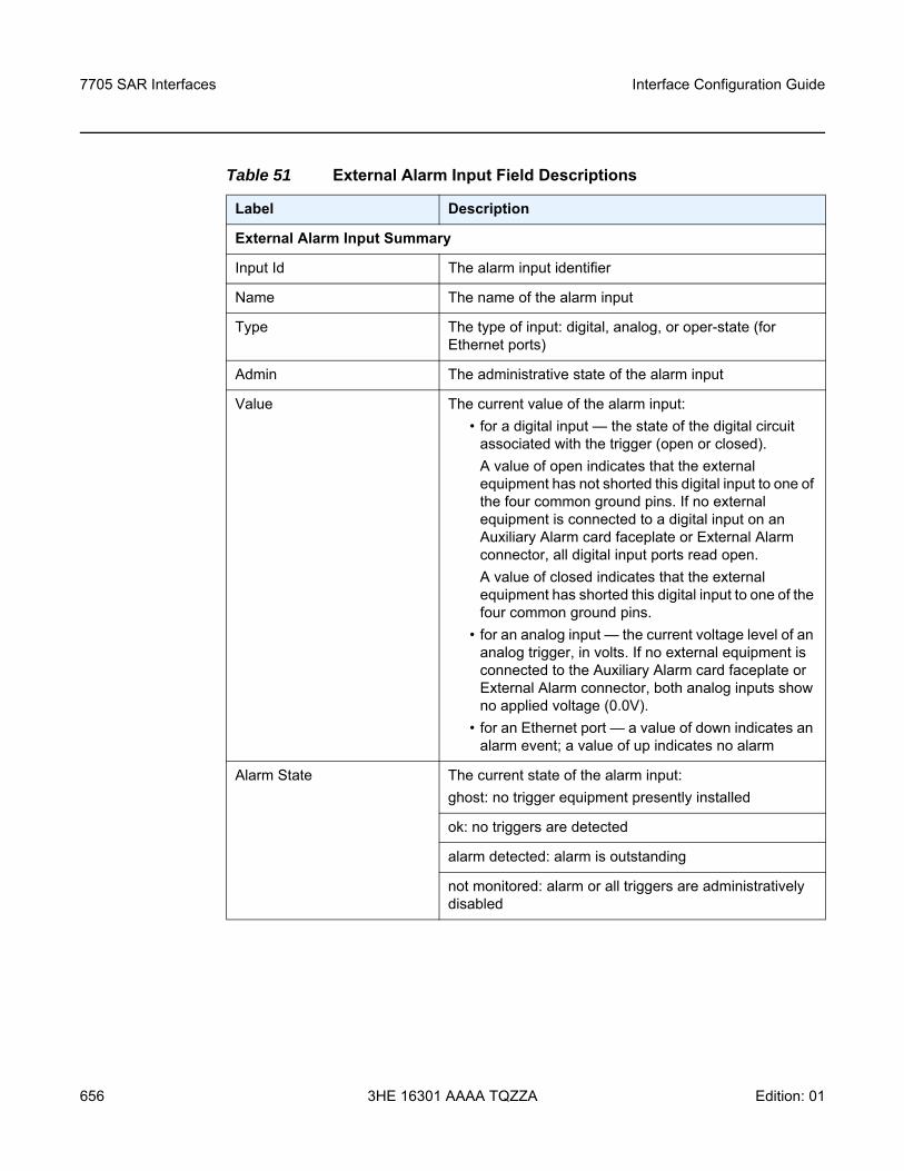
7705 SAR Interfaces
656
Interface Configuration Guide
3HE 16301 AAAA TQZZA Edition: 01
Table 51 External Alarm Input Field Descriptions
Label Description
External Alarm Input Summary
Input Id The alarm input identifier
Name The name of the alarm input
Type The type of input: digital, analog, or oper-state (for Ethernet ports)
Admin The administrative state of the alarm input
Value The current value of the alarm input:• for a digital input — the state of the digital circuit
associated with the trigger (open or closed). A value of open indicates that the external equipment has not shorted this digital input to one of the four common ground pins. If no external equipment is connected to a digital input on an Auxiliary Alarm card faceplate or External Alarm connector, all digital input ports read open. A value of closed indicates that the external equipment has shorted this digital input to one of the four common ground pins.
• for an analog input — the current voltage level of an analog trigger, in volts. If no external equipment is connected to the Auxiliary Alarm card faceplate or External Alarm connector, both analog inputs show no applied voltage (0.0V).
• for an Ethernet port — a value of down indicates an alarm event; a value of up indicates no alarm
Alarm State The current state of the alarm input:ghost: no trigger equipment presently installed
ok: no triggers are detected
alarm detected: alarm is outstanding
not monitored: alarm or all triggers are administratively disabled
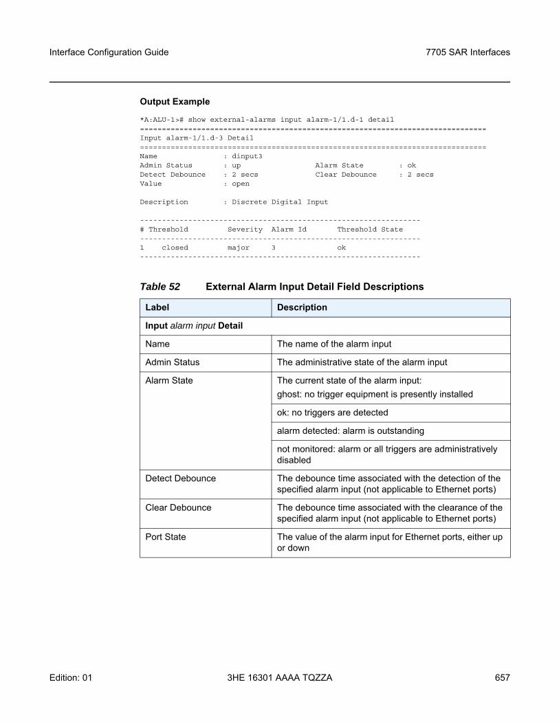
Interface Configuration Guide 7705 SAR Interfaces
Edition: 01 3HE 16301 AAAA TQZZA 657
Output Example
*A:ALU-1># show external-alarms input alarm-1/1.d-1 detail===============================================================================Input alarm-1/1.d-3 Detail===============================================================================Name : dinput3Admin Status : up Alarm State : okDetect Debounce : 2 secs Clear Debounce : 2 secsValue : open
Description : Discrete Digital Input
----------------------------------------------------------------# Threshold Severity Alarm Id Threshold State----------------------------------------------------------------1 closed major 3 ok----------------------------------------------------------------
Table 52 External Alarm Input Detail Field Descriptions
Label Description
Input alarm input Detail
Name The name of the alarm input
Admin Status The administrative state of the alarm input
Alarm State The current state of the alarm input:ghost: no trigger equipment is presently installed
ok: no triggers are detected
alarm detected: alarm is outstanding
not monitored: alarm or all triggers are administratively disabled
Detect Debounce The debounce time associated with the detection of the specified alarm input (not applicable to Ethernet ports)
Clear Debounce The debounce time associated with the clearance of the specified alarm input (not applicable to Ethernet ports)
Port State The value of the alarm input for Ethernet ports, either up or down
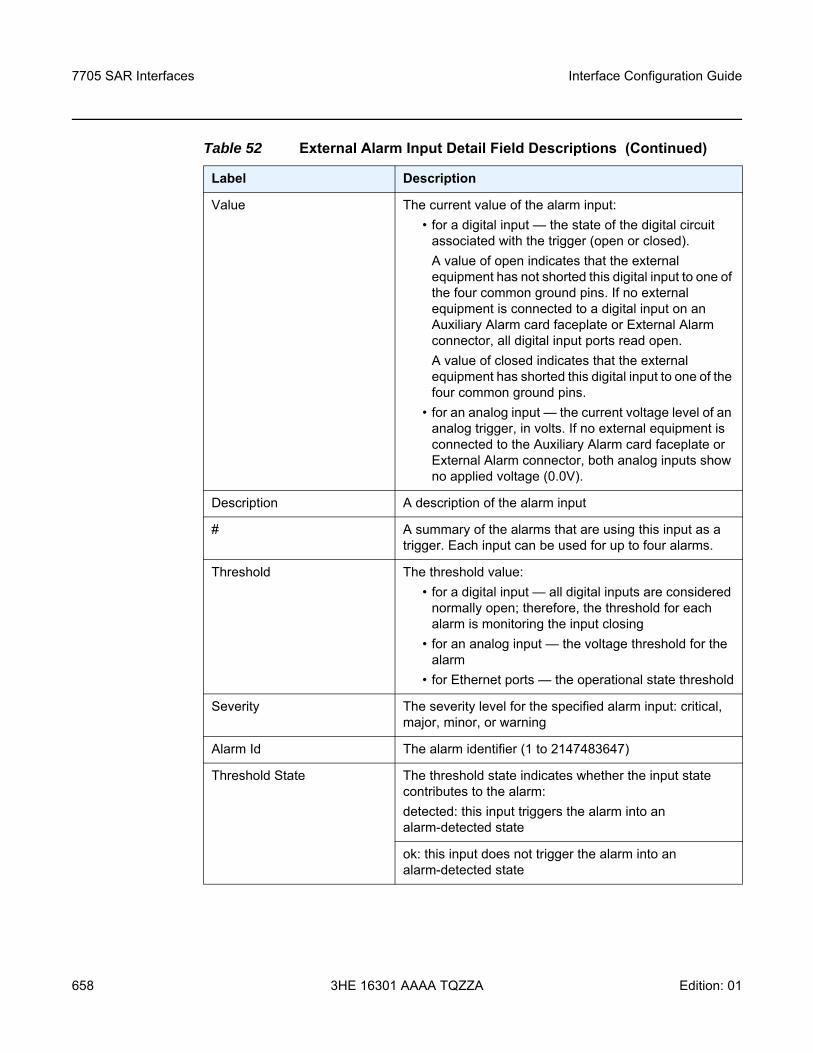
7705 SAR Interfaces
658
Interface Configuration Guide
3HE 16301 AAAA TQZZA Edition: 01
Value The current value of the alarm input:• for a digital input — the state of the digital circuit
associated with the trigger (open or closed). A value of open indicates that the external equipment has not shorted this digital input to one of the four common ground pins. If no external equipment is connected to a digital input on an Auxiliary Alarm card faceplate or External Alarm connector, all digital input ports read open. A value of closed indicates that the external equipment has shorted this digital input to one of the four common ground pins.
• for an analog input — the current voltage level of an analog trigger, in volts. If no external equipment is connected to the Auxiliary Alarm card faceplate or External Alarm connector, both analog inputs show no applied voltage (0.0V).
Description A description of the alarm input
# A summary of the alarms that are using this input as a trigger. Each input can be used for up to four alarms.
Threshold The threshold value:• for a digital input — all digital inputs are considered
normally open; therefore, the threshold for each alarm is monitoring the input closing
• for an analog input — the voltage threshold for the alarm
• for Ethernet ports — the operational state threshold
Severity The severity level for the specified alarm input: critical, major, minor, or warning
Alarm Id The alarm identifier (1 to 2147483647)
Threshold State The threshold state indicates whether the input state contributes to the alarm:detected: this input triggers the alarm into an alarm-detected state
ok: this input does not trigger the alarm into an alarm-detected state
Table 52 External Alarm Input Detail Field Descriptions (Continued)
Label Description
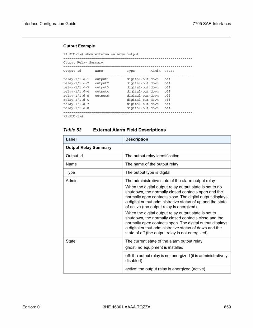
Interface Configuration Guide 7705 SAR Interfaces
Edition: 01 3HE 16301 AAAA TQZZA 659
Output Example
*A:ALU-1># show external-alarms output=================================================================Output Relay Summary=================================================================Output Id Name Type Admin State-----------------------------------------------------------------relay-1/1.d-1 output1 digital-out down offrelay-1/1.d-2 output2 digital-out down offrelay-1/1.d-3 output3 digital-out down offrelay-1/1.d-4 output4 digital-out down offrelay-1/1.d-5 output5 digital-out down offrelay-1/1.d-6 digital-out down offrelay-1/1.d-7 digital-out down offrelay-1/1.d-8 digital-out down off=================================================================*A:ALU-1>#
Table 53 External Alarm Field Descriptions
Label Description
Output Relay Summary
Output Id The output relay identification
Name The name of the output relay
Type The output type is digital
Admin The administrative state of the alarm output relayWhen the digital output relay output state is set to no shutdown, the normally closed contacts open and the normally open contacts close. The digital output displays a digital output administrative status of up and the state of active (the output relay is energized).When the digital output relay output state is set to shutdown, the normally closed contacts close and the normally open contacts open. The digital output displays a digital output administrative status of down and the state of off (the output relay is not energized).
State The current state of the alarm output relay:ghost: no equipment is installed
off: the output relay is not energized (it is administratively disabled)
active: the output relay is energized (active)
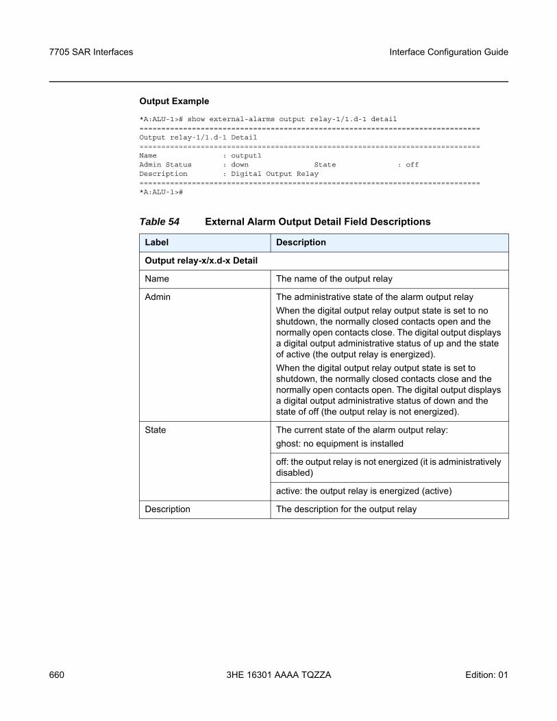
7705 SAR Interfaces
660
Interface Configuration Guide
3HE 16301 AAAA TQZZA Edition: 01
Output Example
*A:ALU-1># show external-alarms output relay-1/1.d-1 detail==============================================================================Output relay-1/1.d-1 Detail==============================================================================Name : output1Admin Status : down State : offDescription : Digital Output Relay==============================================================================*A:ALU-1>#
Table 54 External Alarm Output Detail Field Descriptions
Label Description
Output relay-x/x.d-x Detail
Name The name of the output relay
Admin The administrative state of the alarm output relayWhen the digital output relay output state is set to no shutdown, the normally closed contacts open and the normally open contacts close. The digital output displays a digital output administrative status of up and the state of active (the output relay is energized).When the digital output relay output state is set to shutdown, the normally closed contacts close and the normally open contacts open. The digital output displays a digital output administrative status of down and the state of off (the output relay is not energized).
State The current state of the alarm output relay:ghost: no equipment is installed
off: the output relay is not energized (it is administratively disabled)
active: the output relay is energized (active)
Description The description for the output relay
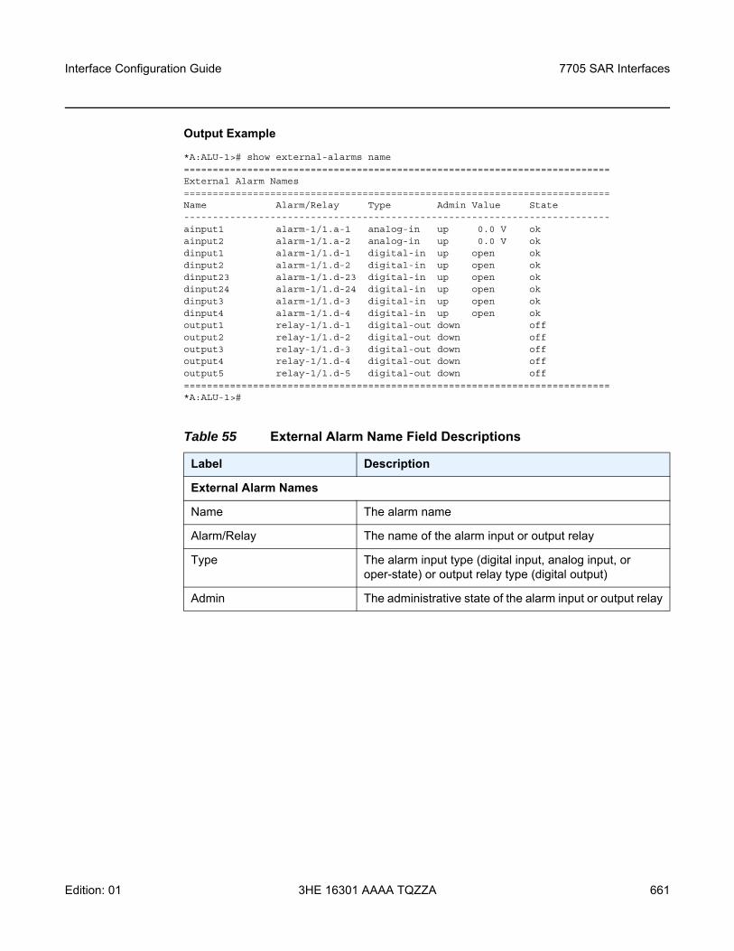
Interface Configuration Guide 7705 SAR Interfaces
Edition: 01 3HE 16301 AAAA TQZZA 661
Output Example
*A:ALU-1># show external-alarms name==========================================================================External Alarm Names==========================================================================Name Alarm/Relay Type Admin Value State--------------------------------------------------------------------------ainput1 alarm-1/1.a-1 analog-in up 0.0 V okainput2 alarm-1/1.a-2 analog-in up 0.0 V okdinput1 alarm-1/1.d-1 digital-in up open okdinput2 alarm-1/1.d-2 digital-in up open okdinput23 alarm-1/1.d-23 digital-in up open okdinput24 alarm-1/1.d-24 digital-in up open okdinput3 alarm-1/1.d-3 digital-in up open okdinput4 alarm-1/1.d-4 digital-in up open okoutput1 relay-1/1.d-1 digital-out down offoutput2 relay-1/1.d-2 digital-out down offoutput3 relay-1/1.d-3 digital-out down offoutput4 relay-1/1.d-4 digital-out down offoutput5 relay-1/1.d-5 digital-out down off==========================================================================*A:ALU-1>#
Table 55 External Alarm Name Field Descriptions
Label Description
External Alarm Names
Name The alarm name
Alarm/Relay The name of the alarm input or output relay
Type The alarm input type (digital input, analog input, or oper-state) or output relay type (digital output)
Admin The administrative state of the alarm input or output relay
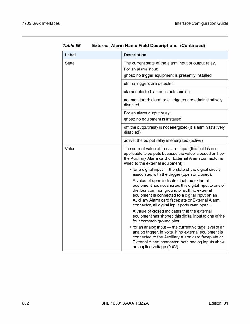
7705 SAR Interfaces
662
Interface Configuration Guide
3HE 16301 AAAA TQZZA Edition: 01
State The current state of the alarm input or output relay.For an alarm input:ghost: no trigger equipment is presently installed
ok: no triggers are detected
alarm detected: alarm is outstanding
not monitored: alarm or all triggers are administratively disabled
For an alarm output relay:ghost: no equipment is installed
off: the output relay is not energized (it is administratively disabled)
active: the output relay is energized (active)
Value The current value of the alarm input (this field is not applicable to outputs because the value is based on how the Auxiliary Alarm card or External Alarm connector is wired to the external equipment):
• for a digital input — the state of the digital circuit associated with the trigger (open or closed). A value of open indicates that the external equipment has not shorted this digital input to one of the four common ground pins. If no external equipment is connected to a digital input on an Auxiliary Alarm card faceplate or External Alarm connector, all digital input ports read open. A value of closed indicates that the external equipment has shorted this digital input to one of the four common ground pins.
• for an analog input — the current voltage level of an analog trigger, in volts. If no external equipment is connected to the Auxiliary Alarm card faceplate or External Alarm connector, both analog inputs show no applied voltage (0.0V).
Table 55 External Alarm Name Field Descriptions (Continued)
Label Description
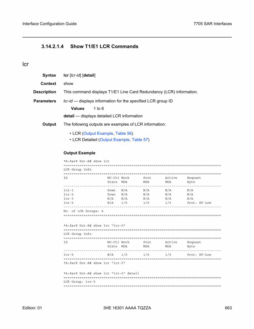
Interface Configuration Guide 7705 SAR Interfaces
Edition: 01 3HE 16301 AAAA TQZZA 663
3.14.2.1.4 Show T1/E1 LCR Commands
lcr
Syntax lcr [lcr-id] [detail]
Context show
Description This command displays T1/E1 Line Card Redundancy (LCR) information.
Parameters lcr-id — displays information for the specified LCR group ID
Values 1 to 6
detail — displays detailed LCR information
Output The following outputs are examples of LCR information:
• LCR (Output Example, Table 56)• LCR Detailed (Output Example, Table 57)
Output Example
*A:Sar8 Dut-A# show lcr===============================================================================LCR Group Info===============================================================================ID MC-Ctl Work Prot Active Request
State MDA MDA MDA Byte-------------------------------------------------------------------------------lcr-1 Down N/A N/A N/A N/Alcr-2 Down N/A N/A N/A N/Alcr-3 N/A N/A N/A N/A N/Alcr-5 N/A 1/5 1/6 1/5 Prot: SF-Low-------------------------------------------------------------------------------No. of LCR Groups: 4===============================================================================
*A:Sar8 Dut-A# show lcr "lcr-5"===============================================================================LCR Group Info===============================================================================ID MC-Ctl Work Prot Active Request
State MDA MDA MDA Byte-------------------------------------------------------------------------------lcr-5 N/A 1/5 1/6 1/5 Prot: SF-Low===============================================================================*A:Sar8 Dut-A# show lcr "lcr-5"
*A:Sar8 Dut-A# show lcr "lcr-5" detail===============================================================================LCR Group: lcr-5===============================================================================
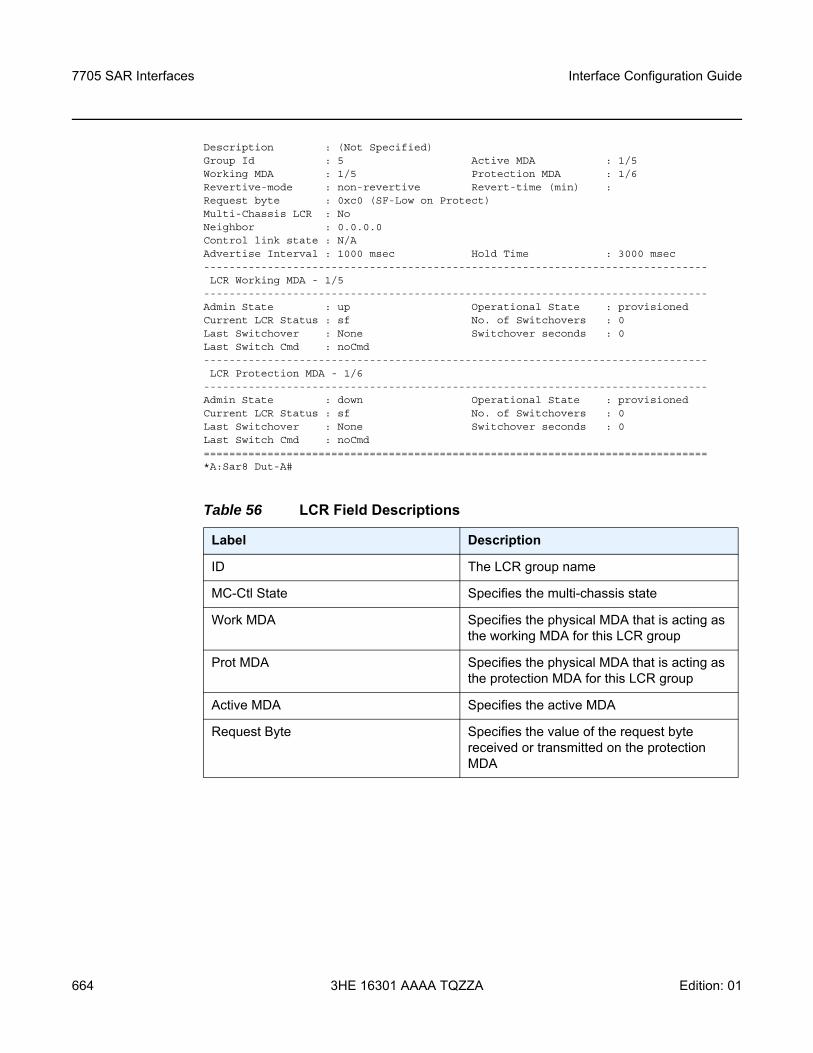
7705 SAR Interfaces
664
Interface Configuration Guide
3HE 16301 AAAA TQZZA Edition: 01
Description : (Not Specified)Group Id : 5 Active MDA : 1/5Working MDA : 1/5 Protection MDA : 1/6Revertive-mode : non-revertive Revert-time (min) :Request byte : 0xc0 (SF-Low on Protect)Multi-Chassis LCR : NoNeighbor : 0.0.0.0Control link state : N/AAdvertise Interval : 1000 msec Hold Time : 3000 msec-------------------------------------------------------------------------------LCR Working MDA - 1/5
-------------------------------------------------------------------------------Admin State : up Operational State : provisionedCurrent LCR Status : sf No. of Switchovers : 0Last Switchover : None Switchover seconds : 0Last Switch Cmd : noCmd-------------------------------------------------------------------------------LCR Protection MDA - 1/6
-------------------------------------------------------------------------------Admin State : down Operational State : provisionedCurrent LCR Status : sf No. of Switchovers : 0Last Switchover : None Switchover seconds : 0Last Switch Cmd : noCmd===============================================================================*A:Sar8 Dut-A#
Table 56 LCR Field Descriptions
Label Description
ID The LCR group name
MC-Ctl State Specifies the multi-chassis state
Work MDA Specifies the physical MDA that is acting as the working MDA for this LCR group
Prot MDA Specifies the physical MDA that is acting as the protection MDA for this LCR group
Active MDA Specifies the active MDA
Request Byte Specifies the value of the request byte received or transmitted on the protection MDA
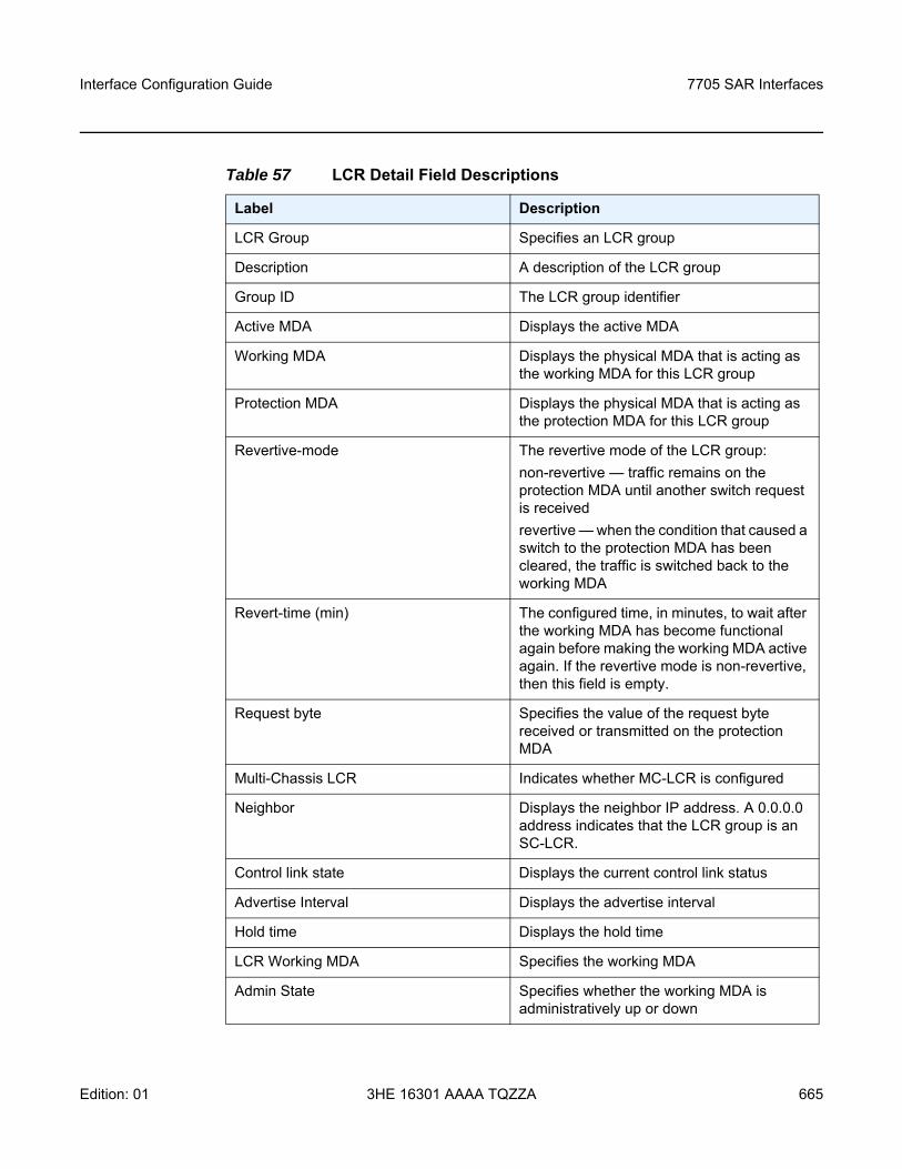
Interface Configuration Guide 7705 SAR Interfaces
Edition: 01 3HE 16301 AAAA TQZZA 665
Table 57 LCR Detail Field Descriptions
Label Description
LCR Group Specifies an LCR group
Description A description of the LCR group
Group ID The LCR group identifier
Active MDA Displays the active MDA
Working MDA Displays the physical MDA that is acting as the working MDA for this LCR group
Protection MDA Displays the physical MDA that is acting as the protection MDA for this LCR group
Revertive-mode The revertive mode of the LCR group:non-revertive — traffic remains on the protection MDA until another switch request is receivedrevertive — when the condition that caused a switch to the protection MDA has been cleared, the traffic is switched back to the working MDA
Revert-time (min) The configured time, in minutes, to wait after the working MDA has become functional again before making the working MDA active again. If the revertive mode is non-revertive, then this field is empty.
Request byte Specifies the value of the request byte received or transmitted on the protection MDA
Multi-Chassis LCR Indicates whether MC-LCR is configured
Neighbor Displays the neighbor IP address. A 0.0.0.0 address indicates that the LCR group is an SC-LCR.
Control link state Displays the current control link status
Advertise Interval Displays the advertise interval
Hold time Displays the hold time
LCR Working MDA Specifies the working MDA
Admin State Specifies whether the working MDA is administratively up or down
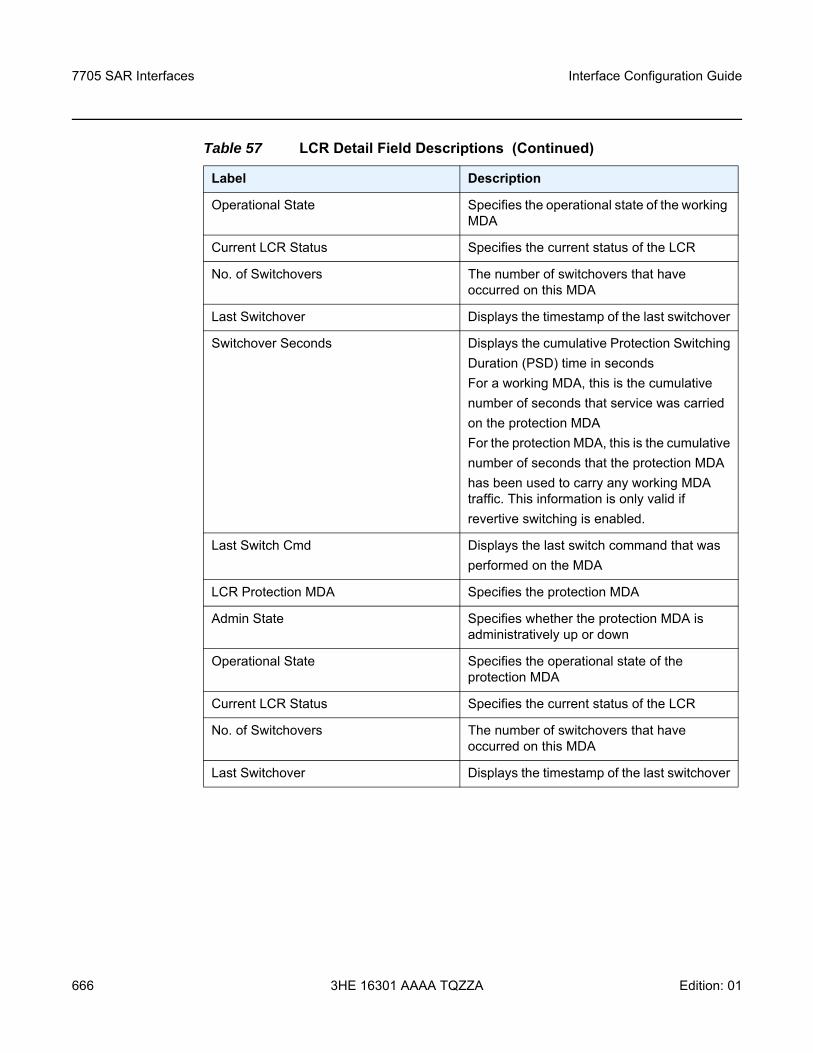
7705 SAR Interfaces
666
Interface Configuration Guide
3HE 16301 AAAA TQZZA Edition: 01
Operational State Specifies the operational state of the working MDA
Current LCR Status Specifies the current status of the LCR
No. of Switchovers The number of switchovers that have occurred on this MDA
Last Switchover Displays the timestamp of the last switchover
Switchover Seconds Displays the cumulative Protection SwitchingDuration (PSD) time in secondsFor a working MDA, this is the cumulativenumber of seconds that service was carriedon the protection MDAFor the protection MDA, this is the cumulativenumber of seconds that the protection MDAhas been used to carry any working MDA traffic. This information is only valid ifrevertive switching is enabled.
Last Switch Cmd Displays the last switch command that wasperformed on the MDA
LCR Protection MDA Specifies the protection MDA
Admin State Specifies whether the protection MDA is administratively up or down
Operational State Specifies the operational state of the protection MDA
Current LCR Status Specifies the current status of the LCR
No. of Switchovers The number of switchovers that have occurred on this MDA
Last Switchover Displays the timestamp of the last switchover
Table 57 LCR Detail Field Descriptions (Continued)
Label Description
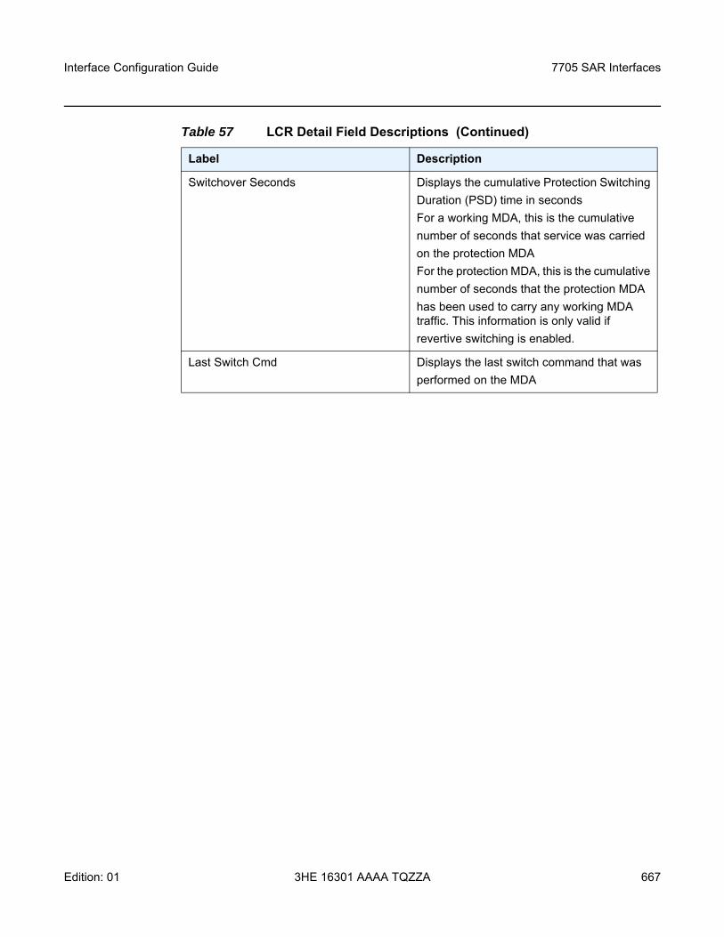
Interface Configuration Guide 7705 SAR Interfaces
Edition: 01 3HE 16301 AAAA TQZZA 667
Switchover Seconds Displays the cumulative Protection SwitchingDuration (PSD) time in secondsFor a working MDA, this is the cumulativenumber of seconds that service was carriedon the protection MDAFor the protection MDA, this is the cumulativenumber of seconds that the protection MDAhas been used to carry any working MDA traffic. This information is only valid ifrevertive switching is enabled.
Last Switch Cmd Displays the last switch command that wasperformed on the MDA
Table 57 LCR Detail Field Descriptions (Continued)
Label Description
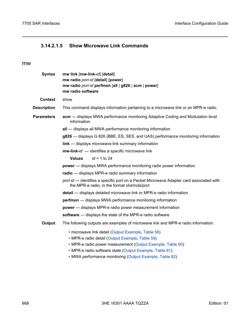
7705 SAR Interfaces
668
Interface Configuration Guide
3HE 16301 AAAA TQZZA Edition: 01
3.14.2.1.5 Show Microwave Link Commands
mw
Syntax mw link [mw-link-id] [detail]mw radio port-id [detail] [power]mw radio port-id perfmon [all | g826 | acm | power]mw radio software
Context show
Description This command displays information pertaining to a microwave link or an MPR-e radio.
Parameters acm — displays MWA performance monitoring Adaptive Coding and Modulation level information
all — displays all MWA performance monitoring information
g826 — displays G.826 (BBE, ES, SES, and UAS) performance monitoring information
link — displays microwave link summary information
mw-link-id — identifies a specific microwave link
Values id = 1 to 24
power — displays MWA performance monitoring radio power information
radio — displays MPR-e radio summary information
port-id — identifies a specific port on a Packet Microwave Adapter card associated with the MPR-e radio, in the format slot/mda/port
detail — displays detailed microwave link or MPR-e radio information
perfmon — displays MWA performance monitoring information
power — displays MPR-e radio power measurement information
software — displays the state of the MPR-e radio software
Output The following outputs are examples of microwave link and MPR-e radio information:
• microwave link detail (Output Example, Table 58)• MPR-e radio detail (Output Example, Table 59)• MPR-e radio power measurement (Output Example, Table 60)• MPR-e radio software state (Output Example, Table 61)• MWA performance monitoring (Output Example, Table 62)
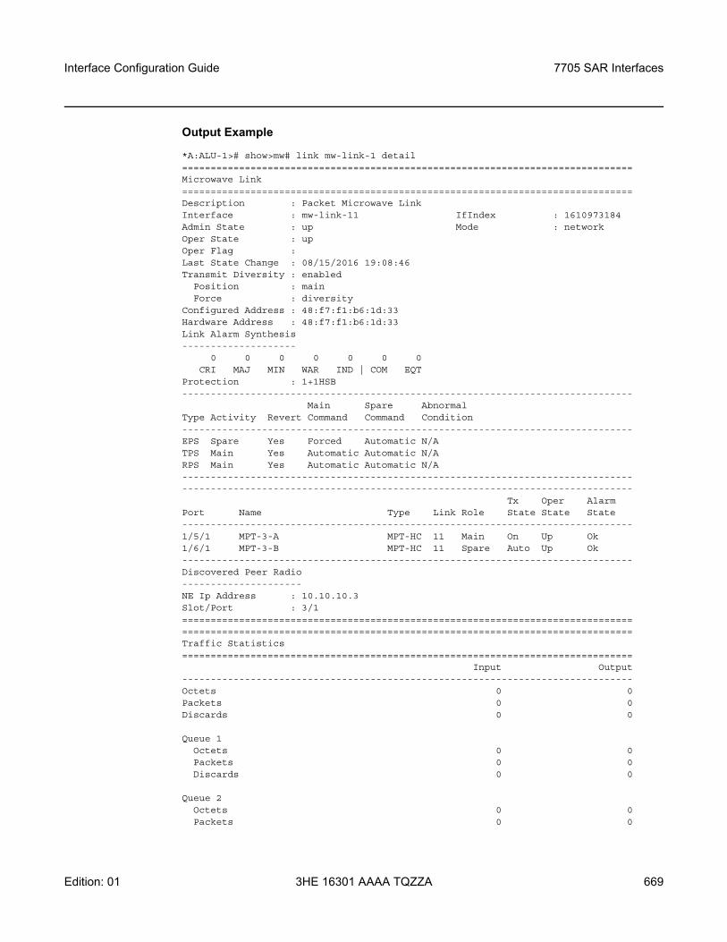
Interface Configuration Guide 7705 SAR Interfaces
Edition: 01 3HE 16301 AAAA TQZZA 669
Output Example
*A:ALU-1># show>mw# link mw-link-1 detail===============================================================================Microwave Link===============================================================================Description : Packet Microwave LinkInterface : mw-link-11 IfIndex : 1610973184Admin State : up Mode : networkOper State : upOper Flag :Last State Change : 08/15/2016 19:08:46Transmit Diversity : enabled
Position : mainForce : diversity
Configured Address : 48:f7:f1:b6:1d:33Hardware Address : 48:f7:f1:b6:1d:33Link Alarm Synthesis--------------------
0 0 0 0 0 0 0CRI MAJ MIN WAR IND | COM EQT
Protection : 1+1HSB-------------------------------------------------------------------------------
Main Spare AbnormalType Activity Revert Command Command Condition-------------------------------------------------------------------------------EPS Spare Yes Forced Automatic N/ATPS Main Yes Automatic Automatic N/ARPS Main Yes Automatic Automatic N/A--------------------------------------------------------------------------------------------------------------------------------------------------------------
Tx Oper AlarmPort Name Type Link Role State State State-------------------------------------------------------------------------------1/5/1 MPT-3-A MPT-HC 11 Main On Up Ok1/6/1 MPT-3-B MPT-HC 11 Spare Auto Up Ok-------------------------------------------------------------------------------Discovered Peer Radio---------------------NE Ip Address : 10.10.10.3Slot/Port : 3/1==============================================================================================================================================================Traffic Statistics===============================================================================
Input Output-------------------------------------------------------------------------------Octets 0 0Packets 0 0Discards 0 0
Queue 1Octets 0 0Packets 0 0Discards 0 0
Queue 2Octets 0 0Packets 0 0
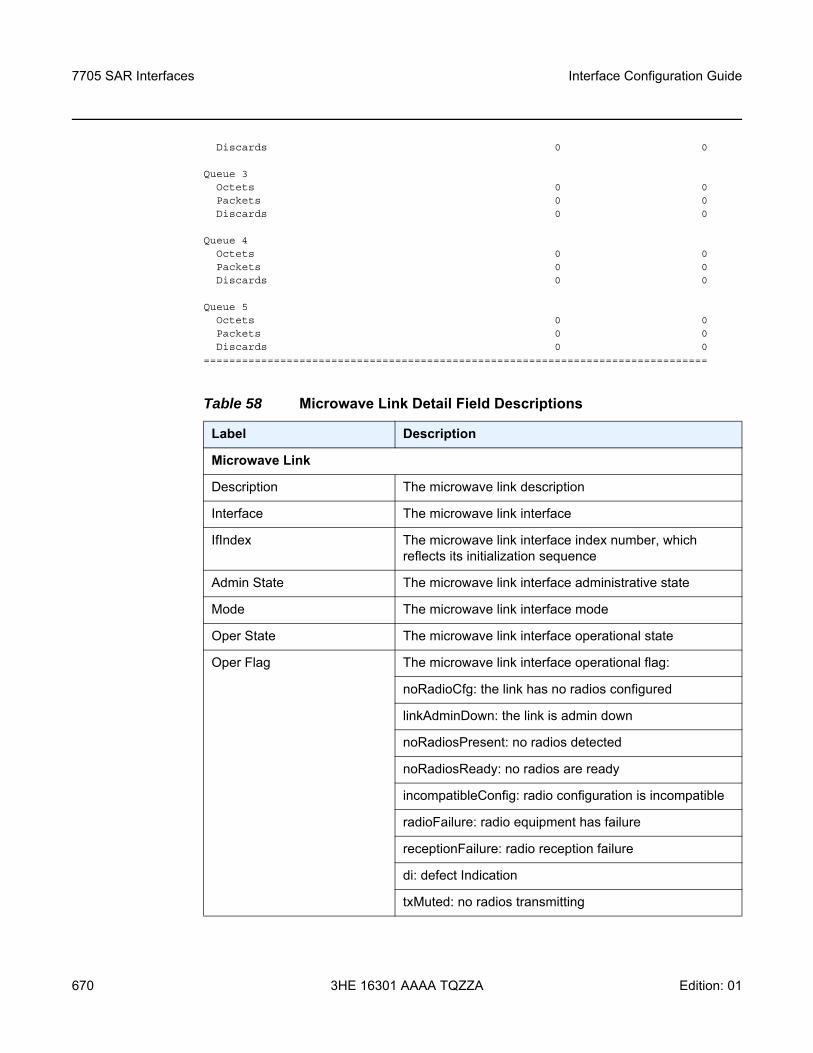
7705 SAR Interfaces
670
Interface Configuration Guide
3HE 16301 AAAA TQZZA Edition: 01
Discards 0 0
Queue 3Octets 0 0Packets 0 0Discards 0 0
Queue 4Octets 0 0Packets 0 0Discards 0 0
Queue 5Octets 0 0Packets 0 0Discards 0 0
===============================================================================
Table 58 Microwave Link Detail Field Descriptions
Label Description
Microwave Link
Description The microwave link description
Interface The microwave link interface
IfIndex The microwave link interface index number, which reflects its initialization sequence
Admin State The microwave link interface administrative state
Mode The microwave link interface mode
Oper State The microwave link interface operational state
Oper Flag The microwave link interface operational flag:
noRadioCfg: the link has no radios configured
linkAdminDown: the link is admin down
noRadiosPresent: no radios detected
noRadiosReady: no radios are ready
incompatibleConfig: radio configuration is incompatible
radioFailure: radio equipment has failure
receptionFailure: radio reception failure
di: defect Indication
txMuted: no radios transmitting
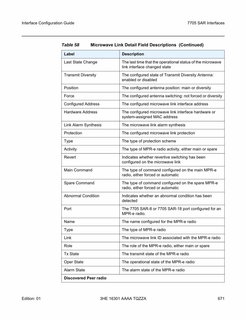
Interface Configuration Guide 7705 SAR Interfaces
Edition: 01 3HE 16301 AAAA TQZZA 671
Last State Change The last time that the operational status of the microwave link interface changed state
Transmit Diversity The configured state of Transmit Diversity Antenna: enabled or disabled
Position The configured antenna position: main or diversity
Force The configured antenna switching: not forced or diversity
Configured Address The configured microwave link interface address
Hardware Address The configured microwave link interface hardware or system-assigned MAC address
Link Alarm Synthesis The microwave link alarm synthesis
Protection The configured microwave link protection
Type The type of protection scheme
Activity The type of MPR-e radio activity, either main or spare
Revert Indicates whether revertive switching has been configured on the microwave link
Main Command The type of command configured on the main MPR-e radio, either forced or automatic
Spare Command The type of command configured on the spare MPR-e radio, either forced or automatic
Abnormal Condition Indicates whether an abnormal condition has been detected
Port The 7705 SAR-8 or 7705 SAR-18 port configured for an MPR-e radio.
Name The name configured for the MPR-e radio
Type The type of MPR-e radio
Link The microwave link ID associated with the MPR-e radio
Role The role of the MPR-e radio, either main or spare
Tx State The transmit state of the MPR-e radio
Oper State The operational state of the MPR-e radio
Alarm State The alarm state of the MPR-e radio
Discovered Peer radio
Table 58 Microwave Link Detail Field Descriptions (Continued)
Label Description
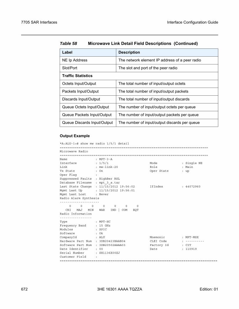
7705 SAR Interfaces
672
Interface Configuration Guide
3HE 16301 AAAA TQZZA Edition: 01
Output Example
*A:ALU-1># show mw radio 1/5/1 detail===============================================================================Microwave Radio===============================================================================Name : MPT-3-AInterface : 1/5/1 Mode : Single NELink : mw-link-20 Role : MainTx State : On Oper State : upOper Flag :Suppressed Faults : HighBer RSLDatabase Filename : mpt_3_a.tarLast State Change : 11/15/2012 19:56:02 IfIndex : 44072960Mgmt Last Up : 11/15/2012 19:56:01Mgmt Last Lost : NeverRadio Alarm Synthesis---------------------
0 0 0 0 0 0 0CRI MAJ MIN WAR IND | COM EQT
Radio Information-----------------Type : MPT-HCFrequency Band : 15 GHzModules : XPICSoftware : OkCompanyId : ALU Mnemonic : MPT-MSXHardware Part Num : 3DB20423BAAB04 CLEI Code : ----------Software Part Num : 3DB20502AAAA03 Factory Id : CITDate Identifier : 00 Date : 110919Serial Number : SH1136X00ZJCustomer Field :====================================================================================
NE Ip Address The network element IP address of a peer radio
Slot/Port The slot and port of the peer radio
Traffic Statistics
Octets Input/Output The total number of input/output octets
Packets Input/Output The total number of input/output packets
Discards Input/Output The total number of input/output discards
Queue Octets Input/Output The number of input/output octets per queue
Queue Packets Input/Output The number of input/output packets per queue
Queue Discards Input/Output The number of input/output discards per queue
Table 58 Microwave Link Detail Field Descriptions (Continued)
Label Description
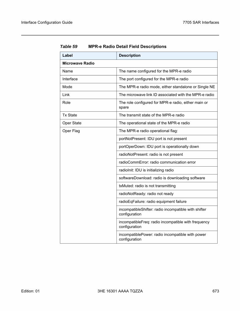
Interface Configuration Guide 7705 SAR Interfaces
Edition: 01 3HE 16301 AAAA TQZZA 673
Table 59 MPR-e Radio Detail Field Descriptions
Label Description
Microwave Radio
Name The name configured for the MPR-e radio
Interface The port configured for the MPR-e radio
Mode The MPR-e radio mode, either standalone or Single NE
Link The microwave link ID associated with the MPR-e radio
Role The role configured for MPR-e radio, either main or spare
Tx State The transmit state of the MPR-e radio
Oper State The operational state of the MPR-e radio
Oper Flag The MPR-e radio operational flag:
portNotPresent: IDU port is not present
portOperDown: IDU port is operationally down
radioNotPresent: radio is not present
radioCommError: radio communication error
radioInit: IDU is initializing radio
softwareDownload: radio is downloading software
txMuted: radio is not transmitting
radioNotReady: radio not ready
radioEqFailure: radio equipment failure
incompatibleShifter: radio incompatible with shifter configuration
incompatibleFreq: radio incompatible with frequency configuration
incompatiblePower: radio incompatible with power configuration
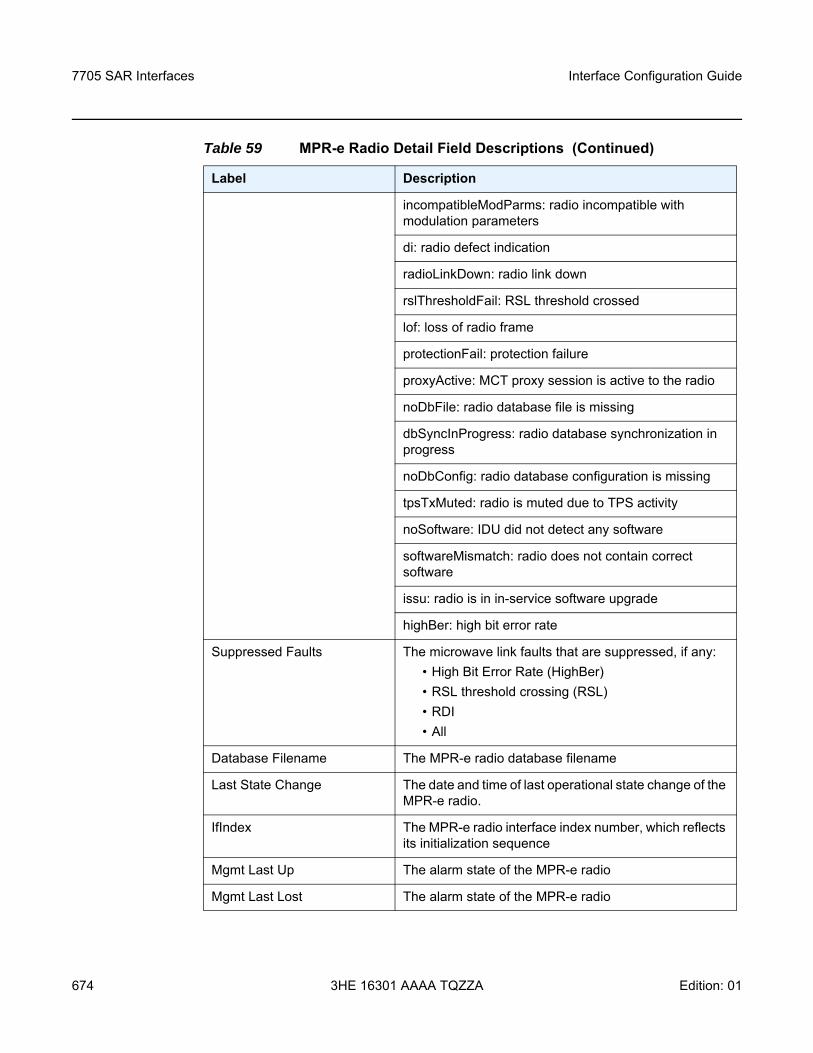
7705 SAR Interfaces
674
Interface Configuration Guide
3HE 16301 AAAA TQZZA Edition: 01
incompatibleModParms: radio incompatible with modulation parameters
di: radio defect indication
radioLinkDown: radio link down
rslThresholdFail: RSL threshold crossed
lof: loss of radio frame
protectionFail: protection failure
proxyActive: MCT proxy session is active to the radio
noDbFile: radio database file is missing
dbSyncInProgress: radio database synchronization in progress
noDbConfig: radio database configuration is missing
tpsTxMuted: radio is muted due to TPS activity
noSoftware: IDU did not detect any software
softwareMismatch: radio does not contain correct software
issu: radio is in in-service software upgrade
highBer: high bit error rate
Suppressed Faults The microwave link faults that are suppressed, if any:• High Bit Error Rate (HighBer)• RSL threshold crossing (RSL)• RDI • All
Database Filename The MPR-e radio database filename
Last State Change The date and time of last operational state change of the MPR-e radio.
IfIndex The MPR-e radio interface index number, which reflects its initialization sequence
Mgmt Last Up The alarm state of the MPR-e radio
Mgmt Last Lost The alarm state of the MPR-e radio
Table 59 MPR-e Radio Detail Field Descriptions (Continued)
Label Description
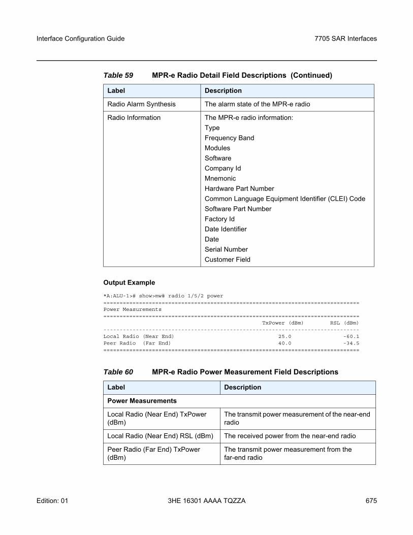
Interface Configuration Guide 7705 SAR Interfaces
Edition: 01 3HE 16301 AAAA TQZZA 675
Output Example
*A:ALU-1># show>mw# radio 1/5/2 power===============================================================================Power Measurements===============================================================================
TxPower (dBm) RSL (dBm)-------------------------------------------------------------------------------Local Radio (Near End) 25.0 -60.1Peer Radio (Far End) 40.0 -34.5===============================================================================
Radio Alarm Synthesis The alarm state of the MPR-e radio
Radio Information The MPR-e radio information:TypeFrequency BandModulesSoftwareCompany IdMnemonicHardware Part NumberCommon Language Equipment Identifier (CLEI) CodeSoftware Part NumberFactory IdDate IdentifierDateSerial NumberCustomer Field
Table 60 MPR-e Radio Power Measurement Field Descriptions
Label Description
Power Measurements
Local Radio (Near End) TxPower (dBm)
The transmit power measurement of the near-end radio
Local Radio (Near End) RSL (dBm) The received power from the near-end radio
Peer Radio (Far End) TxPower (dBm)
The transmit power measurement from the far-end radio
Table 59 MPR-e Radio Detail Field Descriptions (Continued)
Label Description
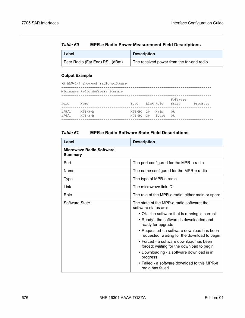
7705 SAR Interfaces
676
Interface Configuration Guide
3HE 16301 AAAA TQZZA Edition: 01
Output Example
*A:ALU-1># show>mw# radio software==============================================================================Microwave Radio Software Summary==============================================================================
SoftwarePort Name Type Link Role State Progress------------------------------------------------------------------------------1/5/1 MPT-3-A MPT-HC 20 Main Ok1/6/1 MPT-3-B MPT-HC 20 Spare Ok===============================================================================
Peer Radio (Far End) RSL (dBm) The received power from the far-end radio
Table 61 MPR-e Radio Software State Field Descriptions
Label Description
Microwave Radio Software Summary
Port The port configured for the MPR-e radio
Name The name configured for the MPR-e radio
Type The type of MPR-e radio
Link The microwave link ID
Role The role of the MPR-e radio, either main or spare
Software State The state of the MPR-e radio software; the software states are:
• Ok - the software that is running is correct• Ready - the software is downloaded and
ready for upgrade• Requested - a software download has been
requested; waiting for the download to begin• Forced - a software download has been
forced; waiting for the download to begin• Downloading - a software download is in
progress• Failed - a software download to this MPR-e
radio has failed
Table 60 MPR-e Radio Power Measurement Field Descriptions
Label Description
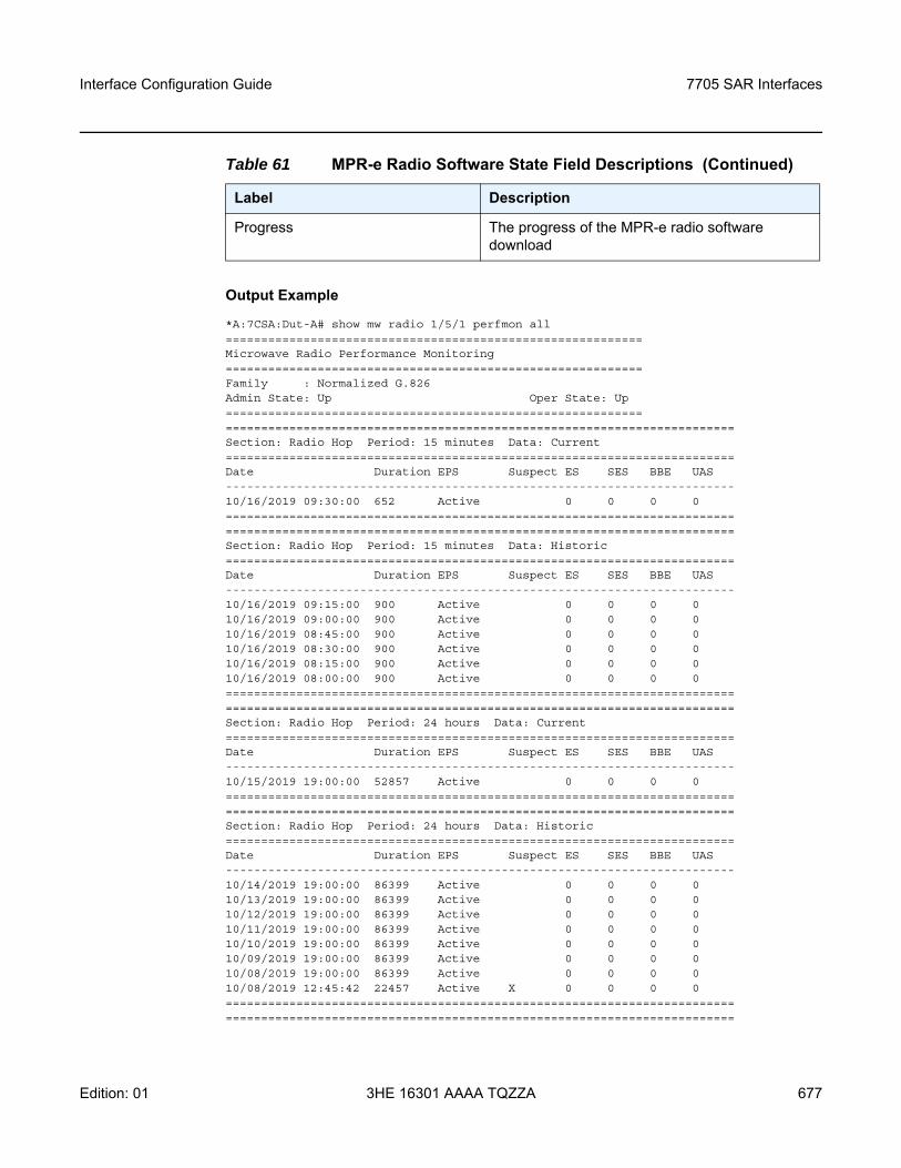
Interface Configuration Guide 7705 SAR Interfaces
Edition: 01 3HE 16301 AAAA TQZZA 677
Output Example
*A:7CSA:Dut-A# show mw radio 1/5/1 perfmon all===========================================================Microwave Radio Performance Monitoring===========================================================Family : Normalized G.826Admin State: Up Oper State: Up===================================================================================================================================Section: Radio Hop Period: 15 minutes Data: Current========================================================================Date Duration EPS Suspect ES SES BBE UAS------------------------------------------------------------------------10/16/2019 09:30:00 652 Active 0 0 0 0================================================================================================================================================Section: Radio Hop Period: 15 minutes Data: Historic========================================================================Date Duration EPS Suspect ES SES BBE UAS------------------------------------------------------------------------10/16/2019 09:15:00 900 Active 0 0 0 010/16/2019 09:00:00 900 Active 0 0 0 010/16/2019 08:45:00 900 Active 0 0 0 010/16/2019 08:30:00 900 Active 0 0 0 010/16/2019 08:15:00 900 Active 0 0 0 010/16/2019 08:00:00 900 Active 0 0 0 0================================================================================================================================================Section: Radio Hop Period: 24 hours Data: Current========================================================================Date Duration EPS Suspect ES SES BBE UAS------------------------------------------------------------------------10/15/2019 19:00:00 52857 Active 0 0 0 0================================================================================================================================================Section: Radio Hop Period: 24 hours Data: Historic========================================================================Date Duration EPS Suspect ES SES BBE UAS------------------------------------------------------------------------10/14/2019 19:00:00 86399 Active 0 0 0 010/13/2019 19:00:00 86399 Active 0 0 0 010/12/2019 19:00:00 86399 Active 0 0 0 010/11/2019 19:00:00 86399 Active 0 0 0 010/10/2019 19:00:00 86399 Active 0 0 0 010/09/2019 19:00:00 86399 Active 0 0 0 010/08/2019 19:00:00 86399 Active 0 0 0 010/08/2019 12:45:42 22457 Active X 0 0 0 0================================================================================================================================================
Progress The progress of the MPR-e radio software download
Table 61 MPR-e Radio Software State Field Descriptions (Continued)
Label Description
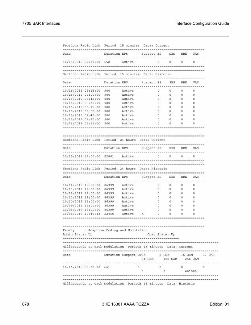
7705 SAR Interfaces
678
Interface Configuration Guide
3HE 16301 AAAA TQZZA Edition: 01
Section: Radio Link Period: 15 minutes Data: Current========================================================================Date Duration EPS Suspect ES SES BBE UAS------------------------------------------------------------------------10/16/2019 09:30:00 658 Active 0 0 0 0================================================================================================================================================Section: Radio Link Period: 15 minutes Data: Historic========================================================================Date Duration EPS Suspect ES SES BBE UAS------------------------------------------------------------------------10/16/2019 09:15:00 900 Active 0 0 0 010/16/2019 09:00:00 900 Active 0 0 0 010/16/2019 08:45:00 900 Active 0 0 0 010/16/2019 08:30:00 900 Active 0 0 0 010/16/2019 08:15:00 900 Active 0 0 0 010/16/2019 08:00:00 900 Active 0 0 0 010/16/2019 07:45:00 900 Active 0 0 0 010/16/2019 07:30:00 900 Active 0 0 0 010/16/2019 07:15:00 900 Active 0 0 0 0========================================================================
========================================================================Section: Radio Link Period: 24 hours Data: Current========================================================================Date Duration EPS Suspect ES SES BBE UAS------------------------------------------------------------------------10/15/2019 19:00:00 52861 Active 0 0 0 0================================================================================================================================================Section: Radio Link Period: 24 hours Data: Historic========================================================================Date Duration EPS Suspect ES SES BBE UAS------------------------------------------------------------------------10/14/2019 19:00:00 86399 Active 0 0 0 010/13/2019 19:00:00 86399 Active 0 0 0 010/12/2019 19:00:00 86399 Active 0 0 0 010/11/2019 19:00:00 86399 Active 0 0 0 010/10/2019 19:00:00 86399 Active 0 0 0 010/09/2019 19:00:00 86399 Active 0 0 0 010/08/2019 19:00:00 86399 Active 0 0 0 010/08/2019 12:45:43 22456 Active X 0 0 0 0========================================================================
========================================================================Family : Adaptive Coding and ModulationAdmin State: Up Oper State: Up==========================================================================================================================================Milliseconds at each modulation Period: 15 minutes Data: Current===============================================================================Date Duration Suspect QPSK 8 PSK 16 QAM 32 QAM
64 QAM 128 QAM 256 QAM-------------------------------------------------------------------------------10/16/2019 09:30:00 661 0 0 0 0
0 0 661009==============================================================================================================================================================Milliseconds at each modulation Period: 15 minutes Data: Historic
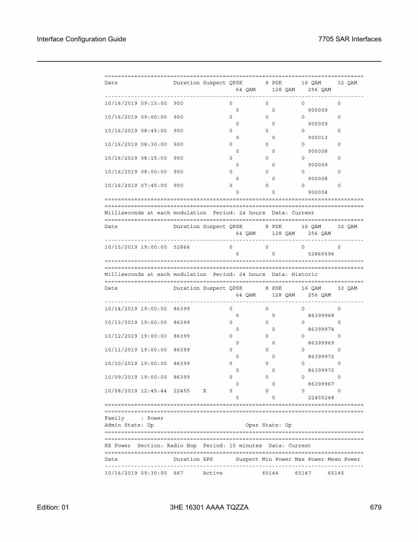
Interface Configuration Guide 7705 SAR Interfaces
Edition: 01 3HE 16301 AAAA TQZZA 679
===============================================================================Date Duration Suspect QPSK 8 PSK 16 QAM 32 QAM
64 QAM 128 QAM 256 QAM-------------------------------------------------------------------------------10/16/2019 09:15:00 900 0 0 0 0
0 0 90000910/16/2019 09:00:00 900 0 0 0 0
0 0 90000910/16/2019 08:45:00 900 0 0 0 0
0 0 90001310/16/2019 08:30:00 900 0 0 0 0
0 0 90000810/16/2019 08:15:00 900 0 0 0 0
0 0 90000910/16/2019 08:00:00 900 0 0 0 0
0 0 90000810/16/2019 07:45:00 900 0 0 0 0
0 0 900008==============================================================================================================================================================Milliseconds at each modulation Period: 24 hours Data: Current===============================================================================Date Duration Suspect QPSK 8 PSK 16 QAM 32 QAM
64 QAM 128 QAM 256 QAM-------------------------------------------------------------------------------10/15/2019 19:00:00 52866 0 0 0 0
0 0 52866596==============================================================================================================================================================Milliseconds at each modulation Period: 24 hours Data: Historic===============================================================================Date Duration Suspect QPSK 8 PSK 16 QAM 32 QAM
64 QAM 128 QAM 256 QAM-------------------------------------------------------------------------------10/14/2019 19:00:00 86399 0 0 0 0
0 0 8639996810/13/2019 19:00:00 86399 0 0 0 0
0 0 8639997410/12/2019 19:00:00 86399 0 0 0 0
0 0 8639996910/11/2019 19:00:00 86399 0 0 0 0
0 0 8639997210/10/2019 19:00:00 86399 0 0 0 0
0 0 8639997210/09/2019 19:00:00 86399 0 0 0 0
0 0 8639996710/08/2019 12:45:44 22455 X 0 0 0 0
0 0 22455248==============================================================================================================================================================Family : PowerAdmin State: Up Oper State: Up==============================================================================================================================================================RX Power Section: Radio Hop Period: 15 minutes Data: Current===============================================================================Date Duration EPS Suspect Min Power Max Power Mean Power-------------------------------------------------------------------------------10/16/2019 09:30:00 667 Active 65144 65147 65145
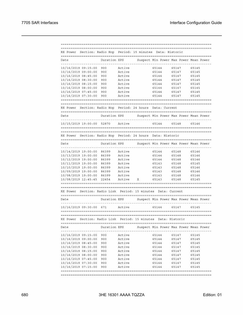
7705 SAR Interfaces
680
Interface Configuration Guide
3HE 16301 AAAA TQZZA Edition: 01
==============================================================================================================================================================RX Power Section: Radio Hop Period: 15 minutes Data: Historic===============================================================================Date Duration EPS Suspect Min Power Max Power Mean Power-------------------------------------------------------------------------------10/16/2019 09:15:00 900 Active 65144 65147 6514510/16/2019 09:00:00 900 Active 65144 65147 6514510/16/2019 08:45:00 900 Active 65144 65147 6514510/16/2019 08:30:00 900 Active 65144 65147 6514510/16/2019 08:15:00 900 Active 65144 65147 6514510/16/2019 08:00:00 900 Active 65144 65147 6514510/16/2019 07:45:00 900 Active 65144 65147 6514510/16/2019 07:30:00 900 Active 65144 65147 65145==============================================================================================================================================================RX Power Section: Radio Hop Period: 24 hours Data: Current===============================================================================Date Duration EPS Suspect Min Power Max Power Mean Power-------------------------------------------------------------------------------10/15/2019 19:00:00 52870 Active 65144 65148 65146==============================================================================================================================================================RX Power Section: Radio Hop Period: 24 hours Data: Historic===============================================================================Date Duration EPS Suspect Min Power Max Power Mean Power-------------------------------------------------------------------------------10/14/2019 19:00:00 86399 Active 65144 65148 6514610/13/2019 19:00:00 86399 Active 65144 65148 6514610/12/2019 19:00:00 86399 Active 65144 65148 6514610/11/2019 19:00:00 86399 Active 65143 65148 6514510/10/2019 19:00:00 86399 Active 65143 65148 6514610/09/2019 19:00:00 86399 Active 65143 65148 6514610/08/2019 19:00:00 86399 Active 65143 65148 6514610/08/2019 12:45:45 22454 Active X 65143 65148 65145==============================================================================================================================================================RX Power Section: Radio Link Period: 15 minutes Data: Current===============================================================================Date Duration EPS Suspect Min Power Max Power Mean Power-------------------------------------------------------------------------------10/16/2019 09:30:00 671 Active 65144 65147 65145==============================================================================================================================================================RX Power Section: Radio Link Period: 15 minutes Data: Historic===============================================================================Date Duration EPS Suspect Min Power Max Power Mean Power-------------------------------------------------------------------------------10/16/2019 09:15:00 900 Active 65144 65147 6514510/16/2019 09:00:00 900 Active 65144 65147 6514510/16/2019 08:45:00 900 Active 65144 65147 6514510/16/2019 08:30:00 900 Active 65144 65147 6514510/16/2019 08:15:00 900 Active 65144 65147 6514510/16/2019 08:00:00 900 Active 65144 65147 6514510/16/2019 07:45:00 900 Active 65144 65147 6514510/16/2019 07:30:00 900 Active 65144 65147 6514510/16/2019 07:15:00 900 Active 65144 65147 65145==============================================================================================================================================================
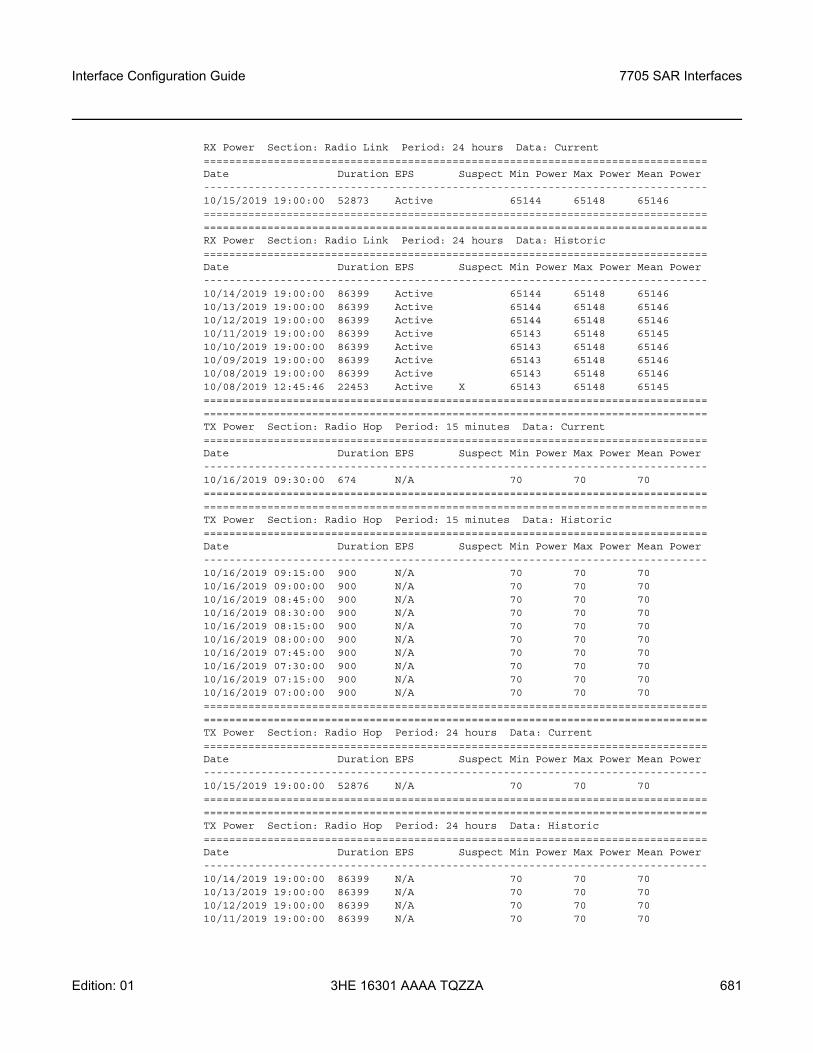
Interface Configuration Guide 7705 SAR Interfaces
Edition: 01 3HE 16301 AAAA TQZZA 681
RX Power Section: Radio Link Period: 24 hours Data: Current===============================================================================Date Duration EPS Suspect Min Power Max Power Mean Power-------------------------------------------------------------------------------10/15/2019 19:00:00 52873 Active 65144 65148 65146==============================================================================================================================================================RX Power Section: Radio Link Period: 24 hours Data: Historic===============================================================================Date Duration EPS Suspect Min Power Max Power Mean Power-------------------------------------------------------------------------------10/14/2019 19:00:00 86399 Active 65144 65148 6514610/13/2019 19:00:00 86399 Active 65144 65148 6514610/12/2019 19:00:00 86399 Active 65144 65148 6514610/11/2019 19:00:00 86399 Active 65143 65148 6514510/10/2019 19:00:00 86399 Active 65143 65148 6514610/09/2019 19:00:00 86399 Active 65143 65148 6514610/08/2019 19:00:00 86399 Active 65143 65148 6514610/08/2019 12:45:46 22453 Active X 65143 65148 65145==============================================================================================================================================================TX Power Section: Radio Hop Period: 15 minutes Data: Current===============================================================================Date Duration EPS Suspect Min Power Max Power Mean Power-------------------------------------------------------------------------------10/16/2019 09:30:00 674 N/A 70 70 70==============================================================================================================================================================TX Power Section: Radio Hop Period: 15 minutes Data: Historic===============================================================================Date Duration EPS Suspect Min Power Max Power Mean Power-------------------------------------------------------------------------------10/16/2019 09:15:00 900 N/A 70 70 7010/16/2019 09:00:00 900 N/A 70 70 7010/16/2019 08:45:00 900 N/A 70 70 7010/16/2019 08:30:00 900 N/A 70 70 7010/16/2019 08:15:00 900 N/A 70 70 7010/16/2019 08:00:00 900 N/A 70 70 7010/16/2019 07:45:00 900 N/A 70 70 7010/16/2019 07:30:00 900 N/A 70 70 7010/16/2019 07:15:00 900 N/A 70 70 7010/16/2019 07:00:00 900 N/A 70 70 70==============================================================================================================================================================TX Power Section: Radio Hop Period: 24 hours Data: Current===============================================================================Date Duration EPS Suspect Min Power Max Power Mean Power-------------------------------------------------------------------------------10/15/2019 19:00:00 52876 N/A 70 70 70==============================================================================================================================================================TX Power Section: Radio Hop Period: 24 hours Data: Historic===============================================================================Date Duration EPS Suspect Min Power Max Power Mean Power-------------------------------------------------------------------------------10/14/2019 19:00:00 86399 N/A 70 70 7010/13/2019 19:00:00 86399 N/A 70 70 7010/12/2019 19:00:00 86399 N/A 70 70 7010/11/2019 19:00:00 86399 N/A 70 70 70
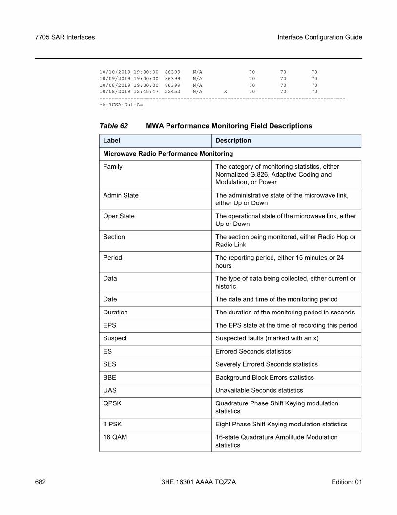
7705 SAR Interfaces
682
Interface Configuration Guide
3HE 16301 AAAA TQZZA Edition: 01
10/10/2019 19:00:00 86399 N/A 70 70 7010/09/2019 19:00:00 86399 N/A 70 70 7010/08/2019 19:00:00 86399 N/A 70 70 7010/08/2019 12:45:47 22452 N/A X 70 70 70===============================================================================*A:7CSA:Dut-A#
Table 62 MWA Performance Monitoring Field Descriptions
Label Description
Microwave Radio Performance Monitoring
Family The category of monitoring statistics, either Normalized G.826, Adaptive Coding and Modulation, or Power
Admin State The administrative state of the microwave link, either Up or Down
Oper State The operational state of the microwave link, either Up or Down
Section The section being monitored, either Radio Hop or Radio Link
Period The reporting period, either 15 minutes or 24 hours
Data The type of data being collected, either current or historic
Date The date and time of the monitoring period
Duration The duration of the monitoring period in seconds
EPS The EPS state at the time of recording this period
Suspect Suspected faults (marked with an x)
ES Errored Seconds statistics
SES Severely Errored Seconds statistics
BBE Background Block Errors statistics
UAS Unavailable Seconds statistics
QPSK Quadrature Phase Shift Keying modulation statistics
8 PSK Eight Phase Shift Keying modulation statistics
16 QAM 16-state Quadrature Amplitude Modulation statistics
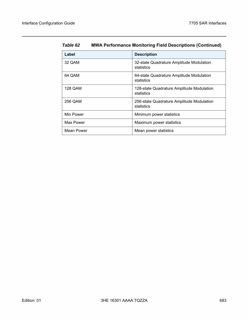
Interface Configuration Guide 7705 SAR Interfaces
Edition: 01 3HE 16301 AAAA TQZZA 683
32 QAM 32-state Quadrature Amplitude Modulation statistics
64 QAM 64-state Quadrature Amplitude Modulation statistics
128 QAM 128-state Quadrature Amplitude Modulation statistics
256 QAM 256-state Quadrature Amplitude Modulation statistics
Min Power Minimum power statistics
Max Power Maximum power statistics
Mean Power Mean power statistics
Table 62 MWA Performance Monitoring Field Descriptions (Continued)
Label Description
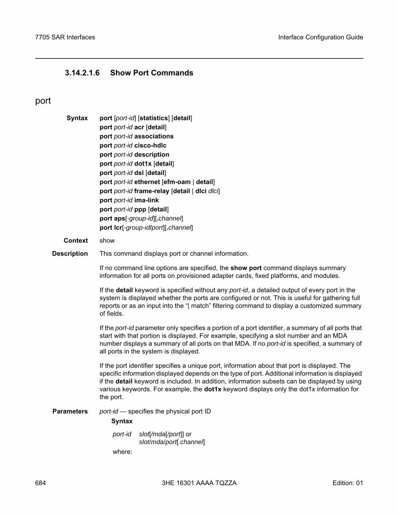
7705 SAR Interfaces
684
Interface Configuration Guide
3HE 16301 AAAA TQZZA Edition: 01
3.14.2.1.6 Show Port Commands
port
Syntax port [port-id] [statistics] [detail]port port-id acr [detail]port port-id associationsport port-id cisco-hdlcport port-id descriptionport port-id dot1x [detail]port port-id dsl [detail]port port-id ethernet [efm-oam | detail]port port-id frame-relay [detail | dlci dlci]port port-id ima-link port port-id ppp [detail]port aps[-group-id][.channel]port lcr[-group-id/port][.channel]
Context show
Description This command displays port or channel information.
If no command line options are specified, the show port command displays summary information for all ports on provisioned adapter cards, fixed platforms, and modules.
If the detail keyword is specified without any port-id, a detailed output of every port in the system is displayed whether the ports are configured or not. This is useful for gathering full reports or as an input into the “| match” filtering command to display a customized summary of fields.
If the port-id parameter only specifies a portion of a port identifier, a summary of all ports that start with that portion is displayed. For example, specifying a slot number and an MDA number displays a summary of all ports on that MDA. If no port-id is specified, a summary of all ports in the system is displayed.
If the port identifier specifies a unique port, information about that port is displayed. The specific information displayed depends on the type of port. Additional information is displayed if the detail keyword is included. In addition, information subsets can be displayed by using various keywords. For example, the dot1x keyword displays only the dot1x information for the port.
Parameters port-id — specifies the physical port IDSyntax
port-id slot[/mda[/port]] or slot/mda/port[.channel]
where:
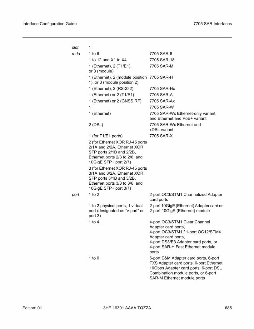
Interface Configuration Guide 7705 SAR Interfaces
Edition: 01 3HE 16301 AAAA TQZZA 685
slot 1mda 1 to 6 7705 SAR-8
1 to 12 and X1 to X4 7705 SAR-181 (Ethernet), 2 (T1/E1), or 3 (module)
7705 SAR-M
1 (Ethernet), 2 (module position 1), or 3 (module position 2)
7705 SAR-H
1 (Ethernet), 2 (RS-232) 7705 SAR-Hc1 (Ethernet) or 2 (T1/E1) 7705 SAR-A1 (Ethernet) or 2 (GNSS RF) 7705 SAR-Ax1 7705 SAR-W1 (Ethernet) 7705 SAR-Wx Ethernet-only variant,
and Ethernet and PoE+ variant2 (DSL) 7705 SAR-Wx Ethernet and
xDSL variant1 (for T1/E1 ports)2 (for Ethernet XOR RJ-45 ports 2/1A and 2/2A, Ethernet XOR SFP ports 2/1B and 2/2B, Ethernet ports 2/3 to 2/6, and 10GigE SFP+ port 2/7)3 (for Ethernet XOR RJ-45 ports 3/1A and 3/2A, Ethernet XOR SFP ports 3/1B and 3/2B, Ethernet ports 3/3 to 3/6, and 10GigE SFP+ port 3/7)
7705 SAR-X
port 1 to 2 2-port OC3/STM1 Channelized Adapter card ports
1 to 2 physical ports, 1 virtual port (designated as “v-port” or port 3)
2-port 10GigE (Ethernet) Adapter card or 2-port 10GigE (Ethernet) module
1 to 4 4-port OC3/STM1 Clear Channel Adapter card ports, 4-port OC3/STM1 / 1-port OC12/STM4 Adapter card ports, 4-port DS3/E3 Adapter card ports, or 4-port SAR-H Fast Ethernet module ports
1 to 6 6-port E&M Adapter card ports, 6-port FXS Adapter card ports, 6-port Ethernet 10Gbps Adapter card ports, 6-port DSL Combination module ports, or 6-port SAR-M Ethernet module ports
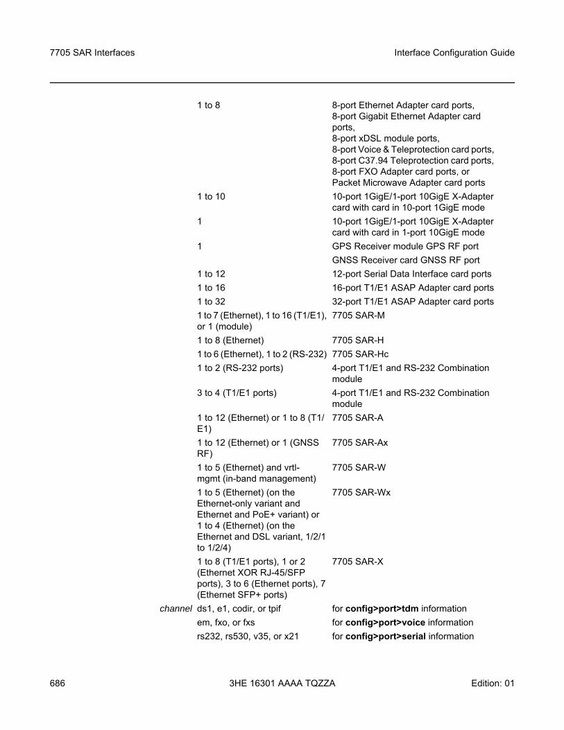
7705 SAR Interfaces
686
Interface Configuration Guide
3HE 16301 AAAA TQZZA Edition: 01
1 to 8 8-port Ethernet Adapter card ports, 8-port Gigabit Ethernet Adapter card ports, 8-port xDSL module ports, 8-port Voice & Teleprotection card ports, 8-port C37.94 Teleprotection card ports, 8-port FXO Adapter card ports, or Packet Microwave Adapter card ports
1 to 10 10-port 1GigE/1-port 10GigE X-Adapter card with card in 10-port 1GigE mode
1 10-port 1GigE/1-port 10GigE X-Adapter card with card in 1-port 10GigE mode
1 GPS Receiver module GPS RF portGNSS Receiver card GNSS RF port
1 to 12 12-port Serial Data Interface card ports1 to 16 16-port T1/E1 ASAP Adapter card ports1 to 32 32-port T1/E1 ASAP Adapter card ports1 to 7 (Ethernet), 1 to 16 (T1/E1), or 1 (module)
7705 SAR-M
1 to 8 (Ethernet) 7705 SAR-H1 to 6 (Ethernet), 1 to 2 (RS-232) 7705 SAR-Hc1 to 2 (RS-232 ports) 4-port T1/E1 and RS-232 Combination
module3 to 4 (T1/E1 ports) 4-port T1/E1 and RS-232 Combination
module1 to 12 (Ethernet) or 1 to 8 (T1/E1)
7705 SAR-A
1 to 12 (Ethernet) or 1 (GNSS RF)
7705 SAR-Ax
1 to 5 (Ethernet) and vrtl-mgmt (in-band management)
7705 SAR-W
1 to 5 (Ethernet) (on the Ethernet-only variant and Ethernet and PoE+ variant) or 1 to 4 (Ethernet) (on the Ethernet and DSL variant, 1/2/1 to 1/2/4)
7705 SAR-Wx
1 to 8 (T1/E1 ports), 1 or 2 (Ethernet XOR RJ-45/SFP ports), 3 to 6 (Ethernet ports), 7 (Ethernet SFP+ ports)
7705 SAR-X
channel ds1, e1, codir, or tpif for config>port>tdm informationem, fxo, or fxs for config>port>voice informationrs232, rs530, v35, or x21 for config>port>serial information
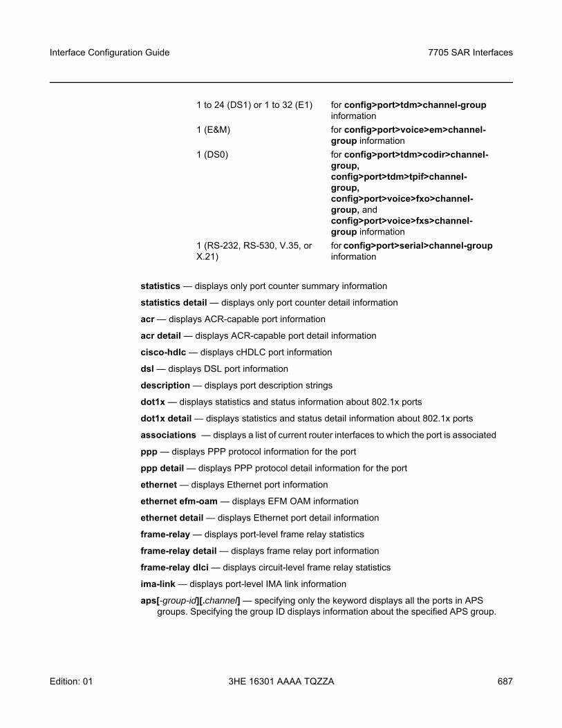
Interface Configuration Guide 7705 SAR Interfaces
Edition: 01 3HE 16301 AAAA TQZZA 687
statistics — displays only port counter summary information
statistics detail — displays only port counter detail information
acr — displays ACR-capable port information
acr detail — displays ACR-capable port detail information
cisco-hdlc — displays cHDLC port information
dsl — displays DSL port information
description — displays port description strings
dot1x — displays statistics and status information about 802.1x ports
dot1x detail — displays statistics and status detail information about 802.1x ports
associations — displays a list of current router interfaces to which the port is associated
ppp — displays PPP protocol information for the port
ppp detail — displays PPP protocol detail information for the port
ethernet — displays Ethernet port information
ethernet efm-oam — displays EFM OAM information
ethernet detail — displays Ethernet port detail information
frame-relay — displays port-level frame relay statistics
frame-relay detail — displays frame relay port information
frame-relay dlci — displays circuit-level frame relay statistics
ima-link — displays port-level IMA link information
aps[-group-id][.channel] — specifying only the keyword displays all the ports in APS groups. Specifying the group ID displays information about the specified APS group.
1 to 24 (DS1) or 1 to 32 (E1) for config>port>tdm>channel-group information
1 (E&M) for config>port>voice>em>channel-group information
1 (DS0) for config>port>tdm>codir>channel-group, config>port>tdm>tpif>channel-group, config>port>voice>fxo>channel-group, and config>port>voice>fxs>channel-group information
1 (RS-232, RS-530, V.35, or X.21)
for config>port>serial>channel-group information
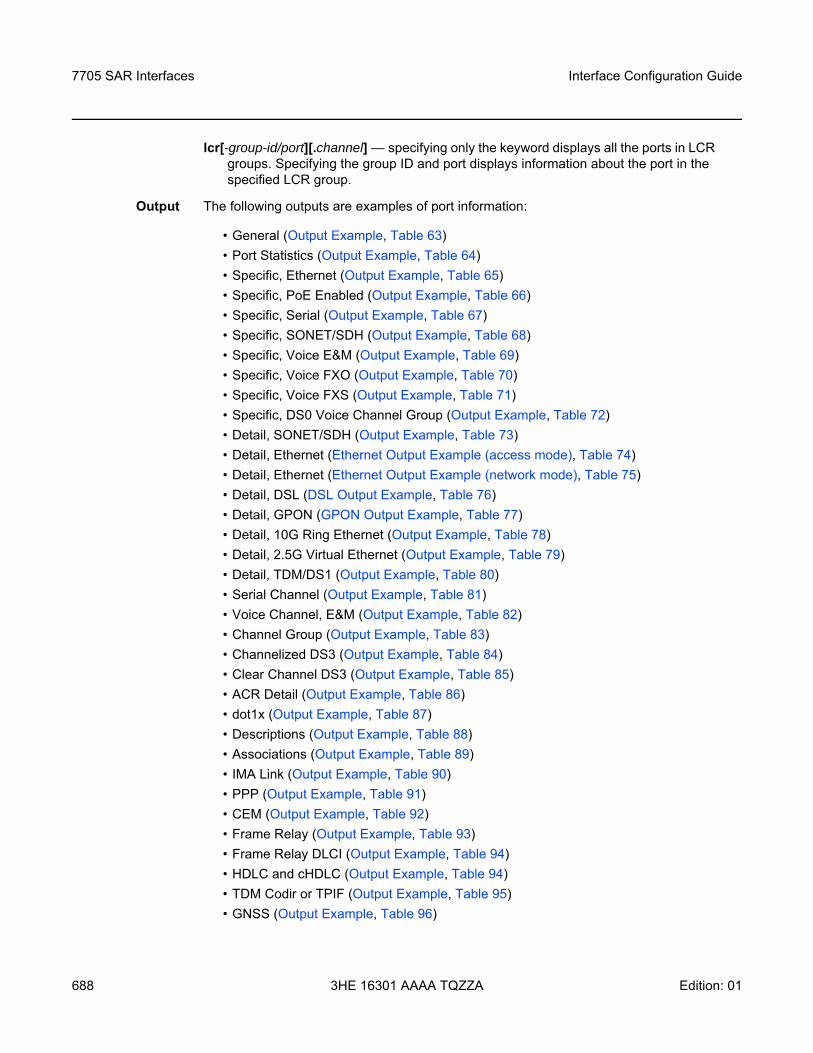
7705 SAR Interfaces
688
Interface Configuration Guide
3HE 16301 AAAA TQZZA Edition: 01
lcr[-group-id/port][.channel] — specifying only the keyword displays all the ports in LCR groups. Specifying the group ID and port displays information about the port in the specified LCR group.
Output The following outputs are examples of port information:
• General (Output Example, Table 63)• Port Statistics (Output Example, Table 64)• Specific, Ethernet (Output Example, Table 65) • Specific, PoE Enabled (Output Example, Table 66)• Specific, Serial (Output Example, Table 67)• Specific, SONET/SDH (Output Example, Table 68)• Specific, Voice E&M (Output Example, Table 69) • Specific, Voice FXO (Output Example, Table 70)• Specific, Voice FXS (Output Example, Table 71)• Specific, DS0 Voice Channel Group (Output Example, Table 72)• Detail, SONET/SDH (Output Example, Table 73)• Detail, Ethernet (Ethernet Output Example (access mode), Table 74) • Detail, Ethernet (Ethernet Output Example (network mode), Table 75) • Detail, DSL (DSL Output Example, Table 76)• Detail, GPON (GPON Output Example, Table 77)• Detail, 10G Ring Ethernet (Output Example, Table 78)• Detail, 2.5G Virtual Ethernet (Output Example, Table 79)• Detail, TDM/DS1 (Output Example, Table 80)• Serial Channel (Output Example, Table 81) • Voice Channel, E&M (Output Example, Table 82) • Channel Group (Output Example, Table 83)• Channelized DS3 (Output Example, Table 84)• Clear Channel DS3 (Output Example, Table 85)• ACR Detail (Output Example, Table 86)• dot1x (Output Example, Table 87)• Descriptions (Output Example, Table 88)• Associations (Output Example, Table 89)• IMA Link (Output Example, Table 90)• PPP (Output Example, Table 91)• CEM (Output Example, Table 92)• Frame Relay (Output Example, Table 93)• Frame Relay DLCI (Output Example, Table 94)• HDLC and cHDLC (Output Example, Table 94)• TDM Codir or TPIF (Output Example, Table 95)• GNSS (Output Example, Table 96)
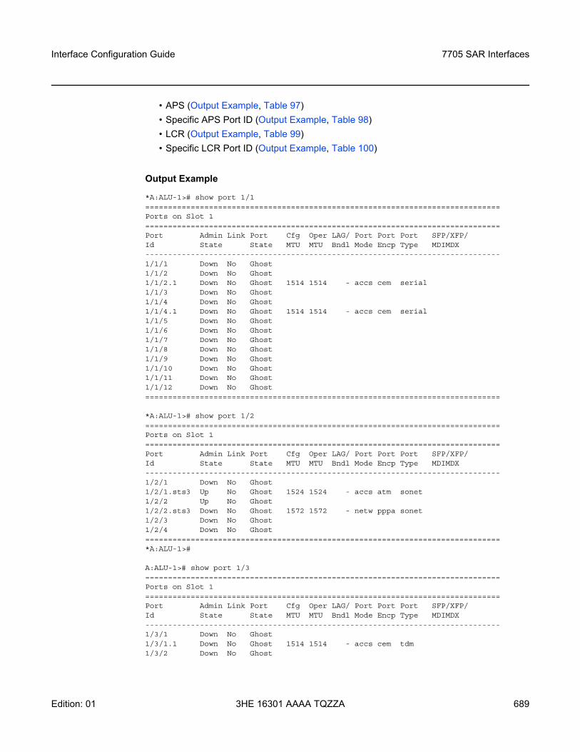
Interface Configuration Guide 7705 SAR Interfaces
Edition: 01 3HE 16301 AAAA TQZZA 689
• APS (Output Example, Table 97) • Specific APS Port ID (Output Example, Table 98) • LCR (Output Example, Table 99) • Specific LCR Port ID (Output Example, Table 100)
Output Example
*A:ALU-1># show port 1/1==============================================================================Ports on Slot 1==============================================================================Port Admin Link Port Cfg Oper LAG/ Port Port Port SFP/XFP/Id State State MTU MTU Bndl Mode Encp Type MDIMDX------------------------------------------------------------------------------1/1/1 Down No Ghost1/1/2 Down No Ghost1/1/2.1 Down No Ghost 1514 1514 - accs cem serial1/1/3 Down No Ghost1/1/4 Down No Ghost1/1/4.1 Down No Ghost 1514 1514 - accs cem serial1/1/5 Down No Ghost1/1/6 Down No Ghost1/1/7 Down No Ghost1/1/8 Down No Ghost1/1/9 Down No Ghost1/1/10 Down No Ghost1/1/11 Down No Ghost1/1/12 Down No Ghost==============================================================================
*A:ALU-1># show port 1/2==============================================================================Ports on Slot 1==============================================================================Port Admin Link Port Cfg Oper LAG/ Port Port Port SFP/XFP/Id State State MTU MTU Bndl Mode Encp Type MDIMDX------------------------------------------------------------------------------1/2/1 Down No Ghost1/2/1.sts3 Up No Ghost 1524 1524 - accs atm sonet1/2/2 Up No Ghost1/2/2.sts3 Down No Ghost 1572 1572 - netw pppa sonet1/2/3 Down No Ghost1/2/4 Down No Ghost==============================================================================*A:ALU-1>#
A:ALU-1># show port 1/3==============================================================================Ports on Slot 1==============================================================================Port Admin Link Port Cfg Oper LAG/ Port Port Port SFP/XFP/Id State State MTU MTU Bndl Mode Encp Type MDIMDX------------------------------------------------------------------------------1/3/1 Down No Ghost1/3/1.1 Down No Ghost 1514 1514 - accs cem tdm1/3/2 Down No Ghost
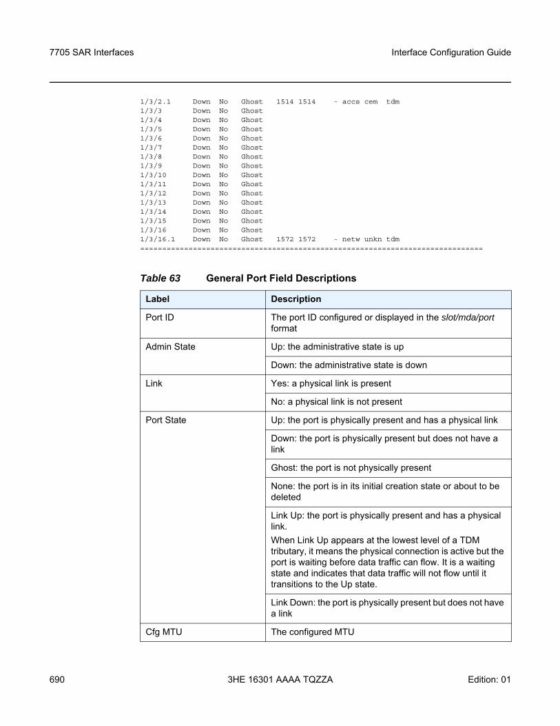
7705 SAR Interfaces
690
Interface Configuration Guide
3HE 16301 AAAA TQZZA Edition: 01
1/3/2.1 Down No Ghost 1514 1514 - accs cem tdm1/3/3 Down No Ghost1/3/4 Down No Ghost1/3/5 Down No Ghost1/3/6 Down No Ghost1/3/7 Down No Ghost1/3/8 Down No Ghost1/3/9 Down No Ghost1/3/10 Down No Ghost1/3/11 Down No Ghost1/3/12 Down No Ghost1/3/13 Down No Ghost1/3/14 Down No Ghost1/3/15 Down No Ghost1/3/16 Down No Ghost1/3/16.1 Down No Ghost 1572 1572 - netw unkn tdm==============================================================================
Table 63 General Port Field Descriptions
Label Description
Port ID The port ID configured or displayed in the slot/mda/port format
Admin State Up: the administrative state is up
Down: the administrative state is down
Link Yes: a physical link is present
No: a physical link is not present
Port State Up: the port is physically present and has a physical link
Down: the port is physically present but does not have a link
Ghost: the port is not physically present
None: the port is in its initial creation state or about to be deleted
Link Up: the port is physically present and has a physical link.When Link Up appears at the lowest level of a TDM tributary, it means the physical connection is active but the port is waiting before data traffic can flow. It is a waiting state and indicates that data traffic will not flow until it transitions to the Up state.
Link Down: the port is physically present but does not have a link
Cfg MTU The configured MTU
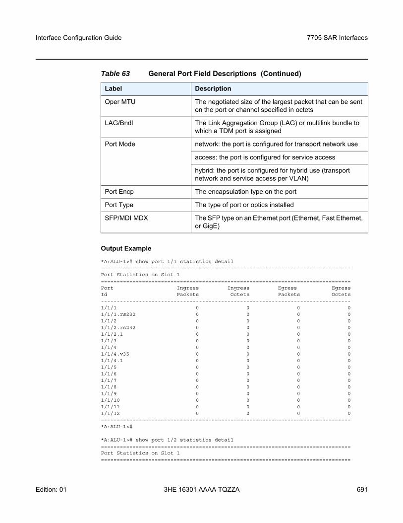
Interface Configuration Guide 7705 SAR Interfaces
Edition: 01 3HE 16301 AAAA TQZZA 691
Output Example
*A:ALU-1># show port 1/1 statistics detail===============================================================================Port Statistics on Slot 1===============================================================================Port Ingress Ingress Egress EgressId Packets Octets Packets Octets-------------------------------------------------------------------------------1/1/1 0 0 0 01/1/1.rs232 0 0 0 01/1/2 0 0 0 01/1/2.rs232 0 0 0 01/1/2.1 0 0 0 01/1/3 0 0 0 01/1/4 0 0 0 01/1/4.v35 0 0 0 01/1/4.1 0 0 0 01/1/5 0 0 0 01/1/6 0 0 0 01/1/7 0 0 0 01/1/8 0 0 0 01/1/9 0 0 0 01/1/10 0 0 0 01/1/11 0 0 0 01/1/12 0 0 0 0===============================================================================*A:ALU-1>#
*A:ALU-1># show port 1/2 statistics detail===============================================================================Port Statistics on Slot 1===============================================================================
Oper MTU The negotiated size of the largest packet that can be sent on the port or channel specified in octets
LAG/Bndl The Link Aggregation Group (LAG) or multilink bundle to which a TDM port is assigned
Port Mode network: the port is configured for transport network use
access: the port is configured for service access
hybrid: the port is configured for hybrid use (transport network and service access per VLAN)
Port Encp The encapsulation type on the port
Port Type The type of port or optics installed
SFP/MDI MDX The SFP type on an Ethernet port (Ethernet, Fast Ethernet, or GigE)
Table 63 General Port Field Descriptions (Continued)
Label Description
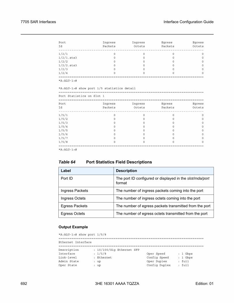
7705 SAR Interfaces
692
Interface Configuration Guide
3HE 16301 AAAA TQZZA Edition: 01
Port Ingress Ingress Egress EgressId Packets Octets Packets Octets-------------------------------------------------------------------------------1/2/1 0 0 0 01/2/1.sts3 0 0 0 01/2/2 0 0 0 01/2/2.sts3 0 0 0 01/2/3 0 0 0 01/2/4 0 0 0 0===============================================================================*A:ALU-1>#
*A:ALU-1># show port 1/5 statistics detail===============================================================================Port Statistics on Slot 1===============================================================================Port Ingress Ingress Egress EgressId Packets Octets Packets Octets-------------------------------------------------------------------------------1/5/1 0 0 0 01/5/2 0 0 0 01/5/3 0 0 0 01/5/4 0 0 0 01/5/5 0 0 0 01/5/6 0 0 0 01/5/7 0 0 0 01/5/8 0 0 0 0===============================================================================*A:ALU-1>#
Output Example
*A:ALU-1># show port 1/5/8===============================================================================Ethernet Interface===============================================================================Description : 10/100/Gig Ethernet SFPInterface : 1/5/8 Oper Speed : 1 GbpsLink-level : Ethernet Config Speed : 1 GbpsAdmin State : up Oper Duplex : fullOper State : up Config Duplex : full
Table 64 Port Statistics Field Descriptions
Label Description
Port ID The port ID configured or displayed in the slot/mda/port format
Ingress Packets The number of ingress packets coming into the port
Ingress Octets The number of ingress octets coming into the port
Egress Packets The number of egress packets transmitted from the port
Egress Octets The number of egress octets transmitted from the port
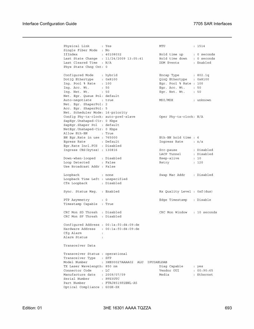
Interface Configuration Guide 7705 SAR Interfaces
Edition: 01 3HE 16301 AAAA TQZZA 693
Physical Link : Yes MTU : 1514Single Fiber Mode : NoIfIndex : 40108032 Hold time up : 0 secondsLast State Change : 11/24/2009 13:05:41 Hold time down : 0 secondsLast Cleared Time : N/A DDM Events : EnabledPhys State Chng Cnt: 0
Configured Mode : hybrid Encap Type : 802.1qDot1Q Ethertype : 0x8100 QinQ Ethertype : 0x8100Ing. Pool % Rate : 100 Egr. Pool % Rate : 100Ing. Acc. Wt. : 50 Egr. Acc. Wt. : 50Ing. Net. Wt. : 50 Egr. Net. Wt. : 50Net. Egr. Queue Pol: defaultAuto-negotiate : true MDI/MDX : unknownNet. Egr. ShaperPol: 2Acc. Egr. ShaperPol: 5Net. Scheduler Mode: 16-priorityConfig Phy-tx-clock: auto-pref-slave Oper Phy-tx-clock: N/ASapEgr.Unshaped-Cir: 0 KbpsSapEgr.Shaper Pol : defaultNetEgr.Unshaped-Cir: 0 KbpsAllow Eth-BN : TrueBN Egr.Rate in use : 765000 Eth-BN hold time : 6Egress Rate : Default Ingress Rate : n/aEgr.Rate Incl.FCS : DisabledIngress CBS(bytes) : 130816 Src-pause : Disabled
LACP Tunnel : DisabledDown-when-looped : Disabled Keep-alive : 10Loop Detected : False Retry : 120Use Broadcast Addr : False
Loopback : none Swap Mac Addr : DisabledLoopback Time Left : unspecifiedCfm Loopback : Disabled
Sync. Status Msg. : Enabled Rx Quality Level : 0xf(dus)
PTP Asymmetry : 0 Edge Timestamp : DisableTimestamp Capable : True
CRC Mon SD Thresh : Disabled CRC Mon Window : 10 secondsCRC Mon SF Thresh : Disabled
Configured Address : 00:1a:f0:d4:09:deHardware Address : 00:1a:f0:d4:09:deCfg Alarm :Alarm Status :
Transceiver Data
Transceiver Status : operationalTransceiver Type : SFPModel Number : 3HE00027AAAA02 ALU IPUIAELDABTX Laser Wavelength: 850 nm Diag Capable : yesConnector Code : LC Vendor OUI : 00:90:65Manufacture date : 2009/07/09 Media : EthernetSerial Number : PFS3UTCPart Number : FTRJ8519P2BNL-A5Optical Compliance : GIGE-SX
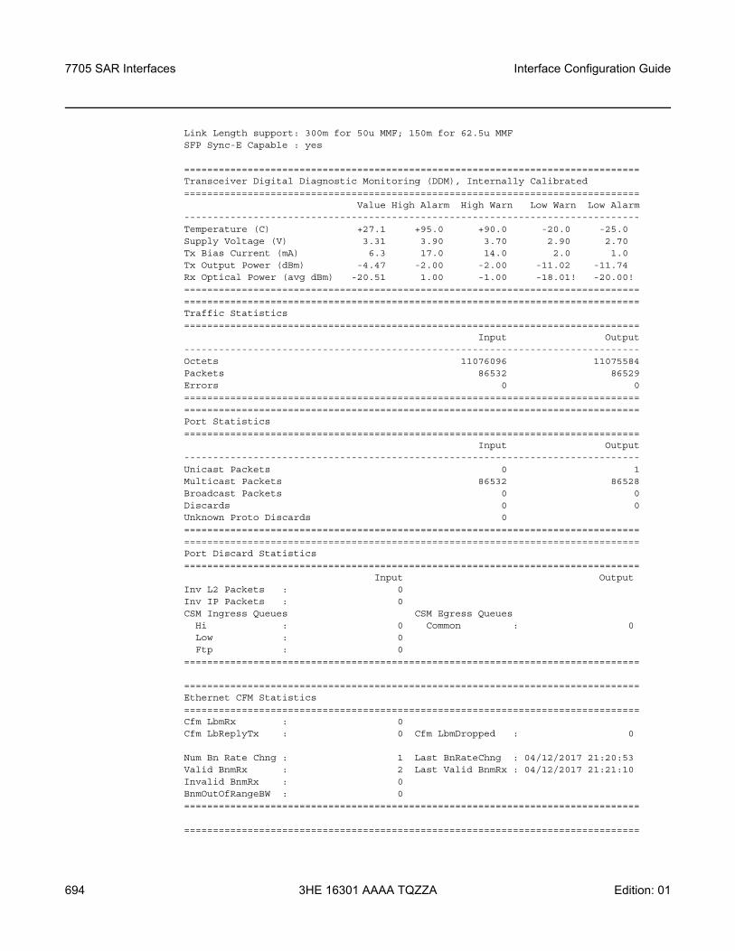
7705 SAR Interfaces
694
Interface Configuration Guide
3HE 16301 AAAA TQZZA Edition: 01
Link Length support: 300m for 50u MMF; 150m for 62.5u MMFSFP Sync-E Capable : yes
===============================================================================Transceiver Digital Diagnostic Monitoring (DDM), Internally Calibrated===============================================================================
Value High Alarm High Warn Low Warn Low Alarm-------------------------------------------------------------------------------Temperature (C) +27.1 +95.0 +90.0 -20.0 -25.0Supply Voltage (V) 3.31 3.90 3.70 2.90 2.70Tx Bias Current (mA) 6.3 17.0 14.0 2.0 1.0Tx Output Power (dBm) -4.47 -2.00 -2.00 -11.02 -11.74Rx Optical Power (avg dBm) -20.51 1.00 -1.00 -18.01! -20.00!==============================================================================================================================================================Traffic Statistics===============================================================================
Input Output-------------------------------------------------------------------------------Octets 11076096 11075584Packets 86532 86529Errors 0 0==============================================================================================================================================================Port Statistics===============================================================================
Input Output-------------------------------------------------------------------------------Unicast Packets 0 1Multicast Packets 86532 86528Broadcast Packets 0 0Discards 0 0Unknown Proto Discards 0==============================================================================================================================================================Port Discard Statistics===============================================================================
Input OutputInv L2 Packets : 0Inv IP Packets : 0CSM Ingress Queues CSM Egress Queues
Hi : 0 Common : 0Low : 0Ftp : 0
===============================================================================
===============================================================================Ethernet CFM Statistics===============================================================================Cfm LbmRx : 0Cfm LbReplyTx : 0 Cfm LbmDropped : 0
Num Bn Rate Chng : 1 Last BnRateChng : 04/12/2017 21:20:53Valid BnmRx : 2 Last Valid BnmRx : 04/12/2017 21:21:10Invalid BnmRx : 0BnmOutOfRangeBW : 0===============================================================================
===============================================================================
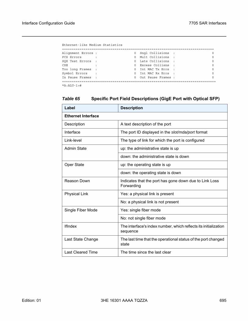
Interface Configuration Guide 7705 SAR Interfaces
Edition: 01 3HE 16301 AAAA TQZZA 695
Ethernet-like Medium Statistics==============================================================================Alignment Errors : 0 Sngl Collisions : 0FCS Errors : 0 Mult Collisions : 0SQE Test Errors : 0 Late Collisions : 0CSE : 0 Excess Collisns : 0Too long Frames : 0 Int MAC Tx Errs : 0Symbol Errors : 0 Int MAC Rx Errs : 0In Pause Frames : 0 Out Pause Frames : 0===============================================================================*A:ALU-1>#
Table 65 Specific Port Field Descriptions (GigE Port with Optical SFP)
Label Description
Ethernet Interface
Description A text description of the port
Interface The port ID displayed in the slot/mda/port format
Link-level The type of link for which the port is configured
Admin State up: the administrative state is up
down: the administrative state is down
Oper State up: the operating state is up
down: the operating state is down
Reason Down Indicates that the port has gone down due to Link Loss Forwarding
Physical Link Yes: a physical link is present
No: a physical link is not present
Single Fiber Mode Yes: single fiber mode
No: not single fiber mode
IfIndex The interface's index number, which reflects its initialization sequence
Last State Change The last time that the operational status of the port changed state
Last Cleared Time The time since the last clear
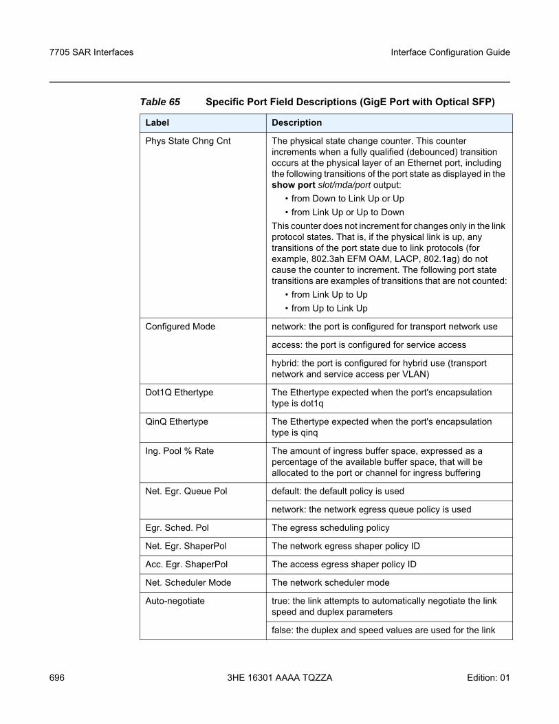
7705 SAR Interfaces
696
Interface Configuration Guide
3HE 16301 AAAA TQZZA Edition: 01
Phys State Chng Cnt The physical state change counter. This counter increments when a fully qualified (debounced) transition occurs at the physical layer of an Ethernet port, including the following transitions of the port state as displayed in the show port slot/mda/port output:
• from Down to Link Up or Up• from Link Up or Up to Down
This counter does not increment for changes only in the link protocol states. That is, if the physical link is up, any transitions of the port state due to link protocols (for example, 802.3ah EFM OAM, LACP, 802.1ag) do not cause the counter to increment. The following port state transitions are examples of transitions that are not counted:
• from Link Up to Up• from Up to Link Up
Configured Mode network: the port is configured for transport network use
access: the port is configured for service access
hybrid: the port is configured for hybrid use (transport network and service access per VLAN)
Dot1Q Ethertype The Ethertype expected when the port's encapsulation type is dot1q
QinQ Ethertype The Ethertype expected when the port's encapsulation type is qinq
Ing. Pool % Rate The amount of ingress buffer space, expressed as a percentage of the available buffer space, that will be allocated to the port or channel for ingress buffering
Net. Egr. Queue Pol default: the default policy is used
network: the network egress queue policy is used
Egr. Sched. Pol The egress scheduling policy
Net. Egr. ShaperPol The network egress shaper policy ID
Acc. Egr. ShaperPol The access egress shaper policy ID
Net. Scheduler Mode The network scheduler mode
Auto-negotiate true: the link attempts to automatically negotiate the link speed and duplex parameters
false: the duplex and speed values are used for the link
Table 65 Specific Port Field Descriptions (GigE Port with Optical SFP)
Label Description
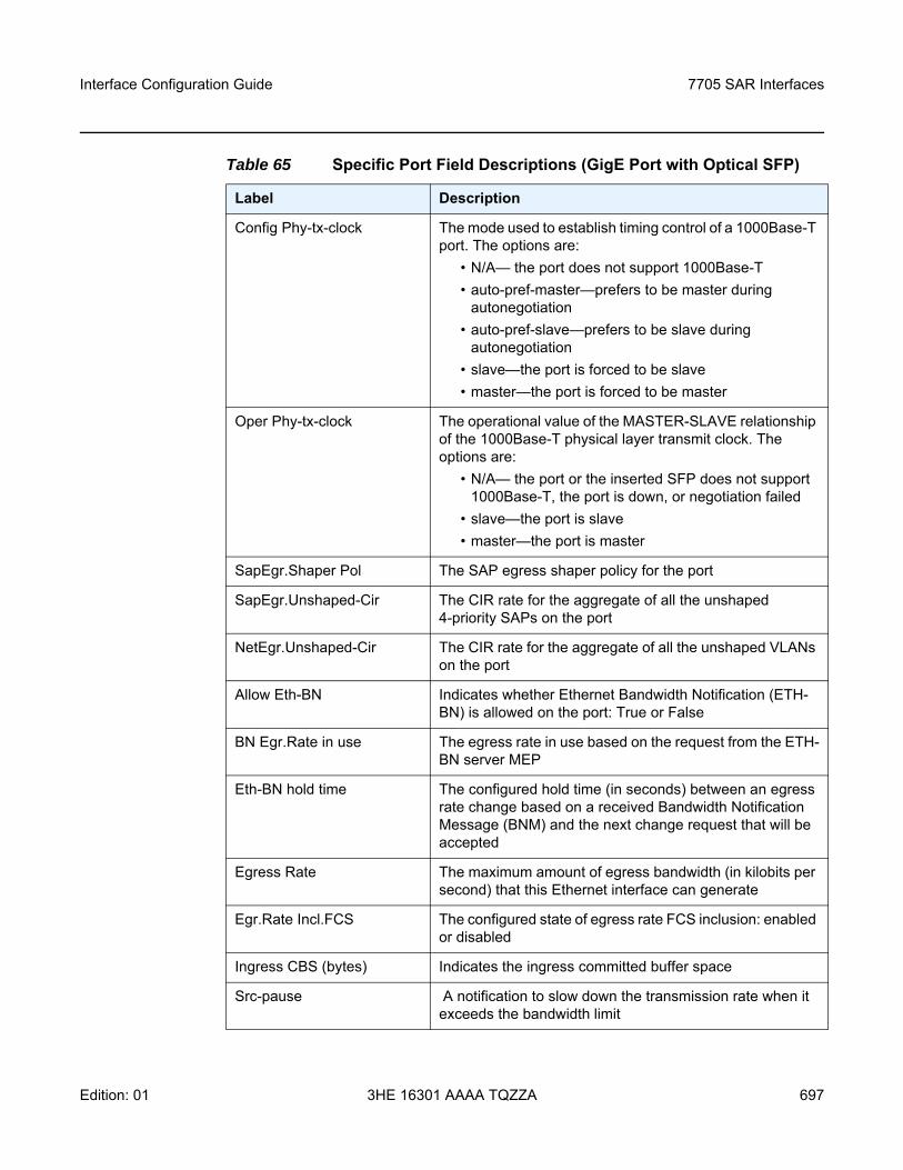
Interface Configuration Guide 7705 SAR Interfaces
Edition: 01 3HE 16301 AAAA TQZZA 697
Config Phy-tx-clock The mode used to establish timing control of a 1000Base-T port. The options are:
• N/A— the port does not support 1000Base-T• auto-pref-master—prefers to be master during
autonegotiation• auto-pref-slave—prefers to be slave during
autonegotiation• slave—the port is forced to be slave • master—the port is forced to be master
Oper Phy-tx-clock The operational value of the MASTER-SLAVE relationship of the 1000Base-T physical layer transmit clock. The options are:
• N/A— the port or the inserted SFP does not support 1000Base-T, the port is down, or negotiation failed
• slave—the port is slave • master—the port is master
SapEgr.Shaper Pol The SAP egress shaper policy for the port
SapEgr.Unshaped-Cir The CIR rate for the aggregate of all the unshaped 4-priority SAPs on the port
NetEgr.Unshaped-Cir The CIR rate for the aggregate of all the unshaped VLANs on the port
Allow Eth-BN Indicates whether Ethernet Bandwidth Notification (ETH-BN) is allowed on the port: True or False
BN Egr.Rate in use The egress rate in use based on the request from the ETH-BN server MEP
Eth-BN hold time The configured hold time (in seconds) between an egress rate change based on a received Bandwidth Notification Message (BNM) and the next change request that will be accepted
Egress Rate The maximum amount of egress bandwidth (in kilobits per second) that this Ethernet interface can generate
Egr.Rate Incl.FCS The configured state of egress rate FCS inclusion: enabled or disabled
Ingress CBS (bytes) Indicates the ingress committed buffer space
Src-pause A notification to slow down the transmission rate when it exceeds the bandwidth limit
Table 65 Specific Port Field Descriptions (GigE Port with Optical SFP)
Label Description
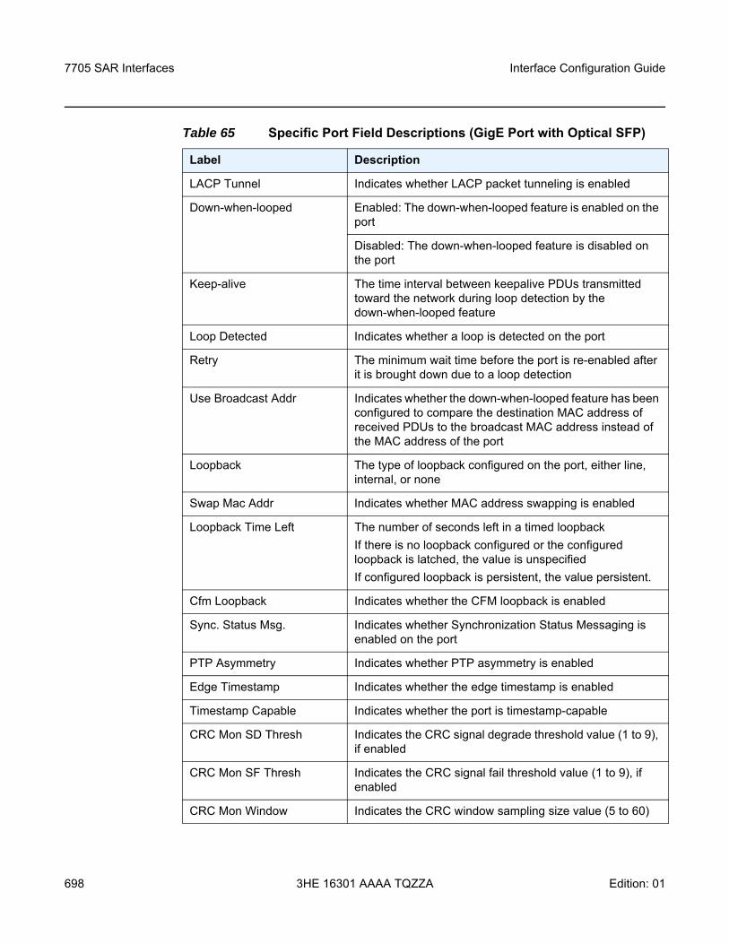
7705 SAR Interfaces
698
Interface Configuration Guide
3HE 16301 AAAA TQZZA Edition: 01
LACP Tunnel Indicates whether LACP packet tunneling is enabled
Down-when-looped Enabled: The down-when-looped feature is enabled on the port
Disabled: The down-when-looped feature is disabled on the port
Keep-alive The time interval between keepalive PDUs transmitted toward the network during loop detection by the down-when-looped feature
Loop Detected Indicates whether a loop is detected on the port
Retry The minimum wait time before the port is re-enabled after it is brought down due to a loop detection
Use Broadcast Addr Indicates whether the down-when-looped feature has been configured to compare the destination MAC address of received PDUs to the broadcast MAC address instead of the MAC address of the port
Loopback The type of loopback configured on the port, either line, internal, or none
Swap Mac Addr Indicates whether MAC address swapping is enabled
Loopback Time Left The number of seconds left in a timed loopbackIf there is no loopback configured or the configured loopback is latched, the value is unspecifiedIf configured loopback is persistent, the value persistent.
Cfm Loopback Indicates whether the CFM loopback is enabled
Sync. Status Msg. Indicates whether Synchronization Status Messaging is enabled on the port
PTP Asymmetry Indicates whether PTP asymmetry is enabled
Edge Timestamp Indicates whether the edge timestamp is enabled
Timestamp Capable Indicates whether the port is timestamp-capable
CRC Mon SD Thresh Indicates the CRC signal degrade threshold value (1 to 9), if enabled
CRC Mon SF Thresh Indicates the CRC signal fail threshold value (1 to 9), if enabled
CRC Mon Window Indicates the CRC window sampling size value (5 to 60)
Table 65 Specific Port Field Descriptions (GigE Port with Optical SFP)
Label Description
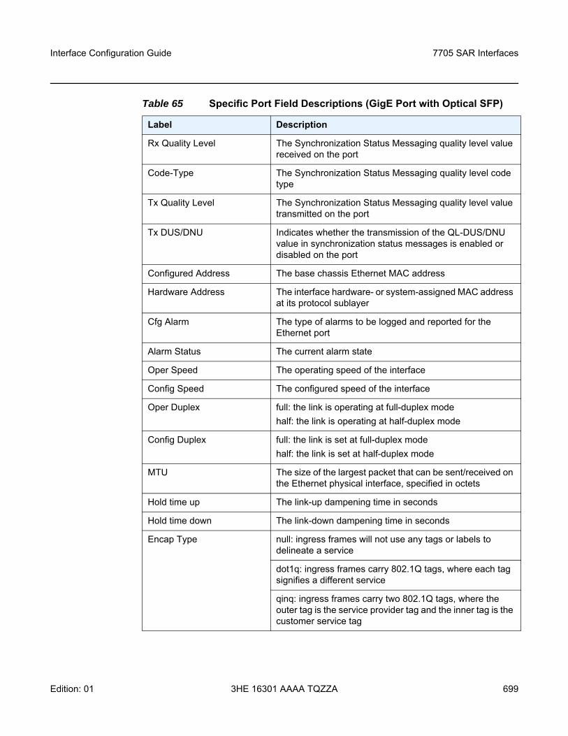
Interface Configuration Guide 7705 SAR Interfaces
Edition: 01 3HE 16301 AAAA TQZZA 699
Rx Quality Level The Synchronization Status Messaging quality level value received on the port
Code-Type The Synchronization Status Messaging quality level code type
Tx Quality Level The Synchronization Status Messaging quality level value transmitted on the port
Tx DUS/DNU Indicates whether the transmission of the QL-DUS/DNU value in synchronization status messages is enabled or disabled on the port
Configured Address The base chassis Ethernet MAC address
Hardware Address The interface hardware- or system-assigned MAC address at its protocol sublayer
Cfg Alarm The type of alarms to be logged and reported for the Ethernet port
Alarm Status The current alarm state
Oper Speed The operating speed of the interface
Config Speed The configured speed of the interface
Oper Duplex full: the link is operating at full-duplex modehalf: the link is operating at half-duplex mode
Config Duplex full: the link is set at full-duplex modehalf: the link is set at half-duplex mode
MTU The size of the largest packet that can be sent/received on the Ethernet physical interface, specified in octets
Hold time up The link-up dampening time in seconds
Hold time down The link-down dampening time in seconds
Encap Type null: ingress frames will not use any tags or labels to delineate a service
dot1q: ingress frames carry 802.1Q tags, where each tag signifies a different service
qinq: ingress frames carry two 802.1Q tags, where the outer tag is the service provider tag and the inner tag is the customer service tag
Table 65 Specific Port Field Descriptions (GigE Port with Optical SFP)
Label Description
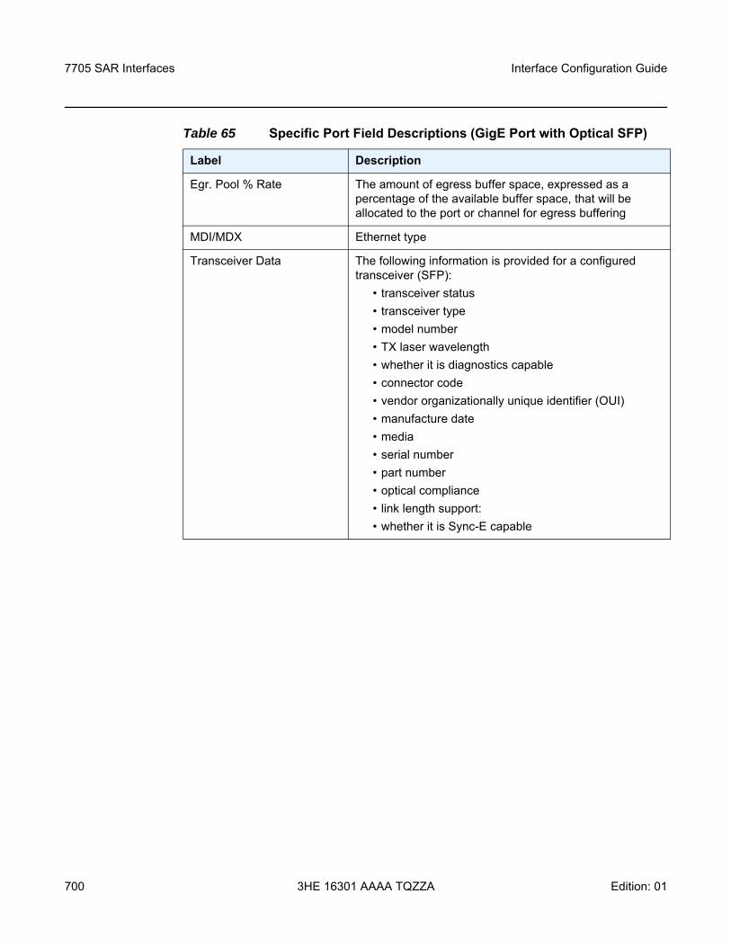
7705 SAR Interfaces
700
Interface Configuration Guide
3HE 16301 AAAA TQZZA Edition: 01
Egr. Pool % Rate The amount of egress buffer space, expressed as a percentage of the available buffer space, that will be allocated to the port or channel for egress buffering
MDI/MDX Ethernet type
Transceiver Data The following information is provided for a configured transceiver (SFP):
• transceiver status• transceiver type• model number• TX laser wavelength• whether it is diagnostics capable • connector code • vendor organizationally unique identifier (OUI)• manufacture date • media • serial number• part number• optical compliance• link length support:• whether it is Sync-E capable
Table 65 Specific Port Field Descriptions (GigE Port with Optical SFP)
Label Description
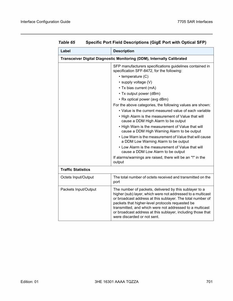
Interface Configuration Guide 7705 SAR Interfaces
Edition: 01 3HE 16301 AAAA TQZZA 701
Transceiver Digital Diagnostic Monitoring (DDM), Internally Calibrated
SFP manufacturers specifications guidelines contained in specification SFF-8472, for the following:
• temperature (C) • supply voltage (V)• Tx bias current (mA)• Tx output power (dBm)• Rx optical power (avg dBm)
For the above categories, the following values are shown:• Value is the current measured value of each variable• High Alarm is the measurement of Value that will
cause a DDM High Alarm to be output• High Warn is the measurement of Value that will
cause a DDM High Warning Alarm to be output• Low Warn is the measurement of Value that will cause
a DDM Low Warning Alarm to be output• Low Alarm is the measurement of Value that will
cause a DDM Low Alarm to be outputIf alarms/warnings are raised, there will be an "!" in the output
Traffic Statistics
Octets Input/Output The total number of octets received and transmitted on the port
Packets Input/Output The number of packets, delivered by this sublayer to a higher (sub) layer, which were not addressed to a multicast or broadcast address at this sublayer. The total number of packets that higher-level protocols requested be transmitted, and which were not addressed to a multicast or broadcast address at this sublayer, including those that were discarded or not sent.
Table 65 Specific Port Field Descriptions (GigE Port with Optical SFP)
Label Description
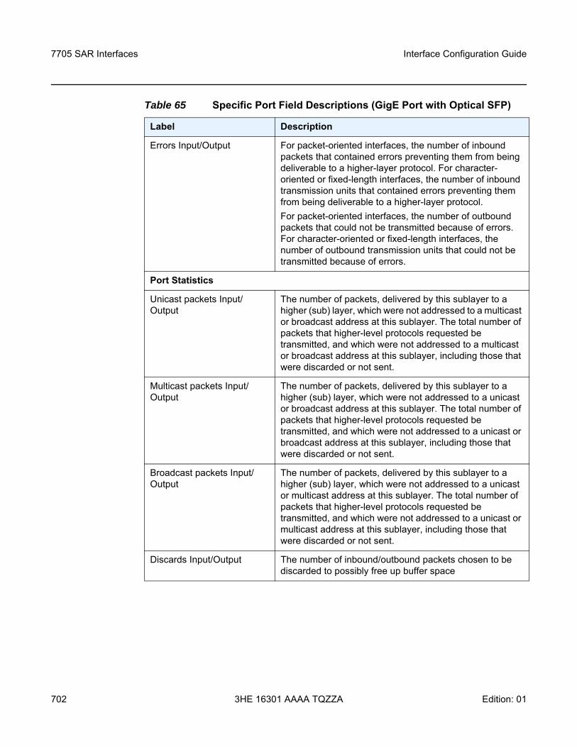
7705 SAR Interfaces
702
Interface Configuration Guide
3HE 16301 AAAA TQZZA Edition: 01
Errors Input/Output For packet-oriented interfaces, the number of inbound packets that contained errors preventing them from being deliverable to a higher-layer protocol. For character-oriented or fixed-length interfaces, the number of inbound transmission units that contained errors preventing them from being deliverable to a higher-layer protocol.For packet-oriented interfaces, the number of outbound packets that could not be transmitted because of errors. For character-oriented or fixed-length interfaces, the number of outbound transmission units that could not be transmitted because of errors.
Port Statistics
Unicast packets Input/Output
The number of packets, delivered by this sublayer to a higher (sub) layer, which were not addressed to a multicast or broadcast address at this sublayer. The total number of packets that higher-level protocols requested be transmitted, and which were not addressed to a multicast or broadcast address at this sublayer, including those that were discarded or not sent.
Multicast packets Input/Output
The number of packets, delivered by this sublayer to a higher (sub) layer, which were not addressed to a unicast or broadcast address at this sublayer. The total number of packets that higher-level protocols requested be transmitted, and which were not addressed to a unicast or broadcast address at this sublayer, including those that were discarded or not sent.
Broadcast packets Input/Output
The number of packets, delivered by this sublayer to a higher (sub) layer, which were not addressed to a unicast or multicast address at this sublayer. The total number of packets that higher-level protocols requested be transmitted, and which were not addressed to a unicast or multicast address at this sublayer, including those that were discarded or not sent.
Discards Input/Output The number of inbound/outbound packets chosen to be discarded to possibly free up buffer space
Table 65 Specific Port Field Descriptions (GigE Port with Optical SFP)
Label Description
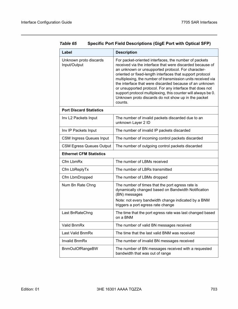
Interface Configuration Guide 7705 SAR Interfaces
Edition: 01 3HE 16301 AAAA TQZZA 703
Unknown proto discards Input/Output
For packet-oriented interfaces, the number of packets received via the interface that were discarded because of an unknown or unsupported protocol. For character-oriented or fixed-length interfaces that support protocol multiplexing, the number of transmission units received via the interface that were discarded because of an unknown or unsupported protocol. For any interface that does not support protocol multiplexing, this counter will always be 0. Unknown proto discards do not show up in the packet counts.
Port Discard Statistics
Inv L2 Packets Input The number of invalid packets discarded due to an unknown Layer 2 ID
Inv IP Packets Input The number of invalid IP packets discarded
CSM Ingress Queues Input The number of incoming control packets discarded
CSM Egress Queues Output The number of outgoing control packets discarded
Ethernet CFM Statistics
Cfm LbmRx The number of LBMs received
Cfm LbReplyTx The number of LBRs transmitted
Cfm LbmDropped The number of LBMs dropped
Num Bn Rate Chng The number of times that the port egress rate is dynamically changed based on Bandwidth Notification (BN) messagesNote: not every bandwidth change indicated by a BNM triggers a port egress rate change
Last BnRateChng The time that the port egress rate was last changed based on a BNM
Valid BnmRx The number of valid BN messages received
Last Valid BnmRx The time that the last valid BNM was received
Invalid BnmRx The number of invalid BN messages received
BnmOutOfRangeBW The number of BN messages received with a requested bandwidth that was out of range
Table 65 Specific Port Field Descriptions (GigE Port with Optical SFP)
Label Description
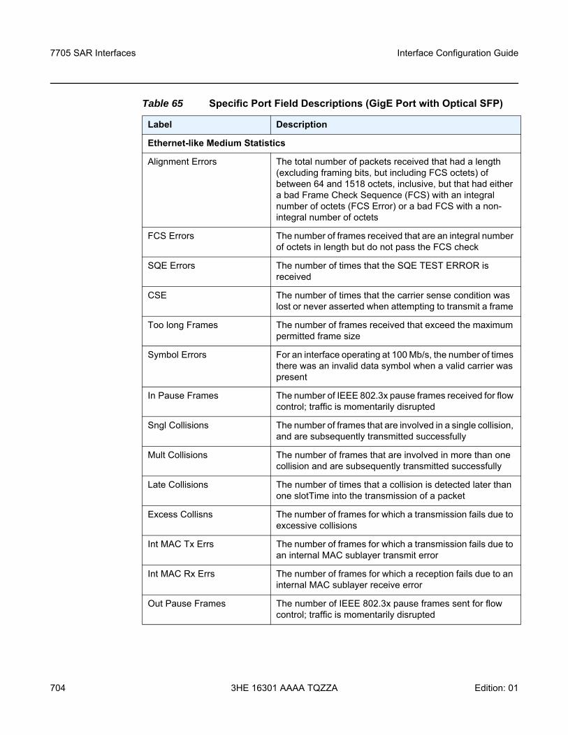
7705 SAR Interfaces
704
Interface Configuration Guide
3HE 16301 AAAA TQZZA Edition: 01
Ethernet-like Medium Statistics
Alignment Errors The total number of packets received that had a length (excluding framing bits, but including FCS octets) of between 64 and 1518 octets, inclusive, but that had either a bad Frame Check Sequence (FCS) with an integral number of octets (FCS Error) or a bad FCS with a non-integral number of octets
FCS Errors The number of frames received that are an integral number of octets in length but do not pass the FCS check
SQE Errors The number of times that the SQE TEST ERROR is received
CSE The number of times that the carrier sense condition was lost or never asserted when attempting to transmit a frame
Too long Frames The number of frames received that exceed the maximum permitted frame size
Symbol Errors For an interface operating at 100 Mb/s, the number of times there was an invalid data symbol when a valid carrier was present
In Pause Frames The number of IEEE 802.3x pause frames received for flow control; traffic is momentarily disrupted
Sngl Collisions The number of frames that are involved in a single collision, and are subsequently transmitted successfully
Mult Collisions The number of frames that are involved in more than one collision and are subsequently transmitted successfully
Late Collisions The number of times that a collision is detected later than one slotTime into the transmission of a packet
Excess Collisns The number of frames for which a transmission fails due to excessive collisions
Int MAC Tx Errs The number of frames for which a transmission fails due to an internal MAC sublayer transmit error
Int MAC Rx Errs The number of frames for which a reception fails due to an internal MAC sublayer receive error
Out Pause Frames The number of IEEE 802.3x pause frames sent for flow control; traffic is momentarily disrupted
Table 65 Specific Port Field Descriptions (GigE Port with Optical SFP)
Label Description
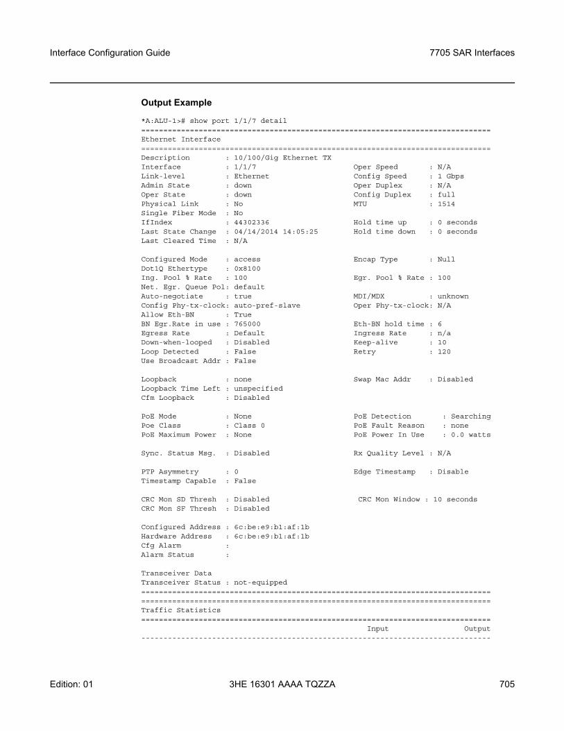
Interface Configuration Guide 7705 SAR Interfaces
Edition: 01 3HE 16301 AAAA TQZZA 705
Output Example
*A:ALU-1># show port 1/1/7 detail===============================================================================Ethernet Interface===============================================================================Description : 10/100/Gig Ethernet TXInterface : 1/1/7 Oper Speed : N/ALink-level : Ethernet Config Speed : 1 GbpsAdmin State : down Oper Duplex : N/AOper State : down Config Duplex : fullPhysical Link : No MTU : 1514Single Fiber Mode : NoIfIndex : 44302336 Hold time up : 0 secondsLast State Change : 04/14/2014 14:05:25 Hold time down : 0 secondsLast Cleared Time : N/A
Configured Mode : access Encap Type : NullDot1Q Ethertype : 0x8100Ing. Pool % Rate : 100 Egr. Pool % Rate : 100Net. Egr. Queue Pol: defaultAuto-negotiate : true MDI/MDX : unknownConfig Phy-tx-clock: auto-pref-slave Oper Phy-tx-clock: N/AAllow Eth-BN : TrueBN Egr.Rate in use : 765000 Eth-BN hold time : 6Egress Rate : Default Ingress Rate : n/aDown-when-looped : Disabled Keep-alive : 10Loop Detected : False Retry : 120Use Broadcast Addr : False
Loopback : none Swap Mac Addr : DisabledLoopback Time Left : unspecifiedCfm Loopback : Disabled
PoE Mode : None PoE Detection : SearchingPoe Class : Class 0 PoE Fault Reason : nonePoE Maximum Power : None PoE Power In Use : 0.0 watts
Sync. Status Msg. : Disabled Rx Quality Level : N/A
PTP Asymmetry : 0 Edge Timestamp : DisableTimestamp Capable : False
CRC Mon SD Thresh : Disabled CRC Mon Window : 10 secondsCRC Mon SF Thresh : Disabled
Configured Address : 6c:be:e9:b1:af:1bHardware Address : 6c:be:e9:b1:af:1bCfg Alarm :Alarm Status :
Transceiver DataTransceiver Status : not-equipped==============================================================================================================================================================Traffic Statistics===============================================================================
Input Output-------------------------------------------------------------------------------
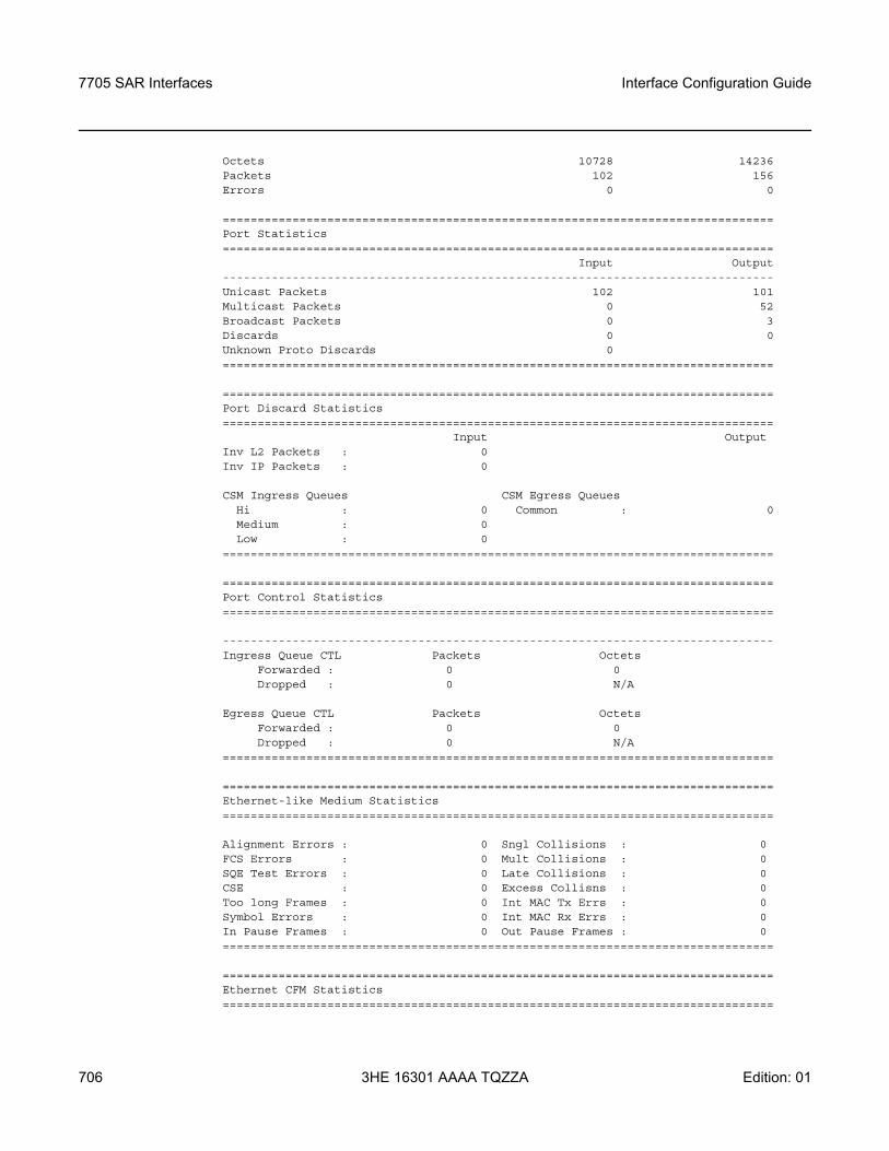
7705 SAR Interfaces
706
Interface Configuration Guide
3HE 16301 AAAA TQZZA Edition: 01
Octets 10728 14236Packets 102 156Errors 0 0
===============================================================================Port Statistics===============================================================================
Input Output-------------------------------------------------------------------------------Unicast Packets 102 101Multicast Packets 0 52Broadcast Packets 0 3Discards 0 0Unknown Proto Discards 0===============================================================================
===============================================================================Port Discard Statistics===============================================================================
Input OutputInv L2 Packets : 0Inv IP Packets : 0
CSM Ingress Queues CSM Egress QueuesHi : 0 Common : 0Medium : 0Low : 0
===============================================================================
===============================================================================Port Control Statistics===============================================================================
-------------------------------------------------------------------------------Ingress Queue CTL Packets Octets
Forwarded : 0 0Dropped : 0 N/A
Egress Queue CTL Packets OctetsForwarded : 0 0Dropped : 0 N/A
===============================================================================
===============================================================================Ethernet-like Medium Statistics===============================================================================
Alignment Errors : 0 Sngl Collisions : 0FCS Errors : 0 Mult Collisions : 0SQE Test Errors : 0 Late Collisions : 0CSE : 0 Excess Collisns : 0Too long Frames : 0 Int MAC Tx Errs : 0Symbol Errors : 0 Int MAC Rx Errs : 0In Pause Frames : 0 Out Pause Frames : 0===============================================================================
===============================================================================Ethernet CFM Statistics===============================================================================
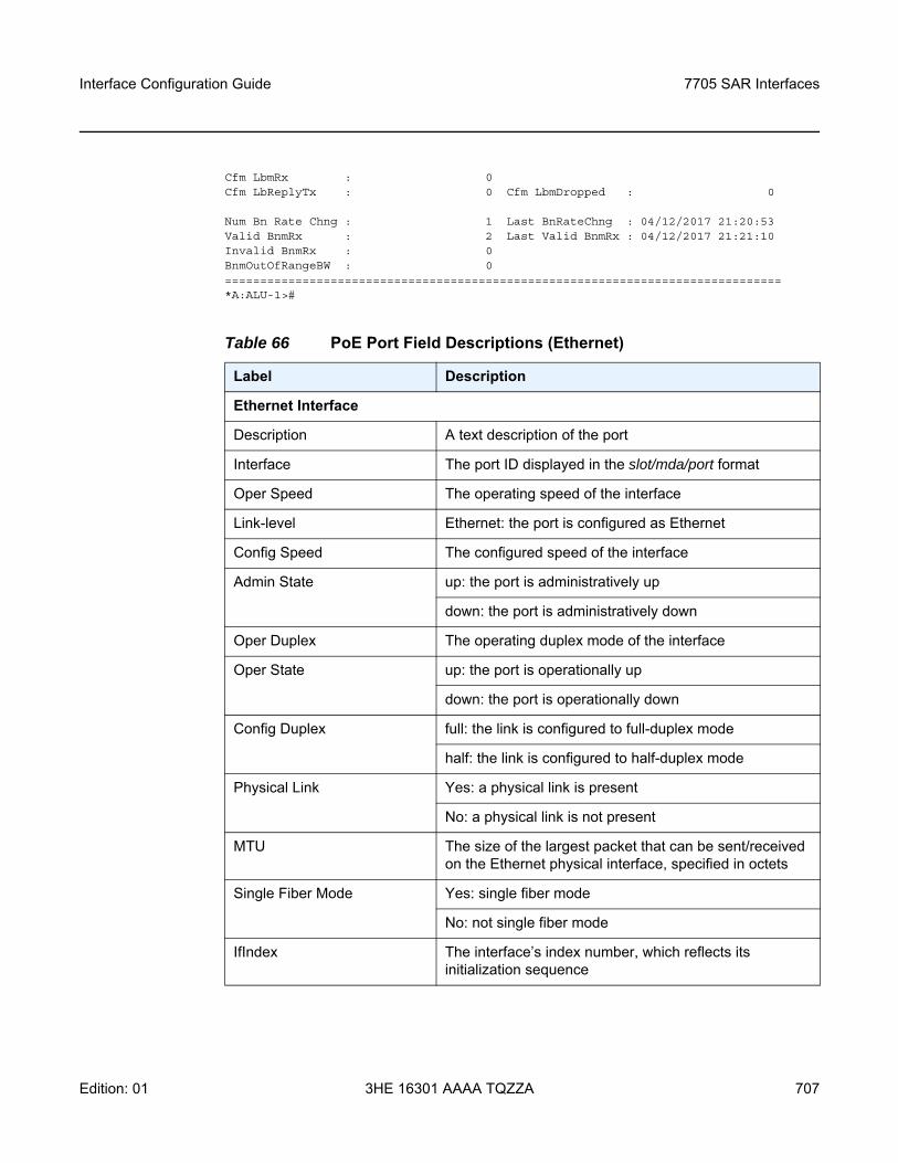
Interface Configuration Guide 7705 SAR Interfaces
Edition: 01 3HE 16301 AAAA TQZZA 707
Cfm LbmRx : 0Cfm LbReplyTx : 0 Cfm LbmDropped : 0
Num Bn Rate Chng : 1 Last BnRateChng : 04/12/2017 21:20:53Valid BnmRx : 2 Last Valid BnmRx : 04/12/2017 21:21:10Invalid BnmRx : 0BnmOutOfRangeBW : 0===============================================================================*A:ALU-1>#
Table 66 PoE Port Field Descriptions (Ethernet)
Label Description
Ethernet Interface
Description A text description of the port
Interface The port ID displayed in the slot/mda/port format
Oper Speed The operating speed of the interface
Link-level Ethernet: the port is configured as Ethernet
Config Speed The configured speed of the interface
Admin State up: the port is administratively up
down: the port is administratively down
Oper Duplex The operating duplex mode of the interface
Oper State up: the port is operationally up
down: the port is operationally down
Config Duplex full: the link is configured to full-duplex mode
half: the link is configured to half-duplex mode
Physical Link Yes: a physical link is present
No: a physical link is not present
MTU The size of the largest packet that can be sent/received on the Ethernet physical interface, specified in octets
Single Fiber Mode Yes: single fiber mode
No: not single fiber mode
IfIndex The interface’s index number, which reflects its initialization sequence
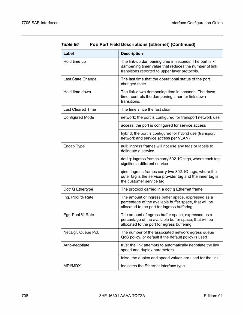
7705 SAR Interfaces
708
Interface Configuration Guide
3HE 16301 AAAA TQZZA Edition: 01
Hold time up The link-up dampening time in seconds. The port link dampening timer value that reduces the number of link transitions reported to upper layer protocols.
Last State Change The last time that the operational status of the port changed state
Hold time down The link-down dampening time in seconds. The down timer controls the dampening timer for link down transitions.
Last Cleared Time The time since the last clear
Configured Mode network: the port is configured for transport network use
access: the port is configured for service access
hybrid: the port is configured for hybrid use (transport network and service access per VLAN)
Encap Type null: ingress frames will not use any tags or labels to delineate a service
dot1q: ingress frames carry 802.1Q tags, where each tag signifies a different service
qinq: ingress frames carry two 802.1Q tags, where the outer tag is the service provider tag and the inner tag is the customer service tag
Dot1Q Ethertype The protocol carried in a dot1q Ethernet frame
Ing. Pool % Rate The amount of ingress buffer space, expressed as a percentage of the available buffer space, that will be allocated to the port for ingress buffering
Egr. Pool % Rate The amount of egress buffer space, expressed as a percentage of the available buffer space, that will be allocated to the port for egress buffering
Net.Egr. Queue Pol. The number of the associated network egress queue QoS policy, or default if the default policy is used
Auto-negotiate true: the link attempts to automatically negotiate the link speed and duplex parameters
false: the duplex and speed values are used for the link
MDI/MDX Indicates the Ethernet interface type
Table 66 PoE Port Field Descriptions (Ethernet) (Continued)
Label Description
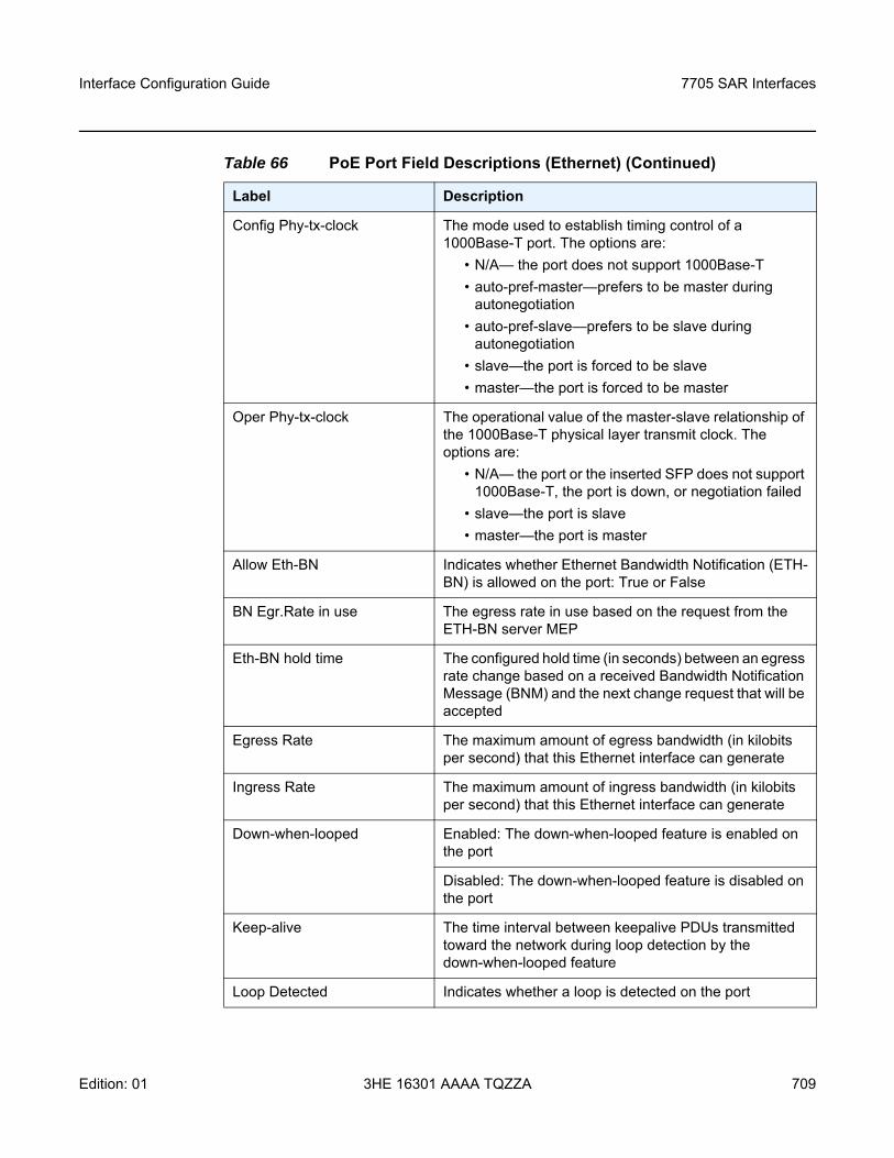
Interface Configuration Guide 7705 SAR Interfaces
Edition: 01 3HE 16301 AAAA TQZZA 709
Config Phy-tx-clock The mode used to establish timing control of a 1000Base-T port. The options are:
• N/A— the port does not support 1000Base-T• auto-pref-master—prefers to be master during
autonegotiation• auto-pref-slave—prefers to be slave during
autonegotiation• slave—the port is forced to be slave • master—the port is forced to be master
Oper Phy-tx-clock The operational value of the master-slave relationship of the 1000Base-T physical layer transmit clock. The options are:
• N/A— the port or the inserted SFP does not support 1000Base-T, the port is down, or negotiation failed
• slave—the port is slave • master—the port is master
Allow Eth-BN Indicates whether Ethernet Bandwidth Notification (ETH-BN) is allowed on the port: True or False
BN Egr.Rate in use The egress rate in use based on the request from the ETH-BN server MEP
Eth-BN hold time The configured hold time (in seconds) between an egress rate change based on a received Bandwidth Notification Message (BNM) and the next change request that will be accepted
Egress Rate The maximum amount of egress bandwidth (in kilobits per second) that this Ethernet interface can generate
Ingress Rate The maximum amount of ingress bandwidth (in kilobits per second) that this Ethernet interface can generate
Down-when-looped Enabled: The down-when-looped feature is enabled on the port
Disabled: The down-when-looped feature is disabled on the port
Keep-alive The time interval between keepalive PDUs transmitted toward the network during loop detection by the down-when-looped feature
Loop Detected Indicates whether a loop is detected on the port
Table 66 PoE Port Field Descriptions (Ethernet) (Continued)
Label Description
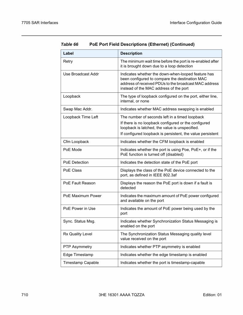
7705 SAR Interfaces
710
Interface Configuration Guide
3HE 16301 AAAA TQZZA Edition: 01
Retry The minimum wait time before the port is re-enabled after it is brought down due to a loop detection
Use Broadcast Addr Indicates whether the down-when-looped feature has been configured to compare the destination MAC address of received PDUs to the broadcast MAC address instead of the MAC address of the port
Loopback The type of loopback configured on the port, either line, internal, or none
Swap Mac Addr. Indicates whether MAC address swapping is enabled
Loopback Time Left The number of seconds left in a timed loopbackIf there is no loopback configured or the configured loopback is latched, the value is unspecified.If configured loopback is persistent, the value persistent
Cfm Loopback Indicates whether the CFM loopback is enabled
PoE Mode Indicates whether the port is using Poe, PoE+, or if the PoE function is turned off (disabled)
PoE Detection Indicates the detection state of the PoE port
PoE Class Displays the class of the PoE device connected to the port, as defined in IEEE 802.3af
PoE Fault Reason Displays the reason the PoE port is down if a fault is detected
PoE Maximum Power Indicates the maximum amount of PoE power configured and available on the port
PoE Power in Use Indicates the amount of PoE power being used by the port
Sync. Status Msg. Indicates whether Synchronization Status Messaging is enabled on the port
Rx Quality Level The Synchronization Status Messaging quality level value received on the port
PTP Asymmetry Indicates whether PTP asymmetry is enabled
Edge Timestamp Indicates whether the edge timestamp is enabled
Timestamp Capable Indicates whether the port is timestamp-capable
Table 66 PoE Port Field Descriptions (Ethernet) (Continued)
Label Description
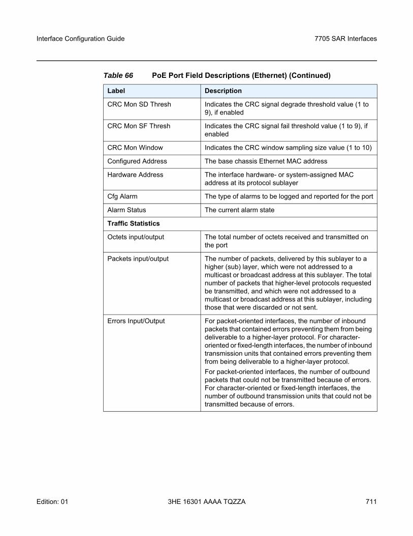
Interface Configuration Guide 7705 SAR Interfaces
Edition: 01 3HE 16301 AAAA TQZZA 711
CRC Mon SD Thresh Indicates the CRC signal degrade threshold value (1 to 9), if enabled
CRC Mon SF Thresh Indicates the CRC signal fail threshold value (1 to 9), if enabled
CRC Mon Window Indicates the CRC window sampling size value (1 to 10)
Configured Address The base chassis Ethernet MAC address
Hardware Address The interface hardware- or system-assigned MAC address at its protocol sublayer
Cfg Alarm The type of alarms to be logged and reported for the port
Alarm Status The current alarm state
Traffic Statistics
Octets input/output The total number of octets received and transmitted on the port
Packets input/output The number of packets, delivered by this sublayer to a higher (sub) layer, which were not addressed to a multicast or broadcast address at this sublayer. The total number of packets that higher-level protocols requested be transmitted, and which were not addressed to a multicast or broadcast address at this sublayer, including those that were discarded or not sent.
Errors Input/Output For packet-oriented interfaces, the number of inbound packets that contained errors preventing them from being deliverable to a higher-layer protocol. For character-oriented or fixed-length interfaces, the number of inbound transmission units that contained errors preventing them from being deliverable to a higher-layer protocol.For packet-oriented interfaces, the number of outbound packets that could not be transmitted because of errors. For character-oriented or fixed-length interfaces, the number of outbound transmission units that could not be transmitted because of errors.
Table 66 PoE Port Field Descriptions (Ethernet) (Continued)
Label Description
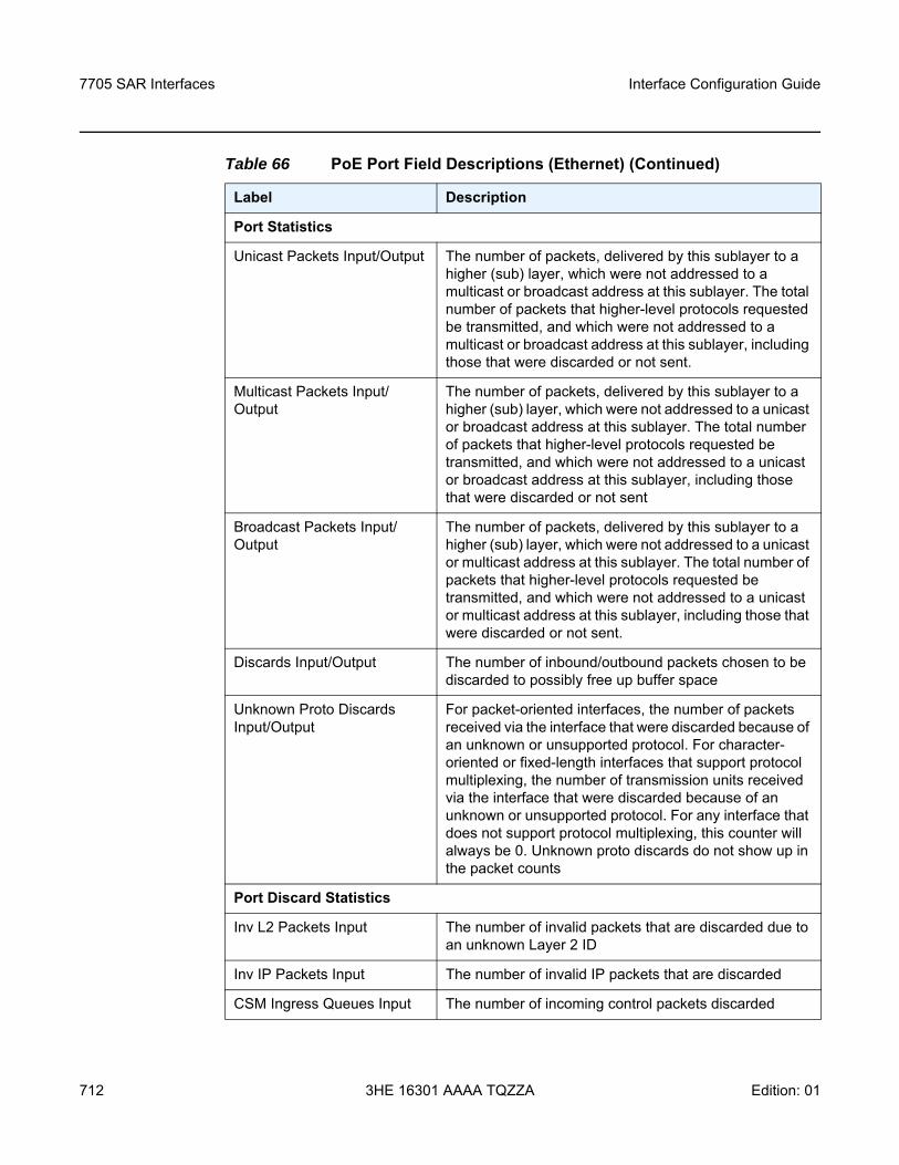
7705 SAR Interfaces
712
Interface Configuration Guide
3HE 16301 AAAA TQZZA Edition: 01
Port Statistics
Unicast Packets Input/Output The number of packets, delivered by this sublayer to a higher (sub) layer, which were not addressed to a multicast or broadcast address at this sublayer. The total number of packets that higher-level protocols requested be transmitted, and which were not addressed to a multicast or broadcast address at this sublayer, including those that were discarded or not sent.
Multicast Packets Input/Output
The number of packets, delivered by this sublayer to a higher (sub) layer, which were not addressed to a unicast or broadcast address at this sublayer. The total number of packets that higher-level protocols requested be transmitted, and which were not addressed to a unicast or broadcast address at this sublayer, including those that were discarded or not sent
Broadcast Packets Input/Output
The number of packets, delivered by this sublayer to a higher (sub) layer, which were not addressed to a unicast or multicast address at this sublayer. The total number of packets that higher-level protocols requested be transmitted, and which were not addressed to a unicast or multicast address at this sublayer, including those that were discarded or not sent.
Discards Input/Output The number of inbound/outbound packets chosen to be discarded to possibly free up buffer space
Unknown Proto Discards Input/Output
For packet-oriented interfaces, the number of packets received via the interface that were discarded because of an unknown or unsupported protocol. For character-oriented or fixed-length interfaces that support protocol multiplexing, the number of transmission units received via the interface that were discarded because of an unknown or unsupported protocol. For any interface that does not support protocol multiplexing, this counter will always be 0. Unknown proto discards do not show up in the packet counts
Port Discard Statistics
Inv L2 Packets Input The number of invalid packets that are discarded due to an unknown Layer 2 ID
Inv IP Packets Input The number of invalid IP packets that are discarded
CSM Ingress Queues Input The number of incoming control packets discarded
Table 66 PoE Port Field Descriptions (Ethernet) (Continued)
Label Description
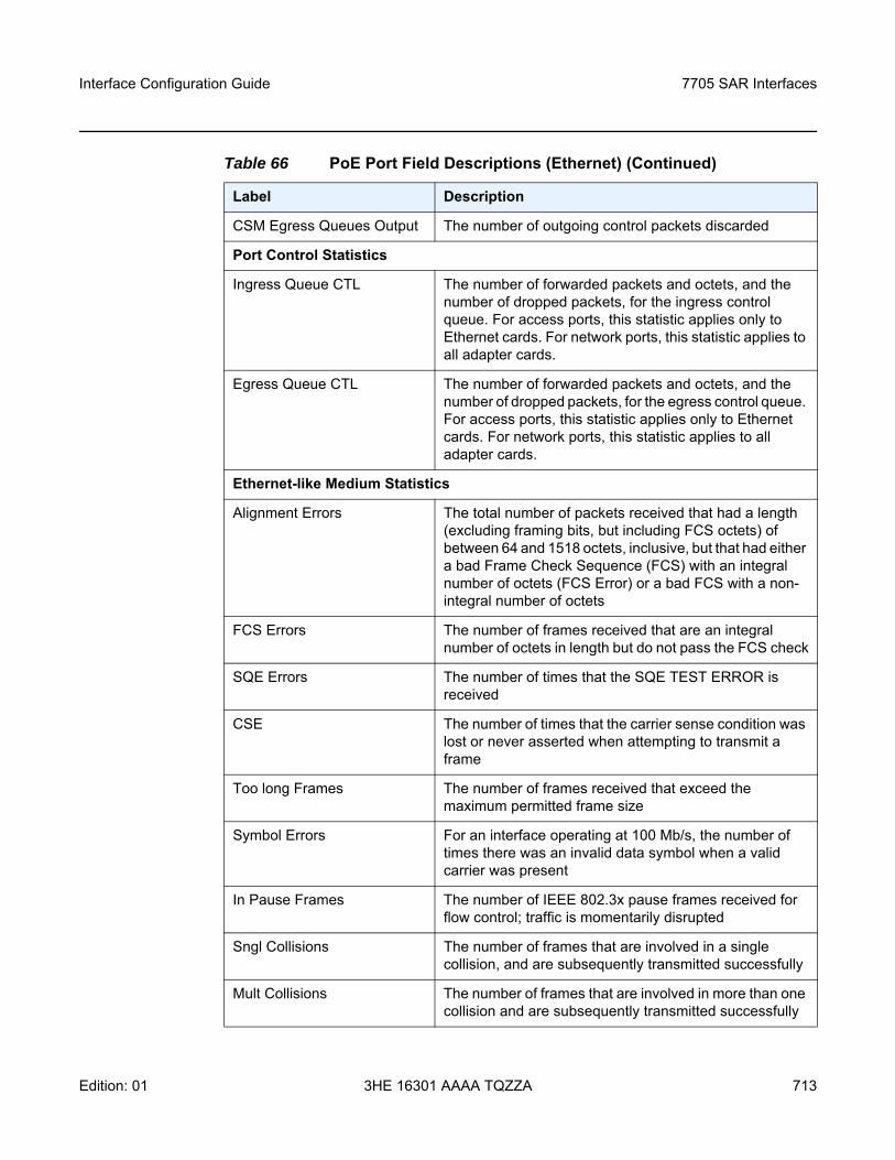
Interface Configuration Guide 7705 SAR Interfaces
Edition: 01 3HE 16301 AAAA TQZZA 713
CSM Egress Queues Output The number of outgoing control packets discarded
Port Control Statistics
Ingress Queue CTL The number of forwarded packets and octets, and the number of dropped packets, for the ingress control queue. For access ports, this statistic applies only to Ethernet cards. For network ports, this statistic applies to all adapter cards.
Egress Queue CTL The number of forwarded packets and octets, and the number of dropped packets, for the egress control queue. For access ports, this statistic applies only to Ethernet cards. For network ports, this statistic applies to all adapter cards.
Ethernet-like Medium Statistics
Alignment Errors The total number of packets received that had a length (excluding framing bits, but including FCS octets) of between 64 and 1518 octets, inclusive, but that had either a bad Frame Check Sequence (FCS) with an integral number of octets (FCS Error) or a bad FCS with a non-integral number of octets
FCS Errors The number of frames received that are an integral number of octets in length but do not pass the FCS check
SQE Errors The number of times that the SQE TEST ERROR is received
CSE The number of times that the carrier sense condition was lost or never asserted when attempting to transmit a frame
Too long Frames The number of frames received that exceed the maximum permitted frame size
Symbol Errors For an interface operating at 100 Mb/s, the number of times there was an invalid data symbol when a valid carrier was present
In Pause Frames The number of IEEE 802.3x pause frames received for flow control; traffic is momentarily disrupted
Sngl Collisions The number of frames that are involved in a single collision, and are subsequently transmitted successfully
Mult Collisions The number of frames that are involved in more than one collision and are subsequently transmitted successfully
Table 66 PoE Port Field Descriptions (Ethernet) (Continued)
Label Description
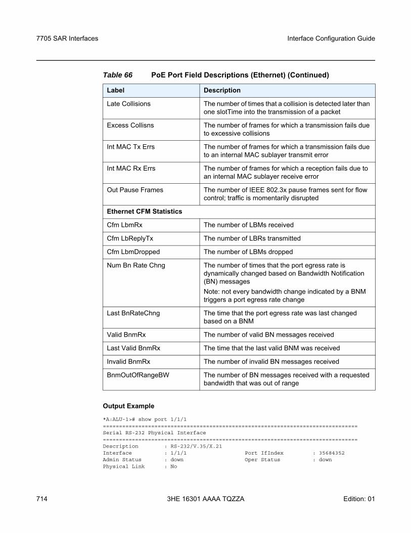
7705 SAR Interfaces
714
Interface Configuration Guide
3HE 16301 AAAA TQZZA Edition: 01
Output Example
*A:ALU-1># show port 1/1/1===============================================================================Serial RS-232 Physical Interface===============================================================================Description : RS-232/V.35/X.21Interface : 1/1/1 Port IfIndex : 35684352Admin Status : down Oper Status : downPhysical Link : No
Late Collisions The number of times that a collision is detected later than one slotTime into the transmission of a packet
Excess Collisns The number of frames for which a transmission fails due to excessive collisions
Int MAC Tx Errs The number of frames for which a transmission fails due to an internal MAC sublayer transmit error
Int MAC Rx Errs The number of frames for which a reception fails due to an internal MAC sublayer receive error
Out Pause Frames The number of IEEE 802.3x pause frames sent for flow control; traffic is momentarily disrupted
Ethernet CFM Statistics
Cfm LbmRx The number of LBMs received
Cfm LbReplyTx The number of LBRs transmitted
Cfm LbmDropped The number of LBMs dropped
Num Bn Rate Chng The number of times that the port egress rate is dynamically changed based on Bandwidth Notification (BN) messagesNote: not every bandwidth change indicated by a BNM triggers a port egress rate change
Last BnRateChng The time that the port egress rate was last changed based on a BNM
Valid BnmRx The number of valid BN messages received
Last Valid BnmRx The time that the last valid BNM was received
Invalid BnmRx The number of invalid BN messages received
BnmOutOfRangeBW The number of BN messages received with a requested bandwidth that was out of range
Table 66 PoE Port Field Descriptions (Ethernet) (Continued)
Label Description
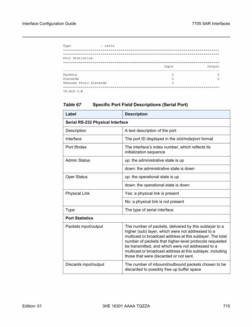
Interface Configuration Guide 7705 SAR Interfaces
Edition: 01 3HE 16301 AAAA TQZZA 715
Type : rs232==============================================================================================================================================================Port Statistics===============================================================================
Input Output-------------------------------------------------------------------------------Packets 0 0Discards 0 0Unknown Proto Discards 0===============================================================================*A:ALU-1>#
Table 67 Specific Port Field Descriptions (Serial Port)
Label Description
Serial RS-232 Physical Interface
Description A text description of the port
Interface The port ID displayed in the slot/mda/port format
Port IfIndex The interface’s index number, which reflects its initialization sequence
Admin Status up: the administrative state is up
down: the administrative state is down
Oper Status up: the operational state is up
down: the operational state is down
Physical Link Yes: a physical link is present
No: a physical link is not present
Type The type of serial interface
Port Statistics
Packets input/output The number of packets, delivered by this sublayer to a higher (sub) layer, which were not addressed to a multicast or broadcast address at this sublayer. The total number of packets that higher-level protocols requested be transmitted, and which were not addressed to a multicast or broadcast address at this sublayer, including those that were discarded or not sent.
Discards input/output The number of inbound/outbound packets chosen to be discarded to possibly free up buffer space
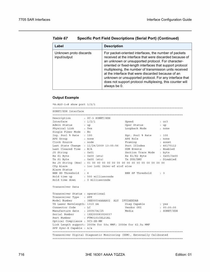
7705 SAR Interfaces
716
Interface Configuration Guide
3HE 16301 AAAA TQZZA Edition: 01
Output Example
*A:ALU-1># show port 1/2/1===============================================================================SONET/SDH Interface===============================================================================Description : OC-3 SONET/SDHInterface : 1/2/1 Speed : oc3Admin Status : up Oper Status : upPhysical Link : Yes Loopback Mode : noneSingle Fiber Mode : NoIng. Pool % Rate : 100 Egr. Pool % Rate : 100APS Group : none APS Role : noneClock Source : node Framing : sonetLast State Change : 11/24/2009 13:05:56 Port IfIndex : 46170112Last Cleared Time : N/A DDM Events : EnabledJ0 String : 0x01 Section Trace Mode : byteRx S1 Byte : 0x00 (stu) Rx K1/K2 Byte : 0x00/0x00Tx S1 Byte : 0x00 (stu) Tx DUS/DNU : DisabledRx J0 String (Hex) : 01 00 00 00 00 00 00 00 00 00 00 00 00 00 00 00Cfg Alarm : loc lrdi lb2er-sf slof slosAlarm Status :BER SD Threshold : 6 BER SF Threshold : 3Hold time up : 500 millisecondsHold time down : 0 milliseconds
Transceiver Data
Transceiver Status : operationalTransceiver Type : SFPModel Number : 3HE00034AAAA02 ALU IPUIAEXDABTX Laser Wavelength: 1310 nm Diag Capable : yesConnector Code : LC Vendor OUI : 00:00:00Manufacture date : 2009/04/25 Media : SONET/SDHSerial Number : 1XX200083926037Part Number : FTM3101CSL2iALOptical Compliance : OC3-SR-MMLink Length support: 2000m for 50u MMF; 2000m for 62.5u MMFSFP Sync-E Capable : n/a===============================================================================Transceiver Digital Diagnostic Monitoring (DDM), Externally Calibrated===============================================================================
Unknown proto discards input/output
For packet-oriented interfaces, the number of packets received at the interface that were discarded because of an unknown or unsupported protocol. For character-oriented or fixed-length interfaces that support protocol multiplexing, the number of transmission units received at the interface that were discarded because of an unknown or unsupported protocol. For any interface that does not support protocol multiplexing, this counter will always be 0.
Table 67 Specific Port Field Descriptions (Serial Port) (Continued)
Label Description
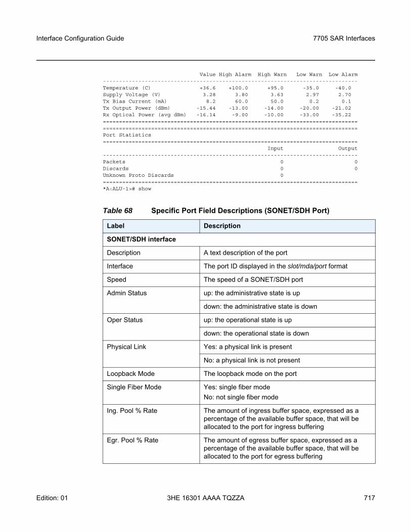
Interface Configuration Guide 7705 SAR Interfaces
Edition: 01 3HE 16301 AAAA TQZZA 717
Value High Alarm High Warn Low Warn Low Alarm-------------------------------------------------------------------------------Temperature (C) +36.6 +100.0 +95.0 -35.0 -40.0Supply Voltage (V) 3.28 3.80 3.63 2.97 2.70Tx Bias Current (mA) 8.2 60.0 50.0 0.2 0.1Tx Output Power (dBm) -15.44 -13.00 -14.00 -20.00 -21.02Rx Optical Power (avg dBm) -16.14 -9.00 -10.00 -33.00 -35.22==============================================================================================================================================================Port Statistics===============================================================================
Input Output-------------------------------------------------------------------------------Packets 0 0Discards 0 0Unknown Proto Discards 0===============================================================================*A:ALU-1># show
Table 68 Specific Port Field Descriptions (SONET/SDH Port)
Label Description
SONET/SDH interface
Description A text description of the port
Interface The port ID displayed in the slot/mda/port format
Speed The speed of a SONET/SDH port
Admin Status up: the administrative state is up
down: the administrative state is down
Oper Status up: the operational state is up
down: the operational state is down
Physical Link Yes: a physical link is present
No: a physical link is not present
Loopback Mode The loopback mode on the port
Single Fiber Mode Yes: single fiber modeNo: not single fiber mode
Ing. Pool % Rate The amount of ingress buffer space, expressed as a percentage of the available buffer space, that will be allocated to the port for ingress buffering
Egr. Pool % Rate The amount of egress buffer space, expressed as a percentage of the available buffer space, that will be allocated to the port for egress buffering

7705 SAR Interfaces
718
Interface Configuration Guide
3HE 16301 AAAA TQZZA Edition: 01
APS group The automatic protection switching group
APS role The automatic protection switching group role
Clock Source node: the link uses the internal clock when transmitting dataloop: the link recovers the clock from the received data stream
Framing sonet: the port is configured for SONET framingsdh: the port is configured for SDH framing
Last State Change The last time that the operational status of the port changed state
Port IfIndex The interface’s index number, which reflects its initialization sequence
Last Cleared Time The time since the last clear
DDM Events Enabled: digital diagnostic monitoring events is enabled for the portDisabled: digital diagnostic monitoring events is disabled for the port
J0 String The section trace value that is sent to the far-end port
Section Trace Mode byte: the section trace in the SONET section header is set in bytesstring: a text string is used to identify the SONET section headerincrement-z0: an incremental STM ID is configured instead of a static value
Rx S1 Byte The synchronization status message value of the received SONET/SDH S1 byte
Rx K1/K2 Byte The value of the received SONET/SDH K1/K2 byte
Tx S1 Byte The synchronization status message value of the transmitted SONET/SDH S1 byte
Tx DUS/DNU Indicates whether the transmission of the QL-DUS/DNU value in synchronization status messages is enabled or disabled on the port
Rx J0 String (Hex) The hex value of the received J0
Table 68 Specific Port Field Descriptions (SONET/SDH Port) (Continued)
Label Description
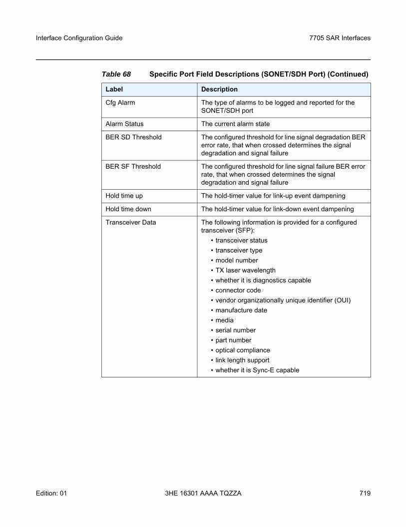
Interface Configuration Guide 7705 SAR Interfaces
Edition: 01 3HE 16301 AAAA TQZZA 719
Cfg Alarm The type of alarms to be logged and reported for the SONET/SDH port
Alarm Status The current alarm state
BER SD Threshold The configured threshold for line signal degradation BER error rate, that when crossed determines the signal degradation and signal failure
BER SF Threshold The configured threshold for line signal failure BER error rate, that when crossed determines the signal degradation and signal failure
Hold time up The hold-timer value for link-up event dampening
Hold time down The hold-timer value for link-down event dampening
Transceiver Data The following information is provided for a configured transceiver (SFP):
• transceiver status• transceiver type• model number• TX laser wavelength• whether it is diagnostics capable • connector code • vendor organizationally unique identifier (OUI)• manufacture date • media • serial number• part number• optical compliance• link length support• whether it is Sync-E capable
Table 68 Specific Port Field Descriptions (SONET/SDH Port) (Continued)
Label Description
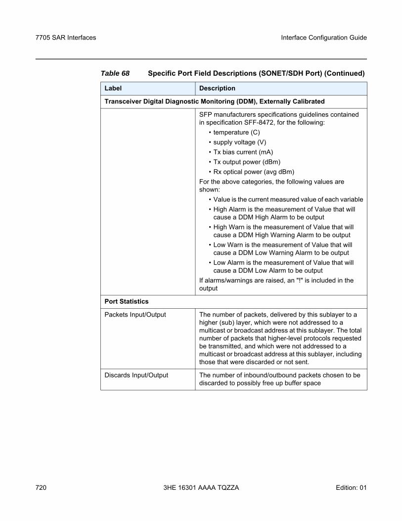
7705 SAR Interfaces
720
Interface Configuration Guide
3HE 16301 AAAA TQZZA Edition: 01
Transceiver Digital Diagnostic Monitoring (DDM), Externally Calibrated
SFP manufacturers specifications guidelines contained in specification SFF-8472, for the following:
• temperature (C) • supply voltage (V)• Tx bias current (mA)• Tx output power (dBm)• Rx optical power (avg dBm)
For the above categories, the following values are shown:
• Value is the current measured value of each variable• High Alarm is the measurement of Value that will
cause a DDM High Alarm to be output• High Warn is the measurement of Value that will
cause a DDM High Warning Alarm to be output• Low Warn is the measurement of Value that will
cause a DDM Low Warning Alarm to be output• Low Alarm is the measurement of Value that will
cause a DDM Low Alarm to be outputIf alarms/warnings are raised, an "!" is included in the output
Port Statistics
Packets Input/Output The number of packets, delivered by this sublayer to a higher (sub) layer, which were not addressed to a multicast or broadcast address at this sublayer. The total number of packets that higher-level protocols requested be transmitted, and which were not addressed to a multicast or broadcast address at this sublayer, including those that were discarded or not sent.
Discards Input/Output The number of inbound/outbound packets chosen to be discarded to possibly free up buffer space
Table 68 Specific Port Field Descriptions (SONET/SDH Port) (Continued)
Label Description
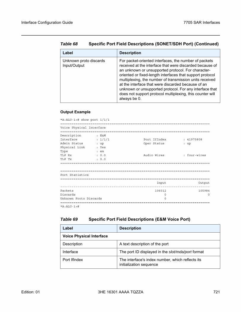
Interface Configuration Guide 7705 SAR Interfaces
Edition: 01 3HE 16301 AAAA TQZZA 721
Output Example
*A:ALU-1># show port 1/1/1===============================================================================Voice Physical Interface===============================================================================Description : E&MInterface : 1/1/1 Port IfIndex : 41975808Admin Status : up Oper Status : upPhysical Link : YesType : emTLP Rx : 0.0 Audio Wires : four-wiresTLP Tx : 0.0===============================================================================
===============================================================================Port Statistics===============================================================================
Input Output-------------------------------------------------------------------------------Packets 106012 105984Discards 0 0Unknown Proto Discards 0===============================================================================*A:ALU-1>#
Unknown proto discards Input/Output
For packet-oriented interfaces, the number of packets received at the interface that were discarded because of an unknown or unsupported protocol. For character-oriented or fixed-length interfaces that support protocol multiplexing, the number of transmission units received at the interface that were discarded because of an unknown or unsupported protocol. For any interface that does not support protocol multiplexing, this counter will always be 0.
Table 69 Specific Port Field Descriptions (E&M Voice Port)
Label Description
Voice Physical Interface
Description A text description of the port
Interface The port ID displayed in the slot/mda/port format
Port IfIndex The interface's index number, which reflects its initialization sequence
Table 68 Specific Port Field Descriptions (SONET/SDH Port) (Continued)
Label Description
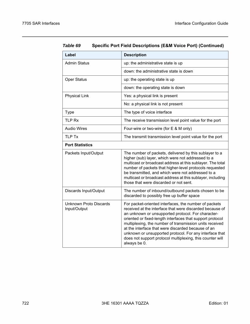
7705 SAR Interfaces
722
Interface Configuration Guide
3HE 16301 AAAA TQZZA Edition: 01
Admin Status up: the administrative state is up
down: the administrative state is down
Oper Status up: the operating state is up
down: the operating state is down
Physical Link Yes: a physical link is present
No: a physical link is not present
Type The type of voice interface
TLP Rx The receive transmission level point value for the port
Audio Wires Four-wire or two-wire (for E & M only)
TLP Tx The transmit transmission level point value for the port
Port Statistics
Packets Input/Output The number of packets, delivered by this sublayer to a higher (sub) layer, which were not addressed to a multicast or broadcast address at this sublayer. The total number of packets that higher-level protocols requested be transmitted, and which were not addressed to a multicast or broadcast address at this sublayer, including those that were discarded or not sent.
Discards Input/Output The number of inbound/outbound packets chosen to be discarded to possibly free up buffer space
Unknown Proto Discards Input/Output
For packet-oriented interfaces, the number of packets received at the interface that were discarded because of an unknown or unsupported protocol. For character-oriented or fixed-length interfaces that support protocol multiplexing, the number of transmission units received at the interface that were discarded because of an unknown or unsupported protocol. For any interface that does not support protocol multiplexing, this counter will always be 0.
Table 69 Specific Port Field Descriptions (E&M Voice Port) (Continued)
Label Description
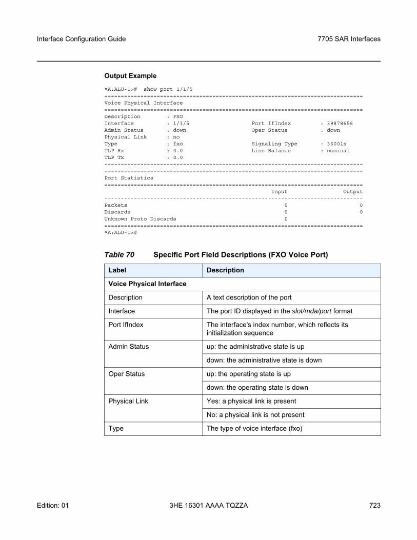
Interface Configuration Guide 7705 SAR Interfaces
Edition: 01 3HE 16301 AAAA TQZZA 723
Output Example
*A:ALU-1># show port 1/1/5===============================================================================Voice Physical Interface===============================================================================Description : FXOInterface : 1/1/5 Port IfIndex : 39878656Admin Status : down Oper Status : downPhysical Link : noType : fxo Signaling Type : 3600lsTLP Rx : 0.0 Line Balance : nominalTLP Tx : 0.0==============================================================================================================================================================Port Statistics===============================================================================
Input Output-------------------------------------------------------------------------------Packets 0 0Discards 0 0Unknown Proto Discards 0===============================================================================*A:ALU-1>#
Table 70 Specific Port Field Descriptions (FXO Voice Port)
Label Description
Voice Physical Interface
Description A text description of the port
Interface The port ID displayed in the slot/mda/port format
Port IfIndex The interface's index number, which reflects its initialization sequence
Admin Status up: the administrative state is up
down: the administrative state is down
Oper Status up: the operating state is up
down: the operating state is down
Physical Link Yes: a physical link is present
No: a physical link is not present
Type The type of voice interface (fxo)
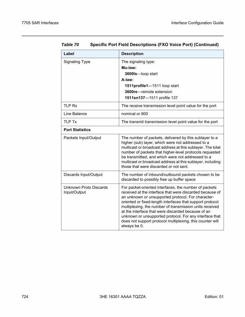
7705 SAR Interfaces
724
Interface Configuration Guide
3HE 16301 AAAA TQZZA Edition: 01
Signaling Type The signaling type: Mu-law:
3600ls—loop startA-law:
1511profile1—1511 loop start3600re—remote extension1511sn137—1511 profile 137
TLP Rx The receive transmission level point value for the port
Line Balance nominal or 800
TLP Tx The transmit transmission level point value for the port
Port Statistics
Packets Input/Output The number of packets, delivered by this sublayer to a higher (sub) layer, which were not addressed to a multicast or broadcast address at this sublayer. The total number of packets that higher-level protocols requested be transmitted, and which were not addressed to a multicast or broadcast address at this sublayer, including those that were discarded or not sent.
Discards Input/Output The number of inbound/outbound packets chosen to be discarded to possibly free up buffer space
Unknown Proto Discards Input/Output
For packet-oriented interfaces, the number of packets received at the interface that were discarded because of an unknown or unsupported protocol. For character-oriented or fixed-length interfaces that support protocol multiplexing, the number of transmission units received at the interface that were discarded because of an unknown or unsupported protocol. For any interface that does not support protocol multiplexing, this counter will always be 0.
Table 70 Specific Port Field Descriptions (FXO Voice Port) (Continued)
Label Description

Interface Configuration Guide 7705 SAR Interfaces
Edition: 01 3HE 16301 AAAA TQZZA 725
Output Example
*A:ALU-1># show port 1/6/1===============================================================================Voice Physical Interface===============================================================================Description : FXOInterface : 1/1/5 Port IfIndex : 39878656Admin Status : down Oper Status : downPhysical Link : noType : fxs Signaling Type : 3600lsTLP Rx : -3.0 Line Balance : nominalTLP Tx : 0.0 Ring Generation : 16==============================================================================================================================================================Port Statistics===============================================================================
Input Output-------------------------------------------------------------------------------Packets 0 0Discards 0 0Unknown Proto Discards 0===============================================================================*A:ALU-1>#
Table 71 Specific Port Field Descriptions (FXS Voice Port)
Label Description
Voice Physical Interface
Description A text description of the port
Interface The port ID displayed in the slot/mda/port format
Port IfIndex The interface's index number, which reflects its initialization sequence
Admin Status up: the administrative state is up
down: the administrative state is down
Oper Status up: the operating state is up
down: the operating state is down
Physical Link Yes: a physical link is present
No: a physical link is not present
Type The type of voice interface (fxs)
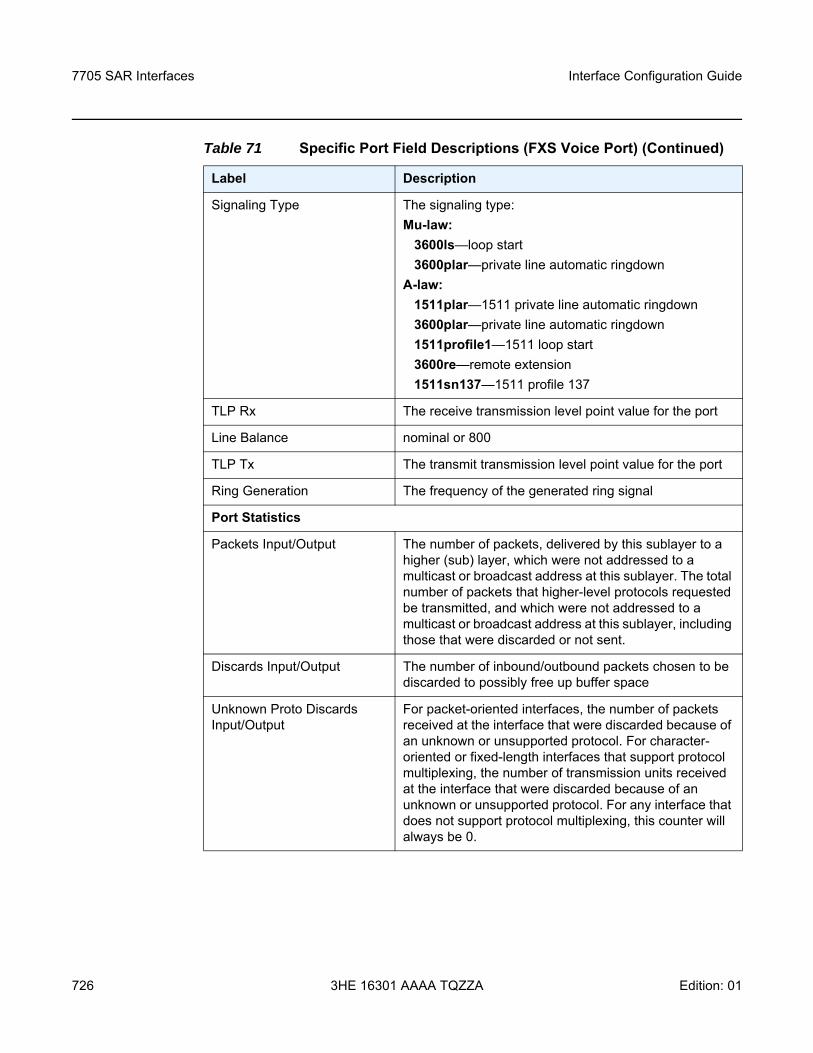
7705 SAR Interfaces
726
Interface Configuration Guide
3HE 16301 AAAA TQZZA Edition: 01
Signaling Type The signaling type: Mu-law:
3600ls—loop start3600plar—private line automatic ringdown
A-law:1511plar—1511 private line automatic ringdown3600plar—private line automatic ringdown1511profile1—1511 loop start3600re—remote extension1511sn137—1511 profile 137
TLP Rx The receive transmission level point value for the port
Line Balance nominal or 800
TLP Tx The transmit transmission level point value for the port
Ring Generation The frequency of the generated ring signal
Port Statistics
Packets Input/Output The number of packets, delivered by this sublayer to a higher (sub) layer, which were not addressed to a multicast or broadcast address at this sublayer. The total number of packets that higher-level protocols requested be transmitted, and which were not addressed to a multicast or broadcast address at this sublayer, including those that were discarded or not sent.
Discards Input/Output The number of inbound/outbound packets chosen to be discarded to possibly free up buffer space
Unknown Proto Discards Input/Output
For packet-oriented interfaces, the number of packets received at the interface that were discarded because of an unknown or unsupported protocol. For character-oriented or fixed-length interfaces that support protocol multiplexing, the number of transmission units received at the interface that were discarded because of an unknown or unsupported protocol. For any interface that does not support protocol multiplexing, this counter will always be 0.
Table 71 Specific Port Field Descriptions (FXS Voice Port) (Continued)
Label Description
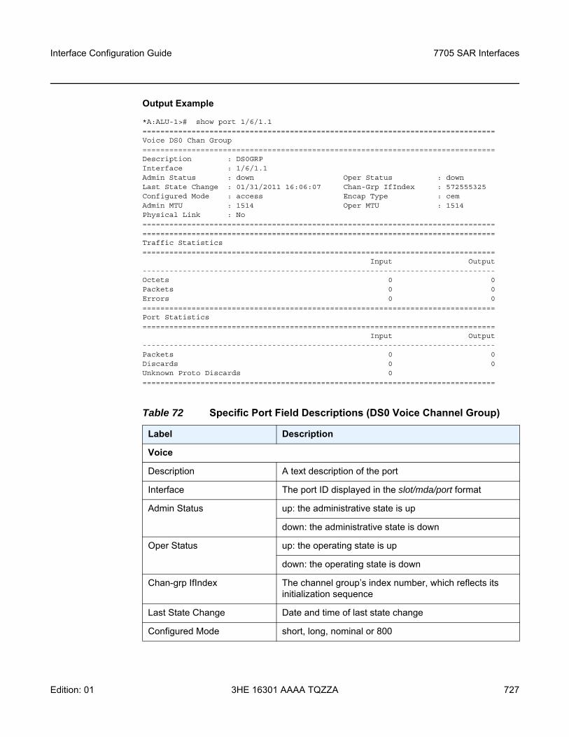
Interface Configuration Guide 7705 SAR Interfaces
Edition: 01 3HE 16301 AAAA TQZZA 727
Output Example
*A:ALU-1># show port 1/6/1.1===============================================================================Voice DS0 Chan Group===============================================================================Description : DS0GRPInterface : 1/6/1.1Admin Status : down Oper Status : downLast State Change : 01/31/2011 16:06:07 Chan-Grp IfIndex : 572555325Configured Mode : access Encap Type : cemAdmin MTU : 1514 Oper MTU : 1514Physical Link : No==============================================================================================================================================================Traffic Statistics===============================================================================
Input Output-------------------------------------------------------------------------------Octets 0 0Packets 0 0Errors 0 0===============================================================================Port Statistics===============================================================================
Input Output-------------------------------------------------------------------------------Packets 0 0Discards 0 0Unknown Proto Discards 0===============================================================================
Table 72 Specific Port Field Descriptions (DS0 Voice Channel Group)
Label Description
Voice
Description A text description of the port
Interface The port ID displayed in the slot/mda/port format
Admin Status up: the administrative state is up
down: the administrative state is down
Oper Status up: the operating state is up
down: the operating state is down
Chan-grp IfIndex The channel group’s index number, which reflects its initialization sequence
Last State Change Date and time of last state change
Configured Mode short, long, nominal or 800
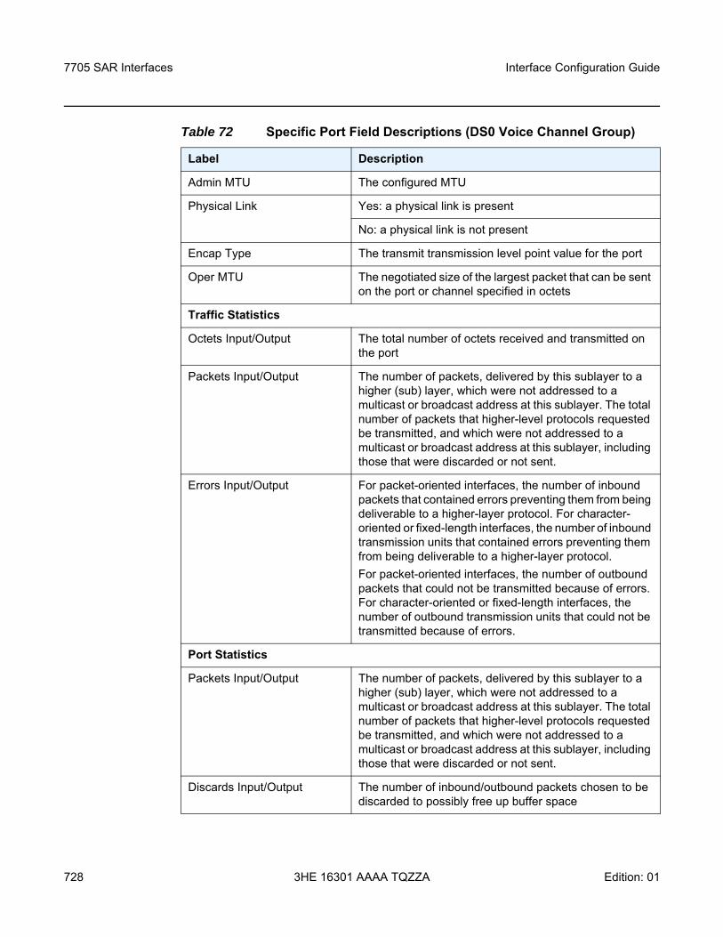
7705 SAR Interfaces
728
Interface Configuration Guide
3HE 16301 AAAA TQZZA Edition: 01
Admin MTU The configured MTU
Physical Link Yes: a physical link is present
No: a physical link is not present
Encap Type The transmit transmission level point value for the port
Oper MTU The negotiated size of the largest packet that can be sent on the port or channel specified in octets
Traffic Statistics
Octets Input/Output The total number of octets received and transmitted on the port
Packets Input/Output The number of packets, delivered by this sublayer to a higher (sub) layer, which were not addressed to a multicast or broadcast address at this sublayer. The total number of packets that higher-level protocols requested be transmitted, and which were not addressed to a multicast or broadcast address at this sublayer, including those that were discarded or not sent.
Errors Input/Output For packet-oriented interfaces, the number of inbound packets that contained errors preventing them from being deliverable to a higher-layer protocol. For character-oriented or fixed-length interfaces, the number of inbound transmission units that contained errors preventing them from being deliverable to a higher-layer protocol.For packet-oriented interfaces, the number of outbound packets that could not be transmitted because of errors. For character-oriented or fixed-length interfaces, the number of outbound transmission units that could not be transmitted because of errors.
Port Statistics
Packets Input/Output The number of packets, delivered by this sublayer to a higher (sub) layer, which were not addressed to a multicast or broadcast address at this sublayer. The total number of packets that higher-level protocols requested be transmitted, and which were not addressed to a multicast or broadcast address at this sublayer, including those that were discarded or not sent.
Discards Input/Output The number of inbound/outbound packets chosen to be discarded to possibly free up buffer space
Table 72 Specific Port Field Descriptions (DS0 Voice Channel Group)
Label Description
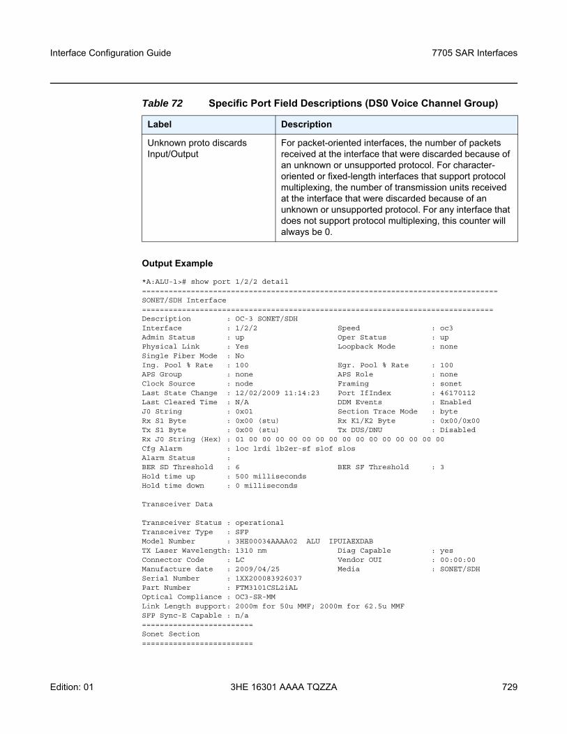
Interface Configuration Guide 7705 SAR Interfaces
Edition: 01 3HE 16301 AAAA TQZZA 729
Output Example
*A:ALU-1># show port 1/2/2 detail================================================================================SONET/SDH Interface===============================================================================Description : OC-3 SONET/SDHInterface : 1/2/2 Speed : oc3Admin Status : up Oper Status : upPhysical Link : Yes Loopback Mode : noneSingle Fiber Mode : NoIng. Pool % Rate : 100 Egr. Pool % Rate : 100APS Group : none APS Role : noneClock Source : node Framing : sonetLast State Change : 12/02/2009 11:14:23 Port IfIndex : 46170112Last Cleared Time : N/A DDM Events : EnabledJ0 String : 0x01 Section Trace Mode : byteRx S1 Byte : 0x00 (stu) Rx K1/K2 Byte : 0x00/0x00Tx S1 Byte : 0x00 (stu) Tx DUS/DNU : DisabledRx J0 String (Hex) : 01 00 00 00 00 00 00 00 00 00 00 00 00 00 00 00Cfg Alarm : loc lrdi lb2er-sf slof slosAlarm Status :BER SD Threshold : 6 BER SF Threshold : 3Hold time up : 500 millisecondsHold time down : 0 milliseconds
Transceiver Data
Transceiver Status : operationalTransceiver Type : SFPModel Number : 3HE00034AAAA02 ALU IPUIAEXDABTX Laser Wavelength: 1310 nm Diag Capable : yesConnector Code : LC Vendor OUI : 00:00:00Manufacture date : 2009/04/25 Media : SONET/SDHSerial Number : 1XX200083926037Part Number : FTM3101CSL2iALOptical Compliance : OC3-SR-MMLink Length support: 2000m for 50u MMF; 2000m for 62.5u MMFSFP Sync-E Capable : n/a=========================Sonet Section=========================
Unknown proto discards Input/Output
For packet-oriented interfaces, the number of packets received at the interface that were discarded because of an unknown or unsupported protocol. For character-oriented or fixed-length interfaces that support protocol multiplexing, the number of transmission units received at the interface that were discarded because of an unknown or unsupported protocol. For any interface that does not support protocol multiplexing, this counter will always be 0.
Table 72 Specific Port Field Descriptions (DS0 Voice Channel Group)
Label Description
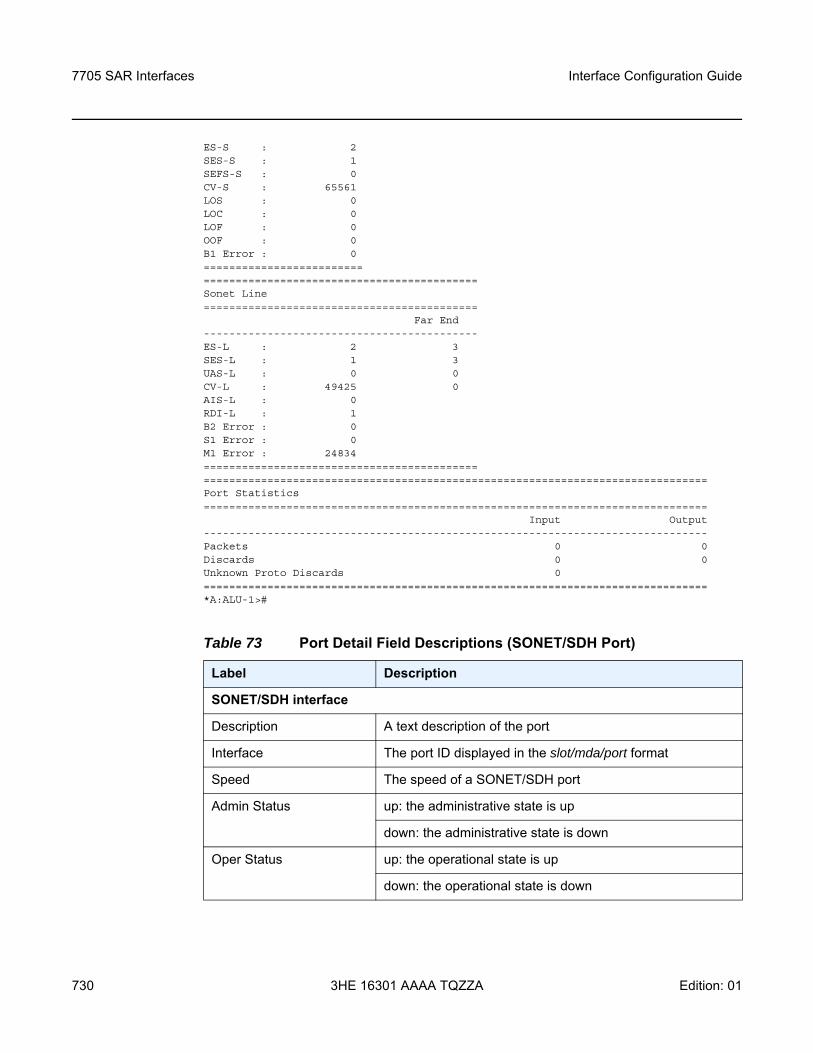
7705 SAR Interfaces
730
Interface Configuration Guide
3HE 16301 AAAA TQZZA Edition: 01
ES-S : 2SES-S : 1SEFS-S : 0CV-S : 65561LOS : 0LOC : 0LOF : 0OOF : 0B1 Error : 0====================================================================Sonet Line===========================================
Far End-------------------------------------------ES-L : 2 3SES-L : 1 3UAS-L : 0 0CV-L : 49425 0AIS-L : 0RDI-L : 1B2 Error : 0S1 Error : 0M1 Error : 24834==========================================================================================================================Port Statistics===============================================================================
Input Output-------------------------------------------------------------------------------Packets 0 0Discards 0 0Unknown Proto Discards 0===============================================================================*A:ALU-1>#
Table 73 Port Detail Field Descriptions (SONET/SDH Port)
Label Description
SONET/SDH interface
Description A text description of the port
Interface The port ID displayed in the slot/mda/port format
Speed The speed of a SONET/SDH port
Admin Status up: the administrative state is up
down: the administrative state is down
Oper Status up: the operational state is up
down: the operational state is down
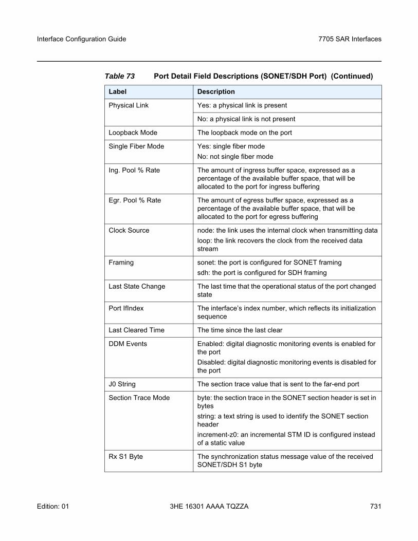
Interface Configuration Guide 7705 SAR Interfaces
Edition: 01 3HE 16301 AAAA TQZZA 731
Physical Link Yes: a physical link is present
No: a physical link is not present
Loopback Mode The loopback mode on the port
Single Fiber Mode Yes: single fiber modeNo: not single fiber mode
Ing. Pool % Rate The amount of ingress buffer space, expressed as a percentage of the available buffer space, that will be allocated to the port for ingress buffering
Egr. Pool % Rate The amount of egress buffer space, expressed as a percentage of the available buffer space, that will be allocated to the port for egress buffering
Clock Source node: the link uses the internal clock when transmitting dataloop: the link recovers the clock from the received data stream
Framing sonet: the port is configured for SONET framingsdh: the port is configured for SDH framing
Last State Change The last time that the operational status of the port changed state
Port IfIndex The interface’s index number, which reflects its initialization sequence
Last Cleared Time The time since the last clear
DDM Events Enabled: digital diagnostic monitoring events is enabled for the portDisabled: digital diagnostic monitoring events is disabled for the port
J0 String The section trace value that is sent to the far-end port
Section Trace Mode byte: the section trace in the SONET section header is set in bytesstring: a text string is used to identify the SONET section headerincrement-z0: an incremental STM ID is configured instead of a static value
Rx S1 Byte The synchronization status message value of the received SONET/SDH S1 byte
Table 73 Port Detail Field Descriptions (SONET/SDH Port) (Continued)
Label Description
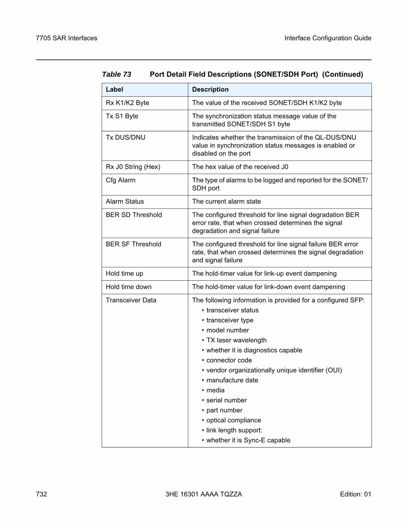
7705 SAR Interfaces
732
Interface Configuration Guide
3HE 16301 AAAA TQZZA Edition: 01
Rx K1/K2 Byte The value of the received SONET/SDH K1/K2 byte
Tx S1 Byte The synchronization status message value of the transmitted SONET/SDH S1 byte
Tx DUS/DNU Indicates whether the transmission of the QL-DUS/DNU value in synchronization status messages is enabled or disabled on the port
Rx J0 String (Hex) The hex value of the received J0
Cfg Alarm The type of alarms to be logged and reported for the SONET/SDH port
Alarm Status The current alarm state
BER SD Threshold The configured threshold for line signal degradation BER error rate, that when crossed determines the signal degradation and signal failure
BER SF Threshold The configured threshold for line signal failure BER error rate, that when crossed determines the signal degradation and signal failure
Hold time up The hold-timer value for link-up event dampening
Hold time down The hold-timer value for link-down event dampening
Transceiver Data The following information is provided for a configured SFP:• transceiver status• transceiver type• model number• TX laser wavelength• whether it is diagnostics capable • connector code • vendor organizationally unique identifier (OUI)• manufacture date • media • serial number• part number• optical compliance• link length support:• whether it is Sync-E capable
Table 73 Port Detail Field Descriptions (SONET/SDH Port) (Continued)
Label Description
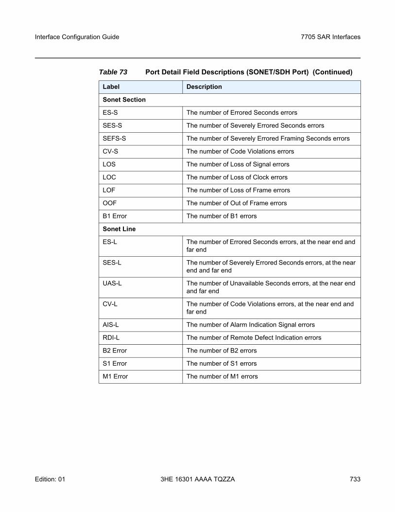
Interface Configuration Guide 7705 SAR Interfaces
Edition: 01 3HE 16301 AAAA TQZZA 733
Sonet Section
ES-S The number of Errored Seconds errors
SES-S The number of Severely Errored Seconds errors
SEFS-S The number of Severely Errored Framing Seconds errors
CV-S The number of Code Violations errors
LOS The number of Loss of Signal errors
LOC The number of Loss of Clock errors
LOF The number of Loss of Frame errors
OOF The number of Out of Frame errors
B1 Error The number of B1 errors
Sonet Line
ES-L The number of Errored Seconds errors, at the near end and far end
SES-L The number of Severely Errored Seconds errors, at the near end and far end
UAS-L The number of Unavailable Seconds errors, at the near end and far end
CV-L The number of Code Violations errors, at the near end and far end
AIS-L The number of Alarm Indication Signal errors
RDI-L The number of Remote Defect Indication errors
B2 Error The number of B2 errors
S1 Error The number of S1 errors
M1 Error The number of M1 errors
Table 73 Port Detail Field Descriptions (SONET/SDH Port) (Continued)
Label Description
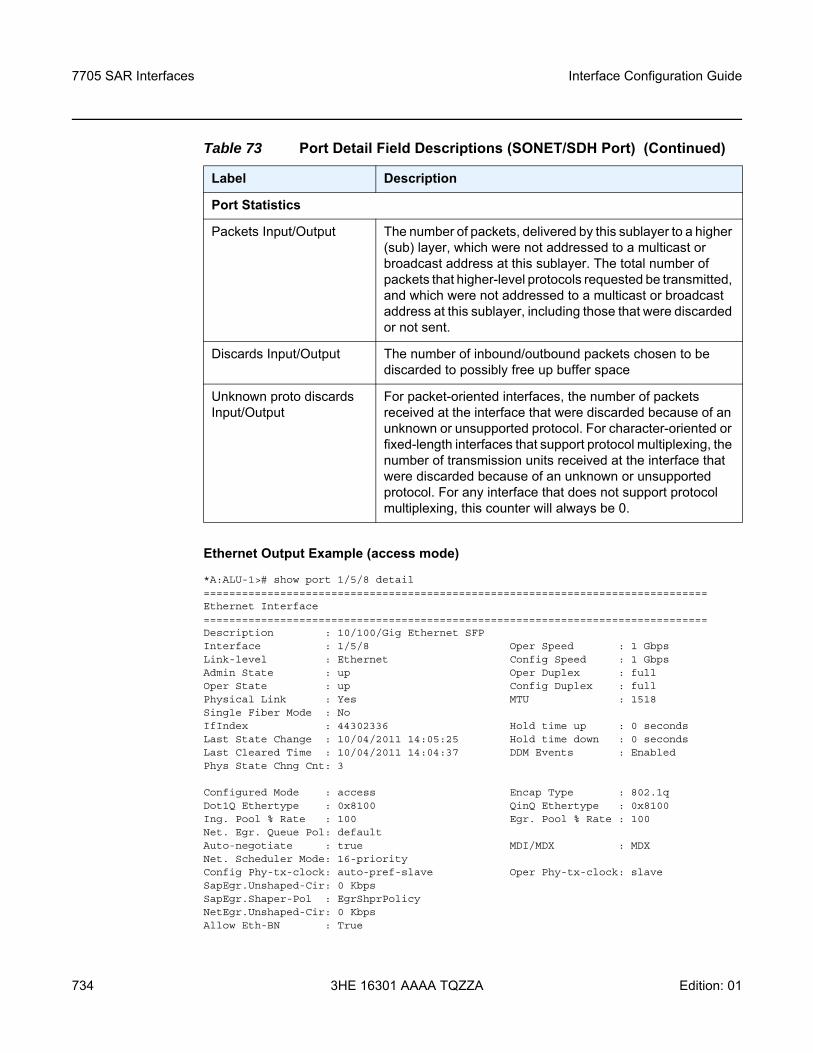
7705 SAR Interfaces
734
Interface Configuration Guide
3HE 16301 AAAA TQZZA Edition: 01
Ethernet Output Example (access mode)
*A:ALU-1># show port 1/5/8 detail===============================================================================Ethernet Interface===============================================================================Description : 10/100/Gig Ethernet SFPInterface : 1/5/8 Oper Speed : 1 GbpsLink-level : Ethernet Config Speed : 1 GbpsAdmin State : up Oper Duplex : fullOper State : up Config Duplex : fullPhysical Link : Yes MTU : 1518Single Fiber Mode : NoIfIndex : 44302336 Hold time up : 0 secondsLast State Change : 10/04/2011 14:05:25 Hold time down : 0 secondsLast Cleared Time : 10/04/2011 14:04:37 DDM Events : EnabledPhys State Chng Cnt: 3
Configured Mode : access Encap Type : 802.1qDot1Q Ethertype : 0x8100 QinQ Ethertype : 0x8100Ing. Pool % Rate : 100 Egr. Pool % Rate : 100Net. Egr. Queue Pol: defaultAuto-negotiate : true MDI/MDX : MDXNet. Scheduler Mode: 16-priorityConfig Phy-tx-clock: auto-pref-slave Oper Phy-tx-clock: slaveSapEgr.Unshaped-Cir: 0 KbpsSapEgr.Shaper-Pol : EgrShprPolicyNetEgr.Unshaped-Cir: 0 KbpsAllow Eth-BN : True
Port Statistics
Packets Input/Output The number of packets, delivered by this sublayer to a higher (sub) layer, which were not addressed to a multicast or broadcast address at this sublayer. The total number of packets that higher-level protocols requested be transmitted, and which were not addressed to a multicast or broadcast address at this sublayer, including those that were discarded or not sent.
Discards Input/Output The number of inbound/outbound packets chosen to be discarded to possibly free up buffer space
Unknown proto discards Input/Output
For packet-oriented interfaces, the number of packets received at the interface that were discarded because of an unknown or unsupported protocol. For character-oriented or fixed-length interfaces that support protocol multiplexing, the number of transmission units received at the interface that were discarded because of an unknown or unsupported protocol. For any interface that does not support protocol multiplexing, this counter will always be 0.
Table 73 Port Detail Field Descriptions (SONET/SDH Port) (Continued)
Label Description
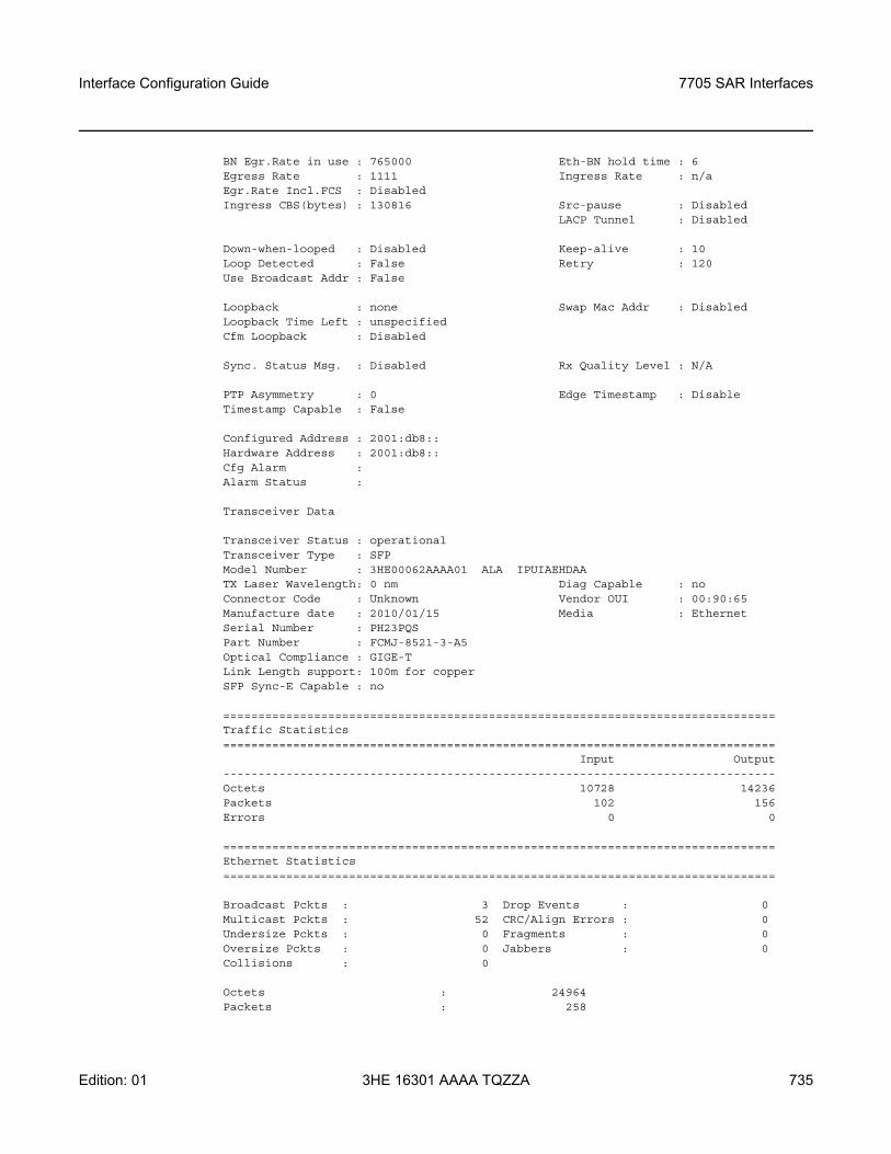
Interface Configuration Guide 7705 SAR Interfaces
Edition: 01 3HE 16301 AAAA TQZZA 735
BN Egr.Rate in use : 765000 Eth-BN hold time : 6Egress Rate : 1111 Ingress Rate : n/aEgr.Rate Incl.FCS : DisabledIngress CBS(bytes) : 130816 Src-pause : Disabled
LACP Tunnel : Disabled
Down-when-looped : Disabled Keep-alive : 10Loop Detected : False Retry : 120Use Broadcast Addr : False
Loopback : none Swap Mac Addr : DisabledLoopback Time Left : unspecifiedCfm Loopback : Disabled
Sync. Status Msg. : Disabled Rx Quality Level : N/A
PTP Asymmetry : 0 Edge Timestamp : DisableTimestamp Capable : False
Configured Address : 2001:db8::Hardware Address : 2001:db8::Cfg Alarm :Alarm Status :
Transceiver Data
Transceiver Status : operationalTransceiver Type : SFPModel Number : 3HE00062AAAA01 ALA IPUIAEHDAATX Laser Wavelength: 0 nm Diag Capable : noConnector Code : Unknown Vendor OUI : 00:90:65Manufacture date : 2010/01/15 Media : EthernetSerial Number : PH23PQSPart Number : FCMJ-8521-3-A5Optical Compliance : GIGE-TLink Length support: 100m for copperSFP Sync-E Capable : no
===============================================================================Traffic Statistics===============================================================================
Input Output-------------------------------------------------------------------------------Octets 10728 14236Packets 102 156Errors 0 0
===============================================================================Ethernet Statistics===============================================================================
Broadcast Pckts : 3 Drop Events : 0Multicast Pckts : 52 CRC/Align Errors : 0Undersize Pckts : 0 Fragments : 0Oversize Pckts : 0 Jabbers : 0Collisions : 0
Octets : 24964Packets : 258
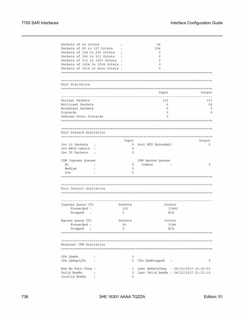
7705 SAR Interfaces
736
Interface Configuration Guide
3HE 16301 AAAA TQZZA Edition: 01
Packets of 64 Octets : 54Packets of 65 to 127 Octets : 204Packets of 128 to 255 Octets : 0Packets of 256 to 511 Octets : 0Packets of 512 to 1023 Octets : 0Packets of 1024 to 1518 Octets : 0Packets of 1519 or more Octets : 0===============================================================================
===============================================================================Port Statistics===============================================================================
Input Output-------------------------------------------------------------------------------Unicast Packets 102 101Multicast Packets 0 52Broadcast Packets 0 3Discards 0 0Unknown Proto Discards 0===============================================================================
===============================================================================Port Discard Statistics===============================================================================
Input OutputInv L2 Packets : 0 Port MTU Exceeded: 0Inv MPLS Labels : 0Inv IP Packets : 0
CSM Ingress Queues CSM Egress QueuesHi : 0 Common : 0Medium : 0Low : 0
===============================================================================
===============================================================================Port Control Statistics===============================================================================
-------------------------------------------------------------------------------Ingress Queue CTL Packets Octets
Forwarded : 102 13482Dropped : 0 N/A
Egress Queue CTL Packets OctetsForwarded : 56 3184Dropped : 0 N/A
===============================================================================
===============================================================================Ethernet CFM Statistics===============================================================================
Cfm LbmRx : 0Cfm LbReplyTx : 0 Cfm LbmDropped : 0
Num Bn Rate Chng : 1 Last BnRateChng : 04/12/2017 21:20:53Valid BnmRx : 2 Last Valid BnmRx : 04/12/2017 21:21:10Invalid BnmRx : 0
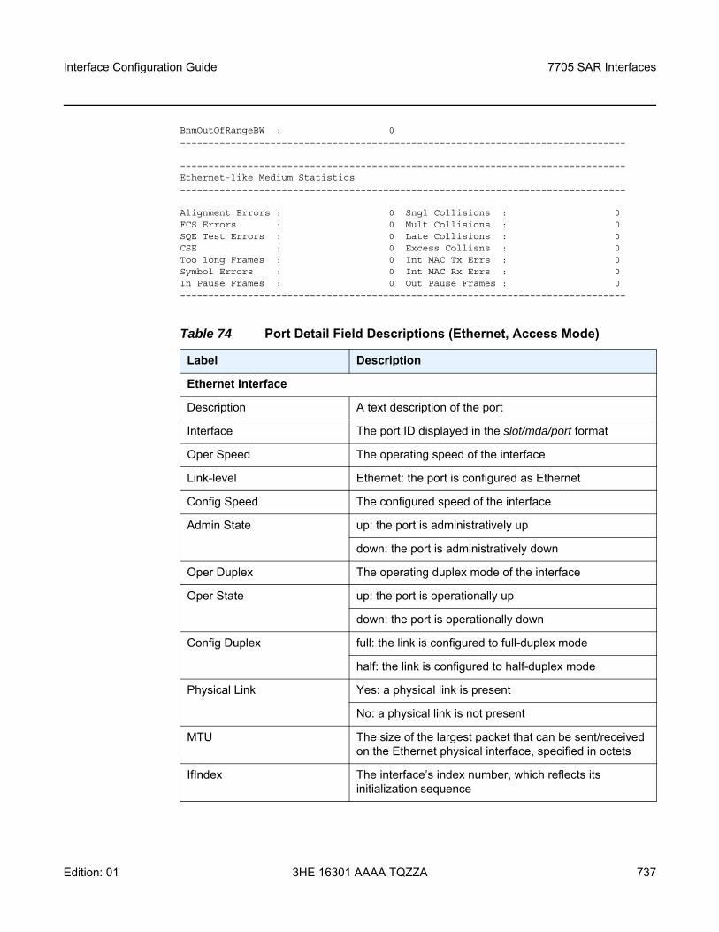
Interface Configuration Guide 7705 SAR Interfaces
Edition: 01 3HE 16301 AAAA TQZZA 737
BnmOutOfRangeBW : 0===============================================================================
===============================================================================Ethernet-like Medium Statistics===============================================================================
Alignment Errors : 0 Sngl Collisions : 0FCS Errors : 0 Mult Collisions : 0SQE Test Errors : 0 Late Collisions : 0CSE : 0 Excess Collisns : 0Too long Frames : 0 Int MAC Tx Errs : 0Symbol Errors : 0 Int MAC Rx Errs : 0In Pause Frames : 0 Out Pause Frames : 0===============================================================================
Table 74 Port Detail Field Descriptions (Ethernet, Access Mode)
Label Description
Ethernet Interface
Description A text description of the port
Interface The port ID displayed in the slot/mda/port format
Oper Speed The operating speed of the interface
Link-level Ethernet: the port is configured as Ethernet
Config Speed The configured speed of the interface
Admin State up: the port is administratively up
down: the port is administratively down
Oper Duplex The operating duplex mode of the interface
Oper State up: the port is operationally up
down: the port is operationally down
Config Duplex full: the link is configured to full-duplex mode
half: the link is configured to half-duplex mode
Physical Link Yes: a physical link is present
No: a physical link is not present
MTU The size of the largest packet that can be sent/received on the Ethernet physical interface, specified in octets
IfIndex The interface’s index number, which reflects its initialization sequence
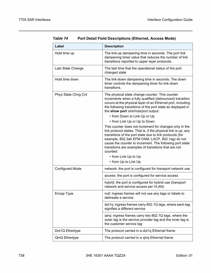
7705 SAR Interfaces
738
Interface Configuration Guide
3HE 16301 AAAA TQZZA Edition: 01
Hold time up The link-up dampening time in seconds. The port link dampening timer value that reduces the number of link transitions reported to upper layer protocols.
Last State Change The last time that the operational status of the port changed state
Hold time down The link-down dampening time in seconds. The down timer controls the dampening timer for link down transitions.
Phys State Chng Cnt The physical state change counter. This counter increments when a fully qualified (debounced) transition occurs at the physical layer of an Ethernet port, including the following transitions of the port state as displayed in the show port slot/mda/port output:
• from Down to Link Up or Up• from Link Up or Up to Down
This counter does not increment for changes only in the link protocol states. That is, if the physical link is up, any transitions of the port state due to link protocols (for example, 802.3ah EFM OAM, LACP, 802.1ag) do not cause the counter to increment. The following port state transitions are examples of transitions that are not counted:
• from Link Up to Up• from Up to Link Up
Configured Mode network: the port is configured for transport network use
access: the port is configured for service access
hybrid: the port is configured for hybrid use (transport network and service access per VLAN)
Encap Type null: ingress frames will not use any tags or labels to delineate a service
dot1q: ingress frames carry 802.1Q tags, where each tag signifies a different service
qinq: ingress frames carry two 802.1Q tags, where the outer tag is the service provider tag and the inner tag is the customer service tag
Dot1Q Ethertype The protocol carried in a dot1q Ethernet frame
QinQ Ethertype The protocol carried in a qinq Ethernet frame
Table 74 Port Detail Field Descriptions (Ethernet, Access Mode)
Label Description
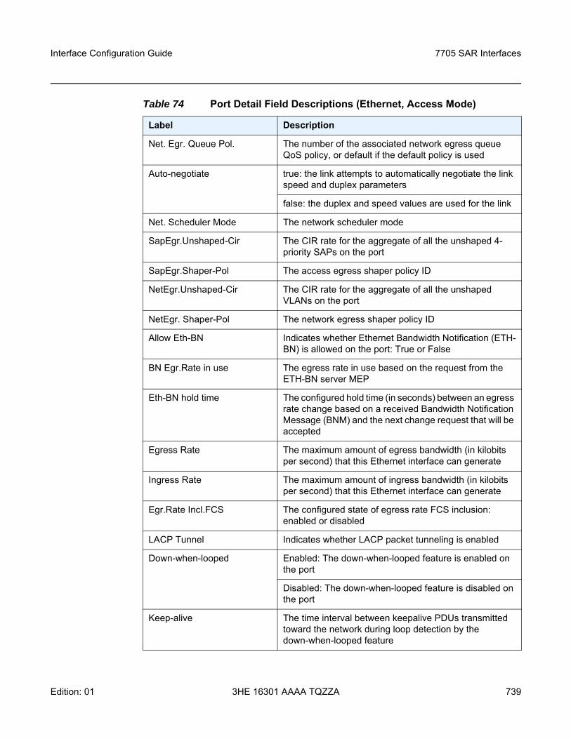
Interface Configuration Guide 7705 SAR Interfaces
Edition: 01 3HE 16301 AAAA TQZZA 739
Net. Egr. Queue Pol. The number of the associated network egress queue QoS policy, or default if the default policy is used
Auto-negotiate true: the link attempts to automatically negotiate the link speed and duplex parameters
false: the duplex and speed values are used for the link
Net. Scheduler Mode The network scheduler mode
SapEgr.Unshaped-Cir The CIR rate for the aggregate of all the unshaped 4-priority SAPs on the port
SapEgr.Shaper-Pol The access egress shaper policy ID
NetEgr.Unshaped-Cir The CIR rate for the aggregate of all the unshaped VLANs on the port
NetEgr. Shaper-Pol The network egress shaper policy ID
Allow Eth-BN Indicates whether Ethernet Bandwidth Notification (ETH-BN) is allowed on the port: True or False
BN Egr.Rate in use The egress rate in use based on the request from the ETH-BN server MEP
Eth-BN hold time The configured hold time (in seconds) between an egress rate change based on a received Bandwidth Notification Message (BNM) and the next change request that will be accepted
Egress Rate The maximum amount of egress bandwidth (in kilobits per second) that this Ethernet interface can generate
Ingress Rate The maximum amount of ingress bandwidth (in kilobits per second) that this Ethernet interface can generate
Egr.Rate Incl.FCS The configured state of egress rate FCS inclusion: enabled or disabled
LACP Tunnel Indicates whether LACP packet tunneling is enabled
Down-when-looped Enabled: The down-when-looped feature is enabled on the port
Disabled: The down-when-looped feature is disabled on the port
Keep-alive The time interval between keepalive PDUs transmitted toward the network during loop detection by the down-when-looped feature
Table 74 Port Detail Field Descriptions (Ethernet, Access Mode)
Label Description
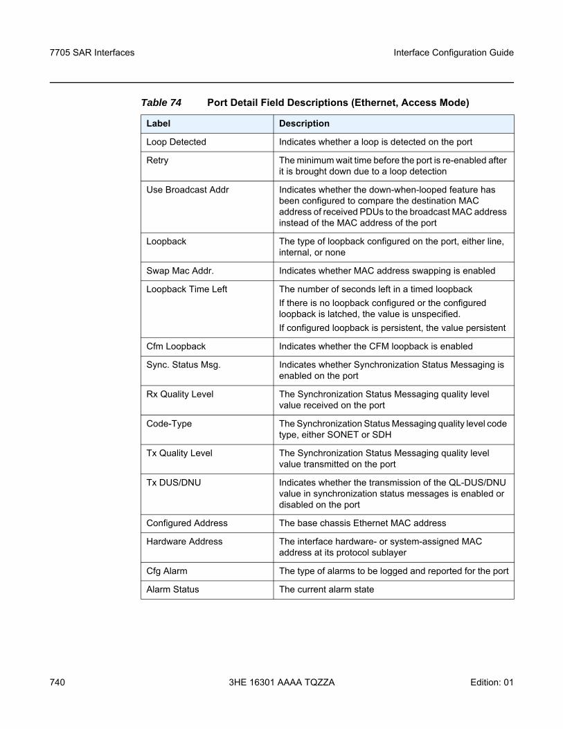
7705 SAR Interfaces
740
Interface Configuration Guide
3HE 16301 AAAA TQZZA Edition: 01
Loop Detected Indicates whether a loop is detected on the port
Retry The minimum wait time before the port is re-enabled after it is brought down due to a loop detection
Use Broadcast Addr Indicates whether the down-when-looped feature has been configured to compare the destination MAC address of received PDUs to the broadcast MAC address instead of the MAC address of the port
Loopback The type of loopback configured on the port, either line, internal, or none
Swap Mac Addr. Indicates whether MAC address swapping is enabled
Loopback Time Left The number of seconds left in a timed loopbackIf there is no loopback configured or the configured loopback is latched, the value is unspecified.If configured loopback is persistent, the value persistent
Cfm Loopback Indicates whether the CFM loopback is enabled
Sync. Status Msg. Indicates whether Synchronization Status Messaging is enabled on the port
Rx Quality Level The Synchronization Status Messaging quality level value received on the port
Code-Type The Synchronization Status Messaging quality level code type, either SONET or SDH
Tx Quality Level The Synchronization Status Messaging quality level value transmitted on the port
Tx DUS/DNU Indicates whether the transmission of the QL-DUS/DNU value in synchronization status messages is enabled or disabled on the port
Configured Address The base chassis Ethernet MAC address
Hardware Address The interface hardware- or system-assigned MAC address at its protocol sublayer
Cfg Alarm The type of alarms to be logged and reported for the port
Alarm Status The current alarm state
Table 74 Port Detail Field Descriptions (Ethernet, Access Mode)
Label Description
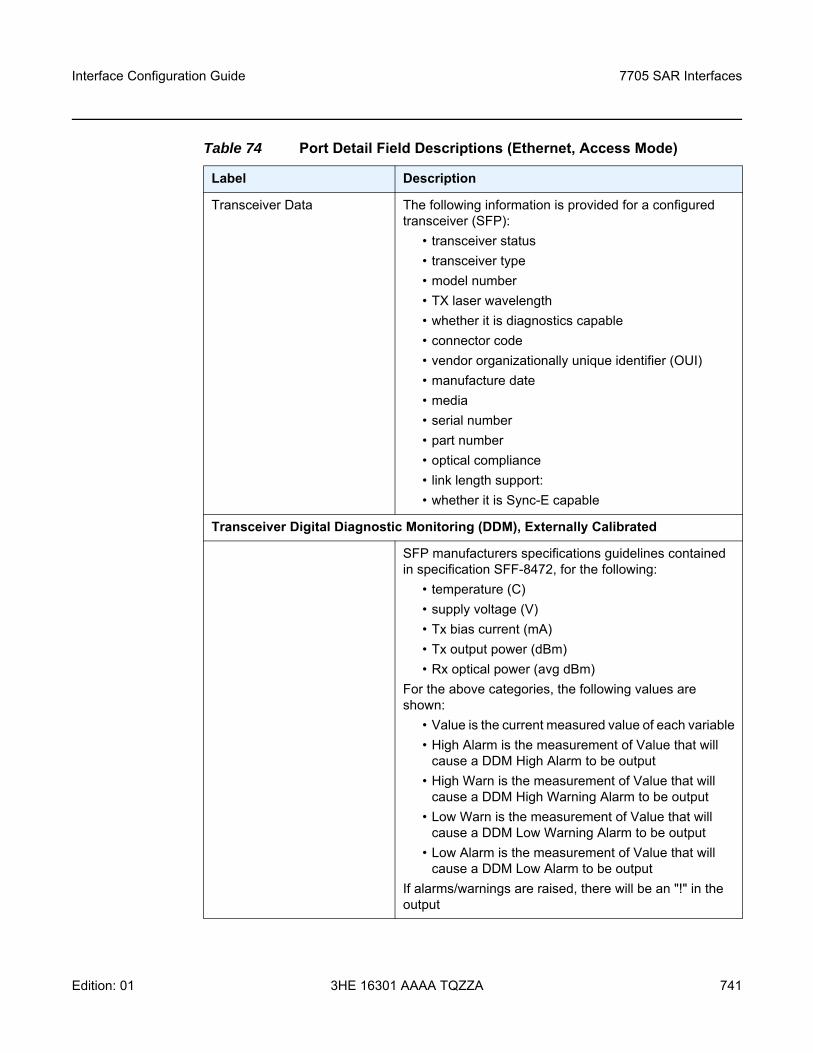
Interface Configuration Guide 7705 SAR Interfaces
Edition: 01 3HE 16301 AAAA TQZZA 741
Transceiver Data The following information is provided for a configured transceiver (SFP):
• transceiver status• transceiver type• model number• TX laser wavelength• whether it is diagnostics capable • connector code • vendor organizationally unique identifier (OUI)• manufacture date • media • serial number• part number• optical compliance• link length support:• whether it is Sync-E capable
Transceiver Digital Diagnostic Monitoring (DDM), Externally Calibrated
SFP manufacturers specifications guidelines contained in specification SFF-8472, for the following:
• temperature (C) • supply voltage (V)• Tx bias current (mA)• Tx output power (dBm)• Rx optical power (avg dBm)
For the above categories, the following values are shown:
• Value is the current measured value of each variable• High Alarm is the measurement of Value that will
cause a DDM High Alarm to be output• High Warn is the measurement of Value that will
cause a DDM High Warning Alarm to be output• Low Warn is the measurement of Value that will
cause a DDM Low Warning Alarm to be output• Low Alarm is the measurement of Value that will
cause a DDM Low Alarm to be outputIf alarms/warnings are raised, there will be an "!" in the output
Table 74 Port Detail Field Descriptions (Ethernet, Access Mode)
Label Description
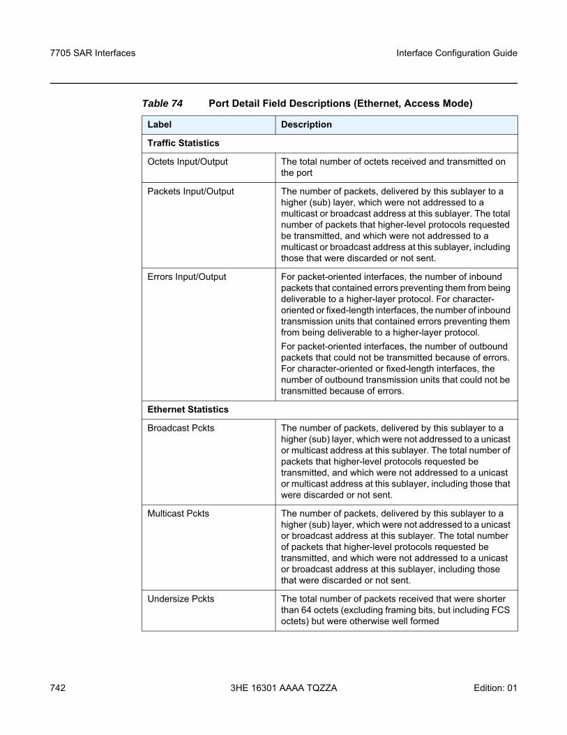
7705 SAR Interfaces
742
Interface Configuration Guide
3HE 16301 AAAA TQZZA Edition: 01
Traffic Statistics
Octets Input/Output The total number of octets received and transmitted on the port
Packets Input/Output The number of packets, delivered by this sublayer to a higher (sub) layer, which were not addressed to a multicast or broadcast address at this sublayer. The total number of packets that higher-level protocols requested be transmitted, and which were not addressed to a multicast or broadcast address at this sublayer, including those that were discarded or not sent.
Errors Input/Output For packet-oriented interfaces, the number of inbound packets that contained errors preventing them from being deliverable to a higher-layer protocol. For character-oriented or fixed-length interfaces, the number of inbound transmission units that contained errors preventing them from being deliverable to a higher-layer protocol.For packet-oriented interfaces, the number of outbound packets that could not be transmitted because of errors. For character-oriented or fixed-length interfaces, the number of outbound transmission units that could not be transmitted because of errors.
Ethernet Statistics
Broadcast Pckts The number of packets, delivered by this sublayer to a higher (sub) layer, which were not addressed to a unicast or multicast address at this sublayer. The total number of packets that higher-level protocols requested be transmitted, and which were not addressed to a unicast or multicast address at this sublayer, including those that were discarded or not sent.
Multicast Pckts The number of packets, delivered by this sublayer to a higher (sub) layer, which were not addressed to a unicast or broadcast address at this sublayer. The total number of packets that higher-level protocols requested be transmitted, and which were not addressed to a unicast or broadcast address at this sublayer, including those that were discarded or not sent.
Undersize Pckts The total number of packets received that were shorter than 64 octets (excluding framing bits, but including FCS octets) but were otherwise well formed
Table 74 Port Detail Field Descriptions (Ethernet, Access Mode)
Label Description
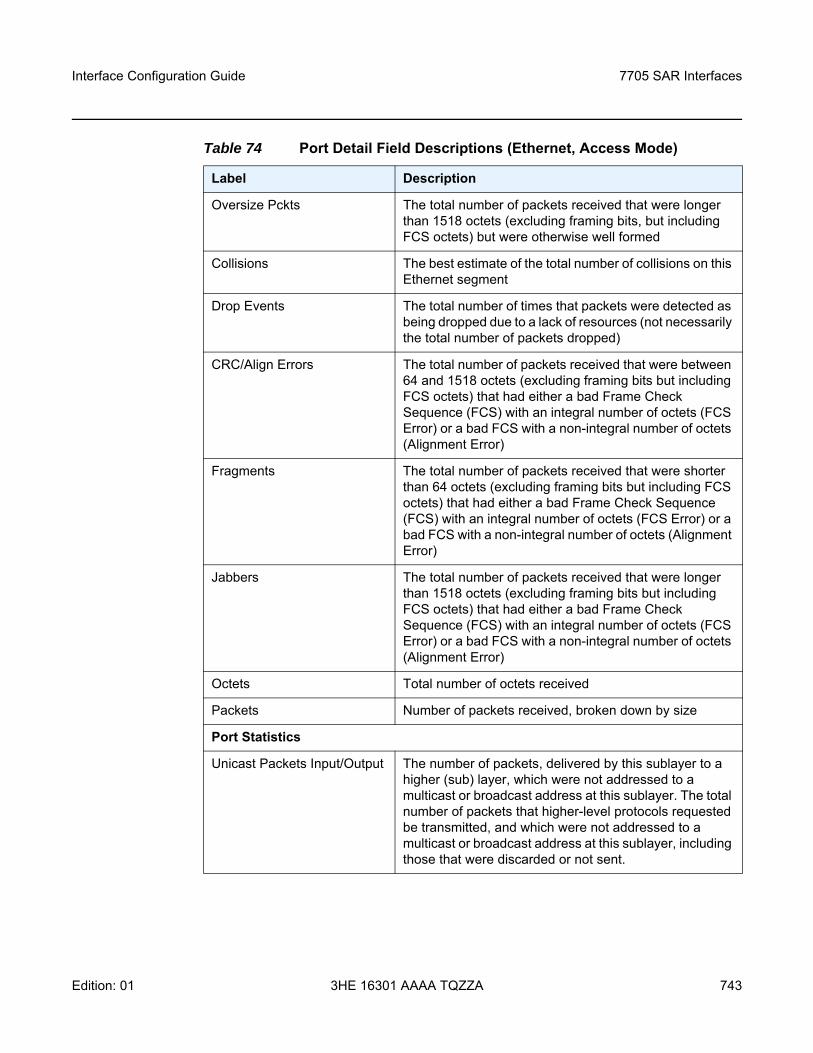
Interface Configuration Guide 7705 SAR Interfaces
Edition: 01 3HE 16301 AAAA TQZZA 743
Oversize Pckts The total number of packets received that were longer than 1518 octets (excluding framing bits, but including FCS octets) but were otherwise well formed
Collisions The best estimate of the total number of collisions on this Ethernet segment
Drop Events The total number of times that packets were detected as being dropped due to a lack of resources (not necessarily the total number of packets dropped)
CRC/Align Errors The total number of packets received that were between 64 and 1518 octets (excluding framing bits but including FCS octets) that had either a bad Frame Check Sequence (FCS) with an integral number of octets (FCS Error) or a bad FCS with a non-integral number of octets (Alignment Error)
Fragments The total number of packets received that were shorter than 64 octets (excluding framing bits but including FCS octets) that had either a bad Frame Check Sequence (FCS) with an integral number of octets (FCS Error) or a bad FCS with a non-integral number of octets (Alignment Error)
Jabbers The total number of packets received that were longer than 1518 octets (excluding framing bits but including FCS octets) that had either a bad Frame Check Sequence (FCS) with an integral number of octets (FCS Error) or a bad FCS with a non-integral number of octets (Alignment Error)
Octets Total number of octets received
Packets Number of packets received, broken down by size
Port Statistics
Unicast Packets Input/Output The number of packets, delivered by this sublayer to a higher (sub) layer, which were not addressed to a multicast or broadcast address at this sublayer. The total number of packets that higher-level protocols requested be transmitted, and which were not addressed to a multicast or broadcast address at this sublayer, including those that were discarded or not sent.
Table 74 Port Detail Field Descriptions (Ethernet, Access Mode)
Label Description
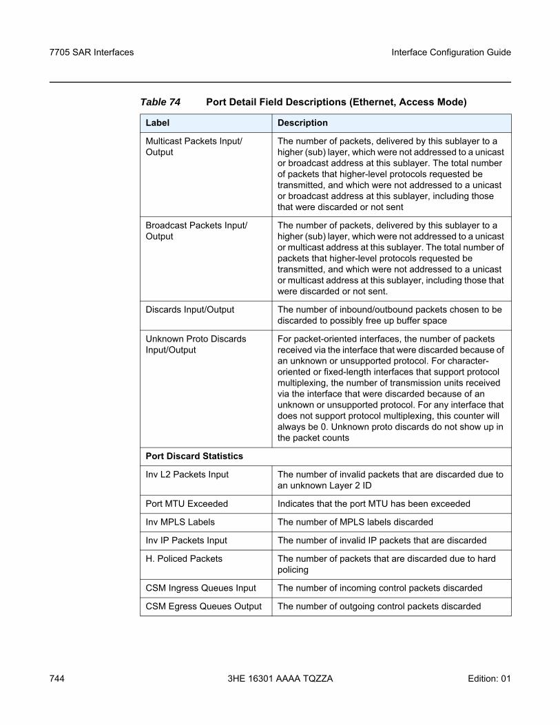
7705 SAR Interfaces
744
Interface Configuration Guide
3HE 16301 AAAA TQZZA Edition: 01
Multicast Packets Input/Output
The number of packets, delivered by this sublayer to a higher (sub) layer, which were not addressed to a unicast or broadcast address at this sublayer. The total number of packets that higher-level protocols requested be transmitted, and which were not addressed to a unicast or broadcast address at this sublayer, including those that were discarded or not sent
Broadcast Packets Input/Output
The number of packets, delivered by this sublayer to a higher (sub) layer, which were not addressed to a unicast or multicast address at this sublayer. The total number of packets that higher-level protocols requested be transmitted, and which were not addressed to a unicast or multicast address at this sublayer, including those that were discarded or not sent.
Discards Input/Output The number of inbound/outbound packets chosen to be discarded to possibly free up buffer space
Unknown Proto Discards Input/Output
For packet-oriented interfaces, the number of packets received via the interface that were discarded because of an unknown or unsupported protocol. For character-oriented or fixed-length interfaces that support protocol multiplexing, the number of transmission units received via the interface that were discarded because of an unknown or unsupported protocol. For any interface that does not support protocol multiplexing, this counter will always be 0. Unknown proto discards do not show up in the packet counts
Port Discard Statistics
Inv L2 Packets Input The number of invalid packets that are discarded due to an unknown Layer 2 ID
Port MTU Exceeded Indicates that the port MTU has been exceeded
Inv MPLS Labels The number of MPLS labels discarded
Inv IP Packets Input The number of invalid IP packets that are discarded
H. Policed Packets The number of packets that are discarded due to hard policing
CSM Ingress Queues Input The number of incoming control packets discarded
CSM Egress Queues Output The number of outgoing control packets discarded
Table 74 Port Detail Field Descriptions (Ethernet, Access Mode)
Label Description
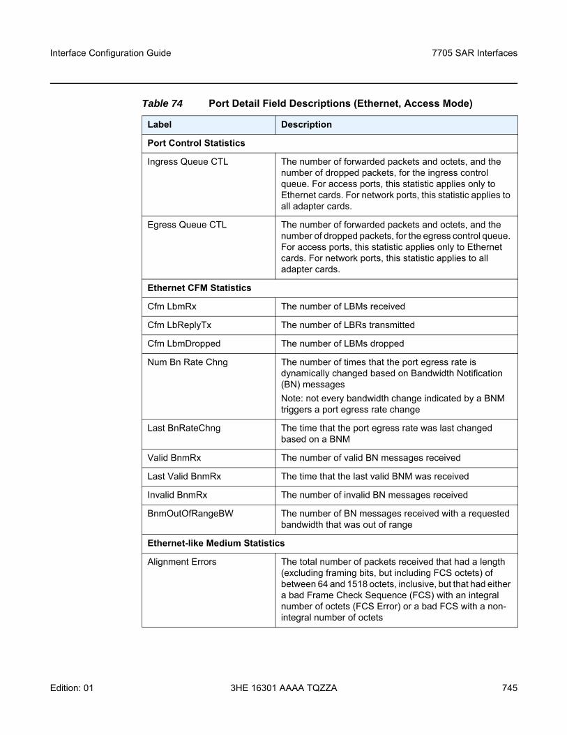
Interface Configuration Guide 7705 SAR Interfaces
Edition: 01 3HE 16301 AAAA TQZZA 745
Port Control Statistics
Ingress Queue CTL The number of forwarded packets and octets, and the number of dropped packets, for the ingress control queue. For access ports, this statistic applies only to Ethernet cards. For network ports, this statistic applies to all adapter cards.
Egress Queue CTL The number of forwarded packets and octets, and the number of dropped packets, for the egress control queue. For access ports, this statistic applies only to Ethernet cards. For network ports, this statistic applies to all adapter cards.
Ethernet CFM Statistics
Cfm LbmRx The number of LBMs received
Cfm LbReplyTx The number of LBRs transmitted
Cfm LbmDropped The number of LBMs dropped
Num Bn Rate Chng The number of times that the port egress rate is dynamically changed based on Bandwidth Notification (BN) messagesNote: not every bandwidth change indicated by a BNM triggers a port egress rate change
Last BnRateChng The time that the port egress rate was last changed based on a BNM
Valid BnmRx The number of valid BN messages received
Last Valid BnmRx The time that the last valid BNM was received
Invalid BnmRx The number of invalid BN messages received
BnmOutOfRangeBW The number of BN messages received with a requested bandwidth that was out of range
Ethernet-like Medium Statistics
Alignment Errors The total number of packets received that had a length (excluding framing bits, but including FCS octets) of between 64 and 1518 octets, inclusive, but that had either a bad Frame Check Sequence (FCS) with an integral number of octets (FCS Error) or a bad FCS with a non-integral number of octets
Table 74 Port Detail Field Descriptions (Ethernet, Access Mode)
Label Description
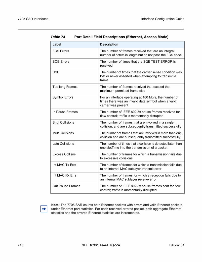
7705 SAR Interfaces
746
Interface Configuration Guide
3HE 16301 AAAA TQZZA Edition: 01
FCS Errors The number of frames received that are an integral number of octets in length but do not pass the FCS check
SQE Errors The number of times that the SQE TEST ERROR is received
CSE The number of times that the carrier sense condition was lost or never asserted when attempting to transmit a frame
Too long Frames The number of frames received that exceed the maximum permitted frame size
Symbol Errors For an interface operating at 100 Mb/s, the number of times there was an invalid data symbol when a valid carrier was present
In Pause Frames The number of IEEE 802.3x pause frames received for flow control; traffic is momentarily disrupted
Sngl Collisions The number of frames that are involved in a single collision, and are subsequently transmitted successfully
Mult Collisions The number of frames that are involved in more than one collision and are subsequently transmitted successfully
Late Collisions The number of times that a collision is detected later than one slotTime into the transmission of a packet
Excess Collisns The number of frames for which a transmission fails due to excessive collisions
Int MAC Tx Errs The number of frames for which a transmission fails due to an internal MAC sublayer transmit error
Int MAC Rx Errs The number of frames for which a reception fails due to an internal MAC sublayer receive error
Out Pause Frames The number of IEEE 802.3x pause frames sent for flow control; traffic is momentarily disrupted
Table 74 Port Detail Field Descriptions (Ethernet, Access Mode)
Label Description
Note: The 7705 SAR counts both Ethernet packets with errors and valid Ethernet packets under Ethernet port statistics. For each received errored packet, both aggregate Ethernet statistics and the errored Ethernet statistics are incremented.
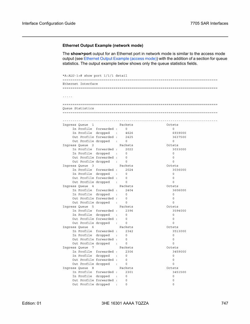
Interface Configuration Guide 7705 SAR Interfaces
Edition: 01 3HE 16301 AAAA TQZZA 747
Ethernet Output Example (network mode)
The show>port output for an Ethernet port in network mode is similar to the access mode output (see Ethernet Output Example (access mode)) with the addition of a section for queue statistics. The output example below shows only the queue statistics fields.
*A:ALU-1># show port 1/1/1 detail===============================================================================Ethernet Interface===============================================================================
.....
===============================================================================Queue Statistics===============================================================================
-------------------------------------------------------------------------------Ingress Queue 1 Packets Octets
In Profile forwarded : 0 0In Profile dropped : 4626 6939000Out Profile forwarded : 2425 3637500Out Profile dropped : 0 0
Ingress Queue 2 Packets OctetsIn Profile forwarded : 2022 3033000In Profile dropped : 0 0Out Profile forwarded : 0 0Out Profile dropped : 0 0
Ingress Queue 3 Packets OctetsIn Profile forwarded : 2024 3036000In Profile dropped : 0 0Out Profile forwarded : 0 0Out Profile dropped : 0 0
Ingress Queue 4 Packets OctetsIn Profile forwarded : 2404 3606000In Profile dropped : 0 0Out Profile forwarded : 0 0Out Profile dropped : 0 0
Ingress Queue 5 Packets OctetsIn Profile forwarded : 2396 3594000In Profile dropped : 0 0Out Profile forwarded : 0 0Out Profile dropped : 0 0
Ingress Queue 6 Packets OctetsIn Profile forwarded : 2342 3513000In Profile dropped : 0 0Out Profile forwarded : 0 0Out Profile dropped : 0 0
Ingress Queue 7 Packets OctetsIn Profile forwarded : 2306 3459000In Profile dropped : 0 0Out Profile forwarded : 0 0Out Profile dropped : 0 0
Ingress Queue 8 Packets OctetsIn Profile forwarded : 2301 3451500In Profile dropped : 0 0Out Profile forwarded : 0 0Out Profile dropped : 0 0
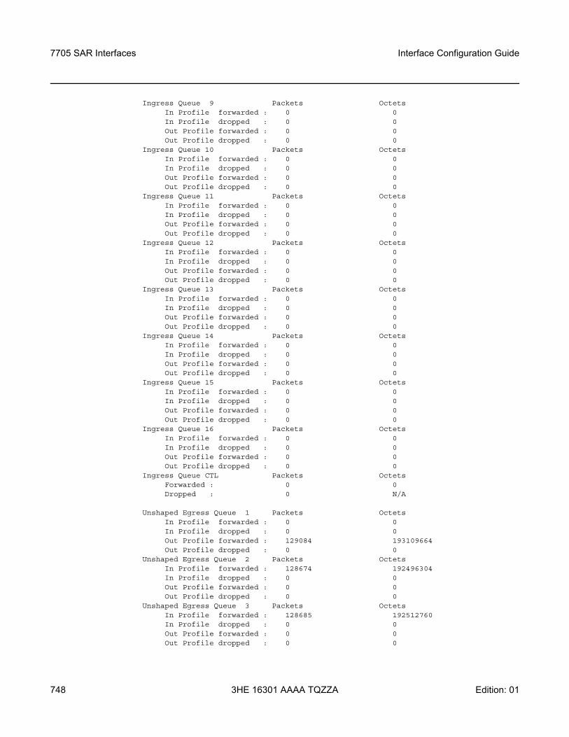
7705 SAR Interfaces
748
Interface Configuration Guide
3HE 16301 AAAA TQZZA Edition: 01
Ingress Queue 9 Packets OctetsIn Profile forwarded : 0 0In Profile dropped : 0 0Out Profile forwarded : 0 0Out Profile dropped : 0 0
Ingress Queue 10 Packets OctetsIn Profile forwarded : 0 0In Profile dropped : 0 0Out Profile forwarded : 0 0Out Profile dropped : 0 0
Ingress Queue 11 Packets OctetsIn Profile forwarded : 0 0In Profile dropped : 0 0Out Profile forwarded : 0 0Out Profile dropped : 0 0
Ingress Queue 12 Packets OctetsIn Profile forwarded : 0 0In Profile dropped : 0 0Out Profile forwarded : 0 0Out Profile dropped : 0 0
Ingress Queue 13 Packets OctetsIn Profile forwarded : 0 0In Profile dropped : 0 0Out Profile forwarded : 0 0Out Profile dropped : 0 0
Ingress Queue 14 Packets OctetsIn Profile forwarded : 0 0In Profile dropped : 0 0Out Profile forwarded : 0 0Out Profile dropped : 0 0
Ingress Queue 15 Packets OctetsIn Profile forwarded : 0 0In Profile dropped : 0 0Out Profile forwarded : 0 0Out Profile dropped : 0 0
Ingress Queue 16 Packets OctetsIn Profile forwarded : 0 0In Profile dropped : 0 0Out Profile forwarded : 0 0Out Profile dropped : 0 0
Ingress Queue CTL Packets OctetsForwarded : 0 0Dropped : 0 N/A
Unshaped Egress Queue 1 Packets OctetsIn Profile forwarded : 0 0In Profile dropped : 0 0Out Profile forwarded : 129084 193109664Out Profile dropped : 0 0
Unshaped Egress Queue 2 Packets OctetsIn Profile forwarded : 128674 192496304In Profile dropped : 0 0Out Profile forwarded : 0 0Out Profile dropped : 0 0
Unshaped Egress Queue 3 Packets OctetsIn Profile forwarded : 128685 192512760In Profile dropped : 0 0Out Profile forwarded : 0 0Out Profile dropped : 0 0
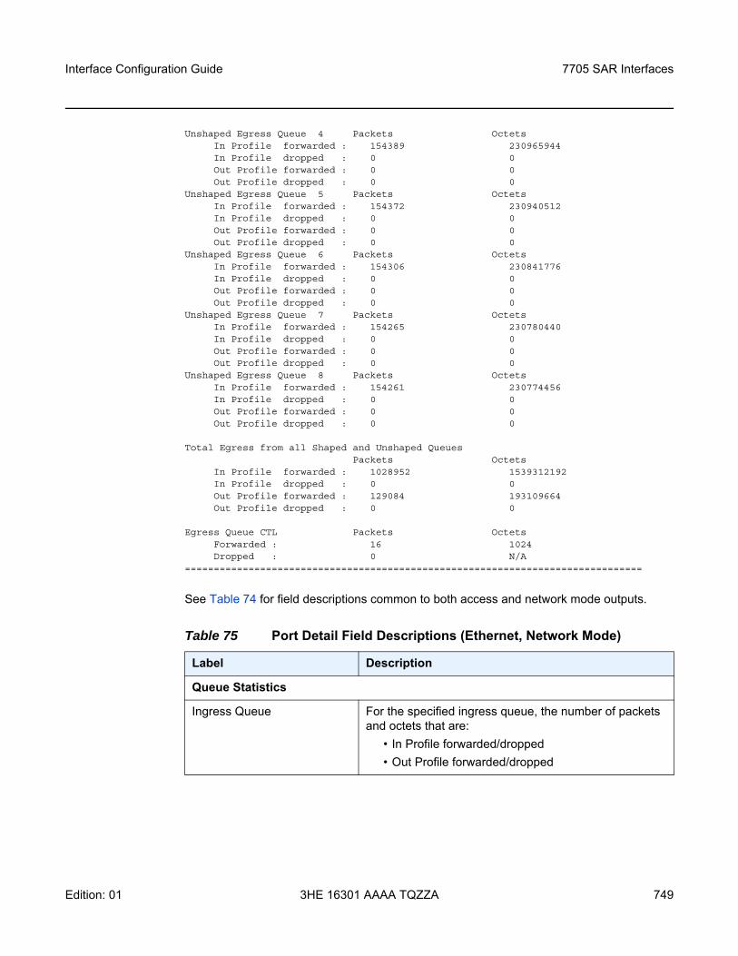
Interface Configuration Guide 7705 SAR Interfaces
Edition: 01 3HE 16301 AAAA TQZZA 749
Unshaped Egress Queue 4 Packets OctetsIn Profile forwarded : 154389 230965944In Profile dropped : 0 0Out Profile forwarded : 0 0Out Profile dropped : 0 0
Unshaped Egress Queue 5 Packets OctetsIn Profile forwarded : 154372 230940512In Profile dropped : 0 0Out Profile forwarded : 0 0Out Profile dropped : 0 0
Unshaped Egress Queue 6 Packets OctetsIn Profile forwarded : 154306 230841776In Profile dropped : 0 0Out Profile forwarded : 0 0Out Profile dropped : 0 0
Unshaped Egress Queue 7 Packets OctetsIn Profile forwarded : 154265 230780440In Profile dropped : 0 0Out Profile forwarded : 0 0Out Profile dropped : 0 0
Unshaped Egress Queue 8 Packets OctetsIn Profile forwarded : 154261 230774456In Profile dropped : 0 0Out Profile forwarded : 0 0Out Profile dropped : 0 0
Total Egress from all Shaped and Unshaped QueuesPackets Octets
In Profile forwarded : 1028952 1539312192In Profile dropped : 0 0Out Profile forwarded : 129084 193109664Out Profile dropped : 0 0
Egress Queue CTL Packets OctetsForwarded : 16 1024Dropped : 0 N/A
===============================================================================
See Table 74 for field descriptions common to both access and network mode outputs.
Table 75 Port Detail Field Descriptions (Ethernet, Network Mode)
Label Description
Queue Statistics
Ingress Queue For the specified ingress queue, the number of packets and octets that are:
• In Profile forwarded/dropped• Out Profile forwarded/dropped
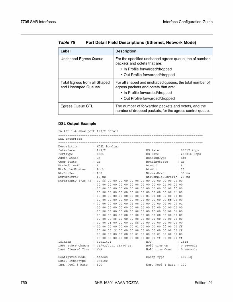
7705 SAR Interfaces
750
Interface Configuration Guide
3HE 16301 AAAA TQZZA Edition: 01
DSL Output Example
*A:ALU-1># show port 1/3/2 detail===============================================================================DSL Interface===============================================================================Description : XDSL BondingInterface : 1/3/2 US Rate : 98017 kbpsPortType : XDSL DS Rate : 200016 kbpsAdmin State : up BondingType : efmOper State : up BondingState : upNtrDslLineID : 1 AtmVpi : 8NtrLockedStatus : lock AtmVci : 35NtrStdDev : 100 NtrMaxError : 56 nsNtrMinError : 10 ns NtrSampleClkPeri*: 28 nsNtrErrHsty (*28 ns): 00 ff 00 00 00 00 00 00 00 00 00 00 00 00 00 00
: 00 00 00 00 00 00 00 00 00 00 00 00 01 00 00 00: 00 00 00 00 00 00 00 00 00 00 00 00 00 00 ff 00: 00 00 00 00 00 00 00 00 00 00 00 00 00 00 ff 00: 00 00 00 00 00 00 00 00 00 01 00 00 01 00 00 00: 00 00 00 00 00 00 00 00 00 00 00 00 00 ff 00 00: 00 00 00 00 00 00 01 00 00 00 00 00 00 00 00 01: 00 00 00 00 00 00 00 00 00 00 ff 00 00 00 00 00: 00 00 00 00 00 00 00 00 00 00 ff 00 00 00 01 00: 00 00 00 00 00 00 00 00 00 00 00 00 00 00 00 00: 00 00 00 ff 00 00 00 00 00 00 00 00 00 00 00 00: 00 00 01 00 00 00 00 ff 00 00 00 00 00 00 00 00: 00 00 00 00 00 00 00 01 00 00 00 00 ff 00 00 ff: 00 00 00 ff 00 00 00 00 00 00 00 00 00 00 00 ff: 00 00 00 00 00 00 00 01 00 00 00 01 00 00 00 00: 00 00 00 00 00 00 00 00 00 00 00 ff 00 00 00 ff
IfIndex : 39911424 MTU : 1518Last State Change : 06/02/2011 18:54:33 Hold time up : 0 secondsLast Cleared Time : N/A Hold time down : 0 seconds
Configured Mode : access Encap Type : 802.1qDot1Q Ethertype : 0x8100Ing. Pool % Rate : 100 Egr. Pool % Rate : 100
Unshaped Egress Queue For the specified unshaped egress queue, the of number packets and octets that are:
• In Profile forwarded/dropped• Out Profile forwarded/dropped
Total Egress from all Shaped and Unshaped Queues
For all shaped and unshaped queues, the total number of egress packets and octets that are:
• In Profile forwarded/dropped• Out Profile forwarded/dropped
Egress Queue CTL The number of forwarded packets and octets, and the number of dropped packets, for the egress control queue.
Table 75 Port Detail Field Descriptions (Ethernet, Network Mode)
Label Description
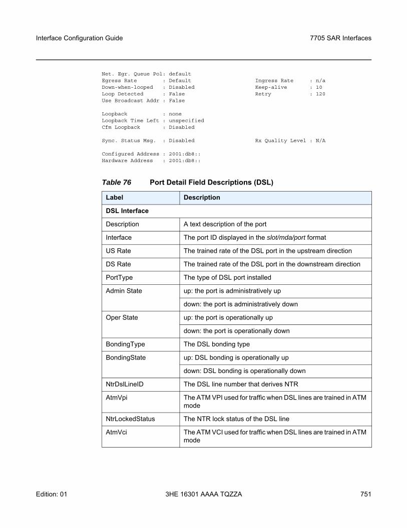
Interface Configuration Guide 7705 SAR Interfaces
Edition: 01 3HE 16301 AAAA TQZZA 751
Net. Egr. Queue Pol: defaultEgress Rate : Default Ingress Rate : n/aDown-when-looped : Disabled Keep-alive : 10Loop Detected : False Retry : 120Use Broadcast Addr : False
Loopback : noneLoopback Time Left : unspecifiedCfm Loopback : Disabled
Sync. Status Msg. : Disabled Rx Quality Level : N/A
Configured Address : 2001:db8::Hardware Address : 2001:db8::
Table 76 Port Detail Field Descriptions (DSL)
Label Description
DSL Interface
Description A text description of the port
Interface The port ID displayed in the slot/mda/port format
US Rate The trained rate of the DSL port in the upstream direction
DS Rate The trained rate of the DSL port in the downstream direction
PortType The type of DSL port installed
Admin State up: the port is administratively up
down: the port is administratively down
Oper State up: the port is operationally up
down: the port is operationally down
BondingType The DSL bonding type
BondingState up: DSL bonding is operationally up
down: DSL bonding is operationally down
NtrDslLineID The DSL line number that derives NTR
AtmVpi The ATM VPI used for traffic when DSL lines are trained in ATM mode
NtrLockedStatus The NTR lock status of the DSL line
AtmVci The ATM VCI used for traffic when DSL lines are trained in ATM mode
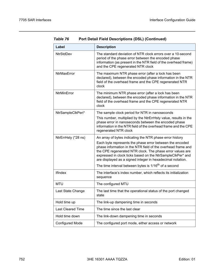
7705 SAR Interfaces
752
Interface Configuration Guide
3HE 16301 AAAA TQZZA Edition: 01
NtrStdDev The standard deviation of NTR clock errors over a 10-second period of the phase error between the encoded phase information (as present in the NTR field of the overhead frame) and the CPE regenerated NTR clock
NtrMaxError The maximum NTR phase error (after a lock has been declared), between the encoded phase information in the NTR field of the overhead frame and the CPE regenerated NTR clock
NtrMinError The minimum NTR phase error (after a lock has been declared), between the encoded phase information in the NTR field of the overhead frame and the CPE regenerated NTR clock
NtrSampleClkPeri* The sample clock period for NTR in nanoseconds This number, multiplied by the NtrErrHsty value, results in the phase error in nanoseconds between the encoded phase information in the NTR field of the overhead frame and the CPE regenerated NTR clock
NtrErrHsty (*28 ns) An array of bytes indicating the NTR phase error history Each byte represents the phase error between the encoded phase information in the NTR field of the overhead frame and the CPE regenerated NTR clock. The phase error values are expressed in clock ticks based on the NtrSampleClkPer* and are displayed as a signed integer in hexadecimal notation.
The time interval between bytes is 1/16th of a second
IfIndex The interface’s index number, which reflects its initialization sequence
MTU The configured MTU
Last State Change The last time that the operational status of the port changed state
Hold time up The link-up dampening time in seconds
Last Cleared Time The time since the last clear
Hold time down The link-down dampening time in seconds
Configured Mode The configured port mode, either access or network
Table 76 Port Detail Field Descriptions (DSL) (Continued)
Label Description
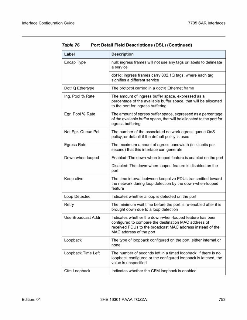
Interface Configuration Guide 7705 SAR Interfaces
Edition: 01 3HE 16301 AAAA TQZZA 753
Encap Type null: ingress frames will not use any tags or labels to delineate a service
dot1q: ingress frames carry 802.1Q tags, where each tag signifies a different service
Dot1Q Ethertype The protocol carried in a dot1q Ethernet frame
Ing. Pool % Rate The amount of ingress buffer space, expressed as a percentage of the available buffer space, that will be allocated to the port for ingress buffering
Egr. Pool % Rate The amount of egress buffer space, expressed as a percentage of the available buffer space, that will be allocated to the port for egress buffering
Net Egr. Queue Pol The number of the associated network egress queue QoS policy, or default if the default policy is used
Egress Rate The maximum amount of egress bandwidth (in kilobits per second) that this interface can generate
Down-when-looped Enabled: The down-when-looped feature is enabled on the port
Disabled: The down-when-looped feature is disabled on the port
Keep-alive The time interval between keepalive PDUs transmitted toward the network during loop detection by the down-when-looped feature
Loop Detected Indicates whether a loop is detected on the port
Retry The minimum wait time before the port is re-enabled after it is brought down due to a loop detection
Use Broadcast Addr Indicates whether the down-when-looped feature has been configured to compare the destination MAC address of received PDUs to the broadcast MAC address instead of the MAC address of the port
Loopback The type of loopback configured on the port, either internal or none
Loopback Time Left The number of seconds left in a timed loopback; if there is no loopback configured or the configured loopback is latched, the value is unspecified
Cfm Loopback Indicates whether the CFM loopback is enabled
Table 76 Port Detail Field Descriptions (DSL) (Continued)
Label Description
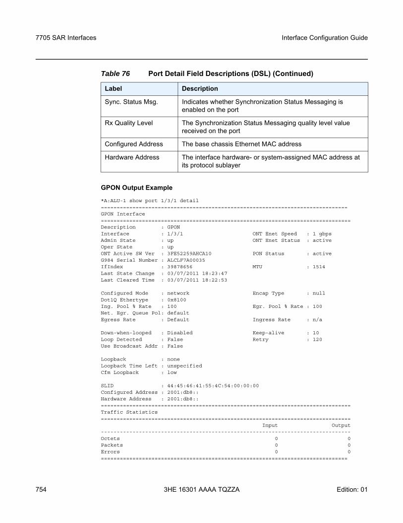
7705 SAR Interfaces
754
Interface Configuration Guide
3HE 16301 AAAA TQZZA Edition: 01
GPON Output Example
*A:ALU-1 show port 1/3/1 detail==============================================================================GPON Interface===============================================================================Description : GPONInterface : 1/3/1 ONT Enet Speed : 1 gbpsAdmin State : up ONT Enet Status : activeOper State : upONT Active SW Ver : 3FE52259AHCA10 PON Status : activeG984 Serial Number : ALCLF7A00035IfIndex : 39878656 MTU : 1514Last State Change : 03/07/2011 18:23:47Last Cleared Time : 03/07/2011 18:22:53
Configured Mode : network Encap Type : nullDot1Q Ethertype : 0x8100Ing. Pool % Rate : 100 Egr. Pool % Rate : 100Net. Egr. Queue Pol: defaultEgress Rate : Default Ingress Rate : n/a
Down-when-looped : Disabled Keep-alive : 10Loop Detected : False Retry : 120Use Broadcast Addr : False
Loopback : noneLoopback Time Left : unspecifiedCfm Loopback : low
SLID : 44:45:46:41:55:4C:54:00:00:00Configured Address : 2001:db8::Hardware Address : 2001:db8::===============================================================================Traffic Statistics===============================================================================
Input Output-------------------------------------------------------------------------------Octets 0 0Packets 0 0Errors 0 0==============================================================================
Sync. Status Msg. Indicates whether Synchronization Status Messaging is enabled on the port
Rx Quality Level The Synchronization Status Messaging quality level value received on the port
Configured Address The base chassis Ethernet MAC address
Hardware Address The interface hardware- or system-assigned MAC address at its protocol sublayer
Table 76 Port Detail Field Descriptions (DSL) (Continued)
Label Description
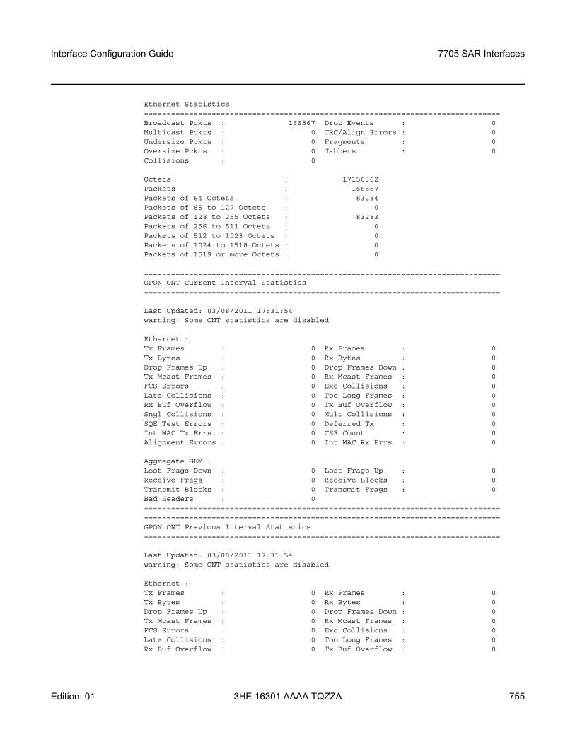
Interface Configuration Guide 7705 SAR Interfaces
Edition: 01 3HE 16301 AAAA TQZZA 755
Ethernet Statistics===============================================================================Broadcast Pckts : 166567 Drop Events : 0Multicast Pckts : 0 CRC/Align Errors : 0Undersize Pckts : 0 Fragments : 0Oversize Pckts : 0 Jabbers : 0Collisions : 0
Octets : 17156362Packets : 166567Packets of 64 Octets : 83284Packets of 65 to 127 Octets : 0Packets of 128 to 255 Octets : 83283Packets of 256 to 511 Octets : 0Packets of 512 to 1023 Octets : 0Packets of 1024 to 1518 Octets : 0Packets of 1519 or more Octets : 0
===============================================================================GPON ONT Current Interval Statistics===============================================================================
Last Updated: 03/08/2011 17:31:54warning: Some ONT statistics are disabled
Ethernet :Tx Frames : 0 Rx Frames : 0Tx Bytes : 0 Rx Bytes : 0Drop Frames Up : 0 Drop Frames Down : 0Tx Mcast Frames : 0 Rx Mcast Frames : 0FCS Errors : 0 Exc Collisions : 0Late Collisions : 0 Too Long Frames : 0Rx Buf Overflow : 0 Tx Buf Overflow : 0Sngl Collisions : 0 Mult Collisions : 0SQE Test Errors : 0 Deferred Tx : 0Int MAC Tx Errs : 0 CSE Count : 0Alignment Errors : 0 Int MAC Rx Errs : 0
Aggregate GEM :Lost Frags Down : 0 Lost Frags Up : 0Receive Frags : 0 Receive Blocks : 0Transmit Blocks : 0 Transmit Frags : 0Bad Headers : 0==============================================================================================================================================================GPON ONT Previous Interval Statistics===============================================================================
Last Updated: 03/08/2011 17:31:54warning: Some ONT statistics are disabled
Ethernet :Tx Frames : 0 Rx Frames : 0Tx Bytes : 0 Rx Bytes : 0Drop Frames Up : 0 Drop Frames Down : 0Tx Mcast Frames : 0 Rx Mcast Frames : 0FCS Errors : 0 Exc Collisions : 0Late Collisions : 0 Too Long Frames : 0Rx Buf Overflow : 0 Tx Buf Overflow : 0
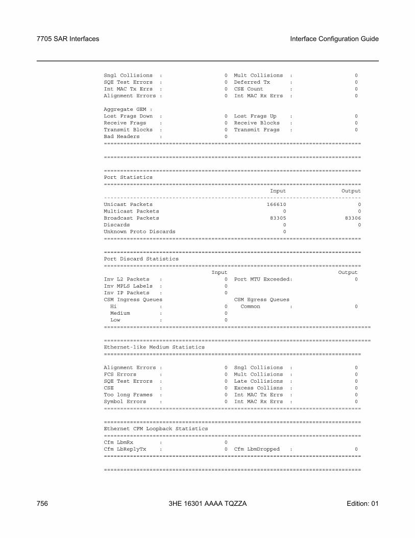
7705 SAR Interfaces
756
Interface Configuration Guide
3HE 16301 AAAA TQZZA Edition: 01
Sngl Collisions : 0 Mult Collisions : 0SQE Test Errors : 0 Deferred Tx : 0Int MAC Tx Errs : 0 CSE Count : 0Alignment Errors : 0 Int MAC Rx Errs : 0
Aggregate GEM :Lost Frags Down : 0 Lost Frags Up : 0Receive Frags : 0 Receive Blocks : 0Transmit Blocks : 0 Transmit Frags : 0Bad Headers : 0===============================================================================
===============================================================================
===============================================================================Port Statistics===============================================================================
Input Output-------------------------------------------------------------------------------Unicast Packets 166610 0Multicast Packets 0 0Broadcast Packets 83305 83306Discards 0 0Unknown Proto Discards 0===============================================================================
===============================================================================Port Discard Statistics===============================================================================
Input OutputInv L2 Packets : 0 Port MTU Exceeded: 0Inv MPLS Labels : 0Inv IP Packets : 0CSM Ingress Queues CSM Egress Queues
Hi : 0 Common : 0Medium : 0Low : 0
==================================================================================
==================================================================================Ethernet-like Medium Statistics===============================================================================
Alignment Errors : 0 Sngl Collisions : 0FCS Errors : 0 Mult Collisions : 0SQE Test Errors : 0 Late Collisions : 0CSE : 0 Excess Collisns : 0Too long Frames : 0 Int MAC Tx Errs : 0Symbol Errors : 0 Int MAC Rx Errs : 0===============================================================================
===============================================================================Ethernet CFM Loopback Statistics===============================================================================Cfm LbmRx : 0Cfm LbReplyTx : 0 Cfm LbmDropped : 0===============================================================================
===============================================================================
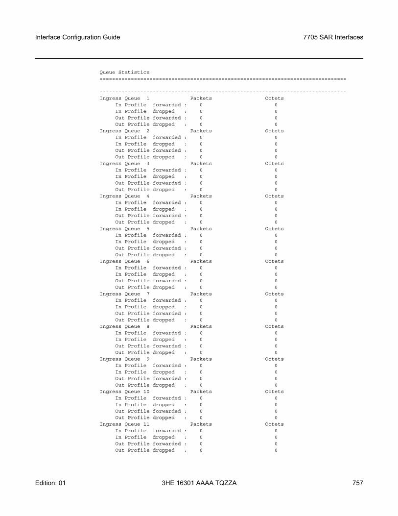
Interface Configuration Guide 7705 SAR Interfaces
Edition: 01 3HE 16301 AAAA TQZZA 757
Queue Statistics===============================================================================
-------------------------------------------------------------------------------Ingress Queue 1 Packets Octets
In Profile forwarded : 0 0In Profile dropped : 0 0Out Profile forwarded : 0 0Out Profile dropped : 0 0
Ingress Queue 2 Packets OctetsIn Profile forwarded : 0 0In Profile dropped : 0 0Out Profile forwarded : 0 0Out Profile dropped : 0 0
Ingress Queue 3 Packets OctetsIn Profile forwarded : 0 0In Profile dropped : 0 0Out Profile forwarded : 0 0Out Profile dropped : 0 0
Ingress Queue 4 Packets OctetsIn Profile forwarded : 0 0In Profile dropped : 0 0Out Profile forwarded : 0 0Out Profile dropped : 0 0
Ingress Queue 5 Packets OctetsIn Profile forwarded : 0 0In Profile dropped : 0 0Out Profile forwarded : 0 0Out Profile dropped : 0 0
Ingress Queue 6 Packets OctetsIn Profile forwarded : 0 0In Profile dropped : 0 0Out Profile forwarded : 0 0Out Profile dropped : 0 0
Ingress Queue 7 Packets OctetsIn Profile forwarded : 0 0In Profile dropped : 0 0Out Profile forwarded : 0 0Out Profile dropped : 0 0
Ingress Queue 8 Packets OctetsIn Profile forwarded : 0 0In Profile dropped : 0 0Out Profile forwarded : 0 0Out Profile dropped : 0 0
Ingress Queue 9 Packets OctetsIn Profile forwarded : 0 0In Profile dropped : 0 0Out Profile forwarded : 0 0Out Profile dropped : 0 0
Ingress Queue 10 Packets OctetsIn Profile forwarded : 0 0In Profile dropped : 0 0Out Profile forwarded : 0 0Out Profile dropped : 0 0
Ingress Queue 11 Packets OctetsIn Profile forwarded : 0 0In Profile dropped : 0 0Out Profile forwarded : 0 0Out Profile dropped : 0 0
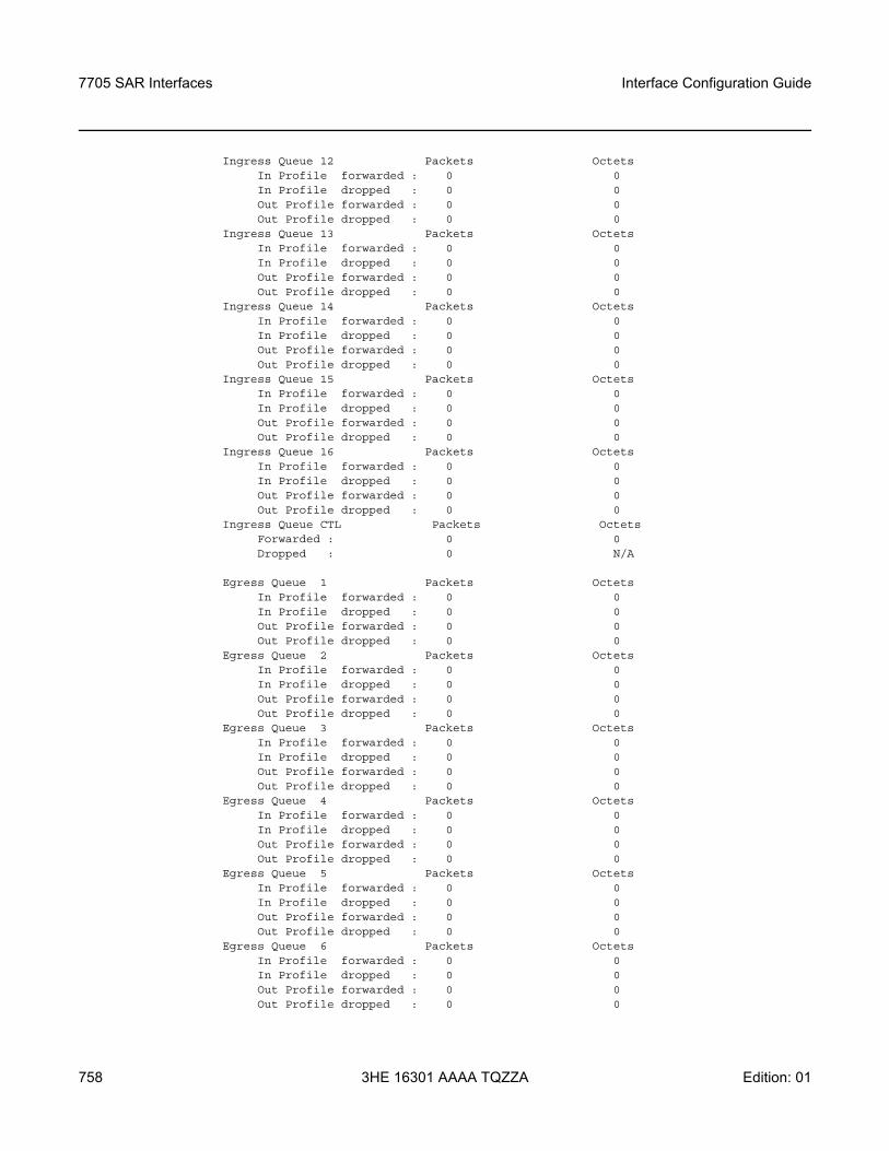
7705 SAR Interfaces
758
Interface Configuration Guide
3HE 16301 AAAA TQZZA Edition: 01
Ingress Queue 12 Packets OctetsIn Profile forwarded : 0 0In Profile dropped : 0 0Out Profile forwarded : 0 0Out Profile dropped : 0 0
Ingress Queue 13 Packets OctetsIn Profile forwarded : 0 0In Profile dropped : 0 0Out Profile forwarded : 0 0Out Profile dropped : 0 0
Ingress Queue 14 Packets OctetsIn Profile forwarded : 0 0In Profile dropped : 0 0Out Profile forwarded : 0 0Out Profile dropped : 0 0
Ingress Queue 15 Packets OctetsIn Profile forwarded : 0 0In Profile dropped : 0 0Out Profile forwarded : 0 0Out Profile dropped : 0 0
Ingress Queue 16 Packets OctetsIn Profile forwarded : 0 0In Profile dropped : 0 0Out Profile forwarded : 0 0Out Profile dropped : 0 0
Ingress Queue CTL Packets OctetsForwarded : 0 0Dropped : 0 N/A
Egress Queue 1 Packets OctetsIn Profile forwarded : 0 0In Profile dropped : 0 0Out Profile forwarded : 0 0Out Profile dropped : 0 0
Egress Queue 2 Packets OctetsIn Profile forwarded : 0 0In Profile dropped : 0 0Out Profile forwarded : 0 0Out Profile dropped : 0 0
Egress Queue 3 Packets OctetsIn Profile forwarded : 0 0In Profile dropped : 0 0Out Profile forwarded : 0 0Out Profile dropped : 0 0
Egress Queue 4 Packets OctetsIn Profile forwarded : 0 0In Profile dropped : 0 0Out Profile forwarded : 0 0Out Profile dropped : 0 0
Egress Queue 5 Packets OctetsIn Profile forwarded : 0 0In Profile dropped : 0 0Out Profile forwarded : 0 0Out Profile dropped : 0 0
Egress Queue 6 Packets OctetsIn Profile forwarded : 0 0In Profile dropped : 0 0Out Profile forwarded : 0 0Out Profile dropped : 0 0
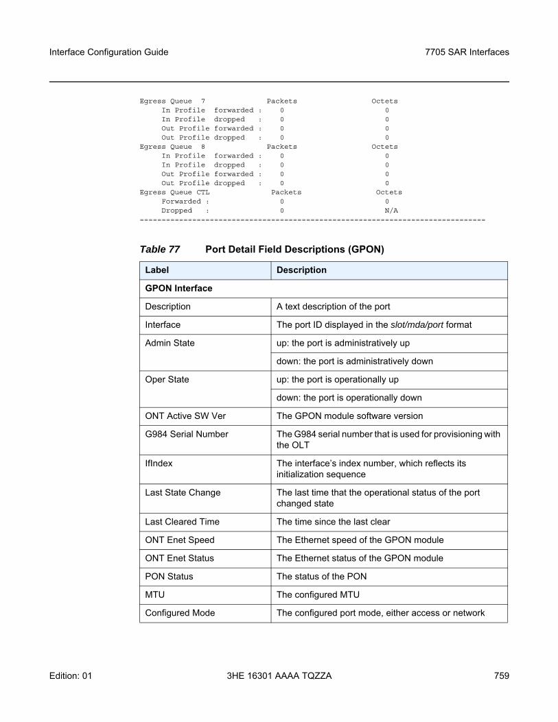
Interface Configuration Guide 7705 SAR Interfaces
Edition: 01 3HE 16301 AAAA TQZZA 759
Egress Queue 7 Packets OctetsIn Profile forwarded : 0 0In Profile dropped : 0 0Out Profile forwarded : 0 0Out Profile dropped : 0 0
Egress Queue 8 Packets OctetsIn Profile forwarded : 0 0In Profile dropped : 0 0Out Profile forwarded : 0 0Out Profile dropped : 0 0
Egress Queue CTL Packets OctetsForwarded : 0 0Dropped : 0 N/A
===============================================================================
Table 77 Port Detail Field Descriptions (GPON)
Label Description
GPON Interface
Description A text description of the port
Interface The port ID displayed in the slot/mda/port format
Admin State up: the port is administratively up
down: the port is administratively down
Oper State up: the port is operationally up
down: the port is operationally down
ONT Active SW Ver The GPON module software version
G984 Serial Number The G984 serial number that is used for provisioning with the OLT
IfIndex The interface’s index number, which reflects its initialization sequence
Last State Change The last time that the operational status of the port changed state
Last Cleared Time The time since the last clear
ONT Enet Speed The Ethernet speed of the GPON module
ONT Enet Status The Ethernet status of the GPON module
PON Status The status of the PON
MTU The configured MTU
Configured Mode The configured port mode, either access or network
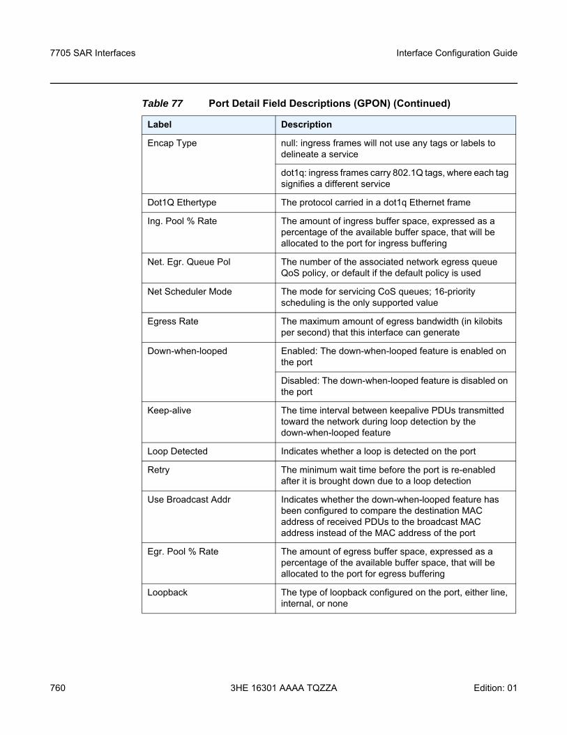
7705 SAR Interfaces
760
Interface Configuration Guide
3HE 16301 AAAA TQZZA Edition: 01
Encap Type null: ingress frames will not use any tags or labels to delineate a service
dot1q: ingress frames carry 802.1Q tags, where each tag signifies a different service
Dot1Q Ethertype The protocol carried in a dot1q Ethernet frame
Ing. Pool % Rate The amount of ingress buffer space, expressed as a percentage of the available buffer space, that will be allocated to the port for ingress buffering
Net. Egr. Queue Pol The number of the associated network egress queue QoS policy, or default if the default policy is used
Net Scheduler Mode The mode for servicing CoS queues; 16-priority scheduling is the only supported value
Egress Rate The maximum amount of egress bandwidth (in kilobits per second) that this interface can generate
Down-when-looped Enabled: The down-when-looped feature is enabled on the port
Disabled: The down-when-looped feature is disabled on the port
Keep-alive The time interval between keepalive PDUs transmitted toward the network during loop detection by the down-when-looped feature
Loop Detected Indicates whether a loop is detected on the port
Retry The minimum wait time before the port is re-enabled after it is brought down due to a loop detection
Use Broadcast Addr Indicates whether the down-when-looped feature has been configured to compare the destination MAC address of received PDUs to the broadcast MAC address instead of the MAC address of the port
Egr. Pool % Rate The amount of egress buffer space, expressed as a percentage of the available buffer space, that will be allocated to the port for egress buffering
Loopback The type of loopback configured on the port, either line, internal, or none
Table 77 Port Detail Field Descriptions (GPON) (Continued)
Label Description
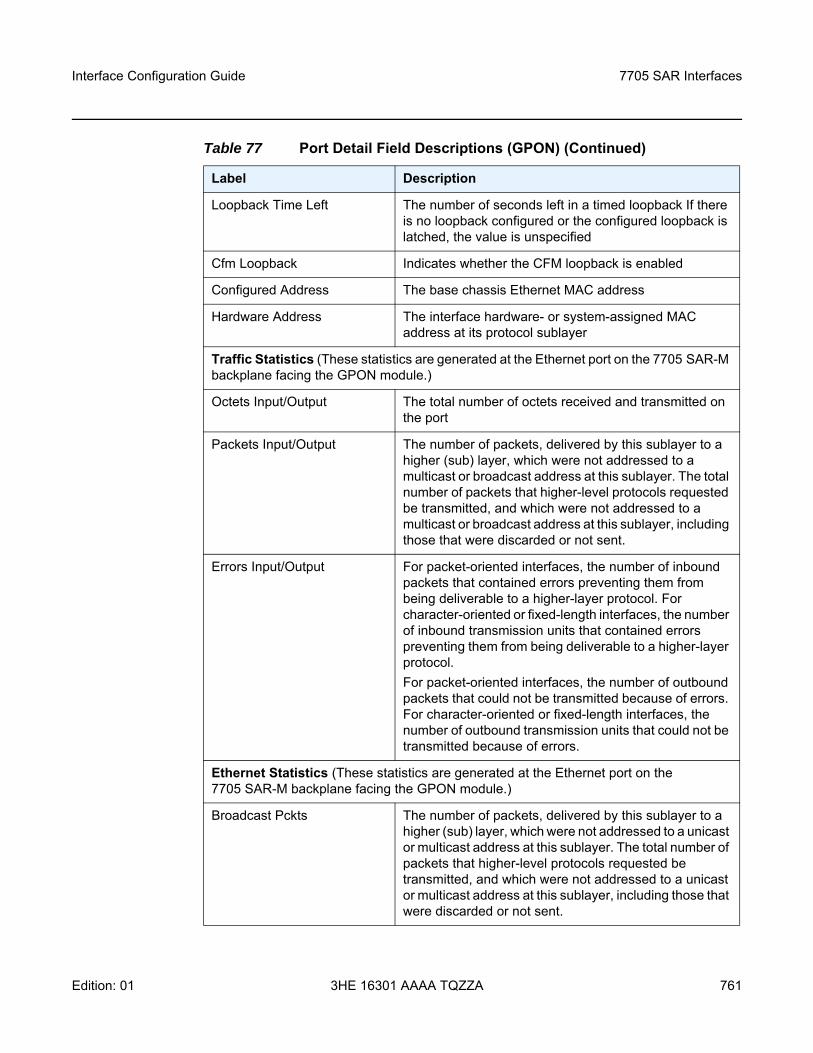
Interface Configuration Guide 7705 SAR Interfaces
Edition: 01 3HE 16301 AAAA TQZZA 761
Loopback Time Left The number of seconds left in a timed loopback If there is no loopback configured or the configured loopback is latched, the value is unspecified
Cfm Loopback Indicates whether the CFM loopback is enabled
Configured Address The base chassis Ethernet MAC address
Hardware Address The interface hardware- or system-assigned MAC address at its protocol sublayer
Traffic Statistics (These statistics are generated at the Ethernet port on the 7705 SAR-M backplane facing the GPON module.)
Octets Input/Output The total number of octets received and transmitted on the port
Packets Input/Output The number of packets, delivered by this sublayer to a higher (sub) layer, which were not addressed to a multicast or broadcast address at this sublayer. The total number of packets that higher-level protocols requested be transmitted, and which were not addressed to a multicast or broadcast address at this sublayer, including those that were discarded or not sent.
Errors Input/Output For packet-oriented interfaces, the number of inbound packets that contained errors preventing them from being deliverable to a higher-layer protocol. For character-oriented or fixed-length interfaces, the number of inbound transmission units that contained errors preventing them from being deliverable to a higher-layer protocol.For packet-oriented interfaces, the number of outbound packets that could not be transmitted because of errors. For character-oriented or fixed-length interfaces, the number of outbound transmission units that could not be transmitted because of errors.
Ethernet Statistics (These statistics are generated at the Ethernet port on the 7705 SAR-M backplane facing the GPON module.)
Broadcast Pckts The number of packets, delivered by this sublayer to a higher (sub) layer, which were not addressed to a unicast or multicast address at this sublayer. The total number of packets that higher-level protocols requested be transmitted, and which were not addressed to a unicast or multicast address at this sublayer, including those that were discarded or not sent.
Table 77 Port Detail Field Descriptions (GPON) (Continued)
Label Description
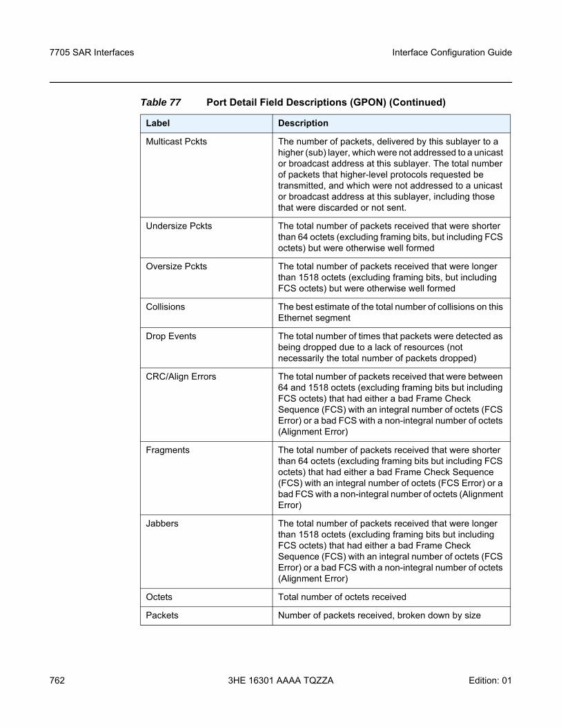
7705 SAR Interfaces
762
Interface Configuration Guide
3HE 16301 AAAA TQZZA Edition: 01
Multicast Pckts The number of packets, delivered by this sublayer to a higher (sub) layer, which were not addressed to a unicast or broadcast address at this sublayer. The total number of packets that higher-level protocols requested be transmitted, and which were not addressed to a unicast or broadcast address at this sublayer, including those that were discarded or not sent.
Undersize Pckts The total number of packets received that were shorter than 64 octets (excluding framing bits, but including FCS octets) but were otherwise well formed
Oversize Pckts The total number of packets received that were longer than 1518 octets (excluding framing bits, but including FCS octets) but were otherwise well formed
Collisions The best estimate of the total number of collisions on this Ethernet segment
Drop Events The total number of times that packets were detected as being dropped due to a lack of resources (not necessarily the total number of packets dropped)
CRC/Align Errors The total number of packets received that were between 64 and 1518 octets (excluding framing bits but including FCS octets) that had either a bad Frame Check Sequence (FCS) with an integral number of octets (FCS Error) or a bad FCS with a non-integral number of octets (Alignment Error)
Fragments The total number of packets received that were shorter than 64 octets (excluding framing bits but including FCS octets) that had either a bad Frame Check Sequence (FCS) with an integral number of octets (FCS Error) or a bad FCS with a non-integral number of octets (Alignment Error)
Jabbers The total number of packets received that were longer than 1518 octets (excluding framing bits but including FCS octets) that had either a bad Frame Check Sequence (FCS) with an integral number of octets (FCS Error) or a bad FCS with a non-integral number of octets (Alignment Error)
Octets Total number of octets received
Packets Number of packets received, broken down by size
Table 77 Port Detail Field Descriptions (GPON) (Continued)
Label Description
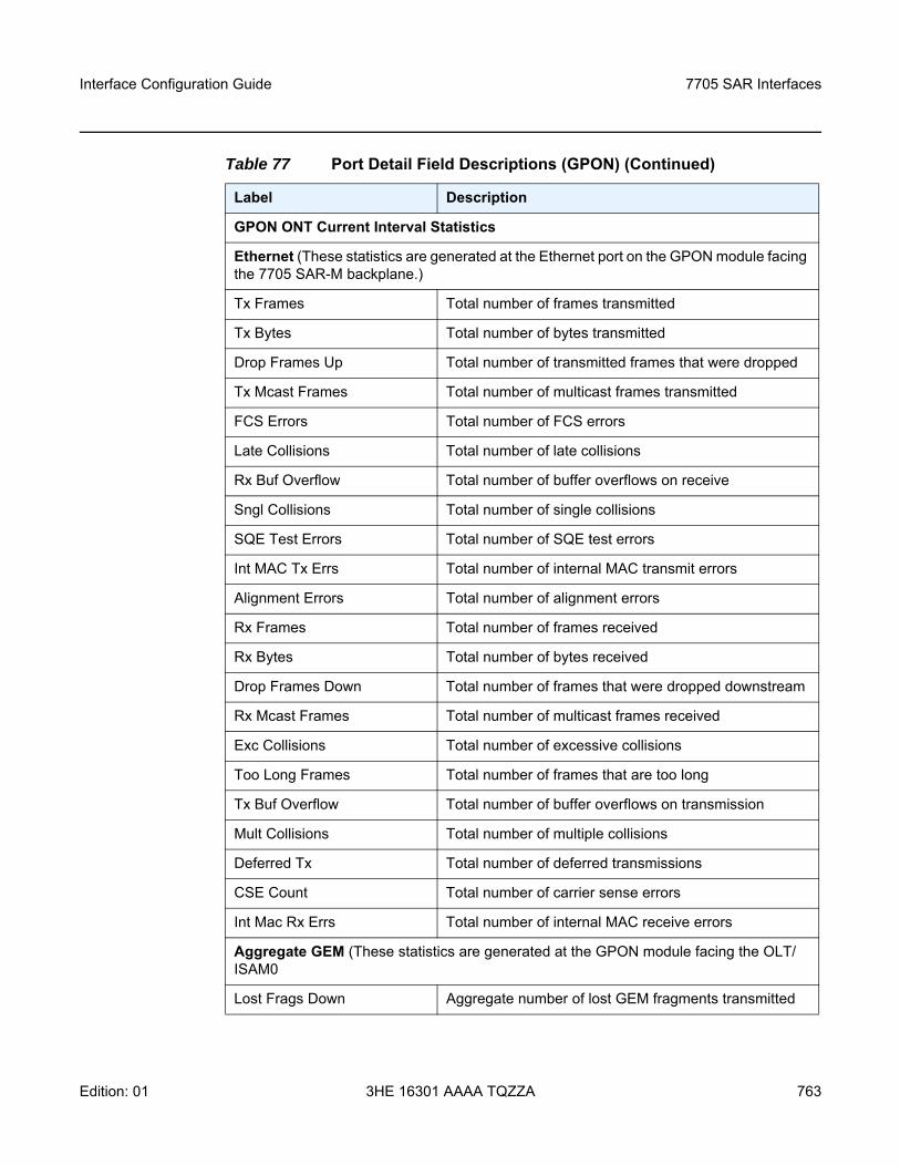
Interface Configuration Guide 7705 SAR Interfaces
Edition: 01 3HE 16301 AAAA TQZZA 763
GPON ONT Current Interval Statistics
Ethernet (These statistics are generated at the Ethernet port on the GPON module facing the 7705 SAR-M backplane.)
Tx Frames Total number of frames transmitted
Tx Bytes Total number of bytes transmitted
Drop Frames Up Total number of transmitted frames that were dropped
Tx Mcast Frames Total number of multicast frames transmitted
FCS Errors Total number of FCS errors
Late Collisions Total number of late collisions
Rx Buf Overflow Total number of buffer overflows on receive
Sngl Collisions Total number of single collisions
SQE Test Errors Total number of SQE test errors
Int MAC Tx Errs Total number of internal MAC transmit errors
Alignment Errors Total number of alignment errors
Rx Frames Total number of frames received
Rx Bytes Total number of bytes received
Drop Frames Down Total number of frames that were dropped downstream
Rx Mcast Frames Total number of multicast frames received
Exc Collisions Total number of excessive collisions
Too Long Frames Total number of frames that are too long
Tx Buf Overflow Total number of buffer overflows on transmission
Mult Collisions Total number of multiple collisions
Deferred Tx Total number of deferred transmissions
CSE Count Total number of carrier sense errors
Int Mac Rx Errs Total number of internal MAC receive errors
Aggregate GEM (These statistics are generated at the GPON module facing the OLT/ISAM0
Lost Frags Down Aggregate number of lost GEM fragments transmitted
Table 77 Port Detail Field Descriptions (GPON) (Continued)
Label Description
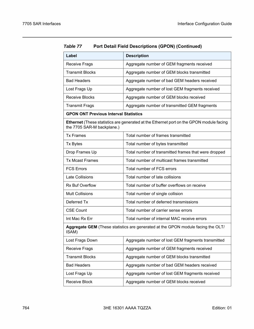
7705 SAR Interfaces
764
Interface Configuration Guide
3HE 16301 AAAA TQZZA Edition: 01
Receive Frags Aggregate number of GEM fragments received
Transmit Blocks Aggregate number of GEM blocks transmitted
Bad Headers Aggregate number of bad GEM headers received
Lost Frags Up Aggregate number of lost GEM fragments received
Receive Blocks Aggregate number of GEM blocks received
Transmit Frags Aggregate number of transmitted GEM fragments
GPON ONT Previous Interval Statistics
Ethernet (These statistics are generated at the Ethernet port on the GPON module facing the 7705 SAR-M backplane.)
Tx Frames Total number of frames transmitted
Tx Bytes Total number of bytes transmitted
Drop Frames Up Total number of transmitted frames that were dropped
Tx Mcast Frames Total number of multicast frames transmitted
FCS Errors Total number of FCS errors
Late Collisions Total number of late collisions
Rx Buf Overflow Total number of buffer overflows on receive
Mult Collisions Total number of single collision
Deferred Tx Total number of deferred transmissions
CSE Count Total number of carrier sense errors
Int Mac Rx Err Total number of internal MAC receive errors
Aggregate GEM (These statistics are generated at the GPON module facing the OLT/ISAM)
Lost Frags Down Aggregate number of lost GEM fragments transmitted
Receive Frags Aggregate number of GEM fragments received
Transmit Blocks Aggregate number of GEM blocks transmitted
Bad Headers Aggregate number of bad GEM headers received
Lost Frags Up Aggregate number of lost GEM fragments received
Receive Block Aggregate number of GEM blocks received
Table 77 Port Detail Field Descriptions (GPON) (Continued)
Label Description
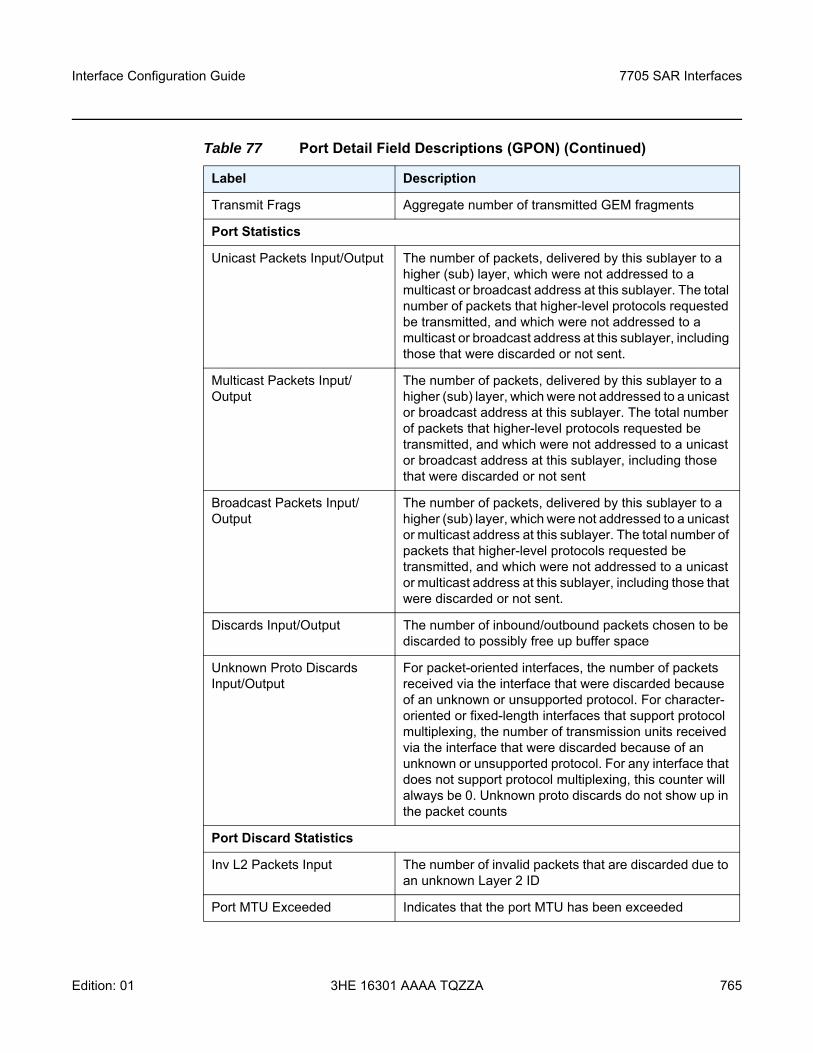
Interface Configuration Guide 7705 SAR Interfaces
Edition: 01 3HE 16301 AAAA TQZZA 765
Transmit Frags Aggregate number of transmitted GEM fragments
Port Statistics
Unicast Packets Input/Output The number of packets, delivered by this sublayer to a higher (sub) layer, which were not addressed to a multicast or broadcast address at this sublayer. The total number of packets that higher-level protocols requested be transmitted, and which were not addressed to a multicast or broadcast address at this sublayer, including those that were discarded or not sent.
Multicast Packets Input/Output
The number of packets, delivered by this sublayer to a higher (sub) layer, which were not addressed to a unicast or broadcast address at this sublayer. The total number of packets that higher-level protocols requested be transmitted, and which were not addressed to a unicast or broadcast address at this sublayer, including those that were discarded or not sent
Broadcast Packets Input/Output
The number of packets, delivered by this sublayer to a higher (sub) layer, which were not addressed to a unicast or multicast address at this sublayer. The total number of packets that higher-level protocols requested be transmitted, and which were not addressed to a unicast or multicast address at this sublayer, including those that were discarded or not sent.
Discards Input/Output The number of inbound/outbound packets chosen to be discarded to possibly free up buffer space
Unknown Proto Discards Input/Output
For packet-oriented interfaces, the number of packets received via the interface that were discarded because of an unknown or unsupported protocol. For character-oriented or fixed-length interfaces that support protocol multiplexing, the number of transmission units received via the interface that were discarded because of an unknown or unsupported protocol. For any interface that does not support protocol multiplexing, this counter will always be 0. Unknown proto discards do not show up in the packet counts
Port Discard Statistics
Inv L2 Packets Input The number of invalid packets that are discarded due to an unknown Layer 2 ID
Port MTU Exceeded Indicates that the port MTU has been exceeded
Table 77 Port Detail Field Descriptions (GPON) (Continued)
Label Description
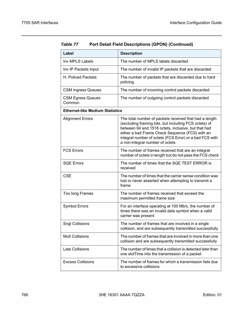
7705 SAR Interfaces
766
Interface Configuration Guide
3HE 16301 AAAA TQZZA Edition: 01
Inv MPLS Labels The number of MPLS labels discarded
Inv IP Packets Input The number of invalid IP packets that are discarded
H. Policed Packets The number of packets that are discarded due to hard policing
CSM Ingress Queues The number of incoming control packets discarded
CSM Egress Queues Common
The number of outgoing control packets discarded
Ethernet-like Medium Statistics
Alignment Errors The total number of packets received that had a length (excluding framing bits, but including FCS octets) of between 64 and 1518 octets, inclusive, but that had either a bad Frame Check Sequence (FCS) with an integral number of octets (FCS Error) or a bad FCS with a non-integral number of octets
FCS Errors The number of frames received that are an integral number of octets in length but do not pass the FCS check
SQE Errors The number of times that the SQE TEST ERROR is received
CSE The number of times that the carrier sense condition was lost or never asserted when attempting to transmit a frame
Too long Frames The number of frames received that exceed the maximum permitted frame size
Symbol Errors For an interface operating at 100 Mb/s, the number of times there was an invalid data symbol when a valid carrier was present
Sngl Collisions The number of frames that are involved in a single collision, and are subsequently transmitted successfully
Mult Collisions The number of frames that are involved in more than one collision and are subsequently transmitted successfully
Late Collisions The number of times that a collision is detected later than one slotTime into the transmission of a packet
Excess Collisions The number of frames for which a transmission fails due to excessive collisions
Table 77 Port Detail Field Descriptions (GPON) (Continued)
Label Description
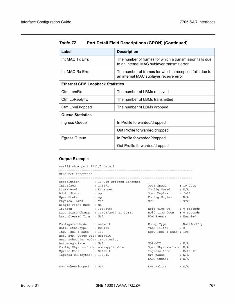
Interface Configuration Guide 7705 SAR Interfaces
Edition: 01 3HE 16301 AAAA TQZZA 767
Output Example
sar18# show port 1/11/1 detail========================================================================Ethernet Interface========================================================================Description : 10-Gig Bridged EthernetInterface : 1/11/1 Oper Speed : 10 GbpsLink-level : Ethernet Config Speed : N/AAdmin State : up Oper Duplex : fullOper State : up Config Duplex : N/APhysical Link : Yes MTU : 9728Single Fiber Mode : NoIfIndex : 39878656 Hold time up : 0 secondsLast State Change : 11/03/2012 21:30:51 Hold time down : 0 secondsLast Cleared Time : N/A DDM Events : Enabled
Configured Mode : network Encap Type : Null&dot1qDot1Q Ethertype : 0x8100 VLAN Filter : 2Ing. Pool % Rate : 100 Egr. Pool % Rate : 100Net. Egr. Queue Pol: defaultNet. Scheduler Mode: 16-priorityAuto-negotiate : N/A MDI/MDX : N/AConfig Phy-tx-clock: not-applicable Oper Phy-tx-clock: N/AEgress Rate : Default Ingress Rate : DefaultIngress CBS(bytes) : 130816 Src-pause : N/A
LACP Tunnel : N/A
Down-when-looped : N/A Keep-alive : N/A
Int MAC Tx Errs The number of frames for which a transmission fails due to an internal MAC sublayer transmit error
Int MAC Rx Errs The number of frames for which a reception fails due to an internal MAC sublayer receive error
Ethernet CFM Loopback Statistics
Cfm LbmRx The number of LBMs received
Cfm LbReplyTx The number of LBMs transmitted
Cfm LbmDropped The number of LBMs dropped
Queue Statistics
Ingress Queue In Profile forwarded/dropped
Out Profile forwarded/dropped
Egress Queue In Profile forwarded/dropped
Out Profile forwarded/dropped
Table 77 Port Detail Field Descriptions (GPON) (Continued)
Label Description
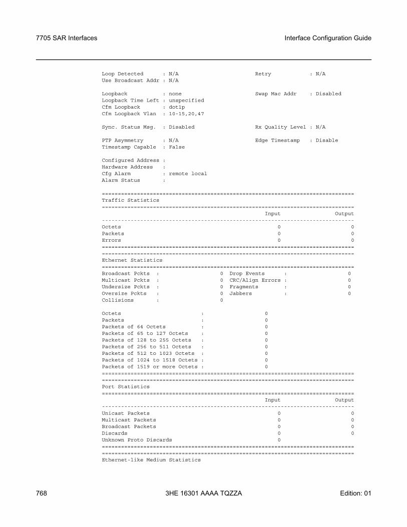
7705 SAR Interfaces
768
Interface Configuration Guide
3HE 16301 AAAA TQZZA Edition: 01
Loop Detected : N/A Retry : N/AUse Broadcast Addr : N/A
Loopback : none Swap Mac Addr : DisabledLoopback Time Left : unspecifiedCfm Loopback : dot1pCfm Loopback Vlan : 10-15,20,47
Sync. Status Msg. : Disabled Rx Quality Level : N/A
PTP Asymmetry : N/A Edge Timestamp : DisableTimestamp Capable : False
Configured Address :Hardware Address :Cfg Alarm : remote localAlarm Status :
===============================================================================Traffic Statistics===============================================================================
Input Output-------------------------------------------------------------------------------Octets 0 0Packets 0 0Errors 0 0==============================================================================================================================================================Ethernet Statistics===============================================================================Broadcast Pckts : 0 Drop Events : 0Multicast Pckts : 0 CRC/Align Errors : 0Undersize Pckts : 0 Fragments : 0Oversize Pckts : 0 Jabbers : 0Collisions : 0
Octets : 0Packets : 0Packets of 64 Octets : 0Packets of 65 to 127 Octets : 0Packets of 128 to 255 Octets : 0Packets of 256 to 511 Octets : 0Packets of 512 to 1023 Octets : 0Packets of 1024 to 1518 Octets : 0Packets of 1519 or more Octets : 0==============================================================================================================================================================Port Statistics===============================================================================
Input Output-------------------------------------------------------------------------------Unicast Packets 0 0Multicast Packets 0 0Broadcast Packets 0 0Discards 0 0Unknown Proto Discards 0==============================================================================================================================================================Ethernet-like Medium Statistics
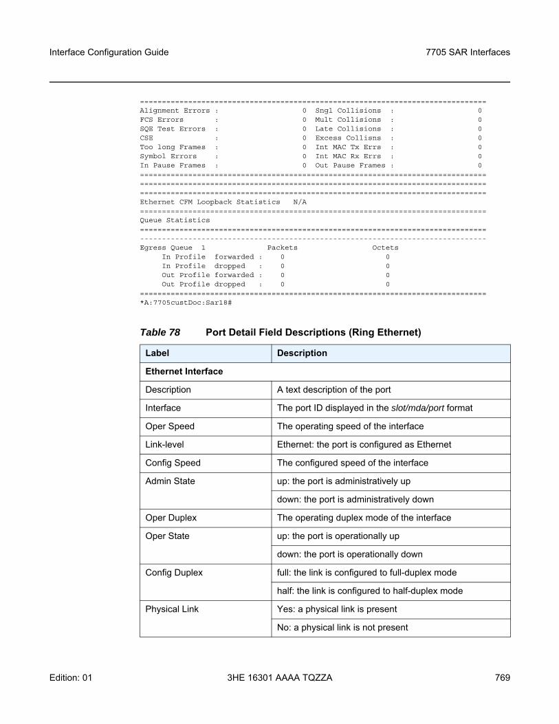
Interface Configuration Guide 7705 SAR Interfaces
Edition: 01 3HE 16301 AAAA TQZZA 769
===============================================================================Alignment Errors : 0 Sngl Collisions : 0FCS Errors : 0 Mult Collisions : 0SQE Test Errors : 0 Late Collisions : 0CSE : 0 Excess Collisns : 0Too long Frames : 0 Int MAC Tx Errs : 0Symbol Errors : 0 Int MAC Rx Errs : 0In Pause Frames : 0 Out Pause Frames : 0=============================================================================================================================================================================================================================================Ethernet CFM Loopback Statistics N/A===============================================================================Queue Statistics===============================================================================-------------------------------------------------------------------------------Egress Queue 1 Packets Octets
In Profile forwarded : 0 0In Profile dropped : 0 0Out Profile forwarded : 0 0Out Profile dropped : 0 0
===============================================================================*A:7705custDoc:Sar18#
Table 78 Port Detail Field Descriptions (Ring Ethernet)
Label Description
Ethernet Interface
Description A text description of the port
Interface The port ID displayed in the slot/mda/port format
Oper Speed The operating speed of the interface
Link-level Ethernet: the port is configured as Ethernet
Config Speed The configured speed of the interface
Admin State up: the port is administratively up
down: the port is administratively down
Oper Duplex The operating duplex mode of the interface
Oper State up: the port is operationally up
down: the port is operationally down
Config Duplex full: the link is configured to full-duplex mode
half: the link is configured to half-duplex mode
Physical Link Yes: a physical link is present
No: a physical link is not present
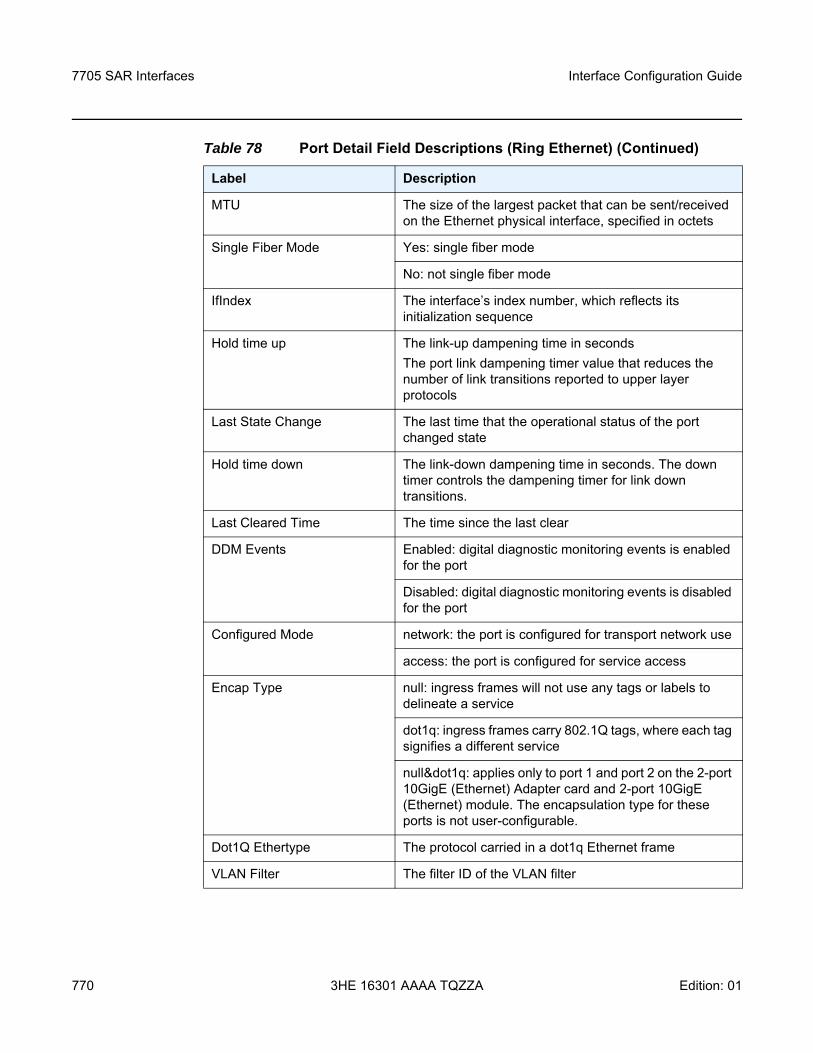
7705 SAR Interfaces
770
Interface Configuration Guide
3HE 16301 AAAA TQZZA Edition: 01
MTU The size of the largest packet that can be sent/received on the Ethernet physical interface, specified in octets
Single Fiber Mode Yes: single fiber mode
No: not single fiber mode
IfIndex The interface’s index number, which reflects its initialization sequence
Hold time up The link-up dampening time in secondsThe port link dampening timer value that reduces the number of link transitions reported to upper layer protocols
Last State Change The last time that the operational status of the port changed state
Hold time down The link-down dampening time in seconds. The down timer controls the dampening timer for link down transitions.
Last Cleared Time The time since the last clear
DDM Events Enabled: digital diagnostic monitoring events is enabled for the port
Disabled: digital diagnostic monitoring events is disabled for the port
Configured Mode network: the port is configured for transport network use
access: the port is configured for service access
Encap Type null: ingress frames will not use any tags or labels to delineate a service
dot1q: ingress frames carry 802.1Q tags, where each tag signifies a different service
null&dot1q: applies only to port 1 and port 2 on the 2-port 10GigE (Ethernet) Adapter card and 2-port 10GigE (Ethernet) module. The encapsulation type for these ports is not user-configurable.
Dot1Q Ethertype The protocol carried in a dot1q Ethernet frame
VLAN Filter The filter ID of the VLAN filter
Table 78 Port Detail Field Descriptions (Ring Ethernet) (Continued)
Label Description
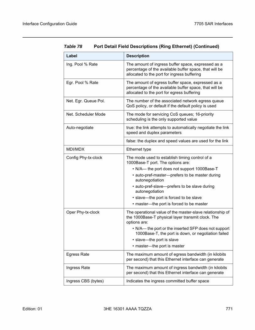
Interface Configuration Guide 7705 SAR Interfaces
Edition: 01 3HE 16301 AAAA TQZZA 771
Ing. Pool % Rate The amount of ingress buffer space, expressed as a percentage of the available buffer space, that will be allocated to the port for ingress buffering
Egr. Pool % Rate The amount of egress buffer space, expressed as a percentage of the available buffer space, that will be allocated to the port for egress buffering
Net. Egr. Queue Pol. The number of the associated network egress queue QoS policy, or default if the default policy is used
Net. Scheduler Mode The mode for servicing CoS queues; 16-priority scheduling is the only supported value
Auto-negotiate true: the link attempts to automatically negotiate the link speed and duplex parameters
false: the duplex and speed values are used for the link
MDI/MDX Ethernet type
Config Phy-tx-clock The mode used to establish timing control of a 1000Base-T port. The options are:
• N/A— the port does not support 1000Base-T• auto-pref-master—prefers to be master during
autonegotiation• auto-pref-slave—prefers to be slave during
autonegotiation• slave—the port is forced to be slave • master—the port is forced to be master
Oper Phy-tx-clock The operational value of the master-slave relationship of the 1000Base-T physical layer transmit clock. The options are:
• N/A— the port or the inserted SFP does not support 1000Base-T, the port is down, or negotiation failed
• slave—the port is slave • master—the port is master
Egress Rate The maximum amount of egress bandwidth (in kilobits per second) that this Ethernet interface can generate
Ingress Rate The maximum amount of ingress bandwidth (in kilobits per second) that this Ethernet interface can generate
Ingress CBS (bytes) Indicates the ingress committed buffer space
Table 78 Port Detail Field Descriptions (Ring Ethernet) (Continued)
Label Description
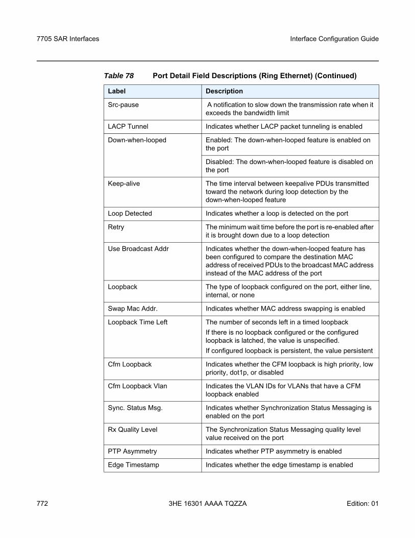
7705 SAR Interfaces
772
Interface Configuration Guide
3HE 16301 AAAA TQZZA Edition: 01
Src-pause A notification to slow down the transmission rate when it exceeds the bandwidth limit
LACP Tunnel Indicates whether LACP packet tunneling is enabled
Down-when-looped Enabled: The down-when-looped feature is enabled on the port
Disabled: The down-when-looped feature is disabled on the port
Keep-alive The time interval between keepalive PDUs transmitted toward the network during loop detection by the down-when-looped feature
Loop Detected Indicates whether a loop is detected on the port
Retry The minimum wait time before the port is re-enabled after it is brought down due to a loop detection
Use Broadcast Addr Indicates whether the down-when-looped feature has been configured to compare the destination MAC address of received PDUs to the broadcast MAC address instead of the MAC address of the port
Loopback The type of loopback configured on the port, either line, internal, or none
Swap Mac Addr. Indicates whether MAC address swapping is enabled
Loopback Time Left The number of seconds left in a timed loopbackIf there is no loopback configured or the configured loopback is latched, the value is unspecified.If configured loopback is persistent, the value persistent
Cfm Loopback Indicates whether the CFM loopback is high priority, low priority, dot1p, or disabled
Cfm Loopback Vlan Indicates the VLAN IDs for VLANs that have a CFM loopback enabled
Sync. Status Msg. Indicates whether Synchronization Status Messaging is enabled on the port
Rx Quality Level The Synchronization Status Messaging quality level value received on the port
PTP Asymmetry Indicates whether PTP asymmetry is enabled
Edge Timestamp Indicates whether the edge timestamp is enabled
Table 78 Port Detail Field Descriptions (Ring Ethernet) (Continued)
Label Description
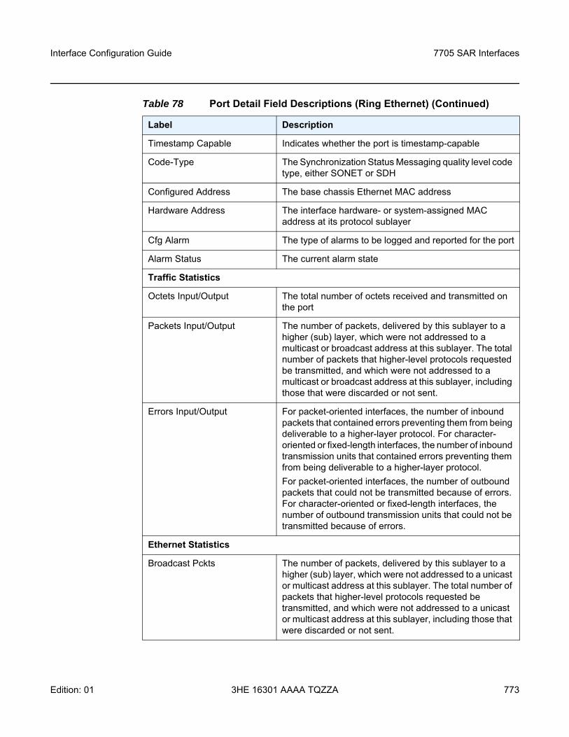
Interface Configuration Guide 7705 SAR Interfaces
Edition: 01 3HE 16301 AAAA TQZZA 773
Timestamp Capable Indicates whether the port is timestamp-capable
Code-Type The Synchronization Status Messaging quality level code type, either SONET or SDH
Configured Address The base chassis Ethernet MAC address
Hardware Address The interface hardware- or system-assigned MAC address at its protocol sublayer
Cfg Alarm The type of alarms to be logged and reported for the port
Alarm Status The current alarm state
Traffic Statistics
Octets Input/Output The total number of octets received and transmitted on the port
Packets Input/Output The number of packets, delivered by this sublayer to a higher (sub) layer, which were not addressed to a multicast or broadcast address at this sublayer. The total number of packets that higher-level protocols requested be transmitted, and which were not addressed to a multicast or broadcast address at this sublayer, including those that were discarded or not sent.
Errors Input/Output For packet-oriented interfaces, the number of inbound packets that contained errors preventing them from being deliverable to a higher-layer protocol. For character-oriented or fixed-length interfaces, the number of inbound transmission units that contained errors preventing them from being deliverable to a higher-layer protocol.For packet-oriented interfaces, the number of outbound packets that could not be transmitted because of errors. For character-oriented or fixed-length interfaces, the number of outbound transmission units that could not be transmitted because of errors.
Ethernet Statistics
Broadcast Pckts The number of packets, delivered by this sublayer to a higher (sub) layer, which were not addressed to a unicast or multicast address at this sublayer. The total number of packets that higher-level protocols requested be transmitted, and which were not addressed to a unicast or multicast address at this sublayer, including those that were discarded or not sent.
Table 78 Port Detail Field Descriptions (Ring Ethernet) (Continued)
Label Description
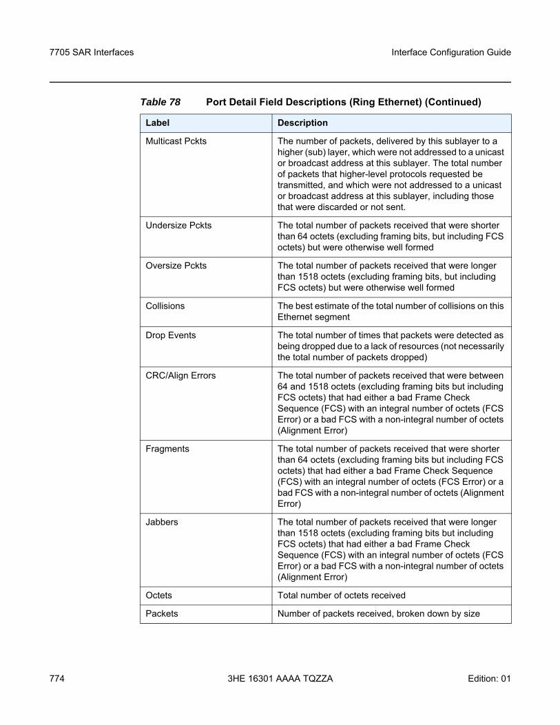
7705 SAR Interfaces
774
Interface Configuration Guide
3HE 16301 AAAA TQZZA Edition: 01
Multicast Pckts The number of packets, delivered by this sublayer to a higher (sub) layer, which were not addressed to a unicast or broadcast address at this sublayer. The total number of packets that higher-level protocols requested be transmitted, and which were not addressed to a unicast or broadcast address at this sublayer, including those that were discarded or not sent.
Undersize Pckts The total number of packets received that were shorter than 64 octets (excluding framing bits, but including FCS octets) but were otherwise well formed
Oversize Pckts The total number of packets received that were longer than 1518 octets (excluding framing bits, but including FCS octets) but were otherwise well formed
Collisions The best estimate of the total number of collisions on this Ethernet segment
Drop Events The total number of times that packets were detected as being dropped due to a lack of resources (not necessarily the total number of packets dropped)
CRC/Align Errors The total number of packets received that were between 64 and 1518 octets (excluding framing bits but including FCS octets) that had either a bad Frame Check Sequence (FCS) with an integral number of octets (FCS Error) or a bad FCS with a non-integral number of octets (Alignment Error)
Fragments The total number of packets received that were shorter than 64 octets (excluding framing bits but including FCS octets) that had either a bad Frame Check Sequence (FCS) with an integral number of octets (FCS Error) or a bad FCS with a non-integral number of octets (Alignment Error)
Jabbers The total number of packets received that were longer than 1518 octets (excluding framing bits but including FCS octets) that had either a bad Frame Check Sequence (FCS) with an integral number of octets (FCS Error) or a bad FCS with a non-integral number of octets (Alignment Error)
Octets Total number of octets received
Packets Number of packets received, broken down by size
Table 78 Port Detail Field Descriptions (Ring Ethernet) (Continued)
Label Description
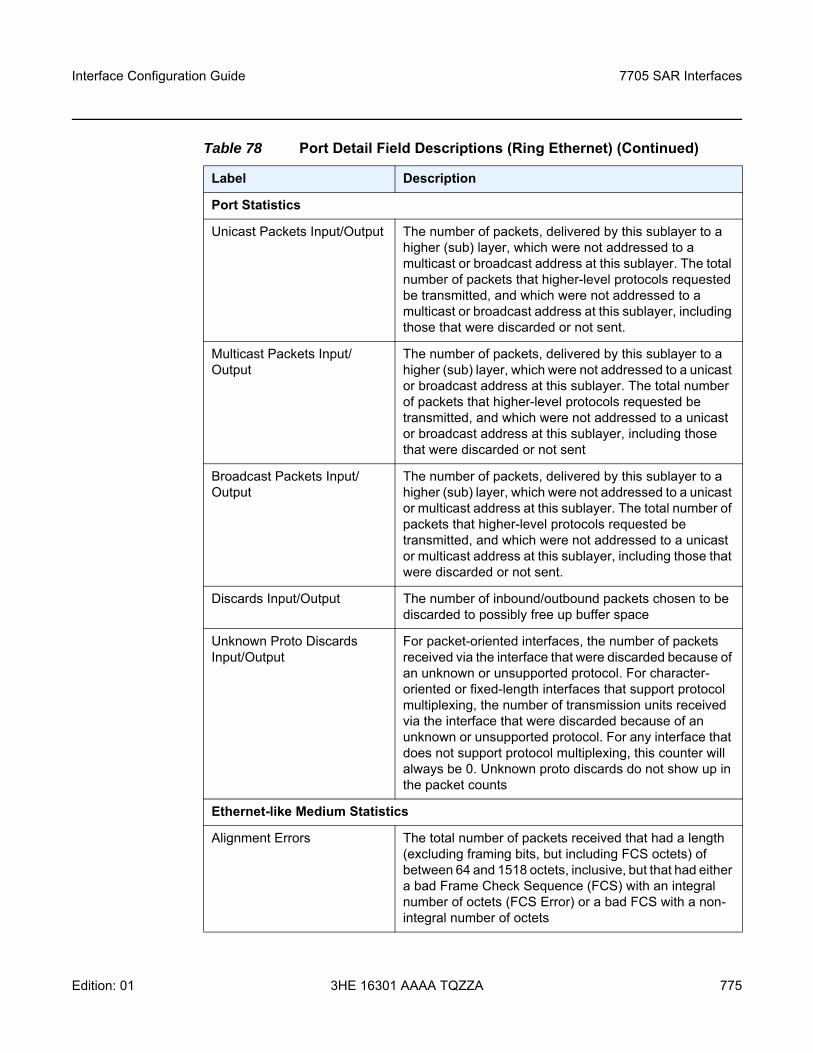
Interface Configuration Guide 7705 SAR Interfaces
Edition: 01 3HE 16301 AAAA TQZZA 775
Port Statistics
Unicast Packets Input/Output The number of packets, delivered by this sublayer to a higher (sub) layer, which were not addressed to a multicast or broadcast address at this sublayer. The total number of packets that higher-level protocols requested be transmitted, and which were not addressed to a multicast or broadcast address at this sublayer, including those that were discarded or not sent.
Multicast Packets Input/Output
The number of packets, delivered by this sublayer to a higher (sub) layer, which were not addressed to a unicast or broadcast address at this sublayer. The total number of packets that higher-level protocols requested be transmitted, and which were not addressed to a unicast or broadcast address at this sublayer, including those that were discarded or not sent
Broadcast Packets Input/Output
The number of packets, delivered by this sublayer to a higher (sub) layer, which were not addressed to a unicast or multicast address at this sublayer. The total number of packets that higher-level protocols requested be transmitted, and which were not addressed to a unicast or multicast address at this sublayer, including those that were discarded or not sent.
Discards Input/Output The number of inbound/outbound packets chosen to be discarded to possibly free up buffer space
Unknown Proto Discards Input/Output
For packet-oriented interfaces, the number of packets received via the interface that were discarded because of an unknown or unsupported protocol. For character-oriented or fixed-length interfaces that support protocol multiplexing, the number of transmission units received via the interface that were discarded because of an unknown or unsupported protocol. For any interface that does not support protocol multiplexing, this counter will always be 0. Unknown proto discards do not show up in the packet counts
Ethernet-like Medium Statistics
Alignment Errors The total number of packets received that had a length (excluding framing bits, but including FCS octets) of between 64 and 1518 octets, inclusive, but that had either a bad Frame Check Sequence (FCS) with an integral number of octets (FCS Error) or a bad FCS with a non-integral number of octets
Table 78 Port Detail Field Descriptions (Ring Ethernet) (Continued)
Label Description
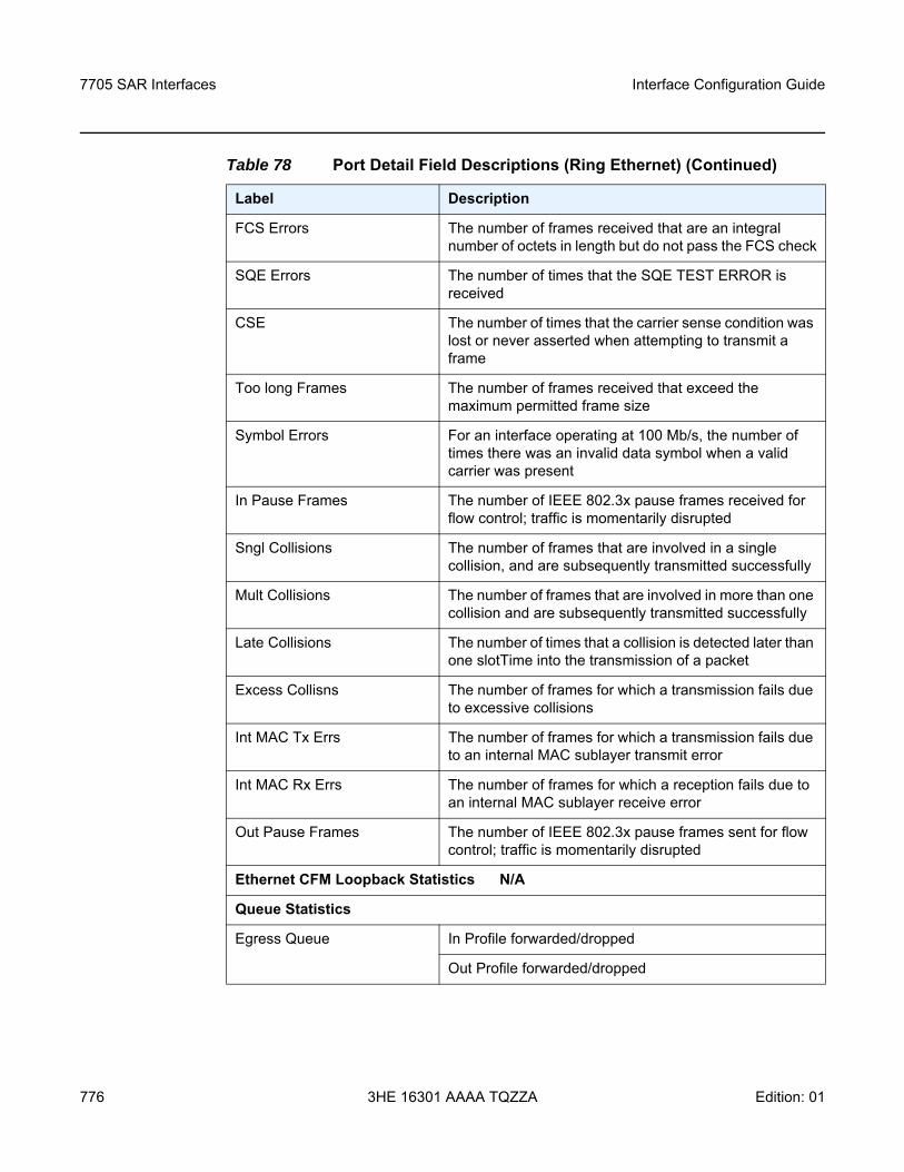
7705 SAR Interfaces
776
Interface Configuration Guide
3HE 16301 AAAA TQZZA Edition: 01
FCS Errors The number of frames received that are an integral number of octets in length but do not pass the FCS check
SQE Errors The number of times that the SQE TEST ERROR is received
CSE The number of times that the carrier sense condition was lost or never asserted when attempting to transmit a frame
Too long Frames The number of frames received that exceed the maximum permitted frame size
Symbol Errors For an interface operating at 100 Mb/s, the number of times there was an invalid data symbol when a valid carrier was present
In Pause Frames The number of IEEE 802.3x pause frames received for flow control; traffic is momentarily disrupted
Sngl Collisions The number of frames that are involved in a single collision, and are subsequently transmitted successfully
Mult Collisions The number of frames that are involved in more than one collision and are subsequently transmitted successfully
Late Collisions The number of times that a collision is detected later than one slotTime into the transmission of a packet
Excess Collisns The number of frames for which a transmission fails due to excessive collisions
Int MAC Tx Errs The number of frames for which a transmission fails due to an internal MAC sublayer transmit error
Int MAC Rx Errs The number of frames for which a reception fails due to an internal MAC sublayer receive error
Out Pause Frames The number of IEEE 802.3x pause frames sent for flow control; traffic is momentarily disrupted
Ethernet CFM Loopback Statistics N/A
Queue Statistics
Egress Queue In Profile forwarded/dropped
Out Profile forwarded/dropped
Table 78 Port Detail Field Descriptions (Ring Ethernet) (Continued)
Label Description
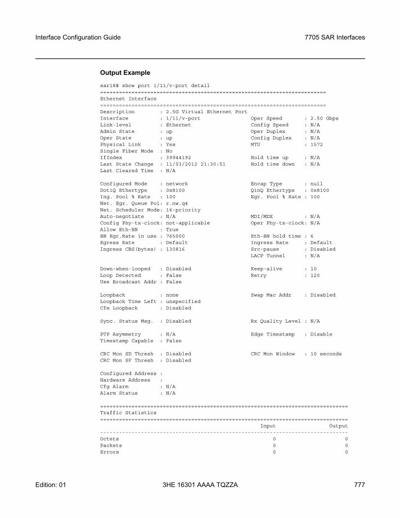
Interface Configuration Guide 7705 SAR Interfaces
Edition: 01 3HE 16301 AAAA TQZZA 777
Output Example
sar18# show port 1/11/v-port detail========================================================================Ethernet Interface========================================================================Description : 2.5G Virtual Ethernet PortInterface : 1/11/v-port Oper Speed : 2.50 GbpsLink-level : Ethernet Config Speed : N/AAdmin State : up Oper Duplex : N/AOper State : up Config Duplex : N/APhysical Link : Yes MTU : 1572Single Fiber Mode : NoIfIndex : 39944192 Hold time up : N/ALast State Change : 11/03/2012 21:30:51 Hold time down : N/ALast Cleared Time : N/A
Configured Mode : network Encap Type : nullDot1Q Ethertype : 0x8100 QinQ Ethertype : 0x8100Ing. Pool % Rate : 100 Egr. Pool % Rate : 100Net. Egr. Queue Pol: r.nw.q4Net. Scheduler Mode: 16-priorityAuto-negotiate : N/A MDI/MDX : N/AConfig Phy-tx-clock: not-applicable Oper Phy-tx-clock: N/AAllow Eth-BN : TrueBN Egr.Rate in use : 765000 Eth-BN hold time : 6Egress Rate : Default Ingress Rate : DefaultIngress CBS(bytes) : 130816 Src-pause : Disabled
LACP Tunnel : N/A
Down-when-looped : Disabled Keep-alive : 10Loop Detected : False Retry : 120Use Broadcast Addr : False
Loopback : none Swap Mac Addr : DisabledLoopback Time Left : unspecifiedCfm Loopback : Disabled
Sync. Status Msg. : Disabled Rx Quality Level : N/A
PTP Asymmetry : N/A Edge Timestamp : DisableTimestamp Capable : False
CRC Mon SD Thresh : Disabled CRC Mon Window : 10 secondsCRC Mon SF Thresh : Disabled
Configured Address :Hardware Address :Cfg Alarm : N/AAlarm Status : N/A
===============================================================================Traffic Statistics===============================================================================
Input Output-------------------------------------------------------------------------------Octets 0 0Packets 0 0Errors 0 0
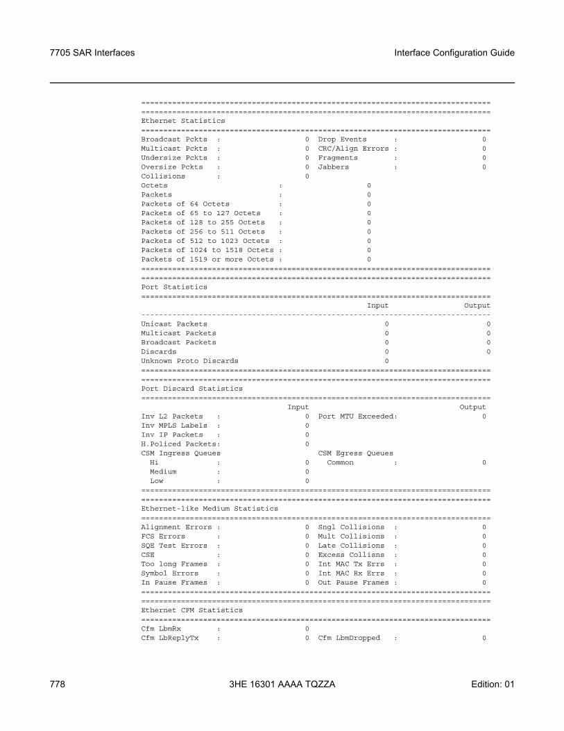
7705 SAR Interfaces
778
Interface Configuration Guide
3HE 16301 AAAA TQZZA Edition: 01
==============================================================================================================================================================Ethernet Statistics===============================================================================Broadcast Pckts : 0 Drop Events : 0Multicast Pckts : 0 CRC/Align Errors : 0Undersize Pckts : 0 Fragments : 0Oversize Pckts : 0 Jabbers : 0Collisions : 0Octets : 0Packets : 0Packets of 64 Octets : 0Packets of 65 to 127 Octets : 0Packets of 128 to 255 Octets : 0Packets of 256 to 511 Octets : 0Packets of 512 to 1023 Octets : 0Packets of 1024 to 1518 Octets : 0Packets of 1519 or more Octets : 0==============================================================================================================================================================Port Statistics===============================================================================
Input Output-------------------------------------------------------------------------------Unicast Packets 0 0Multicast Packets 0 0Broadcast Packets 0 0Discards 0 0Unknown Proto Discards 0==============================================================================================================================================================Port Discard Statistics===============================================================================
Input OutputInv L2 Packets : 0 Port MTU Exceeded: 0Inv MPLS Labels : 0Inv IP Packets : 0H.Policed Packets: 0CSM Ingress Queues CSM Egress Queues
Hi : 0 Common : 0Medium : 0Low : 0
==============================================================================================================================================================Ethernet-like Medium Statistics===============================================================================Alignment Errors : 0 Sngl Collisions : 0FCS Errors : 0 Mult Collisions : 0SQE Test Errors : 0 Late Collisions : 0CSE : 0 Excess Collisns : 0Too long Frames : 0 Int MAC Tx Errs : 0Symbol Errors : 0 Int MAC Rx Errs : 0In Pause Frames : 0 Out Pause Frames : 0==============================================================================================================================================================Ethernet CFM Statistics===============================================================================Cfm LbmRx : 0Cfm LbReplyTx : 0 Cfm LbmDropped : 0
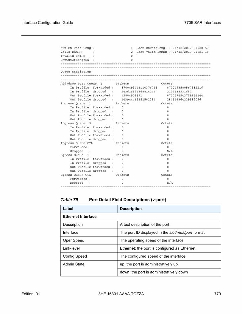
Interface Configuration Guide 7705 SAR Interfaces
Edition: 01 3HE 16301 AAAA TQZZA 779
Num Bn Rate Chng : 1 Last BnRateChng : 04/12/2017 21:20:53Valid BnmRx : 2 Last Valid BnmRx : 04/12/2017 21:21:10Invalid BnmRx : 0BnmOutOfRangeBW : 0==============================================================================================================================================================Queue Statistics===============================================================================-------------------------------------------------------------------------------Add-drop Port Queue 1 Packets Octets
In Profile forwarded : 8700493441110376715 8700493580567332216In Profile dropped : 243616594368814244 2209638931652Out Profile forwarded : 12884901891 8700494542739924144Out Profile dropped : 143944465151581384 284544364229582056
Ingress Queue 1 Packets OctetsIn Profile forwarded : 0 0In Profile dropped : 0 0Out Profile forwarded : 0 0Out Profile dropped : 0 0
Ingress Queue 9 Packets OctetsIn Profile forwarded : 0 0In Profile dropped : 0 0Out Profile forwarded : 0 0Out Profile dropped : 0 0
Ingress Queue CTL Packets OctetsForwarded : 0 0Dropped : 0 N/A
Egress Queue 1 Packets OctetsIn Profile forwarded : 0 0In Profile dropped : 0 0Out Profile forwarded : 0 0Out Profile dropped : 0 0
Egress Queue CTL Packets OctetsForwarded : 0 0Dropped : 0 N/A
===============================================================================
Table 79 Port Detail Field Descriptions (v-port)
Label Description
Ethernet Interface
Description A text description of the port
Interface The port ID displayed in the slot/mda/port format
Oper Speed The operating speed of the interface
Link-level Ethernet: the port is configured as Ethernet
Config Speed The configured speed of the interface
Admin State up: the port is administratively up
down: the port is administratively down
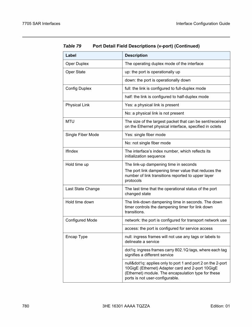
7705 SAR Interfaces
780
Interface Configuration Guide
3HE 16301 AAAA TQZZA Edition: 01
Oper Duplex The operating duplex mode of the interface
Oper State up: the port is operationally up
down: the port is operationally down
Config Duplex full: the link is configured to full-duplex mode
half: the link is configured to half-duplex mode
Physical Link Yes: a physical link is present
No: a physical link is not present
MTU The size of the largest packet that can be sent/received on the Ethernet physical interface, specified in octets
Single Fiber Mode Yes: single fiber mode
No: not single fiber mode
IfIndex The interface’s index number, which reflects its initialization sequence
Hold time up The link-up dampening time in secondsThe port link dampening timer value that reduces the number of link transitions reported to upper layer protocols
Last State Change The last time that the operational status of the port changed state
Hold time down The link-down dampening time in seconds. The down timer controls the dampening timer for link down transitions.
Configured Mode network: the port is configured for transport network use
access: the port is configured for service access
Encap Type null: ingress frames will not use any tags or labels to delineate a service
dot1q: ingress frames carry 802.1Q tags, where each tag signifies a different service
null&dot1q: applies only to port 1 and port 2 on the 2-port 10GigE (Ethernet) Adapter card and 2-port 10GigE (Ethernet) module. The encapsulation type for these ports is not user-configurable.
Table 79 Port Detail Field Descriptions (v-port) (Continued)
Label Description
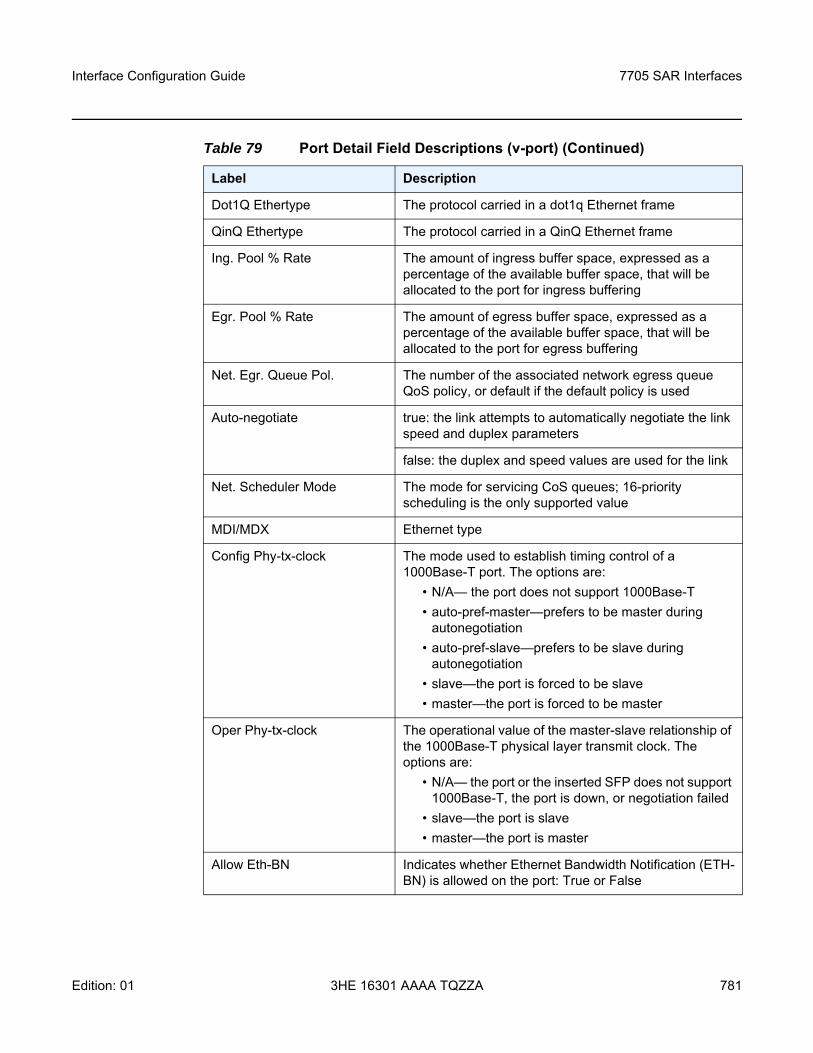
Interface Configuration Guide 7705 SAR Interfaces
Edition: 01 3HE 16301 AAAA TQZZA 781
Dot1Q Ethertype The protocol carried in a dot1q Ethernet frame
QinQ Ethertype The protocol carried in a QinQ Ethernet frame
Ing. Pool % Rate The amount of ingress buffer space, expressed as a percentage of the available buffer space, that will be allocated to the port for ingress buffering
Egr. Pool % Rate The amount of egress buffer space, expressed as a percentage of the available buffer space, that will be allocated to the port for egress buffering
Net. Egr. Queue Pol. The number of the associated network egress queue QoS policy, or default if the default policy is used
Auto-negotiate true: the link attempts to automatically negotiate the link speed and duplex parameters
false: the duplex and speed values are used for the link
Net. Scheduler Mode The mode for servicing CoS queues; 16-priority scheduling is the only supported value
MDI/MDX Ethernet type
Config Phy-tx-clock The mode used to establish timing control of a 1000Base-T port. The options are:
• N/A— the port does not support 1000Base-T• auto-pref-master—prefers to be master during
autonegotiation• auto-pref-slave—prefers to be slave during
autonegotiation• slave—the port is forced to be slave • master—the port is forced to be master
Oper Phy-tx-clock The operational value of the master-slave relationship of the 1000Base-T physical layer transmit clock. The options are:
• N/A— the port or the inserted SFP does not support 1000Base-T, the port is down, or negotiation failed
• slave—the port is slave • master—the port is master
Allow Eth-BN Indicates whether Ethernet Bandwidth Notification (ETH-BN) is allowed on the port: True or False
Table 79 Port Detail Field Descriptions (v-port) (Continued)
Label Description
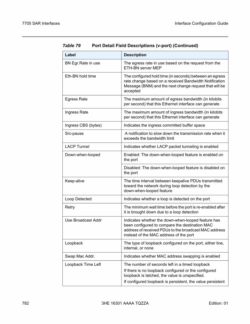
7705 SAR Interfaces
782
Interface Configuration Guide
3HE 16301 AAAA TQZZA Edition: 01
BN Egr.Rate in use The egress rate in use based on the request from the ETH-BN server MEP
Eth-BN hold time The configured hold time (in seconds) between an egress rate change based on a received Bandwidth Notification Message (BNM) and the next change request that will be accepted
Egress Rate The maximum amount of egress bandwidth (in kilobits per second) that this Ethernet interface can generate
Ingress Rate The maximum amount of ingress bandwidth (in kilobits per second) that this Ethernet interface can generate
Ingress CBS (bytes) Indicates the ingress committed buffer space
Src-pause A notification to slow down the transmission rate when it exceeds the bandwidth limit
LACP Tunnel Indicates whether LACP packet tunneling is enabled
Down-when-looped Enabled: The down-when-looped feature is enabled on the port
Disabled: The down-when-looped feature is disabled on the port
Keep-alive The time interval between keepalive PDUs transmitted toward the network during loop detection by the down-when-looped feature
Loop Detected Indicates whether a loop is detected on the port
Retry The minimum wait time before the port is re-enabled after it is brought down due to a loop detection
Use Broadcast Addr Indicates whether the down-when-looped feature has been configured to compare the destination MAC address of received PDUs to the broadcast MAC address instead of the MAC address of the port
Loopback The type of loopback configured on the port, either line, internal, or none
Swap Mac Addr. Indicates whether MAC address swapping is enabled
Loopback Time Left The number of seconds left in a timed loopbackIf there is no loopback configured or the configured loopback is latched, the value is unspecified.If configured loopback is persistent, the value persistent
Table 79 Port Detail Field Descriptions (v-port) (Continued)
Label Description
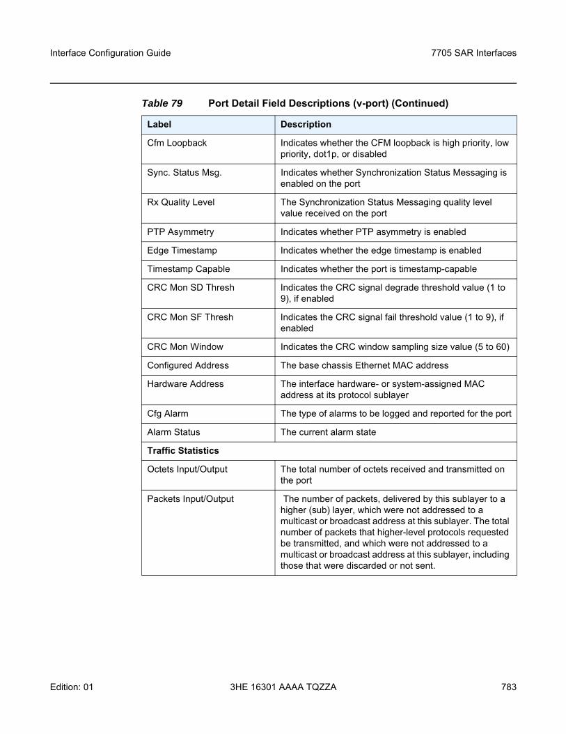
Interface Configuration Guide 7705 SAR Interfaces
Edition: 01 3HE 16301 AAAA TQZZA 783
Cfm Loopback Indicates whether the CFM loopback is high priority, low priority, dot1p, or disabled
Sync. Status Msg. Indicates whether Synchronization Status Messaging is enabled on the port
Rx Quality Level The Synchronization Status Messaging quality level value received on the port
PTP Asymmetry Indicates whether PTP asymmetry is enabled
Edge Timestamp Indicates whether the edge timestamp is enabled
Timestamp Capable Indicates whether the port is timestamp-capable
CRC Mon SD Thresh Indicates the CRC signal degrade threshold value (1 to 9), if enabled
CRC Mon SF Thresh Indicates the CRC signal fail threshold value (1 to 9), if enabled
CRC Mon Window Indicates the CRC window sampling size value (5 to 60)
Configured Address The base chassis Ethernet MAC address
Hardware Address The interface hardware- or system-assigned MAC address at its protocol sublayer
Cfg Alarm The type of alarms to be logged and reported for the port
Alarm Status The current alarm state
Traffic Statistics
Octets Input/Output The total number of octets received and transmitted on the port
Packets Input/Output The number of packets, delivered by this sublayer to a higher (sub) layer, which were not addressed to a multicast or broadcast address at this sublayer. The total number of packets that higher-level protocols requested be transmitted, and which were not addressed to a multicast or broadcast address at this sublayer, including those that were discarded or not sent.
Table 79 Port Detail Field Descriptions (v-port) (Continued)
Label Description
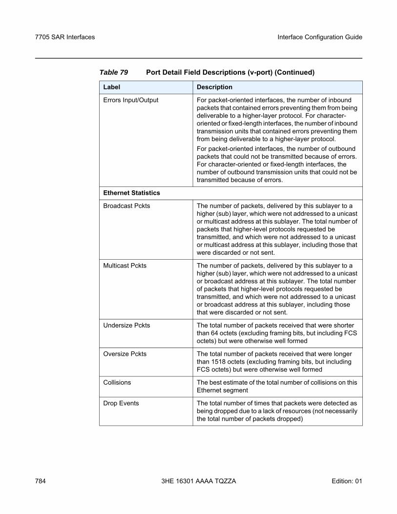
7705 SAR Interfaces
784
Interface Configuration Guide
3HE 16301 AAAA TQZZA Edition: 01
Errors Input/Output For packet-oriented interfaces, the number of inbound packets that contained errors preventing them from being deliverable to a higher-layer protocol. For character-oriented or fixed-length interfaces, the number of inbound transmission units that contained errors preventing them from being deliverable to a higher-layer protocol.For packet-oriented interfaces, the number of outbound packets that could not be transmitted because of errors. For character-oriented or fixed-length interfaces, the number of outbound transmission units that could not be transmitted because of errors.
Ethernet Statistics
Broadcast Pckts The number of packets, delivered by this sublayer to a higher (sub) layer, which were not addressed to a unicast or multicast address at this sublayer. The total number of packets that higher-level protocols requested be transmitted, and which were not addressed to a unicast or multicast address at this sublayer, including those that were discarded or not sent.
Multicast Pckts The number of packets, delivered by this sublayer to a higher (sub) layer, which were not addressed to a unicast or broadcast address at this sublayer. The total number of packets that higher-level protocols requested be transmitted, and which were not addressed to a unicast or broadcast address at this sublayer, including those that were discarded or not sent.
Undersize Pckts The total number of packets received that were shorter than 64 octets (excluding framing bits, but including FCS octets) but were otherwise well formed
Oversize Pckts The total number of packets received that were longer than 1518 octets (excluding framing bits, but including FCS octets) but were otherwise well formed
Collisions The best estimate of the total number of collisions on this Ethernet segment
Drop Events The total number of times that packets were detected as being dropped due to a lack of resources (not necessarily the total number of packets dropped)
Table 79 Port Detail Field Descriptions (v-port) (Continued)
Label Description
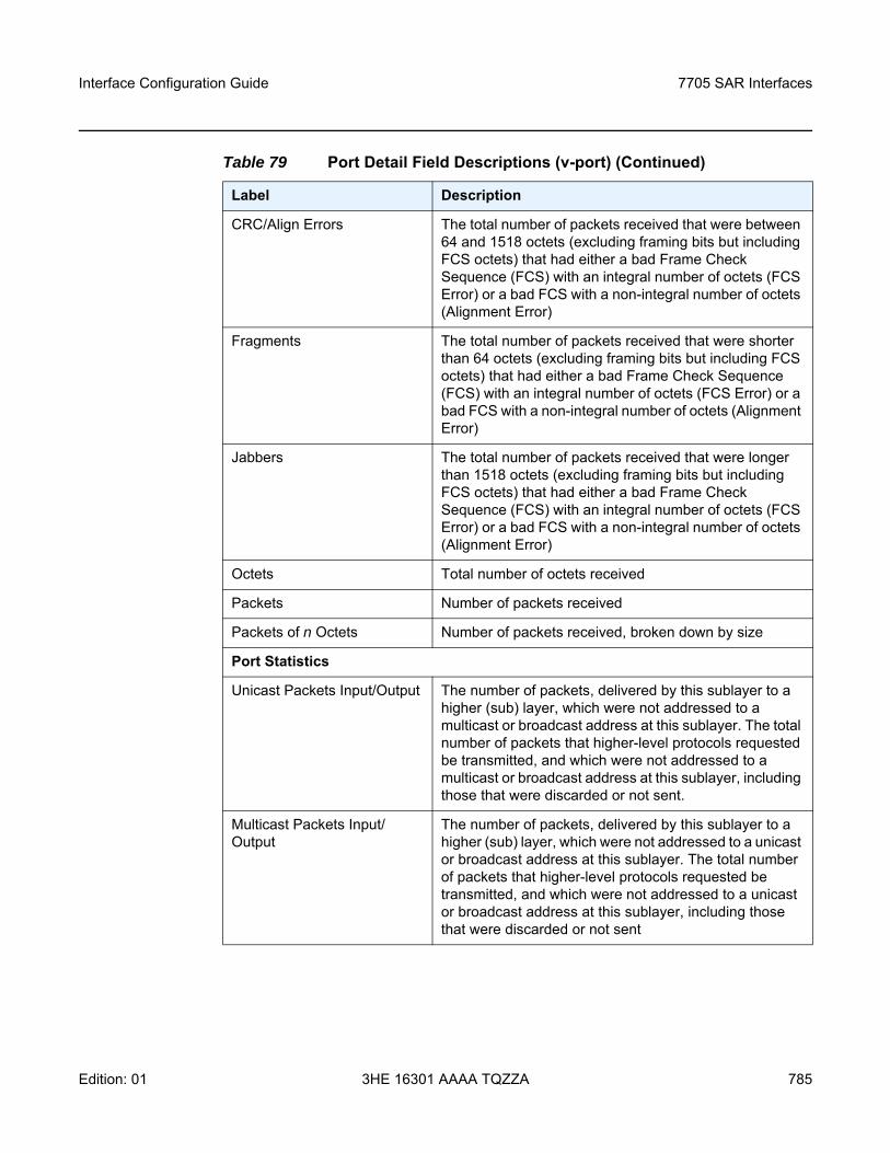
Interface Configuration Guide 7705 SAR Interfaces
Edition: 01 3HE 16301 AAAA TQZZA 785
CRC/Align Errors The total number of packets received that were between 64 and 1518 octets (excluding framing bits but including FCS octets) that had either a bad Frame Check Sequence (FCS) with an integral number of octets (FCS Error) or a bad FCS with a non-integral number of octets (Alignment Error)
Fragments The total number of packets received that were shorter than 64 octets (excluding framing bits but including FCS octets) that had either a bad Frame Check Sequence (FCS) with an integral number of octets (FCS Error) or a bad FCS with a non-integral number of octets (Alignment Error)
Jabbers The total number of packets received that were longer than 1518 octets (excluding framing bits but including FCS octets) that had either a bad Frame Check Sequence (FCS) with an integral number of octets (FCS Error) or a bad FCS with a non-integral number of octets (Alignment Error)
Octets Total number of octets received
Packets Number of packets received
Packets of n Octets Number of packets received, broken down by size
Port Statistics
Unicast Packets Input/Output The number of packets, delivered by this sublayer to a higher (sub) layer, which were not addressed to a multicast or broadcast address at this sublayer. The total number of packets that higher-level protocols requested be transmitted, and which were not addressed to a multicast or broadcast address at this sublayer, including those that were discarded or not sent.
Multicast Packets Input/Output
The number of packets, delivered by this sublayer to a higher (sub) layer, which were not addressed to a unicast or broadcast address at this sublayer. The total number of packets that higher-level protocols requested be transmitted, and which were not addressed to a unicast or broadcast address at this sublayer, including those that were discarded or not sent
Table 79 Port Detail Field Descriptions (v-port) (Continued)
Label Description
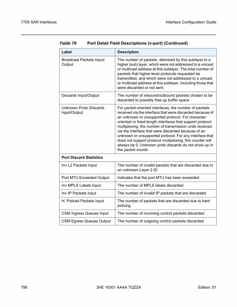
7705 SAR Interfaces
786
Interface Configuration Guide
3HE 16301 AAAA TQZZA Edition: 01
Broadcast Packets Input/Output
The number of packets, delivered by this sublayer to a higher (sub) layer, which were not addressed to a unicast or multicast address at this sublayer. The total number of packets that higher-level protocols requested be transmitted, and which were not addressed to a unicast or multicast address at this sublayer, including those that were discarded or not sent.
Discards Input/Output The number of inbound/outbound packets chosen to be discarded to possibly free up buffer space
Unknown Proto Discards Input/Output
For packet-oriented interfaces, the number of packets received via the interface that were discarded because of an unknown or unsupported protocol. For character-oriented or fixed-length interfaces that support protocol multiplexing, the number of transmission units received via the interface that were discarded because of an unknown or unsupported protocol. For any interface that does not support protocol multiplexing, this counter will always be 0. Unknown proto discards do not show up in the packet counts
Port Discard Statistics
Inv L2 Packets Input The number of invalid packets that are discarded due to an unknown Layer 2 ID
Port MTU Exceeded Output Indicates that the port MTU has been exceeded
Inv MPLS Labels Input The number of MPLS labels discarded
Inv IP Packets Input The number of invalid IP packets that are discarded
H. Policed Packets Input The number of packets that are discarded due to hard policing
CSM Ingress Queues Input The number of incoming control packets discarded
CSM Egress Queues Output The number of outgoing control packets discarded
Table 79 Port Detail Field Descriptions (v-port) (Continued)
Label Description
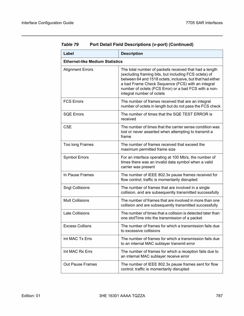
Interface Configuration Guide 7705 SAR Interfaces
Edition: 01 3HE 16301 AAAA TQZZA 787
Ethernet-like Medium Statistics
Alignment Errors The total number of packets received that had a length (excluding framing bits, but including FCS octets) of between 64 and 1518 octets, inclusive, but that had either a bad Frame Check Sequence (FCS) with an integral number of octets (FCS Error) or a bad FCS with a non-integral number of octets
FCS Errors The number of frames received that are an integral number of octets in length but do not pass the FCS check
SQE Errors The number of times that the SQE TEST ERROR is received
CSE The number of times that the carrier sense condition was lost or never asserted when attempting to transmit a frame
Too long Frames The number of frames received that exceed the maximum permitted frame size
Symbol Errors For an interface operating at 100 Mb/s, the number of times there was an invalid data symbol when a valid carrier was present
In Pause Frames The number of IEEE 802.3x pause frames received for flow control; traffic is momentarily disrupted
Sngl Collisions The number of frames that are involved in a single collision, and are subsequently transmitted successfully
Mult Collisions The number of frames that are involved in more than one collision and are subsequently transmitted successfully
Late Collisions The number of times that a collision is detected later than one slotTime into the transmission of a packet
Excess Collisns The number of frames for which a transmission fails due to excessive collisions
Int MAC Tx Errs The number of frames for which a transmission fails due to an internal MAC sublayer transmit error
Int MAC Rx Errs The number of frames for which a reception fails due to an internal MAC sublayer receive error
Out Pause Frames The number of IEEE 802.3x pause frames sent for flow control; traffic is momentarily disrupted
Table 79 Port Detail Field Descriptions (v-port) (Continued)
Label Description
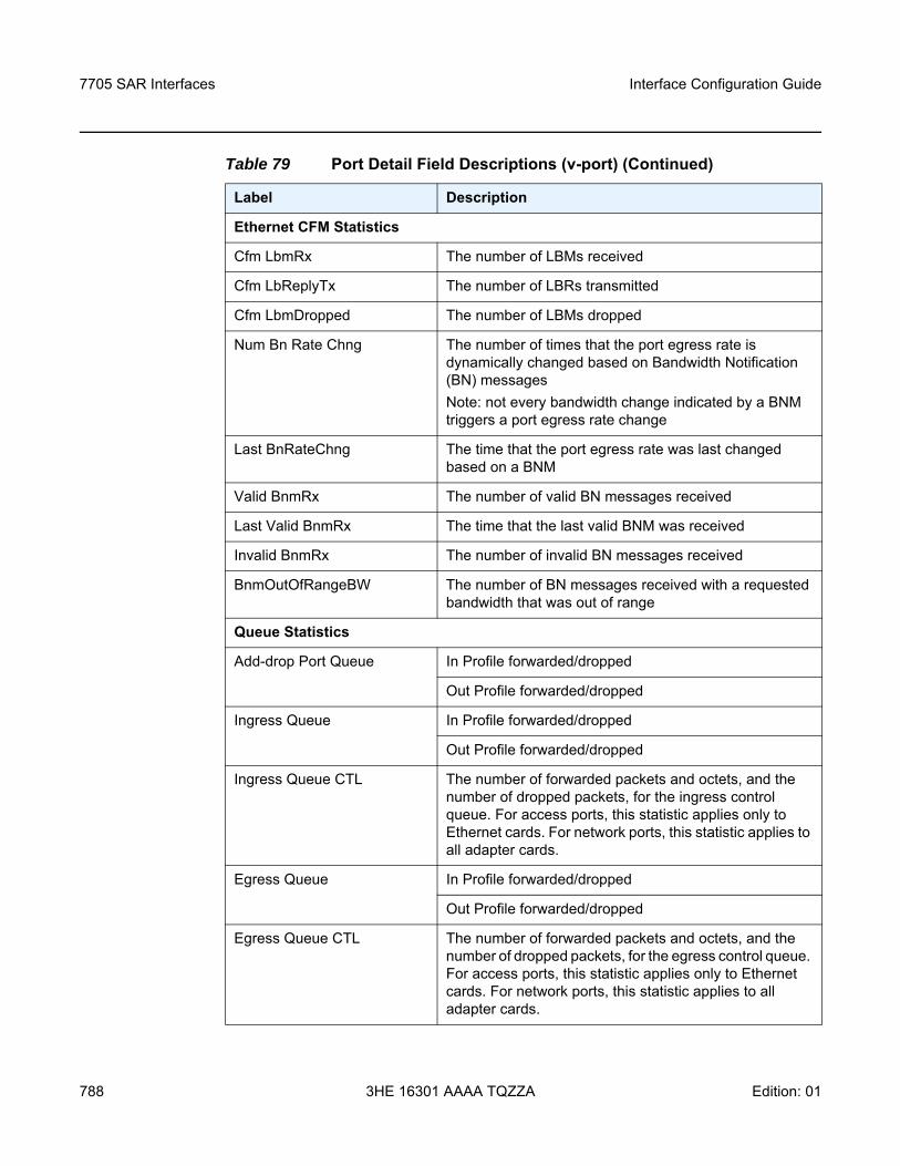
7705 SAR Interfaces
788
Interface Configuration Guide
3HE 16301 AAAA TQZZA Edition: 01
Ethernet CFM Statistics
Cfm LbmRx The number of LBMs received
Cfm LbReplyTx The number of LBRs transmitted
Cfm LbmDropped The number of LBMs dropped
Num Bn Rate Chng The number of times that the port egress rate is dynamically changed based on Bandwidth Notification (BN) messagesNote: not every bandwidth change indicated by a BNM triggers a port egress rate change
Last BnRateChng The time that the port egress rate was last changed based on a BNM
Valid BnmRx The number of valid BN messages received
Last Valid BnmRx The time that the last valid BNM was received
Invalid BnmRx The number of invalid BN messages received
BnmOutOfRangeBW The number of BN messages received with a requested bandwidth that was out of range
Queue Statistics
Add-drop Port Queue In Profile forwarded/dropped
Out Profile forwarded/dropped
Ingress Queue In Profile forwarded/dropped
Out Profile forwarded/dropped
Ingress Queue CTL The number of forwarded packets and octets, and the number of dropped packets, for the ingress control queue. For access ports, this statistic applies only to Ethernet cards. For network ports, this statistic applies to all adapter cards.
Egress Queue In Profile forwarded/dropped
Out Profile forwarded/dropped
Egress Queue CTL The number of forwarded packets and octets, and the number of dropped packets, for the egress control queue. For access ports, this statistic applies only to Ethernet cards. For network ports, this statistic applies to all adapter cards.
Table 79 Port Detail Field Descriptions (v-port) (Continued)
Label Description
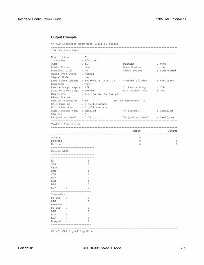
Interface Configuration Guide 7705 SAR Interfaces
Edition: 01 3HE 16301 AAAA TQZZA 789
Output Example
*A:ALU-1>config# show port 1/3/1.e1 detail===============================================================================TDM DS1 Interface===============================================================================Description : E1Interface : 1/3/1.e1Type : e1 Framing : g704Admin Status : down Oper Status : downPhysical Link : no Clock Source : node-timedClock Sync State : normalSignal Mode : casLast State Change : 10/30/2008 14:40:26 Channel IfIndex : 576749569Loopback : noneRemote Loop respond: N/A In Remote Loop : N/ALoad-balance-algo : default Egr. Sched. Pol : N/ACfg Alarm : ais los ber-sd ber sfAlarm Status :BER SD Threshold : 10 BER SF Threshold: 10Hold time up : 0 millisecondsHold time down : 0 millisecondsSync. Status Msg. : Enabled Tx DUS/DNU : DisabledSsm-bit : 6Rx Quality Level : 0x02(prc) Tx Quality Level : 0x02(prc)===============================================================================Traffic Statistics===============================================================================
Input Output-------------------------------------------------------------------------------Octets 0 0Packets 0 0Errors 0 0===========================DS1/E1 Line===========================---------------------------ES 0SES 0SEFS 0UAS 0CSS 0PCV 0LES 0BES 0LCV : 0=========================Transmit:FE-LOF : 0AIS : 0Receive:FE-LOF : 0AIS : 0LOS : 0LOF : 0Looped : 0========================================================================================================DS1/E1 CAS Signalling Bits
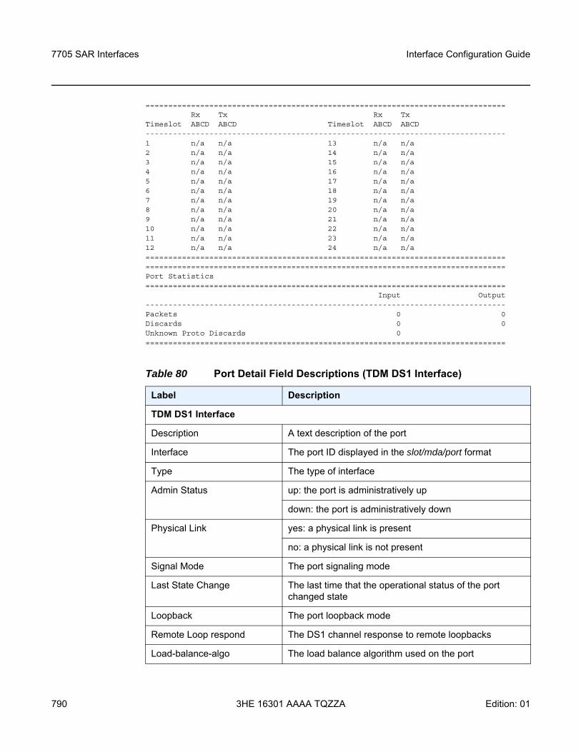
7705 SAR Interfaces
790
Interface Configuration Guide
3HE 16301 AAAA TQZZA Edition: 01
===============================================================================Rx Tx Rx Tx
Timeslot ABCD ABCD Timeslot ABCD ABCD-------------------------------------------------------------------------------1 n/a n/a 13 n/a n/a2 n/a n/a 14 n/a n/a3 n/a n/a 15 n/a n/a4 n/a n/a 16 n/a n/a5 n/a n/a 17 n/a n/a6 n/a n/a 18 n/a n/a7 n/a n/a 19 n/a n/a8 n/a n/a 20 n/a n/a9 n/a n/a 21 n/a n/a10 n/a n/a 22 n/a n/a11 n/a n/a 23 n/a n/a12 n/a n/a 24 n/a n/a==============================================================================================================================================================Port Statistics===============================================================================
Input Output-------------------------------------------------------------------------------Packets 0 0Discards 0 0Unknown Proto Discards 0===============================================================================
Table 80 Port Detail Field Descriptions (TDM DS1 Interface)
Label Description
TDM DS1 Interface
Description A text description of the port
Interface The port ID displayed in the slot/mda/port format
Type The type of interface
Admin Status up: the port is administratively up
down: the port is administratively down
Physical Link yes: a physical link is present
no: a physical link is not present
Signal Mode The port signaling mode
Last State Change The last time that the operational status of the port changed state
Loopback The port loopback mode
Remote Loop respond The DS1 channel response to remote loopbacks
Load-balance-algo The load balance algorithm used on the port
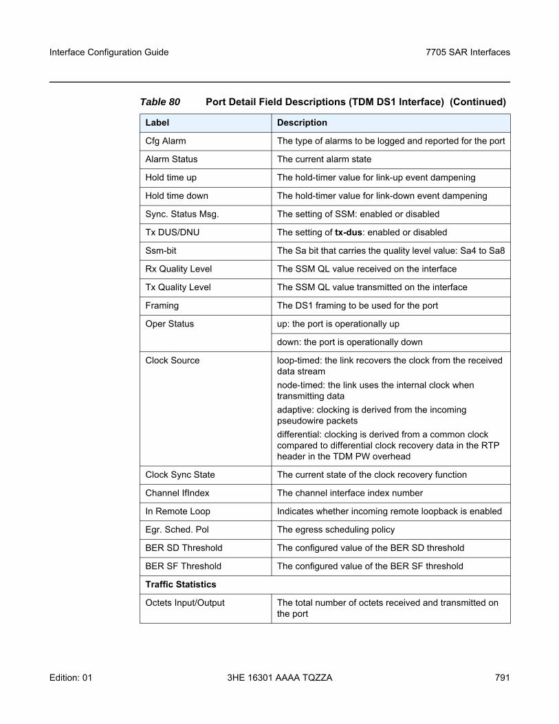
Interface Configuration Guide 7705 SAR Interfaces
Edition: 01 3HE 16301 AAAA TQZZA 791
Cfg Alarm The type of alarms to be logged and reported for the port
Alarm Status The current alarm state
Hold time up The hold-timer value for link-up event dampening
Hold time down The hold-timer value for link-down event dampening
Sync. Status Msg. The setting of SSM: enabled or disabled
Tx DUS/DNU The setting of tx-dus: enabled or disabled
Ssm-bit The Sa bit that carries the quality level value: Sa4 to Sa8
Rx Quality Level The SSM QL value received on the interface
Tx Quality Level The SSM QL value transmitted on the interface
Framing The DS1 framing to be used for the port
Oper Status up: the port is operationally up
down: the port is operationally down
Clock Source loop-timed: the link recovers the clock from the received data streamnode-timed: the link uses the internal clock when transmitting dataadaptive: clocking is derived from the incoming pseudowire packetsdifferential: clocking is derived from a common clock compared to differential clock recovery data in the RTP header in the TDM PW overhead
Clock Sync State The current state of the clock recovery function
Channel IfIndex The channel interface index number
In Remote Loop Indicates whether incoming remote loopback is enabled
Egr. Sched. Pol The egress scheduling policy
BER SD Threshold The configured value of the BER SD threshold
BER SF Threshold The configured value of the BER SF threshold
Traffic Statistics
Octets Input/Output The total number of octets received and transmitted on the port
Table 80 Port Detail Field Descriptions (TDM DS1 Interface) (Continued)
Label Description
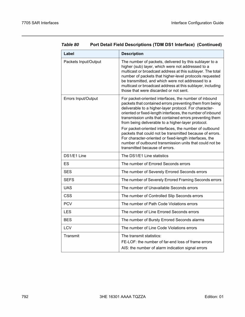
7705 SAR Interfaces
792
Interface Configuration Guide
3HE 16301 AAAA TQZZA Edition: 01
Packets Input/Output The number of packets, delivered by this sublayer to a higher (sub) layer, which were not addressed to a multicast or broadcast address at this sublayer. The total number of packets that higher-level protocols requested be transmitted, and which were not addressed to a multicast or broadcast address at this sublayer, including those that were discarded or not sent.
Errors Input/Output For packet-oriented interfaces, the number of inbound packets that contained errors preventing them from being deliverable to a higher-layer protocol. For character-oriented or fixed-length interfaces, the number of inbound transmission units that contained errors preventing them from being deliverable to a higher-layer protocol.For packet-oriented interfaces, the number of outbound packets that could not be transmitted because of errors. For character-oriented or fixed-length interfaces, the number of outbound transmission units that could not be transmitted because of errors.
DS1/E1 Line The DS1/E1 Line statistics
ES The number of Errored Seconds errors
SES The number of Severely Errored Seconds errors
SEFS The number of Severely Errored Framing Seconds errors
UAS The number of Unavailable Seconds errors
CSS The number of Controlled Slip Seconds errors
PCV The number of Path Code Violations errors
LES The number of Line Errored Seconds errors
BES The number of Bursty Errored Seconds alarms
LCV The number of Line Code Violations errors
Transmit The transmit statistics:FE-LOF: the number of far-end loss of frame errorsAIS: the number of alarm indication signal errors
Table 80 Port Detail Field Descriptions (TDM DS1 Interface) (Continued)
Label Description
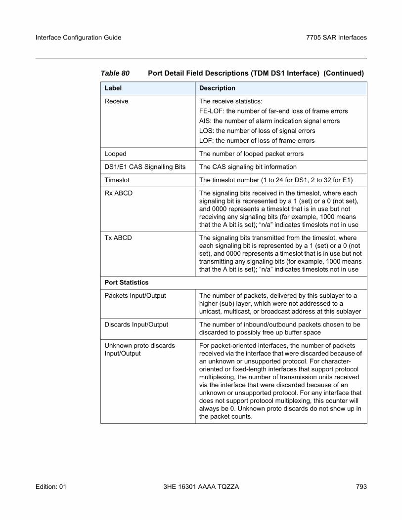
Interface Configuration Guide 7705 SAR Interfaces
Edition: 01 3HE 16301 AAAA TQZZA 793
Receive The receive statistics:FE-LOF: the number of far-end loss of frame errorsAIS: the number of alarm indication signal errorsLOS: the number of loss of signal errorsLOF: the number of loss of frame errors
Looped The number of looped packet errors
DS1/E1 CAS Signalling Bits The CAS signaling bit information
Timeslot The timeslot number (1 to 24 for DS1, 2 to 32 for E1)
Rx ABCD The signaling bits received in the timeslot, where each signaling bit is represented by a 1 (set) or a 0 (not set), and 0000 represents a timeslot that is in use but not receiving any signaling bits (for example, 1000 means that the A bit is set); “n/a” indicates timeslots not in use
Tx ABCD The signaling bits transmitted from the timeslot, where each signaling bit is represented by a 1 (set) or a 0 (not set), and 0000 represents a timeslot that is in use but not transmitting any signaling bits (for example, 1000 means that the A bit is set); “n/a” indicates timeslots not in use
Port Statistics
Packets Input/Output The number of packets, delivered by this sublayer to a higher (sub) layer, which were not addressed to a unicast, multicast, or broadcast address at this sublayer
Discards Input/Output The number of inbound/outbound packets chosen to be discarded to possibly free up buffer space
Unknown proto discards Input/Output
For packet-oriented interfaces, the number of packets received via the interface that were discarded because of an unknown or unsupported protocol. For character-oriented or fixed-length interfaces that support protocol multiplexing, the number of transmission units received via the interface that were discarded because of an unknown or unsupported protocol. For any interface that does not support protocol multiplexing, this counter will always be 0. Unknown proto discards do not show up in the packet counts.
Table 80 Port Detail Field Descriptions (TDM DS1 Interface) (Continued)
Label Description
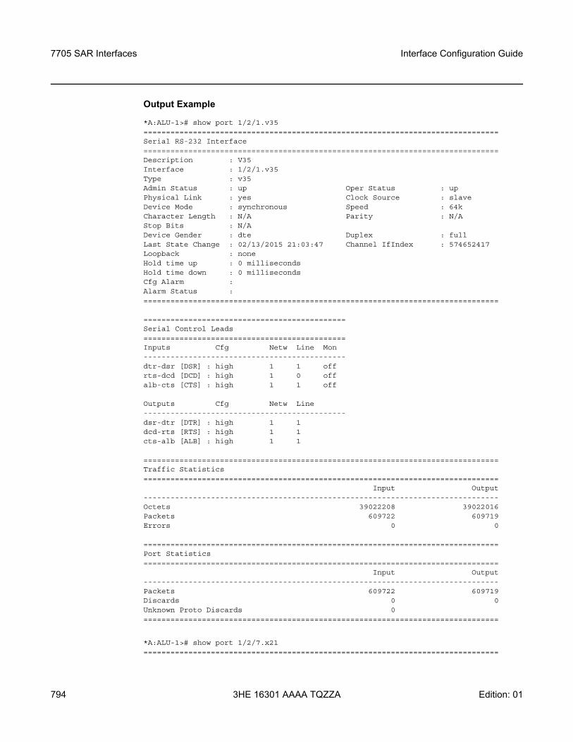
7705 SAR Interfaces
794
Interface Configuration Guide
3HE 16301 AAAA TQZZA Edition: 01
Output Example
*A:ALU-1># show port 1/2/1.v35===============================================================================Serial RS-232 Interface===============================================================================Description : V35Interface : 1/2/1.v35Type : v35Admin Status : up Oper Status : upPhysical Link : yes Clock Source : slaveDevice Mode : synchronous Speed : 64kCharacter Length : N/A Parity : N/AStop Bits : N/ADevice Gender : dte Duplex : fullLast State Change : 02/13/2015 21:03:47 Channel IfIndex : 574652417Loopback : noneHold time up : 0 millisecondsHold time down : 0 millisecondsCfg Alarm :Alarm Status :===============================================================================
=============================================Serial Control Leads=============================================Inputs Cfg Netw Line Mon---------------------------------------------dtr-dsr [DSR] : high 1 1 offrts-dcd [DCD] : high 1 0 offalb-cts [CTS] : high 1 1 off
Outputs Cfg Netw Line---------------------------------------------dsr-dtr [DTR] : high 1 1dcd-rts [RTS] : high 1 1cts-alb [ALB] : high 1 1
===============================================================================Traffic Statistics===============================================================================
Input Output-------------------------------------------------------------------------------Octets 39022208 39022016Packets 609722 609719Errors 0 0
===============================================================================Port Statistics===============================================================================
Input Output-------------------------------------------------------------------------------Packets 609722 609719Discards 0 0Unknown Proto Discards 0===============================================================================
*A:ALU-1># show port 1/2/7.x21===============================================================================
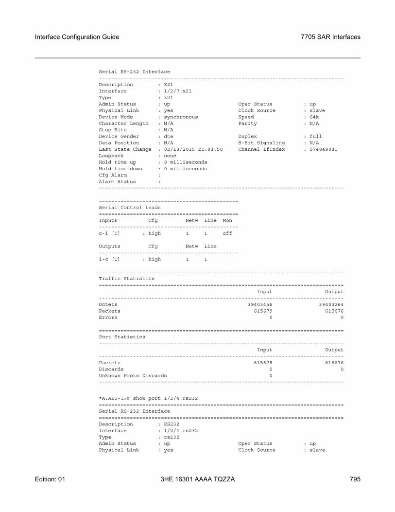
Interface Configuration Guide 7705 SAR Interfaces
Edition: 01 3HE 16301 AAAA TQZZA 795
Serial RS-232 Interface===============================================================================Description : X21Interface : 1/2/7.x21Type : x21Admin Status : up Oper Status : upPhysical Link : yes Clock Source : slaveDevice Mode : synchronous Speed : 64kCharacter Length : N/A Parity : N/AStop Bits : N/ADevice Gender : dte Duplex : fullData Position : N/A S-Bit Signaling : N/ALast State Change : 02/13/2015 21:03:50 Channel IfIndex : 574849031Loopback : noneHold time up : 0 millisecondsHold time down : 0 millisecondsCfg Alarm :Alarm Status :===============================================================================
=============================================Serial Control Leads=============================================Inputs Cfg Netw Line Mon---------------------------------------------c-i [I] : high 1 1 off
Outputs Cfg Netw Line---------------------------------------------i-c [C] : high 1 1
===============================================================================Traffic Statistics===============================================================================
Input Output-------------------------------------------------------------------------------Octets 39403456 39403264Packets 615679 615676Errors 0 0
===============================================================================Port Statistics===============================================================================
Input Output-------------------------------------------------------------------------------Packets 615679 615676Discards 0 0Unknown Proto Discards 0===============================================================================
*A:ALU-1># show port 1/2/4.rs232===============================================================================Serial RS-232 Interface===============================================================================Description : RS232Interface : 1/2/4.rs232Type : rs232Admin Status : up Oper Status : upPhysical Link : yes Clock Source : slave
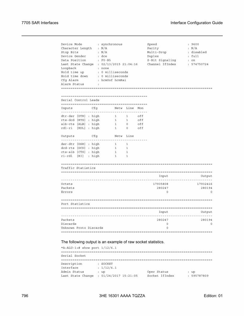
7705 SAR Interfaces
796
Interface Configuration Guide
3HE 16301 AAAA TQZZA Edition: 01
Device Mode : synchronous Speed : 9600Character Length : N/A Parity : N/AStop Bits : N/A Multi-Drop : disabledDevice Gender : dce Duplex : fullData Position : F0-B5 S-Bit Signaling : onLast State Change : 02/13/2015 21:04:16 Channel IfIndex : 574750724Loopback : noneHold time up : 0 millisecondsHold time down : 0 millisecondsCfg Alarm : hcmOof hcmRaiAlarm Status :===============================================================================
=============================================Serial Control Leads=============================================Inputs Cfg Netw Line Mon---------------------------------------------dtr-dsr [DTR] : high 1 1 offrts-dcd [RTS] : high 1 1 offalb-cts [ALB] : high 1 0 offrdl-ri [RDL] : high 1 0 off
Outputs Cfg Netw Line---------------------------------------------dsr-dtr [DSR] : high 1 1dcd-rts [DCD] : high 1 1cts-alb [CTS] : high 1 1ri-rdl [RI] : high 1 1
===============================================================================Traffic Statistics===============================================================================
Input Output-------------------------------------------------------------------------------Octets 17935808 17932416Packets 280247 280194Errors 0 0
===============================================================================Port Statistics===============================================================================
Input Output-------------------------------------------------------------------------------Packets 280247 280194Discards 0 0Unknown Proto Discards 0===============================================================================
The following output is an example of raw socket statistics.*A:ALU-1># show port 1/12/6.1===============================================================================Serial Socket===============================================================================Description : SOCKETInterface : 1/12/6.1Admin Status : up Oper Status : upLast State Change : 01/24/2017 15:21:05 Socket IfIndex : 595787809
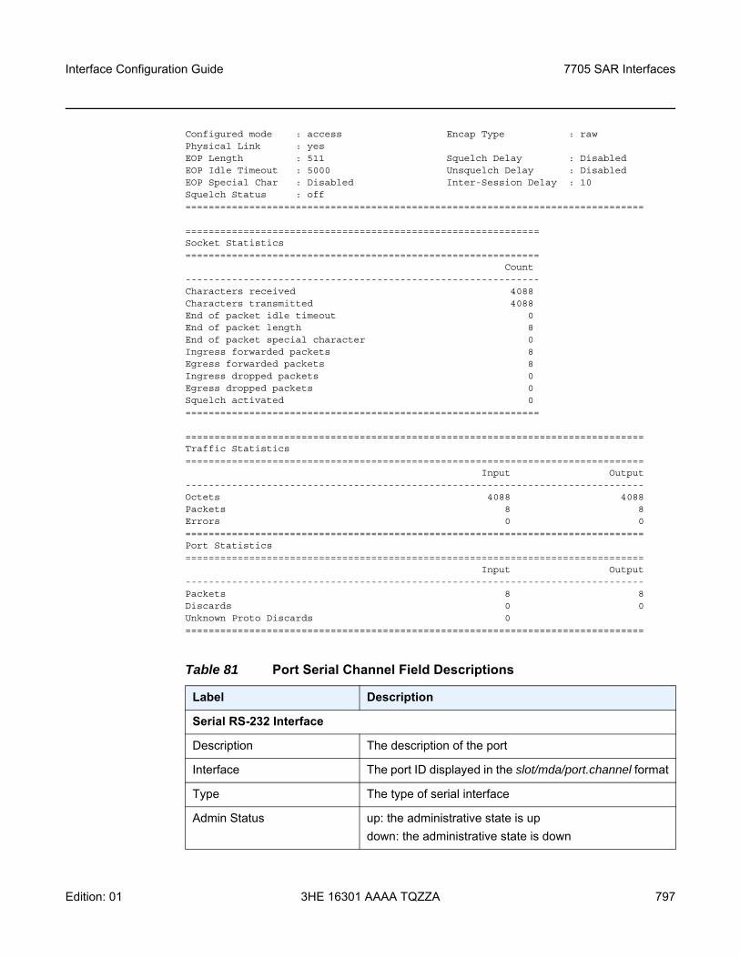
Interface Configuration Guide 7705 SAR Interfaces
Edition: 01 3HE 16301 AAAA TQZZA 797
Configured mode : access Encap Type : rawPhysical Link : yesEOP Length : 511 Squelch Delay : DisabledEOP Idle Timeout : 5000 Unsquelch Delay : DisabledEOP Special Char : Disabled Inter-Session Delay : 10Squelch Status : off===============================================================================
=============================================================Socket Statistics=============================================================
Count-------------------------------------------------------------Characters received 4088Characters transmitted 4088End of packet idle timeout 0End of packet length 8End of packet special character 0Ingress forwarded packets 8Egress forwarded packets 8Ingress dropped packets 0Egress dropped packets 0Squelch activated 0=============================================================
===============================================================================Traffic Statistics===============================================================================
Input Output-------------------------------------------------------------------------------Octets 4088 4088Packets 8 8Errors 0 0===============================================================================Port Statistics===============================================================================
Input Output-------------------------------------------------------------------------------Packets 8 8Discards 0 0Unknown Proto Discards 0===============================================================================
Table 81 Port Serial Channel Field Descriptions
Label Description
Serial RS-232 Interface
Description The description of the port
Interface The port ID displayed in the slot/mda/port.channel format
Type The type of serial interface
Admin Status up: the administrative state is updown: the administrative state is down
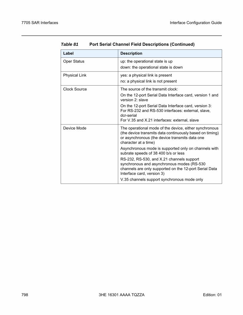
7705 SAR Interfaces
798
Interface Configuration Guide
3HE 16301 AAAA TQZZA Edition: 01
Oper Status up: the operational state is updown: the operational state is down
Physical Link yes: a physical link is presentno: a physical link is not present
Clock Source The source of the transmit clock:On the 12-port Serial Data Interface card, version 1 and version 2: slaveOn the 12-port Serial Data Interface card, version 3: For RS-232 and RS-530 interfaces: external, slave, dcr-serialFor V.35 and X.21 interfaces: external, slave
Device Mode The operational mode of the device, either synchronous (the device transmits data continuously based on timing) or asynchronous (the device transmits data one character at a time)Asynchronous mode is supported only on channels with subrate speeds of 38 400 b/s or lessRS-232, RS-530, and X.21 channels support synchronous and asynchronous modes (RS-530 channels are only supported on the 12-port Serial Data Interface card, version 3)V.35 channels support synchronous mode only
Table 81 Port Serial Channel Field Descriptions (Continued)
Label Description
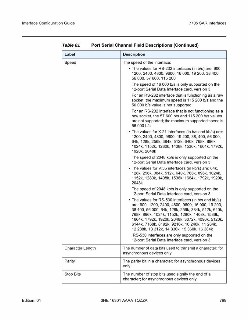
Interface Configuration Guide 7705 SAR Interfaces
Edition: 01 3HE 16301 AAAA TQZZA 799
Speed The speed of the interface:• The values for RS-232 interfaces (in b/s) are: 600,
1200, 2400, 4800, 9600, 16 000, 19 200, 38 400, 56 000, 57 600, 115 200The speed of 16 000 b/s is only supported on the 12-port Serial Data Interface card, version 3For an RS-232 interface that is functioning as a raw socket, the maximum speed is 115 200 b/s and the 56 000 b/s value is not supportedFor an RS-232 interface that is not functioning as a raw socket, the 57 600 b/s and 115 200 b/s values are not supported; the maximum supported speed is 56 000 b/s
• The values for X.21 interfaces (in b/s and kb/s) are: 1200, 2400, 4800, 9600, 19 200, 38, 400, 56 000, 64k, 128k, 256k, 384k, 512k, 640k, 768k, 896k, 1024k, 1152k, 1280k, 1408k, 1536k, 1664k, 1792k, 1920k, 2048kThe speed of 2048 kb/s is only supported on the 12-port Serial Data Interface card, version 3
• The values for V.35 interfaces (in kb/s) are: 64k, 128k, 256k, 384k, 512k, 640k, 768k, 896k, 1024k, 1152k, 1280k, 1408k, 1536k, 1664k, 1792k, 1920k, 2048kThe speed of 2048 kb/s is only supported on the 12-port Serial Data Interface card, version 3
• The values for RS-530 interfaces (in b/s and kb/s) are: 600, 1200, 2400, 4800, 9600, 16 000, 19 200, 38 400, 56 000, 64k, 128k, 256k, 384k, 512k, 640k, 768k, 896k, 1024k, 1152k, 1280k, 1408k, 1536k, 1664k, 1792k, 1920k, 2048k, 3072k, 4096k, 5120k, 6144k, 7168k, 8192k, 9216k, 10 240k, 11 264k, 12 288k, 13 312k, 14 336k, 15 360k, 16 384k RS-530 interfaces are only supported on the 12-port Serial Data Interface card, version 3
Character Length The number of data bits used to transmit a character; for asynchronous devices only
Parity The parity bit in a character; for asynchronous devices only
Stop Bits The number of stop bits used signify the end of a character; for asynchronous devices only
Table 81 Port Serial Channel Field Descriptions (Continued)
Label Description
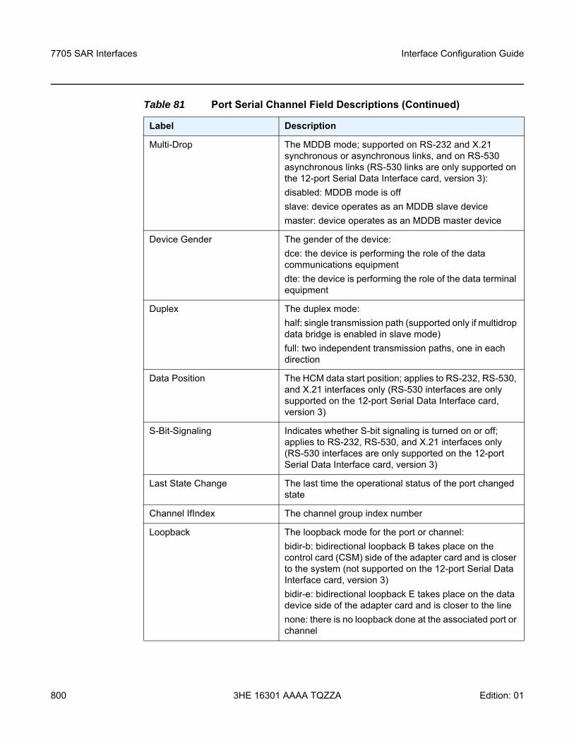
7705 SAR Interfaces
800
Interface Configuration Guide
3HE 16301 AAAA TQZZA Edition: 01
Multi-Drop The MDDB mode; supported on RS-232 and X.21 synchronous or asynchronous links, and on RS-530 asynchronous links (RS-530 links are only supported on the 12-port Serial Data Interface card, version 3):disabled: MDDB mode is offslave: device operates as an MDDB slave devicemaster: device operates as an MDDB master device
Device Gender The gender of the device:dce: the device is performing the role of the data communications equipmentdte: the device is performing the role of the data terminal equipment
Duplex The duplex mode:half: single transmission path (supported only if multidrop data bridge is enabled in slave mode)full: two independent transmission paths, one in each direction
Data Position The HCM data start position; applies to RS-232, RS-530, and X.21 interfaces only (RS-530 interfaces are only supported on the 12-port Serial Data Interface card, version 3)
S-Bit-Signaling Indicates whether S-bit signaling is turned on or off; applies to RS-232, RS-530, and X.21 interfaces only (RS-530 interfaces are only supported on the 12-port Serial Data Interface card, version 3)
Last State Change The last time the operational status of the port changed state
Channel IfIndex The channel group index number
Loopback The loopback mode for the port or channel:bidir-b: bidirectional loopback B takes place on the control card (CSM) side of the adapter card and is closer to the system (not supported on the 12-port Serial Data Interface card, version 3)bidir-e: bidirectional loopback E takes place on the data device side of the adapter card and is closer to the linenone: there is no loopback done at the associated port or channel
Table 81 Port Serial Channel Field Descriptions (Continued)
Label Description
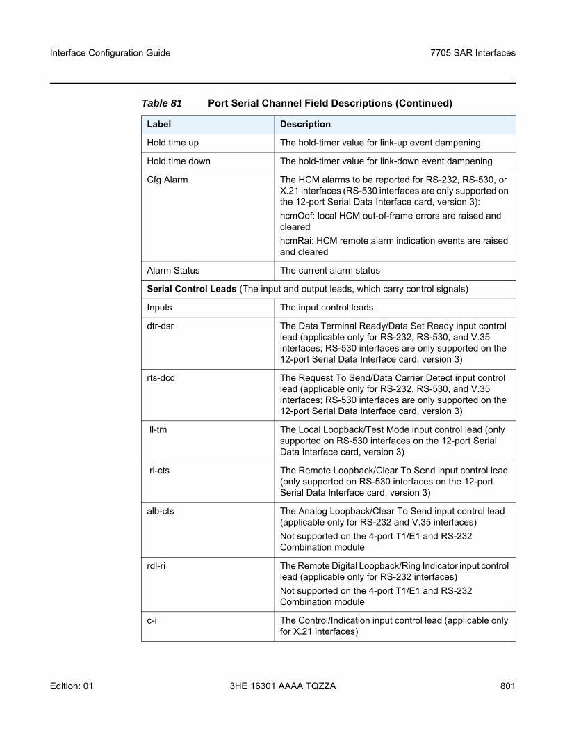
Interface Configuration Guide 7705 SAR Interfaces
Edition: 01 3HE 16301 AAAA TQZZA 801
Hold time up The hold-timer value for link-up event dampening
Hold time down The hold-timer value for link-down event dampening
Cfg Alarm The HCM alarms to be reported for RS-232, RS-530, or X.21 interfaces (RS-530 interfaces are only supported on the 12-port Serial Data Interface card, version 3):hcmOof: local HCM out-of-frame errors are raised and clearedhcmRai: HCM remote alarm indication events are raised and cleared
Alarm Status The current alarm status
Serial Control Leads (The input and output leads, which carry control signals)
Inputs The input control leads
dtr-dsr The Data Terminal Ready/Data Set Ready input control lead (applicable only for RS-232, RS-530, and V.35 interfaces; RS-530 interfaces are only supported on the 12-port Serial Data Interface card, version 3)
rts-dcd The Request To Send/Data Carrier Detect input control lead (applicable only for RS-232, RS-530, and V.35 interfaces; RS-530 interfaces are only supported on the 12-port Serial Data Interface card, version 3)
ll-tm The Local Loopback/Test Mode input control lead (only supported on RS-530 interfaces on the 12-port Serial Data Interface card, version 3)
rl-cts The Remote Loopback/Clear To Send input control lead (only supported on RS-530 interfaces on the 12-port Serial Data Interface card, version 3)
alb-cts The Analog Loopback/Clear To Send input control lead (applicable only for RS-232 and V.35 interfaces)Not supported on the 4-port T1/E1 and RS-232 Combination module
rdl-ri The Remote Digital Loopback/Ring Indicator input control lead (applicable only for RS-232 interfaces)Not supported on the 4-port T1/E1 and RS-232 Combination module
c-i The Control/Indication input control lead (applicable only for X.21 interfaces)
Table 81 Port Serial Channel Field Descriptions (Continued)
Label Description
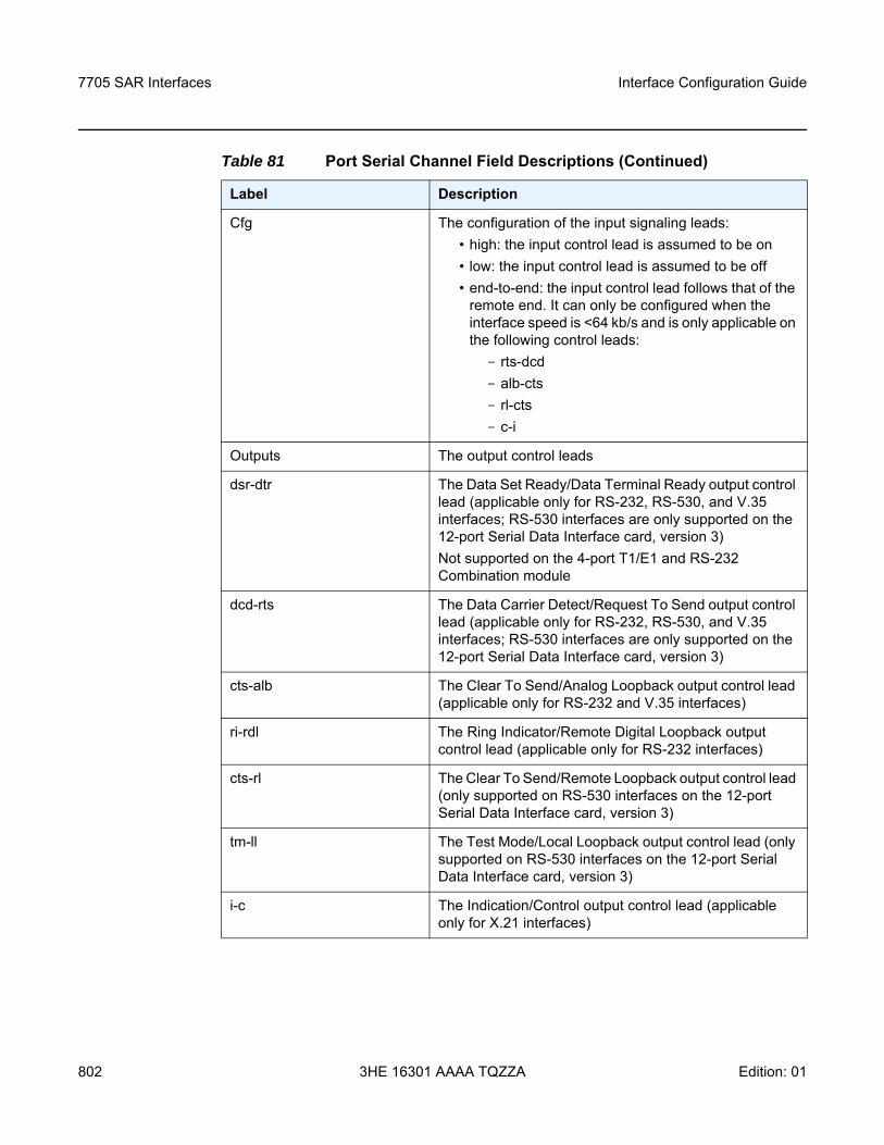
7705 SAR Interfaces
802
Interface Configuration Guide
3HE 16301 AAAA TQZZA Edition: 01
Cfg The configuration of the input signaling leads:• high: the input control lead is assumed to be on• low: the input control lead is assumed to be off• end-to-end: the input control lead follows that of the
remote end. It can only be configured when the interface speed is <64 kb/s and is only applicable on the following control leads:- rts-dcd - alb-cts- rl-cts- c-i
Outputs The output control leads
dsr-dtr The Data Set Ready/Data Terminal Ready output control lead (applicable only for RS-232, RS-530, and V.35 interfaces; RS-530 interfaces are only supported on the 12-port Serial Data Interface card, version 3)Not supported on the 4-port T1/E1 and RS-232 Combination module
dcd-rts The Data Carrier Detect/Request To Send output control lead (applicable only for RS-232, RS-530, and V.35 interfaces; RS-530 interfaces are only supported on the 12-port Serial Data Interface card, version 3)
cts-alb The Clear To Send/Analog Loopback output control lead (applicable only for RS-232 and V.35 interfaces)
ri-rdl The Ring Indicator/Remote Digital Loopback output control lead (applicable only for RS-232 interfaces)
cts-rl The Clear To Send/Remote Loopback output control lead (only supported on RS-530 interfaces on the 12-port Serial Data Interface card, version 3)
tm-ll The Test Mode/Local Loopback output control lead (only supported on RS-530 interfaces on the 12-port Serial Data Interface card, version 3)
i-c The Indication/Control output control lead (applicable only for X.21 interfaces)
Table 81 Port Serial Channel Field Descriptions (Continued)
Label Description
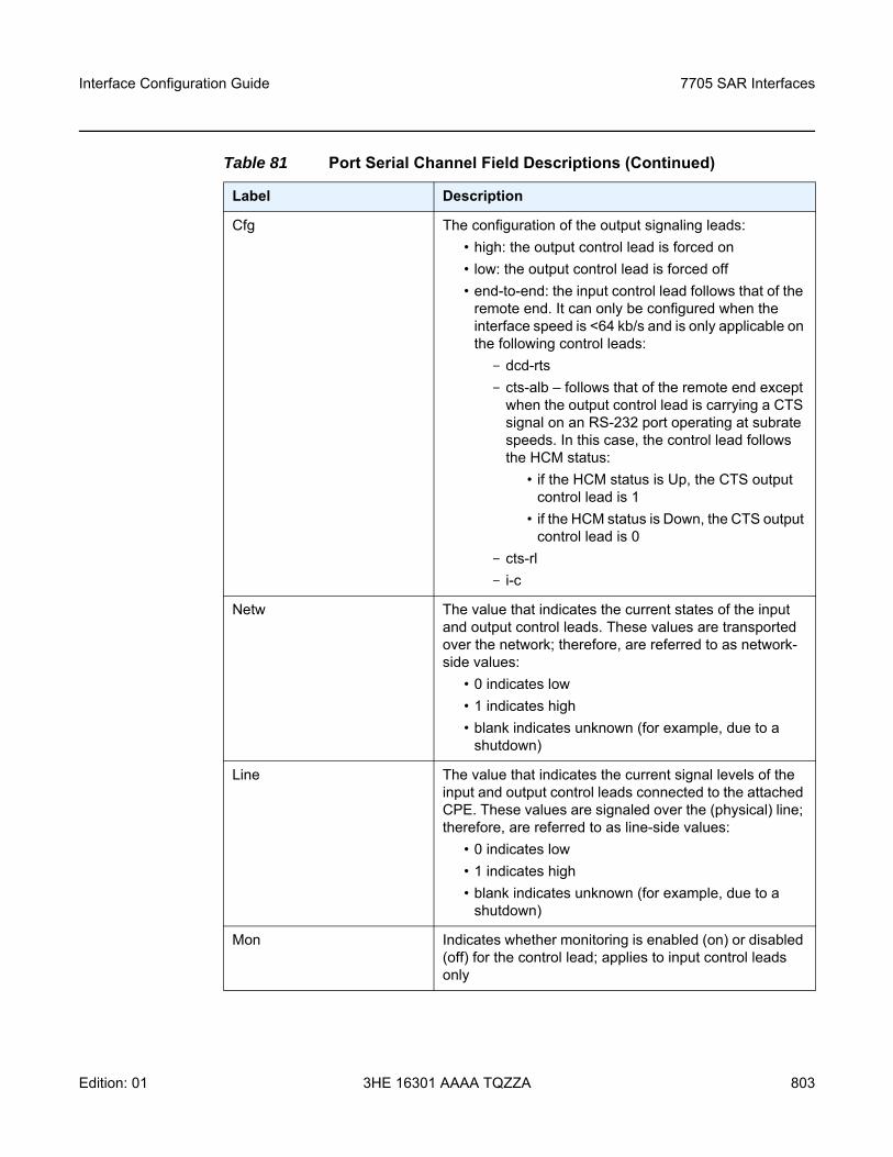
Interface Configuration Guide 7705 SAR Interfaces
Edition: 01 3HE 16301 AAAA TQZZA 803
Cfg The configuration of the output signaling leads:• high: the output control lead is forced on• low: the output control lead is forced off• end-to-end: the input control lead follows that of the
remote end. It can only be configured when the interface speed is <64 kb/s and is only applicable on the following control leads:- dcd-rts- cts-alb – follows that of the remote end except
when the output control lead is carrying a CTS signal on an RS-232 port operating at subrate speeds. In this case, the control lead follows the HCM status:
• if the HCM status is Up, the CTS output control lead is 1
• if the HCM status is Down, the CTS output control lead is 0
- cts-rl- i-c
Netw The value that indicates the current states of the input and output control leads. These values are transported over the network; therefore, are referred to as network-side values:
• 0 indicates low• 1 indicates high• blank indicates unknown (for example, due to a
shutdown)
Line The value that indicates the current signal levels of the input and output control leads connected to the attached CPE. These values are signaled over the (physical) line; therefore, are referred to as line-side values:
• 0 indicates low• 1 indicates high• blank indicates unknown (for example, due to a
shutdown)
Mon Indicates whether monitoring is enabled (on) or disabled (off) for the control lead; applies to input control leads only
Table 81 Port Serial Channel Field Descriptions (Continued)
Label Description
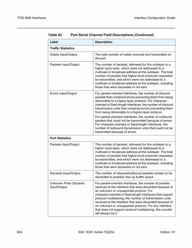
7705 SAR Interfaces
804
Interface Configuration Guide
3HE 16301 AAAA TQZZA Edition: 01
Traffic Statistics
Octets Input/Output The total number of octets received and transmitted on the port
Packets Input/Output The number of packets, delivered by this sublayer to a higher (sub) layer, which were not addressed to a multicast or broadcast address at this sublayer. The total number of packets that higher-level protocols requested be transmitted, and which were not addressed to a multicast or broadcast address at this sublayer, including those that were discarded or not sent.
Errors Input/Output For packet-oriented interfaces, the number of inbound packets that contained errors preventing them from being deliverable to a higher-layer protocol. For character-oriented or fixed-length interfaces, the number of inbound transmission units that contained errors preventing them from being deliverable to a higher-layer protocol.For packet-oriented interfaces, the number of outbound packets that could not be transmitted because of errors. For character-oriented or fixed-length interfaces, the number of outbound transmission units that could not be transmitted because of errors.
Port Statistics
Packets Input/Output The number of packets, delivered by this sublayer to a higher (sub) layer, which were not addressed to a multicast or broadcast address at this sublayer. The total number of packets that higher-level protocols requested be transmitted, and which were not addressed to a multicast or broadcast address at this sublayer, including those that were discarded or not sent.
Discards Input/Output The number of inbound/outbound packets chosen to be discarded to possibly free up buffer space
Unknown Proto Discards Input/Output
For packet-oriented interfaces, the number of packets received at the interface that were discarded because of an unknown or unsupported protocol. For character-oriented or fixed-length interfaces that support protocol multiplexing, the number of transmission units received at the interface that were discarded because of an unknown or unsupported protocol. For any interface that does not support protocol multiplexing, this counter will always be 0.
Table 81 Port Serial Channel Field Descriptions (Continued)
Label Description
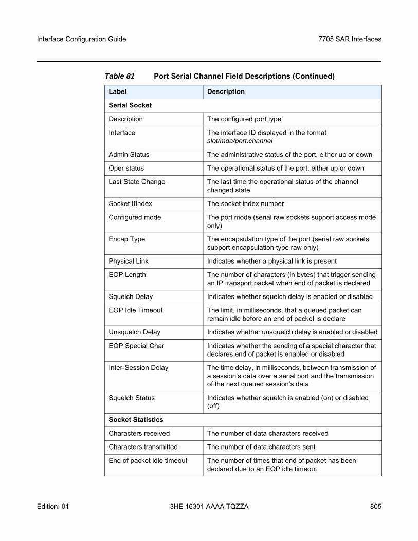
Interface Configuration Guide 7705 SAR Interfaces
Edition: 01 3HE 16301 AAAA TQZZA 805
Serial Socket
Description The configured port type
Interface The interface ID displayed in the format slot/mda/port.channel
Admin Status The administrative status of the port, either up or down
Oper status The operational status of the port, either up or down
Last State Change The last time the operational status of the channel changed state
Socket IfIndex The socket index number
Configured mode The port mode (serial raw sockets support access mode only)
Encap Type The encapsulation type of the port (serial raw sockets support encapsulation type raw only)
Physical Link Indicates whether a physical link is present
EOP Length The number of characters (in bytes) that trigger sending an IP transport packet when end of packet is declared
Squelch Delay Indicates whether squelch delay is enabled or disabled
EOP Idle Timeout The limit, in milliseconds, that a queued packet can remain idle before an end of packet is declare
Unsquelch Delay Indicates whether unsquelch delay is enabled or disabled
EOP Special Char Indicates whether the sending of a special character that declares end of packet is enabled or disabled
Inter-Session Delay The time delay, in milliseconds, between transmission of a session’s data over a serial port and the transmission of the next queued session’s data
Squelch Status Indicates whether squelch is enabled (on) or disabled (off)
Socket Statistics
Characters received The number of data characters received
Characters transmitted The number of data characters sent
End of packet idle timeout The number of times that end of packet has been declared due to an EOP idle timeout
Table 81 Port Serial Channel Field Descriptions (Continued)
Label Description
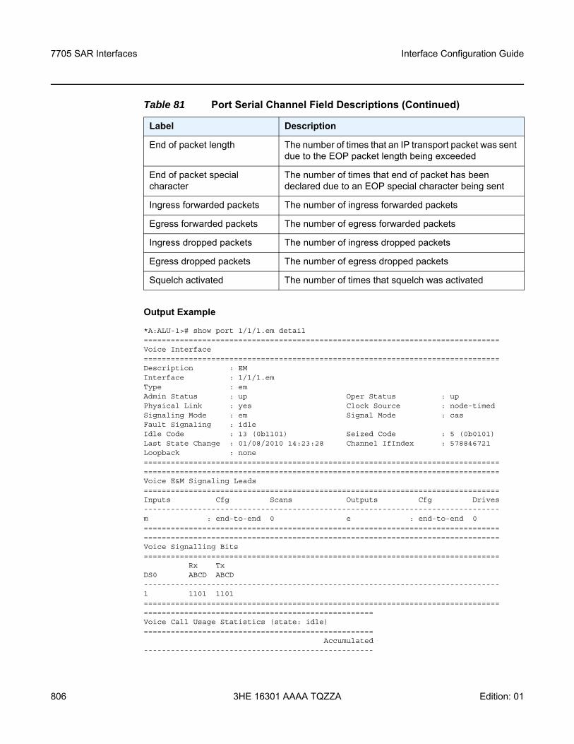
7705 SAR Interfaces
806
Interface Configuration Guide
3HE 16301 AAAA TQZZA Edition: 01
Output Example
*A:ALU-1># show port 1/1/1.em detail===============================================================================Voice Interface===============================================================================Description : EMInterface : 1/1/1.emType : emAdmin Status : up Oper Status : upPhysical Link : yes Clock Source : node-timedSignaling Mode : em Signal Mode : casFault Signaling : idleIdle Code : 13 (0b1101) Seized Code : 5 (0b0101)Last State Change : 01/08/2010 14:23:28 Channel IfIndex : 578846721Loopback : none==============================================================================================================================================================Voice E&M Signaling Leads===============================================================================Inputs Cfg Scans Outputs Cfg Drives-------------------------------------------------------------------------------m : end-to-end 0 e : end-to-end 0==============================================================================================================================================================Voice Signalling Bits===============================================================================
Rx TxDS0 ABCD ABCD-------------------------------------------------------------------------------1 1101 1101==================================================================================================================================Voice Call Usage Statistics (state: idle)===================================================
Accumulated---------------------------------------------------
End of packet length The number of times that an IP transport packet was sent due to the EOP packet length being exceeded
End of packet special character
The number of times that end of packet has been declared due to an EOP special character being sent
Ingress forwarded packets The number of ingress forwarded packets
Egress forwarded packets The number of egress forwarded packets
Ingress dropped packets The number of ingress dropped packets
Egress dropped packets The number of egress dropped packets
Squelch activated The number of times that squelch was activated
Table 81 Port Serial Channel Field Descriptions (Continued)
Label Description
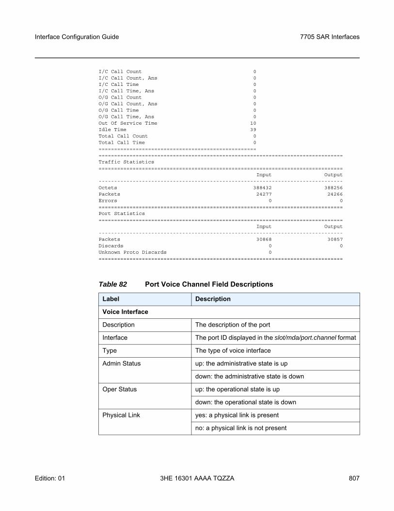
Interface Configuration Guide 7705 SAR Interfaces
Edition: 01 3HE 16301 AAAA TQZZA 807
I/C Call Count 0I/C Call Count, Ans 0I/C Call Time 0I/C Call Time, Ans 0O/G Call Count 0O/G Call Count, Ans 0O/G Call Time 0O/G Call Time, Ans 0Out Of Service Time 10Idle Time 39Total Call Count 0Total Call Time 0==================================================================================================================================Traffic Statistics===============================================================================
Input Output-------------------------------------------------------------------------------Octets 388432 388256Packets 24277 24266Errors 0 0===============================================================================Port Statistics===============================================================================
Input Output-------------------------------------------------------------------------------Packets 30868 30857Discards 0 0Unknown Proto Discards 0===============================================================================
Table 82 Port Voice Channel Field Descriptions
Label Description
Voice Interface
Description The description of the port
Interface The port ID displayed in the slot/mda/port.channel format
Type The type of voice interface
Admin Status up: the administrative state is up
down: the administrative state is down
Oper Status up: the operational state is up
down: the operational state is down
Physical Link yes: a physical link is present
no: a physical link is not present
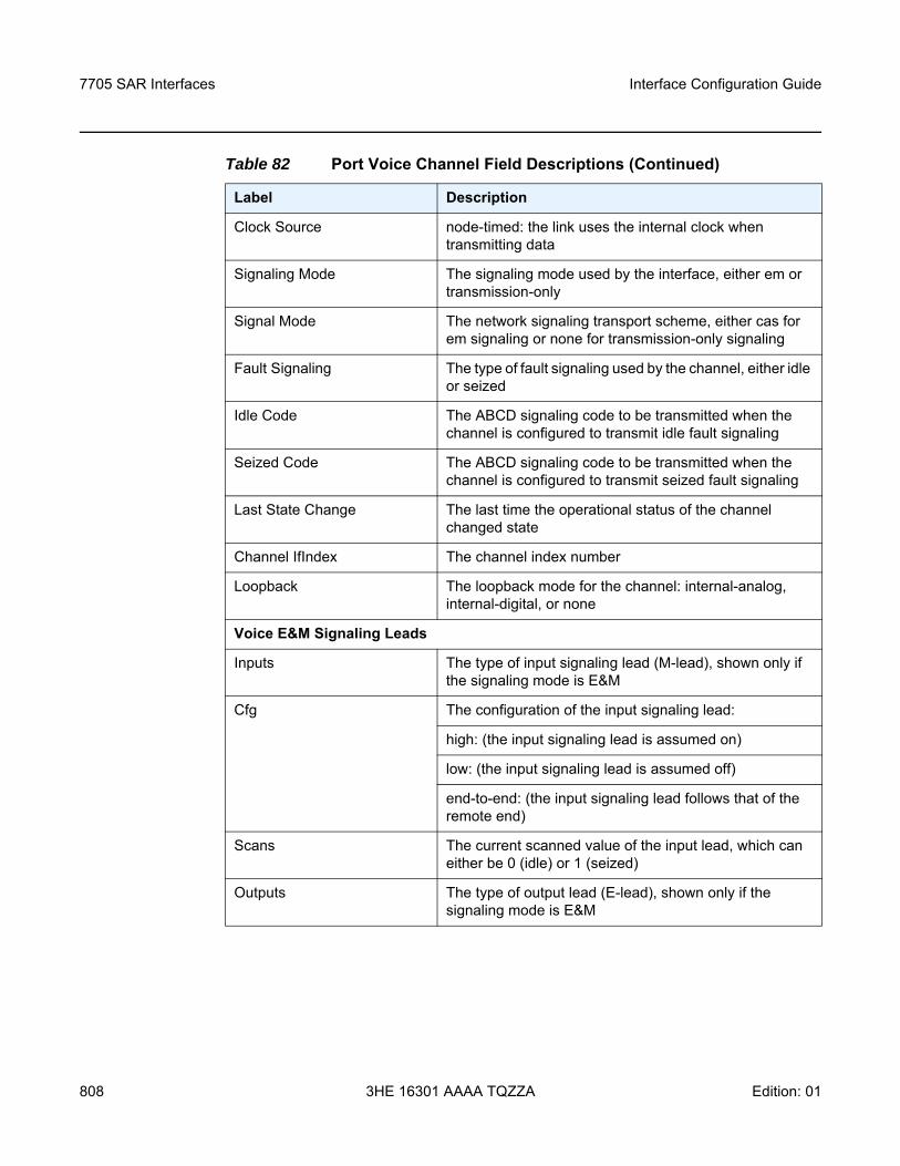
7705 SAR Interfaces
808
Interface Configuration Guide
3HE 16301 AAAA TQZZA Edition: 01
Clock Source node-timed: the link uses the internal clock when transmitting data
Signaling Mode The signaling mode used by the interface, either em or transmission-only
Signal Mode The network signaling transport scheme, either cas for em signaling or none for transmission-only signaling
Fault Signaling The type of fault signaling used by the channel, either idle or seized
Idle Code The ABCD signaling code to be transmitted when the channel is configured to transmit idle fault signaling
Seized Code The ABCD signaling code to be transmitted when the channel is configured to transmit seized fault signaling
Last State Change The last time the operational status of the channel changed state
Channel IfIndex The channel index number
Loopback The loopback mode for the channel: internal-analog, internal-digital, or none
Voice E&M Signaling Leads
Inputs The type of input signaling lead (M-lead), shown only if the signaling mode is E&M
Cfg The configuration of the input signaling lead:
high: (the input signaling lead is assumed on)
low: (the input signaling lead is assumed off)
end-to-end: (the input signaling lead follows that of the remote end)
Scans The current scanned value of the input lead, which can either be 0 (idle) or 1 (seized)
Outputs The type of output lead (E-lead), shown only if the signaling mode is E&M
Table 82 Port Voice Channel Field Descriptions (Continued)
Label Description
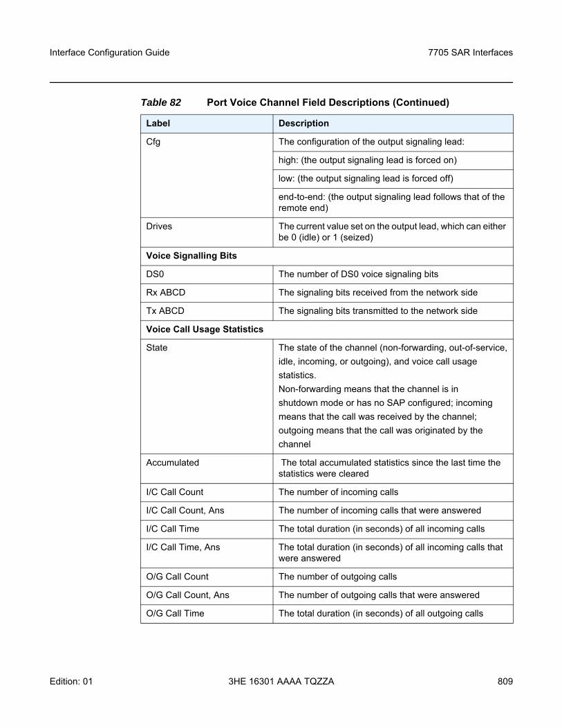
Interface Configuration Guide 7705 SAR Interfaces
Edition: 01 3HE 16301 AAAA TQZZA 809
Cfg The configuration of the output signaling lead:
high: (the output signaling lead is forced on)
low: (the output signaling lead is forced off)
end-to-end: (the output signaling lead follows that of the remote end)
Drives The current value set on the output lead, which can either be 0 (idle) or 1 (seized)
Voice Signalling Bits
DS0 The number of DS0 voice signaling bits
Rx ABCD The signaling bits received from the network side
Tx ABCD The signaling bits transmitted to the network side
Voice Call Usage Statistics
State The state of the channel (non-forwarding, out-of-service,idle, incoming, or outgoing), and voice call usagestatistics.Non-forwarding means that the channel is inshutdown mode or has no SAP configured; incomingmeans that the call was received by the channel;outgoing means that the call was originated by thechannel
Accumulated The total accumulated statistics since the last time the statistics were cleared
I/C Call Count The number of incoming calls
I/C Call Count, Ans The number of incoming calls that were answered
I/C Call Time The total duration (in seconds) of all incoming calls
I/C Call Time, Ans The total duration (in seconds) of all incoming calls that were answered
O/G Call Count The number of outgoing calls
O/G Call Count, Ans The number of outgoing calls that were answered
O/G Call Time The total duration (in seconds) of all outgoing calls
Table 82 Port Voice Channel Field Descriptions (Continued)
Label Description
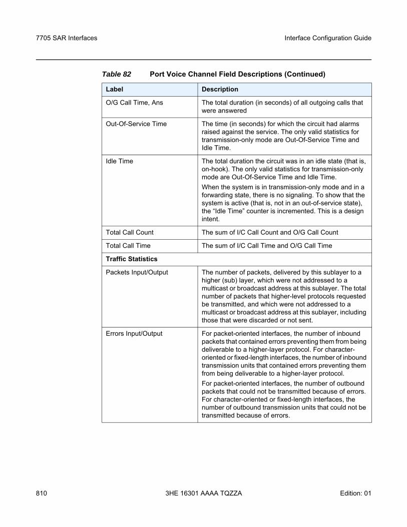
7705 SAR Interfaces
810
Interface Configuration Guide
3HE 16301 AAAA TQZZA Edition: 01
O/G Call Time, Ans The total duration (in seconds) of all outgoing calls that were answered
Out-Of-Service Time The time (in seconds) for which the circuit had alarms raised against the service. The only valid statistics for transmission-only mode are Out-Of-Service Time and Idle Time.
Idle Time The total duration the circuit was in an idle state (that is, on-hook). The only valid statistics for transmission-only mode are Out-Of-Service Time and Idle Time.When the system is in transmission-only mode and in a forwarding state, there is no signaling. To show that the system is active (that is, not in an out-of-service state), the “Idle Time” counter is incremented. This is a design intent.
Total Call Count The sum of I/C Call Count and O/G Call Count
Total Call Time The sum of I/C Call Time and O/G Call Time
Traffic Statistics
Packets Input/Output The number of packets, delivered by this sublayer to a higher (sub) layer, which were not addressed to a multicast or broadcast address at this sublayer. The total number of packets that higher-level protocols requested be transmitted, and which were not addressed to a multicast or broadcast address at this sublayer, including those that were discarded or not sent.
Errors Input/Output For packet-oriented interfaces, the number of inbound packets that contained errors preventing them from being deliverable to a higher-layer protocol. For character-oriented or fixed-length interfaces, the number of inbound transmission units that contained errors preventing them from being deliverable to a higher-layer protocol.For packet-oriented interfaces, the number of outbound packets that could not be transmitted because of errors. For character-oriented or fixed-length interfaces, the number of outbound transmission units that could not be transmitted because of errors.
Table 82 Port Voice Channel Field Descriptions (Continued)
Label Description
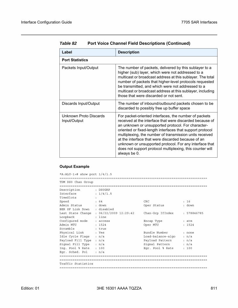
Interface Configuration Guide 7705 SAR Interfaces
Edition: 01 3HE 16301 AAAA TQZZA 811
Output Example
*A:ALU-1># show port 1/4/1.5===============================================================================TDM DS0 Chan Group===============================================================================Description : DS0GRPInterface : 1/4/1.5TimeSlots :Speed : 64 CRC : 16Admin Status : down Oper Status : downBER SF Link Down : disabledLast State Change : 06/22/2009 12:29:42 Chan-Grp IfIndex : 578846785Loopback : lineConfigured mode : access Encap Type : atmAdmin MTU : 1524 Oper MTU : 1524Scramble : truePhysical Link : Yes Bundle Number : noneIdle Cycle Flags : n/a Load-balance-algo : n/aPayload Fill Type : n/a Payload Pattern : n/aSignal Fill Type : n/a Signal Pattern : n/aIng. Pool % Rate : 100 Egr. Pool % Rate : 100Egr. Sched. Pol : n/a==============================================================================================================================================================Traffic Statistics===============================================================================
Port Statistics
Packets Input/Output The number of packets, delivered by this sublayer to a higher (sub) layer, which were not addressed to a multicast or broadcast address at this sublayer. The total number of packets that higher-level protocols requested be transmitted, and which were not addressed to a multicast or broadcast address at this sublayer, including those that were discarded or not sent.
Discards Input/Output The number of inbound/outbound packets chosen to be discarded to possibly free up buffer space
Unknown Proto Discards Input/Output
For packet-oriented interfaces, the number of packets received at the interface that were discarded because of an unknown or unsupported protocol. For character-oriented or fixed-length interfaces that support protocol multiplexing, the number of transmission units received at the interface that were discarded because of an unknown or unsupported protocol. For any interface that does not support protocol multiplexing, this counter will always be 0.
Table 82 Port Voice Channel Field Descriptions (Continued)
Label Description
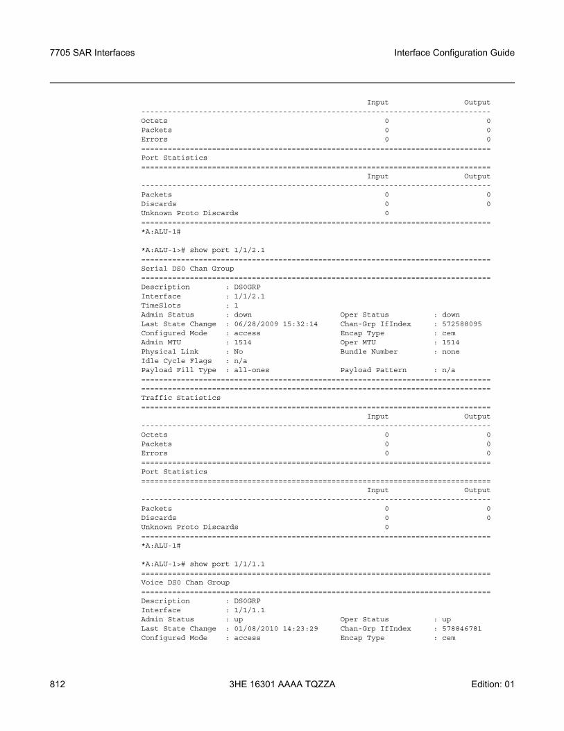
7705 SAR Interfaces
812
Interface Configuration Guide
3HE 16301 AAAA TQZZA Edition: 01
Input Output-------------------------------------------------------------------------------Octets 0 0Packets 0 0Errors 0 0===============================================================================Port Statistics===============================================================================
Input Output-------------------------------------------------------------------------------Packets 0 0Discards 0 0Unknown Proto Discards 0===============================================================================*A:ALU-1#
*A:ALU-1># show port 1/1/2.1===============================================================================Serial DS0 Chan Group===============================================================================Description : DS0GRPInterface : 1/1/2.1TimeSlots : 1Admin Status : down Oper Status : downLast State Change : 06/28/2009 15:32:14 Chan-Grp IfIndex : 572588095Configured Mode : access Encap Type : cemAdmin MTU : 1514 Oper MTU : 1514Physical Link : No Bundle Number : noneIdle Cycle Flags : n/aPayload Fill Type : all-ones Payload Pattern : n/a==============================================================================================================================================================Traffic Statistics===============================================================================
Input Output-------------------------------------------------------------------------------Octets 0 0Packets 0 0Errors 0 0===============================================================================Port Statistics===============================================================================
Input Output-------------------------------------------------------------------------------Packets 0 0Discards 0 0Unknown Proto Discards 0===============================================================================*A:ALU-1#
*A:ALU-1># show port 1/1/1.1===============================================================================Voice DS0 Chan Group===============================================================================Description : DS0GRPInterface : 1/1/1.1Admin Status : up Oper Status : upLast State Change : 01/08/2010 14:23:29 Chan-Grp IfIndex : 578846781Configured Mode : access Encap Type : cem
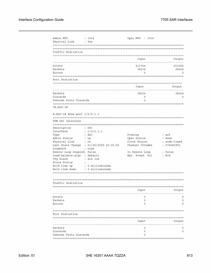
Interface Configuration Guide 7705 SAR Interfaces
Edition: 01 3HE 16301 AAAA TQZZA 813
Admin MTU : 1514 Oper MTU : 1514Physical Link : Yes==============================================================================================================================================================Traffic Statistics===============================================================================
Input Output-------------------------------------------------------------------------------Octets 611744 611584Packets 38234 38224Errors 0 0===============================================================================Port Statistics==============================================================================
Input Output-------------------------------------------------------------------------------Packets 38234 38224Discards 0 0Unknown Proto Discards 0===============================================================================*A:ALU-1#
A:ALU-1# show port 1/2/2.1.1===============================================================================TDM DS1 Interface===============================================================================Description : DS1Interface : 1/2/2.1.1Type : ds1 Framing : esfAdmin Status : up Oper Status : downPhysical Link : no Clock Source : node-timedLast State Change : 01/26/2009 15:35:50 Channel IfIndex : 574685991Loopback : noneRemote Loop respond: false In Remote Loop : falseLoad-balance-algo : default Egr. Sched. Pol : N/ACfg Alarm : ais losAlarm Status :Hold time up : 0 millisecondsHold time down : 0 milliseconds===============================================================================
===============================================================================Traffic Statistics===============================================================================
Input Output-------------------------------------------------------------------------------Octets 0 0Packets 0 0Errors 0 0
===============================================================================Port Statistics===============================================================================
Input Output-------------------------------------------------------------------------------Packets 0 0Discards 0 0Unknown Proto Discards 0===============================================================================
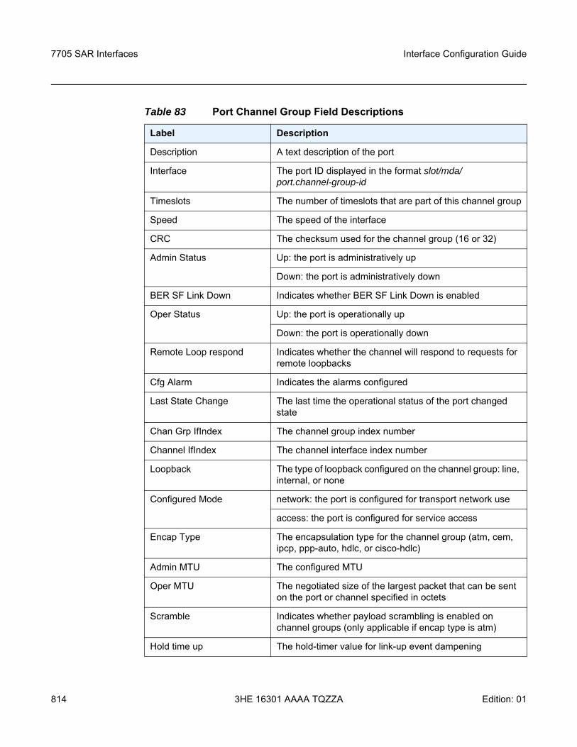
7705 SAR Interfaces
814
Interface Configuration Guide
3HE 16301 AAAA TQZZA Edition: 01
Table 83 Port Channel Group Field Descriptions
Label Description
Description A text description of the port
Interface The port ID displayed in the format slot/mda/port.channel-group-id
Timeslots The number of timeslots that are part of this channel group
Speed The speed of the interface
CRC The checksum used for the channel group (16 or 32)
Admin Status Up: the port is administratively up
Down: the port is administratively down
BER SF Link Down Indicates whether BER SF Link Down is enabled
Oper Status Up: the port is operationally up
Down: the port is operationally down
Remote Loop respond Indicates whether the channel will respond to requests for remote loopbacks
Cfg Alarm Indicates the alarms configured
Last State Change The last time the operational status of the port changed state
Chan Grp IfIndex The channel group index number
Channel IfIndex The channel interface index number
Loopback The type of loopback configured on the channel group: line, internal, or none
Configured Mode network: the port is configured for transport network use
access: the port is configured for service access
Encap Type The encapsulation type for the channel group (atm, cem, ipcp, ppp-auto, hdlc, or cisco-hdlc)
Admin MTU The configured MTU
Oper MTU The negotiated size of the largest packet that can be sent on the port or channel specified in octets
Scramble Indicates whether payload scrambling is enabled on channel groups (only applicable if encap type is atm)
Hold time up The hold-timer value for link-up event dampening
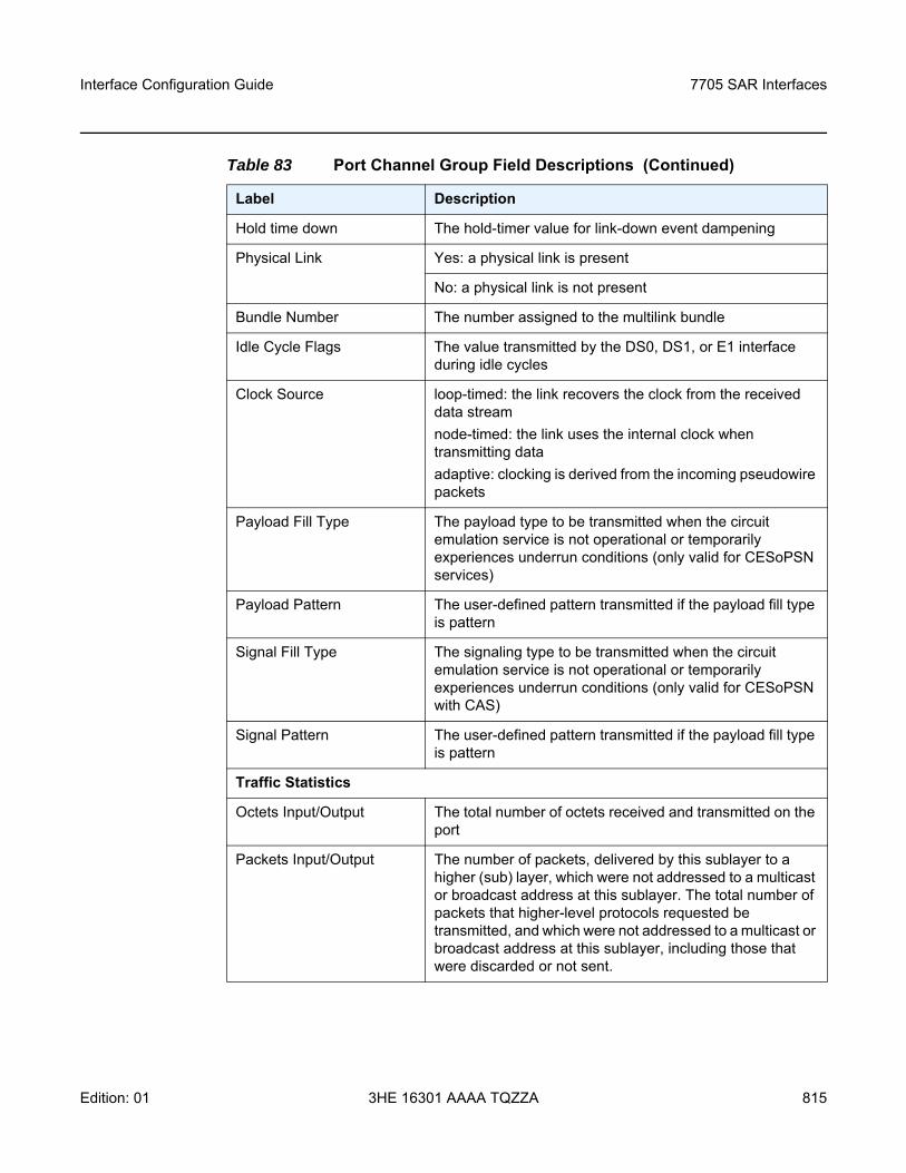
Interface Configuration Guide 7705 SAR Interfaces
Edition: 01 3HE 16301 AAAA TQZZA 815
Hold time down The hold-timer value for link-down event dampening
Physical Link Yes: a physical link is present
No: a physical link is not present
Bundle Number The number assigned to the multilink bundle
Idle Cycle Flags The value transmitted by the DS0, DS1, or E1 interface during idle cycles
Clock Source loop-timed: the link recovers the clock from the received data streamnode-timed: the link uses the internal clock when transmitting dataadaptive: clocking is derived from the incoming pseudowire packets
Payload Fill Type The payload type to be transmitted when the circuit emulation service is not operational or temporarily experiences underrun conditions (only valid for CESoPSN services)
Payload Pattern The user-defined pattern transmitted if the payload fill type is pattern
Signal Fill Type The signaling type to be transmitted when the circuit emulation service is not operational or temporarily experiences underrun conditions (only valid for CESoPSN with CAS)
Signal Pattern The user-defined pattern transmitted if the payload fill type is pattern
Traffic Statistics
Octets Input/Output The total number of octets received and transmitted on the port
Packets Input/Output The number of packets, delivered by this sublayer to a higher (sub) layer, which were not addressed to a multicast or broadcast address at this sublayer. The total number of packets that higher-level protocols requested be transmitted, and which were not addressed to a multicast or broadcast address at this sublayer, including those that were discarded or not sent.
Table 83 Port Channel Group Field Descriptions (Continued)
Label Description
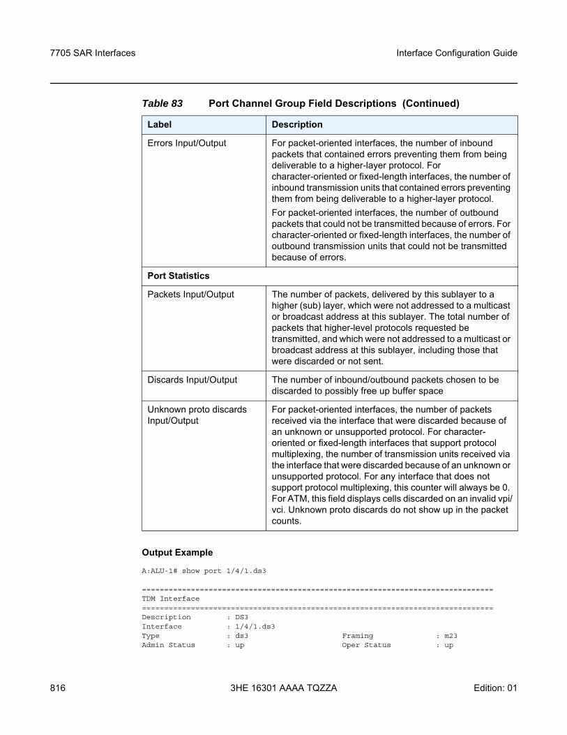
7705 SAR Interfaces
816
Interface Configuration Guide
3HE 16301 AAAA TQZZA Edition: 01
Output Example
A:ALU-1# show port 1/4/1.ds3
===============================================================================TDM Interface===============================================================================Description : DS3Interface : 1/4/1.ds3Type : ds3 Framing : m23Admin Status : up Oper Status : up
Errors Input/Output For packet-oriented interfaces, the number of inbound packets that contained errors preventing them from being deliverable to a higher-layer protocol. For character-oriented or fixed-length interfaces, the number of inbound transmission units that contained errors preventing them from being deliverable to a higher-layer protocol.For packet-oriented interfaces, the number of outbound packets that could not be transmitted because of errors. For character-oriented or fixed-length interfaces, the number of outbound transmission units that could not be transmitted because of errors.
Port Statistics
Packets Input/Output The number of packets, delivered by this sublayer to a higher (sub) layer, which were not addressed to a multicast or broadcast address at this sublayer. The total number of packets that higher-level protocols requested be transmitted, and which were not addressed to a multicast or broadcast address at this sublayer, including those that were discarded or not sent.
Discards Input/Output The number of inbound/outbound packets chosen to be discarded to possibly free up buffer space
Unknown proto discards Input/Output
For packet-oriented interfaces, the number of packets received via the interface that were discarded because of an unknown or unsupported protocol. For character-oriented or fixed-length interfaces that support protocol multiplexing, the number of transmission units received via the interface that were discarded because of an unknown or unsupported protocol. For any interface that does not support protocol multiplexing, this counter will always be 0. For ATM, this field displays cells discarded on an invalid vpi/vci. Unknown proto discards do not show up in the packet counts.
Table 83 Port Channel Group Field Descriptions (Continued)
Label Description
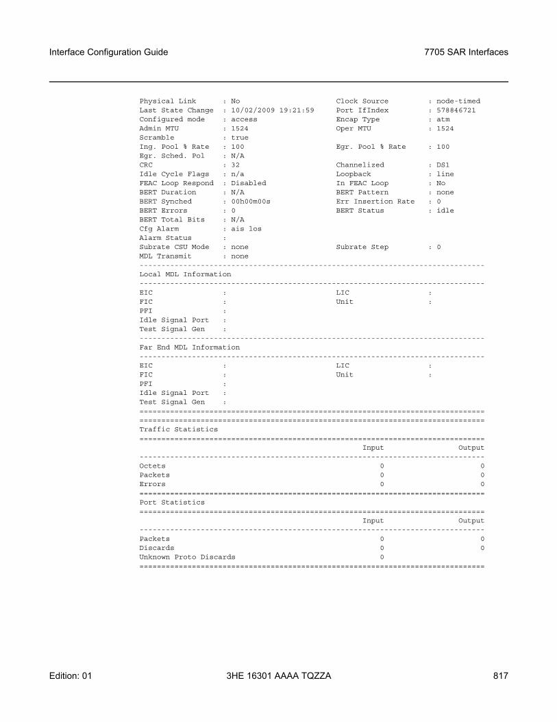
Interface Configuration Guide 7705 SAR Interfaces
Edition: 01 3HE 16301 AAAA TQZZA 817
Physical Link : No Clock Source : node-timedLast State Change : 10/02/2009 19:21:59 Port IfIndex : 578846721Configured mode : access Encap Type : atmAdmin MTU : 1524 Oper MTU : 1524Scramble : trueIng. Pool % Rate : 100 Egr. Pool % Rate : 100Egr. Sched. Pol : N/ACRC : 32 Channelized : DS1Idle Cycle Flags : n/a Loopback : lineFEAC Loop Respond : Disabled In FEAC Loop : NoBERT Duration : N/A BERT Pattern : noneBERT Synched : 00h00m00s Err Insertion Rate : 0BERT Errors : 0 BERT Status : idleBERT Total Bits : N/ACfg Alarm : ais losAlarm Status :Subrate CSU Mode : none Subrate Step : 0MDL Transmit : none-------------------------------------------------------------------------------Local MDL Information-------------------------------------------------------------------------------EIC : LIC :FIC : Unit :PFI :Idle Signal Port :Test Signal Gen :-------------------------------------------------------------------------------Far End MDL Information-------------------------------------------------------------------------------EIC : LIC :FIC : Unit :PFI :Idle Signal Port :Test Signal Gen :==============================================================================================================================================================Traffic Statistics===============================================================================
Input Output-------------------------------------------------------------------------------Octets 0 0Packets 0 0Errors 0 0===============================================================================Port Statistics===============================================================================
Input Output-------------------------------------------------------------------------------Packets 0 0Discards 0 0Unknown Proto Discards 0===============================================================================
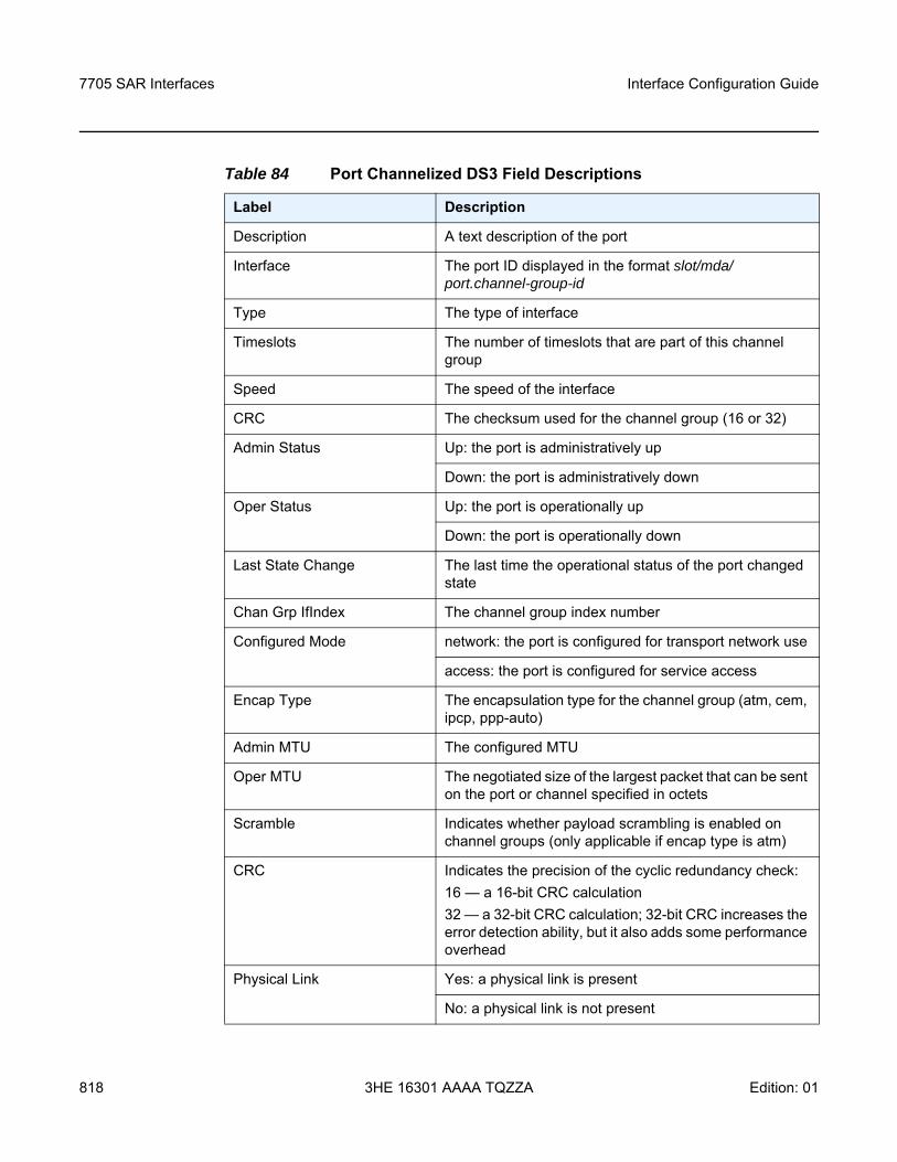
7705 SAR Interfaces
818
Interface Configuration Guide
3HE 16301 AAAA TQZZA Edition: 01
Table 84 Port Channelized DS3 Field Descriptions
Label Description
Description A text description of the port
Interface The port ID displayed in the format slot/mda/port.channel-group-id
Type The type of interface
Timeslots The number of timeslots that are part of this channel group
Speed The speed of the interface
CRC The checksum used for the channel group (16 or 32)
Admin Status Up: the port is administratively up
Down: the port is administratively down
Oper Status Up: the port is operationally up
Down: the port is operationally down
Last State Change The last time the operational status of the port changed state
Chan Grp IfIndex The channel group index number
Configured Mode network: the port is configured for transport network use
access: the port is configured for service access
Encap Type The encapsulation type for the channel group (atm, cem, ipcp, ppp-auto)
Admin MTU The configured MTU
Oper MTU The negotiated size of the largest packet that can be sent on the port or channel specified in octets
Scramble Indicates whether payload scrambling is enabled on channel groups (only applicable if encap type is atm)
CRC Indicates the precision of the cyclic redundancy check:16 — a 16-bit CRC calculation32 — a 32-bit CRC calculation; 32-bit CRC increases the error detection ability, but it also adds some performance overhead
Physical Link Yes: a physical link is present
No: a physical link is not present
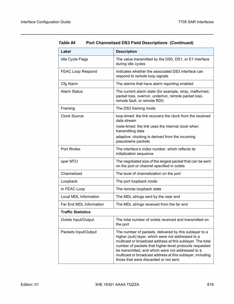
Interface Configuration Guide 7705 SAR Interfaces
Edition: 01 3HE 16301 AAAA TQZZA 819
Idle Cycle Flags The value transmitted by the DS0, DS1, or E1 interface during idle cycles
FEAC Loop Respond Indicates whether the associated DS3 interface can respond to remote loop signals
Cfg Alarm The alarms that have alarm reporting enabled
Alarm Status The current alarm state (for example, stray, malformed, packet loss, overrun, underrun, remote packet loss, remote fault, or remote RDI)
Framing The DS3 framing mode
Clock Source loop-timed: the link recovers the clock from the received data streamnode-timed: the link uses the internal clock when transmitting dataadaptive: clocking is derived from the incoming pseudowire packets
Port IfIndex The interface’s index number, which reflects its initialization sequence
oper MTU The negotiated size of the largest packet that can be sent on the port or channel specified in octets
Channelized The level of channelization on the port
Loopback The port loopback mode
In FEAC Loop The remote loopback state
Local MDL Information The MDL strings sent by the near end
Far End MDL Information The MDL strings received from the far end
Traffic Statistics
Octets Input/Output The total number of octets received and transmitted on the port
Packets Input/Output The number of packets, delivered by this sublayer to a higher (sub) layer, which were not addressed to a multicast or broadcast address at this sublayer. The total number of packets that higher-level protocols requested be transmitted, and which were not addressed to a multicast or broadcast address at this sublayer, including those that were discarded or not sent.
Table 84 Port Channelized DS3 Field Descriptions (Continued)
Label Description
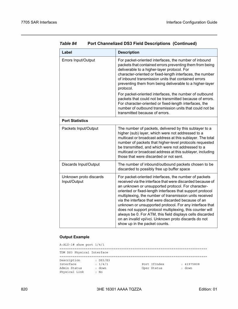
7705 SAR Interfaces
820
Interface Configuration Guide
3HE 16301 AAAA TQZZA Edition: 01
Output Example
A:ALU-1# show port 1/4/1===============================================================================TDM DS3 Physical Interface===============================================================================Description : DS3/E3Interface : 1/4/1 Port IfIndex : 41975808Admin Status : down Oper Status : downPhysical Link : No
Errors Input/Output For packet-oriented interfaces, the number of inbound packets that contained errors preventing them from being deliverable to a higher-layer protocol. For character-oriented or fixed-length interfaces, the number of inbound transmission units that contained errors preventing them from being deliverable to a higher-layer protocol.For packet-oriented interfaces, the number of outbound packets that could not be transmitted because of errors. For character-oriented or fixed-length interfaces, the number of outbound transmission units that could not be transmitted because of errors.
Port Statistics
Packets Input/Output The number of packets, delivered by this sublayer to a higher (sub) layer, which were not addressed to a multicast or broadcast address at this sublayer. The total number of packets that higher-level protocols requested be transmitted, and which were not addressed to a multicast or broadcast address at this sublayer, including those that were discarded or not sent.
Discards Input/Output The number of inbound/outbound packets chosen to be discarded to possibly free up buffer space
Unknown proto discards Input/Output
For packet-oriented interfaces, the number of packets received via the interface that were discarded because of an unknown or unsupported protocol. For character-oriented or fixed-length interfaces that support protocol multiplexing, the number of transmission units received via the interface that were discarded because of an unknown or unsupported protocol. For any interface that does not support protocol multiplexing, this counter will always be 0. For ATM, this field displays cells discarded on an invalid vpi/vci. Unknown proto discards do not show up in the packet counts.
Table 84 Port Channelized DS3 Field Descriptions (Continued)
Label Description
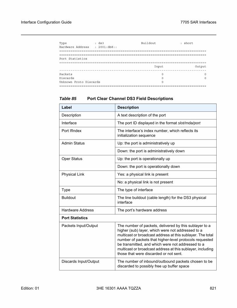
Interface Configuration Guide 7705 SAR Interfaces
Edition: 01 3HE 16301 AAAA TQZZA 821
Type : ds3 Buildout : shortHardware Address : 2001:db8::==============================================================================================================================================================Port Statistics===============================================================================
Input Output-------------------------------------------------------------------------------Packets 0 0Discards 0 0Unknown Proto Discards 0===============================================================================
Table 85 Port Clear Channel DS3 Field Descriptions
Label Description
Description A text description of the port
Interface The port ID displayed in the format slot/mda/port
Port IfIndex The interface’s index number, which reflects its initialization sequence
Admin Status Up: the port is administratively up
Down: the port is administratively down
Oper Status Up: the port is operationally up
Down: the port is operationally down
Physical Link Yes: a physical link is present
No: a physical link is not present
Type The type of interface
Buildout The line buildout (cable length) for the DS3 physical interface
Hardware Address The port’s hardware address
Port Statistics
Packets Input/Output The number of packets, delivered by this sublayer to a higher (sub) layer, which were not addressed to a multicast or broadcast address at this sublayer. The total number of packets that higher-level protocols requested be transmitted, and which were not addressed to a multicast or broadcast address at this sublayer, including those that were discarded or not sent.
Discards Input/Output The number of inbound/outbound packets chosen to be discarded to possibly free up buffer space
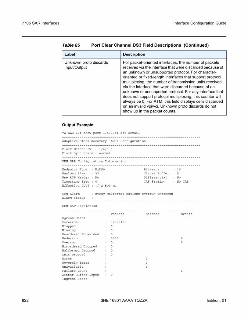
7705 SAR Interfaces
822
Interface Configuration Guide
3HE 16301 AAAA TQZZA Edition: 01
Output Example
*A:ALU-1># show port 1/4/1.e1 acr detail=======================================================================Adaptive Clock Recovery (ACR) Configuration=======================================================================Clock Master PW : 1/4/1.1Clock Sync State : normal-----------------------------------------------------------------------CEM SAP Configuration Information-----------------------------------------------------------------------Endpoint Type : NxDS0 Bit-rate : 16Payload Size : 32 Jitter Buffer : 5Use RTP Header : No Differential : NoTimestamp Freq : 0 CAS Framing : No CASEffective PDVT : +/-2.500 ms
Cfg Alarm : stray malformed pktloss overrun underrunAlarm Status :-----------------------------------------------------------------------CEM SAP Statistics-----------------------------------------------------------------------
Packets Seconds EventsEgress StatsForwarded : 32993106Dropped : 0Missing : 0Reordered Forwarded : 0Underrun : 8058 0Overrun : 0 0Misordered Dropped : 0Malformed Dropped : 0LBit Dropped : 0Error : 3Severely Error : 2Unavailable : 0Failure Count : 1Jitter Buffer Depth : 0Ingress Stats
Unknown proto discards Input/Output
For packet-oriented interfaces, the number of packets received via the interface that were discarded because of an unknown or unsupported protocol. For character-oriented or fixed-length interfaces that support protocol multiplexing, the number of transmission units received via the interface that were discarded because of an unknown or unsupported protocol. For any interface that does not support protocol multiplexing, this counter will always be 0. For ATM, this field displays cells discarded on an invalid vpi/vci. Unknown proto discards do not show up in the packet counts.
Table 85 Port Clear Channel DS3 Field Descriptions (Continued)
Label Description
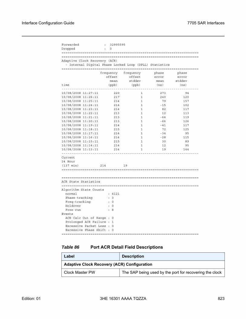
Interface Configuration Guide 7705 SAR Interfaces
Edition: 01 3HE 16301 AAAA TQZZA 823
Forwarded : 32995595Dropped : 0==============================================================================================================================================Adaptive Clock Recovery (ACR)
- Internal Digital Phase Locked Loop (DPLL) Statistics=======================================================================
frequency frequency phase phaseoffset offset error error
mean stddev mean stddevtime (ppb) (ppb) (ns) (ns)-----------------------------------------------------------------------10/08/2008 11:27:11 220 1 273 9410/08/2008 11:26:11 217 1 240 12010/08/2008 11:25:11 214 1 79 15710/08/2008 11:24:11 214 1 -15 10210/08/2008 11:23:11 214 1 82 11710/08/2008 11:22:11 213 1 12 11310/08/2008 11:21:11 213 1 -64 11910/08/2008 11:20:11 213 1 -66 12610/08/2008 11:19:11 214 1 -41 11710/08/2008 11:18:11 215 1 72 12510/08/2008 11:17:11 214 1 -34 9510/08/2008 11:16:11 214 1 -28 11510/08/2008 11:15:11 215 1 30 8910/08/2008 11:14:11 214 1 12 9510/08/2008 11:13:11 214 1 19 144-----------------------------------------------------------------------Current24 Hour(137 min) 214 19=======================================================================
=======================================================================ACR State Statistics=======================================================================Algorithm State Counts
normal : 4121Phase-tracking : 3Freq-tracking : 0Holdover : 0Free-run : 8
EventsACR Calc Out of Range : 0Prolonged ACR Failure : 1Excessive Packet Loss : 0Excessive Phase Shift : 0
=======================================================================
Table 86 Port ACR Detail Field Descriptions
Label Description
Adaptive Clock Recovery (ACR) Configuration
Clock Master PW The SAP being used by the port for recovering the clock

7705 SAR Interfaces
824
Interface Configuration Guide
3HE 16301 AAAA TQZZA Edition: 01
Clock Sync State The current state of the ACR adaptive algorithm
CEM SAP Configuration Information
Endpoint Type The type of endpoint
Bit-rate The number of DS0s or timeslots in the channel group
Payload Size The number of octets contained in the payload of a TDM PW packet when the packet is transmitted
Jitter Buffer The size of the receive jitter buffer, expressed in milliseconds
Use RTP Header Indicates whether RTP headers are used in CES packets (Yes or No)
CAS Framing The type of CAS framing
Effective PDVT The peak-to-peak packet delay variation (PDV) used by the circuit emulation serviceSince the operating system may adjust the jitter buffer setting in order to ensure no packet loss, the configured jitter buffer value may not be the value used by the system. The effective PDVT provides an indication that the PDV has been adjusted by the operating system.
Cfg Alarm The alarms that have alarm reporting enabled
Alarm Status The current alarm state (for example, stray, malformed, packet loss, overrun, underrun, remote packet loss, remote fault, or remote RDI)
Internal Digital Phase Locked Loop (DPLL) Statistics
ACR DPLL Statistics frequency offset mean: the ACR frequency offset mean for the previous 15 sets of 60-s intervals
frequency offset stddev: the ACR frequency offset standard deviation for the previous 15 sets of 60-s intervals
phase error mean: the ACR input phase error mean and output DCO mean for the previous 15 sets of 60-s intervals
phase error stddev: the ACR input phase error standard deviation and output DCO standard deviation for the previous 15 sets of 60-s intervals
Table 86 Port ACR Detail Field Descriptions (Continued)
Label Description
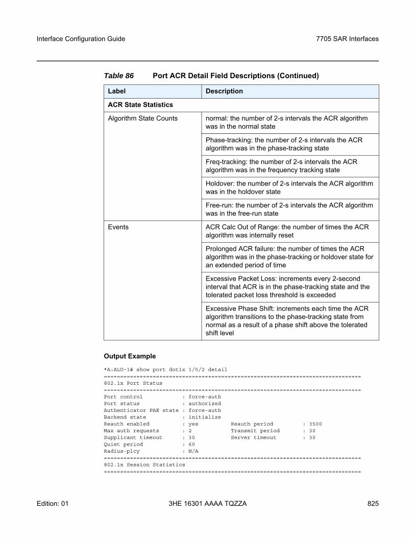
Interface Configuration Guide 7705 SAR Interfaces
Edition: 01 3HE 16301 AAAA TQZZA 825
Output Example
*A:ALU-1# show port dot1x 1/5/2 detail===============================================================================802.1x Port Status===============================================================================Port control : force-authPort status : authorizedAuthenticator PAE state : force-authBackend state : initializeReauth enabled : yes Reauth period : 3500Max auth requests : 2 Transmit period : 30Supplicant timeout : 30 Server timeout : 30Quiet period : 60Radius-plcy : N/A===============================================================================802.1x Session Statistics===============================================================================
ACR State Statistics
Algorithm State Counts normal: the number of 2-s intervals the ACR algorithm was in the normal state
Phase-tracking: the number of 2-s intervals the ACR algorithm was in the phase-tracking state
Freq-tracking: the number of 2-s intervals the ACR algorithm was in the frequency tracking state
Holdover: the number of 2-s intervals the ACR algorithm was in the holdover state
Free-run: the number of 2-s intervals the ACR algorithm was in the free-run state
Events ACR Calc Out of Range: the number of times the ACR algorithm was internally reset
Prolonged ACR failure: the number of times the ACR algorithm was in the phase-tracking or holdover state for an extended period of time
Excessive Packet Loss: increments every 2-second interval that ACR is in the phase-tracking state and the tolerated packet loss threshold is exceeded
Excessive Phase Shift: increments each time the ACR algorithm transitions to the phase-tracking state from normal as a result of a phase shift above the tolerated shift level
Table 86 Port ACR Detail Field Descriptions (Continued)
Label Description
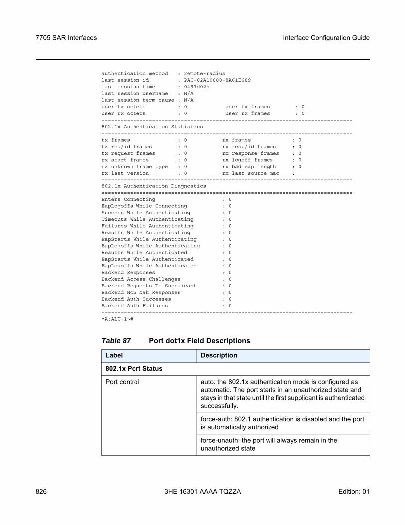
7705 SAR Interfaces
826
Interface Configuration Guide
3HE 16301 AAAA TQZZA Edition: 01
authentication method : remote-radiuslast session id : PAC-02A10000-8A61E689last session time : 0497d02hlast session username : N/Alast session term cause : N/Auser tx octets : 0 user tx frames : 0user rx octets : 0 user rx frames : 0===============================================================================802.1x Authentication Statistics===============================================================================tx frames : 0 rx frames : 0tx req/id frames : 0 rx resp/id frames : 0tx request frames : 0 rx response frames : 0rx start frames : 0 rx logoff frames : 0rx unknown frame type : 0 rx bad eap length : 0rx last version : 0 rx last source mac :===============================================================================802.1x Authentication Diagnostics===============================================================================Enters Connecting : 0EapLogoffs While Connecting : 0Success While Authenticating : 0Timeouts While Authenticating : 0Failures While Authenticating : 0Reauths While Authenticating : 0EapStarts While Authenticating : 0EapLogoffs While Authenticating : 0Reauths While Authenticated : 0EapStarts While Authenticated : 0EapLogoffs While Authenticated : 0Backend Responses : 0Backend Access Challenges : 0Backend Requests To Supplicant : 0Backend Non Nak Responses : 0Backend Auth Successes : 0Backend Auth Failures : 0===============================================================================*A:ALU-1>#
Table 87 Port dot1x Field Descriptions
Label Description
802.1x Port Status
Port control auto: the 802.1x authentication mode is configured as automatic. The port starts in an unauthorized state and stays in that state until the first supplicant is authenticated successfully.
force-auth: 802.1 authentication is disabled and the port is automatically authorized
force-unauth: the port will always remain in the unauthorized state
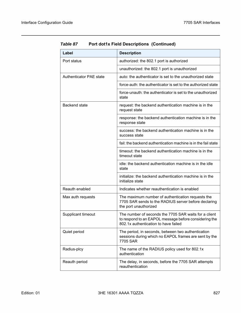
Interface Configuration Guide 7705 SAR Interfaces
Edition: 01 3HE 16301 AAAA TQZZA 827
Port status authorized: the 802.1 port is authorized
unauthorized: the 802.1 port is unauthorized
Authenticator PAE state auto: the authenticator is set to the unauthorized state
force-auth: the authenticator is set to the authorized state
force-unauth: the authenticator is set to the unauthorized state
Backend state request: the backend authentication machine is in the request state
response: the backend authentication machine is in the response state
success: the backend authentication machine is in the success state
fail: the backend authentication machine is in the fail state
timeout: the backend authentication machine is in the timeout state
idle: the backend authentication machine is in the idle state
initialize: the backend authentication machine is in the initialize state
Reauth enabled Indicates whether reauthentication is enabled
Max auth requests The maximum number of authentication requests the 7705 SAR sends to the RADIUS server before declaring the port unauthorized
Supplicant timeout The number of seconds the 7705 SAR waits for a client to respond to an EAPOL message before considering the 802.1x authentication to have failed
Quiet period The period, in seconds, between two authentication sessions during which no EAPOL frames are sent by the 7705 SAR
Radius-plcy The name of the RADIUS policy used for 802.1x authentication
Reauth period The delay, in seconds, before the 7705 SAR attempts reauthentication
Table 87 Port dot1x Field Descriptions (Continued)
Label Description
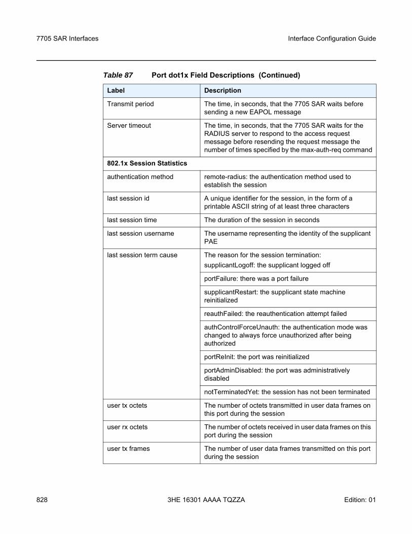
7705 SAR Interfaces
828
Interface Configuration Guide
3HE 16301 AAAA TQZZA Edition: 01
Transmit period The time, in seconds, that the 7705 SAR waits before sending a new EAPOL message
Server timeout The time, in seconds, that the 7705 SAR waits for the RADIUS server to respond to the access request message before resending the request message the number of times specified by the max-auth-req command
802.1x Session Statistics
authentication method remote-radius: the authentication method used to establish the session
last session id A unique identifier for the session, in the form of a printable ASCII string of at least three characters
last session time The duration of the session in seconds
last session username The username representing the identity of the supplicant PAE
last session term cause The reason for the session termination:supplicantLogoff: the supplicant logged off
portFailure: there was a port failure
supplicantRestart: the supplicant state machine reinitialized
reauthFailed: the reauthentication attempt failed
authControlForceUnauth: the authentication mode was changed to always force unauthorized after being authorized
portReInit: the port was reinitialized
portAdminDisabled: the port was administratively disabled
notTerminatedYet: the session has not been terminated
user tx octets The number of octets transmitted in user data frames on this port during the session
user rx octets The number of octets received in user data frames on this port during the session
user tx frames The number of user data frames transmitted on this port during the session
Table 87 Port dot1x Field Descriptions (Continued)
Label Description
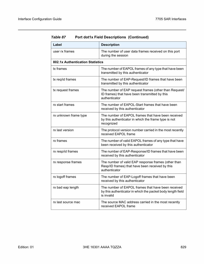
Interface Configuration Guide 7705 SAR Interfaces
Edition: 01 3HE 16301 AAAA TQZZA 829
user rx frames The number of user data frames received on this port during the session
802.1x Authentication Statistics
tx frames The number of EAPOL frames of any type that have been transmitted by this authenticator
tx req/id frames The number of EAP-Request/ID frames that have been transmitted by this authenticator
tx request frames The number of EAP request frames (other than Request/ID frames) that have been transmitted by this authenticator
rx start frames The number of EAPOL-Start frames that have been received by this authenticator
rx unknown frame type The number of EAPOL frames that have been received by this authenticator in which the frame type is not recognized
rx last version The protocol version number carried in the most recently received EAPOL frame
rx frames The number of valid EAPOL frames of any type that have been received by this authenticator
rx resp/id frames The number of EAP-Response/ID frames that have been received by this authenticator
rx response frames The number of valid EAP response frames (other than Resp/ID frames) that have been received by this authenticator
rx logoff frames The number of EAP-Logoff frames that have been received by this authenticator
rx bad eap length The number of EAPOL frames that have been received by this authenticator in which the packet body length field is invalid
rx last source mac The source MAC address carried in the most recently received EAPOL frame
Table 87 Port dot1x Field Descriptions (Continued)
Label Description
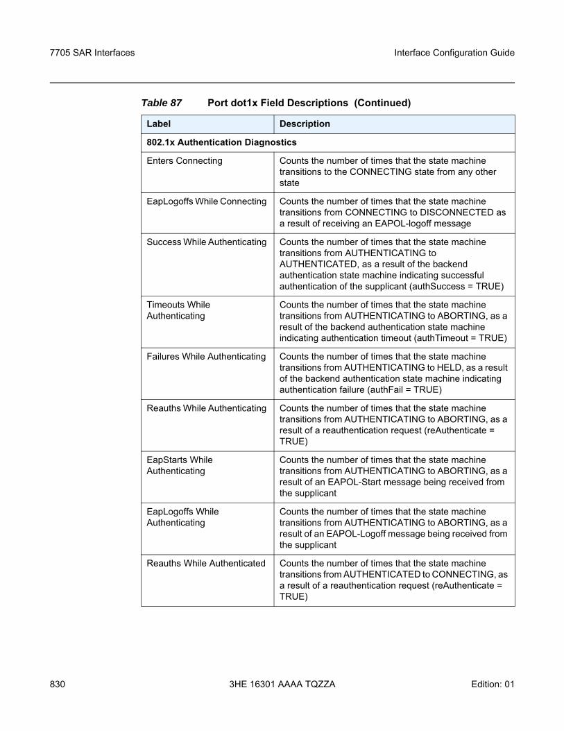
7705 SAR Interfaces
830
Interface Configuration Guide
3HE 16301 AAAA TQZZA Edition: 01
802.1x Authentication Diagnostics
Enters Connecting Counts the number of times that the state machine transitions to the CONNECTING state from any other state
EapLogoffs While Connecting Counts the number of times that the state machine transitions from CONNECTING to DISCONNECTED as a result of receiving an EAPOL-logoff message
Success While Authenticating Counts the number of times that the state machine transitions from AUTHENTICATING to AUTHENTICATED, as a result of the backend authentication state machine indicating successful authentication of the supplicant (authSuccess = TRUE)
Timeouts While Authenticating
Counts the number of times that the state machine transitions from AUTHENTICATING to ABORTING, as a result of the backend authentication state machine indicating authentication timeout (authTimeout = TRUE)
Failures While Authenticating Counts the number of times that the state machine transitions from AUTHENTICATING to HELD, as a result of the backend authentication state machine indicating authentication failure (authFail = TRUE)
Reauths While Authenticating Counts the number of times that the state machine transitions from AUTHENTICATING to ABORTING, as a result of a reauthentication request (reAuthenticate = TRUE)
EapStarts While Authenticating
Counts the number of times that the state machine transitions from AUTHENTICATING to ABORTING, as a result of an EAPOL-Start message being received from the supplicant
EapLogoffs While Authenticating
Counts the number of times that the state machine transitions from AUTHENTICATING to ABORTING, as a result of an EAPOL-Logoff message being received from the supplicant
Reauths While Authenticated Counts the number of times that the state machine transitions from AUTHENTICATED to CONNECTING, as a result of a reauthentication request (reAuthenticate = TRUE)
Table 87 Port dot1x Field Descriptions (Continued)
Label Description
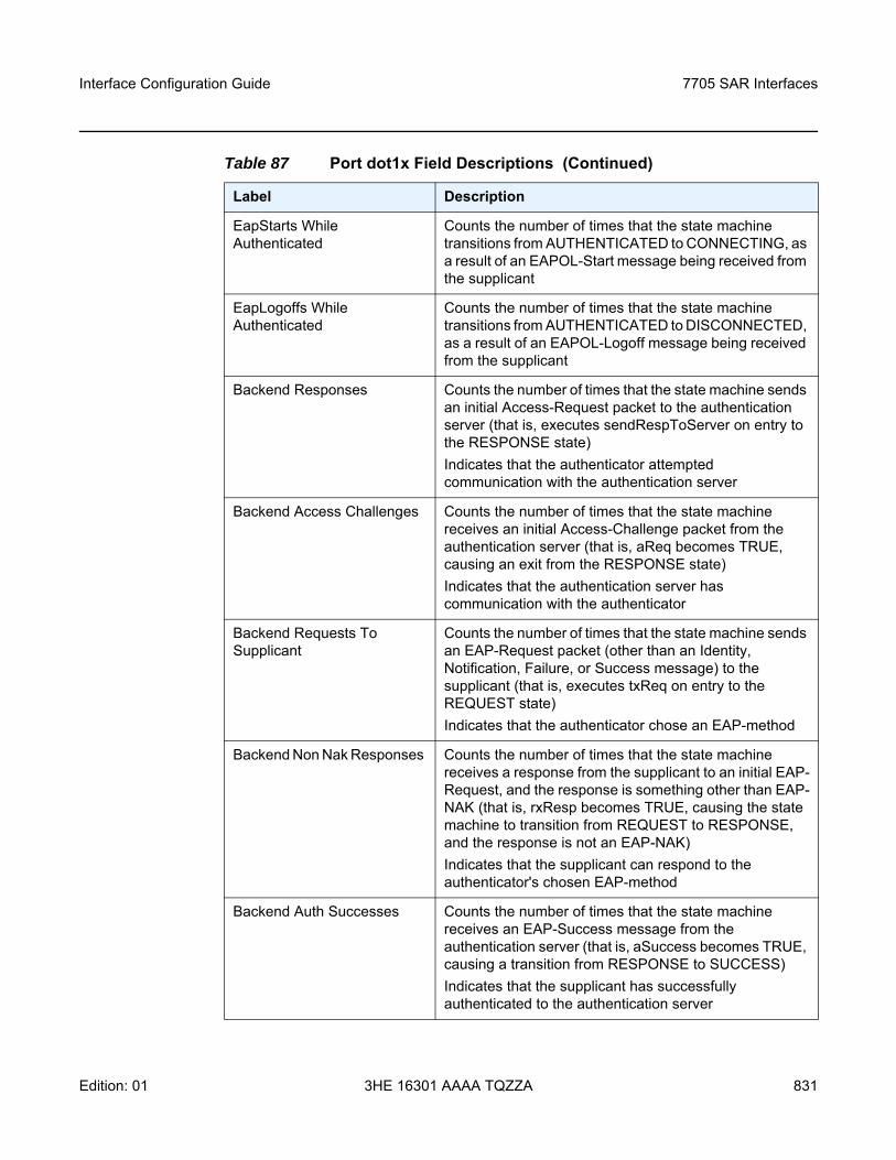
Interface Configuration Guide 7705 SAR Interfaces
Edition: 01 3HE 16301 AAAA TQZZA 831
EapStarts While Authenticated
Counts the number of times that the state machine transitions from AUTHENTICATED to CONNECTING, as a result of an EAPOL-Start message being received from the supplicant
EapLogoffs While Authenticated
Counts the number of times that the state machine transitions from AUTHENTICATED to DISCONNECTED, as a result of an EAPOL-Logoff message being received from the supplicant
Backend Responses Counts the number of times that the state machine sends an initial Access-Request packet to the authentication server (that is, executes sendRespToServer on entry to the RESPONSE state)Indicates that the authenticator attempted communication with the authentication server
Backend Access Challenges Counts the number of times that the state machine receives an initial Access-Challenge packet from the authentication server (that is, aReq becomes TRUE, causing an exit from the RESPONSE state)Indicates that the authentication server has communication with the authenticator
Backend Requests To Supplicant
Counts the number of times that the state machine sends an EAP-Request packet (other than an Identity, Notification, Failure, or Success message) to the supplicant (that is, executes txReq on entry to the REQUEST state)Indicates that the authenticator chose an EAP-method
Backend Non Nak Responses Counts the number of times that the state machine receives a response from the supplicant to an initial EAP-Request, and the response is something other than EAP-NAK (that is, rxResp becomes TRUE, causing the state machine to transition from REQUEST to RESPONSE, and the response is not an EAP-NAK)Indicates that the supplicant can respond to the authenticator's chosen EAP-method
Backend Auth Successes Counts the number of times that the state machine receives an EAP-Success message from the authentication server (that is, aSuccess becomes TRUE, causing a transition from RESPONSE to SUCCESS)Indicates that the supplicant has successfully authenticated to the authentication server
Table 87 Port dot1x Field Descriptions (Continued)
Label Description
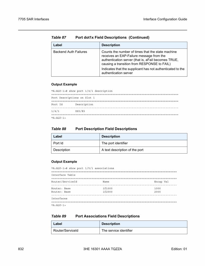
7705 SAR Interfaces
832
Interface Configuration Guide
3HE 16301 AAAA TQZZA Edition: 01
Output Example
*A:ALU-1># show port 1/4/1 description===============================================================================Port Descriptions on Slot 1===============================================================================Port Id Description-------------------------------------------------------------------------------1/4/1 DS3/E3===============================================================================*A:ALU-1>
Output Example
*A:ALU-1># show port 1/5/1 associations==============================================================================Interface Table==============================================================================Router/ServiceId Name Encap Val------------------------------------------------------------------------------Router: Base if1000 1000Router: Base if2000 2000------------------------------------------------------------------------------Interfaces==============================================================================*A:ALU-1>
Backend Auth Failures Counts the number of times that the state machine receives an EAP-Failure message from the authentication server (that is, aFail becomes TRUE, causing a transition from RESPONSE to FAIL)Indicates that the supplicant has not authenticated to the authentication server
Table 88 Port Description Field Descriptions
Label Description
Port Id The port identifier
Description A text description of the port
Table 89 Port Associations Field Descriptions
Label Description
Router/ServiceId The service identifier
Table 87 Port dot1x Field Descriptions (Continued)
Label Description
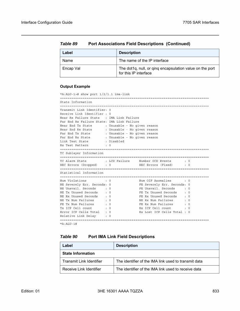
Interface Configuration Guide 7705 SAR Interfaces
Edition: 01 3HE 16301 AAAA TQZZA 833
Output Example
*A:ALU-1># show port 1/2/1.1 ima-link===============================================================================State Information===============================================================================Transmit Link Identifier: 0Receive Link Identifier : 0Near Rx Failure State : IMA Link FailureFar End Rx Failure State: IMA Link FailureNear End Tx State : Unusable - No given reasonNear End Rx State : Unusable - No given reasonFar End Tx State : Unusable - No given reasonFar End Rx State : Unusable - No given reasonLink Test State : DisabledRx Test Pattern : 0===============================================================================TC Sublayer Information===============================================================================TC Alarm State : LCD Failure Number OCD Events : 0HEC Errors (Dropped) : 0 HEC Errors (Fixed) : 0===============================================================================Statistical Information===============================================================================Num Violations : 0 Num OIF Anomalies : 0NE Severely Err. Seconds: 0 FE Severely Err. Seconds: 0NE Unavail. Seconds : 0 FE Unavail. Seconds : 0NE Tx Unused Seconds : 0 FE Tx Unused Seconds : 0NE Rx Unused Seconds : 0 FE Rx Unused Seconds : 0NE Tx Num Failures : 0 NE Rx Num Failures : 0FE Tx Num Failures : 0 FE Rx Num Failures : 0Tx ICP Cell count : 0 Rx ICP Cell count : 0Error ICP Cells Total : 0 Rx Lost ICP Cells Total : 0Relative Link Delay : 0===============================================================================*A:ALU-1#
Name The name of the IP interface
Encap Val The dot1q, null, or qinq encapsulation value on the port for this IP interface
Table 90 Port IMA Link Field Descriptions
Label Description
State Information
Transmit Link Identifier The identifier of the IMA link used to transmit data
Receive Link Identifier The identifier of the IMA link used to receive data
Table 89 Port Associations Field Descriptions (Continued)
Label Description
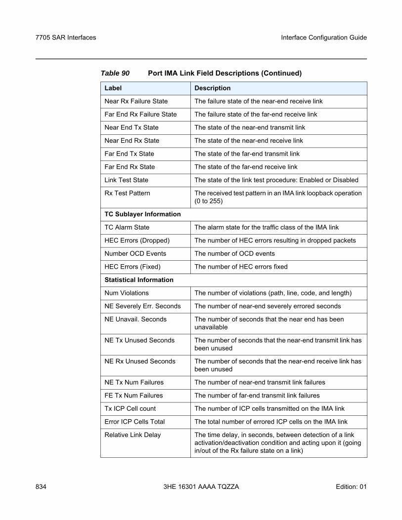
7705 SAR Interfaces
834
Interface Configuration Guide
3HE 16301 AAAA TQZZA Edition: 01
Near Rx Failure State The failure state of the near-end receive link
Far End Rx Failure State The failure state of the far-end receive link
Near End Tx State The state of the near-end transmit link
Near End Rx State The state of the near-end receive link
Far End Tx State The state of the far-end transmit link
Far End Rx State The state of the far-end receive link
Link Test State The state of the link test procedure: Enabled or Disabled
Rx Test Pattern The received test pattern in an IMA link loopback operation (0 to 255)
TC Sublayer Information
TC Alarm State The alarm state for the traffic class of the IMA link
HEC Errors (Dropped) The number of HEC errors resulting in dropped packets
Number OCD Events The number of OCD events
HEC Errors (Fixed) The number of HEC errors fixed
Statistical Information
Num Violations The number of violations (path, line, code, and length)
NE Severely Err. Seconds The number of near-end severely errored seconds
NE Unavail. Seconds The number of seconds that the near end has been unavailable
NE Tx Unused Seconds The number of seconds that the near-end transmit link has been unused
NE Rx Unused Seconds The number of seconds that the near-end receive link has been unused
NE Tx Num Failures The number of near-end transmit link failures
FE Tx Num Failures The number of far-end transmit link failures
Tx ICP Cell count The number of ICP cells transmitted on the IMA link
Error ICP Cells Total The total number of errored ICP cells on the IMA link
Relative Link Delay The time delay, in seconds, between detection of a link activation/deactivation condition and acting upon it (going in/out of the Rx failure state on a link)
Table 90 Port IMA Link Field Descriptions (Continued)
Label Description
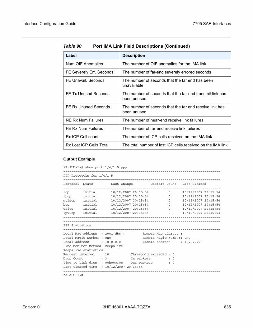
Interface Configuration Guide 7705 SAR Interfaces
Edition: 01 3HE 16301 AAAA TQZZA 835
Output Example
*A:ALU-1># show port 1/4/1.5 ppp===============================================================================PPP Protocols for 1/4/1.5===============================================================================Protocol State Last Change Restart Count Last Cleared-------------------------------------------------------------------------------lcp initial 10/12/2007 20:15:54 0 10/12/2007 20:15:54ipcp initial 10/12/2007 20:15:54 0 10/12/2007 20:15:54mplscp initial 10/12/2007 20:15:54 0 10/12/2007 20:15:54bcp initial 10/12/2007 20:15:54 0 10/12/2007 20:15:54osicp initial 10/12/2007 20:15:54 0 10/12/2007 20:15:54ipv6cp initial 10/12/2007 20:15:54 0 10/12/2007 20:15:54==============================================================================================================================================================PPP Statistics===============================================================================Local Mac address : 2001:db8:: Remote Mac address :Local Magic Number : 0x0 Remote Magic Number: 0x0Local address : 10.0.0.0 Remote address : 10.0.0.0Line Monitor Method: keepaliveKeepalive statisticsRequest interval : 10 Threshold exceeded : 0Drop Count : 3 In packets : 0Time to link drop : 00h00m30s Out packets : 0Last cleared time : 10/12/2007 20:15:54===============================================================================*A:ALU-1>#
Num OIF Anomalies The number of OIF anomalies for the IMA link
FE Severely Err. Seconds The number of far-end severely errored seconds
FE Unavail. Seconds The number of seconds that the far end has been unavailable
FE Tx Unused Seconds The number of seconds that the far-end transmit link has been unused
FE Rx Unused Seconds The number of seconds that the far end receive link has been unused
NE Rx Num Failures The number of near-end receive link failures
FE Rx Num Failures The number of far-end receive link failures
Rx ICP Cell count The number of ICP cells received on the IMA link
Rx Lost ICP Cells Total The total number of lost ICP cells received on the IMA link
Table 90 Port IMA Link Field Descriptions (Continued)
Label Description
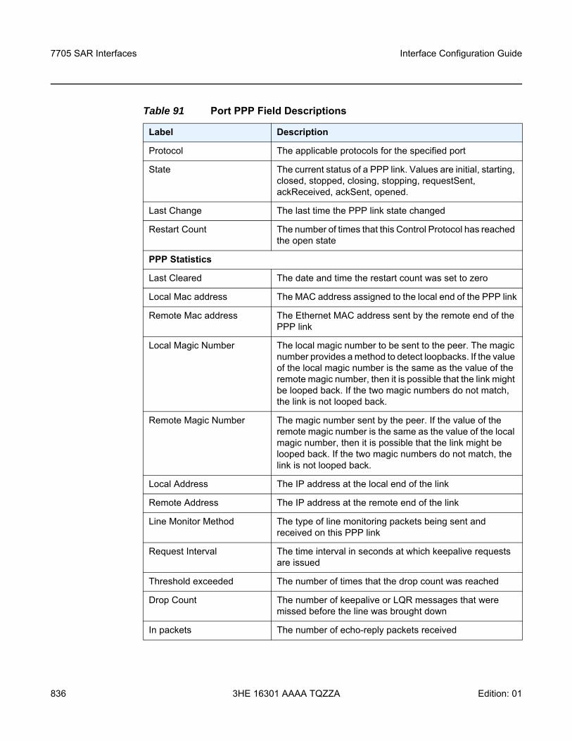
7705 SAR Interfaces
836
Interface Configuration Guide
3HE 16301 AAAA TQZZA Edition: 01
Table 91 Port PPP Field Descriptions
Label Description
Protocol The applicable protocols for the specified port
State The current status of a PPP link. Values are initial, starting, closed, stopped, closing, stopping, requestSent, ackReceived, ackSent, opened.
Last Change The last time the PPP link state changed
Restart Count The number of times that this Control Protocol has reached the open state
PPP Statistics
Last Cleared The date and time the restart count was set to zero
Local Mac address The MAC address assigned to the local end of the PPP link
Remote Mac address The Ethernet MAC address sent by the remote end of the PPP link
Local Magic Number The local magic number to be sent to the peer. The magic number provides a method to detect loopbacks. If the value of the local magic number is the same as the value of the remote magic number, then it is possible that the link might be looped back. If the two magic numbers do not match, the link is not looped back.
Remote Magic Number The magic number sent by the peer. If the value of the remote magic number is the same as the value of the local magic number, then it is possible that the link might be looped back. If the two magic numbers do not match, the link is not looped back.
Local Address The IP address at the local end of the link
Remote Address The IP address at the remote end of the link
Line Monitor Method The type of line monitoring packets being sent and received on this PPP link
Request Interval The time interval in seconds at which keepalive requests are issued
Threshold exceeded The number of times that the drop count was reached
Drop Count The number of keepalive or LQR messages that were missed before the line was brought down
In packets The number of echo-reply packets received
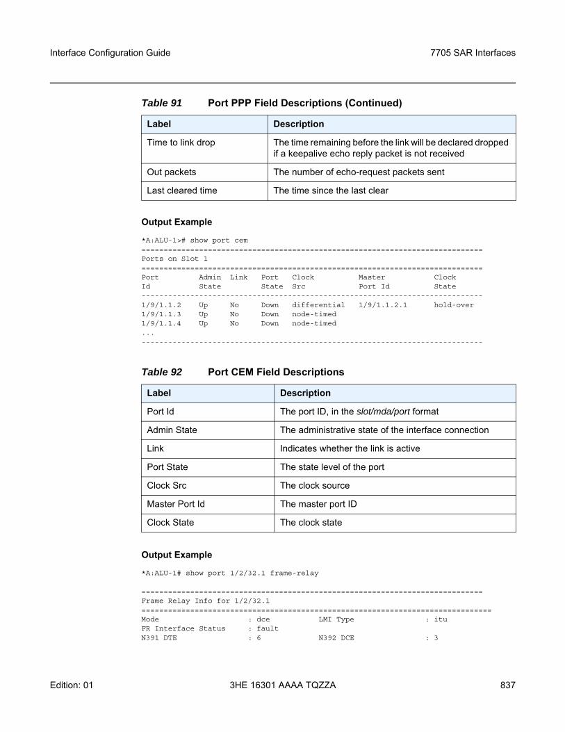
Interface Configuration Guide 7705 SAR Interfaces
Edition: 01 3HE 16301 AAAA TQZZA 837
Output Example
*A:ALU-1># show port cem=============================================================================Ports on Slot 1=============================================================================Port Admin Link Port Clock Master ClockId State State Src Port Id State-----------------------------------------------------------------------------1/9/1.1.2 Up No Down differential 1/9/1.1.2.1 hold-over1/9/1.1.3 Up No Down node-timed1/9/1.1.4 Up No Down node-timed...-----------------------------------------------------------------------------
Output Example
*A:ALU-1# show port 1/2/32.1 frame-relay
=============================================================================Frame Relay Info for 1/2/32.1===============================================================================Mode : dce LMI Type : ituFR Interface Status : faultN391 DTE : 6 N392 DCE : 3
Time to link drop The time remaining before the link will be declared dropped if a keepalive echo reply packet is not received
Out packets The number of echo-request packets sent
Last cleared time The time since the last clear
Table 92 Port CEM Field Descriptions
Label Description
Port Id The port ID, in the slot/mda/port format
Admin State The administrative state of the interface connection
Link Indicates whether the link is active
Port State The state level of the port
Clock Src The clock source
Master Port Id The master port ID
Clock State The clock state
Table 91 Port PPP Field Descriptions (Continued)
Label Description
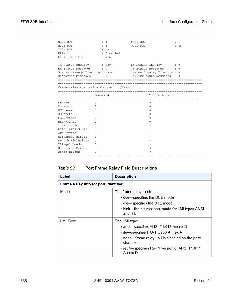
7705 SAR Interfaces
838
Interface Configuration Guide
3HE 16301 AAAA TQZZA Edition: 01
N392 DTE : 3 N393 DCE : 4N393 DTE : 4 T392 DCE : 15T391 DTE : 10FRF-12 : DisabledLink Identifier : N/A
Tx Status Enquiry : 1097 Rx Status Enquiry : 0Rx Status Messages : 0 Tx Status Messages : 0Status Message Timeouts : 1096 Status Enquiry Timeouts : 0Discarded Messages : 0 Inv. RxSeqNum Messages : 0==============================================================================================================================================================frame-relay statistics for port "1/2/32.1"===============================================================================
Received Transmitted-------------------------------------------------------------------------------Frames 0 0Octets 0 0DEFrames 0 0DEOctets 0 0FECNFrames 0 0BECNFrames 0 0Invalid Dlci 0 -Last Invalid Dlci - -Crc Errors 0 -Alignment Errors 0 -Length Violations 0 -Illegal Header 0 -Underruns Errors - 0Other Errors 0 0===============================================================================
Table 93 Port Frame Relay Field Descriptions
Label Description
Frame Relay Info for port identifier
Mode The frame relay mode:• dce—specifies the DCE mode• dte—specifies the DTE mode• bidir—the bidirectional mode for LMI types ANSI
and ITU
LMI Type The LMI type:• ansi—specifies ANSI T1.617 Annex D• itu—specifies ITU-T Q933 Annex A• none—frame relay LMI is disabled on the port/
channel• rev1—specifies Rev 1 version of ANSI T1.617
Annex D
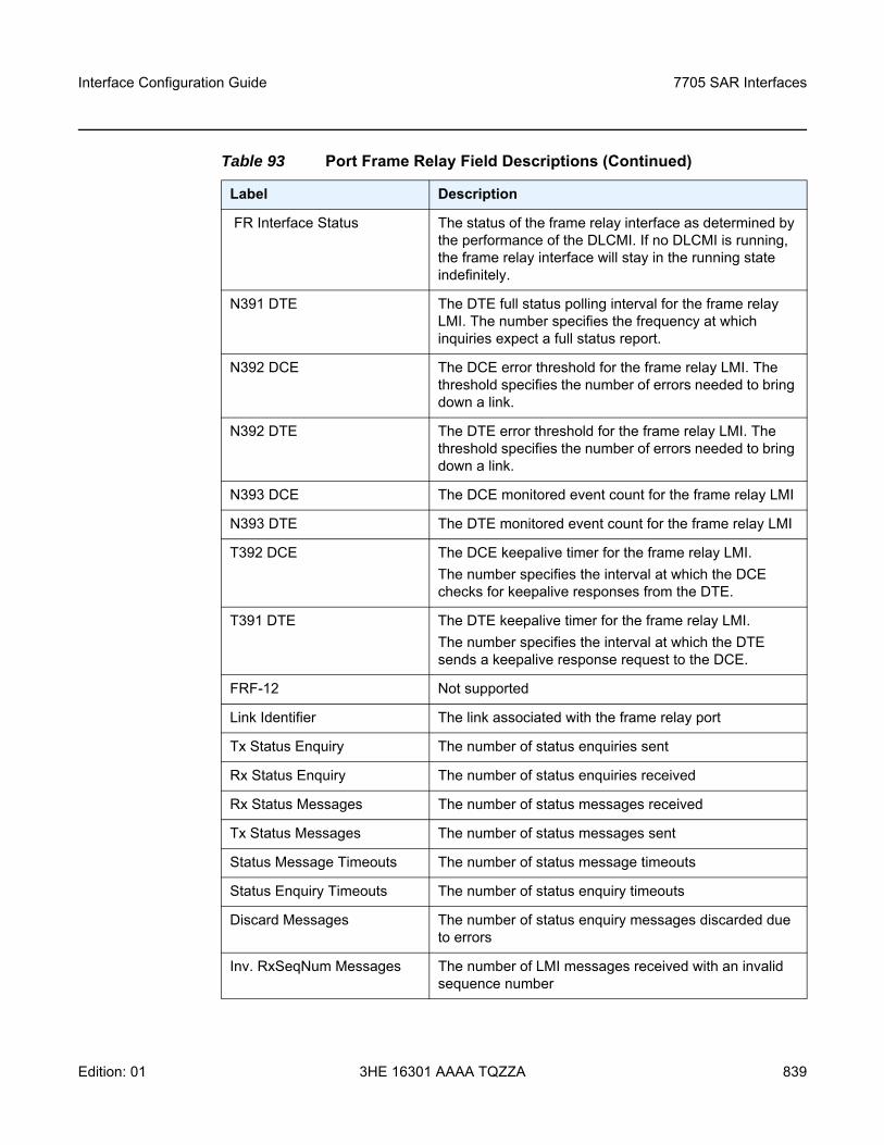
Interface Configuration Guide 7705 SAR Interfaces
Edition: 01 3HE 16301 AAAA TQZZA 839
FR Interface Status The status of the frame relay interface as determined by the performance of the DLCMI. If no DLCMI is running, the frame relay interface will stay in the running state indefinitely.
N391 DTE The DTE full status polling interval for the frame relay LMI. The number specifies the frequency at which inquiries expect a full status report.
N392 DCE The DCE error threshold for the frame relay LMI. The threshold specifies the number of errors needed to bring down a link.
N392 DTE The DTE error threshold for the frame relay LMI. The threshold specifies the number of errors needed to bring down a link.
N393 DCE The DCE monitored event count for the frame relay LMI
N393 DTE The DTE monitored event count for the frame relay LMI
T392 DCE The DCE keepalive timer for the frame relay LMI. The number specifies the interval at which the DCE checks for keepalive responses from the DTE.
T391 DTE The DTE keepalive timer for the frame relay LMI.The number specifies the interval at which the DTE sends a keepalive response request to the DCE.
FRF-12 Not supported
Link Identifier The link associated with the frame relay port
Tx Status Enquiry The number of status enquiries sent
Rx Status Enquiry The number of status enquiries received
Rx Status Messages The number of status messages received
Tx Status Messages The number of status messages sent
Status Message Timeouts The number of status message timeouts
Status Enquiry Timeouts The number of status enquiry timeouts
Discard Messages The number of status enquiry messages discarded due to errors
Inv. RxSeqNum Messages The number of LMI messages received with an invalid sequence number
Table 93 Port Frame Relay Field Descriptions (Continued)
Label Description
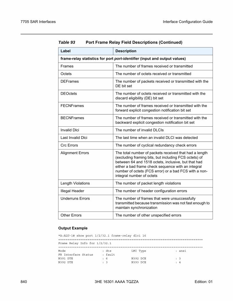
7705 SAR Interfaces
840
Interface Configuration Guide
3HE 16301 AAAA TQZZA Edition: 01
Output Example
*A:ALU-1# show port 1/2/32.1 frame-relay dlci 16===============================================================================Frame Relay Info for 1/2/32.1===============================================================================Mode : dte LMI Type : ansiFR Interface Status : faultN391 DTE : 6 N392 DCE : 3N392 DTE : 3 N393 DCE : 4
frame-relay statistics for port port-identifier (input and output values)
Frames The number of frames received or transmitted
Octets The number of octets received or transmitted
DEFrames The number of packets received or transmitted with the DE bit set
DEOctets The number of octets received or transmitted with the discard eligibility (DE) bit set
FECNFrames The number of frames received or transmitted with the forward explicit congestion notification bit set
BECNFrames The number of frames received or transmitted with the backward explicit congestion notification bit set
Invalid Dlci The number of invalid DLCIs
Last Invalid Dlci The last time when an invalid DLCI was detected
Crc Errors The number of cyclical redundancy check errors
Alignment Errors The total number of packets received that had a length (excluding framing bits, but including FCS octets) of between 64 and 1518 octets, inclusive, but that had either a bad frame check sequence with an integral number of octets (FCS error) or a bad FCS with a non-integral number of octets
Length Violations The number of packet length violations
Illegal Header The number of header configuration errors
Underruns Errors The number of frames that were unsuccessfully transmitted because transmission was not fast enough to maintain synchronization
Other Errors The number of other unspecified errors
Table 93 Port Frame Relay Field Descriptions (Continued)
Label Description
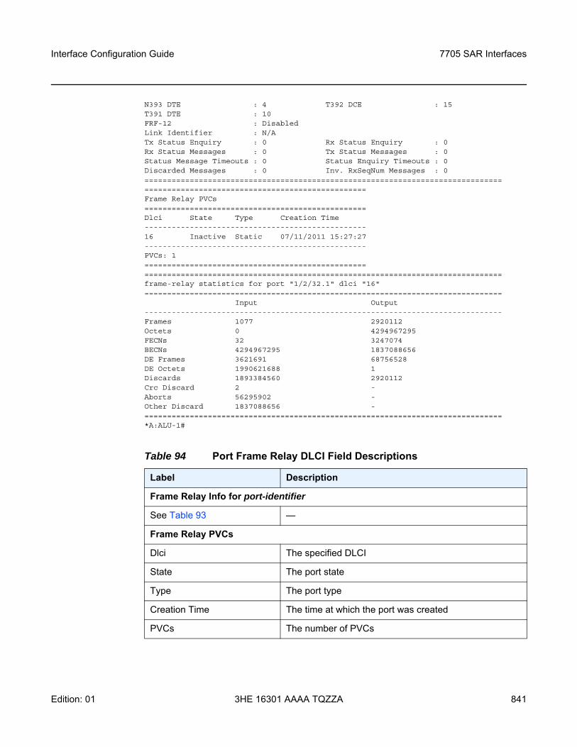
Interface Configuration Guide 7705 SAR Interfaces
Edition: 01 3HE 16301 AAAA TQZZA 841
N393 DTE : 4 T392 DCE : 15T391 DTE : 10FRF-12 : DisabledLink Identifier : N/ATx Status Enquiry : 0 Rx Status Enquiry : 0Rx Status Messages : 0 Tx Status Messages : 0Status Message Timeouts : 0 Status Enquiry Timeouts : 0Discarded Messages : 0 Inv. RxSeqNum Messages : 0================================================================================================================================Frame Relay PVCs=================================================Dlci State Type Creation Time-------------------------------------------------16 Inactive Static 07/11/2011 15:27:27-------------------------------------------------PVCs: 1================================================================================================================================frame-relay statistics for port "1/2/32.1" dlci "16"===============================================================================
Input Output-------------------------------------------------------------------------------Frames 1077 2920112Octets 0 4294967295FECNs 32 3247074BECNs 4294967295 1837088656DE Frames 3621691 68756528DE Octets 1990621688 1Discards 1893384560 2920112Crc Discard 2 -Aborts 56295902 -Other Discard 1837088656 -===============================================================================*A:ALU-1#
Table 94 Port Frame Relay DLCI Field Descriptions
Label Description
Frame Relay Info for port-identifier
See Table 93 —
Frame Relay PVCs
Dlci The specified DLCI
State The port state
Type The port type
Creation Time The time at which the port was created
PVCs The number of PVCs
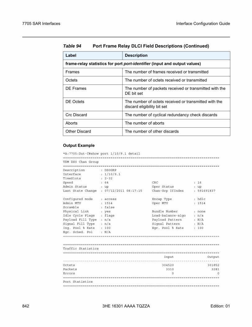
7705 SAR Interfaces
842
Interface Configuration Guide
3HE 16301 AAAA TQZZA Edition: 01
Output Example
*A:7705:Dut-C#show port 1/10/9.1 detail===============================================================================TDM DS0 Chan Group===============================================================================Description : DS0GRPInterface : 1/10/9.1TimeSlots : 2-32Speed : 64 CRC : 16Admin Status : up Oper Status : upLast State Change : 07/12/2011 08:17:15 Chan-Grp IfIndex : 591691837
Configured mode : access Encap Type : hdlcAdmin MTU : 1514 Oper MTU : 1514Scramble : falsePhysical Link : yes Bundle Number : noneIdle Cycle Flags : flags Load-balance-algo : n/aPayload Fill Type : n/a Payload Pattern : N/ASignal Fill Type : n/a Signal Pattern : N/AIng. Pool % Rate : 100 Egr. Pool % Rate : 100Egr. Sched. Pol : N/A===============================================================================
===============================================================================Traffic Statistics===============================================================================
Input Output-------------------------------------------------------------------------------Octets 304520 301852Packets 3310 3281Errors 0 0===============================================================================Port Statistics===============================================================================
frame-relay statistics for port port-identifier (input and output values)
Frames The number of frames received or transmitted
Octets The number of octets received or transmitted
DE Frames The number of packets received or transmitted with the DE bit set
DE Octets The number of octets received or transmitted with the discard eligibility bit set
Crc Discard The number of cyclical redundancy check discards
Aborts The number of aborts
Other Discard The number of other discards
Table 94 Port Frame Relay DLCI Field Descriptions (Continued)
Label Description
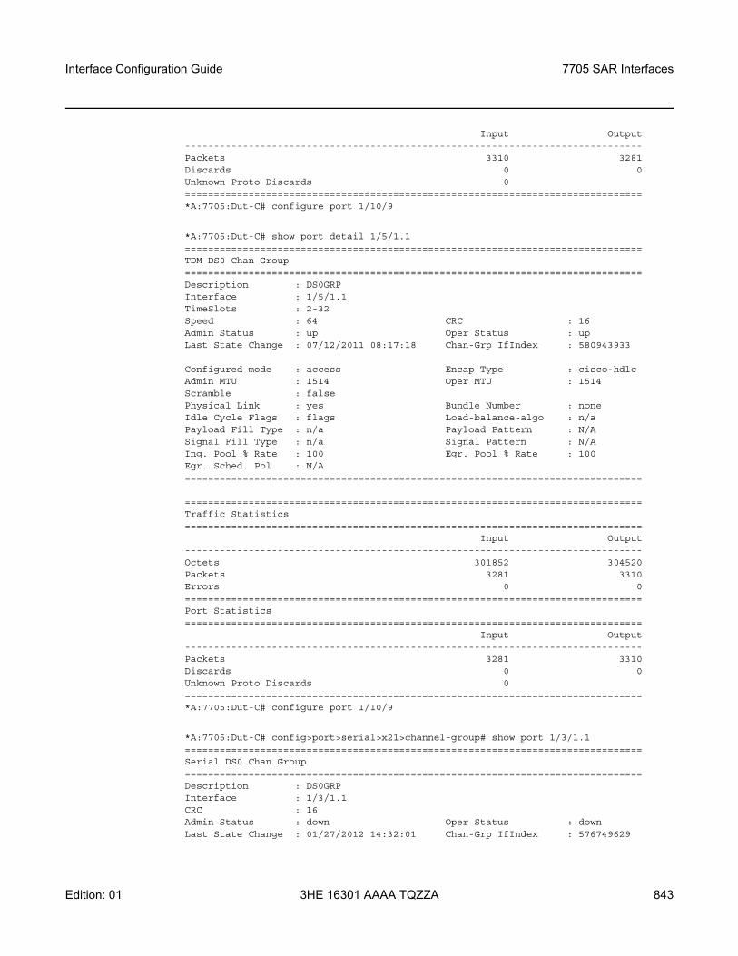
Interface Configuration Guide 7705 SAR Interfaces
Edition: 01 3HE 16301 AAAA TQZZA 843
Input Output-------------------------------------------------------------------------------Packets 3310 3281Discards 0 0Unknown Proto Discards 0===============================================================================*A:7705:Dut-C# configure port 1/10/9
*A:7705:Dut-C# show port detail 1/5/1.1===============================================================================TDM DS0 Chan Group===============================================================================Description : DS0GRPInterface : 1/5/1.1TimeSlots : 2-32Speed : 64 CRC : 16Admin Status : up Oper Status : upLast State Change : 07/12/2011 08:17:18 Chan-Grp IfIndex : 580943933
Configured mode : access Encap Type : cisco-hdlcAdmin MTU : 1514 Oper MTU : 1514Scramble : falsePhysical Link : yes Bundle Number : noneIdle Cycle Flags : flags Load-balance-algo : n/aPayload Fill Type : n/a Payload Pattern : N/ASignal Fill Type : n/a Signal Pattern : N/AIng. Pool % Rate : 100 Egr. Pool % Rate : 100Egr. Sched. Pol : N/A===============================================================================
===============================================================================Traffic Statistics===============================================================================
Input Output-------------------------------------------------------------------------------Octets 301852 304520Packets 3281 3310Errors 0 0===============================================================================Port Statistics===============================================================================
Input Output-------------------------------------------------------------------------------Packets 3281 3310Discards 0 0Unknown Proto Discards 0===============================================================================*A:7705:Dut-C# configure port 1/10/9
*A:7705:Dut-C# config>port>serial>x21>channel-group# show port 1/3/1.1===============================================================================Serial DS0 Chan Group===============================================================================Description : DS0GRPInterface : 1/3/1.1CRC : 16Admin Status : down Oper Status : downLast State Change : 01/27/2012 14:32:01 Chan-Grp IfIndex : 576749629
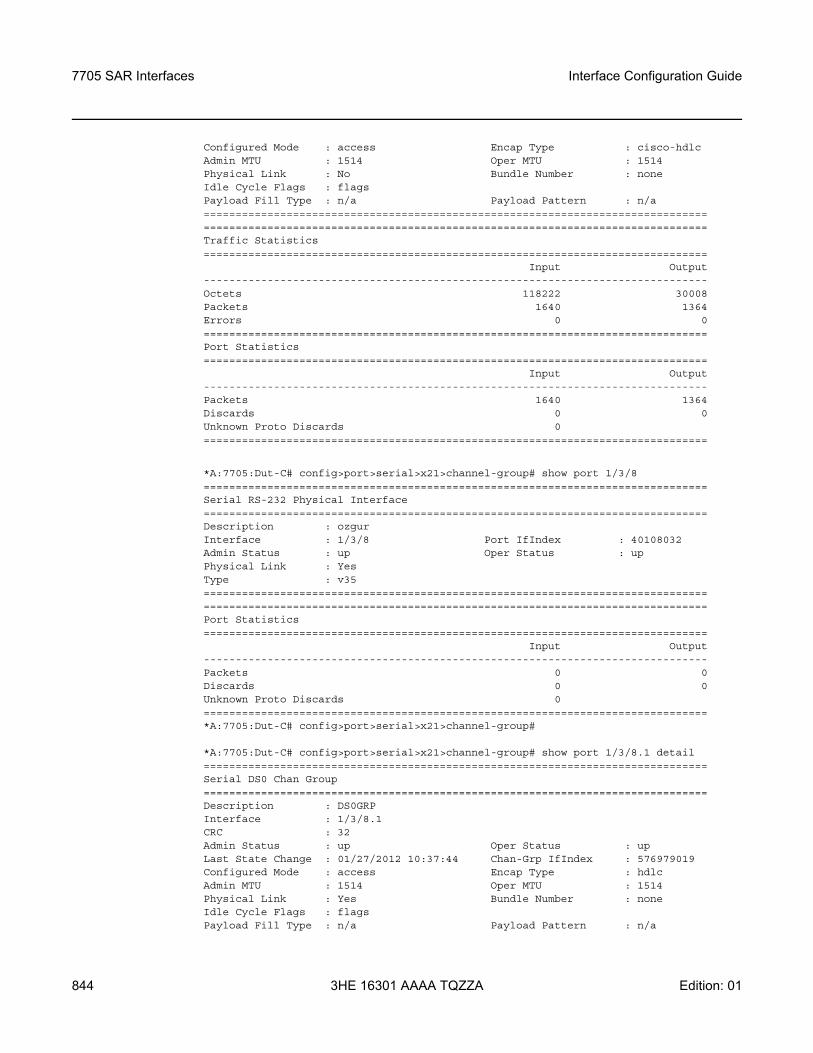
7705 SAR Interfaces
844
Interface Configuration Guide
3HE 16301 AAAA TQZZA Edition: 01
Configured Mode : access Encap Type : cisco-hdlcAdmin MTU : 1514 Oper MTU : 1514Physical Link : No Bundle Number : noneIdle Cycle Flags : flagsPayload Fill Type : n/a Payload Pattern : n/a==============================================================================================================================================================Traffic Statistics===============================================================================
Input Output-------------------------------------------------------------------------------Octets 118222 30008Packets 1640 1364Errors 0 0===============================================================================Port Statistics===============================================================================
Input Output-------------------------------------------------------------------------------Packets 1640 1364Discards 0 0Unknown Proto Discards 0===============================================================================
*A:7705:Dut-C# config>port>serial>x21>channel-group# show port 1/3/8===============================================================================Serial RS-232 Physical Interface===============================================================================Description : ozgurInterface : 1/3/8 Port IfIndex : 40108032Admin Status : up Oper Status : upPhysical Link : YesType : v35==============================================================================================================================================================Port Statistics===============================================================================
Input Output-------------------------------------------------------------------------------Packets 0 0Discards 0 0Unknown Proto Discards 0===============================================================================*A:7705:Dut-C# config>port>serial>x21>channel-group#
*A:7705:Dut-C# config>port>serial>x21>channel-group# show port 1/3/8.1 detail===============================================================================Serial DS0 Chan Group===============================================================================Description : DS0GRPInterface : 1/3/8.1CRC : 32Admin Status : up Oper Status : upLast State Change : 01/27/2012 10:37:44 Chan-Grp IfIndex : 576979019Configured Mode : access Encap Type : hdlcAdmin MTU : 1514 Oper MTU : 1514Physical Link : Yes Bundle Number : noneIdle Cycle Flags : flagsPayload Fill Type : n/a Payload Pattern : n/a
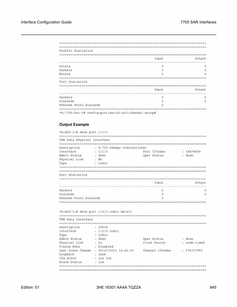
Interface Configuration Guide 7705 SAR Interfaces
Edition: 01 3HE 16301 AAAA TQZZA 845
==============================================================================================================================================================Traffic Statistics===============================================================================
Input Output-------------------------------------------------------------------------------Octets 0 0Packets 0 0Errors 0 0===============================================================================Port Statistics===============================================================================
Input Output-------------------------------------------------------------------------------Packets 0 0Discards 0 0Unknown Proto Discards 0===============================================================================*A:7705:Dut-C# config>port>serial>x21>channel-group#
Output Example
*A:ALU-1># show port 1/1/3===============================================================================TDM Data Physical Interface===============================================================================Description : G.703 64kbps CodirectionalInterface : 1/1/3 Port IfIndex : 39878656Admin Status : down Oper Status : downPhysical Link : NoType : codir==============================================================================================================================================================Port Statistics===============================================================================
Input Output-------------------------------------------------------------------------------Packets 0 0Discards 0 0Unknown Proto Discards 0===============================================================================
*A:ALU-1># show port 1/2/3.codir detail===============================================================================TDM Data Interface===============================================================================Description : CODIRInterface : 1/2/3.codirType : codirAdmin Status : down Oper Status : downPhysical Link : no Clock Source : node-timedTiming 8khz : DisabledLast State Change : 05/27/2013 12:42:10 Channel IfIndex : 574717955Loopback : noneCfg Alarm : ais losAlarm Status : los==============================================================================================================================================================
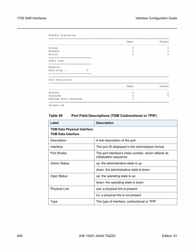
7705 SAR Interfaces
846
Interface Configuration Guide
3HE 16301 AAAA TQZZA Edition: 01
Traffic Statistics===============================================================================
Input Output-------------------------------------------------------------------------------Octets 0 0Packets 0 0Errors 0 0============================Codir Line============================Receive:Data-slip : 0===========================================================================================================Port Statistics===============================================================================
Input Output-------------------------------------------------------------------------------Packets 0 0Discards 0 0Unknown Proto Discards 0===============================================================================*A:ALU-1>#
Table 95 Port Field Descriptions (TDM Codirectional or TPIF)
Label Description
TDM Data Physical InterfaceTDM Data Interface
Description A text description of the port
Interface The port ID displayed in the slot/mda/port format
Port IfIndex The port interface's index number, which reflects its initialization sequence
Admin Status up: the administrative state is up
down: the administrative state is down
Oper Status up: the operating state is up
down: the operating state is down
Physical Link yes: a physical link is present
no: a physical link is not present
Type The type of interface: codirectional or TPIF
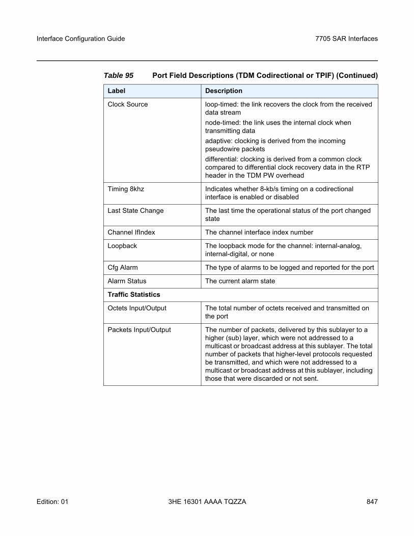
Interface Configuration Guide 7705 SAR Interfaces
Edition: 01 3HE 16301 AAAA TQZZA 847
Clock Source loop-timed: the link recovers the clock from the received data streamnode-timed: the link uses the internal clock when transmitting dataadaptive: clocking is derived from the incoming pseudowire packetsdifferential: clocking is derived from a common clock compared to differential clock recovery data in the RTP header in the TDM PW overhead
Timing 8khz Indicates whether 8-kb/s timing on a codirectional interface is enabled or disabled
Last State Change The last time the operational status of the port changed state
Channel IfIndex The channel interface index number
Loopback The loopback mode for the channel: internal-analog, internal-digital, or none
Cfg Alarm The type of alarms to be logged and reported for the port
Alarm Status The current alarm state
Traffic Statistics
Octets Input/Output The total number of octets received and transmitted on the port
Packets Input/Output The number of packets, delivered by this sublayer to a higher (sub) layer, which were not addressed to a multicast or broadcast address at this sublayer. The total number of packets that higher-level protocols requested be transmitted, and which were not addressed to a multicast or broadcast address at this sublayer, including those that were discarded or not sent.
Table 95 Port Field Descriptions (TDM Codirectional or TPIF) (Continued)
Label Description
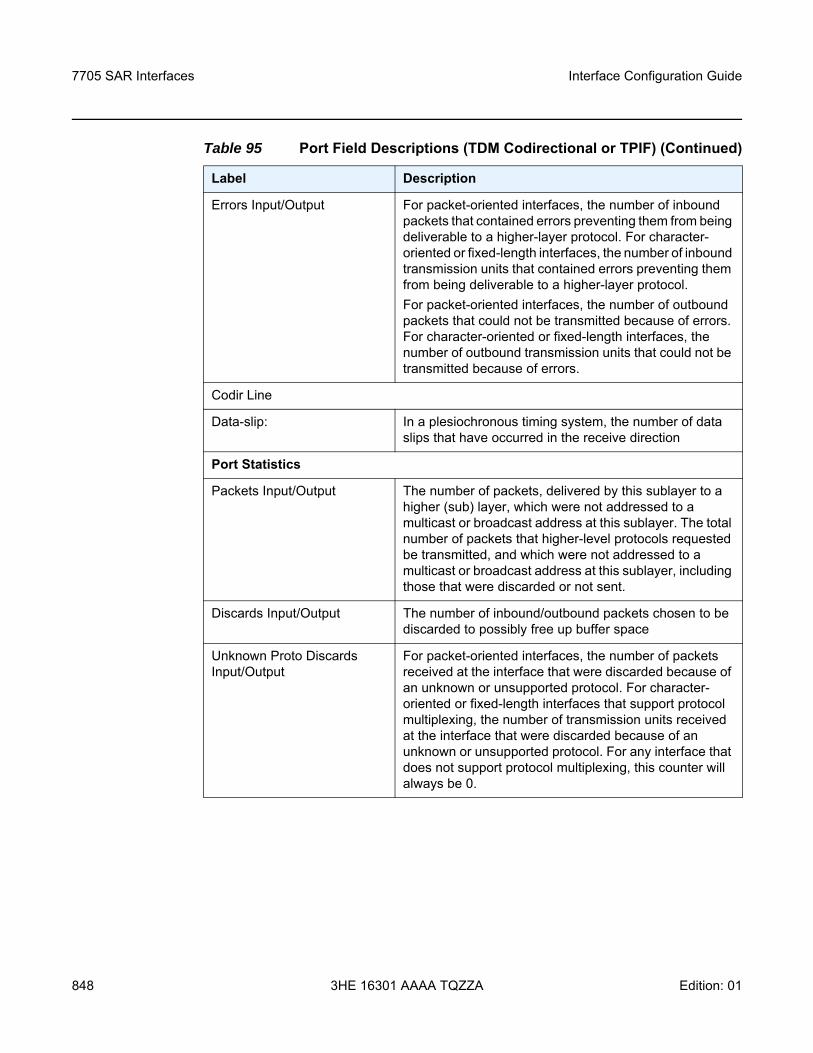
7705 SAR Interfaces
848
Interface Configuration Guide
3HE 16301 AAAA TQZZA Edition: 01
Errors Input/Output For packet-oriented interfaces, the number of inbound packets that contained errors preventing them from being deliverable to a higher-layer protocol. For character-oriented or fixed-length interfaces, the number of inbound transmission units that contained errors preventing them from being deliverable to a higher-layer protocol.For packet-oriented interfaces, the number of outbound packets that could not be transmitted because of errors. For character-oriented or fixed-length interfaces, the number of outbound transmission units that could not be transmitted because of errors.
Codir Line
Data-slip: In a plesiochronous timing system, the number of data slips that have occurred in the receive direction
Port Statistics
Packets Input/Output The number of packets, delivered by this sublayer to a higher (sub) layer, which were not addressed to a multicast or broadcast address at this sublayer. The total number of packets that higher-level protocols requested be transmitted, and which were not addressed to a multicast or broadcast address at this sublayer, including those that were discarded or not sent.
Discards Input/Output The number of inbound/outbound packets chosen to be discarded to possibly free up buffer space
Unknown Proto Discards Input/Output
For packet-oriented interfaces, the number of packets received at the interface that were discarded because of an unknown or unsupported protocol. For character-oriented or fixed-length interfaces that support protocol multiplexing, the number of transmission units received at the interface that were discarded because of an unknown or unsupported protocol. For any interface that does not support protocol multiplexing, this counter will always be 0.
Table 95 Port Field Descriptions (TDM Codirectional or TPIF) (Continued)
Label Description
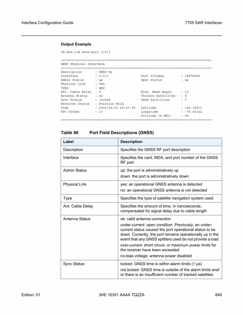
Interface Configuration Guide 7705 SAR Interfaces
Edition: 01 3HE 16301 AAAA TQZZA 849
Output Example
*A:ALU-1># show port 1/3/1
===============================================================================GNSS Physical Interface===============================================================================Description : GNSS RxInterface : 1/3/1 Port IfIndex : 39878656Admin Status : up Oper Status : upPhysical Link : YesType : gpsAnt. Cable Delay : 0 Elev. Mask Angle : 10Antenna Status : ok Visible Satellites : 9Sync Status : locked Used Satellites : 7Receiver Status : Position HoldTime : 2014/04/23 18:47:38 Latitude : +45.34811UTC Offset : 17 Longitude : -75.92142
Altitude (m MSL) : 90===============================================================================
Table 96 Port Field Descriptions (GNSS)
Label Description
Description Specifies the GNSS RF port description
Interface Specifies the card, MDA, and port number of the GNSS RF port
Admin Status up: the port is administratively updown: the port is administratively down
Physical Link yes: an operational GNSS antenna is detectedno: an operational GNSS antenna is not detected
Type Specifies the type of satellite navigation system used
Ant. Cable Delay Specifies the amount of time, in nanoseconds, compensated for signal delay due to cable length
Antenna Status ok: valid antenna connectionunder-current: open condition. Previously, an under-current status caused the port operational status to be down. Currently, the port remains operationally up in the event that any GNSS splitters used do not provide a load.over-current: short circuit, or maximum power limits for the receiver have been exceededno-bias voltage: antenna power disabled
Sync Status locked: GNSS time is within alarm limits (1 µs)not locked: GNSS time is outside of the alarm limits and/or there is an insufficient number of tracked satellites
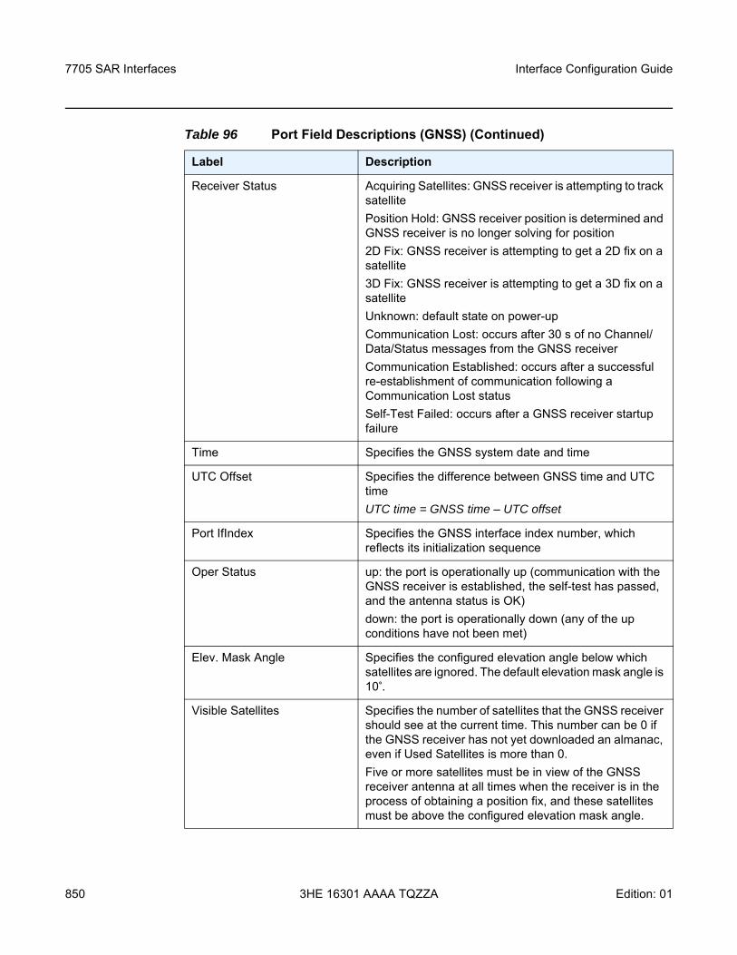
7705 SAR Interfaces
850
Interface Configuration Guide
3HE 16301 AAAA TQZZA Edition: 01
Receiver Status Acquiring Satellites: GNSS receiver is attempting to track satellitePosition Hold: GNSS receiver position is determined and GNSS receiver is no longer solving for position2D Fix: GNSS receiver is attempting to get a 2D fix on a satellite3D Fix: GNSS receiver is attempting to get a 3D fix on a satelliteUnknown: default state on power-upCommunication Lost: occurs after 30 s of no Channel/Data/Status messages from the GNSS receiverCommunication Established: occurs after a successful re-establishment of communication following a Communication Lost statusSelf-Test Failed: occurs after a GNSS receiver startup failure
Time Specifies the GNSS system date and time
UTC Offset Specifies the difference between GNSS time and UTC timeUTC time = GNSS time – UTC offset
Port IfIndex Specifies the GNSS interface index number, which reflects its initialization sequence
Oper Status up: the port is operationally up (communication with the GNSS receiver is established, the self-test has passed, and the antenna status is OK)down: the port is operationally down (any of the up conditions have not been met)
Elev. Mask Angle Specifies the configured elevation angle below which satellites are ignored. The default elevation mask angle is 10°.
Visible Satellites Specifies the number of satellites that the GNSS receiver should see at the current time. This number can be 0 if the GNSS receiver has not yet downloaded an almanac, even if Used Satellites is more than 0.Five or more satellites must be in view of the GNSS receiver antenna at all times when the receiver is in the process of obtaining a position fix, and these satellites must be above the configured elevation mask angle.
Table 96 Port Field Descriptions (GNSS) (Continued)
Label Description
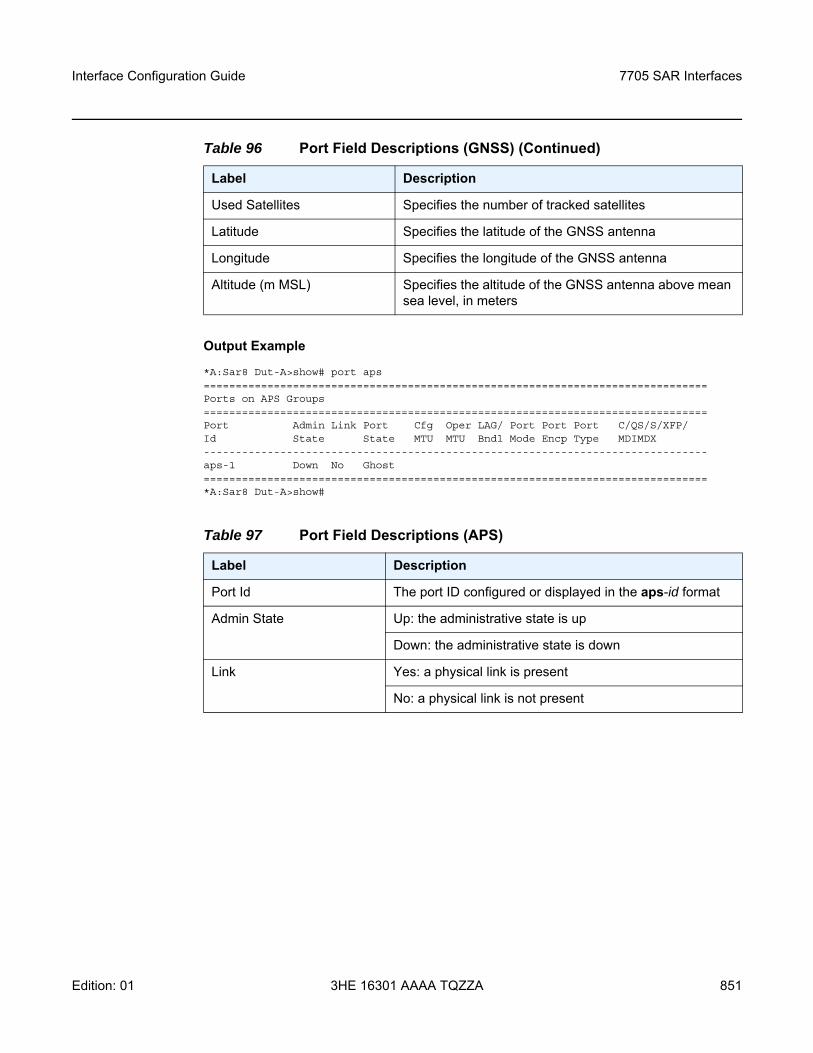
Interface Configuration Guide 7705 SAR Interfaces
Edition: 01 3HE 16301 AAAA TQZZA 851
Output Example
*A:Sar8 Dut-A>show# port aps===============================================================================Ports on APS Groups===============================================================================Port Admin Link Port Cfg Oper LAG/ Port Port Port C/QS/S/XFP/Id State State MTU MTU Bndl Mode Encp Type MDIMDX-------------------------------------------------------------------------------aps-1 Down No Ghost===============================================================================*A:Sar8 Dut-A>show#
Used Satellites Specifies the number of tracked satellites
Latitude Specifies the latitude of the GNSS antenna
Longitude Specifies the longitude of the GNSS antenna
Altitude (m MSL) Specifies the altitude of the GNSS antenna above mean sea level, in meters
Table 97 Port Field Descriptions (APS)
Label Description
Port Id The port ID configured or displayed in the aps-id format
Admin State Up: the administrative state is up
Down: the administrative state is down
Link Yes: a physical link is present
No: a physical link is not present
Table 96 Port Field Descriptions (GNSS) (Continued)
Label Description
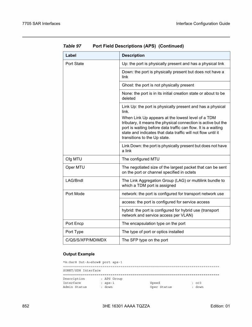
7705 SAR Interfaces
852
Interface Configuration Guide
3HE 16301 AAAA TQZZA Edition: 01
Output Example
*A:Sar8 Dut-A>show# port aps-1===============================================================================SONET/SDH Interface===============================================================================Description : APS GroupInterface : aps-1 Speed : oc3Admin Status : down Oper Status : down
Port State Up: the port is physically present and has a physical link
Down: the port is physically present but does not have a link
Ghost: the port is not physically present
None: the port is in its initial creation state or about to be deleted
Link Up: the port is physically present and has a physical link.When Link Up appears at the lowest level of a TDM tributary, it means the physical connection is active but the port is waiting before data traffic can flow. It is a waiting state and indicates that data traffic will not flow until it transitions to the Up state.
Link Down: the port is physically present but does not have a link
Cfg MTU The configured MTU
Oper MTU The negotiated size of the largest packet that can be sent on the port or channel specified in octets
LAG/Bndl The Link Aggregation Group (LAG) or multilink bundle to which a TDM port is assigned
Port Mode network: the port is configured for transport network use
access: the port is configured for service access
hybrid: the port is configured for hybrid use (transport network and service access per VLAN)
Port Encp The encapsulation type on the port
Port Type The type of port or optics installed
C/QS/S/XFP/MDIMDX The SFP type on the port
Table 97 Port Field Descriptions (APS) (Continued)
Label Description
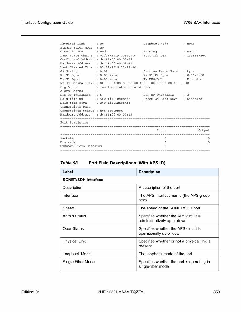
Interface Configuration Guide 7705 SAR Interfaces
Edition: 01 3HE 16301 AAAA TQZZA 853
Physical Link : No Loopback Mode : noneSingle Fiber Mode : NoClock Source : node Framing : sonetLast State Change : 01/09/2019 20:50:16 Port IfIndex : 1358987264Configured Address : d6:64:ff:00:02:49Hardware Address : d6:64:ff:00:02:49Last Cleared Time : 01/24/2019 21:33:06J0 String : 0x01 Section Trace Mode : byteRx S1 Byte : 0x00 (stu) Rx K1/K2 Byte : 0x00/0x00Tx S1 Byte : 0x00 (stu) Tx DUS/DNU : DisabledRx J0 String (Hex) : 00 00 00 00 00 00 00 00 00 00 00 00 00 00 00 00Cfg Alarm : loc lrdi lb2er-sf slof slosAlarm Status :BER SD Threshold : 6 BER SF Threshold : 3Hold time up : 500 milliseconds Reset On Path Down : DisabledHold time down : 200 millisecondsTransceiver DataTransceiver Status : not-equippedHardware Address : d6:64:ff:00:02:49===============================================================================Port Statistics===============================================================================
Input Output-------------------------------------------------------------------------------Packets 0 0Discards 0 0Unknown Proto Discards 0===============================================================================
Table 98 Port Field Descriptions (With APS ID)
Label Description
SONET/SDH Interface
Description A description of the port
Interface The APS interface name (the APS group port)
Speed The speed of the SONET/SDH port
Admin Status Specifies whether the APS circuit is administratively up or down
Oper Status Specifies whether the APS circuit is operationally up or down
Physical Link Specifies whether or not a physical link is present
Loopback Mode The loopback mode of the port
Single Fiber Mode Specifies whether the port is operating in single-fiber mode
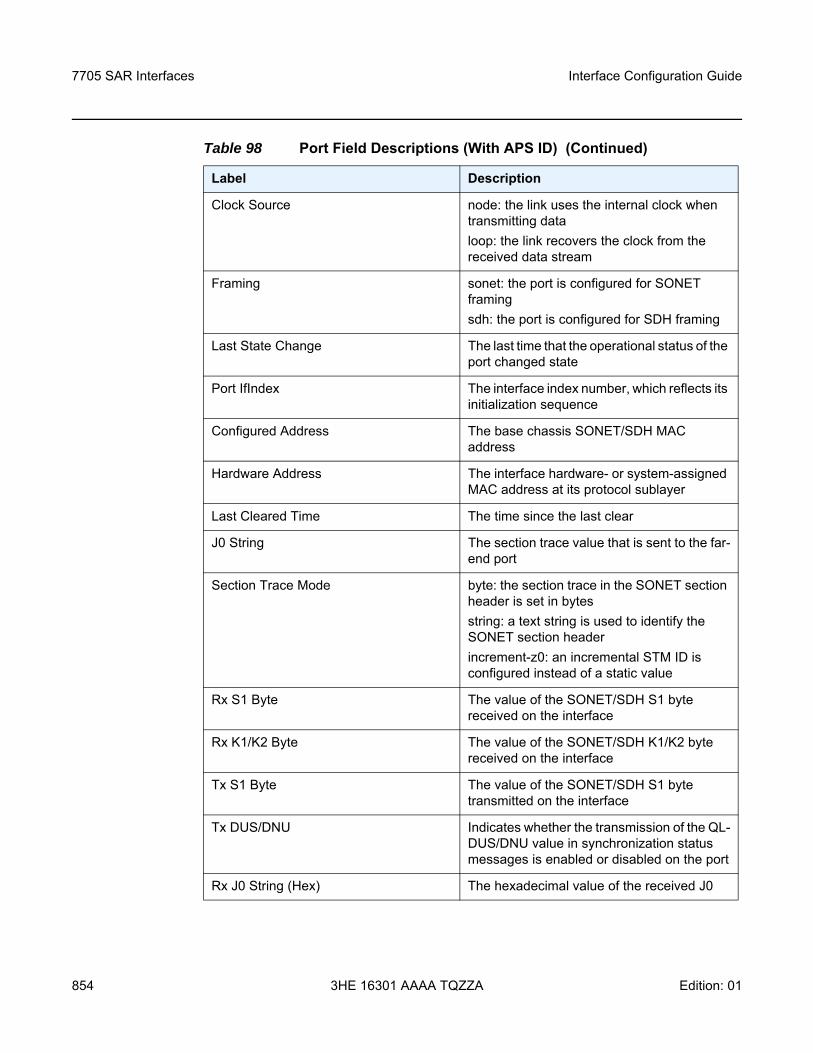
7705 SAR Interfaces
854
Interface Configuration Guide
3HE 16301 AAAA TQZZA Edition: 01
Clock Source node: the link uses the internal clock when transmitting dataloop: the link recovers the clock from the received data stream
Framing sonet: the port is configured for SONET framingsdh: the port is configured for SDH framing
Last State Change The last time that the operational status of the port changed state
Port IfIndex The interface index number, which reflects its initialization sequence
Configured Address The base chassis SONET/SDH MAC address
Hardware Address The interface hardware- or system-assigned MAC address at its protocol sublayer
Last Cleared Time The time since the last clear
J0 String The section trace value that is sent to the far-end port
Section Trace Mode byte: the section trace in the SONET section header is set in bytesstring: a text string is used to identify the SONET section headerincrement-z0: an incremental STM ID is configured instead of a static value
Rx S1 Byte The value of the SONET/SDH S1 byte received on the interface
Rx K1/K2 Byte The value of the SONET/SDH K1/K2 byte received on the interface
Tx S1 Byte The value of the SONET/SDH S1 byte transmitted on the interface
Tx DUS/DNU Indicates whether the transmission of the QL-DUS/DNU value in synchronization status messages is enabled or disabled on the port
Rx J0 String (Hex) The hexadecimal value of the received J0
Table 98 Port Field Descriptions (With APS ID) (Continued)
Label Description
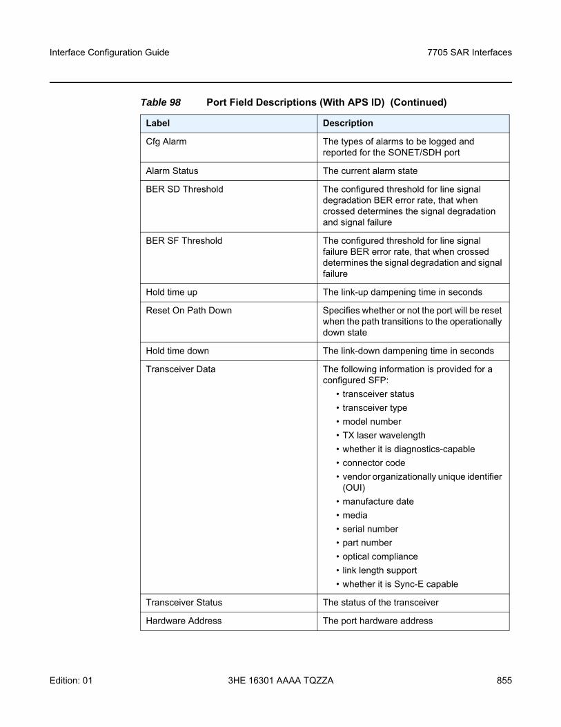
Interface Configuration Guide 7705 SAR Interfaces
Edition: 01 3HE 16301 AAAA TQZZA 855
Cfg Alarm The types of alarms to be logged and reported for the SONET/SDH port
Alarm Status The current alarm state
BER SD Threshold The configured threshold for line signal degradation BER error rate, that when crossed determines the signal degradation and signal failure
BER SF Threshold The configured threshold for line signal failure BER error rate, that when crossed determines the signal degradation and signal failure
Hold time up The link-up dampening time in seconds
Reset On Path Down Specifies whether or not the port will be reset when the path transitions to the operationally down state
Hold time down The link-down dampening time in seconds
Transceiver Data The following information is provided for a configured SFP:
• transceiver status• transceiver type• model number• TX laser wavelength• whether it is diagnostics-capable• connector code• vendor organizationally unique identifier
(OUI)• manufacture date• media• serial number• part number• optical compliance• link length support• whether it is Sync-E capable
Transceiver Status The status of the transceiver
Hardware Address The port hardware address
Table 98 Port Field Descriptions (With APS ID) (Continued)
Label Description
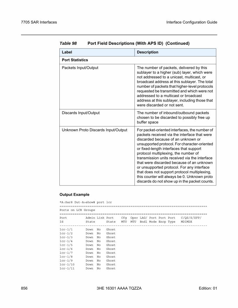
7705 SAR Interfaces
856
Interface Configuration Guide
3HE 16301 AAAA TQZZA Edition: 01
Output Example
*A:Sar8 Dut-A>show# port lcr===============================================================================Ports on LCR Groups===============================================================================Port Admin Link Port Cfg Oper LAG/ Port Port Port C/QS/S/XFP/Id State State MTU MTU Bndl Mode Encp Type MDIMDX-------------------------------------------------------------------------------lcr-1/1 Down No Ghostlcr-1/2 Down No Ghostlcr-1/3 Down No Ghostlcr-1/4 Down No Ghostlcr-1/5 Down No Ghostlcr-1/6 Down No Ghostlcr-1/7 Down No Ghostlcr-1/8 Down No Ghostlcr-1/9 Down No Ghostlcr-1/10 Down No Ghostlcr-1/11 Down No Ghost
Port Statistics
Packets Input/Output The number of packets, delivered by this sublayer to a higher (sub) layer, which were not addressed to a unicast, multicast, or broadcast address at this sublayer. The total number of packets that higher-level protocols requested be transmitted and which were not addressed to a multicast or broadcast address at this sublayer, including those that were discarded or not sent.
Discards Input/Output The number of inbound/outbound packets chosen to be discarded to possibly free up buffer space
Unknown Proto Discards Input/Output For packet-oriented interfaces, the number of packets received via the interface that were discarded because of an unknown or unsupported protocol. For character-oriented or fixed-length interfaces that support protocol multiplexing, the number of transmission units received via the interface that were discarded because of an unknown or unsupported protocol. For any interface that does not support protocol multiplexing, this counter will always be 0. Unknown proto discards do not show up in the packet counts.
Table 98 Port Field Descriptions (With APS ID) (Continued)
Label Description
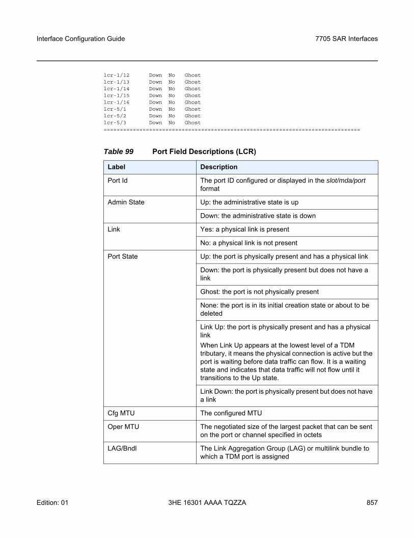
Interface Configuration Guide 7705 SAR Interfaces
Edition: 01 3HE 16301 AAAA TQZZA 857
lcr-1/12 Down No Ghostlcr-1/13 Down No Ghostlcr-1/14 Down No Ghostlcr-1/15 Down No Ghostlcr-1/16 Down No Ghostlcr-5/1 Down No Ghostlcr-5/2 Down No Ghostlcr-5/3 Down No Ghost===============================================================================
Table 99 Port Field Descriptions (LCR)
Label Description
Port Id The port ID configured or displayed in the slot/mda/port format
Admin State Up: the administrative state is up
Down: the administrative state is down
Link Yes: a physical link is present
No: a physical link is not present
Port State Up: the port is physically present and has a physical link
Down: the port is physically present but does not have a link
Ghost: the port is not physically present
None: the port is in its initial creation state or about to be deleted
Link Up: the port is physically present and has a physical linkWhen Link Up appears at the lowest level of a TDM tributary, it means the physical connection is active but the port is waiting before data traffic can flow. It is a waiting state and indicates that data traffic will not flow until it transitions to the Up state.
Link Down: the port is physically present but does not have a link
Cfg MTU The configured MTU
Oper MTU The negotiated size of the largest packet that can be sent on the port or channel specified in octets
LAG/Bndl The Link Aggregation Group (LAG) or multilink bundle to which a TDM port is assigned
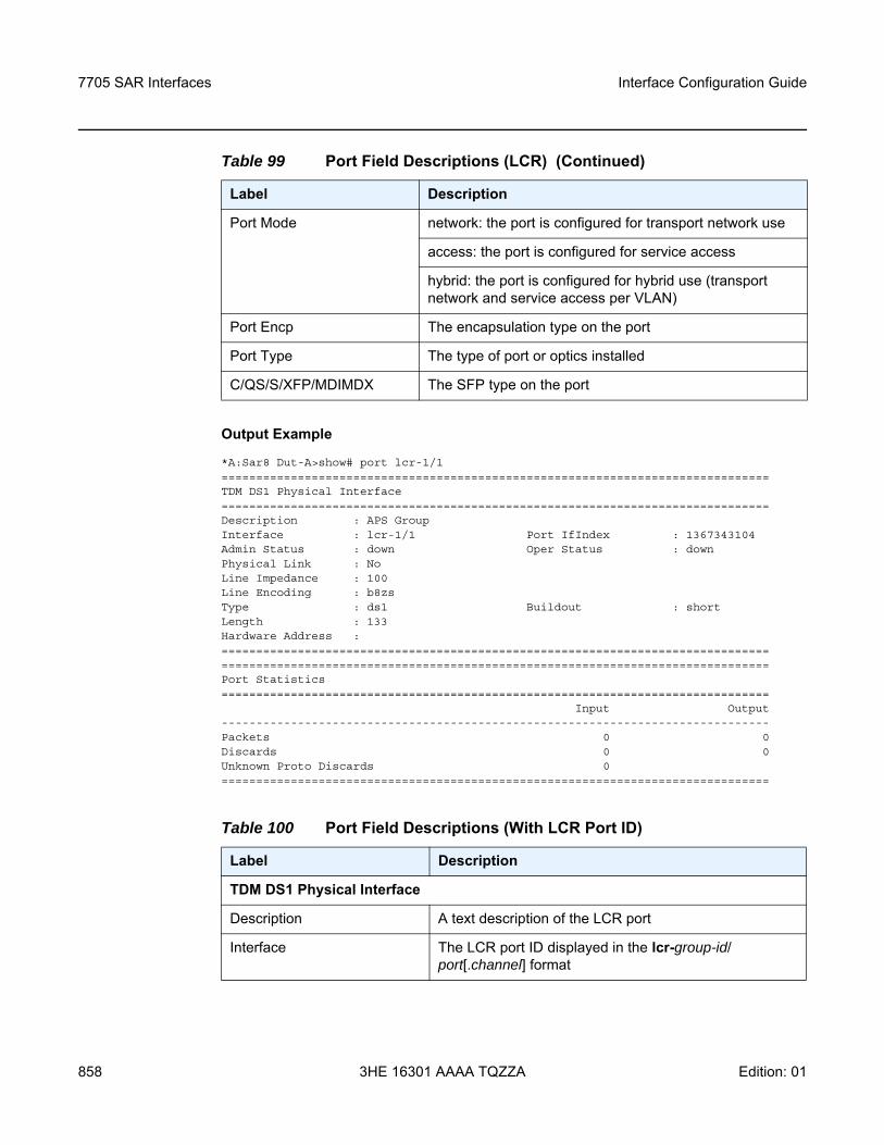
7705 SAR Interfaces
858
Interface Configuration Guide
3HE 16301 AAAA TQZZA Edition: 01
Output Example
*A:Sar8 Dut-A>show# port lcr-1/1===============================================================================TDM DS1 Physical Interface===============================================================================Description : APS GroupInterface : lcr-1/1 Port IfIndex : 1367343104Admin Status : down Oper Status : downPhysical Link : NoLine Impedance : 100Line Encoding : b8zsType : ds1 Buildout : shortLength : 133Hardware Address :==============================================================================================================================================================Port Statistics===============================================================================
Input Output-------------------------------------------------------------------------------Packets 0 0Discards 0 0Unknown Proto Discards 0===============================================================================
Port Mode network: the port is configured for transport network use
access: the port is configured for service access
hybrid: the port is configured for hybrid use (transport network and service access per VLAN)
Port Encp The encapsulation type on the port
Port Type The type of port or optics installed
C/QS/S/XFP/MDIMDX The SFP type on the port
Table 100 Port Field Descriptions (With LCR Port ID)
Label Description
TDM DS1 Physical Interface
Description A text description of the LCR port
Interface The LCR port ID displayed in the lcr-group-id/port[.channel] format
Table 99 Port Field Descriptions (LCR) (Continued)
Label Description
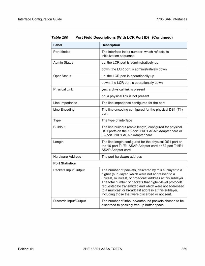
Interface Configuration Guide 7705 SAR Interfaces
Edition: 01 3HE 16301 AAAA TQZZA 859
Port Ifindex The interface index number, which reflects its initialization sequence
Admin Status up: the LCR port is administratively up
down: the LCR port is administratively down
Oper Status up: the LCR port is operationally up
down: the LCR port is operationally down
Physical Link yes: a physical link is present
no: a physical link is not present
Line Impedance The line impedance configured for the port
Line Encoding The line encoding configured for the physical DS1 (T1) port
Type The type of interface
Buildout The line buildout (cable length) configured for physical DS1 ports on the 16-port T1/E1 ASAP Adapter card or 32-port T1/E1 ASAP Adapter card
Length The line length configured for the physical DS1 port on the 16-port T1/E1 ASAP Adapter card or 32-port T1/E1 ASAP Adapter card
Hardware Address The port hardware address
Port Statistics
Packets Input/Output The number of packets, delivered by this sublayer to a higher (sub) layer, which were not addressed to a unicast, multicast, or broadcast address at this sublayer. The total number of packets that higher-level protocols requested be transmitted and which were not addressed to a multicast or broadcast address at this sublayer, including those that were discarded or not sent.
Discards Input/Output The number of inbound/outbound packets chosen to be discarded to possibly free up buffer space
Table 100 Port Field Descriptions (With LCR Port ID) (Continued)
Label Description
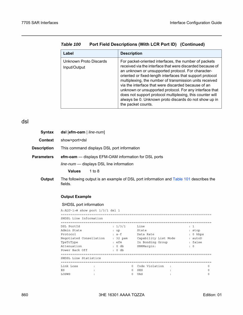
7705 SAR Interfaces
860
Interface Configuration Guide
3HE 16301 AAAA TQZZA Edition: 01
dsl
Syntax dsl [efm-oam | line-num]
Context show>port>dsl
Description This command displays DSL port information
Parameters efm-oam — displays EFM-OAM information for DSL ports
line-num — displays DSL line information
Values 1 to 8
Output The following output is an example of DSL port information and Table 101 describes the fields.
Output Example
SHDSL port informationA:ALU-1># show port 1/3/1 dsl 1===============================================================================SHDSL Line Information===============================================================================DSL PortId : 1/3/1 Line : 1Admin State : up State : stopProtocol : a-f Data Rate : 0 kbpsNegotiated Consellation : 32 pam Capability List Mode : autoDTpsTcType : efm In Bonding Group : falseAttenuation : 0 db SNRMargin: : 0Power Back Off : 0 db===============================================================================SHDSL Line Statistics===============================================================================Link Loss : 0 Code Violation : 0ES : 0 SES : 0LOSWS : 0 UAS : 0
Unknown Proto DiscardsInput/Output
For packet-oriented interfaces, the number of packets received via the interface that were discarded because of an unknown or unsupported protocol. For character-oriented or fixed-length interfaces that support protocol multiplexing, the number of transmission units received via the interface that were discarded because of an unknown or unsupported protocol. For any interface that does not support protocol multiplexing, this counter will always be 0. Unknown proto discards do not show up in the packet counts.
Table 100 Port Field Descriptions (With LCR Port ID) (Continued)
Label Description
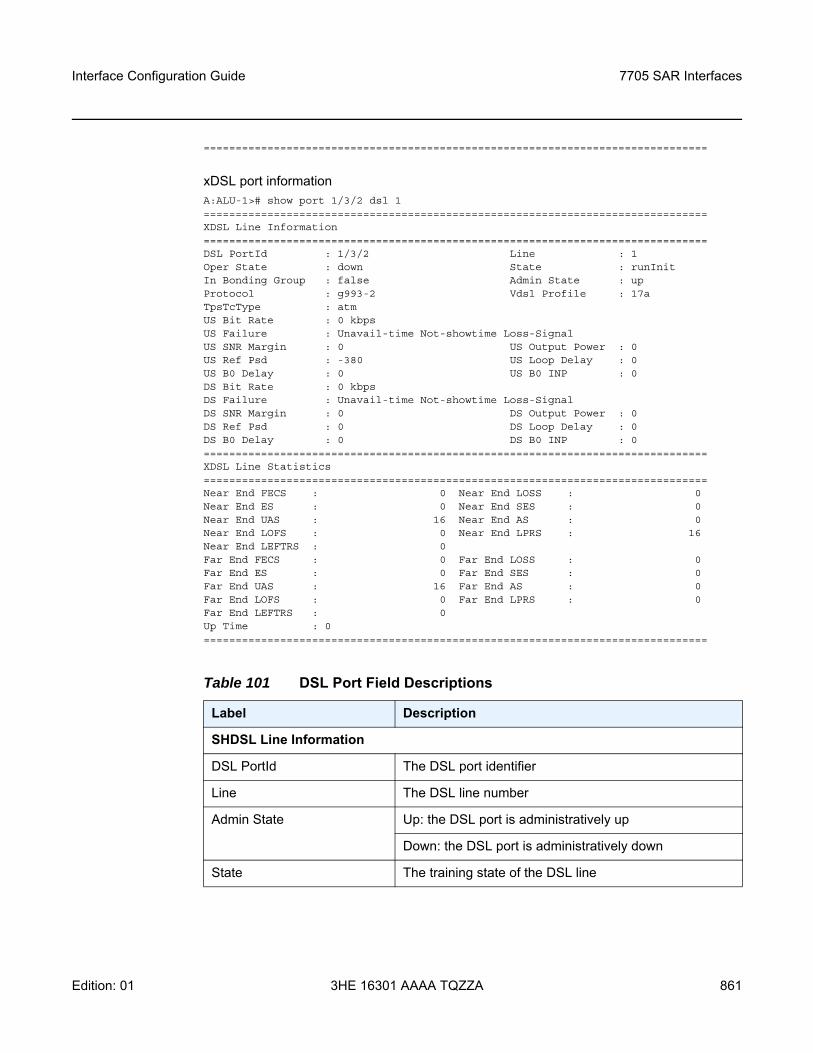
Interface Configuration Guide 7705 SAR Interfaces
Edition: 01 3HE 16301 AAAA TQZZA 861
===============================================================================
xDSL port informationA:ALU-1># show port 1/3/2 dsl 1===============================================================================XDSL Line Information===============================================================================DSL PortId : 1/3/2 Line : 1Oper State : down State : runInitIn Bonding Group : false Admin State : upProtocol : g993-2 Vdsl Profile : 17aTpsTcType : atmUS Bit Rate : 0 kbpsUS Failure : Unavail-time Not-showtime Loss-SignalUS SNR Margin : 0 US Output Power : 0US Ref Psd : -380 US Loop Delay : 0US B0 Delay : 0 US B0 INP : 0DS Bit Rate : 0 kbpsDS Failure : Unavail-time Not-showtime Loss-SignalDS SNR Margin : 0 DS Output Power : 0DS Ref Psd : 0 DS Loop Delay : 0DS B0 Delay : 0 DS B0 INP : 0===============================================================================XDSL Line Statistics===============================================================================Near End FECS : 0 Near End LOSS : 0Near End ES : 0 Near End SES : 0Near End UAS : 16 Near End AS : 0Near End LOFS : 0 Near End LPRS : 16Near End LEFTRS : 0Far End FECS : 0 Far End LOSS : 0Far End ES : 0 Far End SES : 0Far End UAS : 16 Far End AS : 0Far End LOFS : 0 Far End LPRS : 0Far End LEFTRS : 0Up Time : 0===============================================================================
Table 101 DSL Port Field Descriptions
Label Description
SHDSL Line Information
DSL PortId The DSL port identifier
Line The DSL line number
Admin State Up: the DSL port is administratively up
Down: the DSL port is administratively down
State The training state of the DSL line
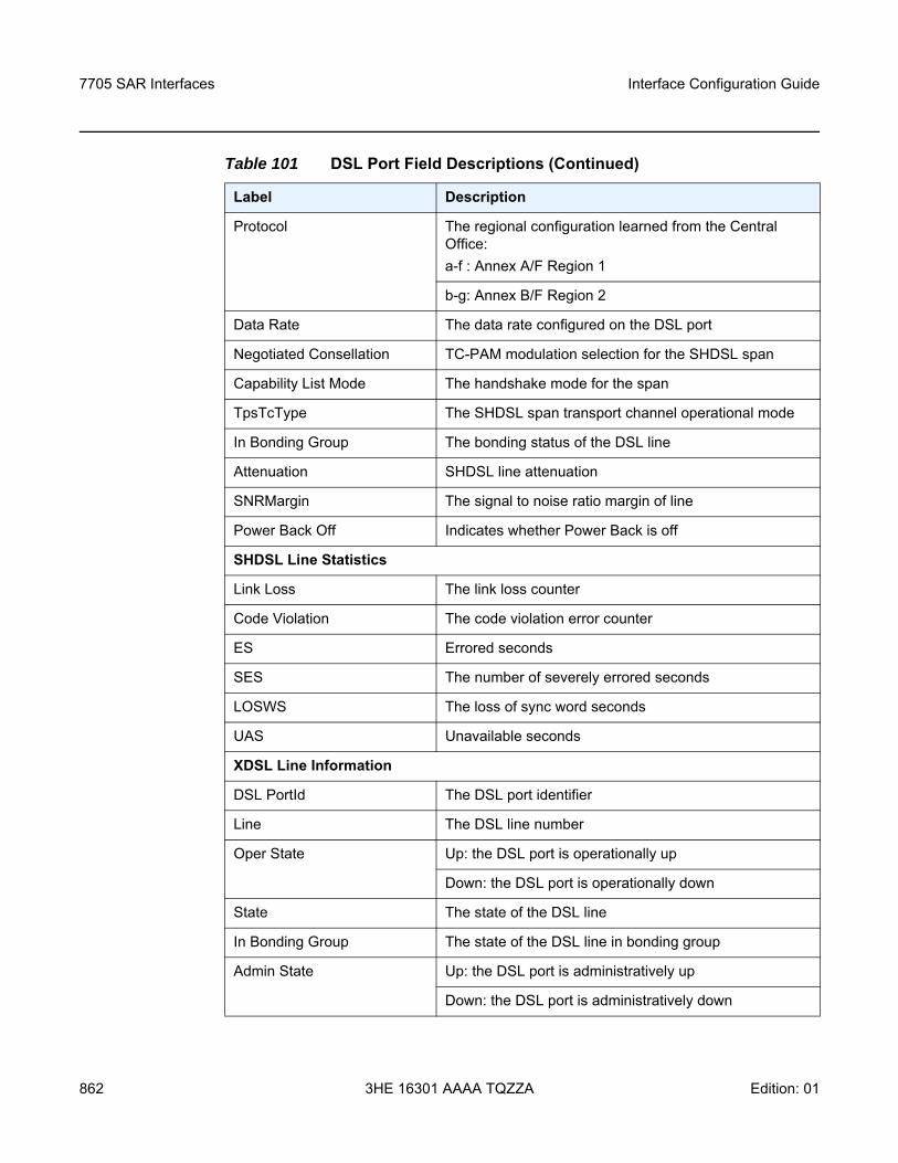
7705 SAR Interfaces
862
Interface Configuration Guide
3HE 16301 AAAA TQZZA Edition: 01
Protocol The regional configuration learned from the Central Office:a-f : Annex A/F Region 1
b-g: Annex B/F Region 2
Data Rate The data rate configured on the DSL port
Negotiated Consellation TC-PAM modulation selection for the SHDSL span
Capability List Mode The handshake mode for the span
TpsTcType The SHDSL span transport channel operational mode
In Bonding Group The bonding status of the DSL line
Attenuation SHDSL line attenuation
SNRMargin The signal to noise ratio margin of line
Power Back Off Indicates whether Power Back is off
SHDSL Line Statistics
Link Loss The link loss counter
Code Violation The code violation error counter
ES Errored seconds
SES The number of severely errored seconds
LOSWS The loss of sync word seconds
UAS Unavailable seconds
XDSL Line Information
DSL PortId The DSL port identifier
Line The DSL line number
Oper State Up: the DSL port is operationally up
Down: the DSL port is operationally down
State The state of the DSL line
In Bonding Group The state of the DSL line in bonding group
Admin State Up: the DSL port is administratively up
Down: the DSL port is administratively down
Table 101 DSL Port Field Descriptions (Continued)
Label Description
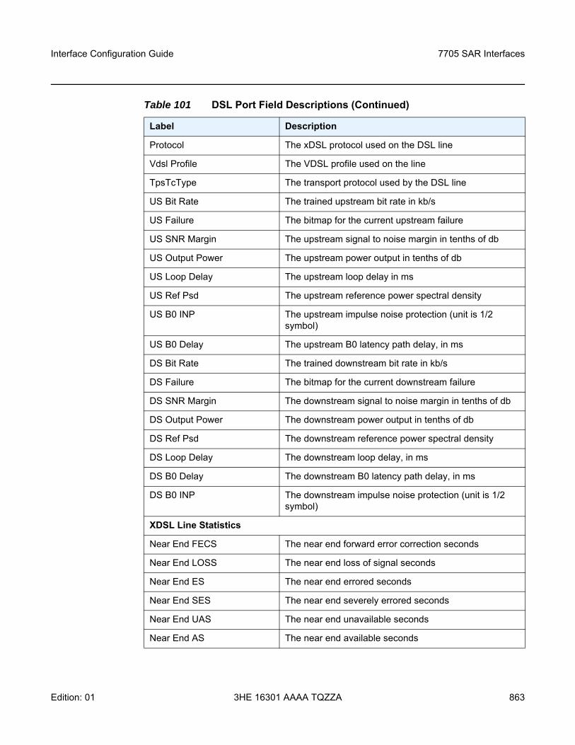
Interface Configuration Guide 7705 SAR Interfaces
Edition: 01 3HE 16301 AAAA TQZZA 863
Protocol The xDSL protocol used on the DSL line
Vdsl Profile The VDSL profile used on the line
TpsTcType The transport protocol used by the DSL line
US Bit Rate The trained upstream bit rate in kb/s
US Failure The bitmap for the current upstream failure
US SNR Margin The upstream signal to noise margin in tenths of db
US Output Power The upstream power output in tenths of db
US Loop Delay The upstream loop delay in ms
US Ref Psd The upstream reference power spectral density
US B0 INP The upstream impulse noise protection (unit is 1/2 symbol)
US B0 Delay The upstream B0 latency path delay, in ms
DS Bit Rate The trained downstream bit rate in kb/s
DS Failure The bitmap for the current downstream failure
DS SNR Margin The downstream signal to noise margin in tenths of db
DS Output Power The downstream power output in tenths of db
DS Ref Psd The downstream reference power spectral density
DS Loop Delay The downstream loop delay, in ms
DS B0 Delay The downstream B0 latency path delay, in ms
DS B0 INP The downstream impulse noise protection (unit is 1/2 symbol)
XDSL Line Statistics
Near End FECS The near end forward error correction seconds
Near End LOSS The near end loss of signal seconds
Near End ES The near end errored seconds
Near End SES The near end severely errored seconds
Near End UAS The near end unavailable seconds
Near End AS The near end available seconds
Table 101 DSL Port Field Descriptions (Continued)
Label Description
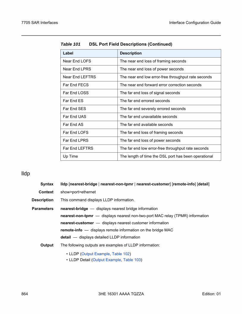
7705 SAR Interfaces
864
Interface Configuration Guide
3HE 16301 AAAA TQZZA Edition: 01
lldp
Syntax lldp [nearest-bridge | nearest-non-tpmr | nearest-customer] [remote-info] [detail]
Context show>port>ethernet
Description This command displays LLDP information.
Parameters nearest-bridge — displays nearest bridge information
nearest-non-tpmr — displays nearest non-two-port MAC relay (TPMR) information
nearest-customer — displays nearest customer information
remote-info — displays remote information on the bridge MAC
detail — displays detailed LLDP information
Output The following outputs are examples of LLDP information:
• LLDP (Output Example, Table 102)• LLDP Detail (Output Example, Table 103)
Near End LOFS The near end loss of framing seconds
Near End LPRS The near end loss of power seconds
Near End LEFTRS The near end low error-free throughput rate seconds
Far End FECS The near end forward error correction seconds
Far End LOSS The far end loss of signal seconds
Far End ES The far end errored seconds
Far End SES The far end severely errored seconds
Far End UAS The far end unavailable seconds
Far End AS The far end available seconds
Far End LOFS The far end loss of framing seconds
Far End LPRS The far end loss of power seconds
Far End LEFTRS The far end low error-free throughput rate seconds
Up Time The length of time the DSL port has been operational
Table 101 DSL Port Field Descriptions (Continued)
Label Description
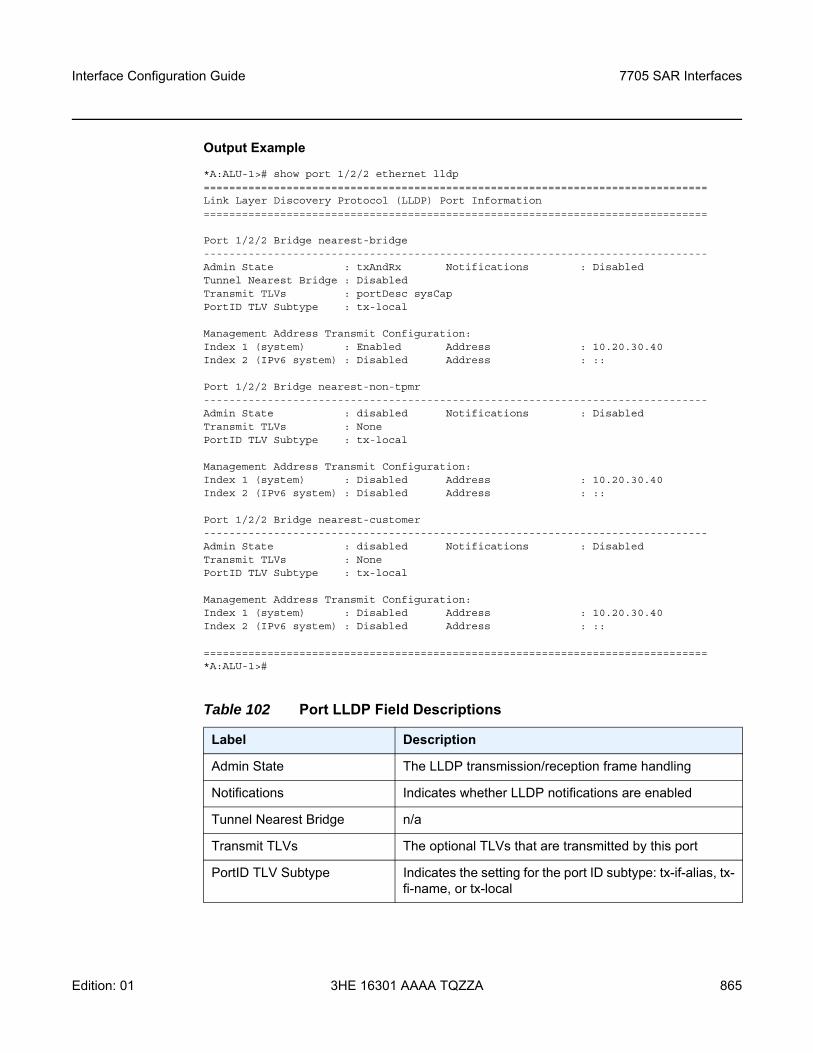
Interface Configuration Guide 7705 SAR Interfaces
Edition: 01 3HE 16301 AAAA TQZZA 865
Output Example
*A:ALU-1># show port 1/2/2 ethernet lldp===============================================================================Link Layer Discovery Protocol (LLDP) Port Information===============================================================================
Port 1/2/2 Bridge nearest-bridge-------------------------------------------------------------------------------Admin State : txAndRx Notifications : DisabledTunnel Nearest Bridge : DisabledTransmit TLVs : portDesc sysCapPortID TLV Subtype : tx-local
Management Address Transmit Configuration:Index 1 (system) : Enabled Address : 10.20.30.40Index 2 (IPv6 system) : Disabled Address : ::
Port 1/2/2 Bridge nearest-non-tpmr-------------------------------------------------------------------------------Admin State : disabled Notifications : DisabledTransmit TLVs : NonePortID TLV Subtype : tx-local
Management Address Transmit Configuration:Index 1 (system) : Disabled Address : 10.20.30.40Index 2 (IPv6 system) : Disabled Address : ::
Port 1/2/2 Bridge nearest-customer-------------------------------------------------------------------------------Admin State : disabled Notifications : DisabledTransmit TLVs : NonePortID TLV Subtype : tx-local
Management Address Transmit Configuration:Index 1 (system) : Disabled Address : 10.20.30.40Index 2 (IPv6 system) : Disabled Address : ::
===============================================================================*A:ALU-1>#
Table 102 Port LLDP Field Descriptions
Label Description
Admin State The LLDP transmission/reception frame handling
Notifications Indicates whether LLDP notifications are enabled
Tunnel Nearest Bridge n/a
Transmit TLVs The optional TLVs that are transmitted by this port
PortID TLV Subtype Indicates the setting for the port ID subtype: tx-if-alias, tx-fi-name, or tx-local
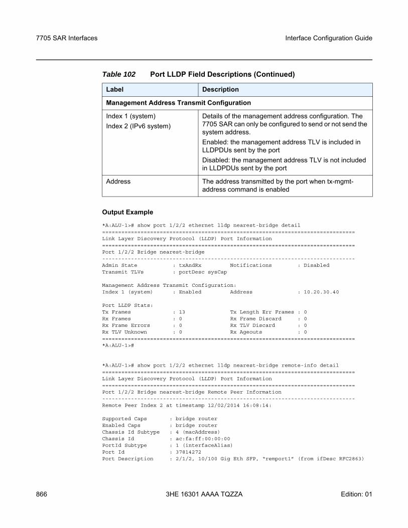
7705 SAR Interfaces
866
Interface Configuration Guide
3HE 16301 AAAA TQZZA Edition: 01
Output Example
*A:ALU-1># show port 1/2/2 ethernet lldp nearest-bridge detail===============================================================================Link Layer Discovery Protocol (LLDP) Port Information===============================================================================Port 1/2/2 Bridge nearest-bridge-------------------------------------------------------------------------------Admin State : txAndRx Notifications : DisabledTransmit TLVs : portDesc sysCap
Management Address Transmit Configuration:Index 1 (system) : Enabled Address : 10.20.30.40
Port LLDP Stats:Tx Frames : 13 Tx Length Err Frames : 0Rx Frames : 0 Rx Frame Discard : 0Rx Frame Errors : 0 Rx TLV Discard : 0Rx TLV Unknown : 0 Rx Ageouts : 0===============================================================================*A:ALU-1>#
*A:ALU-1># show port 1/2/2 ethernet lldp nearest-bridge remote-info detail===============================================================================Link Layer Discovery Protocol (LLDP) Port Information===============================================================================Port 1/2/2 Bridge nearest-bridge Remote Peer Information-------------------------------------------------------------------------------Remote Peer Index 2 at timestamp 12/02/2014 16:08:14:
Supported Caps : bridge routerEnabled Caps : bridge routerChassis Id Subtype : 4 (macAddress)Chassis Id : ac:fa:ff:00:00:00PortId Subtype : 1 (interfaceAlias)Port Id : 37814272Port Description : 2/1/2, 10/100 Gig Eth SFP, “remport1” (from ifDesc RFC2863)
Management Address Transmit Configuration
Index 1 (system)Index 2 (IPv6 system)
Details of the management address configuration. The 7705 SAR can only be configured to send or not send the system address.Enabled: the management address TLV is included in LLDPDUs sent by the portDisabled: the management address TLV is not included in LLDPDUs sent by the port
Address The address transmitted by the port when tx-mgmt-address command is enabled
Table 102 Port LLDP Field Descriptions (Continued)
Label Description
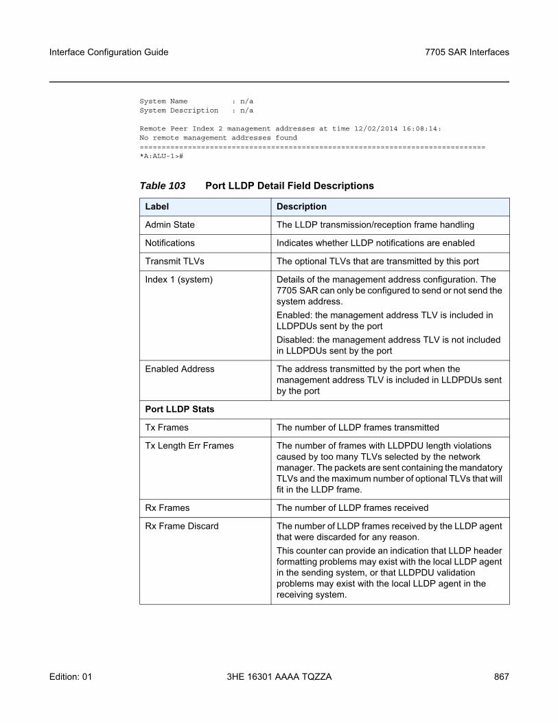
Interface Configuration Guide 7705 SAR Interfaces
Edition: 01 3HE 16301 AAAA TQZZA 867
System Name : n/aSystem Description : n/a
Remote Peer Index 2 management addresses at time 12/02/2014 16:08:14:No remote management addresses found===============================================================================*A:ALU-1>#
Table 103 Port LLDP Detail Field Descriptions
Label Description
Admin State The LLDP transmission/reception frame handling
Notifications Indicates whether LLDP notifications are enabled
Transmit TLVs The optional TLVs that are transmitted by this port
Index 1 (system) Details of the management address configuration. The 7705 SAR can only be configured to send or not send the system address.Enabled: the management address TLV is included in LLDPDUs sent by the portDisabled: the management address TLV is not included in LLDPDUs sent by the port
Enabled Address The address transmitted by the port when the management address TLV is included in LLDPDUs sent by the port
Port LLDP Stats
Tx Frames The number of LLDP frames transmitted
Tx Length Err Frames The number of frames with LLDPDU length violations caused by too many TLVs selected by the network manager. The packets are sent containing the mandatory TLVs and the maximum number of optional TLVs that will fit in the LLDP frame.
Rx Frames The number of LLDP frames received
Rx Frame Discard The number of LLDP frames received by the LLDP agent that were discarded for any reason.This counter can provide an indication that LLDP header formatting problems may exist with the local LLDP agent in the sending system, or that LLDPDU validation problems may exist with the local LLDP agent in the receiving system.
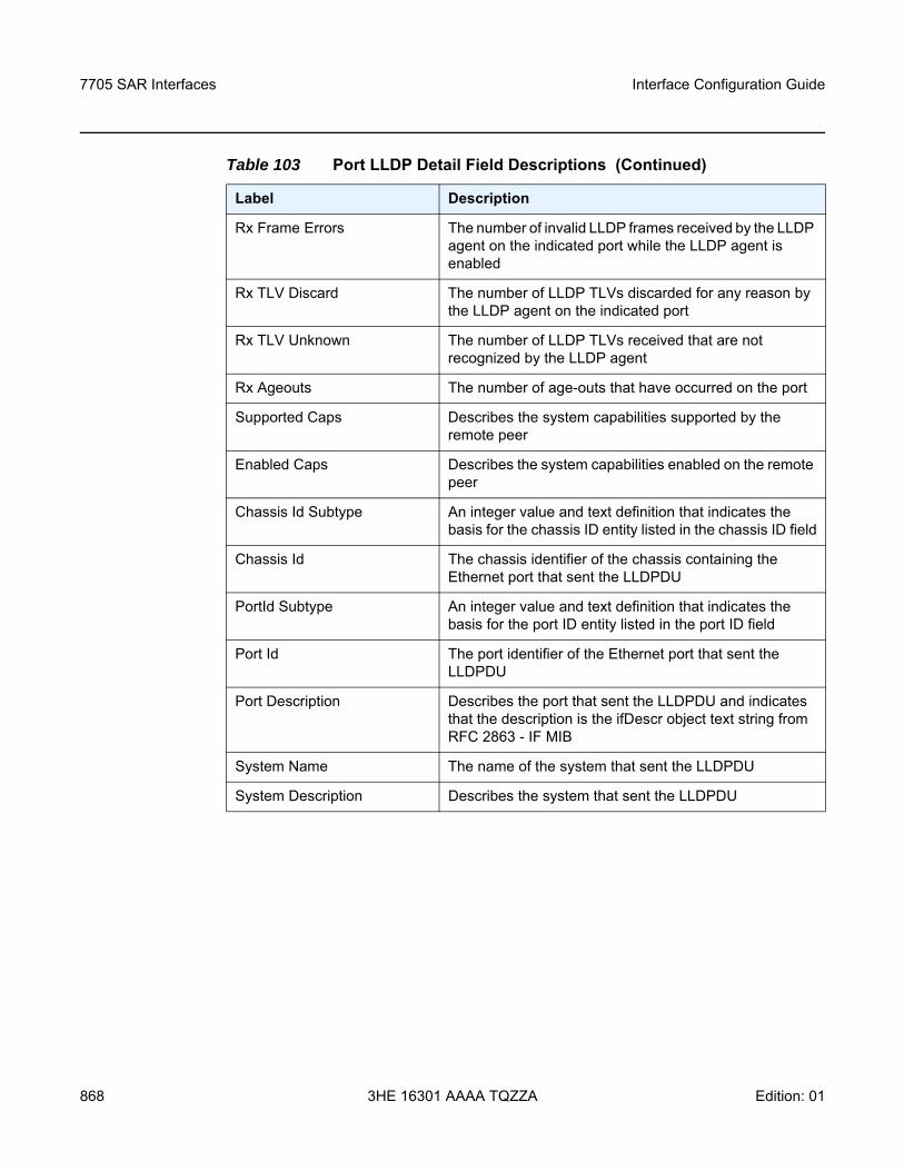
7705 SAR Interfaces
868
Interface Configuration Guide
3HE 16301 AAAA TQZZA Edition: 01
Rx Frame Errors The number of invalid LLDP frames received by the LLDP agent on the indicated port while the LLDP agent is enabled
Rx TLV Discard The number of LLDP TLVs discarded for any reason by the LLDP agent on the indicated port
Rx TLV Unknown The number of LLDP TLVs received that are not recognized by the LLDP agent
Rx Ageouts The number of age-outs that have occurred on the port
Supported Caps Describes the system capabilities supported by the remote peer
Enabled Caps Describes the system capabilities enabled on the remote peer
Chassis Id Subtype An integer value and text definition that indicates the basis for the chassis ID entity listed in the chassis ID field
Chassis Id The chassis identifier of the chassis containing the Ethernet port that sent the LLDPDU
PortId Subtype An integer value and text definition that indicates the basis for the port ID entity listed in the port ID field
Port Id The port identifier of the Ethernet port that sent the LLDPDU
Port Description Describes the port that sent the LLDPDU and indicates that the description is the ifDescr object text string from RFC 2863 - IF MIB
System Name The name of the system that sent the LLDPDU
System Description Describes the system that sent the LLDPDU
Table 103 Port LLDP Detail Field Descriptions (Continued)
Label Description
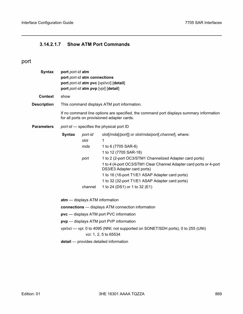
Interface Configuration Guide 7705 SAR Interfaces
Edition: 01 3HE 16301 AAAA TQZZA 869
3.14.2.1.7 Show ATM Port Commands
port
Syntax port port-id atmport port-id atm connectionsport port-id atm pvc [vpi/vci] [detail]port port-id atm pvp [vpi] [detail]
Context show
Description This command displays ATM port information.
If no command line options are specified, the command port displays summary information for all ports on provisioned adapter cards.
Parameters port-id — specifies the physical port ID
atm — displays ATM information
connections — displays ATM connection information
pvc — displays ATM port PVC information
pvp — displays ATM port PVP information
vpi/vci — vpi: 0 to 4095 (NNI; not supported on SONET/SDH ports), 0 to 255 (UNI)vci: 1, 2, 5 to 65534
detail — provides detailed information
Syntax port-id slot[/mda[/port]] or slot/mda/port[.channel], where:slot 1mda 1 to 6 (7705 SAR-8)
1 to 12 (7705 SAR-18)port 1 to 2 (2-port OC3/STM1 Channelized Adapter card ports)
1 to 4 (4-port OC3/STM1 Clear Channel Adapter card ports or 4-port DS3/E3 Adapter card ports)1 to 16 (16-port T1/E1 ASAP Adapter card ports)1 to 32 (32-port T1/E1 ASAP Adapter card ports)
channel 1 to 24 (DS1) or 1 to 32 (E1)
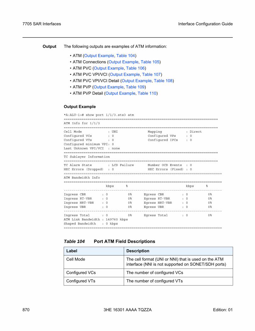
7705 SAR Interfaces
870
Interface Configuration Guide
3HE 16301 AAAA TQZZA Edition: 01
Output The following outputs are examples of ATM information:
• ATM (Output Example, Table 104)• ATM Connections (Output Example, Table 105)• ATM PVC (Output Example, Table 106)• ATM PVC VPI/VCI (Output Example, Table 107)• ATM PVC VPI/VCI Detail (Output Example, Table 108)• ATM PVP (Output Example, Table 109)• ATM PVP Detail (Output Example, Table 110)
Output Example
*A:ALU-1># show port 1/1/3.sts3 atm=============================================================================ATM Info for 1/1/3=============================================================================Cell Mode : UNI Mapping : DirectConfigured VCs : 0 Configured VPs : 0Configured VTs : 0 Configured IFCs : 0Configured minimum VPI: 0Last Unknown VPI/VCI : none=============================================================================TC Sublayer Information=============================================================================TC Alarm State : LCD Failure Number OCD Events : 0HEC Errors (Dropped) : 0 HEC Errors (Fixed) : 0===============================================================================ATM Bandwidth Info===============================================================================
kbps % kbps %-------------------------------------------------------------------------------Ingress CBR : 0 0% Egress CBR : 0 0%Ingress RT-VBR : 0 0% Egress RT-VBR : 0 0%Ingress NRT-VBR : 0 0% Egress NRT-VBR : 0 0%Ingress UBR : 0 0% Egress UBR : 0 0%-------------------------------------------------------------------------------Ingress Total : 0 0% Egress Total : 0 0%ATM Link Bandwidth : 149760 kbpsShaped Bandwidth : 0 kbps===============================================================================
Table 104 Port ATM Field Descriptions
Label Description
Cell Mode The cell format (UNI or NNI) that is used on the ATM interface (NNI is not supported on SONET/SDH ports)
Configured VCs The number of configured VCs
Configured VTs The number of configured VTs
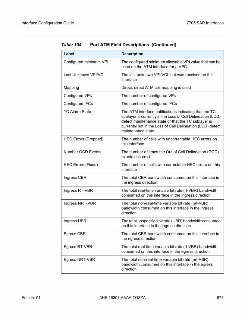
Interface Configuration Guide 7705 SAR Interfaces
Edition: 01 3HE 16301 AAAA TQZZA 871
Configured minimum VPI The configured minimum allowable VPI value that can be used on the ATM interface for a VPC
Last Unknown VPI/VCI The last unknown VPI/VCI that was received on this interface
Mapping Direct: direct ATM cell mapping is used
Configured VPs The number of configured VPs
Configured IFCs The number of configured IFCs
TC Alarm State The ATM interface notifications indicating that the TC sublayer is currently in the Loss of Cell Delineation (LCD) defect maintenance state or that the TC sublayer is currently not in the Loss of Cell Delineation (LCD) defect maintenance state
HEC Errors (Dropped) The number of cells with uncorrectable HEC errors on this interface
Number OCD Events The number of times the Out of Cell Delineation (OCD) events occurred
HEC Errors (Fixed) The number of cells with correctable HEC errors on this interface
Ingress CBR The total CBR bandwidth consumed on this interface in the ingress direction
Ingress RT-VBR The total real-time variable bit rate (rt-VBR) bandwidth consumed on this interface in the ingress direction
Ingress NRT-VBR The total non-real-time variable bit rate (nrt-VBR) bandwidth consumed on this interface in the ingress direction
Ingress UBR The total unspecified bit rate (UBR) bandwidth consumed on this interface in the ingress direction
Egress CBR The total CBR bandwidth consumed on this interface in the egress direction
Egress RT-VBR The total real-time variable bit rate (rt-VBR) bandwidth consumed on this interface in the egress direction
Egress NRT-VBR The total non-real-time variable bit rate (nrt-VBR) bandwidth consumed on this interface in the egress direction
Table 104 Port ATM Field Descriptions (Continued)
Label Description
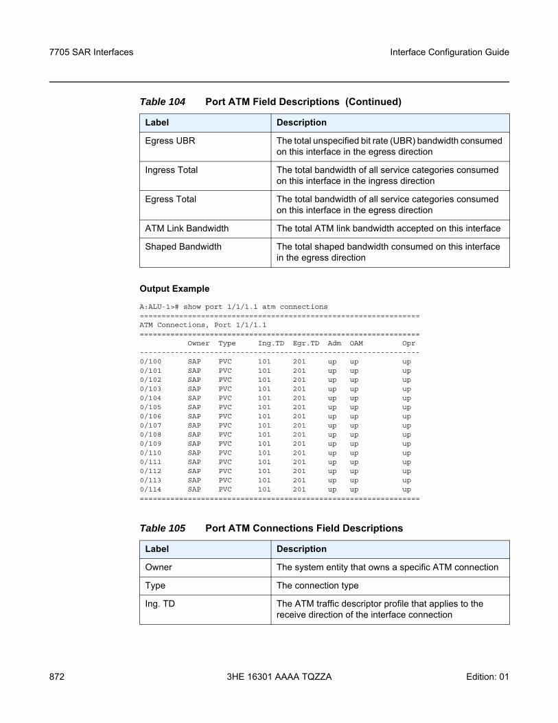
7705 SAR Interfaces
872
Interface Configuration Guide
3HE 16301 AAAA TQZZA Edition: 01
Output Example
A:ALU-1># show port 1/1/1.1 atm connections================================================================ATM Connections, Port 1/1/1.1================================================================
Owner Type Ing.TD Egr.TD Adm OAM Opr----------------------------------------------------------------0/100 SAP PVC 101 201 up up up0/101 SAP PVC 101 201 up up up0/102 SAP PVC 101 201 up up up0/103 SAP PVC 101 201 up up up0/104 SAP PVC 101 201 up up up0/105 SAP PVC 101 201 up up up0/106 SAP PVC 101 201 up up up0/107 SAP PVC 101 201 up up up0/108 SAP PVC 101 201 up up up0/109 SAP PVC 101 201 up up up0/110 SAP PVC 101 201 up up up0/111 SAP PVC 101 201 up up up0/112 SAP PVC 101 201 up up up0/113 SAP PVC 101 201 up up up0/114 SAP PVC 101 201 up up up================================================================
Egress UBR The total unspecified bit rate (UBR) bandwidth consumed on this interface in the egress direction
Ingress Total The total bandwidth of all service categories consumed on this interface in the ingress direction
Egress Total The total bandwidth of all service categories consumed on this interface in the egress direction
ATM Link Bandwidth The total ATM link bandwidth accepted on this interface
Shaped Bandwidth The total shaped bandwidth consumed on this interface in the egress direction
Table 105 Port ATM Connections Field Descriptions
Label Description
Owner The system entity that owns a specific ATM connection
Type The connection type
Ing. TD The ATM traffic descriptor profile that applies to the receive direction of the interface connection
Table 104 Port ATM Field Descriptions (Continued)
Label Description
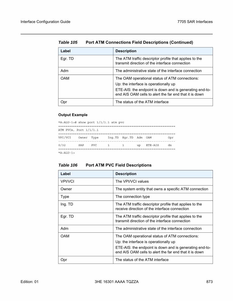
Interface Configuration Guide 7705 SAR Interfaces
Edition: 01 3HE 16301 AAAA TQZZA 873
Output Example
*A:ALU-1># show port 1/1/1.1 atm pvc================================================================ATM PVCs, Port 1/1/1.1================================================================VPI/VCI Owner Type Ing.TD Egr.TD Adm OAM Opr----------------------------------------------------------------0/32 SAP PVC 1 1 up ETE-AIS dn================================================================*A:ALU-1>
Egr. TD The ATM traffic descriptor profile that applies to the transmit direction of the interface connection
Adm The administrative state of the interface connection
OAM The OAM operational status of ATM connections:Up: the interface is operationally upETE-AIS: the endpoint is down and is generating end-to-end AIS OAM cells to alert the far end that it is down
Opr The status of the ATM interface
Table 106 Port ATM PVC Field Descriptions
Label Description
VPI/VCI The VPI/VCI values
Owner The system entity that owns a specific ATM connection
Type The connection type
Ing. TD The ATM traffic descriptor profile that applies to the receive direction of the interface connection
Egr. TD The ATM traffic descriptor profile that applies to the transmit direction of the interface connection
Adm The administrative state of the interface connection
OAM The OAM operational status of ATM connections:Up: the interface is operationally upETE-AIS: the endpoint is down and is generating end-to-end AIS OAM cells to alert the far end that it is down
Opr The status of the ATM interface
Table 105 Port ATM Connections Field Descriptions (Continued)
Label Description
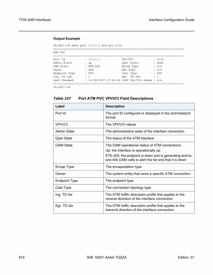
7705 SAR Interfaces
874
Interface Configuration Guide
3HE 16301 AAAA TQZZA Edition: 01
Output Example
*A:ALU-1># show port 1/1/1.1 atm pvc 0/32==============================================================================ATM PVC==============================================================================Port Id : 1/1/1.1 VPI/VCI : 0/32Admin State : up Oper state : downOAM State : ETE-AIS Encap Type : n/aOwner : SAP AAL Type : n/aEndpoint Type : PVC Cast Type : P2PIng. Td Idx : 1 Egr. Td Idx : 1Last Changed : 11/08/2007 17:02:36 ILMI Vpi/Vci Range : n/a==============================================================================*A:ALU-1>#
Table 107 Port ATM PVC VPI/VCI Field Descriptions
Label Description
Port Id The port ID configured or displayed in the slot/mda/port format
VPI/VCI The VPI/VCI values
Admin State The administrative state of the interface connection
Oper State The status of the ATM interface
OAM State The OAM operational status of ATM connections:Up: the interface is operationally upETE-AIS: the endpoint is down and is generating end-to-end AIS OAM cells to alert the far end that it is down
Encap Type The encapsulation type
Owner The system entity that owns a specific ATM connection
Endpoint Type The endpoint type
Cast Type The connection topology type
Ing. TD Idx The ATM traffic descriptor profile that applies to the receive direction of the interface connection
Egr. TD Idx The ATM traffic descriptor profile that applies to the transmit direction of the interface connection
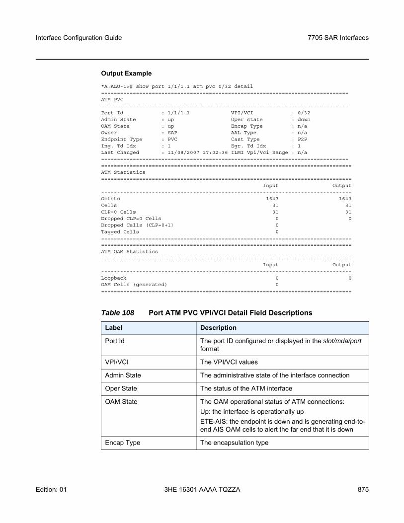
Interface Configuration Guide 7705 SAR Interfaces
Edition: 01 3HE 16301 AAAA TQZZA 875
Output Example
*A:ALU-1># show port 1/1/1.1 atm pvc 0/32 detail==============================================================================ATM PVC==============================================================================Port Id : 1/1/1.1 VPI/VCI : 0/32Admin State : up Oper state : downOAM State : up Encap Type : n/aOwner : SAP AAL Type : n/aEndpoint Type : PVC Cast Type : P2PIng. Td Idx : 1 Egr. Td Idx : 1Last Changed : 11/08/2007 17:02:36 ILMI Vpi/Vci Range : n/a=============================================================================================================================================================ATM Statistics===============================================================================
Input Output-------------------------------------------------------------------------------Octets 1643 1643Cells 31 31CLP=0 Cells 31 31Dropped CLP=0 Cells 0 0Dropped Cells (CLP=0+1) 0Tagged Cells 0==============================================================================================================================================================ATM OAM Statistics===============================================================================
Input Output-------------------------------------------------------------------------------Loopback 0 0OAM Cells (generated) 0===============================================================================
Table 108 Port ATM PVC VPI/VCI Detail Field Descriptions
Label Description
Port Id The port ID configured or displayed in the slot/mda/port format
VPI/VCI The VPI/VCI values
Admin State The administrative state of the interface connection
Oper State The status of the ATM interface
OAM State The OAM operational status of ATM connections:Up: the interface is operationally upETE-AIS: the endpoint is down and is generating end-to-end AIS OAM cells to alert the far end that it is down
Encap Type The encapsulation type
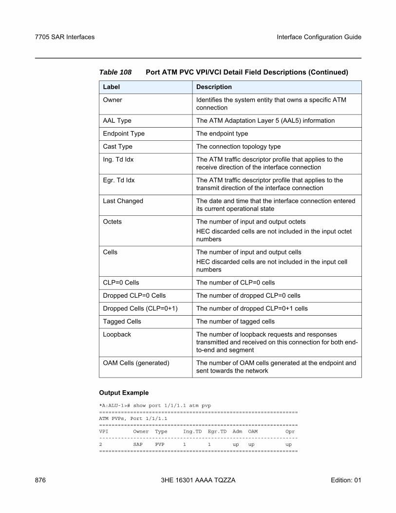
7705 SAR Interfaces
876
Interface Configuration Guide
3HE 16301 AAAA TQZZA Edition: 01
Output Example
*A:ALU-1># show port 1/1/1.1 atm pvp================================================================ATM PVPs, Port 1/1/1.1================================================================VPI Owner Type Ing.TD Egr.TD Adm OAM Opr----------------------------------------------------------------2 SAP PVP 1 1 up up up================================================================
Owner Identifies the system entity that owns a specific ATM connection
AAL Type The ATM Adaptation Layer 5 (AAL5) information
Endpoint Type The endpoint type
Cast Type The connection topology type
Ing. Td Idx The ATM traffic descriptor profile that applies to the receive direction of the interface connection
Egr. Td Idx The ATM traffic descriptor profile that applies to the transmit direction of the interface connection
Last Changed The date and time that the interface connection entered its current operational state
Octets The number of input and output octetsHEC discarded cells are not included in the input octet numbers
Cells The number of input and output cellsHEC discarded cells are not included in the input cell numbers
CLP=0 Cells The number of CLP=0 cells
Dropped CLP=0 Cells The number of dropped CLP=0 cells
Dropped Cells (CLP=0+1) The number of dropped CLP=0+1 cells
Tagged Cells The number of tagged cells
Loopback The number of loopback requests and responses transmitted and received on this connection for both end-to-end and segment
OAM Cells (generated) The number of OAM cells generated at the endpoint and sent towards the network
Table 108 Port ATM PVC VPI/VCI Detail Field Descriptions (Continued)
Label Description
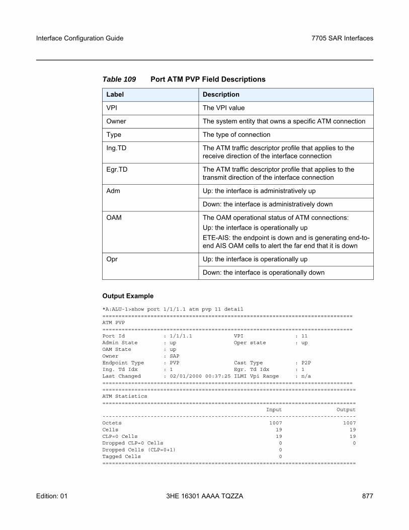
Interface Configuration Guide 7705 SAR Interfaces
Edition: 01 3HE 16301 AAAA TQZZA 877
Output Example
*A:ALU-1>show port 1/1/1.1 atm pvp 11 detail==============================================================================ATM PVP==============================================================================Port Id : 1/1/1.1 VPI : 11Admin State : up Oper state : upOAM State : upOwner : SAPEndpoint Type : PVP Cast Type : P2PIng. Td Idx : 1 Egr. Td Idx : 1Last Changed : 02/01/2000 00:37:25 ILMI Vpi Range : n/a=============================================================================================================================================================ATM Statistics===============================================================================
Input Output-------------------------------------------------------------------------------Octets 1007 1007Cells 19 19CLP=0 Cells 19 19Dropped CLP=0 Cells 0 0Dropped Cells (CLP=0+1) 0Tagged Cells 0===============================================================================
Table 109 Port ATM PVP Field Descriptions
Label Description
VPI The VPI value
Owner The system entity that owns a specific ATM connection
Type The type of connection
Ing.TD The ATM traffic descriptor profile that applies to the receive direction of the interface connection
Egr.TD The ATM traffic descriptor profile that applies to the transmit direction of the interface connection
Adm Up: the interface is administratively up
Down: the interface is administratively down
OAM The OAM operational status of ATM connections:Up: the interface is operationally upETE-AIS: the endpoint is down and is generating end-to-end AIS OAM cells to alert the far end that it is down
Opr Up: the interface is operationally up
Down: the interface is operationally down
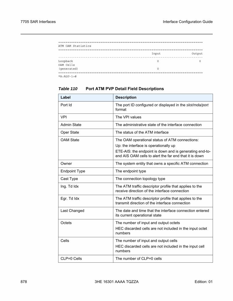
7705 SAR Interfaces
878
Interface Configuration Guide
3HE 16301 AAAA TQZZA Edition: 01
===============================================================================ATM OAM Statistics===============================================================================
Input Output-------------------------------------------------------------------------------Loopback 0 0OAM Cells(generated) 0===============================================================================*A:ALU-1>#
Table 110 Port ATM PVP Detail Field Descriptions
Label Description
Port Id The port ID configured or displayed in the slot/mda/port format
VPI The VPI values
Admin State The administrative state of the interface connection
Oper State The status of the ATM interface
OAM State The OAM operational status of ATM connections:Up: the interface is operationally upETE-AIS: the endpoint is down and is generating end-to-end AIS OAM cells to alert the far end that it is down
Owner The system entity that owns a specific ATM connection
Endpoint Type The endpoint type
Cast Type The connection topology type
Ing. Td Idx The ATM traffic descriptor profile that applies to the receive direction of the interface connection
Egr. Td Idx The ATM traffic descriptor profile that applies to the transmit direction of the interface connection
Last Changed The date and time that the interface connection entered its current operational state
Octets The number of input and output octetsHEC discarded cells are not included in the input octet numbers
Cells The number of input and output cellsHEC discarded cells are not included in the input cell numbers
CLP=0 Cells The number of CLP=0 cells
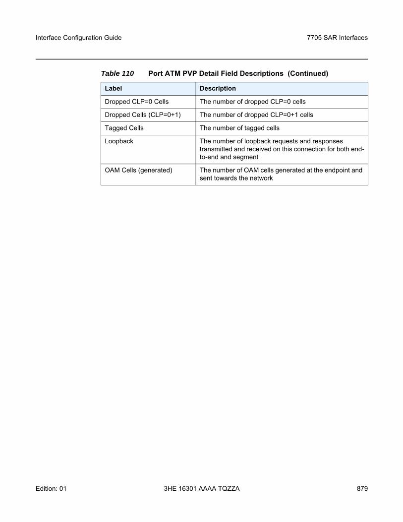
Interface Configuration Guide 7705 SAR Interfaces
Edition: 01 3HE 16301 AAAA TQZZA 879
Dropped CLP=0 Cells The number of dropped CLP=0 cells
Dropped Cells (CLP=0+1) The number of dropped CLP=0+1 cells
Tagged Cells The number of tagged cells
Loopback The number of loopback requests and responses transmitted and received on this connection for both end-to-end and segment
OAM Cells (generated) The number of OAM cells generated at the endpoint and sent towards the network
Table 110 Port ATM PVP Detail Field Descriptions (Continued)
Label Description
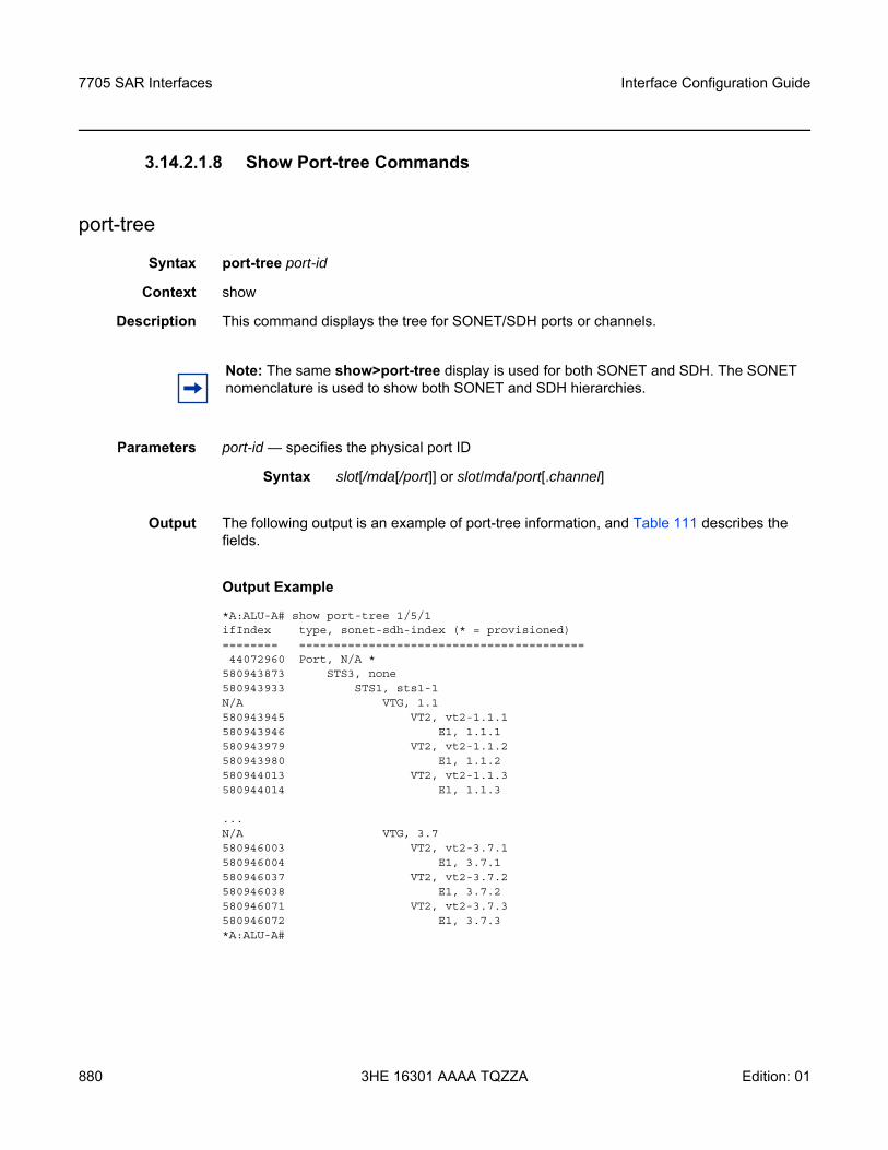
7705 SAR Interfaces
880
Interface Configuration Guide
3HE 16301 AAAA TQZZA Edition: 01
3.14.2.1.8 Show Port-tree Commands
port-tree
Syntax port-tree port-id
Context show
Description This command displays the tree for SONET/SDH ports or channels.
Parameters port-id — specifies the physical port ID
Output The following output is an example of port-tree information, and Table 111 describes the fields.
Output Example
*A:ALU-A# show port-tree 1/5/1ifIndex type, sonet-sdh-index (* = provisioned)======== =========================================44072960 Port, N/A *
580943873 STS3, none580943933 STS1, sts1-1N/A VTG, 1.1580943945 VT2, vt2-1.1.1580943946 E1, 1.1.1580943979 VT2, vt2-1.1.2580943980 E1, 1.1.2580944013 VT2, vt2-1.1.3580944014 E1, 1.1.3
...N/A VTG, 3.7580946003 VT2, vt2-3.7.1580946004 E1, 3.7.1580946037 VT2, vt2-3.7.2580946038 E1, 3.7.2580946071 VT2, vt2-3.7.3580946072 E1, 3.7.3*A:ALU-A#
Note: The same show>port-tree display is used for both SONET and SDH. The SONET nomenclature is used to show both SONET and SDH hierarchies.
Syntax slot[/mda[/port]] or slot/mda/port[.channel]
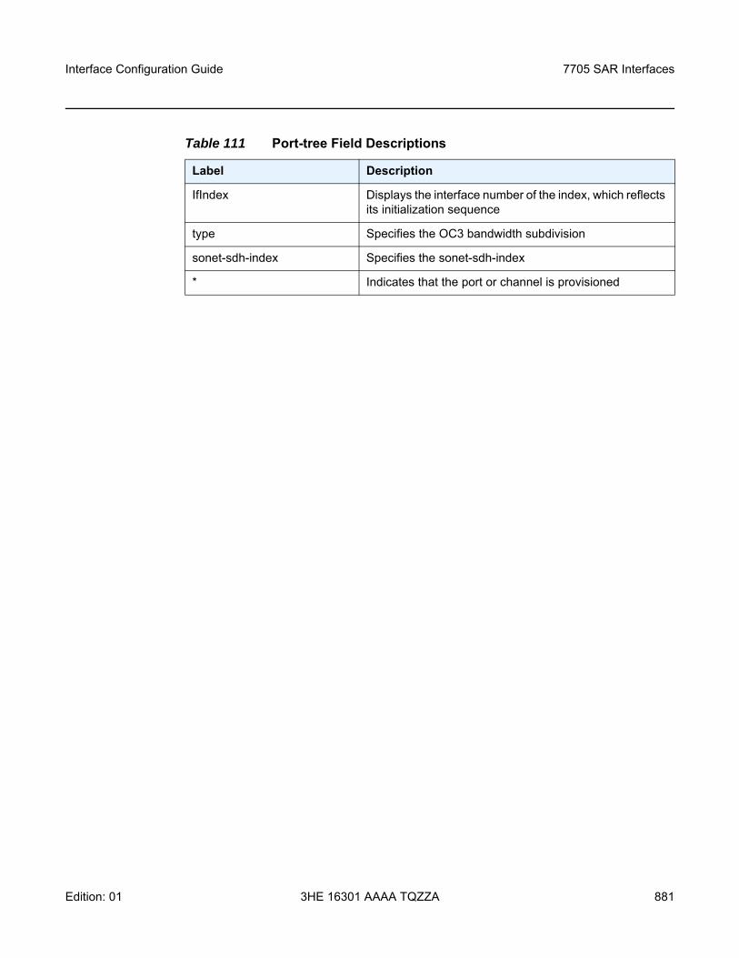
Interface Configuration Guide 7705 SAR Interfaces
Edition: 01 3HE 16301 AAAA TQZZA 881
Table 111 Port-tree Field Descriptions
Label Description
IfIndex Displays the interface number of the index, which reflects its initialization sequence
type Specifies the OC3 bandwidth subdivision
sonet-sdh-index Specifies the sonet-sdh-index
* Indicates that the port or channel is provisioned
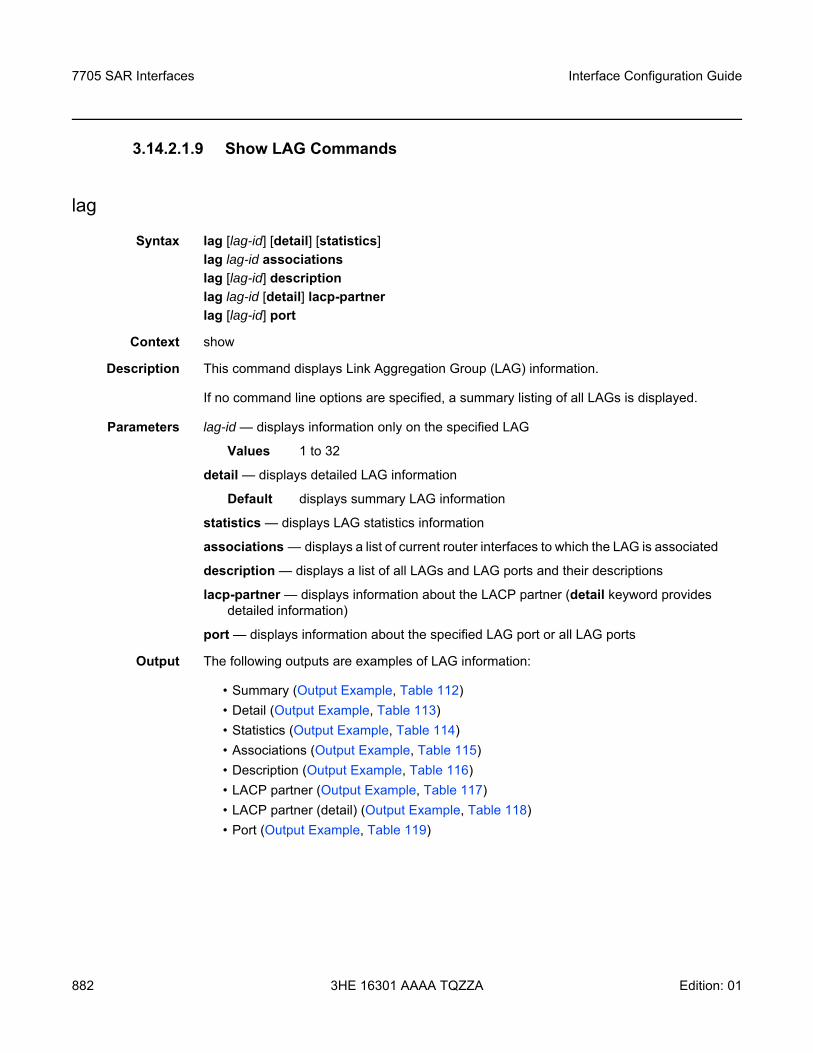
7705 SAR Interfaces
882
Interface Configuration Guide
3HE 16301 AAAA TQZZA Edition: 01
3.14.2.1.9 Show LAG Commands
lag
Syntax lag [lag-id] [detail] [statistics]lag lag-id associationslag [lag-id] descriptionlag lag-id [detail] lacp-partnerlag [lag-id] port
Context show
Description This command displays Link Aggregation Group (LAG) information.
If no command line options are specified, a summary listing of all LAGs is displayed.
Parameters lag-id — displays information only on the specified LAG
Values 1 to 32
detail — displays detailed LAG information
Default displays summary LAG information
statistics — displays LAG statistics information
associations — displays a list of current router interfaces to which the LAG is associated
description — displays a list of all LAGs and LAG ports and their descriptions
lacp-partner — displays information about the LACP partner (detail keyword provides detailed information)
port — displays information about the specified LAG port or all LAG ports
Output The following outputs are examples of LAG information:
• Summary (Output Example, Table 112)• Detail (Output Example, Table 113)• Statistics (Output Example, Table 114)• Associations (Output Example, Table 115)• Description (Output Example, Table 116)• LACP partner (Output Example, Table 117)• LACP partner (detail) (Output Example, Table 118)• Port (Output Example, Table 119)
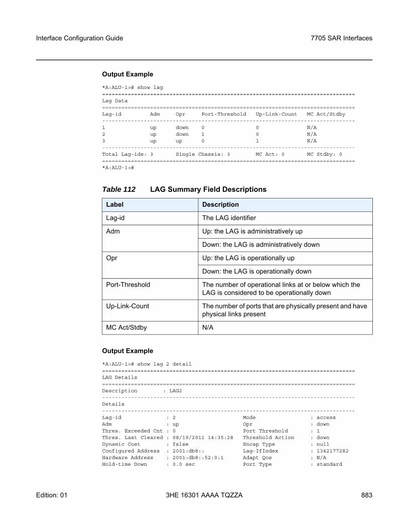
Interface Configuration Guide 7705 SAR Interfaces
Edition: 01 3HE 16301 AAAA TQZZA 883
Output Example
*A:ALU-1># show lag===============================================================================Lag Data===============================================================================Lag-id Adm Opr Port-Threshold Up-Link-Count MC Act/Stdby-------------------------------------------------------------------------------1 up down 0 0 N/A2 up down 1 0 N/A3 up up 0 1 N/A-------------------------------------------------------------------------------Total Lag-ids: 3 Single Chassis: 3 MC Act: 0 MC Stdby: 0===============================================================================*A:ALU-1>#
Output Example
*A:ALU-1># show lag 2 detail===============================================================================LAG Details===============================================================================Description : LAG2-------------------------------------------------------------------------------Details-------------------------------------------------------------------------------Lag-id : 2 Mode : accessAdm : up Opr : downThres. Exceeded Cnt : 0 Port Threshold : 1Thres. Last Cleared : 08/19/2011 14:35:28 Threshold Action : downDynamic Cost : false Encap Type : nullConfigured Address : 2001:db8:: Lag-IfIndex : 1342177282Hardware Address : 2001:db8::52:0:1 Adapt Qos : N/AHold-time Down : 0.0 sec Port Type : standard
Table 112 LAG Summary Field Descriptions
Label Description
Lag-id The LAG identifier
Adm Up: the LAG is administratively up
Down: the LAG is administratively down
Opr Up: the LAG is operationally up
Down: the LAG is operationally down
Port-Threshold The number of operational links at or below which the LAG is considered to be operationally down
Up-Link-Count The number of ports that are physically present and have physical links present
MC Act/Stdby N/A
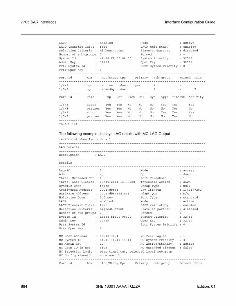
7705 SAR Interfaces
884
Interface Configuration Guide
3HE 16301 AAAA TQZZA Edition: 01
LACP : enabled Mode : activeLACP Transmit Intvl : fast LACP xmit stdby : enabledSelection Criteria : highest-count Slave-to-partner : disabledNumber of sub-groups: 2 Forced : -System Id : a4:58:ff:00:00:00 System Priority : 32768Admin Key : 32769 Oper Key : 32769Prtr System Id : Prtr System Priority : 0Prtr Oper Key : 0-------------------------------------------------------------------------------Port-id Adm Act/Stdby Opr Primary Sub-group Forced Prio-------------------------------------------------------------------------------1/4/3 up active down yes 1 - 11/5/3 up standby down 2 - 2-------------------------------------------------------------------------------Port-id Role Exp Def Dist Col Syn Aggr Timeout Activity-------------------------------------------------------------------------------1/4/3 actor Yes Yes No No No Yes Yes Yes1/4/3 partner Yes Yes No No No No Yes No1/5/3 actor Yes Yes No No No Yes Yes Yes1/5/3 partner Yes Yes No No No No Yes No===============================================================================*A:ALU-1>#
The following example displays LAG details with MC-LAG Output*A:ALU-1># show lag 2 detail===============================================================================LAG Details===============================================================================Description : LAG2-------------------------------------------------------------------------------Details-------------------------------------------------------------------------------Lag-id : 2 Mode : accessAdm : up Opr : downThres. Exceeded Cnt : 0 Port Threshold : 1Thres. Last Cleared : 08/19/2011 14:35:28 Threshold Action : downDynamic Cost : false Encap Type : nullConfigured Address : 2001:db8:: Lag-IfIndex : 1342177282Hardware Address : 2001:db8::52:0:1 Adapt Qos : N/AHold-time Down : 0.0 sec Port Type : standardLACP : enabled Mode : activeLACP Transmit Intvl : fast LACP xmit stdby : enabledSelection Criteria : highest-count Slave-to-partner : disabledNumber of sub-groups: 2 Forced : -System Id : a4:58:ff:00:00:00 System Priority : 32768Admin Key : 32769 Oper Key : 32769Prtr System Id : Prtr System Priority : 0Prtr Oper Key : 0
MC Peer Address : 10.10.10.4 MC Peer Lag-id : 1MC System ID : 11.11.11.11:11:11 MC System Priority : 3MC Admin Key : 12 MC Active/Standby : activeMC Lacp ID in use : true MC extended timeout : falseMC Selection Logic : peer timed out, selected local subgroupMC Config Mismatch : no mismatch-------------------------------------------------------------------------------Port-id Adm Act/Stdby Opr Primary Sub-group Forced Prio-------------------------------------------------------------------------------
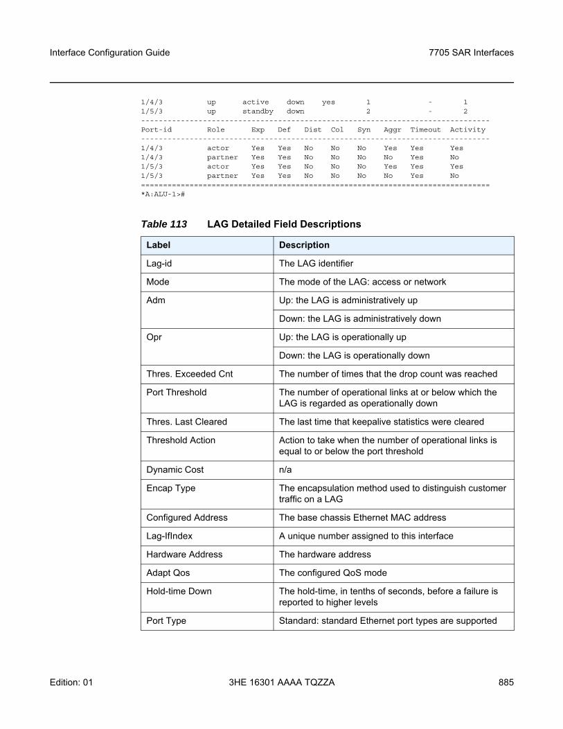
Interface Configuration Guide 7705 SAR Interfaces
Edition: 01 3HE 16301 AAAA TQZZA 885
1/4/3 up active down yes 1 - 11/5/3 up standby down 2 - 2-------------------------------------------------------------------------------Port-id Role Exp Def Dist Col Syn Aggr Timeout Activity-------------------------------------------------------------------------------1/4/3 actor Yes Yes No No No Yes Yes Yes1/4/3 partner Yes Yes No No No No Yes No1/5/3 actor Yes Yes No No No Yes Yes Yes1/5/3 partner Yes Yes No No No No Yes No===============================================================================*A:ALU-1>#
Table 113 LAG Detailed Field Descriptions
Label Description
Lag-id The LAG identifier
Mode The mode of the LAG: access or network
Adm Up: the LAG is administratively up
Down: the LAG is administratively down
Opr Up: the LAG is operationally up
Down: the LAG is operationally down
Thres. Exceeded Cnt The number of times that the drop count was reached
Port Threshold The number of operational links at or below which the LAG is regarded as operationally down
Thres. Last Cleared The last time that keepalive statistics were cleared
Threshold Action Action to take when the number of operational links is equal to or below the port threshold
Dynamic Cost n/a
Encap Type The encapsulation method used to distinguish customer traffic on a LAG
Configured Address The base chassis Ethernet MAC address
Lag-IfIndex A unique number assigned to this interface
Hardware Address The hardware address
Adapt Qos The configured QoS mode
Hold-time Down The hold-time, in tenths of seconds, before a failure is reported to higher levels
Port Type Standard: standard Ethernet port types are supported
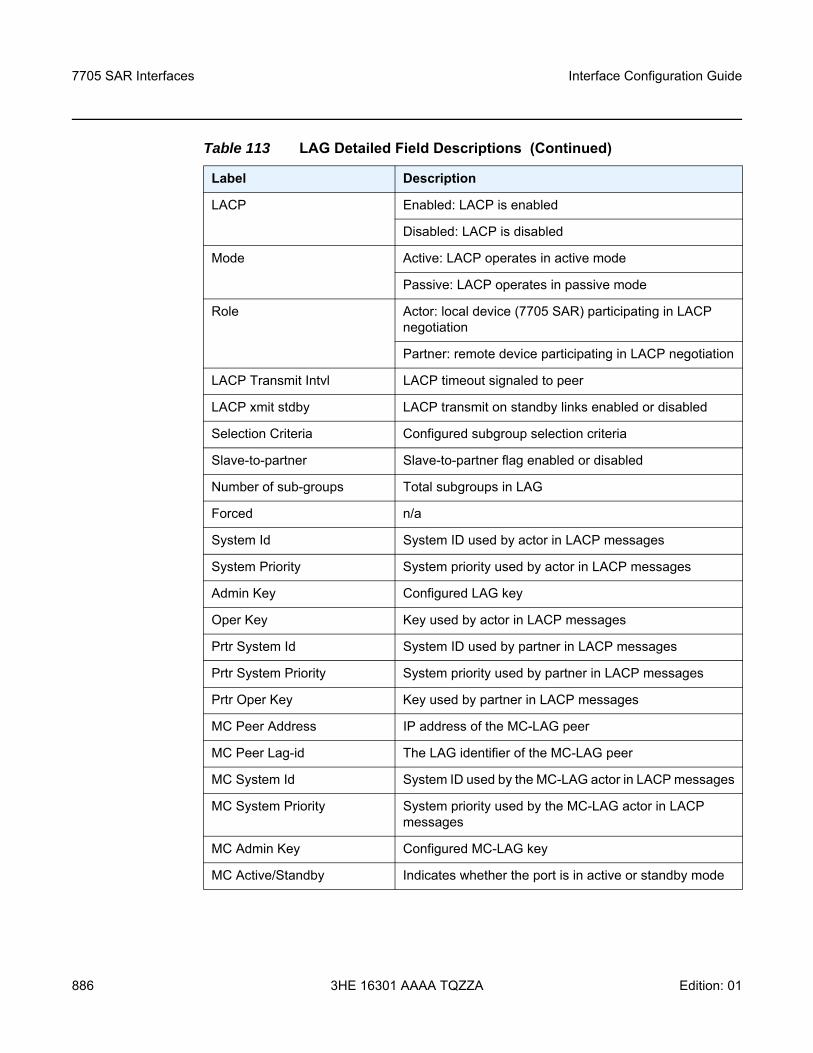
7705 SAR Interfaces
886
Interface Configuration Guide
3HE 16301 AAAA TQZZA Edition: 01
LACP Enabled: LACP is enabled
Disabled: LACP is disabled
Mode Active: LACP operates in active mode
Passive: LACP operates in passive mode
Role Actor: local device (7705 SAR) participating in LACP negotiation
Partner: remote device participating in LACP negotiation
LACP Transmit Intvl LACP timeout signaled to peer
LACP xmit stdby LACP transmit on standby links enabled or disabled
Selection Criteria Configured subgroup selection criteria
Slave-to-partner Slave-to-partner flag enabled or disabled
Number of sub-groups Total subgroups in LAG
Forced n/a
System Id System ID used by actor in LACP messages
System Priority System priority used by actor in LACP messages
Admin Key Configured LAG key
Oper Key Key used by actor in LACP messages
Prtr System Id System ID used by partner in LACP messages
Prtr System Priority System priority used by partner in LACP messages
Prtr Oper Key Key used by partner in LACP messages
MC Peer Address IP address of the MC-LAG peer
MC Peer Lag-id The LAG identifier of the MC-LAG peer
MC System Id System ID used by the MC-LAG actor in LACP messages
MC System Priority System priority used by the MC-LAG actor in LACP messages
MC Admin Key Configured MC-LAG key
MC Active/Standby Indicates whether the port is in active or standby mode
Table 113 LAG Detailed Field Descriptions (Continued)
Label Description
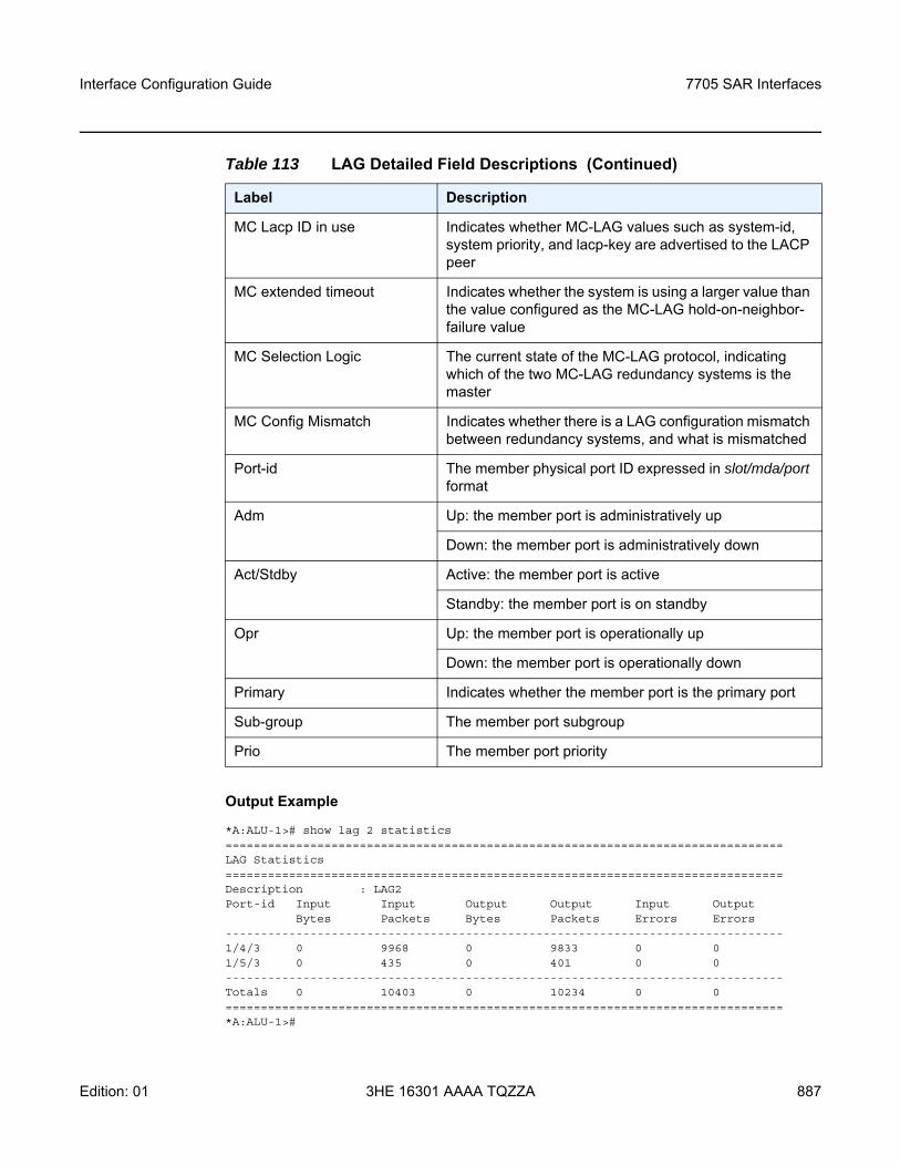
Interface Configuration Guide 7705 SAR Interfaces
Edition: 01 3HE 16301 AAAA TQZZA 887
Output Example
*A:ALU-1># show lag 2 statistics===============================================================================LAG Statistics===============================================================================Description : LAG2Port-id Input Input Output Output Input Output
Bytes Packets Bytes Packets Errors Errors-------------------------------------------------------------------------------1/4/3 0 9968 0 9833 0 01/5/3 0 435 0 401 0 0-------------------------------------------------------------------------------Totals 0 10403 0 10234 0 0===============================================================================*A:ALU-1>#
MC Lacp ID in use Indicates whether MC-LAG values such as system-id, system priority, and lacp-key are advertised to the LACP peer
MC extended timeout Indicates whether the system is using a larger value than the value configured as the MC-LAG hold-on-neighbor-failure value
MC Selection Logic The current state of the MC-LAG protocol, indicating which of the two MC-LAG redundancy systems is the master
MC Config Mismatch Indicates whether there is a LAG configuration mismatch between redundancy systems, and what is mismatched
Port-id The member physical port ID expressed in slot/mda/port format
Adm Up: the member port is administratively up
Down: the member port is administratively down
Act/Stdby Active: the member port is active
Standby: the member port is on standby
Opr Up: the member port is operationally up
Down: the member port is operationally down
Primary Indicates whether the member port is the primary port
Sub-group The member port subgroup
Prio The member port priority
Table 113 LAG Detailed Field Descriptions (Continued)
Label Description
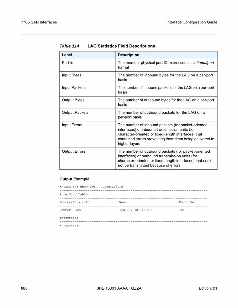
7705 SAR Interfaces
888
Interface Configuration Guide
3HE 16301 AAAA TQZZA Edition: 01
Output Example
*A:ALU-1># show lag 1 associations===============================================================================Interface Table===============================================================================Router/ServiceId Name Encap Val-------------------------------------------------------------------------------Router: Base ies-337-30.30.30.1 104-------------------------------------------------------------------------------Interfaces===============================================================================*A:ALU-1>#
Table 114 LAG Statistics Field Descriptions
Label Description
Port-id The member physical port ID expressed in slot/mda/port format
Input Bytes The number of inbound bytes for the LAG on a per-port basis
Input Packets The number of inbound packets for the LAG on a per-port basis
Output Bytes The number of outbound bytes for the LAG on a per-port basis
Output Packets The number of outbound packets for the LAG on a per-port basis
Input Errors The number of inbound packets (for packet-oriented interfaces) or inbound transmission units (for character-oriented or fixed-length interfaces) that contained errors preventing them from being delivered to higher layers
Output Errors The number of outbound packets (for packet-oriented interfaces) or outbound transmission units (for character-oriented or fixed-length interfaces) that could not be transmitted because of errors
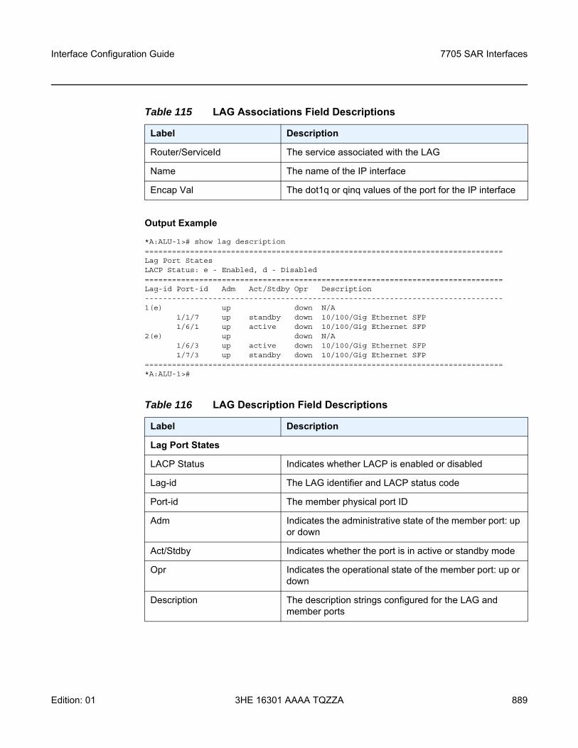
Interface Configuration Guide 7705 SAR Interfaces
Edition: 01 3HE 16301 AAAA TQZZA 889
Output Example
*A:ALU-1># show lag description===============================================================================Lag Port StatesLACP Status: e - Enabled, d - Disabled===============================================================================Lag-id Port-id Adm Act/Stdby Opr Description-------------------------------------------------------------------------------1(e) up down N/A
1/1/7 up standby down 10/100/Gig Ethernet SFP1/6/1 up active down 10/100/Gig Ethernet SFP
2(e) up down N/A1/6/3 up active down 10/100/Gig Ethernet SFP1/7/3 up standby down 10/100/Gig Ethernet SFP
===============================================================================*A:ALU-1>#
Table 115 LAG Associations Field Descriptions
Label Description
Router/ServiceId The service associated with the LAG
Name The name of the IP interface
Encap Val The dot1q or qinq values of the port for the IP interface
Table 116 LAG Description Field Descriptions
Label Description
Lag Port States
LACP Status Indicates whether LACP is enabled or disabled
Lag-id The LAG identifier and LACP status code
Port-id The member physical port ID
Adm Indicates the administrative state of the member port: up or down
Act/Stdby Indicates whether the port is in active or standby mode
Opr Indicates the operational state of the member port: up or down
Description The description strings configured for the LAG and member ports
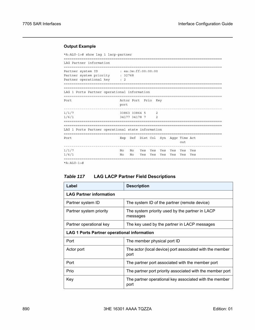
7705 SAR Interfaces
890
Interface Configuration Guide
3HE 16301 AAAA TQZZA Edition: 01
Output Example
*A:ALU-1># show lag 1 lacp-partner===============================================================================LAG Partner information===============================================================================Partner system ID : ea:3e:ff:00:00:00Partner system priority : 32768Partner operational key : 2==============================================================================================================================================================LAG 1 Ports Partner operational information===============================================================================Port Actor Port Prio Key
port-------------------------------------------------------------------------------1/1/7 33863 33864 5 21/6/1 34177 34178 7 2==============================================================================================================================================================LAG 1 Ports Partner operational state information===============================================================================Port Exp Def Dist Col Syn Aggr Time Act
out-------------------------------------------------------------------------------1/1/7 No No Yes Yes Yes Yes Yes Yes1/6/1 No No Yes Yes Yes Yes Yes Yes===============================================================================*A:ALU-1>#
Table 117 LAG LACP Partner Field Descriptions
Label Description
LAG Partner information
Partner system ID The system ID of the partner (remote device)
Partner system priority The system priority used by the partner in LACP messages
Partner operational key The key used by the partner in LACP messages
LAG 1 Ports Partner operational information
Port The member physical port ID
Actor port The actor (local device) port associated with the member port
Port The partner port associated with the member port
Prio The partner port priority associated with the member port
Key The partner operational key associated with the member port
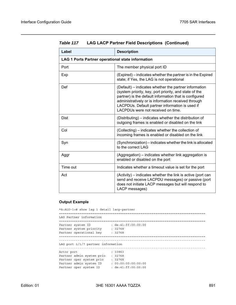
Interface Configuration Guide 7705 SAR Interfaces
Edition: 01 3HE 16301 AAAA TQZZA 891
Output Example
*A:ALU-1># show lag 1 detail lacp-partner===============================================================================LAG Partner information===============================================================================Partner system ID : de:41:ff:00:00:00Partner system priority : 32768Partner operational key : 32768===============================================================================-------------------------------------------------------------------------------LAG port 1/1/7 partner information-------------------------------------------------------------------------------Actor port : 33863Partner admin system prio : 32768Partner oper system prio : 32768Partner admin system ID : 00:00:00:00:00:00Partner oper system ID : de:41:ff:00:00:00
LAG 1 Ports Partner operational state information
Port The member physical port ID
Exp (Expired) – indicates whether the partner is in the Expired state; if Yes, the LAG is not operational
Def (Default) – indicates whether the partner information (system priority, key, port priority, and state of the partner) is the default information that is configured administratively or is information received through LACPDUs. Default partner information is used if LACPDUs were not received on time.
Dist (Distributing) – indicates whether the distribution of outgoing frames is enabled or disabled on the link
Col (Collecting) – indicates whether the collection of incoming frames is enabled or disabled on the link
Syn (Synchronization) – indicates whether the link is allocated to the correct LAG
Aggr (Aggregation) – indicates whether link aggregation is enabled or disabled on the port
Time out Indicates whether a timeout value is set for the port
Act (Activity) – indicates whether the link is active (port can send and receive LACPDU messages) or passive (port does not initiate LACP messages but will respond to LACP messages)
Table 117 LAG LACP Partner Field Descriptions (Continued)
Label Description
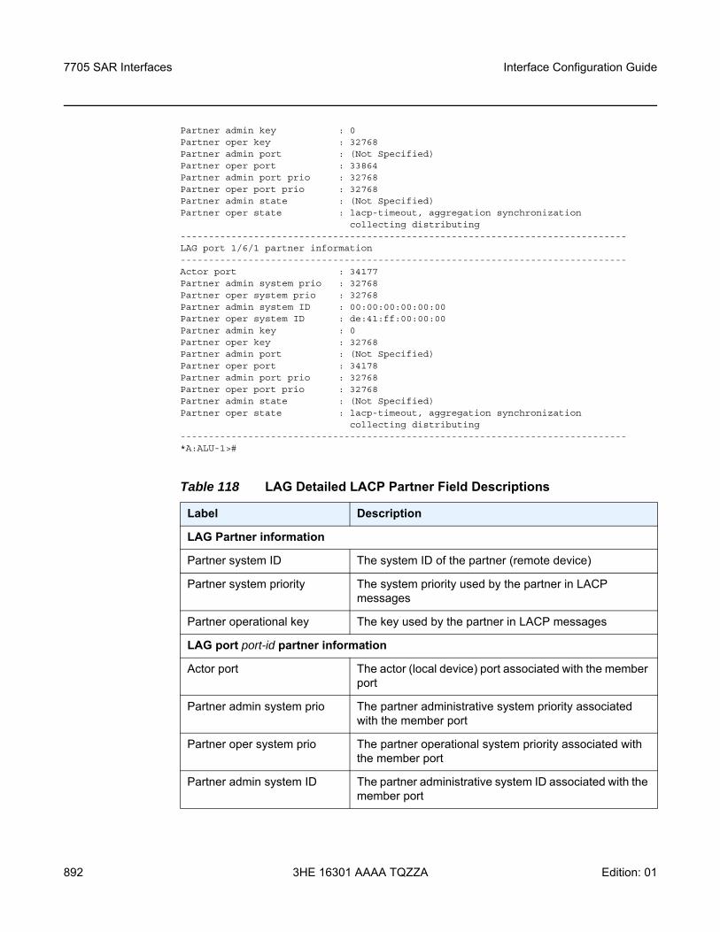
7705 SAR Interfaces
892
Interface Configuration Guide
3HE 16301 AAAA TQZZA Edition: 01
Partner admin key : 0Partner oper key : 32768Partner admin port : (Not Specified)Partner oper port : 33864Partner admin port prio : 32768Partner oper port prio : 32768Partner admin state : (Not Specified)Partner oper state : lacp-timeout, aggregation synchronization
collecting distributing-------------------------------------------------------------------------------LAG port 1/6/1 partner information-------------------------------------------------------------------------------Actor port : 34177Partner admin system prio : 32768Partner oper system prio : 32768Partner admin system ID : 00:00:00:00:00:00Partner oper system ID : de:41:ff:00:00:00Partner admin key : 0Partner oper key : 32768Partner admin port : (Not Specified)Partner oper port : 34178Partner admin port prio : 32768Partner oper port prio : 32768Partner admin state : (Not Specified)Partner oper state : lacp-timeout, aggregation synchronization
collecting distributing-------------------------------------------------------------------------------*A:ALU-1>#
Table 118 LAG Detailed LACP Partner Field Descriptions
Label Description
LAG Partner information
Partner system ID The system ID of the partner (remote device)
Partner system priority The system priority used by the partner in LACP messages
Partner operational key The key used by the partner in LACP messages
LAG port port-id partner information
Actor port The actor (local device) port associated with the member port
Partner admin system prio The partner administrative system priority associated with the member port
Partner oper system prio The partner operational system priority associated with the member port
Partner admin system ID The partner administrative system ID associated with the member port
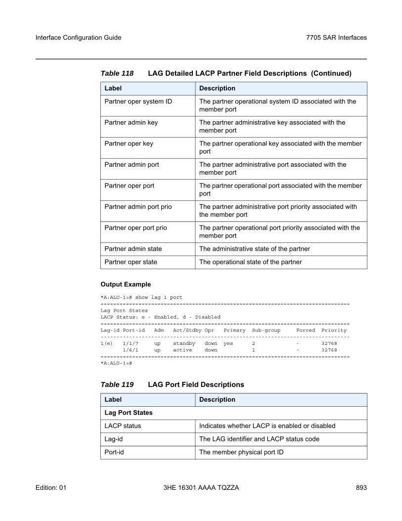
Interface Configuration Guide 7705 SAR Interfaces
Edition: 01 3HE 16301 AAAA TQZZA 893
Output Example
*A:ALU-1># show lag 1 port===============================================================================Lag Port StatesLACP Status: e - Enabled, d - Disabled===============================================================================Lag-id Port-id Adm Act/Stdby Opr Primary Sub-group Forced Priority-------------------------------------------------------------------------------1(e) 1/1/7 up standby down yes 2 - 32768
1/6/1 up active down 1 - 32768===============================================================================*A:ALU-1>#
Partner oper system ID The partner operational system ID associated with the member port
Partner admin key The partner administrative key associated with the member port
Partner oper key The partner operational key associated with the member port
Partner admin port The partner administrative port associated with the member port
Partner oper port The partner operational port associated with the member port
Partner admin port prio The partner administrative port priority associated with the member port
Partner oper port prio The partner operational port priority associated with the member port
Partner admin state The administrative state of the partner
Partner oper state The operational state of the partner
Table 119 LAG Port Field Descriptions
Label Description
Lag Port States
LACP status Indicates whether LACP is enabled or disabled
Lag-id The LAG identifier and LACP status code
Port-id The member physical port ID
Table 118 LAG Detailed LACP Partner Field Descriptions (Continued)
Label Description
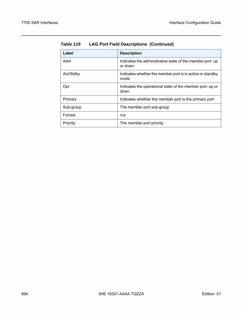
7705 SAR Interfaces
894
Interface Configuration Guide
3HE 16301 AAAA TQZZA Edition: 01
Adm Indicates the administrative state of the member port: up or down
Act/Stdby Indicates whether the member port is in active or standby mode
Opr Indicates the operational state of the member port: up or down
Primary Indicates whether the member port is the primary port
Sub-group The member port sub-group
Forced n/a
Priority The member port priority
Table 119 LAG Port Field Descriptions (Continued)
Label Description
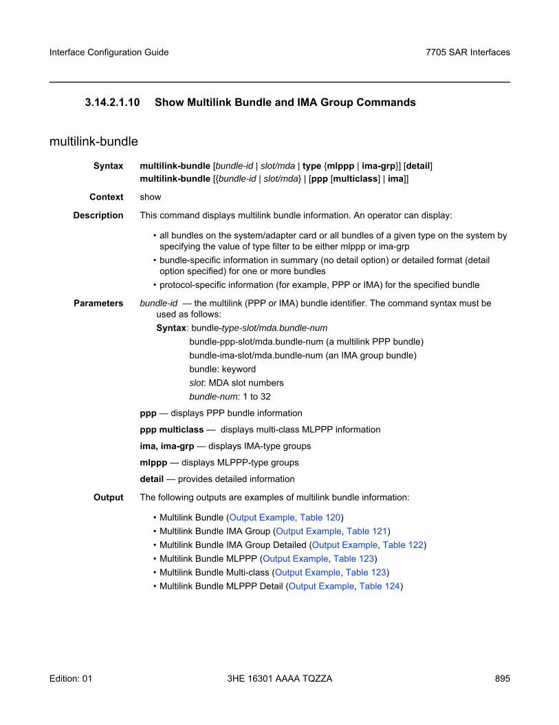
Interface Configuration Guide 7705 SAR Interfaces
Edition: 01 3HE 16301 AAAA TQZZA 895
3.14.2.1.10 Show Multilink Bundle and IMA Group Commands
multilink-bundle
Syntax multilink-bundle [bundle-id | slot/mda | type mlppp | ima-grp] [detail] multilink-bundle [bundle-id | slot/mda | [ppp [multiclass] | ima]]
Context show
Description This command displays multilink bundle information. An operator can display:
• all bundles on the system/adapter card or all bundles of a given type on the system by specifying the value of type filter to be either mlppp or ima-grp
• bundle-specific information in summary (no detail option) or detailed format (detail option specified) for one or more bundles
• protocol-specific information (for example, PPP or IMA) for the specified bundle
Parameters bundle-id — the multilink (PPP or IMA) bundle identifier. The command syntax must be used as follows:Syntax: bundle-type-slot/mda.bundle-num
bundle-ppp-slot/mda.bundle-num (a multilink PPP bundle)bundle-ima-slot/mda.bundle-num (an IMA group bundle)bundle: keywordslot: MDA slot numbersbundle-num: 1 to 32
ppp — displays PPP bundle information
ppp multiclass — displays multi-class MLPPP information
ima, ima-grp — displays IMA-type groups
mlppp — displays MLPPP-type groups
detail — provides detailed information
Output The following outputs are examples of multilink bundle information:
• Multilink Bundle (Output Example, Table 120)• Multilink Bundle IMA Group (Output Example, Table 121)• Multilink Bundle IMA Group Detailed (Output Example, Table 122)• Multilink Bundle MLPPP (Output Example, Table 123)• Multilink Bundle Multi-class (Output Example, Table 123)• Multilink Bundle MLPPP Detail (Output Example, Table 124)
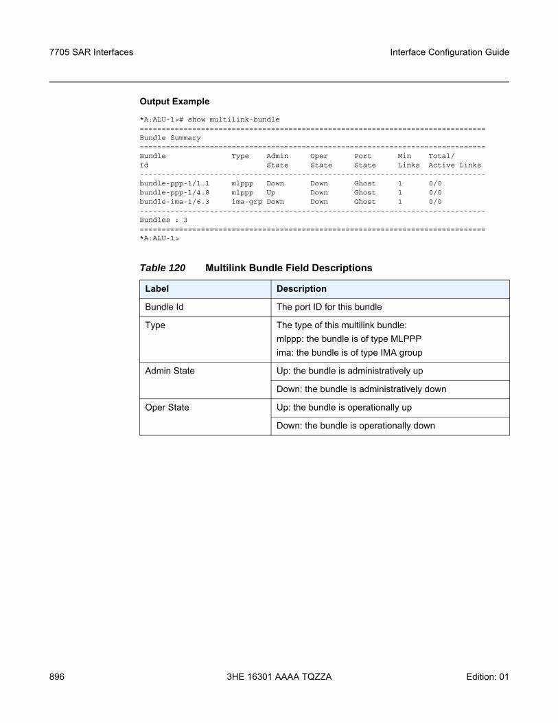
7705 SAR Interfaces
896
Interface Configuration Guide
3HE 16301 AAAA TQZZA Edition: 01
Output Example
*A:ALU-1># show multilink-bundle===============================================================================Bundle Summary===============================================================================Bundle Type Admin Oper Port Min Total/Id State State State Links Active Links-------------------------------------------------------------------------------bundle-ppp-1/1.1 mlppp Down Down Ghost 1 0/0bundle-ppp-1/4.8 mlppp Up Down Ghost 1 0/0bundle-ima-1/6.3 ima-grp Down Down Ghost 1 0/0-------------------------------------------------------------------------------Bundles : 3===============================================================================*A:ALU-1>
Table 120 Multilink Bundle Field Descriptions
Label Description
Bundle Id The port ID for this bundle
Type The type of this multilink bundle:mlppp: the bundle is of type MLPPPima: the bundle is of type IMA group
Admin State Up: the bundle is administratively up
Down: the bundle is administratively down
Oper State Up: the bundle is operationally up
Down: the bundle is operationally down
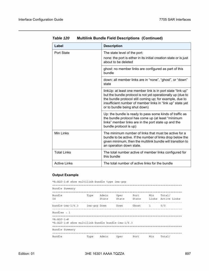
Interface Configuration Guide 7705 SAR Interfaces
Edition: 01 3HE 16301 AAAA TQZZA 897
Output Example
*A:ALU-1># show multilink-bundle type ima-grp===============================================================================Bundle Summary===============================================================================Bundle Type Admin Oper Port Min Total/Id State State State Links Active Links-------------------------------------------------------------------------------bundle-ima-1/6.3 ima-grp Down Down Ghost 1 0/0-------------------------------------------------------------------------------Bundles : 1===============================================================================*A:ALU-1>#*A:ALU-1># show multilink-bundle bundle-ima-1/6.3===============================================================================Bundle Summary===============================================================================Bundle Type Admin Oper Port Min Total/
Port State The state level of the port:none: the port is either in its initial creation state or is just about to be deleted
ghost: no member links are configured as part of this bundle
down: all member links are in “none”, “ghost”, or “down” state
linkUp: at least one member link is in port state “link up” but the bundle protocol is not yet operationally up (due to the bundle protocol still coming up; for example, due to insufficient number of member links in “link up” state yet or to bundle being shut down)
Up: the bundle is ready to pass some kinds of traffic as the bundle protocol has come up (at least “minimum links” member links are in the port state up and the bundle protocol is up)
Min Links The minimum number of links that must be active for a bundle to be active. If the number of links drop below the given minimum, then the multilink bundle will transition to an operation down state.
Total Links The total number active of member links configured for this bundle
Active Links The total number of active links for the bundle
Table 120 Multilink Bundle Field Descriptions (Continued)
Label Description
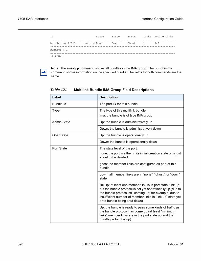
7705 SAR Interfaces
898
Interface Configuration Guide
3HE 16301 AAAA TQZZA Edition: 01
Id State State State Links Active Links-------------------------------------------------------------------------------bundle-ima-1/6.3 ima-grp Down Down Ghost 1 0/0-------------------------------------------------------------------------------Bundles : 1===============================================================================*A:ALU-1>
Note: The ima-grp command shows all bundles in the IMA group. The bundle-ima command shows information on the specified bundle. The fields for both commands are the same.
Table 121 Multilink Bundle IMA Group Field Descriptions
Label Description
Bundle Id The port ID for this bundle
Type The type of this multilink bundle:ima: the bundle is of type IMA group
Admin State Up: the bundle is administratively up
Down: the bundle is administratively down
Oper State Up: the bundle is operationally up
Down: the bundle is operationally down
Port State The state level of the port:none: the port is either in its initial creation state or is just about to be deleted
ghost: no member links are configured as part of this bundle
down: all member links are in “none”, “ghost”, or “down” state
linkUp: at least one member link is in port state “link up” but the bundle protocol is not yet operationally up (due to the bundle protocol still coming up; for example, due to insufficient number of member links in “link up” state yet or to bundle being shut down)
Up: the bundle is ready to pass some kinds of traffic as the bundle protocol has come up (at least “minimum links” member links are in the port state up and the bundle protocol is up)
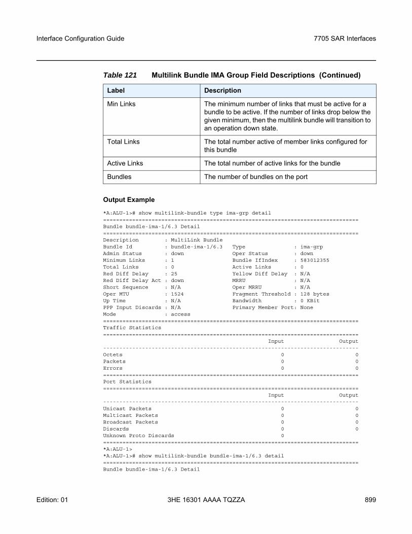
Interface Configuration Guide 7705 SAR Interfaces
Edition: 01 3HE 16301 AAAA TQZZA 899
Output Example
*A:ALU-1># show multilink-bundle type ima-grp detail===============================================================================Bundle bundle-ima-1/6.3 Detail===============================================================================Description : MultiLink BundleBundle Id : bundle-ima-1/6.3 Type : ima-grpAdmin Status : down Oper Status : downMinimum Links : 1 Bundle IfIndex : 583012355Total Links : 0 Active Links : 0Red Diff Delay : 25 Yellow Diff Delay : N/ARed Diff Delay Act : down MRRU : N/AShort Sequence : N/A Oper MRRU : N/AOper MTU : 1524 Fragment Threshold : 128 bytesUp Time : N/A Bandwidth : 0 KBitPPP Input Discards : N/A Primary Member Port: NoneMode : access===============================================================================Traffic Statistics===============================================================================
Input Output-------------------------------------------------------------------------------Octets 0 0Packets 0 0Errors 0 0===============================================================================Port Statistics===============================================================================
Input Output-------------------------------------------------------------------------------Unicast Packets 0 0Multicast Packets 0 0Broadcast Packets 0 0Discards 0 0Unknown Proto Discards 0===============================================================================*A:ALU-1>*A:ALU-1># show multilink-bundle bundle-ima-1/6.3 detail===============================================================================Bundle bundle-ima-1/6.3 Detail
Min Links The minimum number of links that must be active for a bundle to be active. If the number of links drop below the given minimum, then the multilink bundle will transition to an operation down state.
Total Links The total number active of member links configured for this bundle
Active Links The total number of active links for the bundle
Bundles The number of bundles on the port
Table 121 Multilink Bundle IMA Group Field Descriptions (Continued)
Label Description
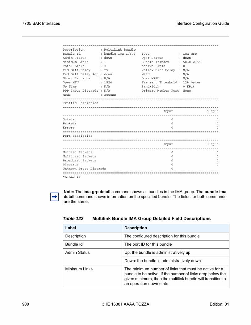
7705 SAR Interfaces
900
Interface Configuration Guide
3HE 16301 AAAA TQZZA Edition: 01
===============================================================================Description : MultiLink BundleBundle Id : bundle-ima-1/6.3 Type : ima-grpAdmin Status : down Oper Status : downMinimum Links : 1 Bundle IfIndex : 583012355Total Links : 0 Active Links : 0Red Diff Delay : 25 Yellow Diff Delay : N/ARed Diff Delay Act : down MRRU : N/AShort Sequence : N/A Oper MRRU : N/AOper MTU : 1524 Fragment Threshold : 128 bytesUp Time : N/A Bandwidth : 0 KBitPPP Input Discards : N/A Primary Member Port: NoneMode : access===============================================================================Traffic Statistics===============================================================================
Input Output-------------------------------------------------------------------------------Octets 0 0Packets 0 0Errors 0 0===============================================================================Port Statistics===============================================================================
Input Output-------------------------------------------------------------------------------Unicast Packets 0 0Multicast Packets 0 0Broadcast Packets 0 0Discards 0 0Unknown Proto Discards 0===============================================================================*A:ALU-1>
Note: The ima-grp detail command shows all bundles in the IMA group. The bundle-ima detail command shows information on the specified bundle. The fields for both commands are the same.
Table 122 Multilink Bundle IMA Group Detailed Field Descriptions
Label Description
Description The configured description for this bundle
Bundle Id The port ID for this bundle
Admin Status Up: the bundle is administratively up
Down: the bundle is administratively down
Minimum Links The minimum number of links that must be active for a bundle to be active. If the number of links drop below the given minimum, then the multilink bundle will transition to an operation down state.
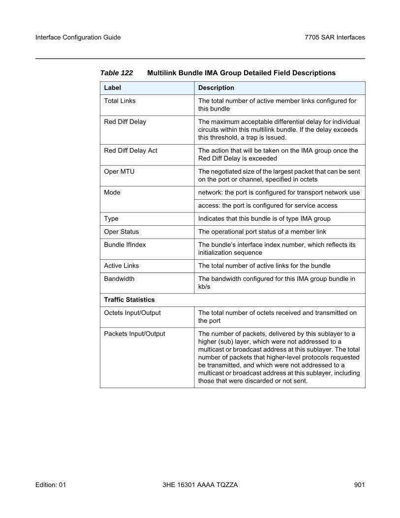
Interface Configuration Guide 7705 SAR Interfaces
Edition: 01 3HE 16301 AAAA TQZZA 901
Total Links The total number of active member links configured for this bundle
Red Diff Delay The maximum acceptable differential delay for individual circuits within this multilink bundle. If the delay exceeds this threshold, a trap is issued.
Red Diff Delay Act The action that will be taken on the IMA group once the Red Diff Delay is exceeded
Oper MTU The negotiated size of the largest packet that can be sent on the port or channel, specified in octets
Mode network: the port is configured for transport network use
access: the port is configured for service access
Type Indicates that this bundle is of type IMA group
Oper Status The operational port status of a member link
Bundle IfIndex The bundle’s interface index number, which reflects its initialization sequence
Active Links The total number of active links for the bundle
Bandwidth The bandwidth configured for this IMA group bundle in kb/s
Traffic Statistics
Octets Input/Output The total number of octets received and transmitted on the port
Packets Input/Output The number of packets, delivered by this sublayer to a higher (sub) layer, which were not addressed to a multicast or broadcast address at this sublayer. The total number of packets that higher-level protocols requested be transmitted, and which were not addressed to a multicast or broadcast address at this sublayer, including those that were discarded or not sent.
Table 122 Multilink Bundle IMA Group Detailed Field Descriptions
Label Description
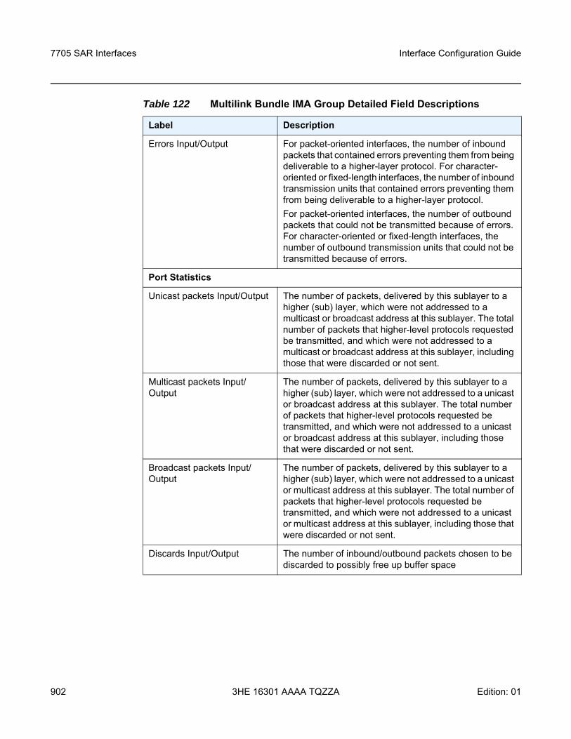
7705 SAR Interfaces
902
Interface Configuration Guide
3HE 16301 AAAA TQZZA Edition: 01
Errors Input/Output For packet-oriented interfaces, the number of inbound packets that contained errors preventing them from being deliverable to a higher-layer protocol. For character-oriented or fixed-length interfaces, the number of inbound transmission units that contained errors preventing them from being deliverable to a higher-layer protocol.For packet-oriented interfaces, the number of outbound packets that could not be transmitted because of errors. For character-oriented or fixed-length interfaces, the number of outbound transmission units that could not be transmitted because of errors.
Port Statistics
Unicast packets Input/Output The number of packets, delivered by this sublayer to a higher (sub) layer, which were not addressed to a multicast or broadcast address at this sublayer. The total number of packets that higher-level protocols requested be transmitted, and which were not addressed to a multicast or broadcast address at this sublayer, including those that were discarded or not sent.
Multicast packets Input/Output
The number of packets, delivered by this sublayer to a higher (sub) layer, which were not addressed to a unicast or broadcast address at this sublayer. The total number of packets that higher-level protocols requested be transmitted, and which were not addressed to a unicast or broadcast address at this sublayer, including those that were discarded or not sent.
Broadcast packets Input/Output
The number of packets, delivered by this sublayer to a higher (sub) layer, which were not addressed to a unicast or multicast address at this sublayer. The total number of packets that higher-level protocols requested be transmitted, and which were not addressed to a unicast or multicast address at this sublayer, including those that were discarded or not sent.
Discards Input/Output The number of inbound/outbound packets chosen to be discarded to possibly free up buffer space
Table 122 Multilink Bundle IMA Group Detailed Field Descriptions
Label Description
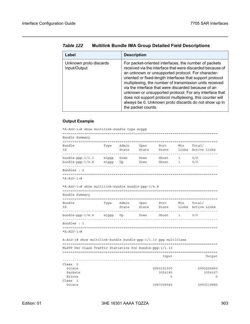
Interface Configuration Guide 7705 SAR Interfaces
Edition: 01 3HE 16301 AAAA TQZZA 903
Output Example
*A:ALU-1># show multilink-bundle type mlppp===============================================================================Bundle Summary===============================================================================Bundle Type Admin Oper Port Min Total/Id State State State Links Active Links-------------------------------------------------------------------------------bundle-ppp-1/1.1 mlppp Down Down Ghost 1 0/0bundle-ppp-1/4.8 mlppp Up Down Ghost 1 0/0-------------------------------------------------------------------------------Bundles : 2===============================================================================*A:ALU-1>#
*A:ALU-1># show multilink-bundle bundle-ppp-1/4.8===============================================================================Bundle Summary===============================================================================Bundle Type Admin Oper Port Min Total/Id State State State Links Active Links-------------------------------------------------------------------------------bundle-ppp-1/4.8 mlppp Up Down Ghost 1 0/0-------------------------------------------------------------------------------Bundles : 1===============================================================================*A:ALU-1>#
A:ALU-1# show multilink-bundle bundle-ppp-1/1.13 ppp multiclass===============================================================================MLPPP Per Class Traffic Statistics for bundle-ppp-1/1.13===============================================================================
Input Output-------------------------------------------------------------------------------Class 0
Octets 2993101300 2993220860Packets 3054185 3054307Errors 0 0
Class 1Octets 2987258540 2993219880
Unknown proto discards Input/Output
For packet-oriented interfaces, the number of packets received via the interface that were discarded because of an unknown or unsupported protocol. For character-oriented or fixed-length interfaces that support protocol multiplexing, the number of transmission units received via the interface that were discarded because of an unknown or unsupported protocol. For any interface that does not support protocol multiplexing, this counter will always be 0. Unknown proto discards do not show up in the packet counts.
Table 122 Multilink Bundle IMA Group Detailed Field Descriptions
Label Description
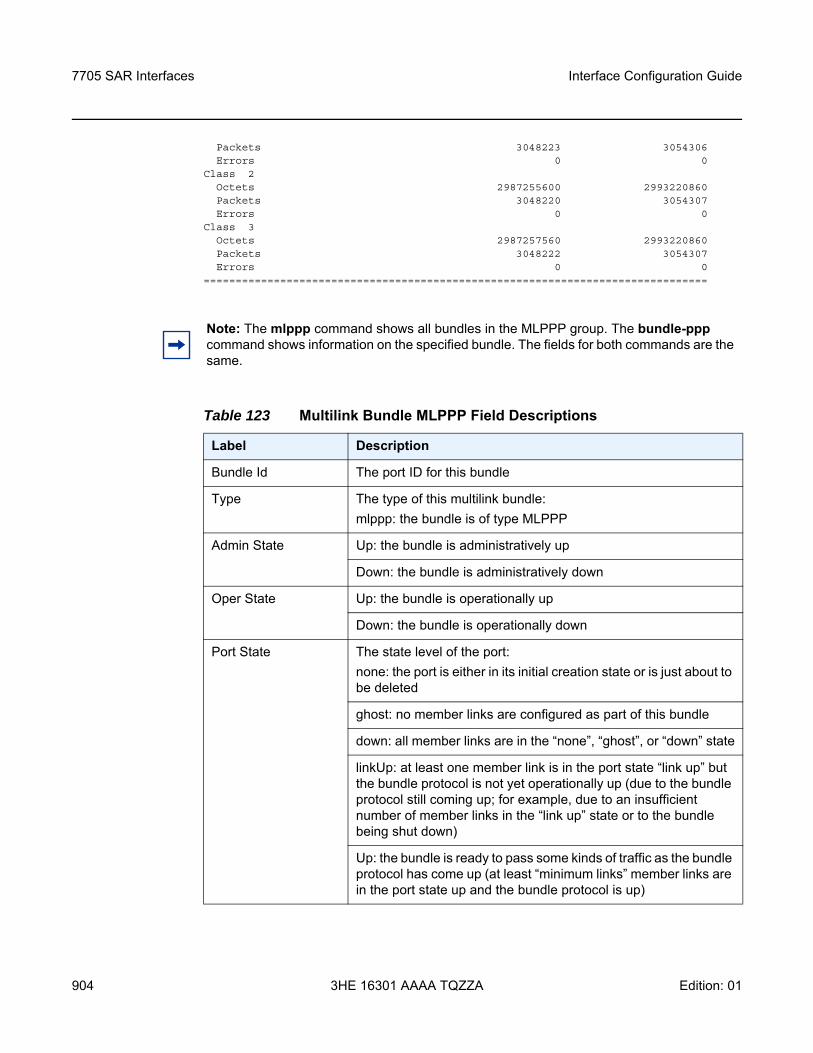
7705 SAR Interfaces
904
Interface Configuration Guide
3HE 16301 AAAA TQZZA Edition: 01
Packets 3048223 3054306Errors 0 0
Class 2Octets 2987255600 2993220860Packets 3048220 3054307Errors 0 0
Class 3Octets 2987257560 2993220860Packets 3048222 3054307Errors 0 0
===============================================================================
Note: The mlppp command shows all bundles in the MLPPP group. The bundle-ppp command shows information on the specified bundle. The fields for both commands are the same.
Table 123 Multilink Bundle MLPPP Field Descriptions
Label Description
Bundle Id The port ID for this bundle
Type The type of this multilink bundle:mlppp: the bundle is of type MLPPP
Admin State Up: the bundle is administratively up
Down: the bundle is administratively down
Oper State Up: the bundle is operationally up
Down: the bundle is operationally down
Port State The state level of the port:none: the port is either in its initial creation state or is just about to be deleted
ghost: no member links are configured as part of this bundle
down: all member links are in the “none”, “ghost”, or “down” state
linkUp: at least one member link is in the port state “link up” but the bundle protocol is not yet operationally up (due to the bundle protocol still coming up; for example, due to an insufficient number of member links in the “link up” state or to the bundle being shut down)
Up: the bundle is ready to pass some kinds of traffic as the bundle protocol has come up (at least “minimum links” member links are in the port state up and the bundle protocol is up)
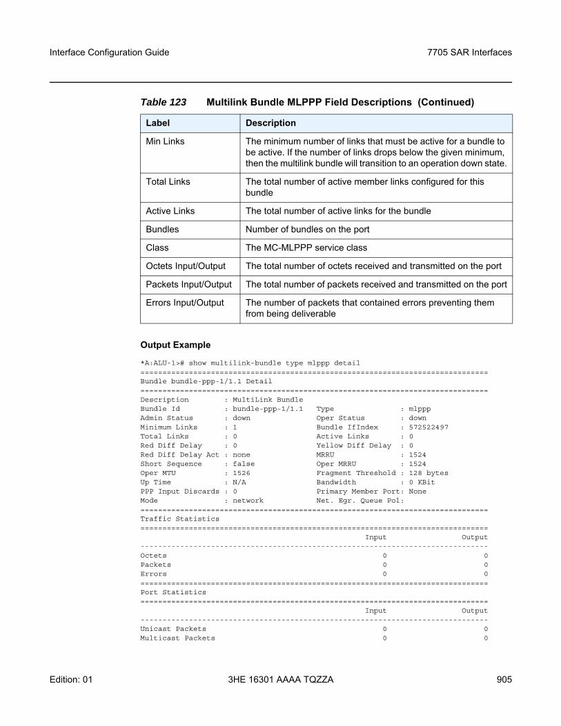
Interface Configuration Guide 7705 SAR Interfaces
Edition: 01 3HE 16301 AAAA TQZZA 905
Output Example
*A:ALU-1># show multilink-bundle type mlppp detail===============================================================================Bundle bundle-ppp-1/1.1 Detail===============================================================================Description : MultiLink BundleBundle Id : bundle-ppp-1/1.1 Type : mlpppAdmin Status : down Oper Status : downMinimum Links : 1 Bundle IfIndex : 572522497Total Links : 0 Active Links : 0Red Diff Delay : 0 Yellow Diff Delay : 0Red Diff Delay Act : none MRRU : 1524Short Sequence : false Oper MRRU : 1524Oper MTU : 1526 Fragment Threshold : 128 bytesUp Time : N/A Bandwidth : 0 KBitPPP Input Discards : 0 Primary Member Port: NoneMode : network Net. Egr. Queue Pol:===============================================================================Traffic Statistics===============================================================================
Input Output-------------------------------------------------------------------------------Octets 0 0Packets 0 0Errors 0 0===============================================================================Port Statistics===============================================================================
Input Output-------------------------------------------------------------------------------Unicast Packets 0 0Multicast Packets 0 0
Min Links The minimum number of links that must be active for a bundle to be active. If the number of links drops below the given minimum, then the multilink bundle will transition to an operation down state.
Total Links The total number of active member links configured for this bundle
Active Links The total number of active links for the bundle
Bundles Number of bundles on the port
Class The MC-MLPPP service class
Octets Input/Output The total number of octets received and transmitted on the port
Packets Input/Output The total number of packets received and transmitted on the port
Errors Input/Output The number of packets that contained errors preventing them from being deliverable
Table 123 Multilink Bundle MLPPP Field Descriptions (Continued)
Label Description
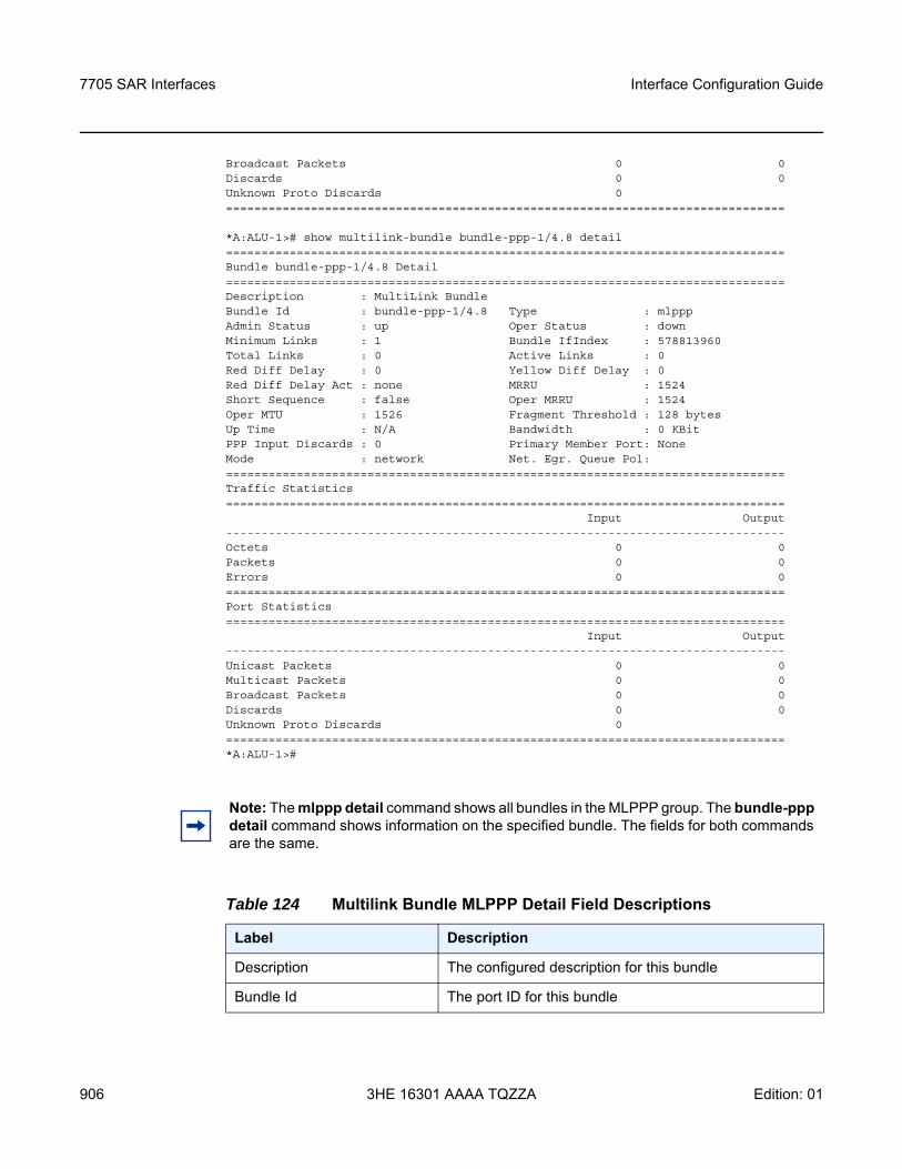
7705 SAR Interfaces
906
Interface Configuration Guide
3HE 16301 AAAA TQZZA Edition: 01
Broadcast Packets 0 0Discards 0 0Unknown Proto Discards 0===============================================================================
*A:ALU-1># show multilink-bundle bundle-ppp-1/4.8 detail===============================================================================Bundle bundle-ppp-1/4.8 Detail===============================================================================Description : MultiLink BundleBundle Id : bundle-ppp-1/4.8 Type : mlpppAdmin Status : up Oper Status : downMinimum Links : 1 Bundle IfIndex : 578813960Total Links : 0 Active Links : 0Red Diff Delay : 0 Yellow Diff Delay : 0Red Diff Delay Act : none MRRU : 1524Short Sequence : false Oper MRRU : 1524Oper MTU : 1526 Fragment Threshold : 128 bytesUp Time : N/A Bandwidth : 0 KBitPPP Input Discards : 0 Primary Member Port: NoneMode : network Net. Egr. Queue Pol:===============================================================================Traffic Statistics===============================================================================
Input Output-------------------------------------------------------------------------------Octets 0 0Packets 0 0Errors 0 0===============================================================================Port Statistics===============================================================================
Input Output-------------------------------------------------------------------------------Unicast Packets 0 0Multicast Packets 0 0Broadcast Packets 0 0Discards 0 0Unknown Proto Discards 0===============================================================================*A:ALU-1>#
Note: The mlppp detail command shows all bundles in the MLPPP group. The bundle-ppp detail command shows information on the specified bundle. The fields for both commands are the same.
Table 124 Multilink Bundle MLPPP Detail Field Descriptions
Label Description
Description The configured description for this bundle
Bundle Id The port ID for this bundle
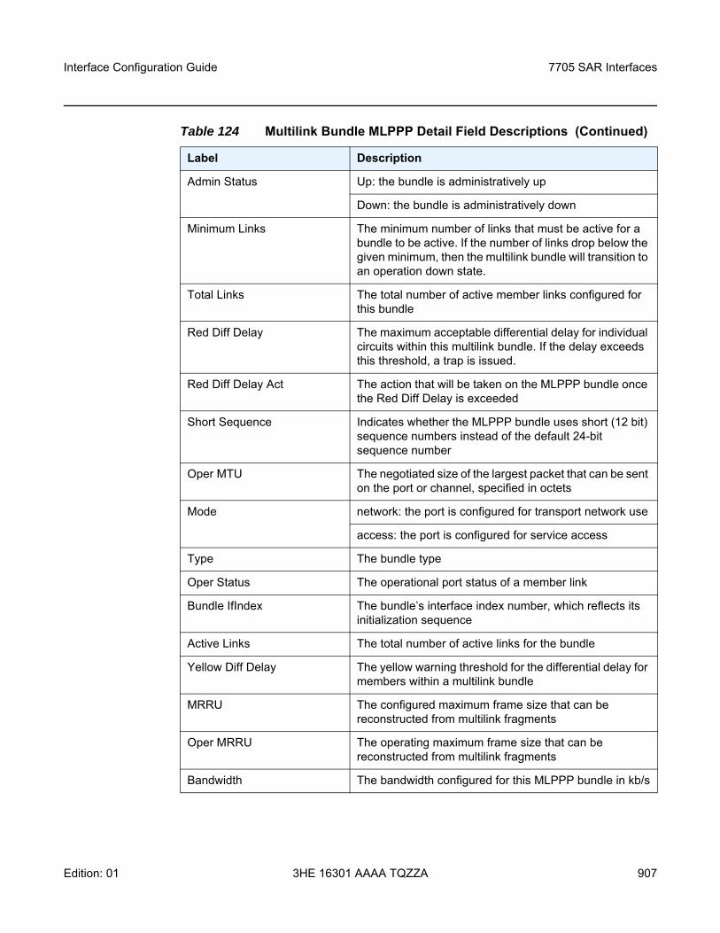
Interface Configuration Guide 7705 SAR Interfaces
Edition: 01 3HE 16301 AAAA TQZZA 907
Admin Status Up: the bundle is administratively up
Down: the bundle is administratively down
Minimum Links The minimum number of links that must be active for a bundle to be active. If the number of links drop below the given minimum, then the multilink bundle will transition to an operation down state.
Total Links The total number of active member links configured for this bundle
Red Diff Delay The maximum acceptable differential delay for individual circuits within this multilink bundle. If the delay exceeds this threshold, a trap is issued.
Red Diff Delay Act The action that will be taken on the MLPPP bundle once the Red Diff Delay is exceeded
Short Sequence Indicates whether the MLPPP bundle uses short (12 bit) sequence numbers instead of the default 24-bit sequence number
Oper MTU The negotiated size of the largest packet that can be sent on the port or channel, specified in octets
Mode network: the port is configured for transport network use
access: the port is configured for service access
Type The bundle type
Oper Status The operational port status of a member link
Bundle IfIndex The bundle’s interface index number, which reflects its initialization sequence
Active Links The total number of active links for the bundle
Yellow Diff Delay The yellow warning threshold for the differential delay for members within a multilink bundle
MRRU The configured maximum frame size that can be reconstructed from multilink fragments
Oper MRRU The operating maximum frame size that can be reconstructed from multilink fragments
Bandwidth The bandwidth configured for this MLPPP bundle in kb/s
Table 124 Multilink Bundle MLPPP Detail Field Descriptions (Continued)
Label Description
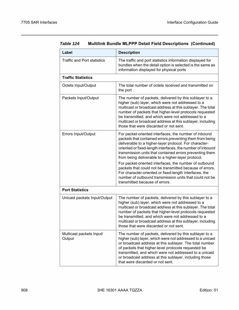
7705 SAR Interfaces
908
Interface Configuration Guide
3HE 16301 AAAA TQZZA Edition: 01
Traffic and Port statistics The traffic and port statistics information displayed for bundles when the detail option is selected is the same as information displayed for physical ports
Traffic Statistics
Octets Input/Output The total number of octets received and transmitted on the port
Packets Input/Output The number of packets, delivered by this sublayer to a higher (sub) layer, which were not addressed to a multicast or broadcast address at this sublayer. The total number of packets that higher-level protocols requested be transmitted, and which were not addressed to a multicast or broadcast address at this sublayer, including those that were discarded or not sent.
Errors Input/Output For packet-oriented interfaces, the number of inbound packets that contained errors preventing them from being deliverable to a higher-layer protocol. For character-oriented or fixed-length interfaces, the number of inbound transmission units that contained errors preventing them from being deliverable to a higher-layer protocol.For packet-oriented interfaces, the number of outbound packets that could not be transmitted because of errors. For character-oriented or fixed-length interfaces, the number of outbound transmission units that could not be transmitted because of errors.
Port Statistics
Unicast packets Input/Output The number of packets, delivered by this sublayer to a higher (sub) layer, which were not addressed to a multicast or broadcast address at this sublayer. The total number of packets that higher-level protocols requested be transmitted, and which were not addressed to a multicast or broadcast address at this sublayer, including those that were discarded or not sent.
Multicast packets Input/Output
The number of packets, delivered by this sublayer to a higher (sub) layer, which were not addressed to a unicast or broadcast address at this sublayer. The total number of packets that higher-level protocols requested be transmitted, and which were not addressed to a unicast or broadcast address at this sublayer, including those that were discarded or not sent.
Table 124 Multilink Bundle MLPPP Detail Field Descriptions (Continued)
Label Description
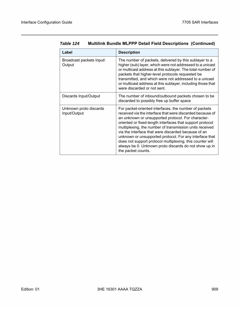
Interface Configuration Guide 7705 SAR Interfaces
Edition: 01 3HE 16301 AAAA TQZZA 909
Broadcast packets Input/Output
The number of packets, delivered by this sublayer to a higher (sub) layer, which were not addressed to a unicast or multicast address at this sublayer. The total number of packets that higher-level protocols requested be transmitted, and which were not addressed to a unicast or multicast address at this sublayer, including those that were discarded or not sent.
Discards Input/Output The number of inbound/outbound packets chosen to be discarded to possibly free up buffer space
Unknown proto discards Input/Output
For packet-oriented interfaces, the number of packets received via the interface that were discarded because of an unknown or unsupported protocol. For character-oriented or fixed-length interfaces that support protocol multiplexing, the number of transmission units received via the interface that were discarded because of an unknown or unsupported protocol. For any interface that does not support protocol multiplexing, this counter will always be 0. Unknown proto discards do not show up in the packet counts.
Table 124 Multilink Bundle MLPPP Detail Field Descriptions (Continued)
Label Description
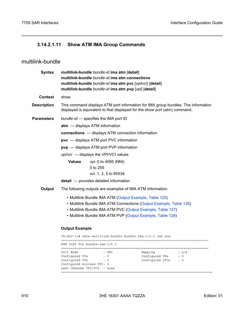
7705 SAR Interfaces
910
Interface Configuration Guide
3HE 16301 AAAA TQZZA Edition: 01
3.14.2.1.11 Show ATM IMA Group Commands
multilink-bundle
Syntax multilink-bundle bundle-id ima atm [detail]multilink-bundle bundle-id ima atm connectionsmultilink-bundle bundle-id ima atm pvc [vpi/vci] [detail]multilink-bundle bundle-id ima atm pvp [vpi] [detail]
Context show
Description This command displays ATM port information for IMA group bundles. The information displayed is equivalent to that displayed for the show port (atm) command.
Parameters bundle-id — specifies the IMA port ID
atm — displays ATM information
connections — displays ATM connection information
pvc — displays ATM port PVC information
pvp — displays ATM port PVP information
vpi/vci — displays the VPI/VCI values
Values vpi: 0 to 4095 (NNI)0 to 255vci: 1, 2, 5 to 65534
detail — provides detailed information
Output The following outputs are examples of IMA ATM information:
• Multilink Bundle IMA ATM (Output Example, Table 125)• Multilink Bundle IMA ATM Connections (Output Example, Table 126)• Multilink Bundle IMA ATM PVC (Output Example, Table 127)• Multilink Bundle IMA ATM PVP (Output Example, Table 128)
Output Example
*A:ALU-1># show multilink-bundle bundle-ima-1/6.3 ima atm=============================================================================ATM Info for bundle-ima-1/6.3=============================================================================Cell Mode : UNI Mapping : n/aConfigured VCs : 0 Configured VPs : 0Configured VTs : 0 Configured IFCs : 0Configured minimum VPI: 0Last Unknown VPI/VCI : none===============================================================================
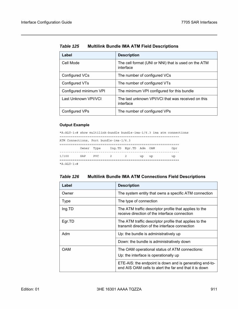
Interface Configuration Guide 7705 SAR Interfaces
Edition: 01 3HE 16301 AAAA TQZZA 911
Output Example
*A:ALU-1># show multilink-bundle bundle-ima-1/6.3 ima atm connections================================================================ATM Connections, Port bundle-ima-1/6.3================================================================
Owner Type Ing.TD Egr.TD Adm OAM Opr----------------------------------------------------------------1/100 SAP PVC 2 2 up up up================================================================*A:ALU-1>#
Table 125 Multilink Bundle IMA ATM Field Descriptions
Label Description
Cell Mode The cell format (UNI or NNI) that is used on the ATM interface
Configured VCs The number of configured VCs
Configured VTs The number of configured VTs
Configured minimum VPI The minimum VPI configured for this bundle
Last Unknown VPI/VCI The last unknown VPI/VCI that was received on this interface
Configured VPs The number of configured VPs
Table 126 Multilink Bundle IMA ATM Connections Field Descriptions
Label Description
Owner The system entity that owns a specific ATM connection
Type The type of connection
Ing.TD The ATM traffic descriptor profile that applies to the receive direction of the interface connection
Egr.TD The ATM traffic descriptor profile that applies to the transmit direction of the interface connection
Adm Up: the bundle is administratively up
Down: the bundle is administratively down
OAM The OAM operational status of ATM connections:Up: the interface is operationally up
ETE-AIS: the endpoint is down and is generating end-to-end AIS OAM cells to alert the far end that it is down
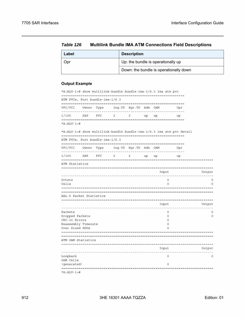
7705 SAR Interfaces
912
Interface Configuration Guide
3HE 16301 AAAA TQZZA Edition: 01
Output Example
*A:ALU-1># show multilink-bundle bundle-ima-1/6.3 ima atm pvc================================================================ATM PVCs, Port bundle-ima-1/6.3================================================================VPI/VCI Owner Type Ing.TD Egr.TD Adm OAM Opr----------------------------------------------------------------1/100 SAP PVC 2 2 up up up================================================================*A:ALU-1>#
*A:ALU-1># show multilink-bundle bundle-ima-1/6.3 ima atm pvc detail================================================================ATM PVCs, Port bundle-ima-1/6.3================================================================VPI/VCI Owner Type Ing.TD Egr.TD Adm OAM Opr----------------------------------------------------------------1/100 SAP PVC 2 2 up up up===============================================================================ATM Statistics===============================================================================
Input Output-------------------------------------------------------------------------------Octets 0 0Cells 0 0==============================================================================================================================================================AAL-5 Packet Statistics===============================================================================
Input Output-------------------------------------------------------------------------------Packets 0 0Dropped Packets 0 0CRC-32 Errors 0Reassembly Timeouts 0Over Sized SDUs 0==============================================================================================================================================================ATM OAM Statistics===============================================================================
Input Output-------------------------------------------------------------------------------Loopback 0 0OAM Cells(generated) 0===============================================================================*A:ALU-1>#
Opr Up: the bundle is operationally up
Down: the bundle is operationally down
Table 126 Multilink Bundle IMA ATM Connections Field Descriptions
Label Description
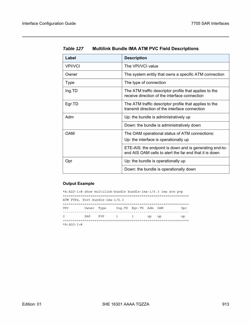
Interface Configuration Guide 7705 SAR Interfaces
Edition: 01 3HE 16301 AAAA TQZZA 913
Output Example
*A:ALU-1># show multilink-bundle bundle-ima-1/6.3 ima atm pvp================================================================ATM PVPs, Port bundle-ima-1/6.3================================================================VPI Owner Type Ing.TD Egr.TD Adm OAM Opr----------------------------------------------------------------2 SAP PVP 1 1 up up up================================================================*A:ALU-1>#
Table 127 Multilink Bundle IMA ATM PVC Field Descriptions
Label Description
VPI/VCI The VPI/VCI value
Owner The system entity that owns a specific ATM connection
Type The type of connection
Ing.TD The ATM traffic descriptor profile that applies to the receive direction of the interface connection
Egr.TD The ATM traffic descriptor profile that applies to the transmit direction of the interface connection
Adm Up: the bundle is administratively up
Down: the bundle is administratively down
OAM The OAM operational status of ATM connections:Up: the interface is operationally up
ETE-AIS: the endpoint is down and is generating end-to-end AIS OAM cells to alert the far end that it is down
Opr Up: the bundle is operationally up
Down: the bundle is operationally down
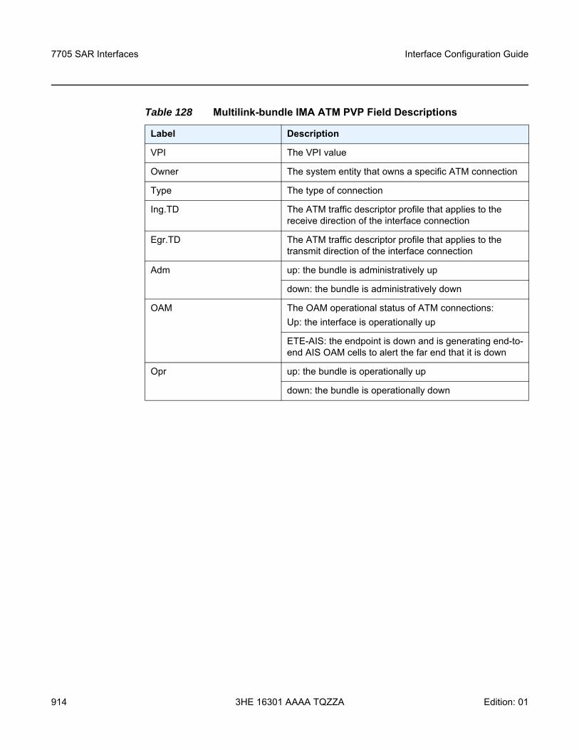
7705 SAR Interfaces
914
Interface Configuration Guide
3HE 16301 AAAA TQZZA Edition: 01
Table 128 Multilink-bundle IMA ATM PVP Field Descriptions
Label Description
VPI The VPI value
Owner The system entity that owns a specific ATM connection
Type The type of connection
Ing.TD The ATM traffic descriptor profile that applies to the receive direction of the interface connection
Egr.TD The ATM traffic descriptor profile that applies to the transmit direction of the interface connection
Adm up: the bundle is administratively up
down: the bundle is administratively down
OAM The OAM operational status of ATM connections:Up: the interface is operationally up
ETE-AIS: the endpoint is down and is generating end-to-end AIS OAM cells to alert the far end that it is down
Opr up: the bundle is operationally up
down: the bundle is operationally down
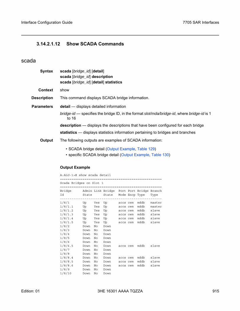
Interface Configuration Guide 7705 SAR Interfaces
Edition: 01 3HE 16301 AAAA TQZZA 915
3.14.2.1.12 Show SCADA Commands
scada
Syntax scada [bridge_id] [detail]scada [bridge_id] descriptionscada [bridge_id] [detail] statistics
Context show
Description This command displays SCADA bridge information.
Parameters detail — displays detailed information
bridge-id — specifies the bridge ID, in the format slot/mda/bridge-id, where bridge-id is 1 to 16
description — displays the descriptions that have been configured for each bridge
statistics — displays statistics information pertaining to bridges and branches
Output The following outputs are examples of SCADA information:
• SCADA bridge detail (Output Example, Table 129)• specific SCADA bridge detail (Output Example, Table 130)
Output Example
A:ALU-1># show scada detail======================================================Scada Bridges on Slot 1======================================================Bridge Admin Link Bridge Port Port Bridge BranchId State State Mode Encp Type Type------------------------------------------------------1/8/1 Up Yes Up accs cem mddb master1/8/1.1 Up Yes Up accs cem mddb master1/8/1.2 Up Yes Up accs cem mddb slave1/8/1.3 Up Yes Up accs cem mddb slave1/8/1.4 Up Yes Up accs cem mddb slave1/8/1.5 Up Yes Up accs cem mddb slave1/8/2 Down No Down1/8/3 Down No Down1/8/4 Down No Down1/8/5 Down No Down1/8/6 Down No Down1/8/6.5 Down No Down accs cem mddb slave1/8/7 Down No Down1/8/8 Down No Down1/8/8.4 Down No Down accs cem mddb slave1/8/8.5 Down No Down accs cem mddb slave1/8/8.6 Down No Down accs cem mddb slave1/8/9 Down No Down1/8/10 Down No Down
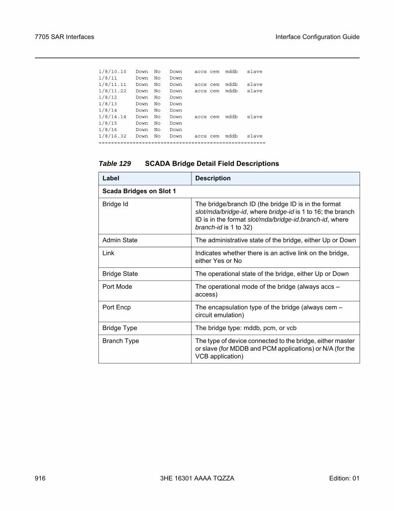
7705 SAR Interfaces
916
Interface Configuration Guide
3HE 16301 AAAA TQZZA Edition: 01
1/8/10.10 Down No Down accs cem mddb slave1/8/11 Down No Down1/8/11.11 Down No Down accs cem mddb slave1/8/11.22 Down No Down accs cem mddb slave1/8/12 Down No Down1/8/13 Down No Down1/8/14 Down No Down1/8/14.14 Down No Down accs cem mddb slave1/8/15 Down No Down1/8/16 Down No Down1/8/16.32 Down No Down accs cem mddb slave======================================================
Table 129 SCADA Bridge Detail Field Descriptions
Label Description
Scada Bridges on Slot 1
Bridge Id The bridge/branch ID (the bridge ID is in the format slot/mda/bridge-id, where bridge-id is 1 to 16; the branch ID is in the format slot/mda/bridge-id.branch-id, where branch-id is 1 to 32)
Admin State The administrative state of the bridge, either Up or Down
Link Indicates whether there is an active link on the bridge, either Yes or No
Bridge State The operational state of the bridge, either Up or Down
Port Mode The operational mode of the bridge (always accs – access)
Port Encp The encapsulation type of the bridge (always cem – circuit emulation)
Bridge Type The bridge type: mddb, pcm, or vcb
Branch Type The type of device connected to the bridge, either master or slave (for MDDB and PCM applications) or N/A (for the VCB application)
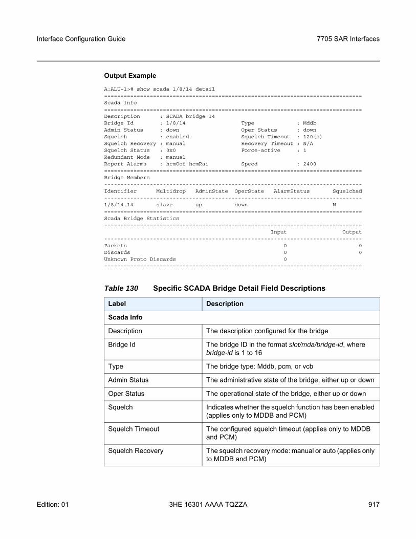
Interface Configuration Guide 7705 SAR Interfaces
Edition: 01 3HE 16301 AAAA TQZZA 917
Output Example
A:ALU-1># show scada 1/8/14 detail===============================================================================Scada Info===============================================================================Description : SCADA bridge 14Bridge Id : 1/8/14 Type : MddbAdmin Status : down Oper Status : downSquelch : enabled Squelch Timeout : 120(s)Squelch Recovery : manual Recovery Timeout : N/ASquelch Status : 0x0 Force-active : 1Redundant Mode : manualReport Alarms : hcmOof hcmRai Speed : 2400===============================================================================Bridge Members-------------------------------------------------------------------------------Identifier Multidrop AdminState OperState AlarmStatus Squelched-------------------------------------------------------------------------------1/8/14.14 slave up down N===============================================================================Scada Bridge Statistics===============================================================================
Input Output-------------------------------------------------------------------------------Packets 0 0Discards 0 0Unknown Proto Discards 0===============================================================================
Table 130 Specific SCADA Bridge Detail Field Descriptions
Label Description
Scada Info
Description The description configured for the bridge
Bridge Id The bridge ID in the format slot/mda/bridge-id, where bridge-id is 1 to 16
Type The bridge type: Mddb, pcm, or vcb
Admin Status The administrative state of the bridge, either up or down
Oper Status The operational state of the bridge, either up or down
Squelch Indicates whether the squelch function has been enabled (applies only to MDDB and PCM)
Squelch Timeout The configured squelch timeout (applies only to MDDB and PCM)
Squelch Recovery The squelch recovery mode: manual or auto (applies only to MDDB and PCM)
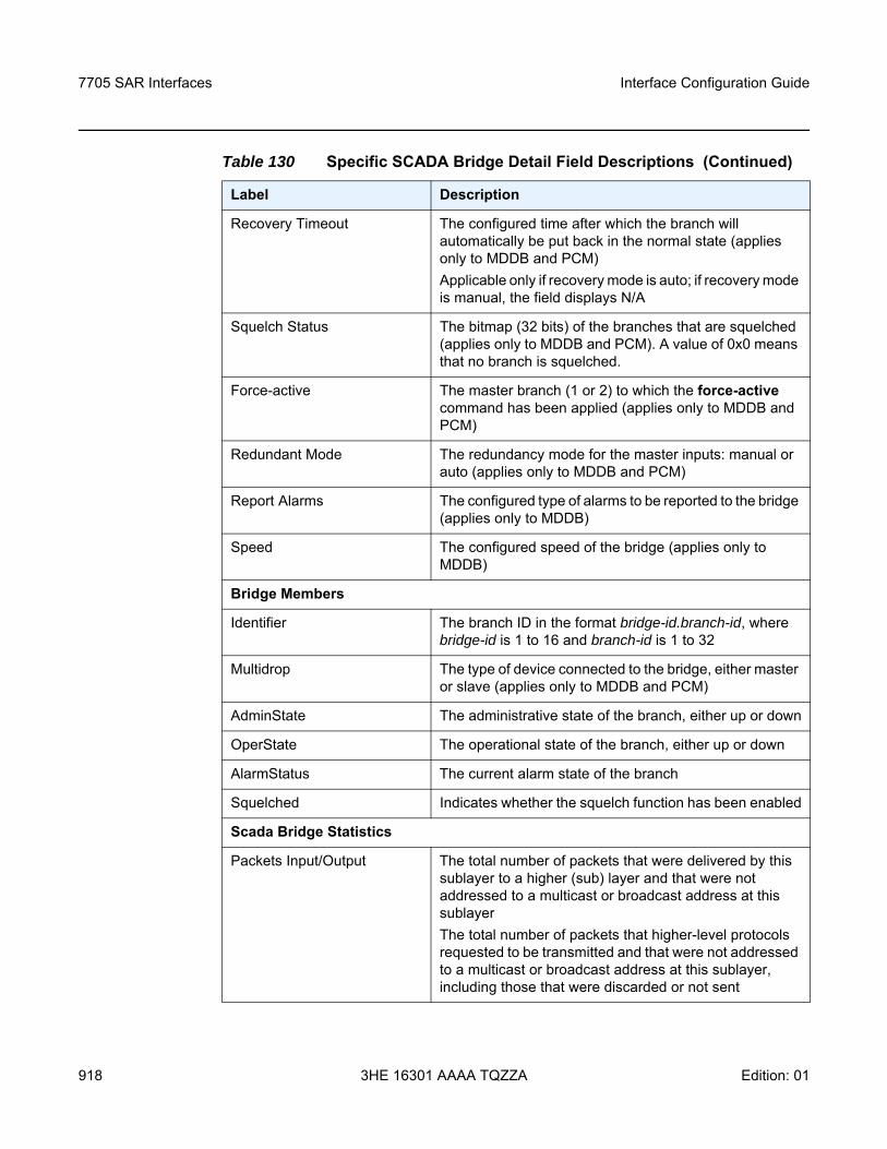
7705 SAR Interfaces
918
Interface Configuration Guide
3HE 16301 AAAA TQZZA Edition: 01
Recovery Timeout The configured time after which the branch will automatically be put back in the normal state (applies only to MDDB and PCM)Applicable only if recovery mode is auto; if recovery mode is manual, the field displays N/A
Squelch Status The bitmap (32 bits) of the branches that are squelched (applies only to MDDB and PCM). A value of 0x0 means that no branch is squelched.
Force-active The master branch (1 or 2) to which the force-active command has been applied (applies only to MDDB and PCM)
Redundant Mode The redundancy mode for the master inputs: manual or auto (applies only to MDDB and PCM)
Report Alarms The configured type of alarms to be reported to the bridge (applies only to MDDB)
Speed The configured speed of the bridge (applies only to MDDB)
Bridge Members
Identifier The branch ID in the format bridge-id.branch-id, where bridge-id is 1 to 16 and branch-id is 1 to 32
Multidrop The type of device connected to the bridge, either master or slave (applies only to MDDB and PCM)
AdminState The administrative state of the branch, either up or down
OperState The operational state of the branch, either up or down
AlarmStatus The current alarm state of the branch
Squelched Indicates whether the squelch function has been enabled
Scada Bridge Statistics
Packets Input/Output The total number of packets that were delivered by this sublayer to a higher (sub) layer and that were not addressed to a multicast or broadcast address at this sublayerThe total number of packets that higher-level protocols requested to be transmitted and that were not addressed to a multicast or broadcast address at this sublayer, including those that were discarded or not sent
Table 130 Specific SCADA Bridge Detail Field Descriptions (Continued)
Label Description
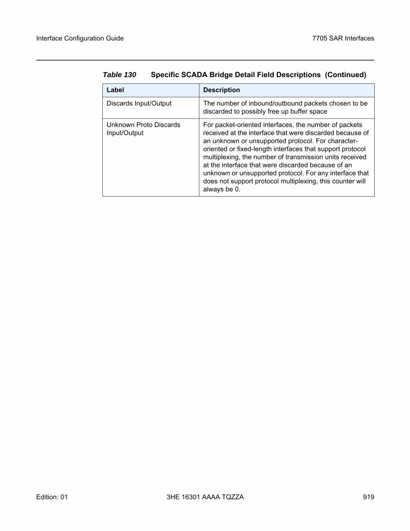
Interface Configuration Guide 7705 SAR Interfaces
Edition: 01 3HE 16301 AAAA TQZZA 919
Discards Input/Output The number of inbound/outbound packets chosen to be discarded to possibly free up buffer space
Unknown Proto Discards Input/Output
For packet-oriented interfaces, the number of packets received at the interface that were discarded because of an unknown or unsupported protocol. For character-oriented or fixed-length interfaces that support protocol multiplexing, the number of transmission units received at the interface that were discarded because of an unknown or unsupported protocol. For any interface that does not support protocol multiplexing, this counter will always be 0.
Table 130 Specific SCADA Bridge Detail Field Descriptions (Continued)
Label Description
7705 SAR Interfaces
920
Interface Configuration Guide
3HE 16301 AAAA TQZZA Edition: 01
3.14.2.2 Monitor Commands
• Port Monitor Commands• Fabric Profile Statistics Monitor Commands• SCADA Monitor Commands
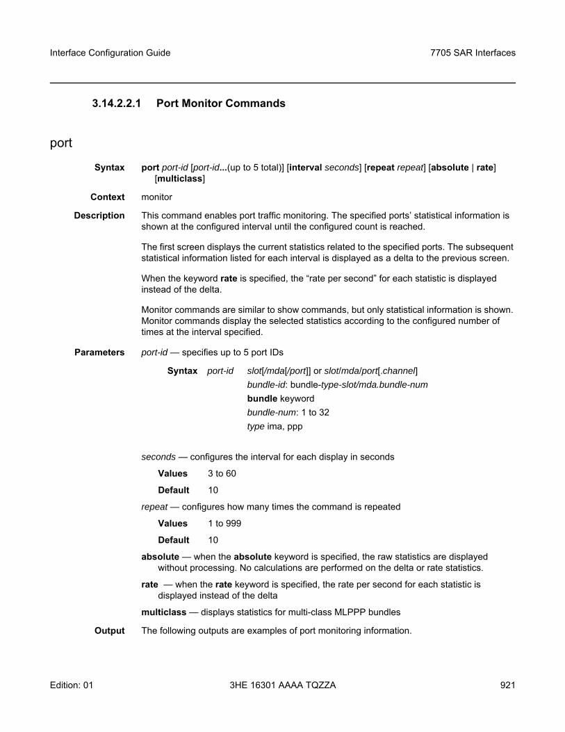
Interface Configuration Guide 7705 SAR Interfaces
Edition: 01 3HE 16301 AAAA TQZZA 921
3.14.2.2.1 Port Monitor Commands
port
Syntax port port-id [port-id...(up to 5 total)] [interval seconds] [repeat repeat] [absolute | rate] [multiclass]
Context monitor
Description This command enables port traffic monitoring. The specified ports’ statistical information is shown at the configured interval until the configured count is reached.
The first screen displays the current statistics related to the specified ports. The subsequent statistical information listed for each interval is displayed as a delta to the previous screen.
When the keyword rate is specified, the “rate per second” for each statistic is displayed instead of the delta.
Monitor commands are similar to show commands, but only statistical information is shown. Monitor commands display the selected statistics according to the configured number of times at the interval specified.
Parameters port-id — specifies up to 5 port IDs
seconds — configures the interval for each display in seconds
Values 3 to 60
Default 10
repeat — configures how many times the command is repeated
Values 1 to 999
Default 10
absolute — when the absolute keyword is specified, the raw statistics are displayed without processing. No calculations are performed on the delta or rate statistics.
rate — when the rate keyword is specified, the rate per second for each statistic is displayed instead of the delta
multiclass — displays statistics for multi-class MLPPP bundles
Output The following outputs are examples of port monitoring information.
Syntax port-id slot[/mda[/port]] or slot/mda/port[.channel]bundle-id: bundle-type-slot/mda.bundle-numbundle keywordbundle-num: 1 to 32type ima, ppp
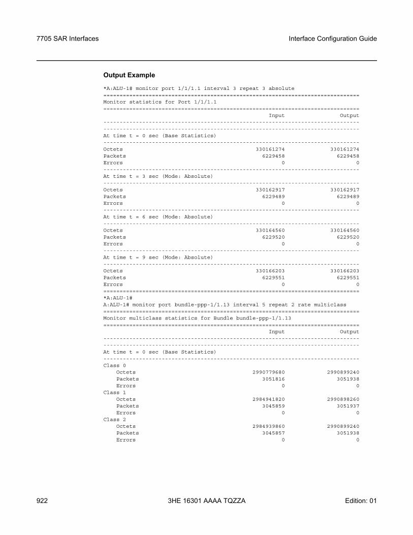
7705 SAR Interfaces
922
Interface Configuration Guide
3HE 16301 AAAA TQZZA Edition: 01
Output Example
*A:ALU-1# monitor port 1/1/1.1 interval 3 repeat 3 absolute===============================================================================Monitor statistics for Port 1/1/1.1===============================================================================
Input Output--------------------------------------------------------------------------------------------------------------------------------------------------------------At time t = 0 sec (Base Statistics)-------------------------------------------------------------------------------Octets 330161274 330161274Packets 6229458 6229458Errors 0 0-------------------------------------------------------------------------------At time t = 3 sec (Mode: Absolute)-------------------------------------------------------------------------------Octets 330162917 330162917Packets 6229489 6229489Errors 0 0-------------------------------------------------------------------------------At time t = 6 sec (Mode: Absolute)-------------------------------------------------------------------------------Octets 330164560 330164560Packets 6229520 6229520Errors 0 0-------------------------------------------------------------------------------At time t = 9 sec (Mode: Absolute)-------------------------------------------------------------------------------Octets 330166203 330166203Packets 6229551 6229551Errors 0 0===============================================================================*A:ALU-1#A:ALU-1# monitor port bundle-ppp-1/1.13 interval 5 repeat 2 rate multiclass===============================================================================Monitor multiclass statistics for Bundle bundle-ppp-1/1.13===============================================================================
Input Output--------------------------------------------------------------------------------------------------------------------------------------------------------------At time t = 0 sec (Base Statistics)-------------------------------------------------------------------------------Class 0
Octets 2990779680 2990899240Packets 3051816 3051938Errors 0 0
Class 1Octets 2984941820 2990898260Packets 3045859 3051937Errors 0 0
Class 2Octets 2984939860 2990899240Packets 3045857 3051938Errors 0 0

Interface Configuration Guide 7705 SAR Interfaces
Edition: 01 3HE 16301 AAAA TQZZA 923
Class 3Octets 2984940840 2990899240Packets 3045858 3051938Errors 0 0
-------------------------------------------------------------------------------At time t = 5 sec (Mode: Rate)-------------------------------------------------------------------------------Class 0
Octets 9408 9408Packets 10 10Errors 0 0
Utilization (% of port capacity) 1.89 1.89Class 1
Octets 9408 9408Packets 10 10Errors 0 0
Utilization (% of port capacity) 1.89 1.89Class 2
Octets 9212 9408Packets 9 10Errors 0 0
Utilization (% of port capacity) 1.85 1.89Class 3
Octets 9408 9408Packets 10 10Errors 0 0
Utilization (% of port capacity) 1.89 1.89-------------------------------------------------------------------------------At time t = 10 sec (Mode: Rate)-------------------------------------------------------------------------------Class 0
Octets 9408 9408Packets 10 10Errors 0 0
Utilization (% of port capacity) 1.89 1.89Class 1
Octets 9408 9408Packets 10 10Errors 0 0
Utilization (% of port capacity) 1.89 1.89Class 2
Octets 9408 9408Packets 10 10Errors 0 0
Utilization (% of port capacity) 1.89 1.89Class 3
Octets 9212 9408Packets 9 10Errors 0 0
Utilization (% of port capacity) 1.85 1.89===============================================================================A:ALU-1#
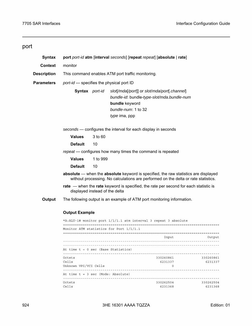
7705 SAR Interfaces
924
Interface Configuration Guide
3HE 16301 AAAA TQZZA Edition: 01
port
Syntax port port-id atm [interval seconds] [repeat repeat] [absolute | rate]
Context monitor
Description This command enables ATM port traffic monitoring.
Parameters port-id — specifies the physical port ID
seconds — configures the interval for each display in seconds
Values 3 to 60
Default 10
repeat — configures how many times the command is repeated
Values 1 to 999
Default 10
absolute — when the absolute keyword is specified, the raw statistics are displayed without processing. No calculations are performed on the delta or rate statistics.
rate — when the rate keyword is specified, the rate per second for each statistic is displayed instead of the delta
Output The following output is an example of ATM port monitoring information.
Output Example
*A:ALU-1# monitor port 1/1/1.1 atm interval 3 repeat 3 absolute===============================================================================Monitor ATM statistics for Port 1/1/1.1===============================================================================
Input Output--------------------------------------------------------------------------------------------------------------------------------------------------------------At time t = 0 sec (Base Statistics)-------------------------------------------------------------------------------Octets 330260861 330260861Cells 6231337 6231337Unknown VPI/VCI Cells 0-------------------------------------------------------------------------------At time t = 3 sec (Mode: Absolute)-------------------------------------------------------------------------------Octets 330262504 330262504Cells 6231368 6231368
Syntax port-id slot[/mda[/port]] or slot/mda/port[.channel]bundle-id: bundle-type-slot/mda.bundle-numbundle keywordbundle-num: 1 to 32type ima, ppp
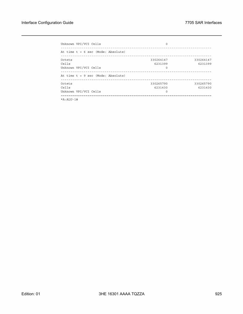
Interface Configuration Guide 7705 SAR Interfaces
Edition: 01 3HE 16301 AAAA TQZZA 925
Unknown VPI/VCI Cells 0-------------------------------------------------------------------------------At time t = 6 sec (Mode: Absolute)-------------------------------------------------------------------------------Octets 330264147 330264147Cells 6231399 6231399Unknown VPI/VCI Cells 0-------------------------------------------------------------------------------At time t = 9 sec (Mode: Absolute)-------------------------------------------------------------------------------Octets 330265790 330265790Cells 6231430 6231430Unknown VPI/VCI Cells 0===============================================================================*A:ALU-1#
7705 SAR Interfaces
926
Interface Configuration Guide
3HE 16301 AAAA TQZZA Edition: 01
3.14.2.2.2 Fabric Profile Statistics Monitor Commands
fabric-profile
Syntax fabric-profile mda mda-id | with-stats-enabled dest-mda | source-mda [interval seconds] [repeat repeat] [absolute | rate]
Context monitor
Description This command enables monitoring of adapter card fabric profile statistics. The specified adapter card statistical information displays and automatically refreshes at the configured interval.
Parameters mda-id — the slot number of the adapter card
with-stats-enabled — if used, this keyword replaces the mda-id parameter, in which case the adapter card that has fabric-stats-enabled configured will be the one which is monitored; that is, the command will be monitor fabric-profile mda with-stats-enabled dest-mda | source-mda. If there are no adapter cards that have fabric-stats-enabled configured, no statistics will be displayed.
dest-mda — displays network and access ingress statistics for all adapter cards going towards the fabric and destined for the specific destination adapter card. The following are also displayed: global fabric statistics, fabric firewall statistics, and the fabric port statistics if the destination adapter card has the collection of fabric statistics enabled. The sum of traffic forwarded or dropped is also displayed.
source-mda — displays network and access ingress traffic statistics from the specified adapter card going towards the fabric and towards a destination adapter card. Fabric firewall statistics and the sum of traffic forwarded or dropped are also displayed.
seconds — configures the interval for each display in seconds
Values 3 to 60
Default 10
repeat — configures how many times the command is repeated
Values 1 to 999
Default 10
absolute — displays the raw statistics without processing. No calculations are performed on the delta or rate statistics.
rate — displays the rate per second for each statistic instead of the delta
Interface Configuration Guide 7705 SAR Interfaces
Edition: 01 3HE 16301 AAAA TQZZA 927
3.14.2.2.3 SCADA Monitor Commands
scada
Syntax scada scada-id [scada-id...(up to 5 total)] [interval seconds] [repeat repeat] [absolute | rate]
Context monitor
Description This command enables traffic monitoring for a SCADA bridge or branch. The statistical information for the specified bridge or branch is shown at the configured interval until the configured count is reached.
The first screen displays the current statistics related to the specified bridge or branch. The subsequent statistical information listed for each interval is displayed as a delta to the previous screen.
When the keyword rate is specified, the “rate per second” for each statistic is displayed instead of the delta.
Monitor commands are similar to show commands, but only statistical information is shown. Monitor commands display the selected statistics according to the configured number of times at the interval specified.
Parameters scada-id — specifies a bridge-id or a branch-id. For a bridge-id, the format is slot/mda/bridge-id, where bridge-id is 1 to 16. For a branch-id, the format is slot/mda/bridge-id.branch-id, where bridge-id is 1 to 16 and branch-id is 1 to 32. Up to five scada-ids can be specified.
seconds — configures the interval for each display in seconds
Values 3 to 60
Default 10
repeat — configures how many times the command is repeated
Values 1 to 999
Default 10
absolute — when the absolute keyword is specified, the raw statistics are displayed without processing. No calculations are performed on the delta or rate statistics.
rate — when the rate keyword is specified, the rate per second for each statistic is displayed instead of the delta; the default mode is delta
7705 SAR Interfaces
928
Interface Configuration Guide
3HE 16301 AAAA TQZZA Edition: 01
3.14.2.3 Clear Commands
external-alarms
Syntax external-alarms alarm [all | alarm-id]
Context clear
Description This command clears remote site external alarm information.
Parameters all — clears the status for all alarms
alarm-id — clears the status for a specific alarm
Values 1 to 2147483647
lag
Syntax lag lag-id statistics
Context clear
Description This command clears statistics for the specified LAG.
Parameters lag-id — the LAG identifier, expressed as a decimal integer
Values 1 to 32
statistics — specifies that statistics are cleared for the specified LAG
mda
Syntax mda mda-idmda mda-id statistics source-mda | destination-mda | fabric-port | fabric-global |
fabric-firewall | allmda mda-id ring all | mac ieee-address | port port-idmda mda-id statistics ip-transportmda mda-id statistics security [encryption | firewall] mda mda-id statistics mirrormda mda-id statistics cflowdmda all
Context clear
Interface Configuration Guide 7705 SAR Interfaces
Edition: 01 3HE 16301 AAAA TQZZA 929
Description The clear mda form of this command reinitializes the specified adapter card or DSL module and clears all the collected fabric statistics related to the card or module. The clear mda statistics form of this command clears all the collected fabric statistics related to the specified adapter card or DSL module. The clear mda ring form of this command clears the dynamic FDB entries related to the specified ring adapter card.
The clear mda all form of this command applies only to the 7705 SAR-A, 7705 SAR-Ax, 7705 SAR-M, 7705 SAR-H, 7705 SAR-Hc, 7705 SAR-W, and 7705 SAR-Wx and is equivalent to clearing all adapter cards using all keywords above (source-mda, destination-mda, fabric-port, and fabric-global)
Parameters mda-id — the slot number of the specified adapter card or DSL module
statistics — specifies that fabric statistics will be cleared for the specified adapter card or DSL module
source-mda — clears all the network and access ingress traffic statistics in the fabric direction from the specified adapter card towards all other destination adapter cards
destination-mda — clears all the network and access ingress traffic statistics towards the specified adapter card fabric port, from all other adapter cards
fabric-port — clears the fabric port statistics towards the specified destination adapter card, if the specified adapter card has fabric-stats-enabled. If the specified adapter card does not have fabric-stats-enabled, no statistics will be cleared.
fabric-global — clears global fabric statistics collected for all egress traffic from the fabric
fabric-firewall — clears fabric firewall statistics collected for all egress traffic from the fabric
security — clears only security statistics for the specified adapter card
encryption — specifies that encryption statistics will be cleared for the specified adapter card
firewall — specifies that firewall statistics will be cleared for the specified adapter card
ip-transport — specifies that IP transport statistics will be cleared for the specified adapter card
mirror — specifies that mirror statistics will be cleared for the specified adapter card
cflowd — clears Cflowd queue statistics on the 7705 SAR-8, 7705 SAR-18, and 7705 SAR-X
mda-id all — clears all the collected fabric statistics related to the specified adapter card. This command is equivalent to clearing the specified adapter card using all keywords above (source-mda, destination-mda, fabric-port, fabric-global).
ring all — clears the entire dynamic FDB
ieee-address — clears the dynamic FDB entry for the specified MAC address
port-id — clears the dynamic FDB entries for the specified port
all — clears all the collected fabric statistics across all adapter cards or modules
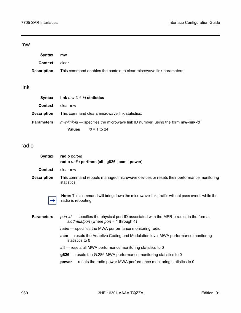
7705 SAR Interfaces
930
Interface Configuration Guide
3HE 16301 AAAA TQZZA Edition: 01
mw
Syntax mw
Context clear
Description This command enables the context to clear microwave link parameters.
link
Syntax link mw-link-id statistics
Context clear mw
Description This command clears microwave link statistics.
Parameters mw-link-id — specifies the microwave link ID number, using the form mw-link-id
Values id = 1 to 24
radio
Syntax radio port-id radio radio perfmon [all | g826 | acm | power]
Context clear mw
Description This command reboots managed microwave devices or resets their performance monitoring statistics.
Parameters port-id — specifies the physical port ID associated with the MPR-e radio, in the format slot/mda/port (where port = 1 through 4)
radio — specifies the MWA performance monitoring radio
acm — resets the Adaptive Coding and Modulation level MWA performance monitoring statistics to 0
all — resets all MWA performance monitoring statistics to 0
g826 — resets the G.286 MWA performance monitoring statistics to 0
power — resets the radio power MWA performance monitoring statistics to 0
Note: This command will bring down the microwave link; traffic will not pass over it while the radio is rebooting.
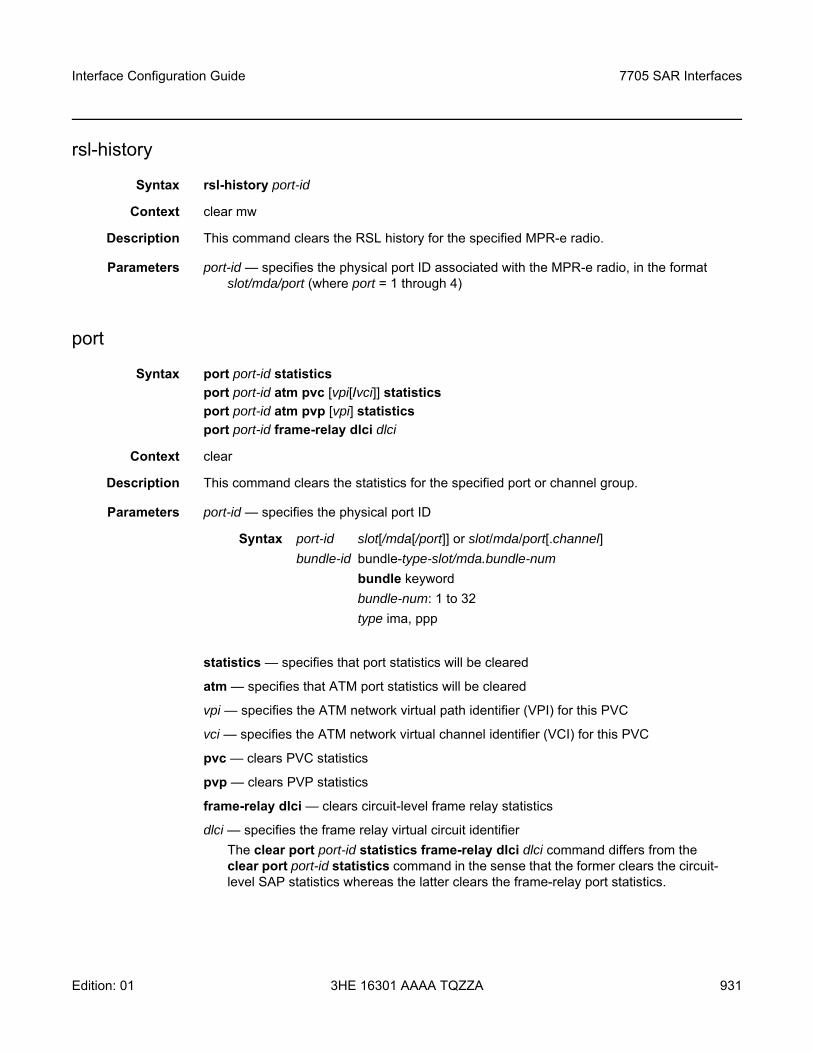
Interface Configuration Guide 7705 SAR Interfaces
Edition: 01 3HE 16301 AAAA TQZZA 931
rsl-history
Syntax rsl-history port-id
Context clear mw
Description This command clears the RSL history for the specified MPR-e radio.
Parameters port-id — specifies the physical port ID associated with the MPR-e radio, in the format slot/mda/port (where port = 1 through 4)
port
Syntax port port-id statisticsport port-id atm pvc [vpi[/vci]] statisticsport port-id atm pvp [vpi] statisticsport port-id frame-relay dlci dlci
Context clear
Description This command clears the statistics for the specified port or channel group.
Parameters port-id — specifies the physical port ID
statistics — specifies that port statistics will be cleared
atm — specifies that ATM port statistics will be cleared
vpi — specifies the ATM network virtual path identifier (VPI) for this PVC
vci — specifies the ATM network virtual channel identifier (VCI) for this PVC
pvc — clears PVC statistics
pvp — clears PVP statistics
frame-relay dlci — clears circuit-level frame relay statistics
dlci — specifies the frame relay virtual circuit identifierThe clear port port-id statistics frame-relay dlci dlci command differs from the clear port port-id statistics command in the sense that the former clears the circuit-level SAP statistics whereas the latter clears the frame-relay port statistics.
Syntax port-id slot[/mda[/port]] or slot/mda/port[.channel]bundle-id bundle-type-slot/mda.bundle-num
bundle keywordbundle-num: 1 to 32type ima, ppp
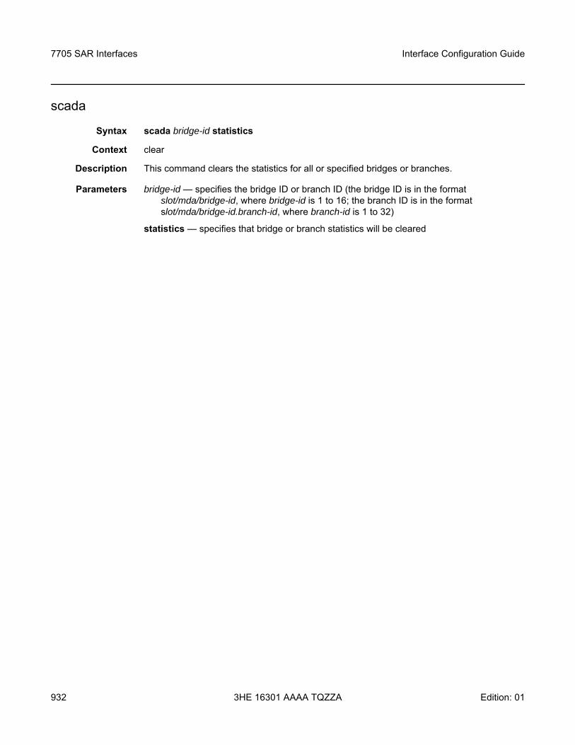
7705 SAR Interfaces
932
Interface Configuration Guide
3HE 16301 AAAA TQZZA Edition: 01
scada
Syntax scada bridge-id statistics
Context clear
Description This command clears the statistics for all or specified bridges or branches.
Parameters bridge-id — specifies the bridge ID or branch ID (the bridge ID is in the format slot/mda/bridge-id, where bridge-id is 1 to 16; the branch ID is in the format slot/mda/bridge-id.branch-id, where branch-id is 1 to 32)
statistics — specifies that bridge or branch statistics will be cleared
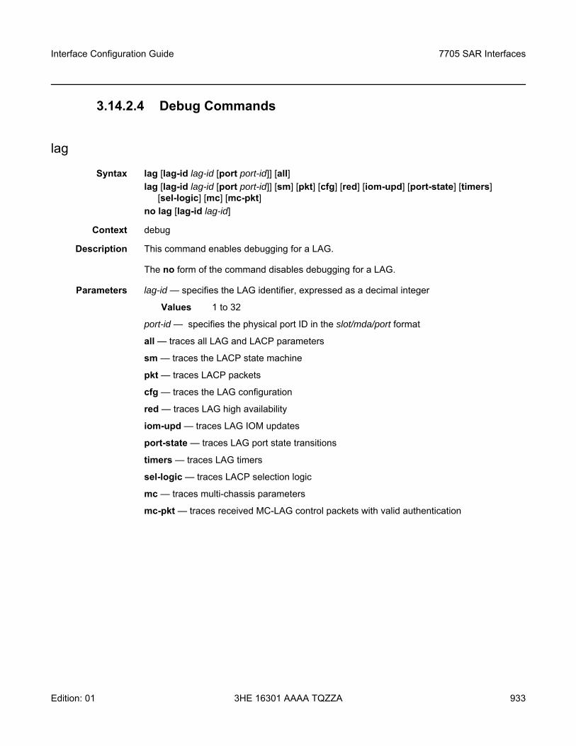
Interface Configuration Guide 7705 SAR Interfaces
Edition: 01 3HE 16301 AAAA TQZZA 933
3.14.2.4 Debug Commands
lag
Syntax lag [lag-id lag-id [port port-id]] [all]lag [lag-id lag-id [port port-id]] [sm] [pkt] [cfg] [red] [iom-upd] [port-state] [timers]
[sel-logic] [mc] [mc-pkt]no lag [lag-id lag-id]
Context debug
Description This command enables debugging for a LAG.
The no form of the command disables debugging for a LAG.
Parameters lag-id — specifies the LAG identifier, expressed as a decimal integer
Values 1 to 32
port-id — specifies the physical port ID in the slot/mda/port format
all — traces all LAG and LACP parameters
sm — traces the LACP state machine
pkt — traces LACP packets
cfg — traces the LAG configuration
red — traces LAG high availability
iom-upd — traces LAG IOM updates
port-state — traces LAG port state transitions
timers — traces LAG timers
sel-logic — traces LACP selection logic
mc — traces multi-chassis parameters
mc-pkt — traces received MC-LAG control packets with valid authentication

7705 SAR Interfaces
934
Interface Configuration Guide
3HE 16301 AAAA TQZZA Edition: 01
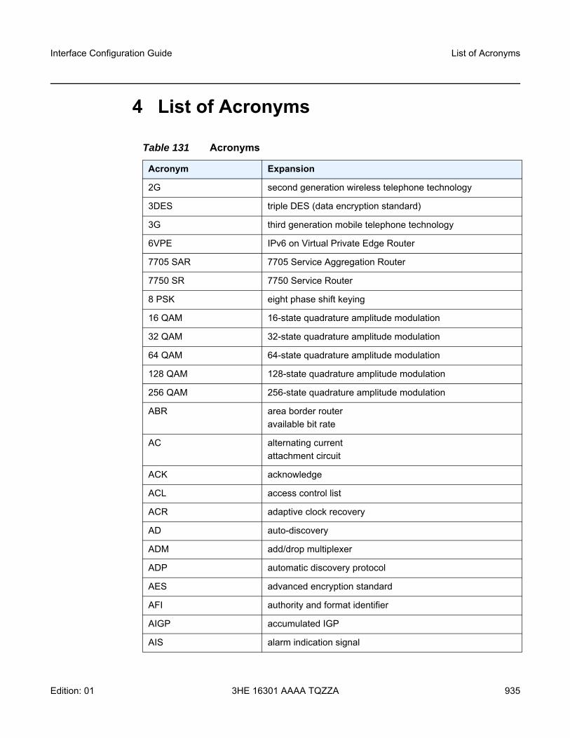
Interface Configuration Guide List of Acronyms
Edition: 01 3HE 16301 AAAA TQZZA 935
4 List of Acronyms
Table 131 Acronyms
Acronym Expansion
2G second generation wireless telephone technology
3DES triple DES (data encryption standard)
3G third generation mobile telephone technology
6VPE IPv6 on Virtual Private Edge Router
7705 SAR 7705 Service Aggregation Router
7750 SR 7750 Service Router
8 PSK eight phase shift keying
16 QAM 16-state quadrature amplitude modulation
32 QAM 32-state quadrature amplitude modulation
64 QAM 64-state quadrature amplitude modulation
128 QAM 128-state quadrature amplitude modulation
256 QAM 256-state quadrature amplitude modulation
ABR area border routeravailable bit rate
AC alternating currentattachment circuit
ACK acknowledge
ACL access control list
ACR adaptive clock recovery
AD auto-discovery
ADM add/drop multiplexer
ADP automatic discovery protocol
AES advanced encryption standard
AFI authority and format identifier
AIGP accumulated IGP
AIS alarm indication signal
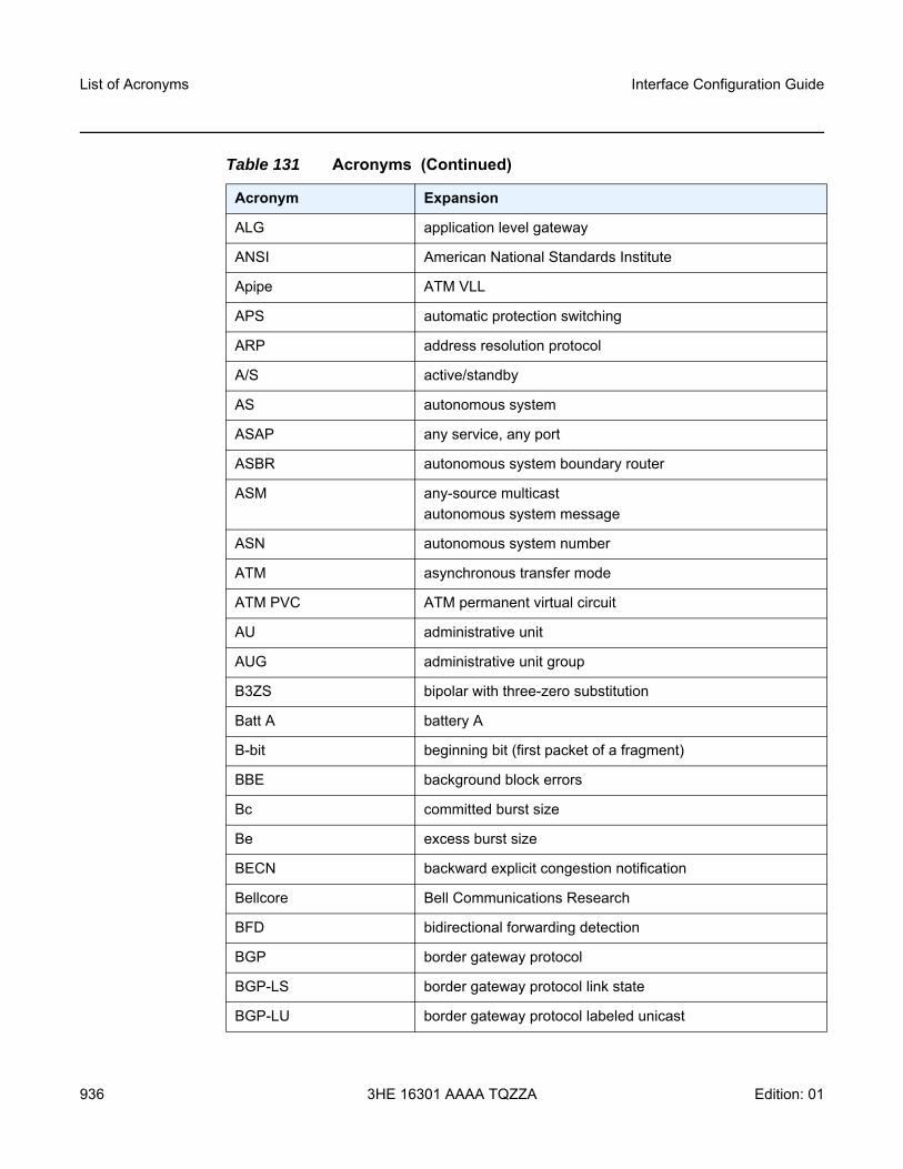
List of Acronyms
936
Interface Configuration Guide
3HE 16301 AAAA TQZZA Edition: 01
ALG application level gateway
ANSI American National Standards Institute
Apipe ATM VLL
APS automatic protection switching
ARP address resolution protocol
A/S active/standby
AS autonomous system
ASAP any service, any port
ASBR autonomous system boundary router
ASM any-source multicastautonomous system message
ASN autonomous system number
ATM asynchronous transfer mode
ATM PVC ATM permanent virtual circuit
AU administrative unit
AUG administrative unit group
B3ZS bipolar with three-zero substitution
Batt A battery A
B-bit beginning bit (first packet of a fragment)
BBE background block errors
Bc committed burst size
Be excess burst size
BECN backward explicit congestion notification
Bellcore Bell Communications Research
BFD bidirectional forwarding detection
BGP border gateway protocol
BGP-LS border gateway protocol link state
BGP-LU border gateway protocol labeled unicast
Table 131 Acronyms (Continued)
Acronym Expansion
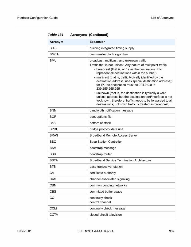
Interface Configuration Guide List of Acronyms
Edition: 01 3HE 16301 AAAA TQZZA 937
BITS building integrated timing supply
BMCA best master clock algorithm
BMU broadcast, multicast, and unknown trafficTraffic that is not unicast. Any nature of multipoint traffic:
• broadcast (that is, all 1s as the destination IP to represent all destinations within the subnet)
• multicast (that is, traffic typically identified by the destination address, uses special destination address); for IP, the destination must be 224.0.0.0 to 239.255.255.255
• unknown (that is, the destination is typically a valid unicast address but the destination port/interface is not yet known; therefore, traffic needs to be forwarded to all destinations; unknown traffic is treated as broadcast)
BNM bandwidth notification message
BOF boot options file
BoS bottom of stack
BPDU bridge protocol data unit
BRAS Broadband Remote Access Server
BSC Base Station Controller
BSM bootstrap message
BSR bootstrap router
BSTA Broadband Service Termination Architecture
BTS base transceiver station
CA certificate authority
CAS channel associated signaling
CBN common bonding networks
CBS committed buffer space
CC continuity checkcontrol channel
CCM continuity check message
CCTV closed-circuit television
Table 131 Acronyms (Continued)
Acronym Expansion
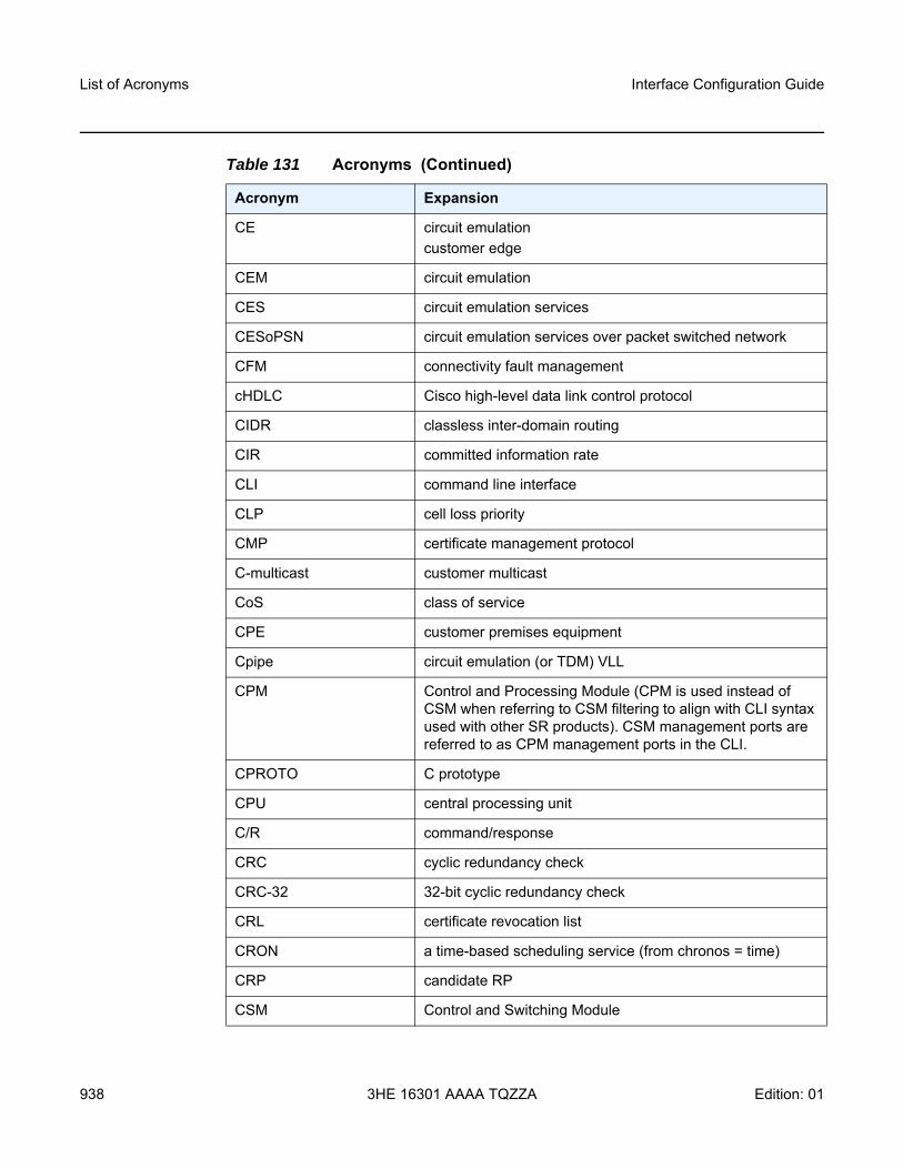
List of Acronyms
938
Interface Configuration Guide
3HE 16301 AAAA TQZZA Edition: 01
CE circuit emulationcustomer edge
CEM circuit emulation
CES circuit emulation services
CESoPSN circuit emulation services over packet switched network
CFM connectivity fault management
cHDLC Cisco high-level data link control protocol
CIDR classless inter-domain routing
CIR committed information rate
CLI command line interface
CLP cell loss priority
CMP certificate management protocol
C-multicast customer multicast
CoS class of service
CPE customer premises equipment
Cpipe circuit emulation (or TDM) VLL
CPM Control and Processing Module (CPM is used instead of CSM when referring to CSM filtering to align with CLI syntax used with other SR products). CSM management ports are referred to as CPM management ports in the CLI.
CPROTO C prototype
CPU central processing unit
C/R command/response
CRC cyclic redundancy check
CRC-32 32-bit cyclic redundancy check
CRL certificate revocation list
CRON a time-based scheduling service (from chronos = time)
CRP candidate RP
CSM Control and Switching Module
Table 131 Acronyms (Continued)
Acronym Expansion
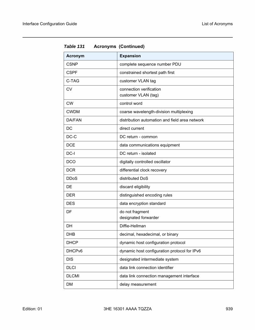
Interface Configuration Guide List of Acronyms
Edition: 01 3HE 16301 AAAA TQZZA 939
CSNP complete sequence number PDU
CSPF constrained shortest path first
C-TAG customer VLAN tag
CV connection verificationcustomer VLAN (tag)
CW control word
CWDM coarse wavelength-division multiplexing
DA/FAN distribution automation and field area network
DC direct current
DC-C DC return - common
DCE data communications equipment
DC-I DC return - isolated
DCO digitally controlled oscillator
DCR differential clock recovery
DDoS distributed DoS
DE discard eligibility
DER distinguished encoding rules
DES data encryption standard
DF do not fragmentdesignated forwarder
DH Diffie-Hellman
DHB decimal, hexadecimal, or binary
DHCP dynamic host configuration protocol
DHCPv6 dynamic host configuration protocol for IPv6
DIS designated intermediate system
DLCI data link connection identifier
DLCMI data link connection management interface
DM delay measurement
Table 131 Acronyms (Continued)
Acronym Expansion
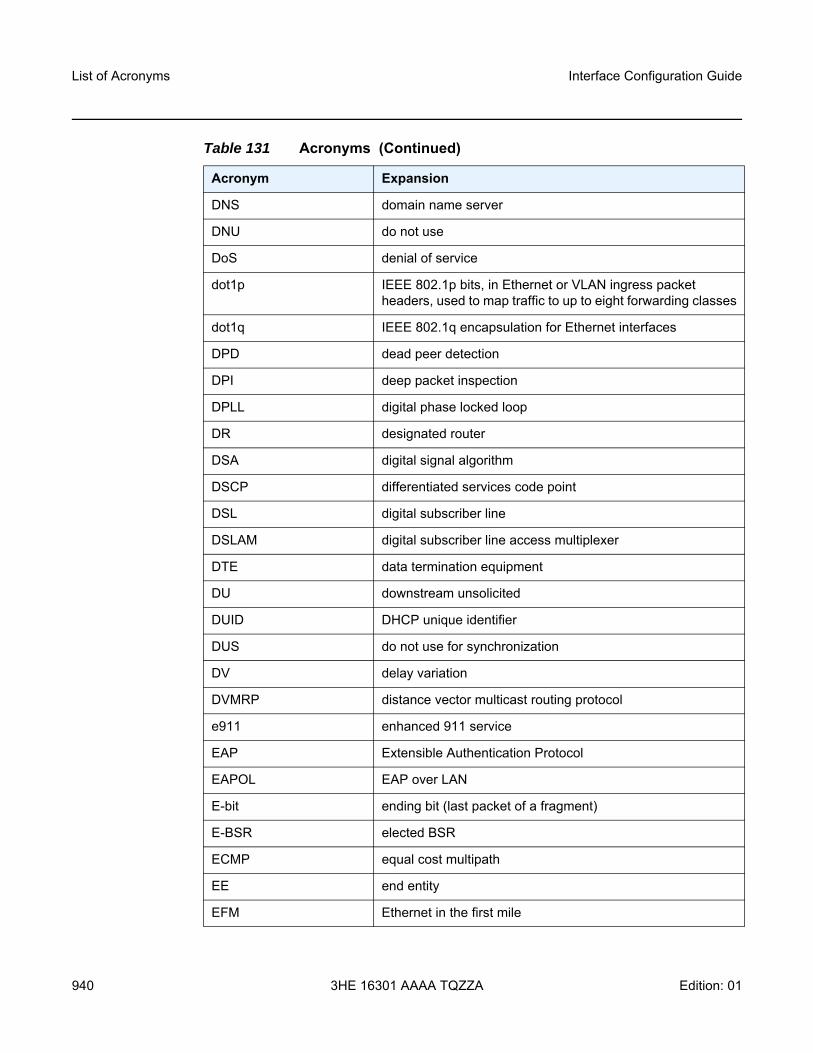
List of Acronyms
940
Interface Configuration Guide
3HE 16301 AAAA TQZZA Edition: 01
DNS domain name server
DNU do not use
DoS denial of service
dot1p IEEE 802.1p bits, in Ethernet or VLAN ingress packet headers, used to map traffic to up to eight forwarding classes
dot1q IEEE 802.1q encapsulation for Ethernet interfaces
DPD dead peer detection
DPI deep packet inspection
DPLL digital phase locked loop
DR designated router
DSA digital signal algorithm
DSCP differentiated services code point
DSL digital subscriber line
DSLAM digital subscriber line access multiplexer
DTE data termination equipment
DU downstream unsolicited
DUID DHCP unique identifier
DUS do not use for synchronization
DV delay variation
DVMRP distance vector multicast routing protocol
e911 enhanced 911 service
EAP Extensible Authentication Protocol
EAPOL EAP over LAN
E-bit ending bit (last packet of a fragment)
E-BSR elected BSR
ECMP equal cost multipath
EE end entity
EFM Ethernet in the first mile
Table 131 Acronyms (Continued)
Acronym Expansion
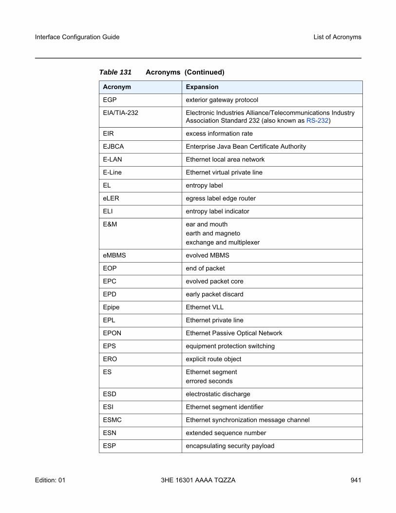
Interface Configuration Guide List of Acronyms
Edition: 01 3HE 16301 AAAA TQZZA 941
EGP exterior gateway protocol
EIA/TIA-232 Electronic Industries Alliance/Telecommunications Industry Association Standard 232 (also known as RS-232)
EIR excess information rate
EJBCA Enterprise Java Bean Certificate Authority
E-LAN Ethernet local area network
E-Line Ethernet virtual private line
EL entropy label
eLER egress label edge router
ELI entropy label indicator
E&M ear and mouthearth and magnetoexchange and multiplexer
eMBMS evolved MBMS
EOP end of packet
EPC evolved packet core
EPD early packet discard
Epipe Ethernet VLL
EPL Ethernet private line
EPON Ethernet Passive Optical Network
EPS equipment protection switching
ERO explicit route object
ES Ethernet segmenterrored seconds
ESD electrostatic discharge
ESI Ethernet segment identifier
ESMC Ethernet synchronization message channel
ESN extended sequence number
ESP encapsulating security payload
Table 131 Acronyms (Continued)
Acronym Expansion
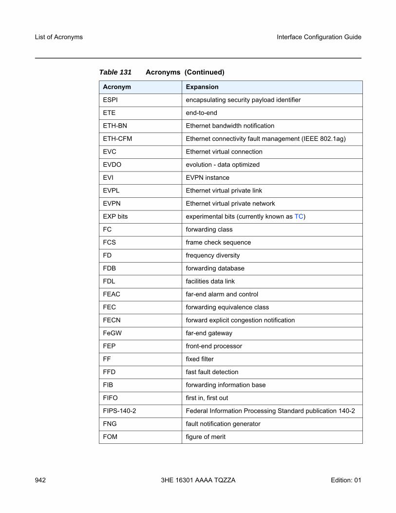
List of Acronyms
942
Interface Configuration Guide
3HE 16301 AAAA TQZZA Edition: 01
ESPI encapsulating security payload identifier
ETE end-to-end
ETH-BN Ethernet bandwidth notification
ETH-CFM Ethernet connectivity fault management (IEEE 802.1ag)
EVC Ethernet virtual connection
EVDO evolution - data optimized
EVI EVPN instance
EVPL Ethernet virtual private link
EVPN Ethernet virtual private network
EXP bits experimental bits (currently known as TC)
FC forwarding class
FCS frame check sequence
FD frequency diversity
FDB forwarding database
FDL facilities data link
FEAC far-end alarm and control
FEC forwarding equivalence class
FECN forward explicit congestion notification
FeGW far-end gateway
FEP front-end processor
FF fixed filter
FFD fast fault detection
FIB forwarding information base
FIFO first in, first out
FIPS-140-2 Federal Information Processing Standard publication 140-2
FNG fault notification generator
FOM figure of merit
Table 131 Acronyms (Continued)
Acronym Expansion
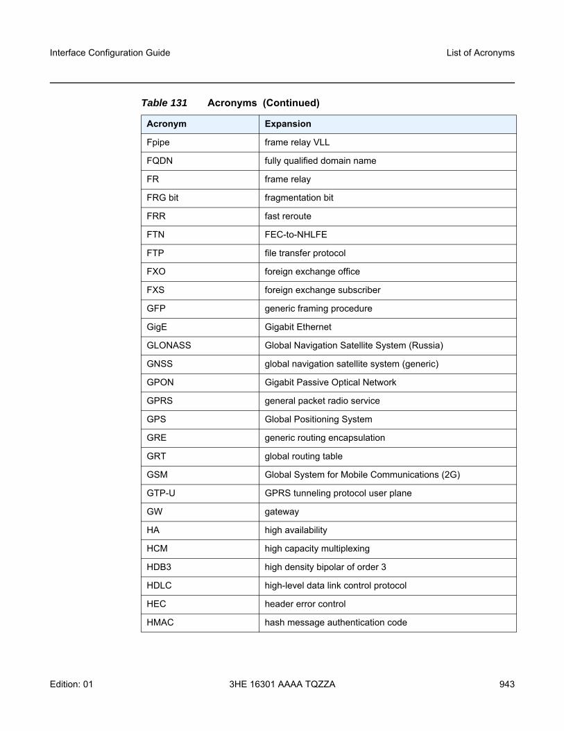
Interface Configuration Guide List of Acronyms
Edition: 01 3HE 16301 AAAA TQZZA 943
Fpipe frame relay VLL
FQDN fully qualified domain name
FR frame relay
FRG bit fragmentation bit
FRR fast reroute
FTN FEC-to-NHLFE
FTP file transfer protocol
FXO foreign exchange office
FXS foreign exchange subscriber
GFP generic framing procedure
GigE Gigabit Ethernet
GLONASS Global Navigation Satellite System (Russia)
GNSS global navigation satellite system (generic)
GPON Gigabit Passive Optical Network
GPRS general packet radio service
GPS Global Positioning System
GRE generic routing encapsulation
GRT global routing table
GSM Global System for Mobile Communications (2G)
GTP-U GPRS tunneling protocol user plane
GW gateway
HA high availability
HCM high capacity multiplexing
HDB3 high density bipolar of order 3
HDLC high-level data link control protocol
HEC header error control
HMAC hash message authentication code
Table 131 Acronyms (Continued)
Acronym Expansion
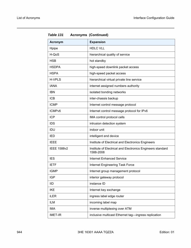
List of Acronyms
944
Interface Configuration Guide
3HE 16301 AAAA TQZZA Edition: 01
Hpipe HDLC VLL
H-QoS hierarchical quality of service
HSB hot standby
HSDPA high-speed downlink packet access
HSPA high-speed packet access
H-VPLS hierarchical virtual private line service
IANA internet assigned numbers authority
IBN isolated bonding networks
ICB inter-chassis backup
ICMP Internet control message protocol
ICMPv6 Internet control message protocol for IPv6
ICP IMA control protocol cells
IDS intrusion detection system
IDU indoor unit
IED intelligent end device
IEEE Institute of Electrical and Electronics Engineers
IEEE 1588v2 Institute of Electrical and Electronics Engineers standard 1588-2008
IES Internet Enhanced Service
IETF Internet Engineering Task Force
IGMP Internet group management protocol
IGP interior gateway protocol
IID instance ID
IKE Internet key exchange
iLER ingress label edge router
ILM incoming label map
IMA inverse multiplexing over ATM
IMET-IR inclusive multicast Ethernet tag—ingress replication
Table 131 Acronyms (Continued)
Acronym Expansion
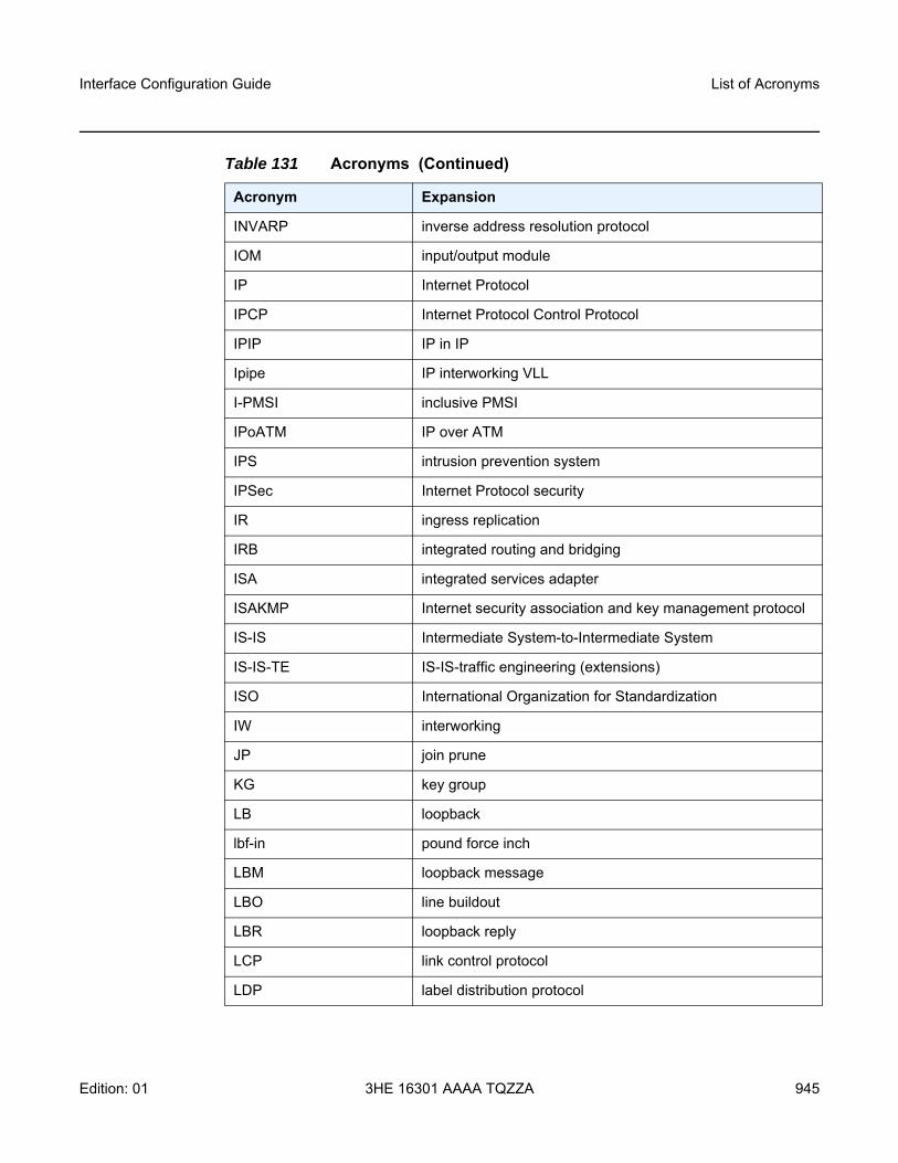
Interface Configuration Guide List of Acronyms
Edition: 01 3HE 16301 AAAA TQZZA 945
INVARP inverse address resolution protocol
IOM input/output module
IP Internet Protocol
IPCP Internet Protocol Control Protocol
IPIP IP in IP
Ipipe IP interworking VLL
I-PMSI inclusive PMSI
IPoATM IP over ATM
IPS intrusion prevention system
IPSec Internet Protocol security
IR ingress replication
IRB integrated routing and bridging
ISA integrated services adapter
ISAKMP Internet security association and key management protocol
IS-IS Intermediate System-to-Intermediate System
IS-IS-TE IS-IS-traffic engineering (extensions)
ISO International Organization for Standardization
IW interworking
JP join prune
KG key group
LB loopback
lbf-in pound force inch
LBM loopback message
LBO line buildout
LBR loopback reply
LCP link control protocol
LDP label distribution protocol
Table 131 Acronyms (Continued)
Acronym Expansion
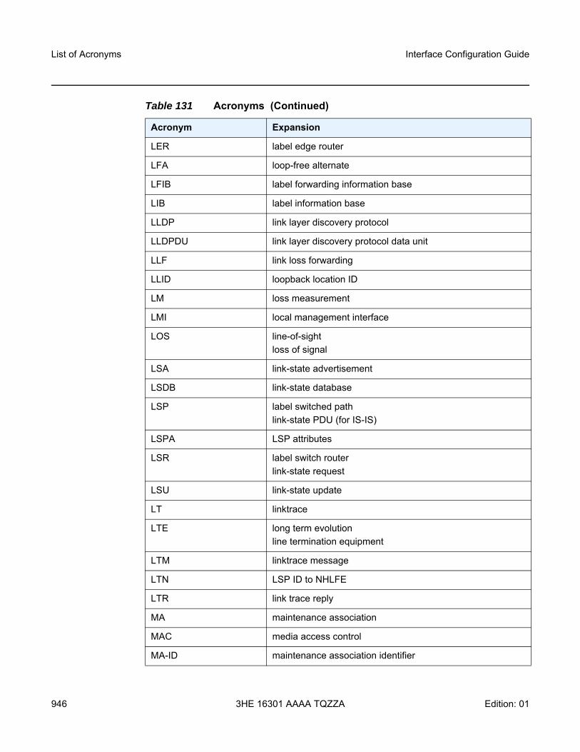
List of Acronyms
946
Interface Configuration Guide
3HE 16301 AAAA TQZZA Edition: 01
LER label edge router
LFA loop-free alternate
LFIB label forwarding information base
LIB label information base
LLDP link layer discovery protocol
LLDPDU link layer discovery protocol data unit
LLF link loss forwarding
LLID loopback location ID
LM loss measurement
LMI local management interface
LOS line-of-sightloss of signal
LSA link-state advertisement
LSDB link-state database
LSP label switched pathlink-state PDU (for IS-IS)
LSPA LSP attributes
LSR label switch routerlink-state request
LSU link-state update
LT linktrace
LTE long term evolutionline termination equipment
LTM linktrace message
LTN LSP ID to NHLFE
LTR link trace reply
MA maintenance association
MAC media access control
MA-ID maintenance association identifier
Table 131 Acronyms (Continued)
Acronym Expansion
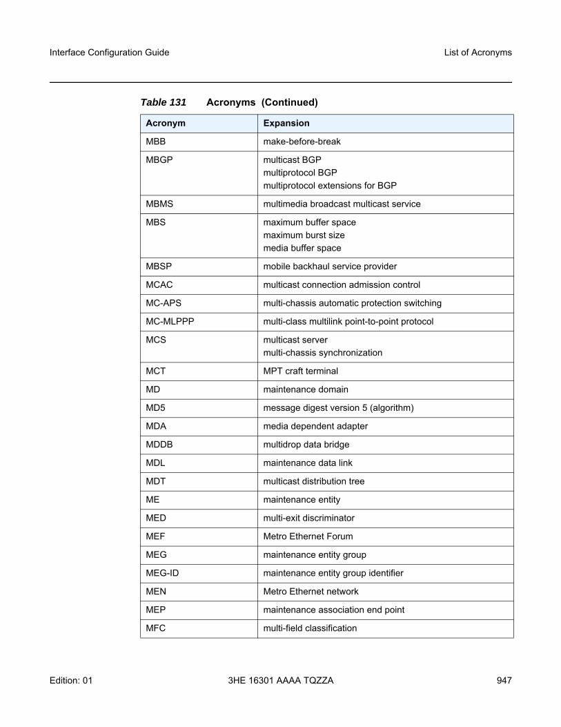
Interface Configuration Guide List of Acronyms
Edition: 01 3HE 16301 AAAA TQZZA 947
MBB make-before-break
MBGP multicast BGPmultiprotocol BGPmultiprotocol extensions for BGP
MBMS multimedia broadcast multicast service
MBS maximum buffer spacemaximum burst sizemedia buffer space
MBSP mobile backhaul service provider
MCAC multicast connection admission control
MC-APS multi-chassis automatic protection switching
MC-MLPPP multi-class multilink point-to-point protocol
MCS multicast servermulti-chassis synchronization
MCT MPT craft terminal
MD maintenance domain
MD5 message digest version 5 (algorithm)
MDA media dependent adapter
MDDB multidrop data bridge
MDL maintenance data link
MDT multicast distribution tree
ME maintenance entity
MED multi-exit discriminator
MEF Metro Ethernet Forum
MEG maintenance entity group
MEG-ID maintenance entity group identifier
MEN Metro Ethernet network
MEP maintenance association end point
MFC multi-field classification
Table 131 Acronyms (Continued)
Acronym Expansion
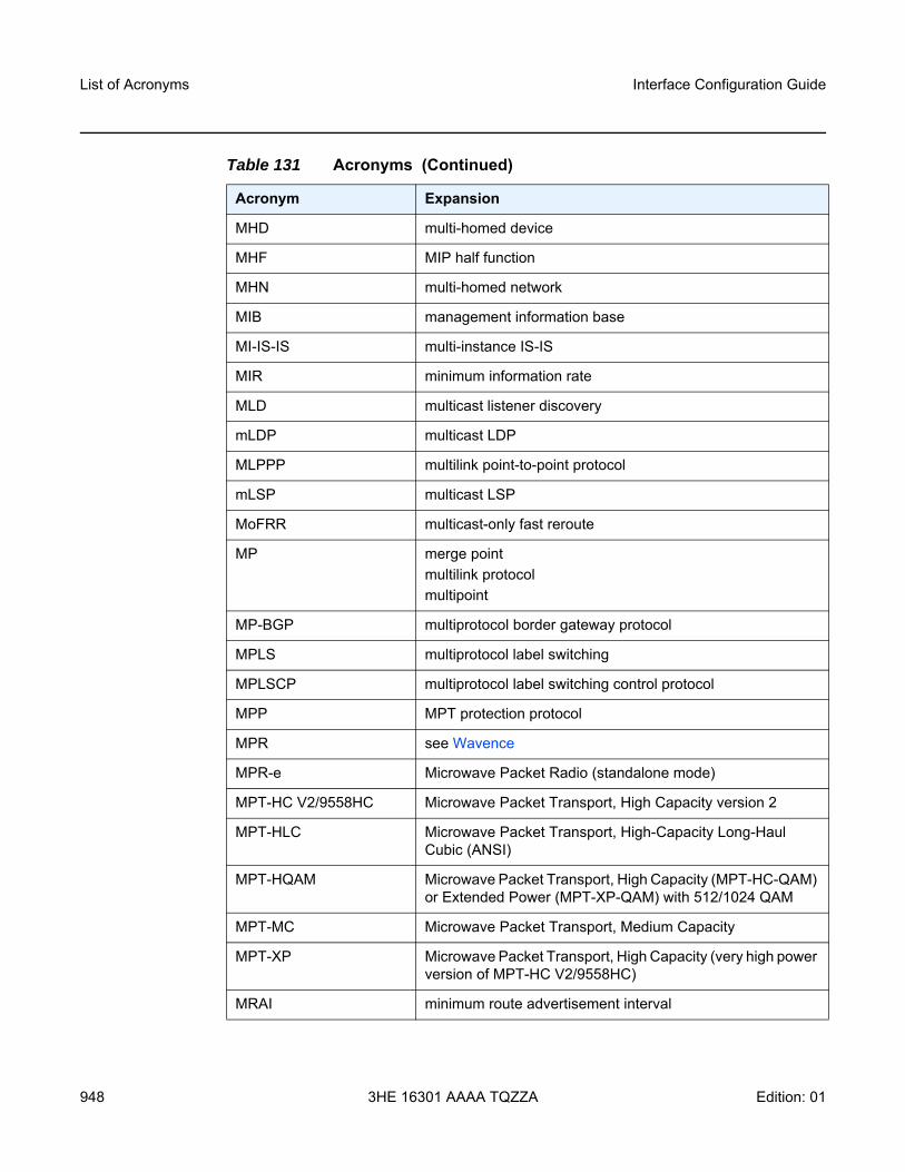
List of Acronyms
948
Interface Configuration Guide
3HE 16301 AAAA TQZZA Edition: 01
MHD multi-homed device
MHF MIP half function
MHN multi-homed network
MIB management information base
MI-IS-IS multi-instance IS-IS
MIR minimum information rate
MLD multicast listener discovery
mLDP multicast LDP
MLPPP multilink point-to-point protocol
mLSP multicast LSP
MoFRR multicast-only fast reroute
MP merge pointmultilink protocolmultipoint
MP-BGP multiprotocol border gateway protocol
MPLS multiprotocol label switching
MPLSCP multiprotocol label switching control protocol
MPP MPT protection protocol
MPR see Wavence
MPR-e Microwave Packet Radio (standalone mode)
MPT-HC V2/9558HC Microwave Packet Transport, High Capacity version 2
MPT-HLC Microwave Packet Transport, High-Capacity Long-Haul Cubic (ANSI)
MPT-HQAM Microwave Packet Transport, High Capacity (MPT-HC-QAM) or Extended Power (MPT-XP-QAM) with 512/1024 QAM
MPT-MC Microwave Packet Transport, Medium Capacity
MPT-XP Microwave Packet Transport, High Capacity (very high power version of MPT-HC V2/9558HC)
MRAI minimum route advertisement interval
Table 131 Acronyms (Continued)
Acronym Expansion
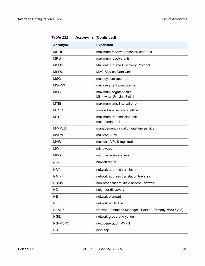
Interface Configuration Guide List of Acronyms
Edition: 01 3HE 16301 AAAA TQZZA 949
MRRU maximum received reconstructed unit
MRU maximum receive unit
MSDP Multicast Source Discovery Protocol
MSDU MAC Service Data Unit
MSO multi-system operator
MS-PW multi-segment pseudowire
MSS maximum segment sizeMicrowave Service Switch
MTIE maximum time interval error
MTSO mobile trunk switching office
MTU maximum transmission unitmulti-tenant unit
M-VPLS management virtual private line service
MVPN multicast VPN
MVR multicast VPLS registration
MW microwave
MWA microwave awareness
N.m newton meter
NAT network address translation
NAT-T network address translation traversal
NBMA non-broadcast multiple access (network)
ND neighbor discovery
NE network element
NET network entity title
NFM-P Network Functions Manager - Packet (formerly 5620 SAM)
NGE network group encryption
NG-MVPN next generation MVPN
NH next hop
Table 131 Acronyms (Continued)
Acronym Expansion
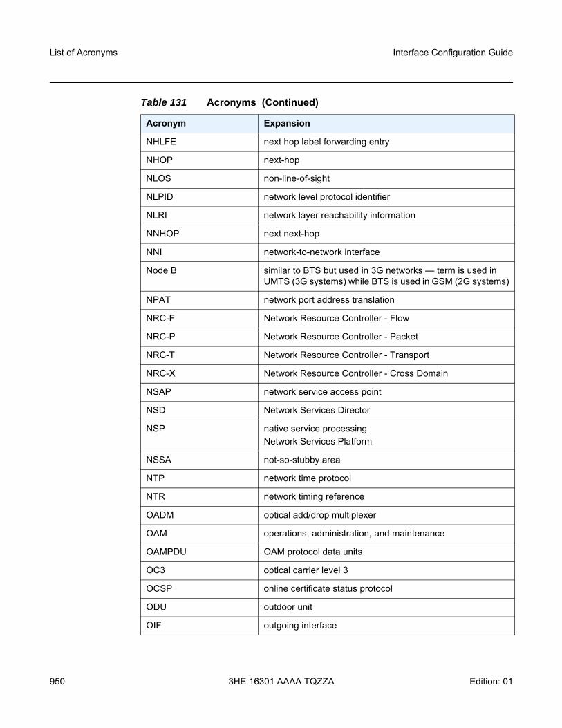
List of Acronyms
950
Interface Configuration Guide
3HE 16301 AAAA TQZZA Edition: 01
NHLFE next hop label forwarding entry
NHOP next-hop
NLOS non-line-of-sight
NLPID network level protocol identifier
NLRI network layer reachability information
NNHOP next next-hop
NNI network-to-network interface
Node B similar to BTS but used in 3G networks — term is used in UMTS (3G systems) while BTS is used in GSM (2G systems)
NPAT network port address translation
NRC-F Network Resource Controller - Flow
NRC-P Network Resource Controller - Packet
NRC-T Network Resource Controller - Transport
NRC-X Network Resource Controller - Cross Domain
NSAP network service access point
NSD Network Services Director
NSP native service processingNetwork Services Platform
NSSA not-so-stubby area
NTP network time protocol
NTR network timing reference
OADM optical add/drop multiplexer
OAM operations, administration, and maintenance
OAMPDU OAM protocol data units
OC3 optical carrier level 3
OCSP online certificate status protocol
ODU outdoor unit
OIF outgoing interface
Table 131 Acronyms (Continued)
Acronym Expansion
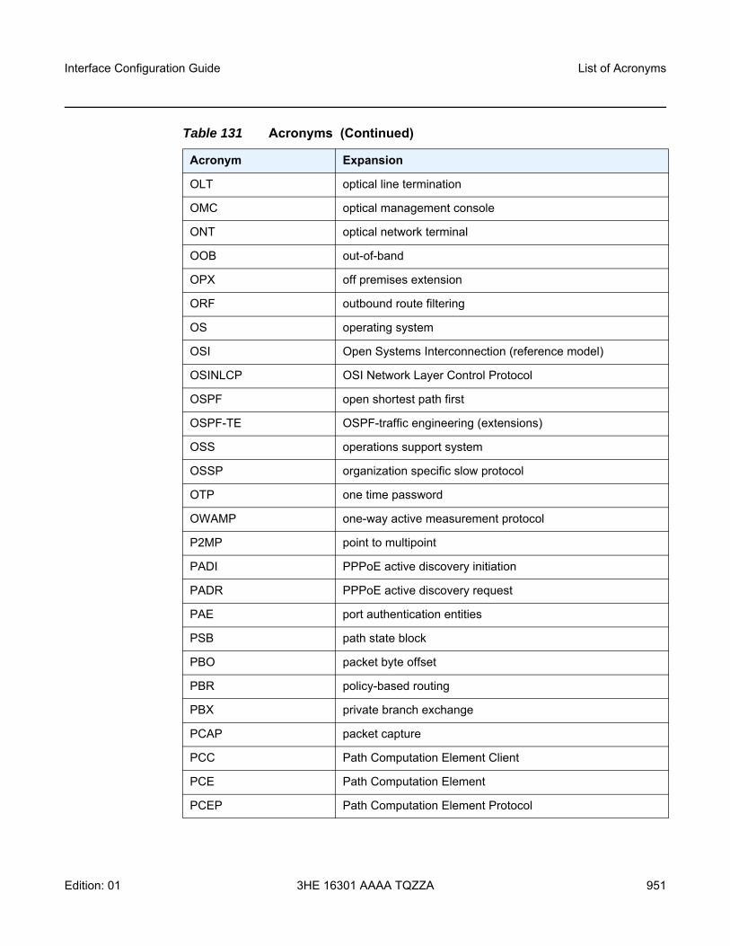
Interface Configuration Guide List of Acronyms
Edition: 01 3HE 16301 AAAA TQZZA 951
OLT optical line termination
OMC optical management console
ONT optical network terminal
OOB out-of-band
OPX off premises extension
ORF outbound route filtering
OS operating system
OSI Open Systems Interconnection (reference model)
OSINLCP OSI Network Layer Control Protocol
OSPF open shortest path first
OSPF-TE OSPF-traffic engineering (extensions)
OSS operations support system
OSSP organization specific slow protocol
OTP one time password
OWAMP one-way active measurement protocol
P2MP point to multipoint
PADI PPPoE active discovery initiation
PADR PPPoE active discovery request
PAE port authentication entities
PSB path state block
PBO packet byte offset
PBR policy-based routing
PBX private branch exchange
PCAP packet capture
PCC Path Computation Element Client
PCE Path Computation Element
PCEP Path Computation Element Protocol
Table 131 Acronyms (Continued)
Acronym Expansion
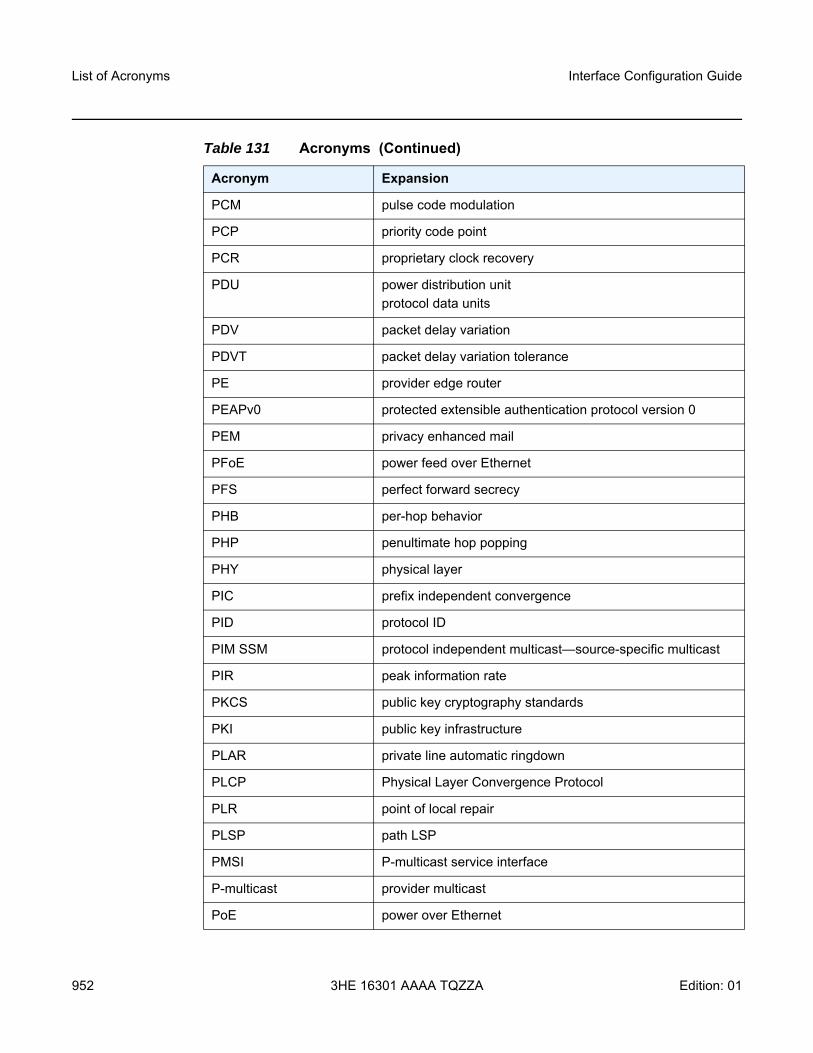
List of Acronyms
952
Interface Configuration Guide
3HE 16301 AAAA TQZZA Edition: 01
PCM pulse code modulation
PCP priority code point
PCR proprietary clock recovery
PDU power distribution unitprotocol data units
PDV packet delay variation
PDVT packet delay variation tolerance
PE provider edge router
PEAPv0 protected extensible authentication protocol version 0
PEM privacy enhanced mail
PFoE power feed over Ethernet
PFS perfect forward secrecy
PHB per-hop behavior
PHP penultimate hop popping
PHY physical layer
PIC prefix independent convergence
PID protocol ID
PIM SSM protocol independent multicast—source-specific multicast
PIR peak information rate
PKCS public key cryptography standards
PKI public key infrastructure
PLAR private line automatic ringdown
PLCP Physical Layer Convergence Protocol
PLR point of local repair
PLSP path LSP
PMSI P-multicast service interface
P-multicast provider multicast
PoE power over Ethernet
Table 131 Acronyms (Continued)
Acronym Expansion
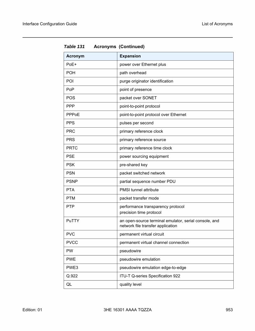
Interface Configuration Guide List of Acronyms
Edition: 01 3HE 16301 AAAA TQZZA 953
PoE+ power over Ethernet plus
POH path overhead
POI purge originator identification
PoP point of presence
POS packet over SONET
PPP point-to-point protocol
PPPoE point-to-point protocol over Ethernet
PPS pulses per second
PRC primary reference clock
PRS primary reference source
PRTC primary reference time clock
PSE power sourcing equipment
PSK pre-shared key
PSN packet switched network
PSNP partial sequence number PDU
PTA PMSI tunnel attribute
PTM packet transfer mode
PTP performance transparency protocolprecision time protocol
PuTTY an open-source terminal emulator, serial console, and network file transfer application
PVC permanent virtual circuit
PVCC permanent virtual channel connection
PW pseudowire
PWE pseudowire emulation
PWE3 pseudowire emulation edge-to-edge
Q.922 ITU-T Q-series Specification 922
QL quality level
Table 131 Acronyms (Continued)
Acronym Expansion
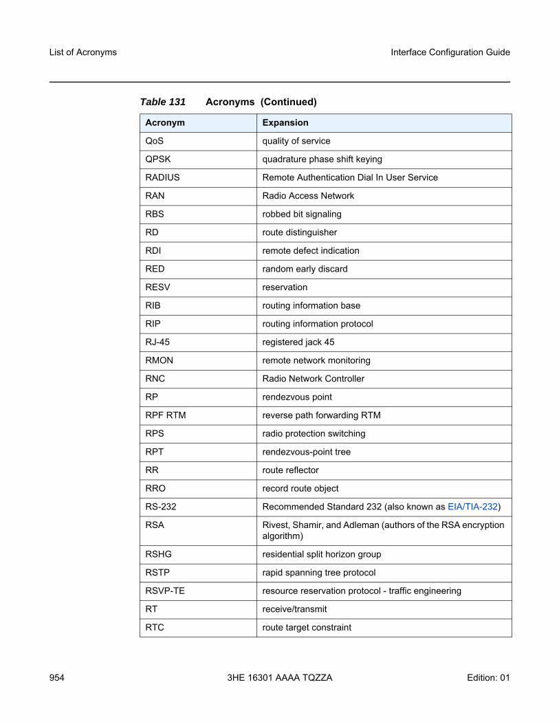
List of Acronyms
954
Interface Configuration Guide
3HE 16301 AAAA TQZZA Edition: 01
QoS quality of service
QPSK quadrature phase shift keying
RADIUS Remote Authentication Dial In User Service
RAN Radio Access Network
RBS robbed bit signaling
RD route distinguisher
RDI remote defect indication
RED random early discard
RESV reservation
RIB routing information base
RIP routing information protocol
RJ-45 registered jack 45
RMON remote network monitoring
RNC Radio Network Controller
RP rendezvous point
RPF RTM reverse path forwarding RTM
RPS radio protection switching
RPT rendezvous-point tree
RR route reflector
RRO record route object
RS-232 Recommended Standard 232 (also known as EIA/TIA-232)
RSA Rivest, Shamir, and Adleman (authors of the RSA encryption algorithm)
RSHG residential split horizon group
RSTP rapid spanning tree protocol
RSVP-TE resource reservation protocol - traffic engineering
RT receive/transmit
RTC route target constraint
Table 131 Acronyms (Continued)
Acronym Expansion

Interface Configuration Guide List of Acronyms
Edition: 01 3HE 16301 AAAA TQZZA 955
RTM routing table manager
RTN battery return
RTP real-time protocol
R&TTE Radio and Telecommunications Terminal Equipment
RTU remote terminal unit
RU rack unit
r-VPLS routed virtual private LAN service
SA security associationsource-active
SAA service assurance agent
SAFI subsequent address family identifier
SAP service access point
SAR-8 7705 Service Aggregation Router – 8-slot chassis
SAR-18 7705 Service Aggregation Router – 18-slot chassis
SAR-A 7705 Service Aggregation Router – two variants:• passively cooled chassis with 12 Ethernet ports and 8
T1/E1 ports• passively cooled chassis with 12 Ethernet ports and no
T1/E1 ports
SAR-Ax 7705 Service Aggregation Router:• passively cooled• DC-powered with a dual-feed DC input that can be
connected to a +24/-48/-60 VDC power source• equipped with 12 Ethernet ports (ports 1 to 4 are XOR
ports and 5 to 12 are 100/1000 Ethernet SFP ports)• equipped with a factory-installed GPS receiver and
GNSS RF faceplate connector
SAR-H 7705 Service Aggregation Router – temperature- and EMC-hardened to the following specifications: IEEE 1613 and IEC 61850-3
SAR-Hc 7705 Service Aggregation Router – compact version of 7705 SAR-H
Table 131 Acronyms (Continued)
Acronym Expansion
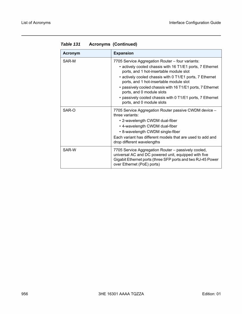
List of Acronyms
956
Interface Configuration Guide
3HE 16301 AAAA TQZZA Edition: 01
SAR-M 7705 Service Aggregation Router – four variants:• actively cooled chassis with 16 T1/E1 ports, 7 Ethernet
ports, and 1 hot-insertable module slot• actively cooled chassis with 0 T1/E1 ports, 7 Ethernet
ports, and 1 hot-insertable module slot• passively cooled chassis with 16 T1/E1 ports, 7 Ethernet
ports, and 0 module slots• passively cooled chassis with 0 T1/E1 ports, 7 Ethernet
ports, and 0 module slots
SAR-O 7705 Service Aggregation Router passive CWDM device – three variants:
• 2-wavelength CWDM dual-fiber• 4-wavelength CWDM dual-fiber• 8-wavelength CWDM single-fiber
Each variant has different models that are used to add and drop different wavelengths
SAR-W 7705 Service Aggregation Router – passively cooled, universal AC and DC powered unit, equipped with five Gigabit Ethernet ports (three SFP ports and two RJ-45 Power over Ethernet (PoE) ports)
Table 131 Acronyms (Continued)
Acronym Expansion
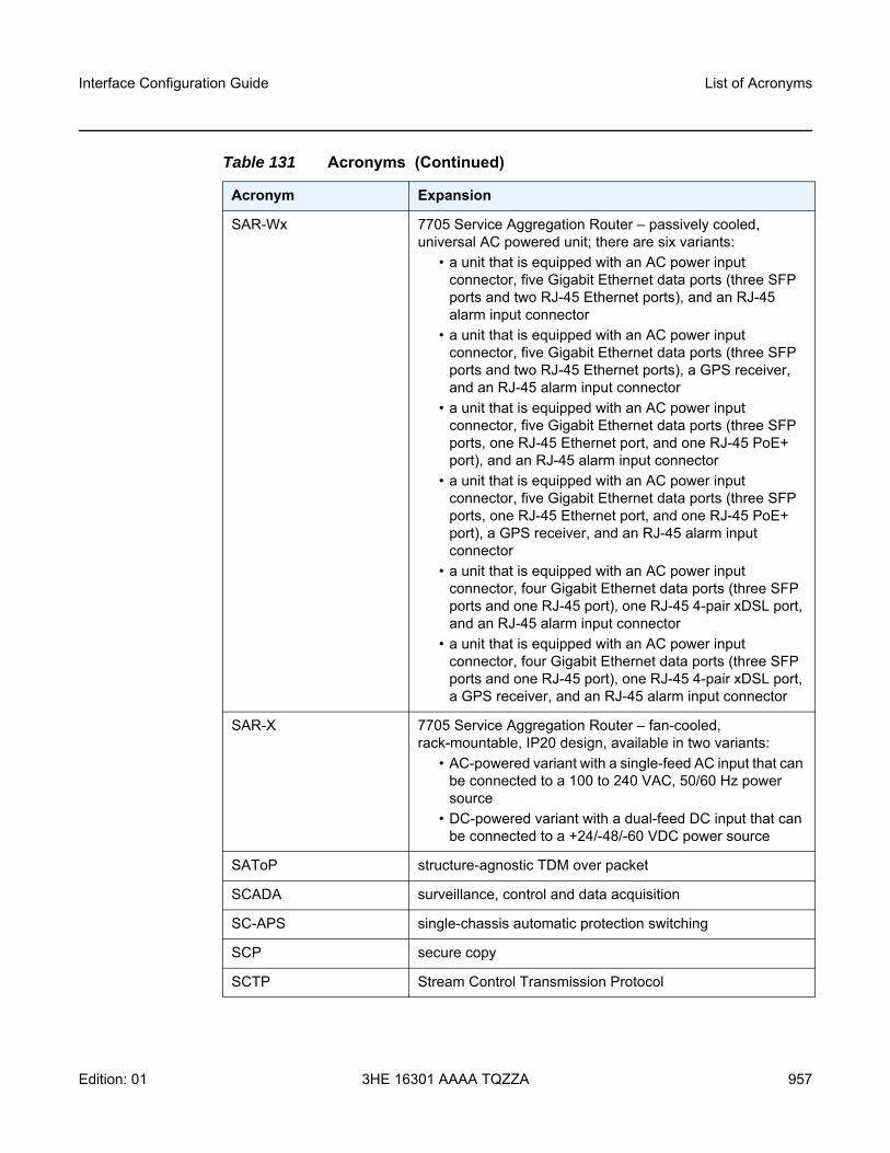
Interface Configuration Guide List of Acronyms
Edition: 01 3HE 16301 AAAA TQZZA 957
SAR-Wx 7705 Service Aggregation Router – passively cooled, universal AC powered unit; there are six variants:
• a unit that is equipped with an AC power input connector, five Gigabit Ethernet data ports (three SFP ports and two RJ-45 Ethernet ports), and an RJ-45 alarm input connector
• a unit that is equipped with an AC power input connector, five Gigabit Ethernet data ports (three SFP ports and two RJ-45 Ethernet ports), a GPS receiver, and an RJ-45 alarm input connector
• a unit that is equipped with an AC power input connector, five Gigabit Ethernet data ports (three SFP ports, one RJ-45 Ethernet port, and one RJ-45 PoE+ port), and an RJ-45 alarm input connector
• a unit that is equipped with an AC power input connector, five Gigabit Ethernet data ports (three SFP ports, one RJ-45 Ethernet port, and one RJ-45 PoE+ port), a GPS receiver, and an RJ-45 alarm input connector
• a unit that is equipped with an AC power input connector, four Gigabit Ethernet data ports (three SFP ports and one RJ-45 port), one RJ-45 4-pair xDSL port, and an RJ-45 alarm input connector
• a unit that is equipped with an AC power input connector, four Gigabit Ethernet data ports (three SFP ports and one RJ-45 port), one RJ-45 4-pair xDSL port, a GPS receiver, and an RJ-45 alarm input connector
SAR-X 7705 Service Aggregation Router – fan-cooled, rack-mountable, IP20 design, available in two variants:
• AC-powered variant with a single-feed AC input that can be connected to a 100 to 240 VAC, 50/60 Hz power source
• DC-powered variant with a dual-feed DC input that can be connected to a +24/-48/-60 VDC power source
SAToP structure-agnostic TDM over packet
SCADA surveillance, control and data acquisition
SC-APS single-chassis automatic protection switching
SCP secure copy
SCTP Stream Control Transmission Protocol
Table 131 Acronyms (Continued)
Acronym Expansion
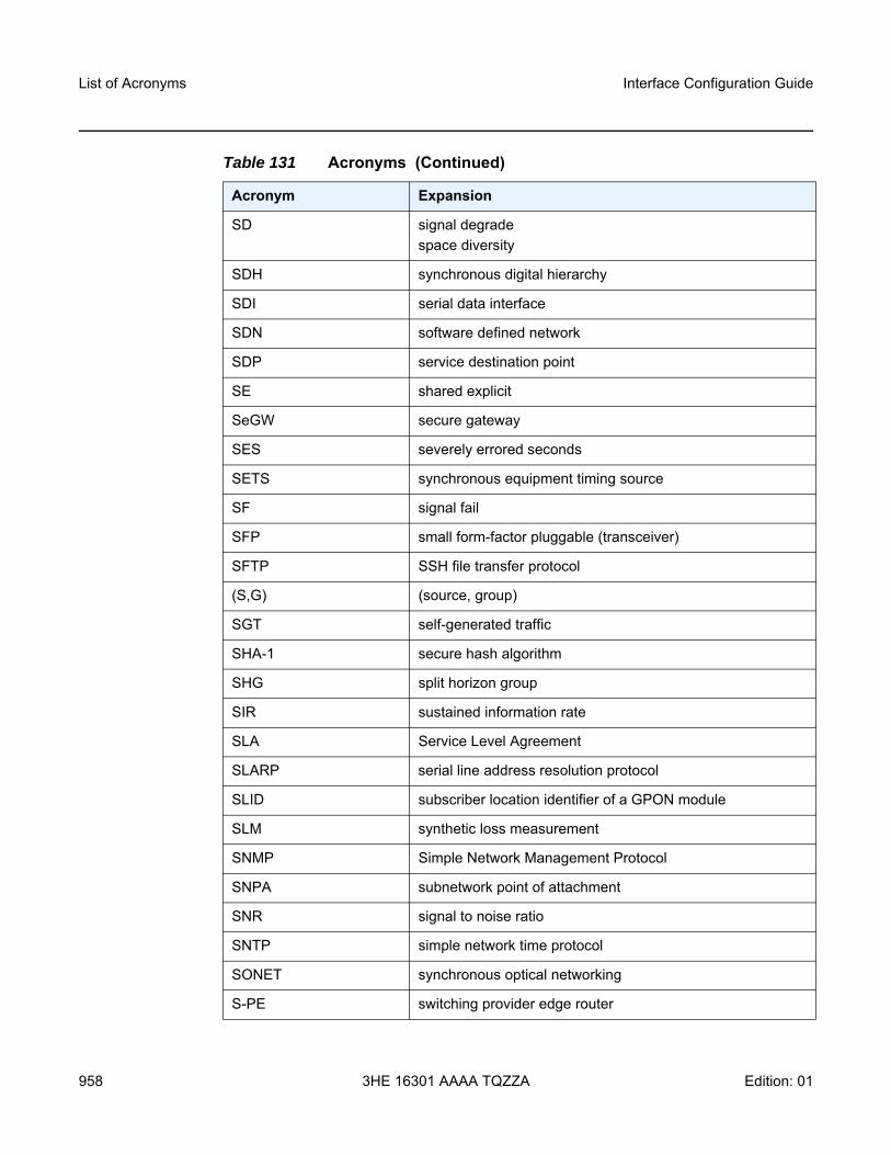
List of Acronyms
958
Interface Configuration Guide
3HE 16301 AAAA TQZZA Edition: 01
SD signal degradespace diversity
SDH synchronous digital hierarchy
SDI serial data interface
SDN software defined network
SDP service destination point
SE shared explicit
SeGW secure gateway
SES severely errored seconds
SETS synchronous equipment timing source
SF signal fail
SFP small form-factor pluggable (transceiver)
SFTP SSH file transfer protocol
(S,G) (source, group)
SGT self-generated traffic
SHA-1 secure hash algorithm
SHG split horizon group
SIR sustained information rate
SLA Service Level Agreement
SLARP serial line address resolution protocol
SLID subscriber location identifier of a GPON module
SLM synthetic loss measurement
SNMP Simple Network Management Protocol
SNPA subnetwork point of attachment
SNR signal to noise ratio
SNTP simple network time protocol
SONET synchronous optical networking
S-PE switching provider edge router
Table 131 Acronyms (Continued)
Acronym Expansion
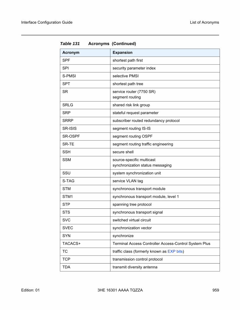
Interface Configuration Guide List of Acronyms
Edition: 01 3HE 16301 AAAA TQZZA 959
SPF shortest path first
SPI security parameter index
S-PMSI selective PMSI
SPT shortest path tree
SR service router (7750 SR)segment routing
SRLG shared risk link group
SRP stateful request parameter
SRRP subscriber routed redundancy protocol
SR-ISIS segment routing IS-IS
SR-OSPF segment routing OSPF
SR-TE segment routing traffic engineering
SSH secure shell
SSM source-specific multicastsynchronization status messaging
SSU system synchronization unit
S-TAG service VLAN tag
STM synchronous transport module
STM1 synchronous transport module, level 1
STP spanning tree protocol
STS synchronous transport signal
SVC switched virtual circuit
SVEC synchronization vector
SYN synchronize
TACACS+ Terminal Access Controller Access-Control System Plus
TC traffic class (formerly known as EXP bits)
TCP transmission control protocol
TDA transmit diversity antenna
Table 131 Acronyms (Continued)
Acronym Expansion
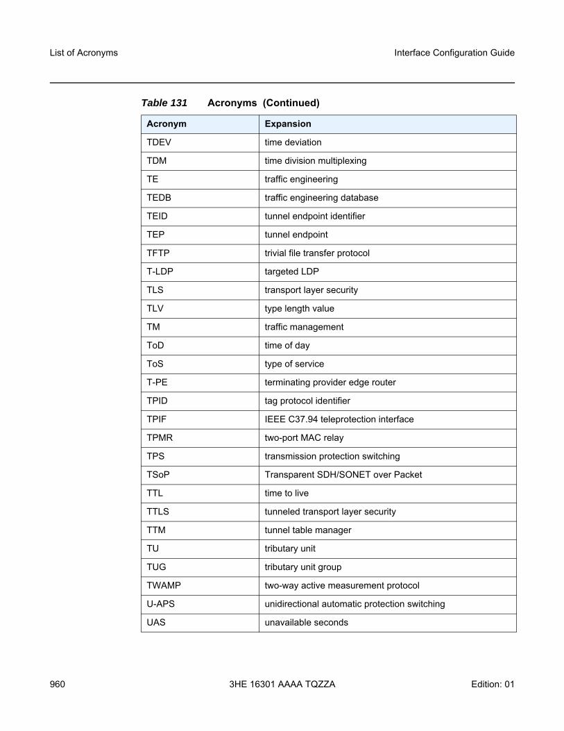
List of Acronyms
960
Interface Configuration Guide
3HE 16301 AAAA TQZZA Edition: 01
TDEV time deviation
TDM time division multiplexing
TE traffic engineering
TEDB traffic engineering database
TEID tunnel endpoint identifier
TEP tunnel endpoint
TFTP trivial file transfer protocol
T-LDP targeted LDP
TLS transport layer security
TLV type length value
TM traffic management
ToD time of day
ToS type of service
T-PE terminating provider edge router
TPID tag protocol identifier
TPIF IEEE C37.94 teleprotection interface
TPMR two-port MAC relay
TPS transmission protection switching
TSoP Transparent SDH/SONET over Packet
TTL time to live
TTLS tunneled transport layer security
TTM tunnel table manager
TU tributary unit
TUG tributary unit group
TWAMP two-way active measurement protocol
U-APS unidirectional automatic protection switching
UAS unavailable seconds
Table 131 Acronyms (Continued)
Acronym Expansion
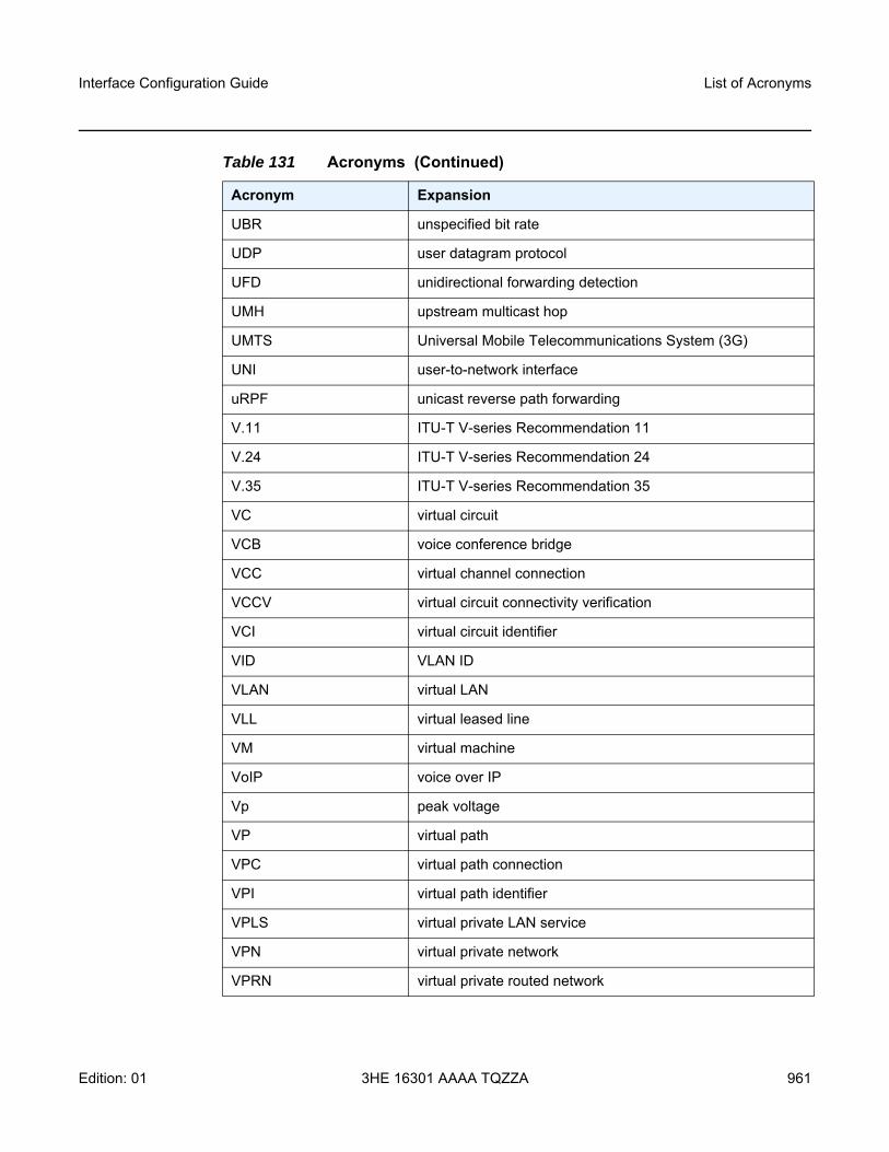
Interface Configuration Guide List of Acronyms
Edition: 01 3HE 16301 AAAA TQZZA 961
UBR unspecified bit rate
UDP user datagram protocol
UFD unidirectional forwarding detection
UMH upstream multicast hop
UMTS Universal Mobile Telecommunications System (3G)
UNI user-to-network interface
uRPF unicast reverse path forwarding
V.11 ITU-T V-series Recommendation 11
V.24 ITU-T V-series Recommendation 24
V.35 ITU-T V-series Recommendation 35
VC virtual circuit
VCB voice conference bridge
VCC virtual channel connection
VCCV virtual circuit connectivity verification
VCI virtual circuit identifier
VID VLAN ID
VLAN virtual LAN
VLL virtual leased line
VM virtual machine
VoIP voice over IP
Vp peak voltage
VP virtual path
VPC virtual path connection
VPI virtual path identifier
VPLS virtual private LAN service
VPN virtual private network
VPRN virtual private routed network
Table 131 Acronyms (Continued)
Acronym Expansion
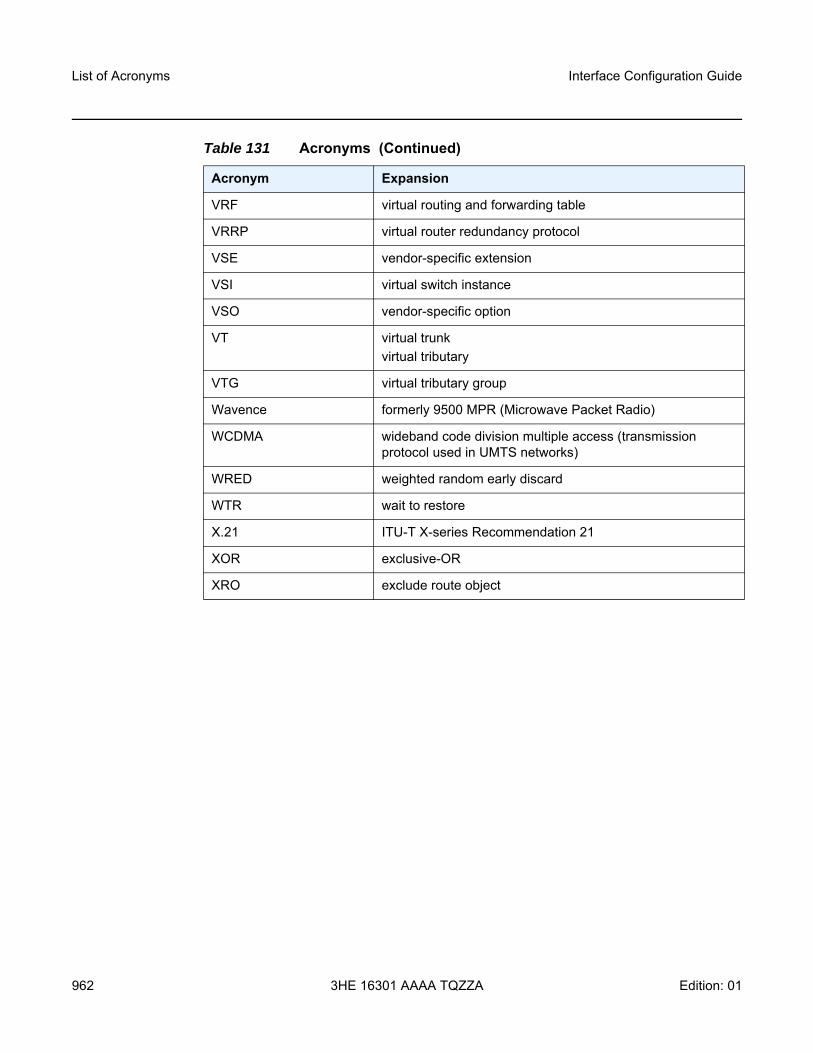
List of Acronyms
962
Interface Configuration Guide
3HE 16301 AAAA TQZZA Edition: 01
VRF virtual routing and forwarding table
VRRP virtual router redundancy protocol
VSE vendor-specific extension
VSI virtual switch instance
VSO vendor-specific option
VT virtual trunkvirtual tributary
VTG virtual tributary group
Wavence formerly 9500 MPR (Microwave Packet Radio)
WCDMA wideband code division multiple access (transmission protocol used in UMTS networks)
WRED weighted random early discard
WTR wait to restore
X.21 ITU-T X-series Recommendation 21
XOR exclusive-OR
XRO exclude route object
Table 131 Acronyms (Continued)
Acronym Expansion
Interface Configuration Guide Standards and Protocol Support
Edition: 01 3HE 16301 AAAA TQZZA 963
5 Standards and Protocol SupportThis chapter lists the 7705 SAR compliance with EMC, environmental, and safety standards, telecom standards, and supported protocols:
• EMC Industrial Standards Compliance• EMC Regulatory and Customer Standards Compliance• Environmental Standards Compliance• Safety Standards Compliance• Telecom Interface Compliance• Directives, Regional Approvals and Certifications Compliance• Security Standards• Telecom Standards• Protocol Support• Proprietary MIBs
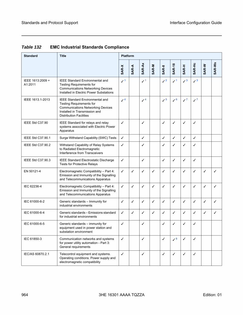
Standards and Protocol Support
964
Interface Configuration Guide
3HE 16301 AAAA TQZZA Edition: 01
Table 132 EMC Industrial Standards Compliance
Standard Title Platform
SAR
-X
SAR
-A
SAR
-Ax
SAR
-M
SAR
-8
SAR
-18
SAR
-H
SAR
-Hc
SAR
-W
SAR
-Wx
IEEE 1613:2009 + A1:2011
IEEE Standard Environmental and Testing Requirements for Communications Networking Devices Installed in Electric Power Substations
1 1 2 1 3 3
IEEE 1613.1-2013 IEEE Standard Environmental and Testing Requirements for Communications Networking Devices Installed in Transmission and Distribution Facilities
4 4 5 6 7 7
IEEE Std C37.90 IEEE Standard for relays and relay systems associated with Electric Power Apparatus
IEEE Std C37.90.1 Surge Withstand Capability (SWC) Tests
IEEE Std C37.90.2 Withstand Capability of Relay Systems to Radiated Electromagnetic Interference from Transceivers
IEEE Std C37.90.3 IEEE Standard Electrostatic Discharge Tests for Protective Relays
EN 50121-4 Electromagnetic Compatibility – Part 4: Emission and Immunity of the Signalling and Telecommunications Apparatus
IEC 62236-4 Electromagnetic Compatibility – Part 4: Emission and Immunity of the Signalling and Telecommunications Apparatus
IEC 61000-6-2 Generic standards – Immunity for industrial environments
IEC 61000-6-4 Generic standards – Emissions standard for industrial environments
IEC 61000-6-5 Generic standards – immunity for equipment used in power station and substation environment
IEC 61850-3 Communication networks and systems for power utility automation - Part 3: General requirements
8
IEC/AS 60870.2.1 Telecontrol equipment and systems. Operating conditions. Power supply and electromagnetic compatibility
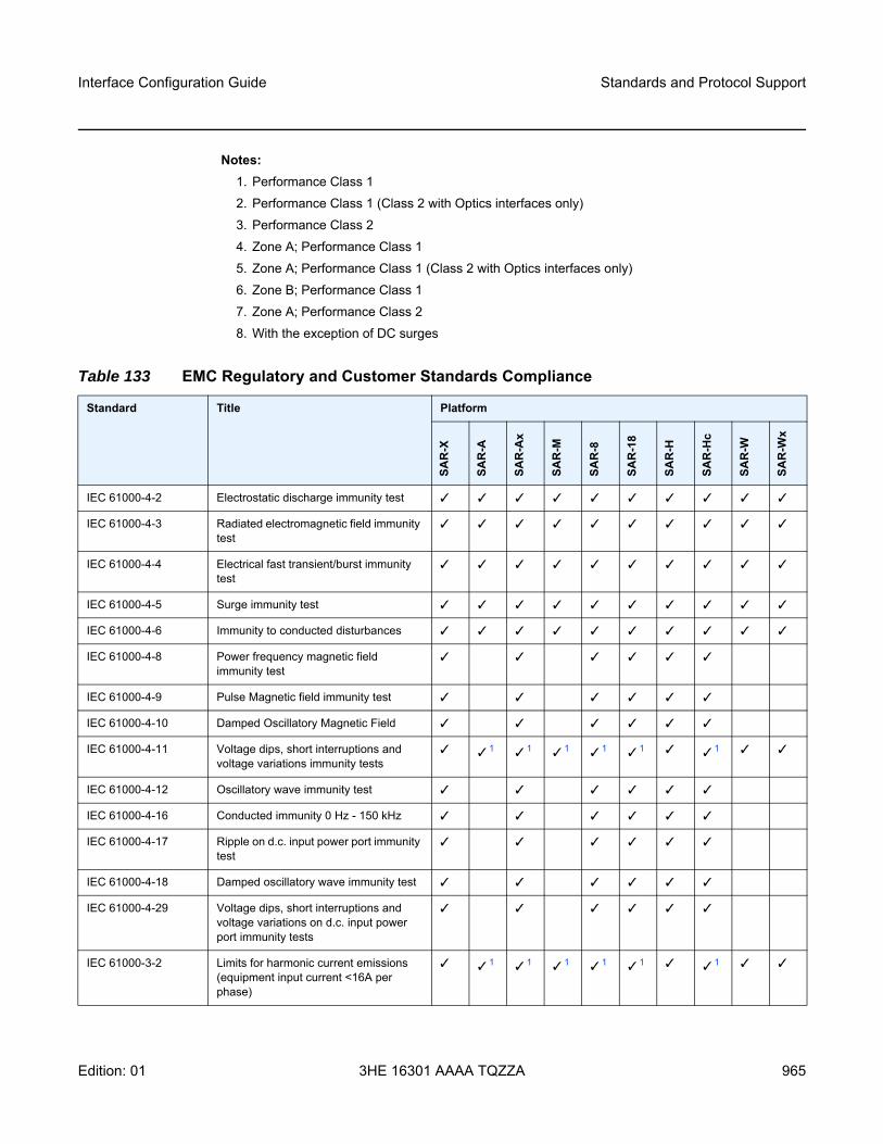
Interface Configuration Guide Standards and Protocol Support
Edition: 01 3HE 16301 AAAA TQZZA 965
Notes:1. Performance Class 12. Performance Class 1 (Class 2 with Optics interfaces only)3. Performance Class 24. Zone A; Performance Class 15. Zone A; Performance Class 1 (Class 2 with Optics interfaces only)6. Zone B; Performance Class 17. Zone A; Performance Class 28. With the exception of DC surges
Table 133 EMC Regulatory and Customer Standards Compliance
Standard Title Platform
SAR
-X
SAR
-A
SAR
-Ax
SAR
-M
SAR
-8
SAR
-18
SAR
-H
SAR
-Hc
SAR
-W
SAR
-Wx
IEC 61000-4-2 Electrostatic discharge immunity test
IEC 61000-4-3 Radiated electromagnetic field immunity test
IEC 61000-4-4 Electrical fast transient/burst immunity test
IEC 61000-4-5 Surge immunity test
IEC 61000-4-6 Immunity to conducted disturbances
IEC 61000-4-8 Power frequency magnetic field immunity test
IEC 61000-4-9 Pulse Magnetic field immunity test
IEC 61000-4-10 Damped Oscillatory Magnetic Field
IEC 61000-4-11 Voltage dips, short interruptions and voltage variations immunity tests
1 1 1 1 1 1
IEC 61000-4-12 Oscillatory wave immunity test
IEC 61000-4-16 Conducted immunity 0 Hz - 150 kHz
IEC 61000-4-17 Ripple on d.c. input power port immunity test
IEC 61000-4-18 Damped oscillatory wave immunity test
IEC 61000-4-29 Voltage dips, short interruptions and voltage variations on d.c. input power port immunity tests
IEC 61000-3-2 Limits for harmonic current emissions (equipment input current <16A per phase)
1 1 1 1 1 1
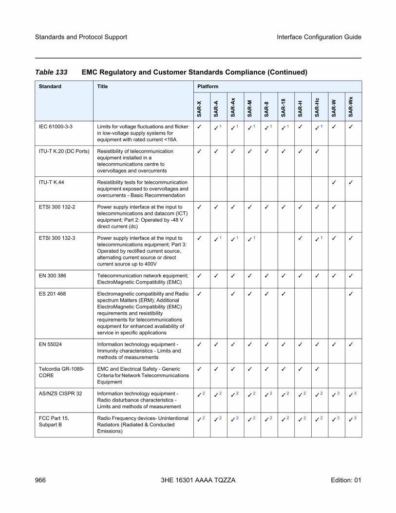
Standards and Protocol Support
966
Interface Configuration Guide
3HE 16301 AAAA TQZZA Edition: 01
IEC 61000-3-3 Limits for voltage fluctuations and flicker in low-voltage supply systems for equipment with rated current <16A
1 1 1 1 1 1
ITU-T K.20 (DC Ports) Resistibility of telecommunication equipment installed in a telecommunications centre to overvoltages and overcurrents
ITU-T K.44 Resistibility tests for telecommunication equipment exposed to overvoltages and overcurrents - Basic Recommendation
ETSI 300 132-2 Power supply interface at the input to telecommunications and datacom (ICT) equipment; Part 2: Operated by -48 V direct current (dc)
ETSI 300 132-3 Power supply interface at the input to telecommunications equipment; Part 3: Operated by rectified current source, alternating current source or direct current source up to 400V
1 1 1 1
EN 300 386 Telecommunication network equipment; ElectroMagnetic Compatibility (EMC)
ES 201 468 Electromagnetic compatibility and Radio spectrum Matters (ERM); Additional ElectroMagnetic Compatibility (EMC) requirements and resistibility requirements for telecommunications equipment for enhanced availability of service in specific applications
EN 55024 Information technology equipment -Immunity characteristics - Limits and methods of measurements
Telcordia GR-1089-CORE
EMC and Electrical Safety - Generic Criteria for Network Telecommunications Equipment
AS/NZS CISPR 32 Information technology equipment - Radio disturbance characteristics - Limits and methods of measurement
2 2 2 2 2 2 2 2 3 3
FCC Part 15, Subpart B
Radio Frequency devices- Unintentional Radiators (Radiated & Conducted Emissions)
2 2 2 2 2 2 2 2 3 3
Table 133 EMC Regulatory and Customer Standards Compliance (Continued)
Standard Title Platform
SAR
-X
SAR
-A
SAR
-Ax
SAR
-M
SAR
-8
SAR
-18
SAR
-H
SAR
-Hc
SAR
-W
SAR
-Wx
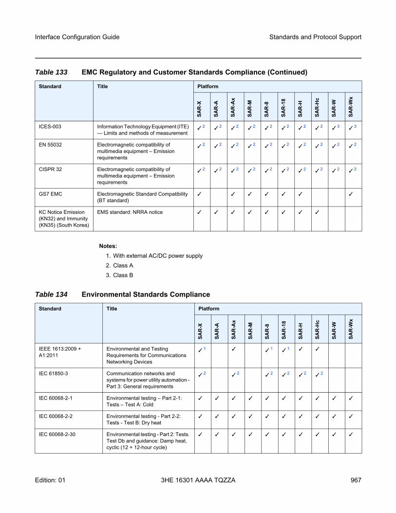
Interface Configuration Guide Standards and Protocol Support
Edition: 01 3HE 16301 AAAA TQZZA 967
Notes:1. With external AC/DC power supply2. Class A3. Class B
ICES-003 Information Technology Equipment (ITE) — Limits and methods of measurement
2 2 2 2 2 2 2 2 3 3
EN 55032 Electromagnetic compatibility of multimedia equipment – Emission requirements
2 2 2 2 2 2 2 2 2 2
CISPR 32 Electromagnetic compatibility of multimedia equipment – Emission requirements
2 2 2 2 2 2 2 2 2 2
GS7 EMC Electromagnetic Standard Compatibility (BT standard)
KC Notice Emission (KN32) and Immunity (KN35) (South Korea)
EMS standard: NRRA notice
Table 133 EMC Regulatory and Customer Standards Compliance (Continued)
Standard Title Platform
SAR
-X
SAR
-A
SAR
-Ax
SAR
-M
SAR
-8
SAR
-18
SAR
-H
SAR
-Hc
SAR
-W
SAR
-Wx
Table 134 Environmental Standards Compliance
Standard Title Platform
SAR
-X
SAR
-A
SAR
-Ax
SAR
-M
SAR
-8
SAR
-18
SAR
-H
SAR
-Hc
SAR
-W
SAR
-Wx
IEEE 1613:2009 + A1:2011
Environmental and Testing Requirements for Communications Networking Devices
1 1 1
IEC 61850-3 Communication networks and systems for power utility automation - Part 3: General requirements
2 2 2 2 2 2
IEC 60068-2-1 Environmental testing – Part 2-1: Tests – Test A: Cold
IEC 60068-2-2 Environmental testing - Part 2-2: Tests - Test B: Dry heat
IEC 60068-2-30 Environmental testing - Part 2: Tests. Test Db and guidance: Damp heat, cyclic (12 + 12-hour cycle)
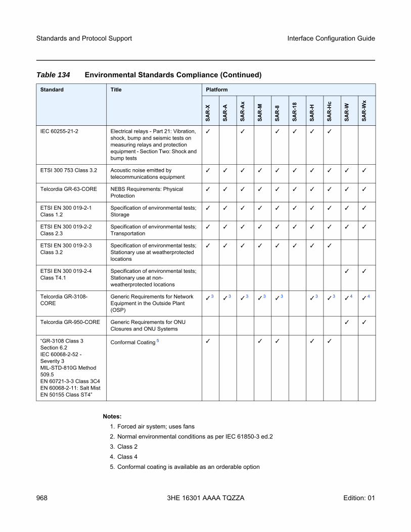
Standards and Protocol Support
968
Interface Configuration Guide
3HE 16301 AAAA TQZZA Edition: 01
Notes:1. Forced air system; uses fans2. Normal environmental conditions as per IEC 61850-3 ed.23. Class 24. Class 45. Conformal coating is available as an orderable option
IEC 60255-21-2 Electrical relays - Part 21: Vibration, shock, bump and seismic tests on measuring relays and protection equipment - Section Two: Shock and bump tests
ETSI 300 753 Class 3.2 Acoustic noise emitted by telecommunications equipment
Telcordia GR-63-CORE NEBS Requirements: Physical Protection
ETSI EN 300 019-2-1 Class 1.2
Specification of environmental tests; Storage
ETSI EN 300 019-2-2 Class 2.3
Specification of environmental tests; Transportation
ETSI EN 300 019-2-3 Class 3.2
Specification of environmental tests; Stationary use at weatherprotected locations
ETSI EN 300 019-2-4 Class T4.1
Specification of environmental tests; Stationary use at non-weatherprotected locations
Telcordia GR-3108-CORE
Generic Requirements for Network Equipment in the Outside Plant (OSP)
3 3 3 3 3 3 3 4 4
Telcordia GR-950-CORE Generic Requirements for ONU Closures and ONU Systems
“GR-3108 Class 3 Section 6.2IEC 60068-2-52 - Severity 3MIL-STD-810G Method 509.5EN 60721-3-3 Class 3C4EN 60068-2-11: Salt MistEN 50155 Class ST4”
Conformal Coating 5
Table 134 Environmental Standards Compliance (Continued)
Standard Title Platform
SAR
-X
SAR
-A
SAR
-Ax
SAR
-M
SAR
-8
SAR
-18
SAR
-H
SAR
-Hc
SAR
-W
SAR
-Wx
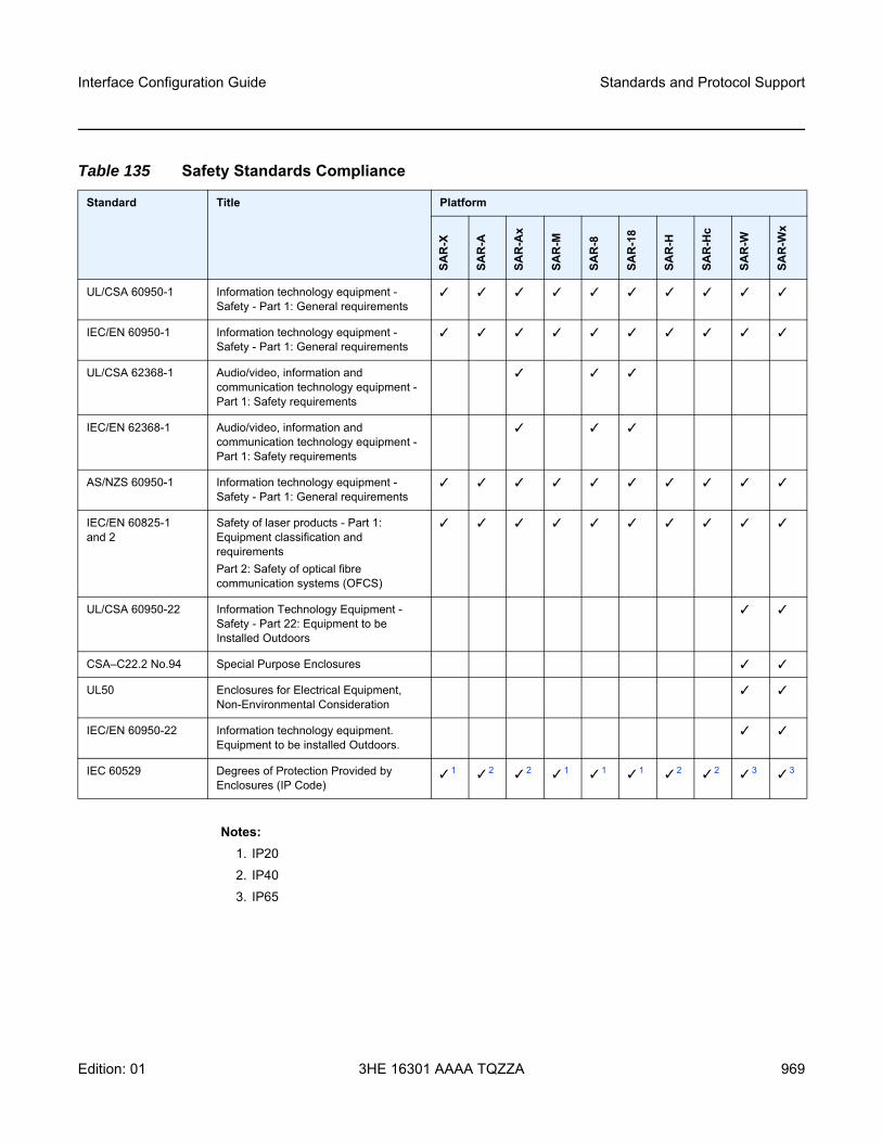
Interface Configuration Guide Standards and Protocol Support
Edition: 01 3HE 16301 AAAA TQZZA 969
Notes:1. IP202. IP403. IP65
Table 135 Safety Standards Compliance
Standard Title Platform
SAR
-X
SAR
-A
SAR
-Ax
SAR
-M
SAR
-8
SAR
-18
SAR
-H
SAR
-Hc
SAR
-W
SAR
-Wx
UL/CSA 60950-1 Information technology equipment - Safety - Part 1: General requirements
IEC/EN 60950-1 Information technology equipment - Safety - Part 1: General requirements
UL/CSA 62368-1 Audio/video, information and communication technology equipment - Part 1: Safety requirements
IEC/EN 62368-1 Audio/video, information and communication technology equipment - Part 1: Safety requirements
AS/NZS 60950-1 Information technology equipment - Safety - Part 1: General requirements
IEC/EN 60825-1 and 2
Safety of laser products - Part 1: Equipment classification and requirements Part 2: Safety of optical fibre communication systems (OFCS)
UL/CSA 60950-22 Information Technology Equipment - Safety - Part 22: Equipment to be Installed Outdoors
CSA–C22.2 No.94 Special Purpose Enclosures
UL50 Enclosures for Electrical Equipment, Non-Environmental Consideration
IEC/EN 60950-22 Information technology equipment. Equipment to be installed Outdoors.
IEC 60529 Degrees of Protection Provided by Enclosures (IP Code)
1 2 2 1 1 1 2 2 3 3
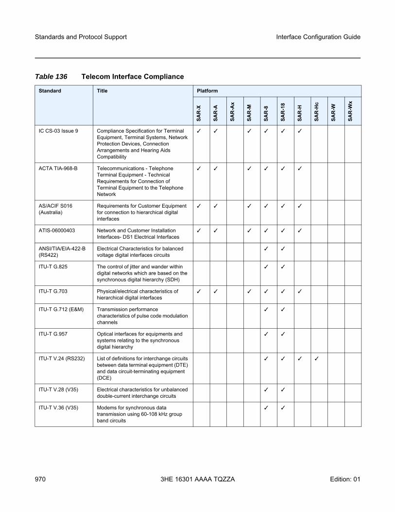
Standards and Protocol Support
970
Interface Configuration Guide
3HE 16301 AAAA TQZZA Edition: 01
Table 136 Telecom Interface Compliance
Standard Title Platform
SAR
-X
SAR
-A
SAR
-Ax
SAR
-M
SAR
-8
SAR
-18
SAR
-H
SAR
-Hc
SAR
-W
SAR
-Wx
IC CS-03 Issue 9 Compliance Specification for Terminal Equipment, Terminal Systems, Network Protection Devices, Connection Arrangements and Hearing Aids Compatibility
ACTA TIA-968-B Telecommunications - Telephone Terminal Equipment - Technical Requirements for Connection of Terminal Equipment to the Telephone Network
AS/ACIF S016 (Australia)
Requirements for Customer Equipment for connection to hierarchical digital interfaces
ATIS-06000403 Network and Customer Installation Interfaces- DS1 Electrical Interfaces
ANSI/TIA/EIA-422-B (RS422)
Electrical Characteristics for balanced voltage digital interfaces circuits
ITU-T G.825 The control of jitter and wander within digital networks which are based on the synchronous digital hierarchy (SDH)
ITU-T G.703 Physical/electrical characteristics of hierarchical digital interfaces
ITU-T G.712 (E&M) Transmission performance characteristics of pulse code modulation channels
ITU-T G.957 Optical interfaces for equipments and systems relating to the synchronous digital hierarchy
ITU-T V.24 (RS232) List of definitions for interchange circuits between data terminal equipment (DTE) and data circuit-terminating equipment (DCE)
ITU-T V.28 (V35) Electrical characteristics for unbalanced double-current interchange circuits
ITU-T V.36 (V35) Modems for synchronous data transmission using 60-108 kHz group band circuits
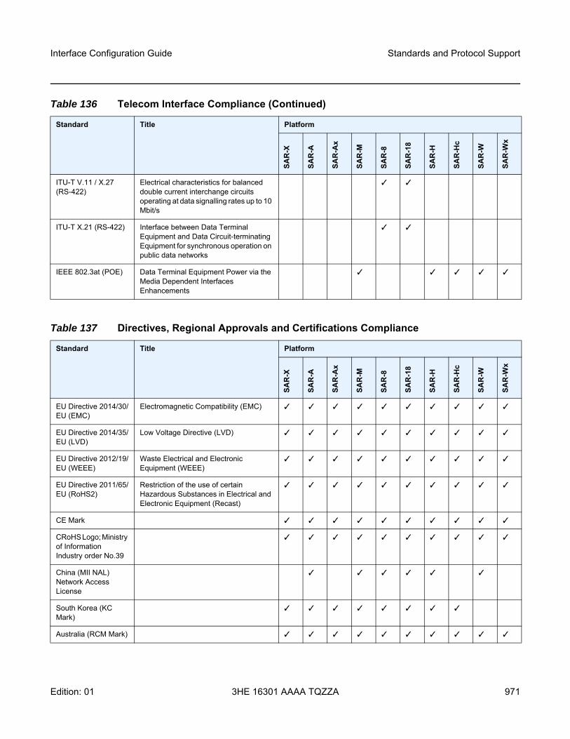
Interface Configuration Guide Standards and Protocol Support
Edition: 01 3HE 16301 AAAA TQZZA 971
ITU-T V.11 / X.27 (RS-422)
Electrical characteristics for balanced double current interchange circuits operating at data signalling rates up to 10 Mbit/s
ITU-T X.21 (RS-422) Interface between Data Terminal Equipment and Data Circuit-terminating Equipment for synchronous operation on public data networks
IEEE 802.3at (POE) Data Terminal Equipment Power via the Media Dependent Interfaces Enhancements
Table 136 Telecom Interface Compliance (Continued)
Standard Title Platform
SAR
-X
SAR
-A
SAR
-Ax
SAR
-M
SAR
-8
SAR
-18
SAR
-H
SAR
-Hc
SAR
-W
SAR
-Wx
Table 137 Directives, Regional Approvals and Certifications Compliance
Standard Title Platform
SAR
-X
SAR
-A
SAR
-Ax
SAR
-M
SAR
-8
SAR
-18
SAR
-H
SAR
-Hc
SAR
-W
SAR
-Wx
EU Directive 2014/30/EU (EMC)
Electromagnetic Compatibility (EMC)
EU Directive 2014/35/EU (LVD)
Low Voltage Directive (LVD)
EU Directive 2012/19/EU (WEEE)
Waste Electrical and Electronic Equipment (WEEE)
EU Directive 2011/65/EU (RoHS2)
Restriction of the use of certain Hazardous Substances in Electrical and Electronic Equipment (Recast)
CE Mark
CRoHS Logo; Ministry of Information Industry order No.39
China (MII NAL) Network Access License
South Korea (KC Mark)
Australia (RCM Mark)
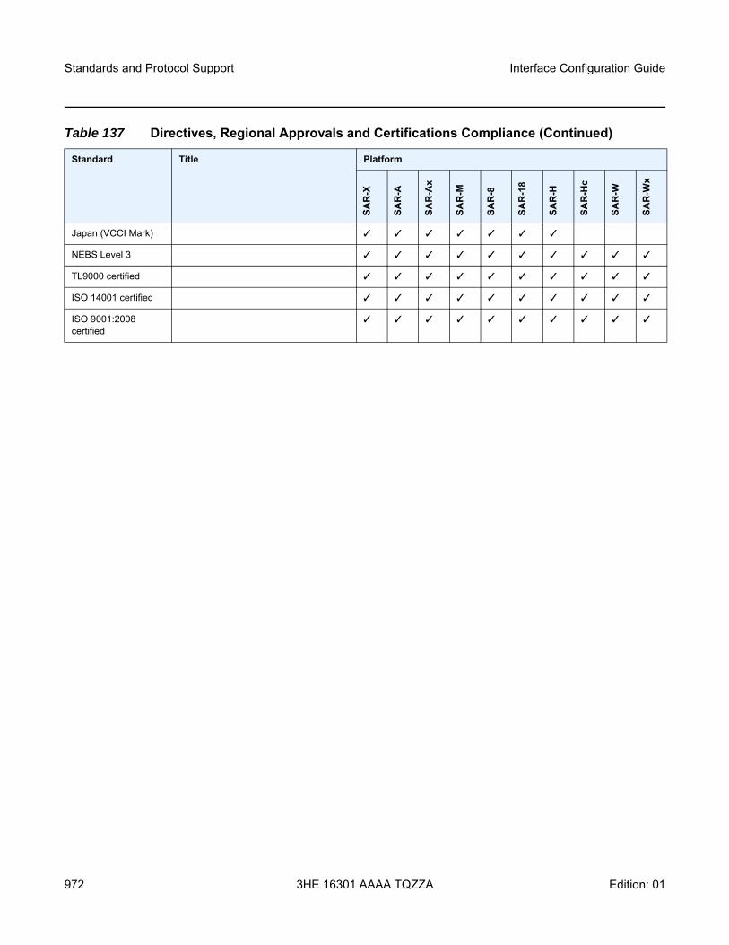
Standards and Protocol Support
972
Interface Configuration Guide
3HE 16301 AAAA TQZZA Edition: 01
Japan (VCCI Mark)
NEBS Level 3
TL9000 certified
ISO 14001 certified
ISO 9001:2008 certified
Table 137 Directives, Regional Approvals and Certifications Compliance (Continued)
Standard Title Platform
SAR
-X
SAR
-A
SAR
-Ax
SAR
-M
SAR
-8
SAR
-18
SAR
-H
SAR
-Hc
SAR
-W
SAR
-Wx
Interface Configuration Guide Standards and Protocol Support
Edition: 01 3HE 16301 AAAA TQZZA 973
Security StandardsFIPS 140-2—Federal Information Processing Standard publication 140-2, Security
Requirements for Cryptographic Modules
Telecom StandardsANSI/TIA/EIA-232-C—Interface Between Data Terminal Equipment and Data
Circuit-Terminating Equipment Employing Serial Binary Data InterchangeIEEE 802.1ad—IEEE Standard for Local and Metropolitan Area Networks---Virtual
Bridged Local Area NetworksIEEE 802.1ag—Service Layer OAMIEEE 802.1p/q—VLAN TaggingIEEE 802.3—10BaseTIEEE 802.3ab—1000BaseTIEEE 802.3ah—Ethernet OAMIEEE 802.3u—100BaseTXIEEE 802.3x —Flow ControlIEEE 802.3z—1000BaseSX/LXIEEE 802.3-2008—Revised base standardIEEE 802.1AX-2008—Link Aggregation Task Force (transferred from IEEE 802.3ad)IEEE C37.94-2017—N Times 64 Kilobit Per Second Optical Fiber Interfaces
Between Teleprotection and Multiplexer EquipmentITU-T G.704—Synchronous frame structures used at 1544, 6312, 2048, 8448 and
44 736 kbit/s hierarchical levelsITU-T G.707—Network node interface for the Synchronous Digital Hierarchy (SDH)ITU-T G.826—End-to-end error performance parameters and objectives for
international, constant bit-rate digital paths and connectionsITU-T G.8032 — Ethernet Ring Protection SwitchingITU-T G.984.1—Gigabit-capable passive optical networks (GPON): general
characteristicsITU-T Y.1564—Ethernet service activation test methodologyITU-T Y.1731—OAM functions and mechanisms for Ethernet-based networks
Standards and Protocol Support
974
Interface Configuration Guide
3HE 16301 AAAA TQZZA Edition: 01
Protocol Support
ATMAF-PHY-0086.001—Inverse Multiplexing for ATM (IMA)af-tm-0121.000—Traffic Management Specification Version 4.1, March 1999GR-1113-CORE—Bellcore, Asynchronous Transfer Mode (ATM) and ATM
Adaptation Layer (AAL) Protocols Generic Requirements, Issue 1, July 1994GR-1248-CORE—Generic Requirements for Operations of ATM Network Elements
(NEs). Issue 3 June 1996ITU-T Recommendation I.432.1—B-ISDN user-network interface - Physical layer
specification: General characteristicsITU-T Recommendation I.610—B-ISDN Operation and Maintenance Principles and
Functions version 11/95RFC 2514—Definitions of Textual Conventions and OBJECT_IDENTITIES for ATM
Management, February 1999RFC 2515—Definition of Managed Objects for ATM Management, February 1999RFC 2684—Multiprotocol Encapsulation over ATM Adaptation Layer 5
BFDdraft-ietf-bfd-mib-00.txt—Bidirectional Forwarding Detection Management
Information Basedraft-ietf-bfd-base-o5.txt—Bidirectional Forwarding Detectiondraft-ietf-bfd-v4v6-1hop-06.txt—BFD IPv4 and IPv6 (Single Hop)draft-ietf-bfd-multihop-06.txt—BFD for Multi-hop Paths
BGPRFC 1397—BGP Default Route AdvertisementRFC 1997—BGP Communities AttributeRFC 2385—Protection of BGP Sessions via the TCP MD5 Signature OptionRFC 2439—BGP Route Flap DampeningRFC 2545—Use of BGP-4 Multiprotocol Extensions for IPv6 Inter-Domain RoutingRFC 2918—Route Refresh Capability for BGP-4RFC 3107—Carrying Label Information in BGP-4RFC 3392—Capabilities Advertisement with BGP-4RFC 4271—BGP-4 (previously RFC 1771)RFC 4360—BGP Extended Communities AttributeRFC 4364—BGP/MPLS IP Virtual Private Networks (VPNs) (previously RFC
2574bis BGP/MPLS VPNs)RFC 4456—BGP Route Reflection: Alternative to Full-mesh IBGP (previously RFC
1966 and RFC 2796)
Interface Configuration Guide Standards and Protocol Support
Edition: 01 3HE 16301 AAAA TQZZA 975
RFC 4486—Subcodes for BGP Cease Notification MessageRFC 4684—Constrained Route Distribution for Border Gateway Protocol/
MultiProtocol Label Switching (BGP/MPLS) Internet Protocol (IP) Virtual Private Networks (VPNs)
RFC 4724—Graceful Restart Mechanism for BGP - GR HelperRFC 4760—Multi-protocol Extensions for BGP (previously RFC 2858)RFC 4893—BGP Support for Four-octet AS Number SpaceRFC 6513—Multicast in MPLS/BGP IP VPNsRFC 6514—BGP Encodings and Procedures for Multicast in MPLS/BGP IP VPNsdraft-ietf-idr-add-paths-04.txt—Advertisement of Multiple Paths in BGPdraft-ietf-idr-add-paths-guidelines-00.txt—Best Practices for Advertisement of
Multiple Paths in BGP
DHCP/DHCPv6RFC 1534—Interoperation between DHCP and BOOTPRFC 2131—Dynamic Host Configuration Protocol (REV)RFC 2132—DHCP Options and BOOTP Vendor ExtensionsRFC 3046—DHCP Relay Agent Information Option (Option 82)RFC 3315—Dynamic Host Configuration Protocol for IPv6RFC 3736—Stateless Dynamic Host Configuration Protocol (DHCP) Service for IPv6
Differentiated ServicesRFC 2474—Definition of the DS Field in the IPv4 and IPv6 HeadersRFC 2597—Assured Forwarding PHB GroupRFC 2598—An Expedited Forwarding PHBRFC 3140—Per-Hop Behavior Identification Codes
Digital Data Network ManagementV.35RS-232 (also known as EIA/TIA-232)X.21
DSL ModulesIEEE 802.2 LLC/SNAP bridged encapsulation while operating in ATM bonded modeITU-T G.991.2 Annex A, B, F and ITU-T G.991.2 Amendment 2 Annex G—SHDSL
standards complianceITU-T G.991.2 Appendix F and G—Support for up to 5696 Kb/s per pair ITU-T G.992.1 (ADSL)ITU-T G.992.3 (G.dmt.bis), Annex A, B, J, M ITU-T G.992.3 Annex K.2 (ADSL2)
Standards and Protocol Support
976
Interface Configuration Guide
3HE 16301 AAAA TQZZA Edition: 01
ITU-T G.992.5, Annex A, B, J, MITU-T G.992.5 Annex K (ADSL2+)ITU-T G.993.2 Amendment 1—Seamless Rate Adaptation ITU-T G.993.2 Annex A and Annex B—xDSL Standards Compliance (ADSL2/2+ and
VDSL2)ITU-T G.993.2 Annex K.3—Supported Transport Protocol Specific Transmission
Convergence functionsITU G.994.1 (2/07) Amendment 1 and 2—G.hs Handshake ITU-T G.998.2—SHDSL 4-pair EFM bondingITU-T G.998.4 G.inp—Physical layer retransmissionITU-T Y.1564 Ethernet service activation test methodologyTR-060—SHDSL rate and reach TR112 (U-R2 Deutsche Telekom AG) Version 7.0 and report of Self-Test-Result
(ATU-T Register#3)
ECMPRFC 2992—Analysis of an Equal-Cost Multi-Path Algorithm
Ethernet VPN (EVPN)RFC 7432—BGP MPLS-Based Ethernet VPNdraft-ietf-bess-evpn-vpls-seamless-integ—(PBB-)EVPN Seamless Integration with
(PBB-)VPLSdraft-ietf-bess-evpn-vpws—Virtual Private Wire Service support in Ethernet VPN
Frame RelayANSI T1.617 Annex D—Signalling Specification For Frame Relay Bearer ServiceITU-T Q.922 Annex A—Digital Subscriber Signalling System No. 1 (DSS1) data link
layer - ISDN data link layer specification for frame mode bearer servicesFRF.1.2—PVC User-to-Network Interface (UNI) Implementation AgreementFRF.12—Frame Relay Fragmentation Implementation AgreementRFC 2427—Multiprotocol Interconnect over Frame Relay
GRERFC 2784—Generic Routing Encapsulation (GRE)
IPSecITU-T X.690 (2002)—ASN.1 encoding rules: Specification of Basic Encoding Rules
(BER), Canonical Encoding Rules (CER) and Distinguished Encoding Rules (DER)
PKCS #12 Personal Information Exchange Syntax StandardRFC 2315—PKCS #7: Cryptographic Message Syntax
Interface Configuration Guide Standards and Protocol Support
Edition: 01 3HE 16301 AAAA TQZZA 977
RFC 2401—Security Architecture for the Internet Protocol RFC 2409—The Internet Key Exchange (IKE)RFC 2986—PKCS #10: Certification Request Syntax SpecificationRFC 3706—A Traffic-Based Method of Detecting Dead Internet Key Exchange (IKE)
PeersRFC 3947—Negotiation of NAT-Traversal in the IKERFC 3948—UDP Encapsulation of IPsec ESP Packets RFC 4303—IP Encapsulating Security Payload (ESP)RFC 4210—Internet X.509 Public Key Infrastructure Certificate Management
Protocol (CMP)RFC 4211—Internet X.509 Public Key Infrastructure Certificate Request Message
Format (CRMF)RFC 4945—The Internet IP Security PKI Profile of IKEv1/ISAKMP, IKEv2, and PKIXRFC 5280—Internet X.509 Public Key Infrastructure Certificate and Certificate
Revocation List (CRL) ProfileRFC 5996—Internet Key Exchange Protocol Version 2 (IKEv2)RFC 7383—Internet Key Exchange Protocol Version 2 (IKEv2) Message
Fragmentation
IPv6RFC 2460—Internet Protocol, Version 6 (IPv6) SpecificationRFC 2462—IPv6 Stateless Address AutoconfigurationRFC 2464—Transmission of IPv6 Packets over Ethernet NetworksRFC 3587—IPv6 Global Unicast Address FormatRFC 3595—Textual Conventions for IPv6 Flow LabelRFC 4007—IPv6 Scoped Address ArchitectureRFC 4193—Unique Local IPv6 Unicast AddressesRFC 4291—IPv6 Addressing ArchitectureRFC 4443—Internet Control Message Protocol (ICMPv6) for the Internet Protocol
Version 6 SpecificationRFC 4649—DHCPv6 Relay Agent Remote-ID OptionRFC 4861—Neighbor Discovery for IP version 6 (IPv6)RFC 5095—Deprecation of Type 0 Routing Headers in IPv6RFC 5952—A Recommendation for IPv6 Address Text Representation
IS-ISRFC 1142—OSI IS-IS Intra-domain Routing Protocol (ISO 10589)RFC 1195—Use of OSI IS-IS for routing in TCP/IP & dual environmentsRFC 2763—Dynamic Hostname Exchange for IS-IS
Standards and Protocol Support
978
Interface Configuration Guide
3HE 16301 AAAA TQZZA Edition: 01
RFC 2966—Domain-wide Prefix Distribution with Two-Level IS-ISRFC 2973—IS-IS Mesh GroupsRFC 3373—Three-Way Handshake for Intermediate System to Intermediate System
(IS-IS) Point-to-Point AdjacenciesRFC 3567—Intermediate System to Intermediate System (IS-IS) Cryptographic
AuthenticationRFC 3719—Recommendations for Interoperable Networks using IS-ISRFC 3784—Intermediate System to Intermediate System (IS-IS) Extensions for
Traffic Engineering (TE)RFC 3787—Recommendations for Interoperable IP NetworksRFC 4205 for Shared Risk Link Group (SRLG) TLVRFC 4971—Intermediate System to Intermediate System (IS-IS) Extensions for
Advertising Router Information RFC 5304—IS-IS Cryptographic AuthenticationRFC 5305—IS-IS Extensions for Traffic Engineering RFC 5308—Routing IPv6 with IS-ISRFC 5309—Point-to-Point Operation over LAN in Link State Routing ProtocolsRFC 5310—IS-IS Generic Cryptographic AuthenticationRFC 6232—Purge Originator Identification TLV for IS-IS
LDPRFC 5036—LDP SpecificationRFC 5283—LDP Extension for Inter-Area Label Switched PathsRFC 5350—-IANA Considerations for the IPv4 and IPv6 Router Alert OptionsRFC 5443—LDP IGP SynchronizationRFC 5561—LDP CapabilitiesRFC 6388—Label Distribution Protocol Extensions for Point-to-Multipoint and
Multipoint-to-Multipoint Label Switched Paths RFC 6512—Using Multipoint LDP When the Backbone Has No Route to the Root RFC 6829—Label Switched Path (LSP) Ping for Pseudowire Forwarding
Equivalence Classes (FECs) Advertised over IPv6RFC 7552—Updates to LDP for IPv6 draft-ietf-mpls-ldp-ip-pw-capability—Controlling State Advertisements Of Non-
negotiated LDP Applicationsdraft-ietf-mpls-oam-ipv6-rao—IPv6 Router Alert Option for MPLS OAMdraft-pdutta-mpls-ldp-adj-capability-00—LDP Adjacency Capabilities draft-pdutta-mpls-ldp-v2-00—LDP Version 2draft-pdutta-mpls-mldp-up-redundancy-00.txt—Upstream LSR Redundancy for
Multi-point LDP Tunnels
Interface Configuration Guide Standards and Protocol Support
Edition: 01 3HE 16301 AAAA TQZZA 979
LDP and IP FRRRFC 5286—Basic Specification for IP Fast Reroute: Loop-Free AlternatesRFC 7490—Remote Loop-Free Alternate (LFA) Fast Reroute (FRR)
MPLSRFC 3031—MPLS ArchitectureRFC 3032—MPLS Label Stack EncodingRFC 3815—Definitions of Managed Objects for the Multiprotocol Label Switching
(MPLS), Label Distribution Protocol (LDP)RFC 6790—The Use of Entropy Labels in MPLS Forwarding
MPLS – OAMRFC 4379—Detecting Multi-Protocol Label Switched (MPLS) Data Plane FailuresRFC 6424— Mechanism for Performing Label Switched Path Ping (LSP Ping) over
MPLS Tunnels
MulticastRFC 3956—Embedding the Rendezvous Point (RP) Address in an IPv6 Multicast
AddressRFC 3973—Protocol Independent Multicast - Dense Mode (PIM-DM): Protocol
Specification (Revised)RFC 4610—Anycast-RP Using Protocol Independent Multicast (PIM), which is
similar to RFC 3446—Anycast Rendevous Point (RP) mechanism using Protocol Independent Multicast (PIM) and Multicast Source Discovery Protocol (MSDP)
RFC 6514—BGP Encodings and Procedures for Multicast in MPLS/IP VPNscisco-ipmulticast/pim-autorp-spec—Auto-RP: Automatic discovery of Group-to-RP
mappings for IP multicast, which is similar to RFC 5059—Bootstrap Router (BSR) Mechanism for Protocol Independent Multicast (PIM)
draft-ietf-l2vpn-vpls-pim-snooping-07—Protocol Independent Multicast (PIM) over Virtual Private LAN Service (VPLS)
draft-ietf-mboned-msdp-deploy-nn.txt—Multicast Source Discovery Protocol (MSDP) Deployment Scenarios
Network ManagementIANA-IFType-MIBITU-T X.721—Information technology- OSI-Structure of Management InformationITU-T X.734—Information technology- OSI-Systems Management: Event Report
Management FunctionM.3100/3120—Equipment and Connection ModelsRFC 1157—SNMPv1
Standards and Protocol Support
980
Interface Configuration Guide
3HE 16301 AAAA TQZZA Edition: 01
RFC 1850—OSPF-MIBRFC 1907—SNMPv2-MIBRFC 2011—IP-MIBRFC 2012—TCP-MIBRFC 2013—UDP-MIBRFC 2030—Simple Network Time Protocol (SNTP) Version 4 for IPv4, IPv6 and OSIRFC 2096—IP-FORWARD-MIBRFC 2138—RADIUSRFC 2206—RSVP-MIBRFC 2571—SNMP-FRAMEWORKMIBRFC 2572—SNMP-MPD-MIBRFC 2573—SNMP-TARGET-&-NOTIFICATION-MIBRFC 2574—SNMP-USER-BASED-SMMIBRFC 2575—SNMP-VIEW-BASED ACM-MIBRFC 2576—SNMP-COMMUNITY-MIBRFC 2588—SONET-MIBRFC 2665—EtherLike-MIBRFC 2819—RMON-MIBRFC 2863—IF-MIBRFC 2864—INVERTED-STACK-MIBRFC 3014—NOTIFICATION-LOG MIBRFC 3164—The BSD Syslog ProtocolRFC 3273—HCRMON-MIBRFC 3411—An Architecture for Describing Simple Network Management Protocol
(SNMP) Management FrameworksRFC 3412—Message Processing and Dispatching for the Simple Network
Management Protocol (SNMP)RFC 3413—Simple Network Management Protocol (SNMP) ApplicationsRFC 3414—User-based Security Model (USM) for version 3 of the Simple Network
Management Protocol (SNMPv3)RFC 3418—SNMP MIBRFC 3954—Cisco Systems NetFlow Services Export Version 9RFC 5101—Specification of the IP Flow Information Export (IPFIX) Protocol for the Exchange of IP Traffic Flow InformationRFC 5102—Information Model for IP Flow Information Exportdraft-ietf-disman-alarm-mib-04.txtdraft-ietf-mpls-ldp-mib-07.txtdraft-ietf-ospf-mib-update-04.txt
Interface Configuration Guide Standards and Protocol Support
Edition: 01 3HE 16301 AAAA TQZZA 981
draft-ietf-mpls-lsr-mib-06.txtdraft-ietf-mpls-te-mib-04.txtTMF 509/613—Network Connectivity Model
OSPFRFC 1765—OSPF Database OverflowRFC 2328—OSPF Version 2RFC 2370—Opaque LSA SupportRFC 2740—OSPF for IPv6RFC 3101—OSPF NSSA OptionRFC 3137—OSPF Stub Router AdvertisementRFC 3509—Alternative Implementations of OSPF Area Border RoutersRFC 3623—Graceful OSPF Restart (support for Helper mode)RFC 3630—Traffic Engineering (TE) Extensions to OSPFRFC 4203 for Shared Risk Link Group (SRLG) sub-TLVRFC 4577—OSPF as the Provider/Customer Edge Protocol for BGP/MPLS IP
Virtual Private Networks (VPNs) (support for basic OSPF at PE-CE links)RFC 4915—Multi-Topology (MT) Routing in OSPF RFC 4970—Extensions to OSPF for Advertising Optional Router Capabilities RFC 5185—OSPF Multi-Area Adjacency
OSPFv3RFC 4552—Authentication/Confidentiality for OSPFv3
PPPRFC 1332—PPP Internet Protocol Control Protocol (IPCP)RFC 1570—PPP LCP Extensions RFC 1619—PPP over SONET/SDHRFC 1661—The Point-to-Point Protocol (PPP)RFC 1662—PPP in HDLC-like FramingRFC 1989—PPP Link Quality MonitoringRFC 1990—The PPP Multilink Protocol (MP)RFC 2686—The Multi-Class Extension to Multi-Link PPP
PseudowiresMetro Ethernet Forum—Implementation Agreement for the Emulation of PDH
Circuits over Metro Ethernet NetworksRFC 3550—RTP: A Transport Protocol for Real-Time Applications RFC 3985—Pseudo Wire Emulation Edge-to-Edge (PWE3) Architecture
Standards and Protocol Support
982
Interface Configuration Guide
3HE 16301 AAAA TQZZA Edition: 01
RFC 4385—Pseudowire Emulation Edge-to-Edge (PWE3) Control Word for Use over an MPLS PSN
RFC 4446—IANA Allocation for PWE3RFC 4447—Pseudowire Setup and Maintenance Using the Label Distribution
Protocol (LDP)RFC 4448—Encapsulation Methods for Transport of Ethernet over MPLS NetworksRFC 4553—Structure-Agnostic Time Division Multiplexing (TDM) over Packet
(SAToP)RFC 4717—Encapsulation Methods for Transport of Asynchronous Transfer Mode
(ATM) over MPLS NetworksRFC 4618—Encapsulation Methods for Transport of PPP/High-Level Data Link
Control (HDLC) over MPLS NetworksRFC 4619—Encapsulation Methods for Transport of Frame Relay over Multiprotocol
Label Switching (MPLS) NetworksRFC 4816—Pseudowire Emulation Edge-to-Edge (PWE3) Asynchronous Transfer
Mode (ATM) Transparent Cell Transport ServiceRFC 5085—Pseudowire Virtual Circuit Connectivity Verification (VCCV): A Control
Channel for PseudowiresRFC 5086—Structure-Aware Time Division Multiplexed (TDM) Circuit Emulation
Service over Packet Switched Network (CESoPSN) draft-ietf-pwe3-redundancy-02.txt—Pseudowire (PW) Redundancy
RIPRFC 1058—Routing Information ProtocolRFC 2453—RIP Version 2
RADIUSRFC 2865—Remote Authentication Dial In User ServiceRFC 2866—RADIUS Accounting
RSVP-TE and FRRRFC 2430—A Provider Architecture for DiffServ & TERFC 2702—Requirements for Traffic Engineering over MPLSRFC 2747—RSVP Cryptographic AuthenticationRFC 2961—RSVP Refresh Overhead Reduction ExtensionsRFC 3097—RSVP Cryptographic Authentication - Updated Message Type ValueRFC 3209—Extensions to RSVP for LSP TunnelsRFC 3210—Applicability Statement for Extensions to RSVP for LSP TunnelsRFC 3477—Signalling Unnumbered Links in Resource ReSerVation Protocol -
Traffic Engineering (RSVP-TE)
Interface Configuration Guide Standards and Protocol Support
Edition: 01 3HE 16301 AAAA TQZZA 983
RFC 4090—Fast Reroute Extensions to RSVP-TE for LSP TunnelsRFC 5440—Path Computation Element (PCE) Communication Protocol (PCEP)draft-ietf-pce-stateful-pce—PCEP Extensions for Stateful PCEdraft-ietf-pce-segment-routing—PCEP Extensions for Segment Routingdraft-alvarez-pce-path-profiles—PCE Path Profiles
Segment Routing (SR)draft-francois-rtgwg-segment-routing-ti-lfa-04—Topology Independent Fast Reroute
using Segment Routingdraft-gredler-idr-bgp-ls-segment-routing-ext-03—BGP Link-State extensions for
Segment Routingdraft-ietf-isis-segment-routing-extensions-04—IS-IS Extensions for Segment
Routingdraft-ietf-mpls-spring-lsp-ping-02—Label Switched Path (LSP) Ping/Trace for
Segment Routing Networks Using MPLS Dataplanedraft-ietf-ospf-segment-routing-extensions-04—OSPF Extensions for Segment
Routing
SONET/SDHGR-253-CORE—SONET Transport Systems: Common Generic Criteria. Issue 3,
September 2000ITU-T Recommendation G.841—Telecommunication Standardization Section of
ITU, Types and Characteristics of SDH Networks Protection Architecture, issued in October 1998 and as augmented by Corrigendum1 issued in July 2002
SSHdraft-ietf-secsh-architecture.txt—SSH Protocol Architecturedraft-ietf-secsh-userauth.txt—SSH Authentication Protocoldraft-ietf-secsh-transport.txt—SSH Transport Layer Protocoldraft-ietf-secsh-connection.txt—SSH Connection Protocoldraft-ietf-secsh- newmodes.txt—SSH Transport Layer Encryption Modesdraft-ietf-secsh-filexfer-13.txt—SSH File Transfer Protocol
SynchronizationG.781—Synchronization layer functions, 2001/09/17G.803—Architecture of transport networks based on the synchronous digital
hierarchy (SDH)G.813—Timing characteristics of SDH equipment slave clocks (SEC)G.823—The control of jitter and wander within digital networks which are based on
the 2048 kbit/s hierarchy, 2003/03/16
Standards and Protocol Support
984
Interface Configuration Guide
3HE 16301 AAAA TQZZA Edition: 01
G.824—The control of jitter and wander within digital networks which are based on the 1544 kbit/s hierarchy, 2003/03/16
G.8261—Timing and synchronization aspects in packet networksG.8262—Timing characteristics of synchronous Ethernet equipment slave clockGR 1244 CORE—Clocks for the Synchronized Network: Common Generic CriteriaIEEE Std 1588-2008—IEEE Standard for a Precision Clock Synchronization
Protocol for Networked Measurement and Control SystemsIEEE Std 1588-2008—IEEE Standard for a Precision Clock Synchronization
Protocol for Networked Measurement and Control Systems, Annex E – Transport of PTP over User Datagram Protocol over Internet Protocol Version 6
ITU-T G.8264—Telecommunication Standardization Section of ITU, Distribution of timing information through packet networks, issued 10/2008
ITU-T G.8265.1—Telecommunication Standardization Section of ITU, Precision time protocol telecom profile for frequency synchronization, issued 10/2010
ITU-T G.8275.1—Telecommunication Standardization Section of ITU, Precision time protocol telecom profile for phase/time synchronization with full timing support from the network, issued 07/2014
ITU-T G.8275.2—Telecommunication Standardization Section of ITU, Precision time protocol telecom profile for time/phase synchronization with partial timing support from the network, issued 06/2016
RFC 5905—Network Time Protocol Version 4: Protocol and Algorithms Specification
TACACS+IETF draft-grant-tacacs-02.txt—The TACACS+ Protocol
TCP/IPRFC 768—User Datagram ProtocolRFC 791—Internet ProtocolRFC 792—Internet Control Message ProtocolRFC 793—Transmission Control Protocol RFC 826—Ethernet Address Resolution ProtocolRFC 854—Telnet Protocol SpecificationRFC 1350—The TFTP Protocol (Rev. 2)RFC 1812—Requirements for IPv4 Routers
TWAMPRFC 5357—A Two-Way Active Measurement Protocol (TWAMP)
VPLSRFC 4762—Virtual Private LAN Services Using LDP
Interface Configuration Guide Standards and Protocol Support
Edition: 01 3HE 16301 AAAA TQZZA 985
VRRPRFC 2787—Definitions of Managed Objects for the Virtual Router Redundancy
ProtocolRFC 3768 Virtual Router Redundancy ProtocolRFC 5798 Virtual Router Redundancy Protocol Version 3 for IPv4 and IPv6
Proprietary MIBsTIMETRA-ATM-MIB.mibTIMETRA-CAPABILITY-7705-V1.mibTIMETRA-CHASSIS-MIB.mibTIMETRA-CLEAR-MIB.mibTIMETRA-FILTER-MIB.mibTIMETRA-GLOBAL-MIB.mibTIMETRA-LAG-MIB.mibTIMETRA-LDP-MIB.mibTIMETRA-LOG-MIB.mibTIMETRA-MPLS-MIB.mibTIMETRA-OAM-TEST-MIB.mibTIMETRA-PORT-MIB.mibTIMETRA-PPP-MIB.mibTIMETRA-QOS-MIB.mibTIMETRA-ROUTE-POLICY-MIB.mibTIMETRA-RSVP-MIB.mibTIMETRA-SAP-MIB.mibTIMETRA-SDP-MIB.mibTIMETRA-SECURITY-MIB.mibTIMETRA-SERV-MIB.mibTIMETRA-SYSTEM-MIB.mibTIMETRA-TC-MIB.mibTIMETRA-VRRP-MIB.mib

Standards and Protocol Support
986
Interface Configuration Guide
3HE 16301 AAAA TQZZA Edition: 01

Customer Document and Product Support
Customer DocumentationCustomer Documentation Welcome Page
Technical SupportProduct Support Portal
Documentation FeedbackCustomer Documentation Feedback

© 2020 Nokia.3HE 16301 AAAA TQZZA