Exploiting High Geopositioning Accuracy of SAR Data ... - MDPI
Upload
khangminh22Category
view
12download
0
© 2021 Nokia. Use subject to Terms available at: www.nokia.com
7705 SAR-Hm7705 SAR-Hmc | Release 21.7.R1
Main Configuration Guide
3HE 17215 AAAC TQZZA
Edition: 01
July 2021
Main Configuration Guide

Main Configuration Guide
2 © 2021 Nokia. Use subject to Terms available at: www.nokia.com
3HE 17215 AAAC TQZZA
Nokia is committed to diversity and inclusion. We are continuously reviewing our customer documentation and consulting with standards bodies to ensure that terminology is inclusive and aligned with the industry. Our future customer documentation will be updated accordingly.
This document includes Nokia proprietary and confidential information, which may not be distributed or disclosed to any third parties without the prior written consent of Nokia.
This document is intended for use by Nokia’s customers (“You”/”Your”) in connection with a product purchased or licensed from any company within Nokia Group of Companies. Use this document as agreed. You agree to notify Nokia of any errors you may find in this document; however, should you elect to use this document for any purpose(s) for which it is not intended, You understand and warrant that any determinations You may make or actions You may take will be based upon Your independent judgment and analysis of the content of this document.
Nokia reserves the right to make changes to this document without notice. At all times, the controlling version is the one available on Nokia’s site.
No part of this document may be modified.
NO WARRANTY OF ANY KIND, EITHER EXPRESS OR IMPLIED, INCLUDING BUT NOT LIMITED TO ANY WARRANTY OF AVAILABILITY, ACCURACY, RELIABILITY, TITLE, NON-INFRINGEMENT, MERCHANTABILITY OR FITNESS FOR A PARTICULAR PURPOSE, IS MADE IN RELATION TO THE CONTENT OF THIS DOCUMENT. IN NO EVENT WILL NOKIA BE LIABLE FOR ANY DAMAGES, INCLUDING BUT NOT LIMITED TO SPECIAL, DIRECT, INDIRECT, INCIDENTAL OR CONSEQUENTIAL OR ANY LOSSES, SUCH AS BUT NOT LIMITED TO LOSS OF PROFIT, REVENUE, BUSINESS INTERRUPTION, BUSINESS OPPORTUNITY OR DATA THAT MAY ARISE FROM THE USE OF THIS DOCUMENT OR THE INFORMATION IN IT, EVEN IN THE CASE OF ERRORS IN OR OMISSIONS FROM THIS DOCUMENT OR ITS CONTENT.
Copyright and trademark: Nokia is a registered trademark of Nokia Corporation. Other product names mentioned in this document may be trademarks of their respective owners.
© 2021 Nokia.

Main Configuration Guide
3HE 17215 AAAC TQZZA © 2021 Nokia. Use subject to Terms available at: www.nokia.com
3
Table of Contents1 Preface...........................................................................................111.1 How to Use This Guide..............................................................................111.1.1 Software Documents in this Documentation Suite ....................................121.1.2 Technical Support......................................................................................14
2 Overview........................................................................................15
3 Basic System Configuration........................................................173.1 CLI Usage..................................................................................................173.2 File System Management..........................................................................173.2.1 7705 SAR-Hm Series File System ............................................................183.3 Boot Options File .......................................................................................193.4 ADP-Hm ....................................................................................................193.4.1 Prerequisites for ADP-Hm .........................................................................203.4.2 The ADP-Hm Process ...............................................................................223.4.2.1 Network Discovery (Phase 1) ....................................................................223.4.2.2 NSP NFM-P Discovery (Phase 2) .............................................................233.4.2.3 NSP NFM-P Configuration (Phase 3)........................................................243.4.3 The Console During the ADP-Hm Process ...............................................273.4.4 LED Operation During the ADP-Hm Process ............................................293.4.5 Terminating ADP-Hm ................................................................................313.5 Basic System Management.......................................................................323.6 Network Services Platform Functional Overview.......................................323.7 Debug Commands.....................................................................................333.8 Tools Commands ......................................................................................33
4 System Management ....................................................................354.1 System Security ........................................................................................354.2 SNMP ........................................................................................................364.3 Event Logs.................................................................................................364.4 In-band Management over LTE.................................................................374.4.1 GRT Lookup and VPRN-to-GRT Route Leaking .......................................384.4.2 Port Cross-Connect (PXC) ........................................................................41
5 Router Configuration....................................................................435.1 IP Router Configuration .............................................................................435.1.1 PDN Router Interfaces ..............................................................................445.1.1.1 IPv4 PDN Router Interface ........................................................................455.1.1.2 IPv6 PDN Router Interface ........................................................................465.1.1.3 Static Cellular System IPv4 Mode .............................................................475.1.1.4 Static Cellular Interface IPv4 Mode ...........................................................485.1.1.5 Dynamic Cellular Interface IPv4 Mode ......................................................495.1.1.6 Static Cellular Interface IPv6 Mode ...........................................................505.1.1.7 Dynamic Cellular Interface IPv6 Mode ......................................................51

Main Configuration Guide
4 © 2021 Nokia. Use subject to Terms available at: www.nokia.com
3HE 17215 AAAC TQZZA
5.1.2 DHCP Client ..............................................................................................535.1.2.1 Restrictions on Configuring a Router Interface with DHCP Client
Enabled .....................................................................................................565.1.2.2 Route Policy Option for DHCP Client ........................................................565.1.2.3 GRE Termination for Services over a DHCP Client ..................................565.1.3 Router Interface Command Reference .....................................................585.1.3.1 PDN Router Interface Configuration and Show Command
Hierarchies ...............................................................................................585.1.3.2 DHCP Client Configuration, Show, Tools, Debug, and Clear
Command Hierarchies...............................................................................605.1.3.3 PDN Router Interface Command Descriptions..........................................625.1.3.4 DHCP Client Command Descriptions........................................................645.2 Filter Policy Support ..................................................................................73
6 Routing Protocols.........................................................................756.1 BGP...........................................................................................................756.1.1 Using a Router Interface Address as the BGP Local Address ..................766.2 RIP.............................................................................................................786.3 OSPF.........................................................................................................786.4 Route Policies............................................................................................79
7 MPLS..............................................................................................817.1 Label Distribution Protocol ........................................................................81
8 Services Overview .......................................................................838.1 Overview ...................................................................................................838.2 Service Types............................................................................................858.3 Nokia Service Model..................................................................................868.4 Service Entities..........................................................................................878.4.1 Applications ...............................................................................................888.4.2 Service Types............................................................................................888.4.2.1 Service Names ..........................................................................................898.4.3 Service Access Points (SAPs)...................................................................898.4.3.1 SAP Encapsulation Types and Identifiers .................................................908.4.3.2 SAP Configuration Considerations ............................................................928.4.4 Service Destination Points (SDPs) ............................................................938.4.4.1 SDP Binding ..............................................................................................948.4.4.2 Spoke and Mesh SDPs .............................................................................958.4.4.3 SDP Encapsulation Types.........................................................................968.4.4.4 SDP Ping .................................................................................................1008.5 Services over the Cellular PDN Interface ................................................1018.5.1 Static Cellular System IPv4 Mode ...........................................................1028.5.2 Static Cellular Interface IPv4 Mode .........................................................1038.5.3 Dynamic Cellular Interface IPv4 Mode ....................................................1048.5.4 Static Cellular Interface IPv6 Mode .........................................................1058.5.5 Dynamic Cellular Interface IPv6 Mode ....................................................1068.6 Services over Ethernet with DHCP Client ...............................................1068.7 Services with the WLAN Interface ..........................................................1078.7.1 Transporting WLAN Access Point Traffic over Services .........................108

Main Configuration Guide
3HE 17215 AAAC TQZZA © 2021 Nokia. Use subject to Terms available at: www.nokia.com
5
8.7.2 Layer 2 Epipe Service to the WLAN-GW.................................................1088.7.3 Services over the WLAN Station Port......................................................110
9 Layer 2 and Layer 3 Services ....................................................1139.1 Virtual Leased Line (VLL) Services .........................................................1139.2 Virtual Private LAN Service (VPLS).........................................................1149.3 Internet Enhanced Service (IES) .............................................................1159.4 Virtual Private Routed Network Service (VPRN) .....................................1159.5 IP Transport Services ..............................................................................1179.5.1 Raw Socket IP Transport Service............................................................1179.5.1.1 Remote Host Manual TCP Connection Check .......................................1229.5.1.2 QoS Requirements for IP Transport ........................................................1239.5.2 GNSS NMEA Data IP Transport Service ................................................1239.5.3 Serial Raw Socket IP Transport Configuration Commands
Hierarchy .................................................................................................1269.5.3.1 IP Transport Configuration Command Descriptions ...............................1279.5.4 IP Transport Show Commands Hierarchy ...............................................1339.5.4.1 IP Transport Show Commands Descriptions...........................................1339.5.5 IP Transport Clear Commands Hierarchy ...............................................1379.5.5.1 IP Transport Clear Commands Descriptions ...........................................137
10 Network Group Encryption .......................................................139
11 Quality of Service ......................................................................14111.1 QoS Policies ............................................................................................14111.2 Network QoS Policies..............................................................................14211.2.1 Dedicated Bearers ..................................................................................14211.3 Network Queue QoS Policies ..................................................................14511.4 Service Ingress and Egress QoS Policies ...............................................145
12 OAM and Diagnostics.................................................................14712.1 OAM, SAA, and OAM-PM .......................................................................147
13 Multiservice Integrated Service Adapter and Extended Services Appliance ....................................................................149
13.1 IP Tunnels ...............................................................................................14913.1.1 IPSec Secured Interface over Cellular ...................................................15013.2 Network Address Translation .................................................................15313.2.1 NAT with Static Port Forwarding .............................................................15313.2.2 NAT Command Reference ......................................................................15713.2.2.1 ISA Configuration Commands .................................................................15713.2.2.2 NAT Service Configuration Commands...................................................15713.2.2.3 NAT VPRN Commands ...........................................................................15913.2.2.4 NAT Persistence Commands ..................................................................16013.2.2.5 NAT IPv4 Filter Policy Commands ..........................................................16013.2.2.6 NAT Routing Protocol Commands ..........................................................161
Main Configuration Guide
6 © 2021 Nokia. Use subject to Terms available at: www.nokia.com
3HE 17215 AAAC TQZZA
14 Acronyms ....................................................................................163
15 Standards and Protocol Support ..............................................209
Main Configuration Guide
3HE 17215 AAAC TQZZA © 2021 Nokia. Use subject to Terms available at: www.nokia.com
7
List of Tables1 Preface...........................................................................................11Table 1 7450 ESS, 7750 SR, 7950 XRS, and VSR Software Guides ...................12
3 Basic System Configuration........................................................17Table 2 LED Operations During the ADP-Hm Process ........................................29
8 Services Overview .......................................................................83Table 3 Pseudowire Service Types ......................................................................85Table 4 GRE Header Descriptions ........................................................................97Table 5 GRE Service Payload Packet Descriptions ..............................................98
9 Layer 2 and Layer 3 Services ....................................................113Table 6 Valid DSCP Names ................................................................................128
14 Acronyms ....................................................................................163Table 7 Numbers .................................................................................................163Table 8 A .............................................................................................................163Table 9 B .............................................................................................................166Table 10 C .............................................................................................................168Table 11 D .............................................................................................................171Table 12 E .............................................................................................................174Table 13 F .............................................................................................................177Table 14 G .............................................................................................................178Table 15 H .............................................................................................................180Table 16 I ...............................................................................................................180Table 17 J ..............................................................................................................184Table 18 K .............................................................................................................184Table 19 L ..............................................................................................................184Table 20 M .............................................................................................................187Table 21 N .............................................................................................................191Table 22 O .............................................................................................................192Table 23 P .............................................................................................................194Table 24 Q .............................................................................................................197Table 25 R .............................................................................................................197Table 26 S .............................................................................................................199Table 27 T .............................................................................................................203Table 28 U .............................................................................................................205Table 29 V .............................................................................................................205Table 30 W ............................................................................................................207Table 31 X .............................................................................................................207

Main Configuration Guide
8 © 2021 Nokia. Use subject to Terms available at: www.nokia.com
3HE 17215 AAAC TQZZA
Main Configuration Guide
3HE 17215 AAAC TQZZA © 2021 Nokia. Use subject to Terms available at: www.nokia.com
9
List of Figures3 Basic System Configuration........................................................17Figure 1 Files on the Integrated Flash Memory Device ...........................................18
4 System Management ....................................................................35Figure 2 GRT Lookup and VPRN-to-GRT Route Leaking .......................................38Figure 3 In-band Management using a VPRN Service and PXC ............................41
8 Services Overview .......................................................................83Figure 4 Service Entities and the Service Model .....................................................88Figure 5 Service Access Point (SAP) ......................................................................90Figure 6 Multiple SAPs on a Single Port..................................................................91Figure 7 SDP Tunnel Pointing from NOK-A to NOK-B ............................................94Figure 8 GRE Header ..............................................................................................97Figure 9 GRE Service Payload Packet over Ethernet .............................................98Figure 10 IPv4 Modes of Operation on the Cellular PDN Interface .........................102Figure 11 Using an Epipe to Connect a WLAN AP to a WLAN-GW .......................109Figure 12 Services Transport over the WLAN Station Port .....................................111
9 Layer 2 and Layer 3 Services ....................................................113Figure 13 IP Transport Service................................................................................118Figure 14 TCP/UDP Packet Transport Over IP/MPLS ............................................120Figure 15 VPRN IP Transport Service.....................................................................121Figure 16 GNSS NMEA Data Over IP Transport Service........................................124
11 Quality of Service ......................................................................141Figure 17 Dedicated Bearer and Differentiated Services over a Cellular
Network ...................................................................................................144
13 Multiservice Integrated Service Adapter and Extended Services Appliance ....................................................................149
Figure 18 IPSec Secured Interface over a Cellular Interface ..................................150Figure 19 NAT with Static Port Forwarding .............................................................154

Main Configuration Guide
10 © 2021 Nokia. Use subject to Terms available at: www.nokia.com
3HE 17215 AAAC TQZZA
Main Configuration Guide Preface
3HE 17215 AAAC TQZZA © 2021 Nokia. Use subject to Terms available at: www.nokia.com
11
1 Preface
1.1 How to Use This Guide
The 7705 SAR-Hm series of routers is made up of the 7705 SAR-Hm and the 7705 SAR-Hmc. Unless specified otherwise, references in this guide to the router, the node, or the system apply to both chassis.
This guide is organized into functional chapters that describe the operation of the routers. It provides conceptual information as well as Command Line Interface (CLI) syntax and command usage for functionality that is specifically related to the 7705 SAR-Hm series.
The 7705 SAR-Hm series of routers shares functionality with the SR OS and the Virtualized Service Router (VSR). This guide is intended to be used in conjunction with guides from the SR software documentation set. Chapters in this guide map to the SR software guides. Shared functionality between the SR OS and the 7705 SAR-Hm series is referenced in each chapter of this guide but described in the relevant SR software guide; users are directed to the appropriate location in the SR guide for information. For ease of use, all references are mapped to section headings in the SR guides.When a high-level section heading from an SR guide is referenced without references to lower-level sections, this indicates that all the functionality described in that section is supported on the 7705 SAR-Hm series. When lower-level section headings are specified, this indicates that only the functionality described in those sections is supported. Lower-level section headings are omitted if those areas of functionality are not supported on the 7705 SAR-Hm series.
Note: This manual generically covers supported Release 21.x.Rx content and may contain some content that will be released in later maintenance loads. Please refer to the 7705 SAR-Hm and SAR-Hmc 21.x.Rx Software Release Notes, part number 3HE1745500xxTQZZA, for information on features supported in each load of the Release 21.x.Rx software.

Preface
12
Main Configuration Guide
© 2021 Nokia. Use subject to Terms available at: www.nokia.com
3HE 17215 AAAC TQZZA
1.1.1 Software Documents in this Documentation Suite
The software guides that make up the documentation suite for the 7705 SAR-Hm series of routers are as follows:
• 7705 SAR-Hm and SAR-Hmc Main Configuration Guide• 7705 SAR-Hm and SAR-Hmc Interface Configuration Guide
Table 1 lists the guides from the SR software documentation suite that are intended to be used with the guides from the 7705 SAR-Hm series.
Table 1 7450 ESS, 7750 SR, 7950 XRS, and VSR Software Guides
Guide Title Description
7450 ESS, 7750 SR, 7950 XRS, and VSR Basic System Configuration Guide
This guide describes system concepts and provides configuration explanations and examples to configure SR OS boot option file (BOF), file system, and system management functions.
7450 ESS, 7750 SR, 7950 XRS, and VSR System Management Guide
This guide describes system security features, SNMP, and event and accounting logs. It covers basic tasks such as configuring management access filters, passwords, and user profiles.
7450 ESS, 7750 SR, 7950 XRS, and VSR Router Configuration Guide
This guide describes logical IP routing interfaces and associated attributes such as IP addresses, as well as IP and MAC-based filtering.
7450 ESS, 7750 SR, 7950 XRS, and VSR Unicast Routing Protocols Guide
This guide provides an overview of unicast routing concepts and provides configuration examples for Routing Information Protocol (RIP) and Border Gateway Protocol (BGP) routing protocols and for route policies.
7450 ESS, 7750 SR, 7950 XRS, and VSR Multicast Routing Protocols Guide
This guide provides an overview of multicast routing concepts and provides configuration examples for Internet Group Management Protocol (IGMP), Multicast Listener Discovery (MLD), Protocol Independent Multicast (PIM), Multicast Source Discovery Protocol (MSDP), Multipoint LDP, multicast extensions to BGP, and Multicast Connection Admission Control (MCAC).
7450 ESS, 7750 SR, 7950 XRS, and VSR MPLS Guide
This guide describes how to configure Multiprotocol Label Switching (MPLS), Resource Reservation Protocol (RSVP), and Label Distribution Protocol (LDP).

Main Configuration Guide Preface
3HE 17215 AAAC TQZZA © 2021 Nokia. Use subject to Terms available at: www.nokia.com
13
7450 ESS, 7750 SR, 7950 XRS, and VSR Services Overview Guide
This guide provides a general overview of functionality provided by the routers and describes how to configure service parameters such as Service Access Points (SAPs), Service Distribution Points (SDPs), customer information, and user services.
7450 ESS, 7750 SR, 7950 XRS, and VSR Layer 2 Services and EVPN Guide: VLL, VPLS, PBB, and EVPN
This guide describes Layer 2 service and Ethernet Virtual Private Network (EVPN) functionality and provides examples to configure and implement Virtual Leased Lines (VLLs), Virtual Private LAN Service (VPLS), Provider Backbone Bridging (PBB), and EVPN.
7450 ESS, 7750 SR, 7950 XRS, and VSR Layer 3 Services Guide: IES and VPRN
This guide describes Layer 3 service functionality and provides examples to configure and implement Internet Enhanced Services (IES) and Virtual Private Routed Network (VPRN) services.
7450 ESS, 7750 SR, 7950 XRS, and VSR Quality of Service Guide
This guide describes how to configure Quality of Service (QoS) policy management.
7450 ESS, 7750 SR, 7950 XRS, and VSR OAM and Diagnostics Guide
This guide describes how to use the Operations, Administration and Management (OAM) and diagnostics tools.
7450 ESS, 7750 SR, 7950 XRS, and VSR Interface Configuration Guide
This guide describes how to provision Input/Output Modules (IOMs), Media Dependent Adapters (MDAs), connectors, and ports.
7450 ESS, 7750 SR, and VSR Multiservice Integrated Service Adapter and Extended Services Appliance Guide
This guide describes services provided by integrated service adapters, such as Application Assurance, IPSec, ad insertion (ADI), and Network Address Translation (NAT).
7450 ESS, 7750 SR, 7950 XRS, and VSR Log Events Guide
This guide describes log events that apply to the 7705 SAR-Hm series of routers.
7450 ESS, 7750 SR, and VSR Triple Play Service Delivery Architecture Guide
This guide describes the Triple Play Service Delivery Architecture (TPSDA) support and provides examples to configure and implement various protocols and services.
7450 ESS, 7750 SR, 7950 XRS, and VSR Classic CLI Command Reference Guide
This guide describes all classic CLI commands and their supported values and parameters.
Table 1 7450 ESS, 7750 SR, 7950 XRS, and VSR Software Guides
Guide Title Description

Preface
14
Main Configuration Guide
© 2021 Nokia. Use subject to Terms available at: www.nokia.com
3HE 17215 AAAC TQZZA
1.1.2 Technical Support
If you purchased a service agreement for your 7705 SAR-Hm series router and related products from a distributor or authorized reseller, contact the technical support staff for that distributor or reseller for assistance. If you purchased a Nokia service agreement, follow this link to contact a Nokia support representative and to access product manuals and documentation updates:
Product Support Portal
7450 ESS, 7750 SR, 7950 XRS, and VSR Clear, Show, and Tools Command Reference Guide
This guide describes all clear, show, and tools commands for both classic and MD-CLI and their supported values and parameters.
Table 1 7450 ESS, 7750 SR, 7950 XRS, and VSR Software Guides
Guide Title Description
Main Configuration Guide Overview
3HE 17215 AAAC TQZZA © 2021 Nokia. Use subject to Terms available at: www.nokia.com
15
2 OverviewThe routers in the 7705 SAR-Hm series provide network connectivity over cellular networks, extending the reach of IP/MPLS networks and related services using cellular wireless infrastructures and WLAN technology.
The 7705 SAR-Hm series software is built from the Nokia Virtualized Service Router (VSR), based on SR OS software that powers the 7750 SR and 7950 XRS routers.
There are two chassis available in the series: the 7705 SAR-Hm and the 7705 SAR-Hmc. There are variants of each chassis based on the capabilities of the cellular radio module included in the unit.
Refer to the SAR-Hm and SAR-Hmc Chassis Installation Guide for a list of radio options and bands supported for each variant.

Overview
16
Main Configuration Guide
© 2021 Nokia. Use subject to Terms available at: www.nokia.com
3HE 17215 AAAC TQZZA

Main Configuration Guide Basic System Configuration
3HE 17215 AAAC TQZZA © 2021 Nokia. Use subject to Terms available at: www.nokia.com
17
3 Basic System ConfigurationThe 7705 SAR-Hm series of routers provides basic system configuration support as covered in the topics listed below:
• CLI Usage• File System Management• Boot Options File• ADP-Hm• Basic System Management • Network Services Platform Functional Overview• Debug Commands • Tools Commands
3.1 CLI Usage
For general information on CLI usage, refer to the “CLI Usage” chapter of the 7450 ESS, 7750 SR, 7950 XRS, and VSR Classic CLI Command Reference Guide.
3.2 File System Management
The 7705 SAR-Hm series routers use the SR OS file system to store files used and generated by the system; for example, image files, configuration files, logging files, and accounting files.
The file commands allow you to copy, create, move, and delete files and directories, navigate to a different directory, display file or directory contents and the image version. The routers in the 7705 SAR-Hm series use on-board flash memory for storing software images.
For general information on file system management support, refer to the “File System Management” chapter of the 7450 ESS, 7750 SR, 7950 XRS, and VSR Basic System Configuration Guide.
Note: The routers in the 7705 SAR-Hm series do not have cf1: or cf2: devices. They only have the cf3: device, which is provided via on-board flash memory.

Basic System Configuration
18
Main Configuration Guide
© 2021 Nokia. Use subject to Terms available at: www.nokia.com
3HE 17215 AAAC TQZZA
3.2.1 7705 SAR-Hm Series File System
The system is shipped from the factory with the BOF configured with an empty primary-config, and with auto-discover enabled. Figure 1 shows the directory structure and file names on the integrated flash memory device with the suggested BOF configuration for the primary-config and primary-image files.
The primary-config file is typically located cf3:/config.cfg. Nokia recommends using the directory structure cf3:/TiMOS-SR-m.n.Yz to hold multiple releases. The location and filenames can be changed in the BOF if required.
Figure 1 Files on the Integrated Flash Memory Device
Files on the integrated flash memory device are:
• both.tim — application software file• kernel.tim
Refer to the 7450 ESS, 7750 SR, 7950 XRS, and VSR Basic System Configuration Guide for a full description of the TiMOS file system.
TiMOS-SR-m.n.Yz
both.tim and kernel.tim
config.cfgbof.cfg
Root
26580
Note: Prior to Release 19.10.R1, the system included the following files in addition to those listed above:
• boot.tim• vxrom.bin• support.bin• u-boot.bin• fman-ucode.bin• mc7475_fw.bin
Refer to the 7705 SAR-Hm and SAR-Hmc Software Release Notes for more information.
Main Configuration Guide Basic System Configuration
3HE 17215 AAAC TQZZA © 2021 Nokia. Use subject to Terms available at: www.nokia.com
19
3.3 Boot Options File
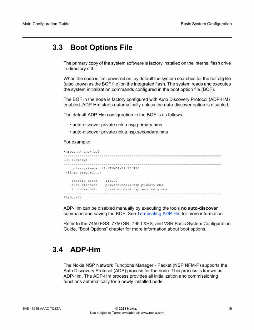
The primary copy of the system software is factory installed on the internal flash drive in directory cf3.
When the node is first powered on, by default the system searches for the bof.cfg file (also known as the BOF file) on the integrated flash. The system reads and executes the system initialization commands configured in the boot option file (BOF).
The BOF in the node is factory configured with Auto Discovery Protocol (ADP-HM) enabled. ADP-Hm starts automatically unless the auto-discover option is disabled.
The default ADP-Hm configuration in the BOF is as follows:
• auto-discover private.nokia.nsp.primary.nms• auto-discover private.nokia.nsp.secondary.nms
For example:
*A:Dut-A# show bof===============================================================================BOF (Memory)===============================================================================
primary-image cf3:/TiMOS-19.10.R1/<lines removed...>
console-speed 115200auto-discover private.nokia.nsp.primary.nmsauto-discover private.nokia.nsp.secondary.nms
===============================================================================*A:Dut-A#
ADP-Hm can be disabled manually by executing the tools no auto-discover command and saving the BOF. See Terminating ADP-Hm for more information.
Refer to the 7450 ESS, 7750 SR, 7950 XRS, and VSR Basic System Configuration Guide, “Boot Options” chapter for more information about boot options.
3.4 ADP-Hm
The Nokia NSP Network Functions Manager - Packet (NSP NFM-P) supports the Auto Discovery Protocol (ADP) process for the node. This process is known as ADP-Hm. The ADP-Hm process provides all initialization and commissioning functions automatically for a newly installed node.

Basic System Configuration
20
Main Configuration Guide
© 2021 Nokia. Use subject to Terms available at: www.nokia.com
3HE 17215 AAAC TQZZA
After one or more SIMs have been installed in a 7705 SAR-Hm series node, when the node is powered on for the first time and any required password change has been made (see Prerequisites for ADP-Hm), the ADP-Hm process running on the node configures a cellular port using the SIM in SIM slot 1, establishes connectivity to the NSP NFM-P, and waits for the NFM-P to complete the discovery and configuration of the node.
This section describes the following topics:
• Prerequisites for ADP-Hm• The ADP-Hm Process• The Console During the ADP-Hm Process• LED Operation During the ADP-Hm Process
See Network Services Platform Functional Overview for information about NSP NFM-P management functions. Refer to the NSP NFM-P User Guide for additional information and procedures to manage the ADP-Hm process.
3.4.1 Prerequisites for ADP-Hm
The prerequisites to allow the ADP-Hm process to automatically discover a 7705 SAR-Hm series router are:
• An NSP NFM-P has been procured, installed, and is managing one or more head-end nodes defined for the cellular domain.
• A valid SIM card is inserted into SIM slot 1 on the node. For dual SIM operation a second SIM is inserted into SIM slot 2.
• For those variants of the 7705 SAR-Hm series node with a unique factory-set password which must be changed at first login, the new password must match the password expected by the NSP NFM-P being used to discover the node during the ADP-Hm process.
• The operator has determined if the one-step or the two-step process will be used by the NSP NFM-P and configures it as such.
• For each carrier private VPN service associated with each installed SIM, a route exists for the NFM-P from the carrier private VPN service or the private-LTE cellular Evolved Packet Core (EPC) towards the cellular domain head-end node or nodes that have reachability to the NSP NFM-P. These gateway nodes allow new 7705 SAR-Hm nodes running ADP-Hm to reach the NSP NFM-P.

Main Configuration Guide Basic System Configuration
3HE 17215 AAAC TQZZA © 2021 Nokia. Use subject to Terms available at: www.nokia.com
21
• A route for the subnet of the cellular domain nodes exists from the cellular domain head-end node to the new node to be discovered. For initial installation of a cellular domain, IP addresses are typically allocated from a /24 or /18 IP address range and the associated routes can be used. In a dual SIM deployment, there must exist a route for the IP addresses associated with each SIM.
• A default Access Point Name (APN) or Virtual Private Network (VPN) service has been procured from the service provider for the SIMs that are installed in the node. If a fixed/static IP address for the IMSI associated with the SIM is required, the address can be allocated in two ways for each SIM:
a. by direct Home Subscriber Server (HSS) allocation (such as when a mobile carrier assigns IP addresses for the SIM and IMSI).
b. by a Radius/AAA/DHCP server owned by the enterprise operator. This method uses a process known as deferred IP allocation between the Home Subscriber Server (HSS) and the PGW of the wireless service provider. When the node first connects and authenticates with the HSS of the wireless provider, the default APN associated with the service indicates that the IP allocation is deferred to the enterprise Radius/AAA/DHCP server. After the PGW learns the static IP address from the server, it is sent to the node in the PDP address IE when the default bearer is established.
• The PGW to which the node will attach using the SIM in slot 1 is configured with additional Protocol Configuration Options (PCO) for the APN. The PCO must include the following two values:- dns-server-ipv4 primary – for example, config/mobile/pdn/apn/pco/dns-
serveripv4 primary - dns-server-ipv4 secondary – for example, config/mobile/pdn/apn/pco/dns-
serveripv4/backup • A primary and secondary DNS server (available from a wireless provider or
owned by an enterprise operator) are configured to resolve the NSP NFM-P IP primary and backup NSP NFM-P IP addresses.
• A SAR-Hm.xml file is loaded on the NSP NFM-P for the cellular domain where the node will reside after discovery. The XML file lists the SIM IMSIs for SIM slot 1 and the node’s associated system IP addresses (if specified in the XML file) of each node that needs to be discovered. In a dual SIM deployment, the SIM in slot 2 is not referred to in this XML file. Refer to the NSP NFM-P User Guide for more information about configuring cellular domains and the associated XML files.
• The operator has enabled ADP-Hm on the NSP NFM-P for the associated prefix addresses of the nodes to be discovered using ADP-Hm in the cellular domain.

Basic System Configuration
22
Main Configuration Guide
© 2021 Nokia. Use subject to Terms available at: www.nokia.com
3HE 17215 AAAC TQZZA
3.4.2 The ADP-Hm Process
The following sections describe the three phases of the ADP-Hm process:
• Network Discovery (Phase 1)• NSP NFM-P Discovery (Phase 2)• NSP NFM-P Configuration (Phase 3)
3.4.2.1 Network Discovery (Phase 1)
When the node boots up initially, it runs the application load, executes the config file (which is empty), and then checks the BOF to determine if ADP-Hm needs to run. If ADP-Hm is enabled, the ADP-Hm process starts and performs the tasks listed below.
• The ADP-Hm process initializes the cellular port that uses SIM1 for PDN connectivity using the default PDN profile, which has a blank APN. When the cellular port attempts to connect to the network, it uses this PDN profile. If the carrier requires an APN other than the default in order for the cellular port to connect to the network, the cellular port can learn the correct APN from the network if the carrier supports that capability. If the carrier does not support devices learning the APN but requires an APN other than the default, then the operator must configure a PDN profile at the system level with the correct APN and assign that PDN profile to cellular port 1/1/1. Refer to the 7705 SAR-Hm and SAR-Hmc Interface Configuration Guide for details about configuring a PDN profile and assigning it to a cellular port.
• After the cellular port connects to the network, ADP-Hm configures a PDN router interface. The PDN router interface can operate in one of three modes. ADP-Hm uses the dynamic cellular interface IP mode of operation. See Dynamic Cellular Interface IPv4 Mode for more information.
• The ADP-Hm process creates a loopback interface with a default name for the PDN interface (such as “pdn1-loopback”). No IP address is assigned to the loopback because it is operating in dynamic cellular interface IP mode.
• The ADP-Hm process uses this loopback interface as the unnumbered interface for the PDN router interface
The CLI output below shows the resulting configuration:
configure routerinterface "pdn1-loopback"
loopbackno shutdown
exitinterface "pdn1-sim1" pdn

Main Configuration Guide Basic System Configuration
3HE 17215 AAAC TQZZA © 2021 Nokia. Use subject to Terms available at: www.nokia.com
23
port 1/1/1unnumbered "pdn1-loopback"no shutdown
exitexit
exit
If the LTE network authenticates and accepts the new node onto the network, a default bearer is established and the following information is provided to the node for the APN to which the node connects:
• the IP address of the cellular interface• the DNS server IP addresses
The configuration is not saved. (Phase 2) NSP NFM-P Discovery begins.
3.4.2.2 NSP NFM-P Discovery (Phase 2)
During the NSP NFM-P Discovery phase the node sends DNS query messages to the DNS server addresses discovered from the previous phase. The node then learns the IP addresses of the NSP NFP-P and sends SNMP traps towards the NSP NFP-P.
The following NSP NFM-P URL names are set for the auto-discover command in the BOF by default:
auto-discover private.nokia.nsp.primary.nmsauto-discover private.nokia.nsp.secondary.nms
The node sends the DNS query message every 5 seconds until a DNS query response message is received with a valid IP address for the primary and secondary NSP NFM-P.
One IP address is required for the ADP-Hm process to continue to the next phase. If no DNS query response message is received, ADP-Hm will time-out and reboot the node. After reboot, the ADP-Hm process restarts from the beginning of Network Discovery (Phase 1).
Note:
The names can also be set to the following:
• another appropriate name, if required• an IP address (which eliminates the requirement for a DNS server)

Basic System Configuration
24
Main Configuration Guide
© 2021 Nokia. Use subject to Terms available at: www.nokia.com
3HE 17215 AAAC TQZZA
After either the NSP NFM-P primary or secondary IP addresses are known by the node, the NSP NFM-P performs the following:
• SNMPv2 trap destinations are set to the NSP NFM-P IP addresses. Log 1 is used to set up the trap destinations.
• ADP-Hm enables NETCONF (note that SSHv2 is enabled by default on the node). ADP-Hm searches the user database for a user with access to NETCONF. If no user exists, NETCONF access is granted to the default user “admin”.
• The node initiates an SNMP trap poll that sends a “Hello” notification trap message to the NSP NFM-P every 15 seconds.
• The node waits for the NSP NFM-P to process the Hello request and then ADP-Hm starts the NSP NFM-P Configuration (Phase 3).
3.4.2.3 NSP NFM-P Configuration (Phase 3)
In the third phase, the NSP NFM-P secures the node and carries out the remaining commissioning steps on the node.
Throughout this phase, the node sends an SNMPv3 trap to theNSP NFM-P every15 seconds until the NSP NFM-P executes the tools “ADP complete” command.
There are two process options available on the NSP NFM-P during this phase. (Refer to the NSP NFM-P user guides for more information about these options.)
1) One-step process – the NSP NFM-P performs all discovery and configuration activities on the node in one step. This allows ADP-Hm to run at the site location from start to finish. After Phase 3 is complete, the node is fully managed and secured. For more information about the one-step process, see One-step Process Details.
2) Two-step process – the NSP NFM-P configures critical security parameters on the node in the first step where operators can monitor progress in a DMZ or staging facility. After step one, the node is secured and fully managed by the NFM-P.
The node is transported to the installation site where the operator performs the second step. When the node is installed and powered on, the NSP NFM-P completes the network-level configuration for the node. The NSP NFM-P configures such things as default tunnels and services to the head-end nodes, or optionally adds the node to an existing network group encryption (NGE) domain. For more information about the two-step process, see Two-step Process Details.
Main Configuration Guide Basic System Configuration
3HE 17215 AAAC TQZZA © 2021 Nokia. Use subject to Terms available at: www.nokia.com
25
3.4.2.3.1 One-step Process Details
In the one-step process, the node is powered on and ADP-Hm completes the entire discovery and configuration of the node in one step.
The NSP NFM-P uses NetConf over SSHv2 to configure SNMPv3 parameters, including the users and security encryption and authentication keys for SNMPv3. This information is based on the mediation policy configured for the cellular domain in the NSP NFM-P.
The NSP NFM-P then completes the configuration of the node. The following list summarizes the actions that the NSP NFM-P performs on the node:
1. Creates a strict security association between the chassis information, IMEI, and the SIM in SIM slot 1. After this association is made, the SIM cannot be inserted into another node and managed by the NSP NFM-P without operator intervention to instruct the NSP NFM-P to create a new association between the SIM and a new chassis.
2. Configures user names and passwords, scope of control, and associated profiles.
3. Configures PDN profiles that are used to connect to the cellular network after ADP-Hm is complete. If dual SIM is enabled for the cellular domain in the NSP NFM-P, then the second cellular port and PDN router interface is configured.
4. Downloads the required radio firmware version for SIM 1 and if dual SIM is enabled, it downloads the radio firmware version for SIM 2. The NSP NFM-P resets the radio so that SIM 1 uses the latest downloaded version.
5. Downloads the required software load and resets the node to use the latest version of the software.
6. Downloads the NGE key-group of the NGE domain associated with the cellular domain if the node is to enter the NGE domain. The PDN router interface is also configured with the key-group needed to enter the NGE domain.
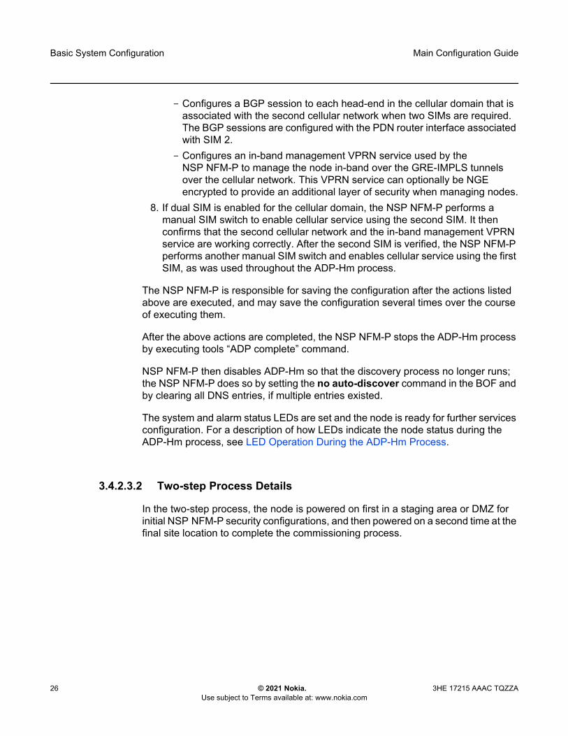
7. If the cellular mode is Static Cellular Interface IP Mode or Dynamic Cellular Interface IP Mode, the NSP NFM-P performs the following configurations towards the head-end nodes of the cellular domain to establish an in-band management service. (For more information, see the Static Cellular Interface IPv4 Mode, and Dynamic Cellular Interface IPv4 Mode sections in this guide.)- Configures a BGP session to each head-end node in the cellular domain
that is associated with the first cellular network. The BGP sessions are configured with the PDN router interface associated with SIM 1.
Basic System Configuration
26
Main Configuration Guide
© 2021 Nokia. Use subject to Terms available at: www.nokia.com
3HE 17215 AAAC TQZZA
- Configures a BGP session to each head-end in the cellular domain that is associated with the second cellular network when two SIMs are required. The BGP sessions are configured with the PDN router interface associated with SIM 2.
- Configures an in-band management VPRN service used by the NSP NFM-P to manage the node in-band over the GRE-IMPLS tunnels over the cellular network. This VPRN service can optionally be NGE encrypted to provide an additional layer of security when managing nodes.
8. If dual SIM is enabled for the cellular domain, the NSP NFM-P performs a manual SIM switch to enable cellular service using the second SIM. It then confirms that the second cellular network and the in-band management VPRN service are working correctly. After the second SIM is verified, the NSP NFM-P performs another manual SIM switch and enables cellular service using the first SIM, as was used throughout the ADP-Hm process.
The NSP NFM-P is responsible for saving the configuration after the actions listed above are executed, and may save the configuration several times over the course of executing them.
After the above actions are completed, the NSP NFM-P stops the ADP-Hm process by executing tools “ADP complete” command.
NSP NFM-P then disables ADP-Hm so that the discovery process no longer runs; the NSP NFM-P does so by setting the no auto-discover command in the BOF and by clearing all DNS entries, if multiple entries existed.
The system and alarm status LEDs are set and the node is ready for further services configuration. For a description of how LEDs indicate the node status during the ADP-Hm process, see LED Operation During the ADP-Hm Process.
3.4.2.3.2 Two-step Process Details
In the two-step process, the node is powered on first in a staging area or DMZ for initial NSP NFM-P security configurations, and then powered on a second time at the final site location to complete the commissioning process.
Main Configuration Guide Basic System Configuration
3HE 17215 AAAC TQZZA © 2021 Nokia. Use subject to Terms available at: www.nokia.com
27
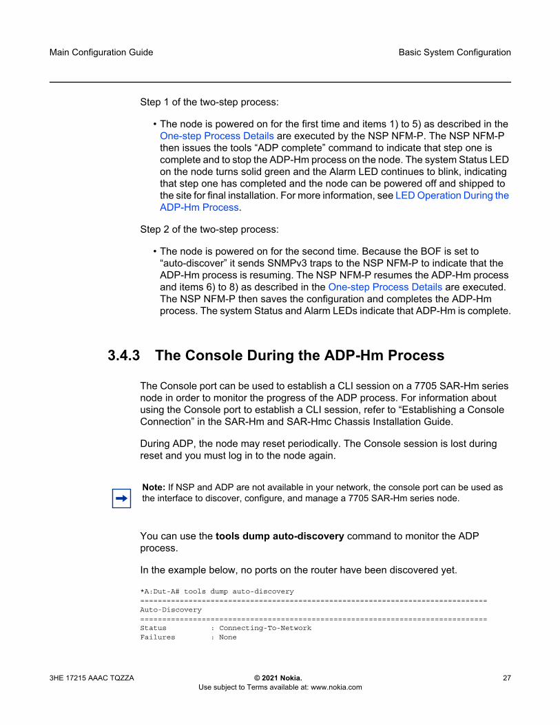
Step 1 of the two-step process:
• The node is powered on for the first time and items 1) to 5) as described in the One-step Process Details are executed by the NSP NFM-P. The NSP NFM-P then issues the tools “ADP complete” command to indicate that step one is complete and to stop the ADP-Hm process on the node. The system Status LED on the node turns solid green and the Alarm LED continues to blink, indicating that step one has completed and the node can be powered off and shipped to the site for final installation. For more information, see LED Operation During the ADP-Hm Process.
Step 2 of the two-step process:
• The node is powered on for the second time. Because the BOF is set to “auto-discover” it sends SNMPv3 traps to the NSP NFM-P to indicate that the ADP-Hm process is resuming. The NSP NFM-P resumes the ADP-Hm process and items 6) to 8) as described in the One-step Process Details are executed. The NSP NFM-P then saves the configuration and completes the ADP-Hm process. The system Status and Alarm LEDs indicate that ADP-Hm is complete.
3.4.3 The Console During the ADP-Hm Process
The Console port can be used to establish a CLI session on a 7705 SAR-Hm series node in order to monitor the progress of the ADP process. For information about using the Console port to establish a CLI session, refer to “Establishing a Console Connection” in the SAR-Hm and SAR-Hmc Chassis Installation Guide.
During ADP, the node may reset periodically. The Console session is lost during reset and you must log in to the node again.
You can use the tools dump auto-discovery command to monitor the ADP process.
In the example below, no ports on the router have been discovered yet.
*A:Dut-A# tools dump auto-discovery===============================================================================Auto-Discovery===============================================================================Status : Connecting-To-NetworkFailures : None
Note: If NSP and ADP are not available in your network, the console port can be used as the interface to discover, configure, and manage a 7705 SAR-Hm series node.
Basic System Configuration
28
Main Configuration Guide
© 2021 Nokia. Use subject to Terms available at: www.nokia.com
3HE 17215 AAAC TQZZA
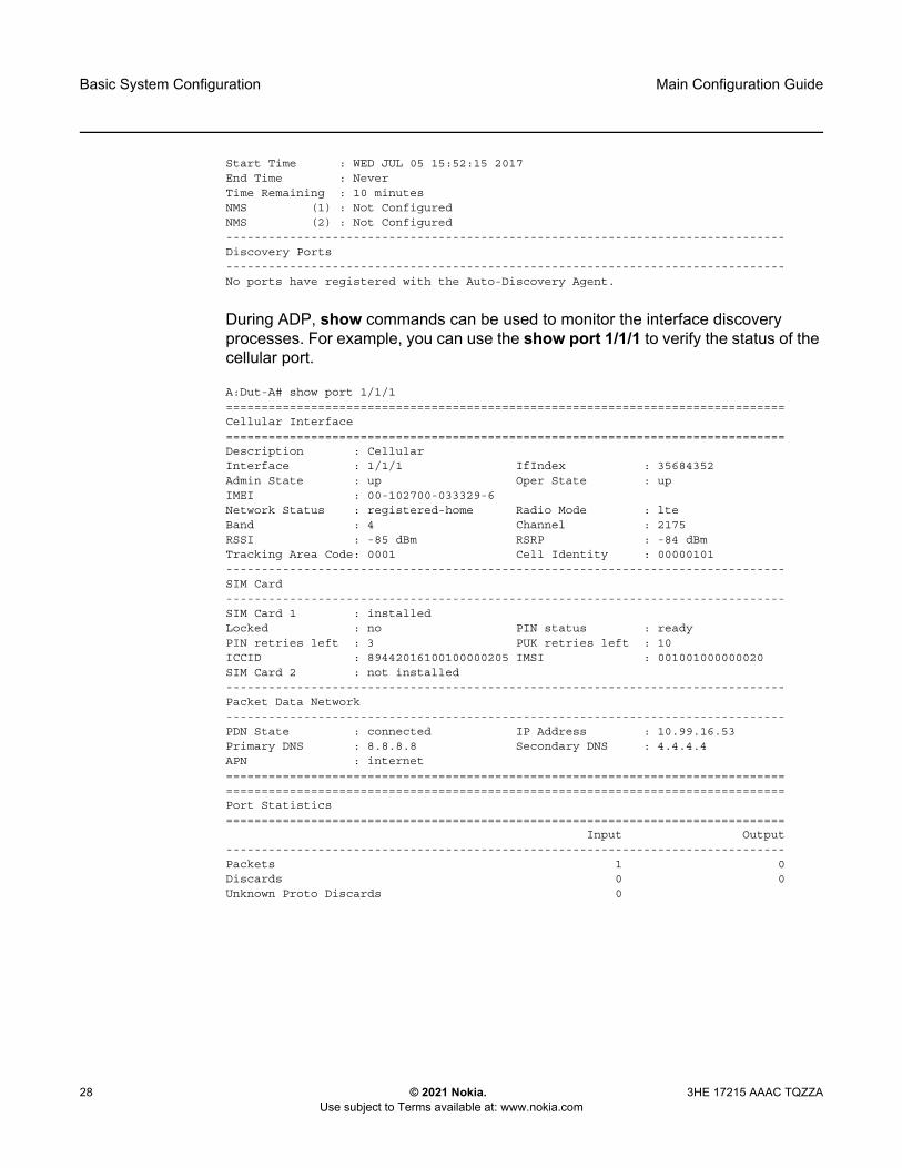
Start Time : WED JUL 05 15:52:15 2017End Time : NeverTime Remaining : 10 minutesNMS (1) : Not ConfiguredNMS (2) : Not Configured-------------------------------------------------------------------------------Discovery Ports-------------------------------------------------------------------------------No ports have registered with the Auto-Discovery Agent.
During ADP, show commands can be used to monitor the interface discovery processes. For example, you can use the show port 1/1/1 to verify the status of the cellular port.
A:Dut-A# show port 1/1/1===============================================================================Cellular Interface===============================================================================Description : CellularInterface : 1/1/1 IfIndex : 35684352Admin State : up Oper State : upIMEI : 00-102700-033329-6Network Status : registered-home Radio Mode : lteBand : 4 Channel : 2175RSSI : -85 dBm RSRP : -84 dBmTracking Area Code: 0001 Cell Identity : 00000101-------------------------------------------------------------------------------SIM Card-------------------------------------------------------------------------------SIM Card 1 : installedLocked : no PIN status : readyPIN retries left : 3 PUK retries left : 10ICCID : 89442016100100000205 IMSI : 001001000000020SIM Card 2 : not installed-------------------------------------------------------------------------------Packet Data Network-------------------------------------------------------------------------------PDN State : connected IP Address : 10.99.16.53Primary DNS : 8.8.8.8 Secondary DNS : 4.4.4.4APN : internet==============================================================================================================================================================Port Statistics===============================================================================
Input Output-------------------------------------------------------------------------------Packets 1 0Discards 0 0Unknown Proto Discards 0

Main Configuration Guide Basic System Configuration
3HE 17215 AAAC TQZZA © 2021 Nokia. Use subject to Terms available at: www.nokia.com
29
3.4.4 LED Operation During the ADP-Hm Process
The system Status and Alarm LEDs indicate the current status of the node during the ADP-Hm process. Table 2 describes LED operation during the ADP-Hm process.
Note: The ADP-Hm process does not inhibit the RSSI signal strength LEDs so that installers can use the RSSI LEDs to optimize the position of the antennas when the ADP-Hm process is running.
Table 2 LED Operations During the ADP-Hm Process
ADP-Hm Status/Phase
Status Alarm
Before ADP-Hm starts
Green (blinking): Indicates that the system is booting up the TiMOS image and running hardware and software diagnostics
—
Network Discovery
Green (blinking) Amber (one blink followed by a pause). The LTE/3G interface LEDs are also active and provide feedback about the LTE interface (showing link status and signal strength). For more information, refer to “7705 SAR-Hm LEDs” in the SAR-Hm and SAR-Hmc Chassis Installation Guide.
NSP NFM-P Discovery
Green (blinking) Amber (two blinks followed by a pause then repeats).
NSP NFM-P Configuration
Green (blinking) Amber (three blinks followed by a pause, then repeats): This blinking occurs during the one-step or two-step process during the NSP NFM-P configuration phase.
Green (solid): Indicates that the ADP-Hm process has completed step one of the two-step process and the system is ready to be powered down, installed at its final location and powered back up to complete step two of the two-step process.

Basic System Configuration
30
Main Configuration Guide
© 2021 Nokia. Use subject to Terms available at: www.nokia.com
3HE 17215 AAAC TQZZA
ADP-Hm Complete
Green (solid): Indicates one of the following:
• ADP-Hm is disabled and the system is operationally up.
• the ADP-Hm process is complete for the one-step process and the system is operationally up.
• the ADP-Hm process completed step two of the two-step process and the system is operationally up.
The Alarm LED displays the current alarm state. For more information, refer to “7705 SAR-Hm LEDs” in the SAR-Hm and SAR-Hmc Chassis Installation Guide.
Table 2 LED Operations During the ADP-Hm Process (Continued)
ADP-Hm Status/Phase
Status Alarm

Main Configuration Guide Basic System Configuration
3HE 17215 AAAC TQZZA © 2021 Nokia. Use subject to Terms available at: www.nokia.com
31
3.4.5 Terminating ADP-Hm
ADP can be disabled manually by executing the bof no auto-discover command and saving the BOF.
To terminate ADP-Hm:
Step 1. Perform one of the following:a. At boot up, the system displays a warning and asks if you wish to
terminate Auto-Discovery. Type y to terminate Auto-Discovery. For example:
WARNING: Auto-discovery is currently running on this system.It is recommended that Auto-Discovery be terminated before makingconfiguration changes using this session; otherwise, any changes made during thisprocess may result in Auto-Discovery failing to complete successfully and/or lost configuration.
Do you wish to terminate Auto-Discovery (y/n?) y
b. Use the tools auto-discovery terminate command. For example:tools# auto-discovery terminate
Step 2. Reboot the node. After reboot, the warning message no longer appears and auto-discovery is removed from the BOF. For example:
*A:Dut-A# show bof===============================================================================BOF (Memory)===============================================================================
primary-image cf3:/TiMOS-19.10.R1/
<lines removed...>
console-speed 115200===============================================================================*A:Dut-A#

Basic System Configuration
32
Main Configuration Guide
© 2021 Nokia. Use subject to Terms available at: www.nokia.com
3HE 17215 AAAC TQZZA
3.5 Basic System Management
For general information on basic system management support, refer to the topics listed below in the “System Management” chapter of the 7450 ESS, 7750 SR, 7950 XRS, and VSR Basic System Configuration Guide.
• System Management Parameters• Administrative Tasks
- Saving Configurations- Specifying Post-Boot Configuration Files
• System Router Instances• System Configuration Process Overview
3.6 Network Services Platform Functional Overview
The Nokia Network Services Platform NSP is a group of interoperating network management modules that provide comprehensive end-to-end management of a wide range of network domains and topologies.
The Nokia NSP Network Functions Manager - Packet (NSP NFM-P) is used to discover, configure, and manage the s nodes and related cellular domains. The NSP NFM-P provides the following specific functions. (Refer to the NSP NFM-P User Guide for more information.)
• creates and manages the cellular domains. A cellular domain is a group of nodes where each node in the group connects to the same head-end nodes, shares the same deployment modes of operation, and is part of the same NGE domain. For more information about deployment modes of operation, see the PDN Router Interfaces section of this guide.
• drives the ADP-Hm process for each new node to be discovered in a cellular domain. For static cellular interface IP and dynamic modes of operation, the NSP NFM-P creates a management VPRN service for in-band management of each node.
• manually adds or removes nodes to and from cellular domains• supports the XML input lists of the SIM IMSI values that are expected to
participate in the cellular domain and initiate the ADP-Hm process within the cellular domain. These lists include the SIM information and optionally, the system IP for node boot-strap process.
Main Configuration Guide Basic System Configuration
3HE 17215 AAAC TQZZA © 2021 Nokia. Use subject to Terms available at: www.nokia.com
33
• creates a security association between the SIM, IMEI, and the chassis identifier for each node being managed such that unexpected changes are flagged as potential security violations to the operator.
• supports configurable NSP NFM-P polling interval of nodes. Configurable polling is intended to minimize traffic between the NSP NFM-P and a large-scale deployment of nodes. To that end, the NSP NFM-P also polls the status of the BGP sessions between head-end nodes and the nodes in the cellular domain in order to monitor the reachability and status of the nodes in the cellular domain.
3.7 Debug Commands
The 7705 SAR-Hm series of routers supports debug commands that enable detailed debug information for various protocols.
Debug output is generally displayed by configuring a log using from debug-trace.
The currently enabled debug can be seen using the show debug command.
A debug configuration does not persist when the router reboots.The admin debug-save command can be used to save the debug configuration. The resulting file can be exec'ed later as needed.
Individual debug commands are described in the 7450 ESS, 7750 SR, 7950 XRS, and VSR Classic CLI Command Reference Guide.
3.8 Tools Commands
The 7705 SAR-Hm series of routers supports tools commands. The tools commands provide two primary functions: dump and perform.
The tools dump commands are used to provide additional detailed and enhanced information about various aspects of the router.
The tools perform commands provide the ability to trigger a variety of actions on the router.
Individual tools commands are described in the 7450 ESS, 7750 SR, 7950 XRS, and VSR Clear, Show, and Tools Command Reference Guide.

Basic System Configuration
34
Main Configuration Guide
© 2021 Nokia. Use subject to Terms available at: www.nokia.com
3HE 17215 AAAC TQZZA
Main Configuration Guide System Management
3HE 17215 AAAC TQZZA © 2021 Nokia. Use subject to Terms available at: www.nokia.com
35
4 System ManagementThe 7705 SAR-Hm series of routers supports system management parameters as covered in the topics listed below:
• System Security• SNMP• Event Logs• In-band Management over LTE
4.1 System Security
For general information on system security support, refer to the topics listed below in the “Security” chapter of the 7450 ESS, 7750 SR, 7950 XRS, and VSR System Management Guide.
• Authentication- Local Authentication- Radius Authentication- TACACS+ Authentication
• Authorization - Local Authorization- Radius Authorization- TACACS+ Authorization
• Security Controls• Vendor-Specific Attributes (VSAs)• Other Security Features
- Secure Shell (SSH)- SSH PKI Authentication- HMAC strengthening (SHA-224/256/384/512) - MAC Client and Server List- Regenerate the ssh-key without disabling SSH- TTL Security for BGP and LDP- Exponential Login Backoff- User Lockout

System Management
36
Main Configuration Guide
© 2021 Nokia. Use subject to Terms available at: www.nokia.com
3HE 17215 AAAC TQZZA
- CLI Login Scripts- 802.1x Network Access Control- TCP Enhanced Authentication Option
• Configuration Notes• Configuring Security with CLI
For descriptions of security commands, refer to the 7450 ESS, 7750 SR, 7950 XRS, and VSR Classic CLI Command Reference Guide and to the 7450 ESS, 7750 SR, 7950 XRS, and VSR Clear, Show, and Tools Command Reference Guide.
4.2 SNMP
For general information on SNMP support, refer to the “SNMP” chapter of the 7450 ESS, 7750 SR, 7950 XRS, and VSR System Management Guide.
4.3 Event Logs
For general information on event log support, refer to the “Event and Accounting Logs” chapter of the 7450 ESS, 7750 SR, 7950 XRS, and VSR System Management Guide.
Main Configuration Guide System Management
3HE 17215 AAAC TQZZA © 2021 Nokia. Use subject to Terms available at: www.nokia.com
37
4.4 In-band Management over LTE
The 7705 SAR-Hm series of routers supports the following modes of operation over a cellular network:
• static cellular system IPv4 mode• static cellular interface IPv4 mode or IPv6 mode• dynamic cellular interface IPv4 mode or IPv6 mode
The way in which the node is managed depends on which mode of operation is in use. See Services over the Cellular PDN Interface for more information about the modes of operation.
When a cellular port on the node is operating in static cellular system IP mode, the system IP address is identical to the cellular IP address assigned during the initial PDN attachment process. To manage the node in this mode, the NSP NFM-P or other network management platform reaches the node without using the system IP address directly over the cellular network. This is the only mode that does not require a pre-established in-band management service to manage the node.
When a cellular port on the node is operating in static cellular interface IP mode or dynamic cellular interface IP mode, the NSP NFM-P or other network management platform can only reach the node through an in-band management VPRN service. For these modes of operation, the system IP address used to manage the node is private and differs from the cellular port IP address assigned when connecting to the cellular network. The system IP address must be advertised from the 7705 SAR-Hm series node to the head-end node by the in-band management VPRN service. Routing in the private IP/MPLS network past the head-end node must allow management traffic to reach the head-end node which will then send the management traffic over the VPRN to the node being managed.
The NSP NFM-P automatically configures the required in-band management VPRN service during the ADP-Hm process; see ADP-Hm for more information.
On the 7705 SAR-Hm series nodes, there are two methods for enabling in-band management over a VPRN service:
• performing a Global Routing Table (GRT) lookup and VPRN-to-GRT route leaking
• using port cross-connect
System Management
38
Main Configuration Guide
© 2021 Nokia. Use subject to Terms available at: www.nokia.com
3HE 17215 AAAC TQZZA
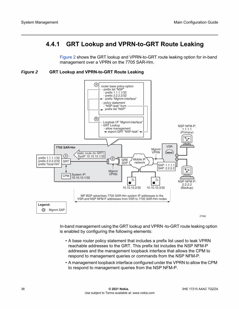
4.4.1 GRT Lookup and VPRN-to-GRT Route Leaking
Figure 2 shows the GRT lookup and VPRN-to-GRT route leaking option for in-band management over a VPRN on the 7705 SAR-Hm.
Figure 2 GRT Lookup and VPRN-to-GRT Route Leaking
In-band management using the GRT lookup and VPRN -to-GRT route leaking option is enabled by configuring the following elements:
• A base router policy statement that includes a prefix list used to leak VPRN reachable addresses to the GRT. This prefix list includes the NSP NFM-P addresses and the management loopback interface that allows the CPM to respond to management queries or commands from the NSP NFM-P.
• A management loopback interface configured under the VPRN to allow the CPM to respond to management queries from the NSP NFM-P.
7705 SAR-Hm
CPM System IP:10.10.10.1/32
27566
NSP NFM-P:2.2.2.2
(Backup)
NSP NFM-P:1.1.1.1
(Primary)
MgmntVPRN
GRESDP
Mobile IP network
VSR
Mgmnt SAP
Legend:
GRTprefix 1.1.1.1/32prefix 2.2.2.2/32prefix “local-Hm”
MgmntVPRN
BA
static route (to GRT):SysIP 10.10.10.1/32
10.10.10.2/32 10.10.10.3/32
B
A router base policy-option - prefix list “NSP” - prefix 1.1.1.1/32 - prefix 2.2.2.2/32 - prefix “Mgmnt-interface” - policy statement - “NSP-leak” from prefix list “NSP”
- Loopbak I/F “Mgmnt-interface”- GRT Lookup - allow management export-GRT “NSP-leak”
SAP: 1.1.1.1SAP: 2.2.2.2
MP BGP advertises 7705 SAR-Hm system IP addresses to theVSR and NSP NFM-P addresses from VSR to 7705 SAR-Hm nodes

Main Configuration Guide System Management
3HE 17215 AAAC TQZZA © 2021 Nokia. Use subject to Terms available at: www.nokia.com
39
• A static route from the VPRN to the GRT for the system IP address of the node• Enable a GRT lookup from the VPRN to the GRT so that management traffic
received over the VPRN from the NSP NFM-P to the 7705 SAR-Hm series node can reach the CPM. This uses the grt-lookup, enable-grt, and allow-local-management CLI commands in the config>service>vprn context. For descriptions of these commands, refer to the 7450 ESS, 7750 SR, 7950 XRS, and VSR Classic CLI Command Reference Guide.
• A VPRN-to-GRT route leak that populates the GRT routing table with addresses that are reachable by the VPRN, using the export-grt command. For a description of this command, refer to the 7450 ESS, 7750 SR, 7950 XRS, and VSR Classic CLI Command Reference Guide. The reachable addresses include those for the NSP NFM-P and the local management loopback interface that allows responses from the CPM to return to the corresponding VPRN.
The CLI output below shows a configuration example of in-band management using GRT lookup and VPRN-to-GRT route leaking, based on Figure 2.
#--------------------------------------------------echo "Policy Configuration"#--------------------------------------------------
policy-optionsbeginprefix-list "NSP"
prefix 1.1.1.1/24 exactprefix 2.2.2.2/24 exactprefix 192.168.255.0/32 exact
exitpolicy-statement "NSP-leak"
entry 10from
prefix-list "NSP"exitaction acceptexit
exitexitcommit
exit#--------------------------------------------------echo "Service Configuration"#--------------------------------------------------
servicecustomer 1 name "1" create
description "Default customer"exitvprn 1 name "1" customer 1 create
interface "NSP" createexit
exitvprn 1 name "1" customer 1 create
route-distinguisher 65650:1auto-bind-tunnel
resolution-filtergre

System Management
40
Main Configuration Guide
© 2021 Nokia. Use subject to Terms available at: www.nokia.com
3HE 17215 AAAC TQZZA
exitresolution filter
exitvrf-target target:65650:1interface "Mgmnt-interface" create
address 192.168.255.0/32loopback
exitstatic-route-entry 10.10.10.1/32
grtno shutdown
exitexitgrt-lookup
enable-grtallow-local-management
exitexport-grt "NSP-leak"
exitno shutdown
exitexit

Main Configuration Guide System Management
3HE 17215 AAAC TQZZA © 2021 Nokia. Use subject to Terms available at: www.nokia.com
41
4.4.2 Port Cross-Connect (PXC)
For information about PXC, refer to the “Interfaces” chapter of the 7450 ESS, 7750 SR, 7950 XRS, and VSR Interface Configuration Guide.
Figure 3 shows an example of the operation of in-band management using a VPRN and PXC.
Figure 3 In-band Management using a VPRN Service and PXC
The CLI example below shows the configuration of the PXC based on the example shown in Figure 3.
Example: A:DUT>config>port 1/2/6 shutdownA:DUT>config>port-xcA:DUT>config>port-xc# pxc 1 createA:DUT>config>port-xc>pxc# port 1/2/6A:DUT>config>port-xc>pxc# no shutdownA:DUT>config>port-xc>pxc# exit allA:DUT>>configureA:DUT>>config# port pxc-1.a no shutdownA:DUT>>config# port pxc-1.b no shutdownA:DUT>>config# port 1/2/6 no shutdown
7705 SAR-Hm
PXC1: Port 1/2/6
port pxc-1.a
port pxc-1.b
Static route in VPRN to reach theCPM system IP via PXC port pxc-1.a
Static route in GRT to reach theNSP NFM-P via PXC port pxc-1.b
GRT I/F:192.168.255.0/31
SSH, SNMP, etc
CPM
System IP:10.10.10.1
VPRN I/F:192.168.255.1/31
26591
NSP NFM-P:1.1.1.1
VPRN VPRNGRE SDPMobile IP network
VSR
VPRN static route: 10.10.10.1/32Next hop: 192.168.255.0
GRT static route: 1.1.1.1/24Next hop: 192.168.255.1
Mgmnt SAPVPRN SAP
Legend:
PDN IP: 88.0.0.1

System Management
42
Main Configuration Guide
© 2021 Nokia. Use subject to Terms available at: www.nokia.com
3HE 17215 AAAC TQZZA
To ensure management traffic from the CPM can reach the NSP NFM-P over the VPRN, an interface in the Global Routing Table (GRT) is configured on one of the PXC ports. In the example shown in Figure 3, the GRT PXC port is port pxc-1.b. This port is looped internally together with PXC port pxc-1.a, the SAP of the in-band management VPRN. A router interface is required on port pxc-1.b:1 (VLAN 1) and used to route management traffic from the CPM towards the in-band management VPRN. A static route is configured in the GRT for the NSP NFM-P address, 1.1.1.1, with a next hop of the VPRN SAP, or port pxc-1.a:1. The CLI output below shows configuration examples in the GRT.
*A:DUT>config>service>vprn# info----------------------------------------------
interface “pxc”address 192.168.255.0/31port pxc-1.b:1no shutdown
exit...
static-route-entry 1.1.1.1/24next-hop 192.168.255.1
no shutdownexit
exit...----------------------------------------------*A:DUT>config>router#
A SAP interface on the other PXC port is required by the in-band management VPRN to route management traffic towards the CPM. A static route is configured in the VPRN for the CPM system IP address 10.10.10.1, with a next hop of the GRT interface port pxc-1.b:1. The CLI output below shows configuration examples for the VPRN.
*A:ALU-1>config>service# info----------------------------------------------...
vprn 1 customer 1 createautonomous-system 65200route-distinguisher 65200:1auto-bind-tunnel
resolution-filtergreexit
exitvrf-target target:65200:1interface “pxc” create
address 192.168.255.1/31sap pxc-1.a:1 createexit
exitstatic-route-entry 10.10.10.1/32 next-hop 192.168.255.0no shutdown
exit...

Main Configuration Guide Router Configuration
3HE 17215 AAAC TQZZA © 2021 Nokia. Use subject to Terms available at: www.nokia.com
43
5 Router ConfigurationThe 7705 SAR-Hm series of routers supports standard IP routing as covered in the topics listed below:
• IP Router Configuration• Filter Policy Support
5.1 IP Router Configuration
This section describes the following functionality on 7705 SAR-Hm series nodes:
• PDN Router Interfaces- IPv4 PDN Router Interface- IPv6 PDN Router Interface- Static Cellular System IPv4 Mode- Static Cellular Interface IPv4 Mode- Dynamic Cellular Interface IPv4 Mode- Static Cellular Interface IPv6 Mode- Dynamic Cellular Interface IPv6 Mode
• DHCP Client - Restrictions on Configuring a Router Interface with DHCP Client Enabled - Route Policy Option for DHCP Client - GRE Termination for Services over a DHCP Client
• Router Interface Command Reference- PDN Router Interface Configuration and Show Command Hierarchies - DHCP Client Configuration, Show, Tools, Debug, and Clear Command
Hierarchies - PDN Router Interface Command Descriptions- DHCP Client Command Descriptions
For general information on IP router configuration support, refer to the topics listed below in the “IP Router Configuration” chapter of the 7450 ESS, 7750 SR, 7950 XRS, and VSR Router Configuration Guide.
• Configuring IP Router Parameters- Interfaces

Router Configuration
44
Main Configuration Guide
© 2021 Nokia. Use subject to Terms available at: www.nokia.com
3HE 17215 AAAC TQZZA
• Network Interfaces• Network Domains• System Interface• Creating an IP Address Range
- Router ID- Autonomous Systems- Confederations- Exporting an Inactive BGP Route from a VPRN- DHCP Relay- Internet Protocol Versions
• Aggregate Next Hop• Invalidate Next-Hop Based on ARP/Neighbor Cache State• Router Interface Encryption with NGE• Process Overview• Configuration Notes• Configuring an IP Router with CLI• Service Management Tasks
For descriptions of IP router commands, refer to the 7450 ESS, 7750 SR, 7950 XRS, and VSR Classic CLI Command Reference Guide and to the 7450 ESS, 7750 SR, 7950 XRS, and VSR Clear, Show, and Tools Command Reference Guide.
5.1.1 PDN Router Interfaces
A packet data network (PDN) router interface is a type of router interface specific to a cellular port. PDN router interfaces are network-facing only and provide the main routing function over a cellular port. Each PDN connection that operates on a cellular port requires a PDN router interface.
A specific PDN router interface is associated with a specific SIM. Port 1/1/1 is always associated with SIM 1 and port 1/1/2 is always associated with SIM2. Therefore, a PDN router interface configured against port 1/1/1 is associated with SIM 1 and a PDN router interface configured against port 1/1/2 is associated with SIM 2. For information on configuring cellular ports, refer to the 7705 SAR-Hm and SAR-Hmc Interface Configuration Guide.

Main Configuration Guide Router Configuration
3HE 17215 AAAC TQZZA © 2021 Nokia. Use subject to Terms available at: www.nokia.com
45
A PDN router interface is configured using the command config>router>interface interface-name pdn. A PDN router interface supports either IPv4 or IPv6 operation. The address type is determined by the protocol, either IPv4 or IPv6, configured for the PDN profile. A PDN profile must be configured and associated with the PDN router interface in order for a cellular port to attach to a cellular network. The address type is learned by the router interface during the PDN attachment process. Refer to the 7705 SAR-Hm and SAR-Hmc Interface Configuration Guide for information on configuring a PDN profile.
5.1.1.1 IPv4 PDN Router Interface
When a cellular port is configured for IPv4 operation, the associated PDN router interface is always an unnumbered interface; therefore, it cannot be directly configured with an IPv4 address. The IPv4 address assigned to a PDN interface must be specified from a loopback interface or learned directly from the cellular network during the cellular network attachment process. An IPv4 address specified from a loopback interface is used in the following ways:
• as the source IPv4 address for GRE-MPLS packets that are sent over a cellular port
• as the BGP local-address for BGP sessions over a cellular port• as the T-LDP local-lsr-id for T-LDP signaling sessions
An IPv4 PDN router interface can operate in one of three modes:
• static cellular system IPv4 mode• static cellular interface IPv4 mode• dynamic cellular interface IPv4 mode
The mode of operation dictates the way in which the IPv4 address is assigned to the PDN router interface and how it is used in conjunction with services.
For information about the types of services supported on an IPv4 PDN router interface and how an IPv4 PDN interface IP addresses is used by services, see Services over the Cellular PDN Interface.
An IPv4 PDN router interface supports Network Group Encryption (NGE). For information on NGE, see Network Group Encryption.
An IPv4 PDN router interface supports IPSec secure interfaces. For information on IPSec secure interfaces, see IPSec Secured Interface over Cellular.

Router Configuration
46
Main Configuration Guide
© 2021 Nokia. Use subject to Terms available at: www.nokia.com
3HE 17215 AAAC TQZZA
5.1.1.2 IPv6 PDN Router Interface
When a cellular port is configured for IPv6 operation, the associated PDN router interface is always a numbered interface.
An IPv6 PDN router interface can operate in one of two modes:
• static cellular interface IPv6 mode• dynamic cellular interface IPv6 mode
The ipv6>address command is used to determine the mode of operation of the PDN router interface. When the address is specified, the IPv6 PDN router interface is operating in static cellular interface IPv6 mode. When the address is not specified, then it is operating in the dynamic cellular interface IPv6 mode.
For information about the types of services supported on an IPv6 PDN router interface, see Services over the Cellular PDN Interface.
An IPv6 PDN router interface supports IPSec secure interfaces. For information on IPSec secure interfaces, see IPSec Secured Interface over Cellular.
An IPv6 PDN router interface does not support NGE.
5.1.1.2.1 Static Routing on an IPv6 PDN Router Interface
When IPv6 is enabled on the PDN router interface, any static routes configured to use the PDN interface name as the next hop do not require the explicit configuration of the link-local address. This is because cellular networks do not require a next hop.
The CLI output below shows an example of a static route configuration on an IPv6-enabled PDN router interface.
*A:DUT# config# routerinterface "pdn-itf" pdn
port 1/1/1ipv6
address 1::1/64exit
exitstatic-route-entry ::/0
next-hop "pdn-itf"exit
exitexit

Main Configuration Guide Router Configuration
3HE 17215 AAAC TQZZA © 2021 Nokia. Use subject to Terms available at: www.nokia.com
47
5.1.1.3 Static Cellular System IPv4 Mode
In the static cellular system IPv4 mode of operation, the unnumbered interface under the PDN router interface is configured as the system interface. When the cellular port associated with the PDN interface attaches to the cellular network, the cellular network statically assigns an IP address to the node for the Access Point Name (APN) and associated installed Subscriber Identity Module (SIM). The system interface is then configured with the IP address that matches the cellular network-assigned IP address. The result is that the IP address provided by the cellular network for the PDN router interface and the system IP address of the node are identical.
A PDN router interface is considered operationally up only when the associated cellular port attaches to the network and an IP address is learned from the cellular attachment. The system checks whether the LTE network-assigned IP address matches the system IP address configured on the PDN interface. If it does not match, the PDN router interface is considered down and an alarm is raised.
The CLI output below shows an example of a PDN interface configured for static cellular system IPv4 mode.
*A:DUT# config# routerinterface “system”
address 88.0.0.1/32no shutdown
exitinterface “pdn1-sim1” pdn
port 1/1/1unnumbered “system”no shutdown
exitexit
exit
When operating in static cellular system IPv4 mode, the following points apply.
• Only one cellular IP address can be used on the node. This affects dual SIM operation. If the PDN router interface of one of the dual SIM cellular ports is operating in static cellular system IPv4 mode, then the other PDN router interface must also operate in static cellular system IPv4 mode. The cellular network for each SIM must allocate the same system IP address when the node attaches to the cellular network over either cellular port.
• Some wireless service providers require that all packets entering their network from user equipment (UE) attached to their network have a source IP address that matches the IP address that the cellular network assigned to the UE. When this is a requirement and the node is using static cellular system IP mode, the PDN interface must be configured with an IP filter that allows only egress packets with a source IP address that matches the system IP address.
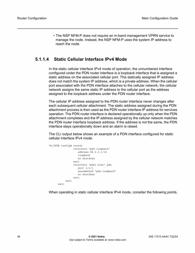
Router Configuration
48
Main Configuration Guide
© 2021 Nokia. Use subject to Terms available at: www.nokia.com
3HE 17215 AAAC TQZZA
• The NSP NFM-P does not require an in-band management VPRN service to manage the node. Instead, the NSP NFM-P uses the system IP address to reach the node.
5.1.1.4 Static Cellular Interface IPv4 Mode
In the static cellular interface IPv4 mode of operation, the unnumbered interface configured under the PDN router interface is a loopback interface that is assigned a static address on the associated cellular port. This statically assigned IP address does not match the system IP address, which is a private address. When the cellular port associated with the PDN interface attaches to the cellular network, the cellular network assigns the same static IP address to the cellular port as the address assigned to the loopback address under the PDN router interface.
The cellular IP address assigned to the PDN router interface never changes after each subsequent cellular attachment. The static address assigned during the PDN attachment process is then used as the PDN router interface IP address for services operation. The PDN router interface is declared operationally up only when the PDN attachment completes and the IP address assigned by the cellular network matches the PDN router interface loopback address. If the address is not the same, the PDN interface stays operationally down and an alarm is raised.
The CLI output below shows an example of a PDN interface configured for static cellular interface IPv4 mode.
*A:DUT# config# routerinterface “pdn-loopback”
address 88.0.0.1/32loopbackno shutdown
exitinterface “pdn1-sim1” pdn
port 1/1/1unnumbered “pdn-loopback”no shutdown
exitexit
exit
When operating in static cellular interface IPv4 mode, consider the following points.
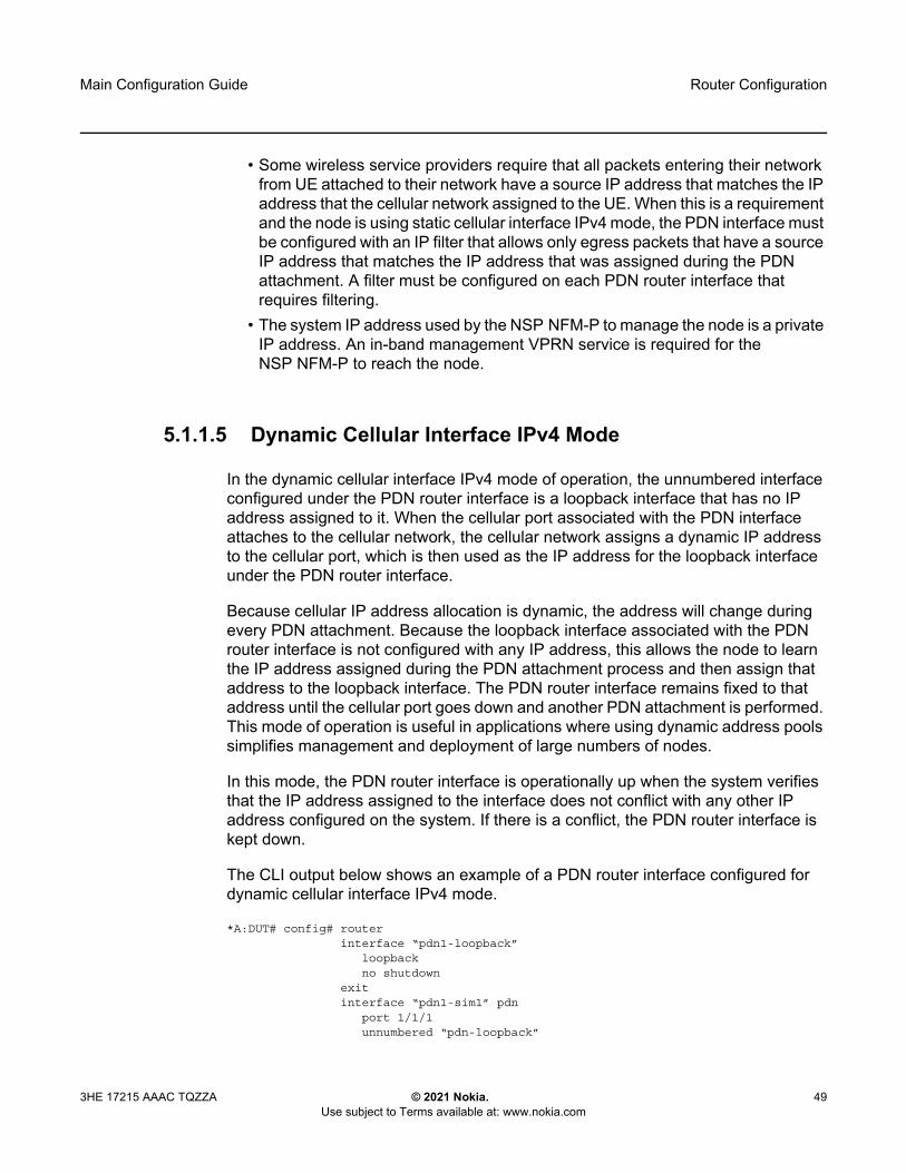
Main Configuration Guide Router Configuration
3HE 17215 AAAC TQZZA © 2021 Nokia. Use subject to Terms available at: www.nokia.com
49
• Some wireless service providers require that all packets entering their network from UE attached to their network have a source IP address that matches the IP address that the cellular network assigned to the UE. When this is a requirement and the node is using static cellular interface IPv4 mode, the PDN interface must be configured with an IP filter that allows only egress packets that have a source IP address that matches the IP address that was assigned during the PDN attachment. A filter must be configured on each PDN router interface that requires filtering.
• The system IP address used by the NSP NFM-P to manage the node is a private IP address. An in-band management VPRN service is required for the NSP NFM-P to reach the node.
5.1.1.5 Dynamic Cellular Interface IPv4 Mode
In the dynamic cellular interface IPv4 mode of operation, the unnumbered interface configured under the PDN router interface is a loopback interface that has no IP address assigned to it. When the cellular port associated with the PDN interface attaches to the cellular network, the cellular network assigns a dynamic IP address to the cellular port, which is then used as the IP address for the loopback interface under the PDN router interface.
Because cellular IP address allocation is dynamic, the address will change during every PDN attachment. Because the loopback interface associated with the PDN router interface is not configured with any IP address, this allows the node to learn the IP address assigned during the PDN attachment process and then assign that address to the loopback interface. The PDN router interface remains fixed to that address until the cellular port goes down and another PDN attachment is performed. This mode of operation is useful in applications where using dynamic address pools simplifies management and deployment of large numbers of nodes.
In this mode, the PDN router interface is operationally up when the system verifies that the IP address assigned to the interface does not conflict with any other IP address configured on the system. If there is a conflict, the PDN router interface is kept down.
The CLI output below shows an example of a PDN router interface configured for dynamic cellular interface IPv4 mode.
*A:DUT# config# routerinterface “pdn1-loopback”
loopbackno shutdown
exitinterface “pdn1-sim1” pdn
port 1/1/1unnumbered “pdn-loopback”
Router Configuration
50
Main Configuration Guide
© 2021 Nokia. Use subject to Terms available at: www.nokia.com
3HE 17215 AAAC TQZZA
no shutdownexit
exitexit
When using dynamic cellular interface IPv4 mode, consider the points listed below.
• IP/MPLS services cannot be anchored to a fixed address on the node. Instead, only those IP/MPLS services that support dynamic IP address learning and behaviors are supported, such as VPRNs with auto-bind or Layer 2 services using pseudowire templates configured with auto-gre-sdp. See Services Overview for more information.
• Some wireless service providers require that all packets entering their network from UE attached to their network have a source IP address that matches the IP address that the cellular network assigned to the UE. When this is a requirement, dynamic cellular interface IPv4 mode should not be used; instead, static cellular interface IPv4 mode should be used. When dynamic cellular interface IPv4 mode is used, there is no way to ensure all packets will meet the source IP address requirement as the node cannot filter a dynamically changing source IP address.
• The system IP address used by the NSP NFM-P to manage the node is a private IP address. An in-band management VPRN service is required for the NSP NFM-P to reach the node.
5.1.1.6 Static Cellular Interface IPv6 Mode
In the static cellular interface IPv6 mode of operation, the PDN router interface IPv6 address is configured using the config>router>interface interface-name pdn>ipv6>address command. The cellular IP address assigned to the PDN router interface is never expected to change after each subsequent attachment to the cellular network. The address configured for the PDN router interface must be within the subnet of the network-assigned static IPv6 address upon PDN attachment, and the configured address cannot be the exact address assigned during the attachment. If the configured address is not within the subnet of the network-assigned IPv6 address or matches the network-assigned IPv6 address, then an alarm is raised and the PDN router interface is kept down.

Main Configuration Guide Router Configuration
3HE 17215 AAAC TQZZA © 2021 Nokia. Use subject to Terms available at: www.nokia.com
51
The CLI output below shows an example of a PDN interface configured for static cellular interface IPv6 mode.
A:DUT# config# routerinterface "pdn1-sim1" pdn
port 1/1/1ipv6
address fd00:1:1:1::1/64exitno shutodwn
exitexit
exit
When operating in static cellular interface IPv6 mode, consider the points listed below.
• GRE-MPLS based services are not supported as those packets use IPv4 addresses.
• IPSec secure interfaces are supported.• Some wireless service providers require that all packets entering their network
from UE attached to their network have a source IP address that is within the IPv6 subnet assigned during the PDN attachment process. When this is a requirement and the node is using static cellular interface IPv6 mode, the PDN interface must be configured with an IP filter that allows only egress packets that have a source IP address that is within the subnet that was assigned during the PDN attachment. A filter must be configured on each PDN router interface that requires filtering.
• The system IP address used by the NSP NFM-P to manage the node is a private IPv4 address. An in-band management VPRN service is required for the NSP NFM-P to reach the node.
5.1.1.7 Dynamic Cellular Interface IPv6 Mode
In the dynamic cellular interface IPv6 mode of operation, the PDN router interface is not configured with an IPv6 address using the config>router>interface interface-name pdn>ipv6>address command. Instead, the IP address and subnet is learned by the PDN router interface each time the cellular interface attaches to the network. The IP address can change with each attachment. This mode of operation is useful in applications where using a dynamic address pool simplifies the management and deployment of large numbers of nodes.
Router Configuration
52
Main Configuration Guide
© 2021 Nokia. Use subject to Terms available at: www.nokia.com
3HE 17215 AAAC TQZZA
Upon PDN attachment, the system dynamically allocates an IPv6 address that exists within the subnet of the IPv6 address assigned by the network during the cellular attachment. The PDN router interface remains fixed to that address until the cellular port goes down and another cellular attachment is performed.
In this mode, the PDN router interface is operationally up when the system verifies that the IP address and subnet assigned to the interface does not conflict with any other IP address and subnet configured on the system. If there is a conflict, the PDN router interface is kept down.
The CLI output below shows an example of a PDN router interface configured for dynamic cellular interface IPv6 mode.
*A:DUT# config# routerinterface “pdn1-sim1” pdn
port 1/1/1ipv6exitno shutdown
exitexit
exit
When using dynamic cellular interface IPv6 mode, the following points apply.
• GRE-MPLS based services are not supported as those packets use IPv4 addresses.
• IPSec secure interfaces are supported.• Some wireless service providers require that all packets entering their network
from UE attached to their network have a source IP address that is within the subnet -assigned IPv6 address and the subnet assigned to the UE during the cellular network attachment. When this is a requirement, dynamic cellular interface IPv6 mode should not be used; instead, static cellular interface IPv6 mode should be used. When dynamic cellular interface IPv6 mode is used there is no way to ensure that all packets will meet the source IP address requirement as the node cannot filter a dynamically changing source IP address.
• The system IP address used by the NSP NFM-P to manage the node is a private IPv4 address. An in-band management VPRN service is required for the NSP NFM-P to reach the node.

Main Configuration Guide Router Configuration
3HE 17215 AAAC TQZZA © 2021 Nokia. Use subject to Terms available at: www.nokia.com
53
5.1.2 DHCP Client
In the base router context, Ethernet ports and the WLAN station port can be configured with a router interface that supports a DHCP client. When the node operates as a DHCP client, it learns the IP address of the interface via dynamic IP address assignment. The DHCP client functionality is enabled by issuing the no shutdown command on the DHCP client in the config>router>interface>autoconfigure>dhcp-client context. The output below shows an example of a router interface enabled as a DHCP client.
*A:DUT# config# router interface "station-wlan-ifc"port 1/4/4autoconfigure dhcp-client
no shutdownexit
exit
When the DHCP client is enabled, changes to the DHCP client configuration take effect when the shutdown command is issued followed by the no shutdown command.
If DHCP relay configurations exist on the node, the DHCP client cannot be enabled until the DHCP relay configurations are removed. Similarly, if DHCP client configurations exist on the node, DHCP relay cannot be enabled until the DHCP client configurations are removed.
The DHCP client only supports IPv4.
When the DHCP client first becomes operational, learns an IP address from a remote DHCP server using a DHCP DISCOVER message.
The node will only send a DHCP DISCOVER message if:
• the DHCP client is enabled and the router interface is operationally up. Shutting down the DHCP client forces the release of the IP address.
• a DHCP NAK message is received from the DHCP server that invalidates the previous DHCP DISCOVER message or any existing lease
When a DHCP client is shut down, all cached values (such as IP addresses and DHCP options) are cleared. They are rediscovered by issuing the no shutdown command.

Router Configuration
54
Main Configuration Guide
© 2021 Nokia. Use subject to Terms available at: www.nokia.com
3HE 17215 AAAC TQZZA
If the port comes operationally up while the DHCP client is enabled and a DHCP discovery was not previously completed or a DHCP release was previously issued, then DHCP discovery is performed. If the port comes operationally up while the DHCP client is enabled and there was a previously completed DHCP discovery, then the DHCP client performs a DHCP REQUEST using the previously cached DHCP information from the discovery.
The operator can force a rediscovery procedure by executing the restart command in the tools>perform>router>autoconfigure>dhcp-client interface context.
The requested DHCP lease time can be configured using the CLI; however, the DHCP server can override this value. The node tracks the DHCP lease time and sends a DHCP REQUEST when half the lease time has elapsed.An IP address lease can be renewed manually using the tools>perform>router>autoconfigure>dhcp-client interface lease-renew command.
If the router interface goes down, the DHCP client parameters are cached for the interface. When the interface comes back up, if an IP address has been allocated and the lease time has not expired, the DHCP router interface will send a DHCP REQUEST to confirm that it can continue to use the IP address associated with the lease.
DHCP options must be configured in the CLI to make use of options received by the DHCP server. Any options received from the DHCP server are ignored if the corresponding options are not specified in the CLI. The DHCP client options are router, static-route, and dns-server. They are configured in the config>router>interface>autoconfigure>dhcp-client>request-options context.
The operator can use the show>router>route-table protocol dhcp-client command to view the active routes in the routing table that have been learned by the DHCP client. As well, the show>router>dns command can be used to view whether the DNS server has been configured to send request messages to the DHCP server.
The CLI provides the option to use the router from the DHCP OFFER as the default gateway. In some scenarios, the router that is reachable via the WLAN port or an Ethernet port will be the default gateway. In other scenarios, the cellular interface will have reachability to the default gateway. The DHCP client router CLI option (under request-options) enables the router request option in the DHCP OFFER message. If the router option is enabled, the default gateway is assigned by the DHCP server.
The DHCP DISCOVER message sent from the node to the DHCP server contains the following options:
• chaddr—the MAC address of the client, either the WLAN or Ethernet port• Option 51—the configured IP address lease time• Option 53—the DHCP message type (DISCOVER)

Main Configuration Guide Router Configuration
3HE 17215 AAAC TQZZA © 2021 Nokia. Use subject to Terms available at: www.nokia.com
55
• Option 60—a user-configurable vendor class identifier, either a hexadecimal string or an ASCII string
• Option 61—a user-defined client identifier: a hexadecimal string, an ASCII string, an interface name, or the client MAC address
• Option 55—the parameter request list: - Option 1—the subnet mask value- Option 3—the router option, a list of IP addresses for routers on the client
subnet (unused if not enabled in the CLI)- Option 54—the DHCP server address
The DHCP OFFER message from the DHCP server must contain the following options at a minimum:
• yiaddr—the DHCP router interface IP address • Option 1—the subnet mask value• Option 3—the router option, a list of IP addresses for routers on the client subnet• Option 51—the configured IP address lease time• Option 53—the DHCP message type (OFFER)• Option 54—the DHCP server address
When responding to the server DHCP OFFER or when extending the time of an existing lease, the DHCP REQUEST message sent from the node to the DHCP server contains the following options:
• chaddr—the client MAC address• Option 50—the requested IP address; this address is the same as the address
contained in the yiaddr field that was received in the DHCP OFFER message• Option 53—the DHCP message type (REQUEST)• Option 54—the DHCP server address; this address is the same as the address
received in the OFFER message• Option 51—the IP address lease time; this value is the same as the lease time
received in the OFFER message• Option 60—the vendor class identifier; this value is the same as the vendor class
identifier in the DISCOVER message• Option 61—the client identifier; this value is the same as the client identifier in
the DISCOVER message• Option 55—the parameter request list:
- Option 1—the subnet mask value- Option 3—the router option, unused if not enabled in the CLI- Option 6—the DNS server option, unused if not enabled in the CLI
Router Configuration
56
Main Configuration Guide
© 2021 Nokia. Use subject to Terms available at: www.nokia.com
3HE 17215 AAAC TQZZA
- Option 54—the DHCP server address- Option 121—the static-route option, unused if not enabled in the CLI
When the DHCP client is shut down, a DHCP RELEASE message is sent to the DHCP server.
For BGP peers to other nodes behind the WLAN AP, the BGP local address can be set using the router interface name where the DHCP client is configured so that changes in the interface address due to DHCP messages are reflected in the local address of BGP sessions using this interface as the local address. For information about configuring services over a router interface enabled as a DHCP client, see Services over Ethernet with DHCP Client.
5.1.2.1 Restrictions on Configuring a Router Interface with DHCP Client Enabled
When a DHCP client is enabled on a router interface, the following commands cannot be configured in the config>router>interface context:
• address• secondary• dhcp• unnumbered• loopback
If any of the commands listed above are enabled, the no shutdown command is not available for the DHCP client until the commands are removed.
5.1.2.2 Route Policy Option for DHCP Client
Routes can be imported from the DHCP client to other routing protocols with the config>router>policy-options>policy-statement>entry>from>protocol dhcp-client command.
5.1.2.3 GRE Termination for Services over a DHCP Client
A router interface configured as a DHCP client supports the following service types: VLL, VPLS, and VPRN. These services use a GRE SDP as a transport tunnel.
Main Configuration Guide Router Configuration
3HE 17215 AAAC TQZZA © 2021 Nokia. Use subject to Terms available at: www.nokia.com
57
When a DHCP client is enabled on a router interface and an address is learned by the client, there is no configuration required in order to terminate GRE SDPs on that interface IP address. GRE termination is enabled on a DHCP client address when the client learns the address. For information about configuring services over a router interface enabled as a DHCP client, see Services over Ethernet with DHCP Client.
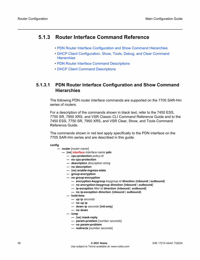
Router Configuration
58
Main Configuration Guide
© 2021 Nokia. Use subject to Terms available at: www.nokia.com
3HE 17215 AAAC TQZZA
5.1.3 Router Interface Command Reference
• PDN Router Interface Configuration and Show Command Hierarchies • DHCP Client Configuration, Show, Tools, Debug, and Clear Command
Hierarchies • PDN Router Interface Command Descriptions • DHCP Client Command Descriptions
5.1.3.1 PDN Router Interface Configuration and Show Command Hierarchies
The following PDN router interface commands are supported on the 7705 SAR-Hm series of routers.
For a description of the commands shown in black text, refer to the 7450 ESS, 7750 SR, 7950 XRS, and VSR Classic CLI Command Reference Guide and to the 7450 ESS, 7750 SR, 7950 XRS, and VSR Clear, Show, and Tools Command Reference Guide.
The commands shown in red text apply specifically to the PDN interface on the 7705 SAR-Hm series and are described in this guide.
config— router [router-name]
— [no] interface interface-name pdn— cpu-protection policy-id — no cpu-protection— description description-string— no description— [no] enable-ingress-stats— group-encryption — no group-encryption
— encryption-keygroup keygroup-id direction {inbound | outbound}— no encryption-keygroup direction {inbound | outbound}— ip-exception filter-id direction {inbound | outbound}— no ip-exception direction {inbound | outbound}
— hold-time— up ip seconds— no up ip— down ip seconds [init-only]— no down
— icmp— [no] mask-reply— param-problem [number seconds]— no param-problem— redirects [number seconds]

Main Configuration Guide Router Configuration
3HE 17215 AAAC TQZZA © 2021 Nokia. Use subject to Terms available at: www.nokia.com
59
— no redirects— ttl-expired [number seconds]— no ttl-expired— unreachables [number seconds]— no unreachables
— if-attribute— [no] admin-group group-name [group-name...(up to 5 max)]— no admin-group — [no] srlg-group group-name [group-name...(up to 5 max)]— no srlg-group
— ingress— filter ip ip-filter-id — no filter ip ip-filter-id
— ip-mtu octets— no ip-mtu— [no] ipv6
— address ipv6-address/prefix-length [eui-64] [track-srrp srrp-instance] [modifier cga-modifier] [dad-disable] [primary-preference primary-reference]
— no address ipv6-address/prefix-length — [no] ntp-broadcast— port port-id— no port — qos network-policy-id [egress-port-redirect-group queue-group-name] [egress-
instance instance-id]] [ingress-fp-redirect-group queue-group-name ingress-instance instance-id]
— no qos— [no] shutdown— tos-marking-state {trusted | untrusted}— no tos-marking-state— unnumbered [ip-addr | ip-int-name]— no unnumbered
show— router interface interface-name

Router Configuration
60
Main Configuration Guide
© 2021 Nokia. Use subject to Terms available at: www.nokia.com
3HE 17215 AAAC TQZZA
5.1.3.2 DHCP Client Configuration, Show, Tools, Debug, and Clear Command Hierarchies
The following router interface commands are supported on the 7705 SAR-Hm series of routers for a DHCP client in the IPv4 mode of operation.
The commands shown in red text apply specifically to a DHCP client on the 7705 SAR-Hm series and are described in this guide.
For a description of the commands shown in black text, refer to the 7450 ESS, 7750 SR, 7950 XRS, and VSR Classic CLI Command Reference Guide and to the 7450 ESS, 7750 SR, 7950 XRS, and VSR Clear, Show, and Tools Command Reference Guide.
config— router [router-name]
— [no] interface interface-name— autoconfigure
— dhcp-client— class-id [hex hex-string] [string ascii-string]— no class-id — client-id [hex hex-string] [interface] [string ascii-string] [use-mac]— no client-id — lease-time [days days] [hrs hours] [min minutes] [sec seconds] [infinite]— request-options
— [no] dns-server— [no] router— [no] static-route
— [no] shutdown
show— router
— autoconfigure — dhcp-client interface ip-int-name— dhcp-client interface ip-int-name routes— dhcp-client interface ip-int-name statistics
— interface interface-name detail— dns — route-table [family] [ip-prefix[/prefix-length] [longer | exact | protocol protocol-name]
[instance instance-id] [all] [next-hop-type type] [qos] [alternative]— route-table [family] summary— route-table family [ip-prefix[/prefix-length] [longer | exact | protocol protocol-name]
[instance instance-id] extensive [all]
tools — dump
— router— autoconfigure
— dhcp-client interface ip-int-name offer— dhcp-client interface ip-int-name offer config-apply-status

Main Configuration Guide Router Configuration
3HE 17215 AAAC TQZZA © 2021 Nokia. Use subject to Terms available at: www.nokia.com
61
— dhcp-client interface ip-int-name offer raw
tools — perform
— router — autoconfigure
— dhcp-client interface ip-int-name lease-renew— dhcp-client interface ip-int-name restart
debug— router
— autoconfigure— dhcp-client interface ip-int-name
— [no] events— [no] packet
— detail-level {low | medium | high}— no detail-level — mode {dropped-only | ingr-and-dropped | egr-ingr-and-dropped}— no mode
— [no] rtm
clear— router
— autoconfigure— dhcp-client interface ip-int-name statistics

Router Configuration
62
Main Configuration Guide
© 2021 Nokia. Use subject to Terms available at: www.nokia.com
3HE 17215 AAAC TQZZA
5.1.3.3 PDN Router Interface Command Descriptions
The commands and parameters described in this section apply specifically to the PDN router interface on the 7705 SAR-Hm series of routers. All other applicable commands, as listed in PDN Router Interface Configuration and Show Command Hierarchies, are described in the 7450 ESS, 7750 SR, 7950 XRS, and VSR Classic CLI Command Reference Guide.
interface
Syntax interface interface-name pdn no interface pdn
Context config>router
Description This command creates a logical IP router interface for the packet data network (PDN). PDN router interfaces are always network-facing interfaces. Once created, attributes such as IP address, port, or system can be associated with the IP interface.
A PDN router interface can be configured for each cellular port.
The no form of the command removes the interface.
Parameters interface-name — an alphanumeric character string describing the interface name, up to a maximum of 32 characters. The interface name must begin with a letter.
pdn — a mandatory keyword specifying that the interface represents a PDN
port
Syntax port port-idno port
Context config>router>interface
Description This command binds the PDN router interface to a physical port. The default value is the only supported port identifier.
Default 1/1/1
Parameters port-id — a value equal to the cellular port identifier on the 7705 SAR-Hm series, configured in the config>port context and in the format slot/mda/port
Note: Not all commands that are visible in the CLI and described in the 7450 ESS, 7750 SR, 7950 XRS, and VSR Classic CLI Command Reference Guide are supported on the 7705 SAR-Hm series of routers.

Main Configuration Guide Router Configuration
3HE 17215 AAAC TQZZA © 2021 Nokia. Use subject to Terms available at: www.nokia.com
63
router
Syntax router interface interface-name
Context show
Description This command displays PDN router interface information.
Output The following output is an example of PDN router interface information.
Output Example
*A:Dut# show router interface "pdntest"===============================================================================Interface Table (Router: Base)===============================================================================Interface-Name Adm Opr(v4/v6) Mode Port/SapId
IP-Address PfxState-------------------------------------------------------------------------------pdntest Up Down/Down Pdn n/a
- --------------------------------------------------------------------------------Interfaces : 1===============================================================================*A:Dut#

Router Configuration
64
Main Configuration Guide
© 2021 Nokia. Use subject to Terms available at: www.nokia.com
3HE 17215 AAAC TQZZA
5.1.3.4 DHCP Client Command Descriptions
The commands and parameters described in this section apply specifically to a DHCP client operating in IPv4 mode on the 7705 SAR-Hm series of routers. All other applicable commands, as listed in DHCP Client Configuration, Show, Tools, Debug, and Clear Command Hierarchies, are described in the 7450 ESS, 7750 SR, 7950 XRS, and VSR Classic CLI Command Reference Guide.
autoconfigure
Syntax autoconfigure
Context config>router>interface
Description This command enables the context to autoconfigure a DHCP client.
dhcp-client
Syntax dhcp-client
Context config>router>interface>autoconfigure
Description This command enables the context to configure DHCP client parameters.
class-id
Syntax class-id [hex hex-string] [string ascii-string]no class-id
Context config>router>interface>autoconfigure>dhcp-client
Description This command configures the vendor class identifier (option 60) for the DHCP client.
The no form of the command deletes the vendor class identifier configuration.
Default n/a
Parameters hex-string — specifies the vendor class identifier for the DHCP client as a hexadecimal string
Values 0x0 to 0xFFFFFFFF (maximum of 254 hex nibbles)
ascii-string — specifies the vendor class identifier for the DHCP client as an ASCII string
Values 127 characters maximum

Main Configuration Guide Router Configuration
3HE 17215 AAAC TQZZA © 2021 Nokia. Use subject to Terms available at: www.nokia.com
65
client-id
Syntax client-id [hex hex-string] [interface] [string ascii-string] [use-mac]no client-id
Context config>router>interface>autoconfigure>dhcp-client
Description This command configures the identifier for the DHCP client (option 61).
The no form of the command deletes the client identifier configuration.
Default use-mac
Parameters hex-string — specifies the client identifier as a hexadecimal string
Values 0x0 to 0xFFFFFFFF (maximum of 254 hex nibbles)
interface — specifies the IPv4 interface name as the client identifier
ascii-string — specifies the client identifier as an ASCII string
Values 127 characters maximum
use-mac — specifies the IPv4 MAC address of the associated port as the client identifier
lease-time
Syntax lease-time [days days] [hrs hours] [min minutes] [sec seconds] [infinite]
Context config>router>interface>autoconfigure>dhcp-client
Description This command configures the lease time granted by the DHCP server to the DHCP client.
Default 1 day
Parameters days — specifies the lease time in days
Values 0 to 3650
hours — specifies the lease time in hours
Values 0 to 23
minutes — specifies the lease time in minutes
Values 0 to 59
seconds — specifies the lease time in seconds
Values 0 to 59
infinite — specifies that the lease never expires

Router Configuration
66
Main Configuration Guide
© 2021 Nokia. Use subject to Terms available at: www.nokia.com
3HE 17215 AAAC TQZZA
request-options
Syntax request-options
Context config>router>interface>autoconfigure>dhcp-client
Description This command configures the DHCP options for the request messages sent to the DHCP server.
Default n/a
dns-server
Syntax [no] dns-server
Context config>router>interface>autoconfigure>dhcp-client>request-options
Description This command enables the DNS server request option in the DHCP OFFER message from the DHCP server if the server supports it. If this option is enabled, it specifies a list of DNS servers available to the client.
The no form of the command disables DNS server as a request option.
Default n/a
router
Syntax [no] router
Context config>router>interface>autoconfigure>dhcp-client>request-options
Description This command enables the router request option in the DHCP OFFER message from the DHCP server if the server supports it. If this option is enabled, the default gateway is assigned by the DHCP server.
The no form of the command disables router as a request option.
Default n/a
static-route
Syntax [no] static-route
Context config>router>interface>autoconfigure>dhcp-client>request-options

Main Configuration Guide Router Configuration
3HE 17215 AAAC TQZZA © 2021 Nokia. Use subject to Terms available at: www.nokia.com
67
Description This command enables the static route request option in the DHCP OFFER message from the DHCP server if the server supports it. If this option is enabled, it specifies a list of classless static routes (that is, the destination network addresses in these static routes include subnet masks) that a client should add to its routing table.
The no form of the command disables static route as a request option.
Default n/a
shutdown
Syntax [no] shutdown
Context config>router>interface>autoconfigure>dhcp-client
Description This command administratively disables the DHCP client.
The no form of the command enables the DHCP client.
Default n/a
dhcp-client
Syntax dhcp-client interface ip-int-namedhcp-client interface ip-int-name routesdhcp-client interface ip-int-name statistics
Context show>router>autoconfigure
Description This command displays DHCP client information.
Parameters ip-int-name — displays DHCP client information associated with the specified IP interface name
routes — displays routing table information for routes received by the DHCP protocol
statistics — displays DHCP client statistics
Output The following outputs are examples of DHCP client information:
• DHCP client information associated with the specified interface name (Output Example (for the specified interface name)
• DHCP client routing table information for routes received by the DHCP protocol (Output Example (for DHCP client routing table information)
• DHCP client statistics (Output Example (for DHCP client statistics)

Router Configuration
68
Main Configuration Guide
© 2021 Nokia. Use subject to Terms available at: www.nokia.com
3HE 17215 AAAC TQZZA
Output Example (for the specified interface name)
*A:Dut-B# show router autoconfigure dhcp-client interface "to-dhcp"===============================================================================DHCP Client state===============================================================================Client IP address : 51.53.2.17/24Client MAC address : 90:3a:a0:f0:ba:d5Server Identifier : 51.54.2.1Router IP address : (Not Specified)Primary DNS : 138.120.252.55Secondary DNS : 138.120.252.57Tertiary DNS : (Not Specified)Lease acquired time : 2021/05/06 23:09:46Lease renew time : 2021/05/07 05:09:46Lease rebind time : 2021/05/07 09:39:46Lease end time : 2021/05/07 11:09:46DHCP RFC protocol state : boundDHCP client user status : establishedDescription : nexthop 51.53.2.1 is reachable (for
routes 135.0.0.0/8)===============================================================================
Output Example (for DHCP client routing table information)
*A:Dut-B# show router autoconfigure dhcp-client interface "to-dhcp" routes===============================================================================DHCP client interface route table===============================================================================Prefix Status
Next-hop(Reason)
-------------------------------------------------------------------------------135.0.0.0/8 installed
51.53.2.1-------------------------------------------------------------------------------No. of routes: 1===============================================================================
Output Example (for DHCP client statistics)
*A:Dut-B# show router autoconfigure dhcp-client interface "to-dhcp" statistics===============================================================================DHCP Client statistics===============================================================================DHCPDISCOVER messages : 10DHCPREQUEST messages : 8DHCPRELEASE messages : 7DHCPDECLINE messages : 0DHCPOFFER messages : 8DHCPACK messages : 8DHCPNAK messages : 0messages dropped : 0Statistics last cleared time : N/A===============================================================================
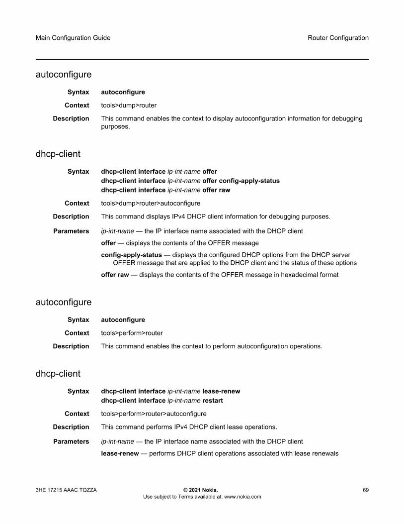
Main Configuration Guide Router Configuration
3HE 17215 AAAC TQZZA © 2021 Nokia. Use subject to Terms available at: www.nokia.com
69
autoconfigure
Syntax autoconfigure
Context tools>dump>router
Description This command enables the context to display autoconfiguration information for debugging purposes.
dhcp-client
Syntax dhcp-client interface ip-int-name offerdhcp-client interface ip-int-name offer config-apply-statusdhcp-client interface ip-int-name offer raw
Context tools>dump>router>autoconfigure
Description This command displays IPv4 DHCP client information for debugging purposes.
Parameters ip-int-name — the IP interface name associated with the DHCP client
offer — displays the contents of the OFFER message
config-apply-status — displays the configured DHCP options from the DHCP server OFFER message that are applied to the DHCP client and the status of these options
offer raw — displays the contents of the OFFER message in hexadecimal format
autoconfigure
Syntax autoconfigure
Context tools>perform>router
Description This command enables the context to perform autoconfiguration operations.
dhcp-client
Syntax dhcp-client interface ip-int-name lease-renewdhcp-client interface ip-int-name restart
Context tools>perform>router>autoconfigure
Description This command performs IPv4 DHCP client lease operations.
Parameters ip-int-name — the IP interface name associated with the DHCP client
lease-renew — performs DHCP client operations associated with lease renewals

Router Configuration
70
Main Configuration Guide
© 2021 Nokia. Use subject to Terms available at: www.nokia.com
3HE 17215 AAAC TQZZA
restart — performs DHCP client operations associated with lease restarts
autoconfigure
Syntax autoconfigure
Context debug>router
Description This command enables the context to perform autoconfiguration debugging operations.
dhcp-client
Syntax dhcp-client interface ip-int-name
Context debug>router>autoconfigure
Description This command enables debugging for an IPv4 DHCP client.
Parameters ip-int-name — the IP interface name associated with the DHCP client
events
Syntax [no] events
Context debug>router>autoconfigure>dhcp-client
Description This command enables or disables debugging for all DHCP client events.
packet
Syntax [no] packet
Context debug>router>autoconfigure>dhcp-client
Description This command enables or disables debugging for all DHCP client packets.
detail-level
Syntax detail-level {low | medium | high}no detail-level
Context debug>router>autoconfigure>dhcp-client>packet
Description This command sets the level of detail for packet tracing.

Main Configuration Guide Router Configuration
3HE 17215 AAAC TQZZA © 2021 Nokia. Use subject to Terms available at: www.nokia.com
71
Parameters low — specifies a low tracing detail level
medium — specifies a medium tracing detail level
high — specifies a high tracing detail level
mode
Syntax mode {dropped-only | ingr-and-dropped | egr-ingr-and-dropped}no mode
Context debug>router>autoconfigure>dhcp-client>packet
Description This command specifies the types of packets to be debugged.
Parameters dropped-only — specifies to debug dropped packets only
ingr-and-dropped — specifies to debug ingress packets and dropped packets
egr-ingr-and-dropped — specifies to debug egress packets, ingress packets, and dropped packets
rtm
Syntax [no] rtm
Context debug>router>autoconfigure>dhcp-client
Description This command enables or disables debugging for the addition, removal, and modification of DHCP client routes to the system Route Table Manager.
autoconfigure
Syntax autoconfigure
Context clear>router
Description This command enables the context to clear autoconfigured DHCP client information.
dhcp-client
Syntax dhcp-client interface ip-int-name statistics
Context clear>router>autoconfigure
Description This command clears IPv4 DHCP client statistics.

Router Configuration
72
Main Configuration Guide
© 2021 Nokia. Use subject to Terms available at: www.nokia.com
3HE 17215 AAAC TQZZA
Parameters ip-int-name — the IP interface name associated with the DHCP client
statistics — clears DHCP client statistics

Main Configuration Guide Router Configuration
3HE 17215 AAAC TQZZA © 2021 Nokia. Use subject to Terms available at: www.nokia.com
73
5.2 Filter Policy Support
For general information on filter policy support, refer to the topics listed below in the “Filter Policies” chapter of the 7450 ESS, 7750 SR, 7950 XRS, and VSR Router Configuration Guide.
• ACL Filter Policy Overview- Filter Policy Basics
• Filter Policy Packet Match Criteria• IPv4/IPv6 Filter Policy Entry Match Criteria• IP Exception Filters• Filter Policy Actions• Viewing Filter Policy Actions• Filter Policy Statistics• Filter Policy Logging• Filter Policy Management
- Filter Policy Advanced Topics• Match List for Filter Policies• Embedded Filters• IP Exception Filters
• Configuring Filter Policies with CLI- Common Configuration Tasks
• Creating an IPv4 Filter Policy• Creating an IPv6 Filter Policy• Creating an IPv4 Exception Filter Policy • Creating an IPv6 Exception Filter Policy • Creating a Match List for Filter Policies• Applying Filter Policies• Creating a Redirect Policy
• Filter Management Tasks
For descriptions of filter commands, refer to the 7450 ESS, 7750 SR, 7950 XRS, and VSR Classic CLI Command Reference Guide and to the 7450 ESS, 7750 SR, 7950 XRS, and VSR Clear, Show, and Tools Command Reference Guide.

Router Configuration
74
Main Configuration Guide
© 2021 Nokia. Use subject to Terms available at: www.nokia.com
3HE 17215 AAAC TQZZA

Main Configuration Guide Routing Protocols
3HE 17215 AAAC TQZZA © 2021 Nokia. Use subject to Terms available at: www.nokia.com
75
6 Routing ProtocolsThe 7705 SAR-Hm series of routers support routing protocols and routing functionality as covered in the topics listed below:
• BGP• RIP• OSPF • Route Policies
6.1 BGP
This section describes the following functionality:
• Using a Router Interface Address as the BGP Local Address
For general information on BGP support, refer to the topics listed below in the “BGP” chapter of the 7450 ESS, 7750 SR, 7950 XRS, and VSR Unicast Routing Protocols Guide.
• BGP Overview• BGP Sessions
- BGP Session State- Detecting BGP Session Failures
• Peer Tracking- High Availability BGP Sessions (BGP graceful restart only)- BGP Session Security- BGP Address Family Support for Different Session Types- BGP Groups
• BGP Design Concepts• BGP Messages• BGP Path Attributes
- Origins- AS Path- Next-Hop
• Unlabeled IPv4 Unicast Routes

Routing Protocols
76
Main Configuration Guide
© 2021 Nokia. Use subject to Terms available at: www.nokia.com
3HE 17215 AAAC TQZZA
• Unlabeled IPv6 Unicast Routes• VPN-IPv4 Routes• VPN-IPv6 Routes• Next-Hop Resolution• Next-Hop Tracking
- Local Preference- Route Aggregation Path Attributes- Community Attributes- Route Reflection Attributes- 4-Octet AS Attributes- AIGP Metric
• BGP Routing Information Base (RIB)• BGP Applications
- BGP Prefix Origin Validation- BGP Route Leaking- BGP Optimal Route Reflection
• BGP Configuration Process Overview• Configuration Notes• Configuring BGP with CLI• BGP Configuration Management Tasks
For descriptions of BGP commands, refer to the 7450 ESS, 7750 SR, 7950 XRS, and VSR Classic CLI Command Reference Guide and to the 7450 ESS, 7750 SR, 7950 XRS, and VSR Clear, Show, and Tools Command Reference Guide.
6.1.1 Using a Router Interface Address as the BGP Local Address
In cellular and WLAN networks, the router interface IP address can be assigned statically or dynamically. A cellular port supports different modes of operation depending on whether the IP address must be assigned statically or dynamically. See PDN Router Interfaces for information about the supported modes of operation on the PDN router interface.

Main Configuration Guide Routing Protocols
3HE 17215 AAAC TQZZA © 2021 Nokia. Use subject to Terms available at: www.nokia.com
77
When the PDN router interface is operating in dynamic cellular interface IP mode, the dynamically changing interface IP address must be reflected in BGP advertisements. Neighbor peers that are originating services that rely on BGP routing information to reach the local node must use the IP address of the PDN router interface on the local node in order to reach it. The local address for BGP sessions from the local node to neighbor peers must therefore match the IP address of the PDN router interface at all times, even after the IP address changes.
To facilitate a dynamically changing router interface IP address, the BGP local-address command must be configured with the name of the loopback interface used by the unnumbered interface under the PDN router interface instead of a fixed IP address. Using the loopback interface name, the SR OS will automatically assign the current IP address of the PDN router interface as the BGP local-address when the PDN router interface comes up (for example, when the cellular PDN interface learns the IP address during the cellular attachment procedure). This means that the BGP local address will inherit the loopback interface's dynamic address information and when routes are being advertised to peers, those peers will be able to route traffic towards this router’s PDN router interface.
Configuring the loopback interface name used by the PDN router interface as the local address is available in both the config>router>bgp>group context and the config>router>bgp>group>neighbor context. For complete command syntax, description, and parameter information, refer to the “configure router bgp commands” section of the 7450 ESS, 7750 SR, 7950 XRS, and VSR Classic CLI Command Reference Guide.
When BGP sessions are using the loopback interface name that is used PDN router interface as the local address, the remote neighbor peer must use the dynamic-neighbor command in order to accept BGP sessions from 7705 SAR-Hm nodes that have dynamically changing router interface IP addresses.
When dual SIM operation is required, there are two PDN interfaces, one per cellular port associated with each SIM. At a minimum, two BGP sessions are required, one for each PDN interface. Each BGP session must be configured with the local-address using the loopback interface associated with each PDN router interface.

Routing Protocols
78
Main Configuration Guide
© 2021 Nokia. Use subject to Terms available at: www.nokia.com
3HE 17215 AAAC TQZZA
6.2 RIP
The 7705 SAR-Hm series of routers support RIP on Ethernet interfaces only.
For general information on RIP support, refer to the topics listed below in the “RIP” chapter in the 7450 ESS, 7750 SR, 7950 XRS, and VSR Unicast Routing Protocols Guide.
• RIP Overview• RIPng• Common Attributes• RIP Configuration Process Overview• Configuration Notes• Configuring RIP with CLI • RIP Configuration Management Tasks• RIP Configuration Command Reference• Show, Clear, and Debug Command Reference
For descriptions of RIP commands, refer to the 7450 ESS, 7750 SR, 7950 XRS, and VSR Classic CLI Command Reference Guide and to the 7450 ESS, 7750 SR, 7950 XRS, and VSR Clear, Show, and Tools Command Reference Guide.
6.3 OSPF
The 7705 SAR-Hm series of routers support OSPF on Ethernet interfaces only.
For general information on OSPF support, refer to the topics listed below in the “OSPF” chapter in the 7450 ESS, 7750 SR, 7950 XRS, and VSR Unicast Routing Protocols Guide.
• Configuring OSPF- OSPF Areas- OSPFv3 Authentication- OSPF Graceful Restart Helper- Virtual Links- Neighbors and Adjacencies- Link-State Advertisements- Metrics

Main Configuration Guide Routing Protocols
3HE 17215 AAAC TQZZA © 2021 Nokia. Use subject to Terms available at: www.nokia.com
79
- Authentication- IP Subnets- Preconfiguration Recommendations- Multiple OSPF Instances- Multi-Address Support for OSPFv3
• SPF LSA Filtering• FIB Prioritization• Extended LSA Support in OSPFv3• Support of Multiple Instance of Router Information LSA in OSPFv2 and OSPFv3• OSPF Configuration Process Overview• Configuration Notes• Configuring OSPF with CLI• OSPF Configuration Management Tasks
For descriptions of OSPF commands, refer to the 7450 ESS, 7750 SR, 7950 XRS, and VSR Classic CLI Command Reference Guide and to the 7450 ESS, 7750 SR, 7950 XRS, and VSR Clear, Show, and Tools Command Reference Guide.
6.4 Route Policies
For general information on route policy support, refer to the topics listed below in the “Route Policies” chapter in the 7450 ESS, 7750 SR, 7950 XRS, and VSR Unicast Routing Protocols Guide.
• Configuring Route Policies• Route Policy Configuration Process Overview• Configuration Notes• Configuring Route Policies with CLI• Route Policy Configuration Management Tasks
For descriptions of route policy commands, refer to the 7450 ESS, 7750 SR, 7950 XRS, and VSR Classic CLI Command Reference Guide and to the 7450 ESS, 7750 SR, 7950 XRS, and VSR Clear, Show, and Tools Command Reference Guide.

Routing Protocols
80
Main Configuration Guide
© 2021 Nokia. Use subject to Terms available at: www.nokia.com
3HE 17215 AAAC TQZZA

Main Configuration Guide MPLS
3HE 17215 AAAC TQZZA © 2021 Nokia. Use subject to Terms available at: www.nokia.com
81
7 MPLSThe 7705 SAR-Hm series of routers support MPLS as covered in the topic listed below:
• Label Distribution Protocol
T-LDP is required for VPLS and Epipe services that depend on T-LDP signaling for label distribution and control. See the Layer 2 and Layer 3 Services chapter for more information about services supported on the 7705 SAR-Hm series.
7.1 Label Distribution Protocol
For general information on Label Distribution Protocol (LDP) support, refer to the topics listed below in the “Label Distribution Protocol” chapter of the 7450 ESS, 7750 SR, 7950 XRS, and VSR MPLS Guide.
• Label Distribution Protocol- Execution Flow- Label Exchange- Global LDP Filters- Configuring Multiple LDP LSR ID- T-LDP Hello Reduction
• TTL Security for BGP and LDP• Unnumbered Interface Support in LDP
- Feature Configuration- Operation of LDP over an Unnumbered IP Interface
• Targeted LDP• User Guidelines and Troubleshooting Procedures• LDP Process Overview• Configuring LDP with CLI• LDP Configuration Management Tasks
For descriptions of LDP commands, refer to the 7450 ESS, 7750 SR, 7950 XRS, and VSR Classic CLI Command Reference Guide and to the 7450 ESS, 7750 SR, 7950 XRS, and VSR Clear, Show, and Tools Command Reference Guide.

MPLS
82
Main Configuration Guide
© 2021 Nokia. Use subject to Terms available at: www.nokia.com
3HE 17215 AAAC TQZZA
Main Configuration Guide Services Overview
3HE 17215 AAAC TQZZA © 2021 Nokia. Use subject to Terms available at: www.nokia.com
83
8 Services Overview Topics in this chapter include:
• Overview• Service Types• Nokia Service Model• Service Entities• Services over the Cellular PDN Interface• Services over Ethernet with DHCP Client• Services with the WLAN Interface
8.1 Overview
A service is a type of communication connection from one place to another. These communication connections have particular attributes and characteristics that are needed to provide a specific communications link through which an information flow or exchange can occur. The 7705 SAR-Hm series of routers support the following services:
• Layer 2 Virtual Leased Line (VLL) and BGP virtual private wire services (VPWS)• Layer 2 virtual private LAN services (VPLS) and BGP VPLS services• Layer 3 IP VPN services (VPRN)• serial transport using raw socket and IP transport services• transporting WLAN interface traffic over a service
The service model uses (logical) service entities to construct a service. These logical entities provide a uniform, service-centric configuration and management model for service provisioning (see Nokia Service Model for more information). Different services can be created on the same node at the same time, and each service is uniquely identified by a service ID.
The supported services provide connectivity between a service access point (SAP) on one node and a SAP on a remote node. A SAP is a logical point where data traffic enters and exits a service. SAPs on the node are associated with Ethernet ports, VLANs, access router interfaces, serial ports, or the WLAN interface.

Services Overview
84
Main Configuration Guide
© 2021 Nokia. Use subject to Terms available at: www.nokia.com
3HE 17215 AAAC TQZZA
A connection between two SAPs on the same router is known as a local service. A connection between SAPs on a local and a remote router is known as a distributed service. SAP-to-SAP local services are supported for Ethernet and WLAN-based services. SAP-to-SAP local services are not supported for serial port and raw socket IP transport services.
Distributed services use service destination points (SDPs) to direct traffic from a local router to a remote router through a service tunnel. An SDP is created on the local router and identifies the endpoint of a logical unidirectional service tunnel. Traffic enters the tunnel at the SDP on the local router and exits the tunnel at the remote router. Hence, a service tunnel provides a path from one service router to another. Because an SDP is unidirectional, two service tunnels are needed for bidirectional communication between two service routers (one SDP on each router). The only supported SDP tunnel type is GRE-MPLS tunnels.
SDPs are configured on each participating service router or are auto-bound to the far-end router depending on the requirements and type of service. When configuring SDPs on the source router, the address of the destination router must be specified. When using the auto-bind function for SDPs, configuring individual SDPs between service routers is not required. The node uses BGP-advertised information to perform the auto-bind SDP function to the far-end routers. For more information on auto-bind, see SDP Binding.
After SDPs are created, they are bound to a specific service, or the service is enabled with auto-bind SDPs, to create a binding to the transport tunnels. In both cases, the SAPs that are part of the service use the bound SDPs as the transport for data traffic between nodes. The binding process is needed to associate the far-end devices to the service; otherwise, far-end devices are not able to participate in the service.
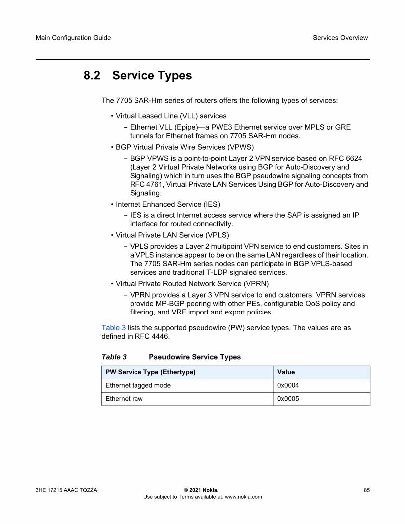
Main Configuration Guide Services Overview
3HE 17215 AAAC TQZZA © 2021 Nokia. Use subject to Terms available at: www.nokia.com
85
8.2 Service Types
The 7705 SAR-Hm series of routers offers the following types of services:
• Virtual Leased Line (VLL) services- Ethernet VLL (Epipe)—a PWE3 Ethernet service over MPLS or GRE
tunnels for Ethernet frames on 7705 SAR-Hm nodes. • BGP Virtual Private Wire Services (VPWS)
- BGP VPWS is a point-to-point Layer 2 VPN service based on RFC 6624 (Layer 2 Virtual Private Networks using BGP for Auto-Discovery and Signaling) which in turn uses the BGP pseudowire signaling concepts from RFC 4761, Virtual Private LAN Services Using BGP for Auto-Discovery and Signaling.
• Internet Enhanced Service (IES)- IES is a direct Internet access service where the SAP is assigned an IP
interface for routed connectivity.• Virtual Private LAN Service (VPLS)
- VPLS provides a Layer 2 multipoint VPN service to end customers. Sites in a VPLS instance appear to be on the same LAN regardless of their location. The 7705 SAR-Hm series nodes can participate in BGP VPLS-based services and traditional T-LDP signaled services.
• Virtual Private Routed Network Service (VPRN)- VPRN provides a Layer 3 VPN service to end customers. VPRN services
provide MP-BGP peering with other PEs, configurable QoS policy and filtering, and VRF import and export policies.
Table 3 lists the supported pseudowire (PW) service types. The values are as defined in RFC 4446.
Table 3 Pseudowire Service Types
PW Service Type (Ethertype) Value
Ethernet tagged mode 0x0004
Ethernet raw 0x0005
Services Overview
86
Main Configuration Guide
© 2021 Nokia. Use subject to Terms available at: www.nokia.com
3HE 17215 AAAC TQZZA
8.3 Nokia Service Model
The 7705 SAR-Hm series of routers is deployed at the customer provider edge (PE). Services are provisioned on the router in order to facilitate the transport of communications data across an IP/MPLS network using the Ethernet or wireless interfaces available on the node. The data is formatted so that it can be transported in encapsulation tunnels created using Layer 3 generic routing encapsulation (GRE) MPLS.
The Nokia service model has four main logical components, referred to as (logical) service entities. The entities are: applications, service types, service access points (SAPs), and service destination points (SDPs) (see Service Entities). In accordance with the service model, the operator uses the (logical) service entities to construct an end-to-end service. The service entities are designed to provide a uniform, service-centric model for service provisioning. This service-centric design implies the following characteristics.
• Multiple services can be bound to a single application.• Multiple service types can be bound to a single tunnel.• Tunnel configurations are independent of the services they carry.• Changes are made to a single service entity rather than to multiple ports on
multiple devices. It is easier to change one tunnel rather than several services.• The operational integrity of a service entity (such as a service tunnel or service
endpoint) can be verified by one operation rather than through the verification of dozens of parameters, thereby simplifying management operations, network scalability, and performance.
• A failure in the network core can be correlated to specific subscribers and services.
• The following policies are applied to various services:- QoS policies- filter policies (IP and MAC)
Additional properties can be configured for bandwidth assignments and class of service on the appropriate entity.

Main Configuration Guide Services Overview
3HE 17215 AAAC TQZZA © 2021 Nokia. Use subject to Terms available at: www.nokia.com
87
8.4 Service Entities
The basic (logical) service entities in the service model used to construct an end-to-end service are:
• Applications• Service Types• Service Access Points (SAPs)• Service Destination Points (SDPs)
Figure 4 shows an example of how the service entities relate to the service model. An application attachment point (for example, an Ethernet port, VLAN, or serial port) connects to a SAP. The SDPs define the entrance and exit points of service tunnels, which carry one-way traffic between the two routers (NOK-A and NOK-B). Configured SDPs are bound to a service or the service is auto-bound which automatically creates tunnels to far-end nodes. The binding of the service to SDPs is the final step in enabling the end-to-end service. In Figure 4, the entrance and exit points are over the wireless interface.
Traffic encapsulation occurs at the SAP and SDP. The 7705 SAR-Hm series supports the following SAP encapsulation types:
• Ethernet untagged or tagged• IP • raw serial character data on the serial ports
The 7705 SAR-Hm series supports GRE-MPLS encapsulation for SDPs.
For information on SAP encapsulation types, see SAP Encapsulation Types and Identifiers. For information on SDP encapsulation types, see SDP Encapsulation Types.

Services Overview
88
Main Configuration Guide
© 2021 Nokia. Use subject to Terms available at: www.nokia.com
3HE 17215 AAAC TQZZA
Figure 4 Service Entities and the Service Model
8.4.1 Applications
Every application must have a customer ID, which is assigned when the application service is created. To provision a service, a customer ID must be associated with the service at the time of service creation.
8.4.2 Service Types
Service types provide the traffic adaptation needed by customer attachment circuits (ACs). This (logical) service entity adapts customer traffic to service tunnel requirements. A VLL service is a point-to-point MPLS-based emulation service, also called Virtual Private Wire Service (VPWS). The 7705 SAR-Hm series provides Ethernet VLL (Epipe) service and BGP VPLS-based Layer 2 service.
The series also provides Ethernet layer (MAC-based) VPLS service (including management VPLS), raw socket IP transport service, as well as IP layer VPRN and IES services, that offer any-to-any connectivity within a Virtual Routing Domain or Generic Routing Domain, respectively.
NOK-A
Application27
Subscribers SubscribersServiceaccesspoints
Servicedestination
points
Servicedestination
points
Serviceaccesspoints
SAP
Application25
SAP
Application7 SAP
Application27
Application25
Application7
NOK-BNo3562
Exit
SDP
Service
Service
Service
SAP
SAP
SAP
SDP
Service
Service
Service
Exit
LTE/WANNetwork
Note: The terms application, customers, and subscribers are used synonymously in this manual. When referring to SR OS manuals for further information, these terms may appear and are interchangeable.

Main Configuration Guide Services Overview
3HE 17215 AAAC TQZZA © 2021 Nokia. Use subject to Terms available at: www.nokia.com
89
8.4.2.1 Service Names
A service ID number must be associated with a service at the time of service creation. Once the service is created, an optional service name can be assigned to the service for use by commands that reference the service.
8.4.3 Service Access Points (SAPs)
Topics in this section include:
• SAP Encapsulation Types and Identifiers• SAP Configuration Considerations
A service access point (SAP) is the point at which a service begins (ingress) or ends (egress) and represents the access point associated with a service. A SAP may be a physical port or a logical entity within a physical port. For example, a SAP may be an Ethernet port or a VLAN that is identified by an Ethernet port and a VLAN tag. Each application service connection is configured to use only one SAP.
A SAP identifies the application interface point for a service on a service router. Figure 5 shows two applications connected to the same service via two different SAPs. The SAP identifiers are 1/2/5 and 1/2/6, which represent the physical ports associated with these SAPs. The physical port information should be configured prior to provisioning a service. Refer to the 7705 SAR-Hm and SAR-Hmc Interface Configuration Guide for more information about configuring a port.
The 7705 SAR-Hm series supports VLL, VPWS, VPLS, and VPRN services. For each service type, the SAP has slightly different parameters; see Layer 2 and Layer 3 Services for information.
In general, SAPs are logical endpoints that are local to the node and are uniquely identified by:
• the physical Ethernet port• the physical serial port• the encapsulation type for the service • the encapsulation identifier (ID), which is the optional VLAN ID for Epipes
Depending on the encapsulation, a physical port can have more than one SAP associated with it (for example, a port may have several VLANs, where each VLAN has an associated SAP). SAPs can only be created on ports designated as “access” in the physical port configuration.

Services Overview
90
Main Configuration Guide
© 2021 Nokia. Use subject to Terms available at: www.nokia.com
3HE 17215 AAAC TQZZA
SAPs cannot be created on ports designated as core-facing “network” ports because these ports have a different set of features enabled in software.
Figure 5 Service Access Point (SAP)
8.4.3.1 SAP Encapsulation Types and Identifiers
The SAP encapsulation type is an access property of the Ethernet port used for the service. It identifies the protocol that is used to provide the service.
The encapsulation ID for Ethernet ports is an optional suffix that is appended to a port-id to specify a logical sub-element for a SAP. For example, port-id:qtag1 represents a port that can be tagged to use IEEE 802.1Q encapsulation (referred to as dot1q), where each individual tag can identify with an individual service.
8.4.3.1.1 Ethernet Encapsulations
The following encapsulation service options are available on Ethernet ports:
• null—supports a single service on the port; for example, where a single customer with a single service customer edge (CE) device is attached to the port.
• dot1q—supports multiple services for one customer or services for multiple customers (see Figure 6). An example of dot1q use might be the case where the Ethernet port is connected to a multi-tenant unit device with multiple downstream customers. The encapsulation ID used to distinguish an individual service is the VLAN ID in the IEEE 802.1Q header.
No3563
Application27
Application27
Application27
NOK-A
LTE/WANNetwork SDP
Service
Service
SAP1/2/5dot1q
SAP1/2/6dot1q
SAP1/2/3dot1q

Main Configuration Guide Services Overview
3HE 17215 AAAC TQZZA © 2021 Nokia. Use subject to Terms available at: www.nokia.com
91
Figure 6 Multiple SAPs on a Single Port
Default SAP on a Dot1q Port
The 7705 SAR-Hm series of routers supports default SAP functionality on dot1q- encapsulated ports. On dot1q-encapsulated ports where a default SAP is configured, all packets with Q-tags not matching any other explicitly defined SAPs are assigned to the default SAP for transport. A default SAP is defined in the CLI using the character “*” as a Q-tag, where the “*” means “all”.
One of the applications where the default SAP feature can be used is for an access connection of an application that uses the whole port to access Layer 2 services. The internal VLAN tags are transparent to the service. This (the use of a whole port) can be provided by a null-encapsulated port. A dedicated VLAN (not used by the user) can be used to provide management to this application.
In this type of environment, two SAPs logically exist, a management SAP and a service SAP. The management SAP can be created by specifying a VLAN tag that is reserved to manage the application. The service SAP covers all other VLANs and behaves as a SAP on a null-encapsulated port.
There are a few constraints related to the use of a default SAP on a dot1q-encapsulated port:
• The default SAP is supported only on VPLS, and Epipe VLL and VPWS services and cannot be created in IES and VPRN services because IES and VPRN services cannot preserve VLAN tag markings.
• For VPLS SAPs with STP enabled, STP listens to untagged and null-tagged BPDUs only. All other tagged BPDUs are forwarded like other customer packets. This is the same behavior as null-encapsulated ports.
• IGMP snooping is not supported on a default SAP. By not allowing IGMP snooping of a default SAP, all IGMP packets will be transparently forwarded.
Application27
SDP
Service
Service
SAP1/2/5dot1q
SAP1/2/6dot1q
SAP1/2/3dot1q
ServiceLTE/WANNetwork Application
27
Application9
No3564
Services Overview
92
Main Configuration Guide
© 2021 Nokia. Use subject to Terms available at: www.nokia.com
3HE 17215 AAAC TQZZA
• The default SAP and the SAP defined by explicit null encapsulation are mutually exclusive (for example, 1/1/1:* and 1/1/1:0 are mutually exclusive). This avoids conflict as to which SAP untagged frames should be associated with.
8.4.3.2 SAP Configuration Considerations
In addition to being an entry or exit point for service traffic, a SAP has to be configured for a service and, therefore, has properties. When configuring a SAP, consider the following.
• A SAP is a local entity and is only locally unique to a given device. The same SAP ID value can be used on another service router.
• There are no default SAPs. All subscriber service SAPs must be created. • The default administrative state for a SAP at creation time is administratively
enabled.• When a SAP is deleted, all configuration parameters for the SAP are also
deleted.• A SAP is owned by and associated with the service in which it is created.• An Ethernet port with a dot1q encapsulation type means that the traffic for the
SAP is identified based on a specific IEEE 802.1Q VLAN ID value. The VLAN ID is stripped off at SAP ingress and the appropriate VLAN ID is placed on at SAP egress. As a result, VLAN IDs only have local significance, so the VLAN IDs for the SAPs for a service need not be the same at each SAP.
• If a port is administratively shut down, all SAPs on that port will be operationally out of service.
• A SAP cannot be deleted until it has been administratively disabled (shut down).• Each SAP can have one of the following policies assigned to it:
- Ingress QoS policy- Egress QoS policy- Ingress filter policy (for Epipe VLL and VPWS SAPs, VPLS SAPs, VPRN
SAPs, IES SAPs, and IES in-band management SAPs)- Egress filter policy (for VPRN and IES SAPs, and for VPLS SAPs (Ethernet
SAPs only))
Main Configuration Guide Services Overview
3HE 17215 AAAC TQZZA © 2021 Nokia. Use subject to Terms available at: www.nokia.com
93
8.4.4 Service Destination Points (SDPs)
Topics in this section include:
• SDP Binding• Spoke and Mesh SDPs• SDP Encapsulation Types• SDP Ping
An SDP identifies the endpoint of a logical unidirectional service tunnel. The service tunnel provides a path from one service router to another.
In more general terms, SDP refers to the service tunnel itself. The SDP terminates at the far-end router, which is responsible for directing the flow of packets to the correct service egress SAPs on that device.
When an SDP is bound to a service, the service is referred to as a distributed service. A distributed service consists of a configuration with at least one SAP on a local node, one SAP on a remote node, and an SDP binding that binds the service to the service tunnel. Multiple SDPs to different far-end nodes are bound to a service to provide transport for SAPs to other nodes participating in that service.
When configured, an SDP has the following characteristics.
• An SDP is locally unique to a participating service router. The same SDP ID can appear on other service routers.
• An SDP uses either the system IP address or the cellular PDN interface IP address of the far-end edge router to locate its destination.
• An SDP is not specific to any one service or to any type of service. Once an SDP is created, services are bound to the SDP. An SDP can also have more than one service type associated with it.
• All services bound to an SDP use the same SDP (transport) encapsulation type defined for the SDP (for example, GRE-MPLS).
Note: In this document and in command line interface (CLI) usage, SDP is defined as Service Destination Point. However, it is not uncommon to find the term SDP defined in several different ways, as in the following list. All variations of SDP have the same meaning:
• Service Destination Point• Service Distribution Point• Service Destination Path• Service Distribution Path• Service Delivery Path

Services Overview
94
Main Configuration Guide
© 2021 Nokia. Use subject to Terms available at: www.nokia.com
3HE 17215 AAAC TQZZA
• An SDP is a service entity used for service management. Even though the SDP configuration and the services carried within it are independent, they are related objects. Operations on the SDP affect all the services associated with the SDP. For example, the operational and administrative state of an SDP controls the state of services bound to the SDP.
• An SDP tunnel from a local device to the far-end device (router) requires a return SDP tunnel from the far end back to the local device. Each device must have an SDP defined for every remote router to which it wants to provide service. The SDP must be created before a distributed service can be configured.
• An SDP can be used to provide PW redundancy, where up to four spoke SDPs can be assigned to a service endpoint that acts as the managing entity to ensure service connection. For information on pseudowire redundancy, refer to the “Pseudo-wire Redundancy” section in the 7450 ESS, 7750 SR, 7950 XRS, and VSR Layer 2 Services and EVPN Guide: VLL, VPLS, PBB, and EVPN.
8.4.4.1 SDP Binding
To configure a distributed service pointing from NOK-A to NOK-B, the SDP ID on the NOK-A side (see Figure 7) must be specified during service creation in order to bind the service to the tunnel (the SDP). Otherwise, service traffic is not directed to a far-end point and the far-end devices cannot participate in the service (there is no service). To configure a distributed service pointing from NOK-B to NOK-A, a return SDP on the NOK-B side must similarly be specified.
Figure 7 SDP Tunnel Pointing from NOK-A to NOK-B
Customer27
Subscribers SubscribersServiceaccesspoints
Servicedestination
points
Servicedestination
points
Serviceaccesspoints
Customer25
Customer7
NOK-A
Customer27SAP
Customer25SAP
Customer7SAP
NOK-BNo3565
SAP1/1/6dot1q
SAP1/2/2dot1q
SAP1/2/6dot1q
SDP-4
Service
Service
Service
Exit
Service
Service
Service
LTE and IPNetwork

Main Configuration Guide Services Overview
3HE 17215 AAAC TQZZA © 2021 Nokia. Use subject to Terms available at: www.nokia.com
95
SDP configuration and binding is required for:
• Layer 2 services that use T-LDP signaling• Layer 3 services that do not use multi-protocol BGP(MP-BGP) to advertise
routes with auto-bind
For Layer 3 VPRN services that use MP-BGP to advertise routes, auto-bind can be configured on the service to automatically bind that service to SDPs with reachability to remote nodes that are participating in MP-BGP.
The VPRN auto-bind function has the following characteristics.
• SDPs can be configured while auto-bind is enabled.• Configuring SDPs when auto-bind is enabled is not required in order to transport
VPRN services between nodes participating in the same VPRN.• Configured SDPs have higher precedence and the node will select the
configured SDP and its attributes to tunnel traffic to the far-end node.• Auto-bind does not require a return path SDP from a far-end router as long as
auto-bind is enabled on that far-end router for the service. If auto-bind is not enabled on the far-end router, then a return path SDP to the local 7705 SAR-Hm series node is required.
• For Layer 2 services that use BGP signaling (BGP-VPLS and BGP-VPWS) to exchange label information for the service, auto-gre can be configured on the pseudowire template of the service to automatically bind that service to SDPs with reachability to remote nodes that are participating in the BGP-signaled Layer 2 service. For information about the auto-GRE function available for BGP-VPLS and BGP-VPWS, refer to the 7450 ESS, 7750 SR, 7950 XRS, and VSR Layer 2 Services and EVPN Guide: VLL, VPLS, PBB, and EVPN.
8.4.4.2 Spoke and Mesh SDPs
There are two types of SDPs: spoke and mesh. The type of SDP defines how flooded traffic (or broadcast traffic, such as an ARP request) is propagated. For point-to-point PW/VLL services, spoke SDPs are the only way to bind services to the far-end router. For VPLS, mesh and spoke SDP bindings are allowed.
A spoke SDP that is bound to a service operates like a traditional bridge port. Flooded traffic that is received on the spoke SDP is transmitted to all the spoke SDPs, mesh SDPs, and SAPs to which it is connected. Flooded traffic is not transmitted back toward the port from which it was received.

Services Overview
96
Main Configuration Guide
© 2021 Nokia. Use subject to Terms available at: www.nokia.com
3HE 17215 AAAC TQZZA
In contrast, a mesh SDP that is bound to a service operates like a single bridge port. Flooded traffic received on a mesh SDP is transmitted to all spoke SDPs and SAPs to which it is connected. Flooded traffic is not transmitted to any other mesh SDPs or back toward the port from which it was received. This property of mesh SDPs is important for multi-node networks; mesh SDPs are used to prevent the creation of routing loops.
8.4.4.3 SDP Encapsulation Types
The Nokia service model uses encapsulation tunnels (also referred to as service tunnels) through the core to interconnect service routers. An SDP is a logical way of referencing the entrance to an encapsulation tunnel.
The following encapsulation type is supported:
• Layer 2 or Layer 3 services within generic routing encapsulation (GRE-MPLS encapsulation)
An SDP has an implicit maximum transmission unit (MTU) value because services are carried in encapsulation tunnels and an SDP is an entrance to the tunnel. The MTU is configurable (in octets), where the transmitted frame can be no larger than the MTU.
8.4.4.3.1 GRE Encapsulation
Generic routing encapsulation (GRE) tunnels are used to transport network layer packets over a Layer 3 network such as an LTE or WLAN interface.
GRE-MPLS SDPs are supported on network interfaces.
GRE Format
In accordance with RFC 2784, a GRE encapsulated packet has the following format:
• delivery header• GRE header• payload packet
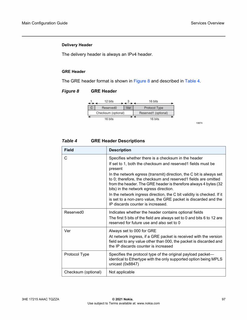
Main Configuration Guide Services Overview
3HE 17215 AAAC TQZZA © 2021 Nokia. Use subject to Terms available at: www.nokia.com
97
Delivery Header
The delivery header is always an IPv4 header.
GRE Header
The GRE header format is shown in Figure 8 and described in Table 4.
Figure 8 GRE Header
Table 4 GRE Header Descriptions
Field Description
C Specifies whether there is a checksum in the headerIf set to 1, both the checksum and reserved1 fields must be presentIn the network egress (transmit) direction, the C bit is always set to 0; therefore, the checksum and reserved1 fields are omitted from the header. The GRE header is therefore always 4 bytes (32 bits) in the network egress direction.In the network ingress direction, the C bit validity is checked. If it is set to a non-zero value, the GRE packet is discarded and the IP discards counter is increased.
Reserved0 Indicates whether the header contains optional fieldsThe first 5 bits of the field are always set to 0 and bits 6 to 12 are reserved for future use and also set to 0
Ver Always set to 000 for GREAt network ingress, if a GRE packet is received with the version field set to any value other than 000, the packet is discarded and the IP discards counter is increased
Protocol Type Specifies the protocol type of the original payload packet—identical to Ethertype with the only supported option being MPLS unicast (0x8847)
Checksum (optional) Not applicable
19874
Checksum (optional)
C
1
Ver Protocol TypeReserved0
Reserved1 (optional)
12 bits
16 bits 16 bits
3 16 bits

Services Overview
98
Main Configuration Guide
© 2021 Nokia. Use subject to Terms available at: www.nokia.com
3HE 17215 AAAC TQZZA
Payload Packet
The payload encapsulation format depends on the type of service that is being carried over GRE-MPLS. The payload encapsulation format for GRE services is shown in Figure 9 and described in Table 5.
Figure 9 GRE Service Payload Packet over Ethernet
Reserved1 (optional) Not applicable
Table 5 GRE Service Payload Packet Descriptions
Field Description
Eth The Layer 2 transport headerThe only Layer 2 protocol supported is EthernetMTU size depends on the encapsulation type (14 bytes for null encapsulation and 18 bytes for dot1q encapsulation)The Ethertype is always set to IP (0x800)
IP Indicates the transport protocolIPv4 is the transport protocol for GRE-MPLS
GRE Indicates the encapsulation protocol
Table 4 GRE Header Descriptions (Continued)
Field Description
Service PayloadCW (for VLL and VPWS)MPLS Service Header
GREIP
Eth
444
2014 or 18
No3566

Main Configuration Guide Services Overview
3HE 17215 AAAC TQZZA © 2021 Nokia. Use subject to Terms available at: www.nokia.com
99
At network egress over a cellular port, the destination IP address of the GRE-MPLS IP header is always the far-end IP address that was either configured for the SDP, or learned through BGP routing. If the far-end address is for a cellular port on another 7705 SAR-Hm series node, then that address could be either the system IP address or the cellular PDN interface IP address, depending on the mode of operation deployed at that far-end location. The source IP address of the GRE-MPLS IP header will always be set to the cellular PDN interface IP address. This address may be statically configured or dynamically assigned to a cellular port. For information about the PDN router interface modes of operation and how the PDN router interface IP address is assigned, see PDN Router Interfaces.
MPLS service header The MPLS service label identifies the service and the specific service element being transported For VLL and VPWS services, the label references the pseudowire that was statically configured, or signaled via T-LDP or BGP signalingFor VPLS services, the label references a particular VPLS pseudowire that was signaled via T-LDP or BGP signaling to allow the end-to-end VPLS serviceFor VPRN services, the label references either a spoke SDP pseudowire associated with the VPRN, or an MP-BGP advertised route that has been signaled via BGP to allow the end-to-end VPRN service
CW for VLL and VPWS
The pseudowire Control word (CW) is a 32-bit (4-byte) field that is inserted between the VC label and the Layer 2 frameFor more information on the Control word, refer to the “Pseudo-wire Control Word” section in the 7450 ESS, 7750 SR, 7950 XRS, and VSR Layer 2 Services and EVPN Guide: VLL, VPLS, PBB, and EVPN.
Services payload The services payload is the payload of the service being encapsulatedFor VLL, VPWS, and VPLS, this is a Layer 2 frame with either null or with dot.1q encapsulationFor VPRN, this is a Layer 3 IPv4 or IPv6 packet without Layer 2 information
Table 5 GRE Service Payload Packet Descriptions (Continued)
Field Description

Services Overview
100
Main Configuration Guide
© 2021 Nokia. Use subject to Terms available at: www.nokia.com
3HE 17215 AAAC TQZZA
At the cellular port network ingress, the destination IP address in the IP header is the same as the cellular PDN interface IP address, since this IP address is the only address reachable over the LTE network. The source IP address of the IP header matches the far-end IP address associated with the GRE-MPLS tunnel. If the packet originated from another cellular port over the cellular network, the source IP address will match the cellular IP address used by the remote node. If the packet originated from another node that is Ethernet connected, then the source IP address is typically the system IP address of those nodes.
At network egress over an Ethernet interface, the source IP address is always set to the node system IP address; the destination IP address is set to one of the following:
• the system IP address of the service router on which the GRE SDP is configured• the far-end interface address• a loopback address
8.4.4.3.2 GRE SDP Tunnel Fragmentation and Reassembly
It is possible to transport services over GRE-MPLS tunnels when the service MTU is larger than the cellular interface MTU. This requires the GRE-MPLS packets to be fragmented and reassembled using GRE SDP fragmentation and reassembly operations. Refer to “GRE SDP Tunnel Fragmentation and Reassembly” in the 7450 ESS, 7750 SR, 7950 XRS, and VSR Services Overview Guide.
8.4.4.3.3 GRE SDP Termination on Router Interface IP Address
In some applications, an Ethernet interface is required to operate as a network interface and originate and terminate GRE-MPLS packets. If the application requires that GRE-MPLS packets terminate on the interface IP address instead of on the system IP address, then GRE SDP termination on the router interface IP address functionality is available. Refer to “GRE SDP Termination on Router Interface IP Address” in the 7450 ESS, 7750 SR, 7950 XRS, and VSR Services Overview Guide.
8.4.4.4 SDP Ping
For general information on SDP ping support, refer to the “SDP Ping” section in the 7450 ESS, 7750 SR, 7950 XRS, and VSR OAM and Diagnostics Guide.

Main Configuration Guide Services Overview
3HE 17215 AAAC TQZZA © 2021 Nokia. Use subject to Terms available at: www.nokia.com
101
8.5 Services over the Cellular PDN Interface
When configuring services to and from the node over the cellular PDN interface, the following points should be considered:
• The mode of operation that is required for the cellular PDN interface, either static cellular system IPv4, static cellular interface IPv4, dynamic cellular interface IPv4, static cellular interface IPv6, or dynamic cellular interface IPv6. See PDN Router Interfaces for information about each mode of operation.
• The service type that is required; for example, a VLL, VPLS, or VPRN. See Layer 2 and Layer 3 Services for information about supported service types.
• The signaling type that is required, either T-LDP, BGP, or both. See MPLS and Router Configuration for information about configuring signaling and routing.
• The routing and reachability of the node for each configured service type when the node is operating with two SIMs. For information on dual SIM deployment, refer to the 7705 SAR-Hm and SAR-Hmc Interface Configuration Guide, “Dual SIM Deployment”.
The combinations of considerations from the list above will result in different configuration requirements when enabling services over a cellular port.
The mode of operation of the cellular port for each enabled SIM is the main consideration when enabling services over cellular. Figure 10 shows an example of the IPv4 modes of operation. The points to consider for enabling services over cellular for each mode of operation are described below.

Services Overview
102
Main Configuration Guide
© 2021 Nokia. Use subject to Terms available at: www.nokia.com
3HE 17215 AAAC TQZZA
Figure 10 IPv4 Modes of Operation on the Cellular PDN Interface
8.5.1 Static Cellular System IPv4 Mode
When a PDN router interface is configured for static cellular system IPv4 mode, consider the points listed below when setting up a service over a PDN router interface and its associated cellular port.
• The system IP address used to manage the node is the same as the cellular PDN interface IP address that gets assigned during the cellular attachment procedure.
• SDPs that are destined to the local node from other nodes must be configured to use the system IP address (identical to the cellular IP address) of the local node as the far-end address.
• T-LDP signaling sessions from the local node to peers use the system IP address as the local address for these sessions. This is the default behavior of the SR OS. The T-LDP sessions from peer nodes to the local node must be established to the system IP address.
LTEPDN interfaceIP: s.s.s.s
7705SAR-Hm GRE Source IP: s.s.s.s
attach IP: s.s.s.s Static system IPaddress allocation(e.g. unique APN + IMSI)
STATUS
WIFI
SIM 1
ALARMS
GPS
SIM 2
7705 SAR-Hm
Stat
Lnk
Lnk
Lnk
Lnk
Act
Act
Act
1
1
3
5
FE
RS232
Stat
Lnk
Lnk
Lnk
Lnk
Act
Act
Act
2
2
4
6
WLAN
GPS
Main
Diversity
ConsoleAlarms
RSSI
12/24V configure>router interface “system” address s.s.s.s/32 interface “pdn1-sim1pdn port 1/1/1 unnumbered ”system”
configure>router interface “pdn-loopback” address i.i.i.i/32 loopback interface “pdn1-sim1pdn port 1/1/1 unnumbered “pdn-loopback”
configure>router interface “pdn-loopback” loopback interface “pdn1-sim1pdn port 1/1/1 unnumbered “pdn-loopback”
Mode 1: Static cellular system
Mode 2: Static cellular interface
Sys IP: s.s.s.s (cellular)
LTEPDN interfaceIP: i.i.i.i
7705SAR-Hm GRE Source IP: i.i.i.i
attach IP: i.i.i.i Static interface IPaddress allocation(e.g. unique APN + IMSI)
STATUS
WIFI
SIM 1
ALARMS
GPS
SIM 2
7705 SAR-Hm
Stat
Lnk
Lnk
Lnk
Lnk
Act
Act
Act
1
1
3
5
FE
RS232
Stat
Lnk
Lnk
Lnk
Lnk
Act
Act
Act
2
2
4
6
WLAN
GPS
Main
Diversity
ConsoleAlarms
RSSI
12/24V
Sys IP: p.p.p.p (private)
Mode 3: Dynamic cellular interface
LTEPDN interfaceIP: d.d.d.d
7705SAR-Hm GRE Source IP: d.d.d.d
attach IP: d2.d2.d2.d2
attach IP: d1.d1.d1.d1Dynamic IP addressallocation from a poolfor each attach
STATUS
WIFI
SIM 1
ALARMS
GPS
SIM 2
7705 SAR-Hm
Stat
Lnk
Lnk
Lnk
Lnk
Act
Act
Act
1
1
3
5
FE
RS232
Stat
Lnk
Lnk
Lnk
Lnk
Act
Act
Act
2
2
4
6
WLAN
GPS
Main
Diversity
ConsoleAlarms
RSSI
12/24V
Sys IP: p.p.p.p (private)
Staticaddress
No addressallocation is dynamic
26488

Main Configuration Guide Services Overview
3HE 17215 AAAC TQZZA © 2021 Nokia. Use subject to Terms available at: www.nokia.com
103
• BGP sessions from the local node to peers where BGP VPWS, BGP VPLS, MP-BGP, or BGP routing is required for services use the system IP address as the local address for sessions. This is the default behavior of the SR OS. BGP sessions from peer nodes to the local node must be established to the system IP address.
• Static cellular system IPv4 mode supports all service types.• In a dual SIM deployment, static cellular system IPv4 mode requires that the
same IP address be allocated for both SIMs. The single system IP address allocation depends on this requirement being met. This requirement can be challenging to meet in most deployment models. Static cellular interface IP mode or dynamic cellular interface IP mode should be considered when dual SIM is required, as these modes allow different IP addresses to be allocated for each SIM.
8.5.2 Static Cellular Interface IPv4 Mode
When a PDN router interface is configured for static cellular interface IPv4 mode, consider the points listed below when setting up a service over a PDN router interface and its associated cellular port.
• The system IP address used to manage the node is not the same as one of the cellular PDN interface IP addresses assigned during the cellular attachment procedure.
• SDPs that are destined to the local node from other nodes must be configured to use the PDN interface IP address of the local node as the far-end address. They must not use the system IP address of the local node as the far-end address.
• T-LDP signaling sessions from the local node to peers must use the PDN interface IP address as the source IP address for these sessions; otherwise, GRE-MPLS services will not function properly. Operators must use the local-lsr-id LDP command to specify that the PDN router interface address is the local LSR ID on this 7705 SAR-Hm for these T-LDP sessions. For information about configuring the local-lsr-id, refer to the 7450 ESS, 7750 SR, 7950 XRS, and VSR Classic CLI Command Reference Guide. When the local-lsr-id is configured, T-LDP sets the source IP address of session packets to the PDN interface IP address.
• BGP sessions from the local node to peers where BGP VPWS, BGP VPLS, MP-BGP, and BGP routing is required for services must use the PDN interface IP address as the source IP address for these sessions. If these sessions do not use the PDN interface IP address as the source IP address, then GRE-MPLS services that require BGP-advertised information will not function properly.

Services Overview
104
Main Configuration Guide
© 2021 Nokia. Use subject to Terms available at: www.nokia.com
3HE 17215 AAAC TQZZA
Operators must configure the BGP local-address command to specify that the PDN router interface is the local address on the local 7705 SAR-Hm series node for these BGP sessions. For information about configuring the BGP local address, see Using a Router Interface Address as the BGP Local Address. When the local-address is configured, BGP sets the source IP address of session packets to the PDN interface IP address.
• Static cellular interface IPv4 mode supports all service types.
When dual SIM operation is required, the points listed above must be considered for each PDN router interface configured for each SIM.
8.5.3 Dynamic Cellular Interface IPv4 Mode
When a PDN router interface is configured for dynamic cellular interface IPv4 mode, consider the points listed below when setting up a service a over PDN router interface and its associated cellular port.
• The system IP address used to manage the node is not the same as the cellular PDN interface IP address assigned during the cellular attachment procedure.
• The PDN interface IP address changes every time the PDN reattaches to the cellular network
• SDP configurations cannot be made from other nodes to the local node. The changing IP address of the PDN interface during each PDN attachment procedure inhibits the static configuration needed to manually configure SDPs.
• T-LDP signaling sessions cannot be established towards the local node because the changing PDN interface IP address inhibits the static configuration of T-LDP sessions towards the PDN interface.
• BGP sessions cannot be established towards the local node because the changing PDN interface IP address inhibits the static configuration of BGP sessions towards the PDN interface.
• BGP sessions from the local node to peers where MP-BGP and BGP routing is required for services must use the PDN interface IP address as the source IP address for these sessions. Operators must specify the loopback interface of the PDN router interface when configuring the BGP local-address command. For information about configuring the BGP local address, see Using a Router Interface Address as the BGP Local Address. When the local-address command is configured with the loopback interface of the PDN router interface, BGP sets the source IP address of session packets to the PDN interface IP address.
Main Configuration Guide Services Overview
3HE 17215 AAAC TQZZA © 2021 Nokia. Use subject to Terms available at: www.nokia.com
105
• BGP far-end peering nodes to the local node must be configured with the dynamic-neighbor command using an IP address range that matches the possible PDN router interface attachment IP addresses on the local node. This allows the PDN interface IP address to dynamically change and re-establish BGP sessions to the same far-end peering node. Refer to the 7450 ESS, 7750 SR, 7950 XRS, and VSR Classic CLI Command Reference Guide for information about the dynamic-neighbor command.
• Only services that use auto-bind or auto-gre-sdp can operate with dynamic cellular interface IP mode. The 7705 SAR-Hm series supports MP-BGP-based VPRN services with auto-bind, and BGP-VPLS and BGP-VPWS with auto-gre-sdp.
• Dynamic cellular interface IP mode does not support the following services:- Layer 2 services that use T-LDP signaling- Layer 3 services that do not use auto-bind
When dual SIM operation is required, the points listed above must be considered for each PDN router interface configured for each SIM.
8.5.4 Static Cellular Interface IPv6 Mode
When a PDN router interface is configured for static cellular interface IPv6 mode, consider the points listed below when setting up a service over a PDN router interface and its associated cellular port.
• GRE-MPLS based services are not supported with static cellular interface IPv6 mode.
• Services that are supported using IPSec secure interfaces are supported with static cellular interface IPv6 mode.
In a dual SIM deployment, the points listed above must be considered for each PDN router interface configured for each SIM.
Services Overview
106
Main Configuration Guide
© 2021 Nokia. Use subject to Terms available at: www.nokia.com
3HE 17215 AAAC TQZZA
8.5.5 Dynamic Cellular Interface IPv6 Mode
When a PDN router interface is configured for dynamic cellular interface IPv6 mode, consider the points listed below when setting up a service over a PDN router interface and its associated cellular port.
• GRE-MPLS based services are not supported with dynamic cellular interface IPv6 mode.
• Services that are supported using IPSec secure interfaces are supported with dynamic cellular interface IPv6 mode.
In a dual SIM deployment, the points listed above must be considered for each PDN router interface configured for each SIM.
8.6 Services over Ethernet with DHCP Client
When configuring services over an Ethernet-based router interface that is enabled as a DHCP client, the IP address is dynamically allocated by the DHCP server that the DHCP client communicates with. See DHCP Client and Router Interface Command Reference for information about configuring the DHCP client on a router interface.
The IP address allocated by the DHCP server might not be the same address each time the DHCP client issues a DHCP discovery or request message. In any case, the value of the address is not typically known and establishing services over the interface needs to account for this discovered IP address.
Consider the following points when setting up a service over an Ethernet-based router interface.
• SDP configurations cannot be made from other nodes to the local node. The potentially changing and unknown IP address inhibits the static configuration that is needed to manually configure SDPs.
• T-LDP signaling sessions cannot be established toward the local node because the potentially changing and unknown IP address inhibits the static configuration of T-LDP sessions toward the interface.
• BGP sessions cannot be established toward the local node because the potentially changing and unknown IP address inhibits the static configuration of BGP sessions toward the interface.
Main Configuration Guide Services Overview
3HE 17215 AAAC TQZZA © 2021 Nokia. Use subject to Terms available at: www.nokia.com
107
• BGP sessions from the local node to peers where MP-BGP and BGP routing is required for services must use the DHCP client IP address as the source IP address for these sessions. Operators must use the router interface name when configuring the BGP local address. For information about configuring the BGP local address, see Using a Router Interface Address as the BGP Local Address. When the local-address command is configured with the DHCP client interface, BGP sets the source IP address of session packets to the IP address learned by the DHCP client from the DHCP server.
• BGP far-end peering nodes to the local node must be configured with the dynamic-neighbor command using an IP address range that matches the possible DHCP client addresses on the local node. This allows the IP address assigned by the DHCP server to the DHCP client to dynamically change and re-establish BGP sessions to the same far-end peering node. Refer to the 7450 ESS, 7750 SR, 7950 XRS, and VSR Classic CLI Command Reference Guide for information about the dynamic-neighbor command.
• Only services that use auto-bind or auto-gre-sdp can operate over a router interface enabled as a DHCP client. The 7705 SAR-Hm series supports MP-BGP-based VPRN services with auto-bind and BGP-VPLS and BGP-VPWS with auto-gre-sdp.
• Router interfaces that are enabled as DHCP clients enabled do not support the following services:- Layer 2 services that use T-LDP signaling- Layer 3 services that do not use auto-bind
8.7 Services with the WLAN Interface
The WLAN interface can be configured as either an access point (AP) or as a station. Refer to the 7705 SAR-Hm and SAR-Hmc Interface Configuration Guide for information about the AP and station and how to configure them.
When configured as an AP, the WLAN interface provides SAP-level connectivity to the traffic it sends and receives over the interface from devices that are connected to it. The WLAN AP traffic can be transported over a service to remote locations; for example, to a remote WLAN gateway.
When configured as a station, the WLAN interface operates as a network interface to transport services over WLAN toward a remote AP. The node uses GRE-MPLS encapsulated SDPs to provide Layer 3 transport over the WLAN station interface.
Services Overview
108
Main Configuration Guide
© 2021 Nokia. Use subject to Terms available at: www.nokia.com
3HE 17215 AAAC TQZZA
8.7.1 Transporting WLAN Access Point Traffic over Services
The WLAN interface can be used as an access point to provide connectivity to other devices. As an access point, the WLAN interface brings device traffic into a service SAP, which is then carried over an SDP and ultimately over a network WAN interface such as an Ethernet port or a cellular port. The port ID of the WLAN interface is used as the SAP ID that binds the WLAN interface to the service. For information about configuring the WLAN MDA and WLAN port parameters to enable the WLAN interface, refer to the 7705 SAR-Hm and SAR-Hmc Interface Configuration Guide.
To provide services from the WLAN AP to other nodes and devices in the network, a Layer 2 Epipe service is required. The Epipe either connects the WLAN AP to the Nokia WLAN gateway (WLAN-GW) enabled on the VSR or 7750 SR, or back hauls the WLAN AP traffic to other nodes in the network. For information about configuring the WLAN-GW, refer to the 7450 ESS, 7750 SR, and VSR Triple Play Service Delivery Architecture Guide.
WLAN clients can be optionally authenticated by an AAA server before being allowed access to the WLAN AP and before their traffic can be carried over the transport service.
8.7.2 Layer 2 Epipe Service to the WLAN-GW
The WLAN interface AP can connect directly to the WLAN Gateway (WLAN-GW) over a Layer 2 Epipe service. For information about the WLAN-GW, refer to "WiFi Aggregation and Offload" in the 7450 ESS, 7750 SR, and VSR Triple Play Service Delivery Architecture Guide.
Figure 11 illustrates the use of an Epipe service to connect the WLAN AP on a 7705 SAR-Hm to the WLAN-GW.

Main Configuration Guide Services Overview
3HE 17215 AAAC TQZZA © 2021 Nokia. Use subject to Terms available at: www.nokia.com
109
Figure 11 Using an Epipe to Connect a WLAN AP to a WLAN-GW
In Figure 11, to connect to the WLAN-GW, the WLAN interface AP port ID must be configured as the L2 SAP of an Epipe service. The Epipe service is configured with a spoke SDP where the far-end address of the SDP (GRE) is configured to reach the gateway address of the WLAN-GW.
There is no signaling required to establish the Epipe service because a static ingress and egress VC label must be configured with the same value. The VC label received by the WLAN-GW from the WLAN AP node (the egress VC label) is reflected back from the WLAN-GW for traffic destined to the WLAN AP node. The 7705 SAR-Hm uses the received VC label (the ingress VC label) to determine that the received traffic is for the Epipe service associated with the WLAN AP SAP.
If the same SSID is used for multiple WLAN APs in the network (for example, an enterprise SSID for a campus-wide WLAN network), the same VC label should be used for each WLAN AP Epipe participating in the same SSID network WLAN service. Using a unique VC label per SSID allows WLAN clients connecting to the SSID to roam between WLAN APs that are broadcasting the same SSID.
The output below shows a configuration example of the SDP and Epipe SAP.
A:ALA-1>config>service# info----------------------------------------------...
epipe 5500 customer 5 vpn 5500 createdescription "WLAN AP mySSIDname to WLAN GW"sap 1/4/1 create
no shutdown
)))
) ) )
) ))
Wi-Fi
LTE
Wireles network
VSR or7750 SR
(WLAN GW - soft-GRE - gw-addr)
EpipeGRE-MPLS Tunnel
Enterprise\IP/MPLS
7705SAR-Hm
LTE RAN andcarrier VPN or
P-LTE ePC7705 SAR-Hm VSR
L2oMPLSoGRE
WLAN Payload
MPLS (Epipe)
GRE
IPv4
Radio Layer
WLAN Payload
MPLS (Epipe)
GRE
IPv4
Ethernet L2
28376
WPA2-EnterpriseAccess Point
(EAP authentication)
Epipe
Epipe service labelreflected back fromWLAN-GW to7705 SAR-Hm
Services Overview
110
Main Configuration Guide
© 2021 Nokia. Use subject to Terms available at: www.nokia.com
3HE 17215 AAAC TQZZA
exitspoke-sdp 1:123 create
description "SDP 1 binding to WLAN GW gw-address"ingress
vc-label 5500exitegress
vc-label 5500exit
exitno shutdown
exit
The WLAN AP authenticates users before forwarding their traffic over the Epipe. For information about security parameters and supported authentication protocols, refer to the 7705 SAR-Hm and SAR-Hmc Interface Configuration Guide.
DHCP snooping and DHCP relay must be enabled on the WLAN AP so that attached clients can successfully acquire an IP address from the WLAN GW when they issue DHCP requests. The WLAN AP snoops for DHCP requests and modifies them to include DHCP option 82, specifically the circuit ID sub-option that includes the MAC address of the AP, the SSID of the AP, and the SSID type of either open or secured. The DHCP request is then relayed to the WLAN GW over the Epipe service. To enable DHCP snooping and DHCP relay on the WLAN port, the command config>port>wlan>access-point>dhcp>no shutdown must be executed in the CLI. For more information, refer to the 7705 SAR-Hm and SAR-Hmc Interface Configuration Guide.
8.7.3 Services over the WLAN Station Port
The WLAN station port provides network-level connectivity to a WLAN AP to provide end-to-end services between the node and another Nokia router. A network interface configured on the WLAN station acts in a similar fashion to network interfaces configured on Ethernet ports. BGP routing and GRE-MPLS-based SDPs can traverse the network interface on the WLAN station port. The remote AP that the WLAN station port connects to must provide the necessary reachability to another Nokia router that can terminate the services from the node.
Figure 12 illustrates how the WLAN station port connected to an AP might provide end-to-end services between the node and another Nokia router.

Main Configuration Guide Services Overview
3HE 17215 AAAC TQZZA © 2021 Nokia. Use subject to Terms available at: www.nokia.com
111
Figure 12 Services Transport over the WLAN Station Port
When configuring services over the WLAN station port, the router interface IP address can be configured manually on the router interface or it can be automatically discovered by the DHCP client configured on the router interface.
When the IP address is configured manually, services are established using standard methods to set up services over Ethernet ports because the WLAN station operates as a standard Ethernet port when it is operationally up.
For information about an automatically discovered IP addresses using the DHCP client, see Services over Ethernet with DHCP Client.
sw1112
BGP local address “wlan router interface”
IP address leasex.x.x.x
WLAN station port+ DHCP client
WLAN AP withDHCP server
GRE-MPLS Transport
ESP Trailer
EthernetWLAN Radio Layer
L2 or L3Payload
IP Src: x.x.x.xDst: v.s.r.a
ESP HeaderNGE Label
Service LabelGRE-MPLS
NGE
WLAN APEthernetbackhaul
VSR or 7750 SR7705 SAR-HmL2 or L3devices
L2 SAP
L3 SAP
L2 SAP
L3 SAP

Services Overview
112
Main Configuration Guide
© 2021 Nokia. Use subject to Terms available at: www.nokia.com
3HE 17215 AAAC TQZZA
Main Configuration Guide Layer 2 and Layer 3 Services
3HE 17215 AAAC TQZZA © 2021 Nokia. Use subject to Terms available at: www.nokia.com
113
9 Layer 2 and Layer 3 ServicesThe 7705 SAR-Hm series of routers support the services listed below:
• Layer 2 services:- Virtual Leased Line (VLL) Services- Virtual Private LAN Service (VPLS)
• Layer 3 services:- Internet Enhanced Service (IES)- Virtual Private Routed Network Service (VPRN)- IP Transport Services
9.1 Virtual Leased Line (VLL) Services
For general information on VLL support, refer to the topics listed below in the “VLL Services” chapter of the 7450 ESS, 7750 SR, 7950 XRS, and VSR Layer 2 Services and EVPN Guide: VLL, VPLS, PBB, and EVPN.
• Ethernet Pipe (Epipe) Services- Epipe Service Overview- Epipe Service Pseudo-Wire VLAN Tag Processing- Epipe Up Operational State Configuration Option
• Pseudo-Wire Redundancy Service Models• BGP Virtual Private Wire Service (VPWS)
- Single-Homed BGP VPWS- Dual-Homed BGP VPWS
• VLL Service Considerations• Configuring a VLL Service with CLI• Service Management Tasks
For descriptions of VLL services commands, refer to the 7450 ESS, 7750 SR, 7950 XRS, and VSR Classic CLI Command Reference Guide and to the 7450 ESS, 7750 SR, 7950 XRS, and VSR Clear, Show, and Tools Command Reference Guide.

Layer 2 and Layer 3 Services
114
Main Configuration Guide
© 2021 Nokia. Use subject to Terms available at: www.nokia.com
3HE 17215 AAAC TQZZA
9.2 Virtual Private LAN Service (VPLS)
For general information on VPLS support, refer to the topics listed below in the “Virtual Private LAN Service” chapter of the 7450 ESS, 7750 SR, 7950 XRS, and VSR Layer 2 Services and EVPN Guide: VLL, VPLS, PBB, and EVPN.
• VPLS Service Overview• VPLS Features
- VPLS Service Pseudo-Wire VLAN Tag Processing- VPLS MAC Learning and Packet Forwarding- Pseudo-Wire Control Word- Table Management- Split Horizon SAP Groups and Split Horizon Spoke SDP Groups- VPLS and Spanning Tree Protocol- VPLS Access Redundancy- Object Grouping and State Monitoring- MAC Flush Message Processing- ACL Next-Hop for VPLS- SDP Statistics for VPLS and VLL Services- BGP VPLS- BGP Multi-Homing for VPLS
• Routed VPLS and I-VPLS- IES or VPRN IP Interface Binding- IP Interface MTU and Fragmentation- ARP and VPLS FDB Interactions- The allow-ip-int-bind VPLS Flag- R-VPLS Caveats
• VPLS Service Considerations• Configuring a VPLS Service with CLI• Service Management Tasks
For descriptions of VPLS service commands, refer to the 7450 ESS, 7750 SR, 7950 XRS, and VSR Classic CLI Command Reference Guide and to the 7450 ESS, 7750 SR, 7950 XRS, and VSR Clear, Show, and Tools Command Reference Guide.

Main Configuration Guide Layer 2 and Layer 3 Services
3HE 17215 AAAC TQZZA © 2021 Nokia. Use subject to Terms available at: www.nokia.com
115
9.3 Internet Enhanced Service (IES)
For general information on IES support, refer to the topics listed below in the “Internet Enhanced Service” chapter of the 7450 ESS, 7750 SR, 7950 XRS, and VSR Layer 3 Services Guide: IES and VPRN.
• IES Service Overview• IES Features
- IP Interfaces• Object Grouping and State Monitoring
- SAPs• Encapsulations• Shaping and Bandwidth Control
- Routing Protocols- QoS Policies- Filter Policies
For descriptions of IES commands, refer to the 7450 ESS, 7750 SR, 7950 XRS, and VSR Classic CLI Command Reference Guide and to the 7450 ESS, 7750 SR, 7950 XRS, and VSR Clear, Show, and Tools Command Reference Guide.
On the 7705 SAR-Hm series of routers, IES services are supported on Ethernet ports. IES services are not supported over cellular ports or the WLAN interface.
9.4 Virtual Private Routed Network Service (VPRN)
For general information on VPRN support, refer to the topics listed below in the “Virtual Private Routed Network” chapter of the 7450 ESS, 7750 SR, 7950 XRS, and VSR Layer 3 Services Guide: IES and VPRN.
• VPRN Service Overview- Routing Prerequisites- Core MP-BGP Support- Route Distinguishers- Route Reflector- CE-to-CE Route Exchange
Layer 2 and Layer 3 Services
116
Main Configuration Guide
© 2021 Nokia. Use subject to Terms available at: www.nokia.com
3HE 17215 AAAC TQZZA
- Constrained Route Distribution (RT constraint)- BGP Best-External in a VPRN Context
• VPRN Features- IP Interfaces
• Traffic Differentiation Based on Route Characteristics• Associating an FC Priority with a Route• Displaying QoS Information Associated with Routes• Object Grouping and State Monitoring• VPRN IP Interface Applicability
- SAPs• Encapsulations• Pseudowire SAPs
- QoS Policies- Filter Policies- DSCP Marking- Configuration of TTL Propagation for VPRN Routes- CE to PE Routing Protocols- Spoke SDPs- IP-VPNs- Traffic Leaking to GRT- Traffic Leaking from VPRN to GRT for IPv6- RIP Metric Propagation in VPRNs- NTP within a VPRN Service- VPN Route Label Allocation
• QoS on Ingress Binding• FIB Prioritization• Configuring a VPRN Service with CLI• Service Management Tasks
For descriptions of VPRN commands, refer to the 7450 ESS, 7750 SR, 7950 XRS, and VSR Classic CLI Command Reference Guide and to the 7450 ESS, 7750 SR, 7950 XRS, and VSR Clear, Show, and Tools Command Reference Guide.

Main Configuration Guide Layer 2 and Layer 3 Services
3HE 17215 AAAC TQZZA © 2021 Nokia. Use subject to Terms available at: www.nokia.com
117
9.5 IP Transport Services
This section provides information on the following topics:
• Raw Socket IP Transport Service• GNSS NMEA Data IP Transport Service• Serial Raw Socket IP Transport Configuration Commands Hierarchy• IP Transport Show Commands Hierarchy• IP Transport Clear Commands Hierarchy
9.5.1 Raw Socket IP Transport Service
Serial data transport using raw sockets over IP transport services is a method of transporting serial data, in character form, over an IP network using Layer 3-based services. This feature can help transport Supervisory Control and Data Acquisition (SCADA) data from Remote Terminal Units (RTUs) to Front-End Processors (FEPs), or SCADA masters.
The functionality provided by the IP transport service feature for serial raw sockets is summarized as follows:
• IP transport local host server function, to listen and open raw socket sessions from remote hosts
• IP transport remote host client function, to initiate and open new raw socket sessions to remote hosts
• Both local host and remote host functions support either TCP or UDP IP transport services
• IP transport over a VPRN service• Enhanced QoS and queuing of sessions to ensure collisions between sessions
do not cause serial data to impact RTUs and end-user equipment
Figure 13 illustrates a more detailed view of the local host (server) and remote host (client) functionality that enables multiple communication streams to and from a serial port using raw socket IP transport.
The figure shows a three-node network, a 7705 SAR-Hm (left), a 7705 SAR-8/7705 SAR-18 (top-right) and a 7750 SR/VSR (bottom right). There are two devices, RTU (1) and RTU (2) connected to the serial ports on the 7705 SAR-Hm. The FEP server [A] can reach the RTUs the via socket sessions that originate from the SDI card on the 7705 SAR-8/7705 SAR-18 node.

Layer 2 and Layer 3 Services
118
Main Configuration Guide
© 2021 Nokia. Use subject to Terms available at: www.nokia.com
3HE 17215 AAAC TQZZA
The bottom right 7750 SR or VSR node is connected to FEP server [B] directly using Ethernet. This FEP server reaches the RTUs via a Layer 3 VPRN service where TCP and UDP sessions originating from the FEP server [B] terminate on the 7705 SAR-Hm to deliver the raw socket serial data to the RTUs.
Through local host and remote host configurations on the 7705 SAR-Hm, 7705 SAR-8, or 7705 SAR-18, serial raw socket IP transport sessions are established to carry serial data over a wireless IP/MPLS network. The source and destination IP addresses and port numbers for these sessions are derived directly from the local/remote host configurations associated with each serial port or master head-end server. Further details are described in the subsequent sections.
Figure 13 IP Transport Service
Substation
7750 SR/vSR
EthFEP [B]GigE
FEP [B] communicates toRTU(1),( 2) as though aterminal server exists
at the substation
No raw-socketconfig on node(Layer 3 VPRN
SAP only)
SCADA ManagementSystems, Front-End-Processors (FEPs)
Central location(NOC#2)
Central location(NOC#1)
26590
7705SAR-Hm
RTU (1) Serial
RTU (2) Serial
7705 SAR-Hmacts as both client
and server simultaneously(e.g. for unsolicited events
from the RTU)
Layer 3IP/MPLSService(VPRN)
“Client” remote-hostsessions initiated from
FEPs to the RTU’slocal-hosts (“servers”)
Local Host IP: X.X.X.XPort: 5001
Local Host IP: X.X.X.XPort: 5002
SerialPort 1
SerialPort 2
RTU(1 A)
RTU(2 A)
SerialTerminal
1
7705SAR-8/18
SDI Card
Remote Host: Z,dPort: 6001
Remote Host: B,dPort: bbbb
Remote Host: Z,dPort: 6001
Remote Host: B,dPort: bbbb
Local Host IP: B,port: bbbb
EthFEP [A]
GigE
Serial P1
Local Host IP: Z.Z.Z.ZPort: 6001Remote Host: X,
dPort: 5001Serial P2
Local Host IP: Z.Z.Z.ZPort: 6002Remote Host: X,
dPort: 5002
“Client” remote-hostsessions initiatedfrom RTUs to FEP
local-hosts (“servers”)
TCP/UDPsessions frommasters [C/D]
RTU(1,2)
A,B
Remote hostconfigs forunsolicitedevents from
RTUs

Main Configuration Guide Layer 2 and Layer 3 Services
3HE 17215 AAAC TQZZA © 2021 Nokia. Use subject to Terms available at: www.nokia.com
119
A raw socket IP transport interface can be configured for each serial port. This allows the raw socket IP transport to receive TCP or UDP session packets from multiple remote hosts when operating as a local host (server), or to create new multiple sessions to remote hosts to send and receive serial data when operating as a client.
There are two main configurations required for a serial raw socket IP transport service to be operational and support the sending and receiving of serial data:
1. Port-level socket configuration—This includes rudimentary serial link parameters such as baud rate, start/stop values, and bits.Also, socket-level configuration is required, such as end-of-packet checking parameters (idle-time, length, special character), and the inter-sessions delay for transmitting sessions data out the serial link. For information on the required port-level configuration, refer to the 7705 SAR-Hm and SAR-Hmc Interface Configuration Guide, Command Reference chapter, “Serial Raw Socket Interface Configuration Command Hierarchy”.
2. IP transport service-level configuration—This includes creating an IP transport subservice to associate the serial port within a Layer 3 VPRN service, so that TCP/UDP encapsulated serial data can be routed within the corresponding Layer 3 service. The IP transport subservice ID is modeled and created identical to creating SAP IDs under the same service types. IP transport configuration includes IP transport local host items and remote host items, such as TCP timers and sessions controls. These are described further in the sections that follow. Also, see Serial Raw Socket IP Transport Configuration Commands Hierarchy for the required information.
A raw socket IP transport service configured for a serial port allows the IP transport local host to listen to and open raw socket sessions from remote hosts that need to communicate over the serial port, and for each serial port’s local host to initiate and open raw socket sessions to remote hosts when serial data needs to be sent to those remote hosts. The local and remote host functions support TCP or UDP sessions (but not both concurrently) over the VPRN service.
The serial data is received as characters that represent bytes in a packet. These bytes are packetized into Layer 3 TCP/UDP packets that are then transported or forwarded across the IP/MPLS network using the node's Layer 3 VPRN service constructs for routing. Figure 14 illustrates how serial data is encapsulated into TCP/UDP packets and transported over IP/MPLS. When using a cellular port, GRE-MPLS and encapsulations for the service would be included, but this is not shown in the figure.

Layer 2 and Layer 3 Services
120
Main Configuration Guide
© 2021 Nokia. Use subject to Terms available at: www.nokia.com
3HE 17215 AAAC TQZZA
Figure 14 TCP/UDP Packet Transport Over IP/MPLS
For raw socket packets to be routed within a VPRN service, an IP transport subservice must be configured within a VPRN context. The IP transport subservice context is where users configure local host and remote host information, such as IP addresses and ports for establishing TCP/UDP sessions, and other per-session parameters. TCP/UDP encapsulated serial data is routed within the corresponding Layer 3 VPRN service. Figure 15 illustrates this basic concept.
Layer 3 Service(VPRN)
RTU (1) Serial Link
SCADAMasters
Substation26506
ControlCenter (NOC)
7705 7705
Inter-packetdelay
Example 7-bitcharacters from DA
protocol packetL3 IPv4 Packet:
Characters inserted as payloadbytes into TCP/UDP packets. 6,7-bit chars up-converted to 8-bits.
TCP/UDP IPv4TCP/UDP packets sent to
SCADA masters over Ethernet,or converted back to serial on
7705 head-end node.
Serialterminal
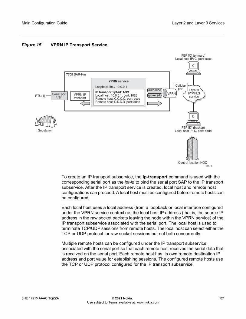
Main Configuration Guide Layer 2 and Layer 3 Services
3HE 17215 AAAC TQZZA © 2021 Nokia. Use subject to Terms available at: www.nokia.com
121
Figure 15 VPRN IP Transport Service
To create an IP transport subservice, the ip-transport command is used with the corresponding serial port as the ipt-id to bind the serial port SAP to the IP transport subservice. After the IP transport service is created, local host and remote host configurations can proceed. A local host must be configured before remote hosts can be configured.
Each local host uses a local address (from a loopback or local interface configured under the VPRN service context) as the local host IP address (that is, the source IP address in the raw socket packets leaving the node within the VPRN service) of the IP transport subservice associated with the serial port. The local host is used to terminate TCP/UDP sessions from remote hosts. The local host can select either the TCP or UDP protocol for raw socket sessions but not both concurrently.
Multiple remote hosts can be configured under the IP transport subservice associated with the serial port so that each remote host receives the serial data that is received on the serial port. Each remote host has its own remote destination IP address and port value for establishing sessions. The configured remote hosts use the TCP or UDP protocol configured for the IP transport subservice.
Layer 3IP/MPLSservice
Cellularport
RTU(1)
7705 SAR-Hm
FEP [D] (backup)Local host IP: D, port: dddd
Serial port1/3/1
28012
Substation
Central location NOC
VPRN IPtransport
IP transport ipt-id: 1/3/1Local host: 10.0.0.1, port; 1026Remote host: C.C.C.C, port; ccccRemote host: D.D.D.D, port; dddd
Loopback Ifc = 10.0.0.1
VPRN service
VPRNauto-bind
spoke sdp
FEP [C] (primary)Local host IP: C, port: cccc
C
D

Layer 2 and Layer 3 Services
122
Main Configuration Guide
© 2021 Nokia. Use subject to Terms available at: www.nokia.com
3HE 17215 AAAC TQZZA
IP transport processing of TCP/UDP packets is performed by the CPM task. Filters configured for protecting the CPM need to take into account the raw socket IP transport packets and ensure the filter is not blocking associated IP transport sessions. For example, operators need to ensure interface IP addresses and ports configured on the node are not blocked, and remote host IP/port combinations are not blocked.
9.5.1.1 Remote Host Manual TCP Connection Check
A manual TCP connection check can be performed for each remote host configured for a raw socket IP transport subservice. When executed by an operator, the TCP connection check attempts to establish a TCP session towards the configured remote host. Only one TCP connection check attempt is made, with a fixed timeout of 5 seconds. If the attempt is successful, the session is torn down immediately without data being sent.
The TCP connection check is initiated in the CLI using the tools>perform>service>ip-transport>remote-host>check-tcp command. The result is displayed in the CLI using the tools>dump>service>ip-transport>remote-host>check-tcp command. Equivalent management is available via SNMP.
If a TCP connection to a remote host already exists due to serial traffic being transmitted, the check returns “successful” without impacting the existing TCP connection.
Note: It is not necessary to configure remote hosts when the IP transport service is not originating sessions. If sessions are only established towards the IP transport local host (for example, remote servers polling the local host), the remote host configuration is not necessary. Remote host configurations may still be desirable when using filter-unknown-host.
Note: IP transport-to-IP transport raw socket data on the same node is not supported.

Main Configuration Guide Layer 2 and Layer 3 Services
3HE 17215 AAAC TQZZA © 2021 Nokia. Use subject to Terms available at: www.nokia.com
123
9.5.1.2 QoS Requirements for IP Transport
Serial raw socket data that is transported using an IP transport service can be DSCP marked at the source node. This allows the source node (local host) of the traffic to mark packets correctly so that downstream nodes prioritize them as needed, and to queue local traffic in the right egress queue based on the classification assigned to the IP transport service.
The node does not support FC classification; instead, it marks the DSCP in packets based on the IP transport subservice DSCP setting. This DSCP setting overrides the DSCP marking that would have otherwise been based on the egress network queue policy FC. These packets will be queued on egress with all other control traffic and will be considered high priority.
Additionally, the DSCP setting is assigned per IP transport subservice for all traffic from the local host and all traffic destined to each remote host. There is no per remote host control for the DSCP setting.
9.5.2 GNSS NMEA Data IP Transport Service
IP transport services are used to send GNSS National Marine Electronics Association (NMEA) data to remote hosts. All IP transport functionality supported for serial data over raw sockets is also available for NMEA data. See Raw Socket IP Transport Service for information.
An IP transport subservice within a Layer 3 VPRN service can be configured to transmit GNSS NMEA data from the GNSS receiver (as the IP transport local host) to one or more remote hosts. See Figure 16. Any packets sent from remote hosts toward the local host of the IP transport subservice are dropped.

Layer 2 and Layer 3 Services
124
Main Configuration Guide
© 2021 Nokia. Use subject to Terms available at: www.nokia.com
3HE 17215 AAAC TQZZA
Figure 16 GNSS NMEA Data Over IP Transport Service
Use the syntax shown below to create an IP transport subservice within a VPRN service.
CLI Syntax: config>service vprn service-id [customer customer-id] [create]
ip-transport ipt-id [create] description description-stringfilter-unknown-host local-host ip-addr ip-addr port-num port-num
protocol {tcp | udp} remote-host host-id [ip-addr ip-addr] [port-num
port-num] [create] description description-string name host-name exit
shutdown tcp
inactivity-timeout seconds max-retries number retry-interval seconds
exit exit
exit exit
GNSS SatelliteGPS, GPS +GLONASS
GNSS NMEA sentence streaming over UDP using IP Transport$RMC,220624.0,A,0059.922901,S,11200.000168,E,3.9,360.0,010717,0.1,E,A*16$GNS,220624.0,0059.922901,S,11200.000168,E,AAN,11,0.7,62.5,40.0,,*09$GGA,220623.0,0059.923987,S,11200.000182,E,1,05,0.7,62.5,M,40.0,M,,*7A
IP Transport service to remote host [A]
IP Transport service remote host [B]
IPT service within VPRN service CellularEnterpriseIP/MPLS
NMEAApplications
(Primary)
NMEAApplications
(Backup)
Operations(Primary)
Operations(Backup)
NSP
LTE
Location queryvia SNMP
A
B
35925
)))
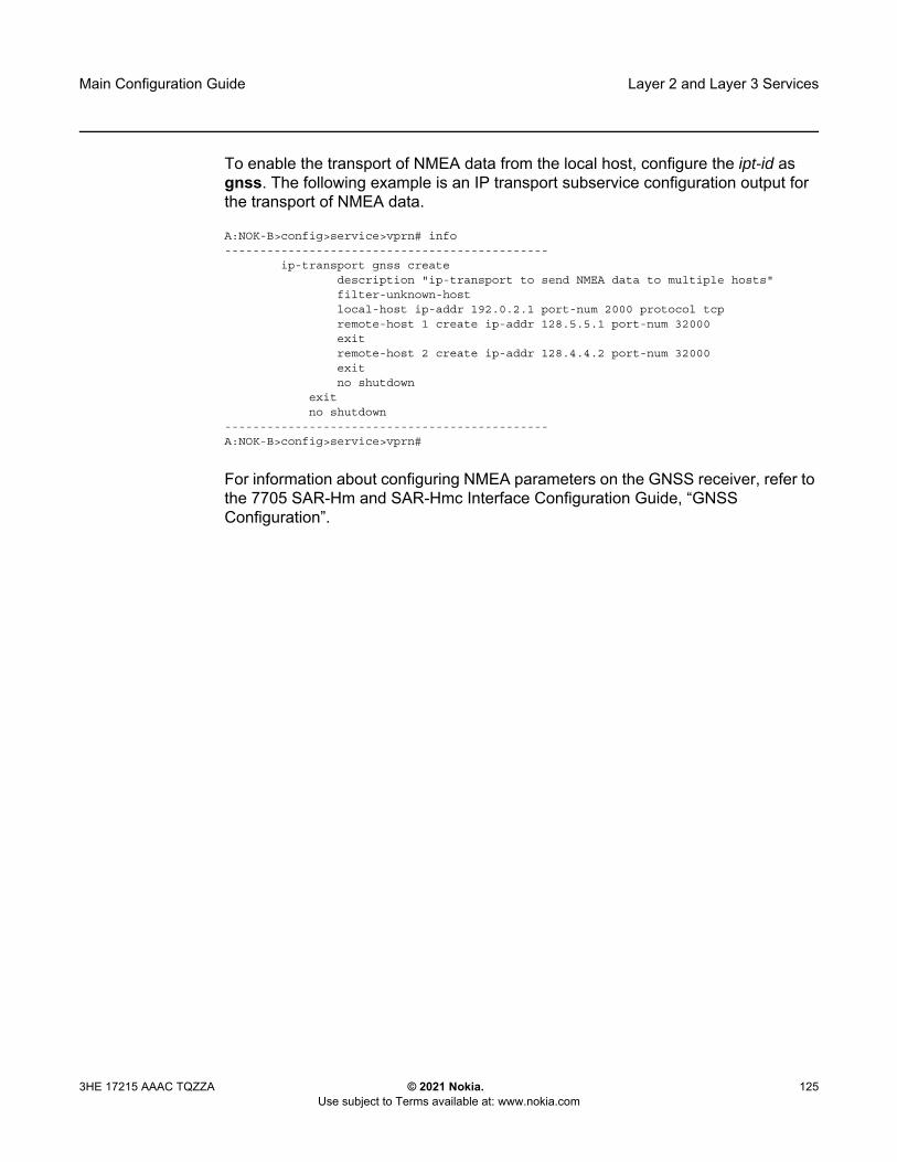
Main Configuration Guide Layer 2 and Layer 3 Services
3HE 17215 AAAC TQZZA © 2021 Nokia. Use subject to Terms available at: www.nokia.com
125
To enable the transport of NMEA data from the local host, configure the ipt-id as gnss. The following example is an IP transport subservice configuration output for the transport of NMEA data.
A:NOK-B>config>service>vprn# info----------------------------------------------
ip-transport gnss createdescription "ip-transport to send NMEA data to multiple hosts"filter-unknown-hostlocal-host ip-addr 192.0.2.1 port-num 2000 protocol tcpremote-host 1 create ip-addr 128.5.5.1 port-num 32000exitremote-host 2 create ip-addr 128.4.4.2 port-num 32000exitno shutdown
exitno shutdown
----------------------------------------------A:NOK-B>config>service>vprn#
For information about configuring NMEA parameters on the GNSS receiver, refer to the 7705 SAR-Hm and SAR-Hmc Interface Configuration Guide, “GNSS Configuration”.

Layer 2 and Layer 3 Services
126
Main Configuration Guide
© 2021 Nokia. Use subject to Terms available at: www.nokia.com
3HE 17215 AAAC TQZZA
9.5.3 Serial Raw Socket IP Transport Configuration Commands Hierarchy
config— service
— vprn service-id [customer customer-id] [create]— ip-transport ipt-id [create]— no ip-transport ipt-id
— description description-string— no description— dscp dscp-name— [no] filter-unknown-host— local-host ip-addr ip-addr port-num port-num protocol {tcp | udp}— no local-host— remote-host host-id [ip-addr ip-addr] [port-num port-num] [create]— no remote-host
— description description-string— no description— name host-name— no name
— [no] shutdown— tcp
— inactivity-timeout seconds— max-retries number— retry-interval seconds

Main Configuration Guide Layer 2 and Layer 3 Services
3HE 17215 AAAC TQZZA © 2021 Nokia. Use subject to Terms available at: www.nokia.com
127
9.5.3.1 IP Transport Configuration Command Descriptions
ip-transport
Syntax ip-transport ipt-id [create]no ip-transport ipt-id
Context config>service>vprn
Description This command creates an IP transport subservice within a VPRN service. An IP transport subservice can be used to transmit serial raw socket data to and from a local host and remote host. An IP transport subservice can also be used to transmit GNSS NMEA data from the GNSS receiver to one or more remote hosts.
All IP transport subservices must be explicitly created using the create keyword. An IP transport subservice is owned by the service within which it is created. An IP transport subservice can only be associated with a single service. The create keyword is not needed when editing parameters for an existing IP transport subservice. An IP transport subservice must first be shut down before changes can be made to the configured parameters.
The no form of this command deletes the IP transport subservice with the specified ipt-id. When an IP transport subservice is deleted, all configured parameters for the IP transport subservice are also deleted.
Default no ip-transport
Parameters ipt-id — the physical port associated with the IP transport subservice
Values For serial raw sockets, the ipt-id must reference an RS-232 serial port that has been configured as a socket and be expressed in the format slot/mda/port For a GNSS receiver, the ipt-id must be configured as gnss
create — creates this IP transport subservice
description
Syntax description description string no description
Context config>service>vprn>ip-transportconfig>service>vprn>ip-transport>remote-host
Description This command creates a text description for a configuration context to help identify the content in the configuration file.
The no form of this command removes any description string from the context.

Layer 2 and Layer 3 Services
128
Main Configuration Guide
© 2021 Nokia. Use subject to Terms available at: www.nokia.com
3HE 17215 AAAC TQZZA
Default no description
Parameters description-string — a description character string. Allowed values are any string up to 80 or 160 characters long (depending on the command, composed of printable, 7-bit ASCII characters. If the string contains special characters (#, $, spaces, etc.), the entire string must be enclosed within double quotes.
dscp
Syntax dscp dscp-name
Context config>service>vprn>ip-transport
Description This command configures the DSCP name used to mark the DSCP field in IP transport packets originating from this node.
Default ef
Parameters dscp-name — the DSCP name used to mark the DSCP field in IP transport packets. Table 6 lists the valid DSCP names.
filter-unknown-host
Syntax [no] filter-unknown-host
Context config>service>vprn>ip-transport
Description This command filters connections from unknown hosts. An unknown host is any host that is not configured as a remote host.
The no form of this command disables the filter.
Default no filter-unknown-host
Table 6 Valid DSCP Names
dscp-name
be, ef, cp1, cp2, cp3, cp4, cp5, cp6, cp7, cp9, cs1, cs2, cs3, cs4, cs5, nc1, nc2, af11, af12, af13, af21, af22, af23, af31, af32, af33, af41, af42, af43, cp11, cp13, cp15, cp17, cp19, cp21, cp23, cp25, cp27, cp29, cp31, cp33, cp35, cp37, cp39, cp41, cp42, cp43, cp44, cp45, cp47, cp49, cp50, cp51, cp52, cp53, cp54, cp55, cp57, cp58, cp59, cp60, cp61, cp62, cp63

Main Configuration Guide Layer 2 and Layer 3 Services
3HE 17215 AAAC TQZZA © 2021 Nokia. Use subject to Terms available at: www.nokia.com
129
local-host
Syntax local-host ip-addr ip-addr port-num port-num protocol {tcp | udp}no local-host
Context config>service>vprn>ip-transport
Description This command creates the local host within the IP transport subservice.
The local host is required to accept TCP/UDP sessions initiated from far-end remote hosts, and for the node to initiate sessions towards the far-end remote hosts.
The local host must be created before a remote host is created.
The no form of this command deletes the local host.
Default no local-host
Parameters ip-addr — the IP address that is used for this local host. The IP address must be the same as a loopback or local interface IP address that is already configured within this service.
Values a.b.c.d (IPv4 address)
port-num — the port number that is used by remote hosts to establish TCP/UDP sessions to this local host
Values 1026 to 49150
protocol {tcp | udp} — the protocol type that is used for all sessions to and from this local host, either tcp or udp
remote-host
Syntax remote-host host-id ip-addr ip-addr] port-num port-num [create]no remote-host host-id
Context config>service>vprn>ip-transport
Description This command creates a remote host within the IP transport subservice. Multiple remote hosts can be created in order to send serial raw socket date or GNSS NMEA data to remote destinations. The create keyword must be used for each remote host that is created.
The no form of this command deletes the remote host.
Default no remote-host
Note: When the IP transport ID is configured as gnss, any packets sent from remote hosts to the local host are dropped.

Layer 2 and Layer 3 Services
130
Main Configuration Guide
© 2021 Nokia. Use subject to Terms available at: www.nokia.com
3HE 17215 AAAC TQZZA
Parameters host-id — the remote host identifier
Values 1 to 2147483647or a name string up to 64 characters
ip-addr — the IP address that is used to reach the remote host in order to route IP transport packets to that remote host
Values a.b.c.d (IPv4 address)
port-num — the destination port number that is used to reach the serial port socket or the GNSS receiver on the remote host
Values 1 to 65535
create — creates this remote host
name
Syntax name host-nameno name
Context config>service>vprn>ip-transport>remote-host
Description This command configures a unique name for this remote host.
The no form of this command deletes the remote host name.
Default n/a
Parameters host-name — a unique name for this remote host, up to 64 characters long
shutdown
Syntax [no] shutdown
Context config>service>vprn>ip-transport
Description This command administratively disables an entity. When disabled, an entity does not change, reset, or remove any configuration settings or statistics.
The operational state of the entity is disabled as well as the operational state of any entities contained within. Many objects must be shut down before they can be deleted.
The no form of this command administratively enables an entity.
Default no shutdown
Special Cases VPRN IP transport subservice — when an IP transport subservice within a VPRN service is shut down, all TCP/UDP packets received from remote hosts are dropped and any serial data received from the serial port is dropped. Any TCP connections that were up are closed and no new TCP connection requests are accepted.
Main Configuration Guide Layer 2 and Layer 3 Services
3HE 17215 AAAC TQZZA © 2021 Nokia. Use subject to Terms available at: www.nokia.com
131
It is not possible to make configuration changes to an IP transport subservice without performing a shutdown first.The operational state of an IP transport subservice is relative to the operational state of the serial port or GNSS receiver for which the IP transport subservice is defined. When a serial port or GNSS receiver is shut down, the IP transport subservice associated with the serial port or GNSS receiver becomes operationally down.When the no shutdown command is executed for an IP transport subservice, it becomes operationally up. Serial data from the serial port or NMEA sentence data from the GNSS receiver is encapsulated in TCP/UDP packets destined for remote hosts, and TCP/UDP packets can be received by the local host, where raw serial data is then sent out the serial port.
tcp
Syntax tcp
Context config>service>vprn>ip-transport
Description This command creates the context to configure TCP parameters within this IP transport subservice.
Default n/a
inactivity-timeout
Syntax inactivity-timeout seconds
Context config>service>vprn>ip-transport>tcp
Description This command specifies how long to wait before disconnecting a TCP connection due to traffic inactivity over the connection.
Default 30 s
Parameters seconds — how long to wait, in seconds, before disconnecting a TCP connection
Values 1 to 65535
max-retries
Syntax max-retries number
Context config>service>vprn>ip-transport>tcp
Description This command specifies the number of times that a remote host, acting as a client, tries to establish a TCP connection after the initial attempt fails.
Layer 2 and Layer 3 Services
132
Main Configuration Guide
© 2021 Nokia. Use subject to Terms available at: www.nokia.com
3HE 17215 AAAC TQZZA
Default 5
Parameters number — the number of attempts to establish a TCP connection after the initial attempt fails
Values 0 to 10
retry-interval
Syntax retry-interval seconds
Context config>service>vprn>ip-transport>tcp
Description This command specifies how long to wait before each TCP max-retries attempt.
Default 5 s
Parameters seconds — how long to wait, in seconds, before each TCP max-retries attempt
Values 1 to 300
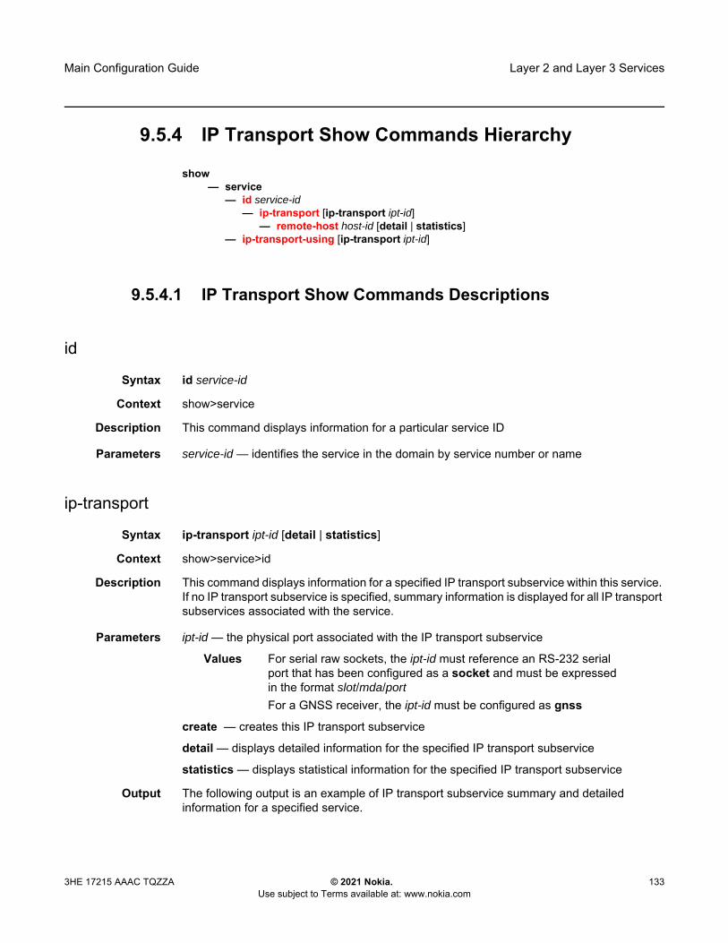
Main Configuration Guide Layer 2 and Layer 3 Services
3HE 17215 AAAC TQZZA © 2021 Nokia. Use subject to Terms available at: www.nokia.com
133
9.5.4 IP Transport Show Commands Hierarchy
show— service
— id service-id— ip-transport [ip-transport ipt-id]
— remote-host host-id [detail | statistics]— ip-transport-using [ip-transport ipt-id]
9.5.4.1 IP Transport Show Commands Descriptions
id
Syntax id service-id
Context show>service
Description This command displays information for a particular service ID
Parameters service-id — identifies the service in the domain by service number or name
ip-transport
Syntax ip-transport ipt-id [detail | statistics]
Context show>service>id
Description This command displays information for a specified IP transport subservice within this service. If no IP transport subservice is specified, summary information is displayed for all IP transport subservices associated with the service.
Parameters ipt-id — the physical port associated with the IP transport subservice
Values For serial raw sockets, the ipt-id must reference an RS-232 serial port that has been configured as a socket and must be expressed in the format slot/mda/port For a GNSS receiver, the ipt-id must be configured as gnss
create — creates this IP transport subservice
detail — displays detailed information for the specified IP transport subservice
statistics — displays statistical information for the specified IP transport subservice
Output The following output is an example of IP transport subservice summary and detailed information for a specified service.
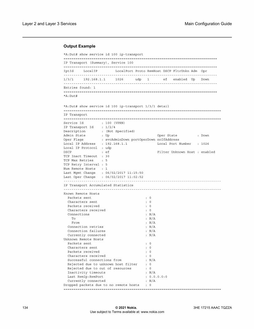
Layer 2 and Layer 3 Services
134
Main Configuration Guide
© 2021 Nokia. Use subject to Terms available at: www.nokia.com
3HE 17215 AAAC TQZZA
Output Example
*A:Dut# show service id 100 ip-transport=============================================================================IP Transport (Summary), Service 100=============================================================================IptId LocalIP LocalPort Proto RemHost DSCP FltrUnkn Adm Opr-----------------------------------------------------------------------------1/3/1 192.168.1.1 1026 udp 1 ef enabled Up Down-----------------------------------------------------------------------------Entries found: 1=============================================================================*A:Dut#
*A:Dut# show service id 100 ip-transport 1/3/1 detail===============================================================================IP Transport===============================================================================Service Id : 100 (VPRN)IP Transport Id : 1/2/4Description : (Not Specified)Admin State : Up Oper State : DownOper Flags : svcAdminDown portOperDown noIfAddressLocal IP Address : 192.168.1.1 Local Port Number : 1026Local IP Protocol : udpDSCP : ef Filter Unknown Host : enabledTCP Inact Timeout : 30TCP Max Retries : 5TCP Retry Interval : 5Num Remote Hosts : 1Last Mgmt Change : 06/02/2017 11:15:50Last Oper Change : 06/02/2017 11:02:52-------------------------------------------------------------------------------IP Transport Accumulated Statistics-------------------------------------------------------------------------------Known Remote Hosts
Packets sent : 0Characters sent : 0Packets received : 0Characters received : 0Connections : N/A
To : N/AFrom : N/A
Connection retries : N/AConnection failures : N/ACurrently connected : N/A
Unknown Remote HostsPackets sent : 0Characters sent : 0Packets received : 0Characters received : 0Successful connections from : N/ARejected due to unknown host filter : 0Rejected due to out of resources : 0Inactivity timeouts : N/ALast RemIp:RemPort : 0.0.0.0:0Currently connected : N/A
Dropped packets due to no remote hosts : 0===============================================================================

Main Configuration Guide Layer 2 and Layer 3 Services
3HE 17215 AAAC TQZZA © 2021 Nokia. Use subject to Terms available at: www.nokia.com
135
remote-host
Syntax remote-host host-id [detail | statistics]
Context show>service>id>ip-transport
Description This command displays information for a specified remote host within this IP transport subservice within this service. If no remote host is specified, summary information is displayed for all remote hosts within this IP transport subservice.
Parameters host-id — the remote host identifier
Values 1 to 2147483647or a name string up to 64 characters long
detail — displays detailed information for a specified remote host
statistics — displays summary information for a specified remote host
Output The following output is an example of IP transport subservice remote host summary and detailed information.
Output Example
*A:Dut# show service id 100 ip-transport remote-host=============================================================================IPT Remote Host (Summary), Service 100 IPT 1/3/1=============================================================================RemId RemIp:RemPort Rcvd Chars Sent Chars Drop Chars State
Rcvd Pkts Sent Pkts Drop Pkts Up Time-----------------------------------------------------------------------------2 192.168.1.1:1027 0 0 0 N/A
0 0 0 N/A-----------------------------------------------------------------------------Number of known remote hosts: 1Number of unknown remote hosts: N/ATotal entries found: 1=============================================================================*A:Dut#
Output Example
*A:Dut# show service id 100 ip-transport 1/3/1 remote-host 2 detail===============================================================================IPT Remote Host===============================================================================Service Id : 100 (IES)IP Transport Id : 1/3/1Remote Host Id : 2Name : (Not Specified)Description : (Not Specified)IP Address : 192.168.1.6 Port Number : 4000Last Mgmt Change : 12/07/2016 16:48:44Session State : connected Up Time : 00h01m44sLast Connect : successful-------------------------------------------------------------------------------IPT Remote Host Statistics

Layer 2 and Layer 3 Services
136
Main Configuration Guide
© 2021 Nokia. Use subject to Terms available at: www.nokia.com
3HE 17215 AAAC TQZZA
-------------------------------------------------------------------------------Sent Pkts : 134 Sent Chars : 201000Dropped Pkts : 0 Dropped Chars : 0Rcvd Pkts : 267 Rcvd Chars : 201000Session information
Connections : 2To : 1From : 1
Connection retries : 0Connection failures : 0Closed by far end : 1Inactivity timeouts : 0
===============================================================================*A:Dut#
ip-transport-using
Syntax ip-transport-using [ip-transport ipt-id]
Context show>service
Description This command displays IP transport subservice information for a specified port. If no port is specified, the command displays a summary of all IP transport subservices defined for this service.
Parameters ipt-id — the physical port associated with the IP transport subservice
Values For serial raw sockets, the ipt-id must reference an RS-232 serial port that has been configured as a socket and must be expressed in the format slot/mda/port For a GNSS receiver, the ipt-id must be configured as gnss
Output The following output is an example of ip-transport-using information.
Output Example
*A:Dut# show service ip-transport-using=========================================IP Transports=========================================IptId SvcId Type Adm Opr-----------------------------------------1/3/1 1 VPRN Down Down1/3/2 2 VPRN Up Down-----------------------------------------Entries found: 2=========================================*A:Dut#
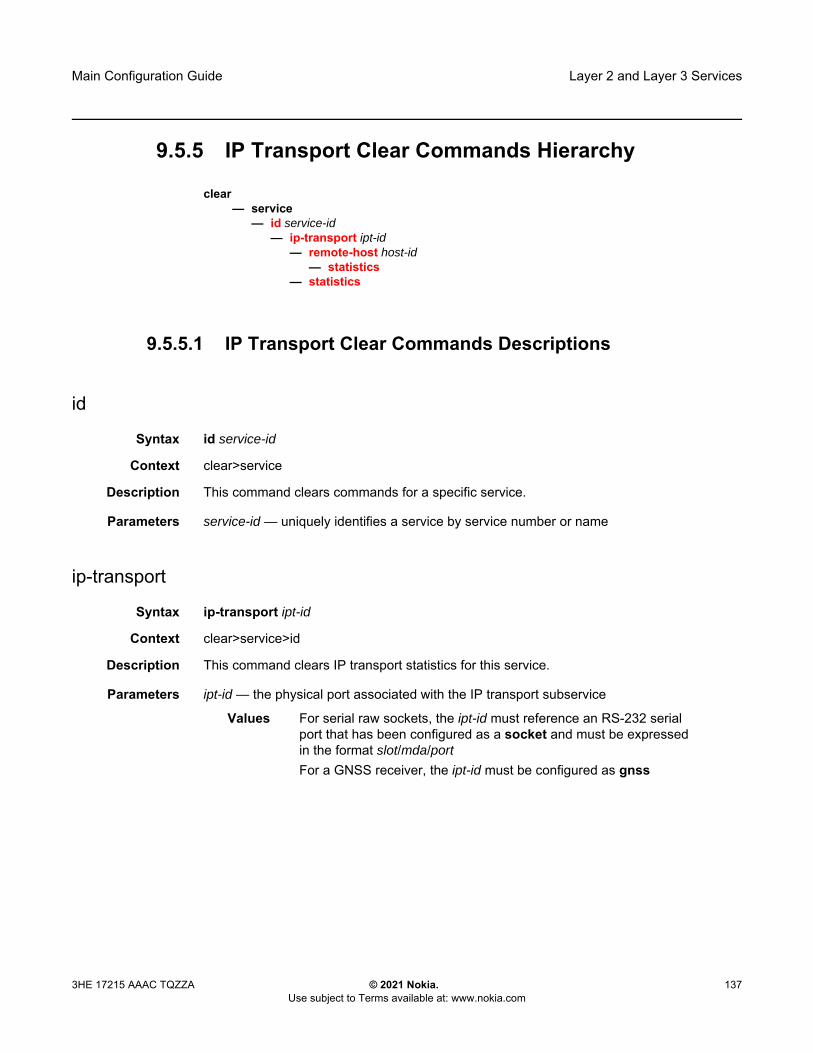
Main Configuration Guide Layer 2 and Layer 3 Services
3HE 17215 AAAC TQZZA © 2021 Nokia. Use subject to Terms available at: www.nokia.com
137
9.5.5 IP Transport Clear Commands Hierarchy
clear— service
— id service-id— ip-transport ipt-id
— remote-host host-id — statistics
— statistics
9.5.5.1 IP Transport Clear Commands Descriptions
id
Syntax id service-id
Context clear>service
Description This command clears commands for a specific service.
Parameters service-id — uniquely identifies a service by service number or name
ip-transport
Syntax ip-transport ipt-id
Context clear>service>id
Description This command clears IP transport statistics for this service.
Parameters ipt-id — the physical port associated with the IP transport subservice
Values For serial raw sockets, the ipt-id must reference an RS-232 serial port that has been configured as a socket and must be expressed in the format slot/mda/port For a GNSS receiver, the ipt-id must be configured as gnss

Layer 2 and Layer 3 Services
138
Main Configuration Guide
© 2021 Nokia. Use subject to Terms available at: www.nokia.com
3HE 17215 AAAC TQZZA
remote-host
Syntax remote-host host-id
Context clear>service>id>ip-transport
Description This command clears statistics pertaining to a specified remote host assigned to this IP transport subservice.
Parameters host-id — the remote host identifier
Values 1 to 2147483647or a name string up to 64 characters long
statistics
Syntax statistics
Context clear>service>id>ip-transportclear>service>id>ip-transport>remote-host
Description This command clears statistics-related information pertaining to all configured IP transport subservices or to all configured remote hosts for a specified IP transport subservice.

Main Configuration Guide Network Group Encryption
3HE 17215 AAAC TQZZA © 2021 Nokia. Use subject to Terms available at: www.nokia.com
139
10 Network Group Encryption The 7705 SAR-Hm series of routers supports Network Group Encryption (NGE) for securing MPLS services and their related control plane. Supported NGE functions include the following:
• SDP encryption of Layer 2 and Layer 3 service• VPRN encryption• router interface and PDN interface encryption of control plane and data plane
Layer 3 packets• PW template encryption for BGP VPLS and BGP VPWS services
For information on router interface encryption commands, refer to the group-encryption command descriptions in the 7450 ESS, 7750 SR, 7950 XRS, and VSR Classic CLI Command Reference Guide.
For information on SDP, VPRN, and PW template encryption, refer to “NGE” in the 7450 ESS, 7750 SR, 7950 XRS, and VSR Services Overview Guide.

Network Group Encryption
140
Main Configuration Guide
© 2021 Nokia. Use subject to Terms available at: www.nokia.com
3HE 17215 AAAC TQZZA
Main Configuration Guide Quality of Service
3HE 17215 AAAC TQZZA © 2021 Nokia. Use subject to Terms available at: www.nokia.com
141
11 Quality of Service The 7705 SAR-Hm series of routers supports Quality of Service (QoS) as covered in the topics listed below:
• QoS Policies• Network QoS Policies• Network Queue QoS Policies• Service Ingress and Egress QoS Policies
11.1 QoS Policies
For general information on QoS policies support, refer to the topics listed below in the “QoS Policies” chapter of the 7450 ESS, 7750 SR, 7950 XRS, and VSR Quality of Service Guide.
• QoS Overview• Forwarding Classes• Queue Parameters• QoS Policies Overview
- Service versus Network QoS- QoS Policy Entities- Network QoS Policies- Network Queue QoS Policies- Service Ingress QoS Policies- Service Egress QoS Policies- Configuration Notes

Quality of Service
142
Main Configuration Guide
© 2021 Nokia. Use subject to Terms available at: www.nokia.com
3HE 17215 AAAC TQZZA
11.2 Network QoS Policies
This section describes the following functionality:
• Dedicated Bearers
For general information on network QoS policies support, refer to the topics listed below in the “Network QoS Policies” chapter of the 7450 ESS, 7750 SR, 7950 XRS, and VSR Quality of Service Guide.
• Network QoS Policies Overview• Network Ingress
- Network Ingress Tunnel QoS Override- Network Ingress IP Match Criteria
• Network Egress• Basic Configurations• Service Management Tasks• Network QoS Policy Command Reference
For descriptions of network QoS policy commands, refer to the 7450 ESS, 7750 SR, 7950 XRS, and VSR Classic CLI Command Reference Guide and to the 7450 ESS, 7750 SR, 7950 XRS, and VSR Clear, Show, and Tools Command Reference Guide.
11.2.1 Dedicated Bearers
A default bearer is established when the node first attaches to a cellular network for each cellular port that has an enabled SIM. An IP address is assigned for each default bearer and the node uses this IP address for the associated PDN router interface that is used to route traffic to and from the cellular network. See the PDN Router Interfaces section for information about PDN router interfaces and IP address assignment.
In addition to the default bearer, the node accepts network-initiated dedicated bearer establishment. The node does not initiate dedicated bearers towards the network.
Main Configuration Guide Quality of Service
3HE 17215 AAAC TQZZA © 2021 Nokia. Use subject to Terms available at: www.nokia.com
143
Dedicated bearers provide a dedicated tunnel for specific types of traffic depending QoS requirements. Since they are established for the same cellular port as the default bearer, dedicated bearers use the same PDN router interface configured for the default bearer for sending and receiving traffic. Dedicated bearers can be a guaranteed bit rate (GBR) or non-GBR, whereas the default bearer can only be non-GBR. Dedicated bearers use traffic flow templates (TFTs) to provide special treatment to specific services that need to use the dedicated bearers.
The network programs TFTs on the cellular interface for each dedicated bearer. The TFTs contains at least one and up to eight packet filter items as follows:
• source address (with subnet mask)• IP protocol number (TCP, UDP)• destination port range• source port range• IPSec Security Parameter Index (SPI)• type of Service (TOS) (IPv4)• Flow-Label (IPv6 only)• evaluation precedence index
The node expects only one TFT to be programmed by the network for each dedicated bearer. More than one TFT per dedicated bearer is not supported.
The node expects that the TFT programmed per dedicated bearer will contain only a TOS packet filter. Other TFT parameters, if they are specified and programmed, are not supported. The TOS packet filter enables mapping of egress packets that match the TOS settings to the corresponding dedicated bearer and provide GBR, or non-GBR, service for the traffic as required.
Operators must coordinate with their wireless service providers and subscribe for dedicated bearers with the specific TOS packet filter settings as required. Operators must then ensure that service ingress classification and marking for the respective traffic flows match the dedicated bearer TOS packet filter when services traffic must egress the radio interface on the dedicated bearer.
Figure 17 illustrates a typical use case for dedicated bearers to differentiate services over a cellular network.

Quality of Service
144
Main Configuration Guide
© 2021 Nokia. Use subject to Terms available at: www.nokia.com
3HE 17215 AAAC TQZZA
Figure 17 Dedicated Bearer and Differentiated Services over a Cellular Network
The CLI output below shows an example of bearer information configured on a cellular port.
*A:Dut-E# show port 1/1/1===============================================================================Cellular Interface===============================================================================...==================================================================Bearer Information==================================================================Bearer Id Bearer Type QCI UL GBR UL MBR DL GBR DL MBR------------------------------------------------------------------
5 default 56 dedicated 1 100 200 1000 500007 dedicated 9
============================================================================================================================Traffic Flow Template Packet Filters==========================================================Bearer Id Filter Id Precedence Direction TOS/Mask----------------------------------------------------------
6 1 1 uplink 0xc0/fc6 2 2 downlink 0x04/fc7 1 200 both
==========================================================
No3567
DA Controllers(Priority 1) 7705
SAR-Hm PGW VSR
ControlCenter
L3 VPNService
LTEpacket core
PrivateIP/MPLS
AMI Collectors(Priority 3)
WeatherMonitoring(Priority 2)
7705 SAR-Hm marking is based on ingress QoS Policy. Packets are queued into their respective egress queues based on FC and sent overtheir respective bearers.
Packets marked from the 7705 SAR-Hmtraverse the LTE packet core and L3 VPNservice provider to the private IP/MPLS network. They are treated and processedaccording to QoS policies configured onthese transit nodes.
Three dedicated bearers are established by the network:1. GBR bearer with QCI=1, rate- limited to 100 kbps2. Non-GBR bearer with QCI=4, rate-limited to 500 kbpsThe default bearer has QCI=8

Main Configuration Guide Quality of Service
3HE 17215 AAAC TQZZA © 2021 Nokia. Use subject to Terms available at: www.nokia.com
145
11.3 Network Queue QoS Policies
For general information on network queue QoS policies support, refer to the topics listed below in the “Network Queue QoS Policies” chapter of the 7450 ESS, 7750 SR, 7950 XRS, and VSR Quality of Service Guide.
• Basic Configurations- Default Network Queue Policy Values
11.4 Service Ingress and Egress QoS Policies
For general information on service ingress and egress QoS policies support, refer to the topics listed below in the “Network Queue QoS Policies” chapter of the 7450 ESS, 7750 SR, 7950 XRS, and VSR Quality of Service Guide.
• Basic Configurations• Service Ingress QoS Policy
- Service Ingress QoS Queue- Ingress Forwarding Class (FC)- Ingress IP Match Criteria- Ingress IPv6 Match Criteria
• Service Egress QoS Policy- Service Egress QoS Queue- Percent-rate Support- Egress SAP FC and FP Overrides- Dot1p Egress Remarking- DSCP/Prec Egress Remarking
• Service Management Tasks
For descriptions of service ingress and egress QoS policy commands, refer to the 7450 ESS, 7750 SR, 7950 XRS, and VSR Classic CLI Command Reference Guide and to the 7450 ESS, 7750 SR, 7950 XRS, and VSR Clear, Show, and Tools Command Reference Guide.

Quality of Service
146
Main Configuration Guide
© 2021 Nokia. Use subject to Terms available at: www.nokia.com
3HE 17215 AAAC TQZZA

Main Configuration Guide OAM and Diagnostics
3HE 17215 AAAC TQZZA © 2021 Nokia. Use subject to Terms available at: www.nokia.com
147
12 OAM and DiagnosticsThe 7705 SAR-Hm series of routers supports OAM and diagnostics as covered in the topic listed below:
• OAM, SAA, and OAM-PM
12.1 OAM, SAA, and OAM-PM
For general information on OAM, SAA, and OAM-PM support, refer to the topics listed below in the “OAM, SAA, and OAM-PM” chapter of the 7450 ESS, 7750 SR, 7950 XRS, and VSR OAM and Diagnostics Guide.
• OAM Overview- SDP Ping
For descriptions of OAM, SAA, and OAM-PM commands, refer to the 7450 ESS, 7750 SR, 7950 XRS, and VSR Classic CLI Command Reference Guide and to the 7450 ESS, 7750 SR, 7950 XRS, and VSR Clear, Show, and Tools Command Reference Guide.

OAM and Diagnostics
148
Main Configuration Guide
© 2021 Nokia. Use subject to Terms available at: www.nokia.com
3HE 17215 AAAC TQZZA

Main Configuration Guide Multiservice Integrated Service Adapter andExtended Services Appliance
3HE 17215 AAAC TQZZA © 2021 Nokia. Use subject to Terms available at: www.nokia.com
149
13 Multiservice Integrated Service Adapter and Extended Services Appliance
The 7705 SAR-Hm series of routers supports the Multiservice Integrated Adapter (MS-ISA) and Extended Services Appliance as covered in the topics listed below:
• IP Tunnels• Network Address Translation
13.1 IP Tunnels
This section describes the following functionality:
• IPSec Secured Interface over Cellular
For general information on IP tunnel support, refer to the topics listed below in the “IP Tunnels” chapter of the 7450 ESS, 7750 SR, and VSR Multiservice Integrated Service Adapter and Extended Services Appliance Guide.
• IP Tunnels Overview- Tunnels ISAs- Operational Conditions- Statistics Collection- Security- IKEv2- SHA2 Support- IPSec Client Lockout- IPSec Tunnel CHILD_SA Rekey- Multiple IKE/ESP Transform Support
• X.509v3 Certificate Overview• Using Certificates for IPSec Tunnel Authentication• Trust-Anchor-Profile• Cert-Profile• Certificate Management Protocol Version 2 (CMPv2)• OCSP• IPSec Deployment Requirements

Multiservice Integrated Service Adapter and Extended Services Appliance
150
Main Configuration Guide
© 2021 Nokia. Use subject to Terms available at: www.nokia.com
3HE 17215 AAAC TQZZA
• IKEv2 Remote-Access Tunnel • Secured Interface• Configuring IPSec with CLI• IP Tunnel Command Reference
To configure and enable IP tunnels, the virtualized tunnel ISA MDA (isa-tunnel-v) must be configured in slot 5 on the router. Refer to the 7705 SAR-Hm and SAR-Hmc Interface Configuration Guide for information.
13.1.1 IPSec Secured Interface over Cellular
The 7705 SAR-Hm series of routers supports IPSec secured interfaces over cellular interfaces.
Figure 18 shows an example of an IPSec secured interface deployment over a cellular interface in a dual SIM environment.
Figure 18 IPSec Secured Interface over a Cellular Interface
With IPSec secured interfaces, static IPSec tunnels can be created under the PDN router interface associated for each SIM. When the SIM is active and the node attaches to the cellular network, the PDN router interface becomes operational. At that time, IPSec secured interface tunnels configured on the interface also begin to establish towards the security gateway they are configured to connect to. When the tunnel is established, data traffic traverses the IPSec secured interface. In Figure 18, only the pair of tunnels associated with the active SIM is operational.
PrimaryCarrier1
PDN1, SIM1VPRNX
BackupCarrier2
PDN2, SIM2
28940
1.1.1.a
1.1.1.b
2.2.2.c
2.2.2.d
SecGW
RTU/IED
Ethernet
Four IPSec tunnelsconfigured. Two tunnels
up at any timedepending which
SIM is active.
BGP in VPRN optional
Operations(Primary)
Operations(Backup)

Main Configuration Guide Multiservice Integrated Service Adapter andExtended Services Appliance
3HE 17215 AAAC TQZZA © 2021 Nokia. Use subject to Terms available at: www.nokia.com
151
The tunnel pair on the second PDN router interface is kept down and becomes operational when the second SIM becomes active.
Each IPsec secured interface tunnel is associated with one service. The supported service types are IES and VPRN.
Each service that needs to be secured over the PDN router interface must be configured with its own IPSec secured interface tunnel. For example if VPRN1, VPRN2, and VPRN3 all need to be secured, then three different IPSec secured interfaces are required, one for each service.
IPSec secured interface is supported on IPv4 and IPv6 PDN router interfaces.
The CLI output below shows an example of IPSec secured interface configured on an IPv6 PDN router interface:
#--------------------------------------------------echo "ISA Configuration"#--------------------------------------------------
isatunnel-group 1 isa-scale-mode tunnel-limit-32 create
reassembly 2000multi-activemda 1/5no shutdown
exitexit
#--------------------------------------------------echo "Router (Network Side) Configuration"#--------------------------------------------------
router Baseinterface "lte-interface1" pdn
port 1/1/1ip-mtu 1500ipv6exitno shutdown
exit#--------------------------------------------------echo "IPsec Configuration"#--------------------------------------------------
ipsecike-transform 1 create
dh-group 21ike-auth-algorithm sha384ike-encryption-algorithm des
exitike-policy 1 create
ike-version 2dpd interval 10ike-transform 1
exitipsec-transform 1 create
esp-auth-algorithm auth-encryptionesp-encryption-algorithm aes256-gcm8

Multiservice Integrated Service Adapter and Extended Services Appliance
152
Main Configuration Guide
© 2021 Nokia. Use subject to Terms available at: www.nokia.com
3HE 17215 AAAC TQZZA
exitexit
#--------------------------------------------------echo "Service Configuration"#--------------------------------------------------
servicevprn 1 name "vprn1" customer 1 create
ipsecsecurity-policy 1 create
entry 1 createlocal-v6-ip 463c:f068:d815:e0ee:7ecf:5660::/96remote-v6-ip c97e:a8fa:1785:52d7:9bb8:9b3b::/96
exitentry 2 create
local-v6-ip 463c:f068:d815:e0ee:7ecf:5661::/96remote-v6-ip c97e:a8fa:1785:52d7:9bb8:9b3c::/96
exitexit
exitroute-distinguisher 1.1.1.1:52static-route-entry c97e:a8fa:1785:52d7:9bb8::/80
ipsec-tunnel "tunnel1-vprn1"no shutdown
exitexitno shutdown
exitexit
#--------------------------------------------------echo "Router (Service Side) Configuration"#--------------------------------------------------
router Baseinterface "lte-interface1" pdn
ipsec tunnel-group 1 public-sap 1ipsec-tunnel "tunnel1-vprn1" private-sap 1 private-service-
name "vprn1" createencapsulated-ip-mtu 1300remote-gateway-address 2001:90:10:3::2security-policy 1dynamic-keying
ike-policy 1pre-shared-key "2KMbfx1sfSVdLxLEJsuVhs/
hfa42V3XyCZMLyubX" hash2transform 1
exitno shutdown
exitno shutdown
exitexit
exit
Main Configuration Guide Multiservice Integrated Service Adapter andExtended Services Appliance
3HE 17215 AAAC TQZZA © 2021 Nokia. Use subject to Terms available at: www.nokia.com
153
13.2 Network Address Translation
This section describes the following Network Address Translation (NAT) functionality supported on the 7705 SAR-Hm series of routers:
• NAT with Static Port Forwarding• NAT Command Reference
NAT runs on a single virtual ISA configured on the node. For general information on NAT support, refer to the topics listed below in “Network Address Translation” in the 7450 ESS, 7750 SR, and VSR Multiservice Integrated Service Adapter and Extended Services Appliance Guide.
• Terminology• Network Address Translation (NAT) Overview• Large Scale NAT• One-to-One (1:1) NAT• NAT Logging
- Syslog/SNMP/Local-File Logging- SNMP Trap Logging- NAT Syslog
• ISA Feature Interactions- MS-ISA Use with Service Mirrors
• Configuring NAT
13.2.1 NAT with Static Port Forwarding
With NAT, the source IP address and the port of the host on the private side (inside) of the network are translated to an external IP address and port on the public side (outside) of the network. The IP address on the inside can be assigned to a raw socket IP host connected to an RS-232 serial interface or assigned to an IP interface associated with an Ethernet port.
Static port forwarding is configured on the CLI using the following parameters:
• inside IP address• inside port• outside IP address

Multiservice Integrated Service Adapter and Extended Services Appliance
154
Main Configuration Guide
© 2021 Nokia. Use subject to Terms available at: www.nokia.com
3HE 17215 AAAC TQZZA
• outside port• protocol
Figure 19 shows an example of a network with a 7705 SAR-Hm series node configured to use NAT with static port forwarding.
Figure 19 NAT with Static Port Forwarding
In the scenario shown above, the “RTU” VPRN service is inside and the “SCADA” VPRN service is outside. The “RTU” VPRN contains two IP transport services, one for each connected device. For information about IP transport services, see IP Transport Services and also refer to “Serial Transport over Raw Sockets” in the 7705 SAR-Hm and SAR-Hmc Interface Configuration Guide.
Figure 19 shows specific values for the inside IP address and port and outside IP address and port. The cellular interface of the node is used as the network-facing interface to transport the outside VPRN traffic.
When a packet is sent from the SCADA master to the node over the LTE network, it will be carried within the outside “SCADA” VPRN service towards the node. The node will send the packet to the BB-ISA MDA to perform the required NAT function based on the configured NAT policy. NAT is applied to the packet as needed. The packet is then processed by the inside “RTU” VPRN service, destined to the corresponding IP transport service.
When a packet is sent from the RTU towards the SCADA master, the inside “RTU” VPRN service sends the packet to the BB-ISA MDA where the NAT policy translates the IP address and port to the outside IP address and port, The BB-ISA MDA then sends the packet to the outside “SCADA” VPRN service where it is routed over the cellular interface using the “SCADA” VPRN service.
The steps and CLI outputs below show the configuration of NAT with static port forwarding based on Figure 19.
28941
IP: 192.168.0.2:20007705 SAR-Hm
LTE
7x50/7705/vSR
SCADA Master(1.2.3.4:1000)
RTU1 - 10.0.0.1:100RTU2 - 10.0.0.1:101RTU3 - 10.0.0.2:100RTU4 - 10.0.0.2:101….etc.
VPRN “RTU”
IPT 1: 192.168.0.1IPT 2: 192.168.0.2
IP: 192.168.0.1:2000IP: 192.168.0.2:2000
VPRN “SCADA”
Loopback: 10.0.0.1
10.0.0.1:10010.0.0.1:101
ISA-BB-V(mda 1/6)
PAT“sar-hm-1”
IP: 192.168.0.1:2000
7705 SAR-Hm

Main Configuration Guide Multiservice Integrated Service Adapter andExtended Services Appliance
3HE 17215 AAAC TQZZA © 2021 Nokia. Use subject to Terms available at: www.nokia.com
155
Step 1. Configure NAT on the BB-ISA MDA:config
isanat-group 1
mda 1/6
Step 2. Configure the inside “RTU” VPRN (1) service for the inside static port forwarding NAT function:
configservice
vprn 1interface 'rtu1'
address 192.168.0.1/32loopback
interface 'rtu2'address 192.168.0.2/32loopback
ip-transport 1/3/1local-host ip-addr 192.168.0.1 port-num 2000 protocol udpremote-host ip-addr 1.2.3.4 port-num 1000 protocol udp
ip-transport 1/3/2local-host ip-addr 192.168.0.2 port-num 2000 protocol udpremote-host ip-addr 1.2.3.4 port-num 1000 protocol udp
configservice
vprn 1nat
insidedestination-prefix 1.2.3.4/24 .nat-policy 'sar-hm-1'
configservice
natnat-policy 'sar-hm-1
pool 'pool-name-1' router 2port-forwarding
lsn router 1 ip 192.168.0.1 protocol udp port 2000 outside-ip 10.0.0.1 outside-port 100 nat-policy "sar-hm-1"
lsn router 1 ip 192.168.0.2 protocol udp port 2000 outside-ip 10.0.0.1 outside-port 101 nat-policy "sar-hm-1"

Multiservice Integrated Service Adapter and Extended Services Appliance
156
Main Configuration Guide
© 2021 Nokia. Use subject to Terms available at: www.nokia.com
3HE 17215 AAAC TQZZA
Step 3. Configure the outside “SCADA” VPRN (2) service for the outside static port forwarding NAT function:
service vprn 2interface 'Outside_RTU'
address 10.0.0.1/32loopback
natoutside
pool 'pool-name-1'nat-group 1 type large-scaleaddress-range 10.0.0.1 10.0.0.1 createport-forwarding-range 30000port-reservations ports 1000

Main Configuration Guide Multiservice Integrated Service Adapter andExtended Services Appliance
3HE 17215 AAAC TQZZA © 2021 Nokia. Use subject to Terms available at: www.nokia.com
157
13.2.2 NAT Command Reference
The 7705 SAR-Hm series of routers supports the NAT commands listed in this section. For command descriptions, refer to the 7450 ESS, 7750 SR, 7950 XRS, and VSR Classic CLI Command Reference Guide.
13.2.2.1 ISA Configuration Commands
config— isa
— nat-group nat-group-id [create]— no nat-group nat-group-id
— active-mda-limit number— no active-mda-limit— description description-string— no description— [no] mda mda-id
— [no] shutdown— [no] suppress-lsn-events— [no] suppress-lsn-sub-blks-free
13.2.2.2 NAT Service Configuration Commands
configure— service
— nat— nat-policy nat-policy-name [create]— no nat-policy nat-policy-name
— block-limit [1..40]— no block-limit [— description description-string— no description— filtering filtering-mode— no filtering— pool nat-pool-name service-name service-name— pool nat-pool-name router router-instance— no pool— port-limits
— forwarding limit— no forwarding— watermarks high percentage-high low percentage-low — no watermarks
— session-limits

Multiservice Integrated Service Adapter and Extended Services Appliance
158
Main Configuration Guide
© 2021 Nokia. Use subject to Terms available at: www.nokia.com
3HE 17215 AAAC TQZZA
— max num-sessions— no max— watermarks high percentage-high low percentage-low — no watermarks
— tcp-mss-adjust segment-size— no tcp-mss-adjust — [no] timeouts
— icmp-query [min minutes] [sec seconds] — no icmp-query— tcp-established [hrs hours] [min minutes] [sec seconds]— no tcp-established — tcp-rst [min minutes] [sec sec]— no tcp-rst— tcp-syn [hrs hours] [min minutes] [sec seconds]— no tcp-syn— tcp-time-wait [min minutes] [sec seconds]— no tcp-time-wait— tcp-transitory [hrs hours] [min minutes] [sec seconds]— no tcp-transitory— udp [hrs hours] [min minutes] [sec seconds]— no udp— udp-dns [hrs hours] [min minutes] [sec seconds]— no udp-dns — udp-inital [min minutes] [sec seconds]— no udp-inital
— [no] udp-inbound-refresh— port-forwarding
— lsn router router-instance [b4 ipv6-address] [aftr ipv6-address] ip ip-address protocol {tcp | udp} [port port] [outside-ip ipv4-address] [outside-port port] [nat-policy nat-policy-name]
— no lsn router router-instance [b4 ipv6-address] ip ip-address protocol {tcp | udp} port port [nat-policy nat-policy-name]

Main Configuration Guide Multiservice Integrated Service Adapter andExtended Services Appliance
3HE 17215 AAAC TQZZA © 2021 Nokia. Use subject to Terms available at: www.nokia.com
159
13.2.2.3 NAT VPRN Commands
config— service
— vprn service-id customer cust-id create— [no] nat
— inside— classic-lsn-max-subscriber-limit max— no classic-lsn-max-subscriber-limit— destination-prefix ip-prefix/length [nat-policy nat-policy-name]— no destination-prefix ip-prefix/length — deterministic
— prefix ip-prefix/length subscriber-type nat-sub-type nat-policy nat-policy-name [create]
— prefix ip-prefix/length subscriber-type nat-sub-type— no prefix ip-prefix/length subscriber-type nat-sub-type
— map start lsn-sub-address end lsn-sub-address to outside-ip-address— no map start lsn-sub-address end lsn-sub-address
— [no] shutdown— nat-policy nat-policy-name— no nat-policy
— outside — mtu value— no mtu— pool nat-pool-name nat-group nat-group-id type pool-type [applications
applications] [create]— no pool nat-pool-name
— address-range start-ip-address end-ip-address [create]— no address-range start-ip-address end-ip-address
— description description-string— no description— [no] drain
— description description-string— no description— mode {auto | napt | one-to-one}— no mode— port-forwarding-range range-end— no port-forwarding-range— port-reservation blocks num-blocks— port-reservation ports num-ports— no port-reservation— subscriber-limit limit— no subscriber-limit— watermarks high percentage-high low percentage-low — no watermarks

Multiservice Integrated Service Adapter and Extended Services Appliance
160
Main Configuration Guide
© 2021 Nokia. Use subject to Terms available at: www.nokia.com
3HE 17215 AAAC TQZZA
13.2.2.4 NAT Persistence Commands
The 7705 SAR-Hm series of routers supports the persistence commands listed in this section. For command descriptions, refer to the 7450 ESS, 7750 SR, 7950 XRS, and VSR Classic CLI Command Reference Guide.
config— system
— persistence— nat-port-forwarding
— description description-string— no description— location cflash-id— no location
13.2.2.5 NAT IPv4 Filter Policy Commands
The 7705 SAR-Hm series of routers supports the NAT IPv4 filter policy commands listed in this section. For command descriptions, refer to the 7450 ESS, 7750 SR, 7950 XRS, and VSR Classic CLI Command Reference Guide.
config— filter
— ip-filter filter-id [name filter-name] [create]— no ip-filter {filter-id | filter-name}
— entry entry-id [create]— no entry entry-id
— [no] action [secondary]— nat [nat-policy nat-policy-name]
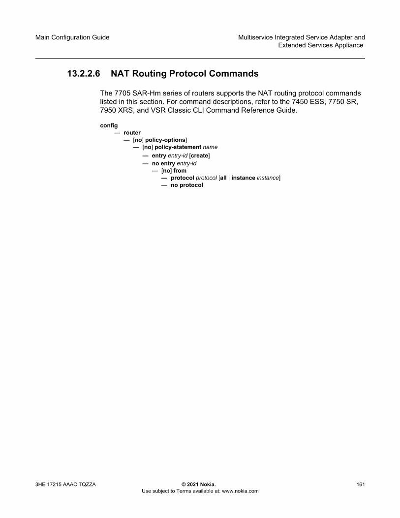
Main Configuration Guide Multiservice Integrated Service Adapter andExtended Services Appliance
3HE 17215 AAAC TQZZA © 2021 Nokia. Use subject to Terms available at: www.nokia.com
161
13.2.2.6 NAT Routing Protocol Commands
The 7705 SAR-Hm series of routers supports the NAT routing protocol commands listed in this section. For command descriptions, refer to the 7450 ESS, 7750 SR, 7950 XRS, and VSR Classic CLI Command Reference Guide.
config— router
— [no] policy-options]— [no] policy-statement name
— entry entry-id [create]— no entry entry-id
— [no] from— protocol protocol [all | instance instance]— no protocol

Multiservice Integrated Service Adapter and Extended Services Appliance
162
Main Configuration Guide
© 2021 Nokia. Use subject to Terms available at: www.nokia.com
3HE 17215 AAAC TQZZA
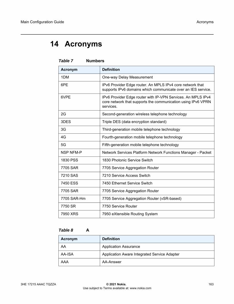
Main Configuration Guide Acronyms
3HE 17215 AAAC TQZZA © 2021 Nokia. Use subject to Terms available at: www.nokia.com
163
14 Acronyms
Table 7 Numbers
Acronym Definition
1DM One-way Delay Measurement
6PE IPv6 Provider Edge router. An MPLS IPv4 core network that supports IPv6 domains which communicate over an IES service.
6VPE IPv6 Provider Edge router with IP-VPN Services. An MPLS IPv4 core network that supports the communication using IPv6 VPRN services.
2G Second-generation wireless telephone technology
3DES Triple DES (data encryption standard)
3G Third-generation mobile telephone technology
4G Fourth-generation mobile telephone technology
5G Fifth-generation mobile telephone technology
NSP NFM-P Network Services Platform Network Functions Manager - Packet
1830 PSS 1830 Photonic Service Switch
7705 SAR 7705 Service Aggregation Router
7210 SAS 7210 Service Access Switch
7450 ESS 7450 Ethernet Service Switch
7705 SAR 7705 Service Aggregation Router
7705 SAR-Hm 7705 Service Aggregation Router (vSR-based)
7750 SR 7750 Service Router
7950 XRS 7950 eXtensible Routing System
Table 8 A
Acronym Definition
AA Application Assurance
AA-ISA Application Aware Integrated Service Adapter
AAA AA-Answer
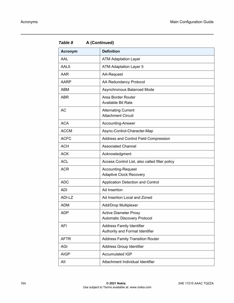
Acronyms
164
Main Configuration Guide
© 2021 Nokia. Use subject to Terms available at: www.nokia.com
3HE 17215 AAAC TQZZA
AAL ATM Adaptation Layer
AAL5 ATM Adaptation Layer 5
AAR AA-Request
AARP AA Redundancy Protocol
ABM Asynchronous Balanced Mode
ABR Area Border RouterAvailable Bit Rate
AC Alternating CurrentAttachment Circuit
ACA Accounting-Answer
ACCM Async-Control-Character-Map
ACFC Address and Control Field Compression
ACH Associated Channel
ACK Acknowledgment
ACL Access Control List, also called filter policy
ACR Accounting-RequestAdaptive Clock Recovery
ADC Application Detection and Control
ADI Ad Insertion
ADI-LZ Ad Insertion Local and Zoned
ADM Add/Drop Multiplexer
ADP Active Diameter ProxyAutomatic Discovery Protocol
AFI Address Family IdentifierAuthority and Format Identifier
AFTR Address Family Transition Router
AGI Address Group Identifier
AIGP Accumulated IGP
AII Attachment Individual Identifier
Table 8 A (Continued)
Acronym Definition

Main Configuration Guide Acronyms
3HE 17215 AAAC TQZZA © 2021 Nokia. Use subject to Terms available at: www.nokia.com
165
AIS Alarm Indication Signal
ALE Access-Loop-Encapsulation
ALG Application-Level Gateway
ALMP Auto-Learn-Mac-Protect
ALTO Application Layer Traffic Optimiser
AMI Alternate Mark Inversion
AN Association Number
AMO Any Mode of Operation
ANSI American National Standards Institute
ANCP Access Node Control Protocol
ANL Access Network Location
API Application Programming Interface
APN Access Point Name
Apipe ATM VLL
AP Access Point
APN Access Point Name
APS Automatic Protection Switching
AQP Application QoS Policies
ARFCN Absolute Radio-Frequency Channel Number
ARP Address Resolution Protocol
A/S Active/Standby
AS Autonomous System
ASAP Any Service Any Port
ASAM Advanced Services Access Manager
ASBR AS Boundary Routers
ASID Acct-Session-Id
ASM Any-Source Multicast
Table 8 A (Continued)
Acronym Definition

Acronyms
166
Main Configuration Guide
© 2021 Nokia. Use subject to Terms available at: www.nokia.com
3HE 17215 AAAC TQZZA
ASN Autonomous System Number
ASO Application Service Option
AT ATtention
ATM Asynchronous Transfer Mode
AVP Attribute Value Pair
Table 9 B
Acronym Definition
B-bit Beginning bit (first packet of a fragment)
BBF Broadband Forum
BC Bandwidth Constraint
BCB Backbone Core Bridge
BCG Burst Control Group
BCP Bridging Control Protocol
B-DA Backbone Destination MAC Address
BEB Backbone Edge Bridge
BECN Backward Explicit Congestion Notification
Bellcore Bell Communications Research
BER Basic Encoding Rules
BER Bit Error Rate
BERT Bit Error Rate Test
BFD Bi-directional Forwarding Detection
BGP Border Gateway Protocol
BITS Building Integrated Timing SourceBuilding Integrated Timing Supply
B-MAC Backbone source and destination MAC address fields defined in the 802.1ah provider MAC encapsulation header
BMCA Best Master Clock Algorithm
Table 8 A (Continued)
Acronym Definition

Main Configuration Guide Acronyms
3HE 17215 AAAC TQZZA © 2021 Nokia. Use subject to Terms available at: www.nokia.com
167
BMU Broadcast, Multicast, and Unknown traffic
BNG Broadband Network Gateway
BOF Boot Option File
BOOTP Bootstrap Protocol
BPDU Bridge Protocol Data Unit
BPG or BPGRP Bundle Protection Group
BR Border Router
BRAS Broadband Remote Access Server
BRG Bridged Residential Gateway
BSA Broadband Service Aggregator
BSAN Broadband Service Access Node
BSC Base Station Controller
BSD Berkeley Software Distribution
BSM Basic Subscriber Management
BSR Bootstrap RouterBroadband Service Router
BTS Base Transceiver Station
BTSH BGP TTL Security Hack
BTV Broadcast Television
BUM Broadcast, Unicast unknown and Multicast
B-VPLS Backbone VPLS
BVID Backbone VLAN ID
BVPLS See B-VPLS
BVS Business VPN Service
BW Bandwidth
Table 9 B (Continued)
Acronym Definition
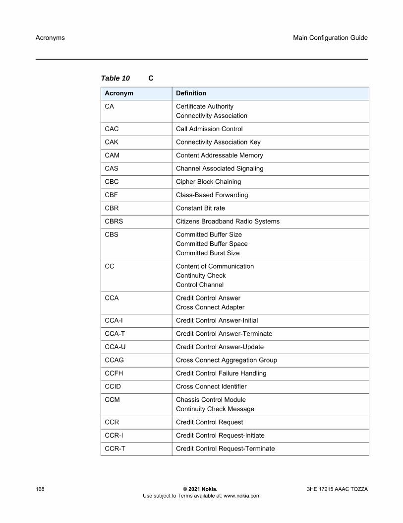
Acronyms
168
Main Configuration Guide
© 2021 Nokia. Use subject to Terms available at: www.nokia.com
3HE 17215 AAAC TQZZA
Table 10 C
Acronym Definition
CA Certificate AuthorityConnectivity Association
CAC Call Admission Control
CAK Connectivity Association Key
CAM Content Addressable Memory
CAS Channel Associated Signaling
CBC Cipher Block Chaining
CBF Class-Based Forwarding
CBR Constant Bit rate
CBRS Citizens Broadband Radio Systems
CBS Committed Buffer SizeCommitted Buffer SpaceCommitted Burst Size
CC Content of CommunicationContinuity CheckControl Channel
CCA Credit Control AnswerCross Connect Adapter
CCA-I Credit Control Answer-Initial
CCA-T Credit Control Answer-Terminate
CCA-U Credit Control Answer-Update
CCAG Cross Connect Aggregation Group
CCFH Credit Control Failure Handling
CCID Cross Connect Identifier
CCM Chassis Control ModuleContinuity Check Message
CCR Credit Control Request
CCR-I Credit Control Request-Initiate
CCR-T Credit Control Request-Terminate
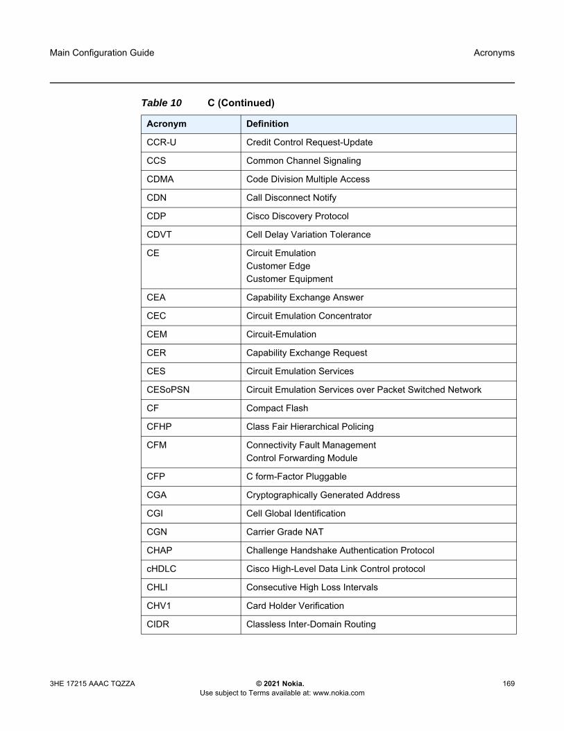
Main Configuration Guide Acronyms
3HE 17215 AAAC TQZZA © 2021 Nokia. Use subject to Terms available at: www.nokia.com
169
CCR-U Credit Control Request-Update
CCS Common Channel Signaling
CDMA Code Division Multiple Access
CDN Call Disconnect Notify
CDP Cisco Discovery Protocol
CDVT Cell Delay Variation Tolerance
CE Circuit EmulationCustomer EdgeCustomer Equipment
CEA Capability Exchange Answer
CEC Circuit Emulation Concentrator
CEM Circuit-Emulation
CER Capability Exchange Request
CES Circuit Emulation Services
CESoPSN Circuit Emulation Services over Packet Switched Network
CF Compact Flash
CFHP Class Fair Hierarchical Policing
CFM Connectivity Fault ManagementControl Forwarding Module
CFP C form-Factor Pluggable
CGA Cryptographically Generated Address
CGI Cell Global Identification
CGN Carrier Grade NAT
CHAP Challenge Handshake Authentication Protocol
cHDLC Cisco High-Level Data Link Control protocol
CHLI Consecutive High Loss Intervals
CHV1 Card Holder Verification
CIDR Classless Inter-Domain Routing
Table 10 C (Continued)
Acronym Definition

Acronyms
170
Main Configuration Guide
© 2021 Nokia. Use subject to Terms available at: www.nokia.com
3HE 17215 AAAC TQZZA
CIR Committed Information Rate
CIST Common and Internal Spanning Tree
CKN Connectivity association Key Name
CLEI Common Language Equipment Identification
CLI Command Line Interface
CLLI Common Language Location Identifier
CLP Cell Loss Priority
CMA Compact Media Adapter
CMAC Customer MAC
CMP Certificate Management Protocol
CMTS Cable Modem Termination System
CO Central Office
CoA Change of Authorization
confed-EBGP Confederation External BGP
CoS Class of Service
CP Connection-Profile
CPE Customer Premises Equipment
Cpipe Circuit Emulation Pipe
CPM Control Processing Module
CP/SFM Control Processor/Switch Fabric Module
CPU Control Processing Unit
CRC Cyclic Redundancy Check
CRC-32 32-bit Cyclic Redundancy Check
CRL Certificate Revocation List
CRMF Certificate Request Message Format
CRON a time-based scheduling service (from chronos = time)
CRP Candidate RP
Table 10 C (Continued)
Acronym Definition

Main Configuration Guide Acronyms
3HE 17215 AAAC TQZZA © 2021 Nokia. Use subject to Terms available at: www.nokia.com
171
CSC Carrier Supporting Carrier
CSC-CE Carrier Supporting Carrier – Customer Edge Router
CSC-PE Carrier Supporting Carrier – Provider Edge Router
CSF Client Signal Fail
CSM Control and Switching Module
CSN Complete Sequence Number
CSNP Complete Sequence Number PDU
CSP Cloud Service Provider
CSPF Constraint-based Shortest Path First
CSR Cellsite Service Router
CSU Channel Service Unit
CSV Certificate Status Verification
C-TAG Customer VLAN tag
CV Connection VerificationCustomer VLAN (tag)
CVID Customer VLAN ID
CW Control Word
Table 11 D
Acronym Definition
DACS Digital Access Cross-connect System
DAD Duplicate Address Detection
DA/FAN Distribution Automation/Field Area Network
DC Direct Current
DCCA Diameter Credit Control Application
DCD Data Carrier Detect
DCE Data Circuit-terminating EquipmentData Communications Equipment
Table 10 C (Continued)
Acronym Definition

Acronyms
172
Main Configuration Guide
© 2021 Nokia. Use subject to Terms available at: www.nokia.com
3HE 17215 AAAC TQZZA
DCI Client Defect Clear IndicationData Center Interconnect
DCP Distributed CPU Protection
DCSC Digital Channel Switch Capable
DDM Digital Diagnostics Monitoring
DDMAP Downstream Detailed Mapping
DDoS Distributed DoS
DDP Dynamic Data Persistency
DDR Dial On Demand Routing
DDS Dynamic Data Services
DE Discard-Eligible
DEM Dynamic Experience Management
DES Data Encryption Standard
DEI Drop Eligibility Indicator
DER Distinguished Encoding Rules
DF Delivery FunctionDo not Fragment
DF Designated Forwarder
DH Diffie-Hellman
DHB Decimal, Hexadecimal, or Binary
DHCP Dynamic Host Configuration Protocol
DHCPv6 Dynamic Host Configuration Protocol for IPv6
DHT Distributed Hash Protocol
DLC Data Link Control
DLCI Data Link Connection Identifier
DLCMI Data Link Connection Management Interface
DM Delay Measurement
DMM Delay Measurement Message
Table 11 D (Continued)
Acronym Definition

Main Configuration Guide Acronyms
3HE 17215 AAAC TQZZA © 2021 Nokia. Use subject to Terms available at: www.nokia.com
173
DMR Delay Measurement Reply
DN Domain Name
DNAT Destination-based Network Address Translation
DNS Domain Name System
DNSSEC DNS Security
DNU Do Not Use
DOD Downstream On Demand
DORA Discovery/Offer/Request/Ack
DoS Denial of Service
dot1p IEEE 802.1p bits, in Ethernet or VLAN ingress packet headers, used to map traffic to up to eight forwarding classes
dot1q IEEE 802.1q encapsulation for Ethernet interfaces
DPA Disconnect Peer Answer
DPD Dead Peer Detection
DPI Digital Program Insertion
DPL Delegated Prefix Length
DPLL Digital Phase Locked Loop
DPR Disconnect Peer Request
DPV Designated Priority Vector
DR Designated Router
DRA Diameter Routing Agent
DRM Digital Rights Management
DSA Digital Signal AlgorithmDirect System Agent
DSAP Destination Service Access Point
DSC Dynamic Services Controller
DSCP Differentiated Services Code Point
DSFS Data SAP Forwarding State
Table 11 D (Continued)
Acronym Definition

Acronyms
174
Main Configuration Guide
© 2021 Nokia. Use subject to Terms available at: www.nokia.com
3HE 17215 AAAC TQZZA
DSL Digital Subscriber Line
DSLAM Digital Subscriber Line Access Multiplexer
DSM Distributed Subscriber Management
DSMAP Downstream Mapping
DSS Digital Signature Standard
DTC DHCP Transaction Cache
DTD Dynamic Topology Discovery
DTE Data Terminal Equipment
DTP Digital Trunking Protocol
DU Downstream Unsolicited
DUID DHCP Unique Identifier
DUS Do not Use for Synchronization
DVB Digital Video Broadcasting
DVMRP Distance Vector Multicast Routing Protocol
DWA Device Watchdog Answer
DWDM Dense Wavelength Division Multiplexing
DWR Device Watchdog Request
Table 12 E
Acronym Definition
e2e End-to-End
EAP Extensible Authentication Protocol
EAPOL EAP over LAN
E-bit Ending bit (last packet of a fragment)
eBGP or EBGP External Border Gateway Protocol
EBS Error Burst Size
E-BSR Elected BSR
Table 11 D (Continued)
Acronym Definition

Main Configuration Guide Acronyms
3HE 17215 AAAC TQZZA © 2021 Nokia. Use subject to Terms available at: www.nokia.com
175
ECID Emulated Circuit Identifiers
ECGI E-UTRAN Cell Global Identifier
ECMP Equal Cost Multipath
ECT Equal Cost Tree
EEPROM Electronically Erasable Programmable Read-Only Memory
EFCI Explicit Forward Congestion Indication
EFEC Enhanced Forward Error Correction
EFH Extended Failure Handling
EFM Ethernet in the First Mile
EGP Exterior Gateway Protocol
EHS Event Handling System
EIC Ethernet Interface Counters
EIGRP Enhanced Interior Gateway Routing Protocol
EIR Excess Information Rate
E-LAN Ethernet Local Area Network
eLER Egress Label Edge Router
E-Line Ethernet Virtual Private Line
eLMI Ethernet Local Management Interface
EMR Efficient Multicast Replication
EMS Enhanced Subscriber Management
eNB Evolved Node B
EOOL End of Options List
EOM End-of-Message
EOR End-of-RIB
EPC Evolved Packet Core
EPD Ethernet Port Damping
Epipe Ethernet PipeEthernet VLL
Table 12 E (Continued)
Acronym Definition
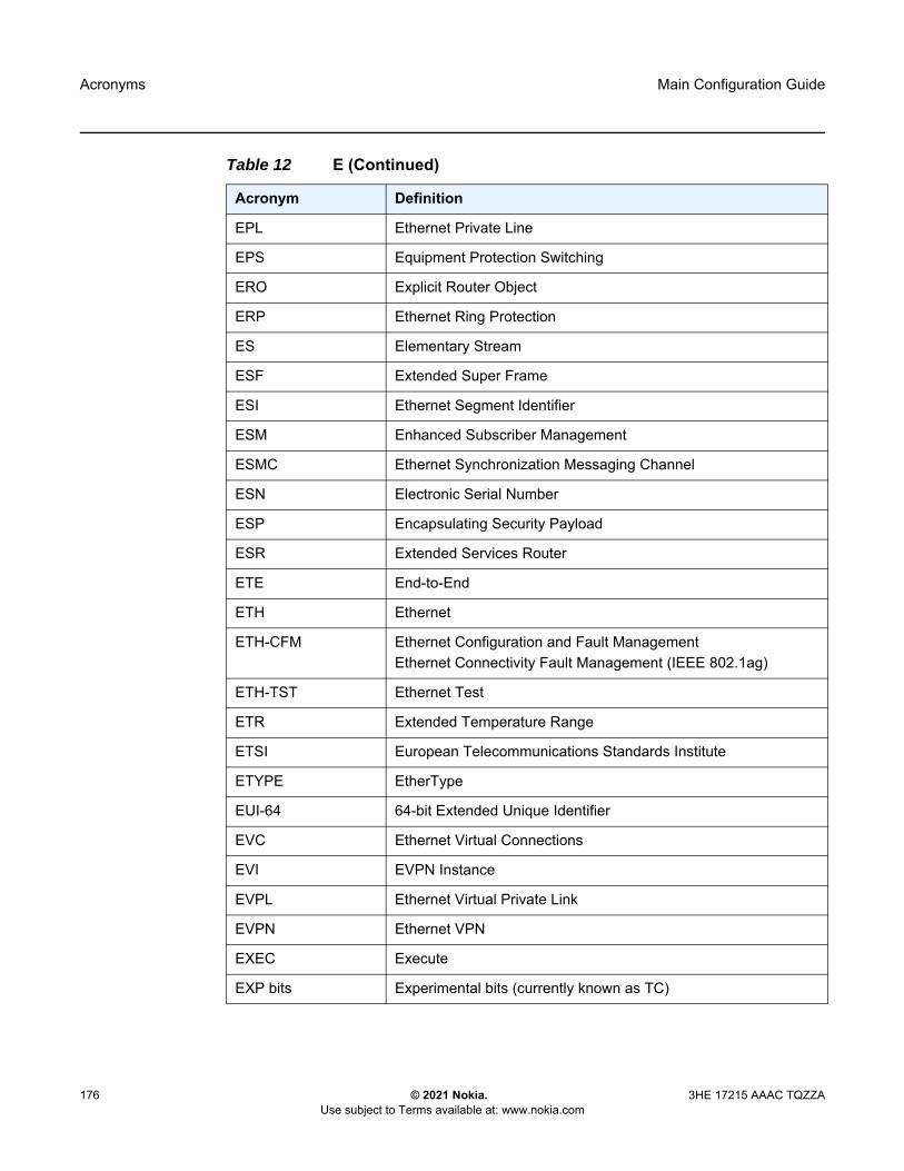
Acronyms
176
Main Configuration Guide
© 2021 Nokia. Use subject to Terms available at: www.nokia.com
3HE 17215 AAAC TQZZA
EPL Ethernet Private Line
EPS Equipment Protection Switching
ERO Explicit Router Object
ERP Ethernet Ring Protection
ES Elementary Stream
ESF Extended Super Frame
ESI Ethernet Segment Identifier
ESM Enhanced Subscriber Management
ESMC Ethernet Synchronization Messaging Channel
ESN Electronic Serial Number
ESP Encapsulating Security Payload
ESR Extended Services Router
ETE End-to-End
ETH Ethernet
ETH-CFM Ethernet Configuration and Fault ManagementEthernet Connectivity Fault Management (IEEE 802.1ag)
ETH-TST Ethernet Test
ETR Extended Temperature Range
ETSI European Telecommunications Standards Institute
ETYPE EtherType
EUI-64 64-bit Extended Unique Identifier
EVC Ethernet Virtual Connections
EVI EVPN Instance
EVPL Ethernet Virtual Private Link
EVPN Ethernet VPN
EXEC Execute
EXP bits Experimental bits (currently known as TC)
Table 12 E (Continued)
Acronym Definition

Main Configuration Guide Acronyms
3HE 17215 AAAC TQZZA © 2021 Nokia. Use subject to Terms available at: www.nokia.com
177
Table 13 F
Acronym Definition
FAP Femto Access Point
FASTE FastE SFP type
FC Forwarding Class
FCC Fast Channel Change
FCS Frame Check Sequence
FD Frame DelayFrequency Diversity
FDB Forwarding Database
FDDI Fiber Distributed Data Interface
FDI Forward Defect Indication
FDL Facilities Data Link
FDR Frame Delay Range
FEAC Far-End Alarm and Control
FEBE Far-End Block Error
FEC Forwarding Equivalence ClassForward Error Correction
FECN Forward Explicit Congestion Notification
FENT Fast Ethernet Network Termination
FEPL Far-End Protection-Line
FF Fixed Filter
FIB Forwarding Information Base
FID Forwarding ID
FIFO First In, First Out
FIN Finish Bit Set
FIPS Federal Information Processing Standards
FIR Fair Information Rate
FIX Financial Information eXchange
FLR Frame Loss Ratio

Acronyms
178
Main Configuration Guide
© 2021 Nokia. Use subject to Terms available at: www.nokia.com
3HE 17215 AAAC TQZZA
FOM Figure of Merit
FPE Forwarding Path Extension
FPGA Field Programmable Gate Array
Fpipe Frame-Relay VLL
F-PLMN Forbidden PLMN
FPP Floor Packet Percentage
FPRI Fine-grained Priority
FQDN Fully Qualified Domain Name
FQF Fully Qualified Flows
FR Frame Relay
FRG Fragmentation bit
FRR Fast Reroute
FSG Fate Sharing Group
FSM Finite State Machine
FTN FEC-to-NHLFE
FTP File Transfer protocol
FTTH Fiber to the Home
Table 14 G
Acronym Definition
G-ACh Generic Associated Channel
GAL Generic ACH Label
GARP Gratuitous ARP
GBMAC Group BMAC
GBR Guaranteed Bit Rate
GFEC G.709 FEC
GFP Generic Framing Procedure
Table 13 F (Continued)
Acronym Definition

Main Configuration Guide Acronyms
3HE 17215 AAAC TQZZA © 2021 Nokia. Use subject to Terms available at: www.nokia.com
179
GGSN Gateway GPRS Support Node
GID Global-ID
GigE Gigabit Ethernet
GIGE GigE SFP type
GIGX GigX SFP
gLSP GMPLS LSP
GMPLS Generalized Multi-Protocol Label Switching
GMR IGMP Group-specific Membership Report
GMRE GMPLS Routing Engine
GNSS Global Navigation Satellite System
GOP Group of Pictures
GPON Gigabit Passive Optical Network
GPRS General Packet Radio Service
GPS Global Positioning System
GR Graceful RestartGuaranteed Restoration
GRACE Graceful restart
GRE Generic Routing Encapsulation
GRT Global Routing Table
GSMP General Switch Management Protocol
GSU Granted Service Unit
GTP GPRS Tunneling Protocol
GUA Global Unicast Address
GVRP GARP VLAN Registration Protocol
Table 14 G (Continued)
Acronym Definition
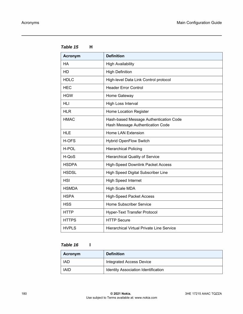
Acronyms
180
Main Configuration Guide
© 2021 Nokia. Use subject to Terms available at: www.nokia.com
3HE 17215 AAAC TQZZA
Table 15 H
Acronym Definition
HA High Availability
HD High Definition
HDLC High-level Data Link Control protocol
HEC Header Error Control
HGW Home Gateway
HLI High Loss Interval
HLR Home Location Register
HMAC Hash-based Message Authentication CodeHash Message Authentication Code
HLE Home LAN Extension
H-OFS Hybrid OpenFlow Switch
H-POL Hierarchical Policing
H-QoS Hierarchical Quality of Service
HSDPA High-Speed Downlink Packet Access
HSDSL High Speed Digital Subscriber Line
HSI High Speed Internet
HSMDA High Scale MDA
HSPA High-Speed Packet Access
HSS Home Subscriber Service
HTTP Hyper-Text Transfer Protocol
HTTPS HTTP Secure
HVPLS Hierarchical Virtual Private Line Service
Table 16 I
Acronym Definition
IAD Integrated Access Device
IAID Identity Association Identification

Main Configuration Guide Acronyms
3HE 17215 AAAC TQZZA © 2021 Nokia. Use subject to Terms available at: www.nokia.com
181
IANA Internet Assigned Numbers Authority
IA-NA Identity Association for Non-Temporary Addresses
IA-PD Identity Association for Prefix Delegation
IAPP Inter Access Point Protocol
IBGP Interior Border Gateway Protocol
IBN Isolated Bonding Network
IB-RCC In-Band Ring Control Connection
ICAP Internet Content Adaptation Protocol
ICB Inter-Chassis Backup
ICC Inter-Card Communication
ICCID Integrated Circuit Card Identifier
ICCN Incoming Call Connected
ICK Integrity Connection Value Key
ICL Inter-Chassis Link
ICMP Internet Control Message Protocol
ICMPv6 Internet Control Message Protocol for IPv6
ICP IMA Control Protocol
ICRQ Incoming Call Request
ICV Integrity Connection ValueIntegrity Check Value
IDi Identification Indicator (an IKEv2 protocol payload)
IDr Identification Responder
IDS Intrusion Detection System
IDU InDoor Unit
IEEE Institute of Electrical and Electronics Engineers
I-ES Interconnect Ethernet-Segment
IES Internet Enhanced Service
IETF Internet Engineering Task Force
Table 16 I (Continued)
Acronym Definition

Acronyms
182
Main Configuration Guide
© 2021 Nokia. Use subject to Terms available at: www.nokia.com
3HE 17215 AAAC TQZZA
IFDV InterFrame Delay Variation
IFF Inbound FEC Filtering
IFG Inter-Frame Gap
IGD Internet Gateway Device
IGH Interface Group Handler
IGMP Internet Group Management Protocol
IGP Interior Gateway Protocol
IGRP Interior Gateway Routing Protocol
IID Instance ID
IIH IS-IS Hello
IIN Issuer Identification Number
IKE Internet Key Exchange
iLDP Interface Label Distribution Protocol
ILER Ingress Label Edge Router
ILM Incoming Label Map
ILMI Integrated Local Management Interface
IMA Inverse Multiplexing over ATM
IME Interface Management Entity
IMEI International Mobile Equipment Identity
IMEISV International Mobile Equipment Identity and its Software Version
IMET Inclusive Multicast Ethernet Tag
IMM Integrated Media Module
IMPM Ingress Multicast Path Management
IMSI International Mobile Subscriber Identification
IOM Input/Output Module
IOTA Internet Over the Air (CDMA)
IP Internet Protocol
Table 16 I (Continued)
Acronym Definition

Main Configuration Guide Acronyms
3HE 17215 AAAC TQZZA © 2021 Nokia. Use subject to Terms available at: www.nokia.com
183
IP-CAN IP Connectivity Access Network
IPCC IP Communication ChannelIP Control Channel
IPCP Internet Protocol Control Protocol
IPFIX IP Flow Information Export
IPG Inter-Packet Gap
Ipipe IP PipeIP Interworking VLL
IPL IP Length
I-PMSI Inclusive Provider Multicast Service Interface
IPOE IP over Ethernet
IPS Intrusion Prevention System
IPsec IP Security
IPTV Internet Protocol Television
IP-VPN Internet Protocol Virtual Private Network
IRB Integrated Routing and Bridging
IRI Intercept Related Information
ISA Integrated Service Adapter
ISA-AA Integrated Service Adapter - Application Assurance
ISAKMP Internet Security Association and Key Management Protocol
ISAM Intelligent Services Access Manager
ISID I-component Service IDI-Service Instance Identifier
IS-IS Intermediate System to Intermediate System
ISO International Organization for Standardization
ISP Internet Service Provider
ISSU In-Service Software Upgrade
IST Internal Spanning Tree
Table 16 I (Continued)
Acronym Definition

Acronyms
184
Main Configuration Guide
© 2021 Nokia. Use subject to Terms available at: www.nokia.com
3HE 17215 AAAC TQZZA
I-TAG Service Instance TAG
ITU-T International Telecommunications Union - Telecommunications
IWF Interworking Function
Table 17 J
Acronym Definition
JID JabberID
JOLT Java OnLine Transactions
JP Join Prune
Table 18 K
Acronym Definition
KAT Keepalive Timer
KPI Key Performance Indicators
Table 19 L
Acronym Definition
L2TP Layer 2 Tunneling Protocol
LA Location Area
LAA Local Address Assignment
LAC L2TP Access Concentrator
LACP Link Aggregation Control Protocol
LAG Link Aggregation Group
LAI Local Area Identity
L-AIS Line Alarm Indication Signal
LAN Local Area Network
LAND Local Area Network Denial
Table 16 I (Continued)
Acronym Definition
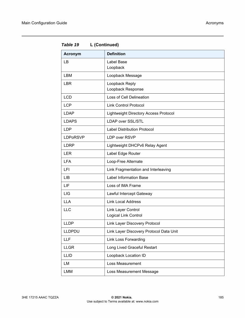
Main Configuration Guide Acronyms
3HE 17215 AAAC TQZZA © 2021 Nokia. Use subject to Terms available at: www.nokia.com
185
LB Label BaseLoopback
LBM Loopback Message
LBR Loopback ReplyLoopback Response
LCD Loss of Cell Delineation
LCP Link Control Protocol
LDAP Lightweight Directory Access Protocol
LDAPS LDAP over SSL/STL
LDP Label Distribution Protocol
LDPoRSVP LDP over RSVP
LDRP Lightweight DHCPv6 Relay Agent
LER Label Edge Router
LFA Loop-Free Alternate
LFI Link Fragmentation and Interleaving
LIB Label Information Base
LIF Loss of IMA Frame
LIG Lawful Intercept Gateway
LLA Link Local Address
LLC Link Layer ControlLogical Link Control
LLDP Link Layer Discovery Protocol
LLDPDU Link Layer Discovery Protocol Data Unit
LLF Link Loss Forwarding
LLGR Long Lived Graceful Restart
LLID Loopback Location ID
LM Loss Measurement
LMM Loss Measurement Message
Table 19 L (Continued)
Acronym Definition

Acronyms
186
Main Configuration Guide
© 2021 Nokia. Use subject to Terms available at: www.nokia.com
3HE 17215 AAAC TQZZA
LMI Local Management Interface
LMR Loss Measurement Response
LMP Link Management Protocol
LNS L2TP Network Server
LOC Loss of Continuity
LODS Link Out of Delay Synchronization
LOF Loss of Frame
LOP Loss of Packets
LOS Loss of Signal
LoT Loss of Transmission
LPM Longest Prefix Match
LPN Label per Next hop
LPP Label per Prefix
LPT Logical Port Type
LPT-S Logical Port Type Subtype
LPT-V Logical Port Type Value
LQR Link Quality Report
LR Label Route
LSA Link-State Advertisement
LSB Least Significant Bit
LSDB Link-Sate Database
LSN Large-Scale NAT
LSP Link-State PDU (for IS-IS)Label-Switched Path
LSR Link-state RequestLabel Switch Router
LSU Link-State Update
LT Linktrace
Table 19 L (Continued)
Acronym Definition

Main Configuration Guide Acronyms
3HE 17215 AAAC TQZZA © 2021 Nokia. Use subject to Terms available at: www.nokia.com
187
LTE Line Termination EquipmentLong Term Evolution
LTM Linktrace Message
LTN LSP ID to NHLFE
LTR Linktrace ReplyLinktrace Response
LTS L2TP Tunnel Switching
LUB Limit Unused Bandwidth
LUDB Local User Data Base
Table 20 M
Acronym Definition
MA Maintenance Association
MA-ID Maintenance Association Identifier
MAC Media Access Control
MACsec Media Access Control Security
MAF Management Access Filter
MAM Maximum Allocation Model
MAN Metropolitan Area Network
MAR Mobile Aggregation Router
MAT MAC Address translation
MBB Make-Before-Break
MBGP Border Gateway Protocol with Multi-protocol extensions
MBH Mobile BackHaul
MBR Maximum Bit Rate
MBS Maximum Buffer SizeMaximum Burst SizeMedia Buffer Space
Table 19 L (Continued)
Acronym Definition
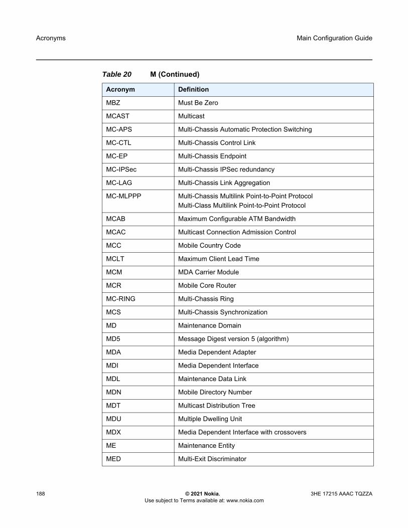
Acronyms
188
Main Configuration Guide
© 2021 Nokia. Use subject to Terms available at: www.nokia.com
3HE 17215 AAAC TQZZA
MBZ Must Be Zero
MCAST Multicast
MC-APS Multi-Chassis Automatic Protection Switching
MC-CTL Multi-Chassis Control Link
MC-EP Multi-Chassis Endpoint
MC-IPSec Multi-Chassis IPSec redundancy
MC-LAG Multi-Chassis Link Aggregation
MC-MLPPP Multi-Chassis Multilink Point-to-Point ProtocolMulti-Class Multilink Point-to-Point Protocol
MCAB Maximum Configurable ATM Bandwidth
MCAC Multicast Connection Admission Control
MCC Mobile Country Code
MCLT Maximum Client Lead Time
MCM MDA Carrier Module
MCR Mobile Core Router
MC-RING Multi-Chassis Ring
MCS Multi-Chassis Synchronization
MD Maintenance Domain
MD5 Message Digest version 5 (algorithm)
MDA Media Dependent Adapter
MDI Media Dependent Interface
MDL Maintenance Data Link
MDN Mobile Directory Number
MDT Multicast Distribution Tree
MDU Multiple Dwelling Unit
MDX Media Dependent Interface with crossovers
ME Maintenance Entity
MED Multi-Exit Discriminator
Table 20 M (Continued)
Acronym Definition

Main Configuration Guide Acronyms
3HE 17215 AAAC TQZZA © 2021 Nokia. Use subject to Terms available at: www.nokia.com
189
MEF Metro Ethernet Forum
MEG Maintenance Entity Group
MEP Maintenance Association EndpointMaintenance Endpoint
MEP-ID Maintenance Association Endpoint Identifier
MFD Mean Frame Delay
MFIB Multicast Forwarding Information Base
MHD Multi-Homed Device
MHF MIP Half Function
MHN Multi-Homed Network
MHV Mirror Header Version
MI Member Identifier
MIB Management Information Base
MIMO Multiple Input/Multiple Output
MIMP MC-IPSec Mastership Protocol
MIP Maintenance Domain Intermediate PointMaintenance Intermediate Points
MIR Minimum Information Rate
MKA MACSec Key Agreement
MLD Multicast Listener Discovery
MLDP Multicast Label Distribution Protocol
MLFR Multi-Link Frame Relay
MLPPP Multilink Point-to-Point Protocol
MME Mobility Management Entity
MLT Multi-Link Trunk
MMRP Multiple MAC Registration Protocol
MNC Mobile Network Code
MNO Mobile Network Operator
Table 20 M (Continued)
Acronym Definition

Acronyms
190
Main Configuration Guide
© 2021 Nokia. Use subject to Terms available at: www.nokia.com
3HE 17215 AAAC TQZZA
MOP Maintenance Operational Procedure
MOS Mean Opinion Score
MP Merge PointMultilink Protocol
MPBGP Multi-Protocol Border Gateway Protocol
MPLS Multiprotocol Label Switching
MPLS-TP Multiprotocol Label Switching - Transport Profile
MPLSCP Multiprotocol Label Switching Control Protocol
MPTS Multi-Program Transport Stream
MRAI Minimum Route Advertisement Interval
MRIB Multicast Routing Information Base
MRP Multi-service Route Processor
MRRU Maximum Received Reconstructed Unit
MRU Maximum Receive Unit
MSAN Multi-Service Access Node
MSAP Managed Service Access Point
MSB Most Significant Bit
MSCC Multiple Services Credit Control
MSDP Multicast Source Discovery Protocol
MSDU MAC Service Data Unit
MSFP Multicast Switch Fabric Plane
MSID Mobile Station Identifier
MSIN Mobile Subscriber Identification Number
MS-ISM Multi-Service Integrated Services Module
MSK Master Session Key
MS-PW Multi-Segment Pseudowire
MSR Mobile Service Router
Table 20 M (Continued)
Acronym Definition

Main Configuration Guide Acronyms
3HE 17215 AAAC TQZZA © 2021 Nokia. Use subject to Terms available at: www.nokia.com
191
MSS Multi-Service SiteMaximum Segment Size
MSTI Multiple Spanning Tree Instances
MSTP Multiple Spanning Tree Protocol
MSTV Microsoft Television
MTBF Mean Time Between Failures
MTSO Mobile Telephony Switching Office
MTTR Mean Time To Repair
MTU Multi-Tenant UnitMaximum Transmission Unit
M-VPLS Management Virtual Private Line Service
MVPN Multicast VPN
MVR Multicast VPLS Registration
MVRP Multiple VLAN Registration Protocol
Table 21 N
Acronym Definition
NAPT Network Address and Port Translation
NAS Network Access Server
NAT Network Address Translation
NBMA Non-Broadcast Multiple Access network
NBNS NetBios Name Server
NDF Non-Designated Forwarder
NET Network Entity Title
NETCONF Network Configuration Protocol
NG-MVPN Next-Generation Multicast VPN
NGE Network Group Encryption
NH Next-Hop
Table 20 M (Continued)
Acronym Definition
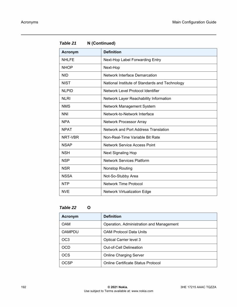
Acronyms
192
Main Configuration Guide
© 2021 Nokia. Use subject to Terms available at: www.nokia.com
3HE 17215 AAAC TQZZA
NHLFE Next-Hop Label Forwarding Entry
NHOP Next-Hop
NID Network Interface Demarcation
NIST National Institute of Standards and Technology
NLPID Network Level Protocol Identifier
NLRI Network Layer Reachability Information
NMS Network Management System
NNI Network-to-Network Interface
NPA Network Processor Array
NPAT Network and Port Address Translation
NRT-VBR Non-Real-Time Variable Bit Rate
NSAP Network Service Access Point
NSH Next Signaling Hop
NSP Network Services Platform
NSR Nonstop Routing
NSSA Not-So-Stubby Area
NTP Network Time Protocol
NVE Network Virtualization Edge
Table 22 O
Acronym Definition
OAM Operation, Administration and Management
OAMPDU OAM Protocol Data Units
OC3 Optical Carrier level 3
OCD Out-of-Cell Delineation
OCS Online Charging Server
OCSP Online Certificate Status Protocol
Table 21 N (Continued)
Acronym Definition

Main Configuration Guide Acronyms
3HE 17215 AAAC TQZZA © 2021 Nokia. Use subject to Terms available at: www.nokia.com
193
ODSA On-Demand Subnet Allocation
OF OpenFlow
OFS OpenFlow Switch
OID Object Identifier
OIF Outgoing Interfaces
OIL Outgoing Interface List
OLT Optical Line Termination
OMCR Oversubscribed Multi-Chassis Redundancy
ONT Optical Network Terminal
OOB Out-of-Band
OOP Out-of-Profile
OPDL Option Data structure List
OPS On-Path Support
ORF Outbound Route Filtering
ORR Optimal Route Reflection
OS Operating System
OSF Oversubscription Factor
OSI Open Systems Interconnection (reference model)
OSINLCP OSI Network Layer Control Protocol
OSPF Open Shortest Path First
OSPF-TE OSPF-Traffic Engineering (extensions)
OSS Operations Support System
OTASP Over the Air Services Provisioning (CDMA)
OTN Optical Transport Network
OTU Optical Transport Unit
OWAMP One-Way Active Measurement Protocol
OXC Optical Cross-connect
Table 22 O (Continued)
Acronym Definition

Acronyms
194
Main Configuration Guide
© 2021 Nokia. Use subject to Terms available at: www.nokia.com
3HE 17215 AAAC TQZZA
Table 23 P
Acronym Definition
P2MP Point-to-Multipoint
PAA PDN Address Allocation
PADI PPPoE Active Discovery Initiation
PADO PPPoE Active Discovery Offer
PADR PPPoE Active Discovery Request
PADS PPPoE Active Discovery Session-confirmation
PADT PPPoE Active Discovery Terminate
PAE Port Authentication Entities
PAGP Port Aggregation Protocol
PAP Password Authentication Protocol
PASTE Provider Architecture for Differentiated Services and Traffic Engineering
PBB Provider Backbone Bridging
PBF Policy-Based Forwarding
PBO Packet-Byte-Offset
PBR Policy-Based Routing
PBT Port-Based Timestamping
PCC Path Computation Element Client
PCC Policy and Charging Control
PCE Path Computation Element
PCEF Policy and Charging Enforcement Function
PCEP Path Computation Element Protocol
PCM Pulse Code Modulation
PCO Protocol Configuration Options
PCP Priority Code Point
PCR Peak Cell RateProprietary Clock Recovery
PCRF Policy and Rule Charging Function

Main Configuration Guide Acronyms
3HE 17215 AAAC TQZZA © 2021 Nokia. Use subject to Terms available at: www.nokia.com
195
PDN Packet Data Network
PDP Packet Data Protocol
PDU Protocol Data Units
PDV Packet Delay Variation
PE Provider Edge Router
PFC Protocol Field Compression
PFS Perfect Forward Secrecy
PFSG Pool Fate Sharing Group
PHB Per-Hop Behavior
PHP Penultimate Hop Popping
PHY Physical layer
PIC Prefix Independent Convergence
PID Packet IdentifierProtocol Identifier
PIM Protocol Independent Multicast
PIM-DM Protocol Independent Multicast-Dense Mode
PIM-SM Protocol Independent Multicast – Sparse Mode
PIN Personal Identification Number
PIP Picture-in-Picture
PIR Peak Information Rate
PKI Public Key Infrastructure
PLMN Public Land Mobile Network
PLR Point of Local Repair
PMSI P-Multicast Service Interface
PMSTP Provider Multi-Instance Spanning Tree Protocol
PMT Program Map Table
PN Packet Number
POA Program Off Air
Table 23 P (Continued)
Acronym Definition

Acronyms
196
Main Configuration Guide
© 2021 Nokia. Use subject to Terms available at: www.nokia.com
3HE 17215 AAAC TQZZA
POI Purge Originator Identification
PON Passive Optical Network
POP Points of Presence
POS Packet over SONET
PPID Payload Protocol Identifier
PPP Point-to-Point Protocol
PPPOE Point-to-Point Protocol over Ethernet
PPS Packets per Second
PPTP Point-to-Point Tunneling Protocol
PRC Path Restoration CombinedPrimary Reference Clock
PRF Pseudorandom Function
PRI Packet Priority
PSB Path State Block
PSC Protection Switching Coordination
PSCP Programmable Subscriber Configuration Policy
PSD Protection Switching Duration
PSI Payload Structure Identifier
PSK Pre-Shared Key
PSM Peer State Machine
PSN Packet-Switched Network
PSNP Partial Sequence Number PDU
PTA PMSI Tunnel AttributePPP Termination Aggregation
PTB Packet Too Big
P-TMSI packet TMSI
PTP Performance Transparency ProtocolPrecision Time Protocol
Table 23 P (Continued)
Acronym Definition

Main Configuration Guide Acronyms
3HE 17215 AAAC TQZZA © 2021 Nokia. Use subject to Terms available at: www.nokia.com
197
PUK Personal Unblocking Code
PVC Permanent Virtual Circuit
PVCC Permanent Virtual Channel Connection
PVST Per VLAN STP
PW Pseudowire
PWE Pseudowire Emulation
PWE3 Pseudowire Emulation Edge-to-Edge
PXC Port Cross-Connect
Table 24 Q
Acronym Definition
Q.922 ITU-T Q-series Specification 922
QCI QoS Class Identifier
QL Quality Level
QoS Quality of Service
QPPB QoS Policy Propagation via BGP
QSFP Quad Small Form-factor Pluggable
Table 25 R
Acronym Definition
RAA Re-Authentication Answer
RADIUS Remote Authentication Dial In User Service
RAI Routing Area Identity
RAM Reporting and Analysis Manager
RAN Radio Access Network
R-APS Ring Automatic Protection Switching
RAR Re-Authentication Request
Table 23 P (Continued)
Acronym Definition

Acronyms
198
Main Configuration Guide
© 2021 Nokia. Use subject to Terms available at: www.nokia.com
3HE 17215 AAAC TQZZA
RC Result Code
RCO Routed Central Office
RD Route Distinguisher
RDI Remote Defect Indication
RDM Russian Doll Model
RDNSS Recursive DNS Server
RED Random Early Discard
RESV Reservation
RET Retransmission
RFD Route Flap Damping
RG Routed Gateway
RGW Residential Gateway
RIB Routing Information Base
RIP Routing Information Protocol
RNC Radio Network Controller
RNCV Ring Node Connectivity Verification
ROA Route Origin Authorization
RP Rendezvous Point
RPC Remote Procedure Call
RPA RP Address
RPF Reverse Path Forwarding
RPL Ring Protection Link
RPS Radio Protection Switching
RR Reporting ReasonRoute Reflector
RRC Radio Resource Control Protocol
RRO Record Route Object
Table 25 R (Continued)
Acronym Definition

Main Configuration Guide Acronyms
3HE 17215 AAAC TQZZA © 2021 Nokia. Use subject to Terms available at: www.nokia.com
199
RSA Rivest, Shamir, and Adleman (authors of the RSA encryption algorithm)
RSB Reservation State Block
RSC Return Sub-Code
RSCP Received Signal Code Power
RSHG Residential Split Horizon Group
RSSI Received Signal Strength Indicator
RSTP Rapid Spanning Tree Protocol
RSU Requested Service Unit
RSVP Resource Reservation Protocol
RSVP-TE Resource Reservation Protocol – Traffic Engineering
RT Receive/Transmit
RT-VBR Real-Time Variable Bit Rate
RTCP RTP Control Protocol
RTM Routing Table Manager
RTMP Real-Time Messaging Protocol
RTMPE Encrypted Real Time Messaging Protocol
RTMPT Tunneled Real Time Messaging Protocol
RTP Real-Time Transport Protocol
RTSP Real-Time Streaming Protocol
RVPLS Routed Virtual Private LAN Service
Table 26 S
Acronym Definition
S2L Source-to-leaf
S-A Source-Active
SA Security Association
SAA Service Assurance Agent
Table 25 R (Continued)
Acronym Definition

Acronyms
200
Main Configuration Guide
© 2021 Nokia. Use subject to Terms available at: www.nokia.com
3HE 17215 AAAC TQZZA
SAC State Advertisement Control
SAFI Subsequent Address Family Identifier
SAI Service Area IdentitySecure Association Identifier
SAII Source Access Individual IdentifierSource Attachment Individual Identifier
SAK Security Association Key
SAP Service Access PointSubscriber Access Point
SASE Stand Alone Synchronization Equipment
SAToP Structure-Agnostic TDM over Packet
SBAU Shared Buffer Average Utilization
SBR Source-Based Reroute
SBU Shared Buffer Utilization
SC Security Channel
SCI Secure Channel Identifier
SCP Secure Copy
SCR Sustained Cell Rate
SCTE Society of Cable Telecommunications Engineers
SCUR Session Charging with Unit Reservation
SD Signal DegradeSpace Diversity
SDH Synchronous Digital Hierarchy
SDN Software Defined Network
SDP Service Destination PointService Distribution Point
SE Shared Explicit
SecTAG Security TAG
SecY MAC Security Entity
Table 26 S (Continued)
Acronym Definition

Main Configuration Guide Acronyms
3HE 17215 AAAC TQZZA © 2021 Nokia. Use subject to Terms available at: www.nokia.com
201
SeGW Secure Gateway
SeND Secure Neighbor Discovery
SETS Synchronous Timing Equipment Subsystem
SF Signal Fail
SFF Small Form Factor
SFM Switch Fabric Module
SFP Small Form-factor Pluggable (transceiver)
SGSN Serving GPRS Support Node
SHA Secure Hash Algorithm
SHCV Subscriber Host Connectivity Verification
SHG Split Horizon Group
SI Strategic Industries
SID Segment ID
SIM Subscriber Identification Module
SIP Session Initiation Protocol
SIR Sustained Information Rate
SL Synthetic LossShort Length
SLA Service Level Agreement
SLAAC Stateless Address Auto-Configuration
SLARP Serial Line Address Resolution Protocol
SLIP Serial Line Internet Protocol
SLM Synthetic Loss Message
SLR Synthetic Loss Reply
SMGR Service Manager
SNAPT Source Network Address and Port Translation
SNCP Sub-Network Connection Protection
SNI Server Name Indicator
Table 26 S (Continued)
Acronym Definition

Acronyms
202
Main Configuration Guide
© 2021 Nokia. Use subject to Terms available at: www.nokia.com
3HE 17215 AAAC TQZZA
SNMP Simple Network Management Protocol
SNPA Subnetwork Point of Attachment
SNR Signal to Noise Ratio
SNTP Simple Network Time Protocol
SOAM Service OAM
SONET Synchronous Optical Network
SOO Site of Origin
SPB Shortest Path Bridging
SPBM Shortest Path Bridging MAC Mode
SPF Shortest Path First
SPI Security Parameter Index
S-PMSI Selective Provider Multicast Service Interface
SPT Shortest Path Tree
SR Segment RoutingService Router (7750 SR)
SRGB Segment Routing Global Block
SRLG Shared Risk Link Group
SRRP Subscriber Routed Redundancy Protocol
SR-MS Segment Routing Mapping Server
SR-TE Segment Routing Traffic Engineering
SSD Solid State Drive
SSH Secure Shell
SSL Secure Socket Layer
SSM Source-Specific MulticastSynchronization Status MessagesSynchronization Status Messaging
SSRC Synchronization Source
SSU System Synchronization UnitSynchronization Supply Unit
Table 26 S (Continued)
Acronym Definition
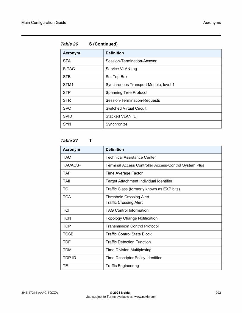
Main Configuration Guide Acronyms
3HE 17215 AAAC TQZZA © 2021 Nokia. Use subject to Terms available at: www.nokia.com
203
STA Session-Termination-Answer
S-TAG Service VLAN tag
STB Set Top Box
STM1 Synchronous Transport Module, level 1
STP Spanning Tree Protocol
STR Session-Termination-Requests
SVC Switched Virtual Circuit
SVID Stacked VLAN ID
SYN Synchronize
Table 27 T
Acronym Definition
TAC Technical Assistance Center
TACACS+ Terminal Access Controller Access-Control System Plus
TAF Time Average Factor
TAII Target Attachment Individual Identifier
TC Traffic Class (formerly known as EXP bits)
TCA Threshold Crossing AlertTraffic Crossing Alert
TCI TAG Control Information
TCN Topology Change Notification
TCP Transmission Control Protocol
TCSB Traffic Control State Block
TDF Traffic Detection Function
TDM Time Division Multiplexing
TDP-ID Time Descriptor Policy Identifier
TE Traffic Engineering
Table 26 S (Continued)
Acronym Definition
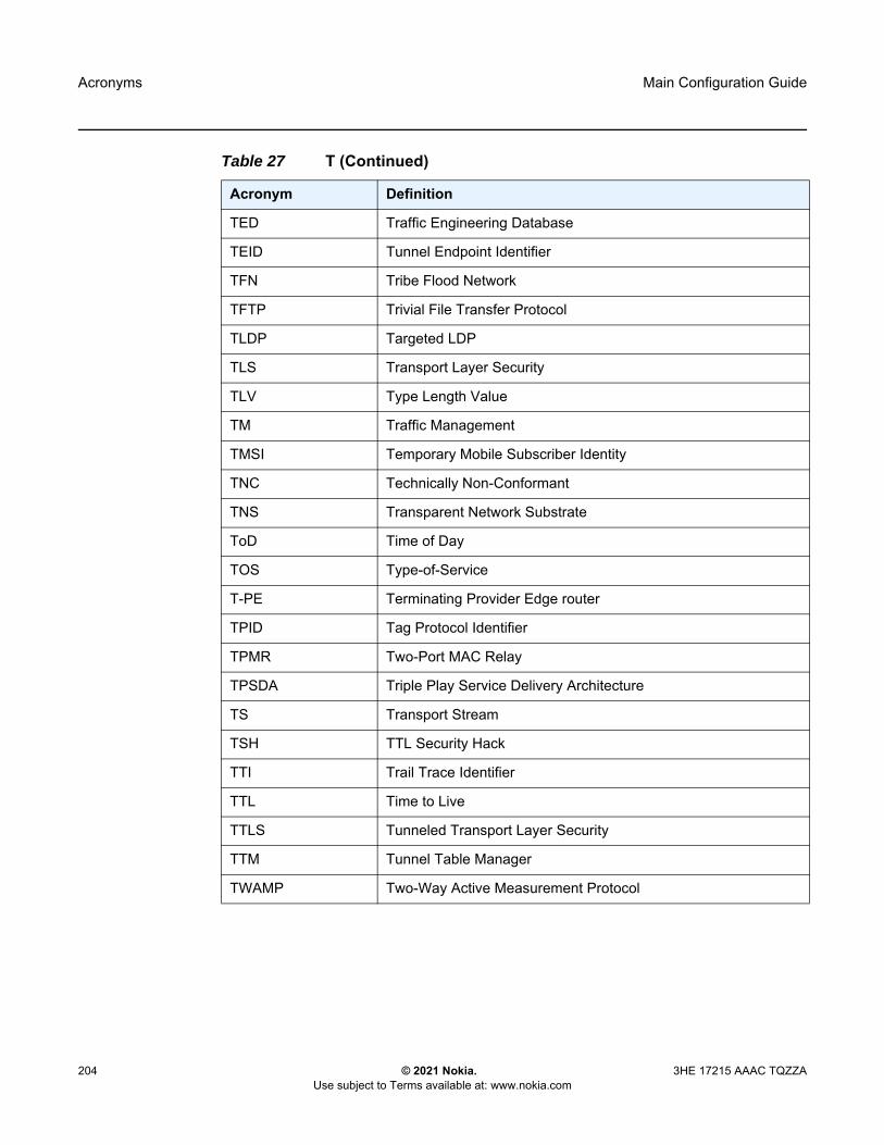
Acronyms
204
Main Configuration Guide
© 2021 Nokia. Use subject to Terms available at: www.nokia.com
3HE 17215 AAAC TQZZA
TED Traffic Engineering Database
TEID Tunnel Endpoint Identifier
TFN Tribe Flood Network
TFTP Trivial File Transfer Protocol
TLDP Targeted LDP
TLS Transport Layer Security
TLV Type Length Value
TM Traffic Management
TMSI Temporary Mobile Subscriber Identity
TNC Technically Non-Conformant
TNS Transparent Network Substrate
ToD Time of Day
TOS Type-of-Service
T-PE Terminating Provider Edge router
TPID Tag Protocol Identifier
TPMR Two-Port MAC Relay
TPSDA Triple Play Service Delivery Architecture
TS Transport Stream
TSH TTL Security Hack
TTI Trail Trace Identifier
TTL Time to Live
TTLS Tunneled Transport Layer Security
TTM Tunnel Table Manager
TWAMP Two-Way Active Measurement Protocol
Table 27 T (Continued)
Acronym Definition

Main Configuration Guide Acronyms
3HE 17215 AAAC TQZZA © 2021 Nokia. Use subject to Terms available at: www.nokia.com
205
Table 28 U
Acronym Definition
U-APS Unidirectional Automatic Protection Switching
UBR Unspecified Bit Rate
UDP User Datagram Protocol
UE User Equipment
UICC Universal Integrated Circuit Card — SIM card
ULD Uni-directional Link Detection
UMTS Universal Mobile Telecommunications System (3G)
UNI User-to-Network Interface
UPnP Universal Plug and Play
uRPF Unicast Reverse Path Forwarding
USIM Universal Subscriber Identity Module — application
USM User-based Security Model
USU Used Service Unit
UTC Coordinated Universal Time
Table 29 V
Acronym Definition
VACM View-based Access Control Model
VAS Value Added Service
VBO VE Block Offset
VBS VE Block Size
VC Virtual Circuit
VCC Virtual Channel Connection
VCCV Virtual Circuit Connectivity Verification
VCI Virtual Circuit Identifier
VCP Virtual Core Port
VE VPLS Edge

Acronyms
206
Main Configuration Guide
© 2021 Nokia. Use subject to Terms available at: www.nokia.com
3HE 17215 AAAC TQZZA
VE-ID VPWS Edge Identifier
V-GW Visited WLAN-GW
VID VLAN ID
VLAN Virtual LAN
VLL Virtual Leased Line
vMEPs Virtual MEPS
VNI VXLAN Network Identifier
VoD Video on Demand
VoIP Voice over IP
VP Virtual Path
VPC Virtual Path Connection
VPI Virtual Path Identifier
VPLS Virtual Private LAN Service
VPN Virtual Private Network
VPRN Virtual Private Routed Network
VPWS Virtual Private Wire Service
VQM Video Quality Monitoring
VRF Virtual Routing and Forwarding table
vRGW Virtual Residential Gateway
VRID Virtual Router ID
VRP Validated ROA Payload
VRRP Virtual Router Redundancy Protocol
VSA Vendor Specific Attribute
VSC Virtual Services Controller
VSD Virtual Services Directory
VSI-ID Virtual Switch Instance identifier
VSM Vendor-Specific MessageVersatile Service Module
Table 29 V (Continued)
Acronym Definition

Main Configuration Guide Acronyms
3HE 17215 AAAC TQZZA © 2021 Nokia. Use subject to Terms available at: www.nokia.com
207
VSO Vendor-Specific Option
VSP Virtual Services Platform
VT Validity TimeVirtual Trunk
VTEP VxLAN Tunnel Endpoint
VTP Virtual Trunk Protocol
VxLAN Virtual eXtensible Local Area Network
Table 30 W
Acronym Definition
WAC WiiMAX Access Controller
WAN Wide Area Network
WAP Wireless Application Protocol
WLAN Wireless Local Area Network
WLAN-GW WLAN Gateway
WPP Web Authentication ProtocolWireless Portal Protocol
WRED Weighted Random Early DetectionWeighted Random Early Discard
WRR Weighted-Round-Robin
Table 31 X
Acronym Definition
XML Extensible Markup Language
X.21 ITU-T X-series Recommendation 21
XMPP eXtensible Messaging and Presence Protocol
Table 29 V (Continued)
Acronym Definition

Acronyms
208
Main Configuration Guide
© 2021 Nokia. Use subject to Terms available at: www.nokia.com
3HE 17215 AAAC TQZZA
Main Configuration Guide Standards and Protocol Support
3HE 17215 AAAC TQZZA © 2021 Nokia. Use subject to Terms available at: www.nokia.com
209
15 Standards and Protocol SupportRefer to the software guides from the SR documentation suite for a list of standards and protocols supported by the SR OS. Use the features and descriptions outlined in this documentation set and in the relevant software release notes to identify the related standards and protocols that are supported by the 7705 SAR-Hm series.

Standards and Protocol Support
210
Main Configuration Guide
© 2021 Nokia. Use subject to Terms available at: www.nokia.com
3HE 17215 AAAC TQZZA

Customer Document and Product Support
Customer DocumentationCustomer Documentation Welcome Page
Technical SupportProduct Support Portal
Documentation FeedbackCustomer Documentation Feedback

© 2021 Nokia.3HE 17215 AAAC TQZZA
Copyright © 2022 FDOKUMEN