HM-DH30000U - JVC Pro
84
REC LINK POWER TIMER STOP/EJECT PLAY PULL-OPEN HM-DH30000U D-VHS DIGITAL RECORDER INSTRUCTIONS LPT0542-001A For Customer Use: Enter below the Model No. and Serial No. which are located on the rear of cabinet. Retain this information for future reference. Model No. Serial No. MTP NTSC CANCEL TIMER START STOP DATE PLAY REW < BACK REC STOP PAUSE FF > CH POWER TV/VCR C. RESET DBS . , ? ABC DEF GHI JKL MNO PQRS TUV WXYZ DAILY(M-F) AUX WEEKLY PROG. CHECK PROG. HS/STD/LS3 SP/EP SKIP SEARCH A/B DISPLAY ENTER/OSD A.MONITOR VCR TV CABLE/DBS 1 2 3 4 5 6 7 8 9 0 2 4 1 3 EXPRESS PROGRAMMING JOG/ SHUTTLE MENU OK NAVIGATION TV CH + TV CH — TV VOL + TV VOL —
-
Upload
khangminh22 -
Category
Documents
-
view
2 -
download
0
Transcript of HM-DH30000U - JVC Pro

REC LINK
POWER
TIMER STOP/EJECT PLAY
PULL-OPEN
HM-DH30000UD-VHS DIGITAL RECORDER
INSTRUCTIONS
LPT0542-001A
For Customer Use:Enter below the Model No. and Serial No. which are located on the rear of cabinet. Retain this information for future reference. Model No. Serial No.
MTPNTSC
CANCEL TIMER
START STOP DATE
PLAYREW
<
BACK
RECSTOP PAUSE
FF
>
CH
POWER
TV/VCR
C. RESET
DBS
. , ? ABC DEF
GHI JKL MNO
PQRS TUV WXYZ
DAILY(M-F)
AUX
WEEKLY
PROG.CHECK
PROG. HS/STD/LS3SP/EP
SKIP SEARCH
A/B DISPLAY ENTER/OSD
A.MONITORVCR TV CABLE/DBS
1 2 3
4 5 6
7 8 9
0
2
4
1
3
EXPRESS PROGRAMMING
JOG/SHUTTLE
MENUOK NAVIGATION
TV CH +
TV CH —
TV VOL +
TV VOL —

2 EN
Dear Customer,Thank you for purchasing the JVC D-VHS video cassette recorder. Before use, please read the safety information and precautionscontained in the following pages to ensure safe use of your new VCR.
CAUTIONS
WARNING:TO PREVENT FIRE OR SHOCKHAZARD, DO NOT EXPOSE THISUNIT TO RAIN OR MOISTURE.CAUTION:This video cassette recorder should be used with AC120V`, 60Hz only.To prevent electric shocks and fire hazards, DO NOT useany other power source.
CAUTION:TO PREVENT ELECTRIC SHOCK, MATCH WIDEBLADE OF PLUG TO WIDE SLOT, FULLY INSERT.
ATTENTION:POUR ÉVITER LES CHOCS ÉLECTRIQUES, INTRODUIRELA LAME LA PLUS LARGE DE LA FICHE DANS LA BORNECORRESPONDANTE DE LA PRISE ET POUSSERJUSQU'AU FOND.
CAUTIONRISK OF ELECTRIC SHOCK
DO NOT OPEN
CAUTION: TO REDUCE THE RISK OF ELECTRIC SHOCK.DO NOT REMOVE COVER (OR BACK).
NO USER-SERVICEABLE PARTS INSIDE.REFER SERVICING TO QUALIFIED SERVICE PERSONNEL.
The lightning flash with arrowhead symbol, within an equilateral triangle, is intended to alert the user to the presence of uninsulated "dangerous voltage" within the product's enclosure that may be of sufficient magnitude to constitute a risk of electric shock to persons.
The exclamation point within an equilateral triangle is intended to alert the user to the presence of important operating and maintenance (servicing) instructions in the literature accompanying the appliance.
Note to CATV system installer:This reminder is provided to call the CATV systeminstaller’s attention to Article 820-40 of the NEC thatprovides guidelines for proper grounding and, in particular,specifies that the cable ground shall be connected to thegrounding system of the building, as close to the point ofcable entry as practical.
CAUTION:Changes or modifications not approved by JVC could voiduser’s authority to operate the equipment.
n Cassettes marked "D-VHS", "S-VHS" and "VHS" can be usedwith this video cassette recorder. However, D-VHS recordingsare possible only with cassettes marked "D-VHS".By using S-VHS ET it is possible to record and play back withS-VHS picture quality on VHS cassettes with this VCR.
n D-VHS is a new digital memory system that uses D-VHStapes. D-VHS was developed as a memory system formultimedia applications that require storage for largevolumes of information, such as for digital video.
n Manufactured under license from Dolby Laboratories."Dolby", "Pro Logic", and the double-D symbol aretrademarks of Dolby Laboratories. Confidential unpublishedworks. Copyright 1992-1997 Dolby Laboratories. All rightsreserved.
NOTE:Change or modifications not approved by the partyresponsible for compliance could void the user's authorityto operate the equipment.This equipment has been tested and found to comply withthe limits for a Class B digital device, pursuant to Part 15 ofthe FCC Rules. These limits are designed to providereasonable protection against harmful interference in aresidential installation. This equipment generates, uses,and can radiate radio frequency energy and, if not installedand used in accordance with the instructions, may causeharmful interference to radio communications. However,there is no guarantee that interference will not occur in aparticular installation. If this equipment does causeharmful interference to radio or television reception, whichcan be determined by turning the equipment off and on,the user is encouraged to try to correct the interference byone or more of the following measures:
Reorient or relocate the receiving antenna.Increase the separation between the equipment andreceiver.Connect the equipment into an outlet on a circuitdifferent from that to which the receiver is connected.Consult the dealer or an experienced radio/TVtechnician for help.
When the equipment is installed in a cabinet or a shelf, makesure that it has sufficient space on all sides to allow for ventilation(10 cm or more on both sides, on top and at the rear.)
When discarding batteries, environmental problems must beconsidered and the local rules or laws governing the disposal ofthese batteries must be followed strictly.
VCR Plus+, C3 and PlusCode are registered trademarks ofGemstar Development Corporation.The VCR Plus+ system is manufactured under license fromGemstar Development Corporation.
MTPNTSC

EN 3IMPORTANT PRODUCTSAFETY INSTRUCTIONSElectrical energy can perform many useful functions. Butimproper use can result in potential electrical shock or firehazards. This product has been engineered and manufacturedto assure your personal safety. In order not to defeat the built-insafeguards, observe the following basic rules for its installation,use and servicing.
ATTENTION:Follow and obey all warnings and instructions marked on yourproduct and its operating instructions. For your safety, pleaseread all the safety and operating instructions before you operatethis product and keep this booklet for future reference.
INSTALLATION1. Grounding or Polarization(A) Your product may be equipped with a polarized alternating-
current line plug (a plug having one blade wider than theother). This plug will fit into the power outlet only one way.This is a safety feature.If you are unable to insert the plug fully into the outlet, tryreversing the plug. If the plug should still fail to fit, contactyour electrician to replace your obsolete outlet. Do notdefeat the safety purpose of the polarized plug.
(B) Your product may be equipped with a 3-wire grounding-typeplug, a plug having a third (grounding) pin. This plug willonly fit into a grounding-type power outlet. This is a safetyfeature.If you are unable to insert the plug into the outlet, contactyour electrician to replace your obsolete outlet. Do notdefeat the safety purpose of the grounding-type plug.
2. Power SourcesOperate your product only from the type of power sourceindicated on the marking label. If you are not sure of the type ofpower supply to your home, consult your product dealer orlocal power company. If your product is intended to operatefrom battery power, or other sources, refer to the operatinginstructions.
3. OverloadingDo not overload wall outlets, extension cords, or integralconvenience receptacles as this can result in a risk of fire orelectric shock.
4. Power Cord ProtectionPower supply cords should be routed so that they are not likelyto be walked on or pinched by items placed upon or againstthem, paying particular attention to cords at plugs, conveniencereceptacles, and the point where they exit from the product.
5. VentilationSlots and openings in the cabinet are provided for ventilation.To ensure reliable operation of the product and to protect itfrom overheating, these openings must not be blocked orcovered.• Do not block the openings by placing the product on a bed,
sofa, rug or other similar surface.• Do not place the product in a built-in installation such as a
bookcase or rack unless proper ventilation is provided or themanufacturer’s instructions have been adhered to.
6. Wall or Ceiling MountingThe product should be mounted to a wall or ceiling only asrecommended by the manufacturer.
ANTENNALEAD IN WIRE
ANTENNADISCHARGE UNIT(NEC SECTION 810-20)
GROUNDING CONDUCTORS(NEC SECTION 810-21)
GROUND CLAMPS
POWER SERVICE GROUNDING ELECTRODE SYSTEM(NEC ART 250. PART H)
NEC – NATIONAL ELECTRICAL CODE
ELECTRIC SERVICEEQUIPMENT
EXAMPLE OF ANTENNA GROUNDING AS PERNATIONAL ELECTRICAL CODE, ANSI/NFPA 70
GROUND CLAMP
ANTENNA INSTALLATIONINSTRUCTIONS1. Outdoor Antenna GroundingIf an outside antenna or cable system is connected to theproduct, be sure the antenna or cable system is grounded so asto provide some protection against voltage surges and built-upstatic charges. Article 810 of the National Electrical Code,ANSI/NFPA 70, provides information with regard to propergrounding of the mast and supporting structure, grounding ofthe lead-in wire to an antenna discharge unit, size of groundingconnectors, location of antenna discharge unit, connection togrounding electrodes, and requirements for the groundingelectrode.
2. LightningFor added protection for this product during a lightning storm,or when it is left unattended and unused for long periods oftime, unplug it from the wall outlet and disconnect the antennaor cable system. This will prevent damage to the product due tolightning and power-line surges.
3. Power LinesAn outside antenna system should not be located in the vicinityof overhead power lines or other electric light or power circuits,or where it can fall into such power lines or circuits. Wheninstalling an outside antenna system, extreme care should betaken to keep from touching such power lines or circuits ascontact with them might be fatal.

4 EN
SERVICING1. ServicingIf your product is not operating correctly or exhibits a markedchange in performance and you are unable to restore normaloperation by following the detailed procedure in its operatinginstructions, do not attempt to service it yourself as opening orremoving covers may expose you to dangerous voltage or otherhazards. Refer all servicing to qualified service personnel.
2. Damage Requiring ServiceUnplug this product from the wall outlet and refer servicing toqualified service personnel under the following conditions:a.When the power supply cord or plug is damaged.b.If liquid has been spilled, or objects have fallen into the
product.c. If the product has been exposed to rain or water.d.If the product does not operate normally by following the
operating instructions. Adjust only those controls that arecovered by the operating instructions as an improperadjustment of other controls may result in damage and willoften require extensive work by a qualified technician torestore the product to its normal operation.
e. If the product has been dropped or damaged in any way.f. When the product exhibits a distinct change in
performance—this indicates a need for service.
3. Replacement PartsWhen replacement parts are required, be sure the servicetechnician has used replacement parts specified by themanufacturer or which have the same characteristics as theoriginal part. Unauthorized substitutions may result in fire,electric shock or other hazards.
4. Safety CheckUpon completion of any service or repairs to this product, askthe service technician to perform safety checks to determinethat the product is in safe operating condition.
HOW TO USE THIS INSTRUCTIONMANUAL The Index on pages 75 – 80 lists frequently-used terms, and
the number of the page on which they are used or explainedin the manual. This section also illustrates the controls andconnections on the front and rear panel, the front displaypanel and the Remote.
The Z mark signals a reference to another page forinstructions or related information.
Operation buttons necessary for the various procedures areclearly indicated through the use of illustrations at thebeginning of each major section.
BEFORE YOU INSTALL YOUR NEWVCR . . .. . . please read the sections/literature listed below. “CAUTIONS” on page 2. “IMPORTANT PRODUCT SAFETY INSTRUCTIONS” on the
previous page.
USE1. AccessoriesTo avoid personal injury:• Do not place this product on an unstable cart, stand, tripod,
bracket, or table. It may fall, causing serious injury to a childor adult, and serious damage to the product.
• Use only with a cart, stand, tripod, bracket, or tablerecommended by the manufacturer or sold with the product.
• Use a mounting accessory recommended by themanufacturer and follow the manufacturer’s instructions forany mounting of the product.
• Do not try to roll a cart with small casters across thresholds ordeep-pile carpets.
2. Product and Cart CombinationA product and cart combination shouldbe moved with care. Quick stops,excessive force, and uneven surfacesmay cause the product and cartcombination to overturn.
3. Water and MoistureDo not use this product near water—for example, near a bathtub, wash bowl, kitchen sink or laundry tub, in a wet basement,or near a swimming pool and the like.
4. Object and Liquid EntryNever push objects of any kind into this product throughopenings as they may touch dangerous voltage points or short-out parts that could result in a fire or electric shock. Never spillliquid of any kind on the product.
5. AttachmentsDo not use attachments not recommended by the manufacturerof this product as they may cause hazards.
6. CleaningUnplug this product from the wall outlet before cleaning. Donot use liquid cleaners or aerosol cleaners. Use a damp clothfor cleaning.
7. HeatThe product should be situated away from heat sources such asradiators, heat registers, stoves, or other products (includingamplifiers) that produce heat.
PORTABLE CART WARNING(Symbol provided by RETAC)

EN 5Failure to heed the following precautions may result in damage to the recorder, remote control or video cassette.1. DO NOT place the recorder…
… in an environment prone to extreme temperatures or humidity.… in direct sunlight.… in a dusty environment.… in an environment where strong magnetic fields are generated.… on a surface that is unstable or subject to vibration.
2. DO NOT block the recorder’s ventilation openings or holes.(If the ventilation openings or holes are blocked by a newspaper or cloth, etc., the heat may not be able to get out.)
3. DO NOT place heavy objects on the recorder or remote control.4. DO NOT place anything which might spill on top of the recorder or remote control.
(If water or liquid is allowed to enter this equipment, fire or electric shock may be caused.)5. DO NOT expose the apparatus to dripping or splashing.6. DO NOT use this equipment in a bathroom or places with water. Also DO NOT place any containers filled with water or liquids
(such as cosmetics or medicines, flower vases, potted plants, cups, etc.) on top of this unit.7. DO NOT place any naked flame sources, such as lighted candles, on the apparatus.8. AVOID violent shocks to the recorder during transport.
ABOUT HEAD CLEANINGAfter an extended period of use, the video heads can become dirty, resulting in a loss of picture or sound duringplayback. If this happens, clean the video heads by using the optional cleaning tapes.
Symptoms of dirty video heads: The picture is not clear, or does not appear.
There is no sound. Mosaic (block) noise appears in the picture. Black or mosaic horizontal stripes appear in the
picture. The picture stops (as if the tape is paused). A blank black or blue screen appears. The picture is fuzzy. (VHS playback)
Use a cleaning tape designed specifically for D-VHS video heads (JVC D-VHS video head cleaner DFC-2) to clean the video heads. In order to avoid misoperation, set "NAVIGATION" to "OFF" ( Z pg. 43). Follow the instructions that are provided with the cleaning tape.
If you still do not get a clear picture after using a cleaning tape: The heads may be worn. Contact your nearest JVC dealer. During VHS playback, if there is a tracking problem, the picture may appear fuzzy. Adjust the tracking manually ( Z pg. 23).
VHS playback
Early symptom Late symptom
D-VHS playback
Block noise Still image Black screen

6 EN CONTENTS
TIMER RECORDING 34VCR Plus+® Timer Programing ..................... 34Changing VCR Plus+ Setting ........................ 36Express Timer Programing .......................... 38
Checking program settings .......................................40Canceling or changing program settings ..................40
VIDEO NAVIGATION 42Navigation Playback .................................. 42
Deactivating Video Navigation ................................43Finding Tapes ............................................. 44
Finding by tape number ...........................................44Finding by recording date ........................................45Finding by category .................................................45Finding blank space .................................................46
Editing Titles ............................................... 47Editing tape title .......................................................47Entering or Editing program title ...............................49Editing program category .........................................49Deleting tape information ........................................50Deleting program information..................................51Checking memory ...................................................51
OTHER USEFUL FUNCTIONS 52Useful Function Settings .............................. 52i.LINK Set Up .............................................. 58Satellite Auto Recording .............................. 60JLIP ID Number Setting ............................... 61EDITING 62Edit From Camcorder .................................. 62Edit To Or From Another VCR/Other Devices ............................................. 64
MULTI-BRAND REMOTE CONTROL 66TV Brand Setting ......................................... 66Cable Box Brand Setting ............................. 67DBS Receiver Brand Setting ......................... 68Changing Remote Control Code ................... 69TROUBLESHOOTING 70
Error Codes and Messages .......................................73Questions and answers ............................................74
INDEX 75List of terms .............................................................75Front panel ..............................................................76Rear panel ...............................................................77Front display panel ..................................................78Child Lock ...............................................................78On-screen display ....................................................79Remote ....................................................................80
SPECIFICATIONS 81FOR SERVICING (Only in U.S.A.) 82WARRANTY (Only in U.S.A.) 83
INSTALLING YOUR NEW VCR 7Connections .................................................. 7INITIAL SETTINGS 9Plug & Play Setting ....................................... 9
Auto Clock Set/Auto Tuner Set ...................................9Clock Setting............................................... 10
Preparations.............................................................10Setting clock semiautomatically
— Semiauto Clock Set .......................................... 11Setting clock manually — Manual Clock Set ...........12
Tuner Setting .............................................. 13Setting channels automatically
— Auto Channel Set .............................................13Setting channels manually
— Manual Channel Set ........................................14Cable Box Control Setting ........................... 15
Installing Controller .................................................15Setting cable box output channel & brand ...............16
DBS Receiver Control Setting ....................... 18Installing Controller .................................................18Setting DBS receiver output channel & brand ..........19
BASIC PLAYBACK AND RECORDING 21Basic Playback ........................................... 21Basic Playback Features ............................. 22
Changing display information ..................................22Checking tape position ............................................22Playing back tape repeatedly — Repeat Playback ....23Adjusting tracking condition
— Tracking Adjustments .......................................23Selecting monitor sound — Audio Monitor ..............23Automatic operations after rewinding
— Next Function Memory ....................................24Locating beginning of recordings — Index Search ...24Locating beginning of timer recordings
— Instant Review .................................................25Skipping unwanted portions — Skip Search .............25Adjusting picture condition — Digital 3-DNR .........25
Basic Recording .......................................... 26D-VHS Recording ....................................................26S-VHS/VHS Recording .............................................27
Basic Recording Features ............................ 28Changing display information ..................................28Specifying recording length
— Instant Timer Recording (ITR) ...........................28Watching one program while recording another ......29Showing on-screen display ......................................29Recording on VHS tapes with S-VHS quality
— Super VHS ET ..................................................29
SPECIAL EFFECT PLAYBACK 31Special Effect Playback ............................... 31
Locating particular scene rapidly— Picture Search..................................................317 High-Speed Picture Search ...............................317 Variable-Speed Picture Search ..........................31
Viewing still picture — Still Picture Playback ...........32Viewing still picture frame by frame
— Frame-by-Frame Playback ...............................32Viewing slow motion picture
— Slow Motion Playback .....................................33

EN 7
S200
DV INi.LINK IN/OUT
DIGITAL OUTOPTICAL
PCM/DOLBY DIGITAL
R
Y
L
PB/CB
VIDEO
PR/CR
S VIDEO S VIDEO
AUDIO R
IN(L-1)
IN(L-2)
L(MONO) VIDEO
REMOTE PAUSE/AV COMPU LINK
CABLE BOX
ANTENNA
AUDIO
OUTOUT
OUTTV
IN
VHF/UHF
IN
INSTALLING YOUR NEW VCR
MatchingTransformer
(not supplied)
AC PowerCord
Audio Cable(supplied)
TV
ANTENNA IN(Antenna or cable input)
Back ofVCR
AC Outlet
Antenna or Cable
Flat Feeder
Coaxial Cable
Connections
AUDIO OUT
To AudioInputConnectors
RF Cable(supplied)
To 75 Ω termninal
Basic Connection
1 Check contentsMake sure the package contains all of theaccessories listed in “SPECIFICATIONS”(Z pg. 81).
2 Situate VCRPlace the VCR on a stable, horizontal surface.
3 Connect VCR to TVThe following connections are required.1 Disconnect the TV antenna from the TV.2 Connect the TV antenna cable to the
ANTENNA IN terminal on the rear of the VCR.3 Connect the supplied RF cable between the TV
OUT terminal on the rear of the VCR and theTV’s antenna input terminal.
4 Connect an audio/video cable between theAUDIO/VIDEO OUT connectors on the rear ofthe VCR and the audio/video input connectorson the TV.
S-VIDEO Connection If you have a TV with S-VIDEO input terminals, see
"S-VIDEO Connection" on page 8.Component Video Connection If you have a TV with component video input
terminals, see "Component Video Connection" onpage 8.
4 Connect VCR to power sourceConnect the AC power plug to the AC outlet.
The clock and tuner channels willautomatically be set when the antenna isconnected and when the AC power cord is firstconnected to an AC power outlet (Z pg. 9).(If “Auto” or “CH” is displayed on the front displaypanel before the VCR is turned on, the clock andtuner channels are being set automatically. Waituntil the clock time is displayed on the front displaypanel before turning on the VCR.)
5 Final preparation for useTurn on the VCR.
You can now perform basic playback(Z pg. 21) or basic recording (Z pg. 26).
NOTES: Your TV must have audio/video input connector for the
connection to the recorder. Even if you are using audio/video cables to connect your VCR
to your TV, you must also connect it using the RF cable. Thiswill ensure that you can record one show while watchinganother (Z pg. 29).
For full identification of the VCR’s rear panel, refer to theIndex ( Z pg. 77).
When you play back the picture of 1080i, 720p, 480p imageformat, the signal is not output from the S-VIDEO or VIDEOoutput connector.
TV OUT
Video Cable(not supplied)
To VideoInputConnectors
VIDEO OUT

8 EN
S200
DV INi.LINK IN/OUT
DIGITAL OUTOPTICAL
PCM/DOLBY DIGITAL
R
Y
L
PB/CB
VIDEO
PR/CR
S VIDEO S VIDEO
AUDIO R
IN(L-1)
IN(L-2)
L(MONO) VIDEO
REMOTE PAUSE/AV COMPU LINK
CABLE BOX
ANTENNA
AUDIO
OUTOUT
OUTTV
IN
VHF/UHF
IN
NOTES: To make the most of the Super VHS picture performance we
recommend that you use the supplied S-VIDEO cable toconnect your VCR to a TV with an S-VIDEO input connector.
To operate the VCR with your TV using the S-VIDEOconnection, set your TV to the AV mode using the TV'sremote control.You can also use the TV/VCR button on the VCR's remotecontrol to set your TV to the AV mode. (Z pg. 66)
When you play back the picture of 1080i, 720p, 480p imageformat, the signal is not output from the S-VIDEO or VIDEOoutput connector.
S-VIDEO ConnectionCONNECT VCR TO TVa– Connect both the RF cable and the AV cables to the TV as
explained in step 3 of "Basic Connection" (Z pg. 7).b– Connect the S-Video cable between the S VIDEO OUT
terminal on the rear of the VCR and the S-VIDEO inputconnector on the TV.
Component Video ConnectionCONNECT VCR TO TVa– Connect both the RF cable and the AV cables to the TV as
explained in step 3 of "Basic Connection" (Z pg. 7).b– Connect the component video cable between the
Component video output terminals on the rear of the VCRand the component video input terminals on the TV.
NOTES: To change the settings or set the timer program on the menu
screen, switch the TV's input mode for the connection withAudio cable.
To view the picture of 480i image format on the TV, or toselect and view ground wave broadcast, connect thecomponent video cable to the TV's Y/CB/CR connectors. Ifyour TV has only the Y/PB/PR connectors, connect also theS-VIDEO or VIDEO connectors between the VCR and TV.
Antenna or Cable
Flat Feeder
Coaxial Cable
AC Outlet
TV
MatchingTransformer
(not supplied)
Audio Cable(supplied)
ANTENNA IN(Antenna or cable input)
AUDIOOUT
S VIDEO OUTAC PowerCord
Back ofVCR
S200
DV INi.LINK IN/OUT
DIGITAL OUTOPTICAL
PCM/DOLBY DIGITAL
R
Y
L
PB/CB
VIDEO
PR/CR
S VIDEO S VIDEO
AUDIO R
IN(L-1)
IN(L-2)
L(MONO) VIDEO
REMOTE PAUSE/AV COMPU LINK
CABLE BOX
ANTENNA
AUDIO
OUTOUT
OUTTV
IN
VHF/UHF
IN
Antenna or Cable
Flat Feeder
Coaxial Cable
AC Outlet
TV
Audio Cable(supplied)
ComponentVideo Output
AUDIOOUT
AC PowerCord
Back ofVCR
S-Video Cable(supplied)
ComponentVideo Cable
(not supplied)
RF Cable (supplied)
RF Cable (supplied)
ANTENNA IN(Antenna or cable input)
INSTALLING YOUR NEW VCR (cont.)
MatchingTransformer
(not supplied)
S-VIDEO IN
EN 9
INFORMATION If “AUTO CLOCK” is set to “ON” on the Clock Set screen on page 11, the clock will be adjusted automatically by the host
channel every hour (except 11:00 PM, midnight, 1:00 AM and 2:00 AM) using the incoming PBS channel clock setting data.(This automatic clock adjustment can only be performed when the VCR is turned off. The clock will be adjusted just on thesehours — on the time displayed on the front display panel, not on the actual real time.)The default setting of “AUTO CLOCK” is “ON”.
If the memory backup fails, because a power outage occurs or because the AC power cord is unplugged, Plug & Play will beperformed when power is restored to the VCR.
Poor antenna or cable signal may prevent the VCR from receiving the Auto clock setting data from the PBS channel. If thisfunction is taking a considerable amount of time, it may be necessary to perform the Semiauto or Manual Clock Setprocedure.
What to do if Plug & Play setting failed If an incorrect time is displayed on the front display panel, you may be receiving the clock setting data of a PBS channel from
an adjacent time zone, or an incorrect PBS channel from a cable TV system. In this case, perform the Semiauto (Z pg. 11) orManual Clock Set (Z pg. 12) procedure.
If “- -:- -” appears on the front display panel, your antenna cable may not be connected to the VCR or there may not be a HostPBS signal available in your area. Ensure that the antenna cable is connected correctly. Then turn on and off the VCR; the Plug& Play setting will be automatically reactivated.If Plug & Play setting is not performed though the antenna cable is connected correctly, perform Manual Clock Set (Z pg. 12)and Auto Channel Set or Manual Channel Set (Z pg. 13 or 14).
INITIAL SETTINGS
Plug & PlaySetting
This VCR sets the clock and tuner channelsautomatically when AC power cord is first connected toan AC outlet. The antenna cable must be connected forthe Plug & Play setting.The time and date can be set automatically by the clocksetting data transmitted from one of the regular TVbroadcast channels. We call this TV channel the “hostchannel” and it is a PBS channel in your area.
1 Perform Plug & Play setupConnect the antenna cable to the VCR(Z pg. 7). Then connect the AC power cord toan AC outlet. Do not turn on the VCR.The clock and tuner channels will be setautomatically.
NOTES: Auto Clock Set is performed first.
“Auto” blinks on the front display panel during AutoClock Set.
Auto Channel Set is performed next. Auto ChannelSet scans all the channels that are receivable by yourVCR. During Auto Channel Set, the channel numbersare displayed as they are scanned and set.
When Plug & Play setting has been completesuccessfully, the correct clock time is displayed. If youperform Plug & Play setting successfully, there is noneed to perform the clock (Z pg. 10) and tuner(Z pg. 13) settings. If, however, you want to add ordelete channels, and use the ghost reduction function,refer to Manual Channel Set on page 14.
ATTENTION If you use a cable box, Plug & Play will not function; set
the clock and tuner channels separately. (Z pg.10 – 14) It takes several minutes for the VCR to complete the Plug
& Play setting. Do not press any buttons on the front panel or on the
Remote while Plug & Play is in progress.
Auto Clock Set/Auto Tuner Set
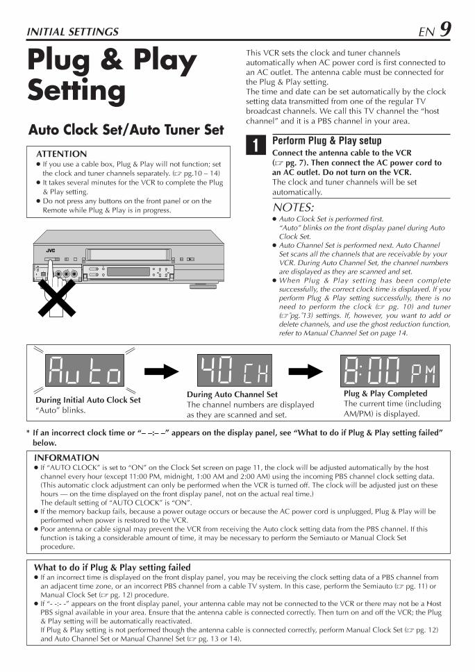
During Initial Auto Clock Set“Auto” blinks.
During Auto Channel SetThe channel numbers are displayedas they are scanned and set.
* If an incorrect clock time or “– –:– –” appears on the display panel, see “What to do if Plug & Play setting failed”below.
Plug & Play CompletedThe current time (includingAM/PM) is displayed.

10 EN
Clock Setting Perform clock setting only if the clock has not been setcorrectly by the Plug & Play setting or if you use a cablebox.Access the Clock Set screen to perform the Semiauto orManual Clock Set. Each procedure starts from step 4after preparation steps below are finished.If you use a cable box, set the clock manually. (Z pg. 12)
Preparations
1 Access Main Menu screenPress MENU.
2 Access Initial Set Up screenPress %fi to move thehighlight bar (arrow) to“INITIAL SET UP”, thenpress OK.
3 Access Clock Set Up screenPress %fi to move thehighlight bar (arrow) to“CLOCK SET UP”, thenpress OK.
“CABLE BOX USERSSET CLOCKMANUALLY”appears on the screen for about 5 seconds, thenthe Clock Set screen appears.
Turn on the VCR and the TV, and select the AVmode on the TV.
1 2 3
4 5 6
7 8 9
0
VCR TV CABLE/DBS
1 8
2 – 7
2 3
INITIAL SETTINGS (cont.)
MAIN MENU
VIDEO NAVIGATIONFUNCTION SET UPTUNER SET UP
3 INITIAL SET UPi. LINK SET UP
PRESS (5∞), THEN (OK)PRESS (MENU) TO END
INITIAL SET UP
3 CLOCK SET UPJLIP ID SET UP
PRESS (5∞), THEN (OK)PRESS (MENU) TO END
4 – 7

EN 11Setting clock semiautomatically— Semiauto Clock SetYou can change the host channel/D.S.T. /time zonesetting manually.First follow steps 1 to 3 on page 10, then go to thefollowing steps.
4 Set Auto Clock to ONPress %fi to move thehighlight bar to “AUTOCLOCK”, then press @ #so that “ON” isselected.
Then;To select the host channel — go to step 5.To select the D.S.T. mode — go to step 6.To select the time zone — go to step 7.
NOTE:The time set previously will be erased when “AUTOCLOCK”, “HOST CH”, “D.S.T.” or “TIME ZONE”setting is changed.
5 Select host channelYou can either select “AUTO” or enter a PBSchannel number.Press %fi to move the highlight bar to “HOSTCH”, then press @ # until “AUTO” or the desiredPBS channel number is selected.
NOTE:Some PBS channels do not transmit clock setting data.
* Auto Daylight Saving TimeThis function enables automatic adjustment of the VCR’sclock at the start and end of Daylight Saving Time.With Auto DST activated, . . .. . . on the first Sunday of April at 2:00 AM, the clock isadjusted to 3:00 AM.. . . on the last Sunday of October at 2:00 AM, theclock is adjusted to 1:00 AM.
CLOCK SET UP
TIME DATE YEAR1:00PM 12/24 2001 MON
AUTO CLOCK : ONHOST CH : AUTO (CATV)D.S.T. : AUTOTIME ZONE : AUTOPRESS (5∞), THEN (2 3)PRESS (MENU) TO END
6 Select D.S.T. modeYou have three choices:AUTO– Select if you want to adjust your VCR’s
clock automatically by the incomingsignal from the host channel. (AutoDaylight Saving Time*)
ON– Adjustment will be made by the built-inclock itself.
OFF– Select when Daylight Saving Time doesnot apply to you.
Press %fi to move the highlight bar to “D.S.T.”,then press @ # repeatedly until the desired settingis selected.
7 Select time zoneYou can select the time zone automatically ormanually.Press %fi to move the highlight bar to “TIMEZONE”, press @ # repeatedly until “AUTO” orthe desired time zone is selected.Each time you press the button, the time zonechanges as follows:
O AUTO O ATLANTIC O EASTERN
O CENTRAL O MOUNTAIN O PACIFIC
O ALASKA O HAWAII O (back to the beginning)
NOTE:If an incorrect clock time is displayed by the Plug &Play setting, you may be receiving the clock settingdata of a PBS channel from an adjacent time zone orfrom an incorrect PBS channel from a cable TV system.If you selected “AUTO” for the host channel in step 5,be sure to select the correct time zone manually.
8 Return to normal screenPress MENU.
IMPORTANTTurn off the VCR after performing Semiauto Clock Set.“Auto” will appear on the front display panel while theclock is being set. The current clock time will appearautomatically when the clock setting is complete.

12 EN
CLOCK SET UP
TIME DATE YEAR– –:– –AM 1/ 1 2001AUTO CLOCK : ONHOST CH : AUTO (CATV)D.S.T. : AUTOTIME ZONE : AUTOPRESS (5∞), THEN (2 3)PRESS (MENU) TO END
Setting clock manually— Manual Clock SetFirst follow steps 1 to 3 on page 10, then go to thefollowing steps.
4 Set timePress @ # until thedesired time appears,then press fi.
Holding @ # changesthe time in 30-minuteintervals.
When the time isentered manually, “AUTO CLOCK” isautomatically set to “OFF”, and “HOST CH”and “TIME ZONE” disappear.
5 Set datePress @ # until the desired date appears, thenpress fi.
Holding @ # changes the date in 15-dayintervals.
6 Set yearPress @ # until the desired year appears.
7 Select D.S.T. modePress %fi to move the highlight bar to “D.S.T.”,then press @ # to select “ON” or “OFF”.ON– Adjustment will be made by the built-in
clock itself.OFF– Select when Daylight Saving Time does
not apply to you.
8 Start clockPress MENU and normal screen appears.
To make corrections any time during the processPress %fi repeatedly until the item you want to changeblinks, then press @ #.
1 2 3
4 5 6
7 8 9
0
VCR TV CABLE/DBS
8
INITIAL SETTINGS (cont.)
4 – 74 57

EN 13Tuner Setting Setting channels automatically
— Auto Channel SetUse Auto Channel Set only if channels have not been setcorrectly by the Plug & Play setting. If you want to addor delete channels, and want to use the ghost reductionfunction, use Manual Channel Set (Z pg. 14).
1 Access Main Menu screenPress MENU.
2 Access Tuner Set Up screenPress %fi to move thehighlight bar (arrow) to“TUNER SET UP”, thenpress OK.
3 Perform Auto Channel SetYou can automaticallyset the receivablechannels in your area inthe order of theirfrequencies.Press %fi to move thehighlight bar (arrow) to“AUTO CHANNEL SETUP”, then press OK.
NOTES: When Auto Channel Set
is complete, “SCANCOMPLETED” appearson screen.
If the scan wasunsuccessful, “SCAN COMPLETED–NO SIGNAL”appears on screen. Check theconnections and start again.
4 Return to normal screenPress MENU.
INFORMATIONThe VCR selects the correct band (TV or CATV)automatically during Auto Channel Set.The selected band will be displayed on the right side of“BAND” on the Tuner Set Up screen.
Turn on the VCR and the TV, and select the AVmode on the TV.
AUTO CHANNEL SET UP
SCANNING...
PRESS (MENU) TO END
1 2 3
4 5 6
7 8 9
0
VCR TV CABLE/DBS
1 4
2 3
2 3
MAIN MENU
VIDEO NAVIGATIONFUNCTION SET UP
3 TUNER SET UPINITIAL SET UPi. LINK SET UP
PRESS (5∞), THEN (OK)PRESS (MENU) TO END
TUNER SET UP
BAND CATV3 AUTO CHANNEL SET UP
MANUAL CHANNEL SETGUIDE CHANNEL SETCABLE BOX SET UPDBS RECEIVER SET UPPRESS (5∞), THEN (OK)PRESS (MENU) TO END

14 EN
3 Access Manual Channel Set screenPress %fi to move thehighlight bar (arrow) to“MANUAL CHANNELSET”, then press OK.
4 Add or skip desired channels To add channels
1 Press the Numberkeys or @ # to input achannel number youwant to add.
2 Press OK to set to“ADD”.
3 Repeat 1 and 2 to add other channels.
To skip channels
1 Press the Numberkeys or @ # to inputa channel numberyou want to skip.
2 Press OK to set to“SKIP”.
3 Repeat 1 and 2 to skip other channels.
5 Return to normal screenPress MENU.
MANUAL CHANNEL SET UP
(CATV)CH 45 ADD
PRESS NUMBER KEY (0–9)OR (2 3), THEN (OK)
PRESS (MENU) TO END
Setting channels manually— Manual Channel SetYou can add the channels you want or delete thechannels you do not want manually.You can also select the ghost reduction mode for eachchannel while adding the channels you want.
1 Access Main Menu screenPress MENU.
2 Access Tuner Set Up screenPress %fi to move the highlight bar (arrow) to“TUNER SET UP”, then press OK.
INITIAL SETTINGS (cont.)
TUNER SET UP
BAND CATVAUTO CHANNEL SET UP
3 MANUAL CHANNEL SETGUIDE CHANNEL SETCABLE BOX SET UPDBS RECEIVER SET UPPRESS (5∞), THEN (OK)PRESS (MENU) TO END
1 2 3
4 5 6
7 8 9
0
VCR TV CABLE/DBS
1 5
2 3
4
2 – 4
4MANUAL CHANNEL SET UP
(CATV)CH 46 SKIP
PRESS NUMBER KEY (0–9)OR (2 3), THEN (OK)
PRESS (MENU) TO END
EN 15
CABLEBOX
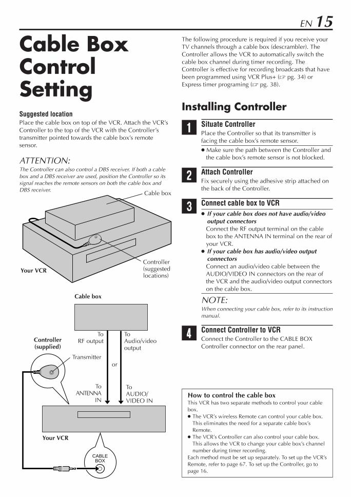
The following procedure is required if you receive yourTV channels through a cable box (descrambler). TheController allows the VCR to automatically switch thecable box channel during timer recording. TheController is effective for recording broadcasts that havebeen programmed using VCR Plus+ (Z pg. 34) orExpress timer programing (Z pg. 38).
Installing Controller
1 Situate ControllerPlace the Controller so that its transmitter isfacing the cable box’s remote sensor.
Make sure the path between the Controller andthe cable box’s remote sensor is not blocked.
2 Attach ControllerFix securely using the adhesive strip attached onthe back of the Controller.
3 Connect cable box to VCR If your cable box does not have audio/video
output connectorsConnect the RF output terminal on the cablebox to the ANTENNA IN terminal on the rear ofyour VCR.
If your cable box has audio/video outputconnectorsConnect an audio/video cable between theAUDIO/VIDEO IN connectors on the rear ofthe VCR and the audio/video output connectorson the cable box.
NOTE:When connecting your cable box, refer to its instructionmanual.
4 Connect Controller to VCRConnect the Controller to the CABLE BOXController connector on the rear panel.
Cable BoxControlSettingSuggested locationPlace the cable box on top of the VCR. Attach the VCR’sController to the top of the VCR with the Controller’stransmitter pointed towards the cable box’s remotesensor.
ATTENTION:The Controller can also control a DBS receiver. If both a cablebox and a DBS receiver are used, position the Controller so itssignal reaches the remote sensors on both the cable box andDBS receiver.
How to control the cable boxThis VCR has two separate methods to control your cablebox. The VCR’s wireless Remote can control your cable box.
This eliminates the need for a separate cable box’sRemote.
The VCR’s Controller can also control your cable box.This allows the VCR to change your cable box’s channelnumber during timer recording.
Each method must be set up separately. To set up the VCR’sRemote, refer to page 67. To set up the Controller, go topage 16.
Cable box
Cable box
Your VCRController(suggestedlocations)
Transmitter
Your VCR
ToANTENNA
IN
ToAUDIO/VIDEO IN
ToRF output
ToAudio/videooutput
or
Controller(supplied)

16 EN
CABLE BOX SET UP
OFF
PRESS (2 3), THEN (OK)PRESS (MENU) TO END
Turn on the VCR and the TV, and select the AVmode on the TV.
Setting cable box outputchannel & brandAfter installation, set the cable box output’s channel andits brand correctly; otherwise, the Controller cannotwork correctly.
1 Turn on cable boxSelect a channel other than channel 9 on yourcable box.
2 Access Main Menu screen on VCRPress MENU.
3 Access Tuner Set Up screenPress %fi to move the highlight bar (arrow) to“TUNER SET UP”, then press OK.
4 Access Cable Box Set screenPress %fi to move thehighlight bar (arrow) to“CABLE BOX SET UP”,then press OK.
5 Select cable box output channelYour selection dependson how your cable boxis connected to yourVCR.
If your cable box isconnected to yourVCR’s ANTENNA INterminal on the rear panelPress @ # until the channel numberrepresenting the cable box’s output (CH2 –CH9) appears on the screen.
If your cable box is connected to your VCR’sAUDIO/VIDEO IN connectors on the front panelPress @ # until “ON F-1 (FRONT)” appears onthe screen.
If your cable box is connected to your VCR’sAUDIO/VIDEO IN (L-1) or AUDIO/VIDEO IN(L-2) connectors on the rear panelPress @ # until “ON L-1 (REAR)” or “ON L-2(REAR)” appears on the screen.
If you do not use a cable boxPress @ # until “OFF” appears on the screen.
1 2 3
4 5 6
7 8 9
0
VCR TV CABLE/DBS
2
3 4
3 46 7
INITIAL SETTINGS (cont.)
TUNER SET UP
BAND CATVAUTO CHANNEL SET UPMANUAL CHANNEL SETGUIDE CHANNEL SET
3 CABLE BOX SET UPDBS RECEIVER SET UPPRESS (5∞), THEN (OK)PRESS (MENU) TO END
7
5

EN 17
CABLE BOX BRAND SET UP
1
PRESS NUMBER KEY (0–9)THEN (OK) TO TEST
PRESS (MENU) TO END
CABLE BOX BRAND SET UP
1
DID YOUR CABLE BOX CHANGE TO CHANNEL 09?
2 YES 3 NO
PRESS (2 3), THEN (OK) PRESS (MENU) TO END
6 Access Cable Box Brand Set screenPress OK.
7 Enter cable box brandPress the appropriateNumber keys to enterthe brand code from thelist shown to the right,then press OK.
If the cable box’schannel changes to 9,setting is completePress OK and “CABLEBOX CONTROL ISON” appears on thescreen for about 5seconds, then itreturns to the normalscreen.
If the cable box’s channel does not change to 91 Press @ # to move the highlight bar to
“NO”.2 Press OK.3 Repeat step 7 until the cable box’s channel
changes to 9 by entering another code.4 If the channel does not change after going
through all the code numbers listed for yourmodel of cable box, then try all the othernumbers.
CABLE BOX BRAND LIST
BRAND CODE
ARCHER 1, 5, 17CABLETENNA 1, 17CABLEVIEW 15, 16, 17, 21, 25CITIZEN 15, 16, 17, 21, 25CURTIS 2, 8DIAMOND 1, 17EASTERN 19GC BRAND 15, 16, 17, 21, 25GEMINI 15GENERAL INSTRUMENTS 1, 4, 6, 11, 12, 15, 28HAMLIN 10, 18, 19, 23JASCO 15JERROLD 1, 4, 6, 11, 12, 15, 28NOVAVISION 2, 8OAK 7, 20PANASONIC 13, 14PULSER 15, 16, 17, 21, 25RCA 13, 14REGAL 10, 18, 19, 23REGENCY 19REMBRANDT 1, 16, 17SAMSUNG 5, 16, 24SCIENTIFIC ATLANTA 2, 8SIGMA 7, 20SL MARX 5, 16, 17, 24, 25SPRUCER 13, 14STARGATE 5, 15, 16, 17, 21, 24, 25TELEVIEW 5, 16, 24TOCOM 1, 4, 16UNIKA 1, 17UNIVERSAL 16, 17, 25VIDEOWAY 3, 9, 22ZENITH 3, 9, 22
If the VCR’s clock has not been set (with AUTOCLOCK set to ON)“CABLE BOX USERS SET CLOCK MANUALLY” appears forabout 5 seconds when you press OK in step 6, then theClock Set screen appears.Perform Manual Clock Set on page 12. If you press MENUafter the clock has been set, the Cable Box Brand Setscreen appears.
NOTES: The Controller may not work with all types of cable box. If your cable box does not respond to any code, you cannot
use the Controller to change cable box channels. In this case,make sure to leave the cable box turned on and tuned to theproper channel before the scheduled start time of timerrecording.Contact your cable company about the possibility ofexchanging your current cable box with the one compatiblewith your VCR.
The VCR can only change the cable box channel through theController during timer recording.
If your cable box cannot be operated with a remote control(because it has no remote sensor), you cannot use theController to change its channels. Make sure to leave thecable box turned on and tuned to the proper channel beforethe scheduled start time of timer recording.
If the VCR’s memory backup expires because of a powerfailure, set the cable box output channel and brand again.
For customers in U.S.A.: If you are unable to set theController, contact JVC toll free at 1-800-252-5722.

18 EN INITIAL SETTINGS (cont.)
The following procedure is required if you receive satellitechannels through a DBS (Direct Broadcast Satellite)receiver. The Controller allows the VCR to automaticallyswitch the DBS receiver’s channels during timer recording.
NOTES: The VCR can automatically change the DBS receiver
channels using the Controller when the VCR has beenprogramed using Express timer programing (Z pg. 38).Because satellite programing does not use PlusCode, theController cannot change the DBS receiver channels duringVCR Plus+ timer recording.(You can also use “Satellite Auto Recording” (Z pg. 60) ifyour DBS receiver is equipped with a timer.)
If a cable box is also used, it is recommended that you connectthe DBS receiver to your VCR’s audio/video input connectorsand the cable box to your VCR’s antenna input terminal.
Installing Controller
1 Situate ControllerPlace the Controller so that its transmitter isfacing the DBS receiver’s remote sensor.
Make sure the path between the Controller andthe DBS receiver’s remote sensor is notblocked.
2 Attach ControllerFix securely using the adhesive strip attached onthe back of the Controller.
3 Connect DBS receiver to VCR If your DBS receiver does not have audio/
video output connectorsConnect the RF output terminal on the DBSreceiver to the ANTENNA IN terminal on therear of your VCR.
If your DBS receiver has audio/video outputconnectorsConnect an audio/video cable between theAUDIO/VIDEO IN connectors on the rear ofthe VCR and the audio/video output connectorson the DBS receiver.
NOTE:When connecting your DBS receiver, refer to itsinstruction manual.
4 Connect Controller to VCRConnect the Controller to the CABLE BOXController connector on the rear panel.
DBS ReceiverControl SettingSuggested locationPlace the DBS (Direct Broadcast Satellite) receiver on topof the VCR. Attach the VCR’s Controller to the top of theVCR with the Controller’s transmitter pointed towardsthe DBS receiver’s remote sensor.
ATTENTION:The Controller can also control a cable box. If both a DBSreceiver and a cable box are used, position the Controller so itssignal reaches the remote sensors on both the DBS receiver andcable box.
How to control the DBS receiverThis VCR has two separate methods to control your DBS receiver. The VCR’s wireless Remote can control your DBS receiver. This eliminates the need for a separate DBS receiver’s Remote. The VCR’s Controller can also control your DBS receiver. This allows the VCR to change your DBS receiver’s channel number
during timer-recording.Each method must be set up separately. To set up the VCR’s Remote, refer to page 68. To set up the Controller, go to page 19.
CABLEBOX
DBS receiver
DBS receiver
Your VCRController(suggestedlocations)
Transmitter
Your VCR
ToANTENNA IN
ToAUDIO/VIDEO IN
ToRF output
ToAudio/Videooutput
or
Controller(supplied)

EN 19Turn on the VCR and the TV, and select the AVmode on the TV.
DBS RECEIVER SET UP
OFF
PRESS (2 3), THEN (OK)PRESS (MENU) TO END
Setting DBS receiver outputchannel & brandAfter installation, set the DBS receiver’s output channeland its brand correctly; otherwise, the Controller cannotwork correctly.
1 Turn on DBS receiverSelect a channel other than channel 55, 100 or205 on your DBS receiver.
2 Access Main Menu screen on VCRPress MENU.
3 Access Tuner Set Up screenPress %fi to move the highlight bar (arrow) to“TUNER SET UP”, then press OK.
4 Access DBS Receiver Set screenPress %fi to move thehighlight bar (arrow) to“DBS RECEIVER SETUP”, then press OK.
5 Select DBS receiver output channelYour selection depends on how your DBSreceiver is connected to your VCR.
If your DBS receiveris connected to yourVCR’s ANTENNA INterminal on the rearpanelPress @ # until thechannel numberrepresenting the DBSreceiver’s output (CH3 or CH4) appears on thescreen.
If your DBS receiver is connected to your VCR’sAUDIO/VIDEO IN connectors on the front panelPress @ # until “ON F-1 (FRONT)” appears onthe screen.
If your DBS receiver is connected to your VCR’sAUDIO/VIDEO IN (L-1) or AUDIO/VIDEO IN(L-2) connectors on the rear panelPress @ # until “ON L-1 (REAR)” or “ON L-2(REAR)” appears on the screen.
If you do not use a DBS receiverPress @ # until “OFF” appears on the screen.
CONTINUED ON NEXT PAGE \
1 2 3
4 5 6
7 8 9
0
VCR TV CABLE/DBS
2
3 4
3 4
TUNER SET UP
BAND CATVAUTO CHANNEL SET UPMANUAL CHANNEL SETGUIDE CHANNEL SETCABLE BOX SET UP
3 DBS RECEIVER SET UPPRESS (5∞), THEN (OK)PRESS (MENU) TO END
5
20 EN
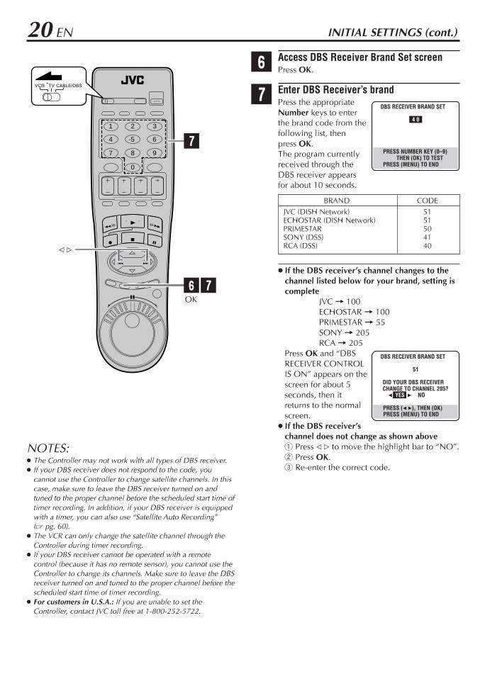
6 Access DBS Receiver Brand Set screenPress OK.
7 Enter DBS Receiver’s brandPress the appropriateNumber keys to enterthe brand code from thefollowing list, thenpress OK.The program currentlyreceived through theDBS receiver appearsfor about 10 seconds.
If the DBS receiver’s channel changes to thechannel listed below for your brand, setting iscomplete
JVC = 100ECHOSTAR = 100PRIMESTAR = 55SONY = 205RCA = 205
Press OK and “DBSRECEIVER CONTROLIS ON” appears on thescreen for about 5seconds, then itreturns to the normalscreen.
If the DBS receiver’schannel does not change as shown above1 Press @ # to move the highlight bar to “NO”.2 Press OK.3 Re-enter the correct code.
BRAND CODEJVC (DISH Network) 51ECHOSTAR (DISH Network) 51PRIMESTAR 50SONY (DSS) 41RCA (DSS) 40
DBS RECEIVER BRAND SET
4 0
PRESS NUMBER KEY (0–9)THEN (OK) TO TEST
PRESS (MENU) TO END
INITIAL SETTINGS (cont.)
DBS RECEIVER BRAND SET
51
DID YOUR DBS RECEIVER CHANGE TO CHANNEL 205?
2 YES 3 NO
PRESS (2 3), THEN (OK) PRESS (MENU) TO END
OK
@ #
1 2 3
4 5 6
7 8 9
0
VCR TV CABLE/DBS
6 7
7
NOTES: The Controller may not work with all types of DBS receiver. If your DBS receiver does not respond to the code, you
cannot use the Controller to change satellite channels. In thiscase, make sure to leave the DBS receiver turned on andtuned to the proper channel before the scheduled start time oftimer recording. In addition, if your DBS receiver is equippedwith a timer, you can also use “Satellite Auto Recording”(Z pg. 60).
The VCR can only change the satellite channel through theController during timer recording.
If your DBS receiver cannot be operated with a remotecontrol (because it has no remote sensor), you cannot use theController to change its channels. Make sure to leave the DBSreceiver turned on and tuned to the proper channel before thescheduled start time of timer recording.
For customers in U.S.A.: If you are unable to set theController, contact JVC toll free at 1-800-252-5722.

EN 21
1
BASIC PLAYBACK AND RECORDING
BasicPlayback
This VCR can check the tape condition during playback(and recording), and realizes the best possible pictures. This recorder can play back tapes that have been
recorded in D-VHS (MTP), S-VHS and VHS formats. When playing back a tape, this recorder automatically
identifies the recording format (D-VHS, S-VHS, orVHS).
When you play back a tape recorded on this VCR, youcan use the Video Navigation function (Z pg. 42).
1 Load a cassetteMake sure the window side is up, the rear labelside is facing you and the arrow on the front ofthe cassette is pointing towards the VCR.Do not apply too much pressure when inserting.
The VCR turns on automatically. The counter is automatically reset to “0:00:00”. The tape will run for a few seconds while the
VCR searches for the tape number. If the tapenumber is found, it will be shown on the TVscreen if “SUPERIMPOSE” is set to “ON.”(Z pg. 56)
If the cassette’s record safety tab has beenremoved, playback begins automatically.
2 Start playbackPress PLAY ( 3 ).
Tape speed is automatically detected. If “V, CALIBRATION” is set to “ON” (default
setting: Z pg. 53), “V, CALIBRATION” appearson the screen, and this VCR checks the tapecondition during automatic tracking (onlycassettes recorded in the S-VHS or VHS mode).
To stop playbackPress STOP ( 7 ) on the Remote or STOP/EJECT ( 7/0 )on the front panel.
To rewind the tape (when it is not running)Press REW ( 1 ).
To fast-forward (when it is not running)Press FF ( ¡ ).
To eject the tapePress STOP/EJECT ( 7/0 ) on the front panel when thetape is not running. You can also eject the cassette when the VCR is turned
off.
To turn off the VCRPress POWER.
NOTES: When you use the Video Navigation function, operate the
VCR only after the tape number is detected; otherwise, youcannot use the Video Navigation function.
When playing back a tape recorded in D-VHS format, theJOG dial and SHUTTLE ring do not work.
Turn on the VCR and the TV, and select the AVmode on the TV.
1 2 3
4 5 6
7 8 9
0
VCR TV CABLE/DBS
2
STOP ( 7 )
FF ( ¡ )REW ( 1 )
POWER
2
STOP/EJECT ( 7/0 )
POWER
SHUTTLEring

22 EN
BasicPlaybackFeatures
Changing display information
Press DISPLAY during playback.Each time you press the button, the front display panelshows the time counter, the clock time and the taperemaining time in sequence .
To display the VCR status including the time counterand the clock time on the TV screen, see “Showing on-screen display” (Z pg. 29).
“COUNT” appears on the screen when the timecounter is shown. “REMAIN” appears on the screenwhen the tape remaining time is shown.
When the tape remaining time appears, “ ” alsolights on the front display panel.
The tape remaining time is calculated based on thetape speed being used. The indicated remaining time isonly an estimate.
To reset the time counter, press C. RESET on theRemote. The counter reading becomes “0:00:00”. It isalso reset when a tape is inserted.
Checking tape position
The tape position indicatorappears on the screen in thefollowing cases: When you change the VCR
operation mode from the stopmode to fast forward orrewind mode.
When you perform an IndexSearch (Z pg. 24) or InstantReview (Z pg. 25).
The position of “ ” in relation to “B” (Beginning) or “E”(End) shows you where you are on the tape.
NOTES: “SUPERIMPOSE” must be set to “ON”, or the indicator will
not appear (Z pg. 56). It may take a few seconds for the tape position indicator to be
displayed.
A
B
Time Counter
Tape Remaining Time
Clock Time
BASIC PLAYBACK AND RECORDING (cont.)
Turn on the VCR and the TV, and select the AVmode on the TV.
1 2 3
4 5 6
7 8 9
0
VCR TV CABLE/DBS
–2
A
E
D
STOP ( 7 )
C. RESET
C
–1D STOP/EJECT ( 7/0 )
C
– 1:23:45 33B E
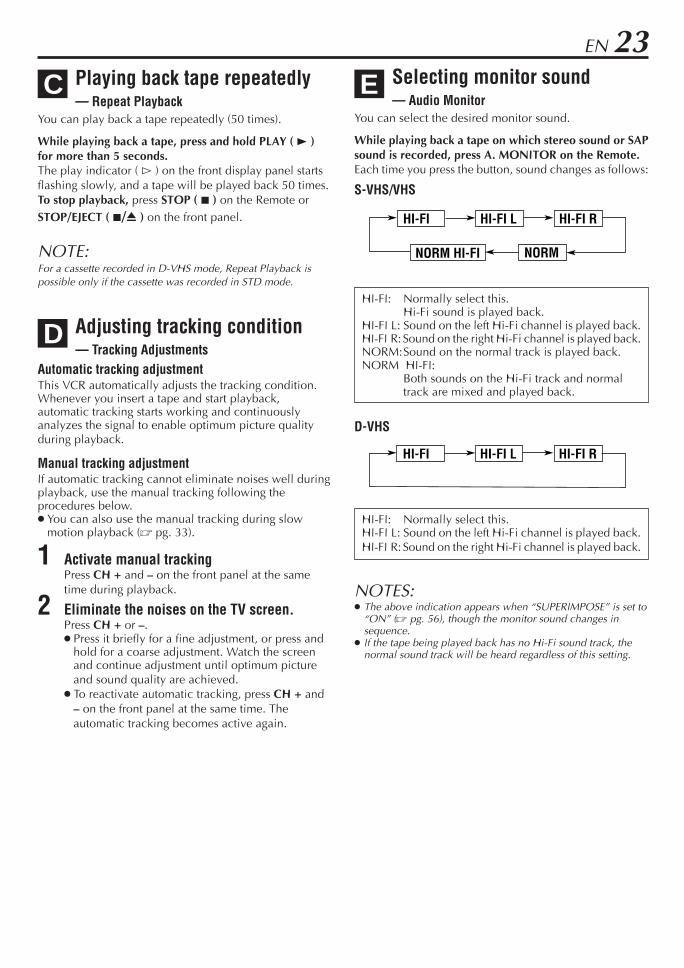
EN 23Selecting monitor sound— Audio Monitor
You can select the desired monitor sound.
While playing back a tape on which stereo sound or SAPsound is recorded, press A. MONITOR on the Remote.Each time you press the button, sound changes as follows:
S-VHS/VHS
HI-FI: Normally select this.Hi-Fi sound is played back.
HI-FI L: Sound on the left Hi-Fi channel is played back.HI-FI R: Sound on the right Hi-Fi channel is played back.NORM:Sound on the normal track is played back.NORM HI-FI:
Both sounds on the Hi-Fi track and normaltrack are mixed and played back.
D-VHS
HI-FI: Normally select this.HI-FI L: Sound on the left Hi-Fi channel is played back.HI-FI R: Sound on the right Hi-Fi channel is played back.
NOTES: The above indication appears when “SUPERIMPOSE” is set to
“ON” (Z pg. 56), though the monitor sound changes insequence.
If the tape being played back has no Hi-Fi sound track, thenormal sound track will be heard regardless of this setting.
C
D
Playing back tape repeatedly— Repeat Playback
You can play back a tape repeatedly (50 times).
While playing back a tape, press and hold PLAY ( 3 )for more than 5 seconds.The play indicator ( # ) on the front display panel startsflashing slowly, and a tape will be played back 50 times.To stop playback, press STOP ( 7 ) on the Remote orSTOP/EJECT ( 7/0 ) on the front panel.
NOTE:For a cassette recorded in D-VHS mode, Repeat Playback ispossible only if the cassette was recorded in STD mode.
Adjusting tracking condition— Tracking Adjustments
Automatic tracking adjustmentThis VCR automatically adjusts the tracking condition.Whenever you insert a tape and start playback,automatic tracking starts working and continuouslyanalyzes the signal to enable optimum picture qualityduring playback.
Manual tracking adjustmentIf automatic tracking cannot eliminate noises well duringplayback, use the manual tracking following theprocedures below. You can also use the manual tracking during slow
motion playback (Z pg. 33).
1 Activate manual trackingPress CH + and – on the front panel at the sametime during playback.
2 Eliminate the noises on the TV screen.Press CH + or –. Press it briefly for a fine adjustment, or press and
hold for a coarse adjustment. Watch the screenand continue adjustment until optimum pictureand sound quality are achieved.
To reactivate automatic tracking, press CH + and– on the front panel at the same time. Theautomatic tracking becomes active again.
NORMNORM HI-FI
HI-FI HI-FI L HI-FI R
E
HI-FI HI-FI L HI-FI R

24 EN BASIC PLAYBACK AND RECORDING (cont.)
Automatic operations afterrewinding — Next Function Memory
The Next Function Memory “tells” the VCR what to doafter rewinding is complete. Ensure that the VCR is in stop mode.
a– For Automatic Playback StartPress REW ( 1 ), then press PLAY ( 3 ) within 2seconds.
b– For Automatic Power OffPress REW ( 1 ), then press POWER within 2seconds.
c– For Automatic Timer StandbyPress REW ( 1 ), then press TIMER within 2seconds.
NOTE:It is not possible to select the Automatic Timer Standby functionif the cassette’s record safety tab is removed.
Locating beginning ofrecordings — Index Search
Index codes are placed on the tape at the beginning ofeach recording when recording on this VCR. You canfind and automatically play back from the beginning ofany recording using the Index Search function.
1 Start searchWhile the tape is not running, press 4 or ¢ onthe Remote.
2 Access distant codeTo access a recording of 2 to 9 index codes away,press 4 or ¢ repeatedly until the correctnumber is displayed on the screen (only if“SUPERIMPOSE” is set to “ON” ; Z pg. 56).Playback begins automatically when the desiredrecording is located.
If you want to find the very beginning of thedesired program, press REW ( ) or FF ( )or turn the SHUTTLE ring after playback starts.
NOTE:An index code is not placed on the tape when recording isresumed from recording pause.
1 2 3
4 5 6
7 8 9
0
VCR TV CABLE/DBS
H
G
IFF ( )
Current positionon the tape
Beginning of the currentprogram recorded
Beginning of the 2nd nextprogram recorded
–1 1 2–2 3
Previousprogramrecorded
Nextprogramrecorded
2nd next
4 ¢
G
F
F –a, b, c
F –C
F –b
–aF
J
SHUTTLEring
REW ( )

EN 25H
Other Useful functions for playback(S-VHS/VHS only)You can also use the following functions for playback.
Video Calibration (S-VHS/VHS only) (Z pg. 53)When this function is set to “ON”, this VCR checks thecondition of the tape in use during playback andrecording, and compensates to provide the highest-possible pictures.
Picture Control (Z pg. 53)This function helps you to adjust the playback picturequality according to your preference.
Digital R3 (Z pg. 53)This function applies edge correction to the luminancesignal to enhance details and provides clear pictures.
Video Stabilizer (Z pg. 53)You can automatically correct vertical vibrations in thepicture when playing back unstable recordings made onanother VCR.
Adjusting picture condition — Digital 3-DNR (S-VHS/VHS only)
The Digital 3-DNR (3-Dimension Noise Reduction) cutsnoise and reproduces clear pictures. Normally turn onDigital 3-DNR.The playback picture may be distorted depending on thetape. In this case, turn off Digital 3-DNR.
Press DIGITAL 3-DNR on the front panel so that theDIGITAL 3-DNR lamp lights up.Each time you press the button, this function turns onand off.
JLocating beginning of timerrecordings — Instant Review
At the press of a button, you can turn on the VCR,rewind the tape and begin to view the most recent timer-recorded program.
Press REVIEW on the Remote after ensuring that theVCR is in the timer recording standby mode.
The VCR turns on, and rewinds to the index codeindicating the beginning of the last timer-recordedprogram, then begins playback automatically.
You can access a program of 2 to 9 index codes awayfrom the current position on the tape. If, for example,you have 5 programs recorded and you want to watchthe third one, press REVIEW three times.
If you want to find the very beginning of the desiredprogram, press REW ( ) or FF ( ) or turn theSHUTTLE ring after playback starts.
If the tape is already rewound when REVIEW ispressed, it will play the tape from the beginning. It willnot fast-forward to an index code.
The Instant Review function will also operate if theVCR is turned on.
Skipping unwanted portions— Skip Search
You can skip over (view at high speed) unwantedportions of the tape.
Press SKIP SEARCH on the Remote once to 4 timesduring playback.Each press initiates a 30-second period of high speedplayback (up to 2 minutes). When the specified portionof the tape is skipped, normal playback resumesautomatically.
To return to normal playback during Skip Search, pressPLAY ( 3 ).
I
26 EN
BasicRecording
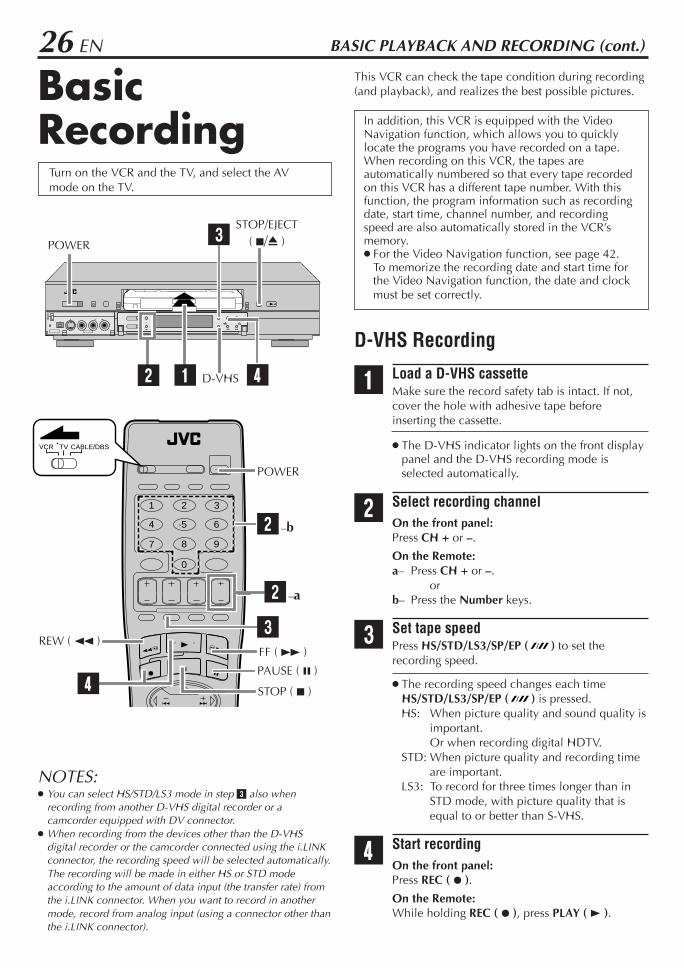
This VCR can check the tape condition during recording(and playback), and realizes the best possible pictures.
In addition, this VCR is equipped with the VideoNavigation function, which allows you to quicklylocate the programs you have recorded on a tape.When recording on this VCR, the tapes areautomatically numbered so that every tape recordedon this VCR has a different tape number. With thisfunction, the program information such as recordingdate, start time, channel number, and recordingspeed are also automatically stored in the VCR’smemory. For the Video Navigation function, see page 42.
To memorize the recording date and start time forthe Video Navigation function, the date and clockmust be set correctly.
D-VHS Recording
1 Load a D-VHS cassetteMake sure the record safety tab is intact. If not,cover the hole with adhesive tape beforeinserting the cassette.
The D-VHS indicator lights on the front displaypanel and the D-VHS recording mode isselected automatically.
2 Select recording channelOn the front panel:Press CH + or –.
On the Remote:a– Press CH + or –.
orb– Press the Number keys.
3 Set tape speedPress HS/STD/LS3/SP/EP ( ) to set therecording speed.
The recording speed changes each timeHS/STD/LS3/SP/EP ( ) is pressed.HS: When picture quality and sound quality is
important.Or when recording digital HDTV.
STD: When picture quality and recording timeare important.
LS3: To record for three times longer than inSTD mode, with picture quality that isequal to or better than S-VHS.
4 Start recordingOn the front panel:Press REC ( ¶ ).
On the Remote:While holding REC ( ¶ ), press PLAY ( 3 ).
Turn on the VCR and the TV, and select the AVmode on the TV.
1
1 2 3
4 5 6
7 8 9
0
VCR TV CABLE/DBS
STOP ( 7 )
FF ( ¡ )REW ( 1 )
32 –a
4
2 –b
POWER
PAUSE ( 8 )
BASIC PLAYBACK AND RECORDING (cont.)
2
3
4
STOP/EJECT( 7/0 )POWER
D-VHS
NOTES: You can select HS/STD/LS3 mode in step 3 also when
recording from another D-VHS digital recorder or acamcorder equipped with DV connector.
When recording from the devices other than the D-VHSdigital recorder or the camcorder connected using the i.LINKconnector, the recording speed will be selected automatically.The recording will be made in either HS or STD modeaccording to the amount of data input (the transfer rate) fromthe i.LINK connector. When you want to record in anothermode, record from analog input (using a connector other thanthe i.LINK connector).
EN 27To pause recordingPress PAUSE ( 8 ). To resume recording, press PLAY ( 3 ).
To stop recordingPress STOP ( 7 ) on the Remote or STOP/EJECT ( 7/0 )on the front panel.
To rewind the tape (when it is not running)Press REW ( 1 ).
To fast-forward the tape (when it is not running)Press FF ( ¡ ).
To eject the tapePress STOP/EJECT ( 7/0 ) on the front panel when thetape is not running. You can also eject the cassette when the VCR is turned
off.
To turn off the VCRPress POWER.
NOTE:If “MEMORY FULL” appears on the display when you startrecording, the VCR’s memory for the Video Navigation functionis full. This is not related to actual recording, so you can finishrecording normally, but the Video Navigation information suchas recording date, start time, end time, and channel number willnot be stored in memory.
It may be unlawful to record or play backcopyrighted material without the consent of thecopyright owner.
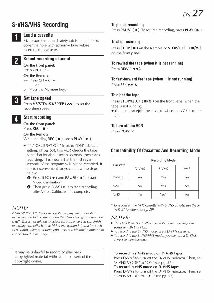
S-VHS/VHS Recording
1 Load a cassetteMake sure the record safety tab is intact. If not,cover the hole with adhesive tape beforeinserting the cassette.
2 Select recording channelOn the front panel:Press CH + or –.
On the Remote:a– Press CH + or –.
orb– Press the Number keys.
3 Set tape speedPress HS/STD/LS3/SP/EP ( ) to set therecording speed.
4 Start recordingOn the front panel:Press REC ( ¶ ).
On the Remote:While holding REC ( ¶ ), press PLAY ( 3 ).
If “V, CALIBRATION” is set to “ON” (defaultsetting: Z pg. 53), this VCR checks the tapecondition for about seven seconds, then startsrecording. This means that the first sevenseconds of the program will not be recorded. Ifthis is inconvenient for you, follow the stepsbelow:1 Press REC ( ¶ ) and PAUSE ( 8 ) to start
Video Calibration.2 Then press PLAY ( 3 ) to start recording
after Video Calibration is complete.
Compatibility Of Cassettes And Recording Mode
CassetteRecording Mode
D-VHS S-VHS VHS
D-VHS Yes Yes Yes
S-VHS No Yes Yes
VHS No Yes* Yes
* To record on the VHS cassette with S-VHS quality, use the S-VHS ET function. (Zpg. 29)
NOTES: The D-VHS (MTP), S-VHS and VHS mode recordings are
possible with this VCR. To record in the D-VHS mode, use a D-VHS cassette. To record in the S-VHS/VHS mode, you can use a D-VHS,
S-VHS or VHS cassette.
To record in S-VHS mode on D-VHS tapes:Press D-VHS to turn off the D-VHS indicator. Then, set“S-VHS MODE” to “ON” (Z pg. 57).To record in VHS mode on D-VHS tapes:Press D-VHS to turn off the D-VHS indicator. Then, set“S-VHS MODE” to “OFF” (Z pg. 57).

28 EN
BasicRecordingFeatures
A
B
Changing display information
Press DISPLAY during recording or recording pause.Each time you press the button, the front display panelshows the time counter, channel number, clock time,and the tape remaining time in sequence.
To display the VCR status including the time counterand the clock time on the TV screen, see “Showing on-screen display” (Z pg. 29).
“COUNT” appears on the screen when the timecounter is shown. “REMAIN” appears on the screenwhen the tape remaining time is shown.
When the tape remaining time appears, “ ” alsolights on the front display panel.
The tape remaining time is calculated based on thetape speed being used. The indicated remaining time isonly an estimate.
To reset the time counter, press C. RESET on theRemote. The counter reading becomes “0:00:00”. It isalso reset when a tape is inserted.
Specifying recording length— Instant Timer Recording (ITR)
You can easily specify the recording length from 30minutes to 8 hours and the VCR shuts off after recordingis finished.
During recording, press REC ( ¶ ) on the front panelrepeatedly until the recording length you want appearson the front display panel.The record ( ) indicator starts flashing.Each time you press the button, recording lengthincreases in 30-minute intervals (up to 8 hours).
To cancel an ITR, press STOP ( 7 ) on the Remote orSTOP/EJECT ( 7 / 0 ) on the front panel.
Time Counter
Tape Remaining Time Clock Time
Channel No.
BASIC PLAYBACK AND RECORDING (cont.)
1 2 3
4 5 6
7 8 9
0
VCR TV CABLE/DBS
A
D
STOP ( 7 )
C. RESET
E –2
Turn on the VCR and the TV, and select the AVmode on the TV.
E –2B
–1E STOP/EJECT ( 7/0 )

EN 29Watching one program whilerecording another
1 Engage TV modeDuring recording... Change the TV’s input mode from AV to TV.
2 Select channel for viewingSelect the channel you want to watch, on the TV.
Showing on-screen display
When “SUPERIMPOSE” is set to “ON” (Z pg. 56), youcan see the current VCR status on the TV screen. For more detailed information about the on-screen
display, see page 79.
1 Display VCR status on TV screenDuring recording orrecording pause, pressOSD on the Remote.All indicationscorresponding to thecurrent VCR status aredisplayed for 5 seconds.The time counter remainson the screen indicating the elapsed time.
The indications are not recorded.
2 Exit on-screen displayPress OSD again.
NOTES: If the VCR is in recording pause mode, “REC PAUSE” is
always displayed. The VCR status can be also displayed during playback.
D
C E
.
Recording on VHS tapes withS-VHS quality — Super VHS ET
This function allows you to record on VHS tapes withS-VHS picture quality. Tapes recorded using this functioncan be played back only on a VCR equipped with theS-VHS ET function. You can activate this function only before you start
recording on a VHS tape. Before recording, make sure “V, CALIBRATION” is set
to “ON” (Z pg. 53).
1 Select S-VHS ET modePress S-VHS ET on the front panel. The S-VHS ETlamp lights up.
To disengage the S-VHS ET mode, press S-VHS ETagain. The lamp goes off.
2 Start recordingOn the front panel:Press REC ( ¶ ).
On the Remote:While holding REC ( ¶ ), press PLAY ( 3 ).
NOTES: You cannot activate the S-VHS ET function...
– while recording is in progress.– while timer-recording or Instant Timer Recording
(Z pg. 28) is in progress.– while Video Calibration (Z pg. 53) is in progress.
S-VHS ET does not work with S-VHS tapes. To keep the highest quality recording and playback pictures
over a long period of time, S-VHS recording on S-VHS tapesis recommended.
Use of high grade tapes are recommended for S-VHS ETrecordings.On some tapes, picture quality will not improve even if the S-VHS ET function is used. Check the recording quality beforeyou start important recordings.
You can play back S-VHS ET recordings on most of S-VHSVCRs and of VHS VCRs equipped with SQPB (S-VHS QUASIPLAYBACK) function. (Notice some VCRs are not compatiblewith this function.)
While playing back a tape recorded with this function, noisemay appear. (If playback picture becomes blurred orinterrupted, use a cleaning cassette.)
During special effect playback (Z pg. 31), noise may appear.If special effect playback is performed frequently on a taperecorded with this function, the tape may be damaged andpicture may be deteriorated
SAP STEREO REC PAUSE
HI-FI THU 12:00 AM ] STD – 1:23:45 33 INDEX-9
B E

30 EN
Accidental erasure preventionTo prevent accidental recording on a recorded cassette,remove its record safety tab.To record on it later, cover the hole with adhesive tape.
Record safety tab
Other useful functions for recordingYou can also use the following functions for recording.
Recording Resume FunctionIf there is a power outage during recording (includingInstant Timer Recording, timer recording and Satellite AutoRecording), the recording will resume automatically whenthe power is restored to the VCR. (No setting is required forthis function.)
Video Calibration (S-VHS/VHS only) (Z pg. 53)When this function is set to “ON”, this VCR checks thecondition of the tape in use during playback andrecording, and compensates to provide the highest-possible pictures.
Second Audio Recording (Z pg. 54)This VCR’s built-in MTS decoder enables reception ofMultichannel TV Sound broadcast.
To record a SAP program received, set “2ND AUDIO REC”to “ON” using the menu screen.
NOTES:When the channel is changed on the VCR; The “STEREO” indication appears on the screen for about
5 seconds if the program is a stereo broadcast. The “SAP” indication appears on the screen for about 5
seconds if the program is a SAP broadcast. Both indications appear when a stereo program is
accompanied by SAP sound.
S-VHS Recording Mode (Z pg. 57)This VCR allows you to record on a D-VHS and S-VHStape with VHS picture quality.
BASIC PLAYBACK AND RECORDING (cont.)

EN 31SPECIAL EFFECT PLAYBACK
Special EffectPlayback
Turn on the VCR and the TV, and select the AVmode on the TV.
With this VCR, you can enjoy special effect playbacksuch as high-speed search, variable-speed search, andstill playback and so on.
Locating particular scenerapidly — Picture Search
7 High-Speed Picture Search:Possible during normal playback or still pictureplayback.You can rapidly locate a particular scene on the tape.
To do forward picture search, turn the SHUTTLE ringfully to the right. When you release the ring, a stillpicture appears.To do reverse picture search, turn the SHUTTLE ringfully to the left. When you release the ring, a still pictureappears. If you turn the ring fully and release it within 1 second,
a still picture appears.
ORTo do forward picture search, press FF ( ).To do reverse picture search, press REW ( ). If you press and hold the button for more than 2
seconds, simply releasing it cancels the picture search,and normal playback resumes.
To resume normal playback, press PLAY ( 3 ).
NOTES: The high-speed picture search speed of the D-VHS recording
is 6 times normal playback speed in HS mode, 12 times inSTD mode, 36 times in LS3 mode.The high-speed picture search speed of the S-VHS/VHSrecording is 11 times normal playback speed in SP mode, 31times in EP mode.
The picture may be distorted at the part where the playbackspeed is changed.
The still picture may appear during the high-speed picturesearch of a tape recorded in D-VHS format on other devices.
A
1 2 3
4 5 6
7 8 9
0
VCR TV CABLE/DBS
A APLAY ( 3 )
SHUTTLEring
7 Variable-Speed Picture Search (S-VHS/VHS only):You can change the speed of picture search.
Turn the SHUTTLE ring to the right (forward search) or tothe left (reverse search).As you turn the SHUTTLE ring, picture search speedchanges (see the diagram on page 32).When you release the ring, a still picture appears. The speed of picture search is determined by the
rotating angle of the SHUTTLE ring.
To resume normal playback, press PLAY ( 3 ).
ATTENTIONWhen playing back a tape recorded in D-VHS format, theJOG dial and SHUTTLE ring do not work.
NOTE:To use the JOG dial/SHUTTLE ring on the Remote, first pressJOG/SHUTTLE on the remote control so that the button lightsup.

32 EN SPECIAL EFFECT PLAYBACK (cont.)
Viewing still picture— Still Picture Playback
Press PAUSE ( 8 ) during normal playback.Playback is freezed and a still picture appears.
To resume normal playback, press PLAY ( 3 ).
NOTE:To obtain a noiseless still picture, it may be necessary to adjusttracking in slow motion playback before starting still pictureplayback.
Viewing still picture frame byframe — Frame-by-Frame Playback (S-VHS/
VHS only)
1 Pause during playbackPress PAUSE ( 8 ).Playback is freezed and a still picture appears.
2 Advance or reverse still pictureTo advance a still picture, turn the JOG dial to theright.To reverse a still picture, turn the JOG dial to theleft.
ORTo advance a still picture, press ¢ (or PAUSE( 8 )) repeatedly.To reverse a still picture, press 4 repeatedly.
To resume normal playback, press PLAY ( 3 ).
B
C
1 2 3
4 5 6
7 8 9
0
VCR TV CABLE/DBS
PLAY ( 3 )
SHUTTLEring
JOG dial
–2C –2
B C –1
JOG/SHUTTLE
C
Rev
erse
Rev
erse
Reverse SlowPlay
Forw
ard
sear
ch
play
slow motion
search
Still
To use the JOG dial/SHUTTLE ring on the Remote, firstpress JOG/SHUTTLE on the remote control so that thebutton lights up.
NOTE:When playing back a tape recorded in D-VHS format, theJOG dial and SHUTTLE ring do not work.
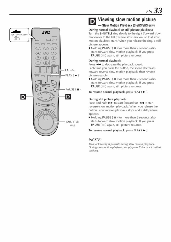
EN 33Viewing slow motion picture— Slow Motion Playback (S-VHS/VHS only)
During normal playback or still picture playback:Turn the SHUTTLE ring slowly to the right (forward slowmotion) or to the left (reverse slow motion) so that slowmotion playback starts.When you release the ring, a stillpicture appears. Holding PAUSE ( 8 ) for more than 2 seconds also
starts forward slow motion playback. If you pressPAUSE ( 8 ) again, still picture resumes.
During normal playback:Press 4 to decrease the playback speed.Each time you press the button, the speed decreases(toward reverse slow motion playback, then reversepicture search). Holding PAUSE ( 8 ) for more than 2 seconds also
starts forward slow motion playback. If you pressPAUSE ( 8 ) again, still picture resumes.
To resume normal playback, press PLAY ( 3 ).
During still picture playback:Press and hold ¢ to start forward (or 4 to startreverse) slow motion playback. When you release thebutton, slow motion playback stops and a still pictureappears. Holding PAUSE ( 8 ) for more than 2 seconds also
starts forward slow motion playback. If you pressPAUSE ( 8 ) again, still picture resumes.
To resume normal playback, press PLAY ( 3 ).
NOTE:Manual tracking is possible during slow motion playback.During slow motion playback, simply press CH + or – to adjusttracking.
D
1 2 3
4 5 6
7 8 9
0
VCR TV CABLE/DBS
D D
PLAY ( 3 )
PAUSE ( 8 )
CH +/–
SHUTTLEring

34 EN
VCR Plus+®
TimerPrograming
Turn on the VCR and the TV, and select the AVmode on the TV.
Timer recording allows you to program the VCR toautomatically record a broadcast at some future time.Up to 8 timer recording programs can be made usingVCR Plus+ timer programing or Express timerprograming method (Z pg. 38) as far as a year inadvance.The VCR Plus+ timer programing system eliminates theneed to input channel, date, start and stop time datawhen programing timer recording settings. Simply key inthe PlusCode number for the TV broadcast you wish torecord and the VCR’s timer will be automaticallyprogramed. (The PlusCode programing numbers are thenumbers next to the program in most TV listing.)
1 Load a cassetteMake sure the record safety tab is intact. If not,cover the hole with adhesive tape, then load itinto the VCR.
The VCR turns on, and the counter is reset,automatically.
2 Access VCR Plus+ screenPress PROG. on theRemote.
The clock must be setto access the VCRPlus+ screen.If you have not set theclock, the Main Menuscreen appears after an error message isdisplayed. Refer to page 9 for the Plug & Playsetting or page 10 for the clock settingprocedure.
3 Enter PlusCode numberPress the appropriateNumber keys to inputthe PlusCode numberprinted in the TVlistings for the TVbroadcast you wish torecord, then press OK.
Then;If the Guide Channel Set screen appears
— go to step 4.If the VCR Plus+ Program screen appears
— go to step 5.
To make corrections, press CANCEL and inputthe correct PlusCode number.
PLUSCODE NUMBER
PRESS NUMBER KEYS (0–9)PRESS (+/–) TO SET
EXPRESS PROGRAMMINGPRESS (PROG.) TO END
PLUSCODE NUMBER
123
PRESS NUMBER KEYS (0–9)THEN (OK)
PRESS (PROG.) TO END
TIMER RECORDING
1
1 2 3
4 5 6
7 8 9
0
VCR TV CABLE/DBS
3 4
2 7
CANCEL
WEEKLY
STOP +/–
8DAILY (M-F)
6
POWER
3 4 74

EN 35
PROGRAMPLUSCODE NUM. : 012345678START STOP DATE8:00PM 10:00PM 12/24/01
CH MONCATV 12 STD (SP)
PRESS (+/–, SP/EP, 8=DAILY9=WEEKLY) THEN (OK)PRESS (PROG.) TO END
4 Input receiving channel numberThe guide channelnumber, which isassigned to the TV orcable station for thePlusCode number thatyou entered in step 3,will appearautomatically on theGuide Channel Set Up screen.Press the Number keys (or @ #) to input thenumber of the channel on which the broadcastfor the PlusCode number is received on the VCRor cable box, then press OK.
The Guide Channel Set screen appears onlywhen you input the PlusCode number of astation for which the guide channel number hasnot been set previously.
If you receive your channels with a cable boxand if you have properly set your Controller,“CABLE CH” appears in place of “VCR CH”. Ifnot, refer to pages 15 – 17.
5 Check program dateThe PlusCode numberyou entered and thecorresponding timerrecording program isdisplayed on theProgram screen. Checkto make sure it isaccurate.
To change the stop time, press STOP +/–. To timer-record daily (Monday–Friday) or
weekly serials, press DAILY (M-F) (number “8”)or WEEKLY (number “9”). “DAILY” or“WEEKLY” appears on the Program screen.Pressing the button again makes eachcorresponding display disappear.
If you made a mistake, press CANCEL to accessthe VCR Plus+ screen again and input thecorrect PlusCode number.
If an incorrect PlusCode number or the one fora broadcast already finished has been inputted,“ERROR” is displayed for about 5 seconds, thenthe VCR Plus+ screen reappears.
6 Set tape speedPress HS/STD/LS3/SP/LP ( ) to set the tapespeed.
IMPORTANTIf you have moved to a different area or if a broadcastingstation’s channel number has been changed, the wrongVCR CH or CABLE CH number will be displayed on theProgram screen in step 5. When this happens, set thecorrect guide channel number for that station. (Z pg. 36,“Changing VCR Plus+ Setting”)
NOTES: Even if a power failure occurs, the VCR keeps your timer
programs. However, the clock time, channel settings, andother menu settings are lost if it lasts for more than 3 minutes.As a result, when the power is supplied again to this VCRafter the power failure, the following will take place.1. This VCR starts the Plug & Play setting automatically to
restore the clock time and channel setting.2. If the clock time and channel setting are restored correctly,
each timer program you have made will start at its starttime unless its end time has elapsed.
To timer-record cable channels received through a cable box,be sure to keep the cable box turned on.
If “MEMORY FULL” appears on the display when you finish aprogram setting, the VCR’s memory for the Video Navigationfunction is full (Z pg. 42). This is not related to actualrecording, so you can finish recording normally, but the VideoNavigation information such as recording date, start time, endtime, and channel number will not be stored in memory.
GUIDE CHANNEL SET UP
GUIDE CH 12VCR CH –––
PRESS NUMBER KEY (0–9)OR (2 3), THEN (OK)
PRESS (PROG.) TO END
7 Return to normal screenPress PROG. or OK.“PROGRAM COMPLETED” appears on thescreen for about 5 seconds, then normal screenappears.
8 Engage timer recording standby modePress TIMER.The VCR turns off automatically and “‰” isdisplayed on the front display panel.
To use the VCR while it is in timer recording standbymodePress TIMER to cancel the timer recording standbymode, then press POWER to turn on the VCR.DO NOT forget to put the VCR into timer recording standbymode again by pressing TIMER after you use the VCR;otherwise, you cannot record the broadcasts you want. When “AUTO TIMER” (Z pg. 56) is set to “ON”, the
timer recording standby mode is automatically engagedwhen the VCR is turned off. It is temporarily canceledwhen the VCR is turned on. You do not have to pressTIMER to engage or disengage the timer recordingstandby mode.

36 EN TIMER RECORDING (cont.)
ChangingVCR Plus+Setting
Turn on the VCR and the TV, and select the AVmode on the TV.
IMPORTANTIf you have moved to a different area or if a broadcastingstation’s channel number has been changed, the wrongVCR CH or CABLE CH number will be displayed on theProgram screen (Z step 5 on page 35). When thishappens, perform the following steps to set the correctguide channel number for that station.
To ensure that VCR Plus+ timer recording operatescorrectly, it is necessary to set the VCR Plus+ “GuideChannel Set” for each station. Read the followinginformation carefully.
VCR Plus+ guide channel matchingThe VCR Plus+ programing system assigns a VCR Plus+guide channel to the TV channels and the cablechannels. These guide channel numbers are also calledthe VCR Plus+ channel codes. Most TV listings have asection, usually a chart, indicating the guide channelnumbers assigned to each station. For accurate VCRPlus+ programing, the VCR Plus+ guide channel numberfor each station should match the channel number onwhich it is received in your area.
NOTES: In many instances, the VCR Plus+ guide channel numbers for
cable and broadcast TV stations DO NOT match the channelnumber on which it is received by your VCR or cable box.Check your TV listing, or contact your cable supplier fordetails.
Many TV stations can be viewed on cable. Check your TVlisting, or contact your cable supplier for details.
1 2 3
4 5 6
7 8 9
0
VCR TV CABLE/DBS
1 6
2 3
4 5
2 – 5
4 5
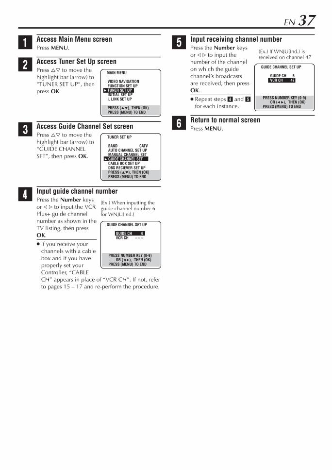
EN 371 Access Main Menu screen
Press MENU.
2 Access Tuner Set Up screenPress %fi to move thehighlight bar (arrow) to“TUNER SET UP”, thenpress OK.
3 Access Guide Channel Set screenPress %fi to move thehighlight bar (arrow) to“GUIDE CHANNELSET”, then press OK.
4 Input guide channel numberPress the Number keysor @ # to input the VCRPlus+ guide channelnumber as shown in theTV listing, then pressOK.
If you receive yourchannels with a cablebox and if you haveproperly set yourController, “CABLECH” appears in place of “VCR CH”. If not, referto pages 15 – 17 and re-perform the procedure.
(Ex.) When inputting theguide channel number 6for WNJU(Ind.)
(Ex.) If WNJU(Ind.) isreceived on channel 47
GUIDE CHANNEL SET UP
GUIDE CH 6VCR CH – – –
PRESS NUMBER KEY (0-9)OR (2 3), THEN (OK)
PRESS (MENU) TO END
GUIDE CHANNEL SET UP
GUIDE CH 6VCR CH 47
PRESS NUMBER KEY (0-9)OR (2 3), THEN (OK)
PRESS (MENU) TO END
5 Input receiving channel numberPress the Number keysor @ # to input thenumber of the channelon which the guidechannel’s broadcastsare received, then pressOK.
Repeat steps 4 and 5for each instance.
6 Return to normal screenPress MENU.
MAIN MENU
VIDEO NAVIGATIONFUNCTION SET UP
3 TUNER SET UPINITIAL SET UPi. LINK SET UP
PRESS (5∞), THEN (OK)PRESS (MENU) TO END
TUNER SET UP
BAND CATVAUTO CHANNEL SET UPMANUAL CHANNEL SET
3 GUIDE CHANNEL SETCABLE BOX SET UPDBS RECIEVER SET UPPRESS (5∞), THEN (OK)PRESS (MENU) TO END

38 EN TIMER RECORDING (cont.)
You can directly program the VCR’s timer to record up to8 broadcasts, as far as a year in advance. Remember, theclock must be set before you can program the timer(Z pg. 10).
1 Load a cassetteMake sure the record safety tab is intact. If not,cover the hole with adhesive tape, then load itinto the VCR.
The VCR turns on, and the counter is reset,automatically.
2 Access VCR PLUS+ screenPress PROG..
3 Access Program screenPress START +/– once.
4 Set program start timePress START +/–repeatedly to enter thetime you wantrecording to start.
Press and hold START+/– to increase thetime in 30-minuteintervals.
5 Set program stop timePress STOP +/– repeatedly to enter the time youwant recording to stop.
Press and hold STOP +/– to increase the time in30-minute intervals.
6 Set program datePress DATE +/–. (The current date is displayed onthe screen. The date you enter appears in itsplace.)
7 Set channel numberPress CH +/–.
If you are using a DBS receiver, see“ATTENTION FOR DBS RECEIVER USERS” onnext page.
Holding down CH +/– rapidly changes thechannel numbers.
Express TimerPrograming
Turn on the VCR and the TV, and select the AVmode on the TV.
1
1 2 3
4 5 6
7 8 9
0
VCR TV CABLE/DBS
WEEKLY
0
DAILY (M-F)
8
POWER
9
2 9
3 – 7
DBS
PROGRAM
START STOP DATE– –:– –AM – –:– –AM – –/– –/– –
CH SUN – – – STD (SP)
PRESS (+/–, SP/EP, 8=DAILY9=WEEKLY) THEN (OK)PRESS (PROG.) TO END
PROGRAM
START STOP DATE 8:00AM – –:– –AM – –/– –/– –
CH SUN – – – STD (SP)
PRESS (+/–, SP/EP, 8=DAILY9=WEEKLY) THEN (OK)PRESS (PROG.) TO END

EN 398 Set tape speed
Press HS/STD/LS3/SP/LP ( ) to set the tapespeed.
9 Return to normal screenPress PROG. or OK.“PROGRAM COMPLETED” appears on thescreen for about 5 seconds, then normal screenappears.
0 Engage timer recording standby modePress TIMER.The VCR turns off automatically and “‰” isdisplayed on the front display panel.
To timer-record daily (Monday–Friday) or weeklyserialsPress DAILY (M-F) (number “8”) or WEEKLY (number“9”) anytime during steps 3 through 8.“DAILY” or “WEEKLY” appears on the Program screen. Pressing the button again makes the corresponding
indication disappear.
To use the VCR while it is in timer recording standbymodePress TIMER to cancel the timer recording standbymode, then press POWER to turn on the VCR.DO NOT forget to put the VCR into timer recordingstandby mode again by pressing TIMER after you use theVCR; otherwise, you cannot record the broadcast youwant. When “AUTO TIMER” (Z pg. 56) is set to “ON”, the
timer recording standby mode is automaticallyengaged when the VCR is turned off. It is temporarilycanceled when the VCR is turned on. You do not haveto press TIMER to engage or disengage the timerrecording standby mode.
ATTENTION FOR DBS RECEIVER USERSIf you are using a DBSreceiver (unless “DBSRECEIVER SET UP” is setto “OFF” Z pg. 19), theband indication (TV, CATVor DBS) appears under thechannel numberindication.TV :To timer-record a regular TV broadcast
received on the VCR.CATV :To timer-record a cable TV broadcast
received on the VCR, or through a cable box(unless “CABLE BOX SET UP” is set to “OFF”Z pg. 16).
DBS :To timer-record a satellite broadcastreceived through a DBS receiver.
NOTE:If “BAND” is set to “TV” on the Tuner Set Up Screen(Z pg. 14) and “CABLE BOX SET UP” is set to “OFF” onthe Cable Box Set screen (Z pg. 16), “CATV” will not bedisplayed on the Program screen; If “BAND” is set to“CATV” or “CABLE BOX SET UP” is set to “ON”, “TV” willnot be displayed.
If the channel number entered requires that the bandbe set, “7=DBS” is displayed on the screen.If this happens, press the Number key “7 (DBS)” toselect “DBS”.
NOTES: Even if a power failure occurs, the VCR keeps your timer
programs. However, the clock time, channel settings, andother menu settings are lost if it lasts for more than 3 minutes.As a result, when the power is supplied again to this VCRafter the power failure, the following will take place.1. This VCR starts the Plug & Play setting automatically to
restore the clock time and channel setting.2. If the clock time and channel setting are restored correctly,
each timer program you have made will start at its starttime unless its end time has elapsed.
Programs that start after midnight must have the next day’sdate.
After timer recording is completed, the VCR turns offautomatically.
You can program the timer recording while a regularrecording is in progress; the menu screens will not berecorded.
If the tape reaches its end during timer recording, the cassetteis automatically ejected.
To timer-record cable or satellite channels, be sure to keepthe cable box or DBS receiver turned on.
If “MEMORY FULL” appears on the display when you finish aprogram setting, the VCR’s memory for the Video Navigationfunction is full (Z pg. 42). This is not related to actualrecording, so you can finish recording normally, but the VideoNavigation information such as recording date, start time, endtime, and channel number will not be stored in memory.
PROGRAM
START STOP DATE8:00PM 10:00PM 12/24/01
CH SUNDBS 110 STD (SP)
PRESS (+/–, SP/EP, 8=DAILY9=WEEKLY) THEN (OK)PRESS (PROG.) TO END
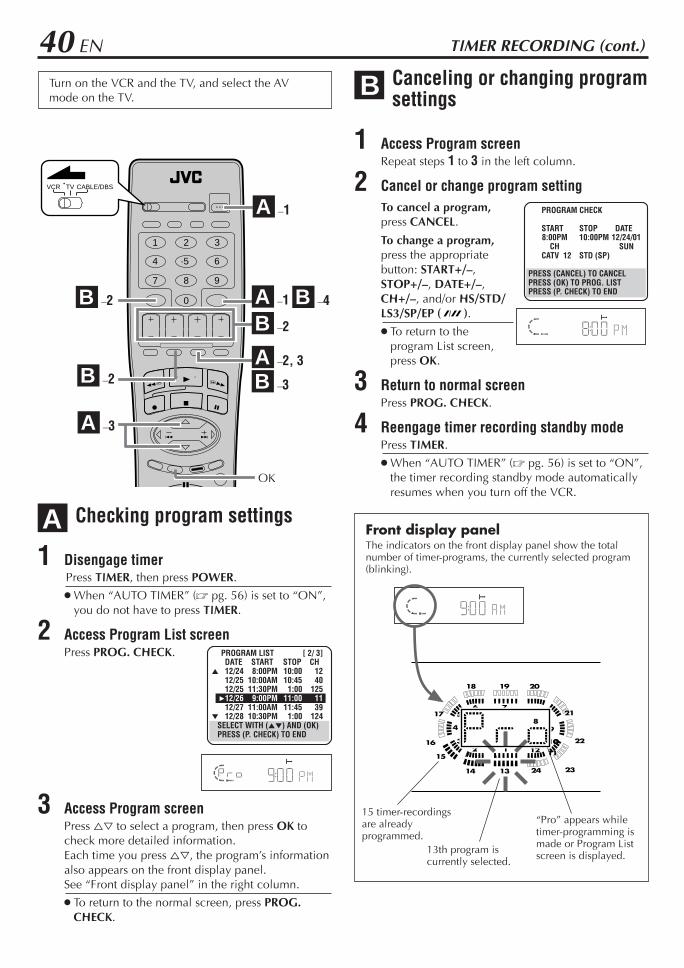
40 EN
–1
TIMER RECORDING (cont.)
Checking program settings
1 Disengage timerPress TIMER, then press POWER.
When “AUTO TIMER” (Z pg. 56) is set to “ON”,you do not have to press TIMER.
2 Access Program List screenPress PROG. CHECK.
3 Access Program screenPress %fi to select a program, then press OK tocheck more detailed information.Each time you press %fi, the program’s informationalso appears on the front display panel.See “Front display panel” in the right column.
To return to the normal screen, press PROG.CHECK.
A
BTurn on the VCR and the TV, and select the AVmode on the TV.
1 2 3
4 5 6
7 8 9
0
VCR TV CABLE/DBS
B –2
B –2
B –3
B –4A –1
B –2A –2, 3
PROGRAM CHECK
START STOP DATE8:00PM 10:00PM 12/24/01
CH SUNCATV 12 STD (SP)
PRESS (CANCEL) TO CANCELPRESS (OK) TO PROG. LISTPRESS (P. CHECK) TO END
PROGRAM LIST [ 2/ 3]DATE START STOP CH
5 12/24 8:00PM 10:00 1212/25 10:00AM 10:45 4012/25 11:30PM 1:00 125
312/26 9:00PM 11:00 1112/27 11:00AM 11:45 39
∞ 12/28 10:30PM 1:00 124SELECT WITH (5∞) AND (OK)PRESS (P. CHECK) TO END
Canceling or changing programsettings
1 Access Program screenRepeat steps 1 to 3 in the left column.
2 Cancel or change program settingTo cancel a program,press CANCEL.
To change a program,press the appropriatebutton: START+/–,STOP+/–, DATE+/–,CH+/–, and/or HS/STD/LS3/SP/EP ( ).
To return to theprogram List screen,press OK.
3 Return to normal screenPress PROG. CHECK.
4 Reengage timer recording standby modePress TIMER.
When “AUTO TIMER” (Z pg. 56) is set to “ON”,the timer recording standby mode automaticallyresumes when you turn off the VCR.
123
4
56 7
89
1010
1112
1314
15
16
17
18 19 20
21
22
2324
15 timer-recordingsare alreadyprogrammed.
13th program iscurrently selected.
“Pro” appears whiletimer-programming ismade or Program Listscreen is displayed.
Front display panelThe indicators on the front display panel show the totalnumber of timer-programs, the currently selected program(blinking).
A –3
OK
A
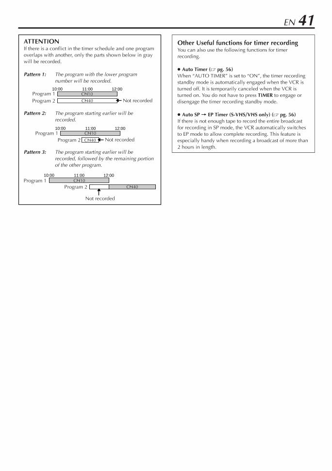
EN 41Other Useful functions for timer recordingYou can also use the following functions for timerrecording.
Auto Timer (Z pg. 56)When “AUTO TIMER” is set to “ON”, the timer recordingstandby mode is automatically engaged when the VCR isturned off. It is temporarily canceled when the VCR isturned on. You do not have to press TIMER to engage ordisengage the timer recording standby mode.
Auto SP = EP Timer (S-VHS/VHS only) (Z pg. 56)If there is not enough tape to record the entire broadcastfor recording in SP mode, the VCR automatically switchesto EP mode to allow complete recording. This feature isespecially handy when recording a broadcast of more than2 hours in length.
ATTENTIONIf there is a conflict in the timer schedule and one programoverlaps with another, only the parts shown below in graywill be recorded.
Pattern 1: The program with the lower programnumber will be recorded.
Pattern 2: The program starting earlier will berecorded.
Pattern 3: The program starting earlier will berecorded, followed by the remaining portionof the other program.
10:00 11:00 12:00CH10
CH40Program 1
Program 2
Not recorded
10:00 11:00 12:00CH10
Program 2 Not recordedProgram 1
CH40
10:00 11:00 12:00CH10
CH40 Not recordedProgram 1Program 2
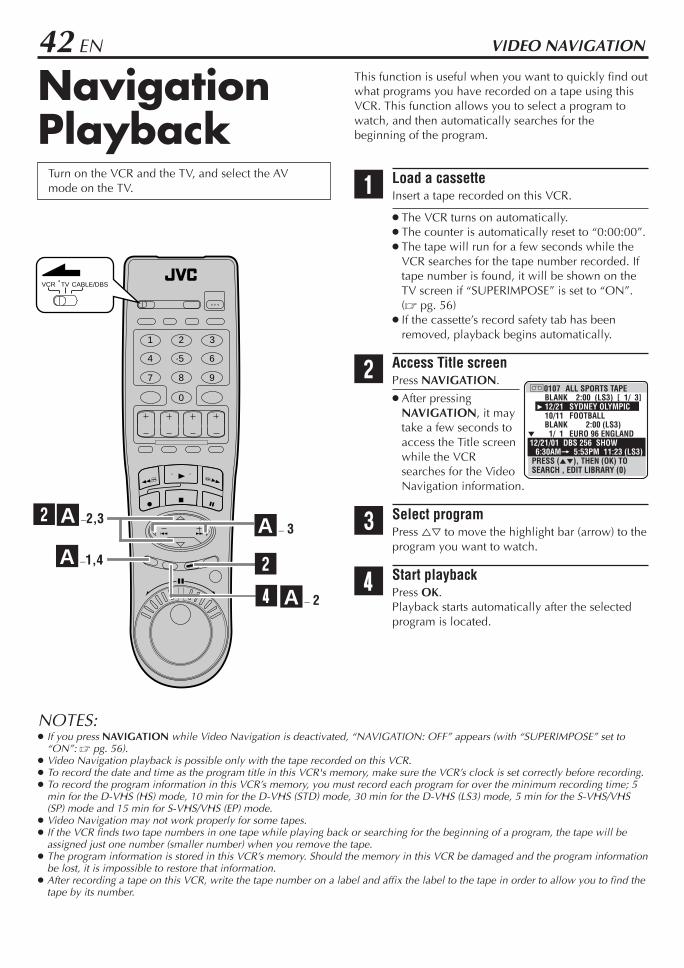
42 EN
NavigationPlayback
Turn on the VCR and the TV, and select the AVmode on the TV.
This function is useful when you want to quickly find outwhat programs you have recorded on a tape using thisVCR. This function allows you to select a program towatch, and then automatically searches for thebeginning of the program.
1 Load a cassetteInsert a tape recorded on this VCR.
The VCR turns on automatically. The counter is automatically reset to “0:00:00”. The tape will run for a few seconds while the
VCR searches for the tape number recorded. Iftape number is found, it will be shown on theTV screen if “SUPERIMPOSE” is set to “ON”.(Z pg. 56)
If the cassette’s record safety tab has beenremoved, playback begins automatically.
2 Access Title screenPress NAVIGATION.
After pressingNAVIGATION, it maytake a few seconds toaccess the Title screenwhile the VCRsearches for the VideoNavigation information.
3 Select programPress %fi to move the highlight bar (arrow) to theprogram you want to watch.
4 Start playbackPress OK.Playback starts automatically after the selectedprogram is located.
VIDEO NAVIGATION
]0107 ALL SPORTS TAPEBLANK 2:00 (LS3) [ 1/ 3]
3 12/21 SYDNEY OLYMPIC10/11 FOOTBALLBLANK 2:00 (LS3)
∞ 1/ 1 EURO 96 ENGLAND12/21/01 DBS 256 SHOW 6:30AM= 5:53PM 11:23 (LS3)
PRESS (5∞), THEN (OK) TO SEARCH , EDIT LIBRARY (0)
1 2 3
4 5 6
7 8 9
0
VCR TV CABLE/DBS
4
A –1,4
A –2,3
A – 2
2
NOTES: If you press NAVIGATION while Video Navigation is deactivated, “NAVIGATION: OFF” appears (with “SUPERIMPOSE” set to
“ON”: Z pg. 56). Video Navigation playback is possible only with the tape recorded on this VCR. To record the date and time as the program title in this VCR's memory, make sure the VCR’s clock is set correctly before recording. To record the program information in this VCR’s memory, you must record each program for over the minimum recording time; 5
min for the D-VHS (HS) mode, 10 min for the D-VHS (STD) mode, 30 min for the D-VHS (LS3) mode, 5 min for the S-VHS/VHS(SP) mode and 15 min for S-VHS/VHS (EP) mode.
Video Navigation may not work properly for some tapes. If the VCR finds two tape numbers in one tape while playing back or searching for the beginning of a program, the tape will be
assigned just one number (smaller number) when you remove the tape. The program information is stored in this VCR’s memory. Should the memory in this VCR be damaged and the program information
be lost, it is impossible to restore that information. After recording a tape on this VCR, write the tape number on a label and affix the label to the tape in order to allow you to find the
tape by its number.
A – 32

EN 43Deactivating Video Navigation
If you do not want to store program information, you candeactivate the Video Navigation function.
1 Access Main Menu screenPress MENU.
2 Access Video Navigation screenPress %fi to move thehighlight bar (arrow) to“VIDEO NAVIGATION”,then press OK.
3 Deactivate Video NavigationPress %fi to move thehighlight bar (arrow) to“NAVIGATION”, thenpress @ #.
Each time you press @ #,Video Navigation turns“ON” or “OFF”.
4 Return to normal screenPress MENU.
A
VIDEO NAVIGATIONUSED MEMORY 50%
SEARCH·EDITBLANK SPACE LIST
3 NAVIGATION OFF
PRESS (5∞), THEN (2 3)PRESS (MENU) TO END
How to read the VideoNavigation screen
Tape numberand tape title
Date ofrecording andprogram title
[Page No./Total Page No.](only 4 programs can beshown at a time)
The detailed programinformation currentlyselected (date, channel,category, start time, end time,recording length, recordingspeed)
Maximum blank timeon the tape
MAIN MENU
3 VIDEO NAVIGATIONFUNCTION SET UPTUNER SET UPINITIAL SET UPi. LINK SET UP
PRESS (5∞), THEN (OK)PRESS (MENU) TO END
]0107 D ALL SPORTS TAPEBLANK 2:00 (LS3) [ 1/ 1]
3 12/21 SYDNEY OLYMPICBLANK 2:00 (LS3) 1/ 1 EURO 96 ENGLANDBLANK 1:00 (LS3)
12/21/01 DBS 256 SHOW 6:30AM= 2:30PM 8:00 (LS3)
PRESS (5∞), THEN (OK) TO SEARCH, EDIT LIBRARY (0)
CHAPTER NAVITATIONTITLE WORLD CUP
1. CHAPTER13 2. CHAPTER2
3. CHAPTER3∞ SECTOR 3-1
PRESS (5∞), THEN (OK) PRESS (NAVIGATION) TO END
D: D-VHS cassetteS: S-VHS cassetteNo display:
VHS cassette
How to read the Video Navigation screen for pre-recorded tape
If you insert a pre-recorded tape and then pressNAVIGATION, the following screen appears.Press %fi to move the highlight bar (arrow) tothe item that you want to watch, then pressthe OK. Playback starts automatically after theselected item is located.
NOTES: Up to 38 characters of the title can be displayed,
and up to 22 characters of each chapter andsection name can be displayed.
The on-screen display is output to the TV with S-VIDEO, VIDEO, COMPONENT VIDEO signal in 480i image format.
Title
Sections
Chapters
SYDNEY OLYMPIC8:00 (LS3)
BLANK2:00(LS3)
EURO 96ENGLAND4:00 (LS3)
BLANK1:00(LS3)
Blank part*
* "BLANK" appears for non-recorded part, the partwhose information has been deleted manually(Z pg. 51), or the part where new program hasbeen recorded.
Example

44 EN VIDEO NAVIGATION (cont.)
Finding TapesTurn on the VCR and the TV, and select the AVmode on the TV.
You can find a tape you want using Video Navigation.You have four methods to find tapes; by tape number, byrecording date, by category, and by tape remaining time.
Finding by tape number
Use the Remote to do the following operations.
1 Access Main Menu screenPress MENU.
2 Access Video Navigation screenPress %fi to move thehighlight bar (arrow) to“VIDEO NAVIGATION”,then press OK.
3 Access Search·Edit screenPress %fi to move thehighlight bar (arrow) to“SEARCH·EDIT”, thenpress OK.
4 Access tape number screenPress %fi to move the highlight bar (arrow) to“TAPE NUM.”, then press OK.
The tape number list screen appears, being sortedby the tape numbers.
A
SEARCH·EDIT
3 TAPE NUM.DATECATEGORY
PRESS (5∞), THEN (OK)PRESS (MENU) TO END
\
1 2 3
4 5 6
7 8 9
0
VCR TV CABLE/DBS
B – 2A – 1,6 B – 4
A – 2 – 4 B – 2
C – 5C – 2,3
C – 2,3
MAIN MENU
3 VIDEO NAVIGATIONFUNCTION SET UPTUNER SET UPINITIAL SET UPi. LINK SET UP
PRESS (5∞), THEN (OK)PRESS (MENU) TO END
VIDEO NAVIGATIONUSED MEMORY 50%
3 SEARCH·EDITBLANK SPACE LISTNAVIGATION ON
PRESS (5∞), THEN (OK)PRESS (MENU) TO END
SRCH·EDIT/TAPE# [ 1/ 3]] TAPE TITLE0017 FOOTBALL
3 0008 RIKSON VS OGAWA0007 WORLD CUP0002 EURO 20000001 CHAMPIONS LEAGUE
∞ PRESS (5∞), THEN (OK) PAGE (2 3) EDIT (0) END (MENU)
A – 2 – 4
C – 3

EN 455 Confirm tape number lists
To go to another page of the lists, press @ #. To playback the selected tape, insert the
corresponding tape on the VCR and press OK.
6 Return to normal screenPress MENU.
Finding by recording date
Use the Remote to do the following operations.
1 Follow steps 1 to 3 on page 44, then go tothe following steps.
2 Access date screenPress %fi to move the highlight bar (arrow) to“DATE”, then press OK.
The list screen appears, being sorted by therecording date.
3 Confirm lists To go to another page of the lists, press @ #. To playback the selected program, insert the
corresponding tape on the VCR and press OK.
4 Return to normal screenPress MENU.
1st page (out of 3pages in thisexample) of the tapenumber lists isshown.
B
\
Finding by category
Use the Remote to do the following operations.To find a program by category, be sure to select programcategory in advance (Z pg. 49).
1 Follow steps 1 to 3 on page 44, then go tothe following steps.
2 Access category screenPress %fi to move thehighlight bar (arrow) to“CATEGORY”, then pressOK.
3 Select categoryPress %fi@ # to move the highlight bar (arrow) tothe category you want, then press OK.
The list screen of the selected category appears.
4 Confirm lists To go to another page of the lists, press @ #. To playback the program, insert the
corresponding tape on the VCR and press OK.
5 Return to normal screenPress MENU.
C
\
SRCH·EDIT/TAPE# [ 1/ 3]] TAPE TITLE0017 FOOT BALL
3 0008 RIKSON VS OGAWA0007 WORLD CUP0002 EURO 20000001 CHAMPIONS LEAGUE
∞ PRESS (5∞), THEN (OK) PAGE (2 3) EDIT (0) END (MENU)
SEARCH·EDIT
TAPE NUM.3 DATE
CATEGORY
PRESS (5∞), THEN (OK)PRESS (MENU) TO END
SRCH·EDIT/DATE [ 1/ 3]DATE ] TITLE 6/20/02 0301 KOREA/JAPA
3 12/31/01 0002 8:02PM F-111/ 9/01 0702 L-2 FOOTBA 5/26/01 0612 8:00AM DBS 99910/06/00 0612 12:45PM CH 45
∞ PRESS (5∞), THEN (OK) PAGE (2 3) END (MENU)
SEARCH·EDIT
TAPE NUM.DATE
3 CATEGORY
PRESS (5∞), THEN (OK)PRESS (MENU) TO END
SRCH·EDIT/CATEGORY
MOVIES SOAPS SPORTSNEWS CHILD EDUCAT.
SERIES SPECIAL MUSICCOMEDY CLASSIC SHOPPINRELIGI. OTHERS MISC.
PRESS (5∞2 3), THEN (OK) PRESS (MENU) TO END
SPORTS [ 1/ 3]] TITLE DATE0001 KOREA/JAPA 6/20/02
3 0002 8:02PM F-1 12/31/010072 L-2 FOOTBA 11/ 9/010132 CHAMPIONS 5/26/000202 EURO 2000 10/06/00
∞ PRESS (5∞), THEN (OK) PAGE (2 3) END (MENU)
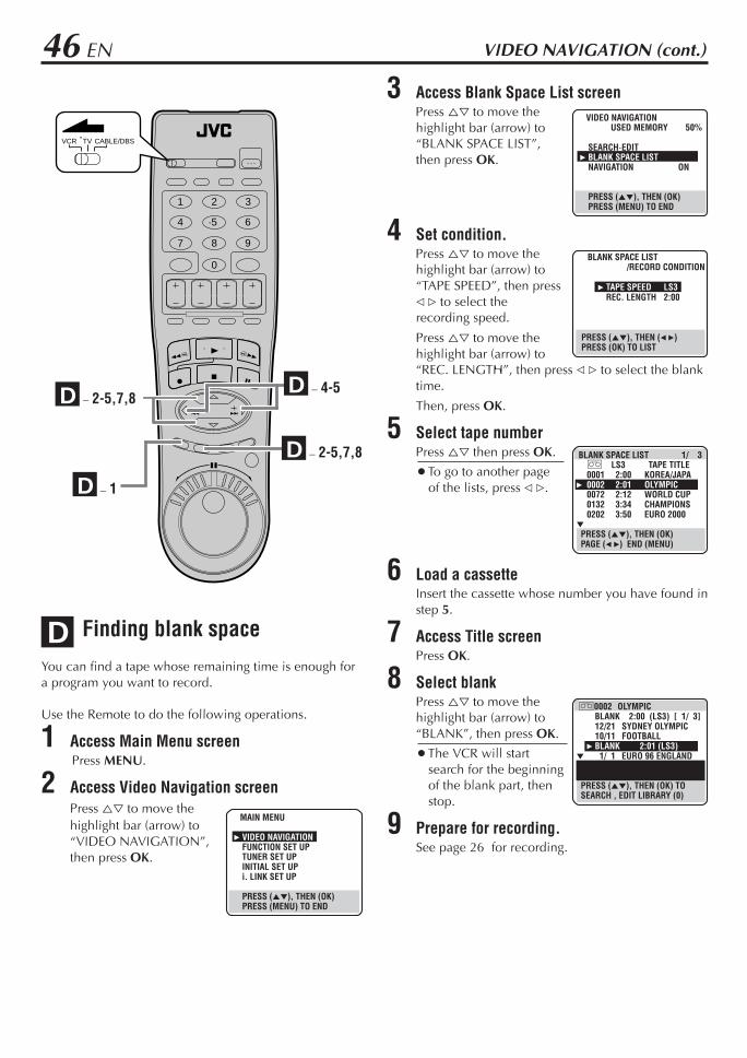
46 EN
Finding blank space
You can find a tape whose remaining time is enough fora program you want to record.
Use the Remote to do the following operations.
1 Access Main Menu screenPress MENU.
2 Access Video Navigation screenPress %fi to move thehighlight bar (arrow) to“VIDEO NAVIGATION”,then press OK.
D
VIDEO NAVIGATION (cont.)
1 2 3
4 5 6
7 8 9
0
VCR TV CABLE/DBS
D – 2-5,7,8
D – 1
D – 2-5,7,8
MAIN MENU
3 VIDEO NAVIGATIONFUNCTION SET UPTUNER SET UPINITIAL SET UPi. LINK SET UP
PRESS (5∞), THEN (OK)PRESS (MENU) TO END
VIDEO NAVIGATIONUSED MEMORY 50%
SEARCH·EDIT3 BLANK SPACE LIST
NAVIGATION ON
PRESS (5∞), THEN (OK)PRESS (MENU) TO END
BLANK SPACE LIST/RECORD CONDITION
3 TAPE SPEED LS3REC. LENGTH 2:00
PRESS (5∞), THEN (2 3)PRESS (OK) TO LIST
3 Access Blank Space List screenPress %fi to move thehighlight bar (arrow) to“BLANK SPACE LIST”,then press OK.
4 Set condition.Press %fi to move thehighlight bar (arrow) to“TAPE SPEED”, then press@ # to select therecording speed.
Press %fi to move thehighlight bar (arrow) to“REC. LENGTH”, then press @ # to select the blanktime.
Then, press OK.
5 Select tape numberPress %fi then press OK.
To go to another pageof the lists, press @ #.
6 Load a cassetteInsert the cassette whose number you have found instep 5.
7 Access Title screenPress OK.
8 Select blankPress %fi to move thehighlight bar (arrow) to“BLANK”, then press OK.
The VCR will startsearch for the beginningof the blank part, thenstop.
9 Prepare for recording.See page 26 for recording.
BLANK SPACE LIST 1/ 3] LS3 TAPE TITLE0001 2:00 KOREA/JAPA
3 0002 2:01 OLYMPIC0072 2:12 WORLD CUP0132 3:34 CHAMPIONS0202 3:50 EURO 2000
∞ PRESS (5∞), THEN (OK) PAGE (2 3) END (MENU)
]0002 OLYMPICBLANK 2:00 (LS3) [ 1/ 3]12/21 SYDNEY OLYMPIC10/11 FOOTBALL
3 BLANK 2:01 (LS3)∞ 1/ 1 EURO 96 ENGLAND
PRESS (5∞), THEN (OK) TO SEARCH , EDIT LIBRARY (0)
D – 4-5

EN 47
Editing TitlesTurn on the VCR and the TV, and select the AVmode on the TV.
When you record a TV program on this VCR, the VCRautomatically records the recording start time, date, andchannel in each program title. If the tape is recorded forthe first time, the tape number and the date and time arerecorded in the tape title. You can then edit the tape titleand the program titles as you like. You can also edit thecategory in the program title.In short, you can use the Video Navigation function tocreate your own video tape library.
Editing tape title
When you want to edit the tape title, follow theprocedure below by using the Remote.
1 Access Main Menu screenPress MENU.
2 Access Video Navigation screenPress %fi to move thehighlight bar (arrow) to“VIDEO NAVIGATION”,then press OK.
3 Access Search·Edit screenPress %fi to move thehighlight bar (arrow) to“SEARCH·EDIT”, thenpress OK.
4 Access tape number screenPress %fi to move thehighlight bar (arrow) to“TAPE NUM.”, then pressOK.
5 Select tape numberPress %fi to move thehighlight bar (arrow) to thetape number for whichyou want to edit the title,then press Number key“0”.
A
A – 2 – 6
B – 3,4
B – 4,5
1 2 3
4 5 6
7 8 9
0
VCR TV CABLE/DBS
B – 2
A – 2 – 7
A – 1,8
B – 6
MAIN MENU
3 VIDEO NAVIGATIONFUNCTION SET UPTUNER SET UPINITIAL SET UPi. LINK SET UP
PRESS (5∞), THEN (OK)PRESS (MENU) TO END
VIDEO NAVIGATIONUSED MEMORY 50%
3 SEARCH·EDITBLANK SPACE LISTNAVIGATION ON
PRESS (5∞), THEN (OK)PRESS (MENU) TO END
SEARCH·EDIT
3 TAPE NUM.DATECATEGORY
PRESS (5∞), THEN (OK)PRESS (MENU) TO END
SRCH·EDIT/TAPE# [ 1/ 3]] TAPE TITLE
3 0017 FOOTBALL0008 RIKSON VS OGAWA0007 WORLD CUP0002 EURO 20000001 CHAMPIONS LEAGUE
∞ PRESS (5∞), THEN (OK) PAGE (2 3) EDIT (0) END (MENU)
C – 3 - 5
C – 6
C – 5
C – 2
CANCEL
A – 5
B – 3
C – 3
A – 7
B – 5

48 EN VIDEO NAVIGATION (cont.)
6 Access edit screenPress %fi to move thehighlight bar (arrow) to“EDIT TAPE TITLE”, thenpress OK.
7 Enter titlePress the Number keys toenter the title, then pressOK.
• For entering thecharacters as the title,refer to “How to enterthe characters andsymbols” on the right column. (In this example,enter “JVC NEWS”.)
8 Return to normal screenPress MENU.
To enter various symbols, press . The screen forentering symbols appears. Press %fi@ # to select asymbol, then press OK.
NOTES: If you make a mistake, press @ # to select the character, then
enter the correct character. If you want to delete a character, press @ # to select the
character, then press CANCEL.
NUMBER KEY CHARACTERS
1 . , ? – + * / [ ] 1
2 A B C a b c 2
3 D E F d e f 3
4 G H I g h i 4
5 J K L j k l 5
6 M N O m n o 6
7 P Q R S p q r s 7
8 T U V t u v 8
9 W X Y Z w x y z 9
0 0 _(space)
EDIT TAPE LIBRARY ] : 0017TAPE TITLE :
FOOTBALL
3 EDIT TAPE TITLEDELETE TAPE INFO
PRESS (5∞), THEN (OK)PRESS (MENU) TO END
EDIT TAPE LIBRARYEDIT TAPE TITLE
JVC NEW S(INPUT LETTERS)
INPUT TITLE WITH (0 – 9, < >,CANCEL), INPUT SYMBOL ( )THEN (OK), END (MENU)
How to enter the characters and symbolsPress the Number keys, then press 33 to enter eachcharacter.Refer to the example below.
(Ex.) Enter “JVC NEWS”.1 Press 5 (JKL) once to enter “J”, then press 33.2 Press 8 (TUV) three times to enter “V”, then press 33.3 Press 2 (ABC) three times to enter “C”, then press 33.4 Press 0 ( ) twice to enter “ (space)”, then press 33.5 Press 6 (MNO) twice to enter “N”, then press 33.6 Press 3 (DEF) twice to enter “E”, then press 33.7 Press 9 (WXYZ) once to enter “W”, then press 33.8 Press 7 (PQRS) four times to enter “S”, then press 33.

EN 49B Entering or Editing program
title
When you want to edit the program title, follow theprocedure below by using the Remote.
1 Load a cassetteInsert a tape on which there is a program you wantto edit.
2 Access Title screenPress NAVIGATION.
3 Select programPress %fi to move thehighlight bar (arrow) to theprogram you want to edit,then press Number key“0”.
4 Access edit screenPress %fi to move thehighlight bar (arrow) to“EDIT PROGRAM TITLE”,then press OK.
5 Enter titlePress the Number keys toenter the title, then pressOK.
• For entering thecharacters as the title,refer to “How to enterthe characters andsymbols” on page 48. (In this example, enter“JVC NEW”.)
6 Return to normal screenPress MENU.
C Editing program category
When you want to change the program category, followthe procedure below by using the Remote.
1 Load a cassetteInsert a tape on which there is a program you wantto edit.
2 Access Title screenPress NAVIGATION.
3 Select programPress %fi to move thehighlight bar (arrow) to theprogram you want to edit,then press Number key“0”.
4 Access category screenPress %fi to move thehighlight bar (arrow) to“EDIT CATEGORY”, thenpress OK.
5 Select categoryPress %fi@ # to select thecategory you want, thenpress OK.
6 Return to normal screenPress MENU.
]0017 ALL SPORTS TAPEBLANK 2:00 (LS3) [ 1/ 3]12/21 SYDNEY OLYMPIC
3 10/11 FOOTBALLBLANK 2:00 (LS3)
∞ 1/ 1 EURO 96 ENGLAND12/21/01 DBS 256 SHOW 6:30AM= 5:53PM 11:23 (LS3)
PRESS (5∞), THEN (OK) TO SEARCH , EDIT LIBRARY (0)
EDIT TAPE LIBRARY ] : 0017PROGRAM TITLE :
FOOTBALL
3 EDIT PROGRAM TITLEEDIT CATEGORYDELETE PROGRAM INFO
PRESS (5∞), THEN (OK)PRESS (MENU) TO END
EDIT TAPE LIBRARYEDIT PROGRAM TITLE
JVC NEW S(INPUT LETTERS)
INPUT TITLE WITH (0 – 9, < >,CANCEL), INPUT SYMBOL ( )THEN (OK), END (MENU)
]0017 ALL SPORTS TAPEBLANK 2:00 (LS3) [ 1/ 3]12/21 SYDNEY OLYMPIC
3 10/11 FOOTBALLBLANK 2:00 (LS3)
∞ 1/ 1 EURO 96 ENGLAND12/21/01 DBS 256 SHOW 6:30AM= 5:53PM 11:23 (LS3)
PRESS (5∞), THEN (OK) TO SEARCH, EDIT LIBRARY (0)
EDIT TAPE LIBRARY ] : 0017PROGRAM TITLE :
FOOTBALL
EDIT PROGRAM TITLE3 EDIT CATEGORY
DELETE PROGRAM INFO
PRESS (5∞), THEN (OK)PRESS (MENU) TO END
EDIT LIBRARY/CATEGORIESTITLE (FOOTBALL)
CATEGORY : SPORTSSMOVIES SOAPS SPORTSNEWS CHILD EDUCAT.
SERIES SPECIAL MUSICCOMEDY CLASSIC SHOPPINRELIGI. OTHERS MISC.
PRESS (5∞2 3), THEN (OK) PRESS (MENU) TO END
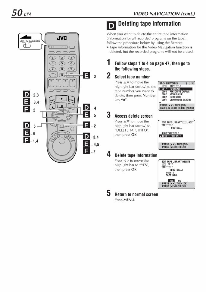
50 EN
Deleting tape information
When you want to delete the entire tape information(information for all recorded programs on the tape),follow the procedure below by using the Remote.• Tape information for the Video Navigation function is
deleted, but the recorded programs will not be erased.
1 Follow steps 1 to 4 on page 47, then go tothe following steps.
2 Select tape numberPress %fi to move thehighlight bar (arrow) to thetape number you want todelete, then press Numberkey “0”.
3 Access delete screenPress %fi to move thehighlight bar (arrow) to“DELETE TAPE INFO”,then press OK.
4 Delete tape informationPress @ # to move thehighlight bar to “YES”,then press OK.
5 Return to normal screenPress MENU.
D
1 2 3
4 5 6
7 8 9
0
VCR TV CABLE/DBS
D – 3,4
E – 4,5
F – 2
D – 5
E – 6
F – 1,4
D – 2,3
E – 3,4
F – 2
VIDEO NAVIGATION (cont.)
SRCH·EDIT/TAPE# [ 1/ 3]] TAPE TITLE
3 0017 FOOTBALL0008 RIKSON VS OGAWA0007 WORLD CUP0002 EURO 20000001 CHAMPIONS LEAGUE
∞ PRESS (5∞), THEN (OK) PAGE (2 3) EDIT (0) END (MENU)
EDIT TAPE LIBRARY ] : 0017TAPE TITLE :
FOOTBALL
EDIT TAPE TITLE3 DELETE TAPE INFO
PRESS (5∞), THEN (OK)PRESS (MENU) TO END
EDIT TAPE LIBRARY DELETE] 0017TAPE TITLE
(FOOTBALL)DELETETAPE INFO
YES NOPRESS (2 3), THEN (OK)PRESS (MENU) TO END
E – 3
E – 2
D – 4
E – 5

EN 51Deleting program information
When you want to delete the stored information for eachrecorded program, follow the procedure below by usingthe Remote.• Program information for the Video Navigation function
is deleted, but the recorded program will not beerased.
1 Load a cassetteInsert a tape on which there is a program you wantto edit.
2 Access Title screenPress NAVIGATION.
3 Select programPress %fi to move thehighlight bar (arrow) to theprogram you want todelete, then press Numberkey “0”.
4 Access delete screenPress %fi to move thehighlight bar (arrow) to“DELETE PROGRAMINFO”, then press OK.
5 Delete program informationPress @ # to move thehighlight bar to “YES”,then press OK.
6 Return to normal screenPress MENU.
E Checking memory
You can check the amount of recorded information inthe VCR’s memory.
1 Access Main Menu screenPress MENU.
2 Access Video Navigation screenPress %fi to move thehighlight bar (arrow) to“VIDEO NAVIGATION”,then press OK.
3 Check memoryThe percentage of theused memory isdisplayed.
4 Return to normal screenPress MENU.
If memory is full, you have to delete unwantedinformation to store more information in the VCR’smemory.
F
]0017 ALL SPORTS TAPEBLANK 2:00 (LS3) [ 1/ 3]12/21 SYDNEY OLYMPIC
3 10/11 WORLD CUPBLANK 2:00 (LS3)
∞ 1/ 1 EURO 96 ENGLAND12/21/01 DBS 256 SHOW 6:30AM= 5:53PM 11:23 (LS3)
PRESS (5∞), THEN (OK) TO SEARCH, EDIT LIBRARY (0)
EDIT TAPE LIBRARY ] : 0017PROGRAM TITLE :
WORLD CUP
EDIT PROGRAM TITLEEDIT CATEGORY
3 DELETE PROGRAM INFO
PRESS (5∞), THEN (OK)PRESS (MENU) TO END
EDIT TAPE LIBRARY DELETE] 0017PROGRAM TITLE
(WORLD CUP)DELETEPROGRAM INFO
YES NOPRESS (2 3), THEN (OK)PRESS (MENU) TO END
MAIN MENU
3 VIDEO NAVIGATIONFUNCTION SET UPTUNER SET UPINITIAL SET UPi. LINK SET UP
PRESS (5∞), THEN (OK)PRESS (MENU) TO END
VIDEO NAVIGATIONUSED MEMORY 50%
3 SEARCH·EDITBLANK SPACE LISTNAVIGATION ON
PRESS (5∞), THEN (OK)PRESS (MENU) TO END

52 EN
1 2 3
4 5 6
7 8 9
0
You can use the other useful function settings on theFunction Set Up screens by following the proceduredescribed below. For the functions you can set on the Function Set Up
screen, see pages 53 to 57.
1 Access Main Menu screenPress MENU.
2 Access Function Set Up screenPress %fi to move thehighlight bar (arrow) to“FUNCTION SET UP”,then press OK.
3 Select Function Menu.Press %fi to move thehighlight bar (arrow) tothe menu of thefunction you want toset, then press OK.
4 Select Function.Press %fi to move thehighlight bar (arrow) tothe function you wantto set.
5 Change settingPress @ #.
6 Return to normal screenPress MENU.
NOTE:To go back to a previous screen during settings, press BACK(1).
Turn on the VCR and the TV, and select the AVmode on the TV.
OTHER USEFUL FUNCTIONS
Useful FunctionSettings
1 6
2 – 4
2 3
FUNCTION SET UP
3 VIDEO FUNCTIONAUDIO FUNCTIONIN/OUT FUNCTIONADDITIONAL
PRESS (5∞), THEN (OK)PRESS (MENU) TO END
FUNCTION SET/VIDEO (VHS)
3 V, CALIBRATION ONPICTURE CONTROL AUTODIGITAL R3 ONVIDEO STABILIZER OFF
SELECT WITH (5∞) AND (2 3)PRESS (MENU) TO END
MAIN MENU
VIDEO NAVIGATION3 FUNCTION SET UP
TUNER SET UPINITIAL SET UPi. LINK SET UP
PRESS (5∞), THEN (OK)PRESS (MENU) TO END
5

EN 53* The default setting is bold in the table below.
When this function is set to “ON”, this VCR checks the condition of thetape in use during playback and recording, and compensates to providethe highest-possible pictures. This takes place whenever you play back atape or start recording after inserting a tape.
NOTES: During playback, this function is always working even though “V,
CALIBRATION” appears just at the beginning of automatic tracking. During recording, this function works only for the first EP recording and the first
SP recording on an inserted tape.For timer recording, this function checks the tape condition both for the SPrecording and the EP recording before the first timer recording starts.
When you play back rental tapes or tapes recorded on other VCRs, set thisfunction either “ON” or “OFF” whichever gives you the best picture.
m PICTURE CONTROL(S-VHS/VHS only)AUTO (NORM)EDITSOFTSHARP
m V, CALIBRATION(S-VHS/VHS only)ONOFF
Video settings [VIDEO (VHS)]
m DIGITAL R3 (S-VHS/VHS only)ONOFF
This function helps you to adjust the playback picture quality accordingto your preference.
AUTO: Normally select this. Picture quality is adjusted(NORM) automatically. When “V, CALIBRATION” is “OFF”,
“NORM” will appear instead of “AUTO”.EDIT: Minimizes picture degradation during editing (recording
and playback).SOFT: Reduces image coarseness when viewing overplayed tapes
containing much noise.SHARP: Clearer, sharper-edged picture when viewing images with
much flat, same-colored surfaces such as cartoons.NOTES: When you select “EDIT”, “SOFT” or “SHARP”, the selected mode will not
change until you select again. Select “EDIT” when you are editing tapes (Z pg. 62, 64). After you finish editing
the tapes, select “AUTO” (“NORM” when “V, CALIBRATION” is “OFF”.)
When this function is set to “ON”, edge correction to the luminancesignal is performed to enhance details. Normally set this function to“ON”.
NOTES: Depending on the type of tape being used, picture quality may be better with
“DIGITAL R3” set to “OFF”. If you use this VCR as the playback VCR for editing, be sure to set “DIGITAL
R3” to “OFF” before starting.
When this function is set to “ON”, you can automatically correct verticalvibrations in the picture when playing back unstable recordings made onanother VCR.
NOTES: When you finish viewing a tape, be sure to set this function to “OFF”. Regardless of the setting, this function has no effect during recording and during
special effects playback. The on-screen display may jitter vertically when this function is set to “ON”. To watch recordings with close-caption, set this function to “OFF”.
m VIDEO STABILIZER(S-VHS/VHS only)ONOFF
CONTINUED ON NEXT PAGE \

54 EN OTHER USEFUL FUNCTIONS (cont.)
* The default setting is bold in the table below.
Up to four audio signal channels can be input from a DV camcorderthrough the DV IN connector (i.LINK). This recorder allows you to selectand record two of these channels. This setting is used to specify whichtwo channels to record.
When there are four DV audio channels (32kHz):AUDIO1: Records the two channels (L/R) of DV AUDIO 1.AUDIO2: Records the two channels (L/R) of DV AUDIO 2.1+2MIX: Mixes and records both DV AUDIO 1 and 2.
When there are two DV audio channels (48kHz):Because there are only two channels, those two channels are recordedregardless of the DV sound setting.
m DV AUDIO RECAUDIO1AUDIO21+2MIX
m OPTICAL OUTDolby D2CH-PCM
Audio settings [AUDIO]
S200
DV INi.LINK IN/OUT
DIGITAL OUTOPTICAL
PCM/DOLBY DIGITAL
R
Y
L
PB/CB
VIDEO
PR/CR
S VIDEO S VIDEO
AUDIO R
IN(L-1)
IN(L-2)
L(MONO) VIDEO
REMOTE PAUSE/AV COMPU LINK
CABLE BOX
ANTENNA
AUDIO
OUTOUT
OUTTV
IN
VHF/UHF
IN
Amplifier equippedwith Dolby Digitaldecoder
Note for connection:Remove the connectorcover from the VCR andthe protection cap fromthe cable.
This VCR
This VCR can send the Dolby Digital bitstream or PCM Audio to externaldevices.When you play back a tape including the Dolby Digital bitstream, and ifyou have a device equipped with Dolby Digital decoder, set thisfunction to “Dolby D”.If not, set this function to “2CH-PCM”.The digital audio is output only when you play back a tape recorded inD-VHS format. The digital audio is not output when you play back atape recorded in S-VHS/VHS format.
When this function is set to “ON”; If a SAP program is received, the SAP audio is recorded on both the
normal and Hi-Fi tracks. The main audio is not recorded. If a non-SAP program is received, the main audio is recorded on both
the Hi-Fi and normal tracks.When this function is set to “OFF”, the SAP audio cannot be recorded.
m 2ND AUDIO RECONOFF
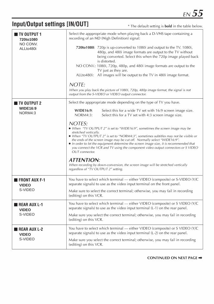
EN 55
You have to select which terminal — either VIDEO (composite) or S-VIDEO (Y/Cseparate signals) to use as the video input terminal on the front panel.
Make sure to select the correct terminal; otherwise, you may fail in recording(editing) on this VCR.
You have to select which terminal — either VIDEO (composite) or S VIDEO (Y/Cseparate signals) to use as the video input terminal (L-1) on the rear panel.
Make sure you select the correct terminal; otherwise, you may fail in recording(editing) on this VCR.
You have to select which terminal — either VIDEO (composite) or S VIDEO (Y/Cseparate signals) to use as the video input terminal (L-2) on the rear panel.
Make sure you select the correct terminal; otherwise, you may fail in recording(editing) on this VCR.
m REAR AUX L-1VIDEOS-VIDEO
m FRONT AUX F-1VIDEOS-VIDEO
m REAR AUX L-2VIDEOS-VIDEO
m TV OUTPUT 1720to1080NO CONV.ALLto480i
Input/Output settings [IN/OUT]
m TV OUTPUT 2WIDE16:9NORM4:3
* The default setting is bold in the table below.
Select the apppropriate mode depending on the type of TV you have.
WIDE16:9: Select this for a wide TV set with 16:9 screen image size.NORM4:3: Select this for a TV set with 4:3 screen image size.
NOTES: When “TV OUTPUT 2” is set to “WIDE16:9”, sometimes the screen image may be
stretched vertically. When “TV OUTPUT 2” is set to “NORM4:3”, sometimes subtitles may not be visible or
the ends of the screen image may be cut off. Normally select “WIDE16:9”. In order to let the equipment determine the screen image size, it is recommended that
you connect the VCR and TV using the component video output connectors or S VIDEOOUT connector.
ATTENTION:When recording by down-conversion, the screen image will be stretched verticallyregardless of “TV OUTPUT 2” setting.
Select the apppropriate mode when playing back a D-VHS tape containing arecording of an HD (High Definition) signal:
720to1080: 720p is up-converted to 1080i and output to the TV. 1080i,480p, and 480i image formats are output to the TV withoutbeing converted. Select this when the 720p image played backis distorted.
NO CONV.: 1080i, 720p, 480p, and 480i image formats are output to theTV just as they are.
ALLto480i: All images will be output to the TV in 480i image format.
NOTE:When you play back the picture of 1080i, 720p, 480p image format, the signal is notoutput from the S-VIDEO or VIDEO output connector.
CONTINUED ON NEXT PAGE \

56 EN OTHER USEFUL FUNCTIONS (cont.)
* The default setting is bold in the table below.
m AUTO TIMERONOFF
m SUPERIMPOSEONOFF
m GRAY BACKONOFF
m POWER SAVE MODEONOFF
Additional settings [ADDTL]When this function is set to “ON”, the VCR automatically switches to EP mode toallow complete recording if there is not enough tape to record the entire programwhile timer-recording in SP mode.For Example . . .Recording a program of 140 minutes in length onto a 120-minute tape
Make sure you set this function to “ON” before the timer-recording starts.
NOTES: If you have programed the VCR to timer-record 2 or more programs, the second program and
those thereafter may not fit on the tape with this function set to “ON”. In this case, do not usethis function, but change the tape speed manually during timer programing.
In order to ensure that the recording fits on the tape, this function may leave a slight non-recorded portion at the end of the tape.
There may be some noise and sound disturbance where the tape speed switches from SP to EPmode on the tape.
This function is not available during ITR (Instant Timer Recording), and will not work properlyon the following tapes: T(ST)-30, T(ST)-60, T(ST)-90, and T(ST)-120.
When this function is set to “ON”:The timer recording standby mode is automatically engaged when the VCR is turnedoff. It is temporarily canceled when the VCR is turned on. You do not have to pressTIMER to engage or disengage the timer recording standby mode.
When this function is set to “OFF”:You have to press TIMER to engage or disengage the timer recording standby mode.
When this function is set to “ON”, various VCR status information (on-screen display)appears on the screen.
NOTES: When you use this VCR as the playback VCR for editing a tape, be sure to set this function to
“OFF”; otherwise, the VCR status information (on-screen display) will be recorded on theedited tape.
If you select a channel on which no signal is received, the channel number is displayedregardless of this function setting.
When this function is set to “ON”, the VCR changes the screen into the gray backscreen automatically after/while the input signals do not come into.
When this function is set to “ON”, you can reduce the power consumption. While theVCR is turned off, the front display panel does not show the clock.When this function is set to “OFF”, an i.LINK device cannot be recognized. As aresult, it is not possible to record a program using the digital tuner’s* timer function.In addition the device does not pass along data if it is in a branched connection.* A digital tuner will be released in the future.
You can swich the guide track indicator on the front display panel as follows(Z pg. 78):
TAPE RUN: displays the remaining time (inside) and the tape position (outside).A. LEVEL: displays the audio level (inside for right sound/outside for left
sound).OFF: turns display off.
m AUTO SP = EP TIMER(S-VHS/VHS only)ONOFF
Approximately 110 minutes
SP mode
Approximately 30 minutes
EP mode
m FRONT DISPLAYTAPE RUNA. LEVELOFF
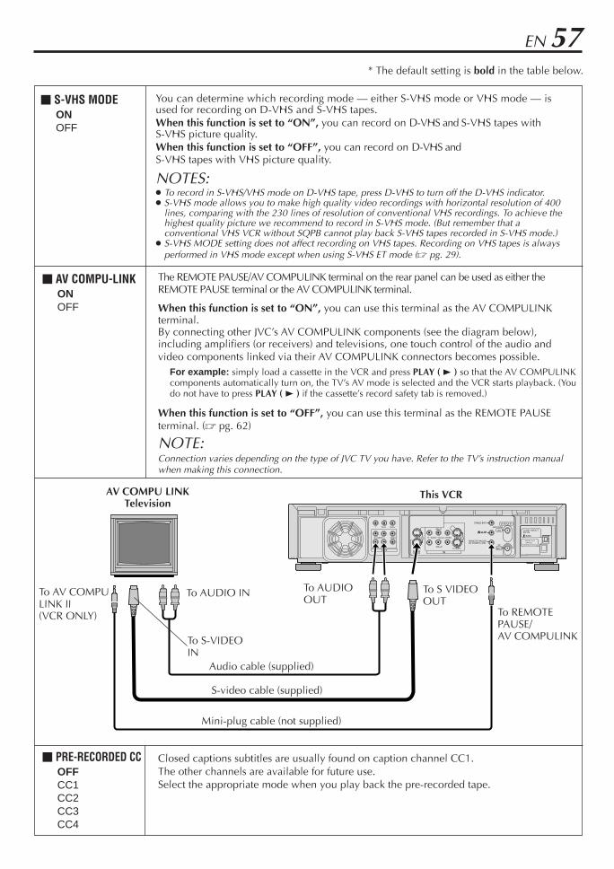
EN 57
S200
DV INi.LINK IN/OUT
DIGITAL OUTOPTICAL
PCM/DOLBY DIGITAL
R
Y
L
PB/CB
VIDEO
PR/CR
S VIDEO S VIDEO
AUDIO R
IN(L-1)
IN(L-2)
L(MONO) VIDEO
REMOTE PAUSE/AV COMPU LINK
CABLE BOX
ANTENNA
AUDIO
OUTOUT
OUTTV
IN
VHF/UHF
IN
* The default setting is bold in the table below.
To AV COMPULINK II(VCR ONLY)
AV COMPU LINKTelevision
This VCR
To AUDIOOUT
Mini-plug cable (not supplied)
Audio cable (supplied)
To REMOTEPAUSE/AV COMPULINK
To AUDIO IN
To S-VIDEOIN
S-video cable (supplied)
To S VIDEOOUT
m AV COMPU-LINKONOFF
The REMOTE PAUSE/AV COMPULINK terminal on the rear panel can be used as either theREMOTE PAUSE terminal or the AV COMPULINK terminal.
When this function is set to “ON”, you can use this terminal as the AV COMPULINKterminal.By connecting other JVC’s AV COMPULINK components (see the diagram below),including amplifiers (or receivers) and televisions, one touch control of the audio andvideo components linked via their AV COMPULINK connectors becomes possible.
For example: simply load a cassette in the VCR and press PLAY ( 3 ) so that the AV COMPULINKcomponents automatically turn on, the TV’s AV mode is selected and the VCR starts playback. (Youdo not have to press PLAY ( 3 ) if the cassette’s record safety tab is removed.)
When this function is set to “OFF”, you can use this terminal as the REMOTE PAUSEterminal. (Z pg. 62)
NOTE:Connection varies depending on the type of JVC TV you have. Refer to the TV’s instruction manualwhen making this connection.
m PRE-RECORDED CCOFFCC1CC2CC3CC4
Closed captions subtitles are usually found on caption channel CC1.The other channels are available for future use.Select the appropriate mode when you play back the pre-recorded tape.
m S-VHS MODEONOFF
You can determine which recording mode — either S-VHS mode or VHS mode — isused for recording on D-VHS and S-VHS tapes.When this function is set to “ON”, you can record on D-VHS and S-VHS tapes withS-VHS picture quality.When this function is set to “OFF”, you can record on D-VHS andS-VHS tapes with VHS picture quality.
NOTES: To record in S-VHS/VHS mode on D-VHS tape, press D-VHS to turn off the D-VHS indicator. S-VHS mode allows you to make high quality video recordings with horizontal resolution of 400
lines, comparing with the 230 lines of resolution of conventional VHS recordings. To achieve thehighest quality picture we recommend to record in S-VHS mode. (But remember that aconventional VHS VCR without SQPB cannot play back S-VHS tapes recorded in S-VHS mode.)
S-VHS MODE setting does not affect recording on VHS tapes. Recording on VHS tapes is alwaysperformed in VHS mode except when using S-VHS ET mode (Z pg. 29).

58 EN OTHER USEFUL FUNCTIONS (cont.)
i.LINK Set Up i.LINK set up for connected deviceWhen you connect i.LINK compatible devices to thisVCR, an i.LINK device number is asigned to each devicein the order of connection.If you want to change the number, follow the procedurebelow.
1 Access Main Menu screenPress MENU.
2 Access i.LINK Set Up screenPress %fi to move the highlight bar (arrow) to“i.LINK SET UP”, then press OK.
3 Confirm LINC settingCheck that “LINC” isset to “AUTO”. If not,press @ # to set to“AUTO”.
4 Reset NumberPress %fi to move thehighlight bar (arrow) to“RESET NUMBER”,then press OK.
5 Set Number againConnect the external devices one by one.
• Make sure to connect the VCR's AC power plugto the AC outlet and turn on the external devicebefore connection.
• Each device will be numbered in the order ofconnection.
NOTE:If you do not want to set i.LINK device number, set “LINC” to“OFF” in step 3.
i.LINK SET UP
3 LINC AUTORESET NUMBER
PRESS (5∞), THEN (2 3)PRESS (MENU) TO END
i.LINK SET UP
LINC AUTO3 RESET NUMBER
PRESS (5∞), THEN (OK)PRESS (MENU) TO END
1 2 3
4 5 6
7 8 9
0
VCR TV CABLE/DBS
1 2 4
32 – 4

EN 59What is “i.LINK?”“i.LINK” is a digital serial interface that allows devicesequipped with an i.LINK connector to exchange digitalvideo signals, digital audio signals, and device controlsignals bi-directionally over a single cable.
i.Link refers to the IEEE1394-1995 industry specification andextensions thereof. The logo is used for products compliantwith the i.Link standard.
This VCR uses a four-pin i.LINK connector to input andoutput MPEG2 video signals, audio signals, and controlsignals. The i.LINK connector is also used as an inputfor DV compressed signals from the DV output of adigital video camera.
i.LINK Connectioni.LINK-compatible devices can be connected in daisychain fashion using i.LINK cables.
Any two devices in the daisy chain can exchange databi-directionally, even if there are other devicesconnected between them.i.LINK also supports a “repeater function” that passesinput MPEG2 and DV signals through to the next devicein the chain.
i.LINK Branched ConnectionIf you are connecting a device that is equipped withthree or more i.LINK connectors, you can also branchthe i.LINK connection.
A B C D
A to D: i.LINK-compatibledevices
i.LINK cable
A B C D
E F
i.LINK cable
A to F: i.LINK-compatible devicesB, C: Devices with three or more i.LINK connectors
A B C D
A B C
A B
Good connection examples(A to D: i.LINK-compatible devices)The connections below do not form a loop.
Bad connection examples(A to D: i.LINK-compatible devices)The connections below form a loop.
A B C D
A B C
A B
C: Device with three i.LINK connectors
NOTE: You can connect as many as 63 devices (including this VCR) through an i.LINK connection. If you use a branched i.LINK
connection, however, the maximum path length on a branch is 17 devices. In the case of a personal computer and some other devices, data is not passed along by those devices if the device power is off.
Furthermore, data is not passed along by this VCR when “FRONT DISPLAY” is set to “OFF” on this VCR (Z pg. 56).For details, refer to the instruction manual for the connected device.
The maximum data transfer speed supported by the i.LINK connector on this VCR is 200Mbps (approximately 200 megabits persecond). The maximum data transfer speed that is actually attained may be slower depending on how this VCR is used or if adevice with a slower transfer speed is connected to this VCR.
i.LINK Connection ExamplesExamples of good i.LINK connections and bad i.LINKconnections are shown below. The digital signals flowto all connected devices. When connecting i.LINKdevices, make sure that the devices are connected insuch a way that digital signals do not return (loop back)to the device that output them. Looped connection isnot permitted.

60 EN OTHER USEFUL FUNCTIONS (cont.)
NOTES: While the Satellite Auto Recording standby mode or after Satellite Auto Recording is finished, the VCR will not enter the timer
recording standby mode even though “AUTO TIMER” is set to “ON”. (Z pg. 56) If you turn off this VCR while Satellite Auto Recording is in progress, recording stops. Video Calibration (Z pg. 53) does not work while Satellite Auto Recording is in progress. Auto Clock (Z pg. 11) does not work while in the Satellite Auto Recording standby mode. The VCR may not record a short portion at the beginning of the program or may record slightly longer than the actual length of the
program when Satellite Auto Recording method is used. If you engage the Satellite Auto Recording standby mode while the DBS receiver is turned on, the VCR will not start Satellite Auto
Recording, and “Err L-1” appears on the front display panel. When you turn off the DBS receiver, “L-1” appears instead of “Err L-1”and the VCR enters the Satellite Auto Recording standby mode.
If you have connected another component other than a DBS receiver (or cable box) to the AUDIO/VIDEO IN or S VIDEO IN (L-1)connectors, be sure not to engage the Satellite Auto Recording standby mode; otherwise, the VCR will start recording when theconnected component is turned on.
Satellite Auto Recording and timer-recording cannot be performed at the same time. If the “L-1” blinks quickly on the front display panel in the Satellite Auto Recording standby mode (even though your DBS receiver
is turned off), Satellite Auto Recording will not work properly.If this is the case, perform “Express Timer Programing” (Z pg. 38) to timer-record a satellite program.(Some DBS receivers output signals even if the power is off. Satellite Auto Recording is not possible with those DBS receivers.)
This function allows you to automatically record asatellite program which is timer-programed on your DBSreceiver.
Preparation: Connect a DBS receiver to the AUDIO/VIDEO IN or S VIDEO IN (L-1) connectors* on the rear;otherwise, you cannot use this function.• You can also connect the cable box if it has a timer.* To use these connectors, you have to select which one to use
(Z pg. 55).
Satellite AutoRecording
4 3
1 Set timer program on DBS receiver• For timer programing method, refer to the
manual supplied with the DBS receiver.
2 Load a cassetteMake sure the record safety tab is intact.
3 Set tape speedPress HS/STD/LS3/SP/EP ( ) to set therecording speed.
4 Engage Satellite Auto Recording standbymodePress and hold REC LINK for more than 2seconds.The VCR turns off automatically and the “L-1”appears on the front display panel (Satellite AutoRecording standby mode).When signals come into the VCR from the DBSreceiver, the VCR starts recording (“L-1” blinksand the record ( ) indicator lights), and stopsrecording and goes off when signals stop comingin.
• Each time you press the button, Satellite AutoRecording standby mode turns on and off.When it is off, “L-1” disappears.
IMPORTANT: Be sure not to turn on the DBS receiverbefore the program starts broadcasting; otherwise, theVCR will start recording when the DBS receiver isturned on.

EN 61JLIP ID NumberSetting
The JLIP (Joint Level Interface Protocol) terminal is usedto connect the VCR to a personal computer or similardevice. By connecting through the JLIP terminals, youcan control the VCR during editing and certain otheroperations, from the connected personal computer orsimilar device.
When connecting this VCR to another device using theJLIP terminals, each device must have a different JLIP IDnumber.
The JLIP ID number of this VCR is preset to “1” whenshipped from the factory. You can change this number toany other number between 1 to 99.
To change the JLIP ID number of this VCR, follow theprocedure below.
1 Access Main Menu screenPress MENU.
2 Access Initial Set Up screenPress %fi to move the highlight bar (arrow) to“INITIAL SET UP”, then press OK.
3 Select JLIP ID Set Up screenPress %fi to move thehighlight bar (arrow) to“JLIP ID SET UP”, thenpress OK.
4 Set JLIP ID NumberPress the Number keysto enter the desired IDnumber, then press OK.
5 Return to normal screenPress MENU.
JLIP ID SET UP
1
PRESS NUMBER KEY (O-9)OR (2 3), THEN (OK)
PRESS (MENU) TO END
INITIAL SET UP
CLOCK SET UP3 JLIP ID SET UP
PRESS (5∞), THEN (OK)PRESS (MENU) TO END
NOTE:For further details on the JLIP system or devices, consult yournearest JVC dealer.U.S. customers can contact JVC directly toll free at 1-800-252-5722.
1 2 3
4 5 6
7 8 9
0
VCR TV CABLE/DBS
1 5
2 3
2 – 4
4

62 EN
Edit FromCamcorder
To rear panelREMOTE PAUSE/AV COMPULINK
connector
Mini-plug cable(not supplied)
(JVC camcorderonly)
Audio cable(supplied)
Camcorder(for playback)
To Audio output
To EDIT
This VCR (for recording)
To AUDIOInput
EDITING
S-video cable(supplied)
To S-videooutput
Various connection for editing tapesThe following three methods can be used for editing tapes. VHS to S-VHS editing (VIDEO-VIDEO connection):
Although the picture quality is inherently limited by theoriginal VHS quality, the edited tape has better picturequality than those made by VHS-to-VHS editing.
S-VHS to VHS editing (VIDEO-VIDEO connection):Since the original source is recorded in S-VHS mode, theedited tape has better picture quality than those made byVHS-to-VHS editing.
S-VHS to S-VHS editing (S-VIDEO connection): Originalpicture quality of S-VHS made can be duplicated withminimal picture degradation. This is the best editingmethod you can use on S-VHS VCRs.
DV to D-VHS editing (DV connection): If your camcorderhas a DV connector, D-VHS recording (HS/STD/LS3mode) is possible with this VCR.However, this VCR can be used only as a recording VCR.
To S-VIDEOInput
1 2 3
4 5 6
7 8 9
0
VCR TV CABLE/DBS
4 7
4 – 6
4 – 6
9
33
S200
DV INi.LINK IN/OUT
DIGITAL OUTOPTICAL
PCM/DOLBY DIGITAL
R
Y
L
PB/CB
VIDEO
PR/CR
S VIDEO S VIDEO
AUDIO R
IN(L-1)
IN(L-2)
L(MONO) VIDEO
REMOTE PAUSE/AV COMPU LINK
CABLE BOX
ANTENNA
AUDIO
OUTOUT
OUTTV
IN
VHF/UHF
IN
To DV output
This VCR (for recording)
To DV INconnector
DV cable(not supplied)
A
B
DV camcorder(for playback)
8
NOTES: It is impossible to dub from the VCR to a camcorder equipped
with the DV connector because the DV signal is not outputfrom the DV IN connector on this VCR.
You cannot select HS mode for recording speed on this VCRwhen connecting to the camcorder equipped with the DVconnector.
You cannot use the i.LINK connection depending on the typeof camcorder equipped with the DV connector. In this case,set "LINC" to "OFF" (Z pg.58).

EN 63You can use a camcorder as the playback VCR and yourVCR as the recording VCR.
1 Make connections A S-VHS/VHS connectionConnect an audio cable between the camcorder’saudio output connectors and your VCR’s audioinput connectors.
When the JVC camcorder is equipped with theMaster Edit Control, you can control the VCRfrom the camcorder. Connect the mini-plugcable (not supplied with this VCR) as illustratedon page 62.
When using a camcorder with a monauraloutput, connect the audio output connector onthe camcorder to the left audio input connectoron this VCR.
NOTE:If the camcorder does not have S-video outputconnector, use a video cable.
B DV connectionConnect a DV cable between the camcorder’sDV connector and your VCR’s DV IN connector.
2 Load a cassetteInsert the cassette to be recorded on into thisVCR (for recording).
3 Select input mode on this VCRL-1 or L-2 — when connecting the camcorder to
the audio/video input connectorson the rear panel.
F-1 — when connecting the camcorder tothe audio/video input connectorson the front panel.
l-1 etc. — when connecting the camcorder toDV IN connector.
Press the Number key “0 (AUX)” or CH +/–.
4 Select video input terminalAccess the “IN/OUT FUNCTION” screen(Z pg. 52).
When using S VIDEO terminal, set “FRONT AUXF-1” (or “REAR AUX L-1 (or L-2)” if you use theconnectors on the rear) to “S-VIDEO”.
When using VIDEO terminal, set “FRONT AUXF-1” (or “REAR AUX L-1 (or L-2)” if you use theconnectors on the rear) to “VIDEO”.
5 Set “PICTURE CONTROL” to “EDIT”(for S-VHS/VHS connection)Access the “VIDEO FUNCTION” screen(Z pg. 52).
If your camcorder is a JVC Master Edit Control-equipped type — go to step 6.If your camcorder is NOT a JVC Master EditControl-equipped type — go to step 7.
6 Set “AV COMPU-LINK” to “OFF”Access the “ADDITIONAL” screen (Z pg. 52).
The REMOTE PAUSE/AV COMPULINKconnector works as the Remote Pauseconnector when “AV COMPU-LINK” is set to“OFF”.
7 Return to normal screenPress MENU.
8 Start playbackPress PLAY ( 3 ) on the camcorder.
NOTE:If the camcorder is equipped with a superimpose/OSDdisable feature then set it to “OFF” before startingplayback.
9 Start recordingOn the front panel:Press REC ( ¶ ).
On the Remote:Press REC ( ¶ ) and PLAY ( 3 ) at the same time.
If you are using a Master Edit Control-equippedJVC camcorder, recording starts automaticallyon this VCR. (Refer to camcorder’s instructionmanual.)
NOTES: Be sure to select “AUTO” for “PICTURE CONTROL” (or
“NORM” when “V, CALIBRATION” is set to “OFF”) after youfinish dubbing the tapes (Z pg. 53).
When you are editing through the DV IN connector, the VCRwill stop if the player begins playing a blank portion of tapeor the signal is interrupted.
Do not connect this VCR to the PC with the i.LINKcable. The operation is not guaranteed.
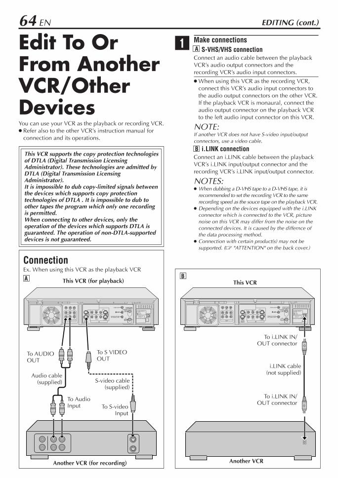
64 EN
S200
DV INi.LINK IN/OUT
DIGITAL OUTOPTICAL
PCM/DOLBY DIGITAL
R
Y
L
PB/CB
VIDEO
PR/CR
S VIDEO S VIDEO
AUDIO R
IN(L-1)
IN(L-2)
L(MONO) VIDEO
REMOTE PAUSE/AV COMPU LINK
CABLE BOX
ANTENNA
AUDIO
OUTOUT
OUTTV
IN
VHF/UHF
IN
S200
DV INi.LINK IN/OUT
DIGITAL OUTOPTICAL
PCM/DOLBY DIGITAL
R
Y
L
PB/CB
VIDEO
PR/CR
S VIDEO S VIDEO
AUDIO R
IN(L-1)
IN(L-2)
L(MONO) VIDEO
REMOTE PAUSE/AV COMPU LINK
CABLE BOX
ANTENNA
AUDIO
OUTOUT
OUTTV
IN
VHF/UHF
IN
Edit To OrFrom AnotherVCR/OtherDevices
Another VCR (for recording)
Audio cable(supplied)
This VCR (for playback)
To AUDIOOUT
ConnectionEx. When using this VCR as the playback VCR
To AudioInput
EDITING (cont.)
To S VIDEOOUT
To S-videoInput
S-video cable(supplied)
A
To i.LINK IN/OUT connector
This VCR
To i.LINK IN/OUT connector
i.LINK cable(not supplied)
B
Another VCR
1 Make connections A S-VHS/VHS connectionConnect an audio cable between the playbackVCR’s audio output connectors and therecording VCR’s audio input connectors.
When using this VCR as the recording VCR,connect this VCR’s audio input connectors tothe audio output connectors on the other VCR.If the playback VCR is monaural, connect theaudio output connector on the playback VCRto the left audio input connector on this VCR.
NOTE:If another VCR does not have S-video input/outputconnectors, use a video cable.
B i.LINK connectionConnect an i.LINK cable between the playbackVCR’s i.LINK input/output connector and therecording VCR’s i.LINK input/output connector.
NOTES: When dubbing a D-VHS tape to a D-VHS tape, it is
recommended to set the recording VCR to the samerecording speed as the souce tape on the playback VCR.
Depending on the devices equipped with the i.LINKconnector which is connected to the VCR, picturenoise on this VCR may differ from the noise on theconnected devices. It is caused by the differnce ofthe data processing method.
Connection with certain product(s) may not besupported. (Z "ATTENTION" on the back cover.)
You can use your VCR as the playback or recording VCR. Refer also to the other VCR’s instruction manual for
connection and its operations.
This VCR supports the copy protection technologiesof DTLA (Digital Transmission LicensingAdministrator). These technologies are admitted byDTLA (Digital Transmission LicensingAdministrator).It is impossible to dub copy-limited signals betweenthe devices which supports copy protectiontechnologies of DTLA . It is impossible to dub toother tapes the program which only one recordingis permitted.When connecting to other devices, only theoperation of the devices which supports DTLA isguaranteed. The operation of non-DTLA-supporteddevices is not guaranteed.

EN 65
1 2 3
4 5 6
7 8 9
0
VCR TV CABLE/DBS
33
2 Load cassettesInsert the playback cassette into the playbackVCR and the cassette to be recorded on into therecording VCR.
3 Select input mode on recording VCRSelect the correct external input on the otherVCR.
On this VCR (when using this VCR as therecording VCR);L-1 or L-2 — when connecting the other VCR
to the audio/video inputconnectors or the rear panel.
F-1 — when connecting the other VCRto the audio/video inputconnectors on the front panel.
I-1 etc. — when connecting the other VCRto i.LINK IN/OUT connector.
Press the Number key “0 (AUX)” or CH +/–.
NOTES: When using this VCR as the recording VCR, set the
video input terminal setting correctly (Z pg. 63). When using this VCR as the playback VCR for
editing, set “DIGITAL R3” to “OFF” (Z pg. 53).
4 Select edit modeSet the edit mode to “ON” for the VCRs if such amode is equipped.
On this VCR, set “PICTURE CONTROL” to“EDIT” (Z pg. 53).
5 Start playbackPress PLAY ( 3 ) on the playback VCR.
NOTE:If the playback VCR is equipped with a superimpose/OSD disable feature then set it to “OFF” before startingplayback (Z pg. 56).
6 Start recordingPress REC ( ¶ ) on the recording VCR.
NOTES: Be sure to select “AUTO” for “PICTURE CONTROL” (or
“NORM” when “V, CALIBRATION” is set to “OFF”) after youfinish dubbing the tapes (Z pg. 53).
When dubbing using the i.LINK connector, set the recordingspeed on the recording VCR to the same speed as the sourcetape on the playback VCR.

66 EN
1 2 3
4 5 6
7 8 9
0
VCR TV CABLE/DBS
MULTI-BRAND REMOTE CONTROL
This Remote can control some functions of remotecontrollable TVs listed below. Without setting, you cancontrol a JVC TV.
1 Turn on the TVTurn on the TV using the Power button on the TVor its Remote.
2 Set remote operation modeSet the VCR/TV/CABLE/DBS selector to “TV”.
3 Set TV brand codeFollow the example shown below.1 Press and hold POWER.2 Press the Number keys to enter your TV’s
brand code by referring to the table below.3 Press STOP ( 7 ), and release POWER.
Once you have set the Remote to operate theTV, you do not have to set it until you replacethe batteries from the Remote.
JVC and PANASONIC have two codes. If theTV does not function with one code, tryentering the other.
4 Operate TVFirst set the VCR/TV/CABLE/DBS selector to“TV”, then press one of the following buttons:POWER, TV/VCR, TV CH +/–, (TVMuting), TV VOL +/–, and Number keys.
For some brands, you must press ENTER afterhaving pressed the Number keys to enter achannel number.
To operate the VCR, set the VCR/TV/CABLE/DBS selector back to “VCR”.
NOTES: Depending on the type of TV, some or all functions cannot be
operated using this Remote. It’s not possible to operate a TV not equipped with a remote
sensor.
TV BRAND NAME BRAND CODE
JVC 01, 03
HITACHI 10
MAGNAVOX 02
MITSUBISHI 03
PANASONIC 04, 11
RCA 05
SHARP 06
SONY 07
SAMSUNG 12
SANYO 13
SEARS 13
TOSHIBA 08
ZENITH 09
TV BrandSetting
(Ex.) To set Remote to RCA 05:
Press in successionHolddown Release
STOPJKL5
POWER AUX
0
3 –2Number
TV CH +/–
POWER
TV VOL +/–
ENTER
TV/VCR
2
3 –3
3 –1 3

EN 67This Remote can control some functions of the cableboxes listed below. Some cable box brands have morethan one code. If your cable box does not function witha specified code, try other codes.
1 Turn on the cable boxTurn on the cable box using the Power button onthe cable box or its Remote.
2 Set remote operation modeSet the VCR/TV/CABLE/DBS selector to “CABLE/DBS”.
3 Enter cable box brand codeFollow the example shown below.1 Press and hold POWER.2 Press the Number keys to enter your cable
box’s brand code by referring to the tablebelow.
3 Press STOP ( 7 ), and release POWER.
Once you have set the Remote to operate thecable box, you do not have to set it until youreplace the batteries from the Remote.
4 Operate cable boxFirst set the VCR/TV/CABLE/DBS selector to“CABLE/DBS”, then press one of the followingbuttons: POWER, TV CH +/–, and Number keys.
For some brands, you must press ENTER afterhaving pressed the Number keys to enter achannel number.
To change the cable box’s channels, pressTV CH +/– or the Number keys. (The CH +/–button can be used to change the VCR’schannels only.)
To operate the VCR, set the VCR/TV/CABLE/DBS selector back to “VCR”.
NOTES: Depending on the type of cable box, some or all functions
cannot be operated using this Remote. It’s not possible to operate a cable box not equipped with a
remote sensor. It’s not possible to set the Remote for both your cable box and
a DBS receiver at the same time. You can only set the Remotecontrol to operate one of these units at a time.
CABLE BOX BRAND NAME BRAND CODE
ARCHER 01, 05, 17CABLETENNA 01, 17CABLEVIEW 15, 16, 17, 21, 25CITIZEN 15, 16, 17, 21, 25CURTIS 02DIAMOND 01, 17EASTERN 19GC BRAND 15, 16, 17, 21, 25GEMINI 15GENERAL INSTRUMENTS 01, 04, 06, 11, 12, 15, 28HAMLIN 10, 18, 19, 23JASCO 15JERROLD 01, 04, 06, 11, 12, 15, 28NOVAVISION 02OAK 07PANASONIC 13, 14PULSER 15, 16, 17, 21, 25RCA 13, 14REGAL 10, 18, 19, 23REGENCY 19REMBRANDT 01, 16, 17SAMSUNG 05, 16, 24SCIENTIFIC ATLANTA 02SIGMA 07SL MARX 05, 16, 17, 24, 25SPRUCER 13, 14STARGATE 05, 15, 16, 17, 21, 24, 25TELEVIEW 05, 16, 24TOCOM 01, 04, 16UNIKA 01, 17UNIVERSAL 16, 17, 25VIDEOWAY 03, 09, 22ZENITH 03, 09, 22
(Ex.) To set the Remote to RCA 14:
Holddown Press in succession Release
Cable BoxBrand Setting
STOP. , ? DHI1 4
POWER
TV CH +/–
1 2 3
4 5 6
7 8 9
0
VCR TV CABLE/DBS
3 –2Number
POWERENTER
2
3 –3
3 –1 3
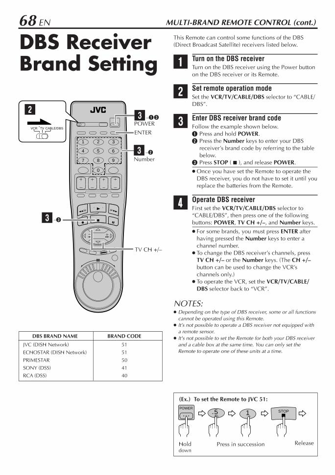
68 EN MULTI-BRAND REMOTE CONTROL (cont.)
This Remote can control some functions of the DBS(Direct Broadcast Satellite) receivers listed below.
1 Turn on the DBS receiverTurn on the DBS receiver using the Power buttonon the DBS receiver or its Remote.
2 Set remote operation modeSet the VCR/TV/CABLE/DBS selector to “CABLE/DBS”.
3 Enter DBS receiver brand codeFollow the example shown below.1 Press and hold POWER.2 Press the Number keys to enter your DBS
receiver’s brand code by referring to the tablebelow.
3 Press STOP ( 7 ), and release POWER.
Once you have set the Remote to operate theDBS receiver, you do not have to set it until youreplace the batteries from the Remote.
4 Operate DBS receiverFirst set the VCR/TV/CABLE/DBS selector to“CABLE/DBS”, then press one of the followingbuttons: POWER, TV CH +/–, and Number keys.
For some brands, you must press ENTER afterhaving pressed the Number keys to enter achannel number.
To change the DBS receiver’s channels, pressTV CH +/– or the Number keys. (The CH +/–button can be used to change the VCR’schannels only.)
To operate the VCR, set the VCR/TV/CABLE/DBS selector back to “VCR”.
NOTES: Depending on the type of DBS receiver, some or all functions
cannot be operated using this Remote. It’s not possible to operate a DBS receiver not equipped with
a remote sensor. It's not possible to set the Remote for both your DBS receiver
and a cable box at the same time. You can only set theRemote to operate one of these units at a time.
DBS BRAND NAME BRAND CODE
JVC (DISH Network) 51ECHOSTAR (DISH Network) 51PRIMESTAR 50SONY (DSS) 41RCA (DSS) 40
(Ex.) To set the Remote to JVC 51:
ReleaseHolddown
Press in succession
DBS ReceiverBrand Setting
STOP. , ?1
JKL5
POWER
1 2 3
4 5 6
7 8 9
0
VCR TV CABLE/DBS
3 –2Number
TV CH +/–
ENTER
2
3 –3
POWER3 –1 3

EN 69This Remote is capable of transmitting two controlcodes; one set to respond to A code control signals andanother set to respond to B code control signals.This Remote control is preset to send A code signalsbecause your VCR is initially set to respond to A codesignals. You can easily modify your VCR and the Remoteto respond to B code signals.When using two JVC VCRs, set two VCRs and theirRemotes to different codes, so that you can operate theseVCRs separately.
1 Set remote operation modeSet the VCR/TV/CABLE/DBS selector to “VCR”.
2 Set remote control code for Remote1 Press and hold A/B.2 Press the Number key “2”.3 Press STOP ( 7 ), and release A/B.
3 Turn off VCRPress POWER on the VCR.
4 Check remote control code for VCRPress PLAY (3) on the VCR for more than 5seconds.
The code currently set appears on the frontdisplay panel.
5 Turn on VCRPress POWER on the Remote.
The code transmitted from the Remote blinksfor a few seconds on the front display panel.
After the code disappears on the front displaypanel, make sure that the VCR is turned on bypressing POWER on the Remote.
To set the Remote and the VCR back to A codecontrol signals, repeat the same procedure asshown above except pressing the Number key“1” in step 2.
To control two VCRs with the same RemoteYou can control two JVC VCRs by switching the remotecontrol code for the Remote between A and B(Z step 2), keeping two VCRs to different control codes. Press the Number key “1” for A code control signals
and the Number key “2” for B code control signals. (Tochange only the remote control code for the Remote,DO NOT perform steps 3 to 5.)
ChangingRemote ControlCode
(Ex.) To set Remote to B code:
Press in successionHolddown
ReleaseSTOP
ABC
A/B
2
1 2 3
4 5 6
7 8 9
0
VCR TV CABLE/DBS
2 –1, 3
52
2 –3
2 –2
NOTE:When "POWER SAVE MODE" is set to "ON" , you can notchange the remote control code. Before changing the code, set"POWER SAVE MODE" to "OFF" (Z pg. 56).
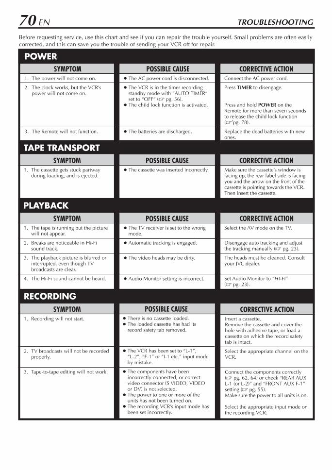
70 EN TROUBLESHOOTING
Before requesting service, use this chart and see if you can repair the trouble yourself. Small problems are often easilycorrected, and this can save you the trouble of sending your VCR off for repair.
POSSIBLE CAUSE The AC power cord is disconnected.
The VCR is in the timer recordingstandby mode with “AUTO TIMER”set to “OFF” (Z pg. 56).
The child lock function is activated.
The batteries are discharged.
SYMPTOM1. The power will not come on.
2. The clock works, but the VCR’spower will not come on.
3. The Remote will not function.
CORRECTIVE ACTIONConnect the AC power cord.
Press TIMER to disengage.
Press and hold POWER on theRemote for more than seven secondsto release the child lock function(Z pg. 78).
Replace the dead batteries with newones.
SYMPTOM1. The cassette gets stuck partway
during loading, and is ejected.
CORRECTIVE ACTIONMake sure the cassette’s window isfacing up, the rear label side is facingyou and the arrow on the front of thecassette is pointing towards the VCR.Then insert the cassette.
POSSIBLE CAUSE The cassette was inserted incorrectly.
SYMPTOM1. The tape is running but the picture
will not appear.
2. Breaks are noticeable in Hi-Fisound track.
3. The playback picture is blurred orinterrupted, even though TVbroadcasts are clear.
4. The Hi-Fi sound cannot be heard.
POSSIBLE CAUSE The TV receiver is set to the wrong
mode.
Automatic tracking is engaged.
The video heads may be dirty.
Audio Monitor setting is incorrect.
CORRECTIVE ACTIONSelect the AV mode on the TV.
Disengage auto tracking and adjustthe tracking manually (Z pg. 23).
The heads must be cleaned. Consultyour JVC dealer.
Set Audio Monitor to “HI-FI”(Z pg. 23).
CORRECTIVE ACTIONInsert a cassette.Remove the cassette and cover thehole with adhesive tape, or load acassette on which the record safetytab is intact.
Select the appropriate channel on theVCR.
Connect the components correctly(Z pg. 62, 64) or check “REAR AUXL-1 (or L-2)” and “FRONT AUX F-1”setting (Z pg. 55).Make sure the power to all units is on.
Select the appropriate input mode onthe recording VCR.
POSSIBLE CAUSE There is no cassette loaded. The loaded cassette has had its
record safety tab removed.
The VCR has been set to “L-1”,“L-2”, “F-1” or “I-1 etc.” input modeby mistake.
The components have beenincorrectly connected, or correctvideo connector (S VIDEO, VIDEOor DV) is not selected.
The power to one or more of theunits has not been turned on.
The recording VCR’s input mode hasbeen set incorrectly.
SYMPTOM1. Recording will not start.
2. TV broadcasts will not be recordedproperly.
3. Tape-to-tape editing will not work.
POWER
TAPE TRANSPORT
PLAYBACK
RECORDING
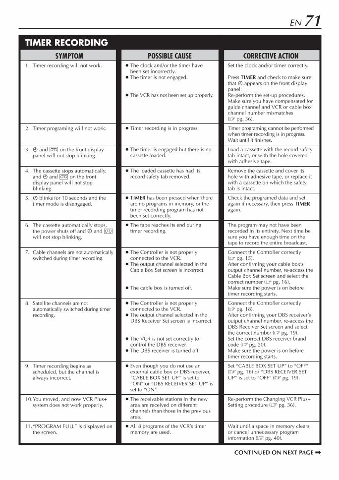
EN 71
CORRECTIVE ACTIONSet the clock and/or timer correctly.
Press TIMER and check to make surethat ‰ appears on the front displaypanel.Re-perform the set-up procedures.Make sure you have compensated forguide channel and VCR or cable boxchannel number mismatches(Z pg. 36).
Timer programing cannot be performedwhen timer recording is in progress.Wait until it finishes.
Load a cassette with the record safetytab intact, or with the hole coveredwith adhesive tape.
Remove the cassette and cover itshole with adhesive tape, or replace itwith a cassette on which the safetytab is intact.
Check the programed data and setagain if necessary, then press TIMERagain.
The program may not have beenrecorded in its entirety. Next time besure you have enough time on thetape to record the entire broadcast.
Connect the Controller correctly(Z pg. 15).After confirming your cable box’soutput channel number, re-access theCable Box Set screen and select thecorrect number (Z pg. 16).Make sure the power is on beforetimer recording starts.
Connect the Controller correctly(Z pg. 18).After confirming your DBS receiver’soutput channel number, re-access theDBS Receiver Set screen and selectthe correct number (Z pg. 19).Set the correct DBS receiver brandcode (Z pg. 20).Make sure the power is on beforetimer recording starts.
Set “CABLE BOX SET UP” to “OFF”(Z pg. 16) or “DBS RECEIVER SETUP” is set to “OFF” (Z pg. 19).
Re-perform the Changing VCR Plus+Setting procedure (Z pg. 36).
Wait until a space in memory clears,or cancel unnecessary programinformation (Z pg. 40).
SYMPTOM1. Timer recording will not work.
2. Timer programing will not work.
3. ‰ and ] on the front displaypanel will not stop blinking.
4. The cassette stops automatically,and ‰ and ] on the frontdisplay panel will not stopblinking.
5. ‰ blinks for 10 seconds and thetimer mode is disengaged.
6. The cassette automatically stops,the power shuts off and ‰ and ]will not stop blinking.
7. Cable channels are not automaticallyswitched during timer recording.
8. Satellite channels are notautomatically switched during timerrecording.
9. Timer recording begins asscheduled, but the channel isalways incorrect.
10.You moved, and now VCR Plus+system does not work properly.
11.“PROGRAM FULL” is displayed onthe screen.
POSSIBLE CAUSE The clock and/or the timer have
been set incorrectly. The timer is not engaged.
The VCR has not been set up properly.
Timer recording is in progress.
The timer is engaged but there is nocassette loaded.
The loaded cassette has had itsrecord safety tab removed.
TIMER has been pressed when thereare no programs in memory, or thetimer recording program has notbeen set correctly.
The tape reaches its end duringtimer recording.
The Controller is not properlyconnected to the VCR.
The output channel selected in theCable Box Set screen is incorrect.
The cable box is turned off.
The Controller is not properlyconnected to the VCR.
The output channel selected in theDBS Receiver Set screen is incorrect.
The VCR is not set correctly tocontrol the DBS receiver.
The DBS receiver is turned off.
Even though you do not use anexternal cable box or DBS receiver,“CABLE BOX SET UP” is set to“ON” or “DBS RECEIVER SET UP” isset to “ON”.
The receivable stations in the newarea are received on differentchannels than those in the previousarea.
All 8 programs of the VCR’s timermemory are used.
TIMER RECORDING
CONTINUED ON NEXT PAGE \

72 EN TROUBLESHOOTING (cont.)
VIDEO NAVIGATIONCORRECTIVE ACTION
Tape information cannot be shown if ithas not been recorded on this VCR.
Video Navigation cannot workcorrectly on a tape if it has more thanone tape number. If this happens, fast-forward the tape up to its end, eject it,and try it again.
Check the remaining memory(Z pg. 51). If it is full, deleteunnecessary Video Navigationinformation. (Z pg. 50, 51).
SYMPTOM1. Tape infomation screen does not
appear for the currently insertedtape.
2. The VCR cannot search for thecorrect program.
3. “MEMORY FULL” appears on thescreen when you try to startrecording.
POSSIBLE CAUSE The current tape inserted has not
been recorded on this VCR.
Two (or more) tape numbers arerecorded on one tape.
The VCR’s memory for VideoNavigation is fully recorded.
ATTENTIONThis VCR contains microcomputers. External electronic noise or interference can cause microcomputer to malfunction. If theVCR does not operate correctly switch its power off and unplug the AC power cord from the AC supply. Wait for a while andthen plug the power back in. Eject and check the condition of the cassette. If everything appears normal, you can operate theVCR as usual.
MOISTURE CONDENSATIONMoisture in the air will condense on the VCR when you move it from a cold place to a warm place, or underextremely humid conditions—just as water droplets form on the surface of a glass filled with cold liquid. Moisturecondensation on the head drum will cause damage to the tape. In conditions where condensation may occur, keep theVCR turned on for a few hours to evaporate the moisture before inserting a tape.
ABOUT HEAD CLEANINGAccumulation of dirt and other particles on the video heads may cause the playback picture to become blurred orinterrupted. Be sure to contact your nearest JVC dealer if such troubles occur.
OTHER PROBLEMSCORRECTIVE ACTION
If you need the skipped channels,restore them (Z pg. 14).
Press PAUSE ( 8 ) to pause therecording, change channels, thenpress PLAY ( 3 ) to resume recording.
Reset the correct brand codes(Z pg. 66, 67 or 68).
Select a different host channel duringSemiauto Clock Set (Z pg. 11), orperform Manual Clock Set (Z pg. 12).
SYMPTOM1. When scanning channels, some of
them are skipped over.
2. The channel cannot be changed.
3. The Remote will not operate yourTV or cable box or DBS receiver.
4. Even though Auto or SemiautoClock Set has been performed, theclock is incorrect.
POSSIBLE CAUSE Those channels have been preset to
be skipped.
Recording is in progress.
The brand codes are set incorrectly.
The clock setting data received fromthe host channel is incorrect.

EN 73Error Codes and MessagesSome error codes and messages may appear on the TV screen when operating the VCR. Refer to the chart below forthe solution.
102
103
104
105
107
200
201
202
203
205
300
301
302
CODE MESSAGE DESCRIPTION
REC PROHIBITED
REC PROHIBITED
CAN NOT DECODE VIDEO OR AUDIOUSE SET TOP BOX OR HDTV TUNER
INPUT BY S-VHS/VHSCHOOSE ANALOG INPUT
CAN NOT REC DIGITAL INPUT BYS-VHS/VHSUSE ANALOG TIMER PROGRAMING
CAN NOT DECODE VIDEO OR AUDIOUSE SET TOP BOX OR HDTV TUNER
WAIT A MINUTECALIBRATING. . .
COPY RESTRICTED PROG OUTPUT480I VIDEO
COPY RESTRICTED PROG CAN NOTPLAY BACK
CAN NOT PLAY BACK THIS TAPE
CAN NOT DECODE VIDEO OR AUDIOUSE SET TOP BOX OR HDTV TUNER
TOO MANY i.LINK INSTRUMENTSREAD INST.BOOK
COPY RESTRICTED PROG OUTPUT480I VIDEO
An attempt was made to make a D-VHS recording of a program forwhich only the analog information is copy protected.
While making a D-VHS recording of a program, a signal in whichonly the analog information is copy protected was input to this VCR.
An attempt was made to dub a D-VHS recording of a digitally copyprotected program.
While dubbing a D-VHS recording, digitally copy protectedinformation was input to this VCR.
This VCR supports copy protection technologies such as DTLA, andcannot record programs that employ digital copy protection.
A signal that is not compatible with this VCR was input. Switch to the analog input for recording. (It may be possible to play
back the material if using a digital tuner*, etc.)
An attempt was made to make an S-VHS/VHS recording of a signalfrom an i.LINK device other than a digital tuner*.
The i.LINK connector on this VCR is intended only for D-VHSrecording. This VCR does not convert a digital signal into an analogsignal for recording. Switch to the analog input for recording.
An attempt was made to make an S-VHS/VHS recording using thetimer function with “i.LINK” selected on the digital tuner* side.
The i.LINK connector on this VCR is intended only for D-VHSrecording. This VCR does not convert a digital signal into an analogsignal for recording. Also, it is not possible to make a D-VHSrecording on VHS tape. Switch to the analog input for recording.
An attempt was made to play back a signal that is not supported bythis VCR.
To play back the signal, use the digital tuner*, etc., that was used torecord the signal.
Normal playback is being prevented by mosaic noise, etc. Wait while the VCR calibrates itself so that it can output a normal
image.
When playing back a program that was copy protected in 1080i,720p, or 480p mode, the VCR down-converts to 480i mode for output.
An attempt was made to play back a tape containing a copy protectedprogram.
Even if you record a copy protected program, this VCR cannot play itback.
An attempt was made to play back a tape containing an invalidD-VHS recording.
A signal format that is not supported by this VCR was input. Use a digital tuner*, etc.
A signal containing too much data was input to the i.LINK connectoron this VCR.
There are too many devices with i.LINK connectors, such as digitaltuners and digital video cameras, connected to the i.LINK connectoron this VCR. Turn off any devices that are not in use.
When playing back a program that was copy protected in 1080i,720p, or 480p mode, the VCR down-converts to 480i mode for output.
* A digital tuner will be released in the future.
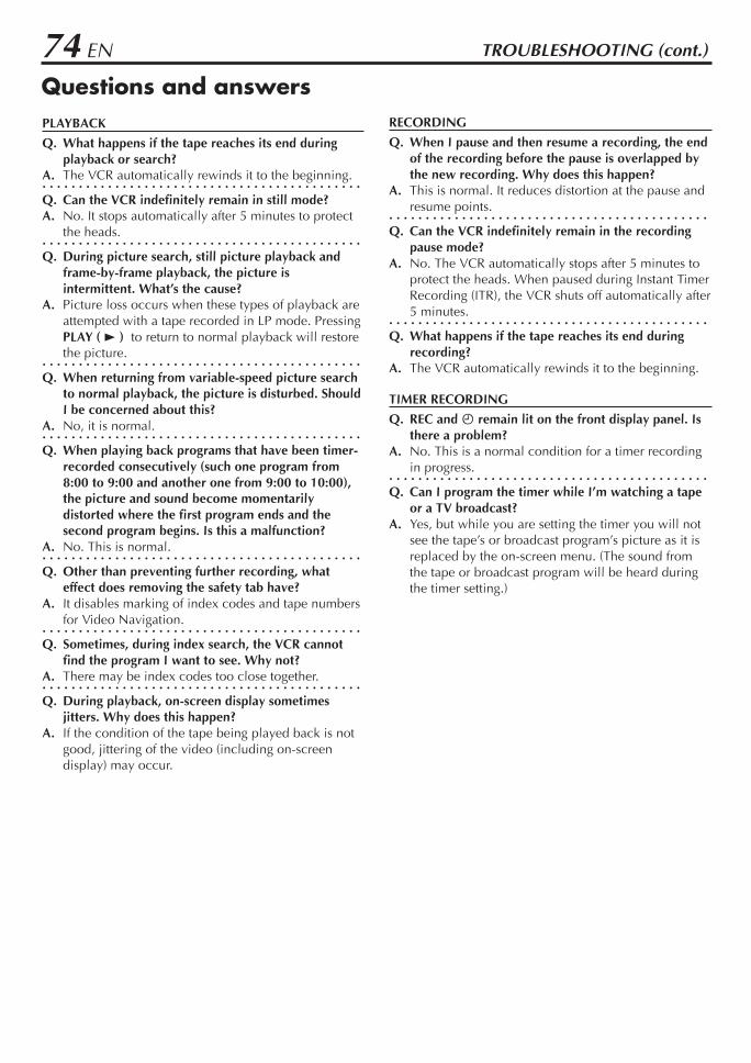
74 EN
RECORDING
Q. When I pause and then resume a recording, the endof the recording before the pause is overlapped bythe new recording. Why does this happen?
A. This is normal. It reduces distortion at the pause andresume points.
. . . . . . . . . . . . . . . . . . . . . . . . . . . . . . . . . . . . . . . . . . . .Q. Can the VCR indefinitely remain in the recording
pause mode?A. No. The VCR automatically stops after 5 minutes to
protect the heads. When paused during Instant TimerRecording (ITR), the VCR shuts off automatically after5 minutes.
. . . . . . . . . . . . . . . . . . . . . . . . . . . . . . . . . . . . . . . . . . . .Q. What happens if the tape reaches its end during
recording?A. The VCR automatically rewinds it to the beginning.
TIMER RECORDING
Q. REC and ‰ remain lit on the front display panel. Isthere a problem?
A. No. This is a normal condition for a timer recordingin progress.
. . . . . . . . . . . . . . . . . . . . . . . . . . . . . . . . . . . . . . . . . . . .Q. Can I program the timer while I’m watching a tape
or a TV broadcast?A. Yes, but while you are setting the timer you will not
see the tape’s or broadcast program’s picture as it isreplaced by the on-screen menu. (The sound fromthe tape or broadcast program will be heard duringthe timer setting.)
Questions and answersPLAYBACK
Q. What happens if the tape reaches its end duringplayback or search?
A. The VCR automatically rewinds it to the beginning.. . . . . . . . . . . . . . . . . . . . . . . . . . . . . . . . . . . . . . . . . . . .Q. Can the VCR indefinitely remain in still mode?A. No. It stops automatically after 5 minutes to protect
the heads.. . . . . . . . . . . . . . . . . . . . . . . . . . . . . . . . . . . . . . . . . . . .Q. During picture search, still picture playback and
frame-by-frame playback, the picture isintermittent. What’s the cause?
A. Picture loss occurs when these types of playback areattempted with a tape recorded in LP mode. PressingPLAY ( 3 ) to return to normal playback will restorethe picture.
. . . . . . . . . . . . . . . . . . . . . . . . . . . . . . . . . . . . . . . . . . . .Q. When returning from variable-speed picture search
to normal playback, the picture is disturbed. ShouldI be concerned about this?
A. No, it is normal.. . . . . . . . . . . . . . . . . . . . . . . . . . . . . . . . . . . . . . . . . . . .Q. When playing back programs that have been timer-
recorded consecutively (such one program from8:00 to 9:00 and another one from 9:00 to 10:00),the picture and sound become momentarilydistorted where the first program ends and thesecond program begins. Is this a malfunction?
A. No. This is normal.. . . . . . . . . . . . . . . . . . . . . . . . . . . . . . . . . . . . . . . . . . . .Q. Other than preventing further recording, what
effect does removing the safety tab have?A. It disables marking of index codes and tape numbers
for Video Navigation.. . . . . . . . . . . . . . . . . . . . . . . . . . . . . . . . . . . . . . . . . . . .Q. Sometimes, during index search, the VCR cannot
find the program I want to see. Why not?A. There may be index codes too close together.. . . . . . . . . . . . . . . . . . . . . . . . . . . . . . . . . . . . . . . . . . . .Q. During playback, on-screen display sometimes
jitters. Why does this happen?A. If the condition of the tape being played back is not
good, jittering of the video (including on-screendisplay) may occur.
TROUBLESHOOTING (cont.)
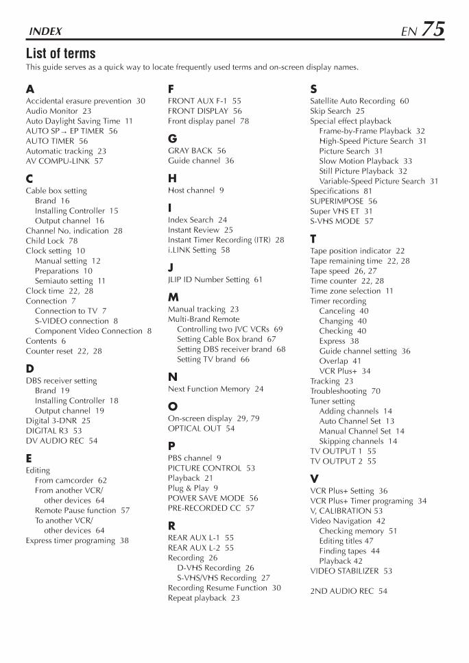
EN 75INDEX
List of termsThis guide serves as a quick way to locate frequently used terms and on-screen display names.
AAccidental erasure prevention 30Audio Monitor 23Auto Daylight Saving Time 11AUTO SP→ EP TIMER 56AUTO TIMER 56Automatic tracking 23AV COMPU-LINK 57
CCable box setting
Brand 16Installing Controller 15Output channel 16
Channel No. indication 28Child Lock 78Clock setting 10
Manual setting 12Preparations 10Semiauto setting 11
Clock time 22, 28Connection 7
Connection to TV 7S-VIDEO connection 8Component Video Connection 8
Contents 6Counter reset 22, 28
DDBS receiver setting
Brand 19Installing Controller 18Output channel 19
Digital 3-DNR 25DIGITAL R3 53DV AUDIO REC 54
EEditing
From camcorder 62From another VCR/
other devices 64Remote Pause function 57To another VCR/
other devices 64Express timer programing 38
FFRONT AUX F-1 55FRONT DISPLAY 56Front display panel 78
GGRAY BACK 56Guide channel 36
HHost channel 9
IIndex Search 24Instant Review 25Instant Timer Recording (ITR) 28i.LINK Setting 58
JJLIP ID Number Setting 61
MManual tracking 23Multi-Brand Remote
Controlling two JVC VCRs 69Setting Cable Box brand 67Setting DBS receiver brand 68Setting TV brand 66
NNext Function Memory 24
OOn-screen display 29, 79OPTICAL OUT 54
PPBS channel 9PICTURE CONTROL 53Playback 21Plug & Play 9POWER SAVE MODE 56PRE-RECORDED CC 57
RREAR AUX L-1 55REAR AUX L-2 55Recording 26
D-VHS Recording 26S-VHS/VHS Recording 27
Recording Resume Function 30Repeat playback 23
SSatellite Auto Recording 60Skip Search 25Special effect playback
Frame-by-Frame Playback 32High-Speed Picture Search 31Picture Search 31Slow Motion Playback 33Still Picture Playback 32Variable-Speed Picture Search 31
Specifications 81SUPERIMPOSE 56Super VHS ET 31S-VHS MODE 57
TTape position indicator 22Tape remaining time 22, 28Tape speed 26, 27Time counter 22, 28Time zone selection 11Timer recording
Canceling 40Changing 40Checking 40Express 38Guide channel setting 36Overlap 41VCR Plus+ 34
Tracking 23Troubleshooting 70Tuner setting
Adding channels 14Auto Channel Set 13Manual Channel Set 14Skipping channels 14
TV OUTPUT 1 55TV OUTPUT 2 55
VVCR Plus+ Setting 36VCR Plus+ Timer programing 34V, CALIBRATION 53Video Navigation 42
Checking memory 51Editing titles 47Finding tapes 44Playback 42
VIDEO STABILIZER 53
2ND AUDIO REC 54

76 EN INDEX (cont.)
Front panel
To access covered connectors, pull and open the connectorcover.
1 POWER button : Z pg. 21, 272 Remote sensor3 TIMER ‰ button : Z pg. 35, 39, 404 REC LINK button : Z pg. 605 DIGITAL 3-DNR button and lamp : Z pg. 256 Cassette loading slot7 HS/STD/LS3/SP/EP button : Z pg. 278 RECORD ( ¶ ) button : Z pg. 26, 279 PAUSE ( 8 ) button : Z pg. 27, 320 STOP/EJECT ( 7/0 ) button : Z pg. 21, 27! PLAY ( 3 ) button : Z pg. 21, 23@ i.LINK IN/OUT (DV IN) Connector (i.Link*) :
Z pg. 62, 64* i.Link refers to the IEEE1394-1995 industry specifi-
cation and extensions thereof. The logo is used forproducts compliant with the i.Link standard.
# S-VIDEO/VIDEO/AUDIO input connectors (F-1): Z pg. 62
$ S-VHS ET button and lamp : Z pg. 29% CH + and – buttons : Z pg. 23, 26, 27^ Front display panel : Z pg. 78& D-VHS button : Z pg. 26* REW ( 1 ) button : Z pg. 21, 31( FF ( ¡ ) button : Z pg. 21, 31
S-VIDEOi.LINK IN/OUTDV IN
IN I -
VIDEO
MENU
(MONO) L RAUDIO
REC LINC
POWER
S200
IN F-1
TIMER STOP/EJECT
HS/STD/LS3
SP/EP
PLAY
REC PAUSE
D-VHS REW FF
3DNR
CH
S-ET
DIGITAL 3-D NR
S-VHS ET
1
@ # $ % ^ & * (
2 3 ! 4 65 7 8 9 0
REC LINK
POWER
TIMER
PULL-OPEN

EN 77Rear panel
1 AC power cord : Z pg. 72 Cooling fan
This prevents the temperature from rising inside theVCR. Do not remove it.
Install the VCR so as not to block the area aroundthe cooling fan.
3 Component video output connectors : Z pg. 84 S VIDEO/AUDIO/VIDEO IN connectors (L-1):
Z pg. 645 JLIP terminal : Z pg. 616 CABLE BOX Controller connector :
Z pg. 15, 187 ANTENNA IN terminal : Z pg. 78 i.LINK IN/OUT, DV IN Connector (i.Link*) :
Z pg. 62, 64* i.Link refers to the IEEE1394-1995 industry specifi-
cation and extensions thereof. The logo is used forproducts compliant with the i.Link standard.
9 S VIDEO/AUDIO/VIDEO OUT connectors :Z pg. 8, 64
0 S VIDEO/AUDIO/VIDEO IN connectors (L-2):Z pg. 64
! REMOTE PAUSE/AV COMPULINK terminal REMOTE PAUSE terminal : Z pg. 62 AV COMPULINK terminal : Z pg. 57
@ TV OUT terminal : Z pg. 7# DIGITAL OUT OPTICAL terminal : Z pg. 54
S200
DV INi.LINK IN/OUT
DIGITAL OUTOPTICAL
PCM/DOLBY DIGITAL
R
Y
L
PB/CB
VIDEO
PR/CR
S VIDEO S VIDEO
AUDIO R
IN(L-1)
IN(L-2)
L(MONO) VIDEO
REMOTE PAUSE/AV COMPULINK
CABLE BOX
ANTENNA
AUDIO
OUTOUT
OUTTV
IN
VHF/UHF
IN
2 4
#@!09
5 63 7 8
1

78 EN
Front display panel
1 Recording speed indicator : Z pg. 26Timer programming indicator (“Pro” appearswhen PROG. or PROG. CHECK button ispressed. “Err” appears when the guide channelerror occurs.) : Z pg. 40
2 Audio Monitor Indicators : Z pg. 233 Symbolic Mode Indicators : Z pg. 23
4 Timer mode indicator : Z pg. 35, 395 D-VHS indicator : Z pg. 266 Program Timer indicator : Z pg. 407 S-VHS ET indicator : Z pg. 29
S-VHSET
+8-15
0dB
NORM
1
9 08
2 3 4 5 6 7
!
STILL:SLOW:
RECORD:
RECORD PAUSE:
PLAY:FF/REW VARIABLESHUTTLE SEARCH:
8 Guide Track IndicatorsRemaining time (inside)/Tape position (outside) IndicatorsAudio level indicators (inside for right sound/outside for left sound)
(You can select which of indicators above to display bysetting “FRONT DISPLAY” (Z pg. 56).)
9 Cassette mark0 Tape remaining time indicator : Z pg. 22, 28! Channel and auxiliary input (“L-1”, “L-2”, “F-1”
and “I-1 etc.”)Counter reading : Z pg. 22, 28(If the counter exceeds –20 hours ("–20:00:00"),the display does not show the "–2" of "–20:00:00". In this case, confirm the counter onthe TV screen.)Clock time : Z pg. 22, 28Child lock indicator : Z See below
INDEX (cont.)
Child LockYou can disable the VCR operations. You can only use the Remote for this operation.
While the VCR is turned on, press and hold POWER onthe Remote for more than 10 seconds.The VCR turns off, and the child lock indicator (CL)appears on the front display panel.
The child lock function is now activated and youcannot turn on the VCR by pressing POWER on thefront panel.
Child lock indicator
To release the child lock, press and hold POWER on theRemote until the VCR turns on. During timer recording, pressing TIMER also releases
the child lock.
NOTES: When the child lock function is in use, keep the Remote out
of the children’s reach. Timer recording programs will be performed even if the child
lock function is activated.

EN 79On-screen display
1 Brand name of the device connected to thei.LINK connector
2 Model name of the device connected to thei.LINK connector
3 Clock time4 Tape speed indication5 Time counter (When “COUNT“ appears)
: Z pg. 22, 28Tape remaining time (When “REMAIN“ appears): Z pg. 22, 28
6 Tape position indicator : Z pg. 227 Image format (HD/SD)
JVC D-VHS I - 1HM-DH30000U SAP STEREO REC PAUSE HI-FI THU 12:00 AM STD SD — 1: 23 : 45 INDEX-9B E
12
456
!0
@#
3
7 8
9
% $
8 Tape direction9 Index no. indication : Z pg. 240 Cassette indication! Audio monitor indications : Z pg. 23@ VCR operation mode indication# STEREO program and SAP (Second Audio
Program) indications : Z pg. 30$ ID number of the device connected to the
i.LINK connector : Z pg. 58(i.LINK device number is assigned in the orderof connection)
% Type of device connected to the i.LINK connec-tor

80 EN
Remote 1 VCR/TV/CABLE/DBS selector : Z pg. 66 – 692 TV/VCR button : Z pg. 663 A/B button : Z pg. 694 Number keys : Z pg. 26, 34
Character input buttons : Z pg. 485 DBS button : Z pg. 396 CANCEL button : Z pg. 34, 40
C. (Counter) RESET button : Z pg. 22, 287 STOP +/– button : Z pg. 35, 388 START +/– button : Z pg. 389 PROG. (Program) button : Z pg. 34, 380 HS/STD/LS3/SP/EP ( ) button : Z pg. 26, 27! REW ( 1 ) button : Z pg. 21, 31
BACK button : Z pg. 52@ REC ( ¶ ) button : Z pg. 26, 27# STOP ( 7 ) button : Z pg. 21, 27$ %fi buttons
TV CH +/– buttons : Z pg. 66 – 68% MENU button^ OK Button& JOG dial: Z pg. 32* A. (Audio) MONITOR button : Z pg. 23
(TV Muting) button : Z pg. 66( POWER button : Z pg. 21, 27) DISPLAY button : Z pg. 22, 28q ENTER button : Z pg. 66 – 68
OSD button : Z pg. 29w DAILY (M-F) button : Z pg. 35, 39e WEEKLY button : Z pg. 35, 39r AUX button : Z pg. 63, 65t TIMER button : Z pg. 35, 39, 40y DATE +/– button : Z pg. 38u CH +/– button : Z pg. 26, 38i SKIP SEARCH button : Z pg. 25o PROG. CHECK button : Z pg. 40p PLAY ( 3 ) button: Z pg. 21, 23Q FF ( ¡ ) button: Z pg. 21, 31W PAUSE ( 8 ) button: Z pg. 27, 32E 4 ¢ (@ #) button : Z pg. 24
TV VOL +/– button : Z pg. 66R REVIEW button : Z pg. 25T NAVIGATION button : Z pg. 42Y JOG/SHUTTLE button and lamp : Z pg. 32U SHUTTLE Ring : Z pg. 31
Buttons with a small dot on the left side of the namecan also be used to operate your TV after setting theVCR/TV/CABLE/DBS selector to “TV”. (Z pg. 66).
How to use the RemoteBefore use, insert two AA size batteries into theRemote with the polarity (ª and ·) matchedcorrectly as indicated on the battery compartment oron the lid.
The Remote can operate most of your VCR’sfunctions, as well as basic functions of TV sets,cable boxes and DBS receivers. Point the Remote toward the remote sensor on the
target component. The maximum operating distance of the remote
control is about 8 m.
NOTE:If the Remote does not work properly, remove its batteries,wait for a few seconds, replace the batteries and then tryagain.
CANCEL TIMER
START STOP DATE
PLAYREW
<
BACK
RECSTOP PAUSE
FF
>
CH
POWER
TV/VCR
C. RESET
DBS
. , ? ABC DEF
GHI JKL MNO
PQRS TUV WXYZ
DAILY(M-F)
AUX
WEEKLY
PROG.CHECK
PROG. HS/STD/LS3SP/EP
SKIP SEARCH
A/B DISPLAY ENTER/OSD
A.MONITORVCR TV CABLE/DBS
1 2 3
4 5 6
7 8 9
0
2
4
1
3
EXPRESS PROGRAMMING
JOG/SHUTTLE
MENUOK NAVIGATION
TV CH +
TV CH —
TV VOL +
TV VOL —
q
p
76
!
@#
%^&
*
QW
R
YT
o
2
3
89
4
0
()
yu
U
i
wert
E
1
5
$
INDEX (cont.)

EN 81GENERALPower requirement : AC 120 V`, 60 HzPower consumption
Power on : 55 WPower off : 18 W
TemperatureOperating : 5°C to 40°C (41°F to 104°F)Storage : –20°C to 60°C (–4°F to140°F)
Operating position : Horizontal onlyDimensions (W x H x D) : 435 mm x 105 mm x 383 mm
(17-3/16" x 4-3/16" x 15-1/8")Weight : 5.7 kg (12.6 lbs)Maximum recording time
D-VHS (HS) : 210 min. with DF-420 videocassette
D-VHS (STD) : 420 min. with DF-420 videocassette
D-VHS (LS3) : 1260 min. with DF-420 videocassette
S-VHS/VHS (SP) : 210 min. with ST-210 videocassette
S-VHS/VHS (EP) : 630 min. with ST-210 videocassette
VIDEO/AUDIO (D-VHS)Video format : MPEG2 standardAudio format : Encode MPEG1 Layer2
Decode MPEG1 Layer2Dolby Digital
Track compositionTape speed : 33.4 mm/sec (HS mode)
16.67 mm/sec (STD mode)5.55 mm/sec (LS3 mode)
Head azimuth : ±30 degDrum rotation : 1800 rpmTracking system : CTL track system
Recording specificationMain data input rate : 28.2 Mbps (HS mode)
14.1 Mbps (STD mode)4.7 Mbps (LS3 mode)
Interface : IEEE1394 compliantDTCP digital copy protectioncompatible
VIDEO/AUDIO (S-VHS/VHS)Format : S-VHS/VHS NTSC standardSignal system : NTSC-type color signal and
EIA monochrome signal,525 lines/60 fields
Recording/Playback system : DA-4 (Double Azimuth) head
helical scan systemSignal-to-noise ratio : 45 dBFrequency range
Normal audio : 70 Hz to 10,000 HzHi-Fi audio : 20 Hz to 20,000 Hz
SPECIFICATIONS
TUNER
Tuning system : Frequency-synthesized tunerChannel coverage
VHF : Channels 2–13UHF : Channels 14–69CATV : 113 Channels
TIMER
Clock reference : QuartzProgram capacity : 1-year programmable timer/
24 programsMemory backup time : Approx. 60 min.
CONNECTORS
Input/Output : i.LINK IN/OUT, DV IN x 2(4-pin, S200)RCA connectors(IN x 3, OUT x 2)S-video connectors(IN x 3, OUT x 2)Component video OUT(Y, PB/CB, PR/CR) x 1Digital OUT(optical) x 1
ACCESSORIES
Provided accessories : Infrared remote control unit,“AA” battery x 2,Audio cable,RF cable (F-type),S-video cable (4-pin),Controller
Specifications shown are for SP mode unless specifiedotherwise.E. & O.E. Design and specifications subject to change withoutnotice.
82 EN
HOW TO LOCATE YOUR JVC SERVICE CENTER
FOR SERVICING (Only in U.S.A.)
JVC SERVICE & ENGINEERINGCOMPANY OF AMERICA
DIVISION OF JVC AMERICAS CORP.
FACTORY SERVICE CENTER LOCATIONS
If you ship the product...
ACCESSORIES
10 New Maple Avenue 1500 Lakes Parkway 705 Enterprise StreetPine Brook, NJ 07058-9641 Lawrenceville, GA 30243-5857 Aurora, IL 60504-8135(973) 396-1000 (770) 339-2522 (630) 851-7855
5665 Corporate Avenue 10700 Hammerly Boulevard, Suite 110 2969 Mapunapuna Place, Suite 105Cypress, CA 90630-4727 Houston, TX 77043-2310 Honolulu, HI 96819-2000(714) 229-8011 (713) 935-9331 (808) 833-5828
13 Cummings Park 8192 W State Road 84 890 Dubuque AvenueWoburn, MA 01801-2105 Davie, FL 33324-4611 South San Francisco, CA 94080-1804(781) 376-9100 (954) 472-1960 (650) 871-2666
Sophisticated electronic products may require occasional service. Just as quality is a keyword in the engineeringand production of the wide array of JVC products, service is the key to maintaining the high level performance forwhich JVC is world famous. The JVC service and engineering organization stands behind our products.
NATIONAL HEADQUARTERSJVC SERVICE & ENGINEERING COMPANY OF AMERICA
DIVISION OF JVC AMERICAS CORP.10 New Maple Avenue
Pine Brook, NJ 07058-9641
Pack your JVC unit in the original carton or one ofequivalent size and strength. Enclose, with the unit, aletter stating the problem or symptom that exists andalso a copy of the receipt or bill of sale you receivedwhen you purchased your JVC unit. Print your homereturn address on the outside and the inside of thecarton. Send to the appropriate JVC Factory ServiceCenter as listed above.
To purchase accessories for your JVC product, youmay contact your local JVC Dealer.Or from the 48 Continental United States call toll free:1-800-882-2345.
Dear customer:In order to receive the most satisfaction from your purchase, read the instruction booklet before operating the unit.In the event that repair is necessary, or for the address nearest your location, please refer to the factory servicecenter list below or within the Continental United States, call 1-800-252-5722 for your authorized servicer. Rememberto retain your Bill of Sale for Warranty Service.
— JVC
CAUTIONTo prevent electrical shock, do not open the cabinet.No user serviceable parts inside.Refer servicing to qualified service personnel.
Don't service it yourself.
TOLL FREE: 1-800-252-5722http://www.jvcservice.com

EN 83WARRANTY (Only in U.S.A.)
LIMITED WARRANTY CONSUMER VIDEO 1-90
JVC COMPANY OF AMERICA warrants this product and all parts thereof, except as set forth below ONLY TO THE ORIGINALPURCHASER AT RETAIL to be FREE FROM DEFECTIVE MATERIALS AND WORKMANSHIP from the date of original retailpurchase for the period as shown below. ("The Warranty Period")
THIS LIMITED WARRANTY IS VALID ONLY IN THE FIFTY (50) UNITED STATES, THE DISTRICT OF COLUMBIA AND INCOMMONWEALTH OF PUERTO RICO.
WHAT WE WILL DO:If this product is found to be defective, JVC will repair or replace defective parts at no charge to the original owner. Such repairand replacement services shall be rendered by JVC during normal business hours at JVC authorized service centers. Partsused for replacement are warranted only for the remainder of the Warranty Period. All products and parts thereof may bebrought to a JVC authorized service center on a carry-in basis except for Television sets having a screen size 25 inches andabove which are covered on an in-home basis.
WHAT YOU MUST DO FOR WARRANTY SERVICE:Return your product to a JVC authorized service center with a copy of your bill of sale. For your nearest JVC authorizedservice center, please call toll free: (800) 252-5722.
If service is not available locally, box the product carefully, preferably in the original carton, and ship, insured, with a copy ofyour bill of sale plus a letter of explanation of the problem to the nearest JVC Factory Service Center, the name and locationof which will be given to you by the toll-free number.
If you have any questions concerning your JVC Product, please contact our Customer Relations Department.
WHAT IS NOT COVERED:This limited warranty provided by JVC does not cover:1. Products which have been subject to abuse, accident, alteration, modification, tampering, negligence, misuse, faulty
installation, lack of reasonable care, or if repaired or serviced by anyone other than a service facility authorized by JVC torender such service, or if affixed to any attachment not provided with the products, or if the model or serial number has beenaltered, tampered with, defaced or removed;
2. Initial installation and installation and removal for repair;3. Operational adjustments covered in the Owner's Manual, normal maintenance, video and audio head cleaning;4. Damage that occurs in shipment, due to act of God, and cosmetic damage;5. Signal reception problems and failures due to line power surge;6. Video Pick-up Tubes/CCD Image Sensor, Cartridge, Stylus (Needle) are covered for 90 days from the date of purchase;7. Accessories;8. Batteries (except that Rechargeable Batteries are covered for 90 days from the date of purchase); from the date of purchase);
There are no other express warranties except as listed above.
THE DURATION OF ANY IMPLIED WARRANTIES INCLUDING THE IMPLIED WARRANTY OF MERCHANTABILITY, ISLIMITED TO THE DURATION OF THE EXPRESS WARRANTY HEREIN.
JVC SHALL NOT BE LIABLE FOR THE LOSS OF USE OF THE PRODUCT, INCONVENIENCE, LOSS OR ANY OTHERDAMAGES, WHETHER DIRECT, INCIDENTAL OR CONSEQUENTIAL (INCLUDING, WITHOUT LIMITATION, DAMAGE TOTAPES, RECORDS OR DISCS) RESULTING FROM THE USE OF THIS PRODUCT, OR ARISING OUT OF ANY BREACHOF THIS WARRANTY. ALL EXPRESS AND IMPLIED WARRANTIES, INCLUDING THE WARRANTIES OFMERCHANTABILITY AND FITNESS FOR PARTICULAR PURPOSE, ARE LIMITED TO THE WARRANTY PERIOD SETFORTH ABOVE.
Some states do not allow the exclusion of incidental or consequential damages or limitations on how long an implied warrantylasts, so these limitations or exclusions may not apply to you. This warranty gives you specific legal rights and you may alsohave other rights which vary from state to state.
JVC COMPANY OF AMERICA 1700 Valley RoadDIVISION OF JVC AMERICAS CORP. Wayne, New Jersey 07470
REFURBISHED PRODUCTS CARRY A SEPARATE WARRANTY, THIS WARRANTY DOES NOT APPLY. FOR DETAILS OFREFURBISHED PRODUCT WARRANTY, PLEASE REFER TO THE REFURBISHED PRODUCT WARRANTY INFORMATIONPACKAGED WITH EACH REFURBISHED PRODUCT.
For customer use:Enter below the Model No. and Serial No. which is located either on the rear, bottom or side of the cabinet. Retain this information for futurereference.
Model No.: Serial No.:
Purchase date: Name of dealer:
PARTS LABOR1 YR 90 DAYS

HM
-DH
30
00
0U
COPYRIGHT © 2001 VICTOR COMPANY OF JAPAN, LTD.Printed in Japan0801 MNV*ID*VPU
IN ADDITION TO AND WITHOUT LIMITING THE FOREGOING, JVC EXPRESSLY DIS-CLAIMS ALL WARRANTIES, EXPRESS OR IMPLIED, AND SHALL NOT BE LIABLE FOR ANYAND ALL DAMAGES, CLAIMS OR LIABILITIES, DIRECT OR INDIRECT, ARISING FROMOR RELATING TO THE USE OF THIS PRODUCT WITH ANY OTHER PRODUCT, DEVICE,COMPONENT, PART OR MATERIAL THAT IS NOT IN CONFORMITY OR COMPLIANTWITH EIA-775-A “DTV 1394 INTERFACE” SPECIFICATION, DATED April 2000 (THE“SPECIFICATION”), OR THAT IMPLEMENTS THE SPECIFICATION IN A NON-CONFORM-ING OR NON-COMPATIBLE MANNER WITH THIS PRODUCT.
THE i.LINK/DV CONNECTION OF THIS PRODUCT CONFORMS TO EIA-775-A “DTV1394 INTERFACE” SPECIFICATION, DATED April 2000 (THE “SPECIFICATION”). USE OFTHIS PRODUCT WITH ANOTHER PRODUCT, DEVICE, COMPONENT, PART OR MATE-RIAL THAT IS NOT IN CONFORMITY OR COMPLIANT WITH THE SPECIFICATION, ORTHAT IMPLEMENTS THE SPECIFICATION IN A NON-CONFORMING OR NON-COMPAT-IBLE MANNER WITH THIS PRODUCT, MAY NOT BE SUPPORTED AND MAY CAUSEDAMAGE TO OR MALFUNCTION OF THIS PRODUCT. ANY USE OF THIS PRODUCTWITH A NON-CONFORMING OR NON-COMPATIBLE PRODUCT, DEVICE, COMPO-NENT, PART OR OTHER MATERIAL SHALL BE AT THE USER’S SOLE AND EXCLUSIVERISK.
ATTENTION