OIL PRO FUEL PRO - Advantage Engineering
50
www.fuelpro-x.com FUEL PRO SERIES Part No. 7702-40-01-1 © Copyright 2006 AEC GROUP INC. Printed in the U.S.A. 3/2006
-
Upload
khangminh22 -
Category
Documents
-
view
7 -
download
0
Transcript of OIL PRO FUEL PRO - Advantage Engineering

www.fuelpro-x.com
TRANS PROSERIES
TRANS PRO+SERIES
OIL PROSERIES
FUEL PROSERIES
DIESEL FUEL PROSERIES
Part No. 7702-40-01-1© Copyright 2006 AEC GROUP INC.
Printed in the U.S.A.3/2006

OPERATIONS MANUAL
TRANS PROSERIES
TRANS PRO+SERIES
OIL PROSERIES
FUEL PROSERIES
DIESEL FUEL PROSERIES

Advantage Engineering® FUEL PRO X-Series™ Table of Contents
Operations Manual Manual Printed in the U.S.A. for AEC GROUP INC. 1
TABLE OF CONTENTSI. INTRODUCTION to the FUEL PRO X-SERIES ........................2
II. SAFETY INFORMATION ............................................................3- Section 1.01: Important Safety Notice .........................................3
- Section 1.02: Important Safety Instructions.................................5
III. SYSTEM FEATURES & SPECIFICATIONS ...............................9- Section 2.01: Features..................................................................9
- Section 2.02: Dimensions & Technical Specifications................10
- Section 2.03: Machine Overview................................................11
- Section 2.04: Control Panel Overview........................................12
IV. OPERATING PROCEDURES ...................................................14
- Section 3.01: Tool Usage / Battery Voltage Chart......................14
- Section 3.02: Identifying The Fuel System Type ........................15
- Section 3.03: Two-Line Fuel Delivery Systems ..........................16
- Section 3.04: One-Line Fuel Delivery Systems ..........................22
V. TROUBLESHOOTING & ADDITIONAL HELP.........................28- Section 4.01: Troubleshooting Guide .........................................28
APPENDIX A - ADAPTERS ............................................................29- Section 5.01: Standard Adapter Kits..........................................29
- Section 5.02: Optional Adapters ................................................40
APPENDIX B - REPLACEMENT PARTS .......................................41- Section 6.01: Replacement Parts...............................................41
APPENDIX C - MAINTENANCE.....................................................44- Section 7.01: Maintenance Procedures .....................................44
APPENDIX D - MATERIAL SAFETY DATA SHEET.......................45
WARRANTY INFORMATION ..........................................................47
MAINTENANCE LOG......................................................................48

I. Introduction Advantage Engineering® FUEL PRO X-Series™
2 Manual Printed in the U.S.A. for AEC GROUP INC. Operations Manual
I. INTRODUCTION TO THEFUEL PRO X-SERIES
Congratulations on the purchase of your FUEL PRO system.
The FUEL PRO system represents the most technologically advanced method forcleaning harmful fuel related contaminants from gasoline internal combustion engines.
With specially formulated Advantage Engineering Petrol Fuel System CleaningSolution and Filters, the FUEL PRO system provides a safe, easy to use, quick,and comprehensive way of maintaining optimum fuel system and vehicle perfor-mance, fuel delivery, and reduced exhaust emissions. Integrated functions withinthe control panel include diagnostic procedures to isolate, and properly identifyfuel system deficiencies.
The FUEL PRO system is fully electronic. When connected to a gasoline engine, ittemporarily replaces the vehicle’s fuel supply and performs most of the cleaning anddiagnostic functions with a four to one (4:1) mixture of fuel and Advantage EngineeringPetrol Fuel System Cleaning Solution and Filters. This mixture is circulated through thefuel distribution system, loosening and dissolving accumulated deposits and contami-nants which are then trapped in the Ultra Fine Filtration system of your FUEL PRO.Induction and combustion system contaminants are similarly released and then con-sumed in the combustion process. Post combustion contaminants are also brokendown and released, particle by particle, passing them safely from the exhaust system.
Restoration of horsepower, fuel economy, and reduced exhaust emissions arecommonly realized as a result of periodic comprehensive fuel system service. Itis recommended that you perform this service every 12,000 miles or annually tomaintain the highest level of fuel system efficiency and overall reliability.
The FUEL PRO system control panel is logically arranged into sections for diagnos-tic, two-line, and single line service procedures. Cleaning processes are graphicallysequenced to guide you through service procedures for two-line fuel delivery sys-tems (PFI, CIS and TBI) and one-line fuel delivery systems (carburetor and some PFIsystems). Diagnostic functions are also graphically displayed
To diagnose and isolate potential problems in most fuel systems, the FUEL PROsystem is capable of measuring the following:
• Vehicle fuel supply flow rate• Vehicle fuel pump maximum output pressure (deadhead)• Vehicle fuel system regulated and un-regulated pressure• Vehicle fuel system component leakdown testing• Vehicle fuel system pressure check• Vacuum
Advantage Engineering® FUEL PRO X-Series™ II. Safety Information
Operations Manual Manual Printed in the U.S.A. for AEC GROUP INC. 3
II. SAFETY INFORMATION
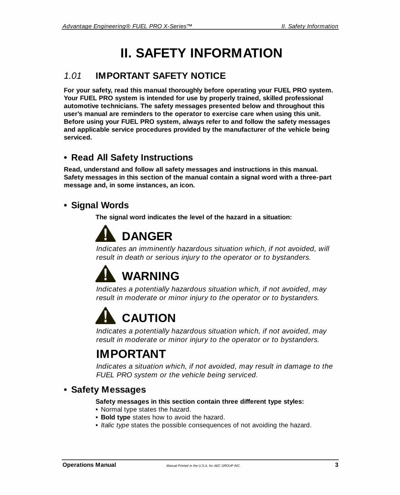
DANGERIndicates an imminently hazardous situation which, if not avoided, willresult in death or serious injury to the operator or to bystanders.
• Safety MessagesSafety messages in this section contain three different type styles:• Normal type states the hazard.• Bold type states how to avoid the hazard.• Italic type states the possible consequences of not avoiding the hazard.
Indicates a situation which, if not avoided, may result in damage to theFUEL PRO system or the vehicle being serviced.
1.01 IMPORTANT SAFETY NOTICEFor your safety, read this manual thoroughly before operating your FUEL PRO system.Your FUEL PRO system is intended for use by properly trained, skilled professionalautomotive technicians. The safety messages presented below and throughout thisuser’s manual are reminders to the operator to exercise care when using this unit.Before using your FUEL PRO system, always refer to and follow the safety messagesand applicable service procedures provided by the manufacturer of the vehicle beingserviced.
• Read All Safety InstructionsRead, understand and follow all safety messages and instructions in this manual.Safety messages in this section of the manual contain a signal word with a three-partmessage and, in some instances, an icon.
• Signal WordsThe signal word indicates the level of the hazard in a situation:
WARNINGIndicates a potentially hazardous situation which, if not avoided, mayresult in moderate or minor injury to the operator or to bystanders.
CAUTION
IMPORTANT
Indicates a potentially hazardous situation which, if not avoided, mayresult in moderate or minor injury to the operator or to bystanders.

II. Safety Information Advantage Engineering® FUEL PRO X-Series™
4 Manual Printed in the U.S.A. for AEC GROUP INC. Operations Manual
Risk of Fire Read Instructions Before Use
Risk of Explosion Mandatory Eye Protection
Risk of Entanglement Mandatory Protective Gloves
Dangerous Fumes Mandatory Protective Clothing
Do Not Pull or Move
• Safety SymbolsA safety symbol, when present, gives a graphical description of the potential hazard, and how to avoid the hazard:

Advantage Engineering® FUEL PRO X-Series™ II. Safety Information
Operations Manual Manual Printed in the U.S.A. for AEC GROUP INC. 5
1.02 IMPORTANT SAFETY INSTRUCTIONS
Vehicle gases contain Carbon Monoxide, which is a colorless & odorless lethal gas.• Only run engines in well ventilated areas and avoid breathing exhaust gases.Extended breathing of exhaust gases will cause serious injury or death.
Improper use and operation.• Read, understand and follow all safety messages and operational
procedures in this manual before operating the FUEL PRO system.• This equipment should be operated only by qualified personnel.• Use this equipment only as described in this manual.Improper use and operation of this product can result in injury.
DANGER
WARNING
Exhaust gases, moving parts, hot surfaces, and potent chemicals may be present during useof the fuel system equipment.• When using chemicals always refer to the MSDS sheets and manufacturer's
instructions for the proper procedure to handle emergency medical treatment, cleanup, handling, and storage requirements.
Improper use of the fuel system equipment or exposure to exhaust gases, moving parts,hot surfaces, or moving parts may cause injury.
WARNING
Flammable fuel chemical and vapors can ignite.• Avoid exposure to flames, sparks, hot engine parts, and other ignition sources.• Keep a fully charged fire extinguisher nearby. The extinguisher should have a
class B rating and be suitable for gasoline, chemical, and electrical fires.• Clean up any fuel or chemical spills immediately. Refer to MSDS sheets and
manufacturer’s instructions for clean up requirements • Dispose of contaminated clean up materials according to governing
environmental laws.• Never look directly into the air induction plenum or carburetor throat when
the engine is operating.• Plug or cap open fuel lines during service.• Keep Fuel System Cleaning Solution container closed except when filling reservoir.Explosion or flame or exposure to flammable liquids and vapors can cause injury.
WARNING

II. Safety Information Advantage Engineering® FUEL PRO X-Series™
6 Manual Printed in the U.S.A. for AEC GROUP INC. Operations Manual
Risk of expelling pressurized fluids.• Verify that engine and machine are off before connecting or disconnecting lines
and adapter hoses.• Keep the service hoses away from hot or moving engine parts. Hoses can split or
burst causing fluid to be expelled.• Tighten all connections properly.
Chemicals may cause respiratory tract and/or skin and eye irritation.• Use only approved chemicals (refer to operator's manual). • Use safety glasses and protective clothing when handling chemicals. • Do not ingest chemicals or breathe vapors• Treatment methods are as follows:
Eyes: Flush eyes with plenty of water.Skin: Wash with soap and water.Inhalation: Move to uncontaminated area.Ingestion: If large amount, get medical attention.If any irritation persists, get medical attention.
• Dispose of used fluid according to environmental laws and regulations.Although motor oil and engine flush solution pose no significant health hazards, some individuals may experience adverse reactions upon contact. Pressurized fluid can causeserious injury.
WARNING
Many fuel systems maintain residual pressure in fuel lines after the engine has been turned off.• Wear safety glasses, chemical resistant gloves, and protective clothing when
connecting and disconnecting fuel lines and adapters.• Confirm ZERO pressure before connecting and disconnecting fuel lines and adapters.Explosion or flame or exposure to flammable liquids and vapors can cause injury.
WARNING
Batteries produce explosive gases and can explode.• Keep sparks and flames away from the battery.• Do not lay tools, equipment, or other conductive items on the battery.• Connect the positive lead of the equipment to the positive lead of the battery first. • Connect the negative lead of the equipment to vehicle ground as far away from
the battery as leads will allow to prevent sparking and igniting of battery gases.• Keep battery acid away from skin and eyes. In case of eye contact, flush with
clean water for 15 minutes and get medical attention.Battery explosion and ignited gases can cause injury.
WARNING

Advantage Engineering® FUEL PRO X-Series™ II. Safety Information
Operations Manual Manual Printed in the U.S.A. for AEC GROUP INC. 7
Engine has moving parts. Risk of entanglement.• Do not place tools on fenders or other places in engine compartment.• Keep yourself, clothing, adapters and service hoses clear of moving parts
such as fan blades, belts and pulleys.• Wear safety goggles (user and bystanders).Moving components can cause injury.
Risk of unexpected vehicle movement.• Block drive wheels before starting vehicle’s engine to begin an exchange.• Unless instructed otherwise, set parking brake and put gear selector in park.• Do not leave a running vehicle unattended.A moving vehicle can cause injury.
WARNING
WARNING
Risk of burns.• Wear gloves when working near hot engine components.• Do not touch hot exhaust systems, manifolds, engines, radiators, etc.Hot components can cause injury or discomfort.
WARNING

II. Safety Information Advantage Engineering® FUEL PRO X-Series™
8 Manual Printed in the U.S.A. for AEC GROUP INC. Operations Manual
Risk of equipment damage.• Servicing, transporting, or storing this machine in an attitude other than the normal
operating position can result in fluid spillage and/or component damage.• Use only the manufacturer’s recommended attachments.• The FUEL PRO system is fully automatic. Refer to your control panel at
all times.• Never pull on the power cord or service hoses to transport the FUEL PRO
system. Damage may occur to these components, or machine may tip over.• Periodically clean the machine by wiping down with a clean, soft, dry cloth.Improper operation of equipment may result in damage to machine or components.
SAVE AND FOLLOW THESE INSTRUCTIONS!
CAUTION
Risk of injury.• This equipment should be operated by qualified personnel only.• Use this equipment only as described in this manual.• Loop the power cord loosely in its proper location when machine is not in use.• Do not operate equipment with a damaged power cord or hoses, or if the
equipment has been dropped or damaged, until it has been examined by a qualified service representative.
• Care should be taken to arrange the power cord and service hoses so that they will not be tripped over or pulled.
• Never pull on the power cord or service hoses to transport the FUEL PRO system. Damage may occur to these components, or machine may tip over.
• Keep area of operation clear of unnecessary tools and equipment. Utilize storage area on the top of the machine and drawers.
• Never leave the machine running unattended.• The FUEL PRO system is not designed for any other purpose than the
cleaning of the fuel delivery system.Operation of your FUEL PRO system by anyone other than qualified personnel may result ininjury.
WARNING

Advantage Engineering® FUEL PRO X-Series™ III. System Features & Specifications
Operations Manual Manual Printed in the U.S.A. for AEC GROUP INC. 9
2.01 FEATURES
Application• Cleans the fuel delivery system, removes soft carbon build up in combustion chamber,
on the intake valves, and in the intake manifold.
• Restores performance, reduces vehicle emissions, and restores fuel economy.
Functions• Intuitive, full electronic, microprocessor controlled panel with internal fuses, overload,
and ground protection
• Step-by-step guided operation
• Simpler adapter hook ups
• Service options: two (2) line and single (1) line
• Electronically controlled diagnostic features to check flow rate, deadhead pressure, running pressure, and leak down
• Pressure and vacuum diagnostic functions accessible independent of fuel system cleaning process
• Stored values for ready comparison between baseline and ending readings
• Diagnostic/Fill cycle allows for injector leak down test prior to initiating fuel service
• Auto Purge: Purges air from FUEL PRO internal lines to avoid “air locks”
• System Pressure Relief: FUEL PRO has programmed and user initiated pressure relief functions
• “Pulse Cleaning” during soak cycle (2 line application)
• Touch pad pressure and time adjustment
• Visual signal for polarity check
• Bright seven segment LED display for time, pressure, and vacuum.
• Board mounted LEDs indicate available procedures and process progression
• Emergency stop button
• Advantage Engineering Petrol Fuel System Cleaning Solution in 250 ml (8 ounce) and 1 liter (32 ounce) clear bottles for convenient and easy to read dispensing
Cabinet Features• Composite cabinet with service and vacuum hose hangers
• Ergonomically correct working height
• 9” rigid rear wheels
• 4” swivel front casters with brakes
• 3.8 quart reservoir with precision 4 ounce increment indicator marks
• 10’ external nylon reinforced Hytron hoses
• 160 psi rated pump
• Convenient recess for ICS bottle and 30” spray tube
• Three adapter storage drawers and convenient top work surface
III. SYSTEM FEATURES & SPECIFICATIONS
III. System Features & Specifications Advantage Engineering® FUEL PRO X-Series™
10 Manual Printed in the U.S.A. for AEC GROUP INC. Operations Manual
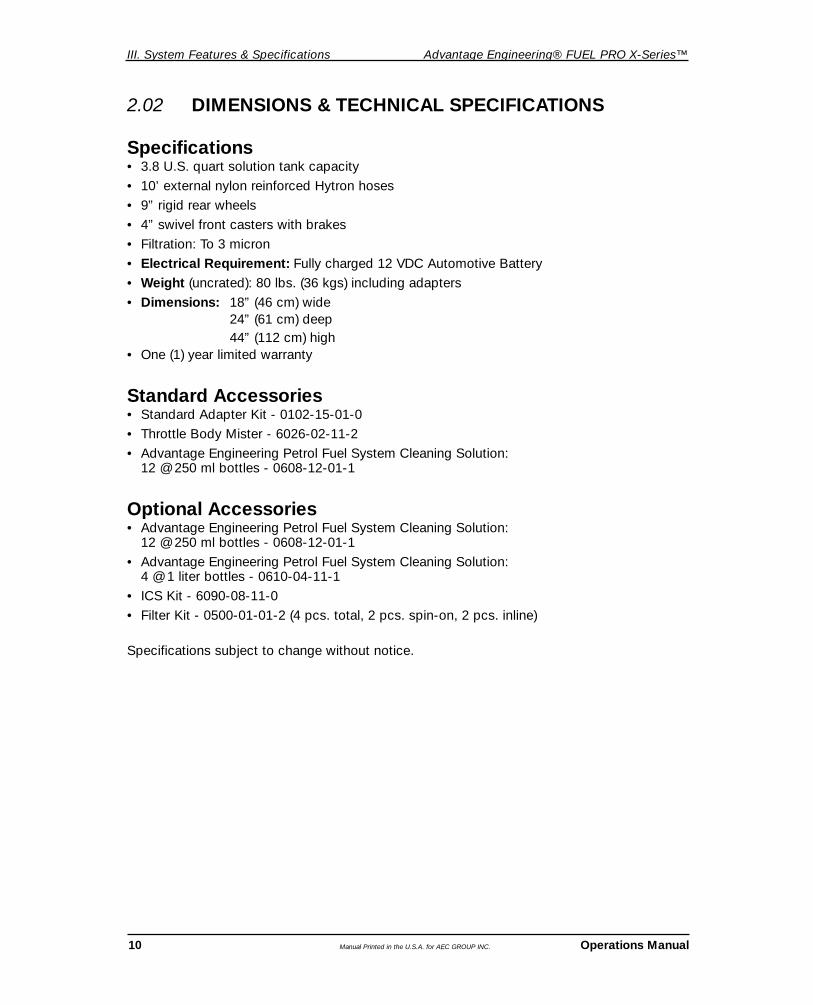
2.02 DIMENSIONS & TECHNICAL SPECIFICATIONS
Specifications• 3.8 U.S. quart solution tank capacity
• 10’ external nylon reinforced Hytron hoses
• 9” rigid rear wheels
• 4” swivel front casters with brakes
• Filtration: To 3 micron
• Electrical Requirement: Fully charged 12 VDC Automotive Battery
• Weight (uncrated): 80 lbs. (36 kgs) including adapters
• Dimensions: 18” (46 cm) wide24” (61 cm) deep44” (112 cm) high
• One (1) year limited warranty
Standard Accessories• Standard Adapter Kit - 0102-15-01-0
• Throttle Body Mister - 6026-02-11-2
• Advantage Engineering Petrol Fuel System Cleaning Solution: 12 @ 250 ml bottles - 0608-12-01-1
Optional Accessories• Advantage Engineering Petrol Fuel System Cleaning Solution:
12 @ 250 ml bottles - 0608-12-01-1
• Advantage Engineering Petrol Fuel System Cleaning Solution: 4 @ 1 liter bottles - 0610-04-11-1
• ICS Kit - 6090-08-11-0
• Filter Kit - 0500-01-01-2 (4 pcs. total, 2 pcs. spin-on, 2 pcs. inline)
Specifications subject to change without notice.

Advantage Engineering® FUEL PRO X-Series™ III. System Features & Specifications
Operations Manual Manual Printed in the U.S.A. for AEC GROUP INC. 11
Recess for ICS Bottle
Work Surface
Control Panel
Rigid 9” Wheels
Pressure andRecovery HoseHanger
BACK OF MACHINE
Return Filter
Vacuum Hose Hanger
Power Cord Hanger
Reservoir Fuel Filter
4” Locking Caster Wheels
3.8 Quart Reservoir
Storage Drawers
Handle
ICS Wand Holder
2.03 MACHINE OVERVIEW

III. System Features & Specifications Advantage Engineering® FUEL PRO X-Series™
12 Manual Printed in the U.S.A. for AEC GROUP INC. Operations Manual
2.04 CONTROL PANEL OVERVIEW
1
6 8
11
12
13
14 17
18 19
9 10
7
15
16
2
3
45
KEYS NAME/FUNCTION DETAILS
1 TIMERDisplay (2 digits) Display time in minutes and seconds and indicator (FL and DH)
for flow rate and deadhead pressure
2 REVERSED POLARITYLED (red) Lights when leads are improperly connected
3 STOP • Press and release to pause serviceButton • Depress and hold for five seconds to reboot machine; pump stops
and system automatically releases internal pressure
4 SYSTEM WARNING Lights to indicate pressure loss or other failuresLED (red)

Advantage Engineering® FUEL PRO X-Series™ III. System Features & Specifications
Operations Manual Manual Printed in the U.S.A. for AEC GROUP INC. 13
KEYS NAME/FUNCTION DETAILS
5 PRESSURE/VACUUMDisplay (3 digits) Displays psi and vacuum
6 DIAGNOSTIC/FILL CYCLEButton – LED (grn) Start Diagnostic/Fill Cycle
7 2-LINE SERVICEButton –LED (grn) Start 2-Line Service
8 1-LINE/CARB SERVICEButton – LED (grn) Start 1-Line Service
9 LEAKDOWN TESTButton – LED (grn) System Auto PurgeButton – LED (red) Start Leakdown Test
10 VACUUM TESTButton LED (grn) Display Vacuum [Negative Pressure (NP)] Reading
11 FILL TANK/FLOW RATE CHECKButton – LED (grn) Depress and Hold. Release when one (1) quart of fuel has been
added to tank to display fill time.
12 DEADHEAD PRESSURE CHECKButton – LED (grn) Press and release to display deadhead pressure on 2-line system;
or regulated pressure on 1-line system
13 FINISH CYCLE/STOP ENGINEButton – LED (grn) Depress at the end of the 2-line or 1-line service.
14 START SOAKButton – LED (grn) Start “Soak” Cycle - Cycle default is 10 minutes
15 SERVICE TIME SETButton – LED (grn) Depress to set Soak and Service Time. (Note: Soak default is 10 minutes.
Service default is 20 minutes.) Five (5) minutes are added to the timer each time the button is depressed. Maximum 60 minutes reverting back to five (5) minutes if depressed again.
16 START SERVICE/START ENGINEButton Starts “Service” Cycle - Cycle default is 20 minutes
17 PRESSURE ADJUSTMENTButtons “+” or “-” to set system pressure for 1-Line Service
18 CONNECT HOSE/START ENGINELED (red) Flashing to signal Tech to connect hoses and start engine
19 CONNECT HOSES/ADD DETERGENTLED (red) Flashing to signal Tech to connect hoses and add detergent

IV. Operating Procedures Advantage Engineering® FUEL PRO X-Series™
14 Manual Printed in the U.S.A. for AEC GROUP INC. Operations Manual
• Frequently inspect and clean any tools used, and lubricate all non-sealed ratchet mechanisms with light oil.
• The use of any other accessories not specified in this manual may create a hazard.• Read, understand and follow Safety Instructions in the front pages of this manual
and on product safety labels
3.01 TOOL USAGE
IV. OPERATING PROCEDURES
CAUTION
BATTERY VOLTAGE CHART
IMPORTANT: A charged battery is required forproper machine function.
VOLTAGE % CHARGE
12.6 to 12.72 VDC 100
12.45 VDC 75
12.30 VDC 50
12.15 VDC 25
@ 80º Fahrenheit (27º Celsius)

Advantage Engineering® FUEL PRO X-Series™ IV. Operating Procedures
Operations Manual Manual Printed in the U.S.A. for AEC GROUP INC. 15
Identify the fuel system type of the vehicle to be serviced before performing any set up, diagnostic, or cleaning procedure on the vehicle.
THERE ARE FOUR MAJOR TYPES OF FUEL SYSTEMS.
CARBURETORA carburetor is the most basic of fuel delivery systems. It is usually centrally mounted over the intake manifold and can be identified by one or more barrels with throttle plates and bowl (w/float).
THROTTLE BODY INJECTION (TBI)Throttle body fuel systems are similar to carburetor equipped engines. They are centrallymounted over the intake manifold and use one or two electronic injectors to deliver fuel.
PORT FUEL INJECTION (PFI)Port fuel injection systems use an electronic injector per cylinder that atomizes fuel directlyinto the intake port.
CONTINUOUS INJECTION SYSTEM (CIS)A CIS fuel system can usually be easily identified by a fuel distributor with solid steel or braided steel hoses running to individual injectors. The fuel distributor in these systems controls the amount of fuel sprayed. The injector opening and closing is controlled by fuel pressure.
NOTE: Running pressure and vacuum can be tested without using “Step by Step” operation:
TESTING FUEL PRESSURE: Connect power cord to a fully charged 12.0 VDC battery.Connect the positive lead of the equipment to the positive lead of the battery first.Connect the negative lead of the equipment to vehicle ground as far away from the bat-tery as leads will allow, to prevent sparking and igniting of battery gases. Unit will per-form a self test and fuel pressure calibration. Connect either the appropriate SchraderValve Adapter Hose to the vehicle’s fuel pressure test port; or connect the T-adapterbetween pressure line from tank and fuel rail. Attach FUEL PRO Red Hose and startengine. Insure integrity of all connections; vehicle fuel pressure is indicated in FUEL PRO’sPressure/Vacuum Display.TESTING VACUUM: Connect power cord to a fully charged 12.0 VDC battery. Connectthe positive lead of the equipment to the positive lead of the battery first. Connect thenegative lead of the equipment to vehicle ground as far away from the battery as leadswill allow, to prevent sparking and igniting of battery gases. Unit will perform a self test andfuel pressure calibration. Connect vacuum hose to vacuum source. Pressure/Vacuumdisplay will show inches of vacuum when vacuum is present.
3.02 IDENTIFYING THE FUEL SYSTEM TYPE

IV. Operating Procedures Advantage Engineering® FUEL PRO X-Series™
16 Manual Printed in the U.S.A. for AEC GROUP INC. Operations Manual
3.03 TWO-LINE FUEL DELIVERY SYSTEMS(PORT FUEL INJECTION, CIS, AND THROTTLE BODYINJECTION SYSTEMS)
FUEL SYSTEM CLEANING PROCEDURES
1. Power up. Connect power cord to a fully charged 12.0 VDC battery. Connect the positive lead of the equipment to the positive lead of the battery first. Connect the negative lead of the equipment to vehicle ground as far away from the battery as leads will allow to preventsparking and igniting of battery gases.
Unit will perform a self test and fuel pressure calibration.
NOTE: If connected incorrectly, the reversed polarity LED will light.
TANK FILL AND DIAGNOSTIC PROCEDURES
1. Press DIAGNOSTIC/FILL CYCLE key. Audible signal will sound and red LED will flash prompting CONNECT HOSES and START ENGINE procedures.
2. Remove vehicle’s gas cap to normalize tank pressure. On OBDII vehicles, replace gas cap; first generation OBD is at your discretion.
2. Disconnect return fuel line from regulator side of fuel rail.3. Identify and connect adapters to the regulator side of the fuel rail and the return fuel line.
(see diagram 1)
FUEL PROSERIES
DIAGRAM 1: 2-LINE FILL AND DIAGNOSTICS

Advantage Engineering® FUEL PRO X-Series™ IV. Operating Procedures
Operations Manual Manual Printed in the U.S.A. for AEC GROUP INC. 17
4. Connect black hose from FUEL PRO system to regulator side of fuel rail.5. Connect red hose from FUEL PRO system to return line to tank.6. Identify and connect adapters to the inlet (pressure) side of fuel rail and feed line from
vehicle fuel supply; connect 6016-02-11-1 “T” Adapter in series with fuel inlet line to engine (long hose with gate valve facing toward vehicle fuel tank). Block off “T” male quick coupler fitting by attaching 6016-01-01-1 Loop Hose to the open male quick coupler fitting.
7. Connect vacuum hose from FUEL PRO system to manifold vacuum port.8. Start engine and check for leaks.9. Press and Hold FILL TANK / FLOWRATE CHECK button until one (1) quart or
thirty-two (32) ounces of gasoline is added to the tank’s fluid level. The Flow Rate, inseconds, will show in the upper left display.
NOTE: If first time use or after installing a new filter, fill tank to 2 quart level and whenprompted, add three (3) 250 ml bottles (approximately 24 ounces) of Advantage EngineeringPetrol Fuel System Cleaning Solution to obtain the desired 4:1 mix ratio; gasoline to CleaningSolution in FUEL PRO. 10. Press and Release DEADHEAD PRESSURE CHECK button. Upper right display will
show deadhead pressure.11. Press and release VACUUM TEST button. Upper right display will indicate current
vacuum reading12. Turn off engine; Press FINISH CYCLE / STOP ENGINE button before continuing
to fuel system cleaning procedures. LEAKDOWN TEST LED will flash.NOTE: All test values obtained during this diagnostic phase (flow rate, deadhead pressure,and leakdown) can be recalled during the fuel system cleaning service by pressing and holding the appropriate diagnostic key. Values will display in the appropriate display window.These values are erased when power to the FUEL PRO system is removed.

IV. Operating Procedures Advantage Engineering® FUEL PRO X-Series™
LEAKDOWN TEST1. Press LEAKDOWN key. This will initiate auto purge. Display will show “PURGE.”
Auto purge will evacuate air from the FUEL PRO internal lines.
2. CONNECT HOSES red LED will flash. Disconnect FUEL PRO Red Hose from Return Line adapter; connect Loop Hose 6016-01-01-1 open female quick coupler to the now open Return Line adapter (male) going to vehicle fuel tank. This allows existing pressure on fuel supply line to safely bleed off to vehicle fuel tank. Next, disconnect Loop Hose female quick coupler connected to T-adapter and connect FUEL PRO Red Hose to the now open male quick coupler on T-adapter.
3. Press LEAKDOWN key. Pump will ramp up, pressurizing the fuel system. Once stabilized, the Pressure/Vacuum display will alternate between baseline pressure and current pressure. Timer display will show elapsed time in minutes. This step is repeatable until the FINISHCYCLE key is depressed.
NOTE: A pressure differential over time indicates a leak somewhere in the system. To deter-mine source of leak, turn valve on T-adapter to closed position and repeat step by depress-ing LEAKDOWN key again. If pressure drops excessively, the leak is somewhere in the fuelrail and/or pressure regulator. To determine which, pinch off black return hose to FUEL PRO.If pressure continues to drop, check for leaky diaphragm on fuel pressure regulator (removevacuum line to fuel pressure regulator. If gasoline is present in vacuum hose, diaphragm isbad; fuel and pressure is leaking past diaphragm), leaky connections and/or fittings; if every-thing looks good, chances are good that you have leaky injectors. Perform injector pressuredrop test per industry standard procedures. If pressure drop stops when FUEL PRO returnhose is pinched off, Pressure Regulator is leaking past flow valve (ball & seat). If pressureholds when valve on T-adapter is turned to closed position, the leak is somewhere in fuelsupply, most likely a bad check valve in the fuel pump, provided that system connections aregood and no external leak exists. 4. To stop leakdown test press FINISH CYCLE key.
2 LINE SERVICE and 1 LINE/CARB/QUICK green LEDs will flash giving operator the option to perform either a 2 LINE service or 1 LINE/CARB/QUICK service.
FUEL PROSERIES
DIAGRAM 2: 2-LINE LEAKDOWN
18 Manual Printed in the U.S.A. for AEC GROUP INC. Operations Manual

Advantage Engineering® FUEL PRO X-Series™ IV. Operating Procedures
Operations Manual Manual Printed in the U.S.A. for AEC GROUP INC. 19
FUEL PROSERIES
DIAGRAM 3: 2-LINE CLEANING
3. Add Advantage Engineering Petrol Fuel System Cleaning Solution to tank. One 250 ml bottle, approx. eight (8) ounces, are required for each one (1) quart, thirty-two (32) ounces,of gasoline collected during the Fill Tank/Flow Rate Check.
NOTE: The LED for SET TIME will flash. Soak time is preset for 10 minutes. This can beadjusted by depressing the SET TIME button. Five minutes will be added each time the but-ton is depressed (i.e. 15, 20, 25....through 60 before reverting to 0).
NOTE: If first time use or after installing a new filter, fill tank to 2 quart level and whenprompted, add three (3) 250 ml bottles, approximately 24 ounces, of Advantage EngineeringPetrol Fuel System Cleaning Solution to obtain the desired 4:1 mix ratio; gasoline to CleaningSolution in FUEL PRO system. The initial fill requires an additional bottle (or approximately 8ounces) because the new Ultra Fine Filter is filled before any fuel comes into the FUEL PROtank. This additional volume of fuel then becomes part of the total system volume and there-fore needs to be recognized and accounted for on the initial fill. After the initial fill, the filterremains full and all volume brought into the machine is accurately represented in FUEL PROtank readings and it is sufficient to then add one bottle of Solution for each quart of gasolinecollected during the Flow Rate Check. 4. Press and release START SOAK button. Check for leaks. The FUEL PRO is
circulating the mixture of cleaning solution and gasoline through the rail. This process removes contaminants and deposits that build up from the heat soak cycle and that
FUEL SYSTEM CLEANING PROCEDURES FOR 2 LINE SERVICE
1. Press 2 LINE SERVICE button.2. See diagram 3. Disconnect long leg (with gate valve) of T-adapter from vehicle fuel supply
line coming from vehicle fuel tank. Connect open end of Loop Hose 6016-01-01-1 female quick coupler to now open adapter from vehicle fuel supply line coming from vehicle fuel tank. This creates a “Loop” of the vehicles supply line to the vehicles return line, avoiding the need to disable the fuel pump.

IV. Operating Procedures Advantage Engineering® FUEL PRO X-Series™
20 Manual Printed in the U.S.A. for AEC GROUP INC. Operations Manual
come in from the vehicle fuel tank.
5. Set cleaning service time. Cleaning service time is preset for 20 minutes. This can be adjusted by depressing the SET TIME button. Five minutes will be added each time the button is depressed (i.e. 25, 30, 35....through 60 before reverting to 5).
6. At this point, it is recommended to tap the starter momentarily (as if to find the TDC mark) six or eight times. This is generally enough to move the crankshaft through 360 degrees of travel. This process will allow the operator to detect any cylinders that have been unintentionally flooded with gasoline and/or cleaning solution during the Soak Mode or with the ICS Kit. If you encounter a flooded cylinder, as you are bumping the starter over,you will notice that suddenly nothing happens when you tap the starter switch. This is due to the fact that as the piston reaches the top of its travel, the liquid does not compress and the piston/rod assembly will not pass through Top Dead Center (TDC) andstops. At this stage, the operator should disable ignition; remove spark plugs; cover the open spark plug holes with shop towels to catch exiting fluids and continue to bump the
OPTION: INDUCTION SYSTEM CLEANING – If so desired, this is a convenient time toadminister cleaning solution to the Throttle Plate Area, Idle Air Bypass circuit and theIntake Plenum with the optional Induction Cleaning System (ICS) Kit 6090-08-11-0.
a) Disconnect air intake hose from throttle body;b) Block throttle open with suitable means;c) Remove screw on cap and spray tube assembly from ICS Spray Bottle;d) Pour approximately four (4) ounces Advantage Engineering Petrol Fuel System
Cleaning Solution into ICS Spray Bottle;e) Replace Spray Tube Assembly and screw on retaining cap;f) Pressurize ICS Spray Bottle from shop air supply, not to exceed 180 p.s.i.g) Shake ICS spray bottle to agitate contents;h) With short spray tube in nozzle, spray throttle plate(s), throttle shaft and idle air
bypass circuit;i) With the long (30”) spray tube inserted to the accessible length of the intake
plenum, apply a liberal spray to the plenum while keeping the spray tube moving toward throttle plate, moving back and forth until the desired amount of cleaning solution has been applied. This amount will vary depending on the size and configuration of the induction plenum. Apply in a prudent manner;
j) If desired, use a soft bristled brush to assist in removing excessive buildup from throttle plate area after allowing solution to penetrate the contaminant;
k) Restore throttle to closed position by removing any and all means used to hold it open during induction system cleaning.
l) Install air intake hose to throttle body and if desired, insert Throttle Body Mister, 6026-02-11-2 in such a manner as to not interfere with throttle plate opening. Use caution to insure that spray from Throttle Body Mister WILL NOT contact any Mass Air Flow Sensor components. Utilization of the Throttle Body Mister can be used during the Engine Running portion of the cleaning process, so no further action is necessary with it at this time.
When soak cycle is finished the LEDs next to the SET TIME and START ENGINE keys will flash.

Advantage Engineering® FUEL PRO X-Series™ IV. Operating Procedures
Operations Manual Manual Printed in the U.S.A. for AEC GROUP INC. 21
starter, allowing any excess fluids to safely escape through the open spark plug port(s). Once the engine is rolling over normally, remove the shop towels; install the spark plugs;enable ignition and, with compressed air, blow ample air in and around engine compartment to insure dispersal of gasoline vapor. NOTE: This condition rarely occurs when proper diagnostic and cleaning processes are performed; however this is an easy step that can save hours of work to correct an unrecognized hydrostatic lock.)
7. Press START SERVICE / START ENGINE button. Start engine. Operating pressure is displayed on the upper right display during this fuel system cleaning procedure. After approximately ten (10) minutes, or enough time to bring engine back up to normal operation temperature and into closed loop operation, it is now possible to utilize the Throttle Body Mister to clean the induction system.
8. Attach throttle body adapter to T-adapter with valve in closed position.
9. Increase engine speed to approximately 1200 to 1500 RPM and slowly open valve on T-adapter. NOTE: Adjust valve to the point engine does not stall.
10. Hold throttle at 1200 to 1500 rpm for maximum of 60 seconds while using the Throttle Body Mister. Close valve on T-adapter and reduce engine speed back to idle. Allow two to three minutes between additional applications.
11. Continue with 2 line rail service until timer expires.
NOTE: An audible alarm will sound and the LED next to FINISH CYCLE / STOP ENGINE button will light when the fuel system cleaning is complete.
12. Stop engine. Depress FINISH CYCLE key.
The FUEL PRO system automatically releases pressure from the hoses when stopped. (Be advised that system pressure will increase due to the normal heat soak cycle after the engine is turned off. Remember that you can relieve system pressure from FUEL PRO system (as long as the power cables are connected to a sufficiently charged battery) by simply pressing and releasing the STOP SIGN button at the top center of the display panel.

IV. Operating Procedures Advantage Engineering® FUEL PRO X-Series™
22 Manual Printed in the U.S.A. for AEC GROUP INC. Operations Manual
3.04 ONE-LINE FUEL DELIVERY SYSTEMS (PORT FUEL INJECTION AND CARBURETOR)
FUEL PROSERIES
DIAGRAM 5A: 1-LINE FILL AND DIAGNOSTICS
FUEL SYSTEM CLEANING PROCEDURES
1. Power up. Connect power cord to a fully charged 12.0 VDC battery. Connect the positive lead of the equipment to the positive lead of the battery first. Connect the negative lead of the equipment to vehicle ground as far away from the battery as leads will allow to prevent sparking and igniting of battery gases.
Unit will perform a self test and fuel pressure calibration.
NOTE: If connected incorrectly, the reversed polarity LED will light.
TANK FILL AND DIAGNOSTIC PROCEDURES
1. Press DIAGNOSTIC/FILL CYCLE key. Audible alarm will signal and red LED will flash prompting CONNECT HOSES and START ENGINE procedures.
2. Disconnect fuel line from carburetor or fuel rail. (See diagram 5A) Identify and connect adapters to line coming from fuel supply and carburetor or fuel rail.

Advantage Engineering® FUEL PRO X-Series™ IV. Operating Procedures
Operations Manual Manual Printed in the U.S.A. for AEC GROUP INC. 23
3. Attach T-adapter as shown. 4. Connect black hose from FUEL PRO system to the male plug of the
T-adapter with valve in open position as shown.5. Start engine and check for leaks.6. Press and Hold FILL TANK / FLOWRATE CHECK button until one (1) quart or
thirty-two (32) ounces of gasoline is added to the tank’s fluid level. The flow rate, inseconds will show in the upper left display. List value is used to determine flow rate.
NOTE: If first time use or after installing a new filter, fill tank to 2 quart level and whenprompted, add three (3) 250 ml bottles, approximately 24 ounces, of Advantage EngineeringPetrol Fuel System Cleaning Solution to obtain the desired 4:1 mix ratio; gasoline to CleaningSolution in FUEL PRO system. The initial fill requires an additional bottle (or approximately 8ounces) because the new Ultra Fine Filter is filled before any fuel comes into the FUEL PROtank. This additional volume of fuel then becomes part of the total system volume and there-fore needs to be recognized and accounted for on the initial fill. After the initial fill, the filterremains full and all volume brought into the machine is accurately represented in FUEL PROtank readings and it is sufficient to then add one bottle of Solution for each quart of gasolinecollected during the Flow Rate Check. 7. Press and Release DEADHEAD PRESSURE CHECK button. Upper right display will
show, in this case, regulated pressure. 8. Press and release VACUUM TEST button. Upper right display will indicate current
vacuum (baseline) reading.

IV. Operating Procedures Advantage Engineering® FUEL PRO X-Series™
24 Manual Printed in the U.S.A. for AEC GROUP INC. Operations Maual
FUEL PROSERIES
DIAGRAM 5B: 1-LINE LEAKDOWN (PFI ONLY – NOT FOR CARBURETOR)
9. Press FINISH CYCLE / STOP ENGINE button and shut off engine before continuing to fuel system cleaning procedures. LEAKDOWN TEST LED will flash.
NOTE: All test values obtained during this diagnostic phase (flow rate, deadhead/regulatedpressure, and leakdown.) can be recalled during the fuel system cleaning service by pressingand holding the appropriate diagnostic key. Values will display in the appropriate display window.These values are erased when power to the FUEL PRO system is removed.
2 LINE SERVICE and 1 LINE/CARB/QUICK green LEDs will flash giving operator the option to perform either a 2 LINE service or 1 LINE/CARB/QUICK service.
LEAKDOWN TEST
1. Press LEAKDOWN key. This will initiate auto purge. Display will show “PURGE.” Auto purge will evacuate air from the FUEL PRO internal lines.
NOTE: Auto purge may take up to 90 seconds after filter change.
2. CONNECT HOSES red LED will flash. Connect hoses (see diagram 5B).
3. Press LEAKDOWN key. Pump will ramp up, pressurizing the fuel system. Once stabilized, the Pressure/Vacuum display will alternate between baseline pressure and current pressure. Timer display will show elapsed time in minutes. This step is repeatable until the FINISH CYCLE key is depressed.
NOTE: A pressure differential (difference between baseline and current pressures) over timeindicates a leak somewhere in the system. Turn valve on T-adapter to closed position andrepeat step by depressing LEAKDOWN key again. If pressure differential remains, the leak issomewhere in the fuel rail. If pressure differential does not remain, the leak is somewhere infuel supply.
4. To stop leakdown test press FINISH CYCLE key.

Advantage Engineering® FUEL PRO X-Series™ IV. Operating Procedures
Operations Manual Manual Printed in the U.S.A. for AEC GROUP INC. 25
FUEL SYSTEM CLEANING PROCEDURES FOR 1 LINE SERVICE
OPTION: INDUCTION SYSTEM CLEANING – If so desired, this is a convenient time toadminister cleaning solution to the Throttle Plate Area, Idle Air Bypass circuit and theIntake Plenum with the optional Induction Cleaning System (ICS) Kit 6090-08-11-0.
a) Disconnect air intake hose from throttle body;b) Block throttle open with suitable means;c) Remove screw on cap and spray tube assembly from ICS Spray Bottle;d) Pour approximately four (4) ounces Advantage Engineering Petrol Fuel System
Cleaning Solution into ICS Spray Bottle;e) Replace Spray Tube Assembly and screw on retaining cap;f) Pressurize ICS Spray Bottle from shop air supply, not to exceed 180 p.s.i.g) Shake ICS spray bottle to agitate and contents;h) With short spray tube in nozzle, spray throttle plate(s), throttle shaft and idle air
bypass circuit;i) With the long (30”) spray tube inserted to the accessible length of the intake
plenum, apply a liberal spray to the plenum while keeping the spray tube moving toward throttle plate, moving back and forth until the desired amount of cleaning solution has been applied. This amount will vary depending on the size and configuration of the induction plenum. Apply in a prudent manner;
j) If desired, use a soft bristled brush to assist in removing excessive buildup from throttle plate area after allowing solution to penetrate the contaminant;
k) Restore throttle to closed position by removing any and all means used to hold it open during induction system cleaning.
l) Install air intake hose to throttle body and if desired, insert Throttle Body Mister, 6026-02-11-2 in such a manner as to not interfere with throttle plate opening. Use caution to insure that spray from Throttle Body Mister WILL NOT contact any Mass Air Flow Sensor components. Utilization of the Throttle Body Mister can be used during the Engine Running portion of the cleaning process, so no further action is necessary with it at this time.

IV. Operating Procedures Advantage Engineering® FUEL PRO X-Series™
26 Manual Printed in the U.S.A. for AEC GROUP INC. Operations Manual
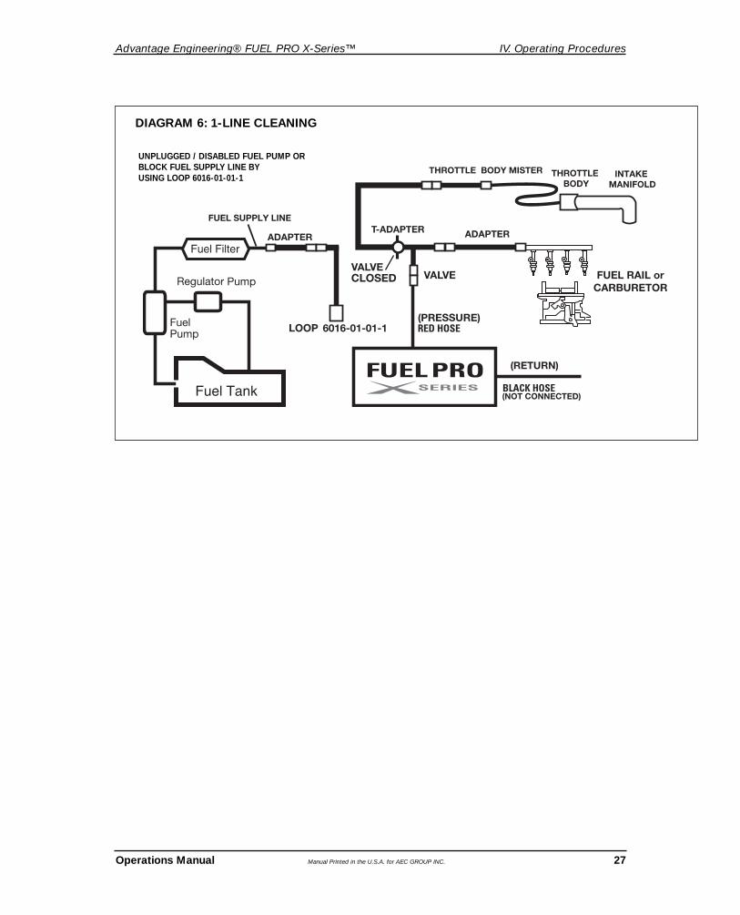
1. Press 1 LINE/CARB/QUICK button.2. Connect hoses per diagram 7.3. Disconnect the long leg of T-Adapter (the one with the gate valve) from adapter going to
vehicle fuel supply line. This frees the long leg of the T-Adapter and makes it available for Induction System Cleaning, using the Throttle Body Mister. Keep gate valve closed.
4. Disconnect FUEL PRO Black (Return) Hose from T-Adapter and connect FUEL PRO Red (Pressure) Hose to T-Adapter.
5. Add Advantage Engineering Petrol Fuel System Cleaning Solution to tank. Note gasoline level. Eight (8) ounces are required for each one (1) quart, thirty-two (32) ounces, of gasoline.
6. Remove fuel pump relay or fuse and/or block fuel supply using 6016-01-01-1, whichever you are most comfortable with. Blocking the fuel supply does not create a deadhead condition on the vehicle’s fuel pump, but rather feeds fuel through the bypass into the tank at pressure regulator or fuel filter, depending on system configuration.
7. Press PRESSURE ADJUST buttons to set the required pressure. Default pressure is set to 3 PSI when Diagnostic Tests are not performed. When Diagnostic Tests are performed, the value recorded during the Deadhead Test is used as the default setting. As mentioned previously, the Deadhead Test, when performed on a single line system, represents the regulated pressure as controlled by the vehicle’s fuel supply system.
8. Set cleaning service time. Cleaning service time is preset for 20 minutes. This can be adjusted by depressing the SET TIME button. Five minutes will be added each time the button is depressed (i.e. 25, 30, 35....through 60 before reverting to 5).
9. Press START SERVICE / START ENGINE button. Start engine. Operation pressure is displayed on the upper right display during this fuel system cleaning procedure. After approximately ten (10) minutes, or enough time to bring engine back up to normal operation temperature and into closed loop operation, it is now possible to utilize the Throttle Body Mister to clean the induction system. (Connections more particularly described in Option steps A and L listed above)
10. Attach throttle body adapter to T-adapter with valve in closed position.11. Increase engine speed to approximately 1200 to 1500 RPM and slowly open valve on
T-adapter. NOTE: Adjust valve to the point engine does not stall.12. Hold throttle at 1200 to 1500 rpm for maximum of 60 seconds while using the Throttle
Body Mister. Close valve on T-adapter and reduce engine speed back to idle. Allow two to three minutes between additional applications.
13. Continue with 1-Line Service until timer expires.
FUEL SYSTEM CLEANING PROCEDURES FOR 1 LINE SERVICE
Advantage Engineering® FUEL PRO X-Series™ IV. Operating Procedures
Operations Manual Manual Printed in the U.S.A. for AEC GROUP INC. 27
FUEL PROSERIES
DIAGRAM 6: 1-LINE CLEANING
UNPLUGGED / DISABLED FUEL PUMP OR BLOCK FUEL SUPPLY LINE BY USING LOOP 6016-01-01-1

28 Manual Printed in the U.S.A. for AEC GROUP INC. Operations Manual
V. Troubleshooting & Additional Help Advantage Engineering® FUEL PRO X-Series™
4.01 TROUBLESHOOTING GUIDE
PROBLEM: Reversed Polarity LED is on and the unit is not operational
SOLUTION: Polarity is Reversed on vehicle’s battery connection. Check connection; Red to positive and Black to vehicle ground as far away from the battery as leads will allow.
PROBLEM: The unit will not power up.
SOLUTION: Check for proper connection on power leads. Verify proper voltage at battery (see Battery Voltage Chart on page 14).
NOTE: If voltage was incorrect (above 18.0 VDC) disconnect leads and reconnect to proper power source. This will reset unit.
PROBLEM: Pump is running but unit will not build pressure.
SOLUTION: Check for proper connection on power leads. Verify proper voltage at battery (see Battery Voltage Chart on page 14).
PROBLEM: Unit performs poorly.
SOLUTION: • Check hoses for damage.
• Check power leads for cuts or frays.
• Check Maintenance Log for filter life. If there are more than 50 services on filters, replace filters and log TTL count in Maintenance Log.
NOTE: To perform fuel service after filter change, fill tank to minimum 2 quart level. Unit purge will consume ± 1quart.
ADDITIONAL HELP
Please verify that items 1-4 above have been reviewed before calling of additional assistance.
In the unlikely event that problems persist with the unit call TechnicalSupport, have you model and serial numbers available before you call.
Remember to send in your warranty card, otherwise service will be delayed.
1-877-906-1395 (U.S. AND CANADA)
V. TROUBLESHOOTING GUIDE

Advantage Engineering® FUEL PRO X-Series™ Appendix A - Adapters
Operations Manual Manual Printed in the U.S.A. for AEC GROUP INC. 29
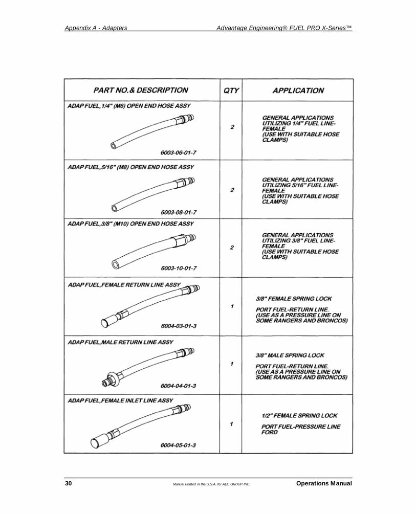
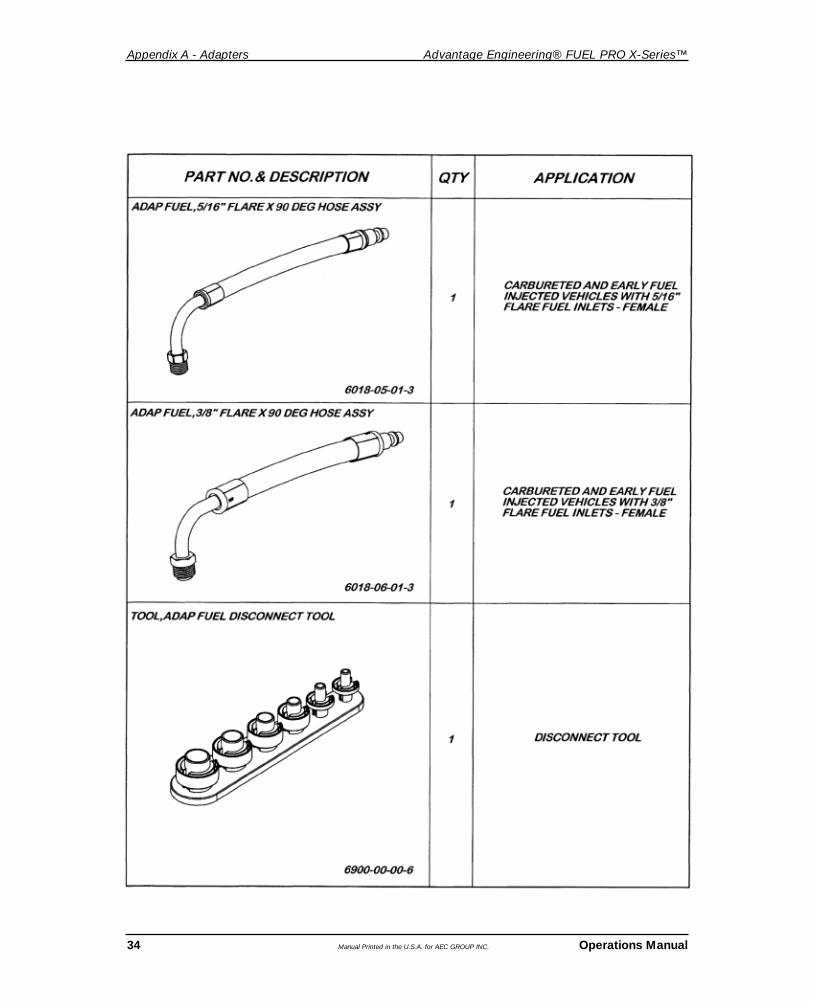
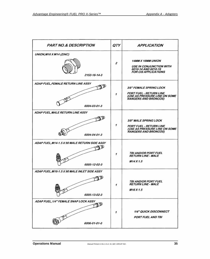
5.01 STANDARD ADAPTER KIT - 0102-15-01-0
APPENDIX A - ADAPTERS
Appendix A - Adapters Advantage Engineering® FUEL PRO X-Series™
30 Manual Printed in the U.S.A. for AEC GROUP INC. Operations Manual

Advantage Engineering® FUEL PRO X-Series™ Appendix A - Adapters
Operations Manual Manual Printed in the U.S.A. for AEC GROUP INC. 31

Appendix A - Adapters Advantage Engineering® FUEL PRO X-Series™
32 Manual Printed in the U.S.A. for AEC GROUP INC. Operations Manual
1ADAPTER3/8” MALE X 5/16” MALE SNAP LOCK
6310-10-08-3
NO TOOL REQUIRED – “PRESS” TO RELEASE
NO TOOL REQUIRED – “PRESS” TO RELEASE
USE WITH 6006-03-01-0 AND6006-05-01-0
6006-05-01-0
6006-03-01-0
ADAP FUEL, 5/16” FEMALE SNAP LOCK X 90 ASSY
ADAP FUEL, 3/8” FEMALE SNAP LOCK X 90 ASSY

Advantage Engineering® FUEL PRO X-Series™ Appendix A - Adapters
Operations Manual Manual Printed in the U.S.A. for AEC GROUP INC. 33
Appendix A - Adapters Advantage Engineering® FUEL PRO X-Series™
34 Manual Printed in the U.S.A. for AEC GROUP INC. Operations Manual
Advantage Engineering® FUEL PRO X-Series™ Appendix A - Adapters
Operations Manual Manual Printed in the U.S.A. for AEC GROUP INC. 35

Appendix A - Adapters Advantage Engineering® FUEL PRO X-Series™
36 Manual Printed in the U.S.A. for AEC GROUP INC. Operations Manual
1
1ADAPTER3/8” MALE X 5/16” MALE SNAP LOCK
6310-10-08-3
NO TOOL REQUIRED – “PRESS” TO RELEASE
NO TOOL REQUIRED – “PRESS” TO RELEASE
USE WITH 6006-03-01-0 AND6006-05-01-0
6006-05-01-0
6006-03-01-0
ADAP FUEL, 5/16” FEMALE SNAP LOCK X 90 ASSY
ADAP FUEL, 3/8” FEMALE SNAP LOCK X 90 ASSY

Advantage Engineering® FUEL PRO X-Series™ Appendix A - Adapters
Operations Manual Manual Printed in the U.S.A. for AEC GROUP INC. 37

Appendix A - Adapters Advantage Engineering® FUEL PRO X-Series™
38 Manual Printed in the U.S.A. for AEC GROUP INC. Operations Manual

Advantage Engineering® FUEL PRO X-Series™ Appendix A - Adapters
Operations Manual Manual Printed in the U.S.A. for AEC GROUP INC. 39
1
1
1
6009-12-01-3
M16 FEMALE MITSUBISHI ASSY
6009-13-01-3
6009-03-01-3
MITSUBISHI (16MM) MALE ASSY
PRESSURE SIDE ON HYUNDAI
AND MITSUBISHI EFI SYSTEMS
RETURN SIDE ON HYUNDAI AND MITSUBISHI EFI SYSTEMS
RETURN SIDE ON HYUNDAI AND MITSUBISHI EFI SYSTEMS
M11 FEMALE MITSUBISHI ASSY

PART NO. & DESCRIPTION QTY
6023-14-01-3M14 MALE SWIVEL CONE ASSY (MBENZ) 1
6024-14-01-3M14 FEMALE CONE ASSY (MBENZ) 1
6027-14-01-3M14-1.5 MALE FLARE ASSY (TOYOTA) 1
6028-14-01-3M14-1.5 FEMALE FLARE ASSY (TOYOTA) 1
6013-02-01-2AUDI & VOLVO RETURN LINE ASSY 1
6026-03-01-110' EXTENSION HOSE ASSY FOR 1THROTTLE BODY MISTER
6008-14-12-46008-14-12-4, HONDA STEP BANJO 1M12-M14
Appendix A - Adapters Advantage Engineering® FUEL PRO X-Series™
40 Manual Printed in the U.S.A. for AEC GROUP INC. Operations Manual
5.02 OPTIONAL ADAPTERS
ORDERING ADAPTERS AND REPLACEMENT PARTS1-877-906-1395 (U.S. AND CANADA)

Advantage Engineering® FUEL PRO X-Series™ Appendix B - Replacement Parts
Operations Manual Manual Printed in the U.S.A. for AEC GROUP INC. 41
APPENDIX B - REPLACEMENT PARTS
0901-54-90-1Hose, 10’ Return
0901-54-90-2Hose, 10’ Pressure
0904-53-10-1Hose, 10’ Vacuum
1624-30-01-2Tray, Upper - FUEL PRO
1624-31-11-2Drawer Assembly - FUEL PRO
1631-09-61-2Wheel, 9’ OD
1635-44-40-4Wheel , Swivel Locking
Caster 4” OD
6026-02-11-2Adapter, Throttle Body Mister
6026-00-01-2Adapter, Throttle Body Mister
Addition For Twin Nozzle Apps.
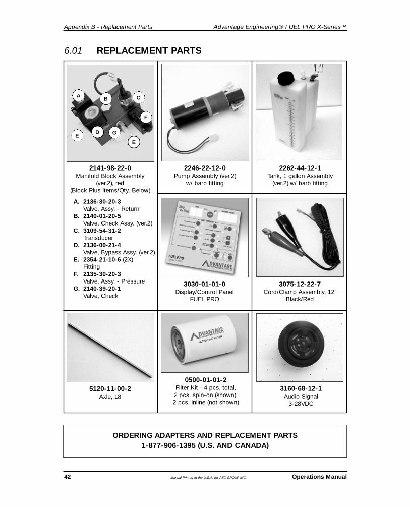
6.01 REPLACEMENT PARTS
Appendix B - Replacement Parts Advantage Engineering® FUEL PRO X-Series™
42 Manual Printed in the U.S.A. for AEC GROUP INC. Operations Manual
2246-22-12-0Pump Assembly (ver.2)
w/ barb fitting
2262-44-12-1Tank, 1 gallon Assembly
(ver.2) w/ barb fitting
3030-01-01-0Display/Control Panel
FUEL PRO
3075-12-22-7Cord/Clamp Assembly, 12’
Black/Red
5120-11-00-2Axle, 18
0500-01-01-2Filter Kit - 4 pcs. total, 2 pcs. spin-on (shown), 2 pcs. inline (not shown)
6.01 REPLACEMENT PARTS
ORDERING ADAPTERS AND REPLACEMENT PARTS1-877-906-1395 (U.S. AND CANADA)
3160-68-12-1Audio Signal
3-28VDC
2141-98-22-0Manifold Block Assembly
(ver.2), red (Block Plus Items/Qty. Below)
A. 2136-30-20-3Valve, Assy. - Return
B. 2140-01-20-5Valve, Check Assy. (ver.2)
C. 3109-54-31-2Transducer
D. 2136-00-21-4Valve, Bypass Assy. (ver.2)
E. 2354-21-10-6 (2X)Fitting
F. 2135-30-20-3Valve, Assy. - Pressure
G. 2140-39-20-1Valve, Check
B C
D
E
GE
F
A
Operations Manual Manual Printed in the U.S.A. for AEC GROUP INC. 43
Advantage Engineering® FUEL PRO X-Series™ Appendix B - Replacement Parts
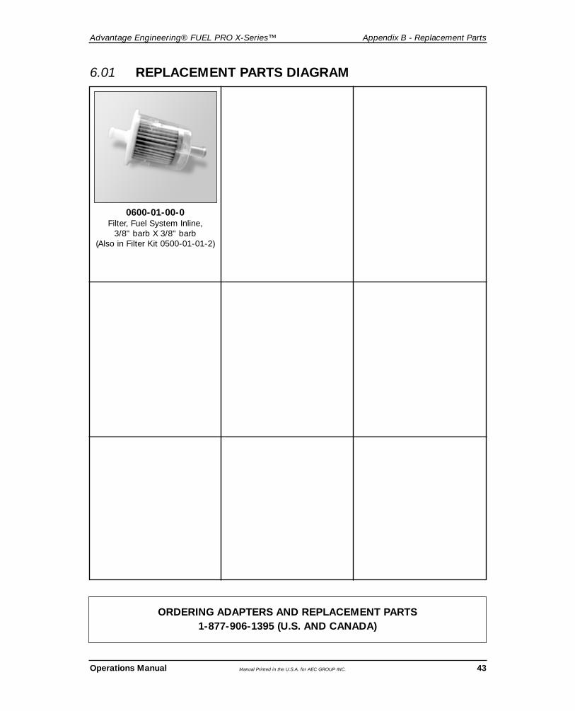
0600-01-00-0Filter, Fuel System Inline,
3/8" barb X 3/8" barb(Also in Filter Kit 0500-01-01-2)
6.01 REPLACEMENT PARTS DIAGRAM
ORDERING ADAPTERS AND REPLACEMENT PARTS1-877-906-1395 (U.S. AND CANADA)

Appendix C - Maintenance Advantage Engineering® FUEL PRO X-Series™
44 Manual Printed in the U.S.A. for AEC GROUP INC. Operations Manual
APPENDIX C - MAINTENANCE
7.01 MAINTENANCE PROCEDURES
The following maintenance procedures should be performed on a routine basis:1. Drain the unit’s fuel reservoir and replace the reservoir fuel filter and return fuel filter
after every 50 cleaning services, as described in the next section.2. Clean the exterior with a plastics cleaning agent or similar product to keep the
cabinet looking new.3. Check all hoses and wires for cuts or frays.4. Check O-rings and condition of adapters.
REPLACE THE FUEL FILTERS
1. Unscrew the old fuel filter from the mounting station on the back of the unit’s cabinet.2. Lightly grease the seal of the new filter and hand-tighten it onto the mounting head.3. Loosen clamps securing in-line filter.4. Install new in-line filter. Secure clamps.5. Dispose of used filters properly.6. Enter your initials, the date and a check mark in the appropriate boxes of the
Maintenance Record.7. Check the filters for leaks when starting next service.
The unit is now ready for the next cleaning service.
• Frequently inspect and clean any tools used, and lubricate all non-sealed ratchet mechanisms with light oil.
• The use of any other accessories not specified in this manual may create a hazard.• Read, understand and follow Safety Instructions in the front pages of this manual and
on product safety labels.
CAUTION

Advantage Engineering® FUEL PRO X-Series™ Appendix D Material Data Safety Sheet
Operations Manual Manual Printed in the U.S.A. for AEC GROUP INC. 45
APPENDIX D MATERIAL DATA SAFETY SHEET

Appendix D Material Data Safety Sheet Advantage Engineering® FUEL PRO X-Series™
46 Manual Printed in the U.S.A. for AEC GROUP INC. Operations Manual

Advantage Engineering® FUEL PRO X-Series™ Warranty Information
Operations Manual Manual Printed in the U.S.A. for AEC GROUP INC. 47
AEC GROUP INC. warrants only to the original Purchaser that under normal use, care andservice, the Equipment (except as otherwise provided herein) shall be free from defects inmaterial and workmanship for one year from the date of original invoice. External hoses,remote control modules, adapters and all other attachments, supplies and consumables(except as otherwise provided herein) are warranted for 90 calendar days from the date oforiginal invoice. Filter elements are not warranted.
SELLER’S OBLIGATIONS UNDER THIS WARRANTY ARE LIMITED SOLELY TO THEREPAIR OR, AT SELLER’S OPTION, REPLACEMENT OF EQUIPMENT OR PARTS WHICHTO SELLER’S SATISFACTION ARE DETERMINED TO BE DEFECTIVE AND WHICH ARENECESSARY, IN SELLER’S JUDGEMENT, TO RETURN THE EQUIPMENT TO GOODOPERATING CONDITION. NO OTHER WARRANTIES EXPRESS OR IMPLIED ORSTATUTORY, INCLUDING WITHOUT LIMITATION ANY IMPLIED WARRANTY OFMERCHANTABILITY OR FITNESS FOR A PARTICULAR PURPOSE, SHALL APPLY ANDALL SUCH WARRANTIES ARE HEREBY EXPRESSLY DISCLAIMED.
This warranty does not cover (and separate charges for parts, labor and related expensesshall apply to) any damage to, malfunctioning, inoperability or improper operation of theEquipment caused by, resulting from or attributable to (A) abuse, misuse or tampering; (B)alteration, modification or adjustment of the Equipment by anyone other than Seller’s authorized representatives; (D) improper or negligent use, application, operation, care, cleaning, storage or handling; (E) fire, water, wind, lightning or other natural causes; (F)adverse environmental conditions, including, without limitation, excessive heat, moisture, corrosive elements, or dust or other air contaminants, radio frequency interference, electricpower failure, power line voltages beyond those specified for the equipment, unusual physical, electrical or electromagnetic stress, and/or any other condition outside of Seller’senvironmental specifications; (G) use of the Equipment in combination or connection withother equipment, attachments, supplies or consumables not manufactured or supplied bySeller; or (H) failure to comply with any applicable federal, state or local regulation.
Repairs or replacements qualifying under this Warranty will be performed on regular businessdays during Seller’s normal working hours within a reasonable time following Purchaser’srequest. All requests for Warranty service must be made during the stated Warranty period.This warranty is non-transferable.
LIMITED ONE (1) YEAR WARRANTYFUEL PRO X-SERIES
Maitenance Log Advantage Engineering® FUEL PRO X-Series™
48 Manual Printed in the U.S.A. for AEC GROUP INC. Operations Manual
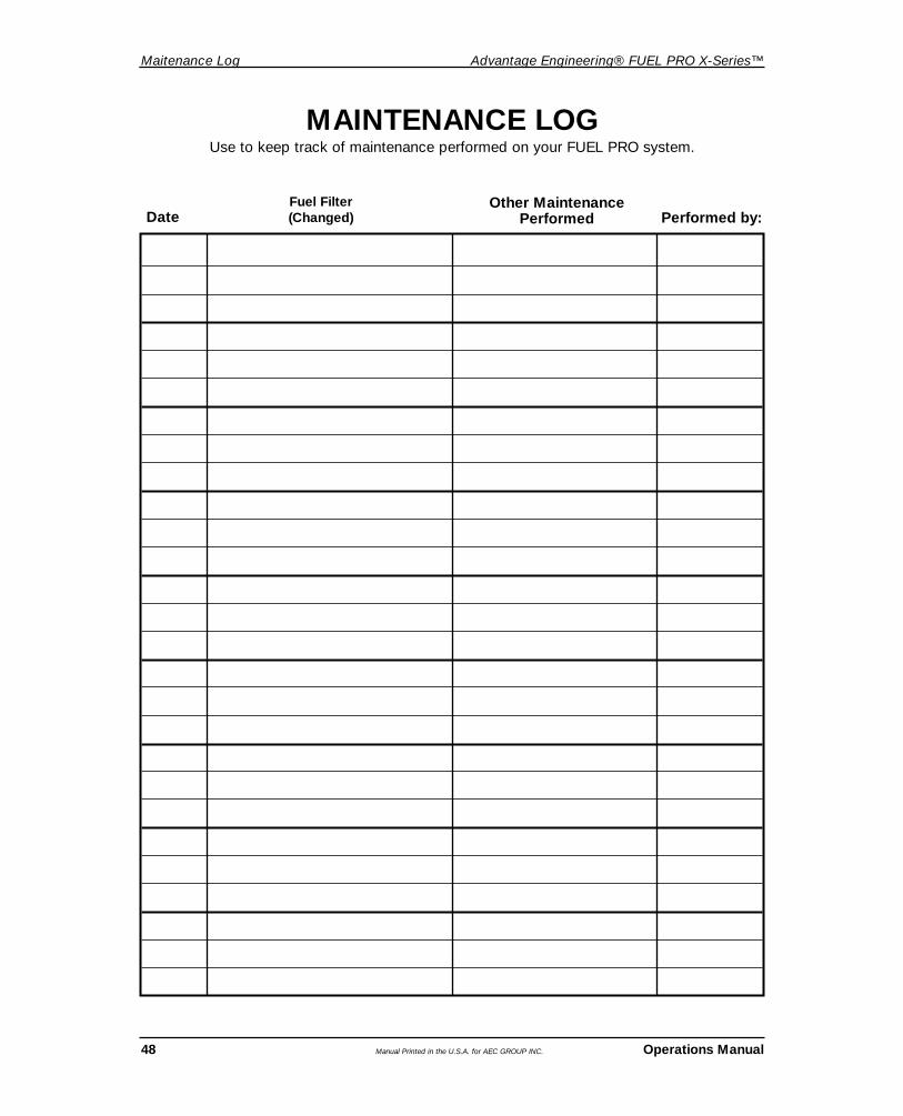
Other MaintenancePerformed Performed by:
Fuel Filter (Changed)Date
MAINTENANCE LOG Use to keep track of maintenance performed on your FUEL PRO system.