Aircraft fuel system
23
Unit: Airframe System -82Title: Aircraft fuel and fire detection system Assignment: 2 Task: 02 (a) Aircraft fuel system The basic units in the fuel system are the fuel tanks. These tanks contain fuel which is kerosene in the case of gas-turbine aircraft and gasoline in the case of piston powered aircraft. The fuel tanks are an integral part of the wing structure. Fuel can be gravity fed to the engines or pumped by electrically operated booster pumps. The fuel flow rate to the engines is determined by the setting of the power levers. The pipes which carry the fuel to the engines are fitted with non-return valves and also have stop cocks to cut fuel flow to the engine in the event of a fire. An important element in the fuel system is fuel filtration which uses filters to remove any contamination from the fuel before it enters the engine. The fuel is usually heated as it is being pumped to the engines to improve the combustion efficiency. Fuel loading can be by a pressurized system or by a gravity system. The pressurized system is connected under wing whilst a gravity system is connected overawing. Fuel quantity is shown by gauges which can be shown in lbs (pounds), kilograms, gallons or liters. Jet engines are more versatile than piston engines in the type of fuel that they can use. Jet engines can burn low octane fuels without significantly affecting performance. The quality of fuel used will eventually affect the engine due to carbon deposits and degradation caused by higher operating temperatures. The main components of the fuel system are, apart from the tanks themselves, the loading system (refueling) and distribution (fuel feed system). Because jet engines need fuel to be delivered under pressure, pumps are necessary to ensure this pressure. These booster pumps are electrically operated and usually sit at the lowest point in the wing. Other important elements in the system are the filter system , the fuel heaters, the fuel venting system and the cross feed system. The fuel filter system prevents the blocking of the engine fuel nozzles or fuel pipes by water, dirt or corroded pieces of the fuel tanks. Venting is needed both for liquid and gas. The gas air mixture in a partially empty tank must be able to adjust to changes in the outside Md. Nur Alam Course/Batch: FENDA 09 Page 1 Student ID: 33
-
Upload
independent -
Category
Documents
-
view
1 -
download
0
Transcript of Aircraft fuel system

Unit: Airframe System -82Title: Aircraft fuel and fire detection system Assignment: 2Task: 02 (a)
Aircraft fuel system
The basic units in the fuel system are the fuel tanks. These tanks contain fuel which is kerosene in the case of gas-turbine aircraft andgasoline in the case of piston powered aircraft. The fuel tanks are anintegral part of the wing structure. Fuel can be gravity fed to the engines or pumped by electrically operated booster pumps.
The fuel flow rate to the engines is determined by the setting of the power levers. The pipes which carry the fuel to the engines are fittedwith non-return valves and also have stop cocks to cut fuel flow to the engine in the event of a fire.
An important element in the fuel system is fuel filtration which uses filters to remove any contamination from the fuel before it enters theengine. The fuel is usually heated as it is being pumped to the engines to improve the combustion efficiency.
Fuel loading can be by a pressurized system or by a gravity system. The pressurized system is connected under wing whilst a gravity systemis connected overawing. Fuel quantity is shown by gauges which can be shown in lbs (pounds), kilograms, gallons or liters.
Jet engines are more versatile than piston engines in the type of fuelthat they can use. Jet engines can burn low octane fuels without significantly affecting performance. The quality of fuel used will eventually affect the engine due to carbon deposits and degradation caused by higher operating temperatures.
The main components of the fuel system are, apart from the tanks themselves, the loading system (refueling) and distribution (fuel feedsystem). Because jet engines need fuel to be delivered under pressure,pumps are necessary to ensure this pressure. These booster pumps are electrically operated and usually sit at the lowest point in the wing.
Other important elements in the system are the filter system , the fuel heaters, the fuel venting system and the cross feed system. The fuel filter system prevents the blocking of the engine fuel nozzles orfuel pipes by water, dirt or corroded pieces of the fuel tanks. Venting is needed both for liquid and gas. The gas air mixture in a partially empty tank must be able to adjust to changes in the outside
Md. Nur Alam Course/Batch: FENDA 09 Page 1Student ID: 33

Unit: Airframe System -82Title: Aircraft fuel and fire detection system Assignment: 2pressure as the aircraft climbs and descends to prevent excessive pressure on the wing skin. In addition pilots must be able to dump fuel from the aircraft to lighten it in the event of an emergency landing soon after take-off. Gravity feed is used where practicable toallow the fuel to flow to the lowest point in the wing. This area contains a collector tank and is where the booster pumps are situated
[1]
Aviation fuel
Aviation fuel is a specialized type of petroleum-based fuel used to power aircraft. It is generally of a higher quality than fuels used inless critical applications, such as heating or road transport, and often contains additives to reduce the risk of icing or explosion due to high temperature, among other properties Most aviation fuels available for aircraft are kinds of petroleum spirit used in engines with spark plugs (i.e. piston and Wankel rotary engines), or fuel for jet turbine engines, which is also used in diesel aircraft engines.
[2]
Functions of different components of aircraft fuel system Fuel Pump: In non-gravity feed designs, fuel has to be pumped from
the fuel tank to the engine and delivered under low pressure to thecarburetor or under high pressure to the fuel injection system.Often, carbureted engines use low pressure mechanical pumps that aremounted outside the fuel tank, whereas fuel injected engines oftenuse electric fuel pumps that are mounted inside the fuel tank andsome fuel injected engines have two fuel pumps: one lowpressure/high volume supply pump in the tank and one highpressure/low volume pump on or near the engine.
Md. Nur Alam Course/Batch: FENDA 09 Page 2Student ID: 33

Unit: Airframe System -82Title: Aircraft fuel and fire detection system Assignment: 2
Figure: fuel pump
Heat exchanger: A device used to exchange heat from one medium to another often through metal walls, usually to extract heat from a medium flowing between two surfaces. A heat exchanger is usually in the form of a radiator with one fluid flowing inside tubes and the other outside them. Various forms of heat exchangers are air-to-air,air-to-liquid, and liquid-to-liquid.
[3]
Figure: straight tube heat exchanger
Convective heat transfer from fluid to the inner wall of thetube,
Conductive heat transfer through the tube wall, and Convective heat transfer from the outer tube wall.
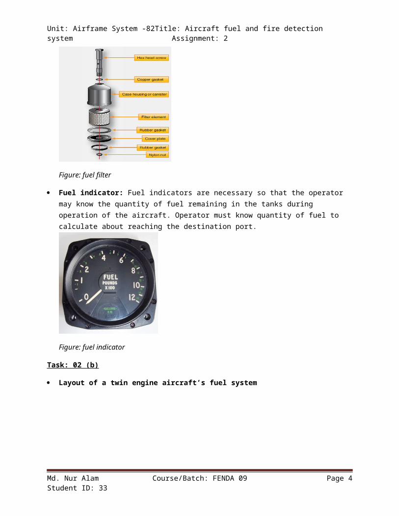
Fuel filters: The Fuel filter used on an aircraft engine is usually one of four types: screen, Cuno, canister, or spin-on. A screen-typefilter with its double-walled construction provides a large filtering area in a compact unit.As oil passes through the fine-meshscreen, dirt, ediment, and other foreign matter are removed and settle to the bottom of the housing. At regular intervals, the coveris removed and the screen and housing cleaned with a solvent. Oil screen filters are used mostly as suction filters on the inlet of the Fuel pump. The Cuno oil filter has a cartridge made of disks andspacers. A cleaner blade fits between each pair of disks. The cleaner blades are stationary, but the disks rotate when the shaft is urned. [4]
Md. Nur Alam Course/Batch: FENDA 09 Page 3Student ID: 33
Unit: Airframe System -82Title: Aircraft fuel and fire detection system Assignment: 2
Figure: fuel filter
Fuel indicator: Fuel indicators are necessary so that the operator may know the quantity of fuel remaining in the tanks during operation of the aircraft. Operator must know quantity of fuel to calculate about reaching the destination port.
Figure: fuel indicator
Task: 02 (b)
Layout of a twin engine aircraft’s fuel system
Md. Nur Alam Course/Batch: FENDA 09 Page 4Student ID: 33

Unit: Airframe System -82Title: Aircraft fuel and fire detection system Assignment: 2
Figure: layout of B737 fuel system
Essential components of twin engine aircraft fuel systemFilter: This is specially used to remove the foreign particlesfrom the fuel.Auxiliary tank: Auxiliary fuel tanks in aircraft are extra fueltanks carried make additional fuel available for increasing theflight range. They are secondary to the main aircraft fuel tank.The tanks are typical of military aircraft.Main Tank: A main fuel tank (or petrol tank) is a safe containerfor flammable fluids. Though any storage tank for fuel may be socalled, the term is typically applied to part of an engine systemin which the fuel is stored and propelled (fuel pump) or released(pressurized gas) into an engineBoost Pump: A Booster pump is a machine which will increase thepressure of a fuel.Cross Feed Valve: It can supply fuel from the fuselage tank toeither or both engines and to cross feed.Engine Driven Pump: This is the pump which pumps the fuel fromthe main tank to the engine
Md. Nur Alam Course/Batch: FENDA 09 Page 5Student ID: 33

Unit: Airframe System -82Title: Aircraft fuel and fire detection system Assignment: 2
Tank selector Valve: The tank selector valves are used to supplyfuel from the main tanks to the engines.
[5] Operation principle of the twin engine aircraft fuel system
The design of the fuel system for an aircraft having two or more engines faces problems not normally encountered in single engine fuel systems. A large number of tanks are often required to carry the necessary fuel. These tanks may be located in widely separated parts of the aircraft, such as the fuselage and the inboard and outboard sections of the wings. The individual engine fuel systems must be interconnected so that fuel can be fed from the various tanks to any engine. In case of engine failure, the fuel normally supplied to the inoperative engine must be made available to the others.
The twin engine fuel system illustrated in as shown in the above diagram is the simple cross feed type. As shown, the tank selector valves are set to supply fuel from the main tanks to the engines. These valves can also be positioned to supply fuel from the auxiliary tanks. The cross feed valve is shown in the off position. It can also be set to supply fuel from the fuselage tank to either or both enginesand to cross feed.
Twin engine aircrafts don't have the complexity, but they still utilize heat exchangers for different reasons. Nearly all have an oil cooler, which is simply a heat exchanger that allows air to flow over a coil carrying hot engine oil. Some larger piston-engine aircraft usea combustion heater for cabin heat. In this unit, a burner provides heat to the core of a heat exchanger--where it is transferred to the cabin air circulating in the outer half of the exchanger.
[6]
Task: 02 (c)
a. Engine Fire Detection: Detection is achieved by means of linear pneumatic sensing systems, often referred to as fire loops, which are gas filled pipes routed around potentially abnormal heat sources. If the temperature in the vicinity of the sensing element rises, the electrical resistance of the core material decreases and
Md. Nur Alam Course/Batch: FENDA 09 Page 6Student ID: 33

Unit: Airframe System -82Title: Aircraft fuel and fire detection system Assignment: 2
a warning indication can be triggered. They are duplicated to allow for continued detection if a single loop in the system becomesfaulty. An open loop due to a short circuit fault will be detectableduring daily preflight testing or by annunciation of a fault in service. Physical damage to a loop such as a ‘pinching’ may lead to a false fire warning but would also produce an independent fault annunciation. The same principles apply to the protection of APUs.
[7]
Figure: diagram of engine fire detection and or warning system
b. Fire extinguishing system: A fire extinguisher system is an active fire protection system which is used to extinguish or control small fires, often in emergency situations. Typically, a fire extinguisherconsists of a hand-held cylindrical pressure vessel containing an agent which can be discharged to extinguish a fire. Their main function is to quickly extinguish a developing fire and alert occupants before extensive damage occurs by filling the protected area with a gas or chemical extinguishing agent.
Aircraft fire detection and extinguishing systema. Inertia Switches: An inertial switch is a switch, firmly mounted
upon a vehicle or other mobile device that senses shock orvibration. It is a part of electrical circuits that may eitherenable or disable some function. The switch shown to the right isintended to disable an electric fuel pump in automotiveapplications. This functionality is required in some vehicle racingapplications, since an electric fuel pump may otherwise continueoperating after a collision or rollover. If the fuel line is brokenor the vehicle is inverted, fuel may be spilled, creating a fire
Md. Nur Alam Course/Batch: FENDA 09 Page 7Student ID: 33
Unit: Airframe System -82Title: Aircraft fuel and fire detection system Assignment: 2
hazard. A small loose of weight (called a proof mass) is trappedwithin a spring-loaded cage. A shock in any direction will causemovement of the mass relative to the cage, and if sufficientlyshocked the cage will spring open, actuating an associated switch.The switch is reset by pressing the cage closed through the flexible(red) top cover, re trapping the mass. These switches are also usedto open a contactor (a large relay) to disable the high powercircuit of a battery electric vehicle upon collision. Automaticactivation is accomplished by a deceleration sensing inertia switch.The inertia switch is designed when access pressure on fuel pump.
[8]b. Fire Warning Panel Indicators: APU fire warning switch illuminated
(red) – indicates fire in APU in normal piston mechanically lockedif no fire signal. Arms APU extinguisher circuit. Closes fuel shutoff valve, APU bleed air valve, and APU inlet
door. Trips generator control relay and breaker. Allows APU fire warning switch to rotate. Rotate left or right discharge APU fire bottle.
Engine bottle discharge light illuminated amber indicated related fireextinguisher bottle has discharged.
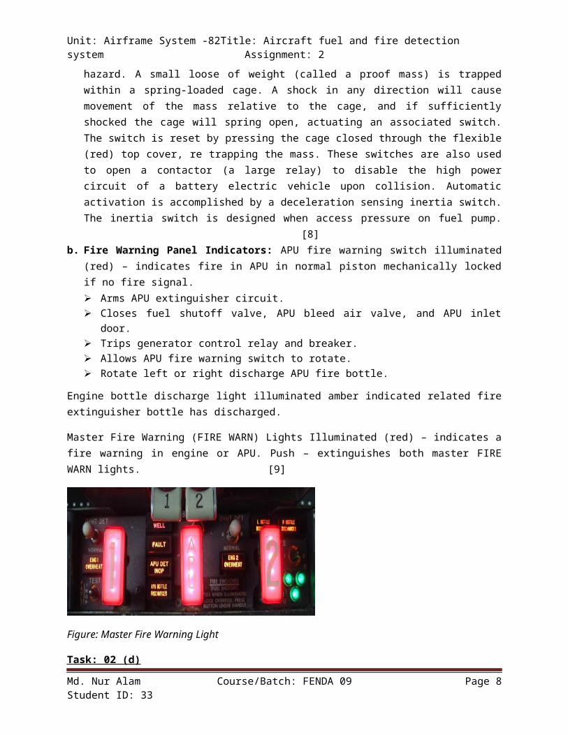
Master Fire Warning (FIRE WARN) Lights Illuminated (red) – indicates afire warning in engine or APU. Push – extinguishes both master FIREWARN lights. [9]
Figure: Master Fire Warning Light
Task: 02 (d)
Md. Nur Alam Course/Batch: FENDA 09 Page 8Student ID: 33

Unit: Airframe System -82Title: Aircraft fuel and fire detection system Assignment: 2
A. Layout of continuous engine fire detection system
Figure: layout of continuous fire detection system
B. Essential components of engine fire warning system
Flammable fluid drainage: For draining flammable fluid overboard. Theengine nacelle and APU installations are designed. These drainageprovisions include drain holes, hoses, and tubing for capturing andsafely discharging flammable fluid leakage overboard.
Ventilation: For minimizing the accumulation of flammable vapor,ventilation air is provided in fire and flammable fluid leakage zones.All ventilation flow is designed to exit safely without beingreinvested. In the engine core fire zone, controlled cooling flowprovides a source of core ventilation. Some installations havededicated ventilation inlets. The APU compartments are ventilated byeither a mechanically driven fan or a passive reduction coolingsystem. Any flammable vapors are forced out through vent openings orthrough the reduction exhaust system. The airflow driven by either ofthese two systems prevents the accumulation of flammable vapors andprovides cooling for hot surfaces.
Firewall: The strut and nacelle areas adjacent to the engine firezones are isolated by a firewall extending from the engine fan frameto the exhaust nozzle. For engines with fan compartment mountedgearbox and accessories, the entire fan cowl and thrust reverser innercowling are designed to be fireproof for in-flight conditions. The
Md. Nur Alam Course/Batch: FENDA 09 Page 9Student ID: 33

Unit: Airframe System -82Title: Aircraft fuel and fire detection system Assignment: 2upper quadrant of the fire zone compartment will prevent burn-throughto the adjoining strut and wing structures for the ground condition.In addition, fireproof feed through, boots, seals, and sealants areused to seal penetrations and gaps on firewalls and barriers toprevent flammable fluid
Electrical fire detection: It is used for detecting fires.
Extinguishing circuits: This circuit is used for extinguishing thefire
Warning, arming and discharge button lights: This button shows warningabout fire by illuminating
Fire extinguishing agents: This agent is used to extinguish the fire.
Illuminated discharge lights: This indicates low pressure in the firebottle
Titanium Firewalls on the engine: The titanium walls can withstandfire and as a result can save the engine.
[10]
C. Operating principle of turbine overheat condition
Continuous fire wire aircraft engine detection systems are used on some aircraft to indicate high area temperatures that may lead to a fire. The number of overheat warning systems varies with the aircraft.On some aircraft, they are provided for each engine turbine and each nacelle, on others they are provided for wheel well areas and for the pneumatic manifold. When an overheat condition occurs in the detector area, the system causes a light on the fire control panels to flash. In most systems the detector is a type of thermal switch. Each detector is operated when the heat rises to a specified temperature. This temperature depends upon the system and the type and model of theaircraft. The switch contacts of the detector are on spring struts, which close whenever the meter case is expanded by heat. One contact of each detector is grounded through the detector mounting bracket. The other contacts of all detectors connect in parallel to the closed
Md. Nur Alam Course/Batch: FENDA 09 Page 10Student ID: 33

Unit: Airframe System -82Title: Aircraft fuel and fire detection system Assignment: 2loop of the warning light circuit. Thus, the closed contacts of any one detector can cause the warning lights to burn.
[11]When the detector contacts close, a ground is provided for the warninglight circuit. Current then flows from an electrical bus through the warning lights and a flasher or keyer to ground. Because of the flasher in the circuit, the lights flash on and off to indicate an overheat condition.
Task: 02 (e)
Job Title: Replacing the fuel cross feed valve of fuel system.
Necessary Equipment:
1. Set of ratchets for various bolt sizes2. Spray lubricant (WD 40)3. Wrench4. Brake spring washer tool5. Screwdriver6. Sealant (3M)7. New cross feed valve8. Paper towel
Description: Cross feed valve is an arrangement of the fuel system plumbing of a multiengine aircraft that allows any of the engines to operate from any of its fuel tanks. The cross-feed system also allows fuel to be transferred from one side of the aircraft to the other sideto maintain balance in flight.
Md. Nur Alam Course/Batch: FENDA 09 Page 11Student ID: 33

Unit: Airframe System -82Title: Aircraft fuel and fire detection system Assignment: 2
Figure: fuel cross feed valve
Procedure:
First of all we have to locate the fuel cross feed valve. To locate wehave take help from the aircraft manual (if don’t know where it is).Before starting the replacement we have to turn the engine off. Thenwe have to put a container below the valve, the pump and theconnections and remove the nuts, washers and the bolts using suitabletools. After that we have to loosen the nut and disconnect the line.Afterwards we have to remove the screws and washers. Then we have toloosen the cross-union together with the lines. Then we have to removeand discard the O-rings and remove the cross feed valve. Then we haveto bring a new cross feed valve according to the aircraft manualspecification. Then apply FUELS on the new O-rings and install the O-rings on the valve. Then apply lubricant on the shaft end of thevalve. Then apply SEALANTS on the head of the screws. Now we have toinstall the valve on the line on the rear spar and screw it. Now wehave to connect the cross-union together with the lines and to thevalve. Now install the O-ring between the cross-union and the pump.Install washers and screw it. Now connect the line to the cross unionand torque the nuts. Now connect the bonding strip with the bolts,washers and the nuts and torque the nuts. After removing the part itis also a necessary step to mark all the parts and bolts with a
Md. Nur Alam Course/Batch: FENDA 09 Page 12Student ID: 33

Unit: Airframe System -82Title: Aircraft fuel and fire detection system Assignment: 2numbering system or tape and marker so that we can reconnect them tothe correct terminal in a correct way.
Safety Precautions:
1. Wear safety glasses or face shields2. Wear safety shoes (no open toes)3. Wear protective gloves4. Wear clothing suited for the job5. Don’t wear rings, watches or any kind of jewelry6. Don’t wear neck ties or loose clothing
ii)
Job Title: Replacing the faulty agent discharge switch.
Figure: agent discharge switch
Necessary Equipment:
1. Phillips head screwdriver2. Plane head screwdriver3. Tester4. New agent discharge switch
Md. Nur Alam Course/Batch: FENDA 09 Page 13Student ID: 33

Unit: Airframe System -82Title: Aircraft fuel and fire detection system Assignment: 2
5. Paper towel
Description:
The engine's AGENT switches are active when a corresponding engineFIRE switch is released out. The SQUIB lights illuminate white tofacilitate identification of the agent switches that are active. Whenthe engine's AGENT switch is active and pushed momentarily, the fireextinguisher bottle is discharged. The DISCH light illuminates amberwhen the fire extinguisher bottle agent pressure is low. Each engineis provided with two fire extinguishers with electrically operatedsquibs to discharge their contents. Each squib has a dual electricsupply. An AGENT switch for each fire extinguisher bottle is locatedon the respective ENG FIRE panel that enables discharging of the fireextinguisher's agent.
Procedure:
First of all we have to locate the faulty agent discharge switch. Tolocate we have take help from the aircraft manual (if don’t know whereit is). Then we have to disconnect the pins 1 and 2 from the aircraftground points. Then remove the shunt devices from the cartridges andconnect the connectors 5WE1-A (5WE2-A) and 7WE1-A (7WE2-A) to theircartridges and make sure that the connectors are correctly connected.Now connect the voltmeter – DC between the pin 1 and 2 ground points.The voltmeter must read OVCD. On the engine/APU fire pane; 1WD, openthe guard of the engine 1, 2 agent discharge switch and push andrelease the switch and ignore the squib legends. Mow push and hold therelated agent 1, 2 discharge switches. We have to make sure that thevoltmeter reads 28 VDC between pin1 and 2 grounding points. Nowrelease the agent 1 and 2 discharge switches and make sure that thevoltmeter read OVDC between pin 1 and 2 grounding points. Now push theengine 1, 2 agent discharge switches back to its original place. Afterremoving the part it is also a necessary step to mark all the partsand bolts with a numbering system or tape and marker so that we canreconnect them to the correct terminal in a correct way.
Safety Precautions:
Md. Nur Alam Course/Batch: FENDA 09 Page 14Student ID: 33

Unit: Airframe System -82Title: Aircraft fuel and fire detection system Assignment: 2
1. Wear safety glasses or face shields2. Wear safety shoes (no open toes)3. Wear protective gloves4. Wear clothing suited for the job5. Don’t wear rings, watches or any kind of jewelry6. Don’t wear neck ties or loose clothing
Task: 02 (f) (M3)
Operating principle of fuel pressurization system
With an injection system fuel is pressurized and introduced just aheadof the inlet ports, directly in to the combustion chamber or at the supercharger impeller. Carburetion uses a pressure differential to vaporize the fuel before it enters the cylinders.
Two types of fuel injection systems are used, they are continuous flowand direct injection. We will describe both of them here.
Continuous Flow
This system provides a continuous flow ofpressurized fuel at each inlet port of thecylinders and it uses the following parts:
Injection pump, positive displacement vane type pump driven by the engine. Feeds excess fuel, which is returned to the tank in use, to
Md. Nur Alam Course/Batch: FENDA 09 Page 15Student ID: 33

Unit: Airframe System -82Title: Aircraft fuel and fire detection system Assignment: 2maintain a positive pressure under all circumstances. Fuel is delivered in liquid form, vapor is separated and has a bypass check valve so that an electric pump can deliver fuel for starting the engine.
Fuel metering unit, Filters the fuel and sets the mixture ratio. The cockpit mixture knob is connected to this unit and leans the fuel. Thecockpit throttle is also connected and regulates the butterfly controlling the air flow to the manifold.
Manifold valve, distributes the fuel to all cylinders and you will seeit on top of the engine with stainless steel tubing running to the inlet ports of the cylinders.
Injector nozzles, injects pressurized metered fuel of the exact right quantity and ratio with air. The design is such that it favors improved fuel atomization for good combustion and power developed by the engine.
Super- and turbocharged engines can also use a fuel injection system but they will need modifications to adjust the fuel flow with rapid throttle openings combined with air pressure sensors in the manifold. More air should mean more fuel if the engine is to run smoothly without faltering when opening the throttle.
Direct Injection
With this system fuel is pressurized and injected directly into the combustion chamber bypassing the inlet valve, much like a diesel engine but with the two spark plugs. It is used on higher powered engines mainly.
This system uses almost the same parts as described above with the continuous flow fuel system.
[12]
Operating principle of fuel transfer modes
Fuel system for pressurization, fuel transfer modes and operation
Cross feed valves operate together. Left and Right Fuel Booster Pumpsoperate independently.
Md. Nur Alam Course/Batch: FENDA 09 Page 16Student ID: 33

Unit: Airframe System -82Title: Aircraft fuel and fire detection system Assignment: 2Fuel System: Normal Operation:Flash Animation = 19K 1. Crossfeed Valves - CLOSED2. Both FTSV - OPEN3. Both Fuel Pumps - ON4. Left and Right fuel tanks feed their respective engines (L to L, Rto R)
Fuel System: Normal Cross feed Operation:Flash Animation = 19K 1.Crossfeed Valves - OPEN2. Left FTSV - OPEN3. Right FTSV - CLOSED4. Left Fuel Pump – ON5. Right Fuel Pump - OFF6.Left fuel tank feeds both engines (L to L/R)
Fuel System: Accident Cross feed Operation:Flash Animation = 21K1. Crossfeed Valves - OPEN2. Left FTSV - OPEN3. Right FTSV - OPEN
Md. Nur Alam Course/Batch: FENDA 09 Page 17Student ID: 33

Unit: Airframe System -82Title: Aircraft fuel and fire detection system Assignment: 24. Left Fuel Pump - ON5. Right Fuel Pump - OFF6. Left fuel tank feeds both engines (L to L/R) and also fills rightfuel tank with the excess fuel
There are generally two types of fuel pumps in aircraft. Low pressurepumps which bring fuel from the tank to the engine and operate prettymuch like any other fuel pump. These are usually located in a sumpwithin the tank and are designed so as not to run dry. The other typeis a high pressure pump which is usually located within the engine.These pumps take the low pressure fuel from the tank and increase fuelpressure dramatically for injection into the burner cans.
Commercial airliners have fuel pumps that can be either mounted insidethe fuel tanks or externally. Basically they consist of a centrifugalimpellor powered by an electric motor.
The Fuel Boost Pump used on Douglas aircraft are a centrifugal pumpthat is powered by a 3-phase AC motor. The pumps are designed tooperate for extended periods in a dry tank after running wet. Non-resettable thermal protectors for each pump motor circuit phaseprevent excessive pump motor temperatures. The outlet check vlave areflapper-type valves that opens under pressure from the pump and willclose if there is reverse pressure in the fuel supply line.
Fuel Primer Pump - A manual pump to add a small amount of fuel at thecylinder intakes to assist in starting a cold engine. Fuel injectedengines do not have this control. For fuel injected engines, a fuelboost pump is used to prime the engine prior to start.
Fuel Quantity Gauge - Indicates the amount of fuel remaining in theidentified tank.
Fuel Select Valve - Connects the fuel flow from the selected tank tothe engine.
If the aircraft is equipped with a fuel pump: Fuel Pressure Gauge -Indicates the supply pressure of fuel to the carburetor (or in thecase of a fuel injected engine, to the fuel controller.)
Fuel Boost Pump Switch - Controls the operation of the auxiliaryelectric fuel pump to provide fuel to the engine before it starts orin case of failure of the engine powered fuel pump. Some largeairplanes have a fuel system that allows the flight crew to jettisonor dump the fuel. When operated, the boost pumps in the fuel tanks
Md. Nur Alam Course/Batch: FENDA 09 Page 18Student ID: 33

Unit: Airframe System -82Title: Aircraft fuel and fire detection system Assignment: 2pump the fuel to the dump chutes or jettison nozzles and overboard toatmosphere. [13]
Tank-to-tank transfer, especially from one side of an aircraft toanother in a single-engine aircraft, is also referred to as cross-feed.
A typical cross-feed cock. In ‘NORM’ position all pumps are energized.‘AFT’ position energizes pumps in the aft tank, opens cross feed valveand transfers fuel to the engine and forward tank. Selection of switchto ‘FORWARD’ position energizes the pump in the forward tank, openscross-feed valve and transfers fuel to the engine and aft tank.
[14]
Task: 02 (g)
Circumstances under the on-board fire extinguishers are automaticallyoperated:
Onboard systems designed to extinguish fires which occur either in theair or on the ground.
Four types of fire extinguishing installations are found on commercialtransport aircraft.
Portable Extinguishers installed at specified locations in boththe main cabin and the flight deck.Hold fire extinguishing systems (with automatic detection).Engine fire bottle extinguishing systems (with automaticdetection).Toilet waste bin bottle extinguishing systems.
Md. Nur Alam Course/Batch: FENDA 09 Page 19Student ID: 33

Unit: Airframe System -82Title: Aircraft fuel and fire detection system Assignment: 2An aircraft fire-extinguishing system provides automatic fireprevention and/or suppression simultaneously in fuel tanks, cargocompartments and, when needed, in cabin using injection of hypoxic(oxygen-depleted) air produced onboard in an air-separation deviceutilizing the flow and pressure of the bleed air. The same air-separation device allows supplying passengers and crew with unlimitedamounts of oxygen for as long as needed. New methods of a rapid firesuppression utilizing the propulsion of water mist or fire-extinguishing foam by hypoxic air are presented. The combination ofwater mist or foam with hypoxic air allows to present two innovativefire-extinguishing compositions. [15]
Hold Fire Extinguishing Systems:
Hold fire extinguishing systems are usually activated as a flight crewresponse to abnormal heat detection in an aircraft hold, and usuallyoperate in a dual function. Part of the available fire suppressioncapability is deployed in an ‘instant’, discharge of extinguishingagent and the remainder is deployed more gradually over a longerperiod of up to an hour, to assist in preventing re-ignition or atleast providing partial fire suppression, to provide more time to getan aircraft with a continuing hold fire warning back on the ground.The FAA has developed minimum performance standards for these systemsand it has been demonstrated that although water misting alone isunable to pass the exploding aerosol can fire test, a combination ofwater misting and inert gas (nitrogen) discharge may be moreeffective. However, for such a solution to be viable, a means of on-board nitrogen generation will be needed.
General: Crews should follow company approved emergency procedures andmanufacturers guidance regarding the conduct of the flight, managementof aircraft systems, identification of the source of a suspected fire,and fire fighting.
This article considers some aspects of airmanship which are applicableto all aircraft and situations.
Protection: At the first indication, or suspicion, of smoke and fumes,or a fire within the aircraft, the flight crew should don smokegoggles and oxygen masks. Goggles and masks need to fit tightly and100% Oxygen with overpressure selected to minimize any ingress ofsmoke and fumes into the mask.
Md. Nur Alam Course/Batch: FENDA 09 Page 20Student ID: 33

Unit: Airframe System -82Title: Aircraft fuel and fire detection system Assignment: 2Unless smoke and fumes are clearly present on the flight deck, thecaptain may elect, in order to maintain communication with the cabincrew, to delay fitting his own mask until the co-pilot has donned hisprotective equipment and is in a position to take control of theaircraft. (LAND AS SOON AS POSSIBLE)
Fight the Fire: While the requirement is to land the aircraft as soonas possible, the crews need to do all that they can to isolate andcontrol the fire.
Engine Fire Bottles: Fire Bottles in engine compartments are usuallyelectrically operated after manual selection by the flight crew basedupon automatic fire detection. In the airborne case, APU fire bottlesare similarly activated but it is usual for automatic APU firedetection during ground operation to trigger automatic shutdown andfire extinguisher activation. The extinguishing agent universallyremains Halon 1301 for all Engines/APUs fitted to civil transportaircraft. However, the US Air Force, Marine Corps and Navy have alldeveloped alternative engine fire extinguisher systems which use HFC-125 and have been successfully tested and subsequently deployed inoperational aircraft. [16]
Toilet waste bins: Toilet waste bin fire extinguishers are activated automatically if heat detectors in the vicinity are activated. Toilet Smoke detector activation does not trigger waste bin fire extinguishers. Alternative extinguishing agents to Halon 1301 have been approved for use in fixed toilet waste bin systems and have also been, uniquely in terms of the search for Halon alternatives, shown tobe more effective than Halon 1301 units whilst being the same size. Since only a documentation change is required to fit these alternativeextinguishers, they have been used for retrofit as well as in new-build aircraft.
Md. Nur Alam Course/Batch: FENDA 09 Page 21Student ID: 33

Unit: Airframe System -82Title: Aircraft fuel and fire detection system Assignment: 2
Source and references:
1. http://www.flightspeak.co.uk/auxiliar.htm 2. http://en.wikipedia.org/wiki/Aviation_fuel#cite_note-oilandgasiq-
13. http://www.answers.com/topic/heat-exchanger 4. http://en.wikipedia.org/wiki/Aircraft_fuel_system 5. https://www.faa.gov/regulations_policies/handbooks_manuals/
aircraft/amt_airframe_handbook/media/ama_ch14.pdf6. http://avstop.com/ac/apgeneral/multienginefuelsystems.html 7. http://www.skybrary.aero/index.php/Engine_Fire_Protection 8. www.smartcockpit.com/fire_panel_indicator.php 9. http://www.prevent-a-fire.eu/pdf/FENWAL_CFD_LICO.pdf 10. http://www.greatwarreplicaaircraft.com/Reference/AC65-
15A_Airframe/Chapter10.pdf11. http://www.fire.tc.faa.gov/pdf/fsr-0032.pdf 12. http://www.experimentalaircraft.info/articles/aircraft-
engine-fuel-injection.php13. http://www.flightspeak.co.uk/auxiliar.htm 14. http://aviation_dictionary.enacademic.com/1812/cross-feed 15. http://www.google.com/patents/US20080168798 16. http://www.skybrary.aero/index.php/
Aircraft_Fire_Extinguishing_Systems
Md. Nur Alam Course/Batch: FENDA 09 Page 22Student ID: 33
Unit: Airframe System -82Title: Aircraft fuel and fire detection system Assignment: 2
Md. Nur Alam Course/Batch: FENDA 09 Page 23Student ID: 33