FUEL SYSTEM - Boote-Forum
100
3 C FUEL INJECTION 90-878079 JANUARY 2000 Page 3C-1 FUEL SYSTEM Section 3C - Fuel Injection Table of Contents Specifications 3C-2 . . . . . . . . . . . . . . . . . . . . . . . . . . . Special Tools 3C-3 . . . . . . . . . . . . . . . . . . . . . . . . . . . Ignition Controller and Detonation Module 3C-6 . . ECM Assembly 3C-8 . . . . . . . . . . . . . . . . . . . . . . . . . Fuel Management System 3C-10 . . . . . . . . . . . . . . . . Fuel Pump 3C-14 . . . . . . . . . . . . . . . . . . . . . . . . . . . . . Electronic Fuel Injection (EFl) System 3C-16 . . . . . . Introduction 3C-16 . . . . . . . . . . . . . . . . . . . . . . . . . . Using the Test Procedures 3C-16 . . . . . . . . . . . . . EFI System Tests 3C-16 . . . . . . . . . . . . . . . . . . . . . Safety Precautions 3C-16 . . . . . . . . . . . . . . . . . . . Fuel Injection System Function 3C-17 . . . . . . . . . Preliminary Checks 3C-17 . . . . . . . . . . . . . . . . . . . . . . Ignition Spark Check 3C-17 . . . . . . . . . . . . . . . . . . Electronic Fuel Injection Set Up 3C-18 . . . . . . . . Fresh Quality Fuel 3C-18 . . . . . . . . . . . . . . . . . . . . Low Battery Voltage 3C-18 . . . . . . . . . . . . . . . . . . Fuel Flow Diagram 3C-19 . . . . . . . . . . . . . . . . . . . . . . Fuel Flow Component Description 3C-20 . . . . . . . . . EFI Electrical Components 3C-21 . . . . . . . . . . . . EFI Fuel Management (Low Pressure Fuel Route) 3C-24 . . . . . . . . . . . . . . . EFI Fuel Management (High Pressure Fuel Route) 3C-25 . . . . . . . . . . . . . . . Fuel Rail Electrical/Fuel Determination 3C-26 . . . . . EFI System Test Procedures 3C-27 . . . . . . . . . . . . . . Fuel Gauge Connection/Pressure Test 3C-27 . . Vapor Separator Fuel Delivery Test 3C-28 . . . . . Vapor Separator Float Test 3C-29 . . . . . . . . . . . . Water Separating Filter Flow Test 3C-30 . . . . . . . Pulse Fuel Pump Delivery Test 3C-31 . . . . . . . . . Final Filter Check and De-Pressurizing EFI System Procedures 3C-32 . . . . . . . . . . . . . . . Pressure Regulator Test 3C-34 . . . . . . . . . . . . . . . Electric Fuel Pump Voltage Test 3C-36 . . . . . . . . Injector Electrical Harness Test 3C-39 . . . . . . . . . ECM Injector Driver Test 3C-40 . . . . . . . . . . . . . . Injector Fuel Delivery Test 3C-40 . . . . . . . . . . . . . Injector Operation Test (Manifold Cover Removed) 3C-40 . . . . . . . . . . . . Induction Manifold Leak Check (Manifold Cover Removed) 3C-43 . . . . . . . . . . . . Air Temperature Sensor Test 3C-45 . . . . . . . . . . . Engine Head Temperature Sensor Test 3C-46 . . Detonation Control System Test (200 Models Only) 3C-46 . . . . . . . . . . . . . . . . . . . . Detonation Sensor Check 3C-47 . . . . . . . . . . . . . Detonation Control Module Check 3C-48 . . . . . . Throttle Position Sensor Test 3C-48 . . . . . . . . . . . Map Sensor Test 3C-49 . . . . . . . . . . . . . . . . . . . . . Problem Diagnosis 3C-50 . . . . . . . . . . . . . . . . . . . Engine Head Temperature Sensor Removal 3C-53 EFI Induction Manifold Removal 3C-54 . . . . . . . . . . . Water Separating Filter Assembly Removal 3C-55 . . . . . . . . . . . . . . . . . . . . . . . . . . . . Water Separating Filter Assembly Installation 3C-56 . . . . . . . . . . . . . . . . . . . . . . . . . . . Throttle Position Sensor and Temperature Sensor Fuel Injector Harness Disconnections 3C-56 . . . . . . . . . . . . . . . . . . . . . . . Oil Reservoir Removal 3C-58 . . . . . . . . . . . . . . . . Fuel Pressure Regulator Removal 3C-59 . . . . . . Fuel Pressure Regulator Disassembly 3C-60 . . Fuel Pressure Regulator Reassembly 3C-60 . . . Vapor Separator Removal 3C-61 . . . . . . . . . . . . . Vapor Separator Disassembly 3C-63 . . . . . . . . . . Installing Vapor Separator Assembly to Induction Manifold 3C-69 . . . . . . . . . . . . . . . . . . . . Manifold Removal 3C-72 . . . . . . . . . . . . . . . . . . . . EFI Induction Manifold Disassembly 3C-74 . . . . . . . Air Temperature Sensor Removal 3C-74 . . . . . . Throttle Position Sensor Removal 3C-75 . . . . . . Fuel Rail Removal 3C-76 . . . . . . . . . . . . . . . . . . . . Fuel Rail Disassembly 3C-78 . . . . . . . . . . . . . . . . Fuel Injector Removal and Disassembly 3C-78 . Injector Harness Removal 3C-80 . . . . . . . . . . . . . Throttle Linkage Removed 3C-81 . . . . . . . . . . . . . EFI System Cleaning and Inspection 3C-82 . . . . . . . Cleaning 3C-82 . . . . . . . . . . . . . . . . . . . . . . . . . . . . Inspection 3C-82 . . . . . . . . . . . . . . . . . . . . . . . . . . . Induction Manifold Assembly 3C-83 . . . . . . . . . . . . . . Injector Harness Installation 3C-83 . . . . . . . . . . . Fuel Injector Assembly and Installation 3C-84 . . Fuel Rail Assembly 3C-86 . . . . . . . . . . . . . . . . . . . Fuel Rail Installation 3C-86 . . . . . . . . . . . . . . . . . . Throttle Position Sensor Installation 3C-88 . . . . . Air Temperature Sensor Installation 3C-89 . . . . . EFI Induction Manifold Installation 3C-91 . . . . . . . . . Oil Reservoir Installation 3C-93 . . . . . . . . . . . . . . Vapor Separator Installation 3C-94 . . . . . . . . . . . Throttle Position Sensor, Air Temperature Sensor and Fuel Injector Harness Connections 3C-96 . . . . . . . . . . . . . . . . . . . . . . . . . ECM Installation 3C-98 . . . . . . . . . . . . . . . . . . . . . . Engine Head Temperature Sensor Installation 3C-99 . . . . . . . . . . . . . . . . . . . . . . . . . . .
-
Upload
khangminh22 -
Category
Documents
-
view
8 -
download
0
Transcript of FUEL SYSTEM - Boote-Forum

3C
FUEL INJECTION
90-878079 JANUARY 2000 Page 3C-1
FUEL SYSTEMSection 3C - Fuel Injection
Table of Contents
Specifications 3C-2. . . . . . . . . . . . . . . . . . . . . . . . . . . Special Tools 3C-3. . . . . . . . . . . . . . . . . . . . . . . . . . . Ignition Controller and Detonation Module 3C-6. . ECM Assembly 3C-8. . . . . . . . . . . . . . . . . . . . . . . . . Fuel Management System 3C-10. . . . . . . . . . . . . . . . Fuel Pump 3C-14. . . . . . . . . . . . . . . . . . . . . . . . . . . . . Electronic Fuel Injection (EFl) System 3C-16. . . . . .
Introduction 3C-16. . . . . . . . . . . . . . . . . . . . . . . . . . Using the Test Procedures 3C-16. . . . . . . . . . . . . EFI System Tests 3C-16. . . . . . . . . . . . . . . . . . . . . Safety Precautions 3C-16. . . . . . . . . . . . . . . . . . . Fuel Injection System Function 3C-17. . . . . . . . .
Preliminary Checks 3C-17. . . . . . . . . . . . . . . . . . . . . . Ignition Spark Check 3C-17. . . . . . . . . . . . . . . . . . Electronic Fuel Injection Set Up 3C-18. . . . . . . . Fresh Quality Fuel 3C-18. . . . . . . . . . . . . . . . . . . . Low Battery Voltage 3C-18. . . . . . . . . . . . . . . . . .
Fuel Flow Diagram 3C-19. . . . . . . . . . . . . . . . . . . . . . Fuel Flow Component Description 3C-20. . . . . . . . .
EFI Electrical Components 3C-21. . . . . . . . . . . . EFI Fuel Management(Low Pressure Fuel Route) 3C-24. . . . . . . . . . . . . . . EFI Fuel Management(High Pressure Fuel Route) 3C-25. . . . . . . . . . . . . . . Fuel Rail Electrical/Fuel Determination 3C-26. . . . . EFI System Test Procedures 3C-27. . . . . . . . . . . . . .
Fuel Gauge Connection/Pressure Test 3C-27. . Vapor Separator Fuel Delivery Test 3C-28. . . . . Vapor Separator Float Test 3C-29. . . . . . . . . . . . Water Separating Filter Flow Test 3C-30. . . . . . . Pulse Fuel Pump Delivery Test 3C-31. . . . . . . . . Final Filter Check and De-PressurizingEFI System Procedures 3C-32. . . . . . . . . . . . . . . Pressure Regulator Test 3C-34. . . . . . . . . . . . . . . Electric Fuel Pump Voltage Test 3C-36. . . . . . . . Injector Electrical Harness Test 3C-39. . . . . . . . . ECM Injector Driver Test 3C-40. . . . . . . . . . . . . . Injector Fuel Delivery Test 3C-40. . . . . . . . . . . . . Injector Operation Test(Manifold Cover Removed) 3C-40. . . . . . . . . . . . Induction Manifold Leak Check(Manifold Cover Removed) 3C-43. . . . . . . . . . . . Air Temperature Sensor Test 3C-45. . . . . . . . . . . Engine Head Temperature Sensor Test 3C-46. . Detonation Control System Test(200 Models Only) 3C-46. . . . . . . . . . . . . . . . . . . . Detonation Sensor Check 3C-47. . . . . . . . . . . . . Detonation Control Module Check 3C-48. . . . . .
Throttle Position Sensor Test 3C-48. . . . . . . . . . . Map Sensor Test 3C-49. . . . . . . . . . . . . . . . . . . . . Problem Diagnosis 3C-50. . . . . . . . . . . . . . . . . . .
Engine Head Temperature Sensor Removal 3C-53EFI Induction Manifold Removal 3C-54. . . . . . . . . . .
Water Separating Filter AssemblyRemoval 3C-55. . . . . . . . . . . . . . . . . . . . . . . . . . . . Water Separating Filter AssemblyInstallation 3C-56. . . . . . . . . . . . . . . . . . . . . . . . . . . Throttle Position Sensor and TemperatureSensor Fuel Injector HarnessDisconnections 3C-56. . . . . . . . . . . . . . . . . . . . . . . Oil Reservoir Removal 3C-58. . . . . . . . . . . . . . . . Fuel Pressure Regulator Removal 3C-59. . . . . . Fuel Pressure Regulator Disassembly 3C-60. . Fuel Pressure Regulator Reassembly 3C-60. . . Vapor Separator Removal 3C-61. . . . . . . . . . . . . Vapor Separator Disassembly 3C-63. . . . . . . . . . Installing Vapor Separator Assembly toInduction Manifold 3C-69. . . . . . . . . . . . . . . . . . . . Manifold Removal 3C-72. . . . . . . . . . . . . . . . . . . .
EFI Induction Manifold Disassembly 3C-74. . . . . . . Air Temperature Sensor Removal 3C-74. . . . . . Throttle Position Sensor Removal 3C-75. . . . . . Fuel Rail Removal 3C-76. . . . . . . . . . . . . . . . . . . . Fuel Rail Disassembly 3C-78. . . . . . . . . . . . . . . . Fuel Injector Removal and Disassembly 3C-78. Injector Harness Removal 3C-80. . . . . . . . . . . . . Throttle Linkage Removed 3C-81. . . . . . . . . . . . .
EFI System Cleaning and Inspection 3C-82. . . . . . . Cleaning 3C-82. . . . . . . . . . . . . . . . . . . . . . . . . . . . Inspection 3C-82. . . . . . . . . . . . . . . . . . . . . . . . . . .
Induction Manifold Assembly 3C-83. . . . . . . . . . . . . . Injector Harness Installation 3C-83. . . . . . . . . . . Fuel Injector Assembly and Installation 3C-84. . Fuel Rail Assembly 3C-86. . . . . . . . . . . . . . . . . . . Fuel Rail Installation 3C-86. . . . . . . . . . . . . . . . . . Throttle Position Sensor Installation 3C-88. . . . . Air Temperature Sensor Installation 3C-89. . . . .
EFI Induction Manifold Installation 3C-91. . . . . . . . . Oil Reservoir Installation 3C-93. . . . . . . . . . . . . . Vapor Separator Installation 3C-94. . . . . . . . . . . Throttle Position Sensor, Air TemperatureSensor and Fuel Injector HarnessConnections 3C-96. . . . . . . . . . . . . . . . . . . . . . . . . ECM Installation 3C-98. . . . . . . . . . . . . . . . . . . . . . Engine Head Temperature SensorInstallation 3C-99. . . . . . . . . . . . . . . . . . . . . . . . . . .

FUEL INJECTION
Page 3C-2 90-878079 JANUARY 2000
Specifications
Electronic Fuel InjectionIdle RPM – All Models 1000 – 1100
Wide Open Throttle RPM 5750 – 6250
Float Adjustment (Vapor Separator)– Float Level Preset @ Factory
Fuel Injectors–All Models (Quantity)–Ignition Controller Uses the Trigger Signal as an Injector Timing Signal as follows:
– #1 Trigger Circuit– #3 Trigger Circuit– #5 Trigger Circuit
6
#3 and #4 Injectors#5 and #6 Injectors#1 and #2 Injectors
Line Pressure @ Injectors 34 psi – 36 psi (234kPa – 248kPa)

FUEL INJECTION
90-878079 JANUARY 2000 Page 3C-3
Special Tools
1. Fuel Pressure Gauge 91-16850A7 (a) or Fuel Pressure Gauge 91-852087A3(b).
51796
55294
ab
2. Digital Diagnostic Terminal (DDT) 91-823686T2
3. Software Cartridge 91-822608--5
4. DDT Reference Manual 90-825159-3

FUEL INJECTION
Page 3C-4 90-878079 JANUARY 2000
5. Adaptor Harness 84-822560A5 (use with DDT)
6. Remote Starter Switch 91-52024A1
7. DMT 2000 Digital Tachometer Multi-meter P/N 91-854009A1
8. Inductive Timing Light 91-99379
9. Spark Gap Tester 91-850439T
55117

FUEL INJECTION
90-878079 JANUARY 2000 Page 3C-5
10. Injector Test Harness 91-833169A1. Can be used to verify that the ECM is supplyingoperating voltage to the injectors. Harness is connected between the injector harnessand the engine harness. Harness is used in conjunction with DVA meter 91-99750A1.Harness will also serve as a convenient way to connect the injector harness to performinjector resistance test.
a b
c d e f
a - To Injector Manifoldb - To Engine Harnessc - RED
d - WHITEe - BLUEf - YELLOW
11. Strap Wrench 91-24937A1
12. Throttle Position Sensor Test Harness (91-859199)
57766

FUEL INJECTION
Page 3C-6 90-878079 JANUARY 2000
Ignition Controller and Detonation Module
4
3
2
1
5
6
7
8

FUEL INJECTION
90-878079 JANUARY 2000 Page 3C-7
Ignition Controller and Detonation Module
REFTORQUE
REF.NO. QTY. DESCRIPTION lb-in lb-ft Nm.
1 3 SCREW (10-32 X 7/8) 30 3.5
2 3 WASHER3 1 IGNITION CONTROLLER4 1 PLATE5 3 BUSHING6 3 WASHER7 3 SCREW (3/16-32 X 1-5/8) 30 3.5
8 1 DETONATION MODULE
FUEL INJECTION
Page 3C-8 90-878079 JANUARY 2000
ECM Assembly
Dielectric Grease (92-823506--1)6
Liquid Neoprene (92-25711--2)
1
2
3
4
5
6
7
89
1011
12
13
1415
16
17
6
25
25
25

FUEL INJECTION
90-878079 JANUARY 2000 Page 3C-9
ECM Assembly
REFTORQUE
REF.NO. QTY. DESCRIPTION lb-in lb-ft Nm.
1 E.C.U. ASSEMBLY (150)
1 1 E.C.U. ASSEMBLY (175)1 E.C.U. ASSEMBLY (200)
2 2 SPACER3 1 CLIP4 2 MOUNT–cowl mounting bracket5 4 WASHER
6 4 NUT 45 57 1 CABLE ASSEMBLY8 1 GROMMET9 1 BUSHING10 1 SCREW (1/4-20 x 1) 45 511 1 LOCKWASHER12 1 WASHER
13 1 WATER SENSOR MODULE ASSEMBLY14 2 SCREW (3/16-32 x 1/2) 25 315 2 WASHER16 1 CONNECTOR (SERVICE)17 AR STA–STRAP

FUEL INJECTION
Page 3C-10 90-878079 JANUARY 2000
Fuel Management System
2
4
5
6
7
8
9
10
11
1213
14
1516
17
18
4
18
18
16
1716
13
22
23
24
25
26
2728 29
30
31
13
19
20
21

FUEL INJECTION
90-878079 JANUARY 2000 Page 3C-11
Fuel Management System
REFTORQUE
REF.NO. QTY. DESCRIPTION lb-in lb-ft Nm.
– 1 FUEL MANAGEMENT ASSEMBLY
1 1 COVER2 1 HARNESS KIT3 1 SEAL4 1 O RING/SEAL KIT5 1 FUEL RAIL6 1 FUEL INJECTOR
7 1 FILTER8 1 RETAINING KIT9 1 THROTTLE BODY10 1 JOINT KIT11 1 LINK12 1 LINK LEVER KIT13 1 STOP SCREW KIT
14 1 SCREW KIT 45 515 1 ELBOW KIT16 1 SCHRADER VALVE KIT17 1 FMA JOINT KIT18 1 HOSE KIT19 1 ROLLER20 12 SCREW (1/4-20 x 4 IN.) 90 10
21 10 WASHER22 1 TEMPERATURE SENSOR ASSEMBLY23 1 O-RING24 3 SCREW (8-32 x 3/8) Drive Tight25 3 LOCKWASHER26 1 INDICATOR–throttle position27 2 SCREW (8-32 x 5/8) 20 2
28 1 LOCKWASHER29 2 WASHER30 1 SLEEVE31 2 PLATE

FUEL INJECTION
Page 3C-12 90-878079 JANUARY 2000
Fuel Management System
1
2
45
67
8
9
11
12
13
14
15
16
1718
1921
22
23
24
25
26 28
14
18
1819
19
17
17
21
21
23
23
23
23
23
2324
25
20
21
23
3 3
25
27
27
A
B
29
10
A = LARGE SCREW (5 MM) (TORQUE TO 30 LB. IN. (3.4 N.M)B = SMALL SCREW (4 MM)(TORQUE TO 20 LB. IN. (2.3 N.M)

FUEL INJECTION
90-878079 JANUARY 2000 Page 3C-13
Fuel Management SystemREF
TORQUEREF.NO. QTY. DESCRIPTION lb. in. lb. ft. N·m
– 1 FUEL MANAGEMENT ASSEMBLY1 1 VAPOR SEPARATOR BODY KIT2 1 O RING3 1 MOUNTING SCREW KIT4 1 COLLAR
5 3 GROMMET6 3 WASHER7 3 WASHER8 3 LOCKWASHER9 3 SCREW 45 510 1 DRAIN SCREW KIT11 1 CHECK VALVE
12 1 FLOAT KIT13 1 FLOAT VALVE KIT14 1 SCREW KIT15 1 COVER KIT16 1 ELBOW KIT17 1 ATTACHING KIT 30 3.5
18 1 PRESSURE REGULATOR KIT19 1 SCHRADER VALVE KIT 45 520 1 TUBING KIT21 1 FUEL PUMP FITTING KIT22 1 O RING/SEAL KIT23 1 FUEL PUMP KIT24 1 FUEL STRAINER KIT
25 1 ELECTRICAL CONNECTION KIT26 1 NUT (M4 x .7) 6 0.727 2 LOCKWASHER28 1 NUT (M5 x .8) 16 1.829 1 DECAL-EPA INFO (1998)

FUEL INJECTION
Page 3C-14 90-878079 JANUARY 2000
Fuel Pump
A
Perfect Seal (92-34227-1)19
1 2
3
4
5
6
78
910
11
12
13
14
15
16
17
18
19
20
21
22
23
24
25
26
27
28
29
19
19
19
19
42
14
19
19
19
19
19
19
A = TO VAPOR SEPARATOR

FUEL INJECTION
90-878079 JANUARY 2000 Page 3C-15
Fuel Pump
REFTORQUE
REF.NO. QTY. DESCRIPTION lb-in lb-ft Nm.
– 1 FUEL PUMP ASSEMBLY
1 1 FUEL PUMP ASSEMBLY2 1 CHECK VALVE3 1 DIAPHRAGM4 2 RETAINER5 1 SPRING6 1 CAP
7 1 SPRING8 1 CAP9 1 DIAPHRAGM10 1 GASKET–base11 1 GASKET-Boost12 1 GASKET-Pulse13 1 PLATE–fuel pump
14 2 ELBOW15 2 SCREW–pump to crankcase (M6 x 50) 55 616 2 SCREW–fuel pump (M5 x 40) 55 617 1 BASE–fuel pump18 1 FUEL LINE (6 IN.)19 7 STA STRAP20 1 FUEL LINE (10-1/2 IN.)
21 1 CONNECTOR22 1 TUBING (15-1/2 IN.)23 1 TUBING (19 IN.)24 1 FUEL FILTER ASSEMBLY25 1 PROBE26 1 FUEL FILTER BASE27 1 CONNECTOR (STRAIGHT)
28 1 ELBOW29 2 SCREW (1/4-20 x 1-1/8 IN.)

FUEL INJECTION
Page 3C-16 90-878079 JANUARY 2000
Electronic Fuel Injection (EFl) System
IntroductionThe troubleshooting information provided here consists of preliminary checks (checks tobe followed before proceeding with EFI tests), diagrams (fuel flow and electrical wiring),component description (from diagrams), flow charts (low pressure fuel delivery, high pres-sure fuel delivery, fuel delivery vs. electrical delivery), problem diagnosis, and a series oftest and check procedures that will help isolate problems associated with the fuel injectionsystem. Each test/check (listed) can be completed without major fuel system disassembly.
Using the Test ProceduresRead the entire test before beginning to perform outlined procedures. Study the RESULTSmaterial prior to testing. This will help in determining that each test is providing desiredresults.
EFI System Tests• EFI Electrical System and ECM Check
• Fuel Gauge Connection/Pressure Test
• Vapor Separator Fuel Delivery Test
• Vapor Separator Float Test
• Water Separating Filter Flow Test
• Pulse Fuel Pump Delivery Test
• Final Filter Check
• Fuel Pressure Regulator Test
• Electric Fuel Pump Test
• Injector Electrical Test
• Injector Fuel Delivery Test
• Injector Operating Test (Manifold Cover Removed)
• Induction Manifold Leak Check (Manifold Cover Removed)
• Sensor Tests
Safety Precautions
CAUTIONAlways use approved safety glasses or goggles when working on pressurized fuelsystems.
DANGERMotor fuels are extremely flammable. Do not show open sparks or flames whenworking near fuel systems.
WARNINGTo avoid potential fire hazards, use extreme caution when connecting and discon-necting fuel line connections and test adaptors. Do not allow fuel to spill on hotengine parts or on live electrical connections.

FUEL INJECTION
90-878079 JANUARY 2000 Page 3C-17
CAUTIONWipe up fuel spills immediately.
CAUTIONDepressurize fuel system prior to opening line connections or removing fuel sys-tem components.
DANGERPerform the tests in this section in a well ventilated area to avoid being overcomeby fuel vapors or poisonous exhaust gases.
Fuel Injection System FunctionFuel is delivered directly to the engine by way of fuel injectors. These injectors are providedwith a constant supply of fuel (34 to 36 psi; 234 to 238 kPa) delivered to the fuel rail. Theinjectors are opened and closed electronically by the Electronic Control Module (ECM).The ECM receives input signals from various sensors in the EFI system which in turn trans-mits controlling outputs (open/close) to the injectors. The length of time the injectors stayopen is considered pulse width. The pulse width will widen (richer) or narrow (leaner) de-pending on signals ECM receives from sensors, to allow efficient operation at all speedsand conditions.
IMPORTANT: The following preliminary steps MUST BE FOLLOWED before at-tempting EFI problem diagnosis.
Preliminary Checks
Ignition Spark CheckPurpose : This test determines if the ignition system is delivering usable spark to the spark plugs. By perform-
ing this test, the probable cause can be isolated to either the ignition system or fuel system.
1. Disconnect all spark plug wires from spark plugs.
2. Connect spark gap tester Quicksilver (91-850439T) to a good ground on engine. Con-nect Spark Plug Extensions (91-877870A1) between tester and spark plug leads.
3. Connect Remote Starter Switch Quicksilver (91-52024A1).
a. Connect RED lead from switch to large positive (+) terminal with RED bandedcable attached [(+) cable from battery].
b. Connect BLACK lead from switch to small terminal with YELLOW/RED lead at-tached.
4. Turn ignition key switch to the “ON” position.
OFFON
START
5. Look at spark gap tester viewing port for presence of good quality spark.
Results: IMPORTANT: The presence of a good spark will not necessarily indicate condition of timing.Ignition timing may be off far enough to prevent the engine from starting, but still allow a goodspark to be present in the spark gap tester.

FUEL INJECTION
Page 3C-18 90-878079 JANUARY 2000
A steady, blue spark should be present at each spark plug wire. If a good spark is present,problem may not be ignition related. If good spark is not present, problem may be ignitionrelated. Trouble shoot ignition system or make sure engine timing is set correctly. Referto appropriate ignition section in this service manual.
Ignition system failure (trigger, control module, wiring, etc.) can cause fuel delivery prob-lems. Injectors are triggered in pairs by one, three, five trigger inputs.
No. 1 Triggers input No. 3 & 4 InjectorsNo. 3 Triggers input No. 5 & 6 InjectorsNo. 5 Triggers input No. 1 & 2 Injectors
Failure in one or more of these primary circuits will cause no spark and no fuel to respectivecylinders (above). Check spark and spark plugs on all cylinders before attempting EFItests.
Electronic Fuel Injection Set UpIMPORTANT: Follow EFI Timing/Synchronizing/Adjustment section 2C before at-tempting tests on EFI system.
EFI set up procedures must be followed before tests on system are performed (refer toSection 2C). Improper set up can result in poor engine performance (i.e. uncontrollableidle speeds, lean sneezing, low power during acceleration or engine will simply not run.)Failure to properly set up the EFI system can lead to misdirections in solving simple prob-lems in the EFI system.
Fresh Quality Fuel
Using a remote fuel tank containing a major brand of premium unleaded gasoline, test runthe outboard to eliminate any problems related to restricted fuel supply (clogged lines, mal-functioning anti-siphon valve, etc.) and/or marginal gasoline.
Low Battery VoltageLow battery voltage can cause EFI system to deliver fuel in an inconsistent manner.
Inspect battery connections and charging system, refer to Section 2B. The EFI system re-quires a substantial amount of voltage to function properly. Operating engine at a low RPMfor an extended period of time can cause low voltage.

FUEL INJECTION
90-878079 JANUARY 2000 Page 3C-19
Fuel Flow Diagram
58185
b
a
a
a
u
c
f
ge
h
q
o
pi
d
j
n
m
tr
s
k
l
a - Fuel Injectors (6)b - Fuel Railc - Fuel Rail Pressure Portd - Fuel Pressure Regulator Manifold Hosee - Fuel Pressure Regulatorf - To Starboard Bleed Junction Blockg - To Port Bleed Junction Blockh - Needle and Seati - Water Separatorj - Water Sensork - Pulse Fuel Pump
l - From Fuel Tankm - From Oil Pumpn - Vapor Separatoro - Vapor Separator to Manifold Vent Hosep - Vapor Separator Floatq - Electric Fuel Pumpr - Manifolds - Injector Wiring Harnesst - Final Filteru - Armature

FUEL INJECTION
Page 3C-20 90-878079 JANUARY 2000
Fuel Flow Component Description
Pulse Fuel Pump (k)The pulse fuel pump operates through alternating crankcase pressure to deliver fuelthrough the water separating filter to the vapor separator.Fuel pressure @ Idle – 2 – 3 psi (13.8 – 20.7 kPa) [Minimum – 1 psi (6.9 kPa)].Fuel Pressure @ Wide-Open-Throttle – 6 – 8 psi (41.4 – 55.2) [Minimum – 4 psi (27.6kPa)].
Water Separating Filter (i)The water separating filter protects the fuel injectors from water and debris. The filter con-tains a sensor probe which monitors water level in the filter. If water is above the sensorprobe, the water detection light will come on and the warning horn will begin a series ofbeeps.
Vapor Separator (n)The vapor separator is a fuel reservoir which continuously blends and circulates fresh fuel,oil and unused fuel/oil from the fuel rail.
a. Fuel Inlet – Fresh fuel delivered from the water separator by the crankcasemounted pulse fuel pump. The amount of fuel allowed to enter the vapor separatoris controlled by a needle/seat and float assembly mounted in the cover of the vaporseparator.
b. Oil Inlet – Oil delivered by the crankshaft driven oil pump.
c. Crankcase Bleed Inlet – Recirculated (unburned) fuel/oil mixture delivered fromthe bleed lines through a filter into the vapor separator.
d. Fuel Pressure Regulator Inlet – Unused fuel/oil mixture being recirculated from thefuel rail back into the vapor separator.
Bleed System (f,g)On carbureted engines, excess fuel which collects in the crankcase is channeled into thetransfer ports to be burned.
On EFI engines, excess crankcase fuel is emptied into the vapor separator. It mixes withfresh incoming fuel and is pumped to the fuel rail and fed through the injectors.
Final Filter (t)The final filter is located below the electric fuel pump in the vapor separator. The filter col-lects debris and prevents them from flowing through the electric pump and into the fuel railand injectors.
Electric Fuel Pump (Inside Vapor Separator) (q)The electric fuel pump runs continuously while providing fuel in excess of engine de-mands. The excess fuel is circulated through the fuel rail to the fuel pressure regulator andback to the vapor separator. Normal fuel pressure is 34 – 36 psi (234 to 248 kPa).

FUEL INJECTION
90-878079 JANUARY 2000 Page 3C-21
Fuel Injectors (a)The fuel injectors are located inside the induction manifold on the fuel rail. The injectorvalve body consists of a solenoid actuated needle and seat assembly. The injector re-ceives signals from the EFI Electronic Control Module. These signals determine how longthe needle is lifted from the seat (pulse width) allowing a measured fuel flow. The pulsewidth will widen (richer) or narrow (leaner) depending on various signals received fromsensors connected to the EFI ECM. The ECM receives signals from the primary ignitioncircuit of cylinders #1, #3 and #5 to fire each pair of injectors accordingly.
A four wire harness connects the fuel injectors to the ECM. The RED wire is at 12 voltsand connects to all injectors. The BLUE, YELLOW and WHITE wires each go to a pair ofinjectors and are normally at 12 volts for a zero differential. To fire the injectors this voltageis brought down to near ground creating a potential across the injectors.
Induction Manifold (r)The induction manifold is a common plenum chamber for accurate pressure measure-ment. It contains 4 throttle shutters on 2 throttle shafts. The shutter opening (idle air open-ing) can be adjusted during EFI set-up procedure. The manifold contains the fuel rail, injec-tors, throttle position sensor and air temperature sensor. A fuel rail pressure port is locatedon the fuel pressure regulator.
Fuel Pressure Regulator (e)The fuel pressure regulator is located on top of the vapor separator and is continuouslyregulating fuel pressure produced by the electric fuel pump. The electric pump is capableof producing 90 psi (621 kPa) of fuel pressure. The pressure regulator limits fuel pressureat the injectors to 34 to 36 psi (234 to 248 kPa).
EFI Electrical ComponentsELECTRONIC CONTROL MODULE (ECM)
The ECM is continually monitoring various engine conditions (engine temperature, enginedetonation control, engine throttle opening) and climate conditions (induction air tempera-ture, barometric pressure and altitude level) needed to calculate fuel delivery (pulse widthlength) of injectors. The pulse width is constantly adjusted (rich/lean conditions) to com-pensate for operating conditions, such as cranking, cold starting, climate conditions, alti-tude, acceleration and deceleration, allowing the outboard to operate efficiently at all en-gine speeds.
12 Volt Battery - The 12 volt battery provides power to the ECM even with the ignitionswitch in the “OFF” position.
IMPORTANT: When disassembling EFI System DISCONNECT BATTERY CABLES.
Starter Sol enoid - Provides 12 volt signal when key is in the “start” position. In the “start”position, injector pulse widths are tripled when engine head temperature is below 90° F(32.2° C) to provide adequate fuel for quick start up. When key is returned to the run posi-tion or engine head temperature is above 90° F (32.2° C), pulse widths return to normalvalue.
Fuel Injectors - A four wire harness connects the fuel injectors to the ECM. The red wireis at 12 volts and connects to all injectors. The blue, yellow and white wires each go to apair of injectors and are normally at 12 volts for a zero differential. To fire the injectors thisvoltage is brought down to near ground creating a potential across the injectors.

FUEL INJECTION
Page 3C-22 90-878079 JANUARY 2000
Electric Fuel Pump - The ECM contains a fuel pump driver circuit that provides power tothe electric fuel pump. The fuel pump does not have its negative terminal (–) “BLACK/REDwire” grounded to the pump housing. The fuel pump positive terminal (+) “RED wire” andthe negative terminal (–) are at 12 volts with the ignition switch in the off position for a zerodifferential. When the pump is on, the negative terminal is brought down to near ground(i.e. 1.5 volts).
SENSOR INTERACTION WITH THE ECM
IMPORTANT: DO NOT run engine for extended periods of time with sensors discon-nected or bypassed (shorted). Serious engine damage may result.
AIR TEMPERATURE SENSOR
The air temperature sensor transmits manifold absolute air temperature, through full RPMrange, to the ECM. As air temperature increases “sensor” resistance decreases causingthe ECM to decrease fuel flow (leaner mixture). Disconnecting the air temp sensor (opencircuit) will increase fuel flow (richen mixture) by 10%. Bypassing air temp sensor (shortin circuit) will cause fuel flow to decrease 10%.The air temperature sensor circuit can betested using the EFI tester. The air temperature sensor can be tested following air temper-ature sensor test on page 3C-45.
MANIFOLD ABSOLUTE PRESSURE (MAP) SENSOR
The map sensor is a non-serviceable sensor mounted in the ECM box. The MAP sensoris used to sense changes in manifold absolute pressure and is connected to the intakemanifold by the way of a vacuum hose. The MAP sensor is functioning through the full RPMrange and is continually signaling induction manifold pressure readings to the ECM. TheECM in turn determines fuel flow as signals are received. Drawing a vacuum on the MAPsensor hose will create a lean fuel condition altering engine operation. If no change occurswhen drawing vacuum, MAP sensor is not functioning properly.
MAP sensor can be tested with the DDT tester, page 3C-50.
ENGINE HEAD TEMPERATURE SENSOR (PORT CYLINDER HEAD)
The Engine Head Temperature Sensor provides the ECM signals related to engine tem-perature to determine level of fuel enrichment during engine warm up. The ECM is receiv-ing information at all engine temperatures but stops fuel enrichment at an engine tempera-ture of 90° F (32° C). An open circuit on the temperature sensor will increase fuel flow upto 40% but will not be affected at wide open throttle. If no change occurs when sensor isdisconnected, sensor may not be functioning properly. The engine head temperature sen-sor can be tested following Engine Head Temperature Sensor Test on page 3C-46.
NOTE: If sensor does not make clean contact with cylinder head a rich condition may exist.
THROTTLE POSITION SENSOR (TPS)
The TPS transmits information to the ECM during low speed and mid range operation, re-lated to throttle angle under various load conditions. TPS adjustment is a critical step inengine set up (Section 2C). Disconnecting the TPS will increase fuel flow 40% at idle butdoes not effect WOT. The TPS can be tested following the Throttle Position Sensor Teston page 3C-49.
NOTE: The higher the voltage, the richer the fuel flow. Refer to TPS Adjustment (Section2C).

FUEL INJECTION
90-878079 JANUARY 2000 Page 3C-23
WATER SENSING SYSTEM
The system consists of a water separating fuel filter (starboard side powerhead), sensingprobe (bottom of filter) and a water sensing module (below ECM box). The water sensingmodule has four wires:
PURPLE - Connects to 12 volt power supply.
LIGHT BLUE - Connects to lube alert, which sounds the warning horn when activated.
TAN - Connects to sensing probe.
BLACK - Connects to ground.
WATER SENSING SYSTEM FUNCTION
1. The filter separates the accumulated water from the fuel.
2. A voltage is always present at sensing probe. When water reaches top of probe it com-pletes the circuit to ground.
3. The completed circuit activates the warning. The warning has a 5-10 second delay,then the module’s red light illuminates and warning horn intermittently sounds.
The system can be tested by disconnecting the TAN wire from sensor probe and holdingto a good engine ground connection for 10 seconds.

FUEL INJECTION
Page 3C-24 90-878079 JANUARY 2000
EFI Fuel Management (Low Pressure Fuel Route)
• Perform all preliminary checks page 3C-17.
• Install fuel pressure gauge on to manifoldpressure port.
• Place ignition switch in “OFF” position 30 sec-onds before testing.
• Place ignition switch in “ON” position andnote pressure within 30 seconds (34 to 36 psi;234 to 248 kPa).
No or low fuel pressurePump does not run Fuel pressure above 36 psi (248 kPa)
Perform Vapor Separator FuelDelivery Test .
Follow High Pressure FuelRoute Flow Chart.
Follow High Pressure FuelRoute Flow Chart.
No or little fuel flow from vaporseparator. Reconnect hose.
Fuel flows freely from vaporseparator. Reconnect hose.
Perform Vapor Separator FloatTest .
Follow High Pressure FuelRoute Flow Chart.
Fuel flows from fresh fuel inlet hose.
Little or no flow from fresh fuelinlet hose. Reconnect hose.
Inspect float system of vaporseparator.
Perform Water Separating Fil-ter Flow Test.
Low or no fuel flow from waterseparating inlet hose. Reconnecthose.
Fuel flows freely from water separat-ing filter inlet hose. Reconnect hose.
Perform Pulse Fuel Pump De-livery Test.
Replace water separating filter.
Fuel flows freely from pulsepump inlet hose. No fuel flow to pulse fuel pump.
See pulse pump removal andinspection section 3A. Locateall fragments of failed pumpbefore reassembly.
Check for restrictions, holes or looseconnections from fuel supply.
Results Results
ResultsResults
Results Results
ResultsResults
Check in-line Filter
FUEL INJECTION
90-878079 JANUARY 2000 Page 3C-25
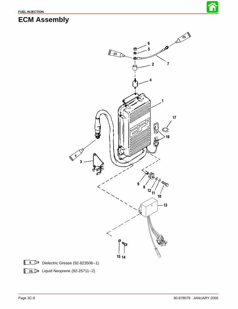
EFI Fuel Management (High Pressure Fuel Route)
• Perform low pressure checks before performingchecks on high pressure route.
• Install fuel pressure gauge (P/N 91-16850A2) on tomanifold pressure port.
• Place ignition switch in “OFF” position 30 secondsbefore testing.
• Place ignition switch in “ON” position and note pres-sure within 30 seconds (34 to 36 psi; 234 to 248 kPa).
No or low fuel pressure Pump does not runFuel pressure above 36 psi (248 kPa)
Perform Final Filter CheckClogged or faulty fuel pressureregulator remove and replace.
Perform Electric Fuel Pump Volt-age Test .
Final filter OK. Final filter clogged.
Perform Fuel Pressure Regula-tor Test .
Clean or replace final filter.
Steady stream of fuel (pres-sure still below 34 psi).
Low or no fuel flow.
Replace fuel regulator.Perform Electric Fuel PumpVoltage Test .
Voltage from ECM driver circuit OK. Low or inconsistent voltagefrom ECM driver circuit.
Replace fuel pump. Replace ECM.
Results Results
ResultsResults
Results Results

FUEL INJECTION
Page 3C-26 90-878079 JANUARY 2000
Fuel Rail Electrical/Fuel Determination
• Perform all preliminary checks page 3C-17.
• Adequate fuel pressure (34 to 36 psi; 234 to248 kPa) follow Low/High Fuel Route FlowCharts.
• Place sport jet in water and run engine be-tween 2000 and 2500 RPM.
No RPM change on cylinder(s),indicating problem in cylinder(s).
RPM decreases (on each cylinder).
Perform Injector Electrical Har-ness Test .
Fuel delivery OK.
Broken circuit to injector. Injector circuit tests OK.
Perform Induction ManifoldDisassembly and inspection .
Perform Injector Fuel DeliveryTest.
RPM increase occurs. No RPM change.
Perform induction manifold dis-assembly. Inspect injector andfilter.
Perform compression check onproblem cylinder.
Low or no compression on cylinder. Compression OK.
Inspect cylinder bore. Refer toSection 4 for disassembly.
NOTE: Injector filters must beinspected prior to reassembly.
Check:1) Damaged reeds2) End cap seals3) Crankcase split line leak4) Crankshaft sealing rings
Results Results
ResultsResults
Results Results
ResultsResults
With engine running (2000-2500 RPM) re-move spark plug leads one at a time usinginsulated pliers.

FUEL INJECTION
90-878079 JANUARY 2000 Page 3C-27
EFI System Test Procedures
Fuel Gauge Connection/Pressure TestIMPORTANT: When checking fuel pressure while engine is running, fuel pressuremay fluctuate. Fuel pressure fluctuation (i.e. 34 to 36 psi “234 to 248 kPa”) is com-mon, as the regulated pressure is a differential between fuel rail and manifold vacu-um.
Purpose: Checking fuel manifold pressure ensures that fuel under usable pressure is available to the fuelinjectors. This test isolates the probable cause as either a fuel delivery or EFI electrical system failure.
IMPORTANT: Fuel pressure should be monitored through full RPM range to deter-mine fuel supply problems at high engine speeds.
1. Connect fuel pressure gauge to induction manifold pressure port.
91-16850
55180
a
a - Pressure Port
2. Turn ignition key switch to “ON” position.
OFFON
START
3. Operate electric fuel pump for approximately 10 seconds.
NOTE: Fuel pump will only operate for approximately 30 seconds. By turning the keyswitch to “OFF” and then back to “ON” the pump will operate for 30 seconds more.
4. Take reading on fuel pressure gauge.
Results: If pressure reading is 34 to 36 psi (234 to 248 kPa), the electric fuel pump is providing fuel withenough pressure to be used by the injectors. Pump malfunction is not the cause of EFI trouble.
If fuel pressure is well below 34 psi (234 kPa), fuel delivery to electric fuel pump, fuel pumpfailure or other related problem exists. Follow low/high fuel pressure flow charts.
If fuel pressure is above 36 psi (248 kPa) go to fuel pressure regulator test.

FUEL INJECTION
Page 3C-28 90-878079 JANUARY 2000
Vapor Separator Fuel Delivery TestPurpose: Verifying there is adequate fuel flow to the electric fuel pump (through full RPM range) will deter-
mine components in low pressure fuel system are functioning correctly.
1. Remove vapor separator drain plug and place a clean container under drain.
55177
Results: If fuel flow is present, fuel is being delivered to electric fuel pump. Go to high pressure flow chart.
If fuel flow is not present, proceed to step 2.
2. Place emergency stop switch in OFF position to prevent engine from starting. If boatis not equipped with a emergency stop switch, connect a jumper lead from the BLACK/YELLOW bullet connector to engine ground.
3. Turn ignition key switch to “START” and operate starter motor for 10 to 20 seconds.
4. Look for fuel flow from hose.
55177
Results: If low or no fuel flow is present, inspect water separating fuel filter and perform Vapor Separator FloatTest.

FUEL INJECTION
90-878079 JANUARY 2000 Page 3C-29
Vapor Separator Float TestPurpose: This test will indicate if float is stuck in the up position.
NOTE: If float is stuck down, vapor separator will over flow causing a rich condition.
1. Remove fuel inlet hose from vapor separator and put end of hose in clean container.
2. Remove all spark plugs from engine to prevent engine from starting.
3. Turn ignition key switch to “START” position and operate starter motor for 15 to 20 sec-onds.
OFFON
START
4. Look for fuel flow from hose.
55178
Results: If fuel flow is present at hose, remove, disassemble and inspect float assembly. See vapor separatordisassembly.
If fuel flow is low or not present, perform Water Separating Filter Flow Test.

FUEL INJECTION
Page 3C-30 90-878079 JANUARY 2000
Water Separating Filter Flow TestPurpose: This test will indicate if water separating filter is clogged.
1. Remove fuel inlet hose to water separating filter. Put end of hose in clean container.
2. Place emergency stop switch in OFF position to prevent engine from starting. If boatis not equipped with a emergency stop switch, connect a jumper lead from the BLACK/YELLOW bullet connector to engine ground.
3. Turn ignition key switch to “START” and operate starter motor for 10 to 20 seconds.
OFFON
START
4. Look for fuel flow from hose.
55183
Results: Fuel flows from water separating inlet hose. Remove and replace clogged filter.
Low or no fuel flow from water separating inlet hose. Perform electric fuel pump deliverytest. If test results are ok, disassemble pulse fuel pump and inspect for damaged checkvalves, gaskets, etc. All fragments of failed pump must be located before reassembly.
FUEL INJECTION
90-878079 JANUARY 2000 Page 3C-31
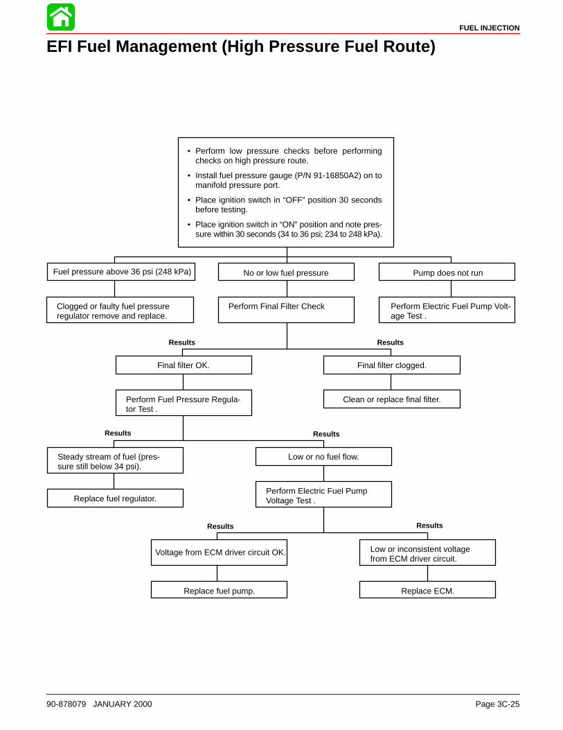
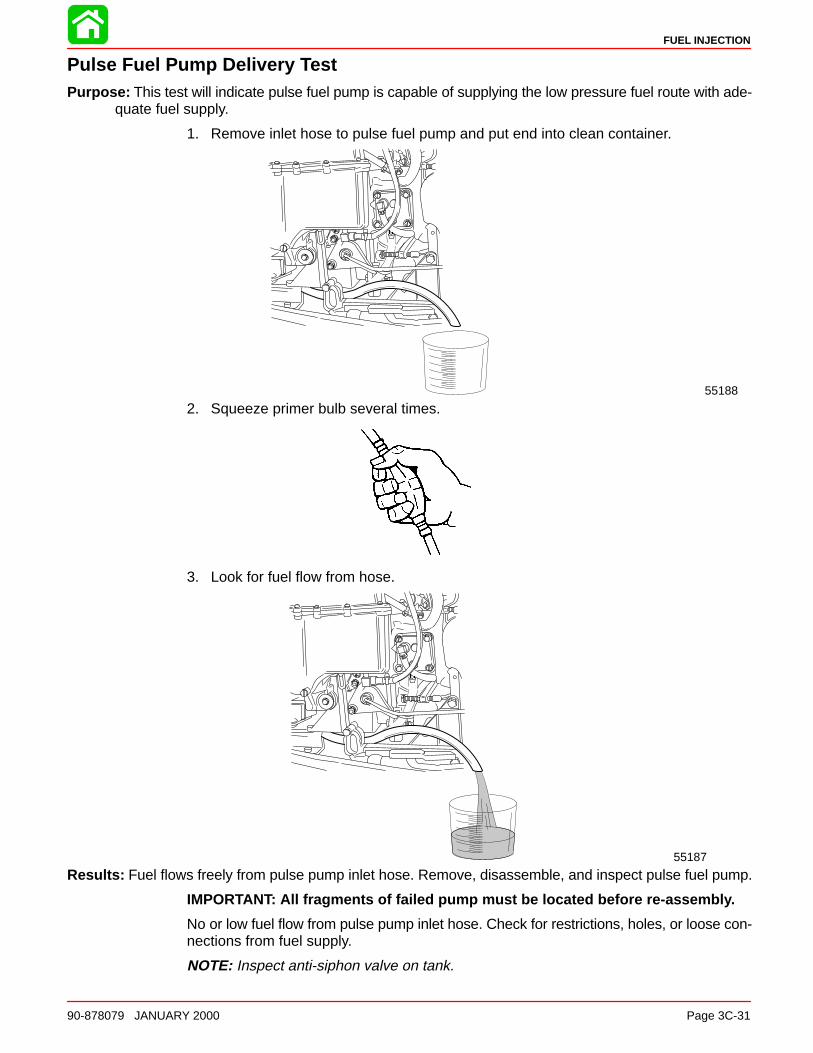
Pulse Fuel Pump Delivery TestPurpose: This test will indicate pulse fuel pump is capable of supplying the low pressure fuel route with ade-
quate fuel supply.
1. Remove inlet hose to pulse fuel pump and put end into clean container.
55188
2. Squeeze primer bulb several times.
3. Look for fuel flow from hose.
55187
Results: Fuel flows freely from pulse pump inlet hose. Remove, disassemble, and inspect pulse fuel pump.
IMPORTANT: All fragments of failed pump must be located before re-assembly.
No or low fuel flow from pulse pump inlet hose. Check for restrictions, holes, or loose con-nections from fuel supply.
NOTE: Inspect anti-siphon valve on tank.

FUEL INJECTION
Page 3C-32 90-878079 JANUARY 2000
Final Filter Check and De-Pressurizing EFI System ProceduresPurpose: Checking the final filter for obstructions, damage etc. eliminates this component as a possible
source of restriction in the system.
1. De-pressurize EFI fuel system by wrapping a clean cloth around pressure port valveand inserting tip of screwdriver into valve, depressing valve core. Let fuel drain fromvalve.
55179
a
a - Pressure Port
2. Remove drain plug from vapor separator and allow fuel to drain into suitable container.
55177

FUEL INJECTION
90-878079 JANUARY 2000 Page 3C-33
3. Remove 3 bolts securing vapor separator assembly to manifold.
55176
a
aa
a - Bolts
4. Tilt vapor separator assembly out from manifold and remove 9 screws securing cover.
5. Remove vapor separator tank from cover.
6. Rotate inlet filter counterclockwise and pull downward to remove filter from fuel pump.
58163
a
a - Inlet Filter
7. Inspect filter for debris or damage.
Results: If filter is clogged with debris, clean filter with solvent and compressed air or replace filter. Reas-semble vapor separator to manifold and recheck fuel pressure. If pressure is still below 34 psi (234kPa), perform fuel Pressure Regulator Test.

FUEL INJECTION
Page 3C-34 90-878079 JANUARY 2000
Pressure Regulator TestPurpose: This test will determine if a weak, plugged or open pressure regulator is causing inadequate fuel
pressure in the system.
1. Connect pressure gauge to EFI test port.
91-16850A7
55180
a
a - Test Port
2. Turn ignition key switch to “ON” position and check fuel pressure reading on gauge.If pressure reading is below 34 psi (234 kPa) go to step 3 following.
OFFON
START
3. Remove fuel pressure regulator, but do not disconnect any hoses from regulator.
4. Put discharge end of regulator in clean container.
5. Turn ignition key switch to “ON” position.
OFFON
START

FUEL INJECTION
90-878079 JANUARY 2000 Page 3C-35
6. Check for fuel flow out of regulator.
Results: If steady stream of fuel exits regulator into container and pressure is below 34 psi (234 kPa), replacepressure regulator.
If low or no fuel exits regulator into container and pressure is below 34 psi (234 kPa), per-form voltage checks on electric fuel pump, following.
If low or no fuel flow exits regulator into container and pressure is above 36 psi (248 kPa),replace regulator.

FUEL INJECTION
Page 3C-36 90-878079 JANUARY 2000
Electric Fuel Pump Voltage Test
CAUTIONWhen checking voltage at pump, DO NOT pry boot covers off terminals with a met-al object, as each terminal is at 12 volts when engine is off. Serious damage toelectric fuel pump and/or ECM box can result.
Purpose: If insufficient electrical power is available at the pump, no or low fuel pressure will be developed.
1. Set volt meter to read battery voltage and connect black test lead to ground, positivetest lead to positive (+) post of fuel pump.
NOTE: Positive test lead can be pierced through boot cover for testing. Refer to voltagetest chart (page 3C-37) for voltage readings.
VOLTSDC AMPS
OHMS
02 4 6 8
10
DCV ACV
DVA
005
10 2010 30
15 4020
05101520304060
100200
55191
a
a - Positive (+) Terminal

FUEL INJECTION
90-878079 JANUARY 2000 Page 3C-37
2. Set volt meter to read battery voltage and connect BLACK test lead to ground, POS-ITIVE test lead to NEGATIVE (–) post of fuel pump.
Negative Test Terminal
VOLTSDC AMPS
OHMS
02 4 6 8
10
DCV ACV
DVA
00510 20
10 3015 4020
05101520304060100
200
55192
a
a - Negative (–) Terminal
3. Perform voltage tests below.
VOLTAGE TEST CHART
Engine Mode BLACK Meter Lead toEngine Ground; RED
Meter Lead to:
Approximate VoltageReading
If Approximate Voltageis not obtained, this in-
dicates:
1. All models (+) terminal of fuel pump 12 – 13.5 volts If reading is below 12volts, the battery is bad,discharged or has badconnection(s). If readingis higher than 13.5 volts,the battery is over-charged
2. Ignition key in “OFF” position.
(–) terminal of fuelpump.
Same reading should beobtained as reading incheck No. 1 (above)
If reading is lower thanin test 1, the ECM is bador there is an open cir-cuit in fuel pump.
3. Ignition key in “ON” position and engine NOT running.
(–) terminal of fuelpump.
1.5 volt or less (voltageshould rise to 12 – 13.5volts after approximately30 seconds.
Bad ECM or bad fuelpump*.
4. Engine being cranked.
(–) terminal of fuelpump.
1.5 volt or less. Bad ECM or bad fuelpump.*
*Check for proper electrical operation of electric fuel pump. (Step 4)

FUEL INJECTION
Page 3C-38 90-878079 JANUARY 2000
4. Disconnect BLACK/RED wire to negative terminal on electric fuel pump. Connect aground jumper wire from negative pump terminal to a good engine ground.
a
a - Negative Terminal
Results: Pump does not operate. Replace electric fuel pump.
Pump operates. But, pressure reading does not change when performing electric fuelpump pressure test. Replace electric fuel pump.
Pump operates. Check BLACK/RED (–) lead and harness for good continuity.
NOTE: BLACK/RED lead is connected to pin 2 of EFI harness.

FUEL INJECTION
90-878079 JANUARY 2000 Page 3C-39
Injector Electrical Harness TestPurpose: This test will determine if electrical or fuel delivery problem exists during the fuel delivery process by
checking for open circuits in injector harness.
1. With outboard in water, start and allow to warm up. Raise engine speed to 2000-2500RPM. Remove spark plug leads one at a time and note RPM change. Determinenon-working (no RPM change) cylinder. Stop engine.
2. Disconnect injector harness (4 pin connector).
IMPORTANT: Use DMT Tester (91-854009A1) and Test Harness (91-833169A1) whentesting injector harness.
3. Connect digital ohmmeter (dial set at 200 scale) leads. POSITIVE lead from ohmmeterconnects to POSITIVE prong “2” (RED wire) of harness connector. Connect NEG-ATIVE lead from ohmmeter to the remaining wires of harness connector as follows:
• WHITE Lead = Injectors, Cylinders 1 and 2
• DARK BLUE Lead = Injectors, Cylinders 3 and 4
• YELLOW = Injectors, Cylinders 5 and 6
58166
1 - YELLOW2 - RED3 - DARK BLUE4 - WHITE
Results: If readings are 1.1 ± .2 both injector circuits are complete. Perform Injector Fuel Delivery Test.
If readings are 2.2 ± .2 one injector does not have a complete circuit. Perform inductionmanifold disassembly and inspection following.

FUEL INJECTION
Page 3C-40 90-878079 JANUARY 2000
ECM Injector Driver TestTo verify that the ECM is operating the injector pairs, connect test harness between man-ifold connector and engine harness. Start engine.
Use DVA meter (91-99750) or DMT (91-854009T1). Set meter to 200 scale. ConnectBLACK meter lead to engine ground and RED test lead to each BLUE, WHITE or YELLOWfemale bullet connector
Normal voltage for a 2.5L engine will be 25 to 60 volts. Voltage will vary with RPM.
Injector Fuel Delivery TestPurpose: This test will determine if injector is delivering fuel when signal is received.
NOTE: It is recommended that the Digital Diagnostic Terminal 91-823686A2 be utilizedfollowing the procedure listed with its’ instruction manual.
Injector Operation Test (Manifold Cover Removed)Purpose: This test determines if the injectors are actually injecting fuel into the engine at a normal rate.
WARNINGDo not start engine with induction manifold cover removed. Disable ignition sys-tem prior to doing this test.
1. Remove induction manifold cover using procedures outlined under “lnduction ManifoldRemoval.”

FUEL INJECTION
90-878079 JANUARY 2000 Page 3C-41
2. Re-attach induction manifold to engine using 1/4-20 x 2-3/4″ screws.
3. Connect a jumper wire between the ECU metal case and a good engine ground.
4. Disconnect all spark plug wires from spark plugs and seal leads with electrical tape toprevent sparking.
5. Put ignition key switch in “START” position.
OFFON
START
6. Look at injector spray pattern using an explosive proof flashlight.
Results A: If fuel spray is not present in all injectors or spray pattern is extremely weak, check wiring harnessto injector connectors, or injector filters for plugging.
If spray patterns are available in most of the injectors, but not all, perform Procedure B.
7. Connect EFI tester. Steps outlined in electrical system and ECM check.

FUEL INJECTION
Page 3C-42 90-878079 JANUARY 2000
8. Connect remote starter Quicksilver (91-52024A1) to NEGATIVE terminal of electricfuel pump and a good engine ground. Depress remote start switch, pump will operateas long as switch is depressed.
WARNINGDo not operate pump for more than 20 seconds continuously.
55197
a
a - Negative Terminal
9. Perform fuel injector test procedures (outlined) while depressing remote starter switch.
Results B: If fuel spray is present using EFI tester, but not present while cranking, perform switch box DVAtests Section 2A (1, 3, 5 switch box failure).
If fuel spray pattern is equal on all injectors, system is functioning normally.

FUEL INJECTION
90-878079 JANUARY 2000 Page 3C-43
Induction Manifold Leak Check (Manifold Cover Removed)Purpose: Lack of good fuel pressure may be caused by an internal leak in the fuel induction manifold and not
caused by a weak pump. This test eliminates the possibility of induction manifold leaks as a probablecause.
WARNINGDo not start engine with induction manifold cover removed. Disable ignition sys-tem prior to performing this test.
WARNINGOperation of EFI system with cover removed can allow fuel to spray components.Be extremely careful when operating the fuel system in this condition.
1. Remove induction manifold cover using procedures outlined under “Induction Man-ifold Removal.”
2. Reattach manifold body without cover to engine using twelve 1/4-20 x 2-3/4″ screwsin place of screws normally used.
3. Connect a jumper wire between the metal case of ECM and a good engine ground.
WARNINGIf a serious leak is present in the induction manifold, fuel may spray out of badseal. Have clean up rags available to remove excess fuel from components.

FUEL INJECTION
Page 3C-44 90-878079 JANUARY 2000
4. Place emergency stop switch in OFF position to prevent engine from starting. If boatis not equipped with a emergency stop switch, connect a jumper lead from the BLACK/YELLOW bullet connector to engine ground.
5. Connect remote starter Quicksilver (91-52024A1) to NEGATIVE terminal of electricfuel pump and a good engine ground. Depress remote start switch, pump will operateas long as switch is depressed.
WARNINGDo not operate pump for more than 20 seconds continuously.
55197
6. Look for leak points on induction manifold while depressing remote starter switch.
Results: If no leaks are present, replace cover and gasket using normal length screws.
If fuel leak is present between sealing surfaces, rebuild system using new o-rings.

FUEL INJECTION
90-878079 JANUARY 2000 Page 3C-45
Air Temperature Sensor TestPurpose: This test eliminates possibilities of improper fuel delivery related to air temperature sensor.
1. Disconnect and remove Air Temperature Sensor from induction manifold.
2. Connect DMT (91-854009T1) to leads of sensor.
3. Place sensor in ice water while monitoring meter reading. Use graph (below) for refer-ence.
NOTE: Temperature/resistance reading may differ slightly from graph curve.SENSOR RESISTANCE VS. AIR TEMPERATURE
AIR
TE
MP.
SE
NS
OR
RE
SIS
TAN
CE
(K
OH
MS
)
Results: Resistance does not change inversely with temperature change. Replace defective Air Tempera-ture Sensor.
Resistance changes inversely with temperature change. Air Temperature Sensor OK.

FUEL INJECTION
Page 3C-46 90-878079 JANUARY 2000
Engine Head Temperature Sensor TestPurpose: This test eliminates possibilities of improper fuel delivery related to the water temperature sensor.
1. Disconnect and remove Engine Head Temperature Sensor (see page 3C-54).
2. Connect DMT (91-854009T1) to bullet leads of sensor.
3. Place sensor in ice water while monitoring meter reading. Use graph (below) for refer-ence.
NOTE: Temperature/resistance reading may differ slightly from graph curve.
Results: Resistance does not change inversely with temperature change. Replace defective Engine HeadTemperature Sensor.
Resistance changes inversely with temperature change. Engine Head Temperature Sen-sor OK.
Detonation Control System Test (200 Models Only)Purpose: This test eliminates possibilities of improper fuel delivery due to failure in detonation control.
1. Place outboard in water, install timing light to number one cylinder.
2. Start engine, allow to warm up. Advance throttle (between 3000-3500 RPM in gear).NOTE: Timing advancement.
Results: Timing advances from 18° to 24° BTDC system functioning properly.
Timing advance from 18° to 24° but retards while maintaining a steady throttle position.System functioning properly, detonation may be occurring. See Detonation Sensor/Mo-dule Checks (following).
Timing advancement does not occur (18° to 24° BTDC). System functioning properly, det-onation may be occurring. See Detonation Sensor/Module Checks (following).
FUEL INJECTION
90-878079 JANUARY 2000 Page 3C-47
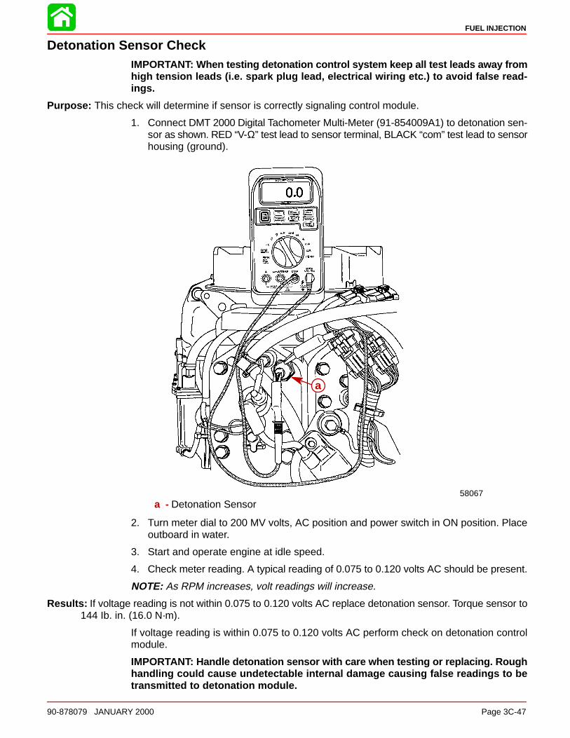
Detonation Sensor CheckIMPORTANT: When testing detonation control system keep all test leads away fromhigh tension leads (i.e. spark plug lead, electrical wiring etc.) to avoid false read-ings.
Purpose: This check will determine if sensor is correctly signaling control module.
1. Connect DMT 2000 Digital Tachometer Multi-Meter (91-854009A1) to detonation sen-sor as shown. RED “V-Ω” test lead to sensor terminal, BLACK “com” test lead to sensorhousing (ground).
58067
a
a - Detonation Sensor
2. Turn meter dial to 200 MV volts, AC position and power switch in ON position. Placeoutboard in water.
3. Start and operate engine at idle speed.
4. Check meter reading. A typical reading of 0.075 to 0.120 volts AC should be present.
NOTE: As RPM increases, volt readings will increase.
Results: If voltage reading is not within 0.075 to 0.120 volts AC replace detonation sensor. Torque sensor to144 Ib. in. (16.0 N·m).
If voltage reading is within 0.075 to 0.120 volts AC perform check on detonation controlmodule.
IMPORTANT: Handle detonation sensor with care when testing or replacing. Roughhandling could cause undetectable internal damage causing false readings to betransmitted to detonation module.

FUEL INJECTION
Page 3C-48 90-878079 JANUARY 2000
Detonation Control Module CheckPurpose: This check will determine if control module is correctly signaling ECM when signals are received
from sensor.
1. Insert probe (a) (i.e. paper clip) to gray/white wire connector (b). Connect digital voltmeter (from EFI tester 91-11001A2 or DMT 2000 91-854009A1) positive clip (c) toprobe and ground clip (d) to engine ground as shown.
51795
d
a
b
c
a - Probeb - Connectorc - Positive Clipd - Ground Clip
2. Turn meter dial to 20 volts DC position and power switch in ON position. Place out-board in water.
3. Start and operate engine at idle.
4. Check meter reading. A reading between 0.30 to 0.70 volts DC should be attained.
5. Increase engine speed (with engine in gear) between 3000-4000 RPM. Check meterreading. A typical reading should be 0.01 volts DC.
Results: If meter reading is 0.30 to 0.70 volt DC at idle and 0.01 volts DC at 3000-4000 RPM, detonationcontrol unit is functioning properly (no detonation occurring).
If voltage reading does not fall within range (0.30 to 0.70 volts DC) at idle, control modulemay be bad.
If voltage reading is above 0.01 volts DC and between 1.0 to 6.6 volts DC at 3000 to 4000RPM detonation is occurring. A constant voltage of 6.6 volts DC would indicate bad deto-nation control module.

FUEL INJECTION
90-878079 JANUARY 2000 Page 3C-49
Throttle Position Sensor TestPurpose: This test eliminates possibilities of improper fuel delivery related to the throttle position indicator.
Refer to EFI electrical system and ECM test.
NOTE: Engine harness MUST BE disconnected from the EFI tester 91-11001A2 (if beingused) and reconnected in the normal running configuration in order to test or adjust thethrottle position sensor.
IMPORTANT: TPS can be adjusted using a digital meter (DMT). Analog (needle) typemay be used although it may be difficult to read the low voltage setting accuratelywith most meters.
1. Disconnect TPS from EFI harness.
58053
a
b
a - Throttle Position Sensor (TPS)b - TPS Harness Connector
2. Connect digital using TPS Test Lead Assembly (91-816085) between TPS connectorand EFI harness connector. Set voltmeter to 2 DC volts.
58054
b
ca
a - TPS Test Lead Assem-bly (91-816085)
b - TPS Connectorc - EFI Harness Connector
IMPORTANT: TAN/BLK head temperature leads must be disconnected from port cyl-inder head before adjusting TPS.

FUEL INJECTION
Page 3C-50 90-878079 JANUARY 2000
3. Disconnect TAN/BLACK engine head temperature sensor leads located on port cylin-der head.
4. Turn key to the “ON” position.
5. Loosen screws (a) securing TPS to manifold.
58055
a
a - Screws
6. Rotate TPS fully clockwise (holding throttle shaft in closed position). Voltmeter shouldread .200 - .300. If readout is not within specifications, adjust TPS to obtain readoutof .240 - .260.
7. Tighten TPS screws to 20 lb. in. (2 Nm) holding correct tolerance.
8. Disconnect remote control cable from throttle lever.
9. Slowly move throttle lever to full open position while monitoring voltage reading. Volt-age reading should increase and decrease smoothly
10. Set volt meter to 20 DC volts. Maximum voltage reading at full throttle is approximately7.46 volts.
11. Remove test lead and reconnect TPS harness to EFI harness.
12. Reconnect TAN/BLACK engine head temperature sensor leads located on port cylin-der head.
NOTE: If engine appears to run too rich or too lean, TPS can be readjusted. Decreasingvoltage yields leaner mixture. Increasing voltage yields richer mixture.
Map Sensor TestPurpose: This test eliminates possibilities of improper fuel delivery caused by the map sensor. Refer to Elec-
tronic Fuel Injection Tester (91-11001A2) and its test manual. The Digital Diagnostic Terminal(91-823686A2) may also be used to test the MAP Sensor. It will display an LED failure light, a PASS/NO operational indication as well as a numeric display value.

FUEL INJECTION
90-878079 JANUARY 2000 Page 3C-51
Problem Diagnosis
Condition Possible Source Action
Engine Down On Power Or RPM – Failed Switch Box
– Failed Stator
– Failed CDM
– Low Compression
– Broken Reed
– Fuel Delivery Problem
– Manifold Fuel Leak
– Vapor Separator Flooding Over, Engine Running Rich.
– Cylinder Head Temperature Sensor Circuit Failed.
Refer to Section 2 Electrical andIgnition Tests.
Refer to Section 2 Electrical andIgnition Tests.
Refer to Section 2 Electrical andIgnition Tests.
Refer to Section 4 Power Head.
Perform Injector Fuel DeliveryTest.
Follow Low/High Pressure FuelRoute Flow Charts and Fuel RailElectrical/Fuel DeterminationFlow Chart.
Perform Induction Manifold LeakCheck.
Check for fuel coming out of va-por separator vent hose.
Check cylinder head temperaturesensor.
Poor Acceleration – Idles Ok,Top Speed Ok
– Improper EFI Set Up.
– Water Covering Idle Relief Exhaust Ports.
– T.P.S. Failure.
– MAP Sensor Failure
– R.F.I. Problem*
Refer to Section 2 Electrical andIgnition for proper EFI set up pro-cedures.
Boats with extended transoms orlow engine mount can cause en-gine to load up on acceleration.
Refer to page 3C-49.
Refer to page 3C-50.
Install BPZ8HS-10 Spark Plugs.

FUEL INJECTION
Page 3C-52 90-878079 JANUARY 2000
Condition Possible Source Action
Poor Acceleration – Idles Ok,Top Speed Ok (Continued)
– Timing Not Advancing. Check for stuck trigger.
Engine Surges Between 4000And 5000 RPM
– Intermittant CDM Failure.
– Final Filter Clogging.
– T.P.S. – Improper Adjustment.
– Injector Connector Problem.
– Vapor Separator Flooding Over.
– Injector Filter Clogged.
Refer to Section 2A Electricaland Ignition for tests.
Perform Final Filter Check.
Refer to Section 2C Electricaland Ignition for T.P.S. adjust-ment.
Perform Injector Fuel DeliveryTest.
Check for fuel coming out of va-por separator vent hose.
Refer to Injector Fuel DeliveryTest.
Engine Idles Ok But Stumbles AtOff Idle Speeds
– Improper EFI Setup.
– Failed CDM.
– Failed Or Disconnected EFI Sensors.
– Fuel Delivery Problem.
– Manifold Fuel Leak.
– R.F.I.* Problem.
– Stator.
– Induction Manifold Air Leak.
Refer to Section 2C Electricaland Ignition for proper EFI set upprocedures.
Refer to Section 2A Electricaland Ignition Tests.
Perform EFI sensor tests.
Follow Low/High Pressure FuelRoute Flow Charts and Fuel RailElectrical/Fuel DeterminationFlow Chart.
Perform Induction Manifold LeakCheck.
Install BPZ8HS-10 Spark Plugs.
Refer to Section 2A Electricaland Ignition for tests.
Check manifold cover gasket,manifold to reed block housinggasket and reed block housing tocrankcase gasket.
Engine Idles Rough (May LeanSneeze) – Acceleration Ok; FullThrottle Ok
– Improper EFI Setup.
– MAP Sensor Failure.
Refer to Section 2C Electricaland Ignition for proper EFI set upprocedures.
Refer to page 3C-50.

FUEL INJECTION
90-878079 JANUARY 2000 Page 3C-53
Condition Possible Source Action
Engine Idles Rough (May LeanSneeze) – Acceleration OK; FullThrottle Ok. (continued)
– CDM Failure.
– Broken Reed.
Refer to Section 2A Electricaland Ignition Tests.
Perform Injector Fuel DeliveryTest.
Engine Runs but Slowly DropsRPM then Dies.
– Restrictions in Fuel System between Tank and Engine.
– Clogged Final Filter.
– Pulse Fuel Pump Failure.
– Electric Fuel Pump Delivery Failure.
Install remote gas tank withfresh, high quality fuel.
Perform Final Filter Check.
Follow Low Pressure Fuel RouteFlow Chart.
Follow High Pressure Fuel RouteFlow Chart.
Engine Stops for No ApparentReason or Does Not Start.
– Battery Undercharged.
– EFI Harness Connections.
– Ignition System Failure.
– Pulse Fuel Pump Failure.
– Electric Fuel Pump Failure.
– ECM Failure.
Check battery connections, un-der charged battery or worn outbattery.
Check EFI harness connector forimproper connection.
Refer to Section 2A Electricaland Ignition Tests.
Follow Low Pressure Fuel RouteFlow Chart.
Follow High Pressure Fuel RouteFlow Chart.
The DDT (91-823686T2) willmonitor information coming fromsensors or switches to the ECMand will indicate if the sensor orswitch is defective. For a morethorough analysis of the ECM,refer to EFI Tester Manual91-11001A2.
Engine Stops for No ApparentReason, but will Restart.
– Battery Overcharged.
– Restriction in Fuel System
Check battery voltage with en-gine running. Should be lessthan 15.5 volts. Refer to ServiceBulletin 96-2.
Check fuel pressure on fuel railat the RPM that failure occurs.
*R.F.I. Radio Frequency Interference. High voltage can alter signals ECM receives from sensors causing im-proper fuel delivery. Route all sensor wires away from high voltage leads (i.e. spark plug leads)

FUEL INJECTION
Page 3C-54 90-878079 JANUARY 2000
Engine Head Temperature Sensor Removal
1. Remove screw and retaining plate.
2. Disconnect wires and remove sensor.
58052
a
b
c
d
a - Wiresb - Sensorc - Retainerd - Screw
FUEL INJECTION
90-878079 JANUARY 2000 Page 3C-55
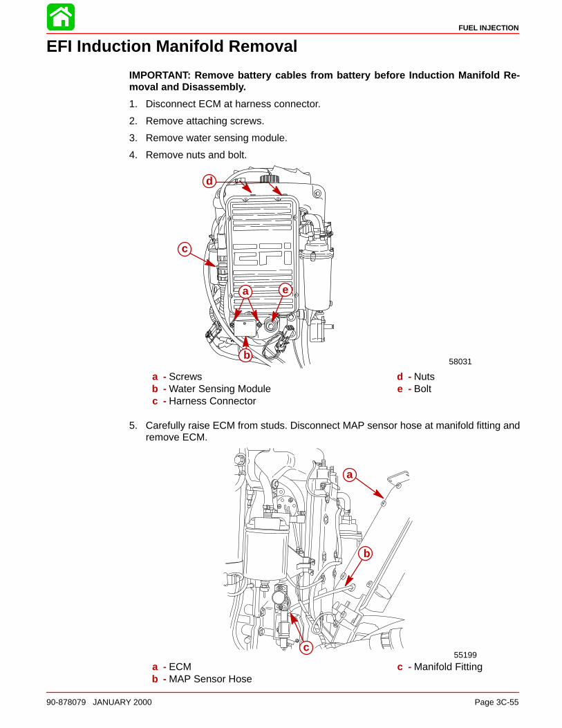
EFI Induction Manifold Removal
IMPORTANT: Remove battery cables from battery before Induction Manifold Re-moval and Disassembly.
1. Disconnect ECM at harness connector.
2. Remove attaching screws.
3. Remove water sensing module.
4. Remove nuts and bolt.
58031
a
b
c
d
e
a - Screwsb - Water Sensing Modulec - Harness Connector
d - Nutse - Bolt
5. Carefully raise ECM from studs. Disconnect MAP sensor hose at manifold fitting andremove ECM.
55199
a
b
c
a - ECMb - MAP Sensor Hose
c - Manifold Fitting

FUEL INJECTION
Page 3C-56 90-878079 JANUARY 2000
Water Separating Filter Assembly RemovalNOTE: To inspect or replace water separator, it is not necessary to remove inlet and outletfuel lines or to unbolt bracket from manifold.
1. Remove water sensor lead from bottom of separator.
55182
a
b
a - Water Separatorb - Water Sensor Lead
2. With wipe towels available, use Strap Wrench (91-24937A1) to remove water separa-tor.
55184
a
a - Strap Wrench (91-24937A1)

FUEL INJECTION
90-878079 JANUARY 2000 Page 3C-57
Water Separating Filter Assembly InstallationIMPORTANT: Apply a light coat of outboard oil to the rectangular sealing ring on thewater separator before installation.
1. After applying oil to sealing ring of water separator, install separator onto bracket.
2. HAND TIGHTEN SEPARATOR. DO NOT use strap wrench or other tool to tighten sep-arator.
3. Reconnect water sensor lead to bottom of separator.
55185
a
a - Sealing Ring
Throttle Position Sensor and Temperature Sensor Fuel Injector HarnessDisconnections
1. Disconnect throttle position sensor at 3 pin connector.
a
b
58055
a - Throttle Position Sensorb - 3 Pin Connector

FUEL INJECTION
Page 3C-58 90-878079 JANUARY 2000
2. Disconnect air temperature sensor at connectors.
b
a
58170
a - Air Temperature Sensorb - Connectors
3. Disconnect fuel injector harness at 4 pin connector.
55193
a
b
a - Fuel Injector Harnessb - 4 Pin Connector

FUEL INJECTION
90-878079 JANUARY 2000 Page 3C-59
Oil Reservoir Removal1. Disconnect low oil sensor bullet connectors (BLUE leads located below fuel/water sep-
arator)
2. Remove sta-strap securing reservoir hose to oil pump and remove hose. Plug hoseto prevent leakage.
58050
a
a - Reservoir Hose
3. Remove 3 screws and remove reservoir.
a
a
58172
b
a - Screwsb - Low Oil Sensor Harness (BLUE lead bullet connectors located below fuel/
water separator)

FUEL INJECTION
Page 3C-60 90-878079 JANUARY 2000
Fuel Pressure Regulator Removal1. Disconnect boat battery from engine harness.
2. De-pressurize EFI fuel system by wrapping a clean cloth around pressure port valveand inserting tip of screwdriver into valve, depressing valve core. Let fuel drain fromvalve.
55179
a
a - Pressure Port
3. Remove return fuel line from pressure regulator.
4. Remove regulator hose from regulator.
5. Remove 2 screws securing regulator to separator and remove regulator.
55204
ba
c
a - Return Fuel Lineb - Regulator Hosec - Screws
FUEL INJECTION
90-878079 JANUARY 2000 Page 3C-61
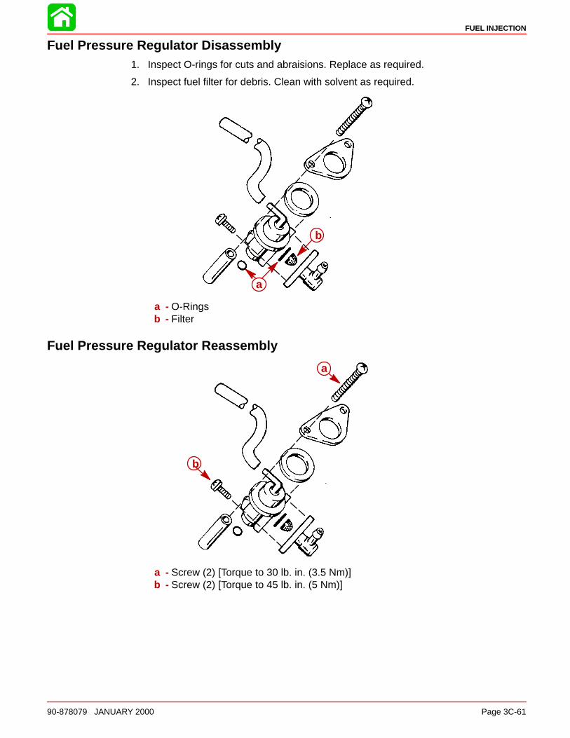
Fuel Pressure Regulator Disassembly1. Inspect O-rings for cuts and abraisions. Replace as required.
2. Inspect fuel filter for debris. Clean with solvent as required.
b
a
a - O-Ringsb - Filter
Fuel Pressure Regulator Reassembly
b
a
a - Screw (2) [Torque to 30 lb. in. (3.5 Nm)]b - Screw (2) [Torque to 45 lb. in. (5 Nm)]

FUEL INJECTION
Page 3C-62 90-878079 JANUARY 2000
Vapor Separator Removal1. Disconnect boat battery from engine harness.
2. De-pressurize EFI fuel system by wrapping a clean cloth around pressure port valveand inserting tip of screwdriver into valve, depressing valve core. Let fuel drain fromvalve.
55179
a
a - Pressure Port
3. Remove return fuel line from pressure regulator.
4. Remove regulator hose from regulator.
5. Remove 2 screws securing regulator to separator and remove regulator.
55204
a b
c
a - Return Fuel Lineb - Regulator Hosec - Screws
FUEL INJECTION
90-878079 JANUARY 2000 Page 3C-63
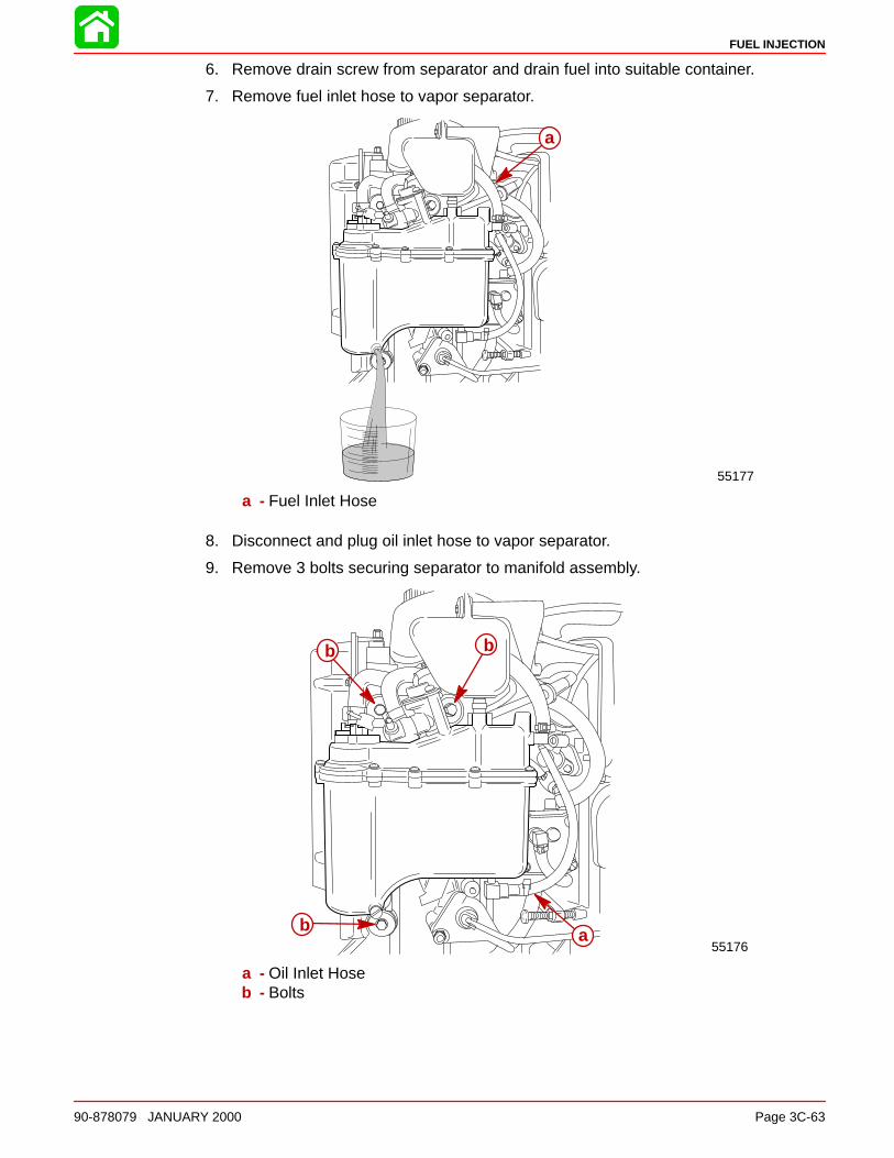
6. Remove drain screw from separator and drain fuel into suitable container.
7. Remove fuel inlet hose to vapor separator.
55177
a
a - Fuel Inlet Hose
8. Disconnect and plug oil inlet hose to vapor separator.
9. Remove 3 bolts securing separator to manifold assembly.
55176
bb
b a
a - Oil Inlet Hoseb - Bolts
FUEL INJECTION
Page 3C-64 90-878079 JANUARY 2000
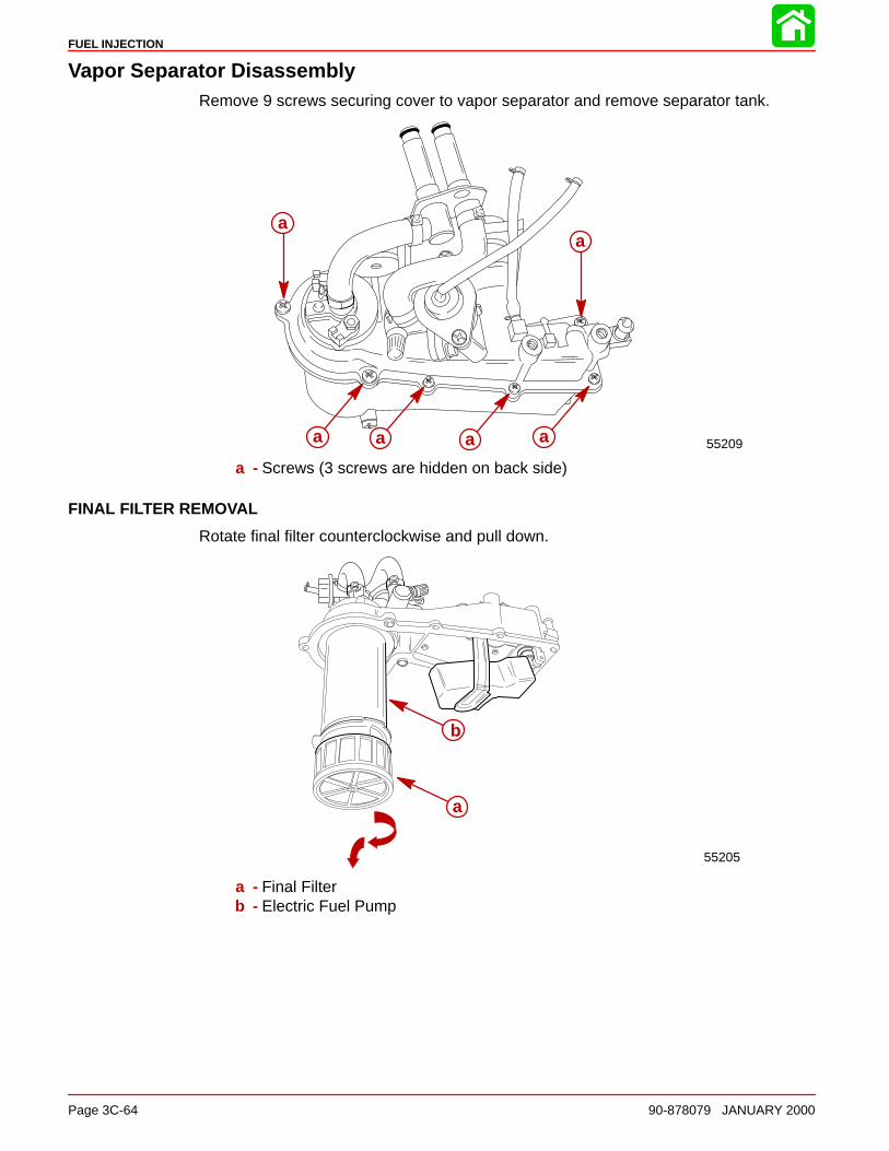
Vapor Separator DisassemblyRemove 9 screws securing cover to vapor separator and remove separator tank.
55209
aa
a a a a
a - Screws (3 screws are hidden on back side)
FINAL FILTER REMOVAL
Rotate final filter counterclockwise and pull down.
55205
a
b
a - Final Filterb - Electric Fuel Pump

FUEL INJECTION
90-878079 JANUARY 2000 Page 3C-65
ELECTRIC FUEL PUMP REMOVAL
NOTE: There are no individually replaceable parts within the electric pump. If brushes orarmature fails, entire pump must be replaced.
1. Remove 2 nuts on POSITIVE and NEGATIVE terminals. Remove pump from separa-tor cover.
55206
aa
b
a - Nutsb - Pump
2. Inspect pump O-rings for cuts or abraisions. Replace O-rings as required.
53702
a
a
a a
a
a - O-rings

FUEL INJECTION
Page 3C-66 90-878079 JANUARY 2000
VAPOR SEPARATOR FLOAT REMOVAL
NOTE: Inspect float for fuel absorbtion or deterioration. DO NOT attempt to bend float armto adjust float height. Float height is preset at factory. Inspect float needle for grooves. In-spect needle seat for debris or corrosion. Replace float, needle and seat* as required.
1. Remove float pivot pin.
2. Remove float and needle for inspection. Replace as required.
55207
d
b
c
a
a - Floatb - Float Armc - Float Needle (Hidden)d - Pivot Pin
*Seat and separator cover must be replaced as an assembly.

FUEL INJECTION
90-878079 JANUARY 2000 Page 3C-67
ELECTRIC FUEL PUMP INSTALLATION
1. Slide fuel pump into separator cover.
NOTE: Fuel pump electrical studs are different diameters. Pump will install properly intocover only one way.
CAUTIONDO NOT over torque fuel pump POSITIVE and NEGATIVE attaching nuts as dam-age to fuel pump will result.
2. Secure pump to cover with 2 nuts. Torque POSITIVE nut to 6 lb. in. (0.7 Nm). TorqueNEGATIVE nut to 16 lb. in. (1.8 Nm).
b
a
c
a - Electric Pumpb - POSITIVE (+) Stud (Small Diameter)c - NEGATIVE (–) Stud (Large Diameter)

FUEL INJECTION
Page 3C-68 90-878079 JANUARY 2000
3. Install rubber pad on bottom of pump.
NOTE: Rubber pad is molded to fit flush on bottom of pump on one side only.
4. Install pump support ring.
NOTE: Pump support ring fits over pad onto pump properly only one way (Tabs face up).
5. Install final filter into pump bottom. Rotate filter clockwise to lock filter onto pump.
ca
b
d
a - Rubber Padb - Support Ring
c - Tabs (face up)d - Final Filter

FUEL INJECTION
90-878079 JANUARY 2000 Page 3C-69
INSTALLING SEPARATOR COVER ASSEMBLY ONTO SEPARATOR TANK
1. Inspect separator tank sealing O-ring for cuts or abraisions. Replace O-ring as re-quired.
NOTE: If O-ring swells due to fuel and air exposure and will not fit in tank O-ring groove,replace O-ring. DO NOT cut O-ring to make it fit as fuel leakage will result.
53701
a
a - O-ring
2. Install cover assembly onto separator tank. Secure cover to tank with 9 screws. Torque5mm screws to 30 lb. in. (3.5 Nm). Torque 4mm screws to 20 lb. in. (2.5 Nm).
5817155209
a
a b b b
b
a - Large Screws (3) (5mm) Torque to 30 lb. in. (3.5 Nm)b - Small Screws (6) (4mm) Torque to 20 lb. in. (2.5 Nm)

FUEL INJECTION
Page 3C-70 90-878079 JANUARY 2000
Installing Vapor Separator Assembly to Induction Manifold1. Inspect O-rings on ends of separator fuel tubes for cuts or abraisions. Replace O-rings
as required.
55217
a a
a - O-rings
2. Install fuel tubes into manifold. Inspect adaptor plate O-rings for cuts or abraisions. Re-place O-rings as required.
55215
a
a - O-rings
3. Secure adaptor plate to manifold with 2 screws. Torque screws to 45 lb. in. (5 Nm).
55216
a
a - Screws [Torque to 45 lb. in. (5 Nm)]

FUEL INJECTION
90-878079 JANUARY 2000 Page 3C-71
NOTE: For ease of reassembly, reinstall oil reservoir on engine BEFORE installing vaporseparator.
4. Secure vapor separator to manifold with 3 screws and washers. Torque screws to 45lb. in. (5 Nm).
NOTE: Spacers are positioned between separator and manifold at the top front and bot-tom attaching screw locations.
55176
a
a
b
a b
a - Screws [Torque to 45 lb. in. (5 Nm)]b - Spacers
IMPORTANT: If fuel outlet hose from electric fuel pump or fuel return hose frommanifold to pressure regulator was disconnected, stainless steel hose clampsMUST BE USED to secure connections. If outlet/return hoses are to be replaced, re-placement tubing kit (32-827694) MUST BE INSTALLED to prevent rupturing or leak-age. DO NOT use sta-straps to secure high pressure fuel lines as leakage will occur.

FUEL INJECTION
Page 3C-72 90-878079 JANUARY 2000
5. Reconnect engine bleed hose to fitting on vapor separator.
6. Reconnect vapor separator over flow hose between separator and manifold.
7. Reconnect pressure regulator hose to top fitting on regulator.
55204
c b
a
de
a - Over Flow Hoseb - Bleed Hosec - Pressure Regulator Hosed - Fuel Outlet Hosee - Fuel Return Hose
8. Connect fuel inlet hose to vapor separator. Secure hose with sta-strap.
9. Connect oil inlet hose to vapor separator. Secure hose with sta-strap.
10. Install throttle link arm to throttle cam.
58050
a
b
c
a - Fuel Inlet Hoseb - Oil Inlet Hosec - Throttle Link Arm
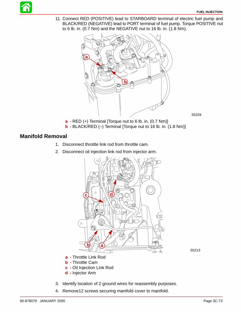
FUEL INJECTION
90-878079 JANUARY 2000 Page 3C-73
11. Connect RED (POSITIVE) lead to STARBOARD terminal of electric fuel pump andBLACK/RED (NEGATIVE) lead to PORT terminal of fuel pump. Torque POSITIVE nutto 6 lb. in. (0.7 Nm) and the NEGATIVE nut to 16 lb. in. (1.8 Nm).
55204
b
a
a - RED (+) Terminal [Torque nut to 6 lb. in. (0.7 Nm)]b - BLACK/RED (–) Terminal [Torque nut to 16 lb. in. (1.8 Nm)]
Manifold Removal1. Disconnect throttle link rod from throttle cam.
2. Disconnect oil injection link rod from injector arm.
55213ab
c d
a - Throttle Link Rodb - Throttle Camc - Oil Injection Link Rodd - Injector Arm
3. Identify location of 2 ground wires for reassembly purposes.
4. Remove12 screws securing manifold cover to manifold.

FUEL INJECTION
Page 3C-74 90-878079 JANUARY 2000
5. Remove manifold cover.
a
a
b
c
58176
a - Ground Wiresb - Screws (12)c - Manifold Cover
6. Disconnect bleed line hoses from manifold fittings.
7. Remove manifold assembly and place on clean work surface.
51795
a
a - Bleed Hoses

FUEL INJECTION
90-878079 JANUARY 2000 Page 3C-75
EFI Induction Manifold Disassembly
1. Remove manifold cover seal from manifold.
51785
b
a
a - Manifold Cover Sealb - Manifold
Air Temperature Sensor Removal1. Remove screws and sensor.
51790
a
a
b
a - Screwsb - Sensor

FUEL INJECTION
Page 3C-76 90-878079 JANUARY 2000
2. Remove O-ring from sensor.
51791
ab
a - O-ringb - Sensor
Throttle Position Sensor RemovalIMPORTANT: Sensor position will need to be set after induction manifold assemblyhas been installed.
1. Remove throttle position sensor screws.
a
58053
a - Screws
2. Remove sensor and sleeve from throttle shaft.
51788
c
a
b
a - Sensorb - Sleevec - Throttle Shaft

FUEL INJECTION
90-878079 JANUARY 2000 Page 3C-77
Fuel Rail Removal1. Remove manifold vacuum hoses.
2. Remove engine bleed hose.
3. Remove screws securing manifold fitting to manifold.
51789
a
b
b c
a - Vacuum Hosesb - Screwsc - Manifold Fitting
4. Remove manifold fitting and O-rings.
51791
b
a
a - Manifold Fittingb - O-rings

FUEL INJECTION
Page 3C-78 90-878079 JANUARY 2000
5. Remove 4 screws securing fuel rail to manifold.
51784
a
a
a - Screws (4)
6. Lift fuel rail from manifold. Note fuel rail guides.
51788
ab
c
c
a - Fuel Railb - Manifoldc - Guides

FUEL INJECTION
90-878079 JANUARY 2000 Page 3C-79
Fuel Rail Disassembly1. Remove tube support from fuel rail.
2. Remove plugs from fuel rail.
3. Remove tubes from tube support.
4. Remove O-rings from plugs, tube support and tubes.
51795
b
d
c
a
a - Tube Supportb - Fuel Railc - Tubesd - Plugs
Fuel Injector Removal and Disassembly1. Lift wire clamp from slot.
2. Disconnect connector from injector.
51792
ad
bc
a - Clampb - Slotc - Connectord - Injector

FUEL INJECTION
Page 3C-80 90-878079 JANUARY 2000
3. Remove injector from manifold.
51789
a
a - Injector
4. Place injector on clean work surface. Remove seals, O-ring and injector filter.
51789
b
d
c
a
a - Injectorb - Sealsc - O-Ringd - Filter

FUEL INJECTION
90-878079 JANUARY 2000 Page 3C-81
Injector Harness Removal1. Remove protective casing from injector wiring harness. Note position of wires for reas-
sembly.
51795
a
b
a - Casingb - Harness
2. Remove screws and injector harness plate.
51792
a
b
a - Screwsb - Plate

FUEL INJECTION
Page 3C-82 90-878079 JANUARY 2000
Throttle Linkage Removed
51786
ba b
c
a - Throttle Camb - Bushingsc - Nut; Tighten until snug against cam, then back off 1/4 turn
51789
ab
c
d
e
fg
k
i
i
j
ih
a - Fiber Washerb - Bushingc - Springd - Roller Cam Brackete - Bracket (Shutter Link)f - Lock Washerg - Nuth - Screwi - Flat Washerj - Cotter Keyk - Progressive Shutter Link

FUEL INJECTION
90-878079 JANUARY 2000 Page 3C-83
EFI System Cleaning and Inspection
Cleaning1. Clean all non-electrical metal parts using a good grade solvent.
2. Use a soft bristle brush for removing large accumulations of dirt or grease and oil.
3. Varnish type coating of induction manifold parts may be removed using carburetorcleaner.
4. Wiring harnesses can be wiped down with a slightly solvent dampened rag.
5. Clean all fuel passages in induction manifold.
6. Dry all components using clean lint free cloths that are free of abrasives such as metalshavings or dirt.
7. Compressed air may be used to dry parts if the air used is free of moisture and un-lubri-cated.
Inspection1. Look at entire system for signs of an obvious problem such as poor condition of wire
insulation, leaking fitting, cracked or loose hoses and lines.
2. Look for fuel or oil leaks wherever these fluids are used (i.e. fuel filter cap, fuel pump,vapor separator cap, etc.).
3. Check for signs of tampering or abuse such as modifications to wiring or hose routing.
4. Look at main connector between engine harness and ECM box for missing, corrodedor bent contact pins and socket. Check for dislodged grommet in ECM where harnessenters box.
5. Look at all sensors (throttle position, air temperature and water temperature) connec-tors and harnesses for bad connections or poor insulation conditions such as fraying,stripping, cracks or signs of abrasion wear.
6. Look for loose, missing or damaged mounting hardware such as stripped threads onscrews.
7. Look at sensors for signs of wear or damage such as cracks, chips, etc.
8. Look at filter housing for cracks, holes or other damage. Check for secure mounting.
9. Look at vapor separator for leaks, cracks, pitting or other damage.
10. Check all rubber mounting grommets for swelling tears, cracks or other conditions thatwould render parts unserviceable.
11. Check vapor separator float for signs of fuel entry in the float. Look at needle for wearof point.
12. Look at injectors for signs of plugging or looseness in fit with induction manifold.
13. Look at throttle linkage for bends, kinking or binding. Check spring for kinks.
14. Inspect all rubber seals and gaskets for swelling, cracks or slices that would cause im-proper sealing.

FUEL INJECTION
Page 3C-84 90-878079 JANUARY 2000
Induction Manifold Assembly
Injector Harness Installation1. Carefully route injector harness into manifold.
2. Install O-ring into groove on injector harness insert. Install harness insert into manifoldport.
b
a
c
a - O-Ringb - Groovec - Insert
3. Install injector harness plate using screws. Tighten securely.
51792
a
b
a - Plateb - Screws

FUEL INJECTION
90-878079 JANUARY 2000 Page 3C-85
4. Install protective casing over positioned injector wiring harness and insert into man-ifold.
51795
a
b
a - Casingb - Harness
Fuel Injector Assembly and Installation1. Install inspected seals, O-ring and injector filter to injector.
51789
a
c
b
d
a - Sealsb - O-Ringc - Filterd - Injector

FUEL INJECTION
Page 3C-86 90-878079 JANUARY 2000
2. Install injector into manifold.
51789
a
a - Injector
3. Install wire clamp into slot on injector connector.
4. Connect to injector.
51792
a
d
bc
a - Clampb - Slotc - Connectord - Injector

FUEL INJECTION
90-878079 JANUARY 2000 Page 3C-87
Fuel Rail Assembly1. Install inspected O-rings to plugs. tube support and tubes.
2. Install tubes to tube support.
3. Install plugs to fuel rail.
4. Install tube support to fuel rail.
51795
b
a
d
c
a - Tube Supportb - Fuel Railc - Tubesd - Plugs
Fuel Rail Installation1. With fuel rail guides in place, install fuel rail to manifold.
51788
ac b
c
a - Fuel Railb - Manifoldc - Guides

FUEL INJECTION
Page 3C-88 90-878079 JANUARY 2000
2. Install 4 screws securing fuel rail to manifold. Torque to 35 Ib. in. (4 Nm).
51784
a
a
a - Screws (4)
3. Install O-rings to manifold fitting. Install fitting to manifold.
51791
b
a
a - Manifold Fittingb - O-rings

FUEL INJECTION
90-878079 JANUARY 2000 Page 3C-89
4. Install screws securing manifold fitting to manifold. Torque screws to 45 lb. in. (5 Nm).
5. Install engine bleed hose.
6. Install manifold vacuum hoses.
51789
a
b
b c
a - Vacuum Hosesb - Screwsc - Manifold Fitting
CAUTIONUse extreme care when installing induction manifold so as to eliminate any possi-bility for air leaks.
Throttle Position Sensor InstallationIMPORTANT: Throttle position sensor must be adjusted following reassembly (seeSection 2C - Timing, Synchronizing, Adjustment).
1. Install sleeve to throttle position sensor.
2. Install sensor into manifold. Sleeve must guide sensor to throttle shaft.
51788
c
a
b
a - Sensorb - Sleevec - Throttle Shaft

FUEL INJECTION
Page 3C-90 90-878079 JANUARY 2000
3. Tighten screws after induction manifold installation and throttle position sensor adjust-ments are completed. Torque screws to 20 lb. in. (2 Nm).
51790
a
a - Screws
Air Temperature Sensor Installation1. Install O-ring to air temperature sensor.
51791
ab
a - O-ringb - Sensor
2. Install air temperature sensor and secure with screws. Tighten screws securely.
51790
a
a
b
a - Screwsb - Sensor

FUEL INJECTION
90-878079 JANUARY 2000 Page 3C-91
3. Carefully install manifold cover seal to manifold.
51785
b
a
a - Manifold Cover Sealb - Manifold
4. Install manifold cover to manifold and secure with M8 x 1.25 x 38mm long bolts throughholes.
NOTE: This will aid in induction manifold installation.
a
a
a - Holes

FUEL INJECTION
Page 3C-92 90-878079 JANUARY 2000
EFI Induction Manifold Installation
1. Install new gasket on induction manifold as shown. Removing dotted line sections aftermanifold installation.
51784
ba
c c
a - Gasketb - Induction Manifoldc - Dotted Line Sections– Remove After Installation
2. With induction manifold held in place, connect bleed line hoses to manifold fittings.
51795
a
a - Bleed Hoses

FUEL INJECTION
90-878079 JANUARY 2000 Page 3C-93
3. Secure induction manifold assembly to engine with screws. Torque screws to 90 Ib.in. (10.0 N·m) using torque sequence shown below.
NOTE: Remove M8 x 1.25 x 38mm long bolts used for reassembly and install remainingscrews. Install ground wires to proper location.
b
c
58176
ab
a - Manifoldb - Screws [Torque to 90 lb. in. (10 Nm)]c - Ground Wires
Cover Screw Torque Sequence

FUEL INJECTION
Page 3C-94 90-878079 JANUARY 2000
IMPORTANT: Before connecting oil pump control rod verify pump quadrant is ro-tated to the clockwise of center.
4. Connect oil injection link rod to injector arm.
5. Connect throttle link rod to throttle cam.
55213ab
c d
a - Throttle Link Rodb - Throttle Cam
c - Oil Injection Link Rodd - Oil Injection Arm
Oil Reservoir Installation1. Install oil reservoir to engine. Connect hose to oil pump fitting and secure with sta-
strap.
2. Reconnect low oil sensor harness bullet connectors (BLUE leads below fuel/waterseparator).
3. Secure reservoir using screws. Torque screws to 25 lb. in. (3 Nm).
58172
b
a
a
a - Screws [Torque 25 lb. in. (3 Nm)]b - Low Oil Sensor Harness (BLUE lead bullet connectors below fuel/water sepa-
rator)

FUEL INJECTION
90-878079 JANUARY 2000 Page 3C-95
Vapor Separator Installation1. Secure adaptor plate to manifold with 2 screws. Torque screws to 45 lb. in. (5 N·m).
55216
a
a - Screws [Torque to 45 lb. in. (5 Nm)]
NOTE: For ease of reassembly, reinstall oil reservoir on engine BEFORE installing vaporseparator.
2. Secure vapor separator to manifold with 3 screws and washers. Torque screws to 45lb. in. (5 Nm).
NOTE: Spacers are positioned between separator and manifold at the top front and bot-tom attaching screw locations.
55176
a
a
b
a b
a - Screws [Torque to 45 lb. in. (5 Nm)]b - Spacers

FUEL INJECTION
Page 3C-96 90-878079 JANUARY 2000
IMPORTANT: If fuel outlet hose from electric fuel pump or fuel return hose frommanifold to pressure regulator was disconnected, stainless steel hose clampsMUST BE USED to secure connections. If outlet/return hoses are to be replaced, re-placement tubing kit (32-827694) MUST BE INSTALLED to prevent rupturing or leak-age. DO NOT use sta-straps to secure high pressure fuel lines as leakage will occur.
3. Connect vapor separator over flow hose between manifold and separator.
4. Connect engine bleed hose to separator.
5. Connect fuel pressure regulator hose to top fitting on manifold.
55204
a
b
ce
d
a - Over Flow Hoseb - Bleed Hosec - Pressure Regulator Hosed - Fuel Outlet Hosee - Fuel Return Hose

FUEL INJECTION
90-878079 JANUARY 2000 Page 3C-97
Throttle Position Sensor, Air Temperature Sensor and Fuel Injector HarnessConnections
1. Connect fuel injector harness at 4 pin connector.
55193
a
b
a - Fuel Injector Harnessb - 4 Pin Connector
2. Connect air temperature sensor leads to bullet connectors.
b
a
58170
a - Air Temperature Sensorb - Connectors

FUEL INJECTION
Page 3C-98 90-878079 JANUARY 2000
3. Connect throttle position sensor at 3 pin connector.
58055
a
b
a - Throttle Position Sensorb - 3 Pin Connector

FUEL INJECTION
90-878079 JANUARY 2000 Page 3C-99
ECM Installation1. Connect MAP sensor hose from ECM to manifold fitting. Place ECM on manifold studs.
55199b
a
c
a - MAP Sensor Hoseb - Fitting
c - ECM
2. Secure ECM to manifold using nuts and screw. Torque nuts and screw to 45 lb. in. (5Nm).
3. Secure water sensing module with screws. Torque screws to 25 lb. in. (3 Nm).
4. Connect ECM harness to engine harness at connector. Install harness into harnessbracket with connecting ring below or above bracket arms.
IMPORTANT: Do not force connecting ring between bracket arms.
58031
a
b
c
d
e
f
a - Nutsb - Screwc - Water Sensing Module
d - Screwse - ECM Harnessf - Engine Harness

FUEL INJECTION
Page 3C-100 90-878079 JANUARY 2000
Engine Head Temperature Sensor InstallationIMPORTANT: Engine Head Tem perature Sensor must make clean contact with cylin-der head for circuit to function properly.
1. Connect wires and install sensor.
2. Install retaining plate and screw. Torque screw to 200 lb. in. (22.5 Nm).
58052
a
b
c
d
a - Wiresb - Sensorc - Retainerd - Screw [Torque to 200 lb. in. (22.5 Nm)]