
Technical Committee - Broadband Forum
108
Technical Committee Traffic Management Specification Version 4.0 af-tm-0056.000 April 1996
-
Upload
khangminh22 -
Category
Documents
-
view
4 -
download
0
Transcript of Technical Committee - Broadband Forum
Technical Committee
Traffic Management Specification
Version 4.0
af-tm-0056.000
April 1996

af-tm-0056.000 Traffic Management Specification Version 4.0
ATM Forum Technical Committeeii
1996 The ATM Forum. All Rights Reserved. No part of this publication may bereproduced in any form or by any means.
The information in this publication is believed to be accurate as of its publication date.Such information is subject to change without notice and the ATM Forum is notresponsible for any errors. The ATM Forum does not assume any responsibility to updateor correct any information in this publication. Notwithstanding anything to the contrary,neither The ATM Forum nor the publisher make any representation or warranty,expressed or implied, concerning the completeness, accuracy, or applicability of anyinformation contained in this publication. No liability of any kind shall be assumed byThe ATM Forum or the publisher as a result of reliance upon any information containedin this publication.
The receipt or any use of this document or its contents does not in any way create byimplication or otherwise:
• Any express or implied license or right to or under any ATM Forum membercompany’s patent, copyright, trademark or trade secret rights which are or may beassociated with the ideas, techniques, concepts or expressions contained herein; nor
• Any warranty or representation that any ATM Forum member companies willannounce any product(s) and/or service(s) related thereto, or if such announcements aremade, that such announced product(s) and/or service(s) embody any or all of the ideas,technologies, or concepts contained herein; nor
• Any form of relationship between any ATM Forum member companies and therecipient or user of this document.
Implementation or use of specific ATM standards or recommendations and ATM Forumspecifications will be voluntary, and no company shall agree or be obliged to implementthem by virtue of participation in the ATM Forum.
The ATM Forum is a non-profit international organization accelerating industrycooperation on ATM technology. The ATM Forum does not, expressly or otherwise,endorse or promote any specific products or services.

Traffic Management Specification Version 4.0 af-tm-0056.000
ATM Forum Technical Committee iii
This specification consolidates the dedication and creativity of many individuals. Thiswork would not have been possible without the involvment of the numerous members ofThe ATM Forum Traffic Management Working Group who made contributions toenhance, analyze, challenge, discuss, and review the specification.
The following individuals deserve mention for their involvment in the production of thisspecification:
• Shirish Sathaye, Editor, Traffic Management Working Group.
• Vijay Samalam, Vice-chair, Traffic Management Working Group.
• Jim Ormord, former Vice-chair, Traffic Management Working Group
This specification also includes previous Traffic Management concepts which werespecified as part of UNI 3.1. Special thanks are extended to the following people forproducing these parts of the specification:
• Dave McDysan, former Chair, Traffic Management Working Group
• Lou Wojnaroski, former Editor, Traffic Management Working Group
Natalie Giroux, ChairThe ATM Forum Traffic Management Working Group

af-tm-0056.000 Traffic Management Specification Version 4.0
ATM Forum Technical Committeeiv
CONTENTSPREFACE ...............................................................................................................................................11. INTRODUCTION ...............................................................................................................................21.1 GENERIC FUNCTIONS............................................................................................................................21.2 RELATION WITH OTHER DOCUMENTS....................................................................................................22. ATM SERVICE ARCHITECTURE ...................................................................................................42.1 DEFINITIONS FOR SERVICE CATEGORIES................................................................................................4
2.1.1 Constant Bit Rate (CBR) Service Category Definition ..................................................................42.1.2 Real-Time Variable Bit Rate (rt-VBR) Service Category Definition..............................................52.1.3 Non-Real-Time (nrt-VBR) Service Category Definition................................................................52.1.4 Unspecified Bit Rate (UBR) Service Category Definition .............................................................52.1.5 Available Bit Rate (ABR) Service Category Definition .................................................................5
2.2 ATM SERVICE CATEGORY PARAMETERS AND ATTRIBUTES....................................................................52.3 RELATIONSHIP BETWEEN NRT-VBR, UBR, AND ABR SERVICE CATEGORIES...........................................6
2.3.1 Nature of Service Guarantees.......................................................................................................62.3.2 Mechanisms .................................................................................................................................7
2.4 FLOW CONTROL MODEL AND SERVICE MODEL FOR THE ABR SERVICE CATEGORY.................................72.4.1 Flow Control Model for ABR .......................................................................................................72.4.2 Detailed Service Model for ABR ..................................................................................................8
3. ATM LAYER QUALITY OF SERVICE .........................................................................................113.1 QUALITY OF SERVICE PARAMETERS.....................................................................................................113.2 NATURE OF QOS COMMITMENTS ........................................................................................................113.3 NEGOTIATION OF QOS PARAMETERS...................................................................................................113.4 TERMINOLOGY...................................................................................................................................12
3.4.1 Cell Events.................................................................................................................................123.4.2 Cell Transfer Outcome...............................................................................................................12
3.5 QOS REFERENCE CONFIGURATION......................................................................................................123.6 DEFINITION OF NEGOTIATED QOS PARAMETERS..................................................................................13
3.6.1 Delay Parameters ......................................................................................................................143.6.2 Accumulation of QoS Parameters...............................................................................................163.6.3 Dependability Parameters..........................................................................................................173.6.4 Accumulation of Dependability Parameters ...............................................................................17
3.7 NON-NEGOTIATED QOS PARAMETERS.................................................................................................173.7.1 Dependability Parameters..........................................................................................................17
4. TRAFFIC CONTRACT ....................................................................................................................194.1 TRAFFIC PARAMETERS AND DESCRIPTORS...........................................................................................19
4.1.1 Traffic Parameters .....................................................................................................................194.1.2 Source Traffic Descriptor...........................................................................................................194.1.3 Connection Traffic Descriptor....................................................................................................19
4.2 TRAFFIC CONTRACT SPECIFICATION....................................................................................................194.3 CELL CONFORMANCE AND CONNECTION COMPLIANCE.........................................................................20
4.3.1 Compliance for CBR, rt-VBR, nrt-VBR, and UBR ......................................................................204.3.2 Compliance for ABR ..................................................................................................................20
4.4 TRAFFIC CONTRACT PARAMETERS AND RELATED ALGORITHMS ...........................................................214.4.1 Cell Delay Variation Tolerance (CDVT) for PCR and SCR ........................................................214.4.2 Generic Cell Rate Algorithm (GCRA).........................................................................................214.4.3 Peak Cell Rate Conformance .....................................................................................................244.4.4 Sustainable Cell Rate and Burst Tolerance ................................................................................25
4.5 TRAFFIC CONTRACT AND CONFORMANCE DEFINITIONS........................................................................264.5.1 Traffic Contract Conformance Definition for CBR Service.........................................................274.5.2 Traffic Contract and Conformance Definition for rt-VBR and nrt-VBR......................................274.5.3 Traffic Contract and Conformance Definition for UBR Service..................................................284.5.4 Summary of Conformance Definitions for CBR, rt-VBR, nrt-VBR, and UBR...............................29

Traffic Management Specification Version 4.0 af-tm-0056.000
ATM Forum Technical Committee v
4.5.5 Traffic Contract and Conformance Definition for ABR Service ..................................................295. FUNCTIONS AND PROCEDURES FOR TRAFFIC MANAGEMENT ........................................315.1 INTRODUCTION..................................................................................................................................315.2 CONNECTION ADMISSION CONTROL....................................................................................................315.3 USAGE PARAMETER CONTROL ............................................................................................................32
5.3.1 UPC Functions...........................................................................................................................325.3.2 UPC Requirements.....................................................................................................................325.3.3 UPC Location ............................................................................................................................335.3.4 Traffic Parameters Subject to UPC Enforcement........................................................................335.3.5 UPC Actions (Cell Tagging and Discard)...................................................................................345.3.6 Relationship between UPC, CLP, and Network Performance......................................................345.3.7 Relationship between UPC and OAM.........................................................................................345.3.8 Reaction to UPC Failures ..........................................................................................................35
5.4 SELECTIVE CELL DISCARD..................................................................................................................355.5 TRAFFIC SHAPING...............................................................................................................................355.6 EXPLICIT FORWARD CONGESTION INDICATION (EFCI).........................................................................355.7 RESOURCE MANAGEMENT USING VIRTUAL PATHS................................................................................365.8 FRAME DISCARD ................................................................................................................................375.9 GENERIC FLOW CONTROL...................................................................................................................375.10 ABR FLOW CONTROL ......................................................................................................................38
5.10.1 Introduction .............................................................................................................................385.10.2 ABR Service Parameters ..........................................................................................................385.10.3 RM-cell Structure.....................................................................................................................405.10.4 Source Behavior.......................................................................................................................435.10.5 Destination Behavior ...............................................................................................................445.10.6 Switch Behavior .......................................................................................................................455.10.7 Virtual Source and Virtual Destination Behavior .....................................................................455.10.8 Point-to-Multipoint Behavior ...................................................................................................465.10.9 Support for Virtual Paths .........................................................................................................47
6. REFERENCES..................................................................................................................................49

af-tm-0056.000 Traffic Management Specification Version 4.0
ATM Forum Technical Committeevi
NORMATIVE ANNEX A: GLOSSARY OF ACRONYMS AND TERMS ........................................50NORMATIVE ANNEX B: MEASUREMENT & ANALYSIS OF QOS PARAMETERS .................53B.1 MEASUREMENT METHODS..................................................................................................................53
B.1.1 Cell Error Parameters ...............................................................................................................53B.1.2 Cell Loss Ratio ..........................................................................................................................53B.1.3 Cell Misinsertion Rate ...............................................................................................................53B.1.4 Cell Transfer Delay ...................................................................................................................54B.1.5 Measuring Cell Non-Conformance Ratio ...................................................................................54B.1.6 Measuring of Range of Cell Transfer Delay...............................................................................55
B.2 FACTORS AFFECTING ATM QOS PARAMETERS...................................................................................56B.2.1 Sources of QoS Degradation......................................................................................................57B.2.2 Impact of QoS Degradation on Performance Parameters...........................................................57
B.3 QOS CLASSES....................................................................................................................................60B.3.1 Specified QoS Classes................................................................................................................60B.3.2 Unspecified QoS Class...............................................................................................................61
NORMATIVE ANNEX C: TRAFFIC CONTRACT RELATED ALGORITHMS ANDPROCEDURES.....................................................................................................................................62C.1 EQUIVALENCE OF VIRTUAL SCHEDULING AND CONTINUOUS LEAKY BUCKET ALGORITHMS...................62C.2 INTERPRETATION OF THE DEFINITION OF PCR AND EQUIVALENT-TERMINAL ........................................63C.3 EXAMPLES OF CELL CLUMPING...........................................................................................................64C.4 INTERPRETATION OF SCR AND BT IN CONJUNCTION WITH PCR...........................................................65
C.4.1 Relationship of CDVT, SCR and BT...........................................................................................66INFORMATIVE APPENDIX I: IMPLEMENTATION EXAMPLES ON ABR SERVICECATEGORY .........................................................................................................................................68I.1 EXAMPLE END-SYSTEM PSEUDOCODE..................................................................................................68I.2 STATE MACHINE.................................................................................................................................72I.3 EXAMPLE FAIRNESS CRITERIA .............................................................................................................73I.4 MCR CHARACTERISTICS.....................................................................................................................74I.5 EXAMPLE SWITCH MECHANISMS..........................................................................................................75
I.5.1 Binary Feedback Schemes ..........................................................................................................75I.5.2 Explicit Rate Feedback Schemes.................................................................................................76I.5.3 Reactive Switch Behavior ...........................................................................................................77
I.6 GENERIC NEGOTIATING BEHAVIOR ......................................................................................................77I.6.1 Overview of Generic Negotiating Behavior.................................................................................77I.6.2 Details of Generic Negotiating Behavior ....................................................................................77I.6.3 Description of Generic Negotiation Algorithm............................................................................78
I.7 TURNING RM-CELLS AROUND.............................................................................................................79I.7.1 Introduction................................................................................................................................79I.7.2 Behavior of the Non-Queuing Options........................................................................................80I.7.3 ACRbck = 0................................................................................................................................83I.7.4 Behavior of the Queuing Options................................................................................................84I.7.5 Summary.....................................................................................................................................86
I.8 END-SYSTEM CONGESTION AND OPTIONAL USE-IT-OR-LOSE-IT BEHAVIOR............................................86INFORMATIVE APPENDIX II: CONFORMANCE EXAMPLES IN A TRAFFIC CONTRACT...88II.1 INTRODUCTION..................................................................................................................................88II.2 EXAMPLE 1: SWITCHED MULTI-MEGABIT DATA SERVICE (SMDS).......................................................88II.3 EXAMPLE 2: FRAME RELAY SERVICE (FRS)........................................................................................89II.4 EXAMPLE 3: CONSTANT BIT RATE SERVICES.......................................................................................90II.5 EXAMPLE 4: LAN INTERCONNECTION................................................................................................91INFORMATIVE APPENDIX III: EXAMPLES OF ABR CONFORMANCE AND COMPLIANCEDEFINITIONS ......................................................................................................................................92III.1 DYNAMIC GCRA: AN EXAMPLE OF A CONFORMANCE DEFINITION .....................................................92III.2 ALGORITHM A TO DETERMINE I(K) ...................................................................................................92III.3 ALGORITHM B TO DETERMINE I(K) ...................................................................................................94
Traffic Management Specification Version 4.0 af-tm-0056.000
ATM Forum Technical Committee vii
III.4 MEASURES OF ABR RM-CELL COMPLIANCE: EXAMPLES ...................................................................96INFORMATIVE APPENDIX IV: APPLICATION EXAMPLES FOR ATM SERVICECATEGORIES......................................................................................................................................98INFORMATIVE APPENDIX V: EXAMPLE OF A FUTURE CDV ACCUMULATION METHOD99V.1 VALUES DETERMINED DIRECTLY FROM THE DELAY DENSITY..............................................................99V.2 DERIVED VALUES PRECOMPUTED AT THE SWITCH...............................................................................99V.3 PARAMETERS USED IN ACCUMULATION ALGORITHMS........................................................................100V.4 ACCUMULATION ALGORITHMS.........................................................................................................100


Traffic Management Specification Version 4.0 af-tm-0056.000
ATM Forum Technical Committee 1
PrefaceThis is Version 4.0 of the ATM Forum Traffic Management Specification. The previous version of thetraffic management specification may be found in:
• ATM User-Network Interface (UNI) Specification Version 3.1, September 1994, Prentice Hall PTR,Upper Saddle, NJ 07458, ISBN 0-13-3933828-X.
This document uses the following three levels for indicating the degree of compliance necessary forspecific functions/procedures/coding associated with traffic management:
• Requirement (R): functions, procedures, and coding necessary for operational compatibility.
• Conditional Requirement (CR): functions, procedures, and coding necessary provided the specifiedoptional functional is implemented.
• Option (O): functions, procedures, and coding that may be useful, but are not necessary foroperational compatibility.
When a level is not specified, the level “Requirement (R)” should be assumed to hold.In this specification, annexes are normative and appendices are informative. The major advances of thisversion are:
• Definition of the ABR service category.
• Detailed ATM service architecture.
• Modifications to conformance definitions.

af-tm-0056.000 Traffic Management Specification Version 4.0
ATM Forum Technical Committee2
1. IntroductionATM technology is intended to support a wide variety of services and applications. The control of ATMnetwork traffic is fundamentally related to the ability of the network to provide appropriately differentiatedQuality of Service (QoS) for network applications. This specification defines procedures and parametersrelated to Traffic Management and Quality of Service. A primary role of traffic management is to protectthe network and the end-system from congestion in order to achieve network performance objectives. Anadditional role is to promote the efficient use of network resources.A set of five service categories are specified. For each one, a set of parameters is given to describe both thetraffic presented to the network, and the Quality of Service (QoS) which is required of the network. Anumber of traffic control mechanisms are defined, which the network may utilize to meet the QoSobjectives.
1.1 Generic FunctionsTo meet these objectives, the following functions form a framework for managing and controlling trafficand congestion in ATM networks and may be used in appropriate combinations depending on the servicecategory.
• Connection Admission Control (CAC) is defined as the set of actions taken by the network during thecall set-up phase in order to determine whether a connection request can be accepted or should berejected (or whether a request for re-allocation can be accommodated).
• Feedback controls are defined as the set of actions taken by the network and by end-systems toregulate the traffic submitted on ATM connections according to the state of network elements.
• Usage Parameter Control (UPC) is defined as the set of actions taken by the network to monitor andcontrol traffic, in terms of traffic offered and validity of the ATM connection, at the end-systemaccess. Its main purpose is to protect network resources from malicious as well as unintentionalmisbehavior, which can affect the QoS of other already established connections, by detectingviolations of negotiated parameters and taking appropriate actions. Such actions may include celldiscard and cell tagging.
• Cell Loss Priority control: For some service categories the end system may generate traffic flows ofcells with Cell Loss Priority (CLP) marking. The network may follow models which treat thismarking as transparent or as significant. If treated as significant, the network may selectively discardcells marked with a low priority to protect, as far as possible, the QoS objectives of cells with highpriority.
• Traffic Shaping: Traffic shaping mechanisms may be used to achieve a desired modification of thetraffic characteristics.
• Network Resource Management (NRM): The service architecture allows logical separation ofconnections according to service characteristics. Although cell scheduling and resource provisioningare implementation and network specific, they can be utilized to provide appropriate isolation andaccess to resources. Virtual Paths are a useful tool for resource management.
• Frame Discard: A congested network that needs to discard cells may discard at the frame level ratherthan at the cell level. The concept of a frame is defined in Section 5.8.
• ABR Flow Control: The ABR flow control protocol may be used to adaptively share the availablebandwidth among participating users.
• Other generic functions are for further study.
1.2 Relation with Other DocumentsThis specification expands on some topics in ITU-T Recommendations I.371-draft, I.356, and I.150.Section 4 of this specification is closely related to ITU-T Recommendation I.371-draft. Some differencesare as follows:
Traffic Management Specification Version 4.0 af-tm-0056.000
ATM Forum Technical Committee 3
• The service categories of the ATM Forum are called ATM transfer capabilities in I.371-draft. Someof the ATM service categories of the ATM Forum are equivalent to some of the ATM transfercapabilities in I.371-draft but have different names: Constant Bit Rate (CBR) is called DeterministicBit Rate (DBR) in I.371-draft and Variable Bit Rate (VBR) is called Statistical Bit Rate (SBR) inI.371-draft. In general, a mapping between the ATM Forum service categories and the ATM transfercapabilities can be made with the following discrepancies:
• The ATM Forum distinguishes between real-time VBR and non-real-time VBR whileI.371-draft so far specifies non-real-time SBR and leaves real-time SBR for further study.
• The ATM Forum has a service category Unspecified Bit Rate (UBR) which has no equivalentATM transfer capability in I.371-draft.
• I.371-draft partially specifies an ATM transfer capability, ATM Block Transfer (ABT),which has no equivalent in this specification.
• ABR is fully specified in this specification, but the ABR transfer capability is only partiallyspecified in I.371-draft and is still under study.
• Differences from ITU-T Recommendation I.356 include:
• This specification provides for negotiation of the following QoS parameters on a connectionbasis:
• Peak-to-peak Cell Delay Variation,
• Maximum Cell Transfer Delay
• Cell Loss Ratio
• ITU-T Recommendation I.356 only defines QoS classes. However, in this specification,individual QoS parameters are specified and QoS classes are retained for backwardcompatibility.
Note: ITU-T SG 13 intends to include a single end-to-end objective applicable for allconnections for CER, SECBR, and CMR, in ITU-T Recommendation I.356.
• The text in Section 1.5 of ITU-T Recommendation I.371-draft is not consistent with Sections 3.4.2.1and 3.4.2.2 of ITU-T Recommendation I.150. Moreover the text in Section 2.3.2 of ITU-TRecommendation I.371-draft is open to different interpretations. In an effort to provide a consistentinterpretation of the above basic concept in this specification, the QoS classes have been divided intotwo categories: Specified QoS classes and the Unspecified QoS class (see Annex B.3). For eachdirection of an ATM layer connection, an end-system requests one QoS class at connection setup orsubscription time. Also, differences exist in the use of RM-cell fields QL and SN defined in ITU-TRecommendation I.371-draft, and the source, destination and switch behaviors (not yet specified inITU-T Recommendation I.371-draft).
• ITU-T Recommendation I.371-draft (Section 6.2.3) states that “The use of a UPC function isrecommended, and the use of an NPC function is a network option.” In this specification, the UPC isoptional.

af-tm-0056.000 Traffic Management Specification Version 4.0
ATM Forum Technical Committee4
2. ATM Service ArchitectureThe architecture for services provided at the ATM layer consists of the following five service categories:
• CBR Constant Bit Rate
• rt-VBR Real-Time Variable Bit Rate
• nrt-VBR Non-Real-Time Variable Bit Rate
• UBR Unspecified Bit Rate
• ABR Available Bit RateThese service categories relate traffic characteristics and QoS requirements to network behavior.Functions such as routing, CAC, and resource allocation are, in general, structured differently for eachservice category. Service categories are distinguished as being either real-time or non-real-time. Forreal-time traffic, there are two categories, CBR and rt-VBR, distinguished by whether the trafficdescriptor contains only the Peak Cell Rate (PCR) or both PCR and the Sustainable Cell Rate (SCR)parameters. The three non-real-time categories (nrt-VBR, UBR, and ABR) are compared anddistinguished in some detail in Section 2.3. All service categories apply to both VCCs and VPCs.Throughout this document, the term “connection” refers to either VCCs or VPCs.The specification of a real-time service category that uses a feedback flow control mechanism similar oridentical to that used for ABR is for further study.This specification uses Resource Management cells, (RM-cells) to control the cell flow of ABRconnections. The use of RM-cells for the control of CBR, rt-VBR, nrt-VBR or UBR connections is notdefined in this specification. However, RM-cells are allowed on such connections. If RM-cells are presenton such connections, then they are considered as part of the user data cell flow.Informative Appendix IV illustrates this service architecture by discussing how different applications maymap into each service category.
2.1 Definitions for Service CategoriesThis section defines the ATM service categories using the following QoS parameters. These QoSparameters are defined in Section 3.6.
• Peak-to-peak Cell Delay Variation (peak-to-peak CDV)
• Maximum Cell Transfer Delay (maxCTD)
• Cell Loss Ratio (CLR)Each of the following service categories will have one or more conformance definitions, as defined inSection 4.5. These Conformance Definitions are distinguished by the manner in which the QoSparameters, particularly CLR, apply to the CLP=0 or CLP=0+1 cell flows.
2.1.1 Constant Bit Rate (CBR) Service Category DefinitionThe Constant Bit Rate service category is used by connections that request a static amount of bandwidththat is continuously available during the connection lifetime. This amount of bandwidth is characterizedby a Peak Cell Rate (PCR) value.The basic commitment made by the network to a user who reserves resources via the CBR capability isthat once the connection is established, the negotiated ATM layer QoS is assured to all cells when all cellsare conforming to the relevant conformance tests. In the CBR capability, the source can emit cells at thePeak Cell Rate at any time and for any duration and the QoS commitments still pertain.CBR service is intended to support real-time applications requiring tightly constrained delay variation(e.g., voice, video, circuit emulation) but is not restricted to these applications. In the CBR capability, thesource may emit cells at, or below the negotiated Peak Cell Rate (and may also even be silent), for periodsof time. Cells which are delayed beyond the value specified by the maximum cell transfer delay(maxCTD) are assumed to be of significantly reduced value to the application.The CBR service category may be used for both VPCs and VCCs.

Traffic Management Specification Version 4.0 af-tm-0056.000
ATM Forum Technical Committee 5
2.1.2 Real-Time Variable Bit Rate (rt-VBR) Service Category DefinitionThe real-time VBR service category is intended for real-time applications, i.e., those requiring tightlyconstrained delay and delay variation, as would be appropriate for voice and video applications. rt-VBRconnections are characterized in terms of a Peak Cell Rate (PCR), Sustainable Cell Rate (SCR), andMaximum Burst Size (MBS). Sources are expected to transmit at a rate which varies with time.Equivalently the source can be described as “bursty”. Cells that are delayed beyond the value specified bymaxCTD are assumed to be of significantly reduced value to the application. Real-time VBR service maysupport statistical multiplexing of real-time sources.
2.1.3 Non-Real-Time (nrt-VBR) Service Category DefinitionThe non-real-time VBR service category is intended for non-real-time applications which have burstytraffic characteristics and which are characterized in terms of a PCR, SCR, and MBS. For those cellswhich are transferred within the traffic contract, the application expects a low cell loss ratio.Non-real-time VBR service may support statistical multiplexing of connections. No delay bounds areassociated with this service category.
2.1.4 Unspecified Bit Rate (UBR) Service Category DefinitionThe Unspecified Bit Rate (UBR) service category is intended for non-real-time applications, i.e., those notrequiring tightly constrained delay and delay variation. Examples of such applications are traditionalcomputer communications applications, such as file transfer and email.UBR service does not specify traffic related service guarantees. No numerical commitments are made withrespect to the CLR experienced by a UBR connection, or as to the CTD experienced by cells on theconnection. A network may or may not apply PCR to the CAC and UPC functions. In the case where thenetwork does not enforce PCR, the value of PCR is informational only. When PCR is not enforced it isstill useful to have PCR negotiated, since this may allow the source to discover the smallest bandwidthlimitation along the path of the connection. Congestion control for UBR may be performed at a higherlayer on an end-to-end basis.The UBR service is indicated by use of the Best Effort Indicator in the ATM User Cell Rate Information
Element.
2.1.5 Available Bit Rate (ABR) Service Category DefinitionABR is an ATM layer service category for which the limiting ATM layer transfer characteristics providedby the network may change subsequent to connection establishment. A flow control mechanism isspecified (Section 5.10) which supports several types of feedback to control the source rate in response tochanging ATM layer transfer characteristics. This feedback is conveyed to the source through specificcontrol cells called Resource Management Cells, or RM-cells. It is expected that an end-system that adaptsits traffic in accordance with the feedback will experience a low cell loss ratio and obtain a fair share ofthe available bandwidth according to a network specific allocation policy. The ABR service does notrequire bounding the delay or the delay variation experienced by a given connection. ABR service is notintended to support real-time applications.On the establishment of an ABR connection, the end-system shall specify to the network both a maximumrequired bandwidth and a minimum usable bandwidth. These shall be designated as peak cell rate (PCR),and the minimum cell rate (MCR), respectively. The MCR may be specified as zero. The bandwidthavailable from the network may vary, but shall not become less than MCR.Further information on the ABR flow control model and service model can be found in Section 2.4.
2.2 ATM Service Category Parameters and AttributesTable 2-1 provides a list of ATM attributes (traffic parameters, QoS parameters, and feedbackcharacteristics) and identifies whether and how these are supported for each service category. Trafficparameters are defined in Section 4 and Section 5. QoS parameters are defined in Section 3.

af-tm-0056.000 Traffic Management Specification Version 4.0
ATM Forum Technical Committee6
ATM Layer Service Category
Attribute CBR rt-VBR nrt-VBR UBR ABR
Traffic Parameters:
PCR and CDVT(4,5) specified specified2 specified3
SCR, MBS, CDVT(4,5) n/a specified n/a
MCR4 n/a n/a specified
QoS Parameters:
peak-to-peak CDV specified unspecified
maxCTD specified unspecified
CLR4 specified unspecified See Note 1
Other Attributes:
Feedback unspecified specified6
Table 2-1: ATM Service Category Attributes
Notes:1. CLR is low for sources that adjust cell flow in response to control information. Whether a
quantitative value for CLR is specified is network specific.2. May not be subject to CAC and UPC procedures.3. Represents the maximum rate at which the ABR source may ever send. The actual rate is subject
to the control information.4. These parameters are either explicitly or implicitly specified for PVCs or SVCs.5. CDVT refers to the Cell Delay Variation Tolerance (see Section 4.4.1). CDVT is not signaled. In
general, CDVT need not have a unique value for a connection. Different values may apply at eachinterface along the path of a connection.
6. See Section 2.4.
2.3 Relationship between nrt-VBR, UBR, and ABR Service CategoriesThree service categories are intended for non-real-time applications. They differ as to the nature of theservice guarantees provided by the network and the mechanisms which are implemented in end-systemsand networks to realize them. Selection of an appropriate service category is application specific.
2.3.1 Nature of Service GuaranteesThe nrt-VBR service category provides commitments for a cell loss ratio for those connections whichremain within the traffic contract negotiated with the network at the time the connection is established.The CLR for cells sent that do not conform to the traffic contract is not guaranteed. Also, some degree ofisolation is assumed; that is, connections which exceed their traffic contract are expected not to cause thenegotiated CLR to be exceeded on connections which do not exceed their traffic contract.The UBR service category offers no traffic related service commitments. No numeric commitment is madeas to the cell loss ratio experienced by a connection, or as to the cell transfer delay experienced by cells onthe connection. Fairness among connections cannot be assumed, although local policy in some networkelements may have this effect.The ABR service category provides a low cell loss ratio for those connections whose end-stations obey aspecified reference behavior. No numeric commitment is made about cell transfer delay. If the endpointsfail to observe the reference behavior, the cell loss ratio is not guaranteed. Fairness among connections is

Traffic Management Specification Version 4.0 af-tm-0056.000
ATM Forum Technical Committee 7
assumed, modified by the MCR, local policy in network elements, and a potentially significant error term.Specific examples of fairness criteria are documented in Appendix I.3. A sufficient degree of isolationbetween connections is necessary so that connections which fail to observe the reference behavior do notcause quality degradation on connections which do observe the reference behavior.
2.3.2 MechanismsThe non-real-time VBR service category is inherently open loop and has a traffic contract. The trafficcontract may be met by the source end-system by use of traffic shaping, and enforced by the networkand/or destination end-system by use of UPC. It is assumed that resources are reserved in network nodesto meet the traffic contract and QoS commitments, and thus connection admission control is provided inthe network. This document does not specify a flow-control scheme for nrt-VBR.The UBR service category is inherently open loop. UBR is not subject to a specific traffic contract but maybe subject to a local policy in individual switches and end-systems.The ABR service is inherently closed loop. The source performs dynamic traffic shaping based onfeedback received from the network. This behavior may be enforced by the network using UPC. Aminimum cell rate (MCR) is negotiated. If the MCR is non-zero, then it is assumed that resources arereserved in network nodes to ensure that the feedback never causes the available cell rate to fall below theMCR, and that low CLR is achieved; thus, connection admission control is provided in the network. Localpolicy in network elements contributes to fairness and isolation, with the objective of achieving low CLRfor those connections which obey the source behavior.
2.4 Flow Control Model and Service Model for the ABR Service Category
2.4.1 Flow Control Model for ABRABR flow control occurs between a sending end-system (source) and a receiving end-system (destination).Sources and destinations are connected via bi-directional connections. For a bi-directional ABRconnection, each connection termination point is both a source and a destination. For the sake ofsimplicity, only the information flow from the source to the destination with its associated RM-cell flowsis considered. The forward direction is the direction from the source to the destination, and the backwarddirection is the direction from the destination to the source. As shown in Figure 2-1, for the forwardinformation flow from the source to the destination, there is a control loop consisting of two RM-cellflows, one in the forward direction and one in the backward.
end-system end-system
NE
S D
Forward information flow
Control loop associated with forward information flow
S: SourceD: DestinationNE: Network Element
NE NE NE
Figure 2-1: Example of a source to destination ABR control loopA source generates forward RM-cells which are turned around by the destination and sent back to thesource as backward RM-cells. These backward RM-cells carry feedback information provided by thenetwork elements and/or the destination back to the source. A network element may:
af-tm-0056.000 Traffic Management Specification Version 4.0
ATM Forum Technical Committee8
• Directly insert feedback control information into RM-cells when they pass in the forward or backwarddirection
• Indirectly inform the source about congestion by setting the EFCI bit in the data cell header of thecells of the forward information flow. In this case, the destination will update the backward RM-cellsbased on this congestion information.
• Generate backward RM-cells.
2.4.2 Detailed Service Model for ABRThe following points summarize some properties of ABR service:
• A goal of ABR service is to provide rapid access to unused network bandwidth at up to PCR,whenever the network bandwidth is available.
• A reference behavior of the source end-system (Section 5.10.4), destination end-system (Section5.10.5), and switch (Section 5.10.6) is specified. Performance commitments by the network will applyonly for end-systems which follow the reference behavior. These performance commitments are interms of a cell loss ratio that is network specific.
• An ABR end-station must always implement both the source and destination behavior.
• In ABR, user data cells shall have CLP=0. However RM-cells may have CLP=1. Since the CLRobjectives for ABR cover only cells with CLP=0, the network may selectively discard RM-cellsmarked CLP=1. Tagging is currently not supported by ABR. It is for further study whether ABR mayalso use CLP=1 user data cells and whether tagging may be applied.
• The ABR service may apply to both VCCs and VPCs.
• A network element may divide an ABR connection into separately controlled segments by closing thefeedback loop using the virtual source and virtual destination function described in Section 5.10.7.Segmentation may be desirable at administrative boundaries, or when the magnitude of round-tripdelay differs between two segments, or due to the preferences of the network operator.
• Fairness: No set of connections should be arbitrarily discriminated against and no set of connectionsshould be arbitrarily favored, although resources may be allocated according to a defined policy. Theresults of the bandwidth allocation process for ABR service approaches some fairness criteria. Anumber of fairness criteria are possible. See Appendix I.3 for examples.
• Acceptable values of Cell Loss Ratio are network specific. The objective is to minimize CLR providedthe end-system adapts the traffic to the changing ATM layer transfer characteristics.
• The rate of any ABR flow has two components: an MCR component, which could be zero, for whichthere is a quantitative commitment made by the network, and an “elastic” component for which thecommitment made by the network is only a relative assurance that bandwidth will be shared fairlyamong the ABR flows.
• MCR is negotiated independently for each direction of a bi-directional ABR connection. Asource is not precluded from sending at a rate less than MCR, when MCR > 0 is negotiated.
• The actual cell rate sent by the end-system on the ABR connection need never be less thanMCR1. The MCR agreed between the end-systems and the network(s) carrying theconnection may range from zero to the maximum value supported by the network(s). Thismaximum may be zero. If the calling end-system does not indicate a requested MCR, thedefault value of MCR is zero.
• The method for fairly allocating bandwidth after MCR commitments are met is an area forimplementation latitude. However, whatever the interpretation, it must be consistent andpredictable within a range of error. The ideal fair share of a connection in a given
1 See Section 5.10.2.2 for details on negotiating MCR.
Traffic Management Specification Version 4.0 af-tm-0056.000
ATM Forum Technical Committee 9
configuration can be calculated given global knowledge. This is described in detail inAppendix I.3.
• If no connections have MCR requirements, and all connections are equally weighted2, themax-min fairness criteria can be applied. Fairness cannot be observed in isolation by a user
of the service. For non-zero MCR requirements and for the case of weighted1 allocation ofbandwidth, other fairness criteria may apply.
• Although the network commits to support MCR, a source may receive indications to reduce its ratebelow MCR. If a source receives such indication and its rate is above MCR it should reduce its rate toMCR. Likewise, if a source receives such indication, and its rate is at or below MCR, the source needmake no change to its rate.
• During a connection establishment for a connection with MCR=0, it is not expected that the CACfunction will block the connection because of bandwidth (e.g., MCR) allocated to other connections.Blocking due to CAC for other reasons is not precluded.
• When ABR connections with MCR >0 are set up, they may block future requests for connections withMCR >0. The management of bandwidth allocation between ABR and other service categories isimplementation dependent.
• Because RM-cells cannot convey the EFCI code point, a switch that relies exclusively on EFCIfeedback to convey its congestion state may (depending on implementation) be unable to effectivelycontrol the rate of in-rate RM-cells on a connection, during periods when no data cells are transmittedon the connection. In the absence of mechanisms to maintain control during such periods a networkmay choose to reserve a certain amount of bandwidth in order to increase the network’s tolerance ofthe in-rate RM-cell stream. The amount of bandwidth reserved for this purpose is network specificand may support only a limited number of connections. This may result in rejection of setup requestsincluding those with MCR=0.
One mechanism that can be used to maintain control of the in-rate RM-cell stream during periodswhen no data cells are transmitted on a connection is via switch behavior #1 b, “relative ratemarking” (see Section 5.10.6).
2.4.2.1 Point-to-multipoint ABR Connections
The support of ABR point-to-multipoint connections is not required for ABR compliance as defined inthis specification. However, the guidelines provided here are intended as a basic framework for a completespecification of point-to-multipoint ABR service in the future.The defining characteristics of an ABR point-to-multipoint connection are its dynamic allocation ofavailable bandwidth and its flow-controlled transport of data from the root to each responding leaf. Underone possible operation, achieving the latter characteristic requires the root of the tree to transmit data at arate that the slowest branch can carry and that the slowest leaf can accept, although all branches andleaves are expected to support a rate greater than or equal to the MCR of the connection at all times.Nevertheless, because the ABR source behavior requires a decrease in rates in the absence of feedback,strict adherence under all circumstances to the requirement for flow-controlled transport would result inthe degradation of performance for the entire tree whenever a single leaf became unresponsive. Therefore,a branch may be designated as in the "non-responding state" if no RM-cells have been received from thebranch for some time, the length of which is implementation specific but indicates the unavailability ofthe branch. The branch point need not consider the presence of branches in the non-responding state insending feedback to the root, and cells lost on non-responding branches are not counted against cell-lossobjectives.Point-to-multipoint behavior is addressed in Section 5.10.8. Branch points, which must replicate cellstraveling from root to leaves and consolidate feedback traveling from leaves to root, are functionally
2Weighted allocation implies that the available bandwidth can be divided in proportion to per connectionweights. These weights could be equally related to MCR or independent of MCR.
af-tm-0056.000 Traffic Management Specification Version 4.0
ATM Forum Technical Committee10
defined, but their operating policies are implementation specific. An ABR branchpoint should ensure thatcell flows on its branches observe the same conformance definitions as point-to-point cell flows. It mustreplicate data and forward RM-cells, consolidate backward RM-cells, (to ensure that the volume ofRM-cells returning to the source do not increase with the number of leaves in the tree), and it mustsupport CLR objectives. Because the expected behavior of the ABR flow on a point-to-multipoint branchis the same as on a point-to-point connection, each branch and leaf must be prepared to accept cells at arate greater than or equal to the negotiated MCR at all times.The behavior of switches (located on a branch), sources and destinations (located at the root or at leaves),and of virtual sources and virtual destinations (located on a branch) are the same for multipoint operationas for point-to-point operation, except that data traffic is not allowed in the direction from the leaves to theroot of the point-to-multipoint tree. Availability of bandwidth on the return path (from leaf towards root)is necessary for the propagation of return RM-cells. Hence, MCR > 0 and PCR > 0 are allowed for thereturn path. When MCR = PCR = 0 is used for the return path, only out-of-rate RM-cells are allowed, asspecified in Section 5.10.8.1. The MCR (PCR) used from leaf to root may differ from the MCR (PCR)used from root to leaf, but must be the same for all leaves. The flow of data cells from the leaves to theroot is precluded because data cells, unlike RM-cells, cannot be consolidated at branch points. Thecell-loss ratio required of a point-to-multipoint ABR connection by some applications may depend on thesize of the point-to-multipoint tree. Some applications need to retransmit a cell to all leaves whenever itdoes not successfully arrive at any leaf. For such applications, it is recommended that the CLR parameter,which applies at each interface to an individual leaf, should be chosen to control the probability ofunsuccessful delivery of each cell to one or more leaves. As an example, under the conservativeassumption that the unsuccessful delivery of a given cell to each of N different leaves are independentevents, the expected relationship between (a) the proportion CLR_total of cells transmitted by the root thatare not successfully received by at least one leaf and (b) the CLR for each individual leaf is
CLR_total = 1- (1-CLR)N
and CLR would be chosen accordingly.The ABR branch point may segment the control loop by placing virtual sources at the interface to one ormore branches and virtual destinations at the branches feeding them. The use of buffering at virtualsources allows the temporal decoupling of the feedback received from the leaves and transmitted to theroot. It also allows the decoupling of the ABR parameters downstream and upstream of the branch point.For delivery with low CLR within a subtree between virtual sources/destinations, the source parameters atthe root must be chosen to accommodate all the branches allowed on the tree. Architectural options,beyond the use of virtual sources/virtual destinations, for further decoupling the ABR control loop includethe use of multicast servers that terminate the ATM layer, but such options are beyond the scope of thisdocument.

Traffic Management Specification Version 4.0 af-tm-0056.000
ATM Forum Technical Committee 11
3. ATM Layer Quality of ServiceThe ATM layer Quality of Service (QoS) is measured by a set of parameters characterizing theperformance of an ATM layer connection. These QoS parameters quantify end-to-end networkperformance at the ATM layer. In ITU-T Recommendation I.356, they are referred to as networkperformance parameters.
3.1 Quality of Service ParametersSix QoS parameters are identified in this specification which correspond to a network performanceobjective. Three of these may be negotiated between the end-systems and the networks. One or morevalues of the QoS parameters may be offered on a per connection basis, corresponding to the number ofrelated performance objectives supported by the network. Support of different performance objectives canbe done by routing the connection to meet different objectives, or by implementation-specific mechanismswithin individual network elements. The following QoS parameters are negotiated:
• Peak-to-peak Cell Delay Variation (peak-to-peak CDV)
• Maximum Cell Transfer Delay (maxCTD)
• Cell Loss Ratio (CLR)The following QoS parameters are not negotiated:
• Cell Error Ratio (CER)
• Severely Errored Cell Block Ratio (SECBR)
• Cell Misinsertion Rate (CMR)Further information on ATM layer QoS may be found in ITU-T Recommendation I.356.
3.2 Nature of QoS CommitmentsA network may support one or more performance objectives for each of the QoS parameters. For eachdirection of a connection, a specific QoS is negotiated among the network(s) and the end-systems. Thenetwork agrees to meet or exceed the negotiated QoS as long as the end-system complies with thenegotiated traffic contract (see Section 4 and ITU-T Recommendation I.371-draft).QoS commitments are probabilistic in nature, and are intended to be only a first order approximation ofthe performance that the network expects to offer over the duration of the connection. Since there is nolimit to the duration of connections, and the network can only make decisions based on informationavailable at the time the connection is established, the actual QoS may vary over the duration of theconnection. In particular, transient events (including uncontrollable impairments in transmission systems)can cause short term performance observations to be worse than the agreed QoS commitment. Thus, QoScommitments can only be evaluated over the long term and over multiple connections with similar QoScommitments.The precision with which the various QoS values can be coded may be significantly greater than theaccuracy with which the network can predict, measure or maintain a given performance level. Thus, thenumber of significant digits in the encoding of the QoS parameters that are expressed as numeric values(rather than orders of magnitude) should not be misconstrued as a commitment to that level of precisionin performance management.
3.3 Negotiation of QoS ParametersThe mechanisms whereby QoS may be negotiated between the end-system and the network in quantifiednumeric units are defined in UNI Signaling 4.0 and PNNI 1.0. These mechanisms supplement the “QoSclass” procedures defined in UNI 3.1 and ITU-T Recommendation I.356. Implementations must at aminimum support QoS indication via QoS classes. In addition implementations capable of stating QoS interms of individual numeric parameter values may do so using the procedures defined in UNI Signaling4.0 and PNNI 1.0.

af-tm-0056.000 Traffic Management Specification Version 4.0
ATM Forum Technical Committee12
3.4 Terminology
3.4.1 Cell EventsThe following two events are defined based on ITU-T Recommendation I.356. These events will be usedin defining the QoS performance parameters.
• A “cell exit event” occurs when the first bit of an ATM cell has completed transmission out of anend-system to a Private ATM network element across the “Private UNI” Measurement Point, or out ofa Private ATM network element to a Public ATM network element across the “Public UNI”Measurement Point, or out of an ATM end-system to a Public ATM network across the “Public UNI”Measurement Point.
• A “cell entry event” occurs when the last bit of an ATM cell has completed transmission into anend-system from a Private ATM network element across the “Private UNI” Measurement Point, orinto a Private ATM network element from a Public ATM network element across the “Public UNI”Measurement Point or into an ATM end-system from a Public ATM network element across the“Public UNI” Measurement Point.
3.4.2 Cell Transfer OutcomeThe following possible cell transfer outcomes between measurement points for transmitted cells aredefined based on ITU-T Recommendation I.356:
• Successful Cell Transfer Outcome: The cell is received corresponding to the transmitted cell within aspecified time Tmax. The binary content of the received cell conforms exactly to the correspondingtransmitted cell payload and the cell is received with a valid header field after header error controlprocedures are completed.
• Errored Cell Outcome: The cell is received corresponding to the transmitted cell within a specifiedtime Tmax. The binary content of the received cell payload differs from that of the correspondingtransmitted cell payload or the cell is received with an invalid header field after header error controlprocedures are completed.
• Lost Cell Outcome: No cell is received corresponding to the transmitted cell within a specified timeTmax. (Examples include “never received” or “late”.)
• Misinserted Cell Outcome: A cell is received for which there is no corresponding transmitted cell.
• Severely-Errored Cell Block Outcome: When M or more Lost Cell outcomes, Misinserted CellOutcomes, or Errored Cell outcomes are observed in a received cell block of N cells transmittedconsecutively on a given connection.
3.5 QoS Reference ConfigurationQoS parameters are defined at measurement points which coincide with interfaces shown in Figure 3-1.
Quantitative values for performance objectives are not defined in this document. However, alternativemeans to measure, or estimate the value of defined performance parameters will be described. QoSperformance of switches and QoS performance objectives of networks are stated in terms of theparameters defined in this section.

Traffic Management Specification Version 4.0 af-tm-0056.000
ATM Forum Technical Committee 13
Figure 3-1: ATM QoS Reference Configurations
3.6 Definition of Negotiated QoS ParametersThis section describes QoS parameters that may apply to a connection. These parameters are defined interms of:a) a method for measuring the transfer characteristics of the network as observed on a single ATM cell (ora sequence of ATM cells) during the lifetime of an ATM virtual connection, andb) a statistical objective that is negotiated, such that the network agrees to meet at least the valuenegotiated over a large sample of cells.
End UserDevice
End UserDevice
End UserDevice
End UserDevice
End UserDevice
End UserDevice
Private ATMNetwork
ATM Bearer Service QoS
ATM Bearer Service QoS
ATM Bearer Service QoS
Private UNI Private UNI
Public UNIPublic UNI
BICI Public UNI Private UNI
End UserDevice
End UserDevice
ATM Bearer Service QoS
Private UNIPublic UNIPublic UNIPublic ATM
NetworkPrivate ATM
Network
Public ATMNetwork
Public ATMNetwork
Public ATMNetwork
Private ATMNetwork
Public UNI
End UserDevice
End UserDevice
ATM Bearer Service QoS
Private UNIPrivate NNIPublic UNI
Private ATMNetwork
Private ATMNetwork

af-tm-0056.000 Traffic Management Specification Version 4.0
ATM Forum Technical Committee14
Measurements are useful for determining network performance (including determination of whethernegotiated statistical objectives for the connection are being met). Measurements occur at measurementpoints, as defined in ITU-T Recommendation I.356.One or more measurements and one or more objectives apply to each relevant aspect of QoS. Themeasurement of network performance on a virtual connection is likely to be different from the negotiatedobjective for the connection at any given time. This is because:
• The negotiated objective is the worst case of network performance (measured over a sample of cellsthat is appropriately large for the given QoS parameter) that the network will allow, including periodsof peak loading. The mechanisms described in Section 5 are used to ensure that the QoS experiencedby existing connections meets at least the negotiated objective. During periods when network loadingis much less than the engineered capacity, the measured performance may be significantly better thanthe negotiated objective.
• Transient events can cause the measured performance of a connection to be worse than the negotiatedobjective, when a measurement is inappropriately used over an insufficiently large sample of cells.
3.6.1 Delay ParametersThe measured Cell Transfer Delay (CTD) is defined as the elapsed time between a cell exit event atmeasurement point 1 (MP1) (e.g., at the source UNI) and the corresponding cell entry event atmeasurement point 2 (MP2) (e.g., the destination UNI) for a particular connection. The Cell TransferDelay between two measurement points is the sum of the total inter-ATM node transmission delay andthe total ATM node processing delay between MP1 and MP2. The various components of the CellTransfer Delay are described in more detail in Annex B of I.356.
Two end-to-end delay parameter objectives are negotiated:
• peak-to-peak CDV
• maxCTD.Figure 3-2 below illustrates the probability density function of the CTD in CBR and real-time VBRservices, and relates it to the peak-to-peak CDV and maxCTD parameters.

Traffic Management Specification Version 4.0 af-tm-0056.000
ATM Forum Technical Committee 15
Figure 3-2: Cell transfer delay probability density model (for real-time service categories)The components of the fixed delay include propagation through the physical media, delays induced bytransmission system, and fixed components of switch processing delay. CDV is induced by buffering andcell scheduling.
3.6.1.1 Maximum Cell Transfer Delay (maxCTD)
The maximum Cell Transfer Delay (maxCTD) specified for a connection is the (1 - α) quantile of CTD.The CLR at connection request time is used to place an upper bound on α. When a switch accumulatesmaxCTD or CDV it may choose a smaller α which may have the effect of over estimating the cumulativemaxCTD or CDV. The assumed relationship between CLR and α is for further study.Refer to UNI Signaling 4.0 for the coding of maxCTD.
3.6.1.2 Cell Delay Variation (CDV)
Two measurement methods are defined for CDV. These are:
• One-point cell delay variation (one-point CDV)
• Two-point cell delay variation (two-point CDV).The negotiated objective for CDV performance is expressed in terms of peak-to-peak CDV.Note: The QoS parameter CDV should not be confused with the connection traffic parameter CDVT (seeSetion 4.4.1).
3.6.1.2.1 One-Point CDV
The one-point CDV describes the variability in the pattern of cell arrival events observed at a singlemeasurement point with reference to the negotiated peak rate 1/T (as defined in ITU-T RecommendationI.371-draft).
Peak-peak CDV
1 - α
ProbabilityDensity
Cell Transfer Delay
Fixed Delay
maxCTD
α
Cells Delivered Lateor lost

af-tm-0056.000 Traffic Management Specification Version 4.0
ATM Forum Technical Committee16
The one-point CDV for cell k (yk) at a measurement point is defined as the difference between the cell’sreference arrival time (ck) and actual arrival time (ak) at the measurement point: yk=ck - ak. The referencearrival time (ck) is defined as follows:
c0 = a0
ck +1 =
ak
+ T if ck ≤ a
k c
k+ T otherwise
Positive values of the one-point CDV correspond to cell clumping; negative values of the one-point CDVcorrespond to gaps in the cell stream. The reference arrival time defined above eliminates the effect ofgaps and provides a measurement of cell clumping.
3.6.1.2.2 Two-Point CDV
The two-point CDV describes the variability in the pattern of cell arrival events observed at the output ofa connection portion (MP2) with reference to the pattern of the corresponding events observed at theinput to the connection portion (MP1).
The two-point CDV for cell k (vk) between two measurement points (MP1 and MP2) is the differencebetween the absolute cell transfer delay of cell k (xk) between the two MPs and a defined reference celltransfer delay (d1,2) between MP1 and MP2: vk = xk- d1,2.
The absolute cell transfer delay (xk) of cell k between MP1 and MP2 is the same as Cell Transfer Delaydefined in Section 3.6.1. The reference cell transfer delay (d1,2) between MP1 and MP2 is the absolutecell transfer delay experienced by a reference cell between the two MPs.
ITU-T Recommendation I.356 provides more details on the CDV measurements.
3.6.1.2.3 Peak-to-peak Cell Delay Variation (peak-to-peak CDV)
The peak-to-peak CDV is the (1 - α) quantile of the CTD minus the fixed CTD that could be experiencedby any delivered cell on a connection during the entire connection holding time.The term “peak-to-peak” refers to the difference between the best and worst case of CTD, where the bestcase is equal to the fixed delay, and the worst case is equal to a value likely to be exceeded withprobability no greater than α. Assuming that the fixed delay is the reference delay for the two point CDVthe range of the distribution of the two-point CDV is the same as the peak-to-peak CDV.Refer to UNI Signaling 4.0 for the coding of peak-to-peak CDV.Networks have a finite ability to control peak-to-peak CDV. Therefore, end-systems cannot expect tonegotiate arbitrarily small values of peak-to-peak CDV as their sole means of meeting jitter and wandertolerances (as specified in ITU-T Recommendations G.822 and G.823).
3.6.2 Accumulation of QoS ParametersThis section specifies accumulation algorithms for the two delay parameters, maxCTD and peak-to-peakCDV. These algorithms are intended to be used in path calculations and to accumulate delay parametersin signaling protocols as a call progresses. As a result, the accumulation algorithms provide estimates ofthe end-to-end values of these parameters along a path. A simple accumulation based on worst caseassumptions is supported in this specification. An example enhancement to the simple method, called the

Traffic Management Specification Version 4.0 af-tm-0056.000
ATM Forum Technical Committee 17
asymptotic method, is described in Appendix V. This enhanced method is for further study for futureversions of this document.The simple accumulation for peak-to-peak CDV is the following: A switch receives the accumulatedpeak-to-peak CDV and adds its contribution of the peak-to-peak CDV(α) to the accumulated peak-to-peakCDV.The simple accumulation for maxCTD is the following: A switch receives the accumulated maxCTD andadds its contribution of the maxCTD(α) to the accumulated maxCTD.In signaling, maxCTD is accumulated only in the forward direction (maxCTDF). However, the CDV isaccumulated in both forward and backward directions (CDVF, CDVB). Consequently the maxCTD for thebackward direction is derivable as:
maxCTDB = CDVB + maxCTDF - CDVF
This is because the fixed delay in the forward direction (maxCTDF - CDVF) is the same as the fixed delayin the reverse direction (maxCTDB - CDVB).
3.6.3 Dependability ParametersOne end-to-end dependability parameter is presently negotiated:
• Cell Loss Ratio (CLR)This end-to-end dependability parameter applies to all service categories except the Unspecified Bit Rate(UBR) service.
3.6.3.1 Cell Loss Ratio (CLR)
The Cell Loss Ratio is defined for a connection as:
CLRLost Cells
Total Transmitted Cells=
Lost and transmitted cells counted in severely errored cell blocks should be excluded from the cellpopulation in computing cell loss ratio.
The CLR parameter is the value of CLR that the network agrees to offer as an objective over the lifetimeof the connection. Refer to UNI Signaling 4.0 for the coding of CLR.The CLR objective applies either to the CLP=0 cell flow or to the aggregate CLP=0+1 cell flow, asdetermined by the applicable conformance definition in Section 4.5.
3.6.4 Accumulation of Dependability ParametersThe CLR parameter is not explicitly accumulated. Each network element accepts or rejects the call basedon a comparison between the loss rate supported by the network element and the requested CLR. Detailsof the CAC are network specific. See UNI Signaling 4.0 for details of CLR signaling.
3.7 Non-negotiated QoS Parameters
3.7.1 Dependability Parameters
3.7.1.1 Cell Error Ratio
The Cell Error Ratio (CER) is defined as follows for a connection:
CERErrored Cells
Sucessfully Transferred Cells Errored Cells=
+

af-tm-0056.000 Traffic Management Specification Version 4.0
ATM Forum Technical Committee18
Successfully transferred cells and errored cells contained in cell blocks counted as severely errored CellBlocks should be excluded from the population used in calculating cell error ratio.
3.7.1.2 Severely-Errored Cell Block Ratio
The Severely Errored Cell Block Ratio (SECBR) is defined as follows for a connection:
SECBRSeverely Errored Cell Blocks
Total Transmitted Cell Blocks=
A cell block is a sequence of N cells transmitted consecutively on a given connection. A severely erroredcell block outcome occurs when more than M errored cells, lost cells, or misinserted cell outcomes areobserved in a received cell block.For practical measurement purposes, a cell block will normally correspond to the number of userinformation cells transmitted between successive OAM cells. Refer to ITU-T Recommendation I.610 forthe size of cell blocks.
3.7.1.3 Cell Misinsertion Rate
The Cell Misinsertion Rate (CMR) is defined as follows for a connection:
CMRMisinsertedCells
Time Interval=
Severely Errored Cell Blocks should be excluded from the population when calculating the cellmisinsertion rate. Cell misinsertion on a particular connection is most often caused by an undetected errorin the header of a cell being transmitted on a different connection. This performance parameter is definedas a rate (rather than the ratio) since the mechanism producing mis-inserted cells is independent of thenumber of transmitted cells received on the corresponding connection.
3.7.1.4 CLR for the ABR Service Category
See Section 3.6.3.1.

Traffic Management Specification Version 4.0 af-tm-0056.000
ATM Forum Technical Committee 19
4. Traffic Contract
4.1 Traffic Parameters and DescriptorsTraffic parameters describe traffic characteristics of a source. For a given connection, traffic parametersare grouped into a source traffic descriptor, which in turn is a component of a connection trafficdescriptor. These terms are defined below.
4.1.1 Traffic ParametersA traffic parameter describes an inherent characteristic of a traffic source. It may be quantitative orqualitative. Traffic parameters defined in this specification include Peak Cell Rate (PCR), Sustainable CellRate (SCR), Maximum Burst Size (MBS), and Minimum Cell Rate (MCR).
4.1.2 Source Traffic DescriptorA source traffic descriptor is the set of traffic parameters of the ATM source. It is used during theconnection establishment to capture the intrinsic traffic characteristics of the connection requested by aparticular source. Section 2.2 identifies a relationship between source traffic descriptors and ATM servicecategories.
4.1.3 Connection Traffic DescriptorThe connection traffic descriptor specifies the traffic characteristics of the ATM connection. Theconnection traffic descriptor includes the source traffic descriptor, the CDVT, and the conformancedefinition that is used to unambiguously specify the conforming cells of the connection. CAC procedureswill use the connection traffic descriptor to allocate resources and to derive parameter values for theoperation of the UPC. The connection traffic descriptor contains the necessary information forconformance testing of cells of the connection at the UNI. These traffic parameters (and any new trafficparameters that may be defined in future specifications) should fulfill the following requirements:
• be understandable by the end-system; conformance testing should be possible.
• be useful in resource allocation schemes meeting network performance requirements.
• be enforceable by the UPC.These criteria should be respected since end-systems may have to provide these traffic parameters andCDVT at connection establishment. In addition, the connection traffic descriptor should be useful to theCAC procedure so that network performance objectives can be maintained once the connection isaccepted. Finally, they should be enforceable by the UPC in order to maintain network performance.
4.2 Traffic Contract SpecificationA traffic contract specifies the negotiated characteristics of a connection.(R) The traffic contract at the Public UNI shall consist of a connection traffic descriptor and a set of QoSparameters for each direction of the connection and shall include the definition of a compliant connection.(O) The Private UNI may optionally support the same traffic contract as the Public UNI or a differenttraffic contract.The connection traffic descriptor consists of all parameters and the conformance definition used to specifyunambiguously the conforming cells of the connection, i.e.,:
• the source traffic descriptor (i.e., PCR, SCR, MBS, and MCR),
• the CDVT,
• the conformance definition.For CBR, rt-VBR, nrt-VBR, and UBR, a conformance definition based on the GCRA is used tounambiguously specify the conforming cells of a connection at the UNI. See Section 4.4.2 for furtherdetails on the conformance definition. Examples of conformance definitions using the GCRA are providedin Appendix II. For ABR, the conformance definition refers to the behavior specified for ABR sources,
af-tm-0056.000 Traffic Management Specification Version 4.0
ATM Forum Technical Committee20
destinations, and switches, but allows for delays between the source and the UNI, which may perturb thetraffic flow.The conformance definition should not be interpreted as the UPC algorithm. For example, although cellconformance at the UNI is defined by the conformance definition based on the GCRA for CBR, rt-VBR,and nrt-VBR, the network may use any UPC algorithm, as long as the operation of the UPC does notviolate the QoS objectives of compliant connections.The values of the traffic contract parameters can be specified either explicitly or implicitly. A parametervalue is explicitly specified when its value is assigned by the end-system using signaling for SVCs, orwhen it is specified by the Network Management System (NMS) for PVCs. A parameter value specified atsubscription time is also considered to be explicitly specified. A parameter value is implicitly specifiedwhen its value is assigned by the network using default rules, which in turn, depend on the informationexplicitly specified by the end-system. A default rule is a rule used by a network to assign a value to atraffic contract parameter that is not explicitly specified. In the case where no default rules are specified,they are network specific.The CAC and UPC procedures are network specific and should take into account the knowledge of thespecified traffic contract to operate efficiently.In order to accommodate additional, experimental traffic parameters at the UNI, signaling messages havethe capability to encode network specific information elements. See UNI Signaling 4.0 for details.
4.3 Cell Conformance and Connection ComplianceConformance applies to cells as they pass the UNI and are, in principle, tested according to somealgorithm. The first cell of the connection initializes the algorithm and from then on each cell is eitherconforming or non-conforming. Even under ideal conditions some cells may be non-conforming.Therefore it is inappropriate for the network to only commit to the QoS objectives for those connectionsfor which all cells are conforming. In effect, connection compliance does not imply that all cellsassociated with the connection are conforming.
4.3.1 Compliance for CBR, rt-VBR, nrt-VBR, and UBR(R) The precise definition of a compliant CBR, rt-VBR, nrt-VBR, or UBR connection is network specific.However, it is required that any definition of a compliant connection for these services shall identify aconnection for which all cells are conforming to be a compliant connection.Based on actions of the UPC function, the network may decide whether or not a connection is compliant.The network commits to support the QoS for all connections that are compliant.(R) For CBR, rt-VBR, nrt-VBR, and UBR connections that are compliant at the UNI, the agreed QoSobjective shall be supported for at least the number of cells equal to the number of conforming cellsaccording to the conformance definition.For non-compliant connections, the network does not need to respect the agreed QoS objective.The conformance definition defines conformity at an interface according to one or more instances of theGCRA algorithm as specified in Section 4.5. For example, the conformance definition may use twoinstances of GCRA, once for PCR of the aggregate (CLP=0+1) cell stream and once for the SCR of theCLP=0 cell stream. Appendix II provides more details and further examples of the conformance definitionfor CBR, rt-VBR, nrt-VBR and UBR connections. The network may offer a limited set of alternativeconformance definitions (all based on the GCRA) which the end-system may choose from, for a givenconnection.
4.3.2 Compliance for ABRFor ABR connections conformance applies to CLP=0 cells which are tested upon their arrival at the UNI.At this point each cell is then identified either as conforming or non-conforming. For a PVC, afterreinitialization of a source, some cells may be judged as non-conforming.(R) The precise definition of a compliant ABR connection is network specific. An ABR connection whosecells all conform (see Section 4.5.5) and whose RM-cells are received in relation to one another and toother cells as specified in Section 5.10 is a compliant connection.Appendix III.4 has examples of tests for the compliant generation of RM-cells.

Traffic Management Specification Version 4.0 af-tm-0056.000
ATM Forum Technical Committee 21
(R) For compliant ABR connections at the Public UNI, the agreed QoS objectives shall be supported for atleast the number of cells equal to the number of conforming cells.(R) The conformance and compliance definitions used at an interface shall be the same forpoint-to-multipoint connections as for point-to-point connections, except that data cells are not allowed onpoint-to-multipoint connections in the direction from the leaves to the root.
4.4 Traffic Contract Parameters and Related Algorithms
4.4.1 Cell Delay Variation Tolerance (CDVT) for PCR and SCRATM layer functions (e.g., cell multiplexing) may alter the traffic characteristics of connections byintroducing Cell Delay Variation. When cells from two or more connections are multiplexed, cells of agiven connection may be delayed while cells of another connection are being inserted at the output of themultiplexer. Similarly, some cells may be delayed while physical layer overhead or OAM cells areinserted. Consequently with reference to the peak emission interval T (i.e., the inverse of the contractedPCR), some randomness may affect the inter-arrival time between consecutive cells of a connection (i.e.,the inverse of the contracted PCR) as monitored at the UNI (public or private). The upper bound on the“clumping” measure is the CDVT. A few examples that illustrate the allowed cell clumping are given inAnnex C.3.Similarly, with reference to the sustained emission interval TS (i.e., the inverse of the contracted SCR),some randomness may affect the inter-arrival time between consecutive cells of a connection (i.e., theinverse of the contracted SCR) as monitored at the UNI (public or private).The CDVT allocated to a particular connection at the private UNI (denoted by CDVT*) represents at thisinterface a bound on the connection cell clumping phenomenon due to the slotted nature of ATM, thephysical layer overhead, and the ATM layer functions, i.e., cell multiplexing performed within theend-system. The CDVT allocated to a particular connection at the public UNI (denoted by CDVT)represents at this interface a bound on the connection cell clumping phenomenon due to the slotted natureof the ATM, the physical layer overhead, and the ATM layer functions performed within the privatenetwork equipment before the public UNI.CDVT and CDVT* may impact the allocation of network resources for a connection. It is thereforerecommended that both the CDVT and CDVT* be upper-bounded.(R) An end-system shall explicitly or implicitly select a value for the CDVT at the public UNI for anATM connection from a set of values supported by the network. Whether the set of values is to bestandardized or to be determined by the network is for further study.(R) The CDVT shall be explicitly specified at the PNNI, BICI, and at the UNI: CDVT and CDVT* arespecified at subscription time. Note: Signaling for CDVT or CVDT* is desirable from a trafficmanagement viewpoint, but not supported in UNI Signaling 4.0.
4.4.2 Generic Cell Rate Algorithm (GCRA)The GCRA is used to define conformance with respect to the traffic contract. For each cell arrival, theGCRA determines whether the cell conforms to the traffic contract of the connection. The UPC functionmay implement the GCRA, or one or more equivalent algorithms to enforce conformance. Althoughtraffic conformance is defined in terms of the GCRA, the network is not required to use this algorithm (orthe same parameter values) for the UPC. Rather, the network may use any UPC as long as the operation ofthe UPC supports the QoS objectives of a compliant connection.The GCRA is a virtual scheduling algorithm or a continuous-state Leaky Bucket Algorithm as defined bythe flowchart in Figure 4-1. The GCRA is used to define, in an operational manner, the relationshipbetween PCR and the CDVT, and the relationship between SCR and the Burst Tolerance (BT). The BTcan be derived from PCR, SCR, and MBS according to Annex C.4. In addition, the GCRA is used tospecify the conformance, at the public or private UNI, of the declared values of the above two tolerances,as well as declared values of the traffic parameters PCR and SCR and MBS. See Section 4.4.3.2 andAnnex C.4 respectively.The GCRA is defined with two parameters: the Increment (I) and the Limit (L).

af-tm-0056.000 Traffic Management Specification Version 4.0
ATM Forum Technical Committee22
The notation “GCRA(I, L)” means the Generic Cell Rate Algorithm with the value of the incrementparameter set equal to I and the value of the limit parameter set equal to L.Note: I and L are not restricted to integer values.The GCRA is formally defined in Figure 4-1. Figure 4-1 is a generic version of Figure 1 in Annex 1 ofI.371-draft. The two algorithms in Figure 4-1 are equivalent in the sense that for any sequence of cellarrival times, {ta(k), k >= 1}, the two algorithms determine the same cells to be conforming and thus thesame cells to be non-conforming. The two algorithms are easily compared by noticing that at each arrivalepoch, ta(k), and after the algorithms have been executed, TAT = X + LCT, as in Figure 4-1. Anexplanation of each algorithm is given in Annex C.

Traffic Management Specification Version 4.0 af-tm-0056.000
ATM Forum Technical Committee 23
Arrival of a cell k at time t a (k)
X' = 0
TAT = TAT + IConforming Cell
?
TAT < ta(k)
?
X' < 0?
?
X' = X - (ta(k) - LCT)
TAT = ta(k)
CONTINUOUS-STATE
LEAKY BUCKET ALGORITHM
VIRTUAL SCHEDULING
ALGORITHM
Theoretical Arrival TimeTAT
Time of arrival of a cellta(k)
Value of the Leaky Bucket counte rX
auxiliary variableX'
Last Compliance TimeLCT
At the time of arrival ta of the firstcell of the connection, TAT = t a(1)
At the time of arrival ta of the first cellof the connection, X = 0 and LCT = t a(k)
I IncrementL Limit
YES
NO
NO YES
NO
NO
YESNonConforming
Cell
NonConforming
Cell
X = X' + ILCT = ta(k)
Conforming Cell
TAT > ta(k) + L
X' > L
YES
Figure 4-1: Equivalent versions of the Generic Cell Rate AlgorithmMultiple instances of the GCRA with possibly different I and L parameters may be applied to multipleflows (CLP=0 and CLP=0+1) of the same connection, or to the same flow. A cell is then conforming onlyif it conforms to all instances of the GCRA against which cells with its CLP state are tested. For example,if one instance of the GCRA tests the CLP=0 flow and one instance tests the CLP=0+1 flow, then aCLP=0 cell is conforming only if it conforms to both instances of the GCRA. In this same configuration, aCLP=1 cell is conforming only if it conforms to the instance of the GCRA that tests the CLP=0+1 flow. Iftagging is used, a tagged cell is conforming only if it conforms as a CLP=1 cell. The state of a particularinstance of the GCRA is updated only by the cells that conform as part of a flow tested by that instance ofthe GCRA. For example, a conforming tagged cell will not update the state of an instance of the GCRA

af-tm-0056.000 Traffic Management Specification Version 4.0
ATM Forum Technical Committee24
that tests the CLP=0 flow, since the tagged cell conforms as a CLP=1 cell. Detailed flow-chartsillustrating the interaction between multiple instances of the GCRA algorithm are given in ITU-TRecommendation I.371-draft.
4.4.3 Peak Cell Rate ConformanceThe Peak Cell Rate (PCR) traffic parameter specifies an upper bound on the rate at which traffic can besubmitted on an ATM connection. Enforcement of this bound by the UPC allows the network to allocatesufficient resources to ensure that the network performance objectives (e.g., for Cell Loss Ratio) can beachieved.In the signaling message, the PCR is coded in cells per second (see UNI Signaling 4.0). The definedcoding for the PCR in the signaling message does not imply that any UPC mechanism has to support thesame linear granularity for the PCR across the complete defined cell rate range.
4.4.3.1 PCR Reference Model
The equivalent-terminal configuration is given in Figure 4-2. It provides an abstract framework fordescribing the UPC at the public UNI. A similar model applies when UPC is implemented at the privateUNI. Traffic sources, the multiplexer and the shaper define the equivalent-terminal. This is an abstractionwhich does not preclude any particular implementation of the end-system. This figure shows one or moreprivate network elements which contain ATM layer switching and/or multiplexing, and thereforecontribute to CDV, as observed at the public UNI.All traffic sources (AALs, etc.) offering cells to a connection are put together in the equivalent-terminal.Each source generates requests to send ATM cells at its own rate. All requests are multiplexed in aMultiplexer (MUX in Figure 4-2) before entering the virtual shaper.The virtual shaper is intended to reflect some smoothness in the cell flow offered to the connection: at thePHY_SAP, the minimal inter-arrival time between two consecutive requests is greater than or equal to Twhich is called the peak emission interval of the connection. The output of the virtual shaper at thePHY_SAP of the equivalent-terminal conforms to GCRA(T, 0). This conformity cannot be required at thePrivate or Public UNIs since CDV is allowed in the private network elements as well as in the end-system.The output of the virtual shaper is affected by functions in the equivalent-terminal that cause CDVcharacterized by CDVT*. The value of CDVT∗ is chosen such that the output cell flow conforms toGCRA(T, CDVT*).The output of the equivalent-terminal is affected by functions in other CPE which may modify the CDV atthe Public UNI characterized by CDVT. The value of τ is chosen such that the output cell flow conformsto GCRA(T, CDVT).The value of the peak emission interval T is user specific to allow for intelligent multiplexing within theend-system. For instance, AALs producing sporadic traffic may be synchronized to share the sametransmission capacity. In other cases, T may be set to account for the combined activity of all trafficsources, e.g., the PCR of a VPC may be the sum of the PCRs of the VCCs contained in the VPC.
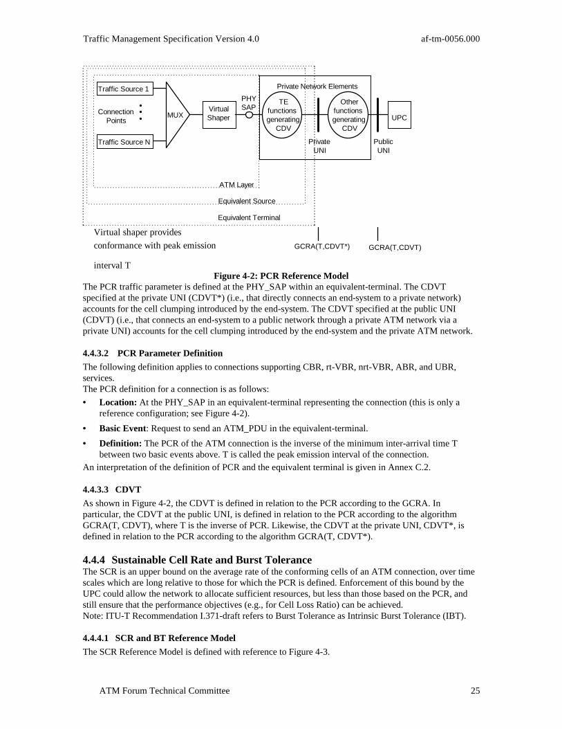
Traffic Management Specification Version 4.0 af-tm-0056.000
ATM Forum Technical Committee 25
Traffic Source N
Traffic Source 1
ConnectionPoints
VirtualShaper
PHYSAP
TEfunctionsgenerating
CDV
Otherfunctionsgenerating
CDV
MUX UPC
PublicUNI
PrivateUNI
Equivalent Source
ATM Layer
Equivalent Terminal
GCRA(T,CDVT*) GCRA(T,CDVT)
Virtual shaper provides
conformance with peak emission
interval T
Private Network Elements
Figure 4-2: PCR Reference ModelThe PCR traffic parameter is defined at the PHY_SAP within an equivalent-terminal. The CDVTspecified at the private UNI (CDVT*) (i.e., that directly connects an end-system to a private network)accounts for the cell clumping introduced by the end-system. The CDVT specified at the public UNI(CDVT) (i.e., that connects an end-system to a public network through a private ATM network via aprivate UNI) accounts for the cell clumping introduced by the end-system and the private ATM network.
4.4.3.2 PCR Parameter Definition
The following definition applies to connections supporting CBR, rt-VBR, nrt-VBR, ABR, and UBR,services.The PCR definition for a connection is as follows:
• Location: At the PHY_SAP in an equivalent-terminal representing the connection (this is only areference configuration; see Figure 4-2).
• Basic Event: Request to send an ATM_PDU in the equivalent-terminal.
• Definition: The PCR of the ATM connection is the inverse of the minimum inter-arrival time Tbetween two basic events above. T is called the peak emission interval of the connection.
An interpretation of the definition of PCR and the equivalent terminal is given in Annex C.2.
4.4.3.3 CDVT
As shown in Figure 4-2, the CDVT is defined in relation to the PCR according to the GCRA. Inparticular, the CDVT at the public UNI, is defined in relation to the PCR according to the algorithmGCRA(T, CDVT), where T is the inverse of PCR. Likewise, the CDVT at the private UNI, CDVT*, isdefined in relation to the PCR according to the algorithm GCRA(T, CDVT*).
4.4.4 Sustainable Cell Rate and Burst ToleranceThe SCR is an upper bound on the average rate of the conforming cells of an ATM connection, over timescales which are long relative to those for which the PCR is defined. Enforcement of this bound by theUPC could allow the network to allocate sufficient resources, but less than those based on the PCR, andstill ensure that the performance objectives (e.g., for Cell Loss Ratio) can be achieved.Note: ITU-T Recommendation I.371-draft refers to Burst Tolerance as Intrinsic Burst Tolerance (IBT).
4.4.4.1 SCR and BT Reference Model
The SCR Reference Model is defined with reference to Figure 4-3.

af-tm-0056.000 Traffic Management Specification Version 4.0
ATM Forum Technical Committee26
Traffic Source N
Traffic Source 1
ConnectionPoints
VirtualShaper
PHYSAP
TEfunctions
generatingCDV
Otherfunctions
generatingCDV
MUX UPC
PublicUNI
PrivateUNI
Equivalent Source
ATM Layer
Equivalent Terminal
CDVT
CDVT*
GCRA(Ts,BT) GCRA(Ts,BT+CDVT*) GCRA(Ts,BT+CDVT)Virtual shaper providesconformance with peak emissioninterval Ts
Figure 4-3: SCR and BT Reference ModelThe SCR and BT traffic parameters are defined at the PHY_SAP within an equivalent-terminal.
4.4.4.2 SCR and BT Definitions
The following definition applies to connections supporting rt-VBR and nrt-VBR services. The SCR andBT parameters for a connection are defined according to the GCRA (Section 4.4.2) as follows:
• Location: At the PHY_SAP in an equivalent-terminal representing the connection (this is only areference configuration; see Figure 4-3).
• Basic Event: Request to send an ATM_PDU in the equivalent-terminal.
• Definition: The SCR, and the BT denoted as of the ATM connection are defined by theGCRA(1/SCR, BT) based on the arrivals of the basic event defined above. The increment parameterof the GCRA is 1/SCR and ΒΤ is the limit parameter of the GCRA.
In the signaling message, the SCR is coded as cells per second. The granularity supported by the signalingmessage is 1 cell/s. The defined coding for the SCR in the signaling message does not imply that any UPCmechanism has to support the same linear granularity for the SCR across the complete defined cell raterange.An interpretation of the definition of SCR and BT in conjunction with PCR is given in Annex C.4.
4.4.4.3 CDVT
As shown in Figure 4-3, the CDVT is defined in relation to the SCR according to the GCRA. Inparticular, the CDVT at the public UNI, is defined in relation to the SCR according to the algorithmGCRA(TS, BT+CDVT), where TS is the inverse of SCR. Likewise, the CDVT* at the private UNI, isdefined in relation to the SCR according to the algorithm GCRA(TS, BT+CDVT*).
4.5 Traffic Contract and Conformance DefinitionsThe conformance of cells of a connection at an interface is defined in relation to the conformancealgorithm and corresponding parameters specified in the connection traffic descriptor. This conformancedefinition is specified in the traffic contract. The set of conformance definitions that is supported at thepublic UNI is network specific. Future service categories may require the definition of new traffic contractparameters.The ITU-T provides a definition of the granularity of PCR, SCR, CDVT, and BT used for definingconformance of a CBR or VBR connection, see ITU-T Recommendation I.371-draft.For network operations, there are two models for the CLP=1 cell flow:

Traffic Management Specification Version 4.0 af-tm-0056.000
ATM Forum Technical Committee 27
• CLP-transparent: The network generally disregards the CLP bit. The CLR objective applies only tothe aggregate CLP=0+1 cell flow, for which the CLP=1 cells experience the same CLR as the CLP=0cells. The tagging option does not apply to this model (see Section 5.3.5).
• CLP-significant: The CLR objective applies only to the CLP=0 cell flow. The CLR for the CLP=1flow is unspecified, as is the CLR for the aggregate flow (CLP=0+1). Network tagging applies as anoption. The network may make a best-effort attempt to transmit the CLP=1 flow. In such a case, thenetwork is likely to employ selective discard (but this will not count against the CLR objective of theconnection).
For the conformance definitions listed below, the CLP-transparent model is used for CBR.1 and VBR.1,and the CLP-significant model is used for VBR.2 and VBR.3.
4.5.1 Traffic Contract Conformance Definition for CBR ServiceConformance for a CBR connection is characterized by PCR and the corresponding CDVT for theCLP=0+1 traffic flow.(R) PCR for CLP=0+1 is a mandatory traffic parameter in any CBR source traffic descriptor.(R) For CBR SVCs, the PCR for CLP=0+1 shall be explicitly specified by the source for each direction inthe initial connection establishment message.(R) The CDVT is a mandatory parameter in any CBR connection traffic descriptor.(R) The CDVT shall be either explicitly specified at subscription time or implicitly specified for any CBRconnection.(R) For SVCs, the signaling message shall be capable of conveying information that identifies at least thefollowing set of conformance definitions. For PVCs, the conformance definition shall be explicitlyidentified at subscription time.
4.5.1.1 CBR.1: Conformance Definition for PCR (CLP=0+1)
The following is a conformance definition for a source traffic descriptor that specifies PCR for theCLP=0+1 cell stream:
1. One GCRA(T0+1, CDVT) defining the CDVT in relation to the PCR of the CLP=0+1 cell stream.T0+1 is the inverse of the PCR specified for the CLP=0+1 cell flow.
2. A cell that is conforming to the GCRA in (1) is said to be conforming to the connection trafficdescriptor.
The tagging option is not applicable to this conformance definition since no separate rate is specified forCLP=0. The CLR objective applies to the aggregate CLP=0+1 cell stream.
4.5.2 Traffic Contract and Conformance Definition for rt-VBR and nrt-VBRConformance for a rt-VBR or nrt-VBR connection is characterized by an SCR parameter andcorresponding MBS parameter for one or more traffic flows, in addition to a PCR parameter andcorresponding CDVT for at least the CLP=0+1 flow. Real-time VBR and nrt-VBR are typicallydistinguished by their QoS parameters, but also by the magnitude(s) of the MBSs supported. Larger MBSsare more typical for nrt-VBR connections. The relationship between BT and MBS is given in Annex C.4.(R) PCR for CLP=0+1 is a mandatory traffic parameter in any source traffic descriptor for a rt-VBR ornrt-VBR connection.(R) For rt-VBR or nrt-VBR SVCs, the PCR for CLP=0+1 must be explicitly specified for each direction inthe initial establishment message.(R) CDVT is a mandatory parameter in any connection traffic descriptor for a rt-VBR or nrt-VBRconnection.(R) CDVT shall be either explicitly specified at subscription time or implicitly specified for any rt-VBR ornrt-VBR connection.(R) For SVCs, the signaling message shall be capable of conveying information that identifies at least thefollowing set of conformance definitions. For permanent connections the conformance definition shall beexplicitly identified at subscription time.
af-tm-0056.000 Traffic Management Specification Version 4.0
ATM Forum Technical Committee28
4.5.2.1 VBR.1: Conformance Definition for PCR (CLP=0+1) and SCR (CLP=0+1)
The following is a conformance definition for a source traffic descriptor that specifies PCR for theCLP=0+1 cell stream and SCR for the CLP=0+1 cell stream:
1. One GCRA(T0+1, CDVT) defining the CDVT in relation to the PCR of the CLP=0+1 cell stream.
T0+1 is the inverse of PCR (CLP=0+1).2. One GCRA(Ts0+1, BT0+1+CDVT) defining the sum of the CDVTCSR and the BT in relation to the
SCR of the CLP=0+1 cell stream. Ts0+1 is the inverse of SCR (CLP=0+1).3. A cell that is conforming to both GCRAs (1) and (2) above is said to be conforming to the
connection traffic descriptor.The tagging option is not applicable to this conformance definition. The CLR objective applies to theaggregate CLP=0+1 cell stream.
4.5.2.2 VBR.2: Conformance Definition for PCR (CLP=0+1) and SCR (CLP=0)
The following is a conformance definition for a source traffic descriptor that specifies PCR for theCLP=0+1 cell stream and SCR for the CLP=0 cell stream:
1. One GCRA(T0+1, CDVT) defining the CDVT in relation to the PCR of the CLP=0+1 cell stream.T0+1 is the inverse of PCR (CLP=0+1).
2. One GCRA(Ts0, BT0+CDVT) defining the sum of the CDVT and the BT in relation to the SCR of
the CLP=0 cell stream. Ts0 is the inverse of SCR (CLP=0).3. A CLP=0 cell that is conforming to both GCRAs (1) and (2) above is said to be conforming to the
connection traffic descriptor. A CLP=1 cell that is conforming to GCRA (1) above is said to beconforming to the connection traffic descriptor.
This conformance definition allows a connection to send CLP=1 cells at a PCR equal to the specified PCRof the CLP=0+1 cell stream. The CLR objective applies to the CLP=0 cell stream. The CLR of the CLP=1cell-stream and the aggregate stream is undefined.
4.5.2.3 VBR.3: Conformance Definition for PCR (CLP=0+1) and SCR (CLP=0)
The following is a conformance definition for a source traffic descriptor that specifies PCR for theCLP=0+1 cell stream and SCR for the CLP=0 cell stream:
1. One GCRA(T0+1, CDVT) defining the CDVT in relation to the PCR of the CLP=0+1 cell stream.T0+1 is the inverse of PCR (CLP=0+1).
2. One GCRA(Ts0, BT0+CDVT) defining the sum of the CDVT and the BT in relation to the SCR of
the CLP=0 cell stream. Ts0 is the inverse of SCR (CLP=0).3. A CLP=0 cell that is conforming to both GCRAs (1) and (2) above is said to be conforming to the
connection traffic descriptor. A CLP=1 cell that is conforming to GCRA (1) above is said to beconforming to the connection traffic descriptor.
4. If the end-system requests tagging, and if tagging is supported by the network, a CLP=0 cell thatis not conforming to GCRA (2) above, but is conforming to GCRA (1) above, will have its CLP bitchanged to 1 and is said to be conforming to the connection traffic descriptor.
This conformance definition allows a connection to send CLP=1 cells at a PCR equal to the specified PCRof the CLP=0+1 cell stream. The CLR objective applies to the CLP=0 cell stream. The CLR of the CLP=1cell-stream and the aggregate stream is undefined.
4.5.3 Traffic Contract and Conformance Definition for UBR ServiceConformance for a UBR connections is characterized by a single PCR and corresponding CDVT for theCLP=0+1 flow. The use of PCR for CAC, and enforcement of PCR by UPC, is network specific. However,if the user requests a non-zero minimum acceptable PCR that cannot be supported by the network, thenthe network may reject the call.(R) PCR for CLP=0+1 is a mandatory traffic parameter in any source traffic descriptor of a UBRconnection.(R) The CDVT is a mandatory parameter in any connection traffic descriptor for a UBR connection.

Traffic Management Specification Version 4.0 af-tm-0056.000
ATM Forum Technical Committee 29
(R) The CDVT shall be either explicitly specified at subscription time or implicitly specified for a UBRconnection.(R) For UBR SVCs, the PCR for CLP=0+1 shall be explicitly specified for each direction in the initialestablishment message.It is desirable that the source end-system conforms to PCR, but the enforcement of this is network specific.
4.5.3.1 UBR.1: Conformance definition for PCR (CLP=0+1), Tagging not applicable
The tagging option does not apply. The network shall not overwrite the CLP bit.
4.5.3.2 UBR.2: Conformance definition for PCR (CLP=0+1), Tagging applicable
The tagging option applies. The network may overwrite the CLP bit to 1 for any cell of that connection.However, such action does not necessarily imply a condition of non-conformance, as would be the case forother service categories.
4.5.4 Summary of Conformance Definitions for CBR, rt-VBR, nrt-VBR, and UBRTable 4-1 summarizes the conformance definitions discussed in this section for the CBR, VBR, and UBRservice categories.
ConformanceDefinition
PCRflow
SCRflow
Taggingoptionactive
CLRon
CBR.1 0 + 1 ns na 0 + 1
VBR.1 0 + 1 0 + 1 na 0 + 1
VBR.2 0 + 1 0 No 0
VBR.3 0 + 1 0 Yes 0
UBR.1 0 + 1 ns na U
UBR.2 0+1 ns Yes4 U
Table 4-1: Summary of conformance definitionsNotes for Table 4-1:
1. ns means that SCR is not specified.2. na means that tagging is not applicable.3. U means that CLR is unspecified (for both CLP=0 & CLP=1).4. When the tagging option is used for a UBR connection the network may overwrite the CLP bit to
1 for any cell of that connection. However, such action does not necessarily imply a condition ofnon-conformance, as would be the case for other service categories.
4.5.5 Traffic Contract and Conformance Definition for ABR ServiceThe algorithm that defines conformance at an interface for each CLP=0 cell on a connection implicitlydefines the response expected of the ABR end-system to feedback contained in backward RM-cells on thereverse connection. This feedback may include information in the Explicit Rate (ER) field or theCongestion Indication (CI) or No Increase (NI) bits of each backward RM-cell.(R) The ABR conformance definition is network specific, but must satisfy the following design constraintsrelative to parameters τ1, τ2, and τ3 as specified for the connection, and delays t1 and t2 as defined inSection 4.5.5.1.1. The conformance definition shall identify each CLP=0 cell as either conforming or non-conforming.2. The conformance definition shall identify all CLP=0 cells on a connection conforming if all CLP=0
cells on a connection conform to GCRA(MCR−1,τ1) .

af-tm-0056.000 Traffic Management Specification Version 4.0
ATM Forum Technical Committee30
3. The conformance definition used at an interface shall find a CLP=0 cell non-conforming only if itsarrival time there and those of the preceding conforming CLP=0 cells on the connection could nothave resulted from the ideal transmission times (as defined in Section 4.5.5.1) of an ABR source anddelays t1 and t2 for the connection satisfying τ3 ≤ t2 ≤ τ 2 and max(t1) − min(t1) ≤ τ1 . In
determining whether a CLP=0 cell is conforming, the network may assume that the inter-cell intervalbetween that cell and the previous CLP=0 cell on the connection (i) shall account for feedbackconveyed in backward RM-cells transmitted across the interface on the backward connection morethan τ2 units before that previous CLP=0 cell and (ii) shall not account for feedback conveyed inbackward RM-cells transmitted across the interface on the backward connection less than τ3 unitsbefore that previous CLP=0 cell.
The parameter τ1 is the CDVT for the ABR connection. τ2 and τ3 are, respectively, the upper and lowerbounds on the delay after which the rate change induced by a backward RM-cell departing from aninterface (in the backward direction) is expected to be observed at the interface (in the forward direction).An example of a conformance test satisfying (1)-(3) above is described in Appendix III and referred to asER-conformance which is defined through the algorithm DGCRA(MCR-1,PCR-1,ICR-1, τ1, τ2, τ3 ).ER-Conformance accounts only for feedback information conveyed in the ER field of the backwardRM-cell and hence does not test whether the connection observes feedback conveyed in the CI or NI bitsof the RM-cell. However, ER-conformance may be an adequate conformance definition for a network thatdoes not rely on the CI or NI bits to convey feedback.
The minimal conformance definition for ABR is GCRA PCR( , )−11τ where the PCR is defined for
CLP=0 flow, according to Section 5.10 on ABR.(O) The definitions of conformance and compliance optionally may be applied to the Private UNI orPrivate NNI.
4.5.5.1 Definitions of ABR Delays
The characteristics of traffic received at the private or public UNI on a given ABR connection dependcritically on the delays between that interface and the source/destination (or virtual source/virtualdestination) that generates the traffic. The delays most relevant to the characteristics of a flow received atthe interface are defined relative to the transmission times of each CLP=0 cell by the traffic source. Atransmission time for a CLP=0 cell is called an Ideal Transmission Time (ITT) if the difference betweenitself and the transmission time for the previous CLP=0 cell on the connection is greater than or equal tothe minimum of (a) the inverse of the Available Cell Rate (ACR) in effect immediately after thetransmission time of the first of the two cells and (b) the inverse of the ACR in effect immediately beforethe transmission time of the second of the two cells. The transmission time for the first cell on theconnection is automatically an ITT. The ACR is calculated as specified in Section 5.10.4. The minimum istaken of (a) and (b) above, because an ABR source has the option of rescheduling the next cell to betransmitted on a connection when new feedback is received.Two delays, t1 and t2 are particularly relevant to traffic characteristics at an interface. The delay t1 denotesthe time from a cell's transmission time by the traffic source to its receipt at the interface in question. Thesecond delay t2 denotes the sum of:
• the delay from the departure at the interface in question of a backward RM-cell on the backwardconnection to the receipt of the RM-cell by the traffic source, and
• the delay from the next transmission time for a CLP=0 cell on the connection (following the receipt ofthe RM-cell by the traffic source) to the arrival at the interface in question of that CLP=0 cell.
Hence, t1 is the one-way transfer delay from the source to the interface and t2 is the round-trip feedbackdelay between the interface and the source, excluding the residual of the inter-cell interval betweensuccessive transmission times.

Traffic Management Specification Version 4.0 af-tm-0056.000
ATM Forum Technical Committee 31
5. Functions and Procedures for Traffic Management
5.1 IntroductionFunctions referred to as congestion control functions in this specification are intended to react to networkcongestion in order to minimize its intensity, spread and duration.The following set of traffic and congestion control functions are described in this specification. ATMnetworks can implement one or a combination of these functions in order to meet QoS objectives ofcompliant connections.
• Connection Admission Control (Section 5.2)
• Usage Parameter Control (Section 5.3)
• Selective Cell Discarding (Section 5.4)
• Traffic Shaping (Section 5.5)
• Explicit Forward Congestion Indication (Section 5.6)
• Resource Management using Virtual Paths (Section 5.7)
• Frame Discard (Section 5.8)
• Generic Flow Control (Section 5.9)
• ABR Flow Control (Section 5.10).Different levels of network performance may be provided on connections by proper routing, trafficshaping, priority control and resource allocation to meet the required QoS for these connections.
5.2 Connection Admission ControlThe Connection Admission Control (CAC) function is defined as the set of actions taken by the networkat SVC establishment or by Network Management during PVC establishment in order to determinewhether a connection can be progressed or should be rejected.
(R) The information contained in the traffic contract (Section 4) shall be accessible to the CAC function.
Based on the CAC function, a connection request is progressed only when sufficient resources areavailable at each successive network element to establish the connection through the whole networkbased on its service category, traffic contract, and QoS, and in order to maintain the agreed QoS ofexisting connections.
For each connection request, the CAC function shall be able to derive the following information from thetraffic contract (see Section 4.2):
• Values of parameters in the source traffic descriptor (Section 4.1.2);
• Requested and acceptable values of each QoS parameter and the requested QoS class (Section 3);
• Value of the CDVT (Section 4.4.1);
• Requested conformance definition (Section 4.5).The CAC function makes use of the traffic contract and the network’s definition of a compliantconnection to determine:
• whether the connection can be accepted or not;
• the connection traffic parameters (see Section 4.1.3) needed by usage parameter control (see Section5.3.1);
• allocation of network resources.
af-tm-0056.000 Traffic Management Specification Version 4.0
ATM Forum Technical Committee32
Different strategies for network resource allocation may be applied for CLP=0 and CLP=1 traffic flows. Inaddition, information such as the measured network load may be used when performing the CACfunction. This may allow a network to achieve higher network utilization while still meeting the networkperformance objectives.The CAC function is network specific.
5.3 Usage Parameter Control(O) The UPC function is optional at the UNI.
5.3.1 UPC FunctionsUsage Parameter Control (UPC) is defined as the set of actions taken by the network to monitor andcontrol traffic. Its main purpose is to protect network resources from malicious as well as unintentionalmisbehavior which can affect the QoS of other already established connections by detecting violations ofnegotiated parameters and taking appropriate actions.Connection monitoring at a UNI (private or public) is referred to as UPC. Connection monitoring at anNNI (private or public) is referred to as NPC. UPC is used as a more generic term (includes NPC) unlessotherwise specified. Connection monitoring encompasses all connections crossing the interface whereUPC is used. UPC applies to both user connections and signaling channels. Methods for monitoringmeta-signaling channels and OAM flows are for further study.The monitoring task for UPC is performed for VCCs and VPCs respectively by the following two actions:
1. checking the validity of VPI and VCI (i.e., whether or not VPI/VCI values are associated withactive VCCs) and monitoring the traffic entering the network from active VCCs in order to ensurethat parameters agreed upon are not violated;
2. checking the validity of VPI (i.e., whether or not VPI values are associated with active VPCs), andmonitoring the traffic entering the network from active VPCs in order to ensure that parametersagreed upon are not violated.
5.3.2 UPC RequirementsUPC algorithms are network specific. However, the UPC function shall support the QoS objectives forcompliant connections (see Section 4.3).When a traffic contract conformance violation occurs, policing actions performed on the cells sent inexcess of the traffic contract are not to be included in the network performance degradation allocated tothe UPC.The CTD and the CDV introduced by the UPC is also part of the CTD and CDV allocated to the network.A method to determine whether a traffic flow is conforming to a negotiated PCR at a given interface isdefined for network performance purposes. Non-conformance is measurable by a 1-point measurement
process in terms of the ratio γM between the number of cells exceeding the traffic contract and the totalnumber of submitted cells.An ideal UPC implementing the one-point measurement process would only take policing actions on anumber of cells according to this ratio. Although the process allows for a cell-based decision, it is notpossible to predict which particular cells of a connection with non-conforming cells will suffer from thepolicing action (because of measurement phasing).According to the definition of the conformance of a traffic flow to a PCR, the transparency of a UPCmechanism can be defined by the accuracy with which this mechanism approaches the ideal mechanism,
i.e., the difference between the reference policing ratio γM and the actual policing ratio γP. A positivedifference means that the UPC is taking less policing action than allowed. A negative difference meansthat policing actions are unduly taken by the UPC.The above description also applies to the SCR and the MBS traffic parameters. The exact way ofmeasuring the transparency of a given mechanism for the UPC and its dependence on time is for furtherstudy.For further information on UPC/NPC accuracy and transparency see ITU-T Recommendation I.371-draft.

Traffic Management Specification Version 4.0 af-tm-0056.000
ATM Forum Technical Committee 33
5.3.3 UPC LocationUPC is performed at the points where the VP or VC link connected to the NT is terminated in thenetwork. Three possibilities are shown in Figure 5-1.
CASE A
CASE B
CASE C
NT
NT
NT
UPC(VP)
UPC(VP)
UPC(VC)
UPC(VC)
UPC(VC)
UPC(VC)
UNI
NT : Network Termination VC-Sw : Virtual Channel Switching FunctionVP-Sw : Virtual Path Switching Function
To another user or to
another network provider
VC-Sw
VP-Sw
VP-Sw
Figure 5-1: Location of the UPC FunctionsNote: Provision of UPC at other locations is for further study.In the following, VC-Sw stands for Virtual Channel Switching Function, and VP-Sw stands for VirtualPath Switching Function. The following VC-Sws and VP-Sws refer to the first switches on the publicnetwork side of the Public UNI (or on the network side of the private UNI, or on the private network sideof the public UNI when UPC is implemented in private network elements). A VC-Sw or a VP-Sw mayrespectively be a VC or VP concentrator.(CR) If connected directly to a VC-Sw (CASE A of Figure 5-1), the UPC function shall be performedwithin the VC-Sw on VCCs before the switching function is executed (action 1, Section 5.3.1).(CR) If connected directly to VC-Sw via VP-SW (CASE B of Figure 5-1), the UPC function shall beperformed within the VP-Sw on VPCs only (actions 2, Section 5.3.1) and within the VC-Sw on VCCsonly (action 1, Section 5.3.1).(CR) If connected to an end-system or to another network via VP-Sw (CASE C of Figure 5-1), the UPCfunction shall be performed within the VP-Sw on VPCs only (action 2, Section 5.3.1).In CASE C of Figure 5-1, the VCC usage parameter control will be done by the first public network (ifany) where VC-Sw is present.
5.3.4 Traffic Parameters Subject to UPC EnforcementThe traffic parameters that may be subject to UPC enforcement are those included in the source trafficdescriptor.(R) The PCR of the CLP=0+1 cell flow shall be subject to UPC for all types of connections at the PublicUNI.(O) Even when the parameters are specified, the enforcement of SCR and MBS is network specific.(O) The PCR of the CLP=0+1 cell flow may be subject to UPC for all types of connections at the PrivateUNI.

af-tm-0056.000 Traffic Management Specification Version 4.0
ATM Forum Technical Committee34
5.3.5 UPC Actions (Cell Tagging and Discard)The UPC is intended to ensure conformance by a connection with the negotiated traffic contract. Theobjective is that a connection will never be able to exceed the traffic contract.At the cell level, actions of the UPC function may include:
• cell passing;
• cell tagging (network option); cell tagging operates on CLP=0 cells only, by overwriting the CLP bitto 1;
• cell discarding.A cell tagging function exists which is optional for both the network and the user. If supported by thenetwork, the user may select tagging when the connection is established. The availability of taggingdepends on the conformance definition of the connection.If the tagging option is used for a connection, CLP=0 cells identified by the UPC function to benon-conforming to the CLP=0 cell stream are converted to CLP=1 cells. Those cells that have the CLP bitconverted from ‘0’ to ‘1’ are called tagged cells. A tagged cell that is identified by the UPC function to beconforming to the CLP = 0 + 1 cell stream is passed; otherwise, it is discarded. Likewise, a cell submittedby an end-system with CLP=1, that is identified by the UPC function to be conforming to the CLP = 0 + 1
cell stream is passed; otherwise, it is discarded.3 Tagging is used to transform a non-conforming CLP=0cell into a conforming CLP=1 cell when the cell is conforming to the aggregate CLP=0+1 flow. If aCLP=0 cell is not conforming to the aggregate CLP=0+1 flow, tagging will not make it conforming.Therefore, the tagging option never applies to the aggregate CLP=0+1 flow, but applies to the CLP=0flow.(R) Cells shall be passed when they are identified by the UPC as conforming. If a tagged cell is passed,then it is considered to be conforming.(R) Cells shall be discarded when they are identified by the UPC as non-conforming.(O) Following the UPC function, traffic shaping may be used to perform cell re-scheduling (e.g., to reducecell clumping) on cells identified by the UPC as conforming.In addition to the above actions at the cell level, one other action performed at the connection level mayoptionally be initiated by the UPC.(O) The UPC function may initiate the release of an identified non-compliant SVC.
5.3.6 Relationship between UPC, CLP, and Network PerformanceWhen an end-system sets the CLP bit, network resources are allocated to CLP=0 and CLP=1 traffic flowsas described in Section 5.2. By controlling the connection traffic flows, allocating adequate resources andselecting suitable routes, a network may provide the requested service category and QoS parameters forCLP=0 and CLP=0+1 cell flows.When no additional network resource has been allocated for the CLP=1 traffic flow (either on user requestor due to network provisioning), CLP=0 cells identified by the UPC as non-conforming are discarded. Inthis case, tagging is not applicable.Section 5.3.2 addresses undue UPC actions on compliant ATM connections. This is part of the networkperformance degradation allocated to the UPC and should occur with very low probability.When cells of the aggregate CLP=0+1 flow are non-conforming to the parameters negotiated for theaggregate stream, the UPC function performed on the aggregate flow may discard CLP=0 cells that wouldnot be considered in excess by the UPC function performed on the CLP=0 cell stream.
5.3.7 Relationship between UPC and OAMFor OAM cell flows across the UNI, the network may require the user to specify traffic parameters for theOAM traffic of an ATM connection. Regardless of whether an end-system explicitly or implicitly specifies
3Note that in principle the cell flow that is passed by the UPC with the tagging option is no greater thanwhat might be passed by a UPC without the tagging option when the end-system sets the CLP bit to 1 onthose cells that would otherwise have been tagged under the tagging option.
Traffic Management Specification Version 4.0 af-tm-0056.000
ATM Forum Technical Committee 35
the OAM cell stream, the network may police OAM cell flows separately from user data cell streams ormay police OAM cell flows together with user data cell streams. However, neither UNI 3.1 nor UNI 4.0signaling support indication of an OAM traffic descriptor. Traffic parameters for OAM cell flow acrossthe UNI may be explicitly specified at subscription time, or implicitly by a default rule. (R) At the service subscription time, the network shall negotiate the upper limit on the OAM traffic as afunction of the connection traffic descriptor for the user data traffic of an ATM connection.The function used to limit the OAM flow is determined by the network. The network may offer alternativelimits from which the end-system may select. If the network polices the OAM cell flows together with userdata cell flows, the UPC parameters are adjusted appropriately to accommodate the OAM flow.
5.3.8 Reaction to UPC FailuresDue to equipment faults (e.g., in UPC devices and/or other network elements) the controlled trafficcharacteristics at the UPC/NPC could be different from the values agreed to during the call set-up phase.To cope with these situations, specific procedures of the management plane should be designed (e.g., inorder to isolate the faulty link).
5.4 Selective Cell Discard(O) A congested network element may selectively discard cells which meet either or both of the followingconditions:a) cells which belong to a non-compliant ATM connection;b) cells which have CLP=1.This is to protect the CLP=0 flow as much as possible. However, if CLP=1 cells are dropped from acompliant ATM connection it is expected that the CLR objective for the connection, as determined by itsconformance definition, will be still met.
5.5 Traffic ShapingTraffic shaping is a mechanism that alters the traffic characteristics of a stream of cells on a connection toachieve better network efficiency whilst meeting the QoS objectives, or to ensure conformance at asubsequent interface.(R)Traffic shaping shall maintain cell sequence integrity on a connection.Examples of traffic shaping are peak cell rate reduction, burst length limiting, reduction of CDV bysuitably spacing cells in time, and cell scheduling policy.The decision whether or not to implement traffic shaping, and if implemented, the location where shapingis done, is network specific. As an example a network may choose to perform traffic shaping inconjunction with suitable UPC/NPC functions and/or virtual source/destination.As a consequence, any connection may be subject to traffic shaping.The options available to the network include:a) No shaping
• Dimension the network in order to accommodate any flow of conforming cells at the ingresswhilst ensuring conformance at the egress without any shaping function.
b) Shaping• Dimension and operate the network so that any flow of conforming cells at the ingress is
conveyed by the network or network segment whilst meeting QoS objectives and apply outputshaping to the traffic in order to meet conformance tests at the egress.
• Shape the traffic at the ingress of the network or network segment and allocate resourcesaccording to the traffic characteristics achieved by shaping, whilst meeting QoS objectives andsubsequent conformance tests at the network or network segment egress.
Traffic shaping may also be used within the end-system to ensure that the cells generated by the source orat the UNI are conforming to the negotiated traffic contract as defined in Section 4.5.
5.6 Explicit Forward Congestion Indication (EFCI)(O) A network element in an impending congested state or a congested state may set an EFCI in the cellheader so that this indication may be examined by the destination end-system. For example, the
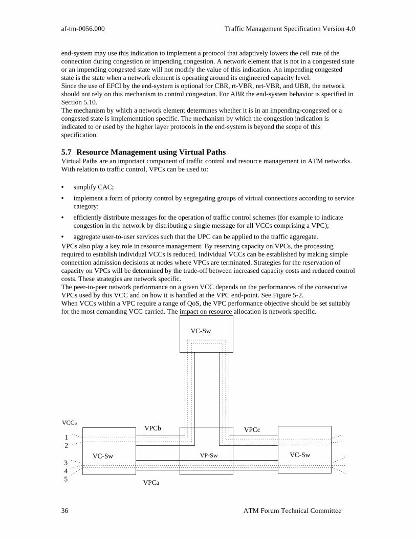
af-tm-0056.000 Traffic Management Specification Version 4.0
ATM Forum Technical Committee36
end-system may use this indication to implement a protocol that adaptively lowers the cell rate of theconnection during congestion or impending congestion. A network element that is not in a congested stateor an impending congested state will not modify the value of this indication. An impending congestedstate is the state when a network element is operating around its engineered capacity level.Since the use of EFCI by the end-system is optional for CBR, rt-VBR, nrt-VBR, and UBR, the networkshould not rely on this mechanism to control congestion. For ABR the end-system behavior is specified inSection 5.10.The mechanism by which a network element determines whether it is in an impending-congested or acongested state is implementation specific. The mechanism by which the congestion indication isindicated to or used by the higher layer protocols in the end-system is beyond the scope of thisspecification.
5.7 Resource Management using Virtual PathsVirtual Paths are an important component of traffic control and resource management in ATM networks.With relation to traffic control, VPCs can be used to:
• simplify CAC;
• implement a form of priority control by segregating groups of virtual connections according to servicecategory;
• efficiently distribute messages for the operation of traffic control schemes (for example to indicatecongestion in the network by distributing a single message for all VCCs comprising a VPC);
• aggregate user-to-user services such that the UPC can be applied to the traffic aggregate.VPCs also play a key role in resource management. By reserving capacity on VPCs, the processingrequired to establish individual VCCs is reduced. Individual VCCs can be established by making simpleconnection admission decisions at nodes where VPCs are terminated. Strategies for the reservation ofcapacity on VPCs will be determined by the trade-off between increased capacity costs and reduced controlcosts. These strategies are network specific.The peer-to-peer network performance on a given VCC depends on the performances of the consecutiveVPCs used by this VCC and on how it is handled at the VPC end-point. See Figure 5-2.When VCCs within a VPC require a range of QoS, the VPC performance objective should be set suitablyfor the most demanding VCC carried. The impact on resource allocation is network specific.
12
345
VC-Sw VP-Sw VC-Sw
VC-Sw
VPCb VPCc
VPCa
VCCs
Traffic Management Specification Version 4.0 af-tm-0056.000
ATM Forum Technical Committee 37
Figure 5-2: Mapping cell loss ratios for VCC and VPCFigure 5-2 illustrates how the network performance offered on VCCs relates to the network performanceoffered by VPCs that support them. In the figure, VCCs 1 and 2 experience a network performance whichdepends on network performance on VPCs b and c and on how these VCCs are handled at the VPCend-points in the VC-Sw element. It may differ from network performance experienced by VCCs 3, 4 and5, at least due to different network performances provided by VPCs.VCCs 3, 4 and 5 experience similar network performances in terms of CTD and CDV if handled similarlyat the VPC end-points in the VC-Sw element.Section 3.2 of ITU-T Recommendation I.311 provides three applications of VPCs. These are:
A) User-user application: the VPC extends between a pair of ATM end-systems
B) User-network application: the VPC extends between a UNI and a network element
C) Network-network application: the VPC extends between network elements.
The above cases imply:
In case A: because the network has no knowledge of the traffic contract, service category, and QoS of theVCCs within the VPC, it is the responsibility of the end-system to determine the appropriate servicecategory and QoS parameters for the VPC in accordance with the network capabilities.
In cases B and C: the network is aware of the QoS of the VCCs carried within the VPC and has toaccommodate them.
The relationship between the service category of the VPC and the service categories of the VCCs itcarries is implementation specific.
Statistical multiplexing of VCCs within a VPC, where the aggregate peak of all VCCs may exceed theVPC capacity, is only possible when all VCCs within the VPC can tolerate the QoS that results from thisstatistical multiplexing. The way this is managed is network specific. As a consequence, when statisticalmultiplexing of Virtual Channel Links is applied by the network, VPCs may be used in order to separatetraffic thereby preventing statistical multiplexing with other types of traffic. This requirement forseparation implies that more than one VPC may be necessary between network origination/destinationpairs to carry all of the service categories, traffic contract parameter values, and/or QoS parameter valuessupported by the network. See Section 5.10.9 for a discussion of ABR Virtual Paths.
5.8 Frame DiscardIf a network element needs to discard cells, it is in many cases more effective to discard at the frame levelrather than at the cell level. The term “frame” means the AAL protocol data unit. The network detects theframe boundaries by examining the SDU-type in the payload type field of the ATM cell header. Framediscard may be used whenever it is possible to delineate frame boundaries by examining the SDU-type inthe payload type field of the ATM cell header.Frame discard may help avoid congestion collapse and can increase goodput.If a network supports frame discard, it can treat user data as frames only if the user requests suchtreatment, either via signaling or at subscription time. The network may invoke frame discardmechanisms, only for connections for which it is specifically enabled. The mechanism by which a networkelement decides to drop frames is implementation-specific.
5.9 Generic Flow ControlThe use of GFC at the UNI is neither assumed nor precluded in this specification. The GFC function isspecified in ITU-T Recommendation I.150 and ITU-T Recommendation I.361.
af-tm-0056.000 Traffic Management Specification Version 4.0
ATM Forum Technical Committee38
5.10 ABR Flow Control
5.10.1 IntroductionIn the ABR service, the source adapts its rate to changing network conditions. Information about the stateof the network like bandwidth availability, state of congestion, and impending congestion, is conveyed tothe source through special control cells called Resource Management Cells (RM-cells). The followingsections specify the format and contents of the RM-cell, the source, destination, and switch behavior, andthe parameters used in the service. Optional segmentation of networks, support for virtual paths, and aframework for point-to-multipoint behavior is also specified. For a description of the ABR flow controlmodel, see Section 2.4.
5.10.2 ABR Service ParametersThis section defines the parameters which are used to implement ABR flow-control on a per-connectionbasis. All parameters are defined, including those which are actually constants and not altered bysignaling.

Traffic Management Specification Version 4.0 af-tm-0056.000
ATM Forum Technical Committee 39
5.10.2.1 Parameter Descriptions
Label Description Units and rangePCR The Peak Cell Rate, PCR, is the cell rate which the source may
never exceed.In Cells/Sec, See Note 1 for range
MCR The Minimum Cell Rate, MCR, is the rate at which the sourceis always allowed to send.
In Cells/Sec, See Note 1 for range
ICR The Initial Cell Rate, ICR, is the rate at which a source shouldsend initially and after an idle period.
In Cells/Sec, See Note 1 for range
RIF Rate Increase Factor, RIF, controls the amount by which the celltransmission rate may increase upon receipt of an RM-cell.
RIF is a power of two, ranging from1/32768 to 1.
Nrm Nrm is the maximum number of cells a source may send foreach forward RM-cell.
Power of 2Range: 2 to 256
Mrm Mrm controls allocation of bandwidth between forwardRM-cells, backward RM-cells, and data cells.
Constant fixed at 2
RDF The Rate Decrease Factor, RDF, controls the decrease in thecell transmission rate.
RDF is a power of 2 from 1/32,768to 1
ACR The Allowed Cell Rate, ACR, is the current rate at which asource is allowed to send.
Units: Cells/Sec
CRM Missing RM-cell count. CRM limits the number of forwardRM-cells which may be sent in the absence of receivedbackward RM-cells.
CRM is an integer. Its size isimplementation specific.
ADTF The ACR Decrease Time Factor is the time permitted betweensending RM-cells before the rate is decreased to ICR.
Units: secondsADTF range: .01 to 10.23 sec:with granularity of 10 ms.
Trm Trm provides an upper bound on the time between forwardRM-cells for an active source.
Units: millisecondsTrm is 100 times a power of twoRange: 100*2-7 to 100*20
FRTT The Fixed Round-Trip Time, FRTT, is the sum of the fixed andpropagation delays from the source to a destination and back.
Units : 1 microsecondsRange: 0 to 16.7 seconds
TBE Transient Buffer Exposure, TBE, is the negotiated number ofcells that the network would like to limit the source to sendingduring startup periods, before the first RM-cell returns.
Units: CellsRange: 0 to 16,777,215
CDF The Cutoff Decrease Factor, CDF, controls the decrease in ACRassociated with CRM.
CDF is zero, or a power of two inthe range 1/64 to 1.
TCR The Tagged Cell Rate, TCR, limits the rate at which a sourcemay send out-of-rate forward RM-cells.
TCR is a constant fixed at 10cells/second
Table 5-1: ABR parameter descriptionsNote 1: Rates are signaled as 24 bit integers which have a minimum value of zero, and a maximum valueof 16,777,215. However, RM-cells use a 16-bit floating point format (see Section 5.10.3.2) which has amaximum value of 4,290,772,992.
5.10.2.2 Signaled Parameters
The following parameters are to be signaled and negotiated separately during connection establishment. Ifany parameter but PCR is unspecified by the source, the first switch will fill in the default value (beforenegotiation). MCR is optionally negotiable; if MCRmin is missing, then MCR is not negotiable.
Name Negotiation DefaultPCR down mandatoryMCR down to MCRmin if
MCRmin is signaled, else no0
ICR down PCRTBE down 16,777,215

af-tm-0056.000 Traffic Management Specification Version 4.0
ATM Forum Technical Committee40
FRTT accumulated Note 1RDF down 1/16RIF down 1/16
Table 5-2: Mandatory parameters to be signaledNote 1: FRTT (Fixed Round-Trip Time) should be set by the source to the fixed source delay. FRTT isthen accumulated during the call setup. FRTT is used to determine other parameters (see Section5.10.2.4). It should be the sum of all the RM-cell fixed delays plus propagation delays in the round tripcall path.Note 2: Because of the downward negotiation of RIF and RDF, a given switch may not be able to supportthe RIF and RDF values selected by switches farther from the source. This may occur because the RIF orRDF value is smaller that the given switch can support or because the ratio RIF/RDF is incompatible withother ABR connections using the given switch. When a switch cannot support the values negotiatedduring the forward pass of the call setup, it may decide to clear the call. Additionally, the specification ofthe QoS class may be signaled. If the QoS class is missing, the default is class zero.
5.10.2.3 Optionally Signaled Parameters
The following additional parameters can be optionally specified by the source during call setup but areoptional for the source to specify. If not specified, the default value will be inserted upon call completion(without negotiation). Also, if any network element does not support Table 5-3, or a parameter in thisgroup, the default value will be the value used.
Parameter Negotiation Default ValueNrm no 32Trm no 100CDF up 1/16ADTF down 0.5Table 5-3: Optionally signaled ABR parameters
5.10.2.4 Parameter Computation After Call Setup
The following parameters are computed or updated by the forward and backward sources upon completionof the call setup when FRTT and the other parameters are known.CRM CRM is computed as:
CRMTBE
Nrm=
ICR ICR is updated after call setup is complete to insure TBE compliance as:
ICR ICRTBE
FRTT=
min ,
5.10.3 RM-Cell StructureTable 5-4 shows the fields and their position within the Resource Management (RM) cell format.

Traffic Management Specification Version 4.0 af-tm-0056.000
ATM Forum Technical Committee 41
Initial Value
FIELD OCTET BIT(s) DESCRIPTION if source-generatedif switch-generated
ordestination-generated
Header 1-5 all ATM HeaderRM-VPC: VCI=6 and PTI=110RM-VCC: PTI=110
ID 6 allProtocolIdentifier 1
DIR 7 8 Direction 0 1BN 7 7 BECN Cell 0 1
CI 7 6CongestionIndication 0
either CI=1or NI=1
NI 7 5 No Increase 0 or 1 or both
RA 7 4Request/Acknowledge 0 or set in accordance with I.371-draft
Reserved 7 3-1 Reserved 0
ER 8-9 allExplicit CellRate
a rate not greater thanPCR parameter
any rate value
CCR 10-11 allCurrent Cell Rate ACR Parameter
0
MCR 12-13 allMinimum CellRate
MCR Parameter0
QL 14-17 all Queue Length 0 or set in accordance with I.371-draft
SN 18-21 allSequenceNumber 0 or set in accordance with I.371-draft
Reserved 22-51 all Reserved 6A (hex) for each octetReserved 52 8-3 Reserved 0CRC-10 52 2-1 CRC-10 See Section 5.10.3.1
53 allTable 5-4: Fields and their position in RM-cells
NIDIR BN Res.
DIR = 0 for forward RM cells = 1 for backward RM cells BN = 1 for Non-Source Generated (BECN) RM cells
= 0 for Source Generated RM cells CI = 1 to indicate congestion
= 0 otherwise NI = 1 to indicate no additive increase allowed
= 0 otherwise RA - Not used for ABR. See description below
CI
8 7 6 5 4 3 2 1
RA Res. Res.
Figure 5-3: Message Type Field (Octet 7)

af-tm-0056.000 Traffic Management Specification Version 4.0
ATM Forum Technical Committee42
5.10.3.1 Description of RM-cell Fields
This section describes how each field of the RM-cell is used. See Table 5-1 for requirements and optionsfor initializing these fields. See also sections 5.10.5 through 5.10.7 for requirements and options formodifying the values in these fields.
• Header: The first five bytes of an RM-cell are the standard ATM header with PTI=110 (binary) for aVCC, and additionally VCI=6 for a VPC. The CLP bit is 0 if the RM-cell is in-rate and 1 if it isout-of-rate.
• ID: The protocol ID identifies the service using the RM-cell. The ITU has assigned protocol ID = 1 toABR service.
• • Message Type FieldDIR : The DIR bit indicates which direction of data flow is associated with the RM-cell. Aforward RM-cell, indicated by DIR=0, is associated with data cells flowing in the same direction.A backward RM-cell, indicated by DIR=1, is associated with data cells flowing in the oppositedirection. DIR is changed from 0 to 1 when an RM-cell is turned around at a destination.BN: The BN bit indicates whether the RM-cell is a Backward Explicit Congestion Notification(BECN) cell (i.e., non-source generated) or not. BN=0 indicates a source generated RM-cellwhile BN=1 indicates a BECN RM-cell generated by a destination or a switch.CI : The CI (congestion indication) bit allows a network element to indicate that there iscongestion in the network. When a source receives a backward RM-cell with CI=1 it decreases itsACR. When turning around a forward RM-cell, a destination will set CI=1 to indicate that theprevious received data cell had the EFCI state set.NI : The NI (no increase) bit is used to prevent a source from increasing its ACR. In contrast toCI=1, NI=1 does not require any decrease. A network element might set NI to 1 to indicateimpending congestion. Normally, a source will initialize NI to 0 so that it might be allowed toincrease its ACR, but it can indicate that it does not need a higher ACR by initializing NI to 1.RA: The RA bit is not used for ATM Forum ABR.
• ER: The ER (Explicit Rate) field is used to limit the source ACR to a specific value. For eachRM-cell ER is set by the source to a requested rate (such as PCR). It may be subsequently reduced byany network element in the path to a value that the element can sustain. ER is formatted as a rate asdefined in Section 5.10.3.2.
• CCR: The CCR field is set by the source to its current ACR. It may be useful to network elements incomputing a value to place in ER. For BECN cells, CCR=0. CCR is formatted as a rate as defined inSection 5.10.3.2.
• MCR: The MCR field carries the connection's Minimum Cell Rate. It may be useful to networkelements in allocating bandwidth among connections. For BECN cells, MCR=0. MCR is formatted asa rate as defined in Section 5.10.3.2.
• QL: The QL field is not used for ATM Forum ABR.
• SN: The SN field is not used for ATM Forum ABR.
• CRC-10: The RM CRC is the same CRC used for all OAM cells. It is computed as the remainder ofthe division (modulo 2) by the generator polynomial of the product of x10 and the content of theRM-cell payload excluding the CRC field (374 bits). Each bit of this payload is considered as acoefficient (modulo 2) of a polynomial of degree 373 using the first bit as the coefficient of thehighest order term. The CRC-10 generating polynomial is: 1+x +x4+x5+ x9+ x10. The result of theCRC calculation is placed with the least significant bit right justified in the CRC field. See ITU-TRecommendation I.610 for examples.
5.10.3.2 Rate Representation
Rates in the RM-cell and in the Source Behavior are represented in a binary floating point representationemploying a 5 bit exponent, e, a 9 bit mantissa, m, and a 1 bit Nonzero flag, nz, as described below:
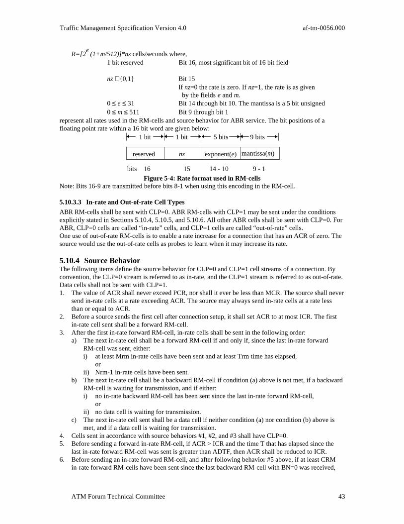
Traffic Management Specification Version 4.0 af-tm-0056.000
ATM Forum Technical Committee 43
R=[2e (1+m/512)]*nz cells/seconds where,
1 bit reserved Bit 16, most significant bit of 16 bit field
nz ∈{0,1} Bit 15 If nz=0 the rate is zero. If nz=1, the rate is as given by the fields e and m.
0 ≤ e ≤ 31 Bit 14 through bit 10. The mantissa is a 5 bit unsigned0 ≤ m ≤ 511 Bit 9 through bit 1
represent all rates used in the RM-cells and source behavior for ABR service. The bit positions of afloating point rate within a 16 bit word are given below:
mantissa(m)
1 bit 5 bits 9 bits1 bit
nz exponent(e)reserved
bits 16 15 14 - 10 9 - 1
Figure 5-4: Rate format used in RM-cellsNote: Bits 16-9 are transmitted before bits 8-1 when using this encoding in the RM-cell.
5.10.3.3 In-rate and Out-of-rate Cell Types
ABR RM-cells shall be sent with CLP=0. ABR RM-cells with CLP=1 may be sent under the conditionsexplicitly stated in Sections 5.10.4, 5.10.5, and 5.10.6. All other ABR cells shall be sent with CLP=0. ForABR, CLP=0 cells are called “in-rate” cells, and CLP=1 cells are called “out-of-rate” cells.One use of out-of-rate RM-cells is to enable a rate increase for a connection that has an ACR of zero. Thesource would use the out-of-rate cells as probes to learn when it may increase its rate.
5.10.4 Source BehaviorThe following items define the source behavior for CLP=0 and CLP=1 cell streams of a connection. Byconvention, the CLP=0 stream is referred to as in-rate, and the CLP=1 stream is referred to as out-of-rate.Data cells shall not be sent with CLP=1.1. The value of ACR shall never exceed PCR, nor shall it ever be less than MCR. The source shall never
send in-rate cells at a rate exceeding ACR. The source may always send in-rate cells at a rate lessthan or equal to ACR.
2. Before a source sends the first cell after connection setup, it shall set ACR to at most ICR. The firstin-rate cell sent shall be a forward RM-cell.
3. After the first in-rate forward RM-cell, in-rate cells shall be sent in the following order:a) The next in-rate cell shall be a forward RM-cell if and only if, since the last in-rate forward
RM-cell was sent, either:i) at least Mrm in-rate cells have been sent and at least Trm time has elapsed, orii) Nrm-1 in-rate cells have been sent.
b) The next in-rate cell shall be a backward RM-cell if condition (a) above is not met, if a backwardRM-cell is waiting for transmission, and if either:i) no in-rate backward RM-cell has been sent since the last in-rate forward RM-cell, orii) no data cell is waiting for transmission.
c) The next in-rate cell sent shall be a data cell if neither condition (a) nor condition (b) above ismet, and if a data cell is waiting for transmission.
4. Cells sent in accordance with source behaviors #1, #2, and #3 shall have CLP=0.5. Before sending a forward in-rate RM-cell, if ACR > ICR and the time T that has elapsed since the
last in-rate forward RM-cell was sent is greater than ADTF, then ACR shall be reduced to ICR.6. Before sending an in-rate forward RM-cell, and after following behavior #5 above, if at least CRM
in-rate forward RM-cells have been sent since the last backward RM-cell with BN=0 was received,
af-tm-0056.000 Traffic Management Specification Version 4.0
ATM Forum Technical Committee44
then ACR shall be reduced by at least ACR*CDF, unless that reduction would result in a rate belowMCR, in which case ACR shall be set to MCR.
7. After following behaviors #5 and #6 above, the ACR value shall be placed in the CCR field of theoutgoing forward RM-cell, but only in-rate cells sent after the outgoing forward RM-cell need tofollow the new rate.
8. When a backward RM-cell (in-rate or out-of-rate) is received with CI=1, then ACR shall be reducedby at least ACR*RDF, unless that reduction would result in a rate below MCR, in which case ACRshall be set to MCR. If the backward RM-cell has both CI=0 and NI=0, then the ACR may beincreased by no more than RIF*PCR, to a rate not greater than PCR. If the backward RM-cell hasNI=1, the ACR shall not be increased.
9. When a backward RM-cell (in-rate or out-of-rate) is received, and after ACR is adjusted according tosource behavior #8, ACR is set to at most the minimum of ACR as computed in source behavior #8,and the ER field, but no lower than MCR.
10. When generating a forward RM-cell, the source shall assign values to the various RM-cell fields asspecified for source-generated cells in Table 5-4.
11. Forward RM-cells may be sent out-of-rate (i.e., not conforming to the current ACR). Out-of-rateforward RM-cells shall not be sent at a rate greater than TCR.
12. A source shall reset EFCI on every data cell it sends.13. The source may implement a use-it-or-lose it policy to reduce its ACR to a value which approximates
the actual cell transmission rate. Use-it-or-lose-it policies are discussed in Appendix I.8.Notes:
1. In-rate forward and backward RM-cells are included in the source rate allocated to a connection.2. The source is responsible for handling local congestion within its scheduler in a fair manner. This
congestion occurs when the sum of the rates to be scheduled exceeds the output rate of thescheduler. The method for handling local congestion is implementation specific.
5.10.5 Destination BehaviorThe following items define the destination behavior for CLP=0 and CLP=1 cell streams of a connection.By convention, the CLP=0 stream is referred to as in-rate, and the CLP=1 stream is referred to asout-of-rate.1. When a data cell is received, its EFCI indicator is saved as the EFCI state of the connection.2. On receiving a forward RM-cell, the destination shall turn around the cell to return to the source. The
DIR bit in the RM-cell shall be changed from “forward” to “backward”, BN shall be set to zero, andCCR, MCR, ER, CI, and NI fields in the RM-cell shall be unchanged except:a) If the saved EFCI state is set, then the destination shall set CI=1 in the RM-cell, and the saved
EFCI state shall be reset. It is preferred that this step is performed as close to the transmissiontime as possible;
b) The destination (having internal congestion) may reduce ER to whatever rate it can supportand/or set CI=1 or NI=1. A destination shall either set the QL and SN fields to zero, preservethese fields, or set them in accordance with ITU-T Recommendation I.371-draft.
The octets defined in Table 5-4 as reserved may be set to 6A (hexadecimal) or left unchanged.The bits defined as reserved in Table 5-4 for octet 7 may be set to zero or left unchanged. Theremaining fields shall be set in accordance with Section 5.10.3.1 (Note that this does not precludelooping fields back from the received RM-cell).
3. If a forward RM-cell is received by the destination while another turned-around RM-cell (on the sameconnection) is scheduled for in-rate transmission:a) It is recommended that the contents of the old cell are overwritten by the contents of the new cell;b) It is recommended that the old cell (after possibly having been over-written) shall be sent
out-of-rate; alternatively the old cell may be discarded or remain scheduled for in-ratetransmission;
c) It is required that the new cell be scheduled for in-rate transmission.4. Regardless of the alternatives chosen in destination behavior #3 above, the contents of an older cell
shall not be transmitted after the contents of a newer cell have been transmitted.

Traffic Management Specification Version 4.0 af-tm-0056.000
ATM Forum Technical Committee 45
5. A destination may generate a backward RM-cell without having received a forward RM-cell. The rateof these backward RM-cells (including both in-rate and out-of-rate) shall be limited to 10cells/second, per connection. When a destination generates an RM-cell it shall set either CI=1 orNI=1, shall set BN=1, and shall set the direction to backward. The destination shall assign values tothe various RM-cell fields as specified for destination generated cells in Table 5-4.
6. When a forward RM-cell with CLP=1 is turned around it may be sent in-rate (with CLP=0) orout-of-rate (with CLP=1).
Notes:1. “Turn around” designates a destination process of transmitting a backward RM-cell in response to
having received a forward RM-cell.2. It is recommended to turn around as many RM-cells as possible to minimize turn-around delay,
first by using in-rate opportunities and then by using out-of-rate opportunities as available. Issuesregarding turning RM-cells around are discussed in Appendix I.7.
5.10.6 Switch BehaviorThe following items define the switch behavior for CLP=0 and CLP=1 cell streams of a connection. Byconvention, the CLP=0 stream is referred to as in-rate, and the CLP=1 stream is referred to as out-of-rate.Data cells shall not be sent with CLP=1.1. A switch shall implement at least one of the following methods to control congestion at queuing
points:a) EFCI marking: The switch may set the EFCI state in the data cell headers;b) Relative Rate Marking: The switch may set CI=1 or NI=1 in forward and/or backward RM-cells;c) Explicit Rate Marking: The switch may reduce the ER field of forward and/or backward
RM-cells (Explicit Rate Marking) ;d) VS/VD Control: The switch may segment the ABR control loop using a virtual source and
destination.2. A switch may generate a backward RM-cell. The rate of these backward RM-cells (including both
in-rate and out-of-rate) shall be limited to 10 cells/second, per connection. When a switch generatesan RM-cell it shall set either CI=1 or NI=1, shall set BN=1, and shall set the direction to backward.The switch shall assign values to the various RM-cell fields as specified for switch-generated cells inTable 5-4.
3. RM-cells may be transmitted out of sequence with respect to data cells. Sequence integrity within theRM-cell stream must be maintained.
4. For RM-cells that transit a switch (i.e., are received and then forwarded), the values of the variousfields before the CRC-10 shall be unchanged except:a) CI, NI, and ER may be modified as noted in #1 aboveb) RA, QL, and SN may be set in accordance with ITU-T Recommendation I.371-draftc) MCR may be corrected to the connection’s MCR if the incoming MCR value is incorrect.
5. The switch may implement a use-it-or-lose-it policy to reduce an ACR to a value which approximatesthe actual cell transmission rate from the source. Use-it-or-lose-it policies are discussed in AppendixI.8.
Notes:1. A switch queuing point is a point of resource contention where cells may be potentially delayed or
lost. A switch may contain multiple queuing points.2. Some example switch mechanisms are presented in Appendix I.5.3. The implications of combinations of the above methods is beyond the scope of this specification.
5.10.7 Virtual Source and Virtual Destination BehaviorVS/VD behavior divides an ABR connection into two or more seperately controlled ABR segments. Thecoupling between adjacent ABR control segments associated with an ABR connection is implementationspecific. Figure 5-5 illustrates an ABR virtual connection which incorporates segmentation.
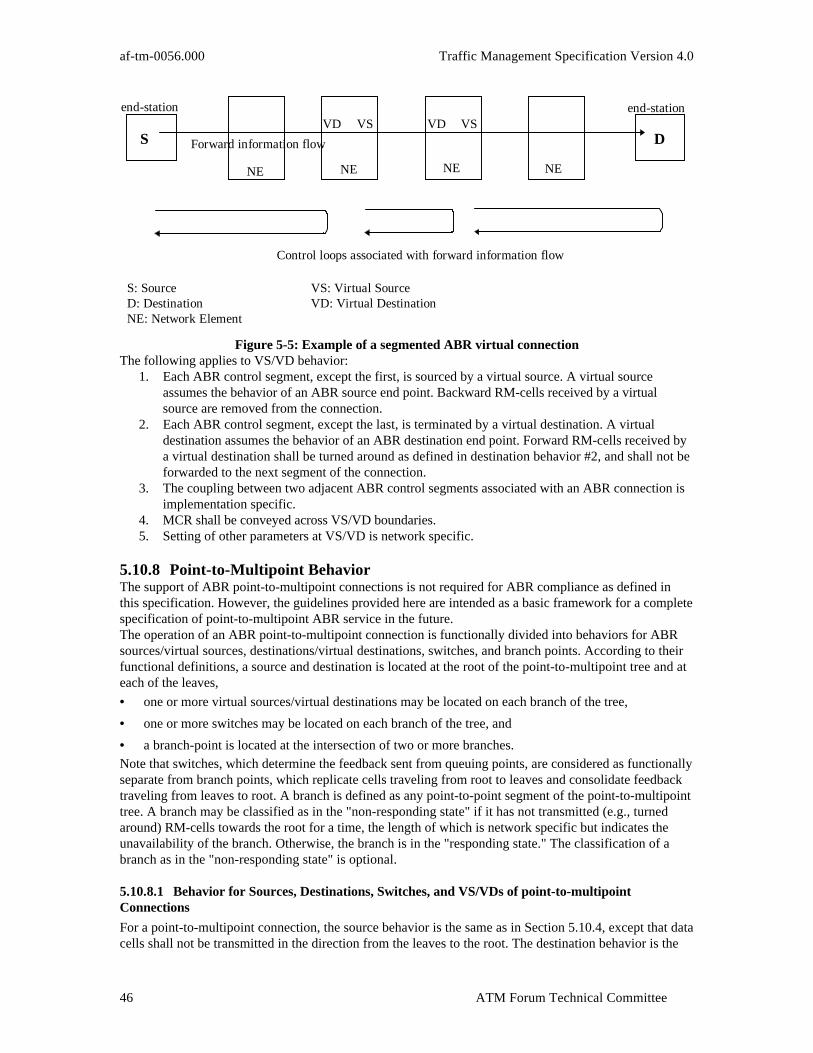
af-tm-0056.000 Traffic Management Specification Version 4.0
ATM Forum Technical Committee46
end-station end-station
NE
S DForward information flow
Control loops associated with forward information flow
S: Source VS: Virtual SourceD: Destination VD: Virtual DestinationNE: Network Element
NE NE NE
VD VSVS VD
Figure 5-5: Example of a segmented ABR virtual connectionThe following applies to VS/VD behavior:
1. Each ABR control segment, except the first, is sourced by a virtual source. A virtual sourceassumes the behavior of an ABR source end point. Backward RM-cells received by a virtualsource are removed from the connection.
2. Each ABR control segment, except the last, is terminated by a virtual destination. A virtualdestination assumes the behavior of an ABR destination end point. Forward RM-cells received bya virtual destination shall be turned around as defined in destination behavior #2, and shall not beforwarded to the next segment of the connection.
3. The coupling between two adjacent ABR control segments associated with an ABR connection isimplementation specific.
4. MCR shall be conveyed across VS/VD boundaries.5. Setting of other parameters at VS/VD is network specific.
5.10.8 Point-to-Multipoint BehaviorThe support of ABR point-to-multipoint connections is not required for ABR compliance as defined inthis specification. However, the guidelines provided here are intended as a basic framework for a completespecification of point-to-multipoint ABR service in the future.The operation of an ABR point-to-multipoint connection is functionally divided into behaviors for ABRsources/virtual sources, destinations/virtual destinations, switches, and branch points. According to theirfunctional definitions, a source and destination is located at the root of the point-to-multipoint tree and ateach of the leaves,
• one or more virtual sources/virtual destinations may be located on each branch of the tree,
• one or more switches may be located on each branch of the tree, and
• a branch-point is located at the intersection of two or more branches.Note that switches, which determine the feedback sent from queuing points, are considered as functionallyseparate from branch points, which replicate cells traveling from root to leaves and consolidate feedbacktraveling from leaves to root. A branch is defined as any point-to-point segment of the point-to-multipointtree. A branch may be classified as in the "non-responding state" if it has not transmitted (e.g., turnedaround) RM-cells towards the root for a time, the length of which is network specific but indicates theunavailability of the branch. Otherwise, the branch is in the "responding state." The classification of abranch as in the "non-responding state" is optional.
5.10.8.1 Behavior for Sources, Destinations, Switches, and VS/VDs of point-to-multipointConnections
For a point-to-multipoint connection, the source behavior is the same as in Section 5.10.4, except that datacells shall not be transmitted in the direction from the leaves to the root. The destination behavior is the

Traffic Management Specification Version 4.0 af-tm-0056.000
ATM Forum Technical Committee 47
same as in Section 5.10.5, the switch behavior the same as in Section 5.10.6, and the virtual source/virtualdestination behavior the same as in Section 5.10.7.
5.10.8.2 Behavior for Branch Points on Point-to-Multipoint Connections
1. An ABR branch point shall replicate each data cell and RM-cell received from the root onto eachbranch that leads to a leaf, whenever the branch is in the responding state. RM-cells may betransmitted onto the leaves out of sequence with respect to data cells, but the sequence integritywithin the RM-cell stream transmitted to each branch must be preserved.
2. An ABR branch point shall transmit forward and backward RM-cells towards the root. This maybe done by consolidating the information from forward and backward RM-cells received in theleaf-to-root direction from each branch in the responding state. However, a branch point isresponsible for assuring that the ABR flow transmitted to each branch (both towards the leavesand towards the root) conforms to the expected behavior for a point-to-point ABR flow, given thatthe ABR flows received by the branch point do. There are network elements which supporttraditional multicasting (i.e., cell duplication) but cannot consolidate RM-cells. Their role withinthe framework of point-to-multipoint ABR service requires further study.
Branch points may send fewer RM-cells to the root than they receive from the leaves of apoint-to-multipoint connection. The method of assigning values to the ER, CI, and NI fields isimplementation specific. When a branch point sets the BN bit, it also sets either CI or NI.
3. An ABR branch point may:• buffer data and generate ABR feedback from queuing points as defined by the switch
behavior in Section 5.10.6;• implement virtual sources and virtual destinations at one or more branches as defined in
Section 5.10.7.
5.10.9 Support for Virtual PathsThis section clarifies three distinct configurations with respect to ABR VPC support:1. Operation of ABR VCCs contained within a VPCABR VCCs within a VPC share its capacity, in the same way ABR connections share the capacity of aphysical link. The method used to divide this VPC capacity among these VCCs is implementationspecific.2. Operation of an ABR VPC carrying VCCsEach end-point of an ABR VPC shall comply with the ABR source and destination behavior. RM-cells forVPC operation shall have VCI=6 and PTI=110 (binary). VCI 6 shall not have other functions assigned toit. This coding is used to distinguish the RM-cells controlling the VPC from any RM-cells belonging tocontained ABR VCCs. Switches operating at the VP level on an ABR VPC shall only act on VPCRM-cells and shall ignore any VCC RM-cells within the VPC. On reception, all cells with VCI=6 may betreated as VP RM-cells, even when the coding of the PTI field is not 110.The method used by an ABR VPC end-point to allocate its dynamically changing capacity between theVCCs it contains is implementation specific. In particular, for an ABR VPC carrying ABR VCCs, themethod used to couple control for the VCCs to bandwidth availability at the VPC end-point isimplementation specific. Figure 5-6 illustrates an ABR VPC.

af-tm-0056.000 Traffic Management Specification Version 4.0
ATM Forum Technical Committee48
end-station end-station
VCC
VCC
S D
VPC control loops associated with forward information flow
VPC end-points
VC-Sw VC-SwVP-Sw VP-Sw
Figure 5-6: Example of an ABR VPC3. Allocation of bandwidth between ABR VPCs and ABR VCCs on the same linkIn the case where link capacity must be shared between both ABR-VPCs and ABR-VCCs the method usedto allocate the bandwidth is implementation specific.
Traffic Management Specification Version 4.0 af-tm-0056.000
ATM Forum Technical Committee 49
6. References1. ITU-T Recommendation G.822, “Controlled slip rate objectives on an international digital
connection,” ITU-T Study Group 13, Geneva, 1990.2. ITU-T Recommendation I.150, “B-ISDN asynchronous transfer mode functional characteristics,”
ITU-T Study Group 13, Geneva, 1995.3. ITU-T Recommendation I.211, “B-ISDN service aspects,” ITU-T Study Group 13, Geneva, 1993.4. ITU-T Recommendation I.311, “B-ISDN general network aspects,” ITU-T Study Group 13,
Geneva, 1993.5. ITU-T Recommendation I.356, “B-ISDN ATM layer cell transfer performance,” ITU-T Study
Group 13, Geneva, 1995.6. ITU-T Recommendation I.361, “B-ISDN ATM layer specification,” ITU-T Study Group 13,
Geneva, 1996.7. I.371-draft, ITU-T Recommendation I.371 (draft), “Traffic control and congestion control in
B-ISDN,” ITU-T Study Group 13, Geneva, April 1996.8. ITU-T Recommendation I.610, “B-ISDN operation and maintenance principles and functions,”
ITU-T Study Group 13, Geneva, 1994.9. ITU-T Recommendation Q.2931, “Broadband integrated services digital network (B-ISDN) -
Digital subscriber signalling No. 2 (DSS 2) - User network interface layer 3 specification for basiccall/connection control,” ITU Study Group 11, Geneva, expected in 1996.
10. The ATM Forum, Interim Local Management Interface (ILMI) Specification (Draft), February1996.
11. The ATM Forum, User-Network Interface (UNI) Signalling Specification (Draft), February 1996.12. The ATM Forum, Private Network-Node Interface (PNNI) Signalling Specfication (Draft),
February 1996.

af-tm-0056.000 Traffic Management Specification Version 4.0
ATM Forum Technical Committee50
Normative Annex A: Glossary of Acronyms and TermsAAL ATM Adaptation LayerABR Available Bit RateABT ATM Block TransferACR Allowed Cell RateRIF Rate Increase FactorATM Asynchronous Transfer ModeBICI Broadband Inter-Carrier InterfaceB-ISDN Broadband ISDNBECN Backward Explicit Congestion NotificationBT Burst ToleranceBN BECN (bit in RM-cell)BRM Backward RM-cellCAC Connection Admission ControlCAPC Congestion Avoidance with Proportional ControlCBR Constant Bit RateCCR Current Cell RateCDF See Table 5-2CDV Cell Delay VariationCDVT CDV ToleranceCER Cell Error RatioCI Congestion Indication (bit in RM-cell)CLP Cell Loss PriorityCLR Cell Loss RatioCMR Cell Misinsertion RateCPE Customer Premises EquipmentCRC Cyclic Redundancy CheckCRF Cell Relay Function or Connection Related FunctionsCRM See Table 5-2CTD Cell Transfer DelayDES Destination End-SystemRM-cell Resource Management CellDGCRA Dynamic GCRADIR Direction (bit in RM-cell)EFCI Explicit Forward Congestion IndicationEPRCA Enhanced Proportional Rate Control AlgorithmER Explicit RateFECN Forward Explicit Congestion NotificationFIFO First In First Out queue service disciplineFRM Forward RM-cellFRS Frame Relay ServiceGCRA Generic Cell Rate AlgorithmGFC Generic Flow ControlIBT Intrinsic Burst ToleranceICR Initial Cell RateIE Information ElementILMI Interim Local Management InterfaceIP Internet ProtocolISDN Integrated Services Digital NetworkITT Ideal Transmission TimeITU International Telecommunications UnionLAN Local Area NetworkLANE LAN Emulation
Traffic Management Specification Version 4.0 af-tm-0056.000
ATM Forum Technical Committee 51
LCT Last Conformance TimeMACR Mean Allowed Cell RatemaxCTD Maximum Cell Transfer DelayMrm Minimum number of cells between RM-cell generationMBS Maximum Burst SizeMCR Minimum Cell RateMCRmin Minimum acceptable MCRMIB Management Information BaseMP Measurement PointMultiprotocol Referring to internetworking layer protocols (including e.g.,
IP, DECNet, IPX, SNA, Apple Talk)NFS Network File ServiceNI No Increase (bit in RM-cell)NMS Network Management SystemNNI Network to node interfaceNPC Network Parameter ControlNrm Maximum number of cells between RM-cell generationnrt-VBR Non-Real-Time VBRNT Network TerminationOAM Operations, Administration and MaintenancePCR Peak Cell RatePDU Protocol Data Unitpeak-to-peak CDV Peak-to-peak Cell Delay VariationPHY Physical LayerPNNI Private Network Node InterfacePTI Payload Type IndicatorPVC Permanent Virtual ConnectionQL Queue Length (field in RM-cell)QoS Quality of ServiceRA Resource Allocation (bit in RM-cell)RDF Rate Decrease FactorRDFF RDF FactorRM-cell Resource Management Cellrt-VBR Real-Time VBRFRTT Fixed Round-trip TimeSAA WG ATM Forum Services Aspects and Applications Working GroupSAP Service Access PointSCR Sustainable Cell RateSDU Service Data UnitSECBR Severely Errored Cell Block RatioSES Source End-SystemSIG WGATM Forum Signaling Working GroupSMDS Switched Multi-megabit Data ServiceSN Sequence Number (field in RM-cell)STD Source Traffic DescriptorSVC Switched Virtual ConnectionSW SwitchTAT Theoretical Arrival TimeTCP Transmission Control ProtocolTCR See Table 5-2TM Traffic ManagementADTF See Table 5-2Trm See Table 5-2UBR Unspecified Bit Rate

af-tm-0056.000 Traffic Management Specification Version 4.0
ATM Forum Technical Committee52
UDP User Datagram ProtocolUNI User Network InterfaceUPC Usage Parameter ControlVBR Variable Bit RateVC Virtual ConnectionVCC Virtual Channel ConnectionVCI Virtual Channel IdentifierVC-SW Virtual Channel Switching FunctionVPC Virtual Path ConnectionVPI Virtual Path IdentifierVP-SW Virtual Path Switching FunctionVS/VD Virtual Source/Virtual DestinationWAN Wide Area Networkτ1, τ2, τ3 See Section 4.5.5

Traffic Management Specification Version 4.0 af-tm-0056.000
ATM Forum Technical Committee 53
Normative Annex B: Measurement & Analysis of QoS Parameters
B.1 Measurement Methods
In this section at least one method to measure each QoS parameter in either an in-service orout-of-service mode is defined. Other alternative measurement methods or estimates are possible.
Either in-service or out-of-service methods may be used to estimate values for the ATM cell transferperformance parameters. In-service methods are based on performance monitoring OAM flows whichmay be introduced into the user cell stream at any VPC or VCC termination or connecting point, and maythen be copied or extracted at any similar point downstream. Details of OAM functions supportingperformance measurement are provided in ITU-T Recommendation I.610. Out-of-service methods consistof establishing a test connection at an appropriate measurement point, introducing a cell stream of knowncontent and timing at that point, and then observing the cell stream at a remote measurement point.
B.1.1 Cell Error ParametersB.1.1.1 Cell Error RatioA method using test stream for out-of-service measurement is described in Annex C of ITU-TRecommendation I.356. It basically involves transferring a known data stream into the network at thesource measurement point and comparing the received data stream with the known data stream at thedestination measurement point.
An in-service measurement is desirable. Annex C of ITU-T Recommendation I.356 suggests a BIP-16indicator to estimate the cell error ratio over a block of N cells.
B.1.1.2 Severely Errored Cell Block RatioSeverely errored cell block ratio can be estimated in service for a set of S consecutive or non consecutivecell blocks by computing the number of lost cell or mis-inserted cell outcomes in each cell block,identifying cell blocks with more than M lost cell or mis-inserted cell outcomes as severely errored cellblocks, and dividing the total number of such severely errored cell blocks by S. This in-servicemeasurement method will undercount severely errored cell blocks to some degree, since it does notinclude delivered errored cells in the estimation of M. A more accurate estimate of severely errored cellblock ratio can be obtained by comparing transmitted and received data in an out-of-servicemeasurement.
B.1.2 Cell Loss RatioA method using OAM cells for in-service measurement is described in Annex C of ITU-TRecommendation I.356. The transmitter inserts OAM cells into a transmitted user information cell streamat suitable intervals. Each OAM cell contains a count of the number of user information cells transmittedsince the last OAM cell. The receiver keeps a running count of the number of user information cellstransmitted (Nt) and received (Nr). Cell loss ratio can then be calculated as (Nt - Nr) / Nt if Nt - Nr ispositive. This method will under-count cell loss events if misinsertion occurs during the measurementperiod. It will over count loss if SECB events are not excluded.
B.1.3 Cell Misinsertion RateA method using OAM cells for in-service measurement is described in Annex C of ITU-TRecommendation I.356. Counts, Nr and Nt, of the received and transmitted cells are obtained during ameasurement period Tm (excluding cells in Severely Errored Cell Blocks), and the Cell MisinsertionRate (CMR) is calculated by dividing the positive difference (Nr-Nt) by Tm. Cell misinsertion events willbe under-counted if cell loss events occur.
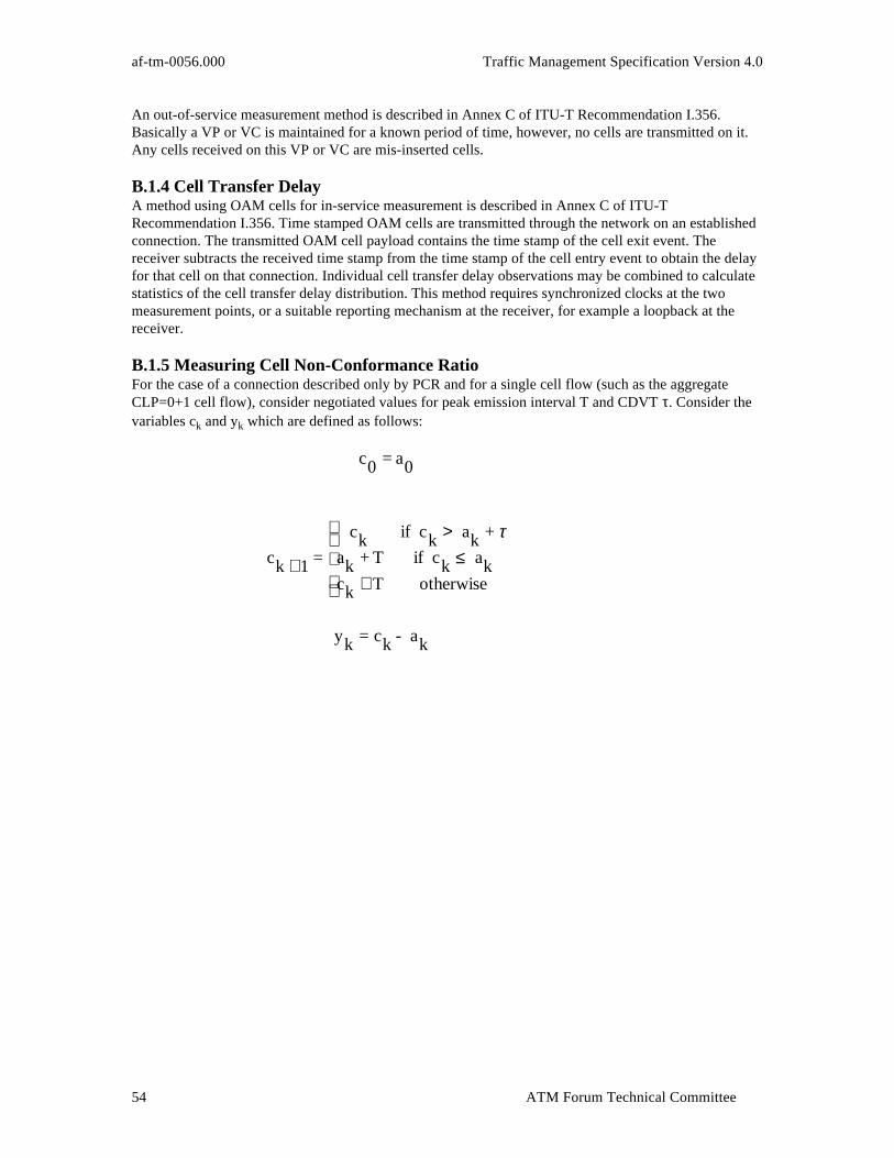
af-tm-0056.000 Traffic Management Specification Version 4.0
ATM Forum Technical Committee54
An out-of-service measurement method is described in Annex C of ITU-T Recommendation I.356.Basically a VP or VC is maintained for a known period of time, however, no cells are transmitted on it.Any cells received on this VP or VC are mis-inserted cells.
B.1.4 Cell Transfer DelayA method using OAM cells for in-service measurement is described in Annex C of ITU-TRecommendation I.356. Time stamped OAM cells are transmitted through the network on an establishedconnection. The transmitted OAM cell payload contains the time stamp of the cell exit event. Thereceiver subtracts the received time stamp from the time stamp of the cell entry event to obtain the delayfor that cell on that connection. Individual cell transfer delay observations may be combined to calculatestatistics of the cell transfer delay distribution. This method requires synchronized clocks at the twomeasurement points, or a suitable reporting mechanism at the receiver, for example a loopback at thereceiver.
B.1.5 Measuring Cell Non-Conformance RatioFor the case of a connection described only by PCR and for a single cell flow (such as the aggregateCLP=0+1 cell flow), consider negotiated values for peak emission interval T and CDVT τ. Consider thevariables ck and yk which are defined as follows:
c0 = a0
ck +1 =
ck if ck > ak + τak + T if ck ≤ akck + T otherwise
yk = ck - ak
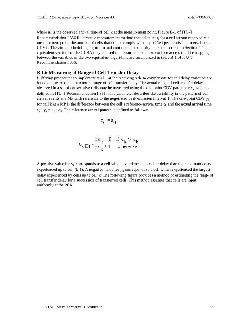
Traffic Management Specification Version 4.0 af-tm-0056.000
ATM Forum Technical Committee 55
where ak is the observed arrival time of cell k at the measurement point. Figure B-1 of ITU-TRecommendation I.356 illustrates a measurement method that calculates, for a cell stream received at ameasurement point, the number of cells that do not comply with a specified peak emission interval and aCDVT. The virtual scheduling algorithm and continuous-state leaky bucket described in Section 4.4.2 asequivalent versions of the GCRA may be used to measure the cell non-conformance ratio. The mappingbetween the variables of the two equivalent algorithms are summarized in table B-1 of ITU-TRecommendation I.356.
B.1.6 Measuring of Range of Cell Transfer DelayBuffering procedures to implement AAL1 at the receiving side to compensate for cell delay variation arebased on the expected maximum range of cell transfer delay. The actual range of cell transfer delayobserved in a set of consecutive cells may be measured using the one-point CDV parameter yk which isdefined in ITU-T Recommendation I.356. This parameter describes the variability in the pattern of cellarrival events at a MP with reference to the negotiated peak emission interval T. The one-point CDV yk
for cell k at a MP is the difference between the cell’s reference arrival time ck and the actual arrival timeak : yk = ck - ak. The reference arrival pattern is defined as follows:
c0 = a0
ck +1=
ak
+ T if ck
≤ ak
ck
+ T otherwise
A positive value for yk corresponds to a cell which experienced a smaller delay than the maximum delayexperienced up to cell (k-1). A negative value for yk corresponds to a cell which experienced the largestdelay experienced by cells up to cell k. The following figure provides a method of estimating the range ofcell transfer delay for a succession of transferred cells. This method assumes that cells are inputuniformly at the PCR.

af-tm-0056.000 Traffic Management Specification Version 4.0
ATM Forum Technical Committee56
START
UPON FIRST CELL ARRIVAL
c1 = c0 + T, k = 0 Q0 = 0
UPON SUBSEQUENT CELL ARRIVAL
k = k + 1 yk = ck - ak
NO Yes (late cell)
Qk = max(Q k-1, yk)
ck+1 = yk + ak + T
NO
YES
END
k = k0
yk < 0
Variables: ck = reference arrival time for cell k at MP ak = actual arrival time for cell k at MP yk = 1-point CDV Qk = observed range of cell transfer delay in the set of cells up to cell k T = the negotiated peak emission interval
Qk = Qk-1 - yk yk = 0
If yk < 0 after cell arrival,
then ck+1 = yk + ak + T = ak + T If yk >= 0 after cell arrival, then ck+1 = yk + ak + T = ck + T
Figure B-1: Estimation of the range of two-point CDV from one-point CDV for connectionsproviding CBR service
B.2 Factors Affecting ATM QoS Parameters
This section provides a list of items to be considered in setting QoS parameter objectives dependent uponcharacteristics that can exist in either private or public networks, or combinations thereof as indicated inFigure 3-1. The objective is to have maximum commonality between public and private networks.

Traffic Management Specification Version 4.0 af-tm-0056.000
ATM Forum Technical Committee 57
This section summarizes the set of ATM cell transfer performance parameters defined in ITU-TRecommendation I.356. The cell events and cell transfer outcomes defined in Section 3.4 of thisdocument are used in defining these performance parameters. This set of ATM cell transfer performanceparameters correspond to the generic criteria of the assessment (shown in parentheses) of the QoS (seeITU-T Recommendation I.356), as follows:
Cell Error Ratio (Accuracy)Severely-Errored Cell Block Ratio (Accuracy)Cell Loss Ratio (Dependability)Cell Misinsertion Rate (Accuracy)Cell Transfer Delay (mean and max) (Speed)Cell Delay Variation (Speed)
B.2.1 Sources of QoS DegradationB.2.1.1 Propagation DelayThis is the delay caused by the Physical media which transports the bits comprising ATM cells betweenUNIs and between ATM switches. This equally impacts public and private networks, dependent upondistance only. Private networks may extend from the desktop to international distances, while publicnetworks generally extend from metropolitan to international distances.
B.2.1.2 Media Error StatisticsThis is the random and/or bursty bit errors that are introduced on the physical media.
B.2.1.3 Switch ArchitectureThe overall architecture of the switch can have significant impacts on performance. Some aspects toconsider are the switch matrix design, buffering strategy and the switch characteristics under load. Theswitch matrix design may range from blocking to non-blocking. The strategy in which the buffer capacityof a port supporting the UNI on an ATM switch is managed may differ significantly across switcharchitectures. The buffer capacity may be dedicated to a single port, it may be shared between multipleports, or some combination thereof. The management of this buffer capacity may range from a singleFirst In First Out (FIFO) queue to a more complex, multiple queue system with an algorithmicallydefined service rule, that could operate based upon priorities. The switch matrix design may introducesome loss under heavy load conditions.
B.2.1.4 Buffer CapacityThis is the actual capacity of the buffer in units of cells at a port supporting the UNI, within an ATMmatrix, or in other elements of an ATM switch.
B.2.1.5 Traffic LoadThis is the load offered by the set of ATM connections on the same route as the connection underconsideration.
B.2.1.6 Number of Nodes in TandemThis is the number of ATM switching nodes that a particular connection traverses.
B.2.1.7 Resource AllocationThis is the capacity allocated to a connection or to a set of connections, such as the set of connections ona given route that are assigned a given QoS class.
B.2.1.8 FailuresThese are events that impact availability, such as port failures, switch failures or link failures. Switchovers between failing equipment or circuits may introduce cell loss.
B.2.2 Impact of QoS Degradation on Performance Parameters

af-tm-0056.000 Traffic Management Specification Version 4.0
ATM Forum Technical Committee58
In this section the impact of each of the sources of QoS degradation on each of the PerformanceParameters of Section 3 is analyzed in a subjective manner as a guideline for what degradations andfactors should be considered in determining a value for the performance parameter. Note that the scope ofQoS is from UNI to UNI as defined in Section 3.
B.2.2.1 Cell Error Ratio and Severely Errored Cell Block RatioThe cell error ratio is expected to be primarily influenced by the error characteristics of the physicalmedia. The severely errored cell block ratio is also expected to be influenced by the error characteristicsof the physical media and by buffer overflows.
Error characteristics may also be a function of the physical distance and the characteristics of the media.Operational effects such as transmission protection switching and rearrangements may also introduceerrors.
B.2.2.2 Cell Loss RatioThe Cell Loss Ratio is expected to be influenced by errors in the cell header, buffer overflows, and thenon-ideal UPC actions. Loss due to the noncompliance of a connection should be excluded when networkcaused losses are to be estimated.
Errors detected in the cell header at the physical layer affect the Cell Loss Ratio. Cells may also be lostdue to failures, protection switching and path reconfiguration.
Different buffering and resource allocation strategies may cause buffer overflow characteristics to differ.
Queuing implementations in some networks may not provide large buffers, or multiple levels of prioritysince transmission capacity and resources will be relatively inexpensive. Therefore, cell loss ratios maybe higher than in a more complicated network. A lost higher level PDU can be detected in a much shorterperiod of time in a local area than in a wide area, so that higher layer protocol re-transmissions can beinitiated sooner and thus will have less impact on higher layer application throughput in local areanetworks than in wide area networks.
Buffering strategies in wider area or lower speed networks may be much more complex than that in local,high speed networks. Transmission capacity resources will be relatively more expensive. Multiple levelsof delay priority, and possibly relatively large buffers, may be implemented. Within a delay-priority levelthe CLP bit may also be used to indicate two levels of loss priority. High delay-priority levels will likelyhave low loss ratios, while lower delay-priority levels may have higher loss ratios during periods ofbuffer congestion.
The number of nodes in tandem may also impact the CLR due to the possibility of overflow in any bufferbetween the source and destination.
Path reconfiguration from a long to a shorter route is also a possible cause of cell losses, due to thedifference in propagation delay. Path reconfiguration is a process at the physical layer used when a pathneeds to be taken out-of-service to perform maintenance. A possible cause is as follows, after a new pathis set up, traffic is transmitted on both paths until it can be verified (at the physical layer) that the newpath is operating properly. At this time, a physical layer switch is made at the receiving end of the path.This process is intended to minimize the interruption to the customer service.
B.2.2.3 Cell Misinsertion RateThe cell misinsertion rate is expected to be primarily influenced by undetected/miscorrected errors in thecell header, which in turn is primarily influenced by the transmission error rate. The likelihood that anundetected/miscorrected cell header error maps into a valid VPI/VCI is also dependent upon the numberof VPI/VCI values that are assigned and being actively used.
Traffic Management Specification Version 4.0 af-tm-0056.000
ATM Forum Technical Committee 59
The cell error ratio will be dependent upon the factors defined in Section B.2.2.1. The number of activeATM sources is likely to be less for a private network than for a public network. This should decrease thelikelihood of an undetected/miscorrected cell header error resulting in a cell which is incorrectlymis-inserted into some other VPI/VCI cell stream at the destination UNI.
The number of sources which can be mapped into another cell address will likely be much larger in apublic network than in a private network.
B.2.2.4 Cell Transfer DelayCell transfer delay is affected by propagation, queuing, routing and switching delays, which are likely todiffer for local and wide-area networks.
B.2.2.5 Cell Delay Variation (CDV)Specification of CDV is essential for Constant Bit Rate (CBR) connection performance. Its value isnecessary for the dimensioning of the elastic buffer required at the terminating end of the connection forabsorbing the accumulated CDV, regardless of whether the network is public or private.
A common, maximum cell delay variation value for private, public and hybrid private/public networks isessential. As an implementation guideline the receiver CDVT should be designed to handle the casewhere a connection traverses three networks, each having three switches in tandem.

af-tm-0056.000 Traffic Management Specification Version 4.0
ATM Forum Technical Committee60
B.2.2.6 Degradation of QoS Parameters SummaryTable B-1 summarizes how various sources of degradation can impact the QoS parameters.
Attribute CER SECBR CLR CMR CTD CDVPropagation Delay XMedia Error Statistics X X X XSwitch Architecture X X XBuffer Capacity X X X XNumber of Tandem Nodes X X X X X XTraffic Load X X X XFailures X X XResource Allocation X X X
Table B-1: Degradation of QoS ParametersCER = Cell Error Ratio
SECBR = Severely Errored Cell Block Ratio
CLR = Cell Loss Ratio
CMR = Cell Misinsertion Rate
CTD = Cell Transfer Delay
CDV = Cell Delay Variation
B.3 QoS Classes
A user of an ATM connection (a VCC or a VPC) is provided with one of a number of QoS classessupported by the network. It should be noted that a VPC may carry VC links of various QoS classes. TheQoS of the VPC must meet the most demanding QoS of the VC links carried as defined in ITU-TRecommendation I.150. The QoS class associated with a given ATM connection is indicated to thenetwork at the time of connection establishment and will not change for the duration of that ATMconnection.
A Quality of Service (QoS) class can have specified performance parameters (Specified QoS class) or nospecified performance parameters (Unspecified QoS class). QoS classes are inherently associated with aconnection. A Specified QoS class specifies a set of performance parameters and the objective values foreach performance parameter identified. Examples of performance parameters that could be in a QoS classare: cell transfer delay, cell delay variation, and cell loss ratio, as currently mentioned in ITU-Trecommendations I.371-draft and Q.2931.
Within a specified QoS class, at most two cell loss ratio parameters may be specified. If a specified QoSclass does contain two cell loss ratio parameters, then one parameter is for all CLP=0 cells and the otherparameter is for all CLP=1 cells of the ATM connection. As presently foreseen, other performanceparameters besides the cell loss ratio would apply to the aggregate cell flow of the ATM connection. AQoS class could contain, for example, the following performance parameters: maximum cell transferdelay, a cell delay variation, and a cell loss ratio on CLP=0 cells.
The network may support several QoS classes. At most one (1) unspecified QoS class can be supported.The performance provided by the network should meet (or exceed) performance parameter objectives ofthe QoS class requested by the ATM end-point. ATM connections shall indicate the requested QoS by aparticular class specification. For PVCs the management system can be used by the network to report theQoS classes across the UNI. For SVCs, a signaling protocol’s information elements can be used tocommunicate the QoS class across the UNI.
B.3.1 Specified QoS Classes

Traffic Management Specification Version 4.0 af-tm-0056.000
ATM Forum Technical Committee 61
A Specified QoS class provides a quality of service to an ATM connection in terms of a subset of theATM performance parameters defined in Section B.2. For each Specified QoS class, there is onespecified objective value for each performance parameter identified as defined in Section B.2. Initially,each network should define objective values for a subset of the ATM performance parameters of SectionB.2 for at least one of the following Service Classes from ITU-T Recommendation I.362 in a referenceconfiguration that may depend on propagation delay and other factors:
Service Class A: Circuit Emulation, Constant Bit Rate Video
Service Class B: Variable Bit Rate Audio and Video
Service Class C: Connection-Oriented Data Transfer
Service Class D: Connectionless Data Transfer
In the future, more “QoS Classes” may be defined for a given “Service Class” described above. Thefollowing Specified QoS Classes are currently defined:
Specified QoS Class 1: support a QoS that will meet Service Class A performance requirements
Specified QoS Class 2: support a QoS that will meet Service Class B performance requirements
Specified QoS Class 3: support a QoS that will meet Service Class C performance requirements
Specified QoS Class 4: support a QoS that will meet Service Class D performance requirements
Specified QoS Class 1 should yield performance comparable to current digital private line performance.
Specified QoS Class 2 is intended for packetized video and audio in teleconferencing and multi-mediaapplications.
Specified QoS Class 3 is intended for interoperation of connection oriented protocols, such as FrameRelay.
Specified QoS Class 4 is intended for interoperation of connectionless protocols, such as IP, or SMDS.
A network may provide the same performance for all or a subset of Specified QoS Classes, subject to theconstraint that the requirements of the most stringent Service Class are met.
B.3.2 Unspecified QoS ClassIn the Unspecified QoS class, no objective is specified for the performance parameters. However, thenetwork may determine a set of internal objectives for the performance parameters. In fact, these internalperformance parameter objectives need not be constant during the duration of a call. Thus, for theUnspecified QoS class there is no explicitly specified QoS commitment on either the CLP=0 or theCLP=1 cell flow. Services using the Unspecified QoS class may have explicitly specified trafficparameters.
An example application of the Unspecified QoS class is the support of “best effort” service (i.e., UBR).For this type of service, the user selects the Best-Effort Capability, the Unspecified QoS class, and only thetraffic parameter for the PCR on CLP=0+1. This capability can be used to support users that are capableof regulating the traffic flow into the network and to adapt to time-variable available resources.The Unspecified QoS class is identified by the integer zero (0) in the ILMI MIB or a code point in asignaling message for the requested QoS class.

af-tm-0056.000 Traffic Management Specification Version 4.0
ATM Forum Technical Committee62
Normative Annex C: Traffic Contract Related Algorithms andProcedures
C.1 Equivalence of Virtual Scheduling and Continuous Leaky Bucket Algorithms
The virtual scheduling algorithm updates a Theoretical Arrival Time (TAT), which is the “nominal”arrival time of the cell assuming that the active source sends equally spaced cells. If the actual arrival timeof a cell is not “too” early relative to the TAT, in particular if the actual arrival time is after TAT - L, thenthe cell is conforming, otherwise the cell is non-conforming.Tracing the steps of the virtual scheduling algorithm in Figure C-1, at the arrival time of the first cellta(1), the theoretical arrival time TAT is initialized to the current time, ta(1). For subsequent cells, if the
arrival time of the kth cell, ta(k), is actually after the current value of the TAT then the cell is conforming
and TAT is updated to the current time ta(k), plus the increment I. If the arrival time of the kth cell isgreater than or equal to TAT - L but less than TAT (i.e., as expressed in Figure C-1, if TAT is less than orequal to ta(k) + L), then again the cell is conforming, and the TAT is increased by the increment I. Lastly,
if the arrival time of the kth cell is less than TAT-L (i.e., if TAT is greater than ta(k) + L), then the cell isnon-conforming and the TAT is unchanged.The continuous-state leaky bucket algorithm can be viewed as a finite-capacity bucket whose real-valuedcontent drains out at a continuous rate of 1 unit of content per time-unit and whose content is increased bythe increment I for each conforming cell. Equivalently, it can be viewed as the work load in afinite-capacity queue or as a real-valued counter. If, at a cell arrival, the content of the bucket is less thanor equal to the limit value, L, then the cell is conforming, otherwise the cell is non-conforming. Thecapacity of the bucket (the upper bound on the counter) is L + I.Tracing the steps of the continuous-state leaky bucket algorithm in Figure C-1 at the arrival time of thefirst cell ta(1), the content of bucket, X, is set to zero and the last conformance time (LCT) is set to ta(1).At the arrival time of the kth cell, ta(k), first the content of the bucket is provisionally updated to the value
X’, which equals the content of the bucket, X, after the arrival of the last conforming cell minus theamount the bucket has drained since that arrival, where the content of the bucket is constrained to benon-negative. Second, if X’ is less than or equal to the limit value L, then the cell is conforming, and thebucket content X is set to X’ plus the increment I for the current cell, and the last conformance time LCT,is set to the current time ta(k). If, on the other hand, X’ is greater than the limit value L, then the cell isnon-conforming and the values of X and LCT are not changed.
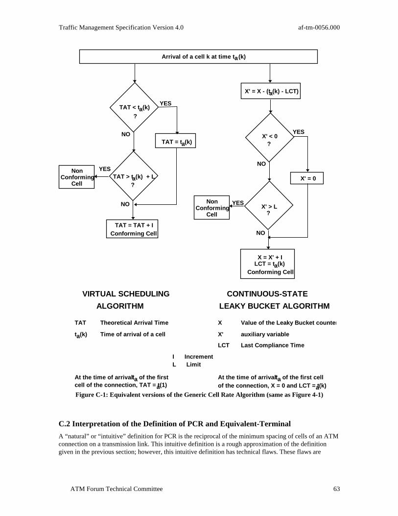
Traffic Management Specification Version 4.0 af-tm-0056.000
ATM Forum Technical Committee 63
Arrival of a cell k at time t a(k)
X' = 0
TAT = TAT + IConforming Cell
?
TAT < ta(k)
?
X' < 0?
?
X' = X - (ta(k) - LCT)
TAT = ta(k)
CONTINUOUS-STATE
LEAKY BUCKET ALGORITHM
VIRTUAL SCHEDULING
ALGORITHM
Theoretical Arrival TimeTAT
Time of arrival of a cellta(k)
Value of the Leaky Bucket counte rX
auxiliary variableX'
Last Compliance TimeLCT
At the time of arrival ta of the firstcell of the connection, TAT = t a(1)
At the time of arrival ta of the first cellof the connection, X = 0 and LCT = t a(k)
I IncrementL Limit
YES
NO
NO YES
NO
NO
YESNonConforming
Cell
NonConforming
Cell
X = X' + ILCT = ta(k)
Conforming Cell
TAT > ta(k) + L
X' > L
YES
Figure C-1: Equivalent versions of the Generic Cell Rate Algorithm (same as Figure 4-1)
C.2 Interpretation of the Definition of PCR and Equivalent-Terminal
A “natural” or “intuitive” definition for PCR is the reciprocal of the minimum spacing of cells of an ATMconnection on a transmission link. This intuitive definition is a rough approximation of the definitiongiven in the previous section; however, this intuitive definition has technical flaws. These flaws are

af-tm-0056.000 Traffic Management Specification Version 4.0
ATM Forum Technical Committee64
resolved by the Equivalent-Terminal definition of Section 4.4.2.1, at the possible expense of someobtuseness.A simple technical flaw of the “intuitive” definition is that for a slotted transmission medium, itconstrains the possible values of PCR to be the reciprocal of an integral number of cell slot times. Forexample and using round numbers, if 150Mbits/second is provided to the ATM layer, then the nextpossible peak rate below 150Mbits/sec is 75Mbits/sec and the next possible one below that is 50Mbits/sec,and so on. This granularity is too coarse.Note that the equivalent-terminal is a conceptual model (or reference configuration). The definition doesnot imply that the real Customer Premises Equipment must do the shaping. The shaping by theEquivalent-Terminal may be viewed as a “thought experiment”. The fact that the source may not haveshaped the traffic does not imply that the traffic is non-conforming since the criterion for conformance isat the UNI and is defined in terms of the GCRA.Lastly, note that a definition of PCR does not tell the end-system the proper choice for the rate that meetsthe specific needs of the end-system. In particular, for VBR traffic sources, the equivalent-terminal modeldoes not uniquely determine the value the end-system should pick for T. In the equivalent-terminal, Tmust be chosen so that the queue in the buffer (“mux”) behind the shaper is stable. This allows T to bechosen so that its reciprocal is any value greater than the sustainable rate, up to the link rate.
C.3 Examples of Cell Clumping
Figure C-2 through Figure C-5 show a few examples that illustrate the potential cell clumping allowed atthe UNI for a given value of τ and for a given value of T (the inverse of the contracted PCR) of an ATMconnection according to the GCRA(T, τ). In all these examples, it is assumed that T = 4.5δ, where δ is thetime required to send 53 octets at the ATM layer data rate of 150 Mbits/sec (i.e., a peak bit rate of 33.3Mbits/sec, including the cell header, is assumed). The notation in figures 3-3 through 3-6 is defined inSection 4.4.1, where it is noted that “X + LCT” equals the “TAT” at each cell arrival time and after theGCRA has been executed.From Figure C-2 it can be observed that the minimum value of τ to be accommodated at the UNI is 0.5δ.From Figures C-3 to C-5, we observe that as τ increases, the minimum inter-arrival time betweenconforming cells decreases. When τ is greater than or equal to T - δ, the maximum number N ofconforming back-to-back cells, i.e., at the full link rate, equals:
N = 1+
τT − δ
For T > δ where x stands for the integer part of x.
This result of back-to-back cell clumping is illustrated in Figure C-4 and Figure C-5.
ta(i)
X + LCT(TAT)
time
Figure C-2: Ideal Cell Arrival at the Public UNI (ττ = 0.5δδ)

Traffic Management Specification Version 4.0 af-tm-0056.000
ATM Forum Technical Committee 65
ta(i)
X + LCT(TAT)
time
Figure C-3: Possible Cell Arrival at the Public UNI (ττ = 1.5δδ)
X + LCT(TAT)
ta(i)
timeFigure C-4: Possible Cell Arrival at the Public UNI (ττ = 3.5δδ)
ta(i)
X + LCT(TAT)
time
Figure C-5: Possible Cell Arrival at the Public UNI (ττ = 7δδ)
C.4 Interpretation of SCR and BT in Conjunction with PCR
The SCR is an upper bound on the possible conforming “average rate” of an ATM connection, where“average rate” is the number of cells transmitted divided by the “duration of the connection”; where inthis case, the “duration of the connection” is the time from the emission of the first cell until the state ofthe GCRA for the SCR returns to zero after the emission of the last cell of the connection. Relative to thePCR parameter, Ts is greater than T.The SCR and BT traffic parameters enable the end-system to describe the future cell flow of an ATMconnection in greater detail than just the PCR. If an end-system is able to specify the future cell flow ingreater detail than just the PCR, then the network may be able to more efficiently utilize the networkresources.If the source wants to submit traffic that conforms to the SCR (Rs = 1/Ts) and the BT (τs) and the PCR(1/T) at the PHY-SAP of the equivalent-terminal, then it offers traffic that is conforming to the GCRA(Ts,
τs) and the peak emission interval T (i.e., GCRA(T, 0)).The BT together with the SCR and the GCRA determine the MBS that may be transmitted at the peak rateand still be in conformance with the GCRA(Ts, τs). The MBS in number of cells is given by
MBST T
s
s= +
−
1
τ
where x stands for the integer part of x.
af-tm-0056.000 Traffic Management Specification Version 4.0
ATM Forum Technical Committee66
In the signaling message, the BT is conveyed through the MBS which is coded as a number of cells. Thegranularity supported by the signaling message is 1 cell. The MBS is used to derive the value of τs. The
MBS and τs apply at the PHY_SAP of the equivalent-terminal. Note that in order to determine τs from the
MBS, the PCR also needs to be specified. By convention, the peak rate used in the calculation of τs is the
PCR of the CLP=0+1 cell flow. This convention holds whether τs is associated with the SCR for theCLP=0, or the CLP=1, or the CLP=0+1 cell flow of the connection. Also, given the MBS, T, and Ts, then
τs is not uniquely determined, but can be any value in the half-closed interval:[ (MBS - 1)(Ts - T), MBS(Ts - T)).
Hence, in order for all parties to derive a common value for τs, by convention, the minimum possible
value is used. Thus, given the MBS, T, and Ts, then τs is set equal to:
τs = (MBS - 1)(Ts - T)
Note that over any closed time interval of length t, the number of cells, N(t), that can be emitted withspacing no less than T and still be in conformance with GCRA(Ts, τs) is bounded by:
N tt
T
t
T
s
s( ) min ,≤ + +
+
1 1
τ
Observe that if t is greater than or equal to the MBS ∗ T, then the first term of the above equation applies;otherwise, the second term applies.Note that the maximum conforming burst size, defined above, does not imply that bursts of this size witharbitrary spacing between the bursts would be conforming with the GCRA(Ts, τs). Rather, in order for aburst this large to be conforming, the cell stream needs to be idle long enough for the state of the GCRAassociated with SCR to become zero (i.e., long enough for the continuous-state leaky bucket to becomeempty) prior to the burst.If an end-system chooses to specify a value for the SCR and BT traffic parameters and wishes to emitconforming bursts at the peak rate, then the appropriate choice of Ts and τs depends on the minimumspacing between bursts as well as the burst size. For a cell flow of an ATM connection, if the minimumspacing between bursts at the equivalent-terminal is TI and if the MBS (with inter-cell spacing T) is B,
then the cell flow is conforming with GCRA(Ts, τs), if Ts, τs are chosen at least large enough to satisfy thefollowing equation:
( )B
T T
T T
I S S
S= +
−−
1
min ,τ
where x stands for the integer part of x.
The traffic pattern conforming with the GCRA(Ts, τs) is in general not unique. Two traffic patterns are
equivalent in relationship with the GCRA(Ts, τs) if they both conform at the PHY_SAP with the
GCRA(Ts, τs) within the equivalent-terminal. Therefore, any cell stream that complies with the GCRA(T,
0) and GCRA(Ts, τs) at the PHY_SAP has a PCR = 1/T, a mean cell rate which is bounded by 1/Ts and aburst length which is bounded by B. Note that the bounds 1/Ts and B are achievable. For example, aperiodic cell stream with period B * Ts which transmits B cells at the peak rate with inter burst spacing TI
= B * (Ts - T) + T has PCR= 1/T, mean cell rate SCR=1/Ts and burst length B, and is compliant withboth GCRAs. C.4.1 Relationship of CDVT, SCR and BT

Traffic Management Specification Version 4.0 af-tm-0056.000
ATM Forum Technical Committee 67
ATM layer functions (e.g., cell multiplexing) may alter the characteristics of a connection’s cell flowbetween the equivalent-terminal and the public or private UNI. Thus, as with the PCR, some tolerance forCDV may need to be considered in order that cells conforming to the GCRA(Ts, τs) at theequivalent-terminal are also conforming at the public UNI.It can be shown that if an end-system emits cells such that the emission epochs are conforming withGCRA(Ts, τs) and if the cells pass through a customer premises ATM network that introduces a randomdelay, but which is within the interval [dmin, dmax], then all cells arriving at the public UNI are
conforming with GCRA(Ts, τs + dmax - dmin). Thus if τ, the CDVT parameter for the PCR is chosen to be
dmax - dmin (or is chosen to be a small quantile, e.g., 10-9, of the possible delay variation), then τ could beused for the CDVT for the SCR as well. Note that although an end-system may choose to select the CDVTfrom the set of values supported by the network to be greater than or equal to dmax - dmin, there is norequirement to do so.In analogy with the PCR, the criterion for conformance to the SCR and the BT is specified at the UNI(both public and private). At the public UNI, the criterion for conformance is specified in terms of GCRAwith the arguments Ts and τs + τ, GCRA(Ts, τs + τ).
With regard to conformance to the SCR at the public UNI, note that conformance depends on τs and on τonly via their sum. Thus, the constraint of a common CDVT τ for both PCR and SCR is not undulyrestrictive as an end-system still has freedom in the choice of τs (by the choice of MBS), and thus can
choose τs so that τs + τ has the desired value. However, note that a negative consequence of choosing τs
dependent on τ is that it violates the modeling principle that traffic parameters in the source trafficdescriptor are chosen based solely on the characteristics of the source and do not consider the equipmentand traffic between the source and the UNI. For example, PCR is a traffic parameter, but CDVT is not atraffic parameter. Thus, although BT is defined herein as a traffic parameter, if the end-system chooses itsvalue based on factors besides the source traffic, then the modeling principle for source traffic descriptorsis violated.Also note that to apply the equations for “MBS”, “N(t)” and “B” in the previous section to burst sizes atthe public UNI, as opposed to at the equivalent-terminal, one simply needs to replace the “τs” with “ τs +
τ.”The text in this section is also applicable to the private UNI, one simply needs to replace τ with τ*.

af-tm-0056.000 Traffic Management Specification Version 4.0
ATM Forum Technical Committee68
Informative Appendix I: Implementation Examples on ABR ServiceCategory
I.1 Example End-System Pseudocode
The following pseudocode provides an example of conforming behavior for the source end system (SES)and destination end system (DES). It represents a minimal but complete implementation of the specifiedend system behavior. This pseudocode also applies to the virtual source and virtual destination behaviors,as when segmented rate control is used by an intermediate network. This pseudocode example is providedfor a single source connection. It assumes, but does not detail, a cell scheduler mechanism that controlsthe cell emissions from the SES. For simplicity of example, it also assumes that only out-of-rate forwardRM-cells will be sent when ACR < TCR.The behavior of the SES is controlled by the values assigned to a set of parameters. PCR, MCR, and ICR,are in units of cells per unit time, and RIF is dimensionless. RDF, CDF and Nrm are dimensionless. PCRand MCR are agreed upon at connection setup time. ICR, RIF, RDF, CDF and Nrm are established by thenetwork(s) at connection setup time, with values that are determined to best optimize performance overvarious network trade-offs. Values for these parameters observe the following constraints:
MCR <= ICR <= PCRMCR <= ACR <= PCR0 <= CCR <= min(ACR, LCR)
where CCR is the current cell rate, reflecting the user’s offered traffic. Generally, but not necessarily,CCR will equal either ACR or 0, as the source either has or doesn’t have traffic to send. LCR is the cellrate due to the physical line limitation. In this pseudocode the parameter “MCR” may be utilized torepresent:
a) A NIC implementation limit, due to a lower bound on the integer precision, e.g., 1 cell/second, b) A (low) value gratuitously offered by the network to provide improved performance, or c) A means to support a contracted or guaranteed “MCR”.Each of the following parameters is assigned a value as a result of connection setup:
ICR, PCR, MCR, RIF, RDF, Nrm, Mrm, CRM, CDF, Trm, TCR, and ADTF.In this section a “!” to the right of a pseudocode statement is the start of a comment. In the comments,“Sn” refers to source behavior #n, and “Dm” refers to destination behavior #m. Each connection has a fewvariables for its operation:
SES Variables (Per connection)ACR Allowed Cell Ratecount Number of cells sent (all kinds) since the last forward RM-cellunack Number of forward RM-cells sent without an RM receivedtime-to-send The time scheduled to send the next cell (in-rate)last-RM The time that the most recent RM was sentturn-around A flag indicating there is an RM-cell to turn-aroundfirst-turn A flag indicating the (first) turn-around RM has priority over data cellsCI-VC A flag indicating the EFCI bit was set on the previous data cell

Traffic Management Specification Version 4.0 af-tm-0056.000
ATM Forum Technical Committee 69
Per-connection Initialization ACR = ICR count = Nrm CI-VC = unack = 0 last-RM = now - Nrm/ICR turn-around = false first-turn = true TDF = TDFF/RDF * 2^Round-up[log2(PCR)]
End-System Pseudocode - Send
if cell-enters-empty-queue-event ! external eventif time-to-send not scheduled
schedule: time-to-send = now ! activate scheduler
if now >= time-to-send and ! scheduled event(data-in-queue or turn-around) ! something to send?
if ACR < TCR ! ACR is low: send only FRMs out-of-rate at TCRsend RM(DIR=forward, CCR=ACR, ER=PCR, CI=0, NI=0, CLP=1) ! S13schedule: time-to-send = now + 1/TCR ! S11 (out-of-rate)
else { ! ACR >= TCR: send RM/data cells in-rateif (count >= Nrm) or ((count > Mrm) and (now >= last-RM + Trm)) ! S3a
time = now - last-RMif time > ADTF and ACR > ICR ! ACR is too high
ACR = ICR ! S5a: idle adjustif (unack >= CRM)
ACR = ACR - ACR*CDF ! S6ACR = max(ACR, MCR)
send RM(DIR=forward,CCR=ACR,ER=PCR,CI=0,NI=0, CLP=0) ! S4,S7,S10count = 0last-RM = nowfirst-turn = true ! S3biunack = unack + 1
elseif turn-around and (first-turn or not data-in-queue) ! in-rate RMsCI-TA = CI-TA or CI-VCsend RM(DIR=backward,CCR-TA,ER-TA,MCR-TA,CI-TA,NI-TA,CLP=0) ! D2CI-VC = 0turn-around = first-turn = false
elsesend data cell (CLP=0, EFCI=0) ! S3c,S4,S14
count = count + 1schedule: time-to-send = now + 1/ACR ! S1,S7 (in-rate)}
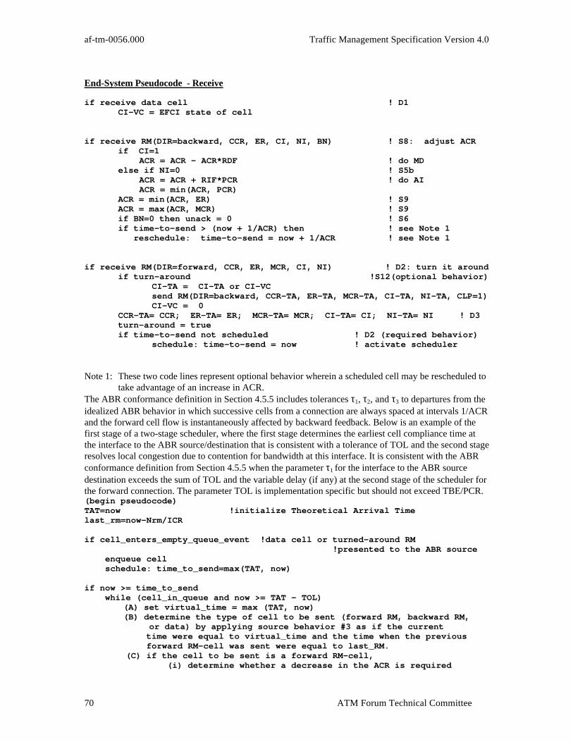
af-tm-0056.000 Traffic Management Specification Version 4.0
ATM Forum Technical Committee70
End-System Pseudocode - Receive
if receive data cell ! D1CI-VC = EFCI state of cell
if receive RM(DIR=backward, CCR, ER, CI, NI, BN) ! S8: adjust ACRif CI=1
ACR = ACR - ACR*RDF ! do MD else if NI=0 ! S5b ACR = ACR + RIF*PCR ! do AI ACR = min(ACR, PCR)
ACR = min(ACR, ER) ! S9ACR = max(ACR, MCR) ! S9if BN=0 then unack = 0 ! S6if time-to-send > (now + 1/ACR) then ! see Note 1 reschedule: time-to-send = now + 1/ACR ! see Note 1
if receive RM(DIR=forward, CCR, ER, MCR, CI, NI) ! D2: turn it aroundif turn-around !S12(optional behavior)
CI-TA = CI-TA or CI-VCsend RM(DIR=backward, CCR-TA, ER-TA, MCR-TA, CI-TA, NI-TA, CLP=1)CI-VC = 0
CCR-TA= CCR; ER-TA= ER; MCR-TA= MCR; CI-TA= CI; NI-TA= NI ! D3turn-around = trueif time-to-send not scheduled ! D2 (required behavior)
schedule: time-to-send = now ! activate scheduler
Note 1: These two code lines represent optional behavior wherein a scheduled cell may be rescheduled totake advantage of an increase in ACR.
The ABR conformance definition in Section 4.5.5 includes tolerances τ1, τ2, and τ3 to departures from theidealized ABR behavior in which successive cells from a connection are always spaced at intervals 1/ACRand the forward cell flow is instantaneously affected by backward feedback. Below is an example of thefirst stage of a two-stage scheduler, where the first stage determines the earliest cell compliance time atthe interface to the ABR source/destination that is consistent with a tolerance of TOL and the second stageresolves local congestion due to contention for bandwidth at this interface. It is consistent with the ABRconformance definition from Section 4.5.5 when the parameter τ1 for the interface to the ABR sourcedestination exceeds the sum of TOL and the variable delay (if any) at the second stage of the scheduler forthe forward connection. The parameter TOL is implementation specific but should not exceed TBE/PCR.(begin pseudocode)TAT=now !initialize Theoretical Arrival Timelast_rm=now-Nrm/ICR
if cell_enters_empty_queue_event !data cell or turned-around RM !presented to the ABR source enqueue cell schedule: time_to_send=max(TAT, now)
if now >= time_to_send while (cell_in_queue and now >= TAT - TOL)
(A) set virtual_time = max (TAT, now) (B) determine the type of cell to be sent (forward RM, backward RM, or data) by applying source behavior #3 as if the current
time were equal to virtual_time and the time when the previous forward RM-cell was sent were equal to last_RM. (C) if the cell to be sent is a forward RM-cell, (i) determine whether a decrease in the ACR is required
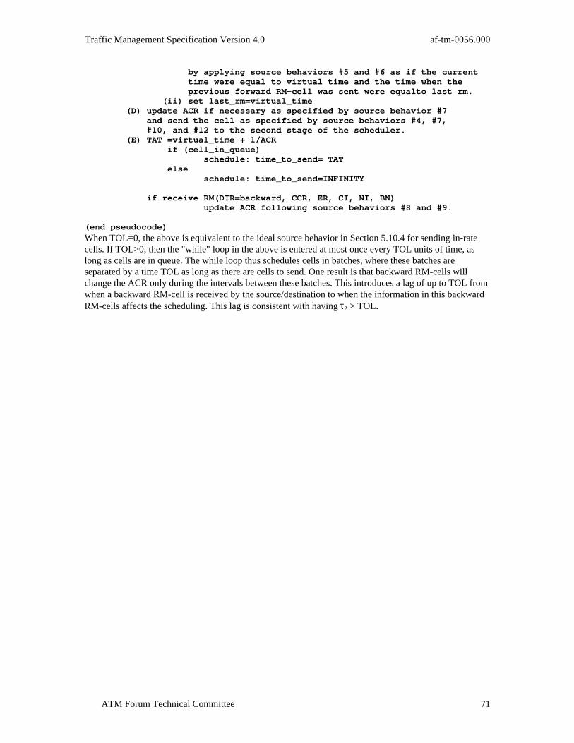
Traffic Management Specification Version 4.0 af-tm-0056.000
ATM Forum Technical Committee 71
by applying source behaviors #5 and #6 as if the current time were equal to virtual_time and the time when the previous forward RM-cell was sent were equalto last_rm. (ii) set last_rm=virtual_time (D) update ACR if necessary as specified by source behavior #7 and send the cell as specified by source behaviors #4, #7, #10, and #12 to the second stage of the scheduler. (E) TAT =virtual_time + 1/ACR if (cell_in_queue) schedule: time_to_send= TAT else schedule: time_to_send=INFINITY
if receive RM(DIR=backward, CCR, ER, CI, NI, BN) update ACR following source behaviors #8 and #9.
(end pseudocode)
When TOL=0, the above is equivalent to the ideal source behavior in Section 5.10.4 for sending in-ratecells. If TOL>0, then the "while" loop in the above is entered at most once every TOL units of time, aslong as cells are in queue. The while loop thus schedules cells in batches, where these batches areseparated by a time TOL as long as there are cells to send. One result is that backward RM-cells willchange the ACR only during the intervals between these batches. This introduces a lag of up to TOL fromwhen a backward RM-cell is received by the source/destination to when the information in this backwardRM-cells affects the scheduling. This lag is consistent with having τ2 > TOL.

af-tm-0056.000 Traffic Management Specification Version 4.0
ATM Forum Technical Committee72
I.2 State Machine
The four ABR service model State Machines are shown below. State Machine 1 controls the generation ofData cells as well as in-rate forward and backward RM-cells. This State Machine follows all of thebehaviors specified in Sections 5.10.4 and 5.10.5. State machines 2 and 3 show the non-standardgeneration of RM-cells. The exact implementation of these state machines is implementation specific.Forward out-of-rate RM-cells are limited only by TCR. Backward RM-cells are limited by Destinationbehavior #5 (10 cells/seconds) and the number of forward RM-cells received. State machine 4 controlsoperation during reception of backward RM-cells. It should be noted that the Source and Destinationtextual behavior descriptions should take precedence in case of discrepancy.
QueueIn-RateBRM
QueueData
PossibleADTF RateReduction
BRM_W:
QD_W:
QueueIn-RateFRM
PossibleCRM RateReduction
FRM_W:
Dispatch
D_BRM:
W_D:
D_QD:
D_RRR:
XRR_FRM:
RRR_XRR:
(Num IR-cells sent since last IR-FRM >= Mrm & Time since last IR-FRM >= Trm))
BRM Waiting &Num IR-cells sent since last IR-FRM < Nrm -1 &(No IR-BRMs sent since last IR-FRM + No Data to send) &(Num IR-cells sent since last IR-FRM < Mrm + Time since last IR-FRM < Trm)
Data to Send &Num IR-cells sent since last IR-FRM < Nrm -1 &(IR-BRM sent since last IR-FRM + No BRM Waiting) &(Num IR-cells sent since last IR-FRM < Mrm + Time since last IR-FRM < Trm)
Generation of In-Rate Cells (Data, Forward and Backward RM-(State Machine #1)
FDA_FRM:CALL SETUP &
FIRST DATA AVAIL
(Source 3b, 4)
(Source 3c, 4, 12)
(Source 3a, 4)
(Source 7, 10)
(Source 2)
(Source 5)
(Source 6)
Note:IR = In RateBRM = Backward RM CellFRM = Forward RM Cell
Deliver cell toscheduler
Update IR_BRM cell sent
Update data cell sent
Reset IR_BRM cell sent and data cell sent, timesince last IR_FRM = now

Traffic Management Specification Version 4.0 af-tm-0056.000
ATM Forum Technical Committee 73
Wait 2
W 2 _B R M :
BRM_W2:
Wait for>= 1/TCR
QueueOut-of-Rate
FRM
W 3 _F R M:
FRM_W3:
QueueBRM
Wait forBRM
IncreaseACR
W _ I A :
IA_W:
Vendor Speci fic Vendor Speci fic
Source Out-of-Rate Forward RM Generatio(State Machine #3)
Destination Generated Backward RM(BN=1) (State Machine #2)
DecreaseACR
W _ DA:
DA_W:
Receive BRM withCI = 1 or MCR < ER <= ACR
Receive BRM with CI = 0 &NI = 0 & ER > ACR
Backward RM Reception(State Machine #4)
(Source 10, 11)
(Source 8, 9)
(Source 8, 9)
(Destination 5)
I.3 Example Fairness Criteria
Define the following parameters:A = Total available bandwidth for all ABR connections on a given link.U = Sum of bandwidth of connections bottlenecked elsewhere (including those limited by PCR).B = A-U, bandwidth to be shared by connections bottlenecked on this link.N = Total number of active connections.N’ = Number of active connections bottlenecked elsewhere.n = N-N’, number of active connections bottlenecked on this link.M = Sum of MCRs of active connections within n.B(i) = Fair allocation for connection i.MCR(i) = MCR of connection i.
The following are the example fairness criteria for the given link.1. Max-Min
The available bandwidth B is equally shared among n connections which are bottlenecked at thelink.

af-tm-0056.000 Traffic Management Specification Version 4.0
ATM Forum Technical Committee74
B(i)=B/n.Comments: This criterion only applies to the case where all connections are unweighted
(or equally weighted) and with zero-MCR.2. MCR plus equal share
The bandwidth allocation for a connection is its MCR plus equal share of the bandwidth B with usedMCR removed.B(i)=MCR(i)+(B-M)/n.Comments: The criterion converges to Max-Min criteria as all MCRs approach zero. To achieve
this criterion, the switch may need to use ACR-MCR to compute the fair share.3. Maximum of MCR or Max-Min share
The bandwidth allocation for a connection is its MCR or Max-Min share, which ever is larger.B(i)=max(MCR(i), Max-Min share).Comments: This criterion also converges to Max-Min criterion as all MCRs approach zero. The
bandwidth allocation according to this criterion may need long iteration time to converge to the equilibrium point.
4. Allocation proportional to MCRThe bandwidth allocation for a connection is weighted proportional to its MCR.B(i)=B*(MCR(i)/M).Comments: This criterion does not apply if there are connections with zero MCR.
5. Weighted allocationThe bandwidth allocation for connection i is proportional to its pre-determined weight, w(i).B(i)=B*(w(i)/sum w(j)).Comments: The Max-Min criterion is a special case with all connections having equal weight.
The weight may be defined independent of MCR or dependent on MCR (e.g., option 4 is with weight proportional to MCR).
I.4 MCR characteristics
This appendix provides a rationale for MCR, and explains its implications on networks and applications.Also see the pseudocode (Appendix I.1, above) for an implementation example.Field of applicationIn the ABR service category, the ACR available to the application varies with network load. There may besome value of ACR below which the performance of the application degenerates. For example,
• protocol liveness may require that protocol control information be sent at some minimum rate;• some applications may become intolerable to users if they are unable to send at least at some
minimum rate;• applications that need to run to completion within a period of time (e.g., an overnight disk
backup that has to be completed by morning), will miss their deadline if they cannot transmit atleast at some minimum rate.
For such applications, the concept of MCR is defined.Some applications will have no way to determine an appropriate value of MCR, and MCR will not alwaysbe needed or wanted by applications or users. In particular, networks may have economic, administrativeor other disincentives to specifying an MCR greater than 0.The Internet concept of an elastic service does not include a MCR. The ABR service category is intendedto meet the requirements of the elastic service definition when MCR=0.In some applications, it may be possible for users to control MCR, even if an MCR is not inherent in thedesign of the application.Definition of MCRMinimum Cell Rate (MCR) is a rate negotiated between the end-systems and the network(s), such that theactual cell rate sent by the end-system on the ABR connection need never be less than MCR. MCR isnegotiated independently for both directions of transfer on a bidirectional ATM connection.

Traffic Management Specification Version 4.0 af-tm-0056.000
ATM Forum Technical Committee 75
MCR is negotiated between the end-systems and the network(s) using the connection control signalingprocedures. The MCR agreed between the end-systems and the network(s) carrying the connection mayrange from 0 to the maximum value supported by the network(s). This maximum may be 0. If the callingend-system does not indicate a requested MCR, the default value of MCR is 0.In the negotiation procedures specified in the signaling protocol, the calling end-system specifies a“requested MCR” and a “smallest acceptable MCR” (MCRmin of Section 5.10.2.2). The MCR valueindicated when the connection is offered to the called end-system(s) will be either the “requested MCR”,or, if that value is not available, a value between the “requested MCR” and the “smallest acceptableMCR”. If the network(s) cannot offer at least the “smallest acceptable MCR”, the connection attempt isblocked. Thus, by specifying a “smallest acceptable MCR” greater than 0 (i.e., a “floor” on thenegotiation), the calling end-system accepts a risk that the connection will be blocked. Blocking inpreference to unacceptable performance may be preferred by some applications and/or users.The option of negotiating an MCR does not imply that ABR is intended to be a real-time service.If an MCR > 0 is negotiated for the connection, the end-systems may transmit at any rate up to the greaterof MCR and ACR. There is no obligation that end-systems transmit at a rate of at least MCR.Implications for network resource allocationPolicy for resource allocation within networks and network elements is implementation specific subject tothe constraint that these policies not preclude the network from meeting the ABR service objectives.Specifically, end-systems are not to be expected to reduce their ACR to less than MCR in order to meetthe cell loss ratio objective.Implications on connection admission control (CAC) and routingNetworks and network elements which offer MCR>0 need to incorporate reservation of MCR resourcesinto their CAC functions in order to meet ABR service objectives. This implies blocking of connectionattempts when the “smallest acceptable MCR” is greater than the resources that the network or networkelement can reserve for MCR.During a connection establishment attempt for a connection that does not request MCR, or for which“smallest acceptable MCR” = 0, the CAC function will not block the connection attempt because ofbandwidth (including MCR) allocated to other connections. Blocking due to CAC for other reasons is notprecluded.
I.5 Example Switch Mechanisms
The following is a high level description of the switch mechanisms that were considered and in somecases simulated by various members of the traffic management working group. While general commentscan be made about the relative merits of these various mechanisms detailed performance characteristicsdepend on the exact source and destination behavior used. The various switch mechanisms can beclassified broadly depending on the congestion monitoring criteria used and the feedback mechanismemployed. The feedback mechanisms have been typically either binary or calculating the explicit rate andsending this information to the source through the RM-cell.I.5.1 Binary Feedback SchemesThe switches perform two important functions: a) Detect incipient congestion and b) provide binaryfeedback to the source. The simplest example of a binary feedback mechanism is based on the old DECbitscheme and was described as part of the original proposal for an end-to-end rate based traffic controlscheme. In this scheme all the VCs share a common FIFO and the queue length is monitored by setting athreshold T. When the queue length exceeds the threshold congestion is declared and the cells passingthrough the queue have their EFCI bit set. When the queue length falls below the threshold the cells arepassed without their EFCI bits set. In variations of this mechanism two thresholds can be used, a highthreshold THigh, and a low threshold TLow. Typically as the queue increases past the low threshold andcrosses the high threshold, THigh, congestion is declared and the cells passing through the queue havetheir EFCI bits set. When the queue starts emptying, the condition of congestion is not removed until thequeue falls below the low threshold.Binary feedback schemes where all the connections may share a common FIFO may sometimes sufferfrom unfairness problems depending on the network topology and the source and destination behavioremployed. Given the same level of congestion at all the switches connections traveling more hops have a
af-tm-0056.000 Traffic Management Specification Version 4.0
ATM Forum Technical Committee76
higher probability of having their EFCI bits set than those traveling a smaller number of hops. Dependingon the source and destination behavior employed these long hop connections get very few opportunities toincrease their rate and consequently their throughputs are starved giving rise to what has been called the“beat down problem”.Potential unfairness problems in binary feedback schemes where all the VCs share a common FIFO can bealleviated by some enhancements to the basic scheme. The simplest enhancement is to provide separateFIFOs for each VC or groups of VCs. This generally results in ensuring fairness among different VCs.Another enhancement is to provide selective feedback or intelligent marking. In this scheme a switchcomputes a “fair share” and if congested sets EFCI bits in cells belonging to only those VCs whose currentrates are above the fair share. Examples of ways that a switch can compute the “fair share” are presentedin the following sections on explicit rate feedback.I.5.2 Explicit Rate Feedback SchemesThe switches perform three important functions:
1. Compute the fair share of the bandwidth for a VC that can be supported.2. Determine the load. (e.g., This can be done by either monitoring the queue length or the queue
growth rate).3. Determine the actual explicit rate and send this information to the source.
Examples of explicit rate switch mechanisms are the Enhanced Proportional Rate Control Algorithm(EPRCA) and two congestion avoidance algorithms.Note: some of the following ER switch mechanisms assume that the information in the forward RM-cell iscorrect. If the sources are not well behaving (e.g., they insert incorrect information) or the flow has beenreshaped when passing through a switch then switches using these methods base their feedback onuncertain information. This may lead to a decrease in fairness and even to increased cell loss.I.5.2.1 EPRCAThis scheme was considered as an enhancement to the Proportional Rate Control Algorithm where thesource sends RM-cells at a rate proportional to its current rate. The RM-cells sent by the source contain adesired explicit rate (ER), the current cell rate usually set to the allowed cell rate (ACR) and thecongestion indication bit CI set to zero. The switch computes a mean allowed cell rate for all VCs(MACR) using a running exponential weighted average. MACR is computed by MACR = (1-α) MACR +α CCR, where α is generally chosen to be 1/16, weights the MACR more than the current CCR. Theswitch monitors its load by keeping track of the queue length. When the RM-cell returns from thedestination the switch reduces the ER field if it is in a state of congestion. In this scheme the fair sharewas computed to be a fraction 7/8 of the MACR. If the value in the ER field is less than the fair share noadjustments are made. On the other hand if the value is higher and the switch is in a congested state thevalue is lowered to its fair share.I.5.2.2 Congestion Avoidance SchemesIn this scheme the rate of change of queue length is used as a load indicator. The load factor is defined asz = Input rate/Target rate. The input rate is measured over a fixed averaging interval and the target rate isset slightly below the link bandwidth, e.g., 85-90%. There are two variations of this scheme that differ inthe algorithm used to compute the fair share or explicit rate based on the load factor.I.5.2.3 ERICAERICA (Explicit Rate Indication for Congestion Avoidance) tries to maintain the network at a load z closeto one. In its simplest form, it calculates two quantities: fairshare, and this VC's share:
Fairshare = Target capacity / Number of active connections VCshare = CCR / z.Here CCR is the current cell rate field in the RM-cell which contains ACR declared by the source (or asmeasured by the switch). This scheme achieves fairness concurrently with efficiency by using thefollowing formula to compute the explicit rate (ER): ER = Max (Fairshare, VCshare).The above quantities are measured periodically using information from the forward RM-cells, and thefeedback is given in the backward RM-cells. This ensures that the most current information is used toprovide fastest feedback. The measurement interval is independent of the rate at which the sources sendRM-cells. For each interval, no more than one new explicit rate value is advertised per VC. This avoids

Traffic Management Specification Version 4.0 af-tm-0056.000
ATM Forum Technical Committee 77
conflicting feedback to sources due to stale information at the switches. The scheme has few parameterswhich can be easily tuned. There are a few other variations of this scheme.I.5.2.4 Congestion Avoidance using Proportional Control (CAPC)Again as in the previous scheme the target utilization is set to be slightly less than one, and the load factoris computed. The load factor is used to update the fair share which is computed differently depending onwhether z<1 or z>1. During underload, the fair share is increased by the formula Fair share = Fair share *Min(ERU, 1+(1-z)*Rup). Rup is a slope parameter between 0.025 and 0.1 and ERU determines themaximum increase allowed in the allotment of fair share. When z>1, the fair share is decreased accordingto Fair share = Fair share * Max(ERF, 1- (z-1)*Rdn) where Rdn is between 0.2 and 0.8 and ERF set to 0.5determines the maximum decrease in the fair share.I.5.2.5 ER based on bandwidth Demand Estimate AlgorithmThe Mean Allowed Cell Rate (MACR) computed at the switch is based on a running exponential averageof the ACR value read from each VC's forward RM-cells. MACR is given by MACR = MACR +(ACR - MACR) * AVF (e.g., AVF = 1/16). If the load factor (LF = Input Rate/Target Rate) is < 1, theleftover bandwidth is reallocated according to MACR = MACR + MAIR, where MAIR is the MACRAdditive Increase Rate (e.g., MAIR = .5 Mbps). A positive queue derivative indicates an increasingbandwidth demand that causes the switch to enter a congestion state, The ER value computed is then ER= MACR * MRF (e.g., MRF = .95), if the switch has detected congestion. Otherwise, ER = MACR.
I.5.3 Reactive Switch BehaviorA reactive switch can be used to partially segment an ABR control loop. It assumes an ER mode of switchoperation. The objective of using reactive switches is to take advantage of short control loops to reducereaction time to congestion and limit buffer requirements, without implementing full VSVD behavior. Itrequires dynamic shaping of traffic on a per-connection basis.The rules of RS operation are:
• An RS assumes the behaviors of an ABR switch as specified in Section 5.10.6
• An RS monitors backward RM-cells in order to extract the content of the ER field
• An RS may never transmit cells of a particular connection at a rate greater than that specified in theER field of the last received backward RM-cell for that connection.
I.6 Generic Negotiating Behavior
This informative appendix describes how signaling negotiates traffic contract and QoS parameters.Requirements on ABR control parameters are different, and are described in Section 5.10.2.1. It isintended to provide an overview of the negotiation process for the user of this specification, and onlygeneric behaviors are provided. Specific procedures and encodings are provided in the UNI signaling andPNNI signaling specifications; the BICI 2.0 specification does not include negotiation, which is plannedto be included in future versions.I.6.1 Overview of Generic Negotiating BehaviorThe purpose of the negotiation is to select a value of each parameter that can both be provided by thenetwork and meets the needs of both end-systems. Since call establishment is accomplished in one roundtrip (two relevant messages), negotiation must be tied to a single round trip exchange. At the highestlevel, the calling end-system proposes a requested value and an acceptable value. The network tries tomeet the requested value, or at least some value between the requested and acceptable value, and if it can'tmeet the acceptable value, it clears the call. Otherwise, it offers the call to the called end-system with thebetter of the requested value and the best value it can support. In some cases, the signaling protocol doesnot explicitly support signaling for a desired value.I.6.2 Details of Generic Negotiating BehaviorThe protocol specifies a range of values for the parameter. Typically, the range is integer valued (althoughreal or enumerated types are possible). In some cases, the range may be a choice of two (or more) discretevalues. One end of the range is designated as the “most desirable” value, and the other is the “leastdesirable” value. If the most desirable value is greater than the least desirable, the negotiation proceeds

af-tm-0056.000 Traffic Management Specification Version 4.0
ATM Forum Technical Committee78
downwards, i.e., decreases in value. Otherwise, negotiation is upwards, i.e., increases in value. Forexample, a high cell rate is considered more desirable than a lower one, and negotiation proceedsdownwards, while a low CTD is more desirable than a higher one, so CTD negotiation proceeds upwards.The protocol also determines whether the objective of the negotiation is to “meet” or to “meet or exceed”the parameter value indicated by the calling end-system. If the objective is to meet the value, it is usuallybecause the parameter relates to a resource (e.g., bandwidth) that can be divided with relatively finegranularity among calls, with a penalty to the network attached to giving a greater value to the connectionthan that indicated. If the objective is to meet or exceed, the network may have alternative values availablenot necessarily over a continuous range, and can't benefit from giving the connection exactly the valueindicated rather than the next most desirable value. For example, peak cell rate is a “meet” parameter,since it can be divided fairly precisely among connections; if there is 10 Mbit/s of capacity available, andthe connection needs 3 Mbit/s, then that quantity will be assigned (ignoring for the present imprecisionand “fudge factors” present in real implementations), and the remainder will be available for otherconnections. Delay is a “meet or exceed” parameter; if a connection needs 50 ms, and routes are availablethat offer 20, 40 and 60 ms, respectively, then the 20 ms or the 40 ms route will be selected (all otherthings being equal), and there will be no reason to pad the delay out to 50 ms.A parameter is characterized as either a “metric” or an “attribute”. A metric is a parameter that requiresthe contribution of each topological component (i.e., link or node) to be accumulated to determine thevalue of the parameter for the connection. An attribute considers each topological component individually,such that the least desirable contribution of one or more links constitutes the parameter value for theconnection. For example, delay is a metric, while peak cell rate is an attribute. In general, path calculationis facilitated by minimizing the number of metrics that can apply to the connection.Note that these definitions are consistent with, but not identical to, those in the PNNI specification.
Behavior CLR maxCTD CDVDirection Up (Note 1) Up UpMeet/Meet or Exceed Meet/Exceed Meet/Exceed Meet/ExceedAttribute or Metric Attribute Metric MetricAccumulation Algorithm N/A see Section 3.6.2 see Section
3.6.2Called end-system may selectless desirable value
no no no
Note 1: The negotiation refers to the actual value of the parameter, and not to its encoding. For example,if CLR = 10-x, the value of the CLR parameter may be represented as x. Therefore negotiating the CLRupwards implies that the actual value of x decreases
Table I-1: Application of generic negotiating procedures to QoS parametersI.6.3 Description of Generic Negotiation AlgorithmThis section provides a high level description of the procedures for generic negotiation. Specific, detailedprocedures and message formats are described in the signalling and PNNI specifications. Theseprocedures are not supported in BICI 2.0, but are expected to be in future versions of the BICIspecification.The negotiation for each parameter operates as follows:1. In the initial call establishment message, the calling end-system may indicates a “requested” value,
which is the value of the parameter that it would like to have, and also indicates either a “highestacceptable value” (for upward negotiation) or a “lowest acceptable value” (for downward negotiation).The latter value is, respectively, the highest or lowest value of the parameter that the callingend-system is willing to accept; that is, it would rather the call be rejected than to have it completedwith a higher or lower value, respectively. If the requested value is not specified (either because thecalling end system chooses not to include it, or because it is not supported in the signaling protocol), itis assumed to be the same as the highest or lowest acceptable value.
2. The switch serving the calling end-system makes a preliminary determination as to whether it canmeet the requested, or at least the highest or lowest acceptable value for the parameter. This might, forexample, involve 'sanity checking', tests against administrative limits or path computation. If thenetwork cannot satisfy at least the highest or lowest acceptable value, it rejects the call. These
Traffic Management Specification Version 4.0 af-tm-0056.000
ATM Forum Technical Committee 79
determinations may also be made at administrative boundaries between networks (e.g., at BICIinterfaces, interfaces between public and private networks or PNNI border nodes).
3. If the parameter is an attribute, the network node interface carries an “indicated” value of theparameter, in addition to the requested and lowest or highest acceptable value. If the parameter is ametric, the network node interface carries a “cumulative” value of the parameter, in addition to therequested and lowest or highest acceptable value. The accumulation function is part of the specificnegotiating behavior for the parameter, and also applies to path computation.
4. Each successive switching system determines an outgoing link over which it will progress the call, anddetermines the value of each parameter that applies to that link. For “meet” parameters, it selects theappropriate value for the parameter. For 'meet or exceed' parameters, it might or might not have achoice among several values, and if so, it selects one according to implementation specific criteria.a) If the parameter is an attribute, the value of the parameter that applies to the outgoing link is
compared with the lowest or highest acceptable value in the initial call establishment message.i) If it is less desirable than highest or lowest acceptable value (i.e., higher than the highest
acceptable value or lower than the lowest acceptable value, whichever applies), the call iscleared (or crankback occurs).
ii) If it is less desirable than the indicated value carried in the incoming initial call establishmentmessage received from a preceeding switching system, or if the initial call establishmentmessage was received from an end-system, then the indicated value carried in the outgoinginitial call establishment is set to the value that applies to the outgoing link.
b) If the parameter is a metric, the accumulation function is applied to value of the parameter thatapplies to the outgoing link and the cumulative parameter value in the incoming initial callestablishment message, resulting in the new cumulative value. If the new cumulative value is lessdesirable than highest or lowest acceptable value (whichever applies), the call is rejected (orcrankback occurs). The new cumulative value is carried in the outgoing initial call establishmentmessage.
c) The call is progressed to the next switching system or the called end-system.5. When the initial call establishment message is received at the called end-system, it contains the
requested, either highest or lowest acceptable, and either indicated or cumulative values of theparameter. The called end-system determines whether or not the value is acceptable, and either acceptsor rejects the call. For some negotiations (e.g., PCR), where the parameter value affects resources inthe called end- system, called end-system may select a less desirable value for the parameter, as longas it is not less desirable than the highest or lowest acceptable value. In this case, the call connectedmessage sent by the called end-system contains the agreed value, which is always between theindicated or cumulative value and the highest or lowest acceptable value contained in the receivedinitial call establishment message.
6. The call connected message progressed through the network, and the call connected message sent tothe calling end-system contains the agreed value, which applies for the duration of the call (absentprotocol specifications for renegotiation).
I.7 Turning RM-Cells Around
I.7.1 IntroductionThe purpose of this section is to explain the behavior of the various allowed possibilities of turning aroundreceived forward RM-cells as specified in destination behavior #3.Destination Behavior #3 states:If a forward RM-cell is received by the destination while another turned-around RM-cell (on the sameVC) is scheduled for in-rate transmission:a) It is recommended that the contents of the old cell are overwritten by the contents of the new cell.b) It is recommended that the old cell (after possibly having been overwritten) shall be sent out-of-rate;alternatively the old cell may be discarded or remain scheduled for in-rate transmission.c) It is required that the new cell be scheduled for in-rate transmission
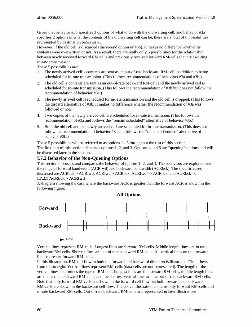
af-tm-0056.000 Traffic Management Specification Version 4.0
ATM Forum Technical Committee80
Given that behavior #3b specifies 3 options of what to do with the old waiting cell, and behavior #3aspecifies 2 options of what the contents of the old waiting cell can be, there are a total of 6 possibilitiesrepresented by destination behavior #3.However, if the old cell is discarded (the second option of #3b), it makes no difference whether itscontents were overwritten or not. As a result, there are really only 5 possibilities for the relationshipbetween newly received forward RM-cells and previously received forward RM-cells that are awaitingin-rate transmission.These 5 possibilities are:1. The newly arrived cell’s contents are sent as an out-of-rate backward RM-cell in addition to being
scheduled for in-rate transmission. (This follows recommendations of behaviors #3a and #3b.)
2. The old cell’s contents are sent as an out-of-rate backward RM-cell and the newly arrived cell isscheduled for in-rate transmission. (This follows the recommendation of #3b but does not follow therecommendation of behavior #3a.)
3. The newly arrived cell is scheduled for in-rate transmission and the old cell is dropped. (This followsthe discard alternative of #3b. It makes no difference whether the recommendation of #3a wasfollowed or not.)
4. Two copies of the newly arrived cell are scheduled for in-rate transmission. (This follows therecommendation of #3a and follows the “remain scheduled” alternative of behavior #3b.)
5. Both the old cell and the newly arrived cell are scheduled for in-rate transmission. (This does notfollow the recommendation of behavior #3a and follows the “remain scheduled” alternative ofbehavior #3b.)
These 5 possibilities will be referred to as options 1 - 5 throughout the rest of this section.The first part of this section discusses options 1, 2, and 3. Options 4 and 5 are “queuing” options and willbe discussed later in the section.I.7.2 Behavior of the Non-Queuing OptionsThis section discusses and compares the behavior of options 1, 2, and 3. The behaviors are explored overthe range of forward bandwidth (ACRfwd) and backward bandwidth (ACRbck). The specific casesdiscussed are ACRbck > ACRfwd, ACRfwd > ACRbck, ACRfwd >> ACRbck, and ACRbck= 0.I.7.2.1 ACRbck > ACRfwdA diagram showing the case where the backward ACR is greater than the forward ACR is shown in thefollowing figure:
Forward
Backward
All Options
time
Vertical lines represent RM-cells. Longest lines are forward RM-cells. Middle length lines are in ratebackward RM-cells. Shortest lines are out of rate backward RM-cells. All vertical lines on the forwardlinks represent forward RM-cells.In this illustration, RM-cell flow in both the forward and backward direction is illustrated. Time flowsfrom left to right. Vertical lines represent RM-cells (data cells are not represented). The length of thevertical lines determines the type of RM-cell. Longest lines are the forward RM-cells, middle length linesare the in-rate backward RM-cells, and the shortest vertical lines are the out-of-rate backward RM-cells.Note that only forward RM-cells are shown in the forward cell flow but both forward and backwardRM-cells are shown in the backward cell flow. The above illustration contains only forward RM-cells andin-rate backward RM-cells. Out-of-rate backward RM-cells are represented in later illustrations.
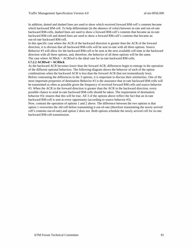
Traffic Management Specification Version 4.0 af-tm-0056.000
ATM Forum Technical Committee 81
In addition, dotted and dashed lines are used to show which received forward RM-cell’s contents becamewhich backward RM-cell. To help differentiate (in the absence of color) between in-rate and out-of-ratebackward RM-cells, dashed lines are used to show a forward RM-cell’s contents that became an in-ratebackward RM-cell and dotted lines are used to show a forward RM-cell’s contents that became anout-of-rate backward RM-cell.In this specific case where the ACR of the backward direction is greater than the ACR of the forwarddirection, it is obvious that all backward RM-cells will be sent in-rate with all three options. SourceBehavior #3 will allow for the backward RM-cell to be sent at the next available cell time in the backwarddirection with all three options, and, therefore, the behavior of all three options will be the same.The case where ACRbck > ACRfwd is the ideal case for in-rate backward RM-cells.I.7.2.2 ACRfwd > ACRbckAs the backward ACR becomes lower than the forward ACR, differences begin to emerge in the operationof the different optional behaviors. The following diagram shows the behavior of each of the optioncombinations when the backward ACR is less than the forward ACR (but not tremendously less).Before contrasting the differences in the 3 options, it is important to discuss their similarities. One of themost important properties of destination Behavior #3 is the assurance that in-rate backward RM-cells willbe transmitted as often as possible given the frequency of received forward RM-cells and source behavior#3. When the ACR in the forward direction is greater than the ACR in the backward direction, everypossible chance to send in-rate backward RM-cells should be taken. The requirement of destinationbehavior #3c insures that this will be true. All 3 of the options above reflect the fact that an in-ratebackward RM-cell is sent at every opportunity (according to source behavior #3).Now, contrast the operation of options 1 and 2 above. The difference between the two options is thatoption 1 overwrites the old cell before transmitting it out-of-rate (therefore transmitting the newly arrivedcell’s contents out-of-rate) and option 2 does not. Both options schedule the newly arrived cell for in-ratebackward RM-cell transmission.

af-tm-0056.000 Traffic Management Specification Version 4.0
ATM Forum Technical Committee82
Forward
Backward
Option 1: Overwrite old cell; send out-of-rate
Option 2: No overwrite; send out-of-ratetime
Forward
Backward
overwritten
overwritten
overwritten
overwritten
overwritten
overwritten
overwritten
Option 3: No out-of-rate; no queuing
Forward
Backward
drop drop drop drop drop drop dropdrop drop
Vertical lines represent RM-cells. Longest lines are forward RM-cells. Middle length lines representin-rate backward RM-cells. Shortest lines are out-of-rate backward RM-cells. All vertical lines on theforward links represent forward RM-cells.The frequency and spacing of both in-rate and out-of-rate backward RM-cells are the same with bothoptions. The difference is that option 1 always transmits the latest information in out-of-rate backwardRM-cells and option 2 does not.The ramifications of old vs. new information in backward RM-cells will now be further explored.It is advantageous to transmit the latest RM-cell data in the presence of explicit rate switches that modifythe explicit rate field in the forward direction or that monitor the CCR field of the RM-cell (in either theforward or the backward direction). Also, out-of-rate backward RM-cells may not be able to be transmittedimmediately because of higher priority traffic (CBR or VBR). If the out-of-rate backward RM-cell isdifferent than the awaiting in-rate backward RM-cell, there will need to be storage capability for 2backward RM-cells per VC. These are some of the reasons behind the recommendation of behavior #3awhich leads to option 1.However, option 1 has a characteristic that needs to be examined. Option 1 has the possibility ofduplicating the contents between an out-of-rate backward RM-cell and the next in-rate backward RM-cell.In fact, whenever there are out-of-rate backward RM-cells with option 1, the next in-rate backwardRM-cell will be a duplicate (except for the CI bit) of the last out-of-rate backward RM-cell. Thisduplication is illustrated in the above figure.The reality is that this duplication has no adverse effect on ABR operation. In the case of explicit rateswitches, it simply means that the explicit rate and the current cell rates of backward RM-cells will alwaysbe the latest that are available. In the case of binary mode switches, if the CI bit is set as the backwardRM-cell is being transmitted (as preferred from destination behavior #2b), then the backward RM-cellalways carries the latest EFCI state.Since the duplication has no effects on either explicit mode or binary mode networks, since there aredefinite advantages to carrying the latest information in backward RM-cells, and since there are

Traffic Management Specification Version 4.0 af-tm-0056.000
ATM Forum Technical Committee 83
implementation advantages in the end stations if only a single RM-cell’s contents needs to be saved,option 1 is recommended over option 2.Option 3 does not support out-of-rate backward RM-cells at all. It can be seen in the figure that, as thebackward ACR falls below the forward ACR, received forward RM-cells begin to be dropped and thenumber of backward RM-cells begins to drop well below the number of received forward RM-cells. Theresponsiveness of the forward ACR control loop will be lessened by the decrease in frequency of backwardRM-cells.I.7.2.3 ACRfwd >> ACRbckNow, the behavior when the forward ACR is much larger than the backward ACR is explored. Thefollowing diagram illustrates the different option combinations under this condition.
Forward
Backward
Option 1: Overwrite old cell; send out-of-rate
time
x x x x x x x
Forward
Backward
Option 2: No overwrite; send out-of-rate
x x x x x x x
overwritten
Option 3: No out-of-rate; no queuing
Forward
Backward x x x x x x x
drop drop dropdrop drop dropdrop drop drop drop dropdrop drop drop drop drop
Vertical lines represent RM-cells. Longest lines are forward RM-cells. Middle length lines representin-rate backward RM-cells. Shortest lines are out-of-rate backward RM-cells. All vertical lines on theforward links represent forward RM-cells.In this case, the rate of forward RM-cells is greater than the cell rate in the backward direction. Noticenow that individual in-rate cell opportunities are shown in the backward channel representations. In-ratecell opportunities are represented as x’s.Once again, options 1 and 2 produce the same frequency and spacing of both in-rate and out-of-ratebackward RM-cells. Again, with both options, the total number of backward RM-cells (both in-rate andout-of-rate) equals the number of received forward RM-cells.Option 3 drops most of the received forward RM-cells. With the very limited number of in-rate backwardRM-cells in this case, the responsiveness of the forward direction ACR control loop may be very limited.
I.7.3 ACRbck = 0The analysis continues with the backward ACR dropping all the way to zero. The following diagramshows the behavior of all option combinations with this case.

af-tm-0056.000 Traffic Management Specification Version 4.0
ATM Forum Technical Committee84
Forward
Backward
Option 1: Overwrite old cell; send out-of-rate
time
Backward
Forward
Option 2: No overwrite; send out-of-rate
Forward
Backward
Option 3: No out-of-rate; no queuing
drop dropdropdrop drop drop dropdrop drop drop
In this case, since there are no in-rate slots in the backward direction, both option 1 and option 2 sendnothing but out-of-rate backward RM-cells. The only difference between these two options is in thelatency of the out-of-rate backward RM-cell’s contents. Option 1 transmits the newly arrived forwardRM-cell’s contents as the out-of-rate backward RM-cell and option 2 transmits the old forward RM-cell’scontents as the out-of-rate backward RM-cell.Notice that there are no backward RM-cells at all in option 3. There are no in-rate cell slots and option 3does not implement out-of-rate backward RM-cells. Any end station implementing option 3 for backwardRM-cell handling cannot operate in a situation where the backward ACR is 0. There must be sufficientMCR in the backward direction to allow for enough in-rate backward RM-cells to effectively implementthe forward ACR control loop.I.7.4 Behavior of the Queuing OptionsOptions 4 and 5 from Section I.7.1 represent queuing options for in-rate backward RM-cells.A queue for in-rate backward RM-cells is in order if there is a desire to handle a situation where clumpingof forward RM-cells occurs. A queue allows for the received clumped RM-cells to be sent in successivein-rate backward RM-cell slots. Without a queue, much of the clump of received RM-cells will betransmitted as out-of-rate backward RM-cells. An illustration of a case where the forward and backwardACRs are equal and a clump of forward RM-cells is received is shown in the following figure.

Traffic Management Specification Version 4.0 af-tm-0056.000
ATM Forum Technical Committee 85
Option 1: Overwrite old cell; send out-of-rate
Option 2: No overwrite; send out of ratetime
Forward
Backward
Forward
Backward
over
write
Option 3: No out of rate; no queuing
Forward
Backward
drop
drop
drop
Option 4: Overwrite old cell; queue cells
Option 5: No overwrite; queue cells
Forward
Backward
Forward
Backward
overwritten
Notice that the difference between options 4 and option 5 is that option 4 always uses the latest receivedforward RM-cell’s contents while option 5 keeps the older RM-cells’ contents in the queue. The queue ofoption 4 could be implemented with a counter along with a single RM-cell storage area. Option 5 requiresa storage area for each of the queued RM-cells.It is also important to discuss what will happen in a queued backward RM-cell implementation when thequeue fills. Recall that a queue may be desired to handle the situation where clumping of forwardRM-cells has occurred in the network. However, a queue does nothing to handle the situation where theforward ACR is larger than the backward ACR. In this case, the queue will fill.When the queue fills, the implementation can use either option 1, option 2, or option 3 to handlesubsequently received forward RM-cells.

af-tm-0056.000 Traffic Management Specification Version 4.0
ATM Forum Technical Committee86
Using option 3 to handle queue overflow is simple to comprehend. When a forward RM-cell is receivedand the queue is full, the head of the queue will be discarded and the newly received forward RM-cell willbe added to the tail of the queue. This works whether the queue was implemented with option 4 or option5.Using option 2 to handle queue overflow is also simple to comprehend. When a forward RM-cell isreceived and the queue is full, the head of the queue will be sent as an out-of-rate backward RM-cell andthe newly received forward RM-cell will be added to the tail of the queue. Again, this works whether thequeue was implemented with option 4 or option 5.A little care must be taken in using option 1 to handle queue overflow. Recall that option 1 sends thecontents of the newly arrived forward RM-cell as an out-of-rate backward RM-cell in addition to queuingit for in-rate backward RM-cell transmission. If the backward RM-cell queue is implemented using option5 (where old cells are not overwritten with the contents of the newly arrived cell), then all cells in thequeue would need to be flushed if the newest forward RM-cell was sent as an in-rate backward RM-cell(see destination behavior #4). If the backward RM-cell queue is implemented using option 4, then there isno problem.I.7.5 SummaryThe advantage of using one of the queuing options (option 4 or option 5) is that network clumping offorward RM-cells can be handled more elegantly. The disadvantage to using one of the queuing options(besides the increase in complexity) is that there will be a longer time before an out-of-rate backwardRM-cell is transmitted when the backward ACR becomes smaller than the forward ACR. The queue mustfill before an out-of-rate backward RM-cell will be sent. (If the destination does not wait for the queue tofill, there is the possibility of transmitting more backward RM-cells than received forward RM-cells.)If a non-queued turn-around RM-cell implementation is desired, the recommendations of destinationbehavior #3 imply that option 1 of this section is the desired mode of operation in turning around receivedforward RM-cells. It has the properties of always transmitting the latest RM data, always using availablein-rate backward RM-cell slots, making full use of allowed out-of-rate backward RM-cell possibilities, andallowing for only one set of backward RM-cell contents to be stored awaiting transmission by thedestination.Option 2 is the second more desirable of the non-queued options since it implements the recommendationof behavior #3b but not of behavior #3a. Option 3 is the least desirable of the 3 non-queued options.Of the queued RM-cell implementations, option 4 is the most desired mode of operation. It implementsthe recommendation of behavior #3a which allows for only the latest RM-cell information to betransmitted. It can also be simpler to implement than option 5. If the queue implemented in option 4overflows, the recommended procedure is to follow the recommendations of behavior #3a and #3b andsend the contents of the newly arrived RM-cell as an out-of-rate backward RM-cell while keeping itscheduled for in-rate transmission.
I.8 End-System Congestion and Optional Use-it-or-lose-it Behavior
Situations will arise where an ABR end-system will not be able to send cells as fast as the ACR allows.This could be due to application or end-system architecture constraints, such as contention for access to adisk. Another possible cause is local scheduler congestion, which occurs when the sum of ACRs to bescheduled exceeds the link rate. Use-it-or-lose-it behavior reduces the ACR assigned to a connection ifthat connection is transmitting significantly below its ACR. The objective of use-it-or-lose-it behavior is toensure that ACR is maintained reasonably close to the real cell transmission rate.Although the source may choose to support use-it-or-lose-it behavior to help protect the switches, it is theresponsibility of the switches to support QoS objectives for ABR connections that conform to themandatory ABR behaviors.Use-it-or-lose-it behavior may be beneficial in the following circumstances:• Temporarily rate limited sources may jump to their acquired ACR at any time, causing an unexpected
step increase in the arrival rate at switches on its path. These kind of jumps occur as contention for
application or scheduler resources fluctuates. Use-it-or-lose-it behavior can reduce these transientfluctuations in traffic load. For networks with binary switches it can reduce the control lagexperienced after transitions from underload to overload. Keeping ACR close to the real rate reduces

Traffic Management Specification Version 4.0 af-tm-0056.000
ATM Forum Technical Committee 87
the number of CI=1 RM-cells required to reduce ACR by an amount sufficient enough to control theactual cell transmission rate.
Note however, that by reducing ACR, use-it-or-lose-it behavior can reduce the performance of requestresponse applications. In addition, sources implementing use-it-or-lose-it behavior may be at a fairnessdisadvantage with respect to sources that do not implement use-it-or-lose-it behavior.The means by which use-it-or-lose-it behavior is achieved is implementation specific. Some examplemethods include:• End-system method 1: forward RM-cell triggered When an in-rate forward RM-cell is sent, if the ACR exceeds the recent transmission rate plus a fixed
bound, the ACR is reduced by a multiplicative factor and the next increase inhibited. Specifically therecent rate R, could be estimated by Nrm divided by the time since the last in-rate forward RM-cellwas sent. If ACR exceeds R+ICR, the ACR could be set to the higher of ACR*15/16 and R+ICR, andthe next increase inhibited.
• End-system method 2: backward RM triggered When a backward RM is received, the ACR increases are limited such that the resulting ACR it is not
significantly greater than the recent transmission rate R. Specifically the received ER could bereduced to R+ICR.
• End-system method 3: Internal congestion algorithm The end-system might run an implementation specific switch algorithm internal to the end-system
that reacts to internal scheduler congestion. To work effectively the scheduler must be able toschedule cells faster than the outgoing link rate. This kind of method does not respond to applicationlevel congestion, but does respond to scheduler congestion.
• Switch based: The use-it-or-lose-it can also be implemented in a switch which monitors each connections cell
transmission rate and sends explicit rate messages to hold ACR within some implementation specificbound.

af-tm-0056.000 Traffic Management Specification Version 4.0
ATM Forum Technical Committee88
Informative Appendix II: Conformance Examples in a Traffic Contract
II.1 Introduction
In the traffic contract, the Cell Delay Variation tolerance specified at the UNI is defined in relation to thePCR by the GCRA and the BT specified at the UNI is defined in relation to the SCR also by the GCRA.Additionally, a conformance definition that defines the combination of GCRAs in relation to the differentcell streams and cell rates of a connection at the UNI is also specified in the traffic contract. Dependingupon the services provided, different conformance definitions could be specified. In this appendix, a fewexamples are given for information purposes.For each example described herein, the service needs are summarized and then followed with aconformance definition that could be used to accommodate the service needs. Specifically, the examplesillustrate how one can emulate the traffic definitions of various services by appropriately mapping theminto parameters of various GCRAs. The specific conformance definition used is for illustrative purposes.Figures are also provided in the form of block diagrams to depict how various GCRAs interact with eachother. Two functional blocks are used to represent the high level flowchart of a GCRA(I, L) algorithm andare labeled by C(I) and U(I):
1. Conformance Checking Functional Block:
C(I)
2. Update Functional Block:
U(I)
The conformance checking functional block represents functions performed in order to determine whethera cell is conforming or not. The update functional block represents the update function performed if a cellis identified as conforming. Note that the only purpose of the block diagrams are to test conformance tothe traffic descriptors as defined by the conformance definition. The conformance definitions indicated inthese examples should not be interpreted as the UPC algorithms. Hence, non-conformance does not implya discard or tagging decision.
II.2 Example 1: Switched Multi-megabit Data Service (SMDS)
SMDS allows customers to send bursts at the full access link rate (e.g., DS3 PLCP). To control thesustainable information rate, an Iinc, a Ninc, and a Cmax are specified. Iinc is the interval (in 53-octetslot times) between increments to the credit. Ninc is the number of credits (in user information octets)increase per increment. Iinc and Ninc together determine a maximum sustainable information rate. Cmaxis the maximum credits that can be accrued. Cmax is 9188 octets for all access classes. An arrivingmessage will be discarded, if the current accrued credits are less than the estimated user informationlength.For an ATM connection supporting the above SMDS application, the following conformance definition(VBR.1, see Section 4.5.2.1) in relation to a source traffic descriptor that specifies the PCR for the CLP=0cell stream and SCR for the CLP=0+1 cell stream could be specified in the traffic contract if a properminimum user information length that the SMDS user could submit is imposed:For an ATM connection supporting the above SMDS application, the following conformance definition(VBR.1) could be specified in the traffic contract:
1. One GCRA(T0+1, CDVT) defining the CDVT in relation to the PCR of the CLP=0+1 cell stream.
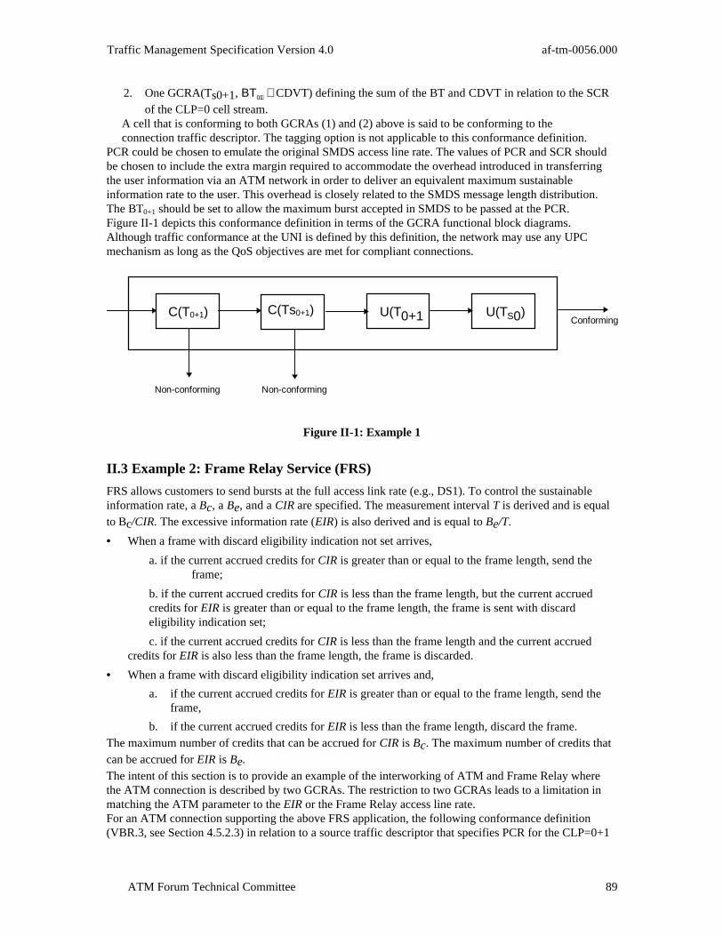
Traffic Management Specification Version 4.0 af-tm-0056.000
ATM Forum Technical Committee 89
2. One GCRA(Ts0+1, ΒΤ0+1+ CDVT) defining the sum of the BT and CDVT in relation to the SCRof the CLP=0 cell stream.
A cell that is conforming to both GCRAs (1) and (2) above is said to be conforming to theconnection traffic descriptor. The tagging option is not applicable to this conformance definition.
PCR could be chosen to emulate the original SMDS access line rate. The values of PCR and SCR shouldbe chosen to include the extra margin required to accommodate the overhead introduced in transferringthe user information via an ATM network in order to deliver an equivalent maximum sustainableinformation rate to the user. This overhead is closely related to the SMDS message length distribution.The BT0+1 should be set to allow the maximum burst accepted in SMDS to be passed at the PCR.Figure II-1 depicts this conformance definition in terms of the GCRA functional block diagrams.Although traffic conformance at the UNI is defined by this definition, the network may use any UPCmechanism as long as the QoS objectives are met for compliant connections.
Non-conforming
Conforming
Non-conforming
C(T0+1) U(T0+1 U(TS0)C(Ts0+1)
Figure II-1: Example 1
II.3 Example 2: Frame Relay Service (FRS)
FRS allows customers to send bursts at the full access link rate (e.g., DS1). To control the sustainableinformation rate, a Bc, a Be, and a CIR are specified. The measurement interval T is derived and is equalto Bc/CIR. The excessive information rate (EIR) is also derived and is equal to Be/T.
• When a frame with discard eligibility indication not set arrives,
a. if the current accrued credits for CIR is greater than or equal to the frame length, send the frame;
b. if the current accrued credits for CIR is less than the frame length, but the current accrued credits for EIR is greater than or equal to the frame length, the frame is sent with discard eligibility indication set;
c. if the current accrued credits for CIR is less than the frame length and the current accruedcredits for EIR is also less than the frame length, the frame is discarded.
• When a frame with discard eligibility indication set arrives and,
a. if the current accrued credits for EIR is greater than or equal to the frame length, send theframe,
b. if the current accrued credits for EIR is less than the frame length, discard the frame.The maximum number of credits that can be accrued for CIR is Bc. The maximum number of credits thatcan be accrued for EIR is Be.
The intent of this section is to provide an example of the interworking of ATM and Frame Relay wherethe ATM connection is described by two GCRAs. The restriction to two GCRAs leads to a limitation inmatching the ATM parameter to the EIR or the Frame Relay access line rate.For an ATM connection supporting the above FRS application, the following conformance definition(VBR.3, see Section 4.5.2.3) in relation to a source traffic descriptor that specifies PCR for the CLP=0+1
af-tm-0056.000 Traffic Management Specification Version 4.0
ATM Forum Technical Committee90
cell stream, SCR for the CLP=0 cell stream could be specified in the traffic contract if a proper minimumframe length that the FRS user could submit is imposed.
1. One GCRA(T0+1,CDVT) defining the CDVT in relation to the PCR of the aggregate CLP=0+1cell stream.
2. One GCRA(Ts0, BT0+CDVT) defining sum of the BT and CDVT in relation to the SCR of theCLP=0 cell stream.
A CLP=0 cell that is conforming to both GCRAs (1) and (2) above is said to be conforming to theconnection traffic descriptor. A CLP=1 cell that is conforming to GCRA (1) above is said to beconforming to the connection traffic descriptor. A CLP=0 cell that is not conforming to GRCA (2)above but is conforming to GCRA (1) above is considered to have the CLP bit changed to 1 andsaid to be conforming to the connection traffic descriptor.
The values of PCR and SCRs should be chosen to include the extra margin required to accommodate theoverhead introduced in transferring the FRS frames via an ATM network. When the PCR is chosen toemulate the FRS access line rate, the EIR that is allowed is the difference between the access line rate andthe CIR. Therefore, the EIR that is allowed possibly exceeds the EIR negotiated for the FRS. However,using traffic shaping, the PCR may be chosen to be the higher of either the required value to achieve theTransfer Delay objectives, or the required value to achieve the sum of CIR and EIR to the user. The BT0should be set to allow the maximum committed burst accepted in FRS to be passed at the PCR.Figure II-2 depicts this conformance definition in terms of the GCRA functional block diagrams.Although traffic conformance at the UNI is defined by this definition, the network may use any UPCmechanism as long as the QoS objectives are met for compliant connections.
Non-conforming
ConformingC(T0) U(T0)
Non-Conforming
Conforming
Non-ConformingConforming
1
0U(T0+1)
U(T0+1)
U(TS0)C(TS0)C(T0+1)
Figure II-2: Example 2
The conformance definition that defines the traffic descriptor can be such that cells that are notconforming with the CLP=0 SCR parameter set may or may not be submitted as CLP=1 cells throughmarking at the source. In this case the single CLP bit in the ATM header carries two meanings; one foruser marked CLP=1 cells and the other for the tagged cells. The network (i.e., the switches) cannotdistinguish between the two meanings. Therefore, the same QoS objectives are supported for both the usermarked CLP=1 cells and the network tagged CLP=1 cells.
II.4 Example 3: Constant Bit Rate Services

Traffic Management Specification Version 4.0 af-tm-0056.000
ATM Forum Technical Committee 91
For an ATM connection supporting a Constant Bit Rate service, the following definition (see Section4.5.1)in relation to a source traffic descriptor that specifies PCR for the CLP=0+1 cell stream could bespecified in the traffic contract:
1. One GCRA(T0+1,CDVT) defining the CDVT in relation to the PCR of the CLP=0+1 cellstream.
A cell that is conforming to this GCRA is said to be conforming to the connection traffic descriptor.PCR is chosen to emulate the constant bit rate of the service.Figure II-3 depicts this conformance definition in terms of the GCRA functional block diagrams.Although traffic conformance at the UNI is defined by this definition, the network may use any UPCmechanism as long as the QoS objectives are met for compliant connections.
Non-Conforming
ConformingC(T0+1) U(T0+1)
Figure II-3: Example 3
II.5 Example 4: LAN Interconnection
In applications such as LAN interconnection, multiple workstations on a LAN can send data over a publicor private ATM WAN to other workstations in other LANs. These LANs can be interconnected throughVPCs across the ATM backbone. In this example it is assumed that a VBR.3 VPC is used (see Section4.5.2.3). In such applications, the user's packets typically have the same level of importance and thereforeare submitted to the ATM network as CLP=0 cells (after being processed at the AAL). Since traffic frommultiple workstations are multiplexed on a given VP, there may not be a traffic shaper on the user side ofthe UNI (this may particularly be the case at the private-UNI). In such applications, it is desirable for thenetwork to tolerate some amount of non-conformance of the CLP=0 stream by tagging thesenon-conforming cells as CLP=1 cells. This allows the users not to be very pessimistic in their trafficdescription and therefore may avoid excessive "over-allocation" for bursty data applications.

af-tm-0056.000 Traffic Management Specification Version 4.0
ATM Forum Technical Committee92
Informative Appendix III: Examples of ABR conformance andcompliance definitions
III.1 Dynamic GCRA: An Example of a Conformance Definition
The Dynamic GCRA (DGCRA), an extension of the GCRA algorithm, may be used to specifyconformance to Explicit-Rate (ER) feedback at the public or private UNI, the Private NNI, or the BICI forthe cell flow of an ABR connection. The DGCRA objectively defines ER-conformance on a cell-by-cellbasis and thus establishes the number of ER-conforming cells on the connection over any specifiedinterval. If ER-conformance is used by the network as the definition of conformance more generally, thenthe number of ER-conforming cells on a compliant connection is a lower bound on the number of cells forwhich QoS objectives should apply. In this way, the definition of ER-conformance can serve as aconstraint on the design of UPC algorithms. It is not necessarily intended as a UPC algorithm itself.The DGCRA differs from the GCRA defined in Section 4.4.2 primarily in that the increment I changeswith time, as determined by ABR feedback information conveyed on the corresponding backwardconnection. The DGCRA checks the conformance of all CLP=0 cells on the ABR connection. Theincrement I may change on the arrival of any CLP=0 cell on the connection, and the increment calculatedon the arrival of the k
th CLP=0 cell on the connection is denoted by I(k). At the arrival time ta(k) of this k
th
cell, the DGCRA algorithm first calculates I(k) and then checks the cell's conformance and updates itsown Last Virtual Scheduling Time (LVST) as follows:Initialize: LVST=ta(1), Iold=I(1).At each arrival time ta(k) of a CLP=0 cell for k≥2,• if ta(k) ≥ LVST + min(I(k),Iold) - τ1, /*cell is conforming*/
then set LVST = max(ta(k), LVST + min(I(k),Iold)) andIold = I(k);
• otherwise /* cell is nonconforming*/do not update algorithm state.
The tolerance τ1, which accommodates jitter or bursts, is a constant that does not depend on k. In thespecial case where I(k)=I (a constant) for all k, the above algorithm is equivalent to GCRA(I, τ1). TheDGCRA accounts for the option of the source to reschedule the next cell transmitted on a connectionwhen new feedback is received.The selection of I(k) depends on two additional delay parameters τ2 and τ3 for the connection. The intervalI(k) must satisfy the constraints that I(0) = 1/ICR and that 1/PCR <= I(k) <= 1/MCR for k ≥ 1,whereMCR is the Minimum Cell Rate and PCR is the Peak Cell Rate for the connection. The DGCRAalgorithm, with the parameters PCR, MCR, ICR, τ1,τ2, and τ3, and is denoted by
DGCRA(MCR-1
,PCR-1
,ICR-1
, τ1, τ2, τ3).The sequence {I(k), k ≥ 1} of increments, which are successively used at arrival times {ta(k), k ≥ 1}ofCLP=0 cells at the interface, depends on the sequence {ER (j), j ≥ 1} of explicit rates sent across theinterface at departure times {tb (j), j ≥ 1}of CLP=0 backward RM-cells on the backward connection. TheDGCRA defers mapping increases in the sequence {ER (j) } of explicit rates into the increments {I(k) }until after a lag τ3, and defers mapping decreases in {ER (j) } into { I(k)} until after a lag τ2. Thisaccommodates the behavior of a connection that requires at least a time τ3 and at most a time τ2 > τ3 toaffect the instructed changes in the rate at which cells arrive at the interface. In addition to checking theuse by the source of explicit-rate feedback, the DGCRA also checks for consistency with the specifiedABR source behavior under RM-return-failure conditions.Two algorithms A and B for determining the increment I(k) are presented below. Algorithm A results in atighter conformance test, but does so at the expense of needing to keep track (possibly via a linked list) ofa potentially large number of scheduled changes to these increments over a moving interval of length τ2
minus τ3. Algorithm B is a simpler test where at most two scheduled changes need to be stored.
III.2 Algorithm A to Determine I(k)
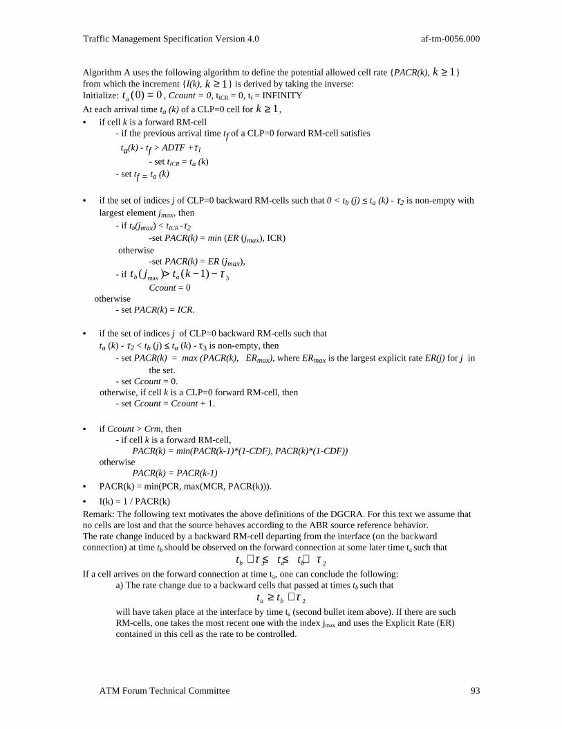
Traffic Management Specification Version 4.0 af-tm-0056.000
ATM Forum Technical Committee 93
Algorithm A uses the following algorithm to define the potential allowed cell rate {PACR(k), k ≥ 1}from which the increment {I(k), k ≥ 1} is derived by taking the inverse:Initialize: ta(0) = 0 , Ccount = 0, tICR = 0, tf = INFINITY
At each arrival time ta (k) of a CLP=0 cell for k ≥ 1,
• if cell k is a forward RM-cell- if the previous arrival time tf of a CLP=0 forward RM-cell satisfies
ta(k) - tf > ADTF +τ1
- set tICR = ta (k)- set tf = ta (k)
• if the set of indices j of CLP=0 backward RM-cells such that 0 < tb (j) ≤ ta (k) - τ2 is non-empty withlargest element jmax, then
- if tb(jmax) < tICR -τ2
-set PACR(k) = min (ER (jmax), ICR) otherwise
-set PACR(k) = ER (jmax),- if tb( jmax )> ta(k −1)− τ 3
Ccount = 0 otherwise
- set PACR(k) = ICR.
• if the set of indices j of CLP=0 backward RM-cells such thatta (k) - τ2 < tb (j) ≤ ta (k) - τ3 is non-empty, then
- set PACR(k) = max (PACR(k), ERmax), where ERmax is the largest explicit rate ER(j) for j in the set.
- set Ccount = 0. otherwise, if cell k is a CLP=0 forward RM-cell, then
- set Ccount = Ccount + 1.
• if Ccount > Crm, then- if cell k is a forward RM-cell,
PACR(k) = min(PACR(k-1)*(1-CDF), PACR(k)*(1-CDF))otherwise
PACR(k) = PACR(k-1)
• PACR(k) = min(PCR, max(MCR, PACR(k))).
• I(k) = 1 / PACR(k)Remark: The following text motivates the above definitions of the DGCRA. For this text we assume thatno cells are lost and that the source behaves according to the ABR source reference behavior.The rate change induced by a backward RM-cell departing from the interface (on the backwardconnection) at time tb should be observed on the forward connection at some later time ta such that
t t tb a b+ ≤ ≤ +τ τ3 2
If a cell arrives on the forward connection at time ta, one can conclude the following:a) The rate change due to a backward cells that passed at times tb such that
t ta b≥ + τ 2
will have taken place at the interface by time ta (second bullet item above). If there are suchRM-cells, one takes the most recent one with the index jmax and uses the Explicit Rate (ER)contained in this cell as the rate to be controlled.
af-tm-0056.000 Traffic Management Specification Version 4.0
ATM Forum Technical Committee94
b) If a cell with index jmax has been identified, if the cell k is CLP=0 forward RM-cell, and if theprevious forward CLP=0 RM-cell arrival time tf satisfies ta(k) - tf > ADTF +τ1 one concludes
that the reduction of ACR down to ICR (source behavior #5) has taken effect. If tb(jmax) < tICR -τ2
then the decrease to ICR must have occurred at the source after backward RM-cell jmax reachedthe source. In that case, PACR(k) is possibly further reduced by replacing ER (jmax) with min(ER (jmax), ICR) (first and second bullet items above).c) If no cell with index jmax can be identified, one takes ICR as the rate to be controlled.d) At the arrival of a forward cell at time ta, Ccount is a lower bound on the number of forwardRM-cells that have left the source since the last backward RM-cell that it received (as in SourceBehavior #6). Backward RM-cells transmitted from the interface to the source at time tb such that
ta < tb + τ3
should not have been received by the source before it had transmitted the cell arriving at theinterface at time ta. Thus, if the forward cell k-1 arrived at time ta(k-1) such that
ta(k −1) < tb( j max) + τ3
then the forward cell k-1 must have left the source before the backward RM-cell departing theinterface at time tb(jmax) arrived at the source. If forward cell k then arrives at the interface at timeta(k) such that
ta(k) ≥ tb( jmax) +τ 2
it is considered to be the first cell leaving the source after the arrival there of the RM-cell jmax, sothat Ccount is set equal to zero in this case (second bullet from above).e) Backward RM-cells that passed at times tb such that
tb + τ3 ≤ ta < tb + τ 2.may also have an impact on the rate at time ta. To be on the safe side, one takes the maximum ofthese rates. Then one takes the maximum of this rate and the rate derived from part a)-c) aboveas the rate to be controlled (second bullet item above).f) If Ccount > Crm and cell k is a forward CLP=0 RM-cell, PACR(k) has to reduced byCDF*PACR(k) (source behavior #6). At the same time, PACR(k) should be at most equal to thePACR at the last forward RM-cell times (1-CDF). But PACR at the last forward RM-cell is justPACR(k-1) since one sets PACR(k) to PACR(k-1) if the cell is not an RM-cell.
III.3 Algorithm B to Determine I(k)
Algorithm B, which follows, is a method to determine the increment I(k) for the DGCRA. The resultingconformance test is an approximation to the conformance test in Appendix III.2 in the following sense: Ata forward CLP=0 cell arrival, the Potential Allowed Cell Rate (PACR) derived in the Algorithm B isgreater than or equal to the PACR resulting from the conformance test in Appendix III.2. The proposedconformance algorithm meets the design constraints for an ABR conformance test stated in Section 4.5.5.Like Algorithm A, Algorithm B derives the PACR from the explicit rates ER(j) received in the backwardRM-cells. A received backward RM-cell results in a delayed increase or a delayed decrease of PACR. Rateincreases are scheduled with a delay of τ3 or earlier. Rate decreases are scheduled with a delay of τ2 orlater.For the sake of simplicity, at most two rate change events are scheduled: The first event is scheduled attime t_first with delayed explicit cell rate DER_first. The second (and last) event is scheduled at timet_last with DER_last. DER_last when scheduled is always a decrease in rate. Whether an explicit rateER(j) results in a rate increase or rate decrease is determined by comparing ER(j) with DER_first and withPACR. If ER(j) is greater or equal to DER_first and PACR then a rate increase is scheduled. If ER(j) issmaller than DER_first then a rate decrease is scheduled.If a rate increase has been scheduled for time t_first and this rate has not yet taken effect, then a furtherrate increase uses the same scheduled increase time t_first with a rate equal to the maximum of the oldDER_first and ER(j). This further rate increase takes then effect with a delay less than τ3 while the firstincrease scheduled for time t_first takes effect with delay τ3. If the first rate change event is a rate decreaseand this rate has not taken effect then a rate increase is scheduled for time t_first but not later than t_now

Traffic Management Specification Version 4.0 af-tm-0056.000
ATM Forum Technical Committee 95
+ τ3. If a decreased delayed cell rate has been scheduled, then a another further rate decrease is scheduledfor time t_last = tb(j) + τ2. Further rate decreases overwrite t_last until the first rate has taken effect.The first part of the algorithm schedules rate increases or rate decreases after arrival of a backwardRM-cell. The last part is used at the arrival of a CLP=0 cell in the forward direction to determine whetherthis cell is conforming. This is done by using an algorithm equivalent to the GCRA.A return of the rate down to ICR is reflected in Algorithm B if the last CLP=0 backward RM-cell arrivedat the source well before the return time to ICR (source behavior #5). In that case, the variableICR_elegible is set equal to “TRUE” and only then can PACR be reduced down to ICR.The following algorithm provides an approximate ABR conformance test:Initialize: t_first = t_last = LVST = 0; t f = INFINITY; ICR_elegible = FALSE; DER_first = DER_last = PACR = ICR; I_old = 1/ICR;
At each t b(j) after a CLP=0 backward RM-cell departure with explicit rate
ER(j): ER(j) = min(PCR, max(MCR, ER(j))); IF ER(j) ≥≥ DER_first (* increase over first scheduled rate? *) THEN t_last = 0; (* un-schedule future decrease rate (if any))*) DER_first = ER(j); (* update scheduled rate *) DER_last = ER(j); IF t_first < t b(j) (* no first rate scheduled? *)
THEN t_first = t b(j) + ττ3; (* schedule new increase *)
IF ER(j) ≥≥ PACR
THEN t_first = min (t_first, t b(j) + ττ3);
(* reschedule if DER_first was decrease *)
IF ER(j) < DER_first (* decrease over the current, first scheduled increase? *)
THEN t_last = t b(j) + ττ2 (* schedule the time for the decrease *)
DER_last = ER(j) (* schedule the decreased rate *) IF t_first < t b(j) (* first event has taken place? *)
THEN t_first = t_last; DER_first = ER(j); (*schedule first event like second event *)
IF t b(j) + ττ2 < t f + ADTF - ττ1 (*cell arrives at source before a possible
rate return down to ICR? *) THEN ICR_elegible = TRUE; ELSE ICR_elegible = FALSE;
When real time t reaches t_first: PACR = DER_first; t_first = t_last; DER_first = DER_last;
At arrival of a forward CLP=0 cell at time t a(k):
IF cell k is a CLP=0 forward RM-cell
THEN IF t a(k) - t f > ADTF + ττ1 and ICR_elegible=TRUE
THEN PACR=min(PACR, ICR); t f = t a(k); ICR_elegible = FALSE;
I(k) = 1/PACR
I' = min(I(k), I_old); (* I' is an auxiliary increment variable *)
IF LVST + I' ≤≤ t_now + ττ1 (* cell conforming? *)
THEN LVST = max (t a(k), LVST + I');

af-tm-0056.000 Traffic Management Specification Version 4.0
ATM Forum Technical Committee96
I_old = I(k); (* cell conforming, update parameters *)ELSE ; (* cell not conforming *)
III.4 Measures of ABR RM-Cell Compliance: Examples
The source behavior in Section 5.10.4 and destination behavior in Section 5.10.5 state explicit conditionsunder which forward and backward RM-cells shall be sent with CLP=0. From the perspective of a source,these conditions result in a specific ordering of forward and backward RM-cells relative to other cells onthe connection. Switch behavior #3, however, allows RM-cells to be served out of sequence with respect todata cells at switches. As a result, a specific ordering of forward and backward RM-cells and other cellscannot be expected at network interfaces. Nevertheless, the relative numbers of each type of cell receivedat an interface over sufficiently long intervals should observe certain constraints. The section providesexamples of such constraints.Source Behavior #3 in Section 5.10.4 results in three distinct regions for the generation of CLP=0 forwardRM-cells. In the first region, one forward RM-cell is sent for every Nrm CLP=0 cells on the connectionand at least at a rate of one per interval Trm. In the second region, one forward RM-cell is sent perinterval Trm. Finally, in the third region, one forward RM-cell is sent per Mrm+1 cells on the connectionbut at a rate no greater than one per interval Trm. As a result, over any interval of length L (in seconds),
the number RCLP= 0f
of CLP=0 forward RM-cells received on the forward connection at the public or
private UNI or BICI and the total number RCLP=0 of CLP=0 cells received on the forward connection at theinterface should satisfy
c ×RCLP=0
Nrm− d ≤ RCLP= 0
f ≤ max a,b× minRCLP= 0
Nrm+
L
Trm,
RCLP=0
Mrm +1
(C1)
where a, b, c, d, Nrm, Mrm, and Trm are constants common to all ABR connections at the interface. Theunits for a and d are cells and for Trm is seconds/cell. The constants b >1 and c <1, which describe thetolerance to deviations from ideal source behavior (as can occur if some cells are lost between the sourceand the interface in question) are dimensionless, as are Nrm and Mrm. The constants a and d account fordeviations from ideal ratios that occur when a small total number of cells are received at the interface onthe connection.
Likewise, over any interval of length L>τ2, the number RCLP= 0b
of CLP=0 backward RM-cells received at
the interface on the connection, the number TCLP= 0f
of CLP=0 forward RM-cells transmitted at the
interface on the corresponding backward connection, and the number TCLP=1f
of CLP=1 forward RM-cells
transmitted at the interface on the backward connection should satisfy
g × min TCLP=0
f, RCLP=0
f( )− h ≤ RCLP= 0
b ≤ max e, f × TCLP=0
f + TCLP=1
f +10L(S+1)( )( ) (C2)
where S is the number of switches through which the received backward RM-cells pass between thesource/destination and the interface in question, where e, f, g, and h are constants common to all ABRconnection at the interface and where τ2 is specified for the connection in question, as described earlier inSection 3.3.2. The constants e and h are in units of cells, and the constants f>1 and g<1, which describethe tolerance to deviations from the ideal source/destination behavior, are dimensionless.An ABR connection that observes the reference behavior for an ABR source also should copy its mostrecently calculated Allowed Cell Rate (ACR) into the Current Cell Rate (CCR) field and its MinimumCell Rate (MCR) into the MCR field of each forward RM-cell. When the forward RM-cell arrives at theprivate or public UNI or BICI, its CCR field should not exceed the inverse of the increment calculated bythe algorithm DGCRA(MCR
-1,PCR
-1,ICR
-1, τ1, τ2, τ3) at that time, and its MCR field should not exceed
the negotiated MCR for the connection. Hence, the number RVf of forward RM-cells received at the
interface with CCR field more than the inverse of the calculated DGCRA increment or with MCR fieldgreater than the negotiated MCR should satisfy
RVf ≤ max u,v × RCLP=0
f + RCLP=1f( )( ) (C3)

Traffic Management Specification Version 4.0 af-tm-0056.000
ATM Forum Technical Committee 97
over any interval, where RCLP=1f
is the number of CLP=1 forward RM-cells received on the forward
connection over the interval and u and v are constants common to all ABR connections at the interface.The constant u is in units of cells, and the constant v is dimensionless. Condition (C3) assures that theratio of the number RV
f of forward RM-cells with CCR or MCR field in violation to the total number
RCLP= 0
f + RCLP=1
f of forward RM-cells is close to 0, except when RCLP= 0
f + RCLP=1
f is small (i.e.,
RCLP= 0
f + RCLP=1
f< u/v).
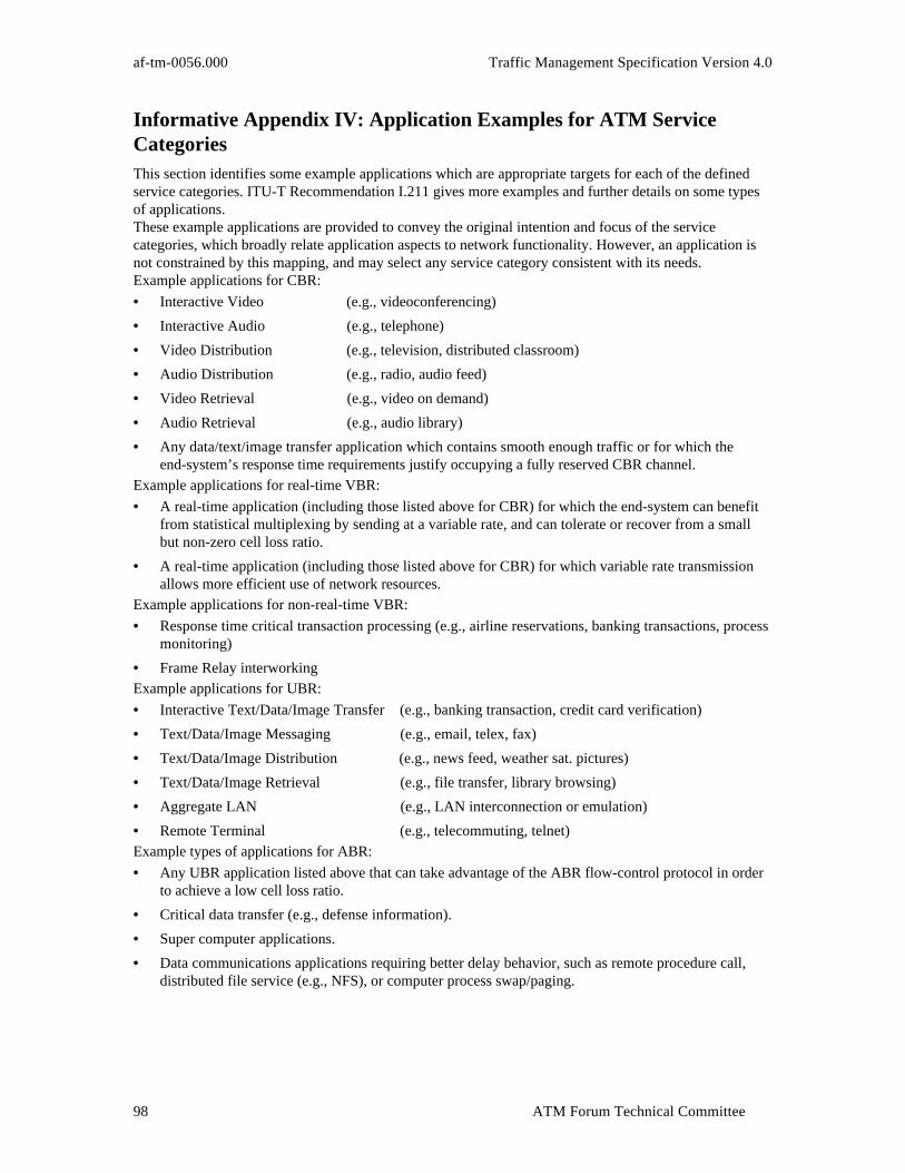
af-tm-0056.000 Traffic Management Specification Version 4.0
ATM Forum Technical Committee98
Informative Appendix IV: Application Examples for ATM ServiceCategoriesThis section identifies some example applications which are appropriate targets for each of the definedservice categories. ITU-T Recommendation I.211 gives more examples and further details on some typesof applications.These example applications are provided to convey the original intention and focus of the servicecategories, which broadly relate application aspects to network functionality. However, an application isnot constrained by this mapping, and may select any service category consistent with its needs.Example applications for CBR:
• Interactive Video (e.g., videoconferencing)
• Interactive Audio (e.g., telephone)
• Video Distribution (e.g., television, distributed classroom)
• Audio Distribution (e.g., radio, audio feed)
• Video Retrieval (e.g., video on demand)
• Audio Retrieval (e.g., audio library)
• Any data/text/image transfer application which contains smooth enough traffic or for which theend-system’s response time requirements justify occupying a fully reserved CBR channel.
Example applications for real-time VBR:
• A real-time application (including those listed above for CBR) for which the end-system can benefitfrom statistical multiplexing by sending at a variable rate, and can tolerate or recover from a smallbut non-zero cell loss ratio.
• A real-time application (including those listed above for CBR) for which variable rate transmissionallows more efficient use of network resources.
Example applications for non-real-time VBR:
• Response time critical transaction processing (e.g., airline reservations, banking transactions, processmonitoring)
• Frame Relay interworkingExample applications for UBR:
• Interactive Text/Data/Image Transfer (e.g., banking transaction, credit card verification)
• Text/Data/Image Messaging (e.g., email, telex, fax)
• Text/Data/Image Distribution (e.g., news feed, weather sat. pictures)
• Text/Data/Image Retrieval (e.g., file transfer, library browsing)
• Aggregate LAN (e.g., LAN interconnection or emulation)
• Remote Terminal (e.g., telecommuting, telnet)Example types of applications for ABR:
• Any UBR application listed above that can take advantage of the ABR flow-control protocol in orderto achieve a low cell loss ratio.
• Critical data transfer (e.g., defense information).
• Super computer applications.
• Data communications applications requiring better delay behavior, such as remote procedure call,distributed file service (e.g., NFS), or computer process swap/paging.

Traffic Management Specification Version 4.0 af-tm-0056.000
ATM Forum Technical Committee 99
Informative Appendix V: Example of a Future CDV AccumulationMethodThis appendix contains a method for peak-to-peak CDV accumulation called the asymptotic method. Thismethod is an example of how the simple method for peak-to-peak CDV accumulation described in Section3.6.2 could be enhanced in future versions of this specification.
V.1 Values Determined Directly from the Delay Density
To accomplish the accumulation, any switch must first be able to determine three parameters intrinsic tothe switch, determined from the probability density function of the delay of Figure 3-2. This delay densityfunction may be determined analytically or through measurements. If the delay density function isdetermined through measurements then the test cases should include a wide variety of background trafficpatterns. The details of determining the density function are implementation specific, but it is expectedthat this density function will be determined based on the switch itself and will require no real-timecomputation. Of particular importance is the probabilistic queuing delay, which is given by the probabilitydensity translated to the left so that the fixed delay is 0. The three parameters precomputed from theprobability density function are:
• The mean queuing delay, µ: Since the transfer delay is the fixed delay plus the queuing delay, we canalso express µ as the mean transfer delay minus the fixed delay.
• The variance of the queuing delays σ2 (or equivalently the standard deviation σ): Since variance isnot sensitive to translation, this is the same as the variance of the cell transfer delay.
• The cell delay variation for the switch, CDV(α): This depends on the parameter α. It is expected thatthe switch will precompute a table of values for CDV(α) over a range of α.
V.2 Derived Values Precomputed at the Switch
Using these three parameters, the switch must compute a value called the discrepancy. The discrepancycan be thought of as a measure of how different the probability density function of the delay is from aGaussian density of the same mean and variance: it measures the difference in values along the x-axisbetween the start of the α-tail of the switch queuing density and the start of the α-tail of the Gaussiandensity. Figure V-1 below illustrates the idea.
Q ueuing DelayDis tribution
G aus s ian D is tribution,S am e M ean & V ariance
Dis c repanc y
Figure V-1: The discrepancy of a queuing delay densityIt is useful to have a table of the abscissas for which the standard normal density has tail size α. The tablebelow gives, for some values of α, the value t(α), defined as the point on the x-axis where a Gaussianrandom variable with mean 0 and standard deviation 1 has right-hand tail area α. For convenience, u(α),

af-tm-0056.000 Traffic Management Specification Version 4.0
ATM Forum Technical Committee100
the reciprocal of t(α) is also given. The precision of the values given is not meant to imply a precision ofcalculation required of the switch, nor are the values of α given here required to be those supported by aswitch.
-log10 α t(α) u(α)
1 1.2815516 0.780304152 2.3263479 0.429858323 3.0902323 0.323600274 3.7190165 0.268888295 4.2648908 0.234472596 4.7534243 0.210374667 5.1993376 0.192332198 5.6120012 0.178189559 5.997807 0.1667276110 6.3613409 0.1571995611 6.7060232 0.1491196812 7.0344838 0.1421568413 7.3487961 0.13607671 14 7.6506281 0.1307082215 7.9413453 0.12592325
Table V-1: Unit Gaussian right-hand tail areasThe definition of the discrepancy can now be given by converting the numbers for the mean 0, standarddeviation 1 Gaussian density to those of the queuing density. The parameter of interest is:The discrepancy d(α) = CDV(α) - (µ + σ * t(α)).
V.3 Parameters used in Accumulation Algorithms
The previous two sections introduced four parameters that can be determined prior to any signaling. Onlythree of these are used in the accumulation algorithm. The fourth parameter, the fixed delay, which isintrinsic to the switch, is also needed. Thus for the accumulations, the following parameters are used:• The mean queuing delay µ;
• The variance of queuing delays σ2;
• The discrepancy d(α);• The fixed delay f.
V.4 Accumulation Algorithms
The accumulation of peak-to-peak CDV and max CTD require signaling of a total of four accumulationparameters: M, V, D, F. Each of these is initialized to the value of 0 at the source. Parameters M, V and Fare increased additively: at each switch, M is replaced by M+µ, V is replaced by V+σ2, and F is replacedby F+f. The parameter D is a maximum of the discrepancies along the path, and so D is replaced bymax{d, D}.The estimated cumulative peak-to-peak CDV is M + t(α) * V1/2 + D. This needs to be no more than therequested peak-to-peak CDV for the call to be accepted. This test can be algebraically rewritten as
((Requested peak-to-peak CDV - M - D) * u(α)) 2 ≥ V,to avoid computation of a square root, if desired.The estimated max CTD is the estimated peak-to-peak CDV plus the sum of the fixed delays F.The mean CTD can be estimated as the sum of F+M, and does not require use of the parameters V or D.
END OF DOCUMENT