AIRCRAFT ACCIDENT REPORT
128
AIRCRAFT ACCIDENT REPORT AASL/2019/01/03/F Accident Investigation Bureau Final Report on the serious incident involving Boeing 737-500 Aircraft with nationality and registration marks 5N-AIS, operated by Azman Air Services Limited, which occurred at Port-Harcourt; Nigeria on 3rd January, 2019
-
Upload
khangminh22 -
Category
Documents
-
view
1 -
download
0
Transcript of AIRCRAFT ACCIDENT REPORT

AIRCRAFT ACCIDENT
REPORT AASL/2019/01/03/F
Accident Investigation Bureau
Final Report on the serious incident involving Boeing 737-500 Aircraft with nationality and
registration marks 5N-AIS, operated by Azman Air Services Limited, which occurred at Port-Harcourt;
Nigeria on 3rd January, 2019

Aircraft Accident Report
AAS/2019/01/03/F
5N-AIS
Printed in Nigeria for the Accident Investigation Bureau (AIB)
This report was produced by the Accident Investigation Bureau, Nigeria (AIB),
Nnamdi Azikiwe International Airport, Abuja.
The report was based upon the investigation carried out by AIB, in accordance with
Annex 13 to the Convention on International Civil Aviation, Civil Aviation Act 2006
and Civil Aviation (Investigation of Air Accidents and Incidents) Regulations 2019. In
accordance with Annex 13 to the Convention on International Civil Aviation, it is not
the purpose of aircraft accident/serious incident investigations to apportion blame or
liability.
Readers are advised that AIB-N investigates for the sole purpose of enhancing
aviation safety. Consequently, AIB reports are confined to matters of safety
significance and should not be used for any other purpose.
The AIB believes that safety information is of great value if it is passed on for the
use of others. Hence, readers are encouraged to copy or reprint reports for further
distribution, acknowledging the AIB as the source.
Safety Recommendations in this report are addressed to the Regulatory Authority of
the State, as well as other stakeholders, as appropriate. The Regulatory Authority is
the authority that ensures implementation and enforcement.
©Accident Investigation Bureau, Nigeria 2020.

Aircraft Accident Report
AAS/2019/01/03/F
5N-AIS
i
TABLE OF CONTENTS
TABLE OF CONTENTS .....................................................................................I
TABLE OF FIGURES ....................................................................................... V
GLOSSARY OF ABBREVIATIONS USED IN THIS REPORT .......................... VII
SYNOPSIS ..................................................................................................... 1
1.0 FACTUAL INFORMATION ..................................................................... 4
1.1 History of the flight.............................................................................. 4
1.2 Injuries to persons .............................................................................. 7
1.3 Damage to aircraft .............................................................................. 7
1.4 Other damage ..................................................................................... 7
1.5 Personnel information .......................................................................... 7
1.5.1 Pilot ......................................................................................... 7
1.5.2 Co-Pilot .................................................................................... 8
1.6 Aircraft information ............................................................................. 9
1.6.1 General information .................................................................. 9
1.6.2 Power plant .............................................................................. 9
1.6.3 Maintenance records of the number two engine ........................ 22
1.7 Meteorological information ................................................................. 23
1.8 Aids to navigation .............................................................................. 24
1.9 Communications ................................................................................ 24

Aircraft Accident Report
AAS/2019/01/03/F
5N-AIS
ii
1.10 Aerodrome information ...................................................................... 24
1.11 Flight recorders ................................................................................. 25
1.11.2 Flight Data Recorder report ................................................... 25
1.12 Wreckage and impact information ...................................................... 30
1.13 Medical and pathological information .................................................. 31
1.14 Fire .................................................................................................. 31
1.15 Survival aspects ................................................................................ 31
1.16 Test and research.............................................................................. 32
1.16.1 Borescope inspection report on number two engine ................ 32
1.16.2 Condition of the magnetic chip detector after the occurrence ... 36
1.17 Organizational and management information ...................................... 43
1.17.1 Azman Air Services Limited .................................................... 43
1.17.2 Nigerian Civil Aviation Authority (NCAA) ................................ 58
1.18 Additional information ........................................................................ 59
1.18.1 Flight Data Monitoring/Flight Data Analysis programme ........... 59
1.18.2 Safety management requirements of Annex 6 ......................... 61
1.18.3 Situation Awareness (SA) ...................................................... 62
2.0 ANALYSIS ........................................................................................... 63
2.1 General ............................................................................................. 63
2.2 Flight crew qualification and composition ............................................ 63
2.3 Conduct of the flight .......................................................................... 64

Aircraft Accident Report
AAS/2019/01/03/F
5N-AIS
iii
2.4 Number two engine vibration, engine surge and oil filter by-pass ......... 66
2.5 Flight Data Monitoring (FDM) programme ........................................... 68
2.5.1 Azman Air Flight Data Monitoring (FDM) programme ................. 68
2.5.2 Oversight of Azman Air’s Flight Data Monitoring program ............ 70
2.5.3 Regulatory requirements of Flight Data Monitoring program ........ 70
3.0 CONCLUSION ..................................................................................... 72
3.1 Findings ............................................................................................ 72
3.2 Causal factor ..................................................................................... 74
3.3 Contributory factors ........................................................................... 74
4.0 SAFETY RECOMMENDATIONS ............................................................ 75
4.1 Interim Safety Recommendations issued in the Preliminary Report ....... 75
4.1.1 Immediate Safety Recommendation (issued 4th February, 2019)
75
4.2 Safety Recommendations issued in this report ..................................... 75
4.2.1 Safety Recommendation 2021-001 ........................................... 75
4.2.2 Safety Recommendation 2021-002 ........................................... 75
4.2.3 Safety Recommendation 2021-003 ........................................... 76
4.2.4 Safety Recommendation 2021-004 ........................................... 76
4.2.5 Safety Recommendation 2021-005 ........................................... 76
4.2.6 Safety Recommendation 2021-006 ........................................... 76
4.2.7 Safety Recommendation 2021-007 ........................................... 76

Aircraft Accident Report
AAS/2019/01/03/F
5N-AIS
iv
APPENDICES ............................................................................................... 77
Appendix 1: Flight Data Monitoring (FDM) Report .......................................... 77

Aircraft Accident Report
AAS/2019/01/03/F
5N-AIS
v
TABLE OF FIGURES
Figure 1: CFM56-3 engine major section component location ................................ 11
Figure 2: Oil supply system schematic ................................................................. 13
Figure 3: Oil scavenge and vent system .............................................................. 14
Figure 4: Magnetic Chip Detector inspection ........................................................ 17
Figure 5: Engine indicating system ...................................................................... 19
Figure 6: High pressure turbine vibration of number two engine ........................... 26
Figure 7: The Engine 2 High pressure turbine vibration gradually decreased over a
period of 90 seconds .......................................................................................... 26
Figure 8: Engine 2 N1 decreased to 68% and then increased to 85% over a period
of 5 sec. ............................................................................................................ 27
Figure 9: Engine 2 fan, compressor and turbine vibration. .................................... 28
Figure 10: Engine 2 Cut-off parameter toggled .................................................... 29
Figure 11: The Flight path of AZM 2316 showing two Go-Arounds with a successful
landing on the third approach ............................................................................. 30
Figure 12: The aircraft after the incident ............................................................. 31
Figure 13: Combustor Nozzle- Dome discoloration and carbon deposit around the
Nozzle Guide Vane ............................................................................................. 33
Figure 14: Burn and missing material of the HPT nozzle ....................................... 34
Figure 15: Trailing edge slots delamination and missing codep coating of HPT blade
......................................................................................................................... 34
Figure 16: Nozzle Guide Vanes Leading edge and Preservation Oil ........................ 35
Figure 17: Burned and missing discourager seal ................................................... 35
Figure 18: Rubbing no overlap of high pressure turbine blade............................... 36
Figure 19: Number two engine Magnetic Chip Detector aft sump showing metallic
particles ............................................................................................................ 37
Figure 20: High Pressure Compressor Blades stages 1-9 heavy tip rub ................ 38
Figure 21: High Pressure Compressor Blades tip rub ............................................ 38

Aircraft Accident Report
AAS/2019/01/03/F
5N-AIS
vi
Figure 22: High pressure Compressor Heavy rub on Cases and stationary Air seals
Stage 1-5 .......................................................................................................... 39
Figure 23: High pressure Compressor Heavy rub on Cases ................................... 40
Figure 24: High pressure Compressor rub on Cases.............................................. 40
Figure 25: High pressure Compressor (HPC) blades rear cases heavy rub .............. 41
Figure 26: High pressure Compressor (HPC) blades rear cases rub ........................ 42

Aircraft Accident Report
AAS/2019/01/03/F
5N-AIS
vii
GLOSSARY OF ABBREVIATIONS USED IN THIS REPORT
A/P Autopilot
A/T Auto Throttle
AASL Azman Air Services Limited
AD Airworthiness Directive
AGB Accessory Gearbox
AGL Above Ground Level
AIB Accident Investigation Bureau
AMM Aircraft Maintenance Manual
AOC Air Operator Certificate
APU Auxiliary Power Unit
ARFFS Aerodrome Rescue and Fire Fighting Service
ATC Air Traffic Control
ATPL Airline Transport Pilot License
AVM Airborne Vibration Monitoring
BSI Borescope Inspection
CDU Control Display Unit
CL Classic
CRM Crew Resource Management
CRS Certificate of Release to Service

Aircraft Accident Report
AAS/2019/01/03/F
5N-AIS
viii
CVR Cockpit Voice Recorder
DME Distance Measuring Equipment
DNMM Murtala Muhammed International Airport
DNPO Port Harcourt International Airport
ECAM Electronic Centralized Aircraft Monitor
EICAS Engine Indicating and Crew-Alerting System
ENG Engine
EPR Engine Pressure Ratio
FAAN Federal Airports Authority of Nigeria
FCT Federal Capital Territory
FDA Flight Data Analysis
FDM Flight Data Monitoring
FDR Flight Data Recorder
FL Flight Level
FMC Flight Management Computer
FOB Fuel on Board
FOD Foreign Object Damage/ Foreign Object Debris
FOQA Flight Operations Quality Assurance
FP Flight Purser
FPM Feet Per Minutes
GS Glide Slope

Aircraft Accident Report
AAS/2019/01/03/F
5N-AIS
ix
h Hour
HPC High Pressure Compressor
HPR High Pressure Ratio
HPT High Pressure Turbine
Hrs Hours
IFR Instrument Flight Rules
IFSD In flight Shut Down
ILS Instrument Landing System
IMC Instrument Meteorological Conditions
Kt Knots
LPC Low Pressure Compressor
LPT Low Pressure Turbine
LRC Long Range Cruise
MA Missed Approach
MCD Magnetic Chip Detector
MCP Mode Control Panel
MHz Mega Hertz
MOPSC Maximum Operational Passenger Seating Capacity
MSA Minimum Safe Altitude
N1 Fan rotor speed in percent rpm
N2 High rotor speed in percent rpm

Aircraft Accident Report
AAS/2019/01/03/F
5N-AIS
x
NGV Nozzle Guide Vanes
Nig. CARs Nigeria Civil Aviation Regulations
NM Nautical Miles
OEI One-Engine Inoperative
OFDM Operational Flight Data Monitoring
PF Pilot Flying
PM Pilot Monitoring
POT APP Port Harcourt Approach
RPM (rpm) Rotations per Minute
RADALT Radio Altimeter
RWY Runway
SA Situational Awareness
SMM Safety Management Manual
SMS Safety Management System
TA Traffic Advisory
TAS True Air Speed
TGB Transfer Gearbox
TO/GA Take-off/Go around
UTC Coordinated Universal Time
VHF Very High Frequency Omni Directional Range
VREF Landing Reference Speed

Aircraft Accident Report
AAS/2019/01/03/F
5N-AIS
xi
VSV Variable Stator Vanes

Aircraft Accident Report
AAS/2019/01/03/F
5N-AIS
1
Aircraft accident report number: AAS/2019/01/03/F
Registered owner and operator: Azman Air Services Limited
Manufacturer: Boeing Aircraft Company, USA
Aircraft type and model: Boeing 737-500
Year of manufacture: 1998
Serial number: 29235
Nationality and registration marks: 5N-AIS
Location: Final Approach to Port-
Harcourt International Airport
Date and Time: 3rd January, 2019 at about
11:19 h, (All times in this
report are local time (UTC +1)
unless otherwise stated)
SYNOPSIS
The Accident Investigation Bureau (AIB) was notified of the occurrence by Azman Air
Services Limited (AASL) on 3rd January, 2019. A team of investigators were
dispatched to the site the next day and commenced investigation.
On 3rd January, 2019 at about 10:10 h, a Boeing 737-500 aircraft with nationality
and registration marks 5N-AIS operated by Azman Air Services Limited on a
scheduled flight AZM 2316, departed Murtala Mohammed International Airport Ikeja,
Lagos (DNMM); Nigeria for Port Harcourt International Airport, Port Harcourt
(DNPO); Nigeria on an Instrument Flight Rules (IFR) Flight Plan. On board were 114
persons including of two cockpit crew, three cabin crew and a fuel endurance of
three hours.
Aircraft Accident Report
AAS/2019/01/03/F
5N-AIS
2
About six minutes after take-off, the number two engine turbine vibration began to
rise and within 40 seconds it reached a peaked of 5.26 unit, stayed for about 40
seconds then gradually decreased and settled at 3.0 units within a period of 90
seconds. AZM 2316 levelled off at FL 290 in cruise with both engines operating at
N1 of 85% RPM. Two minutes later, the number two engine N1 dropped to 68% and
within five seconds it returned to 85%. This coincided with the time when the flight
crew heard a loud bang from the right side which caused airframe vibration and yaw
to the right. The flight crew concluded that the noise might be as a result of cargo
shift as the parameters of engines indicated normal.
AZM 2316 established contact with POT Approach and obtained inbound clearance to
POT for ILS/DME Approach RWY 21. About 13 minutes later, the aircraft began
descent, reported passing FL235 for FL210 and 98 NM on radial 285 inbound.
AZ2316 configured for landing, gears down, flaps set at 15°, 150 kts both engines
stable and symmetrical with N1 at approximately 57%. About a minute later, the
number two engine N1 started decreasing and within five seconds it dropped to 47%
causing asymmetric engine power while the number two turbine vibration began to
increase. At this time, the flight crew reported hearing another loud bang from the
right side accompanied by severe vibration and a yaw to the right. The number two
engine turbine vibration reached 9.90 units. The Approach became unstable, the
Autopilot disengaged, TO/GA was engaged accompanied by Autopilot warning.
About 25 seconds later, the number two engine N1 further decreased to 30%, its
fan vibration and Low pressure compressor vibration increased to 4 units
respectively. The flight crew executed a Missed Approach and AZM 2316 was
vectored to fly heading 350⁰ by the ATC.
The number two engine Oil Filter Bypass Light illuminated during the Go-Around.
The flight crew carried out a precautionary shutdown of number two engine in
accordance with the ENGINE OIL FILTER BYPASS checklist. The flight crew declared
emergency and AZM 2316 was vectored by ATC for the ILS RWY 21. The flight crew
stated that, they got preoccupied by the limitation of 10° bank and map shift, they

Aircraft Accident Report
AAS/2019/01/03/F
5N-AIS
3
did not align with the runway centreline passing through 500 ft RADALT while
experiencing high vibrations in number one engine. The aircraft crossed the localizer
extremely late at 150 ft AGL and one dot high. The Approach became unstable again
and flight crew executed a second Missed Approach.
The aircraft aligned properly on profile during the third landing attempt before
reaching the final approach fix. At 11:35 h, AZM 2316 landed on runway 21.
Causal factor
The failure of number 4 and 5 bearings of engine number 2 leading to loss of power
during approach.
Contributory factors
1. The failure to recognise the abnormal engine conditions (surge) during cruise
phase and hence, not making appropriate decision. This might have been
connected to the insufficient technical knowledge and loss of situational
awareness.
2. Non implementation of the Flight Data Monitoring programme in accordance
with 2.2.5.1 of Azman Air Safety Management System Manual.
3. Non rectification of the number two engine vibration anomalies recorded over
a period of 8 months.
4. Inadequate regulatory oversight of the Azman Air Safety Management
System.
The AIB issued one immediate safety recommendation to the Nigerian Civil Aviation
Authority in the preliminary report.
Seven further Safety Recommendations were issued in this Final Report.

Aircraft Accident Report
AAS/2019/01/03/F
5N-AIS
4
1.0 FACTUAL INFORMATION
1.1 History of the flight
On 3rd January, 2019 at about 10:10 h, a Boeing 737-500 aircraft with nationality
and registration marks 5N-AIS operated by Azman Air Services Limited on a
scheduled flight AZM2316, departed Murtala Muhammed International Airport Ikeja,
Lagos (DNMM); Nigeria for Port Harcourt International Airport, Port Harcourt
(DNPO); Nigeria on an Instrument Flight Rules (IFR) Flight Plan. On board were 114
persons including of two cockpit crew and three cabin crew with a fuel endurance of
three hours. The Pilot was the pilot flying (PF) and the Co-pilot was the pilot
monitoring (PM).
According to the crew, Lagos Air Traffic Control (ATC) cleared AZM2316 to cruise at
flight level FL290.
At 10:15:36 h, Flight Data Recorder (FDR) information showed that the number two
engine turbine vibration started to increase gradually over a period of 40 seconds
reaching a peak of 5.26 units. At 10:17 h, the turbine vibration gradually decreased
over a period of 90 seconds stabilizing at approximately 3.0 units.
At 10:22 h, AZM2316 established contact with Port Harcourt (POT) Air Traffic Control
(ATC) Approach and was given inbound clearance to POT for ILS/DME Approach
Runway (RWY) 21. At 10:26 h, AZM2316 levelled off at FL290. Both engines
appeared to be operating normally at the rotational speed of the low speed spool
(N1) of 85%. At 10:28 h, the number two engine N1 decreased to 68% and then
increased to 85% within a period of 5 seconds.
According to the flight crew, at about 20-25 minutes into the flight during cruise,
there was a sudden loud bang from the right side of the aircraft which caused
vibrations that lasted for less than 5 seconds followed by a yaw to the right. The
flight crew also stated that engine parameter indications were within normal range
with the Autopilot (A/P) and Auto Throttle (A/T) still engaged. The flight crew

Aircraft Accident Report
AAS/2019/01/03/F
5N-AIS
5
enquired from the Purser if the noise was heard in the cabin. The Purser confirmed
they heard it too. The flight crew then instructed the Purser to walk through the
cabin and check if there was anything unusual. He returned to inform the flight crew
that everything seemed normal. The flight crew then assumed the noise might be as
a result of cargo shift.
At 10:33 h, AZM2316 reported passing FL235 for FL210 as released by Lagos Area
Control. POT ATC acknowledged and then further cleared the aircraft to continue
descent to FL110 then requested AZM2316 to report distance and inbound radial to
POT. The crew reported 98 miles on radial 285 inbound.
At 10:52 h, AZM2316 commenced a right turn for finals DNPO RWY 21. Landing
gears were down, 150 kts and Flaps were set to 15°, both engines were stable and
symmetrical with N1 at approximately 57%. At 10:53:47 h, engine number 2 N1
started decreasing to 47% within a period of five seconds and its turbine vibration
started to increase. According to the flight crew, at about 4.5 NM AZM2316, was
already configured for landing when they heard a very loud deafening bang and
severe vibration from the number two engine. The aircraft yawed to the right and
the autopilot disengaged. The PF manually took over control to stabilise the aircraft
by applying left rudder. The PM reported asymmetric thrust even though the Auto-
Throttle was ON. The PF stabilised the aircraft and handed over controls to the Co-
pilot to enable him assess the situation. The pilot then confirmed the asymmetric
thrust and took back controls and elected to execute a missed approach. At
10:53:51 h, the A/P was disengaged and the TO/GA1 was engaged accompanied by
an A/P warning. The number two engine’s turbine vibration indicated severe
vibrations of 9.90 units. At 10:54:16 h, the number two engine fan vibration
increased to 4 units. At 10:55 h the crew then executed a missed approach and
were vectored to fly heading 350⁰ by the ATC.
1 TO/GA (Take-off/Go-around) is an auto pilot/auto throttle setting activating take-off or go-around thrust.
Depending upon aircraft type, it may be activated by depressing a switch or by manually moving the thrust levers to the appropriate position.

Aircraft Accident Report
AAS/2019/01/03/F
5N-AIS
6
The crew stated that, while reading the ENGINE FIRE or ENGINE SEVERE DAMAGE
or SEPARATION checklist of the B737 Quick Reference Handbook (QRH) during the
Go-Around, the number two engine Oil Filter Bypass Light illuminated. At about
10:59 h, the crew carried out a precautionary shutdown of number two engine in
accordance with the ENGINE OIL FILTER BYPASS Checklist of the B737 QRH. The
aircraft was vectored again by ATC for the ILS RWY 21; the crew further stated that,
they got preoccupied by the limitation of 10° bank and map shift, they did not align
with the runway centreline. At about 11:19 h, the flight crew declared emergency.
POT ATC Tower advised the Aerodrome Rescue and Fire Fighting Service (ARFFS) to
be on standby. At 11.21 h, during the second landing attempt, the aircraft did not
intercept the runway centreline passing through 500 ft RADALT while experiencing
high vibrations in number one engine, AZM2316 crossed the localizer extremely late
at a 150 ft AGL (Above Ground Level) and one dot high on the glide slope. The
Approach became unstable again. At about 11.22 h, the TO/GA was activated and
the flight crew executed a second Missed Approach.
During the second Go-Around, the crew reported field in sight, they decided to turn
around and conduct a visual approach for RWY 03. At 11:26 h, after turning left,
they realised that they were far off to the right of the extended centreline RWY 03,
so they requested to extend downwind and position for ILS on RWY 21.
According to the crew, as they started configuring the aircraft for the third approach,
they noticed that the vibration indication for number one engine was rising from 1 to
3 and opted to delay the deployment of flaps in case of loss of number one engine.
The aircraft got back on profile before reaching the final approach fix. At 11:35 h,
the aircraft landed on runway 21. The aircraft taxied to the ramp, parked and all
occupants disembarked unassisted and uninjured. The incident occurred in day time
in instrument meteorological condition.

Aircraft Accident Report
AAS/2019/01/03/F
5N-AIS
7
1.2 Injuries to persons
Injuries Crew Passengers Total in aircraft
Fatal Nil Nil Nil
Serious Nil Nil Nil
Minor Nil Nil Nil
None 5 109 114
Total 5 109 114
1.3 Damage to aircraft
The aircraft was not damaged
1.4 Other damage
Nil
1.5 Personnel information
1.5.1 Pilot
Nationality: Nigerian
Age: 43 years
Licence number: Airline Transport Pilot Licence (A)
Licence validity: 5th March, 2020
Aircraft ratings: Boeing 737-300/500, Hawker Siddeley
125/800XP, Embraer 170/190
Medical validity: 25th November, 2019
Simulator validity: 29th April, 2019

Aircraft Accident Report
AAS/2019/01/03/F
5N-AIS
8
Route/Line check: 9th December, 2018
Total flying time: 3, 724 h
Total flying time (PIC): 996 h
Total on type: 92 h
Total on type (PIC) 92 h
Last 90 days: 92 h
Last 28 days: 92 h
Last 24 hours: 0 h
The Pilot joined Azman Air Services Limited on 9th December, 2018 with zero hour
on Boeing 737. The pilot recent experience had been flying HS125 in corporate
aviation before joining Azman Air.
1.5.2 Co-Pilot
Nationality: Nigerian
Age: 24 years
Licence type: Commercial Pilot Licence (A)
Licence validity: 18th January, 2023
Aircraft ratings: Boeing 737-300/500
Medical validity: 9th December, 2019
Simulator validity: 28th March, 2019
Total flying time: 629 h
Total on type: 431 h
Last 90 days: 122 h
Last 28 days: 25 h
Last 24 hours: 0 h

Aircraft Accident Report
AAS/2019/01/03/F
5N-AIS
9
The Co-Pilot completed his Boeing 737 type training in March, 2018 and commenced
line training in June, 2018.
1.6 Aircraft information
1.6.1 General information
Type: B737-500
Manufacturer: Boeing Aircraft Company USA
Date of manufacture: 1998
Serial number: 29235
Certificate of Airworthiness validity: 30th November, 2019
Certificate of Insurance validity: 25th January, 2019
Certificate of Registration: Issued on 30th November, 2016
Noise Certificate: Issued on 30th November, 2016
Airframe time: 34, 675 h
1.6.2 Power plant
Engines Number one Number two
Engine model CFM56-3C-1 CFM56-3C-1
Serial number 722299 858813
Time since new 60,143 h 44,143 h
Cycles since new 36,412 30,658
1.6.2.1 CFM56 Engine description and operation
1. General
The CFM56-3 is a high bypass, dual-rotor, axial flow turbofan engine. The integrated
fan and booster (low pressure compressor - LPC) is driven by a 4 stage low pressure

Aircraft Accident Report
AAS/2019/01/03/F
5N-AIS
10
turbine (LPT). A single-stage high pressure turbine (HPT) drives the 9 stage high
pressure compressor (HPC). The two rotors are mechanically independent of each
other. Air entering the engine is divided into a primary (inner) airstream and a
secondary (outer) airstream after the primary airstream has been compressed by the
LPC and HPC, combustion of fuel in the annular combustion chamber increases the
HPC discharge air velocity to drive the high and low pressure turbines. An accessory
drive system off the N2 rotor drives engine and airplane accessory components. The
engine consists of 4 major sections: fan major module, core engine major module,
LPT major module and accessory drive system. It also includes the following
components which are not included in any section: spinner front cone, LPT shaft
plug and coupling nut, aft rotating air/oil separator, and oil inlet cover.
2. Engine
The engine is a dual-rotor, axial flow turbofan of high compression ratio and high
bypass ratio. The engine incorporates two multistage turbine-driven compressors
utilizing concentric shafting. The integrated fan and low pressure compressor,
consisting of one fan stage and three compressor (booster) stages is driven by a
four-stage low pressure turbine. The nine-stage high pressure compressor is driven
by a single-stage high pressure turbine. The engine starting system provides the
means for rotating the high pressure rotor (HPR) to establish airflow through the
engine. Rotation of the HPR drives the engine fuel pump and main engine control
and delivers metered fuel under pressure to the combustion chamber. The ignition
system is a high energy capacitor discharge system consisting of two electrically and
physically independent circuits serving separate igniter plugs. The engine includes a
complete self-contained oil system for lubrication and cooling of internal parts.
Thrust reverser mechanisms are utilized at the engine fan discharge to provide a
means of further decelerating the airplane during its landing roll. Various remote
transmitting devices are installed on the engine to provide indication in the flight
compartment of engine performance and condition. Source Boeing 737-300/400/500
Aircraft Maintenance Manual CFM56 Engines (CFM56-3)

Aircraft Accident Report
AAS/2019/01/03/F
5N-AIS
11
Figure 1: CFM56-3 engine major section component location
1.6.2.2 CFM56-3 Oil System
Description and Operation
1. General
A. The engine oil system is a self-contained, centervented and recirculating type
system. Each engine has an independant oil system to provide lubrication and
cooling for the engine main bearings, radial driveshaft bearings and gears and
bearings in the transfer gearbox (TGB) and accessory gearbox (AGB).
B. The oil system is comprised of oil storage, distribution, and indicating systems.
C. Indicating systems provide measurements of oil quantity, pressure, and oil
temperature. Warning lights also provide a low oil pressure warning, and oil filter
bypass warning. The condition of the engine oil system and the performance of
associated engine components are determined by visual indication of these systems
in the flight compartment.
Oil distribution - description and operation
The oil distribution system consists of the supply system and the scavenge system.
The supply system provides oil for lubrication and cooling to the main bearings,
radial driveshaft bearings, and transfer and accessory gearboxes (TGB/AGB). The

Aircraft Accident Report
AAS/2019/01/03/F
5N-AIS
12
scavenge system recovers the oil from the forward and aft sumps and the AGB/TGB
sump for filtering, cooling and recirculation.
The lubrication unit is located on the AGB near the bottom of the fan case on the left
side. It contains the following:
(1) Four positive displacement pumps (three scavenge pumps and the supply
pump).
(2) Oil supply filter, check valve and bypass valve with clogging indicator.
(3) Pressure relief valve located on the oil supply pump discharge side of the unit.
(4) Three magnetic chip detectors (MCD).
2. Operation
A. The oil tank provides storage of oil for continuous distribution by the supply
system. Oil flows from the tank to the supply pump in the lubrication unit on the
AGB. The oil is pressurized and is pumped through the oil supply filter to the main
bearings, radial driveshaft and gearboxes.
B. After distribution, oil is returned to the lubrication unit from three sumps. The
forward sump services the No. 1, No. 2 and No. 3 main bearings. The aft sump
services the No. 4 and No. 5 main bearings. The gearbox sump for the AGB also
collects oil through an external tube from the TGB.
C. The lubrication unit contains a scavenge pump for each sump. The oil is drawn
through one of three magnetic chip detectors (MCD) in the lubrication unit and is
pumped through the scavenge oil filter to the main oil/fuel heat exchanger. Cooled
oil is returned to the oil tank.
D. A drain is provided at the forward and aft bearing compartment for possible oil
leaking past the stationary air/oil seal. The forward seal drain exits through the 8
o'clock fan frame strut. The aft seal drain exits through the 6 o'clock turbine frame
strut.

Aircraft Accident Report
AAS/2019/01/03/F
5N-AIS
13
E. The bearing sumps and gearboxes are interconnected to collect oil vapors before
air/oil separation and venting. The oil tank vent and the TGB/AGB sump are
connected to the forward sump. Vapors from the forward and aft sumps pass
through rotating air/oil separators into the main shaft center vent tube to be vented
out the exhaust. The separated oil is returned to the sumps.
Figure 2: Oil supply system schematic

Aircraft Accident Report
AAS/2019/01/03/F
5N-AIS
14
Figure 3: Oil scavenge and vent system
….
Oil filter bypass warning system
Description and operation
1. General
A. The oil filter bypass warning system provides an indication in the flight
compartment of a clogged scavenge oil filter element and an impending filter

Aircraft Accident Report
AAS/2019/01/03/F
5N-AIS
15
bypass. The system consists of an oil filter differential pressure switch and an oil
filter bypass warning light for each engine.
2. Oil filter differential pressure switch
A. The oil filter differential pressure switch is a snap-action pressure sensitive switch.
The high pressure side of the switch is connected to the oil inlet side of the
scavenge filter housing. The low pressure side is connected to the scavenge filter
outlet tube. The oil filter differential pressure switch is attached to a bracket
mounted on the lubrication unit.
3. Oil filter bypass warning light
A. Two amber oil filter bypass warning lights, one for each engine, are located on
the pilot's center instrument panel, P2. Lights illuminate to indicate oil scavenge filter
bypass.
4. Operation
A. 28 volts dc power is supplied to the oil filter bypass warning system from the P6-3
breaker panel.
B. As the scavenge filter becomes clogged, the pressure differential across the
switch increases.
C. When it gets to 25 to 27 psig, the switch closes to complete the warning light
circuit and the warning light for the oil filter bypass comes on.
NOTE: During the first start of the day or during cold weather starts, the oil pressure
can go above the normal range and the oil filter bypass light can come on. Operate
the engine at idle power; the filter bypass light should go off as the oil warms and
the pressure returns to normal.
….
Oil consumption limits
Normal oil consumption is less than 0.4 U.S. quarts/hour or 0.1 U.S. gallons/hour
(0.38 liters/hour). If you find increased oil consumption that meets the conditions

Aircraft Accident Report
AAS/2019/01/03/F
5N-AIS
16
that follow, you must find the cause and take corrective action; do the engine oil
trouble shooting procedure:
(a) Oil consumption that shows a gradually increasing trend.
(b) Oil consumption that shows a sudden step increase.
(c) Oil consumption that is more than 0.8 U.S. quarts/hour or 0.2 U.S. gallons/hour
(0.76liters/hour). Oil consumption must not be more than a maximum of 1.6 U.S.
quarts/hour or 0.4 U.S. gallons/hour (1.5 liters/hour).
….
Magnetic Chip Detectors (MCD)
Three magnetic chip detectors are used on the lubrication unit, one on the inlet of
each scavenge pump. Each has a removable magnetic plug and a scavenge screen.
They trap particulates before entering the lubrication unit.
Metal contamination can be an indication of distress of the parts in the oil lubricated
parts of the engine. However, the MCD's can collect material not related to engine
parts. The materials can be shot peen material of approximately 0.008 inch (0.29
mm), tool parts, and machine particles. See figure 603

Aircraft Accident Report
AAS/2019/01/03/F
5N-AIS
17
Figure 4: Magnetic Chip Detector inspection
1.6.2.3 Airborne Vibration Monitoring (AVM) system
Description and operation
1. General
The airborne vibration monitoring (AVM) system continuously shows the engine
vibration level. The system consists of two accelerometers (vibration sensors) and a
vibration indicator for each engine and an AVM signal conditioner. Power for the
system is 115 volts ac supplied from transfer bus 1.
Abnormal engine vibration, sudden or progressive, is a positive indication of engine
malfunction. Abnormal vibration can be caused by compressor or turbine blade
damage, rotor imbalance, or other problems. Early warning of engine malfunction
permits corrective action before extensive damage results.
With the engine operating, the engine accelerometers generate signals proportional
to engine motion in radial direction. These signals are received by the AVM signal
conditioner, where they are converted to signals suitable for indicator operation.
Signals are then sent to the vibration indicator. The AVM indicator is shown on the
secondary display as a simulated electro-mechanical device.

Aircraft Accident Report
AAS/2019/01/03/F
5N-AIS
18
2. Engine Vibration Sensors
The engine accelerometers sense engine vibration in terms of engine acceleration in
a radial direction and generate electrical signals proportional to the engine
acceleration. The accelerometers are of the piezoelectric type.
3. AVM Signal Conditioner
The AVM signal conditioner processes inputs from vibration sensors, N1 and N2
speed sensors. The monitor unit is programmed to determine the N1 and N2 rotor
vibration from the fan and core sensors. The unit is a microprocessor with BITE,
self-test and flight data history functions. Have a linear scale for flight compartment
indication. The scale from 0 - 5 scalar units can be compared to a scale of 0 - 10
mils DA (Double Amplitude) of vibration.
4. AVM Indicator
The AVM indicator shows the vibration level of the two engines.
The AVM indicator displays constantly the highest measured vibration values of the
Fan or High Pressure Compressor (HPC). The indicator value for the Fan is
normalized (converted to scaler units) and the HPC value is linear. The indicator
values are displayed in scaler units (s.u.) from 0 to 5 s.u.
The AVM indicator is shown on the secondary EIS display as a simulated electro-
mechanical device.

Aircraft Accident Report
AAS/2019/01/03/F
5N-AIS
19
Figure 5: Engine indicating system
….
Engine vibration guidelines
(1) If the momentary vibration level is greater than 4 units but less than 1 minute in
duration:
(a) No maintenance action is necessary, but only if the vibration indication is not
associated with the aircraft vibration felt by the flight crew and the indication did not
repeat during the flight or during subsequent flights.
(2) If the vibration level is equal to or less than 4 units, use the AVM flight history to
determine the source of the vibration.
(a) If the source of the AVM indication is fan vibration:
1) If engine noise or vibration is felt in the cabin or flight deck during climb or cruise
conditions and the AVM indications are due to fan vibration:
a) No maintenance action is necessary. It is recommended that you do one of
these applicable fan trim balance task.
<1> In-Flight Data Trim Balance Procedure,
Aircraft Accident Report
AAS/2019/01/03/F
5N-AIS
20
<2> In-Flight Data Trim Balance Procedure,
<3> Fan Trim Balance Procedure (Analyzer Method),
<4> Trim Balance Procedure (3-Shot Plot Method),
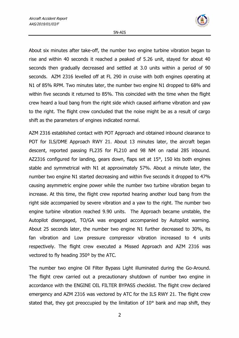
2) If the vibration level is equal to or less than 3 units:
a) No maintenance action is necessary. You can reduce the vibration levels if you
do one of these applicable fan trim balance task:
<1> In-Flight Data Trim Balance Procedure,
<2> In-Flight Data Trim Balance Procedure,
<3> Fan Trim Balance Procedure (Analyzer Method),
<4> Trim Balance Procedure (3-Shot Plot Method),
3) If the vibration level is more than 3 units:
a) It is recommended that you do one of these fan trim balance task.
<1> In-Flight Data Trim Balance Procedure,
<2> In-Flight Data Trim Balance Procedure,
<3> Fan Trim Balance Procedure (Analyzer Method),
<4> Trim Balance Procedure (3-Shot Plot Method),
(b) If the source of the AVM indication is core vibration:
1) If the vibration level is equal to or less than 3 units:
a) No maintenance action is necessary.
2) If the vibration level is more than 3 units:
a) It is recommended that you do the High Vibration Indication Trouble Shooting
(Miscellaneous Observed Problems) procedure within 25 cycles
b) If you do not find the source of the vibration, do a vibration survey and contact
CFM for confirmation of the correct vibration levels
c) Monitor the engine every cycle for any change in the core vibration level.
(3) If the vibration level is more than 4 units:
(a) Do the High Vibration Trouble Shooting (Miscellaneous Observed Problems)
procedure
before the next flight
(b) Use the AVM flight history to determine the source of the vibration.

Aircraft Accident Report
AAS/2019/01/03/F
5N-AIS
21
1) If the source of the AVM indication is fan vibration:
a) Do one of these applicable fan trim balance task:
<1> In-Flight Data Trim Balance Procedure,
<2> In-Flight Data Trim Balance Procedure,
<3> Fan Trim Balance Procedure (Analyzer Method),
<4> Trim Balance Procedure (3-Shot Plot Method),
2) If the source of the AVM indication is core vibration:
a) Do the High Vibration Trouble Shooting (Miscellaneous Observed Problems)
procedure
b) If you do not find the source of the core vibration, do a vibration survey and
contact CFM for vibration level confirmation to replace the engine
1.6.2.4 Compressor Surge and Stall
Compressor stalls are caused by an aerodynamic disruption of the usually smooth
airflow through the compressor stages. The disruption of the air flow can be caused
by these conditions:
(a) There is foreign object ingestion or damage (FOD).
(b) The airfoils are distorted.
(c) The variable stator vanes (VSV) are off schedule.
A compressor stall may be indicated by these conditions:
(a) Abnormal engine noises.
(b) Flames from the engine exhaust and possibly from the engine inlet in severe
cases.
(c) Fluctuating engine performance parameters.
(d) Slow throttle response or no throttle response.
(e) High EGT, or a quick EGT increase when throttle is advanced.

Aircraft Accident Report
AAS/2019/01/03/F
5N-AIS
22
(4) If there is a compressor stall, do these steps:
(a) Quickly (in 1 to 2 seconds) move the forward thrust lever rearward to idle power
to clear the stall.
1) Make sure the EGT and the N2% rpm decreases to normal idle indications.
2) Make sure the engine vibration levels are normal.
1.6.3 Maintenance records of the number two engine
Azman Air uses B737-300/400/500 Approved Maintenance Program (AMP) for the
inspection and maintenance of the aircraft (5N-AIS) and its components. A review of
the aircraft maintenance records indicated that all the required
maintenance/inspections were carried out as at when due. The Certificate of Release
to Service (CRS) for the last C-check (C1) was issued on 14th May, 2018. The last A-
check (1A) was carried out on 23rd December, 2018.
The last shop visit of the number two engine was on the 19th October, 2016 (at
engine time since new 41,200 h and 27551 cycles). The engine life limited part
report has been updated and all the parts were within limit.
A review of the Airworthiness Directives (ADs) compliance records of the engine did
not reveal any outstanding AD. Also, the oil consumption records over a period of
four months prior to the date of occurrence did not reveal significant oil
consumption.
Borescope Inspection (BSI) of the engine was required to be carried out at 4A, 8A
and C-check intervals in accordance with the Azman Air B737-300/400/500 Approved
Maintenance Programme. The investigation team retrieved the following Borescope
inspection records of the number two engine:
1. BSI carried out carried on 28th November, 2017 during 4A/8A inspections
revealed no significant defect.

Aircraft Accident Report
AAS/2019/01/03/F
5N-AIS
23
2. BSI carried out on 19th March, 2018 during the last C-Check found no
significant defects.
3. BSI carried out on 3rd November, 2018 during 4A inspection found no
significant defects
Note: Details of the BSI carried out on the number two engine after the occurrence
are in section 1.16 Test & Research.
1.7 Meteorological information
Time: 0900 UTC
Wind: 08 kts
Visibility: 5km
Weather: Dust Haze
Cloud: No Significant Cloud
Temperature/ Dew point: 27.6°C/6.9°C
Time: 1000 UTC
Wind: 08 kts
Visibility: 5km
Weather: Dust Haze
Cloud: No Significant Cloud
Temperature/ Dew point: 29.4°C/8°C
Time: 1100 UTC
Wind: 08 kts
Visibility: 5km
Weather: Dust Haze

Aircraft Accident Report
AAS/2019/01/03/F
5N-AIS
24
Cloud: No Significant Cloud
Temperature/Dew point: 31.4°C/8.4°C
1.8 Aids to navigation
The navigational aids available at DNPO at the time of the incident were as follows:
‘POT’ VOR/DME 113.5 MHz Serviceable
‘IPC’ ILS/DME 110.3 MHz Serviceable
Radio: Serviceable
HF 124.9 MHz (Approach) Serviceable
VHF 119.2 MHz (Tower mains) Serviceable
VHF 118.6 MHz (Tower secondary) Unserviceable
VHF 122.3 MHz (ATIS) Serviceable
VHF 121.7 MHz (Domestic) Serviceable
VHF 121.5 MHz (Emergency) Serviceable
1.9 Communications
There was effective communication between the aircraft and Air Traffic Control
(ATC).
1.10 Aerodrome information
Port Harcourt International Airport is fully operated by Federal Airports Authority of
Nigeria (FAAN). It is located 32 km west of the city and has a single runway with an
orientation of 03/21 which is 3000 m long and 60 m wide, located at coordinates

Aircraft Accident Report
AAS/2019/01/03/F
5N-AIS
25
latitude 05°00'56"N and longitude 006°56'58"E, and at an elevation of 87 ft Above
Sea Level. There is also a single taxi way parallel to the runway with two exit points.
1.11 Flight recorders
The aircraft was fitted with a Flight Data Recorder (FDR) and a Cockpit Voice
Recorder (CVR). The recorders were retrieved and taken to the AIB Flight Safety
Laboratory at Abuja, where inspection and download were carried out. The data
related to the incident on the CVR was found overwritten.
The FDR and CVR particulars are as below:
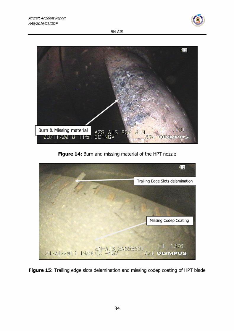
1.11.2 Flight Data Recorder report
The Flight Data Recorder (FDR) was downloaded and analysed at the AIB safety
laboratory in Abuja. The data was fully recovered.
At 10:10 h, AZM2316 took-off from DNMM for a commercial flight heading to DNPO.
At 10:15:36 h, Engine 2 turbine vibration started to increase gradually over a period
of 40 seconds reaching a peak of 5.26 units (typically, vibration >3 is considered
abnormal and >4 is considered critical).
At 10:17 h, the Engine 2 turbine vibration gradually decreased over a period of 90
seconds stabilizing at approximately 3.0 units.
Recorders Flight Data Recorders Cockpit Voice Recorders
Manufacturer Honeywell International Inc. Fairchild
Part number 980-4700-042 S200-0012-00
Serial number 6798 01156
Model SSFDR A200SCVR
Duration 25 hours 2 hours

Aircraft Accident Report
AAS/2019/01/03/F
5N-AIS
26
Figure 6: High pressure turbine vibration of number two engine
Figure 7: The Engine 2 High pressure turbine vibration gradually decreased over a
period of 90 seconds

Aircraft Accident Report
AAS/2019/01/03/F
5N-AIS
27
At 10:26 h, the aircraft levelled off at FL290. Engines 1 & 2 N1 showed to be
operating normally at 85%.
At 10:28 h, engine 2 N1 decreased to 68% uncommanded [sic] and then increased
to 85% over a period of 5 seconds uncommanded [sic].
Figure 8: Engine 2 N1 decreased to 68% and then increased to 85% over a period
of 5 sec.
At 10:52 h, AZM2316 commenced a right turn for finals DNPO RWY 21. Gear was
down and Flaps were set to 15°, Engine 1 & 2 were stable and symmetrical at
approximately 57%.
At 10:53:47 h, engine 2 N1 started decreasing to 47% over a period of 5 seconds
causing asymmetric engine power. Engine 2 turbine vibration started to increase.

Aircraft Accident Report
AAS/2019/01/03/F
5N-AIS
28
At 10:53:51 h, the A/P was disengaged and the TO/GA 2was engaged accompanied
by an A/P warning. The Engine 2 turbine vibration showed severe vibration of 9.90
units.
At 10:54:16 h, Engine 2 Fan Vibration increased to 4 units.
Figure 9: Engine 2 fan, compressor and turbine vibration.
At 10:59 h, Engine 2 Cut-off parameter toggled.
2 TO/GA (Take-off/Go-around) is an auto pilot/auto throttle setting activating take-off or go-around thrust.
Depending upon aircraft type, it may be activated by depressing a switch or by manually moving the thrust levers to the appropriate position.

Aircraft Accident Report
AAS/2019/01/03/F
5N-AIS
29
Figure 10: Engine 2 Cut-off parameter toggled
At 11:21 h, during the second landing attempt, the aircraft did not intercept the
runway centerline passing through 500 ft RADALT while experiencing high vibrations
in Engine 1. At 11:22 h, During the second landing attempt the aircraft crossed the
localizer extremely late at a 150 ft AGL and one dot high. 10 seconds later the
TO/GA was activated.
At 11:34 h, the aircraft was set for a third landing attempt. Descending through 500
ft RADALT the aircraft was on the Localizer, 0.25 dots below the Glideslope with
Flaps 15° and Landing Gear DOWN. At 11:34 h, the aircraft landed uneventfully on
runway 21 DNPO.
The Flight path of AZM2316 showing two Go-Arounds with a successful landing on
the third approach into Port Harcourt International Airport

Aircraft Accident Report
AAS/2019/01/03/F
5N-AIS
30
Figure 11: The Flight path of AZM 2316 showing two Go-Arounds with a successful
landing on the third approach
1.12 Wreckage and impact information
The aircraft landed safely on runway 21 and taxied to the apron with no physical
damage.

Aircraft Accident Report
AAS/2019/01/03/F
5N-AIS
31
Figure 12: The aircraft after the incident
1.13 Medical and pathological information
No medical or pathological tests were conducted on the crew.
1.14 Fire
There was no pre or post incident fire.
1.15 Survival aspects
The aircraft landed safely on runway 21 after the third attempt.

Aircraft Accident Report
AAS/2019/01/03/F
5N-AIS
32
The Aerodrome Rescue and Fire Fighting Service (ARFFS) had already positioned
close to runway 21. After landing, the aircraft taxied to the apron, escorted by the
ARFFS where the occupants disembarked unassisted and uninjured.
1.16 Test and research
1.16.1 Borescope inspection report on number two engine
Soon after the occurrence, a Borescope Inspection (BSI) was carried out on the
number two engine by Aero Contractors Nigeria limited.
The result of the BSI is as presented below:
S/N Item Location Number Findings Remark
1 Fan Blade Inlet 38 All fan blades dirty Serviceable
2 Combustion
Chamber
S10-S15 Dome discoloration and
carbon deposit
Serviceable
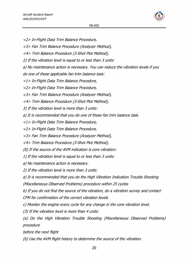
3 HPT Nozzle Guide
Vanes
S10-S15 46 Burns and missing
material on L/E of NGVs
NGV T/E Slots
delamination
White metallic chips
around most NGVs
Not
Serviceable
4 HPT Blades S17, S18 72 Missing Codep coating
mainly on L/E of all
blades burned, missing
pieces and rubbing
discourager seal
Not
Serviceable
Notes:
This engine experienced an In-Flight Shutdown due vibrations

Aircraft Accident Report
AAS/2019/01/03/F
5N-AIS
33
Oil spillage found on inner side of the turbine exhaust sleeve and the flame
arrestor found missing
After full video of borescope inspections, we could suspect number 4 and
number 5 bearing failure. See Appendix 1: Borescope inspection report on
number two engine.
Figure 13: Combustor Nozzle- Dome discoloration and carbon deposit around the
Nozzle Guide Vane
Dome discoloration
and carbon deposit
Aircraft Accident Report
AAS/2019/01/03/F
5N-AIS
34
Figure 14: Burn and missing material of the HPT nozzle
Figure 15: Trailing edge slots delamination and missing codep coating of HPT blade
Missing Codep Coating
Trailing Edge Slots delamination
Burn & Missing material

Aircraft Accident Report
AAS/2019/01/03/F
5N-AIS
35
Figure 16: Nozzle Guide Vanes Leading edge and Preservation Oil
Figure 17: Burned and missing discourager seal
Burned & Missing Discourager
Seal
Missing Codep Coating

Aircraft Accident Report
AAS/2019/01/03/F
5N-AIS
36
Figure 18: Rubbing no overlap of high pressure turbine blade
1.16.2 Condition of the magnetic chip detector after the occurrence
Metallic particles were found on the number two engine magnetic chip detector Aft
Sump after the occurrence.
Rubbing No overlap
High Pressure Turbine Blade

Aircraft Accident Report
AAS/2019/01/03/F
5N-AIS
37
Figure 19: Number two engine Magnetic Chip Detector aft sump showing metallic
particles
1.16.3 Number 2 engine shop disassembly report
After the occurrence Azman Air took the engine to Skybus Aviation Inc. maintenance
and repair facility based at Bournemouth International Airport in the United Kingdom
for exchange. Below is the initial engine disassembly report3:
High Pressure Compressor (HPC) Rotor
Blades stages 1-9 found heavy tip rub see following pictures.
3 The report sent was the initial report, as the engine was deemed beyond economical repair and the
cost to do the full strip down on this engine would be in the region of US $100,000 the decision was made not continue.

Aircraft Accident Report
AAS/2019/01/03/F
5N-AIS
38
Figure 20: High Pressure Compressor Blades stages 1-9 heavy tip rub
Figure 21: High Pressure Compressor Blades tip rub

Aircraft Accident Report
AAS/2019/01/03/F
5N-AIS
39
High pressure Compressor (HPC) front cases
Heavy rub noted on cases and stationary Air seals Stage 1-5 due to HPC rotor and
Blades making contact with cases after No.4 Bearing failure.
See Pictures below.
Figure 22: High pressure Compressor Heavy rub on Cases and stationary Air seals
Stage 1-5

Aircraft Accident Report
AAS/2019/01/03/F
5N-AIS
40
Figure 23: High pressure Compressor Heavy rub on Cases
Figure 24: High pressure Compressor rub on Cases

Aircraft Accident Report
AAS/2019/01/03/F
5N-AIS
41
High pressure Compressor (HPC) rear cases heavy rub noted on cases due to HPC
rotor and blades making contact with cases after No.4 bearing failure.
See Pictures below.
Figure 25: High pressure Compressor (HPC) blades rear cases heavy rub

Aircraft Accident Report
AAS/2019/01/03/F
5N-AIS
42
Figure 26: High pressure Compressor (HPC) blades rear cases rub
High Pressure Turbine (HPT) Rotor
Heavy Blade Tip Rub noted due to HPT Blades coming in contact with Shroud
segments and also extensive damage to rear shaft. No restrictions found in HPT
Rear shaft oil holes
HPT Shroud support and Stage 1 LPT Nozzle
Heavy rub noted on shroud segments due to HPT Rotor Blade contact post No.4
Bearing failure.
Lube Unit Chip Detectors.
AFT Sump – Metal found (post No.4 Bearing Failure).
Forward Sump - Found Clear.
Accessory Gear Box (AGB)/Transfer Gear Box (TGB) - Found Clear.

Aircraft Accident Report
AAS/2019/01/03/F
5N-AIS
43
Oil Type - To be confirmed by customer.
1.17 Organizational and management information
1.17.1 Azman Air Services Limited
Azman Air Services Limited is a privately owned Nigerian Airline founded in 2010.
The company was issued Air Operators Certificate (AOC) on 12th May, 2014 with No.
AAS/AOC/05-14/01 in accordance with the Nigeria Civil Aviation Regulations (Nig.
CARs).
The Airline commenced operation on 15th May, 2014. The Operation and Principal
Maintenance base is located in Kano where it maintains operational and
airworthiness support facilities appropriate for the area and type of operation.
Azman Air Services currently operates scheduled domestic flights. The Airline has
five (5) aircraft in its fleet, comprising of two Boeing 737-500, two Boeing 737-300
and an Airbus A340.
1.17.1.1 Crew Composition
Excerpts from Azman Air Services Operations Manual Part A Chapter 5
5.1.3 Crew Scheduling
A flight crew member is prohibited from operating an aircraft if not qualified for duty
in accordance with the requirements specified in Chapter 6 of the airline’s
Operations Manual. Azman Air’s crew assignment process:
a) ensures that flight crew will operate in compliance with the following:
i) flight crew qualifications requirements and any additional requirements of the
NCAA, as applicable
ii) crew composition requirements;

Aircraft Accident Report
AAS/2019/01/03/F
5N-AIS
44
iii) flight/duty time limitations;
iv) inexperienced flight crew pairing limitations;
v) fitness for duty.
1.17.1.2 Flight crew qualification requirements
Excerpts from Azman Air Services Operations Manual Part A Chapter 6
qualification requirements
6.2 FLIGHT CREW
6.2.1 COMMANDERS
6.2.1.1 The minimum qualification and experience requirements for pilots to act as
Commanders of Azman Air operated commercial flights are:
a) An Airline Transport Pilot’s Licence (Aeroplane), Age below 65 years;
b) Successful completion of an appropriate command course if upgrading;
c) Attainment of a specified minimum experience level for those pilots upgrading to
Commander from within the company or for those going as direct entry
Commanders;
d) Valid Instrument rating;
e) Valid recurrent checks;
f) Valid route and aerodrome competence
g) To be a Commander on the Azman Air Aircraft with upgrade from within Azman
these are the requirements:
i) License ATPL
ii) Medical First Class Fitness

Aircraft Accident Report
AAS/2019/01/03/F
5N-AIS
45
iii) Total Flying Hours 3,000 hours
iv) Minimum Jet aircraft hours 1,500 hours
v) Hours on Type 500 hours
h) In addition to (g) Captains newly employed by Azman Air are expected to have a
minimum of 500 hours Pilot In Command Time on type.
1.17. 1.3 737 Classic Quick Reference Handbook Flight Crew Operations
Manual
7.2 Engine Limit or Surge or Stall
1 Autothrottle (if engaged) . . . . . . . . . Disengage
2 Thrust lever
(affected engine) . . . . Confirm. . . . . Retard until engine indications stay within
limits or the thrust lever is closed
3 Choose one: Engine Limit or Surge or Stall Condition: One or more of these occur:
•Engine indications are abnormal
•Engine indications are rapidly approaching or exceeding limits
•Abnormal engine noises are heard, possibly with airframe vibration
•There is no response to thrust lever movement or the response is abnormal
•Flames in the engine inlet or exhaust are reported.
Objective: To attempt to recover normal engine operation or shut down the engine if
recovery is not possible.
Engine indications are stabilized and EGT is stabilized or decreasing:
►►Go to step 4

Aircraft Accident Report
AAS/2019/01/03/F
5N-AIS
46
Engine indications are abnormal or EGT continues to increase:
►►Go to step 7
4 Thrust lever
(affected engine). . . . . . . . . . . Advance slowly
Check that RPM and EGT follow thrust lever movement.
5 Run the engine normally or at a reduced thrust setting that is surge and stall free.
6 Choose one:
Engine runs normally:
Engine runs at reduced thrust:
Transponder mode selector. . . . . . . . . TA This step prevents climb commands
which can exceed reduced thrust performance capability.
7 Engine start lever (affected engine) . . . . Confirm. . . . . . . CUTOFF
8 PACK switch (affected side) . . . . . . . . . . . . . OFF
This causes the operating pack to regulate to high flow in flight with flaps up.
9 Choose one:
APU is available for start:
APU . . . . . . . . . . . . . . . . . . . . . . START When APU is running:
APU GEN switch
(affected side) . . . . . . . . . . . . .ON
►►Go to step 10
APU is not available:

Aircraft Accident Report
AAS/2019/01/03/F
5N-AIS
47
►►Go to step 10
10 Balance fuel as needed.
11 Transponder mode selector . . . . . . . . . . . . . . TA
This step prevents climb commands which can exceed single engine performance
capability.
12 ISOLATION VALVE switch . . . . . . . . Verify AUTO
This will ensure bleed air is available to both wings if wing anti-ice is needed.
13 A restart may be attempted if there is N1 rotation and no abnormal airframe
vibration.
14 Choose one:
Restart will be attempted:
►►Go to the Engine In-Flight Start checklist on page 7.22
Restart will not be attempted:
►►Go to step 15
15 Plan to land at the nearest suitable airport.
►►Go to the One Engine Inoperative Landing checklist on page 7.29
ENGINE OVERHEAT ►►8.5 Engine Tailpipe Fire ►►8.6 ■ ■ ■ ■
1.17. 1.4 737 Classic Quick Reference Handbook Flight Crew Operations
Manual
7.27 Engine Oil Filter Bypass

Aircraft Accident Report
AAS/2019/01/03/F
5N-AIS
48
Condition: Oil filter contamination can cause oil to bypass the oil filter.
1 Autothrottle (if engaged). . . . . . . . . . .Disengage
2 Thrust lever (affected engine) . . . . . . Confirm . . . . . . Retard slowly
until the OIL FILTER BYPASS light extinguishes or the thrust lever is
closed
3 Choose one:
OIL FILTER BYPASS light extinguishes:
►►Go to step 4
OIL FILTER BYPASS light stays illuminated:
►►Go to the Engine Failure or Shutdown checklist on page 7.14
■ ■ ■ ■
4 Run the engine at reduced thrust to keep the light extinguished.
5 Transponder mode selector . . . . . . . . . . . . . . TA
This step prevents climb commands which can exceed reduced thrust
performance capability. Leak Engine ►►12.3
■ ■ ■ ■
1.17.2.4 737 Flight Crew Operations Manual
7.20 Engine High Vibration
Condition: The vibration level is more than 4.0 units.
Airframe vibration may or may not be felt.
1 Choose one:
In icing conditions:
►►Go to step 2
Not in icing conditions:

Aircraft Accident Report
AAS/2019/01/03/F
5N-AIS
49
►►Go to step 6
Do the following on one engine at a time.
4 Thrust lever (affected engine) . . . . . . . . . Retard to 45% N1for five seconds, then
slowly advance to a minimum of 80% N1while monitoring engine vibration
Vibration decreases:
Continue normal operation.
■ ■ ■ ■
Vibration does not decrease:
►►Go to step 7
6 Autothrottle (if engaged). . . . . . . . . . .Disengage)
7 Thrust lever (affected engine) . . . . Confirm. . . . . . Retard to maintain vibration
levels below 4 units or until the thrust lever is closed
8 Transponder mode selector . . . . . . . . . . . . . . TA
This step prevents climb commands which can exceed reduced thrust performance
capability.
■ ■ ■ ■
1.17.1.5 737 Flight Crew Operations Manual Part B Non-Normal
Checklist Section 8, pages 8.2 thru 8.4
ENGINE FIRE or Engine Severe Damage or Separation
ENGINE FIRE or Engine Severe Damage or Separation Condition:
One or more of these occur:
•Engine fire warning
•Airframe vibrations with abnormal engine indications
•Engine separation.
FIRE WARN and Engine 1 - Fire
FIRE WARN and Engine 2 - Fire
Engine 1 - Fire and FIRE WARN

Aircraft Accident Report
AAS/2019/01/03/F
5N-AIS
50
Engine 2 - Fire and FIRE WARN
1 Auto throttle (if engaged). . . . . . . . . . .Disengage
2 Thrust lever (affected engine) . . . . . . . . Confirm . . . . . Close
3 Engine start lever (affected engine) . . . . . . . . Confirm . . . CUTOFF
4 Engine fire switch (affected engine) . . . . . . . . Confirm . . . . . . Pull to manually
unlock the engine fire switch, press the override and pull.
5 If the engine fire switch or ENG OVERHEAT light is illuminated:
Engine fire switch . . . . . Rotate to the stop and hold for 1 second
If after 30 seconds the engine fire switch or ENG OVERHEAT light stays illuminated:
Engine fire switch. . . . . . . . Rotate to the other stop and hold for 1 second - - - - - -
- - - - - - - - - - - - - - - -
ENGINE FIRE or Engine Severe Damage or Separation
ENGINE FIRE or Engine Severe Damage or Separation Condition:
One or more of these occur:
•Engine fire warning
•Airframe vibrations with abnormal engine indications
•Engine separation.
6 Choose one:
7 ISOLATION VALVE switch . . . . . . . . . . . . CLOSE
8 PACK switch (affected side) . . . . . . . . . . . . . OFF
This causes the operating pack to regulate to high flow in flight with the flaps up.

Aircraft Accident Report
AAS/2019/01/03/F
5N-AIS
51
9 APU BLEED air switch . . . . . . . . . . . . . . . . . OFF
High airframe vibration occurs and continues after the engine is shut down:
Without delay, reduce airspeed and descend to a safe altitude which results in an
acceptable vibration level.
Note: If high vibration returns and further airspeed reduction and descent are not
practical, increasing airspeed may reduce the vibration.
►►Go to step 7
High airframe vibration does not occur or does not continue after the engine is shut
down:
►►Go to step 7
10 Choose one:
11 Balance fuel as needed.
12 Transponder mode selector . . . . . . . . . . . . . . TA
This step prevents climb commands which can exceed single engine performance
capability.
13 ISOLATION VALVE switch (after the fire has been extinguished) . . . . . AUTO
This ensures bleed air is available to both wings if wing anti-ice is needed.
14 Plan to land at the nearest suitable airport.
►►Go to the One Engine Inoperative Landing checklist on page 7.29
■ ■ ■ ■
1.17.1.6 Flight Crew Operations Manual Part B section 7, pages 7.29
thru 7.30

Aircraft Accident Report
AAS/2019/01/03/F
5N-AIS
52
One Engine Inoperative Landing
Condition: Landing must be made with one engine inoperative.
1 Plan a flaps 15 landing.
2 Set VREF 15.
3 Check the Non-Normal Configuration Landing Distance table in the Advisory
Information section of the Performance In flight chapter.
4 Maintain VREF 15 + wind additive on final approach to assure sufficient maneuver
margin and speed for go-around. The minimum wind additive is 5 knots.
5 When engine anti-ice is needed, use on the operating engine only.
6 Checklist Complete Except Deferred Items
Descent Checklist CPCS airplanes Pressurization . . . . . . . CAB ALT ___, LAND ALT
___
DCPCS airplanes Pressurization . . . . . . . . . . . . . . . . . LAND ALT ___
Recall . . . . . . . . . . . . . . . . . . . . . . . . . . Checked
Autobrake . . . . . . . . . . . . . . . . . . . . . . . . . . ___
Landing data . . . . . VREF 15 ___, Minimums ___
Approach briefing . . . . . . . . . . . . . . . . Completed
▼ Continued on next page ▼
One Engine Inoperative Landing Condition: Landing must be made with one engine
inoperative.
Deferred Items
Additional Go-Around Thrust

Aircraft Accident Report
AAS/2019/01/03/F
5N-AIS
53
Choose one:
No Engine Bleed Landing When below 10,000 feet: WING ANTI-ICE switch . . . . . . .
. . . . . . . OFF ISOLATION VALVE switch . . . . . . . . . . CLOSE
BLEED 1 air switch . . . . . . . . . . . . . . . . . OFF
Left PACK switch . . . . . . . . . . . . . . . . . AUTO
BLEED 2 air switch . . . . . . . . . . . . . . . . . OFF
Go-Around Procedure Review Do the normal go–around procedure except: Use flaps 1.
▼One Engine Inoperative Landing continued▼
Additional go-around thrust is needed:
►►Go to No Engine Bleed Landing below
Additional go-around thrust is not needed:
►►Go to Go-Around Procedure Review below
Do not open the APU bleed air valve if the engine fire switch is illuminated.
APU BLEED air switch . . . . . . . . . . . . . . ON
Maintain VREF 15 + 5 knots until reaching flap retraction altitude.
Limit bank angle to 15° when airspeed is less than VREF 15 + 15 knots or the
minimum maneuver speed, whichever is lower.
Accelerate to flaps 1 maneuvering speed before flap retraction.
Approach Checklist Altimeters . . . . . . . . . . . . . . . . . . . . . . . . . .
Additional Deferred Item GROUND PROXIMITY FLAP INHIBIT switch. . . . FLAP
INHIBIT
Landing Checklist ENGINE START switch (operating engine) . . . . . . . . . . . . CONT

Aircraft Accident Report
AAS/2019/01/03/F
5N-AIS
54
Speed brake . . . . . . . . . . . . . . . . . . . . . . .ARMED
Landing gear . . . . . . . . . . . . . . . . . . . . . . . Down
Flaps. . . . . . . . . . . . . . . . . . . . . .15, Green light
1.17.1.7 Azman Air Flight Data Monitoring (FDM) programme
Excerpts from Azman Air Safety Management System Manual
2.2.5 Flight Safety Analysis Program
Safety department is allocated responsibility for the development and management
of the Flight Safety Program. The Flight Safety Officer reports directly to the Safety
Manager on issues relating to flight safety (the Flight Safety Officer is an active line
pilot). The Safety Manager is designated as the independent manager who is
responsible for the performance of the Flight Safety Analysis Program. The Flight
Safety Program includes acquisition of safety information to include the Flight Data
Monitoring system during flight operations, where hazards and potentially hazardous
conditions are monitored and subsequent corrective or preventive actions
respectively are implemented, and regular communication and liaison with
operational managers will be conducted in relation to the flight safety program to
ensure continuous review of the safety of operations. The following listed provide for
the systematic acquisition, correlation and analysis of flight safety information:
Aircraft flight data recorder (FDR) readouts;
Confidential flight and cabin crew operational safety reports;
Flight and cabin crew interviews;
Results from Safety audits;
Flight and cabin crew evaluation reports;
Aircraft engineering and maintenance reports;
FDR and CVR readouts.

Aircraft Accident Report
AAS/2019/01/03/F
5N-AIS
55
The Flight Safety Program provides for the regular analytical information and data
sharing with the relevant operational managers to ensure that any potential hazards
are addressed. The Flight Safety Analysis Program works in conjunction with all
other safety programs within the organization. The Safety department shall keep a
hazard database which provides for historical analysis and trend monitoring. As
safety management is consistently implemented throughout the organization, on
equivalent basis with all the other management system of the organization, all
operational managers share the same responsibility to ensure that any hazards are
eliminated or mitigation efforts are conducted to ensure that the risk of operation is
kept to a level that is acceptable. Relevant information from the Flight Safety
Program shall be distributed to appropriate personnel to ensure that the
recommended corrective actions are timely conducted. The information is
disseminated to the operational personnel through the Safety communication system
as documented in the SMS Manual. Significant issues emanating from the Flight
Safety Program will be tabled by the Safety department to Senior and Executive
Management through the management review process. This information should be
timely shared and actioned on such that timely continual improvement is
implemented. Safety Department shall provide, through the shared computer, a
depository for all electronic safety data. The data shall be securely protected with
regular backup on storage devices to ensure the availability of safety data whenever
it is required. Backup of the Safety computer shall be conducted in accordance with
the organizational backup system. Where it is necessary, Safety department shall
conduct investigations of accidents and incidents, and this information will be used
to ensure continual improvement and the provision of the necessary defences to
avoid future occurrence. Investigation will also be conducted in accordance with the
same process. The accident investigation process will be conducted in accordance
with the procedures detailed in Section 2.3.5.0 of this manual.

Aircraft Accident Report
AAS/2019/01/03/F
5N-AIS
56
2.2.5.1 Flight Data Monitoring Program
An additional source of operational data for Azman Air comes from our Flight Data
Monitoring (FDM) program. FDM is the routine downloading and systematic analysis
of data collected from our aircraft Flight Data Recorders (FDR) for quality assurance
purposes. FDM is a Flight Data Analysis (FDA) program.
The purpose of our FDM program is to detect latent patterns of behavior amongst
flight crews, weaknesses in the ATC system, and anomalies in aircraft performance
which can cause aircraft accidents. The main objective of the program is to improve
safety by identifying trends, not individual acts. Our FDM program encourages
adherence to Standard Operating Procedures and deters non-standard behavior to
enhance flight safety. It confirms the effectiveness of Azman Air training program. It
detects adverse trends in any part of the flight regime and thereby facilitates the
investigation of minor events that would otherwise go unreported. The FDM program
is managed by the Safety Department. The data is downloaded from the FDR of
each aircraft by Maintenance every seven (7) days on a line check and uploaded to
the Azman Air Service Provider for processing.
After processing the processed information is made available on a web site for
consulting purposes. A full statistic report of the events for each fleet is then
presented periodically to Azman Air. The Safety Department accesses the website
periodically. When an anomaly is detected, information is sent to the Manager, Flight
Operations and Chief Pilot, to prepare corrective action. This is then entered into our
Safety Risk Management process. After receiving the full report for each fleet, a
meeting is arranged with Flight Operations to discuss the report and the relevant
issues, together with proposed corrective and preventive actions. Information from
the Flight Safety Analysis program will be distributed to all relevant operational
personnel to ensure timely implementation of corrective action. The program is non-
punitive, confidential, anonymous, and does not jeopardize a crew member’s career.
The program is founded on a bond of trust between our Senior Management, flight
crew and the Safety Department. This trust is an integral component of the positive

Aircraft Accident Report
AAS/2019/01/03/F
5N-AIS
57
safety culture at Azman Air. Any significant issues arising from the Flight Safety
Analysis program shall be presented for senior management review to be considered
where executive management input is required.
1.17.1.7.2 Azman Air Flight Data Monitoring (FDM) reports
FLTECHNICS provided the FDM services to Azman Air for its fleet of B737 aircraft.
The investigation reviewed the FDM reports for 5N-AIS and two other B737 aircraft
in the fleet of the operator covering a period from 18th May, 2018 to 2nd January,
2019.
The flight data monitoring reports of 5N-AIS pertinent to this occurrence specifically
concerning the number two engine vibration limit guide revealed the following:
S/N Period Fan vibration Limit Guide recorded
Code Compressor/Turbine vibration Limit Guide recorded
Code
1 18-23
May 2018
(21 flights)
10 times BTA1013 Nil Nil
2 30 September - 03 October 2018 (21 flights)
Nil Nil 41 times (LPT vibration limit guide occurred in all the 21 flights)
BTA1011
3 05 – 08 October 2018 (23 flights)
Turbine vibration limit guide occurred in all the 23 flights
BTA 1011
4 12-24 October, 2018 (43 flights)
Nil Nil 27 times (turbine vibration limit guide occurred in 13 flights)
BTA1011
5 24-31 October 2018 (23 flights)
3 times BTA1013 Nil Nil
6 14-18 December 2018 (23 flights)
Nil Nil 40 times BTA 1011
Note: The engine vibration limit guide incidences occurred more than once in a flight
in many of the instances.

Aircraft Accident Report
AAS/2019/01/03/F
5N-AIS
58
In addition to the number two engine vibration limit guide, the FDM reports also
indicated that 117 fan vibration limit guide of number one engine occurred in 65
flights that the airline operated between 1st November, 2018 and 2nd January,
2019. The FDM reports also indicated anomalies including multiple ILS deviation
warnings, Localiser deviation warnings, ground proximity warnings, GPWS sink rate,
High rate of descent below 2000 ft, Low power on approach, Speed brake not armed
below 800 and Approach speed high below 500 ft. See Appendix 1: Flight Data
Monitoring Report.
The operator did not provide any evidence of rectification actions as per 2.2.5.1 of
its SMS Manual to address the anomalies contained in the FDM reports submitted to
it by FLTECHNICS.
1.17.2 Nigerian Civil Aviation Authority (NCAA)
NCAA is the government agency saddled with the regulation and oversight of
aviation activities in Nigeria. The NCAA is set up by the Nigerian Civil Aviation Act
(2006) which enables the Director General of NCAA to make regulations in aviation.
The current regulations are as enshrined in the Nigeria Civil Aviation Regulations Nig.
CARs 2015. Relevant sections of the Nig. CARs guide activities of personnel and
service providers in the aviation industry. Oversight activities are achieved by
continuous and periodic audits by inspectors of the NCAA.
1.17.2.1 Nig. CARs 2009 Safety management system with FDM
requirement for Air Operator Certificate holders
9.2.2.11 SAFETY MANAGEMENT SYSTEM
(a) An AOC holder shall establish and maintain a safety management system.
(b) An AOC holder that operates aircraft with a maximum certificated take-off mass
of more than 27,000 kg shall include a flight data monitoring programme as part of
its safety management system.

Aircraft Accident Report
AAS/2019/01/03/F
5N-AIS
59
(c) The AOC holder’s flight data analysis programme shall be non-punitive and
contain adequate safeguards [SIC] to protect the source(s) of the data.
1.17.2.2 Nig. CARs 2015 Safety Management System without FDM
requirement for Air Operator Certificate holders
Safety Management System
9.2.2.10—(a) An AOC holder shall implement a safety management system
acceptable to the Authority as outlined in Nig. CARs Part 20
(b) The AOC holder’s flight data analysis programme shall be non-punitive [SIC] and
contain adequate safeguards to protect the source(s) of data.
1.18 Additional information
1.18.1 Flight Data Monitoring/Flight Data Analysis programme
1.18.1.1 Definitions
Flight Data Analysis is founded on Operational Flight Data Monitoring
(OFDM) which in North America has become known as Flight Operations Quality
Assurance (FOQA). It is a process which routinely captures and analyses recorded
data in order to improve the safety of flight operations.
Flight Data Analysis. A process of analysing recorded flight data in order to
improve the safety of flight operations (ICAO Annex 6 – Operation of aircraft).
Operational Flight Data Monitoring
(OFDM) is the pro-active use of recorded flight data from routine operations to
improve aviation safety.

Aircraft Accident Report
AAS/2019/01/03/F
5N-AIS
60
1.18.1.2 Description of OFDM
The aviation community is under constant pressure to achieve safety improvement.
Operational Flight Data Monitoring (OFDM) offers an efficient solution to this
challenge. OFDM is to some extent a quality assurance process but also has a vital
safety Management dimension. It involves the downloading and analysis of aircraft
flight recorder data on a regular and routine basis. It is widely used by aircraft
operators throughout the world to inform and facilitate corrective actions in a range
of operational areas by offering the ability to track and evaluate flight operations
trends, identify risk precursors, and take the appropriate remedial action. The
potential of OFDM programmes has been materially enhanced by the rapid
expansion in the number of data parameters which can be captured using digital
recorders now routinely carried on aircraft.
1.18.1.3 Benefits of OFDM
FDM strongly contributes to increased flight safety and operational efficiency by:
Providing data to help in the prevention of incidents and accidents. Fewer
flight accidents not only reduce material costs, but also keep passengers’
confidence high.
Improved operational insight: providing the means to identify potential risks
and to modify pilot training programs accordingly.
Improved fuel consumption: FDM provides the ability to identify and make
adjustments to company operating procedures or specific aircraft with
unusually high fuel burn rates.
Reduction in unnecessary maintenance and repairs: FDM data can be used to
help reduce the need for unscheduled maintenance resulting in lower
maintenance costs and increased aircraft availability.
Improved ground conditions and airports: in certain cases, airlines can use
the data captured from their FDM program to support requested changes to
air traffic control and airport procedures.

Aircraft Accident Report
AAS/2019/01/03/F
5N-AIS
61
Reduced number of ACARS messages: non-critical data (e.g. take-off reports,
stable cruise reports) that are sent via ACARS messages can be acquired,
recorded and transmitted via flight data monitoring equipment.
Reduced reliance on flight data recording: flight-monitoring data can be
transmitted automatically over the internet and be analyzed without delay.
Adherence to noise restrictions: flight data monitoring helps airlines
demonstrate adherence to noise restrictions in terms of being able to verify or
deny actual infringement, and avoid incurring fines.
Improved monitoring of flight crew’s cosmic radiation exposure: flight data
monitoring can assist in tracking radiation exposure.
Flight data Monitoring (FDM) programmes provide a powerful tool for the
proactive hazard identification.
Reference: www.skybrary.aero/index.php/Flight_Data_Monitoring_(FDM)
1.18.2 Safety management requirements of Annex 6
3.3 Safety management
Note. —Annex 19 includes safety management provisions for air operators. Further
guidance is contained in the Safety Management Manual (SMM) (Doc 9859).
3.3.2 An operator of an aeroplane of a maximum certificated take-off mass in excess
of 27 000 kg shall establish and maintain a flight data analysis programme as part of
its safety management system.
Note. —An operator may contract the operation of a flight data analysis programme
to another party while retaining overall responsibility for the maintenance of such a
programme.
3.3.3 A flight data analysis programme shall be non-punitive and contain adequate
safeguards to protect the source(s) of the data.
Note 1. —Guidance on the establishment of flight data analysis programmes is
included in the Manual on Flight Data Analysis Programmes (FDAP) (Doc 10000).

Aircraft Accident Report
AAS/2019/01/03/F
5N-AIS
62
Reference: Annex 6 to the Convention on International Civil Aviation (Operations of
Aircraft), Part I – International Commercial Air Transport – Aeroplanes ninth edition
July 2010 Amendment 38 of 13 November 2014.
1.18.3 Situation Awareness (SA)
Situation Awareness SA is defined as the continuous extraction of environmental
information, the integration of this information with previous knowledge to form a
coherent mental picture, and the use of that picture in directing further perception
and anticipating future events.
Situational Awareness (SA) means appreciating all you need to know about what is
going on when the full scope of your task - flying, controlling or maintaining an
aircraft is taken into account. More specifically and in the context of complex
operational environments, SA is concerned with the person's knowledge of particular
task-related events and phenomena. For example, for a fighter pilot SA means
knowing about the threats and intentions of enemy forces as well as the status of
his/her own aircraft. Therefore, in operational terms, SA means having an
understanding of the current state and dynamics of a system and being able to
anticipate future change and developments.
A general definition of SA is that it is the perception of the elements in the
environment within a volume of time and space, the comprehension of their
meaning and the projection of their status in the near future
https://www.skybrary.aero/index.php/Situational_Awareness

Aircraft Accident Report
AAS/2019/01/03/F
5N-AIS
63
2.0 ANALYSIS
2.1 General
The aircraft had a valid Certificate of Airworthiness.
A review of the number two engine’s Airworthiness Directives compliance record,
previous oil filter changes, three previous Borescope Inspections and the oil
consumption records over a period of four months prior to the date of occurrence
did not reveal any discrepancy.
The CVR data related to the incident was found overwritten.
This analysis focuses mainly on the flight crew qualification and composition,
conduct of the flight, number two engine vibration, surge and oil filter by-pass; and
the implementation of Azman Air Flight Data Monitoring (FDM) programme.
2.2 Flight crew qualification and composition
Azman Air Services Operations Manual Part A chapter 6 qualification requirements
states that, captains newly employed by Azman Air are expected to have a minimum
of 500 hours Pilot-In-Command time on type.
However, the Pilot had 92 hours on aircraft type. Therefore, the Pilot did not meet
the minimum Azman Air qualification requirement to be a Pilot-In-Command.
In addition, the flight crew pairing for the flight, exhibited a weakness of the flight
crew experience level on the aircraft type (B737); with the Pilot-in-command having
92 hours on type and the Co-pilot having 431 hours on type respectively.
Azman Air Operations Manual Part A section 5.1.3 (Crew Scheduling) states that a
flight crew member is prohibited from operating an aircraft if not qualified for duty in
accordance with the requirements specified in Chapter 6 of the airline’s Operations

Aircraft Accident Report
AAS/2019/01/03/F
5N-AIS
64
Manual. Azman Air crew assignment process includes crew composition
requirements and inexperienced flight crew composition limitations amongst others.
However, the operations manual does not specify the criteria for determining the
experience level required for crew composition.
Therefore, the investigation could not establish the criteria used in the crew
composition as the Azman Air Operations Manual Part A was not specific.
2.3 Conduct of the flight
At 10:10 h, AZM2316 departed DNMM for DNPO. About six minutes after airborne,
the number two engine indicated turbine vibration of 5.26 units (vibration >3 is
considered abnormal and >4 is considered critical) over a period of 40 seconds. It
decreased and stabilised at 3 units over a period of 90 seconds which was not
noticed by the crew. Five minutes later, AZM2316 levelled off at FL290 with both
engines operating normally at 85% N1.
FDR information showed that at about 18 minutes after take-off, the number two
engine N1 decreased to 68% and then increased to 85% over a period of 5 seconds
uncommanded. This corresponds to the point at which the crew heard a loud bang
with airframe vibration and a yaw to the right. There was enough time for good
instrument scan to spot any abnormal indications for making appropriate decision or
taking necessary actions immediately. However, the scan was not enough to detect
the abnormal indications immediately from the take-off phase.
The investigation believed that the crew did not maintain continuous scan on the
engine instruments from take-off to the time they heard the bang from the number
two engine.
The flight crew did not recognise that there was a surge in the number two engine,
even with the loud bang, airframe vibration and subsequent yaw of the aircraft. This
might have been connected to loss of situational awareness. Had the flight crew

Aircraft Accident Report
AAS/2019/01/03/F
5N-AIS
65
utilised available technical resources on-board, the condition could have been fixed
by referring to appropriate (Engine limits or surge or stall) checklist prescribed in the
company’s Quick Reference Handbook (QRH) pages 7.2 through 7.5 in which an
engine shutdown was recommended if the problem could not be fixed and
eventually landing was imminent as soon as practicable. In this case, a return to
departure airport was recommended because the aerodrome of departure is the first
alternate aerodrome as AZM2316 was still in communication with Lagos Area Control
at the time.
As the flight progressed to DNPO, AZM 2316 commenced a right turn for finals RWY
21, both engines were stable and symmetrical at approximately 57% N1. At about
4.5 NM, AZM2316 was configured for landing (gears down, flap 15°, 150 kts). About
a minute later number two engine N1 decreased to 47% within a period of 5
seconds causing asymmetric engine power and the turbine vibration to increase. At
this point, the crew heard a loud deafening bang accompanied by severe vibration
and a yaw to the right. Four seconds later, the number two engine turbine vibration
showed severe vibration of 9.90 units, the autopilot disengaged as the TO/GA
engaged accompanied by autopilot warning. About 25 seconds later, the number
two engine N1 further decreased to 30%, its fan vibration increased to 4 units. The
crew then executed a missed approach and were vectored to fly heading 350° by
the ATC.
During the Go-Around, as the flight crew executed the “ENGINE FIRE or Engine
Severe Damage or Separation” checklist, the number two engine Oil Filter Bypass
Light illuminated which led the crew to abandon the ENGINE FIRE or Engine Severe
Damage or Separation” checklist and carried out a precautionary shutdown of
number two engine in accordance with the ENGINE OIL FILTER BYPASS checklist. A
good airmanship dictates to always go for the most appropriate checklist and
accomplish it to the end before switching to another checklist. Had the flight crew
accomplished the “Engine Limit Surge or Stall” checklist, it would have directed them
to shut down the number two engine without necessarily going through the Oil Filter

Aircraft Accident Report
AAS/2019/01/03/F
5N-AIS
66
Bypass procedures, thereby saving their time, easing the tensions in the cockpit at
that time and also prepare them for landing through the appropriate landing and Go-
Around checklists.
During the second landing attempt, the crew were preoccupied by the limitation of
10° bank, the aircraft failed to intercept the runway centerline passing through 500
ft RADALT (Radio Altimeter) while experiencing high vibrations in number one
engine. Subsequently, the aircraft crossed the localizer extremely late at 150 ft AGL
(Above Ground Level) and one dot high. As the approach became unstable the crew
executed another missed approach. About 40 minutes after the first approach,
AZM2316 landed on RWY 21 on the third attempt.
2.4 Number two engine vibration, engine surge and oil filter by-pass
Abnormal engine vibration, sudden or progressive, is a positive indication of engine
malfunction. Abnormal vibration can be caused by compressor or turbine blade
damage, rotor imbalance, or other problems. Early warning of engine malfunction
permits corrective action before extensive damage results.
According to the B737 Airplane Maintenance Manual (AMM) 71-00-47/101, severe
vibration of the engine core (compressor or turbine) will eventually lead to the
removal of the engine from service to save it from severe damage.
In this case, the Azman Air Flight Data Monitoring (FDM) reports showed trends of
severe levels of Compressor/Turbine vibration guide occurring over a period of eight
months prior to the date of this occurrence. The operator did not provide any
evidence of taking the recommended corrective actions when FDM anomalies were
found in accordance with the company’s FDM programme.
As the operator continued operation of the number two engine without carrying out
the necessary corrective actions to save the engine, on this incident flight, about six
minutes after take-off, the number two engine experienced severe turbine vibration

Aircraft Accident Report
AAS/2019/01/03/F
5N-AIS
67
of 5.6 units. About 12 minutes later, while the aircraft already in cruise phase, there
was a compressor surge or stall of the number two engine which was occasioned by
a momentary drop of N1 from 85% to 68% accompanied by a loud bang, yaw to the
right and airframe vibration. The N1 returned to normal five seconds later and the
flight continued to Port Harcourt. However, as the aircraft was configured for landing
runway 21, the number two engine N1 momentarily dropped again, this time from
57% to 47% causing asymmetric engine power, accompanied by another loud bang,
severe vibrations and yaw to the right. At this time, the number two engine’s turbine
vibration began rising. About 25 seconds later, the number 2 engine N1 further
decrease to 30%, its Fan vibration reached 4.0 units. The number two engine at this
point was losing power as the N1 continued decreasing. As the flight progressed into
a Go-Around, not later than five minutes, the number two engine oil filter bypass
light came on. This was an indication of a clogged scavenge oil filter element and an
impending filter bypass. The crew followed relevant QRH and shut the number two
engine in flight.
As there was severe turbine vibration, it is probable that, the number 4 and number
5 bearings, which are located in the aft sump of the engine, gave in. Consequently,
pieces of particles from the damaged bearings or seals clogged the aft scavenge oil
filter leading to the illumination of the oil filter bypass warning light in flight.
Azman’s FDM programme reports had already revealed the trend of the status of 5N-
AIS engine number 2 but not all the recommended maintenance actions in the early
stages were implemented. The implementation of these would have saved the
number two engine from the severe damage.
The post occurrence Borescope Inspection carried out on the engine suspected
possible damage of the number 4 and number 5 bearings. The post-occurrence
inspection of the Magnetic Chip Detector located in the aft sump also indicated
trapped metallic particles. This could be an indication of bearing failure in the aft
sump of the engine. The initial number 2 engine disassembly report confirmed that

Aircraft Accident Report
AAS/2019/01/03/F
5N-AIS
68
the number 4 bearing was damaged and there were signs of rubbing of the HPC and
HPT blade tips on the engine casing. Consequently, the engine suffered severe
vibration leading to its malfunction during the approach phase of the incident flight.
2.5 Flight Data Monitoring (FDM) programme
Flight Data Monitoring (FDM) or Flight Data Analysis (FDA) is a pro-active process
which routinely captures and analyses flight data in order to improve the safety of
flight operations. FDM programme forms part of an Air Operator Certificate (AOC)
holder’s safety management system. It is widely used by aircraft operators
throughout the world to inform and facilitate corrective actions in a range of
operational areas by offering the ability to track and evaluate flight operations
trends, identify risk precursors, and take the appropriate remedial action. FDM
strongly contributes to increased flight safety and operational efficiency by providing
data to help in the prevention of incidents and accidents, providing the means to
identify potential risks and to modify pilot training programs accordingly and as a
powerful tool for the proactive hazard identification, amongst other benefits.
2.5.1 Azman Air Flight Data Monitoring (FDM) programme
Azman Air has documented an FDM programme as part of its Safety Management
System (SMS) manual. The FDM programme entails the following activities:
Download of the FDR of each aircraft is carried out every seven (7) days on a
line check and uploaded to FLTECHNICS server for processing.
A full statistic report of the events for each fleet is then presented periodically
to Azman Air.
After receiving the full report for each fleet, a meeting is arranged with Flight
Operations to discuss the report and the relevant issues, together with
proposed corrective and preventive actions.

Aircraft Accident Report
AAS/2019/01/03/F
5N-AIS
69
Information from the Flight Safety Analysis program will be distributed to all
relevant operational personnel to ensure timely implementation of corrective
action.
When an anomaly is detected, information is sent to the Manager, Flight
Operations and Chief Pilot, to prepare corrective action. This is then entered
into the Safety Risk Management process.
Any significant issues arising from the Flight Safety Analysis program shall be
presented for senior management review to be considered where executive
management input is required.
Azman Air might have implemented the analysis portion of its FDM programme, but
failed to appropriately utilise the FDM reports to take the recommended remedial
actions to improve safety of its flights. In almost the whole period from 5th to 24th
October 2018, the FDM reports showed that the Compressor/Turbine vibration limit
guide of number two engine occurred in all the 66 flights this aircraft operated.
Between 14th and 18th December 2018, less than 2 weeks to the occurrence, the
number two engine compressor/turbine vibration occurred 40 times in all the 23
flights. It is imperative to note that in just one flight, the vibration limit guides
occurred several times.
In addition to the number two engine vibration limit guide, the FDM reports also
indicated that 117 fan vibration limit guide of number one engine occurred in 65
flights that the airline operated between 1st November, 2018 and 2nd January,
2019. The FDM reports also indicated anomalies including multiple ILS deviation
warnings, Localiser deviation warnings, ground proximity warnings, GPWS sink rate,
High rate of descent below 2000 ft, Low power on approach, Speed brake not armed
below 800 and Approach speed high below 500 ft.
However, despite the glaring anomalies observed in the various FDM reports
obtained for about a period of eight months prior to this occurrence, Azman Air did

Aircraft Accident Report
AAS/2019/01/03/F
5N-AIS
70
not provide evidence of any action towards rectification of the anomalies as stated in
subsection 2.2.5.1 of its SMS manual.
Unfortunately, this did not raise the necessary alarm to trigger corrective actions by
the management. It appears the incidences of engine vibration and other deviations
reported by the FDM became “a new normal” and neither the flight crew nor the
airline management paid attention anymore. This attitude negates the principles of
safety culture as stated in Azman Air Safety Policy.
2.5.2 Oversight of Azman Air’s Flight Data Monitoring program
The Azman Air’s FDM report of 18th to 13rd May 2018 was part of the documents
submitted to the Nigerian Civil Aviation Authority (NCAA) during the renewal of the
certificate of airworthiness (C of A) of 5N-AIS. The said FDM report contained a
number of anomalies which should have been considered prior to the C of A
renewal. There should have been questions relating to the actions taken by the
operator to address the anomalies in the said FDM report. Furthermore, there is no
evidence of safety audit of the operator’s safety management system to ascertain
the level of its implementation and the operator’s compliance with the safety
management requirements of Nigeria Civil Aviation Regulations.
2.5.3 Regulatory requirements of Flight Data Monitoring program
This investigation observed that paragraph 9.2.2.11(b) of the defunct Nigeria Civil
Aviation Regulations (Nig. CARs) 2009 contained provisions which mandated an AOC
holder that operated aircraft with a maximum certificated take-off mass of more
than 27,000 kg to include a flight data monitoring programme as part of its safety
management system. However, paragraph 9.2.2.10 of the Nig. CARs 2015 somehow
omitted the provision that mandates an AOC holder that operates aircraft with a
maximum certificated take-off mass of more than 27,000 kg to include a flight data
monitoring programme as part of its safety management system.

Aircraft Accident Report
AAS/2019/01/03/F
5N-AIS
71
This forms a difference with paragraph 3.3.2 of the International Civil Aviation
Organisation (ICAO) Standards and Recommended Practices (SARPs) as contained in
Annex 6, Part I of the Convention to the International Civil Aviation.

Aircraft Accident Report
AAS/2019/01/03/F
5N-AIS
72
3.0 CONCLUSION
3.1 Findings
1. The Pilot had 92 hours on the aircraft type while the Co-Pilot had 431
hours on the aircraft type.
2. The Pilot did not meet the 500 hour minimum on type Azman Air
qualification requirement to be a Pilot-In-Command.
3. The aircraft had a valid Certificate of Airworthiness.
4. At about six minutes after takeoff, the number two engine indicated
turbine vibration over a period of 40 seconds after which it decreased
and stabilised over a period of 90 seconds.
5. The turbine vibrations were not recognised by the crew.
6. At about 18 minutes after take-off, the number two Engine N1
decreased to 68% with a loud bang followed by a yaw to the right and
then increased to 85% over a period of 5 seconds.
7. On approach into DNPO number two engine N1 decreased to 47%
within a period of 5 seconds causing asymmetric engine power and the
low turbine vibration increased.
8. At about 4.5 NM to DNPO, the flight crew heard a loud bang again with
number two engine turbine vibration of 9.90 units. The aircraft yawed
violently to the right and the autopilot disconnected.
9. The flight crew did not recognise the operational status of the number
two engine even with the loud bang, airframe vibration and subsequent
yaw of the aircraft.
10. The Pilot stabilised the aircraft and handed over controls to the Co-pilot
to enable him assess the situation.
11. The pilot took back controls and elected to execute a missed approach.
12. The flight crew applied the “Engine Limit Surge or Stall” checklist, when
they noticed the Oil Filter Bypass light ON.

Aircraft Accident Report
AAS/2019/01/03/F
5N-AIS
73
13. The flight crew discontinued the “Engine Limit Surge or Stall” checklist
and switched to the “Oil Filter Bypass Light” checklist.
14. The flight crew carried out a precautionary shut down of No. 2 engine.
15. The crew declared emergency to the ATC.
16. During the second landing attempt, the aircraft failed to intercept the
runway centerline passing through 500 ft RADALT (Radio Altimeter).
17. There was also high vibration in number 1 engine.
18. The flight crew executed two missed approaches and landed on the
third attempt, 40 minutes after the first approach.
19. The CVR was overwritten.
20. Azman Air Operations Manual Part A does not specify the criteria for
determining the experience level required for crew composition.
21. The FDM reports within the period of 8 months preceding the
occurrence showed trends of vibrations on the number two engine.
22. Post-occurrence inspection of the aft sump Magnetic Chip Detector
showed trapped metallic particles.
23. Oil filter bypass light illuminated in flight leading to the precautionary
in-flight shutdown of number two engine during the first Go-around.
24. Paragraph 9.2.2.10 of the Nig. CARs 2015 somehow omitted the
provision that mandates an AOC holder that operates aircraft with a
maximum certificated take-off mass of more than 27,000 kg to include
a flight data monitoring programme as part of its safety management
system in difference with 3.3.2 of ICAO Annex 6, Part I.
25. The operator did not provide any evidence of rectification actions as per
2.2.5.1 of its SMS Manual to address the anomalies contained in the
FDM reports submitted to it by FLTECHNICS.
26. There was no evidence of safety audit of Azman Air’s safety
management system to ascertain the level of its implementation and
the operator’s compliance with the safety management requirements of
the Nigeria Civil Aviation Regulations.

Aircraft Accident Report
AAS/2019/01/03/F
5N-AIS
74
3.2 Causal factor
The failure of number 4 and 5 bearings of engine number 2 leading to loss of power
during approach.
3.3 Contributory factors
1. The failure to recognise the abnormal engine conditions (surge) during cruise
phase and hence, not making appropriate decision. This might have been
connected to the loss of situational awareness.
2. Non implementation of the Flight Data Monitoring programme in accordance
with section 2.2.5.1 of Azman Air Safety Management System Manual.
3. Non rectification of the number two engine vibration anomalies recorded over
a period of 8 months.
4. Inadequate regulatory oversight of the Azman Air Safety Management
System.

Aircraft Accident Report
AAS/2019/01/03/F
5N-AIS
75
4.0 SAFETY RECOMMENDATIONS
4.1 Interim Safety Recommendations issued in the Preliminary Report
4.1.1 Immediate Safety Recommendation (issued 4th February, 2019)
NCAA should ensure Azman Air Services Limited immediately takes further necessary
step to ensure that it reviews the training of the incident flight crew in order to be
able to understand and recognise engine failure/malfunctions and its effect (s) at
every phase of flight before they are allowed to resume flight duties.
No Action taken by the NCAA
4.2 Safety Recommendations issued in this report
4.2.1 Safety Recommendation 2021-001
Azman Air Services Limited should implement fully, the Flight Data Monitoring
programme as stipulated in 2.2.5 of the Azman Air Safety Management System
Manual, including holding regular FDM meetings, timely corrective actions on the
anomalies identified in FDM reports, distribution to all concerned personnel for timely
corrective actions, entering the anomalies into the safety risk management process
and presentation during the senior management review, if relevant.
4.2.2 Safety Recommendation 2021-002
Azman Air Services Limited should review relevant portions of its Operations Manual,
including 5.1.3 of Azman Air Ltd Operations Manual Part A to specify the criteria for
determining the experience level required for crew composition.

Aircraft Accident Report
AAS/2019/01/03/F
5N-AIS
76
4.2.3 Safety Recommendation 2021-003
Azman Air Services Limited should ensure that all its flight crew possess the requisite
qualification as contained in Azman Air Services Operations Manual Part A chapter 6
before they are assigned flight duties/responsibilities.
4.2.4 Safety Recommendation 2021-004
Azman Air Services Limited should develop strategies to implement its safety policy,
including the propagation of safety culture in the organisation.
4.2.5 Safety Recommendation 2021-005
Azman Air should include the one/single engine out manoeuvre during approach in
its simulator curriculum.
4.2.6 Safety Recommendation 2021-006
Nigerian Civil Aviation Authority should carry out safety audit of Azman Air Ltd to
ensure all the elements of safety management system are implemented accordingly.
4.2.7 Safety Recommendation 2021-007
Nigerian Civil Aviation Authority should review the Nigeria Civil Aviation Regulation
(Nig. CARs) 2015 to meet the International Standards and Recommended Practices
as contained in the Annexes to the Chicago Conventions, including 9.2.2.10 to
incorporate the provisions that mandated an AOC holder that operates aircraft with a
maximum certificated take-off mass of more than 27,000 kg to include a flight data
monitoring programme as part of its safety management system.

Aircraft Accident Report
AAS/2019/01/03/F
5N-AIS
77
APPENDICES
Appendix 1: Flight Data Monitoring (FDM) Report

Aircraft Accident Report
AAS/2019/01/03/F
5N-AIS
78

Aircraft Accident Report
AAS/2019/01/03/F
5N-AIS
79

Aircraft Accident Report
AAS/2019/01/03/F
5N-AIS
80
Aircraft Accident Report
AAS/2019/01/03/F
5N-AIS
81

Aircraft Accident Report
AAS/2019/01/03/F
5N-AIS
82

Aircraft Accident Report
AAS/2019/01/03/F
5N-AIS
83

Aircraft Accident Report
AAS/2019/01/03/F
5N-AIS
84

Aircraft Accident Report
AAS/2019/01/03/F
5N-AIS
85

Aircraft Accident Report
AAS/2019/01/03/F
5N-AIS
86

Aircraft Accident Report
AAS/2019/01/03/F
5N-AIS
87

Aircraft Accident Report
AAS/2019/01/03/F
5N-AIS
88

Aircraft Accident Report
AAS/2019/01/03/F
5N-AIS
89

Aircraft Accident Report
AAS/2019/01/03/F
5N-AIS
90

Aircraft Accident Report
AAS/2019/01/03/F
5N-AIS
91
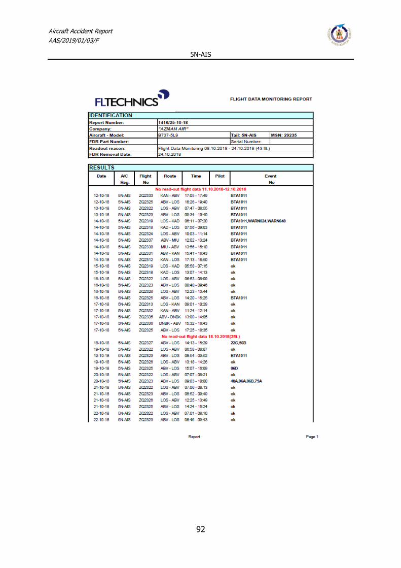
Aircraft Accident Report
AAS/2019/01/03/F
5N-AIS
92
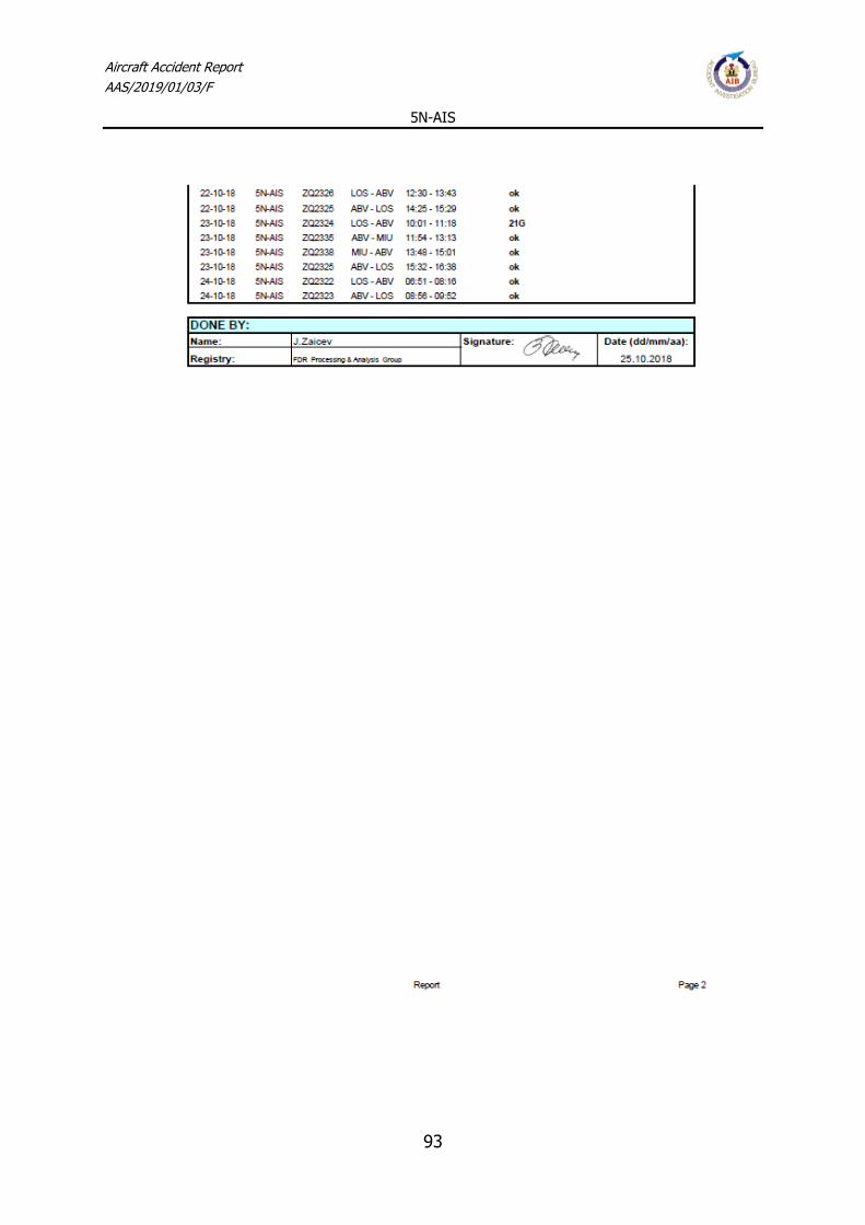
Aircraft Accident Report
AAS/2019/01/03/F
5N-AIS
93

Aircraft Accident Report
AAS/2019/01/03/F
5N-AIS
94

Aircraft Accident Report
AAS/2019/01/03/F
5N-AIS
95

Aircraft Accident Report
AAS/2019/01/03/F
5N-AIS
96

Aircraft Accident Report
AAS/2019/01/03/F
5N-AIS
97

Aircraft Accident Report
AAS/2019/01/03/F
5N-AIS
98

Aircraft Accident Report
AAS/2019/01/03/F
5N-AIS
99

Aircraft Accident Report
AAS/2019/01/03/F
5N-AIS
100

Aircraft Accident Report
AAS/2019/01/03/F
5N-AIS
101

Aircraft Accident Report
AAS/2019/01/03/F
5N-AIS
102

Aircraft Accident Report
AAS/2019/01/03/F
5N-AIS
103

Aircraft Accident Report
AAS/2019/01/03/F
5N-AIS
104

Aircraft Accident Report
AAS/2019/01/03/F
5N-AIS
105

Aircraft Accident Report
AAS/2019/01/03/F
5N-AIS
106

Aircraft Accident Report
AAS/2019/01/03/F
5N-AIS
107

Aircraft Accident Report
AAS/2019/01/03/F
5N-AIS
108

Aircraft Accident Report
AAS/2019/01/03/F
5N-AIS
109
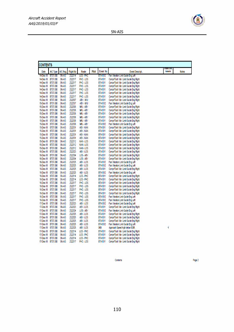
Aircraft Accident Report
AAS/2019/01/03/F
5N-AIS
110

Aircraft Accident Report
AAS/2019/01/03/F
5N-AIS
111
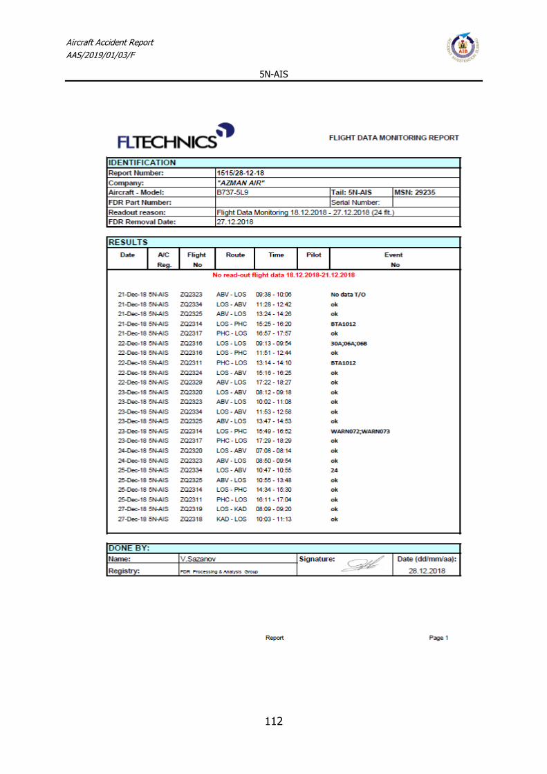
Aircraft Accident Report
AAS/2019/01/03/F
5N-AIS
112

Aircraft Accident Report
AAS/2019/01/03/F
5N-AIS
113

Aircraft Accident Report
AAS/2019/01/03/F
5N-AIS
114

Aircraft Accident Report
AAS/2019/01/03/F
5N-AIS
115