
aircraft nuclear propulsion project quarterly prggress report
152
-
Upload
khangminh22 -
Category
Documents
-
view
0 -
download
0
Transcript of aircraft nuclear propulsion project quarterly prggress report
ORNL-1649
T h i s document consists of 152 poges.
Copy Ydof 266 copies. S e r i e s A.
AIRCRAFT NUCLEAR PROPULSION PROJECT QUARTERLY PRGGRESS REPORT
For Period Ending December IO, 1953
R. C. Briant, Director A. J. Miller, Assistant Director
W. B. Cottreil, Editor
OAK RIDGE NATIONAL LABORATORY Operated by
CARBIDE AND CARBON CHEMKALS COMPANY A Division of Union Carbide and Carbon Corporotion
Oak Ridge, Tennessee Post Office Box P


ORNL-1649 Progress
INTERNAL DlSTRlBUTION
40. J. A. Lane 41. C. E. Lars
10. R. C. Briant 11. F. R. Bruce 12. A. D. Callihan 13. D. W. Cardwell 51. G. J. Nessle 14. J. V. Cathcart 52. H. F. Poppendiek 15. C. E. Center 53. P. M. Reyling 16. R. A. Charpie 54. H. W. Savage 17. J. M. Cisar 55. A. W. Savolainen 18. G. H. Clewett 56. E. D. Shipley 19. C. E. Clifford 57. 0. S' I sman 20. W. B. CottreII 58. I. P. Smith (consultant) 21. R. G. Cochran 59. A. H. Snell 22. D. D. Cowen 60. C. L. Storrs 23. F. L. Cutler 61. C. D. Susano 24. W. K. Eister 62. J. A. Swartout 25. L. B. Emlet (Y-12) 63. E. H. Taylor 26. W. K. Ergen 64. J. B. Trice 27. A. P. Fraas 5. E. R. Van Artsdalen
37. M. T. Kelley 75-84. ANP Library 38. F. Kertesz 85. Biology Librar
C
5
i i i

94. Reactor Experimental \ Engineering Library 91. %Laboratory Records, ORNL W.C.
92. Health Physics Library 95-97. Central Research Library 93. ~ d l a l ~ u r g y Library
86-h. Laboratory Records Cepartment
-,
98-100. 101. 102. 103. 104.
105-1 16. 117.
1 18-1 26. 127.
128-133. 134. 135.
136-1 37. 138-1 45.
146. 147. 148. 149. 150. 151.
156. 157.
158-1 60. 161 -164.
165. 166. 167.
168-1 75.
178-1 79. 180. 181. 182.
1 83- 1 85.
152-1 55.
176-1 77.
#
EXTERNAL DlSTRlRUTlON
Air Force Engincering Office, O a k Ridge Air Forse Plant Representative, Burbank Air Farce Plant Representative, Seattle Air Force Plant Representative, Wod-Ridge ANP Project Office, Fort Worth Argonne National Laboratory (1 copy to Kermit Anderson) Armed Forces Special Weapons Project (Sandia) Atomic Energy Commission, Washington (kt. Col. M, J. Nielsen) Buttel le Memorial Institute Brookhaven National Laboratory Bureau of Aeronautics (Grant) Bureau of Ships Cal ifornia Research and Development Company Carbide and Carbon Chemiccsls Campany (Y-12 Plant) Chicago Patent Group Chief of Naval Research Commonwealth Edison C Convair, San Diego (C. H. Helms) Department of the Navy - Op-362 Detroit Edison Company duPont Company, Augusta duPont Company, W i Bmingtm Foster Wheeler Corporation General Eiectric Company, ANPP General E le i t r i c Company, Richland Glen I... Muirin Co. (T. F. Nogey) Wanford Operations Office Iowa State College Kno! I s Atomic Power La boratary Lockland Area Off ice Los Alumos Scientif ic Laboratory Massachusetts Ins t i t u f e of Technology (Kaufmann Materials Laboratory (WADC) (Col. P. L. Hil l ) Mansanto Chemicsl Company Mound Laboratory
.... ...."..x .. . ..,.. .
.. . .... .. .. . .. ....
i v
dvisory Committee for
eronautics, Washington
196-201. Nuclear Devel
21 1-220. Pratt and W
Radiological Defense L
...
V ... -.-.-!-!?:zmx;x:>; ,.... . . . . . . . . . 1 . . . . . .-.-.-.-.-.-.-.-.-.,.:.. . . .
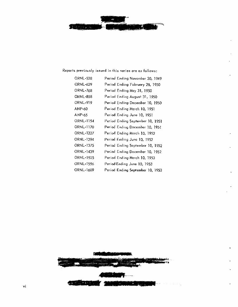
Reports previously issued in this series ure us follows:
0 WNL-528 ORN L-629 0 R N L - 768 ORNL-858 ORNL-919 ANP-60 ANP-65 ORNL-1154 ORblL-1170 ORNL- 1227 0 R N L- 1 294 ORN L- 1 3 75 ORNL-1439 ORNL-1515 ORNL-1556 OR N L- 1 609
Period Ending November 30, 1349 Period Ending February 28, 1950 Period Ending May 31, 1950 Period Ending August 31, 1950 Period Ending December 19, 1950 Period Ending March 10, 1951 Period Ending June PO, 1951 Period Ending September 10, 1951 P e r i d Ending December 10, 1951 Period Ending March 10, 1952 Period Ending June 10, 1952 Period Ending September 10, 1952 Period Ending December 10, 1952 Period Ending March 10, 1953 Period Ending June 10, 1953 Period Ending September 10, 1953
.
vi

CONTENTS
FOREWORD i
PART I . REACTOR THEORY AND DESIGN
INTRODUCTION AND SUMMARY
1. CIRCULATING-FUEL AIRCRAFT REACTOR EXPERIMENT The Experimental Reactor
Control rod sleeves Reactor control Flow in fuel tubes Fuel tube cleaning
Reactor Physics Cr i t ical mass Effect of delayed neutrons Xenon poisoning
The NaF-ZrF,-UF, Fuel Physical properties Fuel production Corrosion of lnconel
Prototype sodium pump test Pump auxiliaries I mpe I I er fabrication Acceptance tests
Fluid Circuits Fuel system Sodium system Valves Auxi I i ary systems
Pumps
I nstrumentat ion Reactor and F lu id Circuit Cleaning Fuel Recovery and Reprocessing
Transportation of fuel Rate of dissolution of ARE fuel Molten fuel dissolution
2. EXPERIMENTAL REACTOR ENGINEERING
Frozen-sodium-sealed pump for sodium Gas-sealed sump pump for in-pile loop test
Pumps for High Temperature Liquids
5
6 6 8 8 8 8
12 12 12 12 13 13 13 14 15 15 15 16 16 16 16 16 16 19 19 19 20 20 21 22
22 23 23 23
vi i

3.
4.
Magnetic-torque-transmi ttsr pump Rotary-Shaft and Valve-Stem Seals for Fluorides
Graphite-packed seal for spiral-grooved shaft Graphite-BeF2 packed seals V-ring seal Bronze-wool, graphite, and MsS2-packed frozen seal Packed seals for valve stems
Materials compati bi I i ty tests Bearing characteristics
Hi gh-Temperature Bearing Development
Heat Exchanger Test Forced-Circu I at ion Corrosion Loap
RE FLECTOR-MOQERATED REACTOR DESIGN STUD1 ES Reactor Physics Fuel Composition and Properties Moderator Regions Hydrodynamics 06 the Fuel Circuit Pump Design Pressure Shell Fuel-to-NaK Heot Exchanger Reactor Controls Sh i e I di ng Filling and Draining of the Reactor
CRITICAL EXPERIMENTS
PART i I . MATERIALS RESEARCH
INTRODUCTION AND SUMMARY
5, CHEMISTRY OF HIGH-TEMPERATURE LIQUIQS Therinal Analysis of Fluaride Systems
NaF-ZrF ,-UF, RbF-LiF-UF, Na F- 3-11 F , Li F-R bF-8eF2 RbF-BeF ,-ZrF,
L i CI-UCI Thermal Analysis of Chloride Systems
NoGI-UCI KCI-UCI RbCI-UCI
v i i i
24 24 24 24 24 25 25 25 25 26 28 29
31 31 33 33 38 39 41 42 42 43 43
44

CSCI-UCI,
c s c I - u c 1 4
KCI-LiCI-UCI RbCl-UCI,
KCI-LiCI-UCI, NaCl-LiCI-UCI ,
Quenching Experiments with the NaF-ZrF, System Differential Thermoanalysi s of the NaF-ZrF, System Fil trat ion Analysis of Fluorides
Mixtures with 53 mole % NaF Mixtures with 50 mole 96 NaF Mixtures with 75 mole % NaF
Spectrophotometry of supercooled fused salts EMF measurements in fused salts Physical chemistry of fused salts
Laboratory-scale production of molten fluorides Purif ication of small fluoride samples for phase studies Production of enriched material for in-pile loop experiment Experi mental production f aci I i t ies Reduction of Na,UF, by hydrogen Treatment of molten NaZrF, with strong reducing agents Reduction of NiF, by hydrogen Preparation of various fluorides
Purif ication of hydroxides Reacfion of sodium hydroxide with carbonaceous matter
Fundamental Chemistry
Production of Purif ied Fluorides
Purif ication and Properties of Hydroxides
6. CORROSION RESEARCH Fluoride Corrosion in Static and Seesaw Tests
lnconel corrosion by fluorides with metal fluoride additives Corrosion of various metal combinations Corrosion of cermets lnconel with o i l and trichloroethylene additives lnconel corrosion by fluorides with MoS, additive Screening tests of metallic bearing materials
Effect of fluoride batch purity Effect of chromium additives Pretreatment of fluoride with Inconel Effect of exposure time Effect of temperature
Fluoride Corrosion of lnconel in Thermal Convection Loops
52 52 52 52 53 53 5.4 5.4 55 55 55 55 56 56 57 58 59 59 59 59 60 60 60 61 62 63 63 63
64 65 65 65 66 67 67 67 67 67 71 72 72 72
c
ix

Effect of surface-to-volume rat io Fluoride with 6.5 mole % U F , The fluoride NoZrF,
Fluoride Corrosion of Nickel and Stainless Steel Loops L iqu id Metal Corrosion
Mass transfer in l iquid leud Static tests of BeQ in sodium, lithium, and lead Spinner tests of Inconel and type 405 stainless steel i n sodium Static tests of beoring materials in sodium, lithium, and lead Static tests of stainless steels in l i thium Stutic tests of solid fuel elements in sodium and sodium hydroxide
Oxidizing power of hydroxide corrosion products Equilibrium pressure of hydrogen in hydroxide-metal systems Mass transfer of chromium in Inconel-fluoride systems
Fundamental Corrosion Research
7. METALLURGY AND CERAMICS Welding and Brazing Research
Brazing of radiator assemblies Brazing of high-conductivity radiator f ins a 1 Electroless” preplating of brazing alloys Inert-arc welding of solid fuel elements
Stress-rupture of Inconel in fluoride fuel Tube-burst tests of tr iaxial ly stressed tubes Environmental effects on creep of Inconel
High-Conductivity Metals for Radiator Fins Diffusion barriers Clad copper Electroplated copper Solid phase bonding
Extrusion of Incanel-type al loys Roll ing of chromium-cobalt alloy Roll ing of cobalt Roll ing of iron-chromium-nickel alloy Cold-rolled columbium alloy
Meclionicnl Properties of Inconel
Fubrication of Special Materials
Tubular Fuel Elements Ceramic Research
Glass-type pump seals Ceramic container for fuel H igh-den 5 ity graphite
Combustion of Sodium Alloys
72 72 73 73 74 74 75 75 76 76 76 80 80 80 82
83 84 84 86 89 89 91 91 91 92 92 93 93 93 93 93 93 94 94 94 94 94 96 96 96 96 96
,
X
8.
9.
io.
HEAT TRANSFER AND PHYSICAL PROPERTIES RESEARCH Heat Capacity Thermal Conductivity of Solidified Salts Density and Viscosity of Fluorides Vapor Pressures of Fluorides Electrical Conductivity of F iuorides Forced Convection Heat Transfer with NaF-KF-LiF Eutectic Flow in Thermal-Convection Loops Fluid F low in an Annulus Transient Surf ace- Boi I ing Studies C i rcul at i ng- Fue I Heat Trans fer
RADIATION DAMAGE Irradiation of Fuel Capsules Creep Under Irradiation In-Pile Circulating Loops
ANALYTICAL STUDIES OF REACTOR MATERIALS Analytical Chemistry of Reactor Materials
Oxidation states of iron Oxidation states of chromium Determination of UF, and UF, Reducing power of NaZrF, with zirconium addition Dissolution of fluoride mixtures containing zirconium
Petrographic Examination of Fluorides Mass Spectrometer Investigations of Irradiated Fluoride Fuels
Calculation of UF4 in unirradiated fuels Calculation of U2Z5 lost from irradiated fuel Determination of UZ3, burnup
Summary of Service Chemical Analyses
PART 1 1 1 . SHIELDING RESEARCH
INTRODUCTION AND SUMMARY
11. BULK SHIELDING REACTOR Spectrum of Gamma Rays Emitted by the BSR
Spectrometer arrangement Results
Fast-Neutron Leakage Spectra of the BSR
12. L ID TANK FACILITY Slant Penetration of Neutrons Through Water Air Duct Tests
.-
xi"
97 97
98 99 99
100 101 102 102 102
103 103 104 106
98
107 107 107 108 108 1 09 109 109 110 1 IO 1 1 1 1 1 1 112
115
116 116 116 116 117
'120 120 121
x i

13.
14.
15.
16.
R ~ ~ o v Q ~ Cross Sections Survey of Lid Tank Experiments
TOWER SHIELDING FACILITY
SHI ELDi NG ANALYSIS Visible bight from a Nuclear Power Plant Neutron Reflection Coefficient for Water
PART IV. APPENDIXES
LIST OF REPORTS ISSUED DURING THE QUARTER
DIRECTORY OF ACTIVE ANP RESEARCH PROJECTS AT ORNL
ORGANlZATlON CHART
122 1 23
125
126 125 1 26
129
131
139
xi i

ANP PROJECT QUARTERLY PROGRESS REPORT
FOREWORD
This quarterly progress report of the Aircraft Nuclear Propulsion Project a t ORNL records the technical progress of the research on the circulating-fuel reactor and a l l other ANP research a t the Laboratory under i t s Contract W-7405-eng-26. The report i s divided into three major parts: I. Reactor Theory and Design, [ I . Materials Research, and 111. Shielding Research. Each part has a separate introduction and summary.
The ANP Project i s comprised of about 300 technical and scienti f ic personnel engaged i n many phases of research directed toward the achievement of nuclear propulsion of aircraft. A considerable portion of t h i s research i s performed in support of the w w k of other organizations participating in the national AMP effort. However, the bulk of the ANP research a t ORNL is directed toward the development of a circulating-fuel type of reactor.
The nucleus of the effort on circulating-fuel reactors i s now centered upon the Aircraft Reactor Experiment - a high-temperature prototype of a circulating-fuel reactor for the propulsion of aircraft. The equipment for this reactor experiment i s now being assembled; the current status of the experiment i s summarized in Section 1 of Part I. The supporting research on materials and problems peculiar to the ARE - previously included in the subject sections - is now included in this ARE section, where convenient. The few exceptions are referenced to the specific section of the report where more detailed infor- mation may be found.
The ANP research, in addition to that for the Aircraft Reactor Experiment, fa l ls into three general categories: (1) studies of aircraft-size circulating-fuel reactors, (2) materials problems associated w i th advanced reactor designs, and (3) studies of shields for nuclear aircraft. These three phases of research are covered in Parts I , II, and Ill, respectively, of th is report.
1


INTRODUCTION AND SUMMARY
Assembly of the Aircraft Reactor Experiment (sec. I ) i s nearing completion; a l l but a few of the components have been received and installed. The items s t i l l missing include the new control rod sleeves and parts of the fueland sodium gas-sealed pumps. As the installation progresses, various auxil iary systems, such as the helium, water, and hydraulic off-gas systems, are being subjected to operational tests. Tests of a prototype pump have established the design criteria for the pump cooling and lubricating systems, as wel l as the operating characteristics of the pump. The new control rod sleeves w i l l effect a reduction in the structural poison in the core and hence reduce the cri t ical mass. Recent physics calculations indicate that the uranium requirement inside the pressure shell w i l l be wel l under 40 Ib of U235. Other physics calculations on reactor kinetics reveal that reactor operation and control w i l l not be adversely affected by either xenon poisoning or the loss of delayed neutrons in the circulating fuel. The fuel, which w i l l be obtained by the addition of u concentrate, Na2UF,, t o a solvent mixture, NaZrF,, has been shown to be reasonably compatible wi th the lnconel container metal for the temperatures and times required. Production of both the solvent and con- centrate are essentially completeand the impurities in each are wel l below acceptable levels. Pro- cedures have been established to assure that the fuel and sodium systems in the experiment w i l l be adequately cleaned prior t o being dilled wi th the solvent and sodium, respectively. Additional studies of the fuel recovery and processing problem have established dissolution rates for both molten and sol id fuel in batches containing 4 kg of U235.
With the near-completion of the Aircraft Reactor Experiment the emphasis of the experimental work has shifted to the development of components for general aircraft reactor application and supporting research. Valves, pumps, bearings and other components of high-temperature fluoride and l iquid metal systems are being developed for these studies (set. 2). Satisfactory, short, frozen-sodium shaft seals, wi th length-to-inside-diameter ratios of 1 to 5, have been developed for sodium pumps. A small gas-sealed pump for an in-pile loop and a canned
magnetic-torque transmitter for a high-temperature aircraft pump ate being developed. Packed seals for fluoride pumps and valves have achieved limited success under controlled conditions, but none of the seals are sufficiently reliable for service conditions. Equ ipment for high-temperature bearing tests is being assembled, and a number of potential bearing moterials are being screened on the basis of wear. A fluoride-to-sodium heat exchange tube bundle and a high-velocity forced-convection cor- rosion loop are being operated, but results are not yet available on either test.
The designs of a family of 50- to 3QO-rnegawatt ref lector-moderated reactors have been prepared to permit an Air Force evaluation of over-atl aircraft performance (sec. 3). The four reactors considered for 50-, loo-, 200-, and 3OGrnegawatt power out- puts are a l l of the same general species, having a l l been extrapolated from the same base. The designs are based upon presumed fuel and were made wi th insufficient physics informatian for the establishment of over-all design limitations. In other respects, however, the designs are on a firmer basis, since considerable shielding and heat exchanger data are avai lableand the hydrodynamics of the fuel circuit and fuel pump have been con- firmed by hydraulic mockups. The gas-sealed centrifugal pump i s designed with special baffl ing above the impeller so that it w i l l operate con- tinuously wi th i t s shaft 80 deg from the verticaf, and it w i l l even operate for 1 inin when inverted without “gassing” the pump. Other aspects of the aircraft reactor, including moderator cooling, assembly of the reactor, control, and fuel f i l l i ng and draining, are discussed.
The Crit ical Experiment Fac i l i ty was used during th is quarter t o determine the static physics charac- terist ics of a mockup of an air-cooled water- moderated reactor fox the General Electric Aircraft Nuclear Propulsion Project (sec. 4). At the s ~ m e time, preparations were made far measurements of a mockup of a Pratt and Whitney sugercsitical-water reactor and a Nuclear Development Associates sodium-cooied reactor, as well CIS the Laboratory’s ref lector-moderated reactor.
5

TEWLY PROGRESS REP0
E. S . Bettis J. L. Meem ANP Division
There were no niodifications in the ARE design or cr i t ical developments in the ARE program during the quarter, and therefore installation of equipment received maximum attention. The installation i s proceeding satisfactorily, and there was no major holdup occasioned by lack of components. For the f i rst time since the project began, i t i s not neces- sary to explain either the cause for some dslay or smie change in plan, and this i s the most signifi- cant remark that can be made to indicate the status the project attained during this quarter. It i s fairly clear now that completion of the installation o f the ARE can be effected in an uneventful manner,
One fuel pump sump tank and one sodium pump sump tank were received, and therefore the instal- lation of piping for the fuel and sodium circuits could proceed in a relatively uninhibited manner, even though the spare fuel and spare sodium tanks have not yet heen received. Tests on a prototype pump havf: established the requirements of the auxil iary systems for the pumps, a5 well as the pump's Operating characteristics and performance.
Since 0 1 1 major components of the experiment are now on hand, a l l crafts have been able to proceed with relatively l i t t le interference. Installation of electrical heaters and insulation i s progressing rapidly. The heaters are approximately 65% in- stal led, but, since the locations for the remaining heaters are more accessible, the iob i s 75% com- plete with regard to man-hours. Insulation work is foliowing closely behind heater installation. The most dif f icult insulating iob, that of insulating tanks and lines in the dump tank pit, i s 957, fin- ished, and about 15% of the other insulation has been installed.
Additional data have been obtained from calcu- lations of the reactor statics and dynamics. An evaluation of the effects of xenon poisoning und of the loss of delayed neutrons indicated that neither w i l l be of much consequence to reactor operation. Calculations of the cri t ical mass by two different methods gave values which show that the uranium requirement in the pressure shell w i l l be wel l be- low the 40 Ib permissible from the viewpoint of uranium allocation and AWE technology. A saving i n mass of about 4 Ib was realized by a reduction in tho poisoning from the control rod sleeves.
The new Inconel-clad control rod sleeves, which w i l l replace the three concentric r ~ i d sleeves that were to be used around each rod, have been fabri- cated. The space outside each new sleeve will be f i l led with beryllium oxide strips, The reactor, which i s complete except for installation of the new rad sleeves and the beryllium oxide strips, has been subjected to preliminary cleaning tests. Tests with simulated reactor duel tubes indicate that ful ly established turbulent f low w i l l be real- ized at a Reynolds number of 5000, which is we!! under the ARE design value of 14,800.
The ultimate fuel w i l l be obtained by the addi- t ion of sufficient fuel concentrate, Na,UF,, to the fuel solvent, NaZrF,, to make the reactor crit ical. The production of the 3300 Ib o f solvent was corn- pleted some time ago, and conversion of the 115 kg of UZ3, into Na,UF, i s nearing completion, Init ial tests of the concentrate show that, with the exception o f one batch 'ivhich was reiected, the impurities in the concentrate ore gratifyingly low, Density and viscosity data have been obtained for the concentrate.
Methods for recovering and reprocessing the fuel after completion of the experiment have received increased attention, It now appears that the used fuel may be transported from the experiment to the reprocessing area in aluminum containers contain- ing 4 kg of U235 and that about 20 such transfers w i l l be required. While the reprocessing procedures had been established previously, additional data have been ottained on dissolution rates for the fuel in both l iquid and molten states.
T H E E X P E R I M E N T A L R E A C T O R
The reactor i s completely assembled (Fig. 1.1) except for the Inconel-clad stainless steel control rod sleeves, which have not yet been received, and the beryll ium oxide strips that w i l l be placed around these sleeves. 'The fuel tubes have been cleaned according to the established cleaning pro- cedures. Additional measurements of f low ptie, nomena in glass mockups o f t h e fuel tube indicate that fu l ly developed turbulent flaw i s realized at Reynolds numbers above SOQ, that is, well under the reactor design value of 14,000.
6

PERIOD ENDING DECEMBER 10, 1953
kSODIUM INLEl
Fig. 1.1. Photograph of the Experimental Reactor.
7

ANPQUARTERLYPROGRESS REPORT
Control Rod Sleeves
In order to reduce the structural poisons in the reactor, it was decided to replace the three con- centric lnconel sleeves around each o f the four control rods (one regulating and three safety) wi th a single Inconel-clad stainless steel sleeve in each hole. Fabrication o f the new control rod sleeves has been finished by the International Nickel Company, but they have not yet been de- livered.
To further reduce the cri t ical mass o f the reactor, the volume outside the rod sleeve was to be packed with beryllium oxide pellets. However, since the beryllium oxide pellets w w l d occupy only about 50% of the volume, it was recently decided to f i l l this volume with strips from unused beryllium oxide moderator blocks. It i s anticipated that approxi- mately 90% of the void volume can be f i l led with the beryllium oxide strips.
Reactor Control
A. L. Southern J, K. Lesl ie ANP Divis ion
There has been only one change (an addition) to the reactor control equipment. An auxil iary low- speed drive has been designed for the regulating rod. This addition was made to provide a means of manually operating the regulating rod when the reactor i s operating at zero power during rod cali- brat ion.
In the event o f f ission chamber fai lure or in- adequate Ak in the regulating rod, it may be neces- sary to change these components during the course of the experiment. Consequently, some of the drive mechanism has been relocated to faci l i tate replacement of both the regulating rod and the fission chambers. No other changes have been made in the reactor controls and this phase o f the work i s complete insofar as preliminary checking can determine completeness.
Flow i n Fuel Tubes
J, Long Go M. Winn Reactor Experimental Engineering Div is ion
The experimental relationship between the friction factor and the Reynolds modulus obtained in a glass replica of the reactor fuel tube system 1
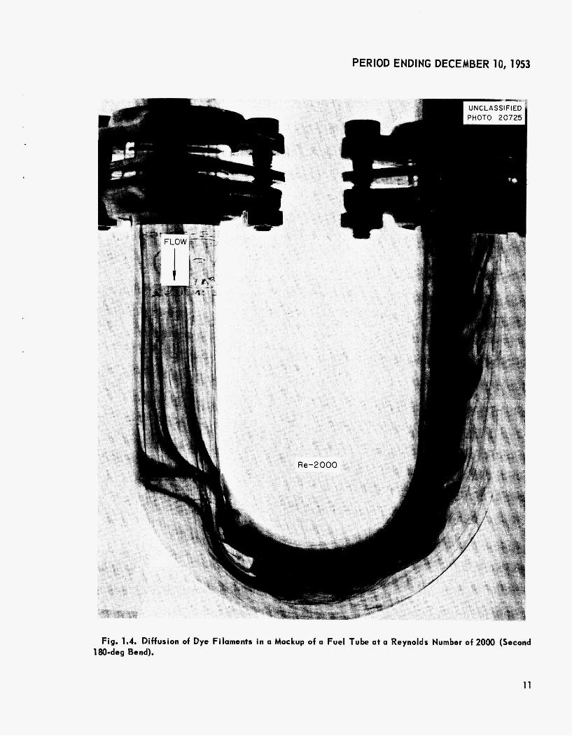
indicated that the transition region (that region which l ies between laminar and ful ly developed turbulent flow) I ies approximately between Reynolds moduli o f 2000 and 5000, Recent photographs, Figs. 1.2, 1.3, and 1.4, show the diffusion of dye filaments in the second 180-deg return bend in a fuel tube under three Reynolds number flow con- ditions: 600, 1300, and 2000, respectively, Un- fortunately, there was more than one dye source present i n the entrance region o f the fuel tube system, and thus several filament trajectories were superimposed, In general, the sharp, d ist inct filaments shown in Figs. 1.2 and 1.3 are character- i s t i c o f laminar flow, whereas the diffuse filaments indicate some turbulence, Fig. 1.4.
Fuel Tube Cleaning
G. D, Whitman, ANP Divis ion
The cleaning procedures for the fuel and sodium systems inside and outside the reactor are de- scribed in a following subsection (cf,, ‘‘Reactor and F lu id Circui t Cleaning”). However, a de- scription of the application of these procedures to the actual cleaning of the reactor fuel tubes follows.
The s ix parallel fuel circuits i n the reactor were f i rs t rinsed, individually, with tap water. Th is flushing was accomplished by valving off the out- lets of a l l but one circuit and passing water at a pressure o f 60 ps i into the fuel inlet header. Following this pressure flushing, each circuit was flushed with d is t i l led water, and the water was blown out as completely as possible wi th helium. After the water that could be blown out had been removed, a vacuum system was connected through a dry-ice cold trap to the fuel tubes, and the re- maining water was evaporated from the fuel circuit at room temperature, During the evaporation pro- cess 2 cfh of helium was bled into the system inlet to sweep out al l moisture. The residual moisture was determined by the Karl Fisher and dew-point methods.
The reactor w i l l be complete when the control rod sleeves and the bottom fuel outlet manifold have been installed, and it w i l l then be ready for inclusion in the system.
’ORNL-1609, ANP Quor. Prog. R e p . Sept. 79, 1953, J. 1. Long and G. M. Winn.
.
8

L
PERIOD ENDING DECEMBER 10,1953
c L - A I PHOTO 20724 1
Fig. 1.2. Diffuaion of Dye Filaments i n a Mockup of a Fuel Tube at a Reynolds Number of 600 (Second 180-deg Bend).
9

ANPQUARTERLYPROGRESSREPORT
Fig. 1.3. Diffusion of Dye Filaments i n a Mockup of a Fuel Tube at a Reynolds Number of 1300 (Second 180-deg Bend).
10
PERIOD ENDING DECEMBER 10,1953
r
i
Fig. 1.4, Diffusion of Dye Filaments i n o Mockup of o Fuel Tube at a Reynolds Numb 180-deg Bend).
11

R E A C T O R PHYSICS
W. K. Ergen J. Bengston C. B. Mills, ANP Divis ion
The UNIVAC multigroup calculations and the locally performed two-group calculations gave values which show that the reduction of the poison- ing by the control rod sleeves has brought the ARE uranium requirement i n the pressure shell to well below the 40 Ib permissible from the viewpoint o f uranium allocation and ARE teclnology. The de- layed neutrons lost from the reactor by fuel circu- lation are predominantly those of long decay constants, and hence a small amount o f excess reactivity makes it unnecessary for the reactor to wait for the long-delayed neutrons. Small excess reactivit ies w i l l bring the reactor to relatively short-time constants (10 sec or so), but when the reactor i s at such a time constant it i s s t i l l sub- stantially below the prompt-critical condition be- cause the short-delayed neutrons are not appreciably reduced by fuel circulation. Speculation as to the xenon poisoning shows that the poisoning effect would be easily observable i f the xenon were not lost from the fuel and i f the xenon cross section were as large for the ARE as it i s for low-tempera- ture reactors. Fai lure to observe the poisoning might mean that Xe135 or i t s parent iodine had evaporated from the fuel, or it might mean that the effective xenon cross section was reduced by the high moderator and neutron temperature. In the latter case, xenon poisoning would s t i l l be a prob- lem i n high-powered reactors of the ARE type,
Cr i t ical Mass
The multigroup calculations made by using the UNIVAC at New York University and essentially the method previously employed2 by the ANP Phys- ics Group have now yielded fairly reliable, though not yet final, data regarding the uranium requirement o f the ARE. These data are in agreement w i th data obtained by the two-group method. They indicate that the elimination of much of the poison origi- nally incorporated into the control rod sleeves has brought the mass requirement to about 15% below the 40 Ib which would be permissible from the viewpoint of phase diagrams, corrosion, and allocation.
2Report o f the Technical Advisory Board to the Techni- cal Committee o f the Aircraft Nuclear Propulsion Program, ANP-52 (Aug. 4, 1950).
3S. Glosstone and M. C. Edlund, The Elements of Nuclear Reactor Theory, p. 329 ff., Van Nostrond, New York, 1952.
Effect of Delayed Neutrons
About one half the delayed neutrons are given off outside the reactor and lost from the chain re- action* These delayed neutrons are predominantly those with long-lived precursors. Most of the short- l ived precursors decay before they are swept out of the reactor, and their delayed neutrons are hence not appreciably reduced by the fuel circulation. Since the neutrons with the long delay times are not very effective, i t w i l l take only a small excess reactivity to al low the chain reaction to proceed without “waiting” for these neutrons. A small excess reactivity w i l l hence bring the reactor to a relatively short time constant o f about 10 seconds. When the reactor i s operating at fu l l power, it w i l l probably exhibit small reactivity fluctuations, and this may temporarily bring the reactor from just cr i t ica l ( inf ini te period) to a period as low as 10 seconds. Hence, it might be dif f icult to keep the reactor steadily at a period longer than 10 seconds. It should be noted that reactivity fluctuations are not expected at low power operation so that it should be possible to operate the reactor on a 30-sec period during the prel iminary, low-power experiments. Because of the only slightly reduced effectiveness of neutrons with short delay times, the amount of additional reactivity required to bring the reactor from a 10-sec period to prompt cri t ical i s quite substantial, and the fuel circu- lation of the ARE does not appreciably reduce th is safety feature below i t s value familiar in stationary- fuel reactors.
Xenon Poisoning Renewed consideration was given to the problem
of xenon poisoning of the ARE. There is reason to believe that the Xe135,and probably also i ts parent iodine, w i l l evaporate from the fuel so that the xenon poisoning effect w i l l not occur in a reactor of the c irculating-fluor ide-fuel type. Conf irmation of th i s would be a major accomplishment of the ARE. To investigate the problem experimentally, the reactor would have to be run for a time some- what shorter than the half l i fe of 1135 at fu l l power and then reduced to very low power. If the xenon poisoning i s appreciable, the reactivity w i l l exhibit the characteristic behavior of f i rs t dropping because of xenon formation by I’35 decay and of then increasing because of Xe135 decoy. Calculations performed by standard methods3 show that this behavior should be easi ly detectable if the iodine and xenon do not evaporate from the fuel. If the behavior i s not found i t could mean
12

PERIOD ENDING DECEMBER 10, 1953
that the poison i s given off. However, i t could also mean that the xenon poisoning is largely reduced by the high moderator and neutron temperature and that the xenon cross section i s rather low for neutrons that are somewhat faster than room-temper- ature thermal neutrons. If the latter explanation were correct, xenon, even with reduced cross section, would be a poison for reactors of higher power than the ARE.
There i s the interesting possibi l i ty that the xenon, and maybe the iodine, i s released from the fuel at a rate comparable to the rate of radioactive decay. I f so, the build-up and decay of the xenon poisoning could s t i l l be observed, but the time constants would be different. A quantitative analysis of the reactivi ty following a full-power run would disclose th is situation. There i s also the theoretical possibi l i ty that other f ission fragments have large absorption resonances at neutron energies above those corresponding to the xenon resonance. In high-temperature reactors such as the ARE, these poisons might conceivably be observable.
T H E NaF-ZrF4-UF4 FUEL
The reactor fuel w i l l be obtained by the addition of a sufficient amount of the fuel concentrate, Na,UF,, t o the fuel solvent, NaZrF,, t o make the reactor cr i t ical. It i s expected that the f inal fuel composition w i l l contain approximately 5.5 mole % UF,. In l ieu of more precise knowledge of the ultimate fuel composition, extensive material research and physical property measurements have been conducted on the fuel composition with 4 and with 6.5 mole % UF,, as well as on the carrier and solvent. About 3300 Ib of the carrier hasbeen produced and is being held under helium pending i t s use i n the experiment. The batch production of the fuel concentrate is nearing completion. The impurities in a l l but one of these batches were exceptionally low, averaging (not including the one poor batch) 48 ppm of Fe, 16 pprn of Cr, and 46 ppm of Ni.
Physical Properties
H. F. Poppendiek Reactor Exper imenta I Engineering Division
The densities and viscosit ies of the fuel solvent, NaZrF,, and of the fuel Concentrate, Na,UF , are being measured; these properties of the fuef with 6.5 mole % UF, were reported p r e ~ i o u s l y . ~ Pre-
liminary density and viscosity values for Na,UF, are: viscosity, 17.5 cp at 725"C, 9.9 cp a t 975°C; density, 5.598 - 0.00119 T g/cm3, where 660°C < T < 100O0C.
Fuel Production
6. J. Nessle 4. E. Eorgan F. A. Dsss
Mater ia I s Chemistry D i v i s i 011
Production of the required 3300 Ib of NaZrF, is now complete, and the material is being held under helium pending i t s use i n the ARE. Processing of the 253 Ib of U235 to produce the fuel concentrate, Na UF,, is nearing completion.
h e fuel concentrate i s being produced by the Y-12 Production Div is ion to permit control of the large quantities of enriched uranium (93.5% U235) involved. Several weeks were spent training operators in the handling of the equipment, as well as i n testing the equipment. A few necessary changes and repairs were made a t that time. The production equipment and the processing technique are essentially the same as those previously described5 for fuel solvent production.
The concentrate w i l l be produced in 15 batches of approximately 30 Ib each. It has provedpossible, after some simple operational changes, to process three batches of material per week. However, three weeks of down-time have been necessary during th i s period because of analytical dif f icult ies and lack of approval of an additional uranium allotment. T o date, 10 of the required 15 batches have been processed, and it i s estimated that the production operation w i l l be completed before December 1.
As the material was produced by the "-112 Production Div is ion for use in the ARE, analyses of the material were made by both the Y-12 and the ORNL groups involved. Any differences in these analyses were to be explained and corrected by using, i f necessary, the tr ipl icate sample original ly taken before production operations proceeded. The analytical situation appears quite satisfactory at present, insofar as p rduc t ion control and fissionable material accountability is concerned. Some discrepancies between the two laboratories have occurred in determinations of the uranium content of the UF,; these dif f icult ies have
,ANP Ouar. Prog. R e p . Sept. 10, 1953, QRNL-1609,
' /bid. , p. 15. p. 15.
13
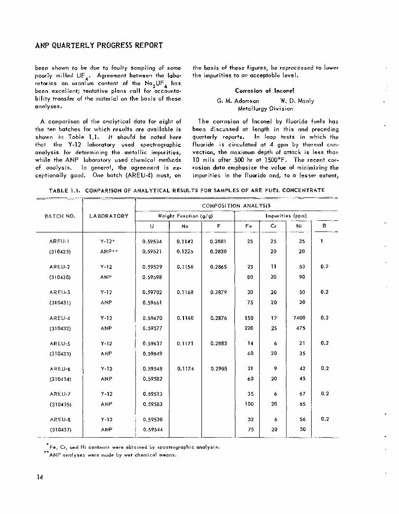
been shown to be due to faulty sampling of some poorly mil led UF,. Agreement between the labo- ratories on uranium content of the Na,UF, has been excellent; tentative plans ca l l for accounta- b i l i t y transfer of the material on the basis of these analyses.
Cr
25
20
11
20
20
20
12
25
6
20
9
20
6
20
6
20
A comparison of the analytical data for eight of the ten batches for which results are available is shown in Table 1.1. It should be noted here that the Y-12 laboratory used spectrographic analysis for determining the metallic impurities, while the ANP laboratory used chemical methods of analysis. In general, the agreement is ex- ceptionally good. One batch (AREU-4) must, on
N i
35
20
53
90
50
20
7400
475
21
35
42
45
67
65
56
50
the basis of these figures, be reprocessed to lower the impurities to an acceptable level.
Corrosion of Inconel
@. M. Adamson W. D. Manly Meta I lurgy Division
The corrosion of lnconel by fluoride fuels has been discussed at length in this and preceding quarterly reports. In loop tests in which the fluoride i s circulated at 4 gprn by thermal can- vection, the maximum depth of attack i s less than 10 m i l s after 500 hr at 1500°F. The recent COP
rosion data emphasize the value of minimizing the impurities in the fluoride and, to a lesser extent,
..-... .___
COMPOSITION ANALYSIS
BATCH NO.
AREU-1
(31 0423)
ARElJ-2
(3 1 043 0)
AREU-3
(310431)
AREU-4
(31 0432)
AREU-5
(310433)
AREU-6
(31 0434)
AREU-7
(310435)
AREU-8
(31 0437)
LABORATORY
Y-12*
ANP**
Y-12
ANP
Y-12
ANP
Y-12
ANP
Y-12
A NP
Y-12
ANP
Y-12
ANP
Y-12
ANP
Weight Fraction (g/g)
U
0.59534
0.59521
0.59529
0.59598
0.59702
0.59661
0.59470
0.59577
0.59637
0.59649
0.59548
0.59582
0.5951 3
0.59583
0.59530
0.59544
Na
0.1142
0.1225
0.1158
0.1168
0.1160
0.1171
0.1 194
F
0.2881
0.2830
0.2865
0.2879
0.2876
0.2883
0.2905
F e
25
23
80
30
75
150
220
14
60
21
60
35
100
32
75
Impurit ies (ppm)
B
1
0.2
0.2
0.2
0.2
0.2
0.2
0.2 .
*Fe, Cr, and N i contents were obtained by spectrographic analysis. ** ANP analyses were made by wet chemical means.
14

PERIOD ENDING DECEMBER 10,1953
the value of clean container systems. Additives to the fluoride, such as ZrH,, which would serve to reduce the impurities in the fluoride mixtures and hence the fluoride corrosion, are being evaluated. For a detailed report of the investi- gation of the effect of various parameters on cor- rosion i n the fluoride-lnconel system, as well as of the postulated mechanism, see sec. 6, "Cor- ros ion Research."
PUMPS
H. W. Savage W, G. Cobb
W. R. Huntley A. G. Grindell
ANP Division
Developmental work on the gas-sealed pumps and auxil iaries for the ARE has progressed to the point where acceptance tests of the pumps for the ARE and the mockup rel iabi l i ty test of a spare pump and auxil iaries are being performed.
Parts for the two fuel and two sodium gas-sealed sump-type pumps are being received; one pump has been completely assembled and two others are almost complete. The pumps for the two systems w i l l be identical except for minor differences in the impeller designs and the volumes of the sump tanks, since the fuel pump sump tank must provide volume for the addition of the fuel concentrate, as wel l as for the thermal expansion of the fuel. The operating characteristics of these pumps, as well
operation of the pump with sodium was terminated after more than 300 hr a t 1200"F, because a gasket leak at the parting face of the pump casing allowed sodium to jet against the top flange near the primary gas seal. No further bearing trouble wus experienced during the tests, and postrun examination revealed no bearing or shaft wear. It is therefore concluded that altering the inter- ference f i t between the bearing and the shaft d id successfully eliminate the slippage that occurred in the previous tests.
Postrun examination showed that sodium vapor had no deleterious effect on the silver-impregnated graphite seal material. To confirm this, silver- impregnated graphite was immersed in sodium at 300°F for 150 hr in a laboratory test, and again no harmful effects could be observed. The test t o determine the rel iabi l i ty of the secondary gas seal a t high system pressure (SO psig) was not completed because of the gasket leak which brought about early termination of pump operation. This test is now being made without sodium in the pump.
It was found that gas entrained during pump start- up could be rejected in $ min at a pumping rate of 35 gpm and in 4 min at a pumping rate of 125 gpm. Since there is no apparent demand for higher pumping rates during startup, the degassing charac- terist ic appears to be satisfactory.
Pump Auxil iaries
Prototype Sodium Pump Test
The tests of the gas-sealed sump pump with NaF-ZrF,-UF, (50-46-4 mole %) were reported previously.6 This pump is a prototype of those being assembled for the ARE. The termination of these tests was caused by bearing noises which were determined to be the result of slippage of the inner bearing race on the shaft. The bearing race and the shaft were altered to give a 0.0002- to 0.0004-in. interference f i t between them in an attempt to eliminate the slippage. Subsequent
dibutylcarbitol from the seal-cavity cooling annulus and 7,000 Btu/hr in the l ight spindle o i l used as shaft and bearing lubricant were found, Th is heat was removed by water in external heat exchangers.
The tests conducted with the prototype pump to determine heat loads of the shaft- and seal-cooling circuits showed the need for redesign of these circuits t o eliminate the rotary union i n the shaft- cooling circuit at the upper end of the pump shaft. The cooling circuits have been modified, and the cooling and lubricating o i l now enters the bearing housing between the upper bearing and the lubricant-
15

and heat removal and the other portion passes into the hollow shaft for heat removal. Al l the o i l col lects below the bottom bearing in a cavity out- side the primary face seal, It flows from the cavity by gravity through nine !/-in.-dia connections at the bottom of the bearing tous ing to the lubricant reservoir for cooling and recirculation.
Heat exchanger tests indicate that eight pumps w i l l be required for the pump lubrication (oil) system, that is, one operating and one spare pump for each of the sodium and fuel pumps. One pump and i ts spare w i l l suffice for the dibutylcarbitol system for a l l sodium and fuel pumps. These uuxi l iary lubrication and coolant pumps have been checked and found to be satisfactory.
Impeller Fabrication
All the lnconel impeller castings made by the vendor have been reiected because af imperfections such as sand inclusions, cold shots in the cast metal, and porosity. Each of these imperfections could result i n pump failure because of structural failure of the impeller vanes or because the re- moval of sand inclusions and metal particles in the cold shots would cause intolerable unbalance of the impeller. As a consequence of these re- jections, impellers for ARE pumps are being fabricated from Inconel plate stock. Impellers for the sodium pumps (high flow) w i l l have curved vanes to provide heat and flow characteristics similar to those of the cast impellers, Impellers far the fuel pumps (low flow) w i l l be drilled, and, although somewhat less eff icient than the curved- vane impellers, they w i l l be easier to fabricate.
Acceptance Tests
Test equipment has been designed and some of it has been placed in operation for running ac- ceptance tests on a l l A R E pumps. These tests w i l l include (1) water tests to determine head, flow, and efficiency of each pump, (2) short-time, cold, run-in tests of seals at 65 psig, and (3) hot tests a t ARE temperature, flow, and pressure conditions. The water test equipment i s now in operation, and an all-lnconel loop is being fabri- cated for the hot tests. The hot test loop w i l l include an ARE-type gas control system and the cooling and lubricating circuits described above. One ARE pump has been assembled and checked with cold water. The performance of the pump in this preliminary test was acceptable.
FLUID CIRCUITS
G. D. Whitman ANP Division
G. A. Cristy Engineering and Ma intennnce Divis ion
Except for the installation of the pumps, the external fuel and sodium systems are essentially completed. Installation of heaters and insulation on these systems isabout 65% complete. Additional tests of the bellows-seal and the frangible-disk valves have demonstrated the rel iabi l i ty .of each under A R E operating conditions. A flow diagram showing the major f lu id circuits and design-point operating conditions is presented in Fig. 1.5.
Fuel System
One fuel pump casing has been received and installed in the fuel system; the other i s expected early in December. Only seven welds remain to be made before the system, including the spore pump, i s completed; some operational tests may be undertaken before installation of the spare pump. The fuel fill-and-flush tanks have been thoroughly cleaned by hot-water flushingand dried by prolonged evacuation at sl ightly elevated temperatures (around 200°C).
Sodium System
The status of the sodium system is comparable t o that of the fuel system. Assembly of the sodium piping is essentially complete, except for 17 welds that are in the v ic in i ty of either the pump casings or of the reactor.
Valves
The valve tests reported previously indicated that the valves to be used in the ARE would give satisfactory performance i f held at a temperature of 1200°F or below. The only additional infor- mation on bellows-seal valves involves operational tests at 1100 to 1275OF after the valve had f irst been held for some time at 1300°F in contact with the fluoride NaF-ZrF,-UF, (50-46-4 mole %). In these latter tests, there was no leakage but some sticking; theoperotionat 1300°F apparently softened the sealing surfaces. The pressure required to open the stuck valves increased rapidly and then leveled off as the valve-closed t ime was increased; a t no time, however, did the pressure exceed 30 psig.
16

I WATER SUPPLY
1 i -
f
Cf4 RELIEF VALVE
e FREEZE VALVE
(3 PUSH-JUTTON CONTROL
u * FLOW IN c fm
-DC-- V A L E NORMALLY OPEN
-*e VALVE NORMALLY CLOSCD
+ THROTTLING VALVE
-?+- CHECK VALVE
j/ PRESSURE :N INChES OF WATER. GAGE @ COOLANT
0 VENT SYSTEM
REMOTE MANUAL VALVE
REMOTE MANUAL ANGLE VALVE
fi MANUAL VALVE
SOLENOID VALVE
FLOW C0NDiT;ONS ARE BASED ON THE ASSUMPTION THAT THE COOLANT HAS THE FOLL0W:NG PROPFRTIES:
P = 210 13/:t3 Cp= Y 3 7 0.23 TO t3 Btu/lb°F cp AT OPERATING CON31TiONS
APPROXIMATE VOLUME OF MAIN S Y S l E M : INTERNAL 1.3 f t 3
INITIAL-EXTERNAL 3.5 t i3 ENRICHING FLUID f.7 f t3 MAX,
T O T I L 6.5 i t3 MAX.
Fig. 1.5. Aircraft Reactor Experiment Flow Diagram,
17


Additional data are also available from tests of the frangible-disk valves operated in the fluoride fuel. The frangible-disk valve was held in contact wi th molten fuel at a temperature of about 1300°F for 160 hr and was opened immediately by the actuatorattheendofthis period. The valve operation was normal in every way. These tests on ARE-type valves in fluoride mixtures have praduced con- fidence in the valves that are to be used in the ARE, and no serious valve problems are anticipated in the operation of the experiment. A l l frangible- d i sk valves have been completely fabricated, tested, and installed. A l l the Fulton-Sylphon valves were thoroughly flushed and tested with helium for leak tightness across the valve seat.
Auxil iary Systems The helium heat exchanger loops and the as-
sociated hydraulic systems have been completed and tested i n air. These tests have shown that the systems have lower pressure drop than calculated, which w i l l result in lower operational speeds and consequently greater factors of safety (or greater heat transfer capacity).
The p i t for the secondary off-gas system has been completed, and about 75% of the piping for the system has been installed. The planned program for inspecting and testing of individual systems i s being put into operation as rapidly as the installations are completed.
l N S T R U M E N T A T l O N
R. G. Affel ANP Division
The detail ing of a l l instrumentation i s essentially System changes have necessitated the complete.
. .- -
ordering of several small components which w i l l arrive soon. Approximately two man-weeks of labor w i l l be required before the control room is ready for complete testing., The flux servo system was installed and tested with simulated error signals. Ninety per cent of the needed copper tubing (12,000t ft) IS installed. All t h i s tubing i s to be checked for leaks. The major jobs re- maining to be done are checking and testing.
R E A C T O R A N D FLUID C I R C U I T C L E A N I N G
L. A. Mann ANP Division
F. F. Blankenship Mater ials Chemi s try D i v i s i on
G. A. Adanison Metallurgy Division
G. A. Cristy Engineering and Maintenance D iv i s ion
Corrosion tests have repeatedly demonstrated the deleterious effects of surface contamination of container metals and of impurities in the fluoride mixture on the corrosive attack on the container. Accordingly, both the sodium and the fuel systems w i l l be cleaned. The methods and procedures to be followed in cleaning these systems have been established by a group consisting of representatives from the ANP chemical, metallurgical, engineering, and ARE groups. The complete, f inal report of th is committee has been issued, and a brief outline of the procedures is given below in the order in which they w i l l be used.
1. 2. 3 .
4. 5.
1 . 2. 3 .
4. 5.
TEST
Hel ium pressure test
F lush wi th hot, high-velocity water
Flush wi th d ist i l led water
Purge wi th helium
Dry by evacuation
Flush components wi th hot water
Rinse with d ist i l led water
Hel ium pressure test
Circulate hot water with detergent7
Drain and evacuate
T E M P E R A T U R E
Reactor Fuel Tubes
Room
150 to 18OoF R oom
Room Room
Fuel System Without Reactor
150 to 1 80aF Room
Room
150 to 180°F Room
P U R P O S E
L e a k test
Remove foreign material
Replace dirty water
Remove water
Complete removal of water
Remove foreign material
Replace dirty water
L e a k test
Remove grease
Remove dirty water __ ~ ___~_~.___
7The detergent to be used is “Kon Kleen;” act ive ingredient, sodium metasil icate.
19
ANPQUARTERLYP
TEST TEMP EHATU H E
Sodium System Without Reactor
PURPOSE
1. F lush components w i th hot water 150 t o 180'F Remove foreign mnterial
2. Rinse w i th d is t i l l ed water Room Replace dir ty W Q ~ W
3. Helium pressure test Room Leak test
4. Circulate hot water wi th detergent'
5. Drain R oani Remove dirty water
6. Rinse with d is t i l l ed woter R o o m Remove a l l troccs of d i r t 7. Alternote evacuation and helium
150 t o 180'F Remove grease
purging Up to 600'F Reinove moisture
Fue l System with Reactor, Part l8
1. Pressure test Room Leak test
2. Circulate hot water wi th detergent7
3. Rinse w i th tap water R ooin Remove cleaning water
4. Rinse w i th d is t i l l ed water Room Remove a l l contamination
5. Alternate evacuation and helium
6. Vacuum rate of r ise Up to 600°F Leak test 7. Hot gas test: argon i n fuel tubes,
helium i n annulus Up to 600'F Leak test
150 to 180'F Remove grease
purging Up to 600'F Remove moisture
Sodium System with Reactor
1. Alternate evacuation and helium purg iny Up to 600°F Remove moisture
2. Circulate sodium 600°F Clean and leak test
1. Heat reactor and fuel piping
2. Evacuate
3. Circulate solvent, NaZrF
4. Replace with c lcon solvent 5
Fuel System with Reactor, Port ( I 8
1200'F 120OOF 1 lOO'F 1 l0Q'F
Above fluoride mixture melting point
To f i l l system
Clean and leak test
Ready for operation
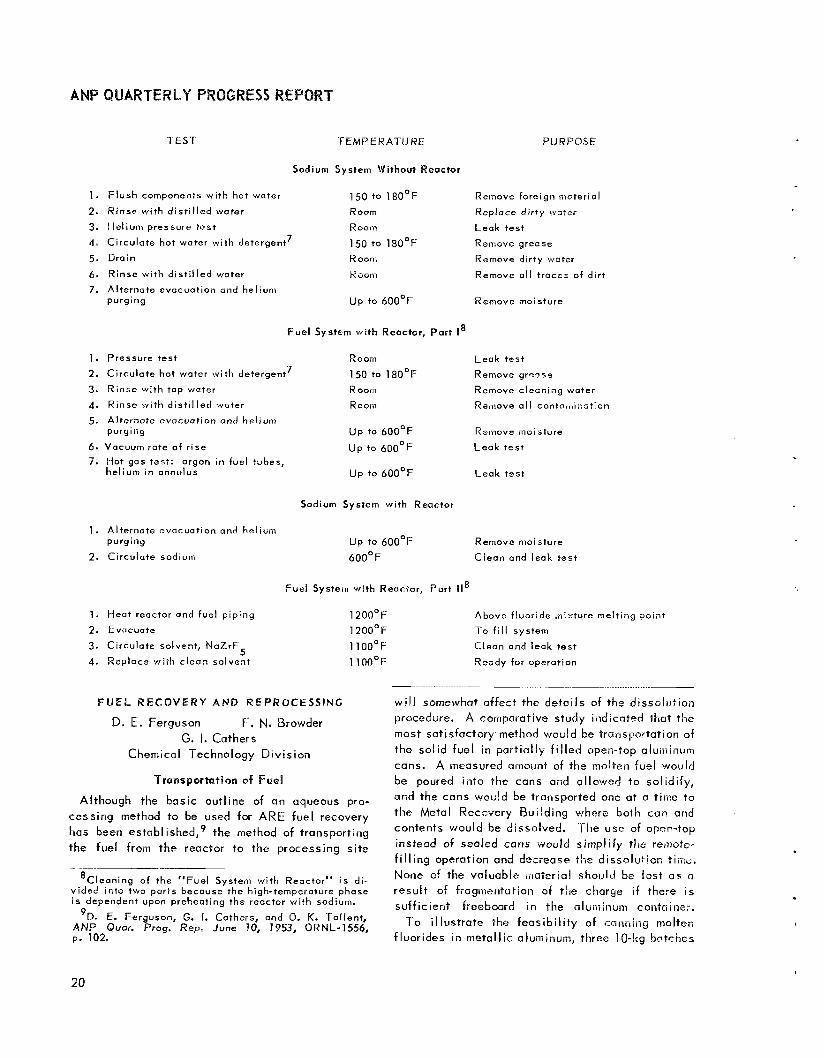
F U E L R E C O V E R Y AND REPROCESSING
D. E. Fergwson F. N. Browder G. I. Cathers
Chemicn I Technology D iv is ion
Transportation of Fuel
Although the basic outline of an aqueous pro- cessing method to be used for ARE fuel recovery has been established,' the niethod of transporting the fuel from the reactor to the processing site
- *Cleaning of the "Fuel System with Reactor" i s di-
vided into two parts because the high-ternperoture phase i s dependent upon preheating the reactor wi th sodium.
9D. E. Ferguson, G. 1. Cathars, and 0. K. Tallent, ANP Quor. Prog. Rep, June 10, 7953, ORNL-1556, p. 102"
- ----. . ___
w i l l somewhat affect the detai ls of the dissolution procedure. A comparative study indicated that the most satisfactory method wou!d be transportation of the solid fuel in partially filled open-top aluminum cans, A measured amount of the molten fuel v/ould be poured into the cans and allowed to solidify, and the cans would be transported one a t n time to the Metol Recovery Building where both can and contents would be dissolved. The use of opefin-top instead of ssaled can5 would simplify the renotc-
f i l l i ng operation and decrease the dissolution Pime. None of the valuable material sho i~ ld be lost as n result of frogmeritation of the charye i f there is sufficient freeboard i n the aluminum container. To i l lustrate the feasibi l i ty of canning moltmn
fluorides in metallic alurniniim, three 10-kg batches
20

PERIOD ENDING DECEMBER 10, 1953
of NaF-ZrF4-UF, (50-46-4 mole %) were transferred to air-cooled aluminum containers. Each of the cans, two with 0.065-in. wal ls and one with a 0.25-in. wall, withstood the test in which the fluoride temperature was 600°C. It was discovered that the thin-walled cans should not be subjected t o more than 5-in. vacuum or 5-psig pressure.
Previously, cans approximately 5 in. in diameter for transporting 6.6 kg of fuel plus flush material, which would contain 0.5 kg of U235 i f the mixture
or a maximum of 1 kg of U23J i f the mixture not homogeneous), were con- sidered.1° This amount of fuel would dissolve to give about 35 gal of solution.
The process appears to be most attractive if 4 kg of uranium per container, which amounts t o 53 kg of fuel plus flush (assuming a homogeneous mix- ture), can be transported and charged to the 500-gal dissolver t o make one 265-gai batch of solution. For this size batch, the containers would be about 9 in. in diameter and 18 in. long. This quantity would be more compatible wi th the s i r e of the Metal Recovery Building equipment, and the number of containers required to transport the 80 to 100 kg of U235 would be reduced from 100 to about 25. Processing of 4 kg of U235 per batch in the exist ing dissolver is subject to approval by the Cr i t ica l i ty Hazards Committee.
Another method of dissolving the fuel involves introducing it to the dissolver in the molten state. If this method w e used, the fuel could be trans- ported in a special can that would hold about 25 kg of UZ3’. The advantages of this method are the
”/bid., p. 103.
rapidity of the dissolution and the decrease in the number of truck trips required for the transportation. The disadvantages are the dif f iculty of providing shielding suitable for use in the handling of the molten material and the excessive development work required on equipment that would have to be bui l t into the cans, for example, heaters for remelting the fuel i f it solidif ied before the dissolution was carried out, temperature-mea sur ing instruments, and devices for controlling flow. Construction of the dissolver a t the ARE site would eliminate the need for constructing transportable shielding and would permit the use of less rugged heaters, but it would require too large a capital expenditure. It would also spl i t the locations of the chemical operations, and additional operators would be requ ired.
Rate of Dissolution of ARE Fuel
Based on the results of laboratory dissolution experiments, a dissolution time of 6 to 12 hr i s estimated for a 53-kg charge of ARE fuel. For a 6.6-kg batch, a dissolution time of 3 to 6 hr i s estimated. A reliable value for the dissolution time cannot be calculated from the data obtained in these small-scale experiments, since the dis- solution rate i s not constant throughout the dis- solving .
With a 1-in.-dia cylindrical charge weighing approximately 50 g, an init ial penetration rate of 0.003 in./min was observed over a 4-min period (Table 1.2). Over the next 3 min, the penetration rate increased to 0.006 in./min, based on the in i t ia l dimensions. This increased rate i s due to uneven penetration and cracking, which exposes
TABLE 1.2. DISSOLUTION RATE OF SOLID ARE FUEL
Cylindrical samples 1 in. in diameter tested inbo i l ing 4 M ni t r ic acid plus 0.67 M aluminum nitratesolut ion
PENETRATION RATE
Second immersion
F i r s t immersion
* Solution alreody contained the normal complement of dissolved fuel.
21

ANP QUARTERLY PR
more surface area. In n second experiment, a penetration rate of 0.005 in./min was observed over a 5-min interval. After the 5-inin period, the sample had broken up into several smaller pieces. Anothei fresh sample tested in a solution that already contained a normal complement of d i s - solved fuel gave a penetration rate of 0.002 in./min; however, in the final stage of on actual dissolution, the charge would probably have broken up to expose a very large surface area per unit weight. Based on these results, the average penetration rate w i l l probably exceed 0.006 in./min.
The sample charges for these experiments were prepared by pouring molten fuel (NaF-ZrF -UF,, 50-48-2 mole %) into a spl i t graphite mo?d and cooling. The pi t formed by contraction on cooling was removed by pressing the cylinder against a hot metal plate. The sample was placed in the dis- solvant (boi l ing4 M nit r icacid and 0.67 M aluminum nitrate solution) and then removed and weighed after a measured interval to determine the amount dissolved.
Since the scale-up of these laboratory data is inconclusive, three charges w i l l be poured into aluminum cans, 6 in. in diameter and 9 in. long, and
dissolved to establish the dissolution time more accurately.
Molten Fuel Dissolutisn
No excessive violence was observed in several preliminary tests in which molten ARE fuel, at temperatures of over 55Q°C, was poured into the
aqueous solvent (4 M nitr ic acid plus 0.67 M aluminum nitrate). On contact with the aqueous phase, the fuel sol idi f ied in the farm of small irregular puit icles 1 to 7 mm in diameter and then dissolved ot a rate of about 50 g in 10 min, which i s comparable wi th the rate of 50 g in 5 min that had been observed with finely ground fuel. Ap- parently the only precaution required is to make sure that the addition is slow enough to prevent excessive overheating and overboil ing. However, col loidal material has been piesent in a l l dissolver solutions prepared todote from molten fuel, possibly as a result of the instabi l i ty or hydrolysis of zirconium compounds in aqueous solutions at high ternperatwes. Some modification of tkc dissolver solution to prevent foimntion of th is material would probably be required i f molten fuel dissolution were to be used.
~~~~~A~ REACT0
W, W. Savage, ANP Divis ion
The completion of the developmental work on the gas-sealed sump pumps for the ARE has ninde possible a change in emphasis of the experimental work, and increased effort has been devoted to the development of a hydrodynamic type of bearing and a heat exchanger for the ref lector-moderated reactor.
The developmental wark on the frozen-sodium- sealed pump for sodium during this quarter includcil tests of a frozen-sodium shaft seal with a single $-in.-long frozen-sodium sealing region backed up w i th helium pressure in the sealing cavity. The short seal i s being developed in an effort tu lower the power consumption of the seal and yet maintain the low leakage obtained with the 5’3/,,-in.-long seal previously described. In tests, the new short seal dissipated approximately 3/4 hp, wi th no power fluctuations, and i t was found that the sodium leakage could be made negligible i f back-up pres-
sure was used to reduce the pressure differential across the seal. Water tests an the gas-sealed sump pump for the in-pile loop showed f luid gassing t o be a problem, and, accordingly, changes are being made in an effort t o eliminate th is conditiov, In other tcsts, the pioblems associated with de-
veloping a canned magnt3lic-torque-transmitter for Q
high-temperature pump for aircraft application are being explored,
Since the adoptian of the gas-sealed sump pump for ARE operation, seal developmental work has been carried on at u reduced rate; however, tests for rotary shaft and valve stem seals hap? con- tinued with materials which showed promise in earlier tests. These include graphite packed around a spiral-grooved shaft, graphite and B e F , mixtures, a V-ring type sea!, and a bronze-wool, graphite, and MoS2 mixture. Although each of these scals
22

PERIOD ENDING DECEMBER 10, 1953
has performed wel l under laboratory controlled con- ditions, none has demonstrated sufficient re l i a t i l i t y to warrant adoption i n a pump for reactor operation. Also, none OC the packing materials tested thus far for valve-stem seals has demonstrated sufficient re l i a t i l i t y t o replace the bellows as a valve-stem sea I .
A hydrodynamic type of bearing which w i l l operate i n l iquid metals, fused salts, or other fluids at temperatures of up to 1500°F i s being developed. Materials for th is application are being screened i n Q compatibil i ty testing device, and a test program i s being planned for obtaining the bearing charac- teristics, which are usually represented as fr ict ion factor vs. Sommerield number.
A heat exchanger incorporating some design features proposed for the reflector-moderated re- actor i s currently being tested. The fluoride system has operated at above 1200°F for Over 600 hr, but performance data are not yet available.
A small forced-convection loop i s being operated t o test corrosion of Inconel i n circulating fluoride mixture NaF-ZrF,-UF, at high f luid velocities and high temperature differences. The f lu id velocit ies obtained in this loop are a factor of 50 or 60 greater than those of thermal-convection loops, but the Reynolds modulus remains in the laminar region a t approximately 1700.
PUMPS F O R HIGH T E M P E R A T U R E LIQUIDS
W. G. Cobb A. G. Grindell
W. R. Huntley W. 8. McDonald
D. R. Ward ANP Division
Frozen-Sodium-Sealed Pump for Sodium
A frozen-sodium shaft seal wi th a I/-in.-long frozen-sodium region backed up with helium pres- sure in the sealing cavity was tested. This seal differed from the previously tested' short seal in that only one 1/-in.-long sealing region was used and the blanket gas was under pressure. The short seal i s being developed i n an effort to lower the power consumption of the sea4 and yet maintain the low leakage ottained with the 5'3/16-in.-long seal previously described.'
For the f i rst 168 hr of operation with the new short seal, the sodium temperature at the pump was 960"F, the suction pressure was 20 psig, and the back-up pressure was 15 psig. The total sodium leakage past the seal during this period was 32 cm3 or an average of 4.8 cm3 per day. Approxi- mately hp was dissipated i n the seal and the power trace was smooth.
The Buna N rubber 0 r ing used to seal the back- up gas was destroyed during the application of heat to remove the sodium leakage at the end of 168 hr, and the reminder of the testing was ac- complished without the use of back-up pressure. Operation was continued for a total of 980 hr with a shaft speed of 1800 rpm, a sodium temperature of 96OoF, and a suction pressure of 12 psig. A sl ight f low of helium was maintained across the back of the seal. The increase in the pressure differential across the seal from 5 psig during the f i rs t part of the test to approximately 12 ps i3 during the remainder of the test resulted in an increase in sodium leakage past the seal to ap- proximately 20 cm3 per day.
Erratic power fluctuations caused by sodium oxide migrating to the cold section of the seal became negligible when a standard, cold-trap, bypass f i l ter was installed i n the loop. The f i l ter bypasses approximately 0.25 gpm of sodium, Ex- cessive heat loss in the f i l ter (approximately 3 kw) necessitated i t s redesign to incorporate a heat economizer designed to waste only 0.3 kw. Transit time through the new f i l ter i s approximately 6 minutes.
The results of these tests, together wi th the previously reported resuits of tests w i th longer frozen-sodium seals, have led to the conclusion that a frozen-sodium shaft seal i s manageable for a sodium pump. A satisfactory length-to-diameter rat io for such a seal is approximately 1 to 5. Leakage of sodium past the seal can be made negligible by using back-up pressure to reduce the pressure differential across the seal. Water cooling i s an efficient means of freezing the seal, and several thousand hours of operation have demon- strated that the hazard in' using water with a properly designed seal is trivial.
' A N P Quar. Prog. Rep. Sept. 70, 1953, ORNL-1609,
'ANP Quar. Prog. Rep. June 70, 1953, ORNL-1556,
3 /bid., p. 17.
Gar-Sealed Sump Pump for fn-pi le Loop Test p. 20.
p. 11. A pump is being developed for in-pile I Q Q ~ tes ts
which i s similar to the laboratory-sized gas-sealed pump3 but which has been scaled down to reduce
23

ANP QUARTERLY PROGRESS REPORT
the f lu id holdup in the pump. Water tests of the f i rst pump constructed show thot the pump head and f low are within design specifications; however, a f lu id gassing problem exists which indicates that some design changes w i l l be necessary.
While some gassing of the f lu id is evident under a l l operating conditions, i ts magnitude increases rapidly as the height of the free f lu id surface above the suction is decreased or the shaft speed i s increased. This indicates that the dif f iculty i s caused by vortexing of the free f luid surface be- cause of shaft rotation. As an in i t ia l attempt to suppress vortexing, changes are being made i n tl ie antiswir l baffles in the pump, and the opening through which the rotating shaft enters the suction chamber is being moved to a point well below the free surface of the fluid.
Magnet ic-Torque-Transmitter Bump
High-temperature pumps for aircraft application may include a canned magnetic-torque-transmitter pump with the external shaft driven by suitable means, for example, a gas turbine. The problems encountered i n building such a torque transmitter are being investigated. Reduced-scale tests hove been conducted for determining the expected efficiency of a magnetic torque transmitter at elevated temperatures, the geometry of such a transmitter, and to what extent slippage occurs as a function of temperature.
The f irst transmitter tested consisted of a permanent magnet outer rotor and a squirrel cage (from a 1/4,,-hp motor) inner rotor. A nonmagnetic stainless steel can separated the driving and driven rotors. The entire assembly (excluding the outboard bearings) was heated to above 1100"F, and the slippage rate was appreciable in the tem- perature range of 600 to 1100°F. However, the ful l t o - h p torque was transmitted from room tempera- ture to 60O"F, but the efficiency then dropped off rapidly at higher temperatures. It i s yet to be determined whether the drop in efficiency i s due t o the drop of the f lux of the permanent magnet or t o lowered resistance of the windings of the rotor. A permanent magnet inner rotor i s presently being constructed which w i l l resolve th is question.
4ANP Qunr. Prog. Rep. Sept. 10, 1953, ORNL-1609,
5 /b id . , p. 24. ' A N P Quur. Prog. Rep. Juiii- 10, 7953, ORNL-1556,
P. 2 3 .
p. 19.
R O T A R Y - S H A F T AND V A L V E - S T E M S E A L S F O R F L U O R I D E S
R. N. Mason P. G. Smith W. C, Tunnel1 ANP Division
Graphite-Packed Seal fw Spirad-Grooved Shaft
Operation of the spiral-grooved shaft wi th a powdered-graphite-packed seal4 has continued for over 3000 hr wi th no detectable leakage of fused fluorides. During this period of operation, heater fai lure occurred on two occasions and caused the shaft rotation to stop. When repairs were miide, operation was resumed with no difficulty.
The previously reported5 test of a seal packed with a mixture of 80% graphite powder and 20% BeF, has now operated for over 3700 hours. The leakage for the past 3500 hr was less than 15 i n . 3 . Power fluctuations have occurred, and some of them were accompanied by squeaking, which indicated possible metal-to-metal contact between the shaft and the gland.
When this packing material was installed i n a tester having a 21/-in.-dia shaft, excessive graphite and BeF, leakage occurred. Investigation d is- closed that the temperature during pretreatment was insufficient to fuse the BeF,, and thus the seal contained loosely packed material rather than the sol idly fused material desired. For the second test, the pretreatment temperature was raised to 1800"F, and the BeF,-rjrophite mixture fused solidly. During the dry run of th is seal, there wos no leakage of powder. The seal region has been operated at a higher temperature (above 975°F) in this test than i n previous tests to reduce power f luctuations. There has Leen some fluoride leakage.
V-Ring S e ~ l Operation of the V-ring seal test6 was continued,
and a heater was installed i m i d e the 2$-in.-dia rotating shaft. During an extended dry run i n which the seal W Q S gradually heated to about 1200"F, satisfactory sealing of helium was ot- tained. The inert gas blanket and seal gas supply was inadvertently shut of f for about 20 miti during operation, and, since s o m e damage to the seal rings occurred, satisfactory sealing could na longer be obtained. Examination of the rings after disassembly of the seal showed that the outside

PERIOD ENDING DECEMBER 10,1953
r ing was 75% destroyed and the other rings had either oxidized or worn about 0.0005 to 0.0015 in. on the inside diameter; the shaft was undamaged, The outside ring has been replaced and another ANP Division dry run w i l l be made i n an attempt to seal helium a t above 1000°F before fluorides are introduced.
Bronze-Wool, Graphite, and h40S2-Packed Frozen Seal
The test7 of the bronze-wool, graphite, and MoS,- packed frozen seal continued unti l operation was terminated at the end of 1198 hr because of leakage of the fluoride mixture NaF-ZrF4-UF,from a flange. The leakage rate was less than 1 cm3 per day with the fluoride pot at 1175OF and pressurized to 10 psi.
An additional test was made with the packing annulus reduced from % to inch. This test was unsuccessful and was terminated at the end of 211 hours. The fai lure was attributed to faulty alignment between the shaft and the packing housing.
HIGH-TEMPERATURE BEARING DEVELOPMENT
R. N. Mason W. C. Tunnel1
P. G. Smith W. K. Stair
Packed Seals for Valve Stems
A series of tests i s i n progress to determine whether the packing materials which sealed well i n the packing penetration tests8 w i l l seal high- temperature fused salts under simulated vulve operating conditions. None of the materials tested has demonstrated sufficient re l iabi l i ty to replace the bellows as a valve-stem seal.
Developmental work i s lander way on a hydro- dynamic type of bearing which w i l l operate i n l iquid metals, fused salts, or other fluids at tem- peratures of up to 1500°F. This developmental program w i l l probably be carried out in three phases: (1) test programs to find materials which have low wear and low corrosion rates i n the fluids of interest at 15OO0F, (2) a test program to establish the bearing characteristics, which are usually represented as fr ict ion factor vs. Sommerfeld number, and (3) the design and test of a bearing for a particular application using the information ob- tained i n phases 1 and 2. Effort to date has been confined to materials compatibil i ty tests and to an evaluation of the accuracy which may be expected i n carrying out the prograni for obtaining bearing characteristics.
Materials Compatibil i ty Tests
In i t ia l screening tests for finding materials that possess satisfactori ly low wear and low corrosion rates are being made in apparatus i n which a 2$-in.-dia, $-in.-thick plate specimen of one ma- terial rotates against a \-irt.-dia stationary pin of another or the same material. The end surface of the pin is ground to u g-in.-radius cylinder to approximate l ine contact along a radial l ine of the rotating plate a t a mean radius of 1 in. from i t s center (Fig. 2.1). Contact pressure between the plate and pin i s maintained by means of an external co i l spring and a sl iding shaft.
The test apparatus consists of a standard valve stem and bonnet placed in a vertical position with the stem down. The pot i n which the molten fluo- r ide mixture is pressurized against the packing i n the bonnet i s welded to the top of the bonnet. The stem i s rotated a t frequent intervals t o simulate valve operation. Three tests have been completed i n which the valve stem was cycled once every 24 hr, and the pressure on the packing was 5 psi. The packings tested were Asbury graphite 805 at llOQ°F, 90% Asbury graphite 805 plus 10% BaF, at llOO°F, and 50% graphite (from the Y-12 Carbon Shop) plus 50% BeF, at 135OOF. Each of these tests was terminated because of fluoride leakage.
7,4NP Quar. Prog. Rep. Sept. 10, 7953, ORNL-1609, P. 25.
* \bid. , p. 28.
A test was run of the equipment made with a Graphitar plate and an lnconel pin. A Hertz stress (estimated stress i n the l ine of contact) of about 10,000 psi, or a 5-lb force load between the plate and pin, was used. With the test specimens sut- merged i n acetylene tetrobromide to simulate the fluoride melt, it was found that the 5-lb load was insuif icient for breaking through the hydrodynamic f i lm and that the f i lm persisted unt i l a load of
about 10 lb was applied to give a Hertz stress of about 15,000 psi. The rate of rotation was 850 rpm, which gave a sl iding speed of about 7.4 fps. Having determined the load requirement, a series of correlation tests was conducted with plates of type 416 stainless steel rotating LIgQinSt stationary
25

UNCLASSIFIED DWG 22338
LOADING SPRING ~
DRIVE WtiEEL
SPINDLE SHAFT
STATIONARY PIN SLIDING SHAFT
ROTATING PLATE
Fig. 2.1. Bearing Materials Compatibility Tester.
pins made of babbit, a die steel, a high-speed tool steel, Stel l i te 6, Stellite Star J, and Superoilite. In each case, the stationary pin and the rotating plate were submerged in a regular-grade, Texaco, Regal “A” oil, without additives, that has a viscosity of SUS 40-44 at 210°F. The results of th is series of tests conformed w i th those obtained earlier at KAPL.’
The f irst test at a high temperature was made with Graphitar rotating against lnconel i n NaF-
9D. 8. V a i l , Compatibi l i ty o f Materiols i n Liquid Meta ls , KAPL-589 (Aug. 18, 1951).
ZrF,-UF, at 1200°F for 2 hours. The Graphitur appeared t o be scratched l ightly and it was warped, while the Inconel specimen appeared to be burred and bui l t up at the rubbing surface.
The following materials are being screened i n seesaw corrosion tests: B, ZrC + Fe, MgO i- Ni, 6eQ + Ni, BeO, hot-pressed AI,O,, high-density graphite, T i c + Ni, Tic + Co, CrC, B,C, WC + Co, and WC + Ni. Plates and pins of mast of the above materials either have been ordered or w i l l be fa br i ca ted ~
Combinations of materials which possess both satisfactori ly low wear and low corrosion rates based on the qualitative results of the screening tests w i l l subsequently be tested i n equipment which simulates a conventional iournal and bearing.
ar i mg Charoc tcr i s t i cs
An evaluation has been made of the accuracy of the data which w i l l be obtained i r i the test program for determining bearing characteristics. Two ex- perimental approaches for obtaining the data hove been reviewed. First, the test may be simply a load-life experimental study to establish reliobi l i t y of a single bearing design i n fluoride melts. information gained .from this opproach might or might not be useful in predicting the behavior ai other bearings; certainly, the information cauld be used only w i th limited assurance. On the other hand, the experimental study may be a performance test i n which an effort i s inadc to establish po- rarneteis which w i l l describe the bearing charm- ter ist ics in such a way that they may be ernployed t o determine design configurations other than the one tested.
The information to be obtained by using the second approach i s usually presented as a plot of lb vs. s,, where f b i s the bearing fr ict ion factor (dimensionless) and Sn is the Somnierfeld variable (dimensionless):
and
where p = absolute viscosity of lubricating fluid,
I b,-sec/i n. 2,
26

PERIOD ENDING DECEMBER 10, 1953
N = journal speed, rps, P = unit bearing load, psi, r = iournal radius, in., c = radial clearance, in., f = coefficient of bearing friction.
The significance of these relationships in design work w i l l depend on their accuracy, which con be defined i n terms of the accuracy to be associated with each of the variables. The fractional pre- c is ion of Sn w i l l depend upon the fractional pre- cision of p, P I N , r , and c, and it may be shown that
As an example, suppose that it i s desired t o evaluate S n with a precision of 410%. I f it i s assumed, for the f i r s t approximation, that each of the quantities p, N, P I r, and c may be measured with the same precision, then
+ (>J P,2 ,
where P, , P ~ , . . . represent the probable errors
of Sn, p, . . , . Taking the partial derivative of Sn with respect to p, N , . . . and substituting i n Eq. 3 gives
n
+ 4 g j 2 PZ ,
and dividing both sides by S: gives
2
". X = d4 (?) = (0.1) = 0,0302,
and PX/x i s the fractional precision of p, N , P I t, or c. The variables N, P, and r can 'be measured t o even greater precision than that required for the example given above, but it i s doubtful whether p or c can be measured to even th i s fractional precision. In this case, i t may be assumed that i ~ , P , and r are measured without error, and P / p and Pc/c are then found to have a fractional pre- cision of
P
-(0.1)* = 0.0447 . x
It is possible to measure c wi th th is degree of precision, but p i s l ikely to involve o much larger error; thus, i f it were necessary t o evoluate Sn t o t10%, the measuring technique for p would have t o be much refined.
Equation 5 may be used to indicate the resulting precision of Sn for the case in which the probable errors in p, N, PI r, and c are known. As an ex- ample, a journal bearing i n a fluoride mixture under the following typical operating conditions w i l l be considered: speed, 1800 rpm; unit load, 20 psi; iournal radius, 1 in.; fluoride temperature, 1200°F; radial clearance between Learing and sleeve, 0.0015 inch. A t 1200°F, the viscosity of the fluo- ride mixture NaF-ZrF,-UF, is reported to be 11.8 cp plus or minus approximately 30%, or p = 11.8 x 1.45 x 10" = 1.72 x 10⁻⁶(lb,-sec/in.2) k 30%. The expected fractional precisions for the variables are then:
Px / x I P x / x 12
0.3 0.09 0.0025 0.0000063 0.025 0.00063 0.00 1 0.00000 1 0.067 0.00449
27

-. ....... .......... .......... - - -- d(0.09) + (0.0000063) ! (0.00063) + (0.000004) + (0.01796) p s n
s n
and
= 210.1086 = 0.3294 or 32.96%
= 1.146 i 33% . I f f b (hearing friction factor) i s considered in a
s imi I csr manner,
FT
R It'c f b = - ,
where
For the assumed operating conditions stated above, the estimated values of the quantities measured for evaluating f b are: r , 1 in.; R = 6 in.; W , 180 Ib ; c, 0.0015 in.; F , 0.5 Ib,. The expected fractiona{precisions for the variables are then
T 7 radius of iournal, in., P,/X (p / X )
f, F 0.20 0.84 R 0.10 0.01
w 0.1 0.01 C 0.067 0.0049
I' = fr ict ional force of torque arm length, R , Ib R : torque arm length, in., W = total bearing load, Ib c = radial clearance between bearing and
The expression for obtaining the fractional pre- c is ion can then be written u s
1 r 0.001 0.000001
sleeve, in.
and
16 ~i i ' - - - - - .- .......... .......... ~ .___ P
-I .- 3- (0.000004) + (0.01) + (0.01) -t (0.0049) = d0.0649 = 0.255 or 25.5% f h
___._.._ ............ .......... ____ and
and the derivations represent ideal conditions, real i ty may result in errors in the relationships as
180 x 6 x 0.0015 high as 75 OF loo%, which would indicate that refinements in measuring a l l cr i t ical parameters may be needed.
0.5 x l 2 f = = 0.308 k 25.5% .
Thus i t appears that the precision of the ex- perimental effort on bearing characteristics i s l imited by the precision of the data available for the viscosity of the fluoride and the abi l i ty to accurately measure the radial clearance and fr ic- t ional force. If consideration i s given to the fact that the Ap/AT for the fluoride i s quite large and that the lubricant f i lm temperature is extremely d i f f i cu l t to accurately measure, the precision of the experimental results w i l l be even lower. Be- cause errors of th is type are usually cumulative
H E A T E X C H A N G E R T E S T
R. E. MacPhersoii PI. J. Sturnpf ANP Division
A heat exchanger incorporating some design features proposed for the reflector-moderated re- actor i s currently being tested. Th is exchanger, which i s enclosed in a 5-in. tube furnace for pre- heating, has the molten fluoride mixture NaF-ZrF, (53-47 mole %) circulating in the shell and high-
28

PERIOD ENDING DECEMBER 10, 1953
UNCLASSiFlEO W I G . 22339
SURGE TANk
RES I STANC E HE AT E R
SUMP-TYPE PUM
HEAT EXCHANGER --
SUMP TANK-’
Fig. 2.2. Keat Exchanger Test Apparatus.
temperature sodium circulating through the tube bundles (Fig. 2.2). A sump-type pump continuously circulates the fluoride mixture; the sodium f low i s maintained by an electromagnetic pump. The sodium i s resistance heated, and it enters the tubes in one half the exchanger to heat the fluo- rides. It i s then cooled in a sodium-to-air radiator (100 kw, interrupted-fin type) from which i f enters the tubes In the other half of the heat exchanger t o cool the fluorides and then returns to the sodium heating coil. Thus both the fluoride mixture and the sodium are alternately cooled and heated. The heat exchanger i s designed to transfer 1.5 mega- watts, but performance to date has been limited by an inabi l i ty to supply sufficient power to the resistance heater for the sodium. ?he fluoride system has been in operation at above 1200°F for
over 600 hr, and the completed bi f lu id system has been operating at 1200 to 1400°F for 300 hours. Performance data are not yet available.
FORCED-CtRCULATION C O R R O S I O N L O O P
D. F. Salmon ANP Division
A small forced-circulation corrosion loop wos operated with NaF-ZrF,-UF, to extend the cor- rosion data being obtained from low-velocity thermal convection loops. The aim I S to eventually obtain a f lu id velocity of 5 fps or greater with a temper- ature difference of 200°F. Circulation i s obtained with an Eastern Industries, E-IOQ, centrifugal pump that was redesigned for sump-type operation and fabricated of Inconel. A gas seal is main- tained in a water-cooled, Teflon-packed gland on
29

ANP QUARTERLY PROGRESS REP0
the shaft. The loop was fabricated of 0.1-in.-OD, 0.02S-in.-waB I lnconel tubing. Heating i s accom- pl ished by passing an electric current through 17 f t of the tubing, and coaling i s by natural convection t o air from 9 ft of tubing. The tubing i s coi led to reduce the space requirement.
The f lu id velocit ies obtained in this loop are o factor of 50 or 60 greater than those of thermal convection loops, but the Reynolds modulus re- mains in the laminar region at approximately 1700, The loop operated approximately 200 hr with a
__ .... { ...... ~ ~ ....... A ...........
gradual slowing down of flow, which indicated possible plugging. A summary of the results i s presented graphically in Fig. 2.3, which shows velocity and temperature difference as Q function of elapsed time. The speed of the pump, which was checked periodically, did not vary appreciably. The velocity of the fluoride mixture was CQICU- toted, rather than measured, from heat balance data on the loop heating section, The loop was termi- nated because of the indicated plugging and i s being examined metallurgically. A second loop i s being constructed.
UNCLASSI FlED
DWG. 22340
...... 1
-. .....
-A-
___^_
96 108 120 132 144 0 12 24 36 48 60 72 84 OPERATING TIME (hr)
420
400
380
- L L 0
360
4
340
320
300
Fig. 2.3. Velocity and Temperature Difference as a Function of Operating Time far NaF-ZrF,-UF, i n an Inconel Forced-Circulation Corrosion Loop.

PERIOD ENDtNG DECEMBER 10, 1953
3. REFLECTOR-MODERATED REACTOR DESIGN STUDIES
R. W. Bussard A. P. Fraas ANP Division
In May 1953, the U. 5. Air Force requested that a series o f design studies be prepared to outl ine the characteristics of 100-, m-, and 600-megawott circulating-fuel reactors. Unfortunately, the re- actor physics work essential for establishing the over-all design l imitations has lagged far behind schedule, and many materials questions are not yet solved. However, even though detailed designs cannot be prepared at this time, it has been recog- nized that design information i s urgently needed, and therefore the preliminary layouts presented in this report were prepared to give the best estimate of preliminary designs that can be made now. While interest was expressed i n reactor power outputs of as much as 600 megawatts, a careful examination of the basic I imiting factors indicated that it would not be prudent to extrapolate the information currently available beyond a reactor s i re of 300 megawatts. The design for the 600- megawatt reactor was therefore dropped, and studies for 50- and 200-megawatt reactors, in addition to the 100- cnd 300-megawatt reactor designs re- quested, were prepared.
The more important parameters for the designs are presented in Tables 3.1 and 3.2. Layouts for SO-, loo-, and 300-megawatt reactors are presented in Figs. 3.1, 3.2, and 3.3, respectively. Detail drawings for the main heot exchanger, pumps, and core shells have been prepared for the 50-megawott reactor. The designs for the 50- and 100-megawatt reactors appear to be quite conservative so that it seemsprobable that their ratingscould be increased to 75 and 150 megawatts, respectively. Parameters such as flow rates and temperature drops would, of course, increase accordingly.
An explanation cnd qualification of the more important features of the principal components and the considerations that determined them has been prepared to supplement the drawings. The static physics, moderator cooling, pumps, hydrodynamics, heat exchangers, pressure shell, control, and fuel addition and drainage systems are each discussed, i n turn. An effort has been made to include in these discussions an indication of the status of the design at this time and of the experimental work planned to provide badly needed design data.
A familiarity with information published previously i s presumed. ' a 2
R E A C T O R PHVSIICS
A wide variety of reactor types and geometries has been considered for circulating fluoride fuels. Of these,the most promising at this time appears to be a reflector-moderated reactor with a central island. Sodium-cooled beryllium seems to be the best choice as the moderating material. However, the picture i s very incomplete because calculations for only about 25 reflector-moderated reactors hod been completed unti l recently because of lack of computing foci I i ties. Calcu I ations for approxi- mately 100 two-region reactors have just been completed, and the results are being analyzed; calculations for about 200 three- to nine-region reactors have been started, By April 1954, th is work should be far enough along to give a more complete picture of the effects of reactor geometry and materials of construction on parameters such as cri t ical mass and power distribution for every type of circulating-fuel reactor that has oppeared promising. A particular effort wi l l be made to f ind an arrangement that w i l l give the most rugged, reliable, and simple reactor construction consistent with l imitations imposed by corrosion and gamma- heating effects.
F ive cri t ical assemblies have been run to date on reflector-moderated reactors. AI I these have been rather rough approximations to what currently appears to be a promising full-scale aircraft reactor, The weakest element i n a l l of these approximations has been the fuel region composition. In the f i rs t cr i t ical assembly, the fuel region was simulated with cans of sodium interspersed with d i s k s of metallic uranium, while in the subsequent ossem- blies, cans of powdered NaF-ZrF,-UQ, were employed. The f i rs t assembly suffered from severe inhomogeneity and self-shielding of the fuel, and the subsequent assemblies had the shortcoming
__I - . ___ 'A. P. Fraos, C. 8. Mills, and A. D. Callihon, ANP
2A. P. Fraas, ANP Qvar. Prog. Rep. Sept. 10, 1953,
Qvar. Prog. Rep. March 10, 1953, ORNL-1515, p. 41.
ORNL-1609, p. 31.
31

P QUARTERLY PROGRESS RE
TABLE 3.1. PRINCIPAL DIMENSIONS O F A SERIES O F REFLECTOR-MODERATED ClRCUk ATINGFU EL REACT0 R S
Power, megawatts
Core diameter, in. Power density in fuel, kw/cm 3
Pressure shell outside diameter, in.
Fuel System 3 Fuel volume in core, f t
Core in let outside diameter, in,
Core in let inside diameter, in.
Core in let area, in.
Fuel volume in in let and outlet ducts, ft3
2
Fuel volume i n heat exchanyer, f t 3
Fuel volume in pump ond plenum, ft 3
Total fuel volume circulating, ft3 Fuel expansion tank volume, ft3 (8% of system volume)
Fuel Pumps
Fuel pump impeller diameter, in.
Fuel pump impeller in let diameter, in.
Fuel pump impeller dischorge height, in.
Fuel pump shaft center l ine to center l ine spacing, in.
Planurn chamber width, in.
Plenum ond volute chamber length, in.
Plenum and volute chamber height, in.
Impeller rpm
Estimated impeller weight, I b Impeller shoft diameter, in.
Impeller overhang, in.
Cr i t i ca l speed, rpm
Sodium Pump
No pump impeller diameter, in.
Na pump impeller in let diameter, in.
No pump impeller dischorge height, in.
No expansion tank volume, f t3 (10% of system volume) 3 No in Be passages, f t
No in pressure shell, f t No in pump and heat exchanger, f t3
3
Fuel-to-Na K Heat Exchanger
Heat exchanger thickness, in.
Heat exchanger inside diameter, in.
Heut exchanger outside diameter, in.
Heat exchanger volume, f t Angle between tubes and equatorial plane, deg
Number of tubes
Tube diameter, in.
Tube spacing, in.
Number of tube bundles
Tube arrangement in each bundle
3
50 18
1.35 48.5
1.3 10 7 40 0.4 1.25 0.3 3.25 0.26
5.75 3.5 1.1 20
14.5 30 2.0
2700 8
1.5 12
6000
3.4 2.4 0.75 0.08 0.43 0.15 0.20
1.7 42
45.4 6 27
2304 0.1875 0.2097
12 8 x 24
100 18 2.7 50.6
1.3 10 7 40 0.4 2.5 0.3 4.5 0.36
7 4.5 1.5 21 15 31 2.0
2700 12
1.75 13
6000
4.1 2.9 0.9 0.09 0.47 0.15 0.25
2.75 42
47.5 10 27
3 744 0.1875 0.2097
12 13 x 24
200 20
3.9 56.4
1.8 1 1 7.7 49 0.5 5
0,5 7.8 0.62
8,5 5,5 1.8
22.5 15.5 33 2.4
2500 17 2 14
5200
5,0 3.5 1.1
4.65 44
53.3 20 27
6600 0, I875 0.21 19
12 22x 25
390 23 3.9 62.0
2.7 12.8
9 67 0.7 7.5 1.0 11.9 0.95
10 6.75 3.2 27
17.5 37 3 .O
2300 24
2.25 15
5000
5.9 4,2 1.2
5.9 47
58.8 30 27
9072 0.1875 0.2094
12 28 x 27
32

Moderator Regian
Volume of ~e pius fuel, ft3 3 Volume of B e only, ft
No. of coolant holes in reflector
No, of coolant holes in islard No coolant tube inside diameter, in.
No coolant tube wall thickness, in.
No pressure shell annulus thickness, in.
PERIOD ENDING DECEMBER 10, 1953
TABLE 3.1. (continued)
that the atomic density in the fuel region was only about 33% of that of l iquid fluoride fuel. These shortcomings w i l l be largely eliminated in a new cr i t ical experiment that i s being planned. Sheet Teflon and O.OOZin.-thick uranium fo i l w i l l be stocked in laminae to simulate the fluoride fuel, both from the standpoint o f atomic density and of neutron-scattering and absorption cross sections.
Another weak point in the cr i t ical assemblies that have been run has been that the geometric approximation lef t much to be desired. It i s planned that the sheet Teflon and the uranium foi l w i l l be cut to appropriate lengths to permit the construction of a configuration essentially the same as that envisioned for the ful I-scale reactor.
F U E L COMPOSlTlQN A N D P R O P E R T I E S
It was assumed in the design work that the physical properties of the fluoride fuel at 1X)OOF would k similar to those of Naf-KF-L iF-UF, (10.9-43.5-44.51.1 mole %), which are, approxi- mately, the following: heat capacity, 0.45 Btu/lb*'F; thermal conductivity, 2.6 Btu/hr.fta' F; viscosity, 3 cp; density 2.0 g/crn3. Heat transfer considerc- tions show that such a fuel would be much better than the sodium-zirconium fuel that has been pre- pared for the ARE. If such a fuel were not de- veloped, it would be necessary to increase the heat exchanger size given in the accompanying designs by o factor of 2 or 3. This would mean an increase in shield weight of about 6% and o serious increase in heat exchanger header complexity.
There are two possible ways of obtaining a sotisfactory fuel. The f i rst i s to use the above- mentioned fluoride, or some modification of it, in a container fabricated of an alloy that has no chro- mium. This should eliminate the serious short- coming of th is particular fluoride mixture, that is, i t s tendency to form low-conductivity f i lms of a highly insoluble potassium-chromium-fluoride mix-
22.4 22.4 25.8 31.5 21.1 21.1 24.0 28.8 208 208 554 5 54 86 86 210 210
a. I 55 0.187 0.1187 0.218 0.016 0.016 0.Q 16 0.016 Q. 125 0. I25 0.187 0.200
ture on surfaces in lnconel systems. Init ial tests show Hastelloy B (80% Ni-20% Mo) to be a possi- ble container material for th is fluoride, and it w i l l be tested in the coming months.
A second way to obtain a fuel with satisfactory physical properties i s to test various melts that have compositions that seem promising, and such a program i s now under way. Melts of seven dif- ferent compositions containing lithium, sodium, rubidium, and beryllium are being prepared, and their physical properties are being determined. The best of these melts w i l l be selected for cor- rosion test work.
M O D E R A T O R REGIONS
Heat transfer analyses indicate that a sodium- cooled beryllium moderator i s superior from the heat transfer standpoint to any other arrangement cansidered thus fora3 Static and seesaw inconel capsule tests show virtual ly no signs of corrosion or mass transfer at 1500°F for beryll ium specimens immersed in sodium. However, it i s fe l t that mass transfer in a larger-scale test loop operating with a substantial temperature differential and with the beryll ium presenting the hottest surface i n the system (as in a full-scale reactor) IS very l ikely t o be serious. A test loop to investigate th is possibi l i ty has been designed, and it i s scheduled to operate about February 1954. Should mass transfer prove to be serious, eanned beryll ium w i l l be tested.
It i s expected that the results of the multigroup reactor calculations wi i I indicate what further moderator designs should be prepared and analyzed from the heat transfer standpoint to investigate the possibi l i t ies of exploit ing lead and bismuth as moderator coolants. Lead and bismuth are
3R. W. Bussord et a!., The Moderator Cooling 5 stem for the Redlector-Moderated Reactor, ORNL.- 151 7 L o be p wb I i shed).
33

interesting because of their high densities. Some hang from the f la t decks that span the pump region. metallurgical work is currently under way in an Th is would not be the case when the fluaride attempt to find a system thut i s satisfactory with system had been filled, however, because the be- respect to corrosion and muss transfer, ry l l ium density (1.84 g/cm3) would be somewhat
Some structural problems exist in designing the less than the expected fuel density (about 2.0 support of the reflector and the island. At f i rst g/cm3) and hence the moderator region would tend glance, it would appear that these assemblies t o float in the fuel. With the maderator region
REACTOR POWER, megawatts 50 100 200 300
Fuel-to-Nak Heat Exchanger and Related Systems
~ u e ~ temperature drop, OF
NcK temperature rise, O F
Fuel h P i n heat exchanyer, psi
NaK L!IP in heat exchanger, psi Fuel flow rate, Ib/sec
NaK f l ow rate, Ib/sec
Fuel flow rate, c fs
NaK f l ow rate, cfs
Fuel veloci ty in heat exchanger, fps
Fuel. f low Reynolds number in heat exchanger
NaK veloci ty in heat exchanger, fps Over-ull heat transfer coefficient, Btu/hr'ft2*oF Fuel-NaK temperature difference, F
Sodium-to-Nak Heat Exchangsr and Related Systsms
Na temperature drop in heat exchanger, O F NaK temperature r i se in heat exchanger, O F
Na AP in heat exchanger, ps i
NaK A P in heat exchanger, psi
Power generated in island, kw Power generated in reflector, k w Power generated in pressure shell, ksu Na f low rate in reflector, Ib/sec
No f low rate in islund and pressure shel l , Ib/sec
Total Na f low rate, Ib/sec
Ncr temperature r ise i n pressure shell, O F No AP in pressure shell, p s i
Na temperature r i se in islund, O F No h P in island, ps i
No temperature r i se in reflector, O F
No AP in reflector, ps i
Na-Nak tempara?ure difference, O F
Shield Cooling System
Power generated i n b i n . lead I oyer, k w Power generated in 24-in. H 2 0 layer, kw
400 400
35 40
263 474 2.1
10.5 8.0
4,600 36,4
3,150 95
100 100 7 7
500 1,700
190 53 22 95
4 72 32
100 36 43
28
110 <3
400 aoo
51 58
527 948 4.2
21.0 9.9
5,700 44.9
3,500 100
150 150
7 9
1,009 3,400 350
72 28
100 39 6
11 1 21
150 27
210 < 6
450 400 61 69
1,053
8.4 42"Q
11.2 6,700 50.9
3,900 110
1,896
150 150
7 T
2,900 7asoo 500 154 51
205 30 6
120 12
1% 18
300 < 12
40Q 400
75 85
1,580 2,844
12.6 63.0 12.2
7,000 55.4
3,850 115
1 50 150
7 7
3,000 11,200
620 234 76
3 10 26
6 1 24
12 150
i a
3 50 <18
34

I
PERIOD ENDING DECEMBER 10, 1953
35

- DWG 22342
FOR PUMP ACJSFMRLY SEE FIG 34
36

PERDOD ENDING DECEMBER 10, 1953
Fig. 3.3. 300-Megawatt Reflector-Moderated Reactor.
37
GRESS REPORT
buoyed up by the fuel in an almost ideal “shock mounting,” occelerations that would occur under crash landing conditions ( in which vertical ac- celerations of as much as 16 g should be antici- pated) would y ie ld a net upward force on the reflector assembly that would be about equal t o i t s weight. In the designs illustrated, the re- flector assemblies are attached to the lower deck of the pump region by welds t o the walls of the sodium return passages.
The sodium pump und heat exchanger subas- semblies are positioned around the top edge of the upper pump deck. The pipe from the sodium pump discharge makes a s l ip f i t into the reflector sodium inlet tube. The leakage through th is s l ip f i t into the sodium return passage simply re- circulates with no penalty other than a small increase in the required pump capacity. The two sodium pump and heat exchanger assemblies could be welded in place by passing a bead around the lower edge at the outer periphery and up and across t h e top where they adjoin the plenum chamber between the two fuel pumps.
The reactor designs illustrated in Figs. 3.1, 3.2, and 3.3 presume that canning of the beryllium w i l l be required but that trace leaks in the Inconel- to-can connections can be tolerated. Therefore the tubes passing through the r i f le-dri l led holes in the reflector are designed to be driven into tapered bores in the f i t t ings shown at the equator, and the outer ends of these same tubes are to be rollccl into their respective header sheets at the top and bottom. The tube connecting fitt ir igs at the equator also serve as dowels to locate the two beryllium hemispheres relat ive to each other.
HYDRODYNAMICS O F T H E F U E L CIRCUIT
Hydrodynamic considerations impose a number o f restraints on the geometry of the fuel passages in the reactor fuel circuit. Thesc restraints are not sharply defin’d, but they are sufficiently r ig id that they l imi t the fuel circuit proportions for a we1 I-balanced design to a considerably narrower range than would at f i rst be expected. The pres- sure drop through the heat exchanger goes up very rapidly with fuel f low rate - so much so that there i s l i t t le to be gained by going to fuel velocit ies which correspond to pressure drops in the heat exchanger sf greater than 80 psi. This i s particu- lasly true i f en effort i s inade to keep the stresses in the core shel ls and heat exchanger tube wal l s
to 500 psi or less. If the rest of the fuel system i s examined carefully, it i s evident that i t should involve a pressure drop very much less than that across the heat exchanger in a well-balanced design. Thus, since a bleed-off-air turbine-pump- drive arrangement seems to be at once the lightest, simplest, and most f lexible and since such a pump drive system should be designed to require less than 3% air bleed-off from the compres~or~ , there seems to be c1 strong incentive to l imi t the pressure drop through the pump inlet and discharge pussages and the core inlet and outlet ducts to not morethan 15 psi.
If it i s assumed that the reactor core diameter i s determined by a compromise between shielding and other considerations and that the island diameter w i l l be determined by f ission density distribution considerations, it becomes evident that these two basic dimensions for the fuel c i rcui t inay be taken as a base for determining the proportions for the rest of the system. The inlet and outlet duct passage arrangements should be as small as possi- ble to simplify the shielding problem and to reduce shield weight. However, i t i s of paramount im- portance t’hat boundary-layer thickening and flow separation be avoided in the diffuser region at the inlet to the COTE. This, in turn, imposes a lower l imi t on the f low passage area that may be used at the core inlet. An asymmetric design might be employed in that th is flow limitation would not apply to the outlet duct, particularly since a diffuser giving a reasonably high eff i- ciency can probably be provided between that duet and the inlet to the heat exchanger. It i s quite evident from this standpoint alone that further shielding tests should be made to investigate the effect of fuel duct size on over-all shield weight. While the problem i s not clearly defined, it does appear from flow test work, as well as from analy- ses of the adverse pressure gradients along the diffuser walls in the core inlet region, that the outer diameter of the core in let duct should be roughly 60% of the core diameter, while the inner diameter of that duct should be between 6Q and 76% of the outer diameter.
‘The plenum chamber between the volute dis- charges and the core inlet ducts should provide for smooth transition and uniform velocity distribution at the inlet to the core. One promising way of accomplishing this would be to provide cn plenum chamber having a height somewhat greater than the
38

PERIOD ENDING DECEMBER 10, 1953
thickness of the core in let duct and a diameter at least half ogain as large as that of the inlet duct. The pump volutes could then be designed to give a f luid velocity entering the plenum chamber about equal to that in the core in let duct. This would mem that for high power density reactors, for example, a 200-megawatt reactor with an l&in.-dia core, the discharge annulus of a mixed f low impeller should be made as wide as possible so that it would approach the height of the plenum chamber. For low power density reactors, fer example, a 50-megawatt reactor with an lSin.-dia core, the disparity in these dimensions i s inherently large. A careful examination of the magnitude o f the eddy losses to be expected at the pump inlet, through the impeller, in h e pump volute, and in the plenum chamber leads to the conclusion that the pump should be designed for an inlet velocity of not much more than about 30 fps, that is, a velocity giving a dynamic head of about 12 psi.
On the basis of these considerations, it i s possible to specify dimensions for the principal fuel f low passages for a wide range of reactor power outputs. While the dimensions are given in Table 3.2, i t should be noted that tbere i s some latitude in the selection of these dimensions. Furthermore, it i s clear that passages of larger size would require substantially heavier shields, while passages of substantially smaller size would be l ikely to give some sort of dif f iculty from the hydrodynamic standpoint.
Some preliminary flow tests were carried out a year and the results were encouraging. Additional flow tests are being made to determine whether the proportions indicated in Table 3.2 lead to a satisfactory configuration for a reactor de- signed for an output of 50 to 100 megawatts.
PUMP D E S I G N
In examining the over-all system requirements, i t becomes evident that it would be very desirable i f the fuel pumps could perform several functions in addition to that of pumping the fuel. It seems l ikely that most of the xenon and possibly some of the other f i ssion-product poisons might be removed from the fluoride mixture i f helium could be bubbled through the fuel while it was being thoroughly agitated. Furthermore, it would be advantageous
.
‘R. E. Boll, Investigation of the Fluid Flow Pattern in a Model of the “Fireball” Reactor, ORNL Y-F15-11 (Sept. 4, 1952).
to have the pumps serve as mixing chambers in which high-uranium-content fuel could be added to the main fuel stream to enrich the mixture and compensate for burnup. Finally, it i s essential that an expansion tank Le provided so that en- trainment of bubbles would not prove to be a problem in maneuvers or in “bumpyxD flight.
The pump arrangement shown in Fig. 3.4 wus worked out to provide for a l l the points mentioned above. The pump design embodies a variation of an idea tested three years ago.’ The back of the impeller i s used to centrifuge out the gas bubbles, The design also uses the overhung impeller, the bearing arrangement, and the face-type gas seal of the previous pump, along with several features that have proved to be successful in sump pump test work during the past year. The principles of opero- t ion are quite simple and have been demonstrated with a plast ic model. The fuel in the expansion tank above the impeller tends ta swirl i n the same direction as the impeller (but at a lower speed) so that i t forms a vortex with a roughly conical free surface. A relatively large amount of f luid leaks from the high-pressure region at the impeller outlet through the labyrinth seal at the periphery of the impeller into the swirl chamber immediately above the impeller. Since this swirl chamber i s connected through a bypass l ine to the impeller inlet, the leakage i s simply recirculated at no cost other than an increase in pumping power. Some f lu id leaks upward through the clearance between the top l i p of the swirl chamber and the outside of the centrifuge cup on the back face of the impeller, but th is leakage rate i s small because there i s l i t t l e pressure differential across th is gap. The leakage that does occur i s made up by bleed f low from small holes in the periphery of the centrifuge cup on the back of the impeller. Thus there is a small, continuous flow from the f lu id vortex in the expansion tank into the centrifuge c u p and thence into the swirl chamber. The f luid region close to the surface of the vortex in the expansion tank i s highly turbulent and ful l of bubbles so that it should be effective in degassing the fuel.
In in i t ia l tests of a water pump with the above- mentioned features, the pump continued to pump when i t was inverted for as much Q S a minute before the l iquid supply in the centrifuge cup and
’A. P. Froas, Progress Report on Stainless Steel Acid Pump Reworked to Test Special Features for Operation w i f h LiquidMatals, ORNL Y-F1S-6 (Fsb. 1, 19583.
____. . --.___._
39

ANPQUARTERLYPROGRESSREP(SRT
UNCLASSIFIED DUG E-46949%
SECTION A-A
J
Fig. 3.4. Gas-Sealed Aircraft Pump.

PERIOD ENDING DECEMBER 10, 1953
swirl chamber was depleted by f luid leakage from the swirl chamber into the expansion tank. The slinger ring on the impeller shaft at the top of the expansion tank acts to throw the f luid away from the shaft when the pump i s inverted and thus pre- vent f low into the clearance around the shaft between the slinger and the face-type gas seal.
A number of other special features have been included in the pump design to adapt it to the full- scale reactor shield. The pump has been designed so that i t can be removed or installed as a sub- assembly with the impeller, shaft, seals, and bearings in a single compact unit. Ascan be seen from Figs. 3.1 and 3.4, th is assembly f i t s into the bore of a cylindrical casing welded to the top of the reactor pressure shell. A 3-in. layer of uranium just above a !!*-in. layer of 6” around the lower part of the impeiler shaft i s at the same level as the reactor gamma shield just outside the pressure shell. The steel seal and bearing support above the layer of uranium gives additional gamma shield- ing, while the o i l - f i l led cavity between the bearings acts as neutron shielding. An air-driven turbine and gear box could be mounted on the flange at the upper end of the pump casing. Since the outer surface of this casing was designed to be about 8 in. inside the outer surface of the shield, there need be no protuberances from the shield surface in the final installation. The long, slender,
supply” tube for fuel enrichment i s suffi- ciently smail that it should not permit much gamma I eak age.
pill I I
The large amount of impeller shaft overhang inherent in the design of the pump could be avoided i f a journal bearing could be operated with the molten fluoride mixture acting as the lubricant. The pump impeller and volute could be designed so that the radial load on such a bearing would be very smoll, perhaps not more than 25 psi. Since the viscosity of the fluoride mixture i s greater than that of water, the arrangement should be completely satisfactory after the pump was started. Pickup and scuffing of the bearing or shaft during startup or shutdown might prove to be problems. A, test r ig for investigating the compatibility of different materials in sodium at high temperature has been bui l t and i s being used to evaluate the compati- b i l i t y of various material combinations in fluorides (cf., sec. 2). Preliminary results are encouraging.
PRESSURE SHELL
As much as i% of the reactor output may go into gamma heating of the pressure shell. The provi- sion for the removal of th is heat presents several design choices, none of which i s entirely satis. factory. If no provision i s made for cooling the pressure shell, it will be much hatter than the fluoride mixture that contacts its inner surface. Unfortunately, th is would give the highest pressure shell temperatures in precisely the zone in which the stresses are the highest, that is, in the liga- ments between the NaK ducts in the lower header region. The pressure shell might be cooled with the coolant system that serves the lead gamma shield, but this would make temperature control dif f icult over a wide range of power outputs because of the inherently large temperature differential. Furthermore, it would make necessary the dumping of large amounts of heat at a low temperature level through the shield coolant radiator - a costly matter in an airplane. Cooling of the pressure shell wi th sodium from the island moderator cooling system has the disadvantage of complicating the pressure shell construction, but it has many advantages. It provides a simple way od returning the sodium that has passed through the island cooling passages to the sodium-to-NaK heat exchanger. It not only serves to cool the pressure shell i n the cri t ical ly stressed fuel discharge end of the reactor so that the creep strength of the lnconel there becomes more than adequate, but it makes it possible to maintain the entire pressure shell ot an essentially uniform temperature. This should markedly reduce both thermal distortion and clearance buildups resulting from differential thermal expansion be- tween the pressure shell, heat exchanger tube bundles, and the reflector.
The construction envisioned i s shown in Figs. 3.1, 3.2, and 3.3. The inner liner assembly con- sists of a k in . - th ick lnconel shell, a \-in. hot- pressed 5” layer, and on inner O.062-in0-thick lnconel can. lnconel is also used to cover the interior of the pressure shela between the two end headers. Closely spaced grooves, & in. deep and 2 in. wide, mi l led into the outer surface of the liner provide ample flow passage area for the sodium to flow upward. Four transfer tubes carry the sodium from the top o i the pressure shell to the outer face of the pressure shell at the sodium-to- NaK heat exchanger inlets. The hot-pressed
41

ANP QUARTERLY PROGRESS REP0
boron blocks are diamond-shaped, with 40-deg angles at their vertexes, and they have robbetad edges. This design permits the covering of a spherical surface with a single block size and shape.
The construction in the v ic in i ty of the end header regions was deliberately varied i n Figs. 3,1, 3.2, and 3.3 to show three different ways in which the detail design may be handled. Another design would involve the use of o pressure shell wi th forged annular protuberances to receive the headers, while yet another possibi l i ty would be a shell suff iciently thick ( a b u t 2,5 in.) to permit machining annwlar groaves for the headers. This latter arrangement would hove the advantage of a more regular ex- terior surface on the pressure shell.
FUEL-TO-NeK HEAT EXCHhB46ER
The heat exchanger envisioned for the reflector- moderated reactors i s similar to that described previously.6 The maior unknowns in the fuel-to- NaK heat exchanger are concerned with fabrication. It i s presumed that the tube-to-header connections wouldbe heliarc welded by hand, as i n the 210-tube s i x-t ube-bundle fluor ide-to-NaK heat exchanger presently being tested. It i s expected that a large amount of welding research and component testing w i l l be required to obtoin a satisfactory solution to th is tube-to-header welding problem.
The tube bundles are separated by long cans that are triangular in cross section and parallel the tubes. The cans would be f i l l ed with hot-pressed B’O to assist in inhibiting the low-energy neutron f lux in the heat exchanger region.
R E A C T O R C O N T R O L S
One of the salient features of the circulating-fuel reactor i s i t s inherent stability. It appears that no fast-moving control rods w i l l be required to cope with fast transients, No large amounts of shim control are required t o compensate for burnup, be- cause a uranium-rich fluoride can be added at intervals during the course of operation. The only important control needed i s a means of varying the mean operating temperature, In examining over-all power plant considerations, it appeared that provi- sion for effecting a temperature change o f 2oQ°F should be included in the design (that is, about
. . . .. . . .. . . . . . . . . 6A. P. Fraas and M. E. Laverne, Heat Exchanger
Design Charts, ORNL-1330 (Dec, 7, 9952).
3% A k / k ) , It appears from cri t ical experiments that th is could be provided by CI 3/8-in.-OD tube f i l l ed with B” and placed to give Q 27417. stroke f rom the pump deck down through the center of the island. While the rod rand i ts actuating mechenism are not shown in designs illustrated, a 0.50-in.-ID tube has been provided through the center of the island to receive the rod. In the design contern- plated, the rod would be machined from a thick- walled tube to give three eq i~a l l y spaced 9 ,!-in.- high ridges along i t s entire length. These ridges would serve PO center the rod in the passage pro- vided and thus give uniform f low of sodium coolant QrOUnd the rod periphery. The ridges would also engage a groovad guide at the upper end to prevent rotation. A short length of %-in*,-lO thread at the top of the rod would be engaged by an internally
ed tube enclosed in a casing extending up through the shield. The tube would be rotated by a drive at the top end through a bellows seal. This seal would be brazed to the center sf a bar with three spherical bearings, one at each end and one in the center, This bar would be inclined at an angle of about 15 deg t o the axis of the control rod drive tube. The center bearing would be fixed relative to the sod casing, while a crank attached t o the upper end of the control rod drive tube would be attached to the lower spherical bearing. As the rod drive tube rotated, the axis of the drive bar would generate a cone, with the centers of the spherical bearings at i t s upper and lower ends generating circles. The drive actuator would be an electric motor and gear box connected to the upper spherical bearing. The closed end of the bellows at the center bearing would describe a wobble-plate type of motion.
The fuel enrichment system that appears most attractive is based on the use of cold-pressed disks of Na,UF, about ?$ in. in diameter and in. high, These disks could be fed to the tops of the fuel addition tubes in the pumps by means of arelot ively simple “pi l l vending” machine. Several promising detail designs of such machines have been pre- pared from which it appears that this phase of the development should not prove to be o serious problems. However, it may be di f f icul t to prevent the fuel in the expansion tank from entering, freezing, and blocking the duel enrichment tube during in- advertent inverted flight. The pump design has been worked out so that th is should not happen,
42

PERIOD ENDING DECEMBER 10, 1953
but the effectiveness of this feature of the swirl expansion tank design has not yet been checked.
SHIE L DING
A substantial amount of fundamental work on the shielding problems of the reflector-moderated reactor has been covered in other Three important factors remain undetermined: namely, the energy spectrum of the short half-l ived fission-product gammas, the effect of variations in endduct and in fuel pump and header tank geometry, andthe possibil i t ies in the use of unusual materials such as lithium hydride. Tests have been carefully planned t o provide the essential design data neces- sary for determining the f irst two of these factors during the coming months, and a long-range program i s contemplated for investigating unusuai materials. I t is hoped that a shielding experiment that i s to be carried out in conjunction with a cr i t ica l experi- ment w i l l yield data that w i l l validate the use of multigroup, multiregion calculations as an aid in shield analysis.
Analyses of the effects of the neutron-to-gamma dose ratio and of varying proportions of gamma shielding on shield weight are being made. The strength of lead and bismuth alloys at temperatures of 250 to 35OoF, shield design for jet fuels i n place of water, shield heat removal, and the dose from the shield after shutdown are also subjects currently being investigated.
FILLING AND DRAINING O F T H E REACTOR
After 100 hr or more of full-power operation, the fuel charge w i l l require roughly 10 in. of lead shielding to bring the radiation from it down t o a level of 1 r/hr at 5 feet. This w i l l mean that a tank to contain the roughly 4 f t 3 of fuel required for a 50.megawatt reactor w i l l require about 10 tons
'Re orf of the 1953 Summer Shielding Session, ORNL- 1575 (o be published).
*Fa H. Abernathy ef al., L i d Tank Shielding T e s t s of the Reflector-Moderated Reactor, ORNL- 161 6 (to be p u bl i shed).
of leod shielding. This cwfd be mounted on a heavily constructed dolly or on an elevator de- signed to raise it up from a p i t under the runway. A cooling system to remove the afterheat from the fuel w i l l also be required. Preliminary estimates indicate that the afterheat can be removed most readily by circulating a l iquid metal through a coiled tube in the fluoride drain tank and then through a radiator t o dump the heat to air forced through the radiator by a blower. Such a system should be reasonably light, compact, and mobile.
The f i l l ing and draining operationcould be carried out by carefully positioning the airplane over the tank after removing a vertical plug, perhaps 5 in. in diameter, from the bottom of the reactor shield. The shielded tank assembly with a pipe extending vertically upward from it could be raised so that the pipe would project into the hole i n the shield. A coupling at the upper end of the pipe would engage a corresponding coupling at the bottom of the reactor pressure shell. The space between the drain valve at the bottom of the reactor and the valve at the top of the pipe from the drain tank could then be evacuated, the drain tank valve and thereactor drain valve opened, and the fuel drained. A blast of helium directed through appropriate fitt ings could be used to blow out the fuel droplets between the valves. The valves could then be closed, the tank disconnected, lowered, and dropped into i t s pit or removed to a suitable location. The reverse procedure could be followed in the Filling operation. Helium pressure on the l iquid i n the shielded tank would serve t6 force the fuel up into the reactor.
The biggest problem in the design of a system of th is sort i s the detail design of the valves and the remotely operated coupling to get the high degree of leak tightness and exceptional rel i- abi l i ty required. Several rough preliminary layouts have been sketched and work i s proceeding in an effort to develop valves and couplings that could be used for routine f i l l ing and draining operations in current ORNL experimental laboratory work.
43
4. CRITICAL EXPERIMENTS
A. D. Callihan D. V. P. Williams H. Lynn Physics Division
J. W. Noaks, Pratt and Whitney Aircraft Division
The Crit ical Experiment Foci l i ty a t the Oak Ridge National Laboratory may be used to de- termine the static physics characteristics of a wide variety of reactor mockups. During the past quarter; measurements were completed on Q
mockup of an air-cooled, water-moderated reactor (AC-1) for the General Electric Aircraft Nuclear Propulsion Project, and preparations were made for measurements on a mockup of a Pratt and Wh i tney supercr i t i c al- w ater reactor, a N uc I ear Development Associates sodium-cooled reactor, and the ORNL’s reflector-moderated reactor (cf., sec. 3, “The Reflector-Moderated Reactor”).
The air-cycle reactor (AC.1) mockup was an approximated cylinder 27 in. in length, 30 in. i n diameter, surrounded by a 7 i - f t - th ick beryllium reflector. The fuel elements and the uranium dis-
tribution were simulated by properly spaced uranium disks sandwiched between m i l d steel which repre- sented the structural materials of the reactor. Each fuel element was surrounded by a 1-in.-thick layer of Plexiglas to simulate the water moderator, The originally designed assembly was an octagonal array of 37 fuel channels. This system, however, could not be made cr i t ical wi th the 7 . 5 i n ~ h i c k beryllium reflector unt i l the number of fuel channels had been increased to 43 and f ive channels had been loaded with twice the uranium prescribed. The cri t ical loading was then 29.8 kg of U235 with 98.9 kg of steel. Flux and power distributions have been determined throughout the core and re- flector. The data w i l l be reported in detail in Q
topical report to be issued by ORNL when the experiment i s complete and are discussed in General E I estr i e’s Engineering Progress Reports.
44


INTRODUCTiON AND SUMMARY
The research on high-temperature l iquids for reactors has been primarily concerned with the determination of phase diagrams of fluoride and chloride systems with and without fissionabie material, although a substantial effort has been devoted to the production and purif ication of halides and hydroxides (sec. 5). Detailed study of the NaF-ZrF,-UF system has continued be- cause of i t s intended application in the Aircraft Reactor Experiment, wherein Na2UF w i l l be added to NaZrF, to produce a suitable fuel. Techniques such as quenching, petrographic and x-ray analysis, differential thermal analysis, and high-temperature fi l tration, as well as the customary thermal analyses, have been applied to the binary and ternary systems NaF-ZrF, and NaF-ZrF,-UF,. Spectrophotometric measurements of fused salts containing UF show only two absorption-spectrum patterns in tfie NaF-ZrF,-UF, system. Some physical property data substantiate the concept that the fused salts are essentially total ly ionized. A number of fluoride samples were purif ied in the laboratory for various tests while the faci l i t ies for the routine production of these fluoride mixtures are being constructed. In an examination of various phases of fluoride purif ication techniques, it was found that the reduct ion rate of Na,UF, by hydrogen increases with temperature. The reducing power of NaH when added t o NaZrF, i s being studied, o s well as the kinetics of the H, reduction of N i *+ in NaZrF,. Chemical studies of hydroxides were l imited to the purif ication of NaOH and Sr(OH), and the determination of the carbonaceous content of NaOH at 700°C.
The recent corrosion studies have been devoted almost entirely to the effects of various parameters on the corrosion of Inconel by fluorides, although some work with hydroxides and l iquid metals was continued (sec. 6). Studies of the corrosion of lncvnel by the fluoride fuel NaF-ZrF,-UF, (50-46-4 mole 7;) have substantiated earlier conclusions that the total attack in 500 hr i s independent of temperature from 1500 to 1650°F and that the ai+ack rate i s time dependent. The value of having purif ied fluoride melts in clean container systems has been investigated not only with regard to the metall ic fluoride impurities in the melt, the concen- fration of which may be directly correlated w i t h corrosive attack, but also with regard ta contami-
6
nation of the container surface, which has a less deleterious effect. Pretreatments of the fuel with chromium and Inconel, as well as the precirculatioti of fuel, have each been effective in reducing attack, and ai l observed correlation between depth of attack and surface-to-volume rat io of the lnconel and fluoride also indicates that the impurities in the fluorides are the mclior factor i n corrosion. The atiack by fluorides on Inconel u t 1500°F apparently increases in intensity, although not in maximum depth, as the UF, content of the melt i s increased from 0 to 6.5 mole 96. Static tests of various combinations of metals in fluorides at 1500°F have shown that one of the metals i s attncked to a greater extent than the other, even though the heavily attacked metal may be relatively unattacked when alone in the fluoride. The fluoride fuel NaF-ZrF,-UF, (50-46-4 mole %) has also been circulated in nickel and type 430 stainless steel loops for 500 hr at 1500°F; no plugging occurred, but some mass transfer was observed in the stain- less steel loop. A number of metal specimens were tested in circulating lead in quartz thermal con- vection loops. Of the metals tested, oxidized types 347 and 304 stainless steel and molybdenum- nickel al loy produced the least mass transfer. Other l iquid metal studies included tests of Incone!, stainless steels, and potential bearing materials in lithium, sodium, and lead. The more fundamental corrosion studies included the determination of the equilibrium pressure of hydrogen in hydroxide metal systems and an attempt to determine the chemical equil ibria for the postulated fluoride corrosion which results in the selective leaching of chromium from Inconel.
The fabrication of high-performance radiators and high-conductivity radiator f ins represents the major undertaking of the metallurgical research program, which also included stress-rupture tests of Inconel, the forming of special a l l ~ y s , the fabrication of solid fuel elements, and the develop- ment of ceramic materials (sec. 7 ). Although Inconel-clad copper t ins are inadequate because of diffusion of nickel into the copperr acopper- aluminum bronze f in and types 310 or 346 stainless steel clad copper f ins have been fabricated and satisfactori ly brazed to lnconel er stainless steel tubing with a number of special brazing alloys. The technique of "backing-up" the heliarc-welded
ANP QUARTERLY PROGRESS REPORT
radiator joints with a brazing al loy produces sound, leak-tight radiators. The stress-rupture l i f e of lnconel under various combinations of temperature, stress, and environment i s being measured; the tests a t 3500 psi and 1500°F show that, as far as rupture l i fe is concerned, air is the mast beneficial environment and hydrogen the inost deleterious. Stress-rupture data are also being obtained for lnconel tubes and for fine- and coarse- grained lncoriel sheet. The limited effort on solid fuel elements has been confined to the drawing of tubular fuel elements and the plug welding of stainless steel-clad fuel plates, both of which were effected with some success. lnconel tubing for experimental equipment i s being drawn satis- factorily with reductions as high as 36%. The rol l ing of various metals and ulloys was effected: columbium sheet after an 87.5% reduction at 1100°F showed complete recrystallization.
The physical properties of several fluorides and metal al loys have been measured at temperatures of up t o 1000"C, and the heat transfer characteristics of reactor coolants are being studied in various systems (sec. 8). The viscosity and density of the ARE fuel concentrate, Na,UF,, and the vapor pressure of the fuel solvent, NaZrF,, have been measured. A l l these values are in l ine with those anticipated for these materials. Other heat capacity, thermal conductivity, density, and vapor pressure data for fluoride compositions of interest have been obtained. Measurements of the velocity in a thermal convection loop indicate that the radial temperature gradients cause turbulence in the l iquid f low at Reynolds numbers above 100; the laminar t low solutions for flow in th is regime are thus in serious error. Forced-convection heat transfer data with the NaF-KF-LiF eutectic; in nickel and in lnconel tubes have been confirmed; the heat transfer in lnconel is less than that in nickel because of f i lm formation. Preiiininary data are available on a forced-flow heat transfer experi- ment in the laminar flow regime, and apparatus is
being prepared for measurements of f luid f low in an annulusand for studies of surface-boiling phenomena.
The radiation damage program included studies of the stabi l i ty of fluoride mixtures in lnconel and determinations of the creep of metals under irradi- ation, as wel l as the construction of the in-pile circulating loop (sec. 9). Although lnconel capsules containing fluor ides show more tendency toward intergranular corrosion under irradiation than they do in out-of-pile control tests, there i s no definite trend in corrosion behavior that can be correlated w i th either irradiatian time (from 53 to $10 hr) or irradiation level (from 230 to 8000 watts/cm3). There were no in-pile creep tests made in the LITR or in the MTR during this quarter, because more rel iable apparatus for creep measurements in both these irradiation faci l i t ies W Q S being developed and constructed. The in-pile circulat ing loop, types of which w i l l be used for forced-convection corrosion tests i n the LITR and in the MTR, i s being fabricated and assembled.
The analytical studies of reactor materials in- c I uded c hem i ca I , s pectr ometr ic , and petrographic analyses of fuel composition and corrosion products (sec. 10). The chemical analyses were primarily concerned with the oxidation states of the con- stituents and the metallic corrosion products in the various fluoride mixtures. Techniques were established for determining the amounts of FeF , CrF,, and UF in fluoride fuel mixtures, as we?! C I S the reducing power of NaZrF,. None of a number of solvents tested were as effective for dissolving the proposed fluoride fuels from the walls of metal containers as the nitr ic and boric acid mixtures whichare currcntly used. Petrographic examination of a number of irradiated and un- irradiated fuel samples did not reveal any dif- ferences in the two species. A technique has been developed by which the mass spectrometer may provide a measurement of the uiunium burnup (due to irradiation), as well as a quantitative analysis of the uranium in the fuel.
3
48

PERIOD ENDING DECEMlBER 10, 1953
5. CHEMISTRY OF HIGH-TEMPERATURE LlQiliDS W. R. Grimes
Materi a1 s Chem i stry Di v i s Con
Exploratory investigations of phase equil ibria in fused salt systems by the simple thermal analysis technique have been extended to a number of chloride systems containing UCI, and UCI, as the fissionable components, as well as to examination of several fluoride systems with and without uranium that are of possible interest as fuels, fuel solvents, or coolants. In addition, the thermal analysis technique has been applied to a number of previously studied systems in attempts to verify some doubtful values in various regions or to amplify data for regions i n which previous experi- mentation was limited.
During the past several months, other techniques useful for more refined studies of systems pre- viously shown to be valuable have been developed and perfected, These techniques, especially quenching, with petrographic and x-roy examination of the solids, differential thermal analysis, and high-temperature filtration, have been applied, in general, to the binary and ternary systems NaF-ZrF, and NaF-ZrF,-UF,. While it i s not yet possible to interpret even the binary system uniquely, i t appears that combining the data ob- tained by these techniques and the thermal analysis data w i l l permit rapid progress to be made.
Spectrophotometric measurements of the absorp- tion spectra of UF, and UF, in fused salts were made, Only two absorption spectrum patterns were found for glosses from the NaF-ZrF,-UF, system. Glasses were obtained with compositions of between 16.65 and 50 mole % UF, i n the ZrF,-UF, binary system.
Additional electrolyses of various solutions of metal chlorides i n potassium chloride were made. Erratic results obtained with chromium anodes have been ascribed tentatively to oxidation o f the chromium. When a thin plate of nickel was used to protect zirconium electrodes f rom oxidation, reproducible emf's were observed.
Measurements of the density and electrical conductivity of the fused salt system LiCI-KCI are indicative of considerable short-range order persisting i n these high-temperature fluids; these und other measurements substantiate the concept that fused salts are essentially total ly ionized.
Faci l i t ies for the production of a variety of fluoride compositions are being prepared and laboratory-scale production i s to be discontinued, except for the preparation of small enriched- uran ium-bearing specimens for radiation stabi I i ty tests. A number of small fluoride samples were purif ied for phase equil ibr ia studies, plans were made for producing the enriched material for the in-pile loop experiments, and various simple structural metal fluorides were prepared for corro- sion studies.
In a study of the reduction of Na,UF, by hydrogen it was found that the rate of reduction increased as a function of temperature. A further check on the possibi l i ty of retaining reducing species in NaZrF, melts was attempted by treating NaZrF, with NaH, and the kinetics of the reduction of Nit' in ' NaZrF, by H, at 800°C was studied be- couseof the importance of th is reduction in fluoride purif ication procedures. Studies of the reaction of sodium hydroxide with carbonaceous matter suggest that it would not be possible to maintain sodium hydroxide free from carbonate at high temperatures in metals which contain appreciable quantities of carbon.
THERMAL ANALYSIS O F F L U O R I D E SYSTEMS
C. J. Barton L. M. Bratcher J. Truit t
Materials Chemistry Division
Additional data that are believed to be more reliable than some obtained ew ly in the phase study program were obtained an Q number of binary and ternary fluoride systems. Revised diagrams w i l l be published in topical reports when the studies are completed. Although some data for compositions in the NaF-ZrF,-UF, system were obtained by the thermal analysis technique, it i s expected that the major emphasis w i l l be placed upon other techniques for study of this system.
Na F- ZIF 4-U F, The probable existence of a ternury eutectic
NaF-ZrF,-UF, (63,519.0-17.5 mole %) with a melting point of 600OC was mentioned in the pre- vious report. Closer study of t h i s region has
49

TERLY PROGRESS REPORT
shown that this composition i s probably near the bottom of a very narrow valley extending down toward the Nu2ZrF6-NaZrF5 eutectic. Additional data between the 40 to 50 mole % NaF lines at several uranium concentration levels essentially confirmed the location of the isotherms in th is region that are shown in the published diagrorn for the system.’ Data for the 75% NaF mixtures are shown in Fig. 5.1. These data indicate solid solution formation between Na,ZrF, and Na,UF, over a wide range of compositions, uiid they have been confirmed by other methods (cf,, subsection on “Filtration Analysis of the NaF-ZrF,-UF, 9ystem”). Thermal data obtained from sealed capsules of ternary mixtures containiilg more than 75% NaF have, in general, indicated melting points that were lower than had been anticipated for t h i s region and lower than had been indicated by the few runs made previously. Further study of th is system by other methods i s planned.
~
’L. hi. Bratcher, R. E. Trnber, Jr., and C. J. Barton, ANP Quar. Prog. Rep . Sep t . 70, 7952, OKNL-1375, Fig. 41, p. 78.
850
800
750 -. - Y
2 700
i3
ill n 3 + w a
1.-
650
6 00
5 50
R bF-L i f. u F Data for the system RbF-LiF-UF, were published
in a previous report.’ Additional datu obtained during th is qucjrter confirmed the existence of two low-melting-point regions in the ternary sy5tem, one close to the RbF-LiF binary eutectic an4 the other in the vicinity of the LiF-UF, eutectic. These data indicate that- revision of the isotherms shown in the published diagram i s needed. It appears to be rather dif f icult to obtain reproducible thermal data in th is system, possibly because of the oxygen introduced into the mixtures by the hygroscopic alkal i fluorides.
NaF-ThF,
Thermal analysis of the system NaF-ThF,, supplemented by petrographic study of a number of slowly cooled compositions, continued during this quarter. It seems to be a di f f icul t matter to prepare
2J. P. Blakely et a/., ANP Quar. Prog, R e p . Sep t . 70, 7957, ORNL-1154, Fig. 13.3, p. 159.
DWG. 22251
Na3UF7 10 20 30 40 50 60 70 80 90 Na3ZrF,
Na3Zr F7 (mole%)
F i g . 5,l. The System Na3UF,-Na,ZrFT
50

PERlOD EN DING DECEMBER 10, 1953
compounds in this system in the purea well-crystal- l ized condition needed for petrographic identifi- cation. Twocrystal l ine phases have been observed, and one of them i s believed to be Na,ThF,, the identity of the other i s s t i l l uncertain. Further study w i l l be required before a satisfactory equi- librium diagram for the system can be prepared.
Li F-RbF-BcF, Thermal data were obtained in the system LiF-
RbF-BeF, for 50 compositions with up to a BeF, concentration of 60 mole %. The lowest melting point observed with these mixtures was 345OC for material containing ( in mole %) 37% LiF, 8% RbF, and 55% BeF,. The composition of this material i s close to that o f the LiF-BeF, binary eutectic reported to melt at 3 5 ~ 5 O C . ~ I t appears unl ikely that compositions with melting points substantially lower than 350°C exist in th is system, except possibly in the high BeF, region which is not amenable to thermal analysis; materials with such high BeF, concentration would probably be o f l i t t le interest in the reactor program because o f their probable high viscosity. These results are similarto those reported previously f Q t the KF-LiF- Be, system. 4
RbF- BeF ,-ZrF, The system RbF-BeF,-ZrF, was investigated
with ZrF, concentrations of up t o 50 mole % and with BeF, concentrations of up to 60 mole %. Halts in the cooling curves at temperatures near 3MoC were observed for several compositions in th is system. It i s l ikely that the lowest thermal effects observed can be attributed to a solid-phase transition, since the RbF-BeF, and RbF-ZrF, binary systems showed thermal effects in the 300 to 3X0C temperature range which were almost certainly due to such transition. No liquidus temperatures significantly lower than 380OC (the minimum melting point in the RbF-BeF, system) were observed with the compositions tested.
THERMAL ANALYSIS O F CHLQRtDE SYSTEMS
C. J. Barton S. A. Boyer MaterioIs Chemistry Division
The UCI, used for most of the phase studies ~f chloride systems made this quarter was prepared
3D. M. Roy, R. Roy, and E. F, Osborn, J. Am. Ceramic SOC. 33, 85 (1950).
by the Y-12 Chemical Division by hydrogenation o f UCI,. The melting point (840OC) obtained for th is material agrees well with the melting point of 842 k 5°C reported by Kraus.' Uranium and chloride analyses of the as-received material checked with the theoretical values very closely; however, slight hydrolysis of the material occurs on heating, even when considerable precaution i s taken to avoid exposure.
LiCI-UC6, Thermal data obtained with a number of composi-
tions in the system LiCI-CICI, are shown in Fig. 5.2. The only eutectic in the system contains approximately 25 mole % UCI, and melts at 495 f 5 O C . Th is i s apparently the lowest melting alkal i cRloride-UC13 binary eutectic, The thermal data gave no indication of compound formation i n th is system, but, since the sol id phases have not yet been studied, the absence of incongruently melting compounds i s not completely demonstrated.
N aC I-U C I An equilibrium diagram for the system NaCI-UCI,
was reported by Kraus,' who stated that there were no cornpounds formed by these components. Thermal data obtained with nine mixtures containing 33 to 85 mole % UC!, are in reasonable agreement with Kraus' data. However, the absence of the eutectic break in the cooling curves for the mixtures con- taining 65 mole % UCl, or more seems to indicate the possibi l i ty of compound formation in the high UCI, region. A thermal effect at 415 L 5OC through- out the region studied here, which was not reported by Kraus, could be due t o a solid trunsition of a compound in the system.
KCI-LPCI Kraus also published an equilibrium diagram for
the system KCI-UCi3.' Thermal analysis of the system in th is laboratory with mixtures containing 12 to 65 mole % UCI, ha5 essentially verified Kraus' data. The maximum difference in liquidus temperatures in the twa studies was about 15°C.
4L. M. Brotcher ond C. J. Barton, ANP Qvar. Prrag. Rep. March 10, 7953, ORNL-1515, p. 113.
5C. A. Krous, Phose Diayrarns o f Some C o m p l e x Sal ts of Uranium with Halides of the Alltali and Alkaline Earth Metals, M-251 (July 1, 1943).
51

ANPQUARTERLYPROGRESSREPBRP
Fig. 5.2. The System LiCI-UCI,.
RtCI-UCi, Preliminary data indicate that there are two
eutectics in the system RbCI-UCI,, one at about 15 mole % UCI, that melts at 605 f 5OC and another lying between 40 and 50 mole 7% UCI, that melts at 515 k 5°C. The compound Rb,UCI, melts congruently at about730°C, while Rb,UCI, appears to melt incongruently at approximately 565OC.
cscs-UCI , Only a few thermal measurements have been made
on the system CsCI-UCI,, but there i s indication that there are probably only two eutectics in th is system. One eutectic has ci high CsCl content and melts at 580"C, and the other contains approxi- mately 47 mole 7% UCI, and melts at about 540°C.
KCI-LiCL-UCI, The few studies that have been made on the
system KCI-LiCI-UCI, indicate that the addition of about 4 mole % UCI, to the KCI-LiCI eutectic lowers the melting point from 355 to 35OC, but L. ~
further additions of UCI, result in a sharp increase in melting point that i s probably due to formation of the high-melting-point K,UCI, complex. Study of th is system w i l l be resumed at a later date.
RbCI- UCl Preliminary data for the system RbCI-UCI, indi-
cate that Rb,UCI, melts congruently at about 63OoC and that the eutectic in the 40 to 50 mole % region melts at approximately 34OOC.
CsCI-UCI, Preliminary data for the system CsCI-UC14 were
presented in the previous report.6 A tentative equilibrium diagram for this system, based on the available thermal data, i s shown in Fig. 5 3 . The cornpound Cs,UCI,, with a melting point of 657 k 5OC, is believed to be the only congruently melting compound in this system. 'There is some evidence for a compound such as CsU,CS, or
,R. J. Sheil, 5. A, Boyer, and C. J . Barton, AMP Quar. Prog. Rep. Sep t . 10, 7953, ORNL-1609, p. 59.
52

PERIOD ENDING DECEMBER 10,1953
800
700
600 I c> L W Lr 3 8 500 a 3 L-
400
300
200
---l----. ~ ........
....
...... ..........
L
/ -7 ----I
... ......... ~~ .... 1 1 5 u
CSCl 10 20 30 40 5 0 60
X I q (mole %)
Fig. 5.3. The System CsCI-UCI 4.
CsU3CI,, that would melt incongruently at about 382OC, which i s only a few degrees above the melting point of the eutectic containing approxi- mately 58 mole % UCI 4.
KCI-L iCI-UCI, Preliminary data reported7 for the system KCI-
LiCI-UCI, indicated a eutectic of unknown compo- sition that melts at approximately 275°C. Further investigation of the system during this quarter confirmed the existence of the low-melting-point eutectic, which appears to contain (in mole '%) approximately 45% KCI, 20% LiCI, and 35% UCI,. However, a more complete study of the system w i l l be required for determining iheeutectic composition w i th more certainty.
'R. J. Sheil and C J. Barton, ANP Quar. Prog. Rep. June IO, 1953, ORNL-1556, p. 42.
70 80 90 vu4
MaCI-LiCI-UCI , The very complete investigution of the system
NaCI-LiCI-UCI, made during this quarter failed to show a ternary eutectic with a melting point significantly lower than that of the lowest melting NaC1-UC14 binary eutectic (375OC). Since this investigation covered the region where low melting compositions are believed most l ikely to occur, no further work w i th this system i s contemplaied at the present. It i s interesting to note that when small amounts of UCI, (2 to 10 mole %) were added to the NaCI-LiCI binary eutectic, the resulting ternary mixtures had lower melting points than those of the binary mixtures. The smallest addi- tion of UCI, (1 mole 76) to the KCI-LiCI eutectic resulted in a higher melting point. This difference in behavior probably can be attributed to the higher melting point of the K,UCI, complex as compared with that of the Na,UCI, complex.
53

ANP QUARTERLY PROGRESS REPORT
QUENCHING E X P E R I M E N T S WITH THE NoF-ZIP4 SYSTEM
C. d. Barton K. E. Thoma R. E. Moose J. ' rruitt
S. 9. White Materials Chemistry Division
Recent improvements in previously described' techniques and equipment for quenching small samples of fused fluorides have greatly improved the reproducibility of results. The technique of determining equilibrium conditions in solid phases by quenching a composition to glass and then heating to the temperature of interest to grow crystalline phases in the glass gives promise o f solving some of the more dif f icul t problems in the NaF-ZrF, system. Only preliminary results with th is technique have been obtained.
It i s apparent that very accurate temperature control i s necessary to establish phase relation- ships in the 40 to 80 mole % ZrF, region of the NaF-ZrF, binary system i n which most of the quenching work hos been done. The improved equipment in use at present controls and measures temperatures to +0.5"C. The two furnaces now in operation make possible the quenching of about 40 samples a day.
O i l has proved to be as effective a quenching medium as mercury and it i s much more convenient because it eliminates the necessity of having to attach it to the capsules, The formation of crystals during quenching has been kept to a minimum through the use of small samples (about 3 mg) and by severe pressing of the portion of the capsule that contains the sample to decrease the sample thickness. However, quench growth i s s t i l l some- times troublesome in the NaF-ZrF4 system. An- other problem that i s not yet completely solved i s the presence in most quench samples of small amounts of an unidentified phase believed to be a comp I ex sod i um zircon i u m oxyf I uor i de. However, the practice of hydrofluorination of small samples (cf., subsection on "Production of Purified Fluo- rides") and the handling of the finely ground samples in vacuum dry boxes have been o f value in keeping these phases at a minimum.
of specimens containing 33 to 46 mole % ZrF, reveals a cubic crystal l ine phase, Because the phase i s isotropic, petrographic
Quenching
identification i s difficult; x-ray diffraction tech- niques w i l l be required to establish the l iquidus temperatures, The cubic material i s believed to be a form of Na,ZrF,, but the possibi l i ty that it i s Nu3Zr2F1 has not yet been eliminated.
Material containing46 inole % ZrF, shows NoZrF, as the primary phase, The liquidus temperature i s 512 to515"C, and the solidus temperature is 510'C. Devitrification at 506OC of glass of th is composi- t ion gave NaZrF, and a small amount of the cubic material.
Material containing 48 mt le 76 ZrF4 shows OS
i t s primary phase on easi ly crystal l ized species believed to be a high-temperature form of Na3Zr,F 19 (designated R3).
In the mixture containing 50 mole % ZrF, the primary phase is R3; the liquidus temperature i s near 518'C; and the solidus temperature i s sl ightly above 510OC. Slow cooling of mixtures with th is composition invoriably gives a phose referred to as NaZrF, and Na3Zr4F19. However, devitr i f i - cation of the gloss of 506OC provided only crystal- l i ne NaZrF, with some glass residue. It now appears that sol id solutions of Na,ZrF, in NaZrF, exist which show optical properties that difBer only slightly from those of NaZrF,. The devitr i f i - cation experiments seem to indicate that NaZrF, i s the stable sol id phase at th is concentration.
Material containing 53.8 mule 74 ZrF, shows R3 as the primary phase; the liquidus temperature has not been established, but it i s above 517OC; the solidus temperatureisabout511°C, BothNci,Zr,F,, and NoZrF, are present below the solidus tempera- ture.
Mixtures containing 57,2 i i~o le % Zr F, correspond to the formula Na,Zr,F, 9. A glass devitrification experimwt produced on almost pure crystal l ine phase with th is composition. Although this sing13 experiment apporen+ly confirms the formula, further experimentdion at th is and neighboring composi- tions w i l l be required to establish beyond doubt the composition of the compound.
D I F F E R E w T c A e. T H E R M 0 a N AL Y s I s a F T H E NaF-ZrF4 SYSTEM
R. A, Bolomey Materials Chemistry Division
The equipment used for differential thema- . . - __ ......... analysis was modified during th is quarter by re-
Sept. 10, 7953, ORNL-1609, p. 59, placing the capsules that had thermocouples 'R. E, Moore and C, J. Barton, A N P Quar. Prog. Rep.
54

PERIOD ENDING DECEMBER 10, ?953
welded to the side with small capsules that have center thermocouple wells. With the new capsules, much better agreement is obtained between heating and cooling curves, and, for most samples, the break for the liquidus transition is sharper and better defined. Heating and cooling rates of l0C per minute can now be employed satisfactori ly for most samples. Data have been obtained with these capsules for mixtures i n the system NaF-ZrF, that were hydrofluorinated before use. A break at about512OC for samples containing 57 to 60 mole % ZrF, suggests that the composition of the phase which precipitates from 50 mole % material i s probably above 57 mole %. It i s possible, however, that the existence of the 512OC break in thisregion i s due to a solid transition; this point w i l l be established by combining the data obtained from differential analysis with that obtained by using quenching techniques. Data are being collected in the 40 to 50 mole % ZrF, range, and, when ex- tended to hrgher ZrF, concentrations, a complete phase di agram wi I 1 be presented.
F l L T R A T f O N ANALYSIS O F FLUORIDES
C. J. Barton R. J. Sheil Materials Chemistry Division
The high-temperature fi l tration method of study- ing phase equil ibria mentioned in the previous report9 was applied mainly to NaF-ZrF,-UF, compositions during th is quarter. Two attempts to f i l ter UF,-ZrF, mixtures were unsuccessful be- cause the high vapor pressure of ZrF, resulted in separation by sublimation rather than l iquid-sol id separation. In the NaF-ZrF,-UF, system, the f i l t rat ion method provided usefwl information about an important fuel composition in addition to data for fundamental studies of phase relation- ships in this system.
Mixtures w i t h 53 mole % NaF The melting point of a mixture containing ( in
mole %) 53.5% NaF, 48.0% ZrF,, and 6.5% UF, has been reported as 545OC. However, i n a previous fi l tration at 56O0C of a 7 mole % UF, mixture, analysis of the residue and of the f i l t rate indicated some segregation of a high-uranium- content material. This experiment has been re- peated carefully with a mixture containing (in mole
9R. J. Sheil and C. J, Barton, ANP Qoar. Prog. Rep. Sept. 70, 1953, ORNL-1609, p. 61.
%) 53.0% NaF, 40.0% Z K F ~ , and 7.0% UF,, which was fi l tered at 604, 575, nnd 560°C. At the two higher temperatures, there was no detectable dif- ference between the f i l t rate and the residue, when examined either petrographically or by x-ray dif- fraction. At 56OoC, more than 99% of the charge material passed through the f i Iter, but examination of the residue indicated that it was a higher ura- nium solid solution than the filtrate. There was not enough residue obtained in this experiment for a chemical analysis, and therefore the significance of the apparent phase separation i s not clear. In one fi l tration carried out at 525OC with the same composition, 63 wt 95 of the material filtered. Both f i l t rate and residue were found to be sol id solu- t ions of the type Na(U)ZrF,, with the residue Rav- ing the higher uranium content. It i s considered significant that no trace of free UF, was detecfed in the sol id phases.
Mixtures with 50 m o l e % NaF Thermal data for NaF-ZrF,-UF, mixtures' O con-
taining 50 mole % NaF seemed to indicate that NaUF, and NaZrF, form solid solutions. Petro- graphic and x-ray diffraction studies have shown that solid solutions do occur in th is system but that UF, is probably the primary phase that sepa- rates from the mixture containing 50% NaF, 25% UF,, and 25% ZrF,. Fi l trat ion experiments with 50% NaF mixtures containing 10, 12.5, 25, 31, and 37.5 mole % UF, showed that UF, separated i n significant amounts from the 12.5, 25, und 31% UF, compositions, with the maximum separation occurring at 25%. Trace amounts of UF, were found in several of the other sol id phases, Because o f the UF, separation, chemical analysis of the f i l t rate and residue did not give a rel iable indica- tion of the l iquidus and solidus temperatures for most of the 50% NaF loin.
Mixtures w i th 75 mole X NaF The thermal data for the 75% NaF compositions
in the NaF-ZrF,-UF, system showed evidence of more or less complete solid solution formation between Na,UF, and No,ZrF,. Since Na,UF, melts incongruently, it was expected tho? the sol id solutions would break down near the uranium end of the series. However, preliminary data indicate
'OL. M. Bratcher and C. J. Barton, A N P Quar. Prcg. Rep. Dec. 10, 7952, ORNL-1439, Fig. 10.2, p. '108.
55
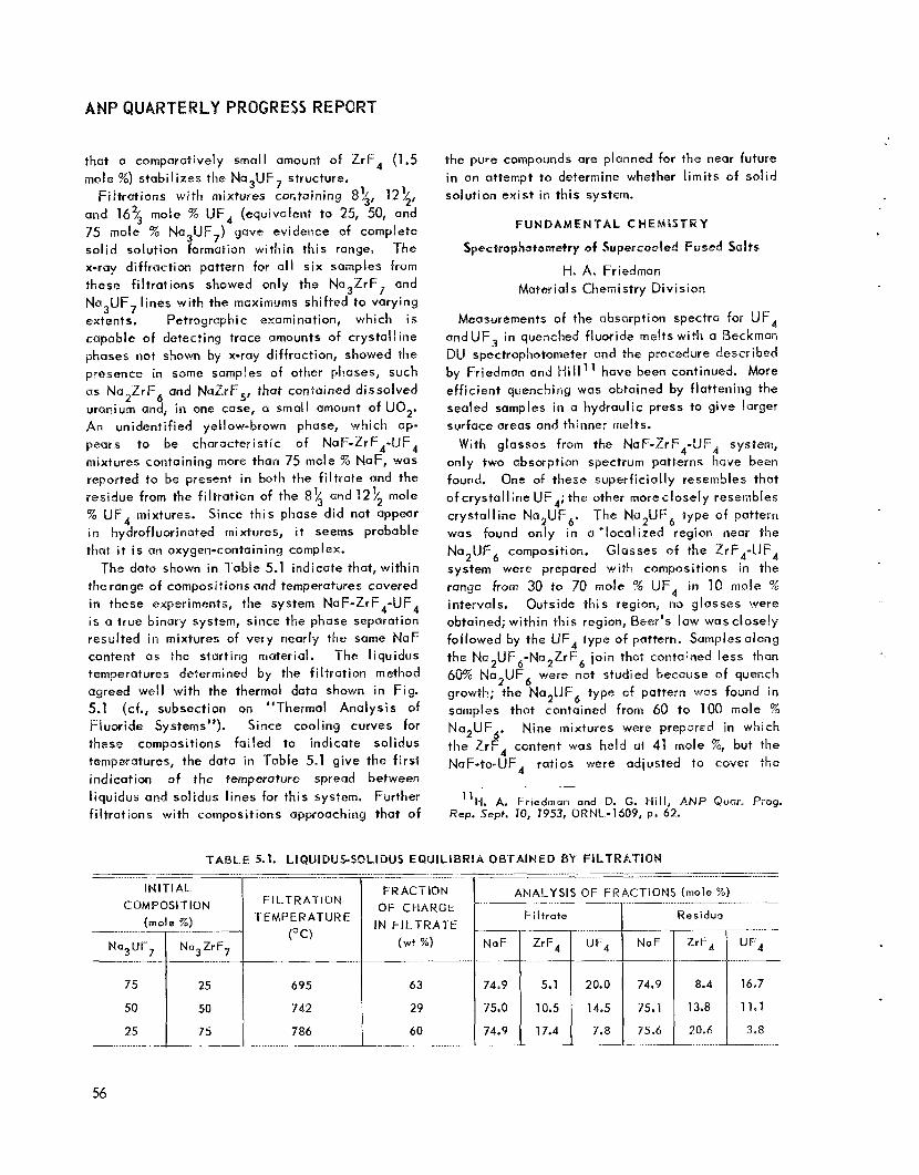
ANP QUARTERLY PROGRESS REPO
that a comparatively small amount of ZrF, (1.5 mole 5%) stabilizes the Na,UF, structure.
Fi l trat ions with mixtures containing a 4, 12\, and 16% mole 76 UF, (equivalent to 25, 50, and 75 mole % Na3UF,) gave evidence of complete solid solution formation within th is range, The x-ray diffraction pattern for a l l six samples from these filtratians showed only the Na,ZrF, and Na,LlF, lines with the maximums shifted PO varying extents. Petrographic examination, which i s capable of detecting trace amounts of crystalline phases i i ~ t shown by x-ray diffraction, showed the presence in some samples of other phases, such as Na,ZrF, and NaZrF,, that contained dissolved uranium and, in one case, a small amount of UO,. An unidentified yellow-brown phase, which ap- pears to be characteristic o f NaF-ZrF,-UF, mixtures containing more than 75 mole % NaF, was rcpaated to he present in both the f i l t rate and the residue from the f i l t rat ion of the 8 \ and 12$ mole % UF, mixtures. Since this phase did not appear in hydrofluorinated mixtures, i t seems probable that i t i s an oxygen-containing complex.
The data shown in Table 5.1 indicate that, within the range o f cornpositioris and temperatures covered in these experiments, the system NaF-ZrF,-UF, i s a true binary system, since the phase separation resulted in mixtures of very nearly the same NaF content as the starting material. The liquidus temperatures determined by the f i l t rat ion method agreed well with the thermal data shown in Fig. 5.1 (cf., subsection on “Thermal Analysis of Fluoride Systems”). Since cooling curves for thase compositions fai led to indicate solidus temperatures, the data in Table 5, l give the f i rst indication o f the temperature spread between liquidus and solidus lines for this system. Further f i l t rat ions with compositions approaching that of
1
the pure compounds are planned for the near future in an attempt to determine whether l imi ts o f solid solution exist in this system,
F U N D A M E N T A L c n E M i s = r R Y
Spectrophotometry of Supercooled Fused S O ~ S S H, A, Friedman
Materials Chemistry Division
Measurements of the absorption spectra for UF, andUF3 in quenched fluoride m e l t s with a Beckman DU spectrophotometer and the procedure described by Friedman and liill” have been continued. More eff icient quenching was obtained by flattening the sealed samples in a hydraulic press to give larger surface areas and thinner melts.
W i t h glasses from the NaF-ZrF4-UF, system, only two absorption spectrum patterns have been found. One of these superficially resembles that of crystalline UF,; the other moreclosely resembles crystal l ine NazUF,. The Na,UF, type of pattern was found only in a ’localized region near the Na,UF, composition. Glasses o f the ZrF,-UF, system were prepared with compositions in the range from 30 to 70 mole % UF, in 10 m o l e % intervals. Outside this region, no glasses were obtained; within this region, Beer’s law was closely followed by the UF, type o f pattern. Samples along the Na,UF,-Na,ZrF, join that contained less than 60% Na,UF, were not studied because of quench growth; the Na,UF, type of pattern was found in samples that contained from 60 to 100 mole 74 Na,UF,. Nine mixtures were prepared in which the ErF, content was held at 41 mole %, but the NaF-to-UF, rat ios were adjusted to covei the
”H. A. Friedman and D. G. H i l l , ANP Quat. Prcg . Rep. S e p t . 10, 1953. ORNL-1609, p. 62.
TABLE 5.1. LIQUIDUS-SOLIDUS EQUILIBRIA OBTAINED BY FILTRATION ... - .......... ~ . _ _ _ _ _
I N I T I A L COMPOSITION
( m o l e %)
50
25 75 ..........
~
F I L T R A l l 0 N TEMPERATURE
(OC)
695
742
786
__ FRACTION
OF CHARGE IN FILTRATE
( w t 7;)
63
29
60
.... ~ _ _ __I_ .̂___ .......... .......
ANALYSIS OF FRACTIONS (mole %)
NaF
74-9
75.0
74.9
Fi l t rate
ZrF,
5.1
10.5
17.4
........ .......
...
20.0
......... ...
“F4
16,7
1 l a 1
3.8
56

PERIOD ENDING DECEMBER 10,1953
region from 6 to 59 mole % UF,; a l l nine mixtures formed glasses and exhibited the UF, type of absorption in conformity with Beer’s law. The NaUF,-NaZrF, system i s currently being investi- gated.
Glasses were obtained with compositions of between 16.67 and 50 mole % UF, in the ZrF,-UF, binary system. At higher concentrations, crystal- l izat ion of UF, could not be avoided. No shift in pattern occurred in the glass region to indicate a change in the nature of the UF, species in the l iqu id melt a t concentrations below x) mole % UF,. The color of the glasses was rust-olive. A typical spectrum i s shown in Fig. 5.4.
0.100
0.300
Ur’ 3 LL 0
? [L W 0.
c U>
z w
-1 r;l
t-- CL 13
0.200
r c
0
0.100
0
.- ..................................
EMF Measurements in Fused Salts
L. E. Top01 Materials Chemistry Division
The techniques described previously have been used for additional electrolyses of various solu- t ions of metal chlorides in potassium chloride. Containers of morganite, graphite anodes, and platinum or nickel cathodes are used, and the electrolyses are carried out at a temperature of 850’C. Potassium chloride solutions containing 1 w t 7% of NiCI, (theoretical E o = 0.82 volt) gave decomposition potentials at 1.20 to 1.26 volts, while solutions containing 10 wt % NiCI, yielded values in the range 1.0 to 1.06 volts. Solutions
700 800 900 1000 500 600
WAVELENGTH (rn/i)
Fig. 5.4. Absorption Spectrum of the ZrF,-UF, System Containing 33.3 mole X UF,.
57

containing 1 to 2 and 10 wt % of FeCI, (theoretical Eo = 1.11 volts) yielded decomposition potentials at 1.50 to 1.55 and 1.20 valts, respectively. A mixture containing 2 wt % of NiCI, and 2 wt % of FeCI, in KC1 yielded two dist inct breaks in the \-E C I J ~ V ~ at 1.18 and 1,56 volts, ns showri in Fig. 5.5.
0 5 0
0 40
0 3 0
I
a 0 E - -
0 20
0 10
0 0 10 2 0 3 0 4 0
E (vo l ts)
Fig. 5.5. Electrolysis at 850°C of Mixture Con- taining 2 wt % of NiCI, and 2 wt % o f Feci, in KGL
Attempts to electrolyze CrF, in KCI in similar experiments have yielded decomposition potentials at about 1.15 to 1.30 and 1.50 to 1.75 volts, but reproducibility of the results has been rather poor. Electrolyses of KCI with chromium anodes have shown erratic results that are tentatively ascribed to oxidation of the chromium, even though attempts are made to maintain an inert atmosphere. Rather erratic changes of slope at ahout 1.2 and 1.9 volts we observed.
When a thin plate of nickel was used to protect zircon i um electrodes from oxidation, reproduc i bl e emf’s at 1.06 to 1.12 volts were observed in electrolyses of KCI. Since nickel i s not dissolved in KCI at potentials below 1.8 volts, h e emf’s
obtained are considered to be characteristic of the zirconium. Based on the value for zirconium and the decomposition potential for KCI (3.1 volts), the potential for the reaction
Pr(-l 4 Zr + 2CI,
appears to be 2.0 volts. When a hydrogen atrnos- phere i s used over the zirconiuin electrodc system, the decomposition potential wises to 1.12 to 1.18 valts. Whether th is may be due to formotion of hydrides of zirconium i s not certain.
Physical Chemistry 06 Fused Salts
E. R. Van h tsda len Chemistry Division
Soma insight into the fundamental physical chemistry of fused salt systems may be realized from the physical properties of these systems. Accordingly, the depression of the freezing point o f sodium nitrate by CI wide variety of solutes was determined, and measurements were made of the density and electrical conductivity of the LiCI-KCI system and the heat capacity of Cdl,. The molten NaCI-KCI system i s also being investigated in the hope that i t w i l l yield not only practical data, but w i l l also contribute to the understanding of short- range order and the noture of electrical conductivity of fused salt systems. This work i s reviewed brief!y below and i s reported in detail in the Chemistry Division semiannual report.’,
Detailed, highly reproducible measurements of the density and the electrical conductivity o f the fused salt system LiCI-KCI were completed for the entire composition f ield over wide temperature ranges. An exact linear relation between molar volume and cornposition at any specified temperature indiccltes that no complex formation occurs in th is molten system. On a molar basis, lithium chloride i s a considerably better el ectri cat conductor than po- tassium chloride, It was therefore significant ts discover that substitution of lithium chloride for s o m e of the potassium chloride actually lowered the equivalent conductance of the solution below that of pure potassium chloride. This phenomenon was interpreted to be indicative of considerable short-range order persisting in these high-tempera- ture fluids. A further tentative explanation of th is
l 2 A , S. Dworkin, D, J. Sasrnor, and E. R. Van Artsdolen, Chem. Div. Semionn. P r o g . Rep. June 20, 7953, O R N L 1587, p. 13-25.
58

PERlOD ENDING DECEMBER 10, 1953
behavior was based on the consideration of the relative sizes of the ions. Substitution of small L is ions for some of the much larger K* ions w i l l shrink the short-range chloride semilattice of the f luid and make transport by Ks appreciably more diff icult. As more and more L i t i s substituted for K , the conductivity w i l l pass through a minimum and again increase until, finally, pure LiCl i s present.
The depression of the freezing point of sodium nitrate was investigated with a wide variety o f solutes. The results significantly substantiate the concept that fused salts are essentially total ly ionized and behave as nearly ideal electrolytes, even at relatively high concentrations of the solute. Thus, calcium, strontium, barium, and lead chlorides, for example, are completely dissociated, as i s LOCI,. FeCI, seems to form two particles only, apparently F e C l i and C1-. Chromate, di- chromate, and bromate ions ate stable in l iquid sodium nitrate, but the metaperiodate ion, IO;, decomposes to yield oxygen and the iodate ion.
The heat capacity of high-purity crystall ine cadmium iodide has been measured from 15°K to room temperature. It remains necessary to de- termine c in the range well below lS0K because of the observed high heat capacity at th is tempera- ture. The heat capacity shows approximately CI
1.4-power temperature dependence at the lowest measured range and, therefore, does not yet f i t either the usual Debye T 3 law or the T 2 law ob- served here for boron nitride. At 298.16'K, the following thermodynamic values have been found for cadmium iodide: c = 19.12cal/mole, So =38.5,, -(be - H g ) / T ~ 2 3 . 1 8 (H' - fl;)/T = 15.31. The So value has an uncertainty of about t0.5 because of theehigh heat capacity value at 15'K and i t s attendant inherent dif f iculty of extrapolation to 0°K. Th is uncertainty is, of course, reflected in the two derived quantities.
t
P
PRODUCTION O F P U R I F I E D FLUORIDES
G. J. Nessle F. F. Blankenship Moterials Chemi stry Div i sion
of enriched uranium were prepared and. distributed to various laboratories for testing. When the ex- perimental production faci l i t ies have been expanded (cf., subsection on "Experimental Production Facilities"), production of materials in this lab- oratory wi l l be terminated, except for the prepara- tion of small enriched-uranium-bearing specimens for radiation stabil ity tests.
Purif icatian of Small FIuoride Samples for Phase Studies
F. F, Blankenship c. M. Blood F. P. Boody
Materials Chemi stry Division
Studies of phase equil ibria in the NaF-ZrF, and NaF-ZrF,-UF, systems by the quenching technique have been hampered by contamination of the materials with traces of water which caused hy- drolysis of the tetravalent halides during the heating period and consequent contamination of the quenched meltwith oxide or oxyfluoride phases. Materials for th is and similar phase equilibrium studies that are essentially free from water and oxygenated compounds are now routinely prepared by a modification of the hydrof luor i nation-hydrogena- tion pretreatment method used for larger specimens.
In th is process a number (up to 28) of small (-25 g) samples are placed in nickel or platinum crucibles on a nickel rock inside a 4-in.diameter nickel reactor for processing. A typical processing cycle of 2 hr of treatment with HF at 800T fol- lowed by stripping w i t h H, at 600uC far 18 Rr has been shown to produce material satisfactory for these purposes. To date, a total of six batches comprising 67 samples has been prepared. It appears, however, that handling of the specimens in a vacuum dry box may be required if freedom from oxygenated phases i s to be maintained.
Production of Enriched Material for In-Pi le Loop Experiment
G. J. Nessle Materials Chemi stry Division
Plans For preparotion of the enriched fuel for a miniature in-pile loop faci l i ty and for charging of the material into it have been prepared in accordance
F, F. Blankenship with the necessary technical and accountability c. M. Blood G. M. Watson considerations. It i s planned that th is loap wi l l
be charged with a uranium-free mixture for prelirni- Twenty-eight batches totaling 55 kg of molten nary testing before the enriched concentrate i s
added for f inal testing.
Laboratory-Scale Production of Molten Fluorides
F. P. Boody
Materials Chemistry Division
fluorides and including one batch containing 15 g
59

LY PROGRESS REPORT
TEMPERATURE
OC O K
......
The processing equipment for th is production operation has been fabricated, When production of the ARE enriched concentrate has been com- pleted, the new process equipment w i l l be instal led in Building 9212 in the area now occupied by the ARE facilities. The enriched fluorides for the in-pile loop w i l l be transferred to the X-IO si te where the loop w i l l be fi l led.
Experimental Production Faci l i t ies
J. P. Blakely C. R. Croft Materials Chemistry Division
B. E. MtCarty R. Reid
ANP Division R. G. Wiley
A total of 329.2 kg of mixed fluorides was processed and dispensed to various requestors during th is quarter. Included in th is total were 14 batches of approximately 2.5 kg each, 3 batches o f approximately 10 kg each, and 10 batches o f approximately 27 kg each.
Although the quantity of fluorides processed decreased, the variety o f demand increased sharply. This tendency i s becoming more pronounced, and it appears that production of large quantities of a few materials w i l l be of considerably less im- portance; versatility and adaptability of equipment w i l l be primary requirements. Consequently, an installation i s being planned for producing a variety of fluoride Compositions with a minimum loss o f time ond equipment.
Reduction of Na,UF, by Hydrogen
Materials Chemistry Division F. F. Blankenship F. P. Boody
The Na,UF, which had previously been hydro- fluorinated and stripped with hydrogen so that the structural metal content should have been reduced to less than 30 ppm was bubbled with hydrogen gas in the original nickel reactor for
1 REACTION RATE AS MOLES OF Hi= PER L ITER OF H2 BUBBLE11
considerable periods of time at 692, 785, and 882aC. It was found that the rate of reduction o f the uranium according to the equation
UF, t \ H 2 = UF, + HF
increased with temperature, as shown in Table 5.2. When the data given in Table 512 arc plotted on a semilogarithmic scale as reaction rate vs. (lh-) x lo4 the straight i ine shown in Fig. 5.6 i s obtained. From the slope of th is curve, the acti- vation energy of the reduction can be calculated to be 33,700 f 2600 cal/rnole.
Treatment of Molten NaZrF, w i t h Strong Reducing Agents
G. M. Watson Materials Chemistry Division
It was previously reported13 that zirconium bars suspended in molten NaZrF5 contained at 80OOC in graphite-lined reactors and stirred by bubbling argon undergo weight losses far in excess of the amount required to reduce structural metal ions. This observation was further confirmed by addi- tional experiments that involved the treatment o f NaZrF, in graphite-lined nickel at 800OC with zirconium chips; the unrecovered zirconium metal amounted ta at least 20 g per kilograin of fused salt. However, it has since been observed that l i t t l e i f any IOSS of weight occurred wherl zirconium metal chips were exposed in a parallel experiment without the graphite liner. The difference might be due to the formation of zirconium carbide, but the available data are insufficient to show it. The possibi l i ty that a portion of the zirconium enters themelt as the trifluoride or as dissolved zirconium metal has not been ruled out.
F. F. Blankenship C, M. Blood
13C- M. Blood et ai., ANP QWOIF. Prug. Rep. Sep t . 70, 1953, ORNL-1609, p. 69.
TABLE 5 . 2 RATE OF REDUCTION O F No2UF6 WITH H q AS A FUNCTION OF TEMPERATURE .......... __ ....... ____-- ...... .- ___ .._.. ...... I-
__
785 692 I 96 5
1058
10.36
9.45
8.8
3.7 x
8.65 I 1.58 x ._._. ....... ........ .....
882 1 1155 I
60

PERIOD ENDllNG DECEMBER '10, 1953
10-6 I I ....... 1 8 0 e 5 9 0 9 5 I00 105 110
- ' x lo4 T P K )
Fig. 5.6. Reaction Rate vs. Reciprocal Temper- ature According to the Equation UF, + '/, H, = UF, t HF.
The effect of uranium metal on NaZrF, was studied by adding 5.5 wt % of uranium chips to the material in a graphite-lined reactor. Unlike the previous experiments, the mixture was treated with hydrogen for 2 hr at 8OO0C, and the material was subsequently f i l tered at 700OC. The f i l t rate started freezing at about 54OOC and contained f ive phases typical ly found in fuels which are reduced to the extent that orange-red UF3*2ZrF, and purple UF, appear. The uranium content of the f i l t rate was 5.00 wt %, and apparently about 90% of the uranium reacted. If i t i s considered that the dis- solved uranium i s present as UF, and that a l l other reduced phases are insoluble, a reducing power of 210 meq per kilogram of melt should have resulted; i f a l l reduced phases remained in solution,
the theoretical reducing power would be 840 medkg. Chemical analysis by H, evolution showed 550 rneq of reducing power per kilogram of filtrate, which indicated the presence of soluble reduced phases in addition to the UF,. l e s s than M pprn of nickel and chromium and 85 ppm of iron were found. The unfiltered residue in the reactor con- tained black opaque materia! which liberated gas readily when treated with di lute acids. X-ray analysis of the residue revealed the presence o f ZrH, UF,, and uranium metal, along with occluded melt. Thus it appears that the uranium did not react quite completely and that same zirconium tetrafluoride was reduced to the metal by the ura- nium. Since ZrH, i s decomposed to the extent of about 25% at 8OOOC under 1 atm of H,," most of the zirconium appears as ZrH.
A further check on the possibi l i ty of retaining reducing species such as Zro, ZrF,, ZrC, ZrH, and ZrH, i n NaZrF, melts was attempted by treating NaZrF, with NaH (2 males per kilogramof melt). The mixture was sparged with hydrogen in a graphite liner for 24 hr ut 800OC and then filtered. The reactor heel contained CI dark-black residue which was tentatively identif ied as ZrH mixed with the melt, Chemical analysis of the white f i l t rate showed 106.5 m e q of reducing power per kilogram or about 5% of that expected i f a l l re- duced species were soluble. Efforts to learn more about the nature of this apparent reducing power w i l l be continued.
Reduction of NiF, by Hydrogen
G. M. Watson Materials Chemistry Division
F. F. Blankenship C. M. Blood
Considerable attention has been given to the kinetics of the reduction of Nit+ in NaZrF, by H, at 800°C because of the importance of th is reduc- t ion i n fluoride purif ication procedures. The use of graphite l iners in the nickel reactors for handling moiten salts i s a great convenience in loading and unloading and in avoiding excessive Contamination with NiF, during the HF treatment. Accordingly, for most of the kinetic studies, graphite-lined reactors have been used. Early suspicions that graphite might reduce Ni** were alloyed by the large, positive, standard free energy estimated for
I4Mv\. N. A. Hall, Trans. Faraday 5oc. 41, 306 (1945).
61

ANP QUARTERLY PR RESS REPORT
VOLUME OF GAS PASSED
Helium Pretreatment Hydrogen Pretreatment . . .
(liters) (I iter s)
IN1 TI PL
CONCf N TRATlON
( m e d k g )
O F NiF,
the reduction with carbon,
2NiF,(solid) + C(solid) ---+ 2Nio(solid)
HF RECOVERED DURING HYDROGEN
THEArMENT (%I
+ CFa(gas) AFYOOOoK = 118 kcal ,
69
119
I 60
and by the failure to find a noticeable difference in shprt experiments without graphite liners. In carrying out more detailed measurements over a period of days, the graphite liners have been found to play an important but incompletely understood role in the reduction of Ni". A s a result, the apparent complexity of the reduction kinetics i s now explainable from a qualitative standpoint, but a new set of experiments without the graphite liner must supplant the many experiments made with the use of the graphite liner before quanti- tat ive data can be assumed.
In a series of t r ia ls which provide evidence for the effect of graphite, a weighed portion of n ickel fluoride was mixed with previously puri f ied NaZrF, which was then pretreated at 80OOC in a graphite- l ined reactor by bubbling inert gas through it at an approximaterateof 400 cm3/min and, finally, treated with hydrogen at the ?.ame approximate bubble rate. The varying concentrations of hydrogen fluoride in the effluent gases were continuously determined by direct titration of standard potassium hydroxide samples to the phenolphtalein end point as the gases bubbled through.
In JaLie 5.3 are listed the in i t ia l concentra- tions of nickel fluoride used, the volume of inert gas passed during pretreatment, the volume of hydrogen passed, and the percentage o f hydrogen ftuoride recovered during the hydrogen treatment. From the results given in Table 5.3, i t appears that the recovery of hydrogen fluoride decreases CIS the length of pretreatment increases; that is, it i s apparent that a fraction of the nickel fluoride added is reduced by some agent other than hydrogen
and that this fraction increases w i th increasing length of Pretreatment.
Since it appeared that the graphite liner was in some fashion effectively reducing the NiF,, one experiment that essentially duplicated the last test shown in Table 5.3 was conducted without the graphite liner in the nickel vessel. Copious evolution of hydrogen fluoride occurred. The re- covery measured amounted to 72.6% at the end of passage of 60 l i ters o f hydrogen, Kinetically, the reaction appears complex in the presence ofgraphite, as evidenced by the variable over-all order with respect to the apparent nickel fluoride concentra- tions.
Preparation of Vasiaws Fluorides
8. J. Sturm Materials Chemistry Division
The methods of preparation and some of the physical properties of numerous complex fluorides that resulted from the interaction of alkal i with structural metal fluorides have been previously re- ported." During this quarter, the simple structural metal fluorides have been used increasingly in corrosion studies, and a major portion of the avail- able time has been devoted to preparation of these rnatericnls. The compositions o f these fluorides were determined by chemical analyses, and some supplementary x-ray and petrographic determinations were made for further characterization.
Several batches of FeF, and FeF, have been prepared by hydrofluorination of the anhydrous chlorides. Emphasis was placed on the preparation of relat ively small batches of these two fluorides
15G. J. Nessle, ANP Quar. Pro . Rep. Dec. 10, 7352, ORNL-1439, p. 123; G, J, Nessqe and M. W, Savage, ANP Quar. frog. Rep. March 10, 7953, ORNL-1515, p. 115; B. J. Sturm and L. G. Overholser, ANf Quor. Prog. Rep. June 70, 7953, ORNL-1556, p. 48.
TABLE 5.3. RESULTS OF TESTS OF THE REDUCTION OF NiF2 BY HYDROGEN - .................... ......... ..................
~ __I_____ ____. 111- ................. .....
I
15.7
29.2
228.0
41
132
1285
82.5
81.6
9.0
62

PERIOD ENDING DECEMBER 10, 1953
of the highest possible purity. Several pounds of anhydrous Ni F, were prepared by hydrofluorination of the hydrated NiF,. Small quantities of anhydrous NiCl were similarly prepared from hydrated NiCI, for special uses,
Previous work had indicated that the precipitate resulting from theaddition of NH4HF, toan aqueous solution of CdCI, could not be quantitatively con- verted to CdF, by hydrofluorination. Further studies have shown that the solids resulting from the addi- t ion of NH,HF, to aqueous solutions of either CdSO, or Cd(C2H302), give the same x-ray pattern as that found for the material prepared from CdCl,; this pattern differs from the accepted pattern for CdF, and apparently indicates complex or double salt formation. It was observed that the interaction of HF with CdCO, in an aqueous medium gives a precipitate of CdF, that has the x-ray properties accepted for CdF,.
In an effort to prepare some of the fluorides of molybdenum, the powdered metal was brominated to produce a material consisting mainly o f MoBr,. A f i rs t attempt to hydrofluorinate this material was incomplete; components of the mixture have not yet been identified.
P URlF K A T ION AND PROP E R T l E S OF HYDROXIDES
Seven batches of NaOH containing approximately 400 g each have been prepared by f i l t rat ion and de- hydration during this quarter. The material obtained containedfrom 0.02 to0.10 wt% of Na,CO, andless than 0.1 wt % of H,O.
The Sr(OH), purif ied during this quarter con- tains considerably less SrCO, than the material previously prepared; the improvement resulted from the replacement of a faulty filter. For the 12 batches produced, the SrCQ, contents range from 0.02 to 0.06 wt %, and the total alkalinit ies, as determined by titration, range from 99.8 to 100.0%.
Reaction of Sodium Hydroxide with Carbonaceous Matter
E, E, Ketchen L. G. Overholser Materials Chemistry Div is ion
A few experiments were run to check observations made elsewhere which suggested that the Na,CO, content increased when NaOH was heated at 70OOC in a sealed nickel container. I f the increase occurs, i t may be due to the presence in the hydroxide of carbonaceous matter capable of oxidation to Na2C0,. Samples of commercial NaOH (about 1.5 wt X Na,CO,) showed no significant change after heating at 700°C for 24 hours. However, the analytical results were not sufficiently precise to detect very small changes in this range of
Pur i f icai ion of Hvdroxides carbonate concentration. When samples of purif ied NaOH (one purified by f i l t rat ion and one by de- cantation) for which accurate C03-analyses could be obtained were heated i n nickel for 24 Rr at
E. E. Ketchen L. G. Overholser Materials Chemi stry Div is ion
The work wi th hydroxides during this quarter has been confined to the purif ication of NaOH and Sr(0H) according to the methods previously des- c r i b e d j 6 Earlier studies indicated that Na,CO, could be separated from NaOH by fi l tering the 50 wt % aqueous solution of NaOH through a fine sintered-glass fi l ter instead of decanting off the NoOH solution, as had been done, Further work has shown that the fi l tration method produces a material with a slightly lower Na2C0, content and without a significant increase in s i l ica content.
16D. R. Cuneo et a/., ANP Quar. Prog. Rep. March 10, 7953, O R N L - 1 2 2 7 , p. 104; E. E. Ketchen and L. 6. Overholser, ANP Quor. Prog. Re#. June 10. 7952, O R N L - 1 2 9 4 , p. 89.
70O0C, slight increases in carbonate content were observed. Both purified NaOH samples contained 0.02 w t X Na,CO, prior to heating. After heating, the NoOH purif ied by decantation contained 0.05 w t % No2C0, and that purif ied by fi l tration con- tained 0.06 wt %. The increase observed could be due to oxidation of the carbon present in the nickel or the NaOH. Additional tubes were filled with NaOH to which had been added 0.2 wt % graphite. After these tubes were heated at 7OOOC for 24 hr, preliminary analyses indicated a marked increase in carbonate content. Th is suggests that carbon i s oxidized by NaOH at 700OC; i f this i s the case, NaOH could not be maintained carbonate free at high temperatures in metals which contain appreci- able percentages of carbon.
63

ANPQUARPERLYPROGRESS
WOSION RESEARCH
W. D. Manly Meta I I urgy Division
W. R. Crimes F. Kertesz Mater io Is Chemistry Div is ion
H. W. Savage ANP Division
The stat ic and the seesaw corrosion testing faci l i t ies have been used to study the corrosion of Inconel, cermets, and some special al loys in the fluoride fuel NaF-ZrF -UF, (50-464 mole %), The effects of improper &greasing of metals and of contaminants in the fluorides were studied, Several tests of bearing materials and hard-facing al loys have been completed i n which the molten fluorides were used as the corroding agent. The materials tested are of considerable interest because of their prospective uses as h igh-temperature b a r i ngs and valve facings. Various cermets have also been tested in the fluorides to determine their fitness for these same applications. Static tests in graphite capsules of Inconel specimens exposed to fluoride fwel to which FeF,, FeF,, o* NiF, additions were made gave anomalous results that were presumably due PO the reduction of the added metal fluorides by the graphite, Static tests of two dissimilar metals indicated that one metal is usually prefer- ent ia l ly attacked.
Fluoride corrosion tests were made in lnconel thermal convection loops t o supplement and extend the data obtained in the above-mentioned and previous static tests. Although the thermal con- vection loops normally operate w i th a hot-leg temperature of 15OO"F, the temperatures were varied to determine the effects of both time and temperature. Addit iona I tests hove substantiated the earlierconclusion that attack by NaF-ZrF4-UF (50-46-4 mole %) on Inconel i s independent 04 temperature, a t least in the range o f 1500 t o 1650°F, and dependent on exposure time. The purity of the fluoride mixture was shown to be important when the attack depth was increased by a factor of 3 in a loop operated with a low-purity batch of fuel, Reductions i n attack, in comparison w i th that found in the standard loop, that is, a loop operated for 5oQ hr at 1500°F, were achieved by (1) precirculating the fluorides, (2) pretreating the fluorides with chromium metal flakes, and (3) holding the fluorides in contact wi th lnconel
turnings before circulation i n the loop. While pretreatmentof the fluorides wi th metallic chromium was beneficial, a chromium plate on the pipe wall WQS not. Increasing the UF, content in the fluoride mixture from 4 t o 6.5 mole % caused an increase in mass transfer in the loops and possibly a S I ight increase in corrosion. The maximum depth ofattack by the purified ARE fuel solvent, NaZrF,, was comparable to that of the purified fuel mixture (with 4 mole % UF,), although the intensity of the NaZrF, attack was much less and the same I T K I S S
transfer was noted. Additional studies were performed in an attempt
toestabl ishthechemical equilibria of the postulated corrosion reaction which results in the selective leaching of chromium from Inconel. Preliminary values have been obtained for the equilibrium con- stants involved, but the data are notyet sufficiently re1 iable.
Nickel and type 430 stainless steel thermal convection loops were also operated with the fluoride NaF-ZrF,-UF, (50-46-4 mole 76). There was no measurable mass transfer in the nickel loop, and the hot-leg surface had a polished finish. The hot leg of the type 430 staipless steel loop showed CI sinall amount of smooth, even removal, with no subsurface voids sr intergranular attack; metal crystals were deposited in the cold leg.
A number of tests, both static and dynamic, were performed with the l iquid metals lithium, sodium, and lead. Tests have been completed on beryllium oxide and a number of bearing materials and cermets.
The investigation of the mass transfer and corrosion of metals and al loys in quartz thermal convection loops containing l iquid lead have continued. The metals tested during this quarter included a molybdenum-nickel (25% M~-75% Ni) OIIOY, a chromium-iron-silicon (14% Cr-84% Fe--2% Si) alloy, and types 3Q4 and 347 stainless steel specimens which were oxidized prior to contact with the lead, The most significant result from
44
PERIOD ENDING DECEMBER 10, 1953
this study was the marked improvement in the resistance to mass trhnsfer of these metals be- cause of the oxide film. Some static tests on the corrosion and mass transfer characteristics of various alloys i n contact with l ithium were com- pleted.
Static tests on a number of sol id fuel elements were performed in sodium and sodium hydroxide. While there was no evidence of attack in any of the sodium tests, all the fuel elements were severely attacked in the hydroxide. In connection with a study of hydroxide containment, the equilibrium pressures of hydrogen over a number of hydroxide- metal systems are being determined.
F L U O R I D E CORROSION IN STATIC AND SEESAW TESTS
E. E. Hoffman J. E. Pope
L. R. Trotter D. C. Vreeland
R. E. Meadows
Metallurgy Div is ion
N. V. Smith Materials Chemistry Div is ion
H. J. Buttram
Both the static capsule and the seesaw tests provide relatively cheap and simple means of investigating the many parameters which affect fluoride corrosion, The seesaw tests in which the capsule containing the f luwide is rocked in a furnace were operated at 4 cps with the hot end of the capsule at 815°C and the cold end at 700°C. The static tests in which the fluoride mixture is sealed i n a capsule were usually conducted for 100 hr at 816OC. In order to permit testing of material which could not be readily fabricated into capsules or to permit variation of the surface-to- volume rat io of fluoride to metal, a number of tests were performed in which the fluoride and metal specimens were contained in graphite capsules. Ai l capsules are f i l led in a helium dry box, and therefore oxidation or hydrolysis of the contents of the capsules is improbable.
lnconel Corrosion by Fluorides with Metal F I u or id e Add it ive s
In general, corrosion of Inconel specimens by several fluoride preparations in graphite capsules was similar to that obtained when lnconel capsules were used in static tests. Some carburization of the specimens was obtained, but no other special effects were obsrvved.
However, when fluorides t o which had been added considerable quantities of FeF,, FeF,, or NiF, were tested i n graphite capsules containing Inconel specimens, rather surprising results were obtained. In each case, tests at $OO°C showed extensive deposition of iron or nickelI usually in fi lms on the graphite capsule and on the speci- men. When FeF, was the additive (in amounts up to 5 wt %I, the corrosion of the Inconel specimen, as observed by metailographic examination and by analysis of the final meit for chromium, was much less than expected. In similar tests with FeF , corrosion of the Inconel was virtually undetectabfe by either technique. In this case, the precipitated f i l m of metal appeared to be protective.
was the added material, however, no protection of the specimen by the f i lm resulted. In these experiments, extremely heavy subsurface void formation to a depth of 9 mils was observed. There i s evidence that corrosion by fluoride mix- tures wi th NiF, added is mwe severe at 600 than at 800°C.
These experiments suggest that graphite or some unknown contaminant i n the graphite is responsible for reduction of the added metai fluoride. While reduction of FeF fi for example, by graphite should have an extremefy low equilibrium constant, it is possible that the volat i le reaction product (CF,) escapes from the system and permits the reaction to proceed, ilt is also possible that there is sufficient oxygen or water adsorbed in or on the graphite so that reduction of oxide by carbon (a reaction wi th an appreciable equilibrium constant a t these temperatures) i s responsible for these effects. Further study of this and similar reactions i s i n progress.
When NiF 2
Corrosion 04 VarirDus Metal Combinations A series of experiments in which various metals,
either alone or i n combination, were tested in molten fluorides i n graphite capsules have yielded the following results. (1) Nickel alone shows no attack. (2) Chromium-plated inconel shows heavy subsurface void formation at a l l temperatures above 600°C; the voids were 3 to 4 m i l s deep at 7QQoC and above. (3) Chromium metal yielded high values for chromium content of the melt; i t i s possible, however, that slight surface oxidation of the chromium pellets used was responsible for this dissolved material. (4) When lncnnel and chromium specimens were exposed together, the chromium
65
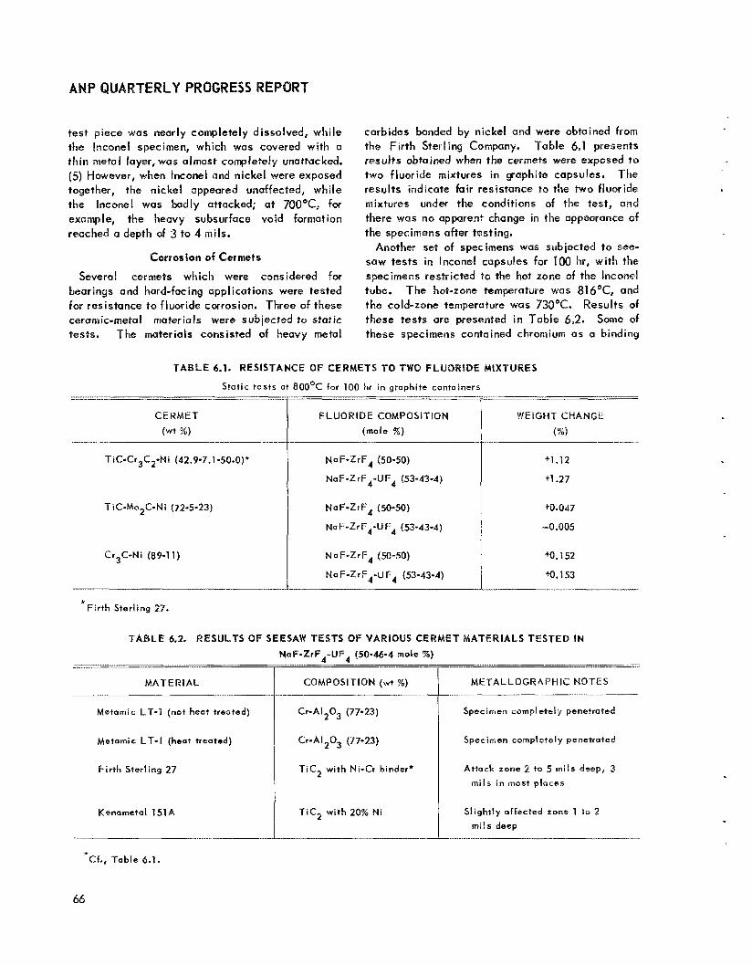
TERLY PROGRESS REPORT
test piece was nearly completely dissolved, while the Iticonel specimen, which was covered with a th in metal layer, was almost completely vnattacked. (59 However, when lnconel and nickel were exposed together, the nickel appeared unaffected, while the Inconel was badly attacked; at 7QQ°C, for example, the heavy subsurface void formation reached a depth of 3 to 4 mils.
Corrosion of Cermets
Several cermets which were considered for bearings and hard-facing applications were tested for resistance to fluoride corrosion. Three of these ceramic-metal materials were subjected to static tests. The materials consisted of heavy metal
carbides bonded by nickel and were obtained from the F i r th Sterling Company. Table 6,1 presents results obtained when the cermets were exposed to two fluoride mixtures in gophi te capsules. The results indicate fair resistance to the two fluoride mixtures under the conditions of the test, and there was no apparent change in the appearance of the specimens after testing.
Another set of specimens was subjected to see- saw tests in lnconel capsules for 100 hr, w i th the specimens restricted to the hot zone of the Inconel tube. The hat-zone temperature was 816'C, and the cold-zone temperature was 730°C. Results of these tests are presented in Table 6 2 . Some of these specimens contained chromium as a binding
TABLE 6.1. RESISTANCE OF CERMETS TO TWO FLUORIDE MIXTURES
Stat ic tes ts a t 8OOoC for 100 hr in graphite cantainers ___-..__I ~
CERMET (wt %)
Tic-Cr3C2-Ni (42.9-7.1 -50.0)*
TiC-Mo2C-Ni (72-5-23)
Cr3C-Ni (89-1 1)
. . .... . .-.
F L UO R ID E COMPOS I T ION (mole %)
NaF-ZrF4 (50-50)
Na F-ZrF4-U F4 (53-43-4)
NaF-ZrF4 (SO-SO)
NaF-ZrF44JF4 (53-43-4)
NaF-ZrF4 (50-50)
Na F-ZrF4-U F4 (53-43-4)
....
WEIGH? CHANGE
(%)
+1.12
+1.27
.....
tO.047
-0.005
"0.152
M. 153
..__ .-. __. ...
MAT ERI A L
Metarnic LT-1 (not heat treated)
Metamic Lf -1 (heat treated)
F i r t h Sterl ing 27
Kenarnetal 151A
_. ... . .. - * Cf., Table 6.1.
NaF-ZrF4-UF4 (50-46-4 mole %)
COMPQSlTlON (wi %)
-..___
* F i r th Sterling 27.
TABLE 6.2. RESULTS OF SEESAW TESTS O f VARIOUS CERMET MATERIALS TESTED IN
Cr-AI2O3 (77-23)
Cr-AI2O3 (77-23)
Picz wi th Ni-Cr binder*
T i c 2 w i th 20% N i
_____- . -- __._._.I
METALLOGRAPHIC NOTES
Specimen completely penetrated
Specimen completely penetrated
Attack zone 2 to 5 m i l s deep, 3 m i l s in most places
Slightly affected zone 1 ta 2 mi ls deep
66

PERIOD ENDING DECEMBER 10,1953
agent, and, as expected, these materials were Screening Tests of Metall ic Bearing Materials attacked by the fluorides. Several tests have been completed in the screen- the heat-treated and unheat-treated conditions, ing program On materials for use in bearing was attacked severely. While the attack On the and hard-facing applications. Materials for these Firth Sterling 27 and on the Kenameta1 151A i n the Seesaw tests was oniy moderate, the increased
tests 'Ompared wi th that in the static tests i s evidenced by the test data on Firth Sterling 27.
Metamic LT-1, in both
must be resistant to cOrrOS,On by fluorides. One set of specimens consisted of HasteIJoys B, C, and D, and Stell i tes 1, 6, 12, 21, 25, 40, and 4'1 deposited on pieces of type 347 stainless steel. These composite specimens were
Of attack in the
lnconel with Oil and Trichloroethylene Additives
Several thermal convection loops had more than average depths of attack which were thought to be due to improper degreasing of the loops prior to f i l l ing. Therefore, a static test was run i n which s ix drops of o i l and six drops of trichloroethylene were added to an lnconel capsule containing an Inconel specimen and the solution was allowed to evaporate in an attempt to duplicate improper de- greasing. This capsule was then loaded with the fluoride mixture NaF-ZrF -UF (50-4-4 mole %) and tested for 100 hr at 8 1 6 O t under static con- ditions, along with a control capsule for corn- parison. The specimen in the control capsule had greater weight loss and depth of attack than the specimen contaminated by the evaporation of the trichloroethylene-oil solution. It appears that under the conditions of this test, the contamination was not detrimental and might even have been beneficial .
Inconel Corrosion by Fluorides wi th MoS, Additive
Molybdenum disulfide is being used as a Swage- lok lubricant i n fluoride production systems, and therefore it was pertinent to determine whether increased corrosion of the lnconel tubing would result i f some of the MoS, were to contaminate the fluoride. Accordingly, two seesaw tests of the fluoride mixture NaF-ZrF,-UF, (50-46-4 mote %) in lnconel tubing were run for 100 hr. In one of these tests, an addition of 3 wt % MoS, was made to the fluoride; the other test was run with no addition to fluoride.
Metallographic examination of sections of tubing from hot and cold zones of both tests showed that more severe attack had taken place in the test with the MoS, addition. The cause of t h i s increased corrosion i s not known. The type and extent of attack both wi th and without MoS, additions i s shown in Fig. 6.1.
tested i n the fluoride mixture NaF-ZrF,-UF4 (50-46-4 mole 7%) for 100 hr at 816°C under static conditions. In these tests, it appeared that Hastelloys B, C, and D and Stell i tes 21, 25, and 40 satisfactori ly resisted attack by this fluoride mixture. Stell i tes 1, 4, 12, and 41 appeared to be attacked severely. The appearance of Stell i te 40 after the test i s shown in Fig. 6.2; the attack i s l imited to a depth of 4 or 5 mils. A s reported previously, it i s apparently the carbides in the Stell i tes which are preferentially attacked by the fused fluoride salts, and it appears that the Stell i tes of low carbon content are not so severely attacked. The results of these tests are presented in Table 6.3.
FLUORIDE C O R R O S i O N OF l N C O N E t IN THERMAL CONVECTION L O O P S
G. M. Adamson Meta I I urg y D iv i s i on
The use of thermal convection loops for determi- ing dynamic corrosion by I iquids has been previously described.' Unless otherwise stated for the tests described in the following sections, the tempera- ture of the hot leg of the loop was maintained at 1500°F and the temperature of the uninsulated cold leg was approximately 1300°F. With the fluoride salts, th is temperature difference results i n a fluid velocity of obout 6 to 8 fpm. The usual testing period i s 500 hours.
Effect of Fluoride Batch Purity
Pilot-plant batches of the fluoride fuel mixture NaF-ZrF,-UF, (50-46-4 mole W) which received a 24-hr gas purif ication instead of the customary 8 hr or less are now available for thermal con- vection loop work. The longer gas purif ication results i n a reduction of the hydrogen fluoride content of the melt. Corrosion results from three
'D. C. Vreeland et a!., ANP Quar. Pros. Rep. March 70, 1953, ORNL-ISIS , p. 121.

ANP QUARTERLY PROGRESS REPORT
Fig. 6.1. Corrosion of lnconal after o 100-hr Seesaw Test at 815OC in the Fluoride NaF-PrF4-UF4 a. Tested with no additive. 250X. b. Tested (50-46-4 male 36) with ondWithout3 w t % MoS, Additive.
with 3 wt '% MoS2 added. 25OX.
68

PERIOD ENDING DECEMBER 10, 1953
TABLE 6.3. CORROSION O f HARD-FACED TYPE 347 STAiNLESS STEEL SPECIMENS EXPOSED TO NaF-ZrF4-UFd FOR 100 hr A T 816OC UNDER STATIC CONDITIONS
HARD- FAC ING MATE RIAL
C
D
Stell ite
1
6
12
21
COMPOSITION (wt W)
Mo, 26 to 30 Fe, 4 to 7 C, 0.12 max
N i, balance
Mo, 16 to 18 Fe, 4.5 to 7 C, 0.15 max
Cr, 15.5 to 17.5 w, 3.75 to 5.25 Ni, balance
cu, 3 AI, 1 Si, 10 Mo, 1 N i , bal ance
c, ?
Cr, 30.5 W, 12.5 Fe, 3 max
c. 2.5 Ni, 1 Co, balance
Cr, 27.5 w, 4 Fe, 2 to 3 max
c, 1 Co, balance
Cr, 29.5 W, 8.25 Fe, 2 t o 3 max
Ni, 1 Co, balance
Cr, 25 to 30 Ni, 1.5 to 3.5 Mo, 4.5 to 6.5 Fc, 2 max
Co, balance
c, 0.2 to 0.35
c8 1.4
METALLOGRAPHIC NOTES
A few voids to a depth of 0.5 mi l
A l i t t l e spal l ing and a few voids to a
maximum depth of 1 mi l
Subsurface voids to a depth of 1.5 mi ls
Many voids t o a depth of 5 EO 10 mi ls
Errat ic ottock up to 15 m i l s deep atong
carbides i n grain boundaries
Errat ic intergranular attack 0 to 13 mi ls deep
A few voids to a depth of 0.5 mi l
69

ANPQUARTERLYPRBGRESSREPQRT
HARD- F ACI N G
MATE RI Al-
Stel l i t e 25
40
41
TABLE 6.3. (continued) _.- I_.._..
COMPOSIT ION ( w t So)
Cr, 19 to 21 C, 0.15 Ni, 9 to 11 W, 14 to 16 Si, 1 Mn, 1 to 2 Fe, 2 Co, balance
Composition not uvailable
Composition not avai lable
ME TALLOGRAPWIC NOTES .-
A few voids to a depth of 0.5 mil
Voids to a depth of 3 t o 5 mils
Heavy, crrati c intergranular attack
4 to 23 mils deep
Fig. 6.2. Stellite 40 After Static Testing in NaF-ZrF,-UF, (50-46-4 msle X) for 100 ks a t 814OC.
lnconel loops operated with this material showed general attack to a depth of 3 mils and some intergranular penetration to a depth of 6 mils. The importance of purity of the materials i s evident from these teats, since the average maximum pene- tration in standard production batches has been present.
9 mils. The reduction in attack, shown on Fig. 6.3, was a lso reflected in the chromium pickup, which was down t o 450 to 600 ppm, that is, less than one half the previous contamination. Some reduction was also obtained in the amount of iron
70

PERIOD ENDDNG DECEMBER 10,1953
Fig. 6.3. Effect of Fluoride Batch Purity on the Corrosion of lnconel Exposed in Thermal Convection Loops to NaF-ZrF,-UF, (50-46=4 mole %) for 500 hr at 15OO0F. o. Exposed to standard production batch. 250X. b. Exposed to high-purity batch. 250X. Reduced 17%.
Fluoride fuel mixtures with high hydrogen fluoride content were circulated i n a number of loops. Increased corrosion, as indicated by heavy attack and maximum penetrations of 14 and 15 mils, WQP;
found under standard operating conditions.
Effect of Chromium Additives
Data were presented previously2 which indicated doubtful improvement in corros ion characteristics when chromium powder was added to the fluoride
mixtures. However, i n a new test, in which the chromium was added in the form of coarse metall ic flakes, a reduction in the depth of attack was found, The fluoride mixture was held in contact w i th the chromium flakes overnight at a temperature of 1300°F before being charged into the loop. Examination subsequent t o operation of the loop showed a maximum penetration of only 4 miis, as compared with penetration of the control loop to a depth of 15 mils. As i n previous tests wi th chromium additions, a thin, continuous, metall ic deposit was found in the cold Seg of the loop.
One thermal convection test was run in which the chromium was added in the form of an electro- plated layer on the inner surface of a &in. length of lnconel pipe. This pipe was welded into the top of the hot leg of a standard loop. After oper- at ion of the loop, no trace of the chromium could be found in the hot leg by metaiIographic exami- nation. Typical subsurface void attack was found in the Inconel, with a maximum penetration of 10 mils. No data are available on the hydrogen fluoride content of the batch circulated i n this loop. The 10 mils of attack i s sl ightly higher than the average, but no change in attack could be seen on opposite sides of the hot leg where the section WQS welded into the loop. Scattered metall ic particles were found on the cold-leg wall. Th is test confirms the earlier finding that, while a direct chromium addition to the fuel may result in a beneficial effect, a chromium plate the pipe wa l l does not offer any protection i n a dynamic sys tem.
Although large additsons of chromium were made to the ftuoride mixtures in both these loops, the chromium concentration in the fluoride mixtures after circulation in Both loops was uniform and was only 1600 ppm. A study of the chemical analyses of fluoride mixtures from other loops showedthis concentration to be the maximum reported. Attempts have been made by the Materiais Chemistry Di- vision to obtain apparent solubil it ies of chromium of over 1% at 800°C in this fluoride mixture, but it i s speculated that 11600 ppm i s an equilibrium concentration. Attempts to obtain this concen- tration in the laboratory have not yet been S U C C ~ S S -
ful.
2G3. M. Adamson, A N P Quer. Prog- Rep. June 10, 7953, ORNL-1556, p+ 60.
71

ANP QUARTERLY PROGRESS REPORT
Pretreatment of Fluoride with lnCQvle!
Some reduction i n corrosive attack was obtained by f irst holding the fluorides in contact wi th Inconel turnings for 100 hr a t 1300°F. After subsequent operation of the convection loop, examination revealed the maximum depth of attack of the lnconel t o be 11 mils, as compared with a maximum depth of 14 mils in the control tests. This pretreatment, although it apparently does not have as beneficial an effect on the corrosion properties us does the chromium addition, has the advantage that it prevents the formation of a layer on the cold-leg wall. It i s l ikely that larger reductions i n attack would be obtained with higher treatment temperatures, although it i s not con- venient to do this with existing equipment.
Effect cf Exposure Time
Two series of lnconel loops have been f i l led ond are now being operated to determine the effect of time on corrosion and mass transfer. One series i s circulating the fluoride fuel NaF- ZrF,-UF, (50-46-4 mole %), and the other is c irculaiing the fuel solvent NaZrF,; period5 of operotion have ranged from 500 t o 5000 hours. Both series of loops were f i l led with especially purified fluorides. Metallographic results are now available for the loops which circulated fuel for 500 and 1000 hours.
Moderato t o heavy subsurface void formation w i th a maximum penetration of 8 mils was found in the hot leg of a loop that operated for 1000 hours. ?he voids tended PO concentrate more in the grain boundaries than they do in standard loops. A n intermittent very th in layer that appeared to be metallic was noted in the cold leg, and a thin, metallic r ing of chromium metal was vis ib le in the cold trap. This is the f irst lncoriel loop circulating the NaF-ZrF,-UF, fuel in which a definite cold-leg layer has been found.
The standard loop that operated for 500 hr showed moderate to heavy attack with a maximum penetration of 6 mils. No metallic deposit was vis ib le in the cold leg or in the trap of th is loop. A dark layer was found in the trap, but it was not metallic. Comparison of the results from these two loop5 helps to confirm the previous observation that a decrease in rate of attack is apparent wi th longer operating times; however, the attack does not stop completely. The increase in the metallic deposit on the cold leg and in the trap points to
mass transfer as the cause of the continuing attack.
Effect of Temperature
Addit ional confirmation of the conclusion pre- sented in the previous report3 that attack is independent of hot-leg temperature from 1480 t o 1650°F has been obtained. A loop operated for 1000 hr w i th a hot-leg temperature of 1650°F showed attack compurable to that of another loop which operated for 1000 hr a t 1500*F. Both loops were f i l led w i th fluoride duel of comparable purity, and the attack in both was moderate, with Q maxi- mum penetration of 8 mils. Furthermore, the voids in both loops were similar, although they weie largerand more concentruted a t the grain boundaries than they were in similar loops operated for only 500 hours.
Effect of Surface-to-Volume Ratio
Large differences have always been observed between the corrosion results obtained in seesaw tests and those obtained in convection loops. One of the main variations is in the surface-to-volume ratios. To determine the effect of th is variable, a loop wos constructed from I-in. tubing instead of from the standard \-in.-IPS pipe. The loop w i th the 1-in. tubing has a surface-to-volume ratio of 4.5 in.2/in.3, while that of a standard loop i s 6.5 in.z/in.3. The attack in the hot-leg of the loop with 1-in. tubing was l ight to moderate, with a maximum penetration of 9 mils. A standard loop f i l l ed from the same fuel batch showed similar attack, w i th a maximum penetration of 5.5 m i l s . The percentage increase in attack depth was about the some as that for the decrease in the surface-to-volume ratios. Phis increase in attack depth wi th a decrease in surface-to-volume rat io again points t o impurities in the fluorides as the major factor in corrosion.
Fluoride wi th 6.5 mole % UF, Tests have been completed on two lnconel loops
circulating the fluoride fuel mixture wi th the highest UF, concentration contemplated for use in the ARE, that is, NaF-ZrF,-UF, (53.3-40.0-6.5 mole %j. For the f i rst test, which was run to provide preliminary data, tl-ie loop was not thoroughly
3G. M. A d a m s o n , ANP Qoor . Prog. Rep. Sep?. 10, 1953, ORNL-1609, p. 77.
72

PERIOD ENDING DECEMBER 10, 1953
cleaned, and the fuel preparation was not of optimum purity. The preliminary test loop was operated for 350 hr at 15a0°F, and, upon exami- nation, was found to hove moderate to heavy attack in the form of subsurface voids to a maximum depth of 12.5 mi ls . A very th in metallic deposit was found in the cold leg. The second test loop was cleaned by circulating NaF-ZrF,, and it was charged with high-purity fuel. Aher 500 hr of operation, th is loop showed heavy attack to a maximum penetration of 7 mils, as shown i n Fig. 6.4. Again, a thin, metallic layer was found in the cold leg. Two more standard lnconel loops are now being operated wi th this high-purity fuel mixture. The preliminary tests indicate that the higher uranium content of th is fuel may cause a small increase in the depth of attack, but additional tests are needed for confirmation. The higher uranium content also causes an increased amount of mass transfer, as shown by the thin, metallic layer in the cold leg.
The Fluoride NaZrF,
One batch of NaZrF,, the ARE fuel solvent, was tested in a series of s ix lnconel loops. Upon examinat ion, the loops showed light to moderate attack, wi th maximum penetration ranging from 4 to 8 mils, and the fluoride was found to contain average impurities, that is, 230 ppm of Cr, 55 pprn
Fig. 6.4. Corrosion of lnconel Thermal Con- vection Loop by High-Purity NaF-ErF,-UF, (53.5- 40.0-6.5 mole %) Afier 500 hi at 15UOOF. 250X. Reduced 15%.
of Fe, and less than 20 ppm of Ni. A typical corrosion specimen taken from the hot leg of one of these loops i s shown in Fig. 6.5. The voids are larger, and they are more definitely concen- trated in the grain boundaries than they were in the tests wi th the uranium-bearing fluoride mixture. The low chromium content of the fluoride after circulation i n these loops i s not understood be- cause, even though the attack was less, it was not decreased so much as was the chromium content. There was a gray layer above the freezing l ine in the trap of each of these loops that was about to \ in. in thickness. This material was identified petrographically as fine, needle-like, metallic crystals of chromium metal dispersed in the fluoride. Some mass transfer hod, therefore, taken place even with the low chromium concentrations found in these loops.
F L U O R I D E CORROSION O F N I C K E L A N D S T A I N L E S S STEEL L O O P S
G. M. Adamson Metallurgy Division
A small amount of mass transfer was previously observed4 i n a nickel loop in which the fuel NaF- ZrF4-UF (50-46-4 mole %) was circulated. To confirm & i s single test, another nickel loop was
4G. M. Adamson, A N P Quar. Prog. Rep. June 70, 1953. ORNL-1556, p. 63-64.
.
Fig. 6.5. Corrosion of lnconel Thermal Convection 250X. Loop by NaZrF, After 500 hr o t 150O0F.
Reduced 12%.
73
AN$ QUARTERLY P
cleaned w i th NaZrF, and operated with high-purity firel. After circulation of the fuel, no metallic crystals were found in the fluorides in the cold leg or in the trap nor could any layer be identified on the cold-leg surface. The surface of the hot leg was bright and polished, and there was no evidence of subsurface voids or intergranular attack. The wa l l thickness was within commercial tolerances, but it was again on the low side. It seems l ikely that a small amount of even removal had taken place, since the surface was polished; however, th is seems t o be the smallest amount of mass transfer yet found.
O n e type 430 stainless steel loop operated with the fuel NaF-ZrF,-UF, (50-46-4 mole %) for 500 hr a t 1500'F with no sign of plugging. However, a prel iminary meta I lograph ic examinat ion revealed unexpected even surface removal in the hot leg rather than the subsurface voids in the grain boundaries thatwere found in the type 316 stainless steel loop. The hot-leg surface was smooth, wi th no subsurface voids or intergranular type of attack. Carbides appear t o have been leached (or possibly t o have gone back into solution) from a zone about 2 mils wide on the surface, and considerable grain growth had taken place in this zone. The outer surface of the pipe was quite rough, and therefore the wal l thickness measurements are questionable. Variations in thickness of from 0.106 to 0,109 in. were found. Since the specified thickness of the wa l l was 0.109 in., it i s evident, at least, that no large amount of even removal occurred. However, same removal had taken place, a s shown by the scattered metallic crystals adhering to the cold-leg surface.
L l Q U l D M E T A L CORROSION
J. E. Pope G. P. Smith L. R. Trotter
W. H. Bridges J. V. Cathcart E. E. Hoffman
D. C. Vreeland Metallurgy Division
Moss Transfer in Liquid Load Investigations of mass transfer and corrosion of
various metal specimens in small, quartz, thermal convection loops containing I iquid lead have been Tontinued. Detai ls of the construction and operation of the laops and the results obtained for Inconel, columbium, molybdenum, types 304, 347, 410, and 446 stainless steel, Armco iron, nickel, chromium,
Nichrome V, and a nickel-iron (30% Ni--70% Fe) al loy were reported p r e v i o u ~ l y . ~ The metals tested during th is quarter included a molybdenwrn-nickel (25% Mo-75% Hi) alloy, a ~hromium-iron-silicon (14% Cr-U% Fe-27% Si) alloy, and types 304 and 347 stainless steel specimens which w w e oxidized prior t o contact wi th the lead.
The molybdenum-nickel al loy loop was operated for 672 hr with hot- and cold-leg temperatures of 820 and 480°C, respectively. Plugging did not occur, but n small amount of mass-transferred material was faund in the bottom of the cold leg. The extent of the corrosive attack may be seen i n Fig. 6.6. A spectroscopic analysis showed that the mass-transferred material consisted uI- most entirely of nickel, the concentration of ma- lybdenum being less than 0.01%. The results for th is loop were comparable to those previously obtained for the 400 series stainless steels.
The loop containing chromium-iron-silicon al loy specimens wa5 operated for 550 hr with hot- and cold-leg temperatures of 805 and 49Q°C, respec- t ively. Again, the mass transfer which occurred was not sufficient to stop circulation, but a plug was starting to form in the cold leg, The amount of mass-transferred material WCIS sl ightly greoter than that %cpiind in loops containing the 400 series stainless steels. Rather severe tntepgrianu lar at- tack to u depth of 12 mils was found,
The effect of an oxide coating on the rnefol specimens was also studied. Sections of types 347 and 304 stainless steel tubing were oxidized unt i I they showed interference colorsocorresponding to oxide thicknesses of 500 to 1000 A. These test specimens were then tested in quartz loopss and marked improvenieqt in resistance to mass transfer W Q S noted with both metals. A loop containing oxidized, tubular, type 347 stainless steel speci. mens was operated for 550 hr with hot- and cold- l eg temperatures of 815 ond 51Q°C, respective!y. The loop wns terminated on schedule and only a smal I amount of mass-transfeared material was found in the cold leg. When the type 347 stainless steel specimens were used in the os-received condition, a plug forined in the loop within 149 hours. Although uniform tntergaon,Jlar attack was observed on the inner surface of the oxidized
5ANP Quat. Prog . Repp . , ORNL-1515, p. 128; ope cit., ORNL-1556, p. 64; o p cit., ORNL-1609, p. 80; M e t . Div. Semionn. Apr. 10, 1953, ORNL-1551, P. 17.
74

PERIOD ENDING DECEMBER 10, J953
Fig. 6.6. Corrosion of a Molybdenum-Nickel (25% Mo-7S% Ni) Al loy Specimen i n a Quartz Thermal Con- vection Loop After Circulation of Lead for 672 hr at 82OoC. 500X.
tubular specimen, much less corrosion was ob- served on the outer surface. The attack appeared t o have started on the outer surface of the specimen at isolated points along the surface, perhaps cor- responding to breaks in the oxide film, and t o have spread out i n fan-like fashion (Fig. 6.7). Cor- rosion of the specimen in the cold leg of the loop was much less pronounced.
A type 304 stainless steel loop containing previ- ously oxidized specimens was also operated for 550 hr without the formation of o plug large enough t o stop circulation. The hot- and cold-leg temper- atures were 800 and 550°C, respectively. Metallo- graphic examination of this loop i s incomplete. In previous tests with type 304 stainless steel specimens in the as-received condition, the loops had t o be terminated within 100 hr because of plug formati on.
Static Tests of Beryll ium Oxide in Sodium, Lithium, and Lead
by \ by \ in., cut from 2-in. hexagonal blocks hot pressed by the Norton Company were tested in sodium, lithium, and lead. One half the speci- mens were tested as cut from the original block, and one half were tested after having been refired for 2 hr at 18OOOC. The refired specimens had higher density and lower apparent porosity than
Specimens of beryllium oxide, approximately 1 4
those specimens which were not refired. The sodium was contained in Inconel tubes, and the l i th ium and the lead were contained in Armco iron tubes. The test time was 100 hr, and the temper- ature was 538’C. The weight and dimension changes after test were less than 1.5%. The weight gains in sodium and lithium were presumed t o be due to absorption of these metals. The specimens tested in lead appeared to be affected the least. Edges of the specimens appeared to be just as sharp after test as before. The refired beryllium oxide specimens apparently had greater resistance to attack than did the specimens that were not refired. The one exception appeared in the sodium test, and, even in th is fest, the refired specimen was more dimensionally stable.
Spinner Tests of Inconel and Type 405 Stainless Steel i n Sodium
A spinner test was run with Inconel-:; in sodium, but the apparatus was not rotated. This test was run t o checlc the possibi l i ty that attack noted in a previous spinner test might be due to impurities i n the sodium or in the atmosphere rather than to the velocity of test. However, much lighter attack and less weight change was noted an these speci- mens than on the Inconel-X specimens previously tested at f lu id velocities of 405 fpm; therefore it i s evident that most of the attack in spinner tests i 5 due to velocity effects.
75
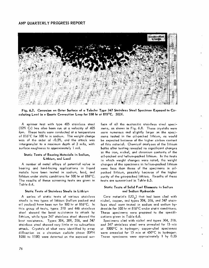
ANP QUARTERLY PROGRESS REPORT
Fig. 6.7. Corrosion on Outer Surface of a Tubular Type 347 Stainless Steel Specimen Exposed to Cir- culating Lead in a Quartz Convection Loop for 550 hr a t 815OC. 50QX.
A spinner test with type 405 stainless steel (12% Cr) has also been run at a velocity of 405 fpm. These tests were conducted at a temperature o f 816°C for 100 hr in sodium. The weight change was of the order of +Q.5%, and the attack was intergranular to a maximum depth of 3 mils, with surface roughness to approximately 1 mil.
Static Tests of Bearing Materials in Sodium, Lithium, and Lead
A number of metal al loys of potential value in bearing and hard-facing applications in l iquid metals have been tested in sodium, lead, and l i thium under static conditions for 100 hr at 816°C. The results of these screening tests are given in Table 6.4.
Static Tests of Stainless Steels in Li th ium
A series of static tests of various stainless steels in two types of lithium (helium packed and o i l packed) have been run for 100 hr at 816°C. In th is group of tests, types 310 and 446 stainless steel showed the least resistance to attack by lithium, while type 347 stainless steel showed the best resistance. Types 304, 309, 316, and 347 stainless steel showed very l i t t le or no subsurface attack. Crystals of what were identified by x-ray diffraction as a chromium carbide phase (DPH 1000 to 1100) were detected on the exposed sur-
face of a l l the austenitic stainless steel speci- mens, as shown in Fig. 6.8, These crystals were more numerous and sl ightly larger an the speci- mens tested in the oil-packed lithium, as would be expected because of the higher carbon content of th is material. Chemical analyses of the lithium baths after testing revealed no significant changes in the iron, nickel, and chromium contents of the oil-packed and helium-packed lithium. In the tests in which weight changes were noted, the weight changes of the specimens in helium-packed lithium were less than those of the specimens in o i l - packed lithium, possibly because of the higher puri ty of the gas-packed lithium. Results of these tests are summarized in Table 6.5.
Static Tests of Solid Fuel Elements in Sodium and Sodium Hydroxide
Core materials (UO,) that had been clad with nickel, copper, and types 304, 316, and 347 stain- less steel were tested in sodium and sodium hy- droxide for 100 hr at 816°C under static conditions. These specimens were prepared to the specifi- cations given in Table 6.6.
Specimens clad with nickel and types 304, 316, and 347 stainless steel were annealed for 15 min at 1000°C in hydrogen; copper-clad specimens were annealed far 15 min at 450°C in hydrogen. These specimens were approximately 1 by 0.35
76

PERtOD ENDING DECEMBER 10,1953
MATERIAL
Ha stel Ioy
B
C
D
Stel l i te 1
6
12
21
TABLE 6.4. STATIC TESTS OF VARIOUS ALLOYS IN SODIUM, LITHIUM, AND LEAD FOR 100 hr AT 816OC
COMPOSITION
Mo, 26 to 30 Fa, 4.7 C, 0.12 max Nil balance
Mo, 16 to 18 Fe, 4.5 to 7 C, 0.15 max
Cr, 15.5 to 17.5 W, 3.75 to 5.25 Ni, balance
cu, 3 AI, 1 Si, 10 Mn, 1 N i, balance c, ?
Cr, 30.5 W. 12.5 Fe, 3 max
C, 2.5 Ni, 1 Co, balance
Cr, 27.5 W, 4 Fe, 2 to 3 max
c, 1 Co, balance
Cr, 29.5 W, 8.25 Fe, 2 to 3 mox
C, 1.4 Ni, 1 Co, balance
Cr, 25 to 30 Ni, 1.5 to 3.5 Fe, 2 max
Mo, 4.5 to 6.5 C, 0.2 to 0.35 Co, bo1 ance
CORROOANT
Sodium
Lead
L ithi um
Sodium
Lead
Lithium
Sodium
Lead
Lithium
Sodium
Lead
Lithium
Sodium
Lead
Lithium
Sodium
Lead
Lit hi um
Sodium
Lead
Lit hi urn
METALLOGRAPHIC NOTES
Some voids to 0.5 m i l in a few places
0 to 5 mi ls o f erratic alloying type of attack
5 mils of subsurface voids
Some voids in a few places to 0.5 m i l
Erratic attack; pract ical ly complete penetration
in some places, very l i t t le in others
4 to 8 m i l s of subsurface voids
Layer of subsurface voids 1 to 2 mils deep on
some portions of specimen
Specimen appeared to be completely penetrated
4 to 6 m i l s of subsurface voids
Apparently no attack
2 mils of voids and intergranular attack
0.5 t o 1 m i l subsurface voids where carbides were attacked
Very slight intergranular penetration, less thon 0.5 m i l
Intergranular attack 1 to 2 mi ls deep
4 t o 6 mi ls of subsurface voids where carbides were attacked
Very slight intergranular penetration, less than
0.5 m i l
Apporently no attack
Less than 0.5 m i l of attack on carbide phase
Apparently no attack
A slight roughening and intergranular pene-
tration to about 0.5 m i l
0.5 m i l of small subsurface voids
77

ANPQUARTERtYPROGRESSREPORT
.......
MATERIAL
Ste l l i te 25
40
41
COMPOSITION
Cr, 19 to 21 c, 0.15 Ni, 9 to 11 W, 14 to 16 Si, 1 Mn, 1 to 2 Fe, 2 Co, balance
Composition not
avai I ab1 e
Composition not
avai lab1 e
TABLE 6.4 (continued) __ ......... .....
CORRODANT
Sodium
~. ................
Lead
Lithium
Sodium
Lead
L i th ium
Sodium
Lead
L i th ium
....... ............ . ~ _ _ _ .......... - ......... ~
METALLOGRAPHIC NOTES
Some voids and intergranular attack to 1 m i l
maximum in a few places
Vo ids to about 0.5 mil
2 mi ls of subsurface voids in most places,
10 to 12 m i l s in several places
Very heavy penetration to about 50 m i l s
Subsurface voids to a depth of 10 m i l s
Apparently no attack
Apparently complete penetration
Subsurface voids to a depth of 10 to 15 m i l s
Fig. 6-8. Type 314 Stainless Steel After Static Testing in Lithium for loo hr a t 81Q'C. Nate crystals attached to surface. 1OOOX. Specimen copper plated to preserve edge during polishing.
78

PERIOD ENDING DECEMBER 10, 1953
by 0.050 inch. The thickness of the care and of each of the cladding layers was approximately 16 mils.
In sodium, the specimens clad with nickel and types 304, 347, and 316 stainless steel showed no evidence of attack. The sample clad with copper had a slightly irregular edge and showed weight and dimensional increases after testing. The many, copper, mass-transferred crystals at-
tached to th is specimen were probably caused by temperature gradients during the test. In the tests i n sodium hydroxide, the copper- and nickel-clad specimens were unattacked, and the types 304, 316, and 347 stainless steel-clad materials were attacked more or less severely, that is, from 5 t o 18 m i l s . The type 347 stainless steel-clad speci- men tested in sodium hydroxide i s shown in Fig. 6.3.
TABLE 6.5. STATIC CORROSION OF STAINLESS STEELS TESTED IN TWO TYPES OF LITHIUM FOR 100 hr AT 816OC
TYPE OF STAINLESS STEEL
310 (a)
316 (a)
WEIGHT CHANGE (g/i n. 2,
0
0
-0.0010
-0.0013
-0.0007
-0.0007
0
+0.0008
ANALYSIS (wt %)
Fe, 0.024 Ni, 0.017 Cr, <O.OOl
Fe, 0.026 Ni, 0.021 Cr, 0.002
Fe, 0.017 Ni, 0.034 Cr, 0.018
Fe, 0.017 Ni, 0.040 Cr, 0.011
Fe, 0.012 Ni, 0.032 Cr, 0.028
Fe, 0.018 Ni, 0.030 Cr, 0.046
Fe, 0.007 Ni, 0.037 Cr, 0.01
Fe, 0.006 Ni, 0.038 Cr, 0.01
METALLOGRAPHIC NOTES
Small crystals (0.5 mii thick) attached to
surfoce; some of th is same phase concen-
trated in grain boundaries near surface
Same as above, with surface of specimen
sl ightly irregular, 0.5 mi l of attack
Specimen attacked to 4 mi ls i n one area; sev-
eral small crystals attached t o surface
No attack on specimen; crystals (0.25 mi l
thick) attached to surface in same areas
Grain boundaries of specimen exuded moisture
to a depth of 6 t o 7 mils, which indicated
penetration by l i th ium to th is depth; crystals
attached to surface in some areas
Grain boundaries of specimen exuded moisture
to a depth of 6 to 8 mils, as above; surface
layer on port of specimen approximately 0.25 mi l in thickness
Groin boundaries exuded moisture to a depth
of 5 mils in some areas; specimen heavi ly
attacked to 0.5 mi l i n one area; crystals
attached t o surface
Approximately 0.5 mi l of grain boundary
attack; 1-mil-thick crystals attached to
surface
*Tested in helium-packed lithium.
**Tested in oil-packed lithium.
79

ANP QUARTERLY PROGRESS REPORT
T A B L E 6.5 (continued)
T Y P E OF STAINLESS STEEL
317 (a)
347 (a)
446 (b)
WEIGHT CHANGE (g/i n.2)
+0.0007
+0.0009
-0.0003
+0.0003
+0.0026
CLADDING
ANALYSIS (wt %)
Fe, 0.009 Ni, 0.028 Cr, 0.008
Fe, 0.004 Ni, 0.009 Cr, 0.035
Fe, 0.11 Ni, 0.038 Cr, 0.003
Fe, 0.015 Ni, 0.039 Cr, 0.002
_ _
METALLOGRAPHIC NOTES
- __ll-l
No attack except far surface layer 0.1 to 0.2 mil th ick
Some as above, wi th crystals PO a maximum thickness of 0.7 mi l
No attack except for 0.25-mil-thick crystals
attached to surface in some areas
Same as above
Grain boundary voids t o a depth of 10 m i l s
T A B L E 6.6. SPECIFICATIONS OF SOLID FUEL ELEMENTS
Type 304 stainless steel
Type 316 stainless steel
Type 347 stainless s tee l
N icke l
Copper
.__ -__
CORE
2 Type 302 stainless steel-UO
Type 302 s ta in less steel-U02
Type 302 stainless s tec l -U02
Nickel -U02
Copper-U02
F U N D A M E N T A L CORROSION R E S E A R C H
J. V. Cathcart G. P. Smith Metallurgy Div is ion
Oxidizing Power of Hydroxide Corrosion Products
The work on trivalent nickel compounds formed in hydroxides was continued. The compound NaNiO, was found to undergo a change in crystal structure at about 225OC, and the structure of the high-temperature form has been determined. The exist ing evidence indicates that the transformation may be of the martensitic type.
6 A N P Quar. Prog. R e p . Sept. 70, 1953, ORNL-1609, p. 84-
.....
ROLLING TEMP ERA TUR E REDUCTION
(%I -.
1225
1225
1225
1100
1000
Equilibrium Pressure of Hydrogen in Hydroxide-Metal Systems
F. Kertesz F. A. Knax Materials Chemistry Div is ion
During this quarter, equilibrium pressures of hydrogen over the KOH-Ni system were partially determined, and values previously reported for NaOH-Cu and NaOH-Au systems were redetermined by using a modified form of the apparutus previ- ou s ly described.
The modified apparatus includes a tang nickel tube which serves as a reaction chamber in place of the metal crucible previously used. This tube i s surrounded by a quartz tube to which i t i s
80

PERIOD ENDING DECEMBER 10, 1953
Hydroxide. 80X.
sealed by means of a Kovar seal. The pressures established inside the nickel tube and in i t s quartz jacket (nickel being permeable to hydrogen at the temperatures ut i l ized in these experiments) are measured by two mercury manometers con- nected to the sysfem by seals; therefore the pres- sure bui l t up by the hydrogen that diffuses through the nickel can be determined independently from the pressure inside the tube. This apparatus ut i l izes both the passivity of nickel to sodium hydroxide and the nonpemeabil ity of quartz to hydrogen. Equilibrium pressures may be estab- l ished more rapidly by adding hydrogen to the quartz-nickel cavity to bring i t s pressure close t o that inside the nickel tube.
The hydrogen pressure of the KOH-Ni system, os determined in the above-described apparatus,
was found to be less than 1 mm at 60OcC, while i t i s in the range of 8 to 12 mm at 700°C. Measure- ments ut higher temperatures are being mode.
The NaOH-Cu and NaOH-Au hydrogen equilibrium pressures were redetermined, and the results agreed closely with those previously reported:6 for the NoOH-Au system at 5'OO"C, 3.5 mm com- pared with 3.0; at 1OOO"C, 7.5 compared with 6.0 mm. The results for the NaOH-Cu system show reasonable ogreement at 700°C (2.2 mm com- pared with 3.0 mm); however, the more recent determinution ut 800°C shows a thus far unex- plained time dependence of the hydrogen pressure. An in i t ia l pressure of 14 mm gradually fell to about 10 mm aftw a f ew hours; the IO-mm pressure then remained constant.
81

ANP QUARTERLY PROGRESS REPORT
Mass Transfer of Chromium i n Incsnel-Fluoride Systems
b. G. Overholser J, D. Redinan C , F. Weaver
Materials Chemistry Division
When lnconel i s exposed to molten fluorides at elevated temperatures, chromium i s selectively leached from the alloy, While a considerable froc- t ion of th is corrosion may be ascribed to oxidizing impurities in the molten material or on the capsule walls, reactions of UF, with the container metals t o y ie ld UF, and complex metal fluorides could wel l be responsible. The reaction
C r + 2 U F 4 e 2 U F , + CrF,
has at 600°C a standard free energy change of -7 kcal and should, i f the ionic species were soluble and showed activi t ies proportional to their concentrations, proceed nearly t o completion. That such i s not the case, or at least that the reaction does not equilibrate at a reasonable rate, i s wel l demonstrated in a large number of corrosion tests.
I f the assumption that the physical solubility of chromium as metal in fused NaZrF, i s quite low i s permissible, then equilibration of UF, dis- solved in NaZrF, with chromium metal followed by separation of the phases and analysis of the f i l t rate would permit evaluation of the equilibrium constant of the reaction. For these studies, the purest NaZrF, available was used, along with chromiuin metal hydrogen f ired at 2000OF in nickel equipment of the type previously described. A l l handling of the materials before testing was per-
TABLE 6.7. ANALYSES OF FILTRATES FROM EQUILIBRATION OF CHROMIUM WlTH NaF-ZrF4-UF4 MELTS
..
CONDITIONS OF EQUILIBRATION
T ime
(hr)
formed in an inert-atmosphere dry box. The f i l - trates obtained were submitted for chemical anal- ysis, ond the results shown in Table 6.7 were obtained.
These data indicate that equilibration i s rapid because the values obtained after 5 hr at temper- ature rare not distinguishable from those obtained for a shorter exposure. It i s obvious from the ex- posure of the nonuranium-bearing material that the chromiwm contains some oxide and that hydrogen f ir ing of the nickel equipment i s not sufficiently complete. (Subsequent experiments, not suffi- ciently complete to report, in which the chromium was f ired under dry hydrogen directly in the nickel reaction vessel demonstrate that it i s possible t o have less than 200 ppm of Cr in the nonuranium- bearing material.) The chromium concentration in- crease resulting froin the reduction of UF, to UF, was obtained by subtracting the chromium content of the nonuraniurn-bearing material from the total chromium found, and this value was used for ob- taining the UF, concentration, since the methods for determining UF', in the presence of divalent chromium are not sufficiently accurate to permit a direct determination of UF,.
If unit act ivi ty i s assumed for the chromium and activi t ies equal to concentrations ( in moles per mole of solvent) are assumed for the uranium and chromium species, these data indicate that the equilibrium constant at 60OOC i s 1.2 by lom3, and, at 8OO0C, it i s 1.7 by loF3. The data are certainly not sufficient in amount or in precision for an evaluation of th is small difference. It does
Temperature (O C)
8 00
800
600
600
Total Uranium (%I
0 0
8.47 8.80
8.80 8.65
8.65 8.88
__
FILTRATE ANALYSIS
Chromium (PPm)
935 930
3420 3330
3200 3 100
3100 3200
355 200
30 40
130 125
130 130
75
40
65
60
50
50
70 60
82

PERIOD ENDING DECEMBER 10, 1953
appear, however, that the standard free energy These experiments are being refined, insofar as change for the reaction at 600°C i s about t l l . 5 purity of the materials and improvement of tech- kcal. The discrepancy between this measured niques are concerned, and additional experiments value and the value of -7 kcal calculated for the w i l l be conducted at considerably lower reagent reaction by assuming no complexing i s probably concentrutions so that the assumptions regarding t o be ascribed ta solvation of the UF,. act iv i t ies w i l l have m o r e val idity.
7. METALLURGY AND CERAMICS
W. D, Manly J. M. Warde Metallurgy Division
A sodiumto-air radiator was fabricated by brazing the tube-to-fin joints and backing up the previously he I i arc- we! ded tu be-to- header and mani f old i ai nf s with brazing alloy G-E No. 62, a nickel-chromium- s i i icon alloy. The radiator assembly was welded and then dry-hydrogen brazed at 2103OF for ap- proximately 30 minutes. Subsequent testing after slow cooling showed a l l the welded and brazed joints t o be satisfactori ly leak and pressure tight. The duplex fabrication technique, that is, the combination of heliarc welding and high-temperature brazing, apparently produces satisfactory, sound, leak-tight radiators and minimizes many of the problems encountered i n brazing operations. The use of the G-E No. 62 brazing alloy eliminates many of the deleterious effects of the Nicrobraz alloy thut was formerly used.
The investigation of the fabrication of high- conductivity f i n materials included a study of diffusion barriers for use between Inconel and capper, electroplating copper to obtain oxidation resistance, and the fabrication of clad-copper f in material in sufficient quantities for experimental radiators. Furthermore, several new high-conduc- t iv i ty f i n materials were studied because it was found that dif fusion of nickel and copper made the brazing of Inconel-clad copper fins to Inconel tubing less satisfactory thah i t was previously thought to be. Each clad-copper and copper-alumi- num bronze f in material was tested by brazing to either Inconel or stainless steel tubing with each of the following brazing alloys: low-melting-point Ni crobraz (LMNB), “electroless ” nic kel-phospho- rus, LMNB plus 10 wi % “electroless” nickel- phosphorus, and nickel-phosphorus-chromium alloys. A summary of the results o f this study i s given. A
series of one hundred 3 x 3 in. nickel f ins i s being electroless” preplafed with nickel-phosphorus
alloy for brazing into a radiator assembly. i n a preliminary test, good-quality brazes were obtained with th is material at-tube-to-fin joints.
The assembly of stainless steel-clad fuel plates into fuel elements i s being studied, and it appears that inert-arc plug welding may be a feasible method of fabrication, The configuration investi- gated consisted basically of a 0.026.in.-thick type 304 stainless steel-clad type 304 stainless steel sheet 24 in, long that was t o be joined on the edge at 2.in. intervals to a O.O4l-in.-thiek type 304 stainless steel side platen
Stress-rupture tests of coarse- and fine-grained Inionel in argon and in fluoride fuel NaF-ZrF,-UF, at temperatures of 1300, 1500, and 165OOF are being made. The tests completed at 150D°F show that hydrogen is the mosi detrimental environment and that air i s the most beneficial, as fur as ruptwe l i fe i s concerned, and that increased duct i l i ty in air and in sodium is probably the result of decarbu- ization. lube-burst tests of tr ioxial ly stressed lnconel tubes are being made with fluoride fuel NaF-ZrF,-UF, inside the tube and purif ied argon outside. Comparison of the data obtained w i th creep data shows that the tube-burst time is about the same as the time for 2% elongation in the tensile creep tests.
Several special alloys for the corrosion testing program were melted in the high-vacuum melting furnace and extruded into a draw blank. The draw blank was drawn into tubing by the Superior Tube Company. Columbium cold worked to a reduction of 87.5% has been shown to h w e a rscrystall izo- t ion temperature of between 1000 and 1 100aC.
, I
83

ANP QUARTERLY PROGRESS REPORT
Tubular fuel elements are being produced by using plug drawing techniques. The drawing schedule was found to be too severe i n that it caused premature failure during drawing. However, even this severe working schedule produced tubing that had excellent inside and outside finishes and there was no evidence of rippling or folding in the core region.
Ten test rings of a beryllium fluoride glass were prepared for determining their suitabil ity as high- temperature pump seals. A ceramic container for use i n the investigation of the electrical resist ivi ty of fluoride fuels is being prepared by isostatically pressing and sintering beryllium oxide. High- density graphite (Graph-i-tite) i s being tested for coinpatihility with fluorides and other molten salts and molten metals.
Studies of the flammability of jets of sodium alloyed with numerous metals have been made. Sodium-mercury alloys containing less than 34 mole % sodium and sodium-bismuth alloys contain-
ing less than 40 mole % sodium did not burn; all other al toys tested burned.
R A Z I N G RESEARCH
P. Patriarca G. M. Slaughter Metallurgy Div is ion
J. M. Cisar, ANP Divis ion
iator Assemblies
It was stated i n the previous report that the G-E No. 62 brazing al loy (69% Ni-B% Cr-ll% Si) might be suitable for use on ANP-type sodium-to-air radiators. Stainless steel joints brazed with this alloy were considered to possess adequate resist- once to cracking. This alloy was also shown to exhibit excellent resistance to high-temperature oxidation. A rneta!!ographic section of a joint af an lnconel tube brazed to a type 304 stainless steel fin and exposed in static air for 1200 hr at 1500'F is shown in Fig. 7.1. It can be seen that
Fig. 7.1. Section of Joint sf lnconel Tube Brazed to a Type 304 Stainless Steel Fin with G E No. 62 razing Alloy and Exposed to Static Air at 15QOOF far 1200 Hours. Etchant: glycsria regia, 7SX

PERIOD ENDiNG DECEMBER 10, 1953
the extent of attack is minor. Previous tests had also shown that this allay was attacked by molten sodium only sl ightly at 1500'F in a 100-hr test.
Therefore the sodiumto-air radiator shown i n Fig. 7.2 was fabricated by brazing the tube-to-fin joints and backing up the previously heliarc-welded tube-te header and manifold joints with brazing alloy. This method of fabrication i s thought to be the most reliable for obtaining a pressure-tight system with one brazing operation.
The tube-to-header welds were manually inert- gas tungsten-arc welded with argon as the shielding gas and helium CIS the back-up gas. The header ccrps and the manifold were also heliarc welded by using suitable joint designs to permit complete penetration.
The sequence of manifold and header cap welding was such that the nickel-chromium-silicon alloy could ulways be applied to the underside of the joint after welding. Each tube-to-header weld was also backed up with this brazing alloy. A typical
heliorc-welded joint backed up with the nickel- chromium-silicon braze is shown in Fig. 7.3. It can be seen that the probability of obtaining a leak-tight joint i s very good.
The completed assembly was then dry-hydrogen brazed by using the thermal cycle shown in Fig. 7.4. A, preheat at 1600GF was uti l ized to permit an equil ization of temperatures over the assembly. The thermocoupte, which was placed directly on the radiator, also indicated that a maximum temper- ature of 2150°F was attained and that the unit was held above 2100°F far approximately 33 minutes. The brazing technique used for th is fabrication ensures a relatively slow coolinq rate so that cracking upon cooling as a result o f uneven thermal contractions should not be Q major probiem.
Helium leak testing at less than 0.03-p vacuum revealed that al l welded and brazed joints i n the radiator were leak tight. The assembly was also pressure t ight to a 20-psi helium pressure when it was immersed i n water.
85

ANP QUARTERLY PROGRESS REPORT
Fig, 9.3. lnconel Tube-to-Header Heliars Welded Joint acked Up with 6-E 0. 62 Braxing Alloy. Etchont: glyceria regia. 50X
It is thus believed that a combination heliarc- welding and high-temperature-brazing procedure i s sati sfactory for fabricating sound leak-tight radi- ators. This duplex technique has been shown to minimize many of the problems and dif f icult ies usually encountered i n brazing operations. The use of the 6-E No3 62 brazing alloy also seems to minimize or completely eliminate many of the deleterious effects o f the Nicrobraz olloy that was farrnerly used.
razing of ~ i ~ ~ - ~ ~ ~ d u c t ~ v ~ ~ y Radiator Fins
Although the problem o f brazing Inconel-clod copper high-conductivity f in material to lnconel tubing was satisfactori ly resolved, as described in the previous report, ’ the subsequent detetminati on of the detrimental effects o f diffusion of nickel and copper has proved to be a l imitat ion of the
’E. S. Bomar et a/., ANP Qoar. Prog. R e p . S e p f . 10, 1953, ORNL-1609, p. 95.
86
method. Accordinqly, Q g r w p ~f other high-canduc- t i v i t y f in materials was Fabricated for brazing tests.
The high-conductivity f in materials studied during the current investigation were types 446 arid 310 stainless steel-clod copper and a copper- aluminum (94% Cu-6% AI) bronze. The fabrication of these materials i s described below under “High- Conductivity Metals for Radiator Fins.” The brazing al loys investigated were low-rnelti ng-point Nicrobram (LMNB), “electroless” nickel-phospho- rus (90% Ni-10% P) alloy, low-melting-point Nicrs- braz plus 10 wt % “electroless” nickel-phosphorus alloy, and nickel-phosphol.Ms-thromium (83% Ni- 10% P-10% Cr) alloy. Each of the brazing QIIOYS was
used i n conjunction with each of the high-condvc- t iv i ty fin materials against lnconel tubing, as well! as against tubing of the same nominal composition as that of the stainless steel component of the f in material.
The test specimens -NE?IF: designed to simulate T flowabil ity specimens. A sheet and a tubs vmre

2400
2000
1600 .- - L+ ui a g 1200 lr 1‘1 a E W t-
800
400
0
PERIOD ENDING DECEMBER 10, 1953
UNCLASSIFIED
I) 20 40 60 80 400 120 140 160 180 200 TIME (rnin)
Fig. 7.4. Thermal Cycle Employed in Furnace Brazing a Heat Exchanger wi th 6 - E No. 62 Alloy. Temperatures were obtained with a chromel-alumel thermocouple secured to the heat exchanger,
placed side by side, and the brazing dloy was applied in i t ia l ly to one end of the specimen. A l l test specimens were brazed i n -7OOF dew-point hydrogen for 10 minutes, A summary of the data and the results of th is study are presented i n Table 7.1, along wi th an evaluation o f the flawabil ity of of the braze material based on visual observations.
The following conclusions have been drawn from these tests:
8 . A l l the brazing alloys investigated, which were chosen because of oxidation resistance and favorable melting temperature, exhibited excel lent flow against types 310 and 446 stainless steel-clad copper when used against Inconel tubing. It appears that the Inconel behaved as a “carrier’# for the alloys.
2. The oxide films present on the as-received type 310 stainless steel tubing used i n this in- vestigation inhibited i n varying degrees the flow of a l l the brazing alloys tested. The removal of
th is oxide by prebright anneoling at 1150°C or by electropolishing improved the observed flow. The most marked effect was the improved flow of L M N B .
3. Removal o f oxide f i lms by prebright annealing or by electropolishing the type 446 stainless steel tubing did not markedly improve the flow of the brazing alloys and was particularly ineffective for the L M N B alloy.
4. The addition of 10 wt % nickel-phosphorus ( 90% Ni- 10% P) alloy to the LMNB alloy markedly improved flow against type 446 stainless steel tubing, although this addition was not beneficial against type 310 stainless steel tubing.
5. The oxide f i l m which formed on the copper- aluminum (94% Cer-676 AI) f in material during the brazing cycle impeded f low o f a l l the brazing al- loys investigated. Prevention of th is oxide forma- tion by preplating w i th electrolytic nickel permitted excellent wetting and flow of all the brazing alloys investigated.
87

AN$ QUARTERLY PROGRESS REP0
Copper-olurninum (94% Cu-6% AI) allay
alcctrgploted with 0.0002 in. of nickel"
Type 446 stainless steel-clod
copper (0.004 in. of coppcr
clod on both sides with 0.002 in. of the steel)
Inconel, as-received
Type 446 stoinloss steel,
prebright onncaled
Type 310 sta in less steel-clad copper (0.004 in. of copper
clod on both sidns with 0.002 in. of the rtssl)
Type 310 sto in less steel, prebright annealed
-. .......... ~ ..-. L .... ......
Intonel, as-received
LMNB 90% Ni-10% P LMNB + 10% Ni-P 80% Mi-10% P-10% Cr
. . .
Type 446 sta in less steel,
as-received
Type 446 ~ t a i n l e s s stad,
prebright annealed in d r y H2 at 1150°C for 15 notin
Type 146 s t o i n l e a s sbrel, electropol ished
Inconel, as-received
Type 310 stainless steal,
a s-rece ived
Type 310 sta in less stsel,
prcbright onneolsd in
dry H2 at 11 5OoC ioi 15 min
Type 310 stainless steel,
elsctrslpal ished
BRAZING A L L O Y
LMNB 90% Ni-10% P LMNB + 10% NI-P' 80% Ni-10% P-10% Cr
LMNa 90% Ni-IO% P LMNB i- 10% Ni-P 80% Ni-10% P-Im Cr
LMNR 90% Ni-10% P LMNR + 10% Ni-P 6@?5 Ni-IOB P-10% Cr
LMNR 90% Ni-10% P LMNR + 10% Ni-P 80% Ni-lO% P-10% Cr
LMNR 90% Ni-10W P LMNB + 10% Ni-P 80% Ni-10% P-10% Cr
L u N a 90% Ni-10% P LMNB + 10% Ni-P 80% Ni-10% P-10% Cr
LMNR 90% Ni-10% P LNN5 + 10% Ni-P 80% ?4i-10% P-IOSS Cr
LMNS 90% Ni-10% P CMN5 + 107. Ni-P 80% Ni-10% P-10% Cr
90% Ni-10% P LMNB + 10% NiSP 80% Ni-10% P-10% Cr
LMNB 90% Ni-IO% P LMNB + 10% Ni-P 80% Ni-10% P-IO% Cr
~ LMNS
BRAZING TEMPERATURE
(OC)
1050 1000 1050 1050
1 OS0
1000 1050 1050
1050 1 oco 1050 1050
1050 1000 1050 1 os0
1050 1000 1050 1050
1050 1000 1050 1050
1 O M 1000 1050 1050
1 OS0 1000 1050 1050
1030 1000 1030 1030
1030 1000 1030 1030
1030 1000 1030 1030
....... ._____
FLOWABlLl1'Y (visual observation)
-. .. . . .. . .
Good Excellent Excellan$ Excel Ien?
Nwne Excellent Good Excel lent
Nons Excel! en:
Good E XED! lent
None Excellent E xce! lent
Excellent
Excellent Excellent Excellent Excellent
None Good None Fair
Good Excellent Exce I I ent
Excel lent
Goad Excel l ent Excel lent
Excel lent
Excellent Excellent Excellent Excellent
Excel lent Excellent Excel lent
E xcellcnt
Excellent Excel lent
E X C * l i f O t
Excel I eat
88

PERIOD ENDING DECEMBER 10, 1953
“Electroless” Preploting of Brazing Alloys
Work on the “electroless” prepeating of nickel- phosphorus brazing alloy, as described previously, has continued, and the method i s being applied to practical brozing problems. A commercially avai lo- ble system of plat ing solutions i s now being successfully used to plate the nickel-phosphorus ai loy on to-be-brazed specimens. The system, Lustralloy, manufactured by Metal Processing Company, Inc., i s cheaper and as satisfactory as the procedure developed by the ORNL Research Shops, A series o f approximately one hundred 3 x 3 in. nickel fins i s currently being preploted with nickel-phosphorus al loy for brazinq into a radiator assembly for the Griscom-Russell Company. A s a preliminory test, two of these fins were sheared into %-in. sections; nickel tubes were
‘P. Patriarca and G. M. Slaughter, ANP Quar. Prog. Rep. Sept. TO, 7953, ORNL-1609, p. 91.
inserted into holes in these fins, and the mock assembly was placed into the hydrogen furnace at 1020OC for approximately 10 minutes. The speci- men was then cooled slowly under a hydrogen atmosphere. The finished specimen was bright, and the joints were wel l brazed. A similarly brazed assembly i s shown in Fig. 7.5. As con be seen, the brazing alloy, originally uniformly distri- buted on the fins and absent on the tubes, was drawn to the capillary. Figure 7.6, a photomicro- graph of the tube-to-fin joints, shows the good quality of the braze.
Inert-Arc Plug Welding of Solid Fuel Elements
The assembly of stainless steel-clad fuel plates into fuel elements of the size and configwation of interest presents a problem for which there are several possible solutions. One method that may prove useful i n certain applications ut i l izes inert-
Fig. 7.5. Tube-to-Fin Assembly Brazed with Pieplated “E~ec~ro!ess*’ Niekei-Phosphorus Brazing AI loy.
89

TERLY PRQGRESS REPORT
Fig. 7.6. Tube-to-Fin Joints Brazed with Preplated “E lect ro le~s” Nickel-Phosphorus Brazing Alloy.
arc plug welding techniques. The configuration investigated in these prel iminaty experiments consisted basical ly of a 0.026-in.-thick type 304 stainless steel-clad type 304 stainless steel sheet 24 in. long that was to be ioined on the edge at 2-in. intervals to a 0.041-in,-thick type 304 stain- less steel side plate,
The ioint design considered to be optimum for welding i s shown i n Fig. 7.7. A hole 0.067 in. i n diameter i s dri l led in a 0.041-in.-thick header sheet to receive a projection 0.062 x 0.026 x 0.125 in. obtained by edge mi l l ing the 0.026-in. type 304 stainless steel-clad sheet. The 0.84-in. extension of the projection above the header sheet was pre- deterrriined from the following volume considera- tions: (1) the volume of the QC67-in.-diol 0.011- in.-deep header hole was 0.00015 in.3; (2) the volume of the 0.062 x 0.026 x 0.125in. proiection was 0.0002 im3; (3) ttis excess of 0.000~5 in.3 would ensure adequate weld buildup and could be removed by f inish machining.
A series of specimens o f the desiqn shown in Fig. 7.7 were welded with variations in arc current, arc time, arc distance, and welding sequence. Since precise control of these variables was re- qui red, cone-arc equipment was used throughout the study, The welds were examined metallograph- ical ly for penetration and flaws,
Examination of test specimens indicated that the most favorable weld geometry could be achieved by two separate inert-arc welding operations. The proiection was melted into a “rivet” by an in i t ia l choice of arc current, OK time, and arc distance. The arc distance was then reduced, and an addi- tional application of current was used to farm the the finished weld, the f i l ler metal being provided by the rivet.
T h e r ivet formed during the f irst operation by using the optimum welding conditions is shown in Fig. 9-8, which i s a section through the weld ioint ccxaesponding to section A-A in Fig. 7.7, The plug weld formed in the second operation is shown i n
90

PERIOD ENDING DECEMBER 10, 1953
Fig. 7.9. As may be noted, the penetration of the However, the application of these techniques to type 304 stainless steel-clad sheet was complete the fabrication o f a multiweld unit should be and reasonably uniform, which indicates that an investigated further. apparently sound weld joint was obtained. It thus appears that inert-arc plug welding may be a feas- ib le method of fabrication o f these assemblies.
MECHANICAL P R O P E R T I E S OF INCONEL
R. B. Oliver K. W. Reber
D. A. Douglas J. M. Woods
UNCLASSlFlEO Metallurgy Div is ion DWG 22216
SECTION 8-6 L a
TYPE 304 STAINLESS STEEL-CLAD SHEET
SECTION A-A
Fig. 7.7. Assembly of Type 304 Stainless Steel Components Prior t o Inert-Arc Plug Welding,
Stress-Rupture of lncond i n Fluoride Fuel
Stress-rupture tests of coarse- and fine-grained lncanel i n argon and in fluoride fuel NaF-ZrF,-UF, at temperatures of 1300, 1500, and 165OOF are be- ing made. Data for the higher stress ranges are complete, and the tests being made currently are expected to rvn from three to eight months. Test- ing in the stress range from 500 to 1500 psi w i l l commence in about s ix months when the s i x new units designed for low loads are completed. The results obtained to date for fine-grained Inconel are summarized in Table 7.2.
TubBurst Tests of Tr ioxial ly Stressed Tubes In the past, data obtained i n the tube-burst tests
of tr iaxial ly stressed Inconel tubes have shown considerable scatter and interpretation has been dif f icult . However, datu obtained in recent tests have shown reasonable reproducibility, and it i s believed that most of the operating dif f icuit ies have been overcome. The present procedure i s to
Fig. 7.8. Section of “Rivet” Farmed by In i t ia l Application of a 30-amp (DCSP) Arc Current for an Arc Time of 2 see at an Arc Length o f 0.140 in. Etchant: aqua regia. 21X Fig. 7.8. Etchant: aqua regia. 21X
Fig. 7.9, Section of Completed Weld Farmed by Application of a 3Gamp Arc Current for 4 sec at an Arc Length of 0.060 in. to the “Rivet” Shown in
91

ANPQUARTERLYPROeaESSRIEPOR'F
.... ~ ........ ___ .......... _____ ....... .. ____
STRESS (psi)
10,QOQ
.... ... ____
10,000
5,000
5,QOO
s.000
2,500
2,50Q ......
7 TEMPERATURE (OF)
1300
1500
1300
1500
1650
1500
1650 -
.......... _..____ .... ~ ....... ..___ ~_ ___ .... ....... ....
RUPTURE TlME IN FLUORIDES L RUPTURE TIME
I N ARGON (hr)
2000 -___ .......... ......... .......
50 30
7000
540 260
2s 25
4000 1200
45Q 175 ............ -- _I.._.
test the tube with the fluoride fuel NaF-ZrF,-UF, inside and purif ied argon outside. The stress range from 500 to 3500 psi i s currently being in- vestigated and tests have been completed in the upper half of the range, In comparing the data with creep data at the same stresses i n the same fuel, it i s found that the tube-burst time is about the same as the time for 2% elongation in the tensi le creep tests. The tube specimens loaded by internal pressures give an axial-to-tangential stress rat io of 1/, which results i n minimum ducti l i ty; thus the results probably represent the minimum l i f e ex- pectancy, other factors being equal. In the near future, these tube specimens w i l l be tested with the fuel inside the tube and sodium, instead of argon, outside.
~ ~ v i r o n ~ e ~ ~ ~ ~ Effects on C~eep of lnconel
Creep tests of lnconel specimens in nitrogen and in sodium environments at 1500'F have recently been completed. Thus it i s now possible to com- pare the effects of six types of environments that lnconel structures might encounter. The results of these creep tests are summarized in Table 7.3.
Table 7.3 shows that hydrogen i s the most detri- mental environment and that air is the m o s t bene- ficial, as far as rupture l i f e i s concerned, It i s interesting to note that, w i t h the exception of the tests i n air and sodium, al l the specimens reached about the same total elongation regardless of the rupture time. The increased ducti l i ty i n air and i n sodium i s probably the result o f decarburization. Chemical analyses are being made to test th is hypothesis. The results presented in Table 7.3 are for Inconel soecimens that were annealed at
TABLE 7.3. RESULTS OF CREEP rtzsrs OF INCONEL ANNEALED A T 1650°F AND TESTED
UNDER A STRESS OF 3500 psi at 1500'F IN VARIOUS ENVlRONMENTS ..... ....... ____ -.. .......
ENVIRONMENT ~ RUkyUERE (hr)
Hydrogen
NaF-ZrF4-UF4
Sodium
Argon
Nitrogen
Air .- ........
444
550
1333
1467
1770
2567 _....____
__ FINAL
ELONGATION (%I 13.0
12.0
35.0
12.0
11.6
50.0
1650'F before being tested. Specimens anneafed at 2050°F and then stressed i n hydrogen or NQF- ZrF,-UF, have shown more resistance to the environmental effect. Tests of this type of speci- men in the other environments are now being made.
H I G H-CON D U C T IV I T Y ME TAL 5
FOR RADIATOR FINS
E. S. Boniar J. H. Coobs H. lnouye, Metallurgy Division
The investigation of the fabrication of high- thermal-conductivity fins was confined during this period to a study of diffusion barriers for use be- tween lnconel a d copper, the fabrication of clad- copper f i n material i n sufficient quantities for the assembly of experimental radiators, and the investigation of special materials.
92

PERIOD ENDING DECEMBER 10, 1953
Diffusion Barriers
Barrier material for use between lnconel and copper was selected on the basis of low solubi l i ty of the element or al loy in copper or Inconel. In addition, it was desired to fabricate thin cmpos i te clads to determine their ro l l ing characteristics. The barrier materials used were tungsten, molybde- num, titanium, zirconium, tantalum, vanadium, types 310 and 446 stainless steel, and iron plus silver.
Several composites were hot rolled approxi- mately 50% at 1800'F and then finished cold to 0,008 in. total thickness. Bonding was not achieved between molybdenum and lnconel or between va- nadium and Inconel, and the following composites could not be successfully rolled: (1) Inconel-Ag- FeCu-Fe-Ag-I nconel and (2) Inconel-W-Cu-W- Inconel. The f irst of these composites was un- successful because of improper design, and the second showed severe stretcher marks. Oxidation and diffusion tests of the other Composites are being made.
Some of the earfier tests of Inconel-clad copper showed the absence of diffusion voids, and there- fore a few tests are now being made to determine the effect of surface preparation on void formation and diffusion. The composites for this study have been fabricated; they consist o f a layer o f oxide on lnconel formed by heating in wet hydrogen and i n air at 1300'F.
Clad Copper
As reported p r e v i o ~ s l y , ~ types 310 and 446 stain- less steel are suitable cladding material for copper for use at 1500"F, while lnconel cladding causes severe diffusion. I n order to establish which of the claddings i s most suitable on copper and also to determine the effect of diffusion on thermal con- ductivity, approximately 1 5 f t 2 samples of copper clod with Inconel, type 310 stainless steel, and type 446 stainless steel have been or are being made. The fin material i s to be strips 4 in. wide a d 0.010 in. total thickness; the copper core w i l l be 0.006 in. thick and the cladding material w i l l be 0.002 in. thick. This material is to be used for the fabrication of experimental heat exchangers.
E I ectropl ated Copper
Plates of chromium plus iron and of iron plus nickel p l u s chromium to give compositions corre- sponding to types 446 and 310 stainless steel,
respectively, did not protect copper from oxidizing at 15000F. A composite made entirely by electro- forming showed the same results. The inabil ity of these plates to protect copper at 1500'F i s ascribed to the lack of a metallurgical bond between the copper and the plate and to the brittleness of the deposits. Although the ducti l i ty con be restored by heating to 16OOOF, the damaging cracks are present i n the as-received or annealed material,
Solid Phase Bonding
An alternate investigation for obtaining uniform thin claddings i s being mode. A bond between the copper and the cladding can be obtained by seam welding material of the final desired thickness. The Glen L. Martin Company proposed this method and has supplied samples up to 4 in. long which appear satisfactory. Joint efforts have, to date, produced claddings 0.002 and 0.001 in. thick.
The thermal properties of the aluminum bronzes a t low temperatures indicate that the conductivity of alloys containing about 6% aluminum i s greater than that of the stainless steels or lnconel by a factor of about 6 at l5OiooOF. Ta verify this, meas- urements are now being made on 6 and 8% aluminum bronzes. These alloys are oxidation resistant, and i f the expected thermal properties are correct, the need to fabricate composite bodies w i l l be eliminated because these alloys may be suitable for use as radiator fins. This i s especially im- portant because dif f icult ies have been experienced i n obtaining clad material from commercial suppliers,
F A B R I C A T I O N OF SPECIAL MATERtALS
E. S. Bomar J. H. Coobs H. Inouye, Metallurgy Division
Extrusion of Inconel-Type Alloys
Extruded lnconel tubing was redrawn from 1 in. i n outside diameter wi th a 0.125-in, wall to 0.BO in. in outside diameter with a 0.035-ine wall by the Superior Tube Company. These materials were drawn satisfactori ly a t reductions as high as 36% per pass wi th annealing after each stage at 19000F. The properties o f the tubing are I isted i n Table 7.4.
The extrusion of near-lnconel allays from seven other vacuum melts was attempted with varying degrees of success. Temperatures from 2850 to
3 ~ . S. ~ o m a r et ai., ANP Quar. rag. R e p . Sept. TO# 7953, ORNL-1609, p. 96.
93

TERLY PRQCRESS
TABLE 7.4. PROPERTIES OF ANNEALED HIGH-PURITY INCONEL TUBING 0.505 in. IN OUTSIDE DIAMETER WITH A 0.035-in. WALL
~ ~- ~
~ ----I ~~
_.
T -- I GRAIN SIZE T E NS1 I_ E S XR E NGTH I YIELD STRENGTH
(psi) MELT NO.*
(psi) . . . . . . . . . . . . . . . . . . . .
0.090/0.130
DPI-8
DPI-9 0.090/0.110
DPS-10 0.090/0.130
81,000
83,400
83,500
80,403
- _ _ ~ 35.000
36,000
40,000
40,800
52
50
49
45
*Analyses of melts 8, 9, and 10 were given in the Metallurgy Division Progress Repor9 for fhc Per!& Ending Apri l 70, 1953, ORNL-1551, Table 22, p. 54,
23B°F were employed to produce the tubing (or rod), and, i n some instaixes, extrusion ratios as low 0s 1O:l were required. A l l the extruded tubing has been sent to the Superior Tube COFT~Q~IY for further reduction. A molybdenum-nickel alloy (M% M0-80% Ni, nominal composition) did not extrude at a reduction of 13:l at 2350°F. An attempt w i l l be made to ext~ude this alloy at a lower reduction rati oB
Rolling of ~ ~ ~ o ~ ~ u ~ ~ ~ ~ ~ ~ ~ ~ ~ Alloy A chromium-cobalt alloy ingot 6 in. long and 1
in, i n diameter (45% G-55% Co, nominal composi- t ion) was cast, and attempts to rol l it at 2350OF showed that this alloy was hot-short. Additions of 05% manganese and 0.5% aluminum did not im- prove the hot-roll ing properties. A solid rod of this alloy which was precisian cast was readily machin- able, but it cracked severely. The present plans cal l far precision casting the alloy tubing. The hardness of the cost alloy i s Rockwell C-50,
A 1 1/-in.-dia, Ci-in,-!ong cobalt ingot containing 05% manganese and 0.5% alLiminum was SUCCC"SS-
ful ly rol led to \-in.-dia rod at 23QQ0F. Previously, i t was found that cobalt without the manganese and aluminum additions WQS hot-short, The al loy containing aluminum and manganese has an as-cast hardness of Rockwell A-49.
Roll ing of ~ r ~ ~ - ~ h r ~ ~ ~ ~ ~ ~ ~ ~ ~ e ~ Alloy
A 1 \-in.-dia# 6-in.-long ingot of iron-chrornium- nickel alloy (45% Fe-40% Cr-15S: Ni) was rolled to J2-in.-dia rod at 2350OF. This alloy was found to he hot-short at 1850'F, even though it contained
1% of a nfckel-manganese-titanium master alloy, Previously, attempts to hot rol I this alloy at 1850'F without the alloy addition were unsuccessful be- cause of hot-shortness. The as-cast alloy has B
hardne5s of Rock\vel I A-62.
Cold-Rolled Columbium
Columbium sheet 8.200 in. thick obtained from the Fansteel Corporation WQS annealed to Q grain size of ASTM 7 at IlOOOC i n Q vacuum. The sheet wa5 cold rolled to 0.02s in., which represented a reduction of 87.5% i n thickness. The room-temper- ature mechanical properties were determined an specimens vacuum annealed for /2 hr at various temperatures and are summarized i n Table 7.5.
The inisrostructure of columbium under these COTPI-
ditions shows pastiaf recrystall ization at loOO°C, and, cat 1 lOO'C, recrystall ization i s cmplete. V O C U W ~ S of the order of IO-' mm Wg were obtained in the annealing furnace. The analysis of the sheet shows 02'5 + 0.3% tantalum, and traces of c o p p e ~ ~ irori, and titanium. Analysis of the oxide content o f the sheet i s not complete, but it i s expected to be greater than 03%.
1
T U B U L A R F U E L ELEMENTS
J. H. Coohs, Metallurgy Div is ion
Drawing of tubular fuel elements has been CORD-
tinued. Plans called for the reduction of s ix tubes on each of two schedules in steps of 15% and 20% reduction per pass, respectively. A! 1 tubes were to be reduced from 0.750 in. i n diameter with a 0.042-in. wal l t o o final s ize of 0.250 in. in diameter with a 0.015-in, wall, or a total reduction of 87%. Plug drawing was used in preference to drawing on a
94

mandrel, as explained p r e ~ i o u s l y . ~ However, be- cause of failure of the tubes at intermediate steps, the drawing schedules could not be carried to com- pletion. Reduction of the tubes was continued as long as was considered practical, that is, unti l each tube had failed within the core region or near the starting end i n such a way as to make further drawing d i f f icu l t or impossible. The final sizes of the tubes processed on the 15% schedule are given in Table 7.6, along with core composition and total reduction.
Because the results wi th the 20% schedule were discwraging, only three tubes were processed; a l l
-
NO. OF PASSES
5
9
9
10
3
5
4!bid., p. 99.
FINAL SlZE (in.)
0.562
0.396
0.396
0.355
0.Q25
0.562
TABLE 7.5. MECHANICA
I ANNEALING
TEMPERATURE ("C)
N 0.
As rolled
300
600
900
1000
1100
1200
- TUBE NO.
PERIOD ENDING DECEMBER 10,1953
tubes foiled on the second pass. Total reduction of these tubes was 36%.
I n general, the tubes reduced by both schedules developed excellent finishes on both inner and outer diameters, w i th no evidence of rippling or folding i n the core region. In most cases, failure occurred near the t ra i l ing end of the core. The failures were attributed mainly to inabi l i ty to keep the plugs positioned in the die properly, wi th the result that the reductions did not conform str ict ly to the schedule. The reductions were somewhat higher than scheduled on severol passes and caused galling i n the dies and foiiure of the tubes because of severe tensile stresses, Samples have been cut from the nine tubes drawn and are now being examined metal lographica Ily.
PROPERTIES OF COLUMB1UM COLD ROLLED TO A REDUCTION OF 87.5% - I 1
YIELD POINT AT TENSILE HARDNESS
0.1% OFFSET STRENGTH (VPN)
145
154
147
136
100
85
86
69,500
62,300
57,300
37,500
23,400
24,000
EL ONGA T 1 ON IN 1 % in.
(%I
4.0
2.6
6.0
8.3
12.6
26.6
18.6
TABLE 7.6. FINAL SIZES OF TUBES PROCESSED ON THE 15% SCHEDULE
COMPOSITION (BY VOLUME)
80% t y p e 302 stainless ateef-20% U02
70% Ni-30% U02
80% Ni-20% U02
70% type 302 stainless steal-30% U 0 2
80% Fe-20% U02
70% Fe-30% UO,
- -. _- ___-__
MODULUS O F E LASTlClTY (X 10-6 p s i )
17.66
16.60
17.30
17.88
19.30
17.20
TOTAL REDUCTfON (%I 56
77
77
80
39
56 ._
95

ANP QUARTERLY PROGRESS REPORT
CERAMIC RESEARCH
L. M. Doney J. A. Gri f f in J. R. Johnson, Metallurgy Div is ion
Gloss-Type Pump Seals Work continued on thedevelopment o f a suitable,
viscous, high-temperature pump seal. Ten test rings, 2 % in. ID, in. OD, T16 in, thick, of a beryllium fluoride glass’ were prepared by melting the glass batch in a platinum crucible and casting the glass i n graphite dies (Fig. 7.10). The rings were cooled slowly i n a blanket of glass wool to minimize cracking. The finished rings were sent to the Experimental Engineering Group for testing.
Ceramic Container far Fuel
Further work i s being done on the fabrication of a ceramic container for use i n the investigation o f the electrical resist ivi ty of the fluoride fuels (cf., sec. 8, “Heat Transfer and Physical Properties”). Three specimens, 5’/2 x 1 x 1 in., were cut from hot-pressed beryll ium oxide blocks (ARE blocks), A hole T1 in. in diameter was dril led 43/2 in. deep along the fong axis of the spec imen and then tapered to 0.158 in. i n diameter for the remaining length of the specimen. These specimens were tested and faJnd to be resistant to attack by the fuel; how- ever, they were too short to satisfy the test condi- tions, Work ha5 commenced on the fabrication of Q
’L. M. Doney, J. A. Griffin, and J. R. Johnson, ANP Quvr . Prog. Rep. Sept. 10, 1953, ORNL-1609, p. 98.
suitably s i red beryll ium oxide shape by isostati- sal ly pressing and sintering.
High-Density Graphite Specimens o f high-density graphite (Graph-i-ti te)
supplied by the Graphite Specialties Corporation were obtained and sent to the Metallurgy Division’s Corrosion Group for compatibility tests with the fluorides and other molten salts and molten metals. Typical properties of this graphite are given by the manufacturer as:
Apparent density,
Tra nver s e break i ng
g/cm3 1.85 to 1.92
strength, psi 4000 to 4500
I b/in.2/in./in. 20 io5 to 25 io5 Modulus of elasticity,
Electr ical resistance#
Permeability ohm-in. 0.00032 to 0.00040
1.85.g/cm3 density Impermeable to water at 40 psi and room temperature for 10 min minimum
1.92-g/cm3 density Impermeable to air a t 40 psi and room temperature for 10 min minimum
COMBUSTION O F S O D I U M A L L O Y S
G. P. Smith M. E, Steidlitz Metal I urgy Div is ion
Studies of the flammability of iets of sodium alloys i n wet and dry air at temperatures of up to 8oOoC have been continued. Sodium-mercury alloys containing less than 34 mole % sodium and sodium- bismuth alloys containing less than do mole % sodium did not burn. AI ! other alloys tested burned i n degrees ranging from sl ight to violent. The com- bustible alloys tested were: binary alloys contain- ing, i n addition to sodium, 90% aluminum, 50 to 60% bismuth, 90% indium, 90% lead, 0.6 to 66% mercury, 99% silver, or 90% zinc; ternary alloys having a 45% sodiurn-50% bismuth base and containing % each of calcium, copper, magnesium, mercury, potassium, or silver; and ternary alloys having a 30% sodium-65% mercury base with 5% each o f aluminum, bismuth, calcium, copper, magnesium,
Fig. 7.10. Glass-Type Pump Seal. Composition potassium, or silver. The humidity of the air was noted to have a very sl ight effect on the rate of (by weight): BeF,, 50%; KF, 25%; MgF,, 16%;
AIF,, 9%. com bus tion.
96

PERIOD ENDING DECEMBER 10, 1953
8. HEAT TRANSFER AND PHYSICAL PROPERTIES RESEARCH
H. F. Poppendiek Reactor Experimental Engineering Division
The physical properties of a number of fluorides and other materials of interest to aircraft reactor technology have been measured. Preliminary density and viscosity measurements have been obtained for the ARE fuel concentrate over the temperature range of 660 to 1000°C; the v iscosi ty varied from about 17.5 cp at 725OC to 9.9 cp at 975OC. The vapor pressure equations for two NaF-ZrF, mixtures were determined. The thermal conductivity of the sol id fluoride mixture NaF-KF- LiF-UF, (10.9-43.544.5-1.1 mole X) was deter- mined to be 1.7 Btu/hr'ft'°F, while that of the sol id heat transfer salt NaNO NaNU,-KNO, (40-7-53 wt X) was only 0.6 BtuXr*ft.OF. The heat capacity of NaF-ZrF4-UF, (50.25-25 mole %) was 0.17 cal /y°C in the solid state and 0.27 cal/g*°C in the l iquid state over the temperature range of 610 to 93OoC, with a heat of fusion of 42 cal/g. The heat capacities of two special samples of type 310 stainless steel and of G E No. 62 brazing alloy have also been measured.
Additional forced-convection heat transfer experiments with NaF-KF-Li F eutectic in a nickel tube were made, and the data obtained were found to be in agreement wi th data from the former experi- ments. No additional thermal resistance was present and no f i lm deposits on the inner surface of the nickel tube were observed, in contrast to the conditions found with this fluoride mixture in Inconel.
Temperature and velocity measurements were obtained in a glass thermal convection loop over a Grashof modulus range from 2 x lo4 to 67 x lo4. The experimental velocity data are compared with predicted values which were obtained by the numeri- cal solution of the laminar-flow heat-conduction equation. The measured values diverge radically from the theoretical values, undoubtedly because of the turbulence which was introduced by the radial temperature gradient and which was observed at Reynolds numbers as low as 100.
Fo rced lami nar-f I ow vo I ume-heat- source vel oci ty and temperature solutions have been derived fox the case in which the f luid viscosity is temperature dependent. These solutions are functions of a new dimensionless modulus which i s a measure of
the importance of the viscosity variation of the system.
Experimental apparatus i s being assembled for measurements of f luid flow in an annulus and for studies of transient surface-boi l ing phenomena. The annulus f low w i l l be determined by photo- graphing dust particles; the essential photographic technique i s being developed. The boil ing studies w i l l be conducted on a f la t metal filament sus- pended in water.
HEAT CAPACITY
W. D. Powers G. C. Blalock Reactor Experimental Engineering Div is ion
The enthalpy and the heat capacity of NaF-ZrF4- UF, (50-25-25 mole %) were determined' i n the l iquid and the solid state with a Bunsen ice calo- rimeter. The data can be represented by the fol- lowing equations:
HJsolid) - HooC(solid) = -18 + 0.17T, c = 0.17 k 0.632, P
at 280 to 61Q°C, HT(liquid) - H,o,(solid) = -39 + 0.27T,
c P = 0.27 _t 0.52, at 610 to 93OoC,
where H i s the enthalpy in cal/g, T i s the tempera- ture OC, c i s the heat capacity in cal/gdoC. The heat of fusion i s 42 cal/g at 61DoC.
The enthalpy and the heat capacity of two special sampfes of type 310 stainless steel and of brazing compound (3-E No. 62 (69% Ni-20% Cr-11% Si) were determined for the General Electr ic Company:2
1. for type 310 stainless steel (heat 64197) from 238 to 858"C,
P
fIT - HOoC -7.2 + 5.'143T,
c P = 0.143 f 0.007;
'W. 0. Powers and G. C . Blalock, Heat C a p a c i t y of Fuel Composition No. 33, ORNL CF 53-11-128 (Nor. 23, 1953).
2W. 0. Powers and G. C. Blalock, Heat c a p a c i t y of Two Sampler of 310 Stainless Steel and of c1 Brazing Compound, ORNL CF 53-9-98 (Sept. 18, 1953).
97

TERLY PROGRESS REP
2. for type 310 stainless steel (heat 64270) from 240 to 834OC,
H , - !Zooc = -5.5 .i 0.1397, c = 0.139 i 0.005; - P
3. for G-E No. 62 brazing al loy from 211 to 84OoC, H , . -.I HOoC - A s 3 + 8.142T,
c = 0.142 I 0.012. P
T H E R M A L CONDUCTIVITY 0 F SOLIDI F i E D S A L T S
W. D. Powers R. M. Rurnett S. J. Claiborne
Reactor Experimental Engineering Division
The thermal conductivities of sslid fluorides have been measured by a transient cooling method. A sphere of the material being studied i s allowed to remain in ci calorimeter unti l a uniform in i t ia l temperature i s established. The sphere i s then rapidly transferred to a large circulating both at a lower temperature. A f ine-gage thermocouple at the tenter of the sphere i s used to determine the time-temperature curve as the sphere cools. Clas- sical transient temperature solutions in ternis of the physical properties of the sphere are available and may be usedto extract the thermal conductivity of the sphere from the experimental tirne-tempera-
5 0
49
48
4 7
~
ir) 46 5
t 4 5
5 4 4
\ b> - + v)
n
4 3
4 2
4 1
40
ture data, In this way the thermal conductivity of the sol id fluoride mixture NaF-KF-Li F-UF, (10.9- 43.5-44.5-1.1 mole %)was foundto be 1,7 B t u h r * f t 2 (OF/ft), CIS compared with a value of 2 Btuhr ' f t ' (OF,&) for the same fluoride mixture in the l iquid state. The thermal conductivity of a solid heat transfer salt (NaN0,-NaN0,-KNO,; 40-7-53 wt %) i s also being determined by the transient cooling method. Prelirninary measurements indicate a value ob 0.6 Btu/hr*ft2('F/ft) over the temperature range 80 to 170' F.
DENSll'Y A N D VISCOSITY OF F L U O R I I D E S
S. I. Coheii T. N. Janes Reactor Experimental Engineering Division
Preliminary viscosity and density measurements on Na2UF, were made3 on a Brookfield viscometer and displacement apparatus, respectively. The density, as plotted in Fig. 8.1, i s given by the equation
p = 5.598 - 0.001 19T,
where p is in g/cm3 and 660°C < 7' < 1O0OoC. I h e viscosity varies from about 17.5 cp at 725OC -
35, I . ohe en, Pre l iminary Measurement of the D e n s i t y V i s c o s i t y of Composi t ion 43 (No2UF6), ORNL and
CF 53-10-86 (Oct. 14, 1953)-
D W G 2 2 2 1
6 00 6 50 700 750 800 850 900 950 I O 0 0 TEMPERATURE ('C)
Figa. 8.1. Density of $la,UF, os Q Function of Temperature.
98

PERIOD ENDING DECEMBER 10, 1953
to about 9.9 cp at 975'C (Fig. 821, and the experi- mental data are represented by the equation
p e 0.92 ,2936/T , where p i s in centipoises and T i s i n O K .
20
r.
D 0 .-
2
Pla DWC. 222 f8
300 900 (000 1100 1200 1300 (400 TEMPERATURE (OK)
Fig. 8.2. Viscosity of Na2UF, OS a Function of Temperature.
The following solid density measurements a t room temperature were made on NaF-ZrF, mixtures i n support of phase studies of these materials:
DENSlTY (g/crn3)
Batch B-62 (53-47 mole %) Batch R-132 (52-48 mole%) 4.103 Batch R-133 4.124 A method for predicting densities of fluoride
mixtures have been deveiopedand w i l l be described in a forthcoming report. Plots of l iquid densities at any temperature vs. the calculated room-tempera- ture densities have been developed that correlate a l l the experimental data available to within 2%. Similar p lots hove been devised for viscosity data, but the correlation i s not dependable.
4.00
VAPOR PRESSURES OF FLUORIDES
R. E. Traber, Jr. R. E. Moore C. J. Barton
Materials Chemistry Division
Additional measurements of vapor pressures by the method of Rodebush and Dixon4 were made.
Chemical analysis has shown that the material used for the previously reported' measurement of the vapor pressure of NaF-ZrF,, nominally 50-50 mole %, actually contained 47 mole W ZrF,. In- stead of being the pure compound NaZrF,, i t was probably a solid solution of NaZrF, and Na,ZrF,. The vapor pressure equation for this 47 mole % ZrF,-53 mole % NaF mixture i s
log P = -- + 7,635,
where P i s in mm Hg and IT i s in O K . The vapor pressure equation for the mixture NaF-ZrF4 (50-50 mole %) i s
721 3 T
6827.7 T
log P = - - + 7.503
over the temperature range 812 to 942%
ELECTRICAL CONDUCTIVITY OF F L U O R I D E S N. D. Greene
Reactor Experimental Engineering Division
Prei iminary electrical conductivity measurements of NaF-ZrF, (%SO mole %) and NaF-ZrF, (57-43 mole %) have been obtained for the temperature range 1000 t o 1800OF. For these measurements, a thick-walled cylindrical tube of beryllium oxide i s mounted vertically in an open lnconel crucible containing the molten fluoride. An electrode i s inserted through the tube, and the electrical path i s defined from the electrode just under the l iquid surface to the lnconel at the bottom of the crucible. However, the beryll ia tube was not sufficiently long to prevent nonisothermal regions i n the cell, and therefore accurate measurement of the salt temperatures were diff icult. A longer tube has been ordered.
An attempt was also made to measure the con- ductivity of NaF-KF-LiF by using the apparatus described above, but this salt penetrated and eroded the tube so badly that the data obtained were deemed unreliable. A new cel l in which only platinum i s i n direct contact with the salt has been designed and i s now being constructed. This ce l l w i l l be used to measure the conducti- vi t ies of salts which are not compatible wi th
,W. ti. Radebush and A. L. Dixon, Phys . Rev, 26,
'Re E. Moore and R. E. Trober, ANP Quor. Prog. Rep. 85'1 (1925).
Sept. IO, 7953, ORNL-1609, pa 106.
99

ANPQUARTERLYPROGRESSREPORT
beryllia. Since slight contamination of the melts occurred as a result of the constituent materials of the crucible going into solution, a more noble material than either lnconel or stainless steel i s indicated. Accordingly, a platinum crucible has been designed and constructed for th is purpose.
FORCED-CONVECTION H E A T TRANSFER WITH NaF-KF-LiF EUTECTIC
ti. W. Hoffman J. Lones Reactor Exper i mental Eng i neeaing D iv i si on
Additional data have been obtained for NaF-KF- L.iF eutectic (11.5-42.8-46.5 mole %)flowing through a heotcd nickel tube. The experimental results are presented in Fig. 8.3 in terms of the Colburn j-function. The previously reported results for NaF-KF-LiF in both nickel and lnconel tubes are also shown.
and the data (circles in Fig. 8.3) were found to I i e approximately 50% below the expected correlation. The discrepancy was believed to be due to the formation of a f i lm of corrosion products at the fluid-metal interface. The heat transfer results and the existence of the f i lm were both definitely veri f ied far NaF-KF-LiF in lnconel tubes in a subsequent experiment (squares in Fig. 8.3). The f i lm was analyzed and found to be K3CrF6 plus a small amount of Li,CrF,.
The data reported at th is time were obtained to establish the val idity of the original results for NaF-KF-LiF i r i nickel tubes. The results (normal triangles in F i g . 8.3) are essentially in agreement with those for nickel tube No. 1;visual observation o f the tube showed no film. The experiment was terminated because of fatigue failure of the nickel tube at the high operating temperatures used.
Experimental apparatus i s being constructed for studying fluoride films formed on lnconel Q S a
In review, NaF-KF-LiF heat transfer data were f i rst obtoined by using a nickel tube. The results (shown by the inverted triangles in Fig. 8.3) indi- cated that the anticipated heat transfer correlation was followed. The experiment was then repeated with the eutectic flowing through an lnconel tube,
function of time and temperature. Because of the unavailability of pure K,CrF,, it has not yet been possible to measure the thermal conductivity of th is material, Several other fluoride mixtures are being studied to determine the thermal conductivity of such f i lms because they may formon lnconel tubes.
UNCLASSIFIEU
0 010
0 005
z I-
3 LL I \
z LL
3 m J 0
G! u L
0002
0 001
/-
5 I o4 2 REYNOLDS MODULUS
= o o ----*
~
Re-'' I
i 1 1
i
105 2 5 lo5
Fig. 8.3. The kModulus VS. Reynolds Modulus bor NoF-KF-LiF (1 1.5-42,0-46,5 mole X).
100

PERIOD ENDING DECEMBER 10, 1953
FLOW IN THERMAL-CONVECTION LOOPS
D. C. Hamilton F. E. Lynch L. D. Palmer
Reactor Experimental Engineering Division
Thermal-convection loops have been used for observing the nature of f low of ordinary f luids and to determine the accuracy and range of usefulness of an analytical method for predicting the mean velocity, or Reynolds modulus, from wall tempera- ture measurements. A discussion of the velocity measurements and f low observations was given in a previous report.6 Additional velocity and wall temperature data have been taken, f lu id temperature traverses have been made, the analytical analyses have been completed, and a report of the results is being p r e p ~ r e d . ~
Measurements of temperature and velocity were taken for f ive specific conditions over the range of Gashof modulus from 2 x lo4 t o 67 x lo4. The corresponding variation of Reynolds modulus was from 50 to 270. The Grashof and Reynolds moduli are, re spec t i vel y,
d3/3gOw(max) Gr, =
2 and
U m J Re z -,
v
where d i s the tube diameter, v i s the kinetic viscosity of the liquid, ,6 i s the thermal coefficient of expansion of the liquid, g is the acceleration of gravity, u , ~ i s the mean f lu id velocity, and Ow(max) i s the maximum variation i n wall tempera- ture.
The f low and heat transfer observed in these experiments were characteristic of free convection rather than forced convection, and thus the signif i- cant parameter which dictates the character of the Slow i s the Grashof modulus ratherthan the Reynolds modu I us.
A t Reynolds moduli of up to about 100, the f low was essentially laminar. Above this value, the Grashof modulus was supercritical, and the flow was laminar over part of the circuit and turbulent
6D. C. Hamilton, F. E. Lynch, and L. D. Palmer, ANP Quar. frog. Rep. June 70, 7953, ORNL-1556, p. 89.
7D. C. Hamilton, F. E. Lynch, and L. D. Palmer, The Nature of the Flow of Ordinary Fluids in o Thermal Convection Harp, ORNL-1624 (to be published).
~ _ll___l_________
in other parts. As the Grashof modulus (and thus Reynolds modulus) was increased, the length of the c i rcui t in laminar flow decreased, In addition, when the Grashof m d o i u s was high, the radial temperature gradient was sufficient to cause vigor- ous secondary f low cel ls in the laminar part of the circuit.
The method for predicting the Reynolds modulus from WO~I temperature measurements employed the numerical solution of the laminar flow equation for heat conduction. The problem was solved on the ORNL high-speed computer, the ORACLE.
In Fig. 8.4, the predicted and measured values of Reynolds moduli are compared. For the f i rs t two sets of data, for which the f low was essentially laminar, the correlation i s no worse than 30%; for Reynolds moduli greater than 100, the flow was observed to be partly turbulent, and a laminar flow solution i s obviously not applicabie. The predic- t ion i s satisfactory for the laminar flow regime, but a similar prediction for the turbulent f low regime cannot be made because the turbulent dif fusivi ty i s not known for th is type of turbulent flow.
UNCLASSIFIED DYG 22220
1900
600
600
400
300 In 3 J
0 s
a
2 200
Ln
_I O
LIJ 400
8 0 n I- 60 u n a 40
30
W
w
2 0
40 10 70 30 40 6 0 RO 10') 200 300 40[1
M E l i I J R E r i RFYNOLDS UOOlJLUb
Fig. 8.4. Comparison of Predicted and Measured Reynolds Moduli far a Thermal Convection Loop.
101

The method used in the previous work for mcasur- ing velocity i s not applicable to higher f lows Therefore a velocity nieasuring device i s being developed which w i l l be applicable at higher velocities and which w i l l not offer resistance to the flow.
FLUID FLOW I N A N A N N U L U S
J, 0, Bradfute Reactor Experimental Engineering Division
The experiment to be used for measuring f luid velocity profiles in annulus systems was described previously.* In essence, the method consists o f photographing Just particles wliich are entrained in air flowing in an annulus. Most of h e recent effort on th is research was devoted to photographic experimentation to develop a procedure for photo- graphing the grid system and the dust particles with the light available from a single flash of a Strobolume. This has been accomplished.
The problem sternred from the fuct that to1 imating a beam of l ight into a sharply defined region in space, a necessary requirement, i s extremely inefficient. A pair of parallel slits, each about 2 mni wide and approximately 25 cm apart, with the Strobolume placed immediately behind the last one, produced what seemed to be the optimum eoinbina- tion of intensity and definition in the usable por- tion of the beam. Although about 700 lumen-seconds per flash of the l ight energy was dissipated by the l ight source, the developed image of the grid sys- tem obtained by using Kodak Tri-X panchromatic f i lm and a stop opening of f:4.7 was so under- exposed that even the doubly accented centimeter lines were barely visible upon careful examination. Several f i Im sensitization a n d latensification materials, as well as high-speed developers, were tried with varying degrees of success and failure. An f:1.8 lens was obtained, and, hy employing this leiis and following a complex developing process, negatives were produced which have sufficient contrast for satisfactory printing. Chalk-*dust particles were also photographed by applying this procedure.
TRANS1 EN T S U R F A C E - B O I L I N G S f U DI E S
M. W. Rosenthal Reactor Experimental Engineering Qivision
In the event a wuter-cooled reactor suddenly became supercritical, the time required for produc-
tion of a certain volume of steam would be of im- portance. Of p r ima~y interest would be phs effect of generation of heat at rates increasing exponen- t ia l l y with time in vertical plates (such as the fuel plates of an MTH-type reactor) submerged in avstcr that was in i t ia l ly at below the boiling point.
To obtain information on th is phenomenon, an experimental study of heat transfer to water under transient conditions hns been undertaken. The basic experimental system i s a f lat metal filament positioned vertically in a tank of water with heat generatedelectricnlly in the filainent. 1 he research program consists of two phases: a study involving exponential generation of heat, which w i l l be started when the necessary electrical equipment has been developed, and a preliminary general study of boiling from a vertical filament, which w i l l begin immediately.
Arrangements have been made for the Instrumenta- tion and Controls Division to develop and construct equipment to regulate the flow of current in the
filament and to produce an exponential heating curve, I hisequipment w i l l also measure and record instantaneous values of the variables of interest. The filament and the adjacent water wi l l be photo- graphed by using a high-speed motion-picture camera synchronized with the heat generation system.
-
D
C I R C U L A T I N G - F U E L H E A T T R A N S F E R
H. F. Poppewdiek L. D. Palmer G. M. Winn
Reactor Experinienial Engineering Bivi sion
Some prel iininury experimental teinperature meas- urements have been obtained in a forced-flow volume-heat-source system under laminar f low conditions. The volume-heat-source i s g e m r a t a d within the fiowing electrolyte by passing an e!ectric current through it. In general, the experimental results are in agreement with the previously de- veloped laminar f low theory. At low flow ~ Q ~ P S
(Reynolds number of 680 OF less), the efFect of the free convection which i s suporimposed OR the forced convection w a s observed. The variable ranges within which theoretical and experinicntal forced-flow VOI ume-I-neat-source behavior have been
8J. 0. Brodfute and J. Is Lang, AMP Q m r . P r c g . R e p . March 70, 7953, ORNL-1515 , pp 160.
1 02

PERlOD ENDING DECEMBER 10, 1953
compared to date are the following:
600 < Re < 14,000,
4.6 < Pr < 8.7,
m t o - t wv,
3 x lo-, : -7j- : 6 x lo-* . -
k
The next set o f experiments i s to be made with the test section in a vertical rather than a horizontal position; also, concentrated sulfuric acid i s to be used as the electrolyte so that a new Prandtl modulus range can be studied.
Currently, the forced-turbulent-flow temperature solution for the case of f lu id f low between parallel plates and annular spaces with volume heat sources in the f luids i s being evaluated. This solution w i l l be useful in estimating f lu id temperature distributions i n reactor systems such as the ref I ector-moder ated reactor.
Forced-I aminar-flow vol ume-heat- source velocity and temperature solutions have been derived for the case in which the f lu id viscosity i s temperature dependent. A simple, algebraic viscosity-tem- perature expression which closely approximates experimental viscosity data was substituted into the hydrodynamic equation. A power series with unknown coefficients was substituted into the heat transfer equation, and two integrations were carried out. The resulting temperature so jution was then substituted into the hydrodynamic equation, and an integration was curried out. The coefficients of the resulting power series velocity solution were determined by relating them to the in i t ia l ly proposed velocity power series and the integral equation describing the mean f lu id velocity. The resulting velocity and temperature solut ions are functions of a new dimensionless modulus, as well as radial position. This dimensionless modulus i s a measure of the importance of the viscosity variation in the f low system.
9. RADIATION DAMAGE
J. B. Trice, Solid State Division A. J. Miller, ANP Division
Inconel capsules containing the fluoride fuel NaF-ZrF,-UF, were irradiated in the L lTR and in the MTR. Exomination of the capsule walls showed a tendency toward intergranular corrosion that does not occur i n unirradiated stat ic tests. The data on depth of penetration showed considerable scatter, and therefore no correlation with power production rate and exposure time could be made. Design and construction continued on the inopile circulating- fuel loops and the MTR creep test equipment.
l R R A D l A T l O N OF FUEL CAPSULES G. W. Kei lholtz C. C. Webster mixture NaF-ZrF,-UF, (50-46-4 mole %) which
were irradiated i n the L lTR for 53, 140, 270, 565, J. G. Morgan 685, and 810 hr each are shown in Fig. 9,l. In H, E. Robertson each case, the power dissipation i n the fluoride was 230 watts/crn3. Out-of-pile control capsules for th is series of tests are shown in Fig. 9.2.
inconel capsules containing various compositions Inconel capsules which were irradiated i n the a# the fluoride fuel system, NaF-ZrF,-UF,, have MTR with power production i n the fluoride mixture been irradiated i n both the Low-Intensity Test of 2500, 3900, and 8000 wotts/cm3 are shown in Reactor (LITR) and in the Materials Testing Re- Figs. 9.3, 9.4, and 9.5, respectively. The NaF-
M. T. Robinson W. R. Willis
W. E. Browning Solid State Division
actor (MTR). These tests have included irradiation times of from 53 to 800 hr with power production from the 230 watts/cm3 with a 4 mole % UF,,fuel i n the LlTR to the 8000 watts/cm3 with a 82 mole % UF, fuel i n the MTR. In general, lnconel sur- faces show more tendency toward intergranular corrosion when in contact with irradiated fuel than they do in out-of-pile tests. However, the data so far available indicate no definite trend i n corrosion penetration either as a function of rate of power production i n the fuel or of irradiation time.
Six Inconel specimens containing the fluoride
103


Fig. 9.2. Static Corrosion of lnconel Exposed to NoF-ZrF -UF, (50-464 m o l e %) o t '1500OF for Various Sirnes.
Accordingly, no more creep tests w i l l be operated i n the LlTR until a suitable strain transducer i s found. Both the Bourdon-tube extensometer and a bimetal expansion extensometer now being de- veloped show promise of becoming reliable meus- uring instruments for use i n the LlTR and in the MTR.
Several models of an in-pile stress-corrosion apparatus are being bui l t to determine the best system for conducting stress-corrosion tests. The discovery of an effect of straining on the corrosion of Inconel' and the recent observation of inter- granular corrosion i n static, in-pile fuel irradiations
'R. B. Oliver et a/., Met. Div. Semlann. Prag. Rep. April 70, 1953, ORNL-1551, Figs. 43 and 44, p. 52, 53.
PERIOD ENDING DECEMBER 10, 1953
Fig. 9.3. Static Corrosion of lnconel by NaF- ZrF,-UF, (50-46-4 mole X ) After Irradiation i n the MTR at 2500 watts/cm3 for 575 hr at 1500°F.
Fig. 9.4. Static Corrosion of Inconel by NaF- ZrF -UF (53.5-40-6.5 mole X ) After 419 hr at 150d°F dith and Without ttrodiation in the MTR a t 3900 watts/cm3.
105

ANPQUARTERLYPROGRESSREPORT
Fig. 9.5. Static Corrosion of lnconel by NaF- ZrF,-UF, (63-25-12 mole %) at 1500°F With and Without Irradiation in the MTR at $000 watts/cm3.
have pointed to the need for data on the effects of in-pile stress corrosion.
The MTR creep test r ig has been welded shut, but considerable dif f iculty has been experienced with leaks i n the helium supply system and in the seals where the lead wires exi t from the pressurized portion of the experimental plug. The complete
instrument assembly has been tested and found satisfactory.
IN-PILE ClRCULATlNG LOOPS
C. E l l i s M. T. Morgon A. 5. Olson
0. S' I sman W. E. Brundage F. M. Blacksher
W. Vi. Parkinson %lid State Division
In-pile circulating loops for studying the corrosion of lnconel by fluoride fuels under dynamic con- dit ions i n a neutron flux are being bui l t for insertion i n hole HB-2 of the LITR. It i s expected that similar loops can be used i n the MTR. A loop consists essentially of U-shaped sections of 0.225-in.-OO tubing, which w i l l be i n the neutron flux, thick-walled \-in. tubing that w i l l connect the irradiated section wi th a Venturi flowmeter and an oir-cooled heat exchanger just inside the reactor shield, and a centrifugal sump pump outside the shield. A l l these components, except the shaft and seal portion of the pump, w i l l be enclosed in a helium atmosphere. A l l in-pile components, other than the pump, w i l l be surrounded by a water- cooled iocket.
The fabrication of components for the f i rst loop i s 80% complete and mast of the work remaining to be done on this loop consists of welding or brazing together the finished parts. The components for a second loop are 40% complete. The withdrawal shield is being fabricated, but work on the shield for the pump has not started. The design of the instrumentation i s 90% complete, and about 85% of the instruments and controls are on hand.

PERIOD ENDING DECEMBER 10, 1953
10. ANALYTICAL STUDIES OF REACTOR MATERIALS
C. D. Susano, Analyt ical Chemistry Division
J. M. Warde, Metallurgy Div is ion
R. Baldock, Stable Isotope Research and Production Division
Developmental work was mainly concerned with the investigation of methods for the determination of the oxidation states of the constituents and the metall ic corrosion products in fluoride fuel mix- tures and fuel solvents. Divalent iron fluoride was leoched from samples of fluoride mixtures with 0.1 M H,SO,, and the iron was determined as the o- phenanthrol ine complex. Divalent chromium fluoride was found to be complexed by 0.17 M (NH ),C,O, and could be distinguished from trivalent cfwomium fluoride, which is readily complexed with a di lute solution of d i sodi um d i hydrogen ethy l e w d iamine- tetraacetate (EDTA) a t pH 4.0.
Studies were continued on the use of ammonium oxalotefor the determination of traces of UF, in the presence of UF,. A separation based on solubi l i ty difference is possible but not for low concen- trations of UF The absorption spectra of so- lutions of UF, in EDTA and HCI were determined.
The effectiveness of solutions of ammonium oxalate, oxalic acid, ond acetic acid as solvents for removing fluoride fuels, which contain zirconium, from metall ic thermal convection loops was in- vestigated. Ammonium oxalate proved the most effective solvent tested; however, i t was not con- sidered so satisfactory as the ni t r ic and boric acid mixtures which are currently used.
Petrographic examinations were mode of irradiated samples of fluoride fuel mixtures. No difference was noted under the petrographic microscope be- tween the irradiated specimens and the comparable control samples.
The mass spectrometer method for quantitative analysis of the uranium content of irradiated fluoride fuel mixtures has recently been extended for use as a measure of uranium burnup during irradiation. A procedure has been developed for calculating the percentage of uranium by weight i n both the un- irradiated and the irradiated conditions. Hence, the loss in uranium content can be determined to the accuracy that the isotope abundances are known in the original material. The portion of this total uranium loss that is due to burnup i s then determined by mathematical analysis.
?'
The activi t ies o f t he Ana I yt i ca I Service Laboratory have increased markedly during the past quarter. A total of 1,378 samples was received as compared w i th 878 for the previous quarter,and 1,201 samples involving a total of 11,034 determinations were reported.
A N A L Y T I C A L CHEMISTRY O F R E A C T O R M A T E R I A L 5
J. C. White Analytical Chem is try D iv i s ion
The developmental work during this quarter con- sisted almost entirely of a search for methods for determining the oxidation states of the constituents and the metall ic corrosion products in ARE fuels and fuel solvents. Three phases of the problem are currently being studied: the determination of the oxidation states of iron in fuel solvent and in the fuel; the deterinination of the Oxidation states of chromium in similar media; and the determination of the Oxidation states of uranium in the fuel. The ultimate aim of these investigations is the determi- nation of each specie i n the presence of the other species. The reducing power QI specially prepared NaZrF, with zirconium additive was also de- termined. The effectiveness of certain solvents for dissolving proposed fuels from the walls of metal containers was investigated. No additional work was conductedon the determination of metallic oxides i n reactor fuels because of the urgency of other problems.
Oxidation Stales of lron
P. V. Hoffman Analytical Chemistry Division
A number of samples of the duel mixture NaF- ZrF,-UF, (50-46-4 mole %) and iron (5 wt X) were heated ond filtered. Divalent, trivalent, and total iron contents were determined, in addition to uranium trifluoride. The finely divided samples were Beached with 0.1 M H,SQ, on the steam bath for 1 hr to remove iron. Ferrous iron in the f i l t rate
107

from the leach was determined with o-phenanthro- line;' iron WQS determined in the leach f i l t rate by f i rs t reducing the iron present with hydroquinone and then determining it as the o-phenanthroline complex. In order to test the efficiency of the leaching process, a separate sample was dissolved, and the iron was thm determined by the o-phen- anthrol ine methad.
The results, with sp relative stondi-ssd error of lW, show that a single c t i d leash i s sufficient to leach iron quantitatively from the fuel mixture. Further evaluation of the data shows that only a small fraction of the a d d 4 iron reacts with the fuel and passes in so6ution through the filter. The oxidation state of this iron i s predominantly, i f not com- pletely, bivalent. It should be recognized, however, that i f FeS, and UF, exist as such in the mixture, reduction of trivalent iron to the bivalent state undoubtedly octi lrs on contact witla sulfuric acid. The absence of UF, was indicated by the hydrogen evolution method.2 However, this method is not sufficient!y sensitive to determine the probable small concentration of UF, which may be present in these samples. The need for a sensitive method for determining UF, in reactor fuels i s evident.
Oxidasion States of Chromium
D. L. Manning Analytical Chemistry Division
Work has continued on the determination of the oxidation states of chromium following i t s reaction wi th UF, in fuel solvent NaZrF,. The formula for the reaction is
NaZrF,
It has been shown that chromiim trif luoride can be separated from chromium meta! by leaching with cvn acetate-buffered solution (pH, 4.0) of disodium d i h ydr cdgs n (EDTA). Chsomiurnmetal i s insolubie in this medium, Several samples were laached wi th EDTA at 60 to 70°C for 3 hr to determine the extant of reduction of CrF, to metallic chromium during the heating period. No residues indicative of metallic chromium were
-e thy le nad i am inetctr aa ceta te
2 ~ B L. Manning, W. K. ~ i ~ l r i r , and R . Rowan, ~ r " . hlsthods af Detnslnirwticn of Ureniurn Tr i f \wr i& , ORNL- 1279 (Apr, 25, 1952).
obtained. This suggests that chromium trif luoride is either not reduced to metall ic chromium or that the metal obtained i s i n such a f inely divided and reactive state that it dissolves in the leach so- lution, kbJWeVer, previous tests would indicate incomplete seduction, probably to divalent chrotmiijm fluoride.
Since EDTA solutions complex both di- and tri- valent chromium, other cornplexing agents were studied to distinguish between CrF and GF,. Preliminary experiments have indicate8 that a 0.17 M (2.5%) solution of ammonium oxalate will readily dissolve CrF at the refluxing temperature, and a
Metall ic chromium, CrF,, and Cr 0, appear to !x insoluble, and they show no tenjency to farm complexes, The nb- sorption spectrum of the complex formed by divalent chromium fluorideand ammonium oxalate i s identical wi th that of the complex formed by the reaction between trivalent chromium chloride and ammoniirm oxahte. Further investigation of the nature of this complex is under way.
The work on the determination of the oxidation states of chromium in reactor fuels has shown that (1) divalent chromium fluoride can apparently be selectively leached with 0.17 M ammonium oxalate., (2) divalent and trivalent chromium fluoride can be leached simultaneously with EDTA, and (3) the metal and the trivalent oxide are not attacked by either of these solvents.
purple comg T ex w i l l form.
DetesmiewtiQo of UF, and UF, w. J. Ross
Ana ly t ica I Chemi stry D iv i s ion
Work on the development of a method for %e de- termination of UF, and UF, i n NaZrF, has been continued, and the inore complete studies show, es reported previously, that EDTA dissolves U F but apparently has l i t t le effect on UF,. he cdec?e of temperature and the concentration and acidity of EDTA on the reaction between UF and EDTA were investigated. Concentration o t the reagent was not cr i t ical over the range 0.88 t o 0.15 M; n concentration of 0.1 M was used in most of the tests, Solutions of EDTA with arid concentrations of pH 4 were not appreciably more effective i n dissolving UF, than those with acid concentrations approaching a p M of 7. Use of solutions less acidic than pH 7resulted in hydrolysis of uranium. Tempt- ~lturt? was the m o s t cr i t ical condition. The sate of
108

PERIOD ENDING DECEMBER 10, 1953
reaction at loooc was approximately ten times that a t 25°C; however, the data obtained at 25'C were not reproducible because of variations in particle size.
Under various conditions of temperature and acidity, the absorption spectra of UF,-EDTA are essentially identical wi th those for UF dissolved in HCI, except that the spectra for thefiF,-EDTA systems are shifted by approximately 20 mp toward the infrared by the presence of EDTA. The maxi- mum molar extinction coefficients for the four spectra shown are neariy equivalent; they range from 35.7 for UF,-HCI to 25.0 for UF,-EDTA at a pH of 6.8 and a temperature of 100°C.
Petrographic and chemical analyses of the three batches of UF, used for the study of solubil ity in 0.1 M EDTA showed UF contents of 92.4, 90.4, and 90.7%" respectively. Samples of these batches were treated with 0.2 M ammonium oxalate at reflux temperature and filtered, and petrographic exami- nation revealed that the residues were essentially free from UF,. The data indicate that during the f i rs t hour of reflux the greater portion of UF, present i s removed but that quantitative separation is questionable, The solubi l i ty of UF, in ammonium oxalate i s low; however, UF, may oxidize slowly upon contact wi th this solvent, as indicated by the appreciable concentration of uranium in the solution when alllowed t o stand overnight. The UF, content of the sample which had been treated with oxalate is being determined and is expected to be near 100%.
On the bas is of the data obtained thus far, UF, and UF, can be separated by ammonium oxalate. However, the method is not sufficiently precise for the separation of traces of UF, from UF,. Similar tests are under way to determine the feasibi l i ty of using 0.1 M EDTA for separating UF,.
Reducing Power of NaZrF, with Zirconium Addition D. L. Manning
Analytical Chemistry Div is ion
acid; the gas i s collected and measured; and the reducing power i s calculated, Essentially no re- ducing power was observed in these samples. A second method which involved complete dissolution of the sample in standard ceric sulfate solution in 9 M H,SQ, and back-titration wi th standard ferrous sulfate solution was used to confirm the resuits. Further tests by the hydrogen evolution method on synthetic samples of NaZrF, and zirconium demon- strated that the method i s quantitative.
Dissolution of Fluoride Mixtures Conta ining Z irtonium
P. V. Hoffman Anal ytica I Chemistry D ivis ion
Ni t r ic and boric acid mixtures hove been used successfully as solvents for fluoride mixtures, but, i n an effort to find a less-corrosive solvent, small- sized lumps of NaF-ZrF, -UF, (50-46-4 mole %) were contacted with various concentrations of ammonium oxalate, oxalic acid, and acetic acid at 70 t o 80"Cfor various periods of time. The optimum concentration of ammonium oxalate was 1 M, which i s approximately o saturated solution at 50'C. [One hundred ml of 1 M (NH4)4C,0,aH,Q will dissolve 1 g of small lumps of fuel in approximately 2 hr.] A 2 M solution was the most effective oxalic acid concentration and was approximately equivalent to 1 hi ammonium oxalate i n dissolution effectiveness. The optimum acetic acid concen- tration was 0.2 M, which yielded only 50% of the solubi l i ty strength of the oxalates. A comparison of the effectiveness of the three reagents tested i s shown in Fig. 10.1. The rate of dissolution wi th 1 M ammonium oxalate is greater than the rate wi th 2 M oxalic acid, although their effectiveness i s nearly equivalent. Ammonium oxalate (1.0 M), because of i ts higher pH ( 6 . 3 , i s to be preferred over 2 hi oxalic acid (QH 0.71, however, with respect t o possible corrosiveness. None of these solvents are suitable, however, for dissolving large-sized lumps of NaF-ZrFd-UF, from metal1 ic containers.
The total reducing power of NaZrF, specially PETROGRAPHIC E X A M ~ ~ A ~ ! ~ ~ OF FLUORRDES prepared by treatment wi th metallic zirconium was determined. In the hydrogen evolution method3 used for this determination, the sample i s treated with 0.2 M HF to liberate the hydrogen which i s formed by the reaction between zirconium and hydrofluoric
G. D. White Meta I I urgy Division
T. N. McVay Con su Itant, Meta I i urgy D iv i s ion
- - ______. Petrographic examinations were made of fluoride
fuel mixtures NaF-ZrF,-UF, (50-46-4 mole %ii) and 3J. C . White and W. J. Ross, ANP Quor. Prog. Rep.
March IO, 1953, ORNL-1515, p. 173.
'I 09

ANP QUARTERLY PROGRESS REP0
I O 0
90
8 0
70
- 6 0 n ._ z 111 > _I
50 L" n n J ...
40
30
20
IO
0 0 0 50
7r . . .
......... t
- DWG 222
.... + ......... M 1.I2C2O4
100 I50 2 00
TIME (hr)
Fig. 10.1. Comparison of Effectiveness of Solu- t ions of Ammonium Oxalate, Oxalic Acid, and Acetic Acid as Solvents for NaF-ZrF,-lJF, (50.464 m o l e %I.
(53.5-40-6.5 mole 76) which had been irradiated a maximum of 492 hr in the MTR. Unirradiated control samples were examined at the same time. These fuels are normally composed of NaZr(U)F,, which is green, and perhaps a very smallamountofo lower refractive index complex, which i s designated E-2. The irradiated samples were normal, except that
the NaZr(U)F, had Q slightly low refractive index and WQS slightly reduced. Therewere no differences between the contra! samples and the irradiated samples which could be observed with CI petrographic microscope.
MASS SPECTROMETER ~ ~ ~ ~ ~ ~ I ~ ~ T i ~ ~ ~ QF I R R A D I A T E D FLUORIDE FUELS
C. R. Boldock Stable Isotope Research and Production Div is ion
The mass spectrometer has been successfully einployed in the quantitative analysis of theuranium content of irradiated fluoride fuel mixtures. Init ially, the mo5s spectrometer method was used to test the val id i ty of chemical analyses, but it WQS recognized that the method could be extended to obtain an accurate measure of fuel burnup. In addition, by using accepted values of cross sectians,on overage value of fhe flux i n which the fuel has been ir- radiated CBR be determined. This gives an in- dependent check of values predicted from other types of measurements and of the internal con- sistency of the calculations. The isotope dilution method as applied to the analysis of irradiated fuel has been used extensively wi th a routine accuracy of t l%, which is not the ultimate l imit of accuracy,
Calculation of UF, in Unirradiated Fuels
For the calculation of the percentage of UF, (by weight) i n unirradiated fluoride fuel samples of known isotopic composition, the exact values far the isotopic masses are used to compute the atomic weight of the uranium in the fuel:
(1) At. wt = 235.12 A , , , t- 234,12A234
+ 238.12A2,, , where A n denotes abundance of uranium isotope of mass number n. The ratio, R , of U235 to U23B i s obtained f rom the muss spectrometer measurement, and since the atoms of U235 and lJ238 are obtained from bath the uranium in the fuel and the natural u,O, spike matosinf added,
(atoms of U235 from fuel) + (otoms of U235 from spike)
(atoms of U238 from fuel) + (utoms of U238 from spike) R E
110

PERIOD ENDING DECEMBER 10, '1953
The atomic weight of uranium i n the spike is 238.07, and therefore
1 1 Y A 2 3 5 W 2 F 2 A 2 3 5 t
at. wt 238.07 R =
2 F 2 A 2 3 8 + '1 F 1 y A 2 3 8 (3 1
at. w t 238.07
where
W , = weight of uranium-bearing fuel, W, = weight of U 3 0 , spike material,
P , = U/UF, = gravimetric factor for uranium
F, = 3U/U 0 = gravimetric factor for urani-
Y x 100 = percentage of UF, (by weight) i n fuel.
If Eq. 3 i s solved for Y ,
i n fuel,
urn in spike, 3 8
W 2 F 2 A 2 3 5 - W 2 F 2 A 2 3 8 .. 238.07 238.07
(4) Y = ' I F 1 * 2 3 8 W1F1A235
R - at. wt ai. wt
Calculoiion of U 2 3 5 Lost from Irradiated Fuel
If C i s defined as the number of gram atomic weights of U 2 3 5 in W , grams of fuel before ir- rad i at ion, then
' l F l Y A 2 3 5
at. wt c = * (5 )
and, for the irradiated spiked fuel sample, the foliowing equation must hold:
V I ' Z F Z A 2 3 5
at. wt 238.07 where X i s the gram atomic weight of the U 2 3 5 present in W , grams of fuel after irradiation. Solving Eq. 6 for X gives
W 2 F 2 A 2 3 8 + R
at. wt 238.07 W,Fl Y A 2 3 8
(7) x =
2F2A 23 5 - 238.07
Then, the gram atomic weight of the U235 lost from W grams of fuel, from Eqs. 5 and 7, i s
W2F2 + - 238.07
and the percentage of U235 lost from the fuel follows as - 1 I
L - A x l o o .
C
Determination of U235 Burnup
Equation 6 gives only the total percentage of U 2 3 5 l os t from the fuel. However, this loss may be due to several factors, including burnup, radiation damage, and replacement of chromium leached from the lmonel walls. A graphical method ha5 been developed t o test this loss to determine whether it can be cornpletelyascribed to the capture of neutrons to produce f ission products and U236, that is, to burnup.
The solution of the differential equation for the first-order rate expression for butnop i s found t o be
(9)
where
al = f ission cross section = 580 barns, a = capture cross section = 105 barns,
q5 = neutron f lux density e2.17 x 1 0l4 n/crn2-sec,
t = irradiation time, set,
up5 (a, 4- u2) #t log - =
2.303 I
~ 2 3 5 1
2
and the slope i s
1 1 1

Therefore
~ 2 3 5 0
~ 2 3 5 1
(11) 109 -- I- 6.4544 x 10⁻⁸t . If a plot i s made of Eq. 11, which night be called
the theoretical curve, it i s possible to compare the experimental results on burnup with the results predicted by theory. In addition, Eq. 1 1 can be used to check the product of the three constants a a and q5, Qr, i f the (a , + a2) values are ossumed to be correct, Eq. 11 can be used as a check on 6, the average flux density.
The values of a, -- 580 barns and a2 = 105 barns arc rather well established. The value of + = 2,17 x n/tm2.sec has been tentatively chosen because it gives the best f i t ta the data based on samples from four test capsules and it is consistent wi th values determined by other means.
1' 2'
SUMMARY OF SERVICE CHEMlCAL ANALYSES
J. C. White A. F. Roemer C. R. Williams
Ana lytica I Chemi stry D iv i sion
Sixty-four samples of UF, and ten samples of Na,UF, (the ARE fuel concentrate) have been analyzed to date. The UF samples were analyzed for uranium only, but comp?ete analyses were made of the fuel concentrates, including determinations
of iron, nickel, and chromium. The cooperative program wi th the Laboratory Division of Y-12 WQS
continued on the determination of uranium, as described in the previous r e p ~ t . ~ The relative d ifferente between laboratories 011 the determi- nation of uraniwrn i n the fuel concentrate was 0.04%, and the difference an the UF, analyses was 0.18%. The larger difference was attributed mainly to the heterogeneity of the samples of IJF,, which contained black particles and comparatively large hard pieces ofa II ighter hue than that of the powdered salt; the large pieces were probably UO,F,, Uranium metal that was considered to be 99.94% pure was used as t h e standard. The relative standcrd error ob 12 samples at a 95% confidence level wns 8,02%.
Solme specimens of Inconel metal used in corrosion tests were analyzed Far uranium, zirconium, sodium, and fluoride and the major canstittrents nickel, Iron, and chromium. Traces sd sodium carbonate i n the range of 0.05% and less in sodium hydroxide: were determined.
The major portion of the work was concerned with the analysis of fluoride duel mixtures. A decided increase occurred in the number of samples received during the quarter. A total of 1,378 samples was received, 1,201 were repwted, and 11,034 deterrni- nations were made (Table 10.1).
4J. C. White et a/., ANP Quar. Prog. R e p June 10, 1953, ORNL-1609, p. 121.
TABLE 10.1. SUMMARY OF SERVICE ANALYSES REPORTED
Experimental Engineering
corrosion Studies
Reoctor Chemistry
ARE F l u i d Circuit
Heat Transfer and Phys ica l Properties Studies
NUMBER OF SAMPLES
596
27 1
256
74
4
1,201
NUMBER OF DE TERM1 N AT i ONS
6,411
3,247
1,000
328
48
1 1,034 . . . ..
112


,

INTRODUCTION AND SUMMARY
E. P. Blizard, Physics Div is ion
The spectra of gamma rays and of fast neutrons from the Bulk Shielding Reactor were measured (sec. 11). The neutron spectrometer was altered for th is work t o improve the sensit ivi ty at some sacri f ice in energy resolution; however, thicker water shields can now be studied. The gamma-ray spectrum of the Bulk Shielding Reactor without a shield showed the usual broad peaks at 2.2 Mev that are due to water capture and those at 7 to 8 Mev that are due to capture in aluminum and possi- bly other materials. The fast-neutron leakage spectra of the BSR were obtained from proton-recoi I measurements for the water-reflected reactor ioad- ing No. 22. Data obtained w i th the nuclear plate camera have been used t o extend the spectrometer data from 1.3 Mev down t o 0.5 Mev. A measure- ment of the angular distribution of fast neutrons in water was also made. At neutron energies above 8 MeV, the intensities a t various angles converge.
The L i d Tank Fac i l i t y was used for studying the slant penetration of f ission neutrons in a hydro- genous shield (sec. 12). This problem i s encoun- tered in specifying a crew-shield side-wall thick- ness. The uncertainty lay in the importance of the short circuit ing of the shield by scattering into paths more nearly normal t o the shield surfaces. For the shield thicknesses which have been meas- ured, it appears that th is short circuiting is un- important, and the attenuation is characteristic of the slant thickness. This is not unexpected for the thin shields (< 7.5 cm) which have been meas- ured t o date. There is as yet nothing conclusive about the behavior of very thick shields w i th slant-incidence radiation, but it w i l l be advan- fageous if the slant th ickness gives the attenuation for the thicker shields.
The L id Tank Fac i l i t y was also used for air duct experiments designed t o give some insight into the interaction between parallel ducts (sec, 12). Data from three sources, (1) a duct consisting of three sections, 22 in. long and 3’?6 in. in diameter, ioined at ongles of 45 deg, (2) a second duct con- s ist ing of two such sections, and (3) the slant penetration experiments, were put into the Simon- Cli f ford formula, and the formula was solved for the ref lect ion factor. The values obtained were in agreement wi th those obtained from previous thermal measurements and thus constituted an important confirmation of those measurements. I t is now fel t that engineering designs based on the
Simon-Clifford theory are on a sound basis when applied t o a single duct, especially when the di- mensions are similar t o those studied. Since it was observed that the peak values of dose meas- ured a t the end of the 19-duct array were a factor of approximately 10 higher than those observed with the single duct, a study of interference be- tween adjacent ducts has been started. Tests are planned to give more quantitative information on the interaction between neighboring ducts and possibly to improve the formula for streaming through ducts.
The effective removal cross section work for which the Lid Tank Fac i l i t y is used was con- tinued, and oid experiments have been reviewed. A new set of values is reported (sec. 12).
A summary of the f irst 50 L id Tank experiments is being prepared (sec. 12). The summary w i l l be useful because of the large role the L id Tank Fac i l i t y has had in the development of various reactor shield designs and because of the constant need for reference t o the data.
The steel structure o f the Tower Shielding Fa- c il i ty has been erected, and the ground structures are approximately 75% complete (sec. 13). The optimistic date for compfetion of the faci l i ty i s January 15.
Some basic shielding research which is not re- ported here because it is supported by another act iv i ty is, nevertheless, of v i ta l interest t o ANP. The development of a scint i l lat ing fast-neutron spectrometer has received considerable impetus recently w i th the growth of a few clear europium- activated lithium iodide crystals. These crystals have been tested on the ORNL Van de Graaff generator and show encouraging energy sensitivity, but an anomalous lack of energy resolution indi- cates that the development is far from complete. Most of the theoretical shielding work has been reported in the Physics Div is ion Semiannual Re- port w i th the exception of a few problems which originated in the experimental program (sec. 14). An unusual calculation has been made of the v is- ible light to be expected from divided-shield aircraft. An estimate of the neutron ref lect ion coefficient for water was obtained by using a
simple model w i th a coincident source and a nondirectional receiver located above the water surface.
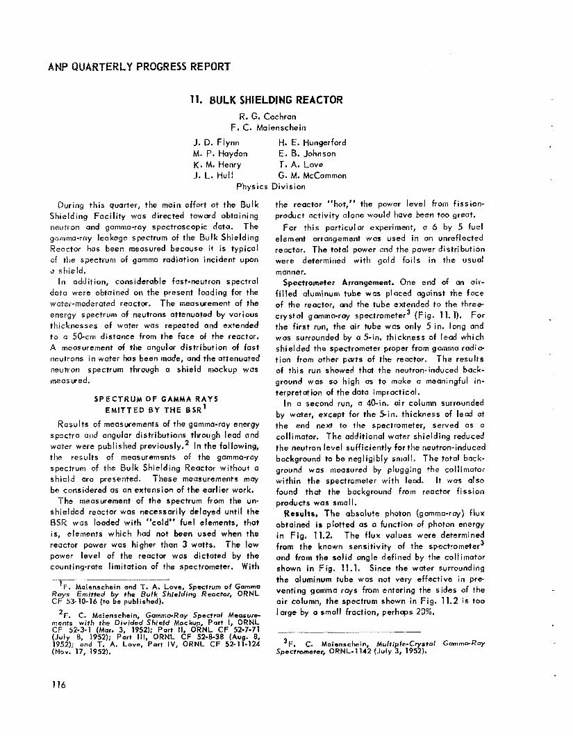
UARTERLY PROGRESS REPORT
11. BULK SHIELDING REACTOR R. G. Cochran
F. C. Maienschein
J. D. Flynn M. P. Haydon K. M. Henry J. L. Hul l
H. E. Hungerford E. B. Johnson T. A. Love S . M. McCammon
Physics Division
During th i s quarter, the main effort at the Bulk Shielding Faci l i ty was directed toward obtaining neutron and gamma-ray spectroscopic data. The gamma-ray leakage spectrum of the Bulk Shielding Reactor has been measured because it is typical of the spectrum of gamma radiation incident upon a shield.
I n addition, considerable fast-neutron spectral data were obtained on the present loading for the water-moderated reactor. The measurement of the energy spectrum of neutrons attenuated by various thicknesses of water wa5 repeated and extended t o 01 50-cm distance from the face of the reactor. A measurement of the angular distribution of fast neut r~ns i n water has been made, and the attenuated neutron spectrum through o shield mockup was measwed.
S P E C T R U M O F G A M M A R A Y S E M ~ T T E D B Y THE B S R ’
Results of measurements of the gamma-ray energy spectra and angular distributions through lead and water were published previously.2 In the following, the results of measurements of the gamma-ray spectrum of the Bulk Shielding Reactor without a shield are presented. These measurements may be considered as an extension of the earlier work.
The measurement of the spectrum from the un- shielded reactor was necessarily delayed unti l the BSR was loaded with “cold” fuel elements, that is, elements which had not been used when the reactor power was higher than 3 watts. The low power level of the reactor was dictated by the counting-rate l imitation of the spectrometer. With
the reactor “hot,” the power level from fission- product act ivi ty done would have h e n too greot.
For this particular experiment, a 6 by 5 fuel element arrangement was used in an unreflected reactor. The total power and the power distribution were determined with gold fo i ls i n the wsual manner.
Spectrometer Arrangement. One end of an air- f i l l ed aluminum tube was placed against the face of the reactor, and the tube extended to the three- crystol gamma-ray spectrometer3 (Fig. 11.1). For the f i rst run, the air tube was only 5 in. long and was surrounded by a 5-in. thickness of lead which shielded the spectrometer proper from gamma radia- t ion from other parts of the reactor. The results of this run showed that the neutron-induced back- ground was so high as to make a meaningful in- terpretation of the data impractical.
In a second run, a 40-in. air column surrounded by water, except for the 5-in. thickness of lead at the end next to the spectrometer, served as a collimator. The additional water shielding reduced the neutron level sufficiently for the neutron-induced background to be negligibly small, The total back- ground was measured by plugging the collimator within the spectrometer with lead. It was also found that the background from reactor f ission products wos small.
Results. The absolute photon (gamma-ray) flux obtained is plotted as a function of photon energy i n Fig. 11.2. The f lux values were determined
3 from the known sensitivity of the spectrometer and from the sol id angle defined hy the collimator shown i n Fig. 11.1. Since the water surrounding
____ - the aluminum tube was not very effective i n pre-
CF 53-10-16 (to be published). air column, the spectrum shown in Fig. 11.2 i s too
’F. Maienschsin and T. A. Love, Spectrum of Gamma R a y s Emitted by the Bulk Shielding Reactor, ORNL venting gamma rays from entering the sides af the
2F. C. Maienschein, Gamma-Roy Spec t ra l Measure- large by a perhaps 20’’ ments w i t h the Div ided Shield Mockup, Part I, ORNL
(July 8, 1952); Part 111, ORNL CF 52-8-38 (Aug. 8, 1952); and T. A. Love, Part IV, ORNL CF 52-11-124 3F. C. Maienschein, Mult iple-Crystal G 0 m m o - R ~ (Nov. 19, 1952).
CF 52-3-1 (Mar. 3, 1952); Part II, ORNL CF 52-7-71 ....... ~ ............
Spectrometer, ORNL-1142 (July 3, 1952).
116

PERIOD ENDING DECEMBER 10, 1953
UNCLASStFlED DWG. 2f656
THREE-CRYSTAL GAMMA- RAY SPECTROMETER-.,
15 in.
L - i o . BORAC LINER
-No1 CRYSTALS
LEAD PLUG
Fig. 11.1. Experimental Arrangement for Measurement of Bulk Shielding Reactor Gamma-Ray Spectrum.
DWG ?*e57 . . . . .- . . -. . . .. . - . . ., -. . . . . . . . . !...--I tos
. . . . . . . . .
Fig, 11.2. Spectrum of Gamma Rays from the Bulk Shielding Reactor.
The spectrum shape shows the usual broad peaks ot 2 2 Mev that are due to water capture and those at 7 to 8 Mev that are due to capture i n aluminum and possibly other materials. The cause of the 0.4-Mev peak, which appears to be real, hos not been found. The O.4PMev peak, however, may well be due to gamma rays from the 0.478-Mev level i n the Li7 formed by neutron capture i n the boron l iner of the spectrometer.
The smooth curve i n Fig. 11.2 represents the spectral shape (not intensity) obtained by Motr'
'J. W. Motz, P h y s . Rev. 86, 753 (1952).
with a Compton-recoil magnetic spectrometer look- ing at a U235 slug in the center of the Los Alamos water boiler and one at the active cote of the fast reactor. The curves cannot be expected to corre- spond closely becouse of the differences i n neutron- capture gamma-ray sources and because the low resolution of the spectrometer used by Motz would smooth out any structure present. The general similari ty in slopes, however, is interesting.
F A S T - N E U T R O N L E A K A G E S P E C T R A OF THE 8SR
The neutron spectrum of the BSR obtained w i th the reactor surrounded by cans of beryll ium oxide as a reflector5 was reported previously. For the data reported here, the previous spectral measure. ments were repeated and additional measurements were made; however, o water-reflected reactor (loading No. 22) was used.6
The measurements were made with the BSF pro ton-recoi I f as t-neutr on spectrometer. Except for the spectrum a t the face of the reactor, the spectral measurements i n water out to 30 cm from the fuel' are i n agreement wi th the previous meas- urements. The spectrum a t the face of the reactor
5R. G. Cochran and K. M. Henry, Fast Neutron Spec- trum of the Bulk Shielding Reactor, Part I, ORNL CF 53-5-105 (to be published).
6f?. G. Cochron et a/ . , A N P Quar. Pmg. R e p . Sept. IO, 1953, ORNL-1609, Fig. 11.1, p. 127.
7R. G. Cochran and K. M. Henry, A Proton Recoil Type Fasf-Neuimn Spectrometer, ORNL-1479 (Apr. 2, 1953.
'R. G. Cochran and K. M. Henry, Fast Neutron S p e r trum of the Bulk Shielding Reactor, Part I ! , ORNL CF 53-11-45 (to be published).
117

i s shown in Fig. 11.3. In addition to the proton- recoi l ineasurements, data obtained wi th the nuclear plate camera9 have been used to extend the spectrometer data from 1.3 Mev down to 0.5 Mev.
Measurements were ailso made out to 50 cm from the reactor. The spectrum measured at 50 cm i s shown in Fig. 11.4; the statistics on these data are quite poor, since the neutron intensity vias approximately at the l imit of sensitivity of the s pe cfr o m tcr .
An attempt was also made to measure the sper- trurn of neutrons emerging from the side o f an air- craft divided-shield mockup. '' The mockup con- sisted of a slab of lead 49' in. thick placed 16 in. from the reactor. 'The shield therefore extended out through the water to a position 113 cm from the reactor. Unfortunately, the neutron spectrometer was not sufficiently sensitive to detect neutrons at 113 cm; however, a spectral measurement was made at 70 cm, but the statistics (Fig. 11.5) were rather poor.
A meosurement of the angular distribution of the fast neutrons in water was made during the
'M. P. Wuydon, E. B. Johnson , rand J. L. M e e m , Meorwemew$ of the Fast Neutron Spectrum of the Bulk Shidding Reactor Usin Nuclear Plates, ORNL CF 53-8-146 (to be publishcdy.
"Reporf of the ANP Shielding Doord for the Aircraft Nuclear Propuls ion Program, ANP-53 (Oct. 16, 1950).
Ibff. 3 Y r G 21840 ,~ -- -
7- - ~ - 1 1 - - -
-- __ -- I 2 3 4 5 6 7 8 9 IO
ENERGY I K e v l
0 - - C
quarter.'l The experimental setup for th is mens- urement i s shown in Fig. 11.5, and the spectra vs. angle data are plotted in Fig . 11.7. At neutron energies above 8Mev, the intensities at the various angles converge, This effect is probnbly due to neutrons which bypass part or all of the collimator. A distance greater than 10 cm from the reactor would be more desirable for this measurement, but then i t would be diff icult to obtain sufficient in- tensity. Figure 11.8 shows the variation of f lux with direction for each of several neutron energies.
"R. G. Cochion and K. Ma Henry, Angular D i s t r i b v t ion of Foof Neutrnns in Water, ORNL CF 53-11-46 ( t o be publ i shed) ,
Qlssr* DWG 21921
50 cm H20 RETWEEN 1 ~
REACTOR AND COLLIMATOR, I 4-'t COLLIMATOR I
50 cm H20 RETWEEN 1 REACTOP AND COLLIMATOR, I
l 4-'t COLLIMATOR 1 --
1 2 3 4 5 6 7 8 9 40 ENERGY ( M e v l
O,'
ENERGY ( M e v l
F i g . 11.4. k4eutp.m Spectrum 5Q cim horn tihe
10 m H20 BEThECN R F k T O F i &NO COLLlM&WR 2 f l C3LLlMATOq
-
SPFCTROMETtH
10 m H20 BEThECN R F k T O F i &NO COLLlM&WR 2 f l C3LLlMATOq
-
SPFCTROMETtH
0 - 3 I 2 3 4 5 6 7 6 9 ' 0
E ' i i 8C .Y W e r l
Fig. 11.3. Neut ro~ Spectrum a t the Face of the BSR. Fig, 11.5. Meuirsan Spectrum 70 cm from WSR.
118

PERIOD E ND1 NG DECEMBER 10,1953
;rma* OWG. 2 2 1 9 9
4 4 f t *-+p ........................... -~ ........................... ~~ ~
BULK SHIELDING REACTOR
I NEIJTRON SPECTROMETER
HOUSING
,,-.-!-in. COLLIMATOR - . ~ ~ ~ ....... ......- . . . . . . . . . . . . . . . ....... .. . . . . . . . . ..,<-.-. '._. -_ -.. , ..., -.--
Fig. 11.6. Experimental Arrangement for Measurement
DIRECTION OF ROTATION
1 0 P VIEW
--I GWG 21843
1
10 I 2 NEUTRON ENFRGY (MeV)
Fig. 11.7. Angular Distribution of Neutrons from BSR in Water.
of Angular Distributionof Neutronsfrom BSRinWater. - DWG. 2i842
Fig. 11.8. Energy Angular Distribution of Neutrons from BSR in Water.
119

ANPQUARSERLYP
12. LID TANK FACILITY
C. L. Storrs
G E-A N P
@. T. Chapman D. K. Pruhey J. M. Miller F. N. Watson
Physics Division
Tentative results of a preliininary experiment performed a t the L id Tank indicate that most of the air-scattered neutrons that penetrate an aircraft crew shield follow the slant path. In another experiment, the study of neutron streaming through air ducts was resumed; doto f r o m the in i t ia l experi- ments have presented an important confirmation of the Simon-Clifford theory. A re-evaluation of a l l measurements for the determination of removal cross sections has improved some of the values, Refer- ence t o L id Tank neutron and gamma data is fuci l i - toted by a recent survey of the f irst 50 experiments.
Approval has been received for the I J S ~ of enriched uranium for a new L id Tank source plate, and a design has beendeveioped which w i l l make possible a far more accurate power calibration. The source plate, as we1 I as its appurtenant power-measuring equipment, i s a t present being constructed in the ORNL Research Shops. I t i s planned to instal l the source plate in January.
SLAWT P E N E T R A T I O N OF NEUTRONS THROUGH W A T E R
A preliminary cxperiment has been performed to determine the slant penetration of f ission neutrons through water. A n air-f i l led nluminum duct, 40 in. long and 2 in. in diameter,was used as a collimated
point” source of fast neutrons, and the fast- neutron dose was determined in the water around the end. The duct was t i l ted froin the normal to the source plate to reduce background of fast neutrons from the ORNL Graphite Reactor. Since ?he fast neutrons are collimated in the outward direction, i f not reduced they would overshadow the fission-plate neutrons which are, of course, isotropic. The data, plattad Q S isodoses arovnd the duct, are shown in Fig. 12.1.
B y integrating the dose along planes through the radiation field, the dose penetrating different thicknesses of water a t various angles was de- termined (Fig. 12.2). This information must be regarded as tentative unti I the dose determinations
I t
have been repeated with more care, but the results obtained so far indicate that most of the dose comes from neutrons that penetrate the shield along the slant path. This indication is similar to that obtained for gamma rays for comparable attenu- a t i om. 1
The observed relaxation lengths range from 4.9 to 6.3 cm. A s would be expected, these values are smaller than those obtained with h i c k shields, since a f ission spectrum was used as a source and the shields were quite thin.
IF. 5. Kim, R. J. Kennedy, and H. 0. Wyckoff, Oblique Attenuation o f Gammo-Rays from Coba/t-CiQ and Cesium- 737 in Polyethylene, Concrete and bead, NBS-2125 ( D e c . 23, 1952). -
DWC 21674
I Fig. 12,I. Fast-Neutron Dose Distribution QTS
the End of Q Duct 101.6 crn Long by 5.08 c m i n Diameter.
1 20

PERIOD ENDING DECEMBER 10, 1953
E DWG. 21876
0
. .. ... -
f, SLANT THICKNESS (cm)
Fig. 12.2. Slant Penetration of Neuirons in Water.
To determine the total air-scattered dose in a divided shield, it is necessary to integrate over a i l angles. Such an integration would presumably give a straight-through relaxation length comparable to that observed in the BSR air-scattering experi- mentS2 It would be desirable to extend the measure- ments to greater thicknesses of water and to harden the spectrum by putting water between the source and the duct entrance. Intensity problems l imi t the extent to which this can be accomplished, however.
AIR DUCT TESTS
The use of the L id Tank Fac i l i t y for the study of neutron streaming through air ducts has been resumed with emphasis on fast-neutron measure- ments. A flow-type dosimeter wi th somewhat greater sensi t iv i ty than that available heretofore was used to determine the dose around the ends of several ducts. One of these ducts was taken from
I--
2H. E. Hungerford, The Skyshine Exper iments at the Bulk Shie ld ing Fucility, ORNL-1611 (to be published).
the 19-duct array studied a year ago.3 It had three sections, 22 in. long and 31%6 in. in diameter, joined at angles of 45 degrees, A second duct consisted of two such sections. The Slant pene- tration experiment described in the preceding sub- section provided a third measurement.
Putting the data from these three measurements into the Simon-Clifford fwmula4 and solving for the reflection factor, a, gave values of 1.0 and 0.9, respectively, for the f irst and second bends. These values are in agreement wi th the value of about 4 obtained from the previous thermal measurements' made in water at a distance of 30 cm from the ends of the ducts (thus the emergent fluxwas filtered and was representative of the hard neutrons that de- termine the dose), and they constitute an important confirmation of those measurements. The value of 1 has been assumed i n recent direct-cycle design studies. It i s now fe l t that engineering designs based on the Simon-Clifford theory are on a sound basis when applied to a single duct, especially when the dimensions are similar to those studied.
Since it was observed that the peak values of dose measured at the end of the 19-duct array were a factor of approximately 10 higher than those o b served with the single duct, a study of interference between adjacent ducts was indicated. This study has been started, wi th a single section and a three-section duct being used. In the f irst con- figuration, one of the possible streaming paths was reproduced in the array by placing the short duct parallel to the f i rs t section of the long duct and 12k in. from it. In this position, it lined up, approximately, with the last section. The result was an increase by a factor of 4.5 in the dose at the end of the long duct.
The short duct was then moved to a position that was again parallel t o the f irst section but con- siderably closer (6 in.) and above it i n a different plane so that there was no direct streaming path. The data (which must be considered tentative) showed no increase in the peak dose beyond the long duct but did show a broadening of the emergent neutron beam. The results obtained from these experiments are shown in Fig. 12.3.
'J. D. F l y n n and C. L. Storrs, Radiation Measuremenfr Around an Array of Cy1 indrical Ducts, ORNL CF-52-12-187 (Dec. 15, 1952).
4A. Simon and C. E. Clifford, The Attenuation of Neutrons by A i r Ducts in Shields, ORNL-1217 (Ncv. 11, 1952).
5C. E. Clifford, private communication.
121
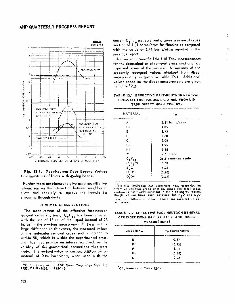
ANPQUARTERLY PROGRESSREPORT
2 (0”
% 5 t- 3
+ v)
9 2
-20 -18 -12 -6 0 6 12 18 20 y. DISTANCE FROM CENTER OF END OF OUCT (c rn )
Fig. 12.3. Fast-Neutron Dose Beyond Various Configurations of Ducts wi th 45-deg Bends.
Further tests are planned to give more quantitative information on the interaction between neigh boring ducts and possibly to improve the formula for streaming through ducts.
REMOVAL CROSS SECTIONS
The measurement of the effective fast-neutron removal cross section of C,F, has been repeated with the use of 15 in. of the fiquid instead of 28 in. as in the previous measurement.6 Despite th is large difference in thickness, the measured values of the molecular removal cross section agreed to wi th in 5%, which is within the experimental error, and thus they provide an interesting check on the val idity of the geometrical corrections that were made. ?he revised value far carbon, O m barn/aton instead of 0.84 barn/atom, when used with the
current C,F, measurements, gives a removal cross section of 1.31 barns/atom for fluorine as compared wi th the value of 1.36 barns/atom reported in the previous report.
A re-examinationof a l l the Lid Tank measurements for the determination of removal cross sections has improved some of the values. A summary of the presently accepted values obtained from direct measurements i s given in Table 12.1. Additional values based on the direct measurements are given in Table 12-2.
TABLE 12.1. EFFECTIVE FAST-NEUTRON RE CROSS SECTION VALUES OBTAINED FROM L ID
TANK DtRECT MEASUREMENTS
MATER I AL
Al Be B i
C CU Fe
Ni w c7F16 C2F3CI
0 4 H 2 0 * D*0*
1.31 barns/atom
1.05 3.43 0.89 2.08 1.95 1.85 2.6 + 0.2
26.6 borns/rnolecule
6.50 4.26
(2.90) (2.78)
*Neither hydrogen nor deuterium has, properly, an affect ive removal cross section, since the total cross section is not nearly constant in the high-energy region. Rough values have been obtained for H 0 and D 0 b a t e d on 140-cai shislds. These arc reported In pa- rentheses.
2 2
TABLE 12.2. EFFECTIVE FAST-NEUTRON REMOVAL C m s s SECTIONS BASED ON LID TANK DIRECT
MEASUREMENTS
B D* F H* 0
0.87 (0.92) 1.31
(0.98) 0.94
6 ~ . L. torrs et a~., ANP ~ u a r . Prog. ~ e p . Sep t . YO, 79.53, ORNL-1609, P. 145-148s *Cf., footnote to Tab le 12.1.
122

SURVEY QF LIQ TANK EXPERIMENTS
Shielding experimentation a t the QRNL L id Tank Fac i l i t y began i n June 1949, and since that time approximately 60 major experiments have been performed. In view of the large ro le th is fac i l i t y has had in the development of various reactor shield designs and because of the constant need for retwence to the data, i t was felt that theexperi- mental results should be compiled in one publication. Accordingly, a summary of the f i rst 50 L id Tank experiments w i l l soon be presented by E. L. Cza pe k. 788
As described in several previous reports, the Lid Tank Fac i l i t y consists of a large water tank adjacent to 5n opening ~n the concrete shield of the
'ORSORT student from Electric Boot Division of General Dynamics Corporation.
*E. L. Czopek, General Survey of Lid Tank Experi- ments 7 Thmogh 50, QRNL-1636 (to be published).
PERIOD ENDING ECEMBER 10, 1953
ORNL Graphite Reactor (Fig. 12.4). A converter plate of uranium covers the opening between the water tank and the reactor shield. This plate absorbs most of the incident thermal neutrons emerging from thereactorond causes fission, which, i n turn, produces the known uranium spectrum of neutrons, as wel l as gamma rays of various energies. Shielding samples are inserted i n the tank, and the transmitted radiation is measured behind the shield. The geometry of the L id Tank permits the use of very large samples, which, in turn, help to reduce uncertainties due to boundary conditions. The water in the tank protects personnel from radiation and allows easy positioning of test samples.
The Lid Tank Faci l i ty was bui l t tz, test both compositions and geometries of shields. W i t h the resulting ex per imenta I data, d i f f ic ul t attenuation problems could be quickly solved and shield thick- nesses couid be predicted (to within an accuracy of

ANPQUARTERLY PROGRESSWEPQWT
+Sol,) without having to rely too much on o knowledge of the attenuation processes.
Experimentation a t th is faci l i ty has primarily been limited t o investigations of the “unit shield” i n which a l l material that functions primarily as shielding is located around the reactor. A l l the experiments covered in the survey can be grouped as follows:
1. Water Shield (experiments 1, 4, 10, 13) 2. Preliminary ~nves t i ga t i ons~ (experiments 2, 3,
5, 6, 8, 10) a. Lead-water shield b. Iron-water shield
3. Boron Carbide Shields (experiments 11, 12) 4. Thermal Shields9 (experiments 18, 20, 36)
a. Lead-water shield b, Iron-water shield
5. Shield Mockups (experiments 7, 14, 15, 16, 17, 18, 29, 459 a. Submarine Thermal Reactor b. Submarine Intermediate Reactor c. Reflector-Moderated Reactor (ANP)
6 . Shield Optimizations (experiments 9, 13, 24) a . Two-component shield of lead and borated
b. Suppression of capture gammas in lead-water shield
c. Optimum position o fa lead-iron gamma shield i n relation to pressure shell
water
~
9 A small amount of boron was present in a majority of these shield mockups .
7. Shield Penetrations (experiments 19, 21, 22, 25, 26, 37, and 38 and special experiments) a. Cylindrical air ducts wi th or without bends b. Array of cyl indrical a i r ducts with or without
bends c. Annular dust (specialized mockups simulating
GE-Rl air outlet and inlet sections) d. Structural members in shields (streaming
effects) e . Instrument plug (modification in shield to
i mprove control instrumentation) 8. Removal Crass Sections (experiments 23, 30, 31,
32,33, 34, 35, 39, 40, 41, 42, 43, 46, 49, 49, SO) 9 . Special Investigations ,
Q, Effects of boration of water (experiment 10) b. Effects of water and air gaps in shields
(experiinent 48) c. Induced radioactivity outside an air duct
(experiment 29) d, Activotian expected in a coolant (sodium)
a t various locations in a boron carbide shield (experiment 10)
e. Gamma scattering around submarine bulkhead (sodium source) (special experiment)
The situation a t present in regard to unit shields or reactor ports of divided shields appears to be that the basic mechanisms ore understood and that, except for the very simplest problems, shield mockups are essential, although the effects of smallchanges in design can be quite wel l predicted. The Lid Tank method of mockup testing is highly developed, and large amounts of data can be col- lected in relatively short times.
124

PERIOD ENDING DECEM8ER 18,1953
13. TOWER SHIELDIN6 FACILITY
C. E. Cli f ford
Physics Division
T. V. Blosser L. B. Holland
The steel structureof the Tower Shielding Faci l i ty has been erected (Fig. 13.1), and the ground structures are approximately 75% complete. The underground building for the reactor controls and for personnel w i l l be available for occupancy by December 10; access i o the control area of the building was authorized in November.
The mechanical components of the reactor have been constructed and are now being assembled, and the reactor tank has been received. Construction of the crew-compartment tank is nearing completion. The last hoist i s scheduled for delivery by January 1, '1954.
The optimistic date fer completion of the faci l i ty is January 15, after whish there w i l l be a one-rnonth period for cr i t ical experiments and shakedown operation. This w i l l be followed by differential shielding measurements in the reactor and the crew-compartment water tanks.
A mockup of a GE air-cooled reactor shield design is scheduled for delivery by March 15 by the General Electr ic Company, and for testing in conjunction wi th this, a crew-shield mockup w i l l be supplied by ORNL.
Fig, 13.1. Tower Shielding Facility, November 13, 1953.
ii 25 <

14. SHIELDING ANALYSIS E. P. Blizard J. E. Faulkner
M. K. Hull ings F. H. Murray
Physics Division
H. E. Stern Consol idated Vu1 tee Aircraft Corporati on
Much of the shielding analysis work for th is quarter was reported in the Physics Division Semi- annual Report’ and i s not repeated here. The work reported i n the Division report included two treat- inents of geometrical transformations with methods of estimating reactor leakage. In addition, some calculational methods for obtaining neutron at- tenuation were presented, On comparison of the calculated attenuations with measured attenuations, it was possible to derive “effective removal cross sections” that when compared with other measure- ments showed reasonable agreement. In addition, gamma-ray absorption coefficients which have been measured for some elements have been used to interpolate the coefficients for other elements.
The vis ib le l ight from an aircraft nuclear power plant has been estimated, and the calculations w i l l be compared with measurements made on the BSR. ‘The measurements of visible l ight are made in air and are not to be confused with the Cerenkov radiation (blue glow) which i s so obvious in water. An estimate of neutron albedo was obtained to supply a simple model for ground and structure scu tter ing problems .
VIS IBLE LIGHT F R O M A N U C L E A R P O W E R P L A N T
The results of some experiments carried out ut Los A ~ Q ~ O S on the visible l ight from a polonium source’ have been used in obtaining an estimate of the ionizing radiation that would have to be present
’E. $. Blizard et a!. Phys. Dive Serniann. P r o s R e p . Scpt. 10, 1953, ORNL-’/630 ( i n p r e s s ) .
around the aircraft reactor shield to just make it visible. If the airplane were approximately 200 ft from the observer, the ionizing radiation near the shield would have to be about 5 x lo6 r/hr. If the airplane were very far from the observer, say 50,000 ft, the ionizing radiation would have to be about lo9 r h r . These estimates w i l l be cornpared with measurements made the BSH.
N E U T R O N REFLECTION COEFFICIENT F O R W A T E R
An estimate of the neutron reflection coefficient for water has been obtained by using a simple model wi th a coineidant source and a ncmdirectioriul receiver located above the water surface. If iso- tropic oxygen scatter and attenuation governed by the removal cross sections are assumed, the re- f lected f lux F at height h for source strength No i s
F 48nh2
The albedo approach gives
N o a F =
1 Orb2 for a re-emission distribution between isotropic and cosine, where a i s the reflection coefficient. A value of Q = 0.085 i s thus obtained which i s i n fair agreement with the experimental value of 8.08.
2J. G. Hoffman, Radiation Doses in the Pajarito Accident of May 21, 7946, !--A-687 (May 26, 1948)-


15. LIST Of REPORTS ISSUED DURING THE QUARTER
REPORT NO. TITLE OF REPORT AUTHOR ( s ) DATE ISSUED
I. Aircraft Reactor Experiment
CF 53-9-15
CF 53-9-53
Experimental Procedure on the ARE (Preliminary)
Supplement to ARE Hazards Summary Report (ORNL-1407)
CF 53-10-62 ARE Fuel Recovery
CF 53-11-95 Report and Recommendations of Second ARE Cleaning Committee
CF 53-12-9 ARE Design Data
ORNL-1650 Stress Analysis of the ARE
J, L. Meem
E. S. Eettis W. E. Cottrell
F. N. Browder
G. A. Cristy L. A. Mann Fa Fa Blankenship G. M. Adamson
W. B. Cottrell
R. L. Maxwell J. W. Walker
11. Experimental Engineering
CF 53-9-32
CF 53-9-102
ANP Experimental Engineering Quarterly Status Report
Design Data and Proposed Test Schedule for Sodium-to-
H. W. Savage
H. J. Stumpf Air Radiators
CF 53-9-180 LlTR Fluoride Fuel Test Loop 0. Sisman
CF 53-10-208 A Flat Plate Heat Exchanger for Reactor System Uses R. W. Bussard
111. Critical Experiments
CF 53-9-19 Static Analysis of the ARE Criticality Experiment C. B. Mills
ORNL-1615 Critical Experiments on Reactor D. Callihan R. C. Keen
QRNL-1634 Preliminary Critical Assembly for the Aircraft Reactor D. Callihan Experiment D. Scott
CF 53-5-239
CF 53-9-4
C F 53-9- 16
C F 53-8- 146
CF 53-9-161
CF 53-10-1
CF 53-10-16
CF 53-11-2
IV, Shielding
Nuclear Dose Measurements on the Divided Shield Mockup a t the Bulk Shielding Facility
L id Tank Shielding Test of the Reflector-Moderated Reactor
Minimum Shield Weight Penalty for Air Ducts
Measurement of the Fast Neutron Spectrum of the Bulk Shielding Reactor Using Nuclear Plates
An Estimate of the Neutron Reflection Coefficient, Using the Concept of Removal Cross-Section
Computation of Effective Removal Cross-Section Measured at ORNL L i d Tank
Spectrum of Gamma Rays Emitted by the Bulk Shielding Reactor
The Shielding of Nuclear Radiations, Lecture I
H. E. Hungerford
F. N. Watson
E. P. Blizord
M. P. Haydon E. E. Johnson J. L. Meem
H. E. Stern
L. S. Abbott
F. C, Maienschein T c A. Love
E. P. Blizard
9-3-53
9-25-53
10-5-53
11-10-53
to be issued
to be issued
9-2-53
9-8-53
9-25-53
10-26-53
9-1-53
10-22-53
10-28-53
5-20-53
9-30-53
9-2-53
to be issued
9-29-53
no date
to be issued
11-2-53
to be issued CF 53-11-45 Fast Neutron Spectrum of the Bulk Shielding Reactor, Part II Re G. Cochran K. M. Henry
129

ANPQUAR"O"ERLYPROGRESSREP08T
REPORT NO.
CF 53-1 1-46
CF 53-11-53
C F 53- 11-54
ORNL-1636
CF 53-10-117
CF 53-10-228
ORN L-1565
ORNL-1633
ORNL-1647
MM-147
MM-151
MM-157
CF 53-10-78
0 RN I- 16 26
U A-P R- 13
BMI-852
BMl-864
CF 53-8-106
CF 53-8-217
CF 53-9-98
CF 53-10-86
Cf 53-1 1-128
0 R N L- 1 6 24
TITLE OF REPORB
IV. Shielding (continued)
Angular Distribution of Fast Neutrons in Water
AUTHOR (s) DATE ISSUED
R. G. Cochran K. M, Henry
The Effect of S o m e Liquid Metal Ducts on Reactor Shields
Gamma-Roy Spectrum of %ha Bulk Shielding Reactor
M. K. I-lullings
F. C. Maienschein
E. L. Cxopek General Survey of Lid Tank fxperiments 1 Through 50
V. Metallurgy
Examination of L.F Pump Loop G. M, Adnmson R. S, Crouso
Metallographic Examination of Second Heat Exchanger from G. M. Adamson R. S, Grouse
H. lnouyc
A. Levy
W. D, Manly
Rensselaer
Ri-Fluid Pump Loop
Scaling of Columbium in Air
Fabrication of Spherical Particles
Interim Report on Stat ic Liquid Metal Corrosion
Third Progress Report on the Flash Welding of Molybdenum. Part 1 - Temperature Distribution During the Flashing Pol ytechnic Cycle Institute
Redrawing of Spacial High Purity lnconel Superior Tube Coi?lpanp/
Progress Report and Final Report to Carbide and Carbon Comrnonwea Ith Chemicals Company Engineering
co. of Ohio VI. Chemistry
Fused Sal t Compositions
Determination of Zirconium by the Chloranilic Acid Method
C, J. Barton
0. Mcnis
Progress Report June30, 1953
for the Period April 1, 19.53 Through Univorsi$y of Arkan sa s
Vapor Pressures of Beryllium Fluoride and Zirconium Battelle Memoria l Fluoride Institute
Potential Liquid Fuels for Nuclear Power Reactors Battel le Memori a1 Institute
VII. Heat Transfer and Physical Properties
Preliminary Results an Flinak Heat Transfer
Preliminary Measureinents of the Density and Viscosity of
H. W. floffman
S. I . Cohan T. N. Jones
W. D. Powers G. C. Blalock
Fluoride Mixture No. 44
Heot Capacity of Two Samples of 310 Stainless Steel and af a Brazing Compound
Preliminar y Meosurement of the Density and Viscosity of s. 1. COhEn Composition 43 jNa2UFg) T. N. Jones
Heat Capacity of Fuel Composition No. 33 W, D. Powers G. C. Blalock
The Nature of the Flow ot Ordinary Fluids in a Thermal D. C. Mamilton
L. D. Palmer Convection Harp F. E, Lynch
t o be issued
to be issued
11-8-53
to be issued
10-6-53
10-27-53
9-1-53
11-12-53
to be issued
9-30-53
10-7-53
11-9-53
10-9-53
10-28-53
7-30-53
7-13-53
94-53
8-1 8-53
8-3 1-53
9- 18-53
10- 14-53
11-23-53
to be issued
130

PERIOD ENDING DECEMBER 10,1953
REPORT NO.
CF 53-94
CF 53-11-147
QRNL-1609
ORNL- 1632
TITLE OF REPORT AUTHOR (s) DATE ISSUED
VI I I . Miscellaneous
The Small Hydrogen Moderated Reactor 6, Be Mills 9-2-53
Directory of Act ive ANP Research Proiects at ORNL
Aircraft Nucleor Propulsion Project Quarterly Progress
W. B. Cottrell 11-27-53
W e B. Come11 10- 15-53 Report for Period Ending September 10, 1953
ORNL Control Computer J. J. Stone to be issued
16. DIRECTORY OF ACTIVE ANP RESEARCH PROJECTS AT ORNL
NOVEMBER 27, 1953
I. REACTOR THEORY AND COMPONENT DESIGN
A. Aircraft Reactor Design 1. Reflector-Moderated Reactor Studies 2. Fluid-Fuel Flow Studies 3. Gamma Heating of the Moderator 4. Design Consultants
13. ARE Design 1. Building 2. Electrical Power Circuits
3. Fluid Circuit Design 4. Fuel Recovery Eqwipment
C. ARE Installation
1. Plumbing 2. Electrical System 3. Controls 4. Instrumentation
5. Exped itor s
6. Coordinators
D. ARE Operations 1. Staff 2. Day Shift
3. Night Shift
9704-1
9704- 1 9704- 1
9704- 1
1000 1000 7503
9201-3
7503 750 3 7503 7503 7503 7503
7503 7503
7 503
Fraas, Laverne, Bwrsard StUmQf Bwssord, Wilner
Wislicenus, JHU; Haines; Chambers, U.T.
Browning Walker Cristy Est abrook
Webster t i a/.
Packard cf a/.
Epler, Monn Affel P erri n, West
W i schhusen, Wotts
Bettis, Meem, Cristy, Mann Wh i tmon, Cottrel I , Gr i nde I I,
Croley, Schafer, Wil l ioms, Southern
Affel, Psrrin, Cobb, Leslie, Allen, Reid, Morrison, Huntley, Gregory, Addison
E. ARE Control Studies 1. High-Temperature Fiss ion Chamber 4500 Honauer
131

2. Control System Design 4500 Epler, Ruble, Mann, Green, Hanauer
Oakes, Mann, Green 3. Control Studies on Simulator
F. Reactor Phys ics 1. Analysis of Cri t ica l Experiments 2. K inet ics o f Circulat ing-Fuel Reactors 3. Computation Techniques for ARE-Type Reactors 4. Statics of Reflector-Moderated Reactors 5. Machine Computations
4500
9704-1 9704- 1 9704- 1 9704-1 4500
M i l l s Ergen
Bengston, Ergen Laverne, Burtnette, Spencer
Charpie, CoveyauI Sangren,
Gcrberich, Given, At ta Proham mer 6. Interpretation of Cr i t ica l Experiments
G. Crit ical Experiments 1. Reflector-Moderated Reactor Cr i t ica l Assembly
4500
9213 Callihan, Williams, Scott,
Zimmerman, L.ynn, Noakes (P&W)
2, Preliminary Assembly of Supercritical-Water Reactor (Prott & Whifney)
3. Preliminary Assembly of AC-1 (General Electr ic ANP P)
H. Bearing, Seal, and Pump Development 1 . Mechanical Pumps for High-Temperature F lu ids 2. High-Temperature Seals for Rotury Shafts 3. Pump for Hydroxide Systems
4. Seals for Hydroxide Systems
5. 6. Canned-Rotor Pump Development
Reari ngs for High- Temper oture Appl i c a t i on
9213 Call ihan et 01.
9213 Call ihan et 01.
McDonal d, Cobb, Huntley,Grindel I McDonald, Tunnell, Smith, Mason Dayton Simons, A l len Stair, Tunnell, Smith, Mason McDonald, Stair, MacPherson,
Gri ndel I
9201-3 920 1-3 BMI BMI 9201-3 9201-3
7. Materials Compatibi l i ty in Molten Sa l t s at
High Temperatures I. Valve Development
1. 2. Valves for Hydroxide Systems
Valves for High-Temperature F lu id Systems
J. Heat Exchanger and Radiator Development
1. High-Temperuture Fluid-to-Air Heat Exchange Test
920 1-3 Stair, Tunnell, Smith, Mason
9201-3 BMI
McDonald Simons, A l len et a/.
MacPherson, Salmon, Fraas, Stumpf
Salmon, Fraas, MacPherson, Bussard
Petersen, Froas
Fraas, Coughlen Fraas, Stumpf, Bailey, U,T. Coughlen
9201-3
2. Fluoride-to-Liquid Metal Heat Exchange Test 9201-3
9201-3 920 1-3 9201-3
3. Heot Exchanger Fabrication 4. 5.
Boeing Turboiet with Sodium Kadiator Radiator and Heat Exchanger Design Studies
6. Ful l -Scale Test Fac i l i t i es
K. Flu id Dynamics of L iqu id Fuel Reactors 1. Pump-Core Shell Component T e s t
L. Instrumentation
1. Pressure-Measuring Devices for High-Temperature F lu id Systems
9201-3
9201-3 Bussard, Gallagher
McDonald, Smith 9201-3
'Bat te l le Memorial Institute.
132

PERIOD ENDING DECEMBER 10, 1953
2. Flow-Measuring Devices for High-Temperature Fluid Systems
3. High-Temperature Strain Gage 4. High-Temperature Calibration Gage
I I . MATERIALS RESEARCH
A. Phose Equilibrium Reseorch 1. Thermal Analysis of Fluoride Systems
2. Thermal Analysis of Chloride Systems
3. Phase Equilibria Among Fluorides by Quenching
4. Equilibria in BeFZ-Bearing Systems by Quenching 5. Differential Thermal Analysis of Fluorides 6. Differential Thermal Analysis of BeF2-Bearing
7. Equilibria Among Fluorides and Chlorides by Sy s tem s
Fi I t r o t ion
8. X-Ray Diffraction Studies of Complex Fluorides
9. Phase Equilibria in Hydride-Hydroxide Systems
10. Phase Equilibria Consultant
B. Chemistry of High-Temperature Liquids 1.
2.
3. 4. Chemical Reactions in Fused Salts 5. Solutions of Metals in Fused Salts 6. Thermagalvanic Potentials in Fused Systems
7. Decomposition Potentials in Fused Systems
8. Spectrophotometric Investigafions of Fused Salts 9. Preporation, Phase Behavior, and Reactions of UF3
Equilibrium Pressures in Hydroxide-Metal Systems
Equilibrium Pressures in Hydroxide-Metal Systems
Equilibrium Pressure in Hydride-Halide Systems
10. Rates of Reduction in Fused Salts
1 1 . Solubility of Uranium Compounds in Hydride- Hydroxide Systems
12. Free Energy of Fluorides 13. Preparation of Pure Hydroxides 14. Preparation of Complex Fluorides 15. Chemistry Consultants
C. Fluoride Production and Handling 1. Pilat*Scale Production of Fluorides
2. Laboratory-Scale Fluoride Production
9201-3
B L H ~ Cor ne I1
9733-2
9733-2
9733-2
Mound 9 7 3 3 2
Mound
9733- 2
4500 9766
MH13
U. Ark. 9766
Mound 9733-3
4500 9733-3
9733-3
9733-3
9733-2
9733-2
BMI 9201-3
9733-3
9733-3
9928
9733-2
McDonald, Smith
Insley, Barton, Watcher,
Barton, Boyer lnsley, Moore, Metcalf, Truitt,
Truitt
Thoma, White Hsik, Orban, Joy et al.
Bo1 omey
Orban et ul.
Barton, Sheil Bred i g
Agron, Thoma Bonus et a/. McVay, U. Ala.
Smothers et 01. Knox, Kertssz Otto, Orban Overhol sur, Redman, Weaver Bredig, Johnson, Bronstein Cuneo Topol, Overholser Friedmon, B1 ankenship Barton, Truitt, Blood, Watson,
5 I ankens h ip
Blood, Watson, Blankenship
Simons et a!. Mann, Petersen, Cisar Ketchen, Overhol ser
Sturm, Overhol ser Gibb, Tufts U. Hill, Duke U. Carter, Carter Lab.
Nessle, Blakely, Eorgan, Croft,
Blood, Watson, Blankenship, Didlake
Boody
bald win-L ima Hamil ton Corp. 'Metal Hydrides, Inc.
1 33

PE 1
99L6 1 -pa26 1-POL6 1 -Pot6 1-PO26 1 -POZ 6 1-PO26 L -POZ6
IW€I 99L6 OOOZ 0002
E-LOt6 99L6
E-L 026
oooz 99L6 oooz
oooz 0002
E-LO26 E-LO26
0002 oooz OOOZ
C-LOZ6 oooz a002 0002
&-LO26 0002
EBSL SOSE 610s SOSP ONV
aosv
99L6
E-L OL6 EOSL 2126
E-LOZ6 L%EEL6

PERIOD ENDING DECEMBER 10, 1953
9. Vapor Pressure of Fluoride Systems
10. Vapor Pressure of BeFZ-Bearing Systems
11, Vapor Pressure of Fluid Systems
1. Heat Transfer
1. Heat Transfer Coefficients of Fluoride and
Hydroxide Systems
2. Heat and Momentum Transfer in Convection Loops
3. Heat Transter in Circulating-Fuel Systems
4. Forced Convection in Annuli
5. Transient Boi l ing Research
6. F lu id-F low Phenomena
J. Metals Fabrication Methods
1.
2. 3. 4.
5.
6.
7.
8. 9.
10.
Welding and Brazing Techniques for ARE
Molybdenum We Id i ng R e search
Molybdenum Welding Research
Resistance Welding for Molybdenum and Clad
Metals
Welds in the Presence of Various Corrosion Media
Nondestructive Testing of Tube-to-Header Welds
Basic Evuluation of Welds Metal Deposits i n
Thick Plates
Development o f High-Temperature Brazing Al loys
Evaluation of the High-Temperature Brazing Alloys
Application of Resistance-Welding Methods to
ANP Materials
K. New Metals Development
1. Molybdenum and Columbium Alloy Studies
2. Heat Treatment of Al loys for Special Projects
3. Al loy Development of New Container Materials
L. Solid Fuel Element Fabrication
1. Solid Fuel Element Fabrication
2. Diffusion-Corrosion i n Solid Fuel Elements
3, Determination of t h e Engineering Properties of Solid Fuel Elements
4. Inspection Methods for Fuel Elements
M, Ceromics and Metals Ceramics
1. Metal Cladding for Beryll ium Oxide
2. Ho t Pressing of Bearing Materials
3. High-Temperature F i r ing of Uranium Oxide t o
Produce Selective Powder Sires
4. Development of Cermets for Reactor Components
5. Ceramic Cootings for ANP Radiotors
9733-2
Mound
BMI’
9204- 1 9204-1 9204- 1 9204-1 9 204- 1 9 204- 1
2000
BMl’ MIT4
RPI5 2000
2000
2000 2000 2000
2000
2000 2000 2000
2000 2000 2000
2000
Gerity
Mich.
2000
2000 9766 9766
Moore
Otban e t 01. Simons e t al.
Hoffman, Lanes
Hamilton, Palmer, Lynch
Poppendiek, Winn, Palmer
Bradfute
Rosenthal
Palmar, Winn, Poppsndiek
Manly, Housley, Slaughter,
Pa triorca
Russell
Wulff
Nippes, Savage
Vreeland, Slaughter Hoffman,
Patriarca
Slaughter, Patriarco
Slaughter, Gray, Patriorco
Potriarco, Slaughter
Slaughter, Patriarca
Slaughter, Potriorca
lnouye
Bomar, Coobs
Inouye
Bomar, Coobs
Bomar, Coobs
Bomar, Coobs, Woods, Oliver,
Douglas
Bomar
Graaf
Bomar, Coobs
Bomar, Coobs
Johnson, Shevlin, Taylor, Hamner
White, Grif f in
~~~
4Massachuset+s Inst i tute of Technology.
5Rensselaer Polytechnic lnstitute.
135

6 . Ceramic Valve Parts for L iqu id Metals and
Fluorides 7. Ceramic Reflecqor
8. Ceramic Coatings for Shielding
9. Fabrication of Be0 Shapes
10. Corrosion of Ceramics
11. High-Density Graphite
N. Strength of Materiols
1. Creep Tests in Fluoride Fuels
2. Creep and Stress Rupture Tests of Metals in
VQCUU~TI Gaseous Environments and in F lu id Media
3. High-Temperature Cycl ic Tensi le Tests
4. TubeBurst Tests
5. Relaxation Tests of Reactor Materials
6. Evaluotian Testing far Other Dsvelopment Groups
7. Fatigue Testing of Reactor Materials
0. Radiation Damage
1. Fused Salt Fuels Irradiation in L ? T R
2. 3. L l T R Dynamic Corrosion Loop
4, Fluoride Fuel Laops for L lTR and MTR
Fuscd Salt Fuels Irradiation i n MTR
5. Engineering Properties of Irradiated Met~ls
6 . Neutron Spectrum of LlTR 7. Creep of Metals and Stress Corrosion in ORNL
Graphite Reactor and L l T R
8. Creep of Metals in MTR 9. Thermal Conductivity of Metals i n ORNL Graphite
Reactor and L lTR 10. Remote Metallography for GE-ANP, Pratt R Whitney,
and In-Pile Corrosion Tests
11. Radiation Dnmage Consultants
P. Materials Analysis and Inspection Methods
1. Determination of the Oxidation States of Metallic
Corrosion Products
2. Detsrrriinatian af Trivalent Uranium in Fuels
3. Analysis of Reactor Fuels and Coolants
4. Deterrninotion of Reducing Power of Fuel5 und
Coolants
5. Detarniinotian of Oxides in Reactor F u e l s 6 . High-Temperature Mass Spectrometry
7. X-Ray Study of Complex Fluorides
9766 9766 9766 U a Alae
9766
9766 2000 9766
9201-3
2000 2000 2000 2000 2000 2000
3550 3005
3550
3550 3550 3005
3550
3005 3025 3001 3025 3001 3005 3 025 3001
9733-4 9733-4 9733-4
Shevlin, Johnson, Taylor
Johnson, White
Whits, Shevlin
Handwark
Dnnsy
Curtis, Kertess, Buttrani
Vreeland, Hoffman
Oaney, Carey
Adamson
Oliver, Douglas
0 Ii ver, Woods
Oliver, Douglas
Oliver et a/.
Oliver, Woods, Rabar Oliver, Reber
K c i l holtz, Morgan
Robertson, Webster, Robinson,
Willis, Browning
Kei lho l tz et 41.
Kei lho l tz e t al.
Sisman, Baumann,
Carroll, Brundage, Blockshes,
Parkinson, El l is, Olson, Morgan
Sisman, Porkinson, Baumann
Carrol I Trice, Sisnan
W i I son, Zukas
Davis
Wilson, Hink le
Cohen, Templeton Weeks
Feldman, Richt
Acton, Schwrsrtz
Rucark, U. Ala.
Smith, Cornell U.
White, Manning
White, Ross
White, RQSS, Roerner, MQnniPIg
9733-4 9733-4 9735 3500 9766
White, Manning
White Baldock, Sites
Agron, Johnson, Bredig
Thoma
136

PERIOD ENDING DECEMBER 10, 1953
8. 9.
10. 11.
12.
13. 14. 15.
Petrographic Examination of Fuels Chemical Methods of Fluid Handling Metol logaaphic Examination Identification of Corrosion Products from
Dynamic Loops
from Dynamic Loop Tests
Assembly and lnterpretotion of Corrosion Data
Metallurgical Examination of Engineering Ports Identification of Corrosion Products Experimental Material Distribution
111. SHIELDING RESEARCH
A. Cross-Sscti on Measur ement s
1. Effective Removal Cross Sections
6. Shielding Measurements 1. Slant Penetration of Neutrons 2. Air Duct Tests - Fast Neutrons 3. Unit Shield Optimization 4. Mockup Tests for Shield Design 5. Divided-Shield Mockup Tests (GE-ANPP) 6. Duct Tests (GE-ANPP) 7. Gamma Rays from Fission
8. Full-Size Mockup Tests of Aircraft Shields 9. Design Parameter Studies (Divided Shield)
C. Shielding Instruments 1. Gamma-Ray Spectroscopy and Calculotions 2, Short-Period Fission-Product Gammo-Ray Spectra
3. Fast-Neutron Dosimeter 4. He Counter for Neutron Spectrometry
5. Neutron Spectroscopy - Proportional Counter 6. Neukon Spectroscopy - Photographic Plates
3
D. Shielding Analysis 1. Development of New Colculational Methods 2. Application of Stochastic Methods 3. Calculation of Neutron Attenuations 4. Calculations of Gamma-Ray Attenuation
E. Experiments on Shielding Facility Reactors 1. Miscellaneous Reactor Expwiments (Ternperoture
Coefficient, Xenon Poisoning, atc.)
2. Bulk Shielding Reactor Power Culibotion
9766 9201-3 2000 9733-3 2000 9201-3 2000 9201-3 2000 9766
3001
3001 3001 3001 3001 3010 3010 3010 TSF6 T S F ~
3010 3010 3001 4500 3010 3010 3006
4500
4500 N DA7 NDA’
3010
3010
McVay, White Mann, Blakely Gray, Krouse, Roeche Blanken ship
Smith, Borie, Dyer Adamson, Blankenship Smith, Vreeland Adamson, Gray, Vresland Yakel Kertesr, Meadows, Didlake
Storrs, Trubey, Watson
Stcurs, Chapman Storrs, Miller Storrs and crew
Storrs and crew Cochran and crew Cochran, Flynn, Hull, Hungerford Maienschein, Love, Cochran, Henry Clifford, Blosser, Holland, Watson Clifford, Blosser, Holland, Watson
Maienschein, Love Maienschein Campbell, Love
Blosser, Hurst Cochran, Henry Cochran, Henry Haydon, Johnson, Cochran
Murray Faulkner, Zerby Goldstein, Aronson, Certaine Gold ste in, W i I k i n s
Cochran, Meem, Cole, Johnson, F lynn
Johnson, Cochran
‘Tower Shielding Facility. ’Nuclear Development Associates, Inc.
137


CHART OF THE TECHNICAL ORGANIZATION OF THE AIRCRAFT NUCLEAR PROPULSION PROJECT AT THE OAK RIDGE NATlOIUAL LABORATORY
OECEMBEP I, I953
ANP LI8RAPY
W. 0. COTTRELL
1. M. CISAR' P. HARMAN.' SEC. WP P . H A R W . SEC. ANP LI8RAPY
W. 0. COTTRELL
1. M. CISAR' P. HARMAN.' SEC. WP P . H A R W . SEC.
L . M. COOK M P
WILDING WW1
U.CARDWELL RD E.WEBSTER RD
1 A. 1. SAVMAINEN E 1 L . M. COOK M P
WILDING WW1
U.CARDWELL RD E.WEBSTER RD
1 A. 1. SAVMAINEN E 1
ANP PROJECT DIRECTOR I R. C. D. HILYER: B R I A N SEC.
1 A.1.MlLLEP
ASSISTAYT DIRECTOR
ANP
ASSISTANT TO DIRECTOR
I I
1 STAFFASSISTAHTFORMETALLURCI
w. 0. W N L Y A. J. MILLER
0. HILYER.' SEC. STAFF ASSISTANT FOR DESIGN
A. P. FRAAS
ARE PROlECT EYGINEER
E. 5. BETTIS'
STAFF ASSISlWT FOR PHYSlO
1.1. ERGEN
I I
HEAT TRWIFER AND PNlSlCAL PWPERTIEL RESEARX i W I L D W C R(Y.1
REE i H. F. PDPPENDIEK
i--
I SHIILDWC RESEARCH
WILDING wo 1 E. P. BLIZARD P
REACTOR rnnicr BUILDING 9704.1 1 W. K. ERGEN ANP
RADIATION DAIMCE I i
IS i
c. 0.0AUlMNN s i
1. E. BRUNDAGE s i
BUILDING 102s S I
1. B TRICE
R. U. ACTOII SI I
PW I S I
1. BERESOVSKI W. E. BROWNING
R. M. CARROLL w. 1. DAVIS M. J. F E L D W N R. W. H A L L N. E. H l N I L E SI G. Y. KEILHOLTL SI 1. G. W R W P, M. 1. MORGAN S A. I. OLSON SI
5s SS IS IS SI
S I S I USAF / S I S I
S S I
D. I. BILLINGTON*
: j NACA
s /
IS 1
GENERAL DESIGN BUILDING 9704-1
A. P. FRAAS ANF
EXQERIUNTAL ENGINEERING BUILDING no14
H. w. SAVAGE ANP
M LIC
G. K ADWION J. P. BLAKELY
ANP Mc
C. P. CWGHLEN J. E. EORGAN
Y.12 ANP
W. C. GEORGE
ANP R. HELTON E. M. LEES R. E.MACPHERSON ANP L. A. WN11 ANP R.N.MASON , EM W. 0. L C M N A L D ASP G. 1. NESSif Mi
ANP ANP
W. R. M E O R N
ANP G. F. PETERYN
Y-12 0. F. U U l O N
W P P. G. SEXTON
**P P. G. Y l T H
ANP 1. C. TUNNELL 0. R. WARD
0. ALEXANDER, SEC. ANP D. STOREY, REC. CL. ANP D. HARRIS, STEW. ANP
ARE OPERATIOMS BUILDING nu3
ANP ANP
E. I. BETTIS 1. L. MEEM
METALLURGY SUILDI*C 2m
w. 0. W N L Y *I
E. 5. B W R u C. R. BOSTON H 1. H. BRIDGES Id
*I ANP
J. V. UTHCART J. U. CISAR'
0. A. WUGLAS M E. E. HOFFMW M H. INOUIE Y R. 0. OLIVER M P. PATRIARCA M K. 1. REBER M G. K SLAUGHTER IJ G. P. WITH M M. E. STEWLITZ M 0. C. VREELANO M 1. W. WWDS M
J. T H W S . SEC. U
J. H. cwns M
TECHNICIANS G. D. BRAD" M 1. 1. EAST Y G. M. GONZALEZ M L. L. HALL J. 0. HUDSON M R. 1. JOHNSON *I V. G. LANE M 8. UCNABB u J. E. POPE C. E. SHUBERT IA L. R. TROTTER L1 C. X. T H W M
Mc
C Mc Mc K Mc MC K Mc K K K K K K K Mc Mc Mc K K K Mc Mc
- L. 5. ABBOT J. E. FAULKNER M. X. WULLUGS F. K W R R A Y H. E. STERN
R. R I W N . MC.
P P P P CY P
1. BENGSTON c. 8. MILLS 1 0. HILYER: SEC. E 1
CMPUTERS A. FORBES *I TSAGARIS
C. 5. BURTNETTE USAF AMP ALC
R. 1. B U W R D 1. G. GALLAGHER
Id. E. LAVERNE ANP x. L. SCOTT ANP
USAF ANP ti. 1. STUMPF
0. M WILNER AGC
a. i. GZEENS-SECT AN?
n. i. SPENCER
D. nwwR.* SEC. ANP
CONSULTANTS
R. G. AFFEL ANP 1.1. ALLEN ANP W. G. COBB ANP
ANP EM
W. 0. COTTRELL. G. A. CRISTY
ANP ANP
1. Y. ESTABROOK A. 0. GRINOELL
AN? 1. 1. K. R. LESLIE HUNTLEY ANP E. R. IUINN' IC
" U F ANP
E. L . C[XIRISON E. 0. PERRIN
WP REE
A. L. SOUTHERN H. L. WATTS
ANP ANP
C. F. WEST G. D. WHITVAN E. VlXi lHUSEN EM
P. HAR*W:SEC. W P
REE REE REE REE REE REE REE REE REE REE
J. 0. BRAOFUTE I. I. CDIEN N. D. GREENE 0. c. HAMILTON H. W. HOFFMAN F. E. LYNCH L . D. PALMER 1.0 . POWERS M. ROSENTHAL
T. SUTTON. SEC.
CMSULTANT I H. A. BETHE. C M N E L L UNIVERSITY 1 CONTRACTOR
NLKLEAR DEVELOPMENT A S X I A T E S . INC. H. GOCDSTEIN R. ARONYW
I cRnIC*L EXPERIMENTS WlwlNCnll I A. H. FOX, UNION COLLEGE
R. L. WAXYELL. UNIVERSITY OF TEMiSSCE G. F. IISLICENUS. 1OhNS HOPKxNS UNIVERS'TY
TECHNICIANS
5. 1. CLAIBORNE T. N. JONES 1. L W E I C. M. WlNN
REE REE REE REE REF REE
M. F. OSBORN W. W. PARKINSON A. E. RICH1 H. E. ROBERTYW LI. T. ROBINSON 0. S l W N W. 1. STURM L. C TEMPLETON P. K UTHE C. C. WEBSTER R. A. WEEKS W. R. WILLIS 1. C. WILSON 1. C. ZUKAS
K STEWART: SEC.
TECHNICIANS W L K W l I L D l f f i FACILITV 8UILDINC 1010
J. D. FLYNN
K. K HENRY
E. 8. JulwIol G. K Uzt**w(I1 P
c. BOUNDS. SEC. P
TECHYICUNS
IANS M ANP W P Mc ANP K W P ANP W P ANP ANP ANP *RP ANP ANP
TECHNIC G. D. BRADY G. I. CHlLTON 1. H. COBURN C. R. CROFT 1. K CUNNINGHW 1. L1. D l D L l i l E
J. R. O K I W O R T H F. U GRIZZELL R. *. W I C K 0. L. JOHNSCU 1. W. KINGSLEY
RUCTORCOWTRDL 0. E. K C A R T Y BUILDING I5W C. E. HILLS
F. A. oms
AMP AWP
Y. A. REDDEN D. E. TlOWELL R. G WlLEI
J. C. GUNOLAU' CONSULTANTS I. H . MNAUER' I J . F. BAILEY. UNIVERSITY OF TENNEiSEE
1.0. RUBLE' L. C. OAKES' C. I. WALKER'
/ ~ 1. F.HAINES ~
W. R. O U B I R S . UNIVERSITY OF TENNESSEE
W. K, STAIR, UNIVERSITY OF TENNESSEE
P. GRWVER. SEC. IC
WILDING 9766
I
CORR(61ON LABORr\TOIY W I L D I N G 9766
F. KERTESZ Mc H. 1. BUTTAAU K F. A. KNOX K R. E. MEAWWS K N. V. WITH K
CONSULTANTS
C. E. CURTIS' LI L. K WNEY. M I. 0. F U L K E R W . M R. L. HAANER. M u. P. HAYMN' P 1. R. JOHNSPI' M A. 1. TAYLOH' G. D. WHITE. 1
A. HOBSS; SEC. Y
REACTOR CALCULATIONS WILDING 4SW i CPISULTANT
1. H. BUCK. WELL SURVEYS. IK 1 TECHNICIANS C. ELLIS F. K BLACKSHER
1. M. CARTER T. R, P. GIBB. WILLIAIA! COLLEGE D. G. HILL, DUKE UNIVERSITY H.INSLEY,BUREAUOFSTANDARDS 1. N. YcVAY, UNIVERSITY OF A U B M
R. 1. GRAY. L1 R. I. CROUSE' LI 1. I[. RCCHE' I4 1. M. KEGLEYI
H. JARVIS 0. J. KIRBY R. K SIHMMlS G. STWT H. WEAVER
CONSULTANTS J. E. MLOWN.
D. F. WEEKES, TEXAS A h M COLLEGE CARNEGIE CNSTITUTE OF TECHNOLCGY TECHNICLAW
1. N. MCVAI, UNbVERSITY OF A L A W 1. I. WEVLIN, D I l O STATE WlVERSlTY
CDITRACTORS BATTELLE MEWRIAL INSTITUTE
TECHNICIANS M. D. ALLEN. M N. U. ATCHLEY' u E. R. BOYDf u W, H. FARMER- R. L. FITZCERALD' M 1. C. tOWER' M E. P. GRIGCA' u
*i C. C. ZACHARY. M a. M. WALLACE-
J. 1. CLEGG R. 1. DAYTON R. I. JAFFEE H. A. PRAY
AND OTHERS
I ~ TOWER SHIELDING FACILITY !
CARTER LABOU'ORIES ME1AL J . M. HYDRIDES, CARTER IliC.
AND OThERS *, 3. 8MdS
W U N O U B O R A T W Y J. J. DURBAGE
M U OTHERS
I NOTE: THIS CHART SHOWS ONLY THE LINES OF TECHNICAL CWROINATION OF THE ANP PROJECT. THE i VARIOUS INDIVIDUALS AND GRWPS OF PEOPLE LISTEOARE ENGAGE0 EITHER WHOLLY OR PART TIME ON I RESEARCH AND DiSlGN WHICH IS CMRDINATED FOR THE BENEFIT OF THE ANP PRWECT IN THE WNNtR
IMOCATED ON ThE CHART. EACH GRWP. HOWEVER. IS ALSO RESWNSlBLE TO ITS DIVISION 31RECT3R
THE KEY TO THE ABBREVIATIONS USE0 I S GlVEN B E L M . I T WOULD BE NOTED THAT SEVERAL WTYDE ORGANIZATIONS HAVE PERYWNEL PARTICIPATING IN THE ORNL-ANP PROGRAM
CONSULTANTS
4. CABRERA, UNIVERSITY OF VIRGINIA 1. J. GRANT,
I. L. GREGG. CORNELL UNIVERSITY i. F. NIPPES.
Y. F. SAVAGE,
i. C. WRIGHT, UNIVERSITY OF A L A U W
WSSACHUSETTI INSTITUTE OF TECHNOLOGY
RENSSEUER POLYTECHNU INSTITUTE
RENSELAER POLYTECHNIC INSTITUTE
CONTRACTORS BALDWIN.LIW.HA*IILTON CORPORATION
F. G. TATNALL AND OTHERS
BATTELLE IAEC MEMORIAL CONTRACTOR) INSTETUTE
1. M. PARKE H. SALLEY 2 . SCHOFIELD
AND OTHERS
GERITY UIWIGAN C M P A N I G. GRAFF
AN0 OTHERS
WSSACHUSETTI INSTITUTE OF TECHNOLOGY 1. YULFF
AN0 OTHERS
P i TECHNICIANS I 1. N. Y W E Y
D. Y l D D l E FUEL REPROCESSIYG
B U I I D I M G I I W
F.L. CULLER. F. R. B W C t
F. N. BROYDCR G. I. CATHERS
UNIVERSITY OF AIKANSAS W. 1. SWTHERS
AND OTHERS L I D TANK
WILDING 3W1 c. L. STORRS
G. 1. C I U P W N J. Y. MILLER D. K. TRUBEY
AC A K ALC ANP C CT cv EM GE IC II Lh
MP NACA P PW no REE SI 15 US* Y.12
ANALYTICAL CHEMISTRY DIVISION - ORNI AEROJETCENERAL CORPORATION AMERICAN L K O W T I V E C W * N V AIRCRAFT NUCLEAR PROPULSCON OIVISION - ORNL CHEMISTRY DIVISION - ORNL CHEWCAL TECHNOLOGY DIVISION - DRNL CONSOLIDATED VULTEE AIRCRAFT CORPORATION ENGINEERING AN0 MAINTENANCE DIVISION -ORNL GENERAL ELECTRICCOUPANY INSTRUMENTATION W D CONTROLS DIVISION - ORNL METALLURGY DIVISION - ORNL LUTERIALS CHEMISTRY DIVISION - ORNL WTHEWTICS PANEL - ORNL NATIONAL ADVISORY CCMUITTEE FOR AERONAUTICS PHYSICS OIVISION - ORNL PRATT AND I H I T N E I AIRCRAFT OIVISION - UAC REY*RCHDIRECTOR'SDEPARTYENT-DRNL RElCTOR EXPERIMENTAL ENGINEERING DIVISION - ORNL STAOLE ISOTOPES DIVlilON - 3RN- SOLQ STATE Oli ' iSlON - CRNL UNliEG STATES AIR FORCE CARB1L.E WD CARBO( CHEMICALS COUPANY W.12 SITE1
A N A L I T K A L CHEWSTRY BUlLOlWC 9m4
C. D. SUSAN0
BUILDING no14 A. F. ROEMER, JR. C. R. WILLIAM
H. H. WILLARD, UNIVERSITY OF MKHIOAN
SPECTROUIAPHIC ANALYSIS BUILDING 97%
1. R. McNALLY
IUS5 S P E C T R W T R Y BUILDIYC 9nr
C. R. B A L D E K ' J. R. SITES SI
I TECHNICIANS I
R E N S E U E R POLYTECHNIC INSTITUTE E. F. NIPPES
AND OTHERS
SUPERIOR TUBE C M P A Y I HUGH COOPER
1 *PART TIME I