Propulsion Products Catalog | Northrop Grumman
144
Propulsion Products Catalog This document does not contain technical data as defined in the ITAR, 22 CFR 120.10; or technology as defined under EAR (15 CFR 730-774). 1
-
Upload
khangminh22 -
Category
Documents
-
view
0 -
download
0
Transcript of Propulsion Products Catalog | Northrop Grumman
Propulsion Products Catalog
This document does not contain technical data as defined in the ITAR, 22 CFR 120.10; or technology as defined under EAR (15 CFR 730-774).
1

Propulsion Products Catalog
This document does not contain technical data as defined in the ITAR, 22 CFR 120.10; or technology as defined under EAR (15 CFR 730-774).
i
INTRODUCTIONNorthrop Grumman’s space propulsion, ordnance, and launch structures products described in this catalog reflect more than 60 years of experience providing high-performance and reliable propulsion to the aerospace industry. The product data sheets within are divided into three categories (Large Motors, Small Motors, and Launch Structures) and summarize the principal design and performance characteristics for initial evaluation. Northrop Grumman routinely modifies products to meet evolving customer needs through detailed design, analysis, and testing that maintain the heritage of prior, flight-proven designs. We welcome the opportunity to provide additional evaluation and optimal solutions for your mission needs.
• Inquiries regarding large motor products and launch structures should be directed to our business development representatives at [email protected]. Additional information can be found at northropgrumman.com/space/propulsion-systems/
• Inquiries regarding small motor products should be directed to our business development representatives at [email protected]
For information about these and other Northrop Grumman products, please visit www.northropgrumman.com.

Propulsion Products Catalog
This document does not contain technical data as defined in the ITAR, 22 CFR 120.10; or technology as defined under EAR (15 CFR 730-774).
ii
TABLE OF CONTENTS
LARGE MOTOR SUMMARY INFORMATION ..............................................................................................1ORION MOTOR SERIES .............................................................................................................................7
ORION 32 ..............................................................................................................................................9ORION 32XL ........................................................................................................................................10ORION 38 ...........................................................................................................................................11ORION 50 (50T) ...................................................................................................................................12ORION 50 XL (50 XLT) ........................................................................................................................13ORION 50S ..........................................................................................................................................14ORION 50ST ........................................................................................................................................15ORION 50SG .......................................................................................................................................16ORION 50S XL .....................................................................................................................................17ORION 50S XLT ...................................................................................................................................18ORION 50S XLG ..................................................................................................................................19
CASTOR® MOTOR SERIES .......................................................................................................................20CASTOR IVA ........................................................................................................................................21CASTOR IVA-XL ..................................................................................................................................22CASTOR IVB .......................................................................................................................................23CASTOR 30 .........................................................................................................................................24CASTOR 30B .......................................................................................................................................25CASTOR 30XL .....................................................................................................................................26CASTOR 120 .......................................................................................................................................27CASTOR 120XL ...................................................................................................................................28
GEM MOTOR SERIES ...............................................................................................................................29GEM 40 (Ground Ignited) .....................................................................................................................30GEM 40 (Air Ignited) ............................................................................................................................31GEM 40VN ...........................................................................................................................................32GEM 46 (Fixed, Ground-Ignited) ..........................................................................................................33GEM 46 (Vectorable, Ground-Ignited) .................................................................................................34GEM 46 (Fixed, Air-Ignited) .................................................................................................................35GEM 60 (Vectorable) ...........................................................................................................................36GEM 60 (Fixed) ....................................................................................................................................37GEM 63 ..............................................................................................................................................38GEM 63XL ............................................................................................................................................39
REUSABLE SOLID ROCKET MOTOR (RSRM) ........................................................................................40RSRM ..............................................................................................................................................41
SPACE LAUNCH SYSTEM (SLS) MOTORS ............................................................................................42SLS Booster .........................................................................................................................................43BSM ..............................................................................................................................................44LAUNCH ABORT MOTOR ................................................................................................................45

Propulsion Products Catalog
This document does not contain technical data as defined in the ITAR, 22 CFR 120.10; or technology as defined under EAR (15 CFR 730-774).
iii
LAUNCH STRUCTURES SUMMARY INFORMATION ..............................................................................46ATLAS V STRUCTURES .....................................................................................................................47DELTA IV STRUCTURES ...................................................................................................................48GEM MOTOR CASES ........................................................................................................................49ORION MOTOR CASES ....................................................................................................................50PEGASUS FAIRING ..........................................................................................................................51
SMALL MOTOR SUMMARY INFORMATION ...........................................................................................52TALOS II AND CASTOR® IB MOTORS .....................................................................................................53
TALOS IITM ...............................................................................................................................................................................................................................................54CASTOR® IB ........................................................................................................................................55
ORION SPACECRAFT LAUNCH ABORT SYSTEM (LAS) ATTITUDE CONTROL MOTOR (ACM) ..........56ORION LAS ACM ...............................................................................................................................57
STAR™ MOTOR SERIES ..........................................................................................................................58STAR 3 ..............................................................................................................................................64STAR 3A ..............................................................................................................................................65STAR 4G ..............................................................................................................................................66STAR 5A ..............................................................................................................................................67STAR 5C ..............................................................................................................................................68STAR 5CB ............................................................................................................................................69STAR 5D ..............................................................................................................................................70STAR 5F ..............................................................................................................................................71STAR 6B ..............................................................................................................................................72STAR 8 ..............................................................................................................................................73STAR 9 ..............................................................................................................................................74STAR 12GV..........................................................................................................................................75STAR 13B ............................................................................................................................................76STAR 15G ............................................................................................................................................77STAR 17 ..............................................................................................................................................78STAR 17A.............................................................................................................................................79STAR 20 ..............................................................................................................................................80STAR 24 ..............................................................................................................................................81STAR 24C ............................................................................................................................................82STAR 26 ..............................................................................................................................................83STAR 26B ............................................................................................................................................84STAR 26C ............................................................................................................................................85STAR 27 ..............................................................................................................................................86STAR 27H ............................................................................................................................................87
STAR 30 SERIES .......................................................................................................................................88STAR 30BP ..........................................................................................................................................89STAR 30C ............................................................................................................................................90STAR 30C/BP ......................................................................................................................................91

Propulsion Products Catalog
This document does not contain technical data as defined in the ITAR, 22 CFR 120.10; or technology as defined under EAR (15 CFR 730-774).
iv
STAR 30E ............................................................................................................................................92STAR 31 AND 37 SERIES ........................................................................................................................93
STAR 31 ..............................................................................................................................................94STAR 37FM..........................................................................................................................................95STAR 37FMV .......................................................................................................................................96STAR 37XFP ........................................................................................................................................97STAR 37GV..........................................................................................................................................98
STAR 48 SERIES .......................................................................................................................................99STAR 48A...........................................................................................................................................100STAR 48A...........................................................................................................................................101STAR 48B ..........................................................................................................................................102STAR 48B ..........................................................................................................................................103STAR 48BV ........................................................................................................................................104STAR 48GXV .....................................................................................................................................105
STAR 63 SERIES .....................................................................................................................................106STAR 63D ..........................................................................................................................................107STAR 63F...........................................................................................................................................108
STAR 75 SERIES .....................................................................................................................................109STAR 75 ............................................................................................................................................110
STAR 92 SERIES ..................................................................................................................................... 111STAR 92 ..........................................................................................................................................112
STAR STAGES .........................................................................................................................................113ADVANCED SOLID AXIAL STAGE (ASAS™) MOTORS .........................................................................115
ASAS 13-30V .....................................................................................................................................118ASAS 21-85V .....................................................................................................................................119ASAS 21-120 .....................................................................................................................................120ASAS 21-120V ...................................................................................................................................121ASAS 28-185/185V ............................................................................................................................122ASAS 32-58V (RAVEN) .....................................................................................................................123ORIOLE ............................................................................................................................................124
ELECTROMECHANICAL THRUST VECTOR ACTUATION SYSTEM ...............................................125ORDNANCE PRODUCTS ........................................................................................................................127
MODEL 2011 ......................................................................................................................................134MODEL 2134b ...................................................................................................................................135SCB INITIATOR ................................................................................................................................136ESA ............................................................................................................................................137EOSA ............................................................................................................................................138

Propulsion Products Catalog
This document does not contain technical data as defined in the ITAR, 22 CFR 120.10; or technology as defined under EAR (15 CFR 730-774).
1
LARGE MOTOR SUMMARY LARGE MOTOR SUMMARY INFORMATIONINFORMATION
ORION, CASTOR®, GEM, AND HEAVY-LIFT BOOSTER CAPABILITIES
Northrop Grumman’s large motor series (Orion, CASTOR, GEM, and Heavy-Lift Boosters) span a significant range of size and boost capability, with motors ranging from approximately 2,000 pounds up to 1.6 million pounds. The figure on the following page provides a graphic comparison of the relative sizes of the principal motors in these series.
Tabular summaries of motor dimensions, weights, and performance data across these motor series are provided in Table 1 and a summary of test and flight experience is provided in Table 2.
Inquiries regarding our large motor products should be directed to our business development representatives at [email protected].

Propulsion Products Catalog
This document does not contain technical data as defined in the ITAR, 22 CFR 120.10; or technology as defined under EAR (15 CFR 730-774) 2

Propulsion Products Catalog
This document does not contain technical data as defined in the ITAR, 22 CFR 120.10; or technology as defined under EAR (15 CFR 730-774) 33
Table 1. Large Motor Summary
Motor Nozzle Diameter (inches)
Overall Length (inches)
Propellant Weight (lbm)
Total Weight (lbm)
Mass Frac-tion
Total Impulse (lbf-sec)
Burn Time (sec) Status
Orion Motor FamilyOrion 32 Vectorable 32.5 119.6 4,429 4,908 0.90 1,231,750 53.6 Component-qualifiedOrion 32 XL Vectorable 32.5 179.5 6,953 7,756 0.90 1,838,200 52.4 Component-qualifiedOrion 38 Vectorable 38 52.6 1,698 1,924 0.88 491,140 66.8 Flight-provenOrion 50 Vectorable 50.2 103.2 6,669 7,395 0.90 1,949,000 75.1 Flight-provenOrion 50 XL Vectorable 50.2 120.9 8,631 9,494 0.91 2,521,900 71.0 Flight-provenOrion 50S Fixed 50.2 350.1 26,801 29,529 0.91 7,873,000 74.9 Flight-provenOrion 50ST Vectorable 50.2 335.4 26,801 29,103 0.92 7,676,500 74.2 Flight-provenOrion 50S XL Fixed 50.2 404.3 33,145 36,153 0.92 9,744,300 69.7 Flight-provenOrion 50S XLT Vectorable 50.2 390.8 33,145 35,763 0.93 9,472,400 69.0 Flight-provenOrion 50S XLG Vectorable 50.2 344.0 33,145 35,525 0.93 9,061,400 69.0 Flight-provenCASTOR Motor FamilyCASTOR IVA Fixed 40.1 363.4 22,286 25,737 0.87 5,967,840 55.2 Flight-provenCASTOR IVA-XL Fixed 40.1 457.0 28,906 33,031 0.88 8,140,170 58.0 Flight-provenCASTOR IVB Vectorable 40.1 353.7 21,990 25,441 0.86 5,880,600 63.6 Flight-provenCASTOR 30 Vectorable 92 144.2 28,098 30,590 0.92 8,239,110 149.8 Flight-provenCASTOR 30B Vectorable 92 169.9 28,405 30,800 0.92 8,539,320 126.7 Flight-provenCASTOR 30XL Vectorable 92 235.8 54,949 58,217 0.94 16,174,800 155.0 Flight-provenCASTOR 120 Vectorable 92 355 107,914 116,993 0.92 30,000,000 79.4 Flight-provenCASTOR 120XL Vectorable 92.1 378.3 114,194 123,383 0.93 31,872,000 83.5 QualifiedGraphite Epoxy Motor (GEM) FamilyGEM 40 Fixed
(Air- Ignited)40.4 449.1 25,940 28,883 0.90 7,351,000 63.3 Flight-proven
GEM 40 VN Vectorable 40.4 425.1 25,940 28,886 0.90 6,950,000 64.6 Flight-provenGEM 46 Fixed (Ground-
Ignited)45.1 495.8 37,180 41,590 0.89 10,425,000 75.9 Flight-proven
GEM 46 Vectorable (Ground-Ignited)
45.1 491.5 37,180 42,196 0.88 10,400,000 76.9 Flight-proven
GEM 46 Fixed (Air- Ignited)
45.1 508.6 37,180 42,039 0.88 10,803,000 75.9 Flight-proven

Propulsion Products Catalog
This document does not contain technical data as defined in the ITAR, 22 CFR 120.10; or technology as defined under EAR (15 CFR 730-774) 4
Motor Nozzle Diameter (inches)
Overall Length (inches)
Propellant Weight (lbm)
Total Weight (lbm)
Mass Frac-tion
Total Impulse (lbf-sec)
Burn Time (sec) Status
GEM 60 Fixed 60 518 65,472 73,156 0.89 17,965,776 90.8 Flight-provenGEM 60 Vectorable 60 518 65,472 74,185 0.88 17,928,000 90.8 Flight-provenGEM 63 Fixed 63.2 792.2 97,195 108,781 0.89 27,110,000 97.6 Flight-proven GEM 63XL Fixed 63.7 865.3 105,497 116,920 0.90 29,570,000 87.3 ProductionReusable Solid Rocket Motor (RSRM) RSRM Vectorable 146.1 1,513.5 1,106,059 1,255,334 0.88 297,001,731 122.2 Flight-provenSpace Launch System (SLS) Motors SLS Booster(5-Segment)
Vectorable 146.1 1,864.7 1,427,807 1,616,123 0.87 298,000,000 132.8 Production
Booster Separation Motor (BSM)
Fixed 12.88 31.1 77 167 0.46 18,400 0.68 Flight-proven
Launch Abort Motor Turn-flow mani-fold/vectorable
36.7 (82.0 if manifold is included)
223.7 4,750 7,629 0.632 1,046,600 4.3 Flight-proven
* In development, subject to refinement

Propulsion Products Catalog
This document does not contain technical data as defined in the ITAR, 22 CFR 120.10; or technology as defined under EAR (15 CFR 730-774) 5
Table 2. Large Motor Test and Flight History
Motor Applications/UsesNumber of Static Fire
Tests
Number of Motors Flown TVC Production Status
Orion 32 Technology Demonstration 1 0 Yes Component-qualified
Orion 32XL Technology Demonstration 1 0 Yes Component-qualified
Orion 38 Pegasus/Taurus/Pegasus XL/ Taurus XL/Minotaur I/Minotaur IV/Minotaur-C/GMD OBV
3 89 Optional Production
Orion 38HP Technology Demonstration 1 0 Yes Development
Orion 50 Pegasus Std 1 10 Optional Out of Production
Orion 50T Taurus Std 0 6 Optional Out of Production
Orion 50 XL Pegasus XL/Minotaur/OBV 2 65 Optional Production
Orion 50 XLT Taurus XL/Minotaur-C 0 12 Optional Production
Orion 50S Pegasus Std/Hyper-X 1 13 No Out of Production
Orion 50ST Taurus Std 1 6 Optional Out of Production
Orion 50SG 0 0 Optional Out of Production
Orion 50S XL Pegasus XL 1 35 No Production
Orion 50S XLG GMD OBV/ALV/IRBM Target 5 27 Optional Production
Orion 50S XLT Taurus XL/Minotaur-C 0 4 Optional Production
CASTOR IVA Delta II/Atlas 2AS 7 313 No Out of Production
CASTOR IVB MAXUS/Targets 3 34 Yes Production
CASTOR IVA-XL HII-A 4 34 No Out of Production
CASTOR 30 Antares/Athena Ic/Athena IIc 1 2 Yes Production
CASTOR 30B Antares 0 2 Yes Production
CASTOR 30XL Antares 1 12 Yes Production
CASTOR 120 Athena Ic/Athena IIc/ Taurus/Taurus XL/Minotaur-C
4 17 Yes Out of production
CASTOR 120XL 0 0 Yes Out of production
GEM 40 Delta 2 13 1003 No Out of Production
GEM 40VN GMD BV+ 3 3 Yes Out of Production
GEM 46 Delta 2 Heavy/Delta 3 6 81 Fixed/TVC Out of Production
GEM 60 Delta 4 14 68 Fixed/TVC Out of Production

Propulsion Products Catalog
This document does not contain technical data as defined in the ITAR, 22 CFR 120.10; or technology as defined under EAR (15 CFR 730-774) 6
Reliability/Success Rate: Demonstrated success rate of 99.79% in flight and static tests. One static test failure and four flight failures in 2,446 tests and flights (two TVC related). Two of the flight failures were subsequently attributed to damage resulting from handling and post-delivery flight processing.
Motor Applications/UsesNumber of Static Fire
Tests
Number of Motors Flown TVC Production Status
GEM 63 Atlas V 3 13 Fixed Production
GEM 63XL Vulcan 2 0 Fixed Production
RSRM Space Shuttle 28(+5-seg ETM-3)
220 Yes Out of Production
SLS Booster(5-Segment)
Space Launch System (SLS) / for-merly Ares I First Stage
6 0(+Ares I-X, 4-seg)
Yes Production
BSM Space Shuttle/Ares I-X/SLS 41 240 No Production
Launch Abort Motor SLS Orion Crew Module 4 2 No Completing development and qualification

Propulsion Products Catalog
This document does not contain technical data as defined in the ITAR, 22 CFR 120.10; or technology as defined under EAR (15 CFR 730-774).
7
ORION MOTOR SERIES
AFFORDABLE, LOW-RISK FLEXIBLE CAPABILITIES
The Orion family of motors began with three stages originally designed for use on the Pegasus® launch vehicle. Modifications to the original three Orion motors, first for extended length (XL) versions and subsequently for skirt, nozzle, and other smaller differences, have accommodated additional applications and enhanced performance capabilities. Vehicle applications successfully flown using Orion motors include Pegasus, Taurus®, Pegasus XL, Minotaur®, Hyper-X, Taurus® Lite, and Taurus XL launch vehicles, and the Ground-based Midcourse Defense ground-based interceptor. New applications continue to evolve, such as target vehicle configurations for the Missile Defense Agency.
The multiple configurations and applications currently existing demonstrate that these flight-proven motors are readily adaptable to a wide range of launch scenarios (e.g., ground-start, air-start, silo-launched, etc.) and missions. Northrop Grumman has also demonstrated support for their deployment and use at a wide range of launch sites and field locations, including multiple non-Continental United States launch sites. Further, it should be noted that much of the adaptation has been accomplished with only relatively minor changes (skirt thicknesses and hole patterns, nozzle length, etc.), with little or no changes to the basic motor.
The current major vehicle applications and variants for Orion motors are shown in the table on the following page. The motor identification key provides a further explanation for nomenclature designations in the Orion motor series.
Inquiries regarding our Orion motor products should be directed to our business development representatives at [email protected].

Propulsion Products Catalog
Approved for Public Release OSR No. 16-S-1432; Dated 05 April 2016 This document does not contain technical data as defined in the ITAR, 22 CFR 120.10;
or technology as defined under EAR (15 CFR 730-774)
8
Flight-Proven Orion Motor Configurations
Orion MotorVehicle Application
First Stage Second Stage Third Stage Fourth Stage50S 50 38 Pegasus50S XL 50 XL 38 Pegasus XL50ST 50T 38 Taurus50S XLT 50 XLT 38 Taurus XL/
Minotaur-C50S XLG 50 XL 38 Taurus Lite
50 XL 3838
Minotaur IMinotaur IV
50S Hyper-X50S XLG 50 XL 38 GMD GBI50S XLG* 50 XLT IRBM target
* with lengthened nozzle
SRM class
SRM diameter (in)
Stretch • With “S” denotes Stage 1 • Without “S” denotes Stage 2
XL or Std motor length • “XL” denotes extra length (otherwise standard length)
Nozzle configuration • “G” denotes ground-launched (truncated exit cone)
Thicker skirt • “T” denotes thicker skirt (increased structural capacity)
Motor Identification Key
Example Orion 50 S XL G T

9This document does not contain technical data as defined in the ITAR, 22 CFR 120.10; or technology as defined under EAR (15 CFR 730-774)
9
For more information, contact: [email protected]
northropgumman.com
9
For more information, contact: [email protected]
northropgumman.com
MOTOR DIMENSIONSMotor diameter, in. ...............................................32.5Overall motor length (including nozzle), in. ....... 119.6
MOTOR PERFORMANCE (73°F VACUUM, VACUUM)Burn time, sec ......................................................53.6Average chamber pressure, psia ..........................756Total impulse, lbf-sec ..................................1,231,750Burn time average thrust, lbf ...........................22,970
NOZZLEHousing material .........................................AluminumExit diameter, in. ................................................22.04Expansion ratio, average .....................................21.8
WEIGHTS, lbmTotal loaded .......................................................4,908Propellant .........................................................4,429Burnout .................................................................449
PROPELLANT DESIGNATION ................. QDL, HTPB POLYMER, 19% ALUMINUM
RACEWAY ...................................... OPTIONAL
ORDNANCE ................................... OPTIONAL
TVA ................................................. OPTIONAL
TEMPERATURE LIMITSOperation .................................................+20°-100°FStorage ....................................................+20°-100°F
PRODUCTION STATUS ......... DEVELOPMENT
ORION 32
VECTORABLE NOZZLE IN-LINE BOOSTER
The Orion 32 is a low-cost, high-performance derivative of an existing upper-stage motor. This development motor is 120 inches long and nominally designed as a second-stage motor. A longer version (Orion 32XL) for potential first stage application is also in design evaluation. This motor configuration has not flown; however, all components, except skirts, are flight-proven.

10This document does not contain technical data as defined in the ITAR, 22 CFR 120.10; or technology as defined under EAR (15 CFR 730-774)
10
For more information, contact: [email protected]
northropgumman.com
10
For more information, contact: [email protected]
northropgumman.com
ORION 32XL
MOTOR DIMENSIONSMotor diameter, in. ...............................................32.5Overall motor length (incl nozzle/fairing), in. .....179.5
MOTOR PERFORMANCE (73°F VACUUM, VACUUM)Burn time, sec ......................................................52.4Average chamber pressure, psia ..........................922Total impulse, lbf-sec ..................................1,838,200Burn time average thrust, lbf ...........................35,056
NOZZLEHousing material .........................................AluminumExit diameter, in. ..................................................15.5Expansion ratio, average .....................................7.99
WEIGHTS, lbmTotal loaded .......................................................7,756Propellant .........................................................6,953Burnout .................................................................745
PROPELLANT DESIGNATION ................ QEM, HTPB POLYMER, 19% ALUMINUM
RACEWAY ...................................... OPTIONAL
ORDNANCE ................................... OPTIONAL
TVA ................................................. OPTIONAL
TEMPERATURE LIMITSOperation .................................................+20°-100°FStorage ....................................................+20°-100°F
PRODUCTION STATUS ......... DEVELOPMENT
VECTORABLE NOZZLE IN-LINE BOOSTERThe Orion 32XL is a low-cost, high-performance derivative of an existing upper-stage motor. This development motor is 180 inches long and nominally designed as a first-stage motor. A shorter version (Orion 32) for potential second stage application is also in design evaluation. This motor configuration has not flown; however, all components, except skirts, are flight-proven.

11Approved for Public Release OSR No. 16-S-1432; Dated 05 April 2016 This document does not contain technical data as defined in the ITAR, 22 CFR 120.10;
or technology as defined under EAR (15 CFR 730-774)
For more information, contact: [email protected]
northropgumman.com
ORION 38
MOTOR DIMENSIONSMotor diameter, in. ...............................................38.0Overall motor length (including nozzle), in. .........52.6Nozzle exit cone diameter, in. ..............................20.7
MOTOR PERFORMANCE (60°F NOMINAL, VACUUM)Burn time to 30 psia, sec .....................................66.8Maximum thrust, lbf… ........................................8,303Effective specific impulse, lbf-sec/lbm ........... 286.97*Total impulse, lbf-sec ................................... 491,140*Burn time average thrust, lbf .............................7,352* Includes 14.6 lbm of expended inerts
WEIGHTS, lbmTotal motor .........................................................1,924Propellant .........................................................1,698Burnout .................................................................206
PROPELLANT DESIGNATION .............. QDL-1, HTPB POLYMER, 19% ALUMINUM
HAZARDS CLASSIFICATION… .................. 1.3
RACEWAY ....................................................NO
ORDNANCE ................................... OPTIONAL
TVA ................................................. OPTIONAL
TEMPERATURE LIMITSOperation .................................................+36°-100°FStorage ....................................................+30°-100°F
PRODUCTION STATUS .............................FLIGHT-PROVEN, PRODUCTION
AIR-IGNITED, VECTORABLE NOZZLE UPPER-STAGE BOOSTERThe Orion 38 was developed as a low-cost, high-performance third stage for the Pegasus launch vehicle and incorporates a ± 5-degree vectorable nozzle. It also functions as the standard third-stage motor for other launch vehicles such as the Pegasus XL, Taurus, Taurus XL, Taurus Lite, and Minotaur-C launch vehicles and as the fourth stage of Minotaur-I and Minotaur IV vehicles. This motor has performed successfully in more than 80 flights over two decades of use.

12Approved for Public Release OSR No. 16-S-1432; Dated 05 April 2016 This document does not contain technical data as defined in the ITAR, 22 CFR 120.10;
or technology as defined under EAR (15 CFR 730-774)
For more information, contact: [email protected]
northropgumman.com
ORION 50 (50T)
AIR-IGNITED, VECTORABLE NOZZLE
The Orion 50 was developed as a low-cost, high-performance second stage for the Pegasus launch vehicle. It incorporates a moveable nozzle with ± 5-degree vector capability. The motor was designed for upper stage applications but can readily accommodate lower expansion ratios, such as for ground-launch application, using a truncated nozzle. The Orion 50 has propelled several satellite missions into successful orbit, including: Pegsat, Microsat, SCD-1 (Brazil’s first data collection satellite), Alexis, and Space Test Experiment Platform (STEP)-2. A nearly identical version with slightly enhanced skirts, the Orion 50T, has also flown successfully as a second stage on Taurus launch vehicle flights.
MOTOR DIMENSIONSMotor diameter, in. ...............................................50.2Overall motor length (including nozzle), in. .......103.2Nozzle exit cone diameter, in. ..............................33.9
MOTOR PERFORMANCE (60°F NOMINAL, VACUUM)Burn time to 30 psia, sec .....................................75.1Maximum thrust, lbf…. .....................................29,554Effective specific impulse, lbf-sec/lbm ........... 290.23*Total impulse, lbf-sec ................................ 1,949,000*Burn time average thrust, lbf ...........................25,939* Includes 46.4 lbm of expended inerts
WEIGHTS, LBMTotal motor .........................................................7,395Propellant .........................................................6,669Burnout .................................................................670
PROPELLANT DESIGNATION .............. QDL-1, HTPB POLYMER, 19% ALUMINUM
HAZARDS CLASSIFICATION… .................. 1.3
RACEWAY .................................................. YES
ORDNANCE .................................... OPTIONAL
TVA .................................................. OPTIONAL
TEMPERATURE LIMITSOperation .................................................+36°-100°F
STORAGE ...................................... +30°-100°F
PRODUCTION STATUS ...........FLIGHT-PROVEN, INACTIVE PRODUCTION

13Approved for Public Release OSR No. 16-S-1432; Dated 05 April 2016 This document does not contain technical data as defined in the ITAR, 22 CFR 120.10;
or technology as defined under EAR (15 CFR 730-774)
For more information, contact: [email protected]
northropgumman.com
MOTOR DIMENSIONSMotor diameter, in. ...............................................50.2Overall motor length (including nozzle), in. .......120.9Nozzle exit cone diameter, in. ..............................33.9
MOTOR PERFORMANCE (60°F NOMINAL, VACUUM)Burn time to 30 psia, sec .....................................71.0Maximum thrust, lbf… ......................................43,713Effective specific impulse, lbf-sec/lbm ........... 290.65*Total impulse, lbf-sec ................................ 2,521,900*Burn time average thrust, lbf ........................... 35,511* Includes 46.4 lbm of expended inerts
WEIGHTS, lbmTotal motor .........................................................9,494Propellant .........................................................8,631Burnout .................................................................808
PROPELLANT DESIGNATION .............. QDL-1, HTPB POLYMER, 19% ALUMINUM
HAZARDS CLASSIFICATION… .................. 1.3
RACEWAY .................................................. YES
ORDNANCE ................................... OPTIONAL
TVA ................................................. OPTIONAL
TEMPERATURE LIMITSOperation .................................................+36°-100°FStorage ....................................................+30°-100°F
PRODUCTION STATUS .............................FLIGHT-PROVEN, PRODUCTION
ORION 50 XL (50 XLT)T)
AIR-IGNITED, VECTORABLE NOZZLE
A flight-proven, extended-length version of the initial Orion 50 is also available. The Orion 50 XL is 18 inches longer and contains almost 2,000 lbm more propellant than the Orion 50. It flew on the 1995 Space Test Experiment Platform (STEP)-3 mission as the second stage of the Pegasus XL. It has also flown as the third-stage motor for the Air Force’s Minotaur launch vehicle as part of the Orbital/Suborbital Program and as the second stage on the Taurus Lite vehicle. In addition, a nearly identical version with heavier skirts, the Orion 50 XLT, launched in May 2004 as a second-stage motor on the enhanced Taurus XL launch vehicle and in October 2017 on Minotaur-C.

14Approved for Public Release OSR No. 16-S-1432; Dated 05 April 2016 This document does not contain technical data as defined in the ITAR, 22 CFR 120.10;
or technology as defined under EAR (15 CFR 730-774)
For more information, contact: [email protected]
northropgumman.com
AIR-IGNITED, FIXED NOZZLEThe Orion 50S was developed as a low-cost, high-performance first stage for the Pegasus launch vehicle. The 50S configuration, shown above incorporating a saddle attachment, has a fixed nozzle and is air ignited after a 5-second freefall drop from approximately 40,000 ft. The Orion 50S has launched Pegasus satellite missions into successful orbit, some of which were Pegsat, Microsat, SCD-1 (Brazil’s first data collection satellite), Alexis, and Space Test Experiment Platform (STEP)-2. This motor, with some additional modifications, has also been used as a booster in Hyper-X flights to support scramjet flight-testing.
ORION 50S
MOTOR DIMENSIONSMotor diameter, in. ...............................................50.2Overall motor length (including nozzle), in. .......350.1Nozzle exit cone diameter, in. ..............................56.0
MOTOR PERFORMANCE (60°F NOMINAL, VACUUM)Burn time to 30 psia, sec .....................................74.9Maximum thrust, lbf .......................................126,641Effective specific impulse, lbf-sec/lbm… ....... 292.25*Total impulse, lbf-sec ................................ 7,873,000*Burn time average thrust, lbf .........................105,097* Includes 137 lbm of expended inerts
WEIGHTS, LBMTotal motor .......................................................29,529Propellant .......................................................26,801Burnout ..............................................................2,533
PROPELLANT DESIGNATION .............. QDL-1, HTPB POLYMER, 19% ALUMINUM
HAZARDS CLASSIFICATION… .................. 1.3
RACEWAY ....................................... OPTIONAL
ORDNANCE .................................... OPTIONAL
TVA ..............................................................NO
TEMPERATURE LIMITSOperation .................................................+36°-100°FStorage…. ...............................................+30°-100°F
PRODUCTION STATUS ........... FLIGHT PROVEN, INACTIVE PRODUCTION

15Approved for Public Release OSR No. 16-S-1432; Dated 05 April 2016 This document does not contain technical data as defined in the ITAR, 22 CFR 120.10;
or technology as defined under EAR (15 CFR 730-774)
For more information, contact: [email protected]
northropgumman.com
ORION 50ST
AIR-IGNITED, VECTORABLE NOZZLE Another version, Orion 50ST, incorporates a ± 5-degree moveable nozzle for the air-ignited Taurus Stage 1. This version has flown on all Taurus missions (both Air Force and commercial versions), such as the Multi-Spectral Thermal Imager (MTI), Orbview-4, Korea Multi-Purpose Satellite (KOMPSAT), etc.
MOTOR DIMENSIONSMotor diameter, in. ...............................................50.2Overall motor length (including nozzle), in. .......335.4Nozzle exit cone diameter, in. ..............................47.6
MOTOR PERFORMANCE (60°F NOMINAL, VACUUM)Burn time, sec ......................................................74.2Maximum thrust, lbf .......................................122,099Effective specific impulse, lbf-sec/lbm… ....... 284.97*Total impulse, lbf-sec ................................ 7,676,500*Burn time average thrust, lbf .........................103,356* Includes 137 lbm of expended inerts
WEIGHTS, LBMTotal motor .......................................................29,103Propellant .......................................................26,801Burnout ..............................................................2,165
PROPELLANT DESIGNATION .............. QDL-1, HTPB POLYMER, 19% ALUMINUM
HAZARDS CLASSIFICATION… .................. 1.3
RACEWAY ....................................... OPTIONAL
ORDNANCE ................................... OPTIONAL
TVA ................................................. OPTIONAL
TEMPERATURE LIMITSOperation .................................................+36°-100°FStorage ....................................................+30°-100°F
PRODUCTION STATUS ...........FLIGHT-PROVEN, INACTIVE PRODUCTION

16Approved for Public Release OSR No. 16-S-1432; Dated 05 April 2016 This document does not contain technical data as defined in the ITAR, 22 CFR 120.10;
or technology as defined under EAR (15 CFR 730-774)
For more information, contact: [email protected]
northropgumman.com
ORION 50SG
GROUND-IGNITED, VECTORABLE NOZZLE Another version, Orion 50SG, incorporates a ± 3-degree moveable nozzle for a ground-ignited Stage 1 configuration. This version is similar to what has flown on the standard Taurus missions, but with a shorter nozzle.
MOTOR DIMENSIONSMotor diameter, in. ...............................................50.2Overall motor length (including nozzle), in. .......318.3Nozzle exit cone diameter, in. ..............................36.0
MOTOR PERFORMANCE (60°F NOMINAL, VACUUM)Burn time, sec ......................................................74.2Maximum thrust, lbf ....................................... 117,358Effective specific impulse, lbf-sec/lbm… ......... 273.7*Total impulse, lbf-sec ................................ 7,372,900*Burn time average thrust, lbf ...........................99,268* Includes 137 lbm of expended inerts
WEIGHTS, LBMTotal motor .......................................................28,865Propellant .......................................................26,801Burnout ..............................................................1,930
PROPELLANT DESIGNATION .............. QDL-1, HTPB POLYMER, 19% ALUMINUM
HAZARDS CLASSIFICATION… .................. 1.3
RACEWAY ....................................... OPTIONAL
ORDNANCE ................................... OPTIONAL
TVA ................................................. OPTIONAL
TEMPERATURE LIMITSOperation .................................................+36°-100°FStorage ....................................................+30°-100°F
PRODUCTION STATUS ................... QUALIFIED, INACTIVE PRODUCTION

17Approved for Public Release OSR No. 16-S-1432; Dated 05 April 2016 This document does not contain technical data as defined in the ITAR, 22 CFR 120.10;
or technology as defined under EAR (15 CFR 730-774)
For more information, contact: [email protected]
northropgumman.com
ORION 50S XL
AIR-IGNITED, FIXED NOZZLEA performance upgrade of the Orion 50S, the Orion 50S XL is 55.4 inches longer and contains 6,500 lbm more propellant. This fixed-nozzle XL version has performed successfully on all Pegasus XL launch vehicle missions, such as the Solar Radiation and Climate Experiment (SORCE), Fast Auroral Snapshot (FAST), High Energy Solar Spectroscopic Imager (HESSI), Orbview-3, and Transition Region and Coronal Explorer (TRACE).
MOTOR DIMENSIONSMotor diameter, in. ...............................................50.2Overall motor length (including nozzle), in. .......404.3Nozzle exit cone diameter, in. ..............................56.0
MOTOR PERFORMANCE (60°F NOMINAL, VACUUM)Burn time to 30 psia, sec .....................................69.7Maximum thrust, lbf .......................................160,404Effective specific impulse, lbf-sec/lbm… ....... 292.78*Total impulse, lbf-sec ................................ 9,744,300*Burn time average thrust, lbf .........................139,726* Includes 137 lbm of expended inerts
WEIGHTS, LBMTotal motor .......................................................36,153Propellant .......................................................33,145Burnout ..............................................................2,837
PROPELLANT DESIGNATION ......QDL-1, HTPB POLYMER, 19% ALUMINUM
HAZARDS CLASSIFICATION… .................. 1.3
RACEWAY ...................................... OPTIONAL
ORDNANCE ................................... OPTIONAL
TVA ..............................................................NO
TEMPERATURE LIMITSOperation ........................................ +36°-100°FStorage ........................................... +30°-100°F
PRODUCTION STATUS .................... FLIGHT-PROVEN, PRODUCTION

18Approved for Public Release OSR No. 16-S-1432; Dated 05 April 2016 This document does not contain technical data as defined in the ITAR, 22 CFR 120.10;
or technology as defined under EAR (15 CFR 730-774)
For more information, contact: [email protected]
northropgumman.com
MOTOR DIMENSIONSMotor diameter, in. ...............................................50.2Overall motor length (including nozzle), in. .......390.8Nozzle exit cone diameter, in. ..............................47.6
MOTOR PERFORMANCE (60°F NOMINAL, VACUUM)Burn time to 30 psia, sec .....................................69.0Maximum thrust, lbf… ....................................156,823Effective specific impulse, lbf-sec/lbm ........... 284.61*Total impulse, lbf-sec ................................ 9,472,400*Burn time average thrust, lbf .........................137,192* Includes 137 lbm of expended inerts
WEIGHTS, LBMTotal motor .......................................................35,763Propellant .......................................................33,145Burnout ..............................................................2,472
PROPELLANT DESIGNATION .............. QDL-1, HTPB POLYMER, 19% ALUMINUM
HAZARDS CLASSIFICATION… .................. 1.3
RACEWAY ....................................... OPTIONAL
ORDNANCE ................................... OPTIONAL
TVA ................................................. OPTIONAL
TEMPERATURE LIMITSOperation .................................................+36°-100°FStorage ....................................................+30°-100°F
PRODUCTION STATUS .............................FLIGHT-PROVEN, PRODUCTION
ORION 50S XLT
AIR-IGNITED, VECTORABLE NOZZLEVectorable nozzle configurations of the Orion 50S XL have also been added to support versatility and new applications. One such configuration, Orion 50S XLT, has been used as a second-stage motor on the enhanced Taurus XL vehicle, which first launched in May 2004. This version incorporates a ± 5-degree vectorable nozzle and thicker skirts.

19Approved for Public Release OSR No. 16-S-1432; Dated 05 April 2016 This document does not contain technical data as defined in the ITAR, 22 CFR 120.10;
or technology as defined under EAR (15 CFR 730-774)
For more information, contact: [email protected]
northropgumman.com
MOTOR DIMENSIONSMotor diameter, in. ...............................................50.2Overall motor length (including nozzle), in. .......344.0Nozzle exit cone diameter, in. ..............................36.0
MOTOR PERFORMANCE (60°F NOMINAL, VACUUM)Burn time to 30 psia, sec .....................................69.0Maximum thrust, lbf… ....................................150,010Effective specific impulse, lbf-sec/lbm ........... 272.26*Total impulse, lbf-sec ................................ 9,061,400*Burn time average thrust, lbf .........................131,200* Includes 137 lbm of expended inerts
WEIGHTS, LBMTotal motor .......................................................35,525Propellant .......................................................33,145Burnout ..............................................................2,237
PROPELLANT DESIGNATION .............. QDL-1, HTPB POLYMER, 19% ALUMINUM
HAZARDS CLASSIFICATION… .................. 1.3
RACEWAY ....................................... OPTIONAL
ORDNANCE .................................... OPTIONAL
TVA ................................................. OPTIONAL
TEMPERATURE LIMITSOperation .................................................+36°-100°FStorage ....................................................+30°-100°F
PRODUCTION STATUS.............................FLIGHT-PROVEN, PRODUCTION
ORION 50S XLG
GROUND-IGNITED, VECTORABLE NOZZLEA ground-ignited, vectorable nozzle configuration with ± 5-degree vector capability has also been developed, designated Orion 50S XLG. This motor was first flown on the Taurus Lite vehicle, February 2003, as the ground-ignited first stage. It is also used on the Orbital Boost Vehicle (OBV) for the Missile Defense Agency (MDA) Ground-based Midcourse Defense (GMD) and as an Intermediate Range Ballistic Missile (IRBM) target for MDA.

Propulsion Products Catalog
This document does not contain technical data as defined in the ITAR, 22 CFR 120.10; or technology as defined under EAR (15 CFR 730-774).
20
CASTOR® MOTOR SERIES
LOW-COST, HIGH-RELIABILITY BOOSTERS
The CASTOR motor family was originally developed in the mid-to-late 1950s to support the NASA Scout and Little Joe vehicles. In 1969, the CASTOR IV was developed to provide first stage propulsion for the Athena H and was later adapted as a strap-on booster for Delta II. The CASTOR I-IV family has a combined total of over 1,900 flights and a demonstrated reliability of 99.95%. Since then, newer derivatives including the CASTOR IVA, IVA-XL, and IVB have replaced the CASTOR IV motor.
• CASTOR IVA, high-performance strap-on propulsion launch vehicles
• CASTOR IVA-XL, 8-foot extended length version with 30% greater launch capability
• CASTOR IVB, thrust vector control version with first stage, second stage, or strap-on booster application
Northrop Grumman currently manufactures a complete line of first- and second-stage and strap-on solid rocket motors. Over 50% of the U.S. space launches carry commercial satellites and CASTOR motors are designed to provide low-cost, high-reliability propulsion to support that access to space. Northrop Grumman has used the base technology from four generations of ballistic missile boosters and the technology and experience from expendable launch vehicle programs to continue to add to the CASTOR series.
Development of the CASTOR 120 motor began in 1989. The CASTOR 120 was designed, using proven technology, to meet the need for a medium-sized, reliable, solid rocket booster. The primary goals of the program were to achieve a >0.999 reliability rating and a 50% cost reduction. CASTOR 120 motors have served as stage one of the Lockheed Martin Athena I and stages one and two on Athena II, and Northrop Grumman Taurus and Minotaur-C vehicles used it as an initial stage (Stage 0) booster.
The CASTOR 30/30B/30XL upper stages have each flown successfully on Northrop Grumman’s Antares launch vehicle for International Space Station resupply missions.
Inquiries regarding our CASTOR motor products should be directed to our business development representatives at [email protected].

21Approved for Public Release OSR No. 16-S-1432; Dated 05 April 2016 This document does not contain technical data as defined in the ITAR, 22 CFR 120.10;
or technology as defined under EAR (15 CFR 730-774)
For more information, contact: [email protected]
northropgumman.com
FIXED NOZZLEThe CASTOR IVA motor was developed in the early 1980s for NASA. By switching to HTPB propellant (from the earlier CASTOR IV), NASA was able to improve Delta II performance by 11%. Development and qualification motors were fired in 1983. Three additional qualification tests were conducted. Each Delta vehicle carried nine CASTOR IVA strap-on motors until 1993. In addition, a straight nozzle version powered Orbital Sciences’ Prospector suborbital vehicle and two motors flew on the Conestoga in October 1995. CASTOR IVA motors have also flown on the Lockheed Martin Atlas IIAS, which was first flown in 1993. The four strap-on boosters on the Atlas IIAS increased payload capacity by 1,500 lb. Two boosters are ground-lit at ignition and two are air-ignition. Two configurations are available; -03, with an 11-degree canted nozzle, and -04, with a 7-degree canted nozzle.
CASTOR IVA
MOTOR DIMENSIONSMotor diameter, in. ...............................................40.1Overall motor length (including nozzle), in. .......363.4Nozzle exit cone diameter, in……… ....................33.6
MOTOR PERFORMANCE (73°F NOMINAL, VACUUM)Burn time, sec ......................................................55.2Maximum thrust, lbf .......................................120,880Specific impulse, lbf-sec/lbm… ..........................265.3Total impulse, lbf-sec ..................................5,967,840Burn time average thrust, lbf .........................108,190
WEIGHTS, LBMTotal motor .......................................................25,737Propellant ........................................................22,286Burnout ..............................................................3,239
PROPELLANT DESIGNATION ........ TP-H8299, HTPB POLYMER, 20% ALUMINUM
HAZARDS CLASSIFICATION….. ................ 1.3
RACEWAY .................................................. YES
ORDNANCE ............................................... YES
TVA ..............................................................NO
TEMPERATURE LIMITSOperation .................................................+30°-100°FStorage………… ......................................+30°-100°F
PRODUCTION STATUS ........... FLIGHT PROVEN, INACTIVE PRODUCTION
0
20000
40000
60000
80000
100000
120000
140000
0 10 20 30 40 50 60
Vacu
um T
hrus
t (lb
f)
Burn Time (Seconds)
CASTOR® IVA Vaccum Thrust vs. TimeCASTOR IVA Vacuum Thrust vs. Time

22Approved for Public Release OSR No. 16-S-1432; Dated 05 April 2016 This document does not contain technical data as defined in the ITAR, 22 CFR 120.10;
or technology as defined under EAR (15 CFR 730-774)
For more information, contact: [email protected]
northropgumman.com
MOTOR DIMENSIONSMotor diameter, in. ...............................................40.1Overall motor length (including nozzle), in. .......457.0Nozzle exit cone diameter, in. ..............................50.5
MOTOR PERFORMANCE (73°F NOMINAL, VACUUM)Burn time, sec ......................................................58.0Maximum thrust, lbf .......................................172,060Specific impulse, lbf-sec/lbm… ..........................282.4Total impulse, lbf-sec ..................................8,140,170Burn time average thrust, lbf .........................140,480
WEIGHTS, LBMTotal motor .......................................................33,031Propellant .......................................................28,906Burnout ..............................................................3,653
PROPELLANT DESIGNATION ........ TP-H8299, HTPB POLYMER, 20% ALUMINUM
HAZARDS CLASSIFICATION… .................. 1.3
RACEWAY .................................................. YES
ORDNANCE ............................................... YES
TVA ..............................................................NO
TEMPERATURE LIMITSOperation .................................................+30°-100°FStorage… ................................................+30°-100°F
PRODUCTION STATUS ........... FLIGHT PROVEN, INACTIVE PRODUCTION
VECTORABLE NOZZLE IN-LINE BOOSTER
CASTOR IVA-XL
FIXED NOZZLEThe CASTOR IVA-XL motor, an 8-foot extension of the CASTOR IVA motor, was first tested in 1992. Successful qualification tests followed in 1992 and 1993. A more recent demonstration motor test was conducted in 1999. The Japanese H-IIA launch vehicle used modified CASTOR IVA-XL motors with 6-degree canted nozzles as solid strap-on boosters. The H-IIA can use two or four solid strap-on boosters depending on mission requirements and vehicle configuration. The first CASTOR IVA-XL solid strap-on booster motors flew on the H-IIA vehicles in 2002.
0
20000
40000
60000
80000
100000
120000
140000
160000
180000
200000
0 5 10 15 20 25 30 35 40 45 50 55 60 65
Vacu
um T
hrus
t (lb
f)
Burn Time (Seconds)
CASTOR® IVA-XL Vaccum Thrust vs. TimeCASTOR IVA-XL Vacuum Thrust vs. Time

23Approved for Public Release OSR No. 16-S-1432; Dated 05 April 2016 This document does not contain technical data as defined in the ITAR, 22 CFR 120.10;
or technology as defined under EAR (15 CFR 730-774)
For more information, contact: [email protected]
northropgumman.com
CASTOR IVB
MOTOR DIMENSIONSMotor diameter, in. ...............................................40.1Overall motor length (including nozzle), in. .......353.7Nozzle exit cone diameter, in. ..............................37.0
MOTOR PERFORMANCE (73°F NOMINAL, VACUUM)Burn time, sec ......................................................63.6Maximum thrust, lbf…. ................................... 119,150Specific impulse, lbf-sec/lbm .............................267.3Total impulse, lbf-sec ..................................5,880,600Burn time average thrust, lbf ...........................92,490
WEIGHTS, LBMTotal motor .......................................................25,441Propellant ........................................................21,990Burnout ..............................................................3,254
PROPELLANT DESIGNATION ....... TP-H8299, HTPB POLYMER, 20% ALUMINUM
HAZARDS CLASSIFICATION….. ................ 1.3
RACEWAY .................................................. YES
ORDNANCE .............................................. YES
TVA ............................................................ YES
TEMPERATURE LIMITSOperation .................................................+30°-100°FStorage……. ............................................+30°-100°F
PRODUCTION STATUS ........................... .............................FLIGHT PROVEN, PRODUCTION
VECTORABLE NOZZLE IN-LINE BOOSTER
The CASTOR IVB motor was the first in the series of CASTOR IV motors to incorporate thrust vector control and a regressive thrust-time trace for aerodynamic pressure considerations. It was developed for the European Space Agency’s MAXUS sounding rockets and first flew in 1991. CASTOR IVB motors have provided first stage boost on all MAXUS flights. CASTOR IVB motors have also served as first stage motors for three of the U.S. Army’s Theater Critical Measurement Program launches in 1996 and 1997, for the U.S. Air Force’s ait-2 (launched from Kodiak, Alaska in 1999), for Spain’s Capricornio in 1997, as first and second stages for the Conestoga launch vehicle in 1995, and as numerous target vehicles for the Missile Defense Agency.
0
20000
40000
60000
80000
100000
120000
140000
0 10 20 30 40 50 60 70
Vacu
um T
hrus
t (lb
f)
Burn Time (Seconds)
CASTOR® IVB Vaccum Thrust vs. TimeCASTOR IVB Vacuum Thrust vs. Time

24Approved for Public Release OSR No. 16-S-1432; Dated 05 April 2016 This document does not contain technical data as defined in the ITAR, 22 CFR 120.10;
or technology as defined under EAR (15 CFR 730-774)
For more information, contact: [email protected]
northropgumman.com
MOTOR DIMENSIONSMotor diameter, in. ..................................................92Overall motor length (including nozzle), in. .......144.2Nozzle exit cone diameter, in. ..............................49.7
MOTOR PERFORMANCE (70°F NOMINAL, VACUUM)Burn time, sec ....................................................149.8Maximum thrust, lbf .........................................74,359Specific impulse, lbf-sec/lbm…. .........................293.1Total impulse, lbf-sec .................................. 8,239,110Burn time average thrust, lbf ...........................53,700
WEIGHTS, LBMTotal motor .......................................................30,590Propellant ........................................................28,098Burnout ..............................................................2,268
PROPELLANT DESIGNATION ...... TP-H1265, HTPB POLYMER, 20% ALUMINUM
HAZARDS CLASSIFICATION… .................. 1.3
RACEWAY ....................................... OPTIONAL
ORDNANCE .................................... OPTIONAL
TVA ............................................................ YES
TEMPERATURE LIMITSOperation .................................................+30°-100°FStorage…. ...............................................+30°-105°F
PRODUCTION STATUS .......... FLIGHT-PROVEN
CASTOR 30
VECTORABLE NOZZLE IN-LINE UPPER STAGE BOOSTERThe CASTOR 30 is a low-cost, robust, state-of-the-art upper stage motor. This commercially developed motor is 144 inches long and nominally designed as an upper stage that can function as a second or third stage depending on the vehicle configuration. The design of the CASTOR 30 uses all flight-proven technology and materials.
0
10000
20000
30000
40000
50000
60000
70000
80000
0 20 40 60 80 100 120 140 160
Vacu
um T
hrus
t (lb
f)
Burn Time (Seconds)
CASTOR® 30 Vaccum Thrust vs. TimeCASTOR 30 Vacuum Thrust vs. Time

25Approved for Public Release OSR No. 16-S-1432; Dated 05 April 2016 This document does not contain technical data as defined in the ITAR, 22 CFR 120.10;
or technology as defined under EAR (15 CFR 730-774)
For more information, contact: [email protected]
northropgumman.com
MOTOR DIMENSIONSMotor diameter, in. ..................................................92Overall motor length (including nozzle), in. .......169.9Nozzle exit cone diameter, in. ..............................62.4
MOTOR PERFORMANCE (70°F NOMINAL, VACUUM)Burn time, sec ....................................................126.7Maximum thrust, lbf .........................................89,090Specific impulse, lbf-sec/lbm… ..........................300.6Total impulse, lbf-sec ..................................8,539,320Burn time average thrust, lbf ...........................67,370
WEIGHTS, LBMTotal motor .......................................................30,800Propellant ........................................................28,405Burnout ..............................................................2,203
PROPELLANT DESIGNATION ........ TP-H8299, HTPB POLYMER, 20% ALUMINUM
HAZARDS CLASSIFICATION…. ................. 1.3
RACEWAY ....................................... OPTIONAL
ORDNANCE ................................... OPTIONAL
TVA ............................................................ YES
TEMPERATURE LIMITSOperation .................................................+30°-100°FStorage… ................................................+30°-105°F
PRODUCTION STATUS .......... FLIGHT-PROVEN
CASTOR 30B
VECTORABLE NOZZLE IN-LINE UPPER STAGE BOOSTERThe CASTOR 30B is a low-cost, robust, state-of-the-art upper stage motor. This production motor incorporates a few modifications from the CASTOR 30, primarily a change in propellant and a longer nozzle. It is 169.9 inches long and nominally designed as an upper stage that can function as a second or third stage depending on the
vehicle configuration.
0
10000
20000
30000
40000
50000
60000
70000
80000
90000
100000
0 10 20 30 40 50 60 70 80 90 100 110 120 130
Vacu
um T
hrus
t (lb
f)
Burn Time (Seconds)
CASTOR® 30B Vaccum Thrust vs. TimeCASTOR 30B Vacuum Thrust vs. Time

26Approved for Public Release OSR No. 16-S-1432; Dated 05 April 2016 This document does not contain technical data as defined in the ITAR, 22 CFR 120.10;
or technology as defined under EAR (15 CFR 730-774)
For more information, contact: [email protected]
northropgumman.com
CASTOR 30XL
VECTORABLE NOZZLE IN-LINE UPPER STAGE BOOSTERThe CASTOR 30XL is a low-cost, robust, state-of-the-art upper stage motor. CASTOR 30XL is more than a stretched version of the CASTOR 30. The motor also capitalizes on existing common designs and materials, plus lessons learned while developing the Large Class Stage I and III. The motor is 235.8 inches long and nominally designed as an upper stage that can function as a second or third stage depending on the vehicle configuration. The nozzle is 8 feet long with a submerged design with a high-performance expansion ratio (55.9:1) and a dual density exit cone well suited for high altitude operation. It features an electro-mechanical thrust vector actuation system with actuators, thermal battery, and electronic controller. First flight on Antares was October 2016.
MOTOR DIMENSIONSMotor diameter, in. ..................................................92Overall motor length (including nozzle), in. .......235.8Nozzle exit cone diameter, in. ..............................78.7
MOTOR PERFORMANCE (70°F VACUUM, VACUUM)Burn time, sec ....................................................155.0Maximum thrust, lbf ....................................... 119,900Effective specific impulse, lbf-sec/lbm… ...........294.4Total impulse, lbf-sec ................................16,174,800Burn time average thrust, lbf .........................104,350
WEIGHTS, LBMTotal motor .......................................................58,217Propellant ........................................................54,949Burnout (est.) .....................................................3,069
PROPELLANT DESIGNATION .............QDL-1, HTPB POLYMER, 19% ALUMINUM
HAZARDS CLASSIFICATION…. ................. 1.3
RACEWAY ....................................................NO
ORDNANCE ................................................NO
TVA ............................................................ YES
TEMPERATURE LIMITSOperation ...................................................+55°-85°FStorage… ................................................+30°-100°F
PRODUCTION STATUS ...............FLIGHT-PROVEN, ....................................................... IN PRODUCTION

27Approved for Public Release OSR No. 16-S-1432; Dated 05 April 2016 This document does not contain technical data as defined in the ITAR, 22 CFR 120.10;
or technology as defined under EAR (15 CFR 730-774)
For more information, contact: [email protected]
northropgumman.com
CASTOR 120
MOTOR DIMENSIONSMotor diameter, in. ...............................................92.0Overall motor length (including nozzle), in. ..........355Nozzle exit cone diameter, in. ..............................59.7
MOTOR PERFORMANCE (70°F VACUUM, VACUUM)Burn time, sec ......................................................79.4Maximum thrust, lbf .......................................440,000Specific impulse, lbf-sec/lbm…. ............................280Total impulse, lbf-sec ................................30,000,000Burn time average thrust, lbf .........................379,000
WEIGHTS, lbmTotal motor ..................................................... 116,993Propellant .....................................................107,914Burnout ..............................................................9,097
PROPELLANT DESIGNATION ....... TP-H1246, HTPB POLYMER, 19% ALUMINUM
HAZARDS CLASSIFICATION….. ................ 1.3
RACEWAY ................................................. YES
ORDNANCE .............................................. YES
TVA ............................................................ YES
TEMPERATURE LIMITSOperation .................................................+30°-100°FStorage ....................................................+30°-100°F
PRODUCTION STATUS .......... FLIGHT PROVEN, INACTIVE PRODUCTION
VECTORABLE NOZZLEThe CASTOR 120 was designed, using proven technology, to meet the need for a medium-sized, reliable solid rocket booster. While primarily anticipated for in-line use, the CASTOR 120 motor can also be configured as a strap-on booster with a moveable nozzle and a cold-gas blowdown system thrust vector control. The thrust vector control system can be removed and the nozzle fixed. The propellant grain can also be tailored to reduce thrust during max-Q pressure for high initial thrust or for a regressive thrust to reduce acceleration. To date, the CASTOR 120 has been used in both first stage and second stage applications.

28Approved for Public Release OSR No. 16-S-1432; Dated 05 April 2016 This document does not contain technical data as defined in the ITAR, 22 CFR 120.10;
or technology as defined under EAR (15 CFR 730-774)
For more information, contact: [email protected]
northropgumman.com
CASTOR 120XL
VECTORABLE NOZZLE BOOSTERThe CASTOR 120XL is a new low-cost, robust, state-of-the-art booster stage. CASTOR 120XL is more than just a stretched version of the CASTOR 120. The motor also capitalizes on existing common designs and materials, as well as lessons learned while developing the Large Class Stage I and III for the U.S. Air Force. The motor is 378.3 inches long and nominally designed as a medium-sized in-line booster. It features an electro-mechanical thrust vector actuation system with actuators, thermal battery and electronic controller.
MOTOR DIMENSIONSMotor diameter, in. ...............................................92.1Overall motor length (including nozzle), in. .......378.3Nozzle exit cone diameter, in. ..............................59.8
MOTOR PERFORMANCE (70°F VACUUM, VACUUM)Burn time, sec ......................................................83.5Maximum thrust, lbf .......................................458,500Effective specific impulse, lbf-sec/lbm…. ..........279.1Total impulse, lbf-sec ................................31,892,000Burn time average thrust, lbf .........................381,701
WEIGHTS, LBMTotal motor .....................................................123,383Propellant ..................................................... 114,194Burnout (est) ......................................................8,850
PROPELLANT DESIGNATION ....... TP-H1246, HTPB POLYMER, 19% ALUMINUM
HAZARDS CLASSIFICATION….. ................ 1.3
RACEWAY .................................................. Yes
ORDNANCE ............................................... Yes
TVA ............................................................. Yes
TEMPERATURE LIMITSOperation .................................................+30°-100°FStorage ....................................................+30°-100°F
PRODUCTION STATUS.....................QUALIFIED, INACTIVE PRODUCTION
Propulsion Products Catalog
This document does not contain technical data as defined in the ITAR, 22 CFR 120.10; or technology as defined under EAR (15 CFR 730-774).
29
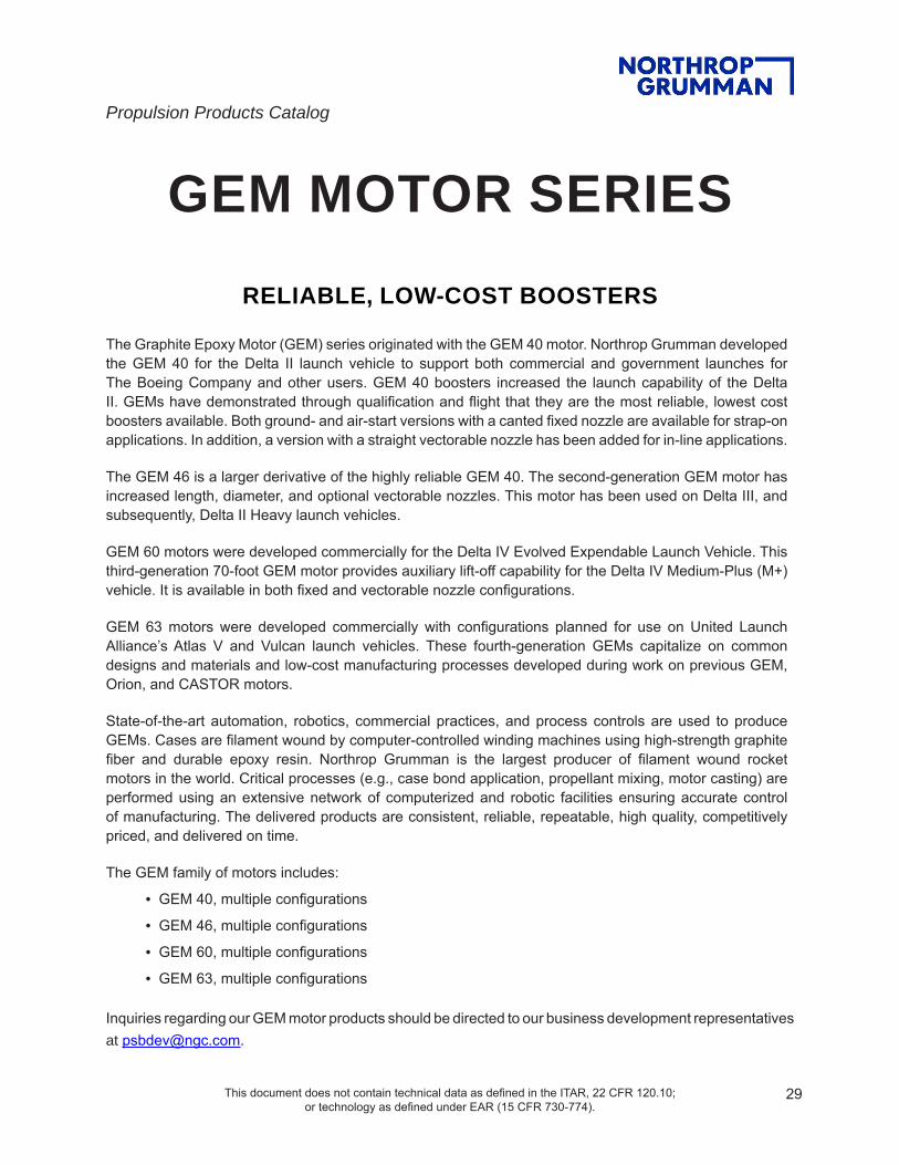
GEM MOTOR SERIESRELIABLE, LOW-COST BOOSTERS
The Graphite Epoxy Motor (GEM) series originated with the GEM 40 motor. Northrop Grumman developed the GEM 40 for the Delta II launch vehicle to support both commercial and government launches for The Boeing Company and other users. GEM 40 boosters increased the launch capability of the Delta II. GEMs have demonstrated through qualification and flight that they are the most reliable, lowest cost boosters available. Both ground- and air-start versions with a canted fixed nozzle are available for strap-on applications. In addition, a version with a straight vectorable nozzle has been added for in-line applications.
The GEM 46 is a larger derivative of the highly reliable GEM 40. The second-generation GEM motor has increased length, diameter, and optional vectorable nozzles. This motor has been used on Delta III, and subsequently, Delta II Heavy launch vehicles.
GEM 60 motors were developed commercially for the Delta IV Evolved Expendable Launch Vehicle. This third-generation 70-foot GEM motor provides auxiliary lift-off capability for the Delta IV Medium-Plus (M+) vehicle. It is available in both fixed and vectorable nozzle configurations.
GEM 63 motors were developed commercially with configurations planned for use on United Launch Alliance’s Atlas V and Vulcan launch vehicles. These fourth-generation GEMs capitalize on common designs and materials and low-cost manufacturing processes developed during work on previous GEM, Orion, and CASTOR motors.
State-of-the-art automation, robotics, commercial practices, and process controls are used to produce GEMs. Cases are filament wound by computer-controlled winding machines using high-strength graphite fiber and durable epoxy resin. Northrop Grumman is the largest producer of filament wound rocket motors in the world. Critical processes (e.g., case bond application, propellant mixing, motor casting) are performed using an extensive network of computerized and robotic facilities ensuring accurate control of manufacturing. The delivered products are consistent, reliable, repeatable, high quality, competitively priced, and delivered on time.
The GEM family of motors includes:
• GEM 40, multiple configurations
• GEM 46, multiple configurations
• GEM 60, multiple configurations
• GEM 63, multiple configurations
Inquiries regarding our GEM motor products should be directed to our business development representatives at [email protected].

30Approved for Public Release OSR No. 16-S-1432; Dated 05 April 2016 This document does not contain technical data as defined in the ITAR, 22 CFR 120.10;
or technology as defined under EAR (15 CFR 730-774)
For more information, contact: [email protected]
northropgumman.com
GEM 40 (GROUND IGNITED)
MOTOR DIMENSIONSMotor diameter, in. ...............................................40.4Overall motor length (including nozzle), in. ..........435Nozzle exit cone diameter, in .............................32.17
MOTOR PERFORMANCE (73°F NOMINAL)Burn time, sec ......................................................63.3Maximum thrust, lbf .......................................144,740Specific impulse, lbf-sec/lbm .............................274.0Total impulse, lbf-sec ..................................7,107,800Burn time average thrust, lbf ......................... 112,200
WEIGHTS, LBMTotal motor .......................................................28,577Propellant .......................................................25,940Burnout ..............................................................2,429
PROPELLANT DESIGNATION .............. QDL-1, HTPB POLYMER, 19% ALUMINUM
HAZARDS CLASSIFICATION… .................. 1.3
RACEWAY .................................................. YES
ORDNANCE .................................................NO
TVA ..............................................................NO
TEMPERATURE LIMITSOperation .................................................+30°-100°FStorage ....................................................+30°-100°F
PRODUCTION STATUS ...........FLIGHT-PROVEN, INACTIVE PRODUCTION
FIXED NOZZLE, GROUND-IGNITEDThe 40-inch-diameter graphite epoxy motor (GEM 40) is a strap-on booster system developed to provide thrust augmentation for the Delta II launch vehicle. The GEM 40 features an IM7/55A graphite epoxy motor case, an aramid-filled EPDM insulator, and a 10-degree canted, fixed nozzle assembly. The nozzle has a high-performance 3-D carbon-carbon throat and carbon phenolic insulators. Ignition is accomplished with a forward-mounted pyrogen igniter. The GEM 40 motor also includes a raceway assembly, forward interstage, and aft attach ball interfaces. GEM 40 strap-on boosters began launching Delta II vehicles in 1990, with final flight in September 2018, ending a successful 28-year, 1,003-motor era.

31Approved for Public Release OSR No. 16-S-1432; Dated 05 April 2016 This document does not contain technical data as defined in the ITAR, 22 CFR 120.10;
or technology as defined under EAR (15 CFR 730-774)
For more information, contact: [email protected]
northropgumman.com
MOTOR DIMENSIONSMotor diameter, in. ...............................................40.4Overall motor length (including nozzle), in. .......449.1Nozzle exit cone diameter, in. ............................38.80
MOTOR PERFORMANCE (73°F NOMINAL)Burn time, sec ......................................................63.3Maximum thrust, lbf…. ...................................149,660Effective specific impulse, lbf-sec/lbm ...............283.4Total impulse, lbf-sec ..................................7,351,000Burn time average thrust, lbf ......................... 116,050
WEIGHTS, LBMTotal motor .......................................................28,883Propellant .......................................................25,940Burnout ..............................................................2,649
PROPELLANT DESIGNATION .............. QDL-1, HTPB POLYMER, 19% ALUMINUM
HAZARDS CLASSIFICATION…. ................. 1.3
RACEWAY .................................................. YES
ORDNANCE .................................................NO
TVA ...............................................................NO
TEMPERATURE LIMITSOperation .................................................+30°-100°FStorage ....................................................+30°-100°F
PRODUCTION STATUS ..........FLIGHT PROVEN, INACTIVE PRODUCTION
FIXED NOZZLE, AIR-IGNITED
GEM 40 (AIR IGNITED)
The 40-inch-diameter graphite epoxy motor (GEM 40) is a strap-on booster system developed to provide thrust augmentation for the Delta II launch vehicle. The GEM 40 features an IM7/55A graphite composite motor case, an aramid-filled EPDM insulator, and a 10-degree canted, fixed nozzle assembly. For the Delta II nine-motor configuration, six motors are ignited on the ground and three in the air. The air-start (altitude-ignited) GEM 40 motor configuration has a lengthened nozzle exit cone with higher expansion ratio, exit-plane-mounted nozzle closure system that is ejected at air-start motor ignition, and a different external insulation scheme. The GEM 40 has flown on Delta II vehicles since 1991. GEM 40 strap-on boosters began launching Delta II vehicles in 1990, with final flight in September 2018, ending a successful 28-year, 1,003-motor era.

32Approved for Public Release OSR No. 16-S-1432; Dated 05 April 2016 This document does not contain technical data as defined in the ITAR, 22 CFR 120.10;
or technology as defined under EAR (15 CFR 730-774)
For more information, contact: [email protected]
northropgumman.com
MOTOR DIMENSIONSMotor diameter, in. ...............................................40.4Overall motor length (including nozzle), in. .......425.1Nozzle exit cone diameter, in. ..............................32.3
MOTOR PERFORMANCE (73°F NOMINAL)Burn time, sec ......................................................64.6Maximum thrust…. ........................................139,036Effective specific impulse, lbf-sec/lbm ...............265.3Total impulse, lbf-sec ..................................6,950,000Burn time average thrust, lbf .........................107,625
WEIGHTS, LBMTotal motor .......................................................28,886Propellant .......................................................25,940Burnout ..............................................................2,607
PROPELLANT DESIGNATION .............. QDL-1, HTPB POLYMER, 19% ALUMINUM
RACEWAY .................................................. YES
ORDNANCE ................................................NO
TVA ............................................................ YES
TEMPERATURE LIMITSOperation .................................................+30°-100°FStorage ....................................................+30°-100°F
PRODUCTION STATUS ..........FLIGHT PROVEN, INACTIVE PRODUCTION
GEM 40VN
VECTORABLE NOZZLE, GROUND-IGNITED, IN-LINE MOTORThe GEM 40VN booster is derived from the successful GEM 40 booster. The GEM 40VN maintains the same loaded motor configuration as the GEM 40 with a design modification to the nozzle assembly to provide ±6-degree thrust vector capability. Air-ignition with extended length nozzle can also be readily provided. The GEM 40VN can be used in both in-line and strap-on booster applications. A version of this motor has been developed and was qualified for use on the Boost Vehicle/Boost Vehicle Plus (BV/BV+) configuration for the Ground-based Midcourse Defense missile interceptor program.

33Approved for Public Release OSR No. 16-S-1432; Dated 05 April 2016 This document does not contain technical data as defined in the ITAR, 22 CFR 120.10;
or technology as defined under EAR (15 CFR 730-774)
For more information, contact: [email protected]
northropgumman.com
MOTOR DIMENSIONSMotor diameter, in. ...............................................45.1Overall motor length (including nozzle), in. .......495.8Nozzle exit cone diameter, in. ............................39.93
MOTOR PERFORMANCE (73°F NOMINAL, VACUUM)Burn time, sec ......................................................75.9Maximum thrust…. ........................................198,800Specific impulse, lbf-sec/lbm .............................277.8Total impulse, lbf-sec ................................10,425,000Burn time average thrust, lbf .........................137,300
WEIGHTS, LBMTotal motor .......................................................41,590Propellant .......................................................37,180Burnout ..............................................................4,050
PROPELLANT DESIGNATION ................ QEM, HTPB POLYMER, 19% ALUMINUM
HAZARDS CLASSIFICATION…. ................. 1.3
RACEWAY ................................................. YES
ORDNANCE ................................................NO
TVA ..............................................................NO
TEMPERATURE LIMITSOperation .................................................+30°-100°FStorage ....................................................+30°-100°F
PRODUCTION STATUS ..........FLIGHT-PROVEN, INACTIVE PRODUCTION
GEM 46 (FIXED, GROUND-IGNITED)
FIXED NOZZLE, GROUND-IGNITED
The larger diameter, extended length graphite epoxy motor (GEM 46) is a strap-on booster system originally developed to increase the payload-to-orbit capability of the Delta III launch vehicle. The GEM 46 features an IM7/55A graphite composite motor case, an aramid-filled EPDM insulator, and a 10-degree canted, fixed nozzle assembly. The nozzle has a high performance 3-D carbon-carbon throat and carbon phenolic insulators. Ignition is accomplished with a forward-mounted pyrogen igniter. The GEM 46 booster includes raceway assembly, forward interstage, and aft attach ball interfaces. GEM 46 motors have been used on both the Delta II Heavy and Delta III launch vehicles.

34Approved for Public Release OSR No. 16-S-1432; Dated 05 April 2016 This document does not contain technical data as defined in the ITAR, 22 CFR 120.10;
or technology as defined under EAR (15 CFR 730-774)
For more information, contact: [email protected]
northropgumman.com
MOTOR DIMENSIONSMotor diameter, in. ...............................................45.1Overall motor length (including nozzle), in. .......491.5Nozzle exit cone diameter, in. ............................36.93
MOTOR PERFORMANCE (73°F NOMINAL, VACUUM)Burn time, sec ......................................................76.9Maximum thrust, lbf…. ...................................196,600Specific impulse, lbf-sec/lbm .............................279.8Total impulse, lbf-sec ................................10,400,000Burn time average thrust, lbf .........................135,200
WEIGHTS, LBMTotal motor .......................................................42,196Propellant ........................................................37,180Burnout ..............................................................4,656
PROPELLANT DESIGNATION ................ QEM, HTPB POLYMER, 19% ALUMINUM
HAZARDS CLASSIFICATION…. ................. 1.3
RACEWAY .................................................. YES
ORDNANCE ................................................NO
TVA ............................................................ YES
TEMPERATURE LIMITSOperation .................................................+30°-100°FStorage ....................................................+30°-100°F
PRODUCTION STATUS ...........FLIGHT-PROVEN, INACTIVE PRODUCTION
GEM 46 (VECTORABLE, GROUND-IGNITED)
VECTORABLE NOZZLE, GROUND-IGNITED
The larger diameter, extended length graphite epoxy motor (GEM 46) is a strap-on booster system originally developed to increase the payload-to-orbit capability of the Delta III launch vehicle. The GEM 46 features an IM7/55A graphite composite motor case and an aramid-filled EPDM insulator. This configuration has a 5-degree canted, ±5-degree moveable nozzle assembly with a high-performance 3-D carbon-carbon throat and carbon phenolic insulators. Ignition is accomplished with a forward mounted pyrogen igniter. This GEM 46 booster includes thrust vector actuation, raceway assembly, forward interstage, and aft attach ball interfaces. Three of these vectorable-nozzle ground-ignited motors were used on each Delta III.

35Approved for Public Release OSR No. 16-S-1432; Dated 05 April 2016 This document does not contain technical data as defined in the ITAR, 22 CFR 120.10;
or technology as defined under EAR (15 CFR 730-774)
For more information, contact: [email protected]
northropgumman.com
GEM 46 (FIXED, AIR-IGNITED)
MOTOR DIMENSIONSMotor diameter, in. ...............................................45.1Overall motor length (including nozzle), in. .......508.6Nozzle exit cone diameter, in. ............................49.25
MOTOR PERFORMANCE (73°F NOMINAL, VACUUM)Burn time, sec ......................................................75.9Maximum thrust, lbf…. ...................................206,000Specific impulse, lbf-sec/lbm .............................290.7Total impulse, lbf-sec ................................10,803,000Burn time average thrust, lbf .........................142,300
WEIGHTS, LBMTotal motor .......................................................42,039Propellant .......................................................37,180Burnout ..............................................................4,397
PROPELLANT DESIGNATION ................ QEM, HTPB POLYMER, 19% ALUMINUM
HAZARDS CLASSIFICATION…. ................. 1.3
RACEWAY ................................................. YES
ORDNANCE ................................................NO
TVA ..............................................................NO
TEMPERATURE LIMITSOperation .................................................+30°-100°FStorage ....................................................+30°-100°F
PRODUCTION STATUS ...........FLIGHT-PROVEN, INACTIVE PRODUCTION
FIXED NOZZLE, AIR-IGNITEDThe larger diameter, extended length graphite epoxy motor (GEM 46) is a strap-on booster system originally developed to increase the payload-to-orbit capability of the Delta III launch vehicle. The GEM 46 features an IM7/55A graphite composite motor case, an aramid-filled EPDM insulator, and a 10-degree canted, fixed nozzle assembly. The nozzle has a high-performance 3-D carbon-carbon throat and carbon phenolic insulators. This air-start (altitude-ignited) GEM 46 motor configuration has a lengthened nozzle exit cone with a higher expansion ratio. Ignition is accomplished with a forward-mounted pyrogen igniter. The GEM 46 booster includes raceway assembly, forward interstage, and aft attach ball interfaces. This GEM 46 motor has been used on both the Delta II Heavy and Delta III launch vehicles.

36Approved for Public Release OSR No. 16-S-1432; Dated 05 April 2016 This document does not contain technical data as defined in the ITAR, 22 CFR 120.10;
or technology as defined under EAR (15 CFR 730-774)
For more information, contact: [email protected]
northropgumman.com
GEM 60 (VECTORABLE)
VECTORABLE NOZZLEThe 60-inch-diameter graphite epoxy motor (GEM 60) is a strap-on booster system developed to increase the payload-to-orbit capability of the Delta IV Medium-Plus (M+) launch vehicles. Two and four strap-on motor configurations of the GEM 60 can be flown on the Delta IV M+ vehicles. The GEM 60 features an IM7R/CLRF-100 graphite composite motor case and aramid-filled EPDM insulator. This configuration has a 5-degree canted, ±5-degree moveable nozzle assembly. The nozzle has a high-performance 3-D carbon-carbon throat, EPDM, and carbon phenolic insulators. Ignition is accomplished with a forward-mounted pyrogen igniter. The GEM 60 booster includes a raceway assembly, forward interstage, aft attach ball interfaces, nosecone, customer-furnished material ordnance/cabling, and closeout hardware. This motor's first flight occurred in November 2002 and was the first flight of the Air Force's Evolved Expendable Launch Vehicle program; final flight was on Delta IV in August 2019.
MOTOR DIMENSIONSMotor diameter, in. ..................................................60Overall motor length (including nozzle), in. ..........518Nozzle exit cone diameter, in. ............................43.12
MOTOR PERFORMANCE (73°F NOMINAL, VACUUM)Burn time, sec ......................................................90.8Maximum thrust…. ........................................277,852Specific impulse, lbf-sec/lbm ................................274Total impulse, lbf-sec ................................17,928,000Burn time average thrust, lbf .........................199,403
WEIGHTS, LBMTotal motor .......................................................74,185Propellant .......................................................65,472Burnout ..............................................................8,203
PROPELLANT DESIGNATION ................QEY, HTPB POLYMER, 19% ALUMINUM
HAZARDS CLASSIFICATION…. ................. 1.3
RACEWAY ................................................. YES
ORDNANCE ............................................... YES
TVA ............................................................ YES
TEMPERATURE LIMITSOperation .................................................+30°-100°FStorage ....................................................+30°-100°F
PRODUCTION STATUS ..........FLIGHT-PROVEN, INACTIVE PRODUCTION

37Approved for Public Release OSR No. 16-S-1432; Dated 05 April 2016 This document does not contain technical data as defined in the ITAR, 22 CFR 120.10;
or technology as defined under EAR (15 CFR 730-774)
For more information, contact: [email protected]
northropgumman.com
GEM 60 (FIXED)
FIXED NOZZLEThe 60-inch-diameter graphite epoxy motor (GEM 60) is a strap-on booster system developed to increase the payload-to-orbit capability of the Delta IV Medium-Plus (M+) launch vehicles. Two and four strap-on motor configurations of the GEM 60 can be flown on the Delta IV M+ vehicles. The GEM 60 features an IM7R/CLRF-100 graphite composite motor case and an aramid-filled EPDM insulator. This configuration has a 10-degree canted, fixed nozzle assembly. The nozzle has a high performance 3-D carbon-carbon throat, EPDM, and carbon phenolic insulators. Ignition is accomplished with a forward-mounted pyrogen igniter. The GEM 60 booster includes a raceway assembly, forward interstage, aft attach ball interfaces, nosecone, customer-furnished material ordnance/cabling, and closeout hardware. This motor’s first flight occurred in December 2009, with final flight on Delta IV in August 2019.
MOTOR DIMENSIONSMotor diameter, in. ..................................................60Overall motor length (including nozzle), in. ..........518Nozzle exit cone diameter, in. ............................43.12
MOTOR PERFORMANCE (73°F NOMINAL, VACUUM)Burn time, sec ......................................................90.8Maximum thrust…. ........................................280,767Specific impulse, lbf-sec/lbm ................................275Total impulse, lbf-sec ................................17,965,776Burn time average thrust, lbf .........................201,260
WEIGHTS, LBMTotal motor .......................................................73,156Propellant .......................................................65,472Burnout ..............................................................7,207
PROPELLANT DESIGNATION ................QEY, HTPB POLYMER, 19% ALUMINUM
HAZARDS CLASSIFICATION…. ................. 1.3
RACEWAY .................................................. YES
ORDNANCE .............................................. YES
TVA ...............................................................NO
TEMPERATURE LIMITSOperation .................................................+30°-100°FStorage ....................................................+30°-100°F
PRODUCTION STATUS ..........FLIGHT-PROVEN, INACTIVE PRODUCTION
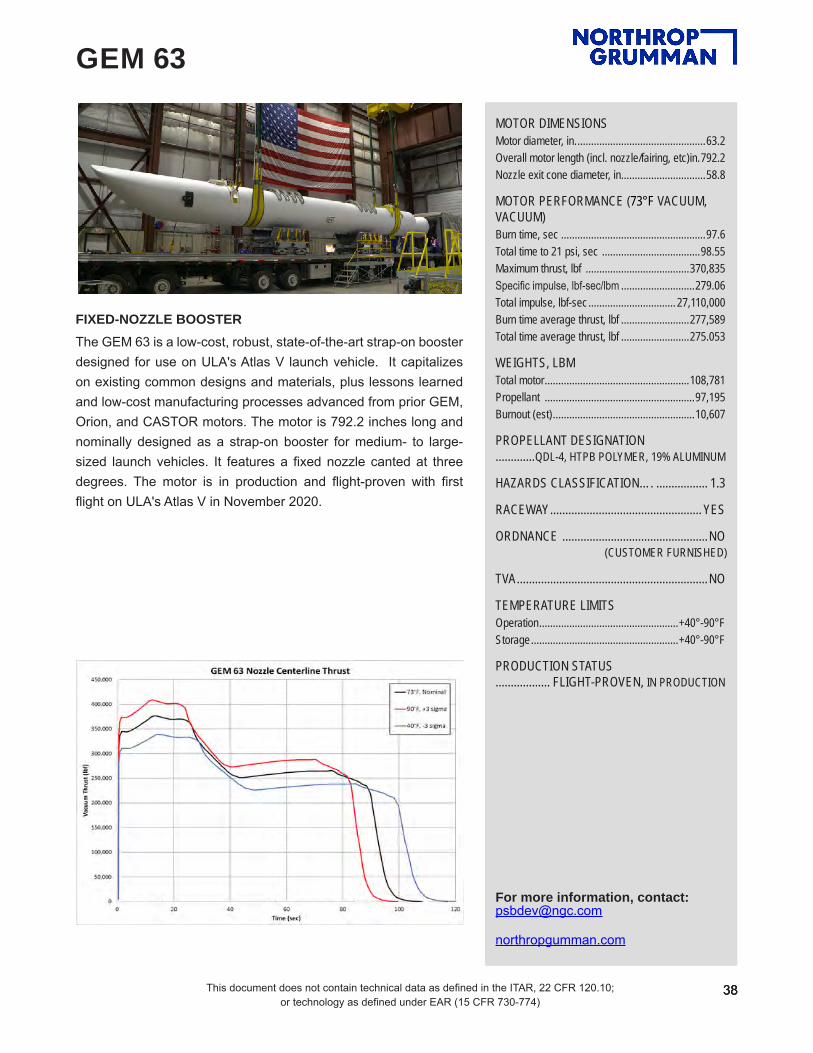
38This document does not contain technical data as defined in the ITAR, 22 CFR 120.10; or technology as defined under EAR (15 CFR 730-774)
38
For more information, contact: [email protected]
northropgumman.com
38
For more information, contact: [email protected]
northropgumman.com
GEM 63
FIXED-NOZZLE BOOSTERThe GEM 63 is a low-cost, robust, state-of-the-art strap-on booster designed for use on ULA's Atlas V launch vehicle. It capitalizes on existing common designs and materials, plus lessons learned and low-cost manufacturing processes advanced from prior GEM, Orion, and CASTOR motors. The motor is 792.2 inches long and nominally designed as a strap-on booster for medium- to large-sized launch vehicles. It features a fixed nozzle canted at three degrees. The motor is in production and flight-proven with first flight on ULA's Atlas V in November 2020.
MOTOR DIMENSIONSMotor diameter, in. ...............................................63.2Overall motor length (incl. nozzle/fairing, etc)in. 792.2Nozzle exit cone diameter, in. ..............................58.8
MOTOR PERFORMANCE (73°F VACUUM, VACUUM)Burn time, sec .....................................................97.6Total time to 21 psi, sec ....................................98.55 Maximum thrust, lbf ......................................370,835Specific impulse, lbf-sec/lbm ...........................279.06Total impulse, lbf-sec ................................ 27,110,000Burn time average thrust, lbf .........................277,589Total time average thrust, lbf .........................275.053
WEIGHTS, LBMTotal motor .....................................................108,781Propellant .......................................................97,195Burnout (est) ....................................................10,607
PROPELLANT DESIGNATION .............QDL-4, HTPB POLYMER, 19% ALUMINUM
HAZARDS CLASSIFICATION…. ................. 1.3
RACEWAY .................................................. YES
ORDNANCE ................................................NO (CUSTOMER FURNISHED)
TVA ...............................................................NO
TEMPERATURE LIMITSOperation ...................................................+40°-90°FStorage ......................................................+40°-90°F
PRODUCTION STATUS .................. FLIGHT-PROVEN, IN PRODUCTION
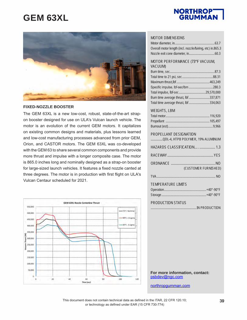
39This document does not contain technical data as defined in the ITAR, 22 CFR 120.10; or technology as defined under EAR (15 CFR 730-774)
39
For more information, contact: [email protected]
northropgumman.com
39
For more information, contact: [email protected]
northropgumman.com
GEM 63XL
FIXED-NOZZLE BOOSTERThe GEM 63XL is a new low-cost, robust, state-of-the-art strap-on booster designed for use on ULA's Vulcan launch vehicle. The motor is an evolution of the current GEM motors. It capitalizes on existing common designs and materials, plus lessons learned and low-cost manufacturing processes advanced from prior GEM, Orion, and CASTOR motors. The GEM 63XL was co-developed with the GEM 63 to share several common components and provide more thrust and impulse with a longer composite case. The motor is 865.0 inches long and nominally designed as a strap-on booster for large-sized launch vehicles. It features a fixed nozzle canted at three degrees. The motor is in production with first flight on ULA's Vulcan Centaur scheduled for 2021.
MOTOR DIMENSIONSMotor diameter, in. ...............................................63.7Overall motor length (incl. nozzle/fairing, etc) in. 865.3Nozzle exit cone diameter, in. ..............................60.3
MOTOR PERFORMANCE (73°F VACUUM, VACUUM)Burn time, sec ......................................................87.3Total time to 21 psi, sec .....................................88.31Maximum thrust,lbf ........................................463,249Specific impulse, lbf-sec/lbm .............................280.3Total impulse, lbf-sec ................................29,570,000Burn time average thrust, lbf .........................337,871Total time average thrust, lbf .........................334,063
WEIGHTS, LBMTotal motor ..................................................... 116,920Propellant .....................................................105,497Burnout (est) ......................................................9,966
PROPELLANT DESIGNATION .............QDL-4, HTPB POLYMER, 19% ALUMINUM
HAZARDS CLASSIFICATION…. ................. 1.3
RACEWAY .................................................. YES
ORDNANCE ................................................NO (CUSTOMER FURNISHED)
TVA ....................................................................... NO
TEMPERATURE LIMITSOperation ...................................................+40°-90°FStorage ......................................................+40°-90°F
PRODUCTION STATUS ....................................................... IN PRODUCTION

Propulsion Products Catalog
This document does not contain technical data as defined in the ITAR, 22 CFR 120.10; or technology as defined under EAR (15 CFR 730-774).
40
REUSABLE SOLID ROCKET MOTOR (RSRM)
In 1974, NASA chose Thiokol (now part of Northrop Grumman) to design and build the solid rocket motors that would boost the fleet of orbiters from the launch pad to the edge of space. With the maiden flight of Columbia (STS-1) in 1981, a new era in space exploration had begun.
The RSRM was the largest solid rocket motor ever to fly and the only solid rocket motor rated for human flight. It was the first booster designed for reuse; reusability of the RSRM case was an important cost-saving factor in the nation’s space program. The boosters provided 80 percent of the thrust needed to launch NASA’s Space Shuttle. Each RSRM consists of four solid propulsion segments, thrust vector control, and an aft exit cone assembly. After burnout at approximately two minutes, the boosters were separated pyrotechnically and fell into the Atlantic for recovery. The motors were cleaned, disassembled, and returned to Utah for refurbishment and reloading. Motor segments are designed for reuse on up to 20 flights. The RSRMs were also designed with the capability to be used as strap-on boosters for other heavy-lift launch vehicle applications.
Inquiries regarding our RSRM motor products should be directed to our business development representatives at [email protected].

41This document does not contain technical data as defined in the ITAR, 22 CFR 120.10; or technology as defined under EAR (15 CFR 730-774)
41
For more information, contact: [email protected]
northropgumman.com
41
For more information, contact: [email protected]
northropgumman.com
RSRM
NASA SPACE SHUTTLE MOTOREach motor is just over 126 ft long and 12 ft in diameter. The entire booster (including nose cap, frustum, and forward and aft skirts) is approximately 149 ft long. Of the motor’s total weight of 1,252,000 lb, propellant accounts for 1,107,000 lb. Each Shuttle launch required the boost of two RSRMs. From ignition to end of burn, each RSRM generated an average thrust of 2,600,000 lb and burned for approximately 123.6 seconds. By the time the twin RSRMs completed their task, the Space Shuttle orbiter reached an altitude of 24 nautical miles and traveled at a speed in excess of 3,000 miles per hour. Engineers directed approximately 110,000 quality control inspections on each RSRM flight set. RSRMs were also static tested as part of the quality assurance and development process.
MOTOR DIMENSIONSMotor diameter, in. .............................................146.1Motor length, in. ............................................1,513.49
MOTOR PERFORMANCE (70°F NOMINAL, VACUUM)Burn time, sec ....................................................122.2Average chamber pressure, psia .......................620.1Total impulse, lbf-sec ..............................297,001,731Web time average thrust, lbf .......................2,430,456
NOZZLEHousing material .......................................D6AC steelExit diameter, in. ..............................................149.64Expansion ratio, average .....................................7.72
WEIGHTS, LBMTotal loaded ................................................1,255,334Propellant ..................................................1,106,059Case ...............................................................98,748Nozzle .............................................................23,942Other ................................................................26,585Burnout ..........................................................144,206
PROPELLANT DESIGNATION .............. TP-H1148, PBAN POLYMER, 86% SOLIDS
HAZARDS CLASSIFICATION…. ................. 1.3
TEMPERATURE LIMITSOperation ....................................................+40º-90ºF
PRODUCTION STATUS .............. FLIGHT PROVEN, OUT OF PRODUCTION

Propulsion Products Catalog
This document does not contain technical data as defined in the ITAR, 22 CFR 120.10; or technology as defined under EAR (15 CFR 730-774).
42
SPACE LAUNCH SYSTEM (SLS) MOTORS
For NASA’s Space Launch System (SLS), Northrop Grumman manufactures the five-segment SLS heavy-lift boosters, the booster separation motors (BSM), and the Launch Abort System’s (LAS) launch abort motor and attitude control motor.
The SLS five-segment booster is the largest solid rocket motor ever built for flight. The SLS booster shares some design heritage with flight-proven four-segment space shuttle reusable solid rocket motors (RSRM), but generates 20 percent greater average thrust and 24 percent greater total impulse. While space shuttle RSRM production has ended, sustained booster production for SLS helps provide cost savings and access to reliable material sources.
Designed to push the spent RSRMs safely away from the space shuttle, Northrop Grumman BSMs were rigorously qualified for human space flight and successfully used on the last fifteen space shuttle missions. These same motors are a critical part of NASA’s SLS. Four BSMs are installed in the forward frustum of each five-segment booster and four are installed in the aft skirt, for a total of 16 BSMs per launch.
The launch abort motor is an integral part of NASA’s LAS. The LAS is designed to safely pull the Orion crew module away from the SLS launch vehicle in the event of an emergency on the launch pad or during ascent. Northrop Grumman is on contract to Lockheed Martin to build the abort motor and attitude control motor—Lockheed is the prime contractor for building the Orion Multi-Purpose Crew Vehicle designed for use on NASA’s SLS.
Inquiries regarding our SLS motor products should be directed to our business development representatives at [email protected].

43This document does not contain technical data as defined in the ITAR, 22 CFR 120.10; or technology as defined under EAR (15 CFR 730-774)
43
For more information, contact: [email protected]
northropgumman.com
43
For more information, contact: [email protected]
northropgumman.com
SLS BOOSTER
VECTORABLE NOZZLE GROUND LAUNCHThe SLS five-segment booster generates a maximum thrust of approximately 3.6 million pounds. The SLS booster also incorporates new technologies and materials, such as non-asbestos insulation that provides cost and weight savings. Originally baselined for Ares I/V under NASA’s Constellation program, the SLS five-segment booster is currently slated as the baseline design for the initial SLS flights. SLS boosters have completed qualification, are in production, and are on schedule to meet NASA’s 2021 initial SLS flight and subsequent flights.
MOTOR DIMENSIONSMotor diameter, in. .............................................146.1Motor length, in. ..............................................1,864.7
MOTOR PERFORMANCE (70°F NOMINAL, VACUUM)Burn time, sec ....................................................132.8Average chamber pressure, psia ..........................572Total impulse, lbf-sec ..............................298,000,000Burn time average thrust, lbf ......................2,247,233
NOZZLEHousing material .......................................D6AC steelExit diameter, in. ................................................149.6Expansion ratio, average .....................................7.72
WEIGHTS, lbmTotal loaded ................................................1,616,123Propellant ..................................................1,427,807Case ...............................................................99,326Nozzle .............................................................24,140Other ................................................................40,456Burnout ..........................................................158,604
PROPELLANT DESIGNATION ........TP-H1148 VIII, PBAN POLYMER, 86% SOLIDS
HAZARDS CLASSIFICATION…. ................. 1.3
TEMPERATURE LIMITS Operation ....................................................+40º-90ºF
PRODUCTION STATUS ....................................................... IN PRODUCTION
Pressure, psia

44This document does not contain technical data as defined in the ITAR, 22 CFR 120.10; or technology as defined under EAR (15 CFR 730-774)
44
For more information, contact: [email protected]
northropgumman.com
44
For more information, contact: [email protected]
northropgumman.com
BSM
MOTOR DIMENSIONSMotor diameter, in. .............................................12.88Motor length, in. ...................................................31.1Nozzle exit cone diameter, in. ............................7.564
MOTOR PERFORMANCE (60°F NOMINAL, VACUUM)Burn time, sec ......................................................0.68Maximum thrust, lbf .........................................22,500Effective specific impulse, lbf-sec/lbm ..................239Total impulse, lbf-sec .......................................18,400Burn time average thrust, lbf ...........................22,100
WEIGHTS, LBMTotal loaded ..........................................................167Propellant ..............................................................77
PROPELLANT DESIGNATION ........... TP-H1262
HAZARDS CLASSIFICATION…. ................. 1.3
RACEWAY ....................................................NO
ORDNANCE .................................................NO
THRUST VECTOR CONTROL .....................NO
TEMPERATURE LIMITSOperation ................................................... 30-120 °FStorage ...................................................... 30-120 °F
PRODUCTION STATUS ........................FLIGHT-PROVEN, IN PRODUCTION
VERSATILE BOOSTER SEPARATION, DECELERATION, OR
TUMBLE MOTORDesigned to push the spent reusable solid rocket motors safely away from the capsule, Northrop Grumman BSMs were rigorously qualified for human space flight and successfully used on the last fifteen space shuttle missions. These same motors are a critical part of NASA’s SLS. Four BSMs are installed in the forward frustum of each booster and four are installed in the aft skirt, for a total of 16 BSMs per launch. All 16 BSMs fire simultaneously at booster separation a little over two minutes into the mission, approximately 25 nautical miles above the earth’s surface. Traveling 3,000 miles per hour at ignition, each BSM provides about 20,000 pounds average thrust over its one-second burn, ensuring successful launch to orbit. Variants of the BSM have also been developed and successfully used as first stage deceleration and tumble motors on NASA’s Ares I-X vehicle in 2009.

45This document does not contain technical data as defined in the ITAR, 22 CFR 120.10; or technology as defined under EAR (15 CFR 730-774)
45
For more information, contact: [email protected]
northropgumman.com
45
For more information, contact: [email protected]
northropgumman.com
LAUNCH ABORT MOTOR
INNOVATIVE TURN-FLOW MANIFOLD TECHNOLOGYThe Launch Abort Motor is an integral part of the Launch Abort System (LAS). Attached atop of Orion spacecraft on the SLS, the LAS is designed to safely pull the Orion crew module away from the launch vehicle in the event of an emergency on the launch pad or during ascent. The abort motor is more than 17 feet tall and measures three feet in diameter, and includes a revolutionary turn-flow rocket manifold technology. The abort motor was successfully static tested by Northrop Grumman in November 2008, June 2017, and December 2018 and successfully flight tested during Orion’s Pad Abort 1 test in 2010 and Ascent Abort-2 test in 2019.
MOTOR DIMENSIONSMotor diameter, in. ...............................................36.7Overall motor length (incl. nozzle/fairing, in. ......223.7Nozzle exit cone diameter, in. ..............................20.2
MOTOR PERFORMANCE (70°F VACUUM, VACUUM))Burn time, sec ........................................................4.3Maximum thrust, lbf .......................................412,240Effective specific impulse, lbf-sec/lbm ...............226.4Total impulse, Mlbf-sec ...............................1,046,600Burn time average thrust, lbf .........................261,000
WEIGHTS, LBMTotal motor .........................................................7,629Propellant .........................................................4,750Burnout (est) .........................................................N/A
PROPELLANT DESIGNATION ................................. .......... TP-H1264, HTPB POLYMER, 6% ALUMINUM
HAZARDS CLASSIFICATION…. ................. 1.3
RACEWAY .................................................. YES
ORDNANCE ......................................................... NO
THRUST VECTOR CONTROL ............................. NO
TEMPERATURE LIMITSOperation ....................................................27-100 °FStorage .......................................................27-100 °F
PRODUCTION STATUS ............................................. ....................... COMPLETING DEVELOPMENT AND QUALIFICATION

Propulsion Products Catalog
This document does not contain technical data as defined in the ITAR, 22 CFR 120.10; or technology as defined under EAR (15 CFR 730-774).
46
LAUNCH STRUCTURES SUMMARY INFORMATIONInquiries regarding launch structures should be directed to our business development representatives at [email protected].

47Approved for Public Release OSR No. 16-S-1432; Dated 05 April 2016 This document does not contain technical data as defined in the ITAR, 22 CFR 120.10;
or technology as defined under EAR (15 CFR 730-774)
For more information, contact: [email protected]
northropgumman.com
ATLAS V STRUCTURESCORE VEHICLE
5M DIAMETER STRUCTURES FABRICATED WITH AUTOMATED TECHNOLOGYFeaturing state-of-the art designs, materials, and processes, the Atlas V family of rockets offers higher performance and greater reliability than its predecessors. The robustness of the Atlas V system is enhanced by the use of common system elements assembled into a family of vehicles that satisfy a wide range of mission requirements while providing substantial performance margins.Northrop Grumman’s Role
• Three part configurations
1. Heat shield
2. Centaur interstage adapter
3. Boattail• Up to 5.4m in diameter (17.5 ft)• Fabricated using automated fiber placement and advanced
hand layup techniques• Manufactured at the Large Structures Center of Excellence
facility
Customer: United Launch Alliance
Prime Contractor: United Launch AllianceNorthrop Grumman has pioneered the use of automated fiber placement for launch vehicle structures.
Heat Shield
Interstage
Boattail
PRODUCTS

48Approved for Public Release OSR No. 16-S-1432; Dated 05 April 2016 This document does not contain technical data as defined in the ITAR, 22 CFR 120.10;
or technology as defined under EAR (15 CFR 730-774)
For more information, contact: [email protected]
northropgumman.com
DELTA IV STRUCTURESCOMMON BOOSTER CORE AND PAYLOAD ACCOMMODATIONS
5M DIAMETER CORE VEHICLE STRUCTURESDelta IV is one of two rockets currently in use by the United States Air Force’s Evolved Expendable Launch Vehicle program. The Delta IV is designed to reduce launch costs and provide assured access to space for U.S. government, commercial, and civilian launch customers.The Delta IV family consists of five launch vehicles based on a common booster core first stage. The second stage is derived from the Delta III, with expanded fuel and oxidizer tanks. GEM 60 strap-ons can be added to provide additional launch capability.Northrop Grumman’s Role
• Family of 10 configurations
1. Centerbodies
2. Interstages
3. Thermal shields
4. Nose cones
5. Payload fairings
6. Payload adapters
7. X-Panels• Up to 5m in diameter (16 ft)• Up to 19m in length (63 ft)• Manufactured using advanced hand layup techniques,
machining, and inspection techniques at the Large Structures Center of Excellence facility
Customer: United Launch Alliance
Prime Contractor: United Launch Alliance
Northrop Grumman provides over 17 different part configurations for the Delta IV family of launch vehicles.
PRODUCTS
Nose Cone
Centerbody
Thermal Shield

49Approved for Public Release OSR No. 16-S-1432; Dated 05 April 2016 This document does not contain technical data as defined in the ITAR, 22 CFR 120.10;
or technology as defined under EAR (15 CFR 730-774)
For more information, contact: [email protected]
northropgumman.com
GEM MOTOR CASESFAMILY OF COMPOSITE CASES
LIGHTWEIGHT CASES SUPPORT MISSION AND COST OBJECTIVESThe Delta family of launch vehicles is configured with affordable, high-performance graphite epoxy motor (GEM) cases to provide additional lift capability during first stage ignition.
Designed to take advantage of proven, off-the-shelf tech-nologies, the GEM system provides increased performance and heavier lift capability than the boosters of its predecessors. GEMs have demonstrated - through qualification and flight – that they are the most reliable, lowest cost boosters available.
State-of-the-art automation, robotics, and process controls are used to produce GEMs. Cases are filament wound at Northrop Grumman’s facility in Clearfield, Utah by computer-controlled winding machines using high-strength graphite fiber and durable epoxy resin.Northrop Grumman’s Role
• Composite filament-wound cases
1. 40, 46 and 60 inches in diameter
2. Up to 42.5 ft. in length
3. Over 1150 cases delivered
4. Production is in the 26th year• Composite filament-wound igniter casings• Composite aeroskirts and nose cones
Customer: Northrop Grumman
Prime Contractor: United Launch Alliance
Northrop Grumman uses proven hand layup techniques to produce
GEM 60 nose cones
GEM cases are produced using advanced filament winding
techniques developed and refined by Northrop Grumman for
over 40 years
PRODUCTS

50Approved for Public Release OSR No. 16-S-1432; Dated 05 April 2016 This document does not contain technical data as defined in the ITAR, 22 CFR 120.10;
or technology as defined under EAR (15 CFR 730-774)
For more information, contact: [email protected]
northropgumman.com
ORION MOTOR CASESFAMILY OF COMPOSITE ROCKET MOTOR CASES
OFF-THE-SHELF COMPOSITE CASES FOR COMMERCIAL LAUNCH, MISSILE DEFENSE, AND SCRAM JET APPLICATIONSThe Orion family of composite structures is a versatile line of structures supporting a range of mission platforms. Proven manufacturing techniques, an outstanding performance record, and affordability make Orion the rocket motor of choice.Northrop Grumman's Role
• Pegasus - First, second, and third stage rocket motor cases, interstage, and payload fairing
• Taurus - First, second, and third stage rocket motor cases• Minotaur - Third and fourth stage rocket motor cases• Ground-based Midcourse Defense Orbital Boost Vehicle -
First, second, and third stage rocket motor cases• Proven filament winding and hand layup techniques• Demonstrated reliability and repeatability
Customer: Northrop Grumman
Prime Contractors: Northrop Grumman
Pegasus
Taurus
X-43C
GMD
PRODUCTS
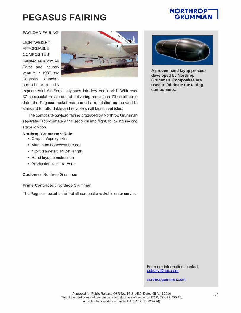
51Approved for Public Release OSR No. 16-S-1432; Dated 05 April 2016 This document does not contain technical data as defined in the ITAR, 22 CFR 120.10;
or technology as defined under EAR (15 CFR 730-774)
For more information, contact: [email protected]
northropgumman.com
PEGASUS FAIRINGPAYLOAD FAIRING
LIGHTWEIGHT, AFFORDABLE COMPOSITESInitiated as a joint Air Force and industry venture in 1987, the Pegasus launches s m a l l , m a i n l y experimental Air Force payloads into low earth orbit. With over 37 successful missions and delivering more than 70 satellites to date, the Pegasus rocket has earned a reputation as the world’s standard for affordable and reliable small launch vehicles.
The composite payload fairing produced by Northrop Grumman separates approximately 110 seconds into flight, following second stage ignition.Northrop Grumman’s Role
• Graphite/epoxy skins• Aluminum honeycomb core• 4.2-ft diameter; 14.2-ft length• Hand layup construction• Production is in 16th year
Customer: Northrop Grumman
Prime Contractor: Northrop Grumman
The Pegasus rocket is the first all-composite rocket to enter service.
A proven hand layupprocess developed by
ATK Composites is used to fabricate the fairing
components
A proven hand layup process developed by Northrop Grumman. Composites are used to fabricate the fairing components.

Propulsion Products Catalog
This document does not contain technical data as defined in the ITAR, 22 CFR 120.10; or technology as defined under EAR (15 CFR 730-774).
52
SMALL MOTOR SUMMARY INFORMATION
TALOS™ II, CASTOR® IB, STAR, STAR STAGES, ASAS, AND ORDNANCE PRODUCTS
Northrop Grumman’s small motor series (Talos, CASTOR IB, STAR, ASAS and ordnance products) span a significant range of size and boost capability, with motors ranging from a few pounds up to approximately 37,000 pounds.
Tabular summaries of STAR motor dimensions, weights, and performance data across the series are pro-vided in the STAR Motor Performance and Experience Summary table within.
Inquiries regarding small motor products should be directed to our business development representatives at [email protected].

Propulsion Products Catalog
This document does not contain technical data as defined in the ITAR, 22 CFR 120.10; or technology as defined under EAR (15 CFR 730-774).
53
TALOS II AND CASTOR® IB MOTORS
Inquiries regarding Talos and CASTOR IB motor products should be directed to our business development representatives at [email protected].

54This document does not contain technical data as defined in the ITAR, 22 CFR 120.10; or technology as defined under EAR (15 CFR 730-774)
For more information, contact: [email protected].
northropgumman.com
TALOS IITM
The Talos II motor is an upgrade to the Talos rocket motor. The Talos II is a high-performance, low-cost booster motor suitable for launch vehices, sounding rockets, and target vehicles. The motor is upgraded with a composite motor case, a higher performance propellant, and a simplified propellant grain geometry. The motor is designed to have common components with the CASTOR IB motor, such as nozzle, igniter, and motor materials. The motor is also designed to be capable of incorporating a thrust vector control nozzle.
MOTOR DIMENSIONSMotor diameter, in. ...............................................32.0Motor length in. ..................................................161.0
MOTOR PERFORMANCE (70°F VACUUM)Burn time, sec ......................................................12.7Burn time average chamber pressure, psia .......1,427Maximum chamber pressure,psia .....................1,772Total impulse, lbf-sec ..................................1,387,370Propellant specific impulse, lbf-sec/lbm .............273.3Effective specific impulse, lbf-sec/lbm ...............271.7Burn time average thrust, lbf ......................... 116,300Maximum thrust, lbf .......................................136,000
NOZZLEInitial throat diameter, in. .....................................6.47Exit diameter, in. .................................................26.7Expansion ratio, average ..................................16:3:1
WEIGHTS, LBMTotal loaded* ......................................................5,753Propellant .........................................................5,083Insulated case assembly ......................................457Nozzle ...................................................................193Igniter ......................................................................20Burnout* ................................................................646 *Excludes ETA lines and S&A
TEMPERATURE LIMITSOperation .....................................................0°-120°FStorage .....................................................-10°-125°F
PROPELLANT DESIGNATION .......... TP-H-3505
CASE MATERIAL…. ....Graphite epoxy composite
PRODUCTION STATUS…. ............ Development

55This document does not contain technical data as defined in the ITAR, 22 CFR 120.10; or technology as defined under EAR (15 CFR 730-774)
For more information, contact: [email protected].
northropgumman.com
CASTOR® IB
The CASTOR IB is an upgrade to the Northrop Grumman CASTOR IA rocket motor. The CASTOR IB is a high perfor-mance, low-cost booster motor suitable for launch vehicles, sounding rockets, and target vehicles. The motor is upgraded with a composite motor case and a higher performance propel-lant. The forward and aft interfaces are identical to that of the CASTOR IA to enable vehicles that have used the CASTOR IA to easily interface with the CASTOR IB. The motor is also designed to be capable of incorporating a thrust vector control nozzle.
MOTOR DIMENSIONSMotor diameter, in. ...............................................32.0Motor length in. ..................................................224.0
MOTOR PERFORMANCE (70°F VACUUM)Burn time, sec. .....................................................51.4Burn time average chamber pressure, psia ..........692Maximum chamber pressure, psia ....................1,310Total impulse, lbf-sec… ..............................2,061,680Propellant specific impulse, lbf-sec/lbm .............278.3Effective specific impulse, lbf-sec/lbm ...............276.2Burn time average thrust, lbf ...........................40,100Maximum thrust, lbf .........................................75,890
NOZZLE Initial throat diameter, in. .....................................6.47Exit diameter, in. .................................................26.7Expansion ratio, average ..................................16.1:1
WEIGHTS, LBMTotal loaded .......................................................8,403Propellant ..........................................................7,356Insulated case assembly ......................................834Nozzle ...................................................................193Igniter ......................................................................20Burnout* ................................................................982 *Excludes S&A
TEMPERATURE LIMITSOperation .....................................................0°-120°FStorage .....................................................-10°-125°F
PROPELLANT DESIGNATION .................................................................. TP-H-8299
CASE MATERIAL….. ...Graphite-epoxy composite
PRODUCTION STATUS ...................Development

Propulsion Products Catalog
Approved for Public Release OSR No. 16-S-1432; Dated 05 April 2016 This document does not contain technical data as defined in the ITAR, 22 CFR 120.10;
or technology as defined under EAR (15 CFR 730-774)
56
ORION SPACECRAFT LAUNCH ABORT SYSTEM
(LAS) ATTITUDE CONTROL MOTOR (ACM)

57Approved for Public Release OSR No. 16-S-1432; Dated 05 April 2016 This document does not contain technical data as defined in the ITAR, 22 CFR 120.10;
or technology as defined under EAR (15 CFR 730-774)
For more information, contact: [email protected].
northropgumman.com
ORION LAS ACM TE-M-1174-1
MOTOR DIMENSIONSMotor diameter, in. ...................................... 32.0Motor length, in. .......................................... 62.8
MOTOR PERFORMANCE (60°F VACUUM)**Burn time/action time, sec .................. 29.4/32.3Ignition rise time, sec ................................ 0.120Pressure, psia .............. 2,180 boost/600 sustainMaximum chamber pressure, psia ........... 2,400Total impulse, lbf-sec ........................99,000 minThrust, lbf .....7,000 min boost/2,500 min sustain
NOZZLESEight, fully proportional valves with single fault tol-erant electromechanical actuation and 100 msec response full stroke
WEIGHTS, LBMTotal loaded* .......................................... 1,629.1Propellant (including igniter propellant) .... 608.2Case assembly ......................................... 538.0Valve assembly (each including actuator) .. 23.3Total inert ............................................... 1,020.9Burnout* ................................................. 1,019.0Propellant mass fraction* ............................ 0.37*Excluding remote S&A/ETA
TEMPERATURE LIMITSOperation ............................................ 33°-99°FStorage ............................................. 30°-100°F
PROPELLANT DESIGNATION .......TP-H-3174
CASE MATERIAL ............................ D6AC steel
The attitude control motor was designed and tested between 2007 and 2010 to control pitch and yaw of the launch abort tower for the Orion spacecraft during an abort maneuver. It is the first human-rated, single fault tolerant solid control system to be flight qualified and flew May 6, 2010 on the PA-1 flight. The design uses a medium-energy propellant and high-strength D6AC steel case. The eight proportional valves utilize 4-D carbon-carbon, silicon carbide for the erosion-sensitive parts. The Launch Abort System attitude control motor was successfully tested during the Orion Crew Vehicle's Pad Abort 1 Test in 2010 and Ascent Abort 2 test in 2019.

Propulsion Products Catalog
Approved for Public Release OSR No. 16-S-1432; Dated 05 April 2016 This document does not contain technical data as defined in the ITAR, 22 CFR 120.10;
or technology as defined under EAR (15 CFR 730-774)
58
STAR™ MOTOR SERIES
PERFORMANCE, CAPABILITY, INTERFACE TAILORING, AND TECHNICAL SUPPORT
SERVICES FOR STAR MOTORS
Northrop Grumman’s STAR, ASAS, Orion, CASTOR, GEM, and RSRM motors span a significant range of impulse capability. Specific applications often require design tailoring and technical support to best achieve mission goals.
The sections that follow describe how Northrop Grumman tailors ballistic performance, provides mission specific capabilities, and/or delivers technical support for STAR series space motors. Similar performance tailoring and support can be provided for our other products.
Tailor Ballistic Performance. Specific examples include efforts to achieve the following goals:
• Increase propellant loading and thus total impulse by stretching motor length
• Cut back or off-load the propellant grain to reduce propellant weight and total impulse
• Limit peak thrust/acceleration levels on the payload/spacecraft by altering propellant formulations and/or grain geometry and/or operating pressure
• Modify the nozzle to adjust throat erosion and thrust profiles
• Incorporate an exit cone extension (e.g., a gas-deployed skirt) to enhance expansion ratio and overall performance
• Minimize performance variation by machining propellant grains to precise weight tolerances and by providing thermal systems to maintain propellant grain temperature
• Incorporate mission-specific propellants that provide desired energy levels, environmental compatibility, and/or exhaust characteristics
Provide Desired Mission-Specific Capabilities. Northrop Grumman is pleased to support our customers with designs that will meet mission-specific conditions. This includes incorporation of additional capabilities and/or providing design compliance with customer-specified flight envelopes, interfaces, and environments. Examples include the following:
• Use of alternative case materials (steel, aluminum, titanium, composite)
• Qualification to new environments
• Use of proven materials to ensure space storability

Propulsion Products Catalog
Approved for Public Release OSR No. 16-S-1432; Dated 05 April 2016 This document does not contain technical data as defined in the ITAR, 22 CFR 120.10;
or technology as defined under EAR (15 CFR 730-774)
59
• Exit cone length truncation or shortening to fit within a restricted envelope
• Provision of active thrust vector control for vehicle steering
• Incorporation of a reaction control system for motor and stage pointing
• Furnishing of thermal protection of spacecraft structures from the heat of motor operation through postfiring heat soak
• Provision of thermal management, using heaters and/or blankets prior to operation
• Integration of motors/stages with spin and de-spin motors and collision avoidance systems
• Design of stages with associated command timers and/or avionics and power systems and related software to enable autonomous stage operation
• Integration of advanced ordnance components for motor initiation, stage separation, and flight termination
• Accommodation of specific spacecraft structural interfaces including incorporation of tabs, skirts, and/or complete interstage structures fabricated from metal or composite material
• Movement or modification of attachment features as required to mate with space-craft/payload
Technical Support. Northrop Grumman can provide technical alternatives and support for design and flight efforts, including the following:
• Inert mass simulators for system ground tests
• Technical trades on critical design parameters needed for overall system design
• System engineering data and analysis support including performance modeling
• Test and analysis to demonstrate operational capability under new environmental conditions (temperatures, spin conditions, space aging, etc.)
• Logistic, personnel, and technical support for motor shipping, packaging, and integration with the spacecraft or launch vehicle at the launch site including, but not limited to, preparing field handling manuals and providing ground support equipment for the motor (e.g., turnover stands, handling stands, and leak test equipment)
Northrop Grumman has the experience to modify our basic motor designs and can design completely new motors at minimum risk to support specific flight applications (see following figure). We are also prepared to provide required technical support for all of our motor, ordnance, and stage products.
STAR 30BP Motor Was Stretched 7 in. to Yield the STAR 30E
STAR 30BP STAR 30E

Propulsion Products Catalog
Approved for Public Release OSR No. 16-S-1432; Dated 05 April 2016 This document does not contain technical data as defined in the ITAR, 22 CFR 120.10;
or technology as defined under EAR (15 CFR 730-774)
60
Documentation and Field Support. Northrop Grumman has prepared and provided to various customers documentation and field support for launches from Cape Canaveral Air Force Station, Kennedy Space Center, Vandenberg Air Force Base, Kodiak Launch Complex, Tanegashima Space Center, Xi Chang, Wallops Flight Facility, Fort Churchill, San Marcos Test Center, Kwajelin Test Center, China Lake Test Center, and Kourou. For most programs, Northrop Grumman prepares the documents; conducts a training session with the responsible ground crew; participates in auditing and modifying the documents to comply with on-site equipment, facilities, and safety practices; and prepares the final documents prior to delivery of the first flight motor in the field, thereby facilitating safe and efficient handling of the first flight system. Northrop Grumman can also be enlisted to review and assess customer-prepared procedures for the safe handling of our rocket motors.
Field Support. Northrop Grumman has the trained personnel to lead, instruct, and assist ground crews for receipt, maintenance, inspection, checkout, and assembly of motors and ordnance items. Training or instructional sessions are often of value to customers and launch range personnel and can be conducted at Northrop Grumman or on-site.
Instructional Field Handling Documentation. The table below lists the procedural documents that can be prepared at customer request for each motor. Many motor programs have adopted these materials for use in the field as supplemental information in the preparation of vehicle stage or spacecraft propulsion units for inspection, buildup, and assembly at the various launch sites.
Typical Instructional Documentation
Document Type DescriptionEngineering Instruction Describes proper unpacking, handling, storage, and maintenance of the rocket motor in the field (safety
precautions)X-ray Inspection Procedure Establishes radiographic inspection procedure to be used for preflight evaluation using launch site
facilitiesInspection Procedure Delineates proper use of equipment and procedures for verification of motor component integritySafe-and-Arm (S&A) Checkout Procedure
Describes electrical checkout of live S&A devices
Ordnance Assembly Procedure
Delineates proper procedure for checkout and installation of squibs, through-bulkhead initiators, explosive transfer assemblies, and S&A devices
Motor Final Inspection and Assembly Procedure
Delineates inspection and preflight buildup of the rocket motor. This procedure can contain many or all other instructional documents for field support and surveillance
Safety Plan Provides information on the proper safety procedures for handling of explosive devicesHandling Equipment Maintenance Procedure
Describes conduct of periodic proof or load tests to verify equipment adequacy. Delineates proper procedures for maintenance of equipment
Motor Flight Instrumentation Installation and Checkout
Describes proper procedures for installation and checkout of items such as pressure transducers, strain gauges, etc. Delineates precautions and need for testing following installation
Other Instruction Many systems have unique requirements for ancillary equipment or ordnance items. Procedures can be prepared to meet almost any system need (e.g., spin balancing)

Propulsion Products Catalog
Approved for Public Release OSR No. 16-S-1432; Dated 05 April 2016 This document does not contain technical data as defined in the ITAR, 22 CFR 120.10;
or technology as defined under EAR (15 CFR 730-774)
61
Motor Ground Support Equipment. In addition to shipping containers, we can provide a variety of ground support equipment for use in handling, inspection, and assembly of the rocket motor and ordnance devices. Northrop Grumman also designs mission-specific equipment for installation of the motor into the spacecraft or stage. Typical ground support equipment available includes the following:
• Shipping containers
• Turnover stands
• Inert mass simulators
• Leak test equipment
In-Transit Instrumentation. Space motors are sensitive to temperature, humidity, and shock loads. Monitoring of the environmental conditions during transportation of space motors is critical. Several standard and proven devices are available. We can also accommodate special problems, such as long periods of transit. Some of the items readily available are:
• Temperature recorders
• Shock indicators
• Humidity indicators
Generally, Northrop Grumman personnel have monitored all activities during development, qualification, and lot acceptance testing of Northrop Grumman motors at various test sites in the United States, Japan, French Guiana, and China. We strongly recommend this support for every flight program. We can provide trained personnel to monitor activities at the launch site or in customer test facilities and to assist in resolution of problems.
Postflight Analysis. Analysis of flight data can help identify trends in motor performance and thus eliminate potential problems. Further, evaluation during a program helps enhance the predictability of flight performance. For example, comparison of ground data with other flight data may enable the customer to reduce the weight of fuel for velocity trimming and reaction control system, allowing for potential of enhanced spacecraft usable weight on subsequent launches.
Typical postflight analysis that Northrop Grumman can support includes the following:
• Ballistic performance
• Acceleration profile
• Derived nonaxial (lateral) thrust data
• Motor temperatures
• Residual thrust
• Other (dependent on flight instrumentation)
Motor Data. A summary of STAR motor performance is presented in the following table. The pages that follow contain data sheets for the various STAR motor configurations.
Inquiries regarding STAR motor products should be directed to our business development representatives at [email protected].

Propulsion Products Catalog
Approved for Public Release OSR No. 16-S-1432; Dated 05 April 2016 This document does not contain technical data as defined in the ITAR, 22 CFR 120.10;
or technology as defined under EAR (15 CFR 730-774)
62
STAR Motor Performance and Experience Summary
STAR Designation
Model Number
Nominal Diameter Total
Impulse, lbf-sec
Effective Specific Impulse,
lbf-sec/lbm
Propellant Weight Propellant Mass
FractionTests Flights
in. cm lbm kg
3 TE-M-1082-1 3.18 8.08 281.4 266.0 1.06 0.48 0.42 26 33A TE-M-1089 3.18 8.08 64.4 241.2 0.27 0.12 0.14 2 34G TE-M-1061 4.45 11.30 595 269.4 2.16 0.98 0.65 2 05* TE-M-500 5.05 12.83 895 189.0 3.8 1.72 0.87 4 115A TE-M-863-1 5.13 13.02 1,289 250.8 5.05 2.27 0.49 6 35C/5CB TE-M-344-15
TE-M-344-164.77 4.77
12.11 12.11
1,252 1,249
268 262.0
4.55 4.62
2.06 2.10
0.47 0.47
245 20
686 160
5D TE-M-989-2 4.88 12.39 3,950 256.0 15.22 6.90 0.68 13 35F TE-M-1198 4.85 12.32 2,216 262.9 8.42 3.82 0.37 9 1946 TE-M-541-3 6.2 15.75 3,077 287.0 10.7 4.85 0.80
47 2386A* TE-M-542-3 6.2 15.75 2,063 285.3 7.2 3.27 0.726B TE-M-790-1 7.32 18.59 3,686 269.0 13.45 6.10 0.60 8 188 TE-M-1076-1 8.06 20.47 7,430 272.9 27.12 12.30 0.71 26 69 TE-M-956-2 9.0 22.86 9,212 289.1 31.8 14.42 0.78 1 010* TE-M-195 10.0 25.40 6,600 251.0 26.3 11.93 0.68 46 Classified12* TE-M-236 12.0 30.48 10,350 252.0 40.3 18.28 0.66 160 34912A* TE-M-236-3 12.1 30.73 13,745 270.0 50.2 22.77 0.67 6 Classified12GV TE-M-951 12.24 31.58 20,669 282.4 72.6 32.9 0.79 5 213* TE-M-458 13.5 34.29 18,800 273.0 68.3 30.98 0.87 7 213A* TE-M-516 13.5 34.29 21,050 286.5 73.0 33.11 0.87 5 913B TE-M-763 13.57 34.47 26,050 285.0 90.9 41.23 0.88 1 213C* TE-M-345-11/12 13.5 34.29 18,200 218.0 66.5 30.16 0.80 125 13113D* TE-M-375 13.5 34.29 17,200 223.0 63.0 28.58 0.81 10 213E* TE-M-385 12.7 32.26 14,200 211.0 55.4 25.13 0.82 65 4813F* TE-M-444 13.5 34.29 21,190 240.0 73.5 33.34 0.83 5 915G TE-M-1030-1 15.04 38.2 50,210 281.8 175.5 79.61 0.85 11 1017 TE-M-479 17.4 44.20 44,500 286.2 153.5 69.63 0.88 6 417A TE-M-521-5 17.4 44.20 71,800 286.7 247.5 112.26 0.89 10 720 Spherical* TE-M-251 20.0 50.80 66,600 234.0 253 114.76 0.93 1 120 TE-M-640-1 19.7 50.04 173,560 286.5 601.6 273.20 0.91 10 3220A* TE-M-640-3 19.7 50.04 184,900 291.9 630.0 285.76 0.91 2 020B* TE-M-640-4 19.8 50.29 174,570 289.1 601.6 272.88 0.89 6 524 TE-M-604 24.5 62.23 126,000 282.9 440.6 199.85 0.92
9 624A* TE-M-604-2 24.5 62.23 112,400 282.4 393.8 178.62 0.9224B* TE-M-604-3 24.5 62.23 126,230 282.9 441.4 200.22 0.9224C TE-M-604-4 24.5 62.23 138,000 282.3 484.0 219.54 0.9226 TE-M-442 26.0 66.04 138,500 271.0 508.5 230.65 0.86
4 1426C TE-M-442-2 26.1 66.29 139,800 272.1 511.4 231.97 0.8826B TE-M-442-1 26.1 66.29 142,760 271.7 524.0 237.68 0.91 1 8

Propulsion Products Catalog
Approved for Public Release OSR No. 16-S-1432; Dated 05 April 2016 This document does not contain technical data as defined in the ITAR, 22 CFR 120.10;
or technology as defined under EAR (15 CFR 730-774)
63
STAR Designation
Model Number
Nominal Diameter Total
Impulse, lbf-sec
Effective Specific Impulse,
lbf-sec/lbm
Propellant Weight Propellant Mass
FractionTests Flights
in. cm lbm kg
27 TE-M-616 27.3 69.34 213,790 287.9 735.6 333.66 0.92 18 3127H TE-M-1157 27.3 69.34 219,195 291.4 744.8 337.84 0.92 1 130* TE-M-700-2 30.0 76.20 300,940 293.0 1,021.7 463.44 0.94 4 030A* TE-M-700-4 30.0 76.20 302,350 294.7 1,021.0 463.12 0.94 1 030B* TE-M-700-5 30.0 76.20 328,200 293.0 1,113.0 504.85 0.94 14 2930BP TE-M-700-20 30.0 76.20 328,455 292.3 1,113.6 505.12 0.93 5 2330C TE-M-700-18 30.0 76.20 376,095 286.4 1,302.5 590.80 0.94 4 2230C/BP TE-M-700-25 30.0 76.20 383,270 291.8 1,302.5 590.80 0.93 0 430E TE-M-700-19 30.0 76.20 407,550 290.4 1,392.0 631.40 0.93 3 1131 TE-M-762 30.1 76.45 840,000 293.5 2,835.0 1285.94 0.93 6 1737* TE-M-364-1 36.8 93.47 356,200 260.0 1,123.0 509.38 0.90 50 637B* TE-M-364-2 36.8 93.47 417,900 291.0 1,440.0 653.17 0.91 1 2137C* TE-M-364-18 36.8 93.47 608,600 285.5 2,125.0 963.88 0.92 1 837D* TE-M-364-3 36.8 93.47 417,900 266.0 1,440.0 653.17 0.91 14 1837E* TE-M-364-4 36.8 93.47 654,200 283.6 2,290.0 1038.73 0.93 13 7537F* TE-M-364-19 36.8 93.47 549,536 286.0 1,909.3 866.04 0.93 8 1037FM TE-M-1139 36.8 93.47 695,620 294.1 2,344.1 1063.27 0.93 5 3037FMV TE-M-1139 36.8 93.47 685,970 289.8 2350.1 1065.99 0.93 0 037G* TE-M-364-11 36.8 93.47 671,809 289.9 2,348.0 1065.04 0.92 4 037GV TE-M-1007-1 35.2 89.41 634,760 293.5 2,148 974.3 0.92 1 037N* TE-M-364-14 36.8 93.47 357,500 290.0 1,232.0 558.83 0.90 1 837S* TE-M-364-15 36.8 93.47 420,329 287.3 1,449.5 657.48 0.92 2 2437X* TE-M-714-1 36.8 93.47 685,148 295.6 2,350.7 1066.26 0.93 1 037XF* TE-M-714-6 36.7 93.22 571,470 290.0 1,950.4 884.69 0.93 9 937XFP TE-M-714-
16/1736.7 93.22 570,040 290.0 1,948.2 883.69 0.92 3 41
37XFPV TE-M-988-1 36.7 93.22 570,040 290.0 1,948.2 883.69 0.91 1 037Y* TE-M-714-2 36.8 93.47 701,000 297.0 2,360.0 1070.48 0.93 2 040* TE-M-186-2 40.1 101.85 443,026 207.0 1,995.0 904.92 0.92 10 048*(short) TE-M-711-3 49.0 124.46 1,269,610 286.6 4,405.0 1998.08 0.95 18 2948*(long) TE-M-711-8 49.0 124.46 1,296,300 292.9 4,405.0 1998.08 0.9448A (short) TE-M-799-1 49.0 124.46 1,528,400 283.4 5,357.2 2429.99 0.94 1 048A (long) TE-M-799 49.0 124.46 1,563,760 289.9 5,357.2 2429.99 0.9448B (short) TE-M-711-17 49.0 124.46 1,275,740 286.0 4,431.2 2009.96 0.94 3 10448B (long) TE-M-711-18 49.0 124.46 1,303,700 292.1 4,431.2 2009.96 0.9448BV TE-M-940-1 49.0 124.46 1,303,700 292.1 4,431.2 2009.96 0.94 3 248V TE-M-940-1 49.0 124.46 1,303,700 292.1 4,431.2 2009.96 0.93 3 148GXV -- 49.0 120.0 1,911,070 306.0 6,205 2814.54 0.92 1 0
63D TE-M-936 63.0 160.02 2,042,450 283.0 7,166.5 3250.67 0.93 5 363F TE-M-963-2 63.1 160.27 2,816,700 297.1 9,401.6 4264.50 0.93 4 275 TE-M-775-1 75.0 190.50 4,797,090 288.0 16,542 7503.32 0.93 1 092 – 93.0 236.22 10,120,100 287.7 34,879 15,820.85 0.94 0 0
*STAR motors that have been replaced by other motor configurations

64Approved for Public Release OSR No. 16-S-1432; Dated 05 April 2016 This document does not contain technical data as defined in the ITAR, 22 CFR 120.10;
or technology as defined under EAR (15 CFR 730-774)
For more information, contact: [email protected].
northropgumman.com
The STAR 3 motor was developed and qualified in 2003 as the transverse impulse rocket system (TIRS) for the Mars Exploration Rover (MER) program for the Jet Propulsion Laboratory (JPL) in Pasadena, CA. Three TIRS motors were carried on each of the MER landers. One of the TIRS motors was fired in January 2004 to provide the impulse necessary to reduce lateral velocity of the MER Spirit lander prior to landing on the Martian surface. The motor also has applicability for spin/despin and separation systems.
MOTOR DIMENSIONSMotor diameter, in. ...............................................3.18Motor length, in. ................................................. 11.36
MOTOR PERFORMANCE (70°F VACUUM)Burn time/action time, sec ...........................0.62/0.66Ignition delay time, sec ........................................0.12Burn time average chamber pressure, psia .......1,502Maximum chamber pressure, psia ....................1,596Total impulse, lbf-sec .........................................281.4Propellant specific impulse, lbf-sec/lbm .............266.0Effective specific impulse, lbf-sec/lbm ...............266.0Burn time average thrust, lbf ................................435Maximum thrust, lbf ..............................................461
NOZZLEInitial throat diameter, in. ...................................0.461Exit diameter, in. ................................................2.072Expansion ratio, initial .......................................20.2:1
WEIGHTS, LBM ................................................Total loaded .........................................................2.55Propellant ...........................................................1.06Case assembly ....................................................0.40Nozzle assembly ................................................0.58Total inert .............................................................1.49Burnout ................................................................1.49Propellant mass fraction ......................................0.42
TEMPERATURE LIMITSOperation .................................................. -40º-104°FStorage ..................................................... -65º-140°F
PROPELLANT DESIGNATION ......... TP-H-3498
CASE MATERIAL .............................. TITANIUM
PRODUCTION STATUS ................................................. FLIGHT-PROVEN
NOTE: Offload configuration delivering 171 lbf-sec of total impulse also qualified
V0504007 [591]
P
THRU
ST, L
BF
PRESSURE, PSIAF
TIME, SEC
0
200
400
600
800
1000
1200
1400
1600
1800
0 0.1 0.2 0.3 0.4 0.5 0.6 0.70
200
400
600
800
1000
1200
1400
1600
1800
STAR 3 TE-M-1082-1

65Approved for Public Release OSR No. 16-S-1432; Dated 05 April 2016 This document does not contain technical data as defined in the ITAR, 22 CFR 120.10;
or technology as defined under EAR (15 CFR 730-774)
For more information, contact: [email protected].
northropgumman.com
STAR 3A TE-M-1089
MOTOR DIMENSIONSMotor diameter, in. ...............................................3.18Motor length, in. .....................................................7.5
MOTOR PERFORMANCE (95°F VACUUM)Burn time/action time, sec ...........................0.44/0.49Ignition delay time, sec ......................................0.007Burn time average chamber pressure, psia ..........520Maximum chamber pressure, psia .......................676Total impulse, lbf-sec ...........................................64.4Propellant specific impulse, lbf-sec/lbm .............241.2Effective specific impulse, lbf-sec/lbm ..............241.2Burn time average thrust, lbf ................................138Maximum thrust, lbf ..............................................180
NOZZLEInitial throat diameter, in. .....................................0.46Exit diameter, in. ....................................................1.1Expansion ratio, initial .........................................5.7:1
WEIGHTS, LBMTotal loaded .........................................................1.96Propellant (including igniter) ................................0.27Total inert .............................................................1.70Burnout ................................................................1.70Propellant mass fraction ......................................0.14
TEMPERATURE LIMITSOperation .................................................. -40º-104°FStorage ..................................................... -65º-140°F
PROPELLANT DESIGNATION ........ TP-H-3498
CASE MATERIAL .............................. TITANIUM
PRODUCTION STATUS ................................................. FLIGHT-PROVEN
The STAR 3A was developed and qualified in 2003 as an offloaded and shortened version of the STAR 3 used for JPL’s Mars Exploration Rover (MER) transverse impulse rocket system (TIRS). It has a shorter case and truncated exit cone to accommodate a lower propellant weight and smaller available volume. The STAR 3A is ideally suited for separation, spin/despin, deorbit, and small satellite applications.
0
20
40
60
80
100
120
140
160
180
0.0 0.1 0.2 0.3 0.4 0.5 0.6 0.7TIME, SEC
THR
US
T, L
BF
V0604003 [593]
0
100
200
300
400
500
600
700
800
PR
ES
SU
RE
, PS
IA
F
P

66Approved for Public Release OSR No. 16-S-1432; Dated 05 April 2016 This document does not contain technical data as defined in the ITAR, 22 CFR 120.10;
or technology as defined under EAR (15 CFR 730-774)
For more information, contact: [email protected].
northropgumman.com
MOTOR DIMENSIONSMotor diameter, in. ...............................................4.45Motor length, in. ...................................................5.43
MOTOR PERFORMANCE (70°F VACUUM)Burn time/action time, sec ...........................10.3/10.8Ignition delay time, sec ......................................0.035Burn time average chamber pressure, psia .......2,185Maximum chamber pressure, psia ....................2,600Total impulse, lbf-sec ............................................595Propellant specific impulse, lbf-sec/lbm .............275.6Effective specific impulse, lbf-sec/lbm ...............269.4Burn time average thrust, lbf ..................................58Maximum thrust, lbf ................................................69
NOZZLEInitial throat diameter, in. .....................................0.15Exit diameter, in. ..................................................1.13Expansion ratio, initial .......................................56.8:1
WEIGHTS, LBMTotal loaded .........................................................3.30Propellant ...........................................................2.16Heavyweight nano ESA .......................................0.17Case assembly ....................................................0.49Nozzle assembly ................................................0.46Total inert .............................................................1.12Burnout ................................................................1.07Propellant mass fraction ......................................0.65
TEMPERATURE LIMITSOperation ..................................................... 40º-90°FStorage ...................................................... 40º-100°F
PROPELLANT DESIGNATION ......... TP-H-3399
CASE MATERIAL .......................... GRAPHITE-EPOXY COMPOSITE
PRODUCTION STATUS ............DEVELOPMENT
STAR 4G TE-M-1061
This STAR motor was developed and tested in January 2000 under a NASA Goddard Space Flight Center program for a low-cost, high mass fraction orbit adjust motor for use in deploying constellations of very small satellites (nanosatellites). The first static test of the STAR 4G prototype motor was conducted 8 months after program start. The motor is designed to operate at high chamber pressure and incorporates a noneroding throat insert to maximize specific impulse.
0
500
1000
1500
2000
2500
3000
0 2 4 6 8 10 12Time, sec
Pre
ssur
e, p
sia
0
10
20
30
40
50
60
70
80
Vac
uum
Thr
ust,
lbf
F
P
V0301055A [482]

67Approved for Public Release OSR No. 16-S-1432; Dated 05 April 2016 This document does not contain technical data as defined in the ITAR, 22 CFR 120.10;
or technology as defined under EAR (15 CFR 730-774)
For more information, contact: [email protected].
northropgumman.com
STAR 5A TE-M-863-1
MOTOR DIMENSIONSMotor diameter, in. ...............................................5.13Motor length, in. ...................................................8.84
MOTOR PERFORMANCE (70°F VACUUM)Burn time/action time, sec ...........................32.0/35.6Ignition delay time, sec ........................................0.04Burn time average chamber pressure, psia ..........453Maximum chamber pressure, psia .......................516Total impulse, lbf-sec .........................................1,289Propellant specific impulse, lbf-sec/lbm .............255.3Effective specific impulse, lbf-sec/lbm ...............250.8Burn time average thrust, lbf ..................................38Maximum thrust, lbf ................................................38
NOZZLEInitial throat diameter, in. .....................................0.24Exit diameter, in. ................................................1.284Expansion ratio, initial .......................................28.6:1
WEIGHTS, LBMTotal loaded .......................................................10.24Propellant ...........................................................5.05Case assembly ....................................................2.02Nozzle assembly ................................................0.57Total inert .............................................................5.17Burnout ................................................................5.08Propellant mass fraction ......................................0.49
TEMPERATURE LIMITSOperation .................................................... -4º-104°FStorage ..................................................... -76º-140°F
SPIN EXPERIENCE, RPM .................UP TO 60
PROPELLANT DESIGNATION .......TP-H-3399
CASE MATERIAL ........................... ALUMINUM
PRODUCTION STATUS .............................................. FLIGHT-PROVEN
The STAR 5A rocket motor was qualified in 1988 to provide a minimum acceleration and extended burn delta-V impulse. With a low-average thrust and a unique off-center nozzle design, the motor can be utilized in many nonstandard geometric configurations for small payload placement or spin-up applications. The STAR 5A first flew in 1989 from the Space Shuttle.

68Approved for Public Release OSR No. 16-S-1432; Dated 05 April 2016 This document does not contain technical data as defined in the ITAR, 22 CFR 120.10;
or technology as defined under EAR (15 CFR 730-774)
For more information, contact: [email protected].
northropgumman.com
MOTOR DIMENSIONSMotor diameter, in. ...............................................4.77Motor length, in. .................................................13.43
MOTOR PERFORMANCE (60°F VACUUM)Burn time/action time, sec ...........................2.80/2.94Ignition delay time, sec ......................................0.015Burn time average chamber pressure, psia .......1,348Maximum chamber pressure, psia ....................1,390Total impulse, lbf-sec .........................................1,252Propellant specific impulse, lbf-sec/lbm .............275.2Effective specific impulse, lbf-sec/lbm ...............268.1Burn time average thrust, lbf ................................439Maximum thrust, lbf ..............................................455
NOZZLEInitial throat diameter, in. ...................................0.483Exit diameter, in. ..................................................2.34Expansion ratio, initial .......................................23.5:1
WEIGHTS, LBMTotal loaded .........................................................9.86Propellant (including igniter propellant) ...............4.55Case assembly ....................................................4.24Nozzle assembly ................................................0.40Total inert ............................................................5.28Burnout ................................................................5.16Propellant mass fraction ......................................0.46
TEMPERATURE LIMITSOperation ................................................... 20º-130°FStorage ..................................................... -25º-130°F
PROPELLANT DESIGNATION .......TP-H-3062
CASE MATERIAL .......................... 4130 STEEL
PRODUCTION STATUS ....... FLIGHT-PROVEN
STAR 5C TE-M-344-15
The STAR 5C rocket motor was initially designed, developed, qualified, and placed in production (1960 through 1963) under a contract with Martin Marietta. The STAR 5C was used to separate the second stage from the trans-stage on the Titan II missile and Titan launch vehicle. The current version was qualified for use in 1976, replacing the earlier main propellant grain with TP-H-3062.

69Approved for Public Release OSR No. 16-S-1432; Dated 05 April 2016 This document does not contain technical data as defined in the ITAR, 22 CFR 120.10;
or technology as defined under EAR (15 CFR 730-774)
For more information, contact: [email protected].
northropgumman.com
STAR 5CB TE-M-344-16
The STAR 5CB rocket motor was redesigned and requalified to separate the second stage from the upper stage on the Titan IV launch vehicle. The motor incorporates a reduced aluminum content (2% Al) propellant to minimize spacecraft contamination during firing. The case, nozzle, and igniter components are unchanged from the STAR 5C design, but the motor has been qualified (in 1989) for the more severe Titan IV environments. This motor was first flown in 1990.
The STAR 5CB has been adapted for other applications. Mounting lugs and studs can be added to the head-end closure while removing the skirts on either end to accommodate mission-specific attachment features.
MOTOR DIMENSIONSMotor diameter, in. ...............................................4.77Motor length, in. .................................................13.43
MOTOR PERFORMANCE (60°F VACUUM)Burn time/action time, sec ...........................2.67/2.77Ignition delay time, sec ......................................0.013Burn time average chamber pressure, psia .......1,388Maximum chamber pressure, psia ....................1,434Total impulse, lbf-sec .........................................1,249Propellant specific impulse, lbf-sec/lbm ................270Effective specific impulse, lbf-sec/lbm ..................262Burn time average thrust, lbf ................................459Maximum thrust, lbf ..............................................492
NOZZLEInitial throat diameter, in. ...................................0.483Exit diameter, in. ..................................................2.34Expansion ratio, initial .......................................23.5:1
WEIGHTS, LBMTotal loaded .........................................................9.93Propellant (excluding 0.03 lbm igniter propellant) 4.62Case assembly ....................................................4.24Nozzle assembly ................................................0.40Total inert ............................................................5.28Burnout ................................................................5.16Propellant mass fraction ......................................0.47
TEMPERATURE LIMITSOperation ..................................................... 0º-130°FStorage ..................................................... -35º-172°F
PROPELLANT DESIGNATION ......TP-H-3237A
CASE MATERIAL .......................... 4130 STEEL
PRODUCTION STATUS ....... FLIGHT-PROVEN
F
P

70Approved for Public Release OSR No. 16-S-1432; Dated 05 April 2016 This document does not contain technical data as defined in the ITAR, 22 CFR 120.10;
or technology as defined under EAR (15 CFR 730-774)
For more information, contact: [email protected].
northropgumman.com
STAR 5D TE-M-989-2
MOTOR DIMENSIONSMotor diameter, in. ...............................................4.88Motor length, in. ...................................................32.7
MOTOR PERFORMANCE (-22°F VACUUM)Burn time/action time, sec ...........................3.03/3.28Ignition delay time, sec ......................................0.029Burn time average chamber pressure, psia .......1,299Maximum chamber pressure, psia ....................1,406Total impulse, lbf-sec .........................................3,950Propellant specific impulse, lbf-sec/lbm .............259.5Effective specific impulse, lbf-sec/lbm ...............256.0Burn time average thrust, lbf ..............................1251Maximum thrust, lbf ...........................................1,410
NOZZLEInitial throat diameter, in. ...................................0.869Exit diameter, in. ................................................2.345Expansion ratio, initial .........................................7.3:1Cant angle, deg ......................................................17
WEIGHTS, LBMTotal loaded .......................................................22.55Propellant (including igniter propellant) .............15.22Case assembly ....................................................5.93Nozzle assembly ................................................1.40Total inert ............................................................7.33Burnout ................................................................7.12Propellant mass fraction ......................................0.68
TEMPERATURE LIMITSOperation .................................................. -67º-158°FStorage ..................................................... -80º-172°F
PROPELLANT DESIGNATION .......TP-H-3062
CASE MATERIAL ..............................TITANIUM
PRODUCTION STATUS .............................................. FLIGHT-PROVEN
The STAR 5D rocket motor was designed and qualified (1996) to serve as the rocket-assisted deceleration motor on the Mars Pathfinder mission for the Jet Propulsion Laboratory (JPL) in Pasadena, CA. The STAR 5D features a titanium case, head-end ignition system, and canted nozzle design and is based on earlier STAR 5 designs. Three of these motors were fired on July 4, 1997, to slow the Pathfinder spacecraft to near-zero velocity before bouncing on the surface of Mars.
0
200
400
600
800
1000
1200
1400
1600
0 0.5 1 1.5 2 2.5 3 3.5
TIME, SEC
THR
UST
, LB
0
200
400
600
800
1000
1200
1400
1600
PRESSU
RE, PSI
F
P
V0703011 [567]

71Approved for Public Release OSR No. 16-S-1432; Dated 05 April 2016 This document does not contain technical data as defined in the ITAR, 22 CFR 120.10;
or technology as defined under EAR (15 CFR 730-774)
For more information, contact: [email protected].
northropgumman.com
STAR 5F TE-M-1198
The STAR 5F rocket motor was designed as the Atlas V launch vehicle first stage retro motor for use during first and second stage separation. It incorporates numerous design features from the STAR 5CB, STAR 5D, and STAR 5E designs to maximize heritage and drive high reliability. The STAR 5F features a stainless steel case, closures, and exit cone; a head-end ignition system; a severely canted nozzle design; and reduced aluminum content propellant to minimize spacecraft contamination during firing. The motor has been qualified for the severe Atlas V environments, including nine static tests in 2011 and 2012.
MOTOR DIMENSIONSMotor diameter, in. ...............................................4.85Motor length, in. .................................................37.26
MOTOR PERFORMANCE (60°F VACUUM)Burn time/action time, sec ...........................1.75/1.93Ignition delay time, sec ......................................0.012Burn time average chamber pressure, psia .......1,315Maximum chamber pressure, psia ....................1,757Total impulse, lbf-sec .........................................2,140Propellant specific impulse, lbf-sec/lbm .............254.2Burn time average thrust, lbf* ............................1,188Maximum thrust, lbf* ..........................................1,363*Along nozzle centerline
NOZZLEInitial throat diameter, in. .....................................0.85Exit diameter, in. ..................................................2.55Expansion ratio, initial .........................................9.1:1Cant angle, deg ...................................................20.0
WEIGHTS, LBMTotal loaded .......................................................30.95Propellant ...........................................................8.42Total inert ..........................................................22.53Propellant mass fraction ......................................0.27
TEMPERATURE LIMITSOperation ................................................... 14º-124°FStorage ..................................................... -35º-160°F
PROPELLANT DESIGNATION .... TP-H-3237B
CASE MATERIAL ...............STAINLESS STEEL
PRODUCTION STATUS .............................................. FLIGHT-PROVEN
0
200
400
600
800
1,000
1,200
1,400
1,600
1,800
0
200
400
600
800
1,000
1,200
1,400
1,600
0.0 0.5 1.0 1.5 2.0 2.5
PRES
SURE
, PSI
A
VACU
UM
TH
RUST
, lb f
TIME, SEC
F P

72Approved for Public Release OSR No. 16-S-1432; Dated 05 April 2016 This document does not contain technical data as defined in the ITAR, 22 CFR 120.10;
or technology as defined under EAR (15 CFR 730-774)
For more information, contact: [email protected].
northropgumman.com
STAR 6B TE-M-790-1
The STAR 6B rocket motor was developed for spin-up and axial propulsion applications for re-entry vehicles. The design incorporates an aluminum case and a carbon-phenolic nozzle assembly. The STAR 6B was qualified in 1984 and first flew in 1985. The motor is capable of spinning at 16 revolutions per second during firing and is qualified for propellant loadings from 5.7 to 15.7 lbm.
MOTOR DIMENSIONSMotor diameter, in. ...............................................7.32Motor length, in. .................................................15.89
MOTOR PERFORMANCE (70°F VACUUM)Burn time/action time, sec ...............................5.9/7.2Ignition delay time, sec ......................................0.010Burn time average chamber pressure, psia ..........846Maximum chamber pressure, psia .......................907Total impulse, lbf-sec .........................................3,686Propellant specific impulse, lbf-sec/lbm ................274Effective specific impulse, lbf-sec/lbm ..................269Burn time average thrust, lbf ................................565Maximum thrust, lbf ..............................................634
NOZZLEInitial throat diameter, in. ...................................0.662Exit diameter, in. ..................................................3.76Expansion ratio, initial/average ....................32:1/28:1
WEIGHTS, LBMTotal loaded .......................................................22.62Propellant (including igniter propellant) .............13.45Case and closure assembly ................................6.02Nozzle assembly ................................................0.80Total inert .............................................................9.17Burnout ................................................................8.92Propellant mass fraction ......................................0.59
TEMPERATURE LIMITSOperation ....................................................30º-110°FStorage ..................................................... -20º-160°F
SPIN EXPERIENCE, RPM .......................... 960
PROPELLANT DESIGNATION ......TP-H-3237A
CASE MATERIAL ........................... ALUMINUM
PRODUCTION STATUS .............................................. FLIGHT-PROVEN

73Approved for Public Release OSR No. 16-S-1432; Dated 05 April 2016 This document does not contain technical data as defined in the ITAR, 22 CFR 120.10;
or technology as defined under EAR (15 CFR 730-774)
For more information, contact: [email protected].
northropgumman.com
STAR 8TE-M-1076-1
MOTOR DIMENSIONSMotor diameter, in. ...............................................8.06Motor length, in. .................................................27.07
MOTOR PERFORMANCE (-22°F vacuum)Burn time/action time, sec ...........................4.33/4.51Ignition delay time, sec ......................................0.025Burn time average chamber pressure, psia .......1,500Maximum chamber pressure, psia ....................1,572Total impulse, lbf-sec .........................................7,430Propellant specific impulse, lbf-sec/lbm .............274.0Effective specific impulse, lbf-sec/lbm ...............272.9Burn time average thrust, lbf .............................1,681Maximum thrust, lbf ...........................................1,742
NOZZLEInitial throat diameter, in. ...................................0.879Exit diameter, in. ................................................4.095Expansion ratio, initial .......................................21.7:1Cant angle, deg ......................................................17
WEIGHTS, LBMTotal loaded .......................................................38.43Propellant .........................................................27.12Case assembly ....................................................6.12Nozzle assembly ................................................3.69Total inert ........................................................... 11.31Burnout .............................................................. 11.20Propellant mass fraction ......................................0.71
TEMPERATURE LIMITSOperation .................................................. -40º-104°FStorage ..................................................... -65º-140°F
PROPELLANT DESIGNATION .......TP-H-3062
CASE MATERIAL ..............................TITANIUM
PRODUCTION STATUS .............................................. FLIGHT-PROVEN
The STAR 8 was developed and qualified (2002) as the rocket assisted deceleration motor for the Mars Exploration Rover (MER) program for the Jet Propulsion Laboratory (JPL) in Pasadena, CA. The motor is based on the STAR 5D motor technology developed for JPL’s Mars Pathfinder program. The STAR 8 first flew in January 2004 when three motors were used to decelerate each of the Spirit and Opportunity rovers for landing at Gusev Crater and Meridiani Planum on Mars.
V0504006 [591]
0
200
400
600
800
1000
1200
1400
1600
1800
0.0 1.0 2.0 3.0 4.0 5.0
P
THR
UST
, LBF
0
200
400
600
800
1000
1200
1400
1600
1800
PRESSU
RE, PSIA
F
TIME, SEC

74Approved for Public Release OSR No. 16-S-1432; Dated 05 April 2016 This document does not contain technical data as defined in the ITAR, 22 CFR 120.10;
or technology as defined under EAR (15 CFR 730-774)
For more information, contact: [email protected].
northropgumman.com
STAR 9 TE-M-956-2
MOTOR DIMENSIONSMotor diameter, in. .................................................9.0Motor length, in. .................................................19.96
MOTOR PERFORMANCE (70°F vacuum)Burn time/action time, sec ...............................9.4/9.8Ignition delay time, sec ........................................0.01Burn time average chamber pressure, psia .......1,072Maximum chamber pressure, psia ....................1,436Total impulse, lbf-sec .........................................9,212Propellant specific impulse, lbf-sec/lbm .............289.7Effective specific impulse, lbf-sec/lbm ...............289.1Burn time average thrust, lbf ................................951Maximum thrust, lbf ........................................... 1,311
NOZZLEInitial throat diameter, in. ...................................0.763Exit diameter, in. ..................................................6.52Expansion ratio, initial ..........................................73:1
WEIGHTS, LBMTotal loaded .........................................................41.0Propellant (including igniter propellant) ...............31.8Case assembly (including igniter inerts) ................6.5Nozzle assembly ..................................................2.7Total inert ..............................................................9.2Burnout ..................................................................9.1Propellant mass fraction ......................................0.78
TEMPERATURE LIMITSOperation ..................................................... 40º-90°FStorage ........................................................ 30º-95°F
PROPELLANT DESIGNATION .......TP-H-1202
CASE MATERIAL .....................GRAPHITE-EPOXY COMPOSITE
PRODUCTION STATUS .....DEMONSTRATION
The STAR 9 rocket motor was developed in 1993 on independent research and development funds to demonstrate a number of low-cost motor technologies. These included an integral aft polar boss/exit cone, two-dimensional carbon-carbon throat, and case-on-propellant manufacturing technique.
1600
1200
800
400
0
1600
1200
800
400
00 2 4 6 8 10 12
TIME, SEC
THR
UST
, LB F
PRESSURE, PSIA
P
F

75Approved for Public Release OSR No. 16-S-1432; Dated 05 April 2016 This document does not contain technical data as defined in the ITAR, 22 CFR 120.10;
or technology as defined under EAR (15 CFR 730-774)
For more information, contact: [email protected].
northropgumman.com
STAR 12GV TE-M-951
MOTOR DIMENSIONSMotor diameter, in. .............................................12.24Motor length, in. ...................................................22.5
MOTOR PERFORMANCE (70°F VACUUM)Burn time/action time, sec ...........................13.9/14.8Ignition delay time, sec ........................................0.02Burn time average chamber pressure, psia .......1,550Maximum chamber pressure, psia ....................1,950Total impulse, lbf-sec .......................................20,669Propellant specific impulse, lbf-sec/lbm .............284.7Effective specific impulse, lbf-sec/lbm ...............282.4Burn time average thrust, lbf .............................1,455Maximum thrust, lbf ...........................................1,980
NOZZLEInitial throat diameter, in. ...................................0.691Exit diameter, in. ..................................................5.26Expansion ratio, initial ..........................................58:1TVC angle, deg .............................................. ± 5 deg
WEIGHTS*, LBMTotal loaded .........................................................92.5Propellant ...........................................................72.6Case assembly ....................................................14.3Nozzle assembly ..................................................4.5Total inert ............................................................19.8Burnout ................................................................19.2Propellant mass fraction ......................................0.79
TEMPERATURE LIMITSOperation ..................................................... 40º-95°F Storage ........................................................ 0º-130°F
PROPELLANT DESIGNATION ........................................................TP-H-3340A
CASE MATERIAL .....................GRAPHITE-EPOXY COMPOSITE
PRODUCTION STATUS .............................................. FLIGHT-PROVEN*Includes actuators and cables only. Battery and controller weights and ACS are not included
The STAR 12GV rocket motor served as the third stage of the U.S. Navy/Missile Defense Agency Terrier Lightweight Exoatmospheric Projectile (LEAP) experiments. The motor first flew in March 1995. The stage has thrust vector control capability, head-end flight destruct ordnance, and utilizes a graphite-epoxy composite case. It is compatible with an aft-end attitude control system module. Northrop Grumman developed the motor design and component technology between 1992 and 1995 under the Advanced Solid Axial Stage (ASAS) program.
3,000
2,500
2,000
1,500
1,000
500
0
0 2 4 6 8 10 12 14 16 18
3,000
2,500
2,000
1,500
1,000
500
0
TIME, SEC
THR
UST
, lb f
PRES
SUR
E, P
SIA
PF
V0802006 [532]

76Approved for Public Release OSR No. 16-S-1432; Dated 05 April 2016 This document does not contain technical data as defined in the ITAR, 22 CFR 120.10;
or technology as defined under EAR (15 CFR 730-774)
For more information, contact: [email protected].
northropgumman.com
STAR 13B TE-M-763
MOTOR DIMENSIONSMotor diameter, in. .............................................13.57Motor length, in. ................................................. 25.11
MOTOR PERFORMANCE (70°F VACUUM)Burn time/action time, sec ...........................14.8/16.1Ignition delay time, sec ........................................0.02Burn time average chamber pressure, psia ..........823Maximum chamber pressure, psia .......................935Total impulse, lbf-sec .......................................26,050Propellant specific impulse, lbf-sec/lbm .............286.6Effective specific impulse, lbf-sec/lbm ...............285.0Burn time average thrust, lbf .............................1,708Maximum thrust, lbf ...........................................2,160
NOZZLEInitial throat diameter, in. .....................................1.20Exit diameter, in. ..................................................8.02Expansion ratio, initial/average ..............49.8:1/41.0:1
WEIGHTS, LBMTotal loaded .......................................................103.7Propellant ............................................................90.9Case assembly ......................................................5.6Nozzle assembly ..................................................3.7Total inert .............................................................12.8Burnout ................................................................12.3Propellant mass fraction ......................................0.88
TEMPERATURE LIMITSOperation ....................................................40º-110°FStorage .......................................................40º-110°F
SPIN EXPERIENCE, RPM .......................... 120
PROPELLANT DESIGNATION ........TP-H-3062
CASE MATERIAL .............................TITANIUM
PRODUCTION STATUS .............................................. FLIGHT-PROVEN
The STAR 13B incorporates a titanium case developed for the STAR 13 with the propellant and nozzle design of an earlier STAR 13 apogee motor. The motor design was qualified in 1983 and was used in 1984 to adjust orbit inclinations of the Active Magnetosphere Particle Tracer Experiment (AMPTE) satellite launched from Delta 180 and in 1988 as a kick motor for a missile defense experiment.

77Approved for Public Release OSR No. 16-S-1432; Dated 05 April 2016 This document does not contain technical data as defined in the ITAR, 22 CFR 120.10;
or technology as defined under EAR (15 CFR 730-774)
For more information, contact: [email protected].
northropgumman.com
MOTOR DIMENSIONSMotor diameter, in. .............................................15.04Motor length, in. .................................................31.57
MOTOR PERFORMANCE (70°F VACUUM)Burn time/action time, sec ...........................33.3/36.4Ignition delay time, sec ......................................0.334Burn time average chamber pressure, psia ..........885Maximum chamber pressure, psia ....................1,585Total impulse, lbf-sec .......................................50,210Propellant specific impulse, lbf-sec/lbm .............285.9Effective specific impulse, lbf-sec/lbm ...............281.8Burn time average thrust, lbf .............................1,470Maximum thrust, lbf ...........................................2,800
NOZZLEInitial throat diameter, in. .....................................0.97Exit diameter, in. ..................................................8.12Expansion ratio, initial ..........................................70:1
WEIGHTS, LBMTotal loaded (excluding ETA and S&A) ..............206.6Propellant (excluding 0.12 lbm of igniter propellant) ..........................................................175.5Case assembly ....................................................22.6Nozzle assembly ..................................................4.6Total inert .............................................................30.9Burnout ................................................................28.3Propellant mass fraction ......................................0.85
TEMPERATURE LIMITSOperation ....................................................40º-110°FStorage .......................................................40º-110°F
SPIN EXPERIENCE, RPM .......................... 125
PROPELLANT DESIGNATION ........TP-H-3340
CASE MATERIAL .....................GRAPHITE-EPOXY COMPOSITE
PRODUCTION STATUS .............................................. FLIGHT-PROVEN
STAR 15G TE-M-1030-1
AN UPPER-STAGE MOTORThe STAR 15G rocket motor was designed and qualified during 1997 in two different grain design configurations. The motor design was based on the ASAS 15-in. diameter development motor that was used to evaluate design features and component and material technology in seven tests between December 1988 and June 1991. Northrop Grumman employed its Thiokol Composite Resin technology on this motor, one of several STAR designs to use a wound graphite-epoxy composite case.
The motor’s unique regressive thrust-time profile is an example of propellant grain tailoring to restrict thrust to maintain a low level of acceleration to the payload. An alternative propellant loading of 131 lbm was also tested during qualification.
4,000
3,000
2,000
1,000
0 0
VACU
UM T
HRUS
T, lb
f
PRES
SURE
, PSI
A
0 5 10 15 20 25 50TIME, SEC
500
1,000
1,500
2,000
2,500
P F
V1101041 [507]
30 35 40 45

78Approved for Public Release OSR No. 16-S-1432; Dated 05 April 2016 This document does not contain technical data as defined in the ITAR, 22 CFR 120.10;
or technology as defined under EAR (15 CFR 730-774)
For more information, contact: [email protected].
northropgumman.com
MOTOR DIMENSIONSMotor diameter, in. ...............................................17.4Motor length, in. .................................................27.06
MOTOR PERFORMANCE (70°F VACUUM)Burn time/action time, sec ...........................17.6/18.6Ignition delay time, sec ......................................0.060Burn time average chamber pressure, psia ..........803Maximum chamber pressure, psia ....................1,000Total impulse, lbf-sec .......................................44,500Propellant specific impulse, lbf-sec/lbm .............290.0Effective specific impulse, lbf-sec/lbm ...............286.2Burn time average thrust, lbf .............................2,460Maximum thrust, lbf ...........................................2,775
NOZZLEInitial throat diameter, in. ...................................1.372Exit diameter, in. ................................................10.69Expansion ratio, initial .......................................60.7:1
WEIGHTS, LBMTotal loaded .......................................................174.3Propellant ..........................................................153.5Case assembly ......................................................8.8Nozzle assembly ..................................................7.0Total inert .............................................................20.8Burnout ................................................................18.8Propellant mass fraction ......................................0.88
TEMPERATURE LIMITSOperation ..................................................... 0º-120°FStorage ........................................................ 0º-120°F
SPIN EXPERIENCE, RPM ......................... 100
PROPELLANT DESIGNATION ........TP-H-3062
CASE MATERIAL ..............................TITANIUM
PRODUCTION STATUS .............................................. FLIGHT-PROVEN
STAR 17 TE-M-479
The STAR 17 motor has served as the apogee kick motor for several programs. The STAR 17 features a silica-phenolic exit cone and a titanium case with a mounting ring on the aft end that can be relocated as required by the customer.
The STAR 17 motor was developed and qualified in six tests conducted at Northrop Grumman and Arnold Engineering Development Center through March 1967. The initial STAR 17 flight was on Delta 57 in July 1968 from the Western Test Range. Subsequent launches have been conducted from Eastern Test Range on Delta and the Atlas vehicle from Western Test Range.

79Approved for Public Release OSR No. 16-S-1432; Dated 05 April 2016 This document does not contain technical data as defined in the ITAR, 22 CFR 120.10;
or technology as defined under EAR (15 CFR 730-774)
For more information, contact: [email protected].
northropgumman.com
MOTOR DIMENSIONSMotor diameter, in. ............................................. 17.4*Motor length, in. .................................................38.64
MOTOR PERFORMANCE (70°F VACUUM)Burn time/action time, sec ...........................19.4/20.6Ignition delay time, sec ......................................0.070Burn time average chamber pressure, psia ..........670Maximum chamber pressure, psia .......................700Total impulse, lbf-sec .......................................71,800Propellant specific impulse, lbf-sec/lbm .............290.1Effective specific impulse, lbf-sec/lbm ...............286.7Burn time average thrust, lbf .............................3,600Maximum thrust, lbf ...........................................3,900
NOZZLEInitial throat diameter, in. ...................................1.884Exit diameter, in. ................................................13.75Expansion ratio, initial .......................................53.2:1
WEIGHTS, LBMTotal loaded ..........................................................277Propellant ..........................................................247.5Case assembly ....................................................13.1Nozzle assembly ................................................10.3Total inert .............................................................29.5Burnout ................................................................26.5Propellant mass fraction ......................................0.89
TEMPERATURE LIMITSOperation ......................................................0º-110°FStorage .........................................................0º-110°F
SPIN EXPERIENCE, RPM .......................... 100
PROPELLANT DESIGNATION ........TP-H-3062
CASE MATERIAL ..............................TITANIUM
PRODUCTION STATUS .............................................. FLIGHT-PROVEN
*The diameter extends to 18.38 in. at the location of the attachment flange
STAR 17A TE-M-521-5
The STAR 17A motor is an apogee kick motor used for the interplanetary monitoring platform and other small satellites. The motor utilizes an extended titanium case to increase total impulse from the STAR 17 and has been used for various missions in launches from Delta and Atlas vehicles between 1969 and 1977. The STAR 17A motor was qualified in the -5 configuration for interplanetary monitoring platform H and J.

80Approved for Public Release OSR No. 16-S-1432; Dated 05 April 2016 This document does not contain technical data as defined in the ITAR, 22 CFR 120.10;
or technology as defined under EAR (15 CFR 730-774)
For more information, contact: [email protected].
northropgumman.com
STAR 20 TE-M-640-1
The STAR 20 Altair III rocket motor was developed as the propulsion unit for the fourth stage of the Scout launch vehicle. The filament-wound, fiberglass-epoxy case contains a 16% aluminum carboxyl-terminated polybutadiene (CTPB) propellant grain. The lightweight, external nozzle is a composite of graphite and plastic that is backed by steel. The STAR 20 Altair III was developed in testing between 1972 and 1978 with flights from the Western Test Range, San Marcos, and Wallops Flight Facility beginning with Scout 189 in August 1974.
Northrop Grumman also developed a modified version of the STAR 20. The STAR 20B design increased case structural capability over the standard STAR 20 to support launch from an F-15 aircraft for the Antisatellite Weapons (ASAT) program. The STAR 20B ASAT motor was qualified during testing in 1982 to 1983 to support flights between January 1984 and September 1986.
MOTOR DIMENSIONSMotor diameter, in. ...............................................19.7Motor length, in. ...................................................58.5
MOTOR PERFORMANCE (70°F VACUUM)Burn time/action time, sec ...........................27.4/31.5Ignition delay time, sec ........................................0.04Burn time average chamber pressure, psia ..........654Maximum chamber pressure, psia .......................807Total impulse, lbf-sec .....................................173,560Propellant specific impulse, lbf-sec/lbm .............288.5Effective specific impulse, lbf-sec/lbm ...............286.5Burn time average thrust, lbf .............................5,500Maximum thrust, lbf ...........................................6,720
NOZZLEInitial throat diameter, in. .......................................2.3Exit diameter, in. ..................................................16.5Expansion ratio, initial .......................................50.2:1
WEIGHTS, LBMTotal loaded .......................................................662.3Propellant (including igniter propellant) .............601.6Case assembly ....................................................24.3Nozzle assembly ................................................12.5Total inert .............................................................60.7Burnout ................................................................58.6Propellant mass fraction ......................................0.91
TEMPERATURE LIMITSOperation ................................................... 40º-100°FStorage .......................................................30º-110°F
SPIN EXPERIENCE, RPM .......................... 180
PROPELLANT DESIGNATION ........TP-H-3062
CASE MATERIAL ........ FIBER GLASS-EPOXY COMPOSITE
PRODUCTION STATUS ....... FLIGHT-PROVEN
0.0 5.0 10.0 15.0 20.0 25.0 30.0 35.0 40.0TIME,SEC
0.0
20.0
40.0
60.0
80.0
100.0
120.0
0.0
20.0
40.0
60.0
80.0
100.0
120.0
THRU
ST, L
BF
PRESSURE, PSIA
F
P
V0604006 [593]

81Approved for Public Release OSR No. 16-S-1432; Dated 05 April 2016 This document does not contain technical data as defined in the ITAR, 22 CFR 120.10;
or technology as defined under EAR (15 CFR 730-774)
For more information, contact: [email protected].
northropgumman.com
STAR 24 TE-M-640
The STAR 24 rocket motor was qualified in 1973 and flown as the apogee kick motor for the Skynet II satellite. The motor assembly uses a titanium case and carbon-phenolic exit cone. Different versions of this motor have been qualified for the Pioneer Venus mission (1978). The initial STAR 24 flight was in 1974 on Delta 100. The STAR 24 motor has flown from both the Eastern Test Range and Western Test Range.
MOTOR DIMENSIONSMotor diameter, in. ...............................................24.5Motor length, in. ...................................................40.5
MOTOR PERFORMANCE (70°F VACUUM)Burn time/action time, sec ...........................29.6/31.1Ignition delay time, sec ........................................0.03Burn time average chamber pressure, psia ..........486Maximum chamber pressure, psia .......................524Total impulse, lbf-sec .....................................126,000Propellant specific impulse, lbf-sec/lbm .............286.0Effective specific impulse, lbf-sec/lbm ...............282.9Burn time average thrust, lbf .............................4,170Maximum thrust, lbf ...........................................4,420
NOZZLEInitial throat diameter, in. .....................................2.42Exit diameter, in. ................................................14.88Expansion ratio, initial/average ..............37.8:1/36.7:1
WEIGHTS, LBMTotal loaded .......................................................481.0Propellant (including igniter propellant) .............440.6Case ...................................................................13.0Nozzle assembly ................................................13.1Total inert .............................................................40.4Burnout ................................................................35.6Propellant mass fraction ......................................0.92
TEMPERATURE LIMITSOperation ......................................................0º-110°FStorage .......................................................20º-110°F
SPIN EXPERIENCE, RPM .......................... 100
PROPELLANT DESIGNATION ........TP-H-3062
CASE MATERIAL ..............................TITANIUM
PRODUCTION STATUS ....... FLIGHT-PROVEN

82Approved for Public Release OSR No. 16-S-1432; Dated 05 April 2016 This document does not contain technical data as defined in the ITAR, 22 CFR 120.10;
or technology as defined under EAR (15 CFR 730-774)
For more information, contact: [email protected].
northropgumman.com
STAR 24C TE-M-640-4
MOTOR DIMENSIONSMotor diameter, in. ...............................................24.5Motor length, in. ...................................................42.0
MOTOR PERFORMANCE (70°F VACUUM)Burn time/action time, sec ...........................28.0/29.6Ignition delay time, sec ........................................0.03Burn time average chamber pressure, psia ..........544Maximum chamber pressure, psia .......................598Total impulse, lbf-sec .....................................138,000Propellant specific impulse, lbf-sec/lbm .............285.1Effective specific impulse, lbf-sec/lbm ...............282.3Burn time average thrust, lbf .............................4,650Maximum thrust, lbf ...........................................4,800
NOZZLEInitial throat diameter, in. ...................................2.443Exit diameter, in. ................................................14.88Expansion ratio, initial .......................................37.1:1
WEIGHTS, LBMTotal loaded .......................................................527.5Propellant (including 1.2 lbm igniter propellant) ...........................................................................484.0Case ...................................................................14.1Nozzle assembly ................................................13.1Total inert .............................................................43.5Burnout ................................................................38.7Propellant mass fraction ......................................0.92
TEMPERATURE LIMITSOperation .....................................................0º-110°F\Storage .......................................................20º-110°F
SPIN EXPERIENCE, RPM .......................... 100
PROPELLANT DESIGNATION ........TP-H-3062
CASE MATERIAL ..............................TITANIUM
PRODUCTION STATUS .............................................. FLIGHT-PROVEN
The STAR 24C was designed and qualified (in 1976) for launching NASA’s International Ultraviolet Experiment (IUE) satellite in January 1978 from the Eastern Test Range on Delta 138. It operates at a slightly higher chamber pressure than earlier STAR 24 motors. The STAR 24C has an elongated cylindrical section and a larger nozzle throat to accommodate increased propellant loading.
0
1000
2000
3000
4000
5000
6000
0 5 10 15 20 25 30 35
TIME, SEC
THRU
ST, L
B
0
100
200
300
400
500
600
PRES
SURE
, PSI
V0703012 [567]
F
P

83Approved for Public Release OSR No. 16-S-1432; Dated 05 April 2016 This document does not contain technical data as defined in the ITAR, 22 CFR 120.10;
or technology as defined under EAR (15 CFR 730-774)
For more information, contact: [email protected].
northropgumman.com
STAR 26 TE-M-442
MOTOR DIMENSIONSMotor diameter, in. ...............................................26.0Motor length, in. ...................................................33.0
MOTOR PERFORMANCE (70°F VACUUM)Burn time/action time, sec ...........................17.8/19.0Ignition delay time, sec ........................................0.06Burn time average chamber pressure, psia ..........575Maximum chamber pressure, psia .......................650Total impulse, lbf-sec .....................................138,500Propellant specific impulse, lbf-sec/lbm .............272.4Effective specific impulse, lbf-sec/lbm ...............271.0Burn time average thrust, lbf .............................7,500Maximum thrust, lbf ...........................................8,000
NOZZLEInitial throat diameter, in. .....................................3.06Exit diameter, in. ................................................12.50 Expansion ratio, initial .......................................16.7:1
WEIGHTS, LBMTotal loaded .......................................................594.0Propellant (including 1.2 lbm igniter propellant) ...........................................................................508.5Case assembly ....................................................39.6Nozzle assembly ................................................23.3Total inert ............................................................85.5Burnout ................................................................83.0Propellant mass fraction ......................................0.86
TEMPERATURE LIMITSOperation ..................................................... 50º-90°FStorage ...................................................... 40º-120°F
SPIN EXPERIENCE, RPM .......................... 400
PROPELLANT DESIGNATION ........TP-H-3114
CASE MATERIAL ........................ D6AC STEEL
PRODUCTION STATUS .............................................. FLIGHT-PROVEN
The STAR 26 was qualified in 1964 for flight as an upper stage in the Sandia National Laboratories’ Strypi IV vehicle. Similar in design to its predecessor, the STAR 24, this motor offers a higher thrust.

84Approved for Public Release OSR No. 16-S-1432; Dated 05 April 2016 This document does not contain technical data as defined in the ITAR, 22 CFR 120.10;
or technology as defined under EAR (15 CFR 730-774)
For more information, contact: [email protected].
northropgumman.com
MOTOR DIMENSIONSMotor diameter, in. ...............................................26.1Motor length, in. ...................................................33.1
MOTOR PERFORMANCE (70°F VACUUM, Isp based on Burner IIA flight data) .........................Burn time/action time, sec ...........................17.8/18.6Ignition delay time, sec ........................................0.06Burn time average chamber pressure, psia ..........623Maximum chamber pressure, psia .......................680Total impulse, lbf-sec .....................................142,760Propellant specific impulse, lbf-sec/lbm .............272.4Effective specific impulse, lbf-sec/lbm ...............271.7Burn time average thrust, lbf .............................7,784Maximum thrust, lbf ...........................................8,751
NOZZLEInitial throat diameter, in. ...................................2.963Exit diameter, in. ................................................12.50Expansion ratio, initial .......................................17.8:1
WEIGHTS, LBMTotal loaded .......................................................575.6Propellant (including 0.4 lbm igniter propellant) ...........................................................................524.0Case assembly ....................................................23.5Nozzle assembly ................................................19.3Total inert .............................................................51.6Burnout ................................................................50.3Propellant mass fraction ......................................0.91
TEMPERATURE LIMITSOperation ..................................................... 50º-90°FStorage ...................................................... 40º-100°F
PROPELLANT DESIGNATION .......TP-H-3114
CASE MATERIAL ..............................TITANIUM
PRODUCTION STATUS .............................................. FLIGHT-PROVEN
STAR 26B TE-M-442-1
The STAR 26B is a version of the STAR 26 that is lightened by utilizing a titanium case. This weight savings has allowed increased propellant loading, resulting in extended performance. The STAR 26B was qualified in a 1970 test and was flown as an upper stage on the Burner IIA spacecraft for Boeing and the U. S. Air Force beginning in 1972.

85Approved for Public Release OSR No. 16-S-1432; Dated 05 April 2016 This document does not contain technical data as defined in the ITAR, 22 CFR 120.10;
or technology as defined under EAR (15 CFR 730-774)
For more information, contact: [email protected].
northropgumman.com
STAR 26C TE-M-442-2
MOTOR DIMENSIONSMotor diameter, in. ...............................................26.1Motor length, in. ...................................................33.1
MOTOR PERFORMANCE (70°F VACUUM)Burn time/action time, sec ...........................16.8/18.3Ignition delay time, sec ........................................0.06Burn time average chamber pressure, psia ..........640Maximum chamber pressure, psia .......................690Total impulse, lbf-sec .....................................139,800Propellant specific impulse, lbf-sec/lbm .............273.4Effective specific impulse, lbf-sec/lbm ...............272.1Burn time average thrust, lbf .............................7,870Maximum thrust, lbf ...........................................8,600
NOZZLEInitial throat diameter, in. ...................................2.963Exit diameter, in. ................................................12.50Expansion ratio, initial .......................................17.8:1
WEIGHTS, LBMTotal loaded .......................................................579.0Propellant (including igniter propellant) ............. 511.4Case assembly ....................................................23.6Nozzle assembly ................................................19.8Total inert .............................................................67.6Burnout ................................................................65.1Propellant mass fraction ......................................0.88
TEMPERATURE LIMITSOperation ..................................................... 50º-90°FStorage ...................................................... 40º-100°F
SPIN CAPABILITY, RPM ............................. 250
PROPELLANT DESIGNATION .......TP-H-3114
CASE MATERIAL .............................TITANIUM
PRODUCTION STATUS ....... FLIGHT-PROVEN
The STAR 26C employs the same titanium alloy case as the STAR 26B; however, the insulation is increased to accommodate high-spin-rate applications. The motor has been used as an upper stage for Sandia National Laboratories’ Strypi IV vehicle and for applications for the U.S. Army.

86Approved for Public Release OSR No. 16-S-1432; Dated 05 April 2016 This document does not contain technical data as defined in the ITAR, 22 CFR 120.10;
or technology as defined under EAR (15 CFR 730-774)
For more information, contact: [email protected].
northropgumman.com
STAR 27 TE-M-616
MOTOR DIMENSIONSMotor diameter, in. ...............................................27.3Motor length, in. ...................................................48.7
MOTOR PERFORMANCE (60°F VACUUM)*Burn time/action time, sec ...........................34.4/37.3Ignition delay time, sec ......................................0.076Burn time average chamber pressure, psia ..........563Maximum chamber pressure, psia .......................497Total impulse, lbf-sec .....................................213,790Propellant specific impulse, lbf-sec/lbm .............290.7Effective specific impulse, lbf-sec/lbm ...............287.9Burn time average thrust, lbf .............................5,720Maximum thrust, lbf ...........................................6,340
NOZZLEInitial throat diameter, in. .....................................2.74Exit diameter, in. ..................................................19.1Expansion ratio, initial .......................................48.8:1
WEIGHTS, LBMTotal loaded .......................................................796.2Propellant (including 0.5 lbm igniter propellant) ...........................................................................735.6Case assembly ....................................................23.6Nozzle assembly .................................................20.4Total inert .............................................................60.6Burnout ................................................................53.6Propellant mass fraction ......................................0.92
TEMPERATURE LIMITSOperation .................................................20 to 100°FStorage ....................................................40 to 100°F
SPIN CAPABILITY, RPM ..............................110
PROPELLANT DESIGNATION .......TP-H-3135
CASE MATERIAL ..............................TITANIUM
PRODUCTION STATUS ....... FLIGHT-PROVEN
The STAR 27 rocket motor was developed and qualified in 1975 for use as the apogee kick motor for the Canadian Communications Research Centre’s Communications Technology Satellite. With its ability to accommodate various propellant loadings (9% offload flown) and explosive transfer assemblies, it has served as the apogee kick motor for various applications. The high-performance motor utilizes a titanium case and carbon-phenolic nozzle. The motor first flew in January 1976 on Delta 119. It has flown for Navigation Satellite Timing and Ranging (NAVSTAR) on Atlas vehicles launched from the Western Test Range, for Geosynchronous Orbiting Environmental Satellites (GOES), for the Japanese N-II vehicle from Tanagashima, and for the Geostationary Meteorological Satellite (GMS) series of weather satellites.
0.0 5.0 10.0 15.0 20.0 25.0 30.0 35.0 40.0
TIME,SEC
0
THRU
ST, L
BF
PRESSURE, PSIA
F
P
V0604007 [593]
1,000
2,000
3,000
4,000
5,000
6,000
7,000
8,000
0
100
200
300
400
500
600
700

87Approved for Public Release OSR No. 16-S-1432; Dated 05 April 2016 This document does not contain technical data as defined in the ITAR, 22 CFR 120.10;
or technology as defined under EAR (15 CFR 730-774)
For more information, contact: [email protected].
northropgumman.com
STAR 27H TE-M-1157
MOTOR DIMENSIONSMotor diameter, in. ...............................................27.3Motor length, in. ...................................................48.0
MOTOR PERFORMANCE (70°F VACUUM)*Burn time/action time, sec ...........................46.3/47.3Ignition delay time, sec ......................................0.150Burn time average chamber pressure, psia ..........596Maximum chamber pressure, psia .......................633Total impulse, lbf-sec .....................................219,195Propellant specific impulse, lbf-sec/lbm .............294.3Effective specific impulse, lbf-sec/lbm ...............291.4Burn time average thrust, lbf .............................4,650Maximum thrust, lbf ...........................................5,250
NOZZLEInitial throat diameter, in. .....................................2.20Exit diameter, in. ................................................19.89Expansion ratio, initial .......................................81.7:1
WEIGHTS, LBMTotal loaded .......................................................810.9Propellant (including 0.5 lbm igniter propellant...........................................................................744.8Case assembly ....................................................21.8Nozzle assembly .................................................29.0Total inert .............................................................66.1Burnout ................................................................58.8Propellant mass fraction ......................................0.92
TEMPERATURE LIMITSOperation ...................................................40 to 90°FStorage ....................................................40 to 100°F
SPIN CAPABILITY, RPM ..............................110
PROPELLANT DESIGNATION .......TP-H-3340
CASE MATERIAL ..............................TITANIUM
PRODUCTION STATUS ....... FLIGHT-PROVEN
The STAR 27H was developed as the apogee kick motor for NASA’s Interstellar Boundary Explorer (IBEX) mission in 2006 and completed qualification testing in July 2007. The STAR 27H is an updated version of the previously qualified STAR 27 motor and features a titanium case with forward and meridional attach flanges and Northrop Grumman’s space-qualified HTPB propellant. The nozzle design, which is also used on the STAR 30C motor, incorporates a contoured nozzle with an integral toroidal igniter and carbon-phenolic exit cone and has flown on over 20 successful missions.
700
600
500
400
300
200
100
0
7000
6000
5000
4000
3000
2000
1000
0
P
F
THR
UST
, lbf
PR
ESS
UR
E, psia
TIME, sec0 5 10 15 20 25 30 35 40 45 50

Propulsion Products Catalog
Approved for Public Release OSR No. 16-S-1432; Dated 05 April 2016 This document does not contain technical data as defined in the ITAR, 22 CFR 120.10;
or technology as defined under EAR (15 CFR 730-774)
88
STAR 30 SERIES

89Approved for Public Release OSR No. 16-S-1432; Dated 05 April 2016 This document does not contain technical data as defined in the ITAR, 22 CFR 120.10;
or technology as defined under EAR (15 CFR 730-774)
For more information, contact: [email protected].
northropgumman.com
STAR 30BP TE-M-700-20
MOTOR DIMENSIONSMotor diameter, in. ...............................................30.0Motor length, in. ...................................................59.3
MOTOR PERFORMANCE (70°F VACUUM)Burn time/action time, sec .................................54/55Ignition delay time, sec ......................................0.150Burn time average chamber pressure, psia ..........514Maximum chamber pressure, psia .......................595Total impulse, lbf-sec .....................................328,455Propellant specific impulse, lbf-sec/lbm .............294.9Effective specific impulse, lbf-sec/lbm ...............292.3Burn time average thrust, lbf .............................5,985Maximum average thrust, lbf .............................6,945
NOZZLEInitial throat diameter, in. .....................................2.68Exit diameter, in. ..................................................23.0Expansion ratio, initial .......................................73.7:1
WEIGHTS, LBMTotal loaded* ...................................................1,196.7Propellant (including 0.6 lbm igniter propellant) ........................................................................ 1,113.6Case assembly ....................................................30.5Nozzle/igniter assembly (excluding igniter propellant) ...............................33.8Total inert* ............................................................83.1Burnout* ...............................................................72.4Propellant mass fraction* ............................0.93*Excluding remote S&A/ETA
TEMPERATURE LIMITSOperation ..................................................... 40º-90°FStorage ...................................................... 40º-100°F
SPIN EXPERIENCE, RPM .......................... 100
PROPELLANT DESIGNATION .......TP-H-3340
CASE MATERIAL ..............................TITANIUM
PRODUCTION STATUS .............................................. FLIGHT-PROVENNote: Design has been ground tested with a 20% offload
The STAR 30BP rocket motor serves as the apogee kick motor for several different satellite manufacturers such as RCA/GE/Lockheed Martin, Hughes/Boeing, and Northrop Grumman. The design incorporates an 89%-solids hydroxyl-terminated polybutadiene (HTPB) propellant in a 6Al-4V titanium case insulated with silica-filled ethylene propylene diene monomer (EPDM) rubber. This motor was the prototype for a head-end web grain design with an integral toroidal igniter incorporated into the submerged nozzle. The STAR 30BP was qualified in 1984 and has flown from Ariane, Space Shuttle, and Delta.
10,000
8,000
6,000
4,000
2,000
0 0
VACU
UM T
HRUS
T, lb
f
PRES
SURE
, PSI
A
0 10 20 30 40 50 70TIME, SEC
100
200
300
400
500
600
700
800
PF
V1101034 [507]
60

90Approved for Public Release OSR No. 16-S-1432; Dated 05 April 2016 This document does not contain technical data as defined in the ITAR, 22 CFR 120.10;
or technology as defined under EAR (15 CFR 730-774)
For more information, contact: [email protected].
northropgumman.com
STAR 30C TE-M-700-18
MOTOR DIMENSIONSMotor diameter, in. ...............................................30.0Motor length, in. ...................................................58.8
MOTOR PERFORMANCE (70°F VACUUM)Burn time/action time, sec .................................51/52Ignition delay time, sec ........................................0.15Burn time average chamber pressure, psia ..........552Maximum chamber pressure, psia .......................604Total impulse, lbf-sec .....................................376,095Propellant specific impulse, lbf-sec/lbm .............288.8Effective specific impulse, lbf-sec/lbm ...............286.4Burn time average thrust, lbf .............................7,300Maximum thrust, lbf ...........................................8,450
NOZZLEInitial throat diameter, in. .....................................2.89Exit diameter, in. ..................................................19.7 Expansion ratio, initial .......................................46.4:1
WEIGHTS, LBMTotal loaded* ...................................................1,389.3Propellant (including igniter propellant)........................................................................1,302.5Case assembly ....................................................35.7Nozzle/igniter assembly (excluding igniter propellant) ......................................Total inert* ............................................................84.8Burnout* ...............................................................74.2Propellant mass fraction* .....................................0.94*Excluding remote S&A/ETA
TEMPERATURE LIMITSOperation ..................................................... 40º-90°FStorage ...................................................... 40º-100°F
SPIN EXPERIENCE, RPM .......................... 100
PROPELLANT DESIGNATION .......TP-H-3340
CASE MATERIAL .............................TITANIUM
PRODUCTION STATUS ....... FLIGHT-PROVEN
The STAR 30C was qualified in 1985 as an apogee kick motor for the RCA/GE/Lockheed Martin Series 3000 satellites. It currently serves on the Hughes/Boeing Satellite Systems HS-376 spacecraft. The case design incorporates an elongated cylindrical section, making the case 5 inches longer than the STAR 30BP case. Like the STAR 30BP, the STAR 30C uses an 89% solids HTPB propellant in a 6Al-4V titanium case insulated with silica-filled EPDM rubber. It has a contoured nozzle with an integral toroidal igniter and a carbon-phenolic exit cone. However, the nozzle is truncated 5 inches to maintain nearly the same overall length as the STAR 30BP. The STAR 30C has flown since 1985 from the Space Shuttle, Ariane, Long March, and Delta.
12,000
10,000
8,000
6,000
4,000
2,000
0 0
VACU
UM T
HRUS
T, lb
f
PRES
SURE
, PSI
A
0 10 20 30 40 50 60TIME, SEC
100
200
300
400
500
600
700
800
PF
V1101035 [507]

91Approved for Public Release OSR No. 16-S-1432; Dated 05 April 2016 This document does not contain technical data as defined in the ITAR, 22 CFR 120.10;
or technology as defined under EAR (15 CFR 730-774)
For more information, contact: [email protected].
northropgumman.com
STAR 30C/BP TE-M-700-25
MOTOR DIMENSIONSMotor diameter, in. ...............................................30.0Motor length, in. ...................................................64.3
MOTOR PERFORMANCE (70°F VACUUM)Burn time/action time, sec .................................51/52Ignition delay time, sec ........................................0.08Burn time average chamber pressure, psia ..........552Maximum chamber pressure, psia .......................604Total impulse, lbf-sec .....................................383,270Propellant specific impulse, lbf-sec/lbm .............294.2Effective specific impulse, lbf-sec/lbm ...............291.8Burn time average thrust, lbf .............................7,400Maximum thrust, lbf ...........................................8,550
NOZZLEInitial throat diameter, in. .....................................2.89Exit diameter, in. ..................................................23.0 Expansion ratio, initial/average .........................63.2:1
WEIGHTS, LBMTotal loaded* ...................................................1,393.6Propellant (including 0.6 lbm igniter propellant) ......... ........................................................................1,302.5Case assembly ....................................................35.7Nozzle/igniter assembly (including igniter propellant) ................................34.5Total inert* ............................................................90.6Burnout* ...............................................................79.6Propellant mass fraction* .....................................0.93*Excluding remote S&A/ETA
TEMPERATURE LIMITSOperation ..................................................... 40º-90°FStorage ...................................................... 40º-100°F
SPIN EXPERIENCE, RPM .......................... 100
PROPELLANT DESIGNATION .......TP-H-3340
CASE MATERIAL .............................TITANIUM
PRODUCTION STATUS ....... FLIGHT-PROVEN
The STAR 30C/BP rocket motor combines the flight-qualified STAR 30C motor case with the same flight-qualified nozzle assembly as the STAR 30BP and STAR 30E motors. No ground qualification test was performed before the first flight. This combination increases the overall motor length and improves the delivered specific impulse. The STAR 30C/BP has flown on the Hughes/BSS HS-376 and Orbital Sciences Start-1 Bus satellites. The design incorporates an 89% solids HTPB propellant in a 6Al-4V titanium case insulated with silica-filled EPDM rubber. It has a contoured nozzle with an integral toroidal igniter and a carbon-phenolic exit cone.
12,000
10,000
8,000
6,000
4,000
2,000
0 0
VACU
UM T
HRUS
T, lb
f
PRES
SURE
, PSI
A
0 10 20 30 40 50 60TIME, SEC
100
200
300
400
500
600
700
800
PF
V1101006 [507]

92Approved for Public Release OSR No. 16-S-1432; Dated 05 April 2016 This document does not contain technical data as defined in the ITAR, 22 CFR 120.10;
or technology as defined under EAR (15 CFR 730-774)
For more information, contact: [email protected].
northropgumman.com
STAR 30E TE-M-700-19
MOTOR DIMENSIONSMotor diameter, in. ...............................................30.0Motor length, in. ...................................................66.3
MOTOR PERFORMANCE (70°F VACUUM)Burn time/action time, sec ...........................51.1/51.8Ignition delay time, sec ........................................0.20Burn time average chamber pressure, psia ..........537Maximum chamber pressure, psia .......................590Total impulse, lbf-sec .....................................407,550Propellant specific impulse, lbf-sec/lbm .............292.8Effective specific impulse, lbf-sec/lbm ...............290.4Burn time average thrust, lbf .............................7,900Maximum thrust, lbf ...........................................8,850
NOZZLEInitial throat diameter, in. .......................................3.0Exit diameter, in. ..................................................23.0Expansion ratio, initial .......................................58.6:1
WEIGHTS, LBMTotal loaded* ...................................................1,485.7Propellant (including 0.6 lbm igniter propellant) ......... ........................................................................1,392.0Case assembly ....................................................37.9Nozzle/igniter assembly (excluding igniter propellant) ...............................33.6Total inert* ............................................................93.7Burnout* ...............................................................82.5Propellant mass fraction* ............................0.93*Excluding remote S&A/ETA
TEMPERATURE LIMITSOperation ..................................................... 40º-90°FStorage ...................................................... 40º-100°F
SPIN EXPERIENCE, RPM .......................... 100
PROPELLANT DESIGNATION .......TP-H-3340
CASE MATERIAL .............................TITANIUM
PRODUCTION STATUS ....... FLIGHT-PROVEN
The STAR 30E serves as an apogee kick motor. Qualified in December 1985, the design incorporates a case cylinder that is 7 inches longer than the STAR 30BP and a nozzle assembly with the same length exit cone as the STAR 30BP. It utilizes an 89% solids HTPB propellant in a 6Al-4V titanium case insulated with silica-filled EPDM rubber. It has a contoured nozzle with an integral toroidal igniter and a carbon-phenolic exit cone. The STAR 30E first flew as an apogee kick motor for Skynet in a December 1988 launch from Ariane.
12,000
10,000
8,000
6,000
4,000
2,000
0 0
VAC
UU
M T
HR
UST
, lb f
PRES
SUR
E, P
SIA
0 10 20 30 40 50 60TIME, SEC
100
200
300
400
500
600
700
800
PF
V1101036 [507]

Propulsion Products Catalog
Approved for Public Release OSR No. 16-S-1432; Dated 05 April 2016 This document does not contain technical data as defined in the ITAR, 22 CFR 120.10;
or technology as defined under EAR (15 CFR 730-774)
93
STAR 31 AND 37 SERIES

94Approved for Public Release OSR No. 16-S-1432; Dated 05 April 2016 This document does not contain technical data as defined in the ITAR, 22 CFR 120.10;
or technology as defined under EAR (15 CFR 730-774)
For more information, contact: [email protected].
northropgumman.com
STAR 31 TE-M-762
MOTOR DIMENSIONSMotor diameter, in. ...............................................30.1Motor length, in. .................................................... 113
MOTOR PERFORMANCE (70°F VACUUM)Burn time/action time, sec .................................45/46Ignition delay time, sec ........................................0.14Burn time average chamber pressure, psia ..........712Maximum chamber pressure, psia .......................865Total impulse, lbf-sec .....................................840,000Propellant specific impulse, lbf-sec/lbm .............296.3Effective specific impulse, lbf-sec/lbm ...............293.5Burn time average thrust, lbf ...........................18,500Maximum thrust, lbf .........................................21,500
NOZZLEInitial throat diameter, in. .....................................3.74Exit diameter, in. ................................................28.67Expansion ratio, initial ..........................................58:1
WEIGHTS, LBMTotal loaded .......................................................3,072Propellant (including igniter propellant) .............2,835Case assembly .......................................................92Nozzle assembly ................................................65.5Total inert ..............................................................237Burnout .................................................................210Propellant mass fraction ..................... 0.92/0.93(with/without external insulation)
TEMPERATURE LIMITSOperation .....................................................40°-90°FStorage ......................................................20°-100°F
PROPELLANT DESIGNATION .......TP-H-3340
CASE MATERIAL .........................KEVLAR-EPOXY COMPOSITE
PRODUCTION STATUS .............................................. FLIGHT-PROVEN
The STAR 31 Antares III is a third-stage rocket motor developed and qualified (1978 to 1979) for Vought Corporation’s Scout launch vehicle. The design incorporates an 89% solids HTPB propellant in a Kevlar® filament-wound case insulated with silica-filled EPDM rubber. The STAR 31 first flew from the Western Test Range in October 1979 to launch the MAGSAT satellite.

95Approved for Public Release OSR No. 16-S-1432; Dated 05 April 2016 This document does not contain technical data as defined in the ITAR, 22 CFR 120.10;
or technology as defined under EAR (15 CFR 730-774)
For more information, contact: [email protected].
northropgumman.com
STAR 37FM TE-M-783
MOTOR DIMENSIONSMotor diameter, in. ...............................................36.8Motor length, in. ...................................................66.5
MOTOR PERFORMANCE (70°F VACUUM)Burn time/action time, sec ...........................62.7/63.3Ignition delay time, sec ........................................0.13Burn time average chamber pressure, psia ..........540Maximum chamber pressure, psia .......................642Total impulse, lbf-sec .....................................686,145Propellant specific impulse, lbf-sec/lbm .............291.9Effective specific impulse, lbf-sec/lbm ...............289.8Burn time average thrust, lbf ...........................10,827Maximum thrust, lbf .........................................12,325
NOZZLEInitial throat diameter, in. .....................................3.52Exit diameter, in. ................................................24.45Expansion ratio, initial .......................................48.2:1
WEIGHTS, LBMTotal loaded* ...................................................2,530.8Propellant (including igniter propellant) ..........2,350.1Case assembly ....................................................71.1Nozzle assembly/igniter assembly (excluding igniter propellant) ...............................75.0Total inert ...........................................................180.1Burnout* .............................................................162.5Propellant mass fraction ............................. 0.93 *Excluding ETA lines and S&A
TEMPERATURE LIMITSOperation ................................................... 20°-110°FStorage ...................................................... 40°-110°F
SPIN EXPERIENCE, RPM ............................ 60
PROPELLANT DESIGNATION .......TP-H-3340
CASE MATERIAL .............................TITANIUM
PRODUCTION STATUS ....... FLIGHT-PROVEN
The STAR 37FM rocket motor was developed and qualified (1984) for use as an apogee kick motor on TRW FLTSATCOM, NASA ACTS, GE/LM, and GPS Block IIR satellites and served as the third stage on Boeing’s Delta II Med-Lite launch vehicle. The motor design features a titanium case, a 3-D carbon-carbon throat, and a carbon-phenolic exit cone. The first flight of the STAR 37FM occurred in 1986.

96Approved for Public Release OSR No. 16-S-1432; Dated 05 April 2016 This document does not contain technical data as defined in the ITAR, 22 CFR 120.10;
or technology as defined under EAR (15 CFR 730-774)
For more information, contact: [email protected].
northropgumman.com
MOTOR DIMENSIONSMotor diameter, in. ...............................................36.8Motor length, in. ...................................................75.5
MOTOR PERFORMANCE (70°F VACUUM)Burn time/action time, sec ...........................62.7/63.3Ignition delay time, sec ........................................0.13Burn time average chamber pressure, psia ..........540Maximum chamber pressure, psia .......................642Total impulse, lbf-sec .....................................694,680Propellant specific impulse, lbf-sec/lbm .............296.6Effective specific impulse, lbf-sec/lbm ...............293.7Burn time average thrust, lbf ...........................10,980Maximum thrust, lbf .........................................12,500
NOZZLEInitial throat diameter, in. .....................................3.52Exit diameter, in. ................................................29.46Expansion ratio, initial .......................................70.0:1Type .....................................VECTORABLE + 4 DEG
WEIGHTS, LBMTotal loaded* ...................................................2,578.8Propellant (including igniter propellant) ..........2,345.3Case assembly ....................................................71.1Nozzle assembly/igniter assembly (excluding igniter propellant) ...............................99.0Total inert ...........................................................236.7Burnout* .............................................................216.9Propellant mass fraction ............................. 0.91 *Excluding ETA lines and S&A
TEMPERATURE LIMITSOperation .....................................................40°-90°FStorage ...................................................... 40°-110°F
PROPELLANT DESIGNATION .......TP-H-3340
CASE MATERIAL .............................TITANIUM
PRODUCTION STATUS ......... DEVELOPMENT
STAR 37FMV TE-M-1139
The STAR 37FMV rocket motor was developed for use as an upper stage motor for missions requiring three-axis control. The motor design features a titanium case, a 3-D carbon-carbon throat, a carbon-phenolic exit cone, and an electromechanically actuated flexseal thrust vector control nozzle.

97Approved for Public Release OSR No. 16-S-1432; Dated 05 April 2016 This document does not contain technical data as defined in the ITAR, 22 CFR 120.10;
or technology as defined under EAR (15 CFR 730-774)
For more information, contact: [email protected].
northropgumman.com
STAR 37XFP TE-M-714-16/-17
MOTOR DIMENSIONSMotor diameter, in. ...............................................36.7Motor length, in. ...................................................59.2
MOTOR PERFORMANCE (55°F VACUUM)Burn time/action time, sec .................................66/67Ignition delay time, sec ........................................0.12Burn time average chamber pressure, psia ..........527Action time average chamber pressure, psia .......523Maximum chamber pressure, psia .......................576Total impulse, lbf-sec .....................................570,450Propellant specific impulse, lbf-sec/lbm .............292.6Effective specific impulse, lbf-sec/lbm ...............290.0Burn time average thrust, lbf .............................8,550Action time average thrust, lfb ...........................8,480Maximum thrust, lbf ...........................................9,550
NOZZLEInitial throat diameter, in. .....................................3.18Exit diameter, in. ................................................23.51Expansion ratio, initial/average ....................54.8/48.7 Type ........................................ FIXED, CONTOURED
WEIGHTS, LBM (EXCLUDING REMOTE S&A/ETA)Total loaded ....................................................2,107.1Propellant (including igniter propellant) ..........1,948.2Case assembly ....................................................58.1Nozzle assembly (excluding igniter propellant) ...70.0Internal insulation ................................................26.8Liner .......................................................................1.2Miscellaneous ........................................................2.8Total inert (excluding igniter propellant) .............159.6Burnout ..............................................................140.3Propellant mass fraction ....................................0.925 S&A/ETA ................................................................4.2
TEMPERATURE LIMITSOperation ..................................................-32°-100°FStorage .......................................................-40°-90°F
PROPELLANT DESIGNATION ........TP-H-3340
CASE MATERIAL .................6AI-4V TITANIUM
PRODUCTION STATUS ....... FLIGHT-PROVEN
The STAR 37XFP TE-M-714-16 configuration was qualified as the orbit insertion motor for the Rockwell/Boeing Global Positioning System Block II as well as for low earth orbit insertion for RCA/GE/Lockheed Martin’s Television Infrared Observation Satellite (TIROS) and the Defense Meteorological Satellite Program (DMSP), and as an apogee motor for RCA/GE/Lockheed Martin series-4000 satellites. The TE-M-714-17 configuration was qualified as the apogee motor for the RCA SATCOM KuBand satellite. The STAR 37XFP motor can be used as a replacement for the STAR 37F motor, which has been discontinued. It features a titanium case, 3-D carbon-carbon throat, carbon-phenolic exit cone, and a head-end web grain design. This motor first flew from the Space Shuttle as an apogee kick motor for SATCOM in 1985 and has also been launched from Ariane and Delta launch vehicles.

98Approved for Public Release OSR No. 16-S-1432; Dated 05 April 2016 This document does not contain technical data as defined in the ITAR, 22 CFR 120.10;
or technology as defined under EAR (15 CFR 730-774)
For more information, contact: [email protected].
northropgumman.com
STAR 37GV TE-M-1007-1
MOTOR DIMENSIONSMotor diameter, in. ...............................................35.2Motor length, in. ...................................................66.2
MOTOR PERFORMANCE (70°F, vacuum)**Burn time/action time, sec ...........................49.0/50.2Ignition delay time, sec ........................................0.16Burn time average chamber pressure, psia .......1,050Maximum chamber pressure, psia ....................1,350Total impulse, lbf-sec .....................................634,760Propellant specific impulse, lbf-sec/lbm .............295.5Effective specific impulse, lbf-sec/lbm ...............293.5 Burn time average thrust, lbf ...........................12,800Maximum thrust, lbf .........................................15,250
NOZZLEInitial throat diameter, in. .......................................2.5Exit diameter, in. ..................................................23.4Expansion ratio, initial .......................................88.2:1Type .................................... VECTORABLE, ±4 DEG
WEIGHTS, LBM*Total loaded .......................................................2,391Propellant .........................................................2,148Case assembly ..................................................153.5Nozzle assembly ................................................75.6Total inert ...........................................................243.0Burnout ..............................................................228.6Propellant mass fraction ......................................0.90
TEMPERATURE LIMITSOperation ....................................................40°- 90°FStorage ......................................................40°-100°F
PROPELLANT DESIGNATION ........TP-H-3340
CASE MATERIAL .....................GRAPHITE-EPOXY COMPOSITE
PRODUCTION STATUS ......... DEVELOPMENT
* Weights do not include TVA system hardware (actuators, brackets, controller, etc.) and reflect test motor configura-tion
** Motor performance reflects test motor configuration. By optimizing the case design and increasing the operating pressure, we estimate that the flight weight motor will result in a 15% performance increase
The STAR 37GV composite case rocket motor was designed to provide increased specific impulse and reduced inert mass to achieve a high mass fraction. It incorporates an electromechanical flexseal thrust vector control system that provides ±4-degree vectorability using electromechanical actuators. Mid-cylinder, head end, aft end, or custom skirts can be implemented easily to meet specific interface requirements. The STAR 37GV was demonstrated in a successful December 1998 static firing.
0
200
400
600
800
1000
1200
1400
0 5 10 15 20 25 30 35 40 45 50 55
Time, sec
Pre
ssur
e, p
sia
0
2,000
4,000
6,000
8,000
10,000
12,000
14,000
16,000
Thru
st, l
b
V0903006 [575]
F
P

Propulsion Products Catalog
Approved for Public Release OSR No. 16-S-1432; Dated 05 April 2016 This document does not contain technical data as defined in the ITAR, 22 CFR 120.10;
or technology as defined under EAR (15 CFR 730-774)
99
STAR 48 SERIES

100Approved for Public Release OSR No. 16-S-1432; Dated 05 April 2016 This document does not contain technical data as defined in the ITAR, 22 CFR 120.10;
or technology as defined under EAR (15 CFR 730-774)
For more information, contact: [email protected].
northropgumman.com
STAR 48A TE-M-799-1
SHORT NOZZLEThe STAR 48A motor was designed and tested in 1984 as an increased payload capability version of the basic STAR 48 by incorporating an 8-inch stretch of the motor case. The short nozzle version is designed to fit within the same 80-inch envelope as the long nozzle versions of the STAR 48 and 48B.
The design uses a high-energy propellant and high-strength titanium case. The submerged nozzle uses a carbon-phenolic exit cone and a 3-D carbon-carbon throat.
The case features forward and aft mounting flanges and multiple tabs for attaching external hardware that can be relocated or modified for varying applications without requalification.
MOTOR DIMENSIONSMotor diameter, in. ...............................................49.0Motor length, in. ...................................................80.0
MOTOR PERFORMANCE (75°F VACUUM)**Burn time/action time, sec ...........................87.2/88.2Ignition delay time, sec ......................................0.100Burn time average chamber pressure, psia ..........543Maximum chamber pressure, psia .......................607Total impulse, lbf-sec ..................................1,528,400Propellant specific impulse, lbf-sec/lbm .............285.3Effective specific impulse, lbf-sec/lbm ...............283.4Burn time average thrust, lbf ...........................17,350Maximum thrust, lbf .........................................21,150
NOZZLEInitial throat diameter, in. .....................................4.49Exit diameter, in. ................................................25.06Expansion ratio, initial .......................................31.2:1
WEIGHTS, LBMTotal loaded* ...................................................5,673.7Propellant (including igniter propellant) ..........5,357.2Case assembly ..................................................153.6Nozzle assembly (excluding igniter propellant) ...84.4Total inert ...........................................................316.5Burnout* .............................................................280.0Propellant mass fraction* ............................ 0.94 *Excluding remote S&A/ETA
TEMPERATURE LIMITSOperation ...................................................30°-100°FStorage ......................................................30°-100°F
SPIN EXPERIENCE, RPM ............................ 80
PROPELLANT DESIGNATION .......TP-H-3340
CASE MATERIAL ..............................TITANIUM**Calculated thrust and impulse based on static test data

101Approved for Public Release OSR No. 16-S-1432; Dated 05 April 2016 This document does not contain technical data as defined in the ITAR, 22 CFR 120.10;
or technology as defined under EAR (15 CFR 730-774)
For more information, contact: [email protected].
northropgumman.com
STAR 48A TE-M-799
LONG NOZZLEThe STAR 48A motor is designed as an increased payload capability version of the basic STAR 48 by incorporating an 8-inch stretch of the motor case. The long nozzle version maximizes performance by also incorporating an 8-inch-longer exit cone, resulting in a longer overall envelope.
The design uses a high-energy propellant and high-strength titanium case. The submerged nozzle uses a carbon-phenolic exit cone and a 3-D carbon-carbon throat.
The case features forward and aft mounting flanges and multiple tabs for attaching external hardware that can be relocated or modified for varying applications without requalification.
MOTOR DIMENSIONSMotor diameter, in. ...............................................49.0Motor length, in. ...................................................88.0
MOTOR PERFORMANCE (75°F VACUUM)Burn time/action time, sec ...........................87.2/88.2Ignition delay time, sec ......................................0.100Burn time average chamber pressure, psia ..........543Maximum chamber pressure, psia .......................607Total impulse, lbf-sec ..................................1,563,760Propellant specific impulse, lbf-sec/lbm .............291.9Effective specific impulse, lbf-sec/lbm ...............289.9Burn time average thrust, lbf ...........................17,750Maximum thrust, lbf .........................................21,650
NOZZLEInitial throat diameter, in. .....................................4.49Exit diameter, in. ..................................................29.5Expansion ratio, initial .......................................43.1:1
WEIGHTS, lbmTotal loaded* ...................................................5,691.1Propellant (including igniter propellant) ..........5,357.2Case assembly ..................................................153.6Nozzle assembly (excluding igniter propellant) .101.8Total inert ...........................................................333.9Burnout* .............................................................294.3Propellant mass fraction* .....................................0.94*Excluding remote S&A/ETA
TEMPERATURE LIMITSOperation ...................................................30°-100°FStorage ......................................................30°-100°F
SPIN EXPERIENCE, RPM ............................ 80
PROPELLANT DESIGNATION .......TP-H-3340
CASE MATERIAL ..............................TITANIUM
PRODUCTION STATUS ......... DEVELOPMENT

102Approved for Public Release OSR No. 16-S-1432; Dated 05 April 2016 This document does not contain technical data as defined in the ITAR, 22 CFR 120.10;
or technology as defined under EAR (15 CFR 730-774)
For more information, contact: [email protected].
northropgumman.com
STAR 48B TE-M-711-17
SHORT NOZZLEThe short nozzle STAR 48B was qualified in 1984 as a replacement for the short nozzle STAR 48 used on the Space Shuttle Payload Assist Module (PAM). The short nozzle configuration first flew from the Space Shuttle in June 1985 for ARABSAT.
The design uses a high-energy propellant and high-strength titanium case. The submerged nozzle uses a carbon-phenolic exit cone and a 3-D carbon-carbon throat.
The case features forward and aft mounting flanges and multiple tabs for attaching external hardware that can be relocated or modified for varying applications without requalification.
MOTOR DIMENSIONSMotor diameter, in. ...............................................49.0Motor length, in. ...................................................72.0
MOTOR PERFORMANCE (75°F VACUUM)Burn time/action time, sec ...........................84.1/85.2Ignition delay time, sec ......................................0.100Burn time average chamber pressure, psia ..........579Maximum chamber pressure, psia .......................618Total impulse, lbf-sec ..................................1,275,740Propellant specific impulse, lbf-sec/lbm .............287.9Effective specific impulse, lbf-sec/lbm ...............286.0Burn time average thrust, lbf ...........................15,100Maximum thrust, lbf ......................................... 17,110
NOZZLEInitial throat diameter, in. .....................................3.98Exit diameter, in. ................................................25.06Expansion ratio, initial .......................................39.6:1
WEIGHTS, LBMTotal loaded* ...................................................4,705.4Propellant (including igniter propellant) ..........4,431.2Case assembly ..................................................128.5Nozzle assembly (excluding igniter propellant) ...81.2Total inert* ..........................................................274.2Burnout* .............................................................245.4Propellant mass fraction* ............................ 0.94*Excluding remote S&A/ETA
TEMPERATURE LIMITSOperation ...................................................30°-100°FStorage ....................................................... 30°100°F
SPIN EXPERIENCE, RPM ............................ 80
PROPELLANT DESIGNATION .......TP-H-3340
CASE MATERIAL .............................TITANIUM
PRODUCTION STATUS ....... FLIGHT-PROVEN

103Approved for Public Release OSR No. 16-S-1432; Dated 05 April 2016 This document does not contain technical data as defined in the ITAR, 22 CFR 120.10;
or technology as defined under EAR (15 CFR 730-774)
For more information, contact: [email protected].
northropgumman.com
STAR 48B TE-M-711-18
LONG NOZZLEThe long nozzle STAR 48B was qualified in 1984 as a replacement for the long nozzle STAR 48 for the Delta II launch vehicle third stage Payload Assist Module (PAM)-Delta. The long nozzle version first flew in June 1985 from the Space Shuttle to place the Morelos satellite in orbit.
The design uses a high-energy propellant and high-strength titanium case. The submerged nozzle uses a carbon-phenolic exit cone and a 3-D carbon-carbon throat.
The case features forward and aft mounting flanges and multiple tabs for attaching external hardware that can be relocated or modified for varying applications without requalification.
MOTOR DIMENSIONSMotor diameter, in. ...............................................49.0Motor length, in. ...................................................80.0
MOTOR PERFORMANCE (75°F vacuum)Burn time/action time, sec ...........................84.1/85.2Ignition delay time, sec ......................................0.100Burn time average chamber pressure, psia ..........579Maximum chamber pressure, psia .......................618Total impulse, lbf-sec ..................................1,303,700Propellant specific impulse, lbf-sec/lbm .............294.2Effective specific impulse, lbf-sec/lbm ...............292.1Burn time average thrust, lbf ...........................15,430Maximum thrust, lbf .........................................17,490
NOZZLEInitial throat diameter, in. .....................................3.98Exit diameter, in. ..................................................29.5Expansion ratio, initial .......................................54.8:1
WEIGHTS, LBMTotal loaded ....................................................4,720.8Propellant (including igniter propellant) ..........4,431.2Case assembly ..................................................128.5Nozzle assembly (excluding igniter propellant) ...96.6Total inert* ..........................................................289.6Burnout* .............................................................257.8Propellant mass fraction* .....................................0.94*Excluding remote S&A/ETA
TEMPERATURE LIMITSOperation ...................................................30°-100°FStorage ......................................................30°-100°F
SPIN EXPERIENCE, RPM ............................ 80
PROPELLANT DESIGNATION .......TP-H-3340
CASE MATERIAL .............................TITANIUM
PRODUCTION STATUS ....... FLIGHT-PROVEN

104Approved for Public Release OSR No. 16-S-1432; Dated 05 April 2016 This document does not contain technical data as defined in the ITAR, 22 CFR 120.10;
or technology as defined under EAR (15 CFR 730-774)
For more information, contact: [email protected].
northropgumman.com
STAR 48BV TE-M-940-1
The STAR 48BV has been qualified (1993) as an upper stage for EER System’s Conestoga Vehicle. The STAR 48V is derived from the highly successful STAR 48B (TE-M-711 series) rocket motor. The STAR 48V provides the same range of total impulse as the STAR 48B with the long exit cone and includes an electromechanically actuated flexseal nozzle thrust vector control system for use on a nonspinning spacecraft. Case attachment features can be modified or relocated for varying applications without requalification.
MOTOR DIMENSIONSMotor diameter, in. ...............................................49.0Motor length, in. ...................................................81.7
MOTOR PERFORMANCE (70°F vacuum)Burn time/action time, sec ...........................84.1/85.2Ignition delay time, sec ......................................0.100Burn time average chamber pressure, psia ..........579Maximum chamber pressure, psia .......................618Total impulse, lbf-sec ..................................1,303,700Propellant specific impulse, lbf-sec/lbm .............294.2Effective specific impulse, lbf-sec/lbm ...............292.1Burn time average thrust, lbf ...........................15,430Maximum thrust, lbf .........................................17,490
NOZZLEInitial throat diameter, in. .....................................3.98Exit diameter, in. ................................................29.43Expansion ratio, initial .......................................54.8:1Type .................................... VECTORABLE, ±4 DEG
WEIGHTS, LBMTotal loaded ....................................................4,772.0Propellant ......................................................4,431.2Case assembly ..................................................128.5Nozzle assembly ................................................. 116Total inert ...........................................................339.8Burnout ..............................................................305.5Propellant mass fraction ......................................0.93
TEMPERATURE LIMITSOperation ...................................................30°-100°FStorage ......................................................30°-100°F
PROPELLANT DESIGNATION ........TP-H-3340
CASE MATERIAL ..............................TITANIUM
PRODUCTION STATUS ....... FLIGHT-PROVEN

105Approved for Public Release OSR No. 16-S-1432; Dated 05 April 2016 This document does not contain technical data as defined in the ITAR, 22 CFR 120.10;
or technology as defined under EAR (15 CFR 730-774)
For more information, contact: [email protected].
northropgumman.com
STAR 48GXV
The STAR 48GXV was conceived and demonstrated as a high-performance upper stage for the Parker Solar Probe program. This motor builds on the heritage STAR 48 family and significantly improves the overall performance by incorporating a composite case, a significant propellant upload and a very high expansion ratio nozzle. A successful demonstration firing was conducted at sea-level conditions in December 2013.
MOTOR DIMENSIONSMotor diameter, in. ...............................................49.0Motor length, in. .................................................120.0
MOTOR PERFORMANCE (70°F vacuum)Burn time, sec ......................................................63.2Burn time average chamber pressure, psia .......1,400Maximum chamber pressure, psia ....................1,644Total impulse, lbf-sec .................................. 1,911,070Propellant specific impulse, lbf-sec/lbm .............307.7Effective specific impulse, lbf-sec/lbm ...............306.0Burn time average thrust, lbf ...........................29,100Maximum thrust, lbf .........................................34,380
NOZZLEInitial throat diameter, in. .....................................2.98Exit diameter, in. ................................................35.88Expansion ratio, average .....................................88:1
WEIGHTS, LBMTotal loaded .......................................................6,768Propellant .........................................................6,205Insulated case assembly ......................................339Nozzle .................................................................184Igniter .....................................................................2.4Burnout* ................................................................528 *Excludes S&A
TEMPERATURE LIMITSOperation ...................................................50°-100°FStorage .....................................................-30°-100°F
PROPELLANT DESIGNATION ................ TP-H-3532
CASE MATERIAL GRAPHITE EPOXY COMPOSITE
PRODUCTION STATUS ..................DEVELOPMENT
Propulsion Products Catalog
Approved for Public Release OSR No. 16-S-1432; Dated 05 April 2016 This document does not contain technical data as defined in the ITAR, 22 CFR 120.10;
or technology as defined under EAR (15 CFR 730-774)
106
STAR 63 SERIES

107Approved for Public Release OSR No. 16-S-1432; Dated 05 April 2016 This document does not contain technical data as defined in the ITAR, 22 CFR 120.10;
or technology as defined under EAR (15 CFR 730-774)
For more information, contact: [email protected].
northropgumman.com
STAR 63D TE-M-936
The STAR 63, as part of the PAM DII upper stage, was flown from the Space Shuttle. The motor utilizes a head-end web and a carbon-phenolic nozzle. The case material is a Kevlar-epoxy composite, although future motors would be made using a graphite-epoxy composite. Testing of STAR 63 series motors began in 1978 with completion of the PAM DII motor qualification in 1985. The first STAR 63D flight was from the Shuttle in November 1985 to place a defense communication satellite in orbit.
The motor derives its heritage from the Advanced Space Propellant Demonstration (ASPD) and the Improved-Performance Space Motor II (IPSM) programs. On the ASPD program, a delivered specific impulse of over 314 lbf-sec/lbm was demonstrated at Arnold Engineering Development Center (AEDC). On the IPSM II program, a dual-extending exit cone with a gas-deployed skirt was demonstrated at AEDC.
In 1994, an 8-year-old STAR 63D motor was tested with a flexseal nozzle. Designated the STAR 63DV, the motor successfully demonstrated performance of the 5-degree thrust vector control nozzle and electromechanical actuation system.
MOTOR DIMENSIONSMotor diameter, in. ...............................................63.0Motor length, in. ...................................................70.0
MOTOR PERFORMANCE (77°F VACUUM)Action time, sec ....................................................108Ignition delay time, sec ......................................0.300Action time average chamber pressure, psia .......607Maximum chamber pressure, psia .......................957Total impulse, lbf-sec ..................................2,042,450Propellant specific impulse, lbf-sec/lbm .............285.0Effective specific impulse, lbf-sec/lbm ...............283.0Action time average thrust, lbf .........................19,050Maximum thrust, lbf .........................................26,710
NOZZLEInitial throat diameter, in. ...................................4.174Exit diameter, in. ................................................21.82Expansion ratio, initial .......................................27.3:1
WEIGHTS, LBMTotal loaded ....................................................7,716.0Propellant (including igniter propellant) ..........7,166.5Case assembly ..................................................233.5Nozzle assembly ...............................................134.0Total inert ...........................................................550.0Burnout ..............................................................508.0Propellant mass fraction ............................. 0.93
TEMPERATURE LIMITSOperation ...................................................30°-100°FStorage ......................................................30°-100°F
SPIN EXPERIENCE, RPM ................................85
PROPELLANT DESIGNATION .......TP-H-1202
CASE MATERIAL ........................KEVLAR-EPOXY COMPOSITE*
PRODUCTION STATUS ....... FLIGHT-PROVEN
* to be replaced with a graphite composite

108Approved for Public Release OSR No. 16-S-1432; Dated 05 April 2016 This document does not contain technical data as defined in the ITAR, 22 CFR 120.10;
or technology as defined under EAR (15 CFR 730-774)
For more information, contact: [email protected].
northropgumman.com
STAR 63F TE-M-963-2
The STAR 63F successfully completed qualification in 1990. It has been utilized as a stage for the Long March launch vehicle. The motor is an extended-case version of the STAR 63D to increase the propellant weight. With the addition of a larger nozzle, the STAR 63F delivers nearly a 300 lbf-sec/lbm specific impulse. Like the STAR 63D, the motor case material was qualified with Kevlar-epoxy composite and requires a change to graphite-epoxy composite.
MOTOR DIMENSIONSMotor diameter, in. ...............................................63.1Motor length, in. .................................................106.7
MOTOR PERFORMANCE (77°F VACUUM)Action time, sec ....................................................120Ignition delay time, sec ......................................0.335Action time average chamber pressure, psia .......680Maximum chamber pressure, psia .......................874Total impulse, lbf-sec ..................................2,816,700Propellant specific impulse, lbf-sec/lbm .............299.6Effective specific impulse, lbf-sec/lbm ...............297.1Action time average thrust, lbf .........................23,520Maximum thrust, lbf .........................................28,160
NOZZLEInitial throat diameter, in. .....................................4.45Exit diameter, in. ..................................................39.4Expansion ratio, initial .......................................78:4:1
WEIGHTS, LBMTotal loaded ..................................................10,122.9Propellant (including igniter propellent) ..........9,401.6Case assembly ..................................................283.3Nozzle assembly ............................................... 211.4Total inert ...........................................................721.3Burnout ..............................................................643.3Propellant mass fraction ............................. 0.93
TEMPERATURE LIMITSOperation .....................................................35°-95°FStorage ........................................................35°-95°F
SPIN EXPERIENCE, RPM ................................85
PROPELLANT DESIGNATION .......TP-H-1202
CASE MATERIAL ........................KEVLAR-EPOXY COMPOSITE*
PRODUCTION STATUS ....... FLIGHT-PROVEN
* to be replaced with a graphite composite

Propulsion Products Catalog
Approved for Public Release OSR No. 16-S-1432; Dated 05 April 2016 This document does not contain technical data as defined in the ITAR, 22 CFR 120.10;
or technology as defined under EAR (15 CFR 730-774)
109
STAR 75 SERIES

110Approved for Public Release OSR No. 16-S-1432; Dated 05 April 2016 This document does not contain technical data as defined in the ITAR, 22 CFR 120.10;
or technology as defined under EAR (15 CFR 730-774)
For more information, contact: [email protected].
northropgumman.com
STAR 75 TE-M-775-1
The STAR 75 demonstration motor was made and tested in December 1985 as a first step in the development and qualification of perigee kick motors in the 9,000- to 17,500-lbm propellant range. The STAR 75 includes many design features and materials proven on previous Northrop Grumman space motors: a slotted, center-perforate propellant grain housed in a graphite-epoxy, filament-wound case and a submerged nozzle with a carbon-phenolic exit cone.
MOTOR DIMENSIONSMotor diameter, in. ...............................................75.0Motor length, in. ..............................................102.0**
MOTOR PERFORMANCE (75°F)Burn time/action time, sec .............................105/107Ignition delay time, sec ........................................0.42Burn time average chamber pressure, psia ..........616Maximum chamber pressure, psia .......................719Total impulse, lbf-sec ................................ 4,797,090*Propellant specific impulse, lbf-sec/lbm ........... 290.0*Effective specific impulse, lbf-sec/lbm ............. 288.0*Burn time average thrust, lbf ......................... 45,000*Maximum thrust, lbf ....................................... 55,000*
NOZZLEInitial throat diameter, in. .......................................6.8Exit diameter, in. ...............................................28.5**Expansion ratio, sea level, initial ...................17.7:1**
WEIGHTS, LBMTotal loaded .....................................................17,783Propellant (including 4.71 lbm igniter propellant) ....... .........................................................................16,542Case assembly .....................................................864Nozzle assembly ..................................................260Total inert ........................................................1,126.4Propellant mass fraction ............................. 0.93
TEMPERATURE LIMITSOperation ...................................................30°-100°FStorage ......................................................30°-100°F
PROPELLANT DESIGNATION ........TP-H-3340
CASE MATERIAL .............. GRAPHITE-EPOXY COMPOSITE
PRODUCTION STATUS ...... DEMONSTRATED
*Predictions under vacuum with flight exit cone **Demonstration motor

Propulsion Products Catalog
Approved for Public Release OSR No. 16-S-1432; Dated 05 April 2016 This document does not contain technical data as defined in the ITAR, 22 CFR 120.10;
or technology as defined under EAR (15 CFR 730-774)
111
STAR 92 SERIES

112Approved for Public Release OSR No. 16-S-1432; Dated 05 April 2016 This document does not contain technical data as defined in the ITAR, 22 CFR 120.10;
or technology as defined under EAR (15 CFR 730-774)
For more information, contact: [email protected].
northropgumman.com
STAR 92
The STAR 92 is a derivative of our successful STAR and CASTOR® series of motors. It incorporates the motor heritage of both systems and can be used in either a third-stage or an upper-stage application. This design progressed to the point at which a preliminary design review was held.
MOTOR DIMENSIONSMotor diameter, in. ...............................................93.0 Motor length, in. .................................................143.0
MOTOR PERFORMANCE (75°F VACUUM)Burn time, sec ....................................................175.6Average chamber pressure, psia ..........................791Total impulse, lbf-sec ................................10,120,100Propellant specific impulse, lbf-sec/lbm .............290.1Effective specific impulse, lbf-sec/lbm ...............287.7Burn time average thrust, lbf ...........................57,570
NOZZLEExit diameter, in. ..................................................42.4Expansion ratio, average ..................................39.0:1
WEIGHTS, LBMTotal loaded ..................................................... 37,119Propellant ........................................................34,879Case .................................................................1,418Nozzle ...................................................................634Other .....................................................................188Total inert ..........................................................2,240Burnout ..............................................................1,939Mass fraction .......................................................0.94
TEMPERATURE LIMITSOperation ...................................................30 to 95°FStorage ......................................................30 to 95°F
PROPELLANT DESIGNATION ........TP-H-8299
CASE MATERIAL .............. GRAPHITE-EPOXY COMPOSITE
PRODUCTION STATUS .............DESIGN CONCEPT (THROUGH PDR)

Propulsion Products Catalog
Approved for Public Release OSR No. 16-S-1432; Dated 05 April 2016 This document does not contain technical data as defined in the ITAR, 22 CFR 120.10;
or technology as defined under EAR (15 CFR 730-774)
113
STAR STAGESNorthrop Grumman offers a family of modular, high-performance upper stages based on our STAR motor series. By employing common, flight-proven subsystems with available STAR motor assemblies, Northrop Grumman provides customers with optimized upper stages at low development risk. The broad range of available STAR motor sizes and performance, combined with our common avionics and mission-specific structures, allows exceptional flexibility in configuring STAR-based stages to meet mission requirements.
The STAR stage architecture is compatible for use on a variety of launch vehicle applications and can be provided in either a spin or three-axis stabilized configuration. The three-axis stabilized stages include a gimbaled motor nozzle and electromechanical thrust vector control while spin stabilized stages include a fixed motor nozzle and, as required, spin-up, spin-down, and nutation control.
Northrop Grumman uses avionics and pneumatic components, as well as flight software, that are common with our launch vehicle programs to provide the STAR stage with the following onboard capabilities:
• Guidance, navigation, and control
• Mission sequencing
• Attitude control
• Power
• Ordnance initiation
• Telemetry
• Post-separation collision and contamination maneuvers
• Flight termination system (if required)
The mechanical assemblies and interfaces of the STAR stage are designed and qualified to meet the unique requirements of a particular mission. Northrop Grumman provides the structures that interface with the launch vehicle; house the electrical, ordnance, and attitude control subsystems; and support the customer’s spacecraft. Depending on the application, the motor can either be part of the primary load path or can be housed within an interstage structure. Northrop Grumman also provides the systems to separate the STAR stage from the launch vehicle as well as to separate the STAR stage from the customer’s spacecraft, if required.
STAR Stage 3700Sfor NASA’s Lunar Prospector
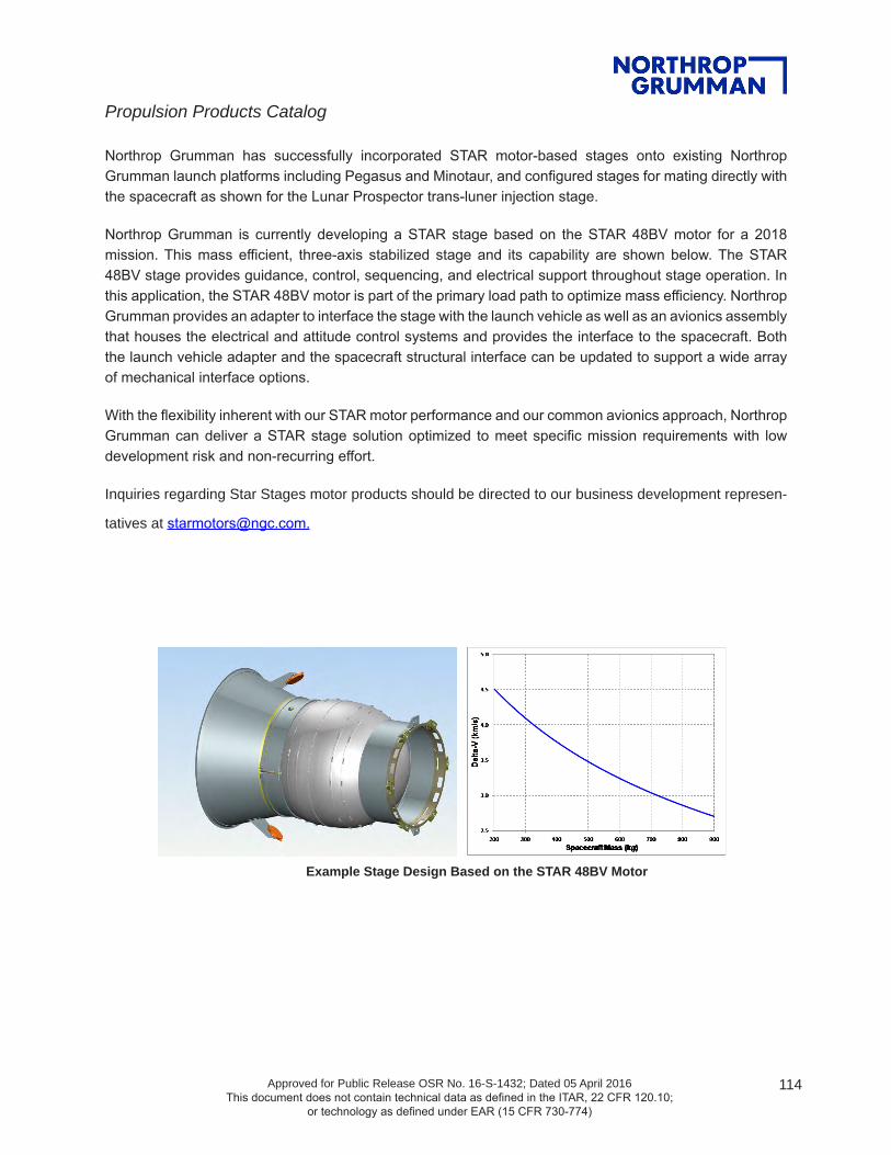
Propulsion Products Catalog
Approved for Public Release OSR No. 16-S-1432; Dated 05 April 2016 This document does not contain technical data as defined in the ITAR, 22 CFR 120.10;
or technology as defined under EAR (15 CFR 730-774)
114
Northrop Grumman has successfully incorporated STAR motor-based stages onto existing Northrop Grumman launch platforms including Pegasus and Minotaur, and configured stages for mating directly with the spacecraft as shown for the Lunar Prospector trans-luner injection stage.
Northrop Grumman is currently developing a STAR stage based on the STAR 48BV motor for a 2018 mission. This mass efficient, three-axis stabilized stage and its capability are shown below. The STAR 48BV stage provides guidance, control, sequencing, and electrical support throughout stage operation. In this application, the STAR 48BV motor is part of the primary load path to optimize mass efficiency. Northrop Grumman provides an adapter to interface the stage with the launch vehicle as well as an avionics assembly that houses the electrical and attitude control systems and provides the interface to the spacecraft. Both the launch vehicle adapter and the spacecraft structural interface can be updated to support a wide array of mechanical interface options.
With the flexibility inherent with our STAR motor performance and our common avionics approach, Northrop Grumman can deliver a STAR stage solution optimized to meet specific mission requirements with low development risk and non-recurring effort.
Inquiries regarding Star Stages motor products should be directed to our business development represen-
tatives at [email protected].
Example Stage Design Based on the STAR 48BV Motor

Propulsion Products Catalog
Approved for Public Release OSR No. 16-S-1432; Dated 05 April 2016 This document does not contain technical data as defined in the ITAR, 22 CFR 120.10;
or technology as defined under EAR (15 CFR 730-774)
115
ADVANCED SOLID AXIAL STAGE (ASAS™) MOTORSNorthrop Grumman’s ASAS family of high-performance solid propellant motors is adaptable to a wide variety of applications. These designs incorporate proven design concepts, materials technology, and manufacturing techniques that provide enhanced operational performance. The technologies reflected in these motor designs were identified and developed in more than 425 tests performed as part of technology programs conducted between 1985 and 2003 for the U. S. Air Force and the Missile Defense Agency.
The ASAS family of motors employs, as appropriate, design features including the following:
• High-strength, high-stiffness graphite-epoxy composite cases permitting increased operating pressure to increase expansion ratio and enhance motor performance, particularly for demanding interceptor applications
• Carbon-carbon throat materials that minimize throat erosion and related performance losses
• Erosion-resistant Kevlar-filled elastomeric insulation to provide thermal protection at minimum weight
• High-performance conventional and advanced composite solid propellant formulations providing required energy, temperature capability, and insensitive munitions characteristics for each of the motor designs
• Electromechanically actuated, flexseal, or trapped ball thrust vector control nozzle technology
• Mission-specific component technology, including carbon-carbon exit cones, consumable igniters, semiconductor bridge-based ignition systems, integrated hybrid warm/cold-gas attitude control systems, and isolation of multiple pulses with a barrier (rather than bulkhead) insulation system
ASAS 21-in. Motor Firing (1998)

Propulsion Products Catalog
Approved for Public Release OSR No. 16-S-1432; Dated 05 April 2016 This document does not contain technical data as defined in the ITAR, 22 CFR 120.10;
or technology as defined under EAR (15 CFR 730-774)
116
ASAS component and materials technology is mature, design scalability has been demonstrated, related engineering design models have been validated, and common components and materials are used in all of these booster configurations. These component technologies have been successfully demonstrated in sea level and simulated altitude tests and in successful flight tests.
By applying these proven technologies to new motor designs, Northrop Grumman offers:
1. Reductions in design, analysis, and development cost and schedule with streamlined component- and motor-level test programs
2. Off-the-shelf component and materials technologies with proven scalability across a range of booster configurations. This reduces development risk and ensures that performance meets design specifications
3. Established tooling, manufacturing, and inspection techniques that provide reproducible, high-quality products
The development philosophy for these motors has been to test a somewhat heavyweight prototype or development unit to confirm design margins without risking failure. This first firing is generally conducted at sea level. Scalability of ASAS design concepts and material technology has been demonstrated in motors ranging from 4 to 32 inches in diameter and will soon be demonstrated in a motor at 40-inches diameter.

Propulsion Products Catalog
Approved for Public Release OSR No. 16-S-1432; Dated 05 April 2016 This document does not contain technical data as defined in the ITAR, 22 CFR 120.10;
or technology as defined under EAR (15 CFR 730-774)
117
Graphite-Epoxy Composite Case Winding (21-in. booster)
Flexseal TVC Nozzle Assembly
Motor Static Firing at Simulated Altitude (ASAS AKS-2 Qualification Motor)
SM-3 FTR-1A Missile Launch with ATK TSRM (January 25, 2001)
Inquiries regarding ASAS motor products should be directed to our business development representa-tives at [email protected].

118Approved for Public Release OSR No. 16-S-1432; Dated 05 April 2016 This document does not contain technical data as defined in the ITAR, 22 CFR 120.10;
or technology as defined under EAR (15 CFR 730-774)
For more information, contact: [email protected].
northropgumman.com
ASAS 13-30V
MOTOR DIMENSIONSMotor diameter, in. ...............................................13.5Motor length, in. ...................................................39.3
MOTOR PERFORMANCE (70°F VACUUM)Burn time, sec ......................................................14.3Burn time average chamber pressure, psia .......1,730Maximum chamber pressure, psia ....................1,975Total impulse, lbf-sec .......................................55,180Propellant specific impulse, lbf-sec/lbm .............281.8Effective specific impulse, lbf-sec/lbm ...............279.5Burn time average thrust, lbf .............................3,825Maximum thrust, lbf ...........................................4,275
NOZZLEInitial throat diameter, in. .......................................1.1Exit diameter, in. ....................................................6.8Expansion ratio, initial .......................................38.3:1
WEIGHTS, LBMTotal loaded* ......................................................250.9Propellant ..........................................................195.8Case ...................................................................40.2Nozzle ...................................................................7.2Total inert .............................................................55.1Burnout* ...............................................................53.5
TEMPERATURE LIMITSOperation ...................................................45°-120°FStorage ......................................................30°-120°F
PROPELLANT DESIGNATION ........TP-H-3340A
CASE MATERIAL ............................. GRAPHITE-EPOXY COMPOSITE
PRODUCTION STATUS ...........FLIGHT-PROVEN
*Excludes ETA lines, safe and arm device, battery, and controller
FIXED AND VECTORABLE UPPER STAGE MOTORThe Advanced Solid Axial Stage (ASAS) 13-30V is a high-performance upper-stage motor derived from the Mk 136 Standard Missile 3 Block IA/IB Third Stage Rocket Motor. The motor is 39.3 inches long and nominally designed as an upper-stage motor. The motor uses a pyrogen igniter for highly repeatable ignition performance. The motor incorporates a + 5-degree nozzle powered by a Northrop Grumman Thrust Vector Electronic Control System (TVECSTM) thrust vector actuation system using electromechanical actuators.

119Approved for Public Release OSR No. 16-S-1432; Dated 05 April 2016 This document does not contain technical data as defined in the ITAR, 22 CFR 120.10;
or technology as defined under EAR (15 CFR 730-774)
For more information, contact: [email protected].
northropgumman.com
ASAS 21-85V TE-M-1031-1
MOTOR DIMENSIONSMotor diameter, in. ...............................................20.4Motor length, in. ...................................................95.5
MOTOR PERFORMANCE (75°F SEA LEVEL)Burn time/action time, sec ...........................24.4/25.7Ignition delay time, sec ......................................0.012Burn time average chamber pressure, psia .......1,100Maximum chamber pressure, psia ....................1,350Total impulse, lbf-sec .....................................347,400Propellant specific impulse, lbf-sec/lbm .............240.6Burn time average thrust, lbf ...........................14,000Maximum thrust, lbf .........................................17,250
NOZZLEInitial throat diameter, in. .......................................3.1Exit diameter, in. .................................................. 11.6Expansion ratio, initial .......................................13.9:1TVC, deg ............................................................ ±4.5
WEIGHTS, LBMTotal loaded .......................................................1,656Propellant ..........................................................1,444Case assembly .....................................................129Nozzle assembly ....................................................33Total inert ..............................................................212Propellant mass fraction ......................................0.87
TEMPERATURE LIMITSOperation ..................................................-10°-130°FStorage .....................................................-20°-130°F
PROPELLANT DESIGNATION ........TP-H-3514A
CASE MATERIAL ............................. GRAPHITE-EPOXY COMPOSITE
PRODUCTION STATUS .............DEVELOPMENT
The ASAS 21-85V is a solid rocket motor with a graphite-composite case that was developed for sounding rockets and high-performance guided booster applications. The initial 21-inch motor static test was conducted to demonstrate application and scaling of ASAS technology to vertical launch system-compatible large booster designs in April 1998. The design incorporated a 4.5-degree thrust vector control nozzle and a low-temperature capable propellant.
Early test efforts led to a June 1999 test for the Air Force Research Laboratory that incorporated a fixed nozzle (blast tube) arrangement to evaluate the use of low-cost materials and design concepts. The ASAS II version of the motor also incorporated a new propellant (TP-H-3516A) with 20% aluminum, 88.5% total solids, and 1% plasticizer.
180001800
1600
1400
1200
1000
800
600
400
200
0
TIME, sec0
THRU
ST, l
bf
PRES
SURE
, psia
16000
14000
12000
10000
8000
6000
4000
2000
05 10 15 20 25 30
F
P
V1098073F [413]

120Approved for Public Release OSR No. 16-S-1432; Dated 05 April 2016 This document does not contain technical data as defined in the ITAR, 22 CFR 120.10;
or technology as defined under EAR (15 CFR 730-774)
For more information, contact: [email protected].
northropgumman.com
ASAS 21-120 TE-M-1059-1
MOTOR DIMENSIONSMotor diameter, in. ...............................................20.5Motor length, in. .................................................138.0
MOTOR PERFORMANCE (75°F SEA LEVEL)Burn time/action time, sec ...........................22.1/22.8Ignition delay time, sec ......................................0.012Burn time average chamber pressure, psia .......1,480Maximum chamber pressure, psia ....................1,760Total impulse, lbf-sec .....................................497,600Propellant specific impulse, lbf-sec/lbm .............244.4Burn time average thrust, lbf ...........................22,300Maximum thrust, lbf .........................................24,700
NOZZLEInitial throat diameter, in. .....................................3.36Exit diameter, in. ................................................16.80Expansion ratio, initial ..........................................25:1
WEIGHTS, LBMTotal loaded .......................................................2,323Propellant ..........................................................2,036Case assembly* ....................................................254Nozzle assembly ....................................................32Total inert ..............................................................286Propellant mass fraction ......................................0.88*Includes igniter without 1.08 lbm propellant
TEMPERATURE LIMITSOperation ...................................................40°-100°FStorage ........................................................0°-100°F
PROPELLANT DESIGNATION ........TP-H-3516A
CASE MATERIAL ............................. GRAPHITE-EPOXY COMPOSITE
PRODUCTION STATUS .............DEVELOPMENT
The ASAS 21-120 is a solid rocket motor with a graphite-composite case that was developed in 2000 for vertical launch system, target, and sounding rocket applications. This is a fixed nozzle version of the ASAS 21-120V motor.
V0301030A [482]28000
24000
20000
16000
12000
8000
4000
0
2000
1800
1600
1400
1200
1000
800
600
400
200
0
TIME, sec
0 4 8 12 16 20 24 28
THRU
ST, l
b f
PRES
SUR
E, p
sia
P
F

121Approved for Public Release OSR No. 16-S-1432; Dated 05 April 2016 This document does not contain technical data as defined in the ITAR, 22 CFR 120.10;
or technology as defined under EAR (15 CFR 730-774)
For more information, contact: [email protected].
northropgumman.com
MOTOR DIMENSIONSMotor diameter, in. ...............................................20.5Motor length, in. .................................................130.0
MOTOR PERFORMANCE (70°F SEA LEVEL)*Burn time/action time, sec ...........................17.9/18.6Ignition delay time, sec ......................................0.005Burn time average chamber pressure, psia .......1,800Maximum chamber pressure, psia ....................2,050Total impulse, lbf-sec .....................................454,700Propellant specific impulse, lbf-sec/lbm .............250.8Burn time average thrust, lbf ...........................24,900Maximum thrust, lbf .........................................28,600
NOZZLEInitial throat diameter, in. .......................................3.0Exit diameter, in. ..................................................14.0Expansion ratio, initial ..........................................20:1TVC, deg .............................................................+5.0
WEIGHTS, LBMTotal loaded .......................................................2,236Propellant (less igniter propellant) .....................1,813Case assembly* ....................................................363Nozzle assembly ....................................................32Total inert (including TVA) .....................................423Propellant mass fraction ......................................0.81*Includes igniter without 1.08 lbm propellant
TEMPERATURE LIMITSOperation ...................................................40°-100°FStorage ........................................................0°-100°F
PROPELLANT DESIGNATION .......... TP-H-3340
CASE MATERIAL ............................. GRAPHITE-EPOXY COMPOSITE
PRODUCTION STATUS .............DEVELOPMENT*Development motor values. Flight design mass fraction is 0.89 with total impulse improvement of approximately 15%.
ASAS 21-120V TE-M-909-1
The ASAS 21-120V solid rocket motor was designed, fabricated, and tested in just four and one-half months after program start. It features a 5 -degree flexseal thrust vector control nozzle with a carbon phenolic exit cone. This successful test led to receipt of the Strategic Defense Initiative Office Director's Award in recognition of outstanding achievement. The ASAS 21-120V configuration is applicable to vertical launch system, target, sounding rocket, and high-performance guided booster applications.
PRES
SURE
, PSI
A
2800
2800
2800
2800
2800
2800
2800
2800
THRU
ST, L
B
35000
30000
25000
20000
15000
10000
5000
00 4 8 12 16 20 24 28 32
TIME, SEC
F
P

122Approved for Public Release OSR No. 16-S-1432; Dated 05 April 2016 This document does not contain technical data as defined in the ITAR, 22 CFR 120.10;
or technology as defined under EAR (15 CFR 730-774)
For more information, contact: [email protected].
northropgumman.com
ASAS 28-185/185V TE-T-1032
The ASAS 28-185 motor is a graphite composite case, fixed nozzle, solid rocket motor applicable to guided first-stage, sounding rocket, and target applications. With a thrust vector control nozzle, the motor is designated ASAS 28-185V. The motor was tested on September 30, 1998, and confirmed scaling of ASAS technology from smaller motors to a 28.5-inch-diameter motor configuration with extended burn time. Motor ignition was successfully achieved with a prototype electro-optical safe-and-arm device and a semiconductor bridge initiator. The motor incorporated a thrust vector control nozzle simulator to evaluate thermal response for simulated flexseal components, but the test nozzle was not vectorable by design.
MOTOR DIMENSIONSMotor diameter, in. ...............................................28.5Motor length, in. ....................................................207
MOTOR PERFORMANCE (75°F SEA LEVEL)Burn time/action time, sec ...........................29.2/31.2Ignition delay time, sec ......................................0.010Burn time average chamber pressure, psia .......1,470Maximum chamber pressure, psia ....................1,660Total impulse, lbf-sec ..................................1,559,050Propellant specific impulse, lbf-sec/lbm .............252.6Burn time average thrust, lbf ...........................52,100Maximum thrust, lbf .........................................61,200
NOZZLEInitial throat diameter, in. .......................................5.0Exit diameter, in. ..................................................21.3Expansion ratio, initial .......................................18.3:1TVC, deg (design capability) ................................. ±5
WEIGHTS, LBM*Total loaded .......................................................6,901Propellant ..........................................................6,172Case assembly .....................................................608Nozzle assembly ..................................................121Total inert ..............................................................729Burnout .................................................................696Propellant mass fraction ......................................0.89*weights without TVC
TEMPERATURE LIMITSOperation .....................................................40°-90°FStorage ...................................................... 20°-110°F
PROPELLANT DESIGNATION .......... TP-H-3340
CASE MATERIAL ............................. GRAPHITE-EPOXY COMPOSITE
PRODUCTION STATUS .............DEVELOPMENT

123Approved for Public Release OSR No. 16-S-1432; Dated 05 April 2016 This document does not contain technical data as defined in the ITAR, 22 CFR 120.10;
or technology as defined under EAR (15 CFR 730-774)
For more information, contact: [email protected].
northropgumman.com
ASAS 32-58V (RAVEN) TE-M-1106-1
Static tested on September 16, 2003, the ASAS 32-58V RApid VEctoring Nozzle (RAVEN) design demonstrated an enhanced slew rate with a trapped ball nozzle using electromechanical actuation. The nozzle was tested on a 32-inch-diameter composite case motor representative of a future missile defense interceptor second stage. The motor was ignited with an Northrop Grumman Missile Products electronic safe-and-arm device and pyrotechnic igniter. Motor design, analysis, fabrication, and successful static test efforts were completed in a five and one-half-month period.
MOTOR DIMENSIONSMotor diameter, in. ..................................................32Motor length, in. ...................................................74.8
MOTOR PERFORMANCE (70°F VACUUM)Burn time/action time, sec ...........................26.6/28.1Ignition delay time, sec ......................................0.057Burn time average chamber pressure, psia .......1,390Maximum chamber pressure, psia ....................1,690Total impulse, lbf-sec .....................................640,580Propellant specific impulse, lbf-sec/lbm .............279.0Effective specific impulse, lbf-sec/lbm ...............277.3Burn time average thrust, lbf ...........................23,900Maximum thrust, lbf .........................................30,880
NOZZLEInitial throat diameter, in. .......................................3.2Exit diameter, in. ..................................................16.9Expansion ratio, initial ..........................................28:1Expansion cone half angle, exit, deg ...................22.5Type ...........................................................ContouredTVC, deg ............................................................ ± 12
WEIGHTS, LBMTotal loaded .......................................................2,618Propellant .........................................................2,296Case assembly .....................................................209Nozzle assembly (including actuators) .................104Igniter assembly (including ESA) ..............................9Total inert ..............................................................322Burnout .................................................................308Propellant mass fraction ......................................0.88
TEMPERATURE LIMITSOperation .....................................................45°-90°FStorage .....................................................-20°-140°F
PROPELLANT DESIGNATION ........TP-H-3527A
CASE MATERIAL ............................. GRAPHITE-EPOXY COMPOSITE
PRODUCTION STATUS .............DEVELOPMENT

124Approved for Public Release OSR No. 16-S-1432; Dated 05 April 2016 This document does not contain technical data as defined in the ITAR, 22 CFR 120.10;
or technology as defined under EAR (15 CFR 730-774)
For more information, contact: [email protected].
northropgumman.com
ORIOLE
0 5 10 15 20 25 30 35TIME, sec
0
5
10
15
20
25
30
SEA-
LEVE
L TH
RUST
, klb
f
0.0
0.5
1.0
1.5
FORE-END PRESSURE, kpsia
F
P
MEOP =1620 psia
OrioleMk70 Terrier
MOTOR DIMENSIONSMotor diameter, in. ..................................................22Motor length, in. ...............................................154.68
MOTOR PERFORMANCE (70°F VACUUM)Burn time/action time, sec .........................30.0/28.85Ignition delay time, sec ......................................0.025Burn time average chamber pressure, psia ..........944Maximum chamber pressure, psia ....................1,410Total impulse, lbf-sec .....................................624,290Propellant specific impulse, lbf-sec/lbm .............288.5Burn time average thrust, lbf ...........................20,790Maximum thrust, lbf .........................................29,570
NOZZLEInitial throat diameter, in. .....................................3.72Exit diameter, in. ................................................19.82Expansion ratio, initial .......................................28.4:1TVC, deg .............................................................N/A
WEIGHTS, LBMTotal loaded .......................................................2,588Propellant (less igniter propellant) .....................2,152Case assembly .....................................................214Nozzle assembly ..................................................145Total inert ..............................................................436Propellant mass fraction ......................................0.83
TEMPERATURE LIMITSOperation .....................................................0°-120°FStorage .....................................................-10°-125°F
PROPELLANT DESIGNATION ............................QDL/SAA-144 ALUMINIZED HTPB
CASE MATERIAL ............................. GRAPHITE-EPOXY COMPOSITE
PRODUCTION STATUS ................ IN PRODUCTION
The Oriole is a 22-inch-diameter, high-performance, low-cost rocket motor used as a first, second, or upper stage for sounding rockets, medium-fidelity target vehicles, and other trans-atmospheric booster and sled test applications. The motor was developed in the late 1990s as a next-generation, high-performance sounding rocket motor and was first successfully static tested in 2000. Five successful flight tests have been completed to date using the Oriole as a second stage. The nozzle has been optimized for high-altitude applications and the graphite-epoxy case and modern high-performance propellant combine to provide a high-mass-fraction and cost-effective design.
Future Oriole variants are in concept development. These include a version, for use as a booster in experimental scramjet or other similar applications, that has extra external insulation, allowing for extended flight times within the atmosphere. There is also a shorter burn time, first-stage booster specific version, which would be an ideal replacement for Talos/Taurus class motors and would yield greater performance. The first stage incorporates a low altitude optimized nozzle and has a burn time in the 12- to 15-second range.
The Oriole motor also has the flexibility to accommodate a thrust vector control system for high-fidelity target or orbital mission applications. In addition, a subscale version, called the Cardinal motor, is suitable for upper-stage applications with Oriole or other motors in the lower stage(s). The Cardinal motor would be about half the size and weight of the full-scale Oriole motor and take advantage of many similar proven components and processes to provide maturity and low-cost benefits.

Propulsion Products Catalog
Approved for Public Release OSR No. 16-S-1432; Dated 05 April 2016 This document does not contain technical data as defined in the ITAR, 22 CFR 120.10;
or technology as defined under EAR (15 CFR 730-774)
125
ELECTROMECHANICAL THRUST VECTOR
ACTUATION SYSTEMNorthrop Grumman has developed the first in a family of thrust vector actuation systems that is designed for low-cost modularity. The controller uses state-of-the-art electronics packaged in a rugged and lightweight mechanical enclosure. Two-axis digital loop closure, communication, and housekeeping functions are performed with less than half the electronic piece part count found in similar thrust vector actuation designs. An innovative, patented, digital design enables this low-cost flexibility.
Derivative controller designs with different maximum output power capability of up to 33 Hp (without torque summing) can be produced from the same basic architecture. This is also true for the actuator design, which can easily be scaled up or down to accommodate almost any combination of output force and speed required.
Inquiries regarding EM TVA products should be directed to our business development representatives at [email protected].

Propulsion Products Catalog
Approved for Public Release OSR No. 16-S-1432; Dated 05 April 2016 This document does not contain technical data as defined in the ITAR, 22 CFR 120.10;
or technology as defined under EAR (15 CFR 730-774)
126
TVECSTM Model TE-A-1154-1 Electromechanical Thrust Vector Actuation System
Product Description:
• Two-channel, linear output electromechanical actuation system
• Brushless DC motors
• Linear variable displacement transducer position feedback
• Resolver rate feedback
• Digital loop closure (position and rate)
• RS-422 communication
• Externally programmable for custom compensation
Options:
• Other stroke and null lengths available with minor actuator modifications (linear variable displacement transducer, ball screw, housing lengths)
• Other communication protocols are available (RS-485, MIL-STD-1553, CAN, analog, etc.); communication digital format is flexible
• Controller mounting provisions and cable lengths can be modified, as required
• Ability to reconfigure digital logic through main communication interface
• Enhanced reliability screening available (JANTXV, Class B, Class H, minimum, and space level)
• Radiation tolerance
• Military temperature range
Product Characteristics
Design Capability
Main Power 80 VDC / 30 A (per channel)Logic Power 28 VDC / 1ARated Speed 7.5 in/secRated Load 1,600 lbfTotal Stroke 2.0 inNull Length 8.394 inNull Length Adjustment 0.2 inWeight (not including battery) 21 lb
Operating Voltage, Main (max) 270 VDCCurrent Limit, Main (max) 50 AMaximum Output Force 3,500 lbfMaximum Rated Speed 13 in/secMaximum Power Output 6 HP

Propulsion Products Catalog
Approved for Public Release OSR No. 16-S-1432; Dated 05 April 2016 This document does not contain technical data as defined in the ITAR, 22 CFR 120.10;
or technology as defined under EAR (15 CFR 730-774)
127
ORDNANCE PRODUCTSNorthrop Grumman Missile Products has produced a wide variety of ordnance products since the 1960s including:
• Conventional electromechanical safe-and-arm devices for STAR series space motor initiation and launch vehicle/stage destruct functions
• Conical-shaped charge assemblies for booster destruct applications on STAR, CASTOR, Titan, Atlas, and Delta
• Semiconductor bridge-based initiators for precise control of ordnance events for military applications such as the universal water activated release system for the U.S. Air Force
• Advanced electronics-based ordnance systems providing reductions in weight, enhanced event control, and system health monitoring
Several of these products are illustrated below and provide an overall heritage of proven reliability while providing flexibility to meet evolving customer needs.

Propulsion Products Catalog
Approved for Public Release OSR No. 16-S-1432; Dated 05 April 2016 This document does not contain technical data as defined in the ITAR, 22 CFR 120.10;
or technology as defined under EAR (15 CFR 730-774)
128
Northrop Grumman ordnance production facilities at Missile Products include equipment for safe and arm assembly, initiator manufacturing, igniter manufacture, pyrotechnic and explosives loading, and laser welding. In addition to ordnance manufacture, Northrop Grumman has facilities at Missile Products to perform nondestructive testing, including X-ray, random vibration, shock and thermal environments, functional testing, and associated live material and product storage.
Electromechanical Safe and Arm Devices. The development and production heritage for electromechanical safe and arm devices represents more than 40 years of product maturity as illustrated below. These devices provide positive control of ordnance events in nonfragmenting and non-outgassing designs that provide external status indication and a safety pin to inhibit operation when desired. The current production Model 2134B is routinely used to initiate STAR series space motors (next page) and for destruct on Atlas IIAS and Titan IVB. The Model 2134B has supported more than 300 flights since 1989 with a 100% operational success rate. It is Eastern-Western Range 127-1 compliant and has flown successfully from Eastern Test Range, Western Test Range, and Kourou and on vehicles such as Titan, Delta, Ariane, and Space Shuttle.
V0298186 [390] V0298190 [390]
Lunar Prospector Command Timer and S&A Integration Conducted by ATK
SA11906A [271]
S&A Development Heritage Supports Product Reliability in Operation
Lunar Prospector Command Timer and S&A Integration Conducted by Northrop Grumman

Propulsion Products Catalog
Approved for Public Release OSR No. 16-S-1432; Dated 05 April 2016 This document does not contain technical data as defined in the ITAR, 22 CFR 120.10;
or technology as defined under EAR (15 CFR 730-774)
129
Typical STAR Series Space Motor Ordnance Train to Provide On-Command Ignition
Northrop Grumman also supports safe and arm and ordnance system development having updated the documentation package and manufacturing instructions for the Space Shuttle S&A device. Northrop Grumman also developed and qualified the Army Tactical Missile Systems (TACMS) arm/fire device for motor ignition and the safe and arm device for Army TACMS warhead initiation and has rebuilt or refurbished existing Minuteman III arm/disarm switches for the U. S. Air Force. For the Minuteman III arm/disarm switch, six-sigma principles were employed to design and implement a manufacturing plan that features manufacturing cells and dedicated production stations. Trained technicians individually evaluate, rebuild, and then retest each arm/disarm switch. In addition, Northrop Grumman has integrated complete ordnance systems, which include Missile Products-fabricated wiring harnesses for missile defense boosters such as the Terrier lightweight exoatmospheric projectile Advanced Solid Axial Stage and the SM-3 Mk 136 Third Stage Rocket Motor. In the area of upper stages, Northrop Grumman conducted the design activity for the Lunar Prospector trans-lunar injection stage. This upper stage used customer-supplied command timer/sequence to control all ordnance functions including initiation of spin motors, separation systems, primary axial propulsion, separation systems, and destruct functions (see below).
Laser Welding Equipment
SCB Initiator Semi - Automated Line Laser Welding Equipment SCB Initiator Semi automated Manufacturing Line

Propulsion Products Catalog
Approved for Public Release OSR No. 16-S-1432; Dated 05 April 2016 This document does not contain technical data as defined in the ITAR, 22 CFR 120.10;
or technology as defined under EAR (15 CFR 730-774)
130
Semi-conductor Bridge (SCB) Initiators. Since 1989, Northrop Grumman has produced more than 60,000 SCB initiators for application in automotive airbags, the mining industry, for parachute release, tank rounds, and for motor and ordnance event initiation. The majority of this production has supported the Universal Water Activated Release System program following qualification of the device in 1994 (figure on following page). The flexibility and robustness of the basic SCB initiator configuration enables Northrop Grumman to tailor pin designs, output charges, and design features for specific applications.
The SCB initiator provides advantages over other initiator technologies by providing low, consistent initiation energy with fast and highly repeatable function times. These devices enhance safety by readily passing no-fire requirements (>1 amp/1 watt/5 minutes), are electrostatic discharge-tolerant, can be tailored to meet MIL-STD-1385B HERO requirements, and are qualified to MIL-STD-1512 requirements. This device produces a 8,500°F plasma at the bridge allowing initiation of insensitive materials. In addition, SCBs are inherently mass producible at the chip and assembly level.
V0298193 [390]
CSC Installed on Lunar Prospector TLI Stage
STAR 48 Destruct Test Using Model 2011 CSC
Silicon Substrate
Aluminum Lands
Doped PolysiliconLayer
Doped PolysiliconLayer
Aluminum Lands
Silicon Substrate
AA
Section A-A
0.050- in.Square
0.020 in.
Bridge (volume of bridge)Controls All: Fire/No-Fire Levels)
SCB Chip and Initiator
Conical-Shaped Charge Assemblies. Conical-shaped charges produced at Northrop Grumman provide a concentrated destructive jet of energy for flight termination applications on a variety of propulsion systems, including boosters used on Titan and Atlas as well as CASTOR and STAR series motors. Northrop Grumman conducts in-house testing for conical-shaped charge lot acceptance and has integrated destruct ordnance for stages including Lunar Prospector for Lockheed Martin and NASA. Conical-shaped charges produced at Northrop Grumman are reviewed and approved by the Eastern and Western Ranges for each application and meet the requirements of EWR 127-1. Photos below show two past uses of the conical-shaped charge.
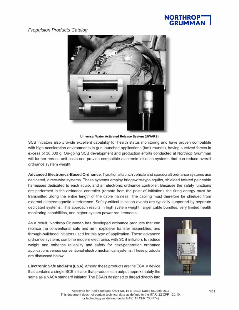
Propulsion Products Catalog
Approved for Public Release OSR No. 16-S-1432; Dated 05 April 2016 This document does not contain technical data as defined in the ITAR, 22 CFR 120.10;
or technology as defined under EAR (15 CFR 730-774)
131
SCB initiators also provide excellent capability for health status monitoring and have proven compatible with high-acceleration environments in gun-launched applications (tank rounds), having survived forces in excess of 30,000 g. On-going SCB development and production efforts conducted at Northrop Grumman will further reduce unit costs and provide compatible electronic initiation systems that can reduce overall ordnance system weight.
Advanced Electronics-Based Ordnance. Traditional launch vehicle and spacecraft ordnance systems use dedicated, direct-wire systems. These systems employ bridgewire-type squibs, shielded twisted pair cable harnesses dedicated to each squib, and an electronic ordnance controller. Because the safety functions are performed in the ordnance controller (remote from the point of initiation), the firing energy must be transmitted along the entire length of the cable harness. The cabling must therefore be shielded from external electromagnetic interference. Safety-critical initiation events are typically supported by separate dedicated systems. This approach results in high system weight, larger cable bundles, very limited health monitoring capabilities, and higher system power requirements.
As a result, Northrop Grumman has developed ordnance products that can replace the conventional safe and arm, explosive transfer assemblies, and through-bulkhead initiators used for this type of application. These advanced ordnance systems combine modern electronics with SCB initiators to reduce weight and enhance reliability and safety for next-generation ordnance applications versus conventional electromechanical systems. These products are discussed below.
Electronic Safe and Arm (ESA). Among these products are the ESA, a device that contains a single SCB initiator that produces an output approximately the same as a NASA standard initiator. The ESA is designed to thread directly into
Universal Water Activated Release System (UWARS)

Propulsion Products Catalog
Approved for Public Release OSR No. 16-S-1432; Dated 05 April 2016 This document does not contain technical data as defined in the ITAR, 22 CFR 120.10;
or technology as defined under EAR (15 CFR 730-774)
132
Addressable Bus Ordnance System Breadboard Prototype
a motor igniter. It has a bulkhead to contain motor pressure and a single electrical connector interface. The small envelope and weight of this safe and arm permits direct installation into the igniter and eliminates the need for explosive transfer assemblies and through bulkhead initiators. The electronic safety features of the ESA will be supplemented with a blocking rotor mechanism driven by a small DC micromotor. The design will mechanically and electrically isolate the electrical initiator from the rest of the ignition train.
Northrop Grumman performed initial environmental and operational testing of prototype ESA units under the ASAS II contract (1999 to 2000). A prototype of the ESA was also used to initiate a Northrop Grumman technology demonstration rocket motor in November 2000 and Northrop Grumman’s RApid VEctoring Nozzle (RAVEN) motor in 2003.
Addressable Bus Ordnance System. Under a 2001 and 2002 Advanced Ordnance Development program, Northrop Grumman designed, fabricated, and demonstrated a breadboard addressable bus ordnance system based on ESA designs. The program also demonstrated implementation of communication protocols allowing individual device control and the ability to merge ordnance and telemetry system features on a single bus.
Northrop Grumman’s addressable bus solution mitigates or eliminates many of the negative attributes associated with traditional ordnance systems. By substituting SCB-based squibs as an enabling technology, a digital bus network will support multiple, individually addressed devices (or nodes) that incorporate safety at the point of initiation and provide new, extensive ordnance and system health monitoring and telemetry gathering capabilities. The Northrop Grumman-developed ESA device forms the basis of the initiator nodes in the proposed system. Because firing energy is stored and switched at the individual system nodes, only low-voltage power and digital commands are transmitted over the system cables. Significant protection from external electromagnetic interference is therefore achieved without heavy shielding. Individual cables are no longer necessary because all of the ordnance events are controlled from a common bus that utilizes a digital communication protocol. As a result, reductions in cabling mass and improvements in installation and checkout can be realized.
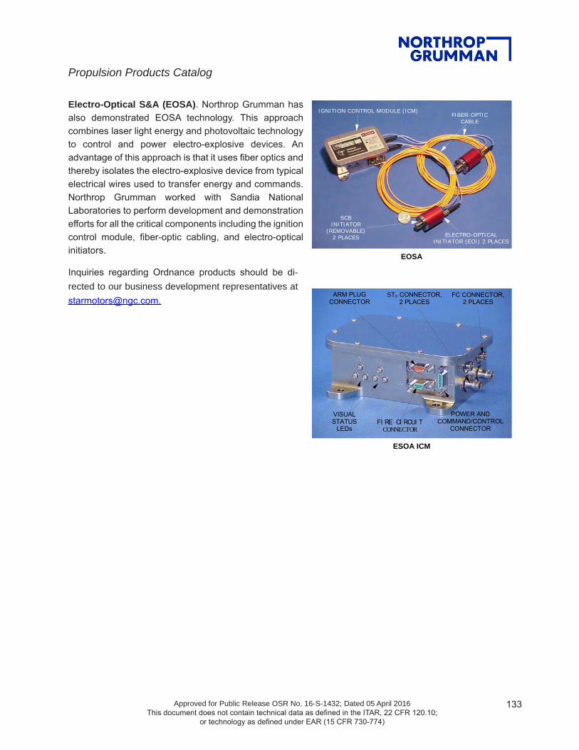
Propulsion Products Catalog
Approved for Public Release OSR No. 16-S-1432; Dated 05 April 2016 This document does not contain technical data as defined in the ITAR, 22 CFR 120.10;
or technology as defined under EAR (15 CFR 730-774)
133
Electro-Optical S&A (EOSA). Northrop Grumman has also demonstrated EOSA technology. This approach combines laser light energy and photovoltaic technology to control and power electro-explosive devices. An advantage of this approach is that it uses fiber optics and thereby isolates the electro-explosive device from typical electrical wires used to transfer energy and commands. Northrop Grumman worked with Sandia National Laboratories to perform development and demonstration efforts for all the critical components including the ignition control module, fiber-optic cabling, and electro-optical initiators.
SCBINITIATOR
(REMOVABLE)2 PLACES ELECTRO-OPTICAL
INITIATOR (EOI) 2 PLACES
IGNITION CONTROL MODULE (ICM)FIBER-OPTIC
CABLE
ARM PLUGCONNECTOR
FI RE CI RCUI TCONNECTOR
FC CONNECTOR,2 PLACES
ST® CONNECTOR,2 PLACES
POWER ANDCOMMAND/CONTROL
CONNECTOR
VISUALSTATUS
LEDs
EOSA
ESOA ICM
Inquiries regarding Ordnance products should be di-rected to our business development representatives at [email protected].

134Approved for Public Release OSR No. 16-S-1432; Dated 05 April 2016 This document does not contain technical data as defined in the ITAR, 22 CFR 120.10;
or technology as defined under EAR (15 CFR 730-774)
For more information, contact: [email protected].
northropgumman.com
CHARACTERISTICSU.N. classification code ...................................... 1.1DBase charge .................Composition C-4: 500 gramsBooster charge ............... Composition A-4: 17 gramsCap material ...................................... Aluminum alloyHousing material ................................ Aluminum alloyLiner material ..................................................CopperInitiation input ................Flexible confined detonating cord with Type III end tip
(144 mg HNS) (detachable)Attachment interface ......................... Mounting flange using a Marman clampExternal finish ............................Clear anodic coatingPenetration at 6-inch stand-off .......12-inch mild steelTemperature environmental extremes .......................................................... -65° to +160°F*Qualification vibration .......... 47.7 grms for 3 min/axisQualification shock .......................... 6,000 g at 700 to
3000 Hz, Q=10Weight, gross .....................................................2.8 lbApplications ..................... Solid motor destruct, liquid tank destruct, payload destruct
*High-temperature exposure up to 30 days
MODEL 2011 TE-0-958-1DESTRUCT CONICAL SHAPED CHARGE (CSC)Northrop Grumman’s Model 2011 CSC is an upgraded version of the highly successful Model 2001 design developed in the 1960s for use on the Delta launch vehicle. The Model 2011 has the same envelope, mounting interfaces, and explosive weight as its predecessor, the Model 2001.
The Model 2011 incorporates a 500-gram composition C-4 main charge, which provides excellent safety, performance, and long-term storage characteristics for a variety of flight termination applications. The Model 2011 is designed to provide several improvements over prior CSC designs. These include: 1) enhanced safety through the use of flexible confined detonating cord input, 2) hermetic sealing of each unit, and 3) incorporation of a liner manufactured to provide optimal target penetration and control of the jet angle.
Northrop Grumman has manufactured more than 1,000 CSCs for flight termination. The Model 2011 was qualified for use on the Atlas IIAS launch vehicle and was first flown in December 1993. Northrop Grumman’s CSCs have flown in many other applications including the Delta, Japanese N, Titan/Centaur, and Atlas/Centaur launch vehicles. They have been reviewed and approved by Eastern and Western Range Safety for each application and meet the requirements of EWR 127-1.

135Approved for Public Release OSR No. 16-S-1432; Dated 05 April 2016 This document does not contain technical data as defined in the ITAR, 22 CFR 120.10;
or technology as defined under EAR (15 CFR 730-774)
For more information, contact: [email protected].
northropgumman.com
CHARACTERISTICS·Unit weight: ........................... 3.4 lb (typical)Motor operating voltage: ............................ 24-32 Vdc Inrush: .........................1.0-3.0 amps for 50 ms max Running: .........................100-250 mA at 28 ±4 VdcStalled rotor current: ...............................360 mA maxActuation time: ...............0.15 to 0.3 sec at 28 ±4 VdcOperating temperature: ....................... –35° to 160°FFiring circuit pin-to-pin resistance: ................................. 0.87 to1.07 ohms (Version 1) or
0.90-1.10 (Version 2)Detonator “no-fire” current/power: ........................................ 1 amp/1 watt for 5 minutesDetonator “all-fire” current: .........................3.5 amps·Detonator (recommended) .............5.0 to 22.0 amps·Firing time at 5.0 amps: ........................ 3 ms (typical)
Optional isolator mounts available for high shock/vibra-tion environments
PERFORMANCE FEATURES Nonfragmenting and non-outgassing Safe if inadvertently fired in the safe position Remote electrical arming and safing The unit can be manually disarmed but cannot be
manually armed Mechanical and electrical systems are inseparable
whether the device is operated electrically or manually
The firing circuit and explosive train are redundant Firing circuits and control/monitor circuits are
located in separate connectors Remote monitoring of safe or armed status is
integral within the circuitry A visual indicator window shows safe or armed
status A safety pin prevents accidental arming of the unit
during transportation, handling, and checkout The safety pin is nonremovable when arming
power is applied In the safe position, the detonator lead wires are
shunted and the shunt is grounded through 15,000-ohm resistors
Firing circuits have 25-ohm resistors to provide for ordnance system checkout in safe position
MODEL 2134B TE-0-734SAFE-AND-ARM (S&A) DEVICEThe Model 2134B was originally qualified for the McDonnell Douglas Delta II launch vehicle. Model 2134B has successfully flown on a number of launch vehicles including Delta, Space Shuttle, Ariane, Titan, Japanese N, and Long March. They have initiated upper-stage sequencing and booster destruct systems and ignited upper-stage motors. Model 2134B improves upon the safe and reliable design of its predecessors by: 1) upgrading detonators to meet the requirements of MIL-STD-1576 and NHB1700.7A and 2) the optional modification of the safety pin to comply with the safety requirements of MIL-STD-1576 and EWR 127-1.
The Model 2134B is a nonfragmenting, non-outgassing, electromechanical S&A initiation device that is remotely mounted and remotely actuated. Because of the nonfragmenting and non-outgassing feature, the device can be located on spacecraft without damage to nearby equipment. The motive power for the unit is furnished by a 28-volt reversible DC motor with an integral planetary gear speed reduction unit. The rotational power of the DC motor is transmitted to the output shaft through spur gears and a friction clutch.
The explosive rotor assembly, visual indicator, and rotary switches are located on the output shaft. These switches control the electrical circuitry, including motor control, remote indication, and firing signals. In the safe position, the explosive rotor assembly is out of phase with the explosive train. When the safety pin is removed and arming current is applied, the output shaft rotates 90 degrees to align the rotor with the explosive train. If arming current is applied with the safety pin installed, the motor operates through the slip clutch to preclude any damage to the unit. The safety pin physically prevents the rotor from rotating while being mechanically locked into place. The output area of the unit contains an adapter that provides interface of the explosive train with a receptor such as explosive transfer assemblies. The explosive transfer assemblies transfer the detonation output from the S&A device for purposes such as rocket motor ignition. The unit’s redundant firing circuits and explosive trains assure a highly reliable initiation.
The Model 2134B has a separate firing connector for each firing circuit. A separate connector is also provided for the arm/disarm and monitor circuits.

136Approved for Public Release OSR No. 16-S-1432; Dated 05 April 2016 This document does not contain technical data as defined in the ITAR, 22 CFR 120.10;
or technology as defined under EAR (15 CFR 730-774)
For more information, contact: [email protected].
northropgumman.com
SAFETY/FEATURES/BENEFITS Contains no primary explosive material Pyrotechnic material test data compatible to
MIL-STD-1316 approved material Qualified to MIL-STD-1512; human-rated Passed electrostatic discharge: 25 kV, 500 pF,
through a 5,000-ohm resistor, over 100 pulses Passes 1-watt/1-amp, 5-minute no-fire require-
ment Passed 420°F performance testing Passed simulated 10-year aging Passed >50,000 g performance testing Passed 28-day temperature shock, humidity, and
altitude environments per MIL-I-23659 Radiated radio frequency sensitivity: MIL-STD-
1385B (HERO), design-dependent Pressure shock: 15,000 psi Monitor current: 100ma, 1,008 hours, -40° to
194°F, 42 cycles Low, consistent energy requirements (1 to 3 mJ) Highly repeatable, fast function time (as low as
50 µs); Highly reliable (0.9992 at 95% confidence) Requires 10% of the energy of a bridgewire
initiator Ability to customize interface configuration and
all-fire and no-fire levels Autoignition: 350°F for 6 hours; 257°F for 12
hours Digital and optical addressable units available Excellent heritage: over 40,000 units fabricated
and over 5,000 successfully tested Handling shock: 6-foot drop, -65° and 215°F, 75
drops Department of Energy-approved for use in
actuators of weapon systems Thermal shock: 200 cycles, -40° to 194°F, 1
hour per cycle; 120 cycles, -65° to 215°F, 1-hour dwell
SCB INITIATOR TEM-I-902Northrop Grumman's Missile Products’s unique squib design employs a patented semiconductor bridge (SCB) to provide advantages over traditional hot-wire devices. Operation of the SCB chip produces a plasma output that enhances safety by allowing the initiation of insensitive materials (rather than primary explosives) in the squib. It achieves highly repeatable and fast function times (as low as 50 msec). The SCB initiator has been qualified to MIL-STD-1512 and serves as part of the human-rated U.S. Air Force’s universal water activated release system. The SCB takes only 10% of the energy required by a conventional bridgewire for initiation (requiring 1 to 3 millijoules versus 30 to 35 millijoules for conventional bridgewire devices), but can meet 1-watt/1-amp for 5 minutes minimum no-fire requirements. The SCB interface configuration and all-fire and no-fire levels can be tailored for individual mission requirements. The device currently meets both Department of Defense and Department of Energy military requirements for electrostatic discharge.
The output of the squib and its mechanical interface can be tailored for specific applications. Our baseline initiator design serves as the core component for all our new devices, including digitally and optically addressable units. Design modifications can be made as necessary to accommodate new requirements or optimize high-volume production needs.
WARNING: THIS DEVICE MAY HAVE A PIN-TO-CASE RESISTANCE AS LOW AS 30 OHMS. SUFFICIENT ENERGY APPLIED FROM PIN TO CASE CAN CAUSE INITIATION. THE USER SHOULD TAKE ALL NECESSARY PRECAUTIONS TO HANDLE AND USE THIS DEVICE SAFELY IN A MANNER CONSISTENT WITH THE DESIGN

137Approved for Public Release OSR No. 16-S-1432; Dated 05 April 2016 This document does not contain technical data as defined in the ITAR, 22 CFR 120.10;
or technology as defined under EAR (15 CFR 730-774)
For more information, contact: [email protected].
northropgumman.com
ESA TEM-0-1068-1
UNIQUE DESIGNDimensions .................... 1-inch diameter, 3.2-inch longESA assembly weight .................................~125 gramsInstalled protrusion length ................................ 2.2 inchMaterial construction ..................... 304L stainless steel Operates on typical 28 Vdc bus Threaded interface Harvard architecture microprocessor No primary explosivesFEATURES BIT capability Safe/arm monitor output (serial data) Initiator bridge verification LED visual status indicator Meets 1-amp/1-watt, 5-minute, no fire requirement Hermetic and maintains reliable pressure seal
(proofed to 20,000 psi) Low-energy SCB initiatorDEMONSTRATED Tested in STAR motor ignition systems Tested in 21- and 24-inch-diameter tactical motor
ignition systems (ASAS boosters) Tested in test motor Baseline for new design STAR motor ignition
systemSAFETY Independent arm and fire inhibits Arm and fire sequence requirements Dual safing methods; quick safe feature and dual-
bleed resistors for fail-safe discharge High- and low-side switch protection to isolate SCB
from stray energy Range safety reviews successfully completedEastern/Western Range Review ............... Spring 2000Range Commanders Council Review ........ Spring 2000U.S. Army Safety Review Board .....................Fall 1999SYSTEM PERFORMANCEArm signal voltage output .......................... 22 – 36 VdcPeak power ....................................... 7 W for 150 msecAverage power .................................................... 1.4 WTransient current .......................<250 mA for 150 msecSteady-state current ......................................... ∼ 50 mAArm time ......................................................<100 msecFire signal voltage input ............................. 18 – 36 VdcSteady-state and transient current ................... <10 mAFire output time ..............................................<10 msecQuick safe ........................................................<1 msecBleed safe ...........................................................<7 secSCB firing time ............................................... <50 µsec Operates over long distances (several hundred
feet) Extensive diagnostic and system status monitoring Capable of autonomous timing of events
The electronic safe-and-arm (ESA) is a low-power, stand-alone S&A device for ordnance initiation. Designed as a drop-in replacement for traditional electromechanical devices, it provides fail-safe, no single-point failure, arm and fire interrupts, and physical blocking of pyrotechnic output in a smaller and lighter weight package. Based on Northrop Grumman’s semiconductor bridge (SCB) squib technology, the ESA provides advanced electromagnetic interference immunity with safety at the point of initiation. By incorporating the SCB squib with a hermetic seal tested to >20,000 psi in the ESA, the traditional pyrotechnic transfer train components can be eliminated to allow for reduced hardware and lot acceptance test costs as well as reducing the burden of tracking items with limited shelf life. Added benefits of the ESA not available in electromechanical S&As are automatic built-in test capability plus the availability of serial status telemetry including safe/arm status and bridge resistance verification.

138Approved for Public Release OSR No. 16-S-1432; Dated 05 April 2016 This document does not contain technical data as defined in the ITAR, 22 CFR 120.10;
or technology as defined under EAR (15 CFR 730-774)
For more information, contact: [email protected].
northropgumman.com
SAFETY FEATURES Three independent and unique inhibits Dedicated connector for FIRE commands Dual safing methods: SAFE command for rapid capacitor discharge Dual bleed resistors for capacitor discharge for
fail-to-safe loss of signal Visual LED status indicators for POWER, ARM,
and SAFE Isolation from stray electrical and electromagnetic
interference energy at the point of initiation Coded optical commands for immunity to stray
optical energy Arming plug removal to interrupt all electrical
power to the control module Does not utilize direct initiation of ordnance by
laser light
PHYSICAL CHARACTERISTICSEOSA assembly weight ...................................1.50 lbICM ......... 1.63-in. high x 3.50-in. wide x 4.44-in. longEOI ..................................1.20-in. dia. X 2.34-in. longFiber size .......................100-micron silicon core fiber
SYSTEM PERFORMANCEOperating voltage ............................................28 VdcPeak power (per channel) ..................... 5W for 1 secAverage power (per channel) ............................... 3WArming/safing time .............................1 sec maximumFiring time ................................................... 100 msec Dual channels for complete redundancy Automatic BIT with extensive diagnostic and
system health monitoring Ability to operate over hundreds of feet of cable Autonomous timing and sequencing of events
EOSA TE-O-1054-1
Northrop Grumman is developing an electro-optical safe-and-arm (EOSA) device that combines laser light energy and photovoltaic technology to safely and reliably initiate electro-explosive devices.
The EOSA consists of an ignition control module (ICM), dual fiber-optic transmission cables (FOTC), and electro-optical initiators (EOI). This system provides complete isolation of the electrical initiator from sources of energy that could cause inadvertent initiation. All power, command, and data signals are transmitted optically between the ICM and the EOI by laser diodes via fiber optic cables. The optical signals are then converted to electrical signals by photovoltaic converters for decoding and action.
This relieves the system from transmission loss effects over long cable lengths that are detrimental to direct laser ordnance initiation systems and from the shielding and noise penalties associated with electrical transmissions.
System input/output, self-diagnostic functions, arming plug, and visual safe/arm indicators are contained in the ICM. Safe-and-arm functions and the initiator squib are contained in the EOI and are activated by coded optical signals from the ICM. System arming causes the EOI to charge a capacitor locally storing the firing energy at the point of initiation. The FIRE command from the ICM causes the EOI to discharge the capacitor to the initiator squib causing it to fire. Either the SAFE command or the loss of signal from the ICM will cause the EOI to rapidly discharge the capacitor through bleed resistors rendering the system SAFE.
A built-in-test capability provides a real-time system check and feedback of the safe/arm status to the user both visually and through vehicle telemetry. The design uses Sandia National Laboratories’ patented electro-optical initiation technology and Northrop Grumman’s patented MIL-STD-1512 qualified semiconductor bridge initiator.