A. 6/? - Jet Propulsion Laboratory
201
A. 6/? ERDA/JPL/954328-76/4 REVIEW OF WORLD EXPERIENCE AND PROPERTIES OF MATERIALS FOR ENCAPSULATION OF TERRESTRIAL PHOTOVOLTAIC ARRAYS Final Report D. C. Carmichael G. B. Gaines F. A. Sliemers C. W. Kistler R. D.Igou July 21, 1976 Work Performed Under Contract No. NAS-7-100-954328 Battelle Columbus Laboratories Columbus, Ohio ENERGY RESEARCH AND DEVELOPMENT ADMINISTRATION Division of Solar Energy ««** \ |1 w
-
Upload
khangminh22 -
Category
Documents
-
view
1 -
download
0
Transcript of A. 6/? - Jet Propulsion Laboratory

A. 6/? ERDA/JPL/954328-76/4
REVIEW OF WORLD EXPERIENCE AND PROPERTIES OF MATERIALS FOR ENCAPSULATION OF TERRESTRIAL
PHOTOVOLTAIC ARRAYS
Final Report
D. C. Carmichael G. B. Gaines
F. A. Sliemers C. W. Kistler
R. D.Igou
July 21 , 1976
Work Performed Under Contract No. NAS-7-100-954328
Battelle Columbus Laboratories Columbus, Ohio
ENERGY RESEARCH AND DEVELOPMENT ADMINISTRATION
Division of Solar Energy ««**
\
|1 w

DISCLAIMER
This report was prepared as an account of work sponsored by an agency of the United States Government. Neither the United States Government nor any agency Thereof, nor any of their employees, makes any warranty, express or implied, or assumes any legal liability or responsibility for the accuracy, completeness, or usefulness of any information, apparatus, product, or process disclosed, or represents that its use would not infringe privately owned rights. Reference herein to any specific commercial product, process, or service by trade name, trademark, manufacturer, or otherwise does not necessarily constitute or imply its endorsement, recommendation, or favoring by the United States Government or any agency thereof. The views and opinions of authors expressed herein do not necessarily state or reflect those of the United States Government or any agency thereof.

DISCLAIMER
Portions of this document may be illegible in electronic image products. Images are produced from the best available original document.

NOTICE This report was prepared as an account of work sponsored by the United States Government. Neither the United States nor the United States Energy Research and Development Administration, nor any of their employees, nor any of their contractors, subcontractors, or their employees, makes any warranty, express or implied, in assumes any legal liability or responsibility for the accuracy, completeness or usefulness of any information, apparatus, product or process disclosed, or represents that its use would not infringe privately owned rights.
This report has been reproduced directly from the best available copy.
Available from the National Technical Information Service, U. S. Department of Commerce, Springfield, Virginia 22161
Price: Paper Copy $7.75 (domestic) $10.25 (foreign)
Microfiche $3.00 (domestic) $4.50 (foreign)
PT initd in Iht Urn i»d 5i«t« of Anwuct USEROA Technical Information Ctntti. 0 * Rufflt, TannMiM

E R D A/JPL/954328-76/4 Distribution Category UC-63
FINAL REPORT
REVIEW OF WORLD EXPERIENCE AND PROPERTIES OF MATERIALS FOR ENCAPSULATION OF TERRESTRIAL PHOTOVOLTAIC ARRAYS
to
JET PROPULSION LABORATORY CALIFORNIA INSTITUTE OF TECHNOLOGY
for the
Encapsulation Task of the Low-Cost Silicon Solar Array Project
NOTICE 1 Tnis report was prepared ai an account ot work sponsored by the United States Government Neither the United States nor the United States Energy Research and Development Administration, nor any of then- employees, nor any of their contractors, subcontractors, or their employees, makes any warranty, express or impbed, or assumes any legal liability or responsibility for the accuracy, completeness or usefulness of any information, apparatus, product or process disclosed or represents tlutl its use would r mfnnge privately owned rights
This work was performed for the Jet Propulsion Laboratory, California Institute of Technology, under NASA Contract NAS7-100 for the U S Energy Research and Development Administration, Division of Solar Energy
The JPL Low-Cost Silicon Solar Array Project is funded by ERDA and forms part of the ERDA Photovoltaic Conversion Program to initiate a major effort toward the development of low-cost solar arrays
July 21, 1976
D. C. Carmichael G. B. Gaines F. A. Sliemers C. W. Kistler R. D. Igou
BATTELLE Columbus Laboratories
505 King Avenue Columbus, Ohio 43201
DISTRIBUTION UF THIS DOCUMENT IS UNUMITED

THIS PAGE
WAS INTENTIONALLY
LEFT BLANK

ABSTRACT
Available information defining the state of the art of encapsulation materials and processes for terrestrial photovoltaic devices and related applications were collected and analyzed. Based on criteria of properties, processability, availability, and cost, candidate materials were identified which have potential for use in encapsulation systems for low-cost, long-life terrestrial photovoltaic arrays manufactured by automated, high-volume processes. The study was in support of the Encapsulation Task of the ERDA Low-Cost Silicon Solar Array (LSSA) Project, managed by JPL. The criteria for consideration of the encapsulation systems were based on the LSSA goals for arrays with a lifetime of over 20 years high reliability, an efficiency greater than 10 percent, a total array price less than $500/kW, and a production capacity of 5 x 10-> kW/yr.
Published and unpublished information relating to encapsulation systems and materials properties was collected by searching the literature and appropriate data bases (over 1300 documents were selected and reviewed) and by personal contacts including site and company visits. A data tabulation summarizing World experience with terrestrial photovoltaic arrays (50 installations) is presented in the report. None of the encapsulation materials used meets all of the LSSA criteria (particularly cost), but some have performed well.
Since the design of the ultimate LSSA device is yet to be established, selection of candidate materials was based upon both the LSSA criteria and specific materials properties (e.g., light transmission) requisite to the functions of various components (e.g., covers, pottants, etc.) in potential encapsulation systems, as well as upon temperature and processing constraints associated with the cell structure. The recommended materials (all commercially available) include, depending upon the device design, various borosilicate and soda-lime glasses and numerous polymeries suitable for specific encapsulation-system functions.
f
i i i

ACKNOWLEDGEMENTS
Major contributions to this study were made by individuals from several groups at Battelle-Columbus. The program manager was D. C. Carmichael; the principal investigator was G. B. Gaines. C. W. Kistler, Jr., led the ceramics effort, with contributions from R. B. Bennett. F. A. Sliemers led the polymer-chemist effort with contributions from R. E. Sharpe, G. P. Nance, and A. R. Bunk. R. D. Igou led the information searching and retrieval efforts. E. L. Briich managed the information system for the study and J. J. Breslin helped with the reporting; their assistance is certainly appreciated.
Significant contributions to the study are acknowledged from members of the Jet Propulsion Laboratory, particularly from W. F. Carroll, Manager of the Encapsulation Task of the LSSA Project, and H. G. Maxwell, JPL Technical Manager of the Battelle effort.
iv
i

TABLE OF CONTENTS
Page
SUMMARY 1
INTRODUCTION 9
PROGRAM APPROACH 11
Acquisition of Literature 11 Site Visits 13 Criteria for Selecting Candidate Materials 13
Known and Achievable Materials Properties 13 Materials Availability 16 Compatibility With Automated Processing Methods 16 Material Costs . . . . 16
TECHNICAL DISCUSSION OF WORLD EXPERIENCE WITH ENCAPSULATION MATERIALS AND SYSTEMS 17
Overview of World Experience With Photovoltaic Arrays 17 Review of Experience With Glass Encapsulation Materials 31
Use of Glass Encapsulants* in Space Solar Cells 31 Corning 7940 33 Fused Silica . . . . •'. 33 Corning 0211 Microsneet 34 Chance-Pilkington Microsheet 34 Corning 7070 35 Corning 7740 and Schott 8330 36 Corning 7059 36 Corning 1720 and 1723 36 Corning 8871 Ribbon 37 Experimental Glasses and Processes 37 Other Inorganic Cover Materials 37
Use of Glass Encapsulants in Terrestrial Solar Cells 38 Surface Treatment Technology 41
Reflection Losses from Uncoated Surfaces 41 Single-Layer Antireflection Coatings 42 Textured Cell Surfaces 44 Low-Reflectivity Glass Surfaces 44 Multilayer Coatings and Filters 45 Electrically Conductive Coatings 46 Processing of Architectural Glass Coatings 46
Related Glass Technology 46 Insulating Glass 46 Encapsulants for Electronic Devices 47 Glass-Strengthening Treatments 4g
Summary and Conclusions of Glass Encapsulation Experience 49 Review of Experience With Polymeric Encapsulation Materials 53
Acrylics 53 Pertinent Characteristics for Encapsulation 53 Photovoltaic Encapsulation Experience 55

TABLE OF CONTENTS (Continued)
Page
Epoxies 56 Pertinent Characteristics for Encapsulation 56 Photovoltaic Encapsulation Experience 59
Fluorocarbons : . 61 Pertinent Characteristics for Encapsulation 61 Photovoltaic Encapsulation Experience with Fluorocarbons 66
Polycarbonates 69 Pertinent Characteristics for Encapsulation 69 Photovoltaic Encapsulation Experience 71
Polyesters 71 Pertinent Characteristics for Encapsulation 71 Photovoltaic Encapsulation Experience 72
Polyimides 73 Pertinent Characteristics for Encapsulation 73 Photovoltaic Encapsulation Experience 73
Polyxylylenes 74 Pertinent Characteristics for Encapsulation . 74 Photovoltaic Encapsulation Experience 74
Silicones . 76 Pertinent Characteristics for Encapsulation 76 Photovoltaic Encapsulation Experience 77
Elastomeric Sealants/Tapes 79 Summary and Conclusions of Polymeric Encapsulation Experience 79
TECHNICAL DISCUSSION OF CANDIDATE MATERIALS FOR TERRESTRIAL PHOTOVOLTAIC-ARRAY ENCAPSULATION . . . . . . . . . . 83
Introduction 83 Glass Candidate Encapsulation Materials 84
Discussion of Candidate Glass Materials 84 Property Data for Candidate Glass Materials 87 Processing Factors Affecting Glass Prices and Energy Content 89 Summary and Conclusions of the Glass Candidate Selections 95
Polymeric Candidate Encapsulation Materials 96 Energy-Cost Considerations 96 Principal Materials Properties Considered in Candidate Selections 96 Adhesives 97 Coatings 98 Films 99 Pottants 101 Sealants 102 Sheet/Tubing 103 Substrates 104 Long-Range Considerations 105
Summary and Conclusions of the Polymeric Candidate Selections 106
RECOMMENDATIONS REGARDING FUTURE STUDIES 109
REFERENCES 112
v i

TABLE OF CONTENTS (Continued)
Page-
APPENDIX A. PROPERTY INFORMATION FOR SELECTED POLYMERIC MATERIALS A-l
APPENDIX B. TRADE NAMES AND SUPPLIERS OF MATERIALS REFERENCED IN REPORT A-2
LIST OF TABLES
Table 1. Data Bases Interrogated . . . 11
Table 2. Accessioned Items Relating to World Experience With Array Encapsulation of Related Applications 12
Table 3. Bibliographic, Journal, and Conference-Proceedings
Sources Interrogated 12
Table 4. Organizations Furnishing Field Experience on Photovoltaic Arrays 13
Table 5. Representative Major Property/Characteristics Required For Components of a Hypothetical Encapsulation System 15
Table 6. Synopsis of World Experience Collected on Encapsulation Materials Tested in Terrestrial Environments 20
Table 7. Summary of Inorganic Materials Identified as Being Used for Space Solar Cells 32
Table 8. Synopsis of World Experience With Terrestrial Solar Cell
Modules Using Glass as a Component in the System Materials 39
Table 9. Comparative Costs of Common Glazing Materials 55
Table 10. General Comparison of Epoxy Curing Agents 58
Table 11. Effect of Ultraviolet Radiation on Properties of Epoxies 60
Table 12. Commercial Fluorocarbon Polymers 62
Table 13. Thermal Properties of Several of the Commercial Fluorocarbons 63
Table 14. Electrical Properties of Several of the Commercial Fluorocarbons at 20 C 64
v i i

LIST OF TABLES (Continued)
Page
Table 15. Mechanical Properties of Several of the Commercial
Fluorocarbons at 20 C 65
Table 16. Comparison of "Teflon" FEP and Fused-Silica Covers 67
Table 17. Effect of Ultraviolet Radiation Exposure on the
Properties of "Teflon" FEP 68
Table 18. Properties of the Parylenes 75
Table 19. Comparison of the Properties of Two Silicone Adhesives 77
Table 20. Effect of Ultraviolet Radiation on Optical Properties of Silicones 78
Table 21. Summary of Characteristics of Organic Materials Classes for Photovoltaic Arrays 81
Table 22. Some Comments Regarding Forming and Postforming Processes for Glass 85
Table 23. Selected Candidate Materials and Their Availability for
Various Encapsulation Concepts 86
Table 24. Property Data for Selected Candidate Materials 88
Table 25. Typical Prices for Annealed Flat Glass 90
Table 26. Simplified Batch Formulation and Raw-Material Costs for Soda-Lime-Silica Container Glass 91
Table 27. Simplified Batch Formulation and Raw-Material Costs for
Low-Expansion Borosilicate Glass 91
Table 28. Energy Consumed by Glass Industry in 1971 and 1973 93
Table 29. Total Energy Consumed in Manufacturing Various Types
of Materials 94
Table 30. Materials Classes for Adhesives Selection 97
Table 31. Adhesives Selections 98
Table 32. Materials Classes for Coatings Selection 99
v i i i

LIST OF TABLES - (Continued)
Page
Table 33. Coatings Selections 99
Table 34. Materials Classes for Film Selection 100
Table 35. Film Selections 100
Table 36. Materials Classes for Pottant Selection 101
Table 37. Pottant Selections 102
Table 38. Materials Classes for Sealant Selection 102
Table 39. Sealant Selections 103
Table 40. Materials Classes for Sheet/Tubing Selection 103
Table 41. Sheet/Tubing Selections 104
Table 42. Reinforced Thermosetting Resins Considered for Use as Encapsulant Substrates 105
Table 43. Summary of Key Characteristics of Various Polymeric Materials Classes and Specialty Materials as Functions of End-Use Applications 107
Table 44. Comparative Cost Figures (1974-1975) fdr Raw Materials (Thin Coverage Applications) 108
Table 45. Comparative Cost Figures (1974-1975) for Raw Materials
(Bulk Applications) 108
LIST OF FIGURES
Figure 1. Schematic of Hypothetical Array Module Identifying
Encapsulation-System Components 14
Figure 2. Spectral Transmittance of 4.8-mm (0.19-in.) Acrylic (Plexiglas II) . . . . 54
Figure 3. Modulus of Elasticity of a Cast Acrylic Sheet (Lucite 129) Versus Temperature 54
i x

LIST OF FIGURES (Continued)
Page
Figure 4. Coefficient of Linear Expansion of Cast Acrylic Sheet 54
Figure 5. Refractive Index Data for Several Transparent Materials 70
Figure 6. Spectral Transmittance of 0.0048-MM (0.19-in.) Polycarbonate (Lexan) 70
Figure 7. Izod Impact Strength (ASTM D-256) Versus Temperature of Polycarbonate (Merlon) 70
Figure 8. Structures of Polymers Used in Sealant Tapes 80
x

REVIEW OF WORLD EXPERIENCE AND PROPERTIES OF MATERIALS FOR ENCAPSULATION OF TERRESTRIAL PHOTOVOLTAIC ARRAYS
SUMMARY
A nine-month study was conducted in support of the Encapsulation Task of the Low-Cost Silicon Solar Array (LSSA) Project which is managed by JPL for ERDA-Division of Solar Energy and is part of ERDA's Photovoltaic Conversion Program. The 1985 goals of the LSSA Project are to develop silicon photovoltaic arrays that:
• Are priced at less than $500/kW (peak) • Are producible in quantities greater than 500.000 kW/yr • Have lifetimes greater than 20 years • Have conversion efficiencies greater than 10 percent.
Three other related studies on encapsulation are being conducted at Battelle's Columbus Laboratories. The scopes of these other studies are described briefly in the Introduction of this report.
Objectives of This Study
The objectives of the study conducted were the following:
• To review world experience and properties of encapsulation-system materials for terrestrial photovoltaic arrays and related applications
• To identify commercially available polymeric and glass materials and-processes having potential for application in encapsulation (protection) systems for low-cost silicon photovoltaic arrays having a 20-ycar service life in terrestrial environments.
A specific goal of the study was to recommend candidate encapsulation materials and processes for investigation in subsequent studies to develop and evaluate encapsulation systems for low-cost, long-life arrays.
Definition of the Problem
Some of the encapsulation materials used in current terrestrial solar arrays appear to be performing satisfactorily, but they do not necessarily meet the requirements of the LSSA Project, owing primarily to factors of high cost, unsuitability for automated processing, and lack of data demonstrating a twenty-year-life capability.
1

Additional materials and processes need to be identified and their pertinent properties fully characterized to guide design and development efforts in the LSSA Project.
The lack of an organized body of information specifically concerned with the performance and critical properties of those materials used in the encapsulation (protection) systems of current and past terrestrial solar arrays and related devices has presented an obstacle to the initiation of an efficient materials and process identification effort. While work in this technical area has been under way at various sites in this country and abroad for a number of years, the data developed, published and unpublished, have not been collected and analyzed systematically. The uncertainty regarding the silicon manufacturing process and the design of the device that will ultimately emerge in the LSSA Project has further complicated the identification problem.
Summary of the Approach Used
As the first step toward accomplishing the study's objectives, available information pertaining to the world experience with encapsulants for solar arrays and for related applications was identified and collected. Material scientists analyzed this information to identify those materials and processes which promise potential for application in the LSSA Project. The criteria used in considering the materials are described below. It should be noted that the materials specialists continuously expanded the information sources and the technical-search terms throughout the study.
Materials and process recommendations are based on the review of the world experience with encapsulants for arrays exposed to terrestrial environments and for related applications, on basic properties of material systems, and on recent trends in materials development. The selection was based on several criteria: (1) known and potentially achievable properties and characteristics, including potential for a service life of 20 years, (2) cost, (3) compatibility with automated processing methods, and (4) availability. (These criteria are discussed in a section of the report under Program Approach.) Applying these criteria in detail requires a knowledge of the ultimate array design. Owing to the absence of this knowledge, the materials properties and characteristics needed in the various possible functional elements of any photovoltaic encapsulation system (e.g., substrates, covers, sealants, pottants) were established through a generalized device design. This procedure provided the materials specialists with some of the property criteria needed for evaluating potential materials candidates. The materials specialists further enlarged this body of property criteria to accomodate technical factors (e.g., temperature limitations) peculiar to the particular types of material and processing systems under consideration.
The principal sources of information on the world experience with encapsulants for terrestrial photovoltaic modules and related devices were: (1) the published literature, (2) unpublished information from material suppliers and fabricators, (3) site visits to organizations which fabricate and/or test modules in terrestrial environments, and (4) discussions with researchers in the solar-array community. Identifying the appropriate published literature was aided by extensive computerized searching of major data banks and governmental information sources dealing with selected subject matter. Articles and documents identified as possible sources of relevant information were collected and then reviewed by researchers specializing in the area of the subject matter. In excess of 1000 articles and documents were collected and reviewed. Site visits were made to numerous U. S. manufacturers currently fabricating terrestrial arrays and to installations which have been concerned
2

with array development and/or testing in "terrestrial environments. Information about the encapsulation experience outside the United States was solicited through the published literature, personal communications, and reports of U. S. researchers who had visited other countries. In this information gathering, the experience with encapsulants in space environments was reviewed to the extent it had relevance to the terrestrial environment. As expected, the space experience had more information with respect to the use of glasses than with polymeric materials as encap-sulant components. The information sought in this program was directed primarily toward the experience with flat arrays without concentration, and the candidate materials selection was also so directed. However, encapsulants for cells used in concentrator systems with low concentration ratios and coatings for the protection of reflector surfaces likely can be drawn from the candidate list of materials.
Summary of the World Experience Survey
The results of the survey of world experience with encapsulants are summarized in detail in Table 6 of the text.
A number of general findings of the survey are pertinent to the objectives of the LSSA Project:
(1) Weathering/Aging Effects. The maximum period of terrestrial exposure of photovoltaic arrays where performance has been monitored has been about 4 years. Some glass and polymeric encapsulation systems have shown acceptable performance for this period, but not with high consistency.
Longer time experience, up to 16 years, with systems incorporating glass covers (see Tabic 6), has apparently been favorable, at least for some modules, but performance has not been monitored and the frequency of failures is not known.
Clearly, encapsulation systems as manufactured in the past cannot meet the LSSA goal of a 20-year life with high reliability. However, some of the systems and materials appear promising from the performance standpoint if lower cost processes and manufacturing quality control are developed.
(2) Costs. The encapsulation system design and processing methods employed to date for protection systems for terrestrial arrays are not suitable for the LSSA Project cost goals, even with production scale-up. Batch processes and material choices which accommodate such processes have been used, due to the low-volume sales of terrestrial arrays. Some of the present materials which have performed satisfactorily might be used if appropriate array designs to more economically exploit these materials or new processing technology are developed.
(3) Development Efforts. There is valuable experience on which to build, but encapsulation systems to meet LSSA goals will require developments in design, materials usage, and processes.
(4) Environments. The experience to date encompasses a wide range of environments. This circumstance is fortunate because many types of failures that can occur have been revealed. However, environmental conditions have not always been well documented; this, of course, complicates past and future comparisons.
3

(5) Hazards. Current array structures and encapsulation designs reflect a wide range in the degree of concern about such hazards as rough handling and malicious damage. The degree of risk to be assumed versus cost and other factors needs to be established.
(6) Materials Choices. The direct and related experience indicates that viable candidates exist in both glass and polymeric materials. Among the materials which have been used and show promising weatherability and transmissivity for front covers are window glass, borosilicate glass, acrylic, polycarbonate, the silicones, and fluorocarbons.
(7) Failures. Many of the failures in arrays tested in the field have been "system" failures rather than "materials" failures, as such. That is, changes in the bulk properties of materials with exposure have not been at fault so much as the mismatching of properties of materials in contact with each other. Delamination of materials at interfaces and moisture permeation into the module package have been prominent failure modes. Corrosion of metallizations, contact posts, and leads has been the consequence.
Most other failures have been due to a design defect or lack of manufacturing quality control. Excessive back-bias on some cells in series has also caused encapsulant failures, but such failures cannot be attributed directly to the encapsulation material. Failures due to handling and "flying" objects have occurred, but not as often as might have been expected.
With regard to the prevalence of failures due to factors other than materials aging, however, it should be noted that some cases of degradation have been observed in monitored exposures and that these exposure times have been relatively short to date.
Experience With Glass Materials
The major features of the terrestrial experience to date with encapsulation systems in which glass constituted at least one component of the system can be summarized in terms of glass weatherability and encapsulation 'design (including optical coupling). Two general classes of glasses, soda-lime-silica and borosilicate, have exhibited acceptable weatherability over periods as long as about 16 years as covers in photovoltaic arrays. When hermetic seal function has been maintained, arrays have not experienced any serious degradation in electrical output attributable to lack of performance of the glass itself. Glass failures per se have stemmed from the material's fragility under shock loading.
Basic modular designs employing glass have varied somewhat. Two major considerations of any design revolve around the manner in which the hermetic seal is made and the role played by the glass in supporting the mechanical structure. Generally, the designs to date have incorporated a rigid structure, part of which has been formed by the glass. The solar cells in some designs have been attached to the structure by an adhesive. Pottants have filled the intervening spaces. In other designs, the cells have been attached to a separate substrate; the substrate and cells were then potted. The hermetic seals generally have been achieved through the use of an adhesive or a gasket. The seals, particularly at the lead wires to the module, have been frequent sources of failure. Concepts are being considered,
4

though not yet tested in any substantial way, in which the cells are integrally bonded to low-expansion borosilicate glasses or in which the seal is a glass-to-glass bond. Both approaches use an electrostatic bonding method.
The designs using pottants have allowed some choice in improving the optical coupling between the solar radiation and the solar cells, in addition to affording shock resistance to the brittle cells. Silicones and oils have usually served as pottants. In some cells, air or inert gases have filled the intervening spaces.
The glass encapsulation experience is summarized in Table 8 and a summary and conclusions regarding the experience are on pages 49-52. Also discussed in the section on glass experience are surface-treatment technology (i.e., reflection losses) and related glass technology (i.e., insulating glass technology).
Experience With Polymeric Materials
Module designs employing polymeric materials as major components of the encapsulation system have been more varied than those employing glass. The experience is likewise more varied. Several polymeric materials used as transparent covers or in materials tests- have shown little degradation in transmittance for periods in the field up to about 4 years. Among these are Lexan*, "Teflon" FEP, and certain silicones. A Plexiglas material has shown little degradation in an 18-year materials test in an arid environment. Failures with polymeric encapsulation components have been rather frequent, however. Separation (delamination) of thecovers from the internal components and moisture permeation have been major sources of failure. Delamination has been prominent particularly in cover structures with multiple layers having different expansion coefficients and mechanical moduli. Polymeric substrates, adhesives, and gaskets have contributed to failures. Moisture permeationhhas resulted in corrosion of the metallizations and leads. Degradation in properties owing to UV exposure has not been as major a problem as might have been anticipated, although exposure times to date have been limited.
Considerable experience with polymeric encapsulant materials is compiled in Table 6 and a summary and conclusions regarding the experience are on pages 79-82.
Summary of Candidate Encapsulation Materials
As noted previously, the second major output of this study was a candidate list of materials which should be considered for the various functions required in the total encapsulation system, selected on the basis of the stated criteria.
Candidate Glass Encapsulation Materials
Because of the necessity to use most glasses in a preformed shape, the selection of candidate glasses and processes for employing them depends heavily upon the array or module design. Moreover, the availability.of many glasses in only limited shapes and forms also dictates that the selection be design dependent. Accordingly, the representative samples of candidate glasses given in the tabulation below are matched to selected design concepts.
'Appendix B identifies trade names and suppliers mentioned in this report.
5

Table 23 of the main text is a detailed list of these materials.
Candidate Glasses Type of Design
Thin flat cover adhesively bonded to a substrate
Flat cover acting also as substrate
• Cells adhesively bonded
Glass Type
Soda-Lime Special
Soda-Lime
Borosilicate
Borosilicate
Soda-Lime
• Cells integrally bonded
Cylindrical tube acting as cover and substrate
Flattened glass tube acting as cover and substrate
• Cells adhesively bonded
• Cells integrally bonded
Pressed glass lenses or cover boxes
Integral cover for discrete cells
• Sputtering or evaporation Borosilicate
• Powder fusion Special
Representative Example
ASG Lustraglass Corning 0211
Float glass (PPG, LOF, Ford, ASG, Guardian, and CE products)
Corning 7740
Corning 7070
01 R-6
Soda-Lime GE008
Borosilicate OIES-1
All Variety of products and manufacturers
Corning 7070
Innotech IP 530
Note that most of the glasses are either soda-lime-silica or borosilicate glasses. Note also that designs using cells integrally bonded to glass must consider only those borosilicate glasses that match closely the thermal-expansion coefficient of silicon.
Special attention is drawn in the body of the report to the availability of some of the glasses in appropriate shapes and with preferred surface treatments. While many formulations of glass can be produced, the price depends markedly on the quantity produced. Economy-of-scale quantities are reached only when yearly production reaches millions of square feet. Availability and cost considerations are treated in the main text.
Candidate Polymeric Encapsulation Materials
The recommended candidate polymeric materials, representative examples of which are identified in the tabulation below, are covered in the report on the basis of the function to be served
6

in the encapsulation system (e.g., adhesive, coating). Of course, all module designs will not involve each function or component listed in the first column of the tabulation. In some designs, multiple functions will be served by a single material. In such cases, a material will have to be chosen on the basis of the best compromise between the properties required for each function and the basic properties of the material. The second column of the tabulation identifies classes of materials recommended for a specific function. Representative examples of the class members are given in the third column.
The characteristics of these polymer materials are discussed in detail in the report and processability. and key properties and characteristics are summarized in Table 43 of the main text.
Encapsulation System Component
Class of Polymeric Materials
Adhesives Acrylic Epoxy Fluorocarbon Silicone
Coatings Acrylic Fluorocarbon Polyimide
1 Polyxylylene Silicone Glass Resin
Films Acrylic Fluorocarbon Polycarbonate Polyester (TP) Polyimide
Pottants Epoxy Silicone
Sealants Acrylics Butyl EPR Polysulfide
Sheet/tubing Acrylic Modacrylic Polycarbonate
Representative Example
Acryloid B-7 (R & H Co.) Eccobond 45LV (E & C) "Teflon" FEP (Du Pont) RTV 108 (GE)
Eccocoat AC-8 (E & C) Kynar (Du Pont) Pyre M.L. (Du Pont) Parylene C (Union Carbide) DC-3140(DC) Type 650 (Owens-Illinois)
Korad A (R & H) Kynar (Pennwalt) Lexan (UV Stab.) (GE) Mylar (Weatherable) (Du Pont) Kapten (Du Pont)
Epocast 212/9617 (Furane) RTV 615 (GE)
MONO (Tremco) Tremco 440 (Tremco) Vistalon 404 (Exxon) Lasto-Meric (Tremco)
Plexiglas (R & H) XT-375 (American Cyanamid) Tuffak (R & H)
Implications of the Results
On the basis of the survey of world experience, the evolvement of encapsulation designs for arrays fabricated to date, as might be expected, has been based on criteria different from
7

those required for the LSSA Project, particularly with respect to cost and high-volume production. On the other hand, the experience indicates that environmentally stable encapsulation designs and materials are possible, though n o r proven. In relationship to LSSA goals, as described in the text, three major and pervasive factors are important in assessing the present state of the art as reflected in these findings: cost, array design, and array testing.
While some current encapsulants may meet certain technical requirements, they do not meet cost requirements. Low-volume production and use of batch processing methods are primary factors in the high costs of present modules. However, costs of encapsulation materials and processing are still expected to be high with present materials in terms of LSSA Project requirements, even if production is increased.
The basic design of the array, including the encapsulation system, must be developed so as to reduce costs. Design simplicity which leads to low processing costs and less material-interface failures appears to be a necessity.
On the basis of array testing to date, the ability of present encapsulants to meet stringent technical requirements for a 20-year lifetime is in doubt. In general, the degradation rates of material properties and array-output performance have received little attention and have been carefully observed in only a few cases and over a maximum of about 4 years. Results have not been consistent and, accordingly, evaluating performance from a 4-year period in terms of the 20-year goal obviously is very risky. Thus, the long-term performance of even the best of today's encapsulation materials and systems, while encouraging, is not proven. However, the experience has provided a valuable basis for identifying candidate encapsulation materials and processes for evaluation and development for low-cost silicon arrays with a 20-year lifetime in terrestrial environments.
8

INTRODUCTION
The study for which the final results are presented here was conducted in support of the Low-Cost Silicon Solar Array (LSSA) Project sponsored by the Energy Research and Development Administration (ERDA), Division of Solar Energy, and managed by the Jet Propulsion Laboratory (JPL). The 1985 objectives of the LSSA Project are to develop the technology and manufacturing capability to produce 500,000 kW/year of photovoltaic arrays at a cost of less than $500/kW and with an efficiency oj greater than 10 percent for a service life of 20 years. The overall scope and goals of this project are described in the Proceedings of the Project Integration Meetings and the Annual Report.^) One of the tasks (Task III) of this five-task project is concerned with the development of the encapsulation systems for terrestrial photovoltaic arrays. Within Task III, four interrelated studies are being conducted by Battelle's Columbus Laboratories:
Study 1: Review of World Experience and Properties of Materials for Encapsulation of Terrestrial Solar-Cell Arrays. Available data defining the state of the art of encapsulation system materials and processes were collected and analyzed to provide a credible basis for defining Task III materials evaluation and development efforts.
Study 2: Definition of Terrestrial Service Environments and Test Conditions for Encapsulation Materials. Environmental conditions to which a terrestrial solar array will be exposed over a 20-year lifetime will be characterized to aid definition of a realistic test program for encapsulation system materials.
Study 3: Evaluation of Test Methods and Material Properties and Processes for Encapsulants. Techniques for meeting property-data, materials, and environmental requirements defined in Studies 1 and 2 will be validated and materials property evaluations will be undertaken.
Study 4: Development of Accelerated and Abbreviated Testing Methods for Predicting Performance of Encapsulation Materials Over a 20-Year Lifetime. Detailed methodology and test plans for conducting accelerated aging evaluations will be developed.
This report presents the final results on Study 1 which was conducted over the period from October, 1975, to June, 1976. A separate report has been prepared on Study 2 (now being reviewed) and additional reports will be prepared for the other studies as they are completed. Quarterly progress reports(2) on the contract describe the other three studies and their relationship to Study 1.
The objectives of Study 1 were:
(1) To provide a summary of world experience related to encapsulation (protection) systems for terrestrial photovoltaic arrays
(2) To recommend candidate materials and processes which offer potential for providing the functions and service required of an encapsulation system for terrestrial arrays.
9

The outputs of this study as defined by the above objectives will contribute to the development of the overall array design and manufacturing process by appraising the current state of the art of encapsulation systems and identifying various potential encapsulation materials and processes that should be considered in the subsequent development of the encapsulation system and manufacturing process for the low-cost arrays.
Specific requirements of the study were to identify potential materials, their known properties*, and unknown but required properties to assist in the selection of materials and properties which should be evaluated in Studies 3 and 4. Battelle and other organizations conducting similar experimental studies required such input information. Material and process possibilities were also needed as input information for studies under another LSSA Project task which is concerned with the development of automated array-assembly manufacturing processes.
With regard to the second goal — that of recommending materials - several considerations are important. Clearly, the choice of candidate materials depends heavily on the design of the specific total encapsulation system. "System" in this report denotes the composite of all components, of either glass or polymeric materials, employed to protect the array. "Protective system" is used by some researchers to denote the same thing. A "final" encapsulation system, of course, has yet to evolve. The encapsulant employed is likely to depend upon the characteristics of the silicon sheet or ribbon being developed, the end use of the array, and the environment in which the array operates, as well as on properties and costs of available materials. Also, the final design of the modules or arrays meeting the LSSA Project goals probably will be substantially different from those now being used in terrestrial arrays. Under these circumstances, the candidate materials to be chosen in this study had to permit many design possibilities. This fact dictated that general classes of materials be considered, in addition to selected members of a class to provide a broad base for the ultimate material choices. The discussions on candidate materials reflect this consideration.
The relatively brief experience to date with encapsulants for terrestrial arrays determined the scope of the effort with regard to both goals of the study. Few materials have been evaluated for terrestrial use, so little actual experience exists on which to base a candidate list. To enlarge the list and its supporting background information, the review of world experience included encapsulants for space photovoltaic arrays and for selected related terrestrial applications. Much of the world experience on solar cells has emanated from efforts directed toward space arrays. Therefore, information concerning space experience, including manufacturing processes for space arrays, that could prove useful for terrestrial applications was sought and is discussed in the report. The effort on related applications, such as encapsulation of other electronic devices, is also incorporated.
The report is organized essentially with respect to the two goals. Following the next section reviewing the approach used in the study, the results of the review of the world experiences are presented, along with a discussion of materials that have been employed. The list and discussion of candidate materials is presented in the next major section of the report. Each of these sections contains separate summaries on the glass and on the polymer materials.
Collected property data on polymeric materials are given in Appendix A due to the large number of materials and data; properties of glass materials are included in the main text.
*It should be noted that the International System of Units (SI), is used in this report in compliance with the National Aeronautics and Space Administration Policy Directive NPD 2220.4 dated September 14, 1970. In accord with a JPL directive, temperatures are given in Celsius, rather than Kelvin, in this report for ease of interpretation of normal climatic temperatures. Conversion factors between English and SI units were obtained from NASA SP-7012. For convenience, in some instances English units are given in parentheses in this report.
10

PROGRAM APPROACH
Published information on the world experience with encapsulants for terrestrial solar arrays and- selected areas regarding encapsulation of space arrays and related applications was collected by computerized and manual searching of the extensive appropriate technical literature, bibliographic documents, and governmental publications. Unpublished information was obtained from company literature, reports of visitors from and to countries outside the United States, private communications, and site visits to organizations having direct experience with aging tests on specific arrays. This information was assembled into a single collection, comprising over 1000 articles and documents. Battelle researchers specializing in the various applicable technical areas helped define the search approach (which was continuously expanded), and reviewed and evaluated the information as to its relevance to this study. On the basis of the data analysis and on the LSSA criteria and appropriate materials-property criteria, specific materials potentially applicable as components in encapsulation systems for photovoltaic arrays were then identified.
Acquisition of Literature
To efficiently search the very large volume of literature of potential interest to this study, the relevant published material was identified as much as was feasible through interrogation of computer-accessible data bases in various organizations. The identities of the data bases and the years of coverage of the,information, where specified, are given in Table 1. Some data bases were interrogated more than once throughout the study to expand the coverage. Table 2 gives the breakdown of the number of accessions with respect to material class. "General Systems" in Table 2 refers to documents either treating a composite material system or dealing with actual solar cells, arrays, or modules. Many of these latter items do not give direct information on encapsulants, but they do furnish background information, particularly with regard to the active system with which the encapsulants must interact.
TABLE 1. DATA BASES INTERROGATED Data Base Years of Coverage
CHEMCON 1972-1976' CIRC 1964-1975
(Air Force) DDC 1965-1975 Engineering Index 1970-1976 ERDA RECON (File 1) Not specified ERDA RECON (File 9) Not specified ERDA RECON (File 10) Not specified INSPEC 1970-1975
(Science Abstracts) NASA 1968-1975 NTIS 1964-1975 PLASTEC Not specified Reliability Analysis Center 1965-1975
(RADC) SSIE Not specified
(Research in progress)
11

TABLE 2. ACCESSIONED ITEMS RELATING TO WORLD EXPERIENCE WITH ARRAY ENCAPSULATION OR RELATED APPLICATIONS
Materials/Systems Items Related Applications
Items
World Experience
Polymers Ceramics and glass General systems
415 277 261
190 100
As can be noticed in Table 1, the years of coverage of some of the data bases are somewhat limited. To preclude the possible loss of pertinent information, bibliographic, journal, and conference-proceedings sources were searched in some detail. Such sources are identified in Table 3.
TABLE 3 BIBLIOGRAPHIC, JOURNAL, AND CONFERENCE-PROCEEDINGS SOURCES INTERROGATED
Conference Records ol the Fifth. Sixth, Seventh, Eighth, Ninth, Tenth, and Eleventh Photovoltaic Specialists Conferences
International Congress, "The Sun in the Service of Mankind", Pans, 1973, Proceedings of the Section on "Photovoltaic Power and Its Applications in Space and on Earth"
The University of Wisconsin Engineering Expenment Station Report No 21, "World Distribution ol Solar Radiation" (July, 1966)
"Proceedings ot the First ERDA Semiannual Solar Photovoltaic Conversion Program Conference" University of California, Los Angeles, California (July, 1975)
Geliotekhnika (Russian Applied Solar Energy Journal), Vol I through Vol 11, Nos 3-4
"Solar Energy, A Bibliography", USAEC (December, 1974)
"Energy, A Special Bibliography with Indexes", NASA (April, 1974)
"Solar Energy Technology, State of the Art, An Annotated Bibliography", Ocean Engineering Information Service (1975)
Eighth Ninth and Tenth Intersociety Energy Conversion Engineering Conference Proceedings
"Optical Coatings lor Solar Cells and Solar Collectois - A Bibliography with Abstracts, 1964-October, 1974", NTIS
"Silicon Solar Cells, A Bibliography with Abstracts, 1964-July, 1975", NTIS
"Cadmium Sulfide Solar Cells, A Bibliography with Abstracts 1964-August, 1975", NTIS
"Optical Coatings for Solar Cells and Solar Collectors - A Bibliography with Abstracts, 1964-August, 1975", NTIS
Ninth, Tenth, Eleventh, Twelfth, and Thirteenth Annual Proceedings, Reliability Physics, IEEE Electron Devices Group and the IEEE Reliability Group
"Solar bnergy Index", Arizona State University (May, 1975)
"Proceedings ol the International Conference on Photovoltaic Power Generation", Hamburg (September, 1974)
12

Site Visits
Additional information regarding specific experience with encapsulation materials was sought from organizations which have produced arrays and also have tested them in the field and organizations which have generated aging data on several manufacturers' products. Table 4 lists these organizations from which unpublished information (in addition to published information) was obtained. Visits and discussions were conducted with each of these organizations except RTC (France) in which case communications were by letters and during a visit of one of their associates to the United States.
TABLE 4. ORGANIZATIONS FURNISHING FIELD EXPERIENCE ON PHOTOVOLTAIC ARRAYS
Solar Power, Inc. Arizona State University Simulation Physics, Inc. U. S. Coast Guard (Groton) Sandia Laboratories Sensor Technology, Inc. NASA Lewis Research Center Spectrolab, Inc. Desert Sunshine Exposure Test, Inc. Mitre Corporation NASA Jet Propulsion Laboratory La Radiotechnique-Complec
(RTC), France
Criteria for Selecting Candidate Materials
The selection of candidate materials for components of the encapsulation system was guided by a general set of criteria based on the objectives of the LSSA Project that were provided to the study. They were: (1) known and achievable properties, (2) availability, (3) compatibility with automated production processes, and (4) cost. Since the final array design and manufacturing processes have not yet been determined, it has not been possible thus far in the LSSA Project to assign quantitative values to such criteria for any one part of the array. Indeed, one function of this study was to provide initial input information on possible alternatives upon which such quantifications can be made in the future. The general requirements considered in this study for the four criteria are discussed below.
Known and Achievable Materials Properties
Figure 1 shows a cross section of a hypothetical photovoltaic array. The various functional components of the encapsulation system for which material choices are to be made are identified. Although discrete silicon cells are shown, it should be remembered that the active material may be in the form of a single-crystal ribbon or a poly crystalline film. Table 5 defines qualitatively some of the major properties and characteristics required for each of the components. Clearly, all properties and characteristics of interest are not included, and their relative importance could vary in accordance with the array design ultimately developed. The problem of identifying candidate materials without a specific design, was approached in the study by considering the requirements associated with a given function (component) in generalized potential encapsulation-system designs. The materials were considered on the basis of the major properties and characteristics required for that function; materials capable of meeting those requirements were ranked the highest for that component or function.
13

A. Antireflective or abrasion/impact-resistant coating
B. Top cover C. Adhesive sealant for lead wire D. Lead wire E. Bottom cover F. Silicon cells
G. Adhesive for bonding cell to substrate
H. Substrate I. Pottant J. Interconnects K. Metallization, collector grid L. Metallization, bottom
FIGURE 1. SCHEMATIC OF HYPOTHETICAL ARRAY MODULE IDENTIFYING ENCAPSULATION-SYSTEM COMPONENTS
All components in different, typical module designs are included for completeness of component nomenclature, although some components are usually combined. Requirements for the various elements are listed in Table 5. Not to scale: some components (i.e., thickness of adhesive layers) are grossly exaggerated in order to show all components.

TABLE 5. REPRESENTATIVE MAJOR PROPERTY/CHARACTERISTICS REQUIRED FOR COMPONENTS OF A HYPOTHETICAL ENCAPSULATION SYSTEM
Encapsulation System
Component (a)
Bonding Characteristics
Properties/Characteristics Required
Transmissi'iry in Solar Spectrum
index of Refraction
Resistance to Ultraviolet Radiation
Impact Resistance
Coefficient of Thermal Expansion
Permeability to Atmospheric Strength
Characteristics
Coating Bondable to top cover
> 90 percent Generally low but matched for total optical coupling
High High Matched to too cover
Not critical Impact resistance required
TOD cover Bondable to coaling and lead adhesive
> 90 percent See above High if no coating used
Matched to coating and adhesive at lead seal
Highly impermeable lo water vapor and other atmospheric vapors i f hermetic function is served by it
High strength required if it forms a part of the mechanical structure
Bottom cover Bondable to lead adheMve if used. bonchble to itself i f same as top cover
Not needed Not critical Not critical Can be critical Close to that of top cover or adhesive
See jbove See above
Adhesive (for lead) Boncable to coveis and leads
Not needed Not critical High Not critical Match lead and covers
See above Low elastic modulus
Adhesive (for cell) Boncable to Silicon, cell substrate. and perhaps to metallization
Not needed Not critical Nol critical if not exposed lo sun-side of cell
Not critical Match Silicon and substrate
Nol critical See above
Substrate Boncable with adhesive to Slicon
Not cr i t ica l D l Nol critical See above Not critical Match adhesive and/or Silicon
Nol critical Depends on design, generally high elastic modulus
Pottant Highly bondable material if solid, not critical lor liquids
> 90 percent Musi be compat with optical cou
lble ipling
High Nol critical Not critical but generally low
Nol critical Not critical
(al As identified in Figure I (b | Space between cells migjit need to be reflecting to reduce array temperature

Materials Availability
Commercially available materials were to be primarily considered in the study. In view of the long-range nature of the photovoltaic market, this criterion was interpreted broadly. Projected availability based on a large market demand was considered, rather than only current availability. Numerous candidate materials suggested in the report are available but not in the quantity and/or form desired. But, assuming a substantial market, the feasibility of industry providing the quantity and shape or form required was considered. Although present materials, rather than new compositions, were reviewed, the study was also addressed to the possibility of modifying existing materials to improve properties, and some recommendations of this type were formulated.
Compatibility With Automated Processing Methods
A high degree of automation will be required in the fabrication of solar arrays to meet the high-production and low-cost goals of the LSSA Project. Project goals for 1985 include achieving a manufacturing capability to produce arrays having a total capacity of 500,000 kW annually at a cost of less than $500/kW(peak). Fabrication of the encapsulant system then must be compatible with such processes. In the absence of knowledge about the ultimate design requirements, the selection of candidate materials took into account to the extent possible the processing methods used for fabricating materials into various forms.
Materials Costs
The cost goal of the LSSA Project, as indicated above, is $500/kW (in 1985) for the complete array. At the present stage in the development of the various materials and processes for fabricating the array, it is not feasible to allocate ultimate cost maxima for each component. However, guideline allotments can be made on the basis of the total-array price goal and reasonable expectations for the various cost items. On a preliminary guideline basis, the maximum costs for assembling finished cells into arrays, including the encapsulation system (processing and materials for encapsulation, framing, etc.) can be considered to be in the range of $200/kW(1) j or $20/m2 (based on the LSSA goal and assuming the generation of 100 peak W/m2).
Certainly, the objective is to develop the lowest cost encapsulation system that will provide adequate array protection, but a $20/m2 allowance is probably the maximum that can be considered within the 1985 cost goal for the total array; this figure provided a guideline for consideration of encapsulation systems. Note also with regard to encapsulation costs that more expensive materials and processes offering a high degree of protection might be considered for use for interim systems prior to 1985.
Cost-projection studies, now being initiated at JPL, on the various elements of the array will provide further direction in the future, as input information from the developmental work on the various materials and processes becomes, available.
16

TECHNICAL DISCUSSION OF WORLD EXPERIENCE WITH ENCAPSULATION MATERIALS AND SYSTEMS
This section of the report presents in detail the findings of the review of the world experi- . ence with encapsulation materials for terrestrial arrays. As mentioned previously, encapsulants for space arrays are also discussed briefly, along with encapsulants for several related applications. Note, too, that results are organized into separate discussions of glasses and polymeric materials. The section on glasses includes a brief discussion of some other inorganic materials such as those used as antireflecting coatings. As anticipated, space experience is more important to the discussion of glasses than to the discussion of organic materials. The number of separate material possibilities is much larger for organic materials than for glasses. This led to a somewhat different treatment in the presentation of the experience on polymeric materials; classes of materials are emphasized in the discussion on polymers. In each discussion, the materials used in the world experience with encapsulants are identified. Also, the general properties are discussed so as to provide background information for the section of the report dealing with recommended candidate materials.
An overview of the results of the survey of world experience with encapsulants is given first to summarize the experience information collected and to present a general context for the detailed discussions which follow in sections on the experience with glass materials and with polymeric materials.
Overview of World Experience with Photovoltaic Arrays
On the basis of published literature and site visits, a summary of the world experience with terrestrial photovoltaic arrays was prepared in tabular form. The presentation in Table 6 includes all such information found in the survey and it is believed that most of the significant experiments are recorded. Details as they are known are given in the table and the results are discussed in the subsequent sections on glass and polymeric materials. Some general features of the experience to date are:
(1) Length of experience. The maximum period of exposure of photovoltaic arrays to actual field conditions under monitored performance has been about 4 years. Some glass and polymeric encapsulation systems have shown acceptable performance for this period, but not with high consistency.
Some longer time experience (up to 16 years), particularly with systems incorporating glass covers, has apparently been favorable at least for some modules, but performance has not been monitored and the frequency of failures is not known.
Clearly, encapsulation systems as manufactured in the past cannot meet the LSSA goal of a 20-year life with high reliability. However, some of the systems and materials appear promising from the performance standpoint if lower cost processes and manufacturing quality control are developed.
17

(2) Scope of environmental exposure. The experience to date encompasses a wide range of environments. This circumstance is fortunate because many types of failures that can occur have been revealed.
(3) Present and future goals and costs. Not surprisingly, the encapsulation goals of manufacturers of arrays up to the present have been far different from those of the LSSA Project. Generally, present arrays have been fabricated for customers and locations for which an inherently high utility value is attached to the product. Low cost and high production have not been prime considerations.
Thus, the choices of materials and processes for encapsulation have been made on the basis of criteria quite different from the LSSA criteria discussed in the previous section. Low-volume sales to date have dictated batch processes and material choices which accommodate such processes.
There is valuable experience on which to build, but encapsulation systems to meet LSSA goals will require developments in designs, materials usage, and processes.
(4) Array structure versus encapsulant. The basic mechanical structures of the unit modules and the arrays into which they will be incorporated are still open. The experience to date does not strongly suggest the structure which ultimately might meet LSSA Project goals. Some designs require the encapsulant to furnish mechanical support; some do not. Obviously, the choice of materials is affected.
Current structures also reflect a wide range in the degree of concern about such hazards as rough handling and malicious damage. The degree of risk to be assumed versus cost and other factors needs to be established.
(5) Material choices. Transparent encapsulation-system components used in photovoltaic arrays fall expectedly into two generic classes: glasses and polymeric materials. The experience accumulated does not indicate a clear choice between the two classes. In fact, on the basis of current experience, it is difficult to differentiate clearly among the members of either class. (Metallic materials for use as a substrate or as a back cover were not included per se in this study.)
On the other hand, and aside from structural considerations, the limited experience indicates that viable candidates exist in both generic classes. Among the materials which have shown promising weatherability and transmissivity for front covers are window (soda-lime-silica) glass, boro-silicate glass, Lexan, Plexiglas, Teflon FEP, and several silicones, as discussed in the following two sections of the report.
(6) Failures. Many of the failures in arrays tested in the field have been "system" failures rather than "material" failures, as such. That is, changes in the bulk properties of materials with exposure have not been at fault so much as the mismatching of properties of materials in contact with each other. Delamination of materials at interfaces and moisture
18

permeation into the module package have been prominent failure modes. Corrosion of metallizations, contacts, and leads has been the consequence.
Most other failures have been due to a design defect or lack of manufacturing quality control. Excessive back-bias on some cells in series has also caused encapsulant failures, but such failures cannot be attributed directly to the encapsulation material. Failures due to handling and "flying" objects have occurred, but not as often as might have been expected.
With regard to the prevalence of failures due to factors other than materials aging, however, it should be noted (Table 6) that some cases of degradation have been observed in monitored exposures and that these exposure times have been relatively short to date.
19

TABLE 6. SYNOPSIS OF WORLD EXPERIENCE COLLECTED ON
Identification Agency/Company Site (Application) Manufacturer Service Conditions Type and Capacity of Array
JPL
JPL
JPL
Barstow, ( a l . , other sites U.S. and Mexico (Seismic observatory)
Portable radio set
PRC-2T (vacuum
Pointe Vincente, Cal .
U.S . <"n?st ("Iiiard (On-Shore Beacon Flasher)
Wide range <50 C rain, snow, sand, wind
Centra lab (Globe Union Inc.) JPL Design Marine environment
Luner Orbital + Ranger Block-I panels (space tells)
11 x 11' ; n/p 4 panels in parallel
IC n/p cells in scries by 1 cell in paralkl
JPL
JPL
JPL
Pointe Vincente, Cal .
(On-Shore Beacon Flasher)
Puinte Vincente, Cal.
(On-Shore Beacon Flasher)
Pointe Vincente, Cal.
(On-Shore Beacon Flasher)
JPL Design
JPL Design
JPL Design
Marine environment
Marine environment
Marine environment
16 n/p cells in series by 1 cell in parallel. solderless cells
Same as above
Similar to above
JPL
JPL
JPL
Pointe Vincente, Cal.
(On-Shore Beacon Flasher)
Pointe Vincente, Cal.
(On-Shore Beacon Flasher)
Pumte Vii iLtnie, Cal.
(Material test)
JPL Design Marine environment
Sharp Electronics Marine environment Corp. (Japan)
Marine environment
9 n/p cells
20 p/n cells
Material only 2x5" pieces single layer
JPL
JPL
JPL
Pointe Vincente, Cal .
(Material test)
Pointe Vincente, Cal.
(Material test)
Pointe Vincente, Cal.
(Material test)
Marine environment
Marine environment
Marine environment
Material only 2x5" pieces single layer
Material only 2x5' pieces single layer
Material only 2x5" pieces (Sandwich)
20

ENCAPSULATION MATERIALS TESTED IN TERRESTRIAL ENVIRONMENTS
Encapsulant Materials
Transparent Cover A d h o n a and
Ottwf Compon.no Samca P*nod
Dam Strvie* Time Performance Dau — Typa of Failure
and Gantral Route Source of
Information'•'
1968 Unknown Little or no abrasion damage. Bird droppingi nnr ror lnt i r
(3.4)
Acrylic cover, used Adhesivc/cncapsulant soft 1969 honeycomb structure rubber
4 panels powered radio set in satisfactory manner with storage system
(3.4)
bpoxy/Srycast 1266 March 21. 1973 to September, 1975
2- l '2yr Epoxy yellowed (5 mo). Surface contaminated^ mo), sand on surface Significant encapsulant darkening ( lyr) . Failed at 2-1/2 yr (Open circuit), moisture penetration
(3-5)
Epoxy/Srycast 1266 March 21. 1973 to September, 1976
3-1/2 yr Epoxy yellowed, reaction with solderless cell contacts (after 1 yr). After 3-1/2 yr, degraded 40T».
(3-S)
RTV-602/pnmer SS4044 March to December 7, 1973 (602 = ^dimethyl silicone) adhesive
Delaminarion of Lexan and primed RTV silicone adhesive after 5 mo
(3-5)
Plexiglass Silicone adhesive D C December 1973 XR63-489 (vinyl dimethyl silicone)
(3-5)
Pulyureilianc encapsulated
8-224 acrylic resin
Kapttiii bubstrale March 1973 to March, 1974 lyr
March, 1973 to September, 1976 3-1/2 yr
polyurethane in good condition after 1 yr, (3-5) polyurethane and Kapton separating around thin edges No electrical data
Acrylic resin case appears in good condition (3-5) after 1 yr (No load.) Only 1%electrical degradation.
Kapton (H-film) 25um thick (polyimide film)
March, 1973 to November, 1974 8 mo Embrittlement of Kapton after 8 mo, test discontinued because of it
(3-5)
Plexiglass u. 159 urn thick (Plexiglass 11 UVA acrylic res n) Lexan (lype luj) u 159 cm thick (polycarbonate
(2) Lexan (Type 1031 Sandwiched with RTV 602/SRC-05 unprimed/ primed (SS-4044 Primer)
March, 1973 ro May. 1976 18 mn
March. 1973 to May, 197b 38 mo
March, 1973 to July, 1974 16 mo
No apparent change in material after 38 mo
Specimens darkened after 1 yr
Delamination after 6 mo Specimens darkened, 6% transmission loss (16 mo).
(3-51
(3-5)
(3-5)
21

TABLE 6.
Identification Agency/Company Site (Application) Manufacturer Service Conditions Type and Capacity of Array
JPL Pointe Vincente. ( a l .
(Material lest)
Marine environment Material only 2xV pieces (Sandwich)
J PL Pointe Vincente, Ca l .
(Material test)
Marine environment Material only 2x=i pieces (Sandwich)
JPL Pointe Vincente, Cal .
(Material test)
Mannc environment Material only 2x5 piece* (two >eparaic samplc*i
JPL San Diego Harbor (Beacon Flasher
Buoy System)
Marine environment
JPL Pointe Vincente, Cal .
(On-Shore Beacon)
JPL Design Marine environment n/p cei l* ^miliar to above (2Sfi i c l l s i
JPL Pasadena, Cal . (Test)
JPL Design Roof top 0.93 m' Ranger lllock I
JPL Mojave Desert, Barstow, Cal. (Seismic faci l i ty)
Desert 0 93 m2 Ranger lllock I (Note fir<i cniryi
LcRC Phnenix, Ariz. (Test)
Real Time Test 1x5 cells; Glossy Surf., Fiberglass substrate 1x5 cells. Matte Surf., Fiberglass substrate 1x5 cells. Glossy Surf.; Aluminum 1x5 cells, Matte Surf.. Aluminum 3x5 cells. Glossy Surf., Aluminum
Phoenix, Ariz. (Accelerated
test)
Sterling, Va. NOAA-RAMOS Weather Station)
Designed by LeRC
Accelerated Test using Emmaque
Real Time Test
1x5 cells. Glossy Surf . Fiberglass subsrratc 1x5 cells; Matte Surf.; Fiberglass substrate 1x5 cells; Glossy Surf.. Aluminum 1x5 cells; Matte Surf.; Aluminum 3x5 cells; Glossy Surf., Aluminum
40-watt array has both 12-\olt < 10 wi and 24-volt (30 w) sections aluminum substrate
LeRC Mammoth M t n . , Ca l .
(NOAA-RAMOS Weather Station)
Designed by LeRC
High altitude. Winds >92 mph. Severe rime ice
60-watt array aluminum substrates
LeRC NASA-Lewis Roof Top (Test)
Designed by LeRC
Real T ime Tests and Accelerated Tests
A number of systems and individual modules of varying sizes and types
22

Continued)
Encapsulant Materials
Transparent Cover Adhesivei and
Other Components Service Period
Dates Service Time Performance Data — Type of Failures
and General Results Source of
Information'1 '
(2i lexan (Type 101) sandwiched with XR 63-4rt9 (No primer)
l c \ a n ( l ' 1 i bonded to i oppcr-iladdcd I pox) I ihcrvlla*
Bonded with RTV 6u:/r,R( -(i5 unpriiiicd pruned (hS-4044 primer)
March. 1973 to May. 1976 38 mo
March, 1973 to July, 1974 16 mo
Specimens darkened; no delamination (38 mo) Transmission loss 5-6%. XR 63-489 (DC) adhesive better than RTV-602 (G . E . ) . RTV-602 probably is excessively permeable to water vapor
Corrosion of copper clad after 3 mo. Test stopped due to muisture penetration.
(3-5)
(3-5)
Tedlar ( l -mil l l"yr>.\ << online
August, 1974 to May, 1976 21 mo No change in appearance or transmission of either matetial sample.
Plexn;lawRTV-6ii2 and primer SS-4044
October, 1973 to April, 1974 6 mos Formation of ocean crustacean a severe problem. Cleaned and put back; lost from mooring late 1974.
(3-4)
I'yrex, o 118 cm lliuk
t.lass-( ornini; nucro*heet (over i e l l only)
Glass-l orning microshect (over) cell only)
Adhesive RTV 602/SR( -05 with SS-4044 primer
March, 1973 to May, 1975. 26 mo Repaired and reported wirh plus R63-489 after May, 1975 16 mo failure. Observed to Sept . , 1976.
1968
1968 to 1969 l y r
Cell-adhesive reaction (5 mo), cloudy, particularly at solderlcss contacts. Dried sand/salt spray. Open-circuit failure (26 mo). No degradation since repair.
Bird droppings Particulate contamination. Interconnect corrosion
Satisfactory performance
(3-5)
<3-5>
(3-5)
FEP Type A ( f i lm lamination)
FEP Type A ( f i lm lamination)
August, 1974 to March. 1975 7 mo
August, 1974 to March. 1975
equiv to -56 mo
Minor delaminations. With anodized Al substrate A P m a x = - 3 . &!o ASCC = 0.470. With Fiberglass Cloth substrate A P m a x = -1 0% ASCC = -0.2<7o. Fiberglass Cloth substrate appears to perform better than anoidized aluminum FEP encapsulant performing wtl l
Results similar to those obtained in real life test FEP encapsulant performing well . Fiberglass Cloth substrate appears to perform better than anodized aluminum
(6-8)
(6 -8 .
FtP Type A ( f i lm lamination)
FEP Type A ( f i lm lamination)
October, 1973 (still operational) 28 mo
November. 1973 (still operational) 27 mo
After 7 mo, no marked degradation. Meeting electrical requirements, after 28 mo (no change). FEP encapsulant performing well.
After 7 mo (July 74) ice damage but meeting electrical design requirements -TCP covering intact After 22 mo, 12 modules (out of 60) replaced due to FEP delamination primarily near load
Some delamination being observed after 22 mo with FEP encapsulated systems An acrylic covered screw down design on heavy anodized aluminum heat-sink material with cells sealed in nitrogen atmosphere performing well since 1972 FEP, FPA, Lucite, Scotchpar and XR63-489 performing well in accelerated tests. Acler, Tedlar, Mylar. Lexan urethane deteriorated after 2 mo. None of latter were stabilized
(7.9,
(7.9)
FEP Type A (film lamination), also other materials
FEP April, 1974 (still operational) Variable Others, variable to 22
(7,9)
23

TABLE e£
Identification Agency/Company
UR<
LeR< m cooperation with Coast Guard
Site/Application Manufacturer Service Conditions Type and Capacity of Array
Inyo Nat'l Forest (14,243 ft White Mtn. peak) Power supply for mountain top voice repeater station
Gulf of Mexico (NOAA-RAMOS experimental
Boston Harbor and Long Island Sound (Buoys)
Designed by Solar ( e l l Branch of LeRC
Designed by UR<
Marine environment
Marine environment
12 v system, 2 aluminum and 1 fihergla-s iloili substrate modules
Single array 3 one-watt Al-substrate modules ^ fi above water on buoy
LeR( in cooperation with TRW
(Test) Accelerated Tests Temperature ( ycling
100 w/m and 80 w/kg Interconnecting soldctlcs
SAT Paris CNES Pans France Univ Paris VI
Pans and Pyrenees (Developmental)
Site exposures Accelerated Tests
CdS/C u2S ( ells
USSR USSR and A usual ia (Battery charging for navigational lights, cathodic protection, and remote area devices)
Various 1-500 W (( dS'Cu->S, Si ind ( JTc ccllsi
Univ. of Delaware Newark, Delaware (Solar One experimental house
Univ of Delaware
Roof lop 24 panels - 1.2x2.4 m <-dN/< U2*> cell
Univ of Delaware
Sandia Laboratones
Newark, Delaware (Solar One experimental house)
5 mi SE of Albuquerque (Test)
Univ of Delaware
Rohm & Hoss
Roof top
Semi arid desert exposure 45* So
Experimental panels containing 1200 cells eacli panel - >30 V ( u2S/( dS cells
Materials only
Desert Sunshine Exposure Tests
40 mi No. of Phoenix, Ariz (Test specimens)
Sheldahl, Inc 40 'So Tensioned and untensioned.
Metahzed solar reflectors
Armania (Test)
Materials only
24

{Continued)
Encapsulant Materials
Transparent Cover Adhesives and
Other Components Service Period
Dates Service Time Performance Data — Type of Failures
and General Results Source of
Information*8 '
i l l * l y [ x A (h im lamination)
Inly, I'174 to Aug , 1974 Destroyed hy lightning (7,9)
I I I l> |x A { f i ln i lul>. l')74 (St i l l operational) 11 mo ( LII- . experiencing considerable delamination (May he due to had hatch as prepared)
(7 9)
I I I I \ | x A ( f i lm lamination!
Ian , IU74 (Sti l l operational) 2S mo In good condition after 16 mo No loss in output FEP encapsulant performing well No delamination
(7,'Jt
I a>er of 11 I In. at laminated to Kapton substrate
i la" Ju
( L l h *calcd iii'idc tuhnlar glass module*: 3 8 and i 4 i m diametir Organic glass
tubt<; used for large modules ( l v L ID diani)
D i rn t de position on glass substrate
AdlteHVL UK- I poly-organoxysiloxane-ure thane for c over vila«, nntl iod of sealing tubes unknown Tubes were evacuated and hack-hl led with diy Mo or lie
l y r
yr(as of 1972)
Sorre darkening of FbP in accelerated tests Modules can withstand al l typical ground handling assembly, storage, and launch conditions Fatigue life of FtP cover exceeds 5 yr with conventional contact
1 yr exposure in Pans and Pyrenees w/o degradation Efficiency of 6? obtained Tests initiated to obtain 105 hour life data at 60 ( AMO in solar simulator Less than 2*7) change in max power after 2x l0 2 hours at 60 C in simulator
No degradation to date 5-6?o cell efficiencies reported ( yl indncal tubes self cleaning ( yl indncal tubes preferred over adhesively honded flat plates for repairability
( i n )
f i l l
U2-1-.)
Glass plate with dry nitrogen purge through pdiiel 1 op absiic-tpated plate for thermal collection
Abcite-covered plexiglass
Teflon string and O silicone rubber adhcsivcs
Aug , 1972 to May. 1973 9 mo Moisture condensation in January Excess (16, 17) temperature in summer Acetic acid release from sealant C el l l i fe found to be very sensitive to temperature and purity of protective gas environment in supplementary lab tests
7 mo No marked cell degradation has occurred after (16) few months(7> Feel need to l im i t cell temperature to 65 (
Plexiglass r)5 sheet Dec 19, 1956 to Sept 24 1973 17 yr, Solar transmission Hfa-90/j after exposure Projects 20 yr service l ife
(18, 19)
Mylar, Teflon rbP Tedlar, Teflon I-PA Polyurethane Polycarbonate, Actar, Kal - r
Polyethylene
March 11, 1974 (St i l l on test) No data available
Possibility of accelerated aging tests using intensified solar radiation reported Aging process does not differ from natural atmosphere condition
(8 20)
(21)
25

TABLE 6.
Identification Agency/Company Site (Application) Manufacturer Service Conditions Type and Capacity of Array
USSR
Sharpe C orp. (Japan)
Univ of Wisconsin
Leningrad (Test)
Many sites in Japan Yokahama, Japan (Buoys)
(Solar C o l l tc t ion)
Research Institute of Polymeric Materials, Leningrad
Sharpe Electronics < orp.
Materials only
Terrestrial Parabolic solar collector
U.S. Army
MITRE Corp.
Geleta Point, Panama Canal Zone (Electronics)
Roof top, McLean, Va (Test)
Solarex
Temp Hi)* year round, rel hum RC-luO",
Facing South. 3o* t i l t
Integrated circuits
50-W panels each panel consists of H module each module consists of 12 cells
MITRE Corp Roof top, McLean Va (Test)
Spectrolab Facing South, 35" t i l t
50-W panels
MITRE Corp.
MITRE Corp
MITRE Corp
Roof top, McLean, Va. (Test)
Roof top,' McLean, Va (Test) Roof top, McLean, Va. (Test)
Centralab (UCLIJ
Solar Power
Solar Power
Facing South, 35* t i l t
Facing South 35' t i l t
Facing South, 35* t i l t
50-W panels
50-W panels
50-W panels
Solar Power Solar Power 1002 modules 7 4 x 34 6 cm containing >-(»" nun cel l*
Solar Power Gulf of Mexico Marine environment Similar to above
Solar Power Montana and Idaho mountain tops
Solar Power High altitude Similar to above
Solar Power (Accelerated tests) Solar Power Accelerated-test Weatherometer
Series E module, 25 to 50 cm x 50 cm 22-90 mm cells
Spectrolab (Various) Spectrolab Normal weathering Commercial si l icon-cel l modules
Spectrolab (Various) Spectrolab Normal weathering Commercial si l icon-cel l modules
Spectrolab Spectrolab New design
26

(Continued)
Encapsulant Materials
Transparent Cover Adhesive* and
Other Components Service Period
Dates Service Time Performance Data - Type of Failures
and General Results Source of
Information' <•>
Polyethylene Structural changes in PF during atmos aging are governed by different laws than case of irrada-tion with light ftom Hg vapor lamp in laboratory
(21)
1963 to present Many applications described data
little material = (22)
Metal l /ed l lh l l Of u llulo c a i c i a t e hutyralc lolvestcr Polystyrene, Mylar
(23)
M l u one ' I po*>
sylgard ldv-H->
I c \ a n tuhc
1914 t o 1916
1974 to 1976
Silicones appear best for severe temp - humidity (24) conditions Some epoxy nearly as good Salt atmos affects silicones more than epoxtes
2 yr 6 of 3D modules exhibited open circuits (25,26) Fill factor of modules vanes from 0 4 to 0 6o after 2 yr Corrosion of metallization occurred due to moisture penetration
2 yr No change in module fill factor after 2 yr (2} 26) Possible water penetration but no measured deleterious effects
1974 to 1976 2 yt No change in module fill factor after 2 yr (26 26)
1974
Sylgard 184 over IX R43117
Lexan burned Failure attributable to system not inherently to cover
Small bubbles apparent between cover layers after few months exposute
(25 26)
Lexan (UV stabilized) sylgard 184 pottant CR-epoxy substtatc
Lexan (lTV stabilized) sylgard 184 pottant CR-epoxy substrate
lexan(UV stabilized) bylgard 184 pottant f"R-epnxy suhstrare
36 mo Glass-reinforced epoxy substrate discolored but maintained rated output Lexan abraded
No failures reported
No failures reported Temperature reaches -40 F
(27)
(27)
(27)
How ( orning R-43117 Sylgard 184 pottant spiay on overt oat GR-epoxy substtate (silicone) bolted to steel frame
Flattened UV-stabilized silicone pottant gel Lexan tubing or oil epoxy end
caps, attached to Al I-beam
Moderately flexible silicone coating (R-4)
< ells applied to fiberglass cloth with adhesive and cloth bonded directly to Al
48 mo
12 mo
No life expetience to date construction (27) materials found to change <10% in Weathero-meter during 10-yr equivalent exposure Will take wind loads to 90 psf (175 mph)
Have had problems with bubbles in pottant, (28) cotrosion in mesh intetconnects and with hermeticiry Design believed by manufacturer to last at least 4 yr in normal weathering environments
Stress relief less than desirable (28) Has performed successfully for >1 yr in normal weatheting envitonments
Glas-s cover (window glass) o\er silicone pottant
( ells potted in silicone and attached through porous sheet to Al
No life experiments to date This is a design supplied to JPL undet the fust LSSA Project procurement
(28)
27

TABLE 6.
Identif ication Agency/Company Site (Application) Manufacturer Service Conditions Type and Capacity of Array
RTt.-La Radiotcchnique-Compelec (France)
Chile ('Generators" to charge batteries for Cu electrolysis
RTC: Generally very dry 0.65 W/module Si cells; wrap-around Ag paint contracts. Cu interconnects. 36 cel ls/module; 150 modules total
RTC: (France)
RTC (France)
(1) Upper Vol ta-Aft ica
(2) Congo
(3) tyrenees-France
(4) Caen-france (5) Bordeaux-
, France (Radio beacons for air navigation)
(1) Nice-France (2) Niger-Afr ica (3) Numerous othet locations throughout world (School T V ; various other applications)
RTC
(1) Summer noon T -50 C; rainy season T=35 C (2) Summer noon T=29-36 C (3) Summer noon T=-6 to f l 5 C ; Summer avg. low T= -30 C; snow and frost
Various environments
2. 5 W/modulc Si cells, cpoxy-glass printed circuit
40 cel ls/ module; 150 module to ta l .
Individual modules at ( l ) - ( 4 ) . 25-W generator of 120 modules at (5)
8 W/modulc Si cells; printed circui t ; 64 cells/module; 500 modules
U.S. Coast Guard Groton, Conn. (rooftop exposure test)
Heliotek (Spectrolab)
Coastal cl imate 27 panels (arrays) 55 x 4G c m . , .1 W at 12 V. 6 modules/panel. Silicon cells. Panels horizontal (not t i l ted). Battery for storage and load (0.77 amp. 12-V lamp) on each.
U. S. Coast Guard Groton, Conn. (rooftop exposure test)
Centralab (OCLI)
Coastal cl imate 35 panels of 8 modules each. Approximate!) 1 watt pet module. Panels horizontal. Silicon cells. Load.and storage hatter) (as above). Module size * 20 x 20 cm.
U. S. Coast Guard Groton, Conn. (rooftop exposure test)
, Solarex Coastal cl imate Several modules.
U.S. Coast Guard Groton, Conn. (rooftop exposute test)
Coastal c l imate One small module onl>.
U, S. Coast Guard Boston, Mass. (experimental buoy)
St. Petersburg, Fla. (experimental buoys)
Centralab (OCLI)
Centralab (OCLI)
Marine (on buoy)
Marine (on buoy)
Eight modules.
Eight modules.
28

Continued)
Encapsulant Materials
Transparent Cover Adhesives and
Other Components Service Period
Dates Service Time Performance Data — Type of Failures
and General Results Source of
Information'*'
Glass panel
Glass cover over silicone pottant encapsulating cells and circuit
Rubber sheet seal; crimped-on Al bell; anodized Al substrate
Injection-molded epoxy belt around assembly
1961 (some or all still in service)
(l)-(4) : 196.5 (some or all still in service) (5) 1968 (statusnot known)
15 yr , Originally some defects: Contact fragility; (29-31) system tightness; assembly fragility No electrical degradation in up to IS yr of service Number of original ISO modules still in service unknown; original defects repaired
( l ) - (4 j ; l l y r Some modules have cracked glass (believed (29-31) due to epoxy belt); epoxy belt somewhat
(5)' M yt cracked Electrical performance still unchanged; no moisture penettation Number of original modules still in service
, unknown
Glass lover over silicone pottant encapsulating cells and circuit
Neoprene hell around assembly.
Aug. 1971 on (some or all still in Up to 5 yr No deterioration in electrical performance (where measured). No changes noted In glass, silicone, or neoprene Number of original modules still in service unknown. No data yet on 1975-76 design which uses welded instead of printed circuitry and cells in RTV 121 silicone between two panes of glass with neoprene belt
(29-31)
flattened Lexan tubes (L'V stabilized)
(boroslllcate)
Silicone
Liquid silicone pottant in tube,
Spring 1974 to present. 2 yr
Aluminum frame. Cells to cover with RTV 615 silicone. Neoprene gasket for sealing between cover and frame. DC 3140 adhesive used for additional frame-to-cover seal.
GR epoxy,
Spring 1974 to present, 2 yr
Spring 1974 to ptesent. lyr
24 of 27 panels failed due principally to (32) thermal stress fatigue of lntetconnects during first yeaf. Corrosion slight. Total delamination at Lexan-slllcone interface. No discoloration of Lexan, Dirt collection not problem here. Antlblrd spikes effective. Three panels still functional after two years.
Good performance except for terminal defect. (32) One of 35 panels failed during first year due to corrosion of terminals. Three additional failures at terminals in second year. Dirt collection not problem here without washing (2-3%degradatlon). Successful repairs made. Back of many functioning modules filled with watet.
Appreciable collection of dirt but performance (32) satisfactory (5-10%degradation, one year). Surface "soft". Lead corrosion and delamination of cell-silicone observed (several panels only).
Acrylic Metal frames. Apparently no pottant between cell and cover.
Spring 1974 to present. 2 yr Very good condition after 2 yr, (32)
Glass (boroslllcate)
See Centralab/ OCLI entry above.
1974 to 1976 2 yr No failures after 2 yr, (32)
Glass (boroslllcate)
See Centralab/ OCLI entry above.
1974 to 1976 2 yr No failures after 2 yr, (32)
29

(a) Source of Information:
Footnotes for Table 6:
(3) Yasui, R. K., and Goldsmith, J. V., "Status of JPL Solar Powered Experiments for Terrestrial Applications", 9th Inter-society Energy Conversion Conference (August 26-30, 1974).
; (4) Yasui, R. K., and Patterson, R. E., "Utilization of Space Technology for Terrestrial Solar Power Applications", paper presented at 10th IEEE Photovoltaic Specialists Conference (1973).
(5) Jet Propulsion Laboratory, NASA, private communication (1976). (6) Forestieri, A. F., and' Anagnostou, E., "The Effect of Sunshine Testing on Terrestrial Solar Cell System Components",
paper presented at 11th IEEE Photovoltaic Specialists Conference, 8 pages (May 6-8, 1975). (7) Lewis Research Center, NASA, private communication (1976). (8) Desert Sunshine Exposure Tests, Inc., private communication (1976). (9) Forestieri, A. F., and Ratajczak, A. F., "Terrestrial Applications of FEP-Encapsulated Solar Cell Modules", NASA
TMX-71608 (September, 1974). (10) Rauschenback, H. S., Cannady, M. D., and Ratajczak, A. F., "FEP-Teflon Encapsulated Solar Cell Modules - Further
Progress", paper presented at 11th IEEE Photovoltaic Specialists Conference (1975). (11) Besson, J., Duy, T. Nguyen, Gauthier, A., Palz, W., Martin, C, and Vedel, J., "Evaluation of CdS Solar Cells as Future
Contender for Large Scale Electricity Production", paper presented at 11th IEEE Photovoltaic Specialists Conference, 468-475 (May, 1975).
(12) Pul'manov, N. V., and Potapov, V. N., "Solar Batteries in Protective Transparent Covers", Geliotekhnika, 8 (5), 25-28 (1972) UDC 662.997.62.
(13) Karpenko, I. V., and Tykvenko, R. N., "Possibilities of the Thin Solar Battery Applications for the Terrestrial Use Units", International Congress, "The Sun in the Service of Minkind", Paris, 151-157 (July 2-6, 1973).
(14) Landsman, A. P., and Pulmanov, N. V., "Low-Powered Photoelectric Generators for the Terrestrial Application", Inter-national'Congress, "The Siiri in the Service of Mankind", Paris, 545-551 (July 2-6, 1973).
(15) Andrianov, K. A., Dmitriev, V. A., Karpenko, I. V., Ksendzatskaya, Yu N., and Makarova, L. I., "Stabilization of the Characteristics of CdS Film Photoconverters", Geliotekhnika, 11 (2), 3-7 (1975) UDC 621.383.
(16) Boer, K. W., and Olsen, J., "The Photovoltaic CdS Converter orTthe Delaware Solar House", paper presented at 10th IEEE Photovoltaic Specialists Conference, 254-257 (November, 1973).
(17). Boer, K. W.„ Freedman, N., Hadley, H.,. Nelson, W., and Selcuk, K., "Flat Plate Collectors with CdS Solar Cells and.First Indications of Feasibility for Their Large Scale Use", International Congress, "The Sun in the Service of Mankind", Paris, 643-662 (July 2-6, 1973).
(18) Rainhart, L. G., and Schimmel, W\ P., Jr., "Effect of Outdoor Aging on Acrylic Sheet", Solar Energy, 17, 259-265 (1974). (19) Sandia.Laboratories (Albuquerque), private communication (1976). (20) Stickley, R. A., et al.,- "Solar Power Array for the Concentration of Energy Semi-Annual Progress Report", paper,
NSF/RANN PB 236-247 (July 31, 1974). (21) Kazanchyan, G. P.,- "Weathering Properties of Polymer Materials Exposed to Intense Solar Radiation", Geliotekhnika,
1 (5), 40-44 (1965). (22) Sharp Corporation, Osaka, Japan, "Technical Information on Sharp Solar Battery Power Supply System", enclosure 4 to
IR 2 253 0543 74. (23) Duffie, J. A., Lappala, R. P., and Lof, G.O.G., "Plastics for Focusing Collectors", Solar Energy, 1_ (4), 9-13 (October, 1957)
63262. . . (24) Reich, Bernard, and Hakim, Edward B., "Environmental Factors Governing Field Reliability of Plastic Transistors and
Integrated Circuits", 10th Annual Reliability Physics Symposium, 82-87 (April, 1972). (25) Hass, G. M., and Bloom, S., "Preliminary Results of the Operation of the Mitre Photovoltaic Energy System", ISES
Abstracts, 1975, p. 118. (26) MITRE Corporation, private communication (1976). (27) Solar Power Corporation, private communication (1976). (28) Spectrolab, private communication (19.76). (29) Salles, Y., "Solar Arrays for Terrestrial Applications and Sounding Balloons", paper presented at 9th IEEE Photovoltaic
Specialists Conference (1972). (30) Salles, Y., "L'evolutidh industrielle des cellules solaires au silicium, Acta Electronica, 18 (4), 339-343 (1975). (31) RTC La Radiotechnique-Compelec France), private communication (1976). ' (32) U.S. Coast Guard Station (Groton, Conn.), private communication (1976)
30

Review of Experience With Glass Encapsulation Materials
In both space and terrestrial photovoltaic arrays the encapsulation system is not generally made up of a single material. The criteria used for selecting the materials for the two applications can differ significantly, although, especially for terrestrial arrays, no standard nomenclature has yet emerged to describe the various components of the encapsulation system and their critical properties. Subsequently in the report attempts are made to separate components of the encapsulation system and to differentiate among various materials to fit specific functions or requirements of a component. Insofar as this discussion of the world experience with glass materials is concerned, the component of primary interest is the solar-cell or solar-array cover. As this is the component used on the sun side of the>eell, it must be transparent throughout most of the solar spectrum. It may or may not assure hermeticity. In space applications, the cover also serves as a radiation shield.
In the discussion that follows, the glass covers that have been used in space systems are treated first. Experience with covers for terrestrial photovoltaic devices is discussed next. For all covers, the surface is of critical importance; accordingly, a third subsection is devoted to surface technology. The fourth subsection describes some appropriate technology from related applications. Finally, some implications from experience with glass in encapsulation systems that hold for the selection of candidate materials are pointed out.
Use of Glass Encapsulants in Space Solar Cells
The materials listed in Table 7 have been used or evaluated for service as transparent covers for space photovoltaic cells. The state-of-the-art glasses have been used primarily on the basis of their ability to meet radiation-resistance requirements, but there are indications that integral covers made from less-radiation-resistant borosilicate glasses will be acceptable and cost effective for earth-satellite applications. The advantages claimed for integral covers are lower processing costs, lower cover weight, and elimination of the need for a UV filter to prevent degradation of the adhesive. Electrostatic-bonding and RF-sputtering processes are being developed for applying integral covers of Corning 7070 borosilicate glass. Evaporation and powder-fusion processes have also been evaluated, but more technical problems have been encountered than has been true with the first two processes.
Of the materials identified in the literature on space solar cells, the borosilicate glasses appear to warrant consideration for terrestrial applications. They are especially attractive for those encapsulation concepts that might involve direct bonding of the glass to the silicon because the thermal expansion coefficients can be matched. In addition, these glasses are quite durable and weather resistant, and are commercially available, albeit not necessarily in a desirable form or size at the present time.
Additional details on fabrication techniques, properties, and testing procedures related to most of the materials listed in Table 7 are discussed below, approximately in order of decreasing popularity of the material. Cover materials which are not adequately described in the literature, e.g., "quartz", or "ceria glass", or those which are identified by nomenclature other than that of a manufacturer, such as Clay-Adams A-145 9 microscope slides, are mentioned only briefly.
31

TABLE 7. SUMMARY OF INORGANIC MATERIALS IDENTIFIED AS BEING USED FOR SPACE SOLAR CELLS
Material Use
Corning 7940 (fused silica) Fused silica Corning 0211 (microsheet) Chance-Pilkington (microsheet)
Stdte-of-the-art glasses generally used in the form of adhesively bonded cover slides
Corning 7070 Corning 7740 Schott 8330
Borosilicate glasses under development for use as integral covers not requiring adhesives
Corning 7059 Corning 1720 Corning 1723 Corning 8871 Experimental glasses Nonglass cover materials _,
Materials evaluated for special cells or cell-manufacturing processes but which arc not commonly used
32

Corning 7940. Corning 7940 has been one of the most commonly used glass cover materials for space solar cells where resistance to high-energy particles is an important factor. It is one of the better known of the "fused-silica" or "quartz" glasses on the market. Rittenhouse(33) reported its use for adhesively bonded covers on several pre-1966 satellites. A MgF2 antireflect-ing coating was employed. A coating acting as a blue filter is commonly applied to the inside surface to "cut o f f UV light with wavelengths shorter than 350 to 400 nm. Light of this wavelength range causes degradation of the organic adhesive. The cover-glass thickness may range from 150 nm (6 mils) to 1500 jum (60 mils) for adhesively bonded covers, depending on the radiation environment that the space vehicle is to experience. The material appears to be in common use as a cover slide for earth satellites(34-39)) and has been evaluated for a sun satell i t e ^ ) a n d interplanetary probes(41). Space-flight tests have revealed that maximum output power of a cell is obtained with covers 150 nm thick, although the specific reasons for this optimization have not been apparent.(42)
Because UV degradation of the cover adhesive is known to cause a loss in output power of the cells, integral covers of Corning 7940 have been applied to silicon solar cells by RF(43,44) and by ion-beam(44,45) sputtering in the United States. British researchers also have applied* Corning 7940 by RF sputtering.(46,47) Both the American and British investigators have found the residual stress in Corning 7940 integral coatings to be excessive, leading to a thickness limit of 50-75 /nm (2-3 mils). Greater thicknesses cause the coatings to delaminate from the silicon substrate.(43-45) Although thick integral coatings are not practical on silicon, cells with 25 to 50-fj.m (1-2 mils) coatings have survived thermal cycling, proton radiation(4°), and UV 16818(49), and have been flight tested on earth satellites^,38) Because of the weight savings associated with the use of thinner covers and the elimination of the adhesive layer (and associated UV-degra-dation problems), interest in integral covers has been maintained, but alternative glasses are being studied to avoid the residual-stress problem associated with this low-expansion material.
Optical properties of conventional Corning 7940 cover slides have been characterized both with and without antireflection coatings and UV filters. Coated covers have been exposed to proton (40,50-53)> electron (40,53,54)j and j jy radiation(40.41) m experiments where degradation was assessed by spectral transmission measurements before and after exposure. For use as a cover with a newly developed, ultraviolet-sensitive silicon cell, a filter with 350-nm cut-on has also been developed.(55) In addition, a method of solder-bonding metallized Corning 7940 covers to silicon cells has been reported(5°) as a means of eliminating adhesives (and UV-degradation problems).
Conventional cover slides of Corning 7940 fused-silica are expensive because slices must be cut from a bulk piece of glass, ground, and polished. Excluding installation, the estimated cost is $5000/m2; installed, the estimated cost is $9000/m2.(57) By comparison, Corning 0211 glass microsheet is drawn directly into sheet form; it needs only to be cut to the desired size. The cost of 25 to 75-/im (1-3 mils) integral covers of sputtered Corning 7940 has been estimated to be $1200/m2 to $6550/m2, depending on thickness and yield.(43) By further comparison, integral covers of Corning 7070 applied by sputtering have estimated installed costs of $350/m2 (44) ̂ $1000/m2 (45,54,58^ and $2500/m2 (59,60) T n e above cost data reflect different assumptions made by the several authors with respect lo production quantity and quality.
Fused Silica. A few records of experience refer to "quartz" or "fused-silica" covers without referencing the manufacturer. Although Corning 7940 glass is probably the most likely material used in these cases, there are other manufacturers of fused silica, particularly bulk glass which could be used as feed stock for sputtering. Transmission data for conventional cover slides of
33

Dynasil 1000, Suprasil W, and Infrasil II before and after radiation testing Van be found in the literature/6 1)
Corning 0211 Microsheet. Corning 0211 glass has viscosity characteristics which permit . it to be drawn directly into sheet form. It is an alkali borosilicate glass(44) which has an expansion coefficient of 72 x 10~7 C"1, a value more than double that of silicon.(44,54) Although it is susceptible to radiation damage(33,44,50-52,54,62-64)^ the material is used on some satellites where some degradation in cell output power can be tolerated(33,34,65,66) Although not specifically designated as Corning 0211, a microsheet glass cover was used on the Skylab spacecraft/6^) Normally, the glass is applied with an adhesive, but low-stress, integral coatings have been applied to silicon by sputtering.(44) However, electrostatic bonding of the Corning 0211 glass has not been as successful.(54)
. Attempts have been made to improve the radiation resistance of Corning 0211 Microsheet by hydrogen impregnation(6^'69) and by doping with 1 to 5 percent Ce02( 6 3 , 64) . The latter approach appears to have been successful, at least for 1-MeV-electron and 22-MeV-proton radiation. Ce02 absorbs in the UV, so Corning 0211 glass doped with increasing concentrations has a progressively lower total (broad-band) transmission than the undoped glass; a cut-on occurs at progressively longer wavelengths. Because the doped glass resists radiation damage, the net effect is that the total transmittance reaches a maximum at about Wi percent Ce02 after either electron or proton radiation.(64) The UV absorption characteristics of the doped glass might eliminate the need for a UV filter.(63)
Corning 0211 glass was one of several materials evaluated as a cover for solar cells considered for a space vehicle to land on Mars, but it chipped and cracked badly in preliminary testing after being subjected to dust particles in a 50 to 100-krri/hr wind.(70) Because fused-silica glass pitted badly, and sapphire covers also cracked in this environment, it was recommended not to use solar cells in a Martian environment.
Chance-Pilkington Microsheet. Chance-Pilkington is a British firm which makes optical glasses for instruments which are marketed through Pilkington Perkin-Elmer (PPE). Reportedly, Chance manufactures microsheet and a cerium-doped (5 percent Ce02) microsheet. It is not known whether these glasses have a more specific designation or code number.
The Royal Aircraft Establishment (RAE) originally used Chance CMS microscope glass as a base glass in evaluating the effect of Ce02 additions on radiation resistance/71) As a result of that effort, a glass with 5 percent Ce02 became commercially available in 1971.(72) n n a s been specified for a number of European satellites('3)j and has been tested with Comsat's new violet cells(38,74) j h e 5 percent Ce02 glass has a UV cut-on at 360 nm. Consequently, no UV filter is needed. A 1-2 C cell-temperature increase was predicted from minor differences in the absorptance/emittance ratios, as compared with undoped glass('2); the increase was confirmed in a Prospero satellite test(75,76) / Ceria-doped cover slides also have been used on a lightweight fold-up solar array developed by the RAE(77-79) and on German satellites^ 0). Presumably, the French also used Chance-Pilkington ceria cover slides in their lightweight fold-up array of 2 kW.(°*) Russian researchers also have used Ce02 to improve the radiation stability of cover glasses.(°2) The Ce02 content of Chance's CMS glass may have been increased to 7 percent in 1973.(83)
34

Corning 7070. Corning 7070 is a low-expansion (32 x 10_/ C"1), borosilicate glass which was considered as an integral cover glass as early as 1964, when coatings were applied to silicon cells by fusion of glass powders.(84) More recently, a patent has been issued for a process in which a cover glass is fused to a silicon cell using powdered 7070 glass as an adhesive (intermediate layer).(85) Although it apparently has not been used as an adhesively bonded cover, considerable interest has been expressed in the material in recent years for use as an integral cover deposited either by electrostatic bonding or by sputtering (so as to avoid the 750-850 C temperatures associated with the powder-fusion technique).
In developing the high-vacuum, ion-beam sputtering process for depositing integral covers on silicon solar cells, Ion Physics found that Corning 7070 could be applied to cells in thicknesses over 50 /zm without spalling of the coating.(44,86) Several glasses which have thermal expansion coefficients close to that of silicon (30 x 10"7 C"1) were evaluated for resistance to 1-MeV electrons. The 7070 glass was found to be more resistant to darkening than 0211 and 7740, although 7070 was not as good as Corning 7940.(44) Silicon cells coated with the 7070 have withstood 30 days of storage at 42 C and a relative humidity of 90 percent. In addition, they survived 10 thermal cycles involving immersion in liquid nitrogen and boiling water.(44) if a Ce02 antireflective coating is applied on silicon, the coating must be vacuum outgassed before applying the integral cover to prevent delamination when the cells are heated above 350 C.(87) Cost estimates based on a limited volume production facility have been estimated to be $0.18 per cell ($450/m2) in one report(44); and $0.30 per cell ($750/m2) in a published article by the same authors(45). Cells integrally coated with Corning 7070 have performed as well as those having adhesively bonded Corning 7940 covers in a satellite test.(38)
British researchers, employing RF-sputtering techniques, have obtained integral coatings of Corning 7070 which exhibit a low residual stress (<3 MN/m2) compared with other borosilicate glasses, such as Corning 7740 or Schott 8330.(46,47) optical defects are common in the RF-sputtered coatings(47)) and delamination during thermal cycling can occur if coatings are applied to Ce02-coated silicon without outgassing(8°). But the process has been brought to the point where a facility capable of coating 300 cells per batch at a deposition rate of 2.6 /zm/hr has been built.(46,47) Coating costs of about $1 per cell ($2500/m2) have been estimated.^6) The introduction of Ce02 into the 7070 glass to improve the 1-MeV electron-radiation resistance has not been beneficial; the transmission loss from the Ce02 additions is greater than that which occurs from electron radiation of the base glass.(47)
More recently, researchers at Simulation Physics have applied the electrostatic bonding technique to integrally bond cover slides of Corning 7070 directly to SiOx- or Ta205-coated silicon cells.(54.58) T n e electrostatic-bonding process was originally developed by P. R. Mallory and Company(89-94). RCA has conducted a fundamental study of the phenomenon and its effects on glass properties.(95,96) Application temperatures of 400 to 700 C are about 200 C below those needed for the powder-fusion approach. The process is capable of bonding covers of almost any thickness in a few minutes.(54,58) Bonding conditions which provide good cover adherence have not been established for Ce02-coated cells. The covers can be applied directly over the metallized contact grid by processing above the 500-C strain point of the glass to allow viscous deformation.(54) Cells fabricated with the Corning 7070 integral covers have survived thermal cycling from -50 to 150 C, 30 days at 95 percent relative humidity at 45 C, and 45 days of UV/vacuum storage without degradation.(54,58) T n e gia s s j s susceptible to 1-MeV electron-radiation damage(54)) but cells fabricated with 7070 integral covers degrade at nearly the same rate as those with adhesively bonded 7940 covers(54,58) Cells with the electrostatically bonded 7070 covers have apparently not yet been space-flight
35

tested, but cover costs in the vicinity of $0.40/cell ($1000/m2)(54,58) appear competitive for space applications.
Hydrogen impregnation has been investigated as a means of improving the radiation resistance of Corning 7070 and other cover glasses. Samples of 7070 subject to 27.6 MN/m2
(4000 psi) of hydrogen at 280 C for 3 days were significantly more resistant to electron-radiation darkening than untreated glass.(68>69) This approach does not appear to have been developed beyond the laboratory stage, and has little merit for terrestrial applications where resistance to electron radiation is not required.
• Corning 7740 and Schott 8330. Corning 7740 is a general-purpose borosilicate glass similar to Corning 7070. It is commonly used for laboratory glassware and cookware. It has a slightly higher expansion coefficient (33 x 10"7 C"1) than 7070, a higher alkali content, and is more susceptible to radiation darkening(44)) although hydrogen impregnation can be effective(68>69) ih reducing radiation damage.
Integral covers applied by ion-beam(44) and RF sputtering(46>47) a n d by electron-beam evaporat ion^) , as discussed above, have been found to have higher residual stresses than those found with 7070. For this reason, Corning 7740 has not been used to as great an extent. However, some silicon solar cells with 25jim (1 mil) covers applied by the powder-fusion technique have been satellite tested/34,42) Unfortunately, the results are difficult to interpret because other cells tested contained thicker covers of more radiation-resistant glasses. The glass has been proposed as a 5-/im-thick cover for low-cost CdS solar cells for terrestrial applic a t i o n s ^ ,99)( and has been sealed to silicon by electrostatic bonding(93,94)
Schott 8330 is a borosilicate glass manufactured in Germany and is similar to Corning 7740. It has been deposited as an integral coating by RF sputtering and has exhibited similar residual stresses/46>47) There is no indication of its use beyond the developmental work noted noted above.
Corning 7059. Corning 7059 is an alkali-free borosilicate glass which has been found to be more radiation resistant when hydrogen impregnated.(68»69) The expansion coefficient (47 x 10"7 C"1) is higher than that of silicon, although it has reportedly been sealed to silicon by electrostatic bonding at about 500 C.(90) Its high BaO contend69 .100) ( 3 7 p e r c e n t ) would be expected to result in a higher index of refraction as compared to other borosilicates. It has been used as a substrate for experimental solar-thermal collector coatings(lOl), but it apparently has not been used as a coating for space solar cells.
Corning 1720 and 1723. Corning 1720 is an aluminosilicate glass with an expansion coefficient of 42 x 10"7 C~l. It has been used as feed-source material for electron-beam evaporation of integral coatings.(62.97,102) Chemical analyses indicated that the deposited coating had a composition decidedly different from the feed source, consisting of about 95 ' percent Si02, compared with a 49 percent Si02 content in the initial glass/1^3) Coatings as thick as 100 /Ltm (4 mils) could be deposited, although the residual stress was high Q>107 N/m2) . Lithium-doped cells with integral coatings of 1720 have been radiation tested and found to degrade at the same rate as uncoated cells/104)
36

Corning 1723 is an aluminosilicate glass similar to 1720, and has been investigated as a hydrogen-impregnated solar-cell cover.(6o,69) j t has an expansion coefficient of 46 x 10"7
C~l. Like 1720, it has a softening point 100 to 200 C higher than most borosilicate glasses. There is no other indication of its use as a protective cover for solar cells.
Corning 8871 Ribbon. Corning 8871 is manufactured in ribbon form for use in capacitors. It is mentioned because other types of glass in ribbon form have been proposed for an automated cover-glass processing line(60) using adhesive bonding. A device to automatically score and break a continuous glass ribbon by means of a hot wire has been described .005) Because of the high expansion coefficient of this glass (102 x 10"7 C"'), it would not be useful as an integral cover, No references to its actual use as a cover have been noted.
Experimental Glasses and Processes. Researchers at GE have attempted to develop glass compositions which can be fused directly to aluminum-contacted silicon cells at temperatures below the eutcctic temperature of the Al/Si system (577 Q.006,107) Dozens of glasses were prepared and evaluated on the basis of (1) electron-radiation resistance, (2) UV-radiation resistance, (3) thermal-expansion coefficient, and (4) fusion evaluations of minus 200-mesh glass powder. Glasses having approximate compositions of 5Li20-3ZnO75B20"3-4Ta2O5-3Al2O3l0SiO2, 5Li20-5ZnO-75B203-6Ta205-2Al2037Si02, and 5Li20-5ZnO-lAl2C>3-70B2O3>4Ta2O5-15GeO2 were found to have the most desirable combination of properties (primarily, electron-radiation resistance). Some aluminum- and silver-contacted silicon cells were coated by fusion of these glasses at 520-580 C to demonstrate feasibility. Cell performance was degraded, depending on the temperature, time, and quality of the cell surface. In addition to requiring a fusion temperature high enough to degrade the cell output, these glasses had expansion coefficients about double that of silicon.
More recently, it has been reported that a Ti02-SiG*2 glass has been applied to silicon cells by firing at 250 C.^™) Because organometallic solutions were used(2°) a s precursors, the process did not require a vacuum treatment. The coating had an index of refraction of 1.8 and withstood 10 min in boiling water. Coated cells had an AMO* efficiency of 10.3 percent. Simple glass compositions formed in situ by the decomposition of commercially available organometallic solutions'* '0) are also used as diffusion sources or passivation layers for silicon devices.
A novel technique for fabricating silicon solar cells is being developed by Syracuse University.0 * ') Semiconducting zinc/aluminum/borosilicate glasses are applied to n-type silicon by fusion of Innotech Glass powders^ *2) sedimentated from an alcohol slurry. Metallized contacts are then applied to the front surface of the glass. Cells with AM 1 * efficiencies of about 5 percent have been prepared by this process.
Other Inorganic Cover Materials. In the inorganic class of materials, glass has been the most commonly studied material for use as covers for space solar cells. But other inorganic materials have been evaluated to some extent. Alumina deposited by electron-beam evaporation^7) has been evaluated as an integral cover for space solar cells, but has not
*AMO, AMI, and AM2 refer to total radiation under "standard" conditions at Air Mass 0 (~1,360 W/m2), Air Mass 1 (~1000 W/m2), and Air Mass 2 (~755 W/m2). (109)
37

performed as well as evaporated glasses in laboratory screening tests. Cover slides of single-crystal alumina (sapphire) have also been evaluated.(34,70) The high cost and weight of the material have restricted its use even in space applications, in spite of the fact that it exhibits high radiation resistance/33,1 13)
Silicon nitride and magnesium oxide have been mentioned as possible cover materials^ 14,115)^ but apparently have not been evaluated for space-cover applications. However, silicon nitride (Si3N4) is used by the microelectronics industry as an alkali-ion diffusion barrier on silicon. Its use as an antireflecting coating on silicon cut-off filters in the IR has been reported/1 16)
Use of Glass Encapsulants in Terrestrial Solar Cells
In this section, the discussion is restricted to the use of glass as an encapsulant component for arrays exposed in terrestrial environments. In somewhat of a contrast to its use in space arrays, glass is being considered in some encapsulation systems for uses other than just the array cover. In these systems, glass serves both as a cover and as a frame, and the mechanical properties of glass are more important. Table 6, presented in an earlier section, summarizes the world experience with encapsulants in terrestrial environments. For this discussion, the experiences with glasses have been drawn from Table 6 and synopsized in Table 8. This experience is further discussed in the following paragraphs. Concepts or materials which have only been proposed or are under development, are not included in Table 8, but some are mentioned in the discussion.
A French company (RTC) has used glass panels as covers for silicon cells since the early 1960's.(29,31) j h e original design consisted of a glass panel clamped to an anodized aluminum box; a rubber gasket was used between the panel and box to hold the cells and form a seal. A 1965 modification used an epoxy-glass (printed circuit) back-panel, a transparent silicone resin pottant, a glass cover, and an epoxy frame to protect the edges of the assembly. Problems encountered with windows cracking from thermal stresses imposed by the frame were eliminated in a 1969 design in which a rubber belt was used to cushion each module. RTC is believed to be using thermally tempered window glass in its current design.
The French have also evaluated CdS/Cu2S solar-cell modules for terrestrial applications/11) For these modules, oxidation of the cell is a serious problem when Aclar or'Teflon films are used, because both of these (especially the latter) are permeable to moisture and oxygen. Modules fabricated with a thin glass cover plate have been exposed for 1 year in both Paris and the Pyrenees without exhibiting any degradation in performance. Currently, the French are evaluating a chemical-spray technique to deposit thin (1 urn) CdS-Q^S films on Sn02-coated glass to form the cells directly on the substrate/cover. The SnC>2 (or In203) would be a transparent front electrode, and a final metallization layer would be the back electrode (and, possibly, encapsulant).
The approach of USSR researchers is somewhat unique in that they use tubular envelopes to encapsulate various types of photovoltaic solar cells/1^-15) Fluorescent-lamp-glass tubes are used up to 5.4-cm diameter, above which organic glass (acrylic polymers) tubes are used because glass tubing of the proper size is not available. Information on the sealing techniques used by these researchers was not found, but it is known that dry gases with high thermal conductivities are used to purge the envelopes before sealing.
38

TABLE 8. SYNOPSIS OF WORLD EXPERIENCE WITH TERRESTRIAL SOLAR CELL MODULES USING GLASS AS A COMPONENT IN THE SYSTEM MATERIALS
Agency/Company Transparent Cover Enctpiulanl Matcriali
JQKMrvtTud utftei Uimponeou Service Time and Locatiufl Service FroMum Infonnaikiot*'
RTC La Radiotechnique-Complec (France)
Design A
Design B
Design C
SAT Paris CNES Pans (France) University Parts VI USSR
JPL
J PL
U S Coast Guard Research and Development Center
University of Delaware
MITRE Corp
Spectrolab
Class panel
Glass cover over silicone pottant
Glass cover over silicone pottant Glass sheet
Cells sealed inside tubular glass modules 3 8 & 5 4 cm in diameter
Pyrex, 0 138 cm thick (JPL fabricated moduli*)
Bo ro silicate glass (Centralab module)
Corning Microsheet (over cell only) Corning Microsheet (over cell only) Bo ro si Limit glass (Centralab modules)
Glass plate(s) with dry nitrogen purge through panel Bo ro silicate glass (Centralab modules) Annealed window glass
Rubber sheet seal, crlmped-on Al belt, anodized A) substrate
Injection-molded epoxy belt around assembly, epoxy-glasi printed circuit board Neoprene belt around assembly
None direct deposition of CdS/Cu2S on glass substrate
15 yr Chile
11 yr Africa and
5 yr Africa and
1 yr I ranee
None after initial (29-31) problems with fragility of system resolved Cracked glass and cracked (29-31) belt but no electrical degradation None reported (29-31)
None reported (11)
UK-1 polyorganoxy-siloxane-urethane for cover glass. method of sealing tubes unknown
Several yr USSR (as of 1972)
None reported (12-1
Adhesive RTV 602/SRC-05 with SS-4044 primer
3 yr(197M976) Point Vincente, CA
Silicone pottant debonding and clouding, interconnect corrosion
(3-5)
Cells bonded with silicone, rubber gasket between cover and substrate
3 yr (1973-1976). Point Vincente, CA
None reported (3-5)
Unspecified 3 mo (1968). Pasadena, CA
Interconnect corrosion (3-4)
Unspecified 1 yr (1968-1969). Bar stow, CA
None reported (3-4)
Cells bonded with silicon**, rubber gasket between cover and substrate
4 yr (1972-1976), Groton, CT
Occasional interconnect corrosion, external terminals require sealant
(32)
Teflon string and GE silicone 9 mo (8/72*5/73), Newark, DE
Moisture condensation acid from pottant
(17)
2 yr (1974-1976) McLean. VA
None reported (26)
Cells encapsulated in silicone rubber pottant between glass cover and aluminum beam substrate
None, moduie design is new
No service evponence as of April. 1976
(28)
(a) Gtations listed below also appear under "References" at the end of the report (3) Yasui, R K , and Goldsmith, J V, "Status of JPL Solar Powered Experiments for Terrestrial Applications", 9th Intersoctety Energy Conversion Conference (August 26-30. 1974) (4) Yasui, R K , and Patterson, R E . "Utilization of Space Technology for Terrestrial Sotar Power Applications", paper presented at 10th IEEE Photovoltaic Specialists Conference (1973) (5) Private comniunicaliuii, JPL personnel
(11) Bcsson. J , Duy, T Nguyen Gauthier, A Palz, W , Martin, C , and Vedel J , "Evaluauon of CdS Solar Cells as Future Contender for Large Scale Electnnty Production", paper presented at 11 th IEEE Photovoltaic Specialists Conference, 468-475 (May. 1975)
(12) Pulmanov, N V , and Potapov, V N , 'Solar Batteries in Protective Transparent Covers", Geliolekhnika, 8 (5), 25 28 (1972) UDC 662 997 62 (13) karpenko t V , and Tykvtnko, R N ."Possibilities ot the Thin Sotar Battery Applications lor ihe Terrestrial Use Units", International Congress, "The Sun in tin Service til Mankind" Pans,
Pans 151-157 (July 2 6, 1973) (14) Landsman. A. P , and Pulmanov. N V
545 551 (July 2-6, 1973) (15) Andrianov, K A , Dmitncv, V A , Karpenko, I V , Ksendzatskaya, Yu N , and Makarova, L 1. "Stabilization of the Characteristics of CdS Rim Photoconverters", Geliotckhmka,
11 (2). 3 7(1975) UDC 621 383 (17) Boer, K W . 1-reed man, N Had ley H , Nelson W , and Selcuk, K "Flat Plate Collectors with CdS Solar Cells and First Indications of I casibility for Their Large Scale Use ,
International Congress "The Sun in the Service of Mankind", Paris. 643-662 (July 2-6. 1973) (26) Private communication Mitre Corporation personnel (28) Private communication, Spectrolab personnel (29) Sallcs, Y , "Solar Arrays for Terrestrial Applications and Sounding Balloons", paper presented at 9th IELF Photovoltaic Specialists Conlerence, (1972) (30) \vnn SJIKS. RTC (I ranee) Acta 1 liclroniui. 18, 4 pp 339 343 (1975) (31) Private communication to D C Cirmichacl from Y Suites RTC (France) May 6. 1976 (32) Private communication, U S Coast Guard personnel
"Low-Powered Photoelectric Generators for the Terrestrial Application" International Congress, "The Sun in the Service of Mankind", Paris,
39

In the United States, JPL, the Coast Guard, and Mitre Corporation have all found more acceptable performance with glasscovered modules of the type made by Centralab (OCLI) than with most other module designs which use polymers for cover material (as described in Tables 6 and 8)/35,' 26, 32) j ^ g Coast Guard experience appears to have been the most extensive in terms of the number of units evaluated and length of exposure time. This organization has experienced some qualitycontrol problems, but no substantive degradation in cell output. Centralab modules appear to be well suited (but not necessarily ideal) for the highreliability re
quirements of offshore navigational aids (lighted buoys): some are now used for this application. High cost and potential moisture entrapment in a cavity between the cells and aluminum sub
strate appear to be the major concerns expressed by people who have tested this product in the field. Solar Energy Corporation (Washington, D.C.) markets an array with a "bulletproof glass covert 17), and Spectrolab has recently introduced a design using annealed window glass(28) as a top cover over a silicon pottant. No other U.S. manufacturers of silicon solarcell modules using glass encapsulants for a present product line are known.
Glass also is being considered in the United States as a combined cover/substrate for low
cost CdS/Cu2S terrestrial solar arrays. The University of Delaware has designed a combined photovoltaic/thermalcollector system which consists of (1) an Abcitecoated acrylic sheet as the outer cover, (2) a cell assembly covered by window glass, and backed by galvanized steel, as the thermal collector surface, and (3) an insulated duct behind the assembly through which air is passed to collect h e a t / 1 ' ) The outer cover is used to create a void space to minimize heat loss from the front surface of the cells. Sealing the edges of the steel/glass assembly to prevent mois
ture permeation in the winter was a problem in this design. A more recent design utilizes Plexi
glas covers; sealing (not described) might still be a problem because the "sealed" units are con
tinually flushed with dry nitrogen/1 18)
The Baldwin Company has proposed using window (float) glass as a substrate/cover for making lowcost, thinfilm CdS/Cu2S cells on a massproduction basis. A chemicalspray tech
nique similar to the French approach noted above is being used to prepare the CdS/Cu2S films/119,120) Th^ "backwall" cell design consists of (1) an electrically conducting and trans
parent (90 percent) SnOx film sprayed onto hot window glass from a solution, (2) a CdS layer grown on the SnOx from a sprayed CdC 12thiourea solution, (3) a CuxS layer similarly deposited, and (4) a back electrode of vacuumdeposited copper. The first three coatings (currently done on a batch basis) are envisioned to be an integral part of a continuous floatglass line, followed by cutting, etching, and vacuum metallization of Inconel and copper contacts (and a lead outer coating)/120) Some of these cells (encapsulated by "O" rings mounted on an aluminum plate) have been life tested by immersion in water; electrolytic corrosion of the copper/aluminum back electrode has occurred. The aluminum has been replaced with lead in a more recent design/120) Doublestrength float glass at a cost of $1.50/m2 ($0.14/ft2)* represented about 54 percent of the total projected array cost of $2,81/m2 ($0.26/ft2). These figures represent a peakkW cost of $51 for an assumed efficiency of 5 percent/120)
Although the quantity of information published on the use of glass as a terrestrial solar en
capsulant is not large, the experience reported can be summarized as having been generally satis
factory. Problems related to sealing technique and quality control have been encountered by U.S. organizations that have modules in the field. When moisture penetration has been prevented, mod
ules have apparently, functioned satisfactorily for about 4 years; under rather detailed testing, no
♦See the section entitled "Glass Candidate Encapsulation Materials" for glass prices calculated from manufacturers shipment and value statistics compiled by the U.S. Department of Commerce.
40

measurable cell degradation has been encountered after 2 years of exposures. Sealing technology used by insulating-glass manufacturers, discussed later, may prove valuable to solar-module manufacturers in that adequate sealing is essential to prevent corrosion of cell components.
The use of glass functioning both as a transparent cover and for structural support appears to be particularly attractive from a cost aspect, both for current and future markets. The dual-functionality concept is incorporated in some CdS/Cu2S thin-film cell concepts aimed at lower cost, but is not evident in any silicon solar-cell modules currently made in the U.S. Two of the present limitations are that ordinary annealed window glass is not sufficiently impact-resistant for the existing remote-area solar-cell market, and that thermally tempered sheets are not readily available in sizes below those used in storm doors. For the low-power modules currently sold on today's market, manufacturers would need to have tempered covers custom manufactured to their size requirements. As larger power arrays become marketable, modules may become larger and could utilize standard sizes produced by the glass industry for existing high-volume (low-cost) applications. Difficulties with availability and processability may also slow the development of nonflat, structural-glass encapsulation systems (such as tubing) until the market becomes large enough to warrant the fabrication of special shapes.
Surface Treatment Technology
For many years, coatings have been applied to optical components to control the reflectivity of light, both across a broad spectrum and in selected wavelength ranges. Coatings also have been considered for reducing the reflectivity of solar-cell surfaces. In addition, methods exist for chemically treating surfaces to reduce light reflection. Aspects of this "surface technology" were reviewed in this study because coatings and/or surface treatments can affect (1) the efficiency of a solar cell, (2) the selection, processability, and/or compatibility of encapsulation materials, and the (3) cost of the cell or cover. The ensuing discussion treats briefly selected information on the following topics:
(1) Reflection losses from uncoated surfaces (2) Single-layer antireflection coatings (3) Textured cell surfaces (4) Low-reflectivity glass surfaces
• (5) Multilayer coatings and filters (6) Electrically conductive coatings (7) Processing of architectural glass coatings.
This discussion is concerned primarily with surface treatments for glass, although much of the background is also applicable to polymer materials.
Reflection Losses from Uncoated Surfaces. Light impinging on a material is either reflected, transmitted, or absorbed, depending on the optical properties of the material and the adjacent media. In the simple case of a low-absorption material such as glass, most of the light is transmitted or reflected. The reflection losses at each surface are related to the difference in index of reflection between the environment (nj) and the material (n2) by the Fresnel equation(121.122).
/ n l " n 2 R = —
V n l + n 2
41
(1)

For window glass (n = 1.52) and air (n = 1.0), the reflection loss from the front surface of the glass is 4.3 percent. If the glass does not absorb any of the 95.7 percent of the transmitted light, and the back boundary is air, 4.1 percent (0.957 x 4.3) is reflected from the back surface of the glass, resulting in a total transmission of 91.6 percent. This total value is typical for common soda-lime-silica glasses, and is not significantly affected by thickness, unless the absorption is high (as with tinted or colored glasses).
Many organic encapsulant materials have lower indexes than glass, and theoretically reflect less light at the front surface. For example, FEP Teflon has a refractive index of 1.34 and a theoretical single-surface reflection loss of only 2.1 percent, compared with 4.3 percent for window glass.
Equation (1) can also be used to calculate the reflection loss at the back surface of a cover material, assuming no absorption occurs and the cover is integrally attached to the silicon (index about 4.0, depending on wavelength)(122)) so that there is only one optical interface. For a glass cover with index of 1.52, the back-surface reflection loss is 20.2 percent of the 95.7 percent transmitted at the front surface, or 19.3 percent of the light incident on the front surface. Thus, 23.6 (19.3 plus 4.3) percent is reflected. The back-surface boundary results in a high loss, and thus, antireflection coatings for cells (discussed below) deserve careful attention.
For an organic encapsulant like FEP Teflon, the back-surface losses are even higher than for glass. The internal interface loss is 24.8 percent of 97.9, or 24.3 percent. The total loss is then 26.4 (24.3 plus 2:1) percent of the light incident on the front surface. Although it might appear from the above example that lower total reflection losses could be obtained by using a high-index encapsulant, trial calculations indicate that the minimum total occurs when the index of a cover material is about 1.95, and where the front and back surface losses are the same. However, the total loss is still about 21.0 percent. Obviously, the index of the cover material is not singularly significant with respect to total transmission if the silicon does not contain an antireflection coating. The use of any transparent cover material with an index between that of air and silicon will result in a lower reflection loss compared with the 36 percent which would occur at an air-silicon surface.
Single-Layer Antireflection Coatings. Because solar-cell efficiency depends on the amount of light actually"absorbed by the cell as well as the cell-conversion efficiency, it is desirable to reduce reflection losses which occur at both the front and back surfaces of the cover material. In the . preceding discussion of reflection losses from bulk (uncoated) materials, it was shown that a cover material with an index intermediate between that of air and the silicon cell is effective in reducing reflection loss from the silicon surface. If the cover material is applied as a thin coating such that the light is "in phase" as it passes through the coating, still lower reflection losses can be obtained. For quarter-wavelength optical coatings, reflection losses (R) for a particular wavelength are given by the equation:
/ n 1 2 - n 0 n 2 \ 2 R=f — _±_i ^ ( 2 )
lr + non2/
where n 0 = index of the environment, nj = index of the coating material, and n2 = index of the bulk material/121" 124) However, the thickness of the optical coating is critical for meeting the "in-phase" criterion, which occurs when the optical thickness,
42

n l t l = | , f , etc/121) (3)
Because the indexes of materials vary with wavelength, the in-phase coupling occurs at a specific wavelength, and interference occurs at adjacent wavelengths. This results in a reflection minimum at the design wavelength, above and below which reflection losses increase/122)
On examination of Equation (2), it can be observed that reflection losses will be essentially zero when n p = n0n2, or when the coating has an index nj = y/n0t\2- For an air-silicon interface, a coating material with index n\ ~ y/\ x 4.0 = 2.0 would give optimum antireflection characteristics if deposited in the proper optical thickness according to Equation (3). Practically, however, SiOx (n = 1.8) coatings became the first antireflection material because they could be formed readily by the controlled oxidation of silicon. From Equation (2), the reflection loss of SiOx-coated silicon is about 14 percent.
However, in the space environment, radiation can damage the cell unless it is protected with a cover material in addition to the thin antireflection coating. Consequently, radiation-resistant cover glasses (see section entitled "Use of Glass Encapsulants in Space Solar Cells") have been attached to SiOx-coated cells with silicone adhesives to obtain this protection. Because the ad-hesives degraded from UV exposure, the cover glasses were designed either to absorb the UV, or to reflect it by means of a multilayer filter on the back surface. (Degradation can also occur from illumination of uncovered cell edges/125)) The addition of a cover, however, raises the index requirements of the antireflection coating.
For cells which are covered, the cover material immediately adjacent to the cell becomes the component (medium 0) for which the cell antireflection coating must be designed. If the cover is glass (n=1.52) attached with an adhesive (n=1.43), Equation 1 predicts only 0.1 percent loss at the front surface of the adhesive. Losses at the back surface of the adhesive (or integral cover) depend on the index of the cell antireflection coating, according to Equation 2. For an adhesive with n=1.43, an antireflection coating with an ideal index n\= \Zh0n2=2.38 would result in zero reflection at the design wavelength. Because borosilicate glasses have indexes around 1.47, the "ideal" antireflection coating for integrally bonded glass covers would be \/l.47 x 4.0 = 2.42, somewhat higher than for an adhesively bonded cover. Integral covers of a polymer like Teflon FEP (n=1.34) require an antireflection coating with an index of about 2.31 to obtain essentially zero losses. On a practical basis, zero cell-reflection losses are not obtained; without any antireflective coatings, however, total losses would be over 20 percent.
In recent years, materials with high indexes have been developed in an effort to obtain an ideal optical match to cell covers. Ce02 (n=2.0), and particularly TiOx (n=2.3) have become common coatings for space silicon cells/62,73,103,126-129) These coatings do not transmit far enough in the UV for the relatively new, high-efficiency "violet" cell, for which Nb?05 (n = 2.2) and, especially, Ta20s (n = 2.4) coatings have been developed/36,37,130,131) Si3N4 (n = 1.87) and Ta205 (n = 2.4) cell coatings have been evaluated as antireflection coatings for integral covers of FEP Teflon (n = 1.34)023,124) ZnS (n = 2.4), and CdS (n = 2.6) have also been considered, but the UV absorption of the latter made it undesirable, while the ZnS coating process degraded electrical performance of experimental cells/ 129)Although antireflection coatings are relatively expensive to apply, they may well have application for terrestrial as well as space solar cells made from single-crystal silicon.
Quarter-wavelength, antireflection optical coatings can be used on the cover materials as well as on the silicon cell, but the efficiency gain is much lower. For glass with an index of 1.52, the ideal coating material for zero reflection loss would have an index of about 1.23. However, solids with indexes this low are unknown. MgF2 (n = 1.39) has the lowest index of those inorganic materials which are reasonably stable in the environment, adhere well to glass, and are
43

reasonably abrasion resistant. It reduces the single-surface reflection loss to about 1.26 percent, or one-quarter that of uncoated glass. Its use has become common on space solar-cell covers, as well as on aircraft-instrument covers, camera lenses, and other glass-covered optical components used in protected environments/^, 127,132)
Textured Cell Surfaces. In the past few years, the concept of texturing the surfaces of silicon cells to reduce reflection losses has been pursued/72,108,133,134) Reflection from uncoated silicon can be cut about one-half by etching. When etching is combined with a Ta205 antireflection coating( 1 33)5 or an FEP Teflon integral cover(135)) reflection losses can be reduced to a few percent over a wide wavelength range. Information on the COMSAT etchant has not been published^ 134^ jjUt potassium hydroxide and hydrazine hydrate have been used as etchants at NASA-Lewis(135); sodium hydroxide has been used by a major manufacturer/'08) Because the silicon reflectivity is reduced so much by etching, the expense of applying quarter-wavelength antireflecting coatings, and that of etching, must be determined and related to the differences in power output, in order that a determination of the lowest cost for a given electrical output can be made.
Low-Reflectivity Glass Surfaces. In this section, methods of producing weather-resistant, low-reflectivity glass surfaces by chemical etching, ion bombardment, and the application of organic coatings are discussed because the technology is especially relevant to terrestrial solar-cell encapsulation systems.
Chemical etching of soda-lime glass in HF baths to produce a frosted surface has long been used by the glass industry for decorative purposes (shower doors) or to reduce specular reflections (picture covers and TV tubes). By the proper control of treatment conditions, an etched layer with an effective quarter-wavelength thickness can be obtained. The layer actually reduces reflection losses rather than changing the reflection from specular to diffuse. Nicoll(136) produced such films on window glass at RCA by exposing samples above HF solutions (1-5 percent) at room temperature. True interference films were formed only with glasses containing substantial CaO, leading him to speculate that the process formed CaF2 films rather than a porous skeleton film. Thomsen, also at RCA(137) ) produced low-reflection films on glass by immersing the material in warm fluosilicic acid (^SiFg). Recently, Honeywell has revived the latter process for treating the surfaces of thermal collector covers made of window glass/13°)
Honeywell uses a dilute HF (1 percent) etch to remove weathering products from the glass, so that the hot fluosilicic acid treatment produces a uniform etch. With a single-treatment bath, the two-surface reflection loss is reduced from about 8 to 1 percent at 600 nm, but the effect is less pronounced at longer wavelengths and, especially, at shorter wavelengths. Exposure of the as-treated surfaces to cyclic humidity and temperature (MIL-STD-81 OB, Method 507, Procedure 1) resulted in a decrease in transmission from about 99 to 92 percent, characteristic of uncoated glass. However, heat treatment at 100 C improved the resistance to humidity. Refractive indexes of 1.19 to 1.37 were calculated from reflectance spectra of single-layer "coatings". No degradation in coating performance was observed for a preliminary sample exposed outdoors for 6 months/138)
Honeywell also evaluated two-layer "coatings" produced by treatment in two baths of different potency. With optimized dual-bath treatments, the sharp minimum in the
44

reflection curves could be changed to a broad band characterized by double minimums, one on each side of the 500-nm peak in the solar spectrum. Reflectance from one sample was less than 1 percent from 350 to 800 nm, with a broad minimum in the visible range.
Honeywell is scaling up the acid-treatment process to make thermal-collector panels commercially. Low-iron sheet glass, which may be either annealed or tempered, will be used because it has a lower absorption coefficient than float glass or conventional sheet glass/139)
A chemical etching process was also used over 15 years ago to produce low-reflectivity glass for the thermal collector of a solar home in Colorado. Samples recently removed for study still show a 97 percent total (spectral and diffuse) transmission in the visible range after cleaning/140) Sandia Laboratories has also looked at chemical etching processes for producing low-reflecting glass surfaces/141) n has found that exposure of glass to fluoroboric acid vapor produced better results than use of HV vapor or hydrofluorosilicic acid-bath processes/142)
Polymeric coatings with low indexes of refraction also offer potential for reducing the reflectivity of glass (or other) surfaces. NASA-Ames(143) has used plasma polymerization to deposit fluorocarbon films on moisture-sensitive alkali-halide windows. The refractive index of films polymerized from chlorotrifluoroethylene was 1.478 at 589 nm. NASA-Ames has also deposited Teflon films on alkali halides by plasma polymerization/144) Bell Laboratories has used a plasma-polymerization process to deposit silica coatings from organosilanes/145) Honeywell(138) briefly investigated solution-dipped Teflon FEP in its study of antireflection coatings, and found it to be more humidity resistant, but only half as efficient, as compared to acid-treated glass surfaces. USSR researchers have combined fluoropolymer and silica (from tetraethoxysilane) coatings for making durable antireflecting coatings for lead germanate, IR-transmitting glass/146) The reader is referred to a subsequent section, "Related Glass Technology", for additional information on oxide-coatings obtained from organometallic compounds.
Ion bombardment is another technique which can be used to lower the reflectivity of glass surfaces/147) PLASTEC published transmission data from untreated and krypton-treated glass which showed that transmission in the visible range is increased by 1.9 — 5.8 percent by the treatment/148) No estimate of projected cost was given. Etching of glass occurs under high-energy ion bombardment which can be combined with photoresist processes to produce corrugated glass surfaces/149)
Multilayer Coatings and Filters. The preceding discussion provides a brief overview of the principal techniques used to optically couple silicon solar cells to an air (or cover) environment. UV filters are also applied to the rear surface of some conventional space-cell cover slides to prevent UV degradation of the adhesive layer between the cell and cover. This filter is a multilayer dielectric/metal/dielectric film optically designed to reflect UV radiation below a certain wavelength, typically 350 nm. Cell efficiency is reduced slightly, but not as much as would occur if the adhesive were to degrade. Because the filter consists of multiple coatings of specific optical thicknesses, it is relatively expensive. Consequently, alternative methods of avoiding adhesive degradation have been under development. One method is the use of a UV-absorbing cover glass, such as the Ce02-stabilized microsheet described earlier. Another approach has been to eliminate completely the adhesive by applying integral glass or polymeric covers. The latter approach appears to be receiving considerable attention, especially those prnnp.sses in this approach which do not require vacuum equipment for deposition of the covers. Thus, even for space applications, the future of multilayer coatings for solar cells
45

appears questionable. However, multilayer coatings are used for premium optical components, instrument cover glasses/150,151) ancj military applications^2!), and might be considered for solar-cell concentrator systems. Multilayer coating technology for infrared optical components is particularly advanced^ 152-156^ and the processing technology could be adapted to solar-cell components if cost-effective.
Electrically Conductive Coatings. Another type of solar-cell coating is the transparent electrically conductive type. Conductive and optically transparent coatings are being developed for back-wall solar cellsO 1.119,120,157)_ for preventing charge build-up on solar cells for a sun-orbiting satellite(40)) a n c j for heterostructure solar-cell conceptsO^o) Cd2Sn04/157) and SnO20 I'l 19,120) coatings are being developed as front-wall electrodes for CdS/Cu2S solar cells. ^ 0 3 is also studied for applications mentioned above(40,158) Where glass is used as the substrate as well as the front protective cover, these coatings can serve as the conductive layer and also as selective coatings which transmit in the visible and reflect the infrared/ 159-163) That is, they function as heat mirrors with low heat-transfer rates/164,165) Sn02~ and In203~coated window glass is available commercially. The In203 coatings have resistivities as low as 5 x 10"3 ohm-cm, and can handle power levels of about 1300 W/m2 if properly contacted/15 9)
Processing of Architectural Glass Coatings. Architectural glass coatings with high reflectivity in the visible and IR range are becoming commonly used to control heat gain to buildings in addition to enhancing their appearance. Most of the coatings are metallic layers applied to the glass by vacuum sputtering and/or electron-beam evaporation/160,166) They can be protected with an evaporated glass coating if exposed to the environment/166) Metal oxide coatings applied by (nonvacuum) chemical processes are also employed. Although these coatings are too reflective for solar-cell applications, they are mentioned to indicate that the technology for automated coating of large areas of glass can be developed if a market for the product exists. Currently, architecturally coated glass is priced about $10 to $30/m2 above that of uncoated glass, depending on the type of coating; the actual processing cost for these coatings is much less than this price addition, but specific manufacturing costs are not generally published.
Related Glass Technology
A brief overview of encapsulation techniques used by the insulating-glass and electronics industries is considered appropriate as background information to supplement the solar-cell and surface technology discussed above. Various methods of improving the strength of glass are also noted, along with observations on the application and limitations of strengthened glass. The intent is to identify and describe glass technology in other areas which may be applicable to solar-cell encapsulation.
Insulating Glass. Over the past decade, insulating glass has become widely used for reducing the heat loss from buildings. Technology associated with this glass type is discussed briefly because it appears to be one method by which solar cells and all interconnections could be hermetically encapsulated using available technology and materials. Insulating (double-glazed) glass consists of two panes of glass separated by a dry-gas space. All-glass units with fused edges are made by some major glass manufacturers. After the edges are fused, the top sheet of glass is pulled upward to obtain the desired spacing. These units are backfilled with a dry gas before final sealing and require no desiccant. A fabrication technique patented by a foreign manufacturer describes one process (resistive heating) for fusing the glass/167)
46

Other methods of hermetically sealing units include the use of a lead/calcium alloy strip which is bonded to a metallized and tinned glass strip around the periphery of the piece and the use of spacers in conjunction with organic sealants. The organic sealants have become the most commonly accepted sealing technique in the industry. Glass-edged (fused edges) units are also made in the United States, but metal-sealed units are no longer made.
When organic sealants are used, an aluminum channel "picture frame" is typically used to space the glass sheets and to contain the dcsiccant used to trap any moisture which may permeate through the organic seals. Two sealants are used by a majority of manufacturers because one sealant will not provide the mechanical strength, low moisture permeability, and UV resistance needed to assure a reasonable service life over a -29 to 71 C (-20 to +160 F) temperature range/168) Typically, polysulfides serve as the primary structural adhesive and sealant, while butyls (hot-melt extruded) provide a moisture barrier (and may serve as a pottant to minimize stress concentrations). Some manufacturers are beginning to use hot-melt adhesives exclusively to minimize processing time required with cure-type sealants. The time required to complete window fabrication has been reduced from 6-12 hours to 15 minutes by one manufacturer using hot-melt as a single-component adhesive/sealant/169) Thermoplastic butyl compounds with mechanical properties intermediate to butyl and polysulfide sealants have been developed as single-component sealants which can be applied in tape form/170)
Because moisture penetration, with subsequent fogging of the glass, is a major non-mechanical type of failure, measurement of the moisture content of the air inside completed units is one method by which manufacturers can monitor performance of products under actual test conditions. A device recently developed at NBS for this specific purpose(171) could be useful in evaluating the performance of solar-cell encapsulants system,
The insulating-glass industry has developed products with high reliability (20-year warranties against seal leakage are available) by using a variety of accelerated test procedures(172)> most of which use the dewpoint of the void space as a measure of performance. Tests are designed to simulate failure mechanisms which could occur in actual service, but at a higher rate. While accelerated tests can be used to compare systems or materials, performance often does not correlate with actual field experience.
Encapsulants for Electronic Devices. Special glasses and processes used for passivating, encapsulating, and sealing in the electronics industry may be useful for encapsulation of terrestrial solar cells. Powder fusion, chemical vapor deposition, pyrolysis of organometallic solutions, and vacuum deposition are processing methods discussed below. Low-melting chalcogenide glasses are also mentioned.
Glass powders which fuse at temperatures from 365 to 800 C are commercially available as encapsulants for electronic components/112,173) The glasses are applied by centrifuging an alcohol slurry of the powder, by doctor blading, screen printing, or spinning. Expansion coefficients of these lead- or zinc-borosilicate glasses range from 30 to 120 x 10"7 C"l. Some have been developed especially for sealing to silicon. Generally, glasses with lower fusion temperatures have the highest expansion coefficients. These types of glasses might be used to seal glass panels together to form hermetically sealed solar-cell panels, or for encapsulating individual cells in a manner analogous to glass encapsulation of microelectronic silicon devices(174) since the early 1960's.
47

Recently, CVD (chemical vapor deposition) has gained acceptance for the passivation of microelectronic components. Borosilicate glasses or phosphosilicate glasses are produced by the pyrolysis of organometallic vapors, followed by heat treatment at about 800 C for densification of the film to obtain maximum stability/175,176) Ternary glasses containing lead or aluminum have been made, but binary glasses are more common. Borosilicate glasses for silicon devices contain about 17 mole percent B2O3 to match the expansion coefficient of silicon. PSG (phospho-silicate-glass) appears to be preferred because the phosphorus reduces residual stresses in the coating, and is effective in trapping alkali (sodium) ions which would otherwise diffuse through the S1O2 passivation layer to the Si-Si02 interfaces and lead to device instability/177-180) CVD silicon nitride "may. be sandwiched between the S1O2 and PSG layers as an additional barrier to sodium-ion contamination/177,179) p§Q deposited from S1H4, PH3, and O2 at about 450 C by •Japanese researchers has been shown to be attacked by water at temperatures above 200 C in an autoclave; phosphorus is removed/181) The phosphorus content of the glass is critical when aluminum is used as a contact material, because without phosphorus, or with more than 1-2 weight percent optimum level, the aluminum corrodes in moist, warm environments/180) However, the PSG progress has apparently been developed to the point where pressure-cooker tests at 121 C are used to evaluate reliability by an accelerated method/177) Heating is claimed to improve the resistance of the PSG to water/182)
A relatively new technique for forming glass passivation layers on microelectronic components at low temperatures is by the pyrolysis of organometallic solutions. Schroeder(183) has published a comprehensive review of coatings which can be deposited by this method. Multicom-ponent glasses can be formed by this chemical precursor procedure without having to premelt ingredients in the normal manner/184) Commercially available alcoholic solutions are used for diffusion sources and as thin passivation layers for microelectronic components/11Q) Coatings applied by this method are relatively abrasion and moisture resistant, depending on the heat-treatment temperature.
Intermetallic (chalcogenide) glasses have been developed for encapsulating moisture-sensitive electronic components at low temperatures (200-400 C). Kohl mentions their use and commercial availability/185) A GTE patent/186) refers to the use of phase-separated As-B-S glass for encapsulating GaAs light-emitting diodes. Chalcogenide glasses have also been studied as encapsulants for alkali-halide IR windows/1°7,188) Qne problem with these glasses is that they are not very transparent in the visible range, although they do transmit well in the IR. Thus, their use for solar cells is doubtful.
Other methods of depositing thin glass films for microelectronic applications include vacuum evaporation, reactive sputtering, and RF sputtering. The reader is referred to Pliskin(189) for a good review.of these methods, as well as CVD, powder fusion, and chemical-pyrolysis techniques. Kohl's(185) chapter on glass is a good source of information on sealing-glass technology.
Glass-Strengthening Treatments. Thermal or thermal-chemical surface treatments can be used to improve the mechanical properties of glass. Safety glass of the type used in patio doors and automotive side windows is produced by thermally tempering (quenching) hot glass. This technique is the most economical method of improving performance, and can increase strength about three to five times. Because the glass surface is put in compression by the treatment, strain energy "stored" in material will be released when failure occurs^and the glass breaks into many small pieces. Thus, thermally tempered glass cannot be cut after tempering or it will "dice".
48

Thermal tempering of soda/lime glass is practical only for thicknesses greater than 3 mm (1/8 in.). Thermally strengthened glass is glass which is strengthened to a lower degree than tempered; it will not dice on fracture.
Chemical strengthening normally involves treatment of the glass in a molten-salt bath to cause an ion exchange at the surface of the glass — a mechanism which places the surface in compression. The process is not as economical as thermal tempering for flat shapes, but is capable of producing strengths 10 times higher than those for ordinary annealed glass. It can be used to strengthen complex shapes or sheets as thin as 1 mm (0.040 in.). The outer surface of the Boeing 747 and Lockheed L-1011 laminated windshields consist of chemically strengthened glass bent elastically to conform to the curved-windshield geometry during the autoclave lamination process/190,191) Thicker pieces of glass would not permit cold bending to the desired aerodynamic configuration and would require preforming, followed by strengthening, to form a curved part. Although the technique is normally used for premium-quality glass products, a salt-spray treatment followed by chemical strengthening in the annealing lehr is being developed as a high-speed process for making lighter weight glass containers/192)
Laminated safety glass is either annealed, tempered, or chemically strengthened glass which is laminated either to additional glass sheets or to organic polymers/1 "3) Polyvinyl butyral film is the most commonly used adhesive layer. Automotive and some aircraft windshields consist of two pieces of tempeied glass laminated with polyvinyl butyral. Boeing 747 and Lockheed L-1011 aircraft windshields have high-impact-resistant organic polymers as the inner sheets and chemically strengthened glass as an abrasion-resistant outer sheet/194)
Coatings of tin or titanium oxide are commonly applied to the exterior surface of glass containers to improve the abrasion resistance of the surface. Organometallic or chloride compounds are vapor transported to (or alcoholic solutions are sprayed on) the containers to form a "hot-end" coating/195-197) The treatment is believed to form a stannic oxide film which improves abrasion resistance but which has little or no effect on strength. Abrasion resistance is improved even further when the "hot-end" treatment is combined with a "cold-end" treatment in which organic polymers are applied as lubricants/195)
Summary and Conclusions of Glass Encapsulation Experience
Glass covers and glass technology used for space solar cells are distinctly different from those which are evolving for terrestrial solar cells because of the distinctly different requirements. The primary functions of the cover for space cells are to protect the cell from particulate and radiation damage, to control cell temperature, and to filter out UV radiation, which degrades the adhesives used for attachment. Because weight is critically important and because the interconnects are not exposed to corrosive environments, covers are used only on discrete cells, rather than as a continuous cover over the whole array.
For terrestrial applications, the principal functions of an encapsulant are to prevent corrosion of the cell including the interconnects and metallization layers and to provide mechanical support and physical protection. Obviously, the encapsulant must also be transparent if used as a front cover. Protecting any adhesive from UV degradation is still important on earth, but may be a lesser problem because the UV flux is lower. The field experience to date with glass covers for terrestrial arrays in the United States appears to be limited to.designs which provide hermetic and physical protection but not mechanical support for the cells. Only the Russians have used glass (fluorescent tubes) as a structural component of the module as well as for hermetic and physical protection. Granted, some structural designs formulated toward
49

low-cost goals may not be compatible with designs that require protection against severe physical damage (such as from rocks). However, for high-volume applications where cost is of major importance, a compromise must be reached between performance criteria and cost. Designs which utilize low-cost materials that perform multiple functions will likely result in the lowest total system cost.
Although many encapsulation concepts can be envisioned, for glass a cost advantage accrues from using it in simple shapes such as sheets or tubes which provide structural as well as hermetic functions. Encapsulants formed in situ by sintering of frit (powder fusion), or by chemical-vapor-deposition (CVD), vacuum-evaporation, or chemical-decomposition processes provide only hermetic protection; another material must be used to obtain structural characteristics. These processes could, however, provide hermetic protection if structural functions were available from another element, such as substrates that are integral to poly crystalline silicon cells.
Various ways of utilizing preformed glass shapes have been identified in this review. Those concepts having particular merit for silicon solar cells representing the current state of the art are:
(1) Electrostatic bonding of cells to low-expansion borosilicate glass. This process could eliminate the need for organic adhesives and UV-filter or -absorbing glass to prevent deterioration of the adhesive. The process and glass could have cost/life/performance advantages in concentration systems, and possibly conventional arrays, but their cost competitiveness will have to be evaluated critically. In addition to higher cost, the borosilicate glass known to be bondable by the process is currently not made in sheet form of any thickness.
(2) Adhesive bonding of cells to window glass. Adhesively bonded glass covers are being used or introduced in both the United States and abroad. This concept could become common because technology and materials used by insulating-glass manufacturers are readily available. Within this concept, there is considerable latitude for design improvement and innovation, such as in sealing the lead wires of each module. Double-glass systems may not be needed if tempered glass is used as a structural sub:
strate/cover. With the glass functioning as the transparent cover and providing structural support, inexpensive coatings which need not be transparent could be applied to the back of the assembly.
(3) Encapsulation of cells in fluorescent-lamp tubing. The availability of preformed shapes at low cost makes this process attractive. If round tubes are used, efficiency may be sacrificed because without optical coupling of the cell to the tubing, there are three reflection-loss surfaces, rather than one. Also, heat buildup may occur from the "greenhouse" effect (which might be used advantageously in a combined photovoltaicrthermal system). The tubes might be flattened so cells could be optically coupled. Physical-mechanical protection afforded by thin-wall tubes may not be sufficient for some applications. However, the self-cleaning characteristics of the tubing, the ability to carry wind loads without additional substrate requirements, simplicity of deployment on racks, and the potential for cell refurbishment are
50

desirable features, regardless of whether the unit is sealed with organics or a glass-sealed unit is ultimately developed.
For any concept, treatment or coating the surfaces of the encapsulant system to reduce reflection losses is an important consideration. Chemical etching processes have demonstrated potential, but only limited information is known about the long-term weatherability of these surfaces. Fluorinated hydrocarbon coatings also appear to have merit because of their low index; however, adhesion, weatherability, and application techniques have not been studied to any extent.
In addition to treatments or coatings for reducing reflection losses, treatments to improve the strength of surfaces may be needed for some applications. The reason for this is that most glass properties are surface governed, and it is often more economical and/or technically advantageous to change the surface chemistry than to use a different glass.
The preceding discussion summarized technology which has been developed by the solar-cell and related industries and which appears to have potential for terrestrial applications.
Specific candidate material recommendations are made in a subsequent section of this report. These are based in part on the following conclusions regarding the use of glass solar-cell encapsultants for terrestrial applications:
(1) Compared to polymers, most common glass encapsulants have lower expansion coefficients, lower moisture permeability, and better weatherability (no UV degradation). These properties can be important design considerations for long-life applications. Thermal-fatigue problems encountered in polymer encapsulant systems are partly related to the expansion coefficient of the encapsulant; the magnitude of the coefficients is typically 20 times higher than that of silicon. By comparison, the expansion coefficient of window glass is only threefold higher than silicon, while borosilicate glasses with expansion coefficients ranging down to or below that of silicon are also available.
(2) The brittleness and poor impact resistance of ordinary annealed glass are factors which may make glass undesirable for some applications. However, system designs which might incorporate thermally thermally tempered sheets or chemically strengthened shapes can minimize these limitations, but, of course, at some cost increase.
(3) For either near- or long-term applications, soda-lime-silica glasses (used for containers, windows, and fluorescent light tubing) will be the most economical compositions to manufacture in any shape since raw-material costs are lowest and the industry has considerable processing experience.
(4) Lowest near-term (1-5 year) costs will be obtained only by adopting glass shapes manufactured for existing high-volume markets.
51

(5) Ordinary annealed soda-lime silica, flat glass is readily available in various sizes, but thermally tempered flat glass is not presently available in sizes below storm-door size, except on special order. This availability limitation might be a problem only for low-power arrays.requiring small modules for which tempered glass must be custom made.
(6) With respect to defects, optical quality of glass used for solar-cell applications need not be exceptionally high because the solar cell uses diffuse as well as normally incident light. Thus, greenhouse-quality sheet glass might be used for lowest possible cost. However, this is an "off-spec" product which is not deliberately made and which cannot be tempered (because of flaws).
(7) Chemically strengthened glass sheet is not readily available, but the technology is, and could be adopted for special design applications. Large-volume cost projections would have to be considered as the material is currently much more expensive than tempered glass.
(8) Low-expansion borosilicate glass is available (as a present product line) from only one manufacturer in sheet form up to 1.22 x 1.52 m (48 x 60 in.). The expansion coefficient of this glass (Corning 7740) does not match that of silicon for integral bonding. Borosilicate glass with properties most suitable for integral bonding (Corning 7070) is available on a commercial basis only in rod or powder form. Although borosilicate glass is more expensive (three to eight times on a unit-weight basis) than soda-lime-silica glass, mass-production techniques can be used to make relatively low-cost shapes (e.g., automobile headlights, laboratory beakers, and coffee makers).
(9) In this early stage in the development of the industry, glass-encapsulation systems will most likely be sealed with organic polymers, both for ease of fabrication and potential for cell refurbishment. • In fact, module designs which permit the repair or- replacement of damaged cells and/or seals with a minimum of effort could be desirable for many applications. In this respect, the sealant might be in the form of an edge seal or a film material to provide hermeticity, and would not function as an adhesive or pottant.
52

Review of Experience With
Polymeric Encapsulation Materials
This section deals with the world experience with polymeric materials as components in the encapsulation of solar arrays. Because of the large number of specific compositions of polymeric materials of possible interest, the information in this section is organized under classes of materials (e.g., acrylics) rather than specific topics as in the previous section on glass encapsulants. Under each major class of polymeric materials, the general characteristics of the class are discussed first; a summary of specific experience in using the materials in array encapsulation systems follows. It is to be recalled that a synopsis of the world experience with the performance of encapsulation systems for terrestrial arrays is given in Table 6.
Acrylics
As a class, the acrylics include principally the polyalkyl acrylates and polyacrylic acid, the polyalkylmethacrylates and polymethacrylic acid, polyacrylonitrile, polymethacrylonitrile, and copolymers in which one or more of these materials are present as a major constituent. Normally, styrene-acrylonitrile and styrene-methylmethacrylate copolymers are considered to be in the styrene family.
Pertinent Characteristics for Encapsulation. Polymethylmethacrylate (PMMA), often referred to as "acrylic", is, by far, the most widely used optical plastic. PMMA sheet is colorless and has a light transmittance of 89-92 percent in the visible range. (198) it is ciOSe to crown glasses in its optical characteristics. The spectral transmittance of a 4.8-mm (0.19-inch)-thick acrylic sheet is shown in Figure 2/199) other chief properties of PMMA include dimensional stability and excellent resistance to outdoor weathering. .
Water absorption has little effect on the optical qualities of acrylics. Only a 0.2 percent increase in linear dimension occurs after 10 days of immersion at 20 C. Acrylic also is virtually immune to the corrosive action of scawatcr/200) Other important characteristics include good dielectric* and mechanical properties over a wide temperature range. Figure 3 shows the effect of temperature on the modulus of elasticity of a cast acrylic sheet from -45 to 120 C according to ASTM 0638-527.(201) The change in coefficient of linear thermal expansion with temperature for a similar sheet is shown in Figure 4.(202)
When compared to various types of glass, cast acrylic has about a ten times larger coefficient of expansion, a better optical memory, lighter weight, better impact properties, and superior processability. From a cost standpoint, it is more expensive than some glasses, but compares favorably with other types of glass (see Table 9)/203)
Acrylics can be formed by injection molding, extrusion, and casting. Aircraft-quality sheet material is subjected to a stretching operation during processing to improve resistance to solvent and stress crazing. The high resistance to crack propagation resulting from the stretching also improves the reliability of pressurized and other stressed parts, and reduces the probability of cracking during subsequent fabrication steps, e.g., sawing, drilling, and machining.
Refers to dielectric strength, volume resistivity, arc resistance, and dielectric constant, power factor, and loss factor over a range of frequencies.
53

1 u
0 9 |}~1 t~~\r\ 0.8 \\[\
g 0 7
o 0 6 o> 'V\ g 0 5 —
1 ttj
1 (r £ 0 4 1 o, AA o 1 -0 / \ / \ £ 0 3 — </) J l / \
0 2 — 1 > r\ 01 / r> J L.. i i i i i i i \
FIGURE 2. SPECTRAL TRANSMITTANCE OF 4.8-MM (0.19-IN.) ACRYUC (PLEX1GLAS 11)099)
4 6 8 10 12 14 16 18 20 22 24 Wavelength, 100 nm
g >̂ u l/l o UJ
(/>
O
•tl •*
34 5 — ^
2 7 6 —
20 7 \ ^
13 8
6 9
. 1 1 1 1 1 1
FIGURE 3. MODULUS OF ELASTICITY OF A CAST ACRYLIC SHEET (LUCITE 129) VERSUS TEMPERATURE( 2 0 1)
-50-25 0 25 50 75 100 125 Temperature, C
FIGURE 4. COEFFICIENT OF LINEAR EXPANSION OF CAST ACRYLIC SHEET<202) Data were obtained from 3.18-mm (1/8-in.) Plexiglas.
- 4 0 - 3 0 - 2 0 -10 0 10 20 30 Temperature, C
54

TABLE 9. COMPARATIVE COSTS OF COMMON GLAZING MATERIALS(2°3)
1972 Cost Normalized to That
Material Thickness, mm (in.) of Double-Strength Glass
Double-strength glass 3.18(1/8) 1.0 Polyvinyl chloride 3.18 1.1 Laminated glass 6.35 (1/4) 1.4 Acrylic 6.35 1.8 Wired glass 6.35 1.8 Plate glass 6.35 2.3 Tempered glass 6.35 2.6 Polycarbonate 6.35 4.6
In addition to sheet structures, acrylics are available primarily as clear protective coatings and films and as nonstructural adhesives. Adhesion to glass, ceramics, metals, and other plastics is very good. Primers often are used to further improve adhesion to metals. Some acrylic coatings and films are functional to 147 C. Intermittent-use temperatures may be as high as 180 C. Adhesive systems are available for bonding acrylics to other transparent materials or to themselves without a significant loss of transparency.
Principal PMMA sheet manufacturers include Du Pont, Rohm and Haas, and Swedlow. Stretched acrylic sheet is available from Sierracin and Swedlow. Acrylic adhesives and films are available from Rohm and Haas and Du Pont, among others.
American Cyanamid offers a series of XT polymers that are described as acrylic multi-polymers. These materials offer the transparency and rigidity of acrylics, but are of improved impact strength, chemical resistance, and processability.
Du Pont offers flat acrylic sheet coated for improved abrasion resistance (Abcite AC). The coating is said to be produced by the hardening of a mixture of tetrafluorethylene/vinyl ester copolymer with a hydrolyzable organosilicate. A melamine-coated acrylic is produced by the Japanese firm, Asahi Glass/203) Antireflecting MgF2 coatings, with a thickness of one-fourth wavelength, increase light transmission to 96 percent, while multilayer coatings raise it to 99 percent. However, adhesion of these coatings can present problems, particularly in hostile environments.
Photovoltaic Encapsulation Experience with Acrylics. Plexiglas, made by Rohm and Haas, is the principal acrylic mentioned in the literature for use in terrestrial applications such as covers for photocells, solar collectors, and photovoltaic arrays. Sandia Laboratories investigators projected a useful life of 20 years for Plexiglas II UVA on the basis of its performance in a desert exposure of over 17 years. (1^> 19) The loss in optical transmittance after 17 years was estimated to be only about 10 percent. It was suggested that this loss might have been reduced by use of an abrasion-resistant coating.
55

An acrylic-solution coating (Borden's Krylon) has been investigated for use as a solar-cell (CdTe) coating/204-206) it w a s found to darken under space conditions (ultraviolet radiation), but the material used was not a UV-inhibited formulation. The use of benzylacetophenone and similar light stabilizers for acrylic has been recommended.(207)
A series of experiments by Jet Propulsion Laboratory(3.4) included cell arrays coated with acrylic resin and a Plexiglas II UVA sheet specimen. After a year of exposure the acrylic material specimen was noticeably clearer than any of the other materials being tested. In earlier work by Hamilton Standard, United Aircraft Corporation, for the U.S. Army Electronics Research and Development Laboratory(208)) j t w a s concluded that a Plexiglas II UVA/RTV-602 composite was the best cover design for protection of solar-cell arrays. This conclusion was based on light-transmission quality, retention of transmission under ultraviolet exposure, and resistance to thermal and mechanical shock.
The current Sharp (Japan) flat-plate module is hermetically sealed in acrylic and, in studies by the U.S. Coast Guard at Groton, Connecticut, is performing exceptionally well/32) Both sides of an evacuated flat collector from Solarsystems, Inc., Tyler, Texas, have thermoformed Plexiglas covers. The collector resembles a kind of shell. It withstands compression from without by means of pegs placed strategically at various points in the absorber to provide necessary support for the covers, and by means of the thickness and design of the covers themselves.(209) Sunstream Division of Grumman Houston Corporation, Bethpage, New York, also uses arched acrylic covers for its flat-plate collectors. According to Sunstream, the curved acrylic is esthetically pleasing and reduces glare, sheds snow easily, and is easily cleaned.
Acrylics also have won acceptance as complexly shaped thermoformed or extruded components in concentration-type collectors. One of the latest commercializations is that of a 0.31 x 3.05 x 0.025-m (1 ft x 10 ft x 0.25 in.) curved Fresnel lens extruded of DuPont optical-grade acrylic that was introduced early this year by Northrup, Inc., Hutchins, Texas/209) The lens has a concentrating factor of 8 and a solar-transmission rate of 91 percent. The collector has a tracking mechanism and is capable of maintaining mean absorber temperatures that range from 93 to 121 C for rather long periods during the daylight hours.
Sandia is also employing acrylic lenses in concentrator system research. (19) The maximum temperature noted by Sanida with a closed Fresnel system has been about 82 C. In open systems, temperature can be maintained within 10 to 15 degrees of ambient. However, costs of air filtration and general maintenance go up appreciably.
Epoxies
Among the numerous epoxy resins available the most common is the diglycidyl ether of bisphenol A (DGEBA). It is available as liquid or solid in a wide variety of epoxy equivalent weights. Other epoxy resin types include the polyfunctional resins (based on the Novalacs, triphenylpropane, etc.), the cycloaliphatics, and the flexibilizing resins/210)
Pertinent Characteristics for Encapsulation. Cured epoxy resins are of particular interest as adhesive, coating, and potting compounds in solar-cell encapsulation applications.
56

Some curing agents must be used in stoichiometric amounts in order to achieve the maximum degree of polymerization, and in order to be completely incorporated into the final molecular structure. If the mixture varies slightly from the proper ratio, or if the curing conditions are not carefully controlled, some of the ingredients (either resin or curing agent) may remain unreacted. The result can be an outgassing or corrosion problem. Other curing agents are employed in catalytic amounts but incorrect mixtures can also adversely affect the reaction and cause similar degradation effects/211,212)
The most commonly used curing agents for epoxy resins are the amines, amides, anhydrides, and boron trifluoride complexes. The advantages and limitations of each are detailed in Table 10.(211) The amines, in turn, can be primary, secondary, tertiary, or a combination of primary and secondary. They may be classified further in terms of overall structure as aliphatic, aromatic, alicyclic, and heterocyclic.
The mechanisms involved in curing epoxy resins are somewhat complex but fall into two general categories/213,214) j n the first, the curing agent (a base, often a tertiary amine) functions solely as a catalyst for opening the epoxide rings, resulting in the formation of an infinite, three-dimensional network. In the second category of cross-linking reaction, the curing agent is incorporated within the epoxy network. The principal cross-linking agents are dibasic acids or their anhydrides, or polyfunctional primary or secondary amines or amides. The simplest example of this type of curing reaction is that with ethylenediamine. Each active hydrogen may react with an epoxy group, so that the final structure is not cross-linked and contains both epoxy and amine.
Dibasic acids react similarly to the amines, but the dibasic acid anhydrides have no active hydrogen and must attach first through a hydroxyl group.
The epoxies are processed readily and possess excellent adhesive properties with a wide variety of substrates. Ihe good adhesion is due partly to the relatively low shrinkage that they undergo during cure and to the hydroxyl groups which assist the initial wetting of polar substances. They have moisture and salt-spray resistance and superior solvent and chemical resistance. Dielectric properties are good and remain fairly constant at high humidities and temperatures to 150 C. Epoxies generally are stable to 150 C and some anhydride- and aromatic amine-cured formulations can be used up to 200 C. Epoxy adhesives have the advantages of ease of processing, and of reworking by thermomechanical means. Principal disadvantages, as cited above, are outgassing and corrosivity.
Modified epoxy adhesives include the epoxy-polysulfides and the epoxy-polyamides. The polysulfide elastomers are used to improve the strength, elasticity, and peel strength of the system, combining the toughness and elastic properties of the elastomer with the structural strength of the epoxies. The epoxy-polysulfides are nonstructural and function as adhesives and sealants. They are effective over the temperature range from 75 to 150 C and exhibit moderate resistance to moisture. The adhesives will cure at room temperature, but elevated-temperature cures provide better chemical resistance in the cured system. Contact to slight positive pressures normally is used during cure. Adhesion to most substrates is good.
The epoxy-polyamides are structural adhesives, available as supported or unsupported films or as two-component liquids. They are used to bond various types of plastics. Most require a moderately high cure temperature (125 to 175 C) with pressures of 70,000-210,000 N/m2
(10-30 psi). (215) They are effective at low temperatures but have a maximum use temperature of about 90 C. They degrade when exposed to high humidities over a period of time. Failure of joints formed with these adhesives generally is of the cohesive type.
57

TABLE 10. GENERAL COMPARISON OF EPOXY CURING AGENTS(211)
General Type of Curing Agent Advantages Limitations
Polyamines (primary, secondary, and tertiary amines)
Polyamides
Anhydrides
Boron trifluoride complexes
Rapid cures Cure at room temperature
or below Excellent wettability and
adhesion
Result in flexible coatings with high vibration, impact, and shock resistance
Nonirritating Coatings have high degree
of adhesion; surface preparation and cleanliness are not as critical to adhesion as with other curing agents
Pot lives are longer than for amine-cured epoxies
Peak exotherm temperatures are lower than for amine-cured epoxies
Long pot life at room temperature
Good thermal resistance (to 260 C)
High heat-distortion temperatures
Low peak exotherm temperature
Coatings do not discolor on aging
Very rapid cures
Short pot life (20 to 60 min) Require careful and accurate weighing and mixing High exotherms may be
difficult to control May result in slightly
colored films May have noxious odor or be
irritating to skin
Electrical properties not as good as with other curing agents
Moisture absorption and permeability are a little higher than for polyamines
Require tertiary amine or other catalyst to accelerate cure
Require higher temperatures (80 to 260 C) and longer limes (up to 24 hr) to effect cure
High exotherm Some have short pot lives Some are hygroscopic
58

Epoxy coatings are available both as 100 percent solids systems and in solution. The former have several advantages over their solution-coating counterparts. Since no solvents or volatile constituents are used in processing these materials, thick layers may be achieved in a single dip or spray operation, and outgassing problems are minimized. In addition to dipping and spraying, the epoxies can also be applied by brush or by casting. For spraying, special equipment is necessary, but coating thicknesses up to 3.2 mm (125 mils) can be achieved in one or two steps.
Among the disadvantages of epoxy coatings are brittleness, poor shock and mechanical resistance, and marginal UV resistance. Flexibilizing curing agents can be used to improve the former properties. Here again, the polysulfides or polyamides can be used. The improved flexibility and shock properties of the modified epoxies are due to the long-chain aliphatic portions of the modifers. Varying degrees of flexibility can be achieved by varying the types and amounts of the curing agent employed. Still another approach involves addition of a carboxyl-terminated butadiene/acrylonitrile (CTBN) liquid copolymer to the epoxy resin prior to cure. A two-phase system is formed that has improved impact strength/216)
In potting applications, a mixture of an intermediate and a curing agent will set, either at room temperature or on heating, without requiring application of pressure, since no volatile matter is evolved. An accelerator may be included. The pot life of the mixture may vary from 30 min or less to a much longer time. Normally, cure may take 24 hr at 20 C or a much shorter time, perhaps 2 hr, at 160 C. Flexibilizers (special diamines or polyols) can be added to the resin system prior to cure to reduce the tendency for cracking of the cured resin during temperature fluctuations in service.
Both glass- and graphite-filled epoxies are of interest for use in solar-array substrate construction, but the former have been used more extensively. Both have a much better match of thermal expansion coefficients with aluminum than unfilled systems. These materials' strength, thermal stability, and resistance to chemicals and to wear are excellent. Graphite-filled epoxies also have been evaluated as conducting resin systems in electronic circuits, and can be formulated to match the coefficient of expansion of silicon. However, the epoxies generally do not appear to have gained widespread usage in solar-cell applications where light transparency is required because of their hard, brittle nature and their tendency to darken when exposed to ultraviolet radiation for moderately long periods. The effect of UV on the optical and electrical properties of several epoxies that are representative of the class are given in Table 11.
Suppliers of formulated epoxy systems are Emerson & Cuming, Epoxy Technology, Epoxylite Corporation, 3M Company, Furane Plastics, Hysol, and others.
Photovoltaic Encapsulation Experience with Epoxies. The epoxies have been explored in considerable depth as adhesives for solar-cell encapsulation in space and terrestrial applications. They were used as adhesives for various applications on the Nimbus, Ranger, Mariner, and other satellite, programs. (33,220)
NASA-LeRC(217) has evaluated epoxies as adhesives for "Teflon" FEP cell covers and found transmission losses in the 10 to 26 percent range after exposures of 510 ESH, compared with a 2 percent loss with FEP alone. NASA-Langley (221) a n ( j Goddard Space Center (218) observed relatively high failure rates with epoxies subjected to thermal and vibrational shock.
59

TABLE 11. EFFECT OF ULTRAVIOLET RADIATION ON PROPERTIES OF EPOXIES
Expos ure(c)
Measured Loss, percent
Application Compound Expos ure(c) Light
Transmission(a) Short-Circuit
Current(b) Application Reference
Stycast 1266 12 mo - 7.8 Encapsulant (3)
Stycast 1266 12 mo 13.4 Encapsulant (3)
Astro epoxy 510 ESH 10 - Adhesive for FEP ' (217)
Astro epoxy 3500 ESH 22 - Adhesive for FEP (217)
Astro epoxy 2000 ESH 20 - Adhesive for Mylar (217)
Transene epoxy 510 ESH 13 - ■ Adhesive for FEP (217)
Epo-Tek 301 510 ESH 26 - Adhesive for FEP (217)
Ciba 502 300 hr (500-W Hg lamp)
(d) - Adhesive for fused silica
(218.219)
Maraglas 656 300 hr (500-W Hg lamp)
(d) - Adhesive for fused silica
(218,219)
(a) Material sample only. (b) Encapsulated solar cell. (c) ESH (equivalent sun hours) is defined as the number of hours of exposure to the
sun at 1 AU (astronomical unit) in vacuum. (d) Not calculated, see appropriate source.
60

Epoxies also have been studied as total encapsulants for photovoltaics in marine environment/3) However, the materials showed signs of yellowing and degradation of electrical properties within a few months of exposure. In cover applications, it was shown that the epoxies are less affected than silicones by salt-containing atmospheres, although they do not hold up as well as the latter under severe temperature-humidity applications/222) Generally, it appears that appropriate modifications to reduce brittleness and UV sensitivity could make the clear epoxies viable candidates for use in solar-cell encapsulation systems as adhesives, coatings, etc., particularly in view of cost and processing considerations.
Glass-reinforced epoxies have been used by Solar Power and Solarex Corporations in certain designs as substrate sheets. These materials apparently have performed well under the high-stress conditions that occur in unprotected areas where winds much in excess of 44.7 m/sec (100 mph) frequently are encountered. They were found to weather badly (discolor and fray) by Mitre Corporation, but strength was not markedly affected/26)
Fluorocarbons
Basically, the entire family of commercial fluorocarbons is based on five fluorinated monomers and ethylene. These are tetrafluoroethylene (TFE), chlorotrifluoroethylene (CTFE), vinyl fluoride (VF), vinylidene fluoride (VDF), and hexafluoropropylene (HFP). TFE also is available in a modified form in which perfluoroalkoxy side chains (PFA) have been substituted. Table 12 lists the principal members of the fluorocarbon family along with structural information, trade names, and manufacturers.
Pertinent Characteristics for Encapsulation. Generally speaking, it is anticipated that the fluorocarbons will find major use as encapsulation films and perhaps in specialty coatings and adhesives for solar-cell encapsulation.
Teflon, because of its high melt viscosity, must be processed by sintering methods. Therefore, it is less likely to be used as an encapsulation component than many of, the other, more easily processed, materials of this class.
"Teflon" FEP can be melt-processed by extrusion, compression, injection, and blow molding. However, it does require high processing temperatures since it has a very high melt viscosity compared with that of most resins. "Teflon" PFA resin can be fabricated by conventional melt-processing techniques typical of those used for other thermoplastics. Processing equipment should be constructed of corrosion-resistant materials and should be capable of operating at temperatures of 310 to 422 C.
The ethylene-tetrafluoroethylene (E-TFE) copolymer can be processed by conventional thermoplastic techniques such as injection molding, compression molding, extrusion, and coating. Films can be thermoformed and heat sealed. E-TFE melts at 268 C but, because of its high melt viscosity, it usually is processed at relatively high melt temperatures in the 300 to 340 C range.
Molding and extruding the CTFE plastics require accurate temperature control and high pressures because of their high melt viscosity. Too little heat renders the plastic unworkable; too much degrades the polymer. Degradation begins above 257 C. Because of the lower temperatures required, compression molding produces CTFE parts with the best properties. Eth-ylene-CTFE copolymers (E-CTFE) can be extruded, injection molded, or applied by powder coating.
61

TABLE 12. COMMERCIAL FLUOROCARBON POLYMERS
Generic Name Abbreviation Structural Repeat Unit Trade Name Manufacturer
Polytetrafluoroethylene TFE
F F I I
- C - C -I I F F
Teflon Du Pont
Polychlorotrifluoroethylene CTFE
CI F I I
- C - C -I I F F
Aclar Kel F
Allied 3M
Polyvinyl fluoride VF
H H I I
- C - C -I I
H F
Tedlar Du Pont
Polyvinylidene fluoride VDF
H F I I
-C-C-I I II F
Kynar Pennwalt
Tetrafluoroethylene-hexafluoropropylene copolymer
FEP
F F I I C-C C-C
F CF 3 I I I I
F F 5-25
Teflon" FEP Du Pom
Perfluoroalkoxy-substituted polytetrafluoroethylene PFA
"F F I l C-C I I F F
F F I I
C - C -F O C n F 2 n + 1
Teflon" PFA Du Pont
Ethylene-tetrafluoroethylene copolymer E-TFE
H H F F I I I I
C - C - C - C -I I I I
H H F F
Tefzel Du Pont
Ethylene-chlorotrifluoro-ethylene copolymer E-CTFE
"H H CI F I I I I
C - C - C - C -I I I I
H H F F
Halar Allied
62

VF polymer is available principally as a heat-sealable extruded film. VDF can be formed into a film by casting or extrusion and can be injection molded. The resin also is available in dispersion form for use in clear, protective-coating applications.
The fluorocarbons are of particular interest in solar-cell encapsulation because of their excellent weatherability, chemical inertness, and very good electrical and mechanical properties. Comparisons of selected properties are presented in Tables 13, 14, and 15 for several of the principal fluorocarbons. Further, thin films of the majority of these materials are optically transparent. As the heat-deflection temperatures of the materials as a class are low, they cannot be used at elevated temperatures as load-bearing components. However, the polymers are thermally very stable, and, for no-load applications, they can be used continuously up to relatively high temperatures (180 to 260 C). "Teflon" PFA, for example, retains all of its original tensile properties after exposure to 230 C for 2000 hours.
From a chemical-property standpoint, the fluorocarbons are almost completely inert to chemical attack except under exposures to molten alkali metals, elemental fluorine, and fluorine precursors such as oxygen difluoride and chlorine trifluoride. Permeability to most chemicals also is low. All of the fluorocarbon polymers show excellent resistance to ultraviolet radiation.
The fluorocarbons can be successfully bonded to themselves or other materials in a variety of ways. A common method is heat bonding which utilizes heat alone or heat and low pressure. FEP, for example, can be heat bonded using the following conditions: (1) a temperature above the film melting point of 282 C and below 327 C, (2) a pressure in the range of 0.34 to 1.36 x 10^ N/m^ (500 to 2000 psi), (3) a dwell time of 1 or 2 min, and (4) a selective surface treatment of the substrate.(223) §p m vvelding, induction heating, and fluidized-bed coatings are other methods used with the fluorocarbons. A number of pressure-sensitive adhesives, tapes, and spray coatings also are available. One adhesive that is used is a polysulfide-epoxy type. It is claimed that chemical etching prior to bonding should not be used because such treatment increases the susceptibility of the material to UV degradation.(223)
TABLE 13. THERMAL PROPERTIES OF SEVERAL OF THE COMMERCIAL FLUOROCARBONS(224-225)
TFE FEP PFA E-TFE VF VDF
Does not melt 253-282 - 271 - 171
56 51 48 71 - 90
287 - - 199 107 149
10.0 8.3-10.5 - 4.2 1.6 8.5 of Expansion, 10"^C"^
Melting Point, C
Heat Deflection (1.8x 10⁶N/m2)C
Service Temperature (Continuous), C
Linear Coefficient
63

«
TABLE 14. ELECTRICAL PROPERTIES OF SEVERAL OF THE COMMERCIAL FLUOROCARBONS AT 20 C (224,225)
Dielectric Strength (Short-Time) kV/mm
TFE
0.015
FEP PFA E-TFE CTFE E-CTFE VF
0.015 0.015 0.013 0.013 0.013 0.088
VDF
0.007
Surface Resistivity, ohm-m <10 1 4 101 3 >10 1 4 5 x 101 2 5 x 101 3 1014
Dielectric Constant
60 Hz 2.1 2.1 2.1 - 2.8 2.6 - 8.4
103 Hz 2.1 2.1 2.1 2.6 2.7 2.6 9.9 7.7
106Hz 2.1 2.1 2.1 2.6 •2.4 2.5 8.0 6.4
Dissipation Factor x 103
60 Hz 0.3 0.2 0.2 - 19 0.7 - 49
103Hz 0.3 - - 0.8 27 2.0 1.3 18.
106Hz ' 0.3 1.2 0.3 5.0 17 9.0 170

TABLE 15. MECHANICAL PROPERTIES OF SEVERAL OF THE COMMERCIAL FLUOROCARBONS AT 20 C (224,225)
TFE FEP PFA E-TFE CTFE E-CTF3 VF VDF
Tensile Strength, 106 N/m2 6.9-27.6 20.7 29.6 44.8 33.8-39.3 48.2 48-124 48.2
Modulos, 108 N/m2 - - - 8.3 10.3-13.1 17.2 17.2-25.5 8.3
Elongation, percent 600 300 300 100-300 105-190 200 115-250 300
Flexural Strength, 106 N/m2 "N.B.00 N.B. N.B. - 53.7-73.7 44.8
Modulus, 108 N/m2 2.8-6.2 6.5 6.9 13.8 13.1-17.2 16.5 - 13.8
Hardness Rockwell R-58 - - R-50 R-85 -
Shore D - 55 60 75 78 - 80
Impact Strength, Izod, J/m 160 N.B. - N.B. 1440 N.B. - 160
(a) No breakage.
\

Photovoltaic Encapsulation Experience with Fluorocarbons. In terms of the use of fluorocarbons in solar-cell and related applications, "Teflon" FEP has received considerable attention recently. It has been evaluated as a cover, as an adhesive for glass covers, and as a total encapsulant. Lockheed and NASA Lewis Research Center (LeRC) have published articles (217,226,228) covering the use of this material and patents have been issued. One of the NASA-LeRC articles (228) compares FEP and fused-silica covers as shown in Table 16.
FEP has good ultraviolet-radiation stability. Researchers at NASA-LeRC have reported a decrease in short-circuit current of only 3 percent after 3600 ESH (equivalent sun hours)(227) and a 10 percent decrease in optical transmission after 9500 ESH.(21') xheir preliminary findings indicated that FEP-covered solar-cell modules showed no degradation in roof-top exposures at the Cleveland site, and reported that the manufacturer states that FEP should withstand Florida sunshine for at least 7 years.(226) Table 17 summarizes data on the effect of ultraviolet radiation on the optical properties of FEP. A rather wide range of exposure times and conditions is represented by a rather limited number of reports. However, property degradation of 2 to 5 percent was reported most frequently with a reported maximum of 10 percent. Most of the evaluations were made using artificial ultraviolet sources.
It also is of interest to note (Table 16) that FEP has a low refractive index, 1.338, making first-surface reflection losses low.(229) Since FEP has a definite melting point, it has been evaluated as a cover and as an adhesive (hot melt). Work by NASA-LeRC indicates that FEP has satisfactory physical properties for use in lightweight, flexible solar-cell arrays(230) a n ( i exhibits compatibility with cells coated with Si02, Ta205, Ti02, and Si3N4.O00)
Investigators at Lockheed and Marshall Space Flight Center considered the required properties of components for lightweight solar arrays.(231) They identified seven materials as possible cell covers; four were glass formulations and three were based on "Teflon" FEP. Preliminary temperature-cycle evaluation of FEP tape (using a silicone adhesive) was reported encouraging. Heat-laminated sheets of FEP are under active investigation for space usage with the indication that systems with FEP applied to both sides of the modules have better survivability. Lockheed has developed solvents for FEP and has applied 25.4 to 254 urn (1 to 10 mils) of FEP by spraying, brushing, or dipping. The sprayed-on coatings are reported to have good ultraviolet stability. violet stability.
Some reduction in peel strength between a cell and its FEP cover was observed under short-term (72 hr) exposure to high humidity and temperature. (228) Further exposure caused delamination of the film. This loss of adhesion was attributed to bond degradation associated with water-vapor permeation. Although FEP has a relatively low moisture permeability, the study showed that the heat-sealing process can increase the water permeability nearly fortyfold. It was found that heat sealing at higher temperatures could improve the moisture resistance of FEP-covered arrays.
The use of adhesives with "Teflon" FEP film as covers for cells has been investigated, but ultraviolet degradation of the adhesives was a problem.(217)
Electron radiation embrittled "Teflon" FEP at relatively high exposures (simulated 20 yr in orbit).(236) NASA-LeRC indicated that above about 80 C, a condition unlikely to be experienced in nonconcentrating systems of interest for terrestrial applications, cross-linking is the predominant aging mode exhibited by FEP; cross-linking is accompanied by embrittlement.(7) This transition is discussed in some depth in related literature.(23 7)
66

TABLE 16. COMPARISON OF "TEFLON" FEP AND FUSED-SILICA COVERS(228)
Density
Refractive Index
Front Surface Reflectance, percent
Handling
Bonding
Available Thickness, /urn
Relative Cost
Antireflection Coating
Ultraviolet Filter
Radiation Protection
Radiation Stability
Emittance
Area
Application Cost
Solar Transmittance
Fused Silica "Teflon" FEP
2.20 2.15
1.54 1.34
4.2 2.1
Fragile Flexible
Adhesive required Heat sealing, no adhesive
152-1016 127-508
500 1
Required Unnecessary
Required Unnecessary
Equivalent for equal mass per unit area
Good
Equivalent
Limited to single cells or small modules
High
Equivalent
Appears adequate but further testing required
Equivalent
Applicable to large area— also protects cell edges
Low
Equivalent
67

TABLE 17. EFFECT OF ULTRAVIOLET RADIATION EXPOSURE ON THE PROPERTIES OF "TEFLON" FEP
Measured Loss, percent Light Short-Circuit
Exposure
1 x 10^ langleys
9 x 10⁵ langleys (°)
4000 ESH(e) (Xe)
3600 ESH
9500 ESH (Hg)
510 ESH
50 days
2 ESH
2000 ESH (Hg-Xe)
400 ESH (Xe)
200 ESH (Hg)
3000 ESH
Transmission^3) Current b) Reference
0 0.2-0.4 (6)
2.6-5.5(d) — (6)
- 10 (10)
— 3 (227,232)
10 - (217)
2. — (217)
- - (38)
— 1.0-2.6 (231)
■°v 3 (228,229)
5 4 (computed) (233)
0 0 (233)
3% (234,235)
(a) Material sample only. (b) FEP-covered solar cell. (c) Equivalent to almost 5 yr of normal exposure. (d) Depending on wavelength. (e) ESH (equivalent sun hours) is defined as the number of hours of exposure to the sun at
1 AU (astonomical unit) in vacuum.
68

Earlier results of real-time and accelerated testing of materials for arrays by NASA-LeRC showed no change in cell performance for FEP-encapsulated cells after 7 months in spite of minor delamination and cracking.(228)
A related NASA Tech Brief (238) describes the use of polyvinylidene fluoride (PVDF) to protect solar cells on the surface of Mars from radiation and dust. Transmission characteristics of PVDF are excellent and the polymer is unaffected by solar radiation. Samples have not discolored and still retain 50 percent of their initial tensile strength after 10 years of exposure in a semitropical oceanic environment. On this basis, PVDF films were recommended for consideration as replacements for glass or quartz on terrestrial photovoltaic arrays.
E-TFE has the ability to perform satisfactorily over prolonged periods of UV exposure. The changes produced in physical properties follow the classical pattern in that tensile strength is largely unchanged, elongation at room temperature is diminished (stiffness is increased, especially at elevated temperature), and electrical losses are increased.
Tedlar (PVF) has a solar transmission of 92 to 94 percent and, according to DuPont, retains some 95 percent of this transmission after Florida exposure for 5 years (209) CTFE, on the other hand, is reported to be adversely affected by ultraviolet radiation.(217,231,233)
Polycarbonates
The polycarbonates are derivaties of carbonic acid and symmetrical aromatic dihydroxy compounds consisting of two phenol residues linked through a methylene group, an alkyl radical, or a hetero atom (oxygen or sulfur). The most common of the polycarbonates is formed by the reaction of Bisphenol A with phosgene. (239)
Pertinent Characteristics for Encapsulation. The polycarbonates are of principal interest in sheet form as transparent protective covers for encapsulated arrays. These materials have higher refractive indexes than the other principal contenders for use as array covers (Figure 5).(^9) A combination of good optical transparency (Figure 6)(1^9) and high impact strength over a temperature range from -170 to 120 C suggests usage in populated areas in which physical damage to solar arrays may result from stones, bullets, etc. It should be noted that a tough-brittle transition occurs at about -33 C, resulting in a dramatic reduction in impact strength (Figure 7).(240) Nevertheless, the low-temperature value is still higher than many unreinforced thermoplastics of the same modulus.
Polycarbonates also have high resistance to creep and are selfextinguishing. Resistance to, and stability in, water and most acids is high. Other properties of importance are good dielectric properties and excellent dimensional stability over a wide range of frequencies. Although polycarbonates are thermoplastics, they approach a number of thermosetting resins in form stability at elevated temperatures.
Because polycarbonates are soluble in commercial solvents and remain stable when melted for long periods of time, all methods commonly used in forming plastics are applicable. Films can be manufactured from solutions, especially in methylene chloride. Dried polycarbonate resins can be processed easily by injection molding, extrusion, vacuum forming, etc. Solvent cementing, adhesive bonding, and hot welding are conventional fabrication techniques with the polycarbonates.
69

or
1.620
1.600 —
x <u "2 1.560 —
t3 1.5401— o
1.520
1.500
1.480
Acrylic-clad polycarbonate
Stretched acrylic
Soda lime glass-
Acrylic -1000 2000
Wavelength, nm
■*7
FIGURE 5. REFRACTIVE INDEX DATA FOR SEVERAL TRANSPARENT MATERIALS 0 " )
3000
a>
E in
1.0 09 0.8 0.7 0.6 Q5 0.4 0.3 0.2 0.1
_
Vis
ible
R
eg
ion
^
h i i i i I
¥I i \A
FIGURE 6. SPECTRAL TRANSMITTANCE OF 0.0048MM (0.19IN.) POLYCARBONATE (LEXAN)O")
' 2 4 6 8 10 12 14 16 18 20 22 24 Wavelength, 100 nm
FIGURE 7. IZOD IMPACT STRENGTH (ASTM D256) VERSUS TEMPERATURE OF POLY
CARBONATE (MERLON)(24°)
-73 ■18 38 93 Temperature, C
49
70

Polycarbonates are susceptible to ultraviolet damage. However, effective UV stabilizers are available. Typically, light transmission is reduced by about 5 percent by addition of the stabilizer. The natural resin can be expected to lose that amount in natural aging. However, coatings are available that can be used to virtually eliminate these shortcomings.
Principal polycarbonate manufacturers are General Electric (Lexan) and Mobay (Merlon). Transparent sheet material is available from General Electric and Rohm and Haas (Tuffak). Coatings for polycarbonate include DuPont's Abcite and Mobay's E-397. General Electric's mar-resistant sheets include MR-4000 and MR-40T4.
Photovoltaic Encapsulation Experience with Polycarbonates. Polycarbonate has been used as a protective cover for solar arrays in studies conducted by JPL(3) and NASA-LeRC(^), In both studies unmodified sheet darkened on terrestrial exposures. However, in work with UV-stabilized polycarbonate, the material has weathered well. Both Solar Power Corporation and Spectrolab, Incorporated, have employed stabilized grades of polycarbonate in some commercial arrays. Solar Power has used polycarbonate in "picture frame" form and Spectrolab has used sheet and molded "flat" tubing to form the exposed surface or a housing for potted cells.
The cost of polycarbonate relative to that of acrylic and various glasses has been shown in Table 9. Although two to five times as costly as the latter materials, the impact strength advantage may be sufficient to offset this difference in applications involving arrays in which high performance is required, e.g., Coast Guard buoys, or, as mentioned above, where projectile hazards exist. Another advantage of polycarbonate over acrylics is its greater thermal stability. However, it has poor abrasion resistance and its optical properties are inferior to those of the acrylics.
Polyesters
The term "polyester" is a broad one and refers to the polycondensation product formed through reaction of any dicarboxylic acid with a dihydroxy alcohol. The polyesters may be thermoplastic (TP) or thermosetting (TS). The TP polyesters are exemplified by polyethylene terephthalate (PET), a condensation product of ethylene glycol and terephthalic acid. PET and related types of polyesters are. known under the DuPont trade names Mylar, Cronar, and Dacron and the Celanese trade name Fortrel.
Thermosetting polyester resins are formed from unsaturated polyester in which ethylene groups occur along the polymer chain. Curing is accomplished by cross linking the long linear chains using vinyl monomers such as styrene, a-methyl styrene, vinyl toulene, or methylmeth-acrylate. Styrene is the most commonly used. The mechanism of polymerization involves free-radical additions across the double bond, and, therefore, no volatile by-products are evolved. This is a distinct advantage over condensation polymerization, where water or other by-products that degrade electrical properties are evolved during the cure.
Pertinent Characteristics for Encapsulation. Among the thermoplastic polyesters, the fiber-forming ones, typified by polyethylene terephthalate (PET), are of interest as encapsulant films. Related materials are copolymers based on PET or materials derived from aromatic or alicyclic monomers. The unsaturated thermosetting systems are of interest as unfilled resin for potting (or casting) applications as well as in reinforced form as components of the substrate.
71

PET-type polyester film is produced as a biaxially oriented film in thicknesses from 3.8 to 356 nm (0.15 to 14 mils). It is flexible arid transparent. PET is amorphous when quenched from the melt but crystallizes when heated above 80 C. PET and related polyesters are relatively unaffected by most common organic solvents, bleaching solutions, reducing agents, and mild alkalis, and by moderate exposure to mineral acids. They are dissolved by phenols and are attacked by hot alkali. Mineral acids cause loss of strength. Water absorption is moderate (up to 0.65 percent) on prolonged immersion.
In addition to these chemical properties, PET film has a balance of electrical, physical, and thermal properties that makes it useful for a wide variety of applications. It is characterized by high dielectric strength, relatively low dissipation factor, high surface and volume resistivity, high tensile strength (1.38 to 2.07 x 10^ N/m2), flexibility to -68 C and good thermal endurance from -60 to 150 C.
The thermosetting polyester resins may be looked upon as solutions of reactive polymers in reactive monomers since, in typical formulations, the polyester resin is dissolved in a styrene or vinyl monomer. The liquid resins are converted to solid polymer by simple peroxide catalyst additions at room or elevated temperatures. Properties of unsaturated polyester are dependent on type and processing methods and cover a broad range. They have very good dielectric properties, are highly resistant to most solvents, acids, bases and salts, and exhibit superior hardness. Outdoor weatherability is good for resins specifically formulated for this service by the use of UV absorbers and/or substitution of methylmethacrylate for a part of the co-reactive styrene.
Unreinforced polyester resins in the form of cured castings are generally weaker and more sensitive to shock than the common thermoplastics. However, the deficiency can be overcome by the reinforcing effect of glass fiber. Glass-fiber-reinforced polyesters are among the strongest materials known. Most polyester resins are used in conjunction with a reinforcement material.
Procedures used in fabricating parts from polyester resins are more varied than with most other types of plastic.(225) Thermosetting molding materials consist of resin, reinforcement, inert mineral fillers, and monomers. Generally, glass fibers are used as the reinforcing agent. The materials are available as premixes in bulk molding compounds and in sheet molding compounds or as preforms. They are compression molded at 100 to 150 C. For laminating, both hand lay ups and sophisticated processing techniques are used to continuously laminate glass-fiber mat and polyester resin to form architectural sheeting. These reinforced systems are of interest as solar array substrates.
Photovoltaic Encapsulation Experience with Polyesters. PET film (Mylar) has been evaluated in a number of studies for use in space and terrestrial solar cell encapsulation. It was used successfully in the construction of the Echo balloons which were in earth orbit for a number of years. It also was used in the Explorer series of satellite balloons as a laminate construction with aluminum. ( " ) it was chosen for use in the Explorer series based on the Echo experience and on its low degradation rate in space environments as demonstrated in laboratory testing.(33)
In another study, 127-/im (5-mil) weatherable Mylar(241,242) w a s iife tested along with a number of other materials under conditions simulating those of solar-still environments (taut membranes exposed to the sun with saturated water vapor condensing on the reverse side). Only two fluorocarbon films and Mylar withstood the environment for more than 4 years.(241,242)
72

Specimens of 25-/im (1-mil) weather-durable Mylar film held up well during UV radiation in vacuum for more than 5000 hr. The light intensity for the experiment was between 0.67 and 1.0 times the integrated solar intensity below 300 nm (3000 A) at 1 astronomical unit.(243) The film darkened somewhat during exposure. Elongation decreased from 120 to 69 percent and tensile strength increased slightly. The weatherable film contains an ultraviolet absorber and is completely absorbing below 350 nm (3500 A).(243)
In still another program, PET was looked at in unmodified form as a thin coating.(244) it was observed that at a thickness of 75 nm (~3 mils) PET absorbs only 0.3 percent of the light within the solar spectrum, i.e., is almost completely transparent to solar radiation. Currently, Mylar is being subjected to outdoor exposure in Phoenix, Arizona, by Desert Sunshine, both in stressed and unstressed conditions. No results are available to date. It is believed that a "weather-able" form of Mylar is being used in this work.
Polyimides
The polyimides are a family of high-temperature thermoplastics prepared by the condensation polymerization of dianhydrides with aromatic diamines. They are characterized by the repeating phthalimide unit. The sequence of reactions in the formation of a typical polyimide polymer involves formation of an intermediate polyamic acid followed by ring closure through elimination of water to yield a high-molecular-weight polymer.
Pertinent Characteristics for Encapsulation. At the present time, the resins are available as potting and encapsulating compounds, as plastic film, and as coatings. Evaluation of the resins has indicated a range of physical and mechanical properties beyond the reach of any unreinforced plastic presently available. Outstanding characteristics include excellent thermal stability from -188 to 532 C, very high resistance to oxidative degradation, weathering, radiation, and all chemicals except strong bases, excellent abrasion resistance, flame resistance, and excellent mechanical and electrical properties which can be retained during continuous use to 245 C in air.
The percentage of water absorption of polyimides is somewhat higher than that of the epoxies and silicones. However, hydrolytic stability is reported to be excellent. DuPont reports excellent protection of polyimide-coated steel and aluminum after 4 mo at 100 percent relative humidity and 38 C. In addition, fully cured, free films have withstood boiling water for 1 year without marked changes in properties.
Polyimide resin suppliers include Ciba-Geigy, DuPont, and 3M Company. Film is available from DuPont and 3M Company. The DuPont film carries the trade name Kapton. Kapton Type H is an all-polyimide film. Also available is Kapton Type F, which is an FEP-fluorocarbon-coated polyimide with heat sealability. DuPont also manufactures a polyimide enamel, Pyre M. L.
Photovoltaic Encapsulation Experience. Polyimide film (Kapton) has been identified in a large number of studies in which it has been used as a substrate in space solar-cell arrays.(210»217, 243,245) it h a s excellent stability to UV(243) a n d proton(246) irradiation in vacuum. Other investigators(241-250) h a v e shown that the material is very stable to electron irradiation.
73

The use of polyimide film in terrestrial array encapsulation is much more limited, possibly because it has somewhat poorer (~80 percent) initial light-transmission properties than most film candidates. Further, it has been shown that Kapton may not be suitable for exposure to ocean environments unless covered with a protective layer.(208) However, it is excellent in terms of UV resistance, mechanical strength, and thermal properties, and, in certain applications, the trade-off may be warranted. Pyre M. L. (Du Pont) coatings have been used extensively in microcircuit applications.^ 1)
Polyxylylenes
Poly-p-xylylene films and coatings may be prepared by the pyrolytic dehydrogenation of gaseous p-xylene. The polymerization reaction requires temperatures of 500 to 1100 C and reduced pressure (130 to 650 N/m2).(252,253) Prepared in this manner, an infusible cross-linked polymer results. More recently, however, Union Carbide Corporation has prepared noncross-linked versions of the polymer using a simplified polymerization procedure in which p-xylene is converted to the dimer which is, in turn, pyrolyzed at about 650 C in vacuum. The dimer is believed to dissociate into a monomer, p-xylylene, which immediately polymerizes on contacting a surface. Although the dimer decomposition temperature is very high, the actual temperature of the contact surface can be maintained as low as 20 C. This material is known as Parylene N. Two other members of the parylene series, Parylene C and Parylene D, contain one and two chlorine atoms, respectively, in the benzene ring. They are prepared in a manner analogous to that for Parylene N.
Pertinent Characteristics for Encapsulation. Because of the method of application of the parylenes, coatings may be applied in thicknesses less than 10 /nm up to about 50 to 75 /um (~0.5 to 3 mils) in a high-purity, pinhole-free manner. Exact controls must be maintained over deposition, however, since some dimer might be left unreacted and become entrapped in the coating.(222)
The parylenes have excellent electrical properties, thermal stability to 250 C in air, low moisture-vapor permeability, and very high abrasion resistance. Further, because parylene can be deposited in very thin coatings, differences in thermal expansions between it and the substrate can be less of a problem than with conventional coatings. The most widely used parylene is Parylene C, which offers significantly lower permeability to moisture and gases (e.g., N2, O2, SO2) while retaining excellent electrical properties. Selected properties of the parylenes are compared in Table 18.(254)
Photovoltaic Encapsulation Experience. The parylenes have been used in several studies as barrier coatings for microcircuits(255) and semiconductors.^!2,256) it has been shown that they provide adequate moisture barriers for semiconductor devices under normal humidity conditions and prevent bimetallic corrosion of certain very active metal combinations. However, the availability of these materials is restricted (exclusive under licensing by Union Carbide) and at present no practical method of reworking them is available. Since the materials are vacuum deposited, the integrity of the films and the cost of application need additional study. No optical properties have been described, although the film is transparent. These materials may find principal use as barrier coatings applied directly to the solar cell before assembly into arrays.
74

TABLE 18. PROPERTIES OF THE PARYLENES(254)
Parylene N Parylene C Parylene D
Surface Resistivity at 25 C and 50% RH, ohm-m
Dielectric Strength (Short Time), kV/mm
ion
0.178
1012
0.142
5 x 10¹⁴
0.140
Heat Distortion Temperature, C 405 280
Water Absorption (24 Hr), percent 0.06 0.01
Relative Gas Permeabilities
N 2 7.7
o2 5.4
CO2 27.8
S 0 2 171.8
H2S 51.2
Relative Moisture Vapor Transmissions
3.2
350
4.5
4.4
1.7
0:13
0.36
0.50
75

Silicones
The silicones, unlike other polymers discussed here, are not entirely organic. Because of the presence of the silicon-oxygen unit, they can be more accurately classified as semiorganic. Materials classed as room-temperature vulcanizing (RTV) are mainly dimethyl and methyl phenyl polysiloxanes but contain active sites, such as hydroxy (SiOH), through which a condensation-type cross-linking reaction occurs to form elastomeric compositions. Alcohol is the curing reaction by-product of this two-component silicone.
If the dimethyl or methyvinylpolysiloxane contains -SiOCOCH3 (acetyloxy) end groups, a second type of room-temperature vulcanization by condensation polymerization can occur. It involves reaction of the active groups with moisture when exposed to air. Acetic acid is a byproduct of the curing reaction. The hydroxyl group is then available for cross linking. These one-component systems must be kept in airtight containers when not in use.
The polysiloxanes also may be cured by a free-radical mechanism involving the methyl groups. If vinyl or allyl groups are present in the structure, polymerization is accelerated. The mechanism of the curing reactions for these two-part systems is detailed in the literature.(251-260) Silicones cured by this method are referred to as "heat-vulcanizing" types. They are of special interest because no by-products are formed.
In the cross-linked system, the substitution of phenyl groups improves oxidative stability but increases material costs. Other modifying groups that sometimes are incorporated in the polymer are amyl for enhanced water repellency, phenylethyl for organic compatibility, and carbeth-oxyethyl as a "bridge" to organics.(261) Regardless of the exact chemical structure, however, the ultimate properties of the cross-linked system are highly dependent on both the type and degree of cross-linking. The silicones are unique in this respect. No other class of polymeries of commercial importance is available with the range of consistancy of these materials.
Pertinent Characteristics for Encapsulation. Silicone formulations are available as solvent solutions, RTV rubbers, and solventless resins. They find utilization as coatings, pottants, and adhesive/sealants as well as molding and laminating resins. The chief properties that render silicones useful in general are the wide range of temperatures over which they are stable and their excellent electrical properties over an extreme range of environmental conditions. Other properties of the silicones that make them highly desirable for use in electronic packaging include a high degree of compatibility with other materials, ease of handling, low toxicity, dimensional stability, and resistance to ozone, ultraviolet radiation, and other environmental factors: Silicones in general also show a high degree of chemical stability, even at high temperatures, when exposed to a variety of chemicals. They are, however, attacked by some chemicals including strong alkalis. They are hydrophobic and, consequently, tend neither to absorb moisture nor tend to be basically affected by it. They are, however, quite permeable to moisture, particularly at low cure densities.
The silicones have certain limitations. The cohesive strength of this class of materials is low and adhesion to other materials often is poor, or at least marginal. The use of primers is a partial remedy for the latter limitation.
General Electric Company and Dow-Corning Corporation are the principal suppliers of silicone materials. These manufacturers supply the materials in a variety of compositions suitable for such uses as adhesives, sealants, potting compounds, and coatings.
76

Photovoltaic Encapsulation Experience. The silicones have been investigated widely for use as adhesives, pottants, and sealants for solar cells. At least 40 specific compounds varying in composition and physical properties have been studied. In general, they are relatively flexible, an advantage in counteracting the difference in thermal-expansion rates betv/een cell materials and polymeric components of the,system. The clear silicones also have good optical-transmission properties and are stable to ultraviolet radiation.
JPL's environmental-exposure studies of solar-powered devices for terrestrial applications^) have included encapsulation systems incorporating silicones. Delamination of primed surfaces using General Electric Company's RTV-602 as an adhesive was reported, while Dow Coming's XR-63-489 showed little or no delamination in 5 to 12 mo. RTV-602 is a dimethyl silicone and XR-63-489 is a specially processed vinyl dimethyl silicone. The delamination and milky hazing of RTV-602 was believed to be related to water-vapor permeation. The properties of the two resins were compared (Table 19), and the conclusion was drawn that RTV-602 is less dense, softer, and weaker than XR-63-489, which results in a weaker polymeric network and less resistance to permeation of water molecules. Other studies at JPL(262 ,263) covering stress analysis of solar-cell arrays indicated that the methyl phenyl types of RTV adhesives are superior to dimethyl types for solar-array applications.
TABLE 19. COMPARISON OF THE PROPERTIES OF TWO SILICONE ADHESIVES*3)
XR-63-489 (Dow Corning)
RTV-602 (General Electric)
Density (Specific Gravity) 1.02 0.99
Hardness, Shore A Durometer 40 15
Tensile Strength, N/m 2 6.21 x 10⁴
(90 psi) 6.89 x 10⁴
(100 psi)
Elongation, percent 100 200
Curing System Additive platinum activated
Condensation, amine cure agent
Brittle Point, C -135 <-60
Water Absorption, percent <1.5 <0.1
Silicone Type Vinyl dimethyl Dimethyl
A large amount of information on the weathering resistance of various silicone materials is available. A recent publication(264) c rtes 13 different silicones that were exposed in hostile environments for extended periods of time with, for the most part, only small changes in optical or strength properties. Data also have been reported for the UV resistance of silicones used as adhesives for protective glass and polymeric covers (Table 20). Generally, the materials performed well. In one case, however, optical-property degradations of up to 11 percent were reported/217)
77

TABLE 20. EFFECT OF ULTRAVIOLET RADIATION ON OPTICAL PROPERTIES OF SILICONES
Exposure
Measured Loss, percent
Compound Exposure light
Transmission Short-Circuit
Current Application Reference
Avery RVCT-91 510 ESH (a) 11 - Adhesive for Teflon (217)
Sylgard 182 200 W-hr/cm2 - 4.6 Adhesive (58)
XR-63-489 i yr - 4-10 Adhesive (266)
XR-63-489 5 yr ' - 4-10 Adhesive (266)
LTV-602 (primer) 1800 hr Darkened - Film on glass (243)
SS-4044 (primer) 1800 hr Darkened less than LTV-602
- Film on glass (243)
LTV-602 150 hr (500-W lamp)
- - Adhesive (218)
LTV-602 300 hr (500-W lamp)
- - Adhesive (218)
Sylgard 182 150 hr (500-W lamp)
- - Adhesive (218)
RTV-602 12 mo (atmos) 11 mo (atmos)
- 1.2 Adhesive for Pyrex Adhesive for Lexan
(3) (3)
XR-63-489 5 mo - - Encapsulant (3)
(a) ESH (equivalent sun hours) is defined as the number of hours of exposure to the sun at 1 AU (astronomical unit) in vacuum.
78

NASA-Ames compared silicone resins as cover-glass adhesives for a high-temperature-range solar-cell panel by heat aging and ultraviolet radiation. (265) Transmission loss caused by ultraviolet radiation was about the same for RTV-602, RTV-615, and XR-63-489, but transmission losses before and after heat aging showed XR-63-489 to be superior. In a study of thermal and particulate radiation effects on encapsulating polymers, NASA-Ames(221) compared RTV-602, RTV-615, RTV-655, XR-63-489, and Sylgard 182. RTV-615 and RTV-655 were the only resins that did not experience a failure during thermal cycling. In the processing area, the use of radiofrequency-activated gas treatment to improve the bondability of silicones has been described.(251)
Currently, Solar Power Corporation, Solarex Corporation, Spectrolab and Sensor Technology International are using silicones in one form or another (elastomers, gels, oils) as pottants for solar cells. Solar Power Corporation uses a hard silicone coating on an elastomeric silicone pot-tant in one of its designs. In one Spectrolab design the silicone cells are conformally coated with a hard silicone. However, stress relief appears to be a problem with this module.(2°)
Elastomeric Sealants/Tapes
In addition to silicone and acrylic sealant materials, several other general classes of sealants deserve mention here from the standpoint of solar-cell encapsulation materials, although most are filled and nonoptical. These include the polysulfides, polyisobutylene, butyl rubber, and ethylene-propylene rubber (EPR).
The sealants are marketed as puttylike mastics, as noncured tapes, and as cured gaskets. The former two types were emphasized in the survey. Polysulfide sealants are mastics based on liquid polymers containing a small amount of cross linking in their structure. They have a mercaptan-terminated structure. These sealants are two-component systems, based on liquid polymers compounded with additives (part one) and an oxidizing curing agent (part two). Heat, humidity, and sulfur accelerate the curing reaction.
Noncured tapes are mostly produced using polyisobutylenes and butyl rubber as binders. Polybutenes are used as plasticizers. The tapes are not used as load-bearing materials, but contain pigments so that they can retain their own shape. They are relatively soft and can be pressed with the fingers or a spatula into seams and joints.(267) The structures of the principal polymeries used in sealant tapes are given in Figure 8. It will be noted that these are all highly saturated materials, a factor that contributes to the excellent weathering of these filled systems.
A final sealant-tape family of materials that should be mentioned consists of the ethylene-propylene rubbers. Again, the saturated backbone is present to produce outstanding aging and weathering properties. Of particular interest are the high-propylene EPR's, which are more rubbery than their high-ethylene counterparts.
Summary and Conclusions of Polymeric Encapsulation Experience
In a qualitative way, Table 21 summarizes the world experience for the principal polymeric classes of materials used in solar-cell arrays. The experience to date is disperse; that is, a large number of compounds have been considered and a wide variety of properties reported.
79

CHo i °
CH 9 -CH 9 -CH ~ CH 9 -C ~ CH9-CH CHc CH, CH;
CH^
Polybutene (random distribution of butene isomers)
CHq CH^ CH. i I i ~
- C H 2 - C - C H 2 - C - C H 2 - C -
CH- CH, CH, 13 ^ 0 3 v.113
Polyisobutylene
CH,
C H 2 - C l
CH0
CH,
•CH 2-CH-CH2-CH 2 -
50
Butyl Rubber
FIGURE 8. STRUCTURES OF POLYMERS USED IN SEALANT TAPES(267>
80

TABLE 21. SUMMARY OF CHARACTERISTICS OF ORGANIC MATERIALS CLASSES FOR PHOTOVOLTAIC ARRAYS
Acrylics Epoxies Fluorocarbons Polycarbonates Polyesters Polyimides Silicones
-\ Properties
Light Transmission Very good Good Good Very good Good Limited Good
Mechanical (Physical) Properties
Good Generally hard and brittle
Good Good Good Very good Marginal
Thermal Cycling - - Poor Good - - - - Good Good
Ultraviolet Radiation 22 Resistance
Good Good FEP, PVF, PVDF, good; others poor
Poor Poor Very good Very good
Moisture Resistance Marginal Possible problem
Good — — Good Good, but high moisture permeability rate
Processability Good Good Good Good
Comments
Good Good Good
Principal Applications Cover Cover, encapsulant
Cover, adhesive, encapsulant
Cover Cover Cover Cover, adhesive, encapsulant
Specific Materials Noted
Plexiglas, Krylon, etc.
Many "Teflon" FEP, Kynar, Tedlar, Aclar, etc.
Lexan Mylar, GR Polyester
Kapton, Pyre M. L.
Many
Consensus of Researchers
Good candidate UV sensitive, unmodified
'Teflon" FEP, PVF, and PVDF are good candidates
UV sensitive, unmodified
UV sensitive, unmodified
Low initial light transmission
Good candidate

However, most individual investigations have covered a limited number of materials (often only one) and specific properties of interest or concern to the investigator. Thus, there are many areas in the literature where there is a serious lack of information. A great deal of research is ongoing in the solar-cell encapsulation area. However, must of the information being obtained is considered proprietary and does not appear in the open literature.
Generally speaking, each of the classes of materials identified in Table 21 has certain characteristics that makes it particularly attractive for use in photovoltaic encapsulation. On the other hand, each has certain disadvantages. However, overall, these classes appear to "offer more" than the other major polymeric materials classes. The acrylics are particularly attractive from the standpoint of processability, optical properties, weather resistance, and price, but they have poor impact strength. The epoxies have excellent mechanical strength and hardness, and a wide useful temperature range, but they have only marginal resistance to ultraviolet irradation and moisture. The fluorocarbons have excellent resistance to weather, chemicals, and water, and they process well, but they are high priced.
The polycarbonates have optical properties that are nearly as good as those of the acrylics and have excellent impact strength. However, they require stabilization against ultraviolet irradiation. Polyesters have a wide range of physical forms, both unfilled and reinforced, but also have only marginal stability to the ultraviolet. Excellent ultraviolet and thermal stability and very good mechanical properties are strong points for the polyimides. However, the light transmission of these materials is limited, and their price is high. The silicones have very good weathering characteristics and are useful in a variety of forms over a wide range of temperatures. They also have good optical properties, but adhesion, mechanical properties, moisture permeability, and price are limitations.
82

TECHNICAL DISCUSSION OF CANDIDATE MATERIALS FOR TERRESTRIAL PHOTOVOLTAIC-ARRAY ENCAPSULATION
Introduction
On the basis of experience with silicon devices, primarily in the microelectronics field, silicon solar cells might be expected, with substantial confidence, to have a service life of 20 years in terrestrial use, provided they are protected from the environment. This need for protection also includes protection for the cell interconnects and the metallizations on the cell which aid in the current-collection process. So, whatever the design of the encapsulation system, some component of it must provide a hermeticity function.
A second general requirement is that the encapsulant components on the sun-side of the cell must be transparent in the solar spectrum. In addition, the optical coupling of the encapsulant to the silicon surface must be such that reflection losses in the solar spectrum are low.
A third general requirement is a long service life; 20 years is the LSSA goal. On the assumption that the encapsulant system will have more than one component, the service life of a given component will be a system trade-off parameter. That is, the definition of a component failure will depend upon the encapsulation system design, as well as the total array design. Since the ultimate total system (or systems) has not yet evolved, the selection of candidate materials involves the evaluation of many materials for several encapsulation functions, each of which might involve a different definition of failure.
As discussed in the early section of this report on "Criteria for Selecting Candidate Materials", selection was based on appropriate properties and characteristics, cost, availability, and ease of automatic processing. Clearly, applying these criteria in any detailed way requires substantial information about the total system. All these criteria will take on different weights, for example, if the ultimate system employs continuous silicon films or ribbon or if individual silicon slices are used. Therefore, as explained earlier, in the absence of detailed design requirements, the materials properties and characteristics needed in the various possible functional components of any photovoltaic encapsulation system (e.g., adhesives, coatings, films, pottants, sealants, covers, substrates) were established through a generalized hypothetical device design (Figure 1). This procedure provided the materials specialists with some of the specific property criteria needed for evaluating candidate materials. The materials speciaUsts further enlarged this body of criteria to accommodate technical factors peculiar to the types of materials and processing systems under consideration.
The candidate materials, their properties and characteristics, cost considerations and availability, and their processing characteristics are discussed in the following major sections on "Glass Candidate Encapsulation Materials" and "Polymeric Candidate Encapsulation Materials". Because of the large number of polymeric materials of interest, detailed properties of these materials are compiled in Appendix A.
83

Glass Candidate Encapsulation Materials
Glass material candidates for particular encapsulation concepts are listed in the first following section; property data are presented in the second, which is followed by a discussion of processing factors affecting glass.
Discussion of Candidate Glass Materials
Various methods of processing glass encapsulants are possible, and a brief overview of the most common forming and postforming operations is presented before introducing candidate materials. Table 22 hsts various processes and provides brief comments about each of them. The intent is to show that traditional forming methods have cost, quality-control, and compositional advantages compared to chemical processing techniques which might be used to form glasses in situ on silicon solar cells. In addition, the table illustrates that a variety of postforming operations might be used with conventionally formed glass (although not with those formed in situ). The encapsulation process may utilize a number of these forming and postforming techniques. For example, glass must still be formed conventionally to make feed-stock for various coating/ encapsulation concepts, and conventionally formed flat glass must still be sealed to provide hermetic encapsulation. Strengthening techniques and surface treatments add processing costs over and above those needed for forming and sealing, and must be cost-effective to be competitive with simpler systems.
Two basic hermetic encapsulation concepts can be envisioned for solar cells: one which is integral to the cell itself (and, possibly, interconnects), or one which provides bulk protection to the cell and interconnects in the form of a continuous cover or envelope. The organic-precursor, glass-forming methods, and postforming coating/encapsulation processes could be used to provide hermetic protection with a minimum amount of material compared to that of various envelope concepts, but a material of some type (possibly plywood) must still be used to provide structural support, system continuity, and/or physical protection. To make a low-cost encapsulation system, each material must be used to its fullest possible extent, ideally providing multiple functions to minimize the need for secondary materials and/or processing. Preformed glass shapes offer the potential by which moisture and other environmental protection, desired structural characteristics, and optical transparency can all be obtained from one material.
Although preformed glass parts have good overall potential as encapsulants, availability can be a problem initially because the parts must be preformed to the system design, or the system designed around existing forms. The availability and system design aspects have been included in the candidate material listing in Table 23. In this listing the candidates for each encapsulation concept are ranked A, B, or C on the basis of present availability considerations only. The list is meant not to be exclusive, but to represent some of the glasses which might be considered for each encapsulation concept. The list contains two classes of glasses which appear to have particular merit for encapsulation of terrestrial solar cells, these being the ordinary low-cost soda-lime-silica glasses (used for windows, containers, and lamp bulbs), and low-expansion boro-silicate glasses with expansion characteristics close to that of silicon. The use of intermediate-expansion borosilicate glasses in lieu of soda-lime-silica is a possibility for locations and/or encapsulation concepts where additional thermal-shock resistance is required, and a close expansion match to silicon is not required. Two examples (Corning 0211 and Innotech 530)
*Cost aspects are discussed in more detail in another section.
84

TABLE 22. SOME COMMENTS REGARDING FORMING AND POSTFORMING PROCESSES FOR GLASS
Process Processing
Cost 2. Shape 3. Thickness 4. Processing
Temperature 5. Quality
Control
Structural Substrate Needed
7. Composition Limited
Columns of Concern Plus Additional Comments
oo
Forming Methods For Glass
Float Low Flat Variable High Separate No No Roll Low Simple Variable High Separate No No Draw - - - - - -
Sheet Low Flat Variable High Separate No No Tube Low-medium Cylindrical Variable High Separate No No Rod Low-medium Round Variable High Separate - No
Press Low-medium Simple Variable High Separate No No Cast Low-medium Simple Variable High Separate No No Blow Low-medium Complex Variable High Separate No No Organic solutions High Complex Thin Low Integral Yes Yes CVD High Complex Thin Low To silicon Yes Yes
Postfoimuig Operations Applicable to Encapsulation of Silicon Solar Arrays
Sealing Electrostatic Low-high Glass-glass Low-high Organic Low-high
Coating/encapsulation Evaporation High Sputtering High Frit/fuse High
Strengthening Thermal tempering Medium Chemical strengthening High Lamination (orgamc) High
Surface treatment Etching High Hot end coatings High Organic coatings High
Reforming Medium
Variable Variable Variable
Variable Variable Variable
Simple Complex
Simple
Variable Variable Variable Variable
Variable Variable Variable
Thin Thin
Variable
Common Variable Variable
Variable Variable Variable Variable
Medium High Low
Low-medium Low-medium Medium-high
Low
Integral Separate Separate
Integral Integral Integral
Separate Separate Integral
Separate Separate Separate Separate
No No No
Yes Yes Yes
No No No
No No No No
Yes No No
Yes Yes Yes
Partly Yes No
Yes/no No No No
High optical quality unnecessary Textured glass OK for cells
Being replaced by float Optical coupling to flat cells Use for postforming feed stock Good for borosihcates Large shapes Hollow ware 1, 3, S, 6, 7, pollution 1, 3, 5, 6, 7, pollution
7, low-expansion borosihcate Lamp-technology background Insulating-glass background
1, 3, 5, 6, 7, shadowing 1, 3, 5, 6, 7, shadowing 1, 3, 5, 6, 7, bubbles and
weatherability
1, but thinner sheets feasible 1, 5, premium product 1, 5, sealing and impact advantages
1, improved transmission 1, abrasion resistance 1, various functions 1, rectangular tubing (example)

TABLE 23. SELECTED CANDIDATE MATERIALS AND THEIR AVAILABILITY FOR VARIOUS ENCAPSULATION CONCEPTS
• Glass Type Soda- Ame BorosilicateW Special or Deve opmental
Encapsulation Concept
oo o o
o
© 00 o o BO
c 'c i -
o
NO 1
as o
X 4)
c
3
O in <
.2 "ob w l» 3
-J o <
1 0 o o 3 O
UH
2" o E 2 a.
o r» o t -oo c '2 la O
o r^ r~ 00
' c 'c o
i o u 5
w 5 UJ
O
^oo c IE u
UJ
>> e o X
o 00
'c
3
< UJ z o 0-
e
S3 0 .
O
i
UJ
u o
o
a. J: u o> o c c U
o Thin flat glass cover, adhesively bonded to substrate A A Flat glass cover acting also as substrate
• Adhesively bonded cells A A A A A c • Integrally bonded cells B A B B • Thin-film cell substrate A A
Cylindrical glass tube cover/substrate • Flat cells on shelf A A A A A • Cylindrical cells adhesively bonded A A A A A • Cylindrical cells integrally bonded B B B • Thin-film cell substrate A A
Rectangular or flattened glass tube cover/substrate • Adhesively bonded cells B B B • Integrally bonded cells B B B
Pressed glass lenses or cover boxes Wid e variety of manufacturers and products Integral covers for discrete cells
• Sputtering or evaporation A • Powder fusion C A A A
(a) Low expansion borosilicates (b) Moat glass also produced by LOF, Ford, ASG, Guardian, and CE Glass in the U. S. (c) Treatment which improves transmission by reducing surface reflectivity. Availability Code: A = Glass available in desired form
B = Not commercially available in desired form, but attractive properties or concept C = Glass or process not fully developed

are included in the "special glass" category, but there are many other "special" borosilicate glasses "available" as compositions which are normally custom made into special shapes (such as head lamps), usually by pressing. Almost all glasses can be formed by pressing, so specific candidate materials are not listed for the "pressed lenses" encapsulation concept.
Although the first seven glasses listed in Table 23 are soda-lime-silica glasses of similar composition and properties, manufacturers usually specialize in either flat glass or pressed-and-blown ware (including tubing), so each type of product is available from different sources. Moreover, any one manufacturer may have several batch formulations (and chemical compositions) for the same glass, because the user purchases properties, not a specific composition, in a glass. Manufacturers select and adjust glass compositions to obtain the desired property, and sometimes make minor compositional changes which affect melting and firing characteristics without significantly affecting properties of the finished product. But, as with organics, minor variations in composition or processing method can have a pronounced effect on properties, so the glass listed should only be considered a "base line" material. For example, no distinction is made as to whether or not a glass is available in strengthened form. Soda-lime-silica flat glass is being thermal tempered in quantity by major manufacturers and custom tempering firms, but because it is a new product with premium properties (such that thinner glass can be used), it is currently priced two to four times higher than annealed glass of comparable thickness. As production capabilities and usage become more common, this price differential could change.
Property Data for Candidate Glass Materials
Selected property data for the various candidate glasses have been compiled in Table 24. Because strength-related properties depend on the physical condition of the surface, environmental conditions, strengthening treatments (if any), and test technique, data of this type are not usually available or reported, especially in such a general comparison table. Instead, property data which reveal the major differences between products within a class, or between classes, have been listed.
As a class, soda-lime-silica glasses have expansion coefficients about three times that of silicon, but there is little difference in properties between glasses in this class except in optical transmission, which is important for this application. Reflection losses, discussed earlier, reduce the transmission to about 92 percent across the visible spectrum, and absorption by the glass accounts for additional loss. Iron oxide is the most common coloring impurity which affects the absorption coefficient of a glass; it absorbs more strongly in the UV and IR than in the visible (thus, iron-containing glass is green). Both the amount of iron oxide in the glass and the oxidation state of the iron affect the transmission characteristics of the glass. These differences account for the lower transmission of float glass compared to that of low-iron sheet glass. Because silicon solar cells are only sensitive to radiation with wavelengths shorter than about 1000 nm (near IR), transmission data for this "upper limit" wavelength, and for the 500-nm "peak" in solar intensity in the visible range, have been included for purposes of comparison in Table 24.. Although float glass has a transmissivity close to that of low-iron, soda-lime-silica glasses in the visible range, its transmissivity is less in the IR. Except for the iron-oxide content and minor differences in the content of other oxides made to obtain specific properties (such as AI2O3 to improve weatherability), all common soda-lime-silica glasses are chemically similar.
As a class, borosilicate glasses are known for low expansion coefficients, good thermal shock resistance, and good chemical durability (weatherability). As the data in Table 24
87

TABLE 24 PROPERTY DATA**) FOR SELECTED CANDIDATE MATERIALS
Sodi-Lime-Silica CUsse, Borosilicate Glasses Spec.1 or Development Quaes
Property
1 O E E
s
i 8 i a E E
f
5 E E
P it il
t i 6rS E ~
if u u. i E S E
f j
9 E 3 E E
A
3 5 E E
<* 5
U E E
si If H
E | E 8 ~ E_ l
I
5 5 i O
Transmittance ~ Visible, at 500 nm, percent 915 92 90 91 92 91 9 90 90 92 92 ~98 92 75 80 IR, at 1000 nm, percent 92 92 92 90 86 86 5 64 88 91 93 ~90 92 55-60 Range >10 percent \Jm 0 29-4 7 03-45 0 32-4 2 0 28-3 5 0 32-4 5
Refractive Index 1 512 151 1 52 1 519 1 510 1 516 1 518 1469 1 474 147 1 47 1 472 1 523 2 0 1 53 1 68 Density, 10"3 kg/m3 2 48 2 47 2 53 25 25 25 2 13 2 23 2 23 2 12 2 22 2 57 2 57 3 78 Thermal Conductivity w/mK (<• 273 K 1 05 1 02 091 091 0 94 1 09 1 13 109 0 96 1 30 Expansion Coefficient, 10~7/C 93 93 5 93 88 88 92 2 86 32 32 5 32 33 33 73 8 a 31 80 44 Youngs Modulus, I 0 1 0 N/m2 ( I 0 6 psi) 6 9 (10) 7 0 (10 2) 6 9 (10) 5 1 17 4) 6 3 (9 1) 74 (108) a Poissons Ratio 0 24 0 22 0 22 0 22 0 20 0 22 Strain Point, C 473 486 SOO SOO 4S6 510 513 430 475 508 | 628 Annealing Point C 515 514 525 550 550 496 560 565 476 525 <3 . t 550 ? | 672 Softening Paint, C 700 696 700 780 780 721 821 825 745 775 720 860 495 635 Chemical Composition percent^) H i Si0 2
Na20 K 2 0
72 3 16 3 03
73 6 160 0 6
- : - -73 1 136 0 03
70 /7 l ' c )
0/1 5 0 5/1 5
80 5 38 0 4
- : ~78 0
S 1 g
•o * „ a
65 5 7 1 7 1 il 5 |
t L i 2 0 CaO 5 0 03 8 87 0 1 ' - - _ - IIIs- - i . 1 = li is 3 MgO 35 36 3 89 0 2 ' 1 3 8 = la J ° is A l 2 0 3 1 9 0 6 013 1 1 ' 22 23
1 3 8 = a* l e 2 0 3
B 2 0 3
ZnO T i 0 2
0 02 0 05-0 06 0 06 0 09 E ^ j ! si E -i 5
l e 2 0 3
B 2 0 3
ZnO T i 0 2
- - - - - -28/25 129
- -~ I 5 0
I I I I 100
27
5 8
It j ! si
E -i 5
j l As 2 0 3 0/1 0
Weatherabdity<d> C C B/C B B B B B A A B B B B/A * (a) Informaiion compiled from various sources (b) Composi'ional information provided to mdiidtc approximate chemistry ol glass bctdusc mdnutaLturers often have several batch lutmulations tor same gUss
all of which provide simiLir properties (c) Data from two different sources (d) tstimated*ranking A = no weatherability probkm anticipated B = may weather under sunn, tirtumstanies C = weathering could be a problem

indicate, they have a slightly lower density"and index of refraction than soda-lime-silica glasses, but have approximately similar transmittance (which can be affected by iron oxide). Depending on the composition, the viscosity data (e.g., softening point) for borosilicates may be higher or lower than those for soda-lime silica glasses. Viscosity characteristics are particularly important to the manufacturer in that they affect forming behavior; they are also important to users who conduct postforming operations. Inasmuch as glass customers purchase properties in a product (e.g., transmittance, expansion coefficient), the chemical analyses of glasses from two different manufacturers having products with similar properties may differ significantly. In addition, manufacturers may have more than one composition for the same glass code, with viscosity characteristics being the only property significantly affected. Thus, the compositional information is provided only to give a rough indication of the principal constituents. As discussed later, the B2O3 content has a significant effect on the raw-material cost, and therefore selling price, of borosilicate glasses.
Processing Factors Affecting Glass Prices and Energy Content
Glass manufacturing is an energy-intensive process which depends strongly on high-volume production to make low-priced products. In this section, the effects of product quality and shape, furnace size, type, and pull rates, glass type, and secondary (postforming) operations on production volume costs, or energy input, are discussed. The parameters are not independent but combine to create a complex set of factors unique to a particular product, tank, or plant.
Product quality (such as optical perfection) is an important factor for most glass products. Very few seedy (bubble-containing) glass products could be sold for windows; yet, if consumers would accept lower quality products, the slightly higher production rates and/or percent packed could result in lower prices. The dimensional and optical quality requirements for container glass are low compared to those for other types of glass. This is one of the reasons why the price per metric ton of container glass shipped is only about 70 percent that of flat glass.
Product shape and size also affect the manufacturing cost per unit weight of glass. Soda-lime-silica incandescent lamp bulbs are more costly to manufacture per unit weight of glass than simple tube shapes because the equipment required is complex. Any shape that can be formed continuously rather than by intermittent pressing or blowing can usually be made at lower cost. Similarly, the greater the thickness of the part, assuming equal processing difficulty, the lower is the unit-weight manufacturing cost (but not necessarily selling price). Very thin glass can be more difficult to form, and is particularly difficult to handle and ship, so costs are commonly higher than those of higher volume standard-size items of the same glass.
Furnace size and type (end-port, slide-port, electric, etc.) are major factors affecting glass-manufacturing costs because larger furnaces are thermally more efficient. However, forming-rate limitations and marketing factors affect the amount of benefits which can be derived by going to larger furnaces, particularly for container glass. The float process has removed forming-rate limitations associated with the production of flat glass by drawing processes (sheet glass); melting tanks are becoming quite large. The newest float tanks can produce three times as much glass per day as the largest sheet tanks, and with better fuel efficiency. The float process cannot, as yet, produce glass thinner than 2.4 mm (3/32 in.), so the process is limited to the
89

production of "single-strength" glass or thicker. Typical prices of uncoated, untempered sheet and float glass are compiled in Table 25; the Department of Commerce data are based on "shipment value" and are reported to reflect manufacturers' wholesale prices, which are considerably lower than retail prices.
Note that average sheet-glass prices have gone up while average float- and plate-glass prices have gone down, reflecting the change in process technology. Some of the thicker float glass being produced today is coated for esthetic purposes, or to control heat transfer (e.g., windows). A large amount of flat glass is thermally tempered, and used in automotive side lights and patio doors. Tempered glass is currently priced two to three times higher than ordinary annealed glass.
TABLE 25. TYPICAL PRICES FOR ANNEALED FLAT GLASS
Glass Description
Price, $/m2 ($/ft2) Calculated From U.S. Department Commerce
Statistics Published in Current Industrial Reports, Flat Glass(a)
1973 1974 First Half
1975
Local Distributor
(Retail), January, 1976
Sheet Glass, average Single strength (3/32 in.) Double strength (1/8 in.) Thin and tinted
1.45 (0.135) 1.58 (0.147) 1.75 (0.163) 1.68 (0.156) 1.82 (0.169) 3.10(0.288)
3.98 (0.37) 5.06 (0.47)
Plate and Float Glass, average Not over 1/8 in. 1/8 to 1/4 in. Over 1/4 in.
3.31 (0.308) 3.16 (0.294) 2.84 (0.264) 2.04(0.190) 3.50 (0.325) 5.11 (0.475)
3.77 (0.35)
(a) Department of Commerce data are based on "shipment value" and are reported to reflect manufacturers' wholesale prices.
The total quantity of flat glass produced in 1974 was about 2.6 x 10⁸ m 2 (2.8 x 109 ft2), of which about 2/3 was produced by the float process. The projected market of 5 x 10^ m2/yr for photovoltaic arrays in 1985 could be accommodated by only a 2 percent increase in production capability.
Pull rate or throughput has a pronounced effect on furnace efficiency because furnaces are designed and built for a specific production rate. As the pull drops below the design range, fuel consumption goes up considerably (about doubling for a furnace operating at 50 percent of load, and increasing exponentially at lower pull rates). Thus, there is strong incentive for keeping furnaces operating at nearly full capacity.
Glass type affects processing costs from the standpoint of batch material costs, refractory wear (i.e., tank life), fuel consumption (melting temperature), and production rate (longer melting time). Borosilicate glasses are considered to be very difficult to melt compared to soda-lime-silica glasses for all the above reasons. Fuel consumption may be 50 percent higher because of reduced throughput and higher temperatures. Raw material costs are typically two to four times those
•The composition of container glass (Table 26) is similar to soda-lime glass used for tubing or flat shapes.
90

TABLE 26. SIMPLIFIED BATCH FORMULATION AND RAW-MATERIAL COSTS FOR SODA-LIME-SILICA CONTAINER GLASS U68.269)
Batch Parts Delivered Cost, Composition of Typical Container
per 100 Oxide ' Cost, S/1000 Glass, weight pe rcen t 2 6 8 ) Name Parts Glass Factor S/1000 kg(a> kg glass S i0 2 Na 2 0 K 2 0 CaO MgO AI2O3
0.62 Feldspar 9.35 0.066 0.055 0.672 0.193
40 3.74
6.3 0.5
Soda ash 22.73 0.585 80 18.18 13.3
Dolomite 8.26 0.218 0.304
15 1.24
Limestone 12.68 0.560 20 2.54
Sand 66.1 1.0 14 9.25 66.1
1.80
1.8 2.5
7.1
$35.11 (72.4) (13.8) (0.62) (9.6) (1.8) (1.8)
(a) Cost data from Reference (269) adjusted to reflect 1976 first quarter prices for Ohio area. Note: Numbers in parentheses are nominal values.
TABLE 27. SIMPLIFIED BATCH FORMULATION AND RAW-MATERIAL COSTS FOR LOW-EXPANSION BOROSILICATE GLASS*269-270)
Batch Parts Delivered Cost, Composition of Coming 7070,
per 100 Oxide Cost, S/1000 weight percent (27°) Name Parts Glass Factor S/1000 kg(a) kg glass Si02 Na20 K20 CaO MgO A1203 B203 Li20
Boric acid 44.44 0.563 270 119.99
Potash 0.733 0.682 340 2.49
Dolomite 0.329 0.218 0.304
20 0.07
Spodumene 4.01 0.080 0.274 0.646
130 5.21
2.59
Lithium carbonate 2.92 0.404 2000 58.40
Sand 67.41 1.0 14 9.44 67.41
28.0 0.5
0.07 0.1
1.1 0.32
1.18
$195.60(70.0) (0.0) (0.5) (0.1) (0.2) (1.1) (28.0) (1.5)
(a) Cost data from Reference (269) adjusted to reflect 1976 first quarter prices for Ohio area. Note: Numbers in parentheses are nominal values.
91

for conventional soda-lime-silica glasses, depending on the glass composition (i.e., property requirements). B2O3, K2O, Li20, PbO, ZnO, and many other oxide components of "special" glasses are available only as refined or synthesized compounds which are much more costly than naturally occurring minerals such as sand, feldspar, and limestone used in soda-lime-silica glasses. To illustrate that the specially refined ingredients of a glass batch are costly, simplified glass batch formulations and raw-material costs for a typical container glass and a low-expansion borosilicate glass (Corning 7070) have been calculated in Tables 26 and 27, respectively. These glass compositions represent two materials wtiich might be used as terrestrial solar-cell encapsulants, the soda-lime-silica because of low price, and the latter for its low "expansion. The raw-material cost differs by a factor of 5, but this difference by itself should not be considered indicative of glass prices, since quality, production volume, and other factors affect pricing. The tables, however, show that soda ash and boric acid account for about half the material costs for each of these glasses. Raw material costs, when combined with lower production volume and melting difficulties, account for borosilicate glasses being priced three to eight times above^ similar products made from soda-lime-silica glass. Currently, about half the boron compounds produced in the U. S. go into glass and ceramic products, so any dramatic increase in the demand for borosilicate glass could result in a "tight" market for boron compounds. ( 2 ' 1 )
Energy contained in glass products consists of that used in mining, in transporting raw materials to the glass plant, and in melting, forming, postforming, and product-handling operations. Plant consumption of energy per ton of glass produced varies considerably from plant to plant and for the type of glass product. Table 28 summarizes average plant energy consumption for four different sections of the glass industry in 1971 and 1973. Of the total energy consumed by the industry, 65 to 85 percent is utilized in melting the glass.
When the energy content of the raw materials used in glass making is considered, the energy consumption increases. Table 29 summarizes the total energy content for container glass and several other materials from one source. Battelle has performed similar calculations for some of these materials and has found differences, depending on what items are actually included. More important, however, is that the data in Table 29 are only for producing primary or raw products, and may not reflect the energy in a finished item. For steel, yield losses associated with secondary forming operations to fabricate wrought products cause the total energy content of the finished products to be about double that of the raw steel; for aluminum the losses are only about 10 percent more. For glass containers, no secondary forming operations are involved because the containers are final products. However, flat glass is tempered by the manufacturer. A rough approximation of the energy required for tempering can be made by calculating the heat required to raise glass about 480 C for tempering, which is 0.41 x 10^ J/kg (0.35 x 10^ Btu/ton). Assuming a furnace efficiency of about 35 percent, the major energy requirement is about 1.4 x 10^ J/kg (1.2 x 10^ Btu/ton). Combining the total energy content of container glass from Table 29, the difference in energy consumed between the container- and flat-glass industries in 1973 (4.0 x 10⁶ J/kg or 3.5 x 10⁶ Btu/ton from Table 28), and the estimated tempering energy required, an energy content of 26.6 x 10" J/kg (22.9 x 10^ Btu/ton) seems to be a reasonable approximation for the total energy content in tempered flat glass. If this total is used to calculate an energy content per unit volume, tempered glass as a final product still requires less energy than any other of the materials of Table 29 in primary form.
* Department of Commerce data are based on "shipment value" and are reported to reflect manufacturers' wholesale prices.
92

TABLE 28. ENERGY CONSUMED BY GLASS INDUSTRY IN 1971 AND 1973*272)
Industry
. Energy Consumed 1971
per Unit of Glass Shipped 1973
SIC No. Industry 106 J/kg (106 Btu/ton) 106 j/kg (106 Btu/ton)
3211 Flat glass 23.87 (20.58) 19.95 (17.20)
3221 Glass containers 15.94 (13.74) 15.90 (13.71)
3229 Pressed and blown glass
46.86 (40.40) 50.84 (43.83)
3231 Products of purchased glass
NA NA NA NA
93

TABLE 29. TOTAL ENERGY CONSUMED IN MANUFACTURING VARIOUS TYPES OF MATERIALS*273)
Material
Approximate Density,
10-3 kg/m3 (lb/ft3)
Energy Content (1970) Per Unit of Product Weight Volume
106 J/kg (106 Btu/ton) ip6 J/m3 (1Q6 Btu/ft3)
Glass containers 2.50 (156)
vO Primary aluminum 2.72 (170)
•^ Raw steel 7.84 (489)
Polyvinyl chloride resin 1.40 (87.4)
Polystyrene resin 1.06(66.1)
21.1 (18.2)
203.9 (175.8)
22.4(19.3)
96.3 (83.0)
134.2 (115.7)
52.8 (1.42)
554.6 (14.9)
175.6 (4.72)
134.8 (3.63)
142.3 (3.82)

Summary and Conclusions of the Glass Candidate Selections
A variety of glass candidate materials and processes have been presented to illustrate that:
(1) There are several techniques by which glass can be used to encapsulate solar cells.
(2) Preformed glass shapes can provide structural as well as hermetic functions of the encapsulant system.
(3) Availability of a particular glass composition does not mean that specific shapes are available.
(4) Processing factors, particularly production volumes, affect the price of glass.
(5) Raw-material costs are a significant factor affecting the price of borosilicate glasses.
(6) Energy content per unit weight or volume of soda-lime-silica glass is low compared to that of other types of materials.
(7) Glass properties (particularly expansion) can be tailored to meet a specific application.
The conclusions reached in the process of selecting candidate materials are:
(1) The total array system (including encapsulant, substrate, and concentrating surface, if any) ultimately must be considered in selecting glasses, either on the basis of technical properties or cost.
(2) Encapsulation systems which utilize glass as a transparent cover and structural member as well as for hermetic protection appear particularly promising both for today's single-crystal-cell technology, and for future thin-film cell concepts.
(3) Soda-lime-silica glasses are, and probably will continue to be, more economical encapsulants than borosilicates on a unit-weight basis.
(4) Borosilicate glasses may be necessary for encapsulation systems in which the glass is integrally bonded to the silicon cells, unless either the glass and/or the cell is extremely thin.
(5) Because glass has not been used extensively as a photovoltaic encapsulant material, there is considerable room for design innovation, with respect to use in both nonconcentration and concentration systems.
95

Polymeric Candidate Encapsulation Materials
The problem of selecting polymeric material has been a matter of (1) defining those polymeric materials classes that are most appropriate to each end-use application, (2) identifying, within each materials class, specific materials with the potential of meeting the system demands, and (3) selecting among specific materials on the basis of projected properties, cost, availability, and the world experience.
Energy-Cost Considerations
Energy consumption, as mentioned here, relates to materials cost and avilability. Raw materials used in producing the polymeries are, for the most part, hydrocarbons whose ultimate sources are crude oil, natural gas, and coal. Thus, production of ethylene and other polymer precursors reduces the amounts available as fuel. As a result, shortages of these hydrocarbon sources will have a pronounced effect on raw-materials availability for use in polymer production. Further, since there is a significant difference in the energy requirements to produce the precursors of the various classes of polymers, projected shortages of raw materials are likely to affect the market for some materials more than others.
The polymerization processing industry is not energy intensive. It is estimated that current energy costs for resin production are generally less than 10 percent of total costs for materials selling for $1.00-2.00/kg. For the less expensive resins, energy costs would, of course, be a higher percentage, while for higher cost materials, energy costs are a very low percentage. Fabrication into sheet or film generally involves considerably higher amounts of energy on a per-kilogram-of-product basis, but other costs associated with fabrication still comprise the bulk of total costs. Ten percent or less for total energy costs associated with the polymerization/processing of materials in the $1.00-2.00/kg class appears to be a reasonable estimate.
Principal Materials Properties Considered in Candidate Selections
In terms of specific properties, transparency in the solar spectrum has been a primary consideration in the selection of all materials exclusive of certain of the sealants and the substrates. Other properties/characteristics that were weighed particularly heavily were weatherability, useful temperature range, and processability. The latter includes handleability, repairability, and ease of automation.
Materials costs and avilability also were important in the selection process. However, because both processing considerations and the finalized system design(s) are basic to the establishment of total system costs, certain materials having relatively high unit costs (e.g., certain siUcones, epoxies, and fluorocarbons) have been selected for continued consideration. These materials appear to fulfill functions in certain conceptualized designs for the encapsulation system that cannot be obtained with lower cost materials. It is anticipated that design modifications could be made, if required, to minimize the amounts required of certain of these high-cost materials while maintaining their unique system functions. Ultimately, it is anticipated that materials development programs are likely to provide less-expensive replacements for, or modifications of, these materials.
It should be emphasized that the materials candidates that have evolved from this study are, in many cases, only representative of a large number of viable ones available from a variety of manufacturers/suppliers. The identification and description of all materials of potential interest for each end-use application, of course, is not feasible. It is believed, however, that the materials selected are consistent with the general property requirements of interest for terrestrial solar-cell encapsulation and with the results of the world experience in this area. A discussion of the selected materials according to the several end-use applications (adhesives, coatings, etc.) follows.
96

Adhesives
Adhesives can be classified either as structural or nonstructural. Generally, the former are load-bearing materials that will strengthen structures, often to the extent that the bond becomes as strong as the materials joined. These high-strength materials are. resin-based and are used to join various types of materials: metals, glass, plastics, etc. For the most part, they are thermosetting types and available both as dry film (prepreg) and as liquid resins. Generally, curing is effected with heat. Most epoxy and phenolic adhesives are examples of this class of materials.
The nonstructural adhesives are non-load-bearing, and are used with a variety of materials where there is no need for high stress resistance. They are thermoplastic, or noncuring, and can have either a rubber or resin base. Chloroprene (neoprene), nitrile and silicone are examples of the rubber-based adhesives; acrylic, cellulose acetate, and polyvinyl acetate are representative of the resin-based nonstructural systems.
The high strength attributable to the structural adhesives generally is accompanied by a high degree of rigidity. The rubber-based nonstructurals, on the other hand, have excellent flexibility. Between these two extremes are the resin-based systems.
From the standpoint of the utilization of adhesives in solar-cell encapsulation, considering various potential designs for the ultimate encapsulant system, both the structural and nonstructural materials classes must be considered. Consequently, in preliminary evaluations, some 18 classes of materials that can provide adhesives candidates were considered. These are listed in Table 30.
TABLE 30. MATERIALS CLASSES FOR ADHESIVES SELECTION
Structural Nonstructural
Acrylic (TS)(a) Acrylic (TP)(a) Epoxy Chloroprene (neoprene) Epoxy-phenolic Epoxy-polysulfide Epoxy-polyamide Fluorocarbon Neoprcnc-phenolic Nitrile Nitrile-phcnolic Polyamide Phenolic Polyester Polyurethane Polysulfide rubber Vinyl-phenolic Silicone
(a) The abbreviations TS and TP designate thermosetting and thermoplastic materials, respectively.
Certain properties of adhesives, e.g., optical transmission, thermal expansion, useful temperature range, dielectric strength, were difficult to obtain. Generally, information is published that is either insufficient or is inconsistent in terms of the properties reported from manufacturer to manufacturer.
The phenolic-containing adhesives were eliminated on the basis of generally poor process-ability when compared to the epoxy class of structural while not providing any real advantages in other areas over the latter. The urethanes do not age well and are relatively high outgassing. The neoprenes have particularly poor flow characteristics.
97

Among the nonstructural, the polysulfide rubber adhesives were eliminated because of low strength, the polyamides because of high moisture absorption and outgassing, and the polyesters because of high shrinkage during cure. The chloroprenes and nitriles were marginal but did not generally provide the optical clarity of the selected classes. The remaining types, i.e., the epoxies and modified epoxies, the acrylics, the fluorocarbons, and the silicones were chosen as materials classes that should be searched in-depth for viable adhesives candidates. Principal suppliers through which additional information was obtained included Emerson and Cuming, General Electric, Dow Corning, 3M, Du Pont, Hysol, Epoxy Technology, and Ablestik. Property and cost information for the materials ultimately selected for evaluation are presented in Appendix A. The selected classes and examples of materials candidates for those classes are identified in Table 31.
TABLE 31. ADHESIVES SELECTIONS
Materials Class Example (Supplier)*3)
Acrylic (TP)(b) Acryloid B-7 (Rohm and Haas Company) Acrylic (TS)(b) Cavalon 3100 S. (E. I. du Pont de Nemours, Inc.) Epoxy Eccobond 45 LV (Emerson & Cuming, Inc.) Epoxy Epo-Tek 310 (Epoxy Technology, Inc.) Epoxy Scotch-Weld 2216 B/A (3M Company) Fluorocarbon "Teflon" FEP (E. I. du Pont de Nemours, Inc.) Silicone RTV-108 (General Electric Company) Silicone RTV-118 (General Electric Company)
(a) The cited materials are examples only. A number of other commercial materials within the given class also are likely to be of interest for the encapsulation task.
(b) TP and TS designate thermoplastic and thermosetting materials, respectively.
It is recognized here, as in the selection of materials examples for other types of end-use applications, that a large number of other materials representing the same classes may provide equally good or, conceivably, superior properties for the encapsulation task. Where such are identified in ensuing work, consideration will be given to their usage, either as substitute or complementing materials.
The types of materials listed in Table 31 include both one- and two-part adhesives. The technique used in applying the adhesive probably is the single most important consideration that determines performance. Consequently, the application instructions provided by the manufacturers, including use of primers where suggested, should be carefully considered in subsequent work with these materials.
Coatings
In considering various designs for the encapsulation of solar cells, polymeric coatings may find utility in any of a number of different protective applications. They may be of value (1) in improving the abrasion and environmental resistance and other properties of a protective cover, (2) in protecting soft potting compounds from dirt and other environmental hazards and in facilitating the removal of ice and snow from such materials, (3) in relieving thermal stresses between other components of the assembly, and (4) providing high electrical insulation between system components and a barrier against moisture and other environmental effects through direct application to the silicon cells and interconnects. The latter would provide the design advantage of eliminating the need for hermetically sealing the overlay encapsulant system.
98

With this multi-use potential in mind, the materials classes most generally associated with coatings applications, along with those providing speciality coatings as defined in the solar-cell encapsulation experience, were identified (Table 32).
TABLE 32. MATERIALS CLASSES FOR COATINGS SELECTION
Acrylic Polystyrene Epoxy Polyurethane Fluorocarbon Polyxylylene Phenolic Silicone Polyimide Vinyl
Among the properties of coatings considered in selecing materials classes for advanced study are transparency, chemical inertness and stability, thermal stability, film integrity, compliancy, shrinkage, processing, adhesion, and hardness.Uu°)
On the basis of property requirements, a number of materials classes were removed from consideration. The epoxies were eliminated primarily on the basis of inflexibility and the resulting problems of stress dissipation, shrinkage, and brittleness. It is recognized that flexibility may be achieved by the use of flexible hardeners or plasticizers, but for coatings applications, the resulting loss of dielectric properties and moisture resistance was weighted heavily. The phenolics were rejected primarily because of high cure-temperature requirements and moisture release during curing. Polystyrene and vinyls were removed on the basis of poor weatherability.
The finalized list (Table 33) includes the acrylic, fluorocarbon, polyimide, polyxylylene, and silicone classes of materials. The list includes materials that may be of interest directly as solar-cell coatings as well as general-purpose coatings for various components of the encapsulation system. Property data for these materials can be found in Appendix A.
TABLE 33. COATINGS SELECTIONS
Materials Pass Example (Supplier)(a)
Acrylic Eccocoat AC-8 (Emerson & Cuming, Inc.) Fluorocarbon Kynar 202 (E.I. du Pont de Nemours, Inc.) Fluorocarbon 'Teflon" FEP (E.I. du Pont de Nemours, Inc.) Polyimide "Pyre M.L." (E.I. du Pont de Nemours, Inc.) Polyxylylene Parylene C (Union Carbide Corporation) Silicone DC-3140 (Dow Corning Corporation) Silicone Glass Resin Type 650 (Owens-Illinois)
(a) The cited materials are examples only. A number of other commercial materials within the given class are likely to be of interest for the encapsulation task.
Films
In discussing the selection of materials for use as films in encapsulation systems, the distinction between films and coatings is made on the basis that films are separate structural units formed prior to application. As such, they are generally distinguished from sheet materials only arbitrarily,
99

on the basis of thickness. The dividing line is not well defined, but certainly materials less than 500 fjim («20 mils) thick are considered to be films, while those with thicknesses of 1600 /zm («1/16 inch) or more can be classified as sheet.
A number of materials classes can provide free films with a wide range of properties and moduli from very high to very low. Included among these classes are those cited in Table 34.
TABLE 34. MATERIALS CLASSES FOR FILM SELECTION
Acrylic Polyimide Cellulosic Polyolefin Fluorocarbon Polystyrene Polycarbonate Vinyl Polyester (TP)(a)
(a) TP designates thermoplastic material.
In considering the various materials, the polyolefins, polystyrenes, and vinyls were rejected on the basis of poor outdoor aging characteristics. Here the fluorine-containing vinyls, e.g., polyvinyl fluoride, arbitrarily have been classified as fluorocarbons rather than vinyls.* The cellulosics were excluded primarily on the basis of moisture sensitivity and generally poor outdoor performance. In rejecting these four materials classes, it was recognized that all have some very desirable properties, principally ease of processing and, generally, low cost. As a result, the possibility exists that these materials could be of interest for applications where the projected service life would be appreciably less than 20 years. Unless a cost-effective method of replacement of the film is developed, however, the use of these materials is not consistent with the goals of the LSSA Project. The fifth class of materials that was rejected is the polyimides. These materials were eliminated because of poor optical characteristics and high cost.
Materials classes chosen for continued study are the acrylics, fluorocarbons, polycarbonates, and thermoplastic polyesters. These classes have provided the example materials listed in Table 35, and represent a broad range of moduli from very flexible to quite rigid. Also identified in Table 35 is a specialty film material, 3M Company's Flexigard. It is a film laminate proposed by the manufacturer for use as outer windows of solar collectors. Appendix A provides property information for the selected films.
TABLE 35. FILM SELECTIONS
Materials Class Example (Supplier/3)
Acrylic Korad A (Rohm and Haas Company) Fluorocarbon Kynar (Pennwalt Corporation) Fluorocarbon Tedlar (E. I. du Pont de Nemours, Inc.) Fluorocarbon 'Teflon" FEP (E. I. du Pont de Nemours, Inc.) Polycarbonate Lexan (UV Stabilized) (General Electric Company) Polyester (TP)(b) Mylar (Weatherable) (E. I. du Pont de Nemours, Inc.)(c) Composite Flexigard (3M Company)
(a) The cited materials are examples only. A number of other commercial materials within the given class also are likely to be of interest for the encapsulation task.
(b) TP designates thermoplastic material. (c) Martin Processing Company formulates a weatherable grade of Mylar.
*The classification of PVF and PVDF as fluorocarbons is maintained throughout this report.
100

Pottants
Pottants (or potting compounds), generally, are one- and two-component liquid systems. Potting is an embedding process in which the material or mixture of materials is "poured" into a "container" and bonds directly to it. No mold is used, and the container becomes an integral part of the assembly.
The problem areas associated with the potting of electronic components include high curing exotherms, resin shrinkage and subsequent stress development, inadequate thermal-shock resistance of materials and components, process-control problems associated both with raw materials and processing, and outgassing and corrosivity problems. For the LSSA Project, these problems are compounded by the added requirements for optical clarity and small coefficient-of-expansion differences with silicon, at least in the majority of envisioned encapsulation designs.
Among the materials classes considered for potting application are those identified in Table 36.
TABLE 36. MATERIALS CLASSES FOR POTT ANT SELECTION
Epoxy Polyurethanes Ethyl cellulose-based resins Silicones (elastomers) Polyamides Silicones (gels) Polybutadiene-based resins Waxes — hot melts Polyesters (TS)(a)
(a) TS designates thermosetting material.
Based on the extensive experience in photovoltaic array applications, the epoxy and silicone pottants are obvious selections for inclusion in the list of candidate materials classes. The butadiene-based resins have some very interesting properties (e.g.,-excellent electrical properties, good adhesion, good moisture resistance). It is known, however, that high cure shrinkage and high exotherms can present problems. Therefore, the butadiene-based resins were rejected even though it is possible that they could provide a low-cost substitute for the silicones in terms of flexible pottants. The urethanes were not included among the selected materials classes because of handling problems and sensitivity to moisture. Many also exhibit poor low-temperature properties. The hot melts, particularly polyethylene and its copolymers with vinyl acetate and certain acrylics, were rejected primarily on the bases of poor aging characteristics and somewhat poorer optical properties than those of the selected classes. The polyester and polystyrene casting resins were rejected because of a combination of problems including high curing exotherms, high shrinkage, during cure, and poor thermal-shock resistance.
Table 37 lists examples of commercial potting compounds chosen for use in subsequent work. As might be expected, only the silicones and epoxies appear on this list. Further, cost considerations could eventually eliminate the silicones from consideration as pottants unless system designs are such that only minimal amounts of material are required. There appears to be a real need to identify a new or modified class of polymeries from which potting materials
101

with the basic property advantages of the silicones can be obtained, and at lower costs. There appears to be considerable research activity in this area currently. Appendix A contains property information for the selected materials.
TABLE 37. POTTANT SELECTIONS
Materials Class Example (Supplier/3)
Epoxy Epocast 212/9617 (Furane Plastics Company) Epoxy Stycast 1269A (Emerson & Cuming, Inc.) Silicone RTV-615 (General Electric Company) Silicone RTV-619 (General Electric Company Silicone RTV-655 (General Electric Company) Silicone Sylgard 184 (Dow-Corning Corporation)
(a) The cited materials are examples only. A number of other commercial materials within the given class also are likely to be of interest for the encapsulation task.
Sealants
Sealant types of principal interest for use in the encapsulation of solar cells are the .puttylike mastic forms and the noncured sealant tapes. The sealants in mastic form can be one- or two-component formulations. The one-component mastics have the advantage of not requiring mixing before application and have a long pot lifeX2^7) These materials depend on moisture to cure, and, consequently, would not be of interest in particularly dry climates. Two-component mastics consist of two reactive, separately packaged parts — a base compound and an accelerator. They are easy to formulate -and their cure time, pot life, and physical properties can be adjusted.
Noncured tapes are mostly produced with polyisobutylene or butyl rubber binders. Poly-butenes are used as plasticizers.(267). Structural fillers, compounded into the polymers, impart cohesive strength to the system. Among the newer tape materials are the ethylene-propylene rubbers.
In the initial screening of materials classes of interest in sealant applications, a number of potential interest were identified. These are listed in Table 38. In this selection, the requirement of optical clarity was removed.
TABLE 38. MATERIALS CLASSES FOR SEALANT SELECTION
Acrylics (M)(a) Polyisobutylene (T)(a) Butyl rubber (T) Polysulfide rubber (M) Chlorosulfonated polyethylene (M) Polyurethane (M) Ethylene-propylene rubber (T) Silicone (M)
(a) (M) or (T) indicate, respectively, that the sealant is of the mastic or tape type.
102

Of the candidate classes listed in Table 38, the polyurethanes were eliminated because of poor resistance to moisture and to UV. The chlorosulfonated polyethylenes were rejected on the basis of shrinkage, poor shelf life, and cure rate. The silicone mastics were selected, as in other end-use applications, on the basis of stabiUty to UV and good properties over a wide temperature range. The acrylic mastics were chosen on the basis of optical properties and aging/ weathering, as well as general overall performance.
The saturated structures of butyl rubber, polyisobutylene, and ethylene-propylene rubber account for their good weathering and made them logical tape candidates. Polysulfide rubber was chosen for use in mastic applications because of its excellent history as a glazing-material sealant in various applications. Its properties of particular interest include excellent resistance to ozone, aging, sunlight, and weathering. Table 39 lists mastic and tape materials examples for the selected classes. Property and cost are presented in Appendix A.
TABLE 39. SEALANT SELECTIONS
Materials Class Example (Supplier)'3)
Acrylic MONO (Tremco Manufacturing Company) (M)(b) Butyl rubber/polyisobutylene Tremco 440 (Tremco Manufacturing Company) (T)W Ethylene propylene rubber Vistalon 404 (Exxon Chemical Company) (T) Polysulfide Lasto-Menc (Tremco Manufacturing Company) (M)
(a) The cited materials are examples only. A number of other commercial materials within the given class also are likely to be of interest for the encapsulation task.
(b) (M) or (T) indicate, respectively, that the sealant is of the mastic or tape type
Sheet/Tubing
As discussed earlier, the term "sheet" in the present program has been arbitrarily defined as a flat material in the thickness range from 1600 /im («1/16 inch) upward. Tubing, be it molded or extruded, generally will have a similar thickness range, and, consequently, may be discussed in the same way as sheet from the standpoint of materials selection for solar-cell encapsulation.
Since both sheet and tubing, as defined, will serve principally to cover the arrays, optical properties and their inertness to aging (UV and moisture resistance) are particularly important. Other important properties/characteristics include processability, mechanical properties (particularly abrasion resistance and impact strength), and, of course, cost. The polymeries that have been considered for this application on the basis of the world experience are listed in Table 40.
TABLE 40. MATERIALS CLASSES FOR SHEET/TUBING SELECTION
Acrylic Modified Acrylic Acryhc-Styrene Copolymer Polycarbonate NAS(a) Polyester SAN<b) Polystyrene ADC(C) Vinyl (rigid) MBS(d) (a) Styrene-acryhc copolymer. (b) Styrene-acrylonitnle copolymer. (c) Allyl diglycol carbonate. (d) Methacrylate-butadiene-styrene terpolymer.
103

Of the materials classes listed in Table 40, only the acrylics, the modified acrylics, and the polycarbonates (UV stabilized) appear to be viable candidates. The rigid vinyls, the styrenes, and styrene-acrylic copolymers, although particularly attractive from the cost/processing standpoint, do not weather well. MBS, a transparent ABS-like material available under the tradename of Cycolac from Borg-Wafner, has good optical properties, but only in thin sections, 380 nm (15 mils), has a transmissivity similar to that of polycarbonate. Transmittance falls to about 80 percent at a thickness of 6350 nm (250 mils). Allyl diglycol carbonate (ADC) is the only available true optical thermoset material. It is widely known as CR-39. However, it can be formed only by casting and is very expensive.
Examples from the particular materials classes selected for further study are listed in Table 41. Their properties are detailed in Appendix A. A specialty material included in the listing is Sun-Lite, a glass-fiber-reinforced polyester sheeting. It is somewhat unique in that it combines good optical properties (85-90 percent transmission) with the advantages (and disadvantages) of a glass-filled material.
TABLE 41. SHEET/TUBING SELECTIONS
Materials Class Example (Supplier)!3)
Acrylic Plexiglas (Rohm and Haas Company) Acrylic Lucite (E. I. du Pont de Nemours, Inc.) Modified Acrylic XT-375 (Americal Cyanamid Company) Polycarbonate Lexan (General Electric Company) Polycarbonate Tuffak (Rohm and Haas Company) GR Polyester Sun-Lite (Premium) (Kalwall Corporation)
(a) The cited materials are examples only. A number of other commercial materials within the given class also are likely to be of interest for the encapsulation task.
Substrates
A number of materials types are candidate substrates. Principal among these are metals, glasses, and polymeries. In considering the polymer materials, it is clear that the thermal and mechanical property requirements of a thick-sheet substrate rule out the use of unfilled polymeries. Reinforced materials or laminated structures are the more viable forms.
In considering reinforced sheet materials, it was anticipated that the sheet would likely be bonded, either adhesively or mechanically, to a suitable retaining structure to form the final assembly. It has been recognized, of course, that certain final system designs will not require a substrate, as defined here. For example, the roofing-shingle design^2 '4) or a roll-out blanket-type design (film encapsulant) would be attached directly to a retaining system without a substrate, as defined.
Table 42 identifies the various materials classes that were considered for the reinforced-sub-strate application. It also identifies processability and property data for the materials on glass-reinforced systems that were used in making the selection. Only the epoxies and polyesters provide what is believed to be the proper combination of characteristics. The melamines and phenolics were ruled out because of moderately low strength, coupled with somewhat poorer processability than the two selected materials classes. The urethanes were rejected on the basis of a combination of low strength and very high thermal expansion. Also the urethanes are poorer from a processing standpoint than either the epoxies or polyesters.
104

TABLE 42. REINFORCED THERMOSETTING RESINS CONSIDERED FOR USE AS ENCAPSULANT SUBSTRATES
Tensile Strength,
108 N/m2
Thermal Expansion,
10-6/C
Elastic Modulus,
108 N/m2 Processability
Epoxies 0.96-2.07 11-30 209 Excellent Melamines 0.34-0.69 15 — Good Phenolics 0.34-0.69 16 227 Good Polyesters 1.72-2.07 20-50 55-138 Excellent Uredianes 0.31-0.55 100-200 — Good
It should be pointed out that, although the substrate materials classes were selected on the basis of comparisons as glass-reinforced systems, other reinforcing fillers also are of interest. Principal among these are graphite and graphite-fiber systems, which will provide a better match of linear coefficients of expansion to silicon than will the glass-reinforced materials.
Long-Range Considerations
In considering long-range development in the solar-cell encapsulation area, what appears most necessary is the development - or if already existent, definition - of materials and pro-" cessing methods that are more cost-effective than current ones. Such development will permit utilization of a broadened range of encapsulant-system design concepts. Systems requiring substantial quantities of many current materials, e.g., the siUcones or fluorocarbons, are too expensive, at least at the present time, to be consistent with ERDA's 1985 encapsulation price goal. Moreover, even with the extensive use of such materials, performance may not be sufficient to reach the projected 20-year service life.
A number of new and modified materials classes that are emerging may provide additional encapsulant-system candidates. These include:
• Modified epoxies (cycloaliphatics and acyclic aliphatics)
• New thermosetting acrylics
• Silicone copolymers and substituted silicones
• Silazanes and siloxyurethanes
• Carboranes (carborane-xylylene and carborane-silioxane)
• Polyquinolins
• Phoryls.
Tailored materials structures at reasonable cost also may result from the current research effort in multiphase polymer systems. Included are polymer blends, functionally terminated corrective systems, and graft and block structures.
105

From the combined materials/processing standpoint, the utilization of multilayer films prepared by special extrusion methods is likely to provide materials with structure tailored to transmit, reflect, and absorb light as a function of wavelength over a wide range of values. This also may be accomplished through selective surface reactions on preformed films.
Among processing methods is the present emphasis on "clean" polymer development. Research is being directed toward removal (or alternatively, toward preventing the inclusion in polymers) of short-chain molecules, catalyst fragments, residual unsaturation, and foreign bodies that can act as centers for promoting degradation. Increases in service life resulting from such treatment may permit the utilization of currently low-cost materials, e.g., the polyolefins, vinyls, and styrenes.
Also of interest is the use of UV-curable prepolymers. It seems reasonable to assume that materials can be formulated to cure to a desired structure in sunlight and, once cured, be extremely stable to UV over prolonged periods of exposure. Here proper formulation simultaneously could provide a route to inexpensive processing and to the achievement of desired properties in the processed material.
Summary and Conclusions of the Polymeric Candidate Selections
Table 43 provides a listing of the various materials classes from which candidate materials for the various end-use applications have been selected. The table provides an overview of these classes in terms of key properties, processing, cost, and availability. Tables 44 and 45^27^) provide representative comparative cost information, based on large-quantity procurements, for the thin-coverage (adhesives, coatings, and films) and bulk (pottants, sealants, and sheet/ tubing) materials applications.
A number of candidate materials for the various end-use applications likely to be required in solar-cell encapsulation designs have been selected on the dual bases of materials properties/ characteristics and the world experience in solar-cell and related technologies. These materials have individual properties (physical, mechanical, optical) that, for the most part, have been well-defined by much research. However, what is needed is a definition of the interactions of these materials (interfaces) under conditions of exposure that are likely to be present in service. Such materials combinations may be thought of as subsystems for the encapsulant system.
Two approaches to the development of effective encapsulant systems could be pursued. One would be to design a system and then identify the materials with the best properties for constructing a cost-effective system based on this design. The second, and the one recommended, is to identify and quantify relevant materials properties (singly and as combinations) of potential interest for the encapsulant-system development and to design a cost-effective system on the basis of these materials-property and compatibility considerations. It is believed that ultimate system effectiveness can best be developed by design evolution based on considerations of the effectiveness of various materials combinations, rather than the reverse.
Since the interactions of materials are basic to the selection of final encapsulation-system designs, it is recommended that detailed studies of these interactions and the materials modifications required to optimize these interactions be carried out prior to any final system design definition. Among subsystem properties that follow obviously from a consideration of most system
106

TABLE 43. SUMMARY OF KEY CHARACTERISTICS OF VARIOUS POLYMERIC MATERIALS CLASSES AND SPECIALTY MATERIALS AS FUNCTIONS OF END-USE APPLICATIONS^
Class of Materials
Relative Cost
Projected Availability Processability
Key Properties
Application Class of
Materials Resin, $/kg(b>
Formulated/ Processed Resul t )
Projected Availability Processability
Light Transmission Weatherability
Useful Temperature
Range Moisture
Resistance
Moisture Barrier
Characteristics Mechanical Strength
Adhesives Acrylic Epoxy
Low (1.20) Medium (to 6.50)
(est.) High (to 11.45) High (4.40 to
15.40)
Low Medium
Good Good
Good Good
Very good Good
Very good Good
Marginal Very good
Marginal Marginal
Marginal Variable
Good Good
Fluorocarbon Silicone
Low (1.20) Medium (to 6.50)
(est.) High (to 11.45) High (4.40 to
15.40)
Medium Low
Good Good
Good Marginal
Good Good-Very good
Very good Very good
Very good Very good
Very good Very good
Very good Variable
Marginal Marginal
Coatings Acrylic Fluorocarbon Polyimide
Low (1.20) High (to 11.45) High (to 15.00)
(est.) Very high
(unknown) High (4.40 to
15.40) Very high (27.50)
Low Medium
Medium-High
Good Good Good
Good Good
Marginal
Very good Good
Marginal
Very good Very good Very good
Marginal Very good Very good
Marginal Very good Very good
Marginal Low
Marginal
Good Marginal
Very good
Polyxylylene
Silicone
Glass resin
Low (1.20) High (to 11.45) High (to 15.00)
(est.) Very high
(unknown) High (4.40 to
15.40) Very high (27.50)
High
Low
Medium
Unknown
Good
Unknown
Marginal
Marginal
Marginal
Good
Good-Very good
Good
Very good
Very good
Very good
Good
Very good
Very good
Very good
Very good
Very good
Unknown
Variable
Variable
Unknown
Marginal
Marginal
Films Acrylic Fluorocarbon Polycarbonate Polyester (TP)
Low (1.20) High (to 11.45) Medium (2.30) Medium (2.05 to
2.70)
Low Medium
Low-Medium Low
Good Good Good Good
Good Good Good Good
Very good Good
Very good Very good
Very good Very good Marginal Marginal
Marginal Very good Very good Very good
Marginal Very good
Good Good
Marginal • Very good Marginal
Low
Good Marginal
Very good Very good
Pottants Epoxy
Silicone
Medium (to 6.50) (est.)
High (4.40 to 15.40)
Medium
Low
Good
Good
Good
Marginal
Good
Good-Very good
Good
Very good
Good
Very good
Marginal
Very good
Variable
Variable
Good
Marginal
Sealants Acrylics Butyl EPR Polysulfide
Low (1.20) Low (1.00) Low (1.00) Medium (2.70 to
3.60)
Low Low Low Low
Good Good Good Good
Good Good Good Good
Very good Very good Very good Very good Very good
Marginal Very good Very good Very good
Marginal Very good Very good Very good
Marginal Very good Very good Very good
Good
Sheet/ Tubing
Acrylic Modacrylic Polycarbonate
Low (1.20) Low (1.20 to 1.45) Medium (2.30)
Low i Low Low-Medium
Good ?
Good
Good Good Good
Very good Very good Very good
Very good Very good Marginal
Marginal Marginal
Very good
Marginal Good Good
Marginal Marginal Marginal
Good Very good Very good
(a) Cost comparisons among various types of applications are likely to be misleading. (b) Based on 1974-1975 prices, see Reference (275). (c) Formulated and processed resin costs are given in Appendix A for specific materials.

designs are (1) the adhesive strength of bonds formed at the various interfaces, (2) the elastic moduli and thermal coefficient of expansion of the materials which, together with bond thickness, define changes in the adhesive strength of the various interfaces with changes in temperature, and (3) the sensitivities of the materials to degradation by ultraviolet light, by moisture, and by air pollutants (chemical stress), and the subsequent effects of such stresses on interfacial properties.
TABLE 44. COMPARATIVE COST FIGURES (1974-1975) FOR RAW MATERIALS (THIN COVERAGE APPLICATIONS)*275)
Specific Class of Materials
Gravity (Typical)
Raw Material Costs Application
Class of Materials
Gravity (Typical) $/kg $/m2 at t=25.4 mm (1 mil)
Adhesives Acrylic 1.18 1.20 0.035 Epoxy 1.25 To 6.50 (est.) 0.20 (est.) Fluorocarbon 2.13(a) To 11.45(a) 0.62(a) Silicone 1.07 4.40 to 15.40 cTo 0.42
Coatings Acrylic 1.18 1.20 0.035 Fluorocarbon 2.13 To 11.45 0.62 Polyimide 1.43 To 15.00 (est.) To 1.50 (est.) Polyxylylene 1.29 Unavailable 0.83(b) Silicone 1.07 4.40 to 15.40 To 0.42 Glass resin 1.30 27.50 To 0.90
Films Acrylic 1.18 1.20 0.035 Fluorocarbon 2.13 To l'l .45 0.62 Polycarbonate 1.20 2.30 0.069 Polyester (TP) 1.38 2.05 to 27.0 0.078
(a) "Teflon" FEP (b) Raw material cost is unavailable. Price listed is for custom coating by Union Carbide Corporation.
TABLE 45. COMPARATIVE COST FIGURES (1974-1975) FOR RAW MATERIALS (BULK APPLICATIONS^275)
'
Class of Materials
Specific Gravity
(Typical) Raw-Material Costs
Application Class of Materials
Specific Gravity
(Typical) $/kg S/100 cc
Pottants Epoxy Silicone
1.25 1.07
To 6.50 (est.) 4.40 to 15.40
To 0.81 (est.) 0.47 to 1.65
Sealants Acrylic Butyl EPR Polysulfide
1.18 0.95 0.86 1.22
1.20 1.00 1.00 2.70 to 3.60
0.14 0.10 0.09 0.33 to 0.44
Sheet/Tubing Acrylic ModacryUc Polycarbonate
1.18 1.15 1.20
1.20 1.16 to 1.42 2.30
0.14 0.13 to 0.16 0.27
108

RECOMMENDATIONS REGARDING FUTURE STUDIES
As evidenced by the world experience to date, the encapsulation technology of silicon photovoltaic modules has advanced to the point that acceptable poweroutput performance can be achieved for periods of at least several years in a variety of rather harsh environments. In terms of the present LSSA Project goals, what has not been achieved is module fabrication at an acceptable cost. In addition, the experience does not give sufficient confidence that present modules will have a life of 20 years, although, in one case, a life of 15 years has been exhibited. Understandably, in the evolution of the photovoltaic module, the emphasis has been on manu
facturing a product that works. Module encapsulation and assembly costs have not been treated as unimportant factors, but less weight could be placed on costs than is required by the LSSA Project goals. The LSSA Project goals represent a revolutionary development in terms of costs, and, to some extent, in terms of service life. In light of these circumstances and the results of this study, three recommendations regarding future studies are presented along with a brief discussion of each.
(1) Close interactions should be set up and maintained between the designers/ developers of the ultimate module and the encpasulation materials/process specialists.
The cost and Ufe goals of the LSSA Project obviously have an enormous impact on the choice of encapsulant materials and processes and on the design of future modules (or arrays). That several designs and encapsula
tion materials have survived for several years is encouraging, but the designs which have exhibited the highest survivability have generaUy been the most expensive. In light of both the cost goals and the projected production volume required, three major considerations are paramount. Firstly, auto
mated production methods for module fabrication must be used. Secondly, ■ a judicious choice of encapsulant materials alone likely will not lead to sufficiently reduced module costs; cheaper and/or lesser amounts of materials must be used. Thirdly, a simple design also appears to be required so that the design itself will permit lower production costs (as well as fewer failures, as discussed below). In the present state of development of the LSSA Pro
ject, the module (or array) design and the manufacturing/assembly processes have yet to evolve. The ultimate design evolved should be based on the characteristics of the materials, materials combinations, and processes which may be used, and vice versa. Also, many important materials properties and materials costs will depend on the processing method and parameters. Thus, the close interactions recommended are needed to develop synergistically the encapsulationsystem design, process, and materials which will accompUsh the LSSA Project goals.
(2) Experimental investigations should be made of interactions at material inter
faces in potential module designs.
This recommendation follows from the results of the analyses of the module failures experienced to date in photovoltaic arrays in the field. Most failures have been of the type which can be called "materialssystem" failures; oc
curring at interfaces between materials. Degradation of bulk materials
109

properties and characteristics, though present in some cases, has not been prominent; several materials such as selected glasses and polymers have shown promising aging characteristics. Most failures have occurred as a result of interactions between different materials and/or at bonds between similar materials.
In present, designs, many different materials are employed in the module. Of course, this means that interfaces are created between materials of different chemical and mechanical properties. Minimizing the number of different materials promises to lead to a better design, but several materials will likely remain in any ultimate design. Careful experimental and analytical studies of potential materials combinations and interfaces are needed and recommended.
Several interfaces which appear to require particular attention from the standpoints of chemical interaction, mechanical stresses, and material selection include (1) the bonding region between the module leads and the material which forms the hermetic seal and (2) the region between the cell metallization and cell cover. Considerations of these interfaces should lead to the determination of the degree of difference allowable in material properties (e.g., mechanical moduli, coefficient of thermal expansion, yield strengths) for a given environment and aid in the selection of materials and processes.
Experimental investigations should be conducted of potential improvements in characteristics of currently available materials through composition or process changes to meet future property and cost requirements for encap-sulants for terrestrial photovoltaic arrays. This recommendation involves modifying properties of current materials and determining effects of processing methods on material properties/characteristics.
In the study reported herein, candidate materials for the various encapsulation functions were selected primarily from currently available materials (though not necessarily available in large quantities). Moreover, classes of materials were selected on the basis of the general properties required for a specific function. As the ultimate module or array, including the encapsulation sysatem, becomes better defined, the properties required wiU be specified more accurately. It will likely be desirable to modify material properties to optimize the design of the encapsulation system, or even make a low-cost design possible. Some directions for achieving modifications are indicated in the main body of the report, and some materials now in the research stage have been mentioned. A detailed and systematic study, including experimental work, with regard to possible modifications is needed and recommended, especially since the world experience has identified in many instances those properties of principal interest and since the specific inadequacies of the more promising materials are now identified to some extent.
Studies should also be made of the effects of processing on material properties. This recommendation follows from the fact that processing parameters can greatly affect properties and from the liklihood that the design
110

of the ultimate automatic fabrication process will require considerable latitude in fixing the processing parameters.
Several areas of investigation should be noted in addition to the particular recommendations above. Investigations are needed to experimentally evalute the numerous materials/process approaches which have been identified as having potential for low-cost, effective encapsulation systems. Also, accelerated/abbreviated (predictive) aging tests are needed in order to be able to predict a 20-year array lifetime with a high degree of confidence. As a third significant area of investigation, additional and more sophisticated diagnostic techniques need to be developed to permit effective evaluation of potential encapsulation materials and encapsulated arrays. Investigations in these areas have been initiated in other studies by Battelle and other organizations under the Encapsulation Task of the LSSA Project^*2), but continued extensive efforts are required in order to permit the development and evaluation of the optimum encapsulation system to meet the Project's cost, production, performance, and service-Ufe goals.
•
111

REFERENCES (1) "Proceedings of the First Task Integration Meeting", Low-Cost Silicon Solar Array Project,-Jet Propulsion
Laboratory, ERDA/JPL-1012-76/1 (January, 1976); "Proceedings of the Second Project Integration Meeting", ERDA/JPL-1012-76/4 (April, 1976); "First Annual Report", ERDA/JPL-1012-76/5 (August, 1976).
(2) "Studies of Encapsulation Materials for Terrestrial Photovoltaic Arrays", J PL Contract 954328, Battcllc, Columbus Laboratories, First Quarterly Progress Report (December 22, 1975); Second Quarterly Progress Report, ERDA/JPL-954328-76/1 (March 26, 1976); Third Quarterly Progress Report, ERDA, JPL-954328-76/2 (June 28, 1976).
(3) Yasui, R. K.., and Goldsmith, J. V., "Status of JPL Solar Powered Experiments for Terrestrial Applications", Presented at Ninth Intersociety Energy Conversion Engineering Conference, San Francisco, August 26-30, 1974.
(4) Yasui, R. K., and Patterson, R. E., "Utilization of Space Technology for Terrestrial Solar Power Applications", Conference Record of the Tenth IEEE Photovoltaic Specialists Conference, November, 13-15, 1973, Palo Alto, California (1974).
(5) Jet Propulsion Laboratory, California Institute of Technology, Private Communication (1976).
(6) Forestieri, A. F., and Anagnostou, E., "The Effect of Sunshine Testing on Terrestrial Solar Cell System Components", The Conference Record of the Eleventh IEEE Photovoltaic Specialists Conference-1975, May 6-8, 1975, Scottsdale, Arizona (1975).
(7) Lewis Research Center, NASA, Private Communication (1976).
(8) Desert Sunshine Exposure Tests, Inc., Private Communication (1976).
(9) Forestieri, A. F., and Ratajczak, A. F., "Terrestrial Applications of FEP-Encapsulated Solar Cell Modules", NASA TMX-71608 (September, 1974).
(10) Rauschenbach,-. H. S., Cannady, M. D., and Ratajczak, A. F., "FEP-Teflon Encapsulated Solar Cell Modules—Further Progress", The Conference Record of the Eleventh IEEE Photovoltaic Specialists Conference-1975, May 6-8, 1975, Scottsdale, Arizona (1975).
(11) Besson, J., Nguyen Duy, T., Gauthier, A., Palz, W., Martin, C , and Vedel, J., "Evaluation of CdS Solar Cells as Future Contender for Large Scale Electricity Production", The Conference Record of the Eleventh IEEE Photovoltaic Specialists Conference-1975, May 6-8, 1975, Scottsdale, Arizona (1975).
(12) Pul'manov, N. V., and Potapov, V. N., "Solar Batteries in Protective Transparent Covers", Geliotekhnika, 8 (5),-25-28 (1972), UDC 662.997.62.
(13) Karpenko, I. V., and Tykvenko, R. N., "Possibilities of the Thin Solar Battery Applications for the Terrestrial Use Units", Presented at International Congress, "The Sun in the Service of Man", Paris, July 2-6, 1973.
(14) Landsman, A. P., and Pulmanov, N. V., "Low-Powered Photoelectric Generators for the Terrestrial Application", Presented at International Congress, "The Sun in the Service of Man", Paris, July 2-6, 1973.
(15) Andrianov, K. A., Dmitriev, V. A., Karpenko, I. V., Ksendzatskaya, Yu. N., and Makarova, L. I., "Stabilization of the Characteristics of CdS Film Photoconverters", Geliotekhnika, 11 (2), 3-7 (1975), UDC 621.383.
(16) Boer, K. W., and Olsen, J., "The Photovoltaic CdS Converter on the Delaware Solar House", Conference Record' of the Tenth IEEE Photovoltaic Specialists Conference, November 13-15, 1973, Palo Alto, California (1974).
112

(17) Boer, K. W., Freedman, N„ Hadley, H., Nelson, W., and Selcuk, K., "Flat Plate Collectors With CdS Solar Cells and First Indications of Feasibility for Their Large Scale Use", Presented at an International Congress, "The Sun .in the Service of Man", Paris, July 2-6, 1973.
(18) Rainhart, L. G., and Schimmel, W. P., Jr., "Effect of Outdoor Aging on Acrylic Sheet", Presented at International Solar Energy Society Meeting, August, 1974, Solar Energy, Vol. 17, pp 259-264.
(19) Sandia Laboratories, Albuquerque, Private Communication (1976).
(20) Stickley, R. A., et al., "Solar Power Array for the Concentration of Energy Semi-Annual Progress Report", Sheldahl, Inc., NSF/RANN PB (July 31, 1974).
(21) Kazanchyan, G. P., "Weathering Properties of Polymer Materials Exposed to Intense Solar Radiation", Geliotekhnika, 1 (5), 40-44 (1965).
(22) "Technical Information on Sharp Solar Battery Power Supply System", Sharp Corporation, Osaka, Japan.
(23) Duffie, J. A., Lappala, R. P., and Lof, G.O.G. "Plastics for Focusing Collectors", Solar Energy, 1 (4), 9-13 (October, 1957).
(24) Reich, B., and Hakim, E. B., "Environmental Factors Governing Field Reliability of Plastic Transistors and Integrated Circuits", Presented at 10th Annual Reliability Physics Symposium, April, 1972.
(25) Haas, G. M., and Bloom, S., "Preliminary Results of the Operation of the Mitre Photovoltaic Energy System", Proceedings of the 1975 International Conference of Solar Energy Society, July 28-August 1, 1975, pp 118119.
(26) MITRE Corporation, Private Communication (1976).
(27) Solar Power Corporation, Private Communication (1976).
(28) Spectrolab, Private Communication (1976).
(29) Salles, Y., "Solar Arrays for Terrestrial Applications and Sounding Balloons", Presented at the Ninth IEEE Photovoltaic Specialists Conference, May 2-4, 1972, Silver Spring, Maryland.
(30) Salles, Y., "Industrial Development of Silicon Solar Cells", Acta Electronica, 18 (4), 339-343 (1975).
(31) RTC La Radiotechnique-Compelec (France), Private Communication (1976).
(32) U.S. Coast Guard Station (Groton, Connecticut), Private Communication (1976).
(33) Rittenhouse, J. B., and Singletary, J. B., "Space Materials Handbook", Supplement 1 to 2nd Edition, "Space Materials Experience", Contract: AF 33(615)-2060 (1966).
(34) Waddel, R. C , "Solar Cell Radiation Damage on Synchronous Satellite ATS-1", Presented at the Seventh IEEE Photovoltaic Specialists Conference, 1968.
(35) Sarles, F. W., Jr., and Stanley, A. G., "Observed Degradation on the LES-6 Synchronous Solar Cell Experiment", Presented at the Eighth IEEE Photovoltaic Specialists Conference, August, 1970.
(36) Goldhammer, L. J., "Particulate Irradiations of an Advanced Silicon Solar Cell", The Conference Record of the Eleventh IEEE Photovoltaic Specialists Conference-1975, May 6-8, 1975, Scottsdale, Arizona (1975).
(37) Goodelle, G. S., Brooks, G. R., and Mosher, J. R., "High Vacuum UV Test of Improved Efficiency Solar Cells", The Conference Record of the Eleventh IEEE Photovoltaic Specialists Conference-1975, May 6-8, 1975, Scottsdale, Arizona (1975).
113

(38) Goldhammer, L. J., and Corrigan, J. P., "Early Results of the ATS-6 Solar Cell Flight Experiment", The Conference Record of the Eleventh IEEE Photovoltaic Specialists Conference-1975, May 6-8, 1975, Scottsdale, Arizona (1975).
(39) Curtin, D. J., and Stockel, J. F., "Evaluation of the Performance of Solar Arrays on Intelsat Spacecraft at Synchronous Altitude", 4th Intersociety Energy Conversion Engineering Conjerence Proceedings (1969), pp 736-742.
(40) Fry, J., and Nicoletta, C. A., "Ultraviolet and Charged Particle Irradiation of Proposed Solar Cell Coverslide Materials and Conductive Coatings for the Helios Spacecraft", NASA-TM-X-65945, X-765-72-205 (June, 1972).
(41) Fogdall, L. B., and Cannaday, S. S., "Experimental In Situ Investigation of the Effects of Protons, Ultraviolet Radiation, and Temperature on Thermophysical Properties of Solar Cell Filters and Other Spacecraft Materials", NASA CR-117365/NTIS (February, 1971).
(42) Wadell, R. C , "Radiation Damage Shielding of Solar Cells on a Synchronous Spacecraft", Presented at the IEEE Intersociety Energy Conversion Engineering Conference, Boulder (1968).
(43) "Solar-Cell Integral Cover-Glass Development", Texas Instruments, Inc., Dallas Components Group, NASA-CR-105388, TI-03-68-90 (November 30, 1968).
(44) Bartels, F. T., Kirkpatrick, A. R., and Tripoli, G. A., "Solar Cell Cover Glass Development", NASA-CR-121468 Contract: NAS5-10236 (March, 1971).
(45) Kirkpatrick, A. R., Tripoli, G. A., and Bartels, F.T.C., "Low Stress Integral Coverslips", Presented at the Eighth IEEE Photovoltaic Specialists Conference, Seattle, Washington, August, 1970.
(46) Brackley, G., Lawson, K., and Satchell, D. W., "Integral Covers for Silicon Solar Cells". Presented at the Ninth IEEE Photovoltaic Specialists Conference, May 2-4, 1972 Silver Spring, Maryland.
(47) Brackley, G., Lawson, K., Pickard, R. G., and Satchell, D. W., "Development of Integral Covers lor Silicon Solar Cells", Electrical Research Assoc. (England), Report No. ESRO-CR-215 (November. 1974).
(48) Fairbanks, J. W., "Evaluation of Integral Covers on Silicon Solar Cells", NASA-TM-X-63875. X-716-69-383 (September, 1969).
(49) Wise, J. F., McClelland, J. A., and Statler, R. L., "Integral Covers for Solar Cells", Presented at the Sixth IEEE Photovoltaic Specialists Conference, 1967.
(50) Wilbur, A. C , and Anderson, D. L., "An Exploratory Study of the Interplanetary Environmental Effects on Solar-Cell Cover Glasses", Presented at the Seventh IEEE Photovoltaic Specialists Conference, November 19-21, 1968.
(51) Lillywhite, M. A., "Low-Energy Proton Effects on Solar Cell Cover Glass Materials", Vol. I, NASA-CR-73372 (November, 1969).
(52) Lillywhite, M. A., "Low Energy Proton Effects on Solar Cell Cover Glass Materials", Vol. 2, NASA-CR-73438 (November, 1969).
(53) Campbell, F. J., "Effects of Radiation on Transmittance of Glasses and Adhesives", Proceedings of 17th Annual Power Sources Conference, May 21-23, 1963.
(54) "Stress Free Application of Glass Covers for Radiation Hardened Solar Cells and Arrays", Simulation Physics, Inc., Burlington, Mass., Interim Report for January 1974-June 1975, AFAPL-TR-75-54 (August, 1975).
114

(55) Strandlund, R., "Results of Developmental Work Concerning a 350nm Cut-On Solar Cell Coverslip", Conference Record of the Tenth IEEE Photovoltaic Specialists Conference, November 13-15, 1973, Palo Alto, California (1974).
(56) Broder, J. D., "Performance of Soldered and Cemented Cover Glass Silicon Solar Cells", NASA-TM-X-2137 (November, 1970).
(57) Ralph, E. L., Stella, P. M., and Zimmerman, E. F., "Development of an Integrated Lightweight Flexible Silicon Solar Cell Array", Quarterly Technical Report, California Institute of Technology, J PL, N AS A-CR-108782, RO-70-9 (January 1, 1970).
(58) Kirkpatrick, A. R., "Integrally Bonded Covers for Silicon Solar Cells", The Conference Record of the Eleventh IEEE Photovoltaic Specialists Conference-1975, May 6-8, 1975, Scottsdale, Arizona (1975).
(59) Salama, A. M., Rowe, W. M., Yasui, R. K., "Stress Analysis and Design of Silicon Solar Cell Arrays and Related Material Properties", Presented at the Ninth IEEE Photovoltaic Specialists Conference, May 2-4, 1972, Silver Spring, Maryland.
(60) Ralph, E. L., and Yasui, R. K., "Silicon Solar Cell Lightweight Integrated Array", Presented at the Eighth IEEE Photovoltaic Specialists Conference, August, 1970, Seattle, Washington.
(61) Nicoletta, C. A., and Eubanks, A. G., "Effects of Simulated Space Radiation on Selected Optical Materials", NASA-TN-D-6758, G-1056 (May, 1972).
(62) Stella, P. M., and Somberg, H., "Integrally Covered Silicon Solar Cells", Presented at the Ninth IEEE Photovoltaic Specialists Conference, May 2-4, 1972, Silver Spring, Maryland.
(63) Haynos, G. A., "Effect of 1 Mev Electrons on Ceria-Doped Solar Cell Cover Glass", NASA-TN-D-7245, L-8785 (May, 1973).
(64) Haynos, G. A., "Effect of Radiation on Cerium-Doped Solar-Cell Cover Glass", NASA-TN-D-6024, L-7323 (December, 1970).
,- f (65) LaVigna, T. A., "The ATS-6 Power System—An Optimized Design for Maximum Power Source Utilization",
10th Intersociety Energy .Conversion Engineering Conference Proceedings (1975), pp 1048-1055.
(66) Smith, A.„Hornbuckle, F., and Betz, F., "Evaluation of Flight Acceptance Thermal Testing tor the ATS-6 Solar Array", The Conference Record of the Eleventh IEEE Photovoltaic Specialists Conference-1975, May 6-8, 1975, Scottsdale, Arizona (1975).
(67) North, N. B., and Baker, D. F., "Solar Array System for the Skylab Orbital Workshop", Presented at the Ninth IEEE Photovoltaic Specialists Conference, May 2-4, 1972, Silver Spring, Maryland.
(68) Faile, S. P., Harding, W. R., and Wallis, A. E., "Hydrogen Impregnated Glass Covers for Hardened Solar Cells", Presented at the Eighth IEEE Photovoltaic Specialists Conference, 1970, Seattle, Washington.
(69) Faile, S. P., and Harding, W. R., "Hydrogen-Impregnated Glass Covers for Hardened Solar Cells", Tem-Pres Research/Carborundum, State College, Pa., Contract F33615-69-C-1221 (March, 1970).
(70) Wade, F. A., "Martian Environmental Effects on Solar Cells and Solar Cell Cover Glasses", NASA-CR-124630, TTU-3101 (August 1, 1971).
(71) Treble, F. C , "Progress in Advanced Solar Array Development", Presented at the Eighth IEEE Photovoltaic Specialists Conference, August, 1970, Seattle, Washington.
(72) Crabb, R. L., "Evaluation of Cerium Stabilized Microsheet Covers for Higher Solar Cell Outputs", Presented at the Ninth IEEE Photovoltaic Specialists Conference, May 2-4, 1972, Silver Spring, Maryland.
115

(73) Treble, F. C , "Status Report on RAE Advanced Solar Array Development", Presented at the Ninth.IEEE Photovoltaic Specialists Conference, May 2-4, 1972, Silver Spring, Maryland.
(74) Statler, R. L., and Walker, D. H., "Solar Cell Experiments on the NTS-1 Satellite", The Conference Record of the Eleventh. IEEE Photovoltaic Specialists Conference-1975, May 6-8, 1975, Scottsdale, Arizona (1975).
(75) Treble, F. C , "The Prospero Solar Cell Experiments", Conference Record of the Tenth IEEE Photovoltaic Specialists Conference, November 13-15, 1973, Palo Alto, California (1974).
(76) Treble, F. C , "The Prospero Solar Cell Experiments", Royal Aircraft Establishment (England), Rept. No. RAE-TR-74061, BR41995 (June, 1974).
(77) Treble, F. C , Space Dept., Royal Aircraft Establishment, UK, "The RAE Lightweight Solar Array", Presented at an International Congress, "The Sun in the Service of Man", Paris, July 2-6, 1973.
(78) Treble, F. C , "The RAE Lightweight Solar Array", Royal Aircraft Establishment (England), Rept. No. RAE-TR-73172 (February, 1974).
(79) Treble, F. C , Dunnett, D., and Crabb, R. L., "Comparative Deep Thermal Cycling of Solar Cell Panels", The Conference Record of the Eleventh IEEE Photovoltaic Specialists Conference-1975, May 6-8, 1975, Scottsdale, Arizona (1975).
(80) LaRoche, G. J., "Basic Solar Panel Techniques at MBB and Their Applications", Conference Record of the Tenth IEEE Photovoltaic Specialists Conference, November 13-15, 1973, Palo Alto, California (1974).
(81) Barkats, G., "Development of Flexible, Fold-Out Solar Array", Presented at an International Congress, "The Sun in the Service of Man", Paris, July 2-6, 1973.
(82) Koltun, M. M..,. Landsman, A. P., "Determination of the Stability and Degree of Blackness of Radiation-Protective Coatings for Photocells", Cosmic Research, Vol. 9, pp 143-145; Kosmicheskie Issledovaniia, Vol. 9, pp 154-156 (January-February, 1971).
(83) "British Space Glass", Spaceflight, 15 (3), 117 (1973).
(84) lies, P. A., "Integral Glass Coatings for Solar Cells", NASA-CR-57963 (1964).
(85) lies, P., A., "Method of Coating Solar Cell With Borosilicate Glass and Resultant Product", U.S. Patent Office Application No. SN-820453 (April 4, 1972).
(86) Bartels, F.T.C., "Long Life Hardened Lithium Doped Silicon Solar Cell Investigation", Ion Physics Corp., Burlington,. Mass., AFAPL-TR-73-47 (June, 1973).
(87) "Solar Cell Cover Glass Development", Periodic Technical Progress Report, Ion Physics Corp., Burlington, Mass., NASA-CR-110533, Rept-6 (November 15, 1968).
(88) Brackley, G., Lawson, K., and Satchell, D. W., "Development of Integral Covers for Silicon Solar Cells", Electrical Research Assoc. (England), Rept No. ESRO-CR-206-IR-1/2 (July, 1974).
(89) Pomerantz, D. I., "Anodic Bonding", U.S. Patent 3,397,278 (August 13, 1968).
(90) Pomerantz, D. I.,, and Wallis, G., "Bonding Electrically Conductive Metals to Insulators", U.S. Patent 3,417,459 (December 24, 1968).
(91) Pomerantz^ D. I., and Wallis, G., "Anodic Bonding of Liquid Metals to Insulators, U.S. Patent 3,470,348 (September 30, 1969).
(92) Pomerantz, D. I., "Bonding an Insulator to an Insulator", U.S. Patent 3,506,424 (April 14, 1970).
116

(93) Wallis, G., and Pomerantz, D. 1., "Field Assisted Glass-Metal Sealing", J. Appl. Phys., 40 (10), 3946 49 (1969).
(94) Wallis, G., "Glass-to-Metal Seals Without Adhesives", Automotive Engineering, 79 (2), 15 19 (1971).
(95) Carlson, D. E., "Ion Depletion of Glass at a Blocking Anode: 1, Theory and Experimental Results for Alkali Silicate Glasses", J. Am. Ceram. Soc, 57 (7), 291-94 (1974).
(96) Carlson, D. E., Hang, K. W., and Stockdale, G. F., "Ion Depletion of Glass at a Blocking Anode: II, Properties of Ion-Depleted Glass", J. Am. Ceram. Soc, 57 (7), 295-300 (1974).
(97) Ralph, E. L., Payne, P. A., Zimmerman, E. F., Somberg, H., and Lovelady, J. N., "Lithium Doped Hardened Solar Cell Optimization. Part I. Solar Cell and Test Equipment Development", Contract F33615-68-C-1198, Heliotek, Sylmar, California (May, 1970).
(98) Seraphin, B. O., "Symposium on the Material Science Aspects of Thin Film Systems for Solar Energy Conversion, held at Tucson, Arizona on May 20-22, 1974", Arizona University, Tucson, Grant NSF-G1-43793 (July, 1974).
(99) "Sensor Tech Solar Energy Converters", Sensor Technology, Inc., Chatsworth, California.
(100) Broder, J. D., and Mazaris, G. A., "The Use of FEP Teflon in Solar Cell Cover Technology", Conference Record of the Tenth IEEE Photovoltaic Specialists Conference, November 13-15, 1973, Palo Alto, California (1974).
(101) Fan, J.C.C., Bachner, F. L., Foley, G. H., and Zavracky, P. M., "Transparent Heat-Mirror Films of Ti02/Ag/Ti02 for Solar Energy Collection and Radiation Insulation", Appl. Phys. Lett., 25(12), pp 693 695 (December 15, 1974).
(102) Stella, P., and Somberg, H., "Development of Integral Covers on Solar Cells", Heliotek Co., NASA-CR-122316, Rept 3 (July, 1971).
(103) Somberg, H., Scott-Monck, J. A., Avery, J. E., and Payne, P. A., "Manufacturing Methods for Silicon Solar Cells With Integral Coverslips", Final Tech. Progress Report, June 1, 1970-March 30, 1972, Contract K336I5-70-C-1619, Heliotek Co., Sylmar, California.
(104) Reynard, D. L., and Peterson, D. G., "Results of a Real-Time Irradiation of Lithium P/N and Conventional N/P Silicon Solar Cells", Presented at the Ninth IEEE Photovoltaic Specialists Conference, May 2-4, 1972, Silver Spring, Maryland.
(105) Oliver, R. L., and Zimmerman, E. F., "Method and Apparatus for Applying Cover Slides", California Institute of Technology (JPL), NASA-CASE-NPO-10575, U.S. Patent Application SN-6615 (January 28, 1970).
(106) Rauch, H. W., Sr., Ulrich, D. R., and Green, J. M., "Glasses Designed for Use as Integral Solar Cell Covers", Conference Record of the Tenth IEEE Photovoltaic Specialists Conference, November 13-15, 1973, Palo Alto, California (1974).
(107) Rauch, H. W., et al., "Integral Glass Covers for Silicon Solar Cells", Space Sciences Laboratory, Philadelphia (October, 1974).
(108) Ralph, E. L., "Recent Advancements in Lowcost Solar Cell Processing", The Conference Record of the Eleventh IEEE Photovoltaic Specialists Conference-1975, May 6-8, 1975, Scottsdale, Arizona (1975).
(109) Mattox, D. M., "Solar-Energy Materials Preparation Techniques", J. Vac. Sci. Technol., 12(5), 1023 31 (September/October, 1975).
(110) Emulsitane Company, Whippany, New Jersey, Private Communication (1976).
117

(111) Anderson, R. L., Kent, G., and Lai, S., "Glass-Si Heterojunction Solar Cells", Syracuse University, Rept No. NSF/RANN/SE/AER74-17631/PR/74/3 (October, 1974).
(112) "lnnotech Glass Products", Innotech Corporation, Norwalk, Connecticut (November 4, 1975).
(113) Staugaitis,.C. L., "Spacecraft Materials Guide", Rept No. NASA-SP-3094 (1975).
(114) "Solar Cell Cover Glass Development", Ion Physics Corp., NASA-CR-97123 (October I, 1967).
(115) Harrison, S., King, W. J., and Solomon, S. J., "Solar Cell Integral Coverslips", Presented at Annual Aviation and Space Conference, June 16-19, 1968, Beverly Hills, California.
(116) Laff, R. A., "Silicon Nitride as an Antireflection Coating for Semiconductor Optics", Applied Optics, 10 (4), 968-9 (April, 1971).
(117) Catalog on Solar Energy Heating and Cooling Products, ERDA-75, available from ERDA Technical Information Center, P.O. Box 62, Oak Ridge, Tennessee, TN 37830.
(118) Windawi, H. M., "Performance and Stability of Cu2S-CdS Solar Cells", The Conference Record of the Eleventh IEEE Photovoltaic Specialists Conference-1975, May 6-8, 1975, Palo Alto, California (1975).
(119) Jordan, J. F., "Development of Low Cost Solar Cells", Workshop Proceedings, Photovoltaic Conversion of Solar Energy for Terrestrial Applications, Cherry Hill, New Jersey, October 23-25, 1973, NSF-RA-N-74-013, pp 182-192.
(120) Jordan, F. J., "Low Cost CdS-Cu2S Solar Cells by the Chemical Spray Method", The Conference Record of the Eleventh IEEE Photovoltaic Specialists Conference-1975, May 6-8, 1975, Scottsdale, Arizona (1975).
(121) Ward, J., "Towards Invisible Glass", Vacuum, 22 (9), 369-375 (September, 1972).
(122) Seibert, G., "Increased Solar Cell Output by Improved Optical Matching" - Part 1 - Theoretical Considerations, European Space Research & Technology (Netherlands), ESRO-TN-90-/ESTEC (March, 1969).
(123) Wang, E. Y., Yu, F.T.S., Simms, V. L., and Brandhorst, H. W., Jr., "Optimum Design of Antireflection Coating for Silicon Solar Cells", Conference Record of the Tenth IEEE Photovoltaic Specialists Conference. November 13-15, 1973, Palo Alto, California (1974).
(124) Wang, E. Y., "Covering Factor of Optically Coated Silicon Solar Cells", Opt. Eng., 14 (2), 176. 177 (March-April, 1975).
(125) Opjorden, R. W., "Solar Cell Optical Design Considerations", Presented at the Ninth IEEE Photovoltaic Specialists Conference, May 2-4, 1972, Silver Spring, Maryland.
(126) Crabb, R. L., and Atzei, A., "Environmental Study of European Silicon Solar Cells With Improved Antireflection Coatings", Presented at the Eighth IEEE Photovoltaic Specialists Conference, August, 1970, Seattle, Washington.
(127) Luft, W., "Status of TiOx Antireflective Coating in U.S.", Conference Record of the Tenth IEEE Photovoltaic Specialists Conference, November 13-15, 1973, Palo Alto, California.
(128) Magee, V., Webb, H. G., Haigh, A. D., and Freestone, R., "Design and Practical Aspects of Maximum Efficiency Silicon Solar Cells for Satellite Applications", Presented at the Ninth IEEE Photovoltaic Specialists Conference, May 2-4, 1972, Silver Spring, Maryland.
(129) Seibert, G., "Increased Solar Cell Output by Improved Optical Matching - Part 2 - Experimental Results", European Space Research & Technology Center (Netherlands), Rept. No. ESRO-TN-91 (April, 1969).
.118

130) Revesz, A G , "Vitreous Oxide Antireflection Films in High-Efficiency Solar Cells", Conference Record of the Tenth IEEE Photovoltaic Specialists Conference, November 13-15, 1973, Palo Alto, Calilorma (1974)
131) Allison, J F , Arndt, R A , and Meulenberg, A , "A Comparison of the COMSAT Violet and Non-Rellcctivc Cells", Tenth Intersociety Energy Conversion Engineering Proceedings (1975) pp 1038 41
132) Lindmayer, J , et al , "Development of 20% Efficient Solar Cell", Progress Report, June to September, 1974, Solarex Corp, NSF/Rann/SE/Gl-43090/PR/74/3
133) Arndt, R A , Allison, J F , Haynos, J G , and Meulenberg, A , J r , "Optical Properties ol the COMSAT Non-Reflective Cell", The Conference Record of the Eleventh IEEE Photovoltaic Specialists Conference-1975. May-6-8, 1975, Scottsdale, Arizona (1975)
134) Haynos, J , Allison, J , Arndt, R , and Meulenberg, A , "The COMSAT Non-Reflective Silicon Solar Cell A Second Generation Improved Cell", Photovoltaic Power Generation, Proceedings oj the International Conference on Photovoltaic Power Generation, Hamburg, Germany, September 25-27, 1974, pp 487 500
135) Baraona, C R , and Brandhorst, H W , "V-Grooved Silicon Solar Cells", The Conference Record ol the Eleventh IEEE Photovoltaic Specialists Conference-1975, May 6-8, 1975, Scottsdale, Arizona (1975)
136) Nicoll, F H , "A New Chemical Method of Reducing the Reflectance of Glass", RCA Re\wu, 6, 287 301 (1942)
137) Thomsen, S M , "Low-Reflection Films Produced on Glass in a Liquid Fluosilicic Acid Bath", RCA RCMCW. pp 143-149 (March, 1951)
138) Mar, H Y B , et a l , "Optical Coatings for Flat Plate Solar Collectors", Final Report, Contract No NSr-C-957 (AER-74-09104), Honeywell, Inc , September, 1974-1975
139) Peterson, R E , and Ramsey, J W , "Thin Film Coatings in Solar-Thermal Power Systems". J I ai S</ Technol, 12 (I), 174-181 (1975)
140) Colorado State University. Private Communication (1976)
141) Mattox, D M , "Solar Energy Materials Preparation Techniques", J Vac Set Technol 12(5) 1021 KHI (1975)
142) Beauchamp, E K , "Low Reflectance Films for Solar Collector Cover Plates", SAND75-0035 (Maieh. 1975)
143) Hollahan, J R, Wydeven, T . and Johnson, C C , "Combination Moisture Resistant and AntiicflcUion Plasma Polymerized Thin Films for Optical Coatings", Applied Optics, 13 (8), 1844 1849 (1974)
144) Hollahan, J R , and Wydeven. T , "Protection of Moisture Sensitive Optical Components With PoKmei Coating", U S Patent Application 402,866 (February 10, 1973)
145) Tien, P K , Smohnsky, G , and Martin, R J , "Thin Organosilicon Films for Integrated Optics". Appl Opt . 11 (3), 637-42 (March, 1972)
146) Shirokshina, Z V, "Antireflection and Protective Coatings of Components Made r-rom lead Germanatc Glasses", Sov J Opt Technol (USA), 41 (9), 411-12 (September, 1974)
147) Koch, J , "Reduction of Reflectivity From Transparent Materials A Memorandum in Evaluation ol lech-niques Applicable to Plastic Helicopter Canopies", Nature, 164 (4157) (July, 1949)
148) Beach, N E , "Reduction of Reflectivity From Transparent Materials A Memorandum in Evaluation of Techniques Applicable to Plastic Helicopter Canopies", Plastics Technical Evaluation Centei, Dover New Jersey, Report No PLASTEC-9 (July, 1962)
119
149) Shank, C. V., and Schmidt, R. V., "Optical Technique for Producing 0.1-u Periodic Surface Structures", Appl. . Phys. Lett. (USA), 23 (3), 154-5 (August I, 1973).
150) Sommers, J., Jr., "A Study of the Bird-Impact Resistance of Windshields for High Performance Transport Aircraft", Federal Aviation Agency, Washington, D.C., Technical Report, Project 314 3X (March, 1964).
151) Beverly, W. D., and Gillette, R. B., "Glass Solar Heat Collector Development, 6 Months Progress Report for Period Ending April 30, 1975", Boeing Company, Seattle, Grant NSF-AER74-09139 (May, 1975).
152) Loomis, J. S., Poulos, J., and Jacobs, S., "Development of Optical Coatings for High-Intensity Laser Applications", Arizona University, Tucson, Optical Sciences Center, Final Report, December 70-March 73, Contract F2960I-71-C-0023 (February, 1975).
153) Church, E. L., Nagel, S. R., Schnatterly, S. E., and Tudron, T. N., "Broadband Antireflection Coating for Germanium in the Infrared", Appl. Opt., 13 (6), 1274-5 (June, 1974).
154) Watts, R. K., DeWit, M., and Holton, W. C , "Nonoxide Chalcogenide Glass Films for Integrated Optics", Appl. Opt., 13 (10), 2329-32 (October, 1974).
155) Loomis, J. S., "Antireflection Coating Designs for 10.6 Micron Window Materials", AFWL-TR-72-180, AD768331 (January, 1973).
156) Lowde, N. A., "Design and Production of Optical Two Layer Coatings With the Aid of Smith's Circle Diagram", RRE Technical Note No. 765 (April, 1974).
157) Haacke, G., "Cadmium Stannate Selective Optical Films for Solar Energy Applications", Presented at National Solar Photovoltaic Program Review Meeting, July 22-25, 1975, Los Angeles, NSF Grant AER 73-07957.
158) Lai, S. W., Franz, S. L., Kent, G., Anderson, R. L., Clifton, J. K., and Masi, J. V., "In203/Si Heterojunction Solar Cells", The Conference Record of the Eleventh IEEE Photovoltaic Specialists Conference-1975, May 6-8. 1975, Scottsdale, Arizona (1975).
159) PPG Technical Brochure G209-22-7M (NESA and NESATRON Glass).
160) Grubb, A. D., "Design and Operation of a Large Scale Semicontinuous Electron Beam Evaporator", / Vac. Sci. Technol.. 10 (10), 53-57 (1973).
161) Sheklein, A. V., Rekant, N. B., Zhukovskaya, E. A., Yurkova, S. V., and Baulina, M. A., "Some Optical Properties of Conducting Tin Oxide Films on Glass", Geliotekhnika (USSR), 2 (4), 57-63 (July, 1966).
162) Sheklein, A. V., and Rekant, N. B., "Some Performance Characteristics of Selective Transparent Insulation", Geliotekhnika, 7 (3), 41-47 (1971).
163) Linford, R.M.F., and Allen, T. H., "Optical Properties of Aerospace Transparencies", Space Shuttle Materials, 3, pp 465-471, National SAMPE Technical Conference, October 5-7, 1971.
164) Apfel, J. H., "Optical Coatings for Collection and Conservation of Solar Energy", J. Vac. Sci. Technol., 12 (5), 1016-1022 (September/October, 1975).
165) Brandhorst, H. W„ Jr., "Solar Cell Assembly, U.S. Patent Application 510,677, NASA-CASE-LEW-11549-1 (September 30, 1974).
166) Kienel, G., and Walter, H., "Sputtering Optical Thin Films on Large Surfaces", Res./Develop., pp 49 56 (November, 1973).
167) Shephard, G., "Method of Forming Welded Multiple Glazing Units", U.S. Patent 3,658,502 (April 25, 1972).
120

168) Strecker, L A , "Sealants for Insulating Glass Units", Adheuves Age, pp 29 35 (Novembei, 1975)
169) "Portable Hot Melt Gun Boosts Production of Insulated-Glass Units", Adhesives Age, pp 50 51 (November, 1975)
170) Defrayne, G O , and Twiss, S B , "Bonding Processes in Automotive Manufacture", Applied Pohmcr S\m-posium No 19 pp 291-308 (1972)
171) "Dew/Frost Point Apparatus Measures Moisture Content Accurately", American Glass Review, p 10 (November, 1975), or ASTM Standardization News, 3 (12), 28 (1975)
172) Robinson, H E , "Durability of Insulating Glass", Proceedings of a Seminar on the Durability of Insulating Glass, Gaithersburg, Md , November 14 and 15, 1968, National Bureau of Standards, Building Science Series (February, 1970)
173) Technical Data Manual on Owens-Illinois Kimble Glasses (undated)
174) Pern, J A , "Glass Encapsulation", in Microelectronic Technology, Samuel L Marshall, Ed , Boston lechnical Publishers, Inc (1967), pp 215-217
175) Kern, W , and Fisher, A W , "Deposition and Properties of Silicon Dioxide and Silicate Films Prepared by Low-Temperature Oxidation of Hydrides", RCA Review, 31 (4), 715-27 (December, 1970)
176) Kern, W , "Infrared Spectroscopic Method for Compositional Determination of Vapor-Deposited Borosilicate Glass Films and Results of Its Application", RCA Review, 32 (3), 429-46 (September, 1971)
177) Khajezadeh, H , and Rose, A S , "Reliability Evaluation of Hermetic Integrated Circuit Chips in Plastic Packages", 13th Annual Reliahilit\ Phvsics S\mposium (April, 1975), pp 87-92
178) Knegler, R J , "Ion Instabilities in MOS Structures", 12th Annual Reliability Physics S\mpo\ium (April, 1974), pp 250-258
179) Woods, M H , "Instabilities in Double Dielectric Structures", RCA, 12th Annual Rehahiht\ Ph\ su s S\m-posium (April, 1974), pp 259-266
180) Paulson, W M , and Kirk R W , "The Fffects of Phosphorus-Doped Passivation Glass on the Corrosion of Aluminum", 12th Annual Reliahilit\ Ph\sics Symposium (April, 1974), pp 172-179
181) Sato, J , Ban, Y, and Maeda, K, "Durability and Stability of Various Insulating Films Against the High Temperature Water in an Autoclave", 9th Annual Reliability Physics Symposium (March-April, 1971), pp 96-106
182) Nagasima, N , Suzuki, H , Tanaka, K , and Nishida, S , "Interaction Between Phosphosihcate Glass Films and Water", J Electrochem Soc, 121 (3), 434 (1974)
183) Schroeder, H , "Oxide Layers Deposited From Organic Solutions", in Physics of Thin Films, Vol 5, Academic Press (1969), pp 87 141
184) Dishch, H , "Preparation nf Multicomponent Glasses Without Fluid Melts", Glastechn Ber, 44(1), I 8 (1971)
185) Kohl, W H , Handbook of Materials and Techniques for Vacuum Devices, Remhold (1967)
186) Klein, R M , "Encapsulation for Light-Emitting Diodes", U S Patent No 3,834,883 (September 10, 1974)
187) Kozyrev, B P , and Buchenkov, V A , "New Protective Coatings lor Filters Made ol KRS-5, AgCI and KBr Crystals", Sov J Opt Technol (USA), 39 (3), 152-4 (March, 1972)
121

(188) Hench, L. L., Dove, D. B., and Loehman, R. E., "Evaluation of Laser Window Materials", Florida Univ., Gainesville Engineering and Industrial Experiment Station. Final Report 1 July 71-30 June 72, Contract Fl9628-7 l-C-0256, DDC Report No. AD-906 561 (August, 1972).
(189) Pliskin, W. A., Kerr, D. R., and Perri, J. A., "Thin Glass Films", in Physics of Thin Films, 4, pp 257 324, Academic Press (1967).
(190) Wiser, G. L., "New Materials in Aircraft Windshields", SAE Paper 700862, Presented at National Aeronautic and Space Engineering and Manufacturing Meeting, October 519, -970, Los Angeles, California.
(191) Olson, J. B., "Design Considerations Affecting Performance of Glass/Plastic Windshields in Airline Service", Aircraft Engineering, 47 pp. 4-12,26 (November, 1975).
(192) Poole, J. P., and Snyder, H. C , "Chemically Strengthened Glass Containers by Ion Exchange", Glass Tech., 16 (5), 109-113 (1975).
(193) Ball, G. L., Ill, Wilken, P. H., North, C. J., and Salyer, I. O., "A Thermoplastic Tranparent Adhesive for Bonding Polycarbonate to Glass", Monsanto Research Corp., Report No. MRC-DA-296 (July, 1971).
(194) Wiser, G. L., "Glass/Plastic Composite Windshields", SAMPE Journal, 6, 29-35 (1952).
(195) Gaiser, R. A., Lyon, K. C , and Scholes, A. B-, "Glass Surface Protection System Sprays Hot and Cold", Ceramic Industry, 84 (4), 96-100, 136-40 (1965).
(196) Evans. C , "Strengthening Glass With Tin Chemicals", Glass, 51 (9), 303-5 (1974).
(197) Ward, J. B., "Strength of Containers With Hot End Coatings Deposited From Stannic Chloride Vapor", Glass Tech., 16 (3), 68-71 (1975).
(198) Torbin, I. D., Daminov, Yu. F., "Optical Parts From Polymers", Soviet Journal Opt. Technology, 41 (10), 492-499 (October, 1974).
(199) Linford, R.M.F., and Allen, T. H., "Optical Properties of Aerospace Transparencies", Meeting ol the National Society of Aerospace Materials and Process Engineers Conference, October 5-7, 1971; Space Shuttle Material*., 3, pp 465-471.
(200) Stachiw, J. D., "Acrylic Plastics in Hydrospace", Oceanol. Int., 5 (2), 24-27 (February, 1970).
(201) E. I. du Pont de Nemours and Company, Inc., "Lucite Acrylic Resins for Molding and Extrusion", undated.
(202) Rohm and Haas Company, "Technical Bulletin P4A", undated.
(203) Sherr, A. E., "Bright Future for Glazing Plastics", Soc. Plast. Eng. J., 28 (11), 24-30 (1972).
(204) Aldrich, R. W., and Cusano, D. A., "Research on Thin Film Polycrystalline Solar Cells", General Electric Company, Final Rept. 1 Sept 62-31 Dec 64, Contract No. AF 33(657)-10601 (February, 1965).
(205) Bernard, P. J., Mottet, S., and LeMetayer, M., "Description and Interpretation of the Results Observed Concerning the Technological Solar Cell Satellite", International Congress, Paris, July 2-6, 1973, "The Sun in the Service of Man", pp 351-359.
(206) Deneye, R. J., Aldrich, R. W., Blake, F. A., Krapf, R. N., and Marple, D., "Improved CdTe Solar Cell and Array Environmental Effects Investigation", General Electric Company, Final Report, Contract: F336I5-67-C-1485 (May, 1969).
(207) Gunder, O. A., Plastmassy, 3 (6) (1968).
122

X)
(208) Monarty, W J , "Modular Design of Improved Solar Converters", Hamilton Standard, Windsor I ocks, Connecticut, Quarterly Progress Report No. 7, December 1 1962-February 28, 1963, Contract No DA36 039SC87461
209) Modern Plastics (May, 1976)
210) Bernatowicz, D T , Broder, J D , and Forestieri, A F , "Silicon Solar Cell Array", U S Patent Application SN-83816, NASA-CASE-LEW-11069-1 (October 26, 1970)
211) Lican, J J , Plastic Coatings for Electronics, McGraw-Hill Book Company, New York (1970)
212) Caruso, S V , Perkins, K L , and Lican, J J , "Design Guidelines for Use of Adhesives in H\bnd Microcir-cuits", NASA TMX-64789 (July, 1973)
213) Lee, H , and Neville, K, Handbook of Epox\ Resins, McGraw-Hill Book Company, New York (1967)
214) Muraca, R F , "Development of Specifications for Polymeric Materials", J PL Contract No 950745 Under NAS7-I00, Interim Report No 1 (August 9, 1965)
215) Cagle, C V, Adhesive Bonding, Techniques and Applications, McGraw-Hill Book Company New York (1968)
216) Rowe, E H , Siebert, A R , and Drake, R S , Modern Plastics, 47, 110 (August, 1970)
217) Anagnostou, E , and Spakowski, A E , "The Effect of Electrons, Protons and Ultraviolet Radiation on Plastic Materials", Presented at the Eighth IEEE Photovoltaic Specialists Conference, August, 1970, Seattle, Washington
218) Haynos, J G , "Investigation of Resinous Materials for Use as Solar Cell Cover Glass Adhesive", NASA-TM-X-55333, X-716-65-369 (September, 1965)
219) Seibert, G , "Integration of Solar Cells Into Modules", European Space Research & Technology Center (Netherlands), ESRO-TM-108 (August, 1969)
220) "Survey and Study for an Improved Solar Cell Module", Jet Propulsion Laboratory, California Institute of Technology, NASA-CR-106266, Rept 900-270 (August 8, 1969)
221) Beatty, M E , Woerner, C V, and Crouch, R K , "Thermal and Particulate Radiation Effects on Potting Polymers", Journal of Materials, 5 (4), 972-984 (December, 1970)
222) Reich, B , and Haxim, E B , "Environmental Factors Governing Field Reliability ol Plastic 1 ransistors and Integrated Circuits", 10th Annual Reliability Physics Symposium (1972)
223) St Cyr, M C , "State of the Art, Methods of Bonding Fluorocarbon Plastics to Structural Materials", AD 261549, NTIS (May, 1961)
224) Modern Plastics Encyclopedia 1976-1976, 52 (10A). McGraw-Hill, New York (October, 1975)
225) "1973-1974, Plastics/ Flastomers Reference Issue", Machine Design, Penton Publishing Company, Cleveland, Ohio (February 15, 1973)
226) Bernatowicz, D T , "The NASA-Lewis Terrestrial Photovoltaic Program", Conference Record of the Tenth IEEE Photovoltaic Specialists Conference, November 13-15, 1973, Palo Alto, California (1974)
227) Forestieri, A, F , and Broder, J D , "Improvements in Silicon Solar Cell Cover Glass Assembly and Packaging Using FEP Teflon", Presented at the Eighth IEEE Photovoltaic Specialists Conference, August, 1970, Seattle, Washington
123

(228) Forestieri, A. F., Greenberg, S. A., McCargo, M., and Palmer, W. L., "FEP Covers for Silicon Solar Cells", Intersociety Energy Conversion Engineering Conference Proceedings (1971), pp 881-8.
(229) Forestieri, A. F., Greenberg, S. A., McCargo, M., and Palmer, W. L., "FEP Covers for Silicon Solar Cells", NASA-TM-X-67824 (1971).
(230) Rauschenback, H. W., and Ratajczak, A. F., "FEP-Teflon Covered Solar Cell Array Advancements", Conference Record of the Tenth IEEE Photovoltaic Specialists Conference, November 13-15, 1973, Palo Alto, California (1974).
(231) Lott, D. R., and Crabtree, W. L., "Properties Criteria for Components and Materials Used in Lightweight Solar Arrays", Presented at Intersociety Energy Conversion Engineering Conference, August 26-30, 1974, pp 100-109.
(232) Broder, J. D., and Forestieri, A. F., "Improvements in Silicon Solar Cell Cover Glass Assembly and Packaging Using FEP Teflon", NASA-TM-X-52875 (July, 1970).
(233) Fayet, P., Paillous, A., and Sable, C , "Prospects for the Use of Stable and Transparent Plastics as Coatings on Solar Arrays", Photovoltaic Power and Its Application in Space and on Earth, International Congress, "The Sun in the Service of Man", Paris. July 2-6, 1973.
(234) Broder, J. D., "Covered Silicon Solar Cells", U.S. Patent Application 371,322, NASA-CASE-LEW-11065-2 (June 18, 1973).
(235) Broder, J. D., "Attaching Cover Glasses to Solar Cells", U.S. Patent Application SN-154930, NASA-CASE-LEW-11065-1 (June 21, 1971).
(236) Marsik, S. J., and Broder, J. D., "Effect of Electron Irradiation in Vacuum on FEP-A Silicon Solar Cell Covers", NASA-TM-X-71713 (1975).
(237) Bowers, G. H., arid Lovejoy, E. R., I & EC Products Research and Development, Vol. 1, No. 2 (June, 1962).
(238) Wizenick, R. J., "Sheet Plastic Filters for Solar Cells", NASA Tech Brief B 72-10090, Category 4, NPO-11464 (1972).
(239) Schnell, H., Industrial and Engineering Chemistry, 51 (2), 157-160 (1959).
(240) "An Engineering Handbook of Merlon Polycarbonate", Mobay Chemical Company (1962).
(241) Bjorksten Research Laboratories, Inc., "Weathering Tests of Plastics and Design of Suspended Envelope Stills", Office of Saline Water Report No. 30, PB 161095 (September,'' 1959).
(242) Bloemer, J. W., Irwin, J. R., and Eibling, J. A., "Final Three Years' Progress on Study and Field Evaluation of Solar Seawater Stills", Battelle Memorial Institute (June, 1965); O.S.W. Report No. 190 (May, 1966).
(243) Anagnostou, E., "Effect of Ultraviolet Irradiation on Selected Plastic Films in Vacuum", NASA-TM-X-1124 (July, 1965).
(244) Zhamalov, A., Eliseev, V. N., and Popkova, A.-M., Trans, of Geliotekhnika (USSR), 6 (4), 29 33(1970).
(245) Bower, W. K., Hietanen, J. R., and Shirland, F. A., "Study of Thin Film Large Area Photovoltaic Solar Energy Conversion", Final Report, Clevite Corp., Cleveland (December 30, 1966).
(246) Curtin, D. J., "Irradiation Studies on State-of-the-Art Cadmium Sulfide Cells", Presented at the Seventh IEEE Photovoltaic Specialists Conference, 1968.
(247) Brandhorst, H. W., Jr., and Hart, R. E., Jr., "Radiation Damage to Cadmium Sulfide Solar Cells", NASA-Lewis TN D-2932 (July, 1965).
124

(248) Hui, W. T., and Corra, J. R., "Thin Film Cadmium Sulfide Solar Cell Array on Plastic Substrate", Presented at the Fifth IEEE Photovoltaic Specialists Conference, NASA-Goddard Space Flight Center, Greenbclt, Maryland, October 19, 1965.
(249) Statler, R. L., and Schaefer, J. C , "Recent CdS Solar Cell Developments", Presented at the Fourth IEEE Photovoltaic Specialists Conference, NASA-Lewis Research Center, Cleveland, Ohio, June 3,' 1964.
(250) Schaefer, J. C , "Thin Film CdS Front Wall Solar Cells", Presented at the Third IEEE Photovoltaic Specialists Conference, Washington, D.C., April 10, 1963.
(251) DeLollis, N. J., Rubber Chemistry and Technology, 46 (2), 549 (1973).
(252) Sawarc, M., J. Polymer Sci., 6, 319 (1951).
(253) Sawarc, M., J. Chem. Phys., 16, 128 (1948).
(254) Union Carbide Corporation, "Polymer Conformal Coatings" (1974).
(255) Hanley, L. D., and Martin, J. H., "A Test of Parylene as a Protective System for Microcircuitry", Proceedings of 13th Annual Reliability Physics Symposium (April, 1975), pp 53-57.
(256) Noga, E. A., "Evaluation of Parylene as a Barrier Coating for Semiconductors", International Microelectronic Symposium Proceedings (1975).
(257) McGregor, R. R., Silicones and Their Uses, McGraw-Hill Book Company, New York (1954).
(256) Rochow, E. G., An Introduction to the Chemistry of Silicones, Wiley, New York (1951).
(259) Eaborn, C , Organo-Silicon Compounds, Butterworth, London (1960).
(260) Noll, W., Chemistry and Technology of Silicones, Academic Press, New York (1968).
(261) Silicone Technology, Edited by Paul F. Bruins, Interscience Publishers, New York (1970).
(262) Salama, A. M., Rowe, W. M., and Yasui, R. K., "Stress Analysis and Design of Silicon Solar Cell Arrays and Related Material Properties", Presented at the Ninth IEEE Photovoltaic Specialists Conference, May 2-4, 1972, Silver Spring, Maryland.
(263) Salama, A. M., Rowe, W. M., and Yasui, R. K., "Thermoelastic Analysis of Solar Cell Arrays and Their Material Properties", NASA-JI'L Technical Memorandum 33 626 (September 1, 1973).
(264) Clark, H. A., "Environmental Resistance Data on Silicone Polymers of Utility in Solar Collectors", Proceedings of the 1975 International Solar Energy Society Conference (1975), pp 188 89.
(265) Cohen, D. B., Schwartz, S., and Lewis, C. A., "Engineering Study ot Elevated I emperature Solar Cell Panel Fabrication Techniques", Presented at the Eighth IEEE Photovoltaic Specialists Conference, August. 1970, Seattle, Washington.
(266) Statler, R. L., and Curtin, D. J., "Silicon Solar Cell Degradation in the Space Environment", Presented at an International Congress, "The Sun in the Service of Man", Paris, July 2-6, 1973.
(267) Sealants, Edited by A. Damusis, Reinhold Publishing Corporation, New York (1967).
(268) Stadler, L. E., and DaDue, A. W., "Review Shows Status of Glass Compositions", Glass Industry, pp 14 16 (December, 1972), and pp 13-15 (January, 1973).
(269) "Material Cost Index", Ceramic Industry, p. 17 (January, 1976).
- 125

(270) The Handbook of Glass Manufacture, Volume II, Fay V. Tooley, Editor, Books tor Industry, Inc., and Glass Industry Magazine, Divisions of Magazines for Industry, Inc., (1974), p 744.
(271) Watt, G. R., "Boron", Mining Engineering, 28 (3), 30-31 (1976).
(272) Schorr, J. R., et al., "Industrial Energy Study of the Glass Industry", Battelle's Columbus Laboratories. Federal Energy Administration and Department of Commerce, Contract No. 14-01-0001-1667 (December. 1974).
(273) "The Data Base: The Potential for Energy Conservation in Nine Selected Industries", Gordian Associates, Inc.. Prepared for Federal Energy Administration (June, 1974).
(274) NASA Technical Brief B75-10289, Lewis Research Center (December, 1975).
(275) "Price Hikes Follow Plastics Reversal", Materials Engineering, 83 (I), 71-74 (January, 1976).
126

APPENDIX A
PROPERTY INFORMATION FOR SELECTED POLYMERIC MATERIALS

APPENDIX A
PROPERTY INFORMATION FOR SELECTED POLYMERIC MATERIALS
Appendix A is set up as a series of Fact Sheets for the various materials of interest. They are further separated by applications as follow:
Page
Adhesives A-3 Acryloid B-7 A-3 Cavalon3100S A-4 Eccobond 45LV A-7 Epo-Tek310 A-8 Scotch-Weld 2216 B/A A-9 "Teflon" FEP A-l 1 RTV 108 A-l 2 RTV 118 A-13
Coatings A-14 Eccocoat AC-8 A-14 Kynar 202 A-l5 "Teflon" FEP A-l7 "Pyre-M.L A-l 8 Parylene C A-20 DC-3140 A-22 Glass Resin Type 650 A-23
Films A-25 Korad A A-25 Kynar A-27 Tedlar A-28 "Teflon" FEP A-30 Lexan A-30 Mylar A-31 Flexigard A-33
Pottants A-34 Epocast 212/9617 A-34 Stycast-1269A A-35 RTV 615 A-36 RTV 619 A-37 RTV-655 A-38 Sylgard 184 A-39
Sealants A-40 MONO A-40 Tremco 440 Preshimmed Tape A-41 Vistalon 404 A-43 Lasto-Meric Liquid Polymer Sealant A-44
A-l

APPENDIX A - (Continued)
Page
Sheet/Tubing A-45 Plexiglas A-45 Lucite A-49 XT-365 A-52 Lexan A-53 Tuffak A-55 Sun-Lite A-56
»
A-2

ADHES1VES
Acryloid B-7 (Rohm and Haas Company) (a)
Acryloid B-7 is one of the family of acryloid resins which are polymeric derivatives of acrylic and methacrylic acids. The resin will "set" merely by solvent evaporation. The "set" film will remain permanently soluble. Acryloid B-7 is available as a 20 percent solids solution in ethylene chloride. It is useful in adhesive applications requiring a colorless, transparent, and flexible joint of good water, electrical, and chemical resistance. The acryloids provide tough thermoplastic bonds with such materials as metal, glass, plastics, natural or synthetic rubber, and fabrics.
Acryloid B-7 can be applied by brushing, roller coating, or spraying. Frequently it is necessary to reduce the viscosity, particularly for spray application. Such solvents as coal tar hydrocarbons, chlorinated hydrocarbons, ketones, esters, ether alcohols, and ether esters in general are suitable for thinning.
The following properties apply to Acryloid B-7:
1. Water-white color, perfect transparency, and resistance to discoloration 2. Good electrical resistance 3. Resistance to water, alcohol, alkali and acids 4. Resistance to mineral oils, vegetable oils, and greases 5. Resistance to chemicals 6. Good adhesion and flexibility.
Acryloid B-7 is available in 0.0037-0.0189 m 3 (1-5 gal) pails at $3.79/kg ($1.72/lb), also in 240 kg (530 lb) drums at $1.59 kg ($0.72/lb).
,(a) Lists of trade names, company names, and cities are contained in Appendix B.
A-3

Cavalon 3100 S (E. 1. du Pont de Nemours, Inc.)
Cavalon 3100 S is a 100 percent reactive modified acrylic structural adhesive designed for high-strength bonding of steel, aluminum, fiberglass-reinforced polyester, and other high-strength structural materials. It also is a high-quality adhesive for general purpose bonding of many decorative or functional nonstructural assemblies.
Cavalon 3100 S provides an excellent balance of shear and peel strength across a wide temperature range up to 121 C (250 F). It is formulated for quick-setting, rapid-cure bonding, Fixture time on most substrates is 3 to 5 min and full cure takes place within 24 hours at room temperature. The cure takes place by contact with a surface activator, Cavalon 3300 S, placed on one of the bonding surfaces. A peroxide accelerator, 3340 S, also is available for incorporation into the adhesive where extremely rapid cure and minimum fixture times are desired. Cost is approximately $6.61/kg ($3.00/lb) for the adhesive.
Physical property data and other pertinent information for Cavalon 3100 S are listed below.
Physical Properties
Property Property Value Solids, percent 100 Viscosity, N s/m^ 10-14 Density, 1000 kg/m3 1.0 Flash Point-Seta Closed Cup 17C(62 F) DOT Classification Flammable Shelf Life at 24 C (75 F) 12 months minimi Working Life Following 3340 S 14 days
Addition at 24 C (75 F) Color Translucent Open Time, min 1-2 Fixture Time (With 3340 S), min 2-5 Fixture Time (Without 3340 S), min 4-9 Bondline, Min/Max, nm 76.2/762 Maximum Thermal Exposure 121 C (250 F)
A-4

Cavalon 3100 S - Continued
Typical Initial Bond Strengths
Tensile Shear T-Peel Bonded to (106 N/m2) (N/0.0254 m)
Cold-Rolled Steel Oily 17 89 Abraded 22 156 Coarse grind 28 267
Cor-Ten Steel Oily 17 156 Coarse grind 30 222
Aluminum 2024-T3 Oily 17 44 Abraded 27 62 FPL acid etch 27 133
Stainless Steel Alkaline cleaned 27 111 Abraded 19 156
Electrogalvanized Steel Oily 10 67 Treated 11 89
Fiberglass-Reinforced Polyester 5.5* -ABS 4.1* -PVC 8 * -Polycarbonate 6.3* -Nylon 6.2* -Acrylic 4.8* ' -High Impact Polystyrene 3.4* - '
•Indicates substrate failure.
A-5

Cavalon 3100 S - Continued
Bond Performance With Various Environmental Exposures
Exposure Tensile Shear (106 N/m2)
5% Salt Spray 38 C (100 F) Initial 4 weeks Cold-rolled steel 17 7 Cor-Ten steel 17 15 Aluminum 2024-T3; etched 28 26 Electrogalvanized steel 10 10
100% RH 38 C (100 F) Initial 8 weeks Cold-rolled steel 17 11 Cor-Ten steel 17 11 Aluminum 2024-T3 abraded 28 13 Aluminum 2024-T3 etched 28 25
Water Immersion 38 C (100 F) Initial 4 weeks Cold-rolled steel 17 14 Aluminum 2024-T3 28 26 Electrogalvanized steel 10 10
100-Octane Fuel Immersion Initial 4 weeks Aluminum 2024-T3 etched 28 28
70 C (158 F) Aging Initial 8 weeks Cold-rolled steel 17 17 Aluminum 2024-T3 28 28 Fiberglass reinforced - -Polyester 6 6
Ambient Aging Initial 2 years Cold-rolled steel, oily 14 15
Florida Exposure 45 Degrees Initial 6 months South, unprotected Cold-rolled steel, oily 15 16 Cold-rolled steel, grit blasted 23 20
Atlas Weathero meter X-41 Cycle Initial 1000 hr Cold-rolled steel, oily 15 17
- A-6

Eccobond 45LV (Emerson-Cuming, Inc.)
Eccobond 45LV is a clear, controlled flexibility epoxy adhesive having a viscosity considerably less than that of Eccobond 45. It is designed for use where shock and peel resistance are desired. It can be cured at room temperature or rapidly at elevated temperature. Adhesion to metals, glass, ceramic and plastic is excellent. The flexibility of Eccobond 45LV is determined by the amount of Catalyst 15LV which is used. Application is by brush, knife, or roller.
-Typical average properties are presented below.
Property Property Value
Uncatalyzed Viscosity, N-s/m2 35 Temperature Range for Use -56 to 147 C
(-70 to +30 Hardness (Shore Durometer) 40 Bond Strength in Shear at Room 22 x 106
Temp, N/m-After 30-Day Soak in Water, N/m2 20 x 106
Flexural Strength, N/m2 38 x 106
Izod Impact, J/0.0254 m of Notch 5.4 Dielectric Strength, kV/mm 16.1 Volume Resistivity, ohm-cm 3 x 10 1 3
Dielectric Constant, 102 to 109 Hz 3.2 to 2.9 Dissipation Factor, 102 to 109 Hz .03 to .04
Of the several formulations given below, the semirigid one is used most frequently.
Rigid Formulation 100 parts Eccobond 45LV 25 parts Catalyst 15LV
Semirigid Formulation 100 parts Eccobond 45 LV 50 parts Catalyst 15LV
Flexible Formulation ' - . 1 0 0 parts Eccobond 45 LV 100 parts Catalyst 15LV
Eccobond 45LV is available at $4.96/kg in 27.2 kg pails. The catalyst 15LV costs $6.06/kg in 18.1 kg pails.
A-7

Epo-Tek 310 (Epoxy Technology, Inc.)
Epo-Tek 310 is a two-component, 100 percent solids, flexible, optically clear epoxy adhesive designed for bonding glass to glass, glass to metal, and metal to metal. It has low viscosity and a long pot life. It can be cured at room temperature or with heat. In addition to its excellent adhesion and optical properties, Epo-Tek 310 will withstand thermal cycling. It can be applied by spatula, brush, hypodermic needle, and commercial dispensing equipment. Other properties are listed below.
Mixing Ratio
Curing Schedule
Pot Life Lap Shear Strength
(Aluminum to Aluminum) Temperature Cycling
(3 Cycles -50 to 85 C) Shelf Life
10 parts "A" and 5.5 parts "B" (hardener)
Overnight at room temperature 2 hours at 65 C (149 F) 8 hours 4 x 10⁶ N/m2
Pass
One year at room temperature
Epo-Tek 310 currently is available at from $40.00 kg ($18.15/lb) in lots of 0.45-4.1 kg (1-9 lb) to $26.68/kg ($12.10/lb) in 22.7 kg (50 lb and over).
A-8

ScotchWeld 2216 B/A (3M Company)
ScotchWeld 2216 B/A is a transparent, twopart, roomtemperaturecuring structural adhesive. It is of the modifiedepoxy class. Normally, the epoxy base "and modified amine accelerator are mixed in equal parts by weight or volume and applied with a spatula, trowel, or by pressure gravity flow. It has a work life of approximately 90 minutes at 24 C (75 F). It is used to bond rubber, metal, wood, most plastics, and masonry products. Curing requires 7 days at 4 C (40 F), 2 hours at 66 C (150 F), 5 minutes at 121 C (250 F), or 2 minutes at 177 C(350 F).
Cost is $251.99/kg ($114.28/gal) for the equalparts combination of base resin and accelerator.
Performance characteristics of ScotchWeld 2216 B/A are listed below.
Property Performance Data
Property
Overlap Shear Strength at 55 C (67 C) Overlap Shear Strength at 24 C (75 F) Overlap Shear Strength at 82 C (180 F) TPeel Strength at 24 C (75 F)
Thermal Conductivity Coefficient of Thermal Expansion
040 C (32104 F) 4080 C (104176 F)
Arc Resistance Dielectric Strength Dielectric Constant at 23 C (73 F) Dielectric Constant at 60 C (140 F) Dissipation Factor at 23 C (73 F) Surface Resistivity at 23 C (73 F)
Volume Resistivity at 23 C (73 F)
Property Value
14 x 106 N/m2 (aluminum FPL etch) 17 x 106 N/m2 (aluminum FPL etch) 2.8 x 10⁶ N/m2 (aluminum FPL etch) 11 1 N/0.0254 m of width (aluminum
FPL etch) 0.391 W/mC
102 x 10 6 C _ 1
134x 10 6 C _ 1
130 seconds 16.1 kV/mm
5.51 (measured at 1.00 kHz) 14.17 (measured at 1.00 kHz) 0.112 (measured at 1.00 kHz) 5.5 x 10^6 ohms (measured at
500 volts dc) 1.9 x 10*2 ohmscm (measured at
500 volts dc)
♦The above data were developed using 7day cure at a temperature of 24 C (77 F) and a pressure of 1.38 x 10⁴ N/m2.
A9

Scotch-Weld 2216 B/A - Continued
Overlap Shear Strength After Environmental Aging
Test Results (24 C), Environment Time, days
14 106 N/m2
100% RH at 49 C (120 F)
Time, days
14 20 30 14 90 10
Salt Spray at 35 C (95 F) 14 16 30 3.5 60 2.1
Tap Water at 24 C (75 F) 14 22 30 20 90 14
Air at 71 C (160 F) 35 32 Air at 149 C (300 F) 40 34 Anti-Icing Fluid at 24 C (75 F) 7 23 Hydraulic Oil at 24 C (75 F) 7 26 JP-4 Fuel 7 22 Hydrocarbon Fluid 7 23
A-10

"Teflon" FEP (E. I. du Pont de Nemours, Inc.)
"Teflon" FEP has a balance of properties including chemical inertness, excellent dielectric properties, nonaging characteristics, performance in temperature extremes, and, in thin sections, excellent optical properties. Unlike "Teflon" TFE, which does not melt in the usual sense and must be processed by methods reminiscent of powder metallurgy, "Teflon" FEP can be melt processed by extrusion, compression-, injection-, and blow molding. The distinct melting point also permits the use of "Teflon" FEP as a hot-melt adhesive.
Few adhesives can match the broad capabilities of "Teflon" FEP film. It is excellent for bonding many materials - metals and nonmetallics as well. It produces strong bonds between two surfaces of TFE or between TFE and other substrates. It also can be used as an adhesive for bonding like FEP films to one another or to other materials.
Because it is available in film form, on a roll, in a range of thicknesses from 12.7-2286 /jm (0.5-90 mils) "Teflon" FEP is more convenient to handle and store than many other adhesives. At a thickness of 127 fim (5 mils) current costs are $28.67/kg ($13.00/lb) or $7.77/m2 ($0.72/ft2). Property information for "Teflon" FEP is given below.
Typical Property Values — "Teflon" FEP
Property Tensile Strength, 23 C (73 F), N/m2
Elongation, 23 C (73 F), percent Flexural Modulus, 23 C (73 F), N/m2
Impact Strength, -54 C (-65 F), J/0.0254 m Impact Strength, 23 C (73 F), J/0.0254 m Hardness, Durometer Deformation Under Load, 23 C,
6.9 x 10⁶ N/m2, 24 hours, percent Melting Point, C
Coefficient of Linear Thermal Expansion per C"1 (-73 to 70 C)
Thermal Conductivity, W/m-C Specific Heat, J/kgC Continuous Service Temperature, C Flammability (Vertical Flame Test)
Dielectric Strength Short Time, 0 254 mm, kV/mm
Dielectric Constant, 60 to 109 Hz Dissipation Factor, 60 to 109 Hz Volume Resistivity, ohm-cm Water Absorption, percent Weather and Chemical Resistance Specific Gravity
Method Property Value
D638 21-28 x 106
D638 300 D790 655-724 x 106
D256 3.9 D256 No break D2240 D55 D621 1.8
250-279 C (482-534 F)
D696 14.9-18.7 x 10⁻⁵
C177 0.251 — 1173 - 204 C (400 F)
(UL 83) Does not support combustion
D149 82.7
D150 2.1 D150 .0001-.001 D257 >10l8 D570 <0.01
— Excellent D792 2.12-2.17
A- l l

RTV 108 (General Electric Company)
RTV 108 is a one-component dimethyl silicone adhesive/sealant with outstanding dielectric properties. It is useful throughout a temperature range from -90 to 205 C (-130 to +400 F) for bonding and sealing. Properties of the uncured and cured resin are presented below.
Property
Color Consistency Shelf Life, months
Typical Uncured Properties
Typical Cured Properties
Specific Gravity Hardness, Shore A Durometer Tensile Strength, N/m2
Elongation, percent Tear Resistance, Die B, N/0.0254 m Brittle Point, C Linear Shrinkage, percent Maximum Continuous Service
Temperature, C Thermal Conductivity W/m-C at
93 C (200 F) Coefficient of Thermal Expansion,
-18 to 177 C (0-350 F), C"1
Dielectric Strength, kV/mm Dielectric Constant at 60 Hz Dissipation Factor at 60 Hz Volume Resistivity, ohm-cm
Property Value
Transparent Paste
12
. 1.07 30
2.4 x 10⁶ 400 200
<-68 0.12 ' 204
0.206
<27 x 10"5
19.7 2.8
.0026 3 x 10¹⁵
RTV is currently available at $5.69/kg ($2.58/lb) in a 204 kg (450 lb) drum, greater than 10 drum quantities at $5.03 kg ($2.28/lb).
A-12

RTV 118 (General Electric Company)
RTV 118 is a one-component dimethyl silicone adhesive/sealant similar to RTV 108. Uncured and cured properties are given below.
Property
Color Consistency Viscosity, N-s/m2
Shelf Life, months
Typical Uncured Properties
Typical Cured Properties
Specific Gravity Hardness, Shore A Durometer Tensile Strength, N/m2
Elongation, percent Tear Resistance, Die B, N/0.0254 m Brittle Point, C Linear Shrinkage, percent Maximum Continuous Service
Temperature, C Thermal Conductivity, W/m-C at
93 C (200 F) Coefficient of Thermal Expansion,
-18 to 177 C (0-350 F), C"1
Dielectric Strength, kV/mm Dielectric Constant at 60 Hz Dissipation Factor at 60 Hz Volume Resistivity, ohm-cm
Property Value
Transparent Self-leveling
35 12
1.07 . 22
3.1 x 10⁶
430 , 147
<-59 0.3 204
0.206. ',
<27 x 10"5
19.7 2.7
.0004 2 x 101 5
RTV 118 is available at $14.33 kg ($6.50/lb) in a 204 kg (450 lb) drum, greater than 10 drum quantities at $13.67 kg ($6.20/lb).
A-13

COATINGS
Eccocoat AC-8 (Emerson and Cuming, Inc.)
Eccocoat AC-8 is a one-part water-white acrylic based coating material. It can be applied by brush, dip, or spray methods. As a clear coating for metal surfaces such as brass, aluminum, and steel, it exhibits excellent adhesion, clarity, and durability. Eccocoat AC-8 is applied at ambient conditions, and dries to a tack-free state in 15-30 min. Adhesion and film hardness are improved by a 30-min bake at temperatures up to 149 C (300 F). Property data are tabulated below.
Property
Viscosity (No. 3 spindle) Flexibility
Color Service Temperature
Weatherability
Dielectric Constant, 60-106 H Z
Dissipation Factor, 60-10^ Hz
Property Value
1.5 Ns/m2
Unaffected by bend over 0.635-cm mandrel
Water white -54 to 177 C (-65 to 350 F)
[slight yellowing at 177 C (350 F)]
Unaffected by 6 months' exposure in Canton, Mass.
3.0-2.6 0.04-0.01
Eccocoat AC-8 costs $4.19/kg in 18.1 kg containers.
A-14

Kynar 202 (Pennwalt Corporation)
Kynar is a polyvinylidene fluoride resin that is characterized by toughness, corrosion resistance, and application versatility. It is a crystalline, high-molecular-weight polymer and has a good balance of properties - chemical, mechanical, electrical, and thermal. Kynar 202 is a dispersion of the material in selected latent solvents. It is an excellent weather resistant barrier coating.
Cured Kynar dispersions usually measure approximately one-third of the wet film thickness. Curing normally is carried out in an air-circulating oven preheated to 160-250 C (320-482 F). The temperature is then raised to about 297 C (567 F) for about 30 min. Properties of the homopolymer resin are given below.
Property ASTM Method Property Value
Specific Gravity Refractive Index, n^
D792 1.75-1.78 Specific Gravity Refractive Index, n^ D542 1.42 Clarity — Transparent to
translucent Melting Point, Crystalline, C Fischer-Johns 171 Water Absorption, percent D570 0.04 Water Vapor Permeability, g/25.4 /im/ - 1.0
24 hr-/m2/atm Resistance to Weathering - Excellent ^ Tensile Strength
25 C (77 F), N/m2 D638 36-52 x 106
100 C (212 F), N/m2 D638 19-23 x 106
Elongation 25 C (77 F), percent D638 25-500 100 C (212 F), percent D638 400-600
Yield Point 25 C (77 F), N/m2 D638 36-51 x 106
100 C (212 F), N/m2 D638 19-23-x 106
Flexural Modulus, Tangent, N/m2 D790 1393 x 106
Compression Strength, 25 C (77 F), N/m2 D695 55-69 x 106
Izod Impact, Notched 25 C (77 F), D256 4.6-5.2 J/0.0254 m
Hardness, Durometer, Shore, D D676 70-80 Thermal Conductivity, 25-163 C - 0.243-0.186
(77-325 F), W/m-C Specific Heat, J/kgC - 1371 Thermal Expansion, 25-60 C (77-140 F) D696 14.4-15.3 x 10~5
Thermal Stability, 1 yr 149 C (300 F) Weight Loss - None Change in Color - Slightly darkene
Thermal Degradation Temperature, C TGA (Du Pont) 410-432 Deflection Temperature, 46 x 10^ D648 149
N/m2, C Deflection Temperature, 182 x 10^ D648 91
N/m2, C Low-Temperature Embrittlement, C D568 <-62
A-15

Kynar 202 - Continued
Property ASTM Method • Property Value Burning Rate D635 Self-extinguishing
Non-dripping Volume Resistivity, ohm-cm D257 2 x l 0 1 4
Surface Arc Resistance, sec D495 50-60 Dielectric Strength, Short Time •
(500 V/sec), kV/mm ' 3175-/im thickness D149 10.2
203-/im thickness D149 50.4 Dielectric Strength, Step by Step D149 37.4
(1 kV Steps), kV/mm Dielectric Constant
60 Hz D150 8.40. 103Hz D150 7.72 106 Hz. D150 6.43 109 Hz D150 2.98
Dissipation Factor 60 Hz D150 0.049 103 Hz D150 0.019 106 Hz D150 0.159 109 Hz D150 0.110
Cost is $24.26/kg ($11.00/lb) in 340 kg (750 lb) quantities.
A-16

"Teflon" FEP (E. I. du Pont de Nemours, Inc.)
(The general properties of "Teflon" FEP were described earlier.)
The material is available in aqueous dispersions for coating applications. Dispersion data are listed below.
Grade Container Weight of Resin Cost
Type 30 0.11 m 3 (30 gal) 93 kg (205 lb) $9.04 kg (4.10/lb) Type 30B 0.11 m 3 (30 gal) 93 kg (205 lb) $9.15 kg (4.15/lb) Type 42 0.11 m 3 (30 gal) 46 kg (102 lb) $9.04 kg (4.10/lb)
A-17

"PyreM.L." (E. I. du Pont de Nemours, Inc.)
"PyreM.L." wire enamels are solutions of polyamic acids formed by the reaction of aro
matic diamines with aromatic dianhydrides. When the enamel is baked, it is converted to an inert polyimide. The polyimide is known for its excellent thermal stability, radiation resistance, solvent resistance, cryogenic resistance, and electrical properties.
Five "PyreM.L." enamels seem to be the most useful of several solvent variations marketed. These are listed below.
Properties of Five PyreM.L. Wire Enamels
RC5069 RC50S7
Polymer Solids Percent* 14.0 16.5 ± 0.5%
Converted Polymer 12.8 15.2 Solids Percent + 0.5%
Gallon Wt/(kg/m3) ± 1045 1055 0.05
Sol. Density (kg/m3 at 1049 1059 25 C) (77 F) ± 0.07
Vise. (Ns/m2 at 25 C) 0.51.2 57 (77 F)**
Flash Point (C) 75 75 (Open Cup)
Solvents NMP NMP (Aromatic (Aromatic
Hydro Hydro
carbon) carbon)
NMP = NMethyl2pyrrolidone ♦Solids Test Method 1 g polymer with 1 ml NMP solvent added and baked 1 hr x 160 C (320 F).
♦♦Viscosity at time of manufacture measured with Brookfield LVF Viscometer No. 3 Spindle at 12 rpm except for RC5069 which uses No. 2 Spindle at 30 rpm.
The mechanical properties of "PyreM.L." polymer films are excellent and are retained over a wide temperature range. The zero strength temperature is 800 C (1472 F). The flex modulus, approximately 2.758 x 10^ N/m2 at ambient temperature, increases by only 25 percent when measured at 190 C (310 F) and decreases by about 50 percent when measured at 250 C (482 F).
Many of the properties of wire coated with "PyreM.L." depend on the degree to which it is cured. This dependence is demonstrated as follows.
RC5019
17.0
15.6
1092
1096
57
96
NMP
RC5044
17.0
15.6
1092
1096
57
96
NMP
RC5063
17.5
16.0
1093
1097
811.5
96
NMP
A18

"Pyre-M.L." - Continued
Incomplete Moderate Thorough Very Thorough 2.0 0.4 0.25 0.15 4.5 3.9 3.7 3.2 16 3 1.6 1.3
Very severe Moderate Slight Very slight Severe None None None
None None None None
Properties of Heavy Build No. 18 (1.024 mm) Wire Coated With "Pyre-M.L."
Degree of Cure
Dissipation FactorO, percent Dielectric Constant 1) Weight Loss("), percent CrazingC3) Crazing After 1/2 Hr x
150C (302 F)(4) Crazing After 1 Hr x
200 C (392 F)(5) Flexibility^)
Intercoat Adhesion Undirectional Scrape Resistance
(kg) (0.23 mm) G.E. Scrape Dielectric Strength Oil and Water Resistance^)
Flexibility Dielectric Strength
(1) Clean wires with soft cloth and bend into U shape. Dip wire in mercury. Connect one end of wire to bridge; place the other lead from the bridge in mercury. Make measurement at 25 C (77 F) at 1000 Hz.
(2) Weigh 70 g of wire degreased with acetone wet cloth. Bake 5 mm at 300 C (572 F) or 2 hr at 200 C (392 F). Cool 2 min and weigh.
(3) Wrap wires on IX through 6X mandrels and dip in 2:1 mixture of N-methyl pyrrolidone and dimethyl-acetamide. Examine under 10X microscope. Many other solvents will give similar results.
(4) As above but bake coils for 30 min at 150 C (302 F) before dipping in solvent. (5) As above but bake 1 hr at 200 C (392 F). (6) Quick snap by NEMA snap test and wrap on IX and 2X mandrels. (7) Place NEMA twists in 7-in. (177.8 mm) length of 3/4-in. (19.05 mm) iron pipe. Add 50 cc of trans
former oil and three drops of water. Seal pipe ends and age 88 hr at 200 C (392 F). Cool. Remove wires and measure dielectric strength and note flexibility.
Jorderline Passes Borderline Passes 2X 2X IX IX
Good Good Fair Fair - 1.02-1.17 1.06-1.27 1.19-1.50
40-70 15-35 20-40 25-45 8.5 kV 12 kV 11 kV 11 kV
Poor Good Good Good 2 kV 7 kV 8.5 kV 5.5 kV
Cost information for "Pyre-M.L." varnishes are listed below.
RC-5063 RC-5057 (10 or more gallons) RC-5019/RC-5044 (10 or more gallons) RC-5069
$8748/m3
$7680/m3
$8584/m3
$6975/m3
Thinner for use with "Pyre-M.L." varnish, designated T-8585 is priced at $6605/m3.
A-19

Parylene C (Union Carbide Corporation)
Parylene is a specialty coating produced by vapor-phase deposition and polymerization of para-xylene (or its chlorinated derivatives). The polymers are highly crystalline, straight-chain compounds that have been known for over 15 years as tough materials with excellent dielectric characteristics. Molecular weight is approximately 500,000.
Parylene is extremely resistant to chemical attack, exceptionally low in trace-metal contamination, and compatible with all organic solvents used in the cleaning and processing of electronic circuits and systems. Although parylene is insoluble in most solvents, it will soften in certain solvents at temperatures in excess of 150 C (302 F).
In current applications, parylene is deposited in thicknesses ranging from 6.4-38 jum (0.25 to 1.5 mils) in a single coating operation. Because it requires no catalysts or solvents, parylene offers the advantage that no foreign substances are present that might adversely affect the performance of the coating. Further, it is applied without increasing the temperature of the object to be coated much above room temperature, eliminating all risk of thermal damage.
Parylene C, poly-monochloro-para-xylylene, is trie most widely used member of the group of parylenes because of its excellent barrier properties. Property data for Parylene C are provided in the following tabulation.
Property Value
69 x 106
55 x 106
200 2.9
1289
0.29 0.29
0.01 (thickness-483 /zm)
1.639 :
280
6.9 x 10"5
220
6 x 10 1 6
1014
3.15 3.10 2.95
0.020 0.019 0.013
Property
Tensile Strength, N/m2
Yield Strength, N/m2
Elongation to Break, percent Yield Elongation, percent Density, kg/m3
Coefficient of Friction Static Dynamic
Water Absorption, percent (24 hours)
Index of Refraction, Nrj (23 C) Melting or Heat Distortion
Temperature, C Linear Coefficient of Expansion, C"* Dielectric Strength, Short Time,
kV/mm at 0.0254 mm Volume Resistivity, 50% RH, ohm-cm
25 C (77 F) Surface Resistivity, 50% RH, ohms .
25 C (77 F) Dielectric Constant
60 Hz 103 Hz 10 6Hz
Dissipation Factor 60 Hz 103 Hz 10 6 Hz
A-20

o
In addition to offering a license for in-house use by customers, Union Carbide provides a Development Custom Coating Service at its Bound Brook facility. Parts coating costs are as follows:
Usable coating volume 9.5 cm x 9.5 cm x 55.9 cm Cost per run $360.00, coating thickness up to 0.038 mm Usable coating volume 20.3 cm x 20.3 cm x 66.0 cm Cost per run $890.00, coating thickness up to 38 fim.
A-21

o
DC-3140 (Dow Corning)
DC-3140 is a clear, flexible, one-component silicone coating that cures at room temperature (72 hours) without emitting acetic acid or other corrosives. It can be applied by dipping, brushing, or spraying.
The material's good tear strength and toughness allows its use in applications requiring ruggedness and high durability. It has very low water absorption and low dielectric losses that make-it ideal for protecting electronic componentry. Other important features include (1) ease of processing, (2) noncorrosivity, (3) wide useful temperature range, (4) environmental resistance, and (5) ease of repair.
DC-3140 is available for $27.00/kg ($12.25/lb) in large quantities. DC-1204 primer is recommended where maximum adhesion is desired. The latter costs $9.26/kg ($4.20/lb).
Typical properties of DC-3140 are presented below.
Property
Physical Properties
Color Specific Gravity Durometer, Hardness Shore A Tensile Strength, N/m2
Elongation, percent Tear Strength, Die B, N/0.0254 m Peel Strength From Primed Aluminum,
N/0.0254 m Thermal Conductivity (25 to 100 C), W/m-C Volume Expansion (25 to 100 C), C_1
ASTM D-149 Electric Strength, kV/mm ASTM D-257 Volume Resistivity, ohm-cm ASTM D-150 Dielectric Constant at 25 C (77 F)
100 Hz 100 kHz
ASTM D-150 Dissipation Factor at 25 C (77 F) 100 Hz 100 kHz
Application Properties
Consistency Viscosity, N-s/m2
Coating Thickness per Dip, mm Skin-Over Time, minutes Tack-Free Time, hours Cure Time, 635 mm, hours Cure Time, 3175-/nm Thickness, hours Full Cure, 3175-pim Thickness, days Thin-Section Cure Nonvolatile Content, percent Shelf Life, months
Property Value
Clear 1.05 22
2.1 x 10⁶
350 89 107
0.122 8.8 x 10"4
19.7 5 x 10¹⁴
2.64 2.63
0.0016 0.0004
Flowable 35
0.38 25
1-1/2 24 72 7
Excellent 97 6
A-22

Glass Resin Type 650 (Owens-Illinois)
Glass resins are semi-inorganic polymers with a "back-bone" of silicon and oxygen. The manufacturer claims the materials contain more than 80 percent silicon and oxygen and are superior to commercial silicones.
The resins are presently supplied in the form of prepolymers in ethyl alcohol solution. The resin concentration is 65 percent. For use in coatings, the alcohol is evaporated and the prepolymers are redissolved in acetone. When cured, they are thermoset silicones which will not soften when heated and are insoluble in all common solvents. Heat must be applied to cure the coating.
Glass Resin Type 650 is the more reactive of the two available types and has exceptional light transparency. Coatings thicker than 25 //m (1 mil) are somewhat brittle; coating thicknesses of 12.7 /am (0.5 mil) are flexible and adhere well to a variety of substrates. General resin properties are listed below.
Property
Specific Gravity Flammability Tensile Strength, N/m2
Elongation, percent Compressive Strength, N/m2
Flexural Strength, N/m2
Modulus of Elasticity Flexural, N/m2
Impact Strength, Izod (J/0.0254 m notch) Hardness, Rockwell R Scale
(6350-/um-thick sample) Dielectric Strength: (1270-MHI sample) Short Time (kV/mm) Dielectric Constant
60 Hz 106 Hz
Dissipation Factor 60 Hz 106 Hz
Arc Resistance, seconds Volume Resistivity, ohm-cm
25 C (77 F) 75 C (167 F)
Coefficient of Linear Expansion: C"1 0-300 C (32-572 F)
Thermal Conductivity, W/mC
Property Value
1.3 Nonflammable
24 x 106
Approx. zero 207 x 106
34 x 106
1379 x 106
0.04 120-140
35.4
4.1 3.2
30 x 10"4
70 x 10"4
130-195
1 x 10l 4
1 x 10 1 6
130 x 10 ' 6
0.142
A-23

Light transmission data specific to Glass Resin Type 650 follow:
Light Transmission, Wave Length, nm percent
360-700 85-95 300 70 230 60 195 0.1
The price schedule for Glass Resin Type 650 is:
Flake Form, B Stage
Less than 45 kg
45 kg up to 450 kg 450 kg up to 900 kg
$33.07/kg 0.45 kg in bag, 4.5 kg in drum
$30.86/kg 45 kg drum $27.56/kg 45 kg drum
A-24

FILMS
Korad A (Rohm and Haas Company)
Korad A film is a durable all-acrylic polymer supplied in film form, and actually may be regarded as a 100 percent solid, prefabricated, quality controlled acrylic coating. As such, it provides complete freedom from the problems of solvents, pigment settling, viscosity-solids limitations, film formation, and thickness variations. It also offers a balance of fabrication, hardness, and toughness not yet attained with liquid systems.
Although adhesives arc required for lamination to metal and most cellulosic surfaces, excellent adhesion to ABS and PVC plastic substrates can be achieved with heat and pressure only. Such film-to-plastic laminates can be readily embossed and vacuum formed.
Korad A is available in the clear form in gauges from 50.8 to 152.4 (im. Widths up to 1.57 meters are available routinely while greater widths are manufactured to order. Cost information for Korad A clear film in various gauges follows:
Thickness 50.8 nm 76.2 pirn
152.4/im
$/kg 4.30 4.30 4.30
Approx. Yield, m2/kg 17.34 11.56 5.78
Approx. Cost, .$/m2
.2487
.3724
.7449
The following tabulation lists pertinent property information for the free film.
Property Thickness, Mm Specific Gravity, degree Area Factor, m 2 kg Dimensional Stability, percent
Blocking Gloss (60 deg), percent reflectance Contrast Ratio deg WVTR, g/24 hr/.064 m2/atm Water Absorption, percent Tear Resistance, N/mm Tensile Strength, N/mm2
Yield Rupture
Test Method
ASTM D-792-60T
Typical Values* 50.8, 76.2, 152.4**
1.26 10.2
10.2-cm-disk in air oven 10 min at 80 C (176 F) 10 min at 130 C (266 F) lUmin at 200 C (392 F) 4.1 (10)4N/m2 16 hr C ASTM D523-62T ASTM D-589-66 ASTM E-96-63T ASTM D-570-63 24 hr at 23 C (73 F) ASTM D-1004-61 (0.08 cm/sec) ASTM D-882-61T 0.08 cm/sec; 10.2-cm GL
6 1.4
0 20 59 66 35 >.98
to 9 to 1.6
175
35 x 106
33 x 106
A-25

Korad A (Rohm and Haas Company) — Continued
Property Tensile Elongation, percent
Yield Rupture
Dielectric Strength, kV/mm Dielectric Constant, at 60 Hz Dielectric Constant, at 103 Hz Volume Resistivity, ohm/cm3
Surface Resistivity, ohm/cm2
Test Method ASTM D88261T 0.08 cm/sec; 10.2cm GL
ASTM D14964T ASTM D15065T ASTM D15065T ASTM D25761 ASTM D23761
Typical Values
4.2 75 86.6 4.8 4.4
1 x 10 1 6
2 x 10 1 4
CODE: GL gauge length ♦Based on 76.2Mm film.
♦♦Other thicknesses can be manufactured should sufficient volume be determined.
Solvent resistance results with Korad A film, based on immersion tests [run in accordance with ASTM D54360 T, 7 days immersion at 24 C (75 F)] are listed below.
Solvent Ethyl Alcohol (100 percent) Isooctane (100 percent) Gasoline JP4 Jet Fuel Motor Oil (SAE30, ASTM No. Ethyl Acetate Toluene 30 percent H2SO4 10 percent HNO3 10 percent NaOH
3)
Results Swollen No Change No Change No Change No Change Dissolved Dissolved No Change No Change No Change
A26

Kynar (Pennwalt Corporation)
(The general properties of Kynar Homo polymer resin were described earlier.)
Kynar film is available in thicknesses greater than 127 Mm (5 mils). It can be vacuum formed readily. The film resists aging, abrasion and biological attack. It is fungus resistant and has low moisture vapor transmission.
Typical properties of 127 Mm (5 mil) Kynar film are listed below:
Property Transparency Flammability
Stability to Ultraviolet Thermal Stability (1 year, 150 C)
Tensile Strength, N/m2
Tensile Elongation, percent
Property Value Clear Self-Extinguishing Nondripping Excellent No Weight Loss Slight Color Change 41-55 x 106
150
A-27

Tedlar (E. I. du Pont de Nemours, Inc.)
The unique properties of Tedlar (polyvinyl fluoride) film include excellent resistance to weathering, outstanding mechanical properties, and inertness toward a wide variety of chemicals and solvents. .
For glazing and solar-energy applications, a 101.6-Mm (4-mil) transparent Tedlar has been developed, designed to obtain maximum strength and toughness. Transmissivities of 92 to 94 percent of total incident solar energy have been measured by pyranometer. The main losses are caused by,surface reflection, with negligible absorption. After 5 years' Florida exposure, the film has retained about 95 percent of its original transmissivity and about half of its original strength and toughness.
Tedlar is available in grades designated 400BG20TR, for use with adhesives, and 400SG20TR. The former can be used to bond to a variety of substrates. Tedlar film costs $0.43/m2/25.4 mm ($0.04/ft2/mil).
Property data for Tedlar film are contained in the following tabulation.
Property Density Impact Strength Moisture Absorption Moisture Vapor Transmission
Refractive Index
Ultimate Tensile Strength
Ultimate Elongation
Gas Permeability Carbon Dioxide
Helium
Hydrogen
Nitrogen
Oxygen
Weatherability
Aging
Heat Sealability
Linear Coefficient of Expansion
Typical Property Value 1.38-1.57 x 10³ kg/m3
1.0-2.2 ^ ? <0.5% for all types 157-205 g/(100m2)
(hr) (25.4 Mm) (53 mm Hg)
1.46
48-124 x 106 N/m2
115-250%
11.1 cc/(0.06 m2) (24 hr) (atm) (25 Mm)
150cc/(0.06 m2) (24 hr) (atm) (25 Mm)
58.1 cc/(0.06 m2) (24 hr) (atm) (25 Mm)
0.25 cc/(0.06 m2) (24 hr) (atm) (25 Mm)
3.2 cc/(0.06 m2) (24 hr) (atm) (25 Mm)
Excellent
3000 hours
Some varieties - see Bulletin TD-14 5.0 x 10"5 C-l
Test Method Weighed samples
Du Pont Pneumatic Tester Water immersion
ASTM E-96-58T; 39.5 C (103 F), 80 percent RH
ASTM D-542 Abbe Re-fractometer; 30 C (86 F)
ASTM D-882, Method A 100% elong./min-Instron
ASTM D-882, Method A 100% elong./min-Instron
ASTM D-1434
ASTM D-1434
ASTM D-1434
ASTM D-1434
ASTM D-1434 Florida exposure; facing
south at 45 degrees to horizontal Circulating air oven;
150 C(302 F)
A-28

Tedlar (E. I. du Pont de Nemours, Inc.) — Continued
Property Shrinkage (Type 20) MD & TD (Type 30) TD only (Type 40) TD only
Temperature range
Typical Property Value 4% at 130 C(266 F) 4% at 170 C (338 F) 2.5% at 170 C (338 F)
Continuous use 72 C t o 107 C (100 F to 225 F)
Short cycles or release, 12 hr Up to 175 C(350 F) Zero Strength 260 C to 300 C (500572 F) Dielectric Constant 9.9 Dielectric Strength, kV/mm 138 Dissipation Factor, percent 1.4
1.7
• 3.4 1.6
Volume Resistivity, ohmcm 7 x 10l 4
1.5 x 101 1
Test Method Air oven, 30 min Air oven, 30 min Air oven, 30 min
Hot bar ASTM D150; 1kHz ASTM D150; 60 Hz ASTM D150; 1000 Hz ASTM D 150; 1000 Hz,
70 C(158 F) ASTM D150; 10 Hz ASTM D150;" 10 Hz,
70 C ( 1 5 8 F ) ASTM D257 ASTM D257; 100 C
(212 F)
♦All tests were performed at 23 C (72 T) unless otherwise noted.
A29

"Teflon" FEP (E. I. du Pont de Nemours, Inc.)
(The general properties of "Teflon" FEP were described earlier.)
The material is available as film in continuous sheeting up to a thickness of 2413 Mm (95 mils). "Teflon" FEP. films can be heat bonded and sealed, vacuum formed, and laminated to various substrates.
Type 9500L lining film 2413 Mm (95 mils) thick is available at $34.18/kg ($15.50/lb) or $185.38/m2 in 90.7-271.6 kg (200-599 lb) quantities and $32.85/kg ($14.90/lb) or $178.21/m2 for quantities greater than 271.6 kg (600 lb).
Lexan (UV Stabilized) (General Electric Company)
Lexan polycarbonate film offers an unusual combination of properties including clarity, dimensional stability, toughness, flexibility, heat resistance, and excellent dielectric performance. It is heat sealable and usable over a range of temperature from -101 to +135 C (-150 to +275 F). It is available in thicknesses from 25-508 Mm (1-20 mils).
Lexan film 127 Mm (5 mil) costs $0,936 m 2 ($0,087 ft2) or $6.17/kg ($2.80/lb).
Property data for Lexan film are summarized in the following table.
Property Area Factor, m2/kg Specific Gravity Tensile Strength, N/m2
Elongation, percent Bursting Strength, Mullen points Tearing Strength, N//im Heat Distortion Temperature, C Folding Endurance Water Absorption (24 hr), percent Dielectric Constant at 25 C
Power Factor at 25 C, percent
Dielectric Strength, kv/mm Volume Resistivity at 25 C, ohm-cm
Test
ASTM D-882-56T ASTM D-882-56T
ASTM D-774 ASTM D-1004
ASTM D-643-43 (B) ASTM D-570
60 Hz 1 kHz 1 MHz 60 Hz 1 kHz 1 MHz
Property Value 32.8 (25 Mm film)
1.20 58-62 x 106
85-105 25-35 (101.6 Mm film)
0.20-0.27 153
250-400 0.35 2.95 2.99 2.93
0.13-0.23 0.13 1.10 59.1 1016
A-30

Mylar (E. I. du Pont de Nemours, Inc.)
Mylar is a polyester film made from polyethylene terephthalate. Mylar has excellent dielectric properties, good tensile, excellent resistance to most chemicals and moisture and can withstand temperature extremes from -70 to 150 C (-94 to +302 F). It is available in roll or sheet form; thicknesses range from 3.6 Mm (1/7 mil) to 355.6 Mm (14 mils), and widths from 6.35 mm (1/4 in.) to 3.05 m (120 in.). It can be laminated, metalized, or coated. Adhesives are available for laminating Mylar to itself and practically any other material. ITie film can also be coated with heat-sealable materials. Typical property data for Mylar film are presented below.
Property
Ultimate Tensile Strength (MD)
Ultimate Elongation (MD)
Tensile Modulus (MD)
Impact Strength Bursting Strength (Mullen) Density Refractive Index (Abbe) Area Factor (sq m/kg/25 Mm) Melting Point Service Temperature Coefficient of Thermal Expansion
Coefficient of Thermal Conductivity (25 Mm Type A)
Heat Sealability Specific Heat Dielectric Strength-Short Term
for 25 Mm Film
Dielectric Constant
Typical Property Value 25 Mm Type A 25 Mm Type T
1 7 2 x l 0 6 N / m 2 3 1 0 x l 0 6 N / m 2
120% 40%
3792 x 106N/m2 5515 x 106N/m2
2-3 N'cm 2-3 N'cm Mm *• J Mm
45.5 x 10⁴N/m2 37.9 x 10⁴N/m2
1395 kg/m3 1377 kg/m3
1.64nD25 28.45 29.16
250 C (480 F) -70 C to 150 C (-100 F to 300 F)
17 x IO"6 C"1
Test Method ASTM D882-64T
Method A-100% min ASTM D882-64T
Method A-100% min ASTM D882-64T
Method A-100% min Du Pont Pneumatic impact
ASTM D774-63T ASTM D1505-63T
ASTM D542-50 Calculation
Fisher-Johns
Modified ASTM D696-44
Dissipation Factor
Volume Resistivity
w JU IO DU c (80 to i z / r ; 0.150 m . c 24 to 77 C(75 to 170 F)
iless coated or treated 1173 J/kg-C 551 kV/mm 500 volts/sec, dc 295 kV/mm ASTM D149-64 and D2305-68; 60 Hz 197 kV/mm 150 C - 60 Hz
3.30 ASTM D150-65T;60 Hz 3.25 1 kHz 3.0 1 MHz 2.8 1 GHz 3.7 150 C - 60 Hz 0.0025 ASTM D150-65T;60 Hz 0.0050 1 kHz 0.016 1 MHz 0.003 1 GHz 0.0040 150 C - 60 Hz
10^8 ohm-cm ASTM D257-66 and D2305-68 lO^3 ohm-cm 150 C
A-31
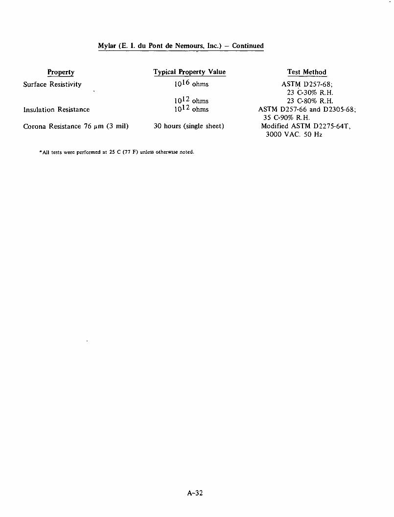
Mylar (E. I. du Pont de Nemours, Inc.) — Continued
Property
Surface Resistivity
Insulation Resistance
Corona Resistance 76 Mm (3 mil)
Typical Property Value
IO 1 6 ohms
lO^2 ohms lO^2 ohms
30 hours (single sheet)
Test Method
ASTM D257-68; 23 C-30% R.H. 23 C-80% R.H.
ASTM D257-66 and D2305-68; 35 C-90% R.H.
Modified ASTM D2275-64T, 3000 VAC. 50 Hz
"All tests were performed at 25 C (77 F) unless otherwise noted.
A-32

Flexigard (3M Company)
Flexigard is a durable, flexible, transparent, weather-resistant composite film that is specially designed for solar applications where temperatures do not exceed 77 C (170 F). Flexigard has not had extensive usage to date. Therefore, property data are limited. However, it has been exposed in Florida at 45 degrees south for 10 years with no signs of degradation. It has also been evaluated at the 3M Solar Energy Test Site since November, 1974, with like results. Tensile strength is 145 x 1.0̂ N/m2.
The product is available in rolls 1.2 m x 45.7 m x 127 Mm at the following prices:
Rolls Meters2 Cost/Meter2
1 56 $3.77 2-4 111 $3.34 5-7 179-390 $3.01 8 446 and over $2.69
A-33

POTT ANTS
Epocast 212/9617 (Furane Plastics, Inc.)
Epocast 212/9617 is a two-part general purpose epoxy pottant that cures at room temperature to a clear material. The flexibility of the cured resin can be modified by changing the ratio of resin to hardener used in the cure. Typical properties are presented in the following tabulation.
Property
Uncured Resin Properties
Resin Number Hardener Number Resin in Mix, parts by weight Hardener in Mix, parts by weight Typical Cure, hours/temperature, C
Viscosity, N-s/m2 at 24 C (75 F) Pot Life, min (100 g, 25 C)
Cured Resin Properties
Hardness, Shore D Specific Gravity Flexural Strength, N/m2
Weight Loss after 48 hr at 149 C (300 F), percent
Weight gain after 24-Hr Water Immersion at 25 C (77 F), percent
Volume Resistivity at 24 C (75 F), ohm-cm 93 C (200 F) 149 C(300 F)
Dielectric Constant at 60 Hz IO4 Hz IO6 Hz
Dissipation Factor at 60 Hz 10 4Hz IO6 Hz
Property Value
212 9617
100 60 (variable)
48/27 3/66
3.2 85
87/84 1.13
69 x IO6
3.33
0.36
9.9 x 10l 4
1.6 x 10⁸
8 x 10? 3.7 3.6 3.4
.009
.010
.021
Epocast 212/9617 is available in 18.1 kg (40 lb) lots for $151.60, 0.21 m 3 (55 gal) drums at $800/drum.
A-34

Stycast-1269A (Emerson and Cuming, Inc.)
Stycast 1269A is a two-part, crystal-clear epoxy casting resin well suited to optical applications. When cured, it has outstanding toughness. Where optical clarity is a prime objective, cure shoulcf be carried out at a temperature no higher than 88 C (190 F). If a fast cure is required, higher cure temperatures may be used, but the cured material will normally become light amber. When fully cured, Stycast 1269A has good high-temperature properties; some discoloration can be expected when the material is exposed to temperatures above 120 C (250 F). Except for the color change, other properties are unaffected. Stycast 1269A exhibits good adhesion to most materials, and negligible exotherm on curing. Excellent electrical properties coupled with exceptional clarity are the outstanding features of this material.
Stycast 1269A is available at a cost of $8.16 kg. Pertinent property data are tabulated below.
General Properties
Specific Gravity Flexural Strength, (N/m^) Thermal Conductivity, W/m'C Coefficient of Thermal Expansion, C~l Dielectric Constant, 106 Hz Loss Tangent, 10^ Hz Volume Resistivity, ohm-cm Dielectric Strength, (kV/mm) Hardness, Shore D
at 25 C (77 F) at 93 C (200 F)
Index of Refraction
Optical Transmission
Percent Transmission Wave-Length Stycast 1269A Pyrex Glass
Meters, x 10 - 6 4.4 mm 7.2 mm 2.0 mm
0.70 88.5 89.5 91.9 0.65 85.2 87,0 91.9 0.60 83.2 85.0 91.9 0.55 83.0 85.0 91.8 0.50 82.5 85.0 91.8 0.45 81.0 82.8 91.5 0.40 75.9 75.9 91.3 0.35 47.8 37.1 86.2 0.30 0 0 0 0.28 0 0 0
The shelf life is 6 months when stored in unopened containers at temperatures no higher than 25 C (77 F).
1.2 228 x 106
0.272 75 x 1(T6
3.8 Below 0.005
7 x 10 1 4
16.9
85 40
1.5401
A-35

RTV 615 (General Electric Company)
RTV 615 is a two-part dimethyl silicone rubber pottant that cures at room temperature. It is "easily pourable" in the uncured state and has ideal dielectric properties for potting applications over a wide temperature range. RTV 615 is available in 200 kg (440 lb) kits at $18.63/kg ($8.45/lb) for 1-3 kits. Greater than 4 kits at $18.04 kg ($8.18/lb). Typical uncured and cured properties are listed below.
Property Property Value
Typical Uncured Properties
Color Clear Consistency Easily pourable Viscosity, N-s/m2 3.0 Shelf Life, months 6
Typical Cured Properties
Specific Gravity 102 Hardness, Shore A Durometer 35 Tensile Strength, N/m2 6.4 x 10⁶
Elongation, percent 150 Tear Resistance, Die B, N/0.0254 m 111 Brittle Point, C <-68 Linear Shrinkage, percent < 2 Thermal Conductivity, W/mC at 93 C 0.206 Coefficient of Thermal Expansion, C 1 270 x 10~6
(-18 to +177 C) Dielectric Strength, kV/mm 19.7 Dielectric Constant at 60 Hz 3.0 Dissipation Factor at 60 Hz .001 Volume Resistivity, ohm-cm 1 x 1 0 ^
A-36

RTV 619 (General Electric Company)
RTV 619 is a low-viscosity liquid which, with the addition of a curing agent, cures to a clear, energy-absorbant gel. It is useful as a dielectric potting material over a wide temperature range. In the uncured state, it pours easily and can be cured at room temperature without exotherm.
The following cure schedule generally is used with RTV 619:
Cure Temperature Approximate Time
25 C (77 F) 24 hr 65 C (149 F) IV* hr
100 C(212 F) 30 min 150 C (302 F) 15 min
Typical properties of the uncured and cured resin are presented below.
Typical Uncured Properties
Color Consistency Viscosity, N's/m2
Specific Gravity Solids, percent Shelf Life at 25 C
(77 F), months
RTV-619A Base Compound
RTV-619B Curing Agent
Clear Easily pourable
0.750 0.97
100 6
Light blue Easily pourable
0.050 0.97
100 6
Typical Uncured Properties (curing agent added)
Viscosity, N-s/m2 0.500 Working time, hr 4
Color Specific Gravity Penetration
Typical Cured Properties
Clear 0.97
mm (Universal Penetrometer, 19.5-gram shaft, 6.35-mm diameter)
<-65 Approximately 1% volume
increase by 10 degrees C 0.172
Freezing Point, C Temperature Effect
on Volume Thermal Conductivity,
W/mC Dielectric Strength - ASTM D-149, kV/mm Dielectric Constant - ASTM D-150, 103 Hz Dissipation Factor - ASTM D-150, 103 Hz Volume Resistivity - ASTM D-257, ohm-cm
19.7 3.0 0.001
1 x 10 1 5
A-37

RTV-655 (General Electric Company)
RTV-655 is a transparent, low-viscosity silicone liquid that cures with the addition of a curing agent to form a rubber-like, tough, transparent solid. It provides environmental protection and mechanical support to encapsulated or fabricated components and assemblies. RTV-655 protects against thermal shock, vibration, moisture, ozone, corona, dust, chemicals, and many other contaminants and, because of its transparency, will permit easy component identification and repair.
RTV-655 is available at $28.53 kg ($12.94/lb) in 1-3 kit lots (200 kg/kit). Greater than 4 kit lots are $27.94/kg ($12.67/lb). Typical property data for the uncured and cured material are given in the following tabulation.
Property
Typical Uncured Properties
Color Viscosity at 25 C (77 F) Consistency Solids Content (nominal), percent Specific Gravity at 25 C (77 F) Shelf Life at 25 C.(77 F) Pot Life at 25 C (77 F) (Curing agent added) Refractive Index
Typical Cured Properties
Color
Specific Gravity ASTM-D676 Durometer, Shore A Thermal Conductivity, W/m*C Temperature Effect on Volume
Tensile Strength, N/m2
Elongation Weight Loss, percent after 1000 hr/200 C (392 F) Dielectric Strength-ASTM D-149 Dielectric Constant-ASTM D-150, 103 Hz Dissipation Factor-ASTM D-150, 103 Hz Volume Resistivity-ASTM D-257
Property Value
Clear - light straw 5 Ns/m2
Easily pourable 100
1.07 6 months minimum
4 hr 1.435
4hr /66 C(150 F) Transparent, clear
light straw 1.07
35 >0.172 <1% volume increase
per 10 C 5.9-6.9 x 10⁶
150% 3.0
19.7 kV/mm 3.00
.001 1 x 10 1 5
• A-38

Sylgard 184 (Dow Corning)
Sylgard 1 84 is a clear, low-viscosity, room-temperature curing dimethyl silicone rubber for use in potting. It is a two-part system and exhibits excellent dielectric properties from -65 to 250 C (-85 to 482 F).
The price of Sylgard 184 resin and catalyst is $18.41/kg. DC 1201 adhesion-promoting primer is $9.26/kg. Pertinent properties of the uncured and cured elastomer are presented below.
Property Property Value
ASTM D-1298 Specific Gravity at 25 C (77 F) 1.05 ASTM D-1084B Viscosity at 25 C (77 F), N-s/m2 5.5 Pot Life at 25 C (77 F) with Curing Agent Added, hours 2
Cured Properties
Color Clear ASTM D-2240 Durometer Hardness, Shore A 35 ASTM D-412 Elongation, percent 100 ASTM,D-792A Specific Gravity at 25 C (77 F) 1.05 ASTM D-412 Tensile Strength, N/m2 6.2 x 10⁶
Thermal Conductivity W/m-C. 0.146 Linear Coefficient of Thermal Expansion,
C 1 from -55 to 150 C 3.0 x 10"4
Volume Expansion, C 1 from -55 to 150 C 9.6 x 10"4
Weight Loss, percent after 1000 hr at 150 C (302 F) 1.6 after 1000 hr at 200 C (392 F) 4.0
ASTM D-570 Water Absorption After 7 Days Immersion at 25 C (77 F), percent 0.10
ASTM D-746 Brittle Point, degrees -65 C (-149 F) ASTM D-1218 Refractive Index 1.430 ASTM D-150 Dielectric Constant, at 60 Hz 2.75*
* 100 kHz 2.75*
ASTM D-150 Dissipation Factor, at 60 Hz 0.001 100 kHz 0.001*
ASTM D-275 Volume Resistivity, ohm-cm 1 x 10 1 4
ASTM D-149 Dielectric Strength, kV/mm 21.7* ASTM D-150 Dielectric Constant, at 60 Hz 2.65**
100 kHz 2.65** ASTM D-150 Dissipation Factor, at 60 Hz 0.001**
100 kHz 0.001** ASTM D-257 Volume Resistivity, ohm-cm 2 x 10 1 4
ASTM D-149 Dielectric Strength, kV/mm 23.6**
•1575 ptm specimens cured 4 hr at 65 C (149 F). ••Aged 1000 hr at 200 C (392 F).
A-39

SEALANTS
MONO (The Tremco Manufacturing Co.)
MONO is an acrylic terpolymer sealant. It does not need modifiers for adhesion, workability, or long life. The desired sealant characteristics of exceptional adhesion and elasticity are an inherent and permanent part of the basic polymer. They will not migrate or disappear with time as is the case with many other high performing sealants. The sealant is highly weather resistant: resisting ultraviolet, oxygen, moisture, heat, and cold.
MONO is available in 0.3 kg (11 oz) tubes at $2.40/tube in case lots.
Performance characteristics of MONO are detailed in the following tabulation.
Property
Adhesion-In-Peel Staining Ultraviolet
Through Glass Accelerated Aging
Sagging Curing Time Resistance to Salt Spray
Weight Loss After Heat Aging, percent
Durability (bond and cohesion after 4 days water immersion; heat and cold conditioning)
Gunnability
Property Value
44 to 89 N None
Excellent resistance No adhesive failure
No adhesive, cohesive failures or oil exudation after 5000 hr
Passes 21 days at 24 C to 51 C (75 F to 120 F)
No adhesive or cohesive failure after 200 hr at 40 C (105 F) in 5% salt solution
12 to 14
50% extension at -18 C (0 F) Passes requirements on mortar, glass, and aluminum
Flow rate more than 20 g in 2 min through 2.54-mm orifice 41 x 104
N/m2, 25 C (77 F)
Test Method
TT-S-230a; 19-GP-5b TT-S-230a; 19-GP-5b TT-S-230a; 19-GP-5b
ASTM E-42, Method E
TT-S-230a; 19-GP-5b TT-S-230a
ASTM E-117-57T
TT-S-230a; 19-GP-5b
TT-S-230a
A-40

Tremco 440 Preshimmed Tape (Tremco Manufacturing Co.) - Sealant Type
Tremco 440 tape is formulated from 100 percent solids, combining butyl and polyisobutylene. It contains no solvent or other volatiles. It is not recommended for use in joints subjected to prolonged periods of water submersion or temperatures exceeding 93 C (200 F).
440 Tape is supplied in different length rolls in the following sizes and shapes: standard sizes (thickness and width): 3.175 mm by 9.525 mm; 3.175 mm by 12.7 mm; 4.7625 mm by 12.7 mm. Other sizes such as 6.35 mm by 12.7 mm available on special order. Comes in aluminum and black/bronze colors.
The cost of Tremco 440 Tape is $0.535/roll for a 4.7625 mm x 12.7 mm x 7.6 m tape (3/16 x 1/2 x 25 ft) roll in case lots of 20 rolls per case.
Performance characteristics of 440 Tape are given below.
Dynamic Movement and Vibration
Dynamic Movement
Adhesion
Heat Resistance
Squeeze-out
Accelerated Aging
Test Method
Voss Tester (as described in Canadian Spec. 19-GP-5) 6.35-mm to 12.7-mm preshimmed Tremco 440. Tape cycled 100,000 times at laboratory conditions and 100,000 times at 71 C (160 F) using infrared lamp
Specimen forming a joint 4.7625-mm wide, 12.7-mm deep, and 152.4-mm long is compressed and extended 85 cycles each at 25%, 50%, and 100% extension and compression
Tested on steel, aluminum, glass, and concrete after 14 days of water immersion, 14 days of conditioning at 82 C (180 F) and 14 days ultraviolet exposure
Specimen conditioned at 135 C (275 F)
Specimen subjected to dynamic extension and compression, also to static and dynamic test at University of Miami
1000 hr exposure in accelerated test unit (equivalent to 6-10 years exposure)
Result
No pumping, no sagging, no significant effect on adhesion
No adhesive or cohesive failure
Excellent
No oil exudation, blistering, flow or loss of adhesion
Very nominal under severe conditions
Adhesion still excellent: 20 to 30 Shore A hardness
A-41

Tremco 440 Preshimmed Tape - Tremco Manufacturing Co. — Sealant Tape — Continued
Low-temperature Flexibility
Compatibility
Test Method 152.4-mm length of tape conditioned
at 88 C (190 F) for 14 days, then to -29 C (-20 F) and bent 180 degrees around a mandrel.
Result No loss of adhesion; no
cracking
Compatible with all Tremco Sealants recommended for glazing, setting panels or sealing mullions
A-42

Vistalon 404 (Exxon Chemical Company)
Vistalon 404 is an ethylene-propylene copolymer for use in sealant applications. Because it is a completely saturated hydrocarbon elastomer, it can be formulated for use in a wide variety of applications in which service aging is critical. The material has exceptional ozone and heat resistance, is resistant to weather, sunlight, and chemicals, has low compression set, good resilience and good low-temperature flexibility.
The performance of peroxide-cured, filled Vistalon 404 is presented below.
Formulation
Vistalon 404 100 Age Rite Resin D 2 FEF Black 60 Zinc Oxide 5 TAC-75 2-DiCup 40 C 10 Specific Gravity 1.12
Processability Properties
Mooney Scorch at 121 C (250 F) (MS) +10, min 30. 132 C (270 F) (MS)+3, min 9
Mooney Viscosity, ML 1 + 8 100 C (212 F) 90
Physical Properties
Hardness, points 68 100% Modulus, N/m2 4.3 x 10⁶
200% Modulus, N/m2 11.4 x 10⁶
Tensile Strength, N/m2 12.4 x 10⁶
Ultimate Elongation, percent 230 Compression Set, Method B, plied
70 hr at 100 C (212 F), percent 11 22 hr at 120 C (302 F), percent 14
Physical Properties, Aged
Air Oven, 70 hr at 150 C (302 F), ASTM D573 Hardness, points change +5 Tensile Strength, percent change - 1 Ultimate Elongation, percent change +4
Air Oven, 70 hr at 175 C (347 F), ASTM D573 Hardness, points of change +5 Tensile Strength, percent change -28 Ultimate Elongation, percent change -26
A-43

Lasto-Meric Liquid Polymer Sealant (Tremco Manufacturing Co.)
Lasto-Meric is a specially-formulated 100 percent polysulfide liquid polymer base sealant.
Lasto-Meric is a nonshrinking, nonoxidizing elastic sealant for glazing and resealing all types of panels and curtain wall construction. It resists long-term exposure to sunlight and will not stain most masonry surfaces.
This long-lasting sealant bonds well to all types of masonry, metal, glass and wood. Lasto-Meric resists cyclical movement without loss of adhesion or cohesion - it remains flexible in a temperature range from -51 to 93 C (-60 to 200 F). The material returns to its original shape and dimensions after periods of deformation.
Gun-grade consistency, Lasto-Meric is designed for general use in caulking, glazing, and sealing, and for filling expansion joints. A two-part compound, Lasto-Meric is blended together before application. After proper mixing, the compound begins to cure and eventually becomes a firm, resilient rubber.
Joints sealed with Lasto-Meric are weatherproof, watertight and permanently flexible regardless of temperature, moisture, or exposure to solar radiation. Porous masonry surfaces should be primed with Tremco No. 1 Primer prior to applying Lasto-Meric.
A-44

SHEET/TUBING
Plexiglas (Rohm and Haas Company)
Plexiglas is the Rohm and Haas Company trademark for a family of thermoplastic acrylic sheets and molding powders for injection molding and extrusion. Among the many desirable properties of Plexiglas, two are preeminent:
• Unexcelled durability indoors and outdoors • Superlative optical properties and clarity.
Resin properties are typified by those of Plexiglas V(811) which is available with varying degrees of ultraviolet transmission.
Average Physical Properties of Plexiglas Molding Pellets
Property
Refractive Index Specific Gravity Tensile Strength
Flexural Strength
Compressive Strength
Impact Strength
Rockwell Hardness Light Transmission
"As Received" Effect of Accelerated
Weathering on Appearance of Clear Material
Deflection Temperature Under Load, unannealed
Melt Flow Rate by Extrusion Plastometer —Condition H —Condition I
Test Conditions
ASTM D-542-50 ASTM D-792-64T ASTM D-638-64T
6.35 mm specimen (0.8 x 10"4 m/s) maximum, N/m2
ASTM D-790-66 . Span-depth ratio 16
(0.4 x 10"4 m/s) maximum, N/m2 . ASTM D-695-68T
(0.8 x 10"4 m/s) maximum, N/m2
ASTM D-256-56(1961) Izod molded notch
(per 0.0254 m of notch) J ASTM D-785-62 ASTM D-1003-61
. Total white, percent LY 406a-6024 (240 hr)
Crazing Discoloration
Warping Unmolding
ASTM D-648-56 (1961) 2 C (3.6 F)/min, 182 x 104 N/m2
ASTM D-1238-63T g/10 min
Property Value
1.49 1.19
72 x 106
110 x 106
117 x 106
0.5
M^97 92
None None None None
92 "C (198 F)
1.2 5.0
A-45

Plexiglas (Rohm and Haas Company) — Continued
Property
Flow Temperature Vicat Softening Point,
2 C (3.6 F)/rnin, 254-/jm penetration, 1000-g load
Shrinkage From Mold Dimension
Dielectric Strength Dielectric Constant Power Factor Loss Factor Arc Resistance Flammability Water Absorption
Test Conditions
ASTM D-569-59(1961) ASTM D-1525-58T, C
ASTM D-955-51 (1961) (Cold mold to cold piece)
mm/m 48 hr ASTM D-149-64 kV/mm ASTM D-150-68, 60 Hz
'• ' ASTM D-150-68, 60 Hz ASTM D-l 50-68, 60 Hz
ASTM D-495-61, sec ASTM D-635^-68 burning rate, m/s ASTM D-570-63 Wt gain on 24-hr "
Water immersion Dimensional change on immersion, percent
Property Value
160 C (320 F) H O C (230 F)
2-6
19.7 3.7 0.05 0.19
No tracking 3.0 x lO"4
0.3
None*
Plexiglas G is the standard type of cast plexiglas sheet. Plexiglas G sheet 1.2 x 2.4 meters is available at $11.19/m2 in 3.175-mm thickness with masking on both sides or at $10.11/m2 with interlayers. , •> .
Plexiglas II UVA (ultraviolet absorbing) sheets have the same general properties as Plexiglas G but are manufactured to more exacting standards of optical quality. The cost of 3.175-mm (1/8 inch) sheet is $29.81/m2 ($2.7.7/ft2);.6.35 mm (1/4 inch) sheet costs $41.64/m2 ($3.87/ft2).
Average physical properties, applicable to both Plexiglas G and II UVA sheet materials, are given below.
Average Physical Properties of Plexiglas Sheet
Property ASTM Method^) Property Value
Thickness, mm 6.35 Specific Gravity D792 1.19 Refractive Index D542 1.49 Light Transmittance and Haze, percent D1003
"As Received" - parallel 91 - total 92 — haze 1
A-46

Plexiglas (Rohm and Haas Company) — Continued
Property ASTM Method(2> Property Value
After 5-Yr Outdoor Exposure, Bristol, Pa., 45 deg. angle facing South, percent
- parallel 90 - total 92 — haze 2
After 240-Hr Artificial Exposure, Carbon Arc Type, per ASTM G-23, percent
— parallel 90 - total 92 — haze 2
Artificial Weathering, Fluorescent D1501 Sunlamp With Dew, 10 cycles, 24Q»hr or Exposure — crazing Fed. Test Std. None
- warping 406, Method 6024 None Instrumental Measurement, Change In D1925 1.0
Yellowness Index After Artificial Weathering
Ultraviolet Transmission, 320 Beckman DU-792 0 nanometers, percent
Tensile Strength (6.35 mm Specimen-0.8 x lO"4 m/s) D638 Maximum, N/m2 72 x 106
Rupture, N/m2 72 x 106
Elongation Maximum, percent 4.9 Elongation Rupture, percent 4.9 Modulus of Elasticity, N/m2 3100 x 106
Poisson's Ratio 0.35 Flexural Strength (Span Depth Ratio
16, 0.4 x 10⁻⁴m/s) D790 Maximum, N/m2 110 x 106
Rupture, N/m2 H O x 106
Modulus of Elasticity, N/m2 3100 x 106
Impact Strength Izod Milled Notch, J/0.0254 m of notch 0.5
Rockwell Hardness D785 M-104 Thermal
Hot Forming Temperature, C 143-182(290-360 Maximum Recommended Continuous
Service Temperature, C 82-93 (180-200 1
A-47

Plexiglas (Rohm and Haas Company) — Continued
Property ASTM Method*2)
Coefficient of Thermal Expansion, C"1 x 10"5 . R&H P4A -40 C (-40 F) -29 C (-20 F) -18 C ( 0 F) -7 C (20 F) 4 C (40 F) 16 C(60 F) 27 C (80 F) 38 C(100 F)
Coefficient of Thermal Conductivity, Cenco-Fitch W
m-C Specilic Heat at 25 C (77 F), kg*C
m-C Specilic Heat at 25 C (77 F), kg*C
Electrical Dielectric Strength, Short Time Test, kV/mm D149 Dielectric Constant D150
60 Hz 1,000 Hz i .000,000 Hz
Power Factor D150 60 Hz 1,000 Hz 1,000,000 Hz
Loss Factor D150 60 Hz 1,000 Hz 1,000,000 Hz
Arc Resistance D495 Volume Resistivity, ohm/cm D257 Surface Resistivity, ohm/square D257
Water Absorption (weight gain) After D229 Immersion, percent for: and
1 day D570 2 days 7 days 28 days 56 days 84 days
A-48

Lucite (E. I. du Pont de Nemours, Inc.)
Lucite acrylic resin is a thermoplastic noted for many desirable qualities: clarity, outdoor durability, unique light-transmission characterisitics, light weight, and shatter resistance. It is available in injection molding and extrusion grades and as preformed sheet. Property information for Lucite 140 resin, a medium-molecular-weight composition priced at $1.32 kg ($0.60/lb) and well-suited for injection molding and extrusion processing with good heat resistance, is given below.
Properties of Molded "Lucite" 140 Acrylic Resin
Property ASTM Method
Tensile Strength, N/m2 3.175 mm thick -57 C (-70 F) D638 23 C (73 F) D638 70 C(158 F) D638
Tensile Elongation, percent -57 C (-70 F) D638 23 C (73 F) D638 7 0 C ( 1 5 8 F ) • D638
Tensile and Flexural Modulus of Elasticity 23 C (73 F), N/m2 D638
Shear Strength, N/m2 D732 Impact Strength, Izod, Milled Notch,
6.35-mm Bars 23 C (73 F) J/0.0254 m D256 Stiffness 23 C (73 F) N/m2 D747 . Flexural Strength 23 C (73 F) N/m2 D790 Hardness, Rockwell D785 Coefficient of Linear Thermal Expansion
-18 to 38 C (0-100 F, average) C"1 D696 Thermal Conductivity, W/nvC Cenco-Fitch Specific Heat, J/kg*C Deformation Under Load 14 x 10^ N/m2
24 hr, 50 C (122 F), percent D621 Deflection Temperature
182 x 104 N/m2, C D648 45.5 x 10⁶ N/m2 C D648
Dielectric Strength, Short Time, 3.175 mm, kV/mm D149
Arc Resistance D495 Volume Resistivity, ohm-cm D257 Dielectric Constant
60 Hz D150 103 Hz D150 106 Hz D150
Property Value
100 x 106
72 x 106
>34 x 106
2 3-5 80
2758-3447 x 106
65 x 106
0.4 2965 x 106
H O x 106
M95
3.4 x 10" 5
0.200 1454
0.3-0.4
92(198 F) 99(210 F)
15.7 No tracking
M O 1 ^
3.5 3.2 2.7
A-49

Lucite (E. I. du Pont de Nemours, Inc.) — Continued
Property ASTM Method
Dissipation Factor 60 Hz D150 103 Hz D150 106 Hz D150
Index of Refraction, n 0 D542 Luminous Transmittance, 3.175 mm, percent E308 Haze, percent D1003 Water Absorption, 24 hr, percent D570 Weight Gain Plus Soluble Matter Loss Soluble Matter Loss Flammability, 3.175 mm, mm/s D635 Specific Gravity D792 Mold Shrinkage D551
Property Value
0.06 0.04 0.02 1.49
92 <3
0.3 <0.1
0.38-0.51 1.19
0.003-0.007
"Lucite" cast acrylic sheet is available as a linear (L) and cross-linked (XL) composition. Both have excellent optics, high impact resistance, excellent weatherability, and close thickness tolerances. Either is suitable for most glazing applications; however, "Lucite" XL sheet offers advantages in solvent resistance. The high-temperature elastic strength of "Lucite" XL minimizes the probability of tear during thermoforming operations. "Lucite" L is easily cemented, using appropriate solvents.
li is available in clear sheet sizes of 91 cm x 91 cm up to 284 cm x 381 cm, cut to size within these limits; it has a nominal thickness range of 3.175 to 6.35 mm. Costs in 13,605 kg minimum quantities are $1.72/kg (3.175 mm), $2.25/kg (4.75 mm), and $2.74/kg (6.35 mm). Average physical properties of "Lucite" L and XL are given below.
Property Data — "Lucite" L and XL
Property
Specific Gravity Refractive Index Light Transmittance
Parallel Total Haze
Spectral Transmission 290 to 330 nm, 6.35 mm Sheet, max percent
Tensile Strength Rupture Modulus of Elasticity Elongation at Rupture
ASTM
D792 D542
D1003
Beckman DU-792
D638
"Lucite" L and XL
1.19 1.49
91% 92%
1%
74 x 106 N/m2
2944 x 106 N/m2
4.5%
A-50

Lucite (E. I. du Pont de Nemours, Inc.) — Continued
Property
Flexural Strength Rupture Modulus of Elasticity
Rockwell Hardness Hot Forming Temperature Heat Distortion Temperature, C
(182 x 104 N/m2) Coefficient of Thermal Expansion, C~l
(average value) Maximum Recommended Continuous
Service Temperature, C Coefficient of Thermal Conductivity, W/nvC Shrinkage, max percent Specific Heat, J/kg*C Surface Resistivity, ohm, 75% RH Volume Resistivity, ohm-cm Dielectnc Strength, kV/mm
Short-Time Test Dielectric Constant
60 Hz 103 Hz 106 Hz
Power Factor 60 Hz 103 Hz 106 Hz
Arc Resistance Water Absorption (Wt Gain on
Immersion For 24 Hr), percent Odor Taste
ASTM
D790
D785
D648
D696
D257 D257 D149
D150
D150
D495 D570
"Lucite" L and XL
103 x 106 N/m2
2944 x 106 N/m2
M-100 135-175 C (275-350 F)
95 (203 F)
7.0 x 10"5
80(176 F) 0 207 2.5 1454
> 1 0 1 6
1015 20
4 4 3
0.06 0.04 0.02
No tracking 0 3
None None
A-51

XT-365 (American Cyanamid Company)
XT-365 is a clear, tough, rigid, modified acrylic molding compound. It is referred to as an acrylic-based multipolymer. American Cyanamid's cost for this resin is $1.12/kg ($0.51/lb) in truck-load quantities. Typical property data for the bulk resin are given in the following tabulation.
Property Color Light Transmission, percent Haze, percent Izod Impact Strength,
Notched J/0.0254 m of notch (6.35 mm bar) 23 C (73 F) 0 C (32 F) -40 C (-40 F)
ASTM Method
D-307-44 D-1003-5 2 D-256-56
Tensile Strength, N/m2 D-638-60T Tensile Modulus, N/m2 D-638-60T Tensile Elongation, percent D-638-60T Flexural Strength, N/m 2 D^790-59T Flexural Modulus, N/m 2 D-790-59T Compressive Strength, N/m2 D-695-54 Rockwell Hardness D-785-60T
Deflection Temperature, C D-648-56 (182 x 10 4 N/m 2 )
Coefficient of Thermal Expansion, C~l D-696-44 Specific Gravity D-792 Water Absorption, percent D-570-59T
24 Hr at 23 C (73 F) Weight Change, percent
One Week Immersion at 23 C (73 F) Water
Dielectric Constant at: D-150 100 Hz 1,000 Hz 1,000,000 Hz
Dissipation Factor at: 100 Hz 1,000 Hz 1,000,000 Hz
Property Value Transparent
87 9
2.0 1.6 . 1.2
48 x 106
2600 x 106
28 76 x 106
2400 x 106
65 x 106
R114 M45
86 (186 F)
9.0 x 10*5 1.1
0.3
0.6
3.25 3.21 2.82
0.028 0.30 0.023
A-52

Lexan (General Electric Company)
Lexan polycarbonate molding resin offers the toughness and performance of many metals, yet provides the processing and design advantages of an engineering thermoplastic. It provides impact strength and support unmatched by any other thermoplastic. It is available in a number of grades as sheet material in sizes ranging from 61 x 122 cm (24 x 48 in.) to 183 x 244 cm (72 x 96 in.), and in thicknesses from 3.175 to 12.7 mm (1/8 to 1/2 in.). Lexan 9030 sheet is the standard outdoor glazing grade. It has outstanding resistance to the detrimental effects of sunlight, rain, erosion, atmospheric chemicals, and temperature change.
Typical resin properties are listed below.
Property Data — Lexan Resin
Property Property Value
Specific Gravity 1.20 Tensile Strength, N/m2 62 x 10° Izod Impact Strength
J per 0.0254-m Notch 21.7 Coefficient Thermal Expansion
C"1 x 10⁻⁵ 6.75 Heat Deflection Temperature, C
(at 45.5 x 10⁴ N/m2) 138 (280 F) (at 182 x 104 N/m2) 132 (270 F)
UL Continuous Use Temperature, C 115 (239 F) Flexural Modulus, N/m2 2344 x 106
Percent Loss Apparent Modulus 14 x 106 N/m2
1000 hr 23 C (73 F) 16 Percent Loss
Apparent Modulus 14 x 106 N/m2
1000 hr 93 C (200 F) 18 Dielectric Strength, kV/mm 15
A-53

Lexan (General Electric Company) — Continued
Property Data - Lexan 9030 Sheet
Property
Weight, 3.175-mm Sheet, kg/m2
4.763-mm Sheet, kg/m2
6.350-mm Sheet, kg/m2
9.525-mm Sheet, kg/m2
12.70-mm Sheet, kg/m2
UV Transmission at 0.385 nm, percent UV Transmission at 0.400 tim, percent Tensile Strength, N/m2
Elongation, percent Compressive Strength, N/m2
Flexural Strength, N/m2
Modulus of Elasticity, N/m2
Property Value
3.81 5.71 7.62
11.42 15.23
<0.1 50
65 x 106
110 " 86 x 106
93 x 106
. 2378 x 106 "
Lexan 9030 is available in 1.22 x 2.44 m,(48 x 96 in.) sheet. $25.72/m2 ($2.39/ft2).
At 3.175 mm (1/8 in.), cost is
A-54

Tuffak (Rohm and Haas Company)
Tuffak polycarbonate is a lightweight, high-impact sheet that transmits 82-89 percent of incident light depending on sheet thickness. It is available in 1.8 x 2.7 m (6 x 9 ft) and 2.7 x 3.7 m (9 x 12 ft) sheets and sheet thicknesses from 1.5875 mm (1/16 in.) to 12.7 mm (1/2 in.).
Average typical properties of Tuffak are given in the following tabulation.
Property
Specific Gravity Optical
Refractive Index Light Transmittance, percent Haze, percent
Tensile Strength, N/m2
Ultimate Yield Elongation, percent
Flexural Strength, N/m2
Flexural Modulus, N/m2
Compressive Strength, 0.2 x 10"4 m/s, N/m2
Impact Strength Izod (3.175 mm notched), J/0.0254 m of notch
Rockwell Hardness
Thermal Heat Deflection Temperature, C Under Load, 182 x 104 N/m2
45.5 x 10⁴ N/m2
Coefficient of Thermal Expansion, C~l Coefficient of Thermal Conductivity, W
m-C Specific Heat, J/kg'C Electrical
Dielectric Strength, Short-Time, Test (at 3.175-mm thick), kV/mm
Dielectric Constant 60 Hz 1,000,000 Hz
Volume Resistivity 23 C (73 F), ohm-cm Miscellaneous
Water Absorption, percent Equilibrium at 23 C (73 F) Equilibrium at 100 C (212 F)
ASTM Method Property Value
D-792 1.2
D-542 1.586 D-1003 85-91 D-1003 0.5-2.0
D-638 66 x 106
D-638 58 x 106
D-638 100 D-790 93 x 106
D-790 2300x 106
D-695 86 x 106
D-256 21.7
D-785 R 118 M 70-78
D-648 135 (275 F) 141 (285 F)
D-696 6.8 x 10⁻⁵ r.177 0.193
D-149
D-150
D-257
D-570
1246
15.0 at 25 C 17.7 at 100 C
2.9 2.9 10 l 4
0.35 0.58
A-55

Sun-Lite (Premium Grade), (Kalwal! Corporation)*
Sun-Lite is a specially designed1 cover material, for solar collectors. It is a fiberglass-reinforcedl polyester available m> regular and' premium grades. It features solar, properties equivalent to or better than those of glass, low. cost, low thermal' expansion, light weight, and1 good strength. It is available in> 1 2 m (4 ft>and h5 mi (5 ft) widths upito>366 m (1*200* ft) long m thicknesses of 635-10'1!6 MHI (0 025-0.040 in.). Costs are $3.01 and' $4.95/m2 for the thicknesses. Property data* for the premium grade are presented below.
Average Property Method Property Value
Solar Energy Transmittance, percent E 424 Method B 85-90-Estimated Solar Lifetime, yr 20 Thermal* Sensitivity at 93 C (200i F) Excellent
at 149 C (300 F) Good, Heat Transmittance, percent 5-20-microns ro> Index of Refraction D 542 1.52 Tensile Strength, N/m2 D638 76 x 106
Flexural Strength, N/m2 D 790 152x 1>06
Flexural Modulus, N/m2 D 790 4 l'OO x 106
Shear Strength, N/m2 D>732 83>x 1!06
Izod Impact, J/0 025 mi D 256 13.6 Water Absorption, percent D 570 0.50-0:60, rhe' lal Expansion, C~l x 10" 5 D̂ 696, 2.5
iiul Conductivity, W/iru'C C 177 0.124 bpecihc Heat, J/kg*C D> 2766 1454 Specific Gravity D 7921 1.4 Weight, kg/m2 NBS PS53 0.85-L43
A-56'

APPENDIX B
TRADE NAMES AND SUPPLIERS OF MATERIALS REFERENCED IN REPORT

APPENDIX B
TRADE NAMES AND SUPPLIERS OF MATERIALS REFERENCED IN REPORT
The following products are cited in the text by suppliers' brand names and are believed to be * registered trademarks. In many cases, where reference to specific brands was made, it is likely that similar materials with equally good properties are available from other manufacturers.
Glass Encapsulation Materials
Trade Designation
ASG Sunadex ASG Lustraglass Corning 7940 Fused Silica Corning 7740 Borosilicate Corning 7070 Borosilicate Corning 7059 Borosilicate Corning 0211 Microsheet Corning 0080 Soda-Lime Corning 1720 Aluminosilicate Corning 1723 Aluminosilicate Corning 8871 Potash Lead Fourco Clearlite General Electric 776 Borosilicate General Electric 008 Soda-Lime General Electric 351 Innotech IP 530 Owens-Illinois KG-33 Borosilicate Owens-Illinois ES-1 Borosilicate Owens-Illinois EE-5 Owens-Illinois R-6 Soda-Lime PPG Float PPG NESA Schott 8330 Borosilicate
, Supplier
ASG Industries, Inc., Kingsport, TN ASG Industries, Inc., Kingsport, TN Corning Glass Works, Corning, NY Corning Glass Works, Corning, NY Corning Glass Works, Corning, NY Corning Glass Works, Corning, NY Corning Glass Works, Corning, NY Corning Glass Works, Corning, NY Corning Glass Works, Corning, NY Corning Glass Works, Corning, NY Corning Glass Works, Corning, NY Fourco Glass Co., Clarksburg, WV General Electric Co., Richmond Heights, OH General Electric Co., Richmond Heights, OH General Electric Co., Richmond Heights, OH Innotech Corp., Norwalk, CT Owens-Illinois', Inc., Toledo, OH Owens-Illinois, Inc., Toledo, OH Owens-Illinois, Inc., Toledo, OH Owens-Illinois, Inc., Toledo, OH PPG Industries, Inc., Pittsburgh, PA PPG Industries, Inc., Pittsburgh, PA Schott Optical Glass, Inc., Duryea, PA
Abcite Aclar Acryloid B-7
Polymeric Encapsulation Materials
E. I. du Pont de Nemours and Co., Inc., Wilmington, Allied Chemical Corp., Morristown, NJ Rohm and Haas Co., Philadelphia, PA
B-l

Polymeric Encapsulation Materials — Continued
Trade Designation
Cavalon 3100S Ciba 502 Cronar CR-39 Cycolac Dacron OC-3140 E-397 Eccobond 45LV Eccocoat AC-8 Epocast 212/9617 Epo-Tek 301 Epo-Tek 310 ■Fortrel iplexigard •Glass Resin 650 Halar Kapton Kel IF Korad A Krylon K.ynar - -Lasto-Meric Lexan LTV -602 Lucite Ma>raglast656 Merlon MONO MR-4'000 MR-40T4 Mylar Parylene Plexiglas Pyre M.L. RTV-1.0 8 RTV-118 RTV-602 RTV-615 RTV-619 RTV-655 RVCT-91 SS-4044
Supplier
E. I. du 'Pont de Nemours and Co., Inc., Wilmington, DE Ciba-Geigy Corp., Ardsley, NY E. I. du Pont de Nemours and Co., Inc., Wilmington, DE Cast Optics-Corp., Hackensack, NJ Borg-Warner Corp., Chicago, IL E. I. du Pont de Nemours and Co., Inc., Wilmington, DE Dow-Corning Corp., Midland, MI Mobay Chemical Corp., Pittsburgh, PA Emerson and Cuming, Inc., Canton, MA Emerson and Cuming, Inc., Canton, MA Furane Plastics Co., Los Angeles, CA Epoxy Technology, Inc., Watertown, MA Epoxy Technology, Inc., Watertown, MA Celanese Corp., New York, NY 3 MCo., St. Paul, MN Owens-Illinois, Inc., Toledo, OH Allied Chemical Corp., Morristown, NJ E. I. du Pont de Nemours and Co., Inc., Wilmington, DE 3 M Co., St. Paul, MN Rohm and Haas Co., Philadelphia, PA Bordon, (Inc., New York, NY E. I. 'du Pomt de Nemours and Co., Inc., Wilmington, DE Tremco Manufacturing Co., Cleveland, OH General Electric Co., Fairfield, CT General Electric Co., Fairfield, CT E. I. du Pont de Nemours and Co., Inc., Wilmington, DE Marblette Corp., Long Island City, NY Mobay Chemical Corp., Pittsburgh, PA Tremco Manufacturing Co., Cleveland, OH General Electric Co., Fairfield, CT General Electric Co., Fairfield, CT E. I. du Pont de Nemours and Co., Inc., Wilmington, DE Union Carbide Corp., New ir'ork, NY Rohm and Haas Co., Philadelphia, PA E. I. du Pont de Nemours and Co., Inc., Wilmington, DE General Electric Co., Fairfield, CT General Electric Co., Fairfield, CT General Electric Co., Fairfield, CT General Electric Co., Fairfield; CT General Electric Co., Fairfield, CT General Electric Co., Fairfield, CT Avery Products Corp., San Marino, CA General Electric Co., Fairfield, CT
B-2

Polymeric Encapsulation Materials — Continued
Trade Designation
Scotch-Weld 2216 B/A Stycast 1266 Stycast 1269A Sun-Lite Sylgard 182 Sylgard 184 Tedlar "Tenon" FEP "Teflon" PFA Tefzel Tremco 440 Tuffak Vistalon 404 XR-63-489 XT-375
Supplier
3 M Co., St. Paul, MN Emerson and Cuming, Inc., Canton, MA Emerson and Cuming, Inc., Canton, MA Kalwall Corp., Manchester, NH Dow-Corning Corp., Midland, MI Dow-Corning Corp., Midland, MI E. I. du Pont de Nemours and Co., Inc., Wilmington, DE E. I. du Pont de Nemours and Co., Inc., Wilmington, DE E. I. du Pont de Nemours and Co., Inc., Wilmington, DE E. I. du Pont de Nemours and Co., Inc., Wilmington, DE Tremco Manufacturing Co., Cleveland, OH Rohm and Haas Co., Philadelphia, PA Exxon Chemical Co., New York, NY Dow-Corning Corp., Midland, MI American Cyanamid Co., Wayne, NJ
B 3