airbreathing propulsion for defense
12
JAMES L. KEIRSEY AIRBREATHING PROPULSION FOR DEFENSE OF THE SURFACE FLEET The primary objective of the Navy-sponsored airbreathing propulsion program at the Applied Physics Laboratory has been the development of an understanding of the physical phenomena associated with the aerodynamics and combustion of ramjet and scramjet propulsion systems. Beginning with early efforts in the 1940s and 1950s on Talos and a broad-based research program on combustion, to the late 1980s involving supersonic combustion ramjets for hypersonic flight, a variety of propulsion systems have been investigated. At present, several propulsion systems have been developed to the stage where advanced development could proceed: an integral-rocket ramjet using storable liquid hydrocarbon fuel, an air-ducted rocket using a boron- based solid fuel, and a dual-combustion ramjet for hypersonic operation using storable hydrocarbon fuel. The technological capability developed at APL is a national asset and will continue to be applied in future systems. INTRODUCTION It all started with Talos. In early 1945, APL began development of a supersonic, radar-guided, ramjet-pro- pelled missile, launched by a solid-propellant booster rocket and carrying a payload of about 600 pounds of explosive. The initial efforts of the APL team, led by Wilbur H. Goss, resulted in a successful flight of the world's first supersonic ramjet later in 1945. The group of scientists and engineers at APL, together with associate contractor s, mounted an effort to build test facilities, to obtain test data on air inlets and combustors, and to formulate the analytical techniques needed for the design of the Talos ramjet engine and missile. By 1951 most of the information needed to formulate the general specifi- cations for the first design was in hand; by January 1955 the initial Talos missile was ready for production. Talos became fully operational in 1958 and remained in the fleet arsenal until 1980. During this twenty-two-year period, Talos compiled a remarkable record of success and reliability and had a distinguished presence in the Vietnam conflict. I In addition to the Talos development program, a more basic research and development effort in airbreathing propulsion was also established at APL in the late 1940s. This effort, led by William H. Avery, involved the inves- tigation of a broad realm of ramjet technology, from combustion fundamentals to practical engineering appli- cations. The success of early ramjet experience in the Talos program had fostered enthusiasm for ramjet tech- nology. The Navy established at APL a block program in airbreathing propulsion, which became a major thrust of the Aeronautics Division. This program continued for forty-three years, and a number of airbreathing systems were investigated. After the development of Talos, em- phasis was on higher flight speed, longer range, lower- volume engine components, and various alternative fuels. The following principal programs (Table 1) were included: f ohns Hopkins APL Technical Digest, Volume 13, Number J (1992) 1. Talos: A liquid-fueled ramjet missile that recorded a total of 1349 flights, of which 750 successive flights were without a ramjet engine failure. Later, as a super- sonic target (Vandal), 320 missiles were flown with a success record of 98 %. 2. Typhon Long-Range (LR): A smaller, higher-speed, liquid-fueled ramjet similar in design to Talos that had eight successful ramjet flight demonstrations without an engine failure. 3. Augmented Thrust Propulsion (ATP): A ducted rock- et using a boron-based solid fuel. 4. Supersonic Combustion Ramjet Missile (SCRAM): A hypersonic vehicle design based on the use of liquid borane high-energy fuels (HEF). 5. Dual-Combustor Ramjet (DCR): A hypersonic vehi- cle design using a hybrid ramjet/scramjet engine that operates with liquid hydrocarbon fuels, which are more logistically acceptable than HEF. 6. Advanced Surface-to-Air Ramjet (ASAR): An inte- gral-rocket ramjet that uses the empty solid-rocket boost- er chamber as a dump-type ramjet combustion chamber and uses liquid hydrocarbon fuels. T ALOS RAMJET A ramjet was the propulsion cycle of choice for Talos because the speed of the missile could supply high- pressure air by ram compression for the combustion chamber. In principle the ramjet engine is similar to the turbojet, but it does not require the more complex rotating machinery of the compressor and turbine. In the air inlet, the required amount of air is captured at supersonic speeds; as the air is decelerated, the dynamic pressure is converted to a high internal pressure. Heat is added in the combustion chamber by burning the fuel, and the heated products are expanded and increased in velocity in the exit nozzle to produce a high exit stream thrust. The 57
-
Upload
khangminh22 -
Category
Documents
-
view
3 -
download
0
Transcript of airbreathing propulsion for defense
JAMES L. KEIRSEY
AIRBREATHING PROPULSION FOR DEFENSE OF THE SURFACE FLEET
The primary objective of the Navy-sponsored airbreathing propulsion program at the Applied Physics Laboratory has been the development of an understanding of the physical phenomena associated with the
aerodynamics and combustion of ramjet and scramjet propulsion systems. Beginning with early efforts in the
1940s and 1950s on Talos and a broad-based research program on combustion, to the late 1980s involving
supersonic combustion ramjets for hypersonic flight, a variety of propulsion systems have been investigated.
At present, several propulsion systems have been developed to the stage where advanced development could
proceed: an integral-rocket ramjet using storable liquid hydrocarbon fuel, an air-ducted rocket using a boronbased solid fuel, and a dual-combustion ramjet for hypersonic operation using storable hydrocarbon fuel. The
technological capability developed at APL is a national asset and will continue to be applied in future systems.
INTRODUCTION
It all started with Talos. In early 1945, APL began development of a supersonic, radar-guided, ramjet-propelled missile, launched by a solid-propellant booster rocket and carrying a payload of about 600 pounds of explosive. The initial efforts of the APL team, led by Wilbur H. Goss, resulted in a successful flight of the world 's first supersonic ramjet later in 1945. The group of scientists and engineers at APL, together with associate contractors, mounted an effort to build test facilities , to obtain test data on air inlets and combustors, and to formulate the analytical techniques needed for the design of the Talos ramjet engine and missile. By 1951 most of the information needed to formulate the general specifications for the first design was in hand; by January 1955 the initial Talos missile was ready for production. Talos became fully operational in 1958 and remained in the fleet arsenal until 1980. During this twenty-two-year period, Talos compiled a remarkable record of success and reliability and had a distinguished presence in the Vietnam conflict. I
In addition to the Talos development program, a more basic research and development effort in airbreathing propulsion was also established at APL in the late 1940s. This effort, led by William H. Avery, involved the investigation of a broad realm of ramjet technology, from combustion fundamentals to practical engineering applications. The success of early ramjet experience in the Talos program had fostered enthusiasm for ramjet technology. The Navy established at APL a block program in airbreathing propulsion, which became a major thrust of the Aeronautics Division. This program continued for forty-three years, and a number of airbreathing systems were investigated. After the development of Talos, emphasis was on higher flight speed, longer range, lowervolume engine components, and various alternative fuels. The following principal programs (Table 1) were included:
f ohns Hopkins APL Technical Digest, Volume 13, Number J (1992)
1. Talos: A liquid-fueled ramjet missile that recorded a total of 1349 flights, of which 750 successive flights were without a ramjet engine failure. Later, as a supersonic target (Vandal), 320 missiles were flown with a success record of 98%.
2. Typhon Long-Range (LR): A smaller, higher-speed, liquid-fueled ramjet similar in design to Talos that had eight successful ramjet flight demonstrations without an engine failure.
3. Augmented Thrust Propulsion (ATP): A ducted rocket using a boron-based solid fuel.
4. Supersonic Combustion Ramjet Missile (SCRAM): A hypersonic vehicle design based on the use of liquid borane high-energy fuels (HEF).
5. Dual-Combustor Ramjet (DCR) : A hypersonic vehicle design using a hybrid ramjet/scramjet engine that operates with liquid hydrocarbon fuels , which are more logistically acceptable than HEF.
6. Advanced Surface-to-Air Ramjet (ASAR): An integral-rocket ramjet that uses the empty solid-rocket booster chamber as a dump-type ramjet combustion chamber and uses liquid hydrocarbon fuels.
T ALOS RAMJET
A ramjet was the propulsion cycle of choice for Talos because the speed of the missile could supply highpressure air by ram compression for the combustion chamber. In principle the ramjet engine is similar to the turbojet, but it does not require the more complex rotating machinery of the compressor and turbine. In the air inlet, the required amount of air is captured at supersonic speeds; as the air is decelerated, the dynamic pressure is converted to a high internal pressure. Heat is added in the combustion chamber by burning the fuel , and the heated products are expanded and increased in velocity in the exit nozzle to produce a high exit stream thrust. The
57

1. L. Keirsey
Table 1. Major APL airbreathing propulsion programs for Navy surface fleet defense.
Missile/ Airbreathing Mach/ Status of Period engine program engine type Fuel altitude development/demonstrations
1945-1980 Talos Subsonic combustion ramjet Liquid HC 2.2/sea level Developed 1945-1958. Operational • Axisymmetric nose inlet JP-5 and 2.5/70,000 ft in fleet 1958-1980. Used as a • Can combustor MCPO dimer supersonic target (Vandal), 1980 to
present 1957-1962 Typhon-LR Subsonic combustion ramjet Liquid HC 3.0/sea level Advanced development program.
• Axisymmetric nose inlet JP-5 4.2/80,000 ft Complete ground test program and • Combustor-fuel cooled RJ-5 flight demo program. Missile
gutter flameholders (Shelldyne-H) composite design similar to Talos, but smaller for more modem ship-board launching systems, higher speed,andlongerrange.
1965-1971 ATP Subsonic combustion ducted Solid fuel, 3.0/sea level Advanced development program. rocket boron based 4-5/70,000 ft Ground component tests of air
• Multiple (4) side inlets inlets and heavy-weight gas • Multiple (4) circular generator and combustor.
combustors • Single gas generator fuel
source with blast tube in jector/flameholder for each combustor
1960--1977 SCRAM Supersonic combustion HEF 4.0/sea level Navy exploratory development ramjet (scramjet) (i.e., boranes) 7.0/Hi-alt program. Ground tests of air
• Modular air inlets inlet(s) and heavy-weight super-(designs with 3 or 4 sonic combustor. Complete engine modules) freejet demo tests at OAL in 1968
• Short supersonic com- and at APL Propulsion Research bustors (24 in.) Laboratory in 1973-1976. HEF
• Short, modular exit fuels produced high performance, nozzle but presented major problems in
acceptance for operational use in the Navy.
1977-1986 OCR Dual mode, subsonic/ Liquid HC 3.0/sea level Exploratory development program. supersonic combustion JP-5 6-7 Hi-alt Component tests, air inlets, and ramjet RJ-5 heavy-weight dual combustor.
• Multiple scoop inlets Technology ready for complete • Fuel preparation in a engine demo tests.
preburner, a dump-type subsonic combustor operated fuel-rich
• Main burner operates with either supersonic or subsonic combustion
1974-1984 ASAR Subsonic combustion, Liquid HC 3.0/sea level Exploratory development and later integral rocket/ramjet JP-5 5/80,000 ft proto typing demo program.
• Multiple circular air inlets RJ-5 Component tests, air inlets, and • Multiport dump combustor heavy-weight combustor.
in spent rocket chamber Successful prototype demo testing of (a) flight-weight integral rocket/ ramjet combustor in all modes (rocket, transition, ramjet), and (b) new exit nozzle thrust vector control system.
Note: HC = hydrocarbon; MCPD = methylcyclopentadiene; JP = jet propulsion; RJ = ramjet; Hi-alt = high-altitude; LR = long-range; ATP = Augmented Thrust Propulsion; SCRAM = Supersonic Combustion Ramjet Missile; HEF = high-energy fuels ; OAL = Ordnance Aerophysics Laboratory; OCR = Dual-Combustor Ramjet; ASAR = Advanced Surface-to-Air Ramjet.
58 Johns Hopkins APL Technical Digest, Volume 13, Number I (1992)

Airbreathing Propulsion
Figure 1. The Unified Talos is shown in the missile-booster configuration , mounted on the Desert Ship launcher at White Sands Missile Range. This missile could employ either a conventional or nuclear warhead and was boosted to ramjet takeover speed by a tandem solidpropellant rocket booster, which separated after boost. (Reprinted from Ref. 2.)
intense development effort for the Talos ramjet, which began in 1945,2 culminated in the Unified Talos missile configuration in the late 1950s (Figs. 1 and 2).
The major problem with early ramjet engines was their inability to provide stable, efficient combustion for long periods at an altitude of 60,000 ft and an airspeed of 2000 ft per second. Early combustor designs were based on the use of simple V-gutter-type flame holders, but at such high-altitude conditions, these simple designs were not effective. The combustion chamber had to operate at a pressure of 1/3 atm and at an inlet air temperature of 200°F. To meet this condition, a can-type flame holder was developed, based on turbojet technology. Low- and high-altitude tests were conducted in the early 1950s, and a combustor was designed to bum efficiently and stably at all necessary conditions.
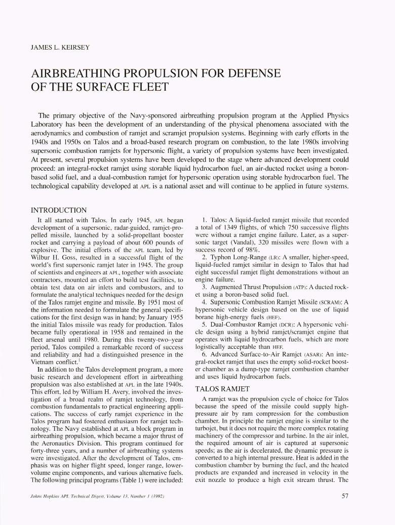
The Talos combustor, depicted in Figure 3, was constructed of conical sections and assembled to provide concentric regions where pilot flame and main air-fuel mixtures were combined to provide stable combustion. Holes in the central cone produced vortex wakes of relatively low speeds to provide the flame-holding action. Ramjet ignition was by a spark plug located in the pilot region. The length of the combustion chamber provided adequate time for efficient combustion. A converging/ diverging nozzle was employed at the exit of the combustor to maintain a low velocity in the combustor, which is necessary to match internal flow conditions of the combustor with the inlet.
Durability of the combustion chamber and exit nozzle was a developmental problem for low-angle shipboard firings, in which high speeds were achieved at low al-
Johns Hopkins APL Technical Digest. Volume / 3. Number / (1992)
titudes, generating high sustained wall-heat fluxes. Burnout of the combustor was prevented by zirconia coatings and control of the air distribution to the various combustor sections. Installing small airfoil sections, called turbulators, on the walls of the cylindrical air duct upstream of the combustor improved airflow distribution and reenergized the boundary layer. Close manufacturing control of dimensions of the combustor also was essential.
The ramjet air inlet was also developed during the same period, beginning with simple normal-shock designs and finally arriving at an efficient multiple-shock design (Fig. 2). Fundamental studies had demonstrated that higher inlet-pressure recovery could be obtained in supersonic flow by using multiple shocks to compress the flow rather than by using a single strong shock as in a normal-shock inlet. Ultimately, a double-cone inlet was selected for Talos.
Hydraulic turbine air scoop
Unified T ALOS /\ Wing span, 110 inches U T,;I.pan, 82 ;nC
~~~~:;;ii
Figure 2. Talos configuration , inboard profile. Four homing antennae were mounted on the cowl of the air inlet, and the innerbody could accommodate a large warhead payload. Air was directed through a long cylindrical duct to the combustor. Control of the missile was by variable wings and fixed tail surfaces to minimize the angle of attack encountered by the air inlet. (Reprinted from Ref. 2.)
59
1. L. Keirsey
Main can flame spreader
I \ Combustion chamber cooling shroud
~OOling shroud \ouvre \
Figure 3. The Talos combustion chamber design used approximately 20% of the captured inlet air along the outer wall for combustion chamber wall and nozzle cooling . Another 15% of the air passed into a pilot section , where pilot fuel was injected through high-pressure spray nozzles to maintain stable combustion under all conditions of flight. The remainder of the air flowed through the center of the engine to the main flame-spreading section, where fuel was injected through low-pressure nozzles and burned to produce the engine thrust. Combustion chamber parts were ceramic-coated to prevent oxidation at high temperatures. (Reprinted from Ref. 2.)
For external multiple-shock inlets of the double-cone design, compression is a three-stage process. First, the air velocity is decelerated to a reduced Mach number as the air passes through the two conical shock waves. The air then passes through the normal shock located near the inlet lip to produce a subsonic flow; finally, the flow is further decelerated in a subsonic diffuser to produce high pressure at the entrance of the combustion chamber. Much inlet development was devoted to establishing the limits of stable inlet operation in order to match performance of the inlet with the combu tor and exit nozzle and also to produce the overall engine operating stability required.
Although the Talos engine was initially developed using JP-5 fuel , a higher-density fuel , methylcyclopentadiene dimer, was u ed after 1966. This fuel provided additional range capability by virtue of its 12% higher volumetric heat release. Hydrogenation of the dimer fuel was necessary to provide stability of the compound for long-term storage.
The final Unified Talos ramjet missile was programmed to fly from Mach 2.0 at sea level to Mach 2.5 at 35,000 ft and above, with a maximum ceiling (without slowdown) of 70,000 ft. This missile had sufficient thrust to produce a 2-g longitudinal acceleration at sea level. Maximum range was greater than 100 nautical miles.
More than 1300 missiles using the Talos ramjet engine have been launched during the twenty-five years of testing, with an overall success rate of 96%. The Vandal
60
program, which employs the Talo airframe and propulsion system as a supersonic target, has achieved an even better reliability (about 98%) u ing propulsion systems that were built at least twenty years earlier.
TYPHON LONG-RANGE RAMJET In 1957 the technical team that developed Talos began
the development of a Super Talos rni ile, later to be designated Typhon Long-Range (LR). The missile was one element of an advanced weapon system designed to meet future naval air-defen e requirement. The development program was under the technical direction of the Applied Physics Laboratory. Reference 3 presents a complete summary of the program.
The Typhon LR was an advanced ramjet missile with higher peed and longer range than Talos , but smaller to fit on ships equipped with launchers for the Terrier missiles. These advances were made possible by progress in technology for ramjet engines, aerodynamics, warheads, packaging (solid-state electronics), materials, and construction methods. A development program was carried out from 1957 to 1963, culminating in a successful series of flight demonstrations. Figure 4 shows a Typhon LR and its launcher.
The ramjet engine was designed to operate from a nominal Mach number of 2.8 at low altitude, following boost by a solid-propellant rocket, and then to accelerate to Mach 4.0 at 70,000 ft and above. It was to be capable
.fohns Hopkins APL Technical Digest, Volume J 3, Number I (1992 )

of level flight (cruise) at altitudes of 90,000 to 100,000 ft,. climbing at steep angles from low altitude, and operation at high angles of attack to intercept maneuvering targets. It had sufficient powered range to intercept targets at 200 nautical miles. Although similar in overall design concept to the Talos missile, detailed design of the engine components was distinctly different (Fig. 5).
The ramjet 's supersonic inlet consisted of a conical surface, followed by a curved surface, called an isentropic compression surface, in front of the cowl lip. The compression waves from this curved surface reduced the velocity of the flow to permit a normal shock in the cowl lip vicinity that would result in an acceptable total pressure loss. The compression waves were focused at the cowl lip to produce full air capture at Mach 4.15. After a normal shock near the cowl lip, the flow was diffused subsonically around the inner body to reduce internal pressure losses from skin friction. After the airflow
Figure4. Typhon Long-Range (LR) serial no. 1 on an early launcher.
20.436 34.839
Innerbody electronics
Homing antennae
Isentropic spike supersonic diffuser
69.523
Guidance and control modules
Thru duct
Guidance and control modules
(all dimensions are in inches)
Airbreathing Propulsion
passed the innerbody, the flow was transported to the aft diffuser by a cylindrical duct.
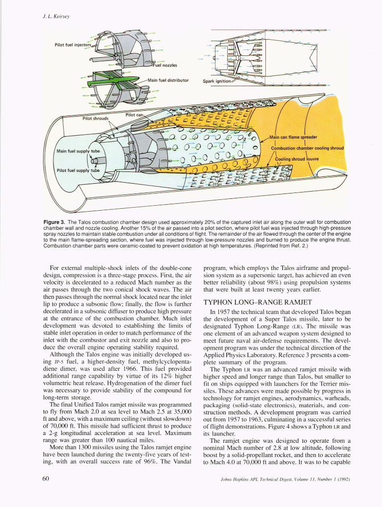
At the end of the cylindrical duct, the area was expanded rapidly to reduce the flow velocity entering the combustor and to provide packaging volume in the annulus for fuel system and hydraulic system components. Air turbines provided power for these systems, with air bled from the diffuser duct. An aerodynamic grid located at the end of the expanding section consisting of many small venturi-shaped flow elements provided a uniform airflow profile at the combustion chamber inlet (Fig. 6).
The combustor design for Typhon LR was simpler in concept than the Talos design, primarily because higher flight speed provided higher air-inlet temperature environment, which promoted more rapid fuel vaporization and combustion reaction rates, permitting use of simpler V-gutter flameholders for Typhon LR in place of the complex can-type combustor used in Talos. Thin sheetmetal, which can bum out from flame flashback with the upstream fuel injection, made the Talos combustor unsuitable for operating at the high air pressures and temperatures encountered by Typhon LR.
The dual fuel-cooled gutters were slightly staggered longitudinally, and a small, conical baffle in the center promoted mixing of the inner-core air into the burning zone. The fuel was injected contra-stream through highpressure drop pintle spray nozzles just three inches upstream of and equally spaced circumferentially around the flameholding gutters. This closely coupled arrangement of fuel injectors and flameholders was adequate for flame stability, and the mixing volume was adequate to achieve relatively high combustion efficiencies with a combustor length of less than twenty-four inches. Combustor ignition was provided by a single spark plug.
The cooling shroud was attached to the outer circumference of the aerodynamic grid, which controlled the quantity of air for cooling the tailpipe and nozzle. The cooling shroud consisted of a series of corrugations containing circumferential slots that provided film cooling of the inner surface. All surfaces exposed to the combustion zone were coated with flame-sprayed zirconia. The
153.75 167.00
Auxiliary power
compartment
Aft subsonic diffuser
191.00 205.00
Control
antennae
Figure 5. Typhon Long-Range (LR) inboard profile. Air inlet is an axisymmetric design, with large innerbody for payload packaging. A long cylindrical duct, surrounded by the annular fuel tank, directs airto the combustor. Unlike Talos, which had movable wings for control , Typhon LR had movable tails.
f ohns Hopkins APL Technical Digest, Volume 13, Number J (1992) 61
1. L. Keirsey
exit nozzle was a convergent-divergent design with a throat area equal to 42% of the combustor area.
An extensive ground test program was carried out for all engine components, ending with free-jet testing of the complete engine. The supersonic inlet was developed over a five-year period, including wind-tunnel tests of models ranging from one-quarter scale to full scale. Many design variations were investigated, producing a broad database from which to choose a final inlet design. Much attention was directed to inlet stability, especially at angle of attack conditions.
A combustor ground test program was also carried out at the Ordnance Aerophysics Laboratory, Daingerfield, Texas. Both heavy-weight and flight-weight combustor designs were tested to optimize combustor performance and develop adequate strength and durability. Complete flight-weight ramjet and airframes were also tested in a free-jet mode at this facility to prove durability before flight testing. A digital performance simulation developed at APL to predict overall engine performance from measured performance inputs of the individual engine components was used throughout both the engine development program and flight test program.
Nine Typhon LR missiles were flight-tested in the period from 23 March 1961 through 9 September 1963. Eight were tests of the ramjet system, all unqualified successes. Later studies showed the Typhon LR to be capable of even higher speeds. Although in flight tests the Typhon LR missile demonstrated its performance goals of high speed and long range, the program was cancelled, principally because of excessive cost and weight of the shipboard guidance and control equipment; however, the high-performance propulsion technology generated and demonstrated in this program is available as options in support of defense missions as required.
AUGMENTED THRUST PROPULSION
With the performance of liquid-hydrocarbon-fueled ramjet propulsion systems having been demonstrated in the Talos and Typhon LR programs, in 1965 APL initiated a program to develop potential designs of air-augmented rocket systems. The principal advantage of any airbreathing propulsion system is that it has a higher specific impulse than a pure rocket, which must carry its own oxidizer; however, the increased cost and complexity of the airbreather is a disadvantage. The solid-propellant
62
Figure 6. Typhon Long-Range (LR) missile combusion chamber. Uniform airflow distribution to the combustor is provided by the aerodynamic grid. Dual , concentric, fuel-cooled V-gutter type flame holders are strut-mounted from a central hUb. Fuel-injection nozzles are mounted on the forward end of the flame-holder gutters. The cooling shroud provides air film-cooling for the tailpipe and exit nozzle.
ducted rocket was seen as a system that could embody the performance advantages of airbreathers while largely retaining the simplicity of a rocket system. A ducted rocket uses the exhaust from a low-temperature, fuel-rich solid-propellant rocket as fuel for a ramjet engine.
Under the sponsorship of the Naval Ordnance Systems Command, APL and two major subcontractors, the Denver Division of the Martin-Marietta Corporation and Atlantic Research Corporation, conducted an advanced technology development program on ducted-rocket propulsion , known as the augmented thrust propulsion (ATP)
program. The development work was directed primarily toward air-augmented solid-propellant rockets of the ducted type, where airflow to the afterburner (ramjet burner) is constrained to be subsonic.
The program included comparative analyses of alternate propulsion methods for missiles. These analyses examined preliminary missile designs using each of the propulsion systems that were being considered (i .e. , solid-rocket, ducted-rocket, liquid-fueled ramjet, and slurry-fueled ramjet). Development of air-augmented solid-rocket system components was required to permit evaluation for comparison with the other systems. Although augmented-thrust propulsion was considered for long-range cruise missiles and small ballistic missiles, a principal emphasis of the APL program was the surfaceto-air missile, called TAR-S AM ER (thrust-augmented rocket-surface-to-air missile, extended range).
The propulsion system had fo ur separate inlets , each of which fed a separate combustor and exit nozzle. A single propellant chamber fed fuel in the form of a hot boron-rich flow to a circular blast tube injector aligned on the centerline of each of the combustion chambers, which were long, cylindrical tubes with silicaphenolic liners; the exit nozzles were asymmetric. The design was controlled to fit within the constraints of a Navy shipboard launcher.
A ground test program was conducted to develop designs for air inlets, fuel-rich solid propellants, and afterburner (ramjet) performance. Air inlets were designed and tested by APL and Martin-Marietta, the fuel-rich solid propellants by Atlantic Research, and the afterburner by the APL Propulsion Research Laboratory.
A baseline propellant contained 60% boron, and highcombustion efficiencies were measured. Comparison with a pure rocket indicated a significant range advantage. This system, however, has a constant fuel-flow rate, and
Johns Hopkins APL Technical Digest. Volume 13. Number J (1992 )
evaluations made at that time indicated that a substantial improvement in performance could be made by providing a variable fuel flow. A warm-gas pintle-type throttling valve was thus designed but never tested. Although the throttling capability could improve the performance of such a missile, it also was complex and degraded its proposed improvement in simplicity over a liquid-fueled ramjet. The program was completed in 1971, with performance of augmented-thrust propulsion a demonstrated technology within the constraints of ground testing.
SUPERSONIC COMBUSTION RAMJET MISSILE
After the Talos and Typhon LR ramjet developments, much interest was also directed toward higher-speed (Mach 6-8) airbreathing missile applications for fleet defense roles. Early theoretical investigations of a ducted supersonic combustion ramjet engine (scramjet) in the late 1950s and early 1960s indicated potential superiority over conventional ramjet performance for operation above about Mach 4.5 to 5.4 The principal differences between a scramjet and ramjet are that the scramjet inlet decelerates the air to a supersonic rather than subsonic speed, combustion occurs in a supersonic rather than
Johns Hopkins APL Technical Digest , Volume 13, Number 1 (1 992)
Airbreathing Propulsion
subsonic flow, and the scramjet does not require an exitnozzle throat. The superior performance of the scramjet results from lower combined inlet and combustor total pressure losses at higher flight speeds. A key, however, for the scramjet was to add heat supersonically without incurring large pressure losses in the combustion process. The scramjet also produces lower static temperatures and pressures in the combustor, which results in reduced heat transfer and structural loads as compared with a conventional subsonic combustion ramjet. Lower temperatures in the combustor reduce the level of dissociation and in tum result in lower kinetic losses in the nozzle.
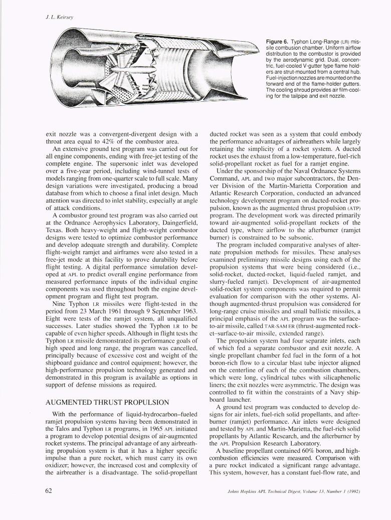
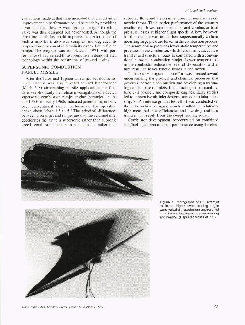
In the SCRAM program, most effort was directed toward understanding the physical and chemical processes that govern supersonic combustion and developing a technological database on inlets, fuels, fuel injection, combustors, exit nozzles, and composite engines. Early studies led to innovative air-inlet designs, termed modular inlets (Fig. 7). An intense ground test effort was conducted on these theoretical designs, which resulted in relatively high measured inlet efficiencies and low drag and heat transfer that result from the swept leading edges.
Combustor development concentrated on combined fuel/fuel injector/combustor performance using the elec-
Figure 7. Photographs of APL scramjet air inlets. Highly swept leading edges were typical of these designs and resulted in minimizing leading-edge pressure drag and heating. (Reprinted from Ref. 11.)
63

1. L. Keirsey
tric arc heated-air facility at the APL Propulsion Research Laboratory, which could generate air temperatures between 3000 and 5000°F. Development efforts involved measurement of combustion efficiency, wall-skin friction and heat transfer, and pitot-pressure surveys and gas sampling at the exit plane of the combustor.5 New calorimetry technique were developed at APL to measure combustion efficiency, as were new gas-sampling probes and improved wall-skin friction balances. For supersonic combustor , the major objective is to obtain high combustion efficiency in a reasonably short combustor length while avoiding large pres ure losses due to wall friction and shocks.
A number of super onic combustor design were tested in a direct -connect mode at APL using various combustor geometries, lengths, inlet-to-exit area ratios, and fuel injector arrangements and at many simulated flight conditions. Typically, combustion efficiencies greater than 80% were achieved, but highly reactive fuels such a triethyl-aluminum (TEA) and HiCal 3-D (principally ethyldecaborane) were required to achieve the requisite performance in the hort combustor lengths tested.
At the same time, a combustor theoretical analysis technique was developed by Billig and compared with test data.6
,7 This method involved simplified assumptions, but it provided a mean of estimating combu tor performance for a given et of combustor inlet conditions and a given amount of heat release; the technique also pre-cribed the strength of a precombustion shock system at
the entrance of the combustor. Based on the inlet and combustor data and the analysis
techniques developed at the time, a missile composite design was formulated (Fig. 8). The design was based on the modular concept for the inlet, with each inlet feeding a separate combu tor and exit nozzle and HiCal (borane) the fuel.
A heavy-weight ground test engine (Fig. 9) was built and tested both at the Ordnance Aerophysics Laboratory in Daingerfield, Texas, in 1968, and later at the APL Propulsion Research Laboratory. Tests covered a Mach number range of 5.0 to 7.3 , and engine performance was measured both by a thrust stand and by engine pressures for a variety of combustor lengths, fuel injectors, and
Overall length
ABC 0 125 "I ! I I I
Inlet
o Diameter NOZZ~ 0 ~
:~~~meter 2:5
5 M I
~ Dimensions are in inches Span
Figure 8. First scramjet missile patent. (Reprinted from Ref. 11.)
64
other factors. 5 Results of the complete free-jet engine tests were in good agreement with predictions based on component tests and theoretical modeling and were the first tests to demonstrate net positive thrust from a scramjet engine.
Figure 10 show the data used to compare fuel-specific impulse (pound of force per pounds of mass flow of fuel per second) of various engine cycles.5 The advantage of the scramjet engine cycle over the ramjet cycle above approximately Mach 6 for either borane or hydrogen fuel is indicated, and the hydrogen-oxygen rocket is shown for comparison.
At this stage (i.e. , 1976), much had been accomplished in the understanding and development demonstration testing to show the potential of scramjet engines for missile applications , but some areas needed further development. Reference 8 presents an excellent historical account of the early SCRAM development. Of course, additional development of combustors, inlets, and noz-
Pitot pressure rake Engine inlet Mach 5-7
free-jet nozzle
Engine support mounted on thrust stand
Figure 9. A Navy/APL heat-sink scramjet engine model in position for a hypersonic test. The engine was a three-module design of a 10-in. diameter. Highly reactive HiCal (borane) fuel was used. (Reprinted from Ref. 10.)
-- Turbojet (kerosene) -- Ramjet (H2) - - Scramjet (H2)
-- Ramjet (borane) -- Scramjet (borane)
500~--~--~--~---~-~
o 400
o 300
o 2000
1000
O~--~--~--~---~--~ o 2 4 6 8 10
Flight Mach number, Mo
Figure 10. Typical engine fuel-specific impulses. (Reprinted from Ref. 5.)
Johns Hopkins APL Technical Digest, Volume 13 , Number 1 (1992 )

zles was needed at high Mach number flight conditions, where high performance is essential; but the primary problem areas were to develop less toxic and logistically more acceptable alternatives to the borane fuels and fuel blends that had already been tested and to develop uncooled materials that would be compatible with the conditions present in the combustor and nozzle. For Navy applications, which are volume limited, the use of hydrogen fuel is not an option, and the emphasis in later work would be with storable heavy hydrocarbon fuels in the dual-combustion ramjet/scramjet engine.
DUAL-COMBUSTOR RAMJET The dual-combustor ramjet (DCR) is an engine concept
that operates on logistically acceptable, conventional hydrocarbon fuels in the hypersonic regime. It is a hybrid cycle that involves both a subsonic combustion dumptype combustor and a supersonic combustor in tandem, as indicated schematically in Figure 11. The DCR engine was conceived in 1977 at APL and was given significant emphasis within the Navy-oriented airbreathing propulsion program until 1986.
In the DCR engine, a small portion of the air captured by the inlet is diverted to a hot-gas generator, which is a dump-type subsonic combustor operating on a dense hydrocarbon fuel. The remainder of the air is ducted supersonically to the supersonic combustor. To simplify the fuel control system, all the fuel is injected into the gas
Supersonic diffuser Isupersonic combustor Subsonic . - , I- Nozzle'" diffuse.~r ~~~~::r========:::=::::=:====--"'"
Fuel injectors
Figure 11. Schematic of dual-combustor ramjet, which operates on conventional liquid hydrocarbon fuels and operates in either all subsonic combustion mode at lower flight speeds and high heat release or as a gas-generator-fed supersonic combustor at high speeds. (Reprinted from Ref. 10.)
Airbreathing Propulsion
generator. Consequently, this combustor must operate very fuel rich for most flight conditions. The dump burner, in this case, prepares the fuel for efficient combustion in the main supersonic combustor.
Both this engine cycle and the pure scramjet engine cycle can be dual-mode engines; that is, they can operate in either the subsonic or supersonic combustion mode. At low flight Mach number and high equivalence ratio, ER ([fueIlair]/[fueIlair] at stoichiometry) , a normal shock is located in the combustor entrance and heat release begins in subsonic flow. Heat is added simultaneously with a drop in pressure in a diverging duct that accelerates the flow through the sonic point to supersonic conditions at the combustor exit. The price paid for the versatility in operation of the DCR over a wide speed range is the complexity and weight of the split-flow inlet compression system and gas generator. The gas generator does, however, prepare the hydrocarbon fuel for efficient combustion downstream in either the subsonic or supersonic combustion mode in a short length (3-5 ft).
Connected-pipe tests of a gas generator, both alone and in tandem with supersonic combustors, were made at the APL Propulsion Research Laboratory, with very favorable results? Figure 12 is a schematic of the dual-combustor test apparatus. Complementing the development efforts have been more fundamental research programs to explore analytically and experimentally and to evolve a better understanding of the physics and chemistry governing the operation of the liquid-fueled scramjet and the DCR.
In the inlet developmental area, emphasis was on a multiple inward-turning scoop configuration (Fig. 13). Ground testing was conducted over a wide Mach number range, and results indicate performance levels of efficiency and inlet drag generally consistent with DCR engine performance requirements; however, development has not been completed.
Figure 14 compares the fuel-specific impulse for the DCR engine with alternate engine types for a dense hydrocarbon fuel. Above a Mach number of approximately 5, calculations indicate that the DCR engine has a clear advantage over a conventional subsonic combustion ramjet, but that it is slightly inferior to a pure supersonic
Contoured Mach 2.5 annular supersonic nozzle
1--1 ft.-J
Heated air (A)
Quench water pitot pressure and species
sample rake 18 point thermocouple rake
Figure 12. Dual-combustor ramjet direct-connect test apparatus. Heavy-weight hardware had interchangeable supersonic combustor sections that permitted testing various lengths and area ratios. Inlet airflow was divided between the gas generator and supersonic flow bypass to simulate the split inlet of the engine. The steam calorimeter devleoped at APL permitted accurate determination of combustion efficiency. The gas generator was capable of operating at fuel-air ratios many times greater than stoichiometric. (Reprinted from Ref. 10.)
Johns Hopkins APL Technical Digest, Volume 13, Number 1 (1992 ) 65

1. L. Keirsey
Figure 13. Photo of the inward-turning air scoop test model. The multiple inward-turning scoop design was developed especially for the dual-combustor ramjet engine. Separate scoops provided airflow for the gas generator and supersonic bypass duct.
combustion engine. For additional discussion, refer to Refs. 10 and 11.
The DCR engine received much attention in evaluations for longer-range fleet defense. The development program was discontinued after 1986, but much of the component testing had already been accompli hed at that time, and an overall engine design has advanced sufficiently for free-jet testing.
ADV ANCED SURFACE-TO-AIR RAMJET An advanced surface-to-air ramjet (ASAR) missile de
sign was initiated in 1974 for the Naval Sea Systems Command. It was a ubsonic combustion ramjet based on cun-ent technology rather than that used in earlier Talo and Typhon LR program. The ASAR has an integral-rocket-ramjet engine in which a single combustion chamber is used for both the solid-rocket boost phase and the liquid-fueled ramjet u tain phase (Fig. 15).
The ramjet has four axisymmetric supersonic air inlets located in the compression field generated by the nose of the missile. The air is ducted aft and dumped into the forward end of the combustion chamber through air inlet ports. During the boost phase the e inlet ports are blocked with glass port covers, which are frangible glass and are removed with explosive charges at the end of boost to permit ramjet takeover. For ramjet operation, fuel is injected from wall injection nozzles just forward of the dump station and ignited with a hot-gas igniter. The ram-
3500,-------.--------.--------.-------,
m .2 (/)
Q) ~ 2500 (/) E :;" o..c-.~ 5 -g 2000 00..°
TIW~ ~ ~ W 1500 (/)00.. ma ::l-u.. .g 1000
c ::l
° Eo 500
2
- Turbojet - Afterburning turbojet - Dual-combustor ramjet - Subsonic combustion ramjet - Supersonic combustion ramjet - Ducted rocket - Solid rocket
4 Flight Mach
number
6 8
Figure 14. Fuel-specific impulse for various missile propulsion systems using dense hydrocarbon fuels. (Reprinted from Ref. 10.)
jet exit nozzle at the end of the chamber has an ejectable insert with a smaller throat size required for rocket operation during boost (Fig. 16).
A ground test program was can-ied out to develop the air inlets and combustor configurations with heavyweight hardware. The combu tor was tested at the APL
Propulsion Research Laboratory, the air inlets in wind tunnel facilities, and a flight-weight engine/missile was designed from this information.
Following the heavy-weight program, a prototyping program was can-ied out on a flight-weight integral-rocket-ramjet combustion chamber design under the technical direction of APL, with as i tance from Hercules, Inc., Alleghany Ballistic Laboratory (ABL) on the booster rocket and combustion chamber and Bendix Aerospace for the ramjet fuel control. The objective of the prototyping effort was to demonstrate the durability and performance of the flight-weight rocket-ramjet combustion chamber in ground tests simulating flight and included firing the booster motor, tran itioning to the ramjet configuration, and operating the ramjet system to simulate flight, all in a single test firing. Because most ramjet test facilities were not designed to allow for the hazards associated with testing large, high-energy solid-propellant rocket motors, APL con tructed a ramjet air supply that could be installed at a rocket test facility.
The great effort involved in designing, constructing, and proving-in this air supply ystem was accomplished
Figure 15. Advanced Surface-to-Air Ramjet (ASAR) general arrangement. It is an integral-rocket-ramjet design with four axisymmetric air inlets mounted in the forebody nose compression field and aligned with the local flow angle. The missile had movable tails for control.
66 Johns Hopkins APL Technical Digest, Volume 13, Number J (1992)
Airbreathing Propulsion
~-----------------------------------90.647--------------------------------~
1+-------------- 80.35 ----------------I.~lfooI.-
14.830 dia.
DC-93-104 silicone rubber I
(all dimensions are in inches)
Figure 16. Advanced Surface-to-Air Ramjet (ASAR) booster motor weights 983 pounds and contains 650 pounds of solid propellant. The forward end of the motor case has four air inlet "stacks" for the air inlet admission ports, which are sealed with frangible glass port covers and are retained in tapered sleeves. The glass port covers are fragmented during booster motor pressure tailoff by explosive charges, which opens the ports for ramjet operation. The motor throat insert needed during rocket booster operation is also separated at pressure tailoff , leaving the properly sized exit nozzle for ramjet operation .
at the APL Propulsion Research Laboratory. At the same time, Hercules was designing, fabricating , and static firing rocket motors, as well as preparing a test bay at ABL for installation of the unique air supply system.
The air supply system contained all the elements for storing, heating, flowing, and controlling the air required, as well as a specially designed transition (from rocket boost to ramjet operation) simulation device. A portable van assembled at APL contained all the electronics, instrumentation, and data acquisition to support the test, with the test sequence entirely computer controlled.
Using this technique, the ASAR flight-weight chamber for rocket boost-ramjet operation was proven-in, including boost rocket firing , transition simulation, ramjet engine ignition, and ramjet combustor operation simulating a full-duration flight. The program also included design and testing of a special exit nozzle with thrust-vector control. Completed in 1984, the ground test program successfully demonstrated the technology required for an advanced surface-to-air ramjet missile that is compatible with use of the Navy 's most modem launching systems.
CONCLUSIONS At present, airbreathing propulsion technology is a
viable option for missile systems requiring extendedrange performance. The APL/Navy program has developed a number of potential design concepts for atmospheric applications, including an integral-rocket ramjet using storable liquid fuels operating up to Mach 5 and a dual-combustion ramjet using storable liquid fuels capable of operating up to Mach 7+. These propulsion designs are ready for advanced development.
The Applied Physics Laboratory 's capabilities in the field of airbreathing propulsion technology have been used in problem solving in other programs, such as the Tomahawk, and have enabled APL to take a leading role in the development of hypersonic propulsion (scramjet) systems for future applications, for example, the National
Johns Hopkins APL Technical Digest. Volume 13. Number I (1992 )
AeroSpace Plane. This technological capability is a national asset and will continue to be applied in future systems.
REFERENCES IGoss, W. H., "Talos in Retrospect," Johns Hopkins APL Tech . Dig. 3, 116 ( 1982).
2Shippen, W. B., Berl , W. G. , Garten, W. Jr. , and Hardgrave, E. 1. , Jr ., "The Tal os Propulsion System," Johns Hopkins APL Tech. Dig. 3 , 126-134 ( 1982).
3Cronvich, L. L. (ed.), Summary Report on Ail frame. Aerodynamic and Propulsion Design of Typholl LR Missiles. SIN I to 9. APL/JHU TG 679 ( 1965).
~J aumotte, A. L. , Rothrock , A. M. , and LeFebvre, A. H. (eds.), Combustion and Propulsion--High Mach Number Air-Breathillg Engines. Pergamon Press,
ew York (196 1). 5Waltrup, P. J ., Anderson, G. Y. , and Stull , F. D., ··Supersonic Combustion Ramjet (Scramjet) Engine Development in the United States,'· in Proc. 3rd International Symposium on Air Breathing Engines, Munich, Germany (Mar 1976).
6BiJlig, F. S. , "Design of Supersonic Combustors Based on Pressure-A rea Fields," in Proc. I fth Symposium (1llIernational) on Combustioll The Combustion Institute, Pittsburgh, Pa . ( 1967).
7BiJlig, F. S. , and Dugger, G. L. , ·'The Interacti on of Shock Waves and Heat Addition in the Design of Supersonic Combustors,'· in Proc. 12th Symposium (International) 0 11 Combusfion , The Combu lion Institute, Pittsburgh, Pa. (1969).
8Gilreath, H. E. , "The Beginning of Hyper onic Ramjet Research at APL," Johns Hopkins APL Tech. Dig. 11 , 3 19-335 ( 1990).
9Keirsey, J . L. , and Cusick, R. T. , " Automated Airbreathing Propulsion Test Facility," Johns Hopkins APL Tech. Dig. 4, 155-165 (1983).
IOBillig, F. S. , "Tactical Missile Design Concepts," Johns Hopkills A PL Tech. Dig. 4, 139-154 (1983) .
IIWaltrup, P. 1. , " Hypersonic Airbreathi ng Propulsion : Evolution and Opportuniti es,'· in Proc. AGARD Conference on Aerodynamics of Hypersonic Lijiing Vehicles, Bristol, England (Apr 1987).
ACKNOWLEDGMENTS: The names of only a few individual s appear in thi s brief summary article and in the references, and the author recognizes this to be a major shortcoming. The work reported herein is the product of literall y several hundred very talented indi viduals at APL, and each one is proud of these programs and accomplishments. Many have invested a major portion of thei r careers in developing this technology, which will conti nue to pay div idends in future programs. The contributions of our associate and subcontractors are also recognized, which in many cases were critical. The writer also gratefu lly acknowledges the written articles and papers that formed the basis for this summary.
67

1. L. Keirsey
THE AUTHOR
JAMES L. KEIRSEY received the B.S.M.E. degree from Texas A & M in 1948. After testing ramjet engines at the Navy's Ordnance Aerophysics Laboratory for three years, he joined APL, specializing in airbreathing engine technology for Navy fleet defense. He has been involved in detailed design and development of ramjet engines and components for missiles such as Talos, Typhon LR, Triton, the Augmented Thrust Propulsion (ducted rocket) system, and the Advanced Surface-to-Air Ramjet (ASAR). He concentrated on development of the Dual -Combustor
Ramjet from 1977 to 1987, headed operation of the Propulsion Research Laboratory from 1974 to 1981, and was supervisor of the Propulsion Group from 1982 through 1987. He retired from APL in December 1987 and is currently a part-time employee of the Aeronautics Department Office.
68 Johns Hopkins APL Technical Digest, Volume 13, Number 1 (1992)