
Investigation of Fuel Injection System of Internal Combustion Engine
50
1 1. Introduction and History of Internal Combustion Engine The internal combustion engine (Ice) is a heat engine that converts chemical energy in a fuel into mechanical energy, usually made available on a rotating output shaft. Chemical energy of the fuel is first converted to thermal energy by means of combustion or oxidation with air inside the engine. This thermal energy raises the temperature and pressure of the gases within the engine, and the high-pressure gas then expands against the mechanical mechanisms of the engine. This expansion is converted by the mechanical linkages of the engine to a rotating crankshaft, which is the output of the engine. The crankshaft, in turn, is connected to a transmission and/or power train to transmit the rotating mechanical energy to the desired final use. For engines this will often be the propulsion of a vehicle. Figure 1-1 An Otto Engine from 1920s US Manufacture Internal Combustion Engine, as the name implies, is when fuel is ignited and burnt inside an internal combustion engine and the most usual type of fuel is petrol, diesel or gas, as in a gas turbine. The earliest internal engines were invented by Jean Joseph Etienne Lenoir (1822- 1900) in the mid 19th century using coal gas as fuel. Gas turbine engines (ones in a jet) were devised for some aircraft during the Second World War and are now used in many naval ships, aircraft, tanks and speedboats. A petrol (gasoline) combustion engine was devised by Gottlieb Daimler (1834-1900) and Wilhelm Maybach (1846-1929) IN 1885. A couple of years later, a diesel engine was invented between 1893-97 by Rudolf C. Karl Diesel (1858- 1913), a German mechanical engineer.
-
Upload
saatchiart -
Category
Documents
-
view
0 -
download
0
Transcript of Investigation of Fuel Injection System of Internal Combustion Engine

1
1. Introduction and History of Internal Combustion Engine
The internal combustion engine (Ice) is a heat engine that converts chemical energy in a fuel into mechanical energy, usually made available on a rotating output shaft. Chemical energy of the fuel is first converted to thermal energy by means of combustion or oxidation with air inside the engine. This thermal energy raises the temperature and pressure of the gases within the engine, and the high-pressure gas then expands against the mechanical mechanisms of the engine. This expansion is converted by the mechanical linkages of the engine to a rotating crankshaft, which is the output of the engine. The crankshaft, in turn, is connected to a transmission and/or power train to transmit the rotating mechanical energy to the desired final use. For engines this will often be the propulsion of a vehicle.
Figure 1-1 An Otto Engine from 1920s US Manufacture
Internal Combustion Engine, as the name implies, is when fuel is ignited and burnt inside an internal combustion engine and the most usual type of fuel is petrol, diesel or gas, as in a gas turbine. The earliest internal engines were invented by Jean Joseph Etienne Lenoir (1822-1900) in the mid 19th century using coal gas as fuel. Gas turbine engines (ones in a jet) were devised for some aircraft during the Second World War and are now used in many naval ships, aircraft, tanks and speedboats. A petrol (gasoline) combustion engine was devised by Gottlieb Daimler (1834-1900) and Wilhelm Maybach (1846-1929) IN 1885. A couple of years later, a diesel engine was invented between 1893-97 by Rudolf C. Karl Diesel (1858-1913), a German mechanical engineer.

2
1.1 Types of Internal Combustion (IC) Engines
There are two main types of IC engines: spark ignition (SI) engines (petrol or gasoline engine) and compression ignition (CI) or diesel engine. Both these engines are further classified as 2-stroke and 4-stroke engine. Internal Combustion Engines, more popularly known as IC engines, are the ones in which the combustion of fuel takes place inside the engine block itself. After combustion of fuel, much heat energy is generated, this is converted into mechanical energy. There are two types of IC engines: rotary and reciprocating engines. In rotary engines, a rotor rotates inside the engine to produce power. In the case of the reciprocating engines, a piston reciprocates within a cylinder. The reciprocating motion of the piston is converted into the rotary motion of the vehicle's wheels. In automobiles, reciprocating engines are used. They are the most widely used type of engine. Reciprocating engines are classified into two types: spark ignition (SI) engines and compression ignition (CI) engines. Since reciprocating engines are the most widely used engines, they have become synonymous with the name IC engines. It is this reason that even the IC engines are broadly classified into two types: SI engines and CI engines.
Figure 1-2 Spark Ignition Engine

3
In SI engines the burning of fuel occurs by a spark generated by the spark plug located in the cylinder head of engine. Due to this fact they are called spark ignition engines. In these engines the fuel used is petrol or gasoline, hence SI engines are also known as Petrol or Gasoline Engines. In the case of CI engines, burning of the fuel occurs because of the high pressure exerted on the fuel. The fuel is compressed to high pressures and it starts burning, hence these engines are called compression ignition engines. In CI engines the fuel used is diesel; hence they are also called Diesel engines. The SI and CI engines are either two stroke or four stroke engines. In the case of the two stroke engine, for every two strokes of the piston inside the cylinder the fuel is burnt. This means for every single rotation of the wheel the fuel is burnt. In the case of four-stroke engines, the fuel is burnt for every four strokes of the piston inside the cylinder. That means each time the fuel is burnt there are two rotations of the wheels of the vehicle. The stroke is the distance traveled by the piston inside the cylinder; it is usually equal to the length of the cylinder.
Figure 1-3 Compression Ignition Engine
Since the 4-stroke engines produce two rotations while 2-stroke engine produces single rotation each time the fuel is burnt, the efficiency of 4-stroke engines is greater than in 2-stroke engines. Ideally the efficiency of 4-stroke engine should be double of 2-stroke engine, but in actuality it is never so.
4
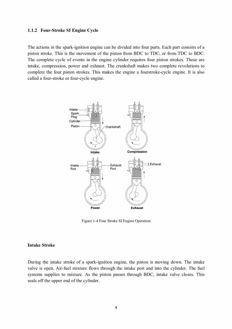
1.1.2 Four-Stroke SI Engine Cycle
The actions in the spark-ignition engine can be divided into four parts. Each part consists of a piston stroke. This is the movement of the piston from BDC to TDC, or from TDC to BDC. The complete cycle of events in the engine cylinder requires four piston strokes. These are intake, compression, power and exhaust. The crankshaft makes two complete revolutions to complete the four piston strokes. This makes the engine a fourstroke-cycle engine. It is also called a four-stroke or four-cycle engine.
Figure 1-4 Four Stroke SI Engine Operation
Intake Stroke
During the intake stroke of a spark-ignition engine, the piston is moving down. The intake valve is open. Air-fuel mixture flows through the intake port and into the cylinder. The fuel systems supplies to mixture. As the piston passes through BDC, intake valve closes. This seals off the upper end of the cylinder.
5
Compression Stroke
After the piston passes BDC, it starts moving up. Both valves are closed. The upward moving piston compresses the air-fuel mixture into a smaller space, between the top of the piston and the cylinder head. This space is combustion chamber. The mixture is compressed 1/8 or less of its original volume. The amount that the mixture is compressed is compression ratio.
Power Stroke
As the piston nears TDC at the end of the compression stroke, an electric spark jumps the gap at the spark plug. The heat from the spark ignites the compressed air-fuel mixture. The air-fuel mixture then burns rapidly. These high temperatures cause very high pressure which pushes down the piston. The connecting rod carries this force to the crankshaft, which turns to move the drive wheels.
Exhaust Stroke
As the piston approaches BDC on the power stroke, the exhaust valve opens. After passing through BDC, the piston moves up again. The burned gases escape through the open exhaust port. As the piston nears TDC, the intake valve opens. When the piston passes through TDC and starts down again, the exhaust valve closes. 1.2.2 Four-Stroke CI Engine Cycle
Diesel engines are similar to spark ignition engines in construction. Both have pistons, with piston rings, movingup and down in cylinders. Both burn fuel in combustion chambers in the upper part of the cylinders. The high pressure produced by the burning fuel pushes the pistons down. This rotates the crankshaft and the rotary motion is carried through shafts and gears to the drive wheels.

6
Figure 1-5 Four Stroke CI Engine Operation
Intake Stroke
The diesel engine takes in air alone. No throttle valve impedes the airflow. In the spark-ignition engine, a mixture of air and fuel enters the engine cyclinders on the intake stroke. The throttle valve controls the amount that enters. Compression Stroke
In the diesel engine, the upward-moving piston compresses air alone. On the other hand, in the spark ignition engine, the piston compresses the air-fuel mixture.
Power Stroke
In diesel engine, a light oil diesel fuel is injected into the compressed and hot air. The heat of compression ignites the fuel. In the spark-ignition engine, a spark at the spark plug ignites the compressed air-fuel mixture.
Exhaust Stroke
The exhaust stroke is the same for both engines. The exhaust valve opens and the burned gases flow out as the piston moves up the cyclinder.

7
1.2.3 Two-Stroke Engine Cycle
The two-stroke petrol engine was very popular throughout the 19th-20th century in motorcycles and small-engined devices, such as chainsaws and outboard motors, and was also used in some cars, a few tractors and many ships. Part of their appeal was their simple design (and resulting low cost) and often high power-to-weight ratio. The lower cost to rebuild and aintain made the two stroke engine incredibly popular, until for the USA their EPA mandated more stringent emission controls in 1978 (taking effect in 1980) and in 2004 (taking effect in 2005 and 2010). The industry largely responded by switching to four-stroke petrol engines, which emit less pollution. Most small designs use petroil lubrication, with the oil being burned in the combustion chamber, causing "blue smoke" and other types of exhaust pollution. This is a major reason why two-stroke engines were replaced by four-stroke engines in many applications.
Simple two-stroke petrol (gas) engines continue to be commonly used in high-power, handheld applications such as string trimmers and chainsaws. The light overall weight, and light-weight spinning parts give important operational and even safety advantages. For example, a four-stroke engine to power a chainsaw operating in any position would be much more expensive and complex than a two-stroke engine that uses a gasoline-oil mixture.
Figure 1-6 Two Stroke Engine Operation The basic internal combustion engine is very simple machine, in principle. A piston moving up and down within a cylinder is connected (by a connecting rod (con-rod)) to a rotating crankshaft. The piston is forced downwards by the expanding gases of a fuel-air mixture burning in the cylinder space above it. This causes the crankshaft to rotate. The momentum of the rotating crankshaft then forces the piston back up again, allowing the next cycle to ocur. Often, a heavy flywheel is attached to the crankshaft, to maintain the momentum of rotation.

8
2. Introduction to Gasoline Injection System
Fuel injection is a system for admitting fuel into an internal combustion engine. It has become the primary fuel delivery system used in automotive engines, having replaced carburetors during the 1980s and 1990s. A variety of injection systems have existed since the earliest usage of the internal combustion engine. The primary difference between carburetors and fuel injection is that fuel injection atomizes the fuel by forcibly pumping it through a small nozzle under high pressure, while a carburetor relies on suction created by intake air accelerated through a Venturi tube to draw the fuel into the airstream. 2.1 Fuel System Developments
The carburetor was almost universally used on petrol engines through until the late 1970s, when fuel injection systems began to appear on mass produced vehicles. Electronic injection was, however, used in the late 1960s to overcome emission control problems with some vehicles intended for the American market. In the 1970s a Bosch mechanical/hydraulic system (Bosch K-Jetronic) gained favour with many European manufacturers: this system tended to lead the way until the early 1980s, when a new generation of electronic injection systems progressively became more common. It is suggested that the first application of fuel injection was on the engine that was used by the Wright Brothers for the first manned flight of an aeroplane. However, simple carburetors were very much the only petrol delivery systems used on mass production vehicle engines for many years. Although diesel engines used a mechanical injection system until fairly recently, petrol engines relied on carburettor systems because of cost, simplicity and the fact that there was no need for high pressure delivery of petrol.
A number of cars did use petrol injection, but these were generally racing cars and not production vehicles. One notable exception, however, was in the mid-1950s, when Mercedes-Benz used an adaptation of a mechanical diesel pump on its racing engines and also on a limited production sports car (Mercedes 300SL); it is interesting to note that these systems were adaptations of diesel mechanical pump systems, which injected fuel directly into the cylinder and not into the intake system, which has been the general principle for most electronic injection systems until recently. So, although fuel injection was not widely used, Mercedes and a number of vehicle and racing engine manufacturers continued to develop the use of fuel injection for petrol engines. Various mechanical and electronic systems used from the early 1960s through to the 1980s were developed to improve emissions for vehicles sold in the United States.

9
It was, however, the introduction of European emissions regulations that effectively forced the use of fuel injection systems on almost all petrol engines by the early 1990s. By this time, electronic control was becoming less expensive and it was therefore inevitable that any mechanical systems would be replaced by electronic injection systems.
2.2 Mechanical Fuel Systems
Engines works on fuel. The earliest form of fuel supply mechanism for modern automobile is carburetor. The primary function of carburetor is to provide the air-fuel mixture to the engine in the required proportion. The carburetor is the part of the engine where fuel is mixed with air before it enters the engine case. The air passes though the opening at the top of the carburetor and enters the venturi, a long tapered tube that speeds up the airflow into the engine. The increase in air velocity causes a drop in pressure, which draws the fuel from the tank. In the middle of the venturi (at the low-pressure zone) is a brass tube assembly called the spray bar. The fuel passes through the spray-bar jet and then mixes with the incoming air.
The air portion of the air/fuel mixture is regulated by the large aluminum barrel that rotates to increase and decrease the size of the intake hole. The flow of fuel is adjusted by one or two needle valves at one or both ends of the spray bar.
Figure 2-1 Carburetor

10
Older 2-stroke engines (and many 4-strokes) have a single high-end needle valve to adjust the mixture at full throttle and a small air-bleed hole in the front of the carburetor to adjust the idle mixture. As the throttle barrel closes, it opens the air-bleed hole to the venturi. A small idle-mixture screw meters the amount of air entering the carburetor. Opening the air-bleed hole lets more air in and leans the idle mixture, and closing it lets less air in to richen the mixture.
Two-needle carburetors (as the name implies) are equipped with two needle valves, one for the high-end mixture adjustment, and a secondary low-end needle valve (sometimes referred to as the low-speed needle) to adjust the idle mixture. When you turn the high-end needle clockwise (screwing it in), it leans the mixture by restricting the amount of fuel that enters the carburetor. Turning it counterclockwise (unscrewing it) richens the mixture by allowing more fuel to flow. Usually, the low-end needle is smaller than the high-end needle, and in some cases, you’ll need a fine-tip screwdriver to adjust the idle mixture because it is recessed into the center of the throttle arm. When you turn the low-end needle clockwise, it richens the idle mixture, and turning it counterclockwise makes the mixture lean.
When the throttle barrel is closed, it also moves laterally, which in turn moves the low-end needle gradually into the fixed spray bar, thus leaning the idle mixture. Of the two types of carburetor, the two-needle type is more sensitive to adjustments and provides faster throttle response through the midrange.
Expected Features of Carburetor System
Ease of cold starting
All operating ranges of the supply air-fuel mixture at the desired rate
The suction of fuel to air is totally ensuring pulvuriz
The mix ratio required in the provision of sudden acceleration
Ensuring economical engine idling as possible
Ease of cleaning and servicing requirements easily removable

11
Provided in the carburetor mixture is too rich or too poor creates engine some negativity. Excess air factor λ> 1.15 requirement is defined as the mixture too lean mixture and start the engine with the mixture of these conditions occurs to following negative.
Because of increase in a lean mixture combustion time and as a result of incomplete combustion in the cylinder, the exhaust begins with a flashback
At the exhaust period, the continued combustion of the exhaust valve causes to destruction into surfaces leads due to extreme temperatures
In particular, the increase of temperature in the exhaust valve can caused the emergence of uncontrolled ignition.such as knocking or pre-ignition
The mixture is too rich, approximately λ <0.84 the following conditions, causes to the emergence of negative
.
Wall of the combustion chamber and the piston surface is sooty. Cylinder and piston is accelerated to wear on the surface
The carbon layer deposition on the walls of the combustion chamber causes the occurrence of uncontrolled ignition
Failure to achieve complete combustion, exhaust gas emissions of harmful CO and unburned HC causes to increase in percent. So that air pollution increases
Especially in warm-up period of the engine, the excessive gasoline entered into cylinder causes getting lower the viscosity of lubricating oil in the cylinder wall
The fuel consumption will increase
2.2.1 The Working Principle of the Carburetor
The carburetor has several functions; firstly it combines gasoline and air creating a highly combustible mixture, secondly it regulates the ratio of air and fuel, and thirdly it controls the engine's speed.

12
When the piston moves down the cylinder on the intake stroke it draws air from the cylinder and intake manifold. A vacuum is created that draws air from the carburetor. The airflow through the carburetor causes fuel to be drawn from the carburetor through the intake manifold past the intake valves and into the cylinder. The amount of fuel mixed into the air to obtain the required air to fuel ratio is controlled by the venturi or choke. When air flows through the venturi its speed increases and the pressure drops. This causes the fuel to be sucked into the air stream from a hole or jet. When the engine is at idle or at rapid acceleration there is not enough air passing through the venturi to draw fuel. To overcome these problems other systems are used.
Figure 2-2 Working Principle of the Carburetor
Gasoline is delivered to the carburetor by the fuel pump and is stored in the fuel bowl. To keep this level of fuel stored in the bowl constant under all conditions a float system is used. A float operated needle valve and seat at the fuel inlet is used to control the fuel level in the bowl. If the fuel level drops below a certain level the float lowers and opens the valve letting more fuel in. When the float rises it pushes the inlet valve against the seat and shuts off the flow of fuel into the bowl.
The throttle controls the speed of the engine by controlling the amount of air fuel allowed in the engine. The throttle is a butterfly valve located after the venturi and is opened by pressing on the gas pedal. The farther the valve is opened the more air/fuel mixture is let into the engine and the faster the engine runs. At low engine speeds when the throttle is only open a little there is not enough air flow to pull in fuel.

13
When the engine is idle there is very little air flowing through the venturi because the throttle valve is closed. The idle port allows the engine to operate under this condition. Fuel is forced through the idle port because of a pressure differential between air in the fuel bowl and vacuum below the throttle valve. Idle fuel mixture is controlled by an adjustable needle valve. At higher engine speeds more fuel is drawn from the main nozzle. Fuel comes from the fuel bowl through the fuel nozzle and into the throat of the carburetor where it mixes with air.
2.3 Electronic Fuel Injection Systems
Constantly changing and evolving from the 1930s to the present system, the fuel system, to power the vehicle's engine performance, fuel consumption and emission reduction or environmentally significant improvements in terms become.
Today, many of the vehicles being used in electronic systems is advantageous in many ways based on mechanical fuel injection system, only disadvantage of electronic systems is expensive. European emission standards to ensure the use of electronic systems today due to favorable operating performance and has become almost mandatory.
The Advantages of Electronic Fuel Injection Systems
To sum it itemise the advantages of electronic fuel injection systems will be briefly as follows:
Reduction of exhaust gas emissions
More economical fuel consumption
To increase the specific power of the engine
Fast reaction to different load conditions
Easy starting and warming
Knock control

14
Idle control and adaptation
Does not require adjustments
Ease of diagnostics
No altitude effect
Better mix adjustment
The Disadvantages of Electronic Fuel Injection Systems
The only disadvantage of electronic fuel injection systems is an expensive system. In addition, this system is not available in most parts repair facilities. In case of failure the most parts have to change. For this reason, electronic fuel injection system in the vehicle is used more in developed countries. Nowadays, vehicles are being produced in our country have electronic fuel injection systems, in underdeveloped and developing countries, electronic fuel injection systems in vehicle are rare.
The Differences Between Carburetor and Electronic Injection Systems
The most important difference between the carburetor and injection system is air-fuel mixing formats and location. Air sucked through the air filter in the caburetor system, when amount of fuel passing from the carburetor and the mixture is distributed to the cylinders carried along by the intake manifold.
In injection, fuel is sprayed to air from intake manifold when entering the combustion chamber. New direct injection petrol engines (FSI), the fuel is sprayed into the combustion chamber.
The main principle of the injection system is that deliver to fuel into the cylinder in the form of particles as small as possible. Thus, the fuel can be burned with highest efficient. Also in the combustion chamber the air-fuel mixture distributed homogeneously, particularly in diesel engines, prevents burns regional.

15
Life of the engine increases and the combustion of the fuel can be a portion of the emission rates can be adjusted downwards. Injection system compared to carburetor systems averagely "%5 to up to %15" provides fuel economy.
2.3.1 D-Jetronic Fuel Injection System
The D-Jetronic system uses constant fuel pressure and flow, so that only injection duration needs to be modified to control air/fuel mixture. The D-Jetronic system measures incoming airflow by monitoring intake manifold pressure.
Engine speed, temperature, and other factors are monitored for the purpose of fine-tuning injection duration. An auxiliary air valve, cold start injector and thermotime switch aid in cold starting and operation.
Figure 2-3 D-Jetronic Fuel Injection System
Air intake temperature sensor : The air temperature sensor provides control unit with information about air temperature, so that control unit can increase the injection quantity as necessary at low intake air temperature. This compensation ceases when intake air temperature is greater than 2O0C.
16
Throttle valve switch : The throttle valve switch is mounted on the throttle housing. This switch signals the control unit of throttle position. During deceleration, above 1500 RPM, throttle switch cuts fuel supply off and below 900 RPM, fuel supply is turned on.
Auxiliary air valve : During cold starts, the auxiliary air valve opens to allow additional air into the inlet duct. As engine heats up, a bi-metallic element expands and closes valve. At approximately 140F (80C) the auxiliary air pipe is completely closed by the valve.
Triggering contacts : The triggering contacts are located in the distributor. They provide signals which determine when and to which cylinder fuel is to be injected. The contacts also supply information concerning engine speed to determine the amount of fuel that needs to be injected into the engine.
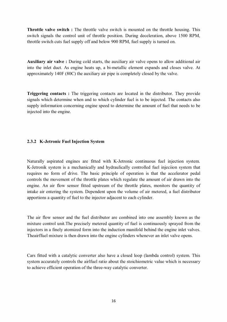
2.3.2 K-Jetronic Fuel Injection System
Naturally aspirated engines are fitted with K-Jetronic continuous fuel injection system. K-Jetronik system is a mechanically and hydraulically controlled fuel injeciion system that requires no form of drive. The basic principle of operation is that the accelerator pedal controls the movement of the throttle plates which regulate the amount of air drawn into the engine. An air flow sensor fitted upstream of the throttle plates, monitors the quantity of intake air entering the system. Dependent upon the volume of air metered, a fuel distributor apportions a quantity of fuel to the injector adjacent to each cylinder.
The air flow sensor and the fuel distributor are combined into one assembly known as the mixture control unit.The precisely metered quantity of fuel is continuously sprayed from the injectors in a finely atomized form into the induction manifold behind the engine inlet valves. Theairffuel mixture is then drawn into the engine cylinders whenever an inlet valve opens.
Cars fitted with a catalytic converter also have a closed loop (lambda control) system. This system accurately controls the airlfuel ratio about the stoichiometric value which is necessary to achieve efficient operation of the three-way catalytic converter.

17
K-Jetronic Fuel Injection System Operation
When the engine starts to run at cold weather condition, the mixture sticks to the manifold and the cylinder wall by concentrating. Therefore, the amount of fuel in the mixture is decreased to lead to the impoverishment of the mixture. To resolve this negativity, it is sprayed from a second injector for enriching to the mixture. This injector continues to run just when engine is cold or until the engine reaches certain temperature with help of heat-sensitive valf.
After reaching a certain temperature, the additional fuel injector is disabled. The heating regulator provides a rich mixture until it reaches the required temperature after this injector is disabled. The heating regulator makes rich mixture by decreasing to control pressure.
The metal plates are taken up when air passes through inlet duct at normal operating state. It is controlled to the fuel distributor via a shaft. As the amount of air passing through the channel get more, metal plates lift up and push up to shaft which attached to it. This shaft provide to injector more fuel by opening channels more in the fuel distributor. In order to increase the engine speed, more mixture will obtained.
Figure 2-4 K-Jetronic Fuel Injection
18
The acceleration is provided when gas throttle is opened suddenly by most opened plate of the sensor case. When the throttle is opened suddenly, the high pressure difference between intake manifold, cylinder and air intake side creates sudden an air flow. In the meantime, the plate will reach the highest level makes further increase as making a slow gas. This sensor allows to transmit extra fuel by connected with the shaft. In this way a rich mixture is obtained which is required for acceleration. The movement of sensor plate becomes available to throttle position.
Fuel shut off is a system to prevent unnecessary fuel consumption at downhill or when take your foot off the gas. In K-Jetronik system, the fuel is cut by disabling the sensor plate which adjusts fuel distribution. The breaker switch is on duty to on/off by-pass duct.
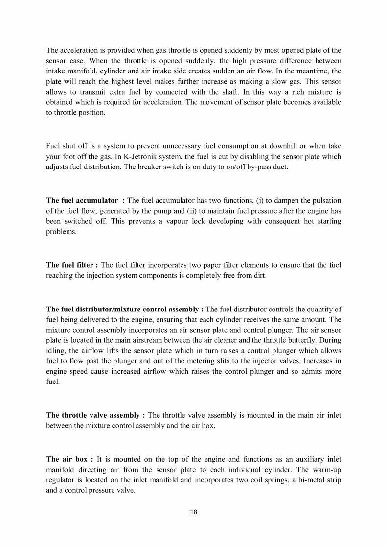
The fuel accumulator : The fuel accumulator has two functions, (i) to dampen the pulsation of the fuel flow, generated by the pump and (ii) to maintain fuel pressure after the engine has been switched off. This prevents a vapour lock developing with consequent hot starting problems.
The fuel filter : The fuel filter incorporates two paper filter elements to ensure that the fuel reaching the injection system components is completely free from dirt.
The fuel distributor/mixture control assembly : The fuel distributor controls the quantity of fuel being delivered to the engine, ensuring that each cylinder receives the same amount. The mixture control assembly incorporates an air sensor plate and control plunger. The air sensor plate is located in the main airstream between the air cleaner and the throttle butterfly. During idling, the airflow lifts the sensor plate which in turn raises a control plunger which allows fuel to flow past the plunger and out of the metering slits to the injector valves. Increases in engine speed cause increased airflow which raises the control plunger and so admits more fuel.
The throttle valve assembly : The throttle valve assembly is mounted in the main air inlet between the mixture control assembly and the air box.
The air box : It is mounted on the top of the engine and functions as an auxiliary inlet manifold directing air from the sensor plate to each individual cylinder. The warm-up regulator is located on the inlet manifold and incorporates two coil springs, a bi-metal strip and a control pressure valve.

19
The regulator controls the fuel supplied to the control circuit which provides pressure variations to the fuel distributor control plunger. When the coil springs are pushing against the control pressure valve there is a high control pressure and this gives a weak mixture. The coil spring pressure application is controlled by the bi-metal strip which in turn is activated in accordance with engine temperature and an electrical heat coil.
The auxiliary air device : The auxiliary air device is located on the inlet manifold. It consists of a pivoted plate, bi-metal strip and heater coil. The purpose of this device is to supply an increased volüme of fuel/air mixture during cold idling.
The start valve : The start valve system consists of an electrical injector and a thermo-time switch. Its purpose is to spray fuel into the air box to assist cold starting, the thermo-time switch regulating the amount of fuel injected.
The safety module : The safety module is located under the facia panel on the driver’s side and is coloured purple (see illustration). Its purpose is to shut off the power supply to the fuel pump should the engine stall or the vehicle be involved in an accident. The module senses ignition pulses, and cuts the fuel supply if the ignition pulses stop.
The fuel shut-off valve system : The fuel shut-off valve system is an economy device whereby air is drawn from within the air cleaner unit through the shut-off valve and directed into the ducting chamber above the air sensor plate causing a depression. This then causes the sensor plate to drop which, in turn, shuts off the fuel supply. The valve is operated by signals from a coolant temperature sensor and a throttle position sensor. The shut-off valve will only operate under the following circumstances:
When the engine coolant temperature is at or above 35°C (95°F)
When the throttle is closed and with the engine speed decelerating from speeds above 1600 rpm
The engine speed is sensed by a speed sensing module which is coloured black and located beneath the facia panel on the driver’s side.

20
2.3.3 KE-Jetronic Fuel Injection System
Electronically controlled mechanical fuel injection. The ECU can be either analog or digital, and the system may or may not have closed-loop lambda control. The system is based on the K-Jetronic mechanical system, with the addition of an electro-hydraulic actuator, that varies the fuel pressure supplied to the mechanical injection components based on several inputs (engine speed, air pressure, coolant temperature, throttle position, lambda etc.) via the ECU. With the electronics disconnected, this system will operate as a K-Jetronic system.
Injection system must inject the correct amount of fuel depend on different conditions. Whereas the increase in engine power was the main object at the start of development work on gasoline injection. Toxic emission and fuel consumption issues are also important. Previous mechanical systems are not able to fulfill these stringent requirements. So, the well-proven K-Jetronic was retained as the basic injection system. Uprated to a more intelligent and efficient system by the addition of electronic circuitry. This synthesis, comprising the mechanical basic functions coupled with electronic adaptation and optimization functions, is the KE-Jetronic.
Figure 2-5 KE-Jetronic Fuel Injection System

21
KE-Jetronic system components which are added to K-Jetronic system :
Air flow measurement potentiometer
Electro-hydraulic adjuster
A second pressure regulator
Temperature sensor
The electro-hydraulic control device is given amount of drive and a certain amount of fuel required for working status is shipped by evaluating the signals sent to the electronic control unit with all of these additional systems.
KE-Jetronic Fuel Injection System Operation
A mechanical hydraulic injection system provides the basis for KE- Jetronic the same as it does for K-Jetronic. The stream of air drawn by the engine deflects a sensor plate, which in turns controls the fuel metering plunger. Depending upon its position, this plunger opens or closes the fuel metering slits.
The basic function of KE-Jetronic is to meter the fuel to the engine dependent upon the quantity of air drawn by the engine. But in contrast to K-Jetronic also takes a number of additional engine operating data into account by means of sensors. The output signals from these signals are processed by an ECU controlling an elctrohydraulic pressure actuator which adapts the injected fuel quantity to the various operating conditions.
In case of malfunction, the KE-Jetronic operates solely with the basic function , and the driver then has a system at this disposal which provides good limp-home capabilities when the engine is warm.

22
Advantages of the KE-Jetronic System
Lower – fuel consumption
With the KE- Jetronic, each cylinder is allocated its own fuel injection valve which injects continually onto the intake valve. The injected fuel vaporizes and mixes intensively with the air drawn in by the piston.
Rapid adaptation to operating conditions
The system prepares the injected fuel value depend on working conditions.(starting, warming, acceleration,cold weather conditions etc.) That provides rapid adaptation.
Cleaner exhaust gases
The required air-fuel mixture is precisely maintained at the level necessary for minimum toxic emissions by reducing post-start enrichment as soon as possible or by the rapid response of the accerelation enrichment.
Higher output power per liter
The efficiently designed air-intake system of KE-Jetronic permits an increase in power due to improved cylinder charge.
Mixture adjustment : In KE-Jetronic system adjustment, except of making the mixture depending on depending on operating conditions and cold starting are different from K-Jetronik system. The electronic control unit evaluate to the signals which are required physical changes of the mixture. The amount of fuel to be sprayed is determined according to the values stored in the memory.
Cold-start enrichment : During a cold start, the air-fuel mixture drawn in by the engine leans off. This is due to the low turbulence at crancking speeds causing poor mixture of the fuel particles with the air and to the minimal evoparation of the fuel and wetting of the cylinder walls and intake ports with fuel at low temperatures.

23
Acceleration : During acceleration, the KE-Jetronic meters additional fuel to the engine as long as it is still cold. Accerelation enrichment by means of the pressure actuator. If the throttle is opened abruptly the air fuel mixture is momentarily leaned-off and a short period of mixture enrichment is needed to ensure good transitional response.
Warm-up enrichment : During warm-up, the engine receives extra fuel depending upon the temperature, the load, and the engine speed.
Full load : The engine delivers its max power at full load when the air fuel mixture must be enriched compared to that at part load. Full load enrichment by means of the pressure actuator: In contrast to part load, where the calibration is for minimum fuel consumption and low emissions at full load it is necessary to enrich the air fuel mixture.
Idle speed control : The idle-mixture control stabilizes the idle speed and thus reduces fuel consumption at idle, particularly in town traffic. Depending upon the deviation of idle speed from the set value, the riactuator supplies the engine with more or less intake air through a bypass around the throttle valve. It takes over the function of axualiary-air device which is no longer needed.
Engine speed limiting : When a present engine speed is reached the ECU suppresses the fuel injection pulses. Adaptation of the air-fuel mixture at high altitudes : The low density of the air at high altitudes necessitates a leaner air-fuel mixture.
Clean emissions : The less complete the combustion, the higher is the emission of toxic substances in the exhaust gas. Perfect or total combustion is impossible even when surplus air is available in plenty. In order to reduce the load on the environment it is imperative that engine exhaust gas emissions are reduced drastically.
Comparison of KE-Jetronic System against K-Jetronic System
The control process is made to hydraulic pressure drop at measuring range of the fuel distributor by electro-hydraulic pressure regulator
K-Jetronic’s warm up regulator is cancelled
24
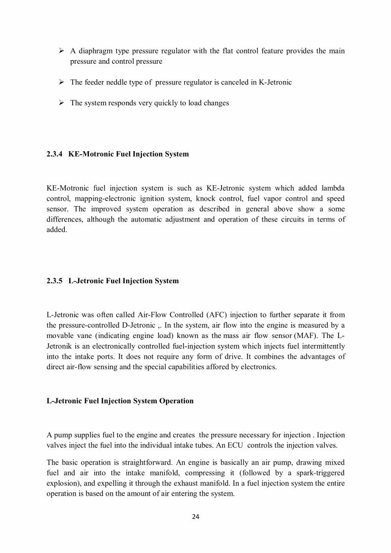
A diaphragm type pressure regulator with the flat control feature provides the main pressure and control pressure
The feeder neddle type of pressure regulator is canceled in K-Jetronic
The system responds very quickly to load changes
2.3.4 KE-Motronic Fuel Injection System
KE-Motronic fuel injection system is such as KE-Jetronic system which added lambda control, mapping-electronic ignition system, knock control, fuel vapor control and speed sensor. The improved system operation as described in general above show a some differences, although the automatic adjustment and operation of these circuits in terms of added.
2.3.5 L-Jetronic Fuel Injection System
L-Jetronic was often called Air-Flow Controlled (AFC) injection to further separate it from the pressure-controlled D-Jetronic ,. In the system, air flow into the engine is measured by a movable vane (indicating engine load) known as the mass air flow sensor (MAF). The L- Jetronik is an electronically controlled fuel-injection system which injects fuel intermittently into the intake ports. It does not require any form of drive. It combines the advantages of direct air-flow sensing and the special capabilities affored by electronics.
L-Jetronic Fuel Injection System Operation
A pump supplies fuel to the engine and creates the pressure necessary for injection . Injection valves inject the fuel into the individual intake tubes. An ECU controls the injection valves.
The basic operation is straightforward. An engine is basically an air pump, drawing mixed fuel and air into the intake manifold, compressing it (followed by a spark-triggered explosion), and expelling it through the exhaust manifold. In a fuel injection system the entire operation is based on the amount of air entering the system.

25
The engine pulls air through an air filter and into an air flow meter. The air flow meter measures the amount of air entering the system. Once measured, the air flows into a large hose that is connected to the intake manifold (a plenum). The intake manifold has a throttle plate that is connected to the driver's foot (the accelerator pedal). The position of this plate determines how much air is drawn into the manifold. Air is then passed into one of four barrels connecting the manifold to the cylinder head. A fuel injector is positioned each barrel and, as air passes through, fuel is sprayed for a specific amount of time into the air stream.
Advantages of the L-Jetronic System
Low fuel consumption
Low pollution exhaust gas
Adaption to operating conditions
Higher power output per liter

26
Figure 2-6 L-Jetronic Fuel Injection System
Throttle and idle control : Throttle opens to allow more air to sucked in to engine. Small amount of air by- passes the throttle so the engine gets air and will idle. Screw on side of throttle adjusts idlespeed. Auxiliary air valve bypasses more air during warm-up to compensate for thicker oil.
WOT (wide open throttle) switches : Idle switch is used for coasting fuel-cutoff. When switch is closed (throttle closed), fuel is cut until engine rpm drops below ECU specified value. If idle is set too high, the coasting fuel-cut off with cause the idle to cycle up and down as the ECU cuts fuel until idle drops below spec, then fuel resumes, RPM rise above specified and fuel is cut again.
27
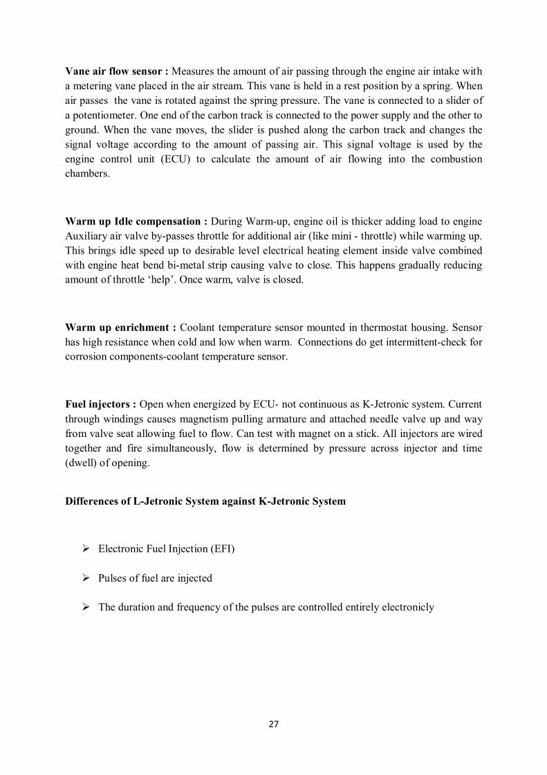
Vane air flow sensor : Measures the amount of air passing through the engine air intake with a metering vane placed in the air stream. This vane is held in a rest position by a spring. When air passes the vane is rotated against the spring pressure. The vane is connected to a slider of a potentiometer. One end of the carbon track is connected to the power supply and the other to ground. When the vane moves, the slider is pushed along the carbon track and changes the signal voltage according to the amount of passing air. This signal voltage is used by the engine control unit (ECU) to calculate the amount of air flowing into the combustion chambers.
Warm up Idle compensation : During Warm-up, engine oil is thicker adding load to engine Auxiliary air valve by-passes throttle for additional air (like mini - throttle) while warming up. This brings idle speed up to desirable level electrical heating element inside valve combined with engine heat bend bi-metal strip causing valve to close. This happens gradually reducing amount of throttle ‘help’. Once warm, valve is closed.
Warm up enrichment : Coolant temperature sensor mounted in thermostat housing. Sensor has high resistance when cold and low when warm. Connections do get intermittent-check for corrosion components-coolant temperature sensor.
Fuel injectors : Open when energized by ECU- not continuous as K-Jetronic system. Current through windings causes magnetism pulling armature and attached needle valve up and way from valve seat allowing fuel to flow. Can test with magnet on a stick. All injectors are wired together and fire simultaneously, flow is determined by pressure across injector and time (dwell) of opening.
Differences of L-Jetronic System against K-Jetronic System
Electronic Fuel Injection (EFI)
Pulses of fuel are injected
The duration and frequency of the pulses are controlled entirely electronicly

28
2.3.6 LH-Jetronic Fuel Injection System
LH-Jetronic is a newly designed fuel injection system. It utilizes a combination of all the best features known today. It operates with a moderate fuel pressure which is held constant by a line pressure regulator. Injection is by means of electrically controlled solenoid valves in the injectors which squirt fuel close to engine intake valves. The injection duration can be measured in milli seconds and is controlled by an electronic control unit.
Figure 2-7 LH-Jetronic Fuel Injection System
The electronic control receives signals on various driving, engine and ambient conditions from a set of sensors. Most important is the air mass meter. It utilizes a system that continuously measures the mass. This is accomplished by a platinum wire filament which is located in the intake air stream. It is held at a certain temperature above intake air temperature by a system of amplifiers, resistors and comparators. The current needed to do thid is measured and a corresponding signal sent to the electronic control unit.
When the engine stops, dirt build-up on the platinum wire filament is burned off by electrically raising the filament temperature to 19200F for less than one second. If dirt was allowed to stay on the filament, false signals would be received and the electronic control unit would order incorrect air-fuel mixture.

29
2.3.7 Mono-Jetronic Fuel Injection System
Jetronic fuel injection systems have proved their worth in millions of vehicles since they were introduced. This is a direct result of the advantages inherent in fuel injection with regard to present-day demands for economic efficiency, performance and, not least important, cleaner exhaust emissions. The Mono-Jetronic is an electronically controlled single-point fuel injection system in which a solenoid-operated fuel injector injects the fuel at a central point above the throttle valve. It is an economically priced system and is particularly suitable for small and medium-sized vehicles. When driving conditions change, and when the engine gets older, using lambda closed-loop control, the Mono-Jetronic always guarantees the correct air-fuel mixture.
Mono-Jetronic Fuel Injection System Operation
Mono-Jetronic fuel injection is an electronically controlled, low pressure, single point injection (SPI) system for 4 cylinder engines. While port injection systems such as KE-Jetronic and L-Jetronic fuel injection employ a separate injector for each cylinder, Mono-Jetronic features a single, centrally-located, solenoid-controlled injection valve for the entire engine.
The heart of the Mono-Jetronic is the central injection unit (described in the following ). It uses a single solenoid operated injector for intermittent fuel injection above the throttle valve. The intake manifold distributes the fuel to the individual cylinders.

30
Figure 2-8 Mono-Jetronic Fuel Injection System
A variety of different sensors are used to monitor engine operation and furnish the essential control parameters for optimum mixture adaptation. Input circuits in the ECU convert the sensor data for transmission to the microprocessor, which analyzes the operating data to determine current engine operating conditions; this information, in turn, provides the basis for calculating control signals to the various final-control elements (actuators). Output amplifiers process the signals for transmission to the injector, throttle-valve actuator and canister-purge valve.
31
2.3.8 Motronic Fuel Injection System
Motronic is the injection system is the most developed L-Jetronic System and a combination of the ignition system. Motronic are available as in 1.7 and 3.2 versions. The heart of this system is the microcomputer which controls to basic motor information and having an ability to measure the amount of injected fuel. This information takes place after testing by engineers pouring over a map gives the possibility to control all movements easily.
The flowmeter in the first system was the same L and LH. LH was performed as in the system then this piece. The basic difference of motronic system is set to advance adjustment by the electronic control unit of the system. The sensors which are located motronic system gives informationabout the amount of air entering the engine, engine speed, crankshaft position, engine and air temperature. Micro computer is a calculator which have capacity to calculate the best ignition timing and amount of fuel to be sprayed at this time.
Motronic control unit input signals for calculating the injection time :
Air mass meter-engine load signal
Intake air temperature
The signal from the throttle control unit
Engine speed sensor signal
Cooling water temperature
The signals of the lambda probe
The accelerator pedal signal
State of sensor signals
The system is totaly electronic and the current is carried by a microprocessor that controls all digital. Motronic fuel injection system compared to L-jetronic, the ignition-performance optimizations values taken into under certain operating conditions required.
32
The amount of fuel determined by methods known is taken into account the most appropriate ignition timing at enrichment mode (Idle, full-load). The five key elements is performed to catch an optimum point of hhis determination process in terms of the following :
Torque
Knocking
Exhaust emissions
Fuel consumption
Adaption of different working condition
Motronic system prepares poor mixing ratio at partial loads or stoichiometric mixture is prepared homogeneous distribution at full-load. In this application, specific fuel consumption reduction will be possible to achieve the level of up to 40%. Fuel can be injected directly into the cylinders with the high pressure injectors which is electromagnetically controlled. A warm wire is used to measure accurately to the incoming air for air mass measurement.
In cold starting, the starter motor is supplied with velocity is very volatile. The control unit does not consider this change. It only produces output signals depending on the engine temperature by a factor of fixed value. At additional injector for cold starting, the amount of fuel in thermal systems without time switch is adjusted by ECU and main injector. The change in amount of fuel during cold start is determined according to total number of revolution from the first ignition, the starter motor driven speed and the engine temperature.

33
Figure 2-9 Motronic Fuel Injection System
The enrichment is carried out according to engine speed at full-load codition. The values, which are corrected by the amount of air and temperature. The correction is made according to temperature in cases where knock.
34
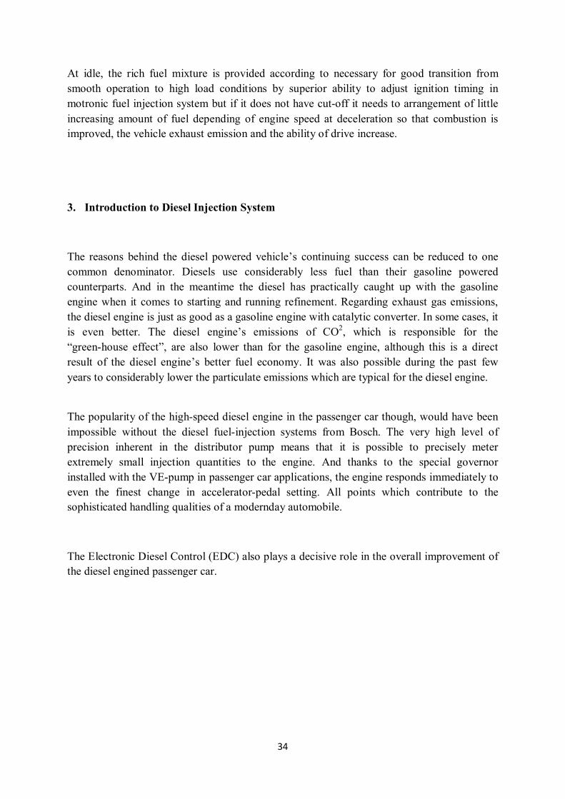
At idle, the rich fuel mixture is provided according to necessary for good transition from smooth operation to high load conditions by superior ability to adjust ignition timing in motronic fuel injection system but if it does not have cut-off it needs to arrangement of little increasing amount of fuel depending of engine speed at deceleration so that combustion is improved, the vehicle exhaust emission and the ability of drive increase.
3. Introduction to Diesel Injection System
The reasons behind the diesel powered vehicle’s continuing success can be reduced to one common denominator. Diesels use considerably less fuel than their gasoline powered counterparts. And in the meantime the diesel has practically caught up with the gasoline engine when it comes to starting and running refinement. Regarding exhaust gas emissions, the diesel engine is just as good as a gasoline engine with catalytic converter. In some cases, it is even better. The diesel engine’s emissions of CO2, which is responsible for the “green-house effect”, are also lower than for the gasoline engine, although this is a direct result of the diesel engine’s better fuel economy. It was also possible during the past few years to considerably lower the particulate emissions which are typical for the diesel engine.
The popularity of the high-speed diesel engine in the passenger car though, would have been impossible without the diesel fuel-injection systems from Bosch. The very high level of precision inherent in the distributor pump means that it is possible to precisely meter extremely small injection quantities to the engine. And thanks to the special governor installed with the VE-pump in passenger car applications, the engine responds immediately to even the finest change in accelerator-pedal setting. All points which contribute to the sophisticated handling qualities of a modernday automobile.
The Electronic Diesel Control (EDC) also plays a decisive role in the overall improvement of the diesel engined passenger car.

35
Figure 3-1 Diesel Engine Fuel Injection System
The following pages will deal with the design and construction of the VE distributor pump, and how it adapts injected fuel quantity, start-of-injection, and duration of injection to the different engine operating conditions. Diesel engines are characterized by their high levels of economic efficiency. This is of particular importance in commercial applications. Diesel engines are employed in a wide range of different versions.
3.1 Mechanical and Electronic Injection
Older engines make use of a mechanical fuel pump and valve assembly which is driven by the engine crankshaft, usually via the timing belt or chain. These engines use simple injectors which are basically very precise spring-loaded valves which will open and close at a specific fuel pressure. The pump assembly consists of a pump which pressurizes the fuel, and a disc-shaped valve which rotates at half crankshaft speed. The valve has a single aperture to the pressurized fuel on one side, and one aperture for each injector on the other. As the engine turns the valve discs will line up and deliver a burst of pressurized fuel to the injector at the cylinder about to enter its power stroke. The injector valve is forced open by the fuel pressure and the diesel is injected until the valve rotates out of alignment and the fuel pressure to that injector is cut off.
Engine speed is controlled by a third disc, which rotates only a few degrees and is controlled by the throttle lever. This disc alters the width of the aperture through which the fuel passes, and therefore how long the injectors are held open before the fuel supply is cut, controlling the amount of fuel injected.

36
This contrasts with the more modern method of having a separate fuel pump (or set of pumps) which supplies fuel constantly at high pressure to each injector. Each injector then has a solenoid which is operated by an electronic control unit, which enables more accurate control of injector opening times depending on other control conditions such as engine speed and loading, resulting in better engine performance and fuel economy. This design is also mechanically simpler than the combined pump and valve design, making it generally more reliable, and less noisy, than its mechanical counterpart.
3.2 Improvement of Diesel Injection System
With an analytic approach a new high pressure fuel injection system called APCRS was developed to fulfill these requirements (Mahr, Dürnholz, Polach and Grieshaber, 2000). The hydraulic layout of the pressure amplified development tool is apart from the amplifier piston modules similar to the standard Common Rail System but with a middle rail pressure. In each injector amplifier modules are integrated to generate high injection pressures determined by a stepped piston.
The amplifier is activated by a second solenoid valve in the injector. Without activating this solenoid the injection system acts as a standard common rail system because of the by-pass path with non-return valve. Varying energizing timing of both solenoid valves flexible pressure curves from ramp to rectangular can be generated. Pilot injections and late post injections are possible without activating the amplifier piston at the intermediate pressure in the rail. With this reduced pressure of the late post injection the risk of oil dilution can be minimized.
To fulfill future exhaust gas limits especially with EGR high injection pressures (2000 bar and more) are required. An increase of the system pressure with a standard common rail system for heavy duty engines leads to high effort on rail and high pressure pump design, lower efficiency and durability. High pressure pump and rail of the development tool APCRS are designed for intermediate pressure level and higher capacity depending on the ratio of amplifier piston. To avoid mixing of engine oil with fuel the high pressure pump for APCRS is fuel lubricated. The APCRS is designed for multiple injection, rate shaping, high injection pressure and high hydraulic efficiency of the injection system to reduce emissions and fuel consumption.

37
3.3 Diesel Injection System Specification
The specification for all diesel engines are restricted more and more regarding exhaust gas limits, fuel consumption, noise and costs and this with increasing demands ondriveability, lifetime, power output, service and diagnosis, Figure 5. Applying EGR or increased rated speed to a heavy duty diesel engine higher maximum injection pressures are essential. To achieve future more stringent exhaust gas limits additionally low sulphur diesel fuel is necessary. The flexible diesel fuelinjection system is assisting this development with the measures multiple injection, rate shaping of the main injection and an increased maximum injection pressure. Furthermore high efficiency of the injection system itself is important. New developments on actuators (new solenoid and piezo technique), nozzle design and ECU control strategies alsofor exhaust gas aftertreatment are key factors for future diesel engine technology. Mixing of oil with the fuel must be reduced for more stringent exhaust gas limits due to the influence of sulphur content in the lubrication oil on the overall soot emissions with a downstream oxidation catalyst.
Figure 3-2 Key Factors for Diesel Fuel Injection System Development
3.4 Requirement of Diesel Injection System
The fuel should be introduced into the combustion chamber within a precisely period of the cycle. The rate of injection should be such that it results in the desired heat release pattern. The quantities of the fuel metered should vary to meet changing speed and load requirements.The injected fuel must be broken into very fine droplets, i.e., good atomization should be obtained.

38
The spray-pattern must be such that it results in rapid mixing of fuel and air The beginning and the end of injection should be sharp, i.e., there should not be any dribbling or after injection.
The injection timing, if desired, should be change to suit the engine speed and load requirements. In the case multi cylinder engines, the distribution of the metered fuel among various cylinders should be uniform. In addition to the above requirements, the weight and the size of the fuel injection system must be minimum.
3.5 Fuel Injection Pumps
The pump’s function is to draw fuel from the fuel reservoir through a filter and deliver liquid fuel at high pressure via nozzle pipes to the following stage of injection. Figure 3-4 depicts a mechanical in-line diesel fuel injector pump.
3.5.1 In-Line Injection Pumps
This type of pump is typically found in the 40 to 100 kW per cylinder maximum power range of engine. It contains a plunger and barrel assembly for each engine cylinder.
Figure 3-3 Typical Mechanical In-Line Diesel Fuel Injector Pump

39
Each plunger is raised by a cam on the pump camshaft (driven via gear or belt off the engine crankshaft) and is forced back by the plunger return spring. The plunger fits sufficiently accurately within the barrel to seal without additional sealing elements, even at high pressures and low speeds. Varying the effective plunger stroke alters the amount of fuel delivered. This is achieved by means of a control rod or rack, which moves in the pump housing and rotates the plunger via a ring gear or linkage lever. The plunger chamber above the plunger is always connected with the chamber below the plunger helix by a vertical groove or bore in the plunger. Delivery ceases when the plunger helix exposes the intake port (port opening), thus connecting the plunger chamber with the suction gallery. When this takes place depends on the rotational position of the plunger. Figure 3-4 depicts the plunger movement during the metering of different quantities of diesel fuel.
Figure 3-4 Helical Control of Fuel Delivery by Rotating Plunger
In the case of a lower helix, delivery always starts (port closing) at the same time, but ends sooner or later depending on the rotational position of the plunger. With a plunger with an upper helix, port closing (start of delivery) not port opening is controlled by the helix and is varied by rotating the plunger.

40
3.5.2 Distributor or Rotary-Type Fuel Injection Pumps
A diesel fuel system comprising of a distributor-type fuel-injection pump with mechanical governor is shown in Figure 3-5.
Figure 3-5 Distributor-Type Diesel Fuel Pump
Normally used in multi-cylinder engines with less than 30 kW per cylinder maximum power with injection pressures up to 75 MPa. These pumps have only one plunger and barrel. The pump plunger is made to describe a combined rotary and stroke movement by the rotating cam plate. The fuel is accurately metered to each injection nozzle in turn by this plunger which simultaneously acts as the distributor. Such units are more compact and cheaper than in-line pumps but cannot achieve such high injection pressures. The distributor-type fuel injection pump is combined with an automatic timing device, governor, and supply pump to form a single unit.

41
A large number of the latest generation passenger cars and light commercial vehicles are fitted with high-pressure rotary pumps with electronically controlled metering valves. Their compactness and flexibility make them well suited to modern emission and performance requirements.
3.5.3 Single-Barrel Injection Pumps
Figure 3-6 shows a section view of a single-barrel fuel injection pump. The operation of the metering element of this type of injection pump has been discussed and is depicted in Figure 3-6.
Figure 3-6 A Single-Barrel Injection Pump
Single-barrel injection pumps are used on small single and twin cylinder diesel engines as well as large engines with outputs of more than 100 kW per cylinder. Such pumps are driven by an auxiliary cam on the engine camshaft.
42
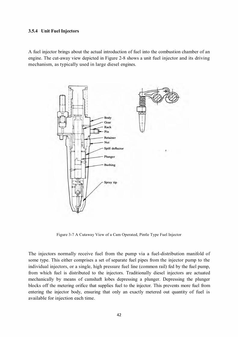
3.5.4 Unit Fuel Injectors
A fuel injector brings about the actual introduction of fuel into the combustion chamber of an engine. The cut-away view depicted in Figure 2-8 shows a unit fuel injector and its driving mechanism, as typically used in large diesel engines.
Figure 3-7 A Cutaway View of a Cam Operated, Pintle Type Fuel Injector
The injectors normally receive fuel from the pump via a fuel-distribution manifold of some type. This either comprises a set of separate fuel pipes from the injector pump to the individual injectors, or a single, high pressure fuel line (common rail) fed by the fuel pump, from which fuel is distributed to the injectors. Traditionally diesel injectors are actuated mechanically by means of camshaft lobes depressing a plunger. Depressing the plunger blocks off the metering orifice that supplies fuel to the injector. This prevents more fuel from entering the injector body, ensuring that only an exactly metered out quantity of fuel is available for injection each time.

43
Next the descending plunger compresses the fuel forcing it through check valves into the injector spray tip. The injector tip is the most critical part of the injection system. It consists of a body containing a spring-loaded needle valve blocking off single or multiple orifices. Once the fuel has been pressurised to a sufficient degree by the plunger it forces the needle off its seat against the spring and fuel can issue through one or multiple orifices, depending on combustion chamber design, into the combustion chamber. It is important to keep the volume of fuel left between the needle and nozzle orifices as small as possible to prevent any fuel flowing into the cylinder after injection is over, to control hydrocarbon emissions, (and possible engine damage).
Figure 3-8 Electronically Controlled Unit Fuel Injector
More recently the technology for electronic control of injectors has become available. Figure 3-8 depicts the metering components of a mechanical injector compared to those of an electronically controlled unit. Instead of using a camshaft lobe to actuate the injector plunger, a solenoid operated control valve performs the injection timing and fuel metering functions. Solenoid valve closure initiates pressurization and injection, and opening causes injection pressure decay and end of injection. Duration of valve closure determines the quantity of fuel injected. The unit, [shown in figure 3-8 above] still uses camshaft/rocker arm driven plungers to generate the injection pressure, and employs needle-valve nozzles of conventional design. Increased flexibility in fuel metering and timing and simpler injector mechanical designs are important advantages.

44
Naturally the evolution of diesel engines over the years has called for engines that are more powerful for their specific capacity while being more fuel efficient and forming less pollutants during the combustion process. All these factors have led to a steady rise in the injection pressures of modern engines. This development is taking place in order to facilitate reducing the droplet size of the ‘fuel mist’. The smaller the fuel droplets contained within the inlet charge are, the better the fuel will mix with the air within the combustion chamber and the more uniformly the combustion flame will propagate within the ‘squish’ volume above the piston releasing maximum energy in a controlled manner.
3.5.5 Common Rail Injection Systems
Common rail direct fuel injection is a modern variant of direct fuel injection system for diesel engines. On diesel engines, it features a high-pressure (over 1,000 bar/15,000 psi) fuel rail feeding individual selenoid valves, as opposed to low-pressure pump feeding unit injectors (Pumpe/Düse or pump nozzles). Third-generation common rail diesels now feature piezoelectric injectors for increased precision, with fuel pressure up to 1,800 bar/26,000 psi.
The common rail system prototype was developed in late 1960s by Robert Huber of Switzerland and the technology further developed by Dr. Marco Ganser at the Swiss Federal Institute of Technology in Zurich, later of Ganser-Hydromag AG (est.1995) in Oberageri.
The first successful usage in production vehicle began in Japan by the mid-1990s. Dr. Shohei Itoh and Masahiko Miyaki of Denso Corporation, a japanese automotive parts manufacturer, developed the common rail fuel system for heavy duty vehicle and turned it into practical use on their ECD-U2 common rail system mounted on the Hino Rising Ranger truck and sold for general use in 1995. Denso claims the first commercial high presure common rail system in 1995.
Modern common rail systems, whilst working on the same principle, are governed by an engine control unit (ECU) which opens each injector electronically rather than mechanically. This was extensively prototyped in the 1990s with collaboration between Magneti Marelli, Centro Ricerche Fiat and Elasis. Afterresearch and development by the Fiat Group, the design was acquired by the german company Robert GmbH for completion of development and refinement for mass-production. In highsight, the sale appeared to be a tactical error for Fiat, as the new technology proved to be highly profitable.

45
The company had little choise but to sell, however, as it was in a poor financial state at the time and lacked the resources to complete development on its own. In 1997 they extended its us efor passenger cars. The first passenger car that used the common rail system was the 1997 model Alfa Romeo 156 2.4 JTD, and later on that same year Mercedes-Benz S220 CDI.
Figure 3-9 Common Rail Fuel Injection System
Common rail engines have been used in marine and locomotive applications for some time. The Cooper-Bessemer GN-8 (cica 1942) is an example of hydraulically operated common rail diesel engine, also known as a modified common rail.
Vickers used common rail system in submarine engine circa 1916. Doxford Engine Ltd. (opposed-piston heavy marine engine) use a common rail system (from 1921 to 1980) whereby a multi-cylinder reciprocating fuel pump generated a pressure of approximately 600 bar, with the fuel being stored in accumulator bottles. Pressure control was achieved by means of an adjustable pump discharge stroke and a “spill valve”. Camshaft-operated mechanical timing valves were used used to supply the spring-loaded Brice/CAV/Lucas injectors, which injected through the side of cylinder into the chamber formed between the pistons. Early engines had a pair of timing cams, one for ahead running an done for astern.

46
Later engines had two injectors per cylinder, and the final series of constant-pressure turbocharged engines were fitted with four injectors per cylinder. This system was used fort he injection of both diesel oil and heavy fuel oil (600cSt heated to a temperature of approximately 130 oC).
Solenoid or piezoelectric valves make possible fine electronic control over the fuel injection time and quantity, and the higher pressure that the common rail technology makes available provides better fuel atomization. In order to lower engine noise, the engine’s electronic control unit can inject a small amount of diesel just before the main injection event (“pilot” injection), thus reducing its explosiveness and vibration, as well as optimizing injection timing and quantity for variations in fuel quality, cold starting and so on. Some advanced common rail fuel systems perform as many as five injectors per stroke. Common rail engines require very short (<10 second) or no heating-up time at all dependent on ambient temperature, and produce lower engine noise and emissions than older systems.
Diesel engines have historically used various forms of fuel injection. Two common types include the unit injection system and the distributor/inline pump systems (See diesel engine and unit injector for more information). While these older systems provided accurate fuel quantity and injection timing control, they were limited by several factors:
They were cam driven, and injection pressure was proportional to engine speed. This typically meant that the highest injection pressure could only be achieved at the highest engine speed and hte maximum achievable injection pressure decreased as engine speeed decreased. This relationship is true with all pumps, even those used on common rail systems; with unit or distributor systems, however, the injection pressure is tied to the instantaneous pressure pf a single pumping event with no accumulator, and thus the relationship is more prominent and troublesome.
They were limited in the number and timing of injection events that could be commanded during a single combustion event. While multiple injection events are possible with these older systems, it is much more difficult and costly to achieve.
For the typical distributor/inline system, the start of injection occured at a pressure determined pressure (often referred to as: pop pressure) and ended at a pre-determined pressure. This characteristic resulted from “dummy” injectors in the cylinder head which opened and closed at pressures determined by the spring preload applied to the plunger in the injector. Once the pressure in the injector reached a pre-determined level, the plunger would lift and injection would start.
47
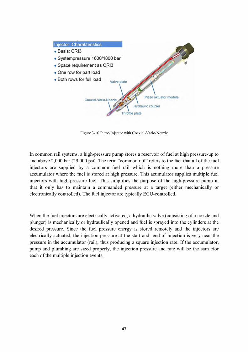
Figure 3-10 Piezo-Injector with Coaxial-Vario-Nozzle
In common rail systems, a high-pressure pump stores a reservoir of fuel at high pressure-up to and above 2,000 bar (29,000 psi). The term “common rail” refers to the fact that all of the fuel injectors are supplied by a common fuel rail which is nothing more than a pressure accumulator where the fuel is stored at high pressure. This acumulator supplies multiple fuel injectors with high-pressure fuel. This simplifies the purpose of the high-pressure pump in that it only has to maintain a commanded pressure at a target (either mechanically or electronically controlled). The fuel injector are typically ECU-controlled.
When the fuel injectors are electrically activated, a hydraulic valve (consisting of a nozzle and plunger) is mechanically or hydraulically opened and fuel is sprayed into the cylinders at the desired pressure. Since the fuel pressure energy is stored remotely and the injectors are electrically actuated, the injection pressure at the start and end of injection is very near the pressure in the accumulator (rail), thus producing a square injection rate. If the accumulator, pump and plumbing are sized properly, the injection pressure and rate will be the sam efor each of the multiple injection events.

48
Figure 3-11 Heart of Common Rail Injection Systems
Advantages of the Common Rail Injection Systems
Improves the air fuel mixture formation
Injection pressure can be freely selected within wide limits
The beginning of the fuel injection quantity of fuel can be determibed accurately (100/6000 rpm in range 100 mm3/revolution)
Provides flexibility in terms of working conditions changed
Combustion is ecological and economical
Disadvantages of the Common Rail Injection Systems
Like all good things have a negative side, this engine also have few disadvantages. The key disadvantage of the CRDi engine is that it is costly than the conventional engine. The list also includes high degree of engine maintenance and costly spare parts. Also this technology can’t be employed to ordinary engines.

49
4. Conclusion
In this study, I have searched into different kind of fuel injection system which in both gasoline engine and diesel engine. The carburetor, D-Jetronic, K-Jetronic, L-Jetronic and motronic fuel injection were presented with their advantages and disadvantages. At today’s technology do not accept carburetor because this system is ineffective to supply efficiency run range in fuel consumption and low emission values. Jetronic systems have endeavored to catch to higher engine performance, lower emission values and lower fuel consumption with their additional systems to adjust better mixture. In addition to motronic system is the most advanced system with well injection and ignition system is combinated so getting more commonly to use passenger vehicles but the system prices are also getting high with complex structures and the fixing to all elements of system are not available. The service cost is modestly high. On the other hand, common rail is getting commonly due to high performance and emission effects. In today, motronic and common rail injection are getting more popular and useable.

50
References
1. Heywood J.B, Internal Combustion Engine Fundamentals, Massachusetts Institute of Technology, Cambridge, (2000).
2. Hillier V.A.W and Rogers D. and Coombes P., Hillier’s Fundamentals of Motor Vehicle Technology, Cheltenham, (2006).
3. Nunney M.J, Light and Heavy Vehicle Technology, Oxford, (2007).
4. Megep, Benzinli Motorlar Yakıt ve Ateşleme Sistemleri, Ankara, (2006).
5. Probst C.O, Bosch Fuel Injection and Engine Management, Cambridge, (2013).
6. Challen B. and Baranescu R., Diesel Engine Reference Book, Oxford, (1999).
7. Hacısevki H., Spark and Compression Ignition Engine, Eastern Mediterranean University, (2007).
8. Internet, http://www.otobil.net/blog/genel/yakit-enjeksiyon-sistemleri, (visited date 2013).
9. Internet, http://tr.wikipedia.org/wiki/Karb%C3%BCrat%C3%B6r, (visited date 2013).
10. Internet, http://www.obinet.gazi.edu.tr/obinet/yakit_sistemi/k_jetronik.htm (visited date 2013).
11. Işıksoluğu M.A, Benzin Motorlarında Yakıt Püskürtme Sistemleri, Istanbul, (2001).
12. Karamangil, M.İ, Direkt Püskürtmeli Benzin Motorları ve Mitsubishi Metodu, Bursa, (2004).
13. Demir A., Sıkıştırma ile Ateşlemeli Motorlar, Istanbul, (2010).
14. Internet, http://www.autoshop101.com/forms/h20.pdf, (visited date 2013).
15. Mahr B., Future and Potential of Diesel Injection Systems, Stuttgart, (2010).
16. Internet, http://www.kfz-tech.de/Engl/LH-Jetronic.htm, (visited 2013).