
Numerical analysis of the combustion process in a four-stroke compressed natural gas engine with...
8
Journal of Mechanical Science and Technology 22 (2008) 1937~1944 www.springerlink.com/content/1738-494x DOI 10.1007/s12206-008-0737-6 Journal of Mechanical Science and Technology Numerical analysis of the combustion process in a four-stroke compressed natural gas engine with direct injection system † Wendy Hardyono Kurniawan and Shahrir Abdullah * Department of Mechanical and Materials Engineering, National University of Malaysia, 43600 UKM Bangi, Selangor Darul Ehsan, Malaysia (Manuscript Received April 16, 2008; Revised June 25, 2008; Accepted July 23, 2008) ------------------------------------------------------------------------------------------------------------------------------------------------------------------------------------------------------------------------------------------------------------------------------------ Abstract In this paper, a numerical study to simulate and analyze the combustion process occurred in a compressed natural gas direct injection (CNG-DI) engine by using a multi-dimensional computational fluid dynamics (CFD) code was presented. The investigation was performed on a single cylinder of the 1.6-liter engine running at wide open throttle at a fixed speed of 2000 rpm. The mesh generation was established via an embedded algorithm for moving meshes and boundaries for providing a more accurate transient condition of the operating engine. The combustion process was characterized with the eddy-break-up model of Magnussen for unpremixed or diffusion reaction. The modeling of gaseous fuel injection was described to define the start and end of injection timing. The utilized ignition strategy into the computational mesh was also explained to obtain the real spark ignition timing. The natural gas employed is con- sidered to be 100% methane (CH 4 ) with three global step reaction scheme. The CFD simulation was started from the intake valves opening until the time before exhaust valves opening. The results of CFD simulation were then compared with the data obtained from the single-cylinder engine experiment and showed a close agreement. For verification pur- pose, comparison between numerical and experimental work are in the form of average in-cylinder pressure, engine power as well as emission level of CO and NO. Keywords: Combustion; Computational fluid dynamics; Compressed natural gas; Direct injection; Diffusion reaction; Ignition ------------------------------------------------------------------------------------------------------------------------------------------------------------------------------------------------------------------------------------------------------------------------------------ 1. Introduction With the great attention to energy availability today, much effort has been directed to development for substituting carbon-based oil fuels. Utilization natural gas is seen as one of the promising solutions to re- solve this kind of problem. While fuel cell is consid- ered as a power source in the future, the use of natural gas for automotive vehicles in their internal combus- tion is more practicable and cheaper. Several advan- tages related to natural gas utilization in terms of en- gineering application are its higher thermal efficiency and lower exhaust emissions including CO 2 due to the higher octane level and lower ratio of carbon and hydrogen ratio, respectively. For light-duty vehicle, direct injection (DI) of com- pressed natural gas (CNG) promises higher thermal efficiencies comparable to those achieved by high compression ratio and unthrottled diesel engines, while maintaining the smoke-free operation of spark ignition (SI) engines and producing slightly higher NOx emissions with the proper operating conditions. In order to meet the more stringent emission regula- tions that has been implemented all around the world, there are still technical difficulties to be resolved to simultaneously reduce both NO and CO produced from the natural gas engines. The CFD modeling of internal combustion engine (ICE) process has one the highest level of complexity and it is a challenging task given the fact that several †This paper was presented at the 9 th Asian International Conference on Fluid Machinery (AICFM9), Jeju, Korea, October 16-19, 2007. * Corresponding author. Tel.: +60 3 8921 6013, Fax.: +60 3 8925 9659 E-mail address: [email protected] © KSME & Springer 2008
-
Upload
independent -
Category
Documents
-
view
0 -
download
0
Transcript of Numerical analysis of the combustion process in a four-stroke compressed natural gas engine with...
Journal of Mechanical Science and Technology 22 (2008) 1937~1944
www.springerlink.com/content/1738-494xDOI 10.1007/s12206-008-0737-6
Journal of
Mechanical Science and Technology
Numerical analysis of the combustion process in a four-stroke compressed natural gas engine with direct injection system†
Wendy Hardyono Kurniawan and Shahrir Abdullah*
Department of Mechanical and Materials Engineering, National University of Malaysia, 43600 UKM Bangi, Selangor Darul Ehsan, Malaysia
(Manuscript Received April 16, 2008; Revised June 25, 2008; Accepted July 23, 2008)
------------------------------------------------------------------------------------------------------------------------------------------------------------------------------------------------------------------------------------------------------------------------------------
Abstract In this paper, a numerical study to simulate and analyze the combustion process occurred in a compressed natural
gas direct injection (CNG-DI) engine by using a multi-dimensional computational fluid dynamics (CFD) code was presented. The investigation was performed on a single cylinder of the 1.6-liter engine running at wide open throttle at a fixed speed of 2000 rpm. The mesh generation was established via an embedded algorithm for moving meshes and boundaries for providing a more accurate transient condition of the operating engine. The combustion process was characterized with the eddy-break-up model of Magnussen for unpremixed or diffusion reaction. The modeling of gaseous fuel injection was described to define the start and end of injection timing. The utilized ignition strategy into the computational mesh was also explained to obtain the real spark ignition timing. The natural gas employed is con-sidered to be 100% methane (CH4) with three global step reaction scheme. The CFD simulation was started from the intake valves opening until the time before exhaust valves opening. The results of CFD simulation were then compared with the data obtained from the single-cylinder engine experiment and showed a close agreement. For verification pur-pose, comparison between numerical and experimental work are in the form of average in-cylinder pressure, engine power as well as emission level of CO and NO.
Keywords: Combustion; Computational fluid dynamics; Compressed natural gas; Direct injection; Diffusion reaction; Ignition ------------------------------------------------------------------------------------------------------------------------------------------------------------------------------------------------------------------------------------------------------------------------------------
1. Introduction
With the great attention to energy availability today, much effort has been directed to development for substituting carbon-based oil fuels. Utilization natural gas is seen as one of the promising solutions to re-solve this kind of problem. While fuel cell is consid-ered as a power source in the future, the use of natural gas for automotive vehicles in their internal combus-tion is more practicable and cheaper. Several advan-tages related to natural gas utilization in terms of en-gineering application are its higher thermal efficiency and lower exhaust emissions including CO2 due to the
higher octane level and lower ratio of carbon and hydrogen ratio, respectively.
For light-duty vehicle, direct injection (DI) of com-pressed natural gas (CNG) promises higher thermal efficiencies comparable to those achieved by high compression ratio and unthrottled diesel engines, while maintaining the smoke-free operation of spark ignition (SI) engines and producing slightly higher NOx emissions with the proper operating conditions. In order to meet the more stringent emission regula-tions that has been implemented all around the world, there are still technical difficulties to be resolved to simultaneously reduce both NO and CO produced from the natural gas engines.
The CFD modeling of internal combustion engine (ICE) process has one the highest level of complexity and it is a challenging task given the fact that several
†This paper was presented at the 9th Asian International Conference on Fluid Machinery (AICFM9), Jeju, Korea, October 16-19, 2007.
*Corresponding author. Tel.: +60 3 8921 6013, Fax.: +60 3 8925 9659 E-mail address: [email protected] © KSME & Springer 2008

1938 W. H. Kurniawan and S. Abdullah / Journal of Mechanical Science and Technology 22 (2008) 1937~1944
processes, parameters and operating conditions oc-curred within the engine should be taken into account such as fuel injection, flame propagation, ignition process, chemical kinetic reaction, exhaust emission formations, tendency for knocking as well as control of air-fuel ratio control. Hence, the computing times of ICE process simulation are costly and require huge computer memory as well as high performance com-puting setup.
A number of automotive researchers have initiated works on natural gas-fuelled engines by performing experiments or numerical simulation. The characteris-tics of combustion and exhaust gas emissions from a dual-fuel diesel engine with natural gas by the means of experimental work and numerical simulation have been performed by Kusaka et al. [1], where numerical computation was performed by using KIVA-3 to analyze the formation of NOx and hydrocarbon total. It was found that NOx within cylinder of dual fuel engine is higher than that of diesel engine due to higher temperature at the initial stage of combustion process. Shiga et al. [2] have also analyzed emissions characteristics from compressed natural gas (CNG) direct-injection combustion using a rapid-compre-ssion-machine with a compression ratio of 10:1 and a disc-shaped combustion chamber. In addition, Ando et al. [3] conducted their experimental with a self-ignited natural gas engine by performing the visuali-zation and combustion study. In numerical analysis, Zhang and Frankel [4] carried out combustion analy-sis of natural gas engine by using the CFD code under the lean combustion and limited analyzed CFD calcu-lation. Comparison of fuel composition and ignition energy at the initial stage of combustion inside a natu-ral gas SI engine was studied by Yossefi et al. [5] by using KIVA-2 and the detailed chemical kinetic algo-rithm to compare the relatively effect of gas composi-tion, i.e. ethane and carbon dioxide inside natural gas. Agarwal and Assanis [6] carried out detailed multi-dimensional modeling of a direct injection natural gas engine with self-ignited condition for the purpose of examining ignition, combustion and formation proc-esses of NO by using KIVA-3 with the eddy-break-up model, coupled with chemical kinetic mechanism for natural gas simulation. Lastly, Zheng et al. [7] inves-tigated fluid flow and combustion process using CFD in a compression ignition natural gas engine with separated chamber.
From literature, numerical analysis of a natural gas engine with spark ignition mounted inside the com-
bustion chamber has yet to be covered in details. Therefore, numerical study of combustion process in a CNG engine with direct injection system, referred to as CNGDI, was carried out. The simulations for the engine operating conditions at the moderate engine speed of 2000 rpm were carried out to investigate the behavior occurred within the engine cylinder during and after combustion process.
2. Engine configuration
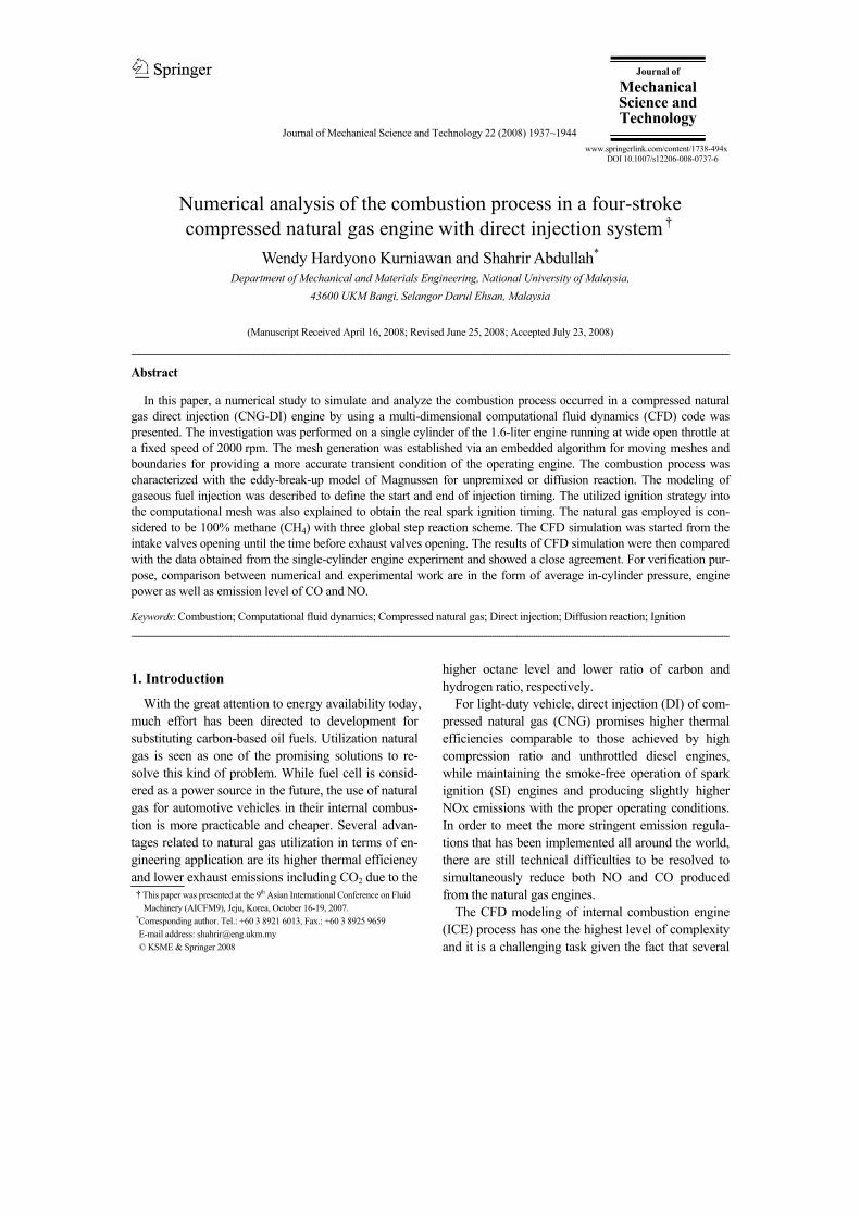
A single cylinder engine was modified into a CNGDI monofuel engine. The engine was operated at wide open throttle condition with a compression ratio of 14:1. The main engine specifications are as given in Table 1 and the section view of its cylinder head and liner is depicted in Fig. 1, which shows the posi-tion of the intake and exhaust ports, intake and ex-haust valves, CNG injector, spark plug and combus-tion chamber with the shape of piston bowl.
The CFD simulation for the combustion process in this analysis were performed by using the moving mesh and boundary algorithm where every event represents the different mesh and boundary geome-tries for every different crank angle in each step of engine cycle. Thus, in order to perform CFD simula-tion for internal combustion process, the analysis was carried out by using transient, moving meshes and boundaries, high compressible Reynolds number, high turbulence intensity, momentum, heat and mass transfer with complex geometries model and chemi-cal-thermal dependent as well [8].
A self-developed grid generation program had been
Table 1. Specification of CNGDI engine.
Engine parameters Value Unit Number of cylinders 4 -
Type Inline - Displacement volume 1596 cm3
Bore 78 mm Stroke 84 mm
Connecting rod length 131 mm Crank radius 44 mm
Compression ratio 14 - Intake valve opening 12 bTDC Intake valve closing 48 aBDC
Exhaust valve opening 45 bBDC Exhaust valve closing 10 aTDC
Maximum intake valve lift 8.1 mm Maximum exhaust valve lift 7.5 mm
W. H. Kurniawan and S. Abdullah / Journal of Mechanical Science and Technology 22 (2008) 1937~1944 1939
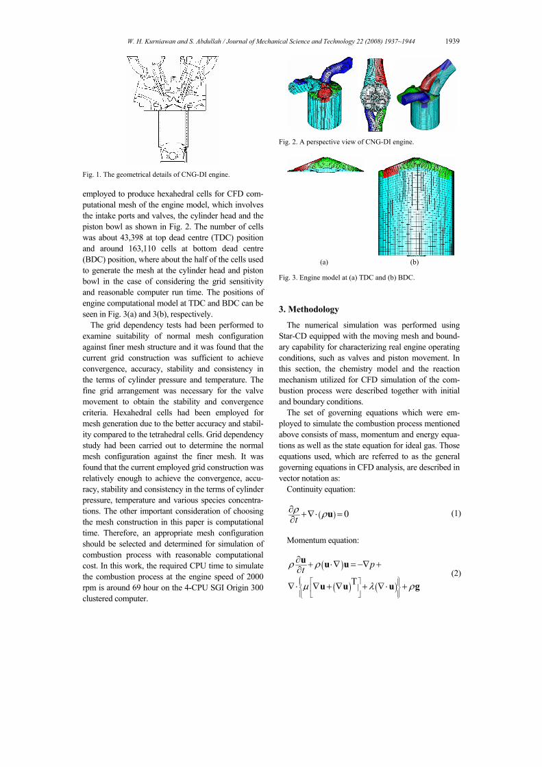
Fig. 1. The geometrical details of CNG-DI engine. employed to produce hexahedral cells for CFD com- putational mesh of the engine model, which involves the intake ports and valves, the cylinder head and the piston bowl as shown in Fig. 2. The number of cells was about 43,398 at top dead centre (TDC) position and around 163,110 cells at bottom dead centre (BDC) position, where about the half of the cells used to generate the mesh at the cylinder head and piston bowl in the case of considering the grid sensitivity and reasonable computer run time. The positions of engine computational model at TDC and BDC can be seen in Fig. 3(a) and 3(b), respectively.
The grid dependency tests had been performed to examine suitability of normal mesh configuration against finer mesh structure and it was found that the current grid construction was sufficient to achieve convergence, accuracy, stability and consistency in the terms of cylinder pressure and temperature. The fine grid arrangement was necessary for the valve movement to obtain the stability and convergence criteria. Hexahedral cells had been employed for mesh generation due to the better accuracy and stabil-ity compared to the tetrahedral cells. Grid dependency study had been carried out to determine the normal mesh configuration against the finer mesh. It was found that the current employed grid construction was relatively enough to achieve the convergence, accu-racy, stability and consistency in the terms of cylinder pressure, temperature and various species concentra-tions. The other important consideration of choosing the mesh construction in this paper is computational time. Therefore, an appropriate mesh configuration should be selected and determined for simulation of combustion process with reasonable computational cost. In this work, the required CPU time to simulate the combustion process at the engine speed of 2000 rpm is around 69 hour on the 4-CPU SGI Origin 300 clustered computer.
Fig. 2. A perspective view of CNG-DI engine.
(a) (b) Fig. 3. Engine model at (a) TDC and (b) BDC.
3. Methodology
The numerical simulation was performed using Star-CD equipped with the moving mesh and bound-ary capability for characterizing real engine operating conditions, such as valves and piston movement. In this section, the chemistry model and the reaction mechanism utilized for CFD simulation of the com-bustion process were described together with initial and boundary conditions.
The set of governing equations which were em-ployed to simulate the combustion process mentioned above consists of mass, momentum and energy equa-tions as well as the state equation for ideal gas. Those equations used, which are referred to as the general governing equations in CFD analysis, are described in vector notation as:
Continuity equation:
( ) 0tρ ρ∂ +∇⋅ =∂ u (1)
Momentum equation:
( )
( ) ( )T
ptρ ρ
µ λ ρ⎧ ⎫⎡ ⎤⎪ ⎪⎨ ⎬⎢ ⎥⎪ ⎪⎣ ⎦⎩ ⎭
∂ + ⋅∇ = −∇ +∂
∇⋅ ∇ + ∇ + ∇⋅ +
u u u
u u u g (2)

1940 W. H. Kurniawan and S. Abdullah / Journal of Mechanical Science and Technology 22 (2008) 1937~1944
Energy equation:
( ) ( ) ( )
( ) ( )2 T
Tc c T p k Tv vtρ ρ
λ µ⎧ ⎫⎡ ⎤⎪ ⎪⎨ ⎬⎢ ⎥⎪ ⎪⎣ ⎦⎩ ⎭
∂ + ⋅∇ =− ∇⋅ +∇ ∇ +∂
∇⋅ +∇ ⋅ ∇ + ∇
u u
u u u u (3)
The turbulence model employed was the k-ε turbu-
lence model [9] for compressible and high Reynolds number flow for reciprocating engines, where k is turbulence kinetic energy and ε is turbulence dissipa-tion rate. As mentioned previously, the finite volume method CFD code employed to solve the discretized equations, which govern the mean fluid motion, is based on the pressure-correction method. The discre-tization of space and time are maintained and moni-tored based on a specified Courant number, which provide stability for time discretization. The time step was defined to obtain the best compromise between requirement for convergence and computing load i.e. smaller time steps are used for initiating simulations and when reaching fuel injection event and TDC po-sition.
The temporal discretization method chosen was implicit with the under relaxation factor of 0.1 to ob-tain criterion for unconditional numerical stability, while the accurate second order differencing scheme of MARS (monotone advection and reconstruction scheme) was employed for the momentum, energy and turbulence equations together with the arbitrary Lagrangian-Eulerian (ALE) technique to treat grid movement associated with movement of piston and valves. The popular PISO algorithm for unsteady flows was then employed to solve the resulting alge-braic equations.
The type of chemical reaction model used to simu-late the combustion process of compressed natural gas was unpremixed or diffusion reaction. The moti-vation of using the diffusion reaction for such engine modeling is due to the monofuel employed (methane). In this reaction, the fuel and the oxidant (air) enter the engine cylinder separately. For modeling, it is neces-sary to solve one additional differential conservation equation for each reaction considered. The chosen conserved scalar is known as the mixture fraction, φ, and is defined as the total mass fraction of burned and unburned fuel. Hence, φ is obtained by solving the following equation:
( ) ( ) t St xt jµ φρφ ρ φ ρ σ
⎛ ⎞⎜ ⎟⎜ ⎟⎝ ⎠
∂∂ +∇⋅ =∇⋅ Γ+ +∂ ∂u (4)
For the simulation of the turbulent combustion, the
eddy break-up (EBU) model of Magnussen [10] was implemented in the present work. The EBU model was usually developed and utilized for any combus-tion applications and was based on the two assump-tions; that as the reaction is single-step irreversible involving fuel (F), oxidant (O) and products (P), plus possible background inert species, and that the reac-tion time scale is so small such that the rate-controlling mechanism is turbulent micro-mixing. According to the employed model, the fuel consump-tion rate is derived as follows:
O Pmin , ,F EBU F EBUPO
Y YR A Y B
k s sρε ⎡ ⎤
⎢ ⎥⎢ ⎥⎣ ⎦
= − ⋅ kg/m3s
(5)
O OO
F F
n Ms
n M≡ and P P
PF F
n Ms
n M≡ (6)
where AEBU and BEBU are dimensionless empirical coefficients with nominal modified values for higher RON, i.e. 12 and 0.8, respectively, according to the burned mass fraction of fuel during combustion. The first two arguments in the square brackets of Eq. (5) determine the local rate-controlling mass fraction, while the third, which may be omitted optionally, is intended to inhibit reaction at low temperature. The micro-mixing time scale is taken to be k/ε, which is the dissipation time scale.
The combustion modeling strategy implemented was based on the three-step global reaction of the EBU model. For natural gas, which is considered as 100% methane (CH4):
CH 0.5O CO 2H4 2 2
CO 0.5O CO2 2H 0.5O H O2 2 2
+ → ++ →+ →
(7)
The mixture was assumed to follow the ideal gas
law. Viscosity, thermal conductivity and specific heat of the mixture are computed from the properties of individual species and are all functions of temperature. The mass fractions of the combustion products were assumed to follow local and instantaneous thermody
W. H. Kurniawan and S. Abdullah / Journal of Mechanical Science and Technology 22 (2008) 1937~1944 1941
Table 2. The operating condition at speed of 2000 rpm.
Operating parameters Unit Value Start of injection timing º before TDC 130 End of injection timing º before TDC 80
Ignition timing º before TDC 18 Initial pressure bar 1.04
Initial temperature K 302 Intake port temperature K 305
Exhaust port temperature K 802 Equivalence ratio - 1.0
Fuel flow rate g/s 0.505
namic equilibrium values. The equilibrium compo-
sition of the cylinder charge depends on the pressure, temperature and equivalence ratio. The considered chemical species were CH4, O2, CO2, H2O, N2, H2, CO and NO.
The engine operating conditions chosen for the CFD simulation for verification against the experi-mental data was carried out for an engine speed of 2000 rpm. The engine operating conditions covered certain variations in the intake temperature, injection timing, injection duration and spark ignition timing. The operating conditions taken from SCRE were listed in Table 2. The simulation was executed by defining the events for engine cycle and it is started from 348º crank angle (CA). It finished at 855ºCA, where the exhaust valves were opened. The measured intake and exhaust temperature from the experiment has been used as boundary condition.
The initial pressure was positioned at 100 kPa. The initial temperature of 302 K was set up for the engine computational mesh. The time step used for every degree of crank angles for three mentioned processes is 0.1, which means that 10 time steps were needed to calculate one degree of crank angle. The reason of choosing the smaller time steps was to avoid the neg-ative densities occurred during the calculation, espe-cially when the mesh distort during the intake and exhaust opens and closes, respectively. The gas was assumed to be fresh air. The initial value of the turbu-lent kinetic energy k was assumed to be spatially uni-form and was set equal to 3% of the kinetic energy of the mean piston speed. 4. Results and discussions
The numerical result of the CFD simulation is pre-sented in this section. The main objective is to inves-
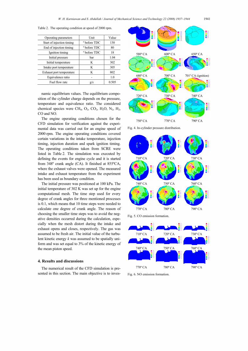
580º CA 600º CA 650º CA
680º CA 700º CA 701º CA (ignition)
720º CA 730º CA 740º CA
750º CA 770º CA 790º CA Fig. 4. In-cylinder pressure distribution.
710º CA 720º CA 730º CA
740º CA 750º CA 760º CA
770º CA 780º CA 790º CA
Fig. 5. CO emission formation.
710º CA 720º CA 730º CA
740º CA 750º CA 760º CA
770º CA 780º CA 790º CA Fig. 6. NO emission formation.

1942 W. H. Kurniawan and S. Abdullah / Journal of Mechanical Science and Technology 22 (2008) 1937~1944
tigate and determine phenomena occurring in the mixture formation and combustion process, such as spray formation during fuel injection, in-cylinder air-fuel mixing pressure distribution and formation of CO and NO.
4.1 In-cylinder pressure distribution
The plots of in-cylinder pressure during the com-bustion process for several crank angles (CA) during compression and power stroke can be depicted in Fig. 9. As predicted, the pressure reached its maximum value at the top part of the cylinder head when the piston reached TDC position during compression stroke, which tend to appear in the side part of engine cylinder, which is near to the spark plug. This shows that the burned fuel causes the flame to propagate to the side part of engine cylinder near the spark plug instead of being distributed uniformly.
4.2 CO emission formation
Fig. 10 presents the level concentration of CO for several crank angles position during and after the combustion. As seen, most of the CO concentration was located next to the cylinder liner wall and inside the piston bowl due to poor combustion, due to oxida-tion process from CO to CO2 in the core gas and to wall quenching.
4.3 NO emission formation
Fig. 6 shows the formation of NO emission inside the cylinder. More NO formed around the spark plug due to higher temperature produced during ignition. Apart from high temperature, the amount of NO gen-erated depends on pressure, air-fuel ratio and combus-tion time within the cylinder. The highest concentra-tion was found around the spark plug, where the highest temperature was observed.
5. Experiment and numerical verification
The experimental setup for the purpose of verifying the CFD simulation was carried out using a SCRE test rig as shown in Fig. 7 (a). During the experiment, all engine boundary conditions were fixed. Pressure sensor (Kistler 6061B) were installed to measure the cylinder pressure occurred during combustion process. To obtain the boundary conditions at the intake and outflow boundaries, thermocouple sensor were in
(a) (b) Fig. 7. Experimental setup: (a) SCRE, (b) gas analyzer.
Fig. 8. The calculated and measured in-cylinder pressure.
Fig. 9. The calculated and measured heat release rate. stalled at nearest possible to the cylinder head so that the temperature of intake and exhaust ports can be determined. Fuel injection supply and ignition timing was controlled by a programmable electronic control unit (ECU). An exhaust gas analyzer to measure the exhaust emissions level was used as shown in Fig. 7 (b) and was located at 3 m from the exhaust port.
The simulated and experimental results were com-pared at 2000 rpm. Fig. 8 illustrates the comparison for in-cylinder pressure curves, while Fig. 9 shows comparison for the heat release rate. Fig. 10 shows the generated P-V diagram with its indicated work is 325 J. Thus, the indicated power resulted from the conversion of indicated work at this speed is 5.42 kW.

W. H. Kurniawan and S. Abdullah / Journal of Mechanical Science and Technology 22 (2008) 1937~1944 1943
Fig. 10. The P-V diagram for indicated power.
Fig. 11. The simulated and measured engine power.
Fig. 12. The calculated and measured CO emission.
As can be seen from Fig. 8, the cylinder pressure
obtained from simulation has the higher value due to the fact that this simplified CFD simulation does not include friction losses due interaction of engine com-ponents. Hence, having a CFD result slightly higher than the experimental data for verification is accept-able. Then, the heat release rate obtained from simu-lation was compared with the experimental data and shows a good agreement as given in Fig. 9. Similarly, the comparison of engine power between the CFD simulation and the experimental data by the dyna-mometer attached to at the SCRE test rig also shows a good agreement.
Fig. 13. The calculated and measured NO emission.
Then, the comparison between the engine power
achieved from the CFD simulation and experimental data were compared and demonstrated in Fig. 11. On the other hand, the assessment of emissions levels can be shown in Figs. 12 and 13 for both CO and NO values, respectively. These simulated emissions value gives the higher values than the measured levels since the data was measured at the distance of 3 m from the exhaust port. 6. Conclusion
In the last, the modeling work presented has proved that the adopted approach of the combustion process via CFD can be implemented to investigate the other phenomena within the engine cylinder, such as the flame propagation, optimization of injection process and even optimization of combustion parameters. For future work, analysis of combustion processes under different engine speeds and operating conditions will be carried out as well as the optimization of critical engine parameters.
Nomenclature-----------------------------------------------------------
A : Surface area of injection boundary (m2) g : Gravitational acceleration (m/s2) k : Thermal conductivity coefficient (W/m·K) k : Turbulent kinetic energy (m2/s2) p : Pressure (N/m2)
S : Source term t : Time (s) T : Temperature (K) u : Velocity vector (m/s) Greek Symbols
ρ : Density (kg/m3)

1944 W. H. Kurniawan and S. Abdullah / Journal of Mechanical Science and Technology 22 (2008) 1937~1944
µ : Dynamic viscosity (Pa·s) cv : Heat capacity at constant volume (J/kg·K) Γ : Diffusivity coefficient σt : Turbulent Schmidt number φ : Mixture fraction ε : Turbulent dissipation rate (m2/s3) Subscripts and Superscripts F : Fuel O : Oxidant P : Product
References
J. Kusaka, T. Okamoto, Y. Daisho, R. Kihara and T. Saito, 'Combustion and exhaust gas emission char-acteristics of a diesel engine dual- fueled with natu-ral gas', JSAE Rev. 21 (2000) 489-496.
S. Shiga, S. Ozone, H. T. C. Machacon, T. Karasawa, H. Nakamura, T. Ueda, N. Jingu, Z. Huang, M. Tsue and M. Kono, 'A study of the combustion and emis-sion characteristics of compressed-natural-gas di-rect-injection stratified combustion using a rapid-compression-machine', Combustion and Flame, 129 (2002) 1-10.
T. Ando, Y. Isobe, D. Sunohara, Y. Daisho and J. Ku-saka, 'Homogeneous charge compression ignition and combustion characteristics of natural gas mix-tures: the visualization and analysis of combustion', JSAE Rev. 24 (2003) 33-40.
D. Zhang and S. H. Frankel, 'A numerical study of natu-ral gas combustion in a lean burn engine, Fuel, 77 (12) (1998) 1339-1347.
D. Yossefi, M. R. Belmont, S. J. Ashcroft, and S. J. Maskell, 'A comparison of the relative effects of fuel composition and ignition energy on the early stages of combustion in a natural gas spark ignition engine using simulation, Proc. IMechE (part D), 214 (2000) 383-393.
A. Agarwal and D. Assanis, Multi-dimensional model-ing of ignition, combustion and nitric oxide forma-tion in direct injection natural gas engines, SAE Pa-per, No. 2000-01-1839 (2000).
Q. P. Zheng, H. M. Zhang and D. F. Zhang, A computa-tional study of combustion in compression ignition natural gas engine with separated chamber, Fuel, 84 (2005) 1515-1523.
S. Abdullah, W. H. Kurniawan and A. Shamsudeen, CFD analysis of the combustion process in a com-pressed natural gas direct injection engine, Proc. 11th Asian Congress of Fluid Mechanics, Kuala Lumpur, Malaysia. (2005) 290-295.
S. H. El-Tahry, k-ε equation for compressible recipro-cating engine flows, J. Energy, 7 (4) (1983) 345-353.
B. F. Magnussen, On the structure of turbulence and a generalised eddy dissipation concept for chemical reaction in turbulent flow, Proc. 19th AIAA Aero-space Meeting, St. Louis, USA. (1981) 1-12.