Compressed Air System Installation Guide - Plant Services
85
COMPRESSORS Compressed Air System Installation Guide Layout Considerations for a Reliable, Energy Efficient, and Safe Compressed Air System By Kaeser’s Compressed Air and Engineering Experts
-
Upload
khangminh22 -
Category
Documents
-
view
9 -
download
0
Transcript of Compressed Air System Installation Guide - Plant Services

COMPRESSORS
Compressed Air System Installation GuideLayout Considerations for a Reliable, Energy Efficient, and Safe Compressed Air System
By Kaeser’s Compressed Air and Engineering Experts

2us.kaeser.com Copyright © 2019 Kaeser Compressors, Inc. All Rights Reserved.Appendices
AdditionalResources
Safety Advisories
Leaks
Preventive Maintenance
Piping
Condensate Management
Air Purity &Treatment
Efficiency Enhancing Equipment
Correct Air Storage
Electrical Supply
Water-cooling
Ventilation
Location
Introduction
More Resources:
Additional resources are in these boxes. Want to hear the latest
Kaeser news? Visit us.kaeser.com/connect
Tip:
Look for these boxes throughout the e-book for additional tips.
About the AuthorsThis e-book was written for you by Kaeser’s team of engineers and compressed air experts.
At Kaeser, we believe that the more you know about operating air systems, the more you’ll get out of them. That’s why we are committed to offering you the most current information you need to wisely install, operate, and maintain your compressed air system.
Our goal is to help you install the most successful compressed air system possible. The tips, guidelines, and warnings included in this e-book are meant to do just that.
While the information included in this e-book is comprehensive, we recognize that each system and application is unique. Applying the principles you read here is an excellent place to start. For the best in system optimization that is tailored to your needs, contact us for additional support.
Throughout the e-book, there are boxes with efficiency tips and additional resources. The links included in those will take you directly to more information that our engineers and compressed air experts have specifically selected to further assist with your compressed air system.
Michael Camber
Marketing Services Manager
Stephen Horne
Blowers / Boosters Product Manager
Neil Mehltretter
Engineering Manager
Werner Rauer
Compressors Product Manager

Introduction
Section I: Location
Section II: Ventilation
Section III: Water-cooling
Section IV: Electrical Supply
Section V: Correct Air Storage
Section VI: Efficiency Enhancing Equipment
Section VII: Air Purity & Treatment
Section VIII: Condensate Management
Section IX: Piping
Section X: Preventive Maintenance
Section XI: Leaks
Section XII: Safety Advisories
Section XIII: Additional Resources
Appendices
Table of Contents
3us.kaeser.com Copyright © 2019 Kaeser Compressors, Inc. All Rights Reserved.
4us.kaeser.com Copyright © 2019 Kaeser Compressors, Inc. All Rights Reserved.Appendices
AdditionalResources
Safety Advisories
Leaks
Preventive Maintenance
Piping
Condensate Management
Air Purity &Treatment
Efficiency Enhancing Equipment
Correct Air Storage
Electrical Supply
Water-cooling
Ventilation
Location
Introduction
Too often, compressed air systems are not given the same level of consideration as other plant equipment when planning a new installation. If you are planning a new facility, you have the opportunity to design an optimal compressed air system installation. Those who are upgrading an existing compressed air system often face many physical restrictions requiring creative solutions. In either case, whether you are modifying a compressed air system or planning a new system, the information contained in this e-book will assist you in identifying the best configuration possible and getting the best possible performance from your compressed air system. Take advantage of the opportunity! You will be rewarded with a more energy efficient system that is easier to maintain and delivers the quality and quantity of air you need.
For the purposes of this e-book, it is assumed that you have identified the three critical parameters for any compressed air system: (1) pressure, (2) capacity, and (3) air quality. These must be determined in order to properly size and select compressors, dryers, filters, piping, etc. If not, this e-book contains some basic example applications and guidelines as to what level of air treatment is needed for each. We strongly recommend that you consult a compressed air specialist to accurately measure these parameters.
Most of this e-book is devoted to planning the layout and installation of your compressed air system. Emphasis is placed on providing you with an efficient, low maintenance system. It will also assist you in establishing compliance with safety and environmental regulations.
This e-book should be used as a supplement to the service manuals provided with your Kaeser compressed air equipment. These contain installation information pertaining to the specific model purchased.
Diagrams in this e-book are presented only as examples. They are not necessarily the best way of installing your particular system. If you need assistance, consult your Kaeser representative for expertise in installing compressed air systems.
Introduction
“ ...the three critical parameters for any compressed air system: (1) pressure, (2) capacity, and (3) air quality...
More Resources:
Contact your local authorized Kaeser Representative for
more information.

{
us.kaeser.com Copyright © 2019 Kaeser Compressors, Inc. All Rights Reserved.
Placement Affects Performance
Location

6us.kaeser.com Copyright © 2019 Kaeser Compressors, Inc. All Rights Reserved.
Introduction
Appendices
AdditionalResources
Safety Advisories
Leaks
Preventive Maintenance
Piping
Condensate Management
Air Purity &Treatment
Efficiency Enhancing Equipment
Correct Air Storage
Electrical Supply
Water-cooling
Ventilation
Location
Receiving your shipment is one of the first considerations in preparing for your new installation. Freight damage happens. It is important that you protect yourself. Be sure to thoroughly inspect your commercial freight before you sign for it. Our freight tips video has everything you need to know to successfully receive any kind of commercial shipment.
In summary:
• Don’t sign until you have inspected
• Check the Tip n’ Tell indicators
• Open the packaging
• Look for signs of replaced packaging
Our rotary screw compressors also ship with instructions attached to the packaging. Carefully read those for additional information.
Location: General Tips

7us.kaeser.com Copyright © 2019 Kaeser Compressors, Inc. All Rights Reserved.
Introduction
Appendices
AdditionalResources
Safety Advisories
Leaks
Preventive Maintenance
Piping
Condensate Management
Air Purity &Treatment
Efficiency Enhancing Equipment
Correct Air Storage
Electrical Supply
Water-cooling
Ventilation
Location
“ Excessive heat, dirt/dust, corrosive chemicals and other conditions may warrant outdoor installation...
Extreme temperatures (hot or cold), moisture, and airborne contaminants affect compressed air equipment’s durability and air quality. For these reasons, we recommend installing compressed air equipment indoors. Because compressor noise is often cited as a reason to place compressors outdoors, Kaeser compressors come standard with full enclosures designed to significantly reduce noise levels.
Sometimes, however, the ambient conditions inside a facility may be worse than outside. Excessive heat, dirt/dust, corrosive chemicals and other conditions may warrant outdoor installation. If outdoor installation is necessary, the compressed air equipment should at least be under a roof.
Location: General Tips

8us.kaeser.com Copyright © 2019 Kaeser Compressors, Inc. All Rights Reserved.
Introduction
Appendices
AdditionalResources
Safety Advisories
Leaks
Preventive Maintenance
Piping
Condensate Management
Air Purity &Treatment
Efficiency Enhancing Equipment
Correct Air Storage
Electrical Supply
Water-cooling
Ventilation
Location
No special foundation or anchoring is necessary for rotary screw compressors. The compressor should be placed on a level surface able to withstand the combined load of the compressor and the equipment used to move it into place.
Location: Floor

9us.kaeser.com Copyright © 2019 Kaeser Compressors, Inc. All Rights Reserved.
Introduction
Appendices
AdditionalResources
Safety Advisories
Leaks
Preventive Maintenance
Piping
Condensate Management
Air Purity &Treatment
Efficiency Enhancing Equipment
Correct Air Storage
Electrical Supply
Water-cooling
Ventilation
Location
The entrance to the compressor room must be large enough to accommodate both the compressed air equip-ment and the equipment used to move it into place (such as a forklift, crane, or pallet truck). The space designated for the compressed air equipment must provide enough clearance around it to:
• Open maintenance doors and access panels
• Remove and replace components
• Install piping and air treatment equipment
• Provide adequate ventilation
Kaeser has designed its compressors so that internal components are easily accessible. Do not defeat this feature by blocking maintenance doors. Your service manual contains dimensional drawings for your specific model.
Location: Access
More Resources:
Need a service manual? Contact your local Kaeser
representative.

10us.kaeser.com Copyright © 2019 Kaeser Compressors, Inc. All Rights Reserved.
Introduction
AdditionalResources
Safety Advisories
Leaks
Preventive Maintenance
Piping
Condensate Management
Air Purity &Treatment
Efficiency Enhancing Equipment
Correct Air Storage
Electrical Supply
Water-cooling
Ventilation
Location
Appendices
Temperature: Be mindful of how the system temperature impacts equipment operation and make sure temperatures remain within the manufacturer’s stated temperature ranges. For air treatment components, the dryer correction factors must be applied.
Low temperatures may impede the proper flow of some types of lubricant and promote undesirable moisture condensation in control lines and other components. For lower ambient temperature applications, Kaeser offers options to protect the compressor including cabinet heaters and electric heat trace tape.
High ambient temperatures, on the other hand, often result in reduced lubricant life. They may also result in excessively high approach temperatures, which would hinder the cooling and condensation efficiency in the aftercooler and subsequent air treatment equipment. (See Ventilation Section for more information.)
Location: Environmental Considerations

11us.kaeser.com Copyright © 2019 Kaeser Compressors, Inc. All Rights Reserved.
Introduction
Appendices
AdditionalResources
Safety Advisories
Leaks
Preventive Maintenance
Piping
Condensate Management
Air Purity &Treatment
Efficiency Enhancing Equipment
Correct Air Storage
Electrical Supply
Water-cooling
Ventilation
LocationLocation: Environmental ConsiderationsAmbient Particulate: The Kaeser cabinet and pre-filter protect the compressor interior from most dirt and dust. In high dust areas it will be necessary to clean and replace the filters more often. In high dust applications, such as flour, cement, or talc production, an additional high dust filtration option may be needed.
Moisture: If possible, avoid exposing the compressor to excessive moisture (from humidity, rain, steam vents, dryer vents, etc.) in the ambient air. Excessive moisture can lead to electrical problems in the motor or with any electronics such as the main compressor controller, promotes rust development on the cabinet and interior components, and hinders lubrication. Kaeser offers a number of options to allow compressor operation in wet/moist conditions, including motor winding heaters, and rain hoods.
Corrosives: Isolate the compressor from corrosive agents such as salt spray, ammonia, chlorine, and other chemicals. These may degrade the protective finishes on the cabinet, attack and erode internal components, and contaminate lubricants and filters.

12us.kaeser.com Copyright © 2019 Kaeser Compressors, Inc. All Rights Reserved.
Introduction
Appendices
AdditionalResources
Safety Advisories
Leaks
Preventive Maintenance
Piping
Condensate Management
Air Purity &Treatment
Efficiency Enhancing Equipment
Correct Air Storage
Electrical Supply
Water-cooling
Ventilation
Location
Rain hoods: As stated, a compressor should normally be installed indoors. If it must be installed outside, it should have overhead protection from rain and snow. If no shelter is provided or if wind driven rain or snow can reach the compressor, rain hoods must be added to both air inlet and exhaust ends of the compressor cabinet exterior. These are available from Kaeser factory installed. Rain hoods may be insufficient in the case of high wind and rain, therefore a shed may be better suited than a covered overhang.
Motor winding heaters: In very wet or humid environments, a motor winding heater will prevent moisture from collecting and condensing within the compressor’s motor windings when the motor is off. Motor winding heaters shut off during operation. They are available from Kaeser factory installed.
Location: Optional Equipment
Compressor here shown with optional rain hoods and cover for compressor controller that protect from the elements and water ingress.

13us.kaeser.com Copyright © 2019 Kaeser Compressors, Inc. All Rights Reserved.
Introduction
Appendices
AdditionalResources
Safety Advisories
Leaks
Preventive Maintenance
Piping
Condensate Management
Air Purity &Treatment
Efficiency Enhancing Equipment
Correct Air Storage
Electrical Supply
Water-cooling
Ventilation
Location
Tip:
Although Kaeser can assist in sizing and designing duct-
work, we recommend that you contact your local heating and air conditioning contractor for
installation.
Cabinet heaters: If the ambient temperature of inlet air ever drops below 40° F (but is still above 25° F), a cabinet heater must be installed. Cabinet heaters are designed to maintain the cabinet temperature at 40° F. This ensures proper oil flow during start-up and inhibits moisture collecting inside the cabinet. It is thermostatically controlled to shut off once the minimum operating temperature within the cabinet is reached. They are available from Kaeser factory installed or as a retrofit kit.
Exhaust air re-circulation systems: If your compressor is located such that it will be exposed to temperatures between 5° and 25 °F, Kaeser suggests installing an exhaust re-circulation system. These are designed to duct compressor exhaust air back to the air inlet in order to maintain the minimum operating temperature and prevent moisture freezing in the compressor components. Since compressors produce approximately 2550 Btu/hour per horsepower, the compressor is an excellent source of heating air.
Keep in mind that, at cold temperatures, aftercoolers and control lines may freeze even when the compressor is running and the airend reaches the proper operating temperature. A combination of cabinet heater, electric heat-trace tape, and duct re-circulation may be necessary.
High ambient temperature option: Compressor components can be special ordered to operate in temperatures up to 126 °F. These are not available as a retrofit.
Location: Optional Equipment

14us.kaeser.com Copyright © 2019 Kaeser Compressors, Inc. All Rights Reserved.
Introduction
Appendices
AdditionalResources
Safety Advisories
Leaks
Preventive Maintenance
Piping
Condensate Management
Air Purity &Treatment
Efficiency Enhancing Equipment
Correct Air Storage
Electrical Supply
Water-cooling
Ventilation
Location
More Resources:
Click here to see a flipbook with more examples of custom built
enclosures.
As an alternative, it’s also possible to install the com-pressed air system in a custom built enclosure. This can save time and money on installation since no special building permits are needed.
Location: Other Options

{
us.kaeser.com Copyright © 2019 Kaeser Compressors, Inc. All Rights Reserved.
Options to Ensure Proper Cooling and Equipment Longevity
Ventilation

16us.kaeser.com Copyright © 2019 Kaeser Compressors, Inc. All Rights Reserved.
Introduction
Appendices
AdditionalResources
Safety Advisories
Leaks
Preventive Maintenance
Piping
Condensate Management
Air Purity &Treatment
Efficiency Enhancing Equipment
Correct Air Storage
Electrical Supply
Water-cooling
Location
“
Ventilation
Compressors produce approximately 2550 Btu per hp...
Tip:
Detailed information about the proper ventilation for your compressor is in the Technical Specifications and Installation
sections of the Service Manual.
Air compressors, refrigerated dryers, and heated desic-cant dryers produce large volumes of heat. Compressors produce approximately 2550 Btu per hp. If not removed from the compressor room, the ambient temperature will increase, reducing system efficiency and operator comfort. There are various ways to provide ventilation. Your choice should consider the following factors:
• Conditions in the compressor room • Conditions outside• Whether you intend to recover heat from the
compressor
This figure shows how ducting can be installed to recover the heat from the compressor to warm the room during the winter and vent the warm air outside during the summer months, for added energy savings.
The fresh air inlet needs to be sized appropriately for the equipment to avoid creating negative pressure in the room. Thermostatically controlled louvers should be installed at the source of inlet air and where exhaust is discharged to protect units from extreme cold when not running or running under low load.
Ventilation
More Resources:
Click here for more information on how to integrate heat
recovery into your compressed air installation.
The diagrams on the following pages provide some basic hints for proper ventilation.

17us.kaeser.com Copyright © 2019 Kaeser Compressors, Inc. All Rights Reserved.
Introduction
Appendices
AdditionalResources
Safety Advisories
Leaks
Preventive Maintenance
Piping
Condensate Management
Air Purity &Treatment
Efficiency Enhancing Equipment
Correct Air Storage
Electrical Supply
Water-cooling
Location
VentilationFor small compressors up to 15 hp, louvered inlets and outlets are often sufficient, as shown here. An exhaust fan is also recommended. Depending on the location, thermostatically controlled inlet louvers are recommended.
Ventilation

18us.kaeser.com Copyright © 2019 Kaeser Compressors, Inc. All Rights Reserved.
Introduction
Appendices
AdditionalResources
Safety Advisories
Leaks
Preventive Maintenance
Piping
Condensate Management
Air Purity &Treatment
Efficiency Enhancing Equipment
Correct Air Storage
Electrical Supply
Water-cooling
Location
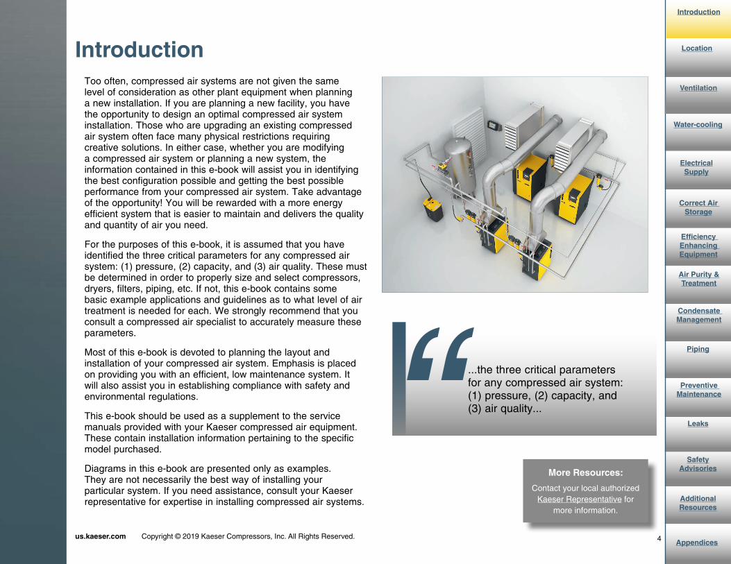
VentilationForced ventilation is recommended for larger compressors above 20 hp as shown here. Depending on the location, thermostatically controlled inlet louvers are also recommended.
Ventilation
Thermostatically controlled recirculation
louvers
19us.kaeser.com Copyright © 2019 Kaeser Compressors, Inc. All Rights Reserved.
Introduction
Appendices
AdditionalResources
Safety Advisories
Leaks
Preventive Maintenance
Piping
Condensate Management
Air Purity &Treatment
Efficiency Enhancing Equipment
Correct Air Storage
Electrical Supply
Location
Ventilation
Water-cooling
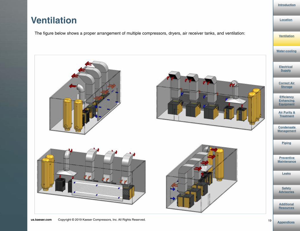
The figure below shows a proper arrangement of multiple compressors, dryers, air receiver tanks, and ventilation:
Ventilation

20us.kaeser.com Copyright © 2019 Kaeser Compressors, Inc. All Rights Reserved.
Introduction
Appendices
AdditionalResources
Safety Advisories
Leaks
Preventive Maintenance
Piping
Condensate Management
Air Purity &Treatment
Efficiency Enhancing Equipment
Correct Air Storage
Electrical Supply
Location
Ventilation
Water-cooling
VentilationDo not place equipment so that exhaust from a compressor blows onto an air receiver, dryer, or into the air inlet of another compressor as shown here:

{
us.kaeser.com Copyright © 2019 Kaeser Compressors, Inc. All Rights Reserved.
Important Additional Considerations
Water-cooling

22us.kaeser.com Copyright © 2019 Kaeser Compressors, Inc. All Rights Reserved.
Introduction
Appendices
AdditionalResources
Safety Advisories
Leaks
Preventive Maintenance
Piping
Condensate Management
Air Purity &Treatment
Efficiency Enhancing Equipment
Correct Air Storage
Electrical Supply
Ventilation
Location
“
Water-cooling
Customers who plan to install water-cooled compressors will receive water data forms...
Tip:
Contact your local Kaeser representative for assistance with water-cooled systems.
Through air-cooled compressors are the norm, water-cooling is an option (40 hp and above for Kaeser). Customers who plan to install water-cooled compressors will receive water data forms to complete, and in addition to an adequate supply of suitable water and drainage, special pumps and plumbing, as well as filtration, water treatment, and chilling equipment may be required depending on the cooling water source. The data collected on this form provides Kaeser’s application engineers with detailed information about the source and characteristics of the water to be used, and enables them to select the proper cooling water piping and heat exchangers for each application.
However, water-cooling introduces several additional considerations, which can have significant impact on system design, installation, and operating costs. For example, the costs of treating and chilling the cooling water.
Water-cooling

23us.kaeser.com Copyright © 2019 Kaeser Compressors, Inc. All Rights Reserved.
Introduction
Appendices
AdditionalResources
Safety Advisories
Leaks
Preventive Maintenance
Piping
Condensate Management
Air Purity &Treatment
Efficiency Enhancing Equipment
Correct Air Storage
Electrical Supply
Ventilation
Location
“
Water-cooling
100% of the electrical energy used by anindustrial air compressor is converted into heat. 96% of this heat can be recovered...
More Resources:
Click here to download a complimentary whitepaper for
more information on the energy savings potential of heat
recovery
Water-cooled applications also give extra opportunities to incorporate heat recovery for additional energy savings. 100% of the electrical energy used by an industrial air compressor is converted into heat. 96% of this heat can be recovered (the balance remains in the compressed air or radiated from the compressor into the immediate surroundings).
For water-cooled compressors, discharged cooling water is connected directly to a continuous process heating application for year-round energy savings—such as a heating boiler’s return circuit. Other applications include heating process fluids, food and beverage products, or even heating the water for showers and bathrooms.
Water-cooling: Heat Recovery

24us.kaeser.com Copyright © 2019 Kaeser Compressors, Inc. All Rights Reserved.
Introduction
Appendices
AdditionalResources
Safety Advisories
Leaks
Preventive Maintenance
Piping
Condensate Management
Air Purity &Treatment
Efficiency Enhancing Equipment
Correct Air Storage
Electrical Supply
Ventilation
Location
Water-cooling
The following shows a real life example of the energy saving potential of integrating heat recovery into your plant operations.
Keep in mind that your energy savings will depend on the type of energy source you have (electricity, heating oil, propane, natural gas, coal), as well as the actual heat that is available for recovery from the compressors.
Water-cooling: Heat Recovery Example

{
us.kaeser.com Copyright © 2019 Kaeser Compressors, Inc. All Rights Reserved.
Important Warnings to Follow
Electrical Supply

26us.kaeser.com Copyright © 2019 Kaeser Compressors, Inc. All Rights Reserved.
Introduction
Appendices
AdditionalResources
Safety Advisories
Leaks
Preventive Maintenance
Piping
Condensate Management
Air Purity &Treatment
Efficiency Enhancing Equipment
Correct Air Storage
Water-cooling
Ventilation
Location
Electrical Supply
Before installing the compressor, check to ensure that your electrical service voltage matches the voltage on the compres-sor nameplate (located inside the electrical cabinet). Whether your compressor is a dual or tri-voltage model, ensure it is internally wired for the proper voltage.
Electrical Supply
!Actual operating voltage must be within +/- 10% of compressor nameplate voltage. Damage or failures due directly or indirectly to insufficient or excessive voltage may not be covered under warranty. Consequently, Kaeser does not recommend operating a 230-volt system on a 208-volt circuit, for example.
Kaeser recommends that each compressor have its own dedicated electrical circuit and disconnect panel. This makes it possible to lock out and tag out an individual piece of equipment without having to shut down other equipment that may be on the same panel. Electrically operated air treatment equipment should be powered through a separate circuit.
Electrical planning should include wiring for a master controller (multiple unit control device) if it is to be installed.
The compressor should be properly grounded. Install an appropriately sized fuse or circuit breaker between the compressor and main electric service.

27us.kaeser.com Copyright © 2019 Kaeser Compressors, Inc. All Rights Reserved.
Introduction
Appendices
AdditionalResources
Safety Advisories
Leaks
Preventive Maintenance
Piping
Condensate Management
Air Purity &Treatment
Efficiency Enhancing Equipment
Correct Air Storage
Water-cooling
Ventilation
Location
ElectricalSupply
For variable speed drive units, make sure that the power supply transformer has a symmetrical, three-phase supply. In a symmetrical three-phase supply, the phase angles and voltage are all the same.
Kaeser’s Sigma Frequency Control (SFC) units require a symmetrical power supply transform with a wye configuration output. The circled configurations indicate the two acceptable options for SFC units.
Electrical Supply
28us.kaeser.com Copyright © 2019 Kaeser Compressors, Inc. All Rights Reserved.
Introduction
Appendices
AdditionalResources
Safety Advisories
Leaks
Preventive Maintenance
Piping
Condensate Management
Air Purity &Treatment
Efficiency Enhancing Equipment
Correct Air Storage
Water-cooling
Ventilation
Location
ElectricalSupply
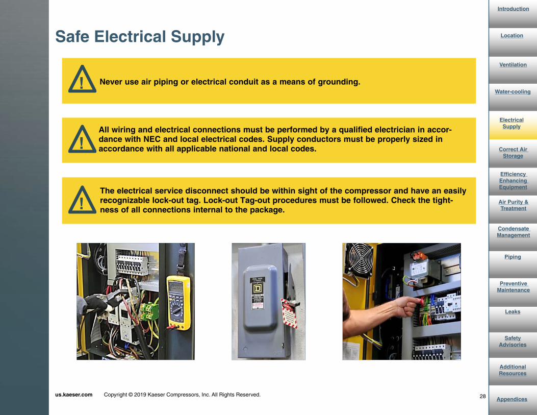
Safe Electrical Supply
! Never use air piping or electrical conduit as a means of grounding.
!All wiring and electrical connections must be performed by a qualified electrician in accor-dance with NEC and local electrical codes. Supply conductors must be properly sized in accordance with all applicable national and local codes.
!The electrical service disconnect should be within sight of the compressor and have an easily recognizable lock-out tag. Lock-out Tag-out procedures must be followed. Check the tight-ness of all connections internal to the package.
{
us.kaeser.com Copyright © 2019 Kaeser Compressors, Inc. All Rights Reserved.
Utilizing Wet and Dry Tanks
Correct Air Storage

30us.kaeser.com Copyright © 2019 Kaeser Compressors, Inc. All Rights Reserved.
Introduction
Appendices
AdditionalResources
Safety Advisories
Leaks
Preventive Maintenance
Piping
Condensate Management
Air Purity &Treatment
Efficiency Enhancing Equipment
Electrical Supply
Water-cooling
Ventilation
Location
Correct Air Storage
To optimize performance, Kaeser suggests installing two receivers. A “wet tank” provides a steady source of controlled air, additional air-cooling, and moisture separation. A “dry tank” stores clean dry air needed for demand surges.
The “wet” tank should be installed after the compressor and will remove much of the moisture from your compressed air. By providing a stable volume of air, this receiver will also prevent excessive compressor cycling. This receiver also provides some protection for your downstream components from any oil slugs discharged from a malfunctioning compressor. The wet tank should be sized accordingly: one to three gallons per compressor(s) cfm at full load.
Correct Air Storage
Wet Tank
Dry Tank
31us.kaeser.com Copyright © 2019 Kaeser Compressors, Inc. All Rights Reserved.
Introduction
Appendices
AdditionalResources
Safety Advisories
Leaks
Preventive Maintenance
Piping
Condensate Management
Air Purity &Treatment
Efficiency Enhancing Equipment
Electrical Supply
Water-cooling
Ventilation
Location
“Correct Air
Storage
More Resources:
Use our calculator for help estimating with sizing your air
receiver.
Tip:
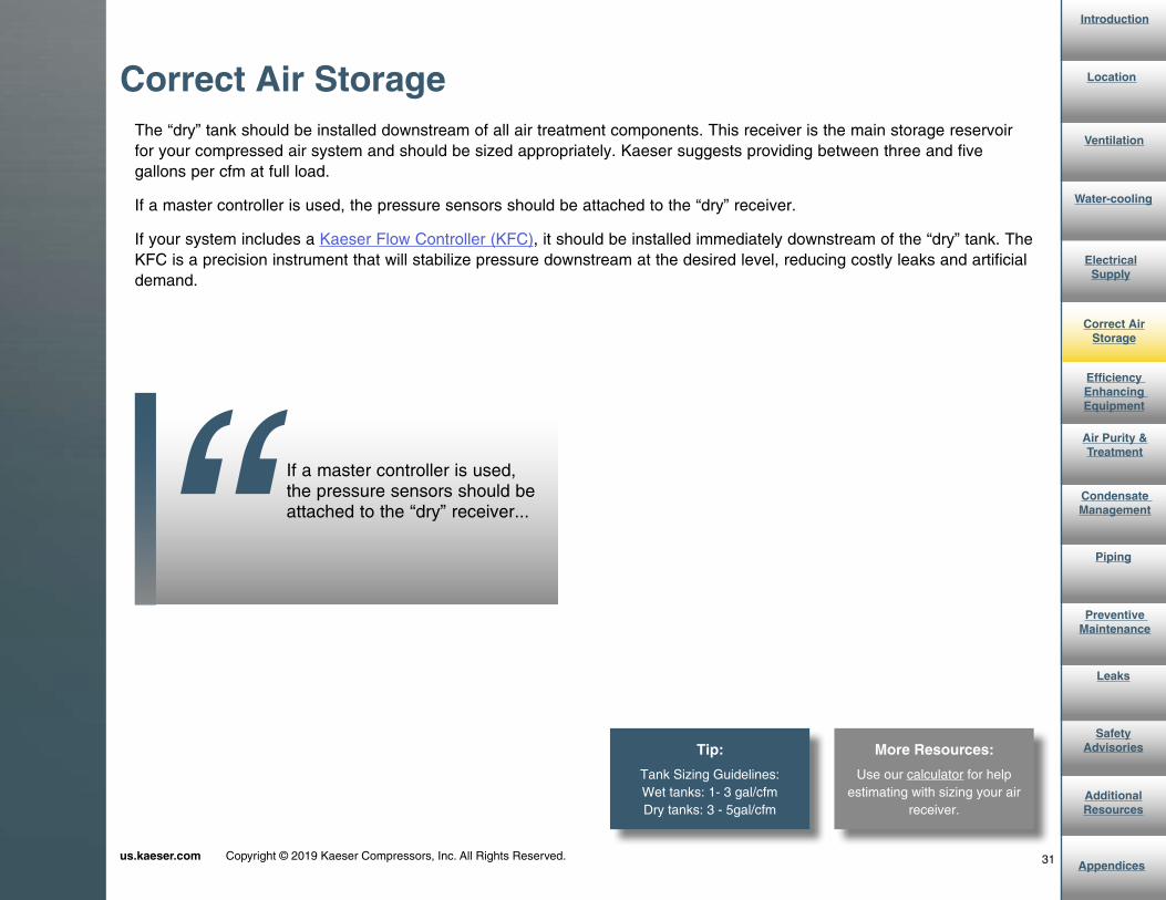
Tank Sizing Guidelines:Wet tanks: 1- 3 gal/cfmDry tanks: 3 - 5gal/cfm
If a master controller is used, the pressure sensors should be attached to the “dry” receiver...
The “dry” tank should be installed downstream of all air treatment components. This receiver is the main storage reservoir for your compressed air system and should be sized appropriately. Kaeser suggests providing between three and five gallons per cfm at full load.
If a master controller is used, the pressure sensors should be attached to the “dry” receiver.
If your system includes a Kaeser Flow Controller (KFC), it should be installed immediately downstream of the “dry” tank. The KFC is a precision instrument that will stabilize pressure downstream at the desired level, reducing costly leaks and artificial demand.
Correct Air Storage

32us.kaeser.com Copyright © 2019 Kaeser Compressors, Inc. All Rights Reserved.
Introduction
Appendices
AdditionalResources
Safety Advisories
Leaks
Preventive Maintenance
Piping
Condensate Management
Air Purity &Treatment
Efficiency Enhancing Equipment
Electrical Supply
Water-cooling
Ventilation
Location
Correct Air Storage
More Resources:
See our blog post on Receiver Tanks for Small Compressed
Air Systems for more tips.
Use the following points as guidelines for installing “wet” or “dry” receiver tanks. Each receiver tank should be:
• Piped in low and piped out high
• ASME approved pressure vessels marked with the maximum working pressure rating. A receiver’s maximum pressure rating must meet or exceed the maximum system pressure.
• Fitted with a good quality pressure gauge (Kaeser recommends large liquid filled gauges for accuracy).
• Fitted with a safety relief valve sized to handle the system’s pressure and total flow with a relieving pressure lower than the rated pressure of the tank.
• Fitted with a dependable drain trap at the lowest point.
• Fitted with an isolation valve at both the inlet and outlet ports.
• Installed in a cool area. Do not place receivers in path of compressor or dryer exhaust flow. Doing so will re-heat the compressed air, reduce moisture separation, and possibly reduce the effectiveness of dryers and filters.
Some applications with heavy intermittent demands should have their own tanks as close to the point of use as possible.
Correct Air Storage

{
us.kaeser.com Copyright © 2019 Kaeser Compressors, Inc. All Rights Reserved.
Optimizing Your System
Efficiency Enhancing Equipment

34us.kaeser.com Copyright © 2019 Kaeser Compressors, Inc. All Rights Reserved.
Introduction
Appendices
AdditionalResources
Safety Advisories
Leaks
Preventive Maintenance
Piping
Condensate Management
Air Purity &Treatment
Correct Air Storage
Water-cooling
Ventilation
Location
Efficiency Enhancing Equipment
Electrical Supply
Tip:
Place the air pressure sensor for the master controller as far down stream as possible to accurately
supply the demand pressure. The “dry” receiver is an excellent choice.
Master Controllers control multiple compressors more efficiently while maintaining a steady supply of compressed air. They can even rotate like-sized machines to equalize service hours.
A master controller’s computing capacity enables it to rapidly recognize changes in system air pressure and react to prevent pressure drop. Unlike cascading pressure control methods used in many older sequencers, advanced master controllers are adaptive and learn the system over time to ensure a reliable supply of air flow at all times.
Efficiency Enhancing Equipment: Master Controllers

35us.kaeser.com Copyright © 2019 Kaeser Compressors, Inc. All Rights Reserved.
Introduction
Appendices
AdditionalResources
Safety Advisories
Leaks
Preventive Maintenance
Piping
Condensate Management
Air Purity &Treatment
Correct Air Storage
Electrical Supply
Water-cooling
Ventilation
Location
Efficiency Enhancing Equipment
More Resources:
Download our whitepaper “Using Master Controls to Improve the Performance
and Efficiency of Industrial AIr Compressors” here.
Benefits of Master Controllers:
Save Energy:
• Run compressors less
• Run compressors on lower pressure
• Reduce air lost to leaks
• Lower artificial demand
Reduced Maintenance Costs:
• Less cycling and switching = longer valve life
• Fewer motor starts = longer motor life
• Balanced hours and fewer PM visits
Improve Operations with More Stable Pressure:
• Improve production equipment performance
• Less downtime due to pressure alarms
• Less scrap and product quality problems
• Learn system operation and select most efficient compressors
Efficiency Enhancing Equipment: Master Controllers

36us.kaeser.com Copyright © 2019 Kaeser Compressors, Inc. All Rights Reserved.
Introduction
Appendices
AdditionalResources
Safety Advisories
Leaks
Preventive Maintenance
Piping
Condensate Management
Air Purity &Treatment
Correct Air Storage
Electrical Supply
Water-cooling
Ventilation
Location
“ Efficiency Enhancing Equipment
Control gaps are flaws in the system design that occur when the control range of the variable speed compressor is not considered...
More Resources:
Download our whitepaper “Applying Variable Speed Compressors in Multiple
Compressor Applications” for more information on avoiding
control gap.
Master controllers can also be effective when used in con-junction with a variable speed drive compressor and multi-ple smaller fixed speed compressors. However, care must be taken in sizing the system to avoid control gap, which causes pressure fluctuations and energy inefficiencies.
Control gaps are flaws in the system design that occur when the control range of the variable speed compressor is not considered. The majority of the time, this happens because a variable speed drive compressor is selected that is the same size or smaller than the fixed speed machines in the system.
This graph shows a system designed to avoid control gap. It can provide a steady operating pressure throughout the flow range of the system since it is properly sized and controlled by a master controller, like Kaeser’s Sigma Air Manager (SAM) 4.0.
Efficiency Enhancing Equipment: Master Controllers

37us.kaeser.com Copyright © 2019 Kaeser Compressors, Inc. All Rights Reserved.
Introduction
Appendices
AdditionalResources
Safety Advisories
Leaks
Preventive Maintenance
Piping
Condensate Management
Air Purity &Treatment
Correct Air Storage
Electrical Supply
Water-cooling
Ventilation
Location
Efficiency Enhancing Equipment
Kaeser’s Sigma Air Manager (SAM) 4.0 offers complete compressed air system management for industrial plants by tying compressors, blowers, or vacuum units together into a secure Sigma Network. SAM 4.0’s powerful 3Dadvanced Control improves pressure stability and system reliability, while the built-in Kaeser Connect web server provides remote monitoring and ongoing energy audit information according to ISO 50001 energy management.
Contact us for help customizing a solution for your system.
Efficiency Enhancing Equipment: Master Controllers
More Resources:
See our video on our SAM 4.0 master controller for more information.

38us.kaeser.com Copyright © 2019 Kaeser Compressors, Inc. All Rights Reserved.
Introduction
Appendices
AdditionalResources
Safety Advisories
Leaks
Preventive Maintenance
Piping
Condensate Management
Air Purity &Treatment
Correct Air Storage
Electrical Supply
Water-cooling
Ventilation
Location
Energy Enhancing Equipment
Maintaining the demand side pressure at its optimum level also eliminates artificial demands on the supply side...“
The Kaeser Flow Controller (KFC) reduces or eliminates energy waste in some applications. Energy consumption is managed by the KFC by its capacity to prevent the air system’s demand side pressure from rising above the minimum pressure for proper plant (demand side) function. By maintaining very tight control (±0.25 psi is not uncommon) of the demand side pressure, the loss of air through leaks and unregulated uses can be greatly reduced. Maintaining the demand side pressure at its optimum level also eliminates artificial demand on the supply side (compressors and air treatment) of the air system. They are effective in multi-unit installations that also include air storage and master controllers.
The KFC should be installed in the air distribution system at a point that maximizes the volume of the system upstream of the KFC. Ideally this location would be immediately upstream of the first tee in the air distribution piping. In all cases, the KFC must be installed downstream of the air treatment (filtration, drying, and storage receivers). The KCF must have dry side storage for proper operation.
KFCs work in conjunction with air storage and master controllers. When system pressure drops, air storage can be utilized to meet the demand and bring the pressure back up. A master controller is necessary to make sure the most efficient combination of units is selected at any given time to meet the demand. It can also monitor the number of motor starts and prevent units from turning on and off too frequently.
Multiple KFCs can be used to control air pressure in areas of a plant that have differing operating pressure requirements. This allows for “fine tuning” your energy conservation initiative and maximizing your operating cost savings.
Energy Enhancing Equipment: Kaeser Flow Controller

{
us.kaeser.com Copyright © 2019 Kaeser Compressors, Inc. All Rights Reserved.
Ensuring Proper Air Quality
Air Purity and Treatment

40us.kaeser.com Copyright © 2019 Kaeser Compressors, Inc. All Rights Reserved.
Introduction
Appendices
AdditionalResources
Safety Advisories
Leaks
Preventive Maintenance
Piping
Condensate Management
Efficiency Enhancing Equipment
Correct Air Storage
Electrical Supply
Water-cooling
Ventilation
Location
Air Purity & Treatment
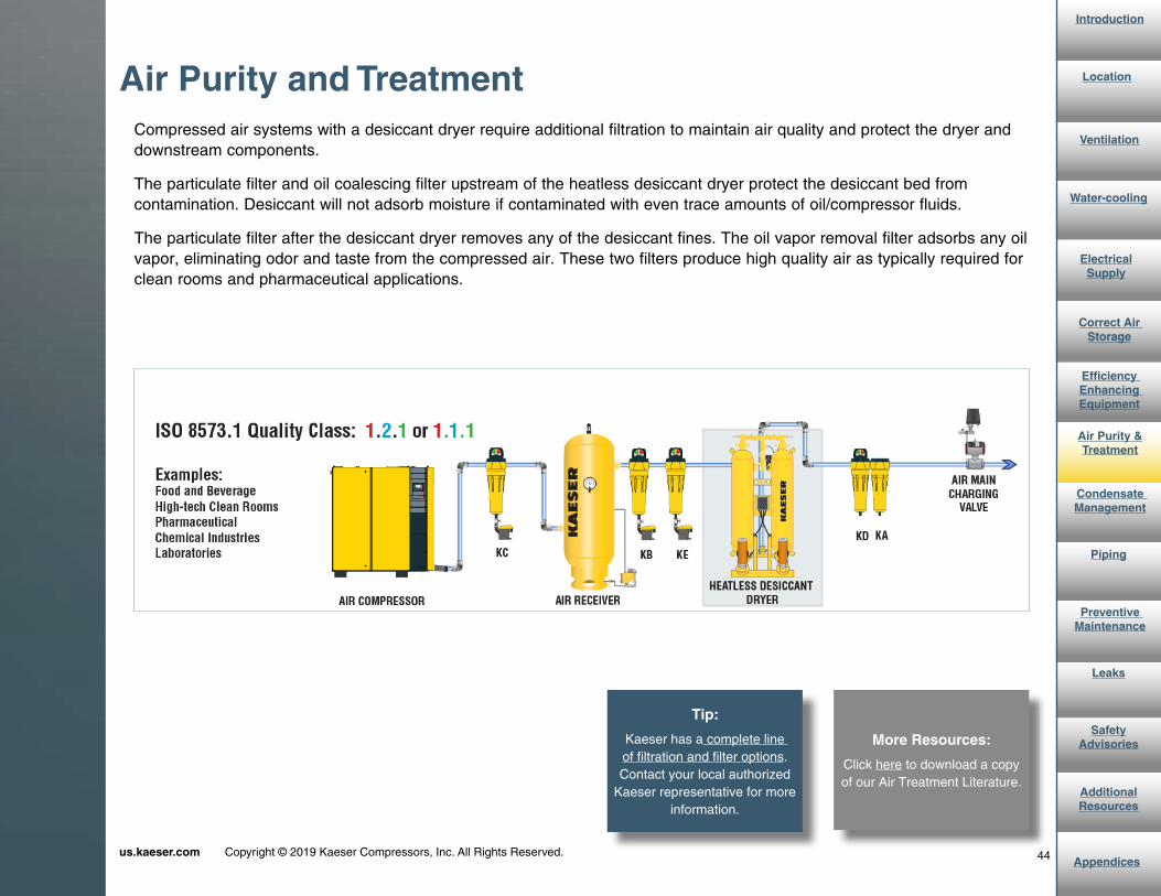
The proper combination and order of filters, receivers, and dryers will ensure efficient elimination of moisture, oil, and partic-ulates. Filters and dryers are available in various sizes and should be selected based on air flow ratings. Keep in mind that the stated performance of air treatment equipment is based on specific constant conditions and may vary with temperature, pressure, and relative humidity. ISO 8573.1:2010 was developed by ISO (International Organizational for Standardization) as a reference to help facility engineers specify compressed air quality for solid particulates, humidity, and oil. A typical pharmaceutical plant, for example, might have a compressed air specification of ISO Quality Class 1.2.1 as shown outlined in the specifications below.
Air Purity and Treatment
At reference conditions: 68°F, 14.5 psia, 0% relative humidity

41us.kaeser.com Copyright © 2019 Kaeser Compressors, Inc. All Rights Reserved.
Introduction
Appendices
AdditionalResources
Safety Advisories
Leaks
Preventive Maintenance
Piping
Condensate Management
Efficiency Enhancing Equipment
Correct Air Storage
Electrical Supply
Water-cooling
Ventilation
Location
Air Purity & Treatment
The next few pages include examples of system layouts and various ISO Air Quality Classes.
The layout below would provide typical low grade air and could be used where the possible presence of some liquid water would be problematic. Note that an aftercooler is necessary with a piston compressor. Kaeser rotary screw compressors include built-in aftercoolers.
Aftercoolers provide an economical way to remove about 70% of the water vapor in compressed air and can be air-cooled or water-cooled. An aftercooler, however, is not a replacement for a compressed air dryer. The air exiting an aftercooler will typically always be saturated and additional condensation in the outlet air can occur.
A liquid separator is included for its ability to capture and remove heavy liquid loads. The liquid separator should be placed as close as possible to the aftercooler outlet and always upstream of all other air treatment components, and must include a no-loss air drain rated for the amount of condensate from the compressor.
Air Purity and Treatment

42us.kaeser.com Copyright © 2019 Kaeser Compressors, Inc. All Rights Reserved.
Introduction
Appendices
AdditionalResources
Safety Advisories
Leaks
Preventive Maintenance
Piping
Condensate Management
Efficiency Enhancing Equipment
Correct Air Storage
Electrical Supply
Water-cooling
Ventilation
Location
Air Purity & Treatment
The layout below would meet the compressed air quality needs typical for packaging, paint spraying, or most compressed air systems. As with the previous layout, the liquid separator is placed after the compressor (which has a built-in aftercooler) for liquid removal.
The oil coalescing filter after the refrigerated dryer removes oil aerosols and remaining liquids and well as fine particles.
The Air Main Charging Valve protects the air treatment components while the air network is pressurized and in the case of low pressure in the facility where air quality is paramount.
Note: Receivers installed before dryers should include an additional filter if the wet receiver is not galvanized or internally coated.
Air Purity and Treatment

43us.kaeser.com Copyright © 2019 Kaeser Compressors, Inc. All Rights Reserved.
Introduction
Appendices
AdditionalResources
Safety Advisories
Leaks
Preventive Maintenance
Piping
Condensate Management
Efficiency Enhancing Equipment
Correct Air Storage
Electrical Supply
Water-cooling
Ventilation
Location
Air Purity & Treatment
For applications that are not overly sensitive to oil, but still require protection from particulates, a particulate filter can be installed downstream of the refrigerated dryer.
These general purpose filters are designed to remove particles and water and most oil aerosols.
Note: Receivers installed before dryers should include an additional filter if the wet receiver is not galvanized or internally coated.
Air Purity and Treatment
44us.kaeser.com Copyright © 2019 Kaeser Compressors, Inc. All Rights Reserved.
Introduction
Appendices
AdditionalResources
Safety Advisories
Leaks
Preventive Maintenance
Piping
Condensate Management
Efficiency Enhancing Equipment
Correct Air Storage
Electrical Supply
Water-cooling
Ventilation
Location
Air Purity & Treatment
Compressed air systems with a desiccant dryer require additional filtration to maintain air quality and protect the dryer and downstream components.
The particulate filter and oil coalescing filter upstream of the heatless desiccant dryer protect the desiccant bed from contamination. Desiccant will not adsorb moisture if contaminated with even trace amounts of oil/compressor fluids.
The particulate filter after the desiccant dryer removes any of the desiccant fines. The oil vapor removal filter adsorbs any oil vapor, eliminating odor and taste from the compressed air. These two filters produce high quality air as typically required for clean rooms and pharmaceutical applications.
Air Purity and Treatment
More Resources:
Click here to download a copy of our Air Treatment Literature.
Tip:
Kaeser has a complete line of filtration and filter options. Contact your local authorized
Kaeser representative for more information.

45us.kaeser.com Copyright © 2019 Kaeser Compressors, Inc. All Rights Reserved.
Introduction
Appendices
AdditionalResources
Safety Advisories
Leaks
Preventive Maintenance
Piping
Condensate Management
Efficiency Enhancing Equipment
Correct Air Storage
Electrical Supply
Water-cooling
Ventilation
Location
Air Purity & Treatment
The Kaeser Breathing System (KBS) is a complete air treatment system designed to produce OSHA Grade D breathing air. It includes particulate and high efficiency oil coalescing pre-filtration for its heatless desiccant dryer. The dryer provides protection for the catalyst material which removes carbon monoxide. Particulate and oil vapor adsorbing afterfilters complete the package.
Ideally, a KBS purifier should be installed at a location where the entering compressed air will have cooled to near normal ambient air temperature. The purifier should be selected for the required volume of breathing air and the air compressor sized for the purifier’s inlet air require-ment. Due to its high operating costs, it should be sized and used only for breathing air.
Air Purity and Treatment: Breathing Purifiers
!Only air treated by a designated breathing air system, or competitive product having carbon monoxide removing capability (filtration alone IS NOT adequate) should be considered safe for breathing.

46us.kaeser.com Copyright © 2019 Kaeser Compressors, Inc. All Rights Reserved.
Introduction
Appendices
AdditionalResources
Safety Advisories
Leaks
Preventive Maintenance
Piping
Condensate Management
Efficiency Enhancing Equipment
Correct Air Storage
Electrical Supply
Water-cooling
Ventilation
Location
Air Purity & Treatment
Be sure to apply the appropriate correction factors to correct the rated capacity for the actual operating conditions...“
Min. Ambient °F Max. Ambient °F Max. Inlet ºF
Refrigerated Dryer 40 110 120
Desiccant Dryer 35, -20* 120 120
Tip:
If your application requires any dryer to be installed in ambient conditions beyond these limits, consult Kaeser
for information on how to prepare the equipment.
Your selection of drying equipment should be based on the dew point necessary for the application and then sized based on the volume and ambient conditions where the dryer is installed. If your dryer or air lines will be exposed to freezing temperatures, for example, you will need a desiccant (or membrane) type dryer even if your pressure dew point requirements might normally be met by a refrigerated dryer. Be sure to apply the appropriate correction factors to correct the rated capacity for the actual operating conditions.
Ensure that dryers (and their drain traps) are rated for at least the maximum system working pressure and airflow. Dryers should be placed along the air line before any pressure reducing valves and after air has been cooled to 100°F or less (the combination of the aftercooler and “wet” tank normally achieves this). High air temperatures will reduce dryer efficiency and may increase power consumption. For this reason, do not place the dryer in the flow of the compressor exhaust. Use the following temperature guidelines for installing dryers:
Air Purity and Treatment: Dryers
*If properly equipped
When sizing air treatment equipment, consider that different sections of your plant may require different levels of compressed air quality. It is more economical to treat smaller amounts of compressed air for a particular application rather than to treat the entire air supply for the highest level of air quality needed.

{
us.kaeser.com Copyright © 2019 Kaeser Compressors, Inc. All Rights Reserved.
Safely Disposing of Contaminants
Condensate Management

48us.kaeser.com Copyright © 2019 Kaeser Compressors, Inc. All Rights Reserved.
Introduction
Appendices
AdditionalResources
Safety Advisories
Leaks
Preventive Maintenance
Piping
Air Purity &Treatment
Efficiency Enhancing Equipment
Correct Air Storage
Electrical Supply
Water-cooling
Ventilation
Location
Condensate Management
Condensate is formed as a result of compressing and then cooling air. The higher the ambient temperature and relative humidity, the greater the volume of condensate produced. Most of this is water, but it is contaminated with some oil and particles from the compressed air system components and airborne particles drawn into the compressor.
This condensate accumulates in receiver tanks, filters, dryers, and piping. If it is not removed, it will be carried downstream with compressed air and contaminate both production equipment and products at the points of use. This may greatly increase your maintenance costs and product reject percentage. In addition, the condensate will saturate filter elements and render them useless. These costs far outweigh the costs of installing a dependable condensate system.
A condensate system is made up of three elements: drain traps (attached to receivers, filters, and dryers), an oil/water separator, and the piping that connects these.
Condensate Management
On a 75° F day with 75% relative humidity...
...a 25 hp compressor producing 100 cfm at 100 psig with its
aftercooler delivering 90° F compressed air...
...produces approximately 4.5 gallons of condensate during a single eight
hour shift.
4.5 gal
Condensate... may greatly increase your maintenance costs and product reject percentage....“

49us.kaeser.com Copyright © 2019 Kaeser Compressors, Inc. All Rights Reserved.
Introduction
Appendices
AdditionalResources
Safety Advisories
Leaks
Preventive Maintenance
Piping
Air Purity &Treatment
Efficiency Enhancing Equipment
Correct Air Storage
Electrical Supply
Water-cooling
Ventilation
Location
Condensate Management
More Resources:
Click here to read a blog entry on the savings potential of
automatic drains over manual drains.
Drain traps are a critical, but often overlooked component in compressed air systems. Drain traps are the devices that remove condensate that accumulates in receivers, filters, and dryers. They prevent the production contamination problems identified earlier. Drain traps must be properly sized to handle the volume of condensate generated and they must be dependable. There are several types of drains, but they may be divided into two categories: manual and automatic.
Manual drains are simply hand-operated valves. They are simple and inexpensive, but are only as reliable as the person expected to check them.
Automatic drain traps open and close without human operation. They should be checked periodically to ensure they are operating properly, but do not need daily attention like manual drains. Automatic drain traps come in two basic types: timed and demand operated.
Condensate Management: Drain Traps

50us.kaeser.com Copyright © 2019 Kaeser Compressors, Inc. All Rights Reserved.
Introduction
Appendices
AdditionalResources
Safety Advisories
Leaks
Preventive Maintenance
Piping
Air Purity &Treatment
Efficiency Enhancing Equipment
Correct Air Storage
Electrical Supply
Water-cooling
Ventilation
Location
“Condensate Management
TET’s do not adjust automatically to the level of condensate present...
Timed electric traps (TETs) are fairly inexpensive and simple. A timer operates a solenoid and opens the drain valve at preset intervals for a preset duration.
TET’s are not recommended for three reasons:
1. If they open too often, they waste compressed air.
2. If don’t open often enough, condensate can build up, render air treatment ineffective, and contaminate the equipment and products.
3. Even when operating correctly, they introduce excess pressurized air into the condensate line. This creates turbulence, which inhibits condensate separation at the separator.
Condensate Management: Drain Traps
51us.kaeser.com Copyright © 2019 Kaeser Compressors, Inc. All Rights Reserved.
Introduction
Appendices
AdditionalResources
Safety Advisories
Leaks
Preventive Maintenance
Piping
Air Purity &Treatment
Efficiency Enhancing Equipment
Correct Air Storage
Electrical Supply
Water-cooling
Ventilation
Location
Condensate Management
Tip:
Kaeser suggests using demand operated drain traps because they are reliable and minimize
compressed air losses.
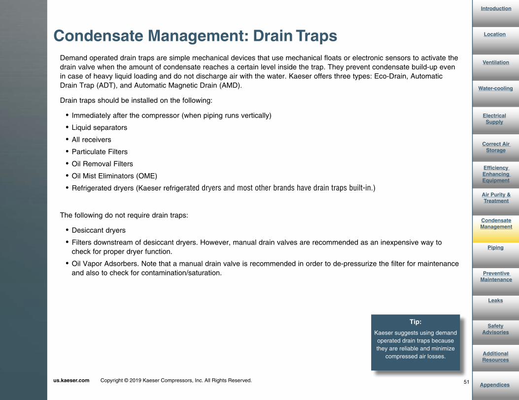
Demand operated drain traps are simple mechanical devices that use mechanical floats or electronic sensors to activate the drain valve when the amount of condensate reaches a certain level inside the trap. They prevent condensate build-up even in case of heavy liquid loading and do not discharge air with the water. Kaeser offers three types: Eco-Drain, Automatic Drain Trap (ADT), and Automatic Magnetic Drain (AMD).
Drain traps should be installed on the following:
• Immediately after the compressor (when piping runs vertically)
• Liquid separators
• All receivers
• Particulate Filters
• Oil Removal Filters
• Oil Mist Eliminators (OME)
• Refrigerated dryers (Kaeser refrigerated dryers and most other brands have drain traps built-in.)
The following do not require drain traps:
• Desiccant dryers
• Filters downstream of desiccant dryers. However, manual drain valves are recommended as an inexpensive way to check for proper dryer function.
• Oil Vapor Adsorbers. Note that a manual drain valve is recommended in order to de-pressurize the filter for maintenance and also to check for contamination/saturation.
Condensate Management: Drain Traps

52us.kaeser.com Copyright © 2019 Kaeser Compressors, Inc. All Rights Reserved.
Introduction
Appendices
AdditionalResources
Safety Advisories
Leaks
Preventive Maintenance
Piping
Air Purity &Treatment
Efficiency Enhancing Equipment
Correct Air Storage
Electrical Supply
Water-cooling
Ventilation
Location
Condensate Management
Drain traps should be mounted below filters and should be fed from the lowest point possible on receivers and dryers. To prevent clogging of the drain trap orifices and mechanisms on equipment other than filters, Kaeser suggests installing a Y-strainer before drain traps. Also, a ball valve should be placed before the Y-strainer to enable maintenance personnel to isolate the strainer from pressure during cleaning. The use of a Y-strainer may not be necessary in conjunction with the AMD 6550 trap. The large orifice and the design of the mechanism make the AMD 6550 less susceptible to clogging than other traps.
The AMD 1550 is designed for use with aftercoolers, coalescing filters, and on liquid separators. The AMD 6550 is for use with aftercoolers, liquid separators, receiver tanks, coalescing filters, drip legs, and other low points in your piping.
Condensate Management: Drain Traps

53us.kaeser.com Copyright © 2019 Kaeser Compressors, Inc. All Rights Reserved.
Introduction
Appendices
AdditionalResources
Safety Advisories
Leaks
Preventive Maintenance
Piping
Air Purity &Treatment
Efficiency Enhancing Equipment
Correct Air Storage
Electrical Supply
Water-cooling
Ventilation
Location
Condensate Management
As mentioned previously, condensate is not just water, but usually also contains oil and solid particles. The combina-tion of oil and particulates often makes the condensate an environmentally hazardous material that must be properly disposed of. You may choose to collect all condensate in large vessels for disposal, but this is an expensive option. Typically, water makes up 95% of the condensate. It will be more economical to separate the water and pay only for disposing of oils and other contaminants. These may be effectively separated at the end of the condensate system in a Condensate Management System (Kaeser’s KCF) or an equal performing oil/water separator. The KCF should be sized to handle the total volume of water collected in the system. Consider the flow demand when sizing the KCF.
Condensate Management: Disposal
! Do not pipe untreated condensate into a storm sewer.
Condensate treated by a KCF may then be piped to a sanitary sewer drain using appropriately sized pipe. The treated condensate should be monitored periodically to confirm purity is in compliance with local, state, and federal environmental regulations. The separated oil is captured by the KCF adsorption filter. This filter may be disposed of in the normal manner. Oil that has only been separated, rather than adsorbed, is considered hazardous waste and appropriate disposal methods must be adhered to.

54us.kaeser.com Copyright © 2019 Kaeser Compressors, Inc. All Rights Reserved.
Introduction
Appendices
AdditionalResources
Safety Advisories
Leaks
Preventive Maintenance
Piping
Air Purity &Treatment
Efficiency Enhancing Equipment
Correct Air Storage
Electrical Supply
Water-cooling
Ventilation
Location
Condensate Management
For maximum condensation collection, install a condensate manifold. These small vessels collect condensate from multiple sources, such as receiver tanks, filters, and dryers, and safely diffuse residual air pressure to maximize separation effectiveness when used in conjunction with a oil/water separator.
Condensate Management: Manifold

55us.kaeser.com Copyright © 2019 Kaeser Compressors, Inc. All Rights Reserved.
Introduction
Appendices
AdditionalResources
Safety Advisories
Leaks
Preventive Maintenance
Piping
Air Purity &Treatment
Efficiency Enhancing Equipment
Correct Air Storage
Electrical Supply
Water-cooling
Ventilation
Location
Condensate Management
Sample Air Treatment Diagram with Condensate Management
Disposal of Condensate: Condensate Management

{
us.kaeser.com Copyright © 2019 Kaeser Compressors, Inc. All Rights Reserved.
Materials and Installation Considerations
Piping

57us.kaeser.com Copyright © 2019 Kaeser Compressors, Inc. All Rights Reserved.
Introduction
Appendices
AdditionalResources
Safety Advisories
Leaks
Preventive Maintenance
Condensate Management
Air Purity &Treatment
Efficiency Enhancing Equipment
Correct Air Storage
Electrical Supply
Water-cooling
Ventilation
Location
Piping
...pressure drop due to friction increases with flow...“
The correct sizing of pipework is important to provide ample flow and steady pressure to all points of use. Pipe diameter dramatically impacts pressure drop. The Compressed Air and Gas Institue publishes tables for esti-mating pressure drop due to friction loss at specific pres-sures. Appendix A contains the chart for 100-psig system pressure. Note that the information in the chart is based on straight pipe that is smooth and clean inside. Pipe bends are an additional source of friction losses in com-pressed air piping. You will notice that pressure drop due to friction increases with flow.
Leaks will be discussed later on in this e-book.
Piping
Tip:
Every 2 psig of pressure drop requires a 1% increase of input
energy to maintain desired pressure.

58us.kaeser.com Copyright © 2019 Kaeser Compressors, Inc. All Rights Reserved.
Introduction
Appendices
AdditionalResources
Safety Advisories
Leaks
Preventive Maintenance
Condensate Management
Air Purity &Treatment
Efficiency Enhancing Equipment
Correct Air Storage
Electrical Supply
Water-cooling
Ventilation
Location
Piping
More Resources:
The Compressed Air Challenge is committed to helping educate compressed air users and has a
number of excellent resources. Visit their website for more information.
The following example from the Compressed Air Challenge demonstrates how to calculate pressure drop in your system.
Piping
Chart courtesy of CAGI
What is the pressure drop in a 2-inch pipe, 350 feet in length, with an initial pressure of 85 psig and a flow rate of 500 cfm-FAD?
According to the chart in Appendix A, a pressure drop for 500 cfm in 1,000 feet of 2-inch pipe is 19.2 psi.
This means:
19.2 x 350 ft. x (85 psig + 14.5) = 5.84 psi 1,000 ft. x (100 psig + 14.5)
This pressure drop is considered excessive. Using 3-inch pipe would be recommended:
2.34 x 350 ft. x (85 psig + 14.5) = 0.71 psi 1,000 ft. x (100 psig + 14.5)

59us.kaeser.com Copyright © 2019 Kaeser Compressors, Inc. All Rights Reserved.
Introduction
Appendices
AdditionalResources
Safety Advisories
Leaks
Preventive Maintenance
Condensate Management
Air Purity &Treatment
Efficiency Enhancing Equipment
Correct Air Storage
Electrical Supply
Water-cooling
Ventilation
Location
Piping
Poor choices in pipe materials, diameter, and layout cause flow restrictions, often resulting in significant pressure drop...
Piping selection directly affects three key elements of every compressed air system: flow, pressure, and air qual-ity. Poor choices in pipe materials, diameter, and layout cause flow restrictions, often resulting in significant pres-sure drop.
The chart on the next page outlines the key advantages and disadvantages of common piping materials.
Piping: Materials
! Regardless of the type of piping material used, it must be rated for at least your maximum working pressure and meet all applicable codes.
“

60us.kaeser.com Copyright © 2019 Kaeser Compressors, Inc. All Rights Reserved.
Introduction
Appendices
AdditionalResources
Safety Advisories
Leaks
Preventive Maintenance
Condensate Management
Air Purity &Treatment
Efficiency Enhancing Equipment
Correct Air Storage
Electrical Supply
Water-cooling
Ventilation
Location
Piping
Material Advantages DisadvantagesBlack Iron • Moderate material costs
• Readily available in multiple sizes
• Labor intensive installation
• May rust and leak
• Rough inside promotes contaminant build-up and creates pressure drop
Galvanized Iron • Moderate material costs
• Readily available in multiple sizes
• Some rust protection
• Often exterior is coated
• Labor intensive installation
• Rough inside promotes contaminant build-up and creates pressure drop
• May rust at joints and leak
Copper • No rust, good air quality
• Smooth interior—low pressure drop
• Requires quality brazing to prevent leaks
• Susceptible to thermal cycling
• Installation requires open flame
Stainless Steel • No rust, good air quality
• Smooth interior—low pressure drop
• Labor intensive installation
• Expensive materials
PVC • Lightweight
• Inexpensive
• Lower safety
• In certain areas, not compliant with certain codes
• Carries static charge
• Subject to bursting
• Adhesives not compatible with compressor oils
Aluminum • Corrosion resistant
• Lightweight
• Easy to install
• Lower cost of ownership
• Lower pressure rating
Piping: Materials

61us.kaeser.com Copyright © 2019 Kaeser Compressors, Inc. All Rights Reserved.
Introduction
Appendices
AdditionalResources
Safety Advisories
Leaks
Preventive Maintenance
Condensate Management
Air Purity &Treatment
Efficiency Enhancing Equipment
Correct Air Storage
Electrical Supply
Water-cooling
Ventilation
Location
Piping
Kaeser does not recommend using PVC or ABS (plas-tics) because some synthetic lubricants degrade plastics, which may lead to pipe rupture. Also, air traveling through a plastic pipe may accumulate a significant static electric charge that could discharge at the point of use when an employee touches the air-driven tool.
Piping: Materials
More Resources:
For more information on the dangers of using PVC piping for compressed air, read our
blog entry.

62us.kaeser.com Copyright © 2019 Kaeser Compressors, Inc. All Rights Reserved.
Introduction
Appendices
AdditionalResources
Safety Advisories
Leaks
Preventive Maintenance
Condensate Management
Air Purity &Treatment
Efficiency Enhancing Equipment
Correct Air Storage
Electrical Supply
Water-cooling
Ventilation
Location
Piping
Use couplings (connections, elbows, etc.) of the same material and pressure rating. Seal threaded joints with a high quality pipe sealant in order to minimize leaks.
• Minimize “T”s and right angles in order to reduce friction losses. Use rounded elbows whenever possible.
• Where “T”s are used, pipe the main flow through the head of the “T” and use the stem to feed the bypass, air drop, etc.
• Full-bore ball valves are recommended wherever valves are required. Ball valves should be placed to facilitate future expansion of compressed air system (e.g., multiple compressors, more points of use).
• Pipe in low and out high of air receiver tanks.
Piping: Installation Tips

63us.kaeser.com Copyright © 2019 Kaeser Compressors, Inc. All Rights Reserved.
Introduction
Appendices
AdditionalResources
Safety Advisories
Leaks
Preventive Maintenance
Condensate Management
Air Purity &Treatment
Efficiency Enhancing Equipment
Correct Air Storage
Electrical Supply
Water-cooling
Ventilation
Location
Piping
• Use braces to secure piping to walls, floor, or ceiling to prevent movement of piping and stressing of pipe joints (which causes leakage).
• Discharge piping should be at least the same diameter as the compressor discharge outlet.
• A flexible pipe/hose connection between rigid air piping and compressor discharge outlet is highly recommended in order to protect the aluminum discharge flange.
• A full-bore ball valve should be installed immediately after the flexible hose connection to isolate and maintain stored pressure downstream when the compressor is serviced. On large compressors (400 hp and higher) a high performance butterfly valve may be a less expensive and more convenient option. Also, an appropriate means of blow-down is required between the compressor and the isolation valve.
• Install an additional fitting (e.g. “Chicago” or “Dixon”) to allow temporary connection of mobile or backup compressor for uninterrupted air flow during maintenance/repair service.
Piping: Installation Tips

64us.kaeser.com Copyright © 2019 Kaeser Compressors, Inc. All Rights Reserved.
Introduction
Appendices
AdditionalResources
Safety Advisories
Leaks
Piping
Condensate Management
Air Purity &Treatment
Efficiency Enhancing Equipment
Correct Air Storage
Electrical Supply
Water-cooling
Ventilation
Location
“Preventive
Maintenance
To ensure ease of filter cartridge replacement, allow enough space under the filter to remove the filter bowl...
Piping should enter receiver tanks low and exit high to pro-mote maximum moisture separation and prevent accumulated condensate from migrating downstream.
Kaeser filters are designed to allow quick access to the filter cartridges without disconnecting any piping. Do not run piping at heights that will put them out of reach or too close to the floor. Doing so will make filter replacement and proper instal-lation of drain traps difficult. To ensure ease of filter cartridge replacement, allow enough space under the filter to remove the filter bowl. This will eliminate the need to disconnect the entire filter from the inlet and outlet piping just to change filter elements.
Mount liquid separators, particulate, and oil coalescing filters so that inlet and outlet connections are horizontal and the filter bowls are vertical. Since separated and coalesced liquids drain by gravity downward inside the filters to the filter sump (and into the drain trap), the vessel must be mounted nearly plumb vertically, so that drainage will not be impeded.
Piping: Air Treatment Piping
!Ensure that the filter heads are installed so that air flows through the filter in the proper direction (as shown on the filter head).

65us.kaeser.com Copyright © 2019 Kaeser Compressors, Inc. All Rights Reserved.
Introduction
Appendices
AdditionalResources
Safety Advisories
Leaks
Preventive Maintenance
Condensate Management
Air Purity &Treatment
Efficiency Enhancing Equipment
Correct Air Storage
Electrical Supply
Water-cooling
Ventilation
Location
Piping
Use full-bore ball valves to isolate all air treatment items to facilitate routine maintenance without loss of compressed air. In applications where air quality is critical and the user cannot afford to shut down the compressed air system, each filter should have bypass piping with a redundant filter. The bypass must have ball valves to isolate it. With this configuration, the user may bypass filters during filter cartridge changes or other filter maintenance without compromising air quality.
Piping: Installation Tips (cont’d)

66us.kaeser.com Copyright © 2019 Kaeser Compressors, Inc. All Rights Reserved.
Introduction
Appendices
AdditionalResources
Safety Advisories
Leaks
Preventive Maintenance
Condensate Management
Air Purity &Treatment
Efficiency Enhancing Equipment
Correct Air Storage
Electrical Supply
Water-cooling
Ventilation
Location
“Piping
More Resources:
See the “Loss of Air Pressure Due to Friction” Chart in Appendix A for help with estimating pressure drop.
Friction loss is related both to the type of pipe used and the length of pipe...
Airdrops to points of use should be fed from a loop system (rather than a dead end system). This effectively reduces air travel distances and helps ensure stable pressure to all points of use. Also, individual airdrops should exit the main pipe from the top so that condensed moisture will not enter the line.
Avoid exposing air lines to freezing temperatures. If the air lines will be exposed to freezing temperatures, use a desiccant or membrane dryer to treat the air before the piping reaches areas where it is exposed to freezing temperatures.
Any time piping goes through various temperature gradients in a facility, consider using additional flexible hoses and remember to size your air treatment appropriately.
Piping: Distribution Piping

{
us.kaeser.com Copyright © 2019 Kaeser Compressors, Inc. All Rights Reserved.
Keeping Your System Up and Running
Preventive Maintenance

68us.kaeser.com Copyright © 2019 Kaeser Compressors, Inc. All Rights Reserved.
Introduction
Appendices
AdditionalResources
Safety Advisories
Leaks
Piping
Condensate Management
Air Purity &Treatment
Efficiency Enhancing Equipment
Correct Air Storage
Electrical Supply
Water-cooling
Ventilation
Location
Preventative Maintenance
More Resources:
Click here to contact your local authorized Kaeser
representative for maintenance recommendations.
Regular preventive maintenance will ensure optimal performance and longer equipment life...“
All mechanical and electrical equipment requires varying degrees of attention to ensure that it operates efficiently. Since most customers rely heavily upon an uninterrupted supply of compressed air, it is sensible for them to invest in preventive maintenance rather than suffer costly downtime and repairs.
It is highly recommended to establish a regular maintenance routine to ensure proper operation of all parts of your compressed air system and maintain a service log for each component. Regular preventive maintenance will ensure optimal performance and longer equipment life.
Each system component (e.g., compressor, filter, dryer, and drain trap) has a service manual or guide with specific instructions on maintenance procedures and intervals. Follow all recommended maintenance procedures. Taking the few minutes to perform these checks will maintain the quality of your compressed air and your air driven tools, reducing the costs associated with repairs and lost production.
Many modern compressed air components (e.g. compressors, blower packages) come equipped with computerized controllers which monitor equipment health and operation in real time, as well as provide typical maintenance intervals reminders. Some offer the capability to send these messages to plant control systems or provide messaging to responsible plant personnel for the equipment.
Preventive Maintenance

69us.kaeser.com Copyright © 2019 Kaeser Compressors, Inc. All Rights Reserved.
Introduction
Appendices
AdditionalResources
Safety Advisories
Leaks
Piping
Condensate Management
Air Purity &Treatment
Efficiency Enhancing Equipment
Correct Air Storage
Electrical Supply
Water-cooling
Ventilation
Location
Preventative Maintenance
In addition to the regular checks by your plant personnel, an effective preventive maintenance program should include regular professional servicing. Standard services are usually performed at manufacturer recommended intervals, but may be recommended more often depending on the usage and operating environment.
Kaeser has a factory-trained, national distribution network that is always ready to assist you with your maintenance needs. Contact your local authorized Kaeser representative to schedule a service appointment.
Preventive Maintenance
!Lack of proper maintenance may invalidate any warranty claims if failures are directly related to a failure to perform routine preventive maintenance. A preventive maintenance contract with your local Kaeser distributor is a means of having this work carried out properly.
!Caution: Compressed air can be dangerous. Extreme care should be exercised at all times. Prior to performing any maintenance or service, system pressure must be vented at all points to ensure human safety. High pressure air should never be directed at anyone. Valves should be opened and closed slowly to prevent damage to separators, filters, and controls caused by sudden surges of pressurized air.
! Caution: Before performing any work, be sure to follow OSHA recommendations for electrical lock-out/tag-out and compressed air blow-down precautions.

{
us.kaeser.com Copyright © 2019 Kaeser Compressors, Inc. All Rights Reserved.
Cost and Detection
Leaks

71us.kaeser.com Copyright © 2019 Kaeser Compressors, Inc. All Rights Reserved.
Introduction
Appendices
AdditionalResources
Safety Advisories
Preventive Maintenance
Piping
Condensate Management
Air Purity &Treatment
Efficiency Enhancing Equipment
Correct Air Storage
Electrical Supply
Water-cooling
Ventilation
Location
Leaks
Tip:
Make leak detection and air audits a part of your regular
maintenance plan.
Most systems have air leaks. Some are present from the time of installation and some develop over time. Regardless of the source, they can greatly reduce your operating effectiveness and cost a lot in energy.
Kaeser recommends a post installation leak check as well as periodic leak detection checks.
Upon commissioning, the air system can be checked for leaks by simply charging the system with air and not using air. If the compressor cycles on to recharge the system or if the pressure drops in the storage tank, there are leaks. Ultrasonic leak detection equipment can easily locate the leaks.
We also recommend annual leak audits to identify and fix leaks that develop over time.
And if you are considering a system energy audit, we strongly recommend a leak audit first to determine how much of your system demand is due to leaks rather than actual production needs.
The graphic on the right shows how much even a single leak can cost you each year. An annual leak detection plan can help you stay ahead of the game.
Leaks
A single, small hole, 1/4” in diameter, costs you approximately $1155 every month.
Leak Size 90 psig 110 psig1/16” $933 $1,112
1/4” $14,948 $17,818
3/8” $33,586 $40,051
1/2” $59,761 $71,271
Based on 8,760 operating hours and $0.10/kWh.
See Appendix C: Discharge of Air Through an Orifice for more information.
Tip:
Consult your local authorized Kaeser representative for as-
sistanceobtaining leak savings information for other pressures.

{
us.kaeser.com Copyright © 2019 Kaeser Compressors, Inc. All Rights Reserved.
Health and Safety Considerations
Safety Advisories

73us.kaeser.com Copyright © 2019 Kaeser Compressors, Inc. All Rights Reserved.
Introduction
Appendices
AdditionalResources
Leaks
Preventive Maintenance
Piping
Condensate Management
Air Purity &Treatment
Efficiency Enhancing Equipment
Correct Air Storage
Electrical Supply
Water-cooling
Ventilation
Location
Safety Advisories
Installation should be conducted in a safe manner in accordance with OSHA and appropriate local regulations. Compressed air can be dangerous and should never be directed towards people. Improper and unsafe contact with compressed air can cause eye damage, sub-cutaneous embolisms, and other serious injuries, including death.
When working in a lift, technicians should use a proper harness and rigging.
Qualified technicians must perform electrical work in a safe manner using UL approved materials and properly insulated tools, equipment, and appropriate personal protective equipment (PPE) for the work. All applicable local, state, and national regulations must be followed.
All pressure vessels must meet ASME and other appropriate local standards.
The compressed air system must be installed so that normal operation poses no threat to worker health or safety. The system must be sufficiently ventilated so that it poses no heat threat to persons nearby.
Hearing protection must be worn in accordance with OSHA standards. Where applicable, prominently display signs warning of noise hazards. Compressor operating noise levels are listed in Kaeser service manuals.
Condensate must be disposed of in accordance with local, state, and federal environmental regulations.
Follow OSHA recommendations for electrical lock-out/tag-out and compressed air blow-down precautions.
Follow all safety recommendations in the manufacturer’s service manual.
Safety Advisories

{
us.kaeser.com Copyright © 2019 Kaeser Compressors, Inc. All Rights Reserved.
More Tips and Resources
Additional Resources

75us.kaeser.com Copyright © 2019 Kaeser Compressors, Inc. All Rights Reserved.
Introduction
Appendices
Safety Advisories
Leaks
Preventive Maintenance
Piping
Condensate Management
Air Purity &Treatment
Efficiency Enhancing Equipment
Correct Air Storage
Electrical Supply
Water-cooling
Ventilation
Location
Additional Resources
Looking for more information on compressed air topics? Check out the following resources below:
• kaesertalksshop.com: Our company blog features posts on a wide range of compressed air topics written by our subject matter experts and is updated regularly. You can also sign up to follow the blog to receive updates whenever there is a new blog post.
• us.kaeser.com/cagi: Kaeser is a member of the Compressed Air and Gas Institute (CAGI), a non-profit organization of competitive companies that manufacture air and gas compressors and related equipment. As a member, Kaeser partici-pates in the performance verification program. You can view the performance data sheets for our units on this website.
• us.kaeser.com/resources: This webpage has a collection of technical articles, material safety data sheets (MSDS), tools, presentations, and much more.
• us.kaeser.com/whitepapers: Our collections of whitepapers provide in-depth technical information on challenges those in the compressed air industry are currently facing.
• Our online Kaeser Toolbox has a number of handy tools for making common compressed air calculations.
• us.kaeser.com/ada: Our Air Demand Analysis (ADA) compressed air assessments can help you improve your existing system.
Additional Resources

{
us.kaeser.com Copyright © 2019 Kaeser Compressors, Inc. All Rights Reserved.
Charts and References
Appendices

77us.kaeser.com Copyright © 2019 Kaeser Compressors, Inc. All Rights Reserved.
Introduction
AdditionalResources
Safety Advisories
Leaks
Preventive Maintenance
Piping
Condensate Management
Air Purity &Treatment
Efficiency Enhancing Equipment
Correct Air Storage
Electrical Supply
Water-cooling
Ventilation
Location
Appendices
table 4.7 Loss of Air Pressure Due to Friction Equivalent Cu ft Cu ft Nominal Diameter, In. Free Air Compressed Per Min Air Per Min
1/2 3/4 1 1 1/4 1 1/2 2 3 4 6 8 10 12 _________________________________________________________________________________ 10 1.28 6.50 .99 0.28 20 2.56 25.9 3.90 1.11 0.25 0.11 30 3.84 58.5 9.01 2.51 0.57 0.26 40 5.12 …. 16.0 4.45 1.03 0.46 50 6.41 …. 25.1 9.96 1.61 0.71 0.19 60 7.68 …. 36.2 10.0 2.32 1.02 0.28 70 8.96 …. 49.3 13.7 3.16 1.40 0.37 80 10.24 …. 64.5. 17.8 4.14 1.83 0.49 90 11.52 …. 82.8 22.6 5.23 2.32 0.62 100 12.81 …. …. 27.9 6.47 2.86 0.77 125 15.82 …. …. 48.6 10.2 4.49 1.19 150 19.23 …. …. 62.8 14.6 6.43 1.72 0.21 175 22.40 …. …. …. 19.8 8.72 2.36 0.28 200 25.62 …. …. …. 25.9 11.4 3.06 0.37 250 31.64 …. …. …. 40.4 17.9 4.78 0.58 300 38.44 …. …. …. 58.2 25.8 6.85 0.84 0.20 350 44.80 …. …. …. …. 35.1 9.36 1.14 0.27 400 51.24 …. …. …. …. 45.8 12.1 1.50 0.35 450 57.65 …. …. …. …. 58.0 15.4 1.89 0.46 500 63.28 …. …. …. …. 71.6 19.2 2.34 0.55 600 76.88 …. …. …. …. …. 27.6 3.36 0.79 700 89.60 …. …. …. …. …. 37.7 4.55 1.09 800 102.5 …. …. …. …. …. 49.0 5.89 1.42 900 115.3 …. …. …. …. …. 62.3 7.6 1.80 1,000 128.1 …. …. …. …. …. 76.9 9.3 2.21 1,500 192.3 …. …. …. …. …. …. 21.0 4.9 0.57 2,000 256.2 …. …. …. …. …. …. 37.4 8.8 0.99 0.24 2,500 316.4 …. …. …. …. …. …. 58.4 13.8 1.57 0.37 3,000 384.6 …. …. …. …. …. …. 84.1 20.0 2.26 0.53 3,500 447.8 …. …. …. …. …. …. …. 27.2 3.04 0.70 0.22 4,000 512.4 …. …. …. …. …. …. …. 35.5 4.01 0.94 0.28 4,500 576.5 …. …. …. …. …. …. …. 45.0 5.10 1.19 0.36 5,000 632.8 …. …. …. …. …. …. …. 55.6 6.3 1.47 0.44 0.17 6,000 768.8 …. …. …. …. …. …. …. 80.0 9.1 2.11 0.64 0.24 7,000 896.0 …. …. …. …. …. …. …. …. 12.2 2.88 0.87 0.33 8,000 1,025 …. …. …. …. …. …. …. …. 16.1 3.77 1.12 0.46 9,000 1,153 …. …. …. …. …. …. …. …. 20.4 4.77 1.43 0.57 10,000 1,280 …. …. …. …. …. …. …. …. 25.1 5.88 1.77 0.69 11,000 1,410 …. …. …. …. …. …. …. …. 30.4 7.10 2.14 0.83 12,000 1,540 …. …. …. …. …. …. …. …. 36.2 8.5 2.54 0.98 13,000 1,668 …. …. …. …. …. …. …. …. 42.6 9.8 2.98 1.15 14,000 1,795 …. …. …. …. …. …. …. …. 49.2 11.5 3.46 1.35 15,000 1,923 …. …. …. …. …. …. …. …. 56.6 13.2 3.97 1.53 16,000 2,050 …. …. …. …. …. …. …. …. 64.5 15.0 4.52 1.75 18,000 2,310 …. …. …. …. …. …. …. …. 81.5 19.0 5.72 2.22 20,000 2,560 …. …. …. …. …. …. …. …. …. 23.6 7.0 2.74 22,000 2,820 …. …. …. …. …. …. …. …. …. 28.5 8.5 3.33 24,000 3,080 …. …. …. …. …. …. …. …. …. 33.8 10.0 3.85 26,000 3,338 …. …. …. …. …. …. …. …. …. 39.7 11.9 4.65 28,000 3,590 …. …. …. …. …. …. …. …. …. 46.2 13.8 5.40 30,000 3,850 …. …. …. …. …. …. …. …. …. 53.0 15.9 6.17
In psi in 1000 ft of pipe, 100 lb gage initial pressure. For longer or shorter lengths of pipe the friction loss is proportional to the length, i.e., for 500 ft, one-half of the above; for 4,000 ft, four times the above, etc.
214 Compressed Air Distribution (Systems) Chap. 4
Appendix A: Loss of Pressure Drop Due to FrictionChart taken from Compressed Air and Gas Handbook. For additional pressures, visit www.cagi.org.

78us.kaeser.com Copyright © 2019 Kaeser Compressors, Inc. All Rights Reserved.
Introduction
AdditionalResources
Safety Advisories
Leaks
Preventive Maintenance
Piping
Condensate Management
Air Purity &Treatment
Efficiency Enhancing Equipment
Correct Air Storage
Electrical Supply
Water-cooling
Ventilation
Location
Appendices
Appendix B: Dryer Correction Factors for Kaeser’s Refrigerated Dryers
Secotec: Capacity Correction Factors for Operating Conditions
Capacity Correction Factors for Ambient Temperature
Selecting the Proper DryerTo correct rated capacity for actual operating conditions, refer to “Capacity Correction Factors for Operating Conditions” and “Capacity Correction Factors for Ambient Temperature”. Find the capacity correction factors corresponding to the inlet and ambient conditions. Multiply these factors to find the “overall” capacity correction factor, then multiply any dryer’s rated capacity by the overall correction factor to determine its capacity at your operating conditions. Capacity correction factors for conditions not shown may be interpolated.
Note that these correction factors are specific to Kaeser model dryers. For additional assistance in sizing dryers for your installation, contact your local authorized Kaeser representative.
Pressure(psig)
Temperature (°F)
75 80 85 90 95 100 105 110 115 120 125 130
60 0.96 0.86 0.77 0.67 0.60 0.53 0.47 0.41 0.37
80 1.11 0.99 0.89 0.78 0.69 0.61 0.54 0.48 0.42
100 1.25 1.12 1.00 0.88 0.78 0.69 0.61 0.53 0.48
115 1.32 1.18 1.05 0.93 0.62 0.73 0.64 0.57 0.50
120 1.33 1.19 1.06 0.94 0.83 0.73 0.65 0.57 0.51
125 1.35 1.21 1.08 0.95 0.84 0.75 0.66 0.58 0.52
140 1.39 1.25 1.11 0.98 0.87 0.77 0.68 0.60 0.53
160 1.46 1.31 1.16 1.02 0.91 0.80 0.71 0.63 0.56
180 1.51 1.35 1.21 1.06 0.94 0.83 0.73 0.65 0.58
200 1.55 1.39 1.24 1.09 0.97 0.85 0.75 0.67 0.59
230 1.59 1.43 1.27 1.12 0.99 0.88 0.77 0.68 0.61
Ambient Air Temperature (°F)
75 80 85 90 95 100 105 110
Factor 1.09 1.05 1.00 0.96 0.92
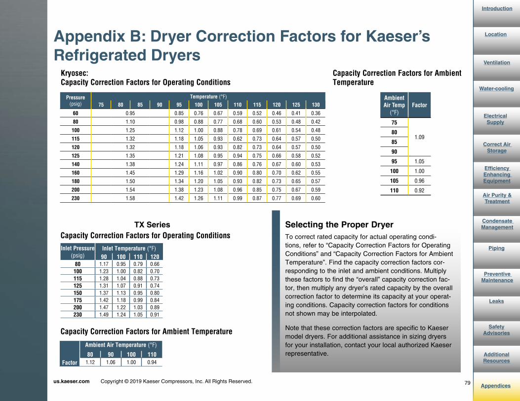
79us.kaeser.com Copyright © 2019 Kaeser Compressors, Inc. All Rights Reserved.
Introduction
AdditionalResources
Safety Advisories
Leaks
Preventive Maintenance
Piping
Condensate Management
Air Purity &Treatment
Efficiency Enhancing Equipment
Correct Air Storage
Electrical Supply
Water-cooling
Ventilation
Location
Appendices
Appendix B: Dryer Correction Factors for Kaeser’s Refrigerated Dryers
Kryosec: Capacity Correction Factors for Operating Conditions
Capacity Correction Factors for Ambient Temperature
Selecting the Proper DryerTo correct rated capacity for actual operating condi-tions, refer to “Capacity Correction Factors for Operating Conditions” and “Capacity Correction Factors for Ambient Temperature”. Find the capacity correction factors cor-responding to the inlet and ambient conditions. Multiply these factors to find the “overall” capacity correction fac-tor, then multiply any dryer’s rated capacity by the overall correction factor to determine its capacity at your operat-ing conditions. Capacity correction factors for conditions not shown may be interpolated.
Note that these correction factors are specific to Kaeser model dryers. For additional assistance in sizing dryers for your installation, contact your local authorized Kaeser representative.
Pressure(psig)
Temperature (°F)
75 80 85 90 95 100 105 110 115 120 125 130
60 0.95 0.85 0.76 0.67 0.59 0.52 0.46 0.41 0.36
80 1.10 0.98 0.88 0.77 0.68 0.60 0.53 0.48 0.42
100 1.25 1.12 1.00 0.88 0.78 0.69 0.61 0.54 0.48
115 1.32 1.18 1.05 0.93 0.62 0.73 0.64 0.57 0.50
120 1.32 1.18 1.06 0.93 0.82 0.73 0.64 0.57 0.50
125 1.35 1.21 1.08 0.95 0.94 0.75 0.66 0.58 0.52
140 1.38 1.24 1.11 0.97 0.86 0.76 0.67 0.60 0.53
160 1.45 1.29 1.16 1.02 0.90 0.80 0.70 0.62 0.55
180 1.50 1.34 1.20 1.05 0.93 0.82 0.73 0.65 0.57
200 1.54 1.38 1.23 1.08 0.96 0.85 0.75 0.67 0.59
230 1.58 1.42 1.26 1.11 0.99 0.87 0.77 0.69 0.60
Ambient Air Temp
(°F)Factor
75
1.0980
85
90
95 1.05
100 1.00
105 0.96
110 0.92
TX SeriesCapacity Correction Factors for Operating Conditions
Capacity Correction Factors for Ambient Temperature
Inlet Pressure(psig)
Inlet Temperature (°F)90 100 110 120
80 1.17 0.95 0.79 0.66100 1.23 1.00 0.82 0.70115 1.28 1.04 0.88 0.73125 1.31 1.07 0.91 0.74150 1.37 1.13 0.95 0.80175 1.42 1.18 0.99 0.84200 1.47 1.22 1.03 0.89230 1.49 1.24 1.05 0.91
Factor
Ambient Air Temperature (°F)
80 90 100 1101.12 1.06 1.00 0.94

80us.kaeser.com Copyright © 2019 Kaeser Compressors, Inc. All Rights Reserved.
Introduction
AdditionalResources
Safety Advisories
Leaks
Preventive Maintenance
Piping
Condensate Management
Air Purity &Treatment
Efficiency Enhancing Equipment
Correct Air Storage
Electrical Supply
Water-cooling
Ventilation
Location
Appendices
Appendix B: Dryer Correction Factors for Kaeser’s Refrigerated Dryers
Selecting the Proper DryerTo correct rated capacity for actual operating conditions, refer to “Capacity Correction Factors for Operating Conditions” and “Capacity Correction Factors for Ambient Temperature”. Find the capacity correction factors corresponding to the inlet and ambient conditions. Multiply these factors to find the “overall” capacity correction factor, then multiply any dryer’s rated capacity by the overall correction factor to determine its capacity at your operating conditions. Capacity correction factors for conditions not shown may be interpolated.
Note that these correction factors are specific to Kaeser model dryers. For additional assistance in sizing dryers for your installation, contact your local authorized Kaeser representative.
Capacity Correction Factors for Ambient TemperatureDemand Manager Series
Capacity Correction Factors for Ambient Temperature
Pressure (psig)
Temperature (°F)
80 85 90 95 100 105 110 115 12080 1.50 1.34 1.17 1.06 0.95 0.87 0.79 0.73 0.66100 1.55 1.39 1.23 1.12 1.00 0.91 0.82 0.76 0.70110 1.58 1.42 1.26 1.15 1.03 0.94 0.86 0.79 0.72115 1.60 1.44 1.28 1.16 1.04 0.96 0.88 0.80 0.73125 1.63 1.47 1.31 1.19 1.07 0.99 0.91 0.83 0.74145 1.69 1.52 1.36 1.24 1.12 1.03 0.94 0.87 0.79175 1.75 1.59 1.42 1.30 1.18 1.09 0.99 0.92 0.84200 1.80 1.64 1.47 1.35 1.22 1.13 1.03 0.96 0.89230 1.82 1.66 1.49 1.37 1.24 1.15 1.05 0.98 0.91
Ambient Air Temperature (°F)
75 80 85 90 95 100 105 110
Air-Cooled 1.15 1.12 1.09 1.06 1.03 1.00 0.97 0.94

81us.kaeser.com Copyright © 2019 Kaeser Compressors, Inc. All Rights Reserved.
Introduction
AdditionalResources
Safety Advisories
Leaks
Preventive Maintenance
Piping
Condensate Management
Air Purity &Treatment
Efficiency Enhancing Equipment
Correct Air Storage
Electrical Supply
Water-cooling
Ventilation
Location
Appendices
Appendix B: Dryer Correction Factors for Kaeser’s Desiccant Dryers
Selecting the Proper DryerTo determine a dryer’s inlet flow capacity at inlet pressures other than 100 psig, multiply the dryer’s rated inlet flow by the multiplier from that corresponds to the system pressure at the dryer inlet.
Note that these correction factors are specific to Kaeser model dryers. For additional assistance in sizing dryers for your installation, contact your local authorized Kaeser representative.
Kaeser Heatless Desiccant Dryers (KAD)
*For operation at pressures lower than 60 psig, please contact factory.
Inlet Pressure Correction FactorInlet Flow Capacity
Kaeser Purge Dryers KED (Heated) and KBD (Blower)
Inlet Flow Capacity
KED/KBD Inlet Conditions Correction Factors
Inlet Pressure
(psig)Multiplier
Inlet Pressure
(psig)Multiplier
60* 0.65 125 1.1070 0.74 130 1.1280 0.83 140 1.1690 0.91 150 1.20100 1.00 175 1.29110 1.04 200 1.37115 1.06 225 1.45120 1.08 250 1.52
All Models (E and PS)
Inlet Flow @ 100 psig
(scfm)KAD 40 40KAD 60 60KAD 90 90KAD 115 115KAD 165 165KAD 260 260KAD 370 370KAD 450 450KAD 590 590KAD 750 750KAD 930 930KAD 1130 1130KAD 1350 1350KAD 1550 1550KAD 2100 2100KAD 3000 3000KAD 4100 4100KAD 5400 5400
Inlet Pressure
(psig)
Inlet Temperature °F (°C)
60 70 80 90 100 110 120
60 1.03 1.01 0.99 0.80 0.58 0.43 0.3270 1.10 1.08 1.07 0.94 0.68 0.50 0.3780 1.17 1.15 1.14 1.08 0.79 0.58 0.4390 1.24 1.22 1.20 1.18 0.89 0.66 0.49100 1.30 1.28 1.26 1.24 1.00 0.74 0.55110 1.36 1.34 1.32 1.30 1.11 0.82 0.61115 1.39 1.37 1.35 1.33 1.16 0.86 0.64120 1.42 1.40 1.38 1.36 1.22 0.90 0.67125 1.45 1.43 1.41 1.39 1.27 0.94 0.70130 1.48 1.46 1.44 1.42 1.33 0.99 0.74140 1.53 1.51 1.49 1.47 1.44 1.07 0.80150 1.58 1.56 1.54 1.52 1.50 1.16 0.87
KED Model
Number
Inlet flow @ 100 psig 100°F
(scfm)300 300
400 400
500 500
600 600
750 750
900 900
1050 1050
1300 1300
1500 1500
1800 1800
2200 2200
2600 2600
3200 3200
KBD Model
Number
Inlet flow @ 100 psig 100°F
(scfm)
500 500
600 600
750 750
900 900
1050 1050
1300 1300
1500 1500
1800 1800
2200 2200
2600 2600
3200 3200
3600 3600
4300 4300

82us.kaeser.com Copyright © 2019 Kaeser Compressors, Inc. All Rights Reserved.
Introduction
AdditionalResources
Safety Advisories
Leaks
Preventive Maintenance
Piping
Condensate Management
Air Purity &Treatment
Efficiency Enhancing Equipment
Correct Air Storage
Electrical Supply
Water-cooling
Ventilation
Location
AppendicesCompressed Air & Gas Institute • 1300 Sumner Avenue • Cleveland, OH 44115
Phone: 216/241-7333 • Fax: 216/241-0105 • E-mail: [email protected]
™
729
General Reference Data
TABLE 8.25 Discharge of Air Through an Orifice
Nominal Diameter, In.
Gage Pressure before Orifice, psi
1/64 1/32 1/16 1/8 1/4 3/8 1/2 5/8 3/4 7/8 1
Discharge, Cu. ft. Free Air Per Min. 1 .028 0.112 0.450 1.80 7.18 16.2 28.7 45.0 64.7 88.1 115 2 .040 0.158 0.633 2.53 10.1 22.8 40.5 63.3 91.2 124 162 3 .048 0.194 0.775 3.10 12.4 27.8 49.5 77.5 111 152 198 4 .056 0.223 0.892 3.56 14.3 32.1 57.0 89.2 128 175 228 5 .062 0.248 0.993 3.97 15.9 35.7 63.5 99.3 143 195 254 6 .068 0.272 1.09 4.34 17.4 39.1 69.5 109 156 213 278 7 .073 0.293 1.17 4.68 18.7 42.2 75.0 117 168 230 300 9 .083 0.331 1.32 5.30 21.1 47.7 84.7 132 191 260 339 12 .095 0.379 1.52 6.07 24.3 54.6 97.0 152 218 297 388 15 .105 0.420 1.68 6.72 26.9 60.5 108 168 242 329 430 20 .123 0.491 1.96 7.86 31.4 70.7 126 196 283 385 503 25 .140 0.562 2.25 8.98 35.9 80.9 144 225 323 440 575 30 .158 0.633 2.53 10.1 40.5 91.1 162 253 365 496 648 35 .176 0.703 2.81 11.3 45.0 101 180 281 405 551 720 40 .194 0.774 3.10 12.4 49.6 112 198 310 446 607 793 45 .211 0.845 3.38 13.5 54.1 122 216 338 487 662 865 50 .229 0.916 3.66 14.7 58.6 132 235 366 528 718 938 60 .264 1.06 4.23 16.9 67.6 152 271 423 609 828 1,082 70 .300 1.20 4.79 19.2 76.7 173 307 479 690 939 1,227 80 .335 1.34 5.36 21.4 85.7 193 343 536 771 1,050 1,371 90 .370 1.48 5.92 23.7 94.8 213 379 592 853 1,161 1,516 100 .406 1.62 6.49 26.0 104 234 415 649 934 1,272 1,661 110 .441 1.76 7.05 28.2 113 254 452 705 1,016 1,383 1,806 120 .476 1.91 7.62 30.5 122 274 488 762 1,097 1,494 1,951 125 .494 1.98 7.90 31.6 126 284 506 790 1,138 1,549 2,023
Based on 100% coefficient of flow. For well-rounded entrance multiply values by 0.97. For sharp-edged orifices a multiplier of 0.65 may be used.This table will give approximate results only. For accurate measurements see ASME Power Test Code, Velocity Volume Flow Measurement.Values for pressures from 1 to 15 psig calculated by standard adiabatic formula.Values for pressures above 15 psig calculated by approximate formula proposed by S. A. Moss: w = 0.5303 aCp1 T1 where w = discharge in lb per sec, a = area of orifice in sq. in., C = coefficient of flow, p1 = upstream total pressure in psia, and T1 = upstream temperature in deg F abs.Values used in calculating above table were C = 1.0, p1 = gage pressure + 14.7 psi, T1 = 530 F abs.Weights (w) were converted to volumes using density factor of 0.07494 lb. per cu. ft. This is correct for dry air at 14.7 psia and 70°F.Formula cannot be used where p1 is less than two times the barometric pressure.
Appendix C: Discharge of Air Through an Orifice
Chart taken from Compressed Air and Gas Handbook. For additional pressures, visit www.cagi.org.

83us.kaeser.com Copyright © 2019 Kaeser Compressors, Inc. All Rights Reserved.
Introduction
AdditionalResources
Safety Advisories
Leaks
Preventive Maintenance
Piping
Condensate Management
Air Purity &Treatment
Efficiency Enhancing Equipment
Correct Air Storage
Electrical Supply
Water-cooling
Ventilation
Location
Appendices
Appendix D: ISO Air Quality Classes
At reference conditions: 68°F, 14.5 psia, 0% relative humidity

84us.kaeser.com Copyright © 2019 Kaeser Compressors, Inc. All Rights Reserved.
Introduction
AdditionalResources
Safety Advisories
Leaks
Preventive Maintenance
Piping
Condensate Management
Air Purity &Treatment
Efficiency Enhancing Equipment
Correct Air Storage
Electrical Supply
Water-cooling
Ventilation
Location
Appendices
Appendix E: Power vs. Flow Characteristics Curves
Source: Compressed Air Challenge. For more information, visit: www.compressedairchallenge.org.
Total kW input and/or specific power over the full operating range must be analyzed for a proper comparison with other
types of capacity control.

The Air Systems Specialist
We earn our customers’ business by supplying superior quality equipment and services. Our products are designed for reliable performance, easy maintenance, and energy efficiency. Prompt and dependable customer service, quality assurance, training, and engineering support contribute to the value our customers have come to expect from Kaeser. Our employees are committed to implementing and maintaining the highest standards of quality to merit customer satisfaction. We aim for excellence in everything we do.
Kaeser Compressors, Inc.511 Sigma DriveFredericksburg, Virginia 22408 USAPhone: 540-898-5500Toll Free: 800-777-7873Email: [email protected]
us.kaeser.com Copyright © 2019 Kaeser Compressors, Inc. All Rights Reserved. USCASIGEB 01/19