Installation Installation Manual - Central States Diesel ...
170
English Original Instructions 6-2019 A053U867 (Issue 5) Installation Installation Manual Manual Generator Set QST30-G5 Engine with PowerCommand ® 3.3 Control DQFAA (Spec G-K) DQFAB (Spec G-K) DQFAC (Spec G-K) DQFAD (Spec G-K)
-
Upload
khangminh22 -
Category
Documents
-
view
0 -
download
0
Transcript of Installation Installation Manual - Central States Diesel ...

EnglishOriginal Instructions 6-2019 A053U867 (Issue 5)
InstallationInstallation ManualManual
Generator SetQST30-G5 Engine with PowerCommand® 3.3 Control
DQFAA (Spec G-K)DQFAB (Spec G-K)DQFAC (Spec G-K)DQFAD (Spec G-K)

iA053U867 (Issue 5) Copyright © 2019 Cummins Inc.
Table of Contents
1. IMPORTANT SAFETY INSTRUCTIONS ....................................................................................... 11.1 Warning, Caution, and Note Styles Used in This Manual ..................................................... 11.2 General Information ................................................................................................................ 1
1.2.1 General Safety Precautions ......................................................................................... 21.3 Generator Set Safety Code .................................................................................................... 5
1.3.1 Generator Set Operating Areas ................................................................................... 51.3.2 Moving Parts Can Cause Severe Personal Injury or Death ........................................ 51.3.3 Positioning of Generator Set....................................................................................... 6
1.4 Electrical Shocks and Arc Flashes Can Cause Severe Personal Injury or Death.................. 61.4.1 Locking the Generator Set Out of Service ................................................................... 71.4.2 AC Supply and Isolation............................................................................................... 81.4.3 AC Disconnect Sources ............................................................................................... 8
1.5 Fuel and Fumes Are Flammable ............................................................................................ 81.5.1 Spillage ....................................................................................................................... 91.5.2 Fluid Containment....................................................................................................... 91.5.3 Do Not Operate in Flammable and Explosive Environments ...................................... 9
1.6 Exhaust Gases Are Deadly..................................................................................................... 91.6.1 Exhaust Precautions ................................................................................................... 9
1.7 Earth Ground Connection ..................................................................................................... 101.8 Decommissioning and Disassembly ..................................................................................... 11
2. INTRODUCTION.......................................................................................................................... 132.1 About This Manual................................................................................................................ 13
2.1.1 Additional Installation Manual Information ................................................................. 132.2 Schedule of Abbreviations .................................................................................................... 142.3 Related Literature ................................................................................................................. 15
2.3.1 Further Information - Literature .................................................................................. 162.4 After Sales Services.............................................................................................................. 16
2.4.1 Maintenance.............................................................................................................. 162.4.2 Warranty..................................................................................................................... 16
3. SYSTEM OVERVIEW .................................................................................................................. 193.1 Generator Set Identification .................................................................................................. 19
3.1.1 Nameplate.................................................................................................................. 193.1.2 Generator Set Components ....................................................................................... 19
3.2 Generator Set Rating............................................................................................................ 203.3 Derating Factors ................................................................................................................... 203.4 Engine Components ............................................................................................................. 213.5 System Options..................................................................................................................... 22
3.5.1 Introduction ................................................................................................................ 223.5.2 Battery Charger.......................................................................................................... 223.5.3 Day Tank.................................................................................................................... 23

Table of Contents 6-2019
ii A053U867 (Issue 5)Copyright © 2019 Cummins Inc.
3.5.4 Enclosures ................................................................................................................. 233.5.5 Fuel Transfer Pump ................................................................................................... 243.5.6 Heaters....................................................................................................................... 253.5.7 Remote Radiator Installation ..................................................................................... 263.5.8 Relays ........................................................................................................................ 263.5.9 Seismic Installation Requirements............................................................................. 263.5.10 Sensors .................................................................................................................... 26
4. INSTALLATION OVERVIEW ....................................................................................................... 294.1 Application and Installation ................................................................................................... 294.2 Safety Considerations........................................................................................................... 294.3 Standby Heating Devices...................................................................................................... 294.4 Product Modifications............................................................................................................ 304.5 De-Rating Factors................................................................................................................ 30
5. SPECIFICATIONS ....................................................................................................................... 315.1 Generator Set Specifications ................................................................................................ 315.2 Engine Fuel Consumption..................................................................................................... 32
6. INSTALLING THE GENERATOR SET ........................................................................................ 336.1 Transportation....................................................................................................................... 336.2 Location ................................................................................................................................ 346.3 Moving the Generator Set..................................................................................................... 35
6.3.1 Rigging Instructions.................................................................................................... 366.4 Mounting ............................................................................................................................... 376.5 Access to Generator Set....................................................................................................... 386.6 Seismic Installation Notes..................................................................................................... 38
7. MECHANICAL CONNECTIONS .................................................................................................. 417.1 Fuel System.......................................................................................................................... 41
7.1.1 Fuel Return Restrictions (or Pressure) Limit.............................................................. 427.1.2 Fuel Line Connections ............................................................................................... 427.1.3 Engine Fuel Connections........................................................................................... 437.1.4 Supply Tank ............................................................................................................... 447.1.5 Fuel Inlet Pressure/Restriction Limit .......................................................................... 457.1.6 Day Tank.................................................................................................................... 457.1.7 Fuel Transfer Pump ................................................................................................... 467.1.8 Fuel Additives............................................................................................................. 46
7.2 Exhaust System.................................................................................................................... 477.3 Ventilation and Cooling......................................................................................................... 517.4 Vents and Ducts.................................................................................................................... 517.5 Dampers ............................................................................................................................... 527.6 Air Inlet and Outlet Openings................................................................................................ 527.7 Remote Radiator Cooling .................................................................................................... 54
7.7.1 Remote Radiator Installation...................................................................................... 547.8 Breakerless Conductor Connections .................................................................................... 55
7.8.1 Overload and Short Circuit Protection of Generator .................................................. 55
Table of Contents6-2019
iiiA053U867 (Issue 5) Copyright © 2019 Cummins Inc.
7.8.2 AmpSentry Protective Relay Time-Over Current Characteristic Curve ..................... 577.8.3 Coordination of Protective Devices............................................................................ 597.8.4 Additional AmpSentry Protective Relay Information .................................................. 59
8. DC CONTROL WIRING ............................................................................................................... 618.1 Guidelines for Customer Connections to the Control System .............................................. 61
8.1.1 Digital Connections .................................................................................................... 628.1.2 Relay Connections..................................................................................................... 62
8.2 PowerCommand 3.3 Customer Connections ....................................................................... 628.2.1 Configurable Outputs ................................................................................................. 628.2.2 Remote Start .............................................................................................................. 628.2.3 Configurable Inputs.................................................................................................... 638.2.4 Remote Emergency Stop........................................................................................... 63
8.3 Customer Relays .................................................................................................................. 638.3.1 Location of Customer Relays..................................................................................... 63
9. AC ELECTRICAL CONNECTIONS ............................................................................................. 659.1 AC Distribution Panel Connections....................................................................................... 66
9.1.1 AC Distribution Panel................................................................................................. 679.2 Transfer Switch ..................................................................................................................... 689.3 Alternator Voltage Connections ............................................................................................ 699.4 Load Connections ................................................................................................................. 70
9.4.1 Generator Set Load Cable Installation....................................................................... 709.4.2 Cabling through Non-Ferrous Gland Plates............................................................... 709.4.3 Cabling through Ferrous Gland Plates ...................................................................... 709.4.4 Distribution Cables..................................................................................................... 70
9.5 Installation of s-CAN Network Cable .................................................................................... 719.6 Load Balancing ..................................................................................................................... 739.7 Fuel Transfer Pump Installation............................................................................................ 73
9.7.1 Fuel Transfer Pump Control AC Connections ........................................................... 739.8 Current Transformers............................................................................................................ 759.9 Coolant Heater...................................................................................................................... 759.10 Alternator Heaters............................................................................................................... 75
9.10.1 Alternator Heater Connection .................................................................................. 759.11 Control Box Heater ............................................................................................................. 75
9.11.1 Control Box Heater Installation ................................................................................ 759.12 Battery Commissioning ....................................................................................................... 76
9.12.1 Safety Precautions................................................................................................... 779.12.2 Pre-Commissioning Procedure ................................................................................ 789.12.3 Filling the Battery with Electrolyte............................................................................ 789.12.4 Charging - Commissioning ...................................................................................... 789.12.5 Connecting the Battery to the Generator Set........................................................... 799.12.6 Electrolyte - Specific Gravity and Temperature ....................................................... 79
9.13 Battery Charger................................................................................................................... 819.13.1 PowerCommand Battery Charger - 15 Amp at 12 Volt and 12 Amp at 24 Volt....... 81
9.14 Grounding ........................................................................................................................... 82

Table of Contents 6-2019
iv A053U867 (Issue 5)Copyright © 2019 Cummins Inc.
10. PRE-START PREPARATION..................................................................................................... 8510.1 Initial Pre-start Checks........................................................................................................ 8510.2 Electrical System ................................................................................................................ 8610.3 Battery Connections............................................................................................................ 8610.4 Site-Specific Configuration.................................................................................................. 8710.5 Starting................................................................................................................................ 87
11. INSTALLATION CHECKLIST ..................................................................................................... 8911.1 Checklist ............................................................................................................................. 89
12. MANUFACTURING FACILITIES ................................................................................................ 9312.1 How to Obtain Service ....................................................................................................... 93
12.1.1 Locating a Distributor ............................................................................................... 93
APPENDIX A. ALTERNATOR RECONNECT DRAWING ................................................................ 95A.1 Alternator Reconnect Drawing.............................................................................................. 97A.2 Alternator Reconnect Drawing.............................................................................................. 99
APPENDIX B. CUSTOMER CONNECTIONS ................................................................................ 107B.1 Control Wiring Diagrams (0630-3440)................................................................................ 109
APPENDIX C. OUTLINE DRAWINGS............................................................................................ 121C.1 Generator Set Outline Drawing (A053G789) - Set Mounted Radiator ............................... 123C.2 Generator Set Outline Drawing (A049K674) - Set Mounted Radiator ............................... 127C.3 Generator Set Outline Drawing (A062H932) - Set Mounted Radiator ............................... 131C.4 Generator Set Outline Drawing (A053G787) - Remote Radiator....................................... 135C.5 Generator Set Outline Drawing (A062M281) - Remote Radiator....................................... 140
APPENDIX D. WIRING DIAGRAMS............................................................................................... 145D.1 PCC3300 Wiring Diagram (A053C830) ............................................................................. 147D.2 Outline Drawing and Schematic - Heater........................................................................... 154D.3 Wiring of Optional Equipment ............................................................................................ 155
APPENDIX E. SEISMIC REQUIREMENTS.................................................................................... 157E.1 Seismic Installation Instructions (A045K403) ..................................................................... 159

1A053U867 (Issue 5) Copyright © 2019 Cummins Inc.
1 IMPORTANT SAFETY INSTRUCTIONSSAVE THESE INSTRUCTIONS. This manual contains important instructions that should be followedduring installation and maintenance of the generator set and batteries.
Safe and efficient operation can be achieved only if the equipment is properly operated and maintained.Many accidents are caused by failure to follow fundamental rules and precautions.
1.1 Warning, Caution, and Note Styles Used in ThisManualThe following safety styles and symbols found throughout this manual indicate potentially hazardousconditions to the operator, service personnel, or equipment.
DANGERIndicates a hazardous situation that, if not avoided, will result in death or serious injury.
WARNINGIndicates a hazardous situation that, if not avoided, could result in death or serious injury.
CAUTIONIndicates a hazardous situation that, if not avoided, could result in minor or moderate injury.
NOTICEIndicates information considered important, but not hazard-related (e.g., messages relating toproperty damage).
1.2 General InformationThis manual should form part of the documentation package supplied by Cummins with specific generatorsets. In the event that this manual has been supplied in isolation, please contact your authorizeddistributor.
NOTICEIt is in the operator’s interest to read and understand all warnings and cautions contained withinthe documentation relevant to the generator set, its operation and daily maintenance.

1. IMPORTANT SAFETY INSTRUCTIONS 6-2019
2 A053U867 (Issue 5)Copyright © 2019 Cummins Inc.
1.2.1 General Safety PrecautionsWARNING
Hot Pressurized LiquidContact with hot liquid can cause severe burns.Do not open the pressure cap while the engine is running. Let the engine cool down beforeremoving the cap. Turn the cap slowly and do not open it fully until the pressure has beenrelieved.
WARNINGMoving PartsMoving parts can cause severe personal injury.Use extreme caution around moving parts. All guards must be properly fastened to preventunintended contact.
WARNINGToxic HazardUsed engine oils have been identified by some state and federal agencies to cause cancer orreproductive toxicity.Do not ingest, breathe the fumes, or contact used oil when checking or changing engine oil.Wear protective gloves and face guard.
WARNINGElectrical Generating EquipmentIncorrect operation can cause severe personal injury or death.Do not operate equipment when fatigued, or after consuming any alcohol or drug.
WARNINGToxic GasesSubstances in exhaust gases have been identified by some state and federal agencies to causecancer or reproductive toxicity.Do not breathe in or come into contact with exhaust gases.
WARNINGCombustible LiquidIgnition of combustible liquids is a fire or explosion hazard which can cause severe burns ordeath.Do not store fuel, cleaners, oil, etc., near the generator set.
WARNINGHigh Noise LevelGenerator sets in operation emit noise, which can cause hearing damage.Wear appropriate ear protection at all times.

1. IMPORTANT SAFETY INSTRUCTIONS6-2019
3A053U867 (Issue 5) Copyright © 2019 Cummins Inc.
WARNINGHot SurfacesContact with hot surfaces can cause severe burns.The unit is to be installed so that the risk of hot surface contact by people is minimized. Wearappropriate PPE when working on hot equipment and avoid contact with hot surfaces.
WARNINGElectrical Generating EquipmentIncorrect operation and maintenance can result in severe personal injury or death.Make sure that only suitably trained and experienced service personnel perform electrical and/ormechanical service.
WARNINGToxic HazardEthylene glycol, used as an engine coolant, is toxic to humans and animals.Wear appropriate PPE. Clean up coolant spills and dispose of used coolant in accordance withlocal environmental regulations.
WARNINGCombustible LiquidIgnition of combustible liquids is a fire or explosion hazard which can cause severe burns ordeath.Do not use combustible liquids like ether.
WARNINGAutomated MachineryAccidental or remote starting of the generator set can cause severe personal injury or death.Isolate all auxiliary supplies and use an insulated wrench to disconnect the starting batterycables (negative [–] first).
WARNINGFire HazardMaterials drawn into the generator set are a fire hazard. Fire can cause severe burns or death.Make sure the generator set is mounted in a manner to prevent combustible materials fromaccumulating under the unit.
WARNINGFire HazardAccumulated grease and oil are a fire hazard. Fire can cause severe burns or death.Keep the generator set and the surrounding area clean and free from obstructions. Repair oilleaks promptly.

1. IMPORTANT SAFETY INSTRUCTIONS 6-2019
4 A053U867 (Issue 5)Copyright © 2019 Cummins Inc.
WARNINGFall HazardFalls can result in severe personal injury or death.Make sure that suitable equipment for performing tasks at height are used in accordance withlocal guidelines and legislation.
WARNINGFire HazardMaterials drawn into the generator set are a fire hazard. Fire can cause severe burns or death.Keep the generator set and the surrounding area clean and free from obstructions.
WARNINGPressurized SystemPressurized systems can rupture/leak which can result in severe personal injury or death.Use appropriate lock out/tag out safety procedures to isolate from all energy sources beforeperforming any service tasks. Use PPE.
WARNINGConfined AreasConfined spaces or areas with restricted access or potential to entrap can cause severe personalinjury or death.Use appropriate lock out/tag out safety procedures to isolate from all energy sources. Use PPE.Follow site specific lone worker protocols/permits to work.
CAUTIONManual Handling Heavy ObjectsHandling heavy objects can cause severe personal injury.Use appropriate lifting equipment and perform tasks with two people where doing so would makecompletion of the task safe.
CAUTIONPower Tools and Hand ToolsTools can cause cuts, abrasions, bruising, puncture injuries.Only trained and experienced personnel should use power tools and hand tools. Use PPE.
CAUTIONSharp Edges and Sharp PointsProjecting corners/parts may cause cuts, abrasions and other personal injury.Use PPE. Be aware of sharp edges and corners/sharp points. Cover/protect them.
NOTICEKeep multi-type ABC fire extinguishers close by. Class A fires involve ordinary combustiblematerials such as wood and cloth. Class B fires involve combustible and flammable liquid fuelsand gaseous fuels. Class C fires involve live electrical equipment. (Refer to NFPA No. 10 in theapplicable region.)

1. IMPORTANT SAFETY INSTRUCTIONS6-2019
5A053U867 (Issue 5) Copyright © 2019 Cummins Inc.
NOTICEBefore performing maintenance and service procedures on enclosed generator sets, make surethe service access doors are secured open.
NOTICEStepping on the generator set can cause parts to bend or break, leading to electrical shorts, or tofuel leaks, coolant leaks, or exhaust leaks. Do not step on the generator set when entering orleaving the generator set room.
NOTICERemove fuel from subbase fuel tank before conducting any hot work.
1.3 Generator Set Safety CodeBefore operating the generator set, read the manuals and become familiar with them and the equipment.Safe and efficient operation can be achieved only if the equipment is properly operated and maintained.Many accidents are caused by failure to follow fundamental rules and precautions.
WARNINGElectrical Generating EquipmentIncorrect operation and maintenance can result in severe personal injury or death.Read and follow all Safety Precautions, Warnings, and Cautions throughout this manual and thedocumentation supplied with the generator set.
1.3.1 Generator Set Operating AreasWARNING
Ejected DebrisDebris ejected during destructive failure can cause serious injury or death by impact, severing orstabbing.Do not to stand alongside the engine or alternator while the generator set is running.
• Operators must not stand alongside the engine or alternator while the generator set is running,unless the risks of doing so have been assessed and adequate mitigation steps have been taken.
• If there are operation/maintenance procedures that require spending time alongside the generatorset when it is running, take every precaution to perform these tasks safely. Keep time spentperforming these tasks to a minimum.
• Be aware of the product environment. Other equipment may be in operation or energized in thesurrounding area.
1.3.2 Moving Parts Can Cause Severe Personal Injury or Death• Keep hands, clothing, and jewelry away from moving parts.

1. IMPORTANT SAFETY INSTRUCTIONS 6-2019
6 A053U867 (Issue 5)Copyright © 2019 Cummins Inc.
• Before starting work on the generator set, disconnect the battery charger from its AC source, thendisconnect the starting batteries using an insulated wrench, negative (–) cable first. This will preventaccidental starting.
• Make sure that fasteners on the generator set are secure. Tighten supports and clamps; keepguards in position over fans, drive belts, etc.
• Do not wear loose clothing or jewelry in the vicinity of moving parts or while working on electricalequipment. Loose clothing and jewelry can become caught in moving parts.
• If any adjustments must be made while the unit is running, use extreme caution around hotmanifolds, moving parts, etc.
1.3.3 Positioning of Generator SetThe generator set should be placed on level ground with adequate open space around it. The immediatearea around the generator set should be free of any flammable material.
NOTICEAccess or service doors must be closed and locked before repositioning, and they must remainlocked during transportation and siting.
NOTICEThe generator set is capable of operating at inclines of up to +/– 2.5 degrees.
1.4 Electrical Shocks and Arc Flashes Can CauseSevere Personal Injury or Death
WARNINGElectric Shock HazardVoltages and currents present an electrical shock hazard that can cause severe burns or death.Contact with exposed energized circuits with potentials of 50 Volts AC or 75 Volts DC or highercan cause electrical shock and electrical arc flash. Refer to standard NFPA 70E or equivalentsafety standards in corresponding regions for details of the dangers involved and for the safetyrequirements.
Guidelines to follow when working on de-energized electrical systems:
• Use proper PPE. Do not wear jewelry and make sure that any conductive items are removed frompockets as these items can fall into equipment and the resulting short circuit can cause shock orburning. Refer to standard NFPA 70E for PPE standards.
• De-energize and lockout/tagout electrical systems prior to working on them. Lockout/Tagout isintended to prevent injury due to unexpected start-up of equipment or the release of stored energy.Please refer to Locking the Generator Set Out of Service section for more information.
• De-energize and lockout/tagout all circuits and devices before removing any protective shields ormaking any measurements on electrical equipment.
• Follow all applicable regional electrical and safety codes.
Guidelines to follow when working on energized electrical systems:

1. IMPORTANT SAFETY INSTRUCTIONS6-2019
7A053U867 (Issue 5) Copyright © 2019 Cummins Inc.
NOTICEIt is the policy of Cummins Inc. to perform all electrical work in a de-energized state. However,employees or suppliers may be permitted to occasionally perform work on energized electricalequipment only when qualified and authorized to do so and when troubleshooting, or if de-energizing the equipment would create a greater risk or make the task impossible and all otheralternatives have been exhausted.
NOTICEExposed energized electrical work is only allowed as per the relevant procedures and must beundertaken by a Cummins authorized person with any appropriate energized work permit for thework to be performed while using proper PPE, tools and equipment.
In summary:
• Do not tamper with or bypass interlocks unless you are authorized to do so.
• Understand and assess the risks - use proper PPE. Do not wear jewelry and make sure that anyconductive items are removed from pockets as these items can fall into equipment and the resultingshort circuit can cause shock or burning. Refer to standard NFPA 70E for PPE standards.
• Make sure that an accompanying person who can undertake a rescue is nearby.
1.4.1 Locking the Generator Set Out of ServiceBefore any work is carried out for maintenance, etc., the generator set must be immobilized. Even if thegenerator set is put out of service by pressing the Off switch on the operator panel, the generator setcannot be considered safe to work on until the engine is properly immobilized, as detailed in the followingprocedures.
NOTICERefer also to the engine specific Operator Manual. This manual contains specific equipmentinstructions that may differ from the standard generator set.
1.4.1.1 Immobilizing for Safe WorkingTo immobilize the generator set:
1. Press the Off mode switch on the operator panel to shut down the generator set.
2. Press the Emergency Stop button. This prevents the generator set starting, regardless of the Startsignal source and provides an additional safety step for immobilizing the generator set.
NOTICEWhen the Emergency Stop button is pressed, the operator panel indicates a Shutdown
condition. The red Shutdown status LED illuminates and a message is displayed.
NOTICEThis condition is stored in the Fault History.
3. As an additional precaution, thoroughly ventilate the plant room before disconnecting any leads.
4. Isolate and lock off the supply to the heater, where fitted.

1. IMPORTANT SAFETY INSTRUCTIONS 6-2019
8 A053U867 (Issue 5)Copyright © 2019 Cummins Inc.
5. Isolate and lock off the supply to the battery charger, where fitted.
6. Isolate the fuel supply to the engine.
7. Using an insulated wrench, disconnect the negative (–) cable first on the starting batteries andcontrol system batteries (if separate).
8. Fit warning notices at each of the above points to indicate Maintenance in Progress – PlantImmobilized for Safe Working.
1.4.2 AC Supply and IsolationNOTICE
Local electrical codes and regulations (for example, BS EN 12601:2010 Reciprocating internalcombustion engine driven generating sets) may require the installation of a disconnect meansfor the generator set, either on the generator set or where the generator set conductors enter afacility.
NOTICEThe AC supply must have the correct over current and earth fault protection according to localelectrical codes and regulations. This equipment must be earthed (grounded).
It is the sole responsibility of the customer to provide AC power conductors for connection to load devicesand the means to isolate the AC input to the terminal box; these must comply with local electrical codesand regulations. Refer to the wiring diagram supplied with the generator set.
The disconnecting device is not provided as part of the generator set, and Cummins accepts noresponsibility for providing the means of isolation.
1.4.2.1 AmpSentryGenerator sets with PC 3.3 control utilize AmpSentry™ protective relay which includes integral ACprotective functions for the alternator and conductors, if conductors are rated for operation at a minimumof 100% of the generator nameplate rating.
1.4.3 AC Disconnect SourcesWARNING
Hazardous VoltageContact with high voltages can cause severe electrical shock, burns, or death.The equipment may have more than one source of electrical energy. Disconnecting one sourcewithout disconnecting the others presents a shock hazard. Before starting work, disconnect theequipment, and verify that all sources of electrical energy have been removed.
1.5 Fuel and Fumes Are FlammableFire, explosion, and personal injury or death can result from improper practices.
• Do not fill fuel tanks while the engine is running unless the tanks are outside the enginecompartment. Fuel contact with hot engine or exhaust is a potential fire hazard.
• Do not permit any flame, cigarette, pilot light, spark, arcing equipment, or other ignition source nearthe generator set or fuel tank.

1. IMPORTANT SAFETY INSTRUCTIONS6-2019
9A053U867 (Issue 5) Copyright © 2019 Cummins Inc.
• Fuel lines must be adequately secured and free of leaks. Fuel connection at the engine should bemade with an approved flexible line. Do not use copper piping on flexible lines as copper willbecome brittle if continuously vibrated or repeatedly bent.
• Make sure all fuel supplies have a positive shutoff valve.
• Make sure the battery area has been well-ventilated prior to servicing near it. Lead-acid batteriesemit a highly explosive hydrogen gas that can be ignited by arcing, sparking, smoking, etc.
1.5.1 SpillageAny spillage that occurs during fueling, oil top-off, or oil change must be cleaned up before starting thegenerator set.
1.5.2 Fluid ContainmentNOTICE
Where spillage containment is not part of a Cummins supply, it is the responsibility of theinstaller to provide the necessary containment to prevent contamination of the environment,especially water courses and sources.
If fluid containment is incorporated into the bedframe, it must be inspected at regular intervals. Any liquidpresent should be drained out and disposed of in line with local health and safety regulations. Failure toperform this action may result in spillage of liquids which could contaminate the surrounding area.
Any other fluid containment area must also be checked and emptied, as described above.
1.5.3 Do Not Operate in Flammable and Explosive EnvironmentsFlammable vapor can cause an engine to over speed and become difficult to stop, resulting in possiblefire, explosion, severe personal injury, and death. Do not operate a generator set where a flammablevapor environment can be created, unless the generator set is equipped with an automatic safety deviceto block the air intake and stop the engine. The owners and operators of the generator set are solelyresponsible for operating the generator set safely. Contact your authorized Cummins distributor for moreinformation.
1.6 Exhaust Gases Are Deadly• Provide an adequate exhaust system to properly expel discharged gases away from enclosed or
sheltered areas, and areas where individuals are likely to congregate. Visually and audibly inspectthe exhaust system daily for leaks per the maintenance schedule. Make sure that exhaust manifoldsare secured and not warped. Do not use exhaust gases to heat a compartment.
• Make sure the unit is well ventilated.
1.6.1 Exhaust PrecautionsWARNING
Hot Exhaust GasesContact with hot exhaust gases can cause severe burns.Wear personal protective equipment when working on equipment.

1. IMPORTANT SAFETY INSTRUCTIONS 6-2019
10 A053U867 (Issue 5)Copyright © 2019 Cummins Inc.
WARNINGHot SurfacesContact with hot surfaces can cause severe burns.The unit is to be installed so that the risk of hot surface contact by people is minimized. Wearappropriate PPE when working on hot equipment and avoid contact with hot surfaces.
WARNINGToxic GasesInhalation of exhaust gases can cause asphyxiation and death.Pipe exhaust gas outside and away from windows, doors, or other inlets to buildings. Do notallow exhaust gas to accumulate in habitable areas.
WARNINGFire HazardContaminated insulation is a fire hazard. Fire can cause severe burns or death.Remove any contaminated insulation and dispose of it in accordance with local regulations.
The exhaust outlet may be sited at the top or bottom of the generator set. Make sure that the exhaustoutlet is not obstructed. Personnel using this equipment must be made aware of the exhaust position.Position the exhaust away from flammable materials - in the case of exhaust outlets at the bottom, makesure that vegetation is removed from the vicinity of the exhaust.
The exhaust pipes may have some insulating covers fitted. If these covers become contaminated theymust be replaced before the generator set is run.
To minimize the risk of fire, make sure the following steps are observed:
• Make sure that the engine is allowed to cool thoroughly before performing maintenance or operationtasks.
• Clean the exhaust pipe thoroughly.
1.7 Earth Ground ConnectionThe neutral of the generator set may be required to be bonded to earth ground at the generator setlocation, or at a remote location, depending on system design requirements. Consult the engineeringdrawings for the facility or a qualified electrical design engineer for proper installation.
NOTICEThe end user is responsible to make sure that the ground connection point surface area is cleanand free of rust before making a connection.
NOTICEThe end user is responsible for making sure that an earthing arrangement that is compliant withlocal conditions is established and tested before the equipment is used.

1. IMPORTANT SAFETY INSTRUCTIONS6-2019
11A053U867 (Issue 5) Copyright © 2019 Cummins Inc.
1.8 Decommissioning and DisassemblyNOTICE
Decommissioning and disassembly of the generator set at the end of its working life mustcomply with local guidelines and legislation for disposal/recycling of components andcontaminated fluids. This procedure must only be carried out by suitably trained andexperienced service personnel. For more information contact your authorized distributor.

This page is intentionally blank.
1. IMPORTANT SAFETY INSTRUCTIONS 6-2019
12 A053U867 (Issue 5)Copyright © 2019 Cummins Inc.

13A053U867 (Issue 5) Copyright © 2019 Cummins Inc.
2 IntroductionWARNING
Hazardous VoltageContact with high voltages can cause severe electrical shock, burns, or death.Make sure that only a trained and experienced electrician makes generator set electrical outputconnections, in accordance with the installation instructions and all applicable codes.
WARNINGElectrical Generating EquipmentFaulty electrical generating equipment can cause severe personal injury or death.Generator sets must be installed, certified, and operated by trained and experienced persons inaccordance with the installation instructions and all applicable codes.
2.1 About This ManualThe purpose of this manual is to provide the users with sound, general information. It is for guidance andassistance with recommendations for correct and safe procedures. Cummins Inc. cannot accept anyliability whatsoever for problems arising as a result of following recommendations in this manual.
The information contained within the manual is based on information available at the time of going to print.In line with Cummins Inc. policy of continuous development and improvement, information may change atany time without notice. The users should therefore make sure that before commencing any work, theyhave the latest information available. The latest version of this manual is available on QuickServe Online(https://quickserve.cummins.com).
Users are respectfully advised that, in the interests of good practice and safety, it is their responsibility toemploy competent persons to carry out any installation work. Consult your authorized distributor for furtherinstallation information. It is essential that the utmost care is taken with the application, installation, andoperation of any engine due to their potentially hazardous nature. Careful reference should also be madeto other Cummins Inc. literature. A generator set must be operated and maintained properly for safe andreliable operation.
For further assistance, contact your authorized distributor.
2.1.1 Additional Installation Manual InformationThe purpose of this manual is to provide the Installation Engineer with sound, general information for theinstallation of the generator set. Refer to the Generator Set Operator Manual for additional informationwhich must also be read before operating the set.
This manual provides installation instructions for the generator set models listed on the front cover. Thisincludes the following information:
• Mounting Recommendations - for fastening the generator set to a base and space requirementsfor normal operation and service.
• Mechanical and Electrical Connections - covers most aspects of the generator set installation.
• Prestart - checklist of items or procedures needed to prepare the generator set for operation.
• Installation Checklist - reference checks upon completion of the installation.
2. Introduction 6-2019
14 A053U867 (Issue 5)Copyright © 2019 Cummins Inc.
This manual DOES NOT provide application information for selecting a generator set or designing thecomplete installation. If it is necessary to design the various integrated systems (fuel, exhaust, cooling,etc.), additional information is required. Review standard installation practices. For engineering dataspecific to the generator set, refer to the Specification and Data Sheets. For application information, referto Application Manual T-030, "Liquid Cooled Generator Sets." To find this manual online:
1. Go to powersuite.cummins.com
2. Click on "Login" on the Home page.
3. Click on "Library".
4. Click on "Technical Documents".
5. Click on "Technical information".
6. Click on "Liquid Cooled Genset Application Manual".
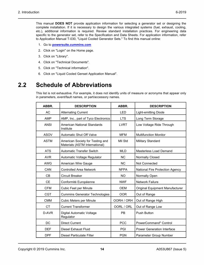
2.2 Schedule of AbbreviationsThis list is not exhaustive. For example, it does not identify units of measure or acronyms that appear onlyin parameters, event/fault names, or part/accessory names.
ABBR. DESCRIPTION ABBR. DESCRIPTION
AC Alternating Current LED Light-emitting Diode
AMP AMP, Inc., part of Tyco Electronics LTS Long Term Storage
ANSI American National StandardsInstitute
LVRT Low Voltage Ride Through
ASOV Automatic Shut Off Valve MFM Multifunction Monitor
ASTM American Society for Testing andMaterials (ASTM International)
Mil Std Military Standard
ATS Automatic Transfer Switch MLD Masterless Load Demand
AVR Automatic Voltage Regulator NC Normally Closed
AWG American Wire Gauge NC Not Connected
CAN Controlled Area Network NFPA National Fire Protection Agency
CB Circuit Breaker NO Normally Open
CE Conformité Européenne NWF Network Failure
CFM Cubic Feet per Minute OEM Original Equipment Manufacturer
CGT Cummins Generator Technologies OOR Out of Range
CMM Cubic Meters per Minute OORH / ORH Out of Range High
CT Current Transformer OORL / ORL Out of Range Low
D-AVR Digital Automatic VoltageRegulator
PB Push Button
DC Direct Current PCC PowerCommand® Control
DEF Diesel Exhaust Fluid PGI Power Generation Interface
DPF Diesel Particulate Filter PGN Parameter Group Number

2. Introduction6-2019
15A053U867 (Issue 5) Copyright © 2019 Cummins Inc.
ABBR. DESCRIPTION ABBR. DESCRIPTION
ECM Engine Control Module PI Proportional/Integral
ECS Engine Control System PID Proportional / Integral / Derivative
EMI Electromagnetic interference PLC Programmable Logic Controller
EN European Standard PMG Permanent Magnet Generator
EPS Engine Protection System PPE Personal Protective Equipment
E-Stop Emergency Stop PT Potential Transformer
FAE Full Authority Electronic PTC Power Transfer Control
FMI Failure Mode Identifier PWM Pulse-width Modulation
FRT Fault Ride Through RFI Radio Frequency Interference
FSO Fuel Shutoff RH Relative Humidity
Genset Generator Set RMS Root Mean Square
GCP Generator Control Panel RTU Remote Terminal Unit
GND Ground SAE Society of Automotive Engineers
LCT Low Coolant Temperature SCR Selective Catalytic Reduction
HMI Human-machine Interface SPN Suspect Parameter Number
IC Integrated Circuit SWL Safe Working Load
ISO International Organization forStandardization
SW_B+ Switched B+
LBNG Lean-burn Natural Gas UL Underwriters Laboratories
LCD Liquid Crystal Display UPS Uninterruptible Power Supply
VPS Valve Proving System
2.3 Related LiteratureBefore any attempt is made to operate the generator set, the operator should take time to read all of themanuals supplied with the generator set, and to familiarize themselves with the warnings and operatingprocedures.
CAUTIONA generator set must be operated and maintained properly if you are to expect safe and reliableoperation. The Operator manual includes a maintenance schedule and a troubleshooting guide.
The relevant manuals appropriate to your generator set are also available:
• Operator Manual for DQFAA, DQFAB, DQFAC, and DQFAD Generator Sets with PowerCommand®
3.3 Controller (A053U864)
• Installation Manual for DQFAA, DQFAB, DQFAC, and DQFAD Generator Sets withPowerCommand® 3.3 Controller (A053U867)
• Service Manual for DQFAA, DQFAB, DQFAC, and DQFAD Generator Sets with PowerCommand®
3.3 Controller (A053U869)
2. Introduction 6-2019
16 A053U867 (Issue 5)Copyright © 2019 Cummins Inc.
• Parts Manual for DQFAA, DQFAB, DQFAC, and DQFAD Generator Sets with PowerCommand® 3.3Controller (961-0211)
• Service Manual for PowerCommand® 3.3 Controller (960-0670)
• Alternator Service Manual for HC Alternator (A040J849)
• Alternator Service Manual for P7 Alternator (A040J850)
• Common Manual for Preventative Maintenance Requirements for High Range Standby DieselGenerator Sets (A035G976)
• Engine Operator and Maintenance Manual for QST30-G5 Engine (3666134)
• Specification and Data Sheets
• Application Manual T-030: Liquid Cooled Generator Sets (A040S369)
• Parts Manual for HC Alternator (0900-9914)
• Parts Manual for P7 Alternator (0900-9912)
• Standard Repair Times - CJ Family (A029C347)
• Fuels for Cummins Engines Service Bulletin (3379001)
• Emissions Warranty Statement (A043G561)
• Warranty Manual (A040W374)
• Global Commercial Warranty Statement (A028U870)
2.3.1 Further Information - LiteratureContact your authorized distributor for more information regarding related literature for this product.
2.4 After Sales ServicesCummins offers a full range of maintenance and warranty services.
2.4.1 MaintenanceWARNING
Electrical Generating EquipmentIncorrect operation and maintenance can result in severe personal injury or death.Make sure that only suitably trained and experienced service personnel perform electrical and/ormechanical service.
For expert generator set service at regular intervals, contact your local distributor. Each local distributoroffers a complete maintenance contract package covering all items subject to routine maintenance,including a detailed report on the condition of the generator set. In addition, this can be linked to a 24-hourcall-out arrangement, providing year-round assistance if necessary. Specialist engineers are available tomaintain optimum performance levels from generator sets. Maintenance tasks should only be undertakenby trained and experienced technicians provided by your authorized distributor.
2.4.2 WarrantyFor details of the warranty coverage for your generator set, refer to the Global Commercial WarrantyStatement listed in the Related Literature section.

2. Introduction6-2019
17A053U867 (Issue 5) Copyright © 2019 Cummins Inc.
In the event of a breakdown, prompt assistance can normally be given by factory trained servicetechnicians with facilities to undertake all minor and many major repairs to equipment on site.
Extended warranty coverage is also available.
For further warranty details, contact your authorized service provider.
NOTICEDamage caused by failure to follow the manufacturer's recommendations will not be covered bythe warranty. Please contact your authorized service provider.
2.4.2.1 Warranty LimitationsFor details of the warranty limitations for your generator set, refer to the warranty statement applicable tothe generator set.

This page is intentionally blank.
2. Introduction 6-2019
18 A053U867 (Issue 5)Copyright © 2019 Cummins Inc.

19A053U867 (Issue 5) Copyright © 2019 Cummins Inc.
3 System OverviewThis section provides an overview of the generator set.
3.1 Generator Set IdentificationEach generator set is provided with a nameplate similar to that shown below. The nameplate providesinformation unique to the generator set.
3.1.1 Nameplate
FIGURE 1. TYPICAL GENERATOR SET NAMEPLATE
3.1.2 Generator Set ComponentsThe main components of a QST30-G5 engine generator set are shown below, and referred to within thissection.
There are various options listed although they may not be available for all models.

3. System Overview 6-2019
20 A053U867 (Issue 5)Copyright © 2019 Cummins Inc.
No Description No Description
1 Air Cleaners 4 Coolant Drain
2 Air Cleaner Service Indicators 5 Oil Drain
3 Radiator Cap 6 Control Panel
FIGURE 2. GENERATOR SET COMPONENTS
3.2 Generator Set RatingFor details of the generator set rating, refer to the generator set nameplate. For operation at temperaturesor altitudes above those stated on the nameplate, a derate may be necessary.
3.3 Derating FactorsTABLE 1. DQFAA DERATING FACTOR
Application Derating Factor

3. System Overview6-2019
21A053U867 (Issue 5) Copyright © 2019 Cummins Inc.
Prime Engine power available up to 3150 m (10335 ft) at ambient temperatures up to 40 °C(104 °F) and 2630 m (8628 ft) at ambient temperatures up to 50 °C (122 °F). Abovethese elevations, derate at 3.5% per 305 m (1000 ft) and 7% per 10 °C (18 °F).
Standby Engine power available up to 3200 m (10500 ft) at ambient temperatures up to 40 °C(104 °F) and 2200 m (7217 ft) at ambient temperatures up to 50 °C (122 °F). Abovethese elevations, derate at 3.5% per 305 m (1000 ft) and 7% per 10 °C (18 °F).
TABLE 2. DQFAB DERATING FACTOR
Application Derating Factor
Prime Engine power available up to 2660 m (8727 ft) at ambient temperatures up to 40 °C(104 °F) and 2090 m (6856 ft) at ambient temperatures up to 50 °C (122 °F). Abovethese elevations, derate at 3.5% per 305 m (1000 ft) and 7% per 10 °C (18 °F)
Standby Engine power available up to 2700 m (8858 ft) at ambient temperatures up to 40 °C(104 °F) and 1655 m (5429 ft) at ambient temperatures up to 50 °C (122 °F). Abovethese elevations, derate at 3.5% per 305 m (1000 ft) and 7% per 10 °C (18 °F)
TABLE 3. DQFAC DERATING FACTOR
Application Derating Factor
Prime Engine power available up to 1650 m (5413 ft) at ambient temperatures up to 40 °C(104 °F) and 975 m (3198 ft) at ambient temperatures up to 50 °C (122 °F). Abovethese elevations, derate at 3.5% per 305 m (1000 ft) and 7% per 10 °C (18 °F).
Standby Engine power available up to 1720 m (5643 ft) at ambient temperatures up to 40 °C(104 °F) and 595 m (1952 ft) at ambient temperatures up to 50 °C (122 °F). Abovethese elevations, derate at 3.5% per 305 m (1000 ft) and 7% per 10 °C (18 °F)
TABLE 4. DQFAD DERATING FACTOR
Application Derating Factor
Prime Engine power available up to 727 m (2385 ft) at ambient temperatures up to 40 °C (104°F). Above these elevations, derate at 3.5% per 305 m (1000 ft) and 7% per 10 °C (18°F).
Standby Engine power available up to 701 m (2300 ft) at ambient temperatures up to 40 °C (104°F). Above these elevations, derate at 3.5% per 305 m (1000 ft) and 7% per 10 °C (18°F).
3.4 Engine ComponentsFor additional engine specific information, refer to the relevant engine manual for the generator set.

3. System Overview 6-2019
22 A053U867 (Issue 5)Copyright © 2019 Cummins Inc.
No. Description No. Description
1 Crankcase Breather Tube (each side) 8 Fuel system
2 Thermostat Housing 9 Fuel Outlet
3 Temperature Sender 10 Oil Pan
4 Water Outlet Connection 11 Oil Drain
5 Exhaust Outlet 12 Oil Fill
6 Magnetic Switch 13 Oil Check
7 Starting Motor 14 Water Inlet Connection
FIGURE 3. ENGINE COMPONENTS
3.5 System Options3.5.1 Introduction
This section provides information for system options that require installation or customer connectionsbefore commissioning the generator set. For more information regarding system options, refer to theoperator and service manual.
3.5.2 Battery ChargerBattery chargers can be wall, bench, or skid mounted. For more information, see Section 9.13 on page81.

3. System Overview6-2019
23A053U867 (Issue 5) Copyright © 2019 Cummins Inc.
3.5.3 Day TankSome generator set installations include a fuel day tank. For more information, refer to Section 7.1.6 onpage 45.
3.5.4 EnclosuresEnclosed generator sets can require optional features to be electrically connected during installation.
NOTICEUse flexible conduit and stranded conductors for connections. Solid copper wire may breakduring generator set operation.

3. System Overview 6-2019
24 A053U867 (Issue 5)Copyright © 2019 Cummins Inc.
No. Description No. Description
1 External Fuel Fill Box 6 Emergency Stop Switch
2 Fuel Alarm Panel 7 120 VAC External Receptacle
3 Overfill Alarm Assembly 8 Motorized Inlet Louver
4 Fuel Fill 9 AC Distribution Panel
5 Fuel System Control
FIGURE 4. TYPICAL OPTIONAL ENCLOSURE FEATURES
3.5.5 Fuel Transfer PumpNOTICE
Damage to the fuel transfer pump can occur if the pump operates with no fuel in the supply tank.Do not connect AC power to the fuel transfer pump control without having fuel in the supplytank.
NOTICEPower to the fuel transfer pump must be fed from a transfer switch and step-down transformer tomaintain 120V power to the pump when utility power in interrupted. Power must be supplied tothe transfer pump during the time the generator set is running or not running.

3. System Overview6-2019
25A053U867 (Issue 5) Copyright © 2019 Cummins Inc.
The fuel pump/controller is pre-wired and ready to connect to a 120 VAC source.
NOTICEWhen power is applied to the control or is restored after a power interruption, the control willautomatically go to the power on mode (functions the same as pressing the ON switch). Thepump starts if the control detects low fuel in the sub-base tank.
A fuel transfer pump and control are available when a sub-base fuel tank is provided. The automaticcontrol operates the fuel pump to maintain a reservoir of fuel in the sub-base tank.
The fuel transfer pump has a maximum inlet restriction capability of 16 inch Hg, which is approximatelyequivalent to 20 feet of diesel.
No. Description No. Description
1 Overfill Alarm 3 Fuel System Control
2 Fuel Fill 4 Leads to 120 VAC Emergency Supply
FIGURE 5. FUEL TRANSFER PUMP/CONTROL LOCATION
3.5.6 Heaters3.5.6.1 Heater Supply and Isolation
An external power supply is required for the operation of the generator set heaters.
NOTICEIf not already provided, it is the sole responsibility of the customer to provide the power supplyand the means to isolate the AC input to the terminal box. Cummins accepts no responsibility forproviding the means of isolation.

3. System Overview 6-2019
26 A053U867 (Issue 5)Copyright © 2019 Cummins Inc.
3.5.6.2 Alternator HeatersAlternator heaters are used to help keep the alternator free of condensation when the generator set is notrunning. For more information on alternator heater components and specifications, refer to Section 9.10on page 75.
3.5.6.3 Coolant HeaterCoolant heaters heat the coolant to maintain a minimum engine temperature when the generator set is notrunning. For more information on coolant heater components and specifications, see Section 9.9 on page75.
3.5.6.4 Control Box HeaterA control box heater provides a means of humidity and temperature control of the control box interior. Itprotects the components when the generator set is subjected to varying ambient air conditions duringextended periods of non-use. For more information on heater components and wiring, see Section 9.11on page 75.
3.5.7 Remote Radiator InstallationSpecial requirements apply if your generator set includes a remote radiator. For more information, refer toSection 7.7 on page 54.
3.5.8 Relays3.5.8.1 Customer Relays
These relays are used for customer-specific applications. For more information, see Section 8.3 on page63.
3.5.9 Seismic Installation RequirementsSeismically certified generator set installations have special requirements, as defined by IAA-VMC(Independent Approval Agency, the VMC Group).
For special installation requirements, refer to the tabulated and written seismic requirements listed in theSeismic Requirements appendix Appendix E on page 157 The installation of the seismically certifiedgenerator set should be overseen by the installation project structural engineer of record.
The "Seismic Certificate of Compliance" should be kept with the Warranty and other generator setdocuments.
The seismic requirements installation drawing and the Seismic Certificate of Compliance for generatorsets are included in the literature package of each seismically certified generator set.
3.5.10 SensorsVarious generator set parameters are measured by sensors, and the resulting signals are processed bythe control board.
Typical sensors include, but are not limited to:
• Oil pressure
• Coolant level
• Fuel level
• Coolant temperature
• Lube oil temperature

3. System Overview6-2019
27A053U867 (Issue 5) Copyright © 2019 Cummins Inc.
• Alternator temperature
3.5.10.1 Pyrometers - Engine ExhaustA pyrometer measures engine exhaust gas temperature. A separate temperature meter is used to monitoreach exhaust outlet elbow.
3.5.10.1.1 Pyrometer Position
No. Description No Description
1 Temperature Meter 3 Temperature Sender
2 Exhaust Outlet Elbows
FIGURE 6. PYROMETER LOCATION AND METER

This page is intentionally blank.
3. System Overview 6-2019
28 A053U867 (Issue 5)Copyright © 2019 Cummins Inc.

29A053U867 (Issue 5) Copyright © 2019 Cummins Inc.
4 Installation OverviewThese installation recommendations apply to typical installations with standard model generator sets.Whenever possible, these recommendations also cover factory designed options or modifications.However, because of the many variables in any installation, it is not possible to provide specificrecommendations for every situation. If there are any questions not answered by this manual, contact yournearest authorized distributor for assistance.
4.1 Application and InstallationA power system must be carefully planned and correctly installed for proper operation. This involves twoessential elements.
• Application (as it applies to generator set installations) refers to the design of the complete powersystem that usually includes power distribution equipment, transfer switches, ventilation equipment,mounting pads, cooling, exhaust, and fuel systems. Each component must be correctly designed sothe complete system will function as intended. Application and design is an engineering functiongenerally done by specifying engineers or other trained specialists. Specifying engineers or othertrained specialists are responsible for the design of the complete power system and for selecting thematerials and products required.
• Installation refers to the actual set-up and assembly of the power system. The installers set up andconnect the various components of the system as specified in the system design plan. Thecomplexity of the system normally requires the special skills of qualified electricians, plumbers,sheet-metal workers, etc. to complete the various segments of the installation. This is necessary sothat all components are assembled using standard methods and practices.
4.2 Safety ConsiderationsThe generator set has been carefully designed to provide safe and efficient service when properlyinstalled, maintained, and operated. However, the overall safety and reliability of the complete system isdependent on many factors outside the control of the generator set manufacturer. To avoid possible safetyhazards, make all mechanical and electrical connections to the generator set exactly as specified in thismanual. All systems external to the generator (fuel, exhaust, electrical, etc.) must comply with allapplicable codes. Make certain all required inspections and tests have been completed and all coderequirements have been satisfied before certifying the installation is complete and ready for service.
WARNINGFall HazardFalls can result in severe personal injury or death.Make sure that suitable equipment for performing tasks at height are used in accordance withlocal guidelines and legislation.
4.3 Standby Heating DevicesCummins requires installing standby generator sets (life safety systems) with engine jacket water coolantheaters in order to ensure a 10 second start. Jacket water coolant heaters are also recommended inprime and continuous applications where time and load acceptance is to be minimized.

4. Installation Overview 6-2019
30 A053U867 (Issue 5)Copyright © 2019 Cummins Inc.
The jacket water coolant heater provided by Cummins rated to provide the above requirements in ambienttemperatures as low as 4 °C (40 °F). Although most Cummins generator sets will start in temperaturesdown to –32 °C (–25 °F) when equipped with engine jacket water coolant heaters, it might take more than10 seconds to warm the engine before a load can be applied when ambient temperatures are below 4 °C(40 °F).
On generator sets equipped with a graphic display, the Low Coolant Temperature message, inconjunction with illumination of the Warning LED, is provided to meet the current requirements. Theengine cold sensing logic initiates a warning when the engine jacket water coolant temperature falls below21 °C (70 °F). In applications where the ambient temperature falls below 4 °C (40 °F), or there exists ahigh amount of cold airflow, the jacket water coolant heater may not provide the necessary heating. Underthese conditions, although the generator set may start, it may not be able to accept load within 10seconds. When this condition occurs, check the coolant heaters for proper operation. If the coolantheaters are operating properly, other precautions may be necessary to warm the engine before applying aload.
4.4 Product ModificationsAgency certified products purchased from Cummins comply only with those specific requirements and asnoted on company product specification sheets. Subsequent modifications must meet commonly acceptedengineering practices and/or local and national codes and standards. Product modifications must besubmitted to the local authority having jurisdiction for approval.
4.5 De-Rating FactorsEngine power and resulting electrical output decrease as ambient temperature or altitude increases. Forde-rating factors applicable at specific sites, contact your authorized distributor.

31A053U867 (Issue 5) Copyright © 2019 Cummins Inc.
5 Specifications
5.1 Generator Set SpecificationsTABLE 5. DQFAA, DQFAB, DQFAC, AND DQFAD SPECIFICATIONS
MODELS DQFAA DQFAB DQFAC DQFAD
Engine
Cummins Diesel Series QST30-G5 QST30-G5 QST30-G5 QST30-G5
Generator kW Rating (Standby /Prime)
750/680 800/725 900/818 1000/900
Engine Fuel Connection
Inlet/Outlet Thread Size Refer to generator set outline drawing
Maximum Weight
AKG Cooling Package 15539 lbs(7048 kg)
16555 lbs(7509 kg)
16720 lbs(7584 kg)
16910 lb(7670 kg)
Bearward Cooling Package 15363 lbs(6971 kg)
15855 lbs(7194 kg)
16910 lbs(7672 kg)
17480 lb(7931 kg)
Fuel
Max. Fuel Inlet Restriction 8 inHg(27 kPa)
8 inHg(27 kPa)
8 inHg(27 kPa)
8 inHg(27 kPa)
Max. Fuel Return Restriction with SetMounted Radiator
20 inHg(67.5 kPa)
20 inHg(67.5 kPa)
20 inHg(67.5 kPa)
20 inHg(67.5 kPa)
Max. Fuel Return Restriction withRemote Radiator
20 inHg(67.5 kPa)
20 inHg(67.5 kPa)
20 inHg(67.5 kPa)
20 inHg(67.5 kPa)
Fuel Pump Flow Rate 150 gal/hr(570 L/hr)
150 gal/hr(570 L/hr)
150 gal/hr(570 L/hr)
150 gal/hr(570 L/hr)
Exhaust
Outlet Size 6 in. NB 6 in. NB 6 in. NB 6 in. NB
Max. Allowable Back Pressure 27 in. H2O(6.8 kPa)
27 in. H2O(6.8 kPa)
27 in. H2O(6.8 kPa)
27 in. H2O(6.8 kPa)
Exhaust Flow at Rated Load 6310 cfm(177 m3/min)
6550 cfm(183 m3/min)
6950 cfm(195 m3/min)
7540 cfm(211 m3/min)
Exhaust Temperature 816 °F(435 °C)
833 °F(445 °C)
866 °F(463 °C)
890 °F(477 °C)
Electrical System
Starting Voltage 24 Volts DC 24 Volts DC 24 Volts DC 24 Volts DC
Battery Group Number 8D 8D 8D 8D

5. Specifications 6-2019
32 A053U867 (Issue 5)Copyright © 2019 Cummins Inc.
MODELS DQFAA DQFAB DQFAC DQFAD
CCA (minimum) 1400 1400 1400 1400
Cooling System
Capacity with AKG Set-mounted 50 °CRadiator
44.08 US gal(166.86 L)
44.08 US gal(166.86 L)
44.08 US gal(166.86 L)
44.08 US gal(166.86 L)
Capacity with Bearward Set-mounted 50°C Radiator
53.2 US gal(201 L)
53.2 US gal(201 L)
53.2 US gal(201 L)
53.2 US gal(201 L)
Airflow: AKG manufactured prior to Sept2016
54929 cfm(1555 m3/min)
54929 cfm(1555 m3/min)
54929 cfm(1555 m3/min)
54929 cfm(1555 m3/min)
Airflow: AKG manufactured post Sept2016
39900 cfm(1130 m3/min)
39900 cfm(1130 m3/min)
39900 cfm(1130 m3/min)
39900 cfm(1130 m3/min)
Airflow: Bearward 35000 cfm(991 m3/min)
35000 cfm(991 m3/min)
35000 cfm(991 m3/min)
35000 cfm(991 m3/min)
Lubricating System
Oil Capacity with Filters 162.8 qt(154 L)
162.8 qt(154 L)
162.8 qt(154 L)
162.8 qt(154 L)
5.2 Engine Fuel ConsumptionTABLE 6. FUEL CONSUMPTION AT 1800 RPM (60 HZ)
QST30 Engine
Model DQFAA DQFAB DQFAC DQFAD
Standby 199.5 L/Hr(52.7 US GPH)
213.5 L/Hr(56.4 US GPH)
241.9 L/Hr(63.9 US GPH)
273.3 L/Hr(72.2 US GPH)
Prime 181.3 L/Hr(47.9 US GPH)
193.1 L/Hr(51.0 US GPH)
218.4 L/Hr(57.7 US GPH)
241.9 L/Hr(63.9 US GPH)
Note: Fuel Consumption at Full Load, refer to Data Sheets for other applications. In line with the CPGpolicy of continuous improvement, these figures are subject to change.

33A053U867 (Issue 5) Copyright © 2019 Cummins Inc.
6 Installing the Generator SetGenerator set installations must be engineered so that the generator set will function properly under theexpected load conditions. Use these instructions as a general guide only. Follow the instructions of theconsulting engineer when locating or installing any components. The complete installation must complywith all local and state building codes, fire regulations, and other applicable regulations.
Requirements to be considered prior to installation are:
• Level mounting surface
• Adequate cooling air
• Adequate fresh induction air
• Discharge of generator set air
• Non-combustible mounting surface
• Discharge of exhaust gases
• Electrical connections
• Accessibility for operation and servicing
• Noise levels
• Vibration isolation
NOTICEDepending on the location and intended use, ensure that international, national or local laws andregulations regarding Air Quality Emissions have been observed and complied with. Be sure toconsult local pollution control or air quality authorities before completing construction plans.
6.1 TransportationWARNING
Heavy LoadIncorrect lifting or repositioning can cause severe personal injury or death.Make sure that only suitably trained and experienced personnel transport and handle generatorsets and associated components.
WARNINGHeavy LoadIncorrect lifting or repositioning can cause severe personal injury or death.Do not lift the generator set by attaching to the engine or alternator lifting points. Do not standunder or near the generator set when lifting.

6. Installing the Generator Set 6-2019
34 A053U867 (Issue 5)Copyright © 2019 Cummins Inc.
NOTICEAny panels or doors must be locked before re-positioning and must remain locked duringtransportation and siting.
• Ensure the generator set is prepared for transport. If necessary drain fluids and ensure that acid orfumes do not leak from the battery (where applicable).
• If the generator set is transported over long distances, protect it against environmental influences bysealing it in a plastic cover or similar.
• Ensure the generator set is secured to the vehicle with suitable securing straps. Wooden chocks andpallets alongside the securing straps can prevent movement during transportation.
• If required, attached impact indicators to the generator set. Upon delivery, check these impactindicators and contact the transport company immediately if an impact has been detected. Impactscan cause serious damage to the generator set and its components.
• Ensure that the generator set cannot turn over during transportation.
• Do not overload the transport vehicle. Under no circumstances should the generator set be startedwhile inside a truck.
• Lifting eyes, where fitted, are to be checked at regular intervals to ensure they are damage free andtight.
6.2 LocationWARNING
Electrical Generating EquipmentIncorrect operation and maintenance can result in severe personal injury or death.Make sure that only suitably trained and experienced service personnel perform electrical and/ormechanical service.
WARNINGIncorrect installationIncorrect installation of the generator set, service or parts replacement, can result in severepersonal injury, death, and/or equipment damage.Service personnel must be trained and experienced to perform electrical and mechanicalcomponent installation.
NOTICEDepending on your location and intended use, additional laws and regulations may require foryou to obtain an air quality emissions permit before beginning installation of your generator set.Be sure to consult local pollution control or air quality authorities before completing yourconstruction plans.
Generator set location is decided mainly by related systems such as ventilation, wiring, fuel, and exhaust.The set should be located as near as possible to the main power service entrance. Exhaust gases mustnot be able to enter or accumulate around inhabited areas.
Provide a location away from extreme ambient temperatures and protect the generator set from adverseweather conditions.
Use the following information to locate the generator set for optimal operating conditions:

6. Installing the Generator Set6-2019
35A053U867 (Issue 5) Copyright © 2019 Cummins Inc.
Surface: Concrete or compacted gravel with the generator set resting on solid, poured concrete blocks, ortimber blocks spaced at reasonable intervals around the perimeter of the generator set.
Leveling: Level the generator set from side-to-side within + 3.5°, and end-to-end within +2.5°.
Placement:
• Generator sets should be a minimum of 5 m (16.4 ft) apart to allow for adequate access.
• Make sure that the air inlets are not obstructed by surrounding trees, buildings, or other obstructions.
• Make sure noise distribution (to prevent echoing) is kept to a minimum.
• Consider exhaust for immediate neighbors.
• The prevailing wind direction should be considered so that the engine combustion air inlet is upwindand the exhaust discharge is downwind.
• The immediate area around the proposed location of the mounting surface should be evaluated forproper drainage so that moisture run-off is sufficient to prevent ponding around the unit(s).
6.3 Moving the Generator SetWARNING
Heavy LoadIncorrect lifting or repositioning can cause severe personal injury or death.Make sure that only suitably trained and experienced personnel transport and handle generatorsets and associated components.
WARNINGHeavy LoadIncorrect lifting or repositioning can cause severe personal injury or death.Do not lift the generator set by attaching to the engine or alternator lifting points. Do not standunder or near the generator set when lifting.
WARNINGMechanical HazardFailed components may be ejected or operate incorrectly which can cause severe personal injuryor death.Do not climb the generator set; this may damage critical parts.
NOTICEMake sure that any shipping brackets supplied with the generator set are fitted, before movingthe generator set. Failure to install the shipping brackets before moving may result in damage tothe generator set.
NOTICEAccess or service doors must be closed and locked before repositioning, and they must remainlocked during transportation and siting.
6. Installing the Generator Set 6-2019
36 A053U867 (Issue 5)Copyright © 2019 Cummins Inc.
It is essential that there are sufficient trained and experienced personnel in attendance to make sure thelifting and transportation of the generator set is undertaken in a safe and appropriate manner, and inaccordance to local guidelines and legislation.
Before lifting the generator set, lifting points, angle of slings, mass, access to intended site, and thedistance of movement should all be taken into account when organizing a suitable crane/hoist. Consult thegenerator set information supplied with the generator set for details of dimensions and mass.
• Make sure the genset is not having fuel in the fuel tank of the generator set.
• Make sure that the crane operating area is able to support the mass of the crane and the generatorset.
• Make sure the equipment used for lifting is adequate to support the weight of the generator set.
• Attach the lifting device to the lifting points only using suitable shackles, chains, and spreader bars.
• Slowly tighten the slings. Inspect the lifting attachments before commencing a full lift to make surethey are attached correctly.
• Hoist the generator set slowly using the indicated lifting points only.
• Guide the generator set with ropes at a safe distance to prevent uncontrolled rotation whenpositioning the generator set.
• Move the generator set to the desired location and place in position, bringing the set down slowly.
• Loosen the slings; unhook and remove the shackles.
6.3.1 Rigging InstructionsWARNING
Heavy LoadIncorrect lifting or repositioning can cause severe personal injury or death.Do not lift the generator set by attaching to the engine or alternator lifting points. Do not standunder or near the generator set when lifting.
WARNINGHeavy LoadIncorrect lifting or repositioning can cause severe personal injury or death.Make sure that only suitably trained and experienced personnel transport and handle generatorsets and associated components.
1. Consult the generator set outline drawing for weight and center-of-gravity information.
2. Attach cables from the lifting lugs to a spreader bar. Never make the spreader bar cable attachmentpoints wider than the attachment points on the skid or the bars. Make sure cables do not touch anyother part of the generator set other than the skid.
NOTICESpreader bar cable attach points width "Y" must never be wider than skid cable attachpoints "X." Distance "X" is the narrowest width.
NOTICEAngle B must be slightly greater than angle A. Angle B should be as close to 90 degrees aspossible to provide a stable lift.

6. Installing the Generator Set6-2019
37A053U867 (Issue 5) Copyright © 2019 Cummins Inc.
3. With pedestal box (not shown), the spreader bars (front and back) should be used to clear thepedestal box and the attachment cables must be as vertical as possible.
NOTICEThe lifting angle (angle C) must not exceed 20° from vertical.
Item Description No. Description
A Angle A 1 Spreader Bar
B Angle B 2 Lifting Point
C Angle C (20° Maximum) 3 Lifting Cables
X The Narrowest Width (On the Skid) 4 Center of Gravity
Y This Distance Must be Less than Distance "X"
FIGURE 7. RIGGING
6.4 MountingGenerator sets are mounted on a steel skid that provides proper support, which is sited on mechanicalspring isolators to provide adequate vibration isolation per application.
NOTICEThe use of unapproved isolators may result in harmful resonances and may void the generatorset warranty.
Mount the generator set on a substantial and level base such as a concrete pad. A non-combustiblematerial must be used for the pad.

6. Installing the Generator Set 6-2019
38 A053U867 (Issue 5)Copyright © 2019 Cummins Inc.
The fixing centers for the mounting bolts can be found on the generator set Outline Drawing referenced inAppendix C on page 121
6.5 Access to Generator SetGenerally, at least 1 meter (3.3 ft) of clearance should be provided on all sides of the generator set formaintenance and service access. (Increase clearance by width of door if optional housing is used.) Araised foundation or slab of 152 mm (6 inches) or more above floor level will make servicing easier.Lighting should be adequate for operation, maintenance and service operations and should be connectedon the load side of the transfer switch so that it is available at all times.
6.6 Seismic Installation Notes1. The design of post-installed anchors in concrete used for the component anchorage is pre-qualified
for seismic applications in accordance with "ACI 355.2" and documented in a report by a reputabletesting agency. (ex. the evaluation service report issued by the International Code Council)
2. Anchors must be installed to an embedment depth as recommended in the pre-qualification testreport as defined in Note 1. For "IBC 2000" and "IBC 2003" applications, the minimum embedmentmust be 8X for the anchor diameter.
3. Anchors must be installed in minimum 4000 PSI compressive strength normal weight concrete.Concrete aggregate must comply with "ASTM C33". Installation in structural lightweight concrete isnot permitted unless otherwise approved by the structural engineer of record.
4. Anchors must be installed to the torque specification as recommended by the anchor manufacturerto obtain maximum loading.
5. Anchors must be installed in locations specified in this section.
6. Wide washers must be installed at each anchor location between the anchor head and equipment fortension load distribution. Wide washers must be Series "W" of American National Standard Type "A"plain washers (ANSI B18.22.1-1965, R1975) with the nominal washer size selected to match thespecified nominal anchor diameter.
7. Concrete floor slab and concrete housekeeping pads must be designed and rebar reinforced forseismic applications in accordance with "ACI 318". The design loads shall be taken as thosespecified in this section.
8. All housekeeping pad thicknesses must be designed in accordance with the pre-qualification testreport as defined in Note 1 or a minimum of 1.5X the anchor embedment depth, whichever is largest.
9. All housekeeping pads must be dowelled or cast into the building structural floor slab and designedfor seismic application per "ACI 318" and as approved by the structural engineer of record.
10. Wall mounted equipment must be installed to a rebar reinforced structural concrete wall that isseismically designed and approved by the engineer of record to resist the added seismic loads fromcomponents being anchored to the wall.
11. Floor mounted equipment (with or without a housekeeping pad) must be installed to a rebarreinforced structural concrete floor that is seismically designed and approved by the engineer ofrecord to resist the added seismic loads from components being anchored to the floor.
12. When installing to a floor or wall, rebar interference must be considered.
13. Attaching seismic certified equipment to any floor or wall other than those constructed of structuralconcrete and designed to accept the seismic loads from said equipment is not permitted by thisspecification and beyond the scope of this certification.
14. Attaching seismic certified equipment to any floor constructed of light weight concrete over steeldecking is not permitted by this specification and beyond the scope of this certification.

6. Installing the Generator Set6-2019
39A053U867 (Issue 5) Copyright © 2019 Cummins Inc.
15. Attaching the seismic certified equipment to any concrete block walls or cinder block walls is notpermitted by this specification and beyond the scope of this certification.
16. Installation upon a rooftop steel dunnage shall be coordinated with the structural engineer of record.
17. Installation upon any rooftop curb shall be coordinated with the curb manufacturer and the structuralengineer of record. Any curb or concrete pad that supports the generator set unit is beyond thescope of this certification.
18. Connections to the equipment, including but not limited to conduit, wiring from cable trays, otherelectrical services, ducting, piping such as exhaust, steam, water, coolant, refrigerant, fuel, or otherconnections, are the responsibility of the installing contractor and beyond the scope of thisdocument. Typical requirements for these connections are stated in the equipment installationmanual. Special considerations for seismic applications are as follows; connections to non-isolatedcomponents or equipment may be installed as typical for that particular application. Connections toisolated components (ex. breaker box bolted directly to an isolated generator set) or isolatedequipment (ex. an enclosed generator set mounted on external isolators) must be flexibly attached.The flexible attachment must provide for enough relative displacement to remain connected to theequipment and functional during and after a seismic event.

This page is intentionally blank.
6. Installing the Generator Set 6-2019
40 A053U867 (Issue 5)Copyright © 2019 Cummins Inc.

41A053U867 (Issue 5) Copyright © 2019 Cummins Inc.
7 Mechanical ConnectionsThe generator set mechanical system installation includes connecting the fuel, exhaust, ventilation, andcooling systems. Before starting any type of fuel installation, all pertinent state and local codes must becomplied with and the installation must be inspected before the unit is put in service.
7.1 Fuel SystemCummins engines normally use a diesel fuel specified to ASTM D975 grade 2 or BS EN 590:2000 is forautomotive diesel, BS 2869:2010+A1:2011 Fuel oils for agricultural, domestic and industrial engines andboilers.
In all fuel system installations, cleanliness is of the utmost importance. Make every effort to prevententrance of moisture, dirt, or contaminants of any kind into the fuel system. Clean all fuel systemcomponents before installing.
NOTICEA fuel filter/strainer/water separator of 100-120 mesh or equivalent (approximately 150 micronsnominal) must be fitted between either the main tank and day tank, or between the main tank andthe engine.
Use only compatible metal fuel lines to avoid electrolysis when fuel lines must be buried. Buried fuel linesmust be protected from corrosion.
NOTICENever use galvanized or copper fuel lines, fittings, or fuel tanks. Condensation in the tank andlines combines with the sulfur in diesel fuel to produce sulfuric acid. The molecular structure ofthe copper or galvanized lines or tanks reacts with the acid and contaminates the fuel.
An electric solenoid valve in the supply line is recommended for all installations and required for indoorautomatic or remote starting installations. Connect the solenoid wires to the generator set “Switched B+”circuit to open the valve during generator set operation.
Separate fuel return lines to the day tank or supply tank must be provided for each generator set in amultiple-set installation to prevent the return lines of idle sets from being pressurized. Fuel return linesmust not contain a shutoff device. Engine damage will occur if the engine is run with the return fuel linesblocked or restricted.
NOTICENever install a shutoff device in fuel return line(s). If fuel return line(s) is blocked or exceeds fuelrestriction limit, engine damage will occur.
NOTICEA base mounted fuel tank may be part of the generator set build. An additional external fuelsystem may be required if the on board fuel capacity is not sufficient for the application.

7. Mechanical Connections 6-2019
42 A053U867 (Issue 5)Copyright © 2019 Cummins Inc.
7.1.1 Fuel Return Restrictions (or Pressure) LimitFuel return drain restriction (consisting of friction head and static head) between the engine injector returnline connection and the fuel tank must not exceed the limit stated in the model-specific generator setSpecification Sheet.
7.1.2 Fuel Line ConnectionsWARNING
Combustible LiquidFuel leaks are a fire and explosion hazard which can cause severe personal injury or death.Always use flexible tubing between the engine and fuel supply to avoid line failure and leaks dueto vibration. The fuel system must meet all application codes.
WARNINGCombustible LiquidIgnition of fuel is a fire and explosion hazard which can cause severe personal injury or death.Do not route fuel lines near electrical wiring.
WARNINGHot SurfaceHot surfaces can ignite fuel. Ignited fuel is a fire and explosion hazard which can cause severeburns or death.Do not route fuel lines near hot exhaust parts.
NOTICEFuel lines must be routed and secured to maintain a 12.7 mm (½ inch) minimum clearance fromelectrical wiring and a 51 mm (2 inches) minimum clearance from hot exhaust parts.
Flexible lines for connecting between the engine and the skid mounted fuel tank (if fitted) are supplied asstandard equipment.
Flexible lines for connecting between the engine and an external fuel supply must be used between theengine fuel system, and the fuel supply and return lines to protect the fuel system from damage caused byvibration, expansion, and contraction.
For additional information refer to T-030 Application Manual.

7. Mechanical Connections6-2019
43A053U867 (Issue 5) Copyright © 2019 Cummins Inc.
No. Description No. Description
1 Day Tank/Skid Mounted Fuel Tank 9 Fill Pipe
2 Engine Fuel Pump 10 Main Fuel Tank
3 Shut Off Valve 11 Supply Line
4 Float Switch 12 Larger Overflow Line 120 Mesh Fuel Strainer
5 Vented Fill Cap 13 120 Mesh Fuel Strainer
6 Injector Fuel Return Line 14 Fuel Transfer Pump Electric Motor Driven
7 Connect to AC Output 15 Baffle
8 Vent Pipe 16 25.4 mm (1 inch) Clearance
FIGURE 8. TYPICAL FUEL SUPPLY INSTALLATION
7.1.3 Engine Fuel ConnectionsIdentification tags are attached to the fuel supply line and fuel return line connections. All models require afuel return line from the injectors to the tank.

7. Mechanical Connections 6-2019
44 A053U867 (Issue 5)Copyright © 2019 Cummins Inc.
No. Description No. Description
1 Fuel Inlet 2 Fuel Outlet
Refer to Appendix C for the dimensional location of fuel line connections
FIGURE 9. FUEL CONNECTION LOCATIONS
TABLE 7. FUEL CONNECTION GUIDELINES
Connection Size
Fuel Inlet Fuel Outlet
1-1/16-12UNF - 2A with 37° TIP 7/8-14UNF - 2A with 37°deg
Hose Type Eaton 1503 or Equivalent Eaton 1503 or Equivalent
Max Restriction Refer to Chapter 5
7.1.4 Supply TankThe fuel supply tank, day tank, or other reservoir must be arranged so that the highest fuel level does notexceed the maximum height above the fuel injectors specified for the engine. The lowest level must notfall below the specified lift height of the engine fuel lift pump. In critical start applications, the lowest levelshould not be less than 150 mm (6 inches) above the engine fuel pump inlet to make sure there is no airin the fuel line during startup. Provisions must be made for draining or pumping out water.
For critical start applications, where generator sets are paralleled or must satisfy emergency start-timerequirements, it is recommended that a fuel tank or reservoir be located such that the lowest possible fuellevel is not less than 150 mm (6 in) above the fuel pump inlet. This will prevent air from accumulating inthe fuel line while the generator set is in standby, eliminating the period during startup when it has to bepurged.
Locate the fuel tank as close as possible to the generator set and within the restriction limitations of thefuel pump.
Install a fuel tank that has sufficient capacity to supply the generator set depending on its application:
• Continuous power
• Prime power
• Standby power
Refer to the Engine Fuel Consumption section for fuel consumption data.
7. Mechanical Connections6-2019
45A053U867 (Issue 5) Copyright © 2019 Cummins Inc.
If the fuel inlet restriction exceeds the defined limit due to the distance/customer-supplied plumbingbetween the generator set and the main fuel tank, a transfer tank (sometimes referred to as a day tank)and auxiliary pump will also be required. If an overhead main fuel tank is installed, a transfer tank and floatvalve will be required to prevent fuel head pressures from being placed on the fuel system components.
For additional information on the size and installation of a supply tank for the application, consult yourlocal authorized Cummins distributor or dealer.
7.1.5 Fuel Inlet Pressure/Restriction LimitEngine performance and fuel system durability is compromised if the fuel inlet pressure or restriction limitsare not adhered to. Fuel inlet pressure or restriction must not exceed the limits stated in the model-specificgenerator set Specification Sheet.
7.1.6 Day TankSome generator set installations may include a fuel day tank. They are used when fuel inlet restrictionlimits cannot be met, or the supply tank is overhead and presents problems of high fuel head pressure forthe fuel inlet and return lines.
7.1.6.1 Supply Tank Lower Than Engine
WARNINGCombustible LiquidSpilled fuel is a fire and explosion hazard which can cause severe personal injury or death.Provide an overflow line to the supply tank from the day tank.
NOTICEThe supply tank top must be below the day tank top to prevent siphoning from the fuel supply tothe day tank.
With this installation, the day tank is installed near the generator set, below the fuel injection system andwithin the fuel inlet restriction limit. Install a fuel transfer pump, to pump fuel from the supply tank to theday tank. A float switch in the day tank controls operation of the auxiliary fuel pump.
Provide a return line from the engine injection system return connection to the day tank. Plumb the returnline to the bottom of day tank as shown in Figure 8 on page 43. Provide a day tank overflow line to thesupply tank in case the float switch fails to shut off the fuel transfer pump.
7.1.6.2 Supply Tank Higher Than EngineWith this installation, the day tank is installed near the generator set, above the fuel injection system andwithin the fuel return restriction limit. Include an automatic fuel shutoff valve in the fuel line between thefuel supply tank and the day tank to stop fuel flow when the generator set is off.
Provide a return line from the engine injection system return connection to the day tank. Plumb the returnline to the bottom of day tank as shown in Figure 8 on page 43.
NOTICESpilled fuel can create environmental hazards. Check local requirements for containment andprevention of draining to sewer and ground water.

7. Mechanical Connections 6-2019
46 A053U867 (Issue 5)Copyright © 2019 Cummins Inc.
7.1.7 Fuel Transfer Pump7.1.7.1 Fuel Transfer Pump Installation
WARNINGCombustible LiquidFuel leaks are a fire and explosion hazard which can cause severe personal injury or death.Make sure that only trained and experienced personnel install and service the generator set inaccordance with applicable codes.
NOTICEDo not smoke near fuel and keep flames, sparks, pilot lights, arcing switches and equipment, andother sources of ignition well away.
A fuel transfer pump and control are available as an option when a sub-base or an in-skid day tank isprovided. The automatic control operates the fuel pump to maintain a reservoir of fuel in the day tank.
7.1.7.1.1 Sub-Base Installation
No. Description No. Description
1 Float Switch Assembly 3 Fuel Supply Line
2 Fuel Fill Cap 4 Fuel Flexible Return Line
FIGURE 10. TYPICAL SUB-BASE INSTALLATION
7.1.8 Fuel AdditivesNOTICE
It is the responsibility of the user to ensure that the correct additives and installation of anexternal fuel supply is designed to meet the local climate conditions.

7. Mechanical Connections6-2019
47A053U867 (Issue 5) Copyright © 2019 Cummins Inc.
Cummins engines are designed, developed, rated, and built to operate on commercially available dieselfuel, therefore, it is not our policy to recommend fuel additives. However in certain situations, whenavailable fuels are of poor quality or problems exist which are peculiar to certain operations or climateconditions, additives can be used. Consult with the fuel supplier and your local distributor prior to the useof fuel additives.
7.2 Exhaust SystemWARNING
Toxic GasesInhalation of exhaust gases can cause asphyxiation and death.Use extreme care during installation to provide a tight exhaust system. Terminate exhaust pipesaway from enclosed or sheltered areas, windows, doors, and vents. Do not use exhaust heat towarm a room, compartment, or storage area.
WARNINGHot SurfaceHot surfaces can start a fire which can cause severe burns or death.Use an approved thimble where exhaust pipes pass through wall or partitions.
NOTICEWeight applied to the engine manifold can result in turbocharger damage. Support the silencerand exhaust piping so no weight or stress is applied to the engine exhaust elbow.
NOTICEGaseous fuels are susceptible to high condensation levels in the exhaust. It is important to haveproperly routed/sized exhaust systems to prevent harm to turbochargers and Oxygen sensors(HEGO).
NOTICELiability for injury, death, damage, and warranty expense due to use of unapproved silencers ormodifications to the exhaust system becomes the responsibility of the person installing theunapproved silencer or performing the modification. Contact your authorized distributor forapproved exhaust system parts.
Pipe exhaust gases to the outside of any enclosure. Locate the exhaust outlets away from any air inlets toavoid gases re-entering the enclosure. Exhaust installations are subject to various detrimental conditionssuch as extreme heat, infrequent operation, and light loads. Regularly inspect the exhaust system bothvisually and audibly to see that the entire system remains fume tight and safe for operation.
NOTICEEnclosed generator sets are not generally designed to be used in a building. If the generator setis to be used in a building, additional requirements must be applied.

7. Mechanical Connections 6-2019
48 A053U867 (Issue 5)Copyright © 2019 Cummins Inc.
Where an enclosed generator set is used in a building, the exhaust system should be extended to vent theexhaust gases. Use sealed joint type fittings where possible to provide a tight exhaust system. Use of sliptype fittings (secured with a clamp) may allow leakage of exhaust gases into the building if not fittedcorrectly. Check to make sure there are no exhaust leaks.
When a unit is provided with a partially installed or incomplete exhaust system, exhaust piping andchimneys shall be designed, constructed, and installed in accordance with the Standard for the Installationand Use of Stationary Combustion Engines and Gas Turbines, NFPA 37, or applicable local standards.Build according to the code requirements in effect at the installation site.
For indoor installation, the exhaust system should use sealed joint type fittings where possible to provide atight exhaust system. Use of slip type fittings (secured with a clamp) may allow leakage of exhaust gasesinto the building if not fitted correctly fitted. Check to make sure there are no exhaust leaks.
Use an approved thimble (see Figure 11 on page 49) where exhaust pipes pass through a wall orpartition. Insulated wall/roof thimbles are used where exhaust pipes pass through a combustible roof orwall. This includes structures, such as wood framing or insulated steel decking, etc. Uninsulated wall/roofthimbles are used where exhaust pipes pass through a non-combustible wall or roof, such as concrete.When a unit is provided with a partially installed or incomplete exhaust system, exhaust piping andchimneys shall be designed, constructed, and installed in accordance with the Standard for the Installationand Use of Stationary Combustion Engines and Gas Turbines, NFPA 37, or applicable local standards.Build according to the code requirements in effect at the installation site.
Rain caps are available for the discharge end of vertical exhaust pipes. The rain cap clamps onto the endof the pipe and opens due to exhaust discharge force from the generator set. When the generator set isstopped, the rain cap automatically closes, protecting the exhaust system from rain, snow, etc.
Use a section of flexible exhaust pipe between the engine and remainder of exhaust system. Support theexhaust system to prevent weight from being applied to engine exhaust outlet elbow/turbochargerconnection.
The exhaust system design should meet local code requirements.
Avoid sharp bends by using sweeping, long radius elbows and provide adequate support for the silencerand tailpipe. Pitch a horizontal run of exhaust pipe downward (away from engine) to allow any moisturecondensation to drain away from the engine. If an exhaust pipe must be turned upward, install acondensation trap at the point where the rise begins (see Figure 12 on page 50).
Shield or insulate exhaust lines if there is danger of personal contact. Allow at least 305 mm (12 inches) ofclearance if the pipes pass close to a combustible wall or partition. Before installing insulation on exhaustsystem components, check the exhaust system for leaks while operating the generator set under full loadand correct all leaks.
Refer to T-030, Liquid Cooled Generator Set Application Manual for more detailed information about sizesof exhaust system pipes and fittings.

7. Mechanical Connections6-2019
49A053U867 (Issue 5) Copyright © 2019 Cummins Inc.
No. Description No. Description
1 Rain Cap 6 Exhaust Pipe Diameter Plus 304 mm (12 Inches)
2 Drip Cap 7 Flashing
3 Holes in End of Inner Sleeve 8 230 mm (9 Inches) Minimum
4 Roof 9 Outside or Dividing Wall
5 230 mm (9 inches) Minimum
FIGURE 11. EXHAUST THIMBLE

7. Mechanical Connections 6-2019
50 A053U867 (Issue 5)Copyright © 2019 Cummins Inc.
FIGURE 12. CONDENSATION TRAP
No. Description No. Description
1 Exhaust Thimble 4 Water Trap with Drain
2 Support Brackets 5 Muffler
3 Flexible Bellows 6 Exhaust Pipe
FIGURE 13. TYPICAL SUSPENDED EXHAUST SYSTEM

7. Mechanical Connections6-2019
51A053U867 (Issue 5) Copyright © 2019 Cummins Inc.
7.3 Ventilation and CoolingWARNING
Toxic GasesEngine and radiator cooling air may carry carbon monoxide gas, which can cause asphyxiationand death.Pipe exhaust gas outside and away from windows, doors, or other inlets to buildings. Do notallow exhaust gas to accumulate in habitable areas.
Generator sets create considerable heat that must be removed by proper ventilation.
Generator sets in factory-mounted housings for outdoor installation are designed for proper cooling andventilation.
Indoor installations require careful design with respect to cooling and ventilation. In an indoor installation,all radiator cooling air must be discharged to the out-of-doors. Duct adapter kits are available.
Outdoor installations normally rely on natural air circulation but indoor installations need properly sizedand positioned vents for required airflow.
Transfer the stray voltage from the cooling system to the ground through the skid.
7.4 Vents and Ducts1. For indoor installations, locate vents so incoming air passes through the immediate area of the
installation before exhausting. Install the air outlet higher than the air inlet to allow for convection airmovement.
2. Size the vents and ducts so they are large enough to allow the required flow rate of air.
3. Wind will restrict free airflow if it blows directly into the air outlet vent. Locate the outlet vent so theeffects of wind are eliminated, or if the outlet vent cannot be located as mentioned, install a windbarrier. See Figure 14.
NOTICEThe "free area" of ducts must be as large as the exposed area of the radiator. Refer to thegenerator set Specification Sheet for the airflow requirements and allowed airflowrestriction.

7. Mechanical Connections 6-2019
52 A053U867 (Issue 5)Copyright © 2019 Cummins Inc.
No. Description No. Description
1 Prevailing Wind Away from Air Outlet Vent 2 Prevailing Wind Towards Air Outlet Vent, WindBarrier Installed
FIGURE 14. WIND BARRIER
7.5 DampersDampers or louvers protect the generator set and equipment room from the outside environment. Theiroperation of opening and closing should be controlled by operation of the generator set.
In cold climates, the radiator exhaust air can be recirculated to modulate the ambient air temperature inthe generator set room. This will help the generator set warm up faster, and help to keep fueltemperatures higher than the cloud point of the fuel. If recirculation dampers are used, they should bedesigned to 'fail closed', with the main exhaust dampers open, so that the generator set can continue tooperate when required. Designers should be aware that the generator set room operating temperature willbe very close to the outdoor temperature, and either not route water piping through the generator setroom, or protect it from freezing.
7.6 Air Inlet and Outlet OpeningsLouvers and screens over air inlet and outlet openings restrict air flow and vary widely in performance.
A louver assembly with narrow vanes, for example, tends to be more restrictive than one with wide vanes.The effective open area specified by the louver or screen manufacturer should be used.
Radiator set cooling air is drawn past the control end of the set by a pusher fan that blows air through theradiator. Locate the air inlet to the rear of the set. Make the inlet vent opening 1.5 times larger than theradiator area.

7. Mechanical Connections6-2019
53A053U867 (Issue 5) Copyright © 2019 Cummins Inc.
Locate the cooling air outlet directly in front of the radiator and as close as possible. The outlet openingmust be at least as large as the radiator area. Length and shape of the air outlet duct should offerminimum restriction to airflow.
A flexible duct connector must be provided at the radiator to prevent exhaust air recirculation around theradiator, to take up generator set movement and vibration, and to prevent transmission of noise. Attachthe flexible duct using screws and nuts so that the duct can be removed for maintenance purposes.Before installing the duct, remove the radiator core guard.
Enclosed generator sets are primarily designed to work in an open environment. When consideringinstalling an enclosed generator set in an enclosed environment specific application factors must beconsidered (air flow, exhaust gas extraction, fuel supply and storage, etc.). For advice, contact theApplication Engineering Group at Cummins Inc.
NOTICEThis installation is not done at the factory; it is done at the customer site by the distributor.
No. Description No. Description
1 Cool Air Inlet Damper 5 Flexible Duct Connector
2 Engine Driven Fan 6 Hot Air Outlet Damper
3 Cooling System 7 Distance Should Not be Less Than Height of CoolingSystem
4 Thermostat Controlled Re-Circulating Damper 8 Wind/Noise Barrier
FIGURE 15. TYPICAL OPEN GENERATOR SET INSTALLATION

7. Mechanical Connections 6-2019
54 A053U867 (Issue 5)Copyright © 2019 Cummins Inc.
7.7 Remote Radiator CoolingThe remote radiator cooling substitutes a remote mounted radiator and an electrically driven fan in placeof generator set mounted components. Removal of the radiator and the fan from the generator setreduces noise levels without forcing dependence on a continuous cooling water supply (necessary withheat exchanger cooling). The remote radiator installation must be completely protected against freezing.
Remote radiator plumbing will vary with installation. Follow recommendations given in Application ManualT-030. See product for friction head and static head limits.
NOTICEBefore filling the cooling system, make sure all hardware is tight. This includes hose clamps, capscrews, fittings, and connections. Use flexible coolant lines with heat exchanger or remotemounted radiator.
NOTICEAll customer connections must be fully supported where they interface with flexible coolantflange. The support must be located within 100 mm from the flexible flange connection.
7.7.1 Remote Radiator InstallationInstallations set up for remote radiator cooling may or may not include flanges. Refer to Appendix C onpage 121 for outline drawings showing remote radiator installations.
A low coolant level sender and a wiring harness are supplied with the generator set. Once the low coolantlevel sender is installed, refer to Appendix D on page 145 for information on connecting the wiringharness.
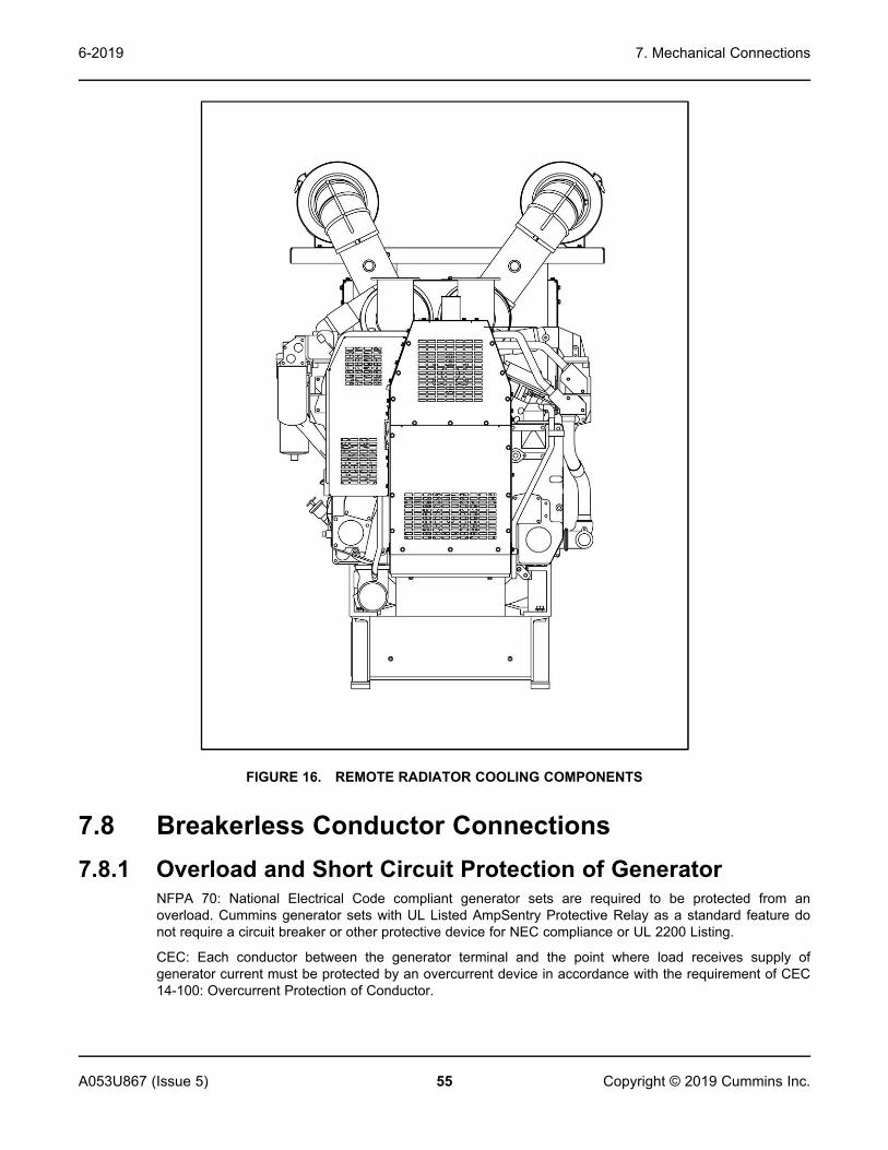
7. Mechanical Connections6-2019
55A053U867 (Issue 5) Copyright © 2019 Cummins Inc.
FIGURE 16. REMOTE RADIATOR COOLING COMPONENTS
7.8 Breakerless Conductor Connections7.8.1 Overload and Short Circuit Protection of Generator
NFPA 70: National Electrical Code compliant generator sets are required to be protected from anoverload. Cummins generator sets with UL Listed AmpSentry Protective Relay as a standard feature donot require a circuit breaker or other protective device for NEC compliance or UL 2200 Listing.
CEC: Each conductor between the generator terminal and the point where load receives supply ofgenerator current must be protected by an overcurrent device in accordance with the requirement of CEC14-100: Overcurrent Protection of Conductor.

7. Mechanical Connections 6-2019
56 A053U867 (Issue 5)Copyright © 2019 Cummins Inc.
UL label indicates to the Authority Having Jurisdiction (AHJ) that the generator set incorporates a ULListed Protective Relay that provides overload and short circuit protection for the generator and itsconductors. The generator set does not require use of a circuit breaker or other protective device forNFPA 70: National Electrical Code compliance or UL 2200 Listing.
7.8.1.1 AmpSentry LabelsThese are typical labels for UL compliant generator sets produced after January 2012.
FIGURE 17. POWER COMMAND 3.3 LABEL
FIGURE 18. TYPICAL INFORMATION LABEL

7. Mechanical Connections6-2019
57A053U867 (Issue 5) Copyright © 2019 Cummins Inc.
FIGURE 19. POWER COMMAND 2.2, 2.3, AND 3.3 SPECIFIC CHECK LABEL
7.8.2 AmpSentry Protective Relay Time-Over CurrentCharacteristic CurveThe protection provided is shown in the figure below, which shows the time-current characteristic of thesupplied protection. This protection curve is specifically designed to protect the generator supplied, soadjustments to the operation points for this curve are not allowed.
NOTICEThe values shown on the current scale are shown based on the value of 1.0 being equal to thenameplate rated current of the generator set for the specific operating voltage.

7. Mechanical Connections 6-2019
58 A053U867 (Issue 5)Copyright © 2019 Cummins Inc.
FIGURE 20. AMPSENTRY PROTECTIVE RELAY TIME OVER-CURRENT CHARACTERISTIC CURVE

7. Mechanical Connections6-2019
59A053U867 (Issue 5) Copyright © 2019 Cummins Inc.
7.8.3 Coordination of Protective DevicesConduct a selective coordination (discrimination) study on the distribution system that incorporates thegenerator set when choosing a generator set. Visit power.cummins.com for a copy of document R-1053,or it can be found using SKM Power Tools for Windows library or from your distributor.
7.8.4 Additional AmpSentry Protective Relay Information
TABLE 8. ADDITIONAL AMPSENTRY PROTECTIVE RELAY INFORMATION FOR POWERCOMMAND 2100CONTROL
Voltage No. of Phases Frequency (Hz) Current (Max) Connection
Battery Supply 8-30 V DC 22 A TB1 (17-22)
Voltage SenseInput 347/600 V 3 50/60 10 mA J8 (4, 7, 12, 20)
Current SenseInput 3 50/60 5 A J7 (11, 12, 15, 16,
19, 20)
AVR ShuntSupply 240 V 1 50/60 100 mA
J8 (21-23)AVR PMGSupply 210 V 1 50/60 100 mA
AVR Output(Continuous) 300 V (Peak) 1 PWM 4 A
J8 (5,13)AVR Output(Max/10seconds)
300 V (Peak) 1 PWM 6 A
Run RelayOutput 30 V DC 8 A; 1.44 A Pilot
Duty TB1 (17-22)
Customer RelayOutput
30 V DC 5 ATB1 (8-15)
250 V 1 AC 5 A; C300 PilotDuty
Indicator Supply 5 V DC 50 mA J2
Engine Sensors 5 V DC 3 mA J7 (13, 17, 21, 22,25, 26, 29-35)
Governor Drive 5-30 V DC 100 mA J7 (14, 24, 28, 36)
Power Out 8-30 V DC 100 mA J7 (1-8, 18)
Solenoid DriverSignal 5-30 V DC 100 mA J7 (9, 10, 23, 27)
Switch Input 8-30 V DC 1 mA J1
MembraneSwitch Input 5 V DC 1 mA J3
Customer Inputs 8-30 V DC 1 mA TB1 (1-6)

7. Mechanical Connections 6-2019
60 A053U867 (Issue 5)Copyright © 2019 Cummins Inc.
Voltage No. of Phases Frequency (Hz) Current (Max) Connection
Power TransferStatus 5-30 V DC 1 mA TB2 (5)
Power TransferSignal Supply 5-30 V DC 100 mA TB2 (3, 4, 6)
Interface 5 V DC 1 mA J50, J51, J4, J6
Communication RS485 TB2 (1, 2)
RS232 J9 (1-5, 9)
CAN (Optional) J10 (1-5)
Trip Current 110% generator nameplate FLA
Percentage ofTrip Current 100 300 600
Trip Times 500 seconds 10 seconds 1 second
Temperature 70 °C Maximum Surrounding Air Ambient

61A053U867 (Issue 5) Copyright © 2019 Cummins Inc.
8 DC Control WiringWARNING
Electric Shock HazardVoltages and currents present an electrical shock hazard that can cause severe burns or death.Avoid contact with the voltage sense and bus sense leads; voltages of up to 600 VAC may stillbe present. These voltages could be live even when the generator set is switched off.
WARNINGElectric Shock HazardVoltages and currents present an electrical shock hazard that can cause severe burns or death.Make sure all power is off before performing control wire installation.
WARNINGElectric Shock HazardVoltages and currents present an electrical shock hazard that can cause severe burns or death.To prevent accidental electrocution, stand on a clean dry wooden platform or clean rubberinsulating mat, make sure your clothing and shoes are dry, remove all jewelry, and use tools withinsulated handles.
The generator set control box contains connection points for remote control and monitor options.
NOTICEAlways run control circuit wiring in a separate metal conduit from the AC power cables to avoidinducing currents that could cause problems within the control.
Use cable ties to keep control wiring away from sharp edges and AC power cables within the controlhousing.
NOTICEStranded copper wire must be used for all customer connections to the control panel. Solidcopper wire may break due to the generator set vibration.
Use flexible conduit for all wiring connections to the generator set.
8.1 Guidelines for Customer Connections to the ControlSystem
• Torque terminals to 0.5 Nm (4.4 in-lb)
• Wire type: Use 60 C rated minimum copper wire
• Terminal screws (if fitted) are slotted 0.6 mm
• Use flat bladed screwdriver with 2.5 mm blade

8. DC Control Wiring 6-2019
62 A053U867 (Issue 5)Copyright © 2019 Cummins Inc.
• Strip wire length to 6.0 mm (0.236 in) for screw type terminals and 10 mm (0.75 in) for push typeterminals
8.1.1 Digital ConnectionsConnection points, other than relayed outputs and network are considered digital connections. Thetype/gauge wire to use for these connections are:
• Less than 305 m (1000 ft), use 0.5 mm2 (20 gauge) stranded copper wire.
• 305 m to 610 m (1000 ft to 2000 ft), use 0.75 mm2 (18 gauge) stranded copper wire.
8.1.2 Relay ConnectionsDue to the wide variety of devices that can be attached to the relay outputs, the electrical contractor mustdetermine the gauge of the stranded copper wire that is used.
8.2 PowerCommand 3.3 Customer ConnectionsRefer to Appendix B on page 107 for information on customer connections.
8.2.1 Configurable OutputsEach output has normally-open contacts. The contacts can be used to control small devices, indicatorlamps, or relays.
The contacts are programmed to energize by entering a code number for the desired event.
NOTICEUsing the InPower service tool or accessing the Setup submenus is required to modify thecustomer outputs. Contact an authorized distributor for assistance.
8.2.1.1 Contact Ratings for Configurable OutputsTABLE 9. CONTACT RATINGS FOR CONFIGURABLE OUTPUTS
Description Value
Maximum Voltage 30 VDC
Maximum Current 3.5 Amps
8.2.2 Remote StartWARNING
Automated MachineryAccidental or remote starting of the generator set can cause severe personal injury or death.Make sure that the generator set cannot be started accidentally or remotely before starting workon the generator.
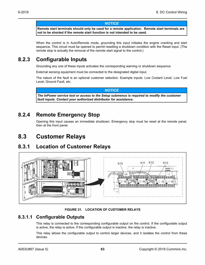
8. DC Control Wiring6-2019
63A053U867 (Issue 5) Copyright © 2019 Cummins Inc.
NOTICERemote start terminals should only be used for a remote application. Remote start terminals arenot to be shorted if the remote start function is not intended to be used.
When the control is in Auto/Remote mode, grounding this input initiates the engine cranking and startsequence. This circuit must be opened to permit resetting a shutdown condition with the Reset input. (Theremote stop is actually the removal of the remote start signal to the control.)
8.2.3 Configurable InputsGrounding any one of these inputs activates the corresponding warning or shutdown sequence.
External sensing equipment must be connected to the designated digital input.
The nature of the fault is an optional customer selection. Example inputs: Low Coolant Level, Low FuelLevel, Ground Fault, etc.
NOTICEThe InPower service tool or access to the Setup submenus is required to modify the customerfault inputs. Contact your authorized distributor for assistance.
8.2.4 Remote Emergency StopOpening this input causes an immediate shutdown. Emergency stop must be reset at the remote panel,then at the front panel.
8.3 Customer Relays8.3.1 Location of Customer Relays
FIGURE 21. LOCATION OF CUSTOMER RELAYS
8.3.1.1 Configurable OutputsThis relay is connected to the corresponding configurable output on the control. If the configurable outputis active, the relay is active. If the configurable output is inactive, the relay is inactive.
This relay allows the configurable output to control larger devices, and it isolates the control from thesedevices.

8. DC Control Wiring 6-2019
64 A053U867 (Issue 5)Copyright © 2019 Cummins Inc.
8.3.1.2 Contact SpecificationsThe contacts are rated at 10 A at 600 VAC.
8.3.1.3 Schematic
FIGURE 22. SCHEMATIC

65A053U867 (Issue 5) Copyright © 2019 Cummins Inc.
9 AC Electrical ConnectionsWARNING
Arc Flash and Shock HazardVoltages and currents present an electrical shock hazard that can cause severe burns or death.Make sure that only service personnel who are trained and experienced perform electrical andmechanical component installations. The AC sensing harness and other cabling will becomeenergized when the generator set is in operation.
WARNINGHazardous VoltageContact with high voltages can cause severe electrical shock, burns, or death.Make sure that only personnel who are trained and qualified to work on this equipment areallowed to operate the generator set and perform maintenance on it.
WARNINGAutomated MachineryAccidental or remote starting of the generator set can cause severe personal injury or death.Isolate all auxiliary supplies and use an insulated wrench to disconnect the starting batterycables (negative [–] first).
WARNINGCombustible GasesIgnition of battery gases is a fire and explosion hazard which can cause severe personal injury ordeath.Do not smoke, or switch the trouble light ON or OFF near a battery. Touch a grounded metalsurface first before touching batteries to discharge static electricity. Stop the generator set anddisconnect the battery charger before disconnecting battery cables. Using an insulated wrench,disconnect the negative (–) cable first and reconnect it last.
WARNINGElectric Shock HazardVoltages and currents present an electrical shock hazard that can cause severe burns or death.Avoid contact with the voltage sense and bus sense leads; voltages of up to 600 VAC may stillbe present. These voltages could be live even when the generator set is switched off.
This section provides the procedure that is used to connect the AC electrical system of the generator set.
Before making any AC electrical connections, make certain the generator set cannot be accidentallystarted. Make sure the Operator Panel is in OFF mode. Turn off or remove AC power from the batterycharger and then remove the negative (–) battery cable from the set starting battery using an insulatedwrench.
If the generator set is being installed in an application where it may parallel with other generators or utilitysources, the generator set control system may be energized from an external source. Lock out tag out anyexternal source that can provide AC power to the generator set.

9. AC Electrical Connections 6-2019
66 A053U867 (Issue 5)Copyright © 2019 Cummins Inc.
NOTICEVentilate the battery area before working on or near battery. Wear goggles. Stop the generatorset and disconnect the battery charger before disconnecting battery cables. Disconnect negative(–) cable first and reconnect last using an insulated wrench.
Connecting the generator set AC electrical system involves:
• Installation of transfer switch
• Installation or verification of paralleling switchboard
• Generator output voltage selection
• Load cable connection
• Standard and optional AC equipment connections (e.g., control box heater, coolant heater, etc.).
For all output connections, including when field connection is made at the alternator terminations,installation should be completed with conductors of appropriate size, type, and rating specified in localcodes (or UL). For UL compliant installations, use conductor size, X AWG, 75 °C or 90 °C copper wire,600V. Where X AWG is the conductor size specified by the local electrical code for 75 °C at the ratedoutput current for the generator set. For non-UL compliant installations, use cable sizes, composition, andrating per local codes. Strain relief, bending space, raceway, and other installation features should becompleted in compliance with local code.
Local regulations often require that wiring connections be made by a licensed electrician, and that theinstallation be inspected and approved before operation. All connections, wire sizes, materials used, etc.must conform to the requirements of electrical codes in effect at the installation site.
Before starting the generator set, check to make sure that all electrical connections are secure, and thatall wiring is complete. Replace and secure any access panels that have been removed during installation.Check that the load cables from the generator set are properly connected.
NOTICEBackfeed to a utility system can cause electrocution or property damage. Do not connect to anybuilding electrical system except through an approved device and after the building main switchis opened.
9.1 AC Distribution Panel ConnectionsNOTICE
Make sure that all circuit breakers are in the OFF position before applying power to theAC distribution panel. Other options may require additional installation beforeconnecting to power.

9. AC Electrical Connections6-2019
67A053U867 (Issue 5) Copyright © 2019 Cummins Inc.
9.1.1 AC Distribution PanelWARNING
Electric Shock HazardVoltages and currents present an electrical shock hazard that can cause severe burns or death.Receptacles J1 through J4 are GFCI protected and must not be used by service personnel as apower source for tools or lighting.
NOTICEMake sure that all circuit breakers are in the OFF position before applying power to the ACdistribution panel. Other options may require additional installation before connecting to power.
NOTICEWhen the generator set contains the fuel transfer pump option, power to the AC distributionpanel must be fed from a transfer switch and step-down transformer to maintain 120V power tothe pump when utility power is interrupted. If the transfer pump option is not installed, power tothe AC distribution panel can be fed from a non-emergency source. (Other optional featuresconnected to the AC distribution panel are not needed for generator set operation.)
The AC distribution panel provides a centralized power source (120/220 VAC) for all optional enclosurefeatures.
All connections to the AC distribution panel must comply with the National Electric Code and all applicablelocal codes and standards using 60 or 75 °C (140 or 167 °F) conductors.
The AC distribution panel is powered with a 150 A, 120/240 VAC, single phase feeder. The 2 lineconductors connect into the 150 A main breaker that is listed for #4 to 2/0 conductors, AL or CU whentorqued to 5.6 Nm (50 in-lbs).
The neutral conductor connects into the neutral bus which is listed for #5 to 300KCMIL conductors, AL orCU when torqued to 28.4 Nm (21 ft-lbs).
The grounding conductor, if used, connects into the ground bar which is listed for #1 to 2/0 conductors, ALor CU when torqued to 23 Nm (17 ft-lbs).
The GFCI receptacle is a 120 VAC/20 A ground fault protected outlet that is for use by service personnel.It also supplies power to the external receptacle.
Receptacles J1 through J4 are for internal use only (not GFCI protected). They are 120 VAC/20 A outletsfor optional enclosure features.

9. AC Electrical Connections 6-2019
68 A053U867 (Issue 5)Copyright © 2019 Cummins Inc.
No. Description No. Description
CIRCUIT BREAKERS 120 VAC RECEPTACLES FOR OPTIONALFEATURES
1/2 150A Main J1 Engine Oil Heater
3/5 40A Coolant Heaters J2 Battery Heater
7/9 40A Coolant Heaters J3 Alternator/Control Cabinet Heaters
11/13
40A Enclosure Heater J4 Battery Charger/Transfer Pump Controller
4 20A J7 Receptacle J5 GFCI Service Receptacle
6 20A J5/J7 Receptacles J6 Optional External Service Receptacle (Not Shown)
8 20A Inlet/Outlet Louvers J7 Enclosure Lights Receptacle
10 20A J1/J2 Receptacles
12 20A J3/J4 Receptacles
14 Spare
FIGURE 23. AC DISTRIBUTION PANEL
9.2 Transfer SwitchA transfer switch must be used for switching the load from the normal power source to the generator set(see Figure 24). Follow the installation instructions provided with the transfer switch when connecting theload and control wiring.

9. AC Electrical Connections6-2019
69A053U867 (Issue 5) Copyright © 2019 Cummins Inc.
No. Description No. Description
1 Normal Power Source 3 Load
2 Overcurrent Protective Device 4 Emergency Power Source
FIGURE 24. TYPICAL LOAD TRANSFER FUNCTION
9.3 Alternator Voltage ConnectionsThese alternators can be configured to the nameplate voltages as shown on the Reconnection Diagramdecal, attached to the backside of the control box cover. Many of the voltages listed will requirereconfiguration of the alternator output leads on the connection terminal block. This reconfiguration mustonly be done by service personnel that are trained and experienced to perform electrical installation. Thegenerator set was adjusted to produce a specified voltage during production verification testing prior toshipment. The installer must always check the stator lead terminal block connections and perform anynecessary reconnect to obtain the voltage required.
Some generator sets are capable of producing a wide range of voltages and connection configurations;others have specific limited capabilities. Refer to wiring diagram and generator voltages (from thenameplate) when reviewing the voltage connection information and use the wiring diagram supplied withyour generator set when actually performing load connections.
NOTICEReconfiguring generator sets to higher voltages can exceed the voltage capability of the specificgenerator windings and damage the generator and also decrease line current, rendering linecircuit breakers too large. Consult with your authorized distributor before performingreconnection for a different voltage.
NOTICEReconfiguring generator sets to lower voltages can reduce generator set ratings, and alsoincrease line current, rendering line circuit breakers too small. Consult with your authorizeddistributor before performing reconnection for a different voltage.

9. AC Electrical Connections 6-2019
70 A053U867 (Issue 5)Copyright © 2019 Cummins Inc.
9.4 Load ConnectionsNOTICE
Flexible conduit and stranded conductors must be used for connections to take up movement ofthe generator set.
All loads are connected to the alternator by bolting stranded load wires to the appropriate terminals on thealternator reconnection terminal block or circuit breaker lugs. The terminals are marked U, V, W, and N toindicate the line and neutral connections. (Reference: U, V, and W correspond with L1, L2 and L3; and Nwith L0 respectively). See Appendix C on page 121 for details about the following:
• Load connections
• Conduit
• Cable Size
9.4.1 Generator Set Load Cable InstallationTo ensure optimum performance of the generator set, load cables passing through cable gland platesmust be adequately protected and secured.
9.4.2 Cabling through Non-Ferrous Gland PlatesSingle core load cables must be secured using non-ferrous cable glands.
9.4.3 Cabling through Ferrous Gland PlatesSingle core load cables must pass through the same hole, or slotted cable gland holes as illustrated (seeFigure 25). Cable glands must be made from non-ferrous material.
No. Description No. Description
1 Cable Gland Holes 2 Slot > 0.5 mm (0.02 in)
FIGURE 25. FERROUS GLAND PLATES
9.4.4 Distribution CablesSingle core power distribution cables should be grouped in a trefoil formation as illustrated (See Figure26). (Trefoil grouping provides optimum cable loading and reduces electrical emissions). To minimizecable temperature rise and reduce cable de-rate factors, cable groups where possible, should be spacedto provide ventilation. Cable groups must be secured with non-ferrous material.

9. AC Electrical Connections6-2019
71A053U867 (Issue 5) Copyright © 2019 Cummins Inc.
FIGURE 26. TREFOIL FORMATION
9.5 Installation of s-CAN Network CableThe s-CAN cable connects the TB3 of the generator set MLD controller with up to 15 other generator setMLD controllers to form a closed s-CAN Network.
FIGURE 27. TB3 PINS
TABLE 10. TB3 PIN ASSIGNMENTS: CUSTOMER INPUT/OUTPUT CONNECTIONS
Customer Terminal Block PCC3300 Pin Description Function/Connects to:
CTB26-2 TB3-1 Ground s-CAN shield connectionpoint or use as a signalreturn for switch inputs
CTB27-2 TB3-2 s-CAN Isolated Ground s-CAN network ground only,Do not connect tochassis/BatteryGroundConnect to TB3-2 ofother PCC3300 controls onthe s-CAN NetworkPCC3300 with MLD ONLY
CTB28-2 TB3-3 s-CAN CAN L s-CAN data line for control-to-controlcommunicationsConnect toTB3-3 of other PCC3300controls on the s-CANNetworkPCC 3300 withMLD ONLY

9. AC Electrical Connections 6-2019
72 A053U867 (Issue 5)Copyright © 2019 Cummins Inc.
Customer Terminal Block PCC3300 Pin Description Function/Connects to:
CTB29-2 TB3-4 s-CAN CAN H s-CAN data line for control-to-controlcommunicationsConnect toTB3-4 of other PCC3300controls on the s-CANNetworkPCC 3300 withMLD ONLY
TB3-2, TB3-3, and TB3-4 s-CAN Network Connections (PC 3.3 MLD ONLY)
FIGURE 28. S-CAN NETWORK DIAGRAM
s-CAN cable requirements: Twisted pair (shielded) cable meets SAE J1939-11 standards, 200 mmaximum network length.
NOTICERecommended cable type: Belden 3106A or equivalent.
To prevent ground loops shield/drain wire are to be connected to TB3-1 at only one end of a s-CANnetwork (bus) cable/segment. Shield continuity must be maintained over entire length of cable/segment.
NOTICERecommended shield connection method Figure 29
FIGURE 29. SHIELD CONNECTIONS ON MLD S-CAN NETWORK

9. AC Electrical Connections6-2019
73A053U867 (Issue 5) Copyright © 2019 Cummins Inc.
9.6 Load BalancingWhen connecting loads to the generator set, balance the loads so that the current flow from each lineterminal (L1, L2, and L3) is about the same. This is especially important if both single phase and threephase loads are connected. Any combination of single phase and three phase loading can be used aslong as each line current is about the same, within 10 percent of median value and no line currentexceeds the name plate rating of the generator. Check the current flow from each line after connectionsby observing the Operator Panel ammeter.
9.7 Fuel Transfer Pump InstallationWARNING
Combustible LiquidFuel leaks are a fire and explosion hazard which can cause severe personal injury or death.Make sure that only trained and experienced personnel install and service the generator set inaccordance with applicable codes.
NOTICEDo not smoke near fuel and keep flames, sparks, pilot lights, arcing switches and equipment, andother sources of ignition well away.
A fuel transfer pump and control are available as an option when a sub-base or an in-skid day tank isprovided. The automatic control operates the fuel pump to maintain a reservoir of fuel in the day tank.
9.7.1 Fuel Transfer Pump Control AC ConnectionsSee the wiring diagrams provided with your generator set when making connections at the fuel pumpcontrol.

9. AC Electrical Connections 6-2019
74 A053U867 (Issue 5)Copyright © 2019 Cummins Inc.
FIGURE 30. FUEL PUMP CONTROL TERMINAL BOARD
The following should be noted.
1. The control can be powered by 120 VAC or 240 VAC. The control is set up at the factory forconnection to 240 VAC.
NOTICETo convert the day tank controller from 240 VAC to 120 VAC, perform the following steps.
a. Remove the two jumpers between terminals TB1-6 and TB1-7 in the control box, andconnect one jumper between terminals TB1-5 and TB1-6 and the other jumper betweenterminals TB1-7 and TB1-8.
b. Move selector switch S103 on the control PCB to the up position for 120 V.
c. On the control transformer, remove the two jumpers between terminals H2 and H3, andconnect one jumper between H1 and H3 and the other jumper between H2 and H4.
NOTICETo convert the day tank controller from 120 VAC to 240 VAC, perform the following steps.
a. Remove the jumpers between terminals TB1-5 and TB1-6 and TB1-7 and TB1-8 in thecontrol box, and connect the two jumpers between terminals TB1-6 and TB1-7.
b. Move selector switch S103 on the control PCB to the down position for 240 VAC.
c. On the control transformer, remove the jumpers between terminals H1 and H3 and H2and H4, and connect the two jumpers between H2 and H3.
2. Attach a tag to the control box indicating the supply voltage.
3. Terminals TB1-8 and TB1-5 are available for connection of a 120 VAC or 240 VAC electric fuelshutoff valve rated not more than 0.5 amps. The voltage rating of the valve must correspond with thevoltage utilized for the pump.

9. AC Electrical Connections6-2019
75A053U867 (Issue 5) Copyright © 2019 Cummins Inc.
9.8 Current TransformersCurrent transformers (CTs) reduce high voltage currents (AC) to enable safe monitoring.
9.9 Coolant HeaterThe coolant heaters are designed to allow the generator set to start and pick up load within 10 seconds ina 4.4 °C (40 °F) environment. In colder ambient temperature environments the starting time may belonger.
9.10 Alternator Heaters9.10.1 Alternator Heater Connection
WARNINGElectric Shock HazardVoltages and currents present an electrical shock hazard that can cause severe burns or death.Water or moisture inside an alternator increases the possibility of flashing and electrical shock.Do not use an alternator which is not dry inside and out.
An alternator heater(s) is used to help keep the alternator free of condensation when the generator set isnot running. During cool and humid conditions, condensation can form within an alternator, creatingflashing and shock hazards.
Connect the heater(s) terminals to a source of power that will be on during the time the engine is notrunning. Be sure the supply voltage and circuit amperage is correct for the heater element rating.
9.11 Control Box Heater9.11.1 Control Box Heater Installation
A thermostat controlled heater is installed inside the control cabinet. Figure 31 shows a typical heater.Figure 32 shows typical heater wiring. Also see Appendix D on page 145.
The control box heater power cord must be installed and connected to a grounded outlet.

9. AC Electrical Connections 6-2019
76 A053U867 (Issue 5)Copyright © 2019 Cummins Inc.
FIGURE 31. TYPICAL CONTROL BOX HEATER
No. Description No. Description
1 Heater 2 Thermostat
FIGURE 32. TYPICAL HEATER WIRING DIAGRAM
9.12 Battery CommissioningNOTICE
Commissioning is to be undertaken by suitably trained and qualified service personnel only.
Lead-acid batteries supplied in dry-charged form are commissioned as follows:
• Pre-Commissioning Procedure
• Filling the Battery with Electrolyte

9. AC Electrical Connections6-2019
77A053U867 (Issue 5) Copyright © 2019 Cummins Inc.
• Charging
• Fitting the Battery to the Generator Set
9.12.1 Safety PrecautionsServicing of batteries are to be performed or supervised by personnel knowledgeable of batteries and therequired precautions. Keep unauthorized personnel away from batteries.
9.12.1.1 General Precautions
WARNINGCombustible GasesIgnition of battery gases is a fire and explosion hazard which can cause severe personal injury ordeath.Laying tools or metal objects across the battery can cause arcing. Never lay tools or metalobjects across the top of the battery.
CAUTIONElectrical ShockA battery presents a risk of electrical shock and high short circuit current which can cause minoror moderate injury.Observe the following precautions when working on batteries.
• Use proper PPE. Remove jewelry such as watches, rings, or other metal objects. Remove anyconductive items from pockets. These items can fall into equipment and result in a short circuit,which can cause shock or burning. Refer to local standards for PPE details (in the U.S: see NFPA70).
• Keep batteries upright to prevent spillage. Electrolyte is a dilute sulphuric acid that is harmful to theskin and eyes.
• Use tools with insulated handles to prevent the risk of electric shock.
9.12.1.2 Fire Hazard
NOTICEDuring the charging of a battery, explosive gases are given off. Keep the battery area wellventilated and away from naked flames and sparks. Do not smoke.
• Before disconnecting a battery, isolate the utility powered battery charger (where fitted).
• To disconnect the battery, use an insulated wrench to disconnect the negative cable first.
• To connect the battery, use an insulated wrench to connect the negative cable last.

9. AC Electrical Connections 6-2019
78 A053U867 (Issue 5)Copyright © 2019 Cummins Inc.
9.12.1.3 Fluid Hazard
WARNINGToxic HazardContact with electrolyte can cause severe personal injury.Wear appropriate PPE when handling electrolyte: acid-proof protective apron, goggles, rubbergloves and boots. If electrolyte is splashed on the skin or in the eyes, flush the affected areasimmediately with water and seek medical attention.
WARNINGHazardous LiquidUncontrolled chemical reactions can cause severe chemical burns or death.Never add undiluted sulfuric acid to a battery.
9.12.2 Pre-Commissioning Procedure1. Check for any damage to the battery case or terminals, and make sure that the battery is clean and
dry.
2. Remove the vent plugs and break any seals (if present), taking care not to damage the plates orseparators. The broken seal will fall into the bottom of the chamber and do no harm.
9.12.3 Filling the Battery with Electrolyte1. Fill each cell of the battery with dilute sulphuric acid (electrolyte) of the correct specific gravity (SG)
according to the levels on the battery label.
2. Filling must be completed in one step.
3. Allow the battery to soak for ten to fifteen minutes. If the electrolyte level has fallen, it should berestored by adding electrolyte of the correct SG to the levels given on the battery label.
4. After filling, place the battery on a commissioning charge within one hour. Charging must take placebefore any load is placed on the battery.
NOTICEFailure to give a commissioning charge may impair the charge capacity and life of the battery.
9.12.4 Charging - Commissioning1. Charge the battery for a minimum of four hours to ensure the acid is sufficiently mixed within the
battery. If the battery has been in storage, check the manufacturer's instructions; the charging periodmay need extending.
2. When the generator set is running, check the charge alternator output using an induction ammeter.

9. AC Electrical Connections6-2019
79A053U867 (Issue 5) Copyright © 2019 Cummins Inc.
9.12.5 Connecting the Battery to the Generator SetNOTICE
A battery must not be fitted to a generator set without charge if the specific charge of theelectrolyte has fallen below 1.240 during storage.
1. Secure the battery. Battery hold-down bolts must be tight, but not over-tight.
2. Smear the terminals with petroleum jelly, if necessary.
3. Fit the vents firmly in position and ensure that the battery is clean and dry.
4. Verify correct polarity when connecting the battery to the set. Even momentary incorrect connectioncan cause damage to the electrical system.
5. Use an insulated wrench connect the positive generator cable first, followed by the negative cable.Terminal connections must be tight, but not over-tight.
9.12.6 Electrolyte - Specific Gravity and TemperatureMaintenance-free batteries are sealed and do not require the addition of electrolyte. Some manufacturersof maintenance-free batteries provide an ‘eye’ or other visible means of telling when the battery isdischarged or approaching the end of its useful life.
9.12.6.1 Checking Electrolyte Level
NOTICENever add tap or well water and never allow the battery electrolyte to drop below the top of theplates, otherwise damage will occur.
NOTICEDo not add water in freezing weather unless the engine will run long enough (2 to 3 hours) tomake sure that water and electrolyte are thoroughly mixed.
Check the level of the electrolyte (acid and water solution) in the batteries at least every month or 100hours of operation, whichever occurs first. Maintain the electrolyte to the levels indicated on the batterylabel. Add distilled water only and recharge. Replace the vent plugs once filling is completed.
If a cell level is low, check the case for leaks.
Keep the battery case clean and dry. An accumulation of moisture will lead to a more rapid discharge andbattery failure.
9.12.6.2 Checking Specific Gravity Using a HydrometerUse a hydrometer to check the specific gravity (SG) of the electrolyte in each battery cell.
Hold the hydrometer vertically and take the reading.

9. AC Electrical Connections 6-2019
80 A053U867 (Issue 5)Copyright © 2019 Cummins Inc.
FIGURE 33. CHECKING SPECIFIC GRAVITY
9.12.6.3 Checking Specific Gravity Using an Acid RefractometerFollow the instructions included with the refractometer. Obtain a small drop of liquid and place it under theclear plastic cover to check the specific gravity (SG) of the electrolyte in each battery cell.
FIGURE 34. TYPICAL BATTERY ACID REFRACTOMETER
9.12.6.4 Specific Gravity Values for BatteriesA fully charged battery will have a corrected specific gravity (SG) of 1.260 at 25 °C (77 °F). Hold thehydrometer vertically and take the reading. Charge the battery if the reading is below 1.215. The tablebelow shows the specific gravity of electrolyte, corrected to 25 °C (77 °F).

9. AC Electrical Connections6-2019
81A053U867 (Issue 5) Copyright © 2019 Cummins Inc.
TABLE 11. SPECIFIC GRAVITY
Temperature For Filling New Cells At End of Charge
Ambient temperature normally below 32 °C (90 °F) 1.270 1.270 – 1.290
Ambient temperature frequently above 32 °C (90 °F) 1.240 1.240 – 1.260
Maximum permissible temperature of electrolyte during charge 45 °C (113 °F) 45 °C (113 °F)
Correct the specific gravity reading for other temperatures by subtracting seven gravity points (0.007) forevery 10 °C (18 °F) when the electrolyte temperature is above 27 °C (80 °F). Apply the correction formulaas follows:
• For every 10 °C (18 °F) above 25 °C (77 °F), subtract 0.007 (7 points)
• For every 10 °C (18 °F) below 25 °C (77 °F), add 0.007 (7 points)
For example: if the specific gravity at 25 °C (77 °F) is 1.260, then the specific gravity at 15 °C (59 °F) is1.267.
9.13 Battery Charger9.13.1 PowerCommand Battery Charger - 15 Amp at 12 Volt and
12 Amp at 24 VoltThere are two types of 15/12-Amp PowerCommand battery chargers. All 15/12-Amp battery chargershave a 20 Amp DC circuit breaker switch on the front of the battery charger. The 120, 208, and 240 VACbattery chargers include two 10 Amp AC circuit breaker switches, all other models include two AC fuseholders.
Refer to the battery charger Owner Manual (901-0107) for more information.

9. AC Electrical Connections 6-2019
82 A053U867 (Issue 5)Copyright © 2019 Cummins Inc.
A 120, 208, and 240 VAC Battery Charger 4 20 Amp DC Circuit Breaker Switch (Shown in the"On" position)
B Battery Charger with Fuse Holders 5 10 Amp AC Circuit Breaker Switches (Shown in the"On" position)
1 Status LED 6 Fault Alarm Output Connector
2 Control Panel 7 10 Amp AC Fuse Holders
3 Reset Button 8 Connector for Optional Battery Temperature Sensor
FIGURE 35. 15/12-AMP POWERCOMMAND BATTERY CHARGERS
9.14 GroundingWARNING
Electric Shock HazardVoltages and currents present an electrical shock hazard that can cause severe burns or death.Make sure that only service personnel who are trained and experienced perform electrical andmechanical component installations. Bonding and grounding must be done properly. All metallicparts that could become energized under abnormal conditions must be properly grounded.

9. AC Electrical Connections6-2019
83A053U867 (Issue 5) Copyright © 2019 Cummins Inc.
The following is a brief description of system and equipment grounding of permanently installed ACgenerators within a facility wiring system.
NOTICEIt is important to follow the requirements of the local electrical code.
Figure 36, Figure 37 and Figure 38 illustrate typical system grounding for a 2-pole, 3-pole, and 4-poleAutomatic Transfer Switch (ATS). In the 2-pole and 3-pole ATS, note that the generator neutral isconnected to the ATS and is NOT bonded to ground at the generator. In the 4-pole ATS system, agrounding electrode conductor and a bonding jumper are used to connect the generator neutral to ground.
Make sure the generator set is grounded to earth in one location only. On generator sets without a circuitbreaker, ground to the point indicated on the top of the generator. On generator sets with circuit breakers,use the ground lug provided in the circuit breaker box.
No. Description No. Description
1 Service Entrance 3 Generator Set
2 2-Pole ATS 4 Load
FIGURE 36. TYPICAL SYSTEM - ONE-PHASE, THREE WIRE UTILITY, TWO-POLE ATS

9. AC Electrical Connections 6-2019
84 A053U867 (Issue 5)Copyright © 2019 Cummins Inc.
No. Description No. Description
1 Service Entrance 3 Generator Set
2 3-Pole ATS 4 Load
FIGURE 37. TYPICAL SYSTEM - THREE-PHASE, FOUR WIRE UTILITY, THREE-POLE ATS
No. Description No. Description
1 Service Entrance 3 Generator Set
2 4-Pole ATS 4 Load
FIGURE 38. TYPICAL SYSTEM - THREE-PHASE, FOUR WIRE UTILITY, FOUR-POLE ATS

85A053U867 (Issue 5) Copyright © 2019 Cummins Inc.
10 Pre-Start PreparationWARNING
Electrical Generating EquipmentIncorrect operation and maintenance can result in severe personal injury or death.Make sure that only suitably trained and experienced service personnel perform electrical and/ormechanical service.
Before an initial start of the generator set, complete the Installation Checklist, see Chapter 11 on page89.
10.1 Initial Pre-start ChecksWARNING
Electric Shock HazardVoltages and currents present an electrical shock hazard that can cause severe burns or death.Make sure that only personnel who are trained and experienced work with distribution voltages.Even after generator set shutdown, an electrical shock hazard may still exist, caused by inducedor residual voltage within the alternator or cables. Some interfaces may display zero voltageeven when voltages are present.
WARNINGHot Pressurized LiquidContact with hot liquid can cause severe burns.Do not open the pressure cap while the engine is running. Let the engine cool down beforeremoving the cap. Turn the cap slowly and do not open it fully until the pressure has beenrelieved.
Before starting, be sure competent personnel have made the following checks to ensure that the unit isready for operation:
• Generator Set Grounding – Grounding (Earthing) must be checked prior to performing service orinspection procedures that may expose personnel to conductors normally energized with voltagesgreater than 600 Volts. Contact your authorized distributor.
• Megger and Insulation Testing – This must be performed on all generator sets before initial start-upand after the generator set Grounding Procedure has been completed. Insulation testing for lowvoltage (less than 600 Volts) generator sets is recommended by Cummins. These tests are used toverify that the windings are dry before the generator set is operated, and to develop a base line forfuture test comparisons. Contact your authorized distributor.
NOTICEWhen Megger testing an alternator, failure to protect the voltage regulator, control and diodescould result in permanent damage to one or more of the electronic components.
• Lubrication – Check the engine lubrication oil level and ensure that the correct level is alwaysmaintained.

10. Pre-Start Preparation 6-2019
86 A053U867 (Issue 5)Copyright © 2019 Cummins Inc.
NOTICEGenerator sets may be shipped dry. They must be filled with the correct type and quantity of oilbefore use. Be sure to check oil level before initial start. Failure to fill to the recommended levelcan result in equipment damage.
• Coolant – Check the engine coolant level and ensure that the level is always maintained. Fill thecooling system to the bottom of the fill neck in the radiator fill or expansion tank. Do not check whilethe engine is hot.
NOTICEIt is essential that Cummins recommendations for the correct type and concentration of anti-freeze and DCA inhibitor are complied with. Warranty claims for damage will be rejected if theincorrect mix has been used. Consult your authorized distributor for the correct anti-freezespecifications and concentration for your operating conditions.
NOTICESome radiators have two fill necks, both of which must be filled after the cooling system hasbeen drained.
NOTICEGenerator sets may be shipped dry. They must be filled with the correct type and quantity ofcoolant before use. Be sure to check coolant level, or levels, before initial start. Refer to coolingsystem instructions in the Operator Manual.
10.2 Electrical SystemVerify all electrical connections are secure and all wiring is complete and inspected. Replace and secureany access panels that may have been removed during installation.
10.3 Battery ConnectionsWARNING
Automated MachineryAccidental or remote starting of the generator set can cause severe personal injury or death.Make sure that the generator set cannot be started accidentally or remotely before starting workon the generator.
WARNINGCombustible GasesIgnition of battery gases is a fire and explosion hazard which can cause severe personal injury ordeath.Do not smoke, or switch the trouble light ON or OFF near a battery. Touch a grounded metalsurface first before touching batteries to discharge static electricity. Stop the generator set anddisconnect the battery charger before disconnecting battery cables. Using an insulated wrench,disconnect the negative (–) cable first and reconnect it last.

10. Pre-Start Preparation6-2019
87A053U867 (Issue 5) Copyright © 2019 Cummins Inc.
Starting the unit requires one or more batteries. For more information on batteries, refer to the ModelSpecifications section. To prevent arcing, use an insulated wrench to connect the positive battery cable,then connect the negative battery cable.
If an automatic transfer switch is installed without a built-in charge circuit, connect a separate batterycharger. Proper selection and maintenance of batteries and battery chargers is essential for systemreliability.
10.4 Site-Specific ConfigurationNOTICE
Site-specific configuration is to be undertaken by suitably trained and qualified service personnelonly.
The generator set is configured at the factory. Before starting the generator set, any site-specificconfiguration should be completed by qualified service personnel.
10.5 StartingRefer to the generator set Operator manual for important safety precautions and recommendedprocedures for starting the generator set and verifying proper operation. Start the generator set and verifyall engine and generator set menus are displaying the correct values.

This page is intentionally blank.
10. Pre-Start Preparation 6-2019
88 A053U867 (Issue 5)Copyright © 2019 Cummins Inc.

89A053U867 (Issue 5) Copyright © 2019 Cummins Inc.
11 Installation Checklist
11.1 ChecklistTick General Items
Generator set output is sufficient to handle maximum anticipated load.
At least 0.9 m (3 feet) of clearance (or greater for housing door) is provided around the entire generator setfor service and ventilation.
The generator set is located in an area not subject to flooding.
All operating personnel have read and are familiar with the generator set Operator manual, all health andsafety procedures, warnings, cautions, precautions, and the other documentation supplied with the generatorset.
All operators have been thoroughly briefed on preventative maintenance procedures.
All operators have read and understand all important safety instructions.
Any parts requiring software have been checked for the latest version. Contact the service representative formore information.
Generator Set Position
The floor, roof, or earth on which the generator set rests is strong enough and will not allow shifting ormovement. Observe local codes on soil bearing capacity due to freezing and thawing.
The generator set is properly supported and retained to an approved base.
The supporting base is large enough and is of non-combustible material, extending 15 cm (6 inches) allaround the generator set.
Provisions have been made for site specific environmental operating conditions (weather protection,proximity to coastline, dusty environments, etc.,)
Cooling Air Flow
Generator set air inlet is faced into the direction of strongest, prevailing winds.
Air inlet openings are unrestricted and are at least 1 to 11/2 times larger than air outlet area.
Cooling air outlet is on downwind side of building (if not, a wind barrier is constructed).
Proper ducting material (sheet metal, canvas) is used between radiator and air outlet.
Diesel Fuel System (if applicable)
Fuel tanks meet or exceed all local, State, or National codes (if applicable).
Fuel lines are properly installed, supported, and protected against damage.
The fuel filters have been installed.
Approved flexible fuel line is installed between the main fuel supply and the generator set’s fuel system nearthe generator set, to protect it against damage caused by vibration, expansion, and contraction.
Strainer or fuel screen (100 to 200 mesh) is installed in the fuel supply line to protect the fuel lift pump, daytank transfer pump, or float valve seat from fuel tank debris (if applicable).
The fuel filter assembly shipped with the generator set is installed and operational (if applicable).

11. Installation Checklist 6-2019
90 A053U867 (Issue 5)Copyright © 2019 Cummins Inc.
Fuel supply shutoff valves are installed to prevent fuel flow in case of leaks.
No shutoff valves are installed on engine fuel return line (if applicable).
External fuel pumps are connected and operational at all times - generator set started or shut down (ifapplicable).
Fuel tanks are filled with the correct grade / type of fuel (if applicable).
Fuel system is properly primed.
No fuel leaks are found in supply line or engine fuel system.
Exhaust System
The breather tube routing is set up to blow the fumes away from the generator set (if applicable)
Operators are thoroughly briefed on the dangers of carbon monoxide gas.
If the installation includes a heavy duty air cleaner, it has been installed.
Areas around generator set are well ventilated, with no possibility of exhaust fumes entering building doors,windows, or intake fans.
Exhaust gases are piped safely outside and away from building.
The correct length of approved rigid pipe is connected to the generator set flexible pipe using approvedsecuring methods with no weight resting on engine exhaust components. There are no bends in flex section.
Condensation drain is provided in lowest section of exhaust piping.
Exhaust piping is insulated to guard against burns to personnel.
Exhaust piping passing through walls or ceilings have approved fire-proof materials and are in compliancewith all codes.
Exhaust piping is large enough in diameter to prevent excessive back pressure on engine.
Verify that the pyrometer meters are functioning.
AC and DC Wiring
For bottom entry circuit breaker installations, the cable chute has been installed (if applicable).
Wire sizes, insulation, conduits and connection methods all meet applicable codes.
AC and DC wires are separated in their own conduit to prevent electrical induction.
All load, line and generator connections are well made and correct.
Flexible conduit is used between the generator and the building or surrounding structure.
Check phase rotation.
Generator Set Pre-Start
Generator set engine is properly serviced with oil and coolant.
Battery charger is installed using the appropriate cable size and is operational.
Battery charger is configured for the proper DC battery voltage, battery type, and float voltage.
Batteries are properly installed, serviced and charged.
Battery temperature sensor is connected and operational (if applicable).
Cooling system is filled with correct volume and concentration of coolant. The water used in the coolant mixhas passed water quality check.

11. Installation Checklist6-2019
91A053U867 (Issue 5) Copyright © 2019 Cummins Inc.
Engine coolant heater is connected and operational.
All generator set covers and safety shields are installed correctly.
All fuel and coolant shutoff valves are operational.
Shipping brackets are removed.
Radiator fan and other external moving parts, including drive belts, are unrestricted.

This page is intentionally blank.
11. Installation Checklist 6-2019
92 A053U867 (Issue 5)Copyright © 2019 Cummins Inc.

93A053U867 (Issue 5) Copyright © 2019 Cummins Inc.
12 Manufacturing FacilitiesU.S. and CANADA EMEA, CIS EMEA, CIS
Cummins Inc.1400 73rd Ave. NEMinneapolis, MN 55432 USA
Cummins Inc.Columbus AvenueManston ParkManston, RamsgateKent CT12 5BFUnited Kingdom
Cummins Inc.Royal Oak Way SouthDaventryNorthamptonshireNN11 8NUUnited Kingdom
Toll Free 1-800-CUMMINSTM
(1-800-286-6467)Phone +1 763-574-5000Fax +1 763-574-5298
Phone +44 1843 255000Fax +44 1843 255902
Phone +44 1327 88-6453Fax +44 1327 88-6125
BRAZIL CHINA INDIA
Rua Jati, 310, CumbicaGuarulhos, SP 07180-900CNPJ: 43.2201.151/0001-10Brazil
Cummins Inc.No.118 South Quanli Road ,Wuhan Economic& TechnologicalDevelopment Zone , Hubei,P.R.China 430058
Cummins Inc.Plot No B-2, SEZ Industrial Area,Village-Nandal & Surwadi, Taluka-PhaltanDist- Satara, Maharashtra 415523India
Phone 0800 286 6467 Phone + 86 (27) 8421 4008Fax + 86 (27) 8421 4804
Phone +91 021 66305514
LATIN AMERICA MEXICO ASIA PACIFIC
3350 Southwest 148th Ave.Suite 205Miramar, FL 33027USA
Eje 122 No. 200 Zona IndustrialSan Luis Potosi, S.L.P. 78395Mexico
Cummins Inc.10 Toh Guan Road #07-01TT International TradeparkSingapore 608838
Phone +1 954 431 551Fax +1 954 433 5797
Phone +52 444 870 6700Fax +52 444 824 0082
Phone +65 6417 2388Fax +65 6417 2399
12.1 How to Obtain ServiceWhen a product requires servicing, contact the nearest Cummins service provider. To locate thedistributor, go to www.cummins.com/support and select Sales and Service Locator. When contactingthe service provider, always supply the complete model, specification, and serial number as shown on thenameplate.
12.1.1 Locating a DistributorIn the U.S. and Canada

12. Manufacturing Facilities 6-2019
94 A053U867 (Issue 5)Copyright © 2019 Cummins Inc.
To easily locate the nearest certified distributor/dealer for Cummins generator sets in your area, or formore information, contact us at 1-800-CUMMINSTM (1-800-286-6467) or visitwww.cummins.com/support.
If unable to contact a distributor using the automated service, consult the Internet.
If unable to arrange a service or resolve an issue, contact the Service Manager at the nearest Cumminsdistributor for assistance.
When contacting the distributor, always supply the complete Model, Specification, and Serial Number asshown on the product nameplate.
Outside the U.S. and Canada
Refer to www.cummins.com/support and select Sales and Service Locator, or send an email [email protected].

95A053U867 (Issue 5) Copyright © 2019 Cummins Inc.
Appendix A. Alternator Reconnect Drawing
Table of ContentsFigure 39. 0625-3100 (Sheet 1 of 2) ............................................................................................................ 97Figure 40. 0625-3100 (Sheet 2 of 2) ............................................................................................................ 98Figure 41. 0630-2459 (Sheet 1 of 7) ............................................................................................................ 99Figure 42. 0630-2459 (Sheet 2 of 7) .......................................................................................................... 100Figure 43. 0630-2459 (Sheet 3 of 7) .......................................................................................................... 101Figure 44. 0630-2459 (Sheet 4 of 7) .......................................................................................................... 102Figure 45. 0630-2459 (Sheet 5 of 7) .......................................................................................................... 103Figure 46. 0630-2459 (Sheet 6 of 7) .......................................................................................................... 104Figure 47. 0630-2459 (Sheet 7 of 7) .......................................................................................................... 105

Appendix A. Alternator Reconnect Drawing 6-2019
96 A053U867 (Issue 5)Copyright © 2019 Cummins Inc.
The drawings included in this section are representative. For current complete information,refer to the drawing package that was shipped with the unit.

Appendix A. Alternator Reconnect Drawing6-2019
97A053U867 (Issue 5) Copyright © 2019 Cummins Inc.
A.1 Alternator Reconnect Drawing
FIGURE 39. 0625-3100 (SHEET 1 OF 2)
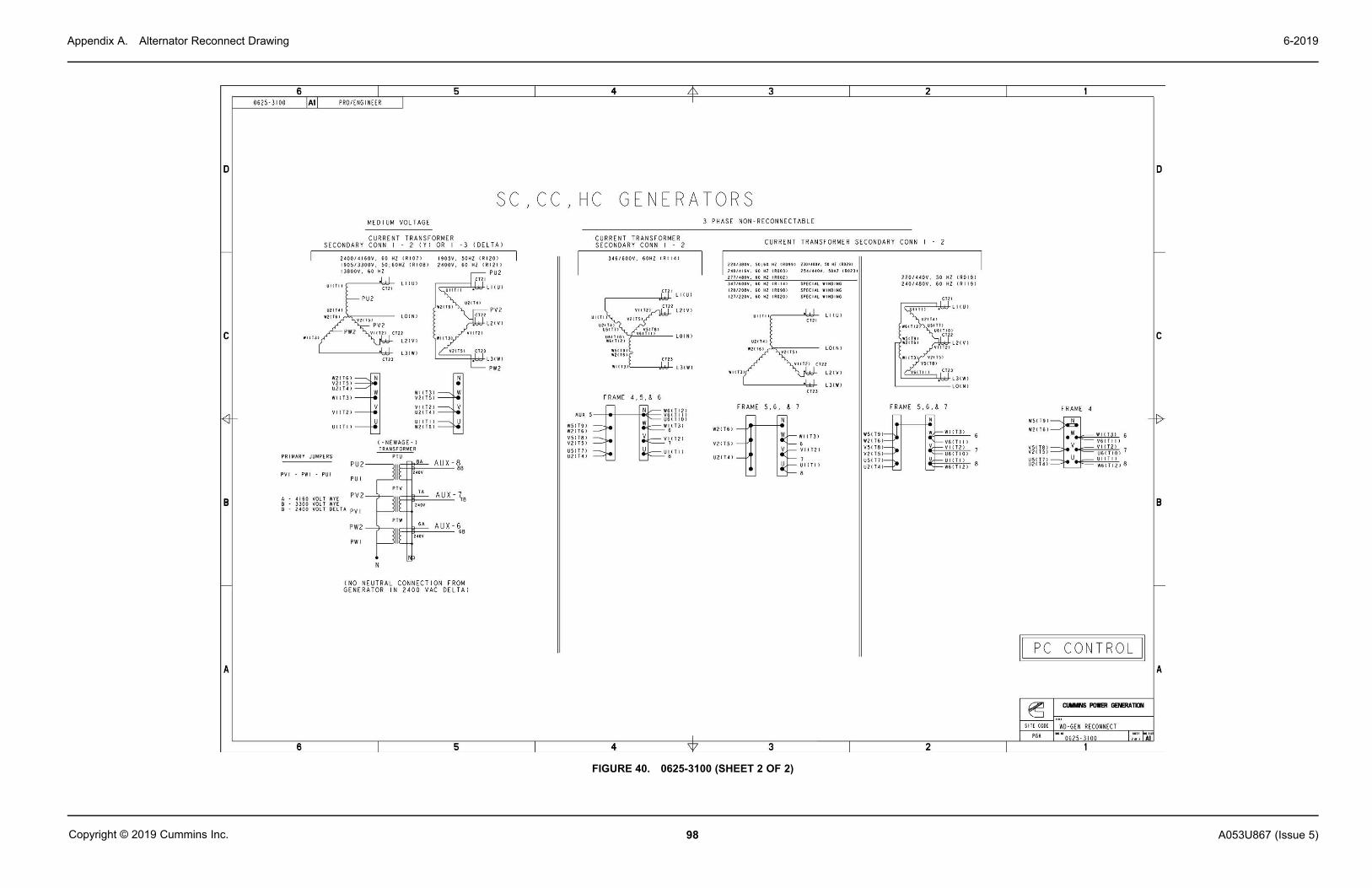
Appendix A. Alternator Reconnect Drawing 6-2019
98 A053U867 (Issue 5)Copyright © 2019 Cummins Inc.
FIGURE 40. 0625-3100 (SHEET 2 OF 2)

Appendix A. Alternator Reconnect Drawing6-2019
99A053U867 (Issue 5) Copyright © 2019 Cummins Inc.
A.2 Alternator Reconnect Drawing
FIGURE 41. 0630-2459 (SHEET 1 OF 7)
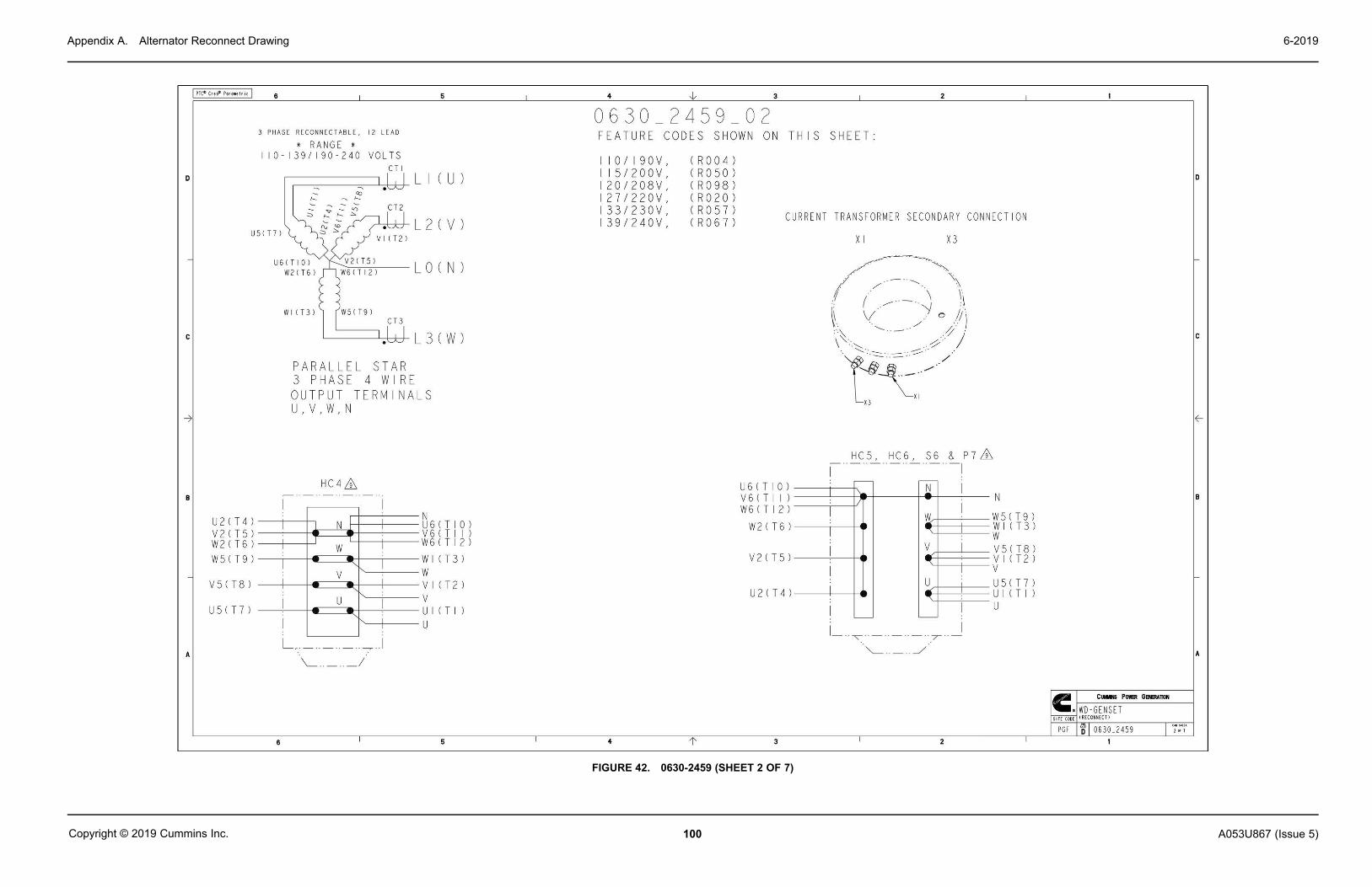
Appendix A. Alternator Reconnect Drawing 6-2019
100 A053U867 (Issue 5)Copyright © 2019 Cummins Inc.
FIGURE 42. 0630-2459 (SHEET 2 OF 7)

Appendix A. Alternator Reconnect Drawing6-2019
101A053U867 (Issue 5) Copyright © 2019 Cummins Inc.
FIGURE 43. 0630-2459 (SHEET 3 OF 7)
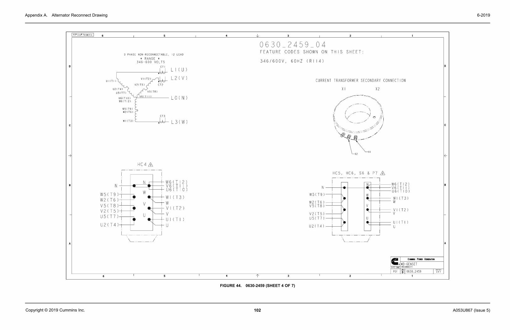
Appendix A. Alternator Reconnect Drawing 6-2019
102 A053U867 (Issue 5)Copyright © 2019 Cummins Inc.
FIGURE 44. 0630-2459 (SHEET 4 OF 7)

Appendix A. Alternator Reconnect Drawing6-2019
103A053U867 (Issue 5) Copyright © 2019 Cummins Inc.
FIGURE 45. 0630-2459 (SHEET 5 OF 7)

Appendix A. Alternator Reconnect Drawing 6-2019
104 A053U867 (Issue 5)Copyright © 2019 Cummins Inc.
FIGURE 46. 0630-2459 (SHEET 6 OF 7)

Appendix A. Alternator Reconnect Drawing6-2019
105A053U867 (Issue 5) Copyright © 2019 Cummins Inc.
FIGURE 47. 0630-2459 (SHEET 7 OF 7)

Appendix A. Alternator Reconnect Drawing 6-2019
106 A053U867 (Issue 5)Copyright © 2019 Cummins Inc.
This page is intentionally blank.

107A053U867 (Issue 5) Copyright © 2019 Cummins Inc.
Appendix B. Customer Connections
Table of ContentsFigure 48. Control Customer Connections - PCC Net Devices ............................................................. 109Figure 49. Customer Connections ............................................................................................................ 110Figure 50. PowerCommand 3.3 Connections - ECM-Based Engines ................................................... 111Figure 51. PowerCommand 3.3 Connections - Hydromechanical Engine ........................................... 112Figure 52. PowerCommand 3.3 Paralleling Connections - Standalone Generator Set ....................... 113Figure 53. PowerCommand 3.3 Paralleling Connections - Synchronize Only ..................................... 114Figure 54. PowerCommand 3.3 Paralleling Connections - Isolated Bus Only ..................................... 115Figure 55. PowerCommand 3.3 Paralleling Connections - Utility Single ............................................. 116Figure 56. PowerCommand 3.3 Paralleling Connections - Utility Multiple ........................................... 117Figure 57. PowerCommand 3.3 Paralleling Connections - Power Transfer Control ........................... 118Figure 58. PowerCommand 3.3 Paralleling Connections - Configurable Paralleling I/O .................... 119

Appendix B. Customer Connections 6-2019
108 A053U867 (Issue 5)Copyright © 2019 Cummins Inc.
The drawings included in this section are representative. For current complete information,refer to the drawing package that was shipped with the unit.

Appendix B. Customer Connections6-2019
109A053U867 (Issue 5) Copyright © 2019 Cummins Inc.
B.1 Control Wiring Diagrams (0630-3440)
FIGURE 48. CONTROL CUSTOMER CONNECTIONS - PCC NET DEVICES

Appendix B. Customer Connections 6-2019
110 A053U867 (Issue 5)Copyright © 2019 Cummins Inc.
FIGURE 49. CUSTOMER CONNECTIONS

Appendix B. Customer Connections6-2019
111A053U867 (Issue 5) Copyright © 2019 Cummins Inc.
FIGURE 50. POWERCOMMAND 3.3 CONNECTIONS - ECM-BASED ENGINES

Appendix B. Customer Connections 6-2019
112 A053U867 (Issue 5)Copyright © 2019 Cummins Inc.
FIGURE 51. POWERCOMMAND 3.3 CONNECTIONS - HYDROMECHANICAL ENGINE

Appendix B. Customer Connections6-2019
113A053U867 (Issue 5) Copyright © 2019 Cummins Inc.
FIGURE 52. POWERCOMMAND 3.3 PARALLELING CONNECTIONS - STANDALONE GENERATOR SET

Appendix B. Customer Connections 6-2019
114 A053U867 (Issue 5)Copyright © 2019 Cummins Inc.
FIGURE 53. POWERCOMMAND 3.3 PARALLELING CONNECTIONS - SYNCHRONIZE ONLY

Appendix B. Customer Connections6-2019
115A053U867 (Issue 5) Copyright © 2019 Cummins Inc.
FIGURE 54. POWERCOMMAND 3.3 PARALLELING CONNECTIONS - ISOLATED BUS ONLY

Appendix B. Customer Connections 6-2019
116 A053U867 (Issue 5)Copyright © 2019 Cummins Inc.
FIGURE 55. POWERCOMMAND 3.3 PARALLELING CONNECTIONS - UTILITY SINGLE

Appendix B. Customer Connections6-2019
117A053U867 (Issue 5) Copyright © 2019 Cummins Inc.
FIGURE 56. POWERCOMMAND 3.3 PARALLELING CONNECTIONS - UTILITY MULTIPLE

Appendix B. Customer Connections 6-2019
118 A053U867 (Issue 5)Copyright © 2019 Cummins Inc.
FIGURE 57. POWERCOMMAND 3.3 PARALLELING CONNECTIONS - POWER TRANSFER CONTROL
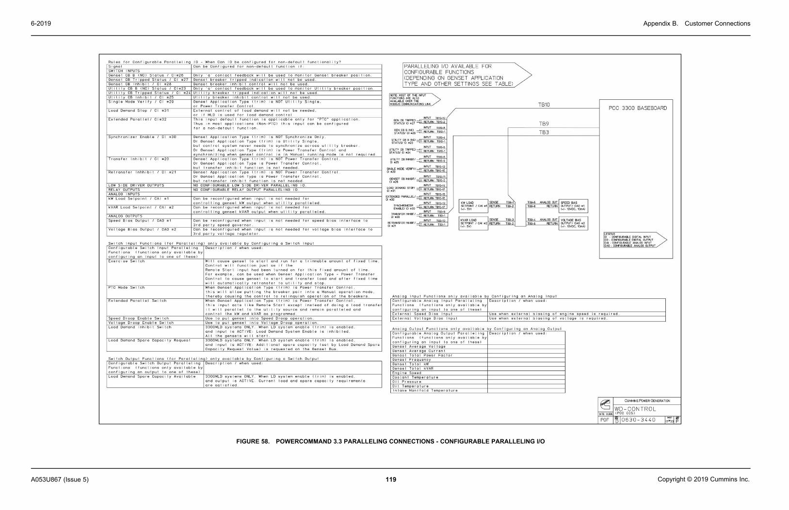
Appendix B. Customer Connections6-2019
119A053U867 (Issue 5) Copyright © 2019 Cummins Inc.
FIGURE 58. POWERCOMMAND 3.3 PARALLELING CONNECTIONS - CONFIGURABLE PARALLELING I/O

Appendix B. Customer Connections 6-2019
120 A053U867 (Issue 5)Copyright © 2019 Cummins Inc.
This page is intentionally blank.

121A053U867 (Issue 5) Copyright © 2019 Cummins Inc.
Appendix C. Outline Drawings
Table of ContentsFigure 59. Generator Set Outline Drawing (Bearward Set Mounted Radiator) (Sheet 1) ................... 123Figure 60. Generator Set Outline Drawing (Bearward Set Mounted Radiator) (Sheet 2) .................... 124Figure 61. Generator Set Outline Drawing (Bearward Set Mounted Radiator) (Sheet 3) .................... 125Figure 62. Generator Set Outline Drawing (Bearward Set Mounted Radiator) (Sheet 4) .................... 126Figure 63. Generator Set Outline Drawing (AKG Set Mounted Radiator) (Sheet 1) ........................... 127Figure 64. Generator Set Outline Drawing (AKG Set Mounted Radiator) (Sheet 2) ............................ 128Figure 65. Generator Set Outline Drawing (AKG Set Mounted Radiator) (Sheet 3) ............................ 129Figure 66. Generator Set Outline Drawing (AKG Set Mounted Radiator) (Sheet 4) ............................ 130Figure 67. Generator Set Outline Drawing (Set Mounted Radiator) (Sheet 1) .................................... 131Figure 68. Generator Set Outline Drawing (Set Mounted Radiator) (Sheet 2) ..................................... 132Figure 69. Generator Set Outline Drawing (Set Mounted Radiator) (Sheet 3) ..................................... 133Figure 70. Generator Set Outline Drawing (Set Mounted Radiator) (Sheet 4) ..................................... 134Figure 71. Generator Set Outline Drawing (Remote Radiator) (Sheet 1) ............................................. 135Figure 72. Generator Set Outline Drawing (Remote Radiator) (Sheet 2) .............................................. 136Figure 73. Generator Set Outline Drawing (Remote Radiator) (Sheet 3) .............................................. 137Figure 74. Generator Set Outline Drawing (Remote Radiator) (Sheet 4) .............................................. 138Figure 75. Generator Set Outline Drawing (Remote Radiator) (Sheet 5) .............................................. 139Figure 76. Generator Set Outline Drawing (Remote Radiator) (Sheet 1) ............................................. 140Figure 77. Generator Set Outline Drawing (Remote Radiator) (Sheet 2) .............................................. 141Figure 78. Generator Set Outline Drawing (Remote Radiator) (Sheet 3) .............................................. 142Figure 79. Generator Set Outline Drawing (Remote Radiator) (Sheet 4) .............................................. 143

Appendix C. Outline Drawings 6-2019
122 A053U867 (Issue 5)Copyright © 2019 Cummins Inc.
The drawings included in this section are representative. For current complete information,refer to the drawing package that was shipped with the unit.
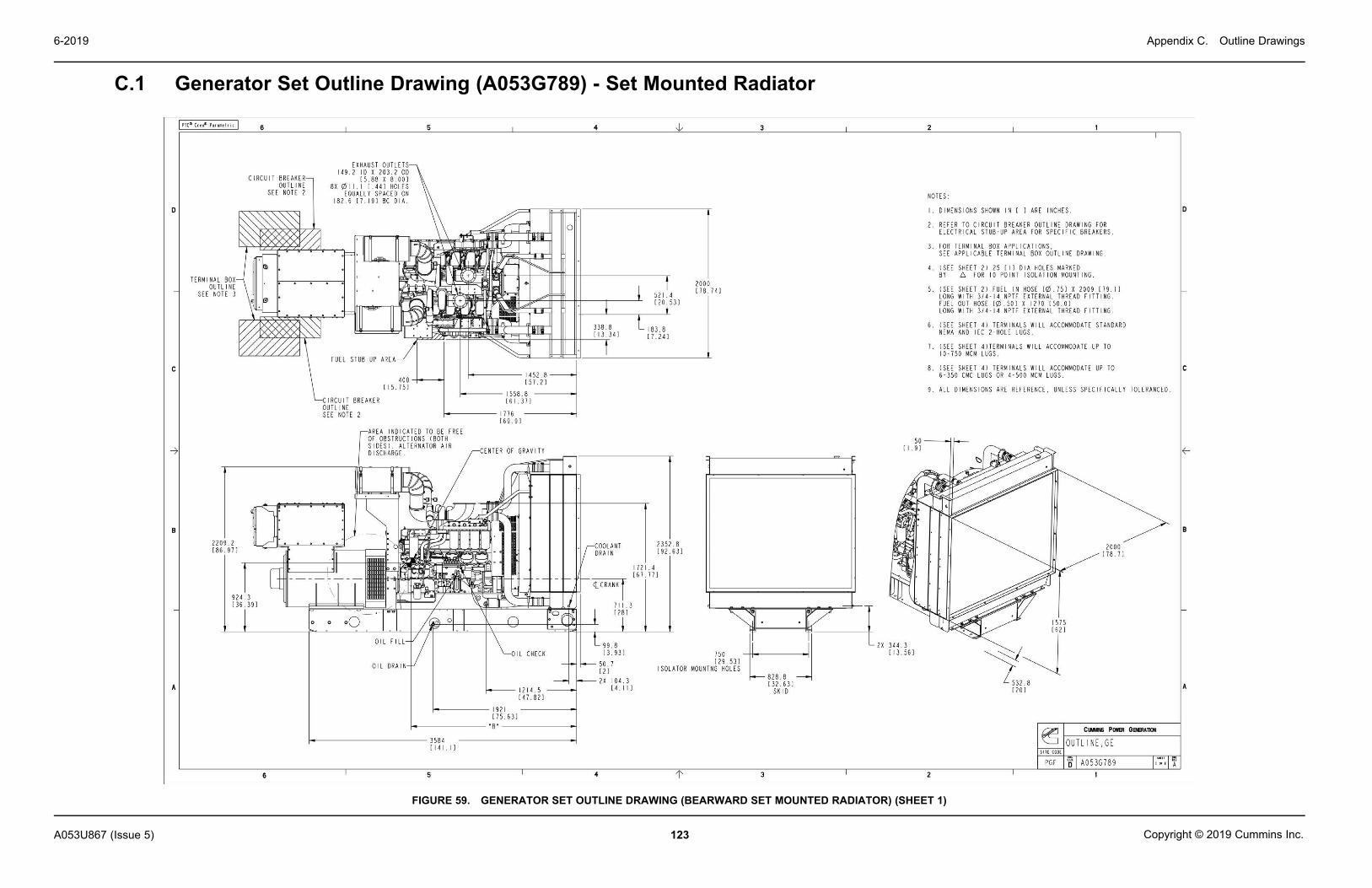
Appendix C. Outline Drawings6-2019
123A053U867 (Issue 5) Copyright © 2019 Cummins Inc.
C.1 Generator Set Outline Drawing (A053G789) - Set Mounted Radiator
FIGURE 59. GENERATOR SET OUTLINE DRAWING (BEARWARD SET MOUNTED RADIATOR) (SHEET 1)

Appendix C. Outline Drawings 6-2019
124 A053U867 (Issue 5)Copyright © 2019 Cummins Inc.
FIGURE 60. GENERATOR SET OUTLINE DRAWING (BEARWARD SET MOUNTED RADIATOR) (SHEET 2)

Appendix C. Outline Drawings6-2019
125A053U867 (Issue 5) Copyright © 2019 Cummins Inc.
FIGURE 61. GENERATOR SET OUTLINE DRAWING (BEARWARD SET MOUNTED RADIATOR) (SHEET 3)

Appendix C. Outline Drawings 6-2019
126 A053U867 (Issue 5)Copyright © 2019 Cummins Inc.
FIGURE 62. GENERATOR SET OUTLINE DRAWING (BEARWARD SET MOUNTED RADIATOR) (SHEET 4)

Appendix C. Outline Drawings6-2019
127A053U867 (Issue 5) Copyright © 2019 Cummins Inc.
C.2 Generator Set Outline Drawing (A049K674) - Set Mounted Radiator
FIGURE 63. GENERATOR SET OUTLINE DRAWING (AKG SET MOUNTED RADIATOR) (SHEET 1)

Appendix C. Outline Drawings 6-2019
128 A053U867 (Issue 5)Copyright © 2019 Cummins Inc.
FIGURE 64. GENERATOR SET OUTLINE DRAWING (AKG SET MOUNTED RADIATOR) (SHEET 2)

Appendix C. Outline Drawings6-2019
129A053U867 (Issue 5) Copyright © 2019 Cummins Inc.
FIGURE 65. GENERATOR SET OUTLINE DRAWING (AKG SET MOUNTED RADIATOR) (SHEET 3)

Appendix C. Outline Drawings 6-2019
130 A053U867 (Issue 5)Copyright © 2019 Cummins Inc.
FIGURE 66. GENERATOR SET OUTLINE DRAWING (AKG SET MOUNTED RADIATOR) (SHEET 4)
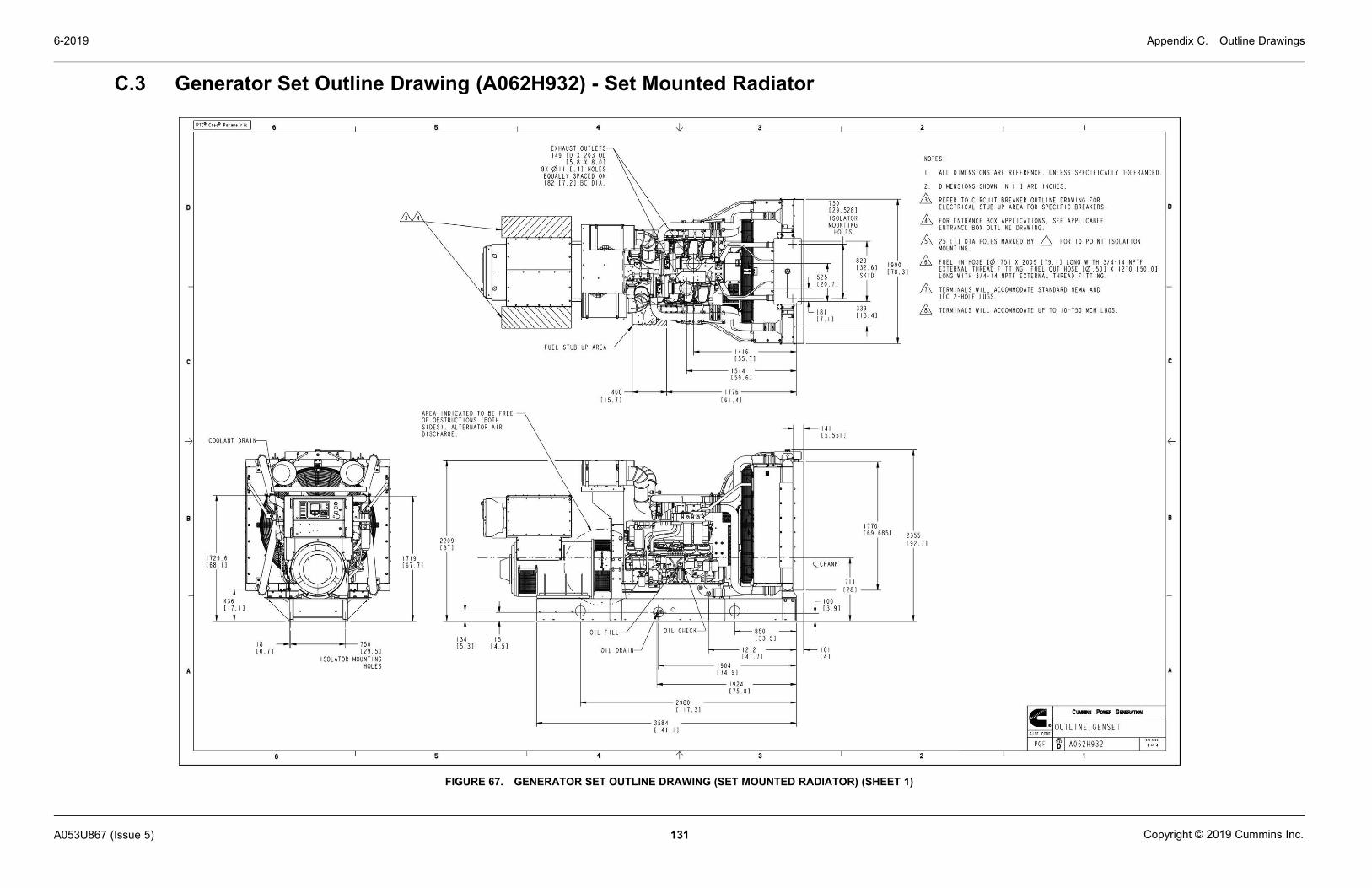
Appendix C. Outline Drawings6-2019
131A053U867 (Issue 5) Copyright © 2019 Cummins Inc.
C.3 Generator Set Outline Drawing (A062H932) - Set Mounted Radiator
FIGURE 67. GENERATOR SET OUTLINE DRAWING (SET MOUNTED RADIATOR) (SHEET 1)

Appendix C. Outline Drawings 6-2019
132 A053U867 (Issue 5)Copyright © 2019 Cummins Inc.
FIGURE 68. GENERATOR SET OUTLINE DRAWING (SET MOUNTED RADIATOR) (SHEET 2)

Appendix C. Outline Drawings6-2019
133A053U867 (Issue 5) Copyright © 2019 Cummins Inc.
FIGURE 69. GENERATOR SET OUTLINE DRAWING (SET MOUNTED RADIATOR) (SHEET 3)

Appendix C. Outline Drawings 6-2019
134 A053U867 (Issue 5)Copyright © 2019 Cummins Inc.
FIGURE 70. GENERATOR SET OUTLINE DRAWING (SET MOUNTED RADIATOR) (SHEET 4)

Appendix C. Outline Drawings6-2019
135A053U867 (Issue 5) Copyright © 2019 Cummins Inc.
C.4 Generator Set Outline Drawing (A053G787) - Remote Radiator
FIGURE 71. GENERATOR SET OUTLINE DRAWING (REMOTE RADIATOR) (SHEET 1)

Appendix C. Outline Drawings 6-2019
136 A053U867 (Issue 5)Copyright © 2019 Cummins Inc.
FIGURE 72. GENERATOR SET OUTLINE DRAWING (REMOTE RADIATOR) (SHEET 2)

Appendix C. Outline Drawings6-2019
137A053U867 (Issue 5) Copyright © 2019 Cummins Inc.
FIGURE 73. GENERATOR SET OUTLINE DRAWING (REMOTE RADIATOR) (SHEET 3)
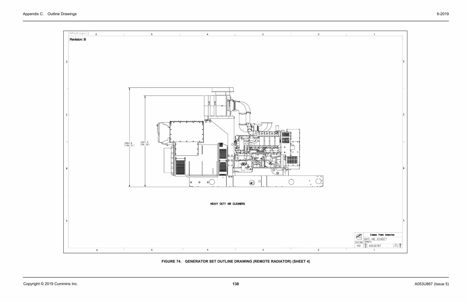
Appendix C. Outline Drawings 6-2019
138 A053U867 (Issue 5)Copyright © 2019 Cummins Inc.
FIGURE 74. GENERATOR SET OUTLINE DRAWING (REMOTE RADIATOR) (SHEET 4)

Appendix C. Outline Drawings6-2019
139A053U867 (Issue 5) Copyright © 2019 Cummins Inc.
FIGURE 75. GENERATOR SET OUTLINE DRAWING (REMOTE RADIATOR) (SHEET 5)

Appendix C. Outline Drawings 6-2019
140 A053U867 (Issue 5)Copyright © 2019 Cummins Inc.
C.5 Generator Set Outline Drawing (A062M281) - Remote Radiator
FIGURE 76. GENERATOR SET OUTLINE DRAWING (REMOTE RADIATOR) (SHEET 1)

Appendix C. Outline Drawings6-2019
141A053U867 (Issue 5) Copyright © 2019 Cummins Inc.
FIGURE 77. GENERATOR SET OUTLINE DRAWING (REMOTE RADIATOR) (SHEET 2)
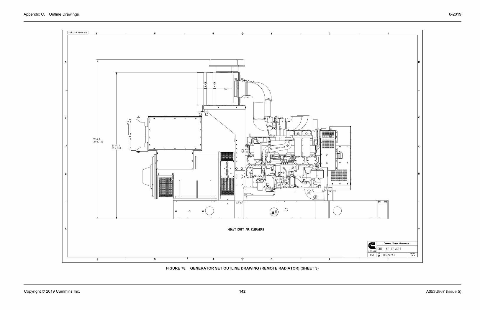
Appendix C. Outline Drawings 6-2019
142 A053U867 (Issue 5)Copyright © 2019 Cummins Inc.
FIGURE 78. GENERATOR SET OUTLINE DRAWING (REMOTE RADIATOR) (SHEET 3)

Appendix C. Outline Drawings6-2019
143A053U867 (Issue 5) Copyright © 2019 Cummins Inc.
FIGURE 79. GENERATOR SET OUTLINE DRAWING (REMOTE RADIATOR) (SHEET 4)

Appendix C. Outline Drawings 6-2019
144 A053U867 (Issue 5)Copyright © 2019 Cummins Inc.
This page is intentionally blank.

145A053U867 (Issue 5) Copyright © 2019 Cummins Inc.
Appendix D. Wiring Diagrams
Table of ContentsFigure 80. PC 3.3 Schematic ..................................................................................................................... 147Figure 81. HMI Display, Bargraph, AUX103 - Wiring Diagram ............................................................... 148Figure 82. Engine Extension Harness - Wiring Diagram ........................................................................ 149Figure 83. HMI Display and Bargraph - Wiring Diagram ........................................................................ 150Figure 84. AUX 101, AUX 102 - Wiring Diagram ...................................................................................... 151Figure 85. Customer Paralleling, Gen Breaker Control Relays; Pyrometer; Configurable Relays,Optional Alarm - Wiring Diagram ............................................................................................................. 152Figure 86. Paralleling Extension Harness - Wiring Diagram ................................................................. 153Figure 87. Heater Outline Drawing and Schematic ................................................................................. 154Figure 88. Wiring for Options (Sheet 1 of 2) ............................................................................................ 155Figure 89. Wiring for Options (Sheet 2 of 2) ............................................................................................ 156

Appendix D. Wiring Diagrams 6-2019
146 A053U867 (Issue 5)Copyright © 2019 Cummins Inc.
The drawings included in this section are representative. For current complete information,refer to the drawing package that was shipped with the unit.

Appendix D. Wiring Diagrams6-2019
147A053U867 (Issue 5) Copyright © 2019 Cummins Inc.
D.1 PCC3300 Wiring Diagram (A053C830)
FIGURE 80. PC 3.3 SCHEMATIC

Appendix D. Wiring Diagrams 6-2019
148 A053U867 (Issue 5)Copyright © 2019 Cummins Inc.
FIGURE 81. HMI DISPLAY, BARGRAPH, AUX103 - WIRING DIAGRAM

Appendix D. Wiring Diagrams6-2019
149A053U867 (Issue 5) Copyright © 2019 Cummins Inc.
FIGURE 82. ENGINE EXTENSION HARNESS - WIRING DIAGRAM

Appendix D. Wiring Diagrams 6-2019
150 A053U867 (Issue 5)Copyright © 2019 Cummins Inc.
FIGURE 83. HMI DISPLAY AND BARGRAPH - WIRING DIAGRAM

Appendix D. Wiring Diagrams6-2019
151A053U867 (Issue 5) Copyright © 2019 Cummins Inc.
FIGURE 84. AUX 101, AUX 102 - WIRING DIAGRAM

Appendix D. Wiring Diagrams 6-2019
152 A053U867 (Issue 5)Copyright © 2019 Cummins Inc.
FIGURE 85. CUSTOMER PARALLELING, GEN BREAKER CONTROL RELAYS; PYROMETER; CONFIGURABLE RELAYS, OPTIONAL ALARM - WIRING DIAGRAM

Appendix D. Wiring Diagrams6-2019
153A053U867 (Issue 5) Copyright © 2019 Cummins Inc.
FIGURE 86. PARALLELING EXTENSION HARNESS - WIRING DIAGRAM

Appendix D. Wiring Diagrams 6-2019
154 A053U867 (Issue 5)Copyright © 2019 Cummins Inc.
D.2 Outline Drawing and Schematic - Heater
FIGURE 87. HEATER OUTLINE DRAWING AND SCHEMATIC

Appendix D. Wiring Diagrams6-2019
155A053U867 (Issue 5) Copyright © 2019 Cummins Inc.
D.3 Wiring of Optional Equipment
FIGURE 88. WIRING FOR OPTIONS (SHEET 1 OF 2)

Appendix D. Wiring Diagrams 6-2019
156 A053U867 (Issue 5)Copyright © 2019 Cummins Inc.
FIGURE 89. WIRING FOR OPTIONS (SHEET 2 OF 2)

157A053U867 (Issue 5) Copyright © 2019 Cummins Inc.
Appendix E. Seismic Requirements
Table of ContentsFigure 90. Seismic Installation Specifications ........................................................................................ 159Figure 91. Seismic Installation Notes ...................................................................................................... 160Figure 92. Seismic Installation Requirements ........................................................................................ 161

Appendix E. Seismic Requirements 6-2019
158 A053U867 (Issue 5)Copyright © 2019 Cummins Inc.
The drawings included in this section are representative. For current complete information,refer to the drawing package that was shipped with the unit.

Appendix E. Seismic Requirements6-2019
159A053U867 (Issue 5) Copyright © 2019 Cummins Inc.
E.1 Seismic Installation Instructions (A045K403)
FIGURE 90. SEISMIC INSTALLATION SPECIFICATIONS

Appendix E. Seismic Requirements 6-2019
160 A053U867 (Issue 5)Copyright © 2019 Cummins Inc.
FIGURE 91. SEISMIC INSTALLATION NOTES

Appendix E. Seismic Requirements6-2019
161A053U867 (Issue 5) Copyright © 2019 Cummins Inc.
FIGURE 92. SEISMIC INSTALLATION REQUIREMENTS
Appendix E. Seismic Requirements 6-2019
162 A053U867 (Issue 5)Copyright © 2019 Cummins Inc.
This page is intentionally blank.


power.cummins.comCopyright © 2019 Cummins Inc. All rights reserved.Cummins, the "C" logo, PowerCommand, AmpSentry, and InPower are trademarks of Cummins Inc.Other company, product, or service names may be trademarks or service marks of others.Specifications are subject to change without notice.