WP The Diesel Locomotive
59
-
Upload
khangminh22 -
Category
Documents
-
view
0 -
download
0
Transcript of WP The Diesel Locomotive


TABLE OF CONTENTS
Introduction . . . . . . . . How The Locomotive Operates. Switch and Fuse Panel. . . Circuit Breaker Panel .. . Engine Control Panel .. . Locomotive Control Console Engine Starting Controls .
SECT ION
SECTION II
Starting Trailing Unit Diesel Engines. Placing Units On The Line .. .... . Precautions Before Moving Locomotives. Handling Light Locomotive ..... Coupling Locomotive Units Together Coupling Locomotive To Train Pumping Up Air . . . .. Brake Pipe Leakage Test ... . Kicking Cars ........ . Starting A Train
Service Selector Switch in Series or Road Position. Accelerating A Train .... . Slowing Down Because Of Grade . Air Braking With Power ... Operating Over Rail Crossing Running Through Water .... Wheel Sl i p Light Indications Locomotive Speed Limit . Multiple Unit Operation. Double Heading .. Isolating A Unit . ... Changing Operating Ends. Stopping Engine. . . . . . . Securing Locomotive For Layover. Towing Locomotive In Train .. Freezing Weather Precautions .
Trouble-shooting . . . . ...
SECTION I I I
Page Number
1 2
3 - 5 6 - 7 8 - 12
13 - 21 22
23 24 25 26 27 28 29 30 31
32 - 33 34 35 36 37 38 39 40 41 42 43
44 - 45 46 47
48 - 49 50
51 - 57

This General Motors switching engine is equipped with a 12 cylinder, 2-stroke cycle, fuel injected, water cooled diesel engine that delivers power to the main generator for tractive purposes.
The hood end of the locomotive is considered the front end, and the operator's controls are appropriately located . On special order , the con-trol console can be equipped with two sets of controls, a ma ster set and a slave set, one on either side of the centrally located contro l console. This arrangement allows the operator to obtain maximum visability in all directions . The master and slave controls are mechanically coupled, so that when one set is operated, the other set follows. The operator may change positions at the control console without changing the setting of the operator ' s controls .
l . Cooling System Shutters 2 . Fan Shroud And Sand
Boxes Location 3 . Air Compressor 4 . Radiators 5 . Equipment Rack
6 . 645E D iesel Engine 7. Engine Blowers 8 . Engine Oil Bath Air F ilters 9 . Au•iliarv Gener•tor
tO. Main Generator l 1. Traction Motor Blower 12 . Control Conso~
- 1 -
I ;! :
13. Air Brake Equipment A nd Electrical Switchgear
14. Battery Box And Sand Boxes 15. Truck 16. Fuel Tank 17 . Air Reservoir

HOW THE LOCOMOTIVE OPERATES
The fuel pump is driven by an electric motor which , for fuel priming, uses current from the storage battery. Once the engine is started and running, the fuel pump motor uses current directly from the auxiliary generator. The fuel pump transfers fuel from the fuel tank under the locomotive to the engine injectors.
The diesel engine is started by ireans of the direct coupled main generator which is temporarily used as a starting rrotor. A storage battery supplies the electric current to rotate the generator and start the engine.
When the engine is running, it supplies mechanical power through shafts and couplings to directly drive two electrical generators, the air compressor, a traction motor blower, and engine mounted lube oil and cooling water purrps . Cooling air for the main generator is provided by a fan attached directly to the main generator armature. The radiator cooling fan is driven by sheaves and belts powered through the air compressor shaft.
The auxiliary generator charges the storage battery and supplies low voltage direct current for the control, lighting, and main generator excitation circuits. The main generator supplies high voltage direct current to the traction motors for locomotive pulling power.
By means of the cab controls, low voltage circuits are established to actuate the engine governor and electrical switchgear .
Four traction mctors are located under the locomotive. Each traction motor is directly geared to an axle and pair of driving wheels . These motors are located in two trucks which support the locomotive weight and distribute it to the driving wheels.
The main generator converts the engine's irechanical power to electrical p01ver, which is then distributed to the traction motors through circuits established by various switchgear components .
The throttle electrically controls speed and power by actuating a speed governor mounted on the engine and by stepping up main generator excitation and output as the throttle is advanced. From a standing start in the switching mode a specific tractive effort is im:nediately available for each operating notch of the throttle . In the series and road modes of operation this specific effort is modulated by the load regulator .
At moderate and high operating speeds a load regulator automatically maintains power output at a level consistent with engine speed.
The air compressor supplies, to the reservoirs. air under pressure used primarily for the air brakes. The air brakes are controlled by the operator through suitable equipment in the cab.
Except for manual operation of the cab controls, locomotive operation is completely automatic. Various alarms and safety devices will alert the operator should any operating difficulties occur.
- 2 -

..,_
SWITCH fltID ME P~EL
CIRCUIT IREAKER PANEL
I
CD 2 @ w I @ t ~ @0! 1" ~
© 0 II ~ CL] @ ~
ii @ @ g ~ @
1
n 'I ~ "" \----r ~
g " ; I Cl 0 ]f ~
UJ J_
. _ SWITCH_ ~ND FUSE PANH ---·----=----",
0 A.EE TEST LIGHT & TOCi.iLE SWITCH Pl ace toggle switch to the or: position to make sure the fuse test 1 i ght
is not burned out. Extinguish the light by movi ng the toggle switch to the OFF position.
0 GR:lLMl PHAY CUTOUT SWITCH The ground relay cut out switch eliminates the ground protective relay
from the locomotive circui ts during certain shop maintenance inspect ions.
THE GROUND RELAY CUTOUT SWI TCH MUST ALWAYS BE KEPT CLOSED DURING NOPNAL OPERATION. Only in the event of extreme emergency and definite instruction from a responsible officer of the railroad may this swi tch be in open position during operation. SERIOUS EQUIPMENT DAMAGE COULD OCCUR.
0 AUXILIARY l:fNEPATOR FIELD 32-A'fflf; RJSE This fuse protects the field excitation circuit of the auxil iary
generator. It must be good and in place at al l time during locomoti ve operation. IN THE EVENT THIS FUSE IS BURNED OUT, IT STOPS AUXILIARY GENERATOR OUTPUT TO THE LOW VOLTAGE SYSTEM AND ALSO STOPS FUEL PU/>fP OPERATION. THE ENGINE WILL EVENTUALLY STOP FROM LACK OF FUEL.
- 3 -

0 R£E TEST BLOCK Place a fuse across the test blocks so that the metal ends of the fuse are
in firm contact with the blocks .
IF THE FUSE IS GOOD, THE LIGHT ( (i) ) WILL COME ONE. IF THE FUSE IS BURNED OUT, THE LICHT WILL NOT COME ON'tND A NEW FUSE I S REQUIRED. Be sure to first test whether light is working as described in (J) .
0 BATTERY CHARGING fHEPIACl£ As a modificati on when requested by the railroad, provis i on is made for
connection of an external source of DC power to charge the locomotive battery . The receptacle is used for this purpose.
8 t'AIN BATTERY' 14'JIFE SWITQ1 The large double-pole single-throw kn ife switch at the l ower portion of
the f use panel i s used to connect the battery to the locomoti ve low voltage sys t em and shoul d be kept closed at al l t imes during operati on. IF THIS .~;i[TCH WERE LEFT '.JPEN, THE FUEL PUMP COULD NOT BE STARTED, THE LIGHTS WOULD !!OT FUllC'IC.V AND THE ENGINE COULD NOT BE STARTED.
IF 'ii!E SWITCH IS OPENED AF':'ER THE ENGINE HAS BEEN STARTED, THE AUXILIARY ;e,·:iERATOP ;.;JLL CONTINUE ':'O SIJ?PL':' T!IE LOW VOLTAGE NEEDS, BUT THE BATTERIES :·.'LL ::c':' RECEIVE CHARGE.
0 STARTWG 1.JOJ-N1F£f{: R£E Th i s fuse i s in use only duri ng the period that the diesel engine is
actuall y being start ed. At this time, battery current flows through the fuse and starti ng contactor to motor the main generator and crank the engine .
Al t hough this fuse should be i n good condition and always left in place, i t has no effect on l ocomo tive operati on other than for eng i ne starting.
; :JEFEC':IVE Ft.::';E CA:: RE DETECTED WHEN ATTEl.fPT!NG TO START THE ENGINE, .:i."!CE A':' T/IA;:" TIME ('O:VE:I -:"l!CUr;H ':'!IE STARTING COllTACTOR CLOSES) THE CRANKING :;,-p:;ur: ::s OPEN.
0 f\LC<ILIARY l:fNERATOR R£E This fuse connects the auxiliary generator to the low vol tage system and
protect s aqainst excess ive current demands .
! ."l THE EVENT THE FU3E :s BURNED OU':', IT STOPS AUXILI ARY GENERATOR OUTPUT ,"() ·:Hr: .:ow VOL?Ar;E SYSTEM AND ALSO s-;ops FUEL PUMP OPERATION . THE ENGINE WILL ~-v::,·.•."."UALLY STOP FROM LACK OF FUEL.
- 4 -
\
·-

0 PAfilRY FIELD 00-Nf'Ef{ S.SE This fuse is used to protect against possible overload or short circuit
damage. The battery field windings of the main generator are excited with current from the locomotive low voltage system. The circuit is established by the battery field contactor.
IF THE FUSE IS FAULTY OR BLOWN, .\'O ALARMS WILL OCCUR, BUT THE LOCOMOTIVE UNIT WILL NOT DEVELOP NORMAL POWER.
® P/\filRY CHARGING S.SE This fuse protects the charging circuit when external power i s connected
to charge the battery .
- 5 •

, 0
'
0
Cl RCUIT Blf.AJ<ER PANEL
SWITCH AND FUSE PANEL
ffi"!Tf{)L 40-A"lPEI{ CI RCU IT Blf.AJ<ER
0
0
__ _j
This circuit breaker sets up t he fuel pump and control circuits for engine sta rt ing. Once the engine is running , power is supplied t hrough this breaker from the auxiliary generator to maintain operating control .
C"HI S CIRCUI? 5REA KEP MUST BE IN THE ON POSITION BEFORE LOCOMOTIVE OPER-4? T'.JN IS POSSIBLE.
LlffiTS ?D-ft1PEI{ CIRCUIT Bl{AKER This circuit breaker must be ON t o supply power for the individual
switches provided for platfonn, engineroom and identification lights.
LOCllL CD"HIDL ?D-A"lPEI{ Cl RCUIT Bf£,L\,ij;R This circuit breaker establ ishes "l ocal" power from the auxiliary
generator to operate heavy duty switchgear and various control devices.
THIS CIRCUIT BREAKER MUST BE IN THE ON POSITION BEFORE OPERATION OF THE LOCOMOTIVE IS POSSIBLE.
- 6 -

rviISCEU.JINEOlli CIRCUIT BffA~R:l Circuit breakers can be provided for the HEADLIGHT, CAB HEATER, SAFETY
DEVICE, SIGNAL LIGHT and RADIO. The circuit breakers should be placed in the ON position to obtain the desired operation.
RJEL Pl.MP CIRCUIT Bf£~R ':.~E FUEL PU:·:P CIRC:JI? BREAKER MUS? 3E o.~· FOR NORNAL OPERK:n:1.
~1JTOR ClJTOlJT SW ITG1 This is a three-position switch controlling operation of the traction
motors.
During normal locomotive operation, it is to be placed in the normal position .
The use of positions No . 1 TRK OUT or No . 2 TRK OUT is only in an emergency or if the locomotive 1s to be run in the maintenance shop.
[),' !10? !·IOL'E -'Ai'.:' ;.:;: .:; :JliE :JF 7'.""E ?Ru.::;:..: .-:,1: OU': (serious damage to elect rical equipment may result).
- 7 -

ENGINE ITT/TIU PNU
E'1E~ENCY R.JEL CUTnEF flfID ENGINE STOP PUSHBUITm PRE::snr; Ir.Is PUS.oBUIION WILL CAUSE THE ENGINE TO STOP fl.lefEDIATELY. IT
!:: ,cp_c.:_- ,! ~ !-OAJEl) A.'.'D DO::s ."10': .'IEED T:: BE RESET.
IHE ,;liITCii OPERATES TO STOP ONLY THE ENGINE !N THE UNIT IN WHICH IT IS i,OCA':ED.
Gffill'ID RElA Y If SET Pl!lHBUITOO The ground relay detects LOW VOLTAGE qrounds during engine start an d HIGH
VOLTAGE grounds durin g operation under power .
WHEN .7 TRIPS , IHE ALAR.'1 BELLS RING IN ALL UNITS OF A CONSIST.
JN THE UNI': AFFECIED, ;ENERATOR EXCITATION IS LOST, THE DIES EL ENGINE GOES _-:JLE SPEED, A.VD -:'i!E ;p:u:m RELAY LIGHT COMES ON.
GUND RELAY L!GfT This liqht indicates an electrical path to ground caused by insulation
fai l ure, the presence of water or an electrical arc .
;.·HEN THE LIGHT IS ON , ':HE LOCOMOTIVE WILL NOT DEVELOP POWER AND THE ENGI.VE ~'ILL REMAIN AT IDLE.
The light can be put out by pressing the qround relay reset pushbutton . It i s not necessary to isolate the unit, nor is it necessary to have the throttle in id le while pres~ing the button .
- 8 -

WHEN THE GROUND RELAY LIGHT COMES ON WR THE THIRD TINE AnER RESETTING, ISOLATE THE AFFECTED UNIT.
Always report gro111d relay light indications to proper maintenance personnel.
c:pttf(fA<i: COIL ptm PfESSOOU)f !'0lE!Vl1lf OIL Allft1 U!i[ A mechanism to detect low engine lubricating oil pressure or high suction
fs built into the engine governor. If low ofl pressure or high suction Is detected a small button (see Figure 1) will pop out of the governor body, indicating that the mechanism has tripped the low oil alann switch. THE AMBER LIGHT ON THE ENGINE CONTROL PANEL I/ILL CONE ON TO INDICATE THAT THE LOii OIL MECHANISM HAS TRIPPED.
- 9 -

When a Crankcase (Oil Pan) Pressure/Low Water/Low Oil alarm occurs, on units equipped with a low water pressure detector or a canbination low water pressure and crankcase pressure detector, it is necessary to determine whether the crankcase pressure-low water detector has tripped to dump engine oil from the line leading to the governor, or whether a true oil failure has occurred. This can be determined by checking the crankcase.pressure-low water detecting device (Figure 2) for protruding reset buttons.
A PROTRUDING UPPER BUTl'ON INDICATES EXCESSIVE OIL PAN PRESSURE - -A PROTRUDING LOWER BUTTON INDICATES LOW WATER.
The hot engine alarm light (r:r:o) operates in conjunction with the alann hel I to wam the operator that the enyine cooling water has reached an exces;ive temperature.
•:.\11;1.v;: S."EEU AND PG>lt.'/' R/:,'MAJN llO~AL, bU'f 1'HF:: l:.'NGINE AND WATER SYSTEM :i.'!0/!W BF. CHECKED IF THf' ALAFM CON1'INUES.
With the main battery switch closed, the battery charging indicator is conneded into the low voltage circuits to indicate the extent of current flowing ·to and from the storage battery. The indicator does not indicate the output of the auxiliary generator . Since the storage battery is usually well charged, tne indicator in nonnal operation should read zero or slightly in the qreen area. The pointer should never be in the red area with the diesel engine running, even at idle speed. Such a reading indicates that the battery is discharging, which if allowed to continue could lead to failure of the locomotive un1t .
- 10 -

A VERY STRONG DISCHARGE AT TIMES OF ENGINE SHUTDOWN, FOLLOWED BY BWWN FUSES, INDICATES A SHORTED BATTERY CHARGING RECTIFIER. WHEN A VERY STRONG DISCHARGE IS INDICATED, EXERCISE CARE BEFORE OPENING THE MAIN BATTERY SWITCH.
As an extra modification, a battery charging light may be applied in lieu of the indicator.
ISOLAT!Cl'l SWITGl The isolation switch has two positions, one labeled START/STOP/ISOLATE,
the other labeled RUN. The functions of these two positions are as follows:
1. START/STOP/ISOLATE POSITION
THE ISOLATION SWITCH IS PLACED IN THIS POSITION WHENEVER THE DIESEL ENGINE IS TO BE STARTED. THE START SWITCH IS EFFECTIVE ONLY WHEN THE ISOLATION SWITCH IS IN THIS POSITION. THE START POSITION IS ALSO USED TO ISOLATE THE UNIT, AND WHEN ISOLATED THE UNIT WILL NOT DEVELOP POWER OR RESPOND TO THE CONTROLS. IN THIS EVENT THE ENGINE WILL RUN AT IDLE SPEED REGARDLESS OF THROTTLE POSITION. THIS POSIWILL ALSO SILENCE THE ALARM BELL IN THE EVENT OF A NO POWER OR LOW LUBE OIL ALARM. IT WILL NOT, HOWEVER, STOP THE ALARM IN THE EVENT OF A HOT ENGINE.
2. RUN POSITION
AFTER THE ENGINE HAS BEEN STARTED, THE UNIT CAN BE PLACF:D "ON THE LINE" BY MOVING THE ISOLATION SWITCH TO THE RUN POSITION. THE UNIT WILL THEN RESPOND TO CONTROL AND WILL DEVELOP POWER IN NORMAL OPERATION.
"1!SCEll'MOlE Sio/ITQJES Switches are included in circuits for various lights and devices on the
locomotive. The switches are closed as desired to operate the class lights, the number lights, and the platform lights.
HOO.IGHT CO'ff!J)L SWITGl The twin sealed-beam front and rear headlights ar'e controlled by the
front and rear headlight switches on the locomotive control panel. A dinming switch is mounted on the right side of the controller. BEFORE THESE SWITCHES WILL FUNCTION, THE 30-AMPERE HEADLIGHT CIRCUIT BREAKER MUST BE PLACED ON.
On locomotives equipped for multiple unit operation, a remote headlight control switch is mounted on the engine control panel. This remote headlight control switch provides for operation of the rear unit headlight from the lead unit. The switch positions are set on each unit as follows:
a. On Lead Unit
If only a single locomotive unit is being used, PLACE THE SWITCH IN SINGLE UNIT POSITION.
In multiple unit service, if trailing units are coupled to the No. 2 or long hood end of the lead unit, PLACE THE SWITCH IN CONTROLLING -COUPLED AT WNG HOOD END POSITION.
- 11 -

In multiple unit service, if trailing units are coupled to the No. or short hood end of the lead unit, PLACE SWI TCH IN CONTROLLING -COUPLED AT SHORT HOOD END POSITION.
b. On Intermediate Units
On units operating in between other units in a multiple unit consist, PLACE THE SWITCH IN THE SINGLE UNIT POSITION.
c. On Trailing Units
The last unit in a multiple unit consist should have the headlight control switch placed in the CONTROLLED - COUPLED AT EITHER END POSITION,
- 12 -

=== ,-
' • f ........... . ..............
"'"'"'"'"'"'"'"'• I 22
Basically the locomotive is equipped with a single set of operator's controls, but on special order a control console containing duplex controls can be provided. 0 Pf:U. R!NfIR llAJ..\{
When the bell ringer is operated, compressed air is directed to the loco-motive warning bell operator. ·
0 ItM.Ffll!BIT BPM W\L'.'t ~#ml£ The independent air brake handle is located directly below the automatic
brake handle. It has two positions; namely, RELEASE and FULL APPLICATION. Between these two positions is the application zone. Since this is a selflapping brake, it automatically laps off the flow of air and maintains brake cylinder pressure corresponding to the position of the handle in the application zone.
DEPRESSION OF THE INDEPENDENT BRAKE VALVE HANDLE WHEN IN THE RELEASE POSITION CAUSES RELEASE OF ANY AUTOMATIC BRAKE APPLICATION EXISTING ON THE LOCOMOTIVE.
- 13

0 AACWUIC BM VAL\{ HA'fil.E The automet1c brake valve handle may be placed 1n any of s1x operet1ng
positions as shown.
CUT- OFF VALVE
THIS VALVE IS USED TO CU'i' OUT THE MAINTAINING FEATURE OF THE 26L BRAKE VAL VE WHEN MAKING LEAKAGE TESTS (EXCEPT E/1ERGENCYJ.
'!'/IE CU'7- 0 FF VALVE IS LOCATED 011 THE AUTOMATIC BRAKE VALVE HOUSING CIREC'i'LY BENEA TH THE AUTOMA'7IC BRAKE VALVE HA:IDZ-E. THIS VAL VE HAS THE FOLLOWING POSITIONS:
A. CUT- OU'7
B. CUT- IN
TRAI.VLINE PRESSURE ADJUSTMEN'!'
THE TRAINLINE AIR PP.EESU.'IE ADJUS'7ING KNOB IS LOCATED BEHIND THE AUTOMATIC SPAKE VALVE AT THE UPPER PORTION OF THE BRAKE PEDESTAL.
0 SANDING SWITQfS When the sanding switch lever 1s operated, electrical energy is d1rected
t hrough interlocks of reverser switchgear to operate either the fon1ard or reve rse sanding magnet va l ves in all units of a consist . The basic switch may be operated in any direction for correct sanding and it is non-latching . A directional sanding switch may be provided as an optional extra, and the switch may be latching if requested by the railroad.
Pneumaticall y controlled sanding is the basic system used, but since the locomotive may be operated in multiple with units that are equi pptd for elect ric control of sanding, trainlined electric control of sand1ng may be provided as an extra 1n addition to or instead of pneumat1c control.
- 14 -
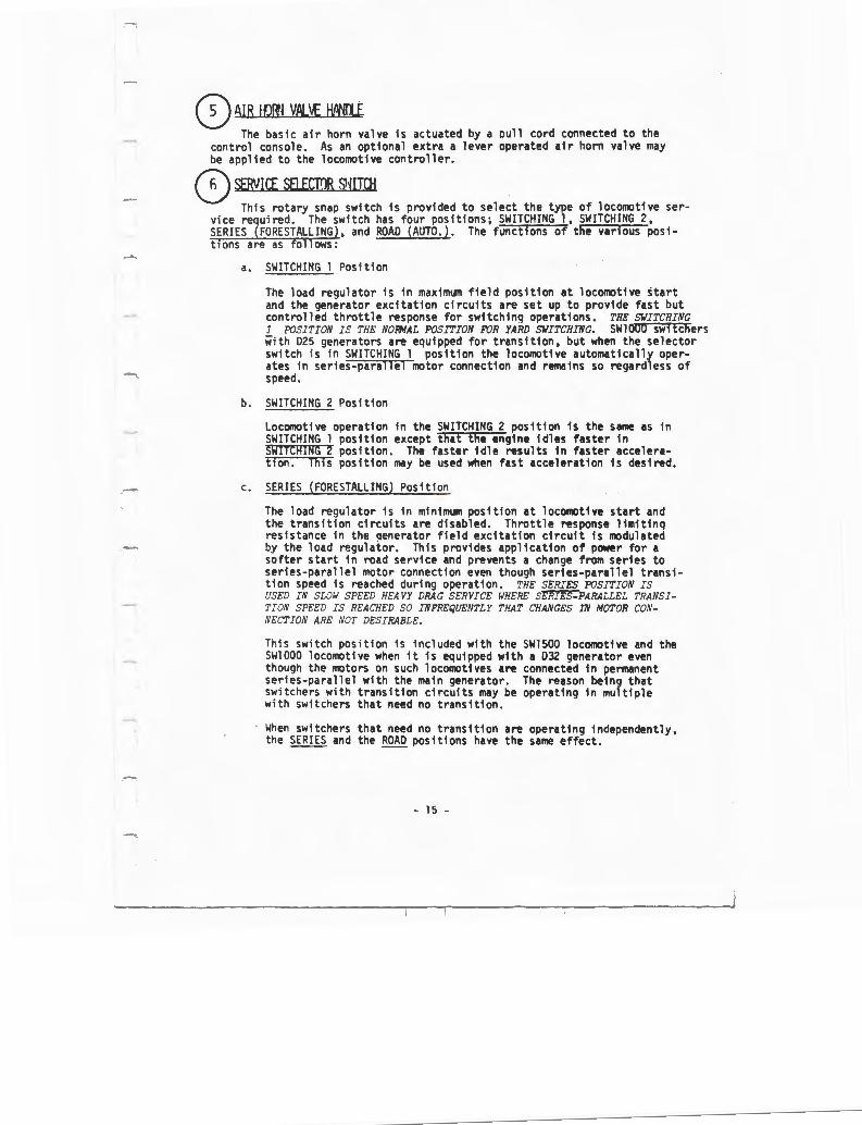
0 AIR lfJ!JI VflL\£ H,ltlli The basic air horn valve is actuated by a oull cord connected to the
control console. As an optional extra a lever operated air horn valve may be applied to the locomotive controller. 0 SERVHI SEl.fCTI)R SHITOf
This rotary snap switch is provided to select the type of locomotive service required. The switch has four positions; SWITCHING 1, SWITCHING 2, SERIES (FORESTALLING), and ROAD (AUTO. ). The functions of the various positions are as follows:
a. SWITCHING l Position
The load regulator is in maxim1111 field position at locomotive start and the generator excitation circuits are set up to provide fast but controlled throttle response for switching operations. THE SWITCHING 1 POSITION IS THE NOFMAL POSITION FOR YARD SWITCHING. SW1000 switchers with D25 generators are equipped for transition, but when the selector switch is in SWITCHING l position the locomotive automatically operates in series-parallel motor connection and remains so regardless of speed.
b. SWITCHING 2 Position
Locomotive operation in the SWITCHING 2 position is the sa111e as in SWITCHING l position except that the engine idles faster in SWITCHING 2 position. The faster idle results in faster acceleration. This position may be used when fast acceleration is desired.
c. SERIES (FORESTALLING) Position
The load regulator is in minimum position at locomotive start and the transition circuits are disabled. Throttle response limiting resistance in the qenerator field excitation circuit is modulated by the load regulator. This provides application of power for a softer start in road service and prevents a change from series to series-parallel motor connection even though series-parallel transition speed is reached during operation. THE SERIES POSITION IS USED IN SLOW SPEED HEAVY DRAG SERVICE WHERE S~PARALLEL TRANSITION SPEED IS REACHED SO INFREQUENTLY THAT CHANGES IN MOTOR CONNECTION ARE NOT DESIRABLE.
This switch position is included with the SW1500 locomotive and the SWlOOO locomotive when it is equipped with a D32 generator even though the motors on such locomotives are connected in permanent series-parallel with the main generator. The reason being that switchers with transition circuits may be operating in multiple with switchers that need no transition.
When switchers that need no transition are operating independently, the SERIES and the ROAD positions have the same effect.
- 15 -

d. ROAD (AUTO.) Position
The load regulator is in minim"'1 field position and transition circuits are in operation on switchers so equipped. Throttle response limiting resistance in the generator field excitation circuit is modulated by the load regulator. This provides for application of power for a softer start in road service and allows 1 change from series to series-parallel motor connection on switchers equipped for transition. THE ROAD 'POSITION IS USED DURING WJDERATE AND HIGH SPEED ROAD OPERATION.--
0 f\IR BM G4.lr£5 Air gauges to indicate main reservoir air pressure as well as various
pressures concerned with the air brakes are prominently located along the tor of the controller.
0 IN!HCATI;~ 11INm! Throttle position is indicated in the ill1J11in1ted indicating window at the
uoper left corner of the controller plate.
0 L'Wl OTIDIT l~ICAT!!R THE LOCOMOTIVE PULLING FORCE IS INDICATED BY THE LOAD CURRENT INDICATING
.'1ETER located at the upper portion of the controller. This meter is graduated to read amperes of electrical current, with 1500 being the maxim"'1 reading on the scale. On special order the meter may be color coded to indicate operation time limits at various meter pointer positions .
THE METER IS CONNECTED SO AS TO INDICATE THE CURRENT FLOWING THROUGH THE NO. 2 TRACTION MOTOR. SINCE 'I'HE AMPERAGE IS THE SAHE IN ALL WJTORS, EACH MOTOR WILL CARRY THE AWJUNT SHOWN ON THE HETER.
® pcs m LI!fil THE PCS OR PNEUMATIC CONTROL SWITCH FUNCTIONS TO AUTONATICALLY REDUCE
LOCOMO'I'IVEPoWER IN THE EVENT THAT AN EXERGENCY OR SAF'E'!Y CONTROL AIR BRAKE APPLICATION OCCURS. IT DOES SO BY REDUCING THE SPEED OF ALL ENGINES TO I DLE.
CAUTION: The engine run switch should be in the OFF position in all trailing 111its, or (dependinq on the type and position of locomotives in the consist) ft is possible that the PCS switch of the lead unit will not act to reduce engine speeds to idle.
When the switch is tripped the PCS OPEN indicating light on the controller will come on. This light is extfngu1shed and locomotive power restored by resetting the PCS switch. Thfs occurs autOlllltfcally, provided that:
a. Control of the air brake is recovered.
b. The throttle is returned to IDLE position .
- 16 -

® l·W:L SLIP LIGJT INTERMITTENT FLASHING OF THE WHEEL SLIP LIGHT INDICATES THAT THE WHEEL
SLIP CONTROL SYSTEM IS DOING ITS JOB AND IS CORRECTING THE SLIPS. IN MOST CASES OF SLIP IT WILL NOT BE NECESSARY TO REDUCE THROTTLE. HOWEVER, UNDER EXTREME RAIL CONDITIONS WHEEL SLIP MAY OCCUR REPEATEDLY. THE THROTTLE SHOULD THEN BE REDUCED TO A POSITION THAT WILL APPLY MAXIMUM POWER WITHOUT EXCESSIVE SLIPPING.
Sand should be used to prevent slipping, not to stop it.
The SWlOOO locomotive is equipoed basically for one step of transition. Transition steps up automatically, but must be stepped backward manually by the operator. The wheel slip light flashes to indicate that operatinq conditions call for backward transition.
'ilA.P.VI.VG: A WHEEL SLIP LI!JH':' FLASHI.'lr; SLC•'l'! A.'ID PERSISTENTLY MAY INDICATE A Pl.IR OF SLIDI.VG WHEELS OR CIRCUIT DIFFICULT'!. STOP THE LOCOMOTIVE AND MAiiE A CAREFUL INSPECTION TO ASCERTAD' 'i'HA': ?HEP.E ARE NC LOCKED SLI!JINr. WHEELS.
This extra light provides a siqnal as desired by the individual railroad,
SA~INfi LI(fil 1his extra light indicates that the manual sanding switch is positioned.
0 ENfililE IUI S1'1ITOJ -::; C!i':AIN CON'i'ROL CF E."IG!l.'E ,<'!'E:ED, -:'HE Eilr:i.VE RU.~' S:ITTCH MUS':' BE ON.
0 <EfPATOR EIEl.D S"/ITO! -:::: OBTAIN POWER FROM :'!IE WCO!+J':'!VE, ':HE 'JE.'l'ERATOR FIELD SWITCH MUS': BE ON. 0 QNTID. !(ID REI PIM> S1"1TOl BEFORE THE EllGINE IS ;'0 !3E STARTED, ':HE CON':'ROL A.VD FUEL PUNP SW!':'CH .'.fUS':'
BF F.",ACED ON.
- 17 -

®mm
The throttle lever actuates switches within the controller to establish low voltage electrical circuits to the engine !IQvernor end to related 1uxil11ry rel a.vs for purposes of controlling engine speed end power. Each running notch on the throttle increases engine speed about 85 RPM, starting et IDLE 1nd !!!:!!!..1_ end going to 900 RPM et full throttle.
NOTE: Switcher locomotives run et 1 low idle speed when on stand-by or road service operation and run at a fast idle speed when the controls are set up for switching start, in SWITCHING 2 position.
EACH RUNNING NOTCH OF THE THROTTLE INCREASES LOCOIDTIVE: POllER BY INCREASING GENERATOR EXCITATION OR ENGINE SPEE:D OR BOTH. THE SYSTEN PROVIDES RAPID POWER RESPONSE AT A LEVE:L CONSISTENT WITH CONTROLLED STARTING,
The basic throttle has ten positions; namely, STOP, IDLE, and running notches 1 through 8. Each of these positions is shown in"'llie illuminated indicator in the upper left hand corner of the controller plate.
When the locomotive is equipped with a duplex control console, neither the master nor the slave throttle lever is provided with a stop position. A seoarate emergency engine stop switch is located near each throttle lever. These switches, identified as M.U. ENG. STOP, may be ustd to stop 111 engines in 1 consist from the cab of the lead unit.
- 18 -

.-
WARNING: DURING NORMAL OPERATION THE M. U. ENG. STOP SWITCH MUST BE IN THE RUN POSITION AT ALL CONTROL STATIONS OF ALL UNITS IN A LOCOMO-TIVE CONSIST. ONLY THE SWITCHES LOCATED IN THE LEAD UNIT ARE COMPLETELY EFFECTIVE IN SHUTTING DOWN ALL ENGINES OF A LOCOMOTIVE CONSIST. THE M.U.ENG.STOP SWITCHES IN TRAILING UNITS MAY ACT TO DECREASE ENGINE SPEED IN ALL UNITS, BUT WILL NOT NECESSARILY CAUSE ENGINE SHUTDOWN.
® '!fPAU~ SWIJOf.S A group of switches is located along the front face of the controller,
each identified by a natne plate indicating switch function. The switches are in the ON position when moved upward.
These three switches are grouped at the right side of the controller. They must be placed in the QfE. position on controllers of trailing units.
@Hml.E\fR
':'HE REVERSE LEVER HAS THREE UNMARKED POSITIONS THAT ARE CONSIS':'E.V'!' WITH TP.E DIRECTION OF LOCOJKJTIVE TRAVEL. THAT IS, THE LEVER IS NOVED FORWARD FOR FC'RWARD LOCOMO'i'IVE TRAVEL, IS CENTERED IN THE NEUTRAL POSITION, AND IS PULLED BACK FOR REVERSE OPERATION. THE POSITION OF THE LEVER SHOULD BE CHANGED ONLY WHEN THE ;:,oc.?MOTIVE IS STANDING STILL.
WI TH THE REVERSE LEVER IN NEUTRAL POSITION, NO POWER WILL BE DEVELOPED WHEN ':'/IE THROTTLE IS OPENED.
l'!V BASIC CONTROL CONSOLES THE REVERSE LEVER CAN BE REMJVED FRON THE CONTROLLER ONLY WHEN THE LEVER IS IN NEUTRAL POSITION AND THE THROTTLE IS IN IDLE PO.~l."IO.V . - REMOVAL OF THE REVERSE LEVER LOCKS THE OPERATINr; CONTROLS IN THE--CONTROLLER. THE REVERSE LEVER SHOULD BE REHOVED FROM TP.E CONTROLLER.<; IN ALL llUT TllE LEAD UNIT OF A MULTIPLE UNIT LOCOMOTIVE CONSIST.
- 19 -

MECHANICAL INTERLOCKS ON THE CONTROLLER
The levers on the controller are interlocked so that with:
a. Throttle lever in IDLE position --
REVERSE LEVER CAN BE MOVED TO ANY POSITION OR REMOVED FROM THE CONTROLLER.
b. Throttle lever in position 1 through 8 -•
REVERSE LEVER POSITION CANNOT BE CHANGED.
c. Throttle lever in STOP position --
REVERSE LEVER CAN BE MOVED TO ANY POSITION, BUT CANNOT BE REMOVED FROM THE CONTROLLER.
NOTE: On control consoles equipped with duplex controls, there is no STOP position on the throttle. Emergency engine stop switches are located next to the throttle levers on the controllers.
d. Reverse lever in forward or reverse position
THROTTLE L!'VER CAN BE MOVED TO ANY POSITION.
e. Reverse lever in neutral position -
THROTTLE LEVER CAN BE MOVED TO ANY POSITION.
f. Reverse lever removed from controller --
THROTTLE LEVER CAN NOT BE MOVED.
NOTE: On units equipped with duplex control consoles, l'ltllOval of the reverse lever from the master controller locks the reverse lever of the slave controller in neutral position.
On un1ts equipped w1th duplex control consoles, the reverse lever can be removed from the master controller when tht throttle is placed in IDLE position and the reverse lever is in neutral position. Whtn tht reverse ltver is r91110ved from the master controller, an interlock in the mechanism prevents 1110vet111nt of the non-removable handle of tht slave controller. The reverse lever should be removed from the master controller in all but the ltad cab of a multiple unit consist.
NOTE: On switcher locomotives, tht diesel engine will run at nonn11l 1dle speed when tht rtvtrst lever is ctnttred. When tht reverser lever is positioned for operetion, tht 1nqin1 will go to fast idlt speed 1f the strvict stltctor switch is positioned for switching start, in SWITCHING 2 position.
- 20 -

® HEADLIGITT DJrt1[;.JG ~·1 ITCH A five position switch is located on the controller next to the reverser
lever. In one position it provides for DIM headlights on both ends of the locomotive. In the other positions it proviaes for a bright or medium headlight at either the front or the rear of the locomotive.
For this switch to function, the two headlight switches on the controller as well as the headlioht circuit breaker on the switch and fuse panel must be placed ON. ·
® HEATER ENJ S1•1ITCH This switch controls the speed of the heater fan. It does not control the
flow of hot water to the heater radiator. Heater water shutoff valves are located in the vicinity of the engine accessory rack.
@ Sl\FETY Oll ITRlL FmT ll/IR The foot bar provides dead man control of the locomotive air brakes. If
the bar is released during ooeration of the locomotive, a whistle will sound and after a delay of approximately 10 seconds a safety control application of the brakes will occur. The delay provides sufficient time for an operator to change stations on locomotives equipped with the duplex control console. 0 ~RTIPl£ !NIT VN....vt. (!·~JEN Pi:rllf!lBJ)
The multiple unit (MU-2) valve is located on the left hand side of the air brake pedestal. Its purpose is to pilot the Fl selector valve which is a device that enables the air brake equipment of one locomotive unit to be controlled by that of another unit.
The basic MU-2 valve has three positions which are:
a. LEAD or DEAD
b. TRAIL 6 or 26 * --- -c. TRAIL 24
The valve is positioned hy pushing in and turning to the desired setting.
* Whenever the MU-2 valve is in the TRAIL 6 or 26 position, and if actuating trainline is not used, then the actuating end connection cutout cock must be opened to atmosphere. This is necessary to prevent the inadvertent loss of air brakes due to possible pressure build-up in the actuating line.
- 21 -

8'JGINE STARTING camrn..s
0 RH PRIME Nill 8-JGINE SIMI SWITCH
Governor Rack Position Scale
This sw i tch, located on the equipment rack in the engineroom, is a threeposition rotary switch used for fuel priming and engine starting. BEFORE ATTEMPTING TO START '!'HE DIESEL ENGINE, THE ISOLATION SWITCH IN THE WCOMOTIVE c~A3 MUST BE PLACED IN ':HE START POSITION. THE ROTARY SWITCH MUST THEN BE PLACED IN THE FUEL PRIME POSITION AND HELD THERE FOR 10 TO 15 SECONDS TO .JPE.'IATE THE FUEL PIF.1P. THE LAYS.I/AFT LEVER MUST THEN BE POSITIONED AND THE .".O':ARY SWITCH PLACED IN THE ENGINE START POSITION AND HELD I FOR NO LONGER .".'!,;:. ~? SECONDS) UNTIL THE ENGINE STARTS.
0 INJECTOR RACK witlUt\L COOIIU LE.YER This engine mounted hand-operated lever operates the injector racks. IT
-~ U~ED TO POSITION THE INJECTOR RACKS DURING ENGINE CRANKING, THEREBY PROVIDING AN JNMEDIATE SUPPLY OF FUEL TO THE CYLINDERS. CD UM WATER !{SET N?HBlJTTON (Wf[N PR;JVIJEl)
Th e low water detector wil l often trip during engine starting, especially when the engine is cold or when the water tank pressure cap has been removed to add water . THE DETECTOR SHOULD BE RESET AS SOON AS THE ENGINE STARTS AND IS IDLING, OR ELSE THE ENGINE WILL SHUT DOWN AFTER A TIME DELAY ESTABLISHED BY THE GOVERNOR. CHECK THE LOW WATER RESET PUSHBUTTON AFTER EVERY ENGINE START.
NOTE : The reset buttons on some detectors will not latch in while the engine is shut down . If such a condition is encountered, reset the device after engine start.
- 22 -

--STARTING TRAIT.ING UNIT DIESEL ENGINES
Engines in trailing units are started in the same manner as the engine in the lead unit.
- 23 -

PLACING UNITS ON THE LINE
After the diesel engines are started and inspected, units may he placed on the line as desired by placing the isolation switch on the engine control panel in the cab in the RUN position. If the consist is at a standstill, be certain that the throttle lever in all units is in the idle position before placing any unit on the line .
- 24 -

--'
PRECAUTIONS BEFORE MOVING LOCOMOTIVES
The following points should be carefully checked before attempting to move the locomotive under its own power:
1. MAKE SURE THAT MAIN RESERVOIR AIR PRESSURE IS NORMAL (approximately 136-146 pounds).
This is very important, since the locomotive is equipped with electro-magnetic switchgear which will function in response to control and permit operation without air pressure for brakes.
2. Check for proper application and release of air brakes.
3. Release hand brake and remove any blocking under the wheels.
- 25 -

HANDT.ING LIGHT LOCOMCYrIVE
With the engine started and placed "on-the-line" and the preceding inspections and precautions completed, the locomotive i. s handled as follows:
1. Place the engine run switch and generator field switch in ON (up) position.
2. Place headlight and other lights ON as needed.
3. Insert reverse lever and move it to desired direction o f travel, either forward or reverse.
NOTE: On switcher locomotives, engine speed will increase if the service selector switch is in the SWITCHING 2 position.
4. Place service selector switch in position for type of service desired.
5. Depress safety control foot bar on units so equipped .
6 . Release air brakes.
7 . Open throttle to Run 1, 2, or 3 as needed to move locomotive at desired speed. Locomotive response to throttle movement is immediate . There is no delay in power bu i ldup . However, with the service selector switch in SERIES or ROAD position, power is modulated by load regul~ position .
CAUTION: Engine should not be operated above throttle position No. 3 until water temperature is greater than 130 F.
8. Throttle should be in IDLE position before coming to a dead stop.
9 . Reverser handle should not be moved to change direction of travel until locomotive is completely stopped.
- 26 -

--COUPLING LOCOMOTIVE UNITS TOGETHER
When coupling units together for multiple unit operation, the procedure below should be followed:
1. Couple and stretch units to insure couplers are locked.
2. Install control cable between units.
NOTE: If the consist is made up with units that are equipped for only pneumatic contr ol of sanding, connect actuating pipes between all units in the consist.
3. Attach platform safety chains between units.
4. Perform ground, engineroom and engine inspections as outlined in preceding artic l es .
5 . Position cab controls for trailing unit operation as outlined in preceding articles.
6 . Connect air brake hoses between units as required by the specific equipment involved.
7. Open required air hose cutout cocks on both units.
NOTE: Units with 26NL brake equipment must have the actuating pipe end hose cutout cock CT.OSED at the rear of the locomot i ve when they are leading units with 6ST. or 6BL brake equipment. If two or more units of 26NL brake equipment are connected together and leading the consis t , the end hoses must be coupled together between units and the cutout cocks on the actuating pipe line OPENED on each unit. Units with 26NL brake equipment must have the actuating pipe cutout cock OPEN at both ends when attached to, but tra i ling units With 6SL or 6BL brake equipment . (This is required to eliminate an undesired brake action occurring on the locomotive.)
A setup of the brakes must then be made on the consist to determine if brakes apply on each unit. Brakes then must be released to determine if all brakes release . The same procedure must be followed to check the independent brake application . Also, release an automatic service application by depressing the independent brake valve handle downward. Inspect all brakes in the consist to determine if they are released.
- 27 -

COUPLING LOCOMOTIVE TO TRAIN
Locomotive should be coupled to train using the same care taken when coupling units together. After coupling, make the followi ng checks:
1. Test to see that couplers are locked by stretching connection .
2. Connect air brake hoses .
3. Slowly open air valves on locomotive and train to cut in brakes.
4 . Pump up air if necessary
- 28 -

... --- ...
PUMPING UP AIR
After cutting in air brakes on train, note the reaction of the main reservoir air gauge, If pre1sure falls below trainline pressure, pump up air as follow1:
l. Place generator field switch in .Q!! (down) po1ition.
2. Move reverie lever to neutral po1ition ,
On switcher locomotives, a fa1t idle speed may be obtained by turning the service selector 1witch to ~TyHING po1ition when reverie lever ia po1itioned or ocomotive movement, and the throttle i1 in idle.
3. Open throttle a1 needed to 1peed up engine and thu1 increase air compressor output.
Throttle mar be advanced to!!,!! !I, or l if neceasary. Engine 1hou d not however be run unloaded (a1 in pumping up air) at speeda beyond throttle No, S position.
- 29 -

BRAKE PIPE LEAKAGE TEST
Prior to operating the 26NL brake equipment, a leakage test must be performed. This is accomplished in the following manner.
l. The cutoff valve is positioned to the IN position.
2. Move the automatic brake valve handle gradually into service position until the equalizing reservoir gauge indicates that a 15 psi reduction has been made.
3. Without any further movement of the automatic brake valve handle, observe the brake pipe gauge until this pressure has dropped 15 psi and exhaust has stopped blowing.
4. At this moment turn the cutoff valve to cur Otrr position. This cuts out the maintaining function of the brake valve.
5. From the instant the cutoff valve is turned to CtIT Otrr position, the brake pipe gauge should be observed and any possible drop in brake pipe pressure should be timed for one minute. Brake pipe leakage must not exceed the rate established by railroad rules.
6. After checking trainline leakage for one minute and the results are observed to be within required limits, return the cutoff indicator to the IN position and proceed to reduce the equalizing gauge pressure until the pressure is the same as brake pipe gauge pressure. This is accomplished by moving the automatic brake valve handle gradually to the right until a full service application has been obtained.
7. After pipe leakage test has been completed, return the automatic brake valve handle to RELEASE position.
- 30 -

KICKING CARS
When the service selector switch is placed in SWITCHING position, the load regulator goes to maximum field position and electric circuits operate to relate tractive effort directly to throttle position at locomotive start. The action of the locomotive power control system during switching operations is such that tractive effort at locomotive start is low in low throttle position and high in high throttle position. This effort is available immediately as the throttle is positioned . It allows sudden but controlled application of power when the throttle is advanced. The rapid application of power gives the locomotive operator a "known" throttle response . The power control at lower throttle positions also simplifies "inching" of cars.
- 31 -

STARTING A TRAIN (SERVICE SELECTOR SWITCH IN SERIES OR ROAD POSITION)
The method to be used in starting a train depends upon many factors such as, the type of locomotive being used; the type, weight and length of the train and amount of slack in the train; as well as the weather, grade and track conditions. Since all of these factors are variable, specific train starting instructions cannot be provided and it will therefore be up to the operator to use good judgment in properly applying the power to suit requirements. There are, however, certain general considerations that should be observed. They are discussed in the following paragraphs.
A basic characteristic of the diesel locomotive is its HIGH STARTING TRACTIVE EFFORT, which makes it imperative that the air brakes be completely released before any attempt is made to start a train .
The locomotive possesses sufficiently high tractive effort to enable it to start most trains without taking slack. The practice of taking slack indiscriminately should thus be avoided. There will, however, be instances in which it is advisable (and sometimes necessary) to take slack in starting a train. Care should he taken in such cases to prevent excessive locomotive acceleration which will cause undue shock to draft gear and couplers, and lading.
Proper handling is important when starting trains, since it has a direct bearing on the power being developed. As the throttle is advanced, a power increase occurs immediately. The strength of the increase is dependent upon throttle position and is modulated by the load regulator.
It is therefore advisable to advance the throttle one notch at a time when starting a train. A train should be started in as low a throttle position as possible, thus keeping the speed of the locomotive at a minimum until all slack has been removed and the train completely stretched. Sometimes it is advisable to reduce the throttle a notch or two at the moment the locomotive hegins to move in order to prevent stretching slack too quickly or avoid slipping.
When ready to start, the following general procedure is reco~mended:
1. Place service selector switch in position for type of service desired.
2. ~ove reverse lever to the desired direction, either forward or reverse.
3. Place engine run and generator field switches in the ON (up) position.
- 32 -

4. Release both automatic and independent air brakes.
S. Open the throttle one notch every few seconds as follows:
a. To run 1 - The engine will load. This may be noted on the load current indicating meter. At an easy starting place the locomotive may start the train.
b . To run 2, 3 or higher (experience and the demands of the schedule will determine this) until the locomotive moves .
6. Reduce throttle one or more notches if acceleration is too rapid.
7. After the train is stretched, advance the throttle as desired.
!!Q!!: When operating at full power to climb a hill, the wheel slip light may indicate frequent slipping. In such case do not reduce throttle unless severe lurching occurs and there is danger of pulling the train apart.
- 33 -

ACCELERATING A TRAIN
After the train has been started, the throttle can be advanced as rapidly as desired to accelerate the train. The speed with which the throttle is advanced depends upon demands of the schedule and the type of locomotive and train involved. In general however, advancing the throttle one notch at a time is desired to prevent slipping.
The load indicating meter provides the best guide for throttle handling when accelerating a train. By observing this meter it will be noted that the pointer moves toward the right (increased amperage) as the throttle is advanced. As soon as the increased power is absorbed, the meter pointer begins moving toward the left. At that time, the throttle may again be advanced. Thus for maximum acceleration without slipping, the throttle should be advanced one notch each time the meter pointer begins moving toward the left until full power is reached in throttle position 8.
Additional train acceleration is provided (on locomotives so equipped) by motor field shunting and/or by changing motor connection with the main generator. These changes tli<e place automatically during throttle changes or after reaching full throttle. The changes in electrical circuits during acceleration take place automatically without any attention or action on the part of the operator.
CAUTION: On SWlOOO units equipped with D25 generators, backward transition (change in motor connection with the main generator) does not occur automatically. Refer to the following articles for recommendations covering operator action as a train slows down.
- 34 -

SLOWING DOWN BECAUSE OF A GRADE
On SWlSOO units and on SWlOOO units equipped with D32 main generators, no changes in motor connection with the main generator occur. Steps of decreasing shunt (on units so equipped) occur automatically and will be indicated by movement of the load current indicating meter pointer. No action is required on the part of the operator.
ON SWlOOO units equipped with D25 main generators steps of decreasing shunt (on units so equipped) occur automatically, but backward transition (change of motor connection) is not automatic. As the locomotive slows down increased load current may be noted. When the meter indication approaches 800 amperes, a current limiting relay operates to decrease generator excitation and cause the wheel slip light to come on and go off. The operator may take the following action:
Reduce throttle position to Run 6 or lower, and after a moment turn the service selector switch to the SERIES position . Reopen the throttle as desired. When the train reaches level or downhill track and increased speed is possible, the service selector switch should be returned to the ROAD position.
If operating conditions are such that a momentary lessening of power is not important, backward transition may be accomplished by placing the throttle in ~ position, and after a momentary delay reopening it as desired.
- 35 -

AIR BRAKING WITH POWER
The method of handling the air brake equipment is left to the discretion of the individual railroad, However, when braking with power, it must be remembered that for any given throttle position, the draw bar pull rapidly increases as the train speed decreases. This pull might become great enough to part the train unless the throttle is reduced as the train speed decreases. Since the pull of the locomotive is indicated by the amperage on the load meteri the operator can maintain a constant pull on the train during a s ow down, by keeping a steady amperage on the load meter. This is accomplished by reducing the throttle a notch whenever the amperage starts to increase. It is recommended that the independent brakes be kept fully released during power braking. The throttle MUST he in Idle before the locomotive comes to a stop.
- 36 -

OPERATING OVER RAIL CROSSING
When operating the locomotive at speeds exceeding 25 MPH, reduce the throttle to a RUN 4 position at least eight seconds before the locomotive reaches a rail crossing. If the locomotive is operating in ~ position or lower, or running less than 25 ~PH, allow the same interval and place the throttle in the next lower position. Advance the throttle after all units of the consist have passed over the crossing. This procedure is necessary to ensure decay of motor and generator voltage to a safe level before the mechanical shock that occurs at rail crossings is transmitted to the motor brushes.
- 37 -

RUNNING THROUGH WATER
Under ABSOLUTELY NO CIRCUMSTANCES should the locomotive be operated through water deep enough to touch the bottom of the traction motors. Water any deeper than 3" above the rail is likely to cause traction motor damage.
When passing through any water on the rails, exercise every precaution under such circumstances and always go very slowly, never exceeding 2 to 3 MPH.
- 38 -

WHEEL SLIP LIGHT INDICATIONS
The momentary flashing of the wheel slip light on and off generally indicates a pair of wheels are slipping. Corrective wheel slip relay action automatically reduces the power output of the main generator which thereby reduces the traction motor torque, stopping the slipping.
In most cases it will be unnecessary to reduce the throttle because of momentary wheel slip action, as the locomotive will automatically reduce its power to stop the slipping, and reapply the power after the slipping has stopped. However, under extreme rail conditions, slipping may occur repeatedly. In this case the throttle should be reduced to a position that will apply the maximum power permissible without causing excessive slipping. Sand should be used to prevent slipping, not to stop it.
On SWlOOO units equipped with D25 generators, the wheel slip light is used to indicate that the current limit relay has picked up to limit main generator current. This occurs when locomotive speed decreases after transition has been made . When such wheel slip light indications appear, it is necessary for the operator to manually initiate backward transition, either by changing service selector switch position or by returning the throttle to ~ position.
- 39 -

LOCOMOTIVE SPEED LIMIT
The maximum speed at which the locomotive can be safely operated is determined by the gear ratio. This ratio is expressed as a double number such as 62:15. The 62 indicates the number of teeth on the axle gear while the 15 represents the number of teeth on the traction motor pinion gear.
Since the two gears are meshed together, it can be seen that for this particular ratio the motor armature turns approximately four times for a single revolution of the driving wheels. The locomotive speed limit is therefore determined by the maximum permissible rotation speed of the motor armature. Exceeding this maximjm could result in serious damage to the traction motors.
Various gear ratios are available to suit specific locomotive operating requirements. For each gear ratio, there is a maximum operating speed . This information is given in the "General Data" section at the beginning of this manual.
Although not basically applied, overspeed protective equipment is available for installation on locomotives. The equipment consists of an electro-pneumatic arrangement with many possible variations to suit spec i fie requirements. In general, however, an electrical switch in the speed recorder is used to detect the ov er-speed . This switch in turn initiates certain air brake f unctions which reduce the train speed.
- 40 -

MULTIPLE UNIT OPERATION
Switching locomotives are basically designed for single unit operation, but can be arranged for multiple unit operation.
A locomotive equipped for multiple operation is supplied with the same electro-hydralic governor control and controller that is supplied on the basic switcher. An isolation switch, stop button, alarm bell, and remote control headlight switch are also provided.
- 41 -

DOUBLE HEADING
Prior to double heading behind another locomotive, make a full service brake pipe reduction with the automatic brake valve, and place the cutoff valve in Cl.ITOlIT position. Return the automatic brake valve handle to the release position and place the independent brake valve in release position. On 26NT. equipment place the MU valve in LEAD position.
The operation of the throttle is normal, but the brakes are controlled from the lead locomotive. An emergency air brake application may be made, however, from the automatic brake valve of the second unit. Also, the brakes on this unit may be released by depressing the independent brake valve handle while it is in the release position.
- 42 -

ISOLATING A UNIT
A locomotive unit in a multiple unit consist may be isolated at any tiine by turning the isolation switch to the ISOLATE position, but discretion as to ti~ing and necessity should be used.
- 43 -

CHANGING OPERATING ENDS
When the locomotive consist includes two or more units with operating controls, the following procedure is recommended in changing from one operating end to the opposite end on locomotives equipped with 26NL brakes.
ON END BEING CUT OUT
1. Move the automatic brake valve handle to service position and make a 20 pound reduction.
2. After brake pipe exhaust stops, place cutoff valve in CUT-01JT position by pushing dial indicator handle in and turning to the desired position.
3. Place independent brake in fully released position.
4. Place ~'U valve in the desired TRAIL position, depending on brake equipment on trailing units. QIU valve is located in the left hand side of the air pedestal. Push dial indicator inward and turn to desired position.)
5. Position automatic brake valve in handle off position. (Handle may be removed if so equipped.)
6. Place reverser handle in neutral position and remove to lock controller.
NOTE: On units equipped with duplex control consoles, only the master controller reverser handle can be removed,
7. At the controller, place all switches in the off position. Be absolutel y certain that the control and fuel pump switch, generator field switch, and engine run switch are in the off position.
8. At the engine control panel, place headlight control switch in proper position for trailing unit operation. Place other switches on as needed.
9. At the circuit breaker panel, the control circuit breaker and the local control circuit breaker remain in the on position.
NOTE: If the local control circuit breaker is inadvertently placed off at this ti~e, the engine will shut down when the trainlined control circuit is re-estab lished. However, the engine may be restarted in the normal manner after placing the local control circuit breaker on.
10. After completing the operations outlined in the preceding. steps, move to the cab of the new lead unit.
- 44 -

ON END BEING CUT IN
l.
2.
3.
4.
5.
6.
7.
8.
9.
At the controller, make certain throttle lever is in .!Q!& and the generator field switch is off,
Insert reverser handle and leave in neutral position.
Insert automatic brake valve handle (if removed) and place in suppression position to nullify any safety control, overspeed, or train control used.
Insert independent brake valve handle (if removed) and move handle to full independent application position.
Position cutoff valve in the CUT-IN position.
Place MU valve in LEAD position.
At the circuit breaker panel, check that the control circuit breaker is in the on position . Other circuit breakers remain on.
At the engine control panel, place the headlight control switch in proper position, and other switches on as needed.
At the controller, place the engine run, control and fuel pump, and generator field switches in on position . Other switches may be placed on as needed.
- 45 -

STOPPING ENGINE
There are six ways to stop the engine.
1. Press stop button on engine control panel .
When the locomotive is standing still or under power, the isolation switch should be placed in STOP position . The stop button can then be pressed in to stop the engine. Since the reaction of the stop button is instantaneous, it need not be held in.
2. Press emergency fuel cutoff button.
F.mergency fuel cutoff pushbuttons are located near each fuel filler opening and on the engine control panel . These pushbuttons operate in the same manner as the STOP button and need not be held in nor reset .
3 . Use layshaft lever.
The layshaft lever at the accessory end of the engine can be operated to override the engine governor and move the injector racks to the no fuel position.
4. Close the low water detector test cock .
When the low water detector trips, oil is dumped from the governor low oil shutdown device, stopping the engine.
5. Use throttle lever or M.U.ENG.STOP switch.
a . On units equipped with single control station, move the throttle to IDLE position, pull the lever out and away from the controller, and move it beyond IDLE to the STOP position. --
b. On units equipped with duplex control stations, move throttle to the IDLE position and place the M.U.ENG . STOP switch in the STOP position.
WARNING: The M.U.ENG.STOP switches in the cab of the lead unit will stop all engines in a consist regardless of throttle position, but the M.U.ENG.STOP switches in trailing units will stop all engines only if the throttle in the lead unit is in the IDLE position .
6. Pull out the low oil shutdown rod on the side of the governor.
CAlITION: Observe freezing weather precautions whenever an engine is shut down during cold weather.
- 46 -

SECURING LOCCMOTIVE FOR LAYOVER
1. Place the reverse lever in neutral position and the throttle in ..!!ll&·
2. Place isolation switch in ~and press stop button J.!!.
3. Place all switches on the controller panel in the OFF position (down).
4. Place all circuit breakers and switches on the circuit breaker panel and the engine control panel in the OFF position and open all knife switches.
5. Apply hand brake and block wheels, if necessary.
6. Cover exhaust stack if there is danger of a severe rain.
7. Drain or otherwise protect engine if there is danger of freezing.
- 47 -
...

TOWING LOCOMOTIVE IN TRAIN
When a locomotive unit equipped with 26NL air brakes is placed within a train consist to be towed, its control and air brake equipment should be set as follows:
1. Drain all air from main reservoirs and air brake equip-ment unless engine is to remain idling.
2. Place the ~:U valve in DEAD position.
3 . Place cutoff valve in CUT OUT position.
4. Place independent brake valve handle in release position .
5. Place automatic brake valve handle in off position.
6. Cut in dead engine feature by turning cutout cock to open (90 to pipe) position. Dead engine cock is located beneath cab floor and may be reached through an access door at side of locomotive.
CAUTION: The pressure regulator is adjusted at a maintenance point in accordance with the type of brake equipment used . The locomotive operator should not attempt to adjust braking pressure.
7. If engine is to remain IDLING, switches should be positioned as follows:
a.
b.
c.
d .
e.
f.
g.
Isolation switch in START position.
All knife switches CLOSED.
Local control and control circuit breakers ON.
Generator field and starting fuses should be removed . Other fuses should be left in place.
Control and fuel pump switch ON.
Fuel pump circuit breaker ON.
Throttle in IDLE, selector in OFF, reverse lever in NEUTRAL. REMCNE REVERSE LEVER"""fROM CONTROLLER to lock contro s.
- 48 -

8. If locomotive is to be towed DEAD in a train, switches should be positioned as folloWS-:-
a.
b.
c.
d.
e.
All knife switches .Qffili.
All circuit breakers OFF.
All control switches ~·
Starting fuse removed.
Throttle should be in IDLE, and REVERSE T.EVER SHOULD BE REMOVED FRCJo! CONTROT:I:!R.
!!Qg: If there is danger of freezing, the engine cooling system should be drained.
- 49 -

FREEZING WEATHER PRECAUTIONS
As long as the diesel engine is running, the cooli ng system wi ll be kept adequatel y warm regardless of amb ient (outside ) t emperatures encountered .
When danger of freezing is present, the cooling system should ~e completely drained. Drain valves are located at the engine sump between t he engine and accessory rack on the f l oor in front of the engine (see fi gure below). To drain the system, open all four valves and allow all to remai n open unti l draining is complete at all valves. This wi ll drain the engine, radiators, water tank, oil cooler , air compressor and heaters.
1. E nwfgcnc:y Cab Ht•atn D rain V alv•• ? H r awr R etur n Lmt• V alvr 3 Cooling Svs tPm D rain V alvt• 4 H t>ater Supply L 1nf! V alve S Engine A ir Bo~ D rain L1nr
- 50 -

TROUBLE SHOOTING
SW-1000 - SW-15()'.)
INTRODUCTION:
This section covers operational problems that may occur on the road and suggests action that may be taken by the operator in response to the trouble.
Safety devices automatically protect equipment in case of faulty operation of almost any component. In f'!!!Deral this protection is obtained by one of the follovl.ng methods.
1. Complete shutdown of the diesel engine .
2. Unloading of the diese 1 engine.
3. Unloading of the diesel engine an:l. restriction to idle engine speed.
- 51 -

r.ondition Probable Cause
Hot. enMne li1')lt and alann. Temporary operating condition.
Eot enr,ine 1i~ht and alarm ~~110,.,..d by Jew oil lir,ht ·md ,.,,,""i.ne shutdown.
Low water level.
W~8~:Nr.: If '<11 extremely hot engine condition exists ruiil the lov water detector did not trip, tho! hot oil dete~tor ma_v have caused engine shutdown. 'lake no further enp:ine room inspections. leave the envneroom area and allow the unit tc remain ~hut down.
- 5? -
Suggested Operator's Response
If temperature does not return to normal in a reasonable time, shut the unit down. Be fore shutdown, make the following checks.
Check cooHng water level.
Check that shutters are open airl fan is operating. If shutters are closed, operate test valve located in the vicinity of the water tank instruction plate. If valve operation opens the shutters, and temperature returns to nonnal, operation may continue to the nearest maintenance point.
Check cooling water level, and check low water detector and governor low oil trip nlunp:er for trip indications.
If cooling water level is lov, check for leaks. Add water as required. Reset the governor low oil pressure trip plun~r and the lov water reset button.
Check the low water reset button vithin 50 seconds after engine start. Reset if necessary. If at'ter reset the low water detector again trips, press and hold the button in while operating the in jector rack manual control lever to increase engine speed and water pump pressure for a short while.

Condition
Low oil light and alarm. Engine shut down.
Probable Cause
I.ow oil pressure.
CAUTION: Observe freezing weather precautions whenever M engine is shut down and freezing conditions are possible.
Groun<I relay light Md 3.la!""l.
I.ow water pressure.
Crankcase (oil pan) overpressure.
Ground relay action.
WARN!NG: Dn not tow or operate a locomotive unless ahsolutely sure that all of its wheels :rc>t .. te freely.
Do not pull cars with a truck cut out. Do not operate at more than half throttle with A. truck c11t out.
- 53 -
Suggested Operator's Response
Check the governor low oil trip plun!!!er and engine oil level. Check for oil leaks. If oil level is satisfactory and no other reason for low oil trip is apparent (engine is not overheated, and the crankcase pressure and low water trip buttons are set) restart the engine. If low oil shutdown occurs again , do not restart the engine.
Check low water detector reset button. If necessary add water to system and restart engine. Check for leaks,
Check crankcase pressure detector reset button. If button protrudes , make no further engineroom inspections. Isolate the unit.
Wait at least 10 seconds, then press the ground relay reset button. If two more l<l"OUnd relay actions occur, isolate the unit.
If a traction motor fault is the cause of the ground relay action, the locomotive may return independently to the maintenance point, by operating the cutout switch on the circuit breaker panel to ~ut out the truck containing the defective motor.

Cond ition
A1'1rm hell rines - No warning li r,ht r on in lead uni t .
En ,.ine loes not respond to t "h.rottle.
Probable Cause
Ground relay action in trailing unit.
Trailing unit shut down.
Tripped circuit breaker; Control switches improperly positioned.
- 54 -
Suggested (),,era.tor's Response
Sa.me response as above.
Check warning lights in cab of affected unit. If no l i ghts are on, check overspeed lever at accessory end of engi ne. If overspeed occurs a gain , operation at reduced t hrott l e may prevent the overspeed t rip . If not, isolate the unit and allow 1 t to remain shut down .
Check the control circuit breaker and the engine run switch. Check electrica l cable at the engine governor.

Condition Probable Cause
Engine responds to throttle Blown fuse. but no power is developed,
Sug!!J!!sted Operator's Response
Check battery field 8o-ampere fuse. Open the main battery nitch before checking and reinstalling the fuse ,
Control breaker tripped. Check control circuit breaker.
Reverser handle centered, P1- reverser handle in an operating position.
Generator field sv:l.tch off. Check position of generator field svitch; also check position of isolation switch . Move throttle between IDIE and l and check pickup and dropout of generator field contactor BF.
Electrical system fault. With service selector switch in SERIES or ROAD position, and the unit developing no pcnier vith throttle at position 1, check position of load regulator. If load regulator is at maximum field position, there is a fault in the excitation system preventing excitation
- 55 -
of the main !!ll!nerator. If tre load regulator remains at minimum field position, there is a fault in the control circuits.

Condition
PCS light on.
Intermittent wheel slip light indications.
Probable Cause
Penalty brake application.
Sua.,,.sted Onerator's Resnonse
Move throttle to IDLE. Move brake valve handle to handleoff position, and then to rel.ease position.
Emergency brake application. Move throttle to IDLE position.
Nonna! wheel slip correction under severe conditions.
- 56 -
Move brake handle to emergency position and wait 45 seconds before moving handle to rel.ease position.
NOTE: Follow railroad regulations af'ter any penalty or emergency brake application.
No action required. Do net reduce throttle unless slippi:ig is so severe that it three.tens to break tJ-e train .

Condition
Excessive wheel slip light indications.
Probable Cause
Locked sliding wheels.
Control or transmission system fault.
CAUTION: Do not pull cars with a truck cut out. Make certain that all wheels rotate freely bet'ore moving the locomotive.
Do not operate at more than hal.i' throttle with a truck cut out.
Trailing units do not respond to throttle.
Local control breaker tripped in trailing unit.
Jumper cable between units not securely connected.
- 57 -
Su<rll@Sted im..rator ' s Resoonse
Check that all vheels on the locomotive rotate t'reely. Do not operate a locomotive unless all 'Wheels rotate t'reely.
Cut out a pair of traction motors alld. check operation. If the slipping condition is corrected with a truck cut out, retum the unit to a maintenance point.
Reset breaker.
Secure jumper cable.