design and analysis of locomotive pantograph - International ...
14
-
Upload
khangminh22 -
Category
Documents
-
view
1 -
download
0
Transcript of design and analysis of locomotive pantograph - International ...

Email ID: [email protected] or [email protected]
www.ijmert.net
ISSN 2454-535XVol. 3, No. 2, May 2017
International Journal of Mechanical Engineering Research and Technology
28
This article can be downloaded from http://www.ijmert.net/Current-Issue.php
Int. J. Mech. Eng. Res. & Tech 2017 Varada Uday Bhaskar and L Siva Rama Krishna, 2017
DESIGN AND ANALYSISOF LOCOMOTIVE PANTOGRAPH
Varada Uday Bhaskar1*and Dr. L Siva Rama Krishna2
*Corresponding Author: Varada Uday Bhaskar, [email protected]
A pantograph is an apparatus mounted on the roof of an electric train, tram or electricbus tocollect power through contact with an overhead catenary wire. The pantograph & the mainspring are subjected to various tests on the Test rig for obtaining strength, durability, Load bearingcapacity, deformations, stresses, strains, wear and tear and frequencies under various loadingconditions.
Keywords: Locomotive, Design, Analysis, Pantograph
INTRODUCTIONThe aim of this thesis is to do design andanalysis of locomotive pantograph using Finiteelement analysis. The pantograph is modeledin Catia V5 R20 based on the dimensions ofReal pantograph AM-12, Meshing is done withHypermesh V11 and then analysis is done onthe meshed model for determining thestresses, strains, displacements and modalfrequencies. The values obtained from manualcalculations are validated with the values ofFE analysis using Ansys workbench V14.5.
OVER VIEW OF PANTOGRAPHIn electric locomotives, Pantograph acts asmobile current carrying equipment which ismounted on the roof of locomotive. It collects
ISSN 2454 – 535X www.ijmert.comVol. 3, No. 2, May 2017
© 2017 IJMERT. All Rights Reserved
Int. J. Mech. Eng. Res. & Tech 2017
Research Paper
1 Sr. Engineer – Tech Mahindra, ME Mechanical CAD/CAM - Osmania University College of Engineering (2013-2015), 100513765128.2 Faculty Adviser M.E (DFM), Dept.of Mechanical Engineering, University College of Engineering, Osmania University.
power from the overhead equipment underboth static and dynamic conditions. There aredifferent types of pantograph on electriclocomotives WAM-4, WCAM-1/AC, WCAM-2/AC, WAG-5, WAG-7, AM-12, AM-12B and

29
This article can be downloaded from http://www.ijmert.net/Current-Issue.php
Int. J. Mech. Eng. Res. & Tech 2017 Varada Uday Bhaskar and L Siva Rama Krishna, 2017
similar design pantographs suitable for variousapplications.
In this Project work Pantograph Faiveleytype AM-12 is chosen for Design and Analysisas it has flexible structure with good stiffnessandease in operation.
VARIOUS PARTS OF THEPANTOGRAPHPantograph consists of Three sub-assemblies1. Upper articulation 2. Middle articulation and3. Lower articulation. The prinicipal parts areshown in Figure.
OPERATION OF THEPANTOGRAPHAdmission of compressed air in thepantograph servomotor raises the pantographand the holding down springs of the servomotor lower the same. The sole function of airis to cancel the lowering effort of the springand it has no direct effect on the pantograph.When the pantograph is working/raised andthe normal working air pressure is maintainedin the servo motor the position is kept still withthe articulated system kept raised only by theup-spring device and is entirely free. Releaseof Compressed air from the servomotorrelease the holding down springs thus lowersthe pantograph.

30
This article can be downloaded from http://www.ijmert.net/Current-Issue.php
Int. J. Mech. Eng. Res. & Tech 2017 Varada Uday Bhaskar and L Siva Rama Krishna, 2017
The Main Objectives of this project workare:
• To measure the dimensions of eachindividual part of the real pantograph typeAM-12.
• Calculation of deformation of main springsof pantograph under various loadingconditions from the measured dimensionsusing the standard formulae available.
• To generate a CAD model of pantographfrom the measured dimensions using CatiaV5 R20 and export the CAD model into.STEP format.
• Import .STEP file into Altair Hypermesh V11and generate finite element model. Exportthe FE model into Ansys work bench V14.5
• Perform analysis with various loadingconditions on the main spring from thegenerated FE model
• Perform Structural analysis on thepantograph for identifying static, dynamicand frequency responses.
• Validate manual calculations with valuesfrom the analysis of FE model.
RESEARCH METHODOLOGYCollection of Design Data
Two dimensional design data of thepantograph is measured and collected fromPantograph type AM-12 at ELS/Lalaguda,Sec-bad. The Images of the Pantograph typeAM-12 from which dimensions are collectedis shown below.

31
This article can be downloaded from http://www.ijmert.net/Current-Issue.php
Int. J. Mech. Eng. Res. & Tech 2017 Varada Uday Bhaskar and L Siva Rama Krishna, 2017
Governing Equation for Deformationof Main Spring of Pantograph
Main springs play a major role in the balancingand control of the pantograph. Main springsact as a bridge between Servo motor andArticulations of the pantograph which help inRaising and lowering of the pantograph.Governing equation for calculation of thedeformation of Main springs is
LG
RJT
...(i)
T = Torque acting on spring = W x D/2 Nm
J = Polar moment of interia of Spring wire = /32 d4 m4
= Maximum shea stress induced in the wire N/m2
R = Mean radius of spring coil m
G = Modulus of rigidity of the spring materialN/m2
= Anguar deflection of the wire when actedupon by the torque T (Degrees)L = Length of one coil x No. of active coils = Dn mWe know that axial deflecion of spring is = x D/2 ...(ii)From the equation (i)

32
This article can be downloaded from http://www.ijmert.net/Current-Issue.php
Int. J. Mech. Eng. Res. & Tech 2017 Varada Uday Bhaskar and L Siva Rama Krishna, 2017
Substituting the value of in equation (ii) weget as
D = Mean dia of spring coil md = Diameter of spring wire mn = No of active coilsG = Modulus of rigidity of the spring material N/m2
W = Axial load on the spring NP = Pitch of the coilsd = Deflection of the spring m
Modeling of the pantograph and Bill ofParts
For visual modeling we require 3 modules ofthe parametric modeling software. Sketcher,Part & Assembly. The modeling is done inCATIA V5 R20.
SKETCHERWe need to constraint the sketches so as torestrict their degrees of freedom and makethem stable.
• The first step is to apply the geometricalconstraints to the sketch, some of which areautomatically applied while drawing.
• After applying the remaining geometricalconstraints, we need to add dimensionalconstraints, using the tools in the constrainttool bar.
PART MODELINGThe Fully constrained sketches are extruded,and Dressed up or shaped according to thereal model. Some of the part models forpantograph modeling are shown in the belowfigures.
33
This article can be downloaded from http://www.ijmert.net/Current-Issue.php
Int. J. Mech. Eng. Res. & Tech 2017 Varada Uday Bhaskar and L Siva Rama Krishna, 2017
Assembly ModelingApplying the Bottom-up methodology withsuitable constraint of assembling in Catia V5R20, the final assembly of the Pantograph modelresulted. For claritydifferent Isometric views ofthe Pantograph model are shown in the Figure.
Assembly Modeling Constraints
Assembly constraints for the pantograph modelsimilar to that of the real model.
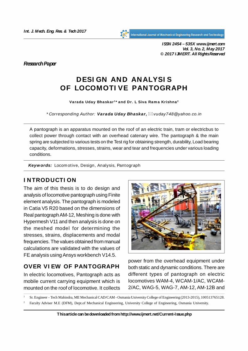
Meshing of the Pantograph ModelMeshing is done inorder to obtain accurateresults while doing analysis on the Meshedmodel obtained from the 3d Cad model.Meshing individual parts in Hypermesh v11.0following quads 2d elements on the surfacesand extracting these elements for the modelresulted in the assembly mesh model.
Analysis on Meshed Model
In the analysis of the main spring ofPantograph type AM-12 the following
considerations are taken with Ref: RDSO/2008/EL/SPEC/0066.
Compressed air supply to the main springs= 5 kg/cm2 to 7 kg/cm2
Static up- thrust = 7 + 0.4 kgf
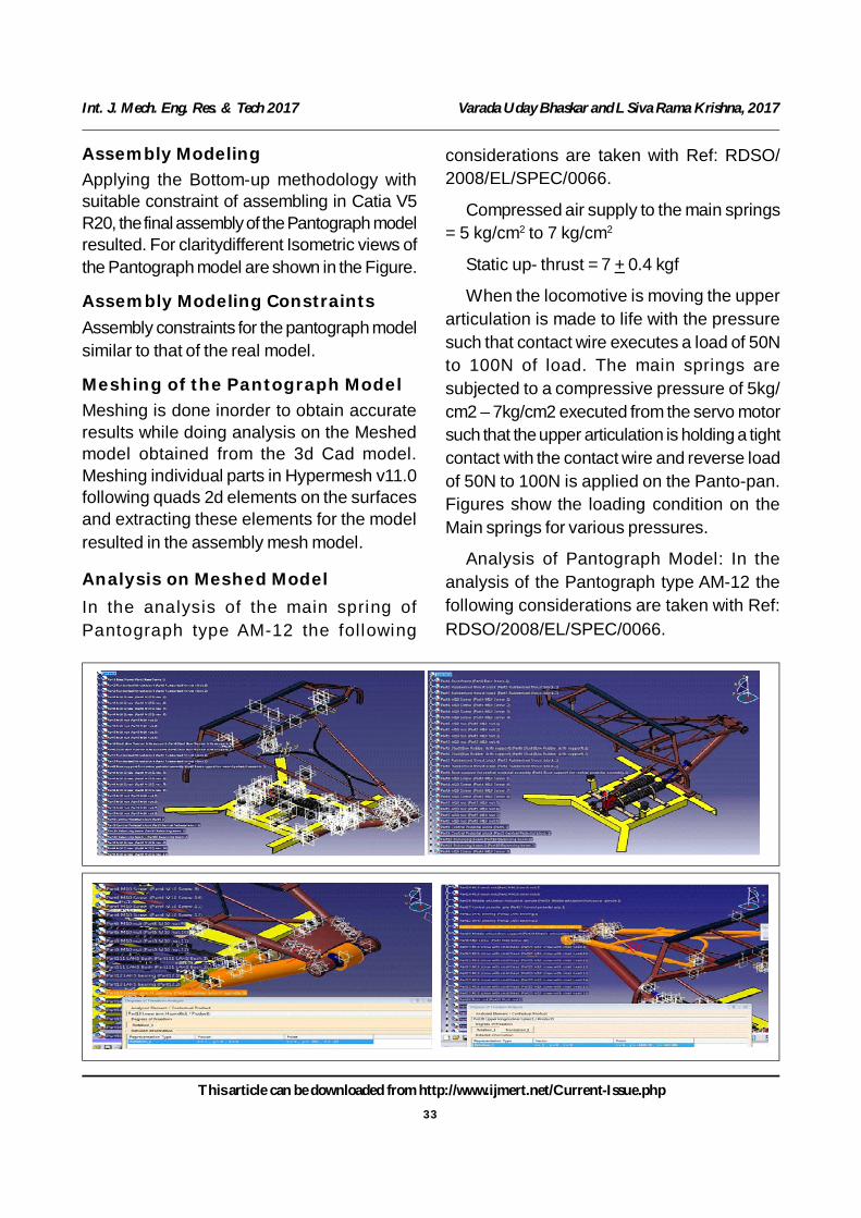
When the locomotive is moving the upperarticulation is made to life with the pressuresuch that contact wire executes a load of 50Nto 100N of load. The main springs aresubjected to a compressive pressure of 5kg/cm2 – 7kg/cm2 executed from the servo motorsuch that the upper articulation is holding a tightcontact with the contact wire and reverse loadof 50N to 100N is applied on the Panto-pan.Figures show the loading condition on theMain springs for various pressures.
Analysis of Pantograph Model: In theanalysis of the Pantograph type AM-12 thefollowing considerations are taken with Ref:RDSO/2008/EL/SPEC/0066.
34
This article can be downloaded from http://www.ijmert.net/Current-Issue.php
Int. J. Mech. Eng. Res. & Tech 2017 Varada Uday Bhaskar and L Siva Rama Krishna, 2017
Loading Condition Pressure acting on Main springs Reverse load acting on the bow assembly orfrom Servomotor Kg/cm2 or MPa Pantograph pan Fb N
1 P = 5 kg/cm2 = 0.49 MPa Fb1 = 50 N
2 P = 5.5 kg/cm2 = 0.54 MPa Fb2 = 60 N
3 P = 6.5 kg/cm2 = 0.64 MPa Fb3 = 70 N
4 P = 7.4 kg/cm2 = 0.73 MPa Fb3 = 80 N
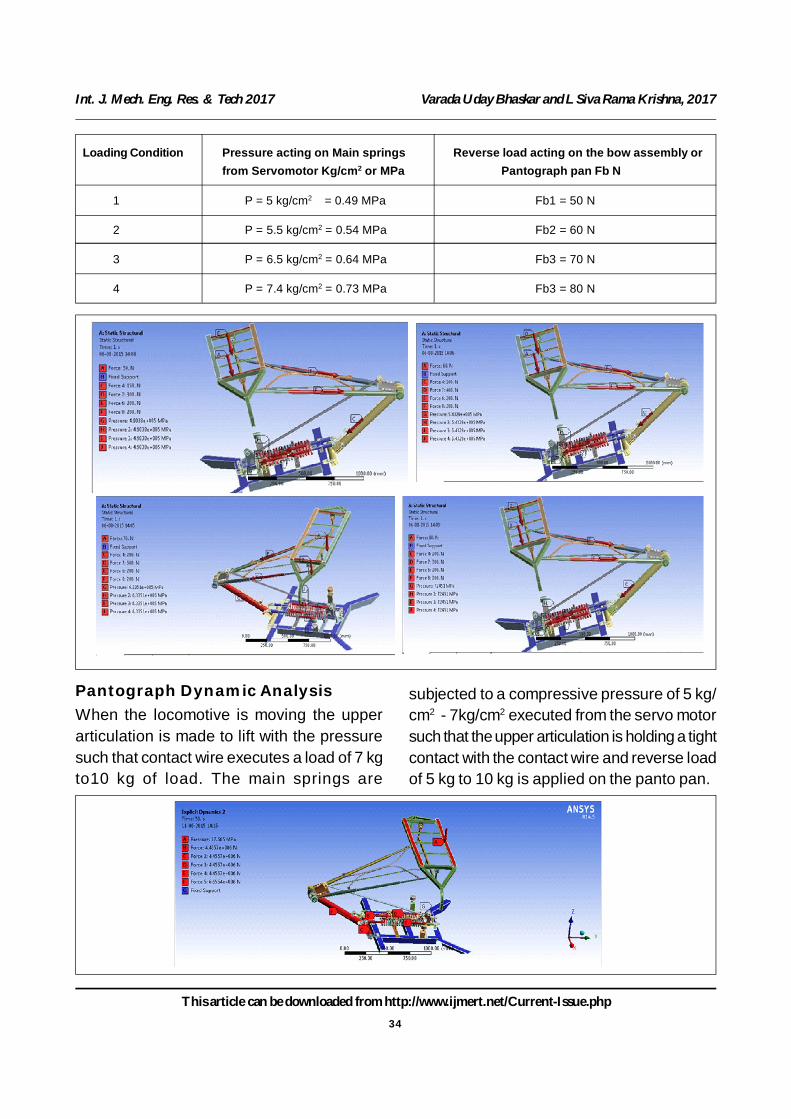
Pantograph Dynamic AnalysisWhen the locomotive is moving the upperarticulation is made to lift with the pressuresuch that contact wire executes a load of 7 kgto10 kg of load. The main springs are
subjected to a compressive pressure of 5 kg/cm2 - 7kg/cm2 executed from the servo motorsuch that the upper articulation is holding a tightcontact with the contact wire and reverse loadof 5 kg to 10 kg is applied on the panto pan.

35
This article can be downloaded from http://www.ijmert.net/Current-Issue.php
Int. J. Mech. Eng. Res. & Tech 2017 Varada Uday Bhaskar and L Siva Rama Krishna, 2017
Analysis of the Main Spring
In the analysis of the Main spring ofPantograph type AM-12 the followingconsiderations are taken with Ref: RDSO/2008/EL/SPEC/0066.
Compressed air supply to the main springs= 5 kg/cm2 to 7 kg/cm2
Static up-thrust = 7 ± 0.4 kgfP1 = 5 kg/cm2 = 51.02 N/mm2 = 0.49 Mpa,P2 = 5.5 kg/cm2 = 56.53 N/mm2 = 0.54 Mpa,P3 = 6.5 kg/cm2 = 65.91 N/mm2 = 0.64 Mpa,P4 = 7.4 kg/cm2 = 75.30 N/mm2 = 0.73 Mpa.
RESULTS AND DISCUSSIONFollowing are the results obtained after doing
the Modeling, Meshing and Analysis usingCatia V5 R20, Altair HyperWorks V11, Ansysworkbench V14.5. A comparison is madebetween the manual calculations and valuesobtained from Practical test analysis.
Deformation of Main spring condition 1, 2, 3and 4
Deformation of the main spring due to the5 kg/cm2 applied pressure resulted to 0.14m.
Deformation of the main spring due to the5.5 kg/cm2 applied pressure resulted to 0.15m.
Deformation of the main spring due to the6.5 kg/cm2 applied pressure resulted to 0.18m.
Deformation of the main spring due to the7.4 kg/cm2 applied pressure resulted to 0.21m.
36
This article can be downloaded from http://www.ijmert.net/Current-Issue.php
Int. J. Mech. Eng. Res. & Tech 2017 Varada Uday Bhaskar and L Siva Rama Krishna, 2017
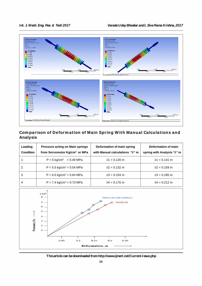
Comparison of Deformation of Main Spring With Manual Calculations andAnalysis
Loading Pressure acting on Main springs Deformation of main spring Deformation of main
Condition from Servomotor Kg/cm2 or MPa with Manual calculations “” m spring with Analysis “” m
1 P = 5 kg/cm2 = 0.49 MPa 1 = 0.120 m 1 = 0.141 m
2 P = 5.5 kg/cm2 = 0.54 MPa 2 = 0.132 m 2 = 0.159 m
3 P = 6.5 kg/cm2 = 0.64 MPa 3 = 0.154 m 3 = 0.185 m
4 P = 7.4 kg/cm2 = 0.73 MPa 4 = 0.176 m 4 = 0.212 m

37
This article can be downloaded from http://www.ijmert.net/Current-Issue.php
Int. J. Mech. Eng. Res. & Tech 2017 Varada Uday Bhaskar and L Siva Rama Krishna, 2017
Graph showing the comparison of manualcalculations and analysis
Deformation of pantograph condition 1P1 = 5kg/cm2 = 0.49 MPa; (Pressure
acting on main springs from servo motor)
Fb1 = 50N (Load acting on the bow)
Other loads due to self weight of pantograph.Resulted that Overall max deformation ofpantograph = 0.029 m
Deformation of pantograph condition 2
P2 = 5.5 kg/cm2 = 0.54 Mpa; ((Pressureacting on main springs from servo motor)
Fb2 = 60N (Load acting on the bow)
Other loads due to self weight of pantograph.Resulted that Overall max deformation ofpantograph = 0.032 m
38
This article can be downloaded from http://www.ijmert.net/Current-Issue.php
Int. J. Mech. Eng. Res. & Tech 2017 Varada Uday Bhaskar and L Siva Rama Krishna, 2017
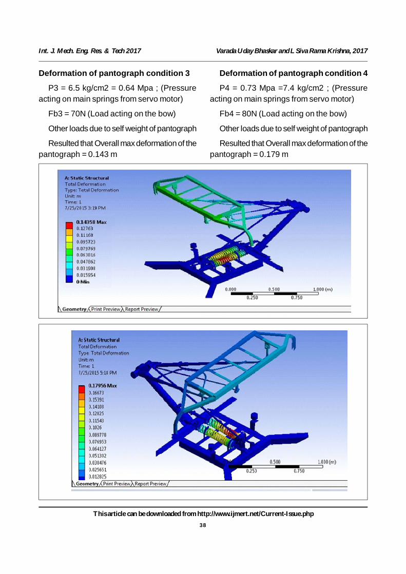
Deformation of pantograph condition 3
P3 = 6.5 kg/cm2 = 0.64 Mpa ; (Pressureacting on main springs from servo motor)
Fb3 = 70N (Load acting on the bow)
Other loads due to self weight of pantograph
Resulted that Overall max deformation of thepantograph = 0.143 m
Deformation of pantograph condition 4
P4 = 0.73 Mpa =7.4 kg/cm2 ; (Pressureacting on main springs from servo motor)
Fb4 = 80N (Load acting on the bow)
Other loads due to self weight of pantograph
Resulted that Overall max deformation of thepantograph = 0.179 m
39
This article can be downloaded from http://www.ijmert.net/Current-Issue.php
Int. J. Mech. Eng. Res. & Tech 2017 Varada Uday Bhaskar and L Siva Rama Krishna, 2017
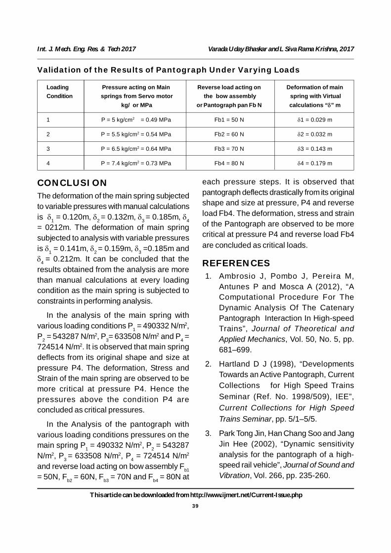
Validation of the Results of Pantograph Under Varying Loads
Loading Pressure acting on Main Reverse load acting on Deformation of mainCondition springs from Servo motor the bow assembly spring with Virtual
kg/ or MPa or Pantograph pan Fb N calculations “” m
1 P = 5 kg/cm2 = 0.49 MPa Fb1 = 50 N 1 = 0.029 m
2 P = 5.5 kg/cm2 = 0.54 MPa Fb2 = 60 N 2 = 0.032 m
3 P = 6.5 kg/cm2 = 0.64 MPa Fb3 = 70 N 3 = 0.143 m
4 P = 7.4 kg/cm2 = 0.73 MPa Fb4 = 80 N 4 = 0.179 m
CONCLUSIONThe deformation of the main spring subjectedto variable pressures with manual calculationsis 1 = 0.120m, 2 = 0.132m, 3 = 0.185m, 4= 0212m. The deformation of main springsubjected to analysis with variable pressuresis 1 = 0.141m, 2 = 0.159m, 3 =0.185m and4 = 0.212m. It can be concluded that theresults obtained from the analysis are morethan manual calculations at every loadingcondition as the main spring is subjected toconstraints in performing analysis.
In the analysis of the main spring withvarious loading conditions P1 = 490332 N/m2,P2 = 543287 N/m2, P3= 633508 N/m2 and P4 =724514 N/m2. It is observed that main springdeflects from its original shape and size atpressure P4. The deformation, Stress andStrain of the main spring are observed to bemore critical at pressure P4. Hence thepressures above the condition P4 areconcluded as critical pressures.
In the Analysis of the pantograph withvarious loading conditions pressures on themain spring P1 = 490332 N/m2, P2 = 543287N/m2, P3 = 633508 N/m2, P4 = 724514 N/m2
and reverse load acting on bow assembly Fb1= 50N, Fb2 = 60N, Fb3 = 70N and Fb4 = 80N at
each pressure steps. It is observed thatpantograph deflects drastically from its originalshape and size at pressure, P4 and reverseload Fb4. The deformation, stress and strainof the Pantograph are observed to be morecritical at pressure P4 and reverse load Fb4are concluded as critical loads.
REFERENCES1. Ambrosio J, Pombo J, Pereira M,
Antunes P and Mosca A (2012), “AComputational Procedure For TheDynamic Analysis Of The CatenaryPantograph Interaction In High-speedTrains”, Journal of Theoretical andApplied Mechanics, Vol. 50, No. 5, pp.681–699.
2. Hartland D J (1998), “DevelopmentsTowards an Active Pantograph, CurrentCollections for High Speed TrainsSeminar (Ref. No. 1998/509), IEE”,Current Collections for High SpeedTrains Seminar, pp. 5/1–5/5.
3. Park Tong Jin, Han Chang Soo and JangJin Hee (2002), “Dynamic sensitivityanalysis for the pantograph of a high-speed rail vehicle”, Journal of Sound andVibration, Vol. 266, pp. 235-260.