FE Analysis of Middle Axle suspension Spring of Electric Locomotive WAG-9 of Indian Railways
6
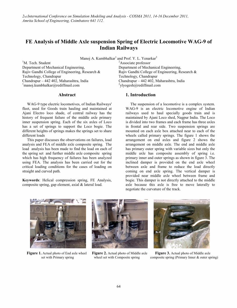
2nd International Conference on Simulation Modeling and Analysis - COSMA 2011, 14-16 December 2011, Amrita School of Engineering, Coimbatore 641 112. 64 FE Analysis of Middle Axle suspension Spring of Electric Locomotive WAG-9 of Indian Railways Manoj A. Kumbhalkar 1 and Prof. Y. L. Yenarkar 2 1 M. Tech. Student Department of Mechanical Engineering, Rajiv Gandhi College of Engineering, Research & Technology, Chandrapur Chandrapur – 442 402, Maharashtra, India 1 [email protected] 2 Associate professor Department of Mechanical Engineering, Rajiv Gandhi College of Engineering, Research & Technology, Chandrapur Chandrapur – 442 402, Maharashtra, India 2 [email protected] Abstract WAG-9 type electric locomotives, of Indian Railways' fleet, used for Goods train hauling and maintained at Ajani Electro loco shade, of central railway has the history of frequent failure of the middle axle primary inner suspension spring. Each of the six axles of Loco has a set of springs to support the Loco bogie. The different heights of springs makes the springs set to share different loads This paper discusses the observations on failures, load analysis and FEA of middle axle composite spring. The load analysis has been made to find the load on each of the spring set and further middle axle composite spring which has high frequency of failures has been analyzed using FEA. The analysis has been carried out for the critical loading conditions for the cases of loading on straight and curved path. Keywords: Helical compression spring, FE Analysis, composite spring, gap element, axial & lateral load. 1. Introduction The suspension of a locomotive is a complex system. WAG-9 is an electric locomotive engine of Indian railways used to haul specially goods train and is maintained by Ajani Loco shed, Nagpur India. The Loco is divided into two frames and each frame has three axles in frontal and rear side. Two suspension springs are mounted on each axle box attached near to each of the wheels called primary springs. The figure 1 shows the arrangement on end axles and figure 2 shows the arrangement on middle axle. The end and middle axle has primary outer spring with variable sizes but only the middle axle has composite assembly of spring i.e. primary inner and outer springs as shown in figure 3. The inclined damper is provided on the end axle wheel between axle and frame to reduce the load directly coming on end axle spring. The vertical damper is provided near middle axle wheel between frame and bogie. This damper is not directly attached to the middle axle because this axle is free to move laterally to negotiate the curvature of the track. Figure 1. Actual photo of End axle wheel Figure 2. Actual photo of Middle axle Figure 3. Actual photo of Middle axle set with Primary spring wheel set with Composite spring composite spring (Primary Inner & outer spring)
Transcript of FE Analysis of Middle Axle suspension Spring of Electric Locomotive WAG-9 of Indian Railways
2nd International Conference on Simulation Modeling and Analysis - COSMA 2011, 14-16 December 2011,
Amrita School of Engineering, Coimbatore 641 112.
64
FE Analysis of Middle Axle suspension Spring of Electric Locomotive WAG-9 of
Indian Railways
Manoj A. Kumbhalkar
1 and Prof. Y. L. Yenarkar
2
1M. Tech. Student
Department of Mechanical Engineering,
Rajiv Gandhi College of Engineering, Research &
Technology, Chandrapur
Chandrapur – 442 402, Maharashtra, India [email protected]
2Associate professor
Department of Mechanical Engineering,
Rajiv Gandhi College of Engineering, Research &
Technology, Chandrapur
Chandrapur – 442 402, Maharashtra, India [email protected]
Abstract
WAG-9 type electric locomotives, of Indian Railways'
fleet, used for Goods train hauling and maintained at
Ajani Electro loco shade, of central railway has the
history of frequent failure of the middle axle primary
inner suspension spring. Each of the six axles of Loco
has a set of springs to support the Loco bogie. The
different heights of springs makes the springs set to share
different loads
This paper discusses the observations on failures, load
analysis and FEA of middle axle composite spring. The
load analysis has been made to find the load on each of
the spring set and further middle axle composite spring
which has high frequency of failures has been analyzed
using FEA. The analysis has been carried out for the
critical loading conditions for the cases of loading on
straight and curved path.
Keywords: Helical compression spring, FE Analysis,
composite spring, gap element, axial & lateral load.
1. Introduction
The suspension of a locomotive is a complex system.
WAG-9 is an electric locomotive engine of Indian
railways used to haul specially goods train and is
maintained by Ajani Loco shed, Nagpur India. The Loco
is divided into two frames and each frame has three axles
in frontal and rear side. Two suspension springs are
mounted on each axle box attached near to each of the
wheels called primary springs. The figure 1 shows the
arrangement on end axles and figure 2 shows the
arrangement on middle axle. The end and middle axle
has primary outer spring with variable sizes but only the
middle axle has composite assembly of spring i.e.
primary inner and outer springs as shown in figure 3. The
inclined damper is provided on the end axle wheel
between axle and frame to reduce the load directly
coming on end axle spring. The vertical damper is
provided near middle axle wheel between frame and
bogie. This damper is not directly attached to the middle
axle because this axle is free to move laterally to
negotiate the curvature of the track.
Figure 1. Actual photo of End axle wheel Figure 2. Actual photo of Middle axle Figure 3. Actual photo of Middle axle
set with Primary spring wheel set with Composite spring composite spring (Primary Inner & outer spring)

2nd International Conference on Simulation Modeling and Analysis - COSMA 2011, 14-16 December 2011,
Amrita School of Engineering, Coimbatore 641 112.
65
1.1. Observations
The problem identified in the arrangement of
suspension spring in WAG-9 railway engine is that the
middle axle primary spring are fails before its expected
life. The maintenance record at loco shade indicates that
there is very high rate of failure of primary inner spring.
For instance in 2009-10 the primary inner spring was
replaced on 51 instances as against 8 instances of middle
axle primary outer spring which is significantly high. It
has been observed that, the inner spring usually breaks
between first to third coils. The figure 4(a) shows the
failed piece of spring and figure 4(b) shows the scratches
on the damper that confirms the deformation of assembly
by about 25mm more than the stationary condition
indicating higher loads while running. It should be noted
that, the material report confirms the spring material is as
per requirements. Further every spring before assembly
tested for the required stiffness.
2. Load distribution on suspension springs
The overall load of about 123 tonne of engine is acted
over all primary suspension spring by the bogie (BG)
frame. At first the load is acted over each middle axle
primary outer spring as the height of this spring higher
than all the spring which is about 258 mm. Then the load
is acted on middle axle inner spring after 2 mm deflection
of outer spring as its height is 2 mm less than outer spring.
After 18 mm deflection the load is distributed over all the
springs as shown in figure 5.
2.1. Load analysis
Using the technical specifications of spring the forces
has been calculated analytically for the case of loco
moving at straight path and the loco moving at curved
path. The technical specifications of each spring are shown
in table 1.
Following assumptions were made for simplification of
cases applied for the analysis of the spring.
i) The rails are smooth and there are no geometrical
irregularities.
ii) The loading is static.
iii) Impact load during operation are neglected.
iv) All other kind of load than mentioned in calculations is
neglected.
v) Wheels are perfectly round and of equal in sizes.
vi) Longitudinal deflection (along the direction of track) of
all the spring is neglected.
vii) Maximum speed of train 80 km/hr in all cases.
viii) Axial deflection of all the springs is same.
ix) Springs are assumed to be linear.
(a) (b)
Figure 4: (a) Failed middle axle inner spring (b) Rubbing
marks over inclined damper on end axle
Table 1: Technical specification of spring set
Particulars Unit
Middle
axle
Outer
Spring
Middle
axle
Inner
Spring
End
Axle
spring
Free length (Lf) mm 258.6 252.4 238.8
Outer diameter (DO) mm 212 104 221
Mean diameter (Dm) mm 180.5 87.5 185
Coil diameter (d) mm 31.5 16.5 36
No. of active coil (n) - 3.5 7.5 3
Total No. of coil - 5.0 9.0 4.5
Pitch mm 51.72 28.04 53.06
Modulus of Rigidity
(G)
N/mm2
78500 78500 78500
stiffness (k) N/mm 470 144 868
Tensile Strength (σu) N/mm2 1550 – 1720
Ultimate shear stress
(τ) N/mm2 860 860 860
Figure 5. Load distribution on all spring
2nd International Conference on Simulation Modeling and Analysis - COSMA 2011, 14-16 December 2011,
Amrita School of Engineering, Coimbatore 641 112.
66
2.1.1. CASE I: For loco moving at straight path
The various load acted upon the axle assembly when
loco is moving on straight path are as given below.
1) Total weight of loco = 123 T
2) Unsprung mass per wheel set = 3.984 T
3) Total unsprung mass = 23.904
4) Net load on all axles = 99.096 T
5) This net load is distributed over each of frontal and rear
wheel sets through front and rear wheel frames.
Thus net load distributed on each frame = 49.548 T
6) This load of 49.548 tonne is acted over all the spring as
per figure 5. After 20 mm deflection of middle axle spring
(inner & outer); the load ‘Wd’ is distributed over end axle
springs.
7) The total load and deflection of end axle and middle
axle springs has obtained by load Wd,
Each end axle and middle axle spring set = 4
Total no. of spring set on end axle = 4 ×2 = 8
Wd = (We × 8) + (Wo × 4) + (Wi × 4)
Wd = [(4×ko) + (4×ki) + (8×ke)] δd
Using technical specification of spring the load and
other design parameters were calculated for the case of
loading on straight path and are shown in table 2.
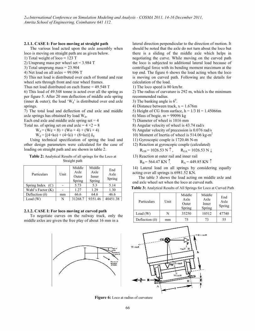
2.1.2. CASE I: For loco moving at curved path
To negotiate curves on the railway track, only the
middle axles are given the free play of about 16 mm in a
lateral direction perpendicular to the direction of motion. It
should be noted that the axle do not turn about the loco but
there is a sliding of the middle axle which helps in
negotiating the curve. While moving on the curved path
the loco is subjected to additional lateral load because of
centrifugal force with its bending moment maximum at the
top end. The figure 6 shows the load acting when the loco
is moving on curved path. Following are the details for
calculation of the load.
1) The loco speed is 80 km/hr.
2) The radius of curvature is 292 m, which is the minimum
recommended radius.
3) The banking angle is 60.
4) Distance between track, x = 1.676m
5) Height of CG from surface, h = 1/3 H = 1.45066m
6) Mass of bogie, m = 99096 kg
7) Diameter of wheel is 1016 mm
8) Angular velocity of wheel is 43.74 rad/s
9) Angular velocity of precession is 0.076 rad/s
10) Moment of Inertia of wheel is 514.06 kg-m2
11) Gyroscopic couple is 1720.46 N-m
12) Reaction at gyroscopic couple (calculated)
RGB = 1026.53 N , RGA = 1026.53 N ↓
13) Reaction at outer rail and inner rail
RB = 564.47 KN , RA = 449.85 KN
14) Lateral load on all springs by considering equally
acting over all springs is 6981.52 KN.
The table 3 shows the load acting on middle axle and
end axle wheel set when the loco at curved path.
Table 2: Analytical Results of all springs for the Loco at
Straight path
Particulars Unit
Middle
Axle
Outer
Spring
Middle
Axle
Inner
Spring
End
Axle
Spring
Spring Index (C) - 5.73 5.3 5.14
Wahl’s Factor (K) - 1.27 1.29 1.30
Deflection (δ) mm 66.6 64.6 46.6
Load (W) N 31268.7 9351.46 40451.38
Table 3: Analytical Results of All Springs for Loco at Curved Path
Particulars Unit
Middle
Axle
Outer
Spring
Middle
Axle
Inner
Spring
End
Axle
Spring
Load (W) N 35250 10512 47740
Deflection (δ) mm 75 73 55
Figure 6: Loco at radius of curvature
2nd International Conference on Simulation Modeling and Analysis - COSMA 2011, 14-16 December 2011,
Amrita School of Engineering, Coimbatore 641 112.
67
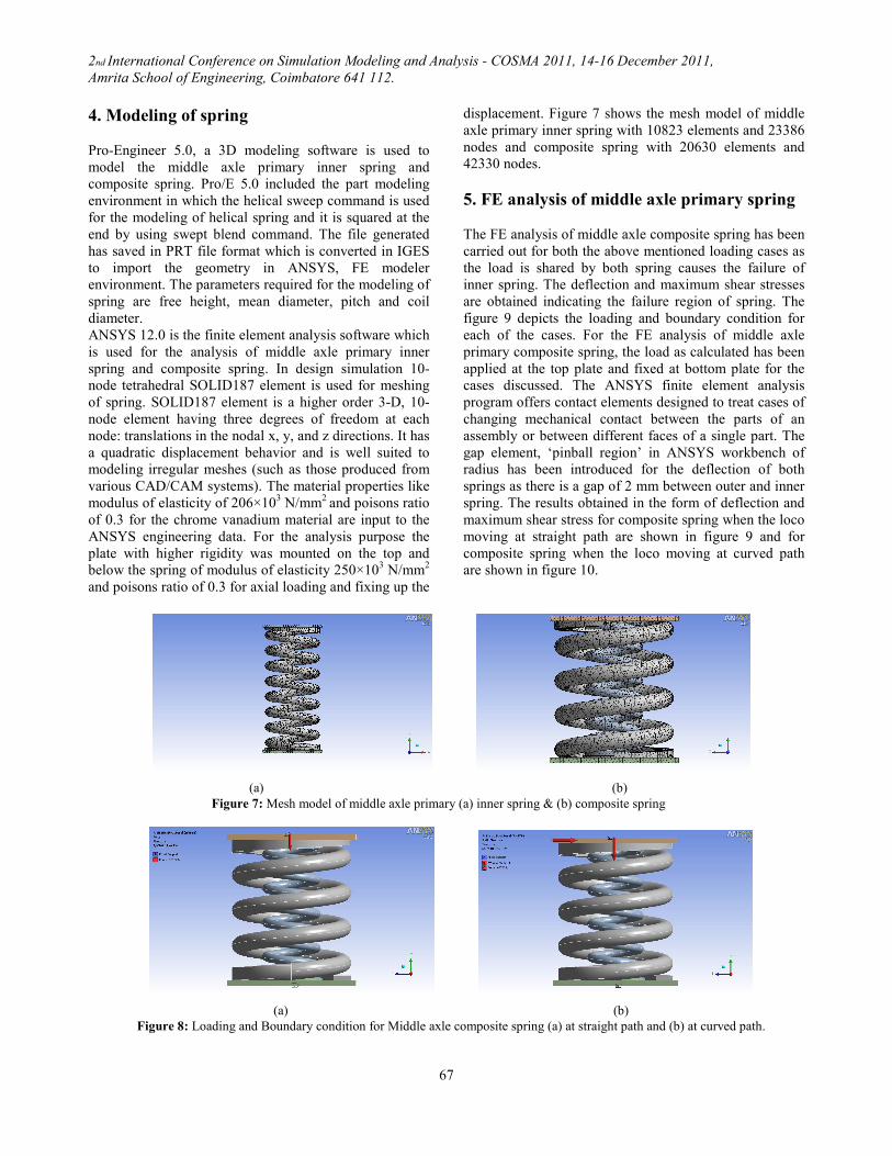
4. Modeling of spring
Pro-Engineer 5.0, a 3D modeling software is used to
model the middle axle primary inner spring and
composite spring. Pro/E 5.0 included the part modeling
environment in which the helical sweep command is used
for the modeling of helical spring and it is squared at the
end by using swept blend command. The file generated
has saved in PRT file format which is converted in IGES
to import the geometry in ANSYS, FE modeler
environment. The parameters required for the modeling of
spring are free height, mean diameter, pitch and coil
diameter.
ANSYS 12.0 is the finite element analysis software which
is used for the analysis of middle axle primary inner
spring and composite spring. In design simulation 10-
node tetrahedral SOLID187 element is used for meshing
of spring. SOLID187 element is a higher order 3-D, 10-
node element having three degrees of freedom at each
node: translations in the nodal x, y, and z directions. It has
a quadratic displacement behavior and is well suited to
modeling irregular meshes (such as those produced from
various CAD/CAM systems). The material properties like
modulus of elasticity of 206×103 N/mm
2 and poisons ratio
of 0.3 for the chrome vanadium material are input to the
ANSYS engineering data. For the analysis purpose the
plate with higher rigidity was mounted on the top and
below the spring of modulus of elasticity 250×103 N/mm
2
and poisons ratio of 0.3 for axial loading and fixing up the
displacement. Figure 7 shows the mesh model of middle
axle primary inner spring with 10823 elements and 23386
nodes and composite spring with 20630 elements and
42330 nodes.
5. FE analysis of middle axle primary spring
The FE analysis of middle axle composite spring has been
carried out for both the above mentioned loading cases as
the load is shared by both spring causes the failure of
inner spring. The deflection and maximum shear stresses
are obtained indicating the failure region of spring. The
figure 9 depicts the loading and boundary condition for
each of the cases. For the FE analysis of middle axle
primary composite spring, the load as calculated has been
applied at the top plate and fixed at bottom plate for the
cases discussed. The ANSYS finite element analysis
program offers contact elements designed to treat cases of
changing mechanical contact between the parts of an
assembly or between different faces of a single part. The
gap element, ‘pinball region’ in ANSYS workbench of
radius has been introduced for the deflection of both
springs as there is a gap of 2 mm between outer and inner
spring. The results obtained in the form of deflection and
maximum shear stress for composite spring when the loco
moving at straight path are shown in figure 9 and for
composite spring when the loco moving at curved path
are shown in figure 10.
(a) (b)
Figure 7: Mesh model of middle axle primary (a) inner spring & (b) composite spring
(a) (b)
Figure 8: Loading and Boundary condition for Middle axle composite spring (a) at straight path and (b) at curved path.

2nd International Conference on Simulation Modeling and Analysis - COSMA 2011, 14-16 December 2011,
Amrita School of Engineering, Coimbatore 641 112.
68
Spring under consideration is highly loaded. This is
purely the case of limiting design as the maximum shear
stress of 748.89 N/mm2
for composite spring at straight
path is nearer to the ultimate shear stress of 860 N/mm2
which increases to 870.06 N/mm2 when the loco at curved
path is enough to initialize a shearing process. FE analysis
of composite spring for all the cases is shown in table 3.
The FE analysis is also shows the region of high
stresses at about one and half coil at which the failure is
known to happen frequently. Hence analysis proves that
the spring is heavily loaded and on some instances like
loco moving on curvature, it crosses the ultimate shear
stress. Further the actual loading condition would have the
additional load as gap in track, alignment errors, jumping
of wheel, breaking loads etc. All these factor shall
contribute to increase in the load (Which can be observed
from the fact that, the damper has scratch) marks, and
hence the stress.
Therefore it can be concluded that, there is an urgent
need to reduce this stresses to the safer limits. One way to
do this would be reduction in pre-stresses by increasing
the length of end axle spring. This shall reduce the pre-
stressing of middle axle spring assembly increasing the
overall stiffness of composite assembly of suspension. The
gap between the middle axle outer spring and end axle
spring is 20 mm because of this there is much pre-stressing
of middle axle springs both outer and inner due to more
(a) Max deflection = 68.58 mm (b) Max shear stress =748.89 N/mm2
Figure 9: FE analysis of middle axle primary composite spring for loco moving at straight path
a) Max deflection = 80.742 mm (b) Max shear stress = 870.06 N/mm2
Figure 10: FE analysis of middle axle primary composite spring for loco moving at curved path
Table 3: FE analysis of composite spring for loco moving at
straight path and curved path
Spring Condition Load (N)
FE Analysis
(ANSYS)
Deflecti
on (mm)
Max shear
stress
(N/mm2)
Composite
spring
At straight
path 40620.16 68.58 748.89
Composite
spring
a. Axial &
b. Lateral
load at
curved path
a. 45762
&
b.6981.52
80.742 870.06

2nd International Conference on Simulation Modeling and Analysis - COSMA 2011, 14-16 December 2011,
Amrita School of Engineering, Coimbatore 641 112.
69
difference. To reduce the pre-stressing of middle axle
springs it is necessary to increase the height of end axle
spring by adding shim into it. By FE analysis it is observed
that the stresses over middle axle composite spring are
reduced by adding shim at end axle spring as shown in
table 4. Since this shall lead to decrease in pre-stressing of
middle axle springs, the life of spring shall definitely
improve. Further this would also mean utilizing the end
axle springs to their capacity as the stress on them will
increase as currently they are stressed much lesser than the
middle axle springs. This “equal stress in all springs
approach” shall yield better life for each of the spring.
However, this shall lead to increase in overall stiffness
and hence reduction of bogie deflection on assembly. This
further shall lead to increase in height of loco which result
of difficulty in join loco with other bogies and increasing
the C.G. of loco. The railway has stringent rules regarding
these aspects and hence the addition of shim has to be
done with care and confirming the railway standards.
Conclusion
From the FE analysis it is clear that the spring under
consideration has shear stresses sufficient to bear while the
loco is moving on the straight path. However while
traveling on the curved path the shear stress are higher
making the design critical. Further the loco has to travel on
the rails which have the joints and local irregularities
which bring the impact loads. It should be noted that the
middle axle does not have lateral damping and it has a free
play of 16 mm to slide to negotiate curvatures. While
negotiating with this curvature, the middle axle springs are
subjected to lateral loading causing the highest moment
and shear stresses at the top end of springs. The FE
analysis suggests the maximum shear stress of about
870.74 N/mm2
while moving on the critical curvatures at
the prescribed speed of 80 km/hr. This is almost same as
that of allowable maximum shear stress of 860 N/mm2.
Further actual working conditions also have additional
loads due to jerks and impact in all three directions making
the loading further complex. Hence the actual stresses are
much more than calculated. Therefore the bending stress
due to lateral loading may initiate a failure which is further
enhance and aggregated because of stress concentration at
the failure region and nature of loading and once there is
significant development of this crack the shearing occurs
almost instantaneously. An observation on the failed
spring confirms this failure by crack initiating followed by
shear failure. Hence it is suggested that (i) the spring
should have some damping for lateral loads that the spring
is subjected to while negotiating the curvatures. (ii) The
initial stresses in the middle axle spring can be reduced by
increasing the length of end axle springs but limiting by
shift in C.G. of loco.
References
[1] Indian railways suspension spring drawing, Drawing number
1209-01-115-008,009, Ajni, Nagur.
[2] Joseph E. Shigley & Charles R. Mischke, “A textbook of
Mechanical Engineering Design”, Tata McGraw Hill, sixth
edition, pg. 588-595.
[3] V. B. Sood & Professor Bridges, (2009), “Notes on curves for
railways”, Indian Railways Institute of Civil Engineering, Pune.
[4] Y. Prawoto, M. Ikeda and S. K. Manville, A. Nishikawa,
(2008), “Failure Analysis of Automotive Suspension Coil
Spring”, 35-48.
[5] Harris Yong, (1998), “The Helical Spring: Theory and
Calculation in the Context of the Automobile Suspension
system”, CIV 205 Term Project.
[6] M. Ruzicka & K. Doubrava, “Loading Regimes and
Designing Helical Coiled Spring”, RES. AGR. ENG., 51, 2005
(2): 50–55
[7] Koutaro Watanabe, Hideo Yamamoto, Yuichi Ito, Hisao
Isobe, “Simplified Stress Calculation Method for Helical
Spring”.
Figure 11: Distribution of load on all spring by adding shim at
end axle spring
Table 4: FE analysis for addition of 5mm shim at end axle spring.
Spring Load (N)
FE Analysis (ANSYS)
Deflection
(mm)
Max shear
stress
(N/mm2)
Composite
spring 38193.465 64.215 702.34