Diesel Electric Locomotive - Rolling Stock Knowledge Resource
12
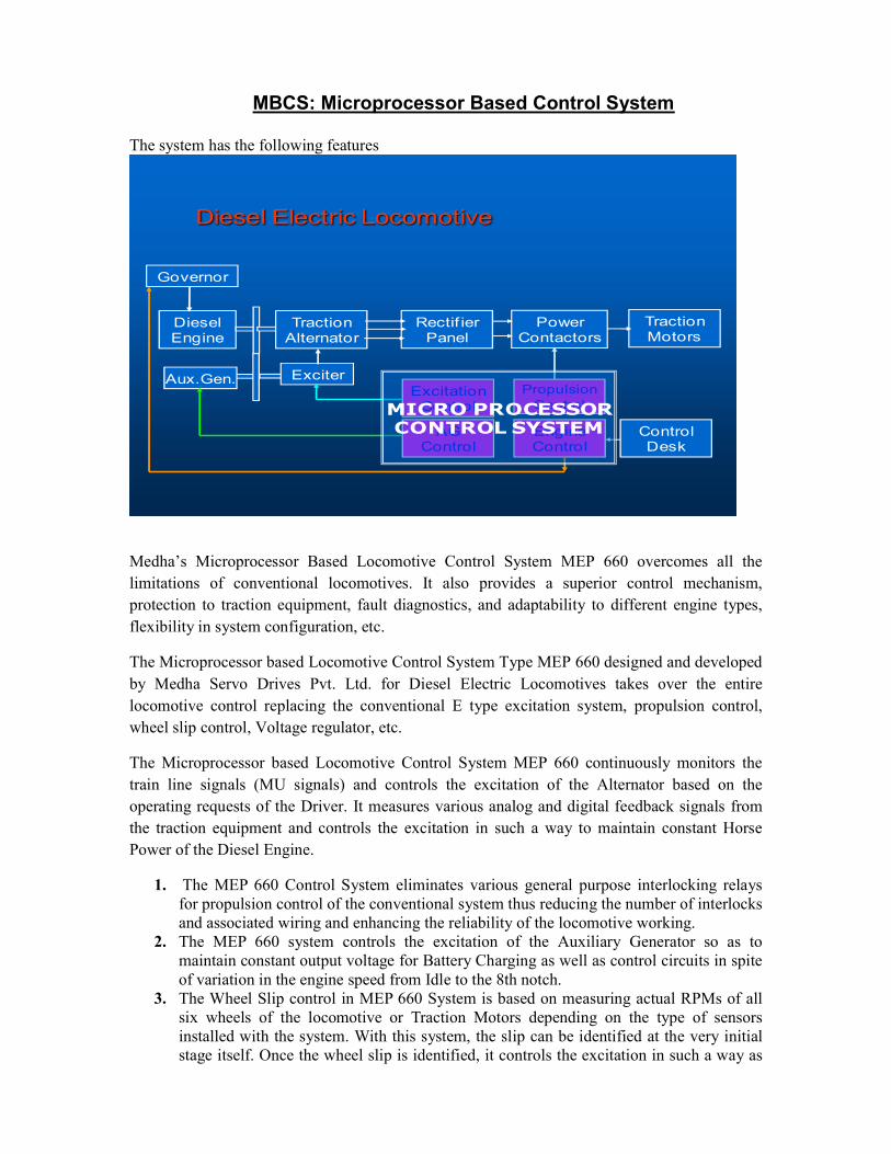
MBCS: Microprocessor Based Control System The system has the following features Diesel Electric Locomotive Diesel Engine Traction Alternator Rectifier Panel Power Contactors Traction Motors Aux.Gen. Governor Exciter Engine Control Control Desk AG Control Propulsion Control Excitation Control MICRO PROCESSOR CONTROL SYSTEM Medha’s Microprocessor Based Locomotive Control System MEP 660 overcomes all the limitations of conventional locomotives. It also provides a superior control mechanism, protection to traction equipment, fault diagnostics, and adaptability to different engine types, flexibility in system configuration, etc. The Microprocessor based Locomotive Control System Type MEP 660 designed and developed by Medha Servo Drives Pvt. Ltd. for Diesel Electric Locomotives takes over the entire locomotive control replacing the conventional E type excitation system, propulsion control, wheel slip control, Voltage regulator, etc. The Microprocessor based Locomotive Control System MEP 660 continuously monitors the train line signals (MU signals) and controls the excitation of the Alternator based on the operating requests of the Driver. It measures various analog and digital feedback signals from the traction equipment and controls the excitation in such a way to maintain constant Horse Power of the Diesel Engine. 1. The MEP 660 Control System eliminates various general purpose interlocking relays for propulsion control of the conventional system thus reducing the number of interlocks and associated wiring and enhancing the reliability of the locomotive working. 2. The MEP 660 system controls the excitation of the Auxiliary Generator so as to maintain constant output voltage for Battery Charging as well as control circuits in spite of variation in the engine speed from Idle to the 8th notch. 3. The Wheel Slip control in MEP 660 System is based on measuring actual RPMs of all six wheels of the locomotive or Traction Motors depending on the type of sensors installed with the system. With this system, the slip can be identified at the very initial stage itself. Once the wheel slip is identified, it controls the excitation in such a way as
-
Upload
khangminh22 -
Category
Documents
-
view
1 -
download
0
Transcript of Diesel Electric Locomotive - Rolling Stock Knowledge Resource
MBCS: Microprocessor Based Control System
The system has the following features
Diesel Electric Locomotive
Diesel Engine
Traction Alternator
Rectif ier Panel
Power Contactors
Traction Motors
Aux.Gen.
Governor
Exciter
Engine Control
Control Desk
AG Control
Propulsion Control
Excitation ControlMICRO PROCESSOR
CONTROL SYSTEM
Medha’s Microprocessor Based Locomotive Control System MEP 660 overcomes all the limitations of conventional locomotives. It also provides a superior control mechanism, protection to traction equipment, fault diagnostics, and adaptability to different engine types, flexibility in system configuration, etc.
The Microprocessor based Locomotive Control System Type MEP 660 designed and developed by Medha Servo Drives Pvt. Ltd. for Diesel Electric Locomotives takes over the entire locomotive control replacing the conventional E type excitation system, propulsion control, wheel slip control, Voltage regulator, etc.
The Microprocessor based Locomotive Control System MEP 660 continuously monitors the train line signals (MU signals) and controls the excitation of the Alternator based on the operating requests of the Driver. It measures various analog and digital feedback signals from the traction equipment and controls the excitation in such a way to maintain constant Horse Power of the Diesel Engine.
1. The MEP 660 Control System eliminates various general purpose interlocking relays for propulsion control of the conventional system thus reducing the number of interlocks and associated wiring and enhancing the reliability of the locomotive working.
2. The MEP 660 system controls the excitation of the Auxiliary Generator so as to maintain constant output voltage for Battery Charging as well as control circuits in spite of variation in the engine speed from Idle to the 8th notch.
3. The Wheel Slip control in MEP 660 System is based on measuring actual RPMs of all six wheels of the locomotive or Traction Motors depending on the type of sensors installed with the system. With this system, the slip can be identified at the very initial stage itself. Once the wheel slip is identified, it controls the excitation in such a way as
to deliver maximum possible tractive effort depending upon the adhesion between the wheel and the rail in the given environmental and track conditions.
4. The MEP 660 Control System also monitors currents, voltages, temperatures etc of various Traction equipments and controls them in such a way that they always operate within the set specified limits. This enhances the life of the traction equipments and improves the reliability and availability of the locomotive.
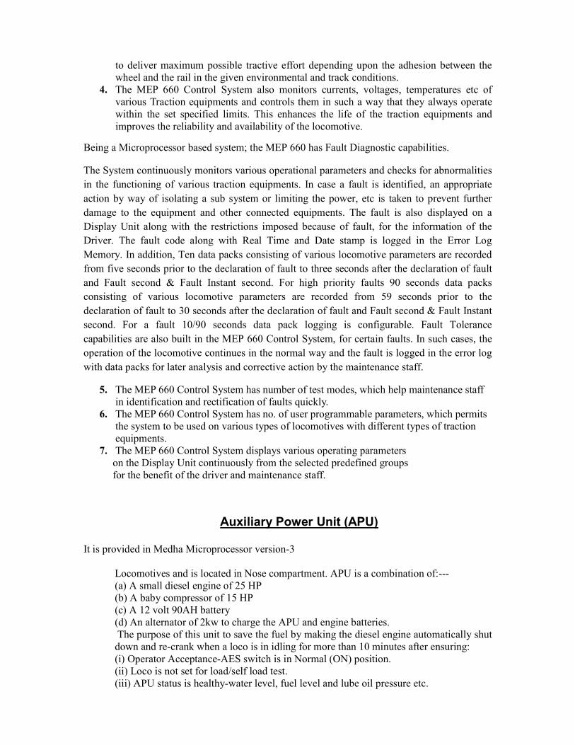
Being a Microprocessor based system; the MEP 660 has Fault Diagnostic capabilities.
The System continuously monitors various operational parameters and checks for abnormalities in the functioning of various traction equipments. In case a fault is identified, an appropriate action by way of isolating a sub system or limiting the power, etc is taken to prevent further damage to the equipment and other connected equipments. The fault is also displayed on a Display Unit along with the restrictions imposed because of fault, for the information of the Driver. The fault code along with Real Time and Date stamp is logged in the Error Log Memory. In addition, Ten data packs consisting of various locomotive parameters are recorded from five seconds prior to the declaration of fault to three seconds after the declaration of fault and Fault second & Fault Instant second. For high priority faults 90 seconds data packs consisting of various locomotive parameters are recorded from 59 seconds prior to the declaration of fault to 30 seconds after the declaration of fault and Fault second & Fault Instant second. For a fault 10/90 seconds data pack logging is configurable. Fault Tolerance capabilities are also built in the MEP 660 Control System, for certain faults. In such cases, the operation of the locomotive continues in the normal way and the fault is logged in the error log with data packs for later analysis and corrective action by the maintenance staff.
5. The MEP 660 Control System has number of test modes, which help maintenance staff in identification and rectification of faults quickly.
6. The MEP 660 Control System has no. of user programmable parameters, which permits the system to be used on various types of locomotives with different types of traction equipments.
7. The MEP 660 Control System displays various operating parameters on the Display Unit continuously from the selected predefined groups for the benefit of the driver and maintenance staff.
Auxiliary Power Unit (APU)
It is provided in Medha Microprocessor version-3
Locomotives and is located in Nose compartment. APU is a combination of:--- (a) A small diesel engine of 25 HP (b) A baby compressor of 15 HP (c) A 12 volt 90AH battery (d) An alternator of 2kw to charge the APU and engine batteries.
The purpose of this unit to save the fuel by making the diesel engine automatically shut down and re-crank when a loco is in idling for more than 10 minutes after ensuring: (i) Operator Acceptance-AES switch is in Normal (ON) position. (ii) Loco is not set for load/self load test. (iii) APU status is healthy-water level, fuel level and lube oil pressure etc.

(iv) Main engine EWT and EOT sensors are healthy and the temperature is greater than 30 degrees.
(v) Battery charging current is below 10A. (vi) MCBs are in ON condition. (vii) BC pressure>2.1kg/cm2 (viii) MR pressure>7.5kg/cm2 (ix) Main engine RPM is in idle(350-400) (x) Reverser handle is neutral. MEP displays show the message “ Loco is going to fuel save mode “ with buzzer sound. A decrement counter is starts from 60 and will decremented for every seconds. When counter reaches zero, MEP energizes ACC (APU cranking contactor) and the following changes will happen; (i) Internal 12 V supply is connected to starter motor of APU engine and gets started. (ii) Main engine will shut down. (iii) Baby compressor starts functioning and maintains MR and BP
(iv) The Alternator starts functioning and 72 V supply is being fed to Locomotive and the batteries are getting charged. When operator wants to resume from full save mode, he has to move the reverser handle to any one direction. The following changes will happen: (i) MEP display shows message “System returning from fuel save mode”. (ii) Loco is cranked by MEP within 5 sec. (iii) When Diesel engine RPM reaches above 300 rpm, MEP energizes ASC(APU shut down
contactor)and shuts the APU within 17 sec.
Distributed Power Control System(DPCS)
Distributed Power Control Systems (DPCS) better known as Loco control gives a radical new method for running longer trains for higher throughput. This article provides the reader within insight into the development and deployment of Distributed Power Control Systems on the Indian Railways. The history of development of DPCS technology in the world is re-traced and also the initial trials on the Indian Railways are discussed. The current developments and the new challenges are covered which provide easy initiation into the technology that makes long trains a reality.
Introduction:
Higher payload throughput is the immutable aim of any rolling stock engineer. In a simple mantra, this translates into heavier, faster and longer trains. However, implementation of this mantra is reciprocally complex compared to the apparent simplicity of the statement. The difficulty in implementation stems from the requirement of upgrading the full railway system (track & signal infrastructure and the rolling stock), simultaneously in order to achieve increased throughputs. Such upgrades require huge resources and time and as a result once a railway is setup, the increase in throughput is normally a result of increased train density rather than improvement of payload tonnage, speed or the length of the train. Distributed Power is a radically different solution that permits running faster and longer trains on existing railway systems with minimal up gradation of the locomotives only. The concept is novel because of the simplicity and ease of implementation. However it is not without its pitfalls. The common understanding of a train is that of a locomotive that pulls a set of series connected payload vehicles which are mechanically (coupler) and pneumatically (brake pipe) coupled. A variation of the
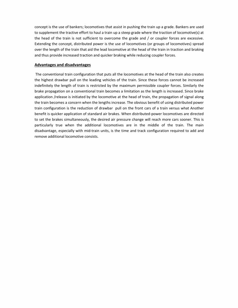
concept is the use of bankers; locomotives that assist in pushing the train up a grade. Bankers are used to supplement the tractive effort to haul a train up a steep grade where the traction of locomotive(s) at the head of the train is not sufficient to overcome the grade and / or coupler forces are excessive. Extending the concept, distributed power is the use of locomotives (or groups of locomotives) spread over the length of the train that aid the lead locomotive at the head of the train in traction and braking and thus provide increased traction and quicker braking while reducing coupler forces.
Advantages and disadvantages
The conventional train configuration that puts all the locomotives at the head of the train also creates the highest drawbar pull on the leading vehicles of the train. Since these forces cannot be increased indefinitely the length of train is restricted by the maximum permissible coupler forces. Similarly the brake propagation on a conventional train becomes a limitation as the length is increased. Since brake application /release is initiated by the locomotive at the head of train, the propagation of signal along the train becomes a concern when the lengths increase. The obvious benefit of using distributed power train configuration is the reduction of drawbar pull on the front cars of a train versus what Another benefit is quicker application of standard air brakes. When distributed-power locomotives are directed to set the brakes simultaneously, the desired air pressure change will reach more cars sooner. This is particularly true when the additional locomotives are in the middle of the train. The main disadvantage, especially with mid-train units, is the time and track configuration required to add and remove additional locomotive consists.

DEMU DPC
INTRODUCTION
DEMU SERVICE:
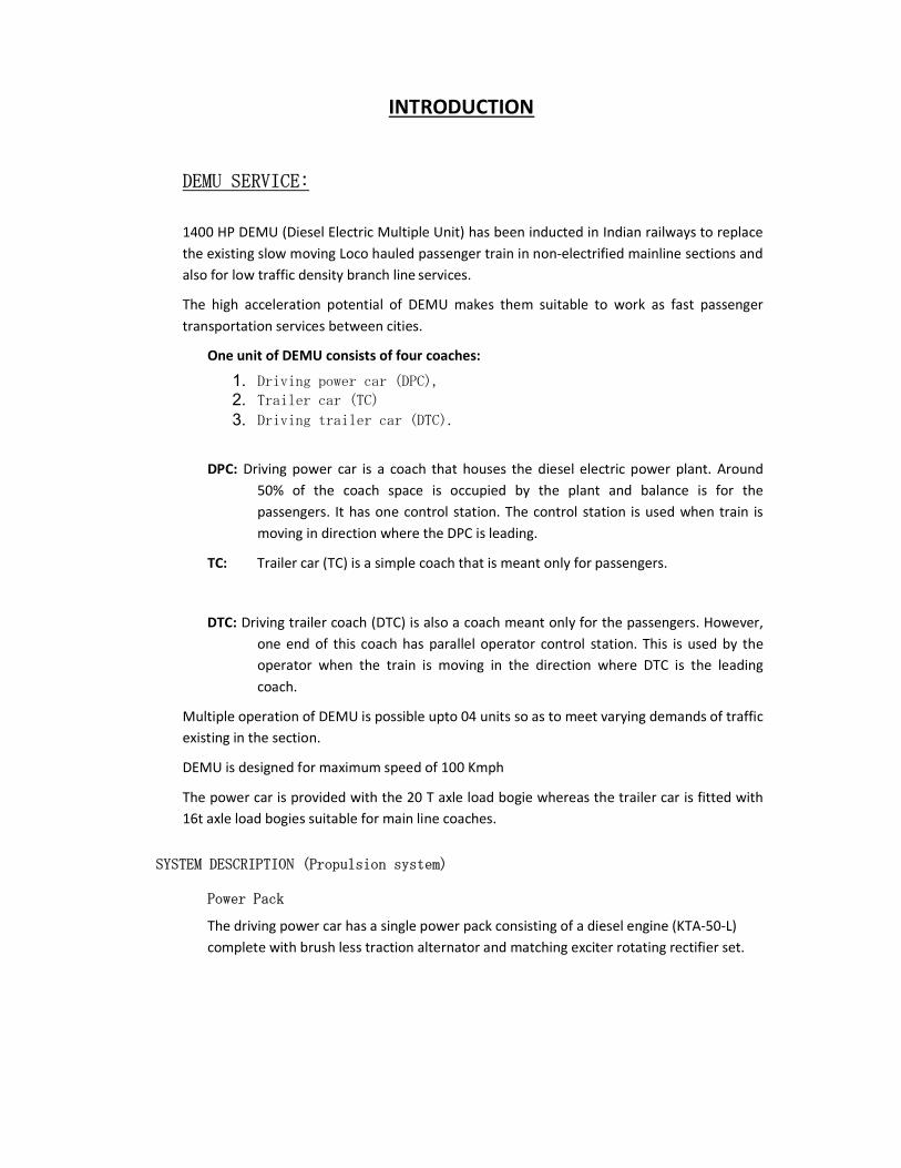
1400 HP DEMU (Diesel Electric Multiple Unit) has been inducted in Indian railways to replace the existing slow moving Loco hauled passenger train in non-electrified mainline sections and also for low traffic density branch line services.
The high acceleration potential of DEMU makes them suitable to work as fast passenger transportation services between cities.
One unit of DEMU consists of four coaches:
1. Driving power car (DPC), 2. Trailer car (TC) 3. Driving trailer car (DTC).
DPC: Driving power car is a coach that houses the diesel electric power plant. Around 50% of the coach space is occupied by the plant and balance is for the passengers. It has one control station. The control station is used when train is moving in direction where the DPC is leading.
TC: Trailer car (TC) is a simple coach that is meant only for passengers.
DTC: Driving trailer coach (DTC) is also a coach meant only for the passengers. However, one end of this coach has parallel operator control station. This is used by the operator when the train is moving in the direction where DTC is the leading coach.
Multiple operation of DEMU is possible upto 04 units so as to meet varying demands of traffic existing in the section.
DEMU is designed for maximum speed of 100 Kmph
The power car is provided with the 20 T axle load bogie whereas the trailer car is fitted with 16t axle load bogies suitable for main line coaches.
SYSTEM DESCRIPTION (Propulsion system)
Power Pack
The driving power car has a single power pack consisting of a diesel engine (KTA-50-L) complete with brush less traction alternator and matching exciter rotating rectifier set.
Rectification
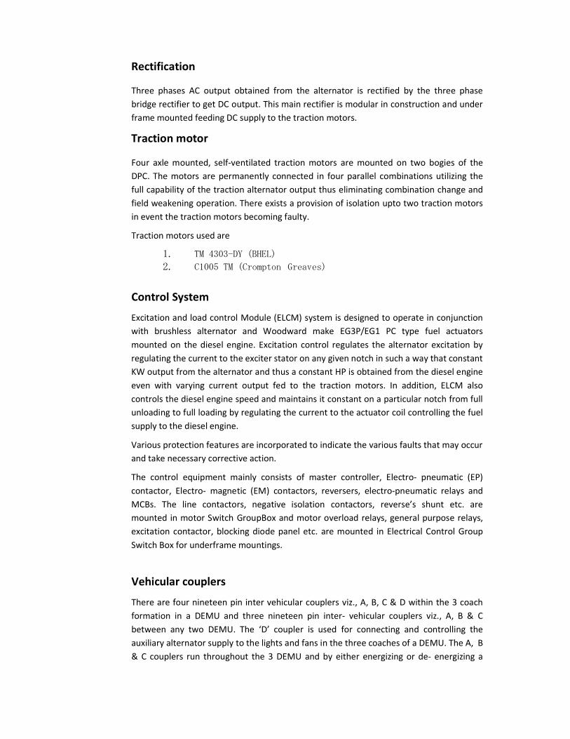
Three phases AC output obtained from the alternator is rectified by the three phase bridge rectifier to get DC output. This main rectifier is modular in construction and under frame mounted feeding DC supply to the traction motors.
Traction motor
Four axle mounted, self-ventilated traction motors are mounted on two bogies of the DPC. The motors are permanently connected in four parallel combinations utilizing the full capability of the traction alternator output thus eliminating combination change and field weakening operation. There exists a provision of isolation upto two traction motors in event the traction motors becoming faulty.
Traction motors used are
1. TM 4303-DY (BHEL) 2. C1005 TM (Crompton Greaves)
Control System
Excitation and load control Module (ELCM) system is designed to operate in conjunction with brushless alternator and Woodward make EG3P/EG1 PC type fuel actuators mounted on the diesel engine. Excitation control regulates the alternator excitation by regulating the current to the exciter stator on any given notch in such a way that constant KW output from the alternator and thus a constant HP is obtained from the diesel engine even with varying current output fed to the traction motors. In addition, ELCM also controls the diesel engine speed and maintains it constant on a particular notch from full unloading to full loading by regulating the current to the actuator coil controlling the fuel supply to the diesel engine.
Various protection features are incorporated to indicate the various faults that may occur and take necessary corrective action.
The control equipment mainly consists of master controller, Electro- pneumatic (EP) contactor, Electro- magnetic (EM) contactors, reversers, electro-pneumatic relays and MCBs. The line contactors, negative isolation contactors, reverse’s shunt etc. are mounted in motor Switch GroupBox and motor overload relays, general purpose relays, excitation contactor, blocking diode panel etc. are mounted in Electrical Control Group Switch Box for underframe mountings.
Vehicular couplers
There are four nineteen pin inter vehicular couplers viz., A, B, C & D within the 3 coach formation in a DEMU and three nineteen pin inter- vehicular couplers viz., A, B & C between any two DEMU. The ‘D’ coupler is used for connecting and controlling the auxiliary alternator supply to the lights and fans in the three coaches of a DEMU. The A, B & C couplers run throughout the 3 DEMU and by either energizing or de- energizing a
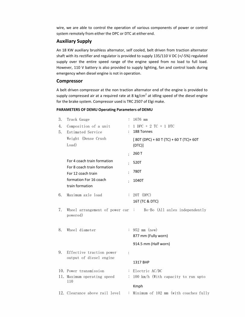
wire, we are able to control the operation of various components of power or control system remotely from either the DPC or DTC at either end.
Auxiliary Supply
An 18 KW auxiliary brushless alternator, self cooled, belt driven from traction alternator shaft with its rectifier and regulator is provided to supply 135/110 V DC (+/-5%) regulated supply over the entire speed range of the engine speed from no load to full load. However, 110 V battery is also provided to supply lighting, fan and control loads during emergency when diesel engine is not in operation.
Compressor
A belt driven compressor at the non traction alternator end of the engine is provided to supply compressed air at a required rate at 8 kg/cm2 at idling speed of the diesel engine for the brake system. Compressor used is TRC 2507 of Elgi make.
PARAMETERS OF DEMU Operating Parameters of DEMU
3. Track Gauge : 1676 mm
4. Composition of a unit : 1 DPC + 2 TC + 1 DTC
5. Estimated Service
Weight (Dense Crush
Load)
For 4 coach train formation For 8 coach train formation For 12 coach train formation For 16 coach train formation
: 188 Tonnes
[ 80T (DPC) + 60 T (TC) + 60 T (TC)+ 60T (DTC)]
: 260 T
: 520T
: 780T
: 1040T
6. Maximum axle load : 20T (DPC)
16T (TC & DTC)
7. Wheel arrangement of power car : Bo-Bo (All axles independently
powered)
8. Wheel diameter : 952 mm (new)
877 mm (Fully worn)
914.5 mm (Half worn)
9. Effective traction power
output of diesel engine :
1317 BHP
10. Power transmission : Electric AC/DC
11. Maximum operating speed : 100 km/h (With capacity to run upto 110
Kmph
12. Clearance above rail level : Minimum of 102 mm (with coaches fully
loaded and wheels in fully worn condition)
13. Reference site conditions : Ambient Temperature : 55 Deg. C
& 55-60 Deg. C inside engine room Humidity : 100 %
Attitude : 0- 600 meter above sea level
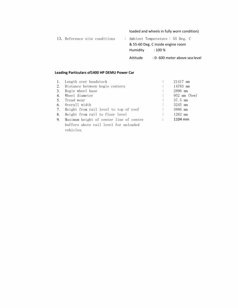
Leading Particulars of1400 HP DEMU Power Car
1. Length over headstock : 21417 mm 2. Distance between bogie centers : 14783 mm 3. Bogie wheel base : 2896 mm 4. Wheel diameter : 952 mm (New) 5. Tread wear : 37.5 mm 6. Overall width : 3245 mm 7. Height from rail level to top of roof : 3886 mm 8. Height from rail to floor level : 1282 mm 9. Maximum height of center line of centre
buffers above rail level for unloaded
vehicles.
: 1104 mm
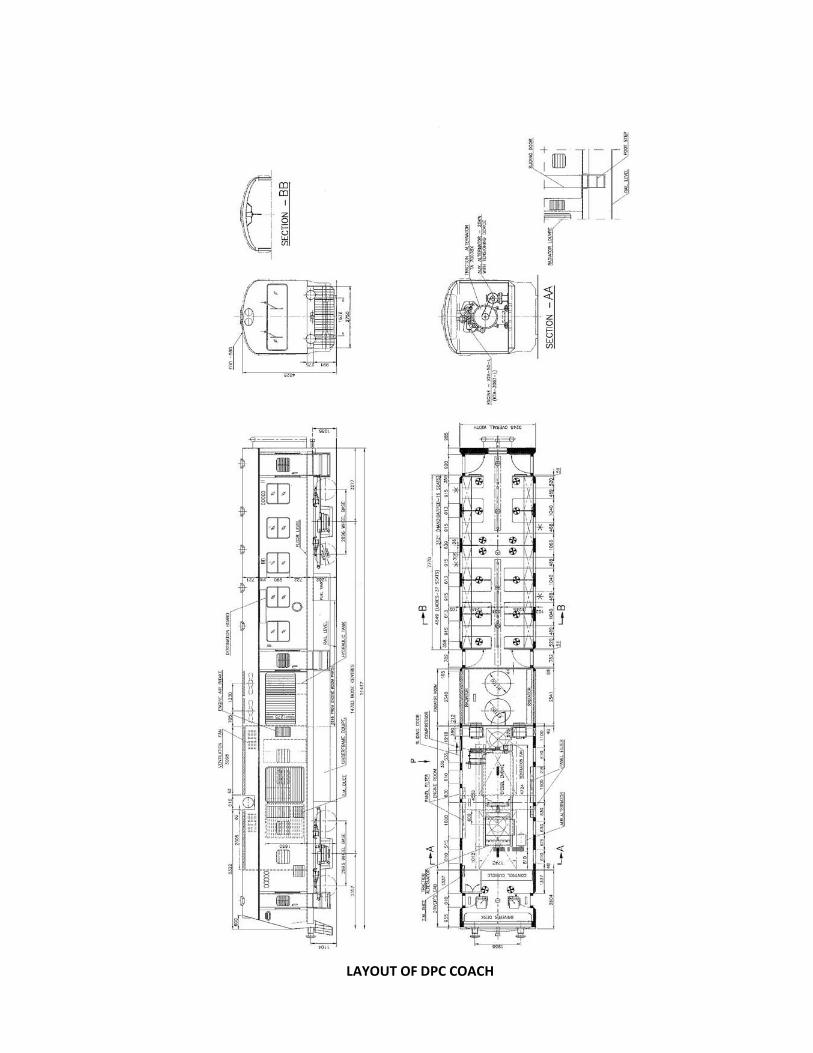
LAYOUT OF DPC COACH
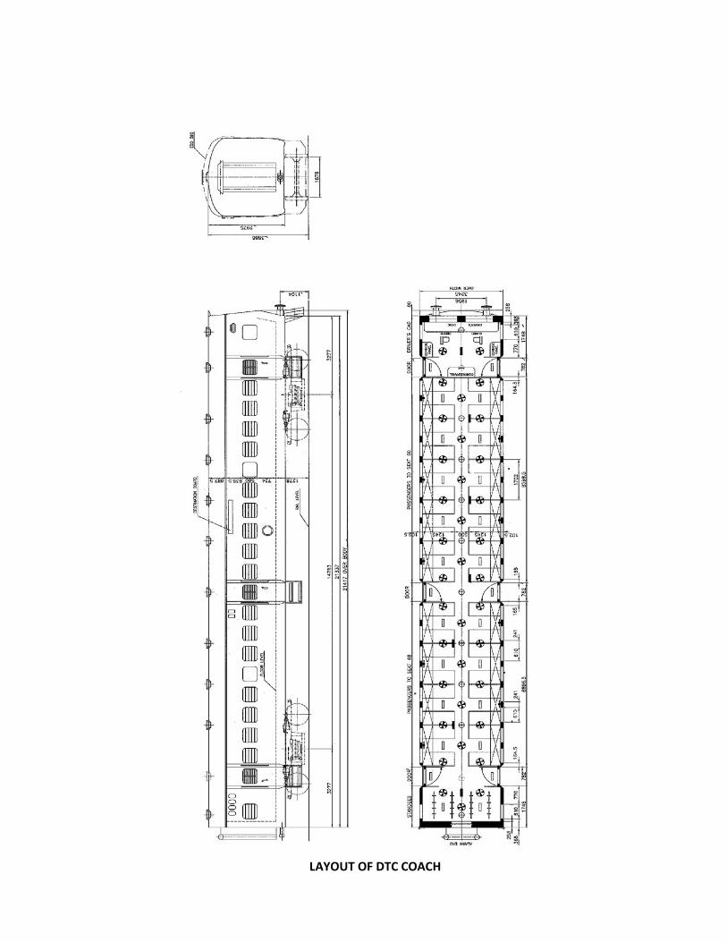
LAYOUT OF DTC COACH
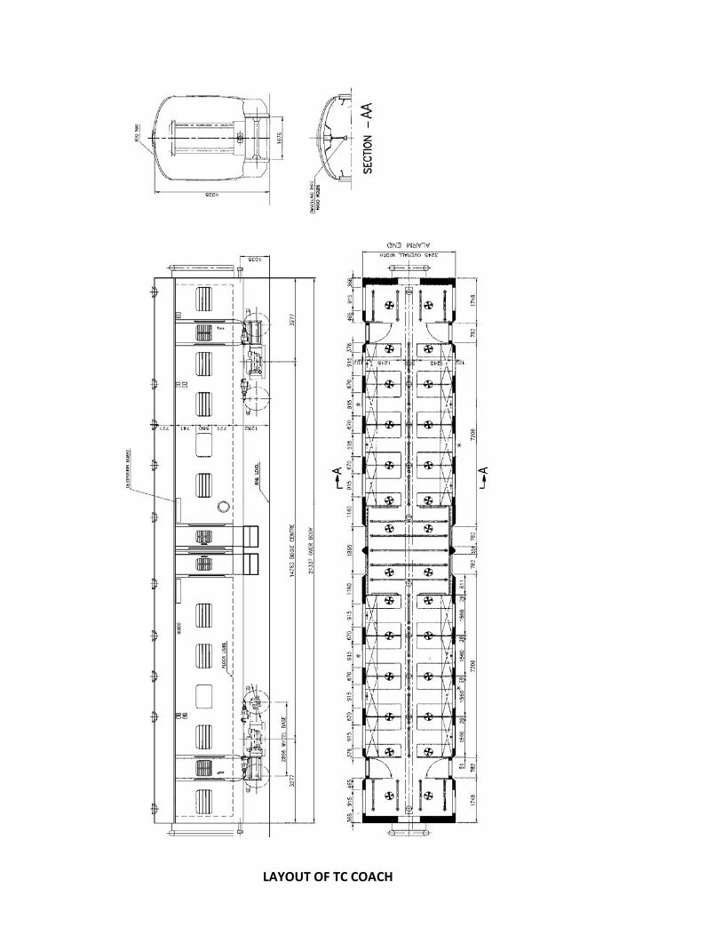
LAYOUT OF TC COACH