'LL' SERIES SELF STEER AXLE - BPW
10
The Quality Factor ‘LL’ SERIES SELF STEER AXLE KINGPIN BEARINGS REMOVAL & REPLACEMENT December 2010
-
Upload
khangminh22 -
Category
Documents
-
view
0 -
download
0
Transcript of 'LL' SERIES SELF STEER AXLE - BPW

The Quality Factor
‘LL’ SerieS SeLf Steer AxLe Kingpin BeAringS
removAL & repLAcement
December 2010

The Quality Factor
Remove the axle. Take off the hubs and brake parts, see the handbooks for the corresponding rigid axles. Take off the track rod. Remove the base plates or the upper closing plates and take out the compression springs (arrow).
Turn the axle upside down so that the thrust washers are on top. Unscrew the fixing screws (2) of the lower closing plates (1). Take off the plates.
Drive the two front spring pins (1) out of the mountings in the steering swivel. Drive the two rear spring pins (2) as far as possible out of the axle beam.
► ▬

The Quality Factor
Place the stub axle under a press so that the thrust washers are below and the stub axle is upright (the thrust washers rest against each other). Exert slight pressure on the kingpin with a suitable mandrel. Heat the axle beam on the end face with a large heating torch flame until the kingpin is loosened, then force it right out in one go with the press.
► If the kingpin is pressed out without being heated, the stub axle bore will be destroyed.
► Mark the stub axle and thrust washers so that later they can be refitted in the same position.
Remove the stub axle and thrust washers. Inspect the kingpin and bushes for wear. Make a visual inspection by opening up the upper and lower bearings. The wear limit of the bushes is reached at a wall thickness of 1.8 mm. If necessary, exchange components. Inspect the thrust washers for wear. If necessary exchange them.
To exchange the thrust washers, grind off the weld seams (arrow) on the stub axle. Using a chisel lift the pinned thrust washer off the axle beam. Do not damage the mating surface on the axle beam.
► Shaft thrust washers must always be exchanged in pairs at the top and bottom and on both sides.
► ▬
►▬
►▬
►▬

The Quality Factor
Drive two new large spring pins into the thrust washer so that the slots are as illustrated (arrow). Then drive the small spring pins into the large spring pins so that the slots are opposite each other.
Place the thrust washer on the stub axle. The mating surfaces must be clean, free of grease and flat. Make the spring pins engage in the bores so that the slots (arrow) in the spring pins face outwards. Drive the shaft thrust ring onto its seat with a plastic hammer.
Clamp the thrust washers with the stub axle and weld them into position with a single pass, as shown in the drawing.
Special filler electrodes: E 18 8Mn B20+ DIN 8556
Weld seam thickness: 3.5 (DIN 1912)
Remove the weld spatter.
►▬
► ▬
► ▬
►▬

The Quality Factor
Press new bushes for the kingpin in with a suitable mandrel carefully and without tilting them until they make full contact with the inner mating surfaces (2) of the kingpin.
► The inner open lubrication passages (1) must face towards the middle of the axle.
Check whether the kingpin slides smoothly into the bushes. If necessary, re-work the bushes.
Since the axle is fitted upside down, a dia. 55 x 8 mm spacer should be placed in the upper kingpin bearing to assist installation. Attach the upper closing plate (1) or base plate (without the compression spring) with two screws (2).
Set up the axle beam in such a way that the thrust washers (arrow) are on top. Heat the rear of the axle beam on both sides in circles until it is dark red.
► ▬

The Quality Factor
Place the shaft thrust washer in position.
► In the case of older versions of thrust washer, the dish in the middle (1) should face the stub axle.
Place the stub axle on the thrust washer. Align all the bores for the kingpin. Press the kingpin into position in one go with the bore for the compression spring facing downwards. If necessary, drive it in with gentle taps of a hammer.
Drive thick spring pins into the mountings in the steering swivel and the shaft thrust ring in such a way that the slots (1) are always in the direction of rotation of the steering swivel. Then drive the thin spring pins into the thick spring pins in such a way that the slots are opposite. Continue to drive both spring pins until they project a little at the bottom of the shaft thrust pin (2). Then drive them back until the shaft thrust ring rests against the steering swivel and the spring pins still project approx. 1 mm. Position the spring pins in the bores of the steering swivel with two blows of a centrepunch.

The Quality Factor
► If there is a flat (arrow) on the upper plate, it must face the brake drum.
► Fit the track rod and steering lock. Fit the brakes and hubs.
Lubricate the kingpin bearings and the brake shaft bearings with BPW special longlife grease ECO-Li Plus *. Install the axle. Check the tracking.
* Alternatively use BPW ECO-Li 91 longlife grease
Make a functional check, see
► Functional check under the vehical.
Fit the lower closing plates with three M10 locking screws or hexagonal screws and spring washers and tighten the screws to the specific torque of 38 Nm. Place the compression spring (arrow) in the bore of the kingpin. Fit the base plate or upper closing plate with locking screws or hexagonal screws and spring washers. Tighten the screws until the compression spring is tensioned.
►▬
►▬

The Quality Factor
Welding of lower and upper thrust washers and installation of outer and inner roll pins. Use in conjunction with BPWL Tech Info 2002.04.0023.
Fit outer and inner roll pins to locate lower thrust washer. Weld washer to the swivel housing along one side of each tab. (One side shown). Weld size: 4mm x 30mm
Align and weld upper thrust washer to axle beam. Weld both sides. (One side shown).Weld size: 4mm x 50mm
D:\docs\service\BPWLLaxlethrustwasherinst
LOWer ThrUsT WAsher (03.128.05.06.0)OUTer rOLL PIn (02.6006.95.90)Inner rOLL PIn (02.6016.01.90)
UPPer ThrUsT WAsher (03.128.05.06.0)
reFer TO BPW sTeerIng AxLe WOrkshOP mAnUALBPW/WhL/94/1 DeF (7001) FOr FULL InsTrUCTIOns
► ▬
► ▬►
▬

Kingpin Bushing Wear Limits forBPW “LL” Series Self Steer Axles
kingpin
kingpin
Sandie Slavin
Text Box
(BPW ECO Li Plus)
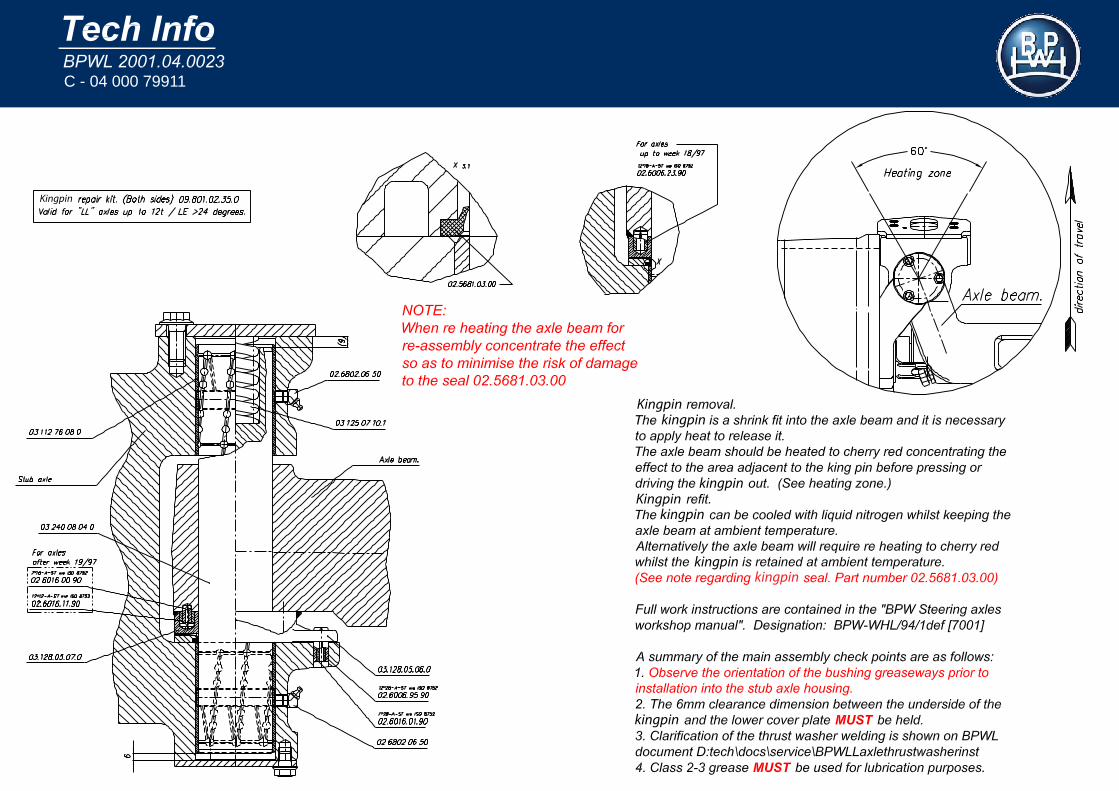
C - 04 000 79911
Kingpin
Kingpinkingpin
kingpinKingpin
kingpin
kingpin
kingpinkingpin