front axle & suspension - Central States Bus Sales
120
L 35 1 APPENDIX FRONT AXLE & SUSPENSION HENDRICKSON AIRTEK / SOFTEK Overview Front Suspensions The Blue Bird All American is equipped with one of two front suspension systems: Hendrickson™ SofTek.™ The Softek front suspension is a three parabolic leaf spring configuration, and is standard equipment on the Forward Engine All American. Hendrickson™ AirTek.™ The Airtek front suspension is an air spring suspension used on the Forward Engine All Americans equipped with air suspension option. Two lev- eling valves maintain ride height at varying axle loads. Axles Hendrickson™ SteerTek. The Forward Engine All American is equipped with Hen- drickson SteerTek front axles. The SteerTek axle includes an anti-lock brake system and is used in 13,200 and 14,600 lb. capacities on All Americans. Appendixes & Other References Appendix 1. AirTek & SofTek. Hendrickson Publication number 17730-248 covers maintenance, adjustment, and component replacement information on the SofTek leaf spring suspension. Please note that this Hendrickson publication also incorpo- rates information on Hendrickson’s SteerTek front axle and AirTek front air suspen- sion. Also See: The Hydraulc Brakes chapter of this manual includes a procedure for re- moving the front disc rotor/hub assembly. Maintenance Maintenance of the front axle and suspension consists of periodic general inspection, checking tightness of fasteners, and lubricating grease fittings. Refer to the mainte- nance charts in this chapter (also included in the Specs & Maintenance chapter) for maintenance inspection intervals. The exploded illustrations in this chapter include torque specifications. The specific Hendrickson axle model installed may be identified by refering to the axle numbers etched near the center front of the axle’s main beam. Hendrickson Identification
-
Upload
khangminh22 -
Category
Documents
-
view
3 -
download
0
Transcript of front axle & suspension - Central States Bus Sales

L
35
1APPENDIX
front axle & suspension
HENDrIcksoNAIrtEk / softEk
Overview
Front Suspensions
The Blue Bird All American is equipped with one of two front suspension systems:
Hendrickson™ SofTek.™ The Softek front suspension is a three parabolic leaf spring
configuration, and is standard equipment on the Forward Engine All American.
Hendrickson™ AirTek.™ The Airtek front suspension is an air spring suspension used
on the Forward Engine All Americans equipped with air suspension option. Two lev-
eling valves maintain ride height at varying axle loads.
Axles
Hendrickson™ SteerTek. The Forward Engine All American is equipped with Hen-
drickson SteerTek front axles. The SteerTek axle includes an anti-lock brake system
and is used in 13,200 and 14,600 lb. capacities on All Americans.
Appendixes & Other References
Appendix 1. AirTek & SofTek. Hendrickson Publication number 17730-248 covers
maintenance, adjustment, and component replacement information on the SofTek
leaf spring suspension. Please note that this Hendrickson publication also incorpo-
rates information on Hendrickson’s SteerTek front axle and AirTek front air suspen-
sion.
Also See: The Hydraulc Brakes chapter of this manual includes a procedure for re-
moving the front disc rotor/hub assembly.
MaintenanceMaintenance of the front axle and suspension consists of periodic general inspection,
checking tightness of fasteners, and lubricating grease fittings. Refer to the mainte-
nance charts in this chapter (also included in the Specs & Maintenance chapter) for
maintenance inspection intervals. The exploded illustrations in this chapter include
torque specifications.
The specific Hendrickson axle model installed may be identified by refering to the axle numbers etched near the center front of the axle’s main beam.
Hendrickson Identification

L
36
SERVICE MANUAL
SofTek Front Suspension
00
10
62
94
m
Right Side ShownLeft Side Symetrical
unless otherwise noted.
B
B
A
C
D
G
G
G
G
SERVICE MANUAL
L
37
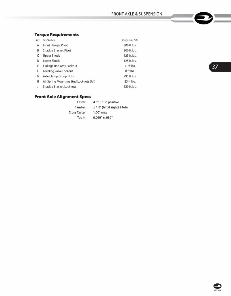
FRonT AxlE & SuSPEnSion
Front Axle Alignment Specs Caster: 4.5° ± 1.5° positive
Camber: ± 1.0° (left & right) 2 Total
Cross Caster: 1.00° max
Toe In: 0.060” ± .030”
Torque Requirements key description torque +- 5%
A Front Hanger Pivot 300 ft.lbs.
B Shackle Bracket Pivot 300 ft.lbs.
C upper Shock 125 ft.lbs.
D lower Shock 125 ft.lbs.
E linkage Rod Assy locknut 11 ft.lbs.
F leveling Valve lockout 8 ft.lbs.
G Axle Clamp Group nuts 295 ft.lbs.
H Air Spring Mounting Stud locknuts (All) 25 ft.lbs.
J Shackle Bracket locknuts 120 ft.lbs.

L
38
SERVICE MANUAL
AirTek Front Air Suspension
00
10
62
94
m
B
B
A
G
C
E
ESHOCK LENGTH
@ RIDE HT:FE=17.25±.25
F
H
H
J
J
H
OUTBOARDSTUD ONLY
D

SERVICE MANUAL
L
39
FRonT AxlE & SuSPEnSion
Torque Requirements key description torque +- 5%
A Front Hanger Pivot 300 ft.lbs.
B Shackle Bracket Pivot 300 ft.lbs.
C upper Shock 125 ft.lbs.
D lower Shock 125 ft.lbs.
E linkage Rod Assy locknut 11 ft.lbs.
F leveling Valve lockout 8 ft.lbs.
G Axle Clamp Group nuts 295 ft.lbs.
H Air Spring Mounting Stud locknuts (All) 25 ft.lbs.
J Shackle Bracket locknuts 120 ft.lbs.
Front Axle Alignment Specs Caster: 4.5° ± 1.5° positive
Camber: ± 1.0° (left & right) 2 Total
Cross Caster: 1.00° max
Toe In: 0.060” ± .030”
Ride Height Adjustment Ride height may be verified by measuring either shock length or air spring height:
1. With leveling valve and linkage installed as shown and air system at 80 PSi or
greater, right hand side shock length from centerline of eye to centerline of
eye should be 17.25” ± .25” for Forward Engine models.
2. if adjustment is required, loosen leveling valve body mounting fasteners from
the frame rail and rotate valve counter-clockwise or clockwise to lengthen or
shorten shock dimension.
3. Tighten valve mounting fasteners to 8 ft. lbs.
4. Remove vertical link lower grommet from stud on spring pad, lower valve
horizontal arm, and release all air from bag.
5. Reconnect link and verify shock length according to step 1. if measurement
is not correct, repeat steps 1 thru 5 until proper ride height is achieved.
6. Repeat steps 1 thru 5 for left hand side.

L
40
Air
tek
/ S
oft
ek S
usp
ensi
on
: Ap
pen
dix
1
Front Axle & Suspension
operation
Interval: Months/Miles
whichever
occurs first
notesfirst
100
0 m
iles
6 / 6
,000
12 /
12,0
00
Spring Suspension
Inspect visually • Check for visual damage. See Hendrickson publication 17730-248.
Check U-bolt torque • • Tighten to 285–305 ft. lbs (32–34 Nm).
Lubricate steering grease fittings • Use NLGI #2 EP or equivalent.
Inspect spring pin lock bolts • Tighten to 380–420 ft. lbs. (515–569 Nm).
Inspect shackle bracket pivot bolt • Tighten to 380–420 ft. lbs. (515–569 Nm).
Inspect shocks • Check for signs of leaks, wear, or damage.
Torque shock mounting bolts • TIghten to 215 ft. lbs. (25 Nm).
Air Suspension
Inspect visually • Check for wear, damage, misalignment. See Hendrickson publication 17730-248.
Check axle to suspension fasteners • • Tighten to 285–305 ft. lbs (32–34 Nm).
Lubricate steering grease fittings • Use NLGI #2 EP or equivalent. Lube with suspension loaded.
Inspect pin lock bolts • Tighten to 380–420 ft. lbs. (515–569 Nm).
Inspect shackle bracket pivot bolt • Tighten to 380–420 ft. lbs. (515–569 Nm).
Torque shock mounting bolts • TIghten to 215 ft. lbs. (25 Nm).
Inspect air spring cushions • Check for wear, abrasions, cuts, or other damage
Check air spring fasteners •
Inspect shocks • Check for signs of leaks, wear, or damage.
Check suspension height • Shock length, eye to eye: 18.5” ± .25”. (470 ± 6mm).
Check ride height control valve bolts • TIghten to 8–10 ft. lbs. (11–14 Nm).
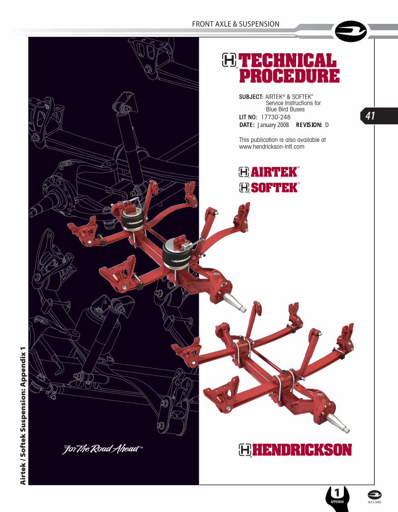
SUBJECT: AIRTEK® & SOFTEK®
Service Instructions for Blue Bird Buses
LIT NO: 17730-248DATE: February 2007 REVISION: C
This publication is also available atwww.hendrickson-intl.comh
di
ki
tlAIRTEK
®&SO
FTEK®
BlBid
B17730
248
DATE: January 2008 REVISION: D
L
41
FRonT AxlE & SuSPEnSion
1APPENDIX
Air
tek
/ S
oft
ek S
usp
ensi
on
: Ap
pen
dix
1

L
42
1APPENDIX
SERVICE MANUAL
Section 1 Introduction . . . . . . . . . . . . . . . . . . . . . . 2
Section 2 Product Description . . . . . . . . . . . . . . . . 3
Section 3 Important Safety Notice. . . . . . . . . . . . . 6
Section 4 Special Tools . . . . . . . . . . . . . . . . . . . . 11
Section 5 Parts ListsFor Vision Buses
AIRTEK – 10K Capacity . . . . . . . . . . . . . . 12SOFTEK – 8K/10K Capacity . . . . . . . . . . . 14
For All American BusesAIRTEK – 14.6K Capacity. . . . . . . . . . . . . 16SOFTEK – 13.2K/14.6K Capacity . . . . . . . 18Right Hand Drive Axle . . . . . . . . . . . . . . . 20
Section 6 Towing Procedure . . . . . . . . . . . . . . . . 21
Section 7 Preventive MaintenanceComponent Inspection. . . . . . . . . . . . . . . . . 24Lubrication Intervals . . . . . . . . . . . . . . . . . . 25Kingpin Lubrication. . . . . . . . . . . . . . . . . . . 25Tie Rod End Lubrication. . . . . . . . . . . . . . . . 26Tie Rod End Inspection . . . . . . . . . . . . . . . . 27Clamp Group Re-torque Interval . . . . . . . . . . 29Tire Inspection . . . . . . . . . . . . . . . . . . . . . . 29Axle Wrap Liner Inspection. . . . . . . . . . . . . . 32Shock Absorber Inspection. . . . . . . . . . . . . . 32Kingpin Bushing Inspection . . . . . . . . . . . . . 34Steering Knuckle Inspection . . . . . . . . . . . . . 35Shackle Thrust Washer Inspection . . . . . . . . 36Front Hanger/Rear Shackle Plate
Surface Paint Wear . . . . . . . . . . . . . . . . . 37
Section 8 Alignment & AdjustmentsAlignment Definitions . . . . . . . . . . . . . . . . . 38Inspection Prior to Alignment . . . . . . . . . . . . 40Front Wheel Alignment . . . . . . . . . . . . . . . . 41AIRTEK Ride Height Adjustment . . . . . . . . . . 43AIRTEK Height Control Valve Test . . . . . . . . . 45Steering Stop . . . . . . . . . . . . . . . . . . . . . . . 46Toe Setting . . . . . . . . . . . . . . . . . . . . . . . . . 46Spring Eye Re-torque. . . . . . . . . . . . . . . . . . 48
Section 9 Component ReplacementFasteners. . . . . . . . . . . . . . . . . . . . . . . . . . 50Spacers . . . . . . . . . . . . . . . . . . . . . . . . . . . 50AIRTEK Height Control Valve. . . . . . . . . . . . . 50AIRTEK Air Spring . . . . . . . . . . . . . . . . . . . . 53AIRTEK Front Leaf Spring Frame Hanger . . . . 57SOFTEK Front Leaf Spring Frame Hanger . . . . 58AIRTEK Rear Shackle Frame Bracket . . . . . . . 59SOFTEK Rear Shackle Frame Bracket. . . . . . . 60SOFTEK Rubber Axle Stop . . . . . . . . . . . . . . 62Thrust Washer . . . . . . . . . . . . . . . . . . . . . . 62AIRTEK Leaf Spring Assembly. . . . . . . . . . . . 63SOFTEK Leaf Spring Assembly . . . . . . . . . . . 66Front Leaf Spring Eye Bushing . . . . . . . . . . . 68Shock Absorber . . . . . . . . . . . . . . . . . . . . . 68AIRTEK Bottom Axle Wrap . . . . . . . . . . . . . . 70SOFTEK Bottom Axle Wrap. . . . . . . . . . . . . . 71AIRTEK Top Axle Wrap (In Chassis) . . . . . . . 72SOFTEK Top Axle Wrap (In Chassis) . . . . . . . 75AIRTEK Front Axle Assembly. . . . . . . . . . . . . 77SOFTEK Front Axle Assembly . . . . . . . . . . . . 78STEERTEK Axle Removal . . . . . . . . . . . . . . . 79
STEERTEK Axle (Removed from Chassis). . 80Steering Knuckle Disassembly . . . . . . . . . 83Kingpin Preparation & Measurement . . . . . 84Kingpin Bushing Removal . . . . . . . . . . . . 86Steering Knuckle Bore Measurement . . . . . 87Kingpin Bushing Installation. . . . . . . . . . . 87Kingpin Bushing Reaming . . . . . . . . . . . . 88Kingpin Seal Installation . . . . . . . . . . . . . 89Steering Knuckle Assembly. . . . . . . . . . . . 90
Tie Rod End and Cross Tube . . . . . . . . . . . . 92
Section 10 AIRTEK Plumbing Diagrams10K Capacity . . . . . . . . . . . . . . . . . . . . . . . 9414.6K Capacity . . . . . . . . . . . . . . . . . . . . . 95
Appendix Reference Material . . . . . . . . . . . . . . . . . . A-97Trouble Shooting Guide . . . . . . . . . . . . . . A-98Torque Specifications . . . . . . . . . . . . . . . A-100Front Alignment Specifications. . . . . . . . . A-108
Technical Procedure Publication Quiz. . . . . . . . . . . A-110
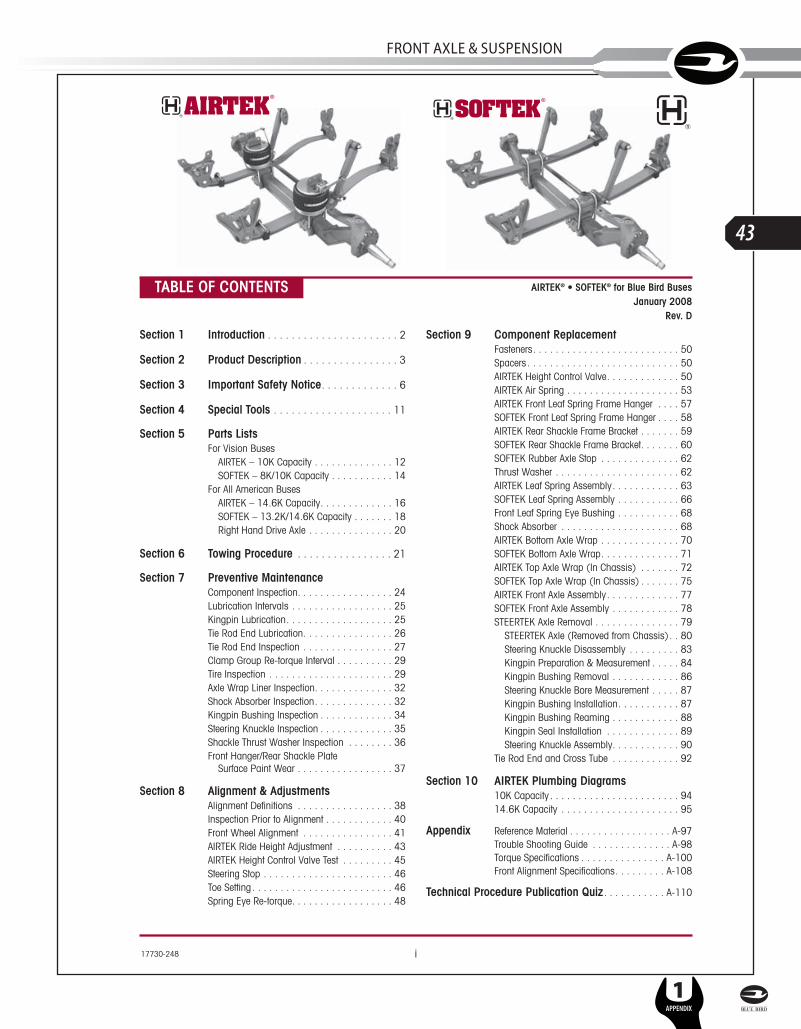
TABLE OF CONTENTS
i17730-248
AIRTEK® • SOFTEK® for Blue Bird BusesJanuary 2008
Rev. D
SERVICE MANUAL
L
43
FRonT AxlE & SuSPEnSion
1APPENDIX
Introduction 2 17730-248
AIRTEK®• SOFTEK® for Blue Bird Buses
SECTION 1
IntroductionThis publication is intended to acquaint and assist maintenance personnel in the preven-tive maintenance, service, repair and rebuild of the following Hendrickson equipment asinstalled on applicable Blue Bird Buses:■ AIRTEK® — An integrated front air suspension with the STEERTEK axle.■ SOFTEK® — An integrated steel spring mechanical suspension with the STEERTEK axle.■ STEERTEK — A lightweight, formed and robotically welded steer axle assembly.
NOTE Use only Hendrickson Genuine parts for servicing this suspension system.
It is important to read and understand the entire Technical Procedure publication prior toperforming any maintenance, service, repair, or rebuild of the product. The information inthis publication contains parts lists, safety information, product specifications, features,proper maintenance, service, repair and rebuild instructions for the AIRTEK/SOFTEKSuspension and the STEERTEK axle.
A Technical Procedure Quiz has been included at the back of this publication. Hendricksonwill provide personalized AIRTEK/SOFTEK Technical Procedure Quiz Achievement Certificateto candidates scoring 80% or higher on the test. Simply complete the test and fill in theenclosed answer sheet or write your answers on a separate sheet with the return address,name, phone number, and company name as it will appear on the award to:
HendricksonATTN: Truck Marketing Test Quiz Assessment 800 S. Frontage RoadWoodridge, Illinois 60517
Hendrickson reserves the right to make changes and improvements to its products and publications at any time. Contact Hendrickson Tech Services at 630-910-2800 or [email protected] for information on the latest version of this manual.
The latest revision of this publication is also available online at www.hendrickson-intl.com.
L
44
1APPENDIX
SERVICE MANUAL

17730-248 3 Product Description
AIRTEK®• SOFTEK® for Blue Bird Buses
SECTION 2
Product DescriptionBLUE BIRD VISION BUSES
FIGURE 2-1 FIGURE 2-2 AIRTEK® Air Suspension System SOFTEK® Mechanical Suspension SystemCapacity: 10,000 pounds Capacity: 8,000/10,000 pounds
BLUE BIRD ALL AMERICAN BUSES
FIGURE 2-3 FIGURE 2-4 AIRTEK® Air Suspension System SOFTEK® Mechanical Suspension SystemCapacity: 14,600 pounds Capacity: 13,200/14,600 pounds
RIGHT HAND DRIVE AXLE
FIGURE 2-5
SERVICE MANUAL
L
45
FRonT AxlE & SuSPEnSion
1APPENDIX
Product Description 4 17730-248
AIRTEK®• SOFTEK® for Blue Bird Buses
STEERTEK — The box-shaped design provides a stiffer axle and resists torsional,longitudinal and vertical loads more effectively than traditional axle beams. Together withthe front limbs of the leaf springs, the robotically welded axle beam forms a torsion system,enhancing roll stability characteristics and improving handling.
Axle clamp group — The patented clamp group provides four-sided clamping pressure.The Clamp Group consists of the following:
■ Top Axle Wrap ■ Bottom Axle Wrap■ Top Axle Wrap Liner ■ Bottom Axle Wrap Liner■ Top Spring Pad ■ ¾" Bolts, Washers and Locknuts
Adjustable tie rod —To help maximize tire life, the tie rod easily adjusts toe-in/out.
Steering knuckles — The steering and tie rod arms are integrated for increased strengthand reduced weight. The unique steering knuckle packaging delivers a maximum of 50°wheel cut. The two piece knuckle design makes servicing the kingpin bushings easier.
AIRTEK — Winner of the 2001 Automotive News and Cap Gemini Ernst & Young PACEAward for Product Innovation. AIRTEK is an integrated front air suspension and roboticallywelded steer axle that work together to form an integrated torsion system. Utilizing asystem approach, Hendrickson has engineered and optimized the following componentsto form a system delivering ride, stability and handling characteristics with reduced weightand maintenance.
Air springs — Exclusive to Hendrickson, the lightweight air springs deliver a soft ride.The air springs are engineered to support 78% of the vertical load while providing alow spring rate. The quick “snap” design for the 10,000 pound capacity, the bolt ondesign for the 14,600 pound capacity, and the “push-to-connect” air supply designalso provide fast and easy removal and installation.
Leaf spring assembly — With its innovative design, the leaf spring provides superiorstability, performance and a soft ride. The patented leaf spring shares loads with the airspring. Durable rubber front and patented rear bushings are greaseless and onlyrequire periodic inspections.
SOFTEK — is an integrated front mechanical suspension and robotically welded steeraxle that work together to form an integrated torsion system. Utilizing a system approach,Hendrickson has engineered and optimized the following components to form a systemdelivering ride, stability and handling characteristics with reduced weight andmaintenance.
Leaf spring assembly — With its innovative design, the leaf spring provides superiorstability, performance and a soft ride. Durable rubber front and patented rear bushingsare greaseless and only require periodic inspections.
Shock absorbers — AIRTEK/SOFTEK utilizes premium shocks that have been tested andtuned specifically for the suspension system.
Frame brackets — Optimized design delivers weight reduction and proven durability. Thefront and rear frame brackets are common between the SOFTEK and AIRTEK suspensions.
L
46
1APPENDIX
SERVICE MANUAL

17730-248 5 Product Description
AIRTEK®• SOFTEK® for Blue Bird Buses
TECHNICAL NOTES1. AIRTEK and SOFTEK are approved for 100% on-highway use; other applications must be pre-
approved by Hendrickson Sales Engineering. System capacity rating for the suspensionrepresents maximum loads on tires at ground level.
2 The STEERTEK axle for the Vision is available with 69" kingpin intersection (KPI). The STEERTEKaxle for the All American is available with 71" kingpin intersection (KPI).
3. AIRTEK suspension weight includes frame and shackle bracket assemblies, main springs, bush-ings, air springs and air spring bracket, height control system, shocks, upper shock bracketsand axle clamp group.
4. SOFTEK suspension weight includes frame and shackle bracket assemblies, steel leaf springs,bushings, shocks, upper shock brackets and axle clamp group.
5. STEERTEK axle weight includes the axle beam, knuckle/steering arm assemblies and tie rodassemblies.
6. AIRTEK and SOFTEK are integral to and available exclusively with the STEERTEK axle. This sys-tem is anti-lock braking system (ABS) ready. STEERTEK is compatible with most industrystandard wheel ends and brakes. Contact OEM for more information.
7. The STEERTEK axle product identification is etched on the center front of the axle beam provid-ing the following information:
■ Axle part number: Identifies the features of the axle beam.
■ Axle assembly number: Identifies the complete assembly, which includes the steeringknuckles and bracket assemblies.
FIGURE 2-6 Front view of STEERTEK axle showing approximate location of Product Identification.
SERVICE MANUAL
L
47
FRonT AxlE & SuSPEnSion
1APPENDIX

Important Safety Notice 6 17730-248
AIRTEK®• SOFTEK® for Blue Bird Buses
SECTION 3
Important Safety NoticeProper maintenance, service and repair are important to the reliable operation of the sus-pension. The procedures recommended by Hendrickson and described in this technicalpublication are methods of performing such maintenance, service and repair. The warnings and cautions should be read carefully to help prevent personal injury and toassure that proper methods are used. Improper maintenance, service or repair may damage the vehicle, cause personal injury, render the vehicle unsafe in operation, or voidthe manufacturer's warranty.Failure to follow the safety precautions in this manual can result in personal injury and/orproperty damage. Carefully read and understand all safety related information within thispublication, on all decals and in all such materials provided by the vehicle manufacturerbefore conducting any maintenance, service or repair.
EXPLANATION OF SIGNAL WORDSHazard “Signal Words” (Danger-Warning-Caution) appear in various locations throughoutthis publication. Information accented by one of these signal words must be observed tohelp minimize the risk of personal injury to service personnel, or possibility of improperservice methods which may damage the vehicle or render it unsafe.
This is the safety alert symbol. It is used to alert you to potential personal injuryhazards. Obey all safety messages that follow this symbol to avoid possibleinjury or death.
Additional ‘Notes’ or ‘Service Hints’ are utilized to emphasize areas of procedural impor-tance and provide suggestions for ease of repair. The following definitions indicate the useof these signal words as they appear throughout the publication.
INDICATES AN IMMINENTLY HAZARDOUS SITUATION WHICH, IF NOT AVOIDED, WILL RESULT INSERIOUS INJURY OR DEATH.
INDICATES A POTENTIAL HAZARDOUS SITUATION WHICH, IF NOT AVOIDED, CAN RESULT INSERIOUS INJURY OR DEATH.
INDICATES A POTENTIAL HAZARDOUS SITUATION WHICH, IF NOT AVOIDED, MAY RESULT INMINOR OR MODERATE INJURY, OR PROPERTY DAMAGE.
NOTE An operating procedure, practice condition, etc. which is essential to emphasize.
SERVICE HINT A helpful suggestion, which will make the servicing being performed a little easierand/or faster.
Also note that particular service operations may require the use of special tools designedfor specific purposes. These special tools can be found in the Special Tools Section of thispublication.
L
48
1APPENDIX
SERVICE MANUAL

17730-248 7 Important Safety Notice
AIRTEK®• SOFTEK® for Blue Bird Buses
SAFETY PRECAUTIONS
FASTENERSLOOSE OR OVER TORQUED FASTENERS CAN CAUSE COMPONENT DAMAGE, LOSS OF VEHICLECONTROL, PROPERTY DAMAGE, OR SEVERE PERSONAL INJURY. MAINTAIN CORRECT TORQUEVALUE AT ALL TIMES. CHECK TORQUE VALUES ON A REGULAR BASIS AS SPECIFIED.
AIR SPRINGSAIR SPRING ASSEMBLIES MUST BE DEFLATED PRIOR TO LOOSENING ANY CLAMP GROUPHARDWARE. UNRESTRICTED AIR SPRING ASSEMBLIES CAN VIOLENTLY SHIFT. DO NOT INFLATE AIRSPRING ASSEMBLIES WHEN THEY ARE UNRESTRICTED. AIR SPRING ASSEMBLIES MUST BERESTRICTED BY SUSPENSION OR OTHER ADEQUATE STRUCTURE. DO NOT INFLATE BEYONDPRESSURES RECOMMENDED BY AIR SPRING MANUFACTURER, CONTACT HENDRICKSONTECHNICAL SERVICES FOR DETAILS. IMPROPER USE OR OVER INFLATION MAY CAUSE AIR SPRINGASSEMBLIES TO BURST, CAUSING PROPERTY DAMAGE AND/OR SEVERE PERSONAL INJURY.
WHEN SERVICING THE VEHICLE OR ATTACHING AN AIR SPRING AND THE VEHICLE IS ON THEGROUND, PRIOR TO AIRING THE SUSPENSION SYSTEM MAKE CERTAIN THE AIR SPRINGLOCATOR IS INDEXED INTO THE UPPER AIR SPRING BRACKET PROPERLY, AND THE AIRSPRING IS FULLY SEATED ON THE SPRING TOP PAD. FAILURE TO FOLLOW THESEINSTRUCTIONS CAN RESULT IN PREMATURE AIR SPRING FAILURE, CAUSE PERSONAL INJURY,OR PROPERTY DAMAGE.
PRIOR TO AND DURING DEFLATION AND INFLATION OF THE FRONT AIR SUSPENSION SYSTEM,ENSURE THAT ALL PERSONNEL AND EQUIPMENT ARE CLEAR FROM UNDER THE VEHICLE ANDAROUND THE SERVICE AREA, FAILURE TO DO SO CAN CAUSE SERIOUS PERSONAL INJURY,DEATH, OR PROPERTY DAMAGE.
LOAD CAPACITYADHERE TO THE PUBLISHED CAPACITY RATINGS FOR THE SUSPENSIONS. ADD-ON AXLEATTACHMENTS (I.E. SLIDING FIFTH WHEELS) AND OTHER LOAD TRANSFERRING DEVICES CANINCREASE THE SUSPENSION LOAD ABOVE THE RATED AND APPROVED CAPACITIES WHICHCAN RESULT IN FAILURE AND LOSS OF VEHICLE CONTROL, POSSIBLY CAUSING PERSONALINJURY OR PROPERTY DAMAGE.
MODIFYING COMPONENTSDO NOT MODIFY OR REWORK PARTS. DO NOT SUBSTITUTE PARTS OF THE SUSPENSION ORAXLE COMPONENTS, USE OF A MODIFIED OR REPLACEMENT PARTS NOT AUTHORIZED BYHENDRICKSON MAY NOT MEET HENDRICKSON’S SPECIFICATIONS, AND CAN RESULT INFAILURE OF THE PART, LOSS OF VEHICLE CONTROL, AND POSSIBLE PERSONAL INJURY ORPROPERTY DAMAGE. USE ONLY HENDRICKSON AUTHORIZED REPLACEMENT PARTS, DO NOTMODIFY PARTS WITHOUT AUTHORIZATION FROM HENDRICKSON.
SHOCK ABSORBERSTHE SHOCK ABSORBERS ARE THE REBOUND TRAVEL STOPS FOR THE SPRINGS. ANYTIME THEFRONT AXLE ON AN AIRTEK SUSPENSION IS SUSPENDED IT IS MANDATORY THAT THE SHOCKABSORBERS REMAIN CONNECTED. FAILURE TO DO SO CAN CAUSE THE AIR SPRINGS TOEXCEED THEIR MAXIMUM LENGTH, POSSIBLY CAUSING THE AIR SPRINGS TO SEPARATE FROMTHE PISTON, OR CAUSE A REVERSE ARCH IN THE STEEL LEAF SPRINGS, POSSIBLY RESULTINGIN PREMATURE STEEL LEAF SPRING FAILURE.
SERVICE MANUAL
L
49
FRonT AxlE & SuSPEnSion
1APPENDIX

Important Safety Notice 8 17730-248
AIRTEK®• SOFTEK® for Blue Bird Buses
TORCH/WELDINGDO NOT USE A CUTTING TORCH TO REMOVE ANY ATTACHING FASTENERS. THE USE OF HEATON SUSPENSION COMPONENTS WILL ADVERSELY AFFECT THE STRENGTH OF THESE PARTS.A COMPONENT DAMAGED IN THIS MANNER CAN RESULT IN THE LOSS OF VEHICLE CONTROLAND POSSIBLE PERSONAL INJURY OR PROPERTY DAMAGE.
EXERCISE EXTREME CARE WHEN HANDLING OR PERFORMING MAINTENANCE IN THE AREA OFTHE SPRING ASSEMBLY AND AXLE. DO NOT CONNECT ARC WELDING GROUND LINE TO THESPRING ASSEMBLY OR AXLE. DO NOT STRIKE AN ARC WITH THE ELECTRODE ON THE SPRINGASSEMBLY OR AXLE. DO NOT USE HEAT NEAR THE SPRING ASSEMBLY OR AXLE. DO NOT NICKOR GOUGE THE SPRING ASSEMBLY OR AXLE. SUCH IMPROPER ACTIONS CAN CAUSE DAMAGETO THE SPRING ASSEMBLY OR THE AXLE CAN FAIL, AND CAN CAUSE LOSS OF VEHICLECONTROL AND POSSIBLE PERSONAL INJURY OR PROPERTY DAMAGE.
OFF ROADWAY TOWINGWHEN A VEHICLE IS DISABLED AND EQUIPPED WITH A STEERTEK AXLE, CARE MUST BE TAKENTO ENSURE THERE IS NO DAMAGE TO THE SUSPENSION WHEN TOWING THE VEHICLE. THEUSE OF A TOW STRAP IS NECESSARY TO TOW A DISABLED VEHICLE INTO A REPAIR FACILITYPARKING LOT INTO THE SHOP BAY. THE TOW STRAPS SHOULD BE CONNECTED TO THE TOWHOOKS PROVIDED BY THE MANUFACTURER AT THE FRONT OF THE BUMPER. IF THE USE OFTOW HOOKS IS NOT AN OPTION THEN A TOW STRAP MAY BE WRAPPED AROUND THE FRONTAXLE (SEE FIGURE 3-1) IN A MANNER THAT IS ACCEPTABLE FOR TOWING THE VEHICLE INTOTHE SHOP. DO NOT USE A TOW CHAIN AROUND THE FRONT AXLE OR WITH A SINGLE POINTLOCATION TO TOW THE VEHICLE, DOING SO WILL DAMAGE THE AXLE, SEE FIGURE 3-2. FORDETAILED TOWING INSTRUCTIONS FOR ON-HIGHWAY TOWING SEE SECTION 6.
FIGURE 3-1 ACCEPTABLE FIGURE 3-2 NOT ACCEPTABLE
PROCEDURES AND TOOLSA MECHANIC USING A SERVICE PROCEDURE OR TOOL WHICH HAS NOT BEEN RECOMMENDEDBY HENDRICKSON MUST FIRST SATISFY HIMSELF THAT NEITHER HIS SAFETY NOR THEVEHICLE’S SAFETY WILL BE JEOPARDIZED BY THE METHOD OR TOOL SELECTED. INDIVIDUALSDEVIATING IN ANY MANNER FROM THE INSTRUCTIONS PROVIDED ASSUME ALL RISKS OFCONSEQUENTIAL PERSONAL INJURY OR DAMAGE TO EQUIPMENT INVOLVED.
PERSONNEL PROTECTIVE EQUIPMENTALWAYS WEAR PROPER EYE PROTECTION AND OTHER REQUIRED PERSONAL PROTECTIVEEQUIPMENT TO HELP PREVENT PERSONAL INJURY WHEN YOU PERFORM VEHICLEMAINTENANCE, REPAIR OR SERVICE.
L
50
1APPENDIX
SERVICE MANUAL

17730-248 9 Important Safety Notice
AIRTEK®• SOFTEK® for Blue Bird Buses
SUPPORT THE VEHICLE PRIOR TO SERVICINGPLACE THE VEHICLE ON A LEVEL FLOOR AND CHOCK THE WHEELS TO HELP PREVENT THEVEHICLE FROM MOVING. NEVER WORK UNDER A RAISED VEHICLE SUPPORTED BY ONLY AFLOOR JACK. ALWAYS SUPPORT A RAISED VEHICLE WITH SAFETY STANDS. BLOCK THEWHEELS AND MAKE SURE THE UNIT WILL NOT ROLL BEFORE RELEASING BRAKES. A JACK CANSLIP OR FALL OVER. SERIOUS PERSONAL INJURY CAN RESULT.
AXLEAXLE CAMBER IS NOT ADJUSTABLE. DO NOT CHANGE THE AXLE CAMBER ANGLE OR BENDTHE AXLE BEAM. BENDING THE AXLE BEAM (SEE FIGURE 3-3) TO CHANGE THE CAMBERANGLE WILL DAMAGE THE AXLE AND REDUCE AXLE STRENGTH, AND WILL VOIDHENDRICKSON'S WARRANTY. A BENT AXLE BEAM CAN CAUSE LOSS OF VEHICLE CONTROL,POSSIBLY CAUSING PERSONAL INJURY OR PROPERTY DAMAGE.
FIGURE 3-3REPLACE ANY SAFETY DECALS THAT ARE FADED, TORN, MISSING, ILLEGIBLE, OR OTHERWISEDAMAGED. CONTACT HENDRICKSON TO ORDER REPLACEMENT LABELS.
STEERTEK IS A UNIQUE AXLE, IN THAT THE KINGPIN IS CRYOGENICALLY INSTALLED IN THEAXLE. THE KINGPIN IS A NON-REPLACEABLE COMPONENT OF THE AXLE ASSEMBLY. DO NOTTRY TO REMOVE THE KINGPIN. IF THE KINGPIN SHOWS SIGNS OF MOVEMENT, CONTACT THEHENDRICKSON TECH SERVICES DEPARTMENT.
THE REPAIR OR RECONDITIONING OF SUSPENSION OR AXLE COMPONENTS IS NOT ALLOWEDAS SHOWN ON LABEL IN FIGURE 3-3. HENDRICKSON ADVISES REPLACING ALL COMPONENTSFOUND TO BE DAMAGED OR OUT OF SPECIFICATIONS. ALL MAJOR HENDRICKSONCOMPONENTS ARE HEAT TREATED AND TEMPERED. AIRTEK/SOFTEK COMPONENTS CANNOTBE BENT, WELDED, HEATED, OR REPAIRED WITHOUT REDUCING THE STRENGTH OR LIFE OFTHE COMPONENT. FAILURE TO FOLLOW THESE GUIDELINES CAN CAUSE LOSS OF VEHICLECONTROL, POSSIBLE PERSONAL INJURY, DEATH, OR PROPERTY DAMAGE AND WILL VOIDAPPLICABLE WARRANTIES.
IF A VEHICLE EQUIPPED WITH A STEERTEK AXLE IS INVOLVED IN A CRASH, A THOROUGHINSPECTION OF THE AXLE SHOULD BE PERFORMED NOTING THE CONDITION OF THE AXLEBEAM, KINGPINS, AND KNUCKLE ASSEMBLIES. IF ANY COMPONENT APPEARS DAMAGED THEAXLE SHOULD BE REPLACED. IN THE EVENT THE CRASH RESULTED IN EXCESSIVE SIDE LOADSUCH AS A BENT WHEEL, HUB, OR SPINDLE, IT IS STRONGLY RECOMMENDED TO REPLACETHE COMPLETE AXLE ASSEMBLY, CONTACT HENDRICKSON TECHNICAL SERVICES WITH ANYQUESTIONS. FAILURE TO REPLACE ANY DAMAGED COMPONENTS CAN CAUSE LOSS OFVEHICLE CONTROL, POSSIBLE PERSONAL INJURY, DEATH, OR PROPERTY DAMAGE AND WILLVOID APPLICABLE WARRANTIES.
SERVICE MANUAL
L
51
FRonT AxlE & SuSPEnSion
1APPENDIX

Important Safety Notice 10 17730-248
AIRTEK®• SOFTEK® for Blue Bird Buses
PARTS CLEANINGSOLVENT CLEANERS CAN BE FLAMMABLE, POISONOUS AND CAUSE BURNS. TO HELP AVOIDSERIOUS PERSONAL INJURY, CAREFULLY FOLLOW THE MANUFACTURER’S PRODUCTINSTRUCTIONS AND GUIDELINES AND THE FOLLOWING PROCEDURE:
1. WEAR PROPER EYE PROTECTION
2. WEAR CLOTHING THAT PROTECTS YOUR SKIN
3. WORK IN A WELL VENTILATED AREA
4. DO NOT USE GASOLINE, OR SOLVENTS THAT CONTAIN GASOLINE. GASOLINE CANEXPLODE
5. HOT SOLUTION TANKS OR ALKALINE SOLUTIONS MUST BE USED CORRECTLY. FOLLOWTHE MANUFACTURER’S RECOMMENDED INSTRUCTIONS AND GUIDELINES CAREFULLYTO HELP PREVENT PERSONAL ACCIDENT OR INJURY
DO NOT USE HOT SOLUTION TANKS OR WATER AND ALKALINE SOLUTIONS TO CLEAN GROUNDOR POLISHED PARTS. DOING SO WILL CAUSE DAMAGE TO THE PARTS AND VOID WARRANTY.
L
52
1APPENDIX
SERVICE MANUAL
SECTION 4
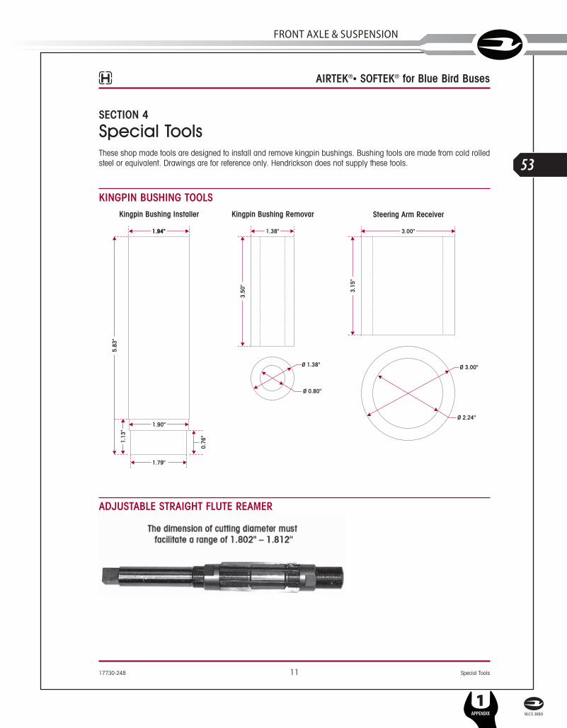
Special ToolsThese shop made tools are designed to install and remove kingpin bushings. Bushing tools are made from cold rolledsteel or equivalent. Drawings are for reference only. Hendrickson does not supply these tools.
KINGPIN BUSHING TOOLS
ADJUSTABLE STRAIGHT FLUTE REAMER
17730-248 11 Special Tools
AIRTEK®• SOFTEK® for Blue Bird Buses
SERVICE MANUAL
L
53
FRonT AxlE & SuSPEnSion
1APPENDIX

SECTION 5
Parts ListBlue Bird Vision Buses - 10K Capacity
Parts Lists 12 17730-248
L
54
1APPENDIX
SERVICE MANUAL

1 64075-002L Air Spring 22 60850-001 Air Spring Bracket 2
59427-008 HCV, Link Mount & Linkage Assembly 1(Includes Key Nos. 3-11)
3 59935-004 Height Control Valve 14 59428-006 HCV Linkage (Replaces 59428-001) 1
64742-001 Link Mount Service Kit(Includes Key Nos. 5-6)
5 *5⁄16"-18 UNC Stud - 2.07" 16 *5⁄16"-18 UNC Stud - 2.44" 17 *5⁄16"-18 UNC Hex Nut 28 *5⁄16" Hardened Washer 29 *5⁄16"-18 UNC Locknut 210 *¼" Hardened Washer 211 *¼"-20 UNC Locknut 212 58913-009L Shock Absorber (Replaces 58913-008) 213 **¾"-10 UNC Upper Shock Bolt 214 **¾"-10 UNC Lower Shock Bolt 215 **¾" Hardened Washer 816 **¾"-10 UNC Hex Locknut 417 59946-001 Shock Spacer 218 59423-002 Shock Bracket 2
60961-163 Leaf Spring Assembly Service KitFor vehicles built prior to 11/06(Includes Key Nos. 19a, 24a, 25)
Leaf Spring Assembly 219a 66805-001 For vehicles built after 11/0619b 60512-000 For vehicles built prior to 11/0620 64488-002 Front Hanger (Replaces 64488-000) 221 **M20 Hex Bolt - 170mm 222 **M20 Hardened Washer 423 **M20 Locknut 2
Rear Shackle Bracket 224a 66510-001 For vehicles built after 11/0624b 64316-000 For vehicles built prior to 11/0625 64314-000 Rear Shackle Plate 426 64159-000 Thrust Washer 4
Only for vehicles built prior to 11/0627 **M20 Hex Bolt - 150mm 428 **M20 Hardened Washer 829 **M20 Locknut 4
60952-XXX Axle Assembly (Includes Key Nos. 30-55) 1Contact Hendrickson Tech Serv. for Part No.
30 64905-004 Axle & Kingpin Assembly 16.5", 8.5" Ride Height
31 LH Lower Steering Knuckle Assembly 158900-035 150 Ackermann Air Brake58900-033 200 Ackermann Air Brake58900-031 250 Ackermann Air Brake58900-055 150 Ackermann Hydraulic Brake58900-053 200 Ackermann Hydraulic Brake58900-051 250 Ackermann Hydraulic Brake
32 RH Lower Steering Knuckle Assembly 158900-036 150 Ackermann Air Brake58900-034 200 Ackermann Air Brake58900-032 250 Ackermann Air Brake58900-056 150 Ackermann Hydraulic Brake58900-054 200 Ackermann Hydraulic Brake58900-052 250 Ackermann Hydraulic Brake
33 60903-016 LH Upper Steering Knuckle Assembly 134 60904-002 RH Upper Steering Knuckle Assembly 1
60961-040 Kingpin Bushing and Bearing Service Kit,Axle Set(Includes Kit Nos. 60961-009 & -039)
60961-009 LH Kingpin Bushing w/Composite Thrust Bearing Service Kit(Includes Key Nos.35-38, 40-42, Loctite)
60961-039 RH Kingpin Bushing w/Roller ThrustBearing Service Kit(Includes Key Nos.35-37, 39-42, Loctite)
35 59156-000 Grease Cap Assembly 436 58937-000 Retaining Ring 437 58909-000 Kingpin Bushing 4
60961-043 Thrust Bearing Service Kit, Axle Set (Includes Kit Nos. 60961-041 & 60961-042)
60961-041 LH Composite Thrust Bearing Service Kit(Includes Key Nos. 38, 40-42, Loctite)
60961-042 RH Roller Thrust Bearing Service Kit(Includes Key Nos. 39-42, Loctite)
38 59828-000 LH Composite Thrust Bearing 139 64256-000 RH Roller Thrust Bearing 140 60259-002 Kingpin Shim - 0.047" 2
Not Shown 60259-001 Kingpin Shim - 0.005" (As needed for service)41 58910-000 Kingpin Seal 442 60236-001 5⁄8"-11 UNC Socket Head Cap Screw 4
Not Shown 60937-000 Loctite (Red) Compound Tube 143 64246-000 ABS Sensor Sleeve 244 ***Tie Rod Assembly, 10K, 5.36 Drop 1
(Includes Key Nos. 45-49)66699-003 200 Ackermann (Replaces 59948-005)66699-001 250 Ackermann (Replaces 59948-006)
45 *7⁄8" Castle Nut 260961-139 ***Tie Rod End Service Kit, Axle Set
(Replaces 60961-012)(Includes Kit Nos. 60961-137 & -138)
60961-137 ***LH Tie Rod End Service Kit(Replaces 60961-029)(Includes Key Nos. 46, 48-49)
60961-138 ***RH Tie Rod End Service Kit(Replaces 60961-030)(Includes Key Nos. 47-49)
46 66645-001 ***LH Tie Rod End (Replaces 64004-001) 147 66645-002 ***RH Tie Rod End (Replaces 64004-002) 148 22962-007 7⁄8" Flat Washer 249 17800-004 Tie Rod Nut Cotter Pin 2
60961-069 Stop Bolt Service Kit, One Side(Includes Key Nos. 50-51)
50 60238-001 ½"-13 UNC Square Head Bolt 251 60240-000 ½"-13 UNC Hex Jam Nut 252 59952-003 Top Axle Wrap 253 64722-003 Bottom Axle Wrap 2
60961-015 Top/Bottom Axle Wrap Liner Service Kit,One Side (Includes Key Nos. 54-55)
54 60508-000 Top Axle Wrap Liner 255 59845-000 Bottom Axle Wrap Liner 2
Clamp Group Service Kit, One Side(Includes Key Nos. 56-58)
60961-051 6.5" Ride Height 60961-052 8.5" Ride Height
56 ¾"-16 UNF Hex bolt 821867-044 6.5" Ride Height - 10.0"21867-045 8.5" Ride Height - 12.0"
57 22962-001 ¾" Flat Washer 858 17700-035 ¾"-16 UNF 2B Nylon Locknut 8
Not Shown 18831-021 Dowel Pin, 8.5" Ride Height - 2.0" 259 Top Pad
64516-001 LH 164516-002 RH 1
60 Front Axle Spacer64536-010 LH 6.5" Ride Height 164536-060 LH 8.5" Ride Height 1
Not Shown 64536-050 RH 8.5" Ride Height 1
AIRTEK® for Blue Bird Vision Buses - 10K Capacity
17730-248 13 Parts Lists
KEY NO. PART NO. DESCRIPTION NO.REQ. KEY NO. PART NO. DESCRIPTION NO.REQ.
SERVICE MANUAL
L
55
FRonT AxlE & SuSPEnSion
1APPENDIX

Blue Bird Vision Buses - 8K/10K Capacity
For vehicles builtprior to 11/06
1011
9 11 1245
49
488a
5024 7
4 51
54
643
414
3
13a
17 16
1617
14
1417
18
17
1211
910
11
45 24
74
5
1
49
48
4 5
3 4
41
43
6
13a
17 18
181714
8a
16
16 17
17
1425
24
26 23
21 3231
34
373839 40
26
24
25
3029
2830
44
42
44
42
46
47
46
4747
4646
47
36
33
19
35
30
29
2730
25
24
2622
203231
26
24
25
34
37 3839
40
8b
13b
1718
1817141515
14
1716
For 8K vehiclesbuilt prior to 2/07
51
51
52
45
8b
Parts Lists 14 17730-248
L
56
1APPENDIX
SERVICE MANUAL

SOFTEK® for Blue Bird Vision Buses - 8K/10K Capacity
1 58913-009L Shock Absorber (Replaces 58913-007) 22 **¾"-10 UNC Upper Shock Bolt 23 **¾"-10 UNC Lower Shock Bolt 24 **¾" Hardened Washer 85 **¾"-10 UNC Hex Locknut 46 59946-001 Shock Spacer 27 59423-002 Shock Bracket 2
Leaf Spring Assembly Service KitFor vehicles built after11/06(Includes Key Nos. 8a, 13a, 14)
60961-161 8K60961-162 10K
Leaf Spring Assembly 28a For vehicles built after 11/06
66623-001 8K66624-001 10K
8b For vehicles built prior to 11/0666364-000 8K60511-000 10K
9 64488-002 Front Hanger (Replaces 64488-000) 210 **M20 Hex Bolt - 170mm 211 **M20 Hardened Washer 412 **M20 Locknut 2
Rear Shackle Bracket 213a 66510-001 For vehicles built after 11/0613b 64316-000 For vehicles built prior to 11/0614 64314-000 Rear Shackle Plate 415 64159-000 Thrust Washer 4
Only for vehicles built prior to 11/0616 **M20 Hex Bolt - 150mm 417 **M20 Hardened Washer 818 **M20 Locknut 4
60952-XXX STEERTEK Axle Assembly 1Contact Hendrickson Tech Serv. for Part No.(Includes Key Nos. 19-44)
19 64905-004 Axle & Kingpin Assembly 16.5", 8.5" Ride Height
20 LH Lower Steering Knuckle Assembly 158900-035 150 Ackermann Air Brake58900-033 200 Ackermann Air Brake58900-031 250 Ackermann Air Brake58900-055 150 Ackermann Hydraulic Brake58900-053 200 Ackermann Hydraulic Brake58900-051 250 Ackermann Hydraulic Brake
21 RH Lower Steering Knuckle Assembly 158900-036 150 Ackermann Air Brake58900-034 200 Ackermann Air Brake58900-032 250 Ackermann Air Brake58900-056 150 Ackermann Hydraulic Brake58900-054 200 Ackermann Hydraulic Brake58900-052 250 Ackermann Hydraulic Brake
22 60903-016 LH Upper Steering Knuckle Assembly 123 60904-002 RH Upper Steering Knuckle Assembly 1
60961-040 Kingpin Bushing and Bearing Service Kit,Axle Set(Includes Kit Nos. 60961-009 & -039)
60961-009 LH Kingpin Bushing w/Composite Thrust Bearing Service Kit(Includes Key Nos. 24-27, 29-31, Loctite)
60961-039 RH Kingpin Bushing w/Roller Thrust Bearing Service Kit(Includes Key Nos. 24-26, 28-31, Loctite)
24 59156-000 Grease Cap Assembly 425 58937-000 Retaining Ring 426 58909-000 Kingpin Bushing 4
60961-043 Thrust Bearing Service Kit, Axle Set(Includes Kit Nos. 60961-041& -042)
60961-041 LH Composite Thrust Bearing Service Kit(Includes Key Nos. 27, 29-31, Loctite)
60961-042 RH Roller Thrust Bearing Service Kit(Includes Key Nos. 28-31, Loctite)
27 59828-000 LH Composite Thrust Bearing 128 64256-000 RH Roller Thrust Bearing 129 60259-002 Kingpin Shim - 0.047" 2
Not Shown 60259-001 Kingpin Shim - 0.005" (As needed for service)30 58910-000 Kingpin Seal 431 60236-001 5⁄8"-11 UNC Socket Head Cap Screw 4
Not Shown 60937-000 Loctite (Red) Compound Tube 132 64246-000 ABS Sensor Sleeve 233 ***Tie Rod Assembly, 10K, 5.36 Drop 1
(Includes Key Nos. 34-38)66699-003 200 Ackermann (Replaces 59948-005)66699-001 250 Ackermann (Replaces 59948-006)
34 *7⁄8" Castle Nut 260961-139 ***Tie Rod End Service Kit, Axle Set
(Replaces 60961-012)(Includes Kit Nos. 60961-137 & -138)
60961-137 ***LH Tie Rod End Service Kit (Replaces 60961-029)(Includes Key Nos. 35, 37-38)
60961-138 ***RH Tie Rod End Service Kit(Replaces 60961-030)(Includes Key Nos. 36-38)
35 66645-001 ***LH Tie Rod End (Replaces 64004-001) 136 66645-002 ***RH Tie Rod End (Replaces 64004-002) 137 22962-007 7⁄8" Flat Washer 238 17800-004 Tie Rod Nut Cotter Pin 2
60961-069 Stop Bolt Service Kit, One Side(Includes Key Nos. 39-40)
39 60238-001 ½"-13 UNC Square Head Bolt 240 60240-000 ½"-13 UNC Hex Jam Nut 241 59952-003 Top Axle Wrap 242 64722-003 Bottom Axle Wrap 2
60961-015 Top/Bottom Axle Wrap Liner Service Kit,One Side (Includes Key Nos. 43-44)
43 60508-000 Top Axle Wrap Liner 244 59845-000 Bottom Axle Wrap Liner 2
Clamp Group Service Kit, One side(Includes Key Nos. 45-47)
60961-140 6.5" Ride Height60961-141 8.5" Ride Height
45 ¾"-16 UNF U-bolt 464804-110 6.5" Ride Height - 11.0" 64804-130 8.5" Ride Height - 13.0"
46 22962-001 ¾" Flat Washer 847 17700-035 ¾"-16 UNF 2B Nylon Locknut 8
Not Shown 18831-021 Dowel Pin, 8.5" Ride Height - 2.0" 164506-000 Top Pad/Axle Stop Assembly
(Includes Key Nos. 48-49)48 64519-000 Top Pad 249 64080-000 Rubber Axle Stop 250 Front Axle Spacer
64536-010 LH 6.5" Ride Height 164536-060 LH 8.5" Ride Height 1
Not Shown 64536-050 RH 8.5" Ride Height 151 66164-000 Thrust Pad Washer 2
For 8K vehicles built prior to 2/0752 66366-001 Clamp Group Spacer 4
For 8K vehicles built prior to 2/07
KEY NO. PART NO. DESCRIPTION NO.REQ. KEY NO. PART NO. DESCRIPTION NO.REQ.
17730-248 15 Parts Lists
SERVICE MANUAL
L
57
FRonT AxlE & SuSPEnSion
1APPENDIX
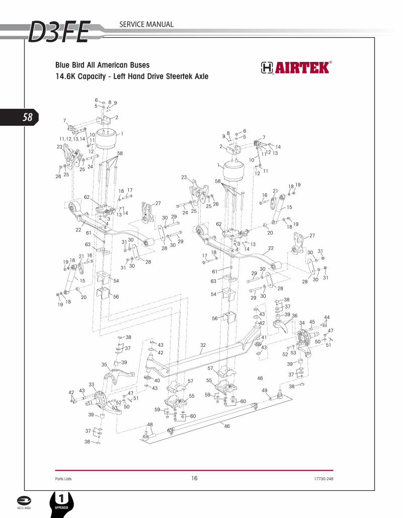
Blue Bird All American Buses14.6K Capacity - Left Hand Drive Steertek Axle
Parts Lists 16 17730-248
L
58
1APPENDIX
SERVICE MANUAL

AIRTEK® for Blue Bird All American Buses - 14.6K Capacity
1 66865-002L Air Spring 22 66807-001 Air Spring Bracket 23 22962-014 ½" Hardened Washer 24 17730-015 ½"-13 UNC Nylon Locknut 25 **¾" Hardened Washer 26 **¾"-10 UNC Nylon Locknut 2
59013-000 Height Control Valve Assembly 2(Includes Key Nos. 7-9)
7 60501-000 Height Control Valve 28 22962-028 ¼" Hardened Washer 49 49983-000 ¼"-20 UNC Locknut 4
66825-001 HCV Linkage Assembly 2(Includes Key Nos. 10-14)
10 59428-005 HCV Linkage 211 *5⁄16"-18 UNC Stud - 2.44" 412 *5⁄16"-18 UNC Hex Nut 413 *5⁄16" Hardened Washer 414 *5⁄16"-18 UNC Locknut 415 58913-011L Shock Absorber 216 **¾"-10 UNC Upper Shock Bolt 217 **¾"-10 UNC Lower Shock Bolt 218 **¾" Hardened Washer 619 **¾"-10 UNC Hex Locknut 420 59946-006 Shock Spacer 221 65000-002 Shock Bracket 222 66805-001 Leaf Spring Assembly 223 64488-002 Front Hanger 224 **M20 Hex Bolt - 170mm 225 **M20 Hardened Washer 426 **M20 Locknut 227 66510-001 Rear Shackle Bracket 228 64314-000 Rear Shackle Plate 429 **M20 Hex Bolt - 150mm 430 **M20 Hardened Washer 831 **M20 Locknut 4
60952-XXX Axle Assembly (Includes Key Nos. 32-57) 1Contact Hendrickson Tech Serv. for Part No.
32 Axle & Kingpin Assembly 16.8", 7.8", 8.8" and 9.8" Ride Height
64905-004 13.2K64905-007 14.6K
33 LH Lower Steering Knuckle Assembly 158900-035 150 Ackermann Air Brake58900-033 200 Ackermann Air Brake58900-031 250 Ackermann Air Brake58900-055 150 Ackermann Hydraulic Brake58900-053 200 Ackermann Hydraulic Brake58900-051 250 Ackermann Hydraulic Brake
34 RH Lower Steering Knuckle Assembly 158900-036 150 Ackermann Air Brake58900-034 200 Ackermann Air Brake58900-032 250 Ackermann Air Brake58900-056 150 Ackermann Hydraulic Brake58900-054 200 Ackermann Hydraulic Brake58900-052 250 Ackermann Hydraulic Brake
35 60903-055 LH Upper Steering Knuckle Assembly 136 60904-002 RH Upper Steering Knuckle Assembly 1
60961-040 Kingpin Bushing and Bearing Service Kit,Axle Set(Includes Kit Nos. 60961-009 & -039)
60961-009 LH Kingpin Bushing w/Composite Thrust Bearing Service Kit(Includes Key Nos.37-40, 42-44, Loctite)
60961-039 RH Kingpin Bushing w/Roller ThrustBearing Service Kit(Includes Key Nos.37-39, 41-44, Loctite)
37 59156-000 Grease Cap Assembly 438 58937-000 Retaining Ring 439 58909-000 Kingpin Bushing 4
60961-043 Thrust Bearing Service Kit, Axle Set (Includes Kit Nos. 60961-041 & 60961-042)
60961-041 LH Composite Thrust Bearing Service Kit(Includes Key Nos. 40, 42-44, Loctite)
60961-042 RH Roller Thrust Bearing Service Kit(Includes Key Nos. 41-44, Loctite)
40 59828-000 LH Composite Thrust Bearing 141 64256-000 RH Roller Thrust Bearing 142 60259-002 Kingpin Shim - 0.047" 2
Not Shown 60259-001 Kingpin Shim - 0.005" (As needed for service)43 58910-000 Kingpin Seal 444 60236-001 5⁄8"-11 UNC Socket Head Cap Screw 4
Not Shown 60937-000 Loctite (Red) Compound Tube 145 64246-000 ABS Sensor Sleeve 246 ***Tie Rod Assembly, 14.6K, 5.36 Drop 1
(Includes Key Nos. 47-51)64006-002 150/200 Ackermann64006-003 250 Ackermann
47 *7⁄8" Castle Nut 260961-011 Tie Rod End Service Kit, Axle Set
(Includes Kit Nos. 60961-027 & -028)60961-027 LH Tie Rod End Service Kit
(Includes Key Nos. 48, 50-51)60961-028 RH Tie Rod End Service Kit
(Includes Key Nos. 49-51)48 64002-001 LH Tie Rod End 149 64002-002 RH Tie Rod End 150 22962-007 7⁄8" Flat Washer 251 17800-004 Tie Rod Nut Cotter Pin 2
60961-069 Stop Bolt Service Kit, One Side(Includes Key Nos. 52-53)
52 60238-001 ½"-13 UNC Square Head Bolt 253 60240-000 ½"-13 UNC Hex Jam Nut 254 59952-026 Top Axle Wrap 255 64722-003 Bottom Axle Wrap 2
60961-015 Top/Bottom Axle Wrap Liner Service Kit,One Side (Includes Key Nos. 56-57)
56 60508-000 Top Axle Wrap Liner 257 59845-000 Bottom Axle Wrap Liner 2
Clamp Group Service Kit, One side(Includes Key Nos. 58-60)
60961-051 6.8" Ride Height 60961-146 7.8" Ride Height 60961-052 8.8" Ride Height 60961-147 9.8" Ride Height
58 ¾"-16 UNF Hex bolt 821867-044 6.8" Ride Height - 10.0"21867-027 7.8" Ride Height - 11.0"21867-045 8.8" Ride Height - 12.0"21867-035 9.8" Ride Height - 13.0"
59 22962-001 ¾" Flat Washer 860 17700-035 ¾"-16 UNF 2B Nylon Locknut 861 Dowel Pin
6.8" Ride Height None Req.18831-022 7.8" Ride Height - 1.13" 218831-021 8.8" Ride Height - 2.0" 218831-023 9.8" Ride Height - 3.0" 2
62 Top Pad66814-001 LH 166814-002 RH 1
63 LH/RH Front Axle Spacer6.8" Ride Height None Req.
64536-025 7.8" Ride Height 264536-050 8.8" Ride Height 264536-075 9.8" Ride Height 2
KEY NO. PART NO. DESCRIPTION NO.REQ. KEY NO. PART NO. DESCRIPTION NO.REQ.
17730-248 17 Parts Lists
SERVICE MANUAL
L
59
FRonT AxlE & SuSPEnSion
1APPENDIX

Blue Bird All American Buses13.2K/14.6K Capacity - Left Hand Drive Steertek Axle
Parts Lists 18 17730-248
L
60
1APPENDIX
SERVICE MANUAL

SOFTEK® for Blue Bird All American Buses - 13.2K/14.6K Capacity
1 58913-010L Shock Absorber 22 **¾"-10 UNC Upper Shock Bolt 23 **¾"-10 UNC Lower Shock Bolt 24 **¾" Hardened Washer 65 **¾"-10 UNC Hex Locknut 46 59946-001 Shock Spacer 27 65000-002 Shock Bracket 28 Leaf Spring Assembly 2
66625-001 13.2K66626-001 14.6K
9 64488-002 Front Hanger 210 **M20 Hex Bolt - 170mm 211 **M20 Hardened Washer 412 **M20 Locknut 213 66510-001 Rear Shackle Bracket 214 64314-000 Rear Shackle Plate 415 **M20 Hex Bolt - 150mm 416 **M20 Hardened Washer 817 **M20 Locknut 4
60952-XXX STEERTEK Axle Assembly 1Contact Hendrickson Tech Serv. for Part No.(Includes Key Nos. 18-43)
18 Axle & Kingpin Assembly 16.8", 7.8", 8.8" and 9.8" Ride Height
64905-002 13.2K64905-005 14.6K
19 LH Lower Steering Knuckle Assembly 158900-035 150 Ackermann Air Brake58900-033 200 Ackermann Air Brake58900-031 250 Ackermann Air Brake58900-055 150 Ackermann Hydraulic Brake58900-053 200 Ackermann Hydraulic Brake58900-051 250 Ackermann Hydraulic Brake
20 RH Lower Steering Knuckle Assembly 158900-036 150 Ackermann Air Brake58900-034 200 Ackermann Air Brake58900-032 250 Ackermann Air Brake58900-056 150 Ackermann Hydraulic Brake58900-054 200 Ackermann Hydraulic Brake58900-052 250 Ackermann Hydraulic Brake
21 60903-055 LH Upper Steering Knuckle Assembly 122 60904-002 RH Upper Steering Knuckle Assembly 1
60961-040 Kingpin Bushing and Bearing Service Kit,Axle Set(Includes Kit Nos. 60961-009 & -039)
60961-009 LH Kingpin Bushing w/Composite Thrust Bearing Service Kit(Includes Key Nos. 23-26, 28-30, Loctite)
60961-039 RH Kingpin Bushing w/Roller Thrust Bearing Service Kit(Includes Key Nos. 23-25, 27-30, Loctite)
23 59156-000 Grease Cap Assembly 424 58937-000 Retaining Ring 425 58909-000 Kingpin Bushing 4
60961-043 Thrust Bearing Service Kit, Axle Set(Includes Kit Nos. 60961-041& -042)
60961-041 LH Composite Thrust Bearing Service Kit(Includes Key Nos. 26, 28-30, Loctite)
60961-042 RH Roller Thrust Bearing Service Kit(Includes Key Nos. 27-30, Loctite)
26 59828-000 LH Composite Thrust Bearing 127 64256-000 RH Roller Thrust Bearing 128 60259-002 Kingpin Shim - 0.047" 2
Not Shown 60259-001 Kingpin Shim - 0.005" (As needed for service)29 58910-000 Kingpin Seal 430 60236-001 5⁄8"-11 UNC Socket Head Cap Screw 4
Not Shown 60937-000 Loctite (Red) Compound Tube 131 64246-000 ABS Sensor Sleeve 2
32 Tie Rod Assembly, 14.6K, 5.36 Drop 1(Includes Key Nos. 33-37)
64006-002 150/200 Ackermann64006-003 250 Ackermann
33 *7⁄8" Castle Nut 260961-011 Tie Rod End Service Kit, Axle Set
(Includes Kit Nos. 60961-027 & -028)60961-027 LH Tie Rod End Service Kit
(Includes Key Nos. 34, 36-37)60961-028 RH Tie Rod End Service Kit
(Includes Key Nos. 35-37)34 64002-001 LH Tie Rod End 135 64002-002 RH Tie Rod End 136 22962-007 7⁄8" Flat Washer 237 17800-004 Tie Rod Nut Cotter Pin 2
60961-069 Stop Bolt Service Kit, One Side(Includes Key Nos. 38-39)
38 60238-001 ½"-13 UNC Square Head Bolt 239 60240-000 ½"-13 UNC Hex Jam Nut 240 59952-026 Top Axle Wrap 241 64722-003 Bottom Axle Wrap 2
60961-015 Top/Bottom Axle Wrap Liner Service Kit, One Side (Includes Key Nos. 42-43)
42 60508-000 Top Axle Wrap Liner 243 59845-000 Bottom Axle Wrap Liner 2
Clamp Group Service Kit, One side(Includes Key Nos. 44-46)
60961-142 6.8" Ride Height60961-143 7.8" Ride Height60961-144 8.8" Ride Height60961-145 9.8" Ride Height
44 ¾"-16 UNF U-bolt 464804-120 6.8" Ride Height - 12.0" 64804-130 7.8" Ride Height - 13.0" 64804-140 8.8" Ride Height - 14.0" 64804-150 9.8" Ride Height - 15.0"
45 22962-001 ¾" Flat Washer 846 17700-035 ¾"-16 UNF 2B Nylon Locknut 847 Dowel Pin
6.8" Ride Height None Req.18831-022 7.8" Ride Height - 1.13" 218831-021 8.8" Ride Height - 2.0" 218831-023 9.8" Ride Height - 3.0" 266806-001 Top Pad/Axle Stop Assembly
(Includes Key Nos. 48-49)48 66666-000 Top Pad 249 64080-000 Rubber Axle Stop 250 LH Front Axle Spacer 1
64536-010 6.8" Ride Height64536-035 7.8" Ride Height64536-060 8.8" Ride Height64536-085 9.8" Ride Height
51 RH Front Axle Spacer 16.8" Ride Height None Req.
64536-025 7.8" Ride Height64536-050 8.8" Ride Height64536-075 9.8" Ride Height
KEY NO. PART NO. DESCRIPTION NO.REQ. KEY NO. PART NO. DESCRIPTION NO.REQ.
17730-248 19 Parts Lists
SERVICE MANUAL
L
61
FRonT AxlE & SuSPEnSion
1APPENDIX

13.2K/14.6K Capacity
Right Hand Drive for Blue Bird All American Buses
STEERTEK Axle Assembly 1(Includes Key Nos. 1-25)
67905-402 SOFTEK Standard Drop - 13.2K67905-404 AIRTEK Deep Drop - 13.2K67905-405 SOFTEK Standard Drop - 14.6K67905-407 AIRTEK Deep Drop - 14.6K
1 LH Lower Steering Knuckle Assembly 158900-035 150 Ackermann Air Brake58900-033 200 Ackermann Air Brake58900-031 250 Ackermann Air Brake58900-055 150 Ackermann Hydraulic Brake58900-053 200 Ackermann Hydraulic Brake58900-051 250 Ackermann Hydraulic Brake
2 RH Lower Steering Knuckle Assembly 158900-036 150 Ackermann Air Brake58900-034 200 Ackermann Air Brake58900-032 250 Ackermann Air Brake58900-056 150 Ackermann Hydraulic Brake58900-054 200 Ackermann Hydraulic Brake58900-052 250 Ackermann Hydraulic Brake
3 60904-001 LH Upper Steering Knuckle Assembly 14 70903-001 RH Upper Steering Knuckle Assembly 1
60961-040 Kingpin Bushing and Bearing Service Kit,Axle Set(Includes Kit Nos. 60961-009 & -039)
60961-009 RH Kingpin Bushing w/Composite Thrust Bearing Service Kit(Includes Key Nos. 5-8, 10-12, Loctite)
60961-039 LH Kingpin Bushing w/Roller Thrust Bearing Service Kit(Includes Key Nos. 5-7, 9-12, Loctite)
5 59156-000 Grease Cap Assembly 46 58937-000 Retaining Ring 47 58909-000 Kingpin Bushing 4
60961-043 Thrust Bearing Service Kit, Axle Set(Includes Kit Nos. 60961-041& -042)
60961-041 RH Composite Thrust Bearing Service Kit(Includes Key Nos. 8, 10-12, Loctite)
60961-042 LH Roller Thrust Bearing Service Kit(Includes Key Nos. 9-12, Loctite)
8 59828-000 RH Composite Thrust Bearing 19 64256-000 LH Roller Thrust Bearing 110 60259-002 Kingpin Shim - 0.047" 2
Not Shown 60259-001 Kingpin Shim - 0.005" (As needed for service)11 58910-000 Kingpin Seal 412 60236-001 5⁄8"-11 UNC Socket Head Cap Screw 4
Not Shown 60937-000 Loctite (Red) Compound Tube 113 64246-000 ABS Sensor Sleeve 214 Tie Rod Assembly, 13.2K 1
(Includes Key Nos. 15-19)60239-005 150/200 Ackermann 60239-001 250 Ackermann
15 *7⁄8" Castle Nut 260961-010 Tie Rod End Service Kit, Axle Set
(Includes Kit Nos. 60961-025 & -026)60961-025 LH Tie Rod End Service Kit
(Includes Key Nos. 16, 18-19)60961-026 RH Tie Rod End Service Kit
(Includes Key Nos. 17-19)16 64000-001 LH Tie Rod End 117 64000-002 RH Tie Rod End 118 22962-007 7⁄8" Flat Washer 219 17800-004 Tie Rod Nut Cotter Pin 2
60961-069 Stop Bolt Service Kit, One Side(Includes Nos. 20-21)
20 60238-001 ½"-13 UNC Square Head Bolt 221 60240-000 ½"-13 UNC Hex Jam Nut 222 59952-026 Top Axle Wrap - 13.2K 2
59952-031 Top Axle Wrap - 14.6K23 64722-003 Bottom Axle Wrap 2
60961-015 Top/Bottom Axle Wrap Liner Service Kit, One Side (Includes Nos. 24-25)
24 60508-000 Top Axle Wrap Liner 225 59845-000 Bottom Axle Wrap Liner 2
Parts Lists 20 17730-248
KEY NO. PART NO. DESCRIPTION NO.REQ. KEY NO. PART NO. DESCRIPTION NO.REQ.
NOTE: * Item included in assembly only, part not sold separately.** Not supplied by Hendrickson, used for reference only. Refer to OEM (vehicle manufacturer) for more information. Hendrickson is not responsible
for components supplied by vehicle manufacturer. For assistance with maintenance and rebuild instructions on these components see vehiclemanufacturer.
*** Hendrickson supplies different tie rod assemblies and each type may take a different replacement tie rod end kit to service. Prior to ordering, findthe part number on the tie rod tube, reference Hendrickson Publication No. SEU-0223 or contact Hendrickson Sales Engineering 630.910.2800for corre spon ding kit numbers.
NOTE: Quantities of service kit components may vary from amount shown in lists.
L
62
1APPENDIX
SERVICE MANUAL
SECTION 6
On Highway and On Roadway Recommended Towing Procedure
Hendrickson recommends that a vehicle equipped with a STEERTEK axle be towed by the following methods (listed in order of preference) for ON HIGHWAY or ON ROADWAY applications.
1. Wheel lift method, the ideal towing procedure
2. Towing the vehicle from the rear method
3. Conventional axle fork method
Please read, understand and comply with any additional towing instructions and safety pre-cautions that may be provided by the vehicle manufacturer.
Hendrickson will not be responsible for any damage to the axle, suspension or other vehiclecomponents resulting from any towing method or fixture not authorized by Hendrickson.
Please contact Hendrickson Tech Services at 630.910.2800 or send email to: [email protected] with any questions regarding proper towing proceduresfor vehicles equipped with a STEERTEK axle.
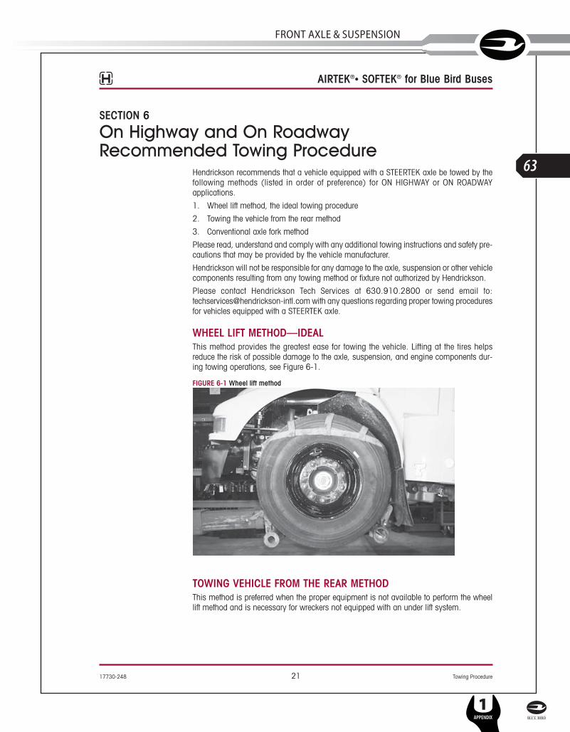
WHEEL LIFT METHOD—IDEALThis method provides the greatest ease for towing the vehicle. Lifting at the tires helpsreduce the risk of possible damage to the axle, suspension, and engine components dur-ing towing operations, see Figure 6-1.
FIGURE 6-1 Wheel lift method
TOWING VEHICLE FROM THE REAR METHODThis method is preferred when the proper equipment is not available to perform the wheellift method and is necessary for wreckers not equipped with an under lift system.
AIRTEK®• SOFTEK® for Blue Bird Buses
17730-248 21 Towing Procedure
SERVICE MANUAL
L
63
FRonT AxlE & SuSPEnSion
1APPENDIX

Towing Procedure 22 17730-248
AIRTEK®• SOFTEK® for Blue Bird Buses
AXLE FORK LIFT METHODThis is an alternative method for towing the vehicle, but requires standard 5" forks, (seeFigures 6-2 and 6-3) and designated lift points inside the axle clamp groups. The follow-ing procedure must be used:■ Place a spacer on the boom, to provide adequate clearance between the oil pan and
the boom if necessary. Lift the vehicle in order to place spacer under tires. This will pro-vide sufficient room under the axle to locate forks in the proper position.
■ Install the fork in the boom properly.■ Position the tow forks directly under the axle, inside the axle clamp groups as shown
in Figure 6-2. FIGURES 6-2 AND 6-3 PROPER TOW FORK LOCATION ON INSIDE CLAMP GROUP ON THE STEERTEK AXLE
■ Prior to lifting the vehicle, ensure that the bottom axle plate is flat in the tow fork to minimize any gap between the bottom axle plate and the tow fork, see Figure 6-4 and6-5. It may be necessary to deflate the air in the steer axle suspension, and/or releasethe tractor brakes. Deflate the steer axle air springs by disconnecting the height controlvalve linkage and lowering the height control valve linkage arm. This will exhaust theair pressure in the steer axle air springs.
FIGURE 6-4 WITHOUT GAP FIGURE 6-5 WITH GAP
NOTE When lifting a vehicle with an under lift boom, care must be taken not to damage theengine’s oil pan. Vehicles equipped with a front fairing may require removal of the frontfairing prior to towing to prevent component damage.
■ Lift vehicle and secure the vehicle to the boom. ■ Install safety straps, it is preferred to use nylon safety straps. Chains have a tendency
to bind and may cause damage to the axle.
L
64
1APPENDIX
SERVICE MANUAL

17730-248 23 Towing Procedure
AIRTEK®• SOFTEK® for Blue Bird Buses
OFF ROADWAY TOWING METHODWHEN A VEHICLE IS DISABLED AND EQUIPPED WITH A STEERTEK AXLE, CARE MUST BETAKEN TO ENSURE THERE IS NO DAMAGE TO THE SUSPENSION OR AXLE WHEN TOWING THEVEHICLE. THE USE OF A TOW STRAP IS NECESSARY TO TOW A DISABLED VEHICLE INTO AREPAIR FACILITY PARKING LOT INTO THE SHOP BAY. THE TOW STRAPS SHOULD BECONNECTED TO THE TOW HOOKS PROVIDED BY THE VEHICLE MANUFACTURER AT THEFRONT OF THE BUMPER. IF THE USE OF TOW HOOKS IS NOT AN OPTION THEN A TOW STRAPMAY BE WRAPPED AROUND THE FRONT AXLE, (SEE FIGURE 6-6) IN A MANNER THAT ISACCEPTABLE FOR TOWING THE VEHICLE INTO THE SHOP. DO NOT USE A TOW CHAINAROUND THE FRONT AXLE TO TOW THE VEHICLE, DOING SO WILL DAMAGE THE AXLE ANDVOID WARRANTY, (SEE FIGURE 6-7) .
THE FOLLOWING METHODS ARE NOT RECOMMENDED FOR: ON HIGHWAY OR ON ROADWAY TOWING
FIGURE 6-6
NYLON STRAPS ARE ACCEPTABLE FOR OFF ROADWAY TOWING
FIGURE 6-7
CHAINS ARE NOT ACCEPTABLE FOROFF ROADWAY TOWING
SERVICE MANUAL
L
65
FRonT AxlE & SuSPEnSion
1APPENDIX
Preventive Maintenance 24 17730-248
AIRTEK®• SOFTEK® for Blue Bird Buses
SECTION 7
Preventive MaintenanceFollowing appropriate inspection procedure is important to help ensure the proper mainte-nance and operation of the AIRTEK®/SOFTEK® suspension system and component partsfunction to their highest efficiency.HENDRICKSON RECOMMENDED PREVENTIVE MAINTENANCE INTERVALS■ The first 1,000 miles■ On-highway – every 25,000 miles (40,000 km) or 6 months, whichever comes first
COMPONENT INSPECTION■ Air spring — Look for chaffing or any signs of spring or component damage.■ Clamp group — Check torque on clamp group mounting hardware. Refer to Torque
Specifications in the appendix of this publication.■ Fasteners — Look for any loose or damaged fasteners on the entire suspension. Make
sure all fasteners are tightened to the specified torque. Refer to Torque Specificationsin the appendix. Use a calibrated torque wrench to check torque in a tightening direc-tion. As soon as the fastener starts to move, record the torque. Correct the torque ifnecessary. Replace any worn or damaged fasteners.
■ Front hangers and shackle brackets — Check for cracks or loose mounting hardware.Replace if necessary, see the Component Replacement Section of this publication forreplacement procedure.
■ Operation — All steering components must move freely through the full range of motionfrom axle stop to axle stop.
■ Shock absorber — Look for any signs of dents or leakage, misting is not considered aleak. See Shock Absorber Inspection in this section.
■ Steel leaf spring and wrap leaf assembly — Look for cracks. Check the front and rearbushings for any wear or deterioration. Replace spring assembly if any of the previousconditions are observed. See the Component Replacement Section of this publication forreplacement procedure.
■ STEERTEK Axle — The axle should be free of any nicks or gouges. Inspect for anycracks or dents on axle.
■ Steering pivot points — Check for looseness at all pivot points. Inspect and lubricate allpivot points. Refer to the Trouble Shooting Guide Section in the Appendix of this publication.
■ Thrust washers (If equipped) — Look for any signs of excessive wear to the thrust wash-ers, shackles and shackle bracket. See Thrust Washer Inspection detailed in this section.
■ Tire wear — Inspect tires for wear patterns that may indicate suspension damage ormisalignment. See Tire Inspection in this section.
■ Top and bottom axle wrap liners — Look for any cracking or broken pieces on liner inload bearing areas. See Axle Wrap Liner Inspection in this section.
■ Top pad (AIRTEK) — Check for cracks or damage. Replace if necessary, see theComponent Replacement Section of this publication for replacement procedure.
■ Top pad and bump stop (SOFTEK) — Check for cracks and/or missing rubber bumpstops. Replace if necessary, see the Component Replacement Section of this publicationfor replacement procedure.
■ Wear and damage — Inspect all parts of suspension for wear and damage. Look forbent or cracked parts. Replace all worn or damaged parts.
See vehicle manufacturer’s applicable publications for other preventative maintenancerequirements.
L
66
1APPENDIX
SERVICE MANUAL

17730-248 25 Preventive Maintenance
AIRTEK®• SOFTEK® for Blue Bird Buses
LUBRICATION INTERVALSFor vehicles equipped with the STEERTEK axle, regular lubrication intervals should be followed to help prevent premature wear to the kingpin bushings and tie rod ends, see lubri-cation chart below.
NOTE The recommended service lubrication interval is a guideline, the vehicle may requireincreased lubrication interval depending on severity of operation.
KINGPIN LUBRICATIONOn the Hendrickson STEERTEK front axle the kingpin grease fittings are located on the topand bottom of the kingpin grease caps.
1. Place the vehicle on a level floor.
2. Prior to greasing the kingpins on the vehicle, the suspension must be in a loadedcondition.
3. Clean off all the grease fittings and grease gun tip with a clean shop towel prior tolubrication.
4. Lubricate the kingpins through the grease fittings on the top and bottom of the steeringknuckle, see Lubrication Specification Matrix above.
5. Force the required lubricant into the upper and lower kingpin grease fittings, until newlubricant flows from the upper axle beam and knuckle and the thrust bearing purgelocation, see Figures 7-1 and 7-2.
NOTE Greasing at the lower zerk should purge grease from the thrust bearing shell. Both sidespurge in the same area. The left side of the axle has a composite style thrust bearing, seeFigure 7-1 and the right side of the axle has a steel roller thrust bearing, see Figure 7-2,for right hand drive axle configuration the thrust bearings will be the opposite.
FIGURE 7-1 FIGURE 7-2
STEERTEK GREASING AND LUBRICATION SPECIFICATIONS
Component Greasing Interval Grease NLGIGrade Outside Temperature
Kinpin BushingsMaximum of 25,000 miles
(40,225 kilometers) or 90 days, whichever
comes first.
MultipurposeGrease 2
Refer to the lubricant manufacturer’s specifications for the temperature service
limits applicable to your area.Tie Rod Ends
Drag Link See Vehicle Manufacturer
NOTE: Lubrication greases acceptable for use on the STEERTEK axle will carry a designation ofNLGI #2 EP and rated GC-LB or equivalent.
SERVICE MANUAL
L
67
FRonT AxlE & SuSPEnSion
1APPENDIX

Preventive Maintenance 26 17730-248
AIRTEK®• SOFTEK® for Blue Bird Buses
TIE ROD END LUBRICATION
LUBRICATION PROCEDURE1. Turn the vehicle wheels straight ahead.
2. Wipe the zerk fitting and grease gun tip with clean shop towels.
3. Wipe the seal/boot clean with shop towels.
4. Attach a grease gun to the zerk fitting. Either a hand or pneumatic grease gun is accept-able. If air operated grease gun is used, system air pressure should not exceed 150psi (1035 kPa).
EXCEEDING THE MAXIMUM AIR PRESSURE TO THE ZERK FITTING CAN CAUSE DAMAGE TO THEDUST BOOT AND COMPONENT FAILURE.
5. Dirt, water, and discolored old grease should flow from the relief vents or purge holesnear the boot crimp or bellows area, see Figure 7-3. Continue to purge grease untilfresh grease flows from the purge area.
FIGURE 7-3
6. If the tie rod end is designed for lube service and it will not accept grease proceed asfollows:
a. Remove the zerk fitting
b. Inspect the threaded zerk fitting hole in the tie rod end and remove any obstructions
c. Install a new zerk fitting
d. Continue the lubrication procedure
e. If the tie rod end will not accept grease following this procedure it will be neces-sary to replace the tie rod end, (see Tie Rod End replacement in the ComponentReplacement Section of this publication)
7. Apply grease until all the old grease is purged from the boot and fresh grease is com-ing out.
L
68
1APPENDIX
SERVICE MANUAL

17730-248 27 Preventive Maintenance
AIRTEK®• SOFTEK® for Blue Bird Buses
TIE ROD END INSPECTION
INSPECTION PROCEDUREBefore beginning this inspection procedure, the entire system must be unloaded (i.e., thefront end of the vehicle must be raised and supported with safety stands).
DO NOT GREASE THE TIE ROD ASSEMBLY BEFORE PERFORMING THE INSPECTION. DOING SOCAN INHIBIT EFFORTS TO DETERMINE ACTUAL WEAR.
REPLACE THE ENTIRE TIE ROD END IF THE BOOT IS TORN OR MISSING, FAILURE TO DO SOCAN CAUSE PREMATURE WEAR OF THE TIE ROD END.
1. Block rear wheels of vehicle. Using the bottom of the axle beam or the frame rails, raisethe front end off the ground and support with stands.
2. With the engine off, turn the wheels from full left to full right and then return to thestraight-ahead position.
3. Check that the boots are in place and completely installed over the tie rod ends.
4. Check for cracking or tears in the boots. Also check the boot seals for damage. Replacethe entire tie rod end if the boot is damaged.
THE CORRECT COTTER PIN MUST BE INSTALLED THROUGH THE TIE ROD END WITH THECASTLE NUT TIGHTENED TO THE PROPER TORQUE SPECIFICATION IN ORDER TO SECURELYATTACH THE TIE ROD. LOSS OF THE COTTER PIN CAN CAUSE THE TIE ROD END NUT TOBECOME LOOSE AND ADVERSELY AFFECT VEHICLE STEERING AND POSSIBLY RESULT IN TOTALLOSS OF STEERING CONTROL.
5. Check that the tie rod end nut is installed and secured with a cotter pin. If the cotter pinis missing, check the nut torque specification and then install a new cotter pin. Alwaystighten the castle nut to specified torque when setting the cotter pin. Do not back off thenut to insert cotter pin.
FIGURE 7-4
6. Check that the tie rod end isthreaded correctly into thecross tube and is engageddeeper than the end of thecross tube slot. The tie rodend must be visible the entirelength of the cross tube slot,see Figure 7-4.
7. Check that zerk fittings areinstalled. Replace a damagedzerk fitting with a new one.
DO NOT USE THE FOLLOWING ITEMS OR METHODS TO CHECK FOR MOVEMENT OF THE TIEROD ASSEMBLY. DAMAGE TO COMPONENTS CAN RESULT IF:
■ A CROW BAR, PICKLE FORK OR 2 x 4 ARE USED.
■ ANYTHING OTHER THAN HANDS ARE USED TO GRASP THE CROSS TUBE ASSEMBLY (CANRESULT IN DAMAGE TO THE CROSS TUBE).
■ EXCESSIVE PRESSURE OR FORCE IS APPLIED TO THE TIE ROD ENDS OR THE JOINTS OFTHE ASSEMBLY.
SERVICE MANUAL
L
69
FRonT AxlE & SuSPEnSion
1APPENDIX

Preventive Maintenance 28 17730-248
AIRTEK®• SOFTEK® for Blue Bird Buses
8. By hand or using a pipe wrench, with jaw protectors to avoid gouging the cross tube,rotate the cross tube toward the front of the vehicle and then toward the rear. After rotat-ing, center the cross tube. If the cross tube will not rotate in either direction, replace bothtie rod ends, see Figure 7-5.
FIGURE 7-5
FIGURE 7-6
9. Position yourself directly below the tierod end. Using both hands, grab theassembly end as close to the tie rod endas possible (no more than 6" or152.4mm). Apply hand pressure withreasonable human effort vertically upand down in a push-pull motion severaltimes (using approx. 50-100 lbs. offorce). Check for any movement orlooseness at both tie rod end locations,see Figure 7-6.
FIGURE 7-7
10. If there is any movement in the tie rodassembly, install a magnetic based dialindicator on the Ackermann arm, seeFigure 7-7.
11. Set the dial indicator to zero.
12. Apply hand pressure with reasonablehuman effort vertically up and down in apush-pull motion several times (usingapprox. 50-100 lbs. of force). Observethe reading on the dial indicator.
13. If the reading is more than 0.060",replace both tie rod ends at the next serv-ice interval.
14. If a tie rod end exhibits 0.125" of move-ment by hand, the vehicle should beremoved immediately from use and thetie rod end be replaced.
NOTE According to the Commercial Vehicle Safety Alliance (CVSA), the vehicle “out of service”criteria is: Any motion other than rotational between any linkage member and itsattachment point of more than 1⁄8" (3mm) measured with hand pressure only.(393.209(d)), (published in the North American Standard Out-of-Service CriteriaHandbook, April 1, 2006.)
L
70
1APPENDIX
SERVICE MANUAL

17730-248 29 Preventive Maintenance
AIRTEK®• SOFTEK® for Blue Bird Buses
CLAMP GROUP RE-TORQUE INTERVAL 1. Clamp group locknuts must be torque to specification at preparation for delivery.
2. Clamp group locknuts must be re-torqued at 1,000 miles.
3. Thereafter follow the 6 month/ 25,000 mile inspection and annual re-torque interval.
4. Ensure that the clamp group is properly aligned and the hex bolts/U-bolts are seated inthe top pad, and the bottom axle wrap is centered on the top axle wrap, see Figure 7-8.
FIGURE 7-8
5. Check for the signs of component or bolt movement.
6. If signs of movement are present, disassemble the clamp group fasteners, check forcomponent wear or damage and replace as necessary, then install new clamp groupfasteners and repeat steps 1 through 5.
FIGURE 7-9
7. Tighten the clamp group locknuts evenly in 50 foot pounds incrementsto 285-305 foot pounds torque in the proper pattern to achieve uni-form bolt tension, see Figure 7-9.
TIRE INSPECTIONThe leading causes of tire wear are the following, in order of importance:
1. Tire Pressure
2. Toe Setting
3. Thrust Angle
4. Camber
The following tire Inspection guidelines are based upon TMC (Technology & MaintenanceCouncil) recommended practices. Any issues regarding irregular tire wear whereHendrickson is asked for assistance, will require tire and alignment maintenance records,reference TMC’s literature numbers RP219A, RP230, or RP 642.
Tire wear is normally the best indicator of vehicle alignment condition. If tires are wearingtoo rapidly or irregularly, alignment corrections may be needed. The tire wear patternsdescribed below can help isolate specific alignment problems.
SERVICE MANUAL
L
71
FRonT AxlE & SuSPEnSion
1APPENDIX

Preventive Maintenance 30 17730-248
AIRTEK®• SOFTEK® for Blue Bird Buses
The most common conditions of concern are:■ Overall Fast Wear (Miles per 32nd)■ Feather Wear■ Cupping■ Diagonal Wear■ Rapid Shoulder Wear (One Shoulder Only)■ One-Sided Wear
FIGURE 7-10Overall Fast Wear — Fast wear can be described as exhibiting a good, but acceleratedwear pattern. It is typically caused by operating conditions, such as mountainous terrain,frequency and severity of turning, abrasive road surfaces in combination with vehicle con-figurations and their attributes-such as power steering, heavy axle loads, high wheel cuts,setback axles, short wheel base tractors, long wheel base straight trucks. To correct thisproblem, consult with vehicle and tire manufacturers when specifying equipment or replac-ing tires. For more information, see TMC RP 219A publication, page 11. For information onhow to accurately measure and record tire rates, see TMC RP 230 publication.
FIGURE 7-11Feather wear — Tread ribs or blocks worn so that one side is higher than the other result-ing in step-offs across the tread face. Generally, ribs or blocks exhibit this wear. To spot thisproblem, do the following:
With one hand flat on the tread of the tire and a firm down pressure, slide your hand acrossthe tread of the tire. In one direction, the tire will feel smooth and in the opposite directionthere will be a sharp edge to the tread. Typical causes of feather wear include: excessiveside force scrubbing, resulting from conditions of misalignment such as excessive toe, driveaxle misalignment, worn, missing or damaged suspension components, bent tie rods orother chassis misalignment.
To correct this problem, tires can be rotated to another axle for maximum utilization ofremaining tread. Additionally, diagnose the vehicle itself and correct misalignment condi-tion as required. If steer tire feathers are in opposite directions, an improper toe condition ismost likely the cause. For more information, see TMC RP 219A publication, page 5.
If feather wear on both steer tires is in the same direction, drive axle or other chassis misalignment is indicated. If one steer tire shows feather wear and the other steer tire hasnormal wear, a combination of toe and drive axle or chassis misalignment is indicated.
FIGURE 7-12Cupping — Localized, dished out areas of fast wear creating a scallopedappearance around the tire. Cupping, which appears around the tire onthe shoulder ribs, may also progress to adjoining ribs, see TMC RP 219Apublication, page 7.
Cupping is usually a result of moderate-to-severe imbalance, improperrim/wheel mounting, excessive wheel end play or other assembly non-uniformity. It can also be due to lack of shock absorber control on somesuspension types.
To solve cupping problems:■ Tires – Correct mismount or balance problem. If ride complaints arise,
steer tires may be rotated to drive or trailer axle.■ Vehicle – Diagnose component imbalance condition, i.e., wheel, rim,
hub, brake, drum. Correct as necessary.
L
72
1APPENDIX
SERVICE MANUAL

17730-248 31 Preventive Maintenance
AIRTEK®• SOFTEK® for Blue Bird Buses
FIGURE 7-13
Diagonal Wear — Can be described as localized flat spots worndiagonally across the tread at approximately 25-35° angles, oftenrepeating around the tread circumference. For more information, seeTMC RP 219A publication, page 20.
Diagonal wear is usually caused by bad wheel bearings, toe out,mismounting of tire and wheel assembly to axle, and mismatchedduals for size and/or inflation pressures. It may start as brake skid.Diagonal wear is aggravated by high speed empty or light loadhauls.
To correct diagonal wear, reverse direction of rotation of the tire. Ifwear is excessive, true tire. If the source of trouble is the vehicle,diagnose cause and correct as needed.
FIGURE 7-14Rapid Shoulder Wear (OneShoulder Only) — Is defined as atire worn on the edge of oneshoulder, sometimes extending to inner ribs. It canprogress to diagonal wipeout. For more information, seeTMC RP 219A publication, page 22.
This wear condition is usually caused by excessive toeor excessive camber. These conditions can be created by
a misaligned or bent axle and can also be caused by loose or worn wheel bearings.
To correct this type of rapid shoulder wear:■ Tires – Change direction of rotation of tire. If shoulder wear is severe, remove and
retread.■ Vehicle – Diagnose misalignment and/or mechanical condition and correct.
FIGURE 7-15One-sided wear — Is excessive wear on one side of tireextending from the shoulder towards the center of thetread. For more information, see TMC RP 219A, page 26.
One-sided wear is usually caused by improper align-ment, worn kingpins, loose wheel bearings, excessivecamber, excessive axle loads, non-parallel axles, ornon-uniform tire and wheel assembly caused byimproper bead seating or bent wheel.
To correct one-sided wear:■ Tires – Depending on severity, rotate tires to another axle position or, if worn to
minimum tread depths, submit for possible retreading.■ Vehicle – Diagnose mechanical problem and correct.
SERVICE MANUAL
L
73
FRonT AxlE & SuSPEnSion
1APPENDIX

Preventive Maintenance 32 17730-248
AIRTEK®• SOFTEK® for Blue Bird Buses
AXLE WRAP LINER INSPECTIONFIGURE 7-16
INSPECTION PROCEDURE■ Axle wrap liners are installed on the STEERTEK
axle to help prevent any type of abrasion on theaxle at the clamp group area. Any time an axlewrap is removed it is mandatory that the axlewrap liner be replaced.
■ Liner Crack Criteria:
It is possible for the axle wrap liner to crack dur-ing service. If the liner is cracked and all thepieces are intact it is not necessary to replace theliner. If the liner is broken out and there arepieces missing the liner must be replaced imme-diately, see Figure 7-16. See Axle Wrapreplacement in the Component ReplacementSection of this publication.
SHOCK ABSORBER INSPECTIONHendrickson uses a long service life, premium shock absorber on all AIRTEK and SOFTEKsuspensions. When the shock absorber replacement is necessary, Hendrickson recom-mends that the shock absorbers be replaced with identical Hendrickson Genuine partsfor servicing. Failure to do so will affect the suspension performance, durability, and willvoid the warranty.
FIGURE 7-17
Inspection of the shock absorber can be performed bydoing a heat test, and a visual inspection. For instruc-tions on shock absorber replacement see theComponent Replacement Section of this publication. Itis not necessary to replace shock absorbers in pairs ifone shock absorber requires replacement.
HEAT TEST1. Drive the vehicle at moderate speeds on rough
road for minimum of fifteen minutes.
DO NOT GRAB THE SHOCK AS IT CAN POSSIBLY CAUSEPERSONAL INJURY.
2. Lightly touch the shock body carefully below thedust cover, see Figure 7-17.
3. Touch the frame to get an ambient reference. Awarm shock absorber is acceptable, a cold shockabsorber should be replaced.
4. To inspect for an internal failure, remove andshake the suspected shock. Listen for the sound ofmetal parts rattling inside. Rattling of metal parts can indicate that the shock has aninternal failure.
L
74
1APPENDIX
SERVICE MANUAL

17730-248 33 Preventive Maintenance
AIRTEK®• SOFTEK® for Blue Bird Buses
VISUAL INSPECTION Look for these potential problems when doing a visual inspection. Inspect the shockabsorbers fully extended. Replace as necessary.
FIGURE 7-18
LEAKING VS. MISTING SHOCK VISUAL INSPECTION The inspection must not be conducted after driving in wet weather or a vehicle wash; shocksneed to be free from water. Many shocks are often mis-diagnosed as failures. Misting is theprocess whereby very small amounts of shock fluid evaporate at a high operating temper-ature through the upper seal of the shock. When the “mist” reaches the cooler outside air,it condenses and forms a film on the outside of the shock body. Misting is perfectly normaland necessary function of the shock. The fluid which evaporates through the seal area helpsto lubricate and prolong the life of the seal.
FIGURE 7-19
A shock that is truly leaking and needs to bereplaced will show signs of fluid leaking instreams from the upper seal. These streams caneasily be seen when the shock is fully extended,underneath the main body (dust cover) of theshock. Look for these potential problems whendoing a visual inspection. Inspect the shockabsorbers fully extended. Replace as necessary.
NOTE The AIRTEK/SOFTEK suspension is equippedwith a premium seal on the shock, however thisseal will allow for misting to appear on theshock body (misting is not a leak and isconsidered acceptable).
If the shock is damaged, install a new shockabsorber as detailed in the Component Replace ment Section of this publication.
SERVICE MANUAL
L
75
FRonT AxlE & SuSPEnSion
1APPENDIX
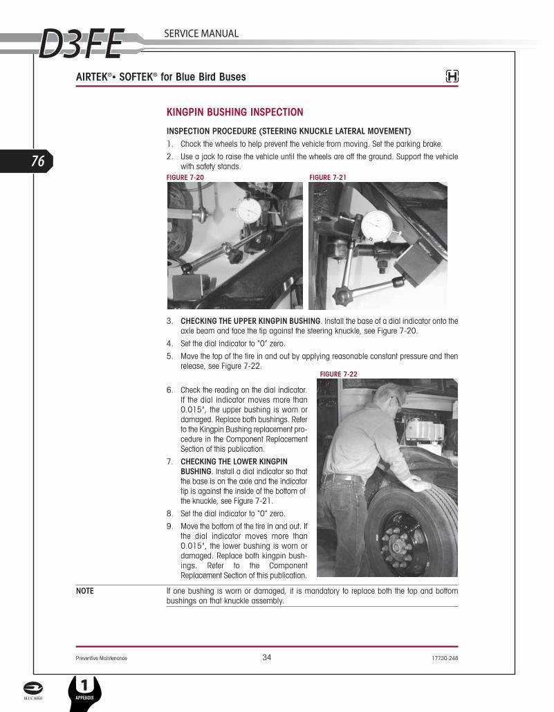
Preventive Maintenance 34 17730-248
AIRTEK®• SOFTEK® for Blue Bird Buses
KINGPIN BUSHING INSPECTION
INSPECTION PROCEDURE (STEERING KNUCKLE LATERAL MOVEMENT)1. Chock the wheels to help prevent the vehicle from moving. Set the parking brake.
2. Use a jack to raise the vehicle until the wheels are off the ground. Support the vehiclewith safety stands.
FIGURE 7-20 FIGURE 7-21
3. CHECKING THE UPPER KINGPIN BUSHING. Install the base of a dial indicator onto theaxle beam and face the tip against the steering knuckle, see Figure 7-20.
4. Set the dial indicator to “0” zero.
5. Move the top of the tire in and out by applying reasonable constant pressure and thenrelease, see Figure 7-22.
FIGURE 7-22
6. Check the reading on the dial indicator.If the dial indicator moves more than0.015", the upper bushing is worn ordamaged. Replace both bushings. Referto the Kingpin Bushing replacement pro-cedure in the Component ReplacementSection of this publication.
7. CHECKING THE LOWER KINGPINBUSHING. Install a dial indicator so thatthe base is on the axle and the indicatortip is against the inside of the bottom ofthe knuckle, see Figure 7-21.
8. Set the dial indicator to “0” zero.
9. Move the bottom of the tire in and out. Ifthe dial indicator moves more than0.015", the lower bushing is worn ordamaged. Replace both kingpin bush-ings. Refer to the ComponentReplacement Section of this publication.
NOTE If one bushing is worn or damaged, it is mandatory to replace both the top and bottombushings on that knuckle assembly.
L
76
1APPENDIX
SERVICE MANUAL

17730-248 35 Preventive Maintenance
AIRTEK®• SOFTEK® for Blue Bird Buses
STEERING KNUCKLE INSPECTION
CHECKING VERTICAL END PLAY (UP AND DOWN MOVEMENT)The operating spec for vertical clearance on the steering knuckle is 0.008" to 0.030".
1. Chock the rear tires to help prevent the vehicle from moving.
2. Set the parking brakes.
3. Use a jack to raise the vehicle until both tires are 1" off the ground. FIGURE 7-23
4. Place a dial indicator on each side of theaxle as follows:
a. Index the wheels slightly (left orright).
b. Place the magnetic dial indicatorbase on the axle, see Figure 7-23.
c. Place the tip of the dial indicator onthe top of the upper steering knuckle(not on the grease cap).
5. Set the dial indicator to “0” (zero).
6. Lower the jack.
7. If vertical clearance is greater than0.030", adjust the upper knuckle toobtain clearance specifications, if adjust-ment does not achieve clearancespecification, install shims (Hendrickson part no. 60259-002) between the top of theaxle and the bottom of the upper steering knuckle to obtain the proper clearance spec-ification. See Steering Knuckle Assembly in the Component Replace ment Section of thispublication for proper shim installation.
8. If vertical clearance is below 0.008", adjust the upper steering knuckle to obtain theproper clearance specification, if adjustment does not achieve clearance specification,remove shims. See Steering Knuckle Assembly in the Component Replacement Sectionof this publication for proper shim removal.
SERVICE MANUAL
L
77
FRonT AxlE & SuSPEnSion
1APPENDIX

Preventive Maintenance 36 17730-248
AIRTEK®• SOFTEK® for Blue Bird Buses
SHACKLE THRUST WASHER INSPECTION (If Equipped)NOTE SOFTEK Vision 8K capacity vehicles built after 02/2007, and all other vehicles built after
11/2006 are not equipped with shackle thrust washers.
In normal use these components will function satisfactorily, even though the componentsmay show some wear.
FIGURE 7-24
An indication that the shackle thrust washers are worn, or need replacement is when thesuspension exhibits one or more of the following conditions:
1. Excessive lateral movement of the spring.
2. The rear spring eye and or thrust washers are in contact with the shackle plates.
3. Normal and unacceptable thickness of the thrust washers (See Figure 7-24) can bemeasured with a micrometer or a ruler.■ The normal thickness of a new thrust washer is 3⁄16" (0.187").■ The minimum thickness allowable for a thrust washer is 3⁄32" (0.090").■ If one or more of these conditions is experienced, disassembly of the rear shack-
le assembly is required to replace the thrust washers. ■ If one thrust washer is worn out, Hendrickson recommends both thrust washers
on that side of the suspension be replaced. Inspect the thrust washers on the otherside of the vehicle and replace if necessary. See Shackle Thrust Washer replace-ment procedure in the Component Replacement Section of this publication.
Thrust Washer
*Specification provided, controlled and subject to change by vehicle manufacturer.
Shackle Bracket
Shackle Plate
M20 LocknutTightening Torque290-310* ft. lbs.
Leaf Spring with Bushing
WasherM20 Bolt
L
78
1APPENDIX
SERVICE MANUAL

17730-248 37 Preventive Maintenance
AIRTEK®• SOFTEK® for Blue Bird Buses
FRONT HANGER/REAR SHACKLE BRACKET SURFACE PAINT WEARThe Hendrickson front suspension systems AIRTEK and SOFTEK equipped on Blue Birdbuses, utilize rubber bushings in the leaf springs. These rubber bushings allow the leafspring to deflect and contact the front hanger and shackle plates when the bus encountershigh lateral acceleration (ex. a highway clover leaf). The rubber bushing will center the leafspring between the legs of the hanger/shackle plates once the vehicle is driven straight.
This function of the rubber bushing may allow the leaf spring to contact the front hanger/rearshackle plate and possibly remove surface paint from the contact area. Surface paint weardoes not cause damage that will affect the function or durability of the front hanger/rearshackle plate or their mating components provided a minimum wall thickness is maintained.
FIGURE 7-25
FIGURE 7-26
An indication that the front hanger/ rearshackle plates are worn and requirereplacement is when the components nolonger meet the following minimumrequirements:■ Front hanger inboard leg minimum
thickness of 9.15 mm and the out-board leg thickness minimumthickness 11.00 mm, see Figure 7-26.
■ Rear shackle plate minimum thick-ness of 5.8 mm, see Figure 7-26.
SERVICE MANUAL
L
79
FRonT AxlE & SuSPEnSion
1APPENDIX

Alignment & Adjustments 38 17730-248
AIRTEK®• SOFTEK® for Blue Bird Buses
SECTION 8
Alignment & Adjustments
ALIGNMENT DEFINITIONSFIGURE 8-1
Ackermann Steering Geometry —The geometry of the four bar linkageconsisting of the front axle beampivot points, tie rod arms, and crosstube and attempts to provide freerolling of front tires in a turn.Ackermann geometry is dependentupon the steering axle track-widthand wheelbase of the vehicle.Improper geometry results in wheelscrub in turns which generallyappears as toe wear on the tire.Usually more wear is present on oneside of the vehicle than the other due to the operational route of the vehicle.
Bump Steer (Feedback) — The feedback felt through the steering linkage to the steeringwheel when a steer axle tire hits a bump in the road. This occurs because the axle-end ofthe drag link and the axle attachment point of the spring do not travel in parallel circulararcs as the suspension moves up and down. This condition can also be caused by trappedair in the power steering system.
FIGURE 8-2Camber — The angle formed by the inward or outward tilt of thewheel reference to a vertical line. Camber is positive when thewheel is tilted outward at the top and is negative when the wheel istilted inward at the top.
Excessive positive camber may cause smooth wear on the outer halfof the tire tread. Excessive negative camber may cause wear on theinner half of the tread. Static-unloaded camber angles are built intothe axle to put the loaded tire perpendicular to the road.
FIGURE 8-3
Caster — The forward or rearwardtilt of the steering axle kingpin inreference to a vertical line. Theangle is measured in degrees.Caster is positive when the top ofthe steering axis is titled rearwardand is negative when the tilt is for-ward. Proper caster is importantfor directional stability and return-ability. Too much positive castercan cause shimmy, excessivesteering effort and is normally a vehicle performance and handling consideration. Unevenpositive caster may create a steering pull toward the side with the lower caster. This attrib-ute may be used to compensate for crowned roads.
ACKERMANN GEOMETRY
Center of Rotation
Rear Axle
WheelBase
L
80
1APPENDIX
SERVICE MANUAL
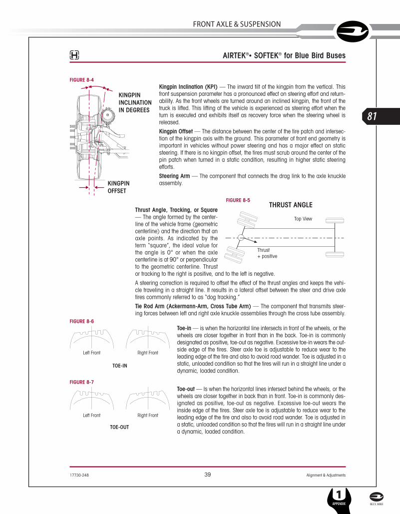
17730-248 39 Alignment & Adjustments
AIRTEK®• SOFTEK® for Blue Bird Buses
FIGURE 8-4Kingpin Inclination (KPI) — The inward tilt of the kingpin from the vertical. Thisfront suspension parameter has a pronounced effect on steering effort and return-ability. As the front wheels are turned around an inclined kingpin, the front of thetruck is lifted. This lifting of the vehicle is experienced as steering effort when theturn is executed and exhibits itself as recovery force when the steering wheel isreleased.
Kingpin Offset — The distance between the center of the tire patch and intersec-tion of the kingpin axis with the ground. This parameter of front end geometry isimportant in vehicles without power steering and has a major effect on staticsteering. If there is no kingpin offset, the tires must scrub around the center of thepin patch when turned in a static condition, resulting in higher static steeringefforts.
Steering Arm — The component that connects the drag link to the axle knuckleassembly.
FIGURE 8-5
Thrust Angle, Tracking, or Square— The angle formed by the center-line of the vehicle frame (geometriccenterline) and the direction that anaxle points. As indicated by theterm “square”, the ideal value forthe angle is 0° or when the axlecenterline is at 90° or perpendicularto the geometric centerline. Thrustor tracking to the right is positive, and to the left is negative.
A steering correction is required to offset the effect of the thrust angles and keeps the vehi-cle traveling in a straight line. It results in a lateral offset between the steer and drive axletires commonly referred to as “dog tracking.”
Tie Rod Arm (Ackermann-Arm, Cross Tube Arm) — The component that transmits steer-ing forces between left and right axle knuckle assemblies through the cross tube assembly.
FIGURE 8-6Toe-in — is when the horizontal line intersects in front of the wheels, or thewheels are closer together in front than in the back. Toe-in is commonlydesignated as positive, toe-out as negative. Excessive toe-in wears the out-side edge of the tires. Steer axle toe is adjustable to reduce wear to theleading edge of the tire and also to avoid road wander. Toe is adjusted in astatic, unloaded condition so that the tires will run in a straight line under adynamic, loaded condition.
FIGURE 8-7Toe-out — Is when the horizontal lines intersect behind the wheels, or thewheels are closer together in back than in front. Toe-in is commonly des-ignated as positive, toe-out as negative. Excessive toe-out wears theinside edge of the tires. Steer axle toe is adjustable to reduce wear to theleading edge of the tire and also to avoid road wander. Toe is adjusted ina static, unloaded condition so that the tires will run in a straight line undera dynamic, loaded condition.
TOE-OUT
TOE-IN
KINGPINOFFSET
KINGPININCLINATIONIN DEGREES
SERVICE MANUAL
L
81
FRonT AxlE & SuSPEnSion
1APPENDIX
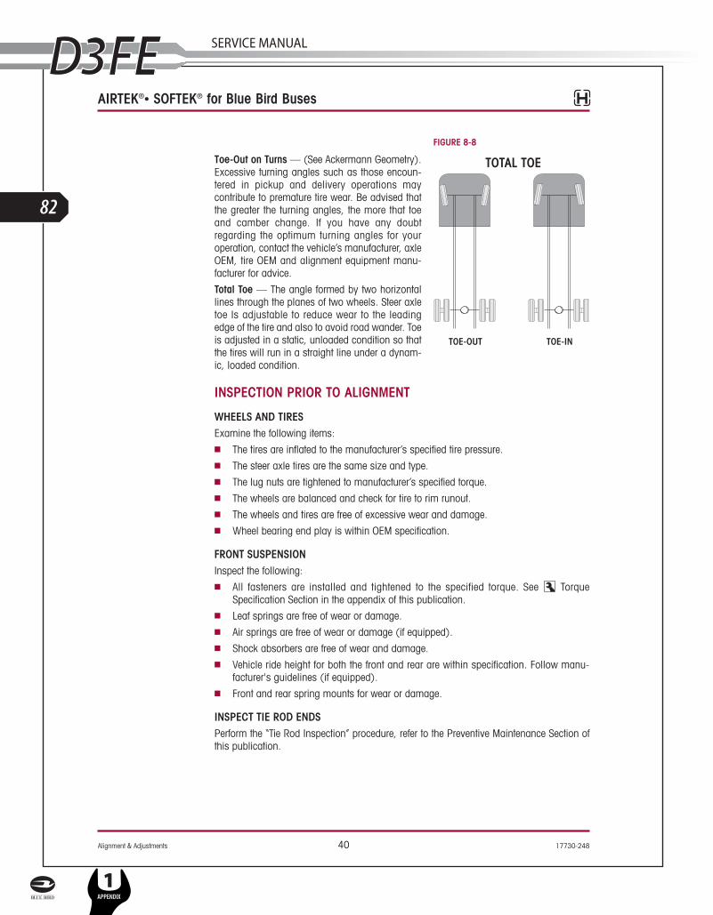
Alignment & Adjustments 40 17730-248
AIRTEK®• SOFTEK® for Blue Bird Buses
FIGURE 8-8
Toe-Out on Turns — (See Ackermann Geometry).Excessive turning angles such as those encoun-tered in pickup and delivery operations maycontribute to premature tire wear. Be advised thatthe greater the turning angles, the more that toeand camber change. If you have any doubtregarding the optimum turning angles for youroperation, contact the vehicle’s manufacturer, axleOEM, tire OEM and alignment equipment manu-facturer for advice.
Total Toe — The angle formed by two horizontallines through the planes of two wheels. Steer axletoe Is adjustable to reduce wear to the leadingedge of the tire and also to avoid road wander. Toeis adjusted in a static, unloaded condition so thatthe tires will run in a straight line under a dynam-ic, loaded condition.
INSPECTION PRIOR TO ALIGNMENT
WHEELS AND TIRESExamine the following items:■ The tires are inflated to the manufacturer’s specified tire pressure.■ The steer axle tires are the same size and type.■ The lug nuts are tightened to manufacturer’s specified torque. ■ The wheels are balanced and check for tire to rim runout.■ The wheels and tires are free of excessive wear and damage.■ Wheel bearing end play is within OEM specification.
FRONT SUSPENSIONInspect the following:■ All fasteners are installed and tightened to the specified torque. See Torque
Specification Section in the appendix of this publication.■ Leaf springs are free of wear or damage.■ Air springs are free of wear or damage (if equipped).■ Shock absorbers are free of wear and damage.■ Vehicle ride height for both the front and rear are within specification. Follow manu-
facturer's guidelines (if equipped).■ Front and rear spring mounts for wear or damage.
INSPECT TIE ROD ENDSPerform the “Tie Rod Inspection” procedure, refer to the Preventive Maintenance Section ofthis publication.
TOE-OUT TOE-IN
L
82
1APPENDIX
SERVICE MANUAL
17730-248 41 Alignment & Adjustments
AIRTEK®• SOFTEK® for Blue Bird Buses
REAR AXLE AND REAR SUSPENSIONRear axle misalignment can cause front tire wear. If the outer edge of one front tire is wornand the inner edge of the other front tire is worn, check the following:■ Make sure the rear axle (especially a tandem axle) is correctly aligned. Refer to the pro-
cedure from the manufacturer of the vehicle or the suspension. ■ All fasteners including U-bolts (if applicable) are installed and tightened to the speci-
fied torque.■ The leaf springs are not worn or damaged.■ The bushings in the leaf springs are not worn or damaged.■ The torque rods (if used) are correctly adjusted (if adjustable).■ The frame is not bent or twisted.■ Refer to any additional recommendations and specifications from the manufacturer of
vehicle on rear axles and suspensions. Reference the TMC (The Technology &Maintenance Council) Guidelines for Total Vehicle Alignment.
FRONT WHEEL ALIGNMENTHendrickson recommends technicians review TMC’s publication TMC (Technology &Maintenance Council) “Guidelines for Total Vehicle Alignment”.
The AIRTEK/SOFTEK front wheel alignment specification can be found in the Appendix of thispublication.
Check the total vehicle wheel alignment when the following occur:■ Every 80,000 to 100,000 miles, or 12-18 months (normal maintenance).■ When the vehicle does not steer correctly.■ To correct a tire wear condition.■ There are two types of front wheel alignment:
1. Minor alignment – a minor front wheel alignment is done for all normal mainte-nance conditions, see below.
2. Major alignment – a major alignment is done when uneven or excessive tire wearis evident, or response at the steering wheel is sluggish, or the need for majorwheel alignment check and adjustment is required, see below.
MINOR FRONT WHEEL ALIGNMENTPerform the minor front wheel alignment in the following sequence:
1. Inspect all systems that affect wheel alignment. Refer to “Inspection Prior to Alignment”in this section.
2. Check the wheel bearing end play.
3. Check and adjust the vehicle ride height (for AIRTEK) as specified in the PreventiveMaintenance Section of this publication.
4. Check toe-in and adjust if necessary.
MAJOR FRONT WHEEL ALIGNMENTBe certain to follow wheel alignment inspection intervals as specified by the original equip-ment manufacturer. Before performing a major front wheel alignment it is recommendedthat alignment equipment calibration be checked to ensure proper vehicle alignment.
SERVICE MANUAL
L
83
FRonT AxlE & SuSPEnSion
1APPENDIX

Alignment & Adjustments 42 17730-248
AIRTEK®• SOFTEK® for Blue Bird Buses
Major wheel alignment is accomplished in the following sequence of operation:
1. Inspect all the systems that influence the wheel alignment. Refer to the “Inspection Priorto Alignment” in this section.
2. Check and adjust the maximum turn angle, (see “Steering Stop Procedure” in this sec-tion), see Figures 8-9 and 8-10.
3. If the vehicle has power steering, check and adjust, if necessary, the pressure relief inthe power steering system. Refer to vehicle manufacturer’s specifications See SteerStops in this section.
4. Verify the turning angle per step 2, (toe-out during vehicle turns or the Ackermannangle). Refer to vehicle manufacturer's specifications.
FIGURE 8-9 FIGURE 8-10
5. Check the kingpin (or steering axis) inclination (the kingpin inclination is notadjustable). Refer to “Kingpin Inclination”, in the Alignment Definitions in this section.
6. Check the camber angle. Do not attempt to adjust. Refer to “Camber” in the AlignmentDefinitions in this section.
AXLE CAMBER IS NOT ADJUSTABLE. DO NOT CHANGE THE AXLE CAMBER ANGLE OR BENDTHE AXLE BEAM. BENDING THE AXLE BEAM TO CHANGE THE CAMBER ANGLE CAN DAMAGE THEAXLE AND REDUCE AXLE STRENGTH, AND WILL VOID HENDRICKSON’S WARRANTY. A BENT AXLEBEAM CAN CAUSE LOSS OF VEHICLE CONTROL, POSSIBLY CAUSING PERSONAL INJURY ORPROPERTY DAMAGE, SEE FIGURE 8-11.FIGURE 8-11
7. Check and adjust caster angle. Refer to “Caster” in the Alignment Definitions in this sec-tion. The use of two different angle caster shims will not change cross caster. Crosscaster is the difference between the caster readings for left and right side of the vehicle.
SERVICE HINT Prior to checking caster confirm that the vehicle is at its proper ride height front and rear.The front and rear ride height must be correct to achieve proper caster.
8. Check and adjust toe-in, refer to adjusting the Toe-In under the Alignment Definitions inthis section.
L
84
1APPENDIX
SERVICE MANUAL
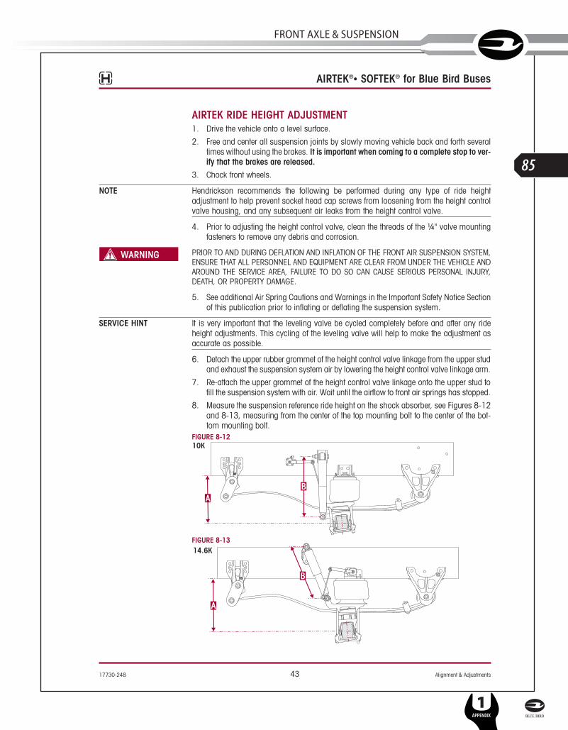
17730-248 43 Alignment & Adjustments
AIRTEK®• SOFTEK® for Blue Bird Buses
AIRTEK RIDE HEIGHT ADJUSTMENT1. Drive the vehicle onto a level surface.
2. Free and center all suspension joints by slowly moving vehicle back and forth severaltimes without using the brakes. It is important when coming to a complete stop to ver-ify that the brakes are released.
3. Chock front wheels.
NOTE Hendrickson recommends the following be performed during any type of ride heightadjustment to help prevent socket head cap screws from loosening from the height controlvalve housing, and any subsequent air leaks from the height control valve.
4. Prior to adjusting the height control valve, clean the threads of the ¼" valve mountingfasteners to remove any debris and corrosion.
PRIOR TO AND DURING DEFLATION AND INFLATION OF THE FRONT AIR SUSPENSION SYSTEM,ENSURE THAT ALL PERSONNEL AND EQUIPMENT ARE CLEAR FROM UNDER THE VEHICLE ANDAROUND THE SERVICE AREA, FAILURE TO DO SO CAN CAUSE SERIOUS PERSONAL INJURY,DEATH, OR PROPERTY DAMAGE.
5. See additional Air Spring Cautions and Warnings in the Important Safety Notice Sectionof this publication prior to inflating or deflating the suspension system.
SERVICE HINT It is very important that the leveling valve be cycled completely before and after any rideheight adjustments. This cycling of the leveling valve will help to make the adjustment asaccurate as possible.
6. Detach the upper rubber grommet of the height control valve linkage from the upper studand exhaust the suspension system air by lowering the height control valve linkage arm.
7. Re-attach the upper grommet of the height control valve linkage onto the upper stud tofill the suspension system with air. Wait until the airflow to front air springs has stopped.
8. Measure the suspension reference ride height on the shock absorber, see Figures 8-12and 8-13, measuring from the center of the top mounting bolt to the center of the bot-tom mounting bolt.
FIGURE 8-12
FIGURE 8-13
SERVICE MANUAL
L
85
FRonT AxlE & SuSPEnSion
1APPENDIX

Alignment & Adjustments 44 17730-248
AIRTEK®• SOFTEK® for Blue Bird Buses
9. The different referenced ride height measurements are as specified in the followingchart. If the reference measurement is not within ± ¼" of the specification, the rideheight MUST be adjusted.
10. Detach the upper grommet of the height control valve linkage from the stud on the lev-eling valve arm and exhaust suspension system air, see Figures 8-14 and 8-15.
11. Adjust the height control valve by loosening the ¼" mounting locknuts and pivoting thevalve body about the mounting bolt.
NOTE It is necessary to place a 3⁄16" Allen wrench in the head of the mounting bolts whileadjusting ride height to prevent movement of the bolts, which can cause air leakage in thebody of the leveling valve.
12. Facing the air spring from the outboard side of the vehicle, pivot the valve body clock-wise to increase the ride height and counter clockwise to decrease the ride height.
13. Tighten the ¼" mounting locknuts to 8-10 foot pounds, (see Figures 8-14 and8-15) and repeat steps 4 through 10 until the reference measurement equals ± ¼" ofthe specification, see Figures 8-12 and 8-13.
14. Remove wheel chocks.FIGURE 8-14 FIGURE 8-15
AIRTEK (FRONT) COMFORT AIR (REAR)
RIDE HEIGHT SHOCK ABSORBERLENGTH RIDE HEIGHT SHOCK ABSORBER
LENGTHDimension A Dimension B
Blue Bird ModelFrom the bottom of theframe to the center of axle
At ride height with atolerance of ¼"
From the bottom of theframe to the bottom of themain support member.
At ride height with atolerance of ¼"
Vision 10K 12½" 18 9⁄16"47⁄8" 22¾"All American Front Engine 147⁄8" 17¼"
All American Rear Engine 147⁄8" 1715⁄32"
L
86
1APPENDIX
SERVICE MANUAL
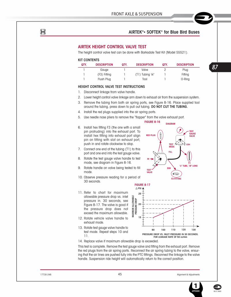
17730-248 45 Alignment & Adjustments
AIRTEK®• SOFTEK® for Blue Bird Buses
AIRTEK HEIGHT CONTROL VALVE TESTThe height control valve test can be done with Barksdale Test Kit (Model 55521).
KIT CONTENTS
HEIGHT CONTROL VALVE TEST INSTRUCTIONS1. Disconnect linkage from valve handle.
2. Lower height control valve linkage arm down to exhaust air from the suspension system.
3. Remove the tubing from both air spring ports, see Figure 8-16. Place supplied toolaround the tubing, press down to pull out tubing. DO NOT CUT THE TUBING.
4. Install the red plugs supplied into the air spring ports.
5. Use needle nose pliers to remove the “flapper” from the valve exhaust port.FIGURE 8-16
6. Install hex fitting F3 (the one with a smallpin protruding) into the exhaust port. Toinstall hex fitting into exhaust port alignpin on fitting with slot on exhaust port,push in and rotate clockwise to stop.
7. Connect one end of the tubing (T1) to thisport and one end into the test gauge valve.
8. Rotate the test gauge valve handle to testmode, see diagram in Figure 8-16.
9. Rotate handle on valve being tested to fillmode.
10. Observe pressure reading for a period of30 seconds.
FIGURE 8-17
11. Refer to chart for maximumallowable pressure drop vs. inletpressure in. 30 seconds, seeFigure 8-17. The valve is good ifthe pressure drop does notexceed the maximum allowable.
12. Rotate vehicle valve handle toexhaust mode.
13. Rotate test gauge valve handle totest mode. Repeat steps 10 and11.
14. Replace valve if maximum allowable drop is exceeded.
This test is complete. Remove the test gauge valve and fitting from the exhaust port. Removethe red plugs from the air spring ports. Reconnect the air spring tubing to the valve, ensur-ing that the air lines are pushed fully into the PTC fittings. Reconnect the linkage to the valvehandle. Suspension ride height will automatically return to the correct position.
QTY. DESCRIPTION QTY. DESCRIPTION QTY. DESCRIPTION
1 Gauge 1 Valve 2 Plug
1 (F3) Fitting 1 (T1) Tubing ¼" 1 Fitting
1 Flush Plug 1 Tool 1 O-Ring
SERVICE MANUAL
L
87
FRonT AxlE & SuSPEnSion
1APPENDIX

Alignment & Adjustments 46 17730-248
AIRTEK®• SOFTEK® for Blue Bird Buses
STEERING STOP
ADJUSTMENT PROCEDUREWhen the axle or lower steering knuckle is replaced, the steering stop adjustment must bechecked.
The steering stop adjustment procedure is as follows:
1. Drive truck onto turntables and chock the rear wheels.
2. Measure the wheel cut. The wheel cut is determined by steering the tires. Wheel cut ismeasured at the inside wheel only, therefore the tires must be turned to the full lockposition for each right hand and left hand direction. Refer to the vehicle manufacturerfor exact specifications.
3. Increase the wheel cut by loosening the jam nuts and screw the axle stops in clockwise.
4. Tighten the jam nuts. FIGURE 8-18
NOTE It is very important that thesides of the square head axlestops are set parallel to theaxle beam to ensure a goodcontact point on the axle, seeFigure 8-18.
5. Decrease the wheel cutby loosening the jamnuts and screw the axlestops out counter-clock-wise.
6. Tighten the jam nuts to 40-60 foot pounds torque.
7. Measure the wheel cut and check for any interference with related steering components.
ALWAYS CHECK/RESET THE STEERING GEAR BOX POPPET WHEN THE WHEEL CUT ISDECREASED. FOLLOW MANUFACTURER'S GUIDELINES FOR THE GEAR BOX POPPET RESETTINGPROCEDURE. FAILURE TO DO SO CAN RESULT IN PREMATURE FAILURE OF THE AXLE ORSTEERING KNUCKLE. THIS CONDITION CAN CAUSE LOSS OF VEHICLE CONTROL, PERSONALINJURY OR PROPERTY DAMAGE AND VOID WARRANTY.
TOE SETTING1. Place the vehicle on a level floor with the wheels in a straight ahead position.
2. Raise the vehicle and support the front axle with jack stands.
3. Use paint and mark the center area of tread on both steer axle tires around the com-plete outer diameter of the tires.
4. Scribe a line through both steer axle tires in the painted area around the complete outerdiameter of the tires.
5. Raise the vehicle and remove the jack stands.
6. Set the vehicle on the ground.
NOTE Do not measure toe-in with the front axle off the ground. The weight of the vehicle must beon the front axle when toe-in is measured.
7. Use a trammel bar and measure the distance between the scribe marks at the rear ofthe steer axle tires. Record the measurement.
L
88
1APPENDIX
SERVICE MANUAL

17730-248 47 Alignment & Adjustments
AIRTEK®• SOFTEK® for Blue Bird Buses
8. Install the trammel bar and measure the distance between the scribe marks at the frontof the steer axle tires. Record the measurement, see Figure 8-19.
NOTE When setting up the trammel bar the pointers should be level with the spindles at the frontand rear of the steer axle tires.
9. To calculate the toe setting subtract the front measurement from the rear measurement,the difference between the two will equal the toe-in/toe-out measurement.
FIGURE 8-19
10. If the toe measurement is not within the specifications of 1/16" ± 1/32"(0.060" ± 0.030"), it will be necessary to adjust the toe setting. Refer to the followingprocedure.
a. Loosen the tie rod cross tube clamp bolts and locknuts.
b. Turn the tie rod cross tube until the specified toe-in distance is achieved.
THE THREADED PORTION OF THE TIE ROD END MUST EXTEND PAST THE SLOTS INTO THE TIE RODCROSS TUBE, SEE FIGURE 8-20. FAILURE TO DO SO CAN CAUSE COMPONENT TO FAIL CAUSINGLOSS OF VEHICLE CONTROL AND POSSIBLE PERSONAL INJURY OR PROPERTY DAMAGE.FIGURE 8-20
c. Tighten the bolt and locknut on the tie rod cross tube to 60-75 foot pounds torque.
11. Repeat steps 1-9 until the correct toe setting is achieved.
SERVICE MANUAL
L
89
FRonT AxlE & SuSPEnSion
1APPENDIX

Alignment & Adjustments 48 17730-248
AIRTEK®• SOFTEK® for Blue Bird Buses
SPRING EYE RE-TORQUEThis procedure to re-torque is necessary when replacing
■ Front Hanger■ Shackle Assembly■ Steel Leaf Spring Assembly
AIRTEK RE-TORQUE PROCEDUREFIGURE 8-21
1. Chock the rear wheels of the vehicle to prevent movement.
2. Verify ride height. Adjust if necessary, see AIRTEK Ride Height adjustment procedure inthis section.
3. Loosen all six (6) front and rear spring eye bolts, see Figure 8-21. FIGURE 8-22
NOTE DO NOT remove the spring eye bolts.
4. Let the suspension settle.
5. Tighten the front M20 spring eye bolt locknuts tovehicle manufacturer's specifications.
6. Tighten the rear M20 spring eye bolt and shack-le bolt locknuts to vehicle manufacturer'sspecifications.
7. Affix a straight edge to the bottom of the framerail in front of the air spring, see Figure 8-22.
8. With the vehicle on a level surface measure thedistance from the top of the straight edge to theground on both sides of the vehicle and recordthe measurements.
9. Measure the difference from one side to the other.
10. Do a road test and repeat measurement steps7 to 9.
11. If the measurement is less than 3⁄8" the vehicle islevel. If measurement is more than 3⁄8" contactHendrickson Tech Services.
L
90
1APPENDIX
SERVICE MANUAL

17730-248 49 Alignment & Adjustments
AIRTEK®• SOFTEK® for Blue Bird Buses
SOFTEK RE-TORQUE PROCEDURE FIGURE 8-23
1. Chock the wheels.
2. Loosen all six (6) front and rear spring eye bolts, see Figure 8-23.
NOTE Do not remove the spring eye bolts.
3. Let the suspension settle.
4. Tighten the front M20 spring eye bolt locknuts to vehicle manufacturer's specifications.
5. Tighten the rear M20 spring eye bolt and shackle bolt locknuts to vehicle manufactur-er's specifications.
6. Affix a straight edge to the bottom of the frame rail behind frame hanger, see Figure 8-22.
7. With the vehicle on a level surface measure the distance from the top of the straightedge to the ground on both sides of the vehicle and record the measurements.
8. Measure the difference from one side to the other.
9. Do a road test and repeat measurement steps 7 to 9.
10. If the measurement is less than 3⁄8" the vehicle is level. If measurement is more than 3⁄8"contact Hendrickson Tech Services.
SERVICE MANUAL
L
91
FRonT AxlE & SuSPEnSion
1APPENDIX

Component Replacement 50 17730-248
AIRTEK®• SOFTEK® for Blue Bird Buses
SECTION 9
Component Replacement
FASTENERSHendrickson recommends that when servicing the vehicle to replace the removed fastenerswith new equivalent fasteners. Maintain correct torque values at all times. Check torque val-ues as specified. See Hendrickson’s Torque Specifications in the Appendix of thispublication. If non-Hendrickson fasteners are used follow torque specifications listed in thevehicle manufacturer’s service manual.
SPACERSThere are different front axle spacer configurations for each front suspension system. Priorto disassembly of the front axle clamp group, note the orientation and quantity of the frontaxle spacer(s) (if equipped). It is required that the axle spacers be installed in the sameorientation and location as removed to preserve the existing vertical alignment. Refer to theParts List Section of this publication.
AIRTEK HEIGHT CONTROL VALVE – 10K
DISASSEMBLY1. Drain the air from the secondary air tank.
PRIOR TO AND DURING DEFLATION AND INFLATION OF THE FRONT AIR SUSPENSION SYSTEM,ENSURE THAT ALL PERSONNEL AND EQUIPMENT ARE CLEAR FROM UNDER THE VEHICLE ANDAROUND THE SERVICE AREA, FAILURE TO DO SO CAN CAUSE SERIOUS PERSONAL INJURY,DEATH, OR PROPERTY DAMAGE.
2. See additional Air Spring Cautions and Warnings in the Important Safety Notice Sectionof this publication prior to inflating or deflating the suspension system.
3. Deflate the air springs by removing the height control valve linkage at the rubber grom-met and lowering the height control linkage arm. This will exhaust the air pressure inthe air springs.
FIGURE 9-1 10K
THE PUSH-TO-CONNECT FITTINGS ARE NON-SERVICEABLE. IT IS NECESSARY TO CLEAN THEDIRT AND DEBRIS AWAY FROM THE PUSH-TO-CONNECT FITTINGS AND THE AIR LINES TO HELPPREVENT ANY FOREIGN MATERIAL FROMENTERING THE AIR SPRING, AIR SYSTEM ORDAMAGING THE PUSH-TO-CONNECT FITTINGS.CLEAN PUSH-TO-CONNECT FITTINGS USINGSOAPY WATER AND A SOFT BRISTLED BRUSH ANDDRY WITH COMPRESSED AIR.
4. Remove the air lines from the height controlvalve, see Figure 9-1. The air lines arepush-to-connect. Push in on the air line torelease tension, push down on the collarand pull out the air line.
5. Remove the two ¼" mounting nuts and washers.
6. Remove the height control valve.
¼ Nylon Air Line"
Leveling Valve Arm
Push-to-connectFittings
Air Spring Bracket
Air Spring
L
92
1APPENDIX
SERVICE MANUAL

17730-248 51 Component Replacement
AIRTEK®• SOFTEK® for Blue Bird Buses
ASSEMBLY1. Attach the height control valve on the vehicle frame as shown in Figure 9-1.
FIGURE 9-2 10K
2. Attach the ¼" washers and thelocknuts. Do not tighten thelocknuts to specified torqueuntil after the proper ride heightis attained. Mount the heightcontrol valve parallel to flangeof the frame, see Figure 9-2.
SERVICE HINT When replacing or installing nylonair line tubing into quick-connectfittings, it is critical that the end ofthe air line is cut square. Impropercut of the end of the air line tubingcan cause the air line to seatimproperly in the quick connect fitting causing air leakage.
FIGURE 9-3 10K
3. Attach the air lines to the heightcontrol valve, see Figure 9-3.
4. Install the height control valve link-age assembly.
5. Adjust the height control valve toproper specifications. See theAlign ment & Adjustments Section ofthis publication for proper ride height adjustment.
6. Tighten the ¼" locknuts to 8-10 foot pounds torque.
AIRTEK HEIGHT CONTROL VALVE – 14.6K
DISASSEMBLY1. Drain the air from the secondary air tank.
PRIOR TO AND DURING DEFLATION AND INFLATION OF THE FRONT AIR SUSPENSION SYSTEM,ENSURE THAT ALL PERSONNEL AND EQUIPMENT ARE CLEAR FROM UNDER THE VEHICLE ANDAROUND THE SERVICE AREA, FAILURE TO DO SO CAN CAUSE SERIOUS PERSONAL INJURY,DEATH, OR PROPERTY DAMAGE.
2. See additional Air Spring Cautions and Warnings in the Important Safety Notice Sectionof this publication prior to inflating or deflating the suspension system.
3. Deflate the air springs by removing the height control valve linkage at the rubber grom-met and lowering the height control linkage arm. This will exhaust the air pressure inthe air springs.
THE PUSH-TO-CONNECT FITTINGS ARE NON-SERVICEABLE. IT IS NECESSARY TO CLEAN THEDIRT AND DEBRIS AWAY FROM THE PUSH-TO-CONNECT FITTINGS AND THE AIR LINES TO HELPPREVENT ANY FOREIGN MATERIAL FROM ENTERING THE AIR SPRING, AIR SYSTEM ORDAMAGING THE PUSH-TO-CONNECT FITTINGS. CLEAN PUSH-TO-CONNECT FITTINGS USINGSOAPY WATER AND A SOFT BRISTLED BRUSH AND DRY WITH COMPRESSED AIR.
To Left HandAir Spring To Right Hand
Air Spring“In” Port
“Exhaust” Port
C1 C2
SERVICE MANUAL
L
93
FRonT AxlE & SuSPEnSion
1APPENDIX

Component Replacement 52 17730-248
AIRTEK®• SOFTEK® for Blue Bird Buses
FIGURE 9-4 14.6K
4. Remove the air lines from the height con-trol valve, see Figure 9-4. The air linesare push-to-connect. Push in on the airline to release tension, push down on thecollar and pull out the air line.
5. Remove the two ¼" mounting nuts andwashers.
6. Remove the height control valve.
ASSEMBLY1. Re-install the air fittings into the height control valve. Ensure the Teflon® thread seal-
ing ring is seated around the base of the fitting’s hex shoulder. Torque to 3-15 footpounds (4-20 Nm).
2. Install the height control valve to the upper air spring bracket by attaching the ¼" wash-ers and locknuts. Torque to 8-10 foot pounds, see Figure 9-5.
FIGURE 9-5 14.6K
3. Install the air lines to theheight control valve. Referthe Plumbing DiagramSection of this publication.
PRIOR TO AND DURINGDEFLATION AND INFLATION OFTHE FRONT AIR SUSPENSIONSYSTEM, ENSURE THAT ALLPERSONNEL AND EQUIPMENTARE CLEAR FROM UNDER THEVEHICLE AND AROUND THESERVICE AREA, FAILURE TO DO SOCAN CAUSE SERIOUS PERSONALINJURY, DEATH, OR PROPERTYDAMAGE.
4. See additional Air SpringCautions and Warnings inthe Important Safety oticeSection of this publication prior to inflating or deflating the suspension system.
5. Inflate the suspension by connecting the height control valve linkage to the height con-trol valve arm and lower mounting bracket. Verify the air springs inflate uniformlywithout binding.
6. Remove the frame supports.
7. Remove the wheel chocks.
8. Verify proper ride height adjustment, (see ride height adjustment in the Alignment &Adjustments Section of this publication).
Height ControlValve
LinkageAssembly
RubberGrommet
LinkMount
¼ LocknutsTightening Torque8-10 ft. lbs.
"
¼ Washers"
¼ Nylon Air Line"
LevelingValve Arm
Air Spring Bracket
Air Spring
L
94
1APPENDIX
SERVICE MANUAL

17730-248 53 Component Replacement
AIRTEK®• SOFTEK® for Blue Bird Buses
AIRTEK AIR SPRING – 10K
DISASSEMBLY1. Place the vehicle on level floor.
2. Chock the wheels.
3. Raise the frame.
4. Support the vehicle with frame stands.
WHEN SERVICING THE VEHICLE OR ATTACHING AN AIR SPRING AND THE VEHICLE IS ON THEGROUND, PRIOR TO AIRING THE SUSPENSION SYSTEM MAKE CERTAIN THE AIR SPRINGLOCATOR IS INDEXED INTO THE UPPER AIR SPRING BRACKET PROPERLY, AND THE AIRSPRING IS FULLY SEATED ON THE SPRING TOP PAD. FAILURE TO FOLLOW THESEINSTRUCTIONS CAN RESULT IN PREMATURE AIR SPRING FAILURE, CAUSE PERSONAL INJURY,OR PROPERTY DAMAGE.
PRIOR TO AND DURING DEFLATION AND INFLATION OF THE FRONT AIR SUSPENSION SYSTEM,ENSURE THAT ALL PERSONNEL AND EQUIPMENT ARE CLEAR FROM UNDER THE VEHICLE ANDAROUND THE SERVICE AREA, FAILURE TO DO SO CAN CAUSE SERIOUS PERSONAL INJURY,DEATH, OR PROPERTY DAMAGE.
5. See additional Air Spring Cautions and Warnings in the Important Safety Notice Sectionof this publication prior to inflating or deflating the suspension system.
6. Remove the air from the air system by disconnecting the height control valve linkageat the rubber grommet of the height control valve arm and allow the arm to drop. Thiswill exhaust air from the system.
IF THE AIR SPRING IS TO BE RE-INSTALLED; INSPECT LOCK-TABS FOR DAMAGE OR CRACKSPRIOR TO RE-INSTALLATION. CARE MUST BE TAKEN TO REMOVE DIRT AND DEBRIS FROM THEPUSH-TO-CONNECT FITTING. FAILURE TO DO SO CAN RESULT IN THE PUSH-TO-CONNECTFITTING FAILING TO SEAL WITH THE AIR LINE.
7. Disconnect the air line to the air spring.
8. Raise the frame to allow for air spring removal.
9. Separate the air spring from the upper air spring bracket by applying downward pres-sure on air spring, see Figure 9-6, pushing outward on the lock-tabs outside thebracket, and inward on inlet lock-tabs. This will dislodge the air spring from the upperair spring bracket.
10. Apply upward pressure between the base of the air spring and the top pad. This willdislodge the air spring from the top pad, see Figure 9-7.
11. Remove the air spring.FIGURE 9-6 FIGURE 9-7
SERVICE MANUAL
L
95
FRonT AxlE & SuSPEnSion
1APPENDIX

Component Replacement 54 17730-248
AIRTEK®• SOFTEK® for Blue Bird Buses
ASSEMBLY1. Insert the air spring into the top pad. Make sure the lock tabs click in place.
2. Compress the air spring and slide into vertical position. There is a locating nodule onthe air spring to index the position in the upper air spring bracket.
3. Pull the air spring up into the upper air spring bracket until the air spring snaps intoplace in the upper air spring bracket. Verify all four lock-tabs are engaged, seeFigure 9-8.
FIGURE 9-8
SERVICE HINT When replacing or installingnylon air line tubing intoquick-connect fittings it iscritical that the end of the airline is cut square. Impropercut of the end of the air linetubing can cause the air lineto seat improperly in thequick connect fitting causingair leakage.
4. Install the air line into the air spring.
WHEN SERVICING THE VEHICLE OR ATTACHING AN AIR SPRING AND THE VEHICLE IS ON THEGROUND, PRIOR TO AIRING THE SUSPENSION SYSTEM MAKE CERTAIN THE AIR SPRINGLOCATOR IS INDEXED INTO THE UPPER AIR SPRING BRACKET PROPERLY, AND THE AIRSPRING IS FULLY SEATED ON THE SPRING TOP PAD. FAILURE TO FOLLOW THESEINSTRUCTIONS CAN RESULT IN PREMATURE AIR SPRING FAILURE, CAUSE PERSONAL INJURY,OR PROPERTY DAMAGE.
PRIOR TO AND DURING DEFLATION AND INFLATION OF THE FRONT AIR SUSPENSION SYSTEM,ENSURE THAT ALL PERSONNEL AND EQUIPMENT ARE CLEAR FROM UNDER THE VEHICLE ANDAROUND THE SERVICE AREA, FAILURE TO DO SO CAN CAUSE SERIOUS PERSONAL INJURY,DEATH, OR PROPERTY DAMAGE.
5. See additional Air Spring Cautions and Warnings in the Important Safety Notice Sectionof this publication prior to inflating or deflating the suspension system.
6. Air up the suspension.
7. Check the air spring for leaks.
8. Check the ride height and adjust if necessary. See Alignment & Adjustments Section ofthis publication for the proper ride height adjustment.
9. Remove the wheel chocks.
L
96
1APPENDIX
SERVICE MANUAL

17730-248 55 Component Replacement
AIRTEK®• SOFTEK® for Blue Bird Buses
AIRTEK AIR SPRING – 14.6K
DISASSEMBLY1. Place the vehicle on level floor.
2. Chock the wheels.
3. Raise the frame.
4. Support the vehicle with frame stands.
WHEN SERVICING THE VEHICLE OR ATTACHING AN AIR SPRING AND THE VEHICLE IS ON THEGROUND, PRIOR TO AIRING THE SUSPENSION SYSTEM MAKE CERTAIN THE AIR SPRINGLOCATOR IS INDEXED INTO THE UPPER AIR SPRING BRACKET PROPERLY, AND THE AIRSPRING IS FULLY SEATED ON THE SPRING TOP PAD. FAILURE TO FOLLOW THESEINSTRUCTIONS CAN RESULT IN PREMATURE AIR SPRING FAILURE, CAUSE PERSONAL INJURY,OR PROPERTY DAMAGE.
PRIOR TO AND DURING DEFLATION AND INFLATION OF THE FRONT AIR SUSPENSION SYSTEM,ENSURE THAT ALL PERSONNEL AND EQUIPMENT ARE CLEAR FROM UNDER THE VEHICLE ANDAROUND THE SERVICE AREA, FAILURE TO DO SO CAN CAUSE SERIOUS PERSONAL INJURY,DEATH, OR PROPERTY DAMAGE.
5. See additional Air Spring Cautions and Warnings in the Important Safety Notice Sectionof this publication prior to inflating or deflating the suspension system.
6. Remove the air from the air system by disconnecting the height control valve linkage(s)at the rubber grommet(s) and allowing the lever(s) to drop. This will exhaust air fromthe system.
7. If the air spring is damaged and the suspension is deflated, it will be necessary to raisethe frame and support the vehicle with frame stands to obtain adequate clearance forair spring removal.
8. Disconnect the ¼" NPT air fitting from the air spring.
9. Remove the lower ½" air spring locknut from the piston stud to remove the air springfrom the top pad, see Figure 9-9.
FIGURE 9-9
SERVICE MANUAL
L
97
FRonT AxlE & SuSPEnSion
1APPENDIX

Component Replacement 56 17730-248
AIRTEK®• SOFTEK® for Blue Bird Buses
10. Remove the ¾" upper air spring locknut from the air spring bracket.
11. Remove the air spring.
ASSEMBLY1. Compress the air spring and slide into vertical position.
2. There is a locating ½" stud and ¾" threading stud on top of the air spring.
3. There are two studs on the bottom of the air spring. Guide studs through the air springbracket and properly seat the lower air spring piston into the top axle pad. Secure the½" locknut to the piston, see Figure 9-10.
FIGURE 9-10
4. Tighten the ¾" upper air spring locknuts to vehicle manufacturer's specifications andthe lower ½" lower air spring locknuts to 20-30 foot pounds.
WHEN SERVICING THE VEHICLE OR ATTACHING AN AIR SPRING AND THE VEHICLE IS ON THEGROUND, PRIOR TO AIRING THE SUSPENSION SYSTEM MAKE CERTAIN THE AIR SPRINGLOCATOR IS INDEXED INTO THE UPPER AIR SPRING BRACKET PROPERLY, AND THE AIRSPRING IS FULLY SEATED ON THE SPRING TOP PAD. FAILURE TO FOLLOW THESEINSTRUCTIONS CAN RESULT IN PREMATURE AIR SPRING FAILURE, CAUSE PERSONAL INJURY,OR PROPERTY DAMAGE.
PRIOR TO AND DURING DEFLATION AND INFLATION OF THE FRONT AIR SUSPENSION SYSTEM,ENSURE THAT ALL PERSONNEL AND EQUIPMENT ARE CLEAR FROM UNDER THE VEHICLE ANDAROUND THE SERVICE AREA, FAILURE TO DO SO CAN CAUSE SERIOUS PERSONAL INJURY,DEATH, OR PROPERTY DAMAGE.
5. See additional Air Spring Cautions and Warnings in the Important Safety Notice Sectionof this publication prior to inflating or deflating the suspension system.
6. Install the air line into the air spring.
7. Air up the suspension.
8. Check the air spring for leaks.
9. Check the ride height and adjust if necessary. See Alignment & Adjustments Section ofthis publication for the proper ride height adjustment.
10. Remove the wheel chocks.
L
98
1APPENDIX
SERVICE MANUAL

17730-248 57 Component Replacement
AIRTEK®• SOFTEK® for Blue Bird Buses
AIRTEK FRONT LEAF SPRING FRAME HANGER
DISASSEMBLY1. Place the vehicle on level floor.
2. Chock the wheels.
3. Raise the frame.
4. Support the vehicle with frame stands.
5. Suspend the front axle from the shock absorbers.
PRIOR TO AND DURING DEFLATION AND INFLATION OF THE FRONT AIR SUSPENSION SYSTEM,ENSURE THAT ALL PERSONNEL AND EQUIPMENT ARE CLEAR FROM UNDER THE VEHICLE ANDAROUND THE SERVICE AREA, FAILURE TO DO SO CAN CAUSE SERIOUS PERSONAL INJURY,DEATH, OR PROPERTY DAMAGE.
6. See additional Air Spring Cautions and Warnings in the Important Safety Notice Sectionof this publication prior to inflating or deflating the suspension system.
7. Deflate the air springs by removing the height control valve linkage and lowering theleveling valve arm. This will exhaust the air pressure in the air springs.
8. Remove the air lines from air springs.
9. Remove the M20 spring eye bolt, washers and locknut.
SERVICE HINT A bottle jack may be required to raise the axle slightly to facilitate removal of the springeye bolt.
10. Remove the frame mounting fasteners from the hanger. See manufacturer's guidelines.
11. Remove the hanger from the vehicle, see Figure 9-11.FIGURE 9-11
ASSEMBLY1. Install the new hanger on the frame.
2. Install new frame fasteners. Follow manufacturer's guidelines.
3. Install the new M20 spring eye bolt from the outboard side of the hanger (see Figure9-11), washers and locknut.
4. Remove the frame stands and lower frame.
SERVICE MANUAL
L
99
FRonT AxlE & SuSPEnSion
1APPENDIX

Component Replacement 58 17730-248
AIRTEK®• SOFTEK® for Blue Bird Buses
PRIOR TO AND DURING DEFLATION AND INFLATION OF THE FRONT AIR SUSPENSION SYSTEM,ENSURE THAT ALL PERSONNEL AND EQUIPMENT ARE CLEAR FROM UNDER THE VEHICLE ANDAROUND THE SERVICE AREA, FAILURE TO DO SO CAN CAUSE SERIOUS PERSONAL INJURY,DEATH, OR PROPERTY DAMAGE.
5. See additional Air Spring Cautions and Warnings in the Important Safety Notice Sectionof this publication prior to inflating or deflating the suspension system.
6. Install the air lines into the air springs.
7. Install the height control valve linkage and inflate the suspension to normal operatingpressure.
8. Tighten M20 locknut to vehicle manufacturer's specifications.
9. Remove the wheel chocks.
SOFTEK FRONT LEAF SPRING FRAME HANGER
DISASSEMBLY1. Place the vehicle on level floor.
2. Chock the wheels.
3. Raise the frame.
4. Support the vehicle with frame stands.
5. Suspend the front axle from the shocks.
6. Remove the M20 spring eye bolt, washers and locknut.
SERVICE HINT A bottle jack may be required to raise the axle slightly to facilitate removal of the springeye bolt.
7. Remove the frame mounting fasteners from the hanger. See manufacturer's guidelines.
8. Remove the hanger from the vehicle, see Figure 9-12.FIGURE 9-12
ASSEMBLY1. Install the new hanger on the frame.
2. Install new frame fasteners. Follow manufacturer's guidelines.
3. Install the new M20 spring eye bolt from the outboard side of the hanger (see Figure9-12), washers and locknut.
L
100
1APPENDIX
SERVICE MANUAL

17730-248 59 Component Replacement
AIRTEK®• SOFTEK® for Blue Bird Buses
4. Remove the frame stands and lower frame.
5. Tighten M20 shackle locknut to vehicle manufacturer's specifications.
6. Remove the wheel chocks.
AIRTEK REAR SHACKLE FRAME BRACKET
DISASSEMBLY1. Place the vehicle on level floor.
2. Chock the wheels.
3. Raise the frame.
4. Support the vehicle with frame stands.
5. Suspend the front axle from the shocks.
PRIOR TO AND DURING DEFLATION AND INFLATION OF THE FRONT AIR SUSPENSION SYSTEM,ENSURE THAT ALL PERSONNEL AND EQUIPMENT ARE CLEAR FROM UNDER THE VEHICLE ANDAROUND THE SERVICE AREA, FAILURE TO DO SO CAN CAUSE SERIOUS PERSONAL INJURY,DEATH, OR PROPERTY DAMAGE.
6. See additional Air Spring Cautions and Warnings in the Important Safety Notice Sectionof this publication prior to inflating or deflating the suspension system.
7. Deflate the air springs by removing the height control valve linkage and lowering theleveling valve arm. This will exhaust the air pressure in the air springs.
8. Remove the air lines from air springs.
9. Remove the rear M20 spring eye and shackle pivot bolts, washers and locknuts.
SERVICE HINT A bottle jack may be required to raise the axle slightly to facilitate removal of the rear springeye bolt.
10. Remove the frame fasteners from the shackle bracket. See manufacturer's guidelines.
11. Remove the shackle bracket from the vehicle, see Figures 9-13 and 9-14.
12. Inspect the shackle assembly and both thrust washers (if equipped) for excessive wearor damage. See Thrust Washer Inspection in the Preventive Maintenance Section of thispublication. Hendrickson recommends the thrust washers be replaced when thisassembly is serviced.
13. If damaged or worn excessively, replace with Genuine Hendrickson Parts as detailedin the Component Replacement Section of this publication.
FIGURE 9-13
SERVICE MANUAL
L
101
FRonT AxlE & SuSPEnSion
1APPENDIX

Component Replacement 60 17730-248
AIRTEK®• SOFTEK® for Blue Bird Buses
FIGURE 9-14
ASSEMBLY1. Install the shackle bracket on the frame.
2. Install new frame fasteners. Follow manufacturer's guidelines.
3. Install the thrust washers (if equipped) and shackle plates with the M20 bolts, wash-ers and locknuts. Snug the shackle bolts. DO NOT tighten.
4. Remove the frame stands and lower frame.
PRIOR TO AND DURING DEFLATION AND INFLATION OF THE FRONT AIR SUSPENSION SYSTEM,ENSURE THAT ALL PERSONNEL AND EQUIPMENT ARE CLEAR FROM UNDER THE VEHICLE ANDAROUND THE SERVICE AREA, FAILURE TO DO SO CAN CAUSE SERIOUS PERSONAL INJURY,DEATH, OR PROPERTY DAMAGE.
5. See additional Air Spring Cautions and Warnings in the Important Safety Notice Sectionof this publication prior to inflating or deflating the suspension system.
6. Install the air lines into the air springs.
7. Install the height control valve linkage and inflate the suspension to normal ride height.
8. Tighten M20 shackle locknuts to vehicle manufacturer's specifications, see Figures9-13 and 9-14.
9. Remove the wheel chocks.
SOFTEK REAR SHACKLE BRACKET
DISASSEMBLY1. Place the vehicle on level floor.
2. Chock the wheels.
3. Raise the frame.
4. Support the vehicle with frame stands.
5. Suspend the front axle from the shocks.
6. Remove the rear M20 spring eye and shackle pivot bolts, washers and locknuts.
SERVICE HINT A bottle jack may be required to raise the axle slightly to facilitate removal of the rear springeye bolt.
7. Remove the frame fasteners from the shackle bracket. See manufacturer's guidelines.
8. Remove the shackle bracket from the vehicle, see Figures 9-15 and 9-16.
L
102
1APPENDIX
SERVICE MANUAL
17730-248 61 Component Replacement
AIRTEK®• SOFTEK® for Blue Bird Buses
9. Inspect the shackle assembly and both thrust washers (if equipped) for excessive wear ordamage. See Thrust Washer Inspection in the Preventive Maintenance Section of this pub-lication. Hendrickson recommends the thrust washers be replaced when this assembly isserviced.
10. If damaged or worn excessively, replace with Genuine Hendrickson Parts as detailedin the Component Replacement Section of this publication.
FIGURE 9-15
FIGURE 9-16
ASSEMBLY1. Install the shackle bracket on the frame.
2. Install new frame fasteners. Follow manufacturer's guidelines.
3. Install the thrust washers (if equipped) and shackle plates with the M20 bolts, wash-ers and locknuts, see Figures 9-15 and 9-16.
4. Remove the frame stands and lower frame.
5. Tighten M20 locknuts to vehicle manufacturer's specifications.
6. Remove the wheel chocks.
SERVICE MANUAL
L
103
FRonT AxlE & SuSPEnSion
1APPENDIX
Component Replacement 62 17730-248
AIRTEK®• SOFTEK® for Blue Bird Buses
SOFTEK RUBBER AXLE STOPFIGURE 9-17
REMOVAL1. Insert a small pry bar
between the rubber stopand the inside of the toppad.
2. Apply downward forceon the pry bar and pullthe rubber stop out ofthe top pad, see Figure9-17.
3. Inspect the top pad and frame rail flange for any contact damage.
4. Clean any debris from inside the top pad.
INSTALLATION1. Lubricate the new rubber axle stop with soapy water.
2. Install the rubber axle stop in the top pad.
3. Apply downward force on the rubber axle stop until it is seated firmly in the top pad.
AIRTEK THRUST WASHERS (If Equipped)
DISASSEMBLY1. Place the vehicle on level floor.
2. Chock the wheels.
3. Raise the frame.
4. Support the vehicle with frame stands.
PRIOR TO AND DURING DEFLATION AND INFLATION OF THE FRONT AIR SUSPENSION SYSTEM,ENSURE THAT ALL PERSONNEL AND EQUIPMENT ARE CLEAR FROM UNDER THE VEHICLE ANDAROUND THE SERVICE AREA, FAILURE TO DO SO CAN CAUSE SERIOUS PERSONAL INJURY,DEATH, OR PROPERTY DAMAGE.
5. See additional Air Spring Cautions and Warnings in the Important Safety Notice Sectionof this publication prior to inflating or deflating the suspension system.
6. Deflate the air springs by removing the height control valve linkage and lowering theleveling valve arm. This will exhaust the air pressure in the air springs.
7. Suspend the front axle from the shocks.
8. Remove the M20 spring eye and shackle pivot bolts, washers and locknuts.
9. Remove the shackle plates and thrust washers (if equipped).
ASSEMBLY1. Install the NEW thrust washers (if equipped) and shackle plates with the M20 bolts,
washers and locknuts, see Figure 9-14.
2. Remove frame stands and lower frame.
13.2K/14.6K8K/10K
Top Pad
Rubber StopTop Pad
Rubber Stop
L
104
1APPENDIX
SERVICE MANUAL

17730-248 63 Component Replacement
AIRTEK®• SOFTEK® for Blue Bird Buses
PRIOR TO AND DURING DEFLATION AND INFLATION OF THE FRONT AIR SUSPENSION SYSTEM,ENSURE THAT ALL PERSONNEL AND EQUIPMENT ARE CLEAR FROM UNDER THE VEHICLE ANDAROUND THE SERVICE AREA, FAILURE TO DO SO CAN CAUSE SERIOUS PERSONAL INJURY,DEATH, OR PROPERTY DAMAGE.
3. See additional Air Spring Cautions and Warnings in the Important Safety Notice Sectionof this publication prior to inflating or deflating the suspension system.
4. Install air lines into the air springs.
5. Install the height control valve linkage and inflate the suspension to normal ride height.
6. Tighten M20 locknuts to vehicle manufacturer's specifications.
7. Remove the wheel chocks.
SOFTEK THRUST WASHERS (If Equipped)
DISASSEMBLY1. Place the vehicle on level floor.
2. Chock the wheels.
3. Raise the frame.
4. Support the vehicle with frame stands.
5. Suspend the front axle from the shocks.
6. Remove the M20 spring eye and shackle pivot bolts, washers and locknuts.
7. Remove the shackle plates and thrust washers (if equipped).
ASSEMBLY1. Install the NEW thrust washers (if equipped) and shackle plates with the M20 bolts,
washers and locknuts, see Figure 9-16.
2. Remove frame stands and lower frame.
3. Tighten M20 locknuts to vehicle manufacturer's specifications.
4. Remove the wheel chocks.
AIRTEK LEAF SPRING ASSEMBLY
DISASSEMBLY1. Place the vehicle on a level floor.
2. Chock the wheels.
3. Raise the frame.
4. Support the vehicle with frame stands.
PRIOR TO AND DURING DEFLATION AND INFLATION OF THE FRONT AIR SUSPENSION SYSTEM,ENSURE THAT ALL PERSONNEL AND EQUIPMENT ARE CLEAR FROM UNDER THE VEHICLE ANDAROUND THE SERVICE AREA, FAILURE TO DO SO CAN CAUSE SERIOUS PERSONAL INJURY,DEATH, OR PROPERTY DAMAGE.
5. See additional Air Spring Cautions and Warnings in the Important Safety Notice Sectionof this publication prior to inflating or deflating the suspension system.
6. Deflate the air springs by removing the height control valve linkage and lowering theheight control valve arm. This will exhaust the air pressure in the air springs.
SERVICE MANUAL
L
105
FRonT AxlE & SuSPEnSion
1APPENDIX

Component Replacement 64 17730-248
AIRTEK®• SOFTEK® for Blue Bird Buses
THE PUSH-TO-CONNECT FITTINGS ARE NON-SERVICEABLE. IT IS NECESSARY TO CLEAN THEDIRT AND DEBRIS AWAY FROM THE PUSH-TO-CONNECT FITTINGS AND THE AIR LINES TO HELPPREVENT ANY FOREIGN MATERIAL FROM ENTERING THE AIR SPRING, AIR SYSTEM ORDAMAGING THE PUSH-TO-CONNECT FITTINGS. CLEAN PUSH-TO-CONNECT FITTINGS USINGSOAPY WATER AND A SOFT BRISTLED BRUSH AND DRY WITH COMPRESSED AIR.
7. Disconnect the air lines at the air springs.
8. Suspend the front axle to remove the load from leaf spring assembly.
9. Remove the air spring (see Air Spring disassembly in this section).
10. Remove the front and rear M20 spring eye bolts washer and locknuts. Loosen the M20shackle pivot bolt.
SERVICE HINT To ease in the removal of the spring eye bolts, it may be necessary to raise the axle slightly.
FIGURE 9-18
L
106
1APPENDIX
SERVICE MANUAL
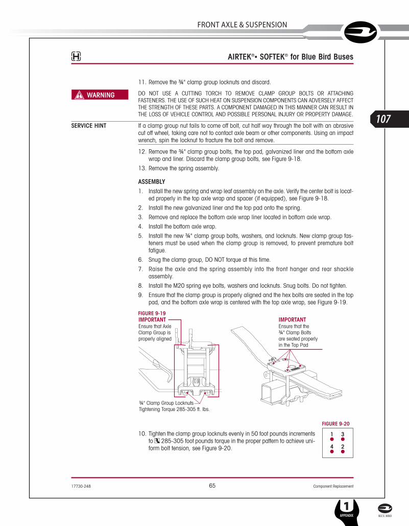
17730-248 65 Component Replacement
AIRTEK®• SOFTEK® for Blue Bird Buses
11. Remove the ¾" clamp group locknuts and discard.
DO NOT USE A CUTTING TORCH TO REMOVE CLAMP GROUP BOLTS OR ATTACHINGFASTENERS. THE USE OF SUCH HEAT ON SUSPENSION COMPONENTS CAN ADVERSELY AFFECTTHE STRENGTH OF THESE PARTS. A COMPONENT DAMAGED IN THIS MANNER CAN RESULT INTHE LOSS OF VEHICLE CONTROL AND POSSIBLE PERSONAL INJURY OR PROPERTY DAMAGE.
SERVICE HINT If a clamp group nut fails to come off bolt, cut half way through the bolt with an abrasivecut off wheel, taking care not to contact axle beam or other components. Using an impactwrench, spin the locknut to fracture the bolt and remove.
12. Remove the ¾" clamp group bolts, the top pad, galvanized liner and the bottom axlewrap and liner. Discard the clamp group bolts, see Figure 9-18.
13. Remove the spring assembly.
ASSEMBLY1. Install the new spring and wrap leaf assembly on the axle. Verify the center bolt is locat-
ed properly in the top axle wrap and spacer (if equipped), see Figure 9-18.
2. Install the new galvanized liner and the top pad onto the spring.
3. Remove and replace the bottom axle wrap liner located in bottom axle wrap.
4. Install the bottom axle wrap.
5. Install the new ¾" clamp group bolts, washers, and locknuts. New clamp group fas-teners must be used when the clamp group is removed, to prevent premature boltfatigue.
6. Snug the clamp group, DO NOT torque at this time.
7. Raise the axle and the spring assembly into the front hanger and rear shackleassembly.
8. Install the M20 spring eye bolts, washers and locknuts. Snug bolts. Do not tighten.
9. Ensure that the clamp group is properly aligned and the hex bolts are seated in the toppad, and the bottom axle wrap is centered with the top axle wrap, see Figure 9-19.
FIGURE 9-19
FIGURE 9-20
10. Tighten the clamp group locknuts evenly in 50 foot pounds incrementsto 285-305 foot pounds torque in the proper pattern to achieve uni-form bolt tension, see Figure 9-20.
SERVICE MANUAL
L
107
FRonT AxlE & SuSPEnSion
1APPENDIX

Component Replacement 66 17730-248
AIRTEK®• SOFTEK® for Blue Bird Buses
PRIOR TO AND DURING DEFLATION AND INFLATION OF THE FRONT AIR SUSPENSION SYSTEM,ENSURE THAT ALL PERSONNEL AND EQUIPMENT ARE CLEAR FROM UNDER THE VEHICLE ANDAROUND THE SERVICE AREA, FAILURE TO DO SO CAN CAUSE SERIOUS PERSONAL INJURY,DEATH, OR PROPERTY DAMAGE.
11. See additional Air Spring Cautions and Warnings in the Important Safety Notice Sectionof this publication prior to inflating or deflating the suspension system.
12. Install air spring.
13. Install air lines, and air up system.
14. Remove the frame supports and load the front axle with the vehicle weight.
15. Verify proper ride height. See Alignment & Adjustments Section of this publication.
16. Tighten the M20 spring eye bolt locknuts to vehicle manufacturer's specifications.
SOFTEK LEAF SPRING ASSEMBLY
DISASSEMBLY1. Place the vehicle on a level floor.
2. Chock the wheels.
3. Raise the vehicle.
4. Support the vehicle with frame stands.
5. Suspend the front axle to remove the load from leaf spring assembly.
6. Remove the front and rear M20 spring eye bolts washer and locknuts. Loosen the M20shackle pivot bolt.
SERVICE HINT To ease in the removal of the spring eye bolts, it may be necessary to raise the axle slightly.
7. Remove the ¾" clamp group U-bolts, washers and locknuts. Discard the fasteners.
DO NOT USE A CUTTING TORCH TO REMOVE CLAMP GROUP BOLTS OR ATTACHINGFASTENERS. THE USE OF SUCH HEAT ON SUSPENSION COMPONENTS CAN ADVERSELY AFFECTTHE STRENGTH OF THESE PARTS. A COMPONENT DAMAGED IN THIS MANNER CAN RESULT INTHE LOSS OF VEHICLE CONTROL AND POSSIBLE PERSONAL INJURY OR PROPERTY DAMAGE.
SERVICE HINT If a clamp group nut fails to come off bolt, cut half way through the bolt with an abrasivecut off wheel, taking care not to contact axle beam or other components. Using an impactwrench, spin the locknut to fracture the bolt and remove.
8. Remove the top pad, galvanized liner and the bottom axle wrap, see Figure 9-21.
9. Remove the spring assembly.
ASSEMBLY1. Install the new spring and wrap leaf assembly on the axle. Verify that the center bolt is
located properly in the top axle wrap and spacer (if equipped), see Figure 9-21.
2. Install the new galvanized liner and the top pad onto the spring.
3. Remove and replace the bottom axle wrap liner located in bottom axle wrap.
4. Install the bottom axle wrap.
5. Install the new ¾" clamp group U-bolts, washers, and locknuts. The locknuts must bereplaced when the clamp group is removed, to prevent premature bolt fatigue.
6. Snug the clamp group, DO NOT torque at this time.
L
108
1APPENDIX
SERVICE MANUAL

17730-248 67 Component Replacement
AIRTEK®• SOFTEK® for Blue Bird Buses
FIGURE 9-21
FIGURE 9-22
7. Raise the axle and the spring and wrap leafassembly into the front hanger and rear shackleassembly.
8. Install the M20 spring eye bolts, washers andlocknuts. Snug bolts. Do not tighten.
9. Ensure that the clamp group is properly alignedand the U-bolts are seated in the top pad, andthe bottom axle wrap is centered with the topaxle wrap, see Figure 9-22.
Front Hanger
Shock Absorber
M20 Bolt
¾" LowerShock Bolt
¾" LowerShock Locknut
Tightening Torque*125-135 ft. lbs.
Leaf Spring
Dowel Pin
Axle Spacer
Axle & Kingpin Assembly
Bottom Axle Wrap Liner
Bottom Axle Wrap¾" Clamp Group LocknutTightening Torque285-305 ft. lbs.
¾" Washer
Rear Hanger
M20 Bolt
M20 LocknutTightening Torque*290-310 ft. lbs.
M20 LocknutTightening Torque*290-310 ft. lbs.
Rear Shackle Plate
Top Wrap
M20 Washer
*Specification provided,controlled and subjectto change byvehicle manufacturer.
SERVICE MANUAL
L
109
FRonT AxlE & SuSPEnSion
1APPENDIX

Component Replacement 68 17730-248
AIRTEK®• SOFTEK® for Blue Bird Buses
FIGURE 9-23
10. Tighten the clamp group locknuts evenly in 50 foot pounds incrementsto 285-305 foot pounds torque in the proper pattern to achieve uni-form bolt tension, see Figure 9-23.
11. Remove the frame supports and load the front axle with the vehicleweight.
12. Tighten the M20 spring eye bolt locknuts to vehicle manufacturer's specifications.
FRONT LEAF SPRING EYE BUSHINGS The spring eye bushings for the AIRTEK and SOFTEK spring and wrap leaf assemblies aredesigned to provide extended service life. If premature wear occurs careful considerationmust be given to the contributing factor that caused the wear. This must be corrected inorder to prevent the new bushing from wearing in the same manner. The front and rearbushings are permanently installed in the spring leaf and are not serviceable. If a bushingwears prematurely, the spring and wrap leaf assembly must be replaced. Follow the pro-cedure for the Front Leaf Spring removal in the Component Replacement Section of thispublication.
AIRTEK/SOFTEK SHOCK ABSORBER – VISION (8K/10K)It is not necessary to replace shock absorbers in pairs if only one shock requires replacement.
DISASSEMBLY1. Remove the ¾" lower mounting bolt, fasteners, and spacer.
2. Remove the ¾" upper mounting bolt and fasteners.
3. Slide the shock absorber out of the upper bracket and off of the lower mounting bolt.
4. Inspect the shock absorber mounting brackets and hardware for damage or wear,replace as necessary.
FIGURE 9-24
ASSEMBLY1. Install the shock absorber into the upper mounting bracket.
2. Install the upper ¾" shock mounting bolt, washers and locknut.
Top Axle Wrap
¾" Lower Shock LocknutTightening torque*125-135 ft. lbs.
ShockAbsorber
Spacer
¾" Bolt
¾" Washer
¾" WasherApply a thin coatingof anti-seize compoundto the shock absorberlower mounting bolt shank,to the mating face of the axle wrap,and spacer, and to the inside boreof the aluminum top axle wrap
*Specification provided, controlled and subject to change by vehicle manufacturer.
L
110
1APPENDIX
SERVICE MANUAL

17730-248 69 Component Replacement
AIRTEK®• SOFTEK® for Blue Bird Buses
3. Apply a thin coating of anti-seize compound to the shock absorber lower mounting boltshank, to the mating face of the axle wrap and spacer, and to the inside bore of thealuminum axle wrap. This is necessary to help prevent seizing of the bolt to the alu-minum axle wrap.
4. Install the lower ¾" bolt from the inboard side to the outboard side of the top axle wrapand attach the spacer, washer, and locknut, see Figure 9-24.
5. Tighten both upper and lower ¾" locknuts to vehicle manufacturer's specifications, seeFigure 9-24.
AIRTEK/SOFTEK SHOCK ABSORBER – ALL AMERICAN (13.2K/14.6K)It is not necessary to replace shock absorbers in pairs if only one shock requires replacement.
DISASSEMBLY1. Remove the ¾" lower mounting bolt, fasteners, and spacer.
2. Remove the ¾" upper mounting bolt and fasteners.
3. Slide the shock absorber out of the lower bracket and off of the lower mounting bolt.
4. Inspect the shock absorber mounting brackets and hardware for damage or wear,replace as necessary.
FIGURE 9-25 FIGURE 9-26
ASSEMBLY1. Install the shock absorber into the upper mounting bracket.
2. Install the upper ¾" shock mounting bolt, washers and locknut.
3. Install the lower ¾" bolt from the inboard side to the outboard side of the top axle wrapand attach the spacer, washer, and locknut, see Figures 9-25 and 9-26.
4. Tighten both upper and lower ¾" locknuts to vehicle manufacturer's specifications, seeFigures 9-25 and 9-26.
Top Pad
¾" Lower Shock LocknutTightening torque*125-135 ft. lbs.
Shock AbsorberSpacer
¾" Bolt
¾" Washer
¾" Washer
Top Pad
¾" Lower Shock LocknutTightening torque*125-135 ft. lbs.
Shock Absorber
Spacer
¾" Bolt
¾" Washer
¾" Washer
AIRTEK 14.6K SOFTEK 13.2K/14.6K
*Specification provided, controlled and subject to change by vehicle manufacturer.
SERVICE MANUAL
L
111
FRonT AxlE & SuSPEnSion
1APPENDIX

Component Replacement 70 17730-248
AIRTEK®• SOFTEK® for Blue Bird Buses
AIRTEK BOTTOM AXLE WRAP
DISASSEMBLY1. Place the vehicle on level floor.
2. Chock the wheels.
3. Raise the frame.
4. Support the vehicle with frame stands.
PRIOR TO AND DURING DEFLATION AND INFLATION OF THE FRONT AIR SUSPENSION SYSTEM,ENSURE THAT ALL PERSONNEL AND EQUIPMENT ARE CLEAR FROM UNDER THE VEHICLE ANDAROUND THE SERVICE AREA, FAILURE TO DO SO CAN CAUSE SERIOUS PERSONAL INJURY,DEATH, OR PROPERTY DAMAGE.
5. See additional Air Spring Cautions and Warnings in the Important Safety Notice Sectionof this publication prior to inflating or deflating the suspension system.
6. Deflate the air springs by disconnecting the height control valve linkage and loweringthe height control valve arm. This will exhaust the air pressure in the air springs.
DO NOT USE A CUTTING TORCH TO REMOVE CLAMP GROUP BOLTS OR ATTACHINGFASTENERS. THE USE OF SUCH HEAT ON SUSPENSION COMPONENTS CAN ADVERSELY AFFECTTHE STRENGTH OF THESE PARTS. A COMPONENT DAMAGED IN THIS MANNER CAN RESULT INTHE LOSS OF VEHICLE CONTROL AND POSSIBLE PERSONAL INJURY OR PROPERTY DAMAGE.
SERVICE HINT If a clamp group nut fails to come off bolt, cut half way through the bolt with an abrasivecut off wheel, taking care not to contact axle beam or other components. Using an impactwrench, spin the locknut to fracture the bolt and remove.
7. Remove ¾" hex bolts, washers and locknuts. Removal of the air spring will berequired. See Air Spring Replacement instructions in this section. Discard fasteners.
8. Remove bottom axle wrap. It may be necessary to use a dead blow mallet to dislodgeaxle wrap.
9. Once removed inspect axle wrap for damage. Replace if necessary.
10. Discard used bottom axle wrap liner.
ASSEMBLY1. Install new bottom axle wrap liner into bottom axle wrap.
2. Install bottom axle wrap on axle.FIGURE 9-27 AIRTEK
L
112
1APPENDIX
SERVICE MANUAL

17730-248 71 Component Replacement
AIRTEK®• SOFTEK® for Blue Bird Buses
3. Install new ¾" clamp group bolts, washers and locknuts. Ensure that the clamp groupis properly aligned and the hex bolts are seated in the top pad, and the bottom axlewrap is centered on the top axle wrap, see Figure 9-27.
FIGURE 9-28
4. Tighten locknuts evenly to 285-305 foot pounds torque, see Figure9-28 for proper torque sequence.
5. Install Air spring. See Air Spring assembly in this section.
6. Remove the wheel chocks.
SOFTEK BOTTOM AXLE WRAP
DISASSEMBLY1. Place the vehicle on level floor.
2. Chock the wheels.
3. Raise the frame.
4. Support the vehicle with frame stands.
DO NOT USE A CUTTING TORCH TO REMOVE CLAMP GROUP BOLTS OR ATTACHINGFASTENERS. THE USE OF SUCH HEAT ON SUSPENSION COMPONENTS CAN ADVERSELY AFFECTTHE STRENGTH OF THESE PARTS. A COMPONENT DAMAGED IN THIS MANNER CAN RESULT INTHE LOSS OF VEHICLE CONTROL AND POSSIBLE PERSONAL INJURY OR PROPERTY DAMAGE.
SERVICE HINT If a clamp group nut fails to come off bolt, cut half way through the bolt with an abrasivecut off wheel, taking care not to contact axle beam or other components. Using an impactwrench, spin the locknut to fracture the bolt and remove.
5. Remove ¾" U-bolts, washers and locknuts. Discard fasteners.
6. Remove bottom axle wrap. It may be necessary to use a dead blow mallet to dislodgeaxle wrap.
7. Once removed inspect axle wrap for damage. Replace if necessary.
8. Discard used bottom axle wrap liner.
ASSEMBLYFIGURE 9-29 SOFTEK
1. Install new bottom axle wrap liner into bottom axlewrap.
2. Install bottom axle wrap on axle.
3. Install new ¾" U-bolts, washers and locknuts.Ensure that the clamp group is properly alignedand the U-bolts are seated in the top pad, and thebottom axle wrap is centered with the top axlewrap, see Figure 9-29.
4. Tighten locknuts evenly to 285-305 foot poundstorque, see Figure 9-28 for proper torque sequence.
5. Remove the wheel chocks.
SERVICE MANUAL
L
113
FRonT AxlE & SuSPEnSion
1APPENDIX
Component Replacement 72 17730-248
AIRTEK®• SOFTEK® for Blue Bird Buses
AIRTEK TOP AXLE WRAP (In Chassis)
DISASSEMBLY1. Place the vehicle on level floor.
2. Chock the wheels.
3. Raise the frame.
4. Support the vehicle with frame stands.
5. Suspend the front axle to remove the load from the spring and wrap leaf assembly.
PRIOR TO AND DURING DEFLATION AND INFLATION OF THE FRONT AIR SUSPENSION SYSTEM,ENSURE THAT ALL PERSONNEL AND EQUIPMENT ARE CLEAR FROM UNDER THE VEHICLE ANDAROUND THE SERVICE AREA, FAILURE TO DO SO CAN CAUSE SERIOUS PERSONAL INJURY,DEATH, OR PROPERTY DAMAGE.
6. See additional Air Spring Cautions and Warnings in the Important Safety Notice Sectionof this publication prior to inflating or deflating the suspension system.
AIR SPRINGS MUST BE DEFLATED PRIOR TO LOOSENING ANY CLAMP GROUP HARDWARE.UNCONSTRAINED AIR SPRINGS CAN VIOLENTLY SHIFT, RESULTING IN POSSIBLE PERSONALINJURY, DEATH OR PROPERTY DAMAGE.
7. Deflate the air springs by disconnecting the height control valve linkage and loweringthe height control valve arm. This will exhaust the air pressure in the air springs.
8. Disconnect the air lines at the air springs.
9. Remove the air spring (See Air Spring disassembly in this section).
10. Support the axle with a jack.
11. Remove the front and rear M20 spring eye bolts, washers and locknuts.
SERVICE HINT A bottle jack may be required to raise the axle slightly in order to remove spring eye bolts.
DO NOT USE A CUTTING TORCH TO REMOVE CLAMP GROUP BOLTS OR ATTACHINGFASTENERS. THE USE OF SUCH HEAT ON SUSPENSION COMPONENTS CAN ADVERSELY AFFECTTHE STRENGTH OF THESE PARTS. A COMPONENT DAMAGED IN THIS MANNER CAN RESULT INTHE LOSS OF VEHICLE CONTROL AND POSSIBLE PERSONAL INJURY OR PROPERTY DAMAGE.
SERVICE HINT If a clamp group nut fails to come off bolt, cut half way through the bolt with an abrasivecut off wheel, taking care not to contact axle beam or other components. Using an impactwrench, spin the locknut to fracture the bolt and remove.
12. Remove the ¾" clamp group bolts, washers and locknuts. Discard fasteners.
13. Remove the top pad, the galvanized liner, and the bottom axle wrap.
14. Remove the lower shock mounting bolt.
15. Remove the spring and wrap leaf assembly
16. Strike the axle wrap with a dead blow mallet at the front and rear on the underside ofthe axle wrap to dislodge it from the axle, see Figure 9-30.
17. Clean and inspect the axle wrap and axle wrap line for cracks or damage, replace eachif cracks or damage are present.
L
114
1APPENDIX
SERVICE MANUAL

17730-248 73 Component Replacement
AIRTEK®• SOFTEK® for Blue Bird Buses
FIGURE 9-30
ASSEMBLY1. Install the new axle wrap liner on the axle.
2. Spray the axle wrap liner and the axle wrap with a silicon lubricant.3. Position the axle wrap on the axle, see Figure 9-31.
DO NOT STRIKE THE TOP AXLE WRAP WITH A HAMMER. HENDRICKSON RECOMMENDS USINGA PLASTIC DEAD BLOW MALLET WITH CARE WHEN INSTALLING THE AXLE WRAP.
FIGURE 9-31
4. Protect the top surface of the axlewrap with a block of wood, card-board, or shop towels.
5. Install a bottle jack between the axlewrap and frame rail flange.
6. Jack the axle wrap down into positionon the axle, using care to make surethe axle wrap bore indexes the locat-ing bushing on the axle.
IMPORTANT NOTE For Flat Floor Models install theintermediate dowel pin into the axle wrap.
7. Install the spring and wrap leafassembly on the axle wrap (indexingthe dowel pin if equipped).
8. Install the galvanized liner and the toppad on the spring and wrap leaf assembly.
9. Remove and replace the bottom axle wrap liner.
10. Install the bottom axle wrap.
11. Install the new ¾" clamp group bolts, washers, and locknuts.
12. Snug the clamp group, DO NOT torque at this time.
13. Use a jack and raise the axle and spring assembly into the front spring hanger andshackle assembly.
SERVICE HINT A bottle jack may be required to raise the axle slightly in order to install the spring eye bolts.
14. Install the M20 spring eye bolts in the front spring hanger and rear shackle assembly.
15. Ensure that the clamp group is properly aligned and the hex bolts are seated in the top pad,and the bottom axle wrap is centered with the top axle wrap, see Figure 9-32.
10K TopAxle Wrap
Top AxleWrap Liner
Axle WrapGuide Pin
Axle
14.6K TopAxle Wrap
SERVICE MANUAL
L
115
FRonT AxlE & SuSPEnSion
1APPENDIX

Component Replacement 74 17730-248
AIRTEK®• SOFTEK® for Blue Bird Buses
FIGURE 9-32
FIGURE 9-33
16. Tighten the ¾" clamp group locknuts evenly to 285-305 footpounds torque in the proper sequence, see Figure 9-33.
17. Remove the jack from the axle.
18. Remove the frame stands.
PRIOR TO AND DURING DEFLATION AND INFLATION OF THE FRONT AIR SUSPENSION SYSTEM,ENSURE THAT ALL PERSONNEL AND EQUIPMENT ARE CLEAR FROM UNDER THE VEHICLE ANDAROUND THE SERVICE AREA, FAILURE TO DO SO CAN CAUSE SERIOUS PERSONAL INJURY,DEATH, OR PROPERTY DAMAGE.
19. See additional Air Spring Cautions and Warnings in the Important Safety Notice Sectionof this publication prior to inflating or deflating the suspension system.
20. Attach air lines to the air springs.
21. Install shocks. (See shock absorber assembly in this section)
22. Air up system to proper ride height. (See Ride Height Adjustment in the Alignment &Adjustments Section of this publication).
23. Tighten the M20 spring eye bolt locknuts to vehicle manufacturer's specifications, seeFigure 9-34.
24. Remove the wheel chocks.FIGURE 9-34
L
116
1APPENDIX
SERVICE MANUAL
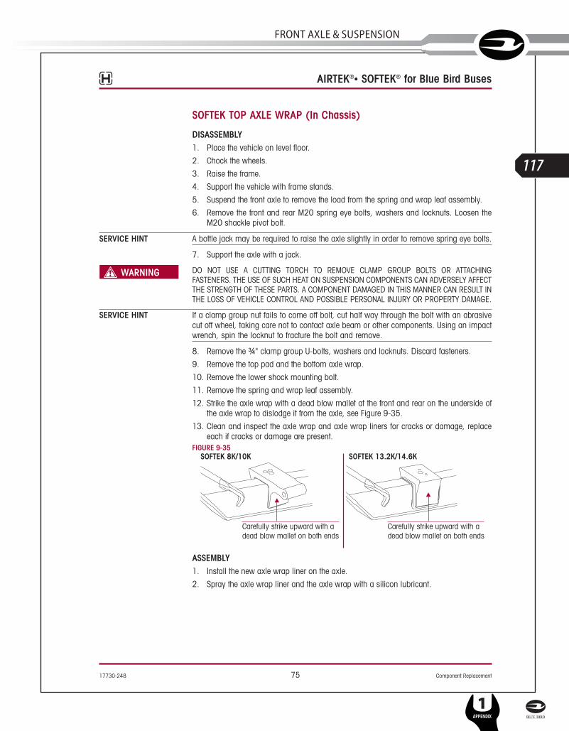
17730-248 75 Component Replacement
AIRTEK®• SOFTEK® for Blue Bird Buses
SOFTEK TOP AXLE WRAP (In Chassis)
DISASSEMBLY1. Place the vehicle on level floor.
2. Chock the wheels.
3. Raise the frame.
4. Support the vehicle with frame stands.
5. Suspend the front axle to remove the load from the spring and wrap leaf assembly.
6. Remove the front and rear M20 spring eye bolts, washers and locknuts. Loosen theM20 shackle pivot bolt.
SERVICE HINT A bottle jack may be required to raise the axle slightly in order to remove spring eye bolts.
7. Support the axle with a jack.
DO NOT USE A CUTTING TORCH TO REMOVE CLAMP GROUP BOLTS OR ATTACHINGFASTENERS. THE USE OF SUCH HEAT ON SUSPENSION COMPONENTS CAN ADVERSELY AFFECTTHE STRENGTH OF THESE PARTS. A COMPONENT DAMAGED IN THIS MANNER CAN RESULT INTHE LOSS OF VEHICLE CONTROL AND POSSIBLE PERSONAL INJURY OR PROPERTY DAMAGE.
SERVICE HINT If a clamp group nut fails to come off bolt, cut half way through the bolt with an abrasivecut off wheel, taking care not to contact axle beam or other components. Using an impactwrench, spin the locknut to fracture the bolt and remove.
8. Remove the ¾" clamp group U-bolts, washers and locknuts. Discard fasteners.
9. Remove the top pad and the bottom axle wrap.
10. Remove the lower shock mounting bolt.
11. Remove the spring and wrap leaf assembly.
12. Strike the axle wrap with a dead blow mallet at the front and rear on the underside ofthe axle wrap to dislodge it from the axle, see Figure 9-35.
13. Clean and inspect the axle wrap and axle wrap liners for cracks or damage, replaceeach if cracks or damage are present.
FIGURE 9-35
ASSEMBLY1. Install the new axle wrap liner on the axle.
2. Spray the axle wrap liner and the axle wrap with a silicon lubricant.
SERVICE MANUAL
L
117
FRonT AxlE & SuSPEnSion
1APPENDIX

Component Replacement 76 17730-248
AIRTEK®• SOFTEK® for Blue Bird Buses
FIGURE 9-36
3. Position the axle wrap on the axle, seeFigure 9-36.
DO NOT STRIKE THE TOP AXLE WRAP WITHA HAMMER. HENDRICKSON RECOMMENDSUSING A PLASTIC DEAD BLOW MALLET WITHCARE WHEN INSTALLING THE AXLE WRAP.
4. Protect the top surface of the axle wrapwith a block of wood, cardboard, orshop towels.
5. Install a bottle jack between the axlewrap and frame rail flange.
6. Jack the axle wrap down into positionon the axle, using care to make surethe axle wrap bore indexes the locatingbushing on the axle.
7. Install the spring and wrap leaf assembly on the axle wrap indexing the center bolt inthe locating hole.
8. Install the top pad on the spring and wrap leaf assembly.
9. Remove and replace the bottom axle wrap liner.
10. Install the bottom axle wrap.
11. Install the new ¾" clamp group U-bolts, washers, and locknuts.
12. Snug the clamp group, DO NOT torque at this time.FIGURE 9-37 SOFTEK
13. Use a jack and raise the axle and spring assem-bly into the front spring hanger and shackleassembly.
SERVICE HINT A bottle jack may be required to raise the axle slightlyin order to install the spring eye bolts.
14. Install the M20 spring eye bolts, washer andlocknuts in the front spring hanger and rearshackle assembly.
15. Ensure that the clamp group is properly alignedand the U-bolts are seated in the top pad, and thebottom axle wrap is centered with the top axlewrap, see Figure 9-37.
FIGURE 9-38
16. Tighten the ¾" clamp group locknuts evenly to 285-305 footpounds torque in the proper sequence, see Figure 9-38.
17. Apply a thin coating of anti-seize to the lower shock mounting bolt.
18. Install shocks. (See shock absorber assembly in this section)
19. Remove the jack from the axle.
20. Remove the frame stands.
21. Tighten the M20 spring eye bolt locknuts to vehicle manufacturer's specifications.
22. Remove the wheel chocks.
8K/10K TopAxle Wrap
Top AxleWrap Liner
Axle WrapGuide Pin
Axle
13.2K/14.6KTop Axle Wrap
L
118
1APPENDIX
SERVICE MANUAL

17730-248 77 Component Replacement
AIRTEK®• SOFTEK® for Blue Bird Buses
AIRTEK FRONT AXLE ASSEMBLY
STEERTEK AXLE CLAMP GROUP CONSIST OF THE FOLLOWING COMPONENTS:■ Top axle wrap ■ Bottom axle wrap■ Top axle wrap liner ■ Bottom axle wrap liner■ Top pad ■ ¾" Bolts, washers and nylon locknuts
FIGURE 9-39SHOWN AIRTEK 10K
Leaf Spring
Spring Eye Bolt
Height ControlValve Linkage
LH LowerSteering Knuckle
Bottom Wrap
Lower Shock Locknut
Bottom AxleWrap Liner
LH UpperSteering Knuckle
RH UpperSteering Knuckle
King Pin Bushing
King Pin Seal
Cap Screws
LH Tie Rod End
Tie Rod Assembly
¾" Bolts
Rear ShackleAssembly
Axle & KingPin Assembly
Top AxleWrap
CotterPin ¾" Washer
¾" Locknut
Composite Bearing
Top Pad
Spacer
Air Spring
RH LowerSteering Knuckle
RH Tie Rod End
RollerBearing
7 8/ " Washer
Castle Nut
SERVICE MANUAL
L
119
FRonT AxlE & SuSPEnSion
1APPENDIX
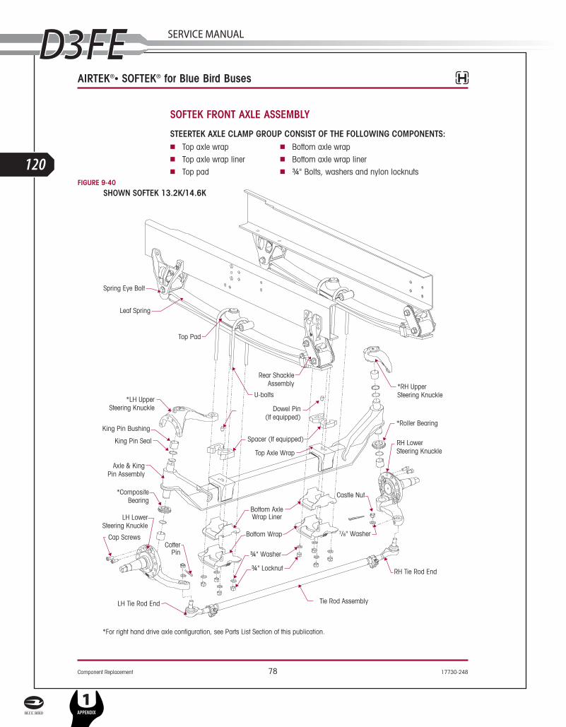
Component Replacement 78 17730-248
AIRTEK®• SOFTEK® for Blue Bird Buses
SOFTEK FRONT AXLE ASSEMBLY
STEERTEK AXLE CLAMP GROUP CONSIST OF THE FOLLOWING COMPONENTS:■ Top axle wrap ■ Bottom axle wrap■ Top axle wrap liner ■ Bottom axle wrap liner■ Top pad ■ ¾" Bolts, washers and nylon locknuts
FIGURE 9-40
L
120
1APPENDIX
SERVICE MANUAL
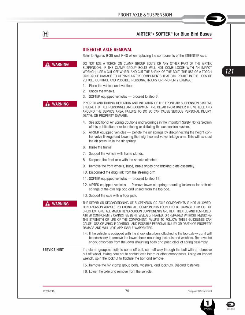
17730-248 79 Component Replacement
AIRTEK®• SOFTEK® for Blue Bird Buses
STEERTEK AXLE REMOVALRefer to Figures 9-39 and 9-40 when replacing the components of the STEERTEK axle.
DO NOT USE A TORCH ON CLAMP GROUP BOLTS OR ANY OTHER PART OF THE AIRTEKSUSPENSION. IF THE CLAMP GROUP BOLTS WILL NOT COME LOOSE WITH AN IMPACTWRENCH, USE A CUT OFF WHEEL AND CUT THE SHANK OF THE BOLT. THE USE OF A TORCHCAN CAUSE DAMAGE TO CERTAIN AIRTEK COMPONENTS THAT CAN RESULT IN THE LOSS OFVEHICLE CONTROL AND POSSIBLE PERSONAL INJURY OR PROPERTY DAMAGE.
1. Place the vehicle on level floor.2. Chock the wheels.3. SOFTEK equipped vehicles — proceed to step 6.
PRIOR TO AND DURING DEFLATION AND INFLATION OF THE FRONT AIR SUSPENSION SYSTEM,ENSURE THAT ALL PERSONNEL AND EQUIPMENT ARE CLEAR FROM UNDER THE VEHICLE ANDAROUND THE SERVICE AREA, FAILURE TO DO SO CAN CAUSE SERIOUS PERSONAL INJURY,DEATH, OR PROPERTY DAMAGE.
4. See additional Air Spring Cautions and Warnings in the Important Safety Notice Sectionof this publication prior to inflating or deflating the suspension system.
5. AIRTEK equipped vehicles — Deflate the air springs by disconnecting the height con-trol valve linkage and lowering the height control valve linkage arm. This will exhaustthe air pressure in the air springs.
6. Raise the frame.
7. Support the vehicle with frame stands.
8. Suspend the front axle with the shocks attached.
9. Remove the front wheels, hubs, brake shoes and backing plate assembly.
10. Disconnect the drag link from the steering arm.
11. SOFTEK equipped vehicles — proceed to step 13.
12. AIRTEK equipped vehicles — Remove lower air spring mounting fasteners for both airsprings at the axle top pad and unseat from the top pad.
13. Support the axle with a floor jack.
THE REPAIR OR RECONDITIONING OF SUSPENSION OR AXLE COMPONENTS IS NOT ALLOWED.HENDRICKSON ADVISES REPLACING ALL COMPONENTS FOUND TO BE DAMAGED OR OUT OFSPECIFICATIONS. ALL MAJOR HENDRICKSON COMPONENTS ARE HEAT TREATED AND TEMPERED.AIRTEK COMPONENTS CANNOT BE BENT, WELDED, HEATED, OR REPAIRED WITHOUT REDUCINGTHE STRENGTH OR LIFE OF THE COMPONENT. FAILURE TO FOLLOW THESE GUIDELINES CANCAUSE LOSS OF VEHICLE CONTROL, AND POSSIBLE PERSONAL INJURY OR DEATH OR PROPERTYDAMAGE AND WILL VOID APPLICABLE WARRANTIES.
14. If the vehicle is equipped with the shock absorbers attached to the top axle wrap, it willbe necessary to remove the lower shock mounting locknuts and washers. Remove theshock absorbers from the lower mounting bolts and push clear of spring assembly.
SERVICE HINT If a clamp group nut fails to come off bolt, cut half way through the bolt with an abrasivecut off wheel, taking care not to contact axle beam or other components. Using an impactwrench, spin the locknut to fracture the bolt and remove.
15. Remove the ¾" clamp group bolts, washers, and locknuts. Discard fasteners.
16. Lower the axle and remove from the vehicle.
SERVICE MANUAL
L
121
FRonT AxlE & SuSPEnSion
1APPENDIX

Component Replacement 80 17730-248
AIRTEK®• SOFTEK® for Blue Bird Buses
STEERTEK AXLE (Removed from Chassis)
AXLE DISASSEMBLY1. Remove the bottom axle wrap and liner from the axle.
2. Strike the top axle wrap with a dead blow mallet at the front and rear on the undersideof the axle wrap to dislodge it from the axle, see Figure 9-41.
FIGURE 9-41
3. After removal of the top axle wrap from the axle inspect for cracks or fretting.
4. Remove the tie rod assembly. See Tie Rod disassembly in this section.
REMOVAL OF THE CAP SCREWS WILL ALLOW THE STEERING KNUCKLE TO SEPARATE FROM THEAXLE. THE BACKBONE MUST BE SUPPORTED BEFORE REMOVAL OF THESE TWO (2) CAPSCREWS. FAILURE TO DO SO CAN CAUSE COMPONENT DAMAGE OR PERSONAL INJURY.
5. Remove the two 5⁄8" socket head cap screws from the steering knuckle assembly.
6. Remove the steering knuckle, thrust bearing, and shims (if equipped).
7. After complete removal of the one side, repeat steps 1-6 for the opposite side of the axle.
8. Inspect the steering kingpin bushings for excessive wear. If worn, replace the kingpinbushings and seals. See the Kingpin Bushing replacement instructions in this section.
AXLE PRE-ASSEMBLYFIGURE 9-42
1. Install the new upper axle wrap liner onthe axle. Index the liner with the axle'sguide pin, see Figure 9-42.
DO NOT STRIKE THE TOP AXLE WRAP WITHA HAMMER. DAMAGE TO THE ALUMINUMAXLE WRAP WILL OCCUR. USE A PLASTICDEAD BLOW MALLET WITH CARE WHENINSTALLING THE AXLE WRAP.
SECURELY INSTALL THE TOP WRAP TO THEAXLE. FAILURE TO DO SO CAN CAUSE LOSSOF CONTROL OF THE VEHICLE, PERSONALINJURY OR PROPERTY DAMAGE.
SERVICE HINT Apply a lubricant (such as an aerosolsilicone) to the outer surface of the plasticliner to aid in assembly of the top axle wrap.
2. Install the top axle wrap, see Axle WrapAssembly instructions located in this section. The axle wrap must be aligned with theguide pin on the axle.
3. At this point in the assembly, do not install anything further on the axle.
Top AxleWrap-8K/10K
Top AxleWrap Liner
Axle WrapGuide Pin Axle
Top AxleWrap
13.2K/14.6K
Bottom AxleWrap Liner
Bottom AxleWrap
L
122
1APPENDIX
SERVICE MANUAL
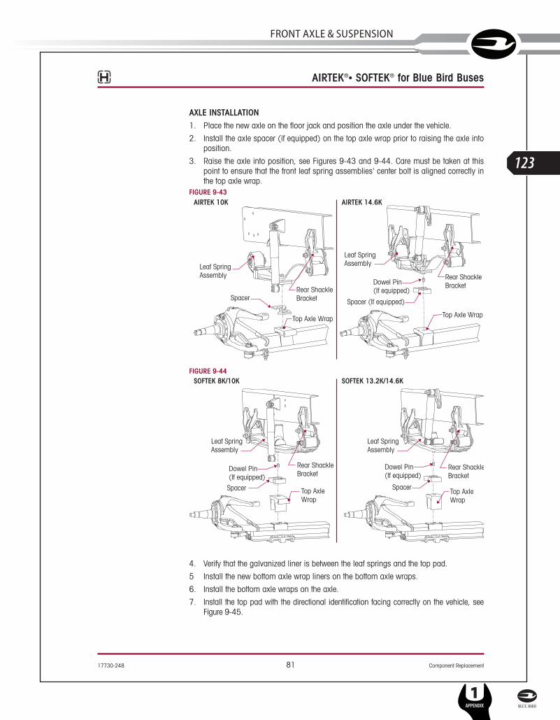
17730-248 81 Component Replacement
AIRTEK®• SOFTEK® for Blue Bird Buses
AXLE INSTALLATION1. Place the new axle on the floor jack and position the axle under the vehicle.
2. Install the axle spacer (if equipped) on the top axle wrap prior to raising the axle intoposition.
3. Raise the axle into position, see Figures 9-43 and 9-44. Care must be taken at thispoint to ensure that the front leaf spring assemblies' center bolt is aligned correctly inthe top axle wrap.
FIGURE 9-43
FIGURE 9-44
4. Verify that the galvanized liner is between the leaf springs and the top pad.
5 Install the new bottom axle wrap liners on the bottom axle wraps.
6. Install the bottom axle wraps on the axle.
7. Install the top pad with the directional identification facing correctly on the vehicle, seeFigure 9-45.
Rear ShackleBracket
SpacerTop AxleWrap
Leaf SpringAssembly
Dowel Pin(If equipped)
Leaf SpringAssembly
Spacer
Rear ShackleBracket
Top AxleWrap
Dowel Pin(If equipped)
SOFTEK 8K/10K SOFTEK 13.2K/14.6K
Rear ShackleBracket
Spacer (If equipped)
Top Axle Wrap
Leaf SpringAssembly
Dowel Pin(If equipped)
Leaf SpringAssembly
SpacerRear ShackleBracket
Top Axle Wrap
AIRTEK 10K AIRTEK 14.6K
SERVICE MANUAL
L
123
FRonT AxlE & SuSPEnSion
1APPENDIX
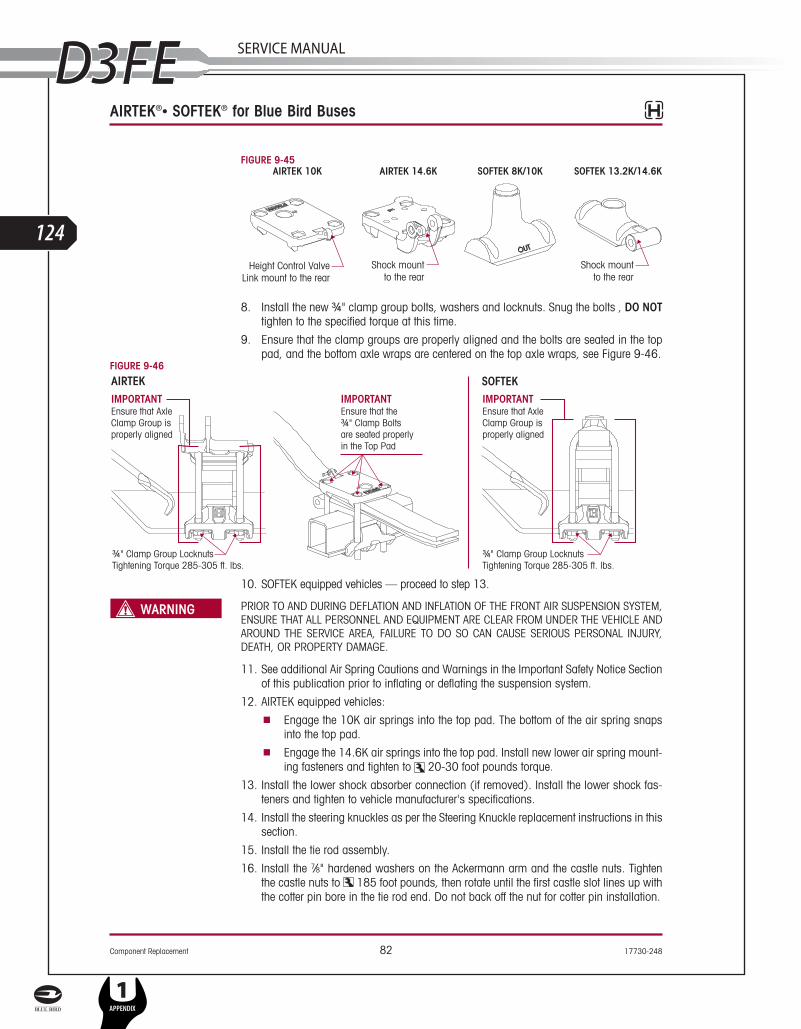
Component Replacement 82 17730-248
AIRTEK®• SOFTEK® for Blue Bird Buses
FIGURE 9-45
8. Install the new ¾" clamp group bolts, washers and locknuts. Snug the bolts , DO NOTtighten to the specified torque at this time.
9. Ensure that the clamp groups are properly aligned and the bolts are seated in the toppad, and the bottom axle wraps are centered on the top axle wraps, see Figure 9-46.
FIGURE 9-46
10. SOFTEK equipped vehicles — proceed to step 13.
PRIOR TO AND DURING DEFLATION AND INFLATION OF THE FRONT AIR SUSPENSION SYSTEM,ENSURE THAT ALL PERSONNEL AND EQUIPMENT ARE CLEAR FROM UNDER THE VEHICLE ANDAROUND THE SERVICE AREA, FAILURE TO DO SO CAN CAUSE SERIOUS PERSONAL INJURY,DEATH, OR PROPERTY DAMAGE.
11. See additional Air Spring Cautions and Warnings in the Important Safety Notice Sectionof this publication prior to inflating or deflating the suspension system.
12. AIRTEK equipped vehicles: ■ Engage the 10K air springs into the top pad. The bottom of the air spring snaps
into the top pad.■ Engage the 14.6K air springs into the top pad. Install new lower air spring mount-
ing fasteners and tighten to 20-30 foot pounds torque.
13. Install the lower shock absorber connection (if removed). Install the lower shock fas-teners and tighten to vehicle manufacturer's specifications.
14. Install the steering knuckles as per the Steering Knuckle replacement instructions in thissection.
15. Install the tie rod assembly.
16. Install the 7⁄8" hardened washers on the Ackermann arm and the castle nuts. Tightenthe castle nuts to 185 foot pounds, then rotate until the first castle slot lines up withthe cotter pin bore in the tie rod end. Do not back off the nut for cotter pin installation.
L
124
1APPENDIX
SERVICE MANUAL

17730-248 83 Component Replacement
AIRTEK®• SOFTEK® for Blue Bird Buses
17. Install the tie rod end cotter pins.
18. Connect the drag link. Install the castle nut. Tighten the castle nut to 185 footpounds, then rotate until the first castle slot lines up with the cotter pin bore in the draglink. Do not back off the nut for cotter pin installation.
19. Install the drag link cotter pin.
20. Install the brake backing plate assemblies.
21. Install the brakes, hubs, and wheels as per manufacturer’s guidelines.
22. Fill the hubs with the proper lubricant (see manufacturer’s guidelines for recommend-ed lubrication specifications).
23. Raise the vehicle and remove the frame stands.
24. Lower the vehicle.
25. SOFTEK equipped vehicles — proceed to step number 27.
26 AIRTEK equipped vehicles — Reconnect the height control valve and air up the system.FIGURE 9-47
27. Tighten the ¾" clamp group locknuts evenly in 50 foot pounds incre-ments to 285-305 foot pounds torque in the proper sequence toachieve uniform bolt tension, see Figure 9-47.
28. SOFTEK equipped vehicles — proceed to step number 30.
29 AIRTEK equipped vehicles — Adjust ride height per instructions in the Alignment &Adjustments Section of this publication.
30. Grease the front steering components as per lubrication guidelines in the PreventiveMaintenance Section of this publication.
31. Remove the wheel chocks.
STEERING KNUCKLE DISASSEMBLY
DISASSEMBLYSee tools needed to remove and install kingpin bushing under the Special Tools Section ofthis publication.
The steering knuckle disassembly and assembly includes the Kingpin Preparation andMeasurement and Kingpin Bushing Removal process.
1. Place the vehicle on level floor.
2. Chock the wheels.
3. Raise the frame.
4. Support the vehicle with frame stands.
5. Remove the wheel and hub assembly.
6. Remove the brake components from steering knuckle.
7. Remove the tie rod assembly.FIGURE 9-48
SERVICE HINT Lightly tap the side of the Ackermannarm with a mallet to separate the tierod end from the Ackermann arm, seeFigure 9-48.
8. Remove the drag link from theknuckle if necessary.
SERVICE MANUAL
L
125
FRonT AxlE & SuSPEnSion
1APPENDIX

Component Replacement 84 17730-248
AIRTEK®• SOFTEK® for Blue Bird Buses
REMOVAL OF THE CAP SCREWS WILL ALLOW THE STEERING KNUCKLE TO SEPARATE FROMTHE AXLE. THE STEERING KNUCKLE MUST BE SUPPORTED BEFORE REMOVAL OF THESE TWO(2) CAP SCREWS. FAILURE TO DO SO CAN CAUSE COMPONENT DAMAGE OR PERSONALINJURY.
FIGURE 9-49
9. Remove the 2 socket head capscrews that connect upperkingpin connection to the steer-ing knuckle, see Figure 9-49.
10. Remove the lower steeringknuckle from the kingpin bysliding it down the kingpin.
11. Remove the upper steeringknuckle by sliding it up off thekingpin.
KINGPIN PREPARATIONAND MEASUREMENT
CLEANING GROUND AND POLISHED PARTS■ Use a cleaning solvent to clean ground or polished parts and surfaces. DO NOT USE
GASOLINE.■ Do not clean ground or polished parts in a hot solution tank or with water, steam, or
alkaline solutions. These solutions will cause corrosion of the parts.
DRYING THE CLEANED PARTS■ Parts must be dried immediately after cleaning. Dry the parts with clean paper towels,
clean rags, or compressed air. Do not dry bearings by spinning with compressed air.Damage to the bearings will result.
PREVENTING CORROSION ON CLEANED PARTS■ Apply a light coating of oil to all cleaned and dried parts that are going to be reused.
Do not apply oil to the brake lining or the brake drums. If parts are to be stored, applyan effective rust inhibitor to all surfaces.
TO HELP PREVENT SERIOUS EYE INJURY, ALWAYS WEAR PROPER EYE PROTECTION WHENYOU PERFORM VEHICLE MAINTENANCE OR SERVICE.
SOLVENT CLEANERS CAN BE FLAMMABLE, POISONOUS AND CAUSE BURNS. TO HELP AVOIDSERIOUS PERSONAL INJURY, CAREFULLY FOLLOW THE MANUFACTURER’S PRODUCTINSTRUCTIONS AND GUIDELINES AND THE FOLLOWING PROCEDURES:
■ WEAR PROPER EYE PROTECTION.■ WEAR CLOTHING THAT PROTECTS YOUR SKIN.■ WORK IN A WELL VENTILATED AREA.■ DO NOT USE GASOLINE, SOLVENTS OR OTHER MATERIALS THAT CONTAIN GASOLINE
THAT CAN EXPLODE.■ HOT SOLUTION TANKS OR ALKALINE SOLUTIONS MUST BE USED CORRECTLY. FOLLOW
THE MANUFACTURER’S RECOMMENDED INSTRUCTIONS AND GUIDELINES CAREFULLYTO HELP PREVENT PERSONAL ACCIDENT OR INJURY.
L
126
1APPENDIX
SERVICE MANUAL

17730-248 85 Component Replacement
AIRTEK®• SOFTEK® for Blue Bird Buses
DO NOT USE HOT SOLUTION TANKS OR WATER AND ALKALINE SOLUTIONS TO CLEAN GROUNDOR POLISHED PARTS. DAMAGE TO THE PARTS WILL RESULT.
THE STEERTEK HAS A UNIQUE AXLE. THE KINGPIN IS CRYOGENICALLY INSTALLED IN THE AXLE.THE KINGPIN IS A NON-REPLACEABLE COMPONENT OF THE AXLE ASSEMBLY. DO NOT TRY TOREMOVE THE KINGPIN. DOING SO WILL DAMAGE THE AXLE AND MAY CAUSE LOSS OF VEHICLECONTROL, PERSONAL INJURY OR PROPERTY DAMAGE. IF THE KINGPIN SHOWS SIGNS OFMOVEMENT, CONTACT HENDRICKSON PRODUCT ENGINEERING - TECH SERVICES.
1. Prepare and polish the kingpin by removing all grease and excess debris using a fine grit(220 grit or higher) emery cloth and parts solvent, see Figures 9-50 through 9-53.
FIGURE 9-50 FIGURE 9-51
FIGURE 9-52 KINGPIN BEFORE CLEANING FIGURE 9-53 KINGPIN AFTER CLEANING
2. Inspect the kingpin for wear or damage. Use a micrometer and measure the upper andlower kingpin in two locations. Positions must be 90º opposed from each other. If thekingpin has less than 1.802" diameter, replacement of the axle is necessary, seeFigures 9-54 through 9-57.Kingpin minimum dimension is 1.802"
FIGURE 9-54 FIGURE 9-55
SERVICE MANUAL
L
127
FRonT AxlE & SuSPEnSion
1APPENDIX
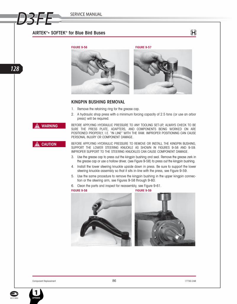
Component Replacement 86 17730-248
AIRTEK®• SOFTEK® for Blue Bird Buses
FIGURE 9-56 FIGURE 9-57
KINGPIN BUSHING REMOVAL 1. Remove the retaining ring for the grease cap.
2. A hydraulic shop press with a minimum forcing capacity of 2.5 tons (or use an arborpress) will be required.
BEFORE APPLYING HYDRAULIC PRESSURE TO ANY TOOLING SET-UP, ALWAYS CHECK TO BESURE THE PRESS PLATE, ADAPTERS, AND COMPONENTS BEING WORKED ON AREPOSITIONED PROPERLY, I.E. “IN LINE” WITH THE RAM. IMPROPER POSITIONING CAN CAUSEPERSONAL INJURY OR COMPONENT DAMAGE.
BEFORE APPLYING HYDRAULIC PRESSURE TO REMOVE OR INSTALL THE KINGPIN BUSHING,SUPPORT THE LOWER STEERING KNUCKLE AS SHOWN IN FIGURES 9-58 AND 9-59.IMPROPER SUPPORT TO THE STEERING KNUCKLES CAN CAUSE COMPONENT DAMAGE.
3. Use the grease cap to press out the kingpin bushing and seal. Remove the grease zerk inthe grease cap or use a hollow driver, (see Figure 9-58) to press out the kingpin bushing.
4. Install the lower steering knuckle upside down in press. Be sure to support the lowersteering knuckle assembly so that it sits in-line with the press, see Figure 9-59.
5. Use the same procedure to remove the kingpin bushing in the upper kingpin connec-tion or the steering arm, see Figures 9-58 through 9-60.
6. Clean the parts and inspect for reassembly, see Figure 9-61.FIGURE 9-58 FIGURE 9-59
L
128
1APPENDIX
SERVICE MANUAL

17730-248 87 Component Replacement
AIRTEK®• SOFTEK® for Blue Bird Buses
FIGURE 9-60 FIGURE 9-61
STEERING KNUCKLE BORE MEASUREMENTComplete the following steering knuckle bore inspection and the measurement instructionsprior to installing the kingpin bushing.
1. Measure the upper knuckle bore inside diameter at two locations. Always use an insidemicrometer or a telescoping gauge when taking a knuckle bore measurement. Someout-of-roundness at the top and bottom of the bore edges is acceptable. Steeringknuckle bore diameter is 1.938" ± 0.003"
2. Measure the upper and lower bore in two positions and at two locations. The two posi-tions must be 90º opposed from each other, see Figures 9-62 through 9-64. If theaverage measurement is more than the knuckle bore maximum diameter specification,replace the knuckle.
FIGURE 9-62 FIGURE 9-63 FIGURE 9-64
KINGPIN BUSHING INSTALLATION1. A hydraulic shop press with a minimum forcing capacity of 5 tons will be required.
BEFORE APPLYING HYDRAULIC PRESSURE TO ANY TOOLING SET-UP, ALWAYS CHECK TO BESURE THE PRESS PLATE, ADAPTERS, AND COMPONENTS BEING WORKED ON AREPOSITIONED PROPERLY, I.E. “IN LINE” WITH THE RAM. IMPROPER POSITIONING CAN CAUSEPERSONAL INJURY OR COMPONENT DAMAGE.
2. Install the lower or upper steering knuckle in the press.
3. Install the kingpin bushing from the machined side (axle side) of the lower steeringknuckle using a bushing driver, (see driver specifications in the Special Tools Section ofthis publication). Press in bushing to a depth of no less than 15/64" (0.236") or 6 mil-limeters and no more than 5/16" (0.32") or 8 millimeters, see Figures 9-65 and 9-67.
4. Following this procedure it is necessary to ream the kingpin bushings to fit the king-pins, (see Kingpin Bushing Reaming Instructions).
SERVICE MANUAL
L
129
FRonT AxlE & SuSPEnSion
1APPENDIX
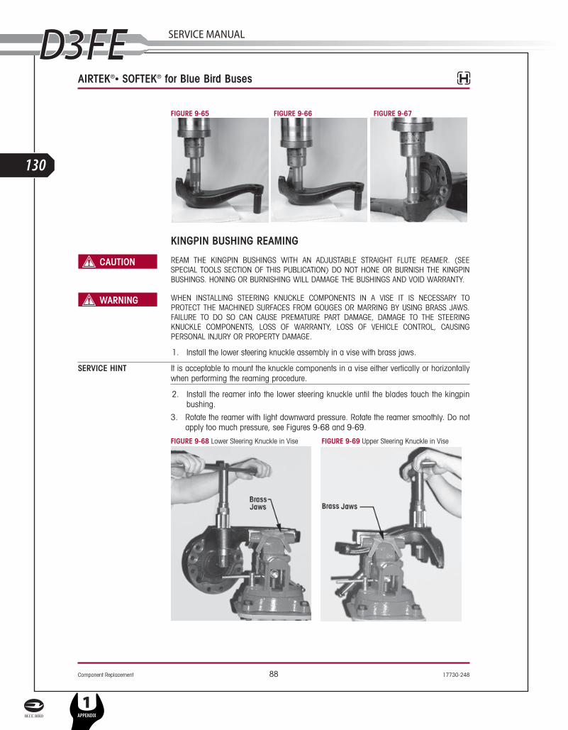
Component Replacement 88 17730-248
AIRTEK®• SOFTEK® for Blue Bird Buses
FIGURE 9-65 FIGURE 9-66 FIGURE 9-67
KINGPIN BUSHING REAMING
REAM THE KINGPIN BUSHINGS WITH AN ADJUSTABLE STRAIGHT FLUTE REAMER. (SEESPECIAL TOOLS SECTION OF THIS PUBLICATION) DO NOT HONE OR BURNISH THE KINGPINBUSHINGS. HONING OR BURNISHING WILL DAMAGE THE BUSHINGS AND VOID WARRANTY.
WHEN INSTALLING STEERING KNUCKLE COMPONENTS IN A VISE IT IS NECESSARY TOPROTECT THE MACHINED SURFACES FROM GOUGES OR MARRING BY USING BRASS JAWS.FAILURE TO DO SO CAN CAUSE PREMATURE PART DAMAGE, DAMAGE TO THE STEERINGKNUCKLE COMPONENTS, LOSS OF WARRANTY, LOSS OF VEHICLE CONTROL, CAUSINGPERSONAL INJURY OR PROPERTY DAMAGE.
1. Install the lower steering knuckle assembly in a vise with brass jaws.
SERVICE HINT It is acceptable to mount the knuckle components in a vise either vertically or horizontallywhen performing the reaming procedure.
2. Install the reamer into the lower steering knuckle until the blades touch the kingpinbushing.
3. Rotate the reamer with light downward pressure. Rotate the reamer smoothly. Do notapply too much pressure, see Figures 9-68 and 9-69.
FIGURE 9-68 Lower Steering Knuckle in Vise FIGURE 9-69 Upper Steering Knuckle in Vise
L
130
1APPENDIX
SERVICE MANUAL

17730-248 89 Component Replacement
AIRTEK®• SOFTEK® for Blue Bird Buses
4. Slide the reamer out of the bottom of the steering knuckle assembly. If it is necessaryto remove the reamer from the top, rotate the reamer opposite of cutting rotation.
5. Clean and remove all kingpin bushing material from the steering knuckle assembly.Take special attention to remove material from the grease channels and dimples.
6. Clean the 5/8" brake backing plate bolts with a wire wheel and run a tap through thethreads of the lower steering knuckle assembly and then flush out with brake cleanerand dry with compressed air.
PRIOR TO INSTALLATION ENSURE THAT ALL RESIDUAL LOCTITE® MATERIAL IS REMOVED FROMTHE MOUNTING BOLTS AND THE THREAD BORES IN THE UPPER STEERING KNUCKLES, ANDNEW LOCTITE 277 OR EQUIVALENT IS APPLIED TO HELP ENSURE THAT THE BOLTS SUSTAINTHE PROPER TORQUE REQUIREMENT. FAILURE TO DO SO CAN CAUSE LOSS OF VEHICLECONTROL RESULTING IN PERSONAL INJURY OR PROPERTY DAMAGE.
NOTE The Hendrickson Genuine part, socket head cap screw comes with a pre-applied loctitecompound.
7. Install the upper and lower steering knuckle on the kingpin.
8. Check for the proper fit by rotating the knuckle assembly back and forth to verify thereis no binding on the kingpin, see Figures 9-70 and 9-71.
9. If the bushing is too tight repeat steps 1 through 8 until the proper clearance isachieved.
NOTE Bushing size is to be 0.001" larger than the kingpin size.
FIGURE 9-70 FIGURE 9-71
KINGPIN SEAL INSTALLATION1. Place the steering knuckle assembly in a vise with brass jaws or place on a suitable work-
bench. The steering knuckle will have the machined surface facing up (axle side up).
2. Lay the kingpin seal into the bore of the steering knuckle. The seal lip should face out-ward or toward the axle.
3. Use a bushing driver tool and press seal firmly into the steering knuckle assembly.
4. Install the kingpin seal until it makes contact with the kingpin bushing, see Figures9-72 and 9-73.
SERVICE MANUAL
L
131
FRonT AxlE & SuSPEnSion
1APPENDIX

Component Replacement 90 17730-248
AIRTEK®• SOFTEK® for Blue Bird Buses
FIGURES 9-72 AND 9-73
STEERING KNUCKLE ASSEMBLY
ASSEMBLYAfter replacement of the kingpin bushings it is necessary to re-assemble the steering knuck-le assemblies. The STEERTEK axle is equipped with two different thrust bearings installed.The composite thrust bearing is installed on the left side of the axle. The roller bearing isinstalled on the right side of the axle, see Figures 9-74 and 9-75, for right hand drive axleconfiguration the thrust bearings will be the opposite. Do not substitute aftermarket com-ponents when servicing.
1. Install the thrust bearing on the lower kingpin with the seal facing up toward axle (theblack seal will designate the top side). The composite thrust bearing is installed on theleft side of the axle. The roller bearing is installed on the right side of the axle, seeFigures 9-74 and 9-75. For right hand drive axle configuration the thrust bearings willbe the opposite.
2. Install the shim on the upper kingpin.
3. Pack the bushing dimples on the upper and lower steering knuckles with multi purposeLithium based grease (NLGI Grade 2) before installation, see Figures 9-74 and 9-75.
FIGURE 9-74 FIGURE 9-75
4. Install the upper steering knuckle on the upper arm kingpin.
5. Install the lower steering knuckle on the lower kingpin and install the old socket headcap screws loose into the top two threaded holes.
L
132
1APPENDIX
SERVICE MANUAL

17730-248 91 Component Replacement
AIRTEK®• SOFTEK® for Blue Bird Buses
SERVICE HINT The easiest way to achieve this is with the grease caps not installed in the knuckleassemblies. This eliminates back pressure. The assembly can then freely slide up anddown on the kingpin. If the grease caps are still installed, remove the grease zerks to avoidcreating back pressure. Grease zerks will be re-installed at the end of the procedure.
6. Install a bottle jack under the lower knuckle and slightly raise the knuckle until it is possible to thread in the (3) brake backing plate bolts by hand. These are for guide purposes only.
7. Snug the two socket head cap screws.
8. Lower the bottle jack so that all the vertical clearance is on the underside of the axle.
9. Affix a magnetic base dial indicator on the axle and place the tip of the dial indicatoron top of the knuckle assembly, see Figure 9-76.
10. Zero the dial indicator. FIGURE 9-76
11. Raise the bottle jack until there is noclearance between the knuckleassembly and the bottom of theaxle, slightly lifting the axle.
12. Check the reading on the dial indi-cator. The specification for verticaltravel on the steering knuckle duringassembly is 0.008" to 0.011".
13. If the clearance is above 0.011",loosen the socket head cap screwsand push down on the knuckleassembly until the proper verticalclearance is achieved. Add (0.005") shim if necessary.
14. If the clearance is below the 0.008", loosen the two socket head cap screws and pullup on the knuckle assembly until the proper vertical clearance is achieved. If the 0.008"minimum clearance is unattainable it may be necessary to remove a 0.005" shim.
NOTE The Hendrickson Genuine part, socket head cap screw comes with a pre-applied loctitecompound.
PRIOR TO INSTALLATION ENSURE THAT ALL RESIDUAL LOCTITE MATERIAL IS REMOVED FROMTHE MOUNTING BOLTS AND THE THREAD BORES IN THE UPPER STEERING KNUCKLE, ANDNEW LOCTITE 277 OR EQUIVALENT IS APPLIED TO HELP ENSURE THAT THE BOLTS SUSTAINTHE PROPER TORQUE REQUIREMENT. FAILURE TO DO SO CAN CAUSE LOSS OF VEHICLECONTROL RESULTING IN PERSONAL INJURY OR PROPERTY DAMAGE.
15. Remove one old socket head cap screw and replace with new socket head cap screw.
16. Remove second socket head cap screw and replace with new socket head cap screw.Tighten both socket head cap screws to 175-200 foot pounds torque.
17. Recheck the vertical clearance with the dial indicator or a 0.010" feeler gauge, seeFigure 9-76.
18. Remove the brake spider bolts, they should thread out freely.
19. Remove the bottle jack and continue assembling the wheel ends.
IMPORTANT NOTE Loctite applied to the three brake spider bolts is a critical procedure to ensure that thesebolts sustain the torque requirement of Steering knuckle assembly.
SERVICE MANUAL
L
133
FRonT AxlE & SuSPEnSion
1APPENDIX

Component Replacement 92 17730-248
AIRTEK®• SOFTEK® for Blue Bird Buses
20. Apply loctite to the three brake spider bolts prior to installation into the brake spider.Tighten bolts to 175-200 foot pounds torque.
DO NOT GREASE KNUCKLES WITHOUT THE BRAKE SPIDER INSTALLED AND TIGHTENED TOPROPER TORQUE. FAILURE TO DO SO CAN CAUSE COMPONENT DAMAGE RESULTING INFAILURE AND LOSS OF VEHICLE CONTROL, POSSIBLY CAUSING PERSONAL INJURY ORPROPERTY DAMAGE.
21. Install the tie rod end into the lower steering knuckle arm.
22. Tighten the castle nuts to 185 foot pounds torque then rotate the castle nut to thenext castle slot and install cotter pin.
23. Install the drag link into the steering arm and tighten to the vehicle manufacturer’s specifications.
24. Install new o-rings on the grease caps and lubricate o-rings with grease.
25. Install grease caps and new retaining rings.
26. Install brakes, drums, wheels and tires.
27. Remove jack and safety stands.
28. Grease steering knuckles with the vehicle on the floor.
29. Remove wheel chocks.
TIE ROD END AND CROSS TUBENOTE: Hendrickson supplies different tie rod configurations. Prior to ordering find the part number
on the tie rod tube. For additional information see Technical Bulletin SEU-0223 or contactHendrickson Sales Engineering.
DISASSEMBLY1. Chock the wheels.
2. Position the steer axle tires straight ahead.
3. Remove the cotter pin and castle nut.
4. Lightly tap the side of the Ackermann arm to loosen the tie rod end from the Ackermannarm, see Figure 9-77.
FIGURE 9-77
5. Repeat to steps 3 and 4 to removethe other tie rod end.
6. Remove the cross tube and tie rodends from the vehicle.
7. Mount the cross tube in a softjaw vice.
8. Remove the hardware from the clamp on the cross tube.
9. Count the exposed threads on the tie rod end being replaced.
10. Remove the tie rod end from the cross tube.
DO NOT HEAT THE CROSS TUBE WITH A TORCH TO FACILITATE THE REMOVAL OF THE TIE RODEND. THE USE OF SUCH HEAT CAN ADVERSELY AFFECT THE STRENGTH OF THE CROSS TUBE.A COMPONENT DAMAGED IN THIS MANNER WILL RESULT IN LOSS OF WARRANTY, AND CANRESULT IN THE AND LOSS OF VEHICLE CONTROL, AND POSSIBLE PERSONAL INJURY ORPROPERTY DAMAGE.
11. If the opposing tie rod end is being replaced repeat steps 8 through 10.
L
134
1APPENDIX
SERVICE MANUAL
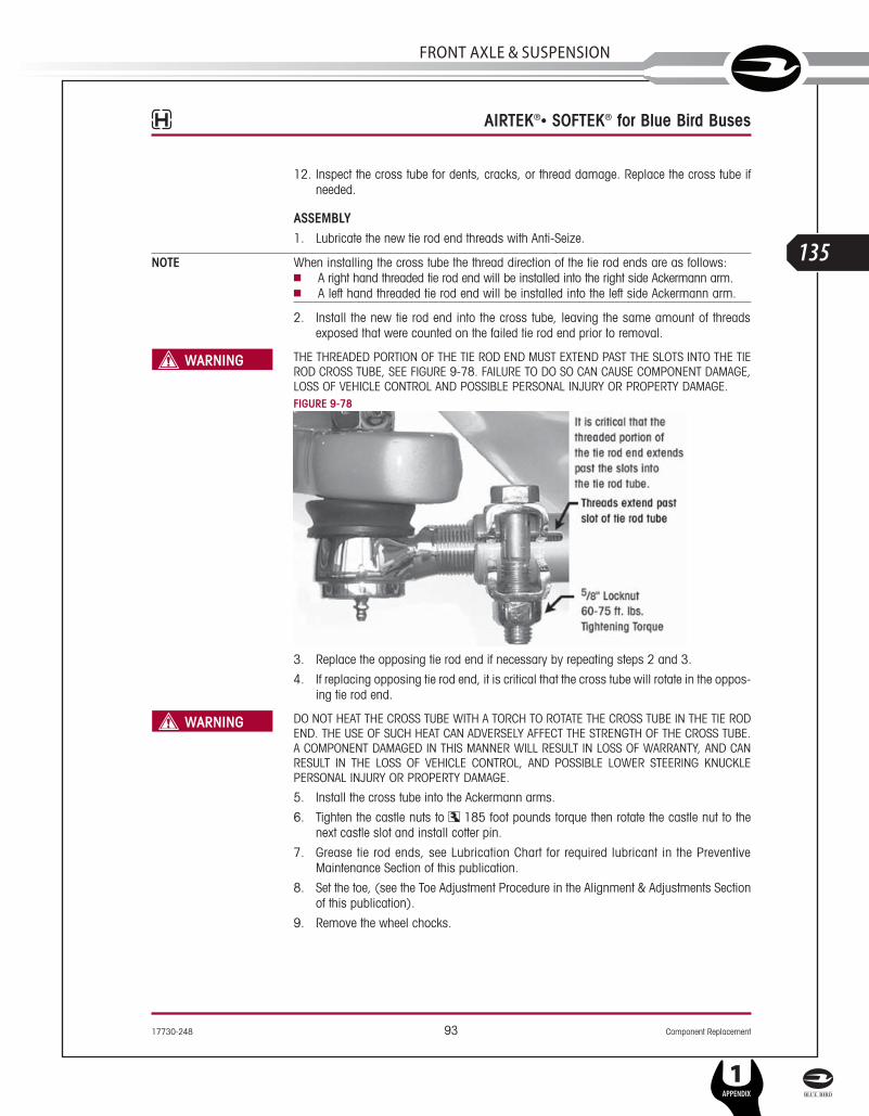
17730-248 93 Component Replacement
AIRTEK®• SOFTEK® for Blue Bird Buses
12. Inspect the cross tube for dents, cracks, or thread damage. Replace the cross tube ifneeded.
ASSEMBLY1. Lubricate the new tie rod end threads with Anti-Seize.
NOTE When installing the cross tube the thread direction of the tie rod ends are as follows:■ A right hand threaded tie rod end will be installed into the right side Ackermann arm.■ A left hand threaded tie rod end will be installed into the left side Ackermann arm.
2. Install the new tie rod end into the cross tube, leaving the same amount of threadsexposed that were counted on the failed tie rod end prior to removal.
THE THREADED PORTION OF THE TIE ROD END MUST EXTEND PAST THE SLOTS INTO THE TIEROD CROSS TUBE, SEE FIGURE 9-78. FAILURE TO DO SO CAN CAUSE COMPONENT DAMAGE,LOSS OF VEHICLE CONTROL AND POSSIBLE PERSONAL INJURY OR PROPERTY DAMAGE.FIGURE 9-78
3. Replace the opposing tie rod end if necessary by repeating steps 2 and 3.
4. If replacing opposing tie rod end, it is critical that the cross tube will rotate in the oppos-ing tie rod end.
DO NOT HEAT THE CROSS TUBE WITH A TORCH TO ROTATE THE CROSS TUBE IN THE TIE RODEND. THE USE OF SUCH HEAT CAN ADVERSELY AFFECT THE STRENGTH OF THE CROSS TUBE.A COMPONENT DAMAGED IN THIS MANNER WILL RESULT IN LOSS OF WARRANTY, AND CANRESULT IN THE LOSS OF VEHICLE CONTROL, AND POSSIBLE LOWER STEERING KNUCKLEPERSONAL INJURY OR PROPERTY DAMAGE.
5. Install the cross tube into the Ackermann arms.
6. Tighten the castle nuts to 185 foot pounds torque then rotate the castle nut to thenext castle slot and install cotter pin.
7. Grease tie rod ends, see Lubrication Chart for required lubricant in the PreventiveMaintenance Section of this publication.
8. Set the toe, (see the Toe Adjustment Procedure in the Alignment & Adjustments Sectionof this publication).
9. Remove the wheel chocks.
SERVICE MANUAL
L
135
FRonT AxlE & SuSPEnSion
1APPENDIX
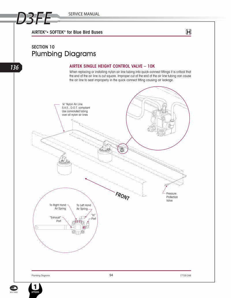
Plumbing Diagrams 94 17730-248
AIRTEK®• SOFTEK® for Blue Bird Buses
SECTION 10
Plumbing Diagrams
AIRTEK SINGLE HEIGHT CONTROL VALVE – 10KWhen replacing or installing nylon air line tubing into quick-connect fittings it is critical thatthe end of the air line is cut square. Improper cut of the end of the air line tubing can causethe air line to seat improperly in the quick connect fitting causing air leakage.
L
136
1APPENDIX
SERVICE MANUAL

17730-248 95 Plumbing Diagrams
AIRTEK®• SOFTEK® for Blue Bird Buses
AIRTEK DUAL HEIGHT CONTROL VALVES – 14.6KWhen replacing or installing nylon air line tubing into quick-connect fittings it is critical thatthe end of the air line is cut square. Improper cut of the end of the air line tubing can causethe air line to seat improperly in the quick connect fitting causing air leakage.
¼" Nylon Air LineS.A.E., D.O.T. compliant
Use convoluted tubingover all nylon air lines
PressureProtectionValve
¾" Nylon Air LineS.A.E., D.O.T. compliant
Use convoluted tubingover all nylon air lines
FRONT
To Air Spring
To Air Spring
“In” Port
“Exhaust”Port
C1
C2
SERVICE MANUAL
L
137
FRonT AxlE & SuSPEnSion
1APPENDIX

96 17730-248
AIRTEK®• SOFTEK® for Blue Bird Buses
L
138
1APPENDIX
SERVICE MANUAL

1773
0–24
8A
pp
end
ix
A-97
Reference MaterialThis technical publication covers Hendrickson Truck Suspension’s recommended procedures for our parts/products. Other components play a major role in overall performance and Hendrickson recommends you follow the specific vehicle manufac-turer’s recommendation for care and maintenance. Some recommended procedureshave been developed by The Technology & Maintenance Council (TMC) andHendrickson supports these recommendations. We have compiled a list of thesebelow.
TMCTo obtain copies of the following RP’s, video’s, or charts, contact TMC at:
TMC/ATA Phone: 703-838-17632200 Mill Road website: tmc.truckline.comAlexandria, VA 22314 online ordering: www.truckline.com/store
Important References
TMC RP 214B Tire/Wheel End Balance and Runout
TMC RP 216 Radial Tire Conditions Analysis Guide
TMC RP 219A Radial Tire Wear Conditions and Causes
TMC RP 222A User’s Guide To Wheels and Rims
TMC RP 230 Tire Test Procedures for Tread wear, Serviceability, and Fuel Economy
TMC RP 514 Pre-Alignment Inspection
TMC RP 618 Wheel Bearing Adjustment Procedure
TMC RP 620B Front End Alignment Steering Geometry
TMC RP 708A Trailer Axle Alignment
TMC RP 642 Guidelines For Total Vehicle Alignment
TMC RP 644 Wheel End Conditions Analysis Guide
TMC RP 645 Tie Rod End Inspection and Maintenance Procedure
Video’s
TMC T0326 Wheel End Maintenance
TMC T0372 Tire Pre-Trip Inspection Guidelines
Other
TMC T0400 Wheel bearing Adjustment Procedure Wall Chart
SERVICE MANUAL
L
139
FRonT AxlE & SuSPEnSion
1APPENDIX

Ap
pe
ndix
17730–248
A-98
AIRTEK/SOFTEKTROUBLESHOOTING GUIDE
CONDITION POSSIBLE CAUSE CORRECTION
Worn or damaged kingpins andkingpin bushings
Dirt in system– contaminated lubricantPolish and inspect kingpin, replace bushingand seals, then follow specified lubricationprocedures
Incorrect lubricant Lubricate axle with specified lubricant
Axle not lubricated at scheduled frequency Lubricant axle at scheduled frequency
Incorrect lubrication procedures Use correct lubrication procedures
Lubrication interval not compatible withoperating conditions
Change lubrication interval to matchoperating conditions
Worn or missing seals Replace worn or missing seals
Vibration or shimmy of front axleduring operation
Caster out of specification Set proper ride height then adjust caster tospecification
Wheels and/or tires out of balance Balance or replace wheels and/or tires
Worn shock absorbers Replace shock absorbers
Worn thrust washers (if equipped) and rearhanger clamps
Replace thrust washers (if equipped) andrear hanger clamps
Broken engine mount Replace engine mount
Wheel bearing adjustment Adjust wheel bearing to the vehiclemanufacturers specifications.
Excessive wear on tires or uneventire tread wear
Tires have incorrect air pressure Adjust tire pressure to manufacturer’sspecification.
Tires out of balance Balance or replace tires
Incorrect tandem axle alignment Align tandem axles
Incorrect toe setting Adjust toe-in to manufacturer’s specification
Incorrect steering arm geometry Repair steering system as necessary
Worn kingpin bushings Replace kingpin bushings
Excessive wheel bearing end play Check specified wheel nut torque, replaceworn or damaged wheel bearings
Wheel bearing adjustment Adjust wheel bearing to the vehiclemanufacturers specifications.
Vehicle is hard to steer
Low pressure in the power steering system Repair power steering system
Steering linkage needs lubrication Lubricate steering linkage
Steering knuckles are binding Check vertical clearance
Incorrect steering ar geometry Repair steering system as necessary
Caster out of specification Set proper ride height then adjust caster tospecification
Tie rod ends hard to move Replace tie rod ends
Worn thrust bearing Replace thrust bearing
Steering gear box internal problemPerform steering gear trouble shootingprocedures per steering gear manufacturingguidelines.
L
140
1APPENDIX
SERVICE MANUAL

1773
0–24
8A
pp
end
ix
A-99
AIRTEK/SOFTEKTROUBLESHOOTING GUIDE (CONTINUED)
CONDITION POSSIBLE CAUSE CORRECTION
Tie rod ends are worn and requirereplacement
Tie rod ends need lubrication Lubricate tie rod end. Make sure lubricationschedule is followed.
Severe operating conditions Increase frequency of inspection andlubrication intervals
Damaged boot on tie rod end Replace tie rod end
Bent or broken cross tube, tie rodend ball stud or tie rod end
NOTE: Damaged components requirereplacement
Pump/gear relief valve pressure settingexceeds system specifications
Adjust power steering system tomanufacturer's specified pressure
Steering gear poppets improperly set ormalfunctioning
Check for proper operation or adjust poppetsto OEM specifications
Axle stops improperly set Set axle stops to OEM specifications
Severe duty cycle service Increase frequency of inspection andlubrication intervals
Worn or broken steering ball stud
Drag link fasteners lightened past specifiedtorque
Tighten drag link fasteners to the specifiedtorque
Lack of lubrication or incorrect lubricant Lubricate linkage with specified lubricant
Power steering stops out of adjustment Adjust steering stops to OEM specifications
Suspension has harsh or bumpyride
Air spring not inflated Check air supply to air spring, repair asnecessary
Air spring ride height out of specification Adjust ride height to proper specification
Broken or worn leaf spring Replace leaf spring
Front suspension overloaded Redistribute steer axle load
Restricted steering radius Steering stops not adjusted correctly Adjust steering stops to achieve correct wheel cut
Vehicle leans
Ride height incorrect Adjust ride height to specification
Air spring(s) are not inflated Repair source of air pressure loss
Suspension is not torqued correctly atinstallation
Perform spring eye re-torque procedure. See Torque Specification Section of thispublication
Leaf spring broken Replace leaf spring
Excessive weight bias Contact the vehicle manufacturer orHendrickson Tech Services
Vehicle wanders
Caster out of specifications Set proper ride height then adjust caster tospecification
Incorrect toe setting Adjust toe to specification
Fifth wheel not greased Grease fifth wheel
Air in the power steering system Remove air form the power steering systems
Rear ride height out of adjustment Adjust ride height to specification
Front ride height out of adjustment Adjust ride height to specification
SERVICE MANUAL
L
141
FRonT AxlE & SuSPEnSion
1APPENDIX
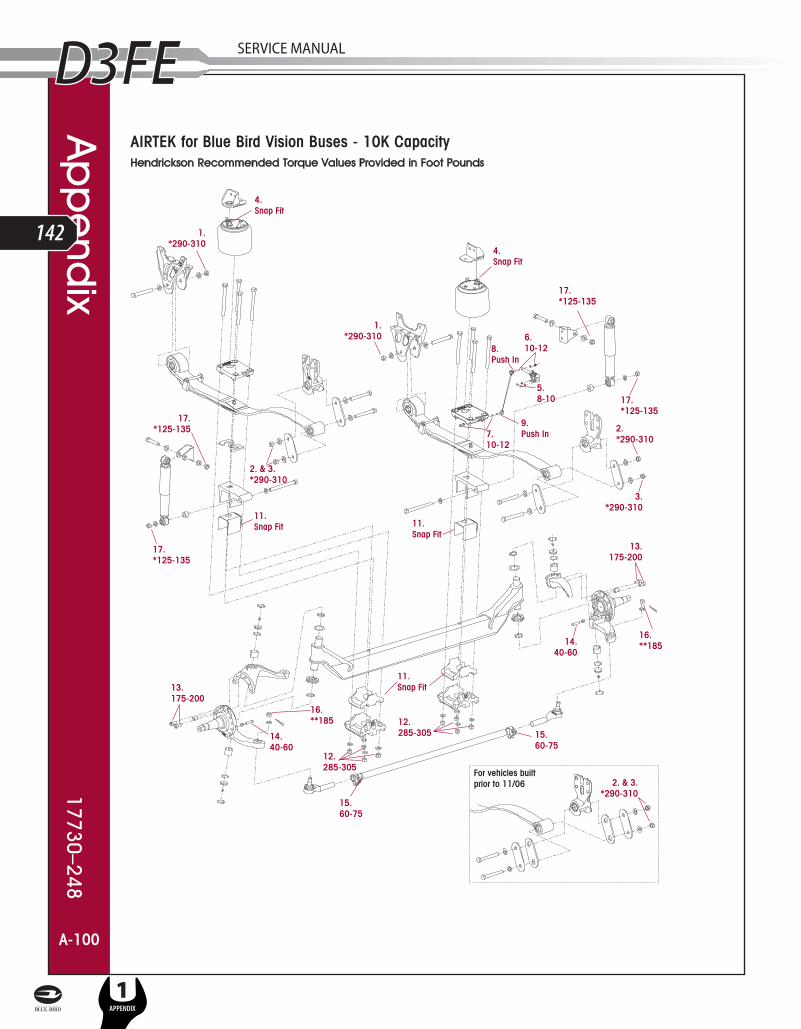
AIRTEK for Blue Bird Vision Buses - 10K CapacityHendrickson Recommended Torque Values Provided in Foot Pounds
A-100
Ap
pe
ndix
17730–248
A-100
L
142
1APPENDIX
SERVICE MANUAL

AIRTEK for Blue Bird Vision Buses – 10KHENDRICKSON RECOMMENDED TORQUE SPECIFICATIONS
NO. COMPONENT QTY. SIZE TORQUE VALUE(in foot pounds)
1 Front Frame Hanger to Front Leaf Spring Eye 2 M20 *290-310
2 Rear Shackle Bracket to Shackle Plate 2 M20 *290-310
3 Rear Shackle Bracket to Spring Eye 2 M20 *290-310
4 Air Spring 2 Self-Locking Snap Fit
5 Height Control Valve to Frame 2 ¼" 8-10
6 HCV Linkage to HCV Arm 2 5/16" 10-12
7 HCV Linkage to Top Pad 2 5/16" 10-12
8 HCV Linkage Grommet to HCV Arm 1 Grommet Push In
9 HCV Linkage Grommet to Top Pad 1 Grommet Push In
10 Spring Center Aligning Dowel Pin (Flat Floor Bus) 2 ¾" ***Loose Fit
11 Axle Wrap Liners for Clamp Group 2 Formed Snap Fit
DO NOT ASSEMBLE CLAMP GROUP WITHOUT AXLE WRAP LINERS. FAILURE TO DO SO CAN CAUSELOSS OF VEHICLE CONTROL, PROPERTY DAMAGE OR PERSONAL INJURY.
12 Clamp Group Hardware 8 ¾" 285-305
ENSURE CLAMP GROUP IS ALIGNED PROPERLY PRIOR TO TIGHTENING HARDWARE. FAILURE TO DOSO CAN CAUSE LOSS OF VEHICLE CONTROL, PROPERTY DAMAGE OR PERSONAL INJURY.
13 Knuckle Attachment Bolt (Socket Head Cap Screw) 4 5/8" 175-200
14 Knuckle / Axle Wheel Stop Bolt 2 5/8" Jam Nut 40-60
15 Tie Rod Tube to Tie Rod Ends 2 5/8" 60-75
16 Tie Rod Ends to Lower Steering Knuckle 2 7/8" Castle Nut **185
17 Shocks Eye Bolts 2 ¾" *125-135
• All hardware ¼" and greater is Grade 8 with no additional lubrication. Frame mount hardware in most cases are Huck style fasteners supplied by the OEM.
NOTE:* All hardware information in gray in the matrix denotes recommended torques for fasteners originally supplied by the vehicle
manufacturer. If Hendrickson supplied fasteners are used, tighten to Hendrickson torque values, if non Hendrickson fasteners are used,follow torque specifications listed in the vehicle manufacturer’s service manual. Hendrickson is not responsible for maintaining vehiclemanufacturer’s torque values.
** Torque to 185 foot lbs., advance nut to next hex face to install cotter pin. Do not back off nut for cotter pin installation.
*** Denote items not shown on illustration.
MODEL AIRTEK COMFORT AIR
Blue Bird RIDE HEIGHT SHOCK ABSORBERLENGTH RIDE HEIGHT SHOCK ABSORBER
LENGTH
From the bottom of theframe to the center of axle
At ride height with atolerance of ¼"
From the bottom of theframe to the bottom of themain support member.
At ride height with atolerance of ¼"
Vision 10K 12½" 18 9/16" 47/8" 22¾"
A-101
1773
0–24
8A
pp
end
ix
A-101
SERVICE MANUAL
L
143
FRonT AxlE & SuSPEnSion
1APPENDIX

A-102
SOFTEK for Blue Bird Vision Buses - 8K/10K CapacityHendrickson Recommended Torque Values Provided in Foot Pounds
For vehicles builtprior to 11/06
6.285-305
6.285-305
5.Snap Fit
9.60-75
10.**185
8.40-60
5.Snap Fit
1.*290-310
1.*290-310
7.175-200
3.*290-310
2. & 3.*290-310
5.Snap Fit
11.*125-135
11.*125-135
11.*125-135
7 .175-200
11.*125-135
10.**185
9.60-75
8.40-60
2.*290-310
12.Press Fit
12.Press Fit
2. & 3.*290-310
Ap
pe
ndix
17730–248
A-102
L
144
1APPENDIX
SERVICE MANUAL

SOFTEK for Blue Bird Vision Buses – 8K/10KHENDRICKSON RECOMMENDED TORQUE SPECIFICATIONS
NO. COMPONENT QTY. SIZE TORQUE VALUE(in foot pounds)
1 Front Frame Hanger to Front Leaf Spring Eye 2 M20 *290-310
2 Rear Shackle Bracket to Shackle Plate 2 M20 *290-310
3 Rear Shackle Bracket to Spring Eye 2 M20 *290-310
4 Spring Center Aligning Dowel Pin (Flat Floor Bus) 2 ¾" ***Loose Fit
5 Axle Wrap Liners for Clamp Group 2 Formed Snap Fit
DO NOT ASSEMBLE CLAMP GROUP WITHOUT AXLE WRAP LINERS. FAILURE TO DO SO CAN CAUSELOSS OF VEHICLE CONTROL, PROPERTY DAMAGE OR PERSONAL INJURY.
6 Clamp Group Hardware 8 ¾" 285-305
ENSURE CLAMP GROUP IS ALIGNED PROPERLY PRIOR TO TIGHTENING HARDWARE. FAILURE TO DOSO CAN CAUSE LOSS OF VEHICLE CONTROL, PROPERTY DAMAGE OR PERSONAL INJURY.
7 Knuckle Attachment Bolt (Socket Head Cap Screw) 4 5/8" 175-200
8 Knuckle / Axle Wheel Stop Bolt 2 5/8" Jam Nut 40-60
9 Tie Rod Tube to Tie Rod Ends 2 5/8" 60-75
10 Tie Rod Ends to Lower Steering Knuckle 2 7/8" Castle Nut **185
11 Shocks Eye Bolts 4 ¾" *125-135
12 Rubber Axle Stop 2 — Press Fit
• All hardware ¼" and greater is Grade 8 with no additional lubrication. Frame mount hardware in most cases are Huck style fasteners supplied by the OEM.
NOTE:* All hardware information in gray in the matrix denotes recommended torques for fasteners originally supplied by the vehicle
manufacturer. If Hendrickson supplied fasteners are used, tighten to Hendrickson torque values, if non Hendrickson fasteners are used,follow torque specifications listed in the vehicle manufacturer’s service manual. Hendrickson is not responsible for maintaining vehiclemanufacturer’s torque values.
** Torque to 185 foot lbs., advance nut to next hex face to install cotter pin. Do not back off nut for cotter pin installation.
*** Denote items not shown on illustration.
A-103
1773
0–24
8A
pp
end
ix
A-103
SERVICE MANUAL
L
145
FRonT AxlE & SuSPEnSion
1APPENDIX
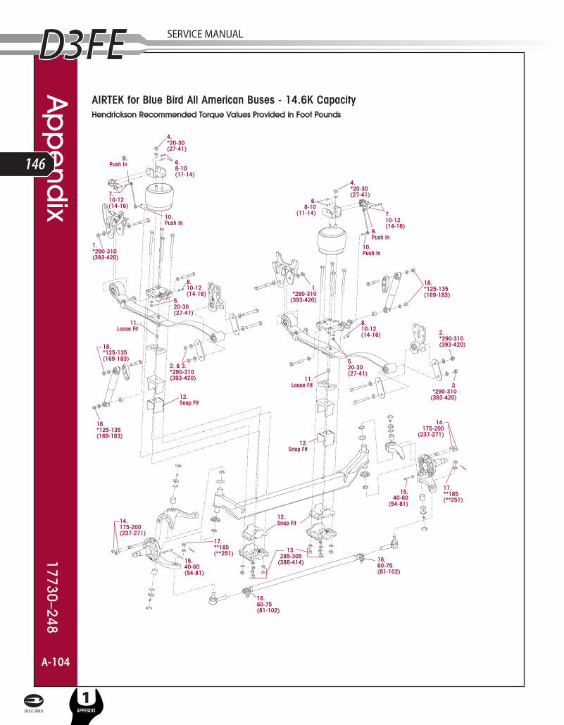
A-104
Ap
pe
ndix
17730–248
AIRTEK for Blue Bird All American Buses - 14.6K CapacityHendrickson Recommended Torque Values Provided in Foot Pounds
A-104
L
146
1APPENDIX
SERVICE MANUAL

AIRTEK for Blue Bird All American Buses – 14.6KHENDRICKSON RECOMMENDED TORQUE SPECIFICATIONS
NO. COMPONENT QTY. SIZETORQUE VALUE
(in foot pounds) (in Nm)
1 Front Frame Hanger to Front Leaf Spring Eye 2 M20 *290-310 *393-420
2 Rear Shackle Bracket to Shackle Plate 2 M20 *290-310 *393-420
3 Rear Shackle Bracket to Spring Eye 2 M20 *290-310 *393-420
4 Air Spring to Air Spring Bracket 2 ¾" *20-30 *27-41
5 Air Spring to Top Pad 2 ½" 20-30 27-41
6 Height Control Valve to Air Spring Bracket 2 ¼" 8-10 11-14
7 HCV Linkage to HCV Arm 2 5/16" 10-12 14-16
8 HCV Linkage to Top Pad 2 5/16" 10-12 14-16
9 HCV Linkage Grommet to HCV Arm 1 Grommet Push In
10 HCV Linkage Grommet to Top Pad 1 Grommet Push In
11 Spring Center Aligning Dowel Pin (Flat Floor Bus) 2 ¾" Loose Fit
12 Axle Wrap Liners for Clamp Group 2 Formed Snap Fit
DO NOT ASSEMBLE CLAMP GROUP WITHOUT AXLE WRAP LINERS. FAILURE TO DO SO CAN CAUSELOSS OF VEHICLE CONTROL, PROPERTY DAMAGE OR PERSONAL INJURY.
13 Clamp Group Hardware 8 ¾" 285-305 386-414
ENSURE CLAMP GROUP IS ALIGNED PROPERLY PRIOR TO TIGHTENING HARDWARE. FAILURE TODO SO CAN CAUSE LOSS OF VEHICLE CONTROL, PROPERTY DAMAGE OR PERSONAL INJURY.
14 Knuckle Attachment Bolt (Socket Head Cap Screw) 4 5/8" 175-200 237-271
15 Knuckle / Axle Wheel Stop Bolt 2 5/8" Jam Nut 40-60 54-81
16 Tie Rod Tube to Tie Rod Ends 2 5/8" 60-75 81-102
17 Tie Rod Ends to Lower Steering Knuckle 2 7/8" Castle Nut **185 **251
18 Shocks Eye Bolts 2 ¾" *125-135 *169-183
• All hardware ¼" and greater is Grade 8 with no additional lubrication. Frame mount hardware in most cases are Huck style fasteners supplied by the OEM.
NOTE:* All hardware information in gray in the matrix denotes recommended torques for fasteners originally supplied by the vehicle
manufacturer. If Hendrickson supplied fasteners are used, tighten to Hendrickson torque values, if non Hendrickson fasteners are used,follow torque specifications listed in the vehicle manufacturer’s service manual. Hendrickson is not responsible for maintaining vehiclemanufacturer’s torque values.
** Torque to 185 foot pounds (251 Nm), advance nut to next hex face to install cotter pin. Do not back off nut for cotter pin installation.
A-105
MODEL AIRTEK COMFORT AIR
Blue Bird RIDE HEIGHT SHOCK ABSORBERLENGTH RIDE HEIGHT SHOCK ABSORBER
LENGTH
From the bottom of theframe to the center of axle
At ride height with atolerance of ¼"
From the bottom of theframe to the bottom of themain support member.
At ride height with atolerance of ¼"
All AmericanFront Engine Model 147⁄8" 17¼" 47⁄8" 22¾"
All AmericanRear Engine Model 147⁄8" 1715⁄32" 1773
0–24
8A
pp
end
ix
A-105
SERVICE MANUAL
L
147
FRonT AxlE & SuSPEnSion
1APPENDIX

A-106
Ap
pe
ndix
17730–248
SOFTEK for Blue Bird All American Buses - 13.2K/14.6K CapacityHendrickson Recommended Torque Values Provided in Foot Pounds
A-106
L
148
1APPENDIX
SERVICE MANUAL

SOFTEK for Blue Bird All American Buses – 13.2K/14.6KHENDRICKSON RECOMMENDED TORQUE SPECIFICATIONS
NO. COMPONENT QTY. SIZETORQUE VALUE
(in foot pounds) (in Nm)
1 Front Frame Hanger to Front Leaf Spring Eye 2 M20 *290-310 *393-420
2 Rear Shackle Bracket to Shackle Plate 2 M20 *290-310 *393-420
3 Rear Shackle Bracket to Spring Eye 2 M20 *290-310 *393-420
4 Spring Center Aligning Dowel Pin (Flat Floor Bus) 2 ¾" Loose Fit
5 Axle Wrap Liners for Clamp Group 2 Formed Snap Fit
DO NOT ASSEMBLE CLAMP GROUP WITHOUT AXLE WRAP LINERS. FAILURE TO DO SO CAN CAUSELOSS OF VEHICLE CONTROL, PROPERTY DAMAGE OR PERSONAL INJURY.
6 Clamp Group Hardware 8 ¾" 285-305 386-414
ENSURE CLAMP GROUP IS ALIGNED PROPERLY PRIOR TO TIGHTENING HARDWARE. FAILURE TO DOSO CAN CAUSE LOSS OF VEHICLE CONTROL, PROPERTY DAMAGE OR PERSONAL INJURY.
7 Knuckle Attachment Bolt (Socket Head Cap Screw) 4 5/8" 175-200 237-271
8 Knuckle / Axle Wheel Stop Bolt 2 5/8" Jam Nut 40-60 54-81
9 Tie Rod Tube to Tie Rod Ends 2 5/8" 60-75 81-102
10 Tie Rod Ends to Lower Steering Knuckle 2 7/8" Castle Nut **185 **251
11 Shocks Eye Bolts 4 ¾" *125-135 *169-183
12 Rubber Axle Stop 2 — Press Fit
• All hardware ¼" and greater is Grade 8 with no additional lubrication. Frame mount hardware in most cases are Huck style fasteners supplied by the OEM.
NOTE:* All hardware information in gray in the matrix denotes recommended torques for fasteners originally supplied by the vehicle
manufacturer. If Hendrickson supplied fasteners are used, tighten to Hendrickson torque values, if non Hendrickson fasteners are used,follow torque specifications listed in the vehicle manufacturer’s service manual. Hendrickson is not responsible for maintaining vehiclemanufacturer’s torque values.
** Torque to 185 foot pounds (251 Nm), advance nut to next hex face to install cotter pin. Do not back off nut for cotter pin installation.
A-107
1773
0–24
8A
pp
end
ix
A-107
SERVICE MANUAL
L
149
FRonT AxlE & SuSPEnSion
1APPENDIX
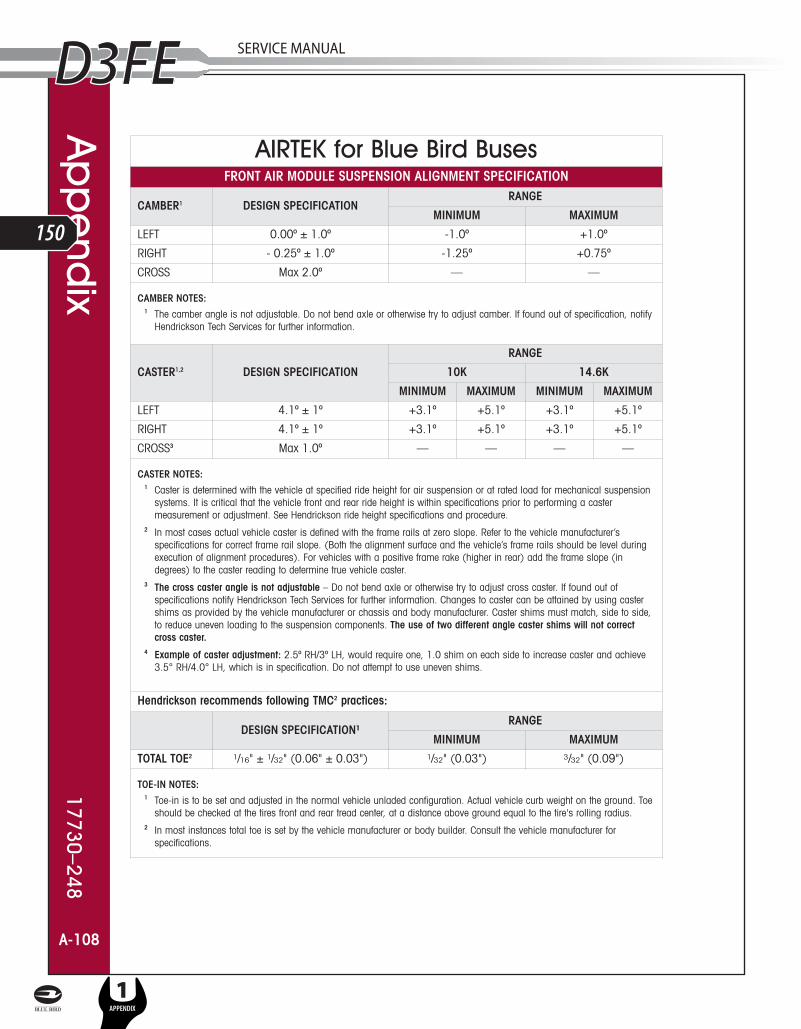
A-108
AIRTEK for Blue Bird BusesFRONT AIR MODULE SUSPENSION ALIGNMENT SPECIFICATION
CAMBER1 DESIGN SPECIFICATIONRANGE
MINIMUM MAXIMUM
LEFT 0.00º ± 1.0º -1.0º +1.0º
RIGHT - 0.25º ± 1.0º -1.25º +0.75º
CROSS Max 2.0º — —
CAMBER NOTES:1 The camber angle is not adjustable. Do not bend axle or otherwise try to adjust camber. If found out of specification, notify
Hendrickson Tech Services for further information.
CASTER1,2 DESIGN SPECIFICATION
RANGE
10K 14.6K
MINIMUM MAXIMUM MINIMUM MAXIMUM
LEFT 4.1º ± 1º +3.1º +5.1º +3.1º +5.1º
RIGHT 4.1º ± 1º +3.1º +5.1º +3.1º +5.1º
CROSS3 Max 1.0º — — — —
CASTER NOTES:1 Caster is determined with the vehicle at specified ride height for air suspension or at rated load for mechanical suspension
systems. It is critical that the vehicle front and rear ride height is within specifications prior to performing a castermeasurement or adjustment. See Hendrickson ride height specifications and procedure.
2 In most cases actual vehicle caster is defined with the frame rails at zero slope. Refer to the vehicle manufacturer’sspecifications for correct frame rail slope. (Both the alignment surface and the vehicle’s frame rails should be level duringexecution of alignment procedures). For vehicles with a positive frame rake (higher in rear) add the frame slope (indegrees) to the caster reading to determine true vehicle caster.
3 The cross caster angle is not adjustable – Do not bend axle or otherwise try to adjust cross caster. If found out ofspecifications notify Hendrickson Tech Services for further information. Changes to caster can be attained by using castershims as provided by the vehicle manufacturer or chassis and body manufacturer. Caster shims must match, side to side,to reduce uneven loading to the suspension components. The use of two different angle caster shims will not correct cross caster.
4 Example of caster adjustment: 2.5º RH/3º LH, would require one, 1.0 shim on each side to increase caster and achieve3.5° RH/4.0° LH, which is in specification. Do not attempt to use uneven shims.
Hendrickson recommends following TMC2 practices:
DESIGN SPECIFICATION¹RANGE
MINIMUM MAXIMUM
TOTAL TOE2 1/16" ± 1/32" (0.06" ± 0.03") 1/32" (0.03") 3/32" (0.09")
TOE-IN NOTES:1 Toe-in is to be set and adjusted in the normal vehicle unladed configuration. Actual vehicle curb weight on the ground. Toe
should be checked at the tires front and rear tread center, at a distance above ground equal to the tire's rolling radius.2 In most instances total toe is set by the vehicle manufacturer or body builder. Consult the vehicle manufacturer for
specifications.
Ap
pe
ndix
17730–248
A-108
L
150
1APPENDIX
SERVICE MANUAL
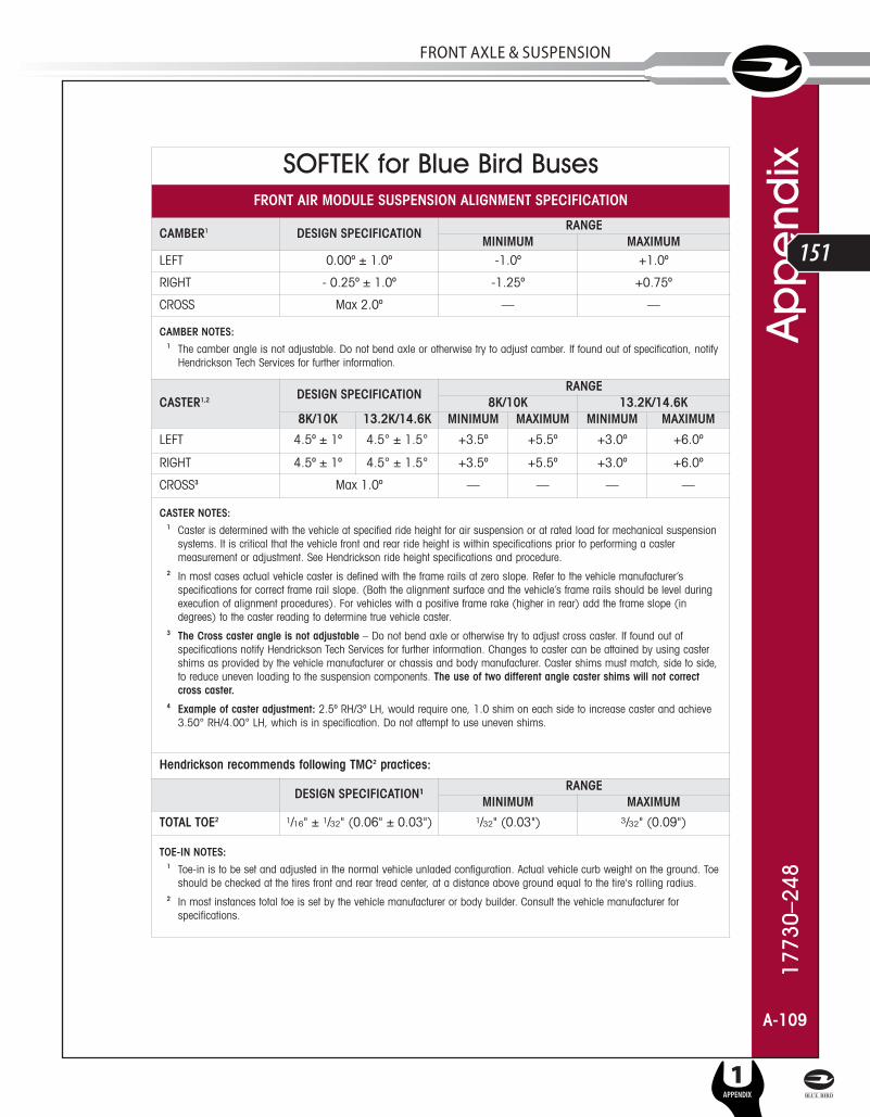
A-109
SOFTEK for Blue Bird BusesFRONT AIR MODULE SUSPENSION ALIGNMENT SPECIFICATION
CAMBER1 DESIGN SPECIFICATIONRANGE
MINIMUM MAXIMUMLEFT 0.00º ± 1.0º -1.0º +1.0º
RIGHT - 0.25º ± 1.0º -1.25º +0.75º
CROSS Max 2.0º — —
CAMBER NOTES:1 The camber angle is not adjustable. Do not bend axle or otherwise try to adjust camber. If found out of specification, notify
Hendrickson Tech Services for further information.
CASTER1,2 DESIGN SPECIFICATIONRANGE
8K/10K 13.2K/14.6K8K/10K 13.2K/14.6K MINIMUM MAXIMUM MINIMUM MAXIMUM
LEFT 4.5º ± 1º 4.5° ± 1.5° +3.5º +5.5º +3.0º +6.0º
RIGHT 4.5º ± 1º 4.5° ± 1.5° +3.5º +5.5º +3.0º +6.0º
CROSS3 Max 1.0º — — — —
CASTER NOTES:1 Caster is determined with the vehicle at specified ride height for air suspension or at rated load for mechanical suspension
systems. It is critical that the vehicle front and rear ride height is within specifications prior to performing a castermeasurement or adjustment. See Hendrickson ride height specifications and procedure.
2 In most cases actual vehicle caster is defined with the frame rails at zero slope. Refer to the vehicle manufacturer’sspecifications for correct frame rail slope. (Both the alignment surface and the vehicle’s frame rails should be level duringexecution of alignment procedures). For vehicles with a positive frame rake (higher in rear) add the frame slope (indegrees) to the caster reading to determine true vehicle caster.
3 The Cross caster angle is not adjustable – Do not bend axle or otherwise try to adjust cross caster. If found out ofspecifications notify Hendrickson Tech Services for further information. Changes to caster can be attained by using castershims as provided by the vehicle manufacturer or chassis and body manufacturer. Caster shims must match, side to side,to reduce uneven loading to the suspension components. The use of two different angle caster shims will not correct cross caster.
4 Example of caster adjustment: 2.5º RH/3º LH, would require one, 1.0 shim on each side to increase caster and achieve3.50° RH/4.00° LH, which is in specification. Do not attempt to use uneven shims.
Hendrickson recommends following TMC2 practices:
DESIGN SPECIFICATION¹RANGE
MINIMUM MAXIMUM
TOTAL TOE2 1/16" ± 1/32" (0.06" ± 0.03") 1/32" (0.03") 3/32" (0.09")
TOE-IN NOTES:1 Toe-in is to be set and adjusted in the normal vehicle unladed configuration. Actual vehicle curb weight on the ground. Toe
should be checked at the tires front and rear tread center, at a distance above ground equal to the tire's rolling radius.2 In most instances total toe is set by the vehicle manufacturer or body builder. Consult the vehicle manufacturer for
specifications.
1773
0–24
8A
pp
end
ix
A-109
SERVICE MANUAL
L
151
FRonT AxlE & SuSPEnSion
1APPENDIX

Tec
hnica
l Proc
ed
ure Q
uiz17730–248
A-110
Technical Procedure Publication Quiz1) What three items have the greatest influence on tire wear?
a) Toe
b) Air Pressure
c) Camber
d) Thrust Angle
2) Caster may be increased or decreased using shims or wedges.
True or False
3) Cross caster may be changed using shims or wedges.
True or False
4) You may bend a STEERTEK axle to correct for improper camber settings.
True or False
5) In an unladen vehicle the correct toe setting for the STEERTEK axle is?
a) 0 to negative 1/8"
b) 0 to negative 1/16"
c) 0 to positive 1/32"
d) 1/16" ± 1/32"
6) When reducing wheel cut on the STEERTEK axle it is necessary to check the steering gearbox poppets.
True or False
7) The torque requirement for the front and rear spring hanger eye bolts are the same.
True or False
8) When servicing the clamp group a technician should always replace the following items.
a) Hex bolts/U-bolts (Grade 8) and nylon locknuts (Grade C)
b) Bottom axle wrap liner
c) Upper axle wrap liner, if removed
d) All of the above
9) What is the clamp group final torque?
a) 500-550 foot pounds (678-746 Nm)
b) 290-310 foot pounds (393-420 Nm)
c) 285-305 foot pounds (386-414 Nm)
d) 240-275 foot pounds (325-373 Nm)
10) What is the torque sequence for the clamp group? See Figure below.
a) 1,3,2,4
b) 1,4,2,3
c) 1,2,3,4
d) The torque sequence does not matter.
11) For a vehicle equipped with a STEERTEK axle it is an acceptable practice to tow using atow chain wrapped around the axle.
True or False
12) The front leaf spring eye bushing is non serviceable
True or False
L
152
1APPENDIX
SERVICE MANUAL

1773
0–24
8 Te
chn
ica
l Pro
ce
dur
e Q
uiz
A-111
13) To remove the STEERTEK knuckle you must.
a) Drive the kingpin out of the axle bore
b) Remove the locking pins before driving the kingpin out
c) Remove the two 5/8" socket head cap screws and separate the knuckle assembly
d) None of the above
14) What is the maximum allowable specification for lateral movement of the steering knuckle?
a) 0.001"
b) 0.075"
c) 0.030"
d) 0.015"
15) When the AIRTEK ride height is checked, it is not necessary to cycle the leveling valvebefore check the ride height.
True or False
16) Worn kingpins are easily removed and replaced.
True or False
17) The lower shock eye bolt mounting torque per the vehicle manufacturer is:
a) 125-135 foot pounds (169-183 Nm)
b) 225-255 foot pounds (305-346 Nm)
c) not critical
d) none of the above
18) Although the AIRTEK/SOFTEK is low maintenance, it is recommended to do a visual inspec-tion on the axle and suspension every ___________ miles.
a) 100,000 or 1 year
b) 25,000 or 6 months
c) Never
19) When replacing the rear spring ¾" length hanger bolts, the new bolts should be installed:
a) From the outboard side to inboard side for AIRTEK 10K and SOFTEK 8K/10K
b) It does not matter what direction the bolts are facing
c) From the inboard side to outboard side for AIRTEK 14.6K and SOFTEK13.2K/14.6K
d) Both a and c
20) The STEERTEK axle combined with the clamp group and stiff front spring limb help to makethe AIRTEK torsionally rigid and reduce body roll.
True or False
21) How many grease points are there on the STEERTEK axle?
a) 2
b) 6
c) 8
d) None
22) It is acceptable to replace a failed shock absorber with any brand that will fit.
True or False
23) A shock that is misting is classified as a leaking shock and should be replaced immediately.
True or False
24) Wheel bearing adjustment has no impact on tire wear.
True or False
SERVICE MANUAL
L
153
FRonT AxlE & SuSPEnSion
1APPENDIX

Tec
hnica
l Proc
ed
ure Q
uiz17730–248
A-112
25) Prior to performing a total vehicle alignment the following components must be inspected.
a) Front and rear spring mounts
b) Steer axle tires
c) Ride height
d) All of the above
26) When the clamp group is disassembled the use of a cutting torch is acceptable to helpremove seized bolts and nuts.
True or False
27) Prior to steering knuckle re-assembly it is critical that residual Loctite be removed and re-applied from the upper kingpin connection.
True or False
28) AIRTEK is available exclusively with the STEERTEK axle.
True or False
29) To heat test a shock absorber you should drive a vehicle at moderate speeds for fifteenminutes.
True or False
30) If the kingpin bushing is worn, then both bushings on that knuckle need to be replaced.
True or False
31) The unique packaging of the steering knuckle will allow up to ______ degrees of wheel cuton the STEERTEK axle.
a) Maximum of 50°
b) 32°
c) 87°
d) None of the above
32) A pre-alignment inspection reveals a tie rod end is worn out of specification. What is thecorrect action needed to complete the alignment.
a) Fill the tie rod with grease to absorb excessive play
b) Replace the tie rod and reset toe before alignment
c) Perform alignment and then replace tie rod end and reset toe
d) Align vehicle and do not repair tie rod end
33) The seal on the thrust bearings are installed facing down.
a) True
b) False
c) Doesn’t matter
34) When servicing tie rod ends it is not necessary to have the part number located on the tierod tube to order tie rod service kits.
True or False
CERTIFICATE Hendrickson will provide a personalized AIRTEK/SOFTEK Technical Procedure QuizAchievement Certificate to candidates scoring 80% or higher on the test. Simplycomplete the test and fill in the enclosed answer sheet or on a separate sheet with thereturn address, name, phone number, and company name as it will appear on theaward to:
Hendrickson
ATTN: Truck Marketing Test Quiz Assessment
800 S. Frontage Road
Woodridge, Illinois 60517
L
154
1APPENDIX
SERVICE MANUAL