Structural Design - 2003 International Building Code
78
CHAPTER 16 STRUCTURAL DESIGN SECTION 1601 GENERAL 1601.1 Scope. The provisions of this chapter shall govern the structural design of buildings, structures and portions thereof regulated by this code. SECTION 1602 DEFINITIONS 1602.1 Definitions. The following words and terms shall, for the purposes of this chapter, have the meanings shown herein. ALLOW ABLE STRESS DESIGN. A method of proportion- ing structural members, such that elastically computed stresses produced in the members by nominal loads do not exceed spec- ified allowable stresses (also called “working stress design”). BALCONY, EXTERIOR. An exterior floor projecting from and supported by a structure without additional independent supports. BASE SHEAR. Total design lateral force or shear at the base. BASIC SEISMIC-FORCE-RESISTING SYSTEMS. Bearing wall system. A structural system without a com- plete vertical load-carrying space frame. Bearing walls or bracing elements provide support for substantial vertical loads. Seismic lateral force resistance is provided by shear walls or braced frames. Building frame system. A structural system with an essen- tially complete space frame providing support for vertical loads. Seismic lateral force resistance is provided by shear walls or braced frames. Dual system. A structural system with an essentially com- plete space frame providing support for vertical loads. Seis- mic lateral force resistance is provided by a moment frame and shear walls or braced frames. Inverted pendulum system. A structure with a large por - tion of its mass concentrated at the top; therefore, having es- sentially one degree of freedom in horizontal translation. Seismic lateral force resistance is provided by the columns acting as cantilevers. Moment-resisting frame system. A structural system with an essentially complete space frame providing support for vertical loads. Seismic lateral force resistance is provided by moment frames. Shear wall-frame interactive system. A structural system which uses combinations of shear walls and frames de- signed to resist seismic lateral forces in proportion to their rigidities, considering interaction between shear walls and frames on all levels. Support of vertical loads is provided by the same shear walls and frames. BOUNDARY MEMBERS. Strengthened portions along shear wall and diaphragm edges (also called “boundary ele- ments”). Boundary element. In light-frame construction, dia- phragms and shear wall boundary members to which sheathing transfers forces. Boundary elements include chords and drag struts at diaphragm and shear wall perime- ters, interior openings, discontinuities and reentrant cor- ners. CANTILEVERED COLUMN SYSTEM. A structural sys- tem relying on column elements that cantilever from a fixed base and have minimal rotational resistance capacity at the top with lateral forces applied essentially at the top and are used for lateral resistance. COLLECTOR ELEMENTS. Members that serve to transfer forces between floor diaphragms and members of the lat- eral-force-resisting system. CONFINED REGION. The portion of a reinforced concrete component in which the concrete is confined by closely spaced special transverse reinforcement restraining the concrete in directions perpendicular to the applied stress. DEAD LOADS. The weight of materials of construction incorporated into the building, including but not limited to walls, floors, roofs, ceilings, stairways, built-in partitions, fin- ishes, cladding and other similarly incorporated architectural and structural items, and fixed service equipment, including the weight of cranes. All dead loads are considered permanent loads. DECK. An exterior floor supported on at least two opposing sides by an adjacent structure, and/or posts, piers or other inde- pendent supports. DEFORMABILITY. The ratio of the ultimate deformation to the limit deformation. High deformability element. An element whose deformability is not less than 3.5 when subjected to four fully reversed cycles at the limit deformation. Limited deformability element. An element that is neither a low deformability or a high deformability element. Low deformability element. An element whose deformability is 1.5 or less. DEFORMATION. Limit deformation. Two times the initial deformation that occurs at a load equal to 40 percent of the maximum strength. Ultimate deformation. The deformation at which failure occurs and which shall be deemed to occur if the sustainable load reduces to 80 percent or less of the maximum strength. DESIGN STRENGTH. The product of the nominal strength and a resistance factor (or strength reduction factor). 2003 INTERNATIONAL BUILDING CODE® 267
-
Upload
khangminh22 -
Category
Documents
-
view
0 -
download
0
Transcript of Structural Design - 2003 International Building Code

CHAPTER 16
STRUCTURAL DESIGN
SECTION 1601GENERAL
1601.1 Scope. The pro vi sions of this chap ter shall gov ern thestruc tural design of build ings, struc tures and por tions thereofreg u lated by this code.
SECTION 1602DEFINITIONS
1602.1 Def i ni tions. The fol low ing words and terms shall, forthe pur poses of this chap ter, have the mean ings shown herein.
ALLOW ABLE STRESS DESIGN. A method of pro por tion -ing struc tural mem bers, such that elas ti cally com puted stressespro duced in the mem bers by nom i nal loads do not exceed spec -i fied allow able stresses (also called “work ing stress design”).
BAL CONY, EXTE RIOR. An exte rior floor pro ject ing fromand sup ported by a struc ture with out addi tional inde pend entsup ports.
BASE SHEAR. Total design lat eral force or shear at the base.
BASIC SEIS MIC-FORCE-RESISTING SYS TEMS.
Bear ing wall sys tem. A struc tural sys tem with out a com -plete ver ti cal load-car ry ing space frame. Bear ing walls orbrac ing el e ments pro vide sup port for sub stan tial ver ti calloads. Seis mic lat eral force re sis tance is pro vided by shearwalls or braced frames.
Build ing frame sys tem. A struc tural sys tem with an es sen -tially com plete space frame pro vid ing sup port for ver ti calloads. Seis mic lat eral force re sis tance is pro vided by shearwalls or braced frames.
Dual sys tem. A struc tural sys tem with an es sen tially com -plete space frame pro vid ing sup port for ver ti cal loads. Seis -mic lat eral force re sis tance is pro vided by a mo ment frameand shear walls or braced frames.
In verted pen du lum sys tem. A struc ture with a large por -tion of its mass con cen trated at the top; there fore, hav ing es -sen tially one de gree of free dom in hor i zon tal trans la tion.Seis mic lat eral force re sis tance is pro vided by the col umnsact ing as can ti le vers.
Mo ment-re sist ing frame sys tem. A struc tural sys tem withan es sen tially com plete space frame pro vid ing sup port forver ti cal loads. Seis mic lat eral force re sis tance is pro vided by mo ment frames.
Shear wall-frame in ter ac tive sys tem. A struc tural sys temwhich uses com bi na tions of shear walls and frames de -signed to re sist seis mic lat eral forces in pro por tion to theirri gid i ties, con sid er ing in ter ac tion be tween shear walls andframes on all lev els. Sup port of ver ti cal loads is pro vided bythe same shear walls and frames.
BOUND ARY MEM BERS. Strengthened por tions alongshear wall and dia phragm edges (also called “bound ary ele -ments”).
Bound ary el e ment. In light-frame con struc tion, di a -phragms and shear wall bound ary mem bers to whichsheath ing trans fers forces. Bound ary el e ments in cludechords and drag struts at di a phragm and shear wall per im e -ters, in te rior open ings, dis con ti nu ities and reentrant cor -ners.
CAN TI LE VERED COL UMN SYS TEM. A struc tural sys -tem rely ing on col umn ele ments that can ti le ver from a fixedbase and have min i mal rota tional resis tance capac ity at the topwith lat eral forces applied essen tially at the top and are used forlat eral resis tance.
COL LEC TOR ELE MENTS. Mem bers that serve to trans ferforces between floor dia phragms and mem bers of the lat -eral-force-resist ing sys tem.
CON FINED REGION. The por tion of a rein forced con cretecom po nent in which the con crete is con fined by closely spacedspe cial trans verse rein force ment restrain ing the con crete indirec tions per pen dic u lar to the applied stress.
DEAD LOADS. The weight of mate ri als of con struc tionincor po rated into the build ing, includ ing but not lim ited towalls, floors, roofs, ceil ings, stair ways, built-in par ti tions, fin -ishes, clad ding and other sim i larly incor po rated archi tec turaland struc tural items, and fixed ser vice equip ment, includ ingthe weight of cranes. All dead loads are con sid ered per ma nentloads.
DECK. An exte rior floor sup ported on at least two oppos ingsides by an adja cent struc ture, and/or posts, piers or other inde -pend ent sup ports.
DEFORMABILITY. The ratio of the ulti mate defor ma tion tothe limit defor ma tion.
High deformability el e ment. An el e ment whosedeformability is not less than 3.5 when sub jected to fourfully re versed cy cles at the limit de for ma tion.
Limited deformability el e ment. An el e ment that is nei thera low deformability or a high deformability el e ment.
Low deformability el e ment. An el e ment whosedeformability is 1.5 or less.
DEFOR MA TION.
Limit de for ma tion. Two times the ini tial de for ma tion thatoc curs at a load equal to 40 per cent of the max i mumstrength.
Ul ti mate de for ma tion. The de for ma tion at which fail ureoc curs and which shall be deemed to oc cur if the sus tain ableload re duces to 80 per cent or less of the max i mum strength.
DESIGN STRENGTH. The prod uct of the nom i nal strengthand a resis tance fac tor (or strength reduc tion fac tor).
2003 INTERNATIONAL BUILDING CODE® 267

DIA PHRAGM. A hor i zon tal or sloped sys tem act ing to trans -mit lat eral forces to the ver ti cal-resist ing ele ments. When theterm “dia phragm” is used, it shall include hor i zon tal brac ingsys tems.
Di a phragm, blocked. In light-frame con struc tion, a di a -phragm in which all sheath ing edges not oc cur ring on afram ing mem ber are sup ported on and fas tened to block ing.
Di a phragm bound ary. In light-frame con struc tion, a lo ca -tion where shear is trans ferred into or out of the di a phragmsheath ing. Trans fer is ei ther to a bound ary el e ment or to an -other force-re sist ing el e ment.
Di a phragm chord. A di a phragm bound ary el e ment per -pen dic u lar to the ap plied load that is as sumed to take ax ialstresses due to the di a phragm mo ment.
Di a phragm, flex i ble. A di a phragm is flex i ble for the pur -pose of dis tri bu tion of story shear and tor sional mo mentwhen the com puted max i mum in-plane de flec tion of the di -a phragm it self un der lat eral load is more than two times theav er age drift of ad join ing ver ti cal el e ments of the lat -eral-force-re sist ing sys tem of the as so ci ated story un derequiv a lent trib u tary lat eral load (see Sec tion 1617.5.3).
Di a phragm, rigid. A di a phragm is rigid for the pur pose ofdis tri bu tion of story shear and tor sional mo ment when thelat eral de for ma tion of the di a phragm is less than or equal totwo times the av er age story drift.
DURA TION OF LOAD. The period of con tin u ous appli ca -tion of a given load, or the aggre gate of peri ods of inter mit tentappli ca tions of the same load.
ELE MENT.
Duc tile el e ment. An el e ment ca pa ble of sus tain ing largecy clic de for ma tions be yond the at tain ment of its nom i nalstrength with out any sig nif i cant loss of strength.
Limited duc tile el e ment. An el e ment that is ca pa ble of sus -tain ing mod er ate cy clic de for ma tions be yond the at tain -ment of nom i nal strength with out sig nif i cant loss ofstrength.
Nonductile el e ment. An el e ment hav ing a mode of fail urethat re sults in an abrupt loss of re sis tance when the el e mentis de formed be yond the de for ma tion cor re spond ing to thede vel op ment of its nom i nal strength. Nonductile el e mentscan not re li ably sus tain sig nif i cant de for ma tion be yond thatat tained at their nom i nal strength.
EQUIP MENT SUP PORT. Those struc tural mem bers orassem blies of mem bers or man u fac tured ele ments, includ ingbraces, frames, lugs, snuggers, hang ers or sad dles, that trans -mit grav ity load and oper at ing load between the equip ment andthe struc ture.
ESSEN TIAL FACIL ITIES. Build ings and other struc turesthat are intended to remain oper a tional in the event of extremeenvi ron men tal load ing from flood, wind, snow or earth quakes.
FAC TORED LOAD. The prod uct of a nom i nal load and a load fac tor.
FLEX I BLE EQUIP MENT CON NEC TIONS. Those con -nec tions between equip ment com po nents that per mit rota tional
and/or translational move ment with out deg ra da tion of per for -mance.
FRAME.
Braced frame. An es sen tially ver ti cal truss, or its equiv a -lent, of the con cen tric or ec cen tric type that is pro vided in abuild ing frame sys tem or dual sys tem to re sist lat eral forces.
Con cen trically braced frame (CBF). A braced frame inwhich the mem bers are sub jected pri mar ily to ax ial forces.
Ec cen trically braced frame (EBF). A di ag o nally bracedframe in which at least one end of each brace frames into abeam a short dis tance from a beam-col umn or from an otherdi ag o nal brace.
Or di nary con cen tri cally braced frame (OCBF). A steelcon cen tri cally braced frame in which mem bers and con nec -tions are de signed in ac cor dance with the pro vi sions ofAISC Seis mic with out mod i fi ca tion.
Spe cial con cen tri cally braced frame (SCBF). A steel orcom pos ite steel and con crete con cen tri cally braced frame inwhich mem bers and con nec tions are de signed for duc tilebe hav ior.
Mo ment frame. A frame in which mem bers and joints re -sist lat eral forces by flex ure as well as along the axis of themem bers. Mo ment frames are cat e go rized as “in ter me di atemo ment frames” (IMF), “or di nary mo ment frames” (OMF), and “spe cial mo ment frames” (SMF).
GUARD. See Sec tion 1002.1.
IMPACT LOAD. The load result ing from mov ing machin ery,ele va tors, craneways, vehi cles and other sim i lar forces andkinetic loads, pres sure and pos si ble sur charge from fixed ormov ing loads.
JOINT. A por tion of a col umn bounded by the high est and low -est sur faces of the other mem bers fram ing into it.
LIMIT STATE. A con di tion beyond which a struc ture ormem ber becomes unfit for ser vice and is judged to be no lon geruse ful for its intended func tion (ser vice abil ity limit state) or tobe unsafe (strength limit state).
LIVE LOADS. Those loads pro duced by the use and occu -pancy of the build ing or other struc ture and do not include con -struc tion or envi ron men tal loads such as wind load, snow load,rain load, earth quake load, flood load or dead load.
LIVE LOADS (ROOF). Those loads pro duced (1) dur ingmain te nance by work ers, equip ment and mate ri als; and (2) dur -ing the life of the struc ture by mov able objects such as plant ersand by peo ple.
LOAD AND RESIS TANCE FACTOR DESIGN (LRFD). Amethod of pro por tion ing struc tural mem bers and their con nec -tions using load and resis tance fac tors such that no appli ca blelimit state is reached when the struc ture is sub jected to appro -pri ate load com bi na tions. The term “LRFD” is used in thedesign of steel and wood struc tures.
LOAD FACTOR. A fac tor that accounts for devi a tions of theactual load from the nom i nal load, for uncer tain ties in the anal -y sis that trans forms the load into a load effect, and for the prob -a bil ity that more than one extreme load will occursimul ta neously.
268 2003 INTERNATIONAL BUILDING CODE®
STRUCTURAL DESIGN
LOADS. Forces or other actions that result from the weight ofbuilding materials, occupants and their possessions, environ-mental effects, differential movement and restrained dimen-sional changes. Permanent loads are those loads in whichvariations over time are rare or of small magnitude, such asdead loads. All other loads are variable loads (see also “Nomi-nal loads”).
LOADS EFFECTS. Forces and deformations produced instructural members by the applied loads.
NOMINAL LOADS. The magnitudes of the loads specified inthis chapter (dead, live, soil, wind, snow, rain, flood and earth-quake).
NOTATIONS.
D = Dead load.
E = Combined effect of horizontal and vertical earthquake-induced forces as defined in Sections 1616.4.1 and1617.1.
Em = Maximum seismic load effect of horizontal and verti-cal seismic forces as set forth in Sections 1616.4.1 and1617.1.
F = Load due to fluids.
Fa = Flood load.
H = Load due to lateral pressure of soil and water in soil.
L = Live load, except roof live load, including any permit-ted live load reduction.
Lr = Roof live load including any permitted live load reduc-tion.
P = Ponding load.
R = Rain load.
S = Snow load.
T = Self-straining force arising from contraction or expan-sion resulting from temperature change, shrinkage,moisture change, creep in component materials, move-ment due to differential settlement or combinationsthereof.
W = Load due to wind pressure.
OTHER STRUCTURES. Structures, other than buildings, forwhich loads are specified in this chapter.
P-DELTA EFFECT. The second order effect on shears, axialforces and moments of frame members induced by axial loadson a laterally displaced building frame.
PANEL (PART OF A STRUCTURE). The section of a floor,wall or roof comprised between the supporting frame of twoadjacent rows of columns and girders or column bands of flooror roof construction.
RESISTANCE FACTOR. A factor that accounts for devia-tions of the actual strength from the nominal strength and themanner and consequences of failure (also called “strengthreduction factor”).
SHALLOW ANCHORS. Shallow anchors are those withembedment length-to-diameter ratios of less than eight.
SHEAR PANEL. A floor, roof or wall component sheathed toact as a shear wall or diaphragm.
SHEAR WALL. A wall designed to resist lateral forces paral-lel to the plane of the wall.
SPACE FRAME. A structure composed of interconnectedmembers, other than bearing walls, that is capable of support-ing vertical loads and that also may provide resistance to seis-mic lateral forces.
SPECIAL TRANSVERSE REINFORCEMENT. Rein-forcement composed of spirals, closed stirrups or hoops andsupplementary cross ties provided to restrain the concrete andqualify the portion of the component, where used, as a confinedregion.
STRENGTH, NOMINAL. The capacity of a structure ormember to resist the effects of loads, as determined by compu-tations using specified material strengths and dimensions andequations derived from accepted principles of structuralmechanics or by field tests or laboratory tests of scaled models,allowing for modeling effects and differences between labora-tory and field conditions.
STRENGTH, REQUIRED. Strength of a member, cross sec-tion or connection required to resist factored loads or relatedinternal moments and forces in such combinations as stipulatedby these provisions.
STRENGTH DESIGN. A method of proportioning structuralmembers such that the computed forces produced in the mem-bers by factored loads do not exceed the member designstrength [also called “load and resistance factor design”(LRFD)]. The term “strength design” is used in the design ofconcrete and masonry structural elements.
WALL, LOAD BEARING. Any wall meeting either of thefollowing classifications:
1. Any metal or wood stud wall that supports more than 100pounds per linear foot (plf) (1459 N/m) of vertical load inaddition to its own weight.
2. Any masonry or concrete wall that supports more than200 plf (2919 N/m) of vertical load in addition to its ownweight.
WALL, NONLOAD BEARING. Any wall that is not aload-bearing wall.
SECTION 1603CONSTRUCTION DOCUMENTS
1603.1 General. Construction documents shall show the size,section and relative locations of structural members with floorlevels, column centers and offsets fully dimensioned. Thedesign loads and other information pertinent to the structuraldesign required by Sections 1603.1.1 through 1603.1.8 shall beclearly indicated on the construction documents for parts of thebuilding or structure.
Exception: Construction documents for buildings con-structed in accordance with the conventional light-frameconstruction provisions of Section 2308 shall indicate thefollowing structural design information:
1. Floor and roof live loads.
2004 OREGON STRUCTURAL SPECIALTY CODE 269
STRUCTURAL DESIGN
G:\DATA\CODES\OREGON_2004\OR_Building(Structural)2004\Final VP\16_OregonBldg_2004.vpWednesday, August 25, 2004 11:29:08 AM
Color profile: DisabledComposite Default screen

2. Ground snow load, Pg.
3. Basic wind speed (3-second gust), miles per hour(mph) (km/hr) and wind exposure.
4. Seismic design category and site class.
1603.1.1 Floor live load. The uniformly distributed, con-centrated and impact floor live load used in the design shallbe indicated for floor areas. Live load reduction of the uni-formly distributed floor live loads, if used in the design,shall be indicated.
1603.1.2 Roof live load. The roof live load used in the de-sign shall be indicated for roof areas (Section 1607.11).
1603.1.3 Roof snow load. The ground snow load, Pg, asshown in Snow Load Analysis for Oregon as published bythe Structural Engineers Association for Oregon, June 1971or as determined from Section 1608.2 exceptions, shall beindicated. The following additional information shall alsobe provided, regardless of whether snow loads govern thedesign of the roof:
1. Flat-roof snow load, Pf.
2. Snow exposure factor, Ce.
3. Snow load importance factor, Is.
4. Thermal factor, Ct.
1603.1.4 Wind design data. The following information re-lated to wind loads shall be shown, regardless of whetherwind loads govern the design of the lateral-force-resistingsystem of the building:
1. Basic wind speed (3-second gust or the fastest mileusing the 1998 Oregon Structural Specialty Codeprovisions), miles per hour (km/hr).
2. Wind importance factor, IW, and building category(occupancy category when the 1998 Oregon Struc-tural Specialty Code provisions are used).
3. Wind exposure, if more than one wind exposure is uti-lized, the wind exposure and applicable wind direc-tion shall be indicated.
4. The applicable internal pressure coefficient.
5. Components and cladding. The design wind pressuresin terms of psf (kN/m2) to be used for the design of ex-terior component and cladding materials not specifi-cally designed by the registered design professional.
1603.1.5 Earthquake design data. The following informa-tion related to seismic loads shall be shown, regardless ofwhether seismic loads govern the design of the lat-eral-force-resisting system of the building:
1. Seismic importance factor, IE, and seismic use group.
2. Mapped spectral response accelerations SS and S1.
3. Site class.
4. Spectral response coefficients SDS and SD1.
5. Seismic design category.
6. Basic seismic-force-resisting system(s).
7. Design base shear.
8. Seismic response coefficient(s), CS.
9. Response modification factor(s), R.
10. Analysis procedure used.
1603.1.6 Flood load. For buildings located in flood hazardareas as established in Section 1612.3, the following infor-mation, referenced to the datum on the community’s FloodInsurance Rate Map (FIRM), shall be shown, regardless ofwhether flood loads govern the design of the building:
1. In flood hazard areas not subject to high-velocitywave action, the elevation of proposed lowest floor,including basement.
2. In flood hazard areas not subject to high-velocitywave action, the elevation to which any nonresidentialbuilding will be dry floodproofed.
3. In flood hazard areas subject to high-velocity waveaction, the proposed elevation of the bottom of thelowest horizontal structural member of the lowestfloor, including basement.
1603.1.7 Special loads. Special loads that are applicable tothe design of the building, structure or portions thereof shallbe indicated along with the specified section of this codethat addresses the special loading condition.
1603.1.8 System and components requiring special in-spections for seismic resistance. Construction documentsor specifications shall be prepared for those systems andcomponents requiring special inspection for seismic resis-tance as specified in Section 1707.1 by the registered designprofessional responsible for their design and shall be sub-mitted for approval in accordance with Section 106.1. Ref-erence to seismic standards in lieu of detailed drawings isacceptable.
1603.2 Restrictions on loading. It shall be unlawful to place,or cause or permit to be placed, on any floor or roof of a build-ing, structure or portion thereof, a load greater than is permittedby these requirements.
1603.3 Live loads posted. Where the live loads for which eachfloor or portion thereof of a commercial or industrial building isor has been designed to exceed 50 psf (2.40 kN/m2), suchdesign live loads shall be conspicuously posted by the owner inthat part of each story in which they apply, using durable signs.It shall be unlawful to remove or deface such notices.
1603.4 Occupancy permits for changed loads. Construc-tion documents for other than residential buildings filed withthe building official with applications for permits shall showon each drawing the live loads per square foot (m2) of areacovered for which the building is designed. Occupancy per-mits for buildings hereafter erected shall not be issued untilthe floor load signs, required by Section 1603.3, have beeninstalled.
SECTION 1604GENERAL DESIGN REQUIREMENTS
1604.1 General. Building, structures and parts thereof shall bedesigned and constructed in accordance with strength design,load and resistance factor design, allowable stress design,empirical design or conventional construction methods, as per-mitted by the applicable material chapters.
1604.2 Strength. Buildings and other structures, and partsthereof, shall be designed and constructed to support safely thefactored loads in load combinations defined in this code with-
270R 2004 OREGON STRUCTURAL SPECIALTY CODE
STRUCTURAL DESIGN
G:\DATA\CODES\OREGON_2004\OR_Building(Structural)2004\Final VP\16_OregonBldg_2004.vpWednesday, August 25, 2004 11:29:09 AM
Color profile: DisabledComposite Default screen

out exceed ing the appro pri ate strength limit states for the mate -ri als of con struc tion. Alter na tively, build ings and otherstruc tures, and parts thereof, shall be designed and con structedto sup port safely the nom i nal loads in load com bi na tionsdefined in this code with out exceed ing the appro pri ate spec i -fied allow able stresses for the mate ri als of con struc tion.
Loads and forces for occu pan cies or uses not cov ered in thischap ter shall be sub ject to the approval of the build ing offi cial.
1604.3 Ser vice abil ity. Struc tural sys tems and mem bersthereof shall be designed to have ade quate stiff ness to limitdeflec tions and lat eral drift. See Sec tion 1617.3 for drift lim itsappli ca ble to earth quake load ing.
1604.3.1 De flec tions. The de flec tions of struc tural mem -bers shall not ex ceed the more re stric tive of the lim i ta tionsof Sec tions 1604.3.2 through 1604.3.5 or that per mit ted byTa ble 1604.3.
1604.3.2 Re in forced con crete. The de flec tion of re in forced con crete struc tural mem bers shall not ex ceed that per mit tedby ACI 318.
1604.3.3 Steel. The de flec tion of steel struc tural mem bersshall not ex ceed that per mit ted by AISC LRFD, AISC HSS,AISC 335, AISI -NASPEC, AISI-Gen eral, AISI-Truss,ASCE 3, ASCE 8-SSD-LRFD/ASD, and the stan dard spec -i fi ca tions of SJI Stan dard Spec i fi ca tions, Load Ta bles andWeight Ta bles for Steel Joists and Joist Girders as ap pli ca -ble.
1604.3.4 Ma sonry. The de flec tion of ma sonry struc turalmem bers shall not ex ceed that per mit ted by ACI 530/ASCE5/TMS 402.
1604.3.5 Alu mi num. The de flec tion of alu mi num struc -tural mem bers shall not ex ceed that per mit ted by AA-94.
1604.3.6 Limits. De flec tion of struc tural mem bers overspan, l, shall not ex ceed that per mit ted by Ta ble 1604.3.
1604.4 Anal y sis. Load effects on struc tural mem bers and theircon nec tions shall be deter mined by meth ods of struc tural anal -y sis that take into account equi lib rium, gen eral sta bil ity, geo -met ric com pat i bil ity and both short- and long-term mate rialprop er ties.
Mem bers that tend to accu mu late resid ual defor ma tionsunder repeated ser vice loads shall have included in their anal y -sis the added eccen tric i ties expected to occur dur ing their ser -vice life.
Any sys tem or method of con struc tion to be used shall bebased on a ratio nal anal y sis in accor dance with well-estab -lished prin ci ples of mechan ics. Such anal y sis shall result in asys tem that pro vides a com plete load path capa ble of trans fer -ring loads from their point of ori gin to the load-resist ing ele -ments.
The total lat eral force shall be dis trib uted to the var i ous ver ti -cal ele ments of the lat eral-force-resist ing sys tem in pro por tionto their rigid i ties con sid er ing the rigid ity of the hor i zon tal brac -ing sys tem or dia phragm. Rigid ele ments that are assumed notto be a part of the lat eral-force-resist ing sys tem shall be per mit -ted to be incor po rated into build ings pro vided that their effect
on the action of the sys tem is con sid ered and pro vided for indesign. Pro vi sions shall be made for the increased forcesinduced on resist ing ele ments of the struc tural sys tem result ingfrom tor sion due to eccen tric ity between the cen ter of appli ca -tion of the lat eral forces and the cen ter of rigid ity of the lat -eral-force-resist ing sys tem.
Every struc ture shall be designed to resist the over turn ingeffects caused by the lat eral forces spec i fied in this chap ter. SeeSec tion 1609 for wind, Sec tion 1610 for lat eral soil loads andSec tions 1613 through 1623 for earth quake.
TABLE 1604.3DEFLECTION LIMITSa, b, c, h, i
CONSTRUCTION L S or W f D + Ld,g
Roof members:e
Supporting plaster ceilingSupporting nonplaster ceilingNot supporting ceiling
l/360l/240l/180
l/360l/240l/180
l/240l/180l/120
Floor members l/360 — l/240
Exterior walls and interior partitions: With brittle finishes With flexible finishes
——
l/240l/120
——
Farm buildings — — l/180
Greenhouses — — l/120
For SI: 1 foot = 304.8 mm.a. For struc tural roof ing and sid ing made of formed metal sheets, the to tal load
de flec tion shall not ex ceed l/60. For sec ond ary roof struc tural mem bers sup -port ing formed metal roof ing, the live load de flec tion shall not ex ceed l/150. For sec ond ary wall mem bers sup port ing formed metal sid ing, the de signwind load de flec tion shall not ex ceed l/90. For roofs, this ex cep tion only ap -plies when the metal sheets have no roof cov er ing.
b. In te rior par ti tions not ex ceed ing 6 feet in height and flex i ble, fold ing andpor ta ble par ti tions are not gov erned by the pro vi sions of this sec tion. Thede flec tion cri te rion for in te rior par ti tions is based on the hor i zon tal load de -fined in Sec tion 1607.13.
c. See Sec tion 2403 for glass sup ports.d. For wood struc tural mem bers hav ing a mois ture con tent of less than 16 per -
cent at time of in stal la tion and used un der dry con di tions, the de flec tion re -sult ing from L + 0.5D is per mit ted to be sub sti tuted for the de flec tionre sult ing from L + D.
e. The above de flec tions do not en sure against ponding. Roofs that do not havesuf fi cient slope or cam ber to as sure ad e quate drain age shall be in ves ti gatedfor ponding. See Sec tion 1611 for rain and ponding re quire ments and Sec -tion 1503.4 for roof drain age re quire ments.
f. The wind load is per mit ted to be taken as 0.7 times the “com po nent and clad -ding” loads for the pur pose of de ter min ing de flec tion lim its herein.
g. For steel struc tural mem bers, the dead load shall be taken as zero.h. For aluminum struc tural mem bers or alu mi num pan els used in roofs or walls
of sun room ad di tions or pa tio cov ers, not sup port ing edge of glass or alu mi -num sand wich pan els, the to tal load de flec tion shall not ex ceed l/60. For alu -mi num sand wich pan els used in roofs or walls of sun room ad di tions or pa tiocov ers, the to tal load de flec tion shall not ex ceed l/120.
i. For can ti le ver mem bers, l shall be taken as twice the length of the can ti le ver.
1604.5 Impor tance fac tors. The value for snow load, windload and seis mic load impor tance fac tors shall be deter mined in accor dance with Table 1604.5.
1604.6 In-situ load tests. The build ing offi cial is autho rized torequire an engi neer ing anal y sis or a load test, or both, of anycon struc tion when ever there is rea son to ques tion the safety ofthe con struc tion for the intended occu pancy. Engi neering anal -y sis and load tests shall be con ducted in accor dance with Sec -tion 1710.
2003 INTERNATIONAL BUILDING CODE® 271
STRUCTURAL DESIGN

272 2003 INTERNATIONAL BUILDING CODE®
STRUCTURAL DESIGN
TABLE 1604.5CLASSIFICATION OF BUILDINGS AND OTHER STRUCTURES FOR IMPORTANCE FACTORS
CATEGORYa NATURE OF OCCUPANCYSEISMIC
FACTOR IESNOW
FACTOR ISWIND
FACTOR IW
I
Buildings and other structures that represent a low hazard to human life in theevent of failure including, but not limited to:
• Agricultural facilities
• Certain temporary facilities
• Minor storage facilities
1.00 0.8 0.87b
II Buildings and other structures except those listed in Categories I, III and IV 1.00 1.0 1.00
III
Buildings and other structures that represent a substantial hazard to human life in theevent of failure including, but not limited to:
• Buildings and other structures where more than 300 people congregate in one area
• Buildings and other structures with elementary school, secondary school orday care facilities with an occupant load greater than 250
• Buildings and other structures with an occupant load greater than 500 for collegesor adult education facilities
• Health care facilities with an occupant load of 50 or more resident patients but nothaving surgery or emergency treatment facilities
• Jails and detention facilities
• Any other occupancy with an occupant load greater than 5,000
• Power-generating stations, water treatment for potable water, waste watertreatment facilities and other public utility facilities not included in Category IV
• Buildings and other structures not included in Category IV containing sufficientquantities of toxic or explosive substances to be dangerous to the public if released
1.25 1.1 1.15
IV
Buildings and other structures designated as essential facilities including, but notlimited to:
• Hospitals and other health care facilities having surgery or emergency treatmentfacilities
• Fire, rescue and police stations and emergency vehicle garages
• Designated earthquake, hurricane or other emergency shelters
• Designated emergency preparedness, communication, and operation centers andother facilities required for emergency response
• Power-generating stations and other public utility facilities required as emergencybackup facilities for Category IV structures
• Structures containing highly toxic materials as defined by Section 307 where thequantity of the material exceeds the maximum allowable quantities of Table 307.7(2)
• Aviation control towers, air traffic control centers and emergency aircraft hangars
• Buildings and other structures having critical national defense functions
• Water treatment facilities required to maintain water pressure for fire suppression
1.50 1.2 1.15
a. For the purpose of Section 1616.2, Categories I and II are considered Seismic Use Group I, Category III is considered Seismic Use Group II and Category IV isequivalent to Seismic Use Group III.
b. In hurricane-prone regions with V 100 miles per hour, Iw shall be 0.77.
6F:\DATA\CODES\ibc_2003\Final VP_Boca\16_ibc_2003.vpThursday, February 26, 2004 7:36:29 AM
Color profile: DisabledComposite Default screen

1604.7 Pre con struc tion load tests. Mate rials and meth ods ofcon struc tion that are not capa ble of being designed byapproved engi neer ing anal y sis or that do not com ply with theappli ca ble mate rial design stan dards listed in Chap ter 35, oralter na tive test pro ce dures in accor dance with Sec tion 1711,shall be load tested in accor dance with Sec tion 1714.
1604.8 Anchor age.
1604.8.1 Gen eral. An chor age of the roof to walls and col -umns, and of walls and col umns to foun da tions, shall be pro -vided to re sist the up lift and slid ing forces that re sult fromthe ap pli ca tion of the pre scribed loads.
1604.8.2 Con crete and ma sonry walls. Con crete and ma -sonry walls shall be an chored to floors, roofs and other struc -tural el e ments that pro vide lat eral sup port for the wall. Suchan chor age shall pro vide a pos i tive di rect con nec tion ca pa bleof re sist ing the hor i zon tal forces spec i fied in this chap ter butnot less than a min i mum strength de sign hor i zon tal force of280 plf (4.10 kN/m) of wall, sub sti tuted for “E” in the loadcom bi na tions of Sec tion 1605.2 or 1605.3. Walls shall be de -signed to re sist bend ing be tween an chors where the an chorspac ing ex ceeds 4 feet (1219 mm). Re quired an chors in ma -sonry walls of hol low units or cav ity walls shall be em bed dedin a re in forced grouted struc tural el e ment of the wall. SeeSec tions 1609.6.2.2 and 1620 for wind and earth quake de sign re quire ments.
1604.8.3 Decks. Where sup ported by at tach ment to an ex te rior wall, decks shall be pos i tively an chored to the pri mary struc -ture and de signed for both ver ti cal and lat eral loads as ap pli ca -ble. Such at tach ment shall not be ac com plished by the use oftoe nails or nails sub ject to with drawal. Where pos i tive con nec -tion to the pri mary build ing struc ture can not be ver i fied dur ingin spec tion, decks shall be self-sup port ing. For decks with can -ti le vered fram ing mem bers, con nec tions to ex te rior walls orother fram ing mem bers shall be de signed and con structed tore sist up lift re sult ing from the full live load spec i fied in Ta ble1607.1 act ing on the can ti le vered por tion of the deck.
SECTION 1605LOAD COMBINATIONS
1605.1 Gen eral. Build ings and other struc tures and por tionsthereof shall be designed to resist the load com bi na tions spec i -fied in Sec tion 1605.2 or 1605.3 and Chap ters 18 through 23,and the spe cial seis mic load com bi na tions of Sec tion 1605.4where required by Sec tion 1620.2.6, 1620.2.9 or 1620.4.4 orSec tion 9.5.2.6.2.11 or 9.5.2.6.3.1 of ASCE 7. Appli ca bleloads shall be con sid ered, includ ing both earth quake and wind,in accor dance with the spec i fied load com bi na tions. Each loadcom bi na tion shall also be inves ti gated with one or more of thevari able loads set to zero.
1605.2 Load com bi na tions using strength design or loadand resis tance fac tor design.
1605.2.1 Ba sic load com bi na tions. Where strength de signor load and re sis tance fac tor de sign is used, struc tures andpor tions thereof shall re sist the most crit i cal ef fects from thefol low ing com bi na tions of fac tored loads:
1.4D (Equa tion 16-1)
1.2D + 1.6L + 0.5(Lr or S or R) (Equa tion 16-2)
1.2D + 1.6(Lr or S or R) + (f1L or 0.8W) (Equation 16-3)
1.2D + 1.6W + f1 L + 0.5(Lr or S or R) (Equa tion 16-4)
1.2D + 1.0E + f1L + f2S (Equa tion 16-5)
0.9D + (1.0E or 1.6W) (Equa tion 16-6)
where:
f1 = 1.0 for floors in places of pub lic as sem bly, for live loads in ex cess of 100 pounds per square foot (4.79 kN/m2), and for park ing ga rage live load.
f1 = 0.5 for other live loads.
f2 = 0.7 for roof con fig u ra tions (such as saw tooth) that do not shed snow off the struc ture.
f2 = 0.2 for other roof con fig u ra tions.
Ex cep tion: Where other fac tored load com bi na tions arespe cif i cally re quired by the pro vi sions of this code, suchcom bi na tions shall take pre ce dence.
1605.2.2 Other loads. Where F, H, P or T is to be con sid -ered in de sign, each ap pli ca ble load shall be added to theabove com bi na tions in ac cor dance with Sec tion 2.3.2 ofASCE 7. Where Fa is to be con sid ered in de sign, the loadcom bi na tions of Sec tion 2.3.3 of ASCE 7 shall be used.
1605.3 Load com bi na tions using allow able stress design.
1605.3.1 Ba sic load com bi na tions. Where al low able stressde sign (work ing stress de sign), as per mit ted by this code, isused, struc tures and por tions thereof shall re sist the most crit i -cal ef fects re sult ing from the fol low ing com bi na tions of loads:
D (Equa tion 16-7)
D + L (Equa tion 16-8)
D + L + (Lr or S or R) (Equa tion 16-9)
D + (W or 0.7E) + L + (Lr or S or R) (Equa tion 16-10)
0.6D + W (Equa tion 16-11)
0.6D + 0.7E (Equa tion 16-12)
Ex cep tions:
1. Crane hook loads need not be com bined with rooflive load or with more than three-fourths of thesnow load or one-half of the wind load.
2. Flat roof snow loads of 30 psf (1.44 kN/m2) or lessneed not be com bined with seis mic loads. Whereflat roof snow loads ex ceed 30 psf (1.44 kN/m2), 20 per cent shall be com bined with seis mic loads.
1605.3.1.1 Load re duc tion. It is per mit ted to mul ti plythe com bined ef fect of two or more vari able loads by0.75 and add to the ef fect of dead load. The com binedload used in de sign shall not be less than the sum of theef fects of dead load and any one of the vari able loads.The 0.7 fac tor on E does not ap ply for this pro vi sion.
In creases in al low able stresses spec i fied in the ap pro -pri ate ma te ri als sec tion of this code or ref er enced stan -dard shall not be used with the load com bi na tions ofSec tion 1605.3.1 ex cept that a du ra tion of load in creaseshall be per mit ted in ac cor dance with Chap ter 23.
2003 INTERNATIONAL BUILDING CODE® 273
STRUCTURAL DESIGN

1605.3.1.2 Other loads. Where F, H, P or T are to be con -sid ered in de sign, the load com bi na tions of Sec tion 2.4.1of ASCE 7 shall be used. Where Fa is to be con sid ered inde sign, the load com bi na tions of Sec tion 2.4.2 of ASCE7 shall be used.
1605.3.2 Al ter na tive ba sic load com bi na tions. In lieu ofthe ba sic load com bi na tions spec i fied in Sec tion 1605.3.1,struc tures and por tions thereof shall be per mit ted to be de -signed for the most crit i cal ef fects re sult ing from the fol low -ing com bi na tions. When us ing these al ter nate ba sic loadcom bi na tions that in clude wind or seis mic loads, al low ablestresses are per mit ted to be in creased or load com bi na tionsre duced, where per mit ted by the ma te rial sec tion of thiscode or ref er enced stan dard. Where wind loads are cal cu -lated in ac cor dance with Sec tion 1609.6 or Sec tion 6 ofASCE 7, the co ef fi cient ω in the fol low ing equations shallbe taken as 1.3. For other wind loads ω shall be taken as 1.0.
D + L + (Lr or S or R) (Equa tion 16-13)
D + L + (ωW) (Equa tion 16-14)
D + L + ωW + S/2 (Equa tion 16-15)
D + L + S + ωW/2 (Equa tion 16-16)
D + L + S + E/1.4 (Equa tion 16-17)
0.9D + E/1.4 (Equa tion 16-18)
Ex cep tions:
1. Crane hook loads need not be com bined with rooflive load or with more than three-fourths of thesnow load or one-half of the wind load.
2. Flat roof snow loads of 30 pounds per square foot(1.44 kN/m2) or less need not be com bined withseis mic loads. Where flat roof snow loads ex ceed30 psf (1.44 kN/m2), 20 per cent shall be com binedwith seis mic loads.
1605.3.2.1 Other loads. Where F, H, P or T are to be con -sid ered in de sign, 1.0 times each ap pli ca ble load shall beadded to the com bi na tions spec i fied in Sec tion 1605.3.2.
1605.4 Spe cial seis mic load com bi na tions. For both allow -able stress design and strength design meth ods, where spe cif i -cally required by Sec tions 1613 through 1622 or by Chap ters18 through 23, ele ments and com po nents shall be designed toresist the forces cal cu lated using Equation 16-19 when theeffects of the seis mic ground motion are addi tive to grav ityforces and those cal cu lated using Equation 16-20 when theeffects of the seis mic ground motion coun ter act grav ity forces.
1.2D + f1L + Em (Equa tion 16-19)
0.9D + Em (Equa tion 16-20)
where:
Em = The max i mum ef fect of hor i zon tal and ver ti cal forcesas set forth in Sec tion 1617.1.
f1 = 1.0 for floors in places of pub lic as sem bly, for liveloads in ex cess of 100 psf (4.79 kN/m2) and for park -ing ga rage live load.
f1 = 0.5 for other live loads.
1605.5 Heli ports and helistops. Heli port and helistop land ingor touch down areas shall be designed for the fol low ing loads,com bined in accor dance with Sec tion 1605:
1. Dead load, D, plus the gross weight of the he li cop ter,Dh, plus snow load, S.
2. Dead load, D, plus two sin gle con cen trated im pactloads, L, ap prox i mately 8 feet (2438 mm) apart ap -plied any where on the touch down pad (rep re sent ingeach of the he li cop ter’s two main land ing gear,whether skid type or wheeled type), hav ing a mag ni -tude of 0.75 times the gross weight of the he li cop ter.Both loads act ing to gether to tal 1.5 times the grossweight of the he li cop ter.
3. Dead load, D, plus a uni form live load, L, of 100 psf(4.79 kN/m2).
SECTION 1606DEAD LOADS
1606.1 Weights of mate ri als and con struc tion. In deter min -ing dead loads for pur poses of design, the actual weights ofmate ri als and con struc tion shall be used. In the absence of def i -nite infor ma tion, val ues used shall be sub ject to the approval ofthe build ing offi cial.
1606.2 Weights of fixed ser vice equip ment. In deter min ingdead loads for pur poses of design, the weight of fixed ser viceequip ment, such as plumb ing stacks and ris ers, elec tri cal feed -ers, heat ing, ven ti lat ing and air-con di tion ing sys tems (HVAC)and fire sprin kler sys tems, shall be included.
SECTION 1607LIVE LOADS
1607.1 Gen eral. Live loads are those loads defined in Sec tion1602.1.
1607.2 Loads not spec i fied. For occu pan cies or uses not des ig -nated in Table 1607.1, the live load shall be deter mined inaccor dance with a method approved by the build ing offi cial.
1607.3 Uni form live loads. The live loads used in the design ofbuild ings and other struc tures shall be the max i mum loadsexpected by the intended use or occu pancy but shall in no casebe less than the min i mum uni formly dis trib uted unit loadsrequired by Table 1607.1.
1607.4 Con cen trated loads. Floors and other sim i lar sur facesshall be designed to sup port the uni formly dis trib uted live loads pre scribed in Sec tion 1607.3 or the con cen trated load, inpounds (kilonewtons), given in Table 1607.1, which ever pro -duces the greater load effects. Unless oth er wise spec i fied, theindi cated con cen tra tion shall be assumed to be uni formly dis -trib uted over an area 2.5 feet by 2.5 feet [6.25 ft2 (0.58 m2)] andshall be located so as to pro duce the max i mum load effects inthe struc tural mem bers.
274 2003 INTERNATIONAL BUILDING CODE®
STRUCTURAL DESIGN

2003 INTERNATIONAL BUILDING CODE® 275
STRUCTURAL DESIGN
OCCUPANCY OR USEUNIFORM
(psf)CONCENTRATED
(lbs.)
1. Apartments (see residential) — —
2. Access floor systemsOffice useComputer use
50100
2,0002,000
3. Armories and drill rooms 150 —
4. Assembly areas and theatersFixed seats (fastened to floor)LobbiesMovable seatsStages and platformsFollow spot, projections and control roomsCatwalks
6010010012550
40
—
5. Balconies (exterior)On one- and two-family residences only, and not exceeding 100 ft.2
10060 —
6. DecksSame as
occupancyservedh
—
7. Bowling alleys 75 —
8. Cornices 60 —
9. Corridors, except as otherwise indicated 100 —
10. Dance halls and ballrooms 100 —
11. Dining rooms and restaurants 100 —
12. Dwellings (see residential) — —
13. Elevator machine room grating (on area of 4 in.2) — 300
14. Finish light floor plate construction (on area of 1 in.2) — 200
15. Fire escapes On single-family dwellings only
10040 —
16. Garages (passenger vehicles only) Trucks and buses
40 Note aSee Section 1607.6
17. Grandstands (see stadium and arena bleachers) — —
18. Gymnasiums, main floors and balconies
100 —
19. Handrails, guards and grab bars See Section 1607.7
20. HospitalsOperating rooms, laboratoriesPrivate roomsWardsCorridors above first floor
60404080
1,0001,0001,0001,000
21. Hotels (see residential) — —
22. LibrariesReading roomsStack roomsCorridors above first floor
60150b
80
1,0001,0001,000
23. ManufacturingLightHeavy
125250
2,0003,000
24. Marquees 75 —
OCCUPANCY OR USEUNIFORM
(psf)CONCENTRATED
(lbs.)
25. Office buildingsFile and computer rooms shall be designed for heavier loads based on anticipated occupancyLobbies and first-floor corridorsOfficesCorridors above first floor
1005080
2,0002,0002,000
26. Penal institutionsCell blocksCorridors
40100
—
27. ResidentialOne- and two-family dwellings Uninhabitable attics without storage Uninhabitable attics with storage Habitable attics and sleeping areas All other areas except balconies and decksHotels and multifamily dwellings Private rooms and corridors serving them Public rooms and corridors serving them
102030
40
40
100
—
28. Reviewing stands, grandstands and bleachers Note c —
29. Roofs See Section 1607.11
30. SchoolsClassroomsCorridors above first floorFirst-floor corridors
4080
100
1,0001,0001,000
31. Scuttles, skylight ribs and accessible ceilings — 200
32. Sidewalks, vehicular driveways and yards, subject to trucking 250d 8,000e
33. Skating rinks 100 —
34. Stadiums and arenasBleachersFixed seats (fastened to floor)
100c
60c—
35. Stairs and exitsOne- and two-family dwellingsAll other
10040
100
Note f
36. Storage warehouses (shall be designedfor heavier loads if required foranticipated storage)
LightHeavy
125250
—
37. StoresRetail
First floorUpper floors
Wholesale, all floors
10075
125
1,0001,0001,000
38. Vehicle barriers See Section 1607.7
39. Walkways and elevated platforms (other than exitways) 60 —
40. Yards and terraces, pedestrians 100 —
TABLE 1607.1MINIMUM UNIFORMLY DISTRIBUTED LIVE LOADS AND MINIMUM CONCENTRATED LIVE LOADSg
(continued)

1607.5 Par ti tion loads. In office build ings and in other build -ings where par ti tion loca tions are sub ject to change, pro vi sionfor par ti tion weight shall be made, whether or not par ti tions areshown on the con struc tion doc u ments, unless the spec i fied liveload exceeds 80 psf (3.83 kN/m2). Such par ti tion load shall notbe less than a uni formly dis trib uted live load of 20 psf(0.96kN/m2).
1607.6 Truck and bus garages. Min i mum live loads forgarages hav ing trucks or buses shall be as spec i fied in Table1607.6, but shall not be less than 50 psf (2.40 kN/m2), unlessother loads are spe cif i cally jus ti fied and approved by the build -ing offi cial. Actual loads shall be used where they are greaterthan the loads spec i fied in the table.
1607.6.1 Truck and bus ga rage live load ap pli ca tion. Thecon cen trated load and uni form load shall be uni formly dis -trib uted over a 10-foot (3048 mm) width on a line nor mal tothe cen ter line of the lane placed within a 12-foot-wide(3658 mm) lane. The loads shall be placed within their in di -vid ual lanes so as to pro duce the max i mum stress in eachstruc tural mem ber. Sin gle spans shall be de signed for theuni form load in Ta ble 1607.6 and one si mul ta neous con cen -trated load po si tioned to pro duce the max i mum ef fect. Mul -ti ple spans shall be de signed for the uni form load in Ta ble1607.6 on the spans and two si mul ta neous con cen tratedloads in two spans po si tioned to pro duce the max i mum neg -a tive mo ment ef fect. Mul ti ple span de sign loads, for otheref fects, shall be the same as for sin gle spans.
1607.7 Loads on hand rails, guards, grab bars and vehi clebar ri ers. Hand rails, guards, grab bars as designed in ICCA117.1 and vehi cle bar ri ers shall be designed and con structedto the struc tural load ing con di tions set forth in this sec tion.
TABLE 1607.6UNIFORM AND CONCENTRATED LOADS
LOADINGCLASSa
UNIFORM LOAD(pounds/linear
foot of lane)
CONCENTRATED LOAD(pounds)b
For momentdesign
For sheardesign
H20-44 andHS20-44
640 18,000 26,000
H15-44 andHS15-44
480 13,500 19,500
For SI: 1 pound per linear foot = 0.01459 kN/m, 1 pound = 0.004448 kN,1 ton = 8.90 kN.
a. An H load ing class des ig nates a two-axle truck with a semitrailer. An HSload ing class des ig nates a trac tor truck with a semitrailer. The num bers fol -low ing the let ter clas si fi ca tion in di cate the gross weight in tons of the stan -dard truck and the year the load ings were in sti tuted.
b. See Sec tion 1607.6.1 for the load ing of mul ti ple spans.
1607.7.1 Hand rails and guards. Hand rail as sem blies andguards shall be de signed to re sist a load of 50 plf (0.73kN/m) ap plied in any di rec tion at the top and to trans fer thisload through the sup ports to the struc ture.
Ex cep tions:
1. For one- and two-fam ily dwell ings, only the sin -gle, con cen trated load re quired by Sec tion1607.7.1.1 shall be ap plied.
2. In Group I-3, F, H and S oc cu pan cies, for ar eas thatare not ac ces si ble to the gen eral pub lic and thathave an oc cu pant load no greater than 50, the min i -mum load shall be 20 pounds per foot (0.29 kN/m).
1607.7.1.1 Con cen trated load. Hand rail as sem blies and guards shall be able to re sist a sin gle con cen trated load of200 pounds (0.89 kN), ap plied in any di rec tion at anypoint along the top, and have at tach ment de vices and sup -port ing struc ture to trans fer this load ing to ap pro pri atestruc tural el e ments of the build ing. This load need not beas sumed to act con cur rently with the loads spec i fied inthe pre ced ing para graph.
1607.7.1.2 Com po nents. In ter me di ate rails (all thoseex cept the hand rail), bal us ters and panel fill ers shall bede signed to with stand a hor i zon tally ap plied nor mal loadof 50 pounds (0.22 kN) on an area equal to 1 square foot(0.093m2), in clud ing open ings and space be tween rails.Re ac tions due to this load ing are not re quired to be su per -im posed with those of Sec tion 1607.7.1 or 1607.7.1.1.
1607.7.1.3 Stress in crease. Where hand rails and guardsare de signed in ac cor dance with the pro vi sions for al low -able stress de sign (work ing stress de sign) ex clu sively forthe loads spec i fied in Sec tion 1607.7.1, the al low ablestress for the mem bers and their at tach ments are per mit -ted to be in creased by one-third.
1607.7.2 Grab bars, shower seats and dress ing roombench seats. Grab bars, shower seats and dress ing roombench seat sys tems shall be de signed to re sist a sin gle con -cen trated load of 250 pounds (1.11 kN) ap plied in any di rec -tion at any point.
1607.7.3 Ve hi cle bar ri ers. Ve hi cle bar rier sys tems for pas -sen ger cars shall be de signed to re sist a sin gle load of 6,000pounds (26.70 kN) ap plied hor i zon tally in any di rec tion to
276 2003 INTERNATIONAL BUILDING CODE®
STRUCTURAL DESIGN
Notes to Table 1607.1For SI: 1 inch = 25.4 mm, 1 square inch = 645.16 mm2, 1 pound persquare foot = 0.0479 kN/m2, 1 pound = 0.004448 kN.1 pound per cu bic foot = 16 kg/m3
a. Floors in ga rages or por tions of build ings used for the stor age of mo tor ve hi -cles shall be de signed for the uni formly dis trib uted live loads of Ta ble1607.1 or the fol low ing con cen trated loads: (1) for ga rages re stricted to ve -hi cles ac com mo dat ing not more than nine pas sen gers, 3,000 pounds act ingon an area of 4.5 inches by 4.5 inches; (2) for me chan i cal park ing struc tureswith out slab or deck which are used for stor ing pas sen ger ve hi cles only,2,250 pounds per wheel.
b. The load ing ap plies to stack room floors that sup port nonmo bile, dou -ble-faced li brary bookstacks, sub ject to the fol low ing lim i ta tions:
1. The nom i nal bookstack unit height shall not ex ceed 90 inches;2. The nom i nal shelf depth shall not ex ceed 12 inches for each face; and3. Parallel rows of dou ble-faced bookstacks shall be sep a rated by aisles not less than 36 inches wide.
c. De sign in ac cor dance with the ICC Stan dard on Bleachers, Folding andTelescopic Seating and Grand stands.
d. Other uni form loads in ac cor dance with an ap proved method which con tains pro vi sions for truck load ings shall also be con sid ered where ap pro pri ate.
e. The con cen trated wheel load shall be ap plied on an area of 20 square inches.f. Min i mum con cen trated load on stair treads (on area of 4 square inches) is
300 pounds.g. Where snow loads oc cur that are in ex cess of the de sign con di tions, the
struc ture shall be de signed to sup port the loads due to the in creased loadscaused by drift buildup or a greater snow de sign de ter mined by the build ingof fi cial (see Sec tion 1608). For spe cial-pur pose roofs, see Sec tion1607.11.2.2.
h. See Sec tion 1604.8.3 for decks at tached to ex te rior walls.

the bar rier sys tem and shall have an chor age or at tach mentca pa ble of trans mit ting this load to the struc ture. For de signof the sys tem, the load shall be as sumed to act at a min i mumheight of 1 foot, 6 inches (457 mm) above the floor or rampsur face on an area not to ex ceed 1 square foot (305 mm2),and is not re quired to be as sumed to act con cur rently withany hand rail or guard load ings spec i fied in the pre ced ingpara graphs of Sec tion 1607.7.1. Ga rages ac com mo dat ingtrucks and buses shall be de signed in ac cor dance with an ap -proved method that con tains pro vi sion for traf fic rail ings.
1607.8 Impact loads. The live loads spec i fied in Sec tion1607.2 include allow ance for impact con di tions. Pro vi sionsshall be made in the struc tural design for uses and loads thatinvolve unusual vibra tion and impact forces.
1607.8.1 El e va tors. El e va tor loads shall be in creased by100 per cent for im pact and the struc tural sup ports shall bede signed within the lim its of de flec tion pre scribed byASME A17.1.
1607.8.2 Ma chin ery. For the pur pose of de sign, the weightof ma chin ery and mov ing loads shall be in creased as fol lows to al low for im pact: (1) el e va tor ma chin ery, 100 per cent; (2)light ma chin ery, shaft- or mo tor-driven, 20 per cent; (3) re -cip ro cat ing ma chin ery or power-driven units, 50 per cent;(4) hang ers for floors or bal co nies, 33 per cent. Per cent agesshall be in creased where spec i fied by the man u fac turer.
1607.9 Reduc tion in live loads. The min i mum uni formly dis -trib uted live loads, Lo, in Table 1607.1 are per mit ted to bereduced accord ing to the fol low ing pro vi sions.
1607.9.1 Gen eral. Sub ject to the lim i ta tions of Sec tions1607.9.1.1 through 1607.9.1.4, mem bers for which a valueof KLLAT is 400 square feet (37.16 m2) or more are per mit tedto be de signed for a re duced live load in ac cor dance with thefol low ing equa tion:
L LK Ao
LL T
= +
0 25
15. (Equa tion 16-21)
For SI: L LK Ao
LL T
= +
0 25
457.
.
where:
L = Re duced de sign live load per square foot (me ter) ofarea sup ported by the mem ber.
Lo = Unreduced de sign live load per square foot (me ter)of area sup ported by the mem ber (see Ta ble1607.1).
KLL = Live load el e ment fac tor (see Ta ble 1607.9.1).
AT = Trib u tary area, in square feet (square me ters). L shall not be less than 0.50Lo for mem bers sup port ing onefloor and L shall not be less than 0.40Lo for mem berssup port ing two or more floors.
TABLE 1607.9.1LIVE LOAD ELEMENT FACTOR, KLL
ELEMENT KLL
Interior columnsExterior columns without cantilever slabs
44
Edge columns with cantilever slabs 3
Corner columns with cantilever slabsEdge beams without cantilever slabsInterior beams
222
All other members not identified above including: Edge beams with cantilever slabs Cantilever beams Two-way slabs Members without provisions for continuous shear transfer normal to their span
1
1607.9.1.1 Heavy live loads. Live loads that ex ceed 100 psf (4.79 kN/m2) shall not be re duced ex cept the live loads formem bers sup port ing two or more floors are per mit ted to bere duced by a max i mum of 20 per cent, but the live load shallnot be less than L as cal cu lated in Sec tion 1607.9.1.
1607.9.1.2 Pas sen ger ve hi cle ga rages. The live loadsshall not be re duced in pas sen ger ve hi cle ga rages ex ceptthe live loads for mem bers sup port ing two or more floorsare per mit ted to be re duced by a max i mum of 20 per cent,but the live load shall not be less than L as cal cu lated inSec tion 1607.9.1.
1607.9.1.3 Spe cial oc cu pan cies. Live loads of 100 psf(4.79 kN/m2) or less shall not be re duced in pub lic as sem -bly oc cu pan cies.
1607.9.1.4 Spe cial struc tural el e ments. Live loadsshall not be re duced for one-way slabs ex cept as per mit -ted in Sec tion 1607.9.1.1. Live loads of 100 psf (4.79kN/m2) or less shall not be re duced for roof mem bers ex -cept as spec i fied in Sec tion 1607.11.2.
1607.9.2 Al ter nate floor live load re duc tion. As an al ter -na tive to Sec tion 1607.9.1, floor live loads are per mit ted tobe re duced in ac cor dance with the fol low ing pro vi sions.Such re duc tions shall ap ply to slab sys tems, beams, gird ers,col umns, piers, walls and foun da tions.
1. A re duc tion shall not be per mit ted in Group A oc cu -pan cies.
2. A re duc tion shall not be per mit ted when the live loadex ceeds 100 psf (4.79 kN/m2) ex cept that the de signlive load for col umns may be re duced by 20 per cent.
3. For live loads not ex ceed ing 100 psf (4.79 kN/m2), thede sign live load for any struc tural mem ber sup port ing150 square feet (13.94 m2) or more is per mit ted to bere duced in ac cor dance with the fol low ing equa tion:
R = r (A – 150) (Equa tion 16-22)
For SI: R = r (A – 13.94)
2003 INTERNATIONAL BUILDING CODE® 277
STRUCTURAL DESIGN

Such re duc tion shall not ex ceed 40 per cent for hor i -zon tal mem bers, 60 per cent for ver ti cal mem bers, norR as de ter mined by the fol low ing equa tion:
R = 23.1 (1 + D/Lo ) (Equa tion 16-23)
where:
A = Area of floor or roof sup ported by the mem -ber, square feet (m2).
D = Dead load per square foot (m2) of area sup -ported.
Lo = Unreduced live load per square foot (m2) ofarea sup ported.
R = Re duc tion in per cent.
r = Rate of re duc tion equal to 0.08 per cent forfloors.
1607.10 Dis tri bu tion of floor loads. Where uni form floor liveloads are involved in the design of struc tural mem bers arranged so as to cre ate con ti nu ity, the min i mum applied loads shall bethe full dead loads on all spans in com bi na tion with the floorlive loads on spans selected to pro duce the great est effect ateach loca tion under con sid er ation. It shall be per mit ted toreduce floor live loads in accor dance with Sec tion 1607.9.
1607.11 Roof loads. The struc tural sup ports of roofs and mar -quees shall be designed to resist wind and, where appli ca ble,snow and earth quake loads, in addi tion to the dead load of con -struc tion and the appro pri ate live loads as pre scribed in thissec tion, or as set forth in Table 1607.1. The live loads act ing ona slop ing sur face shall be assumed to act ver ti cally on the hor i -zon tal pro jec tion of that sur face.
1607.11.1 Dis tri bu tion of roof loads. Where uni form rooflive loads are in volved in the de sign of struc tural mem bersar ranged so as to cre ate con ti nu ity, the min i mum ap pliedloads shall be the full dead loads on all spans in com bi na tionwith the roof live loads on ad ja cent spans or on al ter natespans, which ever pro duces the great est ef fect. See Sec tion1607.11.2 for min i mum roof live loads and Sec tion 1608.5for par tial snow load ing.
1607.11.2 Min i mum roof live loads. Min i mum roof loadsshall be de ter mined for the spe cific con di tions in ac cor -dance with Sec tions 1607.11.2.1 through 1607.11.2.4.
1607.11.2.1 Flat, pitched and curved roofs. Or di naryflat, pitched and curved roofs shall be de signed for thelive loads spec i fied in the fol low ing equation or othercon trol ling com bi na tions of loads in Sec tion 1605,which ever pro duces the greater load. In struc tures wherespe cial scaf fold ing is used as a work sur face for work ersand ma te ri als dur ing main te nance and re pair op er a tions,a lower roof load than spec i fied in the fol low ing equation shall not be used un less ap proved by the build ing of fi cial. Green houses shall be de signed for a min i mum roof liveload of 10 psf (0.479 kN/m2).
Lr = 20R1R2 (Equa tion 16-24)
where: 12 ≤ Lr ≤ 20
For SI: Lr = 0.96 R1R2
where: 0.58 ≤ Lr ≤ 0.96
Lr = Roof live load per square foot (m2) of hor i zon talpro jec tion in pounds per square foot (kN/m2).
The re duc tion fac tors R1 and R2 shall be de ter mined asfol lows:
R1 = 1 for At ≤ 200 square feet (18.58 m2)
(Equa tion 16-25)
R1 = 1.2 – 0.001At for 200 square feet < At < 600 square feet
(Equa tion 16-26)
For SI: 1.2 – 0.011At for 18.58 square me ters < At <55.74 square me ters
R1 = 0.6 for At ≥ 600 square feet (55.74 m2)
(Equa tion 16-27)
where:
At = Trib u tary area (span length mul ti plied by ef fec -tive width) in square feet (m2) sup ported by anystruc tural mem ber, and
F = for a sloped roof, the num ber of inches of rise perfoot (for SI: F = 0.12 × slope, with slope ex -pressed in per cent age points), and
F = for an arch or dome, rise-to-span ra tio mul ti pliedby 32, and
R2 = 1 for F ≤ 4 (Equa tion 16-28)R2 = 1.2 – 0.05 F for 4 < F < 12 (Equa tion 16-29)R2 = 0.6 for F ≥ 12 (Equa tion 16-30)
1607.11.2.2 Spe cial-pur pose roofs. Roofs used forprom e nade pur poses shall be de signed for a min i mumlive load of 60 psf (2.87 kN/m2). Roofs used for roof gar -dens or as sem bly pur poses shall be de signed for a min i -mum live load of 100 psf (4.79 kN/m2). Roofs used forother spe cial pur poses shall be de signed for ap pro pri ateloads, as di rected or ap proved by the build ing of fi cial.
1607.11.2.3 Land scaped roofs. Where roofs are to beland scaped, the uni form de sign live load in the land -scaped area shall be 20 psf (0.958 kN/m2). The weight ofthe land scap ing ma te ri als shall be con sid ered as deadload and shall be com puted on the ba sis of sat u ra tion ofthe soil.
1607.11.2.4 Awn ings and can o pies. Awn ings and can o -pies shall be de signed for a uni form live load of 5 psf(0.240 kN/m2) as well as for snow loads and wind loadsas spec i fied in Sec tions 1608 and 1609.
1607.12 Crane loads. The crane live load shall be the ratedcapac ity of the crane. Design loads for the run way beams,includ ing con nec tions and sup port brack ets, of mov ing bridgecranes and mono rail cranes shall include the max i mum wheelloads of the crane and the ver ti cal impact, lat eral and lon gi tu di -nal forces induced by the mov ing crane.
278 2003 INTERNATIONAL BUILDING CODE®
STRUCTURAL DESIGN

1607.12.1 Maximum wheel load. The maximum wheel loadsshall be the wheel loads produced by the weight of the bridge,as applicable, plus the sum of the rated capacity and the weightof the trolley with the trolley positioned on its runway at the lo-cation where the resulting load effect is maximum.
1607.12.2 Vertical impact force. The maximum wheelloads of the crane shall be increased by the percentagesshown below to determine the induced vertical impact or vi-bration force:
Monorail cranes (powered) · · · · · · · · · 25 percent
Cab-operated or remotely operatedbridge cranes (powered) · · · · · · · · · · · 25 percent
Pendant-operated bridge cranes(powered) · · · · · · · · · · · · · · · · · · 10 percent
Bridge cranes or monorail cranes withhand-geared bridge, trolley and hoist · · · · · 0 percent
1607.12.3 Lateral force. The lateral force on crane runwaybeams with electrically powered trolleys shall be calculatedas 20 percent of the sum of the rated capacity of the craneand the weight of the hoist and trolley. The lateral force shallbe assumed to act horizontally at the traction surface of arunway beam, in either direction perpendicular to the beam,and shall be distributed according to the lateral stiffness ofthe runway beam and supporting structure.
1607.12.4 Longitudinal force. The longitudinal force oncrane runway beams, except for bridge cranes withhand-geared bridges, shall be calculated as 10 percent of themaximum wheel loads of the crane. The longitudinal forceshall be assumed to act horizontally at the traction surface ofa runway beam, in either direction parallel to the beam.
1607.13 Interior walls and partitions. Interior walls and par-titions that exceed 6 feet (1829 mm) in height, including theirfinish materials, shall have adequate strength to resist the loadsto which they are subjected but not less than a horizontal load of5 psf (0.240 kN/m2).
SECTION 1608SNOW LOADS
1608.1 General. Design snow loads shall be determined inaccordance with Section 7 of ASCE 7, but the design roof loadshall not be less than 25 psf (1200 kN/m2), except the designroof load for the Oregon coast from sea level to 300-foot (91440 mm) elevation and west of the line five miles east of High-way 101 shall be a minimum 20 psf (960 kN/m2).
1608.2 Ground snow loads. The ground snow loads to be usedin determining the design snow loads for buildings and otherstructures shall be as shown in Snow Load Analysis for Oregonas published by the Structural Engineers Association of Ore-gon, June 1971.
Exceptions:
1. The ground snow load may be adjusted by the build-ing official when a registered engineer or architectsubmits data substantiating the adjustments. The datashall be adjusted for a 33-year recurrence and shall in-clude the measured water equivalent of snow. Thisground snow load data may then be used in potentialaccumulation calculations; however, in this case thebasic ground snow load used for design shall not beless than 25 psf (1200 N/m2).
2. Snow Load Analysis for Oregon, Map G-12, isamended to require 25 psf (1200 N/m2) minimumsnow load for Wasco County east of Highway 97.
3. The design roof load for the Oregon coast from sea levelto 300-foot (91 440 mm) elevation and west of the linefive miles east of Highway 101 shall be minimum 20 psf(960 N/m2).
1608.3 Flat roof snow loads. The flat roof snow load, pf , on aroof with a slope equal to or less than 5 degrees (0.09 rad) (1inch per foot = 4.76 degrees) shall be calculated in accordancewith Section 7.3 of ASCE 7.
1608.3.1 Exposure factor. The value for the snow exposurefactor, Ce, used in the calculation of pf shall be determinedfrom Table 1608.3.1.
2004 OREGON STRUCTURAL SPECIALTY CODE 279R
STRUCTURAL DESIGN
Pages 280 through 281 deleted
G:\DATA\CODES\OREGON_2004\OR_Building(Structural)2004\Final VP\16_OregonBldg_2004.vpWednesday, August 25, 2004 11:30:13 AM
Color profile: DisabledComposite Default screen

280 2003 INTERNATIONAL BUILDING CODE®
STRUCTURAL DESIGN
FIGURE 1608.2GROUND SNOW LOADS, pg, FOR THE UNITED STATES (psf)

2003 INTERNATIONAL BUILDING CODE® 281
STRUCTURAL DESIGN
FIGURE 1608.2–continuedGROUND SNOW LOADS, pg, FOR THE UNITED STATES (psf)

1608.3.2 Thermal factor. The value for the thermal factor,Ct, used in the calculation of pf shall be determined from Ta-ble 1608.3.2.
1608.3.3 Snow load importance factor. The value for thesnow load importance factor, Is, used in the calculation of pf
shall be determined in accordance with Table 1604.5.Greenhouses that are occupied for growing plants on pro-duction or research basis, without public access, shall be in-cluded in Importance Category I.
1608.3.4 Rain-on-snow surcharge load. Roofs with aslope less than 1/2 inch per foot (2.38 degrees) shall be de-signed for a rain-on-snow surcharge load determined in ac-cordance with Section 7.10 of ASCE 7.
1608.3.5 Ponding instability. For roofs with a slope lessthan 1/4 inch per foot (1.19 degrees), the design calculationsshall include verification of the prevention of ponding insta-bility in accordance with Section 7.11 of ASCE 7.
1608.4 Sloped roof snow loads. The snow load, ps, on a roofwith a slope greater than 5 degrees (0.09 rad) (1 inch per foot =
4.76 degrees) shall be calculated in accordance with Section7.4 of ASCE 7.
1608.5 Partial loading. The effect of not having the balancedsnow load over the entire loaded roof area shall be analyzed inaccordance with Section 7.5 of ASCE 7.
1608.6 Unbalanced snow loads. Unbalanced roof snow loadsshall be determined in accordance with Section 7.6 of ASCE 7.Winds from all directions shall be accounted for when estab-lishing unbalanced snow loads.
1608.7 Drifts on lower roofs. Roofs shall be designed to sus-tain localized loads from snow drifts in accordance with Sec-tion 7.7 of ASCE 7.
1608.8 Roof projections. Drift loads due to mechanical equip-ment, penthouses, parapets and other projections above the roofshall be determined in accordance with Section 7.8 of ASCE 7.
1608.9 Sliding snow. The extra load caused by snow sliding offa sloped roof onto a lower roof shall be determined in accor-dance with Section 7.9 of ASCE 7.
282R 2004 OREGON STRUCTURAL SPECIALTY CODE
STRUCTURAL DESIGN
TABLE 1608.3.1SNOW EXPOSURE FACTOR, Ce
TERRAIN CATEGORYa
EXPOSURE OF ROOFa,b
Fully exposedc Partially exposed Sheltered
A (see Section 1609.4) N/A 1.1 1.3
B (see Section 1609.4) 0.9 1.0 1.2
C (see Section 1609.4) 0.9 1.0 1.1
D (see Section 1609.4) 0.8 0.9 1.0
Above the treeline in windswept mountainous areas 0.7 0.8 N/A
In Alaska, in areas where trees do not exist within a2-mile radius of the site 0.7 0.8 N/A
For SI: 1 mile = 1609 m.a. The terrain category and roof exposure condition chosen shall be representative of the anticipated conditions during the life of the structure. An exposure factor
shall be determined for each roof of a structure.b. Definitions of roof exposure are as follows:
1. Fully exposed shall mean roofs exposed on all sides with no shelter afforded by terrain, higher structures or trees. Roofs that contain several large pieces ofmechanical equipment, parapets which extend above the height of the balanced snow load, hb, or other obstructions are not in this category.
2. Partially exposed shall include all roofs except those designated as “fully exposed” or “sheltered.”3. Sheltered roofs shall mean those roofs located tight in among conifers that qualify as “obstructions.”
c. Obstructions within a distance of 10 ho provide “shelter,” where ho is the height of the obstruction above the roof level. If the only obstructions are a few deciduoustrees that are leafless in winter, the “fully exposed” category shall be used except for terrain category “A.” Note that these are heights above the roof. Heights usedto establish the terrain category in Section 1609.4 are heights above the ground.
TABLE 1608.3.2THERMAL FACTOR, Ct
THERMAL CONDITIONa Ct
All structures except as indicated below 1.0
Structures kept just above freezing and others with cold, ventilated roofs in which the thermal resistance (R-value)between the ventilated space and the heated space exceeds 25h ⋅ ft2 ⋅ °F/Btu 1.1
Unheated structures 1.2
Continuously heated greenhousesb with a roof having a thermal resistance (R-value) less than 2.0h ⋅ ft2 ⋅°F/Btu 0.85
For SI: 1 h ⋅ ft2 ⋅ °F/Btu = 0.176 m2 ⋅ K/W.a. The thermal condition shall be representative of the anticipated conditions during winters for the life of the structure.b. A continuously heated greenhouse shall mean a greenhouse with a constantly maintained interior temperature of 50°F or more during winter months. Such green-
house shall also have a maintenance attendant on duty at all times or a temperature alarm system to provide warning in the event of a heating system failure.
<
G:\DATA\CODES\OREGON_2004\OR_Building(Structural)2004\Final VP\16_OregonBldg_2004.vpWednesday, August 25, 2004 11:30:15 AM
Color profile: DisabledComposite Default screen

SECTION 1609WIND LOADS
1609.1 Applications. Buildings, structures and parts thereofshall be designed to withstand the minimum wind loads pre-scribed herein. Decreases in wind loads shall not be made forthe effect of shielding by other structures.
1609.1.1 Determination of wind loads. Wind loads on ev-ery building or structure shall be determined in accordancewith Section 6 of ASCE 7. Wind shall be assumed to comefrom any horizontal direction and wind pressures shall beassumed to act normal to the surface considered.
Exceptions:
1. Wind loads determined by the provisions of Sec-tion 1609.6.
2. Subject to the limitations of Section 1609.1.1.1,the provisions of SBCCI SSTD 10 Standard forHurricane Resistant Residential Constructionshall be permitted for applicable Group R-2 andR-3 buildings.
3. Subject to the limitations of Section 1609.1.1.1,residential structures using the provisions of theAF&PA Wood Frame Construction Manual forOne- and Two-Family Dwellings.
4. Designs using NAAMM FP 1001 Guide Specifica-tion for Design of Metal Flagpoles.
5. Designs using TIA/EIA-222 for antenna-support-ing structures and antennas.
6. Designs using fastest wind speeds per 1998 Ore-gon Structural Specialty Code design provisions.
1609.1.1.1 Applicability. The provisions of SSTD 10 areapplicable only to buildings located within Exposure, Bor C as defined in Section 1609.4. The provisions ofSSTD 10 and the AF&PA Wood Frame constructionManual for One- and Two-Family Dwellings shall not ap-ply to buildings sited on the upper half of an isolated hill,ridge or escarpment meeting the following conditions:
1. The hill, ridge or escarpment is 60 feet (18 288mm) or higher if located in Exposure B or 30 feet(9144 mm) or higher if located in Exposure C;
2. The maximum average slope of the hill exceeds 10percent; and
3. The hill, ridge or escarpment is unobstructed up-wind by other such topographic features for a dis-
tance from the high point of 50 times the height ofthe hill or 1 mile (1.61 km), whichever is greater.
1609.1.2 Minimum wind loads. The wind loads used in thedesign of the main wind-force-resisting system shall not beless than 10 psf (0.479 kN/m2) multiplied by the area of thebuilding or structure projected on a vertical plane normal tothe wind direction. In the calculation of design wind loadsfor components and cladding for buildings, the algebraicsum of the pressures acting on opposite faces shall be takeninto account. The design pressure for components and clad-ding of buildings shall not be less than 10 psf (0.479 kN/m2)acting in either direction normal to the surface. The designforce for open buildings and other structures shall not be lessthan 10 psf (0.479 kN/m2) multiplied by the area Af.
1609.1.3 Anchorage against overturning, uplift and slid-ing. Structural members and systems and components andcladding in a building or structure shall be anchored to resistwind-induced overturning, uplift and sliding and to providecontinuous load paths for these forces to the foundation.Where a portion of the resistance to these forces is providedby dead load, the dead load, including the weight of soilsand foundations, shall be taken as the minimum dead loadlikely to be in place during a design wind event. Where thealternate basic load combinations of Section 1605.3.2 areused, only two-thirds of the minimum dead load likely to bein place during a design wind event shall be used.
1609.1.4 Protection of openings. In wind-borne debris re-gions, glazing that receives positive external pressure in thelower 60 feet (18 288 mm) in buildings shall be assumed to beopenings unless such glazing is impact resistant or protectedwith an impact-resistant covering meeting the requirementsof an approved impact-resisting standard or ASTM E 1996and of ASTM E 1886 referenced therein as follows:
1. Glazed openings located within 30 feet (9144 mm) ofgrade shall meet the requirements of the Large Mis-sile Test of ASTM E 1996.
2. Glazed openings located more than 30 feet (9144mm) above grade shall meet the provisions of theSmall Missile Test of ASTM E 1996.
Exceptions:
1. Wood structural panels with a minimum thicknessof 7/16 inch (11.1 mm) and maximum panel span of8 feet (2438 mm) shall be permitted for openingprotection in one- and two-story buildings. Panelsshall be precut to cover the glazed openings withattachment hardware provided. Attachments shall be
2004 OREGON STRUCTURAL SPECIALTY CODE 283R
STRUCTURAL DESIGN
TABLE 1609.1.4WIND-BORNE DEBRIS PROTECTION FASTENING SCHEDULE FOR WOOD STRUCTURAL PANELSa,b,c
FASTENER TYPE
FASTENER SPACING (inches)
Panel span ≤ 2 feet 2 feet < Panel span ≤ 4 feet 4 feet < Panel span ≤ 6 feet 6 feet < Panel span ≤ 8 feet
21/2 No. 6 Wood screws 16 16 12 9
21/2 No. 8 Wood screws 16 16 16 12
For SI: 1 inch = 25.4 mm, 1 foot = 304.8 mm, 1 pound = 4.4 N,1 mile per hour = 0.44 m/s.
a. This table is based on a maximum wind speed (3-second gust) of 130 mph and mean roof height of 33 feet or less.b. Fasteners shall be installed at opposing ends of the wood structural panel.c. Where screws are attached to masonry or masonry/stucco, they shall be attached utilizing vibration-resistant anchors having a minimum withdrawal capacity of 490 pounds.
G:\DATA\CODES\OREGON_2004\OR_Building(Structural)2004\Final VP\16_OregonBldg_2004.vpWednesday, August 25, 2004 11:30:17 AM
Color profile: DisabledComposite Default screen

designed to resist the components and cladding loadsdetermined in accordance with the provisions ofSection 1609.6.1.2. Attachment in accordancewith Table 1609.1.4 is permitted for buildings witha mean roof height of 33 feet (10 058 mm) or lesswhere wind speeds do not exceed 130 mph (57.2m/s).
2. Buildings in Category I as defined in Table 1604.5,including production greenhouses as defined inSection 1608.3.3.
1609.1.4.1 Building with openings. Where glazing isassumed to be an opening in accordance with Section1609.1.4, the building shall be evaluated to determine ifthe openings are of sufficient area to constitute an open orpartially enclosed building as defined in Section 1609.2.Open and partially enclosed buildings shall be designedin accordance with the applicable provisions of ASCE 7.
1609.1.5 Wind and seismic detailing. Lateral-force-resist-ing systems shall meet seismic detailing requirements andlimitations prescribed in this code, even when wind codeprescribed load effects are greater than seismic load effects.
1609.2 Definitions. The following words and terms shall, forthe purposes of Section 1609.6, have the meanings shownherein.
BUILDINGS AND OTHER STRUCTURES, FLEXIBLE.Slender buildings and other structures that have a fundamentalnatural frequency less than 1 Hz.
BUILDING, ENCLOSED. A building that does not complywith the requirements for open or partially enclosed buildings.
BUILDING, LOW-RISE. Enclosed or partially enclosedbuildings that comply with the following conditions:
1. Mean roof height, h, less than or equal to 60 feet (18 288mm).
2. Mean roof height, h, does not exceed least horizontal di-mension.
BUILDING, OPEN. A building having each wall at least 80percent open. This condition is expressed for each wall by theequation:
Ao ≥ 0.8 Ag (Equation 16-31)
where:
Ao = Total area of openings in a wall that receives positiveexternal pressure, in square feet (m2).
Ag = The gross area of that wall in which Ao is identified, insquare feet (m2).
BUILDING, PARTIALLY ENCLOSED. A building thatcomplies with both of the following conditions:
1. The total area of openings in a wall that receives positiveexternal pressure exceeds the sum of the areas of open-ings in the balance of the building envelope (walls androof) by more than 10 percent; and
2. The total area of openings in a wall that receives positiveexternal pressure exceeds 4 square feet (0.37 m2) or 1percent of the area of that wall, whichever is smaller, and
the percentage of openings in the balance of the buildingenvelope does not exceed 20 percent.
These conditions are expressed by the following equations:
Ao> 1.10Aoi (Equation 16-32)
Ao > 4 square feet (0.37 m2) or > 0.01Ag, whichever is smaller,and Aoi /Agi ≤ 0.20 (Equation 16-33)
where:
Ao, Ag are as defined for an open building.
Aoi = The sum of the areas of openings in the building enve-lope (walls and roof) not including Ao, in square feet(m2).
Agi = The sum of the gross surface areas of the building enve-lope (walls and roof) not including Ag, in square feet(m2).
BUILDING, SIMPLE DIAPHRAGM. A building in whichwind loads are transmitted through floor and roof diaphragmsto the vertical lateral-force-resisting systems.
COMPONENTS AND CLADDING. Elements of the build-ing envelope that do not qualify as part of the mainwindforce-resisting system.
EFFECTIVE WIND AREA. The area used to determine GCp.For component and cladding elements, the effective wind areain Tables 1609.6.2.1(2) and 1609.6.2.1(3) is the span lengthmultiplied by an effective width that need not be less thanone-third the span length. For cladding fasteners, the effectivewind area shall not be greater than the area that is tributary to anindividual fastener.
HURRICANE-PRONE REGIONS. Areas vulnerable to hur-ricanes defined as:
1. The U.S. Atlantic Ocean and Gulf of Mexico coastswhere the basic wind speed is greater than 90 mph (39.6m/s) and
2. Hawaii, Puerto Rico, Guam, Virgin Islands and Ameri-can Samoa.
IMPORTANCE FACTOR, Iw. A factor that accounts for thedegree of hazard to human life and damage to property.
MAIN WINDFORCE-RESISTING SYSTEM. An assem-blage of structural elements assigned to provide support andstability for the overall structure. The system generally receiveswind loading from more than one surface.
MEAN ROOF HEIGHT. The average of the roof eave heightand the height to the highest point on the roof surface, exceptthat eave height shall be used for roof angle of less than or equalto 10 degrees (0.1745 rad).
WIND-BORNE DEBRIS REGION. Areas within hurri-cane-prone regions within 1 mile (1.61 km) of the coastal meanhigh water line where the basic wind speed is 110 mph (48.4m/s) or greater; or where the basic wind speed is 120 mph (52.8m/s) or greater; or Hawaii.
1609.3 Basic wind speed. The basic wind speed, in mph, forthe determination of the wind loads shall be determined by Fig-ure 1609.
284R 2004 OREGON STRUCTURAL SPECIALTY CODE
STRUCTURAL DESIGN
<
G:\DATA\CODES\OREGON_2004\OR_Building(Structural)2004\Final VP\16_OregonBldg_2004.vpWednesday, August 25, 2004 11:30:18 AM
Color profile: DisabledComposite Default screen
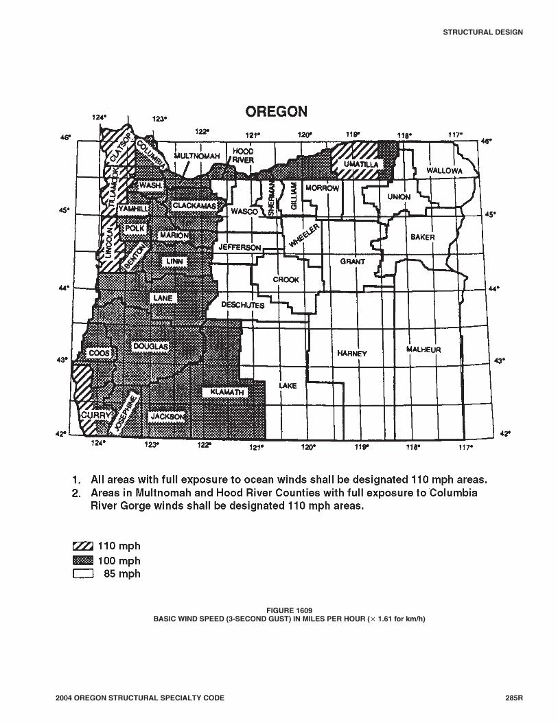
2004 OREGON STRUCTURAL SPECIALTY CODE 285R
STRUCTURAL DESIGN
FIGURE 1609BASIC WIND SPEED (3-SECOND GUST) IN MILES PER HOUR (× 1.61 for km/h)
G:\DATA\CODES\OREGON_2004\OR_Building(Structural)2004\Final VP\16_OregonBldg_2004.vpWednesday, August 25, 2004 11:30:20 AM
Color profile: DisabledComposite Default screen

1609.3.1 Wind speed conversion. When using the 1998Oregon Structural Specialty Code fastest mile wind designprovisions, the 3-second gust wind velocities of Figure1609 shall be converted to fastest-mile wind velocities us-ing Table 1609.3.1.
1609.4 Exposure category. For each wind direction consid-ered, an exposure category that adequately reflects the charac-teristics of ground surface irregularities shall be determined forthe site at which the building or structure is to be constructed.For a site located in the transition zone between categories, thecategory resulting in the largest wind forces shall apply.Account shall be taken of variations in ground surface rough-ness that arise from natural topography and vegetation as wellas from constructed features. For any given wind direction, theexposure in which a specific building or other structure is sitedshall be assessed as being one of the following categories.When applying the simplified wind load method of Section1609.6, a single exposure category shall be used based upon themost restrictive for any given wind direction.
1. Exposure A. This exposure category is no longer used inASCE 7.
2. Exposure B. Urban and suburban areas, wooded areas orother terrain with numerous closely spaced obstructionshaving the size of single-family dwellings or larger. Ex-posure B shall be assumed unless the site meets the defi-nition of another type of exposure.
3. Exposure C. Open terrain with scattered obstructions,including surface undulations or other irregularities,having heights generally less than 30 feet (9144 mm) ex-tending more than 1,500 feet (457.2 m) from the buildingsite in any quadrant. This exposure shall also apply to anybuilding located within Exposure B-type terrain wherethe building is directly adjacent to open areas of Expo-sure C-type terrain in any quadrant for a distance of morethan 600 feet (182.9 m). This category includes flat opencountry, grasslands and shorelines in hurricane-prone re-gions.
4. Exposure D. Flat, unobstructed areas exposed to windflowing over open water (excluding shorelines in hurri-cane-prone regions) for a distance of at least 1 mile (1.61km). Shorelines in Exposure D include inland water-ways, the Great Lakes and coastal areas of California,Oregon, Washington and Alaska. This exposure shall ap-ply only to those buildings and other structures exposed
to the wind coming from over the water. Exposure D ex-tends inland from the shoreline a distance of 1,500 feet(460 m) or 10 times the height of the building or struc-ture, whichever is greater.
1609.5 Importance factor. Buildings and other structuresshall be assigned a wind load importance factor, Iw, in accor-dance with Table 1604.5.
1609.6 Simplified wind load method.
1609.6.1 Scope. The procedures in Section 1609.6 shall bepermitted to be used for determining and applying windpressures in the design of enclosed buildings with flat, ga-bled and hipped roofs and having a mean roof height not ex-ceeding the least horizontal dimension or 60 feet (18 288mm), whichever is less, subject to the limitations of Sections1609.6.1.1 and 1609.6.1.2. If a building qualifies only underSection 1609.6.1.2 for design of its components and clad-ding, then its main windforce-resisting system shall be de-signed in accordance with Section 1609.1.1.
Exception: The provisions of Section 1609.6 shall notapply to buildings sited on the upper half of an isolatedhill or escarpment meeting all of the following condi-tions:
1. The hill or escarpment is 60 feet (18 288 mm) orhigher if located in Exposure B or 30 feet (9144mm) or higher if located in Exposure C.
2. The maximum average slope of the hill exceeds 10percent.
3. The hill or escarpment is unobstructed upwind byother such topographic features for a distance fromthe high point of 50 times the height of the hill or 1mile (1.61 km), whichever is less.
1609.6.1.1 Main windforce-resisting systems. For thedesign of main windforce- resisting systems, the build-ing must meet all of the following conditions:
1. The building is a simple diaphragm building as de-fined in Section 1609.2.
2. The building is not classified as a flexible buildingas defined in Section 1609.2.
3. The building does not have response characteris-tics making it subject to across wind loading, vor-tex shedding, instability due to galloping or flutter;
286R 2004 OREGON STRUCTURAL SPECIALTY CODE
STRUCTURAL DESIGN
TABLE 1609.3.1EQUIVALENT BASIC WIND SPEEDSa,b,c
V3S 85 90 100 105 110 120 125 130 140 145 150 160 170
Vfm 70 75 80 85 90 100 105 110 120 125 130 140 150
For SI: 1 mile per hour = 0.44 m/s.a. Linear interpolation is permitted.b. V3S is the 3-second gust wind speed (mph).c. Vfm is the fastest mile wind speed (mph).
G:\DATA\CODES\OREGON_2004\OR_Building(Structural)2004\Final VP\16_OregonBldg_2004.vpWednesday, August 25, 2004 11:30:21 AM
Color profile: DisabledComposite Default screen

and does not have a site location for which chan-neling effects or buffeting in the wake of upwindobstructions warrant special consideration.
4. The building structure has no expansion joints orseparations.
5. The building is regular shaped and has an approxi-mately symmetrical cross section in each directionwith roof slopes not exceeding 45 degrees (0.78rad.).
1609.6.1.2 Components and cladding. For the designof components and cladding, the building must meet allof the following conditions:
1. The building does not have response characteris-tics making it subject to across wind loading, vor-tex shedding, instability due to galloping or flutter;and does not have a site location for which chan-neling effects or buffeting in the wake of upwindobstructions warrant special consideration.
2. The building is regular shaped with roof slopes notexceeding 45 degrees (0.78 rad.) for gable roofs, or27 degrees (0.47 rad.) for hip roofs.
1609.6.2 Design procedure.
1. The basic wind speed, V, shall be determined in accor-dance with Section 1609.3. The wind shall be as-sumed to come from any horizontal direction.
2. An importance factor Iw shall be determined in accor-dance with Section 1609.5.
3. An exposure category shall be determined in accor-dance with Section 1609.4.
4. A height and exposure adjustment coefficient, λ, shallbe determined from Table 1609.6.2.1(4).
1609.6.2.1 Main windforce-resisting system. Sim-plified design wind pressures, ps, for the mainwindforce-resisting systems represent the net pressures(sum of internal and external) to be applied to the hori-zontal and vertical projections of building surfaces asshown in Figure 1609.6.2.1. For the horizontal pressures(Zones A, B, C, D), ps is the combination of the windwardand leeward net pressures. ps shall be determined fromEquation 16-34).
ps = λ Iw ps30 (Equation 16-34)
where:
λ = Adjustment factor for building height and expo-sure from Table 1609.6.2.1(4).
Iw = Importance factor as defined in Section 1609.5
ps30 = Simplified design wind pressure for Exposure B,at h = 30 feet (9144 mm), and for Iw = 1.0, fromTable 1609.6.2.1(1).
1609.6.2.1.1 Minimum pressures. The load effectsof the design wind pressures from Section 1609.6.2.1shall not be less than assuming the pressures , ps, forZones A, B, C and D all equal to +10 psf (0.48 kN/m2),while assuming Zones E, F, G, and H all equal to 0 psf.
1609.6.2.2 Components and cladding. Net design windpressures, pnet, for the components and cladding of build-ings represent the net pressures (sum of internal and ex-ternal) to be applied normal to each building surface asshown in Figure 1609.6.2.2. The net design wind pres-sure, pnet, shall be determined from Equation 16-35:
pnet = λIw pnet30 (Equation 16-35)
where:
λ = Adjustment factor for building height and expo-sure from Table 1609.6.2.1(4).
Iw = Importance factor as defined in Section 1609.5.
pnet30 = Net design wind pressure for Exposure B, at h =30 feet (9144 mm), and for Iw = 1.0, from Tables1609.6.2.1(2) and 1609.6.2.1(3).
1609.6.2.2.1 Minimum pressures. The positive de-sign wind pressures, pnet, from Section 1609.6.2.2shall not be less than +10 psf (0.48 kN/m2), and thenegative design wind pressures, pnet, from Section1609.6.2.2 shall not be less than -10 psf (-0.48kN/m2).
1609.6.2.3 Load case. Members that act as both part ofthe main windforce-resisting system and as componentsand cladding shall be designed for each separate loadcase.
2004 OREGON STRUCTURAL SPECIALTY CODE 287R
STRUCTURAL DESIGN
G:\DATA\CODES\OREGON_2004\OR_Building(Structural)2004\Final VP\16_OregonBldg_2004.vpWednesday, August 25, 2004 11:30:22 AM
Color profile: DisabledComposite Default screen
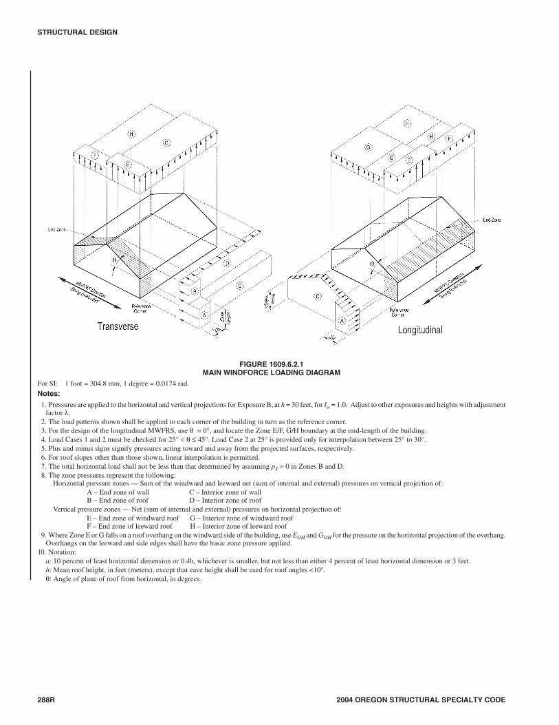
288R 2004 OREGON STRUCTURAL SPECIALTY CODE
STRUCTURAL DESIGN
FIGURE 1609.6.2.1MAIN WINDFORCE LOADING DIAGRAM
For SI: 1 foot = 304.8 mm, 1 degree = 0.0174 rad.Notes:
1. Pressures are applied to the horizontal and vertical projections for Exposure B, at h = 30 feet, for Iw = 1.0. Adjust to other exposures and heights with adjustmentfactor λ.
2. The load patterns shown shall be applied to each corner of the building in turn as the reference corner.3. For the design of the longitudinal MWFRS, use θ = 0°, and locate the Zone E/F, G/H boundary at the mid-length of the building.4. Load Cases 1 and 2 must be checked for 25° < θ ≤ 45°. Load Case 2 at 25° is provided only for interpolation between 25° to 30°.5. Plus and minus signs signify pressures acting toward and away from the projected surfaces, respectively.6. For roof slopes other than those shown, linear interpolation is permitted.7. The total horizontal load shall not be less than that determined by assuming pS = 0 in Zones B and D.8. The zone pressures represent the following:
Horizontal pressure zones — Sum of the windward and leeward net (sum of internal and external) pressures on vertical projection of:A – End zone of wall C – Interior zone of wallB – End zone of roof D – Interior zone of roof
Vertical pressure zones — Net (sum of internal and external) pressures on horizontal projection of:E – End zone of windward roof G – Interior zone of windward roofF – End zone of leeward roof H – Interior zone of leeward roof
9. Where Zone E or G falls on a roof overhang on the windward side of the building, use EOH and GOH for the pressure on the horizontal projection of the overhang.Overhangs on the leeward and side edges shall have the basic zone pressure applied.
10. Notation:a: 10 percent of least horizontal dimension or 0.4h, whichever is smaller, but not less than either 4 percent of least horizontal dimension or 3 feet.h: Mean roof height, in feet (meters), except that eave height shall be used for roof angles <10°.θ: Angle of plane of roof from horizontal, in degrees.
G:\DATA\CODES\OREGON_2004\OR_Building(Structural)2004\Final VP\16_OregonBldg_2004.vpWednesday, August 25, 2004 11:30:24 AM
Color profile: DisabledComposite Default screen

2004 OREGON STRUCTURAL SPECIALTY CODE 289R
STRUCTURAL DESIGN
FIGURE 1609.6.2.2COMPONENT AND CLADDING PRESSURE
For SI: 1 foot = 304.8 mm, 1 degree = 0.0174 rad.Notes:
1. Pressures are applied normal to the surface for Exposure B, at h = 30 feet, for Iw = 1.0. Adjust to other exposures and heights with adjustment factor λ.2. Plus and minus signs signify pressures acting toward and away from the surfaces, respectively.3. For hip roofs with θ ≤ 25°, Zone 3 shall be treated as Zone 2.4. For effective areas between those given, the value is permitted to be interpolated, otherwise use the value associated with the lower effective area.5. Notation:
a: 10 percent of least horizontal dimension or 0.4h, whichever is smaller, but not less than either 4 percent of least horizontal dimension or 3 feet.h: Mean roof height, in feet (meters), except that eave height shall be used for roof angles <10°.θ: Angle of plane of roof from horizontal, in degrees.
G:\DATA\CODES\OREGON_2004\OR_Building(Structural)2004\Final VP\16_OregonBldg_2004.vpWednesday, August 25, 2004 11:30:28 AM
Color profile: DisabledComposite Default screen

290R 2004 OREGON STRUCTURAL SPECIALTY CODE
STRUCTURAL DESIGN
TABLE 1609.6.2.1(1)SIMPLIFIED DESIGN WIND PRESSURE (MAIN WINDFORCE-RESISTING SYSTEM), ps30 (Exposure B at h = 30 feet with Iw = 1.0) (psf)
BASICWIND
SPEED(mph)
ROOFANGLE
(degrees)
ROOFRISE IN
12”LOADCASE
ZONES
Horizontal Pressures Vertical Pressures Overhangs
A B C D E F G H EOH GOH
85
0 to 5° Flat 1 11.5 -5.9 7.6 -3.5 -13.8 -7.8 -9.6 -6.1 -19.3 -15.1
10° 2 1 12.9 -5.4 8.6 -3.1 -13.8 -8.4 -9.6 -6.5 -19.3 -15.1
15° 3 1 14.4 -4.8 9.6 -2.7 -13.8 -9.0 -9.6 -6.9 -19.3 -15.1
20° 4 1 15.9 -4.2 10.6 -2.3 -13.8 -9.6 -9.6 -7.3 -19.3 -15.1
25° 6 12
14.4—
2.3—
10.4—
2.4—
-6.4-2.4
-8.7-4.7
-4.6-0.7
-7.0-3.0
-11.9—
-10.1—
30° to 45° 7 to 12 12
12.912.9
8.88.8
10.210.2
7.07.0
1.05.0
-7.8-3.9
0.34.3
-6.7-2.8
-4.5-4.5
-5.2-5.2
90
0 to 5° Flat 1 12.8 -6.7 8.5 -4.0 -15.4 -8.8 -10.7 -6.8 -21.6 -16.9
10° 2 1 14.5 -6.0 9.6 -3.5 -15.4 -9.4 -10.7 -7.2 -21.6 -16.9
15° 3 1 16.1 -5.4 10.7 -3.0 -15.4 -10.1 -10.7 -7.7 -21.6 -16.9
20° 4 1 17.8 -4.7 11.9 -2.6 -15.4 -10.7 -10.7 -8.1 -21.6 -16.9
25° 6 12
16.1—
2.6—
11.7—
2.7—
-7.2-2.7
-9.8-5.3
-5.2-0.7
-7.8-3.4
-13.3—
-11.4—
30° to 45° 7 to 12 12
14.414.4
9.99.9
11.511.5
7.97.9
1.15.6
-8.8-4.3
0.44.8
-7.5-3.1
-5.1-5.1
-5.8-5.8
100
0 to 5° Flat 1 15.9 -8.2 10.5 -4.9 -19.1 -10.8 -13.3 -8.4 -26.7 -20.9
10° 2 1 17.9 -7.4 11.9 -4.3 -19.1 -11.6 -13.3 -8.9 -26.7 -20.9
15° 3 1 19.9 -6.6 13.3 -3.8 -19.1 -12.4 -13.3 -9.5 -26.7 -20.9
20° 4 1 22.0 -5.8 14.6 -3.2 -19.1 -13.3 -13.3 -10.1 -26.7 -20.9
25° 6 12
19.9—
3.2—
14.4—
3.3—
-8.8-3.4
-12.0-6.6
-6.4-0.9
-9.7-4.2
-16.5—
-14.0—
30° to 45° 7 to 12 12
17.817.8
12.212.2
14.214.2
9.89.8
1.46.9
-10.8-5.3
0.55.9
-9.3-3.8
-6.3-6.3
-7.2-7.2
110
0 to 5° Flat 1 19.2 -10.0 12.7 -5.9 -23.1 -13.1 -16.0 -10.1 -32.3 -25.3
10° 2 1 21.6 -9.0 14.4 -5.2 -23.1 -14.1 -16.0 -10.8 -32.3 -25.3
15° 3 1 24.1 -8.0 16.0 -4.6 -23.1 -15.1 -16.0 -11.5 -32.3 -25.3
20° 4 1 26.6 -7.0 17.7 -3.9 -23.1 -16.0 -16.0 -12.2 -32.3 -25.3
25° 6 12
24.1—
3.9—
17.4—
4.0—
-10.7-4.1
-14.6-7.9
-7.7-1.1
-11.7-5.1
-19.9—
-17.0—
30° to 45° 7 to 12 12
21.621.6
14.814.8
17.217.2
11.811.8
1.78.3
-13.1-6.5
0.67.2
-11.3-4.6
-7.6-7.6
-8.7-8.7
120
0 to 5° Flat 1 22.8 -11.9 15.1 -7.0 -27.4 -15.6 -19.1 -12.1 -38.4 -30.1
10° 2 1 25.8 -10.7 17.1 -6.2 -27.4 -16.8 -19.1 -12.9 -38.4 -30.1
15° 3 1 28.7 -9.5 19.1 -5.4 -27.4 -17.9 -19.1 -13.7 -38.4 -30.1
20° 4 1 31.6 -8.3 21.1 -4.6 -27.4 -19.1 -19.1 -14.5 -38.4 -30.1
25° 6 12
28.6—
4.6—
20.7—
4.7—
-12.7-4.8
-17.3-9.4
-9.2-1.3
-13.9-6.0
-23.7—
-20.2—
30° to 45° 7 to 12 12
25.725.7
17.617.6
20.420.4
14.014.0
2.09.9
-15.6-7.7
0.78.6
-13.4-5.5
-9.0-9.0
-10.3-10.3
130
0 to 5° Flat 1 26.8 -13.9 17.8 -8.2 -32.2 -18.3 -22.4 -14.2 -45.1 -35.3
10° 2 1 30.2 -12.5 20.1 -7.3 -32.2 -19.7 -22.4 -15.1 -45.1 -35.3
15° 3 1 33.7 -11.2 22.4 -6.4 -32.2 -21.0 -22.4 -16.1 -45.1 -35.3
20° 4 1 37.1 -9.8 24.7 -5.4 -32.2 -22.4 -22.4 -17.0 -45.1 -35.3
25° 6 12
33.6—
5.4—
24.3—
5.5—
-14.9-5.7
-20.4-11.1
-10.8-1.5
-16.4-7.1
-27.8—
-23.7—
30° to 45° 7 to 12 12
30.130.1
20.620.6
24.024.0
16.516.5
2.311.6
-18.3-9.0
0.810.0
-15.7-6.4
-10.6-10.6
-12.1-12.1
continued
G:\DATA\CODES\OREGON_2004\OR_Building(Structural)2004\Final VP\16_OregonBldg_2004.vpWednesday, August 25, 2004 11:30:29 AM
Color profile: DisabledComposite Default screen

2004 OREGON STRUCTURAL SPECIALTY CODE 291R
STRUCTURAL DESIGN
TABLE 1609.6.2.1(1)-continuedSIMPLIFIED DESIGN WIND PRESSURE (MAIN WINDFORCE-RESISTING SYSTEM), ps30 (Exposure B at h = 30 feet with Iw = 1.0) (psf)
BASICWIND
SPEED(mph)
ROOFANGLE
(degrees)
ROOFRISE IN
12”LOADCASE
ZONES
Horizontal Pressures Vertical Pressures Overhangs
A B C D E F G H EOH GOH
140
0 to 5° Flat 1 31.1 -16.1 20.6 -9.6 -37.3 -21.2 -26.0 -16.4 -52.3 -40.9
10° 2 1 35.1 -14.5 23.3 -8.5 -37.3 -22.8 -26.0 -17.5 -52.3 -40.9
15° 3 1 39.0 -12.9 26.0 -7.4 -37.3 -24.4 -26.0 -18.6 -52.3 -40.9
20° 4 1 43.0 -11.4 28.7 -6.3 -37.3 -26.0 -26.0 -19.7 -52.3 -40.9
25° 6 12
39.0—
6.3—
28.2—
6.4—
-17.3-6.6
-23.6-12.8
-12.5-1.8
-19.0-8.2
-32.3—
-27.5—
30° to 45° 7 to 12 12
35.035.0
23.923.9
27.827.8
19.119.1
2.713.4
-21.2-10.5
0.911.7
-18.2-7.5
-12.3-12.3
-14.0-14.0
150
0 to 5° Flat 1 35.7 -18.5 23.7 -11.0 -42.9 -24.4 -29.8 -18.9 -60.0 -47.0
10° 2 1 40.2 -16.7 26.8 -9.7 -42.9 -26.2 -29.8 -20.1 -60.0 -47.0
15° 3 1 44.8 -14.9 29.8 -8.5 -42.9 -28.0 -29.8 -21.4 -60.0 -47.0
20° 4 1 49.4 -13.0 32.9 -7.2 -42.9 -29.8 -29.8 -22.6 -60.0 -47.0
25° 6 12
44.8—
7.2—
32.4—
7.4—
-19.9-7.5
-27.1-14.7
-14.4-2.1
-21.8-9.4
-37.0—
-31.6—
30° to 45° 7 to 12 12
40.140.1
27.427.4
31.931.9
22.022.0
3.115.4
-24.4-12.0
1.013.4
-20.9-8.6
-14.1-14.1
-16.1-16.1
170
0 to 5° Flat 1 45.8 -23.8 30.4 -14.1 -55.1 -31.3 -38.3 -24.2 -77.1 -60.4
10° 2 1 51.7 -21.4 34.4 -12.5 -55.1 -33.6 -38.3 -25.8 -77.1 -60.4
15° 3 1 57.6 -19.1 38.3 -10.9 -55.1 -36.0 -38.3 -27.5 -77.1 -60.4
20° 4 1 63.4 -16.7 42.3 -9.3 -55.1 -38.3 -38.3 -29.1 -77.1 -60.4
25° 6 12
57.5—
9.3—
41.6—
9.5—
-25.6-9.7
-34.8-18.9
-18.5-2.6
-28.0-12.1
-47.6—
-40.5—
30° to 45° 7 to 12 12
51.551.5
35.235.2
41.041.0
28.228.2
4.019.8
-31.3-15.4
1.317.2
-26.9-11.0
-18.1-18.1
-20.7-20.7
For SI: 1 inch = 25.4 mm, 1 foot = 304.8 mm, 1 degree = 0.0174 rad, 1 mile per hour = 0.44 m/s, 1 pound per square foot = 47.9 N/m2.
G:\DATA\CODES\OREGON_2004\OR_Building(Structural)2004\Final VP\16_OregonBldg_2004.vpWednesday, August 25, 2004 11:30:30 AM
Color profile: DisabledComposite Default screen

292R 2004 OREGON STRUCTURAL SPECIALTY CODE
STRUCTURAL DESIGN
TABLE 1609.6.2.1(2)NET DESIGN WIND PRESSURE (COMPONENT AND CLADDING), pnet30 (Exposure B at h = 30 feet with Iw = 1.0) (psf)
ZONE
EFFECTIVEWINDAREA
BASIC WIND SPEED V (mph—3-second gust)
85 90 100 110 120 130 140 150 170
1 10 5.3 -13.0 5.9 -14.6 7.3 -18.0 8.9 -21.8 10.5 -25.9 12.4 -30.4 14.3 -35.3 16.5 -40.5 21.1 -52.0
1 20 5.0 -12.7 5.6 -14.2 6.9 -17.5 8.3 -21.2 9.9 -25.2 11.6 -29.6 13.4 -34.4 15.4 -39.4 19.8 -50.7
1 50 4.5 -12.2 5.1 -13.7 6.3 -16.9 7.6 -20.5 9.0 -24.4 10.6 -28.6 12.3 -33.2 14.1 -38.1 18.1 -48.9
1 100 4.2 -11.9 4.7 -13.3 5.8 -16.5 7.0 -19.9 8.3 -23.7 9.8 -27.8 11.4 -32.3 13.0 -37.0 16.7 -47.6
2 10 5.3 -21.8 5.9 -24.4 7.3 -30.2 8.9 -36.5 10.5 -43.5 12.4 -51.0 14.3 -59.2 16.5 -67.9 21.1 -87.2
2 20 5.0 -19.5 5.6 -21.8 6.9 -27.0 8.3 -32.6 9.9 -38.8 11.6 -45.6 13.4 -52.9 15.4 -60.7 19.8 -78.0
2 50 4.5 -16.4 5.1 -18.4 6.3 -22.7 7.6 -27.5 9.0 -32.7 10.6 -38.4 12.3 -44.5 14.1 -51.1 18.1 -65.7
2 100 4.2 -14.1 4.7 -15.8 5.8 -19.5 7.0 -23.6 8.3 -28.1 9.8 -33.0 11.4 -38.2 13.0 -43.9 16.7 -56.4
3 10 5.3 -32.8 5.9 -36.8 7.3 -45.4 8.9 -55.0 10.5 -65.4 12.4 -76.8 14.3 -89.0 16.5 -102.2 21.1 -131.3
3 20 5.0 -27.2 5.6 -30.5 6.9 -37.6 8.3 -45.5 9.9 -54.2 11.6 -63.6 13.4 -73.8 15.4 -84.7 19.8 -108.7
3 50 4.5 -19.7 5.1 -22.1 6.3 -27.3 7.6 -33.1 9.0 -39.3 10.6 -46.2 12.3 -53.5 14.1 -61.5 18.1 -78.9
3 100 4.2 -14.1 4.7 -15.8 5.8 -19.5 7.0 -23.6 8.3 -28.1 9.8 -33.0 11.4 -38.2 13.0 -43.9 16.7 -56.4
1 10 7.5 -11.9 8.4 -13.3 10.4 -16.5 12.5 -19.9 14.9 -23.7 17.5 -27.8 20.3 -32.3 23.3 -37.0 30.0 -47.6
1 20 6.8 -11.6 7.7 -13.0 9.4 -16.0 11.4 -19.4 13.6 -23.0 16.0 -27.0 18.5 -31.4 21.3 -36.0 27.3 -46.3
1 50 6.0 -11.1 6.7 -12.5 8.2 -15.4 10.0 -18.6 11.9 -22.2 13.9 -26.0 16.1 -30.2 18.5 -34.6 23.8 -44.5
1 100 5.3 -10.8 5.9 -12.1 7.3 -14.9 8.9 -18.1 10.5 -21.5 12.4 -25.2 14.3 -29.3 16.5 -33.6 21.1 -43.2
2 10 7.5 -20.7 8.4 -23.2 10.4 -28.7 12.5 -34.7 14.9 -41.3 17.5 -48.4 20.3 -56.2 23.3 -64.5 30.0 -82.8
2 20 6.8 -19.0 7.7 -21.4 9.4 -26.4 11.4 -31.9 13.6 -38.0 16.0 -44.6 18.5 -51.7 21.3 -59.3 27.3 -76.2
2 50 6.0 -16.9 6.7 -18.9 8.2 -23.3 10.0 -28.2 11.9 -33.6 13.9 -39.4 16.1 -45.7 18.5 -52.5 23.8 -67.4
2 100 5.3 -15.2 5.9 -17.0 7.3 -21.0 8.9 -25.5 10.5 -30.3 12.4 -35.6 14.3 -41.2 16.5 -47.3 21.1 -60.8
3 10 7.5 -30.6 8.4 -34.3 10.4 -42.4 12.5 -51.3 14.9 -61.0 17.5 -71.6 20.3 -83.1 23.3 -95.4 30.0 -122.5
3 20 6.8 -28.6 7.7 -32.1 9.4 -39.6 11.4 -47.9 13.6 -57.1 16.0 -67.0 18.5 -77.7 21.3 -89.2 27.3 -114.5
3 50 6.0 -26.0 6.7 -29.1 8.2 -36.0 10.0 -43.5 11.9 -51.8 13.9 -60.8 16.1 -70.5 18.5 -81.0 23.8 -104.0
3 100 5.3 -24.0 5.9 -26.9 7.3 -33.2 8.9 -40.2 10.5 -47.9 12.4 -56.2 14.3 -65.1 16.5 -74.8 21.1 -96.0
1 10 11.9 -13.0 13.3 -14.6 16.5 -18.0 19.9 -21.8 23.7 -25.9 27.8 -30.4 32.3 -35.3 37.0 -40.5 47.6 -52.0
1 20 11.6 -12.3 13.0 -13.8 16.0 -17.1 19.4 -20.7 23.0 -24.6 27.0 -28.9 31.4 -33.5 36.0 -38.4 46.3 -49.3
1 50 11.1 -11.5 12.5 -12.8 15.4 -15.9 18.6 -19.2 22.2 -22.8 26.0 -26.8 30.2 -31.1 34.6 -35.7 44.5 -45.8
1 100 10.8 -10.8 12.1 -12.1 14.9 -14.9 18.1 -18.1 21.5 -21.5 25.2 -25.2 29.3 -29.3 33.6 -33.6 43.2 -43.2
2 10 11.9 -15.2 13.3 -17.0 16.5 -21.0 19.9 -25.5 23.7 -30.3 27.8 -35.6 32.3 -41.2 37.0 -47.3 47.6 -60.8
2 20 11.6 -14.5 13.0 -16.3 16.0 -20.1 19.4 -24.3 23.0 -29.0 27.0 -34.0 31.4 -39.4 36.0 -45.3 46.3 -58.1
2 50 11.1 -13.7 12.5 -15.3 15.4 -18.9 18.6 -22.9 22.2 -27.2 26.0 -32.0 30.2 -37.1 34.6 -42.5 44.5 -54.6
2 100 10.8 -13.0 12.1 -14.6 14.9 -18.0 18.1 -21.8 21.5 -25.9 25.2 -30.4 29.3 -35.3 33.6 -40.5 43.2 -52.0
3 10 11.9 -15.2 13.3 -17.0 16.5 -21.0 19.9 -25.5 23.7 -30.3 27.8 -35.6 32.3 -41.2 37.0 -47.3 47.6 -60.8
3 20 11.6 -14.5 13.0 -16.3 16.0 -20.1 19.4 -24.3 23.0 -29.0 27.0 -34.0 31.4 -39.4 36.0 -45.3 46.3 -58.1
3 50 11.1 -13.7 12.5 -15.3 15.4 -18.9 18.6 -22.9 22.2 -27.2 26.0 -32.0 30.2 -37.1 34.6 -42.5 44.5 -54.6
3 100 10.8 -13.0 12.1 -14.6 14.9 -18.0 18.1 -21.8 21.5 -25.9 25.2 -30.4 29.3 -35.3 33.6 -40.5 43.2 -52.0
4 10 13.0 -14.1 14.6 -15.8 18.0 -19.5 21.8 -23.6 25.9 -28.1 30.4 -33.0 35.3 -38.2 40.5 -43.9 52.0 -56.4
4 20 12.4 -13.5 13.9 -15.1 17.2 -18.7 20.8 -22.6 24.7 -26.9 29.0 -31.6 33.7 -36.7 38.7 -42.1 49.6 -54.1
4 50 11.6 -12.7 13.0 -14.3 16.1 -17.6 19.5 -21.3 23.2 -25.4 27.2 -29.8 31.6 -34.6 36.2 -39.7 46.6 -51.0
4 100 11.1 -12.2 12.4 -13.6 15.3 -16.8 18.5 -20.4 22.0 -24.2 25.9 -28.4 30.0 -33.0 34.4 -37.8 44.2 -48.6
4 500 9.7 -10.8 10.9 -12.1 13.4 -14.9 16.2 -18.1 19.3 -21.5 22.7 -25.2 26.3 -29.3 30.2 -33.6 38.8 -43.2
5 10 13.0 -17.4 14.6 -19.5 18.0 -24.1 21.8 -29.1 25.9 -34.7 30.4 -40.7 35.3 -47.2 40.5 -54.2 52.0 -69.6
5 20 12.4 -16.2 13.9 -18.2 17.2 -22.5 20.8 -27.2 24.7 -32.4 29.0 -38.0 33.7 -44.0 38.7 -50.5 49.6 -64.9
5 50 11.6 -14.7 13.0 -16.5 16.1 -20.3 19.5 -24.6 23.2 -29.3 27.2 -34.3 31.6 -39.8 36.2 -45.7 46.6 -58.7
5 100 11.1 -13.5 12.4 -15.1 15.3 -18.7 18.5 -22.6 22.0 -26.9 25.9 -31.6 30.0 -36.7 34.4 -42.1 44.2 -54.1
5 500 9.7 -10.8 10.9 -12.1 13.4 -14.9 16.2 -18.1 19.3 -21.5 22.7 -25.2 26.3 -29.3 30.2 -33.6 38.8 -43.2
For SI: 1 foot = 304.8 mm, 1 degree = 0.0174 rad, 1 mile per hour = 0.44 m/s, 1 pound per square foot = 47.9 N/m2.Note: For effective areas between those given above, the load is permitted to be interpolated, otherwise use the load associated with the lower effective area.
Ro
of
0to
7d
egre
esR
oo
f>
7to
27d
egre
esR
oo
f>
27to
45d
egre
esW
all
G:\DATA\CODES\OREGON_2004\OR_Building(Structural)2004\Final VP\16_OregonBldg_2004.vpWednesday, August 25, 2004 11:30:32 AM
Color profile: DisabledComposite Default screen

2004 OREGON STRUCTURAL SPECIALTY CODE 293R
STRUCTURAL DESIGN
TABLE 1609.6.2.1(4)ADJUSTMENT FACTOR FOR BUILDING HEIGHT AND EXPOSURE, (λ)
MEAN ROOF HEIGHT(feet)
EXPOSURE
B C D
15 1.00 1.21 1.47
20 1.00 1.29 1.55
25 1.00 1.35 1.61
30 1.00 1.40 1.66
35 1.05 1.45 1.70
40 1.09 1.49 1.74
45 1.12 1.53 1.78
50 1.16 1.56 1.81
55 1.19 1.59 1.84
60 1.22 1.62 1.87
For SI: 1 foot = 304.8 mm.a. All table values shall be adjusted for other exposures and heights by multiplying by the above coefficients.
TABLE 1609.6.2.1(3)ROOF OVERHANG NET DESIGN WIND PRESSURE (COMPONENT AND CLADDING), pnet30 (Exposure B at h = 30 feet with Iw = 1.0) (psf)
ZONE
EFFECTIVEWIND AREA
(sq. ft.)
BASIC WIND SPEED V (mph—3-second gust)
90 100 110 120 130 140 150 170
2 10 -21.0 -25.9 -31.4 -37.3 -43.8 -50.8 -58.3 -74.9
2 20 -20.6 -25.5 -30.8 -36.7 -43.0 -49.9 -57.3 -73.6
2 50 -20.1 -24.9 -30.1 -35.8 -42.0 -48.7 -55.9 -71.8
2 100 -19.8 -24.4 -29.5 -35.1 -41.2 -47.8 -54.9 -70.5
3 10 -34.6 -42.7 -51.6 -61.5 -72.1 -83.7 -96.0 -123.4
3 20 -27.1 -33.5 -40.5 -48.3 -56.6 -65.7 -75.4 -96.8
3 50 -17.3 -21.4 -25.9 -30.8 -36.1 -41.9 -48.1 -61.8
3 100 -10.0 -12.2 -14.8 -17.6 -20.6 -23.9 -27.4 -35.2
2 10 -27.2 -33.5 -40.6 -48.3 -56.7 -65.7 -75.5 -96.9
2 20 -27.2 -33.5 -40.6 -48.3 -56.7 -65.7 -75.5 -96.9
2 50 -27.2 -33.5 -40.6 -48.3 -56.7 -65.7 -75.5 -96.9
2 100 -27.2 -33.5 -40.6 -48.3 -56.7 -65.7 -75.5 -96.9
3 10 -45.7 -56.4 -68.3 -81.2 -95.3 -110.6 -126.9 -163.0
3 20 -41.2 -50.9 -61.6 -73.3 -86.0 -99.8 -114.5 -147.1
3 50 -35.3 -43.6 -52.8 -62.8 -73.7 -85.5 -98.1 -126.1
3 100 -30.9 -38.1 -46.1 -54.9 -64.4 -74.7 -85.8 -110.1
2 10 -24.7 -30.5 -36.9 -43.9 -51.5 -59.8 -68.6 -88.1
2 20 -24.0 -29.6 -35.8 -42.6 -50.0 -58.0 -66.5 -85.5
2 50 -23.0 -28.4 -34.3 -40.8 -47.9 -55.6 -63.8 -82.0
2 100 -22.2 -27.4 -33.2 -39.5 -46.4 -53.8 -61.7 -79.3
3 10 -24.7 -30.5 -36.9 -43.9 -51.5 -59.8 -68.6 -88.1
3 20 -24.0 -29.6 -35.8 -42.6 -50.0 -58.0 -66.5 -85.5
3 50 -23.0 -28.4 -34.3 -40.8 -47.9 -55.5 -63.8 -82.2
3 100 -22.2 -27.4 -33.2 -39.5 -46.4 -53.8 -61.7 -79.3
For SI: 1 foot = 304.8 mm, 1 degree = 0.0174 rad, 1 mile per hour = 0.45 m/s, 1 pound per square foot = 47.9 N/m2.Note: For effective areas between those given above, the load is permitted to be interpolated, otherwise use the load associated with the lower effective area.
Ro
of
0to
7d
egre
esR
oo
f>
7to
27d
egre
esR
oo
f>
27to
45d
egre
es
G:\DATA\CODES\OREGON_2004\OR_Building(Structural)2004\Final VP\16_OregonBldg_2004.vpWednesday, August 25, 2004 11:30:33 AM
Color profile: DisabledComposite Default screen

1609.7 Roof systems.
1609.7.1 Roof deck. The roof deck shall be designed towithstand the wind pressures determined under either theprovisions of Section 1609.6 for buildings with a mean roofheight not exceeding 60 feet (18 288 mm) or Section1609.1.1 for buildings of any height.
1609.7.2 Roof coverings. Roof coverings shall complywith Section 1609.7.1.
Exception: Rigid tile roof coverings that are air perme-able and installed over a roof deck complying with Sec-tion 1609.7.1 are permitted to be designed in accordancewith Section 1609.7.3.
1609.7.3 Rigid tile. Wind loads on rigid tile roof coveringsshall be determined in accordance with the following equation:
Ma = qhCLbLLa[1.0 – Gcp] (Equation 16-36)
For SI: Ma =[ ]q C bLL Gch L a p10
1 000
.
,
−
where:
b = Exposed width, feet (mm) of the roof tile.
CL = Lift coefficient. The lift coefficient for concrete andclay tile shall be 0.2 or shall be determined by test inaccordance with Section 1715.2.
GCp = Roof pressure coefficient for each applicable roofzone determined from Section 6 of ASCE 7. Roof co-efficients shall not be adjusted for internal pressure.
L = Length, feet (mm) of the roof tile.
La = Moment arm, feet (mm) from the axis of rotation tothe point of uplift on the roof tile. The point of upliftshall be taken at 0.76L from the head of the tile andthe middle of the exposed width. For roof tiles withnails or screws (with or without a tail clip), the axis ofrotation shall be taken as the head of the tile for directdeck application or as the top edge of the batten forbattened applications. For roof tiles fastened only bya nail or screw along the side of the tile, the axis of ro-tation shall be determined by testing. For roof tiles in-stalled with battens and fastened only by a clip nearthe tail of the tile, the moment arm shall be deter-mined about the top edge of the batten with consider-ation given for the point of rotation of the tiles basedon straight bond or broken bond and the tile profile.
Ma = Aerodynamic uplift moment, feet-pounds (N-mm)acting to raise the tail of the tile.
qh = Wind velocity pressure, psf (kN/m2) determinedfrom Section 6.5.10 of ASCE 7.
Concrete and clay roof tiles complying with the follow-ing limitations shall be designed to withstand the aerody-namic uplift moment as determined by this section.
1. The roof tiles shall be either loose laid on battens, me-chanically fastened, mortar set or adhesive set.
2. The roof tiles shall be installed on solid sheathingwhich has been designed as components and clad-ding.
3. An underlayment shall be installed in accordancewith Chapter 15.
4. The tile shall be single lapped interlocking with a min-imum head lap of not less than 2 inches (51 mm).
5. The length of the tile shall be between 1.0 and 1.75feet (305 mm and 533 mm).
6. The exposed width of the tile shall be between 0.67and 1.25 feet (204 mm and 381 mm).
7. The maximum thickness of the tail of the tile shall notexceed 1.3 inches (33 mm).
8. Roof tiles using mortar set or adhesive set systemsshall have at least two-thirds of the tile’s area free ofmortar or adhesive contact.
SECTION 1610SOIL LATERAL LOAD
1610.1 General. Basement, foundation and retaining wallsshall be designed to resist lateral soil loads. Soil loads specifiedin Table 1610.1 shall be used as the minimum design lateral soilloads unless specified otherwise in a soil investigation reportapproved by the building official. Basement walls and otherwalls in which horizontal movement is restricted at the top shallbe designed for at-rest pressure. Retaining walls free to moveand rotate at the top are permitted to be designed for active pres-sure. Design lateral pressure from surcharge loads shall beadded to the lateral earth pressure load. Design lateral pressureshall be increased if soils with expansion potential are presentat the site.
Exception: Basement walls extending not more than 8 feet(2438 mm) below grade and supporting flexible floor sys-tems shall be permitted to be designed for active pressure.
SECTION 1611RAIN LOADS
1611.1 Design rain loads. Each portion of a roof shall bedesigned to sustain the load of rainwater that will accumulateon it if the primary drainage system for that portion is blockedplus the uniform load caused by water that rises above the inletof the secondary drainage system at its design flow.
R = 5.2 (ds + dh) (Equation 16-37)
For SI: R = 0.0098 (ds + dh)
where:
dh = Additional depth of water on the undeflected roofabove the inlet of secondary drainage system at its de-sign flow (i.e., the hydraulic head), in inches (mm).
ds = Depth of water on the undeflected roof up to the inlet ofsecondary drainage system when the primary drainagesystem is blocked (i.e., the static head), in inches (mm).
R = Rain load on the undeflected roof, in psf (kN/m2). Whenthe phrase “undeflected roof” is used, deflections fromloads (including dead loads) shall not be consideredwhen determining the amount of rain on the roof.
294R 2004 OREGON STRUCTURAL SPECIALTY CODE
STRUCTURAL DESIGN
G:\DATA\CODES\OREGON_2004\OR_Building(Structural)2004\Final VP\16_OregonBldg_2004.vpWednesday, August 25, 2004 11:30:34 AM
Color profile: DisabledComposite Default screen

1611.2 Ponding instability. Ponding refers to the retention ofwater due solely to the deflection of relatively flat roofs. Roofswith a slope less than one-fourth unit vertical in 12 units hori-zontal (2-percent slope) shall be investigated by structural anal-ysis to ensure that they possess adequate stiffness to precludeprogressive deflection (i.e., instability) as rain falls on them ormeltwater is created from snow on them. The larger of snowload or rain load shall be used in this analysis. The primarydrainage system within an area subjected to ponding shall beconsidered to be blocked in this analysis.
1611.3 Controlled drainage. Roofs equipped with hardwareto control the rate of drainage shall be equipped with a second-ary drainage system at a higher elevation that limits accumula-tion of water on the roof above that elevation. Such roofs shallbe designed to sustain the load of rainwater that will accumu-late on them to the elevation of the secondary drainage systemplus the uniform load caused by water that rises above the inletof the secondary drainage system at its design flow determinedfrom Section 1611.1. Such roofs shall also be checked forponding instability in accordance with Section 1611.2.
SECTION 1612FLOOD LOADS
1612.1 General. Within flood hazard areas as established inSection 1612.3, all new construction of buildings, structures andportions of buildings and structures, including substantial
improvements and restoration of substantial damage to build-ings and structures, shall be designed and constructed to resistthe effects of flood hazards and flood loads. For prohibitionsagainst siting new essential facilities and new special occupancystructures in tsunami inundation zones, see Section 1804.1.1.
1612.2 Definitions. The following words and terms shall, forthe purposes of this section, have the meanings shown herein.
BASE FLOOD. The flood having a 1-percent chance of beingequaled or exceeded in any given year.
BASE FLOOD ELEVATION. The elevation of the baseflood, including wave height, relative to the National GeodeticVertical Datum (NGVD), North American Vertical Datum(NAVD) or other datum specified on the Flood Insurance RateMap (FIRM).
BASEMENT. The portion of a building having its floorsubgrade (below ground level) on all sides.
DESIGN FLOOD. The flood associated with the greater of thefollowing two areas:
1. Area with a flood plain subject to a 1-percent or greaterchance of flooding in any year; or
2. Area designated as a flood hazard area on a community’sflood hazard map, or otherwise legally designated.
DESIGN FLOOD ELEVATION. The elevation of the“design flood,” including wave height, relative to the datumspecified on the community’s legally designated flood hazard
2004 OREGON STRUCTURAL SPECIALTY CODE 295R
STRUCTURAL DESIGN
TABLE 1610.1SOIL LATERAL LOAD
DESCRIPTION OF BACKFILL MATERIALcUNIFIED SOIL
CLASSIFICATION
DESIGN LATERAL SOIL LOADa
(pound per square foot per foot of depth)
Active pressure At-rest pressure
Well-graded, clean gravels; gravel-sand mixes GW 30 60
Poorly graded clean gravels; gravel-sand mixes GP 30 60
Silty gravels, poorly graded gravel-sand mixes GM 40 60
Clayey gravels, poorly graded gravel-and-clay mixes GC 45 60
Well-graded, clean sands; gravelly sand mixes SW 30 60
Poorly graded clean sands; sand-gravel mixes SP 30 60
Silty sands, poorly graded sand-silt mixes SM 45 60
Sand-silt clay mix with plastic fines SM-SC 45 100
Clayey sands, poorly graded sand-clay mixes SC 60 100
Inorganic silts and clayey silts ML 45 100
Mixture of inorganic silt and clay ML-CL 60 100
Inorganic clays of low to medium plasticity CL 60 100
Organic silts and silt clays, low plasticity OL Note b Note b
Inorganic clayey silts, elastic silts MH Note b Note b
Inorganic clays of high plasticity CH Note b Note b
Organic clays and silty clays OH Note b Note b
For SI: 1 pound per square foot per foot of depth = 0.157 kPa/m, 1 foot = 304.8 mm.a. Design lateral soil loads are given for moist conditions for the specified soils at their optimum densities. Actual field conditions shall govern. Submerged or satu-
rated soil pressures shall include the weight of the buoyant soil plus the hydrostatic loads.b. Unsuitable as backfill material.c. The definition and classification of soil materials shall be in accordance with ASTM D 2487.
G:\DATA\CODES\OREGON_2004\OR_Building(Structural)2004\Final VP\16_OregonBldg_2004.vpWednesday, August 25, 2004 11:30:35 AM
Color profile: DisabledComposite Default screen

map. In areas designated as Zone AO, the design flood eleva-tion shall be the elevation of the highest existing grade of thebuilding’s perimeter plus the depth number (in feet) specifiedon the flood hazard map. In areas designated as Zone AO wherea depth number is not specified on the map, the depth numbershall be taken as being equal to 2 feet (610 mm).
DRY FLOODPROOFING. A combination of design modifi-cations that results in a building or structure, including theattendant utility and sanitary facilities, being water tight withwalls substantially impermeable to the passage of water andwith structural components having the capacity to resist loadsas identified in ASCE 7.
EXISTING CONSTRUCTION. Any buildings and struc-tures for which the “start of construction” commenced beforethe effective date of the community’s first flood plain manage-ment code, ordinance or standard. “Existing construction” isalso referred to as “existing structures.”
EXISTING STRUCTURE. See “Existing construction.”
FLOOD or FLOODING. A general and temporary conditionof partial or complete inundation of normally dry land from:
1. The overflow of inland or tidal waters.
2. The unusual and rapid accumulation or runoff of surfacewaters from any source.
FLOOD DAMAGE-RESISTANT MATERIALS. Any con-struction material capable of withstanding direct and pro-longed contact with floodwaters without sustaining anydamage that requires more than cosmetic repair.
FLOOD HAZARD AREA. The greater of the following twoareas:
1. The area within a flood plain subject to a 1-percent orgreater chance of flooding in any year.
2. The area designated as a flood hazard area on a commu-nity’s flood hazard map, or otherwise legally designated.
FLOOD HAZARD AREA SUBJECT TO HIGH VELOC-ITY WAVE ACTION. Area within the flood hazard area thatis subject to high velocity wave action, and shown on a FloodInsurance Rate Map (FIRM) or other flood hazard map as ZoneV, VO, VE or V1-30.
FLOOD INSURANCE RATE MAP (FIRM). An officialmap of a community on which the Federal Emergency Man-agement Agency (FEMA) has delineated both the special floodhazard areas and the risk premium zones applicable to the com-munity.
FLOOD INSURANCE STUDY. The official report providedby the Federal Emergency Management Agency containing theFlood Insurance Rate Map (FIRM), the Flood Boundary andFloodway Map (FBFM), the water surface elevation of the baseflood and supporting technical data.
FLOODWAY. The channel of the river, creek or other water-course and the adjacent land areas that must be reserved inorder to discharge the base flood without cumulatively increas-ing the water surface elevation more than a designated height.
LOWEST FLOOR. The floor of the lowest enclosed area,including basement, but excluding any unfinished orflood-resistant enclosure, usable solely for vehicle parking,
building access or limited storage provided that such enclosureis not built so as to render the structure in violation of this sec-tion.
SPECIAL FLOOD HAZARD AREA. The land area subjectto flood hazards and shown on a Flood Insurance Rate Map orother flood hazard map as Zone A, AE, A1-30, A99, AR, AO,AH, V, VO, VE or V1-30.
START OF CONSTRUCTION. The date of permit issuancefor new construction and substantial improvements to existingstructures, provided the actual start of construction, repair,reconstruction, rehabilitation, addition, placement or otherimprovement is within 180 days after the date of issuance. Theactual start of construction means the first placement of perma-nent construction of a building (including a manufacturedhome) on a site, such as the pouring of a slab or footings, instal-lation of pilings or construction of columns.
Permanent construction does not include land preparation(such as clearing, excavation, grading or filling), the installa-tion of streets or walkways, excavation for a basement, foot-ings, piers or foundations, the erection of temporary forms orthe installation of accessory buildings such as garages or shedsnot occupied as dwelling units or not part of the main building.For a substantial improvement, the actual “start of construc-tion” means the first alteration of any wall, ceiling, floor orother structural part of a building, whether or not that alterationaffects the external dimensions of the building.
SUBSTANTIAL DAMAGE. Damage of any origin sustainedby a structure whereby the cost of restoring the structure to itsbefore-damaged condition would equal or exceed 50 percent ofthe market value of the structure before the damage occurred.
SUBSTANTIAL IMPROVEMENT. Any repair, reconstruc-tion, rehabilitation, addition or improvement of a building orstructure, the cost of which equals or exceeds 50 percent of themarket value of the structure before the improvement or repairis started. If the structure has sustained substantial damage, anyrepairs are considered substantial improvement regardless ofthe actual repair work performed. The term does not, however,include either:
1. Any project for improvement of a building required tocorrect existing health, sanitary or safety code violationsidentified by the building official and that are the mini-mum necessary to assure safe living conditions.
2. Any alteration of a historic structure provided that the al-teration will not preclude the structure’s continued desig-nation as a historic structure.
1612.3 Establishment of flood hazard areas. To establishflood hazard areas, the governing body shall adopt a flood haz-ard map and supporting data. The flood hazard map shallinclude, at a minimum, areas of special flood hazard as identi-fied by the Federal Emergency Management Agency in anengineering report entitled “The Flood Insurance Study for[INSERT NAME OF JURISDICTION],” dated [INSERT DATE OF ISSU-ANCE], as amended or revised with the accompanying FloodInsurance Rate Map (FIRM) and Flood Boundary and FloodwayMap (FBFM) and related supporting data along with any revi-sions thereto. The adopted flood hazard map and supporting dataare hereby adopted by reference and declared to be part of thissection.
296R 2004 OREGON STRUCTURAL SPECIALTY CODE
STRUCTURAL DESIGN
G:\DATA\CODES\OREGON_2004\OR_Building(Structural)2004\Final VP\16_OregonBldg_2004.vpWednesday, August 25, 2004 11:30:36 AM
Color profile: DisabledComposite Default screen

1612.4 Design and construction. The design and constructionof buildings and structures located in flood hazard areas,including flood hazard areas subject to high velocity waveaction, shall be in accordance with ASCE 24.
1612.5 Flood hazard documentation. The following docu-mentation shall be prepared and sealed by a registered designprofessional and submitted to the building official:
1. For construction in flood hazard areas not subject tohigh-velocity wave action:
1.1. The elevation of the lowest floor, including base-ment, as required by the lowest floor elevation in-spection in Section 109.3.3.
1.2. For fully enclosed areas below the design floodelevation where provisions to allow for the auto-matic entry and exit of floodwaters do not meetthe minimum requirements in Section 2.6.1.1,ASCE 24, construction documents shall includea statement that the design will provide for equal-ization of hydrostatic flood forces in accordancewith Section 2.6.1.2, ASCE 24.
1.3. For dry floodproofed nonresidential buildings,construction documents shall include a statementthat the dry floodproofing is designed in accor-dance with ASCE 24.
2. For construction in flood hazard areas subject to high-ve-locity wave action:
2.1. The elevation of the bottom of the lowest hori-zontal structural member as required by the low-est floor elevation inspection in Section 109.3.3.
2.2. Construction documents shall include a state-ment that the building is designed in accordancewith ASCE 24, including that the pile or columnfoundation and building or structure to be at-tached thereto is designed to be anchored to resistflotation, collapse and lateral movement due tothe effects of wind and flood loads acting simul-taneously on all building components, and otherload requirements of Chapter 16.
2.3. For breakaway walls designed to resist a nominalload of less than 10 psf (0.48 kN/m2) or more than20 psf (0.96 kN/m2), construction documentsshall include a statement that the breakaway wallis designed in accordance with ASCE 24.
SECTION 1613EARTHQUAKE LOADS DEFINITIONS
1613.1 Definitions.The following words and terms shall, forthe purposes of this section, have the meanings shown herein.
ACTIVE FAULT/ACTIVE FAULT TRACE. A fault forwhich there is an average historic slip rate of 1 mm per year ormore and geologic evidence of seismic activity within Holocene(past 11,000 years) times. Active fault traces are designated bythe appropriate regulatory agency and/or registered design pro-fessional subject to identification by a geologic report.
ATTACHMENTS, SEISMIC. Means by which componentsand their supports are secured or connected to the seis-
mic-force-resisting system of the structure. Such attachmentsinclude anchor bolts, welded connections and mechanical fas-teners.
BASE. The level at which the horizontal seismic groundmotions are considered to be imparted to the structure.
BOUNDARY ELEMENTS. Chords and collectors at dia-phragm and shear wall edges, interior openings, discontinuitiesand reentrant corners.
BRITTLE. Systems, members, materials and connections thatdo not exhibit significant energy dissipation capacity in theinelastic range.
COLLECTOR. A diaphragm or shear wall element parallel tothe applied load that collects and transfers shear forces to thevertical-force-resisting elements or distributes forces within adiaphragm or shear wall.
COMPONENT. A part or element of an architectural, electri-cal, mechanical or structural system.
Component, equipment. A mechanical or electrical com-ponent or element that is part of a mechanical and/or electri-cal system within or without a building system.
Component, flexible. Component, including its attach-ments, having a fundamental period greater than 0.06 second.
Component, rigid. Component, including its attachments,having a fundamental period less than or equal to 0.06 sec-ond.
DESIGN EARTHQUAKE. The earthquake effects that build-ings and structures are specifically proportioned to resist inSections 1613 through 1622.
DESIGNATED SEISMIC SYSTEM. Those architectural,electrical and mechanical systems and their components thatrequire design in accordance with Section 1621 that have acomponent importance factor, Ip, greater than one.
DISPLACEMENT.
Design displacement. The design earthquake lateral dis-placement, excluding additional displacement due to actualand accidental torsion, required for design of the isolationsystem.
Total design displacement. The design earthquake lateraldisplacement, including additional displacement due to ac-tual and accidental torsion, required for design of the isola-tion system.
Total maximum displacement. The maximum consideredearthquake lateral displacement, including additional dis-placement due to actual and accidental torsion, required forverification of the stability of the isolation system or ele-ments thereof, design of building separations and verticalload testing of isolator unit prototype.
DISPLACEMENT RESTRAINT SYSTEM. A collection ofstructural elements that limits lateral displacement of seismi-cally isolated structures due to the maximum considered earth-quake.
EFFECTIVE DAMPING. The value of equivalent viscousdamping corresponding to energy dissipated during cyclicresponse of the isolation system.
2004 OREGON STRUCTURAL SPECIALTY CODE 297R
STRUCTURAL DESIGN
G:\DATA\CODES\OREGON_2004\OR_Building(Structural)2004\Final VP\16_OregonBldg_2004.vpWednesday, August 25, 2004 11:30:37 AM
Color profile: DisabledComposite Default screen

EFFECTIVE STIFFNESS. The value of the lateral force inthe isolation system, or an element thereof, divided by the cor-responding lateral displacement.
HAZARDOUS CONTENTS. A material that is highly toxicor potentially explosive and in sufficient quantity to pose a sig-nificant life-safety threat to the general public if an uncon-trolled release were to occur.
INVERTED PENDULUM-TYPE STRUCTURES. Struc-tures that have a large portion of their mass concentrated nearthe top, and thus have essentially one degree of freedom in hori-zontal translation. The structures are usually T-shaped with asingle column supporting the beams or framing at the top.
ISOLATION INTERFACE. The boundary between theupper portion of the structure, which is isolated, and the lowerportion of the structure, which moves rigidly with the ground.
ISOLATION SYSTEM. The collection of structural elementsthat includes individual isolator units, structural elements thattransfer force between elements of the isolation system andconnections to other structural elements.
ISOLATOR UNIT. A horizontally flexible and vertically stiffstructural element of the isolation system that permits large lat-eral deformations under design seismic load. An isolator unit ispermitted to be used either as part of or in addition to theweight-supporting system of the building.
LOAD. Gravity load (W). The total dead load and applicableportions of other loads as defined in Sections 1613 through 1622.
MAXIMUM CONSIDERED EARTHQUAKE. The mostsevere earthquake effects considered by this code.
NONBUILDING STRUCTURE. A structure, other than abuilding, constructed of a type included in Section 1622.
OCCUPANCY IMPORTANCE FACTOR. A factorassigned to each structure according to its seismic use group asprescribed in Table 1604.5.
SEISMIC DESIGN CATEGORY. A classification assignedto a structure based on its seismic use group and the severity ofthe design earthquake ground motion at the site.
SEISMIC-FORCE-RESISTING SYSTEM. The part of thestructural system that has been considered in the design to providethe required resistance to the seismic forces prescribed herein.
SEISMIC FORCES. The assumed forces prescribed herein,related to the response of the structure to earthquake motions,to be used in the design of the structure and its components.
SEISMIC USE GROUP. A classification assigned to a build-ing based on its use as defined in Section 1616.2.
SHEAR WALL. A wall designed to resist lateral forces paral-lel to the plane of the wall.
SHEAR WALL-FRAME INTERACTIVE SYSTEM. Astructural system that uses combinations of shear walls andframes designed to resist lateral forces in proportion to theirrigidities, considering interaction between shear walls andframes on all levels.
SITE CLASS. A classification assigned to a site based on thetypes of soils present and their engineering properties asdefined in Section 1615.1.5.
SITE COEFFICIENTS. The values of, Fa, and, Fv, indicatedin Tables 1615.1.2(1) and 1615.1.2(2), respectively.
STORY DRIFT RATIO. The story drift divided by the storyheight.
TORSIONAL FORCE DISTRIBUTION. The distributionof horizontal seismic forces through a rigid diaphragm whenthe center of mass of the structure at the level under consider-ation does not coincide with the center of rigidity (sometimesreferred to as a “diaphragm rotation”).
TOUGHNESS. The ability of a material to absorb energywithout losing significant strength.
WIND-RESTRAINT SEISMIC SYSTEM. The collectionof structural elements that provides restraint of the seismic-iso-lated structure for wind loads. The wind-restraint system maybe either an integral part of isolator units or a separate device.
SECTION 1614EARTHQUAKE LOADS—GENERAL
1614.1 Scope. Every structure, and portion thereof, shall as aminimum, be designed and constructed to resist the effects ofearthquake motions and assigned a seismic design category asset forth in Section 1616.3. Structures determined to be in Seis-mic Design Category A need only comply with Section 1616.4.
Exceptions:
1. Structures designed in accordance with the provisionsof Sections 9.1 through 9.6, 9.13 and 9.14 of ASCE 7shall be permitted.
2. Detached one- and two-family dwellings as applica-ble in Section 101.2 in Seismic Design Categories A,B and C, or located where the mapped short-periodspectral response acceleration, SS, is less than 0.4 g,are exempt from the requirements of Sections 1613through 1622.
3. The seismic-force-resisting system of wood framebuildings that conform to the provisions of Section2308 are not required to be analyzed as specified inSection 1616.1.
4. Agricultural storage structures intended only for inci-dental human occupancy are exempt from the require-ments of Sections 1613 through 1623.
5. Structures located where mapped short-period spec-tral response acceleration, SS, determined in accor-dance with Section 1615.1, is less than or equal to0.15g and where the mapped spectral response accel-eration at 1-second period, S1, determined in accor-dance with Section 1615.1, is less than or equal to0.04g shall be categorized as Seismic Design Cate-gory A. Seismic Design Category A structures needonly comply with Section 1616.4.
6. Structures located where the short-period designspectral response acceleration, SDS, determined in ac-cordance with Section 1615.1, is less than or equal to0.167g and the design spectral response accelerationat 1-second period, SD1, determined in accordancewith Section 1615.1, is less than or equal to 0.067g,
298R 2004 OREGON STRUCTURAL SPECIALTY CODE
STRUCTURAL DESIGN
G:\DATA\CODES\OREGON_2004\OR_Building(Structural)2004\Final VP\16_OregonBldg_2004.vpWednesday, August 25, 2004 11:30:38 AM
Color profile: DisabledComposite Default screen

shall be categorized as Seismic Design Category Aand need only comply with Section 1616.4.
[EB] 1614.1.1 Additions to existing buildings. An addi-tion that is structurally independent from an existing struc-ture shall be designed and constructed as required for a newstructure in accordance with the seismic requirements fornew structures. An addition that is not structurally inde-pendent from an existing structure shall be designed andconstructed such that the entire structure conforms to theseismic-force resistance requirements for new structuresunless the following conditions are satisfied:
1. The addition conforms with the requirements for newstructures,
2. The addition does not increase the seismic forces inany structural element of the existing structure bymore than 5 percent, unless the element has the capac-ity to resist the increased forces determined in accor-dance with Sections 1613 through 1622, and
3. Additions do not decrease the seismic resistance ofany structural element of the existing structure bymore than 5 percent cumulative since the original con-struction, unless the element has the capacity to resistthe forces determined in accordance with Sections1613 through 1622.
[EB] 1614.2 Change of occupancy. See Chapter 34.
[EB] 1614.3 Voluntary alterations. Alterations to existingstructural elements or additions of new structural elements thatare not required by Sections 1613 through 1623 and are initi-ated for the purpose of increasing the strength or stiffness of theseismic-force-resisting system of an existing structure need notbe designed for forces conforming to Sections 1613 through1623 provided that an engineering analysis is submitted indi-cating the following:
1. The design strength of existing structural elements re-quired to resist seismic forces is not reduced.
2. The seismic force to required existing structural ele-ments is not increased beyond their design strength.
3. New structural elements are detailed and connected to theexisting structural elements as required by this chapter.
4. New or relocated nonstructural elements are detailed andconnected to existing or new structural elements as re-quired by this chapter.
5. The alterations do not create a structural irregularity asdefined in Section 1616.5 or make an existing structuralirregularity more severe.
6. The alterations do not result in the creation of an unsafecondition.
1614.4 Quality assurance. A quality assurance plan shall beprovided where required by Chapter 17.
1614.5 Seismic and wind. When the code-prescribed winddesign produces greater effects, the wind design shall govern,
but detailing requirements and limitations prescribed in thisand referenced sections shall be followed.
1614.6 Earthquake recording instrumentation. In SeismicDesign Category D every new building over six stories inheight with an aggregate floor area of 60,000 square feet (5574m2) or more, and every new building over 10 stories in heightregardless of floor area, shall be provided with an approvedsystem with not less than three approved recordingaccelerographs. The accelerographs shall be interconnectedfor common start and common timing.
Exception: In lieu of installing accelerographs, the appli-cant may deposit an amount equivalent to the cost of theaccelerographs to the Earthquake Recording InstrumentFund in the Oregon Department of Geology and Mineral In-dustries. Proof of the alternate payment shall be provided bythe Department of Geology and Mineral Industries to thebuilding official with jurisdiction.
1614.6.1 Location. The instruments shall be located in thelowest floor level, midportion, and near the top of the building.(Upper level instruments shall be positioned to record earth-quake motions at mutually orthogonal directions; for example,N-S and E-W directions.) Each instrument shall be located sothat access is maintained at all times and is unobstructed byroom contents. A sign stating "MAINTAIN CLEAR ACCESSTO THIS INSTRUMENT" shall be posted in a conspicuouslocation. Agents of the Oregon Department of Geology andMineral Industries are considered deputies of the building offi-cial with jurisdiction and shall have access to accelerographsrequired under Section 1646. If access to accelerographs is de-nied, the Department of Geology and Mineral Industries shallhave recourse to remedies provided by law.
1614.6.2 Maintenance. Maintenance and service of the in-struments shall be provided by the owner of the building,subject to the approval of the building official and the Ore-gon Department of Geology and Mineral Industries. Dataproduced by the instruments shall be made available to thebuilding official on request.
1614.6.3 Records. Noninterpretive seismic data recordedby the accelerographs shall be filed with the Oregon Depart-ment of Geology and Mineral Industries. Copies of individ-ual records shall be made available by the OregonDepartment of Geology and Mineral Industries to the publicon request and the payment of an appropriate fee.
2004 OREGON STRUCTURAL SPECIALTY CODE 299R
STRUCTURAL DESIGN
NOTE: When strong motion accelerographs are required and in-stalled in a building, the building official should notify the OregonDepartment of Geology and Mineral Industries (DOGAMI) and in-dicate the address and location of the accelerographs within thebuilding. This information will be used to maintain a catalog of in-stalled accelerographs so that data recordings can be collectedwhen necessary. DOGAMI can be reached at: 800 NE Oregon St.#28, Portland, OR 97232; Telephone (503) 731–4100; Fax (503)731-4066; E-mail “[email protected].” Correspondenceshould be marked “Attention: Strong Motion Program.”
G:\DATA\CODES\OREGON_2004\OR_Building(Structural)2004\Final VP\16_OregonBldg_2004.vpWednesday, August 25, 2004 11:30:39 AM
Color profile: DisabledComposite Default screen

SECTION 1615EARTHQUAKE LOADS—SITE GROUND MOTION
1615.1 General procedure for determining maximum con-sidered earthquake and design spectral response accelera-tions. Ground motion accelerations, represented by responsespectra and coefficients derived from these spectra, shall bedetermined in accordance with the general procedure of Sec-tion 1615.1, or the site-specific procedure of Section 1615.2.The site-specific procedure of Section 1615.2 shall be used forstructures on sites classified as Site Class F, in accordance withSection 1615.1.1.
The mapped maximum considered earthquake spectralresponse acceleration at short periods (SS) and at 1-secondperiod (S1) shall be determined from Figures 1615(1) through(2). Where a site is between contours, straight-line interpola-tion or the value of the higher contour shall be used.
Exception: The mapped maximum considered earthquakeground motions for spectral response acceleration at shortperiods (Ss) and at 1-second periods (S1) can alternatively betaken from the mapped spectral response accelerations pub-lished in the 2003 edition of the NEHRP RecommendedProvisions for Seismic Regulations for New Buildings andOther Structures, prepared by the Building Seismic SafetyCouncil, Washington, D.C.
The site class shall be determined in accordance with Sec-tion 1615.1.1. The maximum considered earthquake spectralresponse accelerations at short period and 1-second periodadjusted for site class effects, SMS and SM1, shall be determinedin accordance with Section 1615.1.2. The design spectralresponse accelerations at short period, SDS, and at 1-secondperiod, SD1, shall be determined in accordance with Section1615.1.3. The general response spectrum shall be determinedin accordance with Section 1615.1.4.
300R 2004 OREGON STRUCTURAL SPECIALTY CODE
STRUCTURAL DESIGN
FIGURE 1615(1)MAXIMUM CONSIDERED EARTHQUAKE GROUND MOTION FOR OREGON STATE
OF 0.2 SEC SPECTRAL RESPONSE ACCELERATION (5 PERCENT OF CRITICAL DAMPING), SITE CLASS B
G:\DATA\CODES\OREGON_2004\OR_Building(Structural)2004\Final VP\16_OregonBldg_2004.vpWednesday, August 25, 2004 11:30:40 AM
Color profile: DisabledComposite Default screen

2004 OREGON STRUCTURAL SPECIALTY CODE 301R
STRUCTURAL DESIGN
FIGURE 1615(2)MAXIMUM CONSIDERED EARTHQUAKE GROUND MOTION FOR OREGON STATE
OF 1.0 SEC SPECTRAL RESPONSE ACCELERATION (5 PERCENT OF CRITICAL DAMPING), SITE CLASS B
Pages 302 through 321 deleted
G:\DATA\CODES\OREGON_2004\OR_Building(Structural)2004\Final VP\16_OregonBldg_2004.vpWednesday, August 25, 2004 11:30:40 AM
Color profile: DisabledComposite Default screen

EFFECTIVE DAMPING. The value of equivalent viscousdamping corresponding to energy dissipated during cyclicresponse of the isolation system.
EFFECTIVE STIFFNESS. The value of the lateral force inthe isolation system, or an element thereof, divided by the cor-responding lateral displacement.
HAZARDOUS CONTENTS. A material that is highly toxicor potentially explosive and in sufficient quantity to pose a sig-nificant life-safety threat to the general public if an uncon-trolled release were to occur.
INVERTED PENDULUM-TYPE STRUCTURES. Struc-tures that have a large portion of their mass concentrated nearthe top, and thus have essentially one degree of freedom in hori-zontal translation. The structures are usually T-shaped with asingle column supporting the beams or framing at the top.
ISOLATION INTERFACE. The boundary between theupper portion of the structure, which is isolated, and the lowerportion of the structure, which moves rigidly with the ground.
ISOLATION SYSTEM. The collection of structural elementsthat includes individual isolator units, structural elements thattransfer force between elements of the isolation system andconnections to other structural elements.
ISOLATOR UNIT. A horizontally flexible and vertically stiffstructural element of the isolation system that permits large lat-eral deformations under design seismic load. An isolator unit ispermitted to be used either as part of or in addition to theweight-supporting system of the building.
LOAD.
Gravity load (W). The total dead load and applicable por-tions of other loads as defined in Sections 1613 through1622.
MAXIMUM CONSIDERED EARTHQUAKE. The mostsevere earthquake effects considered by this code.
NONBUILDING STRUCTURE. A structure, other than abuilding, constructed of a type included in Section 1622.
OCCUPANCY IMPORTANCE FACTOR. A factorassigned to each structure according to its seismic use group asprescribed in Table 1604.5.
SEISMIC DESIGN CATEGORY. A classification assignedto a structure based on its seismic use group and the severity ofthe design earthquake ground motion at the site.
SEISMIC-FORCE-RESISTING SYSTEM. The part of thestructural system that has been considered in the design to pro-vide the required resistance to the seismic forces prescribedherein.
SEISMIC FORCES. The assumed forces prescribed herein,related to the response of the structure to earthquake motions,to be used in the design of the structure and its components.
SEISMIC USE GROUP. A classification assigned to a build-ing based on its use as defined in Section 1616.2.
SHEAR WALL. A wall designed to resist lateral forces paral-lel to the plane of the wall.
SHEAR WALL-FRAME INTERACTIVE SYSTEM. Astructural system that uses combinations of shear walls and
frames designed to resist lateral forces in proportion to theirrigidities, considering interaction between shear walls andframes on all levels.
SITE CLASS. A classification assigned to a site based on thetypes of soils present and their engineering properties asdefined in Section 1615.1.5.
SITE COEFFICIENTS. The values of, Fa, and, Fv, indicatedin Tables 1615.1.2(1) and 1615.1.2(2), respectively.
STORY DRIFT RATIO. The story drift divided by the storyheight.
TORSIONAL FORCE DISTRIBUTION. The distributionof horizontal seismic forces through a rigid diaphragm whenthe center of mass of the structure at the level under consider-ation does not coincide with the center of rigidity (sometimesreferred to as a “diaphragm rotation”).
TOUGHNESS. The ability of a material to absorb energywithout losing significant strength.
WIND-RESTRAINT SEISMIC SYSTEM. The collectionof structural elements that provides restraint of the seismic-iso-lated structure for wind loads. The wind-restraint system maybe either an integral part of isolator units or a separate device.
SECTION 1614EARTHQUAKE LOADS—GENERAL
1614.1 Scope. Every structure, and portion thereof, shall as aminimum, be designed and constructed to resist the effects ofearthquake motions and assigned a seismic design category asset forth in Section 1616.3. Structures determined to be in Seis-mic Design Category A need only comply with Section 1616.4.
Exceptions:
1. Structures designed in accordance with the provisionsof Sections 9.1 through 9.6, 9.13 and 9.14 of ASCE 7shall be permitted.
2. Detached one- and two-family dwellings as applica-ble in Section 101.2 in Seismic Design Categories A,B and C, or located where the mapped short-periodspectral response acceleration, SS, is less than 0.4 g,are exempt from the requirements of Sections 1613through 1622.
3. The seismic-force-resisting system of wood framebuildings that conform to the provisions of Section2308 are not required to be analyzed as specified inSection 1616.1.
4. Agricultural storage structures intended only for inci-dental human occupancy are exempt from the require-ments of Sections 1613 through 1623.
5. Structures located where mapped short-period spec-tral response acceleration, SS, determined in accor-dance with Section 1615.1, is less than or equal to0.15g and where the mapped spectral response accel-eration at 1-second period, S1, determined in accor-dance with Section 1615.1, is less than or equal to0.04g shall be categorized as Seismic Design Cate-gory A. Seismic Design Category A structures needonly comply with Section 1616.4.
302 2003 INTERNATIONAL BUILDING CODE®
STRUCTURAL DESIGN

6. Structures located where the short-period designspectral response acceleration, SDS, determined in ac-cordance with Section 1615.1, is less than or equal to0.167g and the design spectral response accelerationat 1-second period, SD1, determined in accordancewith Section 1615.1, is less than or equal to 0.067g,shall be categorized as Seismic Design Category Aand need only comply with Section 1616.4.
[EB] 1614.1.1 Additions to existing buildings. An addi-tion that is structurally independent from an existing struc-ture shall be designed and constructed as required for a newstructure in accordance with the seismic requirements fornew structures. An addition that is not structurally inde-pendent from an existing structure shall be designed andconstructed such that the entire structure conforms to theseismic-force resistance requirements for new structuresunless the following conditions are satisfied:
1. The addition conforms with the requirements for newstructures,
2. The addition does not increase the seismic forces inany structural element of the existing structure bymore than 5 percent, unless the element has the capac-ity to resist the increased forces determined in accor-dance with Sections 1613 through 1622, and
3. Additions do not decrease the seismic resistance ofany structural element of the existing structure bymore than 5 percent cumulative since the original con-struction, unless the element has the capacity to resistthe forces determined in accordance with Sections1613 through 1622.
[EB] 1614.2 Change of occupancy. When a change of occu-pancy results in a structure being reclassified to a higher seis-mic use group, the structure shall conform to the seismicrequirements for a new structure.
Exceptions:
1. Specific detailing provisions required for a new struc-ture are not required to be met where it can be shownan equivalent level of performance and seismic safetycontemplated for a new structure is obtained. Suchanalysis shall consider the regularity, overstrength, re-dundancy and ductility of the structure within the con-text of the specific detailing provided.
2. When a change of use results in a structure being re-classified from Seismic Use Group I to Seismic UseGroup II and the structure is located in a seismic maparea where SDS < 0.33, compliance with this section isnot required.
[EB] 1614.3 Alterations. Alterations are permitted to be madeto any structure without requiring the structure to comply withSections 1613 through 1623 provided the alterations conformto the requirements for a new structure. Alterations thatincrease the seismic force in any existing structural element bymore than 5 percent or decrease the design strength of anyexisting structural element to resist seismic forces by more than5 percent shall not be permitted unless the entire seis-mic-force-resisting system is determined to conform to Sec-tions 1613 through 1623 for a new structure.
Exception: Alterations to existing structural elements oradditions of new structural elements that are not required bySections 1613 through 1623 and are initiated for the purposeof increasing the strength or stiffness of the seis-mic-force-resisting system of an existing structure need notbe designed for forces conforming to Sections 1613 through1623 provided that an engineering analysis is submitted in-dicating the following:
1. The design strength of existing structural elements re-quired to resist seismic forces is not reduced.
2. The seismic force to required existing structural ele-ments is not increased beyond their design strength.
3. New structural elements are detailed and connected tothe existing structural elements as required by thischapter.
4. New or relocated nonstructural elements are detailedand connected to existing or new structural elementsas required by this chapter.
5. The alterations do not create a structural irregularityas defined in Section 1616.5 or make an existingstructural irregularity more severe.
6. The alterations do not result in the creation of an un-safe condition.
1614.4 Quality assurance. A quality assurance plan shall beprovided where required by Chapter 17.
1614.5 Seismic and wind. When the code-prescribed winddesign produces greater effects, the wind design shall govern,but detailing requirements and limitations prescribed in thisand referenced sections shall be followed.
SECTION 1615EARTHQUAKE LOADS—SITE GROUND MOTION
1615.1 General procedure for determining maximum con-sidered earthquake and design spectral response accelera-tions. Ground motion accelerations, represented by responsespectra and coefficients derived from these spectra, shall bedetermined in accordance with the general procedure of Sec-tion 1615.1, or the site-specific procedure of Section 1615.2.The site-specific procedure of Section 1615.2 shall be used forstructures on sites classified as Site Class F, in accordance withSection 1615.1.1.
The mapped maximum considered earthquake spectralresponse acceleration at short periods (SS) and at 1-secondperiod (S1) shall be determined from Figures 1615(1) through(10). Where a site is between contours, straight-line interpola-tion or the value of the higher contour shall be used.
The site class shall be determined in accordance with Sec-tion 1615.1.1. The maximum considered earthquake spectralresponse accelerations at short period and 1-second periodadjusted for site class effects, SMS and SM1, shall be determinedin accordance with Section 1615.1.2. The design spectralresponse accelerations at short period, SDS, and at 1-secondperiod, SD1, shall be determined in accordance with Section1615.1.3. The general response spectrum shall be determinedin accordance with Section 1615.1.4.
2003 INTERNATIONAL BUILDING CODE® 303
STRUCTURAL DESIGN
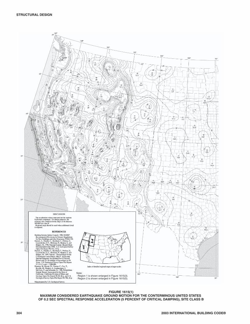
304 2003 INTERNATIONAL BUILDING CODE®
STRUCTURAL DESIGN
FIGURE 1615(1)MAXIMUM CONSIDERED EARTHQUAKE GROUND MOTION FOR THE CONTERMINOUS UNITED STATES
OF 0.2 SEC SPECTRAL RESPONSE ACCELERATION (5 PERCENT OF CRITICAL DAMPING), SITE CLASS B
Note:⋅ Region 1 is shown enlarged in Figure 1615(3).⋅ Region 2 is shown enlarged in Figure 1615(5).

2003 INTERNATIONAL BUILDING CODE® 305
STRUCTURAL DESIGN
FIGURE 1615(1)–continuedMAXIMUM CONSIDERED EARTHQUAKE GROUND MOTION FOR THE CONTERMINOUS UNITED STATES
OF 0.2 SEC SPECTRAL RESPONSE ACCELERATION (5 PERCENT OF CRITICAL DAMPING), SITE CLASS B

306 2003 INTERNATIONAL BUILDING CODE®
STRUCTURAL DESIGN
FIGURE 1615(2)MAXIMUM CONSIDERED EARTHQUAKE GROUND MOTION FOR THE CONTERMINOUS UNITED STATES
OF 1.0 SEC SPECTRAL RESPONSE ACCELERATION (5 PERCENT OF CRITICAL DAMPING), SITE CLASS B
Note:⋅ Region 1 is shown enlarged in Figure 1615(4).⋅ Region 2 is shown enlarged in Figure 1615(6).

2003 INTERNATIONAL BUILDING CODE® 307
STRUCTURAL DESIGN
FIGURE 1615(2)–continuedMAXIMUM CONSIDERED EARTHQUAKE GROUND MOTION FOR THE CONTERMINOUS UNITED STATES
OF 1.0 SEC SPECTRAL RESPONSE ACCELERATION (5 PERCENT OF CRITICAL DAMPING), SITE CLASS B
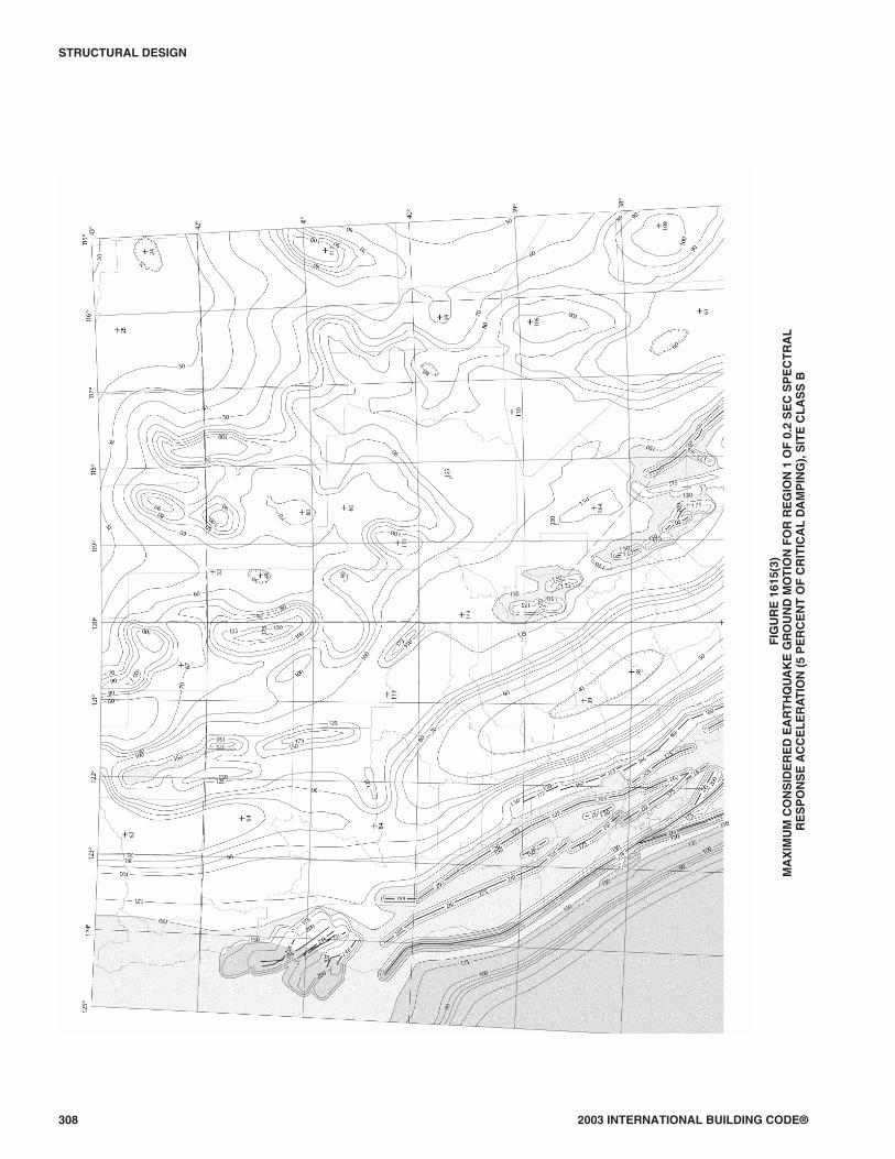
308 2003 INTERNATIONAL BUILDING CODE®
STRUCTURAL DESIGN
FIG
UR
E16
15(3
)M
AX
IMU
MC
ON
SID
ER
ED
EA
RT
HQ
UA
KE
GR
OU
ND
MO
TIO
NF
OR
RE
GIO
N1
OF
0.2
SE
CS
PE
CT
RA
LR
ES
PO
NS
EA
CC
EL
ER
AT
ION
(5P
ER
CE
NT
OF
CR
ITIC
AL
DA
MP
ING
),S
ITE
CL
AS
SB
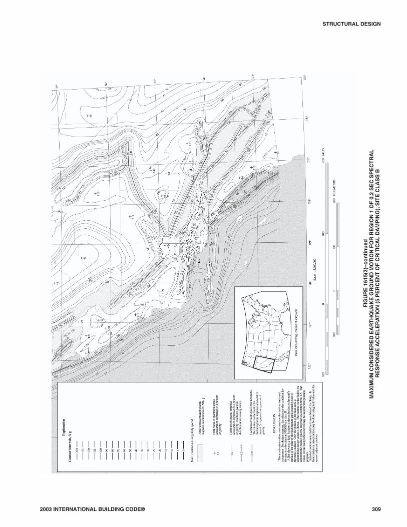
2003 INTERNATIONAL BUILDING CODE® 309
STRUCTURAL DESIGN
FIG
UR
E16
15(3
)–co
nti
nu
edM
AX
IMU
MC
ON
SID
ER
ED
EA
RT
HQ
UA
KE
GR
OU
ND
MO
TIO
NF
OR
RE
GIO
N1
OF
0.2
SE
CS
PE
CT
RA
LR
ES
PO
NS
EA
CC
EL
ER
AT
ION
(5P
ER
CE
NT
OF
CR
ITIC
AL
DA
MP
ING
),S
ITE
CL
AS
SB

310 2003 INTERNATIONAL BUILDING CODE®
STRUCTURAL DESIGN
FIG
UR
E16
15(4
)M
AX
IMU
MC
ON
SID
ER
ED
EA
RT
HQ
UA
KE
GR
OU
ND
MO
TIO
NF
OR
RE
GIO
N1
OF
1.0
SE
CS
PE
CT
RA
LR
ES
PO
NS
EA
CC
EL
ER
AT
ION
(5P
ER
CE
NT
OF
CR
ITIC
AL
DA
MP
ING
),S
ITE
CL
AS
SB

2003 INTERNATIONAL BUILDING CODE® 311
STRUCTURAL DESIGN
FIG
UR
E16
15(4
)–co
nti
nu
edM
AX
IMU
MC
ON
SID
ER
ED
EA
RT
HQ
UA
KE
GR
OU
ND
MO
TIO
NF
OR
RE
GIO
N1
OF
1.0
SE
CS
PE
CT
RA
LR
ES
PO
NS
EA
CC
EL
ER
AT
ION
(5P
ER
CE
NT
OF
CR
ITIC
AL
DA
MP
ING
),S
ITE
CL
AS
SB

312 2003 INTERNATIONAL BUILDING CODE®
STRUCTURAL DESIGN
FIG
UR
E16
15(5
)M
AX
IMU
MC
ON
SID
ER
ED
EA
RT
HQ
UA
KE
GR
OU
ND
MO
TIO
NF
OR
RE
GIO
N2
OF
0.2
SE
CS
PE
CT
RA
LR
ES
PO
NS
EA
CC
EL
ER
AT
ION
(5P
ER
CE
NT
OF
CR
ITIC
AL
DA
MP
ING
),S
ITE
CL
AS
SB

2003 INTERNATIONAL BUILDING CODE® 313
STRUCTURAL DESIGN
FIG
UR
E16
15(5
)–co
nti
nu
edM
AX
IMU
MC
ON
SID
ER
ED
EA
RT
HQ
UA
KE
GR
OU
ND
MO
TIO
NF
OR
RE
GIO
N2
OF
0.2
SE
CS
PE
CT
RA
LR
ES
PO
NS
EA
CC
EL
ER
AT
ION
(5P
ER
CE
NT
OF
CR
ITIC
AL
DA
MP
ING
),S
ITE
CL
AS
SB

314 2003 INTERNATIONAL BUILDING CODE®
STRUCTURAL DESIGN
FIG
UR
E16
15(6
)M
AX
IMU
MC
ON
SID
ER
ED
EA
RT
HQ
UA
KE
GR
OU
ND
MO
TIO
NF
OR
RE
GIO
N2
OF
1.0
SE
CS
PE
CT
RA
LR
ES
PO
NS
EA
CC
EL
ER
AT
ION
(5P
ER
CE
NT
OF
CR
ITIC
AL
DA
MP
ING
),S
ITE
CL
AS
SB
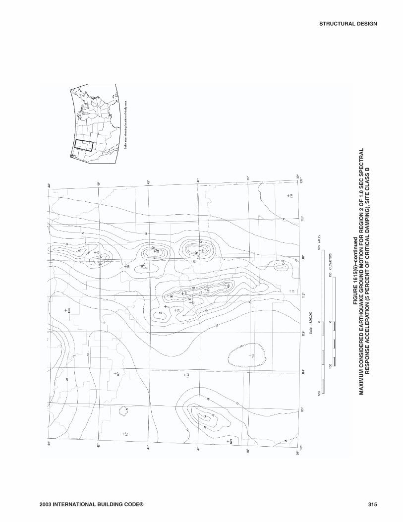
2003 INTERNATIONAL BUILDING CODE® 315
STRUCTURAL DESIGN
FIG
UR
E16
15(6
)–co
nti
nu
edM
AX
IMU
MC
ON
SID
ER
ED
EA
RT
HQ
UA
KE
GR
OU
ND
MO
TIO
NF
OR
RE
GIO
N2
OF
1.0
SE
CS
PE
CT
RA
LR
ES
PO
NS
EA
CC
EL
ER
AT
ION
(5P
ER
CE
NT
OF
CR
ITIC
AL
DA
MP
ING
),S
ITE
CL
AS
SB

316 2003 INTERNATIONAL BUILDING CODE®
STRUCTURAL DESIGN
FIG
UR
E16
15(7
)M
AX
IMU
MC
ON
SID
ER
ED
EA
RT
HQ
UA
KE
GR
OU
ND
MO
TIO
NF
OR
AL
AS
KA
OF
0.2
SE
CS
PE
CT
RA
LR
ES
PO
NS
EA
CC
EL
ER
AT
ION
(5P
ER
CE
NT
OF
CR
ITIC
AL
DA
MP
ING
),S
ITE
CL
AS
SB

2003 INTERNATIONAL BUILDING CODE® 317
STRUCTURAL DESIGN
FIG
UR
E16
15(7
)–co
nti
nu
edM
AX
IMU
MC
ON
SID
ER
ED
EA
RT
HQ
UA
KE
GR
OU
ND
MO
TIO
NF
OR
AL
AS
KA
OF
1.0
SE
CS
PE
CT
RA
LR
ES
PO
NS
EA
CC
EL
ER
AT
ION
(5P
ER
CE
NT
OF
CR
ITIC
AL
DA
MP
ING
),S
ITE
CL
AS
SB
F:\DATA\CODES\ibc_2003\Final VP_Boca\16_ibc_2003.vpMonday, September 08, 2003 10:11:26 AM
Color profile: DisabledComposite Default screen

318 2003 INTERNATIONAL BUILDING CODE®
STRUCTURAL DESIGN
FIG
UR
E16
15(8
)M
AX
IMU
MC
ON
SID
ER
ED
EA
RT
HQ
UA
KE
GR
OU
ND
MO
TIO
NF
OR
HA
WA
IIO
F0.
2S
EC
SP
EC
TR
AL
RE
SP
ON
SE
AC
CE
LE
RA
TIO
N(5
PE
RC
EN
TO
FC
RIT
ICA
LD
AM
PIN
G),
SIT
EC
LA
SS
B

2003 INTERNATIONAL BUILDING CODE® 319
STRUCTURAL DESIGN
FIG
UR
E16
15(8
)–co
nti
nu
edM
AX
IMU
MC
ON
SID
ER
ED
EA
RT
HQ
UA
KE
GR
OU
ND
MO
TIO
NF
OR
HA
WA
IIO
F1.
0S
EC
SP
EC
TR
AL
RE
SP
ON
SE
AC
CE
LE
RA
TIO
N(5
PE
RC
EN
TO
FC
RIT
ICA
LD
AM
PIN
G),
SIT
EC
LA
SS
B
F:\DATA\CODES\ibc_2003\Final VP_Boca\16_ibc_2003.vpMonday, September 08, 2003 10:12:26 AM
Color profile: DisabledComposite Default screen

320 2003 INTERNATIONAL BUILDING CODE®
STRUCTURAL DESIGN
FIGURE 1615(9)MAXIMUM CONSIDERED EARTHQUAKE GROUND MOTION FOR PUERTO RICO,
CULEBRA, VIEQUES, ST. THOMAS, ST. JOHN, AND ST. CROIX OF 0.2 AND 1.0 SEC SPECTRALRESPONSE ACCELERATION (5 PERCENT OF CRITICAL DAMPING), SITE CLASS B

2003 INTERNATIONAL BUILDING CODE® 321
STRUCTURAL DESIGN
FIGURE 1615(10)MAXIMUM CONSIDERED EARTHQUAKE GROUND MOTION FOR GUAM AND TUTUILLA
OF 0.2 AND 1.0 SEC SPECTRAL RESPONSE ACCELERATION(5 PERCENT OF CRITICAL DAMPING), SITE CLASS B

1615.1.1 Site class definitions. The site shall be classified asone of the site classes defined in Table 1615.1.1. Where thesoil shear wave velocity, vs , is not known, site class shall bedetermined, as permitted in Table 1615.1.1, from standardpenetration resistance, N , or from soil undrained shearstrength, su , calculated in accordance with Section 1615.1.5.Where site-specific data are not available to a depth of 100feet (30 480 mm), appropriate soil properties are permitted tobe estimated by the registered design professional preparingthe soils report based on known geologic conditions.
When the soil properties are not known in sufficient detailto determine the site class, Site Class D shall be used unlessthe building official determines that Site Class E or F soil islikely to be present at the site.
1615.1.2 Site coefficients and adjusted maximum con-sidered earthquake spectral response acceleration pa-rameters. The maximum considered earthquake spectralresponse acceleration for short periods, SMS, and at 1-secondperiod, SM1, adjusted for site class effects, shall be deter-mined by Equations 16-38 and 16-39, respectively:
SMS = FaSs (Equation 16-38)
SM1 = FvS1 (Equation 16-39)
where:
Fa = Site coefficient defined in Table 1615.1.2(1).
Fv = Site coefficient defined in Table 1615.1.2(2).
SS = The mapped spectral accelerations for short periodsas determined in Section 1615.1.
S1 = The mapped spectral accelerations for a 1-secondperiod as determined in Section 1615.1.
1615.1.3 Design spectral response acceleration parame-ters. Five-percent damped design spectral response acceler-ation at short periods, SDS, and at 1-second period, SD1, shallbe determined from Equations 16-40 and 16-41, respec-tively:
S SDS MS= 23
(Equation 16-40)
S SD1 M1= 23
(Equation 16-41)
where:
SMS = The maximum considered earthquake spectral re-sponse accelerations for short period as determinedin Section 1615.1.2.
SM1 = The maximum considered earthquake spectral re-sponse accelerations for 1-second period as deter-mined in Section 1615.1.2.
1615.1.4 General procedure response spectrum. Thegeneral design response spectrum curve shall be developedas indicated in Figure 1615.1.4 and as follows:
1. For periods less than or equal to TO, the design spectralresponse acceleration, Sa, shall be determined byEquation 16-42.
2. For periods greater than or equal to TO and less than orequal to TS, the design spectral response acceleration,Sa, shall be taken equal to SDS.
322 2004 OREGON STRUCTURAL SPECIALTY CODE
STRUCTURAL DESIGN
TABLE 1615.1.1SITE CLASS DEFINITIONS
SITECLASS
SOIL PROFILENAME
AVERAGE PROPERTIES IN TOP 100 feet, AS PER SECTION 1615.1.5
Soil shear wavevelocity,vS , (ft/s)
Standard penetrationresistance, N
Soil undrainedshear strength, su , (psf)
A Hard rock vs > 5,000 N/A N/A
B Rock 2,500 < vs ≤ 5,000 N/A N/A
C Very dense soil and soft rock 1,200 < vs ≤ 2,500 N > 50 su ≥ 2,000
D Stiff soil profile 600 ≤ vs ≤ 1,200 15 ≤ N ≤ 50 1,000 ≤ su ≤ 2,000
E Soft soil profile vs < 600 N < 15 su < 1,000
E —
Any profile with more than 10 feet of soil having the following characteristics:1. Plasticity index PI > 20,2. Moisture content w ≥ 40%, and3. Undrained shear strength su < 500 psf
F —
Any profile containing soils having one or more of the following characteristics:1. Soils vulnerable to potential failure or collapse under seismic loading such as liquefiable
soils, quick and highly sensitive clays, collapsible weakly cemented soils.2. Peats and/or highly organic clays (H > 10 feet of peat and/or highly organic clay where
H = thickness of soil)3. Very high plasticity clays (H >25 feet with plasticity index PI >75)4. Very thick soft/medium stiff clays (H >120 feet)
For SI: 1 foot = 304.8 mm, 1 square foot = 0.0929 m2, 1 pound per square foot = 0.0479 kPa. N/A = Not applicable
G:\DATA\CODES\OREGON_2004\OR_Building(Structural)2004\Final VP\16_OregonBldg_2004.vpWednesday, August 25, 2004 11:30:41 AM
Color profile: DisabledComposite Default screen

3. For periods greater than TS, the design spectral re-sponse acceleration, Sa, shall be determined by Equa-tion 16-43.
SS
TT Sa
DS
ODS= +0 6 0 4. . (Equation 16-42)
SS
TaDI= (Equation 16-43)
where:
SDS = The design spectral response acceleration at shortperiods as determined in Section 1615.1.3.
SD1 = The design spectral response acceleration at 1-sec-ond period as determined in Section 1615.1.3.
T = Fundamental period (in seconds) of the structure(see Section 9.5.5.3 of ASCE 7).
TO = 0.2 SD1/SDS
TS = SD1 /SDS
2003 INTERNATIONAL BUILDING CODE® 323
STRUCTURAL DESIGN
TABLE 1615.1.2(1)VALUES OF SITE COEFFICIENT Fa AS A FUNCTION OF SITE CLASS
AND MAPPED SPECTRAL RESPONSE ACCELERATION AT SHORT PERIODS (SS)a
SITECLASS
MAPPED SPECTRAL RESPONSE ACCELERATION AT SHORT PERIODS
Ss ≤ 0.25 Ss = 0.50 Ss = 0.75 Ss = 1.00 Ss ≥ 1.25
A 0.8 0.8 0.8 0.8 0.8
B 1.0 1.0 1.0 1.0 1.0
C 1.2 1.2 1.1 1.0 1.0
D 1.6 1.4 1.2 1.1 1.0
E 2.5 1.7 1.2 0.9 0.9
F Note b Note b Note b Note b Note b
a. Use straight-line interpolation for intermediate values of mapped spectral response acceleration at short period, Ss.b. Site-specific geotechnical investigation and dynamic site response analyses shall be performed to determine appropriate values, except that for structures with pe-
riods of vibration equal to or less than 0.5 second, values of Fa for liquefiable soils are permitted to be taken equal to the values for the site class determined withoutregard to liquefaction in Section 1615.1.5.1.
TABLE 1615.1.2(2)VALUES OF SITE COEFFICIENT FV AS A FUNCTION OF SITE CLASS
AND MAPPED SPECTRAL RESPONSE ACCELERATION AT 1-SECOND PERIOD (S1)a
SITECLASS
MAPPED SPECTRAL RESPONSE ACCELERATION AT SHORT PERIODS
S1 ≤ 0.1 S1 = 0.2 S1 = 0.3 S1 = 0.4 S1 ≥ 0.5
A 0.8 0.8 0.8 0.8 0.8
B 1.0 1.0 1.0 1.0 1.0
C 1.7 1.6 1.5 1.4 1.3
D 2.4 2.0 1.8 1.6 1.5
E 3.5 3.2 2.8 2.4 2.4
F Note b Note b Note b Note b Note b
a. Use straight-line interpolation for intermediate values of mapped spectral response acceleration at 1-second period, S1.b. Site-specific geotechnical investigation and dynamic site response analyses shall be performed to determine appropriate values, except that for structures with pe-
riods of vibration equal to or less than 0.5 second, values of Fv for liquefiable soils are permitted to be taken equal to the values for the site class determined withoutregard to liquefaction in Section 1615.1.5.1.
FIGURE 1615.1.4DESIGN RESPONSE SPECTRUM
F:\DATA\CODES\ibc_2003\Final VP_Boca\16_ibc_2003.vpMonday, September 08, 2003 10:15:40 AM
Color profile: DisabledComposite Default screen

1615.1.5 Site clas si fi ca tion for seis mic de sign. Site clas si -fi ca tion for Site Class C, D or E shall be de ter mined fromTa ble 1615.1.5.
The no ta tions pre sented be low ap ply to the up per 100 feet (30 480 mm) of the site pro file. Pro files con tain ing dis -tinctly dif fer ent soil lay ers shall be sub di vided into thoselay ers des ig nated by a num ber that ranges from 1 to n at thebot tom where there is a to tal of n dis tinct lay ers in the up per100 feet (30 480 mm). The sym bol, i, then re fers to any oneof the lay ers be tween 1 and n.
where:
vsi = The shear wave ve loc ity in feet per sec ond (m/s).
di = The thick ness of any layer be tween 0 and 100 feet(30 480 mm).
v
d
s
ii
n
d
vi
ni
si
= =
=
∑
∑1
1
(Equa tion 16-44)
d ii
n
=∑ =
1100 30 480feet mm( )
Ni is the Stan dard Pen e tra tion Resis tance (ASTM D1586-84) not to exceed 100 blows/foot (mm) as directly mea -sured in the field with out cor rec tions.
N
d ii
n
d
Ni
ni
i
= =
=
∑
∑1
1
(Equa tion 16-45)
Nd
chs
dN
i
mi
i
=
=∑
1
(Equa tion 16-46)
where:
d di si
m
==∑
1
Use only di and Ni for cohesionless soils.
ds = The to tal thick ness of cohesionless soil lay ers in thetop 100 feet (30 480 mm).
sui = The un drained shear strength in psf (kPa), not to ex -ceed 5,000 psf (240 kPa), ASTM D 2166-91 or D2850-87.
sd
uc
d
si
ki
ui
=
=∑
1
(Equa tion 16-47)
where:
d di ci
k
==∑
1
dc = The to tal thick ness (100 – ds) (For SI: 30 480 – ds) ofco he sive soil lay ers in the top 100 feet (30 480 mm).
PI = The plas tic ity in dex, ASTM D 4318.w = The mois ture con tent in per cent, ASTM D 2216. The shear wave ve loc ity for rock, Site Class B, shall be ei -ther mea sured on site or es ti mated by a geotechnical en gi -neer or en gi neer ing ge ol o gist/seis mol o gist for com pe tentrock with mod er ate frac tur ing and weath er ing. Softer andmore highly frac tured and weath ered rock shall ei ther bemea sured on site for shear wave ve loc ity or clas si fied as SiteClass C.
The hard rock, Site Class A, cat e gory shall be sup portedby shear wave ve loc ity mea sure ments ei ther on site or onpro files of the same rock type in the same for ma tion with anequal or greater de gree of weath er ing and frac tur ing. Wherehard rock con di tions are known to be con tin u ous to a depthof 100 feet (30 480 mm), surficial shear wave ve loc ity mea -sure ments are per mit ted to be ex trap o lated to as sess v s .
The rock cat e go ries, Site Classes A and B, shall not beused if there is more than 10 feet (3048 mm) of soil be tweenthe rock sur face and the bot tom of the spread foot ing or matfoun da tion.
1615.1.5.1 Steps for clas si fy ing a site.
1. Check for the four cat e go ries of Site Class F re -quir ing site-spe cific eval u a tion. If the site cor re -sponds to any of these cat e go ries, clas sify the siteas Site Class F and con duct a site-spe cific eval u a -tion.
2. Check for the ex is tence of a to tal thick ness of softclay > 10 feet (3048 mm) where a soft clay layer isde fined by: su < 500 psf (25 kPa), w ≥ 40 per cent,and PI > 20. If these cri te ria are sat is fied, clas sifythe site as Site Class E.
3. Cat e go rize the site us ing one of the fol low ing threemeth ods with v s , N , and su com puted in all cases as spec i fied.
3.1. v s for the top 100 feet (30 480 mm)(v s method).
324 2003 INTERNATIONAL BUILDING CODE®
STRUCTURAL DESIGN
TABLE 1615.1.5SITE CLASSIFICATIONa
SITE CLASS v s N N chor s u
E < 600 ft/s < 15 < 1,000 psf
D 600 to 1,200 ft/s 15 to 50 1,000 to 2,000 psf
C 1,200 to 2,500 ft/s > 50 > 2,000
For SI: 1 foot per second = 304.8 mm per second, 1 pound per square foot = 0.0479 kN/m2. a. If the su method is used and the N ch and su cri te ria dif fer, se lect the cat e gory with the softer soils (for ex am ple, use Site Class E in stead of D).

3.2. N for the top 100 feet (30 480 mm) (Nmethod).
3.3. N ch for cohesionless soil layers (PI < 20)in the top 100 feet (30 480 mm) and aver-age, su , for cohesive soil layers (PI > 20) inthe top 100 feet (30 480 mm) (su method).
1615.2 Site-specific procedure for determining groundmotion accelerations. A site-specific study shall account forthe regional seismicity and geology; the expected recurrencerates and maximum magnitudes of events on known faults andsource zones; the location of the site with respect to these; nearsource effects if any and the characteristics of subsurface siteconditions.
1615.2.1 Probabilistic maximum considered earth-quake. Where site-specific procedures are used as requiredor permitted by Section 1615, the maximum consideredearthquake ground motion shall be taken as that motion rep-resented by an acceleration response spectrum having a2-percent probability of exceedance within a 50-year pe-riod. The maximum considered earthquake spectral re-sponse acceleration at any period, SaM, shall be taken fromthe 2-percent probability of exceedance within a 50-year pe-riod spectrum.
Exception: Where the spectral response ordinates at 0.2second or 1 second for a 5-percent damped spectrum hav-ing a 2-percent probability of exceedance within a50-year period exceed the corresponding ordinates of thedeterministic limit of Section 1615.2.2, the maximumconsidered earthquake ground motion spectrum shall betaken as the lesser of the probabilistic maximum consid-ered earthquake ground motion or the deterministic max-imum considered earthquake ground motion spectrum ofSection 1615.2.3, but shall not be taken as less than thedeterministic limit ground motion of Section 1615.2.2.
1615.2.2 Deterministic limit on maximum consideredearthquake ground motion. The deterministic limit for themaximum considered earthquake ground motion shall bethe response spectrum determined in accordance with Fig-ure 1615.2.2, where site coefficients, Fa and Fv, are deter-mined in accordance with Section 1615.1.2, with the valueof the mapped short-period spectral response acceleration,SS, taken as 1.5g and the value of the mapped spectral re-sponse acceleration at 1 second, S1, taken as 0.6g.
1615.2.3 Deterministic maximum considered earth-quake ground motion. The deterministic maximum con-sidered earthquake ground motion response spectrum shallbe calculated as 150 percent of the median spectral responseaccelerations, SaM, at all periods resulting from a character-istic earthquake on any known active fault within the region.
1615.2.4 Site-specific design ground motion. Wheresite-specific procedures are used to determine the maximumconsidered earthquake ground motion response spectrum,the design spectral response acceleration, Sa, at any periodshall be determined from Equation 16-48:
S Sa aM= 23
(Equation 16-48)
and shall be greater than or equal to 80 percent of the designspectral response acceleration, Sa, determined by the gen-eral response spectrum in Section 1615.1.4.
1615.2.5 Design spectral response coefficients. Where thesite-specific procedure is used to determine the designground motion in accordance with Section 1615.2.4, the pa-rameter SDS shall be taken as the spectral acceleration, Sa,obtained from the site-specific spectra at a period of 0.2 sec-ond, except that it shall not be taken as less than 90 percentof the peak spectral acceleration, Sa, at any period. The pa-rameter SD1 shall be taken as the greater of the spectral accel-eration, Sa, at a period of 1 second or two times the spectralacceleration, Sa, at a period of 2 seconds. The parametersSMS and SM1 shall be taken as 1.5 times SDS and SD1, respec-tively. The values so obtained shall not be taken as less than80 percent of the values obtained from the general proce-dures of Section 1615.1.
SECTION 1616EARTHQUAKE LOADS—CRITERIA SELECTION
1616.1 Structural design criteria. Each structure shall beassigned to a seismic design category in accordance with Sec-tion 1616.3. Seismic design categories are used in this code todetermine permissible structural systems, limitations on heightand irregularity, those components of the structure that must bedesigned for seismic resistance and the types of lateral forceanalysis that must be performed. Each structure shall be pro-vided with complete lateral- and vertical-force-resisting sys-tems capable of providing adequate strength, stiffness andenergy dissipation capacity to withstand the design earthquakeground motions determined in accordance with Section 1615within the prescribed deformation limits of Section 1617.3.The design ground motions shall be assumed to occur alongany horizontal direction of a structure. A continuous load path,or paths, with adequate strength and stiffness to transfer forcesinduced by the design earthquake ground motions from thepoints of application to the final point of resistance shall be pro-vided.
2003 INTERNATIONAL BUILDING CODE® 325
STRUCTURAL DESIGN
FIGURE 1615.2.2DETERMINISTIC LIMIT ON MAXIMUM CONSIDERED
EARTHQUAKE RESPONSE SPECTRUM
F:\DATA\CODES\ibc_2003\Final VP_Boca\16_ibc_2003.vpMonday, September 08, 2003 10:18:47 AM
Color profile: DisabledComposite Default screen

Allowable stress design is permitted to be used to evaluatesliding, overturning and soil bearing at the soil-structure inter-face regardless of the approach used in the design of the struc-ture, provided load combinations of Section 1605.3 areutilized. When using allowable stress design for proportioningfoundations, the value of 0.2 SDSD in Equations 16-50, 16-51,16-52 and 16-53 or Equations 9.5.2.7-1, 9.5.2.7-2, 9.5.2.7.1-1and 9.5.2.7.1-2 of ASCE 7 is permitted to be taken equal tozero. When the load combinations of Section 1605.3.2 are uti-lized, a one-third increase in soil allowable stresses is permittedfor all load combinations that include W or E.
1616.2 Seismic use groups and occupancy importance fac-tors. Each structure shall be assigned a seismic use group and acorresponding occupancy importance factor (IE) as indicated inTable 1604.5.
1616.2.1 Seismic Use Group I. Seismic Use Group I struc-tures are those not assigned to either Seismic Use Group IIor III.
1616.2.2 Seismic Use Group II. Seismic Use Group IIstructures are those, the failure of which would result in asubstantial public hazard due to occupancy or use as indi-cated by Table 1604.5, or as designated by the building offi-cial.
1616.2.3 Seismic Use Group III. Seismic Use Group IIIstructures are those having essential facilities that are re-quired for postearthquake recovery and those containingsubstantial quantities of hazardous substances, as indicatedin Table 1604.5, or as designated by the building official.
Where operational access to a Seismic Use Group IIIstructure is required through an adjacent structure, the adja-cent structure shall conform to the requirements for SeismicUse Group III structures. Where operational access is lessthan 10 feet (3048 mm) from an interior lot line or less than10 feet (3048 mm) from another structure, access protectionfrom potential falling debris shall be provided by the ownerof the Seismic Use Group III structure.
1616.2.4 Multiple occupancies. Where a structure is occu-pied for two or more occupancies not included in the sameseismic use group, the structure shall be assigned the classi-fication of the highest seismic use group corresponding tothe various occupancies.
Where structures have two or more portions that arestructurally separated in accordance with Section 1620,each portion shall be separately classified. Where a structur-ally separated portion of a structure provides required ac-cess to, required egress from or shares life safetycomponents with another portion having a higher seismicuse group, both portions shall be assigned the higher seismicuse group.
1616.3 Determination of seismic design category. All struc-tures shall be assigned to a seismic design category based ontheir seismic use group and the design spectral response accel-eration coefficients, SDS and SD1, determined in accordance withSection 1615.1.3 or 1615.2.5. Each building and structure shallbe assigned to the most severe seismic design category inaccordance with Table 1616.3(1) or 1616.3(2), irrespective ofthe fundamental period of vibration of the structure, T.
Exception: The seismic design category is permitted to bedetermined from Table 1616.3(1) alone when all of the fol-lowing apply:
1. The approximate fundamental period of the structure,Ta, in each of the two orthogonal directions deter-mined in accordance with Section 9.5.5.3.2 of ASCE7, is less than 0.8 Ts determined in accordance withSection 1615.1.4,
2. Equation 9.5.5.2.1-1 of ASCE 7 is used to determinethe seismic response coefficient, Cs, and
3. The diaphragms are rigid as defined in Section 1602.
TABLE 1616.3(1)SEISMIC DESIGN CATEGORY BASED ON
SHORT-PERIOD RESPONSE ACCELERATIONS
VALUE OF SDS
SEISMIC USE GROUP
I II III
SDS < 0.167g A A A
0.167g ≤ SDS < 0.33g B B C
0.33g ≤ SDS < 0.50g C C D
0.50g ≤ SDS Da Da Da
a. Seismic Use Group I and II structures located on sites with mapped maxi-mum considered earthquake spectral response acceleration at 1-second pe-riod, S1, equal to or greater than 0.75g, shall be assigned to Seismic DesignCategory E, and Seismic Use Group III structures located on such sites shallbe assigned to Seismic Design Category F.
TABLE 1616.3(2)SEISMIC DESIGN CATEGORY BASED ON
1-SECOND PERIOD RESPONSE ACCELERATION
VALUE OF SD1
SEISMIC USE GROUP
I II III
SD1 < 0.067g A A A
0.067g ≤ SD1 < 0.133g B B C
0.133g ≤ SD1 < 0.20g C C D
0.20g ≤ SD1 Da Da Da
a. Seismic Use Group I and II structures located on sites with mapped maxi-mum considered earthquake spectral response acceleration at 1-second pe-riod, S1, equal to or greater than 0.75g, shall be assigned to Seismic DesignCategory E, and Seismic Use Group III structures located on such sites shallbe assigned to Seismic Design Category F.
1616.3.1 Site limitation for Seismic Design Category E orF. A structure assigned to Seismic Design Category E or Fshall not be sited over an identified active fault trace.
Exception: Detached Group R-3 as applicable in Section101.2 of light-frame construction.
1616.4 Design requirements for Seismic Design CategoryA. Structures assigned to Seismic Design Category A needonly comply with the requirements of Sections 1616.4.1through 1616.4.5.
1616.4.1 Minimum lateral force. Structures shall be pro-vided with a complete lateral-force-resisting system de-signed to resist the minimum lateral force, Fx, appliedsimultaneously at each floor level given by Equation 16-49:
Fx = 0.01 wx (Equation 16-49)
326 2003 INTERNATIONAL BUILDING CODE®
STRUCTURAL DESIGN
F:\DATA\CODES\ibc_2003\Final VP_Boca\16_ibc_2003.vpMonday, September 08, 2003 10:18:50 AM
Color profile: DisabledComposite Default screen

where:
Fx = The de sign lat eral force ap plied at Level x.wx = The por tion of the to tal grav ity load of the struc ture,
W, lo cated or as signed to Level x.W = The to tal dead load and other loads listed be low:
1. In ar eas used for stor age, a min i mum of 25 per -cent of the re duced floor live load (floor liveload in pub lic ga rages and open park ing struc -tures need not be in cluded).
2. Where an al low ance for par ti tion load is in -cluded in the floor load de sign, the ac tual par ti -tion weight or a min i mum weight of 10 psf(0.479 kN/m2) of floor area, which ever is greater.
3. To tal op er at ing weight of per ma nent equip ment.
4. Twenty per cent of flat roof snow load where flat roof snow load ex ceeds 30 psf (1.44 kN/m2).
The di rec tion of ap pli ca tion of seis mic forces used in de signshall be that which will pro duce the most crit i cal load ef fect ineach com po nent. The de sign seis mic forces are per mit ted to beap plied sep a rately in each of two or thogo nal di rec tions and or -thogo nal ef fects are per mit ted to be ne glected.
The ef fect of this lat eral force shall be taken as E in theload com bi na tions pre scribed in Sec tion 1605.2 for strengthor load and re sis tance fac tor de sign meth ods, or Sec tion1605.3 for al low able stress de sign meth ods. Spe cial seis micload com bi na tions that in clude Em need not be con sid ered.
1616.4.2 Con nec tions. All parts of the struc ture be tweensep a ra tion joints shall be in ter con nected, and the con nec -tions shall be ca pa ble of trans mit ting the seis mic force, Fp,in duced in the con nec tion by the parts be ing con nected. Any smaller por tion of the struc ture shall be tied to the re main der of the struc ture for Fp equal to 0.05 times the weight of thesmaller por tion. A pos i tive con nec tion for re sist ing hor i zon -tal forces act ing on the mem ber shall be pro vided for eachbeam, girder or truss to its sup port. The con nec tion shallhave strength suf fi cient to re sist 5 per cent of the dead andlive load ver ti cal re ac tion ap plied hor i zon tally.
1616.4.3 An chor age of con crete or ma sonry walls. SeeSec tion 1604.8.2.
1616.4.4 Con ven tional light-frame con struc tion. Build ingscon structed in com pli ance with Sec tion 2308 are deemed tocom ply with Sec tions 1616.4.1, 1616.4.2 and 1616.4.3.
1616.4.5 Tank free board. Tanks in Seis mic Use Group IIIac cord ing to Ta ble 9.14.5.1.2 of ASCE 7 shall also com plywith the free board re quire ments of Sec tion 9.14.7.3.6.1.2 ofASCE 7.
1616.5 Build ing con fig u ra tion. Build ings shall be clas si fiedas reg u lar or irreg u lar based on the cri te ria in Sec tion 9.5.2.3 ofASCE 7.
Ex cep tion: Build ings de signed us ing the sim pli fied anal y -sis pro ce dure in Sec tion 1617.5 shall be clas si fied in ac cor -dance with Sec tion 1616.5.1.
1616.5.1 Build ing con fig u ra tion (for use in the sim pli fied anal y sis pro ce dure of Sec tion 1617.5). Build ings de signed us ing the sim pli fied anal y sis pro ce dure in Sec tion 1617.5
shall be clas si fied as reg u lar or ir reg u lar based on the cri te -ria in this sec tion. Such clas si fi ca tion shall be based on theplan and ver ti cal con fig u ra tion. Build ings shall not ex ceedthe lim i ta tions of Sec tion 1616.6.1.
1616.5.1.1 Plan ir reg u lar ity. Build ings hav ing one ormore of the fea tures listed in Ta ble 1616.5.1.1 shall bedes ig nated as hav ing plan struc tural ir reg u lar ity and shall com ply with the re quire ments in the sec tions ref er encedin that ta ble.
1616.5.1.2 Ver ti cal ir reg u lar ity. Build ings hav ing oneor more of the fea tures listed in Ta ble 1616.5.1.2 shall bedes ig nated as hav ing ver ti cal ir reg u lar ity and shall com -ply with the re quire ments in the sec tions ref er enced inthat ta ble.
Ex cep tions:
1. Struc tural ir reg u lar i ties of Type 1a, 1b or 2 inTa ble 1616.5.1.2 do not ap ply where no storydrift ra tio un der de sign lat eral load is greaterthan 130 per cent of the story drift ra tio of thenext story above. Tor sional ef fects need not becon sid ered in the cal cu la tion of story drifts forthe pur pose of this de ter mi na tion. The storydrift ra tio re la tion ship for the top two sto ries ofthe build ing is not re quired to be eval u ated.
2. Ir reg u lar ities of Types 1a, 1b and 2 of Ta ble1616.5.1.2 are not re quired to be con sid ered for one-story build ings in any seis mic de sign cat e -gory or for two-story build ings in Seis mic De -sign Cat e gory A, B, C or D.
1616.6 Anal y sis pro ce dures. A struc tural anal y sis con form ing to one of the types per mit ted in Sec tion 9.5.2.5.1 of ASCE 7 or to thesim pli fied pro ce dure in Sec tion 1617.5 shall be made for all struc -tures. The anal y sis shall form the basis for deter min ing the seis -mic forces, E and Em, to be applied in the load com bi na tions ofSec tion 1605 and shall form the basis for deter min ing the designdrift as required by Sec tion 9.5.2.8 of ASCE 7 or Sec tion 1617.3.
Ex cep tions:
1. Struc tures as signed to Seis mic De sign Cat e gory A.
2. De sign drift need not be eval u ated in ac cor dance withSec tion 1617.3 when the sim pli fied anal y sis methodof Sec tion 1617.5 is used.
1616.6.1 Sim plified anal y sis. A sim pli fied anal y sis, in ac -cor dance with Sec tion 1617.5, shall be per mit ted to be usedfor any struc ture in Seis mic Use Group I, sub ject to the fol -low ing lim i ta tions, or a more rig or ous anal y sis shall be made:
1. Build ings of light-framed con struc tion not ex ceed ingthree sto ries in height, ex clud ing base ments.
2. Build ings of any con struc tion other than light-framedcon struc tion, not ex ceed ing two sto ries in height, ex -clud ing base ments, with flex i ble di a phragms at ev erylevel as de fined in Sec tion 1602.
2003 INTERNATIONAL BUILDING CODE® 327
STRUCTURAL DESIGN

328 2003 INTERNATIONAL BUILDING CODE®
STRUCTURAL DESIGN
TABLE 1616.5.1.1PLAN STRUCTURAL IRREGULARITIES
IRREGULARITY TYPE AND DESCRIPTIONREFERENCE
SECTION
SEISMIC DESIGNCATEGORYa
APPLICATION
1a
Torsional Irregularity—to be considered when diaphragms are not flexible as determined in Section 1602.1.1
Torsional irregularity shall be considered to exist when the maximum story drift, computed including accidental torsion, at one end of the structure transverse to an axis is more than 1.2 times the average of the story drifts at the two ends of the structure.
9.5.5.5.2 of ASCE 71620.4.1
9.5.2.5.1 of ASCE 79.5.5.7.1 of ASCE 7
C, D, E and FD, E and FD, E and F
C, D, E and F
1b
Extreme Torsional Irregularity—to be considered when diaphragms are not flexible as determined in Section 1602.1.
Extreme torsional irregularity shall be considered to exist when the maximum story drift, computed and including accidental torsion, at one end of the structure transverse to an axis is more than 1.4 times the average of the story drifts at the two ends of the structure.
9.5.5.5.2 of ASCE 71620.4.11620.5.1
9.5.2.5.1 of ASCE 79.5.5.7.1 of ASCE 7
C, D, E and FD
E and FD, E and F
C, D, E and F
2
Reentrant CornersPlan configurations of a structure and its lateral-force-resisting system contain reentrant corners where both projections of the structure beyond a reentrant corner are greater than 15 percent of the plan dimension of the structure in the given direction.
1620.4.1 D, E and F
3
Diaphragm DiscontinuityDiaphragms with abrupt discontinuities or variations in stiffness, including those having cutout or open areas greater than 50 percent of the gross enclosed diaphragm area, or changes in effective diaphragm stiffness of more than 50 percent from one story to the next.
1620.4.1 D, E and F
4Out-of-Plane OffsetsDiscontinuities in a lateral-force-resistance path, such as out-of-plane offsets of the vertical elements.
1620.4.19.5.2.5.1 of ASCE 7
1620.2.9
D, E and FD, E and F
B, C, D, E and F
5Nonparallel SystemsThe vertical lateral-force-resisting elements are not parallel to or symmetric about the major orthogonal axes of the lateral-force-resisting system.
1620.3.2 C, D, E and F
a. Seismic design category is determined in accordance with Section 1616.
TABLE 1616.5.1.2VERTICAL STRUCTURAL IRREGULARITIES
IRREGULARITY TYPE AND DESCRIPTIONREFERENCE
SECTION
SEISMIC DESIGNCATEGORYa
APPLICATION
1aStiffness Irregularity—Soft StoryA soft story is one in which the lateral stiffness is less than 70 percent of that in the story above or less than 80 percent of the average stiffness of the three stories above.
9.5.2.5.1 of ASCE 7 D, E, and F
1bStiffness Irregularity—Extreme Soft StoryAn extreme soft story is one in which the lateral stiffness is less than 60 percent of that in the story above or less than 70 percent of the average stiffness of the three stories above.
1620.5.19.5.2.5.1 of ASCE 7
E and FD, E and F
2Weight (Mass) IrregularityMass irregularity shall be considered to exist where the effective mass of any story is more than 150 percent of the effective mass of an adjacent story. A roof that is lighter than the floor below need not be considered.
9.5.2.5.1 of ASCE 7 D, E and F
3Vertical Geometric IrregularityVertical geometric irregularity shall be considered to exist where the horizontal dimension of the lateral- force-resisting system in any story is more than 130 percent of that in an adjacent story.
9.5.2.5.1 of ASCE 7 D, E and F
4In-plane Discontinuity in Vertical Lateral-Force-Resisting ElementsAn in-plane offset of the lateral-force-resisting elements greater than the length of those elements or a reduction in stiffness of the resisting element in the story below.
1620.4.19.5.2.5.1 of ASCE 7
1620.2.9
D, E and FD, E and F
B, C, D, E and F
5
Discontinuity in Capacity—Weak StoryA weak story is one in which the story lateral strength is less than 80 percent of that in the story above. The story strength is the total strength of seismic-resisting elements sharing the story shear for the direction under consideration.
1620.2.39.5.2.5.1 of ASCE 7
1620.5.1
B, C, D, E and FD, E and F
E and F
a. Seismic design category is determined in accordance with Section 1616.

SECTION 1617EARTHQUAKE LOADS—MINIMUM DESIGNLATERAL FORCE AND RELATED EFFECTS
1617.1 Seismic load effect E and Em. The seismic load effect,E, for use in the basic load combinations of Sections 1605.2 and1605.3 shall be determined from Section 9.5.2.7 of ASCE 7.The maximum seismic load effect, Em, for use in the specialseismic load combination of Section 1605.4 shall be the specialseismic load determined from Section 9.5.2.7.1 of ASCE 7.
Exception: For structures designed using the simplifiedanalysis procedure in Section 1617.5, the seismic load ef-fects, E and Em, shall be determined from Section 1617.1.1.
1617.1.1 Seismic load effects, E and Em (for use in thesimplified analysis procedure of Section 1617.5). Seismicload effects, E and Em, for use in the load combinations ofSection 1605 for structures designed using the simplifiedanalysis procedure in Section 1617.5 shall be determined asfollows.
1617.1.1.1 Seismic load effect, E. Where the effects ofgravity and the seismic ground motion are additive, seis-mic load, E, for use in Equations 16-5, 16-10 and 16-17,shall be defined by Equation 16-50:
E = ρQE + 0.2SDSD (Equation 16-50)
where:
D = The effect of dead load.
E = The combined effect of horizontal and verticalearthquake-induced forces.
ρ = A redundancy coefficient obtained in accordancewith Section 1617.2.
QE = The effect of horizontal seismic forces.
SDS = The design spectral response acceleration atshort periods obtained from Section 1615.1.3 or1615.2.5.
Where the effects of gravity and seismic ground mo-tion counteract, the seismic load, E, for use in Equations16-6, 16-12 and 16-18 shall be defined by Equation16-51.
E = ρQE – 0.2SDSD (Equation 16-51)
Design shall use the load combinations prescribed inSection 1605.2 for strength or load and resistance factordesign methodologies, or Section 1605.3 for allowablestress design methods.
1617.1.1.2 Maximum seismic load effect, Em. The max-imum seismic load effect, Em, shall be used in the specialseismic load combinations in Section 1605.4.
Where the effects of the seismic ground motion andgravity loads are additive, seismic load, Em, for use inEquation 16-19, shall be defined by Equation 16-52.
Em = Ω0QE + 0.2SDSD (Equation 16-52)
Where the effects of the seismic ground and gravityloads counteract, seismic load, Em, for use in Equation16-20, shall be defined by Equation 16-53.
Em = Ω0QE – 0.2SDSD (Equation 16-53)
where E, QE, SDS are as defined above and Ω0 is the sys-tem overstrength factor as given in Table 1617.6.2.
The term Ω0QE need not exceed the maximum forcethat can be transferred to the element by the other ele-ments of the lateral-force-resisting system.
Where allowable stress design methodologies areused with the special load combinations of Section1605.4, design strengths are permitted to be determinedusing an allowable stress increase of 1.7 and a resistancefactor, φ, of 1.0. This increase shall not be combined withincreases in allowable stresses or load combination re-ductions otherwise permitted by this code or the materialreference standard except that combination with the du-ration of load increases in Chapter 23 is permitted.
1617.2 Redundancy. The provisions given in Section 9.5.2.4of ASCE 7 shall be used.
Exception: Structures designed using the simplified analy-sis procedure in Section 1617.5 shall use the redundancyprovisions in Sections 1617.2.2.
1617.2.1 ASCE 7, Sections 9.5.2.4.2 and 9.5.2.4.3. ModifySections 9.5.2.4.2 and 9.5.2.4.3 as follows:
9.5.2.4.2 Seismic Design Category D: For structures inSeismic Design Category D, ρ shall be taken as the largestof the values of ρx calculated at each story “x” of the struc-ture in accordance with Equation 9.5.2.4.2-1 as follows:
ρ x = −220
r Ax xmax
where:
rmaxx= The ratio of the design story shear resisted by
the single element carrying the most shear forcein the story to the total story shear, for a givendirection of loading. For braced frames, thevalue of rmaxx
is equal to the lateral force compo-nent in the most heavily loaded brace elementdivided by the story shear. For moment frames,rmaxx
shall be taken as the maximum of the sumof the shears in any two adjacent columns in theplane of a moment frame divided by the storyshear. For columns common to two bays withmoment-resisting connections on oppositesides at the level under consideration, 70 per-cent of the shear in that column is permitted tobe used in the column shear summation. Forshear walls, rmaxx
shall be taken equal to shear inthe most heavily loaded wall or wall pier multi-plied by 10/lw (the metric coefficient is 3.3/lw),divided by the story shear, where lw is the wallor wall pier length in feet (m). The value of theratio of 10/lw need not be greater than 1.0 forbui ld ings of l igh t - f ramed cons t ruc-
2003 INTERNATIONAL BUILDING CODE® 329
STRUCTURAL DESIGN
F:\DATA\CODES\ibc_2003\Final VP_Boca\16_ibc_2003.vpMonday, September 08, 2003 10:24:51 AM
Color profile: DisabledComposite Default screen
tion. For dual sys tems, rmaxx shall be taken as the
max i mum value de fined above, con sid er ing alllat eral-load-re sist ing el e ments in the story. Thelat eral loads shall be dis trib uted to el e mentsbased on rel a tive ri gid i ties con sid er ing the in ter -ac tion of the dual sys tem. For dual sys tems, thevalue of ρ need not ex ceed 80 per cent of the value cal cu lated above.
Ax = The floor area in square feet of the di a phragmlevel im me di ately above the story.
Cal cu la tion of rmaxx need not con sider the ef fects of ac -
ci den tal tor sion and any dy namic am pli fi ca tion of tor -sion re quired by Sec tion 9.5.5.5.2.
For a story with a flex i ble di a phragm im me di atelyabove, rmaxx
shall be per mit ted to be cal cu lated from ananal y sis that as sumes rigid di a phragm be hav ior and ρx,need not ex ceed 1.25.
The value of ρ need not ex ceed 1.5, which is per mit tedto be used for any struc ture. The value of ρ shall not betaken as less than 1.0.
Ex cep tion: For struc tures with seis mic-force-re sist -ing sys tems in any di rec tion com prised solely of spe -cial mo ment frames, the seis mic-force-re sist ingsys tem shall be con fig ured such that the value of ρcalculated in ac cor dance with this sec tion does not ex -ceed 1.25. The cal cu lated value of ρ is per mit ted toex ceed this limit when the de sign story drift, ∆, as de -ter mined in Sec tion 9.5.5.7, does not ex ceed ∆a/ρ forany story where ∆a is the al low able story drift fromTa ble 9.5.2.8.
The met ric equiv a lent of Equa tion 9.5.2.4.2-1 is:
ρxmax x
= −261.
r Ax
where: Ax is in square me ters.
The value ρ shall be per mit ted to be taken equal to 1.0in the fol low ing cir cum stances:
1. When cal cu lat ing dis place ments for dy namic am -pli fi ca tion of tor sion in Sec tion 9.5.5.5.2.
2. When cal cu lat ing de flec tions, drifts and seis micshear forces re lated to Sec tions 9.5.5.7.1 and9.5.5.7.2.
3. For de sign cal cu la tions re quired by Sec tion9.5.2.6, 9.6 or 9.14.
For struc tures with ver ti cal com bi na tions of seis -mic-force-re sist ing sys tems, the value of ρ shall be de ter -mined in de pend ently for each seis mic-force-re sist ingsys tem. The re dun dancy co ef fi cient of the lower por tionshall not be less than the fol low ing:
ρρ
LL u
u
RR
=
where:
ρL = ρ of lower por tion.
RL = R of lower por tion.
ρu = ρ of up per por tion.
Ru = R of up per por tion.
9.5.2.4.3 Seis mic De sign Cat e go ries E and F. For struc -tures in Seis mic De sign Cat e go ries E and F, the value of ρshall be cal cu lated as in di cated in Sec tion 9.5.2.4.2,above.
Ex cep tion: For struc tures with lat eral-force-re sist ingsys tems in any di rec tion con sist ing solely of spe cialmo ment frames, the lat eral-force-re sist ing sys temshall be con fig ured such that the value of ρ cal cu latedin ac cor dance with Sec tion 9.5.2.4.2 does not ex ceed1.1. The cal cu lated value of ρ is per mit ted to ex ceedthis limit when the de sign story drift, ∆, as de ter minedin Sec tion 9.5.5.7, does not ex ceed ∆a/ρ for any storywhere ∆a is the al low able story drift from Ta ble9.5.2.8.
1617.2.2 Redun dancy (for use in the sim pli fied anal y sispro ce dure of Sec tion 1617.5). A redun dancy coef fi cient, ρ,shall be assigned to each struc ture designed using the sim pli -fied anal y sis pro ce dure in Sec tion 1617.5 in accor dance withthis sec tion. Build ings shall not exceed the lim i ta tions of Sec -tion 1616.6.1.
1617.2.2.1 Seis mic De sign Cat e gory A, B or C. Forstruc tures as signed to Seis mic De sign Cat e gory A, B orC (see Sec tion 1616), the value of the re dun dancy co ef fi -cient ρ is 1.0.
1617.2.2.2 Seis mic De sign Cat e gory D, E or F. Forstruc tures in Seis mic De sign Cat e gory D, E or F (see Sec -tion 1616), the re dun dancy co ef fi cient, ρ, shall be takenas the larg est of the val ues of, ρi, cal cu lated at each story“i” of the struc ture in ac cor dance with Equa tion 16-54, as fol lows:
ρ iir A
i
= −220
max
(Equa tion 16-54)
For SI:
ρ iir A
i
= −261.
max
where:
rmax i= The ra tio of the de sign story shear re sisted by the
most heavily loaded sin gle el e ment in the story to the to tal story shear, for a given di rec tion of load -ing.
rmax i= For braced frames, the value rmax i
, is equal to thehor i zon tal force com po nent in the most heavilyloaded brace el e ment di vided by the story shear.
rmax i= For mo ment frames, rmax i
, shall be taken as themax i mum of the sum of the shears in any two ad -ja cent col umns in a mo ment frame di vided by thestory shear. For col umns com mon to two bayswith mo ment-re sist ing con nec tions on op po sitesides at the level un der con sid er ation, it is per mit -ted to use 70 per cent of the shear in that col umn in the col umn shear sum ma tion.
330 2003 INTERNATIONAL BUILDING CODE®
STRUCTURAL DESIGN

rmax i= For shear walls, rmax i
, shall be taken as the max i -mum value of the prod uct of the shear in the wallor wall pier and 10/lw (3.3/lw for SI), di vided bythe story shear, where lw is the length of the wallor wall pier in feet (m). In light-framed con struc -tion, the value of the ra tio of 10/lw need not begreater than 1.0.
rmax i= For dual sys tems, rmax i
, shall be taken as the max -i mum value de fined above, con sid er ing all lat -eral-load-re sist ing el e ments in the story. Thelat eral loads shall be dis trib uted to el e mentsbased on rel a tive ri gid i ties con sid er ing the in ter -ac tion of the dual sys tem. For dual sys tems, thevalue of r need not ex ceed 80 per cent of the valuecal cu lated above.
Ai = The floor area in square feet of the di a phragmlevel im me di ately above the story.
For a story with a flex i ble di a phragm im me di atelyabove, rmax i
shall be per mit ted to be cal cu lated from ananal y sis that as sumes rigid di a phragm be hav ior and ρneed not ex ceed 1.25.
The value, ρ, shall not be less than 1.0, and need notex ceed 1.5.
Cal cu la tion of rmax i need not con sider the ef fects of ac -
ci den tal tor sion and any dy namic am pli fi ca tion of tor -sion re quired by Sec tion 9.5.5.5.2 of ASCE 7.
For struc tures with seis mic-force-re sist ing sys tems inany di rec tion com prised solely of spe cial mo mentframes, the seis mic-force-re sist ing sys tem shall be con -fig ured such that the value of ρ cal cu lated in ac cor dancewith this sec tion does not ex ceed 1.25 for struc tures as -signed to Seis mic De sign Cat e gory D, and does not ex -ceed 1.1 for struc tures as signed to Seis mic De signCat e gory E or F.
Ex cep tion: The cal cu lated value of ρ is per mit ted toex ceed these lim its when the de sign story drift, ∆, asde ter mined in Sec tion 1617.5.4, does not ex ceed ∆a/ρfor any story where ∆a is the al low able story drift fromTa ble 1617.3.1.
The value ρ shall be per mit ted to be taken equal to 1.0in the fol low ing cir cum stances:
1. When cal cu lat ing dis place ments for dy namic am -pli fi ca tion of tor sion in Sec tion 9.5.5.5.2 ofASCE 7.
2. When cal cu lat ing de flec tions, drifts and seis micshear forces re lated to Sec tions 9.5.5.7.1 and9.5.5.7.2 of ASCE 7.
3. For de sign cal cu la tions re quired by Sec tion 1620,1621 or 1622.
For struc tures with ver ti cal com bi na tions of seis -mic-force-re sist ing sys tems, the value, ρ, shall be de ter -mined in de pend ently for each seis mic-force-re sist ingsys tem. The re dun dancy co ef fi cient of the lower por tionshall not be less than the fol low ing:
ρρ
LL uR
= Ru(Equa tion 16-55)
where:
ρL = ρ of lower por tion.RL = R of lower por tion.
ρu = ρ of up per por tion.
Ru = R of up per por tion.
1617.3 Deflec tion and drift lim its. The pro vi sions given inSec tion 9.5.2.8 of ASCE 7 shall be used.
Ex cep tion: Struc tures de signed us ing the sim pli fied anal y -sis pro ce dure in Sec tion 1617.5 shall meet the pro vi sions inSec tion 1617.3.1.
1617.3.1 De flec tion and drift lim its (for use in the sim pli -fied anal y sis pro ce dure of Sec tion 1617.5). The de signstory drift, ∆, as de ter mined in Sec tion 1617.5.4, shall notex ceed the al low able story drift, ∆a, as ob tained from Ta ble1617.3.1 for any story. All por tions of the build ing shall bede signed to act as an in te gral unit in re sist ing seis mic forcesun less sep a rated struc tur ally by a dis tance suf fi cient toavoid dam ag ing con tact un der to tal de flec tion as de ter -mined in Sec tion 1617.5.4. Build ings shall not ex ceed thelim i ta tions of Sec tion 1616.6.1.
1617.4 Equiv a lent lat eral force pro ce dure for seis micdesign of build ings. The pro vi sions given in Sec tion 9.5.5 ofASCE 7 shall be used.
1617.5 Sim plified anal y sis pro ce dure for seis mic design ofbuild ings. See Sec tion 1616.6.1 for lim i ta tions on the use ofthis pro ce dure. For pur poses of this ana lyt i cal pro ce dure, abuild ing is con sid ered to be fixed at the base.
1617.5.1 Seis mic base shear. The seis mic base shear, V, in agiven di rec tion shall be de ter mined in ac cor dance with thefol low ing equa tion:
VS
RW
DS=12.
(Equa tion 16-56)
where:
SDS = The de sign elas tic re sponse ac cel er a tion at short pe -riod as de ter mined in ac cor dance with Sec tion1615.1.3.
R = The re sponse mod i fi ca tion fac tor from Ta ble1617.6.2.
W = The ef fec tive seis mic weight of the struc ture, in clud -ing the to tal dead load and other loads listed be low:
1. In ar eas used for stor age, a min i mum of 25 per -cent of the re duced floor live load (floor liveload in pub lic ga rages and open park ing struc -tures need not be in cluded).
2. Where an al low ance for par ti tion load is in -cluded in the floor load de sign, the ac tual par ti -tion weight or a min i mum weight of 10 psf offloor area, which ever is greater (0.48 kN/m2).
3. To tal weight of per ma nent op er at ing equip ment.4. 20 per cent of flat roof snow load where flat
snow load ex ceeds 30 psf (1.44 kN/m2).
2003 INTERNATIONAL BUILDING CODE® 331
STRUCTURAL DESIGN

1617.5.2 Ver ti cal dis tri bu tion. The forces at each levelshall be cal cu lated us ing the fol low ing equa tion:
FSR
wxDS
x=12.
(Equa tion 16-57)
where:
wx = The por tion of the ef fec tive seis mic weight of thestruc ture, W, at Level x.
1617.5.3 Hor i zon tal dis tri bu tion. Di a phragms con -structed of untopped steel deck ing or wood struc tural pan els or sim i lar light-framed con struc tion are per mit ted to be con -sid ered as flex i ble.
1617.5.4 De sign drift. For the pur poses of Sec tions1617.3.1 and 1620.4.6, the de sign story drift, ∆, shall betaken as 1 per cent of the story height un less a more ex actanal y sis is pro vided.
1617.6 Seis mic-force-resist ing sys tems. The pro vi sions given in Sec tion 9.5.2.2 of ASCE 7 shall be used except as mod i fiedin Sec tion 1617.6.1.
Ex cep tion: For struc tures de signed us ing the sim pli fiedanal y sis pro ce dure in Sec tion 1617.5, the pro vi sions of Sec -tion 1617.6.2 shall be used.
1617.6.1 Mod i fi ca tions to ASCE 7, Sec tion 9.5.2.2.
1617.6.1.1 ASCE 7, Ta ble 9.5.2.2. Mod ify Ta ble 9.5.2.2as fol lows:
1. Bear ing wall sys tems: Or di nary re in forced ma -sonry shear walls shall use a re sponse mod i fi ca tion co ef fi cient of 21/2. Light-framed walls sheathedwith wood struc tural pan els rated for shear re sis -tance or steel sheets shall use a re sponse mod i fi ca -tion co ef fi cient of 61/2. Ta ble 1617.6.2 en tries foror di nary plain pre stressed ma sonry shear walls, in -ter me di ate pre stressed ma sonry shear walls andspe cial pre stressed ma sonry shear walls shall ap -ply.
2. Build ing frame sys tems: Or di nary re in forced ma -sonry shear walls shall use a re sponse mod i fi ca tion co ef fi cient of 3. Light-framed walls sheathed withwood struc tural pan els rated for shear re sis tance orsteel sheets shall use a re sponse mod i fi ca tion co ef -fi cient of 7. Ta ble 1617.6.2 en tries for or di naryplain pre stressed ma sonry shear walls, in ter me di -ate pre stressed ma sonry shear walls and spe cialpre stressed ma sonry shear walls shall ap ply.
3. Dual sys tems with in ter me di ate mo ment framesca pa ble of re sist ing at least 25 per cent of pre -scribed seis mic forces. Spe cial steel con cen tri cally braced frames shall use a de flec tion am pli fi ca tionfac tor of 5.
4. The ta ble col umn ti tled De tailing Ref er ence Sec -tion in Ta ble 1617.6.2 shall ap ply.
1617.6.1.2 ASCE 7, Sec tion 9.5.2.2.2.1. Mod ify Sec tion 9.5.2.2.2.1 by add ing Ex cep tion 3 as fol lows:
3. The fol low ing two-stage static anal y sis pro ce dureis per mit ted to be used for struc tures hav ing a flex i -ble up per por tion sup ported on a rigid lower por -tion where both por tions of the struc turecon sid ered sep a rately can be clas si fied as be ingreg u lar, the av er age story stiff ness of the lower por -tion is at least 10 times the av er age story stiff nessof the up per por tion and the pe riod of the en tirestruc ture is not greater than 1.1 times the pe riod ofthe up per por tion con sid ered as a sep a rate struc -ture fixed at the base:
3.1. The flex i ble up per por tion shall be de -signed as a sep a rate struc ture us ing the ap -pro pri ate val ues of R and ρ.
3.2. The rigid lower por tion shall be de signedas a sep a rate struc ture us ing the ap pro pri -ate val ues of R and ρ. The re ac tions fromthe up per por tion shall be those de ter mined
332 2003 INTERNATIONAL BUILDING CODE®
STRUCTURAL DESIGN
TABLE 1617.3.1ALLOWABLE STORY DRIFT, ∆a (inches)a
BUILDING
SEISMIC USE GROUP
I II III
Buildings, other than masonry shear wall or masonry wall frame buildings, four stories or less in height with interior walls, partitions, ceilings and exterior wall systems thathave been designed to accommodate the story drifts
0.025 hsxb 0.020 hsx 0.015 hsx
Masonry cantilever shear wall buildingsc 0.010 hsx 0.010 hsx 0.010 hsx
Other masonry shear wall buildings 0.007 hsx 0.007 hsx 0.007 hsx
Masonry wall frame buildings 0.013 hsx 0.013 hsx 0.010 hsx
All other buildings 0.020 hsx 0.015 hsx 0.010 hsx
For SI: 1 inch = 25.4 mm.a. There shall be no drift limit for sin gle-story build ings with in te rior walls, par ti tions, ceil ings and ex te rior wall sys tems that have been de signed to ac com mo date
the story drifts.b. hsx is the story height be low Level x.c. Build ings in which the ba sic struc tural sys tem con sists of ma sonry shear walls de signed as ver ti cal el e ments can ti le vered from their base or foun da tion sup port
which are so con structed that mo ment trans fer be tween shear walls (cou pling) is neg li gi ble.

from the anal y sis of the up per por tion am -pli fied by the ra tio of the R/ρ of the up perpor tion over R/ρ of the lower por tion. Thisra tio shall not be less than 1.0.
1617.6.2 Seis mic-force-re sist ing sys tems (for use in theSim plified anal y sis pro ce dure of Sec tion 1617.5). The ba -sic lat eral and ver ti cal seis mic-force-re sist ing sys tems shallcon form to one of the types in di cated in Ta ble 1617.6.2 sub -ject to the lim i ta tions on height in di cated in the ta ble basedon seis mic de sign cat e gory as de ter mined in Sec tion 1616.The ap pro pri ate re sponse mod i fi ca tion co ef fi cient, R, sys -tem overstrength fac tor, Ω0, and de flec tion am pli fi ca tionfac tor, Cd, in di cated in Ta ble 1617.6.2 shall be used in de ter -min ing the base shear, el e ment de sign forces and de signstory drift. For seis mic-force-re sist ing sys tems not listed inTa ble 1617.6.2, an a lyt i cal and test data shall be sub mit tedthat es tab lish the dy namic char ac ter is tics and dem on stratethe lat eral-force re sis tance and en ergy dis si pa tion ca pac ityto be equiv a lent to the struc tural sys tems listed in Ta ble1617.6.2 for equiv a lent re sponse mod i fi ca tion co ef fi cient,R, sys tem overstrength co ef fi cient, Ω0, and de flec tion am -pli fi ca tion fac tor, Cd, val ues. Build ings shall not ex ceed thelim i ta tions of Sec tion 1616.6.1.
Ex cep tion: Struc tures as signed to Seis mic De sign Cat e -gory A.
1617.6.2.1 Dual sys tems. For a dual sys tem, the mo ment frame shall be ca pa ble of re sist ing at least 25 per cent ofthe de sign forces. The to tal seis mic force re sis tance is tobe pro vided by the com bi na tion of the mo ment frame and the shear walls or braced frames in pro por tion to theirstiff ness.
1617.6.2.2 Com bi na tion along the same axis. For other than dual sys tems and shear wall-frame in ter ac tive sys -tems, where a com bi na tion of dif fer ent struc tural sys -tems is uti lized to re sist lat eral forces in the samedi rec tion, the value, R, used for de sign in that di rec tionshall not be greater than the least value for any of the sys -tems uti lized in that same di rec tion.
Ex cep tion: For light-framed, flex i ble di a phragmbuild ings, of Seis mic Use Group I and two sto ries orless in height: Re sisting el e ments are per mit ted to bede signed us ing the least value of R for the dif fer entstruc tural sys tems found on each in de pend ent line ofre sis tance. The value of R used for de sign of di a -phragms in such struc tures shall not be greater thanthe least value for any of the sys tems uti lized in thatsame di rec tion.
1617.6.2.3 Com bi na tions of fram ing sys tems. Wheredif fer ent seis mic-force-re sist ing sys tems are used alongthe two or thogo nal axes of the struc ture, the ap pro pri atere sponse mod i fi ca t ion co ef fi cient, R , sys temoverstrength fac tor, Ω0, and de flec tion am pli fi ca tion fac -tor, Cd, in di cated in Ta ble 1617.6.2 for each sys tem shallbe used.
1617.6.2.3.1 Com bi na tion fram ing fac tor. The re -sponse mod i fi ca tion co ef fi cient, R, in the di rec tionun der con sid er ation at any story shall not ex ceed thelow est re sponse mod i fi ca tion co ef fi cient, R, for the
seis mic-force-re sist ing sys tem in the same di rec tioncon sid ered above that story, ex clud ing pent houses.The sys tem overstrength fac tor, Ω0, in the di rec tionun der con sid er ation at any story, shall not be less thanthe larg est value of this fac tor for the seis -mic-force-re sist ing sys tem in the same di rec tion con -sid ered above that story. In struc tures as signed toSeis mic De sign Cat e gory D, E or F, if a sys tem with are sponse mod i fi ca tion co ef fi cient, R, with a value less than five is used as part of the seis mic-force-re sist ingsys tem in any di rec tion of the struc ture, the low estsuch value shall be used for the en tire struc ture.
Ex cep tions:
1. De tached one- and two-fam ily dwell ingscon structed of light fram ing.
2. The re sponse mod i fi ca tion co ef fi cient, R,and sys tem overstrength fac tor, Ω0, for sup -ported struc tural sys tems with a weightequal to or less than 10 per cent of the weightof the struc ture are per mit ted to be de ter -mined in de pend ent of the val ues of these pa -ram e ters for the struc ture as a whole.
3. The fol low ing two-stage static anal y sis pro -ce dure is per mit ted to be used for struc tureshav ing a flex i ble up per por tion sup ported ona rigid lower por tion where both por tions ofthe struc ture con sid ered sep a rately can beclas si fied as be ing reg u lar, the av er age storystiff ness of the lower por tion is at least 10times the av er age story stiff ness of the up perpor tion and the pe riod of the en tire struc tureis not greater than 1.1 times the pe riod of theup per por tion con sid ered as a sep a rate struc -ture fixed at the base:
3.1. The flex i ble up per por tion shall be de -signed as a sep a rate struc ture us ing the ap pro pri ate val ues of R and ρ.
3.2. The rigid lower por tion shall be de -signed as a sep a rate struc ture us ing the ap pro pri ate val ues of R and ρ. The re -ac tions from the up per por tion shall be those de ter mined from the anal y sis ofthe up per por tion am pli fied by the ra -tio of, R/ρ, of the up per por tion over,R/ρ, of the lower por tion. This ra tioshall not be less than 1.0.
1617.6.2.3.2 Com bi na tion fram ing de tail ing re -quire ments. The de tail ing re quire ments of Sec tion1620 re quired by the higher re sponse mod i fi ca tionco ef fi cient, R, shall be used for struc tural com po nents com mon to sys tems hav ing dif fer ent re sponse mod i fi -ca tion co ef fi cients.
1617.6.2.4 Sys tem lim i ta tions for Seis mic De sign Cat -e gory D, E or F. In ad di tion to the sys tem lim i ta tion in di -cated in Ta ble 1617.6.2, struc tures as signed to Seis micDe sign Cat e gory D, E or F shall be sub ject to the fol low -ing.
2003 INTERNATIONAL BUILDING CODE® 333
STRUCTURAL DESIGN

334 2003 INTERNATIONAL BUILDING CODE®
STRUCTURAL DESIGNTA
BL
E16
17.6
.2D
ES
IGN
CO
EF
FIC
IEN
TS
AN
DFA
CTO
RS
FO
RB
AS
ICS
EIS
MIC
-FO
RC
E-R
ES
IST
ING
SY
ST
EM
S
BA
SIC
SE
ISM
IC-F
OR
CE
-RE
SIS
TIN
GS
YS
TE
M
DE
TAIL
ING
RE
FE
RE
NC
ES
EC
TIO
N
RE
SP
ON
SE
MO
DIF
ICA
TIO
NC
OE
FF
ICIE
NT,
Ra
SY
STE
MO
VE
RS
TRE
NG
THFA
CTO
R,Ω
og
DE
FL
EC
TIO
NA
MP
LIF
ICA
TIO
NFA
CTO
R,C
db
SY
ST
EM
LIM
ITA
TIO
NS
AN
DB
UIL
DIN
GH
EIG
HT
LIM
ITA
TIO
NS
(FE
ET
)B
YS
EIS
MIC
DE
SIG
NC
AT
EG
OR
YA
SD
ET
ER
MIN
ED
INS
EC
TIO
N16
16.3
c
Ao
rB
CD
dE
eF
e
1.B
eari
ngW
allS
yste
ms
A.
Ord
inar
yst
eelb
race
dfr
ames
inlig
ht-f
ram
eco
nstru
ctio
n22
114
231 /
2N
LN
L65
6565
B.
Spec
ialr
einf
orce
dco
ncre
tesh
ear
wal
ls19
10.2
.451 /
221 /
25
NL
NL
160
160
100
C.
Ord
inar
yre
info
rced
conc
rete
shea
rw
alls
1910
.2.3
41 /2
21 /2
4N
LN
LN
PN
PN
P
D.
Det
aile
dpl
ain
conc
rete
shea
rw
alls
1910
.2.2
21 /2
21 /2
2N
LN
PN
PN
PN
P
E.
Ord
inar
ypl
ain
conc
rete
shea
rw
alls
1910
.2.1
11 /2
21 /2
11 /2
NL
NP
NP
NP
NP
F.Sp
ecia
lrei
nfor
ced
mas
onry
shea
rw
alls
1.13
.2.2
.5o
521 /
231 /
2N
LN
L16
016
010
0
G.
Inte
rmed
iate
rein
forc
edm
ason
rysh
ear
wal
ls1.
13.2
.2.4
o31 /
221 /
221 /
4N
LN
LN
PN
PN
P
H.
Ord
inar
yre
info
rced
mas
onry
shea
rw
alls
1.13
.2.2
.3o
21 /2
21 /2
13 /4
NL
160
NP
NP
NP
I.D
etai
led
plai
nm
ason
rysh
ear
wal
ls1.
13.2
.2.2
o2
21 /2
13 /4
NL
NP
NP
NP
NP
J.O
rdin
ary
plai
nm
ason
rysh
ear
wal
ls1.
13.2
.2.1
o11 /
221 /
211 /
4N
LN
PN
PN
PN
P
K.
Lig
htfr
ame
wal
lsw
ithsh
ear
pane
ls—
woo
dst
ruct
ural
pane
ls/s
heet
stee
lpan
els
2306
.4.1
/22
1161 /
23
4N
LN
L65
6565
L.
Lig
htfr
amed
wal
lsw
ithsh
ear
pane
ls—
allo
ther
mat
eria
ls23
06.4
.5/
2211
221 /
22
NL
NL
35N
PN
P
M.
Ord
inar
ypl
ain
pres
tres
sed
mas
onry
shea
rw
alls
2106
.1.1
.111 /
221 /
211 /
4N
LN
PN
PN
PN
P
N.
Inte
rmed
iate
pres
tres
sed
mas
onry
shea
rw
alls
2106
.1.1
.2,
1.13
.2.2
.4o
21 /2
21 /2
21 /2
NL
35N
PN
PN
P
O.
Spec
ialp
rest
ress
edm
ason
rysh
ear
wal
ls21
06.1
.1.3
,1.
13.2
.2.5
o41 /
221 /
231 /
2N
L35
3535
35
2.B
uild
ing
Fra
me
Syst
ems
A.
Stee
lecc
entr
ical
lybr
aced
fram
es,m
omen
t-re
sist
ing,
conn
ectio
nsat
colu
mns
away
from
links
(15)
j8
24
NL
NL
160
160
100
B.
Stee
lecc
entr
ical
lybr
aced
fram
es,n
onm
omen
tre
sist
ing,
conn
ectio
nsat
colu
mns
away
from
links
(15)
j7
24
NL
NL
160
160
100
C.
Spec
ials
teel
conc
entr
ical
lybr
aced
fram
es(1
3)j
62
5N
LN
L16
016
010
0
D.
Ord
inar
yst
eelc
once
ntri
cally
brac
edfr
ames
(14)
j5
241 /
2N
LN
L35
n35
nN
Pn
E.
Spec
ialr
einf
orce
dco
ncre
tesh
ear
wal
ls19
10.2
.46
21 /2
5N
LN
L16
016
010
0
F.O
rdin
ary
rein
forc
edco
ncre
tesh
ear
wal
ls19
10.2
.35
21 /2
41 /2
NL
NL
NP
NP
NP
G.
Det
aile
dpl
ain
conc
rete
shea
rw
alls
1910
.2.2
321 /
221 /
2N
LN
PN
PN
PN
P
(con
tinu
ed)

2003 INTERNATIONAL BUILDING CODE® 335
STRUCTURAL DESIGN
TAB
LE
1617
.6.2
—co
nti
nu
edD
ES
IGN
CO
EF
FIC
IEN
TS
AN
DFA
CTO
RS
FO
RB
AS
ICS
EIS
MIC
-FO
RC
E-R
ES
IST
ING
SY
ST
EM
S
BA
SIC
SE
ISM
IC-F
OR
CE
-RE
SIS
TIN
GS
YS
TE
M
DE
TAIL
ING
RE
FE
RE
NC
ES
EC
TIO
N
RE
SP
ON
SE
MO
DIF
ICA
TIO
NC
OE
FF
ICIE
NT,
Ra
SY
STE
MO
VE
RS
TRE
NG
THFA
CTO
R,Ω
og
DE
FL
EC
TIO
NA
MP
LIF
ICA
TIO
NFA
CTO
R,C
db
SY
ST
EM
LIM
ITA
TIO
NS
AN
DB
UIL
DIN
GH
EIG
HT
LIM
ITA
TIO
NS
(FE
ET
)B
YS
EIS
MIC
DE
SIG
NC
AT
EG
OR
YC
AS
DE
TE
RM
INE
DIN
SE
CT
ION
1616
.3c
Ao
rB
CD
dE
eF
e
H.
Ord
inar
ypl
ain
conc
rete
shea
rw
alls
1910
.2.1
221 /
22
NL
NP
NP
NP
NP
I.C
ompo
site
ecce
ntri
cally
brac
edfr
ames
(14)
k8
24
NL
NL
160
160
100
J.C
ompo
site
conc
entr
ical
lybr
aced
fram
es(1
3)k
52
41 /2
NL
NL
160
160
100
K.
Ord
inar
yco
mpo
site
brac
edfr
ames
(12)
k3
23
NL
NL
NP
NP
NP
L.
Com
posi
test
eelp
late
shea
rw
alls
(17)
k61 /
221 /
251 /
2N
LN
L16
016
010
0
M.
Spec
ialc
ompo
site
rein
forc
edco
ncre
tesh
ear
wal
lsw
ithst
eele
lem
ents
(16)
k6
21 /2
5N
LN
L16
016
010
0
N.
Ord
inar
yco
mpo
site
rein
forc
edco
ncre
tesh
ear
wal
lsw
ithst
eele
lem
ents
(15)
k5
21 /2
41 /2
NL
NL
NP
NP
NP
O.
Spec
ialr
einf
orce
dm
ason
rysh
ear
wal
ls1.
13.2
.2.5
o51 /
221 /
24
NL
NL
160
160
100
P.In
term
edia
tere
info
rced
mas
onry
shea
rw
alls
1.13
.2.2
.4o
421 /
221 /
2N
LN
LN
PN
PN
P
Q.
Ord
inar
yre
info
rced
mas
onry
shea
rw
alls
1.13
.2.2
.3o
321 /
221 /
4N
L16
0N
PN
PN
P
R.
Det
aile
dpl
ain
mas
onry
shea
rw
alls
1.13
.2.2
.2o
21 /2
21 /2
21 /4
NL
NP
NP
NP
NP
S.O
rdin
ary
plai
nm
ason
rysh
ear
wal
ls1.
13.2
.2.1
o11 /
221 /
211 /
4N
LN
PN
PN
PN
P
T.L
ight
fram
ew
alls
with
shea
rpa
nels
—w
ood
stru
ctur
alpa
nels
/she
etst
eelp
anel
s23
06.4
.1/
2211
721 /
241 /
2N
LN
L65
6565
U.
Lig
htfr
amed
wal
lsw
ithsh
ear
pane
ls—
allo
ther
mat
eria
ls23
06.4
.5/
2211
21 /2
21 /2
21 /2
NL
NL
35N
PN
P
V.
Ord
inar
ypl
ain
pres
tres
sed
mas
onry
shea
rw
alls
2106
.1.1
.111 /
221 /
211 /
4N
LN
PN
PN
PN
P
W.
Inte
rmed
iate
pres
tres
sed
mas
onry
shea
rw
alls
2106
.1.1
.2,
1.13
.2.2
.4o
321 /
221 /
2N
L35
NP
NP
NP
X.
Spec
ialp
rest
ress
edm
ason
rysh
ear
wal
ls21
06.1
.1.3
,1.
13.2
.2.5
o41 /
221 /
24
NL
3535
3535
3.M
omen
t-re
sist
ing
Fra
me
Syst
ems
A.
Spec
ials
teel
mom
entf
ram
es(9
)j8
351 /
2N
LN
LN
LN
LN
L
B.
Spec
ials
teel
trus
sm
omen
tfra
mes
(12)
j7
351 /
2N
LN
L16
010
0N
P
C.
Inte
rmed
iate
stee
lmom
entf
ram
es(1
0)j
41 /2
34
NL
NL
35h
NPh,
iN
Ph,i
D.
Ord
inar
yst
eelm
omen
tfra
mes
(11)
j31 /
23
3N
LN
LN
Ph,i
NPh,
iN
Ph,i
E.
Spec
ialr
einf
orce
dco
ncre
tem
omen
tfra
mes
(21.
1)l
83
51 /2
NL
NL
NL
NL
NL
(con
tinu
ed)

336 2003 INTERNATIONAL BUILDING CODE®
STRUCTURAL DESIGNTA
BL
E16
17.6
.2—
con
tin
ued
DE
SIG
NC
OE
FF
ICIE
NT
SA
ND
FAC
TOR
SF
OR
BA
SIC
SE
ISM
IC-F
OR
CE
-RE
SIS
TIN
GS
YS
TE
MS
BA
SIC
SE
ISM
IC-F
OR
CE
-RE
SIS
TIN
GS
YS
TE
M
DE
TAIL
ING
RE
FE
RE
NC
ES
EC
TIO
N
RE
SP
ON
SE
MO
DIF
ICA
TIO
NC
OE
FF
ICIE
NT,
Ra
SY
STE
MO
VE
RS
TRE
NG
THFA
CTO
R,Ω
og
DE
FL
EC
TIO
NA
MP
LIF
ICA
TIO
NFA
CTO
R,C
db
SY
ST
EM
LIM
ITA
TIO
NS
AN
DB
UIL
DIN
GH
EIG
HT
LIM
ITA
TIO
NS
(FE
ET
)B
YS
EIS
MIC
DE
SIG
NC
AT
EG
OR
YA
SD
ET
ER
MIN
ED
INS
EC
TIO
N16
16.3
c
Ao
rB
CD
dE
eF
e
F.In
term
edia
tere
info
rced
conc
rete
mom
entf
ram
es(2
1.1)
l5
341 /
2N
LN
LN
PN
PN
P
G.
Ord
inar
yre
info
rced
conc
rete
mom
entf
ram
es(2
1.1)
l3
321 /
2N
LN
PN
PN
PN
P
H.
Spec
ialc
ompo
site
mom
entf
ram
es(9
)k8
351 /
2N
LN
LN
LN
LN
L
I.In
term
edia
teco
mpo
site
mom
entf
ram
es(1
0)k
53
41 /2
NL
NL
NP
NP
NP
J.C
ompo
site
part
ially
rest
rain
edm
omen
tfra
mes
(8)k
63
51 /2
160
160
100
NP
NP
K.
Ord
inar
yco
mpo
site
mom
entf
ram
es(1
1)k
33
21 /2
NL
NP
NP
NP
NP
L.
Mas
onry
wal
lfra
mes
2106
51 /2
35
NL
NL
160
160
100
4.D
ualS
yste
ms
wit
hSp
ecia
lMom
ent
Fra
mes
A.
Stee
lecc
entr
ical
lybr
aced
fram
es,m
omen
t-re
sist
ing
conn
ectio
ns,a
tcol
umns
away
from
links
(15)
j8
21 /2
4N
LN
LN
LN
LN
L
B.
Stee
lecc
entr
ical
lybr
aced
fram
es,n
onm
omen
t-re
sist
ing
conn
ectio
ns,a
tcol
umns
away
from
links
(15)
j7
21 /2
4N
LN
LN
LN
LN
L
C.
Spec
ials
teel
conc
entr
ical
lybr
aced
fram
es(1
3)j
821 /
261 /
2N
LN
LN
LN
LN
L
D.
Spec
ialr
einf
orce
dco
ncre
tesh
ear
wal
ls19
10.2
.48
21 /2
61 /2
NL
NL
NL
NL
NL
E.
Ord
inar
yre
info
rced
conc
rete
shea
rw
alls
1910
.2.3
721 /
26
NL
NL
NP
NP
NP
F.C
ompo
site
ecce
ntri
cally
brac
edfr
ames
(14)
k8
21 /2
4N
LN
LN
LN
LN
L
G.
Com
posi
teco
ncen
tric
ally
brac
edfr
ames
(13)
k6
21 /2
5N
LN
LN
LN
LN
L
H.
Com
posi
test
eelp
late
shea
rw
alls
(17)
k8
21 /2
61 /2
NL
NL
NL
NL
NL
I.Sp
ecia
lcom
posi
tere
info
rced
conc
rete
shea
rw
alls
with
stee
lele
men
ts(1
6)k
821 /
261 /
2N
LN
LN
LN
LN
L
J.O
rdin
ary
com
posi
tere
info
rced
conc
rete
shea
rw
alls
with
stee
lele
men
ts(1
5)k
721 /
26
NL
NL
NP
NP
NP
K.
Spec
ialr
einf
orce
dm
ason
rysh
ear
wal
ls1.
13.2
.2.5
o7
361 /
2N
LN
LN
LN
LN
L
L.
Inte
rmed
iate
rein
forc
edm
ason
rysh
ear
wal
ls1.
13.2
.2.4
o61 /
23
51 /2
NL
NL
NP
NP
NP
5.D
ualS
yste
ms
wit
hIn
term
edia
teM
omen
tF
ram
esm
A.
Spec
ials
teel
conc
entr
ical
lybr
aced
fram
esf
(13)
j41 /
221 /
24
NL
NL
35h
NPh,
iN
P
B.
Spec
ialr
einf
orce
dco
ncre
tesh
ear
wal
ls19
10.2
.46
21 /2
5N
LN
L16
010
010
0
C.
Ord
inar
yre
info
rced
conc
rete
shea
rw
alls
1910
.2.3
51 /2
21 /2
41 /2
NL
NL
NP
NP
NP
(con
tinu
ed)

2003 INTERNATIONAL BUILDING CODE® 337
STRUCTURAL DESIGN
TAB
LE
1617
.6.2
–co
nti
nu
edD
ES
IGN
CO
EF
FIC
IEN
TS
AN
DFA
CTO
RS
FO
RB
AS
ICS
EIS
MIC
-FO
RC
E-R
ES
IST
ING
SY
ST
EM
S
BA
SIC
SE
ISM
IC-F
OR
CE
-RE
SIS
TIN
GS
YS
TE
M
DE
TAIL
ING
RE
FE
RE
NC
ES
EC
TIO
N
RE
SP
ON
SE
MO
DIF
ICA
TIO
NC
OE
FF
ICIE
NT,
Ra
SY
STE
MO
VE
RS
TRE
NG
THFA
CTO
R,Ω
og
DE
FL
EC
TIO
NA
MP
LIF
ICA
TIO
NFA
CTO
R,C
db
SY
ST
EM
LIM
ITA
TIO
NS
AN
DB
UIL
DIN
GH
EIG
HT
LIM
ITA
TIO
NS
(FE
ET
)B
YS
EIS
MIC
DE
SIG
NC
AT
EG
OR
YA
SD
ET
ER
MIN
ED
INS
EC
TIO
N16
16.3
c
Ao
rB
CD
dE
eF
e
D.
Ord
inar
yre
info
rced
mas
onry
shea
rw
alls
1.13
.2.2
.3o
33
21 /2
NL
160
NP
NP
NP
E.
Inte
rmed
iate
rein
forc
edm
ason
rysh
ear
wal
ls1.
13.2
.2.4
o5
341 /
2N
LN
LN
PN
PN
P
F.C
ompo
site
conc
entr
ical
lybr
aced
fram
es(1
3)k
521 /
241 /
2N
LN
L16
010
0N
P
G.
Ord
inar
yco
mpo
site
brac
edfr
ames
(12)
k4
21 /2
3N
LN
LN
PN
PN
P
H.
Ord
inar
yco
mpo
site
rein
forc
edco
ncre
tesh
ear
wal
lsw
ithst
eele
lem
ents
(15)
k51 /
221 /
241 /
2N
LN
LN
PN
PN
P
6.Sh
ear
Wal
l-fr
ame
Inte
ract
ive
Syst
emw
ith
Ord
inar
yR
einf
orce
dC
oncr
ete
Mom
entF
ram
esan
dO
rdin
ary
Rei
nfor
ced
Con
cret
eSh
ear
Wal
ls
21.1
l
1910
.2.3
51 /2
21 /2
5N
LN
PN
PN
PN
P
7.In
vert
edP
endu
lum
Syst
ems
A.
Can
tilev
ered
colu
mn
syst
ems
21 /2
221 /
2N
LN
L35
3535
B.
Spec
ials
teel
mom
entf
ram
es(9
)j21 /
22
21 /2
NL
NL
NL
NL
NL
C.
Ord
inar
yst
eelm
omen
tfra
mes
(11)
j11 /
42
21 /2
NL
NL
NP
NP
NP
D.
Spec
ialr
einf
orce
dco
ncre
tem
omen
tfra
mes
21.1
l21 /
22
11 /4
NL
NL
NL
NL
NL
8.St
ruct
ural
Stee
lSys
tem
sN
otSp
ecif
ical
lyD
etai
led
for
Seis
mic
Res
ista
nce
AIS
C—
335
AIS
C—
LR
FDA
ISI
AIS
C—
HSS
33
3N
LN
LN
PN
PN
P
For
SI:
1fo
ot=
304.
8m
m,1
poun
dpe
rsq
uare
foot
=0.
0479
KN
/m2 .
a.R
espo
nse
mod
ific
atio
nco
effi
cien
t,R
,for
use
thro
ugho
ut.
b.D
efle
ctio
nam
plif
icat
ion
fact
or,C
d.c.
NL
=N
otlim
ited
and
NP
=N
otpe
rmitt
ed.
d.Se
eSe
ctio
n16
17.6
.2.4
.1fo
ra
desc
ript
ion
ofbu
ildin
gsy
stem
slim
ited
tobu
ildin
gsw
itha
heig
htof
240
feet
orle
ss.
e.Se
eSe
ctio
n16
17.6
.2.4
.1fo
rbu
ildin
gsy
stem
slim
ited
tobu
ildin
gsw
itha
heig
htof
160
feet
orle
ss.
f.O
rdin
ary
mom
entf
ram
eis
perm
itted
tobe
used
inlie
uof
inte
rmed
iate
mom
entf
ram
ein
Seis
mic
Des
ign
Cat
egor
ies
Ban
dC
.g.
The
tabu
late
dva
lue
ofth
eov
erst
reng
thfa
ctor
,Ωo,
ispe
rmitt
edto
bere
duce
dby
subt
ract
ing
1 / 2fo
rst
ruct
ures
with
flex
ible
diap
hrag
ms
buts
hall
notb
eta
ken
asle
ssth
an2.
0fo
ran
yst
ruct
ure.
h.St
eelo
rdin
ary
mom
entf
ram
esan
din
term
edia
tem
omen
tfra
mes
are
perm
itted
insi
ngle
-sto
rybu
ildin
gsup
toa
heig
htof
60fe
et,w
hen
the
mom
entj
oint
soff
ield
conn
ectio
nsar
eco
nstr
ucte
dof
bolte
den
dpl
ates
and
the
dead
load
ofth
ero
ofdo
esno
texc
eed
15po
unds
per
squa
refo
ot.T
hede
adw
eigh
tof
the
port
ion
ofw
alls
mor
eth
an35
feet
abov
eth
eba
sesh
alln
otex
ceed
15po
unds
per
squa
refo
ot.
i.St
eelo
rdin
ary
mom
entf
ram
esar
epe
rmitt
edin
build
ings
upto
ahe
ight
of35
feet
,whe
reth
ede
adlo
adof
the
wal
ls,f
loor
san
dro
ofdo
esno
texc
eed
15po
unds
per
squa
refo
ot.
j.A
ISC
341
Part
Ior
Part
III
sect
ion
num
ber.
k.A
ISC
341
Part
IIse
ctio
nnu
mbe
r.l.
AC
I31
8,Se
ctio
nnu
mbe
r.m
.Ste
elin
term
edia
tem
omen
tres
istin
gfr
ames
aspa
rtof
adu
alsy
stem
are
notp
erm
itted
inSe
ism
icD
esig
nC
ateg
orie
sD
,E,a
ndF.
n.St
eelo
rdin
ary
conc
entr
ical
lybr
aced
fram
esar
epe
rmitt
edin
pent
hous
est
ruct
ures
and
insi
ngle
-sto
rybu
ildin
gsup
toa
heig
htof
60fe
etw
hen
the
dead
load
ofth
ero
ofdo
esno
texc
eed
15po
unds
pers
quar
efo
ot.
o.A
CI
530/
ASC
E5/
TM
S40
2se
ctio
nnu
mbe
r.

1617.6.2.4.1 Limited build ing height. For build ingsthat have steel-braced frames or con cretecast-in-place shear walls, the height lim its in Ta ble1617.6.2 for Seis mic De sign Cat e gory D or E are in -creased to 240 feet (73 152 mm) and for Seis mic De -sign Cat e gory F to 160 feet (48 768 mm) pro vided that the build ings are con fig ured such that the bracedframes or shear walls ar ranged in any one plane con -form to the fol low ing:
1. The braced frames or shear walls in any oneplane shall re sist no more than 50 per cent of the to tal seis mic forces in each di rec tion, ne glect -ing tor sional ef fects.
2. The seis mic force in the braced frames or shearwalls in any one plane re sult ing from tor sionalef fects shall not ex ceed 20 per cent of the to talseis mic force in the braced frames or shearwalls.
1617.6.2.4.2 In ter ac tion ef fects. Mo ment-re sist ingframes that are en closed or ad joined by stiffer el e -ments not con sid ered to be part of the seis -mic-force-re sist ing sys tem shall be de signed so thatthe ac tion or fail ure of those el e ments will not im pairthe ver ti cal load and seis mic-force-re sist ing ca pa bil -ity of the frame. The de sign shall con sider and pro vide for the ef fect of these rigid el e ments on the struc turalsys tem at de for ma tions cor re spond ing to the de signstory drift, ∆, as de ter mined in Sec tion 1617.5.4. Inad di tion, the ef fects of these el e ments shall be con sid -ered when de ter min ing whether a struc ture has one ormore of the ir reg u lar i ties de fined in Sec tion 1616.5.1.
1617.6.2.4.3 Deformational com pat i bil ity. Ev erystruc tural com po nent not in cluded in the seis -mic-force-re sist ing sys tem in the di rec tion un der con -sid er ation shall be de signed to be ad e quate for ver ti cal load-car ry ing ca pac ity and the in duced mo ments andshears re sult ing from the de sign story drift, ∆, as de -ter mined in ac cor dance with Sec tion 1617.5.4. Where al low able stress de sign is used, ∆ shall be com putedwith out di vid ing the earth quake force by 1.4. The mo -ments and shears in duced in com po nents that are notin cluded in the seis mic-force-re sist ing sys tem in thedi rec tion un der con sid er ation shall be cal cu lated in -clud ing the stiff en ing ef fects of ad join ing rigid struc -tural and nonstructural el e ments.
Ex cep tion: Re in forced con crete frame mem bersnot de signed as part of the seis mic-force-re sist ingsys tem shall com ply with Sec tion 21.11 of ACI318.
1617.6.2.4.4 Spe cial mo ment frames. A spe cial mo -ment frame that is used but not re quired by Ta ble1617.6.2 is per mit ted to be dis con tin ued and sup -ported by a stiffer sys tem with a lower re sponse mod i -fi ca tion co ef fi cient, R, pro vided the re quire ments ofSec tions 1620.2.3 and 1620.4.1 are met. Where a spe -cial mo ment frame is re quired by Ta ble 1617.6.2, theframe shall be con tin u ous to the foun da tion.
SECTION 1618DYNAMIC ANALYSIS PROCEDURE FOR THE
SEISMIC DESIGN OF BUILDINGS1618.1 Dynamic anal y sis pro ce dures. The fol low ingdynamic anal y sis pro ce dures are per mit ted to be used in lieu ofthe equiv a lent lat eral force pro ce dure of Sec tion 1617.4:
1. Modal Re sponse Spec tral Anal y sis.
2. Lin ear Time-his tory Anal y sis.3. Non lin ear Time-his tory Anal y sis.
The dynamic anal y sis pro ce dures listed above shall be per -formed in accor dance with the require ments of Sec tions 9.5.6,9.5.7 and 9.5.8, respec tively, of ASCE 7.
SECTION 1619EARTHQUAKE LOADS
SOIL-STRUCTURE INTERACTION EFFECTS1619.1 Anal y sis pro ce dure. If soil-struc ture inter ac tion iscon sid ered in the deter mi na tion of seis mic design forces andcor re spond ing dis place ments in the struc ture, the pro ce duregiven in Sec tion 9.5.9 of ASCE 7 shall be used.
SECTION 1620EARTHQUAKE LOADS—DESIGN, DETAILING
REQUIREMENTS AND STRUCTURAL COMPONENT LOAD EFFECTS
1620.1 Struc tural com po nent design and detail ing. Thedesign and detail ing of the com po nents of the seis -mic-force-resist ing sys tem shall com ply with the require mentsof Sec tion 9.5.2.6 of ASCE 7 in addi tion to the nonseismicrequire ments of this code except as mod i fied in Sec tions1620.1.1, 1620.1.2 and 1620.1.3.
Ex cep tion: For struc tures de signed us ing the sim pli fiedanal y sis pro ce dure in Sec tion 1617.5, the pro vi sions of Sec -tions 1620.2 through 1620.5 shall be used.
1620.1.1 ASCE 7, Sec tion 9.5.2.6.2.5. Sec tion 9.5.2.6.2.5of ASCE 7 shall not ap ply.
1620.1.2 ASCE 7, Sec tion 9.5.2.6.2.11. Mod ify ASCE 7,Sec tion 9.5.2.6.2.11, to read as fol lows:
9.5.2.6.2.11 El e ments sup port ing dis con tin u ous walls orframes. Col umns, beams, trusses or slabs sup port ing dis -con tin u ous walls or frames of struc tures and the con nec tions of the dis con tin u ous el e ment to the sup port ing mem ber hav -ing plan ir reg u lar ity Type 4 of Ta ble 9.5.2.3.2 or ver ti cal ir -reg u lar ity Type 4 of Ta ble 9.5.2.3.3 shall have the de signstrength to re sist the max i mum ax ial force that can de velopin ac cor dance with the spe cial seis mic loads of Sec tion9.5.2.7.1.
Ex cep tions:
1. The quan tity E in Sec tion 9.5.2.7.1 need not ex -ceed the max i mum force that can be trans mit ted tothe el e ment by the lat eral-force-re sist ing sys tem atyield.
2. Con crete slabs sup port ing light-framed walls.
338 2003 INTERNATIONAL BUILDING CODE®
STRUCTURAL DESIGN

1620.1.3 ASCE 7, Sec tion 9.5.2.6.3. Mod ify ASCE 7, Sec -tion 9.5.2.6.3, to read as fol lows:
9.5.2.6.3 Seis mic De sign Cat e gory C. Struc tures as -signed to Cat e gory C shall con form to the re quire mentsof Sec tion 9.5.2.6.2 for Cat e gory B and to the re quire -ments of this sec tion. Struc tures that have plan struc turalir reg u lar ity Type 1a or 1b of Ta ble 9.5.2.3.2 along bothprin ci pal plan axes, or plan struc tural ir reg u lar ity Type 5of Ta ble 9.5.2.3.2, shall be an a lyzed for seis mic forces incom pli ance with Sec tion 9.5.2.5.2.2. When the squareroot of the sum of the squares method of com bin ing di -rec tional ef fects is used, each term com puted shall be as -signed the sign that will yield the most con ser va tivere sult.
The or thogo nal com bi na tion pro ce dure of Sec tion9.5.2.5.2.2, Item a, shall be re quired for any col umn orwall that forms part of two or more in ter sect ing seis -mic-force-re sist ing sys tems and is sub jected to ax ial load due to seis mic forces act ing along ei ther prin ci pal planaxis equal ing or ex ceed ing 20 per cent of the ax ial loadde sign strength of the col umn or wall.
1620.2 Struc tural com po nent design and detail ing (for usein the sim plified anal y sis pro ce dure of Sec tion 1617.5). Thedesign and detail ing of the com po nents of the seis -mic-force-resist ing sys tem for struc tures designed using thesim pli fied anal y sis pro ce dure in Sec tion 1617.5 shall com plywith the require ments of this sec tion in addi tion to thenonseismic require ments of this code. Buildidngs shall notexceed the lim i ta tions of Sec tion 1616.6.1.
Ex cep tion: Struc tures as signed to Seis mic De sign Cat e -gory A.
Struc tures assigned to Seis mic Design Cat e gory B (see Sec -tion 1616) shall con form to Sec tions 1620.2.1 through1620.2.10.
1620.2.1 Sec ond-or der load ef fects. Where θ ex ceeds 0.10as de ter mined in Sec tion 9.5.5.7.2 in ASCE 7, sec ond-or derload ef fects shall be in cluded in the eval u a tion of com po nent and con nec tion strengths.
1620.2.2 Open ings. Where open ings oc cur in shear walls,di a phragms or other plate-type el e ments, re in force ment atthe edges of the open ings shall be de signed to trans fer thestresses into the struc ture. The edge re in force ment shall ex -tend into the body of the wall or di a phragm a dis tance suf fi -cient to de velop the force in the re in force ment.
1620.2.3 Dis con ti nu ities in ver ti cal sys tem. Struc tureswith a dis con ti nu ity in lat eral ca pac ity, ver ti cal ir reg u lar ityType 5, as de fined in Ta ble 1616.5.1.2, shall not be over twosto ries or 30 feet (9144 mm) in height where the “weak”story has a cal cu lated strength of less than 65 per cent of thestory above.
Ex cep tion: Where the “weak” story is ca pa ble of re sist -ing a to tal seis mic force equal to the overstrength fac tor,Ω0, as given in Ta ble 1617.6.2, mul ti plied by the de signforce pre scribed in Sec tion 1617.5, the height lim i ta tiondoes not ap ply.
1620.2.4 Con nec tions. All parts of the struc ture, ex cept atsep a ra tion joints, shall be in ter con nected and the con nec -
tions shall be de signed to re sist the seis mic force, Fp, in -duced by the parts be ing con nected. Any smaller por tion ofthe struc ture shall be tied to the re main der of the struc turefor the greater of:
Fp = 0.133 SDS wp (Equa tion 16-58)
or
Fp = 0.05 wp (Equa tion 16-59)
where:
SDS = The de sign, 5-per cent damped, spec tral re sponse ac -cel er a tion at short pe ri ods as de fined in Sec tion1615.
wp = The weight of the smaller por tion. A pos i tive con nec tion for re sist ing a hor i zon tal force act -ing par al lel to the mem ber shall be pro vided for each beam,girder or truss to its sup port for a force not less than 5 per -cent of the dead plus live load re ac tion.
1620.2.5 Di a phragms. Per mis si ble de flec tion shall be thatde flec tion up to which the di a phragm and any at tached dis -trib ut ing or re sist ing el e ment will main tain its struc tural in -teg rity un der de sign load con di tions, such that the re sist ingel e ment will con tinue to sup port de sign loads with out dan -ger to oc cu pants of the struc ture.
Floor and roof di a phragms shall be de signed to re sist Fp
as fol lows:
Fp = 0.2 I ESDS wp + Vpx (Equa tion 16-60)
where:
Fp = The seis mic force in duced by the parts.
IE = Oc cu pancy im por tance fac tor (Ta ble 1604.5).SDS = The short-pe riod site de sign spec tral re sponse ac cel -
er a tion co ef fi cient (Sec tion 1615).
wp = The weight of the di a phragm and other el e ments ofthe struc ture at tached to the di a phragm.
Vpx = The por tion of the seis mic shear force at the level ofthe di a phragm, re quired to be trans ferred to thecom po nents of the ver ti cal seis mic-force-re sist ingsys tem be cause of the off sets or changes in stiff nessof the ver ti cal com po nents above or be low the di a -phragm.
Di a phragms shall pro vide for both shear and bend ingstresses re sult ing from these forces. Di a phragms shall haveties or struts to dis trib ute the wall an chor age forces into thedi a phragm. Di a phragm con nec tions shall be pos i tive, me -chan i cal or welded-type con nec tions.
1620.2.6 Col lec tor el e ments. Col lec tor el e ments shall bepro vided that are ca pa ble of trans fer ring the seis mic forcesorig i nat ing in other por tions of the struc ture to the el e mentpro vid ing the re sis tance to those forces. Col lec tor el e ments,splices and their con nec tions to re sist ing el e ments shallhave the de sign strength to re sist the spe cial load com bi na -tions of Sec tion 1605.4.
Ex cep tion: In struc tures or por tions thereof braced en -tirely by light-framed shear walls, col lec tor el e ments,splices and con nec tions to re sist ing el e ments need only
2003 INTERNATIONAL BUILDING CODE® 339
STRUCTURAL DESIGN

have the strength to re sist the load com bi na tions of Sec -tion 1605.2 or 1605.3.
1620.2.7 Bear ing walls and shear walls. Bear ing walls and shear walls and their an chor age shall be de signed for anout-of-plane force, Fp, that is the greater of 10 per cent of theweight of the wall, or the quan tity given by Equa tion 16-61:
Fp = 0.40 IE SDS ww (Equa tion 16-61)
where:
IE = Oc cu pancy im por tance fac tor (Ta ble 1604.5).SDS = The short-pe riod site de sign spec tral re sponse ac cel -
er a tion co ef fi cient (Sec tion 1615.1.3 or 1615.2.5).
ww = The weight of the wall.
In ad di tion, con crete and ma sonry walls shall be an -chored to the roof and floors and mem bers that pro vide lat -eral sup port for the wall or that are sup ported by the wall.The an chor age shall pro vide a di rect con nec tion be tweenthe wall and the sup port ing con struc tion ca pa ble of re sist ing the greater of the force, Fp, as given by Equa tion 16-61 or(400 SDS IE) pounds per lin ear foot of wall. For SI: 5838 SDS IE
N/m. Walls shall be de signed to re sist bend ing be tween an -chors where the an chor spac ing ex ceeds 4 feet (1219 mm).Par a pets shall con form to the re quire ments of Sec tion9.6.2.2 of ASCE 7.
1620.2.8 In verted pen du lum-type struc tures. Sup portingcol umns or piers of in verted pen du lum-type struc tures shallbe de signed for the bend ing mo ment cal cu lated at the basede ter mined us ing the pro ce dures given in Sec tion 1617.4and vary ing uni formly to a mo ment at the top equal toone-half the cal cu lated bend ing mo ment at the base.
1620.2.9 El e ments sup port ing dis con tin u ous walls orframes. Col umns or other el e ments sub ject to ver ti cal re ac -tions from dis con tin u ous walls or frames of struc tures hav -ing plan ir reg u lar ity Type 4 of Ta ble 1616.5.1.1 or ver ti calir reg u lar ity Type 4 of Ta ble 1616.5.1.2 shall have the de sign strength to re sist spe cial seis mic load com bi na tions of Sec -tion 1605.4. The con nec tions from the dis con tin u ous wallsor frames to the sup port ing el e ments need not have the de -sign strength to re sist the spe cial seis mic load com bi na tionsof Sec tion 1605.4.
Ex cep tions:
1. The quan tity, Em, in Sec tion 1617.1.1.2 need notex ceed the max i mum force that can be trans mit tedto the el e ment by the lat eral-force-re sist ing sys tem at yield.
2. Con crete slabs sup port ing light-framed walls.
1620.2.10 Di rec tion of seis mic load. The di rec tion of ap -pli ca tion of seis mic forces used in de sign shall be that which will pro duce the most crit i cal load ef fect in each com po nent. The re quire ment will be deemed sat is fied if the de sign seis -mic forces are ap plied sep a rately and in de pend ently in eachof the two or thogo nal di rec tions.
1620.3 Seis mic Design Cat e gory C. Struc tures assigned toSeis mic Design Cat e gory C (see Sec tion 1616) shall con formto the require ments of Sec tion 1620.2 for Seis mic Design Cat e -gory B and to Sec tions 1620.3.1 through 1620.3.2.
1620.3.1 An chor age of con crete or ma sonry walls. Con -crete or ma sonry walls shall be an chored to floors and roofsand mem bers that pro vide out-of-plane lat eral sup port forthe wall or that are sup ported by the wall. The an chor ageshall pro vide a pos i tive di rect con nec tion be tween the walland floor or roof ca pa ble of re sist ing the hor i zon tal forcesspec i fied in Equa tion 16-62 for struc tures with flex i ble di a -phragms or in Sec tion 9.6.1.3 of ASCE 7 (us ing ap of 1.0 and Rp of 2.5) for struc tures with di a phragms that are not flex i -ble.
Fp = 0.8 SDSIEww (Equa tion 16-62)
where:
Fp = The de sign force in the in di vid ual an chors.
IE = Oc cu pancy im por tance fac tor in ac cor dance withSec tion 1616.2.
SDS = The de sign earth quake spec tral re sponse ac cel er a -tion at short pe riod in ac cor dance with Sec tion1615.1.3.
ww = The weight of the wall trib u tary to the an chor. Di a phragms shall be pro vided with con tin u ous ties orstruts be tween di a phragm chords to dis trib ute these an chor -age forces into the di a phragms. Where added chords areused to form subdiaphragms, such chords shall trans mit thean chor age forces to the main cross ties. The max i mumlength-to-width ra tio of the struc tural subdiaphragm shallbe 21/2 to 1. Con nec tions and an chor ages ca pa ble of re sist ing the pre scribed forces shall be pro vided be tween the di a -phragm and the at tached com po nents. Con nec tions shall ex -tend into the di a phragms a suf fi cient dis tance to de velop theforce trans ferred into the di a phragm.
The strength de sign forces for steel el e ments of the wallan chor age sys tem shall be 1.4 times the force oth er wise re -quired by this sec tion.
In wood di a phragms, the con tin u ous ties shall be in ad di -tion to the di a phragm sheath ing. An chor age shall not be ac -com plished by use of toe nails or nails sub ject to with drawal, nor shall wood led gers or fram ing be used in cross-grainbend ing or cross-grain ten sion. The di a phragm sheath ingshall not be con sid ered ef fec tive as pro vid ing the ties orstruts re quired by this sec tion.
In metal deck di a phragms, the metal deck shall not beused as the con tin u ous ties re quired by this sec tion in the di -rec tion per pen dic u lar to the deck span.
Di a phragm-to-wall an chor age us ing em bed ded straps shallbe at tached to or hooked around the re in forc ing steel or oth -er wise ter mi nated so as to di rectly trans fer force to the re in -forc ing steel.
1620.3.2 Di rec tion of seis mic load. For struc tures that haveplan struc tural ir reg u lar ity Type 1a or 1b of Ta ble 1616.5.1.1 along both prin ci pal plan axes, or plan struc tural ir reg u lar ity Type 5 in Ta ble 1616.5.1.1, the crit i cal di rec tion re quire -ment of Sec tion 1620.2.10 shall be deemed sat is fied if com -po nents and their foun da tions are de signed for the fol low ing or thogo nal com bi na tion of pre scribed loads.
One hun dred per cent of the forces for one di rec tion plus30 per cent of the forces for the per pen dic u lar di rec tion. The
340 2003 INTERNATIONAL BUILDING CODE®
STRUCTURAL DESIGN

com bi na tion re quir ing the max i mum com po nent strengthshall be used. Al ter na tively, the ef fects of the two or thogo -nal di rec tions are per mit ted to be com bined on a square rootof the sum of the squares (SRSS) ba sis. When the SRSSmethod of com bin ing di rec tional ef fects is used, each termcom puted shall be as signed the sign that will re sult in themost con ser va tive re sult.
The or thogo nal com bi na tion pro ce dure above shall be re -quired for any col umn or wall that forms part of two or morein ter sect ing seis mic-force-re sist ing sys tems and is sub -jected to ax ial load due to seis mic forces act ing along ei therprin ci pal plan axis equal ing or ex ceed ing 20 per cent of theax ial load de sign strength of the col umn or wall.
1620.4 Seis mic Design Cat e gory D. Struc tures assigned toSeis mic Design Cat e gory D shall con form to the require mentsof Sec tion 1620.3 for Seis mic Design Cat e gory C and to Sec -tions 1620.4.1 through 1620.4.6.
1620.4.1 Plan or ver ti cal ir reg u lar i ties. For build ings hav -ing a plan struc tural ir reg u lar ity of Type 1a, 1b, 2, 3 or 4 inTa ble 1616.5.1.1 or a ver ti cal struc tural ir reg u lar ity of Type4 in Ta ble 1616.5.1.2, the de sign forces de ter mined fromSec tion 1617.5 shall be in creased 25 per cent for con nec -tions of di a phragms to ver ti cal el e ments and to col lec tors,and for con nec tions of col lec tors to the ver ti cal el e ments.
Ex cep tion: When con nec tion de sign forces are de ter -mined us ing the spe cial seis mic load com bi na tions ofSec tion 1605.4
1620.4.2 Ver ti cal seis mic forces. In ad di tion to the ap pli ca -ble load com bi na tions of Sec tion 1605, hor i zon tal can ti le -ver and hor i zon tal pre stressed com po nents shall bede signed to re sist a min i mum net up ward force of 0.2 timesthe dead load.
1620.4.3 Di a phragms. Floor and roof di a phragms shall bede signed to re sist de sign seis mic forces de ter mined in ac -cor dance with Equa tion 16-63 as fol lows:
F
F
wpx
ii x
n
ii x
n= =
=
∑
∑w px (Equa tion 16-63)
where:
Fi = The de sign force ap plied to Level i.Fpx = The di a phragm de sign force.
wi = The weight trib u tary to Level i.
wpx = The weight trib u tary to the di a phragm at Level x.
The force de ter mined from Equa tion 16-63 need not ex -ceed 0.4SDSIEwpx but shall not be less than 0.2SDSIEwpx whereSDS is the de sign spec tral re sponse ac cel er a tion at short pe -riod de ter mined in Sec tion 1615.1.3 and IE is the oc cu pancyim por tance fac tor de ter mined in Sec tion 1616.2. When thedi a phragm is re quired to trans fer de sign seis mic force fromthe ver ti cal-re sist ing el e ments above the di a phragm to otherver ti cal-re sist ing el e ments be low the di a phragm due to off -sets in the place ment of the el e ments or to changes in rel a -
tive lat eral stiff ness in the ver ti cal el e ments, these forcesshall be added to those de ter mined from Equa tion 16-63 and to the up per and lower lim its on that equa tion.
1620.4.4 Col lec tor el e ments. Col lec tor el e ments shall bepro vided that are ca pa ble of trans fer ring the seis mic forcesorig i nat ing in other por tions of the struc ture to the el e mentpro vid ing re sis tance to those forces.
Col lec tor el e ments, splices and their con nec tions to re -sist ing el e ments shall re sist the forces de ter mined in ac cor -dance with Equa tion 16-63. In ad di tion, col lec tor el e ments,splices and their con nec tions to re sist ing el e ments shallhave the de sign strength to re sist the earth quake loads as de -fined in the spe cial load com bi na tions of Sec tion 1605.4.
Ex cep tion: In struc tures, or por tions thereof, braced en -tirely by light-framed shear walls, col lec tor el e ments,splices and their con nec tions to re sist ing el e ments needonly be de signed to re sist forces in ac cor dance withEqua tion 16-63.
1620.4.5 Build ing sep a ra tions. All struc tures shall be sep -a rated from ad join ing struc tures. Sep a ra tions shall al low for the dis place ment δM. Ad ja cent build ings on the same prop -erty shall be sep a rated by at least δMT where
δ δ δMT M M= +( ) ( )12
22 (Equa tion 16-64)
and δM1 and δM2 are the dis place ments of the ad ja cent build -ings.
When a struc ture ad joins a prop erty line not com mon to apub lic way, that struc ture shall also be set back from theprop erty line by at least the dis place ment, δM, of that struc -ture.
Ex cep tion: Smaller sep a ra tions or prop erty line set -backs shall be per mit ted when jus ti fied by ra tio nal anal y -ses based on max i mum ex pected ground mo tions.
1620.4.6 An chor age of con crete or ma sonry walls to flex -i ble di a phragms. In ad di tion to the re quire ments of Sec tion 1620.3.1, con crete and ma sonry walls shall be an chored toflex i ble di a phragms based on the fol low ing:
1. When el e ments of the wall an chor age sys tem are notloaded con cen tri cally or are not per pen dic u lar to thewall, the sys tem shall be de signed to re sist all com po -nents of the forces in duced by the ec cen tric ity.
2. When pi las ters are pres ent in the wall, the an chor ageforce at the pi las ters shall be cal cu lated con sid er ingthe ad di tional load trans ferred from the wall pan els tothe pi las ters. The min i mum an chor age at a floor orroof shall not be less than that spec i fied in Item 1.
1620.5 Seis mic Design Cat e gory E or F. Struc tures assignedto Seis mic Design Cat e gory E or F (Sec tion 1616) shall con -form to the require ments of Sec tion 1620.4 for Seis mic DesignCat e gory D and to Sec tion 1620.5.1.
1620.5.1 Plan or ver ti cal ir reg u lar i ties. Struc tures hav ingplan ir reg u lar ity Type 1b of Ta ble 1616.5.1.1 or ver ti cal ir -reg u lar i ties Type 1b or 5 of Ta ble 1616.5.1.2 shall not beper mit ted.
2003 INTERNATIONAL BUILDING CODE® 341
STRUCTURAL DESIGN

SECTION 1621ARCHITECTURAL, MECHANICAL AND
ELECTRICAL COMPONENT SEISMIC DESIGNREQUIREMENTS
1621.1 Component design. Architectural, mechanical, elec-trical and nonstructural systems, components and elementspermanently attached to structures, including supporting struc-tures and attachments (hereinafter referred to as “compo-nents”), and nonbuilding structures that are supported by otherstructures, shall meet the requirements of Section 9.6 of ASCE7 except as modified in Sections 1621.1.1, 1621.1.2 and1621.1.3, excluding Section 9.6.3.11.2, of ASCE 7, asamended in this section.
1621.1.1 ASCE 7, Section 9.6.3.11.2: Section 9.6.3.11.2 ofASCE 7 shall not apply.
1621.1.2 ASCE 7, Section 9.6.2.8.1. Modify ASCE 7, Sec-tion 9.6.2.8.1, to read as follows:
9.6.2.8.1 General. Partitions that are tied to the ceilingand all partitions greater than 6 feet (1829 mm) in heightshall be laterally braced to the building structure. Suchbracing shall be independent of any ceiling splay brac-ing. Bracing shall be spaced to limit horizontal deflectionat the partition head to be compatible with ceiling deflec-tion requirements as determined in Section 9.6.2.6 forsuspended ceilings and Section 9.6.2.6 for other systems.
Exception: Partitions not taller than 9 feet (2743 mm)when the horizontal seismic load does not exceed 5psf (0.240 KN/m2) required in Section 1607.13 of theInternational Building Code.
1621.1.3 ASCE 7, Section 9.6.3.13. Modify ASCE 7, Sec-tion 9.6.3.13, to read as follows:
9.6.3.13 Mechanical equipment, attachments and sup-ports. Attachments and supports for mechanical equip-ment not covered in Sections 9.6.3.8 through 9.6.3.12 orSection 9.6.3.16 shall be designed to meet the force anddisplacement provisions of Section 9.6.1.3 and 9.6.1.4and the additional provisions of this section. In additionto their attachments and supports, such mechanicalequipment designated as having an Ip = 1.5, which con-tains hazardous or flammable materials in quantities thatexceed the maximum allowable quantities for an opensystem listed in Section 307 of the International Build-ing Code, shall, itself, be designed to meet the force anddisplacement provisions of Sections 9.6.1.3 and 9.6.1.4and the additional provisions of this section. The seismicdesign of mechanical equipment, attachments and theirsupports shall include analysis of the following: the dy-namic effects of the equipment, its contents and, whenappropriate, its supports. The interaction between theequipment and the supporting structures, including othermechanical and electrical equipment, shall also be con-sidered.
SECTION 1622NONBUILDING STRUCTURES SEISMIC
DESIGN REQUIREMENTS
1622.1 Nonbuilding structures. The requirements of Section9.14 of ASCE 7 shall apply to nonbuilding structures except asmodified by Sections 1622.1.1, 1622.1.2 and 1622.1.3.
1622.1.1 ASCE 7, Section 9.14.5.1. Modify Section9.14.5.1, Item 9, to read as follows:
9.Where an approved national standard provides a basis forthe earthquake-resistant design of a particular type ofnonbuilding structure covered by Section 9.14, such a stan-dard shall not be used unless the following limitations aremet:
1. The seismic force shall not be taken as less than 80percent of that given by the remainder of Section9.14.5.1.
2. The seismic ground acceleration, and seismic coeffi-cient, shall be in conformance with the requirementsof Sections 9.4.1 and 9.4.1.2.5, respectively.
3. The values for total lateral force and total base over-turning moment used in design shall not be less than80 percent of the base shear value and overturningmoment, each adjusted for the effects of soil structureinteraction that is obtained by using this standard.
1622.1.2 ASCE 7, Section 9.14.7.2.1. Modify Section9.14.7.2.1 to read as follows:
9.14.7.2.1 General. This section applies to all earth-re-taining walls. The applied seismic forces shall be deter-mined in accordance with Section 9.7.5.1 with ageotechnical analysis prepared by a registered designprofessional.
The seismic use group shall be determined by the proxim-ity of the retaining wall to other nonbuilding structures orbuildings. If failure of the retaining wall would affect an ad-jacent structure, the seismic use group shall not be less thanthat of the adjacent structure, as determined in Section 9.1.3.Earth-retaining walls are permitted to be designed for seis-mic loads as either yielding or nonyielding walls. Cantile-vered reinforced concrete retaining walls shall be assumedto be yielding walls and shall be designed as simple flexuralwall elements.
1622.1.3 ASCE 7, Section 9.14.7.9. Add a new Section9.14.7.9 to read as follows:
9.14.7.9 Buried structures. As used in this section, theterm “buried structures” means subgrade structures suchas tanks, tunnels and pipes. Buried structures that aredesignated as Seismic Use Group II or III, as determinedin Section 9.1.3, or are of such a size or length as to war-rant special seismic design as determined by the regis-tered design professional, shall be identified in thegeotechnical report. Buried structures shall be designedto resist seismic lateral forces determined from a sub-stantiated analysis using standards approved by thebuilding official. Flexible couplings shall be provided forburied structures where changes in the support system,configurations or soil condition occur.
342 2003 INTERNATIONAL BUILDING CODE®
STRUCTURAL DESIGN
F:\DATA\CODES\ibc_2003\Final VP_Boca\16_ibc_2003.vpMonday, April 19, 2004 1:33:56 PM
Color profile: DisabledComposite Default screen

SECTION 1623SEISMICALLY ISOLATED STRUCTURES
1623.1 Design requirements. Every seismically isolatedstructure and every portion thereof shall be designed and con-structed in accordance with the requirements of Section 9.13 ofASCE 7, except as modified in Section 1623.1.1.
1623.1.1 ASCE 7, Section 9.13.6.2.3. Modify ASCE 7,Section 9.13.6.2.3, to read as follows:
9.13.6.2.3 Fire resistance. Fire-resistance ratings for the iso-lation system shall comply with Section 714.7 of the Inter-national Building Code.
2003 INTERNATIONAL BUILDING CODE® 343
STRUCTURAL DESIGN
77F:\DATA\CODES\ibc_2003\Final VP_Boca\16_ibc_2003.vpThursday, February 26, 2004 7:36:41 AM
Color profile: DisabledComposite Default screen

344 2003 INTERNATIONAL BUILDING CODE®