INDUSTRY CODE
80
INDUSTRY CODE FOR FIXED PLATFORMS, WALKWAYS, STAIRWAYS AND LADDERS FOR WORKING AT HEIGHT
-
Upload
khangminh22 -
Category
Documents
-
view
0 -
download
0
Transcript of INDUSTRY CODE

INDUSTRY CODEFOR
FIXED PLATFORMS, WALKWAYS, STAIRWAYS AND LADDERS
FOR WORKING AT HEIGHT

Photos provided by Rigcom Pty Ltd and reproduced for this publication with permission.
Illustrations provided by Sayfa Pty Ltd and reproduced for this publication with permission
Whilst all care has been taken to prepare information that is factual and in alignment with all Federal, State and Territory legislative requirements, this document should not be relied
on solely as a prescriptive guideline. All error and omission are excepted.
Working at Height Association LimitedABN 79 116 837 819
PO Box 91, Lane Cove, NSW 1595
www.waha.org.au

INDUSTRY CODE FOR FIXED PLATFORMS, WALKWAYS, STAIRWAYS AND LADDERS. SEPTEMBER 2021 P3
INDEX PAGE NO.
1. Industry Guidelines 5 1.1 Preface 5 1.2 Scope and Purpose 5 1.3 Hierarchy of Control 5 1.4 Installation and Manufacturer’s Instructions 7 1.5 CommissioningCertification 8 1.6 Handover Documentation 9
2. Product and System Selection 20 2.1 Overview / Introduction 12 2.2 Walkways and Guardrails 20 2.3 Steps and Landings 22 2.4 Platforms 22 2.5 Stairways 22 2.6 Step Type Ladders 24 2.7 TwinStileRungTypeLadder 28 2.8 AngledRungTypeLadders 29
3. Design and Layout 36 3.1 Introduction 36 3.2 AccessBetweenLevels 36 3.3 AccesstoMaintenanceAreas 43 3.4 Platforms 46 3.5 Voids,Penetrations,BrittleorFragileSurfaces 46 3.6 Stairways 48 3.7 StepLadders 48 3.8 RungandStepTypeLadderspositioninginrelationtofalledge 49 3.9 Positioning of Mechanical Plant and Equipment on Roofs 52

INDUSTRY CODE FOR FIXED PLATFORMS, WALKWAYS, STAIRWAYS AND LADDERS. SEPTEMBER 2021P4P4
APPENDICES PAGE NO.
A Definitions 55 B Referenced Standards, Codes and Documents 59 D Responsibilities 60 D1 System Designer and Engineer 59 D2 SystemInstaller/Certifier 59 D3 System Workplace Manager 61 D4 System Users 62 D5 SystemInspector/Re-certifier 62 E Core Competencies 63 E1 System Designer 63 E2 SystemInstaller/Certifier 64 E3 System Workplace Manager 66 E4 System Users 67 E5 SystemInspector/Re-certifier 68 F Checklists 69

INDUSTRY CODE FOR FIXED PLATFORMS, WALKWAYS, STAIRWAYS AND LADDERS. SEPTEMBER 2021 P5
1. INDUSTRY GUIDELINES
1.1 Preface
TheAS1657AustralianStandardforFixedPlatforms,Walkways,Guardrails,StairwaysandLaddersprescribe the Design, Construction and Installation of access and passive fall protection systems, particularly in relation to maintenance on roof areas.
InthepastUntilnow,industryhasusedasystemofself-certificationtodeterminethesafeinstallationofthesesystemsandmanufacturershaveprovidedguidelineshowever,thedefinitionsofsafeinstallationandadequatedocumentationhavenotbeendefinedinamethodconsistentwithindustryexpectations.
Market demands have also called for incremental documentation to provide industry with a set of principlesforinstallationspecifictothesetypesofapplications,ratherthanasolerelianceonthetraditional,genericCodesofPracticepublishedbytheFederal,StateandTerritoryRegulators.This Industry Code is intended to provide that further guidance and is intended for use by installation companies, inspection entities, end users, facility managers and building owners on the recommended best practice methodologies to ensure safe access to a system, system design, installation and inspectionoffixedplatforms,walkways,guardrails,meshscreens,stairwaysandladders.
ThispublicationhasbeencompiledwithinputfromRegulators,Manufacturers,IndustryAssociationsandpeoplewithtechnicalknowledgeinthesubject.Itisalsotheoutcomeofaperiodofsignificantpublic and industry consultation and input, we therefore commend its use by all entities with an interest or need in managing these safety systems.
1.2 Scope and Purpose
ThisIndustryCodeisdesignedbeappliedinconjunctionwiththeAS1657AustralianStandardandprovidesguidanceandclarificationontheWorkHealthandSafetyRegulationandshouldbereadinassociationwithrelevantWorkplaceHealthandSafetyRegulationsandWAHAAS/NZS1891IndustryCodeforFallArrestSystems,asapplicable.
1.3 Hierarchy of Control
The Hierarchy of Control for Working at Height shall be followed to determine the most appropriate control measure to reduce or eliminate the risk of a fall. Passive fall protection is always the preferred method of protection and should be implemented wherever frequent maintenance is required.Permanent means of access is the preferred method of access and should be implemented wherever frequent maintenance is required.
Accesstoanupperlevelorbetweenrooflevelsshouldbeundertakenusingthemostsuitableaccesssystem (i.e. Stair, Ladder) appropriate to the maintenance task being undertaken.

INDUSTRY CODE FOR FIXED PLATFORMS, WALKWAYS, STAIRWAYS AND LADDERS. SEPTEMBER 2021P6P6
PASSIVE FALL PROTECTION – Passive fall protection systems such as guardrail, provide protection to the operator for frequent maintenance(i.e.formechanicalplantandequipment).Anymaintenancerequiring tools or parts to be taken to maintenance area will need the highest level of access and fall protection.
ACTIVE FALL PROTECTION –Activefallprotectionorfallarrestsystems,suchasanchorpointsand static lines provide protection for the operator via a harness and are suitable for periodic or infrequent maintenance (i.e. gutter cleaning and glass cleaning).
The ways of controlling risks are ranked from the highest level of protection and reliability to the lowest as shown in Table 1. This ranking is known as the hierarchy of risk control.
The Workplace Health and Safety Regulations require duty holders to work through this hierarchy when managing risk:
!PASSIVE FALL PROTECTION – Passive fall protection systems such as guardrail, provide protection to the operator for frequent maintenance (i.e. for mechanical plant and equipment). Any maintenance requiring tools or parts to be taken to maintenance area will need the highest level of access and fall protection.
ACTIVE FALL PROTECTION – Active fall protection or fall arrest systems, such as anchor points and static lines provide protection for the operator via a harness and are suitable for periodic or infrequent maintenance (i.e. gutter cleaning and glass cleaning).
The ways of controlling risks are ranked from the highest level of protection and reliability to the lowest as shown in Table 1. This ranking is known as the hierarchy of risk control.
The Workplace Health and Safety Regulations require duty holders to work through this hierarchy when managing risk:
TABLE 1.1 – HIERARCHY OF CONTROL
Level of Protection Control Solution Reliability of
control
Level 1 HIGH EliminationElimination of the height safety hazard through redesign. Eliminate the need to work at height.
MOST
Level 2 MEDIUM
SubstitutionSubstitute the height safety hazard with something safer. e.g. Relocation of equipment to be maintained into safe area
MODERATEIsolationIsolate the height safety hazard from people. e.g. Provide physical barrier, Guardrailing to prevent operator entering area of risk.
Engineering controls
Reduce the risk through engineering controls (means of suitable fall protection)
Level 3 LOW
Administrative Controls
Use administration systems to control access. (Signage, Procedures, Training, Permit)
LEASTUse of personal protective equipment
Use of fall protection equipment (anchor systems, harness, shock absorbing lanyards etc.) in conjunction with safe work method statements (SWMS)
The aim must always be to eliminate a hazard, which is the most effective control. If this is not reasonably practicable, the risk should be minimalised by working through the other alternatives in the hierarchy. Lower levels of control can I be considered after higher levels have been deemed to be ‘not reasonably practicable’.
! w5
TABLE 1 - Hierarchy of Control

INDUSTRY CODE FOR FIXED PLATFORMS, WALKWAYS, STAIRWAYS AND LADDERS. SEPTEMBER 2021 P7
1.3.1. Level 1 Control Measures
ThemosteffectivecontrolmeasureistoEliminatethehazardandassociatedrisk.Thebestwaytodothisisbyfirstly,notintroducingthehazardintheworkplace.Forexample,youcaneliminatetheriskof a fall from height by doing the work at ground level. The system owner should attempt to design outthehazardand,ifnot,workwiththesystemdesignertoincorporateriskcontrolmeasuresthatarecompatible with the functional requirements.
1.3.2. Level 2 Control Measures
Ifitisnotreasonablypracticabletoeliminatethehazardsandassociatedrisks,thesystemdesignershould minimise the risks using one or more of the following approaches:• Substitutethehazardwithsomethingsafer.Forinstance,relocateequipmentrequiringfrequent
maintenanceintothe‘SafeZone’.• Isolatethehazardfrompeople.Forinstance,installpermanentguard-railing.• UseEngineeringControl.Anengineeringcontrolisacontrolmeasurethatisphysicalinnature.
1.3.3. Level 3 Control Measures
Theserelyonhumanbehaviourandsupervision,andusedontheirown,tendtobetheleasteffectivein minimising risks. Two approaches to reduce risk in this way are:• UseAdministrativeControl.Administrativecontrolsareworkmethodsorproceduresthatare
designedtominimiseexposuretoahazard.Theseshouldbedocumentedbyboththesystemdesigner and the operator. System signage is part of administrative controls.
• UsePersonalProtectiveEquipment(PPE).Inheightsafety,examplesofPPEincludefallarrestrated full body harnesses and shock absorbing lanyards. Personal protective equipment only limits theharmfuleffectsofahazardifworkerswearandusethePPEcorrectly.Administrativecontrolsand PPE should only be used when there are no other practical control measures available or as aninterimmeasureuntilamoreeffectivewayofcontrollingtheriskcanbeused,ortosupplementhigher level control measures as a back-up.
1.4 Installation and Manufacturer’s Instructions
1.4.1. Installation
The installation process involves a series of steps required to complete the end-to-end task of installation; these steps include:• Riskassesstheworkareaforhazards;• CompleteSafeWorkMethodStatements(SWMS);• Accessthestructuresafely–e.g.utilisingElevatedWorkingPlatforms(EWPs),ladders,scaffolding
or other structure to complete the installation;• Compileandtransferthesystemcomponentsandtoolsontotheworksite;• Installthesafetysystemonadefinedstructure;• ObtainsysteminstallationcertificationfromtheInstaller/Certifier;• Followinginstallation,removetheinstallationtools,excessmaterialsanddebrisfromthesite;• Removealltemporaryaccessequipmentfromthelocationoncesystemsareconfirmedas
functional;• Safelyexitqualifiedinstallersandcontractorsfromthesiteoncecomplete;• Completethefinalinspection;• Compilehandovermanual(refer1.6HandoverDocumentation)andissueelectronicandhardcopy
to the site owner/manager.

INDUSTRY CODE FOR FIXED PLATFORMS, WALKWAYS, STAIRWAYS AND LADDERS. SEPTEMBER 2021P8P8
1.4.2. Manufacturer’s Instructions
Every manufacturer must supply instructions for the correct installation of their product.
InstallationofallAccessandPassiveFallProtectionsystemsshallbeinaccordancewiththemanufacturer’sinstructions,currentregulationsandAustralianStandards.
1.5 Commissioning Certification
1.5.1. Commissioning
Thecommissioningandcertificationprocessareasub-setoftheinstallationprocess.Itisspecificallyidentifiedintheseguidelinesduetotheimportanceofitsplaceintheinstallationprocess.
Commissioning shall include the following documentation which is an essential part of the system handover manual:• Anas-builtlayoutofaccesssystems,witheachelementclearlyidentified• Installationinspectionchecklistforeachaccesssystem• Testingresults(ifrequired)foreachaccesssystem• LabellinganddocumentationinaccordancewithSection8ofAS1657:2018• Maintenanceinspectionchecklistforeachaccesssystem• Operatorinstructionsandtrainingrequirements(wherenecessary)
Oncethesystemhasbeeninstalled,andcertifiedinaccordancewiththemanufacturer’sinstructions,currentregulationsandAustralianStandards,itcanthenbedeemedfitforuse.
1.5.2 Compliance Placards / System Entry
The Compliance Placard (also known as an Installation Signboard & Service Record) is an important part of every safety access system, as it provides essential information to users prior to system use.
In order to minimise the risk of unsafe use, the placards should be placed in a position that it is at an average eye height of a person at the point(s) of initial access. This enables the operator accessing the system to understand the installed system, prior to using any part of it, including the initial access point. It is also a suggestion to display as-built layout of the access system, at each entry point.
It is strongly recommended that Compliance Placards be placed either on the wall directly below the access point or door, just prior to accessing the system. If this is not possible, it should be placed on a location like the fascia, so that it can be still read and understood prior to accessing any part of the system.
In addition, to be compliant, all Compliance Placards must be:• Legible• Haveallfieldspopulated• Beconsistentwiththeloadratingsandthenumberofpeoplefortheinstallation
It is also strongly recommended that compliance placards be replaced if:• Theyhavebecomedamaged/destroyedovertime• Datefieldsareconsumed/full• Informationisnotconsistentwithactualinstallationdetails

INDUSTRY CODE FOR FIXED PLATFORMS, WALKWAYS, STAIRWAYS AND LADDERS. SEPTEMBER 2021 P9
1.5.3 Typical System Data Plate
The access system must have a data plate / compliance sticker that includes:• Manufacturer,supplierortheinstaller’scompanyname• MonthandYearofinstallation• Dateoflastinspectionandexpiry • Nameand/orreferencecodeofsiteandsystem.• Loadratingornumberofpersonsthatcansafelyusethesystematonetime(ifapplicable)
1.5.4 Installation Certification
InstallationCertificationisdifferenttoProductCertification(Referto1.6CertificationDocuments).InstallationCertificationistheresultoftheprocessbywhichaCompetentPersondeterminesthataproduct / system installation is consistent with the manufacturer’s instructions, current regulations and AustralianStandardsandthelayoutspecifiedbytheSystemDesigner.
Installationcertificationshallconsistof:• Collatingandreviewingthedocumentationforthesystem,includingcompliancestatements,
system design information, load ratings and operator instructions.• AninspectionoftheinstalledsystemthatitmeetstheSystemDesignerandManufacturer
requirements.• Issuingacompliancecertificateonceallrequirementsaresatisfied.
Self-issued certificates of compliance are only considered valid, if they are provided in conjunction with the supporting evidence as outlined above.
Some manufacturers or installation companies may also have a centralised system of project or‘systemregistration’inplace,whichallowsforaneffectivecross-referencethatadesignandinstallationisregisteredasbeingcompliant.Verificationoftheavailabilityofthisprocesscanbesought through the installer or directly with the manufacturer.
1.6 Handover Documentation
Ahandovermanualofalldocumentationisrequiredatthecompletionoftheinstallationandcertificationofasystem.Thisdocumentationisacollectionofalltheinformationaboveintoahardcopy folder and/or electronic folder and provides the end user/client with evidence that their systems have been installed in accordance with the manufacturer’s instructions and are compliant with current regulationsandAustralianStandards.
This documentation should always be accessible to any contractor or employee that may have a need to access the system installed. It will also provide valuable information about the timing for re-certifications,hazardsandanyotherimportantconsiderationsregardingsystemuse.
It is important that a documentation handover is not just a process of sending the information in the mailorpassingitoverwithoutexplainingthecontentstotherelevantpersonsotheyknowhowitcan be used to manage the safety of operators for the systems on their site, but Training / Induction sessionmayneedtobearranged,especiallyformorecomplexsystems.

INDUSTRY CODE FOR FIXED PLATFORMS, WALKWAYS, STAIRWAYS AND LADDERS. SEPTEMBER 2021P10P10
Asummaryofthecontentsofa‘typical’handovermanualshallinclude:
• Product / System Conformance Certificate(s)-Thismightbeintheformofindividualcertificatesforeachsystemorasummarysheetdetailingasitecompliancecertificate.Thesearedocumentssupplied by the manufacturer and should provide proprietary system codes (if applicable), details onthesystemcompliancetospecificstandards®ulationsandloadratings.
• Conformance Report / Risk Assessment - Even though a safety system might be installed on a building, the means of access may not provide safe access across the entire site/structure as the frequency of access in locations is infrequent/unnecessary. In these circumstances it is wise to provideariskprofilefortheselocations,sooperatorsunderstandthelimitsofthecurrentsystemsin place. Rescue Method should be detailed where applicable. Site / Product Photos are not mandatory but provide a useful tool for Workplace Managers and system users to understand the nature of the products and systems installed on the building. This is important as many products require a visual inspection.
• As-Built Layouts are a visual representation of the products / systems installed layout across the site. These layouts must show the installed location of each product / system and should be of asizeorresolutionthatcanberead/zoomedoutsothatdetail,positionorreferencenumberscanberead.Scannedsystemdesigner’s“CAD”drawingsareoftenunreadableorwithsuchpoorresolution they are not tenable as a reference document. Exclusion Zonesmustbeidentifiedasareas to avoid accessing. Many sites do not have a system for height safety access across the entirearea,astheremaybelittleneedforprovidingone.Byidentifyingtheexclusionareas,aWorkplace Manager and operator is informed about the safe places to access and egress a safety system.
• Installation Certificate must be documented by the Product / System installer and include the following:
- SiteName - SiteAddress - SiteReferenceNumber - Date System Commissioned for use - InstallerCompanyName - InstallerContactName - InstallerTelephoneNumber&EmailAddress - Name&Signatureofpersonfillinginthecertificate - DateCertificatecompleted
• Operation instruction manualswithspecificdetailonhowtheinstalledproduct/systemshouldbe used, preferably with step by step photos / diagrams showing this, the limitations of the product / system technical details (if necessary) and duration of any required maintenance. These documents are generally provided by the manufacturer and provide useful information about product use requirements.

INDUSTRY CODE FOR FIXED PLATFORMS, WALKWAYS, STAIRWAYS AND LADDERS. SEPTEMBER 2021 P11
• Inspection / Maintenance Record - These are the records of the inspection completed by a competentpersonfortheproducts/systemsinstalled,onarecertificationschedule.Thishistoryis an important record of ongoing compliance and providing evidence that the procedures for maintaining the safety systems is in place. Generally, this procedure is done in accordance with Standards/Manufacturers inspection time frames, by a Competent Person. There also may be locationswheretheoperatingenvironmentisextremeandthereforemorefrequentinspectionmaybe required. These details should be noted in the handover manual.
• Product Warranties stating the duration of the Manufacturer’s warranty period for the installed product/systemandanyspecificterms,conditionsorexclusionstothewarranty.Thesedocuments are provided by the manufacturer.
• Manufacturer Test Reports and Certification Documents - These documents verify that the products/systemsinstalled,canbeusedsafelyasintended,onyourspecificsite(roof,buildingor structure), have been tested by the manufacturer and demonstrate conformance to all relevant AustralianStandardsandregulations.
• Working at Heights Management Template-Althoughnotmandatory,formsandgeneralsafetyinformation and the utilisation of a roof access permit system is something many companies choose to put in place as a risk control measure. Samples of such documents can be a good start for entities wishing to pursue using this system.

INDUSTRY CODE FOR FIXED PLATFORMS, WALKWAYS, STAIRWAYS AND LADDERS. SEPTEMBER 2021P12P12
2. PRODUCT AND SYSTEM SELECTION
2.1 Overview / Introduction
TheAS1657AustralianStandardforFixedPlatforms,Walkways,Guardrails,StairwaysandLaddersprescribe the Design, Construction and Installation of access and passive fall protection systems, particularly in relation to maintenance on roof areas.Thesafetyofanyaccesssafetysystemisprimarilydefinedintheinitialdesign.Poordesigncanincrease the likelihood of a system being unused or impact the ability of a person to complete their tasksafelyoreffectively.Conversely,aformulatedsystemdesignenablesapersontoaccessasystemwithease,limitingthechanceofaninjuryandindeedshouldassistthemtocompleteataskefficientlywithout risk to themselves or others.Product selection is an important part of the process to ensure the selected method is suitable for the maintenancetaskstobeundertaken.DesignofAccessandFallProtectionSystemsformaintenanceonroofsisbasedonthefrequencyandtypeofmaintenancerequired.Accordingtohierarchyofcontrol for working at height consideration needs to be made for the type of maintenance that is to be carriedoutonroofs.Areasofmaintenancearegenerallyseparatedintothefollowingcategories;
2.1.1. Frequent Maintenance
Mechanical Plant and Equipment including, but not limited to; condenser units, exhaust fans, and solar panels; these fall into the frequent maintenance category, which require a permanent means of access (i.e. Stair or Fixed Ladder) for the operator and a passive means of fall protection (i.e. Guardrail), where located within a danger zone.
The following parameters are fundamental to provide a safe means of access for maintenance of mechanical plant and equipment;• Accesstotheroofareaviaapermanentstairorladdersystem.• Operatortotraverseflatroof(lessthan15degrees)togainaccesstoequipmenttobemaintained,
wherever possible.• Roofareawithin3.0Moffalledgeonflatroof(lessthan15degrees)tobeavoided-Fallprotection
required across entire roof area on steep roofs (over 15 degrees). • MaintenanceZone(600mmclearpassage)requiredforoperatortoaccessaroundandbetween
equipment.ReferFigures3.16and3.17.
2.1.2. Periodic Maintenance
Gutter and Glass cleaning and other similar activities, fall into the periodic maintenance category and usually require a less frequent access for maintenance, than mechanical plant and equipment; therefore, means of access should be via fixed system (i.e. Fixed Ladder), wherever possible and an active means of fall protection (i.e. Anchor or Static Line) implemented, where located within a danger zone. Portable means of access (i.e. Portable Ladder) maybe considered if a fixed system is not practicable and circumstance falls within limitations set out in Table 3 Product / System Selection Criteria.

INDUSTRY CODE FOR FIXED PLATFORMS, WALKWAYS, STAIRWAYS AND LADDERS. SEPTEMBER 2021 P13
2.1.3 Infrequent Maintenance
General Roof Areas including, roof deck, parapet edges and flashings fall into the infrequent maintenance category and a temporary means of access and fall protection maybe considered if fixed systems are not practicable for maintenance in these areas. (i.e. Elevating Work Platform)
TABLE 2.1: Maintenance Criteria (Roof Access)
TABLE 2.2: Maintenance Criteria (Fall Protection)
PRODUCTANDSYSTEMSELECTION
3. INFREQUENT MAINTENANCE - General Roof Areas including, roof deck, parapet edges and flashings fall into the infrequent maintenance category and a temporary means of access and fall protection maybe considered if fixed systems are not practicable for maintenance in these areas. (i.e. Elevating Work Platform)
TABLE 2.1: MAINTENANCE CRITERIA (Roof Access)
TABLE 2.2: MAINTENANCE CRITERIA (Fall Protection)
ROOF ACCESS MAINTENANCE CRITERIA
MAINTENANCE CATEGORY ITEM FREQUENC
Y REQUIREMENT
A PRIORITY
Mechanical plant and equipment e.g. hot water, A/C and refrigeration units, mechanical exhausts, solar panels, P.V. cells
Frequent
ROOF ACCESS Roof Walkway - 0° to 20° or Stairway - 20° to 45°
B PRIORITYGutters and Windows e.g. eave gutters, box gutters, clerestory windows, roof lights
Periodic
ROOF ACCESS Step Type Ladder - 60° to 70° or Rung Type Ladder - 70° to 90° (Preferred angle; 75°)
C PRIORITYGeneral Roof Areas e.g. parapets, flashings, roof sheeting
Infrequent
ROOF ACCESS Rung Type Ladder - 70° to 90° (Preferred angle; 75°) or Portable Ladder - 75°
FALLPROTECTIONMAINTENANCECRITERIA
MAINTENANCE CATEGORY ITEM FREQUENC
Y REQUIREMENT
A PRIORITY
Mechanical Plant and Equipment e.g. hot water, A/C and refrigeration units, mechanical exhausts, solar panels, p.v. cells
Frequent FALL PROTECTION Passive Fall Protection - Permanent i.e. Permanent Guardrail, Screen
B PRIORITY
Gutters and Windows e.g. eave gutters, box gutters, clerestory windows, roof lights
Periodic FALL PROTECTION Active Fall Protection - Permanent i.e. Fall Arrest Anchor Point, Static Line, Rigid Rail
C PRIORITY
General Roof Areas e.g. Parapets, flashings, roof sheeting
Infrequent FALL PROTECTION Temporary Fall Protection i.e. Temporary Guardrail, Temporary Anchor Point, Elevated Work Platform
PAGE! INDUSTRYCODEFORAS1657_21/05/201912
FREQUENCY

INDUSTRY CODE FOR FIXED PLATFORMS, WALKWAYS, STAIRWAYS AND LADDERS. SEPTEMBER 2021P14P14
PRODUCTANDSYSTEMSELECTION
TYPICAL ACCESS LAYOUT
The diagram below shows examples of typical applications for access systems, covering a significant number of typical applications for these types of permanently mounted access systems. (Note, this diagram does not show any fall arrest systems);
!
FIGURE 2.1: TYPICAL ACCESS LAYOUT
TABLE 2.3: PRODUCT / SYSTEM SELECTION CRITERIA
No. SYSTEM APPLICATIONS MAINTENANCECRITERIA
1 RoofHatchwithinternalladder
Controlledaccesstoroofarea,fromwithinbuildingformaintenanceofmechanicalplantandequipment.Maynotbesuitableforlargerequipmentneeds.
FrequentorPeriodicMaintenanceAccess
2 RoofWalkways Designatedaccesstomechanicalplantandequipment. FrequentMaintenanceAccess
3 Guardrail/Screen
PassiveFallProtecRonprovidingphysicalbarrierformaintenanceofmechanicalplantandequipmentwithindangerzones.
FrequentMaintenanceAccess
4 RungLadder Accessbetweenlevelsofupto3.5mtogeneralroofareas.FallProtecRonrequiredatladderheadifover2.0mhigh.
PeriodicorInfrequentMaintenanceAccess
5 StepLadder/Crossover
Accessbetweenlevelsofupto6.0moraccessoverpipework,mechanicalequipment,parapets.Intermediatelanding(s)andfallprotecRonrequiredabove6.0mhigh
PeriodicMaintenance
6 RungLadderwithVerRcalLifeline
Accesstolevelsofgreaterthan3.5mhigh,wherelessfrequentmaintenancetasksarerequired,e.g.gu\ercleaning,generalroofrepairs,radiotowers.LadderposiRonedat90°(verRcal).
PeriodicorInfrequentMaintenanceAccess
PAGE! INDUSTRYCODEFORAS1657_21/05/201914
FIGURE 2.1: Typical Access Layout
Typical Access Layout
Thediagrambelowshowsexamplesoftypicalapplicationsforaccesssystems,coveringasignificantnumberoftypicalapplicationsforthesetypesofpermanentlymountedaccesssystems.(Note,thisdiagram does not show any fall arrest systems);

INDUSTRY CODE FOR FIXED PLATFORMS, WALKWAYS, STAIRWAYS AND LADDERS. SEPTEMBER 2021 P15
PRODUCTANDSYSTEMSELECTION
TYPICAL ACCESS LAYOUT
The diagram below shows examples of typical applications for access systems, covering a significant number of typical applications for these types of permanently mounted access systems. (Note, this diagram does not show any fall arrest systems);
!
FIGURE 2.1: TYPICAL ACCESS LAYOUT
TABLE 2.3: PRODUCT / SYSTEM SELECTION CRITERIA
No. SYSTEM APPLICATIONS MAINTENANCE CRITERIA
1 Roof Hatch with internal ladder
Controlled access to roof area, from within building for maintenance of mechanical plant and equipment. May not be suitable for larger equipment needs.
Frequent or Periodic Maintenance Access
2 Roof Walkways
Designated access to mechanical plant and equipment. Frequent Maintenance Access
3 Guardrail / Screen
Passive Fall Protection providing physical barrier for maintenance of mechanical plant and equipment within danger zones.
Frequent Maintenance Access
4 Rung Ladder Access between levels of up to 3.5m to general roof areas. Fall Protection required at ladder head if over 2.0m high.
Periodic or Infrequent Maintenance Access
5 Step Ladder / Crossover
Access between levels of up to 6.0m or access over pipework, mechanical equipment, parapets. Intermediate landing(s) and fall protection required above 6.0m high
Periodic Maintenance
6 Rung Ladder with Vertical Lifeline
Access to levels of greater than 3.5m high, where less frequent maintenance tasks are required, e.g. gutter cleaning, general roof repairs, radio towers. Ladder positioned at 90° (vertical).
Periodic or Infrequent Maintenance Access
PAGE! INDUSTRYCODEFORAS1657_21/05/201913
TABLE 2.3: Product / System Selection Criteria
Over page is a guide for the means of product selection for means of access requirements (refer Table 2.4). Guidelines for Selecting means of access.
PRODUCTANDSYSTEMSELECTION
7 Rung Ladder with Cage
Access to levels of greater than 3.5m high, where less frequent maintenance tasks are required, e.g. gutter cleaning, general roof repairs, radio towers. Ladder positioned at 75°.
Periodic or Infrequent Maintenance Access
8 Portable Ladder
Generally suited for single story buildings up to 4m high or as far as reasonably practicable with risk assessment required for anything beyond this.
Infrequent Maintenance
9 Stairway Access to roofs and plant areas where maintenance of mechanical plant is required. 4050mm between landings (Maximum 18 risers per flight)
Frequent Maintenance
PAGE! INDUSTRYCODEFORAS1657_21/05/201914

INDUSTRY CODE FOR FIXED PLATFORMS, WALKWAYS, STAIRWAYS AND LADDERS. SEPTEMBER 2021P16P16
TABLE 2.4: Product / System Selection Criteria Access Method
PRODUCTANDSYSTEMSELECTION
Below is a guide for the means of product selection for means of access requirements (refer Table 3). Guidelines for Selecting means of access.
TABLE 2.4: PRODUCT / SYSTEM SELECTION CRITERIA
TYPE OF ACCESS SYSTEM
ANGLE OF
ACCESS SYSTEM
MAINTENANCE FREQUENCY
CONSIDERATIONS / LIMITATIONS APPLICATIONS
Roof walkways
0° to 20° Frequent maintenance. High traffic areas, suitable for use when loads or tools need to be carried.
Slip resistance of walking surface and damage protection to light gauge substrate (e.g. metal roof deck). Guardrail required when the cross fall slope is >12 degrees or the directional slope is ≥15 degrees. (Sec 5.4.1 & 5.4.2)
Provides designated access to mechanical plant and equipment and between service platforms. e.g. HVAC, solar, generalroof maintenance
Stairways
/ Roof Stairs
20° to 45° Frequent maintenance. High traffic areas, suitable for where loads, tools and equipment need to be carried.
Step-type ladder
60° to 70° Periodic maintenance. Medium traffic areas, where there is no need to carry loads or large tools.
Maximum 6.0m vertical distance between landings. Operator must face ladder when accessing or egressing. Ladders exceeding 6.0M in fall distance require a cage protection.
Access to smaller mechanical plant Vehicle load access Access to low level landings or platforms Step over for pipework or other obstructions
Rung-type ladder (twin – stiles_ Preferred range 70° to 75°
70° to 90° Periodic maintenance. Medium to low traffic areas, where there is no need to carry large tools or equipment.
Maximum 6.0m vertical distance between landings. Ladders exceeding 3.5m require a cage or fall protection device. Generally intended for single person use Consider need for restricted access or locked-off access
Access to plant or structure where limited space precludes other forms of access. Radio Towers or masts. Access for gutter cleaning. Not specifically intended for evacuation purposes. Physically harder to use than Stairway or Step Ladder.
PAGE! INDUSTRYCODEFORAS1657_21/05/201915
PRODUCTANDSYSTEMSELECTION
Below is a guide for the means of product selection for means of access requirements (refer Table 3). Guidelines for Selecting means of access.
TABLE 2.4: PRODUCT / SYSTEM SELECTION CRITERIA
TYPE OF ACCESS SYSTEM
ANGLE OF
ACCESS SYSTEM
MAINTENANCE FREQUENCY
CONSIDERATIONS / LIMITATIONS APPLICATIONS
Roof walkways
0° to 20° Frequent maintenance. High traffic areas, suitable for use when loads or tools need to be carried.
Slip resistance of walking surface and damage protection to light gauge substrate (e.g. metal roof deck). Guard railing may be required when angle of slope is 12° or greater.
Provides designated access to mechanical plant and equipment and between service platforms. e.g. HVAC, solar, general roof maintenance
Stairways/ Roof Stairs
20° to 45° Frequent maintenance. High traffic areas, suitable for where loads, tools and equipment need to be carried.
Good for low to medium heights. Maximum height between landings is 4050mm (18 risers at 225mm at 45°). Width and angle of stairs to be selected to suit expected use. Roof Stairs should be used for roof Slopes (20° to 45°).
Frequent access between levels. Access to mechanical plant and equipment between service platforms. Access to service bays. Vehicle operator access. Suitable for emergency evacuations (conditions apply). Suitable for two-way traffic Less physical effort required than ladders.
Step-type ladder
60° to 70° Periodic maintenance. Medium traffic areas, where there is no need to carry loads or large tools.
Maximum 6.0m vertical distance between landings. Operator must face ladder when accessing or egressing. Ladders exceeding 6.0M in fall distance require a cage protection.
Access to smaller mechanical plant Vehicle load access Access to low level landings or platforms Step over for pipework or other obstructions
Rung-type ladder (twin – stiles_ Preferred range 70° to 75°
70° to 90° Periodic maintenance. Medium to low traffic areas, where there is no need to carry large tools or equipment.
Maximum 6.0m vertical distance between landings. Ladders exceeding 3.5m require a cage or fall protection device. Generally intended for single person use Consider need for restricted access or locked-off access
Access to plant or structure where limited space precludes other forms of access. Radio Towers or masts. Access for gutter cleaning. Not specifically intended for evacuation purposes. Physically harder to use than Stairway or Step Ladder.
PAGE! INDUSTRYCODEFORAS1657_21/05/201915

INDUSTRY CODE FOR FIXED PLATFORMS, WALKWAYS, STAIRWAYS AND LADDERS. SEPTEMBER 2021 P17
TABLE 2.4: Product / System Selection Criteria Access Method
PRODUCTANDSYSTEMSELECTION
TABLE 2.3 – PRODUCT / SYSTEM SELECTION CRITERIA
TYPE OF ACCESS SYSTEM
ANGLE OF
ACCESS SYSTEM
MAINTENANCE FREQUENCY
CONSIDERATIONS / LIMITATIONS APPLICATIONS
Elevating Work Platforms
N/A Periodic access Operator must remain within basket whilst undertaking maintenance task. Paved hard stand required below where maintenance required to support Elevating Work Platform.
Gutter and Glass cleaning. Maintenance of wall and roof-edge mounted equipment e.g. cameras, communication transmitters, lighting, etc…
Temporary Access - Towers and Scaffolding
N/A Infrequent access Firm stable surface to erect access system. To be assembled and certified by competent person.
Storm damage repair. Glass replacement and other unforeseen maintenance tasks.
Portable Ladders
75° Infrequent access Maximum vertical distance of less than 4.0m. Fall Protection required to transition operator into safe zone.
Access to low level roofs and canopies.
TYPE OF FALL
PROTECTION SYSTEM
CATAGORY OF
ACCESS SYSTEM
MAINTENANCE FREQUENCY
CONSIDERATIONS / LIMITATIONS APPLICATIONS
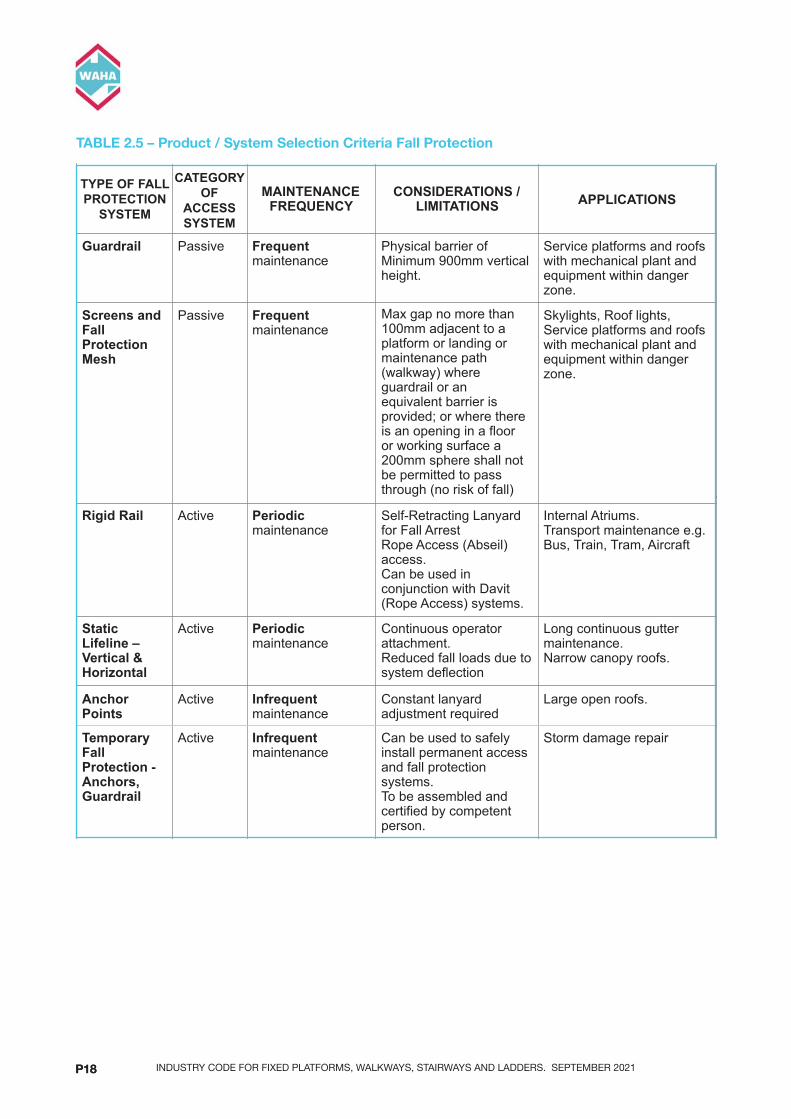
Guardrail Passive Frequent maintenance
Physical barrier of Minimum 900mm vertical height.
Service platforms and roofs with mechanical plant and equipment within danger zone.
Screens and Fall Protection Mesh
Passive Frequent maintenance
Maximum 300mm horizontal gap before physical barrier required.
Skylights, Roof lights, Service platforms and roofs with mechanical plant and equipment within danger zone.
Rigid Rail Active Periodic maintenance
Self-Retracting Lanyard for Fall Arrest Rope Access (Abseil) access. Can be used in conjunction with Davit (Rope Access) systems.
Internal Atriums. Transport maintenance e.g. Bus, Train, Tram, Aircraft
Static Lifeline – Vertical & Horizontal
Active Periodic maintenance
Continuous operator attachment. Reduced fall loads due to system deflection
Long continuous gutter maintenance. Narrow canopy roofs.
Anchor Points
Active Infrequent maintenance
Constant lanyard adjustment required
Large open roofs.
PAGE! INDUSTRYCODEFORAS1657_21/05/201916
INDUSTRY CODE FOR FIXED PLATFORMS, WALKWAYS, STAIRWAYS AND LADDERS. SEPTEMBER 2021P18P18
TABLE 2.5 – Product / System Selection Criteria Fall Protection
PRODUCTANDSYSTEMSELECTION
4. Selecting a Fixed Means of Access The means of access to a maintenance area shall be selected from the following diagram, considering the hierarchical order given:
• Roof Walkways with an angle between 0° and 20°.
• Stairways with an angle between 20° and 45°.
• Step-type ladders with an angle between 60° and 70°.
• Rung-type ladders with an angle between 70° and 90°.
!
FIGURE 2.2: LIMITS OF SLOPE (ANGLE)
2.2. Walkways and Guardrails
Temporary Fall Protection - Anchors, Guardrail
Active Infrequent maintenance
Can be used to safely install permanent access and fall protection systems. To be assembled and certified by competent person.
Storm damage repair
PAGE! INDUSTRYCODEFORAS1657_21/05/201917
PRODUCTANDSYSTEMSELECTION
TABLE 2.3 – PRODUCT / SYSTEM SELECTION CRITERIA
TYPE OF ACCESS SYSTEM
ANGLE OF
ACCESS SYSTEM
MAINTENANCE FREQUENCY
CONSIDERATIONS / LIMITATIONS APPLICATIONS
Elevating Work Platforms
N/A Periodic access Operator must remain within basket whilst undertaking maintenance task. Paved hard stand required below where maintenance required to support Elevating Work Platform.
Gutter and Glass cleaning. Maintenance of wall and roof-edge mounted equipment e.g. cameras, communication transmitters, lighting, etc…
Temporary Access - Towers and Scaffolding
N/A Infrequent access Firm stable surface to erect access system. To be assembled and certified by competent person.
Storm damage repair. Glass replacement and other unforeseen maintenance tasks.
Portable Ladders
75° Infrequent access Maximum vertical distance of less than 4.0m. Fall Protection required to transition operator into safe zone.
Access to low level roofs and canopies.
TYPE OF FALL
PROTECTION SYSTEM
CATAGORY OF
ACCESS SYSTEM
MAINTENANCE FREQUENCY
CONSIDERATIONS / LIMITATIONS APPLICATIONS
Guardrail Passive Frequent maintenance
Physical barrier of Minimum 900mm vertical height.
Service platforms and roofs with mechanical plant and equipment within danger zone.
Screens and Fall Protection Mesh
Passive Frequent maintenance
Max gap no more than 100mm adjacent to a platform or landing or maintenance path (walkway) where guardrail or an equivalent barrier is provided; or where there is an opening in a floor or working surface a 200mm sphere shall not be permitted to pass through (no risk of fall)
Skylights, Roof lights, Service platforms and roofs with mechanical plant and equipment within danger zone.
Static Lifeline – Vertical & Horizontal
Active Periodic maintenance
Long continuous gutter maintenance. Narrow canopy roofs.
Anchor Points
Active Infrequent maintenance
Constant lanyard adjustment required
Large open roofs.
PAGE! INDUSTRYCODEFORAS1657_21/05/201916
PRODUCTANDSYSTEMSELECTION
TABLE 2.3 – PRODUCT / SYSTEM SELECTION CRITERIA
TYPE OF ACCESS SYSTEM
ANGLE OF
ACCESS SYSTEM
MAINTENANCE FREQUENCY
CONSIDERATIONS / LIMITATIONS APPLICATIONS
Elevating Work Platforms
N/A Periodic access Operator must remain within basket whilst undertaking maintenance task. Paved hard stand required below where maintenance required to support Elevating Work Platform.
Gutter and Glass cleaning. Maintenance of wall and roof-edge mounted equipment e.g. cameras, communication transmitters, lighting, etc…
Temporary Access - Towers and Scaffolding
N/A Infrequent access Firm stable surface to erect access system. To be assembled and certified by competent person.
Storm damage repair. Glass replacement and other unforeseen maintenance tasks.
Portable Ladders
75° Infrequent access Maximum vertical distance of less than 4.0m. Fall Protection required to transition operator into safe zone.
Access to low level roofs and canopies.
TYPE OF FALL
PROTECTION SYSTEM
CATAGORY OF
ACCESS SYSTEM
MAINTENANCE FREQUENCY
CONSIDERATIONS / LIMITATIONS APPLICATIONS
Guardrail Passive Frequent maintenance
Physical barrier of Minimum 900mm vertical height.
Service platforms and roofs with mechanical plant and equipment within danger zone.
Screens and Fall Protection Mesh
Passive Frequent maintenance
Maximum 300mm horizontal gap before physical barrier required.
Skylights, Roof lights, Service platforms and roofs with mechanical plant and equipment within danger zone.
Rigid Rail Active Periodic maintenance
Self-Retracting Lanyard for Fall Arrest Rope Access (Abseil) access. Can be used in conjunction with Davit (Rope Access) systems.
Internal Atriums. Transport maintenance e.g. Bus, Train, Tram, Aircraft
Static Lifeline – Vertical & Horizontal
Active Periodic maintenance
Continuous operator attachment. Reduced fall loads due to system deflection
Long continuous gutter maintenance. Narrow canopy roofs.
Anchor Points
Active Infrequent maintenance
Constant lanyard adjustment required
Large open roofs.
PAGE! INDUSTRYCODEFORAS1657_21/05/201916
TYPE OF FALL PROTECTION
SYSTEM
CATEGORY OF
ACCESS SYSTEM

INDUSTRY CODE FOR FIXED PLATFORMS, WALKWAYS, STAIRWAYS AND LADDERS. SEPTEMBER 2021 P19
2.1.4. Selecting a Fixed Means of Access
The means of access to a maintenance area shall be selected from the following diagram, considering the hierarchical order given:• RoofWalkwayswithananglebetween0°and20°.• Stairwayswithananglebetween20°and45°.• Step-typeladderswithananglebetween60°and70°.• Rung-typeladderswithananglebetween70°and90°.
PRODUCTANDSYSTEMSELECTION
4. Selecting a Fixed Means of AccessThe means of access to a maintenance area shall be selected from the following diagram, considering the hierarchical order given:
• Roof Walkways with an angle between 0° and 20°.
• Stairways with an angle between 20° and 45°.
• Step-type ladders with an angle between 60° and 70°.
• Rung-type ladders with an angle between 70° and 90°.
!
StaMcLifeline–VerMcal&Horizontal
AcRve Periodicmaintenance
ConRnuousoperatora\achment.ReducedfallloadsduetosystemdeflecRon
LongconRnuousgu\ermaintenance.Narrowcanopyroofs.
AnchorPoints
AcRve Infrequentmaintenance
Constantlanyardadjustmentrequired
Largeopenroofs.
TemporaryFallProtecMon-Anchors,Guardrail
AcRve Infrequentmaintenance
CanbeusedtosafelyinstallpermanentaccessandfallprotecRonsystems.TobeassembledandcerRfiedbycompetentperson.
Stormdamagerepair
PAGE! INDUSTRYCODEFORAS1657_21/05/201919
FIGURE 2.2: Limits Of Slope (Angle)

INDUSTRY CODE FOR FIXED PLATFORMS, WALKWAYS, STAIRWAYS AND LADDERS. SEPTEMBER 2021P20P20
2.2 Walkways and Guardrails
Walkwaysreduceslipsandtriphazards,providingdesignatedroutebetweenfrequentlyaccessedlocations and protect roof surface within these frequently accessed routes. Guardrails provide a passivemeansofprotectionwhenlocatedwithinadangerzone.
2.2.1 Typical Walkway Application Types
FIGURE 2.3: 0-7 Degrees FIGURE 2.6: 0-10 Degrees
FIGURE 2.4: 8-12 Degrees FIGURE 2.7: 11-20 Degrees
FIGURE 2.5: 12+ Degrees FIGURE 2.8: 15 - 20 degrees (sec 5.4.2)
Direction of Travel
Typical Guardrail Requirements (From AS1657 :2018 Standards)
Max 7°
Max 10°
WalkwayDirection of Travel Walkway
Direction of Travel
Max 12°
Walkway
Max 20° 12°+ G/Rail Required
Direction of Travel
Walkway
Cleats
Walkway
12°+
12°+ -20°
WalkwayCleats
0 – 7 degrees
Guardrail
Direction of Travel
D9046
Direction of Travel
Typical Guardrail Requirements (From AS1657 :2018 Standards)
Max 7°
Max 10°
WalkwayDirection of Travel Walkway
Direction of Travel
Max 12°
Walkway
Max 20° 12°+ G/Rail Required
Direction of Travel
Walkway
Cleats
Walkway
12°+
12°+ -20°
WalkwayCleats
0 – 7 degrees
Guardrail
Direction of Travel
D9046
XXXX
A3XXXX
XXXX
MV
PreliminaryMVXX/XX/XX1 XX
A
B
C
D
E
F
A
B
C
D
E
F
12345678
12345678
MATERIAL
DESCRIPTION
PRODUCT CODE FAB No. DWG No. REV
SIZE
SHT #
THIS DRAWING REMAINS THE PROPERTY OF SAYFA GROUP® AND MAY NOT BE CHANGED WITHOUT WRITTEN PERMISSION
1029 MOUNTAIN HWYBORONIA VIC 3155T +61 1300 301 755F +61 1300 881 092E [email protected] sayfa.com.auABN 47 631 210 199
UNTOLERANCED DIMENSIONS
DIMENSION DIAMETER LENGTH
± 0.25mm± 0.50mm± 0.75mm
0 - 250mm250 - 750mm
>750mm
± 0.5mm± 1.0mm± 1.5mm
DRN:
CHK:
APP:
DATE:
DATE:
DATE:
SCALE
FINISH
COMMENTSAPPBYDATEREV
1/1
DRAWING 2.8
15°+ -20°
WalkwayCleats
Direction of Travel
Handrail (one side)
MIN
900
(PRE
FERR
ED 1
000)
DRAWING 3.18c
Walkway same angle as roof Walkway same angle as roof
Walkway to be levelled Cleats required
Levelled Walkway & Guardrail Guardrail and Cleats
ACROSS SLOPE IN-LINE WITH SLOPE

INDUSTRY CODE FOR FIXED PLATFORMS, WALKWAYS, STAIRWAYS AND LADDERS. SEPTEMBER 2021 P21
FIGURE 2.10: Change of Level greater than 300 mm but not exceeding 450 mm
FIGURE 2.11: Change of Level greater than 450 mm
PRODUCTANDSYSTEMSELECTION
ACROSS SLOPE IN-LINE WITH SLOPE
2.3. Steps and Landings
1. Change in Level
Where the level of a walkway above an adjacent walkway or floor is 300 mm or less, access from one level to the other may be gained without the provision of an intermediate step.
FIGURE 2.7: CHANGE OF LEVEL 300 MM OR LESS
Where the change of level is greater than 300 mm but does not exceed 450 mm, a minimum of one intermediate step shall be provided.
GuardrailandLevelledWalkway
GuardrailandCleats
PAGE! INDUSTRYCODEFORAS1657_21/05/201922
PRODUCT AND SYSTEM SELECTION
PAGE 19 INDUSTRY CODE FOR AS1657_21/05/2019
2.3. Steps and Landings
2.3.1 Change in Level
FIGURE 2.7: CHANGE OF LEVEL 300 MM OR LESS
Where the level of a walkway above an adjacent walkway or floor is 300 mm or less, access from one level to the other may be gained without the provision of an intermediate step.
FIGURE 2.8: CHANGE OF LEVEL GREATER THAN 300 MM BUT NOT EXCEEDING 450 MM
Where the change of level is greater than 300 mm but does not exceed 450 mm, a minimum of one intermediate step shall be provided.
FIGURE 2.9: CHANGE OF LEVEL MORE THEN 450 MM
Access between adjacent levels where the difference exceeds 450 mm shall be in accordance with the requirements of Section 7 of AS1657 or by means of a sloping walkway complying with Section 5.
Commented [MV2]: This section has been revised
Commented [MV3]: Include Rung Ladder option
Where the level of a walkway above an adjacentwalkwayorflooris300mmorless, access from one level to the other may be gained without the provision of an intermediate step.
Where the change of level is greater than300mmbutdoesnotexceed450mm, a minimum of one intermediate step shall be provided.
Accessbetweenadjacentlevelswherethedifferenceexceeds450mmshallbeinaccordancewiththerequirementsofSection7ofAS1657orbymeansofaslopingwalkwaycomplying with Section 5.
FIGURE 2.9: Change of Level 300 mm or Less
2.3 Steps and Landings
2.3.1. Change in level

INDUSTRY CODE FOR FIXED PLATFORMS, WALKWAYS, STAIRWAYS AND LADDERS. SEPTEMBER 2021P22P22
2.4 Platforms
RefertoAustralianStandardsAS1657.
- Platforms should be minimum 600mm wide and provide standing space 600mm clear of all cross-traffic,doorswingoranyotherstructure.-Whereplatformsaregreaterthan300mmaboveanothersurface,anyexposededgesshouldbehighlightedwithyellownon-slipedgestrips.
2.5 Stairways
Stairwaysareaneffectivemeansofaccessbetweenlevels,offeringeaseofpassageforpersonsand equipment. Stairways should be used where frequent access is required for maintenance of mechanical plant and equipment and where tools, parts and equipment need to be taken to the maintenancearea.FundamentalparametersforStairwaysareasfollows;• Angleofsloperangeisbetween20and45Degrees• Minimum600mmlandinglengthrequiredatbase,intermediateandtopofstairway• Minimumlandingwidthtobesamewidthasstair.• Minimum2000mmheadclearancerequired.• Maximum18risersperflight(refertoAS1657:2018.7.2.2),whichisgenerallyaboutmaximumof
approximately4000mminverticalheight.• Landingorchange-in-directionplatformrequiredatintervals,every18risers.Whengreaterthan36
risers, a change-in-direction is required or intermediate landing of minimum 2000mm length.• Whereitisnecessaryforapersontostepsidewaysfromaroofstair,thelandingadjacentmustbe
a minimum 600mm in length and the minimum width to be same width as stair.
2.5.1. Stairways (Single Flight)
Singleflightstairsareaneffectivemeansofaccessbetweenlevels,wherefrequentmaintenanceisrequired,upto4050mmverticaldistanceor18risers
PRODUCTANDSYSTEMSELECTION
• Where it is necessary for a person to step sideways from a roof stair, the landing adjacent must be a minimum 600mm in length and the minimum width to be same width as stair.
1. Stairways (Single Flight)Single flight stairs are an effective means of access between levels, where frequent maintenance is required, up to 4050mm vertical distance or 18 risers
!
FIGURE 2.10: STAIRWAYS (SINGLE FLIGHT)
PAGE! INDUSTRYCODEFORAS1657_21/05/201924
FIGURE 2.12: Stairways (Single Flight)

INDUSTRY CODE FOR FIXED PLATFORMS, WALKWAYS, STAIRWAYS AND LADDERS. SEPTEMBER 2021 P23
PRODUCTANDSYSTEMSELECTION
2. Stairways (Roof-Type)Roof Stairs (stairway following slope of roof) are an effective means of access where frequent maintenance is required on steep pitched of roofs, between 20 and 45 degrees.
!
FIGURE 2.11: STAIRWAYS (ROOF TYPE)
PAGE! INDUSTRYCODEFORAS1657_21/05/201925
FIGURE 2.13: Stairways (Roof Type)
2.5.2. Stairways (Roof-Type)
RoofStairs(stairwayfollowingslopeofroof)areaneffectivemeansofaccesswherefrequentmaintenance is required on steep pitched of roofs, between 20 and 45 degrees.
INDUSTRY CODE FOR FIXED PLATFORMS, WALKWAYS, STAIRWAYS AND LADDERS. SEPTEMBER 2021P24P24
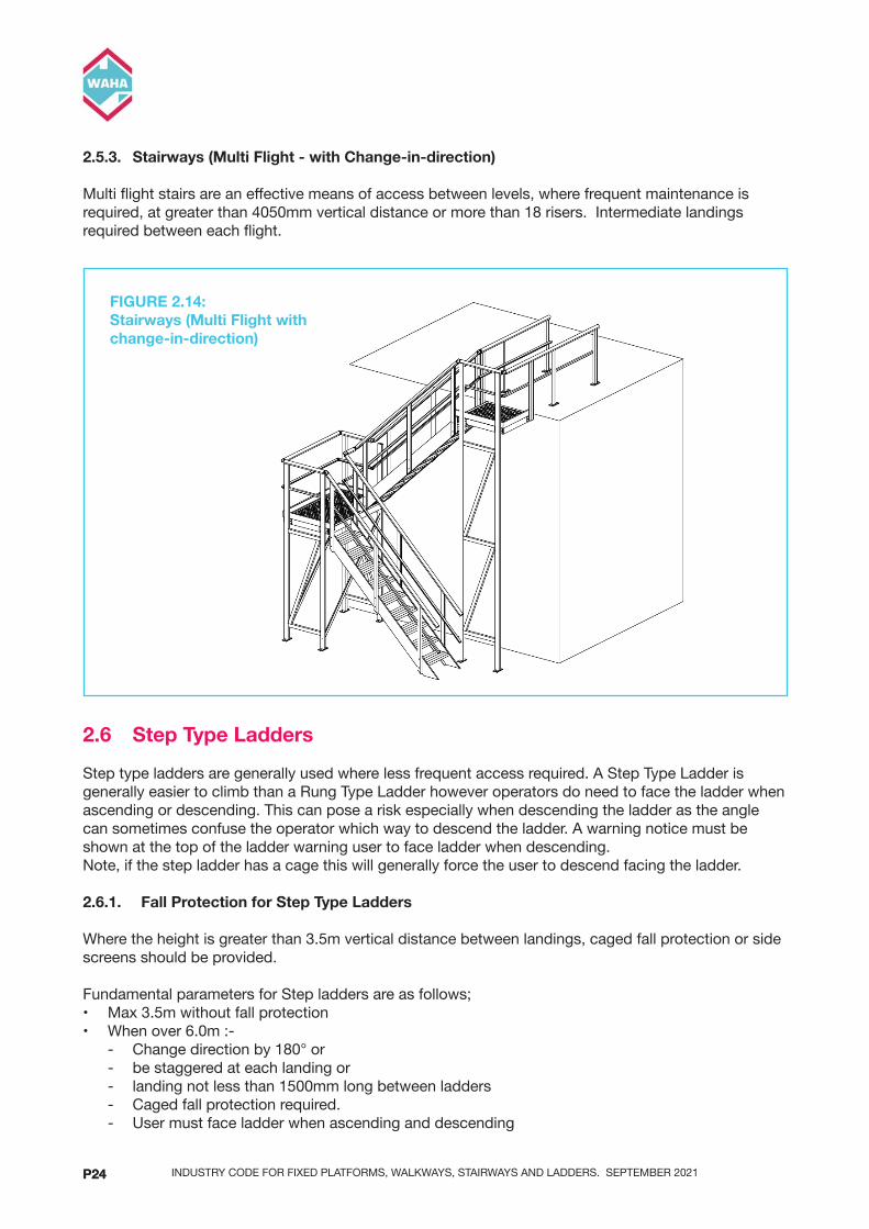
2.5.3. Stairways (Multi Flight - with Change-in-direction)
Multiflightstairsareaneffectivemeansofaccessbetweenlevels,wherefrequentmaintenanceisrequired,atgreaterthan4050mmverticaldistanceormorethan18risers.Intermediatelandingsrequiredbetweeneachflight.
2.6 Step Type Ladders
Steptypeladdersaregenerallyusedwherelessfrequentaccessrequired.AStepTypeLadderisgenerally easier to climb than a Rung Type Ladder however operators do need to face the ladder when ascending or descending. This can pose a risk especially when descending the ladder as the angle cansometimesconfusetheoperatorwhichwaytodescendtheladder.Awarningnoticemustbeshown at the top of the ladder warning user to face ladder when descending.Note,ifthestepladderhasacagethiswillgenerallyforcetheusertodescendfacingtheladder.
2.6.1. Fall Protection for Step Type Ladders
Where the height is greater than 3.5m vertical distance between landings, caged fall protection or side screens should be provided.
FundamentalparametersforStepladdersareasfollows;• Max3.5mwithoutfallprotection• Whenover6.0m:- - Changedirectionby180°or - be staggered at each landing or - landing not less than 1500mm long between ladders - Caged fall protection required. - User must face ladder when ascending and descending
PRODUCTANDSYSTEMSELECTION
3. Stairways (Multi Flight - with Change-in-direction)Multi flight stairs are an effective means of access between levels, where frequent maintenance is required, at greater than 4050mm vertical distance or more than 18 risers. Intermediate landings required between each flight.
!
FIGURE 2.12: STAIRWAYS (MULTI FLIGHT WITH CHANGE-IN-DIRECTION)
2.6. Step Type Ladders
Step type ladders are generally used where less frequent access required. A Step Type Ladder is generally easier to climb than a Rung Type Ladder however operators do need to face the ladder when ascending or descending. This can pose a risk especially when descending the ladder as the angle can sometimes confuse the operator which way to descend the ladder. A warning notice must be shown at the top of the ladder warning user to face ladder when descending.
Note, if the step ladder has a cage this will generally force the user to descend facing the ladder.
2.6.1. Fall Protection for Step Type Ladders
Where the height is greater than 3.5m vertical distance between landings, caged fall protection or side screens should be provided.
Fundamental parameters for Step ladders are as follows;
• Max 3.5m without fall protection
• When over 6.0m :-
- Change direction by 180° or
- be staggered at each landing or
PAGE! INDUSTRYCODEFORAS1657_21/05/201926
FIGURE 2.14: Stairways (Multi Flight with change-in-direction)

INDUSTRY CODE FOR FIXED PLATFORMS, WALKWAYS, STAIRWAYS AND LADDERS. SEPTEMBER 2021 P25
FIGURE 2.13: Type Step Ladders
PRODUCTANDSYSTEMSELECTION
- landing not less than 1500mm long between ladders
- Caged fall protection required.
- User must face ladder when ascending and descending
! !
FIGURE 2.13: STEP TYPE LADDERS
PAGE! INDUSTRYCODEFORAS1657_21/05/201927
PRODUCTANDSYSTEMSELECTION
- landing not less than 1500mm long between ladders
- Caged fall protection required.
- User must face ladder when ascending and descending
! !
FIGURE 2.13: STEP TYPE LADDERS
PAGE! INDUSTRYCODEFORAS1657_21/05/201927
PRODUCTANDSYSTEMSELECTION
!
PAGE! INDUSTRYCODEFORAS1657_21/05/201928
FIGURE 2.16: Step Type Ladders
NOTE,whenladderheightisover2m,lead-onguarrailofminimum2.0misrecommended.
FIGURE 2.15: Step Type Ladders

INDUSTRY CODE FOR FIXED PLATFORMS, WALKWAYS, STAIRWAYS AND LADDERS. SEPTEMBER 2021P26P26
PRODUCTANDSYSTEMSELECTION
!
!
PAGE! INDUSTRYCODEFORAS1657_21/05/201929
PRODUCTANDSYSTEMSELECTION
!
!
PAGE! INDUSTRYCODEFORAS1657_21/05/201929
FIGURE 2.17: Step Type Ladders
FIGURE 2.18: Step Type Ladders

INDUSTRY CODE FOR FIXED PLATFORMS, WALKWAYS, STAIRWAYS AND LADDERS. SEPTEMBER 2021 P27
PRODUCTANDSYSTEMSELECTION
!
!
PAGE! INDUSTRYCODEFORAS1657_21/05/201930
PRODUCTANDSYSTEMSELECTION
!
!
PAGE! INDUSTRYCODEFORAS1657_21/05/201930
FIGURE 2.19: Step Type Ladders
FIGURE 2.20: Step Type Ladders

INDUSTRY CODE FOR FIXED PLATFORMS, WALKWAYS, STAIRWAYS AND LADDERS. SEPTEMBER 2021P28P28
2.7 Twin Stile Rung Type Ladders
Twin stile Rung type ladders are used where periodic or infrequent access is required. RungLaddersshouldbeangled(75°approx.),whereverpracticable,overagainstverticaltypeastheuser requires less energy to climb the ladder and the centre of gravity of the person is closer to the ladder which making it a lesser risk of overbalancing and potentially falling.
Hierarchy of Rung type Ladders 1. AngledLadder(withCageover3.5m) 2. Vertical Ladder (with fall arrest system over 3.5m) 3. Vertical ladder with cage (with cage over 3.5m)
Type of ladder installed must be selected to suit maintenance task required. Consideration must be made on the following;• Angle,75°-90°(preferred75°approx.)• 6.0mmaximumdistancebetweenlandings• 6.0mmaximumdistancebetweenrestplatforms(VerticalLifelineLadder)• Fallprotectionontheladderisrequiredwhenover3.5m• VerticalLifelineLadderwithFallArrestsystemshouldnotbeusedwheremaintenanceof
mechanical plant and machinery is required, however it may be appropriate where gutter maintenance is required, and roof mounted fall arrest system installed that operator will use with harness.
• OperatorwillrequiretrainingtouseVerticalLifelineladders.
2.7.1. Fall Protection for Rung Type Ladders
Where the height is greater than 3.5m vertical distance between landings, fall protection must be provided by one of the followings means: -
Cage Fall ProtectionCage protection is preferred on any angled ladder. It should be noted that some States do not accept cages as fall protection. Refer to the relative State regulatory requirements as to the recommended method of fall protection.
Acagedladdermaynot‘arrest’afallandinsomecasesmayjust‘funnel’thefalltothebaseoftheladder, causing serious injury. It can also be a bigger issue if the user got trapped in the cage. It would makeitdifficultforrescueoperations.
FallprotectionshouldbeeitherCageorVerticalfallarrestsystemNOTBOTH.Itwillbeverydifficulttorescue anyone if they have fallen and trapped in a cage with a vertical line system.
Fall Arrest SystemFallArrestsystemsmayinclude,Cablesystems,Track,Rail.EquipmentsuchasInertiaReels,twin-tail lanyards may be also be used however a risk assessment must be performed for this type of fall protection.
Cable or track fall arrest systems may not work on inclined situations. Seek approval from the manufacturer of these systems if used on angled/inclined situations. The other consideration is the user will need to be trained in the use of fall arrest equipment etc. There will also be a need for a minimum of 2 people in case of a fall/rescue requirements. The likelihood of rescue is very low as a verticalfallarrestsystemincorporatedwilllimitafalltoamaximumof600mm.Ifafallwastooccur,the likelihood of severe injury occurring is very low.

INDUSTRY CODE FOR FIXED PLATFORMS, WALKWAYS, STAIRWAYS AND LADDERS. SEPTEMBER 2021 P29
2.8 Angled Rung Type Ladders
Notes• Fallprotectionontheladderrequiredafter3.5mverticalheight.• Handrailsorlead-onrailsrequiredasanaidtoaccessandtohelptheuserturnaroundbefore
descending the ladder. • Firstdiagrambelowisgenerallysuitedtoheightslessthan2000mm.• Seconddiagramshowsa2000mm‘lead-on’systemforfallprotection.Thisisrequiredwhenover
3.5m
PRODUCTANDSYSTEMSELECTION
Fall Arrest systems may include, Cable systems, Track, Rail. Equipment such as Inertia Reels, twin-tail lanyards may be also be used however a risk assessment must be performed for this type of fall protection.
Cable or track fall arrest systems may not work on inclined situations. Seek approval from the manufacturer of these systems if used on angled/inclined situations. The other consideration is the user will need to be trained in the use of fall arrest equipment etc. There will also be a need for a minimum of 2 people in case of a fall/rescue requirements. The likelihood of rescue is very low as a vertical fall arrest system incorporated will limit a fall to a maximum of 600mm. If a fall was to occur, the likelihood of severe injury occurring is very low.
2.8. Angled Rung Type Ladders
Notes
• Fall protection on the ladder required after 3.5m vertical height.
• Handrails or lead-on rails required as an aid to access and to help the user turn around before descending the ladder.
• First diagram below is generally suited to heights less than 2000mm.
• Second diagram shows a 2000mm ‘lead-on’ system for fall protection. This is required when over 3.5m
!
!
PAGE! INDUSTRYCODEFORAS1657_21/05/201932
FIGURE 2.21: Angled Rung Type Ladders

INDUSTRY CODE FOR FIXED PLATFORMS, WALKWAYS, STAIRWAYS AND LADDERS. SEPTEMBER 2021P30P30
2.8.1 Angled Rung Ladders with Cage
Notes• Heightupto6m• Cagerequiredafter3.5m• Angle–70°-80°(Preferred75°)
PRODUCTANDSYSTEMSELECTION
2.8.1 Angled Rung Ladders with CageNotes
• Height up to 6m
• Cage required after 3.5m
• Angle – 70° - 80° (Preferred 75°)
!
FIGURE 2.15: ANGLED RUNG TYPE LADDERS WITH CAGE
PAGE! INDUSTRYCODEFORAS1657_21/05/201934
FIGURE 2.22: Angled Rung Type Ladders with Cage

INDUSTRY CODE FOR FIXED PLATFORMS, WALKWAYS, STAIRWAYS AND LADDERS. SEPTEMBER 2021 P31
PRODUCTANDSYSTEMSELECTION
!
FIGURE 2.16: ANGLED RUNG TYPE LADDERS WITH CAGE
2. Vertical Rung Ladders with Fall Arrest / Rail Systems(Type 1 Fall Arrest Device (AS/NZS 1891.3)
PAGE! INDUSTRYCODEFORAS1657_21/05/201935
FIGURE 2.23: Angled Rung Type Ladders with Cage

INDUSTRY CODE FOR FIXED PLATFORMS, WALKWAYS, STAIRWAYS AND LADDERS. SEPTEMBER 2021P32P32
2.8.2. Vertical Rung Ladders with Fall Arrest / Rail Systems (Type 1 Fall Arrest Device (AS/NZS 1891.3)
PRODUCTANDSYSTEMSELECTION
! !
Vertical Ladders with fall arrest systems are only good for areas where there are infrequent access requirements.
Vertical Ladders with fall arrest systems are recommended for areas with infrequent maintenance requirements. The operator/user must have a working-at-heights ticket to use the system as it requires a harness. It must also be noted that the fall arrest system and harness must be made easily available so that there is less chance of the operator climbing the ladder with no fall protection. It is a recommendation that a cabinet which houses the harness and fall arrestor device must be kept within close proximity to the ladder.
Vertical fall arrest ladders will require a rest platform every 6.0m maximum. The rest platform must be on the side of the fall arrest system. The ladder may be of one continuous system.A ladder with vertical fall arrest system is not recommended for use when exiting through a roof hatch as the user will need to detach from the system before exiting onto the roof.
!
PAGE! INDUSTRYCODEFORAS1657_21/05/201936
Vertical Ladders with fall arrest systems are only good for areas where there are infrequent access requirements.
Vertical Ladders with fall arrest systems are recommended for areas with infrequent maintenance requirements. The operator/user must have a working-at-heights ticket to use the system as it requires a harness. It must also be noted that the fall arrest system and harness must be made easily available so that there is less chance of the operator climbing the ladder with no fall protection. It is a recommendation that a cabinet which houses the harness and fall arrestor device must be kept within close proximity to the ladder.
Verticalfallarrestladderswillrequirearestplatformevery6.0mmaximum.Considerationsforrestplatforms less than 6m intervals should be considered in relation to risk and tasks being done. The rest platform must be on the side of the fall arrest system. The ladder may be of one continuous system.Aladderwithverticalfallarrestsystemisnotrecommendedforusewhenexitingthrougharoofhatchastheuserwillneedtodetachfromthesystembeforeexitingontotheroof.

INDUSTRY CODE FOR FIXED PLATFORMS, WALKWAYS, STAIRWAYS AND LADDERS. SEPTEMBER 2021 P33
PRODUCTANDSYSTEMSELECTION
! !
Vertical Ladders with fall arrest systems are only good for areas where there are infrequent access requirements.
Vertical Ladders with fall arrest systems are recommended for areas with infrequent maintenance requirements. The operator/user must have a working-at-heights ticket to use the system as it requires a harness. It must also be noted that the fall arrest system and harness must be made easily available so that there is less chance of the operator climbing the ladder with no fall protection. It is a recommendation that a cabinet which houses the harness and fall arrestor device must be kept within close proximity to the ladder.
Vertical fall arrest ladders will require a rest platform every 6.0m maximum. The rest platform must be on the side of the fall arrest system. The ladder may be of one continuous system.A ladder with vertical fall arrest system is not recommended for use when exiting through a roof hatch as the user will need to detach from the system before exiting onto the roof.
!
PAGE! INDUSTRYCODEFORAS1657_21/05/201936
PRODUCTANDSYSTEMSELECTION
FIGURE 2.17: VERTICAL RUNG LADDERS WITH FALL ARREST / RAIL SYSTEMS (UP TO 6m)
!
FIGURE 2.18:
VERTICAL RUNG LADDERS WITH FALL ARREST / RAIL SYSTEMS INCLUDING REST PLATFORM (6m – 12m)
PAGE! INDUSTRYCODEFORAS1657_21/05/201937
FIGURE 2.24: Vertical Rung Ladders with all Arrest / Rail Systems (Up To 6m)
FIGURE 2.25: Vertical Rung Ladders with Fall Arrest / Rail Systems including Rest Platform (6m – 12m)

INDUSTRY CODE FOR FIXED PLATFORMS, WALKWAYS, STAIRWAYS AND LADDERS. SEPTEMBER 2021P34P34
2.8.3. Vertical Rung Ladder with Cage (Least preferred option)
Vertical caged ladders are the lowest on the hierarchy for rung-type ladders. It is a harder ladder to climb and the cage may not ‘catch’ a fall but merely guide or ‘funnel’ the fall to the base of the ladder. Vertical caged ladders should only be used if angled caged ladders cannot be used (space constraints) and where there is regular maintenance required which would require multiple operators beingtrainedifaVerticalLadderwithfallarrestsystemwasused.Ariskassessmentmustbedonetoevaluate the correct system to be proposed.
NOTE: Vertical Rung Ladder with Cage and Fall Arrest Systems
(Least preferred option)
It is not recommended that vertical caged ladders should incorporate a vertical fall arrest system as an additional fall protection means. If a person was to fall in the cage, they could get jammed in the cage anditwouldbeverydifficulttorescuetheoperatorinthissituation.Itwouldbeadvisedthatthecagedshould be removed then use the vertical fall arrest system only.
PRODUCTANDSYSTEMSELECTION
3. Vertical Rung Ladder with Cage(Note these are not recommended)
Vertical caged ladders are the lowest on the hierarchy for rung-type ladders. It is a harder ladder to climb and the cage may not ‘catch’ a fall but merely guide or ‘funnel’ the fall to the base of the ladder. Vertical caged ladders should only be used if angled caged ladders cannot be used (space constraints) and where there is regular maintenance required which would require multiple operators being trained if a Vertical Ladder with fall arrest system was used.
A risk assessment must be done to evaluate the correct system to be proposed.
NOTE: Vertical Rung Ladder with Cage and Fall Arrest Systems
(Note, these are not recommended)
It is not recommended that vertical caged ladders should incorporate a vertical fall arrest system as an additional fall protection means. If a person was to fall in the cage, they could get jammed in the cage and it would be very difficult to rescue the operator in this situation. It would be advised that the caged should be removed then use the vertical fall arrest system only.
!
PAGE! INDUSTRYCODEFORAS1657_21/05/201938

INDUSTRY CODE FOR FIXED PLATFORMS, WALKWAYS, STAIRWAYS AND LADDERS. SEPTEMBER 2021 P35
PRODUCTANDSYSTEMSELECTION
!
4. Single Stile Rung Ladders - Refer to Australian Standards - AS1657
5. Individual Rung Ladder (Step Irons)Refer to Australian Standards - AS1657
PAGE! INDUSTRYCODEFORAS1657_21/05/201939
4. Single Stile Rung Ladders - Refer to Australian Standards - AS1657
5. Individual Rung Ladder (Step Irons)
Refer to Australian Standards - AS1657

INDUSTRY CODE FOR FIXED PLATFORMS, WALKWAYS, STAIRWAYS AND LADDERS. SEPTEMBER 2021P36P36
3. DESIGN AND LAYOUT
3.1 IntroductionThissectionoutlinesrequirementsaroundpositioningandlayoutofAccessandFallProtectionsystemsdrawingattentiontosomeareasoftheAS1657whichmaybedifficulttointerpret
3.2 Access Between Levels
3.2.1 Change in Level 1.1. 0 - 300mm 1.2. 300 - 450mm 1.3. 450mm+
DESIGNANDLAYOUT
3. Design and Layout 3.1. Introduction
This section outlines requirements around positioning and layout of Access and Fall Protection systems drawing attention to some areas of the AS1657 which may be difficult to interpret
3.2. Access between levels
1. Change in Level 1.1. 0 - 300mm
1.2. 300 - 450mm
1.3. 450mm+
!
2. Transition from Roof Edge (Fixed Systems)Transition onto a roof from an external ladder/stair should be protected from a fall hazard.
Guardrailing or barriers should be provided where a fall hazard exists, and vertical distance exceeds 2000mm above lower level. A minimum protection of 2000mm on either side of the entry point or leading into the roof ‘safe-zone’ is required. Roof Slope and other risks must be considered. Refer roof slope diagram (Figure 2.1).
!40
FIGURE 3.1: Change in LevelWhere the level of a walkway above an adjacentwalkwayorflooris300mmorless, access from one level to the other may be gained without the provision of an intermediate step.
Where the change of level is greater than 300mmbutdoesnotexceed450mm,aminimum of one intermediate step shall be provided.
Accessbetweenadjacentlevelswherethedifferenceexceeds450mmshallbeinaccordance with the requirements of Section 7ofAS1657orbymeansofaslopingwalkway complying with Section 5.

INDUSTRY CODE FOR FIXED PLATFORMS, WALKWAYS, STAIRWAYS AND LADDERS. SEPTEMBER 2021 P37
3.2.2. Transition from Roof Edge (Fixed Systems)
Transitionontoarooffromanexternalladder/stairshouldbeprotectedfromafallhazard.Guardrailingorbarriersshouldbeprovidedwhereafallhazardexists,andverticaldistanceexceeds2000mmabovelowerlevel.Aminimumprotectionof2000mmoneithersideoftheentrypointorleadingintotheroof‘safe-zone’isrequired.RoofSlopeandotherrisksmustbeconsidered.Referroofslopediagram(Figure2.2).
DESIGNANDLAYOUT
!
!
FIGURE 3.1: TRANSITION FROM ROOF EDGE (FIXED SYSTEMS)
!41
DESIGNANDLAYOUT
!
!
FIGURE 3.1: TRANSITION FROM ROOF EDGE (FIXED SYSTEMS)
!41
FIGURE 3.2: Transition from Roof Edge (Fixed Systems)

INDUSTRY CODE FOR FIXED PLATFORMS, WALKWAYS, STAIRWAYS AND LADDERS. SEPTEMBER 2021P38P38
3.2.3. Portable Ladder with Ladder Bracket Access to Roof
Aladderbracketandportableladdersystemshouldonlybeusedwhereinfrequentaccessisrequired.In every situation a risk assessment should be carried out to establish the best means of access, however if a portable means of access is selected, it is recommended to have a system whereby the user can step through the top of the ladder (by means of grab-rails mounted to the roof) as preferred to stepping around the ladder.
Ameansofprotectingtheoperatorfromfallingshouldbeincluded,suchasa2mguardrailsystemorananchorwithatransitionlanyard(strop),toenabletooperatortoattachbeforegettingoffthetopofthe ladder.
Thetransitionstropshouldbethewithinreach(approximately600mm)fromthefrontoftheroofedgeand should not be any closer than 200mm to the roof edge.
The following must be considered when selecting portable ladder as means of access;• Themaximumheightforthistypeaccessshouldbe4.0mverticaldistancebetweenlevels.
Refertotable2.3.Accesstoareasoverthisheightshouldbemadeusingapermanentsystem e.g. stairway or ladder.
• PortableLaddermustextendminimum1.0mpaststepoffpoint.• PortableLaddersshouldonlybeusedwhereinfrequentaccessisrequired.Wherefrequent
maintenanceisrequiredi.e.,HVACunits,solarpanels,otherelectrical/mechanicalequipment,access should be made using a permanent system e.g. stairway or ladder.
• PortableLaddercanalsobeusedwherecontrolledaccess(securityreasons)isrequired.• PortableLaddershouldnotbeusedwhereasecondladderneedstobeliftedtointermediatelevel,
to gain access to another level.
Aguardraillead-onkitisthepreferablearrangementforaportableladderandladderbracket,allowinganoperatortowalkstraightintothesafezonewithouttheneedtosteparoundthestiles,alsoreducingtheriskofafallatthepointoftransitionofftheladder.
DESIGNANDLAYOUT
3. Portable Ladder with Ladder Bracket and Transition Lanyard (Strop) A ladder bracket and portable ladder system should only be used where infrequent access is required.
In every situation a risk assessment should be carried out to establish the best means of access, however if a portable means of access is selected, it recommended to have a system whereby the user can step through the top of the ladder (by means of grab-rails mounted to the roof) as preferred to stepping around the ladder.
A means of protecting the operator from falling should be included, such as a 2m guardrail system or an anchor with a transition lanyard (strop), to enable to operator to attach before getting off the top of the ladder.
The transition strop should be the within reach (approximately 600mm) from the front of the roof edge and should not be any closer than 200mm to the roof edge.
The follow must be considered when selecting portable ladder as means of access;
• The maximum height for this type access should be 4.0m. vertical distance between levels. Access to areas over this height should be made using a permanent system e.g. stairway or ladder.
• Portable Ladder must extend minimum 1.0m above top landing.
• Portable Ladders should only be used where infrequent access is required. Where frequent maintenance is required i.e., HVAC units, solar panels, other electrical/mechanical equipment, access should be made using a permanent system e.g. stairway or ladder.
• Portable Ladder can also be used where controlled access (security reasons) is required
• Portable Ladder should not be used where a second ladder needs to be lifted to intermediate level, to gain access to another level
! !
FIGURE 3.2: PORTABLE LADDER WITH LADDER BRACKET AND TRANSITION LANYARD (STROP)
!42
FIGURE 3.3: Portable Ladder with Ladder Bracket and Guardrail Lead-on Kit or Transition Lanyard (Strop)
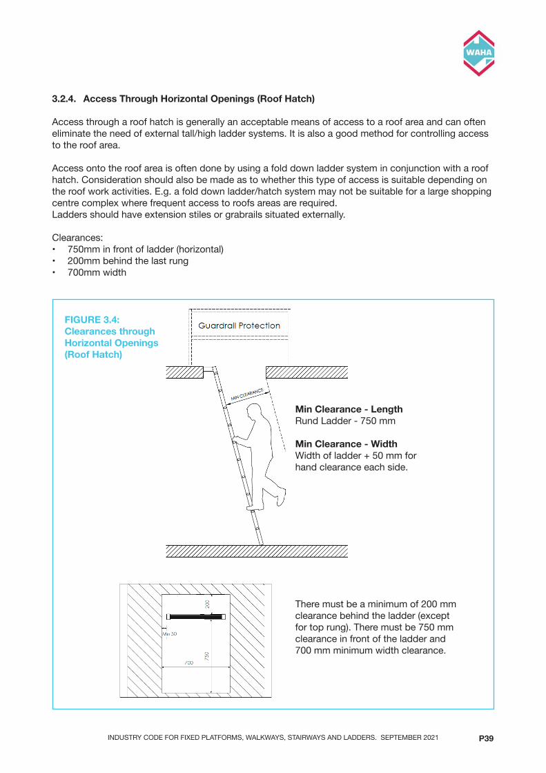
INDUSTRY CODE FOR FIXED PLATFORMS, WALKWAYS, STAIRWAYS AND LADDERS. SEPTEMBER 2021 P39
3.2.4. Access Through Horizontal Openings (Roof Hatch)
Accessthrougharoofhatchisgenerallyanacceptablemeansofaccesstoaroofareaandcanofteneliminatetheneedofexternaltall/highladdersystems.Itisalsoagoodmethodforcontrollingaccessto the roof area.
Accessontotheroofareaisoftendonebyusingafolddownladdersysteminconjunctionwitharoofhatch. Consideration should also be made as to whether this type of access is suitable depending on the roof work activities. E.g. a fold down ladder/hatch system may not be suitable for a large shopping centrecomplexwherefrequentaccesstoroofsareasarerequired.Laddersshouldhaveextensionstilesorgrabrailssituatedexternally.
Clearances:• 750mminfrontofladder(horizontal)• 200mmbehindthelastrung• 700mmwidth
DESIGNANDLAYOUT
4. Access Through Horizontal Openings (Roof Hatch)Access through a roof hatch is generally an acceptable means of access to a roof area and can often eliminate the need of external tall/high ladder systems. It is also a good method for controlling access to the roof area.
Access onto the roof area is often done by using a fold down ladder system in conjunction with a roof hatch. Consideration should also be made as to whether this type of access is suitable depending on the roof work activities. E.g. a fold down ladder/hatch system may not be suitable for a large shopping centre complex where frequent access to roofs areas are required.
Ladder should have extension stiles or grabrails situated externally.
Clearances:
• 750mm in front of ladder (horizontal)
• 200mm behind the last rung
• 700mm width
!
!
!44
There must be a minimum of 200 mm clearancebehindtheladder(exceptfor top rung). There must be 750 mm clearance in front of the ladder and 700 mm minimum width clearance.
DESIGNANDLAYOUT
4. Access Through Horizontal Openings (Roof Hatch)Access through a roof hatch is generally an acceptable means of access to a roof area and can often eliminate the need of external tall/high ladder systems. It is also a good method for controlling access to the roof area.
Access onto the roof area is often done by using a fold down ladder system in conjunction with a roof hatch. Consideration should also be made as to whether this type of access is suitable depending on the roof work activities. E.g. a fold down ladder/hatch system may not be suitable for a large shopping centre complex where frequent access to roofs areas are required.
Ladder should have extension stiles or grabrails situated externally.
Clearances:
• 750mm in front of ladder (horizontal)
• 200mm behind the last rung
• 700mm width
!
!
!44
Min Clearance - LengthRund Ladder - 750 mm
Min Clearance - WidthWidth of ladder + 50 mm for hand clearance each side.
FIGURE 3.4: Clearances through Horizontal Openings (Roof Hatch)

INDUSTRY CODE FOR FIXED PLATFORMS, WALKWAYS, STAIRWAYS AND LADDERS. SEPTEMBER 2021P40P40
FIGURE 3.5: Clearances through Horizontal Openings (Roof Hatch)
THIS PROPERTY REMAINS THE PROPERTY OF SAYFA GROUP AND MAY NOT BE CHANGED WITHOUT WRITTEN PERMISSIONFOR FURTHER INFORMATION REFER TO OUR WEBSITE AT sayfa.com.au
1029 MOUNTAIN HWY BORONIA VIC 3155T +61 1300 301 755E [email protected]
F +61 1300 881 092E sayfa.com.au
DRG No. DATE
Code REV
DESCRIPTION
Clearances Through Horizontal Openings XXX 3/10/2019
XXX 1
Guardrail Protection
Min Clearance - LengthStep Ladder Angle60° - 1000mm65° - 950mm70° - 900mm
Min Clearance - WidthWidth of ladder +50mm for hand clearance each side.
MIN CLEARANCE
MIN CLEARANCE
MIN
CLE
ARA
NC
E
Guardrail Protection
Guardrail Protection
Min Clearance - LengthRung Ladder - 750mm
Min Clearance - WidthWidth of ladder +50mm for hand clearance each side.
Min Clearance - HeightStairway- 2.0m
Min Clearance - WidthWidth of stairway +50mm for hand clearance each side.

INDUSTRY CODE FOR FIXED PLATFORMS, WALKWAYS, STAIRWAYS AND LADDERS. SEPTEMBER 2021 P41
3.2.4.1 Top rung in relation to landing
• TopRungneedstobelevelwiththesurfaceyouwillbesteppingontoormax300mmbelow.Thegap from top rung to structure behind must be a min 100mm, anything greater than 100mm will requireaninfilllanding.Allrungsbelowtoprungrequireminimum200mmclearance.
3.2.5 Guardrail Around an Opening (Hatch)
• Guardrailshallbeprovidedtoatleast3sidesoftheopening• HandGripsshallbeprovided.Thesecanbeeitherasretractablestilesconnectedtotheladderor
fixedhandgripsmountedabove.
THIS PROPERTY REMAINS THE PROPERTY OF SAYFA GROUP AND MAY NOT BE CHANGED WITHOUT WRITTEN PERMISSIONFOR FURTHER INFORMATION REFER TO OUR WEBSITE AT sayfa.com.au
1029 MOUNTAIN HWY BORONIA VIC 3155T +61 1300 301 755E [email protected]
F +61 1300 881 092E sayfa.com.au
DRG No. DATE
Code REV
DESCRIPTION
Clearances Through Horizontal Openings XXX 3/10/2019
XXX 1
MIN 750
Up to
300
mm
belo
w la
ndin
g
100 - 200
Landing
If gap behind TOP rung is greaterthan 200mm, an infill is required
If gap behind TOP rung is greater than 100 mm, aninfillisrequiredlevelwith top rung.
FIGURE 3.6 Internal - Through Horizontal Openings (Roof Hatch)

INDUSTRY CODE FOR FIXED PLATFORMS, WALKWAYS, STAIRWAYS AND LADDERS. SEPTEMBER 2021P42P42
3.2.5.1 Fold Down Ladders (Attic Type)
Althoughfolddownladdersarenotincludedinanystandards,thesetypesofladderscanbeanacceptablemeansofaccesstoaroofareaandcanofteneliminatetheneedofexternaltall/highladdersystems.Folddownladdersusedincommercial/industrialenvironmentsshouldbetestedaccordingly.Approvalfromthemanufacturershouldbeconfirmediftheladderisfitforpurpose.
Itisimportanttorealisethatfolddownladdersdonotofferanyfallprotectionthereforefallprotectionwillneedtobeconsideredintheceilingspacearea.Ariskassessmentshouldbeperformedonladders used if vertical height is over 3.5m. Consideration should be made that this could be a better meansofaccesscomparedtoanexternalladderofgreaterheight.
Consideration must be given to the integration of a fold down ladder with ladder in internal ceiling space. Some important points: -• Alignmentofbothladders–i.e.sameangleofslope• Sametype–rungladderwithrungladder,Stepladderwithstepladder• Transitionbetweenfolddownladderandinternalceilingladder.Rungspacingmustnotexceed
300mm• Integrationoffolddownladderpositioninrelationtoroofhatchposition.• Maintainingminimumclearancesthroughalltransitions. DESIGNANDLAYOUT
!
FIGURE 3.5: FOLD DOWN LADDERS (ATTIC TYPE)
!47
FIGURE 3.7 Fold Down Ladders (Attic Type)

INDUSTRY CODE FOR FIXED PLATFORMS, WALKWAYS, STAIRWAYS AND LADDERS. SEPTEMBER 2021 P43
3.3 Access to Maintenance Areas
3.3.1 Mechanical Plant and Equipment
3.3.1.1 Walkwaycloserthan2mtoanyedgerequiresguardrail.Ariskassessmentshouldbemadeas in some application/situation this may need to be increased (Such as hi-rise buildings may need to be a greater distance because of high winds etc)
3.3.1.2 Slope of roof–refertoallslopeguidelinesasperstandards.AlsorefertoFig2.2.
3.3.2 Solar Panels and Photovoltaic Cells
3.3.2.1 Whensolarpanels(PVCells)areplacedonaroofitisoftenrequestedthatthemaximumroofareaisfilledwithpanelshoweverconsiderationmustbemadeformaintenancepathsandedge/guttermaintenance.Aclearpathofatleast600mmisrequiredforwalkwaysystems. If harness-based fall protection is required for edge/gutter maintenance, an area ofatleast2.0m+Walkway(refertoFIG3.8)isrequiredtoallowtheusertooperatein‘restraint’.Ifguardrailisusedastheedgeprotection,thenapprox.1.0misrequired (RefertoFIG3.19
DESIGNANDLAYOUT
!
FIGURE 3.15: WALKWAY LAYOUT WITH SOLAR PANELS
!
FIGURE 3.16: WALKWAY LAYOUT WITH SOLAR PANELS
!59
FIGURE 3.19: Walkway Layout With Solar Panels Roof Slope - <12 degrees

INDUSTRY CODE FOR FIXED PLATFORMS, WALKWAYS, STAIRWAYS AND LADDERS. SEPTEMBER 2021P44P44
FIGURE 3.8: Roof Slope Less Than 12 Degrees (Flat Roof)
Thefollowingdiagramsaretypicalexamplesofwalkwayandguardraillayoutsshowingvariousroofslopes and equipment maintenance criteria.
XXXX
A3XXXX
XXXX
MV
PreliminaryMVXX/XX/XX1 XX
A
B
C
D
E
F
A
B
C
D
E
F
12345678
12345678
MATERIAL
DESCRIPTION
PRODUCT CODE FAB No. DWG No. REV
SIZE
SHT #
THIS DRAWING REMAINS THE PROPERTY OF SAYFA GROUP® AND MAY NOT BE CHANGED WITHOUT WRITTEN PERMISSION
1029 MOUNTAIN HWYBORONIA VIC 3155T +61 1300 301 755F +61 1300 881 092E [email protected] sayfa.com.auABN 47 631 210 199
UNTOLERANCED DIMENSIONS
DIMENSION DIAMETER LENGTH
± 0.25mm± 0.50mm± 0.75mm
0 - 250mm250 - 750mm
>750mm
± 0.5mm± 1.0mm± 1.5mm
DRN:
CHK:
APP:
DATE:
DATE:
DATE:
SCALE
FINISH
COMMENTSAPPBYDATEREV
OVER 15° < 20°
Guardrail
Walkway
18m
MA
X (O
ver 1
5°)
Guardrail required along walkway run where slope exceeds 15 degrees
SAFE ZONE
DANGER ZONE
UNDER 12°
HVAC
Guardrail
Walkway
MIN 2000
Guardrail required for portion of equipment within danger zone
DRAWING 3.9DRAWING 3.8
DESIGNANDLAYOUT
!
FIGURE 3.15: WALKWAY LAYOUT WITH SOLAR PANELS
!
FIGURE 3.16: WALKWAY LAYOUT WITH SOLAR PANELS
!59
FIGURE 3.20: Walkway Layout Without Solar PanelsRoof Slope - <12 degrees

INDUSTRY CODE FOR FIXED PLATFORMS, WALKWAYS, STAIRWAYS AND LADDERS. SEPTEMBER 2021 P45
XXXX
A3XXXX
XXXX
MV
PreliminaryMVXX/XX/XX1 XX
A
B
C
D
E
F
A
B
C
D
E
F
12345678
12345678
MATERIAL
DESCRIPTION
PRODUCT CODE FAB No. DWG No. REV
SIZE
SHT #
THIS DRAWING REMAINS THE PROPERTY OF SAYFA GROUP® AND MAY NOT BE CHANGED WITHOUT WRITTEN PERMISSION
1029 MOUNTAIN HWYBORONIA VIC 3155T +61 1300 301 755F +61 1300 881 092E [email protected] sayfa.com.auABN 47 631 210 199
UNTOLERANCED DIMENSIONS
DIMENSION DIAMETER LENGTH
± 0.25mm± 0.50mm± 0.75mm
0 - 250mm250 - 750mm
>750mm
± 0.5mm± 1.0mm± 1.5mm
DRN:
CHK:
APP:
DATE:
DATE:
DATE:
SCALE
FINISH
COMMENTSAPPBYDATEREV
OVER 15° < 20°
Guardrail
Walkway
18m
MA
X (O
ver 1
5°)
Guardrail required along walkway run where slope exceeds 15 degrees
SAFE ZONE
DANGER ZONE
UNDER 12°
HVAC
Guardrail
Walkway
MIN 2000
Guardrail required for portion of equipment within danger zone
DRAWING 3.9DRAWING 3.8 FIGURE 3.9: Roof Slope Greater Than 12 Degrees (Sloping Roof)
3.3.3 Guardrailing
Horizontalgapinshouldnotexceed100mmfrompermanentstructure.
Gapsinterminationstoexistingstructuresorguardrailingshouldnotexceed100mm.Itisrecommended that where guardrail is installed as roof edge protection, but gutters may need to be cleaned by reaching through the guardrail, a third rail should be added (below the kneerail) to reduce the risk of slipping through.
DESIGNANDLAYOUT
Horizontal gap in should not exceed 100mm from permanent structure.
Gaps in terminations to existing structures or guardrailing should not exceed 100mm. It is recommended that where guardrail is installed as roof edge protection, but gutters may need to be cleaned by reaching through the guardrail, a third rail should be added (below the kneerail) to reduce the risk of slipping through.
!
FIGURE 3.8: GUARDRAILING
3.4. Platforms
Refer to Australian Standards AS1657
Guardrailing is required on all exposed sides of a platform that is greater than 300mm above an adjacent platform or floor.
!
3.4.1 ToeboardWhere an object could fall from a platform or landing onto an area to which access by persons is available, a toeboard in accordance with the requirements of AS1657 shall be provided (refer to 4.6).
Guardrail installed on a roof edge as a means of fall protection should not require toeboard unless there is a specific task to be performed near the edge, that necessitates the need for it.
!50
FIGURE 3.10: Guardrailing

INDUSTRY CODE FOR FIXED PLATFORMS, WALKWAYS, STAIRWAYS AND LADDERS. SEPTEMBER 2021P46P46
3.4 Platforms
RefertoAustralianStandardsAS1657
Guardrailingisrequiredonallexposedsidesofaplatformthatisgreaterthan300mmaboveanadjacentplatformorfloor.
DESIGNANDLAYOUT
Horizontal gap in should not exceed 100mm from permanent structure.
Gaps in terminations to existing structures or guardrailing should not exceed 100mm. It is recommended that where guardrail is installed as roof edge protection, but gutters may need to be cleaned by reaching through the guardrail, a third rail should be added (below the kneerail) to reduce the risk of slipping through.
!
FIGURE 3.8: GUARDRAILING
3.4. Platforms
Refer to Australian Standards AS1657
Guardrailing is required on all exposed sides of a platform that is greater than 300mm above an adjacent platform or floor.
!
3.4.1 ToeboardWhere an object could fall from a platform or landing onto an area to which access by persons is available, a toeboard in accordance with the requirements of AS1657 shall be provided (refer to 4.6).
Guardrail installed on a roof edge as a means of fall protection should not require toeboard unless there is a specific task to be performed near the edge, that necessitates the need for it.
!50
Guardrail on PlatformsGuardrail is not required on a platform if the height to lower landing is less than 300 mm and (W) is not more than 1000 mm. If (W) is less than 1000 mm then the guardrail height must be increased by 300 mm.If platform is higher than 300 mm, guardrailing is required on the platform.
3.5 Voids, Penetrations, Brittle or Fragile Surfaces
Where access is required within 2.0m of a brittle or fragile roof surface, fall protection must be provided. Where access is required across a skylight/roof light, a walkway crossover with guardrail protection at least 2.0m to each side of the brittle/fragile surface is required, or a mesh cover may be used.
3.5.1 Types of passive Fall Protection
- Skylight Mesh- Guardrail- Walkway Cross-over
3.5.2 Size of Surface
Suitable fall protection is required where maintenance operator will be within 2.0 meters of a void, penetration,brittleorfragilesurfaceof200mmvs300mmorgreaterindiameterordimension(lengthxwidth),wheredistancetothelevelbelowexceeds2.0meters.
3.5.3 Load Requirement
Minimum load requirement for roof surface where maintenance operator will be within 2.0 meters is 2kNor200kgpointload,wheredistancetothelevelbelowexceeds2.0meters.
FIGURE 3.11

INDUSTRY CODE FOR FIXED PLATFORMS, WALKWAYS, STAIRWAYS AND LADDERS. SEPTEMBER 2021 P47
3.5.4 Mesh Protection Testing
If a cover is used as a control measure it must be made of a material strong enough to prevent peoplefromfallingthroughthehole,penetrationoropeningandshouldbesecurelyfixedtopreventdislodgement or accidental removal.
Covers over penetrations should be designed to safely withstand a point load of at least 2kNor200kilograms
DESIGNANDLAYOUT
!
FIGURE 3.12: DIAGRAM SHOWING DIFFERENT SITUATIONS OF WHERE SKYLIGHT PROTECITON IS REQUIRED
3.11. Positioning of Mechanical Plant and Equipment on Roofs
Positioning of mechanical plant and equipment is important to ensure that the safety of the operator and the tasks to be performed are considered.
!
FIGURE 3.13: POSITIONING OF MECHANICAL PLANT AND (NO PASSIVE FALL PROTECTION - FALL ARREST)
!56
FIGURE 3.16: Diagram Showing Different Situations of Where Skylight Proteciton is Required
Roof Slope - <12 degrees

INDUSTRY CODE FOR FIXED PLATFORMS, WALKWAYS, STAIRWAYS AND LADDERS. SEPTEMBER 2021P48P48
3.6 Stairways
3.6.1 Refer Section 2.5
3.7 Step Ladders
3.7.1 Refer Section 2.6
TESTING
4. Testing1. Skylight protection mesh testing
(An interesting note has been found in the SWA (managing the risk of falls at workplaces (Oct 18) as to testing for mesh in penetrations)
We could apply this same test…
!
!61
FIGURE 12: Mesh Protection Example

INDUSTRY CODE FOR FIXED PLATFORMS, WALKWAYS, STAIRWAYS AND LADDERS. SEPTEMBER 2021 P49
3.8 Rung and Step Type Ladders positioning in relation to fall edge
Twin Stile Ladders
• Ladders less than 3.5m Where an access ladder of less than 3.5m (no fall protection required on ladder) is installed, it must be situated minimum 2.0m from any fall edge on the lower level.
• Ladders greater than 3.5m (Caged Ladder) Where an access ladder of greater than 3.5m, (with fall protection cage), is installed closer than 2.0m to a fall edge a guardrail or physical barrier of minimum 900mm high is required on the lower level.Whereitisinstalledcloserthan500mmtoguardrailedfalledge,thenacageextensionorextendedbarrierisrequiredonthefallside(ReferAS1657:2018.7.4.7eandf).
Vertical lifeline ladder can be positioned within 50mm of guardrailed fall edge, as operator will be constantly attached to the fall arrest system.
THIS PROPERTY REMAINS THE PROPERTY OF SAYFA GROUP AND MAY NOT BE CHANGED WITHOUT WRITTEN PERMISSIONFOR FURTHER INFORMATION REFER TO OUR WEBSITE AT sayfa.com.au
1029 MOUNTAIN HWY BORONIA VIC 3155T +61 1300 301 755E [email protected]
F +61 1300 881 092E sayfa.com.au
DRG No. DATE
Code REV
DESCRIPTION
Rung ladder positioning 11/3/2021
XXXX XXXX
Less
than
3.5
mG
reat
er th
an 2
m
Min 2.0m
Min 500
Gre
ater
than
2.0
m
FIGURE 3.13: Ladder Position

INDUSTRY CODE FOR FIXED PLATFORMS, WALKWAYS, STAIRWAYS AND LADDERS. SEPTEMBER 2021P50P50
DESIGNANDLAYOUT
!
!
FIGURE 3.10: RUNG LADDERS GREATER THAN 3.5M (CAGED LADDERS)
!53
DESIGNANDLAYOUT
!
!
FIGURE 3.10: RUNG LADDERS GREATER THAN 3.5M (CAGED LADDERS)
!53
FIGURE 3.14: Ladders Greater Than 3.5m (Caged Ladders)

INDUSTRY CODE FOR FIXED PLATFORMS, WALKWAYS, STAIRWAYS AND LADDERS. SEPTEMBER 2021 P51
DESIGNANDLAYOUT
!
FIGURE 3.11: RUNG LADDERS GREATER THAN 3.5M (CAGED LADDERS)
If the ladder is situated at an area where the adjacent level below is less than 2.0m, the ladder may be positioned against the Guardrailing. Fall protection is required on the ladder where the height from lower landing to upper landing is greater than 3.5m.
3.10.Brittle and Fragile Surfaces
Where access is required within 2.0m of a brittle or fragile roof surface, fall protection must be provided. Types of passive Fall Protection are: -
• Skylight Mesh
• Guardrail
• Walkway Cross-over
Where access is required across a skylight/roof light, a walkway crossover with guardrail protection at least 2.0m to each side of the brittle/fragile surface is required, or a mesh cover may be used.
!55
FIGURE 3.15: Ladders Greater Than 3.5m (Caged Ladders)
If the ladder is situated at an area where the adjacent level below is less than 2.0m, the ladder may bepositionedagainsttheGuardrailing.Fallprotectionisrequiredontheladderwheretheheightfromlower landing to upper landing is greater than 3.5m.

INDUSTRY CODE FOR FIXED PLATFORMS, WALKWAYS, STAIRWAYS AND LADDERS. SEPTEMBER 2021P52P52
XXXX
A3XXXX
XXXX
MV
PreliminaryMVXX/XX/XX1 XX
A
B
C
D
E
F
A
B
C
D
E
F
12345678
12345678
MATERIAL
DESCRIPTION
PRODUCT CODE FAB No. DWG No. REV
SIZE
SHT #
THIS DRAWING REMAINS THE PROPERTY OF SAYFA GROUP® AND MAY NOT BE CHANGED WITHOUT WRITTEN PERMISSION
1029 MOUNTAIN HWYBORONIA VIC 3155T +61 1300 301 755F +61 1300 881 092E [email protected] sayfa.com.auABN 47 631 210 199
UNTOLERANCED DIMENSIONS
DIMENSION DIAMETER LENGTH
± 0.25mm± 0.50mm± 0.75mm
0 - 250mm250 - 750mm
>750mm
± 0.5mm± 1.0mm± 1.5mm
DRN:
CHK:
APP:
DATE:
DATE:
DATE:
SCALE
FINISH
COMMENTSAPPBYDATEREV
DANGER ZONE2.0m
FALL ARRESTZONE
400mm
MAINTENANCEACCESS ZONE
600mmMECHANICAL
EQUIPMENT ZONE
DANGER ZONESAFE ZONE
ROOF SLOPE<15 °
DRAWING 3.17FIGURE 3.17: Positioning Of Mechanical Plant And (No Passive Fall Protection - Fall Arrest)
3.9 Positioning of Mechanical Plant and Equipment on Roofs
Positioning of mechanical plant and equipment is important to ensure that the safety of the operator and the tasks to be performed are considered.

INDUSTRY CODE FOR FIXED PLATFORMS, WALKWAYS, STAIRWAYS AND LADDERS. SEPTEMBER 2021 P53
XXXX
A3XXXX
XXXX
MV
PreliminaryMVXX/XX/XX1 XX
A
B
C
D
E
F
A
B
C
D
E
F
12345678
12345678
MATERIAL
DESCRIPTION
PRODUCT CODE FAB No. DWG No. REV
SIZE
SHT #
THIS DRAWING REMAINS THE PROPERTY OF SAYFA GROUP® AND MAY NOT BE CHANGED WITHOUT WRITTEN PERMISSION
1029 MOUNTAIN HWYBORONIA VIC 3155T +61 1300 301 755F +61 1300 881 092E [email protected] sayfa.com.auABN 47 631 210 199
UNTOLERANCED DIMENSIONS
DIMENSION DIAMETER LENGTH
± 0.25mm± 0.50mm± 0.75mm
0 - 250mm250 - 750mm
>750mm
± 0.5mm± 1.0mm± 1.5mm
DRN:
CHK:
APP:
DATE:
DATE:
DATE:
SCALE
FINISH
COMMENTSAPPBYDATEREV
DRAWING 3.18b
900
300
FIGURE 3.18: Positioning Of Mechanical Plant And Equipment (With Passive Fall Protection - Guardrailing)
DANGER ZONE2.0m
FALL ARRESTZONE
400mm
MAINTENANCEACCESS ZONE
600mmMECHANICAL
EQUIPMENT ZONE
Mechanical Equipment Setback - (Using Fall Arrest) No Passive Protection
Mechanical Equipment Setback - (Using Fall Arrest) No Passive Protection
Positioning of Mechanical Plant and Equipment from Fall Edge
DANGER ZONESAFE ZONE
MAINTENANCEACCESS ZONE
1000mMECHANICAL
EQUIPMENT ZONE
MIN 600mm

INDUSTRY CODE FOR FIXED PLATFORMS, WALKWAYS, STAIRWAYS AND LADDERS. SEPTEMBER 2021P54P54
XXXX
A3XXXX
XXXX
MV
PreliminaryMVXX/XX/XX1 XX
A
B
C
D
E
F
A
B
C
D
E
F
12345678
12345678
MATERIAL
DESCRIPTION
PRODUCT CODE FAB No. DWG No. REV
SIZE
SHT #
THIS DRAWING REMAINS THE PROPERTY OF SAYFA GROUP® AND MAY NOT BE CHANGED WITHOUT WRITTEN PERMISSION
1029 MOUNTAIN HWYBORONIA VIC 3155T +61 1300 301 755F +61 1300 881 092E [email protected] sayfa.com.auABN 47 631 210 199
UNTOLERANCED DIMENSIONS
DIMENSION DIAMETER LENGTH
± 0.25mm± 0.50mm± 0.75mm
0 - 250mm250 - 750mm
>750mm
± 0.5mm± 1.0mm± 1.5mm
DRN:
CHK:
APP:
DATE:
DATE:
DATE:
SCALE
FINISH
COMMENTSAPPBYDATEREV
ROOF SLOPE>12°
DRAWING 3.18c
Guardrail on ParapetHeight of guardrail must be min 90 mm frommain walking surface e.g. roof deck.(Unlessboxgutterismorethan 1000 mm wide - then height is measuredfromboxgutter).
INDUSTRY CODE FOR FIXED PLATFORMS, WALKWAYS, STAIRWAYS AND LADDERS. SEPTEMBER 2021 P55
5. APPENDICES
APPENDIX A - Definitions
1. Anchor PointAnanchorpoint,forattachmentofafallarrestlanyardorlifeline,installedonabuildingorstructure,intendedtoremaininplaceandbeusedatregularintervalsbyanyqualifiedpersons.
2. Batch NumberApermanentalpha/numericalmarkingonanitemtracingthematerialsanditemtothesourcematerials at production.
3. Certifying BodyAnindependent,thirdpartyorganisationthathasoverseenand/orreviewedthetestingofaproductinaccordancewithaprescribedStandardandverifieditsperformanceagainsttheentiretestingregimeofthatStandardtoconfirmtheproductcanbemarkedwithacertificationmark.
4. Certified ProductAproductthathasbeencertifiedbyanCertifyingBodyaspassingalltheprescribedmanufacturingandperformance(type)testsoutlinedinagivenStandardandassuchcarriesamarkofcertificationbytheCertifyingBodyasbeingaverificationofthatprocess.
5. Competent PersonApersonwhohas,throughacombinationoftraining,educationandexperience,acquiredknowledgeandskillsenablingthatpersontocorrectlyperformaspecifiedtask.
6. Compliance PlacardsAninformationplatethatislocatedattheentrytoaheightsafetysystem(includingverticalorhorizontallifelineoranchorsysteminstallations)thatprovidesallrequiredinformationregardingthesystem rating and whether it is currently in service.
7. Data PlateAdataplateisatagattachedtoanindividuallifeline,railsystemoranchorthatprovidesallrequiredinformation regarding the product rating and whether it is currently in service.
8. Diversion AnchorAsecondaryanchorusedtoconnectalifelineusingakarabinertoreduce/removetheriskofapendulum fall.
9. Engineer - StructuralApersonwhoiseligibleforCorporateMembershipofEngineersAustraliaortheInstituteofProfessionalEngineers,NewZealandandwhohasappropriateexperienceandcompetencetoassess the integrity of a building or structure for the purpose of supporting the loads imposed by anchorage points.

INDUSTRY CODE FOR FIXED PLATFORMS, WALKWAYS, STAIRWAYS AND LADDERS. SEPTEMBER 2021P56P56
10. Fall Arrest SystemPersonal fall protection system for work at a height by which a fall is intended to be arrested to prevent the collision of the user with the ground or structure.
11. Guardrail (hand rail)Apermanentlyinstalled,horizontalstructuretypicallyataheightof900mm-1100mm,madeoftimber,steel or aluminium, designed to prevent a person or materials from moving to an edge or dangerous location.
12. Horizontal Lifeline or Horizontal RailAlinearanchorwhichallowusersoffallarrestequipmenttheflexibilityoflateralmovement,withouthaving to disconnect from the anchorage.
13. Installation CertificationAproductinstallationthathasbeencertifiedasmeetingtherequirementsoftheManufacturer’sinstallationinstructionsinordertobeabletoperformtothespecifieddesignanduserequirements.
14. Installation InspectionThe procedure by which a competent person (Installation Inspector) assesses the completed anchor installation as to its compliance with the Standard, relevant Code of Practice, manufacturers’ installations instructions and suitability for ongoing use by an end user such that their safety is assured.
15. Ladder cageAsteeloraluminiumshroudattachedtoapermanentlyinstalledladdertopreventtheuserfromfallingbackwardsoffaladderduringclimbing.
16. ManufacturerAnentitythatmanufacturesproductsspecificallydesignedforfallprotection,designedtocomplywithAustralianandNewZealandStandards.
17. Portable ladderAtemporary,removableclimbingdevicemadefromfibreglass,steeloraluminiumwithtwostilesandequally spaced steps (typically with round or square bars) that can be used to access between levels.
18. Prescribed SystemRefers to a series of components provided from multiple sources and deemed suitable to be usedtogetherbytheinstallationcompanyforcreatingapermanenthorizontalorverticallifelinesystem.Prescribedsystemsarenotrequiredtobetested,butonlybesignedoffbyaCompetentPerson. Given the lack of testing accountability by virtue of their design, for this reason they are not recommended for use under this Industry Code.
19. Proprietary SystemAproprietarysysteminthisCodereferstoasetofcomponentsprovidedbyasinglemanufacturerthatareassembledtogetherinordertocreateapermanenthorizontalorverticallifelineorrailsystem.AproductcertifiedtoAS/NZS1891.2isautomaticallyrecognisedasaProprietarySystem.
20. Qualified InstallerApersonwhohasbeenthroughdefinedtrainingcoursesandpassedthetestingprocesssufficienttodemonstratetheircompetencyatinstallingafallprotectionsystemtotheManufacturer’sdefinedrequirements.

INDUSTRY CODE FOR FIXED PLATFORMS, WALKWAYS, STAIRWAYS AND LADDERS. SEPTEMBER 2021 P57
21. Re-certification ProcessAperiodicreviewofananchorpointorlifelinesystemandtheverificationofitscompliancewiththeoriginalInstallationCertificationbyaCompetentPerson.
22. Restraint Technique SystemControlonaperson’smovementbyuseofafallarrestanchororlifelinewiththeuseafixedlengthlanyard or other adjustable component that physically prevent the user from reaching an area where a fall can occur.
23. Roof HatchAmeansofpersonnelaccesstothetopofarooflocationthatcanbesealedtopreventtheingressofweather when not in use.
24. Rope AccessTechniques using ropes, normally incorporating two separately secured systems, one as a primary means of access and the other as back-up security. The system of work is used with a harness in combination with other devices, for getting to and from the place of work and for work positioning. This work should be undertaken with the oversight of a relevant trades association, Level 3 ‘Supervisor level’qualification.
25. Rung ladderApermanently-installedclimbingdevicemadefromsteeloraluminiumwithtwostilesandequallyspaced rungs (typically with round or square bars) that can be used to access between levels.
26. Serial NumberAuniquepermanentalpha/numericalmarkingonanitemthatidentifiesasystemoritem.
27. Shall‘Shall’ indicates that a requirement is mandatory.
28. Should‘Should’ indicates that a requirement is recommended.
29. StairwayApermanently-installedaccesssystemwithguardrails,platformsandequally-spacedflatsteps,thatcan be used to access between levels of a building.
30. StandardAnAustralianandNewZealandStandardthathasbeenpublishedbyStandardsAustralia,followingthe prescribed drafting and public review process.
31. Step Ladder / Cross OverApermanently-installedclimbingdevicemadefromsteeloraluminium,typicallywithaguardrailandequallyspacedflatstepsthatcanbeusedtospanoverobstructionsinordertoaccessbetweenlevelsor locations.
32. System DesignerACompetentPersonwhohastheresponsibilitytodesignanaccesssystemincorporatinganchorsorlifeline systems, or a combination of both, utilising the Industry Code, Codes of Practice, Standards and Manufacturer’s instructions such that the safety of the users of the system can be assured.

INDUSTRY CODE FOR FIXED PLATFORMS, WALKWAYS, STAIRWAYS AND LADDERS. SEPTEMBER 2021P58P58
33. Vertical Lifeline or Vertical RailAreverticalanchorageswhichallowusersoffallarrestequipmenttheflexibilityofverticalmovement,without having to disconnect from the anchorage.
34. Walkway Apermanentlyinstalledplatformusedtoprovideastablemeansofaccessfortraversingarooforstructure.
35. Workplace ManagerAPersonConductingaBusinessorUndertaking(PCBU)orapersonwhoisinchargeofasiteonwhich work activity is being completed.

INDUSTRY CODE FOR FIXED PLATFORMS, WALKWAYS, STAIRWAYS AND LADDERS. SEPTEMBER 2021 P59
Appendix B - Referenced Standards, Codes and Documents
Standard/Document
How it relates
AS/NZS 1891.1 This is the manufacturing standard for harness and lanyards. There are no specific requirements in this standard relating to anchor systems.
AS/NZS 1891.2 This standard covers horizontal lifelines and life rails. Note the standard is in 3 parts – Proprietary systems - covers engineered systems as designed by suppliers of complete systems. The second part (Prescribed Systems) is a design developed by the drafting committee after extensive testing– it offers “off the shelf” designs of HLL’s providing they are installed strictly in compliance with the design. Beam and trolley systems are covered in the third section.
AS/NZS 1891.3 This standard covers vertical rope systems (both metal and fibre) and track/rail systems. It also covers inertia reel style devices.
AS/NZS 1891.4 This document covers selection, use and maintenance for harness based working at height equipment. In addition, this standard also sets out the minimum strength requirements for anchor points for single person, two person and static line end anchorages.
AS/NZS 5532 This document covers single point anchors (for connection of one or two persons) including davits, tripods, beam style anchors and counterweighted systems. This standard is a manufacturing only standard that proposes testing methods for anchors. For required site specific applications, refer to the information provided in this Industry Code to comprise an entire installation.
AS/NZS 4488, parts 1 & 2
These documents cover rope access and part 2, which detail, the selection and safe use of equipment, sets out some parameters for anchor design.
AS 1657 The standard for the design, manufacture, installation of fixed ladders, platforms, walkways, guard-railing, stairways, used for equipment to gain safe access and egress to and from anchor systems.
IS0 17020 Standard on inspection bodies and what needs to be dealt with in an inspection of equipment. This is the standard to which NATA (National Association of Testing Authorities) accredits inspectors and certifiers of equipment.
IS0 17025 Testing standard for inspection companies covering type testing, in situ testing and load testing of anchors. This is the standard to which NATA (National Association of Testing Authorities) organizations that test equipment.
IRATA ICOP Sections: 1.3, 2.7.8.2.2, 2.7.8.2.3, 2.8.8.3.1, 2.7.9.6, 2.11.6.1, 2.11.2.8 - 2.11.2.10 et all, Annex F et al, Annex L Section 2.6.7.1
ARAA Code Permanent Anchors for Rope Access Use, version 1e - 22/10/2007
ISO 22846 International Standard for Rope Access - Parts 1 & 2
INDUSTRY CODE - Issue 1a - July, 2018 - Page !48
APPENDIX B - Referenced Standards, Codes and Documents

INDUSTRY CODE FOR FIXED PLATFORMS, WALKWAYS, STAIRWAYS AND LADDERS. SEPTEMBER 2021P60P60
APPENDIX D - Responsibilities
Thisappendixisincludedtoprovideadetailedsummaryoftheresponsibilitiesofthevariousrolestobe undertaken in the development through to commissioning and use of a safety system.
D1 System Designer and Engineer
System Designer – is responsible for documenting the layout and positioning of the anchorages or lifeline,publicprotectionandrescueconsiderations.Theyalsodefinethesystemspecificationandareresponsible for obtaining manufacturer endorsement for their proposed layout/design. In some cases, thismaybebywayofacalculationprogramdefiningasystemdesignload.Inothercases,thesystemdesignermayaccessaproductthatoffersdesignparametersfromwhichasuitabledesigncanbeverifiedasabletoperformtothedesignrequirement(suchasinstructionmanuals,technicalliterature).
Engineer – is responsible for assessment of the underlying substrate and its suitability to sustain structural loads.
D2 System Installer / Certifier
Qualified Installer – installs the product in the correct location, following the manufacturer’s installation instructions, design layout and the engineer’s structural requirements.
Installation Certification – ensures that the engineer, system designer and manufacturer’s requirementsaremetfortheparticularinstallationwhenfirstinstalled.
Installation Inspector/Re-certifier – conducts routine inspections and maintenance of the system. Thisrequiresfollowingthemanufacturer’scertificationdocumentsandshouldbeaccompaniedbyqualificationsfollowingStandardssuchasISO17025testingrequirementsandISO17020requirementsfor in-service inspection. The inspector ensures that the system is suitable for ongoing use based on themanufacturer’sspecifications.
The installation team shall comprise individuals who demonstrate competency in the installation of anchorage points and/or lifeline systems (both permanent and temporary), relevant to the works to becarriedout.Ateamshallhaveinstallersthatarefullytrainedinallaspectsoftheworkstomaintaintheir safety and the safety of others. They must also be able to demonstrate their rescue plan in the event of an emergency.
Everyinstallershallbesuitablyqualifiedandcompetenttoworksafelyatheights,includingtheuseoftemporarysystemsfortheirownpersonalsafetyduringtheinstallation.TheseQualifiedInstallersshall provide a system for their own rescue, if there is a likelihood of them falling whilst installing the anchors or systems.
The team must also have individuals within it that have the skills to operate tools and testing equipmentandshallbeabletodemonstratetheycansafelycompletetheworks(hereinidentifiedasQualifiedInstallers).
The Workplace Manager has the responsibility to ensure that the installers performing the works required are capable of performing the work in a safe method.
Someexamplesoftheverificationofthiscompetencycouldbeasfollows: (1) EvidenceofsuccessfultrainingcompletionoftheQualifiedInstallerbytheManufacturerofthe
products being installed

INDUSTRY CODE FOR FIXED PLATFORMS, WALKWAYS, STAIRWAYS AND LADDERS. SEPTEMBER 2021 P61
(2) WorkSafelyatHeightstrainingcertificates,includingrescue (3) WhiteCard/Constructioninductioncertificates (4) Alevel3ropeaccesstechnicianwithaqualificationfromarelevanttradeassociation (5) Buildinglicenses (6) Otherformsofrelevantqualifications
The installation team shall understand all relevant aspects of the access equipment and anchors being installedandofanyfixings,adhesivesorcompoundsthatmayrequirespecialtreatmenttoensuretheyoperate satisfactorily. Specialised product installation training shall be provided to the installers by the manufacturer. The manufacturer shall deem the installer competent in the installation of their product. RefertoAppendixEtoviewtheminimumcompetenciesforQualifiedInstallers.
Acorecomponentoftheverificationprocessthatisoftenmissedisassessingtheinstallerfortheir insurance coverage.AQualifiedInstallershouldprovideacopyofthesedocumentsfortheWorkplace Manager prior to any works being completed: A. CertificateofCurrencyforPublicLiabilityInsurance(typicallyfor$20Morgreater); B. WorkersCompensationInsurance; C. Professional Indemnity Insurance.
D3 System Workplace Manager
The person who is in control of the workplace is referred to in this document as the Workplace Manager. The Workplace Manager may include the building manager, body corporate, the commercial tenant, the facility manager, the property owner or employer.
The Workplace Manager has a duty to ensure that the design, installation, testing (where required), certification,documentationandhandoverarecarriedoutcorrectly.Thisincludesensuringthatpersonnel are competent to carry out the physical works and that the correct process is followed in undertaking the design and installation.
Further,safetywhiletheworksarebeingcarriedoutmustbeensuredatalltimes.Thisnotonlyextendstothestaffoftheworkplace,butisforallcontractorswhoareemployedtocompleteandcertify the installation.
In ensuring the safety of persons and the works, the competencies to operate equipment including any accessequipment,certifications(e.g.EWP)mustbeavailableandmaintained.

INDUSTRY CODE FOR FIXED PLATFORMS, WALKWAYS, STAIRWAYS AND LADDERS. SEPTEMBER 2021P62P62
D4 System Users
The responsibilities of system users are primarily around managing the safe access of the system by themselves and others. In other words, the user has a responsibility to ensure they have the appropriate: (1) Traininginsystemuseandarefamiliarwithsystemhazardsandoperationalfunctions; (2) Havetherelevantworkingatheightqualifications(ifrequired)toundertakesystemaccess; (3) Have in place a safe work method statement (SWMS), rescue plan and all PPE equipment
required to undertake the works planned to to be completed; (4) That all others working with them can equally demonstrate their conformance with these
requirements; (5) Have the the technical skills, knowledge and training to perform the rescue if required.
D5 System Inspector / Re-certifier
D5.1 System Marking/Labelling using a Compliance Placard Allanchorpointsshouldbeidentifiedwithaweather-proofdatatag/plate(preferred),orbeidentifiedonananchor/riggingplanpositionedattheentrypointtothesystem(leastpreferred-refer to Section 1.10.1.3).
The anchor tag should have the following information: 1. Anindelibleserialnumberorbatchnumber. 2. Themanufacturerandsupplier’sname,trademarkorothermeansofidentification. 3. The manufacturer’s batch number or serial number of the component. 4. Theproductrating,inkN,orcapacity(e.g.singleperson/limitedfree-fall). 5. Thecharactersintheidentificationmarkshallbereadableanddiscernibleafterinstallation. 6. Each anchor shall have an attached label or marking to identify it for personnel attachment
only.
The labelling shall be legible and durable taking account of likely weather conditions.
Followinganyincidentsuchasafall,affectedanchorsshallbetaggedandwithdrawnfromserviceuntil an engineering assessment/inspection has been carried out and the anchor replaced, repaired orre-certified.
D5.2 On-Site Testing
Verification test–Noproofloadtestisrequired,avisualinspectionisperformedtoconfirmtheinstallationisasperthemanufacturer’srecommendations/specifications.
Installation of systems should only be performed by individuals that have been trained and accreditedbythemanufacturertobecompetenttocompletethistask.VerificationofthiscanbebywayofacertificateissuedbythemanufacturertotheCertifiedInstaller/Re-Certifier,detailingthe validity of their training in that system.
Manufacturers of equipment should specify which products require visual inspections or physical pulltesting.Generallypulltestingisrequiredonfrictiontypefixtures(refertoAS/NZS1891.4)

INDUSTRY CODE FOR FIXED PLATFORMS, WALKWAYS, STAIRWAYS AND LADDERS. SEPTEMBER 2021 P63
APPENDIX E - Core Competencies
Thisappendixisincludedtoprovideadetailedsummaryofthecompetenciesandskillsetsofthevarious roles to be undertaken in the development through to commissioning and use of a safety system.
E1 System Designer
The System Designer ensures the works are safe to install and are suitable for the intended end use (e.g. that the anchor or lifeline system will actually work for the needs of the users). Where possible the anchor or lifeline system should be designed for restraint technique use.
The System Designer shall ensure: - That the installation can be carried out in a safe manner so as not to place the installers, users
or public at risk - That the structure is assessed prior to the installation to determine if engineering assistance is
required - Thatsuitabledrawings,specificationsandotherdocumentationisproducedtoensuresite
personnel understand how the installation is to be carried out - Thatsuitablematerials(anchors,lifelinecomponents,fixings,paints,sealantsetc.)are
specifiedtoensuresuitabilityforuse,safetyanddurability - Anabilitytoassessthestructureagainstdesignspecificationsandreaddrawings. - To ensure that the installation is suitable for use, have an understanding of how to use a
harness based system of work and concepts such as • Ensuringthereisalwayssafepassageto,fromandaroundanchorandlifelineinstallation.
ThismayrequiretheadditionofAS1657solutions • Ensuringthatelementsofthebuildingsuchasglassfaçadeelementsareprotectedand
ensure that operators and their equipment are not placed at risk by these elements • Ensurethatanchorsandlifelinesarenotplacedtooclosetofallpotentialssuchasroof
edges • Ensuringtherearenopendulumfallsinharnessbasedwork, • Documentinghowapersoncouldberescuedfromthesystem • Limitingtheabilityofapersontofalloveranedge, • Whereapotentialofafalloveranedgecouldoccur,tomakesomeallowanceforthisthus
preventing lanyard damage • HowtodealwithsurroundinghazardssuchasLaserlite,skylights,asbestosroofing,and
plant in the way of anchors or lanyard runs etc. • Limitingpotentialfalldistances. • Howtoassessanddealwithsteepinclinessuchassteeproofs.
Design experience:Demonstrate an ability to design a system that protects a person whilst they are connected to the system carrying out particular tasks.
• Understandingthetaskstobeperformed,andthepurposeofthesystem.Noteforropeaccessworksthedesignermayneedtoseekexpertguidancetoassistinthistask
• Accesstothesystemandaccessbetweenlevels. • UnderstandthisIndustryCode,relevantAustralian&NewZealandStandards,work
instructions and manufacturer’s instructions • Anunderstandingoftherangeofsuitableproductsinthemarketplace. • Demonstrateabilitytounderstandhowtheproductsareinstalledandbeabletoeffectively
transmit this information to site personnel.
INDUSTRY CODE FOR FIXED PLATFORMS, WALKWAYS, STAIRWAYS AND LADDERS. SEPTEMBER 2021P64P64
Demonstrate an ability to carry out the design work by way of demonstrating hours under supervision bywayofalogbookorsomeotherwaysuchasdemonstrationofexperienceintheareabywayofprevious successful projects.
Theworkexperiencerecordedshallberelatedtothetask,andrelatedactivities.Inthecaseofaropeaccessinstallation,duetoadditionalcomplexity,demonstratespecificexperiencein this area.
Demonstration of suitable experience is suggested as follows:*Designingatleast5complexsystems.Thereshouldberegularassessmentofthepersonscompetency by instruction and observation by the Workplace Manager.
To ensure that the designer has suitable experience, the following minimum qualifications are expected to be held by this person: • Safeworkingatheightsorequivalentropeaccesscourse(AS/NZS1891.4,AppendixE,
Level3ARAAorIRATA),thechoiceofwhichshouldberelevanttothesystemdesign/function;
• Manufacturer’strainingonproduct,fixing,structureanddesignlayout.
EngineerEligibleformembershipofEngineersAustraliaandhasexperiencetoassessthestructureofthebuilding(SeedefinitioninAppendixA) - ApracticalworkingknowledgeoftherelevantCodesofPracticeandStandards - Ademonstratedhistoryinsystemsandanchordesignandlayout - Afamiliaritywithmanufacturerdesignandstrengthrequirementsforanchorsandlifelines
E2 System Installer / Certifier
Certifiercompetencyisacombinationoftraining,educationandexperiencecovering:1. Knowledge of relevant standards2. Abilitytoassesstheinstalledsystemandthesubstrate.
Acertifiershouldhaveatleast3yearsrelevantexperienceofacombinationofsystemdesign,installation and use of installed systems, unless a person can demonstrate equivalent relevant experience.
Aspointedoutpreviouslyinthisdocumenttheterm“installation”canmeanaslittleasdrillingholesorasmuchasundertakingawiderangeofengineering,testingandcertificationfunctions.
Tobecompetent,QualifiedInstallersshalldemonstratetheabilityto: • Usethecorrecttools • Workinasafemannersoasnottoplacethemselvesorthepublicatrisk • ApracticalworkingknowledgeofAustralian&NewZealandStandards,workinstructions
and manufacturer’s instructions • Demonstrateabilitytoinstallequipmentanddocumentthisinstallationprocess • Anabilitytoassessthestructureagainstdesignspecificationsandreaddrawings.
Minimum training requirements: • Safeworkingatheights,includingrescue(AS/NZS1891.4,AppendixE) • Constructioninductiontraining • Manufacturerstrainingoninstallingspecificproduct • Useofspecificaccessequipmentthatmayberequired–e.g.Elevatingworkplatform

INDUSTRY CODE FOR FIXED PLATFORMS, WALKWAYS, STAIRWAYS AND LADDERS. SEPTEMBER 2021 P65
Installation experience:Installersshouldworkunderthesupervisionofanexperiencedoperatorwhoshouldbeabletodemonstrateaminimumlevelofexperienceinrelevantworks.
Forropeaccessoperatives,thisexperiencecanbedemonstratedthroughtheuseofalogbookasitisrequiredtokeeprecordsofhoursbeingspent.Non-ropeaccessstaffmaybeabletoutilisealternativemeans to demonstrate/record hours being spent installing systems.
The Workplace Manager should ensure that senior installation personnel have a recommended relevant competency of at least 50 hours general installation works, with 10 hours directly related to each product that is to be installed. There should be regular assessment of the person’s competency byinstructionandobservation.Thisexperiencemustincludeworkinginsimilarenvironmentswiththespecificproduct.
Astheseniorinstallerwillgenerallybesupervisingotherpersonnel,itmustbeensuredthattheskillsheld are suitable to do this.
Demonstrateexperienceintheirabilitytodotheworkbywayofrecordinghoursspentontheprojectunder someone else’s supervision by way of a log book, or similar process.
Theworkexperiencerecordedshallberelatedtothetaskandrelatedactivities.
Theinstallershallbetrainedandaccreditedbythemanufactureroftheanchororlifelineinthespecificproduct installation with training, updated or refreshed every 24 months to take into account changes inAustralianstandardsandproductdevelopment.Trainingshallbespecifictothatproductandthemanufacturershallcertifytheinstaller,designerandcertifierascompetenttoperformthosetasks.
Initial certifier of ladder and platformThispersonhastheresponsibilitytoreviewandinspectthefinalinstalledsystemanddocumentationandtoprovideacertificateofconformancetothisIndustryCodefortheentiresystem,whichincludesdocumentation.
This person shall demonstrate competency as follows: - ApracticalworkingknowledgeoftherelevantCodesofPractice&Standards - Anabilitytoassessthestructureagainstdesignspecificationsandreaddrawings. - Common installation errors - Thattheanchorandlifelineisinstalledtothedesignersspecifications - Structural requirements, and the manufacturer’s installation instructions. - The ability to overview testing (where necessary) and verify pass / fail criteria - Anunderstandingofsuitablelayoutsandtasksappropriatefortheworkstobecompleted.
Thecertifiershouldpossessthefollowingminimumtraining/qualifications: • 2year’sexperienceinworkingatheightsindustry.; • Manufacturer’strainingandaccreditationonproduct,fixing,structureanddesignlayout.

INDUSTRY CODE FOR FIXED PLATFORMS, WALKWAYS, STAIRWAYS AND LADDERS. SEPTEMBER 2021P66P66
Certifier’s experience:Thecertifiershoulddemonstrateatleast2yearsrelevantindustryexperience(e.g..Designing,installing or using anchor based systems systems)
E3 System Workplace Manager
E3.1 After the Installation
Aftercommissioningoftheworks,thesystemishandedovertotheWorkplaceManager.
1. Workplace Manager Guidelines
Once the anchor or lifeline installation has been handed over, the Workplace Manager has the responsibility to ensure that:
- Handover documents are retained and updated as required - Procedures are developed to ensure that only persons trained in use of the installation are
allowed to use the system - User information is provided to system users. - Areasonableamountofsupervisionandtrainingisprovidedtoensurethatthesystemsare
used correctly. - That there are adequate rescue plans in place, which are practiced. - The system is used correctly, by suitably trained personnel - The system is maintained and inspected in a timely fashion in accordance with the instructions
setoutintheInspectionandRecertificationguidelines(refertoSection2). In addition to the Workplace Manager, other persons may also have concurrent responsibilities
in regard to the proper use and maintenance of the anchor or lifeline installation (e.g. Subcontract Company who intends to use the installation).
2. Inspection & Recertification
This involves the process of conducting routine compliance inspections for all installations in the control of the Workplace Manager. They should seek to: ● Ensurethatinspectionsareperformedinatimelyfashion. ● Thatthemanufacturer’srecommendation/specificationareadheredtoo. ● Priortoandduringuseofthesystem,theusershouldconductongoinginspectionstoensure
thatanydamageisidentifiedandreportedtotheWorkplaceManager. ● Thesystemshouldnotbeallowedtobeusedifitisnotcurrentinregardtoinspectionandis
not bearing markings indicating currency. ● Eachstatehasitsownrequirementsforthefrequencyofanchorandlifelineinspection.These
requirements are prescribed in state based WH&S Regulations, Codes of Practice or industry specificguidancematerial.
● Acts,RegulationsandCodesofpractisearehigherorderlegislationthanAustralianStandards,and as such, when those documents prescribe how often anchors and lifelines are inspected, takespriorityandprecedenceovertherequirementsAustralianStandardsorthisdocument.

INDUSTRY CODE FOR FIXED PLATFORMS, WALKWAYS, STAIRWAYS AND LADDERS. SEPTEMBER 2021 P67
3. Verification on Anchor & System Design & Installation
The Workplace Manager should ensure that they have documented evidence of the adequacy of the anchors and lifeline systems i.e. that the anchor complies with the strength requirements of AS/NZS1891.4,andaccessequipmentisinconformancewithAS1657.
Anyreviewshallalsoincludetheadequacyofthesubstrate’scapacity.Manufacturer’sshouldalsobeabletoprovidedocumentedevidence(e.g.testcertificates)thattheproductorsystemhascompatibilitywiththestructureorroofprofileinordertoproveasystemiscapablyofoperatingwithinthe strength requirements.
Whereasystemoranchorisfoundtobedeficient: • Tagtheanchorsystemoutofuse • Upgradethesystemtomeetminimumrequirements,or • Removethesystemandreplacewithonemeetingthecurrentrequirements.
4. Uncertified / Non Verified Systems
There may be an occasion when a Workplace Manager becomes aware of an anchor or lifeline installation on a new premises that they are unsure about. Even if it does have a compliance plate and is within service, they should take the following steps: (1) Until further notice, check the system out of service until an inspection can be performed; (2) Contact the last inspection company to review their documentation and provide copies of the
latest data; (3) If non-contactable, contact the installation company to determine the details of the system
installation if available; (4) If non-contactable, contact the manufacturer to determine the details of the system installation
ifavailable.Theycanarrangeforasuitablyqualifiedinstallertovisitthesiteandconductaninspection;
(5) Onlyreturnthesystemtoservicewhenyouhavesatisfiedyourselfthesystemisfitforuse.
E4 System Users
The core competencies of system users are primarily around managing the safe access of the system by themselves and others. In other words, the user has a personal responsibility to ensure they have the appropriate skill sets. The Workplace Manager should set a standard for system access and entry, including but not limited to: (1) Training/knowledgeinsystemuseandthatusersarefamiliarwiththespecificsystemhazards
on the location and how the risks can be managed; (2) Havetherelevantworkingatheightqualifications(ifrequired)toundertakesystemaccess; (3) Have knowledge of equipment, processes and the ability to implement a rescue plan in the
event of an emergency whilst utilising the safety system; (4) That all others working with the system can demonstrate their conformance with these
requirements.
In the event they fall short of these requirements, the user should obtain information from the WorkplaceManagerinordertoensuretheycanoperatesafely,orobtainthequalificationsrequiredtoprovide them with the competencies for safe system access.

INDUSTRY CODE FOR FIXED PLATFORMS, WALKWAYS, STAIRWAYS AND LADDERS. SEPTEMBER 2021P68P68
E5 System Inspector / Re-certifier Inspector of ladder and platform systems (Referred to as a “Re-certifier”)
Shall demonstrate competency as follows: - ApracticalworkingknowledgeoftherelevantCodesofPracticeandStandards - Anabilitytoidentifydefectsanddeteriorationinanchorinstallationsandtorecordthefindings. - Abilitytoassesschangestothestructurethataffectthesystembeingusedasintended. - Abilitytouseananchororlifelinebasedsystem. - Abilitytoreviewthesystemdocumentation. - Abilitytomakejudgementassessmentswhereexistinganchororlifelinesystemmaynothave
allexpecteddocumentationandlabellinginformationavailable. - Beamanufactureraccredited/certifiedinspectorforeachparticularsystemthattheyarere-
certifying.
It is expected that the re-certifier will hold the following minimum training/qualifications: - Safeworkingatheightsorequivalentropeaccesscourse(AS/NZS1891.4AppendixE,Level3
ARAA,IRATA),thechoiceofwhichshouldberelevanttothesystemdesign/function; - Manufacturer’strainingonproduct,fixing,structureanddesignlayout.
Re-Certifier’s experience:There-certifiershoulddemonstrateatleast2year’sexperienceinworkingatheightsindustry,includingacombinationofrelevantindustryexperience(e.g.acombinationofdesigning,installing,inspecting or using anchor based systems systems).

INDUSTRY CODE FOR FIXED PLATFORMS, WALKWAYS, STAIRWAYS AND LADDERS. SEPTEMBER 2021 P69
APPENDIX F - Checklists
ThisappendixisincludedtoprovidesamplesofCheckliststhatcanbeusedbythedifferentrolestobe utilised in the development through to commissioning and use of a safety system.
These samples are not prescriptive, but general guidelines.
Pleaserefertomanufacturer-specificchecklistsforinstallationsinadditiontothoseprovidedforguidance on inspection.

INDUSTRY CODE FOR FIXED PLATFORMS, WALKWAYS, STAIRWAYS AND LADDERS. SEPTEMBER 2021P70P70
\
INDUSTRY CODE - Issue 1a - July, 2018 - Page !61
SAMPLE
COMPLIANCE STATEMENT FOR PERMANENT LADDER, WALKWAY, PLATFORM INSTALLATION
(To be completed by the initial certifier, with date for recertification, strength rating, number of users and unique identifier included)
By signing this document, the certifier confirms that all anchors and systems have been labelled in accordance with sound labelling principles. All permanent anchor points should be marked with the following information:
● Manufacturer’s/installer’s contact● Load rating and direction.● Specific use ● Most recent inspection/service date
This information should, where practical, be fixed to or at the entry point for each system or ladder, but may in some cases be fitted at one location such as the access door to a roof. Individual components should preferably be marked with at least a serial No or batch No to enable traceability.
Attach sketch / plan of anchor layout and system manual.
Page of 1 2
Contact details of company AddressEmail Phone Fax
1. System commissioning date
2. Required frequency of inspection
(Specify date - Every x months)
3. Testing, inspection requirements:
(Specify testing e.g. Load test or visual)
4. Location of the system (For a complex systems, attach a sketch of layout)
5. Product description and serial numbers
(Insert serial numbers)
SAMPLE

INDUSTRY CODE FOR FIXED PLATFORMS, WALKWAYS, STAIRWAYS AND LADDERS. SEPTEMBER 2021 P71INDUSTRY CODE - Issue 1a - July, 2018 - Page !62
NAME & CONTACT DETAILS OF ALL COMPANIES RESPONSIBLE FOR INSTALLATION:
* Note that the design phase may involve several different parties
I certify that the details set out on this document are true and that the system has been laid out, designed, installed, certified and documented in accordance with the requirements of the Industry Code.
Signed……………………………
Print name……………………………Phone………………………Date……………………
Page of 2 2
DESIGNER* ● Layout● Structural● Product● Rescue
STRUCTURAL ENGINEER(Where applicable)
● Company and Name
MANUFACTURER ● Product Specification
● Installation instructions
● Certification of installer
INSTALLER ● Installation
● Testing
INTENDED SYSTEM USE
1 e.g. Gutter Cleaning
2
3
4
SAMPLE
SAMPLE

INDUSTRY CODE FOR FIXED PLATFORMS, WALKWAYS, STAIRWAYS AND LADDERS. SEPTEMBER 2021P72P72
INDUSTRY CODE - Issue 1a - July, 2018 - Page !63
SAMPLE
F1 INSPECTION CHECKLIST – GENERAL INSPECTION CRITERIA (System Installer)
The inspection checklist below is a list of general considerations of an inspection process. This is a guide only and checklists should be based on the manufacturer’s requirements, nature of the anchors involved, their location and any specific environmental conditions that may impact the performance of an anchor or system.
Refer to additional specific instructions for inspecting:● Walkway● Platform● Stairway● Ladder● Horizontal systems● Vertical systems● Anchor points
Page of 1 1
PROJECT AREA ITEM TICK / CROSS
Design ● Determine if the system layout is still suitable for thetasks for which it is being used / was originallydesigned
Installation Visually inspect for:● Corrosion● Data plate is in-tact● Number of users noted on data plate● System rating noted on data plate● Any evidence of light degradation● Any evidence of system damage
System configuration
Visually inspect for:● All system components, including PPE equipment are
in-tact and still safe for use (harnesses, lifelinetravellers, shock absorbers, ropes, access ladders,ladder brackets)
Operations Manual
● Is in place and accessible by users. All components ofthe original manual are in-tact, includingmanufacturer’s instructions, use requirements andinspection checklists from previous inspections
Exclusion Zones ● Are there any areas of the structure that are notcovered for access by these systems that need to beidentified and reported?
SAMPLE

INDUSTRY CODE FOR FIXED PLATFORMS, WALKWAYS, STAIRWAYS AND LADDERS. SEPTEMBER 2021 P73INDUSTRY CODE - Issue 1a - July, 2018 - Page !64
SAMPLE
F2 INSPECTION CHECKLIST FOR A SYSTEM CERTIFIER
Page of 1 1
PROJECT AREA
ITEM TICK OR CROSS
Design ● System layout suitable for works to be carried out?● Structural considerations (e.g. Has suitable
engineering overview been applied?)● Selection of suitable products (this covers anchor,
fixings, sealants, corrosion resistance etc.)● Has a viable rescue method been allowed for?● Is there safe access to and from anchor system and
around works?● Are any building features over which ropes may need
to pass suitable for loads or have protection allowed for (i.e. Sharp edges, glass balustrades etc.)?
Installation ● Are works completed in a workmanlike manner?● Have fixings and anchors been installed as per
manufacturer’s specifications?● Have works been properly cleaned up?● Does the installation works follow the
specifications and drawings?
Testing / Commissioning / Certification
● Has all required testing been successfully undertaken?
● Has all necessary remedial works resulting from testing been adequately completed?
● Has all required labelling and signage been provided?
● Are all serial numbers and batch numbers recorded?
● Has a suitable system manual been produced?
Documentation and handover to Workplace Manager
● Has system manual been handed to Workplace Manager?
● Has documentation adequately set out maintenance and inspection requirements and listed necessary operator skills, supervision levels and any special PPE and protection methods required?
● Has a formal handover with Workplace Manager been carried out?
● Has the issue of operator training been adequately covered?
SAMPLE

INDUSTRY CODE FOR FIXED PLATFORMS, WALKWAYS, STAIRWAYS AND LADDERS. SEPTEMBER 2021P74P74INDUSTRY CODE - Issue 1a - July, 2018 - Page !65
SAMPLE
F3 INSPECTION CHECKLIST FOR SYSTEM INSPECTION –ONGOING RE-CERTIFICATION
SECTION DETAIL Pass or
FailDocumentation ● Is there a system manual?
● Is the system manual adequately detailed?● Does the system manual set out a proposed rescue
method?● Does the system manual set out inspection and test
methods?● Does the system manual provide a layout of the anchor
system?● Does the system manual provide serial and batch
numbers of all anchors?● Does the system manual adequately show the method of use/
rigging from the anchors?● Does the system manual detail the works intended to be
carried out from the anchor system?● Does the system manual detail any constraints on use of
equipment?● Does the system manual contain the original certifier’s sign off
confirming the system complies with WAHA Industry Code?● Does the system manual demonstrate how to deal with
building features where additional protection may be required (e.g. Glass balustrades, sharp edges etc.)?
● Does the system manual detail any special componentsof PPE, slings etc. that may be required for specific use of the system?
Layout ● Is the layout of the anchor system suitable for safe use for theintended works (i.e. The works specified in the systemmanual)?
● Is system layout suitable to avoid “voids” at corners ?
Labelling ● Is system adequately labelled?● Have updated labels been fitted at THIS inspection to
demonstrate anchors are safe for use?
Corrosion / Substrate
● Have all anchors and substrate to which they are fitted beeninspected for:
➢ Corrosion➢ Degradation of substrate➢ Degraded sealant
● Where documentation requires it, have anchors beenremoved to inspect internally for corrosion?
Page of 1 2
SAMPLE

INDUSTRY CODE FOR FIXED PLATFORMS, WALKWAYS, STAIRWAYS AND LADDERS. SEPTEMBER 2021 P75
INDUSTRY CODE - Issue 1a - July, 2018 - Page !66
SAMPLE
F3 INSPECTION CHECKLIST FOR SYSTEM INSPECTION –ONGOING RE-CERTIFICATION (CONTINUED)
Where there is inadequate information available to satisfactorily tick above boxes, then all or some of the works may require investigation to update the works. Note that this may place the re-certifier in a position of becoming the System Designer of the system and as such, great care must be taken with re-certifying or updating existing installations.
While remedial or update works are being undertaken, the system should be tagged out of service.
Page of 2 2
SECTION DETAIL Pass or
Fail
Fixings ● Have all fixings been inspected for:➢ Corrosion➢ Loose fixings➢ Degraded adhesives➢ Degraded sealant➢ Installation to manufacturer’s requirements
Component/Structure Condition
● Have all items been inspected for:➢ Serial / batch numbers➢ Corrosion➢ Loose components➢ Distorted components➢ Current inspection tags (if system was not “in
date”, this may raise questions about its overall management)
● Are any devices used in protection of equipment or building features (e.g. glass balustrades) present and in useable condition?
Testing ● Has testing as required by the system manual beencarried out?
● Was all testing successful (i.e. All items passed)?● Has any issues raised by the testing been remedied
safely?
General ● Are any components of PPE or items such as slingswhich may have been supplied for use with the systempresent, within date and in serviceable condition?
● Is the system suitable to be re-certified and continue tobe used?
SAMPLE

INDUSTRY CODE FOR FIXED PLATFORMS, WALKWAYS, STAIRWAYS AND LADDERS. SEPTEMBER 2021P76P76INDUSTRY CODE - Issue 1a - July, 2018 - Page !67
SAMPLE
F4 INSPECTION CHECKLIST FOR A WORKPLACE MANAGER - SYSTEM INSTALLATIONS
Page of 1 1
PROJECT AREA ITEM TICK OR CROSS
Design ● A complete design and layout of the proposedsystem is provided in ‘plan’ view
Installer Qualifications
● The installer can provide:● Verification of Insurance coverage for Public
Liability, Professional indemnity and WorkersCompensation insurance coverage
● Evidence of manufacturer training/certification as aninstaller
● Evidence of working at heights training
Installation Preparation
● Engineered drawings or opinions of the systemlayout are suitable (if required);
● Results of a calculation program verifying the loads ofthe system will not affect the structure of the building;
● Evidence that the product selection being offered bythe installer is suitable for the location/materials towhich the installation is being made.
Testing / Commissioning / Certification
● A copy of the operations manual for the systemincluding use instructions, numbers of users, tasks forwhich the system can be used, inspectionrequirements, Installation certificates, Proof load testresults and/or certificates, manufacturerendorsements
Documentation to be kept in suitable storage location for ongoing access
● Folder with all required documentation is provided foraccess by the facility manager and users if required
● Evidence of Hand-Over and Training provided toensure safe use of the system
SAMPLE

INDUSTRY CODE FOR FIXED PLATFORMS, WALKWAYS, STAIRWAYS AND LADDERS. SEPTEMBER 2021 P77
NOTES

INDUSTRY CODE FOR FIXED PLATFORMS, WALKWAYS, STAIRWAYS AND LADDERS. SEPTEMBER 2021P78P78
NOTES

INDUSTRY CODE FOR FIXED PLATFORMS, WALKWAYS, STAIRWAYS AND LADDERS. SEPTEMBER 2021 P79

www.waha.org.au
PRODUCED BY: THEWORKINGATHEIGHTASSOCIATION
(WAHA)
ISSUE: NUMBER1,SEPTEMBER2021
POBOX91LANECOVE,NSW1595