2003 International Existing Building Code
300
-
Upload
khangminh22 -
Category
Documents
-
view
3 -
download
0
Transcript of 2003 International Existing Building Code
2003 INTERNATIONAL EXISTING BUILDING CODE®ii
2003 International Existing Building Code®
First Printing: January 2003
ISBN 1-892395-73-8 (soft)ISBN 1-892395-89-4 (e-document)
COPYRIGHT © 2003by
INTERNATIONAL CODE COUNCIL, INC.
ALL RIGHTS RESERVED. This 2003 International Existing Building Code® is a copyrighted work owned by the InternationalCode Council, Inc. Without advance written permission from the copyright owner, no part of this book may be reproduced, dis-tributed, or transmitted in any form or by any means, including, without limitation, electronic, optical or mechanical means (byway of example and not limitation, photocopying, or recording by or in an information storage retrieval system). For informa-tion on permission to copy material exceeding fair use, please contact: Publications, 4051 West Flossmoor Road, Country ClubHills, IL 60478-5795 (Phone 800-214-4321).
Trademarks: �International Code Council,� the �International Code Council� logo and the �International Existing BuildingCode� are trademarks of the International Code Council, Inc.
PRINTED IN THE U.S.A
2003 INTERNATIONAL EXISTING BUILDING CODE® iii
PREFACE
IntroductionInternationally, code officials recognize the need for a modern, up-to-date code addressing repair, alteration, addition or changeof occupancy in existing buildings. The International Existing Building Code®, in this 2003 edition, is designed to meet thisneed through model code regulations that safeguard the public health and safety in all communities, large and small.
This comprehensive existing building code establishes minimum regulations for existing buildings using prescriptive and per-formance-related provisions. It is founded on broad-based principles intended to encourage the use and reuse of existing build-ings while requiring reasonable upgrades and improvements. This 2003 edition is fully compatible with all the InternationalCodes (I-Codes) TM published by the International Code Council (ICC)®, including the International Building Code®, ICC Elec-trical CodeTM, International Energy Conservation Code®, International Fire Code®, Internamtional Fuel Gas Code®, Interna-tional Mechanical Code®, ICC Performance Code for Buildings and FacilitiesTM, International Plumbing Code®, InternationalPrivate Sewage Disposal Code®, International Property Maintenance Code®, International Residential Code®, InternationalUrban-Wildland Interface CodeTM and International Zoning Code®.
The International Existing Building Code provisions provide many benefits, including the model code development process,which offers an international forum for building professionals to discuss performance and prescriptive code requirements. Thisforum provides an excellent arena to debate proposed revisions. This model code also encourages international consistency inthe application of provisions.
DevelopmentThis is the first edition of the International Existing Building Code and is the culmination of an effort initiated in 2000 by adevelopment committee appointed by the ICC and consisting of representatives of the three statutory members of the Interna-tional Code Council: Building Officials and Code Administrators International, Inc. (BOCA), International Conference ofBuilding Officials (ICBO), and Southern Building Code Congress International (SBCCI). The intent was to draft a comprehen-sive set of regulations for existing buildings consistent with and inclusive of the scope of the existing model codes. Technicalcontent of the latest model codes promulgated by BOCA, ICBO, and SBCCI as well as other rehabilitation codes was utilizedas the basis for this code�s development, followed by a public forum in 2001 and the publication of the 2001 Final Draft. This2003 edition is based on the Final Draft with changes approved in the 2002 ICC code development process. A new edition suchas this is promulgated every three years.
With the development and publication of the family of International Codes in 2000, the continued development and mainte-nance of the model codes individually promulgated by BOCA (�BOCA National Codes�), ICBO (�Uniform Codes�), andSBCCI (�Standard Codes�) was discontinued. The 2003 International Codes, as well as their predecessors, the 2000 Interna-tional Codes, are intended to succeed those codes previously developed by BOCA, ICBO, and SBCCI.
The development of a single family of comprehensive and coordinated International Codes was a significant milestone in thedevelopment of regulations for the built environment. The timing of this publication reflects a milestone in the change in struc-ture of the model codes, namely, the pending consolidation of BOCA, ICBO, and SBCCI into the ICC. The activities and ser-vices previously provided by the individual model code organizations will be the responsibility of the consolidated ICC.
This code is founded on principles intended to encourage the use and reuse of existing buildings that adequately protect pub-lic health, safety, and welfare; provisions that do not unnecessarily increase construction costs; provisions that do not restrictthe use of new materials, products, or methods of construction; and provisions that do not give preferential treatment to particu-lar types or classes of materials, products, or methods of construction.
AdoptionThe International Existing Building Code is available for adoption and use by jurisdictions internationally. Its use within a gov-ernmental jurisdiction is intended to be accomplished through adoption by reference in accordance with proceedings establish-ing the jurisdiction�s laws. At the time of adoption, jurisdictions should insert the appropriate information in provisionsrequiring specific local information, such as the name of the adopting jurisdiction. These locations are shown in bracketedwords in small capital letters in the code and in the sample ordinance. The sample adoption ordinance on page v addresses sev-eral key elements of a code adoption ordinance, including the information required for insertion into the code text.
MaintenanceThe International Existing Building Code is kept up to date through the review of proposed changes submitted by code enforce-ment officials, industry representatives, design professionals, and other interested parties. Proposed changes are carefully con-sidered through an open code development process in which all interested and affected parties may participate.
2003 INTERNATIONAL EXISTING BUILDING CODE®iv
The contents of this work are subject to change both through the code development cycles and the governmental body thatenacts the code into law. For more information regarding the code development process, contact the Code and Standard Devel-opment Department of the International Code Council.
While the development procedure of the International Existing Building Code assures the highest degree of care, ICC and thefounding members of ICC�BOCA, ICBO, SBCCI, their members, and those participating in the development of this code donot accept any liability resulting from compliance or noncompliance with these provisions, because ICC and its founding mem-bers do not have the power or authority to police or enforce compliance with the contents of this code. Only the governmentalbody that enacts the code into law has such authority.
Letter Designations in Front of Section NumbersIn each code development cycle, proposed changes to this code are considered at the Code Development Hearing by the Inter-national Existing Building Code Development Committee, whose action constitutes a recommendation to the voting member-ship for final action on the proposed change. Proposed changes to a code section whose number begins with a letter in bracketsare considered by a different code development committee. For instance, proposed changes to code sections that are precededby the letter [F] (e.g., [F] 1306.2), are considered by the International Fire Code Development Committee at the Code Develop-ment Hearing. Where this designation is applicable to the entire content of a main section of the code, the designation appears atthe main section number and title and is not repeated at every subsection in that section.
The content of sections in this code that begin with a letter designation is maintained by another code development committeein accordance with the following: [B] = International Building Code Development Committee; [F] = International Fire CodeDevelopment Committee; [P] = International Plumbing Code Development Committee; and [FG] = International Fuel GasCode Development Committee.
2003 INTERNATIONAL EXISTING BUILDING CODE® v
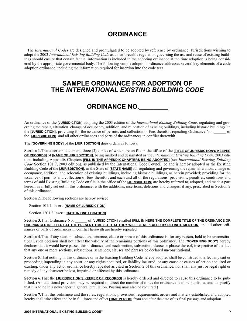
ORDINANCE
The International Codes are designed and promulgated to be adopted by reference by ordinance. Jurisdictions wishing toadopt the 2003 International Existing Building Code as an enforceable regulation governing the use and reuse of existing build-ings should ensure that certain factual information is included in the adopting ordinance at the time adoption is being consid-ered by the appropriate governmental body. The following sample adoption ordinance addresses several key elements of a codeadoption ordinance, including the information required for insertion into the code text.
SAMPLE ORDINANCE FOR ADOPTION OFTHE INTERNATIONAL EXISTING BUILDING CODE
ORDINANCE NO.________
An ordinance of the [JURISDICTION] adopting the 2003 edition of the International Existing Building Code, regulating and gov-erning the repair, alteration, change of occupancy, addition, and relocation of existing buildings, including historic buildings, inthe [JURISDICTION]; providing for the issuance of permits and collection of fees therefor; repealing Ordinance No. ______ ofthe [JURISDICTION] and all other ordinances and parts of the ordinances in conflict therewith.
The [GOVERNING BODY] of the [JURISDICTION] does ordain as follows:
Section 1.That a certain document, three (3) copies of which are on file in the office of the [TITLE OF JURISDICTION�S KEEPEROF RECORDS] of [NAME OF JURISDICTION], being marked and designated as the International Existing Building Code, 2003 edi-tion, including Appendix Chapters [FILL IN THE APPENDIX CHAPTERS BEING ADOPTED] (see International Existing BuildingCode Section 101.7, 2003 edition), as published by the International Code Council, be and is hereby adopted as the ExistingBuilding Code of the [JURISDICTION], in the State of [STATE NAME] for regulating and governing the repair, alteration, change ofoccupancy, addition, and relocation of existing buildings, including historic buildings, as herein provided; providing for theissuance of permits and collection of fees therefor; and each and all of the regulations, provisions, penalties, conditions andterms of said Existing Building Code on file in the office of the [JURISDICTION] are hereby referred to, adopted, and made a parthereof, as if fully set out in this ordinance, with the additions, insertions, deletions and changes, if any, prescribed in Section 2of this ordinance.
Section 2.The following sections are hereby revised:
Section 101.1. Insert: [NAME OF JURISDICTION]
Section 1201.2 Insert: [DATE IN ONE LOCATION]
Section 3.That Ordinance No. ______ of [JURISDICTION] entitled [FILL IN HERE THE COMPLETE TITLE OF THE ORDINANCE ORORDINANCES IN EFFECT AT THE PRESENT TIME SO THAT THEY WILL BE REPEALED BY DEFINITE MENTION] and all other ordi-nances or parts of ordinances in conflict herewith are hereby repealed.
Section 4.That if any section, subsection, sentence, clause or phrase of this ordinance is, for any reason, held to be unconstitu-tional, such decision shall not affect the validity of the remaining portions of this ordinance. The [GOVERNING BODY] herebydeclares that it would have passed this ordinance, and each section, subsection, clause or phrase thereof, irrespective of the factthat any one or more sections, subsections, sentences, clauses and phrases be declared unconstitutional.
Section 5.That nothing in this ordinance or in the Existing Building Code hereby adopted shall be construed to affect any suit orproceeding impending in any court, or any rights acquired, or liability incurred, or any cause or causes of action acquired orexisting, under any act or ordinance hereby repealed as cited in Section 2 of this ordinance; nor shall any just or legal right orremedy of any character be lost, impaired or affected by this ordinance.
Section 6.That the [JURISDICTION�S KEEPER OF RECORDS] is hereby ordered and directed to cause this ordinance to be pub-lished. (An additional provision may be required to direct the number of times the ordinance is to be published and to specifythat it is to be in a newspaper in general circulation. Posting may also be required.)
Section 7.That this ordinance and the rules, regulations, provisions, requirements, orders and matters established and adoptedhereby shall take effect and be in full force and effect [TIME PERIOD] from and after the date of its final passage and adoption.

2003 INTERNATIONAL EXISTING BUILDING CODE®vi
2003 INTERNATIONAL EXISTING BUILDING CODE® vii
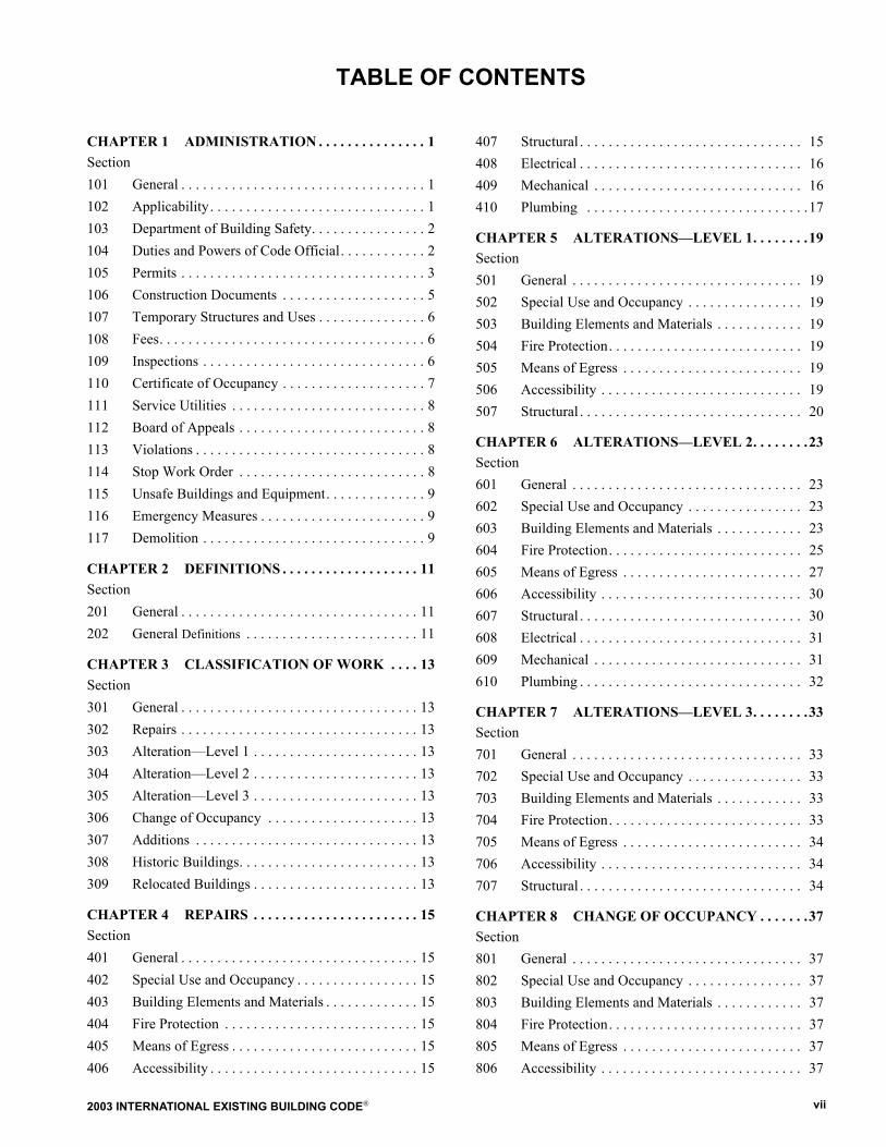
CHAPTER 1 ADMINISTRATION . . . . . . . . . . . . . . . 1Section101 General . . . . . . . . . . . . . . . . . . . . . . . . . . . . . . . . . . 1102 Applicability. . . . . . . . . . . . . . . . . . . . . . . . . . . . . . 1103 Department of Building Safety. . . . . . . . . . . . . . . . 2104 Duties and Powers of Code Official. . . . . . . . . . . . 2105 Permits . . . . . . . . . . . . . . . . . . . . . . . . . . . . . . . . . . 3106 Construction Documents . . . . . . . . . . . . . . . . . . . . 5107 Temporary Structures and Uses . . . . . . . . . . . . . . . 6108 Fees. . . . . . . . . . . . . . . . . . . . . . . . . . . . . . . . . . . . . 6109 Inspections . . . . . . . . . . . . . . . . . . . . . . . . . . . . . . . 6110 Certificate of Occupancy . . . . . . . . . . . . . . . . . . . . 7111 Service Utilities . . . . . . . . . . . . . . . . . . . . . . . . . . . 8112 Board of Appeals . . . . . . . . . . . . . . . . . . . . . . . . . . 8113 Violations . . . . . . . . . . . . . . . . . . . . . . . . . . . . . . . . 8114 Stop Work Order . . . . . . . . . . . . . . . . . . . . . . . . . . 8115 Unsafe Buildings and Equipment. . . . . . . . . . . . . . 9116 Emergency Measures . . . . . . . . . . . . . . . . . . . . . . . 9117 Demolition . . . . . . . . . . . . . . . . . . . . . . . . . . . . . . . 9
CHAPTER 2 DEFINITIONS . . . . . . . . . . . . . . . . . . . 11Section201 General . . . . . . . . . . . . . . . . . . . . . . . . . . . . . . . . . 11202 General Definitions . . . . . . . . . . . . . . . . . . . . . . . . 11
CHAPTER 3 CLASSIFICATION OF WORK . . . . 13Section301 General . . . . . . . . . . . . . . . . . . . . . . . . . . . . . . . . . 13302 Repairs . . . . . . . . . . . . . . . . . . . . . . . . . . . . . . . . . 13303 Alteration�Level 1 . . . . . . . . . . . . . . . . . . . . . . . 13304 Alteration�Level 2 . . . . . . . . . . . . . . . . . . . . . . . 13305 Alteration�Level 3 . . . . . . . . . . . . . . . . . . . . . . . 13306 Change of Occupancy . . . . . . . . . . . . . . . . . . . . . 13307 Additions . . . . . . . . . . . . . . . . . . . . . . . . . . . . . . . 13308 Historic Buildings. . . . . . . . . . . . . . . . . . . . . . . . . 13309 Relocated Buildings . . . . . . . . . . . . . . . . . . . . . . . 13
CHAPTER 4 REPAIRS . . . . . . . . . . . . . . . . . . . . . . . 15Section401 General . . . . . . . . . . . . . . . . . . . . . . . . . . . . . . . . . 15402 Special Use and Occupancy . . . . . . . . . . . . . . . . . 15403 Building Elements and Materials . . . . . . . . . . . . . 15404 Fire Protection . . . . . . . . . . . . . . . . . . . . . . . . . . . 15405 Means of Egress . . . . . . . . . . . . . . . . . . . . . . . . . . 15406 Accessibility . . . . . . . . . . . . . . . . . . . . . . . . . . . . . 15
407 Structural . . . . . . . . . . . . . . . . . . . . . . . . . . . . . . . 15408 Electrical . . . . . . . . . . . . . . . . . . . . . . . . . . . . . . . 16409 Mechanical . . . . . . . . . . . . . . . . . . . . . . . . . . . . . 16410 Plumbing . . . . . . . . . . . . . . . . . . . . . . . . . . . . . . .17
CHAPTER 5 ALTERATIONS�LEVEL 1. . . . . . . .19Section501 General . . . . . . . . . . . . . . . . . . . . . . . . . . . . . . . . 19502 Special Use and Occupancy . . . . . . . . . . . . . . . . 19503 Building Elements and Materials . . . . . . . . . . . . 19504 Fire Protection. . . . . . . . . . . . . . . . . . . . . . . . . . . 19505 Means of Egress . . . . . . . . . . . . . . . . . . . . . . . . . 19506 Accessibility . . . . . . . . . . . . . . . . . . . . . . . . . . . . 19507 Structural . . . . . . . . . . . . . . . . . . . . . . . . . . . . . . . 20
CHAPTER 6 ALTERATIONS�LEVEL 2. . . . . . . .23Section601 General . . . . . . . . . . . . . . . . . . . . . . . . . . . . . . . . 23602 Special Use and Occupancy . . . . . . . . . . . . . . . . 23603 Building Elements and Materials . . . . . . . . . . . . 23604 Fire Protection. . . . . . . . . . . . . . . . . . . . . . . . . . . 25605 Means of Egress . . . . . . . . . . . . . . . . . . . . . . . . . 27606 Accessibility . . . . . . . . . . . . . . . . . . . . . . . . . . . . 30607 Structural . . . . . . . . . . . . . . . . . . . . . . . . . . . . . . . 30608 Electrical . . . . . . . . . . . . . . . . . . . . . . . . . . . . . . . 31609 Mechanical . . . . . . . . . . . . . . . . . . . . . . . . . . . . . 31610 Plumbing . . . . . . . . . . . . . . . . . . . . . . . . . . . . . . . 32
CHAPTER 7 ALTERATIONS�LEVEL 3. . . . . . . .33Section701 General . . . . . . . . . . . . . . . . . . . . . . . . . . . . . . . . 33702 Special Use and Occupancy . . . . . . . . . . . . . . . . 33703 Building Elements and Materials . . . . . . . . . . . . 33704 Fire Protection. . . . . . . . . . . . . . . . . . . . . . . . . . . 33705 Means of Egress . . . . . . . . . . . . . . . . . . . . . . . . . 34706 Accessibility . . . . . . . . . . . . . . . . . . . . . . . . . . . . 34707 Structural . . . . . . . . . . . . . . . . . . . . . . . . . . . . . . . 34
CHAPTER 8 CHANGE OF OCCUPANCY . . . . . . .37Section801 General . . . . . . . . . . . . . . . . . . . . . . . . . . . . . . . . 37802 Special Use and Occupancy . . . . . . . . . . . . . . . . 37803 Building Elements and Materials . . . . . . . . . . . . 37804 Fire Protection. . . . . . . . . . . . . . . . . . . . . . . . . . . 37805 Means of Egress . . . . . . . . . . . . . . . . . . . . . . . . . 37806 Accessibility . . . . . . . . . . . . . . . . . . . . . . . . . . . . 37
TABLE OF CONTENTS
2003 INTERNATIONAL EXISTING BUILDING CODE®viii
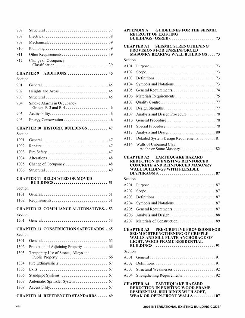
807 Structural . . . . . . . . . . . . . . . . . . . . . . . . . . . . . . . 37808 Electrical . . . . . . . . . . . . . . . . . . . . . . . . . . . . . . . 38809 Mechanical. . . . . . . . . . . . . . . . . . . . . . . . . . . . . . 39810 Plumbing . . . . . . . . . . . . . . . . . . . . . . . . . . . . . . . 39811 Other Requirements . . . . . . . . . . . . . . . . . . . . . . . 39812 Change of Occupancy
Classification . . . . . . . . . . . . . . . . . . . . . . . . . . 39
CHAPTER 9 ADDITIONS . . . . . . . . . . . . . . . . . . . . 45Section901 General. . . . . . . . . . . . . . . . . . . . . . . . . . . . . . . . . 45902 Heights and Areas . . . . . . . . . . . . . . . . . . . . . . . . 45903 Structural . . . . . . . . . . . . . . . . . . . . . . . . . . . . . . . 45904 Smoke Alarms in Occupancy
Groups R-3 and R-4 . . . . . . . . . . . . . . . . . . . . . 46905 Accessibility. . . . . . . . . . . . . . . . . . . . . . . . . . . . . 46906 Energy Conservation . . . . . . . . . . . . . . . . . . . . . . 46
CHAPTER 10 HISTORIC BUILDINGS . . . . . . . . . . 47Section1001 General. . . . . . . . . . . . . . . . . . . . . . . . . . . . . . . . . 471002 Repairs . . . . . . . . . . . . . . . . . . . . . . . . . . . . . . . . . 471003 Fire Safety . . . . . . . . . . . . . . . . . . . . . . . . . . . . . . 471004 Alterations . . . . . . . . . . . . . . . . . . . . . . . . . . . . . . 481005 Change of Occupancy . . . . . . . . . . . . . . . . . . . . . 481006 Structural . . . . . . . . . . . . . . . . . . . . . . . . . . . . . . . 49
CHAPTER 11 RELOCATED OR MOVED BUILDINGS . . . . . . . . . . . . . . . . . . . . . . . . . . . 51
Section1101 General. . . . . . . . . . . . . . . . . . . . . . . . . . . . . . . . . 511102 Requirements . . . . . . . . . . . . . . . . . . . . . . . . . . . . 51
CHAPTER 12 COMPLIANCE ALTERNATIVES. . 53Section1201 General. . . . . . . . . . . . . . . . . . . . . . . . . . . . . . . . . 53
CHAPTER 13 CONSTRUCTION SAFEGUARDS . 65Section1301 General. . . . . . . . . . . . . . . . . . . . . . . . . . . . . . . . . 651302 Protection of Adjoining Property . . . . . . . . . . . . 661303 Temporary Use of Streets, Alleys and
Public Property . . . . . . . . . . . . . . . . . . . . . . . . 661304 Fire Extinguishers . . . . . . . . . . . . . . . . . . . . . . . . 671305 Exits . . . . . . . . . . . . . . . . . . . . . . . . . . . . . . . . . . 671306 Standpipe Systems . . . . . . . . . . . . . . . . . . . . . . . 671307 Automatic Sprinkler System . . . . . . . . . . . . . . . . 671308 Accessibility. . . . . . . . . . . . . . . . . . . . . . . . . . . . . 67
CHAPTER 14 REFERENCED STANDARDS . . . . . 69
APPENDIX A GUIDELINES FOR THE SEISMIC RETROFIT OF EXISTING BUILDINGS (GSREB) . . . . . . . . . . . . . . . . . . . . . . 73
CHAPTER A1 SEISMIC STRENGTHENING PROVISIONS FOR UNREINFORCED MASONRY BEARING WALL BUILDINGS . . . . 73
SectionA101 Purpose . . . . . . . . . . . . . . . . . . . . . . . . . . . . . . . . . 73A102 Scope. . . . . . . . . . . . . . . . . . . . . . . . . . . . . . . . . . . 73A103 Definitions. . . . . . . . . . . . . . . . . . . . . . . . . . . . . . . 73A104 Symbols and Notations . . . . . . . . . . . . . . . . . . . . . 73A105 General Requirements. . . . . . . . . . . . . . . . . . . . . . 74A106 Materials Requirements . . . . . . . . . . . . . . . . . . . . 75A107 Quality Control . . . . . . . . . . . . . . . . . . . . . . . . . . . 77A108 Design Strengths . . . . . . . . . . . . . . . . . . . . . . . . . . 77A109 Analysis and Design Procedure . . . . . . . . . . . . . . 78A110 General Procedure. . . . . . . . . . . . . . . . . . . . . . . . . 78A111 Special Procedure . . . . . . . . . . . . . . . . . . . . . . . . . 78A112 Analysis and Design . . . . . . . . . . . . . . . . . . . . . . . 80A113 Detailed System Design Requirements. . . . . . . . . 81A114 Walls of Unburned Clay,
Adobe or Stone Masonry. . . . . . . . . . . . . . . . . . 82
CHAPTER A2 EARTHQUAKE HAZARD REDUCTION IN EXISTING REINFORCED CONCRETE AND REINFORCED MASONRY WALL BUILDINGS WITH FLEXIBLE DIAPHRAGMS. . . . . . . . . . . . . . . . . . . . . . . . . . . . . 87
SectionA201 Purpose . . . . . . . . . . . . . . . . . . . . . . . . . . . . . . . . . 87A202 Scope. . . . . . . . . . . . . . . . . . . . . . . . . . . . . . . . . . . 87A203 Definitions. . . . . . . . . . . . . . . . . . . . . . . . . . . . . . . 87A204 Symbols and Notations . . . . . . . . . . . . . . . . . . . . . 87A205 General Requirements. . . . . . . . . . . . . . . . . . . . . . 87A206 Analysis and Design . . . . . . . . . . . . . . . . . . . . . . . 88A207 Materials of Construction . . . . . . . . . . . . . . . . . . . 89
CHAPTER A3 PRESCRIPTIVE PROVISIONS FOR SEISMIC STRENGTHENING OF CRIPPLE WALLS AND SILL PLATE ANCHORAGE OF LIGHT, WOOD-FRAME RESIDENTIAL BUILDINGS . . . . . . . . . . . . . . . . . . . . . . . . . . . . . . 91
SectionA301 General . . . . . . . . . . . . . . . . . . . . . . . . . . . . . . . . . 91A302 Definitions. . . . . . . . . . . . . . . . . . . . . . . . . . . . . . . 91A303 Structural Weaknesses . . . . . . . . . . . . . . . . . . . . . 92A304 Strengthening Requirements. . . . . . . . . . . . . . . . . 92
CHAPTER A4 EARTHQUAKE HAZARD REDUCTION IN EXISTING WOOD-FRAME RESIDENTIAL BUILDINGS WITH SOFT, WEAK OR OPEN-FRONT WALLS . . . . . . . . . . 107
2003 INTERNATIONAL EXISTING BUILDING CODE® ix
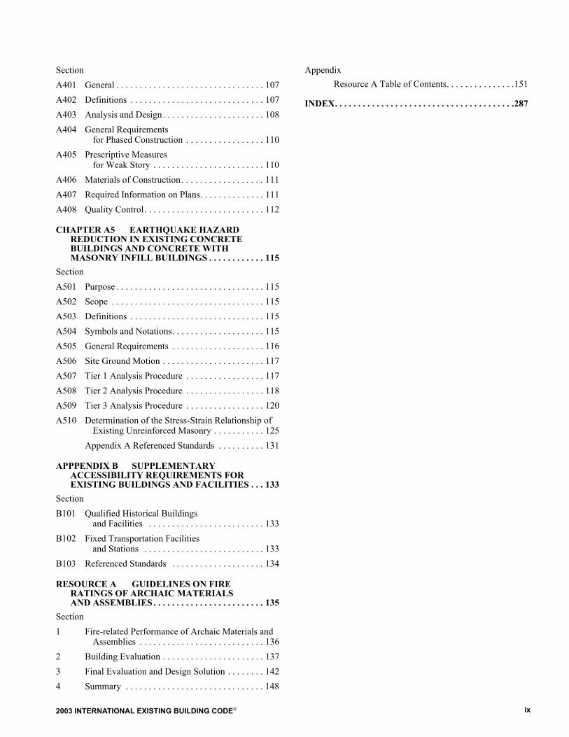
SectionA401 General . . . . . . . . . . . . . . . . . . . . . . . . . . . . . . . . 107A402 Definitions . . . . . . . . . . . . . . . . . . . . . . . . . . . . . 107A403 Analysis and Design. . . . . . . . . . . . . . . . . . . . . . 108A404 General Requirements
for Phased Construction . . . . . . . . . . . . . . . . . 110A405 Prescriptive Measures
for Weak Story . . . . . . . . . . . . . . . . . . . . . . . . 110A406 Materials of Construction. . . . . . . . . . . . . . . . . . 111A407 Required Information on Plans. . . . . . . . . . . . . . 111A408 Quality Control. . . . . . . . . . . . . . . . . . . . . . . . . . 112
CHAPTER A5 EARTHQUAKE HAZARD REDUCTION IN EXISTING CONCRETE BUILDINGS AND CONCRETE WITHMASONRY INFILL BUILDINGS . . . . . . . . . . . . 115
SectionA501 Purpose . . . . . . . . . . . . . . . . . . . . . . . . . . . . . . . . 115A502 Scope . . . . . . . . . . . . . . . . . . . . . . . . . . . . . . . . . 115A503 Definitions . . . . . . . . . . . . . . . . . . . . . . . . . . . . . 115A504 Symbols and Notations. . . . . . . . . . . . . . . . . . . . 115A505 General Requirements . . . . . . . . . . . . . . . . . . . . 116A506 Site Ground Motion . . . . . . . . . . . . . . . . . . . . . . 117A507 Tier 1 Analysis Procedure . . . . . . . . . . . . . . . . . 117A508 Tier 2 Analysis Procedure . . . . . . . . . . . . . . . . . 118A509 Tier 3 Analysis Procedure . . . . . . . . . . . . . . . . . 120A510 Determination of the Stress-Strain Relationship of
Existing Unreinforced Masonry . . . . . . . . . . . 125Appendix A Referenced Standards . . . . . . . . . . 131
APPPENDIX B SUPPLEMENTARY ACCESSIBILITY REQUIREMENTS FOR EXISTING BUILDINGS AND FACILITIES . . . 133
SectionB101 Qualified Historical Buildings
and Facilities . . . . . . . . . . . . . . . . . . . . . . . . . 133B102 Fixed Transportation Facilities
and Stations . . . . . . . . . . . . . . . . . . . . . . . . . . 133B103 Referenced Standards . . . . . . . . . . . . . . . . . . . . 134
RESOURCE A GUIDELINES ON FIRERATINGS OF ARCHAIC MATERIALS AND ASSEMBLIES . . . . . . . . . . . . . . . . . . . . . . . . 135
Section1 Fire-related Performance of Archaic Materials and
Assemblies . . . . . . . . . . . . . . . . . . . . . . . . . . . 1362 Building Evaluation . . . . . . . . . . . . . . . . . . . . . . 1373 Final Evaluation and Design Solution . . . . . . . . 1424 Summary . . . . . . . . . . . . . . . . . . . . . . . . . . . . . . 148
AppendixResource A Table of Contents. . . . . . . . . . . . . . .151
INDEX. . . . . . . . . . . . . . . . . . . . . . . . . . . . . . . . . . . . . . .287

2003 INTERNATIONAL EXISTING BUILDING CODE®x
2003 INTERNATIONAL EXISTING BUILDING CODE® 1
SECTION 101GENERAL
101.1 Title. These regulations shall be known as the Exist-ing Building Code of [NAME OF JURISDICTION], hereinafterreferred to as �this code.�101.2 Scope. The provisions of the International ExistingBuilding Code shall apply to the repair, alteration, change ofoccupancy, addition, and relocation of existing buildings. Abuilding or portion of a building that has not been previouslyoccupied or used for its intended purpose shall comply withthe provisions of the International Building Code for newconstruction. Repairs, alterations, change of occupancy,existing buildings to which additions are made, historicbuildings, and relocated buildings complying with the provi-sions of the International Building Code, InternationalMechanical Code, International Plumbing Code, and Inter-national Residential Code as applicable shall be consideredin compliance with the provisions of this code.101.3 Intent. The purpose of this code is to establish theminimum requirements to safeguard the public health,safety, and welfare insofar as they are affected by the repair,alteration, change of occupancy, addition, and relocation ofexisting buildings.101.4 Existing buildings. The legal occupancy of anybuilding existing on the date of adoption of this code shall bepermitted to continue without change, except as is specifi-cally covered in this code, the International Fire Code, orthe International Property Maintenance Code, or as isdeemed necessary by the code official for the general safetyand welfare of the occupants and the public.101.5 Maintenance. Buildings and parts thereof shall bemaintained in a safe and sanitary condition. The provisionsof the International Property Maintenance Code shall applyto the maintenance of existing buildings and premises;equipment and facilities; light, ventilation, space heating,sanitation, life and fire safety hazards; responsibilities ofowners, operators, and occupants; and occupancy of existingpremises and buildings. All existing devices or safeguardsshall be maintained in all existing buildings. The owner orthe owner�s designated agent shall be responsible for themaintenance of the building. To determine compliance withthis subsection, the code official shall have the authority torequire a building to be reinspected. Except where specifi-cally permitted by this code, the code shall not provide thebasis for removal or abrogation of fire protection and safetysystems and devices in existing buildings.
101.5.1 Work on individual components or por-tions. Where the code official determines that a componentor a portion of a building or structure is in need of repair,strengthening or replacement by provisions of this code,only that specific component or portion shall be required tobe repaired, strengthened, or replaced unless specificallyrequired by other provisions of this code.101.5.2 Design values for existing materials and con-struction. The incorporation of existing materials, con-struction, and detailing into the structural system shall be
permitted when approved by the code official. Minimumquality levels and maximum strength values shall complywith this code.
101.6 Safeguards during construction. All constructionwork covered in this code, including any related demolition,shall comply with the requirements of Chapter 13.101.7 Appendices. The code official is authorized torequire rehabilitation and retrofit of buildings, structures, orindividual structural members in accordance with the appen-dices of this code if such appendices have been individuallyadopted. When any of such appendices is specifically refer-enced in the text of this code, it becomes a part of this codewithout any special adoption by the local jurisdiction.101.8 Correction of violations of other codes. R e p a i r sor alterations mandated by any property, housing, or firesafety maintenance code or mandated by any licensing ruleor ordinance adopted pursuant to law shall conform only tothe requirements of that code, rule, or ordinance and shallnot be required to conform to this code unless the coderequiring such repair or alteration so provides.
SECTION 102APPLICABILITY
102.1 General. Where in any specific case different sec-tions of this code specify different materials, methods ofconstruction, or other requirements, the most restrictive shallgovern. Where there is a conflict between a general require-ment and a specific requirement, the specific requirementshall be applicable.102.2 Other laws. The provisions of this code shall not bedeemed to nullify any provisions of local, state, or federal law.102.3 Application of references. References to chapter orsection numbers or to provisions not specifically identifiedby number shall be construed to refer to such chapter, sec-tion, or provision of this code.102.4 Referenced codes and standards. The codes andstandards referenced in this code shall be considered part ofthe requirements of this code to the prescribed extent of eachsuch reference. Where differences occur between provisionsof this code and referenced codes and standards, the provi-sions of this code shall apply.
102.4.1 Standards and guidelines for structural eval-uation. The code official shall allow structural evaluation,condition assessment, and rehabilitation of buildings, struc-tures, or individual structural members based on this code�sappendix chapters, referenced standards, guidelines, or otherapproved standards and procedures. 102.4.2 Compliance with other codes, standards, andguides. Compliance with the structural provisions of the2000 International Building Code, 2003 International Build-ing Code, 1999 BOCA National Building Code, 1997 Stan-dard Building Code or 1997 Uniform Building Code shall bedeemed exceeding or equivalent to compliance with thestructural provisions of this code.
CHAPTER 1
ADMINISTRATION
2003 INTERNATIONAL EXISTING BUILDING CODE®2
ADMINISTRATION
102.5 Partial invalidity. In the event that any part or pro-vision of this code is held to be illegal or void, this shall nothave the effect of making void or illegal any of the otherparts or provisions.
SECTION 103DEPARTMENT OF BUILDING SAFETY
103.1 Creation of enforcement agency. The Departmentof Building Safety is hereby created, and the official incharge thereof shall be known as the code official.103.2 Appointment. The code official shall be appointedby the chief appointing authority of the jurisdiction.103.3 Deputies. In accordance with the prescribed proce-dures of this jurisdiction and with the concurrence of theappointing authority, the code official shall have the author-ity to appoint a deputy code official, the related technicalofficers, inspectors, plan examiners, and other employees.Such employees shall have powers as delegated by the codeofficial.
SECTION 104DUTIES AND POWERS OF CODE OFFICIAL
104.1 General. The code official is hereby authorized anddirected to enforce the provisions of this code. The code offi-cial shall have the authority to render interpretations of thiscode and to adopt policies and procedures in order to clarifythe application of its provisions. Such interpretations, poli-cies, and procedures shall be in compliance with the intentand purpose of this code. Such policies and procedures shallnot have the effect of waiving requirements specifically pro-vided for in this code.104.2 Applications and permits. The code official shallreceive applications, review construction documents, andissue permits for the repair, alteration, addition, demolition,change of occupancy, and relocation of buildings; inspect thepremises for which such permits have been issued; andenforce compliance with the provisions of this code.
104.2.1 Preliminary meeting. When requested by thepermit applicant, the code official shall meet with the permitapplicant prior to the application for a construction permit todiscuss plans for the proposed work or change of occupancyin order to establish the specific applicability of the provi-sions of this code.
Exception: Repairs and Level 1 alterations.104.2.1.1 Building evaluation. The code official isauthorized to require an existing building to be investi-gated and evaluated by a registered design professionalbased on the circumstances agreed upon at the prelimi-nary meeting to determine the existence of any poten-tial nonconformance with the provisions of this code.
104.3 Notices and orders. The code official shall issue allnecessary notices or orders to ensure compliance with this code.104.4 Inspections. The code official shall make all of therequired inspections, or the code official shall have theauthority to accept reports of inspection by approved agen-
cies or individuals. Reports of such inspections shall be inwriting and be certified by a responsible officer of suchapproved agency or by the responsible individual. The codeofficial is authorized to engage such expert opinion asdeemed necessary to report upon unusual technical issuesthat arise, subject to the approval of the appointing authority.
104.5 Identification. The code official shall carry properidentification when inspecting structures or premises in theperformance of duties under this code.
104.6 Right of entry. Where it is necessary to make aninspection to enforce the provisions of this code, or wherethe code official has reasonable cause to believe that thereexists in a structure or upon a premises a condition which iscontrary to or in violation of this code which makes thestructure or premises unsafe, dangerous, or hazardous, thecode official is authorized to enter the structure or premisesat reasonable times to inspect or to perform the dutiesimposed by this code, provided that if such structure or pre-mises be occupied that credentials be presented to the occu-pant and entry requested. If such structure or premises beunoccupied, the code official shall first make a reasonableeffort to locate the owner or other person having charge orcontrol of the structure or premises and request entry. Ifentry is refused, the code official shall have recourse to theremedies provided by law to secure entry.
104.7 Department records. The code official shall keepofficial records of applications received, permits and certifi-cates issued, fees collected, reports of inspections, andnotices and orders issued. Such records shall be retained inthe official records for the period required for retention ofpublic records.
104.8 Liability. The code official, member of the Board ofAppeals, or employee charged with the enforcement of thiscode, while acting for the jurisdiction in good faith and with-out malice in the discharge of the duties required by thiscode or other pertinent law or ordinance, shall not thereby berendered liable personally and is hereby relieved from per-sonal liability for any damage accruing to persons or prop-erty as a result of any act or by reason of an act or omissionin the discharge of official duties. Any suit instituted againstan officer or employee because of an act performed by thatofficer or employee in the lawful discharge of duties andunder the provisions of this code shall be defended by legalrepresentative of the jurisdiction until the final terminationof the proceedings. The code official or any subordinate shallnot be liable for cost in any action, suit, or proceeding that isinstituted in pursuance of the provisions of this code.
104.9 Approved materials and equipment. M at e r i a l s ,equipment, and devices approved by the code official shallbe constructed and installed in accordance with suchapproval.
104.9.1 Used materials and equipment. The use ofused materials which meet the requirements of this code fornew materials is permitted. Used equipment and devicesshall not be reused unless approved by the code official.
104.10 Modifications. Wherever there are practical diffi-culties involved in carrying out the provisions of this code,
2003 INTERNATIONAL EXISTING BUILDING CODE® 3
ADMINISTRATION
the code official shall have the authority to grant modifica-tions for individual cases upon application of the owner orowner�s representative, provided the code official shall firstfind that special individual reason makes the strict letter ofthis code impractical and the modification is in compliancewith the intent and purpose of this code, and that such modi-fication does not lessen health, accessibility, life and firesafety, or structural requirements. The details of action grant-ing modifications shall be recorded and entered in the files ofthe Department of Building Safety.
104.11 Alternative materials, design and methods ofconstruction, and equipment. The provisions of this codeare not intended to prevent the installation of any material orto prohibit any design or method of construction not specifi-cally prescribed by this code, provided that any such alterna-tive has been approved. An alternative material, design, ormethod of construction shall be approved where the codeofficial finds that the proposed design is satisfactory andcomplies with the intent of the provisions of this code, andthat the material, method, or work offered is, for the purposeintended, at least the equivalent of that prescribed in thiscode in quality, strength, effectiveness, fire resistance, dura-bility, and safety.
104.11.1 Tests. Whenever there is insufficient evidence ofcompliance with the provisions of this code or evidence thata material or method does not conform to the requirements ofthis code, or in order to substantiate claims for alternativematerials or methods, the code official shall have the author-ity to require tests as evidence of compliance to be made atno expense to the jurisdiction. Test methods shall be as speci-fied in this code or by other recognized test standards. In theabsence of recognized and accepted test methods, the codeofficial shall approve the testing procedures. Tests shall beperformed by an approved agency. Reports of such tests shallbe retained by the code official for the period required forretention.
SECTION 105PERMITS
105.1 Required. Any owner or authorized agent whointends to repair, add to, alter, relocate, demolish, or changethe occupancy of a building or to repair, install, add, alter,remove, convert, or replace any electrical, gas, mechanical,or plumbing system, the installation of which is regulated bythis code, or to cause any such work to be done, shall firstmake application to the code official and obtain the requiredpermit.
105.1.1 Annual permit. In lieu of an individual permitfor each alteration to an already approved electrical, gas,mechanical, or plumbing installation, the code official isauthorized to issue an annual permit upon application there-for to any person, firm, or corporation regularly employingone or more qualified trade persons in the building, structure,or on the premises owned or operated by the applicant for thepermit.
105.1.2 Annual permit records. The person to whom anannual permit is issued shall keep a detailed record of alter-
ations made under such annual permit. The code officialshall have access to such records at all times, or such recordsshall be filed with the code official as designated.
105.2 Work exempt from permit. Exemptions from per-mit requirements of this code shall not be deemed to grantauthorization for any work to be done in any manner in vio-lation of the provisions of this code or any other laws or ordi-nances of this jurisdiction. Permits shall not be required forthe following:
Building:1. Sidewalks and driveways not more than 30 inches
(762 mm) above grade and not over any basementor story below and that are not part of an accessibleroute.
2. Painting, papering, tiling, carpeting, cabinets,counter tops, and similar finish work.
3. Temporary motion picture, television, and theaterstage sets and scenery.
4. Shade cloth structures constructed for nursery or agri-cultural purposes, and not including service systems.
5. Window awnings supported by an exterior wall ofGroup R-3 or Group U occupancies.
6. Movable cases, counters, and partitions not over 69inches (1753 mm) in height.
Electrical:Repairs and maintenance: Minor repair work, includ-ing the replacement of lamps or the connection ofapproved portable electrical equipment to approvedpermanently installed receptacles.Radio and television transmitting stations: The pro-visions of this code shall not apply to electrical equip-ment used for radio and television transmissions, butdo apply to equipment and wiring for power supply, theinstallations of towers, and antennas.Temporary testing systems: A permit shall not berequired for the installation of any temporary systemrequired for the testing or servicing of electrical equip-ment or apparatus.
Gas:1. Portable heating appliance.2. Replacement of any minor part that does not alter
approval of equipment or make such equipmentunsafe.
Mechanical:1. Portable heating appliance.2. Portable ventilation equipment.3. Portable cooling unit.4. Steam, hot, or chilled water piping within any heat-
ing or cooling equipment regulated by this code.5. Replacement of any part that does not alter its
approval or make it unsafe.6. Portable evaporative cooler.
2003 INTERNATIONAL EXISTING BUILDING CODE®4
ADMINISTRATION
7. Self-contained refrigeration system containing 10pounds (4.54 kg) or less of refrigerant and actuatedby motors of 1 horsepower (746 W) or less.
Plumbing:
1. The stopping of leaks in drains, water, soil, waste,or vent pipe; provided, however, that if any con-cealed trap, drainpipe, water, soil, waste, or ventpipe becomes defective and it becomes necessary toremove and replace the same with new material,such work shall be considered as new work, and apermit shall be obtained and inspection made asprovided in this code.
2. The clearing of stoppages or the repairing of leaksin pipes, valves, or fixtures, and the removal andreinstallation of water closets, provided such repairsdo not involve or require the replacement or rear-rangement of valves, pipes, or fixtures.
105.2.1 Emergency repairs. Where equipment replace-ments and repairs must be performed in an emergency situa-tion, the permit application shall be submitted within the nextworking business day to the code official.
105.2.2 Repairs. Application or notice to the code officialis not required for ordinary repairs to structures and itemslisted in Section 105.2. Such repairs shall not include the cut-ting away of any wall, partition, or portion thereof, theremoval or cutting of any structural beam or load-bearingsupport, or the removal or change of any required means ofegress or rearrangement of parts of a structure affecting theegress requirements; nor shall ordinary repairs include addi-tion to, alteration of, replacement, or relocation of any stand-pipe, water supply, sewer, drainage, drain leader, gas, soil,waste, vent, or similar piping, electric wiring, or mechanicalor other work affecting public health or general safety.
105.2.3 Public service agencies. A permit shall not berequired for the installation, alteration, or repair of genera-tion, transmission, distribution, or metering or other relatedequipment that is under the ownership and control of publicservice agencies by established right.
105.3 Application for permit. To obtain a permit, theapplicant shall first file an application therefor in writing ona form furnished by the Department of Building Safety forthat purpose. Such application shall:
1. Identify and describe the work in accordance withChapter 3 to be covered by the permit for which appli-cation is made.
2. Describe the land on which the proposed work is to bedone by legal description, street address, or similardescription that will readily identify and definitelylocate the proposed building or work.
3. Indicate the use and occupancy for which the pro-posed work is intended.
4. Be accompanied by construction documents and otherinformation as required in Section 106.3.
5. State the valuation of the proposed work.
6. Be signed by the applicant or the applicant�s autho-rized agent.
7. Give such other data and information as required bythe code official.
105.3.1 Action on application. The code official shallexamine or cause to be examined applications for permitsand amendments thereto within a reasonable time after filing.If the application or the construction documents do not con-form to the requirements of pertinent laws, the code officialshall reject such application in writing, stating the reasonstherefor. If the code official is satisfied that the proposedwork conforms to the requirements of this code and laws andordinances applicable thereto, the code official shall issue apermit therefor as soon as practicable.
105.3.2 Time limitation of application. An applicationfor a permit for any proposed work shall be deemed to havebeen abandoned 180 days after the date of filing, unless suchapplication has been pursued in good faith or a permit hasbeen issued; except that the code official is authorized togrant one or more extensions of time for additional periodsnot exceeding 90 days each. The extension shall be requestedin writing and justifiable cause demonstrated.
105.4 Validity of permit. The issuance or granting of apermit shall not be construed to be a permit for, or anapproval of, any violation of any of the provisions of thiscode or of any other ordinance of the jurisdiction. Permitspresuming to give authority to violate or cancel the provi-sions of this code or other ordinances of the jurisdiction shallnot be valid. The issuance of a permit based on constructiondocuments and other data shall not prevent the code officialfrom requiring the correction of errors in the constructiondocuments and other data. The code official is also autho-rized to prevent occupancy or use of a structure where in vio-lation of this code or of any other ordinances of thisjurisdiction.
105.5 Expiration. Every permit issued shall becomeinvalid unless the work on the site authorized by such permitis commenced within 180 days after its issuance, or if thework authorized on the site by such permit is suspended orabandoned for a period of 180 days after the time the work iscommenced. The code official is authorized to grant, in writ-ing, one or more extensions of time for periods not more than180 days each. The extension shall be requested in writingand justifiable cause demonstrated.
105.6 Suspension or revocation. The code o ff i c i a l i sauthorized to suspend or revoke a permit issued under theprovisions of this code wherever the permit is issued in erroror on the basis of incorrect, inaccurate, or incomplete infor-mation or in violation of any ordinance or regulation or anyof the provisions of this code.
105.7 Placement of permit. The building permit or copyshall be kept on the site of the work until the completion ofthe project.
2003 INTERNATIONAL EXISTING BUILDING CODE® 5
ADMINISTRATION
SECTION 106CONSTRUCTION DOCUMENTS
106.1 Submittal documents. Construction documents spe-cial inspection and structural observation programs, investi-gation and evaluation reports, and other data shall besubmitted in one or more sets with each application for a per-mit. The construction documents shall be prepared by a reg-istered design professional where required by the statutes ofthe jurisdiction in which the project is to be constructed.Where special conditions exist, the code official is autho-rized to require additional construction documents to be pre-pared by a registered design professional.
Exception: The code official is authorized to waive the sub-mission of construction documents and other data notrequired to be prepared by a registered design professional ifit is found that the nature of the work applied for is such thatreviewing of construction documents is not necessary toobtain compliance with this code.106.1.1 Information on construction documents.Construction documents shall be dimensioned and drawnupon suitable material. Electronic media documents are per-mitted to be submitted when approved by the code official.Construction documents shall be of sufficient clarity to indi-cate the location, nature, and extent of the work proposedand show in detail that it will conform to the provisions ofthis code and relevant laws, ordinances, rules, and regula-tions, as determined by the code official. The work areasshall be shown.
106.1.1.1 Fire protection system shop draw-ings. Shop drawings for the fire protection system(s)shall be submitted to indicate conformance with thiscode and the construction documents and shall beapproved prior to the start of system installation. Shopdrawings shall contain all information as required bythe referenced installation standards in Chapter 9 of theInternational Building Code.
106.1.2 Means of egress. The construction documentsfor alterations Level 2, alterations Level 3, additions, andchanges of occupancy shall show in sufficient detail the loca-tion, construction, size, and character of all portions of themeans of egress in compliance with the provisions of thiscode. The construction documents shall designate the num-ber of occupants to be accommodated in every work area ofevery floor and in all affected rooms and spaces.106.1.3 Exterior wall envelope. Construct ion docu-ments for all work affecting the exterior wall envelope shalldescribe the exterior wall envelope in sufficient detail todetermine compliance with this code. The construction docu-ments shall provide details of the exterior wall envelope asrequired, including windows, doors, flashing, intersectionswith dissimilar materials, corners, end details, control joints,intersections at roof, eaves, or parapets, means of drainage,water-resistive membrane, and details around openings.
The construction documents shall include manufac-turer�s installation instructions that provide supportingdocumentation that the proposed penetration and openingdetails described in the construction documents maintainthe wind and weather resistance of the exterior wall enve-
lope. The supporting documentation shall fully describethe exterior wall system which was tested, where applica-ble, as well as the test procedure used.
106.2 Site plan. The construction documents submittedwith the application for permit shall be accompanied by asite plan showing to scale the size and location of new con-struction and existing structures on the site, distances fromlot lines, the established street grades, and the proposed fin-ished grades; and it shall be drawn in accordance with anaccurate boundary line survey. In the case of demolition, thesite plan shall show construction to be demolished and thelocation and size of existing structures and construction thatare to remain on the site or plot. The code official is autho-rized to waive or modify the requirement for a site plan whenthe application for permit is for alteration, repair, or changeof occupancy.
106.3 Examination of documents. The code official shallexamine or cause to be examined the construction documentsand shall ascertain by such examinations whether the con-struction or occupancy indicated and described is in accor-dance with the requirements of this code and other pertinentlaws or ordinances.
106.3.1 Approval of construction documents. Whenthe code official issues a permit, the construction documentsshall be approved in writing or by stamp as �Reviewed forCode Compliance.� One set of construction documents soreviewed shall be retained by the code official. The other setshall be returned to the applicant, shall be kept at the site ofwork, and shall be open to inspection by the code official or aduly authorized representative.
106.3.2 Previous approvals. This code shall not requirechanges in the construction documents, construction, or des-ignated occupancy of a structure for which a lawful permithas been heretofore issued or otherwise lawfully authorized,and the construction of which has been pursued in good faithwithin 180 days after the effective date of this code and hasnot been abandoned.
106.3.3 Phased approval. The code official is authorizedto issue a permit for the construction of foundations or anyother part of a building before the construction documentsfor the whole building or structure have been submitted, pro-vided that adequate information and detailed statements havebeen filed complying with pertinent requirements of thiscode. The holder of such permit for the foundation or otherparts of a building shall proceed at the holder�s own risk withthe building operation and without assurance that a permitfor the entire structure will be granted.
106.3.4 Deferred submittals. For the purposes of thissection, deferred submittals are defined as those portions ofthe design that are not submitted at the time of the applica-tion and that are to be submitted to the code official within aspecified period.
Deferral of any submittal items shall have the priorapproval of the code official. The registered design pro-fessional in responsible charge shall list the deferred sub-mittals on the construction documents for review by thecode official.
2003 INTERNATIONAL EXISTING BUILDING CODE®6
ADMINISTRATION
Submittal documents for deferred submittal items shallbe submitted to the registered design professional inresponsible charge who shall review them and forwardthem to the code official with a notation indicating thatthe deferred submittal documents have been reviewed andthat they have been found to be in general conformance tothe design of the building. The deferred submittal itemsshall not be installed until their design and submittal doc-uments have been approved by the code official.
106.4 Amended construction documents. Work shall beinstalled in accordance with the reviewed construction docu-ments, and any changes made during construction that arenot in compliance with the approved construction documentsshall be resubmitted for approval as an amended set of con-struction documents.106.5 Retention of construction documents. One se t ofapproved construction documents shall be retained by thecode official for a period of not less than the period requiredfor retention of public records.106.6 Design professional in responsible charge. W h e nit is required that documents be prepared by a registereddesign professional, the code official shall be authorized torequire the owner to engage and designate on the buildingpermit application a registered design professional who shallact as the registered design professional in responsiblecharge. If the circumstances require, the owner shall desig-nate a substitute registered design professional in responsiblecharge who shall perform the duties required of the originalregistered design professional in responsible charge. Thecode official shall be notified in writing by the owner if theregistered design professional in responsible charge ischanged or is unable to continue to perform the duties. Theregistered design professional in responsible charge shall beresponsible for reviewing and coordinating submittal docu-ments prepared by others, including phased and deferredsubmittal items, for compatibility with the design of thebuilding. Where structural observation is required, theinspection program shall name the individual or firms whoare to perform structural observation and describe the stagesof construction at which structural observation is to occur.
SECTION 107TEMPORARY STRUCTURES AND USES
107.1 General. The code official is authorized to issue apermit for temporary structures and temporary uses. Suchpermits shall be limited as to time of service but shall not bepermitted for more than 180 days. The code official is autho-rized to grant extensions for demonstrated cause.107.2 Conformance. Temporary structures and uses shallconform to the structural strength, fire safety, means ofegress, accessibility, light, ventilation, and sanitary require-ments of this code as necessary to ensure the public health,safety, and general welfare.107.3 Temporary power. The code official is authorizedto give permission to temporarily supply and use power inpart of an electric installation before such installation hasbeen fully completed and the final certificate of completion
has been issued. The part covered by the temporary certifi-cate shall comply with the requirements specified for tempo-rary lighting, heat, or power in the ICC Electrical Code.107.4 Termination of approval. T h e c o d e o f f i c i a l i sauthorized to terminate such permit for a temporary structureor use and to order the temporary structure or use to be dis-continued.
SECTION 108FEES
108.1 Payment of fees. A permit shall not be valid untilthe fees prescribed by law have been paid. Nor shall anamendment to a permit be released until the additional fee, ifany, has been paid.108.2 Schedule of permit fees. On buildings, electrical,gas, mechanical, and plumbing systems or alterations requir-ing a permit, a fee for each permit shall be paid as required inaccordance with the schedule as established by the applica-ble governing authority.108.3 Building permit valuations. The applicant for apermit shall provide an estimated permit value at time ofapplication. Permit valuations shall include total value ofwork including materials and labor for which the permit isbeing issued, such as electrical, gas, mechanical, plumbingequipment, and permanent systems. If, in the opinion of thecode official, the valuation is underestimated on the applica-tion, the permit shall be denied unless the applicant can showdetailed estimates to meet the approval of the code official.Final building permit valuation shall be set by the code offi-cial. 108.4 Work commencing before permit issuance. A n yperson who commences any work on a building, electrical,gas, mechanical, or plumbing system before obtaining thenecessary permits shall be subject to an additional fee estab-lished by the code official that shall be in addition to therequired permit fees.108.5 Related fees. The payment of the fee for the con-struction, alteration, removal, or demolition of work done inconnection to or concurrently with the work authorized by abuilding permit shall not relieve the applicant or holder ofthe permit from the payment of other fees that are prescribedby law.108.6 Refunds. The code official is authorized to establisha refund policy.
SECTION 109INSPECTIONS
109.1 General. Construction or work for which a permit isrequired shall be subject to inspection by the code official,and such construction or work shall remain accessible andexposed for inspection purposes until approved. Approval asa result of an inspection shall not be construed to be anapproval of a violation of the provisions of this code or ofother ordinances of the jurisdiction. Inspections presuming togive authority to violate or cancel the provisions of this code

2003 INTERNATIONAL EXISTING BUILDING CODE® 7
ADMINISTRATION
or of other ordinances of the jurisdiction shall not be valid. Itshall be the duty of the permit applicant to cause the work toremain accessible and exposed for inspection purposes. Nei-ther the code official nor the jurisdiction shall be liable forexpense entailed in the removal or replacement of any mate-rial required to allow inspection.
109.2 Preliminary inspection. Before issuing a permit,the code official is authorized to examine or cause to beexamined buildings and sites for which an application hasbeen filed.
109.3 Required inspections. The code official, upon noti-fication, shall make the inspections set forth in Sections109.3.1 through 109.3.9.
109.3.1 Footing or foundation inspection. Footing andfoundation inspections shall be made after excavations forfootings are complete and any required reinforcing steel is inplace. For concrete foundations, any required forms shall bein place prior to inspection. Materials for the foundation shallbe on the job, except where concrete is ready-mixed inaccordance with ASTM C 94, the concrete need not be onthe job.
109.3.2 Concrete slab or under-floor inspection. Con-crete slab and under-floor inspections shall be made afterin-slab or under-floor reinforcing steel and building serviceequipment, conduit, piping accessories, and other ancillaryequipment items are in place but before any concrete isplaced or floor sheathing installed, including the sub floor.
109.3.3 Lowest floor elevation. For additions and sub-stantial improvements to existing buildings in flood hazardareas, upon placement of the lowest floor, including base-ment, and prior to further vertical construction, the elevationdocumentation required in the International Building Codeshall be submitted to the code official.
109.3.4 Frame inspection. Framing inspections shall bemade after the roof deck or sheathing, all framing, fire block-ing, and bracing are in place and pipes, chimneys, and ventsto be concealed are complete and the rough electrical,plumbing, heating wires, pipes, and ducts are approved.
109.3.5 Lath or gypsum board inspection. Lath andgypsum board inspections shall be made after lathing andgypsum board, interior and exterior, is in place but beforeany plastering is applied or before gypsum board joints andfasteners are taped and finished.
Exception: Gypsum board that is not part of afire-resistance-rated assembly or a shear assembly.
109.3.6 Fire-resistant penetrations. Protection of jointsand penetrations in fire-resistance-rated assemblies shall notbe concealed from view until inspected and approved.
109.3.7 Other inspections. In addition to the inspectionsspecified above, the code official is authorized to make orrequire other inspections of any construction work to ascer-tain compliance with the provisions of this code and otherlaws that are enforced by the Department of Building Safety.
109.3.8 Special inspections. Special inspections shall berequired in accordance with the International Building Code.
109.3.9 Final inspection. The final inspection shall bemade after all work required by the building permit is com-pleted.
109.4 Inspection agencies. The code official is authorizedto accept reports of approved inspection agencies, providedsuch agencies satisfy the requirements as to qualificationsand reliability. 109.5 Inspection requests. I t shal l be the duty of theholder of the building permit or their duly authorized agentto notify the code official when work is ready for inspection.It shall be the duty of the permit holder to provide access toand means for any inspections of such work that are requiredby this code.109.6 Approval required. Work shall not be done beyondthe point indicated in each successive inspection without firstobtaining the approval of the code official. The code official,upon notification, shall make the requested inspections andshall either indicate the portion of the construction that is sat-isfactory as completed or shall notify the permit holder or anagent of the permit holder wherein the same fails to complywith this code. Any portions that do not comply shall be cor-rected and such portion shall not be covered or concealeduntil authorized by the code official.
SECTION 110CERTIFICATE OF OCCUPANCY
110.1 Altered area use and occupancy classificationchange. No altered area of a building and no relocatedbuilding shall be used or occupied, and no change in theexisting occupancy classification of a building or portionthereof shall be made until the code official has issued a cer-tificate of occupancy therefor as provided herein. Issuance ofa certificate of occupancy shall not be construed as anapproval of a violation of the provisions of this code or ofother ordinances of the jurisdiction.110.2 Certificate issued. After the code official inspectsthe building and finds no violations of the provisions of thiscode or other laws that are enforced by the Department ofBuilding Safety, the code official shall issue a certificate ofoccupancy that shall contain the following:
1. The building permit number.2. The address of the structure.3. The name and address of the owner.4. A description of that portion of the structure for which
the certificate is issued.5. A statement that the described portion of the structure
has been inspected for compliance with the require-ments of this code for the occupancy and division ofoccupancy and the use for which the proposed occu-pancy is classified.
6. The name of the code official.7. The edition of the code under which the permit was
issued.8. The use and occupancy in accordance with the provi-
sions of the International Building Code.
2003 INTERNATIONAL EXISTING BUILDING CODE®8
ADMINISTRATION
9. The type of construction as defined in the Interna-tional Building Code.
10. The design occupant load and any impact the alter-ation has on the design occupant load of the area notwithin the scope of the work.
11. If an automatic sprinkler system is provided, whetherthe sprinkler system is required.
12. Any special stipulations and conditions of the build-ing permit.
110.3 Temporary occupancy. The code official is autho-rized to issue a temporary certificate of occupancy before thecompletion of the entire work covered by the permit, pro-vided that such portion or portions shall be occupied safely.The code official shall set a time period during which thetemporary certificate of occupancy is valid.
110.4 Revocation. The code official is authorized to, inwriting, suspend or revoke a certificate of occupancy or com-pletion issued under the provisions of this code wherever thecertificate is issued in error or on the basis of incorrect infor-mation supplied, or where it is determined that the buildingor structure or portion thereof is in violation of any ordinanceor regulation or any of the provisions of this code.
SECTION 111SERVICE UTILITIES
111.1 Connection of service utilities. No pe r son sha l lmake connections from a utility, source of energy, fuel, orpower to any building or system that is regulated by thiscode for which a permit is required, until approved by thecode official.
111.2 Temporary connection. The code official shall havethe authority to authorize the temporary connection of thebuilding or system to the utility source of energy, fuel, orpower.
111.3 Authority to disconnect service utilities. The codeofficial shall have the authority to authorize disconnection ofutility service to the building, structure, or system regulatedby this code and the codes referenced in case of emergencywhere necessary to eliminate an immediate hazard to life orproperty. The code official shall notify the serving utilityand, wherever possible, the owner and occupant of the build-ing, structure, or service system of the decision to disconnectprior to taking such action. If not notified prior to discon-necting, the owner or occupant of the building, structure, orservice system shall be notified in writing, as soon as practi-cal thereafter.
SECTION 112BOARD OF APPEALS
112.1 General. In order to hear and decide appeals oforders, decisions, or determinations made by the code offi-cial relative to the application and interpretation of this code,there shall be and is hereby created a board of appeals. Theboard of appeals shall be appointed by the governing body
and shall hold office at its pleasure. The board shall adoptrules of procedure for conducting its business.112.2 Limitations on authority. An application for appealshall be based on a claim that the true intent of this code orthe rules legally adopted thereunder have been incorrectlyinterpreted, the provisions of this code do not fully apply, oran equally good or better form of construction is proposed.The board shall have no authority to waive requirements ofthis code.112.3 Qualifications. The board of appeals shall consist ofmembers who are qualified by experience and training topass on matters pertaining to building construction and arenot employees of the jurisdiction.
SECTION 113VIOLATIONS
113.1 Unlawful acts. It shall be unlawful for any person,firm, or corporation to repair, alter, extend, add, move,remove, demolish, or change the occupancy of any buildingor equipment regulated by this code or cause same to bedone in conflict with or in violation of any of the provisionsof this code.113.2 Notice of violation. The code official is authorizedto serve a notice of violation or order on the person responsi-ble for the repair, alteration, extension, addition, moving,removal, demolition, or change in the occupancy of a build-ing in violation of the provisions of this code or in violationof a permit or certificate issued under the provisions of thiscode. Such order shall direct the discontinuance of the illegalaction or condition and the abatement of the violation.113.3 Prosecution of violation. If the notice of violation isnot complied with promptly, the code official is authorized torequest the legal counsel of the jurisdiction to institute theappropriate proceeding at law or in equity to restrain, correct,or abate such violation or to require the removal or termina-tion of the unlawful occupancy of the building or structure inviolation of the provisions of this code or of the order ordirection made pursuant thereto.113.4 Violation penalties. Any person who violates a pro-vision of this code or fails to comply with any of the require-ments thereof or who repairs or alters or changes theoccupancy of a building or structure in violation of theapproved construction documents or directive of the codeofficial or of a permit or certificate issued under the provi-sions of this code shall be subject to penalties as prescribedby law.
SECTION 114STOP WORK ORDER
114.1 Authority. Whenever the code official finds anywork regulated by this code being performed in a mannercontrary to the provisions of this code or in a dangerous orunsafe manner, the code official is authorized to issue a stopwork order. 114.2 Issuance. The stop work order shall be in writingand shall be given to the owner of the property involved or to
2003 INTERNATIONAL EXISTING BUILDING CODE® 9
ADMINISTRATION
the owner�s agent, or to the person doing the work. Uponissuance of a stop work order, the cited work shall immedi-ately cease. The stop work order shall state the reason for theorder and the conditions under which the cited work will bepermitted to resume.
114.3 Unlawful continuance. Any person who shall con-tinue any work after having been served with a stop workorder, except such work as that person is directed to performto remove a violation or unsafe condition, shall be subject topenalties as prescribed by law.
SECTION 115UNSAFE BUILDINGS AND EQUIPMENT
115.1 Conditions. Buildings or existing equipment thatare or hereafter become unsafe, insanitary, or deficientbecause of inadequate means of egress facilities, inadequatelight and ventilation, or which constitute a fire hazard, or inwhich the structure or individual structural members exceedthe limits established by the definition of Dangerous inChapter 2, or that involve illegal or improper occupancy orinadequate maintenance, shall be deemed an unsafe condi-tion. Unsafe buildings shall be taken down and removed ormade safe, as the code official deems necessary and as pro-vided for in this code. A vacant structure that is not securedagainst entry shall be deemed unsafe.
115.2 Record. The code official shall cause a report to befiled on an unsafe condition. The report shall state the occu-pancy of the structure and the nature of the unsafe condition.
115.3 Notice. If an unsafe condition is found, the code offi-cial shall serve on the owner, agent, or person in control ofthe structure a written notice that describes the conditiondeemed unsafe and specifies the required repairs or improve-ments to be made to abate the unsafe condition, or thatrequires the unsafe building to be demolished within a stipu-lated time. Such notice shall require the person thus notifiedto declare immediately to the code official acceptance orrejection of the terms of the order.
115.4 Method of service. Such notice shall be deemedproperly served if a copy thereof is delivered to the ownerpersonally; sent by certified or registered mail addressed tothe owner at the last known address with the return receiptrequested; or delivered in any other manner as prescribed bylocal law. If the certified or registered letter is returned show-ing that the letter was not delivered, a copy thereof shall beposted in a conspicuous place in or about the structureaffected by such notice. Service of such notice in the forego-ing manner upon the owner�s agent or upon the personresponsible for the structure shall constitute service of noticeupon the owner.
115.5 Restoration. The building or equipment determinedto be unsafe by the code official is permitted to be restored toa safe condition. To the extent that repairs, alterations, oradditions are made or a change of occupancy occurs duringthe restoration of the building, such repairs, alterations, addi-tions, or change of occupancy shall comply with the require-ments of this code.
SECTION 116EMERGENCY MEASURES
116.1 Imminent danger. When, in the opinion of the codeofficial, there is imminent danger of failure or collapse of abuilding that endangers life, or when any building or part ofa building has fallen and life is endangered by the occupationof the building, or when there is actual or potential danger tothe building occupants or those in the proximity of any struc-ture because of explosives, explosive fumes or vapors, or thepresence of toxic fumes, gases, or materials, or operation ofdefective or dangerous equipment, the code official is herebyauthorized and empowered to order and require the occu-pants to vacate the premises forthwith. The code officialshall cause to be posted at each entrance to such structure anotice reading as follows: �This Structure Is Unsafe and ItsOccupancy Has Been Prohibited by the Code Official.� Itshall be unlawful for any person to enter such structureexcept for the purpose of securing the structure, making therequired repairs, removing the hazardous condition, or ofdemolishing the same.116.2 Temporary safeguards. Notwithstanding other pro-visions of this code, whenever, in the opinion of the codeofficial, there is imminent danger due to an unsafe condition,the code official shall order the necessary work to be done,including the boarding up of openings, to render such struc-ture temporarily safe whether or not the legal procedureherein described has been instituted; and shall cause suchother action to be taken as the code official deems necessaryto meet such emergency.116.3 Closing streets. When necessary for public safety,the code official shall temporarily close structures and closeor order the authority having jurisdiction to close sidewalks,streets, public ways, and places adjacent to unsafe structures,and prohibit the same from being utilized.116.4 Emergency repairs. For the purposes of this sec-tion, the code official shall employ the necessary labor andmaterials to perform the required work as expeditiously aspossible.116.5 Costs of emergency repairs. Costs incurred in theperformance of emergency work shall be paid by the juris-diction. The legal counsel of the jurisdiction shall instituteappropriate action against the owner of the premises wherethe unsafe structure is or was located for the recovery of suchcosts.116.6 Hearing. Any person ordered to take emergencymeasures shall comply with such order forthwith. Anyaffected person shall thereafter, upon petition directed to theappeals board, be afforded a hearing as described in thiscode.
SECTION 117DEMOLITION
117.1 General. The code official shall order the owner ofany premises upon which is located any structure that in thecode official�s judgment is so old, dilapidated, or has becomeso out of repair as to be dangerous, unsafe, insanitary, or oth-erwise unfit for human habitation or occupancy, and such

2003 INTERNATIONAL EXISTING BUILDING CODE®10
ADMINISTRATION
that it is unreasonable to repair the structure, to demolish andremove such structure; or if such structure is capable ofbeing made safe by repairs, to repair and make safe and sani-tary or to demolish and remove at the owner�s option; orwhere there has been a cessation of normal construction ofany structure for a period of more than two years, to demol-ish and remove such structure.117.2 Notices and orders. All notices and orders shallcomply with Section 113.117.3 Failure to comply. If the owner of a premises failsto comply with a demolition order within the time pre-scribed, the code official shall cause the structure to bedemolished and removed, either through an available publicagency or by contract or arrangement with private persons,and the cost of such demolition and removal shall be chargedagainst the real estate upon which the structure is located andshall be a lien upon such real estate.117.4 Salvage materials. When any structure has beenordered demolished and removed, the governing body orother designated officer under said contract or arrangementaforesaid shall have the right to sell the salvage and valuablematerials at the highest price obtainable. The net proceeds ofsuch sale, after deducting the expenses of such demolitionand removal, shall be promptly remitted with a report of suchsale or transaction, including the items of expense and theamounts deducted, for the person who is entitled thereto,subject to any order of a court. If such a surplus does notremain to be turned over, the report shall so state.
2003 INTERNATIONAL EXISTING BUILDING CODE® 11
SECTION 201GENERAL
201.1 Scope. Unless otherwise expressly stated, the fol-lowing words and terms shall, for the purposes of this code,have the meanings shown in this chapter. 201.2 Interchangeability. Words used in the present tenseinclude the future; words stated in the masculine genderinclude the feminine and neuter; the singular numberincludes the plural and the plural, the singular. 201.3 Terms defined in other codes. Where terms are notdefined in this code and are defined in the other Interna-tional Codes, such terms shall have the meanings ascribed tothem as in those codes. 201.4 Terms not defined. Where terms are not definedthrough the methods authorized by this chapter, such termsshall have ordinarily accepted meanings such as the contextimplies.
SECTION 202GENERAL DEFINITIONS
ADDITION. An extension or increase in floor area, numberof stories, or height of a building or structure. ALTERATION. Any construction or renovation to anexisting structure other than repair or addition. Alterationsare classified as Level 1, Level 2, and Level 3.CHANGE OF OCCUPANCY. A change in the purpose orlevel of activity within a building that involves a change inapplication of the requirements of this code.DANGEROUS. Any building or structure or any individualmember with any of the structural conditions or defectsdescribed below shall be deemed dangerous:
1. The stress in a member or portion thereof due to allfactored dead and live loads is more than one and onethird the nominal strength allowed in the InternationalBuilding Code for new buildings of similar structure,purpose, or location.
2. Any portion, member, or appurtenance thereof likelyto fail, or to become detached or dislodged, or to col-lapse and thereby injure persons.
3. Any portion of a building, or any member, appurte-nance, or ornamentation on the exterior thereof is notof sufficient strength or stability, or is not anchored,attached, or fastened in place so as to be capable ofresisting a wind pressure of two thirds of that specifiedin the International Building Code for new buildingsof similar structure, purpose, or location withoutexceeding the nominal strength permitted in the Inter-national Building Code for such buildings.
4. The building, or any portion thereof, is likely to col-lapse partially or completely because of dilapidation,deterioration or decay; construction in violation of theInternational Building Code; the removal, movementor instability of any portion of the ground necessary
for the purpose of supporting such building; the deteri-oration, decay or inadequacy of its foundation; damagedue to fire, earthquake, wind or flood; or any othersimilar cause.
5. The exterior walls or other vertical structural memberslist, lean, or buckle to such an extent that a plumb linepassing through the center of gravity does not fallinside the middle one third of the base.
EQUIPMENT OR FIXTURE. Any plumbing, heating,electrical, ventilating, air conditioning, refrigerating, and fireprotection equipment, and elevators, dumb waiters, escala-tors, boilers, pressure vessels and other mechanical facilitiesor installations that are related to building services. Equip-ment or fixture shall not include manufacturing, production,or process equipment, but shall include connections frombuilding service to process equipment.EXISTING BUILDING. A building erected prior to thedate of adoption of the appropriate code, or one for which alegal building permit has been issued.[B] FLOOD HAZARD AREA. The greater of the follow-ing two areas:
1. The area within a flood plain subject to a 1-percent orgreater chance of flooding in any year.
2. The area designated as a flood hazard area on a com-munity�s flood hazard map, or otherwise legally desig-nated.
HISTORIC BUILDING. Any building or structure that islisted in the State or National Register of Historic Places;designated as a historic property under local or state desig-nation law or survey; certified as a contributing resourcewithin a National Register listed or locally designated his-toric district; or with an opinion or certification that theproperty is eligible to be listed on the National or State Reg-isters of Historic Places either individually or as a contribut-ing building to a historic district by the State HistoricPreservation Officer or the Keeper of the National Registerof Historic Places. LOAD-BEARING ELEMENT. Any column, girder, beam,joist, truss, rafter, wall, floor or roof sheathing that supportsany vertical load in addition to its own weight or any lateralload.REHABILITATION. Any work, as described by the cate-gories of work defined herein, undertaken in an existingbuilding.REHABILITATION, SEISMIC. Wo r k c o n d u c t e d t oimprove the seismic lateral force resistance of an existingbuilding.REPAIR. The restoration to good or sound condition of anypart of an existing building for the purpose of its mainte-nance.SEISMIC LOADING. The assumed forces prescribedherein, related to the response of the structure to earthquakemotions, to be used in the analysis and design of the struc-ture and its components.
CHAPTER 2
DEFINITIONS

2003 INTERNATIONAL EXISTING BUILDING CODE®12
DEFINITIONS
[B] SUBSTANTIAL DAMAGE. For the purpose of deter-mining compliance with the flood provisions of this code,damage of any origin sustained by a structure whereby thecost of restoring the structure to its before-damaged condi-tion would equal or exceed 50 percent of the market value ofthe structure before the damage occurred.
[B] SUBSTANTIAL IMPROVEMENT. For the purposeof determining compliance with the flood provisions of thiscode, any repair, alteration, addition, or improvement of abuilding or structure, the cost of which equals or exceeds 50percent of the market value of the structure before theimprovement or repair is started. If the structure has sus-tained substantial damage, any repairs are considered sub-stantial improvement regardless of the actual repair workperformed. The term does not, however, include either:
1. Any project for improvement of a building required tocorrect existing health, sanitary, or safety code viola-tions identified by the code official and that is the min-imum necessary to assure safe living conditions, or
2. Any alteration of a historic structure, provided that thealteration will not preclude the structure�s continueddesignation as a historic structure.
SUBSTANTIAL STRUCTURAL DAMAGE. A conditionwhere:
1. In any story, the vertical elements of the lateral-force-resisting system, in any direction and taken as a whole,have suffered damage such that the lateral load-carry-ing capacity has been reduced by more than 20 percentfrom its pre-damaged condition, or
2. The vertical load-carrying components supportingmore than 30 percent of the structure�s floor or roofarea have suffered a reduction in vertical load-carryingcapacity to below 75 percent of the InternationalBuilding Code required strength levels calculated byeither the strength or allowable stress method.
TECHNICALLY INFEASIBLE. An alteration of a build-ing or a facility that has little likelihood of being accom-plished because the existing structural conditions require theremoval or alteration of a load-bearing member that is anessential part of the structural frame or because other exist-ing physical or site constraints prohibit modification or addi-tion of elements, spaces, or features that are in full and strictcompliance with the minimum requirements for new con-struction and that are necessary to provide accessibility.
[B] UNSAFE BUILDINGS OR EQUIPMENT. Buildingsor existing equipment that is insanitary or deficient becauseof inadequate means of egress facilities, inadequate light andventilation, or that constitutes a fire hazard, or that is other-wise dangerous to human life or the public welfare or thatinvolves illegal or improper occupancy or inadequate main-tenance, shall be deemed an unsafe condition.
WORK AREA. That portion or portions of a building con-sisting of all reconfigured spaces as indicated on the con-struction documents. Work area excludes other portions ofthe building where incidental work entailed by the intended
work must be performed and portions of the building wherework not initially intended by the owner is specificallyrequired by this code.
2003 INTERNATIONAL EXISTING BUILDING CODE® 13
SECTION 301GENERAL
301.1 Scope. The work performed on an existing buildingshall be classified in accordance with this chapter. 301.2 Work area. The work area, as defined in Chapter 2,shall be identified on the construction documents.301.3 Compliance alternatives. The provisions of Chap-ters 4 through 10 are not applicable where the building com-plies with Chapter 12.301.4 Occupancy and use. When determining the appro-priate application of the referenced sections of this code, theoccupancy and use of a building shall be determined in accor-dance with Chapter 3 of the International Building Code.
SECTION 302REPAIRS
302.1 Scope. Repairs, as defined in Chapter 2, include thepatching or restoration of materials, elements, equipment, orfixtures for the purpose of maintaining such materials, ele-ments, equipment, or fixtures in good or sound condition. 302.2 Application. Repairs shall comply with the provi-sions of Chapter 4.
SECTION 303ALTERATION�LEVEL 1
303.1 Scope. Level 1 alterations include the removal andreplacement or the covering of existing materials, elements,equipment, or fixtures using new materials, elements, equip-ment, or fixtures that serve the same purpose.303.2 Application. Level 1 alterations shall comply withthe provisions of Chapter 5.
SECTION 304ALTERATION�LEVEL 2
304.1 Scope. Level 2 alterations include the reconfigura-tion of space, the addition or elimination of any door or win-dow, the reconfiguration or extension of any system, or theinstallation of any additional equipment.304.2 Application. Level 2 alterations shall comply withthe provisions of Chapter 5 for Level 1 alterations as well asthe provisions of Chapter 6.
SECTION 305ALTERATION�LEVEL 3
305.1 Scope. Level 3 alterations apply where the workarea exceeds 50 percent of the aggregate area of the build-ing.305.2 Application. Level 3 alterations shall comply withthe provisions of Chapters 5 and 6 for Level 1 and 2 alter-ations, respectively, as well as the provisions of Chapter 7.
SECTION 306CHANGE OF OCCUPANCY
306.1 Scope. Change of occupancy provisions applywhere the activity is classified as a change of occupancy asdefined in Chapter 2.306.2 Application. Changes of occupancy shall complywith the provisions of Chapter 8.
SECTION 307ADDITIONS
307.1 Scope. Provisions for additions shall apply wherework is classified as an addition as defined in Chapter 2.307.2 Application. Additions to existing buildings shallcomply with the provisions of Chapter 9.
SECTION 308HISTORIC BUILDINGS
308.1 Scope. Historic buildings provisions shall apply tobuildings classified as historic as defined in Chapter 2.308.2 Application. Except as specifically provided for inChapter 10, historic buildings shall comply with applicableprovisions of this code for the type of work being per-formed.
SECTION 309RELOCATED BUILDINGS
309.1 Scope. Relocated buildings provisions shall apply torelocated or moved buildings.309.2 Application. Relocated buildings shall comply withthe provisions of Chapter 11.
CHAPTER 3
CLASSIFICATION OF WORK

2003 INTERNATIONAL EXISTING BUILDING CODE®14
CLASSIFICATION OF WORK
2003 INTERNATIONAL EXISTING BUILDING CODE® 15
SECTION 401GENERAL
401.1 Scope. Repairs as described in Section 302 shallcomply with the requirements of this chapter. Repairs to his-toric buildings shall comply with this chapter, except asmodified in Chapter 10.401.2 Permitted materials. Except as otherwise requiredherein, work shall be done using materials permitted by theapplicable code for new construction or using like materialssuch that no hazard to life, health or property is created.401.3 Conformance. The work shall not make the build-ing less conforming to the building, plumbing, mechanical,electrical or fire codes of the jurisdiction, or to alternativematerials, design and methods of construction, or any previ-ously approved plans, modifications, alternative methods, orcompliance alternatives, than it was before the repair wasundertaken.401.4 Flood hazard areas. In flood hazard areas, repairsthat constitute substantial improvement shall require that thebuilding comply with Section 1612 of the InternationalBuilding Code.
SECTION 402SPECIAL USE AND OCCUPANCY
402.1 General. Repair of buildings classified as specialuse or occupancy as described in the International BuildingCode shall comply with the requirements of this chapter.
SECTION 403BUILDING ELEMENTS AND MATERIALS
403.1 Hazardous materials. Hazardous materials that areno longer permitted, such as asbestos and lead-based paint,shall not be used.403.2 Glazing in hazardous locations. Replacementglazing in hazardous locations shall comply with the safetyglazing requirements of the International Building Code orInternational Residential Code as applicable.
Exception: Glass block walls, louvered windows, andjalousies repaired with like materials.
SECTION 404FIRE PROTECTION
404.1 General. Repairs shall be done in a manner thatmaintains the level of fire protection provided.
SECTION 405MEANS OF EGRESS
405.1 General. Repairs shall be done in a manner thatmaintains the level of protection provided for the means ofegress.
SECTION 406ACCESSIBILITY
406.1 General. Repairs shall be done in a manner thatmaintains the level of accessibility provided.
SECTION 407STRUCTURAL
407.1 General. Repairs of structural elements shall com-ply with this section.
407.1.1 Seismic evaluation and design. Seismic eval-uation and design of an existing building and its compo-nents shall be based on the assumed forces related to theresponse of the structure to earthquake motions.
407.1.1.1 Evaluation and design procedures. Theseismic evaluation and design of an existing buildingshall be based on the procedures specified in the Inter-national Building Code, Appendix A of this code(GSREB), ASCE 31 or FEMA 356.407.1.1.2 IBC level seismic forces. When seismicforces are required to meet the International BuildingCode level, they shall be based on 100 percent of thevalues in the International Building Code or FEMA356. Where FEMA 356 is used, the FEMA 356 BasicSafety Objective (BSO) shall be used for buildings inSeismic Use Group I. For buildings in other SeismicUse Groups the applicable FEMA 356 performancelevels shown in Table 407.1.1.2 for BSE-1 and BSE-2Earthquake Hazard Levels shall be used.
TABLE 407.1.1.2IBC SEISMIC USE GROUP EQUIVALENTS TO FEMA 356 AND
ASCE 31 PERFORMANCE LEVELSa
a. The charging provisions for Seismic Use Group equivalents to ASCE 31and FEMA 356 BSE-1 for reduced International Building Code levelseismic forces are located in Section 407.1.1.3.
b. Performance Levels for Seismic Use Group III shall be taken as halfwaybetween the performance levels specified for Seismic Use Groups II andIV.
407.1.1.3 Reduced IBC level seismic forces.When seismic forces are permitted to meet reducedInternational Building Code levels, they shall be basedon 75 percent of the assumed forces prescribed in the
SEISMIC USE GROUP
(BASED ON IBC TABLE 1604.5)
PERFORMANCE LEVELS OF ASCE 31 AND FEMA 356 BSE-
1 EARTHQUAKE HAZARD LEVEL
PERFORMANCE LEVELS OF FEMA 356 BSE-2 EARTH-QUAKE HAZARD
LEVEL
I Life Safety (LS) CollapsePrevention (CP)
II Life Safety (LS) CollapsePrevention (CP)
III Note b Note b
IV ImmediateOccupancy (IO) Life Safety (LS)
CHAPTER 4
REPAIRS
2003 INTERNATIONAL EXISTING BUILDING CODE®16
REPAIRS
International Building Code, applicable chapters inAppendix A of this code (GSREB), the applicable per-formance level of ASCE 31 as shown in Table407.1.1.2, or the applicable performance level for theBSE-1 Earthquake Hazard Level of FEMA 356 shownin Table 407.1.1.2.
407.1.2 Wind design. Wind design of existing build-ings shall be based on the procedures specified in theInternational Building Code or International ResidentialCode as applicable.
407.2 Reduction of strength. Repairs shall not reduce thestructural strength or stability of the building, structure, orany individual member thereof.
Exception: Such reduction shall be allowed provided thecapacity is not reduced to below the International Build-ing Code levels.
407.3 Damaged buildings. Damaged buildings shall berepaired in accordance with this section.
407.3.1 New structural frame members. New s t ruc -tural frame members used in the repair of damaged build-ings, including anchorage and connections, shall complywith the International Building Code.
Exception: For the design of new structural framemembers connected to existing structural frame mem-bers, the use of reduced International Building Codelevel seismic forces as specified in Section 407.1.1.3shall be permitted.
407.3.2 Substantial structural damage. Buildings thathave sustained substantial structural damage shall complywith this section.
407.3.2.1 Engineering evaluation and analysis. Anengineering evaluation and analysis that establishes thestructural adequacy of the damaged building shall beprepared by a registered design professional and sub-mitted to the code official. The evaluation and analysismay assume that all damaged structural elements andsystems have their original strength and stiffness. Theseismic analysis shall be based on one of the proce-dures specified in Section 407.1.1.
407.3.2.1.1 Extent of repair. The evaluation andanalysis shall demonstrate that the building, oncerepaired, complies with the wind and seismic provi-sions of the International Building Code.
Exception: The seismic design level for therepair design shall be the higher of the BuildingCode in effect at the time of original constructionor reduced International Building Code levelseismic forces as specified in Section 407.1.1.3.
407.3.3 Below substantial s tructural damage.Repairs to buildings damaged to a level below the sub-stantial structural damage level as defined in Section 202shall be allowed to be made with the materials, methods,and strengths in existence prior to the damage unless suchexisting conditions are dangerous as defined in Chapter 2.New structural frame members as defined in Chapter 2shall comply with Section 407.3.1.
407.3.4 Other uncovered structural elements. Wherein the course of conducting repairs other uncovered struc-tural elements are found to be unsound or otherwise struc-turally deficient, such elements shall be made to conformto the requirements of Section 407.3.2.1.1.
407.3.5 Flood hazard areas. In flood hazard areas,damaged buildings that sustain substantial damage shallbe brought into compliance with Section 1612 of theInternational Building Code.
SECTION 408ELECTRICAL
408.1 Material. Existing electrical wiring and equipmentundergoing repair shall be allowed to be repaired or replacedwith like material.
Exceptions:
1. Replacement of electrical receptacles shall complywith the applicable requirements of Section406.3(D) of NFPA 70.
2. Plug fuses of the Edison-base type shall be used forreplacements only where there is no evidence ofover fusing or tampering per applicable require-ments of Section 240.51(B) of NFPA 70.
3. For replacement of nongrounding-type receptacleswith grounding-type receptacles and for branch cir-cuits that do not have an equipment grounding con-ductor in the branch circuitry, the groundingconductor of a grounding-type receptacle outletshall be permitted to be grounded to any accessiblepoint on the grounding electrode system, or to anyaccessible point on the grounding electrode conduc-tor in accordance with Section 250.130(C) of NFPA70.
4. Non-“hospital grade” receptacles in patient bedlocations of Group I-2 shall be replaced with “hos-pital grade” receptacles, as required by NFPA 99and Article 517 of NFPA 70.
5. Frames of electric ranges, wall-mounted ovens,counter-mounted cooking units, clothes dryers, andoutlet or junction boxes that are part of the existingbranch circuit for these appliances shall be permit-ted to be grounded to the grounded circuit conductorin accordance with Section 250.140 of NFPA 70.
SECTION 409MECHANICAL
409.1 General. Existing mechanical systems undergoingrepair shall comply with Section 401.1 and the scoping pro-visions of Chapter 1 where applicable.
2003 INTERNATIONAL EXISTING BUILDING CODE® 17
REPAIRS
[P] SECTION 410PLUMBING
410.1 Materials. The following plumbing materials andsupplies shall not be used:
1. Sheet and tubular copper and brass trap and tailpiecefittings less than the minimum wall thickness of .027inch (0.69 mm).
2. Solder having more than 0.2-percent lead in the repairof potable water systems.
3. Water closets having a concealed trap seal or anunventilated space or having walls that are not thor-oughly washed at each discharge in accordance withASME A112.19.2M.
4. The following types of joints shall be prohibited:4.1. Cement or concrete joints.4.2. Mastic or hot-pour bituminous joints.4.3. Joints made with fittings not approved for the
specific installation.4.4. Joints between different diameter pipes made
with elastomeric rolling O-rings.4.5. Solvent-cement joints between different types
of plastic pipe.4.6. Saddle-type fittings.
5. The following types of traps are prohibited: 5.1. Traps that depend on moving parts to maintain
the seal.5.2. Bell traps.5.3. Crown-vented traps.5.4. Traps not integral with a fixture and that
depend on interior partitions for the seal,except those traps constructed of an approvedmaterial that is resistant to corrosion and deg-radation.
410.2 Water closet replacement. When any water closetis replaced, the replacement water closet shall comply withthe International Plumbing Code. The maximum water con-sumption flow rates and quantities for all replaced waterclosets shall be 1.6 gallons (6 L) per flushing cycle.
Exception: Blowout-design water closets [3.5 gallons (13L) per flushing cycle].

2003 INTERNATIONAL EXISTING BUILDING CODE®18
REPAIRS
2003 INTERNATIONAL EXISTING BUILDING CODE® 19
SECTION 501GENERAL
501.1 Scope. Level 1 alterations as described in Section303 shall comply with the requirements of this chapter.Level 1 alterations to historic buildings shall comply withthis chapter, except as modified in Chapter 10.501.2 Conformance. An existing building or portionthereof shall not be altered such that the building becomesless safe than its existing condition.
Exception: Where the current level of safety or sanitationis proposed to be reduced, the portion altered shall con-form to the requirements of the International BuildingCode.
501.3 Flood hazard areas. In flood hazard areas, alter-ations that constitute substantial improvement shall requirethat the building comply with Section 1612 of the Interna-tional Building Code.
SECTION 502SPECIAL USE AND OCCUPANCY
502.1 General. Alteration of buildings classified as spe-cial use and occupancy as described in the InternationalBuilding Code shall comply with the requirements of Sec-tion 501.1 and the scoping provisions of Chapter 1 whereapplicable.
SECTION 503BUILDING ELEMENTS AND MATERIALS
503.1 Interior finishes. All newly installed interior fin-ishes shall comply with the flame spread requirements of theInternational Building Code.503.2 Carpeting. New carpeting used as an interior floorfinish material shall comply with the radiant flux require-ments of the International Building Code.503.3 Materials and methods. All new work shall com-ply with materials and methods requirements in the ICCElectrical Code, International Building Code, InternationalEnergy Conservation Code, International Mechanical Code,and International Plumbing Code, as applicable, that specifymaterial standards, detail of installation and connection,joints, penetrations, and continuity of any element, compo-nent, or system in the building.
[FG] 503.3.1 International Fuel Gas Code. Th e fo l -lowing sections of the International Fuel Gas Code shallconstitute the fuel gas materials and methods require-ments for Level 1 alterations.
1. All of Chapter 3, entitled �General Regulations,�except Sections 303.7 and 306.
2. All of Chapter 4, entitled �Gas Piping Installa-tions,� except Sections 401.8 and 402.3.
2.1. Sections 401.8 and 402.3 shall apply whenthe work being performed increases the loadon the system such that the existing pipe
does not meet the size required by code.Existing systems that are modified shall notrequire resizing as long as the load on thesystem is not increased and the systemlength is not increased even if the alteredsystem does not meet code minimums.
3. All of Chapter 5, entitled �Chimneys and Vents.�4. All of Chapter 6, entitled �Specific Appliances.�
SECTION 504FIRE PROTECTION
504.1 General. Alterations shall be done in a manner thatmaintains the level of fire protection provided.
SECTION 505MEANS OF EGRESS
505.1 General. Means of egress for buildings undergoingalteration shall comply with the requirements of Section501.1 and the scoping provisions of Chapter 1 where appli-cable.
SECTION 506ACCESSIBILITY
506.1 General. A building, facility, or element that isaltered shall comply with the applicable provisions in Sec-tions 506.1.1 through 506.1.12, Chapter 11 of the Interna-tional Building Code, and ICC A117.1 unless technicallyinfeasible. Where compliance with this section is technicallyinfeasible, the alteration shall provide access to the maxi-mum extent technically feasible.
Exceptions:1. The altered element or space is not required to be
on an accessible route unless required by Section506.2.
2. Accessible means of egress required by Chapter 10of the International Building Code are not requiredto be provided in existing buildings and facilities.
3. Type B dwelling or sleeping units required by Sec-tion 1107 of the International Building Code are notrequired to be provided in existing buildings andfacilities.
506.1.1 Entrances. Where an alteration includes alter-ations to an entrance, and the building or facility has anaccessible entrance on an accessible route, the alteredentrance is not required to be accessible unless requiredby Section 506.2. Signs complying with Section 1110 ofthe International Building Code shall be provided.506.1.2 Elevators. Altered elements of existing eleva-tors shall comply with ASME A17.1 and ICC A117.1.Such elements shall also be altered in elevators pro-grammed to respond to the same hall call control as thealtered elevator.
CHAPTER 5
ALTERATIONS�LEVEL 1

2003 INTERNATIONAL EXISTING BUILDING CODE®20
ALTERATIONS�LEVEL 1
506.1.3 Platform lifts. Platform (wheelchair) lifts com-plying with ICC A117.1 and installed in accordance withASME A18.1 shall be permitted as a component of anaccessible route.506.1.4 Ramps. Where steeper slopes than allowed bySection 1010.2 of the International Building Code arenecessitated by space limitations, the slope of ramps in orproviding access to existing buildings or facilities shallcomply with Table 506.1.4.
TABLE 506.1.4RAMPS
For SI:1 inch = 25.4 mm.
506.1.5 Dining areas. An accessible route to raised orsunken dining areas or to outdoor seating areas is notrequired provided that the same services and decor areprovided in an accessible space usable by any occupantand not restricted to use by people with a disability.506.1.6 Performance areas. Where it is technicallyinfeasible to alter performance areas to be on an accessi-ble route, at least one of each type of performance areashall be made accessible.506.1.7 Jury boxes and witness stands. In alterations,accessible wheelchair spaces are not required to belocated within the defined area of raised jury boxes orwitness stands and shall be permitted to be located outsidethese spaces where ramp or lift access poses a hazard byrestricting or projecting into a required means of egress.506.1.8 Dwelling or sleeping units. Where Group I-1,I-2, I-3, R-1, R-2, or R-4 dwelling or sleeping units arebeing altered, the requirements of Section 1107 of theInternational Building Code for accessible or Type Aunits and Chapter 9 of the International Building Code foraccessible alarms apply only to the quantity of the spacesbeing altered.506.1.9 Toilet rooms. Where it is technically infeasibleto alter existing toilet and bathing facilities to be accessi-ble, an accessible unisex toilet or bathing facility is per-mitted. The unisex facility shall be located on the samefloor and in the same area as the existing facilities.506.1.10 Dressing, fitting, and locker rooms. Where itis technically infeasible to provide accessible dressing,fitting, or locker rooms at the same location as similartypes of rooms, one accessible room on the same levelshall be provided. Where separate sex facilities are pro-vided, accessible rooms for each sex shall be provided.Separate sex facilities are not required where only unisexrooms are provided.506.1.11 Thresholds. The maximum height of thresh-olds at doorways shall be 3/4 inch (19.1 mm). Such thresh-olds shall have beveled edges on each side.
506.1.12 Extent of application. An al terat ion of anexisting element, space, or area of a building or facilityshall not impose a requirement for greater accessibilitythan that which would be required for new construction.Alterations shall not reduce or have the effect of reduc-ing accessibility of a building, portion of a building, orfacility.
506.2 Alterations affecting an area containing a primaryfunction. Where an alteration affects the accessibility to, orcontains an area of, primary function, the route to the pri-mary function area shall be accessible. The accessible routeto the primary function area shall include toilet facilities ordrinking fountains serving the area of primary function. Forthe purposes of complying with this section, an area of pri-mary function shall be defined by applicable provisions of 49CFR Part 37.43(c) or 28 CFR Part 36.403.
Exceptions:1. The costs of providing the accessible route are not
required to exceed 20 percent of the costs of thealterations affecting the area of primary function.
2. This provision does not apply to alterations limitedsolely to windows, hardware, operating controls,electrical outlets, and signs.
3. This provision does not apply to alterations limitedsolely to mechanical systems, electrical systems,installation or alteration of fire protection systems,and abatement of hazardous materials.
4. This provision does not apply to alterations under-taken for the primary purpose of increasing theaccessibility of an existing building, facility, or ele-ment.
SECTION 507STRUCTURAL
507.1 General. Where alteration work includes replace-ment of equipment that is supported by the building or wherea reroofing permit is required, the structural provisions ofthis section shall apply.507.2 Design criteria. Existing structural components sup-porting alteration work shall comply with this section.
507.2.1 Replacement of roofing or equipment. Wherereplacement of roofing or equipment results in additionaldead loads, structural components supporting such re-roofing or equipment shall comply with the vertical loadrequirements of the International Building Code.
Exceptions:1. Structural elements whose stress is not
increased by more than 5 percent.2. Buildings constructed in accordance with the
International Residential Code or the conven-tional construction methods of the Interna-tional Building Code and where the additionaldead load from the equipment is not increasedby more than 5 percent.
SLOPE MAXIMUM RISE
Steeper than 1:10 but not steeper than 1:8
3 inches
Steeper than 1:12 but not steeper than 1:10
6 inches
2003 INTERNATIONAL EXISTING BUILDING CODE® 21
ALTERATIONS�LEVEL 1
507.2.2 Parapet bracing and wall anchors for reroofpermits. Unreinforced masonry bearing wall buildingsclassified as Seismic Design Category D, E, or F shallhave parapet bracing and wall anchors installed at the roofline whenever a reroofing permit is issued. Such parapetbracing and wall anchors shall be designed in accordancewith the reduced International Building Code level seis-mic forces as specified in Section 407.1.1.3 and designprocedures of Section 407.1.1.1.
507.3 Roof diaphragm. Where roofing materials areremoved from more than 50 percent of the roof diaphragm ofa building or section of a building where the roof diaphragmis a part of the main windforce-resisting system the integrityof the roof diaphragm shall be evaluated and if found defi-cient because of insufficient or deteriorated connections,such connections shall be provided or replaced.

2003 INTERNATIONAL EXISTING BUILDING CODE®22
ALTERATIONS�LEVEL 1
2003 INTERNATIONAL EXISTING BUILDING CODE® 23
SECTION 601GENERAL
601.1 Scope. Level 2 alterations as described in Section304 shall comply with the requirements of this chapter.
Exception: Buildings in which the reconfiguration isexclusively the result of compliance with the accessibilityrequirements of Section 506.2 shall be permitted to com-ply with Chapter 5.
601.2 Alteration Level 1 compliance. In addition to therequirements of this chapter, all work shall comply with therequirements of Chapter 5.
601.3 Compliance. All new construction elements, com-ponents, systems, and spaces shall comply with the require-ments of the International Building Code.
Exceptions:
1. Windows may be added without requiring compli-ance with the light and ventilation requirements ofthe International Building Code.
2. Newly installed electrical equipment shall complywith the requirements of Section 608.
3. The length of dead-end corridors in newly con-structed spaces shall only be required to complywith the provisions of Section 605.6.
4. The minimum ceiling height of the newly createdhabitable and occupiable spaces and corridors shallbe 7 feet (2134 mm).
SECTION 602SPECIAL USE AND OCCUPANCY
602.1 General. Alteration of buildings classified as spe-cial use and occupancy as described in the InternationalBuilding Code shall comply with the requirements of Sec-tion 601.1 and the scoping provisions of Chapter 1 whereapplicable.
SECTION 603BUILDING ELEMENTS AND MATERIALS
603.1 Scope. The requirements of this section are lim-ited to work areas in which Level 2 alterations are beingperformed, and shall apply beyond the work area wherespecified.
603.2 Vertical openings. Existing vertical openings shallcomply with the provisions of Sections 603.2.1, 603.2.2, and603.2.3.
603.2.1 Existing vertical openings. All existing inte-rior vertical openings connecting two or more floorsshall be enclosed with approved assemblies having afire-resistance rating of not less than 1 hour withapproved opening protectives.
Exceptions:1. Where vertical opening enclosure is not
required by the International Building Code orthe International Fire Code.
2. Interior vertical openings other than stairwaysmay be blocked at the floor and ceiling of thework area by installation of not less than 2inches (51 mm) of solid wood or equivalentconstruction.
3. The enclosure shall not be required where: 3.1. Connecting the main floor and mezza-
nines; or3.1. All of the following conditions are met:
3.1.1. The communicating area has alow hazard occupancy or has amoderate hazard occupancythat is protected throughout byan automatic sprinkler system.
3.1.2. The lowest or next to the lowestlevel is a street floor.
3.1.3. The entire area is open andunobstructed in a manner suchthat it may be assumed that afire in any part of the intercon-nected spaces will be readilyobvious to all of the occupants.
3.1.4. Exit capacity is sufficient toprovide egress simultaneouslyfor all the occupants of all lev-els by considering all areas tobe a single floor area for thedetermination of required exitcapacity.
3.1.5. Each floor level, consideredseparately, has at least one halfof its individual required exitcapacity provided by an exit orexits leading directly out of thatlevel without having to traverseanother communicating floorlevel or be exposed to thesmoke or fire spreading fromanother communicating floorlevel.
4. In Group A occupancies, a minimum 30-minuteenclosure shall be provided to protect all verti-cal openings not exceeding three stories.
5. In Group B occupancies, a minimum 30-minuteenclosure shall be provided to protect all verti-cal openings not exceeding three stories. Thisenclosure, or the enclosure specified in Section603.2.1, shall not be required in the followinglocations:
CHAPTER 6
ALTERATIONS�LEVEL 2
2003 INTERNATIONAL EXISTING BUILDING CODE®24
ALTERATIONS�LEVEL 2
5.1. Buildings not exceeding 3,000 squarefeet (279 m2) per floor.
5.2. Buildings protected throughout by anapproved automatic fire sprinkler system.
6. In Group E occupancies, the enclosure shall notbe required for vertical openings not exceedingthree stories when the building is protectedthroughout by an approved automatic fire sprin-kler system.
7. In Group F occupancies, the enclosure shall notbe required in the following locations:
7.1. Vertical openings not exceeding threestories.
7.2. Special purpose occupancies where nec-essary for manufacturing operations anddirect access is provided to at least oneprotected stairway.
7.3. Buildings protected throughout by anapproved automatic sprinkler system.
8. In Group H occupancies, the enclosure shall notbe required for vertical openings not exceedingthree stories where necessary for manufacturingoperations and every floor level has directaccess to at least two remote enclosed stairwaysor other approved exits.
9. In Group M occupancies, a minimum 30-minuteenclosure shall be provided to protect all verticalopenings not exceeding three stories. Thisenclosure, or the enclosure specified in Section603.2.1, shall not be required in the followinglocations:
9.1. Openings connecting only two floor lev-els.
9.2. Occupancies protected throughout by anapproved automatic sprinkler system.
10. In Group R-1 occupancies, the enclosure shallnot be required for vertical openings not exceed-ing three stories in the following locations:
10.1. Buildings protected throughout by anapproved automatic sprinkler system.
10.2. Buildings with less than 25 dwellingunits or sleeping units where everysleeping room above the second floor isprovided with direct access to a fireescape or other approved second exit bymeans of an approved exterior door orwindow having a sill height of notgreater than 44 inches (1118 mm) andwhere:10.2.1. Any exit access corridor
exceeding 8 feet (2438 mm) inlength that serves two means ofegress, one of which is anunprotected vertical opening,shall have at least one of the
means of egress separated fromthe vertical opening by a 1-hourfire barrier; and
10.2.2. The building is protectedthroughout by an automatic firealarm system, installed andsupervised in accordance withthe International BuildingCode.
11. In Group R-2 occupancies, a minimum 30-minute enclosure shall be provided to protect allvertical openings not exceeding three stories.This enclosure, or the enclosure specified inSection 603.2.1, shall not be required in the fol-lowing locations:
11.1. Vertical openings not exceeding twostories with not more than four dwellingunits per floor.
11.2. Buildings protected throughout by anapproved automatic sprinkler system.
11.3. Buildings with not more than fourdwelling units per floor where everysleeping room above the second floor isprovided with direct access to a fireescape or other approved second exit bymeans of an approved exterior door orwindow having a sill height of notgreater than 44 inches (1118 mm) andthe building is protected throughout byan automatic fire alarm system comply-ing with Section 604.4.
12. One- and two-family dwellings.13. Group S occupancies where connecting more
than two floor levels or where connecting notmore than three floor levels and the structure isequipped throughout with an approved auto-matic sprinkler system.
14. Group S occupancies where vertical openingprotection is not required for open parkinggarages and ramps.
603.2.2 Supplemental shaft and floor opening enclo-sure requirements. Where the work area on any floorexceeds 50 percent of that floor area, the enclosurerequirements of Section 603.2 shall apply to verticalopenings other than stairways throughout the floor.
Exception: Vertical openings located in tenant spacesthat are entirely outside the work area.
603.2.3 Supplemental stairway enclosure require-ments. Where the work area on any floor exceeds 50 per-cent of that floor area, stairways that are part of the meansof egress serving the work area shall, at a minimum, beenclosed with smoke-tight construction on the highestwork area floor and all floors below.
Exception: Where stairway enclosure is not requiredby the International Building Code or the InternationalFire Code.
2003 INTERNATIONAL EXISTING BUILDING CODE® 25
ALTERATIONS�LEVEL 2
603.3 Smoke barriers. Smoke barriers in Group I-2 occu-pancies shall be installed where required by Sections 603.3.1and 603.3.2.
603.3.1 Compartmentation. Where the work area is ona story used for sleeping rooms for more than 30 patients,the story shall be divided into not less than two compart-ments by smoke barrier walls complying with Section603.3.2 such that each compartment does not exceed22,500 square feet (2093 m2), and the travel distance fromany point to reach a door in the required smoke barriershall not exceed 200 feet (60 960 mm).
Exception: Where neither the length nor the width ofthe smoke compartment exceeds 150 feet (45 720 mm),the travel distance to reach the smoke barrier door shallnot be limited.
603.3.2 Fire-resistance rating. The smoke bar r ie rsshall be fire-resistance rated for 30 minutes and con-structed in accordance with the International BuildingCode.
603.4 Interior finish. The interior finish of walls and ceil-ings in exits and corridors in any work area shall complywith the requirements of the International Building Code.
Exception: Existing interior finish materials that do notcomply with the interior finish requirements of the Inter-national Building Code shall be permitted to be treatedwith an approved fire-retardant coating in accordancewith the manufacturer�s instructions to achieve therequired rating.603.4.1 Supplemental interior finish requirements.Where the work area on any floor exceeds 50 percent ofthe floor area, Section 603.4 shall also apply to the inte-rior finish in exits and corridors serving the work areathroughout the floor.
Exception: Interior finish within tenant spaces that areentirely outside the work area.
603.5 Guards. The requirements of Sections 603.5.1 and603.5.2 shall apply in all work areas.
603.5.1 Minimum requirement. Every port ion of afloor, such as a balcony or a loading dock, that is morethan 30 inches (762 mm) above the floor or grade belowand is not provided with guards, or those in which theexisting guards are judged to be in danger of collapsing,shall be provided with guards.603.5.2 Design. Where there are no guards or whereexisting guards must be replaced, the guards shall bedesigned and installed in accordance with the Interna-tional Building Code.
SECTION 604FIRE PROTECTION
604.1 Scope. The requirements of this section shall be lim-ited to work areas in which Level 2 alterations are being per-formed, and where specified they shall apply throughout thefloor on which the work areas are located or otherwisebeyond the work area.
604.2 Automatic sprinkler systems. Automatic sprinklersystems shall be provided in accordance with the require-ments of Sections 604.2.1 through 604.2.5. Installationrequirements shall be in accordance with the InternationalBuilding Code.
604.2.1 High-rise buildings. In high-rise buildings,work areas that include exits or corridors shared by morethan one tenant or that serve an occupant load greater than30 shall be provided with automatic sprinkler protectionwhere the work area is located on a floor that has a suffi-cient sprinkler water supply system from an existingstandpipe or a sprinkler riser serving that floor.
604.2.1.1 Supplemental automatic sprinkler sys-tem requirements. Where the work area on any floorexceeds 50 percent of that floor area, Section 604.2.1shall apply to the entire floor on which the work area islocated.
Exception: Tenant spaces that are entirely outsidethe work area.
604.2.2 Groups A, E, F-1, H, I, M, R-1, R-2, R-4, S-1,and S-2. In buildings with occupancies in Groups A, E,F-1, H, I, M, R-1, R-2, R-4, S-1, and S-2, work areas thatinclude exits or corridors shared by more than one tenantor that serve an occupant load greater than 30 shall beprovided with automatic sprinkler protection where all ofthe following conditions occur:
1. The work area is required to be provided with auto-matic sprinkler protection in accordance with theInternational Building Code as applicable to newconstruction;
2. The work area exceeds 50 percent of the floor area;and
3. The building has sufficient municipal water supplyfor design of a fire sprinkler system available to thefloor without installation of a new fire pump.
Exception: Work areas in Group R occupancies threestories or less in height.604.2.2.1 Mixed uses. In work areas containingmixed uses, one or more of which requires automaticsprinkler protection in accordance with Section604.2.2, such protection shall not be required through-out the work area provided that the uses requiring suchprotection are separated from those not requiring pro-tection by fire-resistance-rated construction having aminimum 2-hour rating for Group H and a minimum 1-hour rating for all other occupancy groups.
604.2.3 Windowless stories. Work located in a win-dowless story, as determined in accordance with the Inter-national Building Code, shall be sprinklered where thework area is required to be sprinklered under the provi-sions of the International Building Code for newly con-structed buildings and the building has a sufficientmunicipal water supply available to the floor withoutinstallation of a new fire pump.604.2.4 Other required suppression systems. Inbuildings and areas listed in Table 903.2.13 of the Inter-
2003 INTERNATIONAL EXISTING BUILDING CODE®26
ALTERATIONS�LEVEL 2
national Building Code, work areas that include exits orcorridors shared by more than one tenant or serving anoccupant load greater than 30 shall be provided withsprinkler protection under the following conditions:
1. The work area is required to be provided with auto-matic sprinkler protection in accordance with theInternational Building Code applicable to new con-struction; and
2. The building has sufficient municipal water supplyfor design of a fire sprinkler system available to thefloor without installation of a new fire pump.
604.2.5 Supervision. Fire sprinkler systems required bythis section shall be supervised by one of the followingmethods:
1. Approved central station system in accordance withNFPA 72;
2. Approved proprietary system in accordance withNFPA 72;
3. Approved remote station system of the jurisdictionin accordance with NFPA 72; or
4. Approved local alarm service that will cause thesounding of an alarm in accordance with NFPA 72.
Exception: Supervision is not required for the follow-ing:
1. Underground gate valve with roadway boxes.2. Halogenated extinguishing systems.3. Carbon dioxide extinguishing systems.4. Dry and wet chemical extinguishing systems.5. Automatic sprinkler systems installed in accor-
dance with NFPA 13R where a common supplymain is used to supply both domestic and auto-matic sprinkler systems and a separate shutoffvalve for the automatic sprinkler system is notprovided.
604.3 Standpipes. Where the work area includes exits orcorridors shared by more than one tenant and is located morethan 50 feet (15 240 mm) above or below the lowest level offire department access, a standpipe system shall be provided.Standpipes shall have an approved fire department connec-tion with hose connections at each floor level above or belowthe lowest level of fire department access. Standpipe systemsshall be installed in accordance with the International Build-ing Code.
Exceptions:1. No pump shall be required provided that the stand-
pipes are capable of accepting delivery by firedepartment apparatus of a minimum of 250 gallonsper minute (gpm) at 65 pounds per square inch (psi)(946 L/m at 448KPa) to the topmost floor in build-ings equipped throughout with an automatic sprin-kler system or a minimum of 500 gpm at 65 psi(1892 L/m at 448KPa) to the topmost floor in allother buildings. Where the standpipe terminatesbelow the topmost floor, the standpipe shall be
designed to meet (gpm/psi) (L/m/KPa) require-ments of this exception for possible future extensionof the standpipe.
2. The interconnection of multiple standpipe risersshall not be required.
604.4 Fire alarm and detection. An approved fire alarmsystem shall be installed in accordance with Sections 604.4.1through 604.4.3. Where automatic sprinkler protection isprovided in accordance with Section 604.2 and is connectedto the building fire alarm system, automatic heat detectionshall not be required.
An approved automatic fire detection system shall beinstalled in accordance with the provisions of this code andNFPA 72. Devices, combinations of devices, appliances, andequipment shall be approved. The automatic fire detectorsshall be smoke detectors, except that an approved alternativetype of detector shall be installed in spaces such as boilerrooms, where products of combustion are present during nor-mal operation in sufficient quantity to actuate a smoke detec-tor.
604.4.1 Occupancy requirements. A fire alarm sys-tem shall be installed in accordance with Sections604.4.1.1 through 604.4.1.7. Existing alarm-notificationappliances shall be automatically activated throughout thebuilding. Where the building is not equipped with a firealarm system, alarm-notification appliances within thework area shall be provided and automatically activated.
Exceptions:
1. Occupancies with an existing, previouslyapproved fire alarm system.
2. Where selective notification is permitted, alarm-notification appliances shall be automaticallyactivated in the areas selected.
604.4.1.1 Group E. A fire alarm system shall beinstalled in work areas of Group E occupancies asrequired by the International Fire Code for existingGroup E occupancies.
604.4.1.2 Group I-1. A fire alarm system shall beinstalled in work areas of Group I-1 residentialcare/assisted living facilities as required by the Interna-tional Fire Code for existing Group I-1 occupancies.
604.4.1.3 Group I-2. A fire alarm system shall beinstalled in work areas of Group I-2 occupancies asrequired by the International Fire Code for existingGroup I-2 occupancies.
604.4.1.4 Group I-3. A fire alarm system shall beinstalled in work areas of Group I-3 occupancies asrequired by the International Fire Code for existingGroup I-3 occupancies.
604.4.1.5 Group R-1. A fire alarm system shall beinstalled in Group R-1 occupancies as required bythe International Fire Code for existing Group R-1occupancies.

2003 INTERNATIONAL EXISTING BUILDING CODE® 27
ALTERATIONS�LEVEL 2
604.4.1.6 Group R-2 A fire alarm system shall beinstalled in work areas of Group R-2 apartment build-ings as required by the International Fire Code forexisting Group R-2 occupancies.604.4.1.7 Group R-4. A fire alarm system shall beinstalled in work areas of Group R-4 residentialcare/assisted living facilities as required by the Interna-tional Fire Code for existing Group R-4 occupancies.
604.4.2 Supplemental fire alarm system require-ments. Where the work area on any floor exceeds 50 per-cent of that floor area, Section 604.4.1 shall applythroughout the floor.
Exception: Alarm-initiating and notification appli-ances shall not be required to be installed in tenantspaces outside of the work area.
604.4.3 Smoke alarms. Individual sleeping units andindividual dwelling units in any work area in Group R-1,R-2, R-3, R-4, and I-1 occupancies shall be provided withsmoke alarms in accordance with the International FireCode.
Exception: Interconnection of smoke alarms outside ofthe rehabilitation work area shall not be required.
SECTION 605MEANS OF EGRESS
605.1 Scope. The requirements of this section shall be lim-ited to work areas that include exits or corridors shared bymore than one tenant within the work area in which Level 2alterations are being performed, and where specified theyshall apply throughout the floor on which the work areas arelocated or otherwise beyond the work area.605.2 General. The means of egress shall comply with therequirements of this section.
Exceptions:1. Where the work area and the means of egress serv-
ing it complies with NFPA 101.2. Means of egress conforming to the requirements of
the International Building Code under which thebuilding was constructed shall be considered com-pliant means of egress if, in the opinion of the codeofficial, they do not constitute a distinct hazard tolife.
605.3 Number of exits. The number of exits shall be inaccordance with Sections 605.3.1 through 605.3.3.
605.3.1 Minimum number. Every story utilized forhuman occupancy on which there is a work area thatincludes exits or corridors shared by more than one tenantwithin the work area shall be provided with the minimumnumber of exits based on the occupancy and the occupantload in accordance with the International Building Code.In addition, the exits shall comply with Sections 605.3.1.1and 605.3.1.2.
605.3.1.1 Single-exit buildings. Only one exit isrequired from buildings and spaces of the followingoccupancies:
1. In Group A, B, E, F, M, U, and S occupancies, asingle exit is permitted in the story at the level ofexit discharge when the occupant load of the storydoes not exceed 50 and the exit access travel dis-tance does not exceed 75 feet (22 860 mm).
2. Group B, F-2, and S-2 occupancies not morethan two stories in height that are not greaterthan 3,000 square feet per floor (279 m2), whenthe exit access travel distance does not exceed75 feet (22 860 mm). The minimum fire-resis-tance rating of the exit enclosure and of theopening protection shall be 1 hour.
3. Open parking structures where vehicles aremechanically parked.
4. Groups R-1 and R-2, except that in communityresidences for the developmentally disabled, themaximum occupant load excluding staff is 12.
5. Groups R-1 and R-2 not more than two stories inheight, when there are not more than four dwell-ing units per floor and the exit access travel dis-tance does not exceed 50 feet (15 240 mm). Theminimum fire-resistance rating of the exit enclo-sure and of the opening protection shall be 1hour.
6. In multilevel dwelling units in buildings ofOccupancy Group R-1 or R-2, an exit shall notbe required from every level of the dwelling unitprovided that one of the following conditions ismet:
6.1. The travel distance within the dwellingunit does not exceed 75 feet (22 860mm); or
6.2. The building is not more than three sto-ries in height and all third-floor space ispart of one or more dwelling unitslocated in part on the second floor; andno habitable room within any such dwell-ing unit shall have a travel distance thatexceeds 50 feet (15 240 mm) from theoutside of the habitable room entrancedoor to the inside of the entrance door tothe dwelling unit.
7. In Group R-2, H-4, H-5, and I occupancies andin rooming houses and childcare centers, a sin-gle exit is permitted in a one-story building witha maximum occupant load of 10 and the exitaccess travel distance does not exceed 75 feet(22 860 mm).
8. In buildings of Group R-2 occupancy that areequipped throughout with an automatic firesprinkler system, a single exit shall be permittedfrom a basement or story below grade if everydwelling unit on that floor is equipped with anapproved window providing a clear opening ofat least 5 square feet (0.47 m2) in area, a mini-mum net clear opening of 24 inches (610 mm) inheight and 20 inches (508 mm) in width, and a
2003 INTERNATIONAL EXISTING BUILDING CODE®28
ALTERATIONS�LEVEL 2
sill height of not more than 44 inches (1118 mm)above the finished floor.
9. In buildings of Group R-2 occupancy of anyheight with not more than four dwelling unitsper floor; with a smokeproof enclosure or out-side stair as an exit; and with such exit locatedwithin 20 feet (6096 mm) of travel to theentrance doors to all dwelling units servedthereby.
10. In buildings of Group R-3 occupancy equippedthroughout with an automatic fire sprinkler sys-tem, only one exit shall be required from base-ments or stories below grade.
605.3.1.2 Fire escapes required. When more thanone exit is required, an existing or newly constructedfire escape complying with Section 605.3.1.2.1 shall beaccepted as providing one of the required means ofegress.
605.3.1.2.1 Fire escape access and details. Fireescapes shall comply with all of the followingrequirements:
1. Occupants shall have unobstructed access tothe fire escape without having to pass througha room subject to locking.
2. Access to a new fire escape shall be through adoor, except that windows shall be permittedto provide access from single dwelling unitsor sleeping units in Group R-1, R-2, and I-1occupancies or to provide access from spaceshaving a maximum occupant load of 10 inother occupancy classifications.
3. Newly constructed fire escapes shall be per-mitted only where exterior stairs cannot beutilized because of lot lines limiting the stairsize or because of the sidewalks, alleys, orroads at grade level.
4. Openings within 10 feet (3048 mm) of fireescape stairs shall be protected by fire assem-blies having minimum 3/4-hour fire-resistanceratings.
Exception: Opening protection shall notbe required in buildings equipped through-out with an approved automatic sprinklersystem.
5. In all buildings of Group E occupancy, up toand including the 12th grade, buildings ofGroup I occupancy, rooming houses, andchildcare centers, ladders of any type are pro-hibited on fire escapes used as a requiredmeans of egress.
605.3.1.2.2 Construction. The fire escape shall bedesigned to support a live load of 100 pounds persquare foot (4788 Pa) and shall be constructed ofsteel or other approved noncombustible materials.Fire escapes constructed of wood not less than nom-inal 2 inches (51 mm) thick are permitted on build-
ings of Type V construction. Walkways and railingslocated over or supported by combustible roofs inbuildings of Types III and IV construction are per-mitted to be of wood not less than nominal 2 inches(51 mm) thick.
605.3.1.2.3 Dimensions. Stairs shall be at least 22inches (559 mm) wide with risers not more than,and treads not less than, 8 inches (203 mm). Land-ings at the foot of stairs shall not be less than 40inches (1016 mm) wide by 36 inches (914 mm) longand located not more than 8 inches (203 mm) belowthe door.
605.3.2 Mezzanines. Mezzanines in the work area andwith an occupant load of more than 50 or in which thetravel distance to an exit exceeds 75 feet (22 860 mm)shall have access to at least two independent means ofegress.
Exception: Two independent means of egress are notrequired where the travel distance to an exit does notexceed 100 feet (30 480 mm) and the building is pro-tected throughout with an automatic sprinkler system.
605.3.3 Main entrance�Group A. All buildings ofGroup A with an occupant load of 100 or more shall beprovided with a main entrance capable of serving as themain exit with an egress capacity of at least one half ofthe total occupant load. The remaining exits shall becapable of providing one half of the total required exitcapacity.
Exception: Where there is no well-defined main exitor where multiple main exits are provided, exits shallbe permitted to be distributed around the perimeter ofthe building provided that the total width of egress isnot less than 100 percent of the required width.
605.4 Egress doorways. Egress doorways in any workarea shall comply with Sections 605.4.1 through 605.4.5.
605.4.1 Two egress doorways required. Wo r k a r e a sshall be provided with two egress doorways in accordancewith the requirements of Sections 605.4.1.1 and605.4.1.2.
605.4.1.1 Occupant load and travel distance. Inany work area, all rooms and spaces having an occu-pant load greater than 50 or in which the travel distanceto an exit exceeds 75 feet (22 860 mm) shall have aminimum of two egress doorways.
Exceptions:
1. Storage rooms having a maximum occupantload of 10.
2. Where the work area is served by a single exitin accordance with Section 605.3.1.1.
605.4.1.2 Group I-2. In buildings of Group I-2 occu-pancy, any patient sleeping room or suite of patientrooms greater than 1,000 square feet (93 m2) within thework area shall have a minimum of two egress door-ways.
2003 INTERNATIONAL EXISTING BUILDING CODE® 29
ALTERATIONS�LEVEL 2
605.4.2 Door swing. In the work area and in the egresspath from any work area to the exit discharge, all egressdoors serving an occupant load greater than 50 shallswing in the direction of exit travel.
605.4.2.1 Supplemental requirements for doorswing. Where the work area exceeds 50 percent of thefloor area, door swing shall comply with Section605.4.2 throughout the floor.
Exception: Means of egress within or serving onlya tenant space that is entirely outside the work area.
605.4.3 Door closing. In any work area, all doors open-ing onto an exit passageway at grade or an exit stair shallbe self-closing or automatically closing by listed closingdevices.
Exceptions:1. Where exit enclosure is not required by the
International Building Code.2. Means of egress within or serving only a tenant
space that is entirely outside the work area.605.4.3.1 Supplemental requirements for doorclosing. Where the work area exceeds 50 percent of thefloor area, doors shall comply with Section 605.4.3throughout the exit stair from the work area to the levelof exit discharge.
605.4.4 Panic hardware. In any work area, and in theegress path from any work area to the exit discharge, inbuildings or portions thereof of Group A assembly occu-pancies with an occupant load greater than 100, allrequired exit doors equipped with latching devices shallbe equipped with approved panic hardware.
605.4.4.1 Supplemental requirements for panichardware. Where the work area exceeds 50 percent ofthe floor area, panic hardware shall comply with Sec-tion 605.4.4 throughout the floor.
Exception: Means of egress within a tenant spacethat is entirely outside the work area.
605.4.5 Emergency power source in Group I-3. Workareas in buildings of Group I-3 occupancy having remotepower unlocking capability for more than 10 locks shallbe provided with an emergency power source for suchlocks. Power shall be arranged to operate automaticallyupon failure of normal power within 10 seconds and for aduration of not less than 1 hour.
605.5 Openings in corridor walls. Openings in corridorwalls in any work area shall comply with Sections 605.5.1through 605.5.4.
Exception: Openings in corridors where such corridorsare not required to be rated in accordance with the Inter-national Building Code.605.5.1 Corridor doors. Corridor doors in the workarea shall not be constructed of hollow core wood and shallnot contain louvers. All dwelling unit or sleeping unit cor-ridor doors in work areas in buildings of Groups R-1, R-2,and I-1 shall be at least 13/8-inch (35 mm) solid core woodor approved equivalent and shall not have any glass panels,
other than approved wired glass or other approved glazingmaterial in metal frames. All dwelling unit or sleeping unitcorridor doors in work areas in buildings of Groups R-1, R-2, and I-1 shall be equipped with approved door closers. Allreplacement doors shall be 13/4-inch (45 mm) solid bondedwood core or approved equivalent, unless the existingframe will accommodate only a 13/8-inch (35 mm) door.
Exceptions:1. Corridor doors within a dwelling unit or sleep-
ing unit.2. Existing doors meeting the requirements of
HUD Guideline on Fire Ratings of ArchaicMaterials and Assemblies (IEBC Resource A)for a rating of 15 minutes or more shall beaccepted as meeting the provisions of thisrequirement.
3. Existing doors in buildings protected throughoutwith an approved automatic sprinkler systemshall be required only to resist smoke, be reason-ably tight fitting, and shall not contain louvers.
4. In group homes with a maximum of 15 occu-pants and that are protected with an approvedautomatic detection system, closing devices maybe omitted.
5. Door assemblies having a fire-protection ratingof at least 20 minutes.
605.5.2 Transoms. In all buildings of Group I-1, R-1,and R-2 occupancy, all transoms in corridor walls in workareas shall either be glazed with 1/4-inch (6.4 mm) wiredglass set in metal frames or other glazing assemblies hav-ing a fire-protection rating as required for the door andpermanently secured in the closed position or sealed withmaterials consistent with the corridor construction. 605.5.3 Other corridor openings. In any work area,any other sash, grill, or opening in a corridor and any win-dow in a corridor not opening to the outside air shall besealed with materials consistent with the corridor con-struction.
605.5.3.1 Supplemental requirements for othercorridor opening. Where the work area exceeds 50percent of the floor area, Section 605.5.3 shall be appli-cable to all corridor windows, grills, sashes, and otheropenings on the floor.
Exception: Means of egress within or serving onlya tenant space that is entirely outside the work area.
605.5.4 Supplemental requirements for corridoropenings. Where the work area on any floor exceeds 50percent of the floor area, the requirements of Sections605.5.1 through 605.5.3 shall apply throughout the floor.
605.6 Dead-end corridors. Dead-end corridors in anywork area shall not exceed 35 feet (10 670 mm).
Exceptions:1. Where dead-end corridors of greater length are per-
mitted by the International Building Code.

2003 INTERNATIONAL EXISTING BUILDING CODE®30
ALTERATIONS�LEVEL 2
2. In other than Group A and H occupancies, the maxi-mum length of an existing dead-end corridor shallbe 50 feet (15 240 mm) in buildings equippedthroughout with an automatic fire alarm systeminstalled in accordance with the International Build-ing Code.
3. In other than Group A and H occupancies, the maxi-mum length of an existing dead-end corridor shallbe 70 feet (21 356 mm) in buildings equippedthroughout with an automatic sprinkler systeminstalled in accordance with the International Build-ing Code.
4. In other than Group A and H occupancies, the maxi-mum length of an existing, newly constructed, orextended dead-end corridor shall not exceed 50 feet(15 240 mm) on floors equipped with an automaticsprinkler system installed in accordance with theInternational Building Code.
605.7 Means-of-egress lighting. Means-of-egress lightingshall be in accordance with this section, as applicable.
605.7.1 Artificial lighting required. Means of egressin all work areas shall be provided with artificial lightingin accordance with the requirements of the InternationalBuilding Code.605.7.2 Supplemental requirements for means-of-egress lighting. Where the work area on any floorexceeds 50 percent of that floor area, means of egressthroughout the floor shall comply with Section 605.7.1.
Exception: Means of egress within or serving only atenant space that is entirely outside the work area.
605.8 Exit signs. Exit signs shall be in accordance withthis section, as applicable.
605.8.1 Work areas. Means of egress in all work areasshall be provided with exit signs in accordance with therequirements of the International Building Code.605.8.2 Supplemental requirements for exit signs. Wherethe work area on any floor exceeds 50 percent of thatfloor area, means of egress throughout the floor shallcomply with Section 605.8.1.
Exception: Means of egress within a tenant space thatis entirely outside the work area.
605.9 Handrails. The requirements of Sections 605.9.1and 605.9.2 shall apply to handrails from the work area floorto the level of exit discharge.
605.9.1 Minimum requirement. Every required exitstairway that is part of the means of egress for any workarea and that has three or more risers and is not providedwith at least one handrail, or in which the existing hand-rails are judged to be in danger of collapsing, shall be pro-vided with handrails for the full length of the run of stepson at least one side. All exit stairways with a requiredegress width of more than 66 inches (1676 mm) shallhave handrails on both sides.605.9.2 Design. Handrails required in accordance withSection 605.9.1 shall be designed and installed in accor-
dance with the provisions of the International BuildingCode.
605.10 Guards. The requirements of Sections 605.10.1and 605.10.2 shall apply to guards from the work area floorto the level of exit discharge but shall be confined to theegress path of any work area.
605.10.1 Minimum requirement. Every open portionof a stair, landing, or balcony that is more than 30 inches(762 mm) above the floor or grade below and is not pro-vided with guards, or those portions in which existingguards are judged to be in danger of collapsing, shall beprovided with guards.605.10.2 Design. Guards required in accordance withSection 605.10.1 shall be designed and installed in accor-dance with the International Building Code.
SECTION 606ACCESSIBILITY
606.1 General. A building, facility, or element that isaltered shall comply with Section 506.606.2 Stairs and escalators in existing buildings. In alter-ations where an escalator or stair is added where noneexisted previously, an accessible route shall be provided inaccordance with Sections 1104.4 and 1104.5 of the Interna-tional Building Code.606.3 Dwelling units and sleeping units. Where GroupI-1, I-2, I-3, R-1, R-2, or R-4 dwelling units or sleeping unitsare being added, the requirements of Section 1107 of the Inter-national Building Code for accessible units or Type A unitsand Chapter 9 of the International Building Code for accessi-ble alarms apply only to the quantity of spaces being added.
SECTION 607STRUCTURAL
607.1 General. Where alteration work includes installationof additional equipment that is structurally supported by thebuilding or reconfiguration of space such that portions of thebuilding become subjected to higher gravity loads asrequired by Tables 1607.1 and 1607.6 of the InternationalBuilding Code, the provisions of this section shall apply.607.2 Reduction of strength. Alterations shall not reducethe structural strength or stability of the building, structure,or any individual member thereof.
Exception: Such reduction shall be allowed as long as thestrength and the stability of the building are not reducedto below the International Building Code levels.
607.3 New structural members. New structural membersin alterations, including connections and anchorage, shallcomply with the International Building Code.607.4 Existing structural members. Existing structuralcomponents supporting additional equipment or subjected toadditional loads based on International Building Code Tables1607.1 and 1607.6 as a result of a reconfiguration of spacesshall comply with Sections 607.4.1 through 607.4.3.
2003 INTERNATIONAL EXISTING BUILDING CODE® 31
ALTERATIONS�LEVEL 2
607.4.1 Gravity loads. Existing structural elementssupporting any additional gravity loads as a result of addi-tional equipment or space reconfiguration shall complywith the International Building Code.
Exceptions: 1. Structural elements whose stress is not increased
by more than 5 percent. 2. Buildings of Group R occupancy with not more
than five dwelling units or sleeping units usedsolely for residential purposes where the exist-ing building and its alteration comply with theconventional light-frame construction methodsof the International Building Code or the provi-sions of the International Residential Code.
607.4.2 Lateral loads. Buildings in which Level 2alterations increase the seismic base shear by more than 5percent shall comply with the structural requirementsspecified in Section 707.607.4.3 Snow drift loads. Any structural element of anexisting building subjected to additional loads from theeffects of snow drift as a result of additional equipmentshall comply with the International Building Code.
Exceptions: 1. Structural elements whose stress is not increased
by more than 5 percent.2. Buildings of Group R occupancy with no more
than five dwelling units or sleeping units usedsolely for residential purposes where the exist-ing building and its alteration comply with theconventional light-frame construction methodsof the International Building Code or the provi-sions of the International Residential Code.
SECTION 608ELECTRICAL
608.1 New installations. All newly installed electricalequipment and wiring relating to work done in any work areashall comply with the materials and methods requirements ofChapter 5.
Exception: Electrical equipment and wiring in newlyinstalled partitions and ceilings shall comply with allapplicable requirements of the ICC Electrical Code.
608.2 Existing installations. Existing wiring in all workareas in Group A-1, A-2, A-5, H, and I occupancies shall beupgraded to meet the materials and methods requirements ofChapter 5. 608.3 Residential occupancies. In Group R-2, R-3, andR-4 occupancies and buildings regulated by the Interna-tional Residential Code, the requirements of Sections608.3.1 through 608.3.7 shall be applicable only to workareas located within a dwelling unit.
608.3.1 Enclosed areas. All enclosed areas, other thanclosets, kitchens, basements, garages, hallways, laundryareas, utility areas, storage areas, and bathrooms shallhave a minimum of two duplex receptacle outlets or one
duplex receptacle outlet and one ceiling or wall-typelighting outlet.
608.3.2 Kitchens. Kitchen areas shall have a minimumof two duplex receptacle outlets.
608.3.3 Laundry areas. Laundry areas shall have aminimum of one duplex receptacle outlet located near thelaundry equipment and installed on an independent cir-cuit.
608.3.4 Ground fault circuit interruption. Newlyinstalled receptacle outlets shall be provided with groundfault circuit interruption as required by the ICC ElectricalCode.
608.3.5 Minimum lighting outlets. At least one light-ing outlet shall be provided in every bathroom, hallway,stairway, attached garage, and detached garage with elec-tric power, and to illuminate outdoor entrances and exits.
608.3.6 Utility rooms and basements. A t l e a s t o n elighting outlet shall be provided in utility rooms and base-ments where such spaces are used for storage or containequipment requiring service.
608.3.7 Clearance for equipment. Clearance for elec-trical service equipment shall be provided in accordancewith the ICC Electrical Code.
SECTION 609MECHANICAL
609.1 Reconfigured or converted spaces. All reconf ig-ured spaces intended for occupancy and all spaces convertedto habitable or occupiable space in any work area shall beprovided with natural or mechanical ventilation in accor-dance with the International Mechanical Code.
Exception: Existing mechanical ventilation systems shallcomply with the requirements of Section 609.2.
609.2 Altered existing systems. In mechanically venti-lated spaces, existing mechanical ventilation systems that arealtered, reconfigured, or extended shall provide not less than5 cubic feet per minute (cfm) (0.0024 m3/s) per person ofoutdoor air and not less than 15 cfm (0.0071 m3/s) of ventila-tion air per person; or not less than the amount of ventilationair determined by the Indoor Air Quality Procedure ofASHRAE 62.
609.3 Local exhaust. All newly introduced devices, equip-ment, or operations that produce airborne particulate matter,odors, fumes, vapor, combustion products, gaseous contami-nants, pathogenic and allergenic organisms, and microbialcontaminants in such quantities as to affect adversely orimpair health or cause discomfort to occupants shall be pro-vided with local exhaust.

2003 INTERNATIONAL EXISTING BUILDING CODE®32
ALTERATIONS�LEVEL 2
SECTION 610PLUMBING
610.1 Minimum fixtures. Where the occupant load of thestory is increased by more than 20 percent, plumbing fixturesfor the story shall be provided in quantities specified in theInternational Plumbing Code based on the increased occu-pant load.
2003 INTERNATIONAL EXISTING BUILDING CODE® 33
SECTION 701GENERAL
701.1 Scope. Level 3 alterations as described in Section305 shall comply with the requirements of this chapter.701.2 Compliance. In addition to the provisions of thischapter, work shall comply with all of the requirements ofChapters 5 and 6. The requirements of Sections 603, 604,and 605 shall apply within all work areas whether or notthey include exits and corridors shared by more than onetenant and regardless of the occupant load.
Exception: Buildings in which the reconfiguration ofspace affecting exits or shared egress access is exclu-sively the result of compliance with the accessibilityrequirements of Section 506.2 shall not be required tocomply with this chapter.
SECTION 702SPECIAL USE AND OCCUPANCY
702.1 High-rise buildings. Any building having occupiedfloors more than 75 feet (22 860 mm) above the lowest levelof fire department vehicle access shall comply with therequirements of Sections 702.1.1 and 702.1.2.
702.1.1 Recirculating air or exhaust systems. When afloor is served by a recirculating air or exhaust systemwith a capacity greater than 15,000 cubic feet per minute(701 m3/s), that system shall be equipped with approvedsmoke and heat detection devices installed in accordancewith the International Mechanical Code. 702.1.2 Elevators. Where there is an elevator or eleva-tors for public use, at least one elevator serving the workarea shall comply with Section 607.1 of the InternationalFire Code.
702.2 Boiler and furnace equipment rooms. Boiler andfurnace equipment rooms adjacent to or within the followingfacilities shall be enclosed by 1-hour fire-resistance-ratedconstruction: day nurseries, children�s shelter facilities, resi-dential childcare facilities, and similar facilities with chil-dren below the age of 21/2
years or that are classified asGroup I-2 occupancies, shelter facilities, residences for thedevelopmentally disabled, group homes, teaching familyhomes, transitional living homes, rooming and boardinghouses, hotels, and multiple dwellings.
Exceptions:1. Furnace and boiler equipment of low-pressure type,
operating at pressures of 15 pounds per square inchgauge (psig) (103.4 KPa) or less for steam equip-ment or 170 psig (1171 KPa) or less for hot waterequipment, when installed in accordance with man-ufacturer recommendations.
2. Furnace and boiler equipment of residential R-3type with 200,000 British thermal units (Btu)(2.11 × 10⁸ J) per hour input rating or less is notrequired to be enclosed.
3. Furnace rooms protected with automatic sprinklerprotection.
702.2.1 Emergency controls. Emergency controls forboilers and furnace equipment shall be provided in accor-dance with the International Mechanical Code in allbuildings classified as day nurseries, children�s shelterfacilities, residential childcare facilities, and similar facil-ities with children below the age of 21/2 years or that areclassified as Group I-2 occupancies, and in group homes,teaching family homes, and supervised transitional livinghomes in accordance with the following:
1. Emergency shutoff switches for furnaces and boil-ers in basements shall be located at the top of thestairs leading to the basement; and
2. Emergency shutoff switches for furnaces and boil-ers in other enclosed rooms shall be located outsideof such room.
SECTION 703BUILDING ELEMENTS AND MATERIALS
703.1 Existing shafts and vertical openings. Exis t ingstairways that are part of the means of egress shall beenclosed in accordance with Section 603.2.1 between thehighest work area floor and the level of exit discharge andall floors below.
703.2 Fire partitions in Group R-3. Fire separation inGroup R-3 occupancies shall be in accordance with Section703.2.1.
703.2.1 Separation required. Where the work area isin any attached dwelling unit in Group R-3 or any multi-ple single family dwelling (townhouse), walls separatingthe dwelling-units that are not continuous from the foun-dation to the underside of the roof sheathing shall be con-structed to provide a continuous fire separation usingconstruction materials consistent with the existing wall orcomplying with the requirements for new structures. Allwork shall be performed on the side of the dwelling unitwall that is part of the work area.
Exception: Where alterations or repairs do not resultin the removal of wall or ceiling finishes exposing thestructure, walls are not required to be continuousthrough concealed floor spaces.
703.3 Interior finish. Interior finish in exits serving thework area shall comply with Section 603.4 between thehighest floor on which there is a work area to the floor ofexit discharge.
SECTION 704FIRE PROTECTION
704.1 Automatic sprinkler systems. Automatic sprinklersystems in accordance with Section 604.2 shall be providedin all work areas.
CHAPTER 7
ALTERATIONS�LEVEL 3
2003 INTERNATIONAL EXISTING BUILDING CODE®34
ALTERATIONS�LEVEL 3
704.1.1 High-rise buildings. In high-rise buildings,work areas shall be provided with automatic sprinklerprotection where the building has a sufficient municipalwater supply system to the site. Where the work areaexceeds 50 percent of floor area, sprinklers shall be pro-vided in the specified areas where sufficient municipalwater supply for design and installation of a fire sprinklersystem is available at the site.704.1.2 Rubbish and linen chutes. Rubbish and linenchutes located in the work area shall be provided withsprinklered protection where protection of the rubbish andlinen chute would be required under the provisions of theInternational Building Code for new construction and thebuilding has sufficient municipal water supply availableto the site.
704.2 Fire alarm and detection systems. Fire alarm anddetection systems complying with Sections 604.4.1 and604.4.3 shall be provided throughout the building in accor-dance with the International Building Code.
704.2.1 Manual fire alarm systems. In Group A, B, E,F, H, I, M, R-1, and R-2 occupancies a manual fire alarmsystem shall be provided on all floors in the work area.Alarm notification appliances shall be provided on suchfloors and shall be automatically activated as required bythe International Building Code.
Exceptions: 1. Where the International Building Code does
not require a manual fire alarm system. 2. Alarm-initiating and notification appliances
shall not be required to be installed in tenantspaces outside of the work area.
3. Visual alarm notification appliances are notrequired, except where an existing alarm sys-tem is upgraded or replaced or where a new firealarm system is installed.
SECTION 705MEANS OF EGRESS
705.1 General. The means of egress shall comply with therequirements of Section 605 except as specifically requiredin Sections 705.2 and 705.3.705.2 Means-of-egress lighting. Means of egress from thehighest work area floor to the floor of exit discharge shall beprovided with artificial lighting within the exit enclosure inaccordance with the requirements of the International Build-ing Code.705.3 Exit signs. Means of egress from the highest workarea floor to the floor of exit discharge shall be provided withexit signs in accordance with the requirements of the Inter-national Building Code.
SECTION 706ACCESSIBILITY
706.1 General. A building, facility, or element that isaltered shall comply with Section 506.
SECTION 707STRUCTURAL
707.1 General. Where buildings are undergoing Level 3alterations including structural alterations, the provisions ofthis section shall apply.707.2 Reduction of strength. Alterations shall not reducethe structural strength or stability of the building, structure,or any individual member thereof.
Exception: Such reduction shall be allowed providedthat the structural strength and the stability of the build-ing are not reduced to below the International BuildingCode levels.
707.3 New structural members. New structural membersin alterations, including connections and anchorage, shallcomply with the International Building Code.707.4 Minimum design loads. The minimum design loadson existing elements of a structure that do not support addi-tional loads as a result of an alteration shall be the loadsapplicable at the time the building was constructed.707.5 Structural alterations. Buildings and structuresundergoing structural alterations or buildings in which theseismic base shear is increased by more than 5 percentbecause of alterations shall comply with this section.
707.5.1 Evaluation and analysis. An engineering eval-uation and analysis that establishes the structural ade-quacy of the altered structure shall be prepared by aregistered design professional and submitted to the codeofficial. Where more than 30 percent of the total floor androof areas of the building or structure has been or is pro-posed to be involved in structural alteration within a 12-month period, the evaluation and analysis shall demon-strate that the altered building or structure complies withthe International Building Code for wind loading andwith reduced International Building Code level seismicforces as specified in Section 407.1.1.3 for seismic load-ing. For seismic considerations, the analysis shall bebased on one of the procedures specified in Section407.1.1.1. The areas to be counted toward the 30 percentshall be those areas tributary to the vertical load-carryingcomponents such as joists, beams, columns, walls, andother structural components that have been or will beremoved, added, or altered, as well as areas such as mez-zanines, penthouses, roof structures, and in-filled courtsand shafts.
Exceptions:1. Buildings of Group R occupancy with no more
than five dwelling units or sleeping units usedsolely for residential purposes that are alteredbased on the conventional light-frame con-struction methods of the International BuildingCode or in compliance with the provisions ofthe International Residential Code.
2. Where such alterations involve only the low-est story of a building and the change ofoccupancy provisions of Chapter 8 do notapply, only the lateral-force-resisting compo-
2003 INTERNATIONAL EXISTING BUILDING CODE® 35
ALTERATIONS�LEVEL 3
nents in and below that story need complywith this section.
707.5.2 Limited structural alteration. W h e r e n o tmore than 30 percent of the total floor and roof areas ofthe building is involved in structural alteration within a12-month period, the evaluation and analysis shall dem-onstrate that the altered building or structure complieswith the loads applicable at the time the building was con-structed.
707.6 Additional vertical loads. Where gravity loading isincreased on the roof or floor of a building or structure, allstructural members affected by such increase shall meet thegravity load requirements of the International Building Code.
Exceptions:
1. Structural elements whose stress is not increased bymore than 5 percent.
2. Buildings of Group R occupancy with no more thanfive dwelling units or sleeping units used solely forresidential purposes that are altered based on theconventional light-frame construction methods ofthe International Building Code or in compliancewith the provisions of the International ResidentialCode.
707.7 Voluntary lateral-force-resisting system alter-ations. Alterations of existing structural elements that areinitiated for the purpose of increasing the lateral-force-resist-ing strength or stiffness of an existing structure and that arenot required by other sections of this code shall not berequired to be designed for forces conforming to the Interna-tional Building Code provided that an engineering analysis issubmitted to show that:
1. The capacity of existing structural elements requiredto resist forces is not reduced;
2. The lateral loading to existing structural elements isnot increased beyond their capacity;
3. New structural elements are detailed and connected tothe existing structural elements as required by theInternational Building Code;
4. New or relocated nonstructural elements are detailedand connected to existing or new structural elementsas required by the International Building Code; and
5. A dangerous condition as defined in this code is notcreated.
Voluntary alterations to lateral-force-resisting systems con-ducted in accordance with Appendix A and the referencedstandards of this code shall be permitted.

2003 INTERNATIONAL EXISTING BUILDING CODE®36
ALTERATIONS�LEVEL 3
2003 INTERNATIONAL EXISTING BUILDING CODE® 37
SECTION 801GENERAL
801.1 Repair and alteration with no change of occu-pancy classification. Any repair or alteration work under-taken in connection with a change of occupancy that doesnot involve a change of occupancy classification asdescribed in the International Building Code shall conformto the applicable requirements for the work as classified inChapter 3 and to the requirements of Sections 802 through811.
Exceptions:
1. Compliance with all of the provisions of Chapter 7is not required where the change of occupancy clas-sification complies with the requirements of Sec-tion 812.3.
2. As modified in Section 1005 for historic buildings.
3. As permitted in Chapter 12.
801.2 Partial change of occupancy group. Where a por-tion of an existing building is changed to a new occupancygroup, Section 812 shall apply.
801.3 Certificate of occupancy required. A certificate ofoccupancy shall be issued where a change of occupancyoccurs that results in a different occupancy classification asdetermined by the International Building Code.
SECTION 802SPECIAL USE AND OCCUPANCY
802.1 Compliance with the Building Code. W h e r e t h echaracter or use of an existing building or part of an existingbuilding is changed to one of the following special use oroccupancy categories as defined in Chapter 4 of the Interna-tional Building Code, the building shall comply with all ofthe applicable requirements of the International BuildingCode.
1. Covered mall buildings.
2. Atriums.
3. Motor vehicle related occupancies.
4. Aircraft related occupancies.
5. Motion picture projection rooms.
6. Stages and platforms.
7. Special amusement buildings.
8. Incidental use areas.
9. Hazardous materials.
802.2 Underground buildings. An underground buildingin which there is a change of use shall comply with therequirements of the International Building Code applicableto underground structures.
SECTION 803BUILDING ELEMENTS AND MATERIALS
803.1 General. Building elements and materials in por-tions of buildings undergoing a change of occupancy classi-fication shall comply with Section 812.
SECTION 804FIRE PROTECTION
804.1 General. Fire protection requirements of Section812 shall apply where a building or portions thereof undergoa change of occupancy classification.
SECTION 805MEANS OF EGRESS
805.1 General. Means of egress in portions of buildingsundergoing a change of occupancy classification shall com-ply with Section 812.
SECTION 806ACCESSIBILITY
806.1 General. Accessibility in portions of buildingsundergoing a change of occupancy classification shall com-ply with Section 812.5.
SECTION 807STRUCTURAL
807.1 Gravity loads. Buildings or portions thereof subjectto a change of occupancy where such change in the nature ofoccupancy results in higher uniform or concentrated loadsbased on Tables 1607.1 and 1607.6 of the InternationalBuilding Code shall comply with the gravity load provisionsof the International Building Code.
Exception: Structural elements whose stress is notincreased by more than 5 percent.
807.2 Snow and wind loads. Buildings and structuressubject to a change of occupancy where such change in thenature of occupancy results in higher wind or snow impor-tance factors based on Table 1604.5 of the InternationalBuilding Code shall be analyzed and shall comply with theapplicable wind or snow load provisions of the InternationalBuilding Code.
Exception: Where the new occupancy with a higherimportance factor is less than or equal to 10 percent of thetotal building floor area. The cumulative effect of the areaof occupancy changes shall be considered for the pur-poses of this exception.
807.3 Seismic loads. Existing buildings with a change ofoccupancy shall comply with the seismic provisions of Sec-tions 807.3.1 and 807.3.2.
807.3.1 Compliance with the International BuildingCode. When a building or portion thereof is subject to achange of occupancy such that a change in the nature of
CHAPTER 8
CHANGE OF OCCUPANCY
2003 INTERNATIONAL EXISTING BUILDING CODE®38
CHANGE OF OCCUPANCY
the occupancy results in a higher seismic factor based onTable 1604.5 of the International Building Code or wheresuch change of occupancy results in a reclassification of abuilding to a higher hazard category as shown in Table812.4.1 and a change of a Group M occupancy to a GroupA, E, I-1 R-1, R-2, or R-4 occupancy with two-thirds ormore of the floors involved in Level 3 alteration work, thebuilding shall conform to the seismic requirements of theInternational Building Code for the new seismic usegroup.
Exceptions: 1. Group M occupancies being changed to Group
A, E, I-1, R-1, R-2, or R-4 occupancies forbuildings less than six stories in height and inSeismic Design Category A, B, or C.
2. Specific detailing provisions required for a newstructure are not required to be met where it canbe shown that an acceptable level of perfor-mance and seismic safety is obtained for theapplicable seismic use group using reducedInternational Building Code level seismicforces as specified in Section 407.1.1.3. Therehabilitation procedures shall be approved bythe code official and shall consider the regular-ity, over-strength, redundancy, and ductility ofthe lateral-load-resisting system within the con-text of the existing detailing of the system.
3. Where the area of the new occupancy with ahigher hazard category is less than or equal to10 percent of the total building floor area andthe new occupancy is not classified as SeismicUse Group IV. For the purposes of this excep-tion, where a structure is occupied for two ormore occupancies not included in the sameseismic use group, the structure shall beassigned the classification of the highest seis-mic use group corresponding to the variousoccupancies. Where structures have two ormore portions that are structurally separated inaccordance with Section 1620 of the Interna-tional Building Code, each portion shall be sep-arately classified. Where a structurallyseparated portion of a structure providesrequired access to, required egress from, orshares life safety components with another por-tion having a higher seismic use group, bothportions shall be assigned the higher seismicuse group. The cumulative effect of the area ofoccupancy changes shall be considered for thepurposes of this exception.
4. Where the new occupancy with a higher hazardcategory is within only one story of a buildingor structure, only the lateral-force-resisting ele-ments in that story and all lateral-force-resist-ing elements below that story shall be requiredto comply with Section 807.3.1 and Exception2. The lateral forces generated by masses ofsuch upper floors shall be included in the anal-
ysis and design of the lateral-force-resistingsystems for the strengthened floor. Such forcesmay be applied to the floor level immediatelyabove the topmost strengthened floor and bedistributed in that floor in a manner consistentwith the construction and layout of theexempted floor.
5. Unreinforced masonry bearing wall buildingsin Seismic Use Group II and in Seismic UseGroups II and III when in Seismic Design Cate-gories A, B, and C shall be allowed to bestrengthened to meet the requirements ofAppendix A of the code (GSREB).
807.3.2 Access to Seismic Use Group IV. W h e r e t h echange of occupancy is such that compliance with Section807.3.1 is required and the seismic use group is a Cate-gory IV, the operational access to such Seismic UseGroup IV existing structure shall not be through an adja-cent structure.
Exception: Where the adjacent structure conforms tothe requirements for Seismic Use Group IV structures.
Where operational access is less than 10 feet (3048 mm)from an interior lot line or less than 10 feet (3048 mm)from another structure, access protection from potentialfalling debris shall be provided by the owner of the Seis-mic Use Group IV structure.
SECTION 808ELECTRICAL
808.1 Special occupancies. Where the occupancy of anexisting building or part of an existing building is changed toone of the following special occupancies as described in theICC Electrical Code, the electrical wiring and equipment ofthe building or portion thereof that contains the proposedoccupancy shall comply with the applicable requirements ofthe ICC Electrical Code whether or not a change of occu-pancy group is involved:
1. Hazardous locations.2. Commercial garages, repair, and storage.3. Aircraft hangars. 4. Gasoline dispensing and service stations.5. Bulk storage plants.6. Spray application, dipping, and coating processes.7. Health care facilities.8. Places of assembly.9. Theaters, audience areas of motion picture and televi-
sion studios, and similar locations.10. Motion picture and television studios and similar
locations.11. Motion picture projectors.12. Agricultural buildings.
808.2 Unsafe conditions. Where the occupancy of anexisting building or part of an existing building is changed,
2003 INTERNATIONAL EXISTING BUILDING CODE® 39
CHANGE OF OCCUPANCY
all unsafe conditions shall be corrected without requiring thatall parts of the electrical system be brought up to the currentedition of the ICC Electrical Code.
808.3 Service upgrade. Where the occupancy of an exist-ing building or part of an existing building is changed, elec-trical service shall be upgraded to meet the requirements ofthe ICC Electrical Code for the new occupancy.
808.4 Number of electrical outlets. Where the occupancyof an existing building or part of an existing building ischanged, the number of electrical outlets shall comply withthe ICC Electrical Code for the new occupancy.
SECTION 809MECHANICAL
809.1 Mechanical requirements. Where the occupancy ofan existing building or part of an existing building is changedsuch that the new occupancy is subject to different kitchenexhaust requirements or to increased mechanical ventilationrequirements in accordance with the International Mechani-cal Code, the new occupancy shall comply with the intent ofthe respective International Mechanical Code provisions.
SECTION 810PLUMBING
810.1 Increased demand. Where the occupancy of anexisting building or part of an existing building is changedsuch that the new occupancy is subject to increased or differ-ent plumbing fixture requirements or to increased water sup-ply requirements in accordance with the InternationalPlumbing Code, the new occupancy shall comply with theintent of the respective International Plumbing Code provi-sions.
810.2 Food handling occupancies. If the new occupancyis a food handling establishment, all existing sanitary wastelines above the food or drink preparation or storage areasshall be panned or otherwise protected to prevent leakingpipes or condensation on pipes from contaminating food ordrink. New drainage lines shall not be installed above suchareas and shall be protected in accordance with the Interna-tional Plumbing Code.
810.3 Interceptor required. If the new occupancy willproduce grease or oil-laden wastes, interceptors shall be pro-vided as required in the International Plumbing Code.
810.4 Chemical wastes. If the new occupancy will pro-duce chemical wastes, the following shall apply:
1. If the existing piping is not compatible with the chem-ical waste, the waste shall be neutralized prior toentering the drainage system, or the piping shall bechanged to a compatible material.
2. No chemical waste shall discharge to a public sewersystem without the approval of the sewage authority.
810.5 Group I-2. If the occupancy group is changed toGroup I-2, the plumbing system shall comply with the appli-cable requirements of the International Plumbing Code.
SECTION 811OTHER REQUIREMENTS
811.1 Light and ventilation. Light and ventilation shallcomply with the requirements of the International BuildingCode for the new occupancy.
SECTION 812CHANGE OF OCCUPANCY CLASSIFICATION
812.1 Compliance with Chapter 7. The occupancy classi-fication of an existing building may be changed, providedthat the building meets all of the requirements of Chapter 7applied throughout the building for the new occupancy groupand complies with the requirements of Sections 802 through812.
812.1.1 Change of occupancy group without separa-tion. Where a portion of an existing building is changedto a new occupancy group and that portion is not sepa-rated from the remainder of the building with fire barriershaving a fire-resistance rating as required in the Interna-tional Building Code for the separate occupancy, theentire building shall comply with all of the requirementsof Chapter 7 applied throughout the building for the mostrestrictive occupancy group in the building and with therequirements of this chapter.
Exception: Compliance with all of the provisions ofChapter 7 is not required when the change of occu-pancy group complies with the requirements of Section812.3.
812.1.2 Change of occupancy group with separation. Aportion of an existing building that is changed to a newoccupancy group and that is separated from the remainderof the building with fire barriers having a fire-resistancerating as required in the International Building Code forthe separate occupancy shall comply with all the require-ments of Chapter 7 for the new occupancy group and withthe requirements of this chapter.
Exception: Compliance with all of the provisions ofChapter 7 is not required when the change of use com-plies with the requirements of Section 812.3.
812.2 Hazard category classifications. The relative de-gree of hazard between different occupancy groups shall beas set forth in the hazard category classifications specified inTables 812.4.1, 812.4.2, and 812.4.3 of Sections 812.4.1,812.4.2, and 812.4.3.
812.2.1 Change of occupancy classification to anequal or lesser hazard. An existing building or portionthereof may have its use changed to an occupancy groupwithin the same hazard classification category or to anoccupancy group within a lesser hazard classification cat-egory (higher number) in all four hazard category classifi-cations, provided it complies with the provisions ofChapter 7 for the new occupancy group, applied through-out the building or portion thereof.
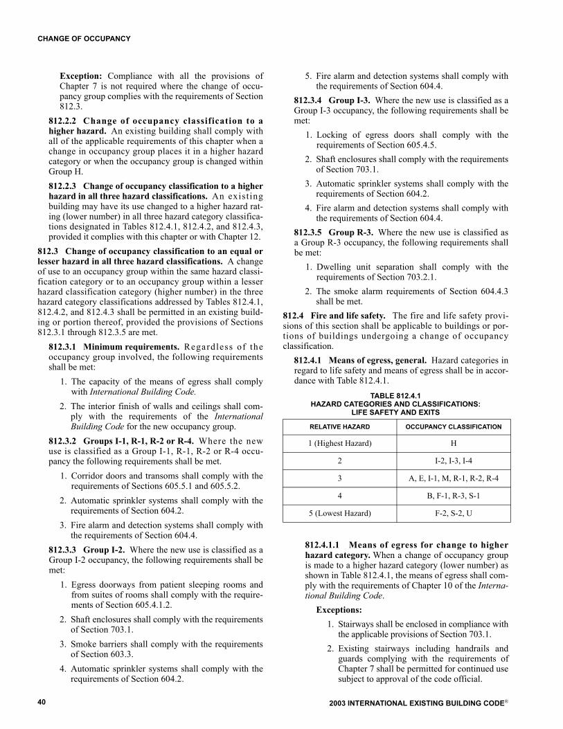
2003 INTERNATIONAL EXISTING BUILDING CODE®40
CHANGE OF OCCUPANCY
Exception: Compliance with all the provisions ofChapter 7 is not required where the change of occu-pancy group complies with the requirements of Section812.3.
812.2.2 Change of occupancy classification to ahigher hazard. An existing building shall comply withall of the applicable requirements of this chapter when achange in occupancy group places it in a higher hazardcategory or when the occupancy group is changed withinGroup H. 812.2.3 Change of occupancy classification to a higherhazard in all three hazard classifications. An existingbuilding may have its use changed to a higher hazard rat-ing (lower number) in all three hazard category classifica-tions designated in Tables 812.4.1, 812.4.2, and 812.4.3,provided it complies with this chapter or with Chapter 12.
812.3 Change of occupancy classification to an equal orlesser hazard in all three hazard classifications. A changeof use to an occupancy group within the same hazard classi-fication category or to an occupancy group within a lesserhazard classification category (higher number) in the threehazard category classifications addressed by Tables 812.4.1,812.4.2, and 812.4.3 shall be permitted in an existing build-ing or portion thereof, provided the provisions of Sections812.3.1 through 812.3.5 are met.
812.3.1 Minimum requirements. Regardless of theoccupancy group involved, the following requirementsshall be met:
1. The capacity of the means of egress shall complywith International Building Code.
2. The interior finish of walls and ceilings shall com-ply with the requirements of the InternationalBuilding Code for the new occupancy group.
812.3.2 Groups I-1, R-1, R-2 or R-4. Where the newuse is classified as a Group I-1, R-1, R-2 or R-4 occu-pancy the following requirements shall be met.
1. Corridor doors and transoms shall comply with therequirements of Sections 605.5.1 and 605.5.2.
2. Automatic sprinkler systems shall comply with therequirements of Section 604.2.
3. Fire alarm and detection systems shall comply withthe requirements of Section 604.4.
812.3.3 Group I-2. Where the new use is classified as aGroup I-2 occupancy, the following requirements shall bemet:
1. Egress doorways from patient sleeping rooms andfrom suites of rooms shall comply with the require-ments of Section 605.4.1.2.
2. Shaft enclosures shall comply with the requirementsof Section 703.1.
3. Smoke barriers shall comply with the requirementsof Section 603.3.
4. Automatic sprinkler systems shall comply with therequirements of Section 604.2.
5. Fire alarm and detection systems shall comply withthe requirements of Section 604.4.
812.3.4 Group I-3. Where the new use is classified as aGroup I-3 occupancy, the following requirements shall bemet:
1. Locking of egress doors shall comply with therequirements of Section 605.4.5.
2. Shaft enclosures shall comply with the requirementsof Section 703.1.
3. Automatic sprinkler systems shall comply with therequirements of Section 604.2.
4. Fire alarm and detection systems shall comply withthe requirements of Section 604.4.
812.3.5 Group R-3. Where the new use is classified asa Group R-3 occupancy, the following requirements shallbe met:
1. Dwelling unit separation shall comply with therequirements of Section 703.2.1.
2. The smoke alarm requirements of Section 604.4.3shall be met.
812.4 Fire and life safety. The fire and life safety provi-sions of this section shall be applicable to buildings or por-tions of buildings undergoing a change of occupancyclassification.
812.4.1 Means of egress, general. Hazard categories inregard to life safety and means of egress shall be in accor-dance with Table 812.4.1.
TABLE 812.4.1 HAZARD CATEGORIES AND CLASSIFICATIONS:
LIFE SAFETY AND EXITS
812.4.1.1 Means of egress for change to higherhazard category. When a change of occupancy groupis made to a higher hazard category (lower number) asshown in Table 812.4.1, the means of egress shall com-ply with the requirements of Chapter 10 of the Interna-tional Building Code.
Exceptions: 1. Stairways shall be enclosed in compliance with
the applicable provisions of Section 703.1. 2. Existing stairways including handrails and
guards complying with the requirements ofChapter 7 shall be permitted for continued usesubject to approval of the code official.
RELATIVE HAZARD OCCUPANCY CLASSIFICATION
1 (Highest Hazard) H
2 I-2, I-3, I-4
3 A, E, I-1, M, R-1, R-2, R-4
4 B, F-1, R-3, S-1
5 (Lowest Hazard) F-2, S-2, U
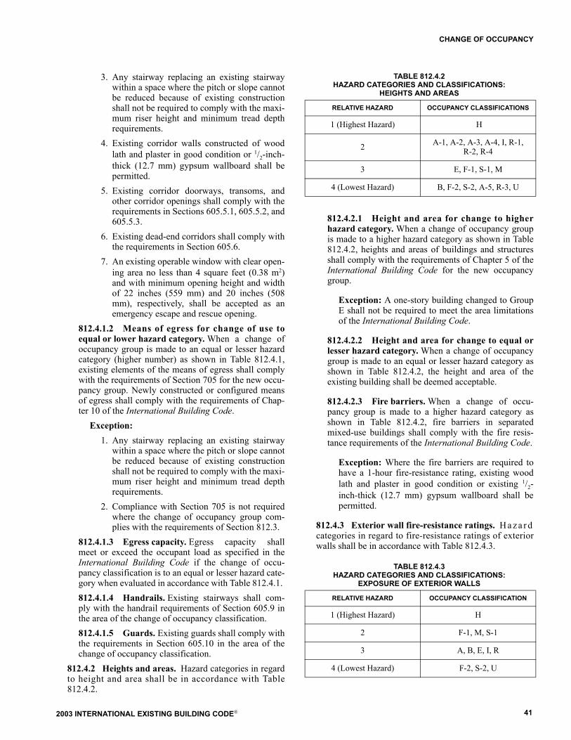
2003 INTERNATIONAL EXISTING BUILDING CODE® 41
CHANGE OF OCCUPANCY
3. Any stairway replacing an existing stairwaywithin a space where the pitch or slope cannotbe reduced because of existing constructionshall not be required to comply with the maxi-mum riser height and minimum tread depthrequirements.
4. Existing corridor walls constructed of woodlath and plaster in good condition or 1/2-inch-thick (12.7 mm) gypsum wallboard shall bepermitted.
5. Existing corridor doorways, transoms, andother corridor openings shall comply with therequirements in Sections 605.5.1, 605.5.2, and605.5.3.
6. Existing dead-end corridors shall comply withthe requirements in Section 605.6.
7. An existing operable window with clear open-ing area no less than 4 square feet (0.38 m2)and with minimum opening height and widthof 22 inches (559 mm) and 20 inches (508mm), respectively, shall be accepted as anemergency escape and rescue opening.
812.4.1.2 Means of egress for change of use toequal or lower hazard category. When a change ofoccupancy group is made to an equal or lesser hazardcategory (higher number) as shown in Table 812.4.1,existing elements of the means of egress shall complywith the requirements of Section 705 for the new occu-pancy group. Newly constructed or configured meansof egress shall comply with the requirements of Chap-ter 10 of the International Building Code.
Exception:1. Any stairway replacing an existing stairway
within a space where the pitch or slope cannotbe reduced because of existing constructionshall not be required to comply with the maxi-mum riser height and minimum tread depthrequirements.
2. Compliance with Section 705 is not requiredwhere the change of occupancy group com-plies with the requirements of Section 812.3.
812.4.1.3 Egress capacity. Egress capacity shallmeet or exceed the occupant load as specified in theInternational Building Code if the change of occu-pancy classification is to an equal or lesser hazard cate-gory when evaluated in accordance with Table 812.4.1. 812.4.1.4 Handrails. Existing stairways shall com-ply with the handrail requirements of Section 605.9 inthe area of the change of occupancy classification. 812.4.1.5 Guards. Existing guards shall comply withthe requirements in Section 605.10 in the area of thechange of occupancy classification.
812.4.2 Heights and areas. Hazard categories in regardto height and area shall be in accordance with Table812.4.2.
TABLE 812.4.2 HAZARD CATEGORIES AND CLASSIFICATIONS:
HEIGHTS AND AREAS
812.4.2.1 Height and area for change to higherhazard category. When a change of occupancy groupis made to a higher hazard category as shown in Table812.4.2, heights and areas of buildings and structuresshall comply with the requirements of Chapter 5 of theInternational Building Code for the new occupancygroup.
Exception: A one-story building changed to GroupE shall not be required to meet the area limitationsof the International Building Code.
812.4.2.2 Height and area for change to equal orlesser hazard category. When a change of occupancygroup is made to an equal or lesser hazard category asshown in Table 812.4.2, the height and area of theexisting building shall be deemed acceptable.
812.4.2.3 Fire barriers. When a change of occu-pancy group is made to a higher hazard category asshown in Table 812.4.2, fire barriers in separatedmixed-use buildings shall comply with the fire resis-tance requirements of the International Building Code.
Exception: Where the fire barriers are required tohave a 1-hour fire-resistance rating, existing woodlath and plaster in good condition or existing 1/2-inch-thick (12.7 mm) gypsum wallboard shall bepermitted.
812.4.3 Exterior wall fire-resistance ratings. H a z a r dcategories in regard to fire-resistance ratings of exteriorwalls shall be in accordance with Table 812.4.3.
TABLE 812.4.3 HAZARD CATEGORIES AND CLASSIFICATIONS:
EXPOSURE OF EXTERIOR WALLS
RELATIVE HAZARD OCCUPANCY CLASSIFICATIONS
1 (Highest Hazard) H
2 A-1, A-2, A-3, A-4, I, R-1,R-2, R-4
3 E, F-1, S-1, M
4 (Lowest Hazard) B, F-2, S-2, A-5, R-3, U
RELATIVE HAZARD OCCUPANCY CLASSIFICATION
1 (Highest Hazard) H
2 F-1, M, S-1
3 A, B, E, I, R
4 (Lowest Hazard) F-2, S-2, U

2003 INTERNATIONAL EXISTING BUILDING CODE®42
CHANGE OF OCCUPANCY
812.4.3.1 Exterior wall rating for change ofoccupancy classification to a higher hazard cate-gory. When a change of occupancy group is made to ahigher hazard category as shown in Table 812.4.3,exterior walls shall have fire resistance and exterioropening protectives as required by the InternationalBuilding Code. This provision shall not apply to wallsat right angles to the property line.
Exception: A 2-hour fire-resistance rating shall beallowed where the building does not exceed threestories in height and is classified as one of the fol-lowing groups: A-2 and A-3 with an occupant loadof less than 300, B, F, M, or S.
812.4.3.2 Exterior wall rating for change of occu-pancy classification to an equal or lesser hazardcategory. When a change of occupancy group is madeto an equal or lesser hazard category as shown in Table812.4.3, existing exterior walls, including openings,shall be accepted. 812.4.3.3 Opening protectives. Openings in exte-rior walls shall be protected as required by the Interna-tional Building Code. Where openings in the exteriorwalls are required to be protected because of their dis-tance from the property line, the sum of the area ofsuch openings shall not exceed 50 percent of the totalarea of the wall in each story.
Exceptions: 1. Where the International Building Code per-
mits openings in excess of 50 percent. 2. Protected openings shall not be required in
buildings of Group R occupancy that do notexceed three stories in height and that arelocated not less than 3 feet (914 mm) from theproperty line.
3. Where exterior opening protectives arerequired, an automatic sprinkler systemthroughout may be substituted for openingprotection.
4. Exterior opening protectives are not requiredwhen the change of occupancy group is to anequal or lower hazard classification in accor-dance with Table 812.4.3.
812.4.4 Enclosure of vertical shafts. Enclosure of ver-tical shafts shall be in accordance with Sections 812.4.4.1through 812.4.4.4.
812.4.4.1 Minimum requirements. Vertical shaftsshall be designed to meet the International BuildingCode requirements for atriums or the requirements ofthis section. 812.4.4.2 Stairways. When a change of occupancygroup is made to a higher hazard category as shown inTable 812.4.1, interior stairways shall be enclosed asrequired by the International Building Code.
Exceptions: 1. In other than Group I occupancies, an enclo-
sure shall not be required for openings servingonly one adjacent floor and that are not con-nected with corridors or stairways servingother floors.
2. Unenclosed existing stairways need not beenclosed in a continuous vertical shaft if eachstory is separated from other stories by 1-hourfire-resistance-rated construction or approvedwired glass set in steel frames and all exit cor-ridors are sprinklered. The openings betweenthe corridor and the occupant space shall haveat least one sprinkler head above the openingson the tenant side. The sprinkler system shallbe permitted to be supplied from the domesticwater-supply systems, provided the system isof adequate pressure, capacity, and sizing forthe combined domestic and sprinkler require-ments.
3. Existing penetrations of stairway enclosuresshall be accepted if they are protected inaccordance with the International BuildingCode.
812.4.4.3 Other vertical shafts. Interior verticalshafts other than stairways, including but not limited toelevator hoistways and service and utility shafts, shallbe enclosed as required by the International BuildingCode when there is a change of use to a higher hazardcategory as specified in Table 812.4.1.
Exceptions: 1. Existing 1-hour interior shaft enclosures shall
be accepted where a higher rating is required. 2. Vertical openings, other than stairways, in
buildings of other than Group I occupancyand connecting less than 6 stories shall not berequired to be enclosed if the entire building isprovided with an approved automatic sprin-kler system.
812.4.4.4 Openings. All openings into existing verti-cal shaft enclosures shall be protected by fire assem-blies having a fire-protection rating of not less than 1hour and shall be maintained self-closing or shall beautomatic closing by actuation of a smoke detector. Allother openings shall be fire protected in an approvedmanner. Existing fusible link-type automatic door-clos-ing devices shall be permitted in all shafts except stair-ways if the fusible link rating does not exceed 135ºF(57ºC).
812.5 Accessibility. Existing buildings or portions thereofthat undergo a change of group or occupancy classificationshall have all of the following accessible features:
1. At least one accessible building entrance.2. At least one accessible route from an accessible build-
ing entrance to primary function areas. 3. Signage complying with Section 1110 of the Interna-
tional Building Code.4. Accessible parking, where parking is provided.
2003 INTERNATIONAL EXISTING BUILDING CODE® 43
CHANGE OF OCCUPANCY
5. At least one accessible passenger loading zone, whereloading zones are provided.
6. At least one accessible route connecting accessibleparking and accessible passenger loading zones to anaccessible entrance.
Where it is technically infeasible to comply with the newconstruction standards for any of these requirements for achange of group or occupancy, the above items shall conformto the requirements to the maximum extent technically feasi-ble. Changes of group or occupancy that incorporate anyalterations or additions shall comply with this section andSections 506.1 and 905.1 as applicable.
Exception: Type B dwelling or sleeping units required bySection 1107 of the International Building Code are notrequired to be provided in existing buildings and facili-ties.
812.6 Seismic loads. Existing buildings with a change ofoccupancy classification shall comply with the seismic pro-visions of Section 807.3.

2003 INTERNATIONAL EXISTING BUILDING CODE®44
CHANGE OF OCCUPANCY
2003 INTERNATIONAL EXISTING BUILDING CODE® 45
SECTION 901 GENERAL
901.1 Scope. An addition to a building or structure shallcomply with the building, plumbing, electrical, and mechan-ical codes, without requiring the existing building or struc-ture to comply with any requirements of those codes or ofthese provisions.
Exception: In flood hazard areas, the existing building issubject to the requirements of Section 903.5.
901.2 Creation or extension of nonconformity. An addi-tion shall not create or extend any nonconformity in theexisting building to which the addition is being made withregard to accessibility, structural strength, fire safety, meansof egress, or the capacity of mechanical, plumbing, or elec-trical systems.901.3 Other work. Any repair or alteration work withinan existing building to which an addition is being made shallcomply with the applicable requirements for the work asclassified in Chapter 3.
SECTION 902HEIGHTS AND AREAS
902.1 Height limitations. No addition shall increase theheight of an existing building beyond that permitted underthe applicable provisions of Chapter 5 of the InternationalBuilding Code for new buildings.902.2 Area limitations. No addition shall increase thearea of an existing building beyond that permitted under theapplicable provisions of Chapter 5 of the InternationalBuilding Code for new buildings unless fire separation asrequired by the International Building Code is provided.
Exception: In-filling of floor openings and nonoccupia-ble appendages such as elevator and exit stair shafts shallbe permitted beyond that permitted by the InternationalBuilding Code.
902.3 Fire protection systems. E x i s t i n g f i r e a r e a sincreased by the addition shall comply with Chapter 9 of theInternational Building Code.
SECTION 903STRUCTURAL
903.1 Compliance with the International BuildingCode. Additions to existing buildings or structures are newconstruction and shall comply with the International Build-ing Code.903.2 Additional gravity loads. Existing structural ele-ments supporting any additional gravity loads as a result ofadditions shall comply with the International BuildingCode.
Exceptions: 1. Structural elements whose stress is not increased by
more than 5 percent.
2. Buildings of Group R occupancy with no more thanfive dwelling units or sleeping units used solely forresidential purposes where the existing buildingand the addition comply with the conventionallight-frame construction methods of the Interna-tional Building Code or the provisions of the Inter-national Residential Code.
903.3 Lateral-force-resisting system. The lateral-force-resisting system of existing buildings to which additions aremade shall comply with Sections 903.3.1, 903.3.2, and903.3.3.
Exceptions:1. In Type V construction, Group R occupancies
where the lateral-force story shear in any story isnot increased by more than 10 percent.
2. Buildings of Group R occupancy with no more thanfive dwelling units or sleeping units used solely forresidential purposes where the existing buildingand the addition comply with the conventionallight-frame construction methods of the Interna-tional Building Code or the provisions of the Inter-national Residential Code.
3. Additions where the lateral-force story shear in anystory is not increased by more than 5 percent.
903.3.1 Vertical addition. Any element of the lateral-force-resisting system of an existing building subjected toan increase in vertical or lateral loads from the verticaladdition shall comply with the lateral load provisions ofthe International Building Code.903.3.2 Horizontal addition. Where horizontal addi-tions are structurally connected to an existing structure,all lateral-force-resisting elements of the existing struc-ture affected by such addition shall comply with the lat-eral load provisions of the International Building Code.Lateral loads imposed on the elements of the existingstructure and the addition shall be determined by a rela-tive stiffness analysis of the combined structure includingtorsional effects.903.3.3 Voluntary addition of structural elements toimprove the lateral-force-resisting system. Voluntaryaddition of structural elements to improve the lateral-force-resisting system of a building shall comply withSection 707.7.
903.4 Snow drift loads. Any structural element of anexisting building subjected to additional loads from theeffects of snow drift as a result of an addition shall complywith the International Building Code.
Exceptions: 1. Structural elements whose stress is not increased by
more than 5 percent.2. Buildings of Group R occupancy with no more than
five dwelling units or sleeping units used solely forresidential purposes where the existing buildingand the addition comply with the conventional
CHAPTER 9
ADDITIONS
2003 INTERNATIONAL EXISTING BUILDING CODE®46
ADDITIONS
light-frame construction methods of the Interna-tional Building Code or the provisions of the Inter-national Residential Code.
903.5 Flood hazard areas. Additions and foundations inflood hazard areas shall comply with the followingrequirements:
1. For horizontal additions that are structurally intercon-nected to the existing building:
1.1. If the addition and all other proposed work,when combined, constitute substantial improve-ment, the existing building and the addition shallcomply with Section 1612 of the InternationalBuilding Code.
1.2. If the addition constitutes substantial improve-ment, the existing building and the addition shallcomply with Section 1612 of the InternationalBuilding Code.
2. For horizontal additions that are not structurally inter-connected to the existing building:
2.1. The addition shall comply with Section 1612 ofthe International Building Code.
2.2. If the addition and all other proposed work,when combined, constitute substantial improve-ment, the existing building and the addition shallcomply with Section 1612 of the InternationalBuilding Code.
3. For vertical additions and all other proposed work that,when combined, constitute substantial improvement,the existing building shall comply with Section 1612 ofthe International Building Code.
4. For a new, replacement, raised, or extended foundation,if the foundation work and all other proposed work,when combined, constitute substantial improvement,the existing building shall comply with Section 1612 ofthe International Building Code.
SECTION 904SMOKE ALARMS IN OCCUPANCY
GROUPS R-3 AND R-4
904.1 Smoke alarms in an addition. Whenever an addi-tion is made to a building or structure of a Group R-3 or R-4occupancy, hardwired, interconnected smoke alarms meetingthe requirements of the International Building Code or Inter-national Residential Code as applicable shall be installed andmaintained in the addition.
904.2 S m o k e a l a r m s i n e x i s t i n g p o r t i o n s o f abuilding. Whenever an addition is made to a building orstructure of a Group R-3 or R-4 occupancy, the existingbuilding shall be provided with smoke alarms as required bythe International Building Code or International ResidentialCode as applicable.
SECTION 905ACCESSIBILITY
905.1 Minimum requirements. Accessibility provisionsfor new construction shall apply to additions. An additionthat affects the accessibility to, or contains an area of, pri-mary function shall comply with the requirements of Section506.2 for accessible routes.
SECTION 906ENERGY CONSERVATION
906.1 Minimum requirements. Addi t ions to exis t ingbuildings or structures may be made to such buildings orstructures without making the entire building or structurecomply with the requirements of the International EnergyConservation Code. The addition shall conform to therequirements of the International Energy Conservation Codeas they relate to new construction only.
2003 INTERNATIONAL EXISTING BUILDING CODE® 47
SECTION 1001GENERAL
1001.1 Scope. It is the intent of this chapter to providemeans for the preservation of historic buildings. Historicalbuildings shall comply with the provisions of this chapterrelating to their repair, alteration, relocation and change ofoccupancy. 1001.2 Report. A historic building undergoing repair,alteration, or change of occupancy shall be investigated andevaluated. If it is intended that the building meet therequirements of this chapter, a written report shall be pre-pared and filed with the code official by a registered designprofessional when such a report is necessary in the opinionof the code official. Such report shall be in accordance withChapter 1 and shall identify each required safety feature thatis in compliance with this chapter and where compliancewith other chapters of these provisions would be damagingto the contributing historic features. In high seismic zones, astructural evaluation describing, at minimum, a completeload path and other earthquake-resistant features shall beprepared. In addition, the report shall describe each featurethat is not in compliance with these provisions and shalldemonstrate how the intent of these provisions is compliedwith in providing an equivalent level of safety.1001.3 Special occupancy exceptions�museums. Whena building in Group R-3 is also used for Group A, B, or Mpurposes such as museum tours, exhibits, and other publicassembly activities, or for museums less than 3000 squarefeet (279 m2), the code official may determine that the occu-pancy is Group B when life-safety conditions can be demon-strated in accordance with Section 1001.2. Adequate meansof egress in such buildings, which may include a means ofmaintaining doors in an open position to permit egress, alimit on building occupancy to an occupant load permittedby the means of egress capacity, a limit on occupancy of cer-tain areas or floors, or supervision by a person knowledge-able in the emergency exiting procedures, shall be provided.1001.4 Flood hazard areas. In flood hazard areas, if allproposed work, including repairs, work required because ofa change of occupancy, and alterations, constitutes substan-tial improvement, then the existing building shall complywith Section 1612 of the International Building Code.
Exception: If a historic building will continue to be ahistoric building after the proposed work is completed,then the proposed work is not considered a substantialimprovement. For the purposes of this exception, a his-toric building is:
1. Listed or preliminarily determined to be eligible forlisting in the National Register of Historic Places;
2. Determined by the Secretary of the U.S. Depart-ment of Interior to contribute to the historical sig-nificance of a registered historic district or a districtpreliminarily determined to qualify as a historicdistrict; or
3. Designated as historic under a state or local historic
preservation program that is approved by theDepartment of Interior.
SECTION 1002REPAIRS
1002.1 General. Repairs to any portion of a historic build-ing or structure shall be permitted with original or like mate-rials and original methods of construction, subject to theprovisions of this chapter.1002.2 Dangerous buildings. When a historic building isdetermined to be dangerous, no work shall be requiredexcept as necessary to correct identified unsafe conditions.1002.3 Relocated buildings. Foundations of relocatedhistoric buildings and structures shall comply with the Inter-national Building Code. Relocated historic buildings shallotherwise be considered a historic building for the purposesof this code. Relocated historic buildings and structures shallbe sited so that exterior wall and opening requirements com-ply with the International Building Code or with the compli-ance alternatives of this code.1002.4 Chapter 4 compliance. Historic buildings under-going repairs shall comply with all of the applicable require-ments of Chapter 4, except as specifically permitted in thischapter.1002.5 Replacement. Replacement of existing or missingfeatures using original materials shall be permitted. Partialreplacement for repairs that match the original in configura-tion, height, and size shall be permitted. Such replacementsshall not be required to meet the materials and methodsrequirements of Section 401.2.
Exception: Replacement glazing in hazardous locationsshall comply with the safety glazing requirements ofChapter 24 of the International Building Code.
SECTION 1003FIRE SAFETY
1003.1 Scope. Historic buildings undergoing alterations,changes of occupancy, or that are moved shall comply withSection 1003.1003.2 General. Every historic building that does not con-form to the construction requirements specified in this codefor the occupancy or use and that constitutes a distinct firehazard as defined herein shall be provided with an approvedautomatic fire-extinguishing system as determined appropri-ate by the code official. However, an automatic fire-extin-guishing system shall not be used to substitute for, or act asan alternative to, the required number of exits from anyfacility.1003.3 Means of egress. Existing door openings and cor-ridor and stairway widths less than those specified elsewherein this code may be approved, provided that, in the opinionof the code official, there is sufficient width and height for aperson to pass through the opening or traverse the means ofegress. When approved by the code official, the front or
CHAPTER 10
HISTORIC BUILDINGS
2003 INTERNATIONAL EXISTING BUILDING CODE®48
HISTORIC BUILDINGS
main exit doors need not swing in the direction of the path ofexit travel, provided that other approved means of egresshaving sufficient capacity to serve the total occupant load areprovided.
1003.4 Transoms. In fully sprinklered buildings of GroupR-1, R-2 or R-3 occupancy, existing transoms in corridorsand other fire-resistance-rated, walls may be maintained iffixed in the closed position. A sprinkler shall be installed oneach side of the transom.
1003.5 Interior finishes. The existing finishes of wallsand ceilings shall be accepted when it is demonstrated thatthey are the historic finishes.
1003.6 Stairway enclosure. In buildings of three stories orless, exit enclosure construction shall limit the spread ofsmoke by the use of tight-fitting doors and solid elements.Such elements are not required to have a fire-resistance rat-ing.
1003.7 One-hour fire-resistant assemblies. Where 1-hourfire-resistance-rated construction is required by these provi-sions, it need not be provided, regardless of construction oroccupancy, where the existing wall and ceiling finish is woodor metal lath and plaster.
1003.8 Glazing in fire-resistance-rated systems. Historicglazing materials in interior walls required to have a 1-hourfire-resistance rating may be permitted when provided withapproved smoke seals and when the area affected is providedwith an automatic sprinkler system.
1003.9 Stairway railings. G r a n d s t a i r w a y s s h a l l b eaccepted without complying with the handrail and guardrequirements. Existing handrails and guards at all stairs shallbe permitted to remain, provided they are not structurallydangerous.
1003.10 Guards. Guards shall comply with Sections1003.10.1 and 1003.10.2.
1003.10.1 Height. Existing guards shall comply withthe requirements of Section 405.
1003.10.2 Guard openings. The spacing between exist-ing intermediate railings or openings in existing ornamen-tal patterns shall be accepted. Missing elements ormembers of a guard may be replaced in a manner that willpreserve the historic appearance of the building or struc-ture.
1003.11 Exit signs. Where exit sign or egress path markinglocation would damage the historic character of the building,alternative exit signs are permitted with approval of the codeofficial. Alternative signs shall identify the exits and egresspath.
1003.12 Automatic fire-extinguishing systems. 1003.12.1 General. Every historical building that can-not be made to conform to the construction requirementsspecified in the International Building Code for the occu-pancy or use and that constitutes a distinct fire hazardshall be deemed to be in compliance if provided with anapproved automatic fire-extinguishing system.
Exception: When the code official approves an alter-native life-safety system.
SECTION 1004ALTERATIONS
1004.1 Accessibility requirements. The prov i s ions o fSection 506 shall apply to buildings and facilities designatedas historic structures that undergo alterations, unless techni-cally infeasible. Where compliance with the requirements foraccessible routes, ramps, entrances, or toilet facilities wouldthreaten or destroy the historic significance of the building orfacility, as determined by the code official, the alternativerequirements of Sections 1004.1.1 through 1004.1.5 for thatelement shall be permitted.
1004.1.1 Site arrival points. At least one main entranceshall be accessible.1004.1.2 Multilevel buildings and facilities. An acces-sible route from an accessible entrance to public spaceson the level of the accessible entrance shall be provided.1004.1.3 Entrances. At least one main entrance shall beaccessible.
Exceptions: 1. If a main entrance cannot be made accessible,
an accessible nonpublic entrance that isunlocked while the building is occupied shallbe provided; or
2. If a main entrance cannot be made accessible, alocked accessible entrance with a notificationsystem or remote monitoring shall be provided.
1004.1.4 Toilet and bathing facilities. W h e r e t o i l e trooms are provided, at least one accessible toilet roomshall be provided for each sex, or a unisex toilet roomcomplying with Section 1109.2.1 of the InternationalBuilding Code shall be provided.1004.1.5 Ramps. The slope of a ramp run of 24 inches(610 mm) maximum shall not be steeper than one unitvertical in eight units horizontal (12-percent slope).
SECTION 1005CHANGE OF OCCUPANCY
1005.1 General. Historic buildings undergoing a change ofoccupancy shall comply with the applicable provisions ofChapter 8, except as specifically permitted in this chapter.When Chapter 8 requires compliance with specific require-ments of Chapter 4, Chapter 5, or Chapter 6 and when thoserequirements are subject to the exceptions in Section 1002,the same exceptions shall apply to this section.1005.2 Building area. The allowable floor area for historicbuildings undergoing a change of occupancy shall be permit-ted to exceed by 20 percent the allowable areas specified inChapter 5 of the International Building Code.1005.3 Location on property. Historic structures undergo-ing a change of use to a higher hazard category in accordancewith Section 812.4.3 may use alternative methods to comply
2003 INTERNATIONAL EXISTING BUILDING CODE® 49
HISTORIC BUILDINGS
with the fire resistance and exterior opening protectiverequirements. Such alternatives shall comply with Section1001.2.
1005.4 Occupancy separation. Required occupancy sepa-rations of 1 hour may be omitted when the building is pro-vided with an approved automatic sprinkler systemthroughout.
1005.5 Roof covering. Regardless of occupancy or usegroup, roof-covering materials not less than Class C shall bepermitted where a fire-retardant roof covering is required.
1005.6 Means of egress. Existing door openings and corri-dor and stairway widths less than those that would be accept-able for nonhistoric buildings under these provisions shall beapproved, provided that, in the opinion of the code official,there is sufficient width and height for a person to passthrough the opening or traverse the exit and that the capacityof the exit system is adequate for the occupant load, or whereother operational controls to limit occupancy are approvedby the code official.
1005.7 Door swing. When approved by the code official,existing front doors need not swing in the direction of exittravel, provided that other approved exits having sufficientcapacity to serve the total occupant load are provided.
1005.8 Transoms. In corridor walls required by these provi-sions to be fire-resistance rated, existing transoms may bemaintained if fixed in the closed position, and fixed wiredglass set in a steel frame or other approved glazing shall beinstalled on one side of the transom.
Exception: Transoms conforming to Section 1003.4 shallbe accepted.
1005.9 Finishes. Where finish materials are required tohave a flame-spread classification of Class III or better,existing nonconforming materials shall be surfaced with anapproved fire-retardant paint or finish.
Exception: Existing nonconforming materials need notbe surfaced with an approved fire-retardant paint or finishwhere the building is equipped throughout with an auto-matic fire-suppression system installed in accordancewith the International Building Code and the noncon-forming materials can be substantiated as being historic incharacter.
1005.10 One-hour fire-resistant assemblies. W h e r e 1 -hour fire-resistance-rated construction is required by theseprovisions, it need not be provided, regardless of construc-tion or occupancy, where the existing wall and ceiling finishis wood lath and plaster.
1005.11 Stairs and railings. Existing stairways shall com-ply with the requirements of these provisions. The code offi-cial shall grant alternatives for stairways and railings ifalternative stairways are found to be acceptable or are judgedto meet the intent of these provisions. Existing stairwaysshall comply with Section 1003.
Exception: For buildings less than 3000 square feet (279 m 2) , ex is t ing condi t ions a re permi t ted toremain at all stairs and rails.
1005.12 Exit signs. The code official may accept alterna-tive exit sign locations where such signs would damage thehistoric character of the building or structure. Such signsshall identify the exits and exit path.1005.13 Exit stair live load. Existing historic stairways inbuildings changed to a Group R-1 or R-2 occupancy shall beaccepted where it can be shown that the stairway can supporta 75-pounds-per-square-foot (366 kg/m2) live load.1005.14 Natural light. When it is determined by the codeofficial that compliance with the natural light requirementsof Section 811.1.1 will lead to loss of historic character orhistoric materials in the building, the existing level of naturallighting shall be considered acceptable.1005.15 Accessibility requirements. The provisions ofSection 812.5 shall apply to buildings and facilities desig-nated as historic structures that undergo a change of occu-pancy, unless technically infeasible. Where compliance withthe requirements for accessible routes, ramps, entrances, ortoilet facilities would threaten or destroy the historic signifi-cance of the building or facility, as determined by the author-ity having jurisdiction, the alternative requirements ofSections 1004.1.1 through 1004.1.5 for those elements shallbe permitted.
SECTION 1006STRUCTURAL
1006.1 General. Historic buildings shall comply with theapplicable structural provisions for the work as classified inChapter 3.
Exception: The code official shall be authorized to acceptexisting floors and approve operational controls that limitthe live load on any such floor.
1006.2 Unsafe structural elements. Where the code offi-cial determines that a component or a portion of a building orstructure is dangerous as defined in this code and is in needof repair, strengthening, or replacement by provisions of thiscode, only that specific component or portion shall berequired to be repaired, strengthened, or replaced.

2003 INTERNATIONAL EXISTING BUILDING CODE®50
HISTORIC BUILDINGS

2003 INTERNATIONAL EXISTING BUILDING CODE® 51
SECTION 1101GENERAL
1101.1 Scope. This chapter provides requirements forrelocated or moved structures. 1101.2 Conformance. The building shall be safe forhuman occupancy as determined by the International FireCode and the International Property Maintenance Code.Any repair, alteration, or change of occupancy undertakenwithin the moved structure shall comply with the require-ments of this code applicable to the work being performed.Any field-fabricated elements shall comply with therequirements of the International Building Code or theInternational Residential Code as applicable.
SECTION 1102REQUIREMENTS
1102.1 Location on the lot. The building shall be locatedon the lot in accordance with the requirements of the Inter-national Building Code or the International ResidentialCode as applicable. 1102.2 Foundation. The foundation system of relocatedbuildings shall comply with the International BuildingCode or the International Residential Code as applicable.
1102.2.1 Connection to the foundation. The connec-tion of the relocated building to the foundation shall complywith the International Building Code or the InternationalResidential Code as applicable.1102.3 Wind loads. Buildings shall comply with Interna-tional Building Code or International Residential Codewind provisions as applicable.
Exceptions: 1. Detached one- and two-family dwellings and
Group U occupancies where wind loads at the newlocation are not higher than those at the previouslocation.
2. Structural elements whose stress is not increasedby more than 5 percent.
1102.4 Seismic loads. Buildings shall comply with Inter-national Building Code or International Residential Codeseismic provisions at the new location as applicable.
Exceptions: 1. Structures in Seismic Design Categories A and B
and detached one- and two-family dwellings inSeismic Design Categories A, B, and C where theseismic loads at the new location are not higherthan those at the previous location.
2. Stuctural elements whose stress is not increased bymore than 5 percent.
1102.5 Snow loads. Structures shall comply with Interna-tional Building Code or International Residential Code
snow loads as applicable where snow loads at the new loca-tion are higher than those at the previous location.
Exception: Structural elements whose stress is notincreased by more than 5 percent.
1102.6 Flood hazard areas. If relocated or moved into aflood hazard area, structures shall comply with Section1612 of the International Building Code.1102.7 Required inspection and repairs. The code offi-cial shall be authorized to inspect, or to require approvedprofessionals to inspect at the expense of the owner, thevarious structural parts of a relocated building to verify thatstructural components and connections have not sustainedstructural damage. Any repairs required by the code officialas a result of such inspection shall be made prior to the finalapproval.
CHAPTER 11
RELOCATED OR MOVED BUILDINGS

2003 INTERNATIONAL EXISTING BUILDING CODE®52
RELOCATED OR MOVED BUILDINGS
2003 INTERNATIONAL EXISTING BUILDING CODE® 53
SECTION 1201GENERAL
1201.1 Scope. The provisions of this chapter are intendedto maintain or increase the current degree of public safety,health, and general welfare in existing buildings while per-mitting repair, alteration, addition, and change of occupancywithout requiring full compliance with Chapters 4 through10, except where compliance with other provisions of thiscode is specifically required in this chapter.1201.2 Applicability. Structures existing prior to [DATETO BE INSERTED BY THE JURISDICTION. Note: it is recom-mended that this date coincide with the effective date ofbuilding codes within the jurisdiction], in which there iswork involving additions, alterations, or changes of occu-pancy shall be made to conform to the requirements of thischapter or the provisions of Chapters 4 through 10. The pro-visions of Sections 1201.2.1 through 1201.2.5 shall apply toexisting occupancies that will continue to be, or are pro-posed to be, in Groups A, B, E, F, M, R, and S. These provi-sions shall not apply to buildings with occupancies in GroupH or Group I.
1201.2.1 Change in occupancy. Where an ex is t ingbuilding is changed to a new occupancy classificationand this section is applicable, the provisions of this sec-tion for the new occupancy shall be used to determinecompliance with this code.1201.2.2 Part change in occupancy. Where a portionof the building is changed to a new occupancy classifica-tion and that portion is separated from the remainder ofthe building with fire barrier wall assemblies having afire-resistance rating as required by Table 302.3.3 of theInternational Building Code or Section R317 of the Inter-national Residential Code for the separate occupancies,or with approved compliance alternatives, the portionchanged shall be made to conform to the provisions ofthis section.
Where a portion of the building is changed to a newoccupancy classification and that portion is not separatedfrom the remainder of the building with fire separationassemblies having a fire-resistance rating as required byTable 302.3.3 of the International Building Code or Sec-tion R317 of the International Residential Code for theseparate occupancies, or with approved compliance alter-natives, the provisions of this section which apply to eachoccupancy shall apply to the entire building. Where thereare conflicting provisions, those requirements whichsecure the greater public safety shall apply to the entirebuilding or structure.1201.2.3 Additions. Additions to existing buildingsshall comply with the requirements of the InternationalBuilding Code, International Residential Code, and thiscode for new construction. The combined height and areaof the existing building and the new addition shall notexceed the height and area allowed by Chapter 5 of theInternational Building Code. Where a fire wall that com-plies with Section 705 of the International Building Code
is provided between the addition and the existing build-ing, the addition shall be considered a separate building.1201.2.4 Alterations and repairs. An existing build-ing or portion thereof that does not comply with therequirements of this code for new construction shall notbe altered or repaired in such a manner that results in thebuilding being less safe or sanitary than such building iscurrently. If, in the alteration or repair, the current level ofsafety or sanitation is to be reduced, the portion altered orrepaired shall conform to the requirements of Chapters 2through 12 and Chapters 14 through 33 of the Interna-tional Building Code.1201.2.5 Accessibility requirements. All portions ofthe buildings proposed for change of occupancy shallconform to the accessibility provisions of Chapter 11 ofthe International Building Code.
1201.3 Acceptance. For repairs, alterations, additions, andchanges of occupancy to existing buildings that are evalu-ated in accordance with this section, compliance with thissection shall be accepted by the code official.
1201.3.1 Hazards. Where the code official determinesthat an unsafe condition exists as provided for in Section115, such unsafe condition shall be abated in accordancewith Section 115.1201.3.2 Compliance with other codes. Buildings thatare evaluated in accordance with this section shall com-ply with the International Fire Code and InternationalProperty Maintenance Code.1201.3.3 Compliance with flood hazard provisions.In flood hazard areas, buildings that are evaluated inaccordance with this section shall comply with Section1612 of the International Building Code if the work cov-ered by this section constitutes substantial improvement.
1201.4 Investigation and evaluation. For proposed workcovered by this chapter, the building owner shall cause theexisting building to be investigated and evaluated in accor-dance with the provisions of Sections 1201.4 through1201.9.
1201.4.1 Structural analysis. The owner shall have astructural analysis of the existing building made to deter-mine adequacy of structural systems for the proposedalteration, addition, or change of occupancy. The existingbuilding shall be capable of supporting the minimum loadrequirements of Chapter 16 of the International BuildingCode.1201.4.2 Submittal. The results of the investigationand evaluation as required in Section 1201.4, along withproposed compliance alternatives, shall be submitted tothe code official.1201.4.3 Determination of compliance. The code offi-cial shall determine whether the existing building, withthe proposed addition, alteration, or change of occupancy,complies with the provisions of this section in accordancewith the evaluation process in Sections 1201.5 through1201.9.
CHAPTER 12
COMPLIANCE ALTERNATIVES
2003 INTERNATIONAL EXISTING BUILDING CODE®54
COMPLIANCE ALTERNATIVES
1201.5 Evaluation. The evaluation shall be comprised ofthree categories: fire safety, means of egress, and generalsafety, as described in Sections 1201.5.1 through 1201.5.3.
1201.5.1 Fire safety. Included within the fire safety cat-egory are the structural fire resistance, automatic firedetection, fire alarm, and fire-suppression system featuresof the facility.1201.5.2 Means of egress. Included within the meansof egress category are the configuration, characteristics,and support features for means of egress in the facility.1201.5.3 General safety. Included within the generalsafety category are the fire safety parameters and themeans-of-egress parameters.
1201.6 Evaluation process. The evaluation process speci-fied herein shall be followed in its entirety to evaluate exist-ing buildings. Table 1201.7 shall be utilized for tabulatingthe results of the evaluation. References to other sections ofthis code indicate that compliance with those sections isrequired in order to gain credit in the evaluation herein out-lined. In applying this section to a building with mixed occu-pancies , where the separa t ion between the mixedoccupancies does not qualify for any category indicated inSection 1201.6.16, the score for each occupancy shall bedetermined, and the lower score determined for each sectionof the evaluation process shall apply to the entire building.
Where the separation between the mixed occupancies qual-ifies for any category indicated in Section 1201.6.16, thescore for each occupancy shall apply to each portion of thebuilding based on the occupancy of the space.
1201.6.1 Building height. The value for building heightshall be the lesser value determined by the formula inSection 1201.6.1.1. Chapter 5 of the International Build-ing Code, including allowable increases due to automaticsprinklers as provided for in Section 504.2, shall be usedto determine the allowable height of the building. Subtractthe actual building height from the allowable height anddivide by 121/2 feet (3810 mm). Enter the height value andits sign (positive or negative) in Table 1201.7 underSafety Parameter 1201.6.1, Building Height, for firesafety, means of egress, and general safety. The maximumscore for a building shall be 10.
1201.6.1.1 Height formula. The following formulasshall be used in computing the building height value.
Height value, feet = (AH) � (EBH) × CF 12.5
Height value, stories = (AS � EBS) × CF(Equation 12-1) where:
AH = Allowable height in feet (mm) from Table503 of the International Building Code.
EBH = Existing building height in feet (mm).AS = Allowable height in stories from Table 503 of
the International Building Code.EBS = Existing building height in stories.CF = 1 if (AH) � (EBH) is positive.
CF = Construction type factor shown in Table1201.6.6(2) if (AH) � (EBH) is negative.
Note: Where mixed occupancies are separated and indi-vidually evaluated as indicated in Section 1201.6, the val-ues AH, AS, EBH, and EBS shall be based on the height ofthe fire area of the occupancy being evaluated.
1201.6.2 Building area. The value for building areashall be determined by the formula in Section 1201.6.2.2.Section 503 of the International Building Code and theformula in Section 1201.6.2.1 shall be used to determinethe allowable area of the building. The allowable areashall be the lesser value calculated by Equations 12-2 and12-3.This shall include any allowable increases due toopen perimeter and automatic sprinklers as provided forin Section 506 of the International Building Code. Sub-tract the actual building area from the allowable area anddivide by 1,200 square feet (112 m2). Enter the area valueand its sign (positive or negative) in Table 1201.7 underSafety Parameter 1201.6.2, Building Area, for fire safety,means of egress, and general safety. In determining thearea value, the maximum permitted positive value for areais 50 percent of the fire safety score as listed in Table1201.8, Mandatory Safety Scores.
1201.6.2.1 Allowable area formula. The followingformula shall be used in computing allowable area:
Aa =
(Equation 12-2)Amax. = 3 × Aa, as calculated in accordance with Section
503.3 of the International Building Code.
Aa,max. = (Equation 12-3)where:
Aa = Allowable area per floor.
Is = Area increase due to sprinkler protection,percent as calculated in accordance withSection 506.3 of the International Build-ing Code.
If = Area increase due to frontage, percent ascalculated in accordance with Section506.2 of the International Building Code.
At = Tabular area per floor in accordance withTable 503 of the International BuildingCode, square feet (m2).
Amax = Total area of the entire building.
Aa, max. = Allowable area per floor based on the lim-itations of Section 503.3 of the Interna-tional Building Code.
1201.6.2.2 Area formula. The following formulashall be used in computing the area value. Determinethe area value for each occupancy fire area on a floor-by-floor basis. For each occupancy, choose the mini-
100 If Is+ +( ) At×
100---------------------------------------------
AmaxNumber of stories-------------------------------------------
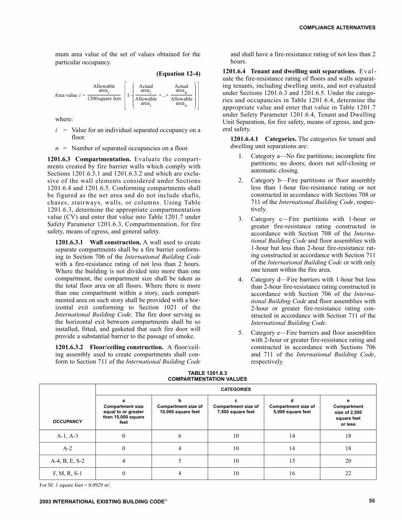
2003 INTERNATIONAL EXISTING BUILDING CODE® 55
COMPLIANCE ALTERNATIVES
mum area value of the set of values obtained for theparticular occupancy.
(Equation 12-4)
where:
i = Value for an individual separated occupancy on afloor.
n = Number of separated occupancies on a floor.
1201.6.3 Compartmentation. Evaluate the compart-ments created by fire barrier walls which comply withSections 1201.6.3.1 and 1201.6.3.2 and which are exclu-sive of the wall elements considered under Sections1201.6.4 and 1201.6.5. Conforming compartments shallbe figured as the net area and do not include shafts,chases, stairways, walls, or columns. Using Table1201.6.3, determine the appropriate compartmentationvalue (CV) and enter that value into Table 1201.7 underSafety Parameter 1201.6.3, Compartmentation, for firesafety, means of egress, and general safety.
1201.6.3.1 Wall construction. A wall used to createseparate compartments shall be a fire barrier conform-ing to Section 706 of the International Building Codewith a fire-resistance rating of not less than 2 hours.Where the building is not divided into more than onecompartment, the compartment size shall be taken asthe total floor area on all floors. Where there is morethan one compartment within a story, each compart-mented area on such story shall be provided with a hor-izontal exit conforming to Section 1021 of theInternational Building Code. The fire door serving asthe horizontal exit between compartments shall be soinstalled, fitted, and gasketed that such fire door willprovide a substantial barrier to the passage of smoke.
1201.6.3.2 Floor/ceiling construction. A floor/ceil-ing assembly used to create compartments shall con-form to Section 711 of the International Building Code
and shall have a fire-resistance rating of not less than 2hours.
1201.6.4 Tenant and dwelling unit separations. Eval -uate the fire-resistance rating of floors and walls separat-ing tenants, including dwelling units, and not evaluatedunder Sections 1201.6.3 and 1201.6.5. Under the catego-ries and occupancies in Table 1201.6.4, determine theappropriate value and enter that value in Table 1201.7under Safety Parameter 1201.6.4, Tenant and DwellingUnit Separation, for fire safety, means of egress, and gen-eral safety.
1201.6.4.1 Categories. The categories for tenant anddwelling unit separations are:
1. Category a�No fire partitions; incomplete firepartitions; no doors; doors not self-closing orautomatic closing.
2. Category b�Fire partitions or floor assemblyless than 1-hour fire-resistance rating or notconstructed in accordance with Sections 708 or711 of the International Building Code, respec-tively.
3. Category c�Fire partitions with 1-hour orgreater fire-resistance rating constructed inaccordance with Section 708 of the Interna-tional Building Code and floor assemblies with1-hour but less than 2-hour fire-resistance rat-ing constructed in accordance with Section 711of the International Building Code or with onlyone tenant within the fire area.
4. Category d�Fire barriers with 1-hour but lessthan 2-hour fire-resistance rating constructed inaccordance with Section 706 of the Interna-tional Building Code and floor assemblies with2-hour or greater fire-resistance rating con-structed in accordance with Section 711 of theInternational Building Code.
5. Category e�Fire barriers and floor assemblieswith 2-hour or greater fire-resistance rating andconstructed in accordance with Sections 706and 711 of the International Building Code,respectively.
TABLE 1201.6.3COMPARTMENTATION VALUES
For SI: 1 square foot = 0.0929 m2.
Area value i =
Allowableareai
1200square feet-------------------------------------- 1�
Actualareai
Allowableareai
------------------------- +...+
Actualarean
Allowablearean
-------------------------
CATEGORIES
OCCUPANCY
aCompartment size equal to or greater than 15,000 square
feet
bCompartment size of
10,000 square feet
cCompartment size of
7,500 square feet
dCompartment size of
5,000 square feet
eCompartment size of 2,500 square feet
or less
A-1, A-3 0 6 10 14 18
A-2 0 4 10 14 18
A-4, B, E, S-2 4 5 10 15 20
F, M, R, S-1 0 4 10 16 22
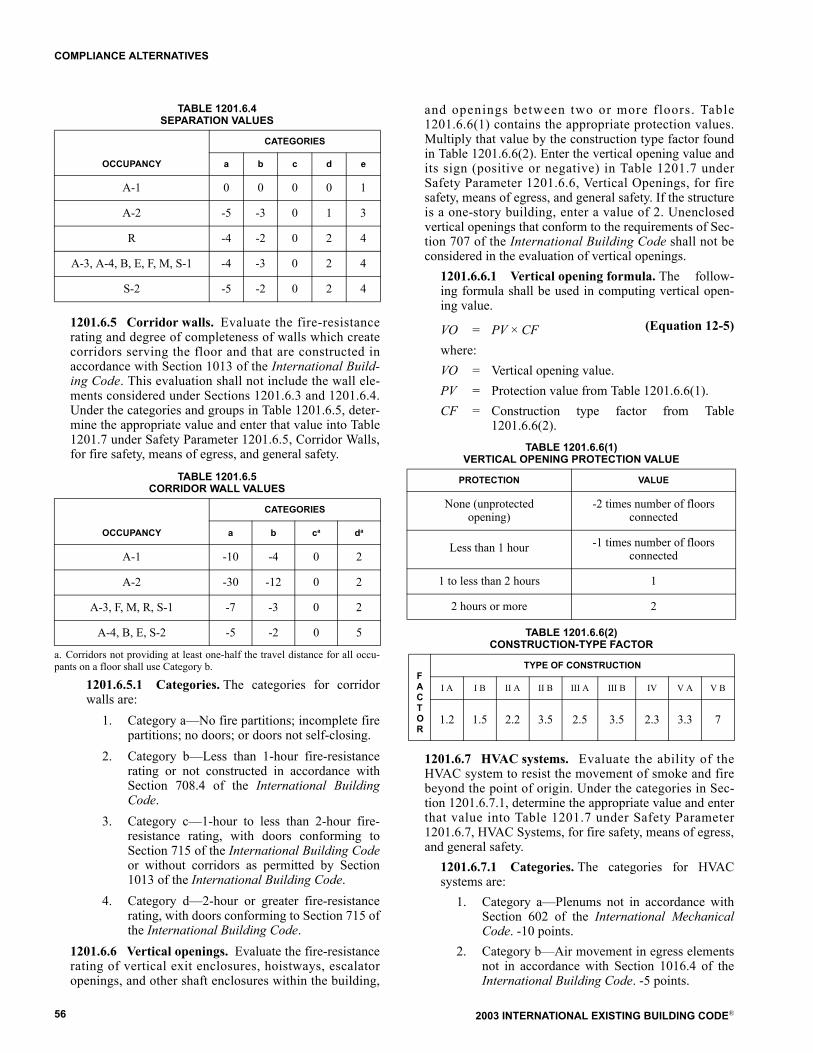
2003 INTERNATIONAL EXISTING BUILDING CODE®56
COMPLIANCE ALTERNATIVES
TABLE 1201.6.4SEPARATION VALUES
1201.6.5 Corridor walls. Evaluate the fire-resistancerating and degree of completeness of walls which createcorridors serving the floor and that are constructed inaccordance with Section 1013 of the International Build-ing Code. This evaluation shall not include the wall ele-ments considered under Sections 1201.6.3 and 1201.6.4.Under the categories and groups in Table 1201.6.5, deter-mine the appropriate value and enter that value into Table1201.7 under Safety Parameter 1201.6.5, Corridor Walls,for fire safety, means of egress, and general safety.
TABLE 1201.6.5CORRIDOR WALL VALUES
a. Corridors not providing at least one-half the travel distance for all occu-pants on a floor shall use Category b.
1201.6.5.1 Categories. The categories for corridorwalls are:
1. Category a�No fire partitions; incomplete firepartitions; no doors; or doors not self-closing.
2. Category b�Less than 1-hour fire-resistancerating or not constructed in accordance withSection 708.4 of the International BuildingCode.
3. Category c�1-hour to less than 2-hour fire-resistance rating, with doors conforming toSection 715 of the International Building Codeor without corridors as permitted by Section1013 of the International Building Code.
4. Category d�2-hour or greater fire-resistancerating, with doors conforming to Section 715 ofthe International Building Code.
1201.6.6 Vertical openings. Evaluate the fire-resistancerating of vertical exit enclosures, hoistways, escalatoropenings, and other shaft enclosures within the building,
and openings between two or more floors. Table1201.6.6(1) contains the appropriate protection values.Multiply that value by the construction type factor foundin Table 1201.6.6(2). Enter the vertical opening value andits sign (positive or negative) in Table 1201.7 underSafety Parameter 1201.6.6, Vertical Openings, for firesafety, means of egress, and general safety. If the structureis a one-story building, enter a value of 2. Unenclosedvertical openings that conform to the requirements of Sec-tion 707 of the International Building Code shall not beconsidered in the evaluation of vertical openings.
1201.6.6.1 Vertical opening formula. The follow-ing formula shall be used in computing vertical open-ing value.
(Equation 12-5)VO = PV × CFwhere:VO = Vertical opening value.PV = Protection value from Table 1201.6.6(1).CF = Construction type factor from Table
1201.6.6(2).TABLE 1201.6.6(1)
VERTICAL OPENING PROTECTION VALUE
TABLE 1201.6.6(2)CONSTRUCTION-TYPE FACTOR
1201.6.7 HVAC systems. Evaluate the ability of theHVAC system to resist the movement of smoke and firebeyond the point of origin. Under the categories in Sec-tion 1201.6.7.1, determine the appropriate value and enterthat value into Table 1201.7 under Safety Parameter1201.6.7, HVAC Systems, for fire safety, means of egress,and general safety.
1201.6.7.1 Categories. The categories for HVACsystems are:
1. Category a�Plenums not in accordance withSection 602 of the International MechanicalCode. -10 points.
2. Category b�Air movement in egress elementsnot in accordance with Section 1016.4 of theInternational Building Code. -5 points.
CATEGORIES
OCCUPANCY a b c d e
A-1 0 0 0 0 1
A-2 -5 -3 0 1 3
R -4 -2 0 2 4
A-3, A-4, B, E, F, M, S-1 -4 -3 0 2 4
S-2 -5 -2 0 2 4
CATEGORIES
OCCUPANCY a b ca da
A-1 -10 -4 0 2
A-2 -30 -12 0 2
A-3, F, M, R, S-1 -7 -3 0 2
A-4, B, E, S-2 -5 -2 0 5
PROTECTION VALUE
None (unprotectedopening)
-2 times number of floors connected
Less than 1 hour -1 times number of floors connected
1 to less than 2 hours 1
2 hours or more 2
FACTOR
TYPE OF CONSTRUCTION
I A I B II A II B III A III B IV V A V B
1.2 1.5 2.2 3.5 2.5 3.5 2.3 3.3 7
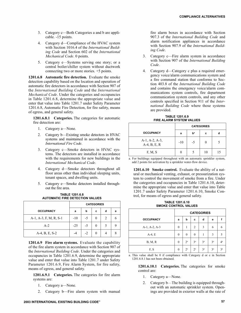
2003 INTERNATIONAL EXISTING BUILDING CODE® 57
COMPLIANCE ALTERNATIVES
3. Category c�Both Categories a and b are appli-cable. -15 points.
4. Category d�Compliance of the HVAC systemwith Section 1016.4 of the International Build-ing Code and Section 602 of the InternationalMechanical Code. 0 points.
5. Category e�Systems serving one story; or acentral boiler/chiller system without ductworkconnecting two or more stories. +5 points.
1201.6.8 Automatic fire detection. Evaluate the smokedetection capability based on the location and operation ofautomatic fire detectors in accordance with Section 907 ofthe International Building Code and the InternationalMechanical Code. Under the categories and occupanciesin Table 1201.6.8, determine the appropriate value andenter that value into Table 1201.7 under Safety Parameter1201.6.8, Automatic Fire Detection, for fire safety, meansof egress, and general safety.
1201.6.8.1 Categories. The categories for automaticfire detection are:
1. Category a�None.2. Category b�Existing smoke detectors in HVAC
systems and maintained in accordance with theInternational Fire Code.
3. Category c�Smoke detectors in HVAC sys-tems. The detectors are installed in accordancewith the requirements for new buildings in theInternational Mechanical Code.
4. Category d�Smoke detectors throughout allfloor areas other than individual sleeping units,tenant spaces, and dwelling units.
5. Category e�Smoke detectors installed through-out the fire area.
TABLE 1201.6.8AUTOMATIC FIRE DETECTION VALUES
1201.6.9 Fire alarm systems. Evaluate the capabilityof the fire alarm system in accordance with Section 907 ofthe International Building Code. Under the categories andoccupancies in Table 1201.6.9, determine the appropriatevalue and enter that value into Table 1201.7 under SafetyParameter 1201.6.9, Fire Alarm System, for fire safety,means of egress, and general safety.
1201.6.9.1 Categories. The categories for fire alarmsystems are:
1. Category a�None.2. Category b�Fire alarm system with manual
fire alarm boxes in accordance with Section907.3 of the International Building Code andalarm notification appliances in accordancewith Section 907.9 of the International Build-ing Code.
3. Category c�Fire alarm system in accordancewith Section 907 of the International BuildingCode.
4. Category d�Category c plus a required emer-gency voice/alarm communications system anda fire command station that conforms to Sec-tion 403.8 of the International Building Codeand contains the emergency voice/alarm com-munications system controls, fire departmentcommunication system controls, and any othercontrols specified in Section 911 of the Inter-national Building Code where those systemsare provided.
TABLE 1201.6.9FIRE ALARM SYSTEM VALUES
a. For buildings equipped throughout with an automatic sprinkler system,add 2 points for activation by a sprinkler water-flow device.
1201.6.10 Smoke control. Evaluate the ability of a nat-ural or mechanical venting, exhaust, or pressurization sys-tem to control the movement of smoke from a fire. Underthe categories and occupancies in Table 1201.6.10, deter-mine the appropriate value and enter that value into Table1201.7 under Safety Parameter 1201.6.10, Smoke Con-trol, for means of egress and general safety.
TABLE 1201.6.10SMOKE CONTROL VALUES
a. This value shall be 0 if compliance with Category d or e in Section1201.6.8.1 has not been obtained.
1201.6.10.1 Categories. The categories for smokecontrol are:
1. Category a�None.2. Category b�The building is equipped through-
out with an automatic sprinkler system. Open-ings are provided in exterior walls at the rate of
CATEGORIES
OCCUPANCY a b c d e
A-1, A-3, F, M, R, S-1 -10 -5 0 2 6
A-2 -25 -5 0 5 9
A-4, B, E, S-2 -4 -2 0 4 8
OCCUPANCY
CATEGORIES
a ba c d
A-1, A-2, A-3,A-4, B, E, R
-10 -5 0 5
F, M, S 0 5 10 15
CATEGORIES
OCCUPANCY a b c d e f
A-1, A-2, A-3 0 1 2 3 6 6
A-4, E 0 0 0 1 3 5
B, M, R 0 2a 3a 3a 3a 4a
F, S 0 2a 2a 3a 3a 3a
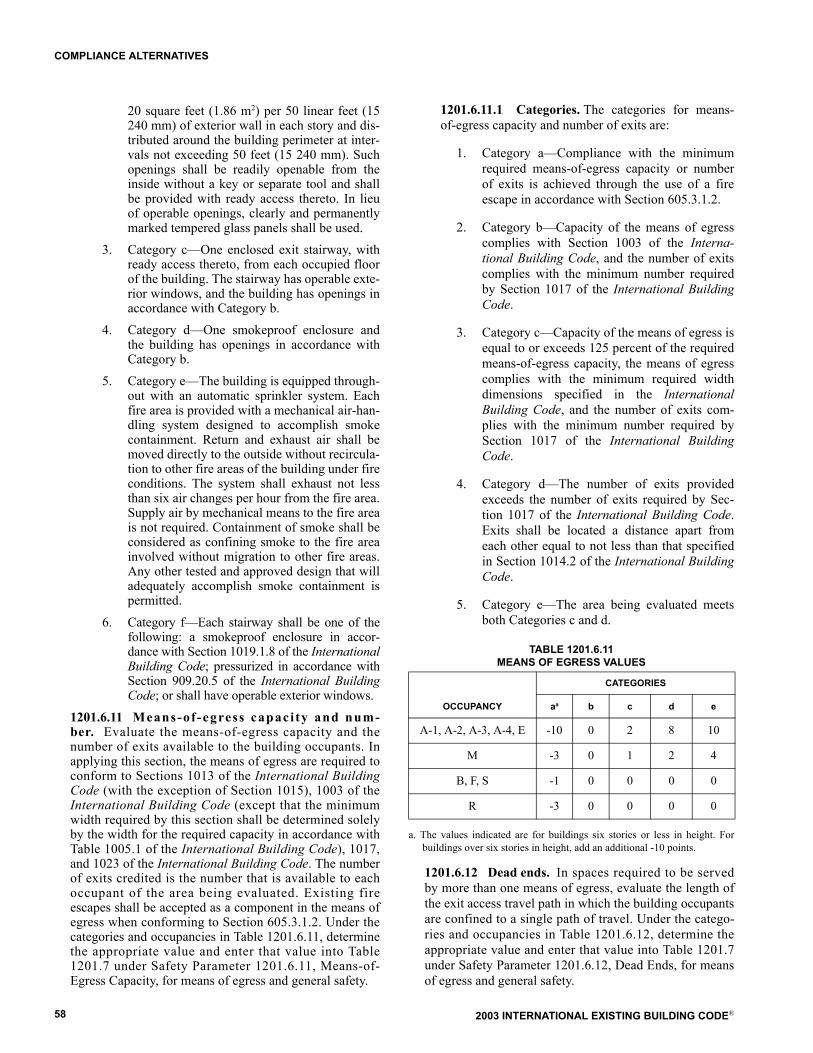
2003 INTERNATIONAL EXISTING BUILDING CODE®58
COMPLIANCE ALTERNATIVES
20 square feet (1.86 m2) per 50 linear feet (15240 mm) of exterior wall in each story and dis-tributed around the building perimeter at inter-vals not exceeding 50 feet (15 240 mm). Suchopenings shall be readily openable from theinside without a key or separate tool and shallbe provided with ready access thereto. In lieuof operable openings, clearly and permanentlymarked tempered glass panels shall be used.
3. Category c�One enclosed exit stairway, withready access thereto, from each occupied floorof the building. The stairway has operable exte-rior windows, and the building has openings inaccordance with Category b.
4. Category d�One smokeproof enclosure andthe building has openings in accordance withCategory b.
5. Category e�The building is equipped through-out with an automatic sprinkler system. Eachfire area is provided with a mechanical air-han-dling system designed to accomplish smokecontainment. Return and exhaust air shall bemoved directly to the outside without recircula-tion to other fire areas of the building under fireconditions. The system shall exhaust not lessthan six air changes per hour from the fire area.Supply air by mechanical means to the fire areais not required. Containment of smoke shall beconsidered as confining smoke to the fire areainvolved without migration to other fire areas.Any other tested and approved design that willadequately accomplish smoke containment ispermitted.
6. Category f�Each stairway shall be one of thefollowing: a smokeproof enclosure in accor-dance with Section 1019.1.8 of the InternationalBuilding Code; pressurized in accordance withSection 909.20.5 of the International BuildingCode; or shall have operable exterior windows.
1201.6.11 Means-of-egress capaci ty and num-ber. Evaluate the means-of-egress capacity and thenumber of exits available to the building occupants. Inapplying this section, the means of egress are required toconform to Sections 1013 of the International BuildingCode (with the exception of Section 1015), 1003 of theInternational Building Code (except that the minimumwidth required by this section shall be determined solelyby the width for the required capacity in accordance withTable 1005.1 of the International Building Code), 1017,and 1023 of the International Building Code. The numberof exits credited is the number that is available to eachoccupant of the area being evaluated. Existing fireescapes shall be accepted as a component in the means ofegress when conforming to Section 605.3.1.2. Under thecategories and occupancies in Table 1201.6.11, determinethe appropriate value and enter that value into Table1201.7 under Safety Parameter 1201.6.11, Means-of-Egress Capacity, for means of egress and general safety.
1201.6.11.1 Categories. The categories for means-of-egress capacity and number of exits are:
1. Category a�Compliance with the minimumrequired means-of-egress capacity or numberof exits is achieved through the use of a fireescape in accordance with Section 605.3.1.2.
2. Category b�Capacity of the means of egresscomplies with Section 1003 of the Interna-tional Building Code, and the number of exitscomplies with the minimum number requiredby Section 1017 of the International BuildingCode.
3. Category c�Capacity of the means of egress isequal to or exceeds 125 percent of the requiredmeans-of-egress capacity, the means of egresscomplies with the minimum required widthdimensions specified in the InternationalBuilding Code, and the number of exits com-plies with the minimum number required bySection 1017 of the International BuildingCode.
4. Category d�The number of exits providedexceeds the number of exits required by Sec-tion 1017 of the International Building Code.Exits shall be located a distance apart fromeach other equal to not less than that specifiedin Section 1014.2 of the International BuildingCode.
5. Category e�The area being evaluated meetsboth Categories c and d.
TABLE 1201.6.11MEANS OF EGRESS VALUES
a. The values indicated are for buildings six stories or less in height. Forbuildings over six stories in height, add an additional -10 points.
1201.6.12 Dead ends. In spaces required to be servedby more than one means of egress, evaluate the length ofthe exit access travel path in which the building occupantsare confined to a single path of travel. Under the catego-ries and occupancies in Table 1201.6.12, determine theappropriate value and enter that value into Table 1201.7under Safety Parameter 1201.6.12, Dead Ends, for meansof egress and general safety.
CATEGORIES
OCCUPANCY aa b c d e
A-1, A-2, A-3, A-4, E -10 0 2 8 10
M -3 0 1 2 4
B, F, S -1 0 0 0 0
R -3 0 0 0 0

2003 INTERNATIONAL EXISTING BUILDING CODE® 59
COMPLIANCE ALTERNATIVES
1201.6.12.1 Categories. The categories for deadends are:
1. Category a � Dead end of 35 feet (10 670 mm)in nonsprinklered buildings or 70 feet (21 340mm) in sprinklered buildings.
2. Category b � Dead end of 20 feet (6096 mm);or 50 feet (15 240 mm) in Group B in accor-dance with Section 1016.3, Exception 2 of theInternational Building Code.
3. Category c � No dead ends; or ratio of lengthto width (l/w) is less than 2.5:1.
TABLE 1201.6.12DEAD-END VALUES
a. For dead-end distances between categories, the dead end value shall beobtained by linear interpolation.
1201.6.13 Maximum exit access travel distance to anexit. Evaluate the length of exit access travel to anapproved exit. Determine the appropriate points in accor-dance with the following equation and enter that valueinto Table 1201.7 under Safety Parameter 1201.6.13,Maximum Exit Access Travel Distance for means ofegress and general safety. The maximum allowable exitaccess travel distance shall be determined in accordancewith Section 1015 of the International Building Code.
(Equation 12-6)
1201.6.14 Elevator control. Evaluate the passengerelevator equipment and controls that are available to thefire department to reach all occupied floors. Elevatorrecall controls shall be provided in accordance with theInternational Fire Code. Under the categories and occu-pancies in Table 1201.6.14, determine the appropriatevalue and enter that value into Table 1201.7 under SafetyParameter 1201.6.14, Elevator Control, for fire safety,means of egress, and general safety. The values shall bezero for a single story building.
1201.6.14.1 Categories. The categories for elevatorcontrols are:
1. Category a�No elevator.
2. Category b�Any elevator without Phase I andII recall.
3. Category c�All elevators with Phase I and IIrecall as required by the International FireCode.
4. Category d�All meet Category c; or Category bwhere permitted to be without recall; and at leastone elevator that complies with new construc-tion requirements serves all occupied floors.
TABLE 1201.6.14ELEVATOR CONTROL VALUES
For SI: 1 foot = 304.8 mm.NP = Not permitted.
1201.6.15 Means-of-egress emergency lighting. Eval-uate the presence of and reliability of means-of-egressemergency lighting. Under the categories and occupanciesin Table 1201.6.15, determine the appropriate value andenter that value into Table 1201.7 under Safety Parameter1201.6.15, Means-of-Egress Emergency Lighting, formeans of egress and general safety.
1201.6.15.1 Categories. The categories for means-of-egress emergency lighting are:
1. Category a�Means-of-egress lighting and exitsigns not provided with emergency power inaccordance with Section 2702 of the Interna-tional Building Code.
2. Category b�Means-of-egress lighting and exitsigns provided with emergency power in accor-dance with Section 2702 of the InternationalBuilding Code.
3. Category c�Emergency power provided tomeans-of-egress lighting and exit signs, whichprovides protection in the event of power fail-ure to the site or building.
TABLE 1201.6.15MEANS-OF-EGRESS EMERGENCY LIGHTING VALUES
NP = Not permitted.
1201.6.16 Mixed occupancies. Where a building hastwo or more occupancies that are not in the same occu-pancy classification, the separation between the mixedoccupancies shall be evaluated in accordance with this
CATEGORIESa
OCCUPANCY a b c
A-1, A-3, A-4, B, F, M, R, S -2 0 2
A-2, E -2 0 2
Maximum allowabletravel distance �
Maximum actualtravel distance
Points = 20 ×Maximum allowable travel distance
ELEVATOR TRAVEL
CATEGORIES
a b c d
Less than 25 feet of travel above or below the primary level of elevator access for emergency fire-fighting or rescue personnel
-2 0 0 +2
Travel of 25 feet or more above or below the primary level of elevator access for emergency fire-fighting or rescue personnel
-4 NP 0 +4
NUMBER OF EXITS REQUIRED BY SECTIONS 1018.1 AND 1018.2
OF THE INTERNATIONALBUILDING CODE
CATEGORIES
a b c
Two or more exits NP 0 4
Minimum of one exit 0 1 1
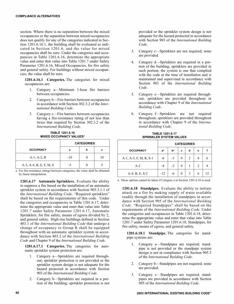
2003 INTERNATIONAL EXISTING BUILDING CODE®60
COMPLIANCE ALTERNATIVES
section. Where there is no separation between the mixedoccupancies or the separation between mixed occupanciesdoes not qualify for any of the categories indicated in Sec-tion 1201.6.16.1, the building shall be evaluated as indi-cated in Section 1201.6, and the value for mixedoccupancies shall be zero. Under the categories and occu-pancies in Table 1201.6.16, determine the appropriatevalue and enter that value into Table 1201.7 under SafetyParameter 1201.6.16, Mixed Occupancies, for fire safetyand general safety. For buildings without mixed occupan-cies, the value shall be zero.
1201.6.16.1 Categories. The categories for mixedoccupancies are:
1. Category a�Minimum 1-hour fire barriersbetween occupancies.
2. Category b�Fire barriers between occupanciesin accordance with Section 302.3.2 of the Inter-national Building Code.
3. Category c�Fire barriers between occupancieshaving a fire-resistance rating of not less thantwice that required by Section 302.3.2 of theInternational Building Code.
TABLE 1201.6.16MIXED OCCUPANCY VALUESa
a. For fire-resistance ratings between categories, the value shall be obtainedby linear interpolation.
1201.6.17 Automatic Sprinklers. Evaluate the abilityto suppress a fire based on the installation of an automaticsprinkler system in accordance with Section 903.3.1.1 ofthe International Building Code. �Required sprinklers�shall be based on the requirements of this code. Underthe categories and occupancies in Table 1201.6.17, deter-mine the appropriate value and enter that value into Table1201.7 under Safety Parameter 1201.6.17, AutomaticSprinklers, for fire safety, means of egress divided by 2,and general safety. High-rise buildings defined in Section403.1 of the International Building Code that undergo achange of occupancy to Group R shall be equippedthroughout with an automatic sprinkler system in accor-dance with Section 403.2 of the International BuildingCode and Chapter 9 of the International Building Code.
1201.6.17.1 Categories. The categories for auto-matic sprinkler system protection are:
1. Category a�Sprinklers are required through-out; sprinkler protection is not provided or thesprinkler system design is not adequate for thehazard protected in accordance with Section903 of the International Building Code.
2. Category b�Sprinklers are required in a por-tion of the building; sprinkler protection is not
provided or the sprinkler system design is notadequate for the hazard protected in accordancewith Section 903 of the International BuildingCode.
3. Category c�Sprinklers are not required; noneare provided.
4. Category d�Sprinklers are required in a por-tion of the building; sprinklers are provided insuch portion; the system is one that compliedwith the code at the time of installation and ismaintained and supervised in accordance withSection 903 of the International BuildingCode.
5. Category e�Sprinklers are required through-out; sprinklers are provided throughout inaccordance with Chapter 9 of the InternationalBuilding Code.
6. Category f�Sprinklers are not requiredthroughout; sprinklers are provided throughoutin accordance with Chapter 9 of the Interna-tional Building Code.
TABLE 1201.6.17SPRINKLER SYSTEM VALUES
a. These options cannot be taken if Category a in Section 1201.6.18 is used.
1201.6.18 Standpipes. Evaluate the ability to initiateattack on a fire by making supply of water availablereadily through the installation of standpipes in accor-dance with Section 905 of the International BuildingCode. �Required Standpipes� shall be based on therequirements of the International Building Code. Underthe categories and occupancies in Table 1201.6.18, deter-mine the appropriate value and enter that value into Table1201.7 under Safety Parameter 1201.6.18, Standpipes, forfire safety, means of egress, and general safety.
1201.6.18.1 Standpipe. The categories for stand-pipe systems are:
1. Category a�Standpipes are required; stand-pipe is not provided or the standpipe systemdesign is not in compliance with Section 905.3of the International Building Code.
2. Category b�Standpipes are not required; noneare provided.
3. Category c�Standpipes are required; stand-pipes are provided in accordance with Section905 of the International Building Code.
CATEGORIES
OCCUPANCY a b c
A-1, A-2, R -10 0 10
A-3, A-4, B, E, F, M, S -5 0 5
CATEGORIES
OCCUPANCY aa ba c d e f
A-1, A-3, F, M, R, S-1 -6 -3 0 2 4 6
A-2 -4 -2 0 1 2 4
A-4, B, E, S-2 -12 -6 0 3 6 12
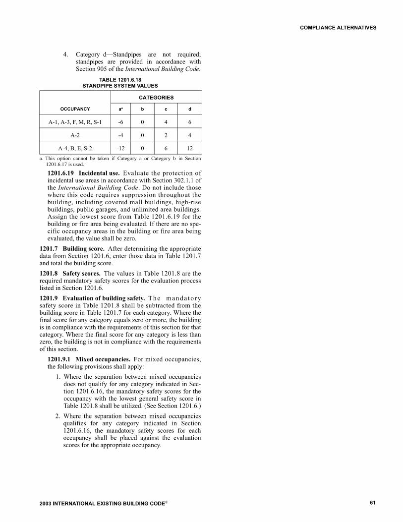
2003 INTERNATIONAL EXISTING BUILDING CODE® 61
COMPLIANCE ALTERNATIVES
4. Category d�Standpipes are not required;standpipes are provided in accordance withSection 905 of the International Building Code.
TABLE 1201.6.18STANDPIPE SYSTEM VALUES
a. This option cannot be taken if Category a or Category b in Section1201.6.17 is used.
1201.6.19 Incidental use. Evaluate the protection ofincidental use areas in accordance with Section 302.1.1 ofthe International Building Code. Do not include thosewhere this code requires suppression throughout thebuilding, including covered mall buildings, high-risebuildings, public garages, and unlimited area buildings.Assign the lowest score from Table 1201.6.19 for thebuilding or fire area being evaluated. If there are no spe-cific occupancy areas in the building or fire area beingevaluated, the value shall be zero.
1201.7 Building score. After determining the appropriatedata from Section 1201.6, enter those data in Table 1201.7and total the building score.1201.8 Safety scores. The values in Table 1201.8 are therequired mandatory safety scores for the evaluation processlisted in Section 1201.6.1201.9 Evaluation of building safety. T h e m a n d a t o r ysafety score in Table 1201.8 shall be subtracted from thebuilding score in Table 1201.7 for each category. Where thefinal score for any category equals zero or more, the buildingis in compliance with the requirements of this section for thatcategory. Where the final score for any category is less thanzero, the building is not in compliance with the requirementsof this section.
1201.9.1 Mixed occupancies. For mixed occupancies,the following provisions shall apply:
1. Where the separation between mixed occupanciesdoes not qualify for any category indicated in Sec-tion 1201.6.16, the mandatory safety scores for theoccupancy with the lowest general safety score inTable 1201.8 shall be utilized. (See Section 1201.6.)
2. Where the separation between mixed occupanciesqualifies for any category indicated in Section1201.6.16, the mandatory safety scores for eachoccupancy shall be placed against the evaluationscores for the appropriate occupancy.
CATEGORIES
OCCUPANCY aa b c d
A-1, A-3, F, M, R, S-1 -6 0 4 6
A-2 -4 0 2 4
A-4, B, E, S-2 -12 0 6 12

2003 INTERNATIONAL EXISTING BUILDING CODE®62
COMPLIANCE ALTERNATIVES
TABLE 1201.6.19INCIDENTAL USE AREA VALUESa
a. AFSS = Automatic fire suppression system; SP = Smoke partitions (See IBC Section 302.1.1.1).Note: For Table 1201.7, see page 63.
TABLE 1201.8MANDATORY SAFETY SCORESa
a. MFS = Mandatory Fire SafetyMME = Mandatory Means of EgressMGS = Mandatory General Safety
TABLE 1201.9EVALUATION FORMULASa
a. FS = Fire Safety MFS = Mandatory Fire SafetyME = Means of Egress MME = Mandatory Means of EgressGS = General Safety MGS = Mandatory General Safety
PROTECTION REQUIRED BY TABLE
302.1.1 OF THE INTERNATIONAL BUILDING CODE
PROTECTION PROVIDED
None 1 hour AFSS AFSS with SP
1 hour and AFSS
2 hours 2 hours and AFSS
2 hours and AFSS -4 -3 -2 -2 -1 -2 0
2 hours, or 1 hour and AFSS
-3 -2 -1 -1 0 0 0
1 hour and AFSS -3 -2 -1 -1 0 -1 0
1 hour -1 0 -1 -1 0 0
1 hour, or AFSS with SP
-1 0 -1 -1 0 0 0
AFSS with SP -1 -1 -1 -1 0 -1 0
1 hour or AFSS -1 0 0 0 0 0 0
OCCUPANCY FIRE SAFETY (MFS) MEANS OF EGRESS (MME) GENERAL SAFETY (MGS)
A-1 20 31 31
A-2 21 32 32
A-3 22 33 33
A-4, E 29 40 40
B 30 40 40
F 24 34 34
M 23 40 40
R 21 38 38
S-1 19 29 29
S-2 29 3 39
FORMULA T1201.7 T1201.8 SCORE PASS FAIL
FS - MFS > 0
ME - MME ≥ 0
GS - MGS ≥ 0
(FS) - (MFS) = (ME) - (MME) = (GS) - (MGS) =
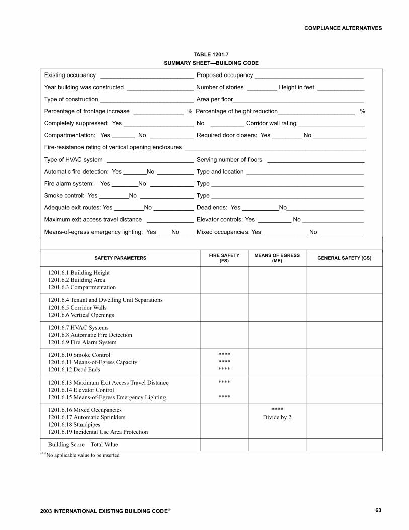
2003 INTERNATIONAL EXISTING BUILDING CODE® 63
COMPLIANCE ALTERNATIVES
TABLE 1201.7SUMMARY SHEET�BUILDING CODE
****No applicable value to be inserted
Existing occupancy ____________________________ Proposed occupancy _________________________________________
Year building was constructed ____________________ Number of stories _________ Height in feet ______________ Type of construction ____________________________ Area per floor _________________________________________________
Percentage of frontage increase _______________ % Percentage of height reduction_______________________ %
Completely suppressed: Yes _____________________ No __________ Corridor wall rating _________________________
Compartmentation: Yes _________ No _____________ Required door closers: Yes _________ No ____________________
Fire-resistance rating of vertical opening enclosures ______________________________________________________
Type of HVAC system __________________________ Serving number of floors _____________________________ Automatic fire detection: Yes _______No ___________ Type and location ____________________________________________
Fire alarm system: Yes ________No _____________ Type _________________________________________________________
Smoke control: Yes _________No ________________ Type _________________________________________________________
Adequate exit routes: Yes _________No ____________ Dead ends: Yes ___________No _____________________________
Maximum exit access travel distance ______________ Elevator controls: Yes __________ No _______________________
Means-of-egress emergency lighting: Yes ___ No ____ Mixed occupancies: Yes _____________ No _________________
SAFETY PARAMETERS FIRE SAFETY (FS)
MEANS OF EGRESS (ME) GENERAL SAFETY (GS)
1201.6.1 Building Height1201.6.2 Building Area1201.6.3 Compartmentation
1201.6.4 Tenant and Dwelling Unit Separations1201.6.5 Corridor Walls1201.6.6 Vertical Openings
1201.6.7 HVAC Systems1201.6.8 Automatic Fire Detection1201.6.9 Fire Alarm System
1201.6.10 Smoke Control1201.6.11 Means-of-Egress Capacity1201.6.12 Dead Ends
************
1201.6.13 Maximum Exit Access Travel Distance1201.6.14 Elevator Control1201.6.15 Means-of-Egress Emergency Lighting
****
****
1201.6.16 Mixed Occupancies1201.6.17 Automatic Sprinklers1201.6.18 Standpipes1201.6.19 Incidental Use Area Protection
****Divide by 2
Building Score�Total Value

2003 INTERNATIONAL EXISTING BUILDING CODE®64
COMPLIANCE ALTERNATIVES
Actual value i =
Allowableareai
1200square feet-------------------------------------- 1�
Actualareai
Allowableareai
------------------------- +�+
Actualarean
Allowablearean
-------------------------
Allowable

2003 INTERNATIONAL EXISTING BUILDING CODE® 65
SECTION 1301GENERAL
[B] 1301.1 Scope. The provisions of this chapter shallgovern safety during construction that is under the jurisdic-tion of this code and the protection of adjacent public andprivate properties.[B] 1301.2 Storage and placement. Construction equip-ment and materials shall be stored and placed so as not toendanger the public, the workers or adjoining property forthe duration of the construction project.1301.3 Alterations, repairs, and additions. R e q u i r e dexits, existing structural elements, fire protection devices,and sanitary safeguards shall be maintained at all times dur-ing alterations, repairs, or additions to any building or struc-ture.
Exceptions:1. When such required elements or devices are being
altered or repaired, adequate substitute provisionsshall be made.
2. When the existing building is not occupied.[B] 1301.4 Manner of removal. Waste materials shall beremoved in a manner which prevents injury or damage topersons, adjoining properties, and public rights-of-way.[B] 1301.5 Facilities required. Sanitary facilities shall beprovided during construction or demolition activities inaccordance with the International Plumbing Code.[B] 1301.6 Protection of pedestrians. Pedestrians shallbe protected during construction and demolition activitiesas required by Sections 1301.6.1 through 1301.6.7 andTable 1301.6. Signs shall be provided to direct pedestriantraffic.
[B] 1301.6.1 Walkways. A walkway shall be pro-vided for pedestrian travel in front of every construction
and demolition site unless the authority having jurisdic-tion authorizes the sidewalk to be fenced or closed.Walkways shall be of sufficient width to accommodatethe pedestrian traffic, but in no case shall they be lessthan 4 feet (1219 mm) in width. Walkways shall be pro-vided with a durable walking surface. Walkways shall beaccessible in accordance with Chapter 11 of the Interna-tional Building Code and shall be designed to support allimposed loads and in no case shall the design live loadbe less than 150 psf (7.2 kN/m2).[B] 1301.6.2 Directional barricades. Pedestrian traf-fic shall be protected by a directional barricade wherethe walkway extends into the street. The directional bar-ricade shall be of sufficient size and construction todirect vehicular traffic away from the pedestrian path.[B] 1301.6.3 Construction railings. Construction rail-ings shall be at least 42 inches (1067 mm) in height andshall be sufficient to direct pedestrians around construc-tion areas.[B] 1301.6.4 Barriers. Barriers shall be a minimum of8 feet (2438 mm) in height and shall be placed on theside of the walkway nearest the construction. Barriersshall extend the entire length of the construction site.Openings in such barriers shall be protected by doorswhich are normally kept closed.
[B] 1301.6.4.1 Barrier design. Barriers shall bedesigned to resist loads required in Chapter 16 ofthe International Building Code unless constructedas follows:
1. Barriers shall be provided with 2 × 4 top andbottom plates.
2. The barrier material shall be a minimum of 3/4inch (19.1 mm) inch boards or 1/4 inch (6.4mm) wood structural use panels.
[B] TABLE 1301.6PROTECTION OF PEDESTRIANS
For SI: 1 foot = 304.8 mm.
HEIGHT OFCONSTRUCTION DISTANCE OF CONSTRUCTION TO LOTLINE TYPE OF PROTECTION REQUIRED
8 feet or lessLess than 5 feet Construction railings
5 feet or more None
Less than 5 feet Barrier and covered walkway
More than 8 feet
5 feet or more, but not more than one-fourth the height of construction Barrier and covered walkway
5 feet or more, but between one-fourth and one-half the height of construction Barrier
5 feet or more, but exceeding one-half the height of construction None
CHAPTER 13
CONSTRUCTION SAFEGUARDS
2003 INTERNATIONAL EXISTING BUILDING CODE®66
CONSTRUCTION SAFEGUARDS
3. Wood structural use panels shall be bondedwith an adhesive identical to that for exteriorwood structural use panels.
4. Wood structural use panels 1/4 inch (6.4 mm) or1/16 inch (23.8 mm) in thickness shall havestuds spaced not more than 2 feet (610 mm) oncenter.
5. Wood structural use panels 3/8 inch (9.5 mm) or1/2 inch (12.7 mm) in thickness shall have studsspaced not more than 4 feet (1219 mm) on cen-ter, provided a 2 inch by 4 inch (51 mm by 102mm) stiffener is placed horizontally at the midheight where the stud spacing exceeds 2 feet(610 mm) on center.
6. Wood structural use panels 5/8 inch (15.9 mm)or thicker shall not span over 8 feet (2438 mm).
[B] 1301.6.5 Covered walkways. Covered walkwaysshall have a minimum clear height of 8 feet (2438 mm) asmeasured from the floor surface to the canopy overhead.Adequate lighting shall be provided at all times. Coveredwalkways shall be designed to support all imposed loads.In no case shall the design live load be less than 150 psf(7.2 kN/m2) for the entire structure.
Exception: Roofs and supporting structures of coveredwalkways for new, light-frame construction notexceeding two stories in height are permitted to bedesigned for a live load of 75 psf (3.6 kN/m2) or theloads imposed on them, whichever is greater. In lieu ofsuch designs, the roof and supporting structure of acovered walkway are permitted to be constructed asfollows:
1. Footings shall be continuous 2 × 6 members.2. Posts not less than 4 × 6 shall be provided on
both sides of the roof and spaced not more than12 feet (3658 mm) on center.
3. Stringers not less than 4 × 12 shall be placed onedge upon the posts.
4. Joists resting on the stringers shall be at least2 × 8 and shall be spaced not more than 2feet (610 mm) on center.
5. The deck shall be planks at least 2 inches (51mm) thick or wood structural panels with anexterior exposure durability classification atleast 23/32 inch (18.3 mm) thick nailed to thejoists.
6. Each post shall be knee-braced to joists andstringers by 2 × 4 minimum members 4 feet(1219 mm) long.
7. A 2 × 4 minimum curb shall be set on edgealong the outside edge of the deck.
[B] 1301.6.6 Repair, maintenance and removal.Pedestrian protection required by Section 1301.6 shall bemaintained in place and kept in good order for the entirelength of time pedestrians may be endangered. The owneror the owner�s agent, upon the completion of the con-
struction activity, shall immediately remove walkways,debris and other obstructions and leave such public prop-erty in as good a condition as it was before such work wascommenced.
[B] 1301.6.7 Adjacent to excavations. Every excava-tion on a site located 5 feet (1524 mm) or less from thestreet lot line shall be enclosed with a barrier not less than6 feet (1829 mm) high. Where located more than 5 feet(1524 mm) from the street lot line, a barrier shall beerected when required by the code official. Barriers shallbe of adequate strength to resist wind pressure as speci-fied in Chapter 16 of the International Building Code.
[B] SECTION 1302PROTECTION OF ADJOINING PROPERTY
1302.1 Protection required. Adjoining public and privateproperty shall be protected from damage during constructionand demolition work. Protection must be provided for foot-ings, foundations, party walls, chimneys, skylights and roofs.Provisions shall be made to control water run-off and erosionduring construction or demolition activities. The personmaking or causing an excavation to be made shall providewritten notice to the owners of adjoining buildings advisingthem that the excavation is to be made and that the adjoiningbuildings should be protected. Said notification shall bedelivered not less than 10 days prior to the scheduled startingdate of the excavation.
[B] SECTION 1303TEMPORARY USE OF STREETS, ALLEYS AND
PUBLIC PROPERTY
1303.1 Storage and handling of materials. T h e t e m p o -rary use of streets or public property for the storage or han-dling of materials or of equipment required for constructionor demolition, and the protection provided to the public shallcomply with the provisions of the authority having jurisdic-tion and Section 1303.
1303.2 Obstructions. Construction materials and equip-ment shall not be placed or stored so as to obstruct access tofire hydrants, standpipes, fire or police alarm boxes, catchbasins or manholes, nor shall such material or equipment belocated within 20 feet (6.1 m) of a street intersection, orplaced so as to obstruct normal observations of traffic signalsor to hinder the use of public transit loading platforms.
1303.3 Utility fixtures. Building materials, fences, shedsor any obstruction of any kind shall not be placed so as toobstruct free approach to any fire hydrant, fire departmentconnection, utility pole, manhole, fire alarm box, or catchbasin, or so as to interfere with the passage of water in thegutter. Protection against damage shall be provided to suchutility fixtures during the progress of the work, but sight ofthem shall not be obstructed.
2003 INTERNATIONAL EXISTING BUILDING CODE® 67
CONSTRUCTION SAFEGUARDS
SECTION 1304FIRE EXTINGUISHERS
[F] 1304.1 Where required. All structures under construc-tion, alteration, or demolition shall be provided with not lessthan one approved portable fire extinguisher in accordancewith Section 906 of the International Fire Code and sized fornot less than ordinary hazard as follows:
1. At each stairway on all floor levels where combustiblematerials have accumulated.
2. In every storage and construction shed.3. Additional portable fire extinguishers shall be provided
where special hazards exist, such as the storage and useof flammable and combustible liquids.
[B] 1304.2 Fire hazards. The provisions of this code andof the International Fire Code shall be strictly observed tosafeguard against all fire hazards attendant upon constructionoperations.
[B] SECTION 1305EXITS
1305.1 Stairways required. Where an existing buildingexceeding 50 feet (15 240 mm) in height is altered, at leastone temporary lighted stairway shall be provided unless oneor more of the permanent stairways is available for egress asthe construction progresses.1305.2 Maintenance of exits. Required means of egressshall be maintained at all times during alterations, repairsand additions to any building.
[F] SECTION 1306STANDPIPE SYSTEMS
1306.1 Where required. Buildings required to have astandpipe system in accordance with this code shall be pro-vided with not less than one standpipe for use during con-struction. Such standpipes shall be installed where theprogress of construction is not more than 40 feet (12 192mm) in height above the lowest level of fire departmentaccess. Such standpipe shall be provided with fire depart-ment hose connections at accessible locations adjacent tousable stairs. Such standpipes shall be extended as construc-tion progresses to within one floor of the highest point ofconstruction having secured decking or flooring.1306.2 Buildings being demolished. Where a building orportion of a building is being demolished and a standpipe isexisting within such a building, such standpipe shall bemaintained in an operable condition so as to be available foruse by the fire department. Such standpipe shall be demol-ished with the building but shall not be demolished morethan one floor below the floor being demolished.1306.3 Detailed requirements. S t a n d p i p e s s h a l l b einstalled in accordance with the provisions of Chapter 9 ofthe International Building Code.
Exception: Standpipes shall be either temporary or per-manent in nature, and with or without a water supply, pro-vided that such standpipes conform to the requirements of
Section 905 of the International Building Code as tocapacity, outlets and materials.
1306.4 Water supply. Water supply for fire protection,either temporary or permanent, shall be made available assoon as combustible material accumulates.
[F] SECTION 1307AUTOMATIC SPRINKLER SYSTEM
1307.1 Completion before occupancy. In portions of abuilding where an automatic sprinkler system is required bythis code, it shall be unlawful to occupy those portions of thebuilding until the automatic sprinkler system installation hasbeen tested and approved, except as provided in Section110.3.1307.2 Operation of valves. Operation of sprinkler con-trol valves shall be permitted only by properly authorizedpersonnel and shall be accompanied by notification of dulydesignated parties. When the sprinkler protection is beingregularly turned off and on to facilitate connection of newlycompleted segments, the sprinkler control valves shall bechecked at the end of each work period to ascertain that pro-tection is in service.
SECTION 1308ACCESSIBILITY
1308.1 Construction sites. Structures, sites, and equip-ment directly associated with the actual process of construc-tion, including but not limited to scaffolding, bridging,material hoists, material storage, or construction trailers arenot required to be accessible.

2003 INTERNATIONAL EXISTING BUILDING CODE®68
CONSTRUCTION SAFEGUARDS
2003 INTERNATIONAL EXISTING BUILDING CODE® 69
REFERENCED STANDARDS
This chapter lists the standards that are referenced in various sections of this document. The standards are listed herein by thepromulgating agency of the standard, the standard identification, the effective date and title, and the section or sections of thisdocument that reference the standard. The application of the referenced standards shall be as specified in Section 102.4.
ASCE American Society of Civil Engineers1801 Alexander Bell DriveReston, VA 20191-4400
StandardReferencedNumber Title
Referencedin code
section number
31�02 Seismic Evaluation of Existing Buildings . . . . . . . . . . . . . . . . . . . . . . . . . . . . . . . . . . . . . . 407.1.1, Table 407.1.1.2, 407.1.1.3
ASHRAE American Society of Heating, Refrigerating and Air Conditioning Engineers1791 Tullie Circle, NEAtlanta, GA 30329
StandardReferencedNumber Title
Referencedin code
section number
62�01 Ventilation for Acceptable Indoor Air Quality . . . . . . . . . . . . . . . . . . . . . . . . . . . . . . . . . . . . . . . . . . . . . . . . . . . . . . . . . . 609.2
ASME American Society of Mechanical Engineers3 Park AvenueNew York, NY 10016
StandardReferencedNumber Title
Referencedin code
section number
A17.1�2000A18.1�1999A112.19.2M�1998
Safety Code for Elevators and Escalators. . . . . . . . . . . . . . . . . . . . . . . . . . . . . . . . . . . . . . . . . . . . . . . . . . . . . . . . . . . . 506.1.2Safety Standard for Platform Lifts and Stairway Chair Lifts � with A18.1a�2001 Addenda . . . . . . . . . . . . . . . . . . 506.1.3Vitreous China Plumbing Fixtures . . . . . . . . . . . . . . . . . . . . . . . . . . . . . . . . . . . . . . . . . . . . . . . . . . . . . . . . . . . . . . . . . . . 410.1
DOJDepartment of Justice950 Pennsylvania Avenue NWWashington, DC 20530-0001
StandardReferencedNumber Title
Referencedin code
section number
28 CFR Part 36.403Nondiscrimination on the Basis of Disability by Public Accommodations and in Commercial Facilities � New Construction and Alterations � Alterations: Path of Travel . . . . . . . . . . . . . . . . . . . . . . . . . . . . . . 506.2
CHAPTER 14
REFERENCED STANDARDS

2003 INTERNATIONAL EXISTING BUILDING CODE®70
REFERENCED STANDARDS
DOTnDepartment of Transportation400 7th Street SWRoom 8102Washington, DC 20590-0001
StandardReferencedNumber Title
Referencedin code
section number
49 CFR Part 37.43 (c) Alteration of Transportation Facilities by Public Entities . . . . . . . . . . . . . . . . . . . . . . . . . . . . . . . . . . . . . . . . . . . . . . . . . 506.2
FEMAFederal Emergency Management AgencyFederal Center Plaza500 C Street SWWashington, DC 20472
StandardReferencedNumber Title
Referencedin code
section number
PUB 356 Pre-standard and Commentary for the Seismic Rehabilitation of Buildings . . . . . . . . . . 407.1.1.1, Table 407.1.1.2, 407.1.1.3
ICCInternational Code Council, Inc.5203 Leesburg Pike, Suite 600Falls Church, VA 22041
StandardReferencedNumber Title
Referencedin code
section number
IBC�00 International Building Code®. . . . . . . . . . . . . . . . . . . . . . . . . . . . . . . . . . . . . . . . . . . . . . . . . . . . . . . . . . . . . . . . . . . . . . 102.4.2
IBC�03 International Building Code®. . . . . . . . . . . . . . . . . . . . . . . . . . 101.2, 102.4.2, 106.1.1.1, 109.3.3, 109.3.8, 110.2, 202, 301.4, 401.4, 402.1, 403.2, 407.1.1.1, 407.1.1.3, Table 407.1.1.2, 407.1.2,
407.2, 407.3.1, 407.3.2.1.1, 407.3.5, 501.3, 502.1, 503.1, 503.2, 503.3, 506.1, 506.1.1,506.1.7, 506.1.9, 507.2.1, 507.2.2, 601.3, 602.1, 603.2.1, 603.2.3, 603.3.2, 603.4,
603.5.2, 604.2, 604.2.2, 604.2.3, 604.2.4, 604.3, 605.2, 605.3.1, 605.4.3, 605.5,605.6, 605.7.1, 605.8.1, 605.9.2, 605.10.2, 606.2, 606.3, 607.1, 607.2, 607.3, 607.4,
607.4.1, 607.4.3, 704.1.2, 704.2, 704.2.1, 705.2, 705.3, 707.2, 707.3, 707.5.1,707.6, 707.7, 801.1, 801.3, 802.1, 802.2, 807.1, 807.2, 807.3.1, 811.1.1.1, 812.1.1,
812.1.2, 812.3.1, 812.4.1.1, 812.4.1.2, 812.4.1.3, 812.4.2.1, 812.4.2.3, 812.4.3.1, 812.4.3.3,812.4.4.1, 812.4.4.3, 812.5, 902.1, 902.2, 903.1, 903.2, 903.3, 903.3.1, 903.3.2, 903.4,
903.5, 904.1, 904.2, 1001.4, 1002.3, 1002.5, 1005.2, 1005.9, 1101.2, 1102.1, 1102.2, 1102.2.1,1102.3, 1102.4, 1102.5, 1102.6, 1201.2.2, 1201.2.3, 1201.2.4, 1201.2.5, 1201.3.3, 1201.4.1,
1201.6.1, 1201.6.1.1, 1201.6.2, 1201.6.2.1, 1201.6.3.1, 1201.6.3.2, 1201.6.13, 1201.6.4.1,1201.6.5, 1201.6.5.1, 1201.6.6,1201.6.7.1, 1201.6.8, 1201.6.9.1, 1201.6.10.1, 1201.6.11, 1201.6.11.1, 1201.6.12.1, 1201.6.15.1, Table 1201.6.15,
1201.6.16.1, 1201.6.17, 1201.6.17.1, 1201.6.18, 1201.6.18.1, 1201.6.19, 1301.6.1, 1301.6.4.1, 1301.6.7, 1306.3
ICC/ANSI A117.1�98 Guidelines for Accessible and Usable Buildings and Facilities . . . . . . . . . . . . . . . . . . . . . . Table 407.1.1.2, 506.1.2, 506.1.3
ICC EC�03 ICC Electrical Code� . . . . . . . . . . . . . . . . . . . . . . . . . . . . . . . . . . . . . . . . . . . 107.3, 503.3, 608.1, 808.1, 808.2, 808.3, 808.4
IECC�03 International Energy Conservation Code® . . . . . . . . . . . . . . . . . . . . . . . . . . . . . . . . . . . . . . . . . . . . . . . . . . . . . . . 503.3, 906.1
IFC�03 International Fire Code® . . . . . . . . . . . . . . . . . . . . . . . . . . 101.4, 603.2.1, 603.2.3, 604.4.1.1, 604.4.1.2, 604.4.1.3, 604.4.1.4,604.4.1.5, 604.4.1.6, 604.4.1.7, 604.4.3, 702.1.2, 1101.2, 1201.3.2,
1201.6.8.1, 1201.6.14, 1201.6.14.1, 1304.1, 1304.2
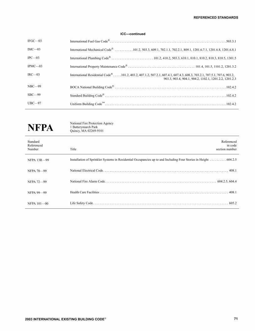
2003 INTERNATIONAL EXISTING BUILDING CODE® 71
REFERENCED STANDARDS
IFGC�03 International Fuel Gas Code®. . . . . . . . . . . . . . . . . . . . . . . . . . . . . . . . . . . . . . . . . . . . . . . . . . . . . . . . . . . . . . . . . . . . . .503.3.1
IMC�03 International Mechanical Code® . . . . . . . . . . .101.2, 503.3, 609.1, 702.1.1, 702.2.1, 809.1, 1201.6.7.1, 1201.6.8, 1201.6.8.1
IPC�03 International Plumbing Code® . . . . . . . . . . . . . . . . . . . . . . . . . 101.2, 410.2, 503.3, 610.1, 810.1, 810.2, 810.3, 810.5, 1301.5
IPMC�03 International Property Maintenance Code® . . . . . . . . . . . . . . . . . . . . . . . . . . . . . . . . . . . . . . . . 101.4, 101.5, 1101.2, 1201.3.2
IRC�03 International Residential Code® . . . . .101.2, 403.2, 407.1.2, 507.2.1, 607.4.1, 607.4.3, 608.3, 703.2.1, 707.5.1, 707.6, 903.2, 903.3, 903.4, 904.1, 904.2, 1102.1, 1201.2.2, 1201.2.3
NBC�99 BOCA National Building Code® . . . . . . . . . . . . . . . . . . . . . . . . . . . . . . . . . . . . . . . . . . . . . . . . . . . . . . . . . . . . . . . . . . .102.4.2
SBC�99 Standard Building Code® . . . . . . . . . . . . . . . . . . . . . . . . . . . . . . . . . . . . . . . . . . . . . . . . . . . . . . . . . . . . . . . . . . . . . . . . .102.4.2
UBC�97 Uniform Building Code� . . . . . . . . . . . . . . . . . . . . . . . . . . . . . . . . . . . . . . . . . . . . . . . . . . . . . . . . . . . . . . . . . . . . . . . . .102.4.2
NFPA National Fire Protection Agency 1 Batterymarch ParkQuincy, MA 02269-9101
StandardReferencedNumber Title
Referencedin code
section number
NFPA 13R�99 Installation of Sprinkler Systems in Residential Occupancies up to and Including Four Stories in Height . . . . . . . . . . 604.2.5
NFPA 70�99 National Electrical Code. . . . . . . . . . . . . . . . . . . . . . . . . . . . . . . . . . . . . . . . . . . . . . . . . . . . . . . . . . . . . . . . . . . . . . . . . . . 408.1
NFPA 72�99 National Fire Alarm Code. . . . . . . . . . . . . . . . . . . . . . . . . . . . . . . . . . . . . . . . . . . . . . . . . . . . . . . . . . . . . . . . . . . 604.2.5, 604.4
NFPA 99�99 Health Care Facilities . . . . . . . . . . . . . . . . . . . . . . . . . . . . . . . . . . . . . . . . . . . . . . . . . . . . . . . . . . . . . . . . . . . . . . . . . . . . . 408.1
NFPA 101�00 Life Safety Code . . . . . . . . . . . . . . . . . . . . . . . . . . . . . . . . . . . . . . . . . . . . . . . . . . . . . . . . . . . . . . . . . . . . . . . . . . . . . . . . . 605.2
ICC�continued

2003 INTERNATIONAL EXISTING BUILDING CODE®72
REFERENCED STANDARDS
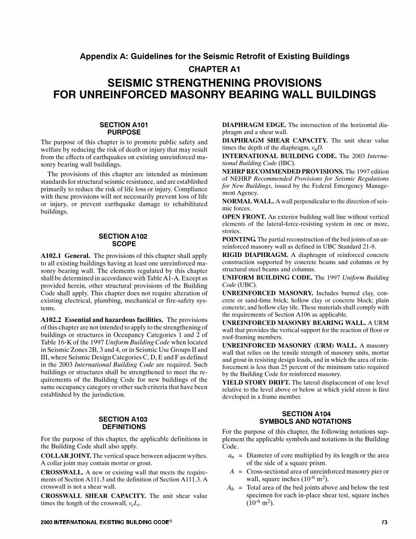
���� ���������� ��� ���� �������� ���® ��
�������� �� �������� �� ��� ������� ����� �� � �������� ��������
������� ��
������� ���� ��� � ��!"���! �#!� $ ��� #!���% ���! �& ����� '�(( �$�(%� �
�����! ��)��$��!��
The purpose of this chapter is to promote public safety andwelfare by reducing the risk of death or injury that may resultfrom the effects of earthquakes on existing unreinforced ma-sonry bearing wall buildings.
The provisions of this chapter are intended as minimumstandards for structural seismic resistance, and are establishedprimarily to reduce the risk of life loss or injury. Compliancewith these provisions will not necessarily prevent loss of lifeor injury, or prevent earthquake damage to rehabilitatedbuildings.
�����! ��)*��!��
A102.1 General. The provisions of this chapter shall applyto all existing buildings having at least one unreinforced ma-sonry bearing wall. The elements regulated by this chaptershall be determined in accordancewith TableA1-A. Except asprovided herein, other structural provisions of the BuildingCode shall apply. This chapter does not require alteration ofexisting electrical, plumbing, mechanical or fire-safety sys-tems.
A102.2 Essential and hazardous facilities. The provisionsof this chapter are not intended to apply to the strengtheningofbuildings or structures in Occupancy Categories 1 and 2 ofTable 16-K of the 1997Uniform Building Code when locatedin Seismic Zones 2B, 3 and 4, or in Seismic UseGroups II andIII, where Seismic DesignCategoriesC, D, E and F as definedin the 2003 International Building Code are required. Suchbuildings or structures shall be strengthened to meet the re-quirements of the Building Code for new buildings of thesame occupancy category or other such criteria that have beenestablished by the jurisdiction.
�����! ��)+%�#� ���! �
For the purpose of this chapter, the applicable definitions inthe Building Code shall also apply.COLLAR JOINT. The vertical space between adjacent wythes.A collar joint may contain mortar or grout.
CROSSWALL. A new or existing wall that meets the require-ments of Section A111.3 and the definition of Section A111.3. Acrosswall is not a shear wall.
CROSSWALL SHEAR CAPACITY. The unit shear valuetimes the length of the crosswall, vcLc.
DIAPHRAGM EDGE. The intersection of the horizontal dia-phragm and a shear wall.DIAPHRAGM SHEAR CAPACITY. The unit shear valuetimes the depth of the diaphragm, vuD.INTERNATIONAL BUILDING CODE. The 2003 Interna-tional Building Code (IBC).NEHRPRECOMMENDEDPROVISIONS.The 1997 editionof NEHRP Recommended Provisions for Seismic Regulationsfor New Buildings, issued by the Federal Emergency Manage-ment Agency.NORMALWALL.Awall perpendicular to the direction of seis-mic forces.OPEN FRONT. An exterior building wall line without verticalelements of the lateral-force-resisting system in one or more,stories.POINTING.The partial reconstruction of the bed joints of an un-reinforced masonry wall as defined in UBC Standard 21-8.RIGID DIAPHRAGM. A diaphragm of reinforced concreteconstruction supported by concrete beams and columns or bystructural steel beams and columns.UNIFORM BUILDING CODE. The 1997 Uniform BuildingCode (UBC).UNREINFORCED MASONRY. Includes burned clay, con-crete or sand-lime brick; hollow clay or concrete block; plainconcrete; and hollow clay tile. These materials shall complywiththe requirements of Section A106 as applicable.UNREINFORCED MASONRY BEARINGWALL. A URMwall that provides the vertical support for the reaction of floor orroof-framing members.UNREINFORCED MASONRY (URM) WALL. A masonrywall that relies on the tensile strength of masonry units, mortarand grout in resisting design loads, and in which the area of rein-forcement is less than 25 percent of the minimum ratio requiredby the Building Code for reinforced masonry.YIELD STORY DRIFT. The lateral displacement of one levelrelative to the level above or below at which yield stress is firstdeveloped in a frame member.
�����! ��),�&��!(� � % !����! �
For the purpose of this chapter, the following notations sup-plement the applicable symbols and notations in the BuildingCode.an = Diameter of core multiplied by its length or the area
of the side of a square prism.A = Cross-sectional area of unreinforcedmasonry pier or
wall, square inches (10-6 m2).Ab = Total area of the bed joints above and below the test
specimen for each in-place shear test, square inches(10-6 m2).
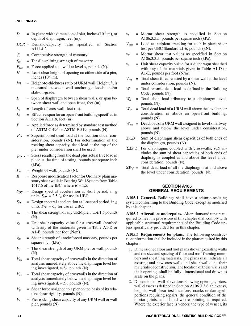
�� ���� ���������� ��� ���� �������� ���®
D = In-plane width dimension of pier, inches (10-3 m), ordepth of diaphragm, feet (m).
DCR = Demand-capacity ratio specified in SectionA111.4.2.
��� = Compressive strength of masonry.
fsp = Tensile-splitting strength of masonry.
Fwx = Force applied to a wall at level x, pounds (N).
H = Least clear height of opening on either side of a pier,inches (10-3 m).
h/t = Height-to-thickness ratio of URMwall. Height, h, ismeasured between wall anchorage levels and/orslab-on-grade.
L = Span of diaphragm between shear walls, or span be-tween shear wall and open front, feet (m).
Lc = Length of crosswall, feet (m).
Li = Effective span for an open-front building specified inSection A111.8, feet (m).
P = Applied force as determined by standard test methodof ASTM C 496 or ASTM E 519, pounds (N).
�� = Superimposed dead load at the location under con-sideration, pounds (kN). For determination of therocking shear capacity, dead load at the top of thepier under consideration shall be used.
���� = Stress resulting from the dead plus actual live load inplace at the time of testing, pounds per square inch(kPa).
Pw = Weight of wall, pounds (N).
R = Responsemodification factor for Ordinary plainma-sonry shear walls in BearingWall System fromTable1617.6 of the IBC, where R = 1.5.
SDS = Design spectral acceleration at short period, in gunits. SDS = 2.5Ca for use in UBC.
SD1 = Design spectral acceleration at 1-second period, in gunits. SD1 = Cv for use in UBC.
va = The shear strength of any URMpier, vmA/1.5 pounds(N).
vc = Unit shear capacity value for a crosswall sheathedwith any of the materials given in Table A1-D orA1-E, pounds per foot (N/m).
vm = Shear strength of unreinforced masonry, pounds persquare inch (kPa).
Va = The shear strength of any URM pier or wall, pounds(N).
Vca = Total shear capacity of crosswalls in the direction ofanalysis immediately above the diaphragm level be-ing investigated, vcLc, pounds (N).
Vcb = Total shear capacity of crosswalls in the direction ofanalysis immediately below the diaphragm level be-ing investigated, vcLc, pounds (N).
Vp = Shear force assigned to a pier on the basis of its rela-tive shear rigidity, pounds (N).
Vr = Pier rocking shear capacity of any URMwall or wallpier, pounds (N).
vt = Mortar shear strength as specified in SectionA106.3.3.5, pounds per square inch (kPa).
Vtest = Load at incipient cracking for each in-place sheartest per UBC Standard 21-6, pounds (kN).
vto = Mortar shear test values as specified in SectionA106.3.3.5, pounds per square inch (kPa).
vu = Unit shear capacity value for a diaphragm sheathedwith any of the materials given in Table A1-D orA1-E, pounds per foot (N/m).
Vwx = Total shear force resisted by a shear wall at the levelunder consideration, pounds (N).
W = Total seismic dead load as defined in the BuildingCode, pounds (N).
Wd = Total dead load tributary to a diaphragm level,pounds (N).
Ww = Total dead load of a URMwall above the level underconsideration or above an open-front building,pounds (N).
Wwx = Dead load of a URMwall assigned to level x halfwayabove and below the level under consideration,pounds (N).
�vuD = Sum of diaphragm shear capacities of both ends ofthe diaphragm, pounds (N).
�����=For diaphragms coupled with crosswalls, vuD in-cludes the sum of shear capacities of both ends ofdiaphragms coupled at and above the level underconsideration, pounds (N).
�Wd = Total dead load of all the diaphragms at and abovethe level under consideration, pounds (N).
�����! ��)-� ���( ��.$����� ��
A105.1 General. Buildings shall have a seismic-resistingsystem conforming to the Building Code, except as modifiedby this chapter.
A105.2 Alterations and repairs. Alterations and repairs re-quired tomeet the provisions of this chapter shall complywithapplicable structural requirements of the Building Code un-less specifically provided for in this chapter.
A105.3 Requirements for plans. The following construc-tion information shall be included in the plans required by thischapter:
1. Dimensioned floor and roof plans showing existingwallsand the size and spacing of floor and roof-framing mem-bers and sheathing materials. The plans shall indicate allexisting and new crosswalls and shear walls and theirmaterials of construction. The location of these walls andtheir openings shall be fully dimensioned and drawn toscale on the plans.
2. Dimensioned wall elevations showing openings, piers,wall classes as defined in Section A106.3.3.8, thickness,heights, wall shear test locations, cracks or damagedportions requiring repairs, the general condition of themortar joints, and if and where pointing is required.Where the exterior face is veneer, the type of veneer, its
�������

���� ���������� ��� ���� �������� ���® ��
thickness and its bonding and/or ties to the structuralwallmasonry shall also be noted.
3. The type of interior wall and ceilingmaterials, and fram-ing.
4. The extent and type of existing wall anchorage to floorsand roof when used in the design.
5. The extent and type of parapet corrections that were pre-viously performed, if any.
6. Repair details, if any, of cracked or damaged unrein-forced masonry walls required to resist forces specifiedin this chapter.
7. All other plans, sections and details necessary to delin-eate required retrofit construction.
8. The design procedure used shall be stated on both theplans and the permit application.
9. Details of the anchor prequalification program requiredby UBC Standard 21-7, if used, including location andresults of all tests.
A105.4 Structural observation. Structural observation shallbe provided if required by the building official for structuresregulated by this chapter. The owner shall employ the engi-neer or architect responsible for the structural design, oranother engineer or architect designated by the engineer or ar-chitect responsible for the structural design, to perform struc-tural observation as defined in the Building Code. Observeddeficiencies shall be reported in writing to the owner�s repre-sentative, special inspector, contractor and the building offi-cial. The structural observer shall submit to the building offi-cial a written statement that the site visits have been made andshall identify any reported deficiencies that, to the best of thestructural observer�s knowledge, have not been resolved.
�����! ��)/�������(� ��.$����� ��
A106.1 General. Materials permitted by this chapter, in-cluding their appropriate strength design values and those ex-isting configurations of materials specified herein, may beused to meet the requirements of this chapter.
A106.2 Existing materials. Existing materials used as partof the required vertical-load-carrying or lateral-force-resist-ing system shall be in sound condition, or shall be repaired orremoved and replaced with new materials. All other unrein-forced masonry materials shall comply with the followingrequirements:
1. The lay-up of the masonry units shall comply with Sec-tion A106.3.2, and the quality of bond between the unitshas been verified to the satisfaction of the buildingofficial;
2. Concrete masonry units are verified to be load-bearingunits complying with UBC Standard 21-4 or such otherstandard as is acceptable to the building official; and
3. The compressive strength of plain concretewalls shall bedetermined based on cores taken from each class of con-crete wall. The location and number of tests shall be thesame as those prescribed for tensile-splitting strength
tests in Sections A106.3.3.3 and A106.3.3.4, or in Sec-tion A108.1.
The use of materials not specified herein or in SectionA108.1 shall be based on substantiating research data or engi-neering judgment, with the approval of the building official.
A106.3 Existing unreinforced masonry.
A106.3.1 General. Unreinforced masonry walls used tocarry vertical loads or seismic forces parallel and perpen-dicular to the wall plane shall be tested as specified in thissection. All masonry that does not meet the minimum stan-dards established by this chapter shall be removed and re-placed with new materials, or alternatively, shall have itsstructural functions replaced with new materials and shallbe anchored to supporting elements.
A106.3.2 Lay-up of walls.
A106.3.2.1 Multiwythe solid brick. The facing andbacking shall be bonded so that not less than 10 percentof the exposed face area is composed of solid headers ex-tending not less than 4 inches (102 mm) into the backing.The clear distance between adjacent full-length headersshall not exceed 24 inches (610 mm) vertically or hori-zontally. Where the backing consists of two or morewythes, the headers shall extend not less than 4 inches(102 mm) into the most distant wythe, or the backingwythes shall be bonded together with separate headerswhose area and spacing conform to the foregoing.Wythes of walls not bonded as described above shall beconsidered veneer. Veneer wythes shall not be includedin the effective thickness used in calculating the height-to-thickness ratio and the shear capacity of the wall.
Exception: In other than Seismic Zone 4, or whereSD1 exceeds 0.3g, veneer wythes anchored as speci-fied in the Building Code and made composite withbackupmasonry may be used for calculation of the ef-fective thickness.
A106.3.2.2 Grouted or ungrouted hollow concrete orclay block and structural hollow clay tile. Grouted orungrouted hollow concrete or clay block and structuralhollow clay tile shall be laid in a running bond pattern.
A106.3.2.3 Other lay-up patterns. Lay-up patternsother than those specified in Sections A106.3.2.1 andA106.3.2.2 above are allowed if their performance canbe justified.
A106.3.3 Testing of masonry.
A106.3.3.1 Mortar tests. The quality of mortar in allmasonry walls shall be determined by performing in-place shear tests in accordance with the following:1. The bed joints of the outer wythe of the masonry
should be tested in shear by laterally displacing asingle brick relative to the adjacent bricks in thesame wythe. The head joint opposite the loadedend of the test brick should be carefully excavatedand cleared. The brick adjacent to the loaded endof the test brick should be carefully removed bysawing or drilling and excavating to provide spacefor a hydraulic ram and steel loading blocks. Steel
�������
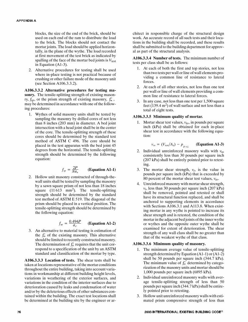
�� ���� ���������� ��� ���� �������� ���®
blocks, the size of the end of the brick, should beused on each end of the ram to distribute the loadto the brick. The blocks should not contact themortar joints. The load should be applied horizon-tally, in the plane of the wythe. The load recordedat first movement of the test brick as indicated byspalling of the face of the mortar bed joints isVtestin Equation (A1-3).
2. Alternative procedures for testing shall be usedwhere in-place testing is not practical because ofcrushing or other failuremode of the masonry unit(see Section A106.3.3.2).
A106.3.3.2 Alternative procedures for testing ma-sonry. The tensile-splitting strength of existing mason-ry, fsp, or the prism strength of existing masonry, ��� ,may be determined in accordancewith one of the follow-ing procedures:
1. Wythes of solid masonry units shall be tested bysampling the masonry by drilled cores of not lessthan 8 inches (203 mm) in diameter. A bed jointintersection with a head joint shall be in the centerof the core. The tensile-splitting strength of thesecores should be determined by the standard testmethod of ASTM C 496. The core should beplaced in the test apparatus with the bed joint 45degrees from the horizontal. The tensile-splittingstrength should be determined by the followingequation:
fsp � 2P�an (Equation A1-1)
2. Hollow unit masonry constructed of through-the-wall units shall be tested by sampling themasonryby a sawn square prism of not less than 18 inchessquare (11 613 mm2). The tensile-splittingstrength should be determined by the standardtest method of ASTM E 519. The diagonal of theprism should be placed in a vertical position. Thetensile-splitting strength should be determined bythe following equation:
��� � �������� (Equation A1-2)
3. An alternative to material testing is estimation ofthe ��� of the existing masonry. This alternativeshould be limited to recently constructedmasonry.The determination of ��� requires that the unit cor-respond to a specification of the unit by an ASTMstandard and classification of the mortar by type.
A106.3.3.3 Location of tests. The shear tests shall betaken at locations representative of themortar conditionsthroughout the entire building, taking into account varia-tions in workmanship at different building height levels,variations in weathering of the exterior surfaces, andvariations in the condition of the interior surfaces due todeterioration caused by leaks and condensation of waterand/or by the deleterious effects of other substances con-tained within the building. The exact test locations shallbe determined at the building site by the engineer or ar-
chitect in responsible charge of the structural designwork. An accurate record of all such tests and their loca-tions in the building shall be recorded, and these resultsshall be submitted to the buildingdepartment for approv-al as part of the structural analysis.
A106.3.3.4 Number of tests. Theminimum number oftests per class shall be as follows:1. At each of both the first and top stories, not less
than two tests perwall or line ofwall elements pro-viding a common line of resistance to lateralforces.
2. At each of all other stories, not less than one testper wall or line of wall elements providing a com-mon line of resistance to lateral forces.
3. In any case, not less than one test per 1,500 squarefeet (139.4 m2) of wall surface and not less than atotal of eight tests.
A106.3.3.5 Minimum quality of mortar.1. Mortar shear test values, vto, in pounds per square
inch (kPa) shall be obtained for each in-placeshear test in accordance with the following equa-tion:
vto � (Vtest�Ab)� pD�L
(Equation A1-3)
2. Individual unreinforced masonry walls with vtoconsistently less than 30 pounds per square inch(207 kPa) shall be entirely pointed prior to retest-ing.
3. The mortar shear strength, vt, is the value inpounds per square inch (kPa) that is exceeded by80 percent of the mortar shear test values, vto.
4. Unreinforcedmasonrywithmortar shear strength,vt, less than 30 pounds per square inch (207 kPa)shall be removed, pointed and retested or shallhave its structural function replaced, and shall beanchored to supporting elements in accordancewith Sections A106.3.1 and A113.8. When exist-ing mortar in any wythe is pointed to increase itsshear strength and is retested, the condition of themortar in the adjacent bed joints of the innerwytheor wythes and the opposite outer wythe shall beexamined for extent of deterioration. The shearstrength of any wall class shall be no greater thanthat of the weakest wythe of that class.
A106.3.3.6 Minimum quality of masonry.1. The minimum average value of tensile-splitting
strength determined by Equation (A1-1) or (A1-2)shall be 50 pounds per square inch (344.7 kPa).The minimum value of ��� determined by catego-rization of the masonry units andmortar should be1,000 pounds per square inch (6895 kPa).
2. Individual unreinforced masonry walls with aver-age tensile-splitting strength of less than 50pounds per square inch (344.7 kPa) shall be entire-ly pointed prior to retesting.
3. Hollowunit unreinforcedmasonrywallswith esti-mated prism compressive strength of less than
�������

���� ���������� ��� ���� �������� ���® ��
1,000 pounds per square inch (6895 kPa) shall begrouted to increase the average net area compres-sive strength.
A106.3.3.7 Collar joints. The collar joints shall be in-spected at the test locations during each in-place sheartest, and estimates of the percentage of adjacent wythesurfaces that are covered with mortar shall be reportedalong with the results of the in-place shear tests.
A106.3.3.8 Unreinforced masonry classes. Existingunreinforced masonry shall be categorized into one ormore classesbasedon shear strength, quality of construc-tion, state of repair, deterioration andweathering. Aclassshall be characterized by the allowable masonry shearstress determined in accordance with Section A108.2.Classes shall be defined for whole walls, not for smallareas of masonry within a wall.
A106.3.3.9 Pointing. Deteriorated mortar joints in un-reinforced masonry walls shall be pointed according toUBC Standard 21-8. Nothing shall prevent pointing ofany deteriorated masonry wall joints before the tests aremade, except as required in Section A107.1.
�����! ��)0.$�(��& �! ��!(
A107.1 Pointing. Preparation and mortar pointing shall beperformed with special inspection.
Exception: At the discretion of the building official, inci-dental pointing may be performed without special inspec-tion.
A107.2 Masonry shear tests. In-place masonry shear testsshall complywith SectionA106.3.3.1. Testing of masonry fordetermination of tensile-splitting strength shall comply withSection A106.3.3.2.
A107.3 Existing wall anchors. Existing wall anchors usedas all or part of the required tension anchors shall be tested inpullout according toUBCStandard 21-7. The minimum num-ber of anchors tested shall be four per floor, with two tests atwalls with joists framing into the wall and two tests at wallswith joists parallel to the wall, but not less than 10 percent ofthe total number of existing tension anchors at each level.
A107.4 New bolts. All new embedded bolts shall be subjectto periodic special inspection in accordancewith the BuildingCode, prior to placement of the bolt and grout or adhesive inthe drilled hole. Five percent of all bolts that do not extendthrough thewall shall be subject to a direct-tension test, and anadditional 20 percent shall be tested using a calibrated torquewrench. Testing shall be performed in accordance with UBCStandard 21-7. New bolts that extend through the wall withsteel plates on the far side of the wall need not be tested.
Exception: Special inspection in accordance with theBuilding Code may be provided during installation of newanchors in lieu of testing.All new embedded bolts resisting tension forces or a com-
bination of tension and shear forces shall be subject to period-ic special inspection in accordance with the Building Code,
prior to placement of the bolt and grout or adhesive in thedrilled hole. Five percent of all bolts resisting tension forcesshall be subject to a direct-tension test, and an additional 20percent shall be tested using a calibrated torque wrench. Test-ing shall be performed in accordance with UBC Standard21-7. New through-bolts need not be tested.
�����! ��)1%��� ���� ���
A108.1 Values.
1. Strength values for existing materials are given in TableA1-D, and for new materials, in Table A1-E.
2. Strength values not specified herein or in the BuildingCode may be as specified in the NEHRP RecommendedProvisions.
3. Capacity reduction factors need not be used.
4. The use of new materials not specified herein shall bebased on substantiating research data or engineeringjudgment, with the approval of the building official.
A108.2 Masonry shear strength. The unreinforcedmason-ry shear strength, vm, shall be determined for each masonryclass from one of the following equations:
1. The unreinforced masonry shear strength, vm, shall bedetermined by Equation (A1-4) when the mortar shearstrength has been determined by Section A106.3.3.1.
vm � 0.56vt � 0.75PD
A(Equation A1-4)
The mortar shear strength values, vt, shall be determinedin accordance with Section 106.3.3.5 and shall not ex-ceed 100 pounds per square inch (689.5 kPa) for the de-termination of vm.
2. The unreinforcedmasonry shear, vm, shall be determinedby Equation (A1-5) when tensile-splitting strength hasbeen determined in accordancewith SectionA106.3.3.2,Item 1 or 2.
vm � 0.8fsp � 0.5PD
A(Equation A1-5)
3. When ��� has been estimated by categorization of theunits and mortar in accordance with IBC Section2105.2.2.1 or UBC Section 2105.3.4, the unreinforcedmasonry shear strength, vm, shall not exceed 200 poundsper square inch (1380 kPa) or the lesser of the following:
a) ��� ���� or
b) 200 psi or
c) v� 0.75PD
A(Equation A1-6)
For SI:1 psi = 6.895 kPa.
�������

�� ���� ���������� ��� ���� �������� ���®
Where:v = 62.5 psi (430 kPa) for running bondmasonry not
grouted solid.v = 100 psi (690 kPa) for running bond masonry
grouted solid.v = 25 psi (170 kPa) for stack bond grouted solid.
A108.3 Masonry compression. Where any increase in deadplus live compression stress occurs, the compression stress inunreinforced masonry shall not exceed 300 pounds per squareinch (2070 kPa).
A108.4 Masonry tension. Unreinforced masonry shall beassumed to have no tensile capacity.
A108.5 Existing tension anchors. The resistance values ofthe existing anchors shall be the average of the tension tests ofexisting anchors having the same wall thickness and joist ori-entation.
A108.6 Foundations. For existing foundations, new totaldead loadsmay be increased over the existing dead load by 25percent. New total dead load plus live load plus seismic forcesmay be increased over the existing dead load plus live load by50percent. Higher valuesmaybe justified only in conjunctionwith a geotechnical investigation.
�����! ��)2� �(&��� � % %��� ��!��%$��
A109.1 General. The elements of buildings hereby requiredto be analyzed are specified in Table A1-A.
A109.2 Selection of procedure. Buildings with rigid dia-phragms shall be analyzed by the general procedure of Sec-tion A110, which is based on the Building Code. Buildingswith flexible diaphragms shall be analyzed by the general pro-cedure or, when applicable, may be analyzed by the specialprocedure of Section A111.
�����! ���)� ���( ��!��%$��
A110.1 Minimum design lateral forces. Buildings shall beanalyzed to resist minimum lateral forces assumed to act non-concurrently in the direction of each of the main axes of thestructure in accordance with the following:
� � ���� ���
(Equation A1-7)
A110.2 Lateral forces on elements of structures. Parts andportions of a structure not covered in Sections A110.3 andA110.4 shall be analyzed and designed per the current Build-ing Code, using force levels defined in Section A110.1.
Exceptions:1. Unreinforced masonry walls for which height-to-
thickness ratios do not exceed ratios set forth in TableA1-B need not be analyzed for out-of-plane loading.Unreinforced masonry walls that exceed the allow-
able h/t ratios of Table A1-B shall be braced accord-ing to Section A113.5.
2. Parapets complying with Section A113.6 need not beanalyzed for out-of-plane loading.
A110.3 Out-of-plane loading for URM walls. Unrein-forced masonry walls for which height-to-thickness ratios donot exceed the ratios set forth in Table A1-B need not be ana-lyzed for out-of-plane loading. Unreinforced masonry wallsthat exceed the allowable h/t ratios of Table A1-B shall bebraced according to Section A113.5. Parapets of such wallsthat complywithSectionA113.6 neednot be analyzed for out-of-plane loading. Walls shall be anchored to floor and roof di-aphragms in accordance with Section A113.1.
A110.4 In-plane loading of URM shear walls and frames.Vertical lateral-load-resisting elements shall be analyzed inaccordance with Section A112.
A110.5 Redundancy and overstrength factors. Any redun-dancy or overstrength factors contained in the Building Codemay be taken as unity. The vertical component of earthquakeload (Ev) may be taken as zero.
�����! ����������( ��!��%$��
A111.1 Limits for the application of this procedure. Thespecial procedures of this section may be applied only tobuildings having the following characteristics:1. Flexible diaphragms at all levels above the base of the
structure.2. Vertical elements of the lateral-force-resisting system
consisting predominantly of masonry or concrete shearwalls.
3. Except for single-story buildings with an open front onone side only, a minimum of two lines of vertical ele-ments of the lateral-force-resisting system parallel toeach axis of the building. (See Section A111.8 for open-front buildings.)
A111.2 Lateral forces on elements of structures. With theexception of the diaphragm provisions in Section A111.4, ele-ments of structures shall comply with Sections A110.2through A110.5.
A111.3 Crosswalls. Crosswalls shall meet the requirementsof this section.
A111.3.1 Crosswall definition. A crosswall is a wood-framedwall sheathedwith any of thematerials described inTable A1-D or A1-E or other system as defined in SectionA111.3.5. Crosswalls shall be spaced no more than 40 feet(12 192 mm) on center measured perpendicular to the di-rection of consideration, and shall be placed in each story ofthe building. Crosswalls shall extend the full story heightbetween diaphragms.
Exceptions:1. Crosswalls need not be provided at all levels when
used in accordance with Section A111.4.2, Item 4.2. Existing crosswalls need not be continuous below a
wood diaphragm at or within 4 feet (1219 mm) ofgrade, provided:
�������
���� ���������� ��� ���� �������� ���® ��
2.1 Shear connections and anchorage require-ments of Section A111.5 are satisfied at alledges of the diaphragm.
2.2 Crosswalls with total shear capacity of0.5SD1�Wd interconnect the diaphragm to thefoundation.
2.3 The demand-capacity ratio of the diaphragmbetween the crosswalls that are continuous totheir foundations does not exceed 2.5, calcu-lated as follows:
DCR � (2.1SD1 Wd � Vca)2vuD
(Equation A1-8)
A111.3.2 Crosswall shear capacity. Within any 40 feet(12 192 mm) measured along the span of the diaphragm,the sum of the crosswall shear capacities shall be at least 30percent of the diaphragm shear capacity of the strongest di-aphragm at or above the level under consideration.
A111.3.3 Existing crosswalls. Existing crosswalls shallhave a maximum height-to-length ratio between openingsof 1.5 to 1. Existing crosswall connections to diaphragmsneed not be investigated as long as the crosswall extends tothe framing of the diaphragms above and below.
A111.3.4 New crosswalls. New crosswall connections tothe diaphragm shall develop the crosswall shear capacity.New crosswalls shall have the capacity to resist an over-turning moment equal to the crosswall shear capacity timesthe story height. Crosswall overturning moments need notbe cumulative over more than two stories.
A111.3.5 Other crosswall systems. Other systems, suchasmoment-resisting frames, maybe used as crosswalls pro-vided that the yield story drift does not exceed 1 inch (25.4mm) in any story.
A111.4 Wood diaphragms.
A111.4.1 Acceptable diaphragm span. A diaphragm isacceptable if the point (L,DCR) on Figure A1-1 fallswithinRegion 1, 2 or 3.
A111.4.2 Demand-capacity ratios. Demand-capacity ra-tios shall be calculated for the diaphragm at any level ac-cording to the following formulas:
1. For a diaphragmwithout qualifying crosswalls at lev-els immediately above or below:
DCR = 2.1SD1Wd/�vuD (Equation A1-9)2. For a diaphragm in a single-story building with quali-
fying crosswalls, or for a roof diaphragm coupled bycrosswalls to the diaphragm directly below:
DCR = 2.1SD1Wd/(�vuD + Vcb) (Equation A1-10)3. For diaphragms in a multistory building with qualify-
ing crosswalls in all levels:
DCR = 2.1SD1�Wd/(��vuD + Vcb) (Equation A1-11)DCR shall be calculated at each level for the set of di-aphragms at and above the level under consideration.
In addition, the roof diaphragm shall alsomeet the re-quirements of Equation (A1-10).
4. For a roof diaphragm and the diaphragm directly be-low, if coupled by crosswalls:
DCR = 2.1SD1�Wd/��vuD (Equation A1-12)
A111.4.3 Chords. An analysis for diaphragm flexureneed not be made, and chords need not be provided.
A111.4.4 Collectors. An analysis of diaphragm collectorforces shall be made for the transfer of diaphragm edgeshears into vertical elements of the lateral-force-resistingsystem. Collector forcesmay be resisted by new or existingelements.
A111.4.5 Diaphragm openings.1. Diaphragm forces at corners of openings shall be in-
vestigated and shall be developed into the diaphragmby new or existing materials.
2. In addition to the demand-capacity ratios of SectionA111.4.2, the demand-capacity ratio of the portion ofthe diaphragm adjacent to an opening shall be calcu-lated using the opening dimension as the span.
3. Where an opening occurs in the end quarter of the dia-phragm span, the calculation of vuD for the demand-capacity ratio shall be based on the net depth of thediaphragm.
A111.5 Diaphragm shear transfer. Diaphragms shall beconnected to shear walls with connections capable of devel-oping the diaphragm-loading tributary to the shear wall givenby the lesser of the following formulas:
V = 1.2SD1 Cp Wd (Equation A1-13)
using the Cp values in Table A1-C, or
V = vuD (Equation A1-14)
A111.6 Shear walls (In-plane loading).
A111.6.1 Wall story force. The wall story force distrib-uted to a shear wall at any diaphragm level shall be the less-er value calculated as:
Fwx = 0.8SD1(Wwx + Wd/2) (Equation A1-15)but need not exceed
Fwx = 0.8SD1Wwx + vuD (Equation A1-16)
A111.6.2 Wall story shear. The wall story shear shall bethe sum of the wall story forces at and above the level ofconsideration.
Vwx = �Fwx (Equation A1-17)
A111.6.3 Shear wall analysis. Shear walls shall complywith Section A112.
A111.6.4 Moment frames. Moment frames used in placeof shear walls shall be designed as required by the BuildingCode, except that the forces shall be as specified in SectionA111.6.1, and the story drift ratio shall be limited to 0.015,except as further limited by Section A112.4.2.
�������

�� ���� ���������� ��� ���� �������� ���®
A111.7 Out-of-plane forces�unreinforced masonrywalls.
A111.7.1 Allowable unreinforced masonry wall height-to-thickness ratios. The provisions of Section A110.2 areapplicable, except the allowable height-to-thickness ratiosgiven in Table A1-B shall be determined from Figure A1-1as follows:
1. In Region 1, height-to-thickness ratios for buildingswith crosswalls may be used if qualifying crosswallsare present in all stories.
2. In Region 2, height-to-thickness ratios for buildingswith crosswalls may be used whether or not qualify-ing crosswalls are present.
3. In Region 3, height-to-thickness ratios for �all otherbuildings� shall be used whether or not qualifyingcrosswalls are present.
A111.7.2 Walls with diaphragms in different re-gions. When diaphragms above and below the wall underconsideration have demand-capacity ratios in different re-gions of Figure A1-1, the lesser height-to-thickness ratioshall be used.
A111.8 Open-front design procedure. A single-storybuildingwith an open front onone side and crosswalls parallelto the open front may be designed by the following procedure:
1. Effective diaphragmspan,Li, for use inFigure A1-1 shallbe determined in accordancewith the following formula:
Li = 2 [(Ww/Wd)L + L] (Equation A1-18)2. Diaphragm demand-capacity ratio shall be calculated as:
DCR= 2.12SD1(Wd +Ww)/[(vuD) +Vcb] (EquationA1-19)
�����! ���*� �(&��� � % %���
A112.1 General. The following requirements are applica-ble to both the general procedure and the special procedurefor analyzing vertical elements of the lateral-force-resistingsystem.
A112.2 Existing unreinforced masonry walls.
A112.2.1 Flexural rigidity. Flexural components ofdeflection may be neglected in determining the rigidity ofan unreinforced masonry wall.
A112.2.2 Shear walls with openings. Wall piers shall beanalyzed according to the following proceure, which is dia-gramed in Figure A1-2.
1. For any pier,1.1 The pier shear capacity shall be calculated as:
Va = vmA/1.5 (Equation A1-20)1.2 The pier rocking shear capacity shall be calcu-
lated as:
Vr = 0.9PDD/H (Equation A1-21)
2. Thewall piers at any level are acceptable if they com-ply with one of the following modes of behavior:2.1 Rocking controlled mode. When the pier
rocking shear capacity is less than the piershear capacity, i.e., Vr < Va for each pier in alevel, forces in the wall at that level, Vwx, shallbe distributed to each pier in proportion toPDD/H.
For the wall at that level:
0.7 Vwx < �Vr (Equation A1-22)
2.2 Shear controlled mode.Where the pier shearcapacity is less than the pier rocking capacity,i.e., Va < Vr in at least one pier in a level, forcesin the wall at the level,Vwx, shall be distributedto each pier in proportion to D/H.For each pier at that level:
Vp < Va (Equation A1-23)
and
Vp < Vr (Equation A1-24)
If Vp < Va for each pier and Vp > Vr for one ormore piers, such piers shall be omitted fromthe analysis, and the procedure shall be re-peated for the remaining piers, unless the wallis strengthened and reanalyzed.
3. Masonry pier tension stress. Unreinforced masonrywall piers need not be analyzed for tension stress.
A112.2.3 Shear walls without openings. Shear wallswithout openings shall be analyzed the same as for wallswith openings, except thatVr shall be calculated as follows:
Vr = 0.9 (PD + 0.5Pw) D/H (Equation A1-25)
A112.3 Plywood-sheathed shear walls. Plywood-sheathedshear walls may be used to resist lateral forces for buildingswith flexible diaphragms analyzed according to provisions ofSection A111. Plywood-sheathed shear walls may not be usedto share lateral forceswith othermaterials along the same lineof resistance.
A112.4 Combinations of vertical elements.
A112.4.1 Lateral-force distribution. Lateral forcesshall be distributed among the vertical-resisting elementsin proportion to their relative rigidities, except that mo-ment-resisting frames shall comply with Section A112.4.2.
A112.4.2 Moment-resisting frames. Moment-resistingframes shall not be usedwith an unreinforced masonrywallin a single line of resistance unless the wall has piers thathave adequate shear capacity to sustain rocking in accor-dance with Section A112.2.2. The frames shall be designedin accordance with the Building Code to carry 100 percentof the lateral forces tributary to that line of resistance, as de-termined from Equation (A1-7). The story drift ratio shallbe limited to 0.0075.
�������
���� ���������� ��� ���� �������� ���® ��
�����! ���+%����(�% �&���� %��� ��.$����� ��
A113.1 Wall anchorage.
A113.1.1 Anchor locations. Unreinforcedmasonrywallsshall be anchored at the roof and floor levels as requiredin Section A110.2. Ceilings of plaster or similar materials,when not attached directly to roof or floor framing andwhere abutting masonry walls, shall either be anchored tothe walls at a maximum spacing of 6 feet (1829 mm), or beremoved.
A113.1.2 Anchor requirements. Anchors shall consistof bolts installed through the wall as specified in TableA1-E, or an approved equivalent at a maximum anchorspacing of 6 feet (1829 mm). All wall anchors shall be se-cured to the joists to develop the required forces.
A113.1.3 Minimum wall anchorage. Anchorage of ma-sonry walls to each floor or roof shall resist a minimumforce determined as 0.9SDS times the tributary weight or200 pounds per linear foot (2920 N/m), whichever is great-er, acting normal to the wall at the level of the floor or roof.Existing wall anchors, if used, must meet the requirementsof this chapter or must be upgraded.
A113.1.4 Anchors at corners. At the roof and floor lev-els, both shear and tension anchors shall be providedwithin2 feet (610 mm) horizontally from the inside of the cornersof the walls.
A113.2 Diaphragm shear transfer. Bolts transmittingshear forces shall have a maximum bolt spacing of 6 feet(1829mm)and shall have nuts installed overmalleable ironorplate washers when bearing on wood, and heavy-cut washerswhen bearing on steel.
A113.3 Collectors. Collector elements shall be providedthat are capable of transferring the seismic forces originatingin other portions of the building to the element providing theresistance to those forces.
A113.4 Ties and continuity. Ties and continuity shall con-form to the requirements of the Building Code.
A113.5 Wall bracing.
A113.5.1 General. Where a wall height-to-thickness ra-tio exceeds the specified limits, the wall may be laterallysupported by vertical bracing members per SectionA113.5.2 or by reducing the wall height by bracing per Sec-tion A113.5.3.
A113.5.2 Vertical bracing members. Vertical bracingmembers shall be attached to floor and roof construction fortheir design loads independently of required wall anchors.Horizontal spacing of vertical bracing members shall notexceed one-half of the unsupported height of the wall or 10feet (3048 mm). Deflection of such bracingmembers at de-sign loads shall not exceed one-tenth of the wall thickness.
A113.5.3 Intermediate wall bracing. The wall heightmay be reduced by bracing elements connected to the flooror roof. Horizontal spacing of the bracing elements and
wall anchors shall be as required by design, but shall not ex-ceed 6 feet (1829 mm) on center. Bracing elements shall bedetailed to minimize the horizontal displacement of thewall by the vertical displacement of the floor or roof.
A113.6 Parapets. Parapets and exterior wall appendagesnot conforming to this chapter shall be removed, or stabilizedor braced to ensure that the parapets and appendages remain intheir original positions.
Themaximum height of anunbraced unreinforcedmasonryparapet above the lower of either the level of tension anchorsor the roof sheathing shall not exceed the height-to-thicknessratio shown in Table A1-F. If the required parapet height ex-ceeds thismaximum height, a bracing system designed for theforces determined in accordancewith the Building Code shallsupport the top of the parapet. Parapet corrective work mustbe performed in conjunction with the installation of tensionroof anchors.
The minimum height of a parapet above any wall anchorshall be 12 inches (305 mm).
Exception: If a reinforced concrete beam is provided at thetop of the wall, the minimum height above the wall anchormay be 6 inches (152 mm).
A113.7 Veneer.1. Veneer shall be anchored with approved anchor ties con-
forming to the required design capacity specified in theBuildingCode and shall be placed at amaximumspacingof 24 inches (610 mm) with a maximum supported areaof 4 square feet (0.372 m2).
Exception: Existing anchor ties for attaching brickveneer to brick backing may be acceptable, providedthe ties are in good condition and conform to the fol-lowing minimum size and material requirements.Existing veneer anchor ties may be considered ade-
quate if they are of corrugated galvanized iron stripsnot less than 1 inch (25.4 mm) in width, 8 inches (203mm) in length and 1/16 inch (1.6 mm) in thickness, orthe equivalent.
2. The location and condition of existing veneer anchor tiesshall be verified as follows:2.1 An approved testing laboratory shall verify the
location and spacing of the ties and shall submit areport to the building official for approval as partof the structural analysis.
2.2 The veneer in a selected area shall be removed toexpose a representative sample of ties (not lessthan four) for inspection by the building official.
A113.8 Nonstructural masonry walls. Unreinforced ma-sonry walls that carry no design vertical or lateral loads andthat are not required by the design to be part of the lateral-force-resisting system shall be adequately anchored to neworexisting supporting elements. The anchors and elements shallbe designed for the out-of-plane forces specified in the Build-ing Code. The height- or length-to-thickness ratio betweensuch supporting elements for suchwalls shall not exceednine.
A113.9 Truss and beam supports. Where trusses andbeams other than rafters or joists are supported on masonry,
�������
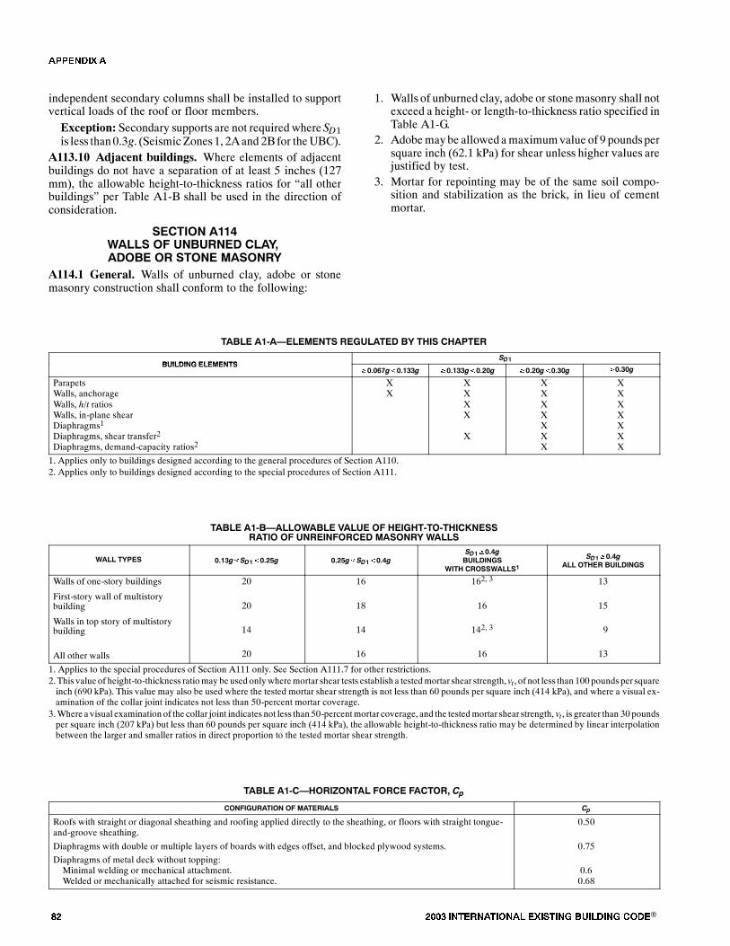
�� ���� ���������� ��� ���� �������� ���®
independent secondary columns shall be installed to supportvertical loads of the roof or floor members.Exception: Secondary supports are not required where SD1is less than0.3g. (SeismicZones1, 2Aand 2B for theUBC).
A113.10 Adjacent buildings. Where elements of adjacentbuildings do not have a separation of at least 5 inches (127mm), the allowable height-to-thickness ratios for �all otherbuildings� per Table A1-B shall be used in the direction ofconsideration.
�����! ���,'�((� !# $ �$� �% �(�&3�%!�� !� ��! � ���! �&
A114.1 General. Walls of unburned clay, adobe or stonemasonry construction shall conform to the following:
1. Walls of unburned clay, adobe or stonemasonry shall notexceed a height- or length-to-thickness ratio specified inTable A1-G.
2. Adobemaybe allowed amaximumvalue of 9 poundspersquare inch (62.1 kPa) for shear unless higher values arejustified by test.
3. Mortar for repointing may be of the same soil compo-sition and stabilization as the brick, in lieu of cementmortar.
TABLE A1-A�ELEMENTS REGULATED BY THIS CHAPTER
BUILDING ELEMENTSSD1
BUILDING ELEMENTS�0.067g�0.133g �0.133g�0.20g �0.20g�0.30g �0.30g
ParapetsWalls, anchorageWalls, h/t ratiosWalls, in-plane shearDiaphragms1
Diaphragms, shear transfer2
Diaphragms, demand-capacity ratios2
XX
XXXX
X
XXXXXXX
XXXXXXX
1. Applies only to buildings designed according to the general procedures of Section A110.2. Applies only to buildings designed according to the special procedures of Section A111.
TABLE A1-B�ALLOWABLE VALUE OF HEIGHT-TO-THICKNESSRATIO OF UNREINFORCED MASONRY WALLS
WALL TYPES 0.13g�SD1�0.25g 0.25g�SD1�0.4gSD1�0.4gBUILDINGS
WITH CROSSWALLS1SD1�0.4g
ALL OTHER BUILDINGS
Walls of one-story buildings
First-story wall of multistorybuilding
Walls in top story of multistorybuilding
All other walls
20
20
14
20
16
18
14
16
162, 3
16
142, 3
16
13
15
9
13
1. Applies to the special procedures of Section A111 only. See Section A111.7 for other restrictions.2. This value of height-to-thickness ratiomay be used onlywheremortar shear tests establish a testedmortar shear strength, vt , of not less than 100 pounds per squareinch (690 kPa). This value may also be used where the tested mortar shear strength is not less than 60 pounds per square inch (414 kPa), and where a visual ex-amination of the collar joint indicates not less than 50-percent mortar coverage.
3.Where a visual examination of the collar joint indicates not less than 50-percentmortar coverage, and the testedmortar shear strength, vt , is greater than 30 poundsper square inch (207 kPa) but less than 60 pounds per square inch (414 kPa), the allowable height-to-thickness ratio may be determined by linear interpolationbetween the larger and smaller ratios in direct proportion to the tested mortar shear strength.
TABLE A1-C�HORIZONTAL FORCE FACTOR, Cp
CONFIGURATION OF MATERIALS Cp
Roofs with straight or diagonal sheathing and roofing applied directly to the sheathing, or floors with straight tongue-and-groove sheathing.
Diaphragms with double or multiple layers of boards with edges offset, and blocked plywood systems.
Diaphragms of metal deck without topping:Minimal welding or mechanical attachment.Welded or mechanically attached for seismic resistance.
0.50
0.75
0.60.68
�������
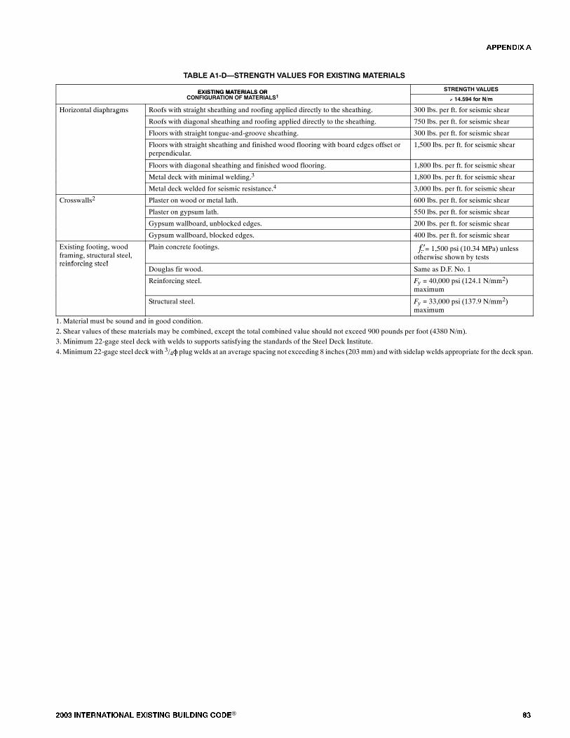
���� ���������� ��� ���� �������� ���® ��
TABLE A1-D�STRENGTH VALUES FOR EXISTING MATERIALS
EXISTING MATERIALS OR STRENGTH VALUESEXISTING MATERIALS ORCONFIGURATION OF MATERIALS1
� 14.594 for N/m
Horizontal diaphragms Roofs with straight sheathing and roofing applied directly to the sheathing. 300 lbs. per ft. for seismic shearp g
Roofs with diagonal sheathing and roofing applied directly to the sheathing. 750 lbs. per ft. for seismic shear
Floors with straight tongue-and-groove sheathing. 300 lbs. per ft. for seismic shear
Floors with straight sheathing and finished wood flooring with board edges offset orperpendicular.
1,500 lbs. per ft. for seismic shear
Floors with diagonal sheathing and finished wood flooring. 1,800 lbs. per ft. for seismic shear
Metal deck with minimal welding.3 1,800 lbs. per ft. for seismic shear
Metal deck welded for seismic resistance.4 3,000 lbs. per ft. for seismic shear
Crosswalls2 Plaster on wood or metal lath. 600 lbs. per ft. for seismic shear
Plaster on gypsum lath. 550 lbs. per ft. for seismic shear
Gypsum wallboard, unblocked edges. 200 lbs. per ft. for seismic shear
Gypsum wallboard, blocked edges. 400 lbs. per ft. for seismic shear
Existing footing, woodframing, structural steel,reinforcing steel
Plain concrete footings. = 1,500 psi (10.34 MPa) unlessotherwise shown by tests��
reinforcing steelDouglas fir wood. Same as D.F. No. 1
Reinforcing steel. Fy = 40,000 psi (124.1 N/mm2)maximum
Structural steel. Fy = 33,000 psi (137.9 N/mm2)maximum
1. Material must be sound and in good condition.2. Shear values of these materials may be combined, except the total combined value should not exceed 900 pounds per foot (4380 N/m).3. Minimum 22-gage steel deck with welds to supports satisfying the standards of the Steel Deck Institute.4.Minimum 22-gage steel deck with 3/4� plug welds at an average spacing not exceeding 8 inches (203 mm) and with sidelap welds appropriate for the deck span.
�������
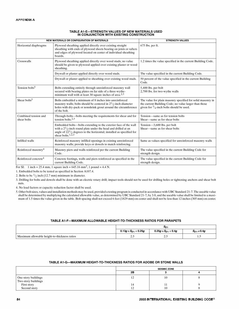
�� ���� ���������� ��� ���� �������� ���®
TABLE A1-E�STRENGTH VALUES OF NEW MATERIALS USEDIN CONJUNCTION WITH EXISTING CONSTRUCTION
NEW MATERIALS OR CONFIGURATION OF MATERIALS STRENGTH VALUES
Horizontal diaphragms Plywood sheathing applied directly over existing straightsheathing with ends of plywood sheets bearing on joists or raftersand edges of plywood located on center of individual sheathingboards.
675 lbs. per ft.
Crosswalls Plywood sheathing applied directly over wood studs; no valueshould be given to plywood applied over existing plaster or woodsheathing.
1.2 times the value specified in the current Building Code.
Drywall or plaster applied directly over wood studs. The value specified in the current Building Code.
Drywall or plaster applied to sheathing over existing wood studs. 50 percent of the value specified in the current BuildingCode.
Tension bolts5 Bolts extending entirely through unreinforced masonry wallsecured with bearing plates on far side of a three-wythe-minimum wall with at least 30 square inches of area.2,3
5,400 lbs. per bolt2,700 lbs. for two-wythe walls
Shear bolts5 Bolts embedded a minimum of 8 inches into unreinforcedmasonry walls; bolts should be centered in 21/2-inch-diameterholes with dry-pack or nonshrink grout around the circumferenceof the bolt.
The value for plain masonry specified for solid masonry inthe current Building Code; no value larger than thosegiven for 3/4-inch bolts should be used.
Combined tension andshear bolts
Through-bolts�bolts meeting the requirements for shear and fortension bolts.2,3
Tension�same as for tension boltsShear�same as for shear bolts
Embedded bolts�bolts extending to the exterior face of the wallwith a 21/2-inch round plate under the head and drilled at anangle of 221/2 degrees to the horizontal; installed as specified forshear bolts.1,2,3
Tension�3,600 lbs. per boltShear�same as for shear bolts
Infilled walls Reinforced masonry infilled openings in existing unreinforcedmasonry walls; provide keys or dowels to match reinforcing.
Same as values specified for unreinforced masonry walls
Reinforced masonry4 Masonry piers and walls reinforced per the current BuildingCode.
The value specified in the current Building Code forstrength design.
Reinforced concrete4 Concrete footings, walls and piers reinforced as specified in thecurrent Building Code.
The value specified in the current Building Code forstrength design.
For SI: 1 inch = 25.4 mm, 1 square inch = 645.16 mm2, 1 pound = 4.4 N.1. Embedded bolts to be tested as specified in Section A107.4.2. Bolts to be 1/2 inch (12.7 mm) minimum in diameter.3. Drilling for bolts and dowels shall be done with an electric rotary drill; impact tools should not be used for drilling holes or tightening anchors and shear boltnuts.
4. No load factors or capacity reduction factor shall be used.5.Other bolt sizes, values and installationmethodsmay be used, provided a testing program is conducted in accordancewith UBCStandard 21-7.The useable valueshall be determined by multiplying the calculated allowable value, as determined by UBC Standard 21-7, by 3.0, and the useable value shall be limited to a maxi-mum of 1.5 times the value given in the table. Bolt spacing shall not exceed 6 feet (1829 mm) on center and shall not be less than 12 inches (305 mm) on center.
TABLE A1-F�MAXIMUM ALLOWABLE HEIGHT-TO-THICKNESS RATIOS FOR PARAPETS
SD10.13g�SD1 < 0.25g 0.25g�SD1 < 0.4g SD1�0.4g
Maximum allowable height-to-thickness ratios 2.5 2.5 1.5
TABLE A1-G�MAXIMUM HEIGHT-TO-THICKNESS RATIOS FOR ADOBE OR STONE WALLS
SEISMIC ZONE
2B 3 4
One-story buildingsTwo-story buildings
First storySecond story
12
1412
10
1110
8
98
�������
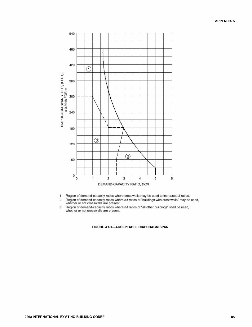
���� ���������� ��� ���� �������� ���® ��
01 2 3 4 5 60
60
120
180
240
360
300
420
480
540
DIAPHRAGMSPAN,L
ORL i(FEET)
�
0.3048
FORm
DEMAND-CAPACITY RATIO, DCR
2
3
1
1. Region of demand-capacity ratios where crosswalls may be used to increase h/t ratios.2. Region of demand-capacity ratios where h/t ratios of �buildings with crosswalls� may be used,
whether or not crosswalls are present.3. Region of demand-capacity ratios where h/t ratios of �all other buildings� shall be used,
whether or not crosswalls are present.
FIGURE A1-1�ACCEPTABLE DIAPHRAGM SPAN
�������
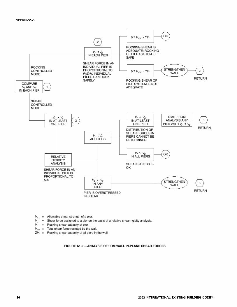
�� ���� ���������� ��� ���� �������� ���®
Vr �VaIN EACH PIER
0.7 Vwx ��Vr
ROCKING SHEAR ISADEQUATE; ROCKINGOF PIER SYSTEM ISSAFE
0.7 Vwx ��Vr
ROCKING SHEAR OFPIER SYSTEM IS NOTADEQUATE
Vp�VaALL PIERS
Vr � VpIN AT LEASTONE PIER
DISTRIBUTION OFSHEAR FORCES INPIERS CANNOT BEDETERMINED
Vr � VpIN ALL PIERS
SHEAR STRESS ISOK
OK
OMIT FROMANALYSIS ANY
PIER WITH Vr � Vp
3
RETURN
STRENGTHENWALL
Vp � VaIN ANYPIER
PIER IS OVERSTRESSEDIN SHEAR
RELATIVERIGIDITYANALYSIS
SHEAR FORCE IN ANINDIVIDUAL PIER ISPROPORTIONAL TOD/H
Vr � VaIN AT LEASTONE PIER
SHEARCONTROLLEDMODE
3
COMPAREVr AND Va
IN EACH PIER1
ROCKINGCONTROLLEDMODE
OK
Va = Allowable shear strength of a pier.Vp = Shear force assigned to a pier on the basis of a relative shear rigidity analysis.Vr = Rocking shear capacity of pier.Vwx = Total shear force resisted by the wall.�Vr = Rocking shear capacity of all piers in the wall.
2
2
RETURN
STRENGTHENWALL
3
RETURN
SHEAR FORCE IN ANINDIVIDUAL PIER ISPROPORTIONAL TOPDD/H. INDIVIDUALPIERS CAN ROCKSAFELY
FIGURE A1-2 �ANALYSIS OF URM WALL IN-PLANE SHEAR FORCES
�������
���� ���������� ��� ���� �������� ���® ��
������� ��
�������� ����� �� ������� �������� ��������� �������� �� ��������� ������� ���� ��� ���� ���� �������� ���������
������� ����������
Thepurpose of this chapter is to promote public safety andwel-fare by reducing the risk of death or injury thatmay result fromthe effects of earthquakes on reinforced concrete and rein-forced masonry wall buildings with flexible diaphragms.Based on past earthquakes, these buildings have been catego-rized as being potentially hazardous and prone to significantdamage, including possible collapse in a moderate to majorearthquake. The provisions of this chapter are minimum stan-dards for structural seismic resistance established primarily toreduce the risk of life loss or injury on both subject and adjacentproperties. These provisions will not necessarily prevent lossof life or injury, or prevent earthquake damage to an existingbuilding that complies with these standards.
������� ���������
The provisions of this chapter shall apply to wall anchoragesystems that resist out-of-plane forces for all buildings in Seis-mic Zones 2B, 3 and 4, or where Seismic Design Categories C,D, E and F are required. The date of applicability for retrofitshall be determined by the building official. Buildings de-signed under building codes in effect after the adoption of the1997 edition of the Uniform Building Code or the adoption ofthe BOCA National Building Code or Standard Building Codethat use the 1997 edition of the NEHRP Recommended Provi-sions for Seismic Regulations, are considered to comply withthese provisions.
������� ���� ����������
For the purpose of this chapter, the applicable definitions inChapters 16, 19, 21, 22 and 23 of the 1997 Uniform BuildingCode and the following shall apply:
FLEXIBLEDIAPHRAGMS.Roofs and floors including, butnot limited to, those sheathed with plywood, wood decking(1-by or 2-by) or metal decks without concrete topping slabs.
������� ����������� �� ���������
For the purpose of this chapter, the applicable symbols andnotations in the Building Code shall apply.
������� ����������� ����������
A205.1 General. The seismic-resisting elements specified inthis chapter shall comply with provisions of Chapter 16 of theBuilding Code, except as modified herein.
A205.2 Alterations and repairs. Alterations and repairs re-quired to meet the provisions of this chapter shall comply withapplicable structural requirements of the Building Code unlessspecifically modified in this chapter.
A205.3 Requirements for plans. The plans shall accuratelyreflect the results of the engineering investigation and design,and shall show all pertinent dimensions and sizes for plan re-view and construction. The following shall be provided:
1. Floor plans and roof plans shall show existing framingconstruction, diaphragm construction, proposed wall an-chors, cross-ties and collectors. Existing nailing, anchors,ties and collectors shall also be shown on the plans if theyare considered part of the lateral-force-resisting system.
2. At elevations where there are alterations or damage, de-tails shall show roof and floor heights, dimensions ofopenings, location and extent of existing damage, andproposed repair.
3. Typical wall panel details and sections with panel thick-ness, height, pilasters and location of anchors shall beprovided.
4. Details shall include existing and new anchors and themethod of developing anchor forces into the diaphragmframing, existing and/or new cross ties, and existing and/or newor improved support of roof and floor girders at pi-lasters or walls.
5. The basis for design and the Building Code used for thedesign shall be stated on the plans.
A205.4 Structural observation. Structural observation shallbe provided where required by the Building Code for all struc-tures regulated by this chapter. The owner shall employ the en-gineer or architect responsible for the structural design, oranother engineer or architect designated by the engineer or ar-chitect responsible for the structural design, to perform struc-tural observations as defined in the Building Code. Observeddeficiencies shall be reported in writing to the owner�s repre-sentative, special inspector, contractor and the building offi-cial. The structural observer shall submit to thebuildingofficiala written statement that the site visits have beenmade and shallidentify any reported deficiencies that, to the best of the struc-tural observer�s knowledge, have not been resolved.
�� ���� ���������� ��� ���� �������� ���®
������� ������������ �� �����
A206.1 Reinforced concrete and reinforced masonry wallanchorage. Concrete and masonry walls shall be anchored toall floors and roofs that provide lateral support for thewall. Theanchorage shall provide a positive direct connection betweenthe wall and floor or roof construction capable of resisting 75percent of the horizontal forces specified in the BuildingCode.
A206.2 Special requirements for wall anchorage systems.The steel elements of the wall anchorage system shall be de-signed in accordancewith theBuildingCodewithout the use ofthe 1.33 short duration allowable stress increasewhen using al-lowable stress design.A load increase of 1.4 shall be usedwhendesigningwith theUniformBuilding Code for allowable stressdesign. No load increase is required when using the Interna-tional Building Code.
Wall anchors shall be provided to resist out-of-plane forces,independent of existing shear anchors.
Exception: Existing cast-in-place shear anchors may beused aswall anchors if the tie element canbe readily attachedto the anchors and if the engineer or architect can establishtension values for the existing anchors through the use of ap-proved as-built plans or testing and through analysis show-ing that the bolts are capable of resisting the total shear load(including dead load) while being acted upon bythe maximum tension force due to an earthquake. Criteriafor analysis and testing shall be determined by the buildingofficial.Expansion anchors are only allowed with special inspection
and approved testing for seismic loading.Attaching the edge ofplywood sheathing to steel ledgers is not considered compliantwith the positive anchoring requirements of this chapter. At-taching the edge of steel decks to steel ledgers is not consideredas providing the positive anchorage of this chapter unless test-ing and/or analysis are performed to establish shear values forthe attachment perpendicular to the edge of the deck. Anyinstallation shall be subject to special inspection.
A206.3 Development of anchor loads into the dia-phragm. Developmentof anchor loads into roof and floor dia-phragms shall comply with Chapter 16 of the Building Code.
Exception: If continuously tiedgirders arepresent, themax-imumspacingof the continuity ties is thegreater of thegirderspacing or 24 feet (7315 mm).In wood diaphragms, anchorage shall not be accomplished
by use of toenails or nails subject towithdrawal.Wood ledgers,top plates or framing shall not be used in cross-grain bending orcross-grain tension. The continuous ties required in Chapter 16of the Building Code shall be in addition to the diaphragmsheathing.
Lengths of development of anchor loads in wood dia-phragms shall be based on existing field nailing of the sheath-ing unless existing edge nailing is positively identified on theoriginal construction plans or at the site.
If collectors are not present at re-entrant corners, they shallbe provided. New collectors shall be designed for the capacityrequired to develop into the diaphragma force equal to the less-
er of the rocking or shear capacity of the re-entrant wall, or thetributary shear. The capacity of the collector need not exceedthe capacity of the diaphragm. A connection shall be providedfrom the collector to the re-entrant wall to transfer the full col-lector force (load). If a truss or beamother than a rafter or purlinis supported by the re-entrant wall or by a column integral withthe re-entrant wall, then an independent secondary column isrequired to support the roof or floor members whenever rock-ing or shear capacity of the re-entrant wall is less than the tribu-tary shear.
A206.4 Anchorage at pilasters. Anchorage at pilasters shallbe designed for the tributary wall-anchoring load per SectionA206.1, considering the wall as a two-way slab. The edges ofthe two-way slab shall be considered fixed when there is conti-nuity at pilasters and shall be considered pinned at roof andfloor. The pilasters or the walls immediately adjacent to the pi-lasters shall be anchored directly to the roof framing such thatthe existing vertical anchor bolts at the top of the pilasters arebypassed without permitting tension or shear failure at the topof the pilasters.
Exception: If existing vertical anchor bolts at the top of thepilasters are used for the anchorage, additional exterior con-finement shall be provided as required to resist the total an-chorage force.The minimum anchorage force at a floor or roof between
the pilasters shall be that specified in Section A206.1.
A206.5 Symmetry. Symmetry of wall anchorage and continu-ity connectors about the minor axis of the framing member isrequired.
Exception: Eccentricity may be allowed when it can beshown that all components of forces are positively resisted.The resistance must be supported by calculations or tests.
A206.6 Minimum member size.Wood members used to de-velop anchorage forces to the diaphragmmust be at least 3-inch(76 mm) nominal members for new construction and replace-ment.All suchmembersmust be checked for gravity and earth-quake loading as part of the wall-anchorage system.
Exception:Existing 2-inch (51mm)nominalmembersmaybe doubled and internailed tomeet the strength requirement.
A206.7 Combination of anchor types. New anchors used incombination on a single framing member shall be of compat-ible behavior and stiffness.
A206.8 Miscellaneous. Existing mezzanines relying on rein-forced concrete or reinforcedmasonrywalls for vertical and/orlateral support shall be anchored to the walls for the tributarymezzanine load. Walls depending on the mezzanine for lateralsupport shall be anchored per Sections A206.1, A206.2 andA206.3.
Exception: Existing mezzanines that have independent lat-eral and vertical support need not be anchored to the walls.
Existing interior reinforced concrete, or reinforcedmasonrywalls that extend to the floor above or to the roof diaphragm,shall be anchored for out-of-plane forces per Sections A206.1and A206.3.Walls extending through the roof diaphragm shallbe anchored for out-of-plane forces on both sides to provide di-
�������
���� ���������� ��� ���� �������� ���® ��
aphragm continuity. In the in-plane direction, thewalls may beisolated or shall be developed into the diaphragm for a lateralforce equal to the lesser of the rocking or shear capacity of thewall or the tributary shear, but need not exceed the diaphragmcapacity.
������� ��� ��������� �� �����������
All materials permitted by the Building Code, including theirappropriate strength or allowable stresses,may be used tomeetthe requirements of this chapter.
�������

�� ���� ���������� ��� ���� �������� ���®
���� ���������� ��� ���� �������� ���® ��
������� ��
��������� ����� ��� ��� ��� ���� ��� ������ ���� � � �� ����� � ������� �� �����
���������� ���� ��� ���� �
���� ������ ����
A301.1 Purpose. The provisions of this chapter are intendedto promote public safety and welfare by reducing the risk ofearthquake-induced damage to existing wood-frame residen-tial buildings. The requirements contained in this chapter areprescriptive minimum standards intended to improve the seis-mic performance of residential buildings; however, they willnot necessarily prevent earthquake damage.
This chapter sets standards for strengthening thatmay be ap-proved by the building official without requiring plans or cal-culations prepared by an architect or engineer. The provisionsof this chapter are not intended to prevent the use of anymateri-al or method of construction not prescribed herein. The build-ing official may require that construction documents forstrengthening using alternative materials or methods be pre-pared by an architect or engineer.
A301.2 Scope. The provisions of this chapter apply to light,wood-frame residential buildings that are in Seismic DesignCategories D, E and F of the 2003 IBC (located in SeismicZones 3 and 4 of theUBC), containing one ormore of the struc-tural weaknesses specified in Section A303.
Exception:Theprovisions of this chapter do not apply to thebuildings, or elements thereof, listed below. These buildingsor elements require analysisby an engineer or architect in ac-cordance with Section A301.3 to determine appropriatestrengthening.1. Group R, Division 1 occupancies with more than four
dwelling units.2. Buildings with a lateral-force-resisting system using
poles or columns embedded in the ground.3. Cripple walls that exceed 4 feet (1219 mm) in height.4. Buildings exceeding three stories in height and any
three-story building with cripple wall studs exceeding14 inches (356 mm) in height.
5. Buildings where the building official determines thatconditions exist that are beyond the scope of the pre-scriptive requirements of this chapter.
The provisions of this chapter do not apply to structures, orportions thereof, constructed on a concrete slab on grade.
The details and prescriptive provisions herein are not in-tended to be the only acceptable strengthening methods per-mitted. Alternative details and methods may be used when ap-proved by the building official. Approval of alternatives shallbe based on test data showing that the method or material usedis at least equivalent in terms of strength, deflectionand capacity to that provided by the prescriptive methods andmaterials.
The provisions of this chapter may be used to strengthen histor-ic structures, provided they are not in conflict with other relatedprovisions and requirements that may apply.
A301.3 Alternative design procedures. When analysis byan engineer or architect is required in accordance with SectionA301.2, such analysis shall be in accordance with all require-ments of the Building Code, except that the base shear may betaken as 75 percent of the horizontal forces specified in theBuilding Code.
���� ������� ��
For thepurposeof this chapter, in addition to the applicabledef-initions in the Building Code, certain additional terms are de-fined as follows:
CHEMICAL ANCHOR. An assembly consisting of athreaded rod, washer, nut and chemical adhesive approved bythe building official for installation in existing concrete or ma-sonry.
COMPOSITE PANEL. A wood structural panel productcomposed of a combination of wood veneer and wood-basedmaterial, and bonded with waterproof adhesive.
CRIPPLE WALL. A wood-frame stud wall extending fromthe top of the foundation to the underside of the lowest floorframing.
EXPANSION BOLT. A single assembly approved by thebuilding official for installation in existing concrete or mason-ry. For the purposeof this chapter, expansionbolts shall containa base designed to expand when properly set, wedging the boltin the pre-drilled hole. Assembly shall also include appropriatewasher and nut.
ORIENTEDSTRANDBOARD(OSB).Amat-formedwoodstructural panel product composed of thin rectangular woodstrands or wafers arranged in oriented layers and bonded withwaterproof adhesive.
PERIMETER FOUNDATION. A foundation system that islocated under the exterior walls of a building.
PLYWOOD. A wood structural panel product composed ofsheets of wood veneer bonded together with the grain of adja-cent layers oriented at right angles to one another.
SNUG-TIGHT.As tight as an individual can torque a nut on abolt by hand, using a wrench with a 10-inch-long (254 mm)handle, and the point atwhich the full surface of the platewash-er is contacting the wood member and slightly indenting thewood surface.
�� ���� ���������� ��� ���� �������� ���®
WAFERBOARD.Amat-formed wood structural panel prod-uct composed of thin rectangular woodwafers arranged in ran-dom layers and bonded with waterproof adhesive.
WOODSTRUCTURALPANEL.A structural panel productcomposed primarily of wood and meeting the requirements ofUnited States Voluntary Product Standard PS 1 and UnitedStates Voluntary Product Standard PS 2. Wood structural pan-els include all-veneer plywood, composite panels containing acombination of veneer and wood-based material, and mat-formed panels such as oriented strand board and waferboard.
���� ������������� ���� ��
For the purpose of this chapter, structural weaknesses shall beas specified below.
1. Sill plates or floor framing that are supported directly onthe ground without an approved foundation system.
2. A perimeter foundation system that is constructed only ofwood posts supported on isolated pad footings.
3. Perimeter foundation systems that are not continuous.
Exceptions:1. Existing single-story exterior walls not exceeding10 feet (3048 mm) in length, forming an extensionof floor area beyond the line of an existing continu-ous perimeter foundation.
2. Porches, storage rooms and similar spaces not con-taining fuel-burning appliances.
4. Aperimeter foundation system that is constructed of unre-inforced masonry or stone.
5. Sill plates that are not connected to the foundation or thatare connectedwith less thanwhat is required by theBuild-ing Code.
Exception: When approved by the building official,connections of a sill plate to the foundation made withother than sill bolts may be accepted if the capacity ofthe connection is equivalent to that required by theBuilding Code.
6. Cripple walls that are not braced in accordance with therequirements of Section A304.4 and Table A3-A, or crip-ple walls not braced with diagonal sheathing or woodstructural panels in accordance with the Building Code.
���� ������� ���� � �������� �
A304.1 General.
A304.1.1 Scope. The structural weaknesses noted in Sec-tion A303 shall be strengthened in accordance with the re-quirements of this section. Strengthening work may includeboth new construction and alteration of existing construc-tion. Except as provided herein, all strengthening work andmaterials shall comply with the applicable provisions of theBuilding Code. Alternative methods of strengthening may
be used, provided such systems are designed by an engineeror architect and are approved by the building official.
A304.1.2 Condition of existing wood materials. All ex-isting wood materials that will be a part of the strengtheningwork (sills, studs, sheathing, etc.) shall be in a sound condi-tion and free from defects that substantially reduce the ca-pacity of the member. Any wood material found to containfungus infection shall be removed and replaced with newmaterial. Any wood material found to be infested with in-sects or to have been infested with insects shall be strength-ened or replaced with newmaterials to provide a net dimen-sion of sound wood at least equal to its undamaged originaldimension.
A304.1.3 Floor joists not parallel to foundations. Floorjoists framed perpendicular or at an angle to perimeterfoundations shall be restrained either by an existing nominal2-inch-wide (51 mm) continuous rim joist or by a nominal2-inch-wide (51 mm) full-depth blocking between alternatejoists in one-and two-storybuildings, andbetween each joistin three-story buildings. Existing blocking for multistorybuildingsmust occur at each joist space above a braced crip-ple wall panel.
Existing connections at the top and bottom edges of an ex-isting rim joist or blocking need not be verified in one-storybuildings. Inmultistory buildings, the existing top edge con-nection need not be verified; however, the bottom edgeconnection to either the foundation sill plate or the top plateof a cripple wall shall be verified. The minimum existingbottom edge connection shall consist of 8d toenails spaced6 inches (152 mm) apart for a continuous rim joist, or three8d toenails per block. When this minimum bottom edge-connection is not present or cannot be verified, a supplemen-tal connection installed as shown in Figure A3-8 shall beprovided.
Where an existing continuous rim joist or the minimumexisting blocking does not occur, new 3/4-inch (19 mm)wood structural panel blocking installed tightly betweenfloor joists and nailed as shown in Figure A3-8 shall be pro-vided at the inside face of the cripple wall. In lieu of 3/4-inch(19 mm) wood structural panel blocking, tightfitting, full-depth 2-inch (51 mm) blocking may be used. New blockingmay be omitted where it will interfere with vents or plumb-ing that penetrates the wall.
A304.1.4 Floor joists parallel to foundations. Where ex-isting floor joists are parallel to the perimeter foundations,the end joist shall be located over the foundation and, exceptfor required ventilation openings, shall be continuous and incontinuous contact with the foundation sill plate or the topplate of the cripple wall. Existing connections at the top andbottom edges of the end joist need not be verified in one-story buildings. In multistory buildings, the existing topedge connection of the end joist need not be verified; howev-er, the bottom edge connection to either the foundation sillplate or the top plate of a cripple wall shall be verified. Theminimum bottom edge connection shall be 8d toenailsspaced 6 inches (152 mm) apart. If this minimum bottomedge connection is not present or cannot be verified, a sup-
�������
���� ���������� ��� ���� �������� ���® ��
plemental connection installed as shown in Figure A3-9shall be provided.
A304.2 Foundations.
A304.2.1 New perimeter foundations. New perimeterfoundations shall be provided for structures with the struc-tural weaknesses noted in Items 1 and 2 of Section A303.Soil investigations or geotechnical studies are not requiredfor this work unless the building is located in a special studyzone as designated by the jurisdiction or other public agency.
A304.2.2 Foundation evaluation by an engineer or ar-chitect. Partial perimeter foundations or unreinforced ma-sonry foundations shall be evaluated by anengineer or archi-tect for the force levels noted in SectionA301.3. Test reportsor other substantiating data to determine existing foundationmaterial strengths shall be submitted for review. When ap-proved by the building official, these foundation systemsmay be strengthened in accordance with the recommenda-tions included with the evaluation in lieu of being replaced.
Exception: In lieu of testing existing foundations to de-termine material strengths, and when approved by thebuilding official, a new nonperimeter foundation systemdesigned for the forces noted in Section A301.3 may beused to resist all exterior wall lateral forces.
A304.2.3 Details for new perimeter foundations. Allnew perimeter foundations shall be continuous andconstructed according to one of the details shown in FigureA3-1 or A3-2.
Exceptions:1. When approved by the building official, the exist-
ing clearance between existing floor joists or gird-ers and existing grade below the floor need notcomply with the Building Code.
2. When approved by the building official, and whendesigned by an engineer or architect, partial perim-eter foundationsmaybeused in lieuof acontinuousperimeter foundation.
A304.2.4 Required compressive strength. New concretefoundations shall have a minimum compressive strength of2,500 pounds per square inch (17.24 MPa) at 28 days.
A304.2.5 New hollow-unit masonry foundations. Newhollow-unit masonry foundations shall be solidly grouted.Mortar shall beTypeMorS, and the grout andmasonryunitsshall comply with the Building Code.
A304.2.6 Reinforcing steel. Reinforcing steel shall com-ply with the requirements of the Building Code.
A304.3 Foundation sill plate anchorage.
A304.3.1 Existing perimeter foundations. When thebuilding has an existing continuous perimeter foundation,all perimeter wall sill plates shall be bolted to the founda-tion with chemical anchors or expansion bolts in accor-dance with Table A3-A.
Anchors or bolts shall be installed in accordance withFigure A3-3, with the plate washer installed between the nutand the sill plate. The nut shall be tightened to a snug-tight
condition after curing is complete for chemical anchors andafter expansionwedge engagement for expansion bolts. Theinstallation of nuts on all bolts shall be subject to verificationby the building official. Where existing conditions preventanchor or bolt installation through the sill plate, this connec-tion may bemade in accordance with Figure A3-4A, A3-4Bor A3-4C. The spacing of these alternate connections shallcomply with the maximum spacing requirements of TableA3-A. Expansion bolts shall not be used when the installa-tion causes surface cracking of the foundation wall at thelocation of the bolt.
A304.3.2 Placement of chemical anchors and expansionbolts. Chemical anchors or expansion bolts shall be placedwithin 12 inches (305 mm), but not less than 9 inches (229mm), from the ends of sill plates and shall be placed in thecenter of the stud space closest to the required spacing. Newsill platesmay be installed in pieceswhen necessary becauseof existing conditions. For lengths of sill plate greater than12 feet (3658mm), anchors or bolts shall be spaced along thesill plate as noted in Table A3-A. For other lengths of sillplate, see Table A3-B. For lengths of sill plate less than 30inches (762 mm), a minimum of one anchor or bolt shall beinstalled.
Exception: Where physical obstructions such as fire-places, plumbing or heating ducts interferewith the place-ment of an anchor or bolt, the anchor or bolt shall beplaced as close to the obstruction as possible, but not lessthan 9 inches (229 mm) from the end of the plate. Center-to-center spacing of the anchors or bolts shall be reducedas necessary to provide the minimum total number of an-chors required based on the full length of the wall.Center-to-center spacing shall not be less than 12 inches(305 mm).
A304.3.3 Newperimeter foundations. Sill plates for newperimeter foundations shall be bolted as required by TableA3-A and as shown in Figure A3-1 or A3-2.
A304.4 Cripple wall bracing.
A304.4.1 General. Exterior cripple walls not exceeding 4feet (1219 mm) in height shall use the prescriptive bracingmethod listed below. Cripple walls over 4 feet (1219mm) inheight require analysis by an engineer or architect in accor-dance with Section A301.3.
A304.4.1.1 Sheathing installation requirements.Wood structural panel sheathing shall not be less than15/32-inch (12 mm) thick and shall be installed in accor-dance with Figure A3-5 or A3-6. All individual pieces ofwood structural panels shall be nailed with 8d commonnails spaced 4 inches (102 mm) on center at all edges and12 inches (305mm)oncenter at each intermediate supportwith not less than two nails for each stud. Nails shall bedriven so that their heads are flush with the surface of thesheathing and shall penetrate the supporting member aminimum of 11/2 inches (38 mm). When a nail fracturesthe surface, it shall be left in place and not counted as partof the required nailing. A new 8d nail shall be locatedwithin 2 inches (51 mm) of the discounted nail and behand-driven flushwith the sheathing surface.All horizon-tal joints must occur over nominal 2-inch-by-4-inch
�������
�� ���� ���������� ��� ���� �������� ���®
(51 mm by 102 mm) blocking installed with the nominal4-inch (102 mm) dimension against the face of theplywood.
Vertical joints at adjoining pieces of wood structuralpanels shall be centered on existing studs such that there isa minimum 1/8 inch (3.2 mm) between the panels, andsuch that the nails are placed a minimum of 1/2 inch (12.7mm) from the edges of the existing stud.Where such edgedistances cannot be maintained because of the width ofthe existing stud, a new stud shall be added adjacent tothe existing studs and connected in accordance withFigure A3-7.
A304.4.2 Distribution and amount of bracing. SeeTable A3-A and Figure A3-10 for the distribution andamount of bracing required. Each braced panel must be atleast two times the height of the cripple studwall but not lessthan 48 inches (1219 mm) in length or width. Where theminimum amount of bracing prescribed in Table A3-A can-not be installed along any walls, the bracing must be de-signed in accordance with Section A301.3.
Exception: Where physical obstructions such as fire-places, plumbing or heating ducts interferewith the place-ment of cripple wall bracing, the bracing shall then beplaced as close to the obstruction as possible. The totalamount of bracing required shall not be reduced becauseof obstructions.
A304.4.3 Stud space ventilation. When bracingmaterialsare installed on the interior face of studs forming an enclosedspace between the new bracing and the existing exterior fin-ish, each braced stud space must be ventilated. Adequateventilation and access for future inspection shall beprovidedby drilling one 2-inch to 3-inch-diameter (51 mm to 76mm)round hole through the sheathing, nearly centered betweeneach stud at the top and bottom of the cripple wall. Suchholes should be spaced a minimum of 1 inch(25 mm) clear from the sill or top plates. In stud spaces con-taining sill bolts, thehole shall be locatedon the center lineofthe sill bolt but not closer than 1 inch (25mm) clear from thenailing edge of the sheathing. When existing blocking oc-
curs within the stud space, additional ventilation holes shallbe placed above and below the blocking, or the existingblock shall be removed and a new nominal 2-inch-by-4-inch(51mmby102mm)block shall be installedwith thenominal4-inch (102mm) dimension against the face of the plywood.For stud heights less than 18 inches (457mm), only one ven-tilation hole need be provided.
A304.4.4 Existing underfloor ventilation. Existing un-derfloor ventilation shall not be reduced without providingequivalent newventilation asclose to the existingventilationas possible. Braced panels may include underfloor ventila-tion openings when the height of the opening, measuredfrom the top of the foundationwall to the top of the opening,does not exceed 25 percent of the height of the cripple studwall; however, the length of the panel shall be increased adistance equal to the length of the opening or one stud spaceminimum.Where an opening exceeds 25 percent of the crip-ple wall height, braced panels shall not be located where theopening occurs. See Figure A3-7.
Exception: For homes with a post and pier foundationsystemwhere anewcontinuousperimeter foundation sys-tem is being installed, newventilation shall be provided inaccordance with the Building Code.
A304.5 Quality control. All work shall be subject to inspec-tion by the building official including, but not limited to:
1. Placement and installation of newchemical anchors or ex-pansion bolts installed in existing foundations. Special in-spection is not required for chemical anchors installed inexisting foundations regulated by the prescriptive provi-sions of this chapter.
2. Installation and nailing of new cripple wall bracing.3. Any work may be subject to special inspection when re-
quired by the building official in accordance with theBuilding Code.
A304.6 Phasing of the strengthening work. When ap-proved by the building official, the strengthening work con-tained in this chapter may be completed in phases. Thestrengtheningwork in anyphase shall beperformedon twopar-allel sides of the structure at the same time.
�������

���� ���������� ��� ���� �������� ���® ��
TABLE A3-A�SILL PLATE ANCHORAGE AND CRIPPLE WALL BRACING
AMOUNT OF BRACING3,4,5
NUMBER OF STORIESABOVE CRIPPLE WALLS
MINIMUM SILL PLATE CONNECTION ANDMAXIMUM SPACING1,2
A Combination of Exterior WallsFinished with Portland Cement Plaster
and Roofing UsingClay Tile or Concrete Tile Weighing More
than 6 psf (287 N/m2) All Other Conditions
One story 1/2 inch (12.7 mm) spaced 6 feet, 0 inch(1829 mm) center-to-center with washerplate
Each end and not less than 50 percent of thewall length
Each end and not less than 40percent of the wall length
Two stories 1/2 inch (12.7 mm) spaced 4 feet, 0 inch(1219 mm) center-to-center with washerplate; or 5/8 inch (15.9 mm) spaced6 feet, 0 inch (1829 mm) center-to-centerwith washer plate
Each end and not less than 70 percent of thewall length
Each end and not less than 50percent of the wall length
Three stories 5/8 inch (15.9 mm) spaced 4 feet, 0 inch(1219 mm) center-to-center with washerplate
100 percent of the wall length6 Each end and not less than 80percent of the wall length6
1. Sill plate anchors shall be chemical anchors or expansion bolts in accordance with Section A304.3.1.2. All washer plates shall be 2 inches by 2 inches by 3/16 inch (51 mm by 51 mm by 4.8 mm) minimum.3. See Figure A3-10 for braced panel layout.4. Braced panels at ends of walls shall be located as near to the end as possible.5. All panels along a wall shall be nearly equal in length and shall be nearly equal in spacing along the length of the wall.6. The minimum required underfloor ventilation openings are permitted in accordance with Section A304.4.4.
TABLE A3-B�SILL PLATE ANCHORAGE FOR VARIOUS LENGTHS OF SILL PLATE1,2
LENGTHS OF SILL PLATE
NUMBER OF STORIESLess than 12 feet (3658 mm) to
6 feet (1829 mm)Less than 6 feet (1829 mm) to
30 inches (762 mm)Less than 30 inches
(762 mm)3
One story Three connections Two connections One connection
Two stories Four connections for 1/2-inch (12.7 mm)anchors or boltsorThree connections for 5/8-inch (15.9 mm)anchors or bolts
Two connections One connection
Three stories Four connections Two connections One connection
1. Connections shall be either chemical anchors or expansion bolts.2. See Section A304.3.2 for minimum end distances.3. Connections shall be placed as near to the center of the length of plate as possible.
TABLE A3-C�NOT USED
�������
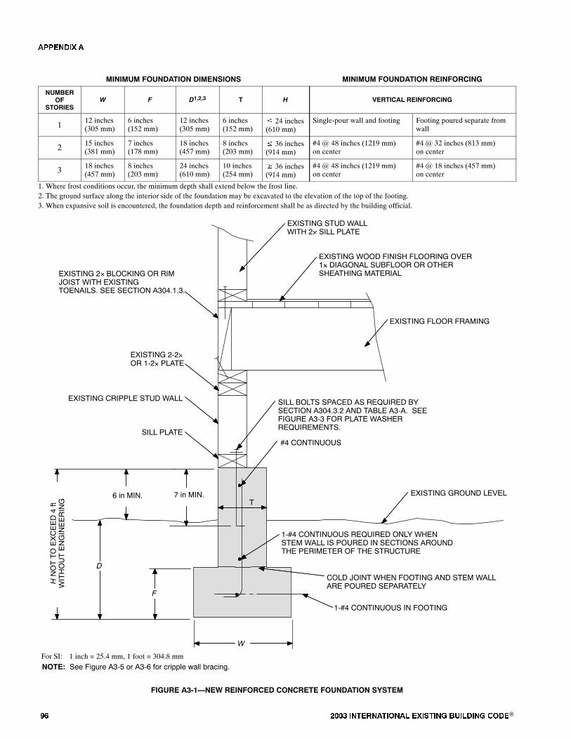
�� ���� ���������� ��� ���� �������� ���®
MINIMUM FOUNDATION DIMENSIONS MINIMUM FOUNDATION REINFORCING
NUMBEROF
STORIESW F D1,2,3 T H VERTICAL REINFORCING
112 inches(305 mm)
6 inches(152 mm)
12 inches(305 mm)
6 inches(152 mm)
� 24 inches(610 mm)
Single-pour wall and footing Footing poured separate fromwall
215 inches(381 mm)
7 inches(178 mm)
18 inches(457 mm)
8 inches(203 mm)
� 36 inches(914 mm)
#4 @ 48 inches (1219 mm)on center
#4 @ 32 inches (813 mm)on center
318 inches(457 mm)
8 inches(203 mm)
24 inches(610 mm)
10 inches(254 mm)
� 36 inches(914 mm)
#4 @ 48 inches (1219 mm)on center
#4 @ 18 inches (457 mm)on center
1. Where frost conditions occur, the minimum depth shall extend below the frost line.2. The ground surface along the interior side of the foundation may be excavated to the elevation of the top of the footing.3. When expansive soil is encountered, the foundation depth and reinforcement shall be as directed by the building official.
EXISTING STUD WALLWITH 2� SILL PLATE
EXISTING WOOD FINISH FLOORING OVER1� DIAGONAL SUBFLOOR OR OTHERSHEATHING MATERIAL
EXISTING CRIPPLE STUD WALL
EXISTING 2� BLOCKING OR RIMJOIST WITH EXISTINGTOENAILS. SEE SECTION A304.1.3.
EXISTING 2-2�OR 1-2� PLATE
EXISTING GROUND LEVEL
SILL BOLTS SPACED AS REQUIRED BYSECTION A304.3.2 AND TABLE A3-A. SEEFIGURE A3-3 FOR PLATE WASHERREQUIREMENTS.
SILL PLATE
EXISTING FLOOR FRAMING
1-#4 CONTINUOUS IN FOOTING
#4 CONTINUOUS
NOTE: See Figure A3-5 or A3-6 for cripple wall bracing.
T
W
1-#4 CONTINUOUS REQUIRED ONLY WHENSTEM WALL IS POURED IN SECTIONS AROUNDTHE PERIMETER OF THE STRUCTURE
COLD JOINT WHEN FOOTING AND STEM WALLARE POURED SEPARATELY
HNOTTOEXCEED4ft
WITHOUTENGINEERING
F
D
7 in MIN.6 in MIN.
For SI: 1 inch = 25.4 mm, 1 foot = 304.8 mm
FIGURE A3-1�NEW REINFORCED CONCRETE FOUNDATION SYSTEM
�������
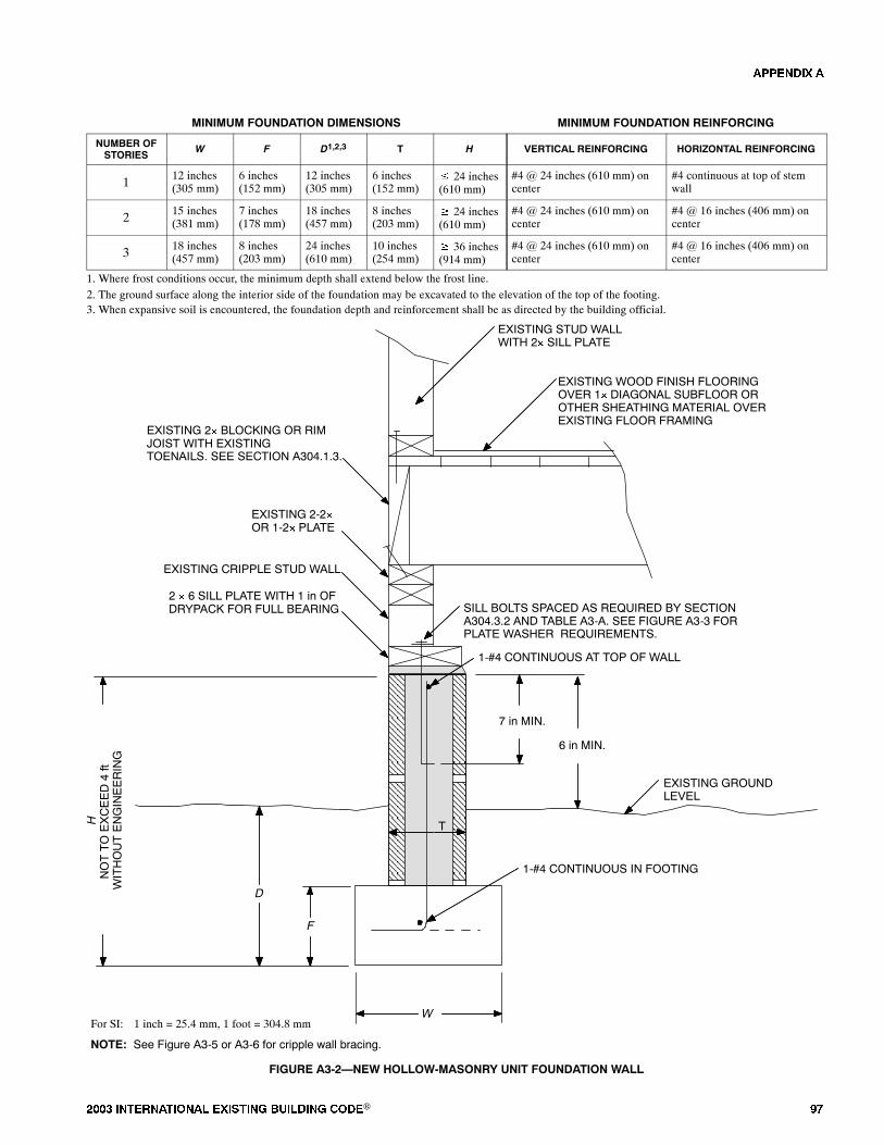
���� ���������� ��� ���� �������� ���® ��
MINIMUM FOUNDATION DIMENSIONS MINIMUM FOUNDATION REINFORCING
NUMBER OFSTORIES
W F D1,2,3 T H VERTICAL REINFORCING HORIZONTAL REINFORCING
112 inches(305 mm)
6 inches(152 mm)
12 inches(305 mm)
6 inches(152 mm)
� 24 inches(610 mm)
#4 @ 24 inches (610 mm) oncenter
#4 continuous at top of stemwall
215 inches(381 mm)
7 inches(178 mm)
18 inches(457 mm)
8 inches(203 mm)
� 24 inches(610 mm)
#4 @ 24 inches (610 mm) oncenter
#4 @ 16 inches (406 mm) oncenter
318 inches(457 mm)
8 inches(203 mm)
24 inches(610 mm)
10 inches(254 mm)
� 36 inches(914 mm)
#4 @ 24 inches (610 mm) oncenter
#4 @ 16 inches (406 mm) oncenter
1. Where frost conditions occur, the minimum depth shall extend below the frost line.2. The ground surface along the interior side of the foundation may be excavated to the elevation of the top of the footing.3. When expansive soil is encountered, the foundation depth and reinforcement shall be as directed by the building official.
EXISTING WOOD FINISH FLOORINGOVER 1� DIAGONAL SUBFLOOR OROTHER SHEATHING MATERIAL OVEREXISTING FLOOR FRAMING
EXISTING CRIPPLE STUD WALL
EXISTING 2� BLOCKING OR RIMJOIST WITH EXISTINGTOENAILS. SEE SECTION A304.1.3.
EXISTING 2-2�OR 1-2� PLATE
EXISTING GROUNDLEVEL
2 � 6 SILL PLATE WITH 1 in OFDRYPACK FOR FULL BEARING
1-#4 CONTINUOUS IN FOOTING
EXISTING STUD WALLWITH 2� SILL PLATE
SILL BOLTS SPACED AS REQUIRED BY SECTIONA304.3.2 AND TABLE A3-A. SEE FIGURE A3-3 FORPLATE WASHER REQUIREMENTS.
T
W
HNOTTOEXCEED4ft
WITHOUTENGINEERING
F
D
7 in MIN.
6 in MIN.
For SI: 1 inch = 25.4 mm, 1 foot = 304.8 mm
1-#4 CONTINUOUS AT TOP OF WALL
NOTE: See Figure A3-5 or A3-6 for cripple wall bracing.
FIGURE A3-2�NEW HOLLOW-MASONRY UNIT FOUNDATION WALL
�������
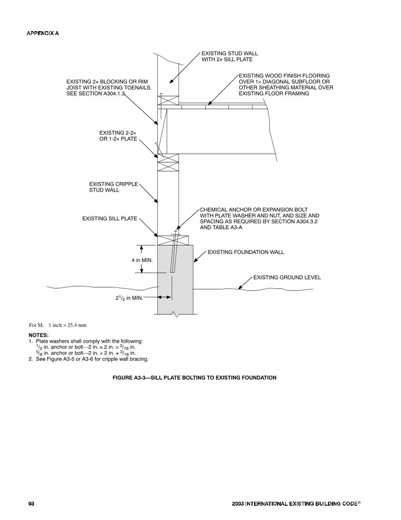
�� ���� ���������� ��� ���� �������� ���®
EXISTING STUD WALLWITH 2� SILL PLATE
EXISTING WOOD FINISH FLOORINGOVER 1� DIAGONAL SUBFLOOR OROTHER SHEATHING MATERIAL OVEREXISTING FLOOR FRAMING
EXISTING CRIPPLESTUD WALL
EXISTING SILL PLATE
EXISTING FOUNDATION WALL
EXISTING 2� BLOCKING OR RIMJOIST WITH EXISTING TOENAILS.SEE SECTION A304.1.3.
EXISTING 2-2�OR 1-2� PLATE
EXISTING GROUND LEVEL
CHEMICAL ANCHOR OR EXPANSION BOLTWITH PLATE WASHER AND NUT, AND SIZE ANDSPACING AS REQUIRED BY SECTION A304.3.2AND TABLE A3-A
21/2 in MIN.
NOTES:1. Plate washers shall comply with the following:
1/2 in. anchor or bolt�2 in. � 2 in. � 3/16 in.5/8 in. anchor or bolt�2 in. � 2 in. � 3/16 in.
2. See Figure A3-5 or A3-6 for cripple wall bracing.
4 in MIN.
For SI: 1 inch = 25.4 mm
FIGURE A3-3�SILL PLATE BOLTING TO EXISTING FOUNDATION
A3-4
�������
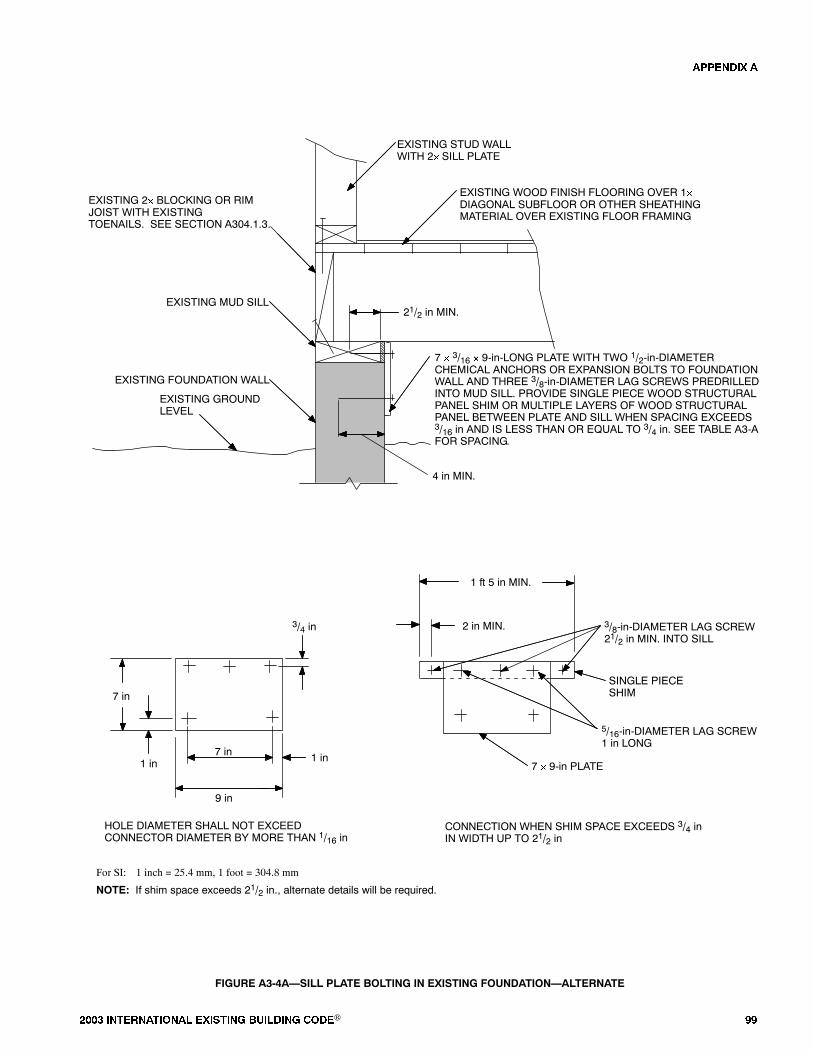
���� ���������� ��� ���� �������� ���® ��
EXISTING 2� BLOCKING OR RIMJOIST WITH EXISTINGTOENAILS. SEE SECTION A304.1.3.
7 in
9 in
1 in
1 ft 5 in MIN.
2 in MIN.
5/16-in-DIAMETER LAG SCREW1 in LONG
SINGLE PIECESHIM
3/8-in-DIAMETER LAG SCREW21/2 in MIN. INTO SILL
CONNECTION WHEN SHIM SPACE EXCEEDS 3/4 inIN WIDTH UP TO 21/2 in
EXISTING MUD SILL
EXISTING FOUNDATION WALL
EXISTING GROUNDLEVEL
7 � 3/16 � 9-in-LONG PLATE WITH TWO 1/2-in-DIAMETERCHEMICAL ANCHORS OR EXPANSION BOLTS TO FOUNDATIONWALL AND THREE 3/8-in-DIAMETER LAG SCREWS PREDRILLEDINTO MUD SILL. PROVIDE SINGLE PIECE WOOD STRUCTURALPANEL SHIM OR MULTIPLE LAYERS OF WOOD STRUCTURALPANEL BETWEEN PLATE AND SILL WHEN SPACING EXCEEDS3/16 in AND IS LESS THAN OR EQUAL TO 3/4 in. SEE TABLE A3-AFOR SPACING.
EXISTING STUD WALLWITH 2� SILL PLATE
EXISTING WOOD FINISH FLOORING OVER 1�DIAGONAL SUBFLOOR OR OTHER SHEATHINGMATERIAL OVER EXISTING FLOOR FRAMING
21/2 in MIN.
HOLE DIAMETER SHALL NOT EXCEEDCONNECTOR DIAMETER BY MORE THAN 1/16 in
NOTE: If shim space exceeds 21/2 in., alternate details will be required.
7 � 9-in PLATE
4 in MIN.
3/4 in
7 in
1 in
For SI: 1 inch = 25.4 mm, 1 foot = 304.8 mm
FIGURE A3-4A�SILL PLATE BOLTING IN EXISTING FOUNDATION�ALTERNATE
�������
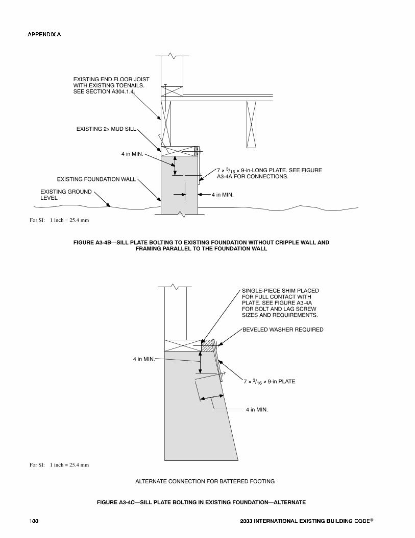
��� ���� ���������� ��� ���� �������� ���®
EXISTING 2� MUD SILL
EXISTING FOUNDATION WALL
EXISTING END FLOOR JOISTWITH EXISTING TOENAILS.SEE SECTION A304.1.4.
EXISTING GROUNDLEVEL 4 in MIN.
7 � 3/16 � 9-in-LONG PLATE. SEE FIGUREA3-4A FOR CONNECTIONS.
4 in MIN.
For SI: 1 inch = 25.4 mm
FIGURE A3-4B�SILL PLATE BOLTING TO EXISTING FOUNDATION WITHOUT CRIPPLE WALL ANDFRAMING PARALLEL TO THE FOUNDATION WALL
ALTERNATE CONNECTION FOR BATTERED FOOTING
7 � 3/16 � 9-in PLATE
SINGLE-PIECE SHIM PLACEDFOR FULL CONTACT WITHPLATE. SEE FIGURE A3-4AFOR BOLT AND LAG SCREWSIZES AND REQUIREMENTS.
BEVELED WASHER REQUIRED
4 in MIN.
4 in MIN.
For SI: 1 inch = 25.4 mm
FIGURE A3-4C�SILL PLATE BOLTING IN EXISTING FOUNDATION�ALTERNATE
�������
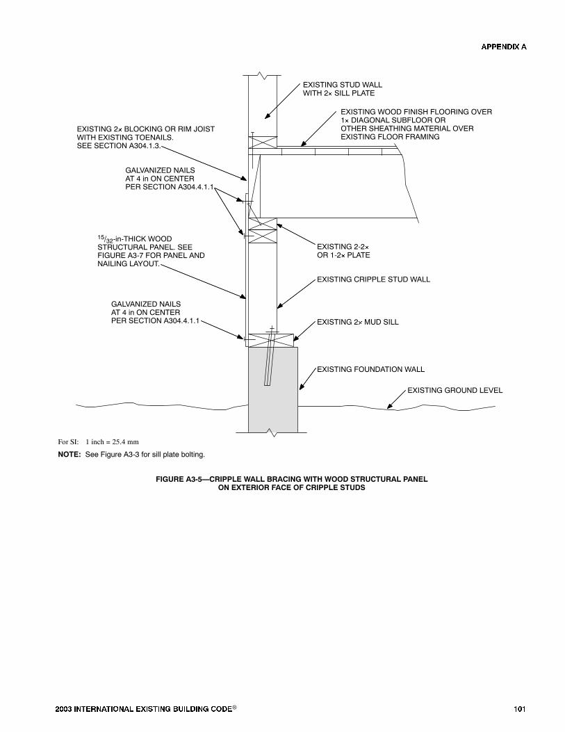
���� ���������� ��� ���� �������� ���® ���
EXISTING STUD WALLWITH 2� SILL PLATE
EXISTING WOOD FINISH FLOORING OVER1� DIAGONAL SUBFLOOR OROTHER SHEATHING MATERIAL OVEREXISTING FLOOR FRAMING
EXISTING CRIPPLE STUD WALL
EXISTING 2� MUD SILL
EXISTING FOUNDATION WALL
EXISTING 2� BLOCKING OR RIM JOISTWITH EXISTING TOENAILS.SEE SECTION A304.1.3.
EXISTING 2-2�OR 1-2� PLATE
EXISTING GROUND LEVEL
15/32-in-THICK WOODSTRUCTURAL PANEL. SEEFIGURE A3-7 FOR PANEL ANDNAILING LAYOUT.
GALVANIZED NAILSAT 4 in ON CENTERPER SECTION A304.4.1.1
GALVANIZED NAILSAT 4 in ON CENTERPER SECTION A304.4.1.1
For SI: 1 inch = 25.4 mm
NOTE: See Figure A3-3 for sill plate bolting.
FIGURE A3-5�CRIPPLE WALL BRACING WITH WOOD STRUCTURAL PANELON EXTERIOR FACE OF CRIPPLE STUDS
�������

��� ���� ���������� ��� ���� �������� ���®
EXISTING STUD WALLWITH 2� SILL PLATE
EXISTING WOOD FINISH FLOORING OVER1� DIAGONAL SUBFLOOR OROTHER SHEATHING MATERIAL OVEREXISTING FLOOR FRAMING
EXISTING CRIPPLE STUD WALL
NEW 2� BLOCKINGWITH 4-10d NAILSEACH BLOCK TO SILL
EXISTING 2� MUD SILL
EXISTING FOUNDATION WALL
EXISTING 2� BLOCKING OR RIMJOIST WITH EXISTING TOENAILS.SEE SECTION A304.1.3.
EXISTING 2-2�OR 1-2� PLATE
EXISTING GROUND LEVEL
15/32-in-THICK WOOD STRUCTURAL PANEL.SEE FIGURE A3-7 FOR PANEL AND NAILINGLAYOUT.
NOTE: See Figure A3-3 for sill plate bolting.
For SI: 1 inch = 25.4 mm
���� ������� ��
���� � ����������
FIGURE A3-6�CRIPPLE WALL BRACING WITH WOOD STRUCTURAL PANELON INTERIOR FACE OF CRIPPLE STUDS
�������
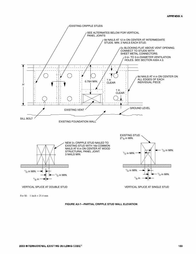
���� ���������� ��� ���� �������� ���® ���
EXISTING FOUNDATION WALL
GROUND LEVELEXISTING VENT
EXISTING CRIPPLE STUDS
2� BLOCKING FLAT ABOVE VENT OPENING.CONNECT TO STUDS WITHSHEET METAL CONNECTORS.
2-in- TO 3-in-DIAMETER VENTILATIONHOLES. SEE SECTION A304.4.3.
SILL BOLT
SEE ALTERNATES BELOW FOR VERTICALPANEL JOINTS
8d NAILS AT 12 in ON CENTER AT INTERMEDIATESTUDS. MIN. 2 NAILS EACH STUD.
8d NAILS AT 4 in ON CENTER ONALL EDGES OF EACHINDIVIDUAL PIECE
NEW 2� CRIPPLE STUD NAILED TOEXISTING STUD WITH 16d COMMONNAILS AT 6 in ON CENTER AT WOODSTRUCTURAL PANEL JOINT.3 NAILS MIN.
EXISTING STUD21/8 in MIN.
VERTICAL SPLICE AT DOUBLE STUD VERTICAL SPLICE AT SINGLE STUD
1 inCLEAR
1 inCLEAR
0.75H MIN.H
1/2 in MIN.1/2 in MIN.
1/2 in MIN.1/8 in
1/2 in MIN.1/2 in MIN.
1/2 in MIN.
1/8 in
For SI: 1 inch = 25.4 mm
FIGURE A3-7�PARTIAL CRIPPLE STUD WALL ELEVATION
�������
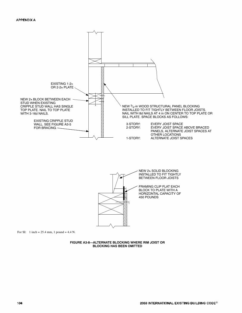
��� ���� ���������� ��� ���� �������� ���®
NEW 3/4-in WOOD STRUCTURAL PANEL BLOCKINGINSTALLED TO FIT TIGHTLY BETWEEN FLOOR JOISTS.NAIL WITH 8d NAILS AT 4 in ON CENTER TO TOP PLATE ORSILL PLATE. SPACE BLOCKS AS FOLLOWS:
3-STORY: EVERY JOIST SPACE2-STORY: EVERY JOIST SPACE ABOVE BRACED
PANELS, ALTERNATE JOIST SPACES ATOTHER LOCATIONS
1-STORY: ALTERNATE JOIST SPACES
EXISTING CRIPPLE STUDWALL. SEE FIGURE A3-5FOR BRACING.
EXISTING 1-2�OR 2-2� PLATE
NEW 2� BLOCK BETWEEN EACHSTUD WHEN EXISTINGCRIPPLE STUD WALL HAS SINGLETOP PLATE. NAIL TO TOP PLATEWITH 3-16d NAILS.
FRAMING CLIP FLAT EACHBLOCK TO PLATE WITH AHORIZONTAL CAPACITY OF450 POUNDS
For SI: 1 inch = 25.4 mm, 1 pound = 4.4 N.
NEW 2� SOLID BLOCKINGINSTALLED TO FIT TIGHTLYBETWEEN FLOOR JOISTS
FIGURE A3-8�ALTERNATE BLOCKING WHERE RIM JOIST ORBLOCKING HAS BEEN OMITTED
�������
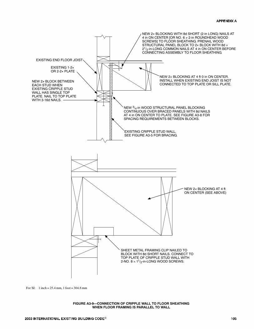
���� ���������� ��� ���� �������� ���® ���
EXISTING 1-2�OR 2-2� PLATE
EXISTING END FLOOR JOIST
NEW 3/4-in WOOD STRUCTURAL PANEL BLOCKINGCONTINUOUS OVER BRACED PANELS WITH 8d NAILSAT 4 in ON CENTER TO PLATE. SEE FIGURE A3-8 FORSPACING REQUIREMENTS BETWEEN BLOCKS.
NEW 2� BLOCKING WITH 8d SHORT (2-in LONG) NAILS AT4 in ON CENTER [OR NO. 6 � 2-in ROUNDHEAD WOODSCREWS] TO FLOOR SHEATHING. PRENAIL WOODSTRUCTURAL PANEL BLOCK TO 2� BLOCK WITH 8d �21/2-in-LONG COMMON NAILS AT 4 in ON CENTER BEFORECONNECTING ASSEMBLY TO FLOOR SHEATHING.
NEW 2� BLOCK BETWEENEACH STUD WHENEXISTING CRIPPLE STUDWALL HAS SINGLE TOPPLATE. NAIL TO TOP PLATEWITH 3-16d NAILS.
NEW 2� BLOCKING AT 4 ft 0 in ON CENTER.INSTALL WHEN EXISTING END JOIST IS NOTCONNECTED TO TOP PLATE OR SILL PLATE.
SHEET METAL FRAMING CLIP NAILED TOBLOCK WITH 8d SHORT NAILS. CONNECT TOTOP PLATE OF CRIPPLE STUD WALL WITH2-NO. 8 � 11/2-in-LONG WOOD SCREWS.
NEW 2� BLOCKING AT 4 ftON CENTER (SEE ABOVE)
EXISTING CRIPPLE STUD WALL.SEE FIGURE A3-5 FOR BRACING.
For SI: 1 inch = 25.4 mm, 1 foot = 304.8 mm
FIGURE A3-9�CONNECTION OF CRIPPLE WALL TO FLOOR SHEATHINGWHEN FLOOR FRAMING IS PARALLEL TO WALL
�������
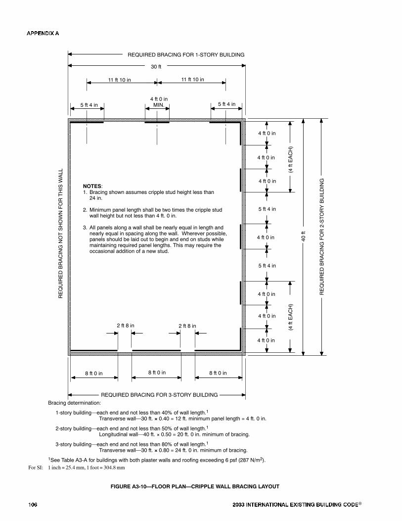
��� ���� ���������� ��� ���� �������� ���®
30 ft
5 ft 4 in
11 ft 10 in
REQUIRED BRACING FOR 3-STORY BUILDING
2 ft 8 in
Bracing determination:
1-story building�each end and not less than 40% of wall length.1Transverse wall�30 ft. � 0.40 = 12 ft. minimum panel length = 4 ft. 0 in.
2-story building�each end and not less than 50% of wall length.1Longitudinal wall�40 ft. � 0.50 = 20 ft. 0 in. minimum of bracing.
3-story building�each end and not less than 80% of wall length.1Transverse wall�30 ft. � 0.80 = 24 ft. 0 in. minimum of bracing.
1See Table A3-A for buildings with both plaster walls and roofing exceeding 6 psf (287 N/m2).
8 ft 0 in
NOTES:1. Bracing shown assumes cripple stud height less than
24 in.
2. Minimum panel length shall be two times the cripple studwall height but not less than 4 ft. 0 in.
3. All panels along a wall shall be nearly equal in length andnearly equal in spacing along the wall. Wherever possible,panels should be laid out to begin and end on studs whilemaintaining required panel lengths. This may require theoccasional addition of a new stud.
REQUIRED BRACING FOR 1-STORY BUILDING
11 ft 10 in
4 ft 0 inMIN. 5 ft 4 in
REQUIREDBRACINGNOTSHOWNFORTHIS
WALL
40ft
5 ft 4 in
(4ftEACH)
5 ft 4 in
REQUIREDBRACINGFOR2-STORYBUILDING
2 ft 8 in (4ftEACH)
8 ft 0 in 8 ft 0 in
4 ft 0 in
4 ft 0 in
4 ft 0 in
4 ft 0 in
4 ft 0 in
4 ft 0 in
4 ft 0 in
For SI: 1 inch = 25.4 mm, 1 foot = 304.8 mm
FIGURE A3-10�FLOOR PLAN�CRIPPLE WALL BRACING LAYOUT
�������
���� ���������� ��� ���� �������� ���® ���
������� ��
�������� ����� �� ������� �������� ��� ������ ���� ������ ��� ����
���� ����� ���� �� ���������� �����
������� �����������
A401.1 Purpose. The purpose of this chapter is to promotepublicwelfare and safety by reducing the risk of death or injurythat may result from the effects of earthquakes on existingwood-frame, multiunit residential buildings. The ground mo-tions of past earthquakes have caused the loss of human life,personal injury and property damage in these types of build-ings. This chapter createsminimum standards to strengthen themore vulnerable portions of these structures. When fully fol-lowed, these minimum standards will improve the perfor-mance of these buildings but will not necessarily prevent allearthquake-related damage.
A401.2 Scope.The provisions of this chapter shall apply to allexisting wood-frame buildings, or portions thereof, that areused as hotels, lodging houses, congregate residences or apart-ment houses where:
1. The ground floor portion of the wood-frame structurecontains parking or other similar open floor space thatcauses soft, weak or open-front wall lines as defined inthis chapter, and there exists one or more levels above, or
2. The walls of any story or basement of wood constructionare laterally braced with nonconforming structural mate-rials as defined in this chapter, a soft or weak wall line ex-ists as defined in this chapter, and there exist two or morelevels above.
This chapter is applicable to Seismic Hazard Zones whereSD1 is 0.3g or higher, or in Seismic Zones 3 and 4 of the UBC.
������� ���� ����������
Notwithstanding the applicable definitions, symbols and nota-tions in the Building Code, the following definitions shall ap-ply for the purposes of this chapter:
APARTMENTHOUSE.Any building or portion thereof thatcontains three or more dwelling units. For the purposes of thischapter, �apartment house� includes residential condomini-ums.
ASPECT RATIO. The span-width ratio for horizontal dia-phragms and the height-length ratio for vertical diaphragms.
CONGREGATE RESIDENCE. A congregate residence isany building or portion thereof for occupancy by other than afamily that contains facilities for living, sleeping and sanitationas required by this code, and that may include facilities for eat-ing and cooking.A congregate residencemay be a shelter, con-vent, monastery, dormitory, fraternity or sorority house, but
does not include jails, hospitals, nursing homes, hotels or lodg-ing houses.
CRIPPLE WALL. A wood-frame stud wall extending fromthe top of the foundation wall to the underside of the lowestfloor framing.
DWELLING UNIT. Any building or portion thereof for notmore than one family that contains living facilities, includingprovisions for sleeping, eating, cooking and sanitation as re-quired by this code, or congregate residence for 10 or fewerpersons.
EXPANSION ANCHOR. An approved mechanical fastenerplaced in hardened concrete that is designed to expand in a self-drilled or pre-drilled hole of a specified size and engage thesides of the hole in one or more locations to develop shear and/or tension resistance to applied loadswithoutgrout, adhesiveordrypack.
GROUNDFLOOR.Any floorwithin thewood-frameportionof a building whose elevation is immediately accessible froman adjacent grade by vehicles or pedestrians. The ground floorportion of the structure does not include any level that is com-pletely below adjacent grades.
GUESTROOM. Any room or rooms used or intended to beused by a guest for sleeping purposes. Every 100 square feet(9.3m2) of superficial floor area in a congregate residence shallbe considered a guestroom.
HOTEL.Any building containing six or more guestrooms in-tended or designed to be used, rented, hired out to be occupied,or that are occupied, for sleeping purposes by guests.
LEVEL. A story, basement or underfloor space of a buildingwith cripple walls exceeding 4 feet (1219 mm) in height.
LIFE SAFETY PERFORMANCE LEVEL. The buildingperformance level that includes significant damage to bothstructural and nonstructural components during a design earth-quake, though at least somemargin against either partial or to-tal structural collapse remains. Injuriesmay occur, but the levelof risk for life-threatening injury and entrapment is low.
LODGINGHOUSE.Anybuilding or portion thereof contain-ing at least one but notmore than five guest roomswhere rent ispaid in money, goods, labor or otherwise.
MOTEL.Motel shall mean a hotel as defined in this chapter.
MULTIUNIT RESIDENTIAL BUILDINGS. Hotels, lodg-ing houses, congregate residences and apartment houses.
NONCONFORMING STRUCTURAL MATERIALS.Wall bracing materials other than wood structural panels or di-agonal sheathing.
��� ���� ���������� ��� ���� �������� ���®
OPEN-FRONTWALLLINE.An exterior wall line, withoutvertical elements of the lateral-force-resisting system, that re-quires tributary seismic forces to be resistedbydiaphragmrota-tionor excessive cantilever beyondparallel linesof shearwalls.Diaphragms that cantilever more than 25 percent of the dis-tance between lines of lateral-force-resisting elements fromwhich thediaphragmcantilevers shall be considered excessive.Exterior exit balconies of 6 feet (1829 mm) or less in widthshall not be considered excessive cantilevers.
RETROFIT. An improvement of the lateral-force-resistingsystem by alteration of existing structural elements or additionof new structural elements.
SOFTWALLLINE.Awall line whose lateral stiffness is lessthan that required by story drift limitations or deformationcompatibility requirements of this chapter. In lieu of analysis, asoft wall line may be defined as a wall line in a story where thestory stiffness is less than 70 percent of the story above for thedirection under consideration.
STORYSTRENGTH.The total strength of all seismic-resist-ing elements sharing the same story shear in the direction underconsideration.
WALLLINE.Any length of wall along a principal axis of thebuilding used to provide resistance to lateral loads. Parallelwall lines separated by less than 4 feet (1219mm) shall be con-sidered one wall line for the distribution of loads.
WEAK WALL LINE. A wall line in a story where the storystrength is less than 80 percent of the story above in the direc-tion under consideration.
������� ������������ �� �����
A403.1 General. Buildings within the scope of this chaptershall be analyzed, designed and constructed in conformancewith the 1997Uniform Building Code� except as modified inthis chapter. Prior to any analysis, an initial screening reviewofthe buildings shall be performed as noted in Section A403.1.1.All items found to be noncompliant shall be addressed in thisanalysis.
No alteration of the existing lateral-force-resisting or verti-cal-load-carrying system shall reduce the strength or stiffnessof the existing structure.When any portion of a buildingwithinthe scope of this chapter is constructed onor into a slope steeperthan 1 unit vertical in 3 unitshorizontal, the lateral-force-resist-ing system at and below the base level diaphragm shall be ana-lyzed for the effects of concentrated lateral forces at the basecaused by this hillside condition.
Exceptions:1. Buildings in which all items on the applicable check-
list�Tables A4-A through A4-D�are marked com-pliant.
2. Prescriptive measures provided in Section A405 maybeused in two-storybuildingsof no geometrical irregu-laritywhen the roof covering of the structure is ofmate-rial weighing 5 pounds per square foot (240 N/m2) orless;when the aspect ratio of the floor diaphragmmeets
the current code requirements; and only when deemedappropriate by the building official.
A403.1.1 Initial screening. Prior to any analysis, an initialscreening review of the buildings shall be performed.Eachof the evaluation statementson this checklist shall be
marked compliant (C), noncompliant (NC), or not applica-ble (N/A). Compliant statements identify issues that areacceptable according to the criteria of this chapter, whilenoncompliant statements identify issues that require furtherinvestigation. Certain statementsmay not apply to the build-ings being evaluated. For noncompliant evaluation state-ments, the design professional may choose to conductfurther investigation or comply with the prescriptive re-quirements of this chapter.
A403.2 Scope of analysis. This chapter requires the alter-ation, repair, replacementor additionof structural elementsandtheir connections to meet the strength and stiffness require-ments herein. The lateral-load-path analysis shall include theresisting elements and connections from the wood diaphragmabove any soft, weak or open-front wall lines to the foundationsoil interface or the upper level of a Type I structure below. Thetop story of any building need not be analyzed. The lateral-load-path analysis for added structural elements shall also in-clude evaluation of the allowable soil-bearing and lateral pres-sures in accordance with UBC Section 1805.
Exception:When an open-front, weak or soft wall line ex-ists because of parking at the ground level of a two-levelbuilding, and the parking area is less than 20 percent of theground floor level, then only thewall lines in the open,weakor soft directions of the enclosed parking area need complywith the provisions of this chapter.
A403.3 Design base shear. The design base shear in a givendirection shall be 75percent of the valuedetermined byFormu-las (30-4) through (30-7) in UBC Section 1630.2.
A403.4 Vertical distribution of forces. The total seismicforce shall be distributed over the height of the structure basedon Formula (30-15) in UBC Section 1630.5. Distribution offorce by story weight shall be permitted for two-story build-ings. The value ofR used in the design of any story shall be lessthan or equal to the value ofRused in the given direction for thestory above.
A403.5 Weak story limitation.The structure shall not exceed30 feet (9144 mm) in height or two levels if the lower levelstrength is less than 65 percent of the story above. Existingwalls shall be strengthened as required to complywith this pro-vision unless the weak level can resist a total lateral seismicforce of �0 times the design force prescribed in SectionA403.4.The story strength for each level of all other structures shall
be a minimum of 80 percent of the story above.
A403.6 Story drift limitation. The calculated story drift foreach retrofitted level shall not exceed the allowable deforma-tion compatible with all vertical-load-resisting elements and0.025 times the story height. The calculated story drift shall notbe reduced by the effects of horizontal diaphragm stiffness butshall be increased when these effects produce rotation. Driftcalculations shall be in accordance with UBC Section 1630.9and 1630.10.
�������
���� ���������� ��� ���� �������� ���® ���
The effects of rotation and soil stiffness shall be included inthe calculated story drift when lateral loads are resisted by ver-tical elements whose required depth of embedment is deter-mined by pole formulas, such as Formulas (6-1) and (6-2)in UBC Section 1806.8.2. The range of this coefficient ofsubgrade reaction used in the deflection calculations shall beprovided from an approved geotechnical engineering report orother approved methods.
A403.7 P � effects. The requirements of UBC Sections1630.13 and 1633.2.4 shall apply except as modified herein.All structural framing elements and their connections not re-quired by design to be part of the lateral-force-resisting systemshall be designed and/or detailed to be adequate to maintainsupport of design dead plus live loadswhen subjected to the ex-pected deformations caused by seismic forces. The stress anal-ysis of cantilever columns shall use a buckling factor of 2.1 forthe direction normal to the axis of the beam.
A403.8 Ties and continuity. All parts of the structure in-cluded in the scope of Section A403.2 shall be interconnected,and the connection shall be capable of resisting the seismicforce created by the partsbeing connected.Any smaller portionof a building shall be tied to the remainder of the building withelements having a strength to resist 0.5CaI times the weight ofthe smaller portion. A positive connection for resisting a hori-zontal force acting parallel to themember shall be provided foreach beam, girder or truss included in the lateral load path. Thisforce shall not be less than 0.5CaI times the dead plus live load.
A403.8.1Cripplewalls.Unbraced cripplewalls found to benoncompliant in Table A4-C shall be analyzed and designedper Chapter 3. When a single top plate exists in the cripplewall, all end joints in the top plate shall be tied. Ties shall beconnected to each end of the discontinuous top plate andshall be equal to one of the following:
1. Three-inch-by-6-inch (76 mm by 152 mm), 18-gagegalvanized steel, nailed with six 8d common nails ateach end.
2. One and one-fourth-inch-by-12-inch (32 mm by 305mm), 18-gage galvanized steel, nailed with six 16dcommon nails at each end.
3. Two-inch-by-4-inch-by-12-inch (51 mm by 102 mmby 305 mm) wood blocking, nailed with six 16d com-mon nails at each end.
A403.9 Collector elements. Collector elements shall be pro-vided that can transfer the seismic forces originating in otherportions of the building to the elementswithin the scope ofSec-tion A403.2 that provide resistance to those forces.
A403.10 Horizontal diaphragms. The analysis of shear de-mand or capacity of an existing plywood or diagonallysheathed horizontal diaphragm need not be investigated unlessthe diaphragm is required to transfer lateral forces from thelateral-resisting elements above the diaphragm to other lateral-resisting elements below the diaphragm because of an offset inplacement of the elements.
Wood diaphragms in structures that support floors or roofsabove shall not be allowed to transmit lateral forces by rotationor cantilever except as allowed by the Building Code. Howev-
er, rotational effects shall be accounted for when unsymmetricwall stiffness increases shear demands.
Exception:Diaphragms that cantilever 25 percent or less ofthe distance between lines of lateral-load-resisting elementsfrom which the diaphragm cantilevers may transmit theirshears by cantilever, provided that rotational effects on shearwalls parallel and perpendicular to the load are taken intoaccount.
A403.11 Shear walls. Shear walls shall have sufficientstrength and stiffness to resist the tributary seismic loads andshall conform to the special requirements of this section.
A403.11.1 Gypsum or cement plaster products.Gypsumor cementplaster products shall not be used to provide lateralresistance in the soft or weak story.
A403.11.2 Wood structural panels.
A403.11.2.1 Drift limit. Wood structural panel shearwalls shall meet the story drift limitation of SectionA403.6. Conformance to the story drift limitation shallbe determined by approved testing or calculation, oranalogies drawn therefrom, and not by the use of an as-pect ratio. Calculated deflection shall be determined ac-cording to UBC Standard 23-2, Section 23.223, �Cal-culation of Shear Wall Deflection,� and 25 percent shallbe added to account for inelastic action and repetitiveloading. Contribution to the shear wall deflection fromthe anchor or tie-down slippage shall also be included.The slippage contribution shall include the verticalelongation of the connectormetal components, the verti-cal slippage of the connectors to framing members,localized crushing of wood due to bearing loads, andshrinkage of the wood elements because of changes inmoisture content as a result of aging. The total verticalslippage shall be multiplied by the shear panel aspect ra-tio and added to the total horizontal deflection. Individu-al shear panels shall be permitted to exceed the maxi-mum aspect ratio, provided the story drift and allowableshear capacities are not exceeded.
A403.11.2.2 Openings. Shear walls are permitted to bedesigned for continuity around openings in accordancewith Section 2315.1 of theUBC.Blocking and steel strap-ping shall be provided at corners of the openings to trans-fer forces from discontinuous boundary elements into ad-joiningpanelelements.Alternatively, theperforated shearwall provisions of the IBC may be used.
A403.11.2.3 Wood species of framing members.Allowable shear values for wood structural panels shallconsider the species of the framing members. When theallowable shear values are based on Douglas fir-larchframing members, and framing members are constructedof other species of lumber, the allowable shear valuesshall be multiplied by the following factors: 0.82 for spe-cies with specific gravities greater than or equal to 0.42but less than 0.49, and 0.65 for specieswith specific gravi-ties less than 0.42. Redwood shall use 0.65 and hem firshall use 0.82, unless otherwise approved.
A403.11.3 Substitution for 3-inch (76 mm) nominalwidth framing members. Two 2-inch (51 mm) nominal
�������

��� ���� ���������� ��� ���� �������� ���®
width framing members shall be permitted in lieu of any re-quired 3-inch (76 mm) nominal width framing memberwhen the existing and new framingmembers are of equal di-mensions, when they are connected as required to transferthe in-plane shear between them, and when the sheathingfasteners are equally divided between them.
A403.11.4 Hold-down connectors.
A403.11.4.1 Expansion anchors in tension. Expansionanchors that provide tension strength by friction resist-ance shall not be used to connect hold-downdevices to ex-isting concrete or masonry elements. Expansion anchorsthat provide tension strengthbybearing (commonly refer-enced as �undercut� anchors) shall be permitted.
A403.11.4.2 Required depth of embedment. The re-quired depth of embedment or edge distance for theanchor used in the hold-down connector shall be providedin the concrete or masonry below any plain concrete slabunless satisfactory evidence is submitted to the buildingofficial that shows that the concrete slab and footings areof monolithic construction.
A403.11.4.3 Required preload of bolted hold-downconnectors. Bolted hold-down connectors shall be pre-loaded to reduce slippage of the connector. Preloadingshall consist of tightening the nut on the tension anchor af-ter the placement but before the tightening of the shearbolts in the panel flangemember. The tension anchor shallbe tightened until the shear bolts are in firm contact withthe edge of the hole nearest the direction of the tension an-chor. Hold-down connectors with self-jigging bolt stand-offs shall be installed in a manner to permit preloading.
������� ����������� ����������
��� ����� �����������
When the building contains three ormore levels, the work spe-cified in this chapter shall be permitted to be done in the follow-ing phases. Work shall start with Phase I unless otherwiseapproved by the building official. When the building does notcontain the conditions shown in any phase, the sequence of ret-rofit work shall proceed to the next phase in numerical order.
Phase 1 Work. The first phase of the retrofit work shall in-clude the ground floor portion of the wood structure that con-tains parking or other similar open floor space.
Phase 2 Work. The second phase of the retrofit work shallinclude walls of any level of wood construction with two ormore levels above that are laterally bracedwithnonconformingstructural materials.
Phase 3Work.The third and final phase of the retrofit workshall include the remaining portions of the building up to, butnot including, the top story as specified in Section A403.2.
������� ��� ����������!� �������
��� ���� �����
A405.1 Scope. The proposed prescriptive measures providedhere are intended to reduce the earthquake vulnerability of thestructure and to reduce the possibility of collapse or partial col-lapse of the building in the event of a moderate to major earth-quake.
A405.1.1 Performance. The improved earthquake perfor-mance of the structure due to the proposed prescriptivemea-sures varies and is greatly controlled by all of the following:proximity to the fault line; soil type; weight of roof and floorabove; quality of existingwalls, posts and columns, and theirconnections to the floor diaphragm; and the quality ofconstruction provided to comply with the prescriptive mea-sures. The implementation of the proposed measures is notintended to improve the earthquake performance of thebuilding above the first story.
A405.1.2 Limitation. The proposed prescriptive measuresrely on rotation of the second floor diaphragm to distributethe load between the side and rearwall enclosing the parkingarea. The owner shall provide access to ensure that the floordiaphragm is ofwood structural panel or diagonal sheathing.In the absence of such a verification, a new wood structuralpanel diaphragm must be applied of minimum thickness of3/4 inch (19mm) andwith10d commonnails at 6 inches (152mm) on center.
A405.1.3 Additional conditions. To qualify for prescrip-tivemeasures, the followingadditional conditionsneed tobesatisfied:
1. Diaphragm aspect ratio = 1.5 or less.2. Minimum length of side shear walls = 20 feet (6096
mm) with less than 10 percent openings.3. Minimum length of rear shear walls = 3/4 of rear wall
length with individual walls not having more than 10percent openings.
A405.2 Minimum required retrofit.
A405.2.1 Anchor bolt size and spacing. The anchor boltsize and spacing shall be a minimum of 3/4 inch (19 mm) indiameter at 32 inches (813 mm) on center. Where existingbolts are inadequate, new steel plates bolted to the side of thefoundation and nailed to the sill may be used, such as an ap-proved connector.
A405.2.2 Connection to floor above.Shearwall top platesshall be connected to blocking or rim joist at upper floorwithaminimumof18-gagegalvanized steel angle clips 41/2 inch-es (114mm) long with 12-8d nails spaced no farther than 16inches (406 mm) on center, or by equivalent shear transfermethods.
A405.2.3 Shear wall sheathing. The shear wall sheathingshall be aminimumof 15/32 inch (11.9mm)5-PlyStructural Iwith 10d nails at 4 inches (102mm)on center at edges and 12inches (305 mm) on center at field; blocked all edges with 3by 4 or larger. Where existing sill plates are less than 3-bythick, place flat 2-by on top of sill between studs, with flat18-gage galvanized steel clips 41/2 inches (114 mm) long
�������

���� ���������� ��� ���� �������� ���® ���
with 12-8d nails or 3/8-inch-diameter (9.5 mm) lags throughblocking for shear transfer to sill plate. Stagger nailing fromwall sheathing between existing sill and new blocking. An-chor new blocking to foundation as specified above.
A405.2.4 Shear wall hold-downs. Shear walls shall beprovided with hold-down anchors at each end. Two hold-down anchors are required at intersecting corners. Hold-downs shall be approved connectors with a minimum5/8-inch-diameter (15.9mm) threaded rod or other approvedanchor with a minimum allowable load of 4,000 pounds(17.8 kN). Anchor embedment in concrete shall not be lessthan 5 inches (127 mm). Tie-rod systems shall not be lessthan 5/8 inch (15.9 mm) in diameter unless using highstrength cable. Threaded rod or high strength cable elonga-tion shall not exceed 5/8 inch (15.9mm) using design forces.
������� ���"��������� �� �����������
A406.1 New materials. All materials approved by this code,including their appropriate allowable stresses and minimumaspect ratios, shall be permitted tomeet the requirements of thischapter.
A406.2 Allowable foundation and lateral pressures. Al-lowable foundation and lateral pressures shall be permitted touse the values fromUBCTable 18-I-A. The coefficient of vari-ation of subgrade reaction shall be established by an approvedgeotechnical engineering report or other approved methodswhen used in the deflection calculations of embedded verticalelements as required in Section A403.6.
A406.3 Existing materials. All existing materials shall be insound condition and constructed in conformance to this codebefore they can be used to resist the lateral loads prescribed inthis chapter. The verification of existing material conditionsand their conformance to these requirements shall be made byphysical observation reports, material testing or record draw-ings as determined by the structural designer and as approvedby the building official.
A406.3.1 Horizontal wood diaphragms. Existing hori-zontal wood diaphragms that require analysis under SectionA403.10 shall be permitted to use Table A4-E for their al-lowable values.
A406.3.2 Wood-structural-panel shear walls.
A406.3.2.1 Allowable nail slip values. When the re-quired drift calculations of Section A403.11.2.1 rely onthe lower slip values for common nails or surfaced drylumber, their use in construction shall be verified by expo-sure. The use of box nails and unseasoned lumber may beassumed without exposure. The design value of the boxnails shall be assumed to be similar to that of commonnails having the same diameter. Verification of surfaceddry lumber shall be by identification conforming to UBCSection 2340.1.
A406.3.2.2 Plywood panel construction.When verifi-cation of the existing plywood materials is by use of re-
cord drawings alone, the panel construction for plywoodshall be assumed to be of three plies. The plywoodmodu-lus �G� shall be assumed equal to 50,000 pounds persquare inch (345 MPa).
A406.3.3 Existing wood framing. Wood framing is per-mitted to use the design stresses specified in the buildingcode under which the building was constructed or otherstress criteria approved by the building official.
A406.3.4 Structural steel.All existing structural steel shallbe permitted to use the allowable stresses forGradeA36.Ex-isting pipe or tube columns shall be assumed to be of mini-mum wall thickness unless verified by testing or exposure.
A406.3.5 Strength of concrete.All existing concrete foot-ings shall be permitted to use the allowable stresses for plainconcrete with a compressive strength of 2,000 pounds persquare inch (13.8 MPa). The strength of existing concretewith a recorded compressive strength greater than 2,000pounds per square inch (13.8 MPa) shall be verified by test-ing, record drawings or department records.
A406.3.6 Existing sill plate anchorage. Existing cast-in-place anchor bolts shall bepermitted touse the allowable ser-vice loads for bolts with proper embedment when used forshear resistance to lateral loads.
������� ���#����� ����������� �� �����
A407.1 General. The plans shall show all necessary dimen-sions and materials for plan review and construction and shallaccurately reflect the results of the engineering investigationand design. Details specific to the actual condition found shallbe shown on the drawings to assure installation of all elementsrequired for construction of the necessary complete load path.The plans shall contain a note that states that this retrofit wasdesigned in compliance with the criteria of this chapter.
A407.2 Existing construction. The plans shall show existingdiaphragm and shear wall sheathing and framing materials;fastener type and spacing; diaphragm and shear wall connec-tions; continuity ties; and collector elements. The plans shallalso show the portion of the existingmaterials that needs verifi-cation during construction.
A407.3 New construction.
A407.3.1 Foundation plan elements.The foundation planshall include the size, type, location and spacingof all anchorbolts with the required depth of embedment, edge and enddistance; the location and size of all columns for braced ormoment frames; referenced details for the connection ofbraced or moment-resisting frames to their footing; and ref-erenced sections for any grade beams and footings.
A407.3.2 Framing plan elements. The framing plan shallinclude the width, location and material of shear walls; thewidth, location andmaterial of frames; references on detailsfor the column-to-beam connectors, beam-to-wall connec-tions, and shear transfers at floor and roof diaphragms; andthe required nailing and length for wall top plate splices.
�������
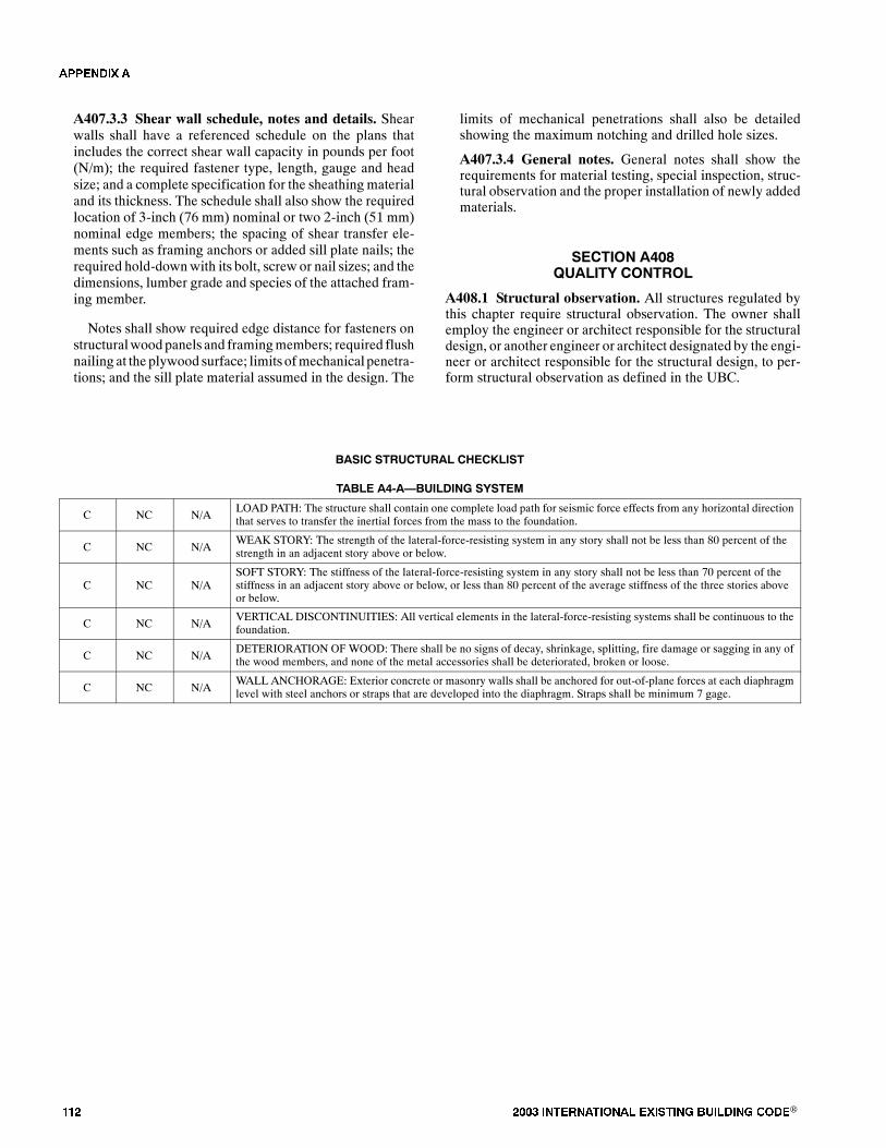
��� ���� ���������� ��� ���� �������� ���®
A407.3.3 Shear wall schedule, notes and details. Shearwalls shall have a referenced schedule on the plans thatincludes the correct shear wall capacity in pounds per foot(N/m); the required fastener type, length, gauge and headsize; and a complete specification for the sheathing materialand its thickness. The schedule shall also show the requiredlocation of 3-inch (76 mm) nominal or two 2-inch (51 mm)nominal edge members; the spacing of shear transfer ele-ments such as framing anchors or added sill plate nails; therequired hold-downwith its bolt, screw or nail sizes; and thedimensions, lumber grade and species of the attached fram-ing member.
Notes shall show required edge distance for fasteners onstructuralwoodpanels and framingmembers; required flushnailing at the plywood surface; limits ofmechanical penetra-tions; and the sill plate material assumed in the design. The
limits of mechanical penetrations shall also be detailedshowing the maximum notching and drilled hole sizes.
A407.3.4 General notes. General notes shall show therequirements for material testing, special inspection, struc-tural observation and the proper installation of newly addedmaterials.
������� ���$����� �������
A408.1 Structural observation. All structures regulated bythis chapter require structural observation. The owner shallemploy the engineer or architect responsible for the structuraldesign, or another engineer or architect designated by the engi-neer or architect responsible for the structural design, to per-form structural observation as defined in the UBC.
BASIC STRUCTURAL CHECKLIST
TABLE A4-A�BUILDING SYSTEM
C NC N/ALOAD PATH: The structure shall contain one complete load path for seismic force effects from any horizontal directionthat serves to transfer the inertial forces from the mass to the foundation.
C NC N/AWEAK STORY: The strength of the lateral-force-resisting system in any story shall not be less than 80 percent of thestrength in an adjacent story above or below.
C NC N/ASOFT STORY: The stiffness of the lateral-force-resisting system in any story shall not be less than 70 percent of thestiffness in an adjacent story above or below, or less than 80 percent of the average stiffness of the three stories aboveor below.
C NC N/AVERTICAL DISCONTINUITIES: All vertical elements in the lateral-force-resisting systems shall be continuous to thefoundation.
C NC N/ADETERIORATION OFWOOD: There shall be no signs of decay, shrinkage, splitting, fire damage or sagging in any ofthe wood members, and none of the metal accessories shall be deteriorated, broken or loose.
C NC N/AWALL ANCHORAGE: Exterior concrete or masonry walls shall be anchored for out-of-plane forces at each diaphragmlevel with steel anchors or straps that are developed into the diaphragm. Straps shall be minimum 7 gage.
�������
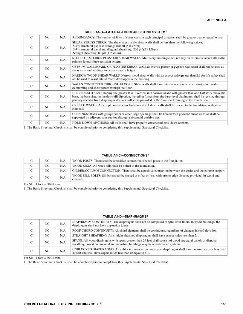
���� ���������� ��� ���� �������� ���® ���
TABLE A4-B�LATERAL-FORCE-RESISTING SYSTEM1
C NC N/A REDUNDANCY: The number of lines of shear walls in each principal direction shall be greater than or equal to two.
C NC N/A
SHEAR STRESS CHECK: The shear stress in the shear walls shall be less than the following values:5-Ply structural panel sheathing: 400 plf (5.8 kN/m)3-Ply structural panel and diagonal sheathing: 200 plf (2.9 kN/m)Straight sheathing: 80 plf (1.2 kN/m)
C NC N/ASTUCCO (EXTERIOR PLASTER) SHEARWALLS: Multistory buildings shall not rely on exterior stucco walls as theprimary lateral-force-resisting system.
C NC N/AGYPSUM WALLBOARD OR PLASTER SHEAR WALLS: Interior plaster or gypsum wallboard shall not be used asshear walls on buildings over one story in height.
C NC N/ANARROWWOOD SHEAR WALLS: Narrow wood shear walls with an aspect ratio greater than 2:1 for life safety shallnot be used to resist lateral forces developed in the building.
C NC N/AWALLS CONNECTED THROUGH FLOORS: Shear walls shall have interconnection between stories to transferoverturning and shear forces through the floor.
C NC N/AHILLSIDE SITE: For a sloping site greater than 1 vertical in 3 horizontal and with greater than one-half story above thebase, the base shear in the downhill direction, including forces from the base-level diaphragm, shall be resisted throughprimary anchors from diaphragm struts or collectors provided in the base-level framing to the foundation.
C NC N/ACRIPPLE WALLS: All cripple walls below first-floor-level shear walls shall be braced to the foundation with shearelements.
C NC N/AOPENINGS: Walls with garage doors or other large openings shall be braced with plywood shear walls or shall besupported by adjacent construction through substantial positive ties.
C NC N/A HOLD-DOWN ANCHORS: All walls shall have properly constructed hold-down anchors.
1. The Basic Structural Checklist shall be completed prior to completing this Supplemental Structural Checklist.
TABLE A4-C�CONNECTIONS1
C NC N/A WOOD POSTS: There shall be a positive connection of wood posts to the foundation.
C NC N/A WOOD SILLS: All wood sills shall be bolted to the foundation.
C NC N/A GIRDER/COLUMN CONNECTION: There shall be a positive connection between the girder and the column support.
C NC N/AWOOD SILL BOLTS: Sill bolts shall be spaced at 6 feet or less, with proper edge distance provided for wood andconcrete.
For SI: 1 foot = 304.8 mm.1. The Basic Structural Checklist shall be completed prior to completing this Supplemental Structural Checklist.
TABLE A4-D�DIAPHRAGMS1
C NC N/ADIAPHRAGM CONTINUITY: The diaphragms shall not be composed of split-level floors. In wood buildings, thediaphragms shall not have expansion joints.
C NC N/A ROOF CHORD CONTINUITY: All chord elements shall be continuous, regardless of changes in roof elevation.
C NC N/A STRAIGHT SHEATHING: All straight-sheathed diaphragms shall have aspect ratios less than 2:1.
C NC N/ASPANS: All wood diaphragms with spans greater than 24 feet shall consist of wood structural panels or diagonalsheathing. Wood commercial and industrial buildings may have rod-braced systems.
C NC N/AUNBLOCKEDDIAPHRAGMS: All unblocked wood-structural-panel diaphragms shall have horizontal spans less than40 feet and shall have aspect ratios less than or equal to 4:1.
For SI: 1 foot = 304.8 mm.1. The Basic Structural Checklist shall be completed prior to completing this Supplemental Structural Checklist.
�������

��� ���� ���������� ��� ���� �������� ���®
TABLE A4-E�ALLOWABLE VALUES FOR EXISTING MATERIALS
EXISTING MATERIALS OR ALLOWABLE VALUESEXISTING MATERIALS ORCONFIGURATIONS OF MATERIALS1
� 14.594 for N/m
1. Horizontal diaphragms2
1.1 Roofs with straight sheathing and roofing applied directly to the sheathing1.2 Roofs with diagonal sheathing and roofing applied directly to the sheathing1.3 Floors with straight tongue-and-groove sheathing1.4 Floors with straight sheathing and finished wood flooring with board edges offset or per-
pendicular1.5 Floors with diagonal sheathing and finished wood flooring
100 lbs. per ft. for seismic shear250 lbs. per ft. for seismic shear100 lbs. per ft. for seismic shear500 lbs. per ft. for seismic shear
600 lbs. per ft. for seismic shear
2. Crosswalls2,3
2.1 Plaster on wood or metal lath2.2 Plaster on gypsum lath2.3 Gypsum wallboard, unblocked edges2.4 Gypsum wallboard, blocked edges
Per side:200 lbs. per ft. for seismic shear175 lbs. per ft. for seismic shear75 lbs. per ft. for seismic shear125 lbs. per ft. for seismic shear
3. Existing footings, wood framing, structural steel and reinforced steel
3.1 Plain concrete footings
3.2 Douglas fir wood3.3 Reinforcing steel3.4 Structural steel
= 1,500 psi (10.3 MPa) unless otherwise shownby tests4
Allowable stress same as D.F. No. 14
= 18,000 psi (124 MPa) maximum4
= 20,000 psi (138 MPa) maximum4
���
��
��
For SI: 1 foot = 304.8 mm.1. Material must be sound and in good condition.2. A one-third increase in allowable stress is not allowed.3. Shear values of these materials may be combined, except the total combined value shall not exceed 300 pounds per foot.4. Stresses given may be increased for combinations of loads as specified in the Building Code.
�������
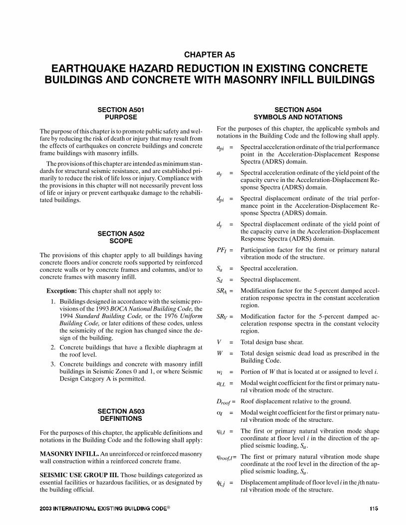
���� ���������� ��� ���� �������� ���® ���
������� ��
�������� ����� �� ����� �� �������� ����������� ���� �� �������� ���� ������� ������ ��� ����
������� ����������
Thepurpose of this chapter is to promote public safety andwel-fare by reducing the risk of death or injury thatmay result fromthe effects of earthquakes on concrete buildings and concreteframe buildings with masonry infills.
Theprovisionsof this chapter are intended asminimumstan-dards for structural seismic resistance, and are established pri-marily to reduce the risk of life loss or injury. Compliancewiththe provisions in this chapter will not necessarily prevent lossof life or injury or prevent earthquake damage to the rehabili-tated buildings.
������� ���������
The provisions of this chapter apply to all buildings havingconcrete floors and/or concrete roofs supported by reinforcedconcrete walls or by concrete frames and columns, and/or toconcrete frames with masonry infill.
Exception: This chapter shall not apply to:
1. Buildings designed in accordancewith the seismic pro-visions of the 1993 BOCANational Building Code, the1994 Standard Building Code, or the 1976 UniformBuilding Code, or later editions of these codes, unlessthe seismicity of the region has changed since the de-sign of the building.
2. Concrete buildings that have a flexible diaphragm atthe roof level.
3. Concrete buildings and concrete with masonry infillbuildings in Seismic Zones 0 and 1, or where SeismicDesign Category A is permitted.
������� ���� ����������
For the purposes of this chapter, the applicable definitions andnotations in the Building Code and the following shall apply:
MASONRYINFILL.Anunreinforced or reinforcedmasonrywall construction within a reinforced concrete frame.
SEISMIC USE GROUP III. Those buildings categorized asessential facilities or hazardous facilities, or as designated bythe building official.
������� ����������� �� ���������
For the purposes of this chapter, the applicable symbols andnotations in the Building Code and the following shall apply.
api = Spectral accelerationordinateof the trialperformancepoint in the Acceleration-Displacement ResponseSpectra (ADRS) domain.
ay = Spectral acceleration ordinate of the yield point of thecapacity curve in the Acceleration-Displacement Re-sponse Spectra (ADRS) domain.
dpi = Spectral displacement ordinate of the trial perfor-mance point in the Acceleration-Displacement Re-sponse Spectra (ADRS) domain.
dy = Spectral displacement ordinate of the yield point ofthe capacity curve in the Acceleration-DisplacementResponse Spectra (ADRS) domain.
PFI = Participation factor for the first or primary naturalvibration mode of the structure.
Sa = Spectral acceleration.
Sd = Spectral displacement.
SRA = Modification factor for the 5-percent damped accel-eration response spectra in the constant accelerationregion.
SRV = Modification factor for the 5-percent damped ac-celeration response spectra in the constant velocityregion.
V = Total design base shear.
W = Total design seismic dead load as prescribed in theBuilding Code.
wi = Portion of W that is located at or assigned to level i.
aLL = Modalweight coefficient for the first or primary natu-ral vibration mode of the structure.
Droof = Roof displacement relative to the ground.
�I = Modalweight coefficient for the first or primary natu-ral vibration mode of the structure.
�i,I = The first or primary natural vibration mode shapecoordinate at floor level i in the direction of the ap-plied seismic loading, Sa .
�roof,I= The first or primary natural vibration mode shapecoordinate at the roof level in the direction of the ap-plied seismic loading, Sa .
�i,j = Displacement amplitude of floor level i in the jth natu-ral vibration mode of the structure.
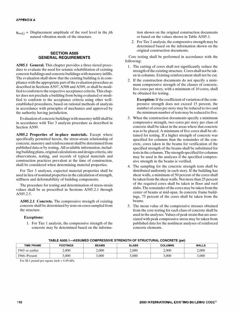
��� ���� ���������� ��� ���� �������� ���®
�roof,j = Displacement amplitude of the roof level in the jthnatural vibration mode of the structure.
������� ����������� ����������
A505.1 General. This chapter provides a three-tiered proce-dure to evaluate the need for seismic rehabilitation of existingconcrete buildings and concrete buildingswithmasonry infills.The evaluation shall show that the existing building is in com-pliancewith the appropriate part of the evaluation procedure asdescribed in Sections A507, A508 and A509, or shall bemodi-fied to conform to the respective acceptance criteria. This chap-ter does not preclude a building from being evaluated or modi-fied to conform to the acceptance criteria using other well-established procedures, based on rational methods of analysisin accordance with principles of mechanics and approved bythe authority having jurisdiction.
Evaluation of concrete buildingswithmasonry infill shall bein accordance with Tier 3 analysis procedure as described inSection A509.
A505.2 Properties of in-place materials. Except wherespecifically permitted herein, the stress-strain relationship ofconcrete,masonry and reinforcement shall be determined frompublished data or by testing. All available information, includ-ingbuildingplans, original calculations anddesign criteria, siteobservations, testing, and records of typical materials andconstruction practices prevalent at the time of construction,shall be considered when determining material properties.
For Tier 3 analyses, expected material properties shall beused in lieu of nominal properties in the calculation of strength,stiffness and deformabiltity of building components.
The procedure for testing and determination of stress-strainvalues shall be as prescribed in Sections A505.2.1 throughA505.2.5.
A505.2.1 Concrete. The compressive strength of existingconcrete shall be determined by tests on cores sampled fromthe structure.
Exceptions:
1. For Tier 1 analysis, the compressive strength of theconcrete may be determined based on the informa-
tion shown on the original construction documentsor based on the values shown in Table A505.1.
2. For Tier 2 analysis, the compressive strength may bedetermined based on the information shown on theoriginal construction documents.
Core testing shall be performed in accordance with thefollowing:
1. The cutting of cores shall not significantly reduce thestrength of the existing structure.Cores shall not be tak-en in columns. Existing reinforcement shall not be cut.
2. If the construction documents do not specify a mini-mum compressive strength of the classes of concrete,five cores per story, with a minimum of 10 cores, shallbe obtained for testing.
Exception: If the coefficient of variation of the com-pressive strength does not exceed 15 percent, thenumber of cores per storymay be reduced to two andtheminimumnumber of testsmay be reduced to five.
3. When the construction documents specify a minimumcompressive strength, two cores per story per class ofconcrete shall be taken in the areas where that concretewas to be placed. Aminimum of five cores shall be ob-tained for testing. If a higher strength of concrete wasspecified for columns than the remainder of the con-crete, cores taken in the beams for verification of thespecified strength of the beams shall be substituted fortests in the columns. The strength specified for columnsmay be used in the analyses if the specified compres-sive strength in the beams is verified.
4. The sampling for the concrete strength tests shall bedistributed uniformly in each story. If the building hasshear walls, a minimum of 50 percent of the cores shallbe taken from the shearwalls.Notmore than 25 percentof the required cores shall be taken in floor and roofslabs. The remainder of the coresmaybe taken from thecenter of beams at mid-span. In concrete frame build-ings, 75 percent of the cores shall be taken from thebeams.
5. The mean value of the compressive stresses obtainedfrom the core testing for each class of concrete shall beused in the analyses. Values of peak strain that are asso-ciated with peak compressive stress may be taken frompublished data for the nonlinear analyses of reinforcedconcrete elements.
TABLE A505.1�ASSUMED COMPRESSIVE STRENGTH OF STRUCTURAL CONCRETE (psi)
TIME FRAME FOOTINGS BEAMS SLABS COLUMNS WALLS
1965 or earlier 2,000 2,000 2,000 2,000 2,000
1966�Present 3,000 3,000 3,000 3,000 3,000For SI:1 pound per square inch = 6.89 kPa
�������
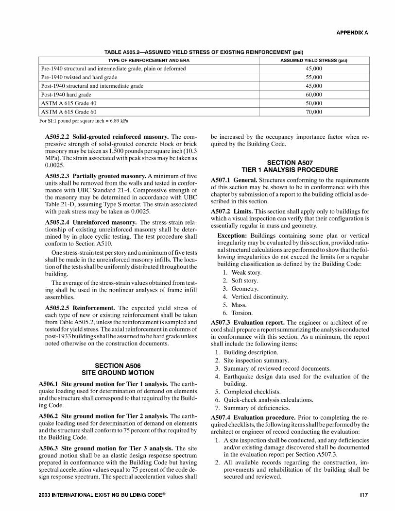
���� ���������� ��� ���� �������� ���® ���
TABLE A505.2�ASSUMED YIELD STRESS OF EXISTING REINFORCEMENT (psi)
TYPE OF REINFORCEMENT AND ERA ASSUMED YIELD STRESS (psi)
Pre-1940 structural and intermediate grade, plain or deformed 45,000
Pre-1940 twisted and hard grade 55,000
Post-1940 structural and intermediate grade 45,000
Post-1940 hard grade 60,000
ASTM A 615 Grade 40 50,000
ASTM A 615 Grade 60 70,000
For SI:1 pound per square inch = 6.89 kPa
A505.2.2 Solid-grouted reinforced masonry. The com-pressive strength of solid-grouted concrete block or brickmasonrymaybe taken as 1,500 pounds per square inch (10.3MPa). The strain associatedwith peak stressmay be taken as0.0025.
A505.2.3 Partially grouted masonry. Aminimum of fiveunits shall be removed from the walls and tested in confor-mance with UBC Standard 21-4. Compressive strength ofthe masonry may be determined in accordance with UBCTable 21-D, assuming Type S mortar. The strain associatedwith peak stress may be taken as 0.0025.
A505.2.4 Unreinforced masonry. The stress-strain rela-tionship of existing unreinforced masonry shall be deter-mined by in-place cyclic testing. The test procedure shallconform to Section A510.
One stress-strain test per story and aminimumof five testsshall be made in the unreinforced masonry infills. The loca-tion of the tests shall be uniformly distributed throughout thebuilding.
The average of the stress-strain values obtained from test-ing shall be used in the nonlinear analyses of frame infillassemblies.
A505.2.5 Reinforcement. The expected yield stress ofeach type of new or existing reinforcement shall be takenfromTableA505.2, unless the reinforcement is sampled andtested for yield stress. The axial reinforcement in columnsofpost-1933buildings shall be assumed to behard gradeunlessnoted otherwise on the construction documents.
������� �������� ���� ������
A506.1 Site ground motion for Tier 1 analysis. The earth-quake loading used for determination of demand on elementsand the structure shall correspond to that required by theBuild-ing Code.
A506.2 Site ground motion for Tier 2 analysis. The earth-quake loading used for determination of demand on elementsand the structure shall conform to 75 percent of that required bythe Building Code.
A506.3 Site ground motion for Tier 3 analysis. The siteground motion shall be an elastic design response spectrumprepared in conformance with the Building Code but havingspectral acceleration values equal to 75 percent of the code de-sign response spectrum. The spectral acceleration values shall
be increased by the occupancy importance factor when re-quired by the Building Code.
������� ��� ���� � �������� ����� ��
A507.1 General. Structures conforming to the requirementsof this section may be shown to be in conformance with thischapter by submission of a report to the building official as de-scribed in this section.
A507.2 Limits. This section shall apply only to buildings forwhich a visual inspection can verify that their configuration isessentially regular in mass and geometry.
Exception: Buildings containing some plan or verticalirregularitymaybe evaluated by this section, provided ratio-nal structural calculationsare performed to show that the fol-lowing irregularities do not exceed the limits for a regularbuilding classification as defined by the Building Code:1. Weak story.2. Soft story.3. Geometry.4. Vertical discontinuity.5. Mass.6. Torsion.
A507.3 Evaluation report. The engineer or architect of re-cord shall prepare a report summarizing the analysis conductedin conformance with this section. As a minimum, the reportshall include the following items:1. Building description.2. Site inspection summary.3. Summary of reviewed record documents.4. Earthquake design data used for the evaluation of the
building.5. Completed checklists.6. Quick-check analysis calculations.7. Summary of deficiencies.
A507.4 Evaluation procedure. Prior to completing the re-quired checklists, the following itemsshall beperformedby thearchitect or engineer of record conducting the evaluation:1. A site inspection shall be conducted, and any deficiencies
and/or existing damage discovered shall be documentedin the evaluation report per Section A507.3.
2. All available records regarding the construction, im-provements and rehabilitation of the building shall besecured and reviewed.
�������
��� ���� ���������� ������� ��� ���� ���®
3. Material characteristics of the building shall be deter-mined in accordance with Section A505.2.
4. The necessary earthquake design datamust be establishedfor use in the evaluation in accordance with SectionA506.1 and the Building Code.
Based on the above information, the appropriate checklist(s)shall be completed in accordance with Section A507.5. Uponcompleting the checklist(s), all noncompliant statements shallbe summarized and included in the evaluation report.
All noncompliant items shall be mitigated by rehabilitatingthe structure, or shall be shown tobe compliant by performingaTier 2 or Tier 3 analysis.
A507.5 Evaluation checklists. Checklist selection shall bebased on the Seismic Zone and occupancy or Seismic DesignCategory of the particular building(s) as follows:
1. Any occupancy in Seismic Zones 2A and 2B or SeismicDesign Categories B and C: Basic Structural Checklist.
2. Any occupancy in Seismic Zones 3 and 4 or Seismic De-sign Categories D and E: Basic Structural Checklist andSupplemental Structural Checklist.
The Foundation Checklist shall be completed for all build-ings.
Each evaluation statement of each required checklist shall begiven one of the following marks: Compliant (C), Noncom-pliant (NC), or Not Applicable (N/A).
Statements that cannot be answered adequately because of alack of information or that require further investigation beyondwhat is available at the time of the evaluation shall be deemednoncompliant (NC).
For buildingswith a distinct lateral-force-resisting system ineach principal direction, or with more than one type of lateral-force-resisting system in the same principal direction, a sepa-rate checklist evaluation shall be completed for each directionand/or system.
A507.6 Quick-check analysis procedure. Analysis underSection A507 shall be limited to quick-checks when requiredby the evaluation statements or the building official.
Exception:Certain statements may require additional anal-ysis not directly addressed under this section. In such condi-tions, the design professional shall use rational analyticalmethods in addressing the statement.
Buildings shall be analyzed to resist the minimum lateralforces assumed to act nonconcurrently in the direction of eachprincipal axis of the structure in accordance with the BuildingCode.
Calculation of the design force level shall be in accordancewith Section A506.1.
For buildings more than one story in height, the total forceshall be distributed in accordance with the requirements of theBuilding Code.
Horizontal distribution of shear and torsionalmoments shallbe in accordance with the Building Code. The 5-percent acci-dental torsion factor, the torsional amplification factor and theredundancy factor need not be considered.
A507.6.1 Shear stress in frame columns. The averageshear stress, Vavg , in the columns of concrete frames shall becomputed in accordance with Equation (A5-1).
Vavg �nc(Vj)
(nc � nf)Ac(Equation A5-1)
Where:
Ac = Summation of the cross-sectional area of all col-umns in the story under consideration.
nc = Total number of columns of the frames, in the di-rection of loading.
nf = Total number of frames in the direction of loading.Vj = Story shear computed in accordance with Section
A507.6.
Equation (A5-1) assumes that all of the columns in the framehave similar stiffness. When the above assumption leads toan unconservative condition, the load shall be distributed inaccordance with the columns� relative rigidities.
A507.6.2 Shear stress in shear walls. The average shearstress in shear walls, Vavg , shall be calculated in accordancewith Equation (A5-2).
Vavg = Vj/Aw (Equation A5-2)
Where:
Aw = Summation of the horizontal cross-sectional areaof all shearwalls in the direction of loading.Open-ings shall be taken into consideration when com-putingAw. Formasonrywalls, the net area shall beused.
Vj = Story shear at level j computed in accordancewithSection A507.6.
A507.6.3 Axial stress because of overturning. The axialstress of columns subjected to overturning forces, Pot , shallbe calculated in accordance with Equation (A5-3).
�ot � 23� V (hn)
(Lnf)(Equation A5-3)
Where:
hn = Height (in feet) above the base to the roof level.L = Total length of the frame (in feet).nf = Total number of frames in the direction of loading.V = Lateral force.
������� ������ �������� ���������
A508.1 General.ATier 2 analysis includes an analysis usingthe following linear methods: Static or equivalent lateral forceprocedures. A linear dynamic analysis may be used to deter-mine the distribution of the base shear over the height of thestructure. The analysis, as a minimum, shall address all poten-tial deficiencies identified in Tier 1, using procedures specifiedin this section.
If a Tier 2 analysis identifies a nonconforming condition,such condition shall be modified to conform to the acceptancecriteria. Alternatively, the design professional may choose toperformaTier 3 analysis to verify the adequacyof the structure.
������� �
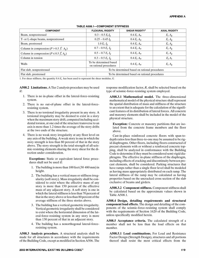
���� ���������� ��� ���� �������� ���® ���
TABLE A508.1�COMPONENT STIFFNESS
COMPONENT FLEXURAL RIGIDITY SHEAR RIGIDITY1 AXIAL RIGIDITY
Beam, nonprestressed 0.3 � 0.5 EcIg 0.4 Ec Aw Ec AgT- or L-shape beams, nonprestressed 0.25 � 0.45 Ig 0.4 Ec Aw Ec AgBeam, prestressed 1.0 Ec Ig 0.4 Ec Aw Ec Ag
Column in compression (P�0.5 Ag)��� 0.7 � 0.9 Ec Ig 0.4 Ec Aw Ec Ag
Column in compression (P�0.5 Ag)��� 0.5 � 0.7 Ec Ig 0.4 Ec Aw Ec Ag
Column in tension 0.3 � 0.5 Ec Ig 0.4 Ec Aw Es As
Walls To be determined basedon rational procedures
0.4 Ec Aw Ec Ag
Flat slab, nonprestressed To be determined based on rational procedures
Flat slab, prestressed To be determined based on rational procedures
1. For shear stiffness, the quantity 0.4 Ec has been used to represent the shear modulus, G.
A508.2 Limitations.ATier 2 analysis proceduremay be usedif:
1. There is no in-plane offset in the lateral-force-resistingsystem.
2. There is no out-of-plane offset in the lateral-force-resisting system.
3. There is no torsional irregularity present in any story. Atorsional irregularity may be deemed to exist in a storywhen themaximumstory drift, computed including acci-dental torsion, at one end of the structure transverse to anaxis is more than 1.2 times the average of the story driftsat the two ends of the structure.
4. There is no weak story irregularity at any floor level onany axis of the building. Aweak story is one in which thestory strength is less than 80 percent of that in the storyabove. The story strength is the total strength of all seis-mic-resisting elements sharing the story shear for the di-rection under consideration.
Exceptions: Static or equivalent lateral force proce-dures shall not be used if:
1. The building ismore than 100 feet (30 480mm) inheight.
2. The building has a vertical mass or stiffness irreg-ularity (soft story). Mass irregularity shall be con-sidered to exist where the effective mass of anystory is more than 150 percent of the effectivemass of any adjacent story. A soft story is one inwhich the lateral stiffness is less than 70 percent ofthat in the story above or less than 80percent of theaverage stiffness of the three stories above.
3. The building has a vertical geometric irregularity.Vertical geometric irregularity shall be consideredto exist where the horizontal dimension of the lat-eral-force-resisting system in any story is morethan 130 percent of that in an adjacent story.
4. The building has a nonorthogonal lateral-force-resisting system.
A508.3 Analysis procedure. A structural analysis shall bemade for all structures in accordance with the requirementsof the Building Code, except asmodified in SectionA506. The
response modification factor, R, shall be selected based on thetype of seismic-force-resisting system employed.
A508.3.1 Mathematical model. The three-dimensionalmathematicalmodel of the physical structure shall representthe spatial distribution of mass and stiffness of the structureto an extent that is adequate for the calculation of the signifi-cant features of its distribution of lateral forces. All concreteand masonry elements shall be included in the model of thephysical structure.
Exception: Concrete or masonry partitions that are iso-lated from the concrete frame members and the floorabove.
Cast-in-place reinforced concrete floors with span-to-depth ratios less than three-to-onemay be assumed to be rig-id diaphragms. Other floors, including floors constructed ofprecast elements with or without a reinforced concrete top-ping, shall be analyzed in conformance with the BuildingCode to determine if theymust be considered semi-rigid dia-phragms. The effective in-plane stiffness of the diaphragm,including effects of cracking and discontinuity between pre-cast elements, shall be considered. Parking structures thathave ramps rather than a single floor level shall be modeledas having mass appropriately distributed on each ramp. Thelateral stiffness of the ramp may be calculated as havingproperties based on the uncracked cross section of the slabexclusive of beams and girders.
A508.3.2 Component stiffness.Component stiffness shallbe calculated based on the approximate values shown inTable A508.1.
A508.4 Design, detailing requirements and structuralcomponent load effects. The design and detailing of the com-ponents of the seismic-force-resisting system shall complywith the requirements of Section 1620 of the Building Code,unless specifically modified herein.
A508.5 Acceptance criteria. The calculated strength of amember shall not be less than the load effects on thatmember.
A508.5.1 Load combinations. For Load and ResistanceFactor Design (Strength Design), structures and all portionsthereof shall resist the most critical effects from the
�������

��� ���� ���������� ��� ���� �������� ���®
combinations of factored loads prescribed in the BuildingCode.
Exception: For concrete beams and columns, the sheareffect shall be determined based on the most critical loadcombinations prescribed in the Building Code. The shearload effect because of seismic forces shall be multipliedby a factor ofCd , or 0.7 R for use with the UBC, but com-bined shear load effect needs not be greater thanVe, as cal-culated in accordance with Equation (A5-4). Mpr1 andMpr2 are the end moments, assumed to be in the same di-rection (clock-wise or counter clock-wise), based on steeltensile stress being equal to 1.25 fywhere fy is the specifiedyield strength.
Ve �Mpr1�Mpr2
L�
Wg
2(Equation A5-4)
Where:
Wg = Total gravity loads on the beam.
A508.5.2 Determination of the strength of members.The strength of a member shall be determined by multiply-ing the nominal strength of the member by a strength reduc-tion factor, �. The nominal strength of the member shall bedetermined in accordance with the Building Code.
������� ���"���� � �������� ����� ��
A509.1 General.ATier 3 evaluation shall be performedusingthe procedure prescribed in Section A509.2. Alternatively, theproceduresprescribed inSectionsA509.3 andA509.4mayalsobe used where specifically permitted herein.
A509.1.1 Mathematical model. The three-dimensionalmathematicalmodel of the physical structure shall representthe spatial distribution of mass and stiffness of the structureto an extent that is adequate for the calculation of the signifi-cant features of its dynamic response. All concrete and ma-sonry elements shall be included in themodel of the physicalstructure.
Exception: Concrete or masonry partitions that are iso-lated from the concrete frame members and the floorabove.
Cast-in-place reinforced concrete floors with span-to-depth ratios less than three-to-onemay be assumed to be rig-id diaphragms. Other floors, including floors constructed ofprecast elements with or without a reinforced concrete top-ping, shall be analyzed in conformance with the BuildingCode to determine if theymust be considered semi-rigid dia-phragms. The effective in-plane stiffness of the diaphragm,including effects of cracking and discontinuity between pre-cast elements, shall be considered. Parking structures thathave ramps rather than a single floor level shall be modeledas having mass appropriately distributed on each ramp. Thelateral stiffness of the ramp may be calculated as havingproperties based on the uncracked cross section of the slabexclusive of beams and girders.
A509.1.2 Acceptance criteria.
A509.1.2.1 Compressive strain determination. Com-pressive strain in columns, shear walls and infills may bedetermined by the nonlinear analysis or a procedure thatassumes plane sections remain plane.
Compressive strain shall be determined for combinedflexure and axial loading. The seismic flexural momentsand axial load shall be taken from the response spectrumanalysis for frame or shear wall buildings, and from thesubstructure model for infill frames. The combination ofcritical effects for analysis of compressive strain shall bethose given in the Building Code for Strength Design orLoad and Factor Resistance Design.
A509.1.2.2 Story drift limitation. Story drift is the dis-placementof one level relative to the level above or below,calculated by the response spectrumanalysis using the ap-propriate effective stiffness. The story drift is limited todisplacement that causes any of the following effects:
1. Compressive strain of 0.003 in the frame confininginfill or in a shear wall.
2. Compressive strain of 0.004 in a reinforced concretecolumn, unless the engineer can show by publishedexperimental research that the existing confinementreinforcement justifies higher values of strain.
3. Peak strain in masonry infills as determined by ex-perimental data or by physical testing as prescribedin Section A510.
4. Displacement that was calculated by the nonlinearanalysis as to when strength degradation of any ele-ment began.
Exception: Item 4 may be taken as the displace-ment that causes a strength degradation in that lineof resistance equal to 10 percent of the sum of thestrength of the elements in that line of resistance.
A509.1.2.3 Shear strength limitation. The required in-plane shear strength of all columns, piers and shear wallsshall be the shear associated with the moments induced atthe ends of columns or piers and at the base of shear wallsby the story displacements. No strength reduction factorsshall be used in the determination of strength.
A509.2 Pseudo-nonlinear dynamic analysis procedure.Structures shall be analyzed for seismic forces acting concur-rently on the orthogonal axes of the structure. The effects of theloading on two orthogonal axes shall be combined by SRSSmethods. The analysis shall include all torsional effects. Acci-dental torsional effects need not be considered.
A509.2.1 Determination of the effective stiffness.
A509.2.1.1 General. The effective stiffness of concreteand masonry elements or systems shall be calculated asthe secant stiffness of the element or systemwith due con-sideration of the effects of tensile cracking and compres-sion strain. The secant stiffness shall be taken from theforce-displacement relationship of the element or system.The secant stiffness shall be measured as the slope fromthe origin to the intersection of the force-displacementrelationship at the assumed displacement. The force-
�������
���� ���������� ��� ���� �������� ���® ���
displacement relationship shall be determined by a non-linear analysis. The force-displacement analysis shall in-clude the calculation of the displacement at whichstrength degradation begins.
Exception: The initial effective moment of inertia ofbeams and columns in shear wall or infilled framebuildings may be estimated using Table A508.1. Theratio of effective moment of inertia used for the beamsand for the columns shall be verified by Equations(A5-5), (A5-6) and (A5-7). The estimates shall be re-vised if the ratio used exceeds the ratio calculated bymore than 20 percent.
Ie � Mcr
Ma3Ig ��1�Mcr
Ma3� Icr (Equation A5-5)
Where:
Mcr �fr Igyt (Equation A5-6)
and
fr � 7.5 f �c (Equation A5-7)
A509.2.1.2 Effective stiffness of infills. The effectivestiffness of an infill shall be determined from a nonlinearanalysis of the infill and the confining frame.The effect ofthe infill on the stiffness of the system shall be determinedby differentiating the force-displacement relationship ofthe frame-infill system from the frame-only system.
A509.2.1.3 Model of infill. The mathematical model ofan infilled frame structure shall include the stiffness ef-fects of the infill as a pair of diagonals in the bays of theframe. The diagonals shall be considered as having con-crete properties and only axial loads. Their lines of actionshall intersect the beam-column joints. The secant stiff-ness of the force-displacement relationship, calculated asprescribed in Section A509.2.1.2, shall be used to deter-mine the effective area of the diagonals. The effectivestiffness of the frame shall be determined as specified inSection A509.2.1.1. Other procedures that provide thesame effective stiffness for the combination of infill andframe may be used when approved by the building offi-cial.
A509.2.2 Description of analysis procedures. The pseu-do-nonlinear dynamic analysis is an iterative response spec-trum analysis procedure using effective stiffness as the stiff-ness of the structural components. The response spectrumanalysis shall use the peak dynamic response of all modeshaving a significant contribution to total structural response.Peak modal responses are calculated using the ordinates ofthe appropriate response spectrum curve that corresponds tothe modal periods.Maximummodal contributions are com-bined in a statistical manner to obtain an approximate totalstructural response.
The effective stiffnesses shall be determined by an itera-tive method. The mathematical model using assumed effec-tive stiffnesses shall be used to calculate dynamic displace-ments. The effective stiffness of all concrete and masonry
elements shall be modified to represent the secant stiffnessobtained from the nonlinear force-displacement analysis ofthe element or system at the calculated displacement. A re-analysis of the mathematical model shall be made using theadjusted effective stiffness of existing and supplemental ele-ments and systemsuntil closure of the iterative process is ob-tained.Adifferenceof 10percent from the effective stiffnessused and that recalculatedmay be assumed to constitute clo-sure of the iterative process.
A509.2.2.1 Number ofmodes.At least 90 percent of theparticipating mass of the structure is included in the cal-culation of response for each principal horizontal direc-tion.
A509.2.2.2 Combiningmodes.The peak displacementsfor eachmode shall be combined by recognizedmethods.Modal interaction effects of three-dimensional modelsshall be considered when combining modal maxima.
A509.3 Capacity spectrum analysis procedure.
A509.3.1 General. This section presents an alternativeprocedure for a nonlinear static analysis for verification ofacceptableperformancebycomparing the availablecapacityto the earthquake demand.
Where inelastic torsional response is a dominant featureof overall response, the engineer shall use either a retrofitthat reduces the torsional response or an alternative analysisprocedure. Inelastic torsional response may be deemed toexist if torsional irregularity as defined in Section A508.2 ispresent in any story.
The behavior of foundation components and the effects ofsoil-structure interaction shall bemodeled or shown to be in-significant to building response.
A509.3.2 Modeling of building components.
A509.3.2.1 Component initial stiffness. Componentinitial stiffness shall be represented by a secant value de-fined by the effective yield point of the component. Theeffective initial stiffness shall be calculated using prin-ciples of mechanics, with due consideration of the effectsof tensile cracking and compression strain.
Exception: Component effective initial stiffness maybe calculated using the approximate values shown inTable A508.1.
A509.3.2.2 Component strength.The strength of build-ing components shall be calculated using the proceduresoutlined in the appropriate section of the Building Code.
Exception: Component properties may be calculatedusing the principles ofmechanics as verified by experi-mental results.
A509.3.2.3 Component deformability. The deform-ability of building components shall be obtained fromnonlinear load-deformation relationships that are ap-propriate for the component being considered. The non-linear load-deformation relationship shall include infor-mation on the plastic deformation capacity at whichlateral strength degrades, the plastic deformation capacity
�������
��� ���� ���������� ��� ���� �������� ���®
at which gravity-load resistance degrades, and the residu-al strength of the component after strength degradation.
The nonlinear load-deformation relationships of build-ing components shall be determined from nonlinear anal-yses based on the principles of mechanics, experimentaldata or established values published in technical litera-ture, as approved by the building official.
A509.3.3 Description of analysis procedures.
A509.3.3.1 Determination of the capacity curve. Thestructure�s capacity shall be represented by a capacitycurve, which is a plot of the building�s base shear versusroof displacement. The capacity curve shall be deter-mined by performing a series of sequential analyses withincreasing lateral load, using a mathematical model thataccounts for reduced resistance of yielding components.The analysis should include the effect of gravity loads onthe building�s response to lateral loads.
Lateral forces shall be applied to the structure in pro-portion to the product of mass and fundamental modeshape.
Exceptions:
1. For buildings with weak stories, the vertical dis-tribution of lateral forces shall be modified to re-flect the changed fundamental mode shape afteryielding of the weak story.
2. For buildings over 100 feet (30 480mm) in heightor buildings with irregularities that cause signifi-cant participation from modes of vibration otherthan the fundamental mode, the vertical distribu-tion of lateral forces shall reflect the contributionof higher modes.
A509.3.3.2 Conversion of the capacity curve to thecapacity spectrum. The capacity curve calculated inSection A509.3.3.1 shall be converted to the capacityspectrum, which is a representation of the capacity curvein the Acceleration-Displacement Response Spectra(ADRS) format. Each point on the capacity curve shall beconverted using Equations (A5-8) and (A5-9).
a �V�W�1
(Equation A5-8)
� ������
����������
(Equation A5-9)
Where:
PF1 ��N
i�1Wi�i1�g
�N
i�1Wi�2
i1�g(Equation A5-10)
�1 �� �Ni�1
Wi�i1�g�2
� �Ni�1Wi�g�� �N
i�1Wi�2
i1�g�(Equation A5-11)
A509.3.3.3 Bilinear representation of the capacityspectrum.A bilinear representation of the capacity spec-
trumcurveobtained inSectionA509.3.3.2 shall be used inestimating the appropriate reduction of spectral demand.The first segment of the bilinear representation of the ca-pacity spectrum shall be a line from the origin at the initialstiffness of the building using the component initial stiff-ness specified inTableA508.1.The second segment of thebilinear representation of the capacity spectrum shall be aline back from the trial performance point, api , dpi , at aslope that results in the area under the bilinear representa-tionbeing approximately equal to the areaunder theactualcapacity spectrum curve. The intersection of the twosegments of the bilinear representation of the capacityspectrum shall determine the yield point ay, dy.
A509.3.3.4 Development of the demand spectrum.The demand spectrum is a plot of the spectral accelerationand spectral displacement of the demand earthquakeground motion in the Acceleration-Displacement Re-sponse Spectra (ADRS) format. The 5-percent dampedacceleration response spectra in Section A506 shall bemodified for use in the capacity spectrum analysis proce-dure as follows:
1. In the constant acceleration region, the 5-percentdamped acceleration spectra shall be multiplied by:
SRA � 1.51� 0.32 ln�21(aydpi � dyapi)apidpi
�5� � 0.56
(Equation A5-12)
2. In the constantvelocity region, the5-percentdampedacceleration spectra shall be multiplied by:
SRv � 1.40� 0.25 ln�21(aydpi � dyapi)apidpi
�5� � 0.67
(Equation A5-13)
3. The spectral displacement ordinate, Sd , for a corre-sponding spectral acceleration, Sa , shall be deter-mined from:
Sd � Sa T4�2
g (Equation A5-14)
A509.3.3.5 Calculation of the performance point.Theperformance point shall represent the maximum roof dis-placement expected for the demand earthquake groundmotion. When the displacement of intersection of the ca-pacity spectrumdefined in SectionA509.3.3.2 and thede-mand spectrum defined in Section A509.3.3.4 is within 5percent of the displacement of the trial performance point,api , dpi , used in Section A509.3.3.3, the trial performancepoint shall be considered the performance point. If the in-tersection of the capacity spectrum and the demand spec-trum is not within the acceptable tolerance of 5 percent, anew trial performance point shall be selected and the anal-ysis shall be repeated.
A509.3.4 Response limits. The inter-story drift betweenfloors of the building and the corresponding strains in build-ing components shall be checked at the performance point toverify acceptability under the demand earthquake groundmotion. Performance shall be considered acceptable ifbuilding response parameters do not exceed the limitationsoutlined in Section A509.1.2.
�������
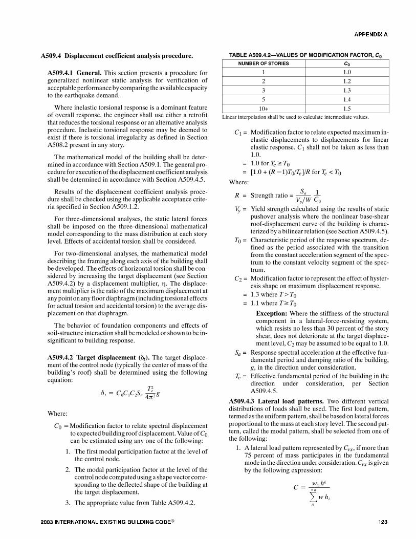
���� ���������� ��� ���� �������� ���® ���
A509.4 Displacement coefficient analysis procedure.
A509.4.1 General. This section presents a procedure forgeneralized nonlinear static analysis for verification ofacceptableperformancebycomparing the availablecapacityto the earthquake demand.
Where inelastic torsional response is a dominant featureof overall response, the engineer shall use either a retrofitthat reduces the torsional response or an alternative analysisprocedure. Inelastic torsional response may be deemed toexist if there is torsional irregularity as defined in SectionA508.2 present in any story.
The mathematical model of the building shall be deter-mined in accordance with Section A509.1. The general pro-cedure for executionof thedisplacement coefficient analysisshall be determined in accordance with Section A509.4.5.
Results of the displacement coefficient analysis proce-dure shall be checked using the applicable acceptance crite-ria specified in Section A509.1.2.
For three-dimensional analyses, the static lateral forcesshall be imposed on the three-dimensional mathematicalmodel corresponding to the mass distribution at each storylevel. Effects of accidental torsion shall be considered.
For two-dimensional analyses, the mathematical modeldescribing the framing along each axis of the building shallbe developed. The effects of horizontal torsion shall be con-sidered by increasing the target displacement (see SectionA509.4.2) by a displacement multiplier, �. The displace-ment multiplier is the ratio of the maximum displacement atanypointon any floor diaphragm(including torsionaleffectsfor actual torsion and accidental torsion) to the average dis-placement on that diaphragm.
The behavior of foundation components and effects ofsoil-structure interaction shall bemodeled or shown to be in-significant to building response.
A509.4.2 Target displacement (�t). The target displace-ment of the control node (typically the center of mass of thebuilding�s roof) shall be determined using the followingequation:
�t � C0C1C2SaT2e
4�2 g
Where:
C0�Modification factor to relate spectral displacementto expected building roof displacement.Value ofC0can be estimated using any one of the following:
1. The first modal participation factor at the level ofthe control node.
2. The modal participation factor at the level of thecontrol node computedusing a shape vector corre-sponding to the deflected shape of the building atthe target displacement.
3. The appropriate value from Table A509.4.2.
TABLE A509.4.2�VALUES OF MODIFICATION FACTOR, C0NUMBER OF STORIES C0
1 1.0
2 1.2
3 1.3
5 1.4
10+ 1.5Linear interpolation shall be used to calculate intermediate values.
C1 = Modification factor to relate expectedmaximum in-elastic displacements to displacements for linearelastic response. C1 shall not be taken as less than1.0.
= 1.0 for Te�T0= [1.0 + (R�1)T0/Te]/R for Te < T0
Where:
R = Strength ratio =Sa
Vy�W1C0
Vy = Yield strength calculated using the results of staticpushover analysis where the nonlinear base-shearroof-displacement curve of the building is charac-terized by a bilinear relation (see SectionA509.4.5).
T0 = Characteristic period of the response spectrum, de-fined as the period associated with the transitionfrom the constant acceleration segment of the spec-trum to the constant velocity segment of the spec-trum.
C2 = Modification factor to represent the effect of hyster-esis shape on maximum displacement response.
= 1.3 where T�T0= 1.1 where T�T0
Exception: Where the stiffness of the structuralcomponent in a lateral-force-resisting system,which resists no less than 30 percent of the storyshear, does not deteriorate at the target displace-ment level,C2 may be assumed to be equal to 1.0.
Sa = Response spectral acceleration at the effective fun-damental period and damping ratio of the building,g, in the direction under consideration.
Te = Effective fundamental period of the building in thedirection under consideration, per SectionA509.4.5.
A509.4.3 Lateral load patterns. Two different verticaldistributions of loads shall be used. The first load pattern,termedas theuniformpattern, shall bebasedon lateral forcesproportional to the mass at each story level. The second pat-tern, called the modal pattern, shall be selected from one ofthe following:1. A lateral load pattern represented by Cvx , if more than
75 percent of mass participates in the fundamentalmode in the direction under consideration.Cvx is givenby the following expression:
C� wx hk�n
i1
w hi
�������
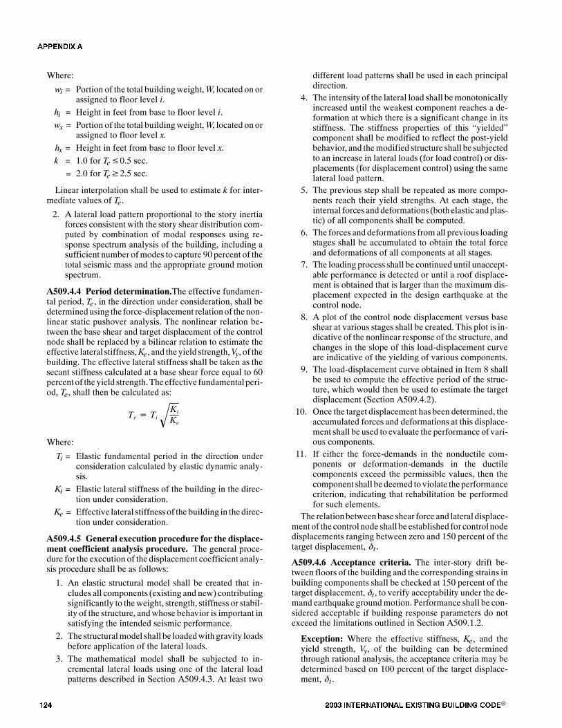
��� ���� ���������� ��� ���� �������� ���®
Where:
wi = Portion of the total buildingweight,W, located on orassigned to floor level i.
hi = Height in feet from base to floor level i.
wx = Portion of the total buildingweight,W, located on orassigned to floor level x.
hx = Height in feet from base to floor level x.
k = 1.0 for Te�0.5 sec.
= 2.0 for Te�2.5 sec.
Linear interpolation shall be used to estimate k for inter-mediate values of Te .
2. A lateral load pattern proportional to the story inertiaforces consistent with the story shear distribution com-puted by combination of modal responses using re-sponse spectrum analysis of the building, including asufficient number ofmodes to capture 90 percent of thetotal seismic mass and the appropriate ground motionspectrum.
A509.4.4 Period determination.The effective fundamen-tal period, Te , in the direction under consideration, shall bedeterminedusing the force-displacement relationof thenon-linear static pushover analysis. The nonlinear relation be-tween the base shear and target displacement of the controlnode shall be replaced by a bilinear relation to estimate theeffective lateral stiffness,Ke , and theyield strength,Vy, of thebuilding. The effective lateral stiffness shall be taken as thesecant stiffness calculated at a base shear force equal to 60percent of theyield strength.Theeffective fundamentalperi-od, Te , shall then be calculated as:
Te � TiKi
Ke
Where:
Ti = Elastic fundamental period in the direction underconsideration calculated by elastic dynamic analy-sis.
Ki = Elastic lateral stiffness of the building in the direc-tion under consideration.
Ke = Effective lateral stiffness of the building in thedirec-tion under consideration.
A509.4.5 General execution procedure for the displace-ment coefficient analysis procedure. The general proce-dure for the execution of the displacement coefficient analy-sis procedure shall be as follows:
1. An elastic structural model shall be created that in-cludes all components (existing and new) contributingsignificantly to theweight, strength, stiffness or stabil-ity of the structure, andwhose behavior is important insatisfying the intended seismic performance.
2. The structuralmodel shall be loadedwith gravity loadsbefore application of the lateral loads.
3. The mathematical model shall be subjected to in-cremental lateral loads using one of the lateral loadpatterns described in Section A509.4.3. At least two
different load patterns shall be used in each principaldirection.
4. The intensity of the lateral load shall bemonotonicallyincreased until the weakest component reaches a de-formation at which there is a significant change in itsstiffness. The stiffness properties of this �yielded�component shall be modified to reflect the post-yieldbehavior, and themodified structure shall be subjectedto an increase in lateral loads (for load control) or dis-placements (for displacement control) using the samelateral load pattern.
5. The previous step shall be repeated as more compo-nents reach their yield strengths. At each stage, theinternal forces anddeformations (bothelastic andplas-tic) of all components shall be computed.
6. The forces and deformations fromall previous loadingstages shall be accumulated to obtain the total forceand deformations of all components at all stages.
7. The loading process shall be continued until unaccept-able performance is detected or until a roof displace-ment is obtained that is larger than the maximum dis-placement expected in the design earthquake at thecontrol node.
8. A plot of the control node displacement versus baseshear at various stages shall be created. This plot is in-dicative of the nonlinear response of the structure, andchanges in the slope of this load-displacement curveare indicative of the yielding of various components.
9. The load-displacement curve obtained in Item 8 shallbe used to compute the effective period of the struc-ture, which would then be used to estimate the targetdisplacement (Section A509.4.2).
10. Once the target displacement has been determined, theaccumulated forces and deformations at this displace-ment shall be used to evaluate the performance of vari-ous components.
11. If either the force-demands in the nonductile com-ponents or deformation-demands in the ductilecomponents exceed the permissible values, then thecomponent shall be deemed to violate theperformancecriterion, indicating that rehabilitation be performedfor such elements.
The relationbetweenbase shear force and lateral displace-ment of the control node shall be established for control nodedisplacements ranging between zero and 150 percent of thetarget displacement, � t �
A509.4.6 Acceptance criteria. The inter-story drift be-tween floors of the building and the corresponding strains inbuilding components shall be checked at 150 percent of thetarget displacement, �t , to verify acceptability under the de-mand earthquake groundmotion. Performance shall be con-sidered acceptable if building response parameters do notexceed the limitations outlined in Section A509.1.2.
Exception: Where the effective stiffness, Ke , and theyield strength, Vy, of the building can be determinedthrough rational analysis, the acceptance criteria may bedetermined based on 100 percent of the target displace-ment, � t .
�������

���� ���������� ��� ���� �������� ���® ���
������� ���� ������������ �� ��� ������#������
������������ �� �������� ���������� �������
A510.1 Scope. This section covers procedures for determin-ing the expected compressive modulus, peak strain and peakcompressive stress of unreinforced brick masonry used for in-fills in frame buildings.
A510.2 General procedure. The outer wythe of multiplewythe brick masonry shall be tested by inserting two flat jacksinto the mortar joints of the outer wythe. The prism height (thevertical distance between the flat jacks) shall be five brickshigh. The test location shall have adequate overburden and/orvertical confinement to resist the flat jack forces.
A510.3 Preparation for the test.Removeamortar joint at thetop and bottom of the test prism by saw-cutting or drilling andgrinding to a smooth surface. The cuts for inserting the flatjacks shall not have a deviation from parallel of more than 3/8inch (9.53 mm). The deviation from parallel shall bemeasuredat the ends of the flat jacks. The width of the saw cut shall notexceed the width of the mortar joint. The length of the saw cuton the face of thewallmay exceed the length of the flat jacks bynotmore than twice the thickness of the outerwythe plus 1 inch(25.4 mm).
A510.4 Required equipment. The flat jacks shall be rectan-gular or with semi-circular ends to mimic the radius of the sawblade used to cut the slot for the flat jack. The length of the flatjack shall be 18 inches (457mm)maximum and 16 inches (406mm) minimum. This length shall be measured on the longestedge of a flat jack with semi-circular ends. The maximumwidth of the flat jack shall not exceed the average width of thewythe of brick that is loaded. Theminimumwidth of a flat jackshall be 31/2 inches (89 mm) measured out-to-out of the flatjack. The flat jack shall have a minimum of two ports to allowair in the flat jack to be replaced by hydraulic fluid. The unusedport shall be sealed after all of the air is forced out of the flatjack. The thickness of the flat jack shall not exceed three-quarters of theminimum height of themortar joint. It is recom-mended that the height of the flat jack be about one-half of thewidth of the slot cut for installation of the flat jack. The remain-ing space can be filled with steel shim plates having plan di-mensions equal to the flat jack.
A510.5 Data acquisition equipment. The strain in the testedprism shall be recorded by gauges or similar recording equip-ment having a minimum range of 0.0001 inch (0.0025 mm).The compressive strain shall be measured on the surface of theprism and shall have a gauge length,measured vertically on theface of the prism, of 10 inches (254mm)minimum. The gaugepoints shall be fixed to the wall by drilled-in anchors or byanchors set in epoxy or similar material. The support for thedata-recording apparatus shall be isolated from the wall by aminimumof 1/16 inch (1.5mm), so that the gauge length used inthe calculation of strain can be taken as the measured lengthbetween the anchors of the equipment supports. The gaugingequipment shall be as close to the face of the prism as possible,to minimize the probability of erroneous strain measurementscaused by bulging of the prism outward from its original plane.
The compressive strain data shall bemeasured at aminimumof two points on the vertical face of the prism. These pointsshall be theone-third pointsof the length of the flat jacks plusorminus 1/2 inch (12.7 mm). As an alternative, the strain may bemeasured at three points on the face of the prism.These points shall be spaced at one-quarter of the flat jack
length plus or minus 1/2 inch (12.7 mm).
A horizontal gauge at midheight of the prismmay be used torecord Poisson strain, but this recording data should be consid-ered secondary in importance to the vertical gauges, and thehorizontal gauge�s placement shall not interfere with placingthe vertical gauging as close as possible to the face of the prism.
A510.6 Loading and recording data. The loading shall beapplied by hydraulic pumps that add hydraulic fluid to the flatjacks in a controlled method. The application of load shall beincremental and held constant while strains are recorded. Theincreasing loading for each cycle of loading shall be dividedinto a minimum of four equal load increments. The strain shallbe recorded at each load step. The decrease in loading shall bedivided into a minimum of two equal unloading increments.Strain shall be recorded on the decreasing load steps. The hy-draulic pressure shall be reduced to zero, and the permanentstrain caused by this cycle of loading shall be recorded. Thisprocedure shall be used for each cycle of loading.
The load applied in each cycle of loading shall be deter-mined by estimating the peak compressive stressof the existingbrick masonry. The hydraulic pressure needed to cause thispeak compressive stress in the prism shall be calculated by as-suming that the area of the loaded prism is equal to the area ofthe flat jack.Amaximumof one-third of this pressure, roundedto the nearest 25 pounds per square inch (172 kPa), shall be ap-plied in the specified increments to the peak pressure pre-scribed for the first cycle of loading. After recording the straindata, this pressure shall be reduced in a controlled manner, foreach of the specified increments for unloading and for record-ing data. Themaximum jack pressure on the subsequent cyclesshall be one-half, two-thirds, five-sixths and estimated peakpressure. If the estimated peak compressive stress is less thanthe existing peak compressive stress, the cyclic loading and un-loading shall continue using increments of increasing pressureequal to those used prior to the application of estimated peakpressure.
All strain data shall be recorded to 0.0001 inch (0.0025mm).Jack pressure shall be recorded in increments of 25 pounds persquare inch (172 kPa) pressure.
A510.7 Quality control.The flat jack shall be calibratedbeforeuse by placing the flat jack between bearing plates of 2-inch (51mm) minimum thickness in a calibrated testing machine. A cal-ibration curve to convert hydraulic pressure in the flat jack to to-tal load shall be prepared and included in the report of the testresults. Flat jacks shall be recalibrated after three uses.
The hydraulic pressure in the flat jacks shall be determinedby a calibrated dial indicator having a subdivision of 25 poundsper square inch (172 kPa) or less. The operator of the hydraulicpump shall use this dial indicator to control the required incre-ments of hydraulic pressure in loading and unloading.
A510.8 Interpretation of the data. The data obtained fromthe testing required bySectionA505.2.4 shall be averagedboth
�������

��� ���� ���������� ��� ���� �������� ���®
in the expected peak compressive stress and the correspondingpeak strain.The envelopeof the averaged stress-strain relation-ship of all tests shall be used for the material model of the ma-sonry in the infilled frame. If two strain measurements havebeen made on the surface of the prism, these strain measure-
ments shall be averaged for determination of the stress-strainrelationship for the test. If three strainmeasurements have beenmade on the surface of the prism, the data recorded by thecenter gauge shall be given a weight of two for preparing theaverage stress-strain relationship for the test.
TABLE A5-A�BASIC STRUCTURAL CHECKLIST
This basic structural checklist shall be completed when required by Section A507.5 prior to completing the corresponding supplemental structural checklist.
Each of the evaluation statements on this checklist shall be marked compliant (C), noncompliant (NC), or not applicable (N/A) for a Tier I evaluation.Compliant statements identify issues that are acceptable according to the criteria of this chapter and the Building Code, while noncompliant statementsidentify issues that require further investigation. Certain statements may not apply to the buildings being evaluated. Noncompliant items shall be mitigatedby rehabilitating the structure, or shall be shown to be compliant by performing a Tier 2 or Tier 3 analysis.
BUILDING SYSTEMGeneral
C NC N/ALOAD PATH: The structure shall contain one complete load path for seismic force effects from any horizontal direction thatserves to transfer the inertial forces from the mass to the foundation.
C NC N/AADJACENT BUILDINGS: An adjacent building shall not be located next to the structure being evaluated closer than 4 percentof the height.
C NC N/AMEZZANINES: Interior mezzanine levels shall be braced independently of the main structure, or shall be anchored to thelateral-force-resisting elements of the main structure.
Configuration
C NC N/AWEAK STORY: The strength of the lateral-force-resisting system in any story shall not be less than 80 percent of the strengthin an adjacent story above or below.
C NC N/ASOFT STORY: The stiffness of the lateral-force-resisting system in any story shall not be less than 70 percent of the stiffness inan adjacent story above or below, or less than 80 percent of the average stiffness of the three stories above or below.
C NC N/AGEOMETRY: There shall be no changes in horizontal dimension of the lateral-force-resisting system of more than 30 percentin a story relative to adjacent stories, excluding one-story penthouses.
C NC N/AVERTICAL DISCONTINUITIES: All vertical elements in the lateral-force-resisting system shall be continuous to thefoundation.
C NC N/A MASS: There shall be no change in effective mass of more than 50 percent from one story to the next.
C NC N/ATORSION: The distance between the story center of mass and the story center of rigidity shall be less than 20 percent of thebuilding width in either plan dimension.
Condition of Materials
C NC N/ADETERIORATION OF CONCRETE: There shall be no visible deterioration of concrete or reinforcing steel in any of thevertical- or lateral-force-resisting elements.
C NC N/APOST-TENSIONING ANCHORS: There shall be no evidence of corrosion or spalling in the vicinity of post-tensioning or endfittings. Coil anchors shall not have been used.
C NC N/A MASONRY UNITS: There shall be no visible deterioration of masonry units.
C NC N/AMASONRY JOINTS: The mortar shall not be easily scraped away from the joints by hand with a metal tool, and there shall beno areas of eroded mortar.
C NC N/ACONCRETE WALL CRACKS: All existing diagonal cracks in wall elements shall be less than 1/8 inch for Seismic UseGroups other than Group III and less than 1/16 inch for Seismic Use Group III; shall not be concentrated in one location; andshall not form an X pattern.
C NC N/AREINFORCED MASONRY WALL CRACKS: All existing diagonal cracks in wall elements shall be less than 1/8 inch forSeismic Use Groups other than Group III and less than 1/16 inch for Seismic Use Group III; shall not be concentrated in onelocation; and shall not form an X pattern.
C NC N/ACRACKS IN BOUNDARY COLUMNS: There shall be no existing diagonal cracks wider than 1/8 inch for Seismic Use Groupsother than Group III and wider than 1/16 inch for Seismic Use Group III in concrete columns that encase masonry infills.
LATERAL-FORCE-RESISTING SYSTEMMoment Frames
General
C NC N/AREDUNDANCY: The number of lines of moment frames in each principal direction shall be greater than or equal to two forSeismic Use Groups I, II and III. The number of bays of moment frames in each line shall be greater than or equal to two forSeismic Use Groups other than Group III, and three for Seismic Use Group III.
Moment Frames with Infill Walls
C NC N/A INTERFERING WALLS: All infill walls placed in moment frames shall be isolated from structural elements.
(Continued)
�������
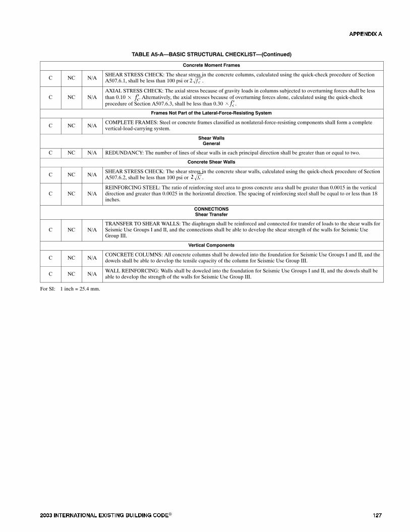
���� ���������� ��� ���� �������� ���® ���
TABLE A5-A�BASIC STRUCTURAL CHECKLIST�(Continued)
Concrete Moment Frames
C NC N/ASHEAR STRESS CHECK: The shear stress in the concrete columns, calculated using the quick-check procedure of SectionA507.6.1, shall be less than 100 psi or .2 f �c
C NC N/AAXIAL STRESS CHECK: The axial stress because of gravity loads in columns subjected to overturning forces shall be lessthan 0.10� . Alternatively, the axial stresses because of overturning forces alone, calculated using the quick-checkprocedure of Section A507.6.3, shall be less than 0.30� .
������
Frames Not Part of the Lateral-Force-Resisting System
C NC N/ACOMPLETE FRAMES: Steel or concrete frames classified as nonlateral-force-resisting components shall form a completevertical-load-carrying system.
Shear WallsGeneral
C NC N/A REDUNDANCY: The number of lines of shear walls in each principal direction shall be greater than or equal to two.
Concrete Shear Walls
C NC N/ASHEAR STRESS CHECK: The shear stress in the concrete shear walls, calculated using the quick-check procedure of SectionA507.6.2, shall be less than 100 psi or .� ���
C NC N/AREINFORCING STEEL: The ratio of reinforcing steel area to gross concrete area shall be greater than 0.0015 in the verticaldirection and greater than 0.0025 in the horizontal direction. The spacing of reinforcing steel shall be equal to or less than 18inches.
CONNECTIONSShear Transfer
C NC N/ATRANSFER TO SHEAR WALLS: The diaphragm shall be reinforced and connected for transfer of loads to the shear walls forSeismic Use Groups I and II, and the connections shall be able to develop the shear strength of the walls for Seismic UseGroup III.
Vertical Components
C NC N/ACONCRETE COLUMNS: All concrete columns shall be doweled into the foundation for Seismic Use Groups I and II, and thedowels shall be able to develop the tensile capacity of the column for Seismic Use Group III.
C NC N/AWALL REINFORCING: Walls shall be doweled into the foundation for Seismic Use Groups I and II, and the dowels shall beable to develop the strength of the walls for Seismic Use Group III.
For SI: 1 inch = 25.4 mm.
�������
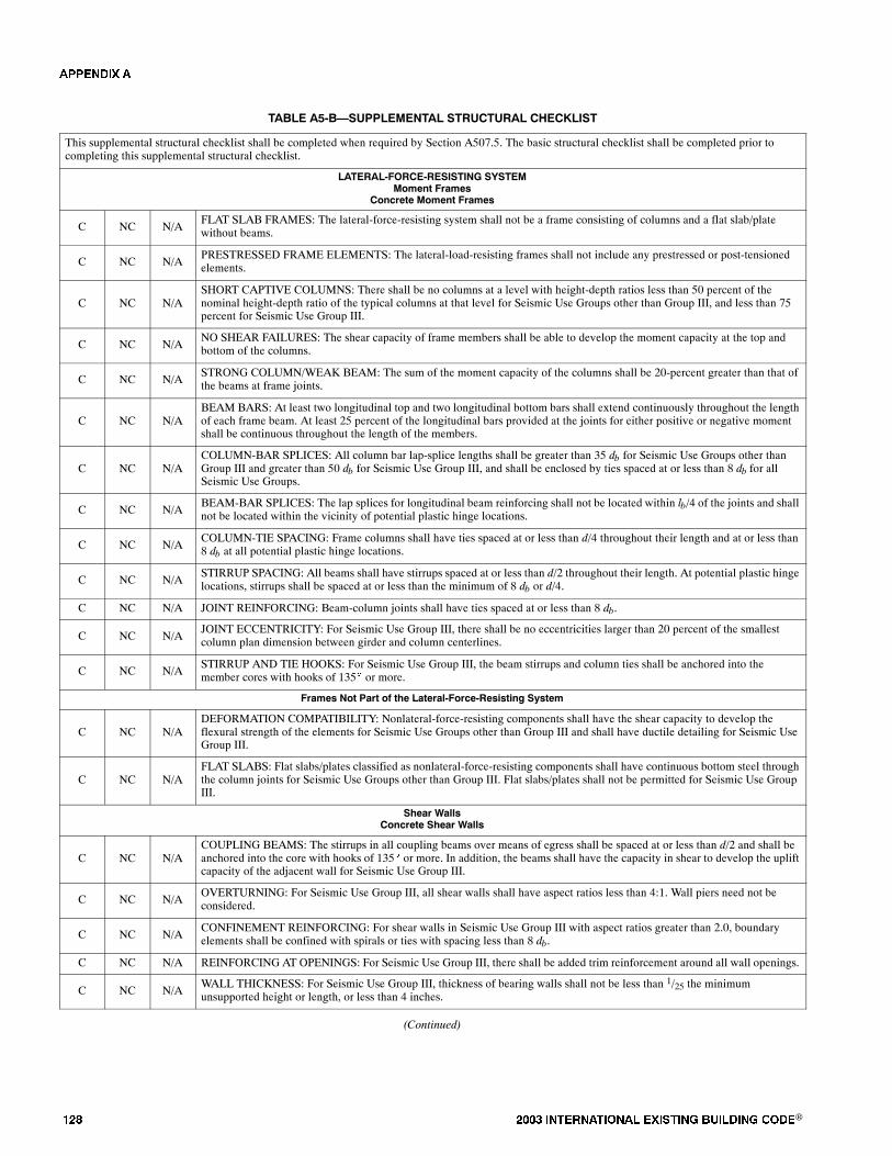
��� ���� ���������� ��� ���� �������� ���®
TABLE A5-B�SUPPLEMENTAL STRUCTURAL CHECKLIST
This supplemental structural checklist shall be completed when required by Section A507.5. The basic structural checklist shall be completed prior tocompleting this supplemental structural checklist.
LATERAL-FORCE-RESISTING SYSTEMMoment Frames
Concrete Moment Frames
C NC N/AFLAT SLAB FRAMES: The lateral-force-resisting system shall not be a frame consisting of columns and a flat slab/platewithout beams.
C NC N/APRESTRESSED FRAME ELEMENTS: The lateral-load-resisting frames shall not include any prestressed or post-tensionedelements.
C NC N/ASHORT CAPTIVE COLUMNS: There shall be no columns at a level with height-depth ratios less than 50 percent of thenominal height-depth ratio of the typical columns at that level for Seismic Use Groups other than Group III, and less than 75percent for Seismic Use Group III.
C NC N/ANO SHEAR FAILURES: The shear capacity of frame members shall be able to develop the moment capacity at the top andbottom of the columns.
C NC N/ASTRONG COLUMN/WEAK BEAM: The sum of the moment capacity of the columns shall be 20-percent greater than that ofthe beams at frame joints.
C NC N/ABEAM BARS: At least two longitudinal top and two longitudinal bottom bars shall extend continuously throughout the lengthof each frame beam. At least 25 percent of the longitudinal bars provided at the joints for either positive or negative momentshall be continuous throughout the length of the members.
C NC N/ACOLUMN-BAR SPLICES: All column bar lap-splice lengths shall be greater than 35 db for Seismic Use Groups other thanGroup III and greater than 50 db for Seismic Use Group III, and shall be enclosed by ties spaced at or less than 8 db for allSeismic Use Groups.
C NC N/ABEAM-BAR SPLICES: The lap splices for longitudinal beam reinforcing shall not be located within lb/4 of the joints and shallnot be located within the vicinity of potential plastic hinge locations.
C NC N/ACOLUMN-TIE SPACING: Frame columns shall have ties spaced at or less than d/4 throughout their length and at or less than8 db at all potential plastic hinge locations.
C NC N/ASTIRRUP SPACING: All beams shall have stirrups spaced at or less than d/2 throughout their length. At potential plastic hingelocations, stirrups shall be spaced at or less than the minimum of 8 db or d/4.
C NC N/A JOINT REINFORCING: Beam-column joints shall have ties spaced at or less than 8 db.
C NC N/AJOINT ECCENTRICITY: For Seismic Use Group III, there shall be no eccentricities larger than 20 percent of the smallestcolumn plan dimension between girder and column centerlines.
C NC N/ASTIRRUP AND TIE HOOKS: For Seismic Use Group III, the beam stirrups and column ties shall be anchored into themember cores with hooks of 135� or more.
Frames Not Part of the Lateral-Force-Resisting System
C NC N/ADEFORMATION COMPATIBILITY: Nonlateral-force-resisting components shall have the shear capacity to develop theflexural strength of the elements for Seismic Use Groups other than Group III and shall have ductile detailing for Seismic UseGroup III.
C NC N/AFLAT SLABS: Flat slabs/plates classified as nonlateral-force-resisting components shall have continuous bottom steel throughthe column joints for Seismic Use Groups other than Group III. Flat slabs/plates shall not be permitted for Seismic Use GroupIII.
Shear WallsConcrete Shear Walls
C NC N/ACOUPLING BEAMS: The stirrups in all coupling beams over means of egress shall be spaced at or less than d/2 and shall beanchored into the core with hooks of 135� or more. In addition, the beams shall have the capacity in shear to develop the upliftcapacity of the adjacent wall for Seismic Use Group III.
C NC N/AOVERTURNING: For Seismic Use Group III, all shear walls shall have aspect ratios less than 4:1. Wall piers need not beconsidered.
C NC N/ACONFINEMENT REINFORCING: For shear walls in Seismic Use Group III with aspect ratios greater than 2.0, boundaryelements shall be confined with spirals or ties with spacing less than 8 db.
C NC N/A REINFORCING AT OPENINGS: For Seismic Use Group III, there shall be added trim reinforcement around all wall openings.
C NC N/AWALL THICKNESS: For Seismic Use Group III, thickness of bearing walls shall not be less than 1/25 the minimumunsupported height or length, or less than 4 inches.
(Continued)
�������

���� ���������� ��� ���� �������� ���® ���
TABLE A5-B�SUPPLEMENTAL STRUCTURAL CHECKLIST�(Continued)
DIAPHRAGMSGeneral
C NC N/A DIAPHRAGM CONTINUITY: The diaphragms shall not be composed of split-level floors.
C NC N/ADIAPHRAGM OPENINGS ADJACENT TO SHEAR WALLS: Diaphragm openings immediately adjacent to the shear wallsshall be less than 25 percent of the wall length for Seismic Use Groups I and II, and less than 15 percent of the wall length forSeismic Use Group III.
C NC N/APLAN IRREGULARITIES: There shall be tensile capacity to develop the strength of the diaphragm at re-entrant corners orother locations of plan irregularities. This statement shall apply to Seismic Use Group III only.
C NC N/ADIAPHRAGM REINFORCEMENT AT OPENINGS: There shall be reinforcement around all diaphragm openings larger than50 percent of the building width in either major plan dimension. This statement shall apply to Seismic Use Group III only.
Other Diaphragms
C NC N/A OTHER DIAPHRAGMS: The diaphragm shall not consist of a system other than those described in Section A502.
CONNECTIONSVertical Components
C NC N/ALATERAL LOAD AT PILE CAPS: Pile caps shall have top reinforcement, and piles shall be anchored to the pile caps forSeismic Use Groups I and II. The pile cap reinforcement and pile anchorage shall be able to develop the tensile capacity of thepiles for Seismic Use Group III.
For SI: 1 inch = 25.4 mm.
�������
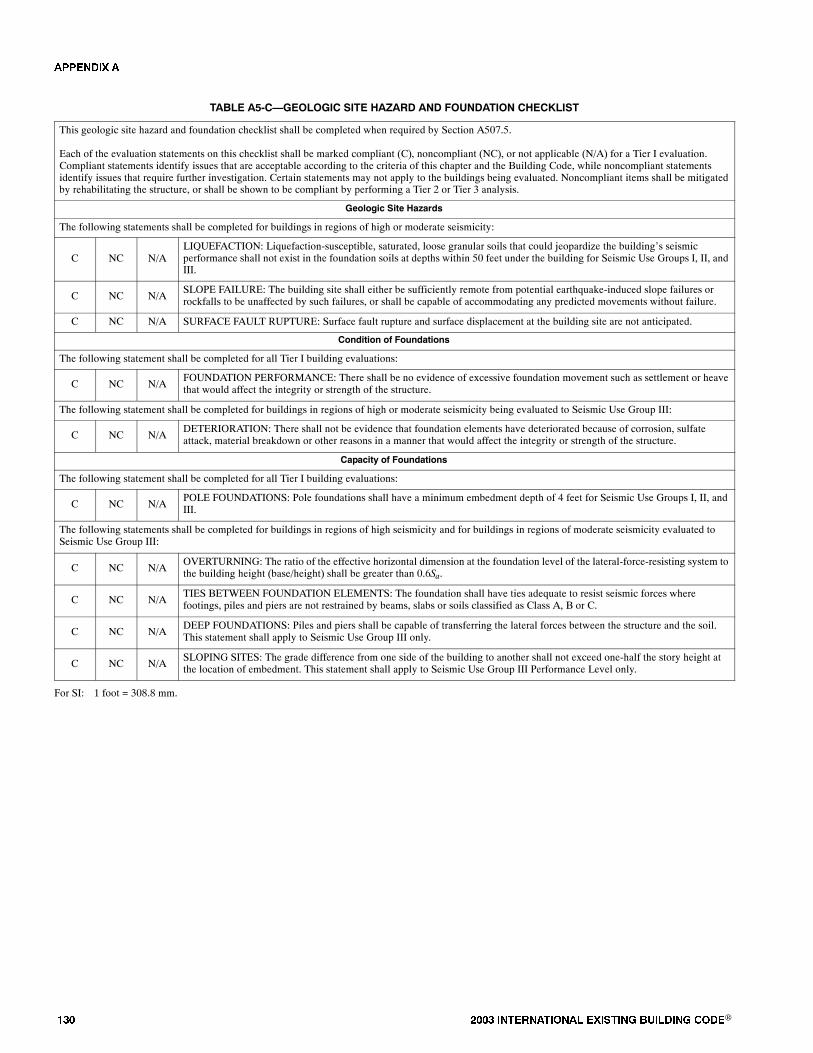
��� ���� ���������� ��� ���� �������� ���®
TABLE A5-C�GEOLOGIC SITE HAZARD AND FOUNDATION CHECKLIST
This geologic site hazard and foundation checklist shall be completed when required by Section A507.5.
Each of the evaluation statements on this checklist shall be marked compliant (C), noncompliant (NC), or not applicable (N/A) for a Tier I evaluation.Compliant statements identify issues that are acceptable according to the criteria of this chapter and the Building Code, while noncompliant statementsidentify issues that require further investigation. Certain statements may not apply to the buildings being evaluated. Noncompliant items shall be mitigatedby rehabilitating the structure, or shall be shown to be compliant by performing a Tier 2 or Tier 3 analysis.
Geologic Site Hazards
The following statements shall be completed for buildings in regions of high or moderate seismicity:
C NC N/ALIQUEFACTION: Liquefaction-susceptible, saturated, loose granular soils that could jeopardize the building�s seismicperformance shall not exist in the foundation soils at depths within 50 feet under the building for Seismic Use Groups I, II, andIII.
C NC N/ASLOPE FAILURE: The building site shall either be sufficiently remote from potential earthquake-induced slope failures orrockfalls to be unaffected by such failures, or shall be capable of accommodating any predicted movements without failure.
C NC N/A SURFACE FAULT RUPTURE: Surface fault rupture and surface displacement at the building site are not anticipated.
Condition of Foundations
The following statement shall be completed for all Tier I building evaluations:
C NC N/AFOUNDATION PERFORMANCE: There shall be no evidence of excessive foundation movement such as settlement or heavethat would affect the integrity or strength of the structure.
The following statement shall be completed for buildings in regions of high or moderate seismicity being evaluated to Seismic Use Group III:
C NC N/ADETERIORATION: There shall not be evidence that foundation elements have deteriorated because of corrosion, sulfateattack, material breakdown or other reasons in a manner that would affect the integrity or strength of the structure.
Capacity of Foundations
The following statement shall be completed for all Tier I building evaluations:
C NC N/APOLE FOUNDATIONS: Pole foundations shall have a minimum embedment depth of 4 feet for Seismic Use Groups I, II, andIII.
The following statements shall be completed for buildings in regions of high seismicity and for buildings in regions of moderate seismicity evaluated toSeismic Use Group III:
C NC N/AOVERTURNING: The ratio of the effective horizontal dimension at the foundation level of the lateral-force-resisting system tothe building height (base/height) shall be greater than 0.6Sa.
C NC N/ATIES BETWEEN FOUNDATION ELEMENTS: The foundation shall have ties adequate to resist seismic forces wherefootings, piles and piers are not restrained by beams, slabs or soils classified as Class A, B or C.
C NC N/ADEEP FOUNDATIONS: Piles and piers shall be capable of transferring the lateral forces between the structure and the soil.This statement shall apply to Seismic Use Group III only.
C NC N/ASLOPING SITES: The grade difference from one side of the building to another shall not exceed one-half the story height atthe location of embedment. This statement shall apply to Seismic Use Group III Performance Level only.
For SI: 1 foot = 308.8 mm.
�������
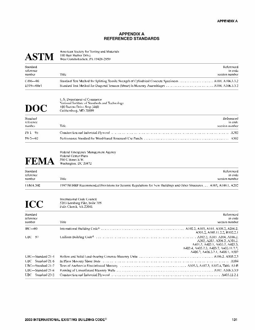
���� ���������� ��� ���� �������� ���® ���
�������� ��������� ���������
�������� ����� � ������� ��� ������������ ���� ����� ��������� ���� ���������� � �!"#$%#!&!
������� '� ��������� ������ �� ����(���� ����� ������ �(����
�"!)*!) ������� ���� ����� � +������� ������� ������� ����������� ������� +������� ���"� ���),-,-,#, , , , , , , , , , , , , , , , , , , ,
.&�!*���� ������� ���� ����� � ������� ������ /����0 �� ������ ����������� ���"� ���),-,-,#, , , , , , , , , , , , , , , , , , , , , , , , , , , ,
1,, ��+������� �������2������ 3�����(�� �������� ��� ����������� �(���( ����� �+ -")���� 4��������(��� �� #�$!!
������� '� ��������� ������ �� ����(���� ����� ������ �(����
%�*!& �����(���� ��� 3��(������ ��5� �-�#, , , , , , , , , , , , , , , , , , , , , , , , , , , , , , , , , , , , , , , , , , , , , , , , , , , , , , , , , , , , , , , , , , , , ,
%#*!# �� ������ ������� � ��%����� ��(��(���%1�� ����� �-�#, , , , , , , , , , , , , , , , , , , , , , , , , , , , , , , , , , , , , , , , , , , , , , , , , ,
6������ .�������� ���������� ������6������ ������ ��7�&�� � ����� ,�,��� ���������� �� #�"8#
������� '� ��������� ������ �� ����(���� ����� ������ �(����
6.�� -�# �!!8 2.�' '��������� ������� � ������ '��(������ � 2�5 �(������� ��� 9���� ��(��(��� ���-� ���$,�� �#�#, , ,
3����������� ��� �(����&#�- :����(�� ���� (��� 8�$�� 6���� ��(���� ;� ##�"�
������� '� ��������� ������ �� ����(���� ����� ������ �(����
3��*�� 3����������� �(������ ���� ���#,#� ���-� ���"� ���$,#� �#�),#�, , , , , , , , , , , , , , , , , , , , , , , , , , , , , , , , , , , , , , , , , , , , , , , , ,�-��,#� �"�-,��,#,#� ���#,#,�
1��*!8 1�� �� �(������ ���� ���#,#� ���-� ���"� ���$,#�, , , , , , , , , , , , , , , , , , , , , , , , , , , , , , , , , , , , , , , , , , , , , , , , , , , , , , , , , , ,�#�#� �#�-� �#�),#� �-��,#�
�"��,#� �"�-,�� �"�-,#� �"�-,-��"�-,"� �"�&,#,-� �"�-,8� �"�-,��,#,#�
�"�),#� �"�),-,#,�� �"�$,�� �&�#
1��*������� #�%" ���5 ��� ��� :��%%������� ������� ������ 1���� ���),#� �&�&,#,-, , , , , , , , , , , , , , , , , , , , , , , , , , , , , , , , , , , , , , , , , , , ,
1��*������� #�%) 3�% ���� ������ ���� ����� ���", , , , , , , , , , , , , , , , , , , , , , , , , , , , , , , , , , , , , , , , , , , , , , , , , , , , , , , , , , , , , , , , , , , , , , , , , , ,
1��*������� #�%8 ����� ������ �� 1����� ���� ������ ���&,-� ���8,-� ���8,"� ����� ��%., , , , , , , , , , , , , , , , , , , , , , , , , , , , , , , , , , , , , , ,
1��*������� #�%$ ������ 1����� ���� ������ ����� ���-� ���),-,-,!, , , , , , , , , , , , , , , , , , , , , , , , , , , , , , , , , , , , , , , , , , , , , , , , , , , , , , , , ,
1��*������� #-%# �����(���� ��� 3��(������ ��5� �"�-,��,#,�, , , , , , , , , , , , , , , , , , , , , , , , , , , , , , , , , , , , , , , , , , , , , , , , , , , , , , , , , , , , , , , ,
�������

��� ���� ���������� ��� ���� �������� ���®

2003 INTERNATIONAL EXISTING BUILDING CODE® 133
The provisions contained in this appendix are not mandatory unless specifically referenced in the adopting ordinance.
SECTION B 101QUALIFIED HISTORICAL BUILDINGS
AND FACILITIESB101.1 General. Qualified historic buildings and facili-ties shall comply with Sections B101.2 through B101.5.
B101.2 Qualified historic buildings and facilities.These procedures shall apply to buildings and facilities des-ignated as historic structures that undergo alterations or achange of occupancy.
B101.3 Qualified historic buildings and facilities sub-ject to Section 106 of the National Historic PreservationAct. Where an alteration or change of occupancy is under-taken to a qualified historic building or facility that is subjectto Section 106 of the National Historic Preservation Act, thefederal agency with jurisdiction over the undertaking shallfollow the Section 106 process. Where the State HistoricPreservation Officer or Advisory Council on Historic Preser-vation determines that compliance with the requirements foraccessible routes, ramps, entrances, or toilet facilities wouldthreaten or destroy the historic significance of the building orfacility, the alternative requirements of Section 1005 for thatelement are permitted.
B101.4 Qualified historic buildings and facilities not sub-ject to Section 106 of the National Historic PreservationAct. Where an alteration or change of occupancy is under-taken to a qualified historic building or facility that is notsubject to Section 106 of the National Historic PreservationAct, and the entity undertaking the alterations believes thatcompliance with the requirements for accessible routes,ramps, entrances, or toilet facilities would threaten ordestroy the historic significance of the building or facility,the entity shall consult with the State Historic PreservationOfficer. Where the State Historic Preservation Officer deter-mines that compliance with the accessibility requirementsfor accessible routes, ramps, entrances, or toilet facilitieswould threaten or destroy the historical significance of thebuilding or facility, the alternative requirements of Section1005 for that element are permitted.
B101.4.1 C o n s u l t a t i o n w i t h i n t e re s t e d p e r -sons. Interested persons shall be invited to participatein the consultation process, including state or local acces-sibility officials, individuals with disabilities, and organi-zations representing individuals with disabilities.
B101.4.2 Certified local government historic preser-vation programs. Where the State Historic PreservationOfficer has delegated the consultation responsibility forpurposes of this section to a local government historicpreservation program that has been certified in accor-dance with Section 101 of the National Historic Preserva-tion Act of 1966 [(16 U.S.C. 470a(c)] and implementingregulations (36 CFR 61.5), the responsibility shall be per-
mitted to be carried out by the appropriate local govern-ment body or official.
B101.5 Displays. In qualified historic buildings and facil-ities where alternative requirements of Section 1005 are per-mitted, displays and written information shall be locatedwhere they can be seen by a seated person. Exhibits andsigns displayed horizontally shall be 44 inches (1120 mm)maximum above the floor.
SECTION B 102FIXED TRANSPORTATION FACILITIES
AND STATIONSB102.1 General. Existing fixed transportation facilitiesand stations shall comply with Section B102.2.
B102.2 Existing facilities�key stations. Rapid rail, lightrail, commuter rail, intercity rail, high-speed rail and otherfixed guide-way systems, altered stations, and intercity railand key stations, as defined under criteria established by theDepartment of Transportation in Subpart C of 49 CFR Part37, shall comply with Sections B102.2.1 through B102.2.3.
B102.2.1 Accessible route. At least one accessibleroute from an accessible entrance to those areas neces-sary for use of the transportation system shall be pro-vided. The accessible route shall include the featuresspecified in Appendix E109.2 of the International Build-ing Code, except that escalators shall comply with Inter-national Building Code Section 3005.2.2. Wheretechnical unfeasibility in existing stations requires theaccessible route to lead from the public way to a paid areaof the transit system, an accessible fare collectionmachine complying with International Building CodeAppendix E109.2.3 shall be provided along such accessi-ble route.
B102.2.2 Platform and vehicle floor coordination.Station platforms shall be positioned to coordinate withvehicles in accordance with applicable provisions of 36CFR Part 1192. Low-level platforms shall be 8 inches(250 mm) minimum above top of rail.
Exception: Where vehicles are boarded from side-walks or street-level, low-level platforms shall be per-mitted to be less than 8 inches (250 mm).
B102.2.3 Direct connections. New direct connectionsto commercial, retail, or residential facilities shall, to themaximum extent feasible, have an accessible route com-plying with Section 506.2 from the point of connection toboarding platforms and transportation system elementsused by the public. Any elements provided to facilitatefuture direct connections shall be on an accessible routeconnecting boarding platforms and transportation systemelements used by the public.
APPENDIX B
SUPPLEMENTARY ACCESSIBILITY REQUIREMENTSFOR EXISTING BUILDINGS AND FACILITIES

2003 INTERNATIONAL EXISTING BUILDING CODE®134
APPENDIX B
SECTION B103REFERENCED STANDARDS
Y3.H626 2P National Historic Preservation J101.2, 43/933Act of 1966, as amended J101.3, 3rd Edition, Washington,DC: J101.3.2 US Government Printing Office, 1993.2003 International Building Code.49 CFR Part 37.43 (c), Alteration of Transportation Facilitiesby Public Entities, Department of Transportation, 400 7thStreet SW, Room 8102, Washington, DC 20590-0001.

���� ���������� ��� ���� �������� ���® ���
�������� �
������ �� �� ������ � ������ �������� �� ���������
�����������The International Existing Building Code (IEBC) is a comprehensive code with the goal of addressing all aspects of work takingplace in existing buildings and providing user friendly methods and tools for regulation and improvement of such buildings. Thisresource document is included within the cover of the IEBCwith that goal inmind and as a step towards accomplishing that goal.
In the process of repair and alteration of existing buildings, based on the nature and the extent of the work, the IEBCmight requirecertain upgrades in the fire resistance rating of building elements, at which time it becomes critical for the designers and the codeofficials to be able to determine the fire resistance rating of the existing building elements as part of the overall evaluation for theassessment of the need for improvements. This resource document provides a guideline for such an evaluation for fire resistancerating of archaic materials that is not typically found in the modern model building codes.
Resource A is only a guideline and is not intended to be a document for specific adoption as it is not written in the format orlanguage of ICC�s International Codes and is not subject to the code development process
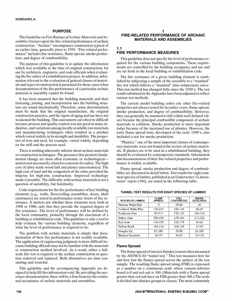
��� ���� ���������� ��� ���� �������� ���®
�������TheGuideline onFire Ratingsof ArchaicMaterials andAs-
semblies focuses upon the fire-related performance of archaicconstruction. �Archaic� encompasses construction typical ofan earlier time, generally prior to 1950. �Fire-related perfor-mance� includes fire resistance, flame spread, smoke produc-tion, and degree of combustibility.
The purpose of this guideline is to update the informationwhich was available at the time of original construction, foruse by architects, engineers, and code officials when evaluat-ing the fire safety of a rehabilitation project. In addition, infor-mation relevant to the evaluation of general classes ofmateri-als and types of construction is presented for those caseswhendocumentation of the fire performance of a particular archaicmaterial or assembly cannot be found.
It has been assumed that the building materials and theirfastening, joining, and incorporation into the building struc-ture are sound mechanically. Therefore, some determinationmust be made that the original manufacture, the originalconstruction practice, and the rigors of aging and use have notweakened the building. This assessment can often be difficultbecause process and quality control was not good in many in-dustries, and variations among locally available rawmaterialsand manufacturing techniques often resulted in a productwhich variedwidely in its strength and durability. The proper-ties of iron and steel, for example, varied widely, dependingon the mill and the process used.
There is nothing inherently inferior about archaicmaterialsor construction techniques. The pressures that promote funda-mental change are most often economic or technological�matters not necessarily related to concerns for safety. The highcost of labor made wood lath and plaster uneconomical. Thehigh cost of land and the congestion of the cities provided theimpetus for high-rise construction. Improved technologymade it possible. The difficulty with archaic materials is not aquestion of suitability, but familiarity.
Code requirements for the fire performance of key buildingelements (e.g., walls, floor/ceiling assemblies, doors, shaftenclosures) are stated in performance terms: hours of fire re-sistance. It matters not whether these elements were built in1908 or 1980, only that they provide the required degree offire resistance. The level of performance will be defined bythe local community, primarily through the enactment of abuilding or rehabilitation code. This guideline is only a tool tohelp evaluate the various building elements, regardless ofwhat the level of performance is required to be.
The problem with archaic materials is simply that docu-mentation of their fire performance is not readily available.The application of engineering judgment is more difficult be-cause building officialsmay not be familiar with thematerialsor construction method involved. As a result, either a full-scale fire test is required or the archaic construction in ques-tion removed and replaced. Both alternatives are time con-suming and wasteful.
This guideline and the accompanying Appendix are de-signed to help fill this information void. By providing the nec-essary documentation, there will be a firm basis for the contin-ued acceptance of archaic materials and assemblies.
����������� ����������� �� ��� ��
������� ��� ���������
������ ����������� ��������
This guideline does not specify the level of performance re-quired for the various building components. These require-ments are controlled by the building occupancy and use andare set forth in the local building or rehabilitation code.
The fire resistance of a given building element is estab-lished by subjecting a sample of the assembly to a �standard�fire test which follows a �standard� time-temperature curve.This test method has changed little since the 1920�s. The testresults tabulated in the Appendix have been adjusted to reflectcurrent test methods.
The current model building codes cite other fire-relatedproperties not always tested for in earlier years: flame spread,smoke production, and degree of combustibility. However,they can generally be assumed to fall within well defined val-ues because the principal combustible component of archaicmaterials is cellulose. Smoke production is more importanttoday because of the increased use of plastics. However, theearly flame spread tests, developed in the early 1940�s, alsoincluded a test for smoke production.
�Plastics,� one of the most important classes of contempo-rarymaterials, were not found in the reviewof archaicmateri-als. If plastics are to be used in a rehabilitated building, theyshould be evaluated by contemporary standards. Informationand documentation of their fire-related properties and perfor-mance is widely available.
Flame spread, smoke production and degree of combusti-bility are discussed in detail below. Test results for eight com-mon species of lumber, published in anUnderwriter�sLabora-tories� report (104), are noted in the following table:
TUNNEL TEST RESULTS FOR EIGHT SPECIES OF LUMBER
������� �� ����
�� �
���� �
���
����������
����
���������
������� ����� ��� � �� �� ��
�������� ����� ��� ��� ��� ��� ��� �� ��
�������� ��� �� ��� ��� ��� ��� ���
������ ��� ��� ��� ��� ��� �� ���
��� ��� ��� ��� ��� �� �� ��
������ ��!� ��� ��� ��� ��� �� ��
"��#��� $�� �� ��� �� �� �� ���
������� %����!& �� � �� �� �� ���
��� ! �"�!��The flame spreadof interior finishes ismost oftenmeasured
by the ASTM E-84 �tunnel test.� This test measures how farand how fast the flames spread across the surface of the testsample. The resulting flame spread rating (FSR) is expressedas a number on a continuous scale where cement-asbestosboard is 0 and red oak is 100. (Materials with a flame spreadgreater than red oak have an FSR greater than 100.) The scaleis divided into distinct groups or classes. The most commonly
�� ����
���� ���������� ��� ���� �������� ���® ���
used flame spread classifications are: Class I or A*, with a0-25 FSR; Class II or B, with a 26-75 FSR; and Class III or C,with a 76-200 FSR. The NFPA Life Safety Code also has aClass D (201-500 FSR) and Class E (over 500 FSR) interiorfinish.
These classifications are typically used in modern buildingcodes to restrict the rate of fire spread. Only the first threeclassifications are normally permitted, though not all classesof materials can be used in all places throughout a building.For example, the interior finish of building materials used inexits or in corridors leading to exits is more strictly regulatedthan materials used within private dwelling units.
In general, inorganic archaic materials (e.g., bricks or tile)can be expected to be in Class I. Materials of whole wood aremostly Class II. Whole wood is defined as wood used in thesame form as sawn from the tree. This is in contrast to the con-temporary reconstituted wood products such as plywood, fi-berboard, hardboard, or particle board. If the organic archaicmaterial is not whole wood, the flame spread classificationcould be well over 200 and thus would be particularly un-suited for use in exits and other critical locations in a building.Some plywoods and various wood fiberboards have flamespreads over 200. Although they can be treatedwith fire retar-dants to reduce their flame spread, it would be advisable to as-sume that all such products have a flame spread over 200 un-less there is information to the contrary.
� �#! ����������
The evaluation of smoke density is part of the ASTM E-84tunnel test. For the eight species of lumber shown in the tableabove, the highest levels are 275-305 for Yellow Pine, butmost of the others are less smoky than red oak which has anindex of 100. The advent of plastics caused substantial in-creases in the smoke density values measured by the tunneltest. The ensuing limitation of the smoke production for walland ceiling materials by the model building codes has been areaction to the introduction of plastic materials. In general,cellulosic materials fall in the 50-300 range of smoke densitywhich is below the general limitation of 450 adopted bymanycodes.
�!$�!! �% �� &�'��&����(
The model building codes tend to define �noncombustibil-ity� on the basis of having passed ASTME-136 or if themate-rial is totally inorganic. The acceptance of gypsumwallboardas noncombustible is based on limiting paper thickness to notover 1/8 inch and a 0-50 flame spread rating by ASTM E-84.At times there were provisions to define aClass I or Amaterial(0-25 FSR) as noncombustible, but this is not currently recog-nized by most model building codes.
If there is any doubt whether or not an archaic material isnoncombustible, it would be appropriate to send out samplesfor evaluation. If an archaic material is determined to be non-combustible according to ASTM E-136, it can be expectedthat it will not contribute fuel to the fire.
��)��������� ��������� *���One of the earliest formsof timber construction used exteri-
or load-bearing masonry walls with columns and/or woodenwalls supporting wooden beams and floors in the interior ofthe building. This form of construction, often called �mill� or�heavy timber� construction, has approximately 1 hour fireresistance. The exterior walls will generally contain the firewithin the building.With the development of dimensional lumber, there was a
switch from heavy timber to �balloon frame� construction.The balloon frame uses load-bearing exterior wooden wallswhich have long timbers often extending from foundation toroof. When longer lumber became scarce, another form ofconstruction, �platform� framing, replaced the balloon fram-ing. The difference between the two systems is significant be-cause platform framing is automatically fire-blocked at everyfloor while balloon framing commonly has concealed spacesthat extend unblocked from basement to attic. The architect,engineer, and code official must be alert to the details ofconstruction and the ease with which fire can spread in con-cealed spaces.
)������ �+������
A given rehabilitation project will most likely go throughseveral stages. The preliminary evaluation process involvesthe designer in surveying the prospective building. The fire re-sistance of existing building materials and construction sys-tems is identified; potential problems are noted for closerstudy. The final evaluation phase includes: developing designsolutions to upgrade the fire resistance of building elements, ifnecessary; preparing working drawings and specifications;and the securing of the necessary code approvals.
)����������* �+������A preliminary evaluation should begin with a building sur-
vey to determine the existing materials, the general arrange-ment of the structure and the use of the occupied spaces, andthe details of construction. The designer needs to know �whatis there� before a decision can be reached about what to keepand what to remove during the rehabilitation process. Thispreliminary evaluation should be as detailed as necessary tomake initial plans. The fire-related properties need to be de-termined from the applicable building or rehabilitation code,and the materials and assemblies existing in the building thenneed to be evaluated for these properties. Twowork sheets areshown below to facilitate the preliminary evaluation.Two possible sources of information helpful in the prelimi-
nary evaluation are the original building plans and the build-ing code in effect at the time of original construction. Plansmay be on file with the local building department or in the of-fices of the original designers (e.g., architect, engineer) ortheir successors. If plans are available, the investigator shouldverify that the building was actually constructed as called forin the plans, as well as incorporate any later alterations or
* Some codes use Roman numerals, others use letters.
�� ����
��� ���� ���������� ��� ���� �������� ���®
changes to the building. Earlier editions of the local buildingcode should be on file with the building official. The code ineffect at the time of constructionwill contain fire performancecriteria. While this is no guarantee that the required perfor-mance was actually provided, it does give the investigatorsome guidance as to the level of performance which may beexpected. Under some code administration and enforcementsystems, the code in effect at the time of construction also de-fines the level of performance that must be provided at thetime of rehabilitation.Figure 1 illustrates one method for organizing preliminary
field notes. Space is provided for the materials, dimensions,and condition of the principal building elements. Each floor ofthe structure should be visited and the appropriate informationobtained. In practice, there will often be identical materialsand construction on every floor, but the exception may be ofvital importance. A schematic diagram should be prepared ofeach floor showing the layout of exits and hallways and indi-catingwhere each element described in the field notes fits intothe structure as a whole. The exact arrangement of interiorwalls within apartments is of secondary importance from afire safety point of view and need not be shown on the draw-ings unless these walls are required by code to have a fire re-sistance rating.The location of stairways and elevators should be clearly
marked on the drawings. All exterior means of escape (e.g.,fire escapes) should be identified.*The following notes explain the entries in Figure 1.
Exterior Bearing Walls: Many old buildings utilize heavilyconstructedwalls to support the floor/ceiling assemblies at theexterior of the building. Theremay be columns and/or interiorbearingwallswithin the structure, but the exteriorwalls are animportant factor in assessing the fire safety of a building.
The field investigator should note how the floor/ceiling as-semblies are supported at the exterior of the building. If col-umns are incorporated in the exterior walls, the walls may beconsidered non-bearing.
InteriorBearingWalls: It maybe difficult to determinewheth-er or not an interior wall is load bearing, but the field investi-gator should attempt to make this determination. At a laterstage of the rehabilitation process, this question will need tobe determined exactly. Therefore, the field notes should be asaccurate as possible.
Exterior Non-BearingWalls: The fire resistance of the exteri-or walls is important for two reasons. These walls (both bear-ing and non-bearing) are depended upon to: a) contain a firewithin the buildingof origin; or b) keep an exterior fireoutsidethe building. It is therefore important to indicate on the draw-ings where any openings are located as well as the materialsand construction of all doors or shutters. The drawings shouldindicate the presence ofwiredglass, its thickness and framing,and identify the materials used for windows and door frames.The protection of openings adjacent to exterior means of es-cape (e.g., exterior stairs, fire escapes) is particularly impor-tant. The ground floor drawing should locate the building onthe property and indicate the precise distances to adjacentbuildings.
Interior Non-BearingWalls (Partitions): A partition is a �wallthat extends from floor to ceiling and subdivides space withinany story of a building.� (48) Figure 1 has twocategories (A&B) for Interior Non-Bearing Walls (Partitions) which can beused for different walls, such as hallway walls as compared tointer-apartment walls. Under some circumstances there maybe only one type of wall construction; in others, three or moretypes of wall construction may occur.
* Problems providing adequate exiting are discussed at length in the Egress Guideline for Residential Rehabilitation.
�� ����
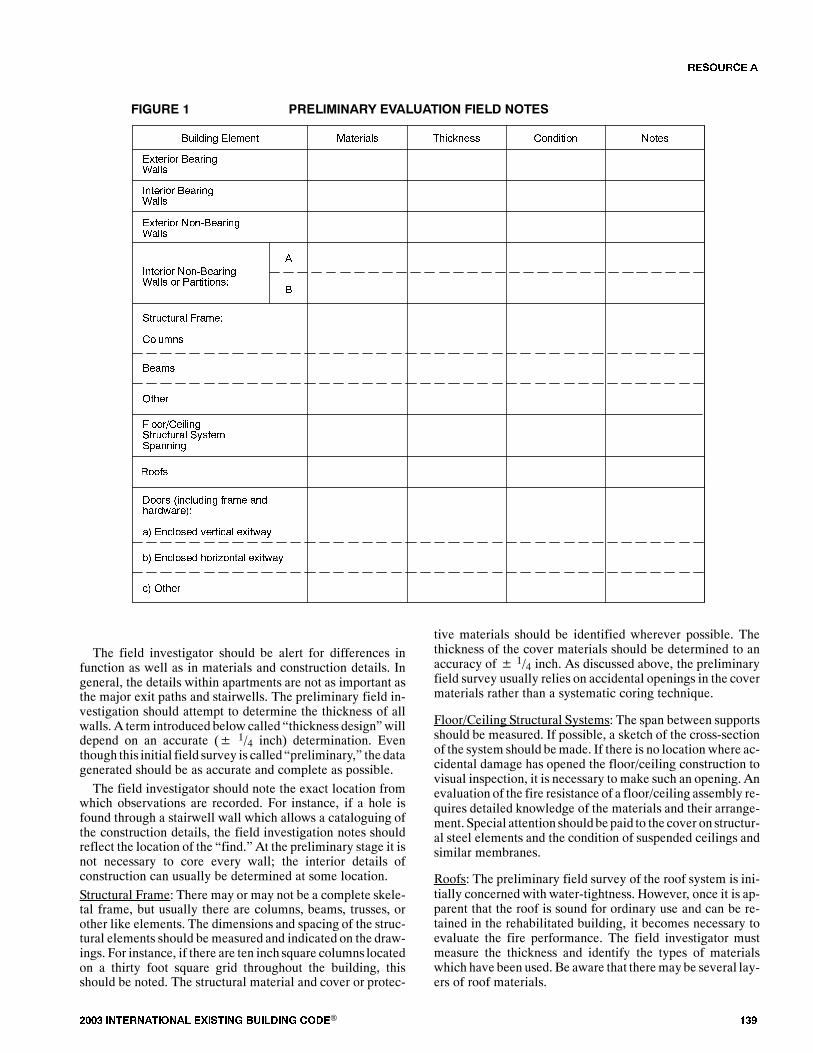
���� ���������� ��� ���� �������� ���® ���
�������� ������ �
����� � �������� ������� �������� ��� � ����
������� ������ �
�������� ��������� �
�������� �����
�� ���
������� ��������� � �� ���������
�
����
����
� ���!��� ���������� �"�����#��
$��%�
&���� '�� ���� %��� ����(��)�
) �� ���� *����� ����("
+) �� ���� ����,�� ����("
�) ����
�
����� � ��������* �+������ ���� ����
The field investigator should be alert for differences infunction as well as in materials and construction details. Ingeneral, the details within apartments are not as important asthe major exit paths and stairwells. The preliminary field in-vestigation should attempt to determine the thickness of allwalls. A term introduced below called �thickness design�willdepend on an accurate (� 1/4 inch) determination. Eventhough this initial field survey is called �preliminary,� the datagenerated should be as accurate and complete as possible.
The field investigator should note the exact location fromwhich observations are recorded. For instance, if a hole isfound through a stairwell wall which allows a cataloguing ofthe construction details, the field investigation notes shouldreflect the location of the �find.� At the preliminary stage it isnot necessary to core every wall; the interior details ofconstruction can usually be determined at some location.
Structural Frame: There may or may not be a complete skele-tal frame, but usually there are columns, beams, trusses, orother like elements. The dimensions and spacing of the struc-tural elements should be measured and indicated on the draw-ings. For instance, if there are ten inch square columns locatedon a thirty foot square grid throughout the building, thisshould be noted. The structural material and cover or protec-
tive materials should be identified wherever possible. Thethickness of the cover materials should be determined to anaccuracy of� 1/4 inch. As discussed above, the preliminaryfield survey usually relies on accidental openings in the covermaterials rather than a systematic coring technique.
Floor/Ceiling Structural Systems: The span between supportsshould be measured. If possible, a sketch of the cross-sectionof the system should bemade. If there is no location where ac-cidental damage has opened the floor/ceiling construction tovisual inspection, it is necessary to make such an opening. Anevaluation of the fire resistance of a floor/ceiling assembly re-quires detailed knowledge of the materials and their arrange-ment. Special attention should be paid to the cover on structur-al steel elements and the condition of suspended ceilings andsimilar membranes.
Roofs: The preliminary field survey of the roof system is ini-tially concerned with water-tightness. However, once it is ap-parent that the roof is sound for ordinary use and can be re-tained in the rehabilitated building, it becomes necessary toevaluate the fire performance. The field investigator mustmeasure the thickness and identify the types of materialswhich have been used. Be aware that theremaybe several lay-ers of roof materials.
�� ����
��� ���� ���������� ��� ���� �������� ���®
Doors: Doors to stairways and hallways represent some of themost important fire elements to be considered within a build-ing. The uses of the spaces separated largely controls the levelof fire performance necessary. Walls and doors enclosingstairs or elevator shafts would normally require a higher levelof performance than between a the bedroom and bath. Thevarious uses are differentiated in Figure 1.Careful measurements of the thickness of door panels must
be made, and the type of core material within each door mustbe determined. It should be noted whether doors have self-closing devices; the general operation of the doors should bechecked. The latch should engage and the door should fittightly in the frame. The hinges should be in good condition. Ifglass is used in the doors, it should be identified as either plainglass or wired glass mounted in either a wood or steel frame.Materials: The field investigator should be able to identify or-dinary building materials. In situations where an unfamiliarmaterial is found, a sample should be obtained. This sampleshould measure at least 10 cubic inches so that an ASTME-136 fire test can be conducted to determine if it is combus-tible.Thickness: The thickness of all materials should be measuredaccurately since, under certain circumstances, the level of fireresistance is very sensitive to the material thickness.Condition: The method of attaching the various layers andfacings to one another or to the supporting structural elementshould be noted under the appropriate building element. The
�secureness� of the attachmnent and the general condition ofthe layers and facings should be noted here.Notes: The �Notes� column can be used for many purposes,but it might be a good idea tomake specific references to otherfield notes or drawings.After the building survey is completed, the data collected
must be analyzed. A suggested work sheet for organizing thisinformation is given below as Figure 2.The required fire resistance and flame spread for each
building element are normally established by the local build-ing or rehabilitation code. The fire performance of the exist-ing materials and assemblies should then be estimated, usingone of the techniques described below. If the fire performanceof the existing building element(s) is equal to or greater thanthat required, the materials and assemblies may remain. If thefire performance is less than required, then corrective mea-sures must be taken.The most common methods of upgrading the level of
protection are to either remove and replace the existing build-ing element(s) or to repair and upgrade the existing materialsand assemblies. Other fire protection measures, such as auto-matic sprinklers or detection and alarm systems, also could beconsidered, though they are beyond the scope of this guide-line. If the upgradedprotection is still less than that required ordeemed to be acceptable, additional correctivemeasuresmustbe taken. This process must continue until an acceptable levelof performance is obtained.
�� ����
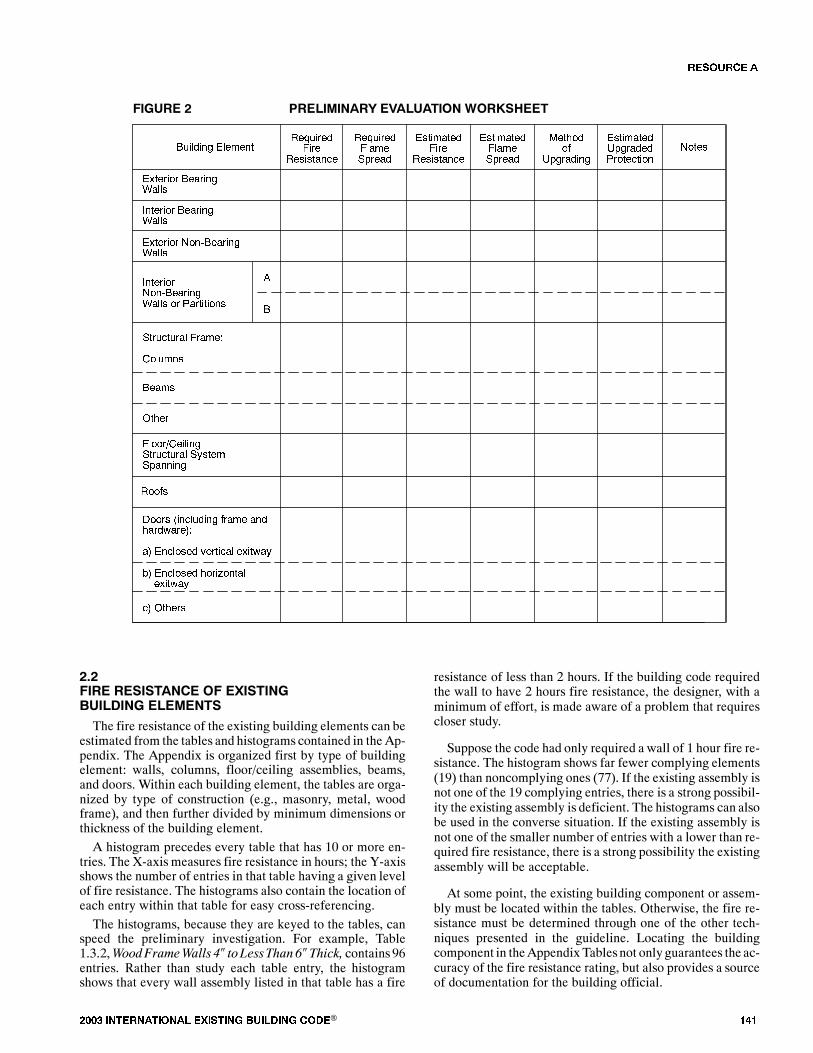
���� ���������� ��� ���� �������� ���® ���
�������� ������ �
$�-���������
$�������
$�-������ ���#���
������������
$�������
��������� ���#���
��� ��� � ����
������� ������ �
�������� ��������� �
�������� �����
�� ���
���������������� � �� ��������
�
����
����
� ���!��� ���������� �"�����#��
$��%�
&���� '�� ���� %��� ����(��)�
) �� ���� *����� ����("
+) �� ���� ����,�� ����("
�) �����
�
����� ) ��������* �+������ ,��-� ��
�������%
.#�����
��������.#��������������
�����
)�)��� �������� �� �.��������� �������The fire resistance of the existing building elements can be
estimated from the tables and histograms contained in the Ap-pendix. The Appendix is organized first by type of buildingelement: walls, columns, floor/ceiling assemblies, beams,and doors. Within each building element, the tables are orga-nized by type of construction (e.g., masonry, metal, woodframe), and then further divided by minimum dimensions orthickness of the building element.
A histogram precedes every table that has 10 or more en-tries. The X-axis measures fire resistance in hours; the Y-axisshows the number of entries in that table having a given levelof fire resistance. The histograms also contain the location ofeach entry within that table for easy cross-referencing.
The histograms, because they are keyed to the tables, canspeed the preliminary investigation. For example, Table1.3.2,WoodFrameWalls 4� to LessThan 6�Thick, contains96entries. Rather than study each table entry, the histogramshows that every wall assembly listed in that table has a fire
resistance of less than 2 hours. If the building code requiredthe wall to have 2 hours fire resistance, the designer, with aminimum of effort, is made aware of a problem that requirescloser study.
Suppose the code had only required a wall of 1 hour fire re-sistance. The histogram shows far fewer complying elements(19) than noncomplying ones (77). If the existing assembly isnot one of the 19 complying entries, there is a strong possibil-ity the existing assembly is deficient. The histograms can alsobe used in the converse situation. If the existing assembly isnot one of the smaller number of entries with a lower than re-quired fire resistance, there is a strong possibility the existingassembly will be acceptable.
At some point, the existing building component or assem-bly must be located within the tables. Otherwise, the fire re-sistance must be determined through one of the other tech-niques presented in the guideline. Locating the buildingcomponent in theAppendix Tablesnot only guarantees the ac-curacy of the fire resistance rating, but also provides a sourceof documentation for the building official.
�� ����
��� ���� ���������� ��� ���� �������� ���®
)�/������ �� ��������� � ��������� ���������
There are often many features in existing walls or floor/ceiling assemblies which were not included in the originalcertification or fire testing. The most common examples arepipes and utility wires passed through holes poked through anassembly. During the life of the building, many penetrationsare added, andby the time a building is ready for rehabilitationit is not sufficient to just consider the fire resistance of the as-sembly asoriginally constructed. It is necessary to consider allpenetrations and their relative impact upon fire performance.For instance, the fire resistance of the corridor wall may beless important than the effect of plain glass doors or transoms.In fact, doors are the most important single class of penetra-tions.
A fully developed fire generates substantial quantities ofheat and excess gaseous fuel capable of penetrating any holeswhich might be present in the walls or ceiling of the firecompartment. In general, this leads to a severe degradation ofthe fire resistance of those building elements and to a greaterpotential for fire spread. This is particularly applicable to pen-etrations located high in a compartment where the positivepressure of the fire can force the unburned gases through thepenetration.
Penetrations in a floor/ceiling assembly will generallycompletely negate the barrier qualities of the assembly andwill lead to rapid spread of fire to the space above. It will notbe a problem, however, if the penetrations are filled with non-combustible materials strongly fastened to the structure. Theupper half of walls are similar to the floor/ceiling assembly inthat a positive pressure can reasonably be expected in the topof the room, and this will push hot and/or burning gasesthrough the penetration unless it is completely sealed.
Building codes require doors installed in fire resistive wallsto resist the passage of fire for a specified period of time. If thedoor to a fully involved room is not closed, a large plume offire will typically escape through the doorway, preventinganyone from using the space outside the door while allowingthe fire to spread. This is why door closers are so important.Glass in doors and transoms can be expected to rapidly shatterunless constructed of listed or approved wire glass in a steelframe. As with other building elements, penetrations or non-rated portions of doors and transoms must be upgraded orotherwise protected.
Table 5.1 in Section V of the Appendix contains 41 entriesof doors mounted in sound tightfitting frames. Part 3.4 belowoutlines one procedure for evaluating and possibly upgradingexisting doors.
/���� �+������ ��� ����� ������
The final evaluation begins after the rehabilitation projecthas reached the final design stage and the choices made tokeep certain archaic materials and assemblies in the rehabili-tated building. The final evaluation process is essentially a
more refined and detailed version of the preliminary evalua-tion. The specific fire resistance and flame spread require-ments are determined for the project. This may involve localbuilding and fire officials reviewing the preliminary evalua-tion as depicted in Figures 1 and 2 and the field drawings andnotes. When necessary, provisions must be made to upgradeexisting building elements to provide the required level of fireperformance.
There are several approaches to design solutions that canmake possible the continued use of archaic materials and as-semblies in the rehabilitated structure. The simplest case oc-curs when the materials and assembly in question are foundwithin the Appendix Tables and the fire performance proper-ties satisfy code requirements. Other approaches must beused, though, if the assembly cannot be found within the Ap-pendix or the fire performance needs to be upgraded. Theseapproaches have been grouped into two classes: experimentaland theoretical.
/�� � �.�������� �������
If a material or assembly found in a building is not listed inthe Appendix Tables, there are several other ways to evaluatefire performance. One approach is to conduct the appropriatefire test(s) and thereby determine the fire-related propertiesdirectly. There are a number of laboratories in the UnitedStateswhich routinely conduct the various fire tests. Acurrentlist can be obtained by writing the Center for Fire Research,National Bureau of Standards, Washington, D.C. 20234.
The contract with any of these testing laboratories shouldrequire their observation of specimen preparation as well asthe testing of the specimen. A complete description of whereand how the specimen was obtained from the building, thetransportation of the specimen, and its preparation for testingshould be noted in detail so that the building official can besatisfied that the fire test is representative of the actual use.
The test report should describe the fire test procedure andthe response of the material or assembly. The laboratory usu-ally submits a cover letterwith the report to describe the provi-sions of the fire test that were satisfied by the material or as-sembly under investigation. A building official will generallyrequire this cover letter, butwill also read the report to confirmthat the material or assembly complies with the code require-ments. Local code officials should be involved in all phases ofthe testing process.
The experimental approach can be costly and time consum-ing because specimens must be taken from the building andtransported to the testing laboratory. When a load bearing as-sembly has continuous reinforcement, the test specimenmustbe removed from the building, transported, and tested in onepiece. However, when the fire performance cannot be deter-mined by other means, there may be no alternative to a full-scale test.
A �non-standard� small-scale test can be used in specialcases. Sample sizes need only be 10-25 square feet, while full-scale tests require test samples of either 100 or 180 square feetin size. This small-scale test is best suited for testing non-loadbearing assemblies against thermal transmission only.
�� ����

���� ���������� ��� ���� �������� ���® ���
/�) � ������� �������
There will be instances whenmaterials and assemblies in abuilding undergoing rehabilitation cannot be found in the Ap-pendix Tables. Even where test results are available for moreor less similar construction, the proper classification may notbe immediately apparent. Variations in dimensions, loadingconditions, materials, or workmanship may markedly affectthe performance of the individual building elements, and theextent of such a possible effect cannot be evaluated from thetables.
Theoretical methods being developed offer an alternativeto the full-scale fire tests discussed above. For example, Sec-tion 4302(b) of the 1979 edition of theUniformBuildingCodespecifically allows an engineering design for fire resistance inlieu of conducting full-scale tests. These techniques drawupon computer simulation and mathematical modeling, ther-modynamics, heat-flow analysis, and materials science topredict the fire performance of building materials and assem-blies.
One theoretical method, known as the �Ten Rules of FireEndurance Ratings,� was published by T. Z. Harmathy in theMay, 1965 edition of Fire Technology. (35) Harmathy�sRulesprovide a foundation for extending the data within the Appen-dix Tables to analyze or upgrade current as well as archaicbuilding materials or assemblies.
���� *0� �� �����
Rule 1: The �thermal�* fire endurance of a construction con-sisting of a number of parallel layers is greater than the sumofthe �thermal� fire endurances characteristic of the individuallayers when exposed separately to fire.
The minimum performance of an untested assembly can beestimated if the fire endurance of the individual components isknown. Though the exact rating of the assembly cannot bestated, the endurance of the assembly is greater than the sumof the endurance of the components.
When a building assembly or component is found to be de-ficient, the fire endurance can be upgraded byproviding a pro-tective membrane. This membrane could be a new layer ofbrick, plaster, or drywall. The fire endurance of this mem-brane is called the �finish rating.� Appendix Tables 1.5.1 and1.5.2 contain the finish ratings for the most commonlyemployed materials. (See also the notes to Rule 2).
The test criteria for the finish rating is the same as for thethermal fire endurance of the total assembly: average temper-ature increasesof 250�F above ambient or 325�F above ambi-ent at any one place with the membrane being exposed to thefire. The temperature is measured at the interface of the as-sembly and the protective membrane.
Rule 2: The fire endurance of a constructiondoes not decreasewith the addition of further layers.
Harmathy notes that this rule is a consequence of the pre-vious rule. Its validity follows from the fact that the additionallayers increase both the resistance to heat flow and the heat
capacity of the construction. This, in turn, reduces the rate oftemperature rise at the unexposed surface.
This rule is not just restricted to �thermal� performance butaffects the other fire test criteria: direct flame passage, cottonwaste ignition, and load bearing performance. This meansthat certain restrictionsmust be imposedon thematerials to beadded and on the loading conditions. One restriction is that anew layer, if applied to the exposed surface, must not produceadditional thermal stresses in the construction, i.e., its thermalexpansion characteristics must be similar to those of the adja-cent layer. Each new layer must also be capable of contribut-ing enough additional strength to the assembly to sustain theadded dead load. If this requirement is not fulfilled, the allow-able live load must be reduced by an amount equal to theweight of the new layer. Because of these limitations, this ruleshould not be applied without careful consideration.
Particular caremust be taken if thematerial added is a goodthermal insulator. Properly located, the added insulationcould improve the �thermal� performance of the assembly.Improperly located, the insulation could block necessary ther-mal transmission through the assembly, thereby subjectingthe structural elements to greater temperatures for longer peri-odsof time, and could cause premature structural failure of thesupporting members.
Rule 3: The fire endurance of constructions containing con-tinuous air gaps or cavities is greater than the fire enduranceof similar constructions of the same weight, but containing noair gaps or cavities.
By providing for voids in a construction, additional resist-ances are produced in the path of heat flow. Numerical heatflow analyses indicate that a 10 to 15 percent increase in fireendurance can be achieved by creating an air gap at the mid-plane of a brick wall. Since the gross volume is also increasedby the presence of voids, the air gaps and cavities have a bene-ficial effect on stability as well. However, constructions con-taining combustible materials within an air gap may be re-garded as exceptions to this rule because of the possibledevelopment of burning in the gap.
There are numerous examples of this rule in the tables. Forinstance:
Table 1.1.4; Item W-8-M-82: Cored concrete masonry,nominal 8 inch thick wall with one unit in wall thickness andwith 62% minimum of solid material in each unit, load bear-ing (80 PSI). Fire endurance: 21/2 hours.Table 1.1.5; Item W-10-M-11: Cored concrete mansonry,
nominal 10 inch thick wall with two units in wall thicknessand a2 inch air space, load bearing (80 PSI). The units are essential-ly the same as item W-8-M-82. Fire endurance: 31/2 hours.These walls show1 hour greater fire endurance by the addi-
tion of the 2 inch air space.
Rule 4: The farther an air gap or cavity is located from the ex-posed surface, the more beneficial is its effect on the fire en-durance.
Radiation dominates the heat transfer across an air gap orcavity, and it is markedly higher where the temperature is
* The �thermal� fire endurance is the time at which the average temperature on the unexposed side of a construction exceeds its initial value by 250� whenthe other side is exposed to the �standard� fire specified by ASTM Test Method E-19.
�� ����
��� ���� ���������� ��� ���� �������� ���®
higher. The air gap or cavity is thus a poor insulator if it is lo-cated in a region which attains high temperatures during fireexposure.
Some of the clay tile designs take advantage of these fac-tors. The double cell design, for instance, ensures that there isa cavity near the unexposed face. Some floor/ceiling assem-blies have air gaps or cavities near the top surface and theseenhance their thermal performance.
Rule 5: The fire endurance of a construction cannot be in-creased by increasing the thickness of a completely enclosedair layer.
Harmathy notes that there is evidence that if the thicknessof the air layer is larger than about 1/2 inch, the heat transferthrough the air layer depends only on the temperature of thebounding surfaces, and is practically independent of the dis-tance between them. This rule is not applicable if the air layeris not completely enclosed, i.e., if there is a possibility of freshair entering the gap at an appreciable rate.
Rule 6: Layers of materials of low thermal conductivity arebetter utilized on that side of the construction on which fire ismore likely to happen.
As in Rule 4, the reason lies in the heat transfer process,though the conductivity of the solid ismuch less dependent onthe ambient temperature of the materials. The low thermalconductor creates a substantial temperature differential to beestablished across its thickness under transient heat flow con-ditions. This rule may not be applicable to materials undergo-ing physico-chemical changes accompanied by significantheat absorption or heat evolution.
Rule 7: The fire endurance of asymmetrical constructions de-pends on the direction of heat flow.
This rule is a consequence of Rules 4 and 6 as well as otherfactors. This rule is useful in determining the relative protec-tion of corridors and stairwells from the surrounding spaces.In addition, there are often situationswhere a fire ismore like-ly, or potentially more severe, from one side or the other.
Rule 8: The presence of moisture, if it does not result in explo-sive spalling, increases the fire endurance.
The flowof heat into an assembly is greatly hindered by therelease and evaporation of themoisture foundwithin cementi-tious materials such as gypsum, portland cement, or magne-sium oxychloride. Harmathy has shown that the gain in fireendurance may be as high as 8 percent for each percent (byvolume) of moisture in the construction. It is the moisturechemically bound within the construction material at the timeof manufacture or processing that leads to increased fire en-durance. There is no direct relationship between the relativehumidity of the air in the pores of thematerial and the increasein fire endurance.
Under certain conditions theremay be explosive spalling oflow permeability cementitious materials such as dense con-crete. In general, one can assume that extremely old concretehas developed enough minor cracking that this factor shouldnot be significant.
Rule 9: Load-supporting elements, such asbeams, girdersandjoists, yield higher fire endurances when subjected to fire en-durance tests as parts of floor, roof, or ceiling assemblies thanthey would when tested separately.
One of the fire endurance test criteria is the ability of a load-supporting element to carry its design load. The element willbe deemed to have failed when the load can no longer be sup-ported.Failure usually results for two reasons. Some materials,
particularly steel andothermetals, losemuchof their structur-al strength at elevated temperatures. Physical deflection of thesupporting element, due to decreased strength or thermal ex-pansion, causes a redistribution of the load forces and stressesthroughout the element. Structural failure often results be-cause the supporting element is not designed to carry the re-distributed load.
Roof, floor, and ceiling assemblies have primary (e.g.,beams) and secondary (e.g., floor joists) structural members.Since the primary load-supporting elements span the largestdistances, their deflection becomes significant at a stagewhenthe strength of the secondary members (including the roof orfloor surface) is hardly affected by the heat. As the secondarymembers follow the deflection of the primary load-supportingelement, an increasingly larger portion of the load is trans-ferred to the secondary members.When load-supporting elements are tested separately, the
imposed load is constant and equal to the design load through-out the test. By definition, no distribution of the load is pos-sible because the element is being tested by itself.Without anyother structural members to which the load could be trans-ferred, the individual elements cannot yield a higher fire en-durance than they do when tested as parts of a floor, roof orceiling assembly.Rule 10: The load-supporting elements (beams, girders,joists, etc.) of a floor, roof, or ceiling assembly can be replacedby such other load-supporting elements which, when testedseparately, yielded fire endurances not less than that of the as-sembly.
This rule depends on Rule 9 for its validity. A beam or gird-er, if capable of yielding a certain performance when testedseparately, will yield an equally good or better performancewhen it forms a part of a floor, roof, or ceiling assembly. Itmust be emphasized that the supporting element of one as-sembly must not be replaced by the supporting element ofanother assembly if the performance of this latter element isnot known from a separate (beam) test. Because of the load-reducing effect of the secondary elements that results from atest performed on an assembly, the performance of the sup-porting element alone cannot be evaluated by simple arithme-tic. This rule also indicates the advantage of performing sepa-rate fire tests on primary load-supporting elements.
�������� �� ���� *0� �����Harmathy provided one schematic figure which illustrated
his Rules.* It should be useful as a quick reference to assist inapplying his Rules.
* Reproduced from the May 1965 Fire Technology (Vol. 1, No. 2). Copyright National Fire Protection Association, Boston. Reproduced by permission.
�� ����

���� ���������� ��� ���� �������� ���® ���
��$�
���� �����& ����$� � �/ $
��$�
�� ��
��� ��
$./� 0
�� ��
��� ��
$./� 1
�� ��
��� ��
$./� 2
�� ���
���� ��� ��
$./� 3
��
�����
���
�� ��
��� ��
$./� 4
�� ��
��� ��
$./� 5
��$� ��$�
�� ��
��� ��
$./� 6
�� ��
��� ��
$./� 7
���
���������
� ����������
���
���������
� ����������
��$� ��$�
���� �����&����$���/8
� $ �9� �/ $������/8
� $ � ���� �9�������& ����$���/8
�� ��
������������ �������� �� �� ����
� : %��� ������
���� � ��� �� $��/���& �8 ���� � �� ��� ��
$./� 3;
��� ��
$./� <
����� �
�.����� �������� �� ���� *0� �����
The following examples, based in whole or in part uponthose presented in Harmathy�s paper (35), show how theRules can be applied to practical cases.
������� �
Problem
A contractor would like to keep a partition which consists of a33/4 inch thick layer of red clay brick, a 11/4 inch thick layer ofplywood, and a 3/8 inch thick layer of gypsumwallboard, at alocationwhere 2hour fire endurance is required. Is this assem-bly capable of providing a 2 hour protection?
Solution
(1) This partition does not appear in the Appendix Tables.
(2) Bricks of this thickness yield fire endurances of approxi-mately 75 minutes (Table 1.1.2, Item W-4-M-2).
(3) The 11/4 inch thick plywood has a finish rating of 30 min-utes.
(4) The 3/8 inch gypsum wallboard has a finish rating of 10minutes.
(5) Using the recommended values from the tables and apply-ing Rule 1, the fire endurance (FI) of the assembly is largerthan the sum of the individual layers, or
�� � �� � �� � � � �� ����
Discussion
This example illustrates how the Appendix Tables can be uti-lized to determine the fire resistance of assemblies not explic-itly listed.
�� ����
��� ���� ���������� ��� ���� �������� ���®
�������
Problem
(1) A number of buildings to be rehabilitated have the sametype of roof slab which is supported with different structuralelements.
(2) The designer and contractor would like to determinewhether or not this roof slab is capable of yielding a 2 hour fireendurance. According to a rigorous interpretation of ASTME-119, however, only the roof assembly, including the roofslab as well as the cover and the supporting elements, can besubjected to a fire test. Therefore, a fire endurance classifica-tion cannot be issued for the slabs separately.
(3) The designer and contractor believe this slab will yield a2 hour fire endurance evenwithout the cover, and any beam ofat least 2 hour fire endurance will provide satisfactory sup-port. Is it possible to obtain a classification for the slab sepa-rately?
Solution
(1) The answer to the question is yes.
(2) According to Rule 10 it is not contrary to common sense totest and classify roofs and supporting elements separately.Furthermore, according to Rule 2, if the roof slabs actuallyyield a 2 hour fire endurance, the endurance of an assembly,including the slabs, cannot be less than 2 hours.
(3) The recommended procedure would be to review thetables to see if the slab appears as part of any tested roof orfloor/ceiling assembly. The supporting system can be re-garded as separate from the slab specimen, and the fire endur-ance of the assembly listed in the table is at least the fire endur-ance of the slab. There would have to be an adjustment for theweight of the roof cover in the allowable load if the test speci-men did not contain a cover.
(4) The supporting structure or element would have to have atleast a 2 hour fire endurance when tested separately.
Discussion
If the tables did not include tests on assemblies which con-tained the slab, one procedure would be to assemble the roofslabs on any convenient supporting system (not regarded aspart of the specimen) and to subject them to a load which, be-sides the usually required superimposed load, includes someallowances for the weight of the cover.
�������
Problem
A steel-joisted floor and ceiling assembly is known to haveyielded a fire endurance of 1 hour and 35minutes. At a certainlocation, a 2 hour endurance is required.What is themost eco-nomical way of increasing the fire endurance by at least 25minutes?
Solution
(1) Themost effective techniquewould be to increase the ceil-ing plaster thickness. Existing coats of paint would have to beremoved and the surface properly prepared before the newplaster could be applied. Other materials (e.g., gypsum wall-board) could also be considered.
(2) There may be other techniques based on other principles,but an examination of the drawings would be necessary.Discussion(1) The additional plaster has at least three effects:
a) The layer of plaster is increased and thus there is again of fire endurance (Rule 1).
b) There is a gain due to shifting the air gap farther fromthe exposed surface (Rule 4).
c) There is more moisture in the path of heat flow to thestructural elements (Rules 7 and 8).
(2) The increase in fire endurance would be at least as large asthat of the finish rating for the added thickness of plaster. Thecombined effects in (1) above would further increase this by afactor of 2 or more, depending upon the geometry of the as-sembly.
������� �ProblemThe fire endurance of itemW-l0-M-l in Table 1.1.5 is 4 hours.This wall consists of two 33/4 inch thick layers of structuraltiles separated by a 2 inch air gap and 3/4 inch portland cementplaster or stucco on both sides. If the actual wall in the build-ing is identical to itemW-10-M-1 except that it has a 4 inch airgap, can the fire endurance be estimated at 5 hours?SolutionThe answer to the question is no for the reasons contained inRule 5.
������� �ProblemIn order to increase the insulating value of its precast roofslabs, a company has decided to use two layers of differentconcretes. The lower layer of the slabs, where the strength ofthe concrete is immaterial (all the tensile load is carried by thesteel reinforcement), would be made with a concrete of lowstrength but good insulating value. The upper layer, where theconcrete is supposed to carry the compressive load, would re-main the original high strength, high thermal conductivityconcrete. How will the fire endurance of the slabs be affectedby the change?SolutionThe effect on the thermal fire endurance is beneficial:(1) The total resistance to heat flow of the new slabs has beenincreased due to the replacement of a layer of high thermalconductivity by one of low conductivity.(2) The layer of low conductivity is on the side more likely tobe exposed to fire,where it ismore effectively utilized accord-ing to Rule 6. The layer of low thermal conductivity also pro-vides better protection for the steel reinforcement, thereby ex-tending the time before reaching the temperature at which thecreep of steel becomes significant.
/�/1 �-���� �����2 �����*The �thickness design� strategy is based upon Harmathy�s
Rules 1 and 2. This design approach can be used when theconstructionmaterials have been identified andmeasured, but
�� ����
���� ���������� ��� ���� �������� ���® ���
the specific assembly cannot be located within the tables. Thetables should be surveyed again for thinner walls of likemate-rial and construction detail that have yielded the desired orgreater fire endurance. If such an assembly can be found, thenthe thicker walls in the building have more than enough fireresistance. The thickness of the walls thusbecomes the princi-pal concern.
This approach can also be used for floor/ceiling assemblies,except that the thickness of the cover* and the slab become thecentral concern. The fire resistance of the untested assemblywill be at least the fire resistance of an assembly listed in thetable having a similar designbutwith less cover and/or thinnerslabs. For other structural elements (e.g., beams and col-umns), the element listed in the table must also be of a similardesign but with less cover thickness.
/�3�+������ �� �����A separate section on doors has been included because the
process for evaluation presentedbelowdiffers from those sug-gested previously for other building elements. The impact ofunprotected openings or penetrations in fire resistant assem-blies has been detailed in Part 2.3 above. It is sufficient to notehere that openings left unprotectedwill likely lead to failure ofthe barrier under actual fire conditions.
For other types of building elements (e.g., beams, col-umns), the Appendix Tables can be used to establish a mini-mum level of fire performance. The benefit to rehabilitation isthat the need for a full-scale fire test is then eliminated. Fordoors, however, this cannot be done. The data contained inAppendix Table 5.1, Resistance of Doors to Fire Exposure,can only provide guidance as to whether a successful fire testis even feasible.
For example, a door required to have 1 hour fire resistanceis noted in the tables as providing only 5 minutes. The likeli-hood of achieving the required 1 hour, even if the door is up-graded, is remote. The ultimate need for replacement of thedoors is reasonably clear, and the expense and time needed fortesting can be saved. However, if the performance docu-mented in the table is near or in excess of what is being re-quired, then a fire test should be conducted. The test docu-mentation can then be used as evidence of compliance withthe required level of performance.
The table entries cannot be used as the sole proof of perfor-mance of the door in question because there are too many un-known variables which could measurably affect fire perfor-mance. The wood may have dried over the years; coats offlammable varnish could have been added. Minor deviationsin the internal construction of a door can result in significantdifferences in performance. Methods of securing inserts inpanel doors can vary. The major non-destructive method ofanalysis, an x-ray, often cannot provide the necessary detail. Itis for these, and similar reasons, that a fire test is still felt to benecessary.
It is often possible to upgrade the fire performance of an ex-isting door. Sometimes, �as is� and modified doors are evalu-
ated in a single series of tests when failure of the unmodifieddoor is expected. Because doors upgraded after an initial fail-ure must be tested again, there is a potential savings of timeand money.The most common problems encountered are plain glass,
panel inserts of insufficient thickness, and improper fit of adoor in its frame. The latter problem can be significant be-cause a fire can develop a substantial positive pressure, andthe fire will work its way through otherwise innocent-lookinggaps between door and frame.One approach to solving these problems is as follows. The
plain glass is replaced with approved or listed wire glass in asteel frame. The panel inserts can be upgraded by adding anadditional layer of material. Gypsum wallboard is often usedfor this purpose. Intumescent paint applied to the edges of thedoor and frame will expand when exposed to fire, forming aneffective seal around the edges. This seal, coupled with thegenerally even thermal expansion of a wood door in a woodframe, can prevent the passage of flames and other fire gases.Figure 3 below illustrates these solutions.Because the interior construction of a door cannot be deter-
mined by a visual inspection, there is no absolute guaranteethat the remaining doors are identical to the one(s) removedfrom the building and tested. But the same is true for doorsconstructed today, and reason and judgment must be applied.Doors that appear identical upon visual inspection can beweighed. If the weights are reasonably close, the doors can beassumed to be identical and therefore provide the same levelof fire performance. Another approach is to fire test more thanone door or to dismantle doors selected at random to see ifthey had been constructed in the samemanner. Original build-ing plans showing door details or other records showing thatdoors were purchased at one time or obtained from a singlesupplier can also be evidence of similar construction.More often though, it iswhat is visible to the eye that ismost
significant. The investigator should carefully check the con-dition and fit of the door and frame, and for frames out ofplumb or separating from the wall. Door closers, latches, andhinges must be examined to see that they function properlyand are tightly secured. If these are in order and the door andframe have passed a full-scale test, there can be a reasonablebasis for allowing the existing doors to remain.
3������*
This section summarizes the various approaches anddesignsolutions discussed in the preceding sections of the guideline.The term �structural system� includes: frames, beams, col-umns, and other structural elements. �Cover� is a protectivelayer(s) of materials or membrane which slows the flow ofheat to the structural elements. It cannot be stressed toostrongly that the fire endurance of actual building elementscan be greatly reduced or totally negated by removing part ofthe cover to allow pipes, ducts, or conduits to pass through theelement. This must be repaired in the rehabilitation process.The following approaches shall be considered equivalent.
* Cover: the protective layer or membrane of material which slows the flow of heat to the structural elements.
�� ����
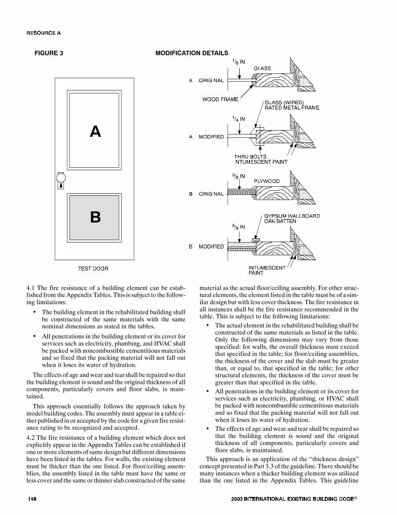
��� ���� ���������� ��� ���� �������� ���®
=/���
�
�
� & �$���
�!� ��>
$�=���/�
� &����&�
$�=���/�
� &����&�
=/��� '��$�&)$���& ����/ �$���
�9$. � /�����.������� �����
�!� ��>
�/8� &
�!� ��>
=8��.� ��//� �$& �? ������
���.������������
�!� ��>
����� / �������� �����
���� & $
4.1 The fire resistance of a building element can be estab-lished from theAppendix Tables. This is subject to the follow-ing limitations:
� The building element in the rehabilitated building shallbe constructed of the same materials with the samenominal dimensions as stated in the tables.
� All penetrations in the building element or its cover forservices such as electricity, plumbing, and HVAC shallbe packed with noncombustible cementitious materialsand so fixed that the packing material will not fall outwhen it loses its water of hydration.
The effects of age andwear and tear shall be repaired so thatthe building element is sound and the original thickness of allcomponents, particularly covers and floor slabs, is main-tained.
This approach essentially follows the approach taken bymodel building codes. The assemblymust appear in a table ei-ther published in or accepted by the code for a given fire resist-ance rating to be recognized and accepted.
4.2 The fire resistance of a building element which does notexplicitly appear in the Appendix Tables can be established ifone ormore elements of same design but different dimensionshave been listed in the tables. For walls, the existing elementmust be thicker than the one listed. For floor/ceiling assem-blies, the assembly listed in the table must have the same orless cover and the sameor thinner slab constructed of the same
material as the actual floor/ceiling assembly. For other struc-tural elements, the element listed in the tablemust be of a sim-ilar design but with less cover thickness. The fire resistance inall instances shall be the fire resistance recommended in thetable. This is subject to the following limitations:� The actual element in the rehabilitated building shall be
constructed of the same materials as listed in the table.Only the following dimensions may vary from thosespecified: for walls, the overall thickness must exceedthat specified in the table; for floor/ceiling assemblies,the thickness of the cover and the slab must be greaterthan, or equal to, that specified in the table; for otherstructural elements, the thickness of the cover must begreater than that specified in the table.
� All penetrations in the building element or its cover forservices such as electricity, plumbing, or HVAC shallbe packed with noncombustible cementitious materialsand so fixed that the packing material will not fall outwhen it loses its water of hydration.
� The effects of age and wear and tear shall be repaired sothat the building element is sound and the originalthickness of all components, particularly covers andfloor slabs, is maintained.
This approach is an application of the �thickness design�concept presented in Part 3.3 of the guideline. There should bemany instances when a thicker building element was utilizedthan the one listed in the Appendix Tables. This guideline
�� ����
���� ���������� ��� ���� �������� ���® ���
recognizes the inherent superiority of a thicker design. Note:�thickness design� for floor/ceiling assemblies and structuralelements refers to cover and slab thickness rather than totalthickness.The �thickness design� concept is essentially a special case
of Harmathy�s Rules (specifically Rules 1 and 2). It should berecognized that the only source of data is the AppendixTables. If other data are used, it must be in connectionwith theapproach below.4.3 The fire resistance of building elements can be establishedby applyingHarmathy�s TenRules of Fire Resistance Ratingsas set forth in Part 3.2 of the guideline. This is subject to thefollowing limitations:
� The data from the tables can be utilized subject to thelimitations in 4.2 above.
� Test reports from recognized journals or published pa-pers can be used to support data utilized in applyingHarmathy�s Rules.
� Calculations utilizing recognized and well establishedcomputational techniques can be used in applying Har-mathy�s Rules. These include, but are not limited to,analysis of heat flow, mechanical properties, deflec-tions, and load bearing capacity.
�� ����

��� ���� ���������� ��� ���� �������� ���®
���� ���������� ��� ���� �������� ���® ���
��������
���� ����The fire resistance tables that follow are a part of Resource A and provide a tabular form of assigning fire resistance ratings tovarious archaic building elements and assemblies.
These tables for archaic materials and assemblies do for archaic materials what Tables 720.1(1), 720.1(2), and 720.1(3) of theInternational Building Code do for more modern building elements and assemblies. The fire resistance tables of Resource Ashould be used as described in the �Purpose and Procedure� that follows the table of contents for these tables.
�������� � ����� �� ��������
Purpose 153
Section I�Walls
1.1.1 Masonry 0 in. - 4 in. thick 154
1.1.2 Masonry 4 in. - 6 in. thick 158
1.1.3 Masonry 6 in. - 8 in. thick 167
1.1.4 Masonry 8 in. - 10 in. thick 173
1.1.5 Masonry 10 in. - 12 in. thick 182
1.1.6 Masonry 12 in. - 14 in. thick 186
1.1.7 Masonry 14 in. or more thick 193
1.2.1 Metal Frame 0 in. - 4 in. thick 196
1.2.2 Metal Frame 4 in. - 6 in. thick 200
1.2.3 Metal Frame 6 in. - 8 in. thick 202
1.2.4 Metal Frame 8 in. - 10 in. thick 203
1.3.1 Wood Frame 0 in. - 4 in. thick 204
1.3.2 Wood Frame 4 in. - 6 in. thick 205
1.3.3 Wood Frame 6 in. - 8 in. thick 213
1.4.1 Miscellaneous Materials 0 in. - 4 in. thick 213
1.4.2 Miscellaneous Materials 4 in. - 6 in. thick 214
1.5.1 Finish Ratings�Inorganic Materials Thickness 215
1.5.2 Finish Ratings�Organic Materials Thickness 216
Section II�Columns
2.1.1 Reinforced Concrete Min. Dim. 0 in. - 6 in. 217
2.1.2 Reinforced Concrete Min. Dim. 10 in. - 12 in. 217
2.1.3 Reinforced Concrete Min. Dim. 12 in. - 14 in. 221
2.1.4 Reinforced Concrete Min. Dim. 14 in. - 16 in. 222
2.1.5 Reinforced Concrete Min. Dim. 16 in. - 18 in. 223
2.1.6 Reinforced Concrete Min. Dim. 18 in. - 20 in. 225
2.1.7 Reinforced Concrete Min. Dim. 20 in. - 22 in. 226
2.1.8 Hexagonal Reinforced Concrete Diameter - 12 in. - 14 in. 227
2.1.9 Hexagonal Reinforced Concrete Diameter - 14 in. - 16 in. 228
�� ����
��� ���� ���������� ��� ���� �������� ���®
2.1.10 Hexagonal Reinforced Concrete Diameter - 16 in.- 18 in. 228
2.1.11 Hexagonal Reinforced Concrete Diameter - 20 in. - 22 in. 228
2.2 Round Cast Iron Columns Minimum Dimension 229
2.3 Steel�Gypsum Encasements Minimum Area of Solid Material 230
2.4 Timber Minimum Dimension 231
2.5.1.1 Steel/Concrete Encasements Minimum Dimension less than 6 in. 231
2.5.1.2 Steel/Concrete Encasements Minimum Dimension 6 in. - 8 in. 232
2.5.1.3 Steel/Concrete Encasements Minimum Dimension 8 in. - 10 in. 233
2.5.1.4 Steel/Concrete Encasements Minimum Dimension 10 in. - 12 in. 235
2.5.1.5 Steel/Concrete Encasements Minimum Dimension 12 in. - 14 in. 240
2.5.1.6 Steel/Concrete Encasements Minimum Dimension 14 in. - 16 in. 242
2.5.1.7 Steel/Concrete Encasements Minimum Dimension 16 in. - 18 in. 243
2.5.2.1 Steel/Brick and Block Encasements Minimum Dimension 10 in. - 12 in. 244
2.5.2.2 Steel/Brick and Block Encasements Minimum Dimension 12 in. - 14 in. 244
2.5.2.3 Steel/Brick and Block Encasements Minimum Dimension 14 in. - 16 in. 245
2.5.3.1 Steel/Plaster Encasements Minimum Dimension 6 in. - 8 in. 245
2.5.3.2 Steel/Plaster Encasements Minimum Dimension 8 in. - 10 in. 246
2.5.4.1 Steel/Miscellaneous Encasements Minimum Dimension 6 in. - 8 in. 246
2.5.4.2 Steel/Miscellaneous Encasements Minimum Dimension 8 in. - 10 in. 246
2.5.4.3 Steel/Miscellaneous Encasements Minimum Dimension 10 in. - 12 in. 247
Section III�Floor/Ceiling Assemblies
3.1 Reinforced Concrete Assembly thickness 248
3.2 Steel Structural Elements Membrane thickness 254
3.3 Wood Joist Membrane thickness 261
3.4 Hollow Clay Tile with ReinforcedConcrete Assembly thickness 266
Section IV�Beams
4.1.1 Reinforced Concrete Depth - 10 in. - 12 in. 269
4.1.2 Reinforced Concrete Depth - 12 in. - 14 in. 272
4.1.3 Reinforced Concrete Depth - 14 in. - 16 in. 274
4.2.1 Reinforced Concrete/Unprotected Depth - 10 in. - 12 in. 275
4.2.2 Steel/Concrete Protection Depth - 10 in. - 12 in. 275
Section V�Doors
5.1 Resistance of Doors to Fire Exposure Thickness 276
�� ����
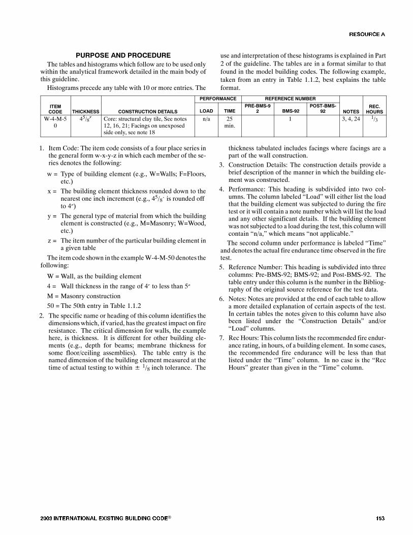
���� ���������� ��� ���� �������� ���® ���
������� �� �������The tables and histogramswhich follow are to be used only
within the analytical framework detailed in the main body ofthis guideline.Histograms precede any table with 10 or more entries. The
use and interpretation of these histograms is explained in Part2 of the guideline. The tables are in a format similar to thatfound in the model building codes. The following example,taken from an entry in Table 1.1.2, best explains the tableformat.
PERFORMANCE REFERENCE NUMBER
ITEMCODE THICKNESS CONSTRUCTION DETAILS LOAD TIME
PRE-BMS-92 BMS-92
POST-BMS-92 NOTES
REC.HOURS
W-4-M-50
45/8� Core: structural clay tile, See notes12, 16, 21; Facings on unexposedside only, see note 18
n/a 25min.
1 3, 4, 24 1/3
1. Item Code: The item code consists of a four place series inthe general form w-x-y-z in which each member of the se-ries denotes the following:
w = Type of building element (e.g., W=Walls; F=Floors,etc.)
x = The building element thickness rounded down to thenearest one inch increment (e.g., 45/8� is rounded offto 4�)
y = The general type of material from which the buildingelement is constructed (e.g., M=Masonry; W=Wood,etc.)
z = The item number of the particular building element ina given table
The itemcode shown in the exampleW-4-M-50 denotes thefollowing:
W =Wall, as the building element
4 = Wall thickness in the range of 4� to less than 5�
M = Masonry construction
50 = The 50th entry in Table 1.1.2
2. The specific name or heading of this column identifies thedimensionswhich, if varied, has the greatest impact on fireresistance. The critical dimension for walls, the examplehere, is thickness. It is different for other building ele-ments (e.g., depth for beams; membrane thickness forsome floor/ceiling assemblies). The table entry is thenamed dimension of the building element measured at thetime of actual testing to within� 1/8 inch tolerance. The
thickness tabulated includes facings where facings are apart of the wall construction.
3. Construction Details: The construction details provide abrief description of the manner in which the building ele-ment was constructed.
4. Performance: This heading is subdivided into two col-umns. The column labeled �Load� will either list the loadthat the building element was subjected to during the firetest or it will contain a note number which will list the loadand any other significant details. If the building elementwas not subjected to a load during the test, this columnwillcontain �n/a,� which means �not applicable.�The second column under performance is labeled �Time�
and denotes the actual fire endurance time observed in the firetest.5. Reference Number: This heading is subdivided into three
columns: Pre-BMS-92; BMS-92; and Post-BMS-92. Thetable entry under this column is the number in the Bibliog-raphy of the original source reference for the test data.
6. Notes: Notes are provided at the end of each table to allowa more detailed explanation of certain aspects of the test.In certain tables the notes given to this column have alsobeen listed under the �Construction Details� and/or�Load� columns.
7. Rec Hours: This column lists the recommended fire endur-ance rating, in hours, of a building element. In some cases,the recommended fire endurance will be less than thatlisted under the �Time� column. In no case is the �RecHours� greater than given in the �Time� column.
�� ����
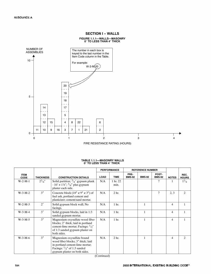
��� ���� ���������� ��� ���� �������� ���®
����� �� � ���FIGURE 1.1.1�WALLS�MASONRY
0� TO LESS THAN 4� THICK
12
13
14
15 4
5
17
0
FIRE RESISTANCE RATING (HOURS)
NUMBER OFASSEMBLIES
1 2 3 4
5
10
010 9 16 3
18
11
The number in each box iskeyed to the last number in theItem Code column in the Table.
For example:W-3-M-20
22 68
1 21 27
19
20
TABLE 1.1.1�MASONRY WALLS0� TO LESS THAN 4� THICK
PERFORMANCE REFERENCE NUMBER
ITEMCODE THICKNESS CONSTRUCTION DETAILS LOAD TIME
PRE-BMS-92 BMS-92
POST-BMS-92 NOTES
REC.HOURS
W-2-M-1 21/4� Solid partition; 3/4� gypsum plank- 10� � 1�6�; 3/4� plus gypsumplaster each side.
N/A 1 hr. 22min.
7 1 11/4
W-3-M-2 3� Concrete block (18� � 9� � 3�) offuel ash, portland cement andplasticizer; cement/sand mortar.
N/A 2 hr. 7 2, 3 2
W-2-M-3 2� Solid gypsum block wall; Nofacings.
N/A 1 hr. 1 4 1
W-3-M-4 3� Solid gypsum blocks, laid in 1:3sanded gypsum mortar.
N/A 1 hr. 1 4 1
W-3-M-5 3� Magnesium oxysulfate wood fiberblocks; 2� thick; laid in portlandcement-lime mortar; Facings: 1/2�of 1:3 sanded gypsum plaster onboth sides.
N/A 1 hr. 1 4 1
W-3-M-6 3� Magnesium oxysulfate boundwood fiber blocks; 3� thick; laidin portland cement-lime mortar;Facings: 1/2� of 1:3 sandedgypsum plaster on both sides.
N/A 2 hr. 1 4 2
(Continued)
�� ����
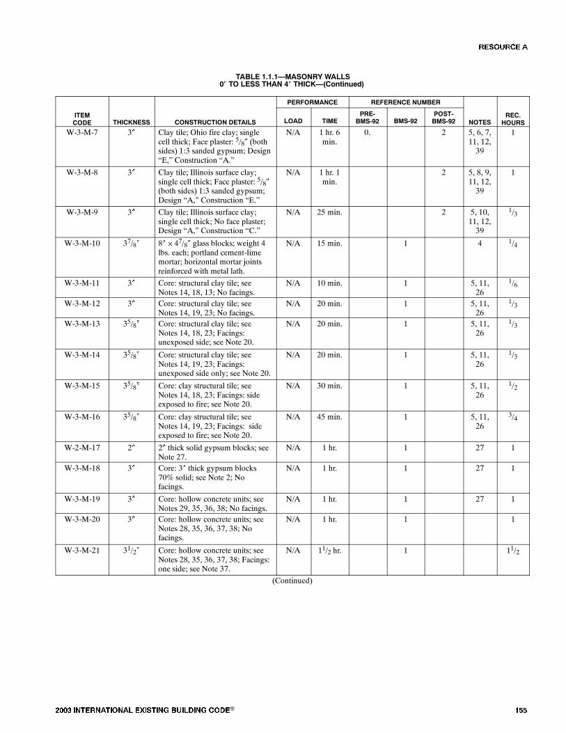
���� ���������� ��� ���� �������� ���® ���
TABLE 1.1.1�MASONRY WALLS0� TO LESS THAN 4� THICK�(Continued)
PERFORMANCE REFERENCE NUMBER
ITEMCODE THICKNESS CONSTRUCTION DETAILS LOAD TIME
PRE-BMS-92 BMS-92
POST-BMS-92 NOTES
REC.HOURS
W-3-M-7 3� Clay tile; Ohio fire clay; singlecell thick; Face plaster: 5/8� (bothsides) 1:3 sanded gypsum; Design�E,� Construction �A.�
N/A 1 hr. 6min.
0. 2 5, 6, 7,11, 12,39
1
W-3-M-8 3� Clay tile; Illinois surface clay;single cell thick; Face plaster: 5/8�(both sides) 1:3 sanded gypsum;Design �A,� Construction �E.�
N/A 1 hr. 1min.
2 5, 8, 9,11, 12,39
1
W-3-M-9 3� Clay tile; Illinois surface clay;single cell thick; No face plaster;Design �A,� Construction �C.�
N/A 25 min. 2 5, 10,11, 12,39
1/3
W-3-M-10 37/8� 8� � 47/8� glass blocks; weight 4lbs. each; portland cement-limemortar; horizontal mortar jointsreinforced with metal lath.
N/A 15 min. 1 4 1/4
W-3-M-11 3� Core: structural clay tile; seeNotes 14, 18, 13; No facings.
N/A 10 min. 1 5, 11,26
1/6
W-3-M-12 3� Core: structural clay tile; seeNotes 14, 19, 23; No facings.
N/A 20 min. 1 5, 11,26
1/3
W-3-M-13 35/8� Core: structural clay tile; seeNotes 14, 18, 23; Facings:unexposed side; see Note 20.
N/A 20 min. 1 5, 11,26
1/3
W-3-M-14 35/8� Core: structural clay tile; seeNotes 14, 19, 23; Facings:unexposed side only; see Note 20.
N/A 20 min. 1 5, 11,26
1/3
W-3-M-15 35/8� Core: clay structural tile; seeNotes 14, 18, 23; Facings: sideexposed to fire; see Note 20.
N/A 30 min. 1 5, 11,26
1/2
W-3-M-16 35/8� Core: clay structural tile; seeNotes 14, 19, 23; Facings: sideexposed to fire; see Note 20.
N/A 45 min. 1 5, 11,26
3/4
W-2-M-17 2� 2� thick solid gypsum blocks; seeNote 27.
N/A 1 hr. 1 27 1
W-3-M-18 3� Core: 3� thick gypsum blocks70% solid; see Note 2; Nofacings.
N/A 1 hr. 1 27 1
W-3-M-19 3� Core: hollow concrete units; seeNotes 29, 35, 36, 38; No facings.
N/A 1 hr. 1 27 1
W-3-M-20 3� Core: hollow concrete units; seeNotes 28, 35, 36, 37, 38; Nofacings.
N/A 1 hr. 1 1
W-3-M-21 31/2� Core: hollow concrete units; seeNotes 28, 35, 36, 37, 38; Facings:one side; see Note 37.
N/A 11/2 hr. 1 11/2
(Continued)
�� ����
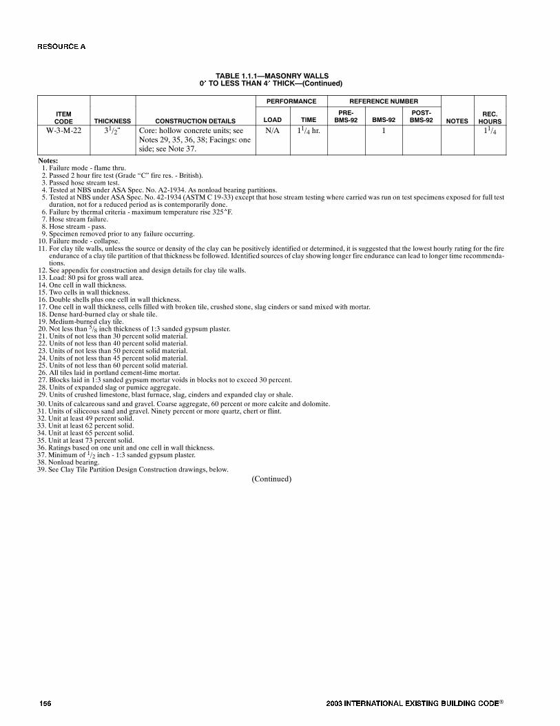
��� ���� ���������� ��� ���� �������� ���®
TABLE 1.1.1�MASONRY WALLS0� TO LESS THAN 4� THICK�(Continued)
PERFORMANCE REFERENCE NUMBER
ITEMCODE THICKNESS CONSTRUCTION DETAILS LOAD TIME
PRE-BMS-92 BMS-92
POST-BMS-92 NOTES
REC.HOURS
W-3-M-22 31/2� Core: hollow concrete units; seeNotes 29, 35, 36, 38; Facings: oneside; see Note 37.
N/A 11/4 hr. 1 11/4
Notes:1. Failure mode - flame thru.2. Passed 2 hour fire test (Grade �C� fire res. - British).3. Passed hose stream test.4. Tested at NBS under ASA Spec. No. A2-1934. As nonload bearing partitions.5. Tested at NBS under ASA Spec. No. 42-1934 (ASTM C 19-33) except that hose stream testing where carried was run on test specimens exposed for full testduration, not for a reduced period as is contemporarily done.
6. Failure by thermal criteria - maximum temperature rise 325�F.7. Hose stream failure.8. Hose stream - pass.9. Specimen removed prior to any failure occurring.10. Failure mode - collapse.11. For clay tile walls, unless the source or density of the clay can be positively identified or determined, it is suggested that the lowest hourly rating for the fire
endurance of a clay tile partition of that thickness be followed. Identified sources of clay showing longer fire endurance can lead to longer time recommenda-tions.
12. See appendix for construction and design details for clay tile walls.13. Load: 80 psi for gross wall area.14. One cell in wall thickness.15. Two cells in wall thickness.16. Double shells plus one cell in wall thickness.17. One cell in wall thickness, cells filled with broken tile, crushed stone, slag cinders or sand mixed with mortar.18. Dense hard-burned clay or shale tile.19. Medium-burned clay tile.20. Not less than 5/8 inch thickness of 1:3 sanded gypsum plaster.21. Units of not less than 30 percent solid material.22. Units of not less than 40 percent solid material.23. Units of not less than 50 percent solid material.24. Units of not less than 45 percent solid material.25. Units of not less than 60 percent solid material.26. All tiles laid in portland cement-lime mortar.27. Blocks laid in 1:3 sanded gypsum mortar voids in blocks not to exceed 30 percent.28. Units of expanded slag or pumice aggregate.29. Units of crushed limestone, blast furnace, slag, cinders and expanded clay or shale.30. Units of calcareous sand and gravel. Coarse aggregate, 60 percent or more calcite and dolomite.31. Units of siliceous sand and gravel. Ninety percent or more quartz, chert or flint.32. Unit at least 49 percent solid.33. Unit at least 62 percent solid.34. Unit at least 65 percent solid.35. Unit at least 73 percent solid.36. Ratings based on one unit and one cell in wall thickness.37. Minimum of 1/2 inch - 1:3 sanded gypsum plaster.38. Nonload bearing.39. See Clay Tile Partition Design Construction drawings, below.
(Continued)
�� ����
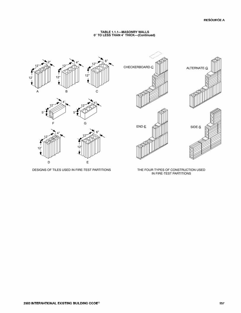
���� ���������� ��� ���� �������� ���® ���
TABLE 1.1.1�MASONRY WALLS0� TO LESS THAN 4� THICK�(Continued)
6�
12�
5�
12�
12� 12�12�
12�
12� 12� 12�
12�
12� 12�
4�4�
A B C
D E
F G
4�
6�4�2�
DESIGNS OF TILES USED IN FIRE-TEST PARTITIONS THE FOUR TYPES OF CONSTRUCTION USEDIN FIRE-TEST PARTITIONS
CHECKERBOARD-C ALTERNATE-G
END-E SIDE-S
5�
�� ����

��� ���� ���������� ��� ���� �������� ���®
FIGURE 1.1.2�WALLS�MASONRY4� TO LESS THAN 6� THICK
39
46
54
16
37
40
48
52
57
33
49
53
FIRE RESISTANCE RATING (HOURS)
NUMBER OFASSEMBLIES
5
10
15
036
93
4
41
24
58
17
59
38
The number in each box iskeyed to the last number in theItem Code column in the Table.
For example:
W-5-M-108
0 1 2 3 4
100 43
41
50
72
76
109
73
74
77
94 42
51
63 64
88
55
62
70
71
56
99
106
34
44
45
9
32
61
8
13
21
6
10
11
2
60
3
66
5
22
1
12
75 78
85
87
68
89
96
25
31
35
65 69
97
67 20
79
86
26
82
83
27
29
30
23 19
101
18
108
102
107
28
14
15
7
81
84
91
80
92
110
98
105
90
95
103
104
TABLE 1.1.2�MASONRY WALLS4� TO LESS THAN 6� THICK
PERFORMANCE REFERENCE NUMBER
ITEMCODE THICKNESS CONSTRUCTION DETAILS LOAD TIME
PRE-BMS-92 BMS-92
POST-BMS-92 NOTES
REC.HOURS
W-4-M-1 4� Solid 3� thick, gypsum blocks laidin 1:3 sanded gypsum mortar;Facings: 1/2� of 1:3 sandedgypsum plaster (both sides).
N/A 2 hr. 1 1 2
W-4-M-2 4� Solid clay or shale brick. N/A 1 hr. 15min.
1 1, 2 11/4
W-4-M-3 4� Concrete; No facings. N/A 1 hr. 30min.
1 1 11/2
W-4-M-4 4� Clay tile; Illinois surface clay;single cell thick; No face plaster;Design �B,� Construction �C.�
N/A 25 min. 2 3-7, 36 1/3
W-4-M-5 4� Solid sand-lime brick. N/A 1 hr. 45min.
1 1 13/4
W-4-M-6 4� Solid wall; 3� thick block; 1/2�plaster each side; 173/4� � 83/4� �
3� �Breeze Blocks�; portlandcement/sand mortar.
N/A 1 hr. 52min.
7 2 13/4
W-4-M-7 4� Concrete (4020 psi);Reinforc�ment: vertical 3/8�;horizontal 1/4�; 6� � 6� grid.
3.4tons/ft.
2 hr. 10min.
7 2 2
W-4-M-8 4� Concrete wall (4340 psi crush);reinforcement 1/4� diameter rebaron 8� centers (vertical andhorizontal).
N/A 1 hr. 40min.
7 2 12/3
�� ����
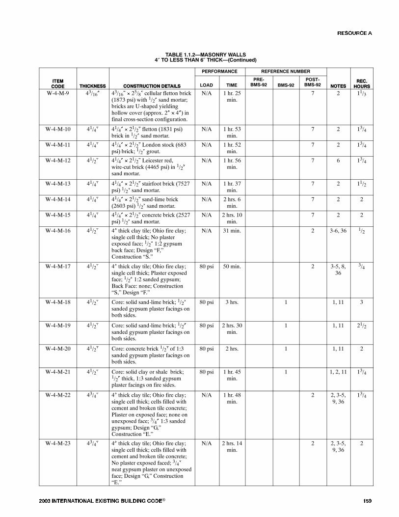
���� ���������� ��� ���� �������� ���® ���
TABLE 1.1.2�MASONRY WALLS4� TO LESS THAN 6� THICK�(Continued)
ITEMCODE
REC.HOURSNOTES
REFERENCE NUMBERPERFORMANCE
CONSTRUCTION DETAILSTHICKNESSITEMCODE
REC.HOURSNOTES
POST-BMS-92BMS-92
PRE-BMS-92TIMELOADCONSTRUCTION DETAILSTHICKNESS
W-4-M-9 43/16� 43/16� � 25/8� cellular fletton brick(1873 psi) with 1/2� sand mortar;bricks are U-shaped yieldinghollow cover (approx. 2� � 4�) infinal cross-section configuration.
N/A 1 hr. 25min.
7 2 11/3
W-4-M-10 41/4� 41/4� � 21/2� fletton (1831 psi)brick in 1/2� sand mortar.
N/A 1 hr. 53min.
7 2 13/4
W-4-M-11 41/4� 41/4� � 21/2� London stock (683psi) brick; 1/2� grout.
N/A 1 hr. 52min.
7 2 13/4
W-4-M-12 41/2� 41/4� � 21/2� Leicester red,wire-cut brick (4465 psi) in 1/2�sand mortar.
N/A 1 hr. 56min.
7 6 13/4
W-4-M-13 41/4� 41/4� � 21/2� stairfoot brick (7527psi) 1/2� sand mortar.
N/A 1 hr. 37min.
7 2 11/2
W-4-M-14 41/4� 41/4� � 21/2� sand-lime brick(2603 psi) 1/2� sand mortar.
N/A 2 hrs. 6min.
7 2 2
W-4-M-15 41/4� 41/4� � 21/2� concrete brick (2527psi) 1/2� sand mortar.
N/A 2 hrs. 10min.
7 2 2
W-4-M-16 41/2� 4� thick clay tile; Ohio fire clay;single cell thick; No plasterexposed face; 1/2� 1:2 gypsumback face; Design �F,�Construction �S.�
N/A 31 min. 2 3-6, 36 1/2
W-4-M-17 41/2� 4� thick clay tile; Ohio fire clay;single cell thick; Plaster exposedface; 1/2� 1:2 sanded gypsum;Back Face: none; Construction�S,� Design �F.�
80 psi 50 min. 2 3-5, 8,36
3/4
W-4-M-18 41/2� Core: solid sand-lime brick; 1/2�sanded gypsum plaster facings onboth sides.
80 psi 3 hrs. 1 1, 11 3
W-4-M-19 41/2� Core: solid sand-lime brick; 1/2�sanded gypsum plaster facings onboth sides.
80 psi 2 hrs. 30min.
1 1, 11 21/2
W-4-M-20 41/2� Core: concrete brick 1/2� of 1:3sanded gypsum plaster facings onboth sides.
80 psi 2 hrs. 1 1, 11 2
W-4-M-21 41/2� Core: solid clay or shale brick;1/2� thick, 1:3 sanded gypsumplaster facings on fire sides.
80 psi 1 hr. 45min.
1 1, 2, 11 13/4
W-4-M-22 43/4� 4� thick clay tile; Ohio fire clay;single cell thick; cells filled withcement and broken tile concrete;Plaster on exposed face; none onunexposed face; 3/4� 1:3 sandedgypsum; Design �G,�Construction �E.�
N/A 1 hr. 48min.
2 2, 3-5,9, 36
13/4
W-4-M-23 43/4� 4� thick clay tile; Ohio fire clay;single cell thick; cells filled withcement and broken tile concrete;No plaster exposed faced; 3/4�neat gypsum plaster on unexposedface; Design �G,� Construction�E.�
N/A 2 hrs. 14min.
2 2, 3-5,9, 36
2
�� ����
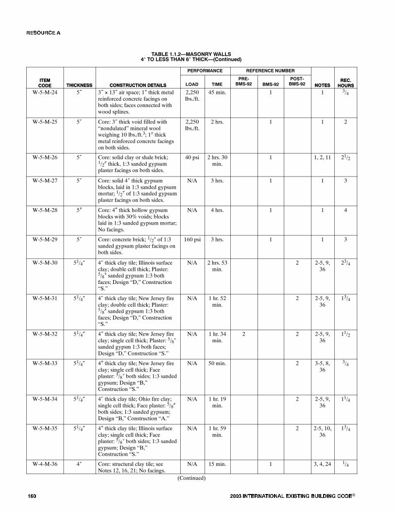
��� ���� ���������� ��� ���� �������� ���®
TABLE 1.1.2�MASONRY WALLS4� TO LESS THAN 6� THICK�(Continued)
ITEMCODE
REC.HOURSNOTES
REFERENCE NUMBERPERFORMANCE
CONSTRUCTION DETAILSTHICKNESSITEMCODE
REC.HOURSNOTES
POST-BMS-92BMS-92
PRE-BMS-92TIMELOADCONSTRUCTION DETAILSTHICKNESS
W-5-M-24 5� 3� � 13� air space; 1� thick metalreinforced concrete facings onboth sides; faces connected withwood splines.
2,250lbs./ft.
45 min. 1 1 3/4
W-5-M-25 5� Core: 3� thick void filled with�nondulated� mineral woolweighing 10 lbs./ft.3; 1� thickmetal reinforced concrete facingson both sides.
2,250lbs./ft.
2 hrs. 1 1 2
W-5-M-26 5� Core: solid clay or shale brick;1/2� thick, 1:3 sanded gypsumplaster facings on both sides.
40 psi 2 hrs. 30min.
1 1, 2, 11 21/2
W-5-M-27 5� Core: solid 4� thick gypsumblocks, laid in 1:3 sanded gypsummortar; 1/2� of 1:3 sanded gypsumplaster facings on both sides.
N/A 3 hrs. 1 1 3
W-5-M-28 5� Core: 4� thick hollow gypsumblocks with 30% voids; blockslaid in 1:3 sanded gypsum mortar;No facings.
N/A 4 hrs. 1 1 4
W-5-M-29 5� Core: concrete brick; 1/2� of 1:3sanded gypsum plaster facings onboth sides.
160 psi 3 hrs. 1 1 3
W-5-M-30 51/4� 4� thick clay tile; Illinois surfaceclay; double cell thick; Plaster:5/8� sanded gypsum 1:3 bothfaces; Design �D,� Construction�S.�
N/A 2 hrs. 53min.
2 2-5, 9,36
23/4
W-5-M-31 51/4� 4� thick clay tile; New Jersey fireclay; double cell thick; Plaster:5/8� sanded gypsum 1:3 bothfaces; Design �D,� Construction�S.�
N/A 1 hr. 52min.
2 2-5, 9,36
13/4
W-5-M-32 51/4� 4� thick clay tile; New Jersey fireclay; single cell thick; Plaster: 5/8�sanded gypsm 1:3 both faces;Design �D,� Construction �S.�
N/A 1 hr. 34min.
2 2 2-5, 9,36
11/2
W-5-M-33 51/4� 4� thick clay tile; New Jersey fireclay; single cell thick; Faceplaster: 5/8� both sides; 1:3 sandedgypsum; Design �B,�Construction �S.�
N/A 50 min. 2 3-5, 8,36
3/4
W-5-M-34 51/4� 4� thick clay tile; Ohio fire clay;single cell thick; Face plaster: 5/8�both sides; 1:3 sanded gypsum;Design �B,� Construction �A.�
N/A 1 hr. 19min.
2 2-5, 9,36
11/4
W-5-M-35 51/4� 4� thick clay tile; Illinois surfaceclay; single cell thick; Faceplaster: 5/8� both sides; 1:3 sandedgypsum; Design �B,�Construction �S.�
N/A 1 hr. 59min.
2 2-5, 10,36
13/4
W-4-M-36 4� Core: structural clay tile; seeNotes 12, 16, 21; No facings.
N/A 15 min. 1 3, 4, 24 1/4
(Continued)
�� ����
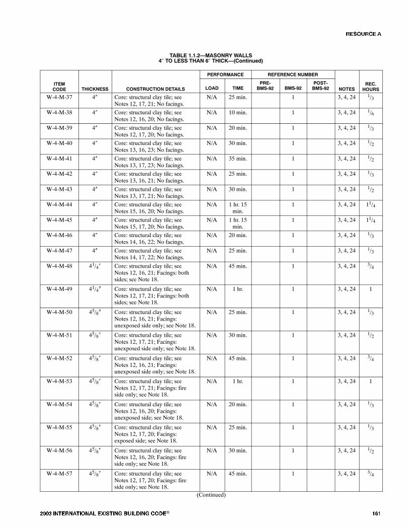
���� ���������� ��� ���� �������� ���® ���
TABLE 1.1.2�MASONRY WALLS4� TO LESS THAN 6� THICK�(Continued)
PERFORMANCE REFERENCE NUMBER
ITEMCODE THICKNESS CONSTRUCTION DETAILS LOAD TIME
PRE-BMS-92 BMS-92
POST-BMS-92 NOTES
REC.HOURS
W-4-M-37 4� Core: structural clay tile; seeNotes 12, 17, 21; No facings.
N/A 25 min. 1 3, 4, 24 1/3
W-4-M-38 4� Core: structural clay tile; seeNotes 12, 16, 20; No facings.
N/A 10 min. 1 3, 4, 24 1/6
W-4-M-39 4� Core: structural clay tile; seeNotes 12, 17, 20; No facings.
N/A 20 min. 1 3, 4, 24 1/3
W-4-M-40 4� Core: structural clay tile; seeNotes 13, 16, 23; No facings.
N/A 30 min. 1 3, 4, 24 1/2
W-4-M-41 4� Core: structural clay tile; seeNotes 13, 17, 23; No facings.
N/A 35 min. 1 3, 4, 24 1/2
W-4-M-42 4� Core: structural clay tile; seeNotes 13, 16, 21; No facings.
N/A 25 min. 1 3, 4, 24 1/3
W-4-M-43 4� Core: structural clay tile; seeNotes 13, 17, 21; No facings.
N/A 30 min. 1 3, 4, 24 1/2
W-4-M-44 4� Core: structural clay tile; seeNotes 15, 16, 20; No facings.
N/A 1 hr. 15min.
1 3, 4, 24 11/4
W-4-M-45 4� Core: structural clay tile; seeNotes 15, 17, 20; No facings.
N/A 1 hr. 15min.
1 3, 4, 24 11/4
W-4-M-46 4� Core: structural clay tile; seeNotes 14, 16, 22; No facings.
N/A 20 min. 1 3, 4, 24 1/3
W-4-M-47 4� Core: structural clay tile; seeNotes 14, 17, 22; No facings.
N/A 25 min. 1 3, 4, 24 1/3
W-4-M-48 41/4� Core: structural clay tile; seeNotes 12, 16, 21; Facings: bothsides; see Note 18.
N/A 45 min. 1 3, 4, 24 3/4
W-4-M-49 41/4� Core: structural clay tile; seeNotes 12, 17, 21; Facings: bothsides; see Note 18.
N/A 1 hr. 1 3, 4, 24 1
W-4-M-50 45/8� Core: structural clay tile; seeNotes 12, 16, 21; Facings:unexposed side only; see Note 18.
N/A 25 min. 1 3, 4, 24 1/3
W-4-M-51 45/8� Core: structural clay tile; seeNotes 12, 17, 21; Facings:unexposed side only; see Note 18.
N/A 30 min. 1 3, 4, 24 1/2
W-4-M-52 45/8� Core: structural clay tile; seeNotes 12, 16, 21; Facings:unexposed side only; see Note 18.
N/A 45 min. 1 3, 4, 24 3/4
W-4-M-53 45/8� Core: structural clay tile; seeNotes 12, 17, 21; Facings: fireside only; see Note 18.
N/A 1 hr. 1 3, 4, 24 1
W-4-M-54 45/8� Core: structural clay tile; seeNotes 12, 16, 20; Facings:unexposed side; see Note 18.
N/A 20 min. 1 3, 4, 24 1/3
W-4-M-55 45/8� Core: structural clay tile; seeNotes 12, 17, 20; Facings:exposed side; see Note 18.
N/A 25 min. 1 3, 4, 24 1/3
W-4-M-56 45/8� Core: structural clay tile; seeNotes 12, 16, 20; Facings: fireside only; see Note 18.
N/A 30 min. 1 3, 4, 24 1/2
W-4-M-57 45/8� Core: structural clay tile; seeNotes 12, 17, 20; Facings: fireside only; see Note 18.
N/A 45 min. 1 3, 4, 24 3/4
(Continued)
�� ����

��� ���� ���������� ��� ���� �������� ���®
TABLE 1.1.2�MASONRY WALLS4� TO LESS THAN 6� THICK�(Continued)
PERFORMANCE REFERENCE NUMBER
ITEMCODE THICKNESS CONSTRUCTION DETAILS LOAD TIME
PRE-BMS-92 BMS-92
POST-BMS-92 NOTES
REC.HOURS
W-4-M-58 45/8� Core: structural clay tile; seeNotes 13, 16, 23; Facings:unexposed side only; see Note 18.
N/A 40 min. 1 3, 4, 24 2/3
W-4-M-59 45/8� Core: structural clay tile; seeNotes 13, 17, 23; Facings:unexposed side only; see Note 18.
N/A 1 hr. 1 3, 4, 24 1
W-4-M-60 45/8� Core: structural clay tile; seeNotes 13, 16, 23; Facings: fireside only; see Note 18.
N/A 1 hr. 15min.
1 3, 4, 24 11/4
W-4-M-61 45/8� Core: structural clay tile; seeNotes 13, 17, 23; Facings: fireside only; see Note 18.
N/A 1 hr. 30min.
1 3, 4, 24 11/2
W-4-M-62 45/8� Core: structural clay tile; seeNotes 13, 16, 21; Facings:unexposed side only; see Note 18.
N/A 35 min. 1 3, 4, 24 1/2
W-4-M-63 45/8� Core: structural clay tile; seeNotes 13, 17, 21; Facings:unexposed face only; see Note 18.
N/A 45 min. 1 3, 4, 24 3/4
W-4-M-64 45/8� Core: structural clay tile; seeNotes 13, 16, 23; Facings:exposed face only; see Note 18.
N/A 1 hr. 1 3, 4, 24 1
W-4-M-65 45/8� Core: structural clay tile; seeNotes 13, 17, 21; Facings:exposed side only; see Note 18.
N/A 1 hr. 15min.
1 3, 4, 24 11/4
W-4-M-66 45/8� Core: structural clay tile; seeNotes 15, 17, 20; Facings:unexposed side only; see Note 18.
N/A 1 hr. 30min.
1 3, 4, 24 11/2
W-4-M-67 45/8� Core: structural clay tile; seeNotes 15, 16, 20; Facings:exposed side only; see Note 18.
N/A 1 hr. 45min.
1 3, 4, 24 13/4
W-4-M-68 45/8� Core: structural clay tile; seeNotes 15, 17, 20; Facings:exposed side only; see Note 18.
N/A 1 hr. 45min.
1 3, 4, 24 13/4
W-4-M-69 45/8� Core: structural clay tile; seeNotes 15, 16, 20; Facings:unexposed side only; see Note 18.
N/A 1 hr. 30min.
1 3, 4, 24 13/4
W-4-M-70 45/8� Core: structural clay tile; seeNotes 14, 16, 22; Facings:unexposed side only; see Note 18.
N/A 30 min. 1 3, 4, 24 1/2
W-4-M-71 45/8� Core: structural clay tile; seeNotes 14, 17, 22; Facings:exposed side only; see Note 18.
N/A 35 min. 1 3, 4, 24 1/2
W-4-M-72 45/8� Core: structural clay tile; seeNotes 14, 16, 22; Facings: fireside of wall only; see Note 18.
N/A 45 min. 1 3, 4, 24 3/4
W-4-M-73 45/8� Core: structural clay tile; seeNotes 14, 17, 22; Facings: fireside of wall only; see Note 18.
N/A 1 hr. 1 3, 4, 24 1
W-5-M-74 51/4� Core: structural clay tile; seeNotes 12, 16, 21; Facings: bothsides; see Note 18.
N/A 1 hr. 1 3, 4, 24 1
(Continued)
�� ����

���� ���������� ��� ���� �������� ���® ���
TABLE 1.1.2�MASONRY WALLS4� TO LESS THAN 6� THICK�(Continued)
PERFORMANCE REFERENCE NUMBER
ITEMCODE THICKNESS CONSTRUCTION DETAILS LOAD TIME
PRE-BMS-92 BMS-92
POST-BMS-92 NOTES
REC.HOURS
W-5-M-75 51/4� Core: structural clay tile; seeNotes 12, 17, 21; Facings: bothsides; see Note 18.
N/A 1 hr. 15min.
1 3, 4, 24 11/4
W-5-M-76 51/4� Core: structural clay tile; seeNotes 12, 16, 20; Facings: bothsides; see Note 18.
N/A 45 min. 1 3, 4, 24 3/4
W-5-M-77 51/4� Core: structural clay tile; seeNotes 12, 17, 20; Facings: bothsides; see Note 18.
N/A 1 hr. 1 3, 4, 24 1
W-5-M-78 51/4� Core: structural clay tile; seeNotes 13, 16, 23; Facings: bothsides of wall; see Note 18.
N/A 1 hr. 30min.
1 3, 4, 24 11/2
W-5-M-79 51/4� Core: structural clay tile; seeNotes 13, 17, 23; Facings: bothsides of wall; see Note 18.
N/A 2 hrs. 1 3, 4, 24 2
W-5-M-80 51/4� Core: structural clay tile; seeNotes 13, 16, 21; Facings: bothsides of wall; see Note 18.
N/A 1 hr. 15min.
1 3, 4, 24 11/4
W-5-M-81 51/4� Core: structural clay tile; seeNotes 13, 16, 21; Facings: bothsides of wall; see Note 18.
N/A 1 hr. 30min.
1 3, 4, 24 11/2
W-5-M-82 51/4� Core: structural clay tile; seeNotes 15, 16, 20; Facings: bothsides; see Note 18.
N/A 2 hrs. 30min.
1 3, 4, 24 21/2
W-5-M-83 51/4� Core: structural clay tile; seeNotes 15, 17, 20; Facings: bothsides; see Note 18.
N/A 2 hrs. 30min.
1 3, 4, 24 21/2
W-5-M-84 51/4� Core: structural clay tile; seeNotes 14, 16, 22; Facings: bothsides of wall; see Note 18.
N/A 1 hr. 15min.
1 3, 4, 24 11/4
W-5-M-85 51/4� Core: structural clay tile; seeNotes 14, 17, 22; Facings: bothsides of wall; see Note 18.
N/A 1 hr. 30min.
1 3, 4, 24 11/2
W-4-M-86 4� Core: 3� thick gypsum blocks70% solid; see Note 26; Facings:both sides; see Note 25.
N/A 2 hrs. 1 2
W-4-M-87 4� Core: hollow concrete units; seeNotes 27, 34, 35; No facings.
N/A 1 hr. 30min.
1 11/2
W-4-M-88 4� Core: hollow concrete units; seeNotes 28, 33, 35; No facings.
N/A 1 hr. 1 1
W-4-M-89 4� Core: hollow concrete units; seeNotes 28, 34, 35; Facings: bothsides; see Note 25.
N/A 1 hr. 45min.
1 13/4
W-4-M-90 4� Core: hollow concrete units; seeNotes 27, 34, 35; Facings: bothsides; see Note 25.
N/A 2 hrs. 1 2
W-4-M-91 4� Core: hollow concrete units; seeNotes 27, 32, 35; No facings.
N/A 1 hr. 15min.
1 11/4
W-4-M-92 4� Core: hollow concrete units; seeNotes 28, 34, 35; No facings.
N/A 1 hr. 15min.
1 11/4
W-4-M-93 4� Core: hollow concrete units; seeNotes 29, 32, 35; No facings.
N/A 20 min. 1 1/3
(Continued)
�� ����
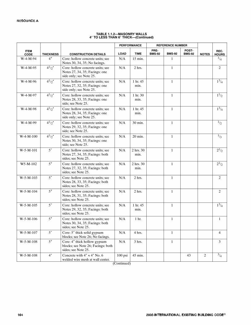
��� ���� ���������� ��� ���� �������� ���®
TABLE 1.1.2�MASONRY WALLS4� TO LESS THAN 6� THICK�(Continued)
PERFORMANCE REFERENCE NUMBER
ITEMCODE THICKNESS CONSTRUCTION DETAILS LOAD TIME
PRE-BMS-92 BMS-92
POST-BMS-92 NOTES
REC.HOURS
W-4-M-94 4� Core: hollow concrete units; seeNotes 30, 34, 35; No facings.
N/A 15 min. 1 1/4
W-4-M-95 41/2� Core: hollow concrete units; seeNotes 27, 34, 35; Facings: oneside only; see Note 25.
N/A 2 hrs. 1 2
W-4-M-96 41/2� Core: hollow concrete units; seeNotes 27, 32, 35; Facings: oneside only; see Note 25.
N/A 1 hr. 45min.
1 13/4
W-4-M-97 41/2� Core: hollow concrete units; seeNotes 28, 33, 35; Facings: oneside; see Note 25.
N/A 1 hr. 30min.
1 11/2
W-4-M-98 41/2� Core: hollow concrete units; seeNotes 28, 34, 35; Facings: oneside only; see Note 25.
N/A 1 hr. 45min.
1 13/4
W-4-M-99 41/2� Core: hollow concrete units; seeNotes 29, 32, 35; Facings: oneside; see Note 25.
N/A 30 min. 1 1/2
W-4-M-100 41/2� Core: hollow concrete units; seeNotes 30, 34, 35; Facings: oneside; see Note 25.
N/A 20 min. 1 1/3
W-5-M-101 5� Core: hollow concrete units; seeNotes 27, 34, 35; Facings: bothsides; see Note 25.
N/A 2 hrs. 30min.
1 21/2
W5-M-102 5� Core: hollow concrete units; seeNotes 27, 32, 35; Facings: bothsides; see Note 25.
N/A 2 hrs. 30min.
1 21/2
W-5-M-103 5� Core: hollow concrete units; seeNotes 28, 33, 35; Facings: bothsides; see Note 25.
N/A 2 hrs. 1 2
W-5-M-104 5� Core: hollow concrete units; seeNotes 28, 31, 35; Facings: bothsides; see Note 25.
N/A 2 hrs. 1 2
W-5-M-105 5� Core: hollow concrete units; seeNotes 29, 32, 35; Facings: bothsides; see Note 25.
N/A 1 hr. 45min.
1 13/4
W-5-M-106 5� Core: hollow concrete units; seeNotes 30, 34, 35; Facings: bothsides; see Note 25.
N/A 1 hr. 1 1
W-5-M-107 5� Core: 5� thick solid gypsumblocks; see Note 26; No facings.
N/A 4 hrs. 1 4
W-5-M-108 5� Core: 4� thick hollow gypsumblocks; see Note 26; Facings: bothsides; see Note 25.
N/A 3 hrs. 1 3
W-5-M-108 4� Concrete with 4� � 4� No. 6welded wire mesh at wall center.
100 psi 45 min. 43 2 3/4
(Continued)
�� ����

���� ���������� ��� ���� �������� ���® ���
TABLE 1.1.2�MASONRY WALLS4� TO LESS THAN 6� THICK�(Continued)
PERFORMANCE REFERENCE NUMBER
ITEMCODE THICKNESS CONSTRUCTION DETAILS LOAD TIME
PRE-BMS-92 BMS-92
POST-BMS-92 NOTES
REC.HOURS
W-5-M-110 4� Concrete with 4� � 4� No. 6welded wire mesh at wall center.
N/A 1 hr. 15min.
43 2 11/4
Notes:1. Tested as NBS under ASA Spec. No. A 2-1934.2. Failure mode - maximum temperature rise.3. Treated at NBS under ASA Spec. No. 42-1934 (ASTMC 19-53) except that hose stream testing where carried out was run on test specimens exposed for fulltest duration, not for or reduced period as is contemporarily done.
4. For clay tile walls, unless the source the clay can be positively identified, it is suggested that the most pessimistic hour rating for the fire endurance of a claytile partition of that thickness to be followed. Identified sources of clay showing longer fire endurance can lead to longer time recommendations.
5. See appendix for construction and design details for clay tile walls.6. Failure mode - flame thru or crack formation showing flames.7. Hole formed at 25 minutes; partition collapsed at 42 minutes or removal from furnace.8. Failure mode - collapse.9. Hose stream pass.10. Hose stream hole formed in specimen.11. Load: 80 psi for gross wall cross sectional area.12. One cell in wall thickness.13. Two cells in wall thickness.14. Double cells plus one cell in wall thickness.15. One cell in wall thickness, cells filled with broken tile, crushed stone, slag, cinders or sand mixed with mortar.16. Dense hard-burned clay or shale tile.17. Medium-burned clay tile.18. Not less than 5/8 inch thickness of 1:3 sanded gypsum plaster.19. Units of not less than 30 percent solid material.20. Units of not less than 40 percent solid material.21. Units of not less than 50 percent solid material.22. Units of not less than 45 percent solid material.23. Units of not less than 60 percent solid material.24. All tiles laid in portland cement-lime mortar.25. Minimum 1/2 inch - 1:3 sanded gypsum plaster.26. Laid in 1:3 sanded gypsum mortar. Voids in hollow units not to exceed 30 percent.27. Units of expanded slag or pumice aggregate.28. Units of crushed limestone, blast furnace slag, cinders and expanded clay or shale.29. Units of calcareous sand and gravel. Coarse aggregate, 60 percent or more calcite and dolomite.30. Units of siliceous sand and gravel. Ninety percent or more quartz, chert or flint.31. Unit at least 49 percent solid.32. Unit at least 62 percent solid.33. Unit at least 65 percent solid.34. Unit at least 73 percent solid.35. Ratings based on one unit and one cell in wall thickness.36. See Clay Tile Partition Design Construction drawings, below.
(Continued)
�� ����
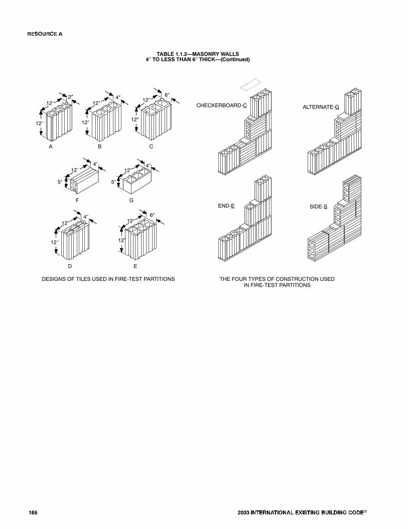
��� ���� ���������� ��� ���� �������� ���®
TABLE 1.1.2�MASONRY WALLS4� TO LESS THAN 6� THICK�(Continued)
6�
12�
5�
12�
12� 12�12�
12�
12� 12� 12�
12�
12� 12�
4�4�
A B C
D E
F G
4�
6�4�2�
DESIGNS OF TILES USED IN FIRE-TEST PARTITIONS THE FOUR TYPES OF CONSTRUCTION USEDIN FIRE-TEST PARTITIONS
CHECKERBOARD-C ALTERNATE-G
END-E SIDE-S
5�
�� ����

���� ���������� ��� ���� �������� ���® ���
FIGURE 1.1.3�WALLS�MASONRY6� TO LESS THAN 8� THICK
9
10
12
13
22
23
27
28
24
30
31
0
FIRE RESISTANCE RATING (HOURS)
NUMBER OFASSEMBLIES
1 2 3 4
5
10
02
21
3 14
29
4
39
11
The number in each box iskeyed to the last number in theItem Code column in the Table.
For example:
W-6-M-63
59 8
15
16
32
40
42
5 7
44
8a
43
5 6
47
1
38
60
37
20
56
63
45
46
61
1917
51
57
33
34
35
186
36
25
26
41
48
49
53
50
34
58
65
55
62
64
52
66
TABLE 1.1.3�MASONRY WALLS6� TO LESS THAN 8� THICK
PERFORMANCE REFERENCE NUMBER
ITEMCODE THICKNESS CONSTRUCTION DETAILS LOAD TIME
PRE-BMS-92 BMS-92
POST-BMS-92 NOTES
REC.HOURS
W-6-M-1 6� Core: 5� thick, solid gypsumblocks laid in 1:3 sanded gypsummortar; 1/2� of 1:3 sanded gypsumplaster facings on both sides.
N/A 6 hrs. 1 6
W-6-M-2 6� 6� clay tile; Ohio fire clay; singlecell thick; No plaster; Design �C,�Construction �A.�
N/A 17 min. 2 1, 3, 4,6, 55
1/4
W-6-M-3 6� 6� clay tile; Illinois surface clay;double cell thick; No plaster;Design �E,� Construction �C.�
N/A 45 min. 2 1-4, 7,55
3/4
W-6-M-4 6� 6� clay tile; New Jersey fire clay;double cell thick; No plaster;Design �E,� Construction �S.�
N/A 1 hr. 1min.
2 1-4, 8,55
1
W-7-M-5 71/4� 6� clay tile; Illinois surface clay;double cell thick; Plaster: 5/8� -1:3 sanded gypsum both faces;Design �E,� Construction �A.�
N/A 1 hr. 41min.
2 1-4, 55 12/3
W-7-M-6 71/4� 6� clay tile; New Jersey fire clay;double cell thick; Plaster: 5/8� -1:3 sanded gypsum both faces;Design �E,� Construction �S.�
N/A 2 hrs. 23min.
2 1-4, 9,55
21/3
W-7-M-7 71/4� 6� clay tile; Ohio fire clay; singlecell thick; Plaster: 5/8� sandedgypsum; 1:3 both faces; Design�C,� Construction �A.�
N/A 1 hr. 54min.
2 1-4, 9,55
23/4
(Continued)
�� ����
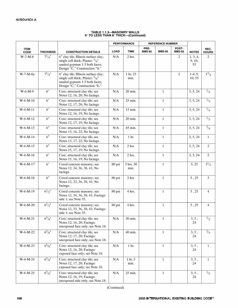
��� ���� ���������� ��� ���� �������� ���®
TABLE 1.1.3�MASONRY WALLS6� TO LESS THAN 8� THICK�(Continued)
PERFORMANCE REFERENCE NUMBER
ITEMCODE THICKNESS CONSTRUCTION DETAILS LOAD TIME
PRE-BMS-92 BMS-92
POST-BMS-92 NOTES
REC.HOURS
W-7-M-8 71/4� 6� clay tile; Illinois surface clay;single cell thick; Plaster: 5/8�sanded gypsum 1:3 both faces;Design �C,� Construction �S.�
N/A 2 hrs. 2 1, 3, 4,9, 10,55
2
W-7-M-8a 71/4� 6� clay tile; Illinois surface clay;single cell thick; Plaster: 5/8�sanded gypsum 1:3 both faces;Design �C,� Construction �E.�
N/A 1 hr. 23min.
2 1-4, 9,10, 55
13/4
W-6-M-9 6� Core: structural clay tile; seeNotes 12, 16, 20; No facings.
N/A 20 min. 1 3, 5, 24 1/3
W-6-M-10 6� Core: structural clay tile; seeNotes 12, 17, 20; No facings.
N/A 25 min. 1 3, 5, 24 1/3
W-6-M-11 6� Core: structural clay tile; seeNotes 12, 16, 19; No facings.
N/A 15 min. 1 3, 5, 24 1/4
W-6-M-12 6� Core: structural clay tile; seeNotes 12, 17, 19; No facings.
N/A 20 min. 1 3, 5, 24 1/3
W-6-M-13 6� Core: structural clay tile; seeNotes 13, 16, 22; No facings.
N/A 45 min. 1 3, 5, 24 3/4
W-6-M-14 6� Core: structural clay tile; seeNotes 13, 17, 22; No facings.
N/A 1 hr. 1 3, 5, 24 1
W-6-M-15 6� Core: structural clay tile; seeNotes 15, 17, 19; No facings.
N/A 2 hrs. 1 3, 5, 24 2
W-6-M-16 6� Core: structural clay tile; seeNotes 15, 16, 19; No facings.
N/A 2 hrs. 1 3, 5, 24 2
W-6-M-17 6� Cored concrete masonry; seeNotes 12, 34, 36, 38, 41; Nofacings.
80 psi 3 hrs. 30min.
1 5, 25 31/2
W-6-M-18 6� Cored concrete masonry; seeNotes 12, 33, 36, 38, 41; Nofacings.
80 psi 3 hrs. 1 5 , 25 3
W-6-M-19 61/2� Cored concrete masonry; seeNotes 12, 34, 36, 38, 41; Facings:side 1; see Note 35.
80 psi 4 hrs. 1 5 , 25 4
W-6-M-20 61/2� Cored concrete masonry; seeNotes 12, 33, 36, 38, 41; Facings:side 1; see Note 35.
80 psi 4 hrs. 1 5 , 25 4
W-6-M-21 65/8� Core: structural clay tile; seeNotes 12, 16, 20; Facings:unexposed face only; see Note 18.
N/A 30 min. 1 3, 5 ,24
1/2
W-6-M-22 65/8� Core: structural clay tile; seeNotes 12, 17, 20; Facings:unexposed face only; see Note 18.
N/A 40 min. 1 3, 5 ,24
2/3
W-6-M-23 65/8� Core: structural clay tile; seeNotes 12, 16, 20; Facings:exposed face only; see Note 18.
N/A 1 hr. 1 3, 5 ,24
1
W-6-M-24 65/8� Core: structural clay tile; seeNotes 12, 17, 20; Facings:exposed face only; see Note 18.
N/A 1 hr. 5min.
1 3, 5 ,24
1
W-6-M-25 65/8� Core: structural clay tile; seeNotes 12, 16, 19; Facings:unexposed side only; see Note 18.
N/A 25 min. 1 3, 5 ,24
1/3
(Continued)
�� ����

���� ���������� ��� ���� �������� ���® ���
TABLE 1.1.3�MASONRY WALLS6� TO LESS THAN 8� THICK�(Continued)
PERFORMANCE REFERENCE NUMBER
ITEMCODE THICKNESS CONSTRUCTION DETAILS LOAD TIME
PRE-BMS-92 BMS-92
POST-BMS-92 NOTES
REC.HOURS
W-6-M-26 65/8� Core: structural clay tile; seeNotes 12, 7, 19; Facings:unexposed face only; see Note 18.
N/A 30 min. 1 3, 5 ,24
1/2
W-6-M-27 65/8� Core: structural clay tile; seeNotes 12, 16, 19; Facings:exposed side only; see Note 18.
N/A 1 hr. 1 3, 5 ,24
1
W-6-M-28 65/8� Core: structural clay tile; seeNotes 12, 17, 19; Facings: fireside only; see Note 18.
N/A 1 hr. 1 3, 5 ,24
1
W-6-M-29 65/8� Core: structural clay tile; seeNotes 13, 16, 22; Facings:unexposed side only; see Note 18.
N/A 1 hr. 1 3, 5 ,24
1
W-6-M-30 65/8� Core: structural clay tile; seeNotes 13, 17, 22; Facings:unexposed side only; see Note 18.
N/A 1 hr. 15min.
1 3, 5 ,24
11/4
W-6-M-31 65/8� Core: structural clay tile; seeNotes 13, 16, 22; Facings: fireside only; see Note 18.
N/A 1 hr. 15min.
1 3, 5 ,24
11/4
W-6-M-32 65/8� Core: structural clay tile; seeNotes 13, 17, 22; Facings: fireside only; see Note 18.
N/A 1 hr. 30min.
1 3, 5 ,24
11/2
W-6-M-33 65/8� Core: structural clay tile; seeNotes 15, 16, 19; Facings:unexposed side only; see Note 18.
N/A 2 hrs. 30min.
1 3, 5 ,24
21/2
W-6-M-34 65/8� Core: structural clay tile; seeNotes 15, 17, 19; Facings:unexposed side only; see Note 18.
N/A 2 hrs. 30min.
1 3, 5 ,24
21/2
W-6-M-35 65/8� Core: structural clay tile; seeNotes 15, 16, 19; Facings: fireside only; see Note 18.
N/A 2 hrs. 30min.
1 3, 5 ,24
21/2
W-6-M-36 65/8� Core: structural clay tile; seeNotes 15, 17, 19; Facings: fireside only; see Note 18.
N/A 2 hrs. 30min.
1 3, 5, 24 21/2
W-7-M-37 7� Cored concrete masonry; seeNotes 12, 34, 36, 38, 41; see Note35 for facings on both sides.
80 psi 5 hrs. 1 5, 25 5
W-7-M-38 7� Cored concrete masonry; seeNotes 12, 33, 36, 38, 41; see Note35 for facings.
80 psi 5 hrs. 1 5, 25 5
W-7-M-39 71/4� Core: structural clay tile; seeNotes 12, 16, 20; Facings: bothsides; see Note 18.
N/A 1 hr. 15min.
1 3, 5, 24 11/4
W-7-M-40 71/4� Core: structural clay tile; seeNotes 12, 17, 20; Facings: bothsides; see Note 18.
N/A 1 hr. 30min.
1 3, 5, 24 11/2
W-7-M-41 71/4� Core: structural clay tile; seeNotes 12, 16, 19; Facings: bothsides; see Note 18.
N/A 1 hr. 15min.
1 3, 5, 24 11/4
W-7-M-42 71/4� Core: structural clay tile; seeNotes 12, 17, 19; Facings: bothsides; see Note 18.
N/A 1 hr. 30min.
1 3, 5, 24 11/2
(Continued)
�� ����

��� ���� ���������� ��� ���� �������� ���®
TABLE 1.1.3�MASONRY WALLS6� TO LESS THAN 8� THICK�(Continued)
PERFORMANCE REFERENCE NUMBER
ITEMCODE THICKNESS CONSTRUCTION DETAILS LOAD TIME
PRE-BMS-92 BMS-92
POST-BMS-92 NOTES
REC.HOURS
W-7-M-43 71/4� Core: structural clay tile; seeNotes 13, 16, 22; Facings: bothsides of wall; see Note 18.
N/A 1 hr. 30min.
1 3, 5, 24 11/2
W-7-M-44 71/4� Core: structural clay tile; seeNotes 13, 17, 22; Facings: bothsides of wall; see Note 18.
N/A 2 hrs. 1 3, 5, 24 11/2
W-7-M-45 71/4� Core: structural clay tile; seeNotes 15, 16, 19; Facings: bothsides; see Note 18.
N/A 3 hrs. 30min.
1 3, 5, 24 31/2
W-7-M-46 71/4� Core: structural clay tile; seeNotes 15, 17, 19; Facings: bothsides; see Note 18.
N/A 3 hrs. 30min.
1 3, 5, 24 31/2
W-6-M-47 6� Core: 5� thick solid gypsumblocks; see Note 45; Facings: bothsides; see Note 45.
N/A 6 hrs. 1 6
W-6-M-48 6� Core: hollow concrete units; seeNotes 47, 50, 54; No facings.
N/A 1 hr. 15min.
1 11/4
W-6-M-49 6� Core: hollow concrete units; seeNotes 46, 50, 54; No facings.
N/A 1 hr. 30min.
1 11/2
W-6-M-50 6� Core: hollow concrete units; seeNotes 46, 41, 54; No facings.
N/A 2 hrs. 1 2
W-6-M-51 6� Core: hollow concrete units; seeNotes 46, 53, 54; No facings.
N/A 3 hrs. 1 3
W-6-M-52 6� Core: hollow concrete units; seeNotes 47, 53, 54; No facings.
N/A 2 hrs. 30min.
1 21/2
W-6-M-53 6� Core: hollow concrete units; seeNotes 47, 51, 54; No facings.
N/A 1 hr. 30min.
1 11/2
W-6-M-54 61/2� Core: hollow concrete units; seeNotes 46, 50, 54; Facings: oneside only; see Note 35.
N/A 2 hrs. 1 2
W-6-M-55 61/2� Core: hollow concrete units; seeNotes 4, 51, 54; Facings: one side;see Note 35.
N/A 2 hrs. 30min.
1 21/2
W-6-M-56 61/2� Core: hollow concrete units; seeNotes 46, 53, 54; Facings: oneside; see Note 35.
N/A 4 hrs. 1 4
W-6-M-57 61/2� Core: hollow concrete units; seeNotes 47, 53, 54; Facings: oneside; see Note 35.
N/A 3 hrs. 1 3
W-6-M-58 61/2� Core: hollow concrete units; seeNotes 47, 51, 54; Facings: oneside; see Note 35.
N/A 2 hrs. 1 2
W-6-M-59 61/2� Core: hollow concrete units; seeNotes 47, 50, 54; Facings: oneside; see Note 35.
N/A 1 hr. 45min.
1 13/4
W-7-M-60 7� Core: hollow concrete units; seeNotes 46, 53, 54; Facings: bothsides; see Note 35.
N/A 5 hrs. 1 5
W-7-M-61 7� Core: hollow concrete units; seeNotes 46, 51, 54; Facings: bothsides; see Note 35.
N/A 3 hrs. 30min.
1 31/2
(Continued)
�� ����
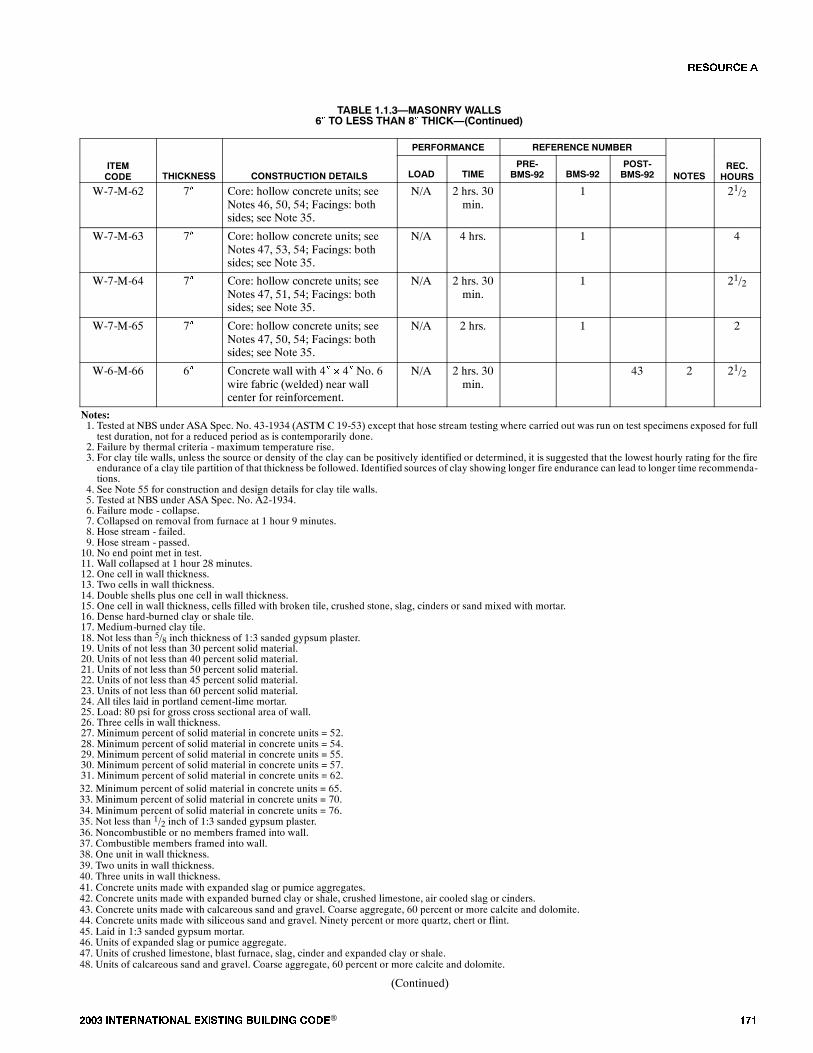
���� ���������� ��� ���� �������� ���® ���
TABLE 1.1.3�MASONRY WALLS6� TO LESS THAN 8� THICK�(Continued)
PERFORMANCE REFERENCE NUMBER
ITEMCODE THICKNESS CONSTRUCTION DETAILS LOAD TIME
PRE-BMS-92 BMS-92
POST-BMS-92 NOTES
REC.HOURS
W-7-M-62 7� Core: hollow concrete units; seeNotes 46, 50, 54; Facings: bothsides; see Note 35.
N/A 2 hrs. 30min.
1 21/2
W-7-M-63 7� Core: hollow concrete units; seeNotes 47, 53, 54; Facings: bothsides; see Note 35.
N/A 4 hrs. 1 4
W-7-M-64 7� Core: hollow concrete units; seeNotes 47, 51, 54; Facings: bothsides; see Note 35.
N/A 2 hrs. 30min.
1 21/2
W-7-M-65 7� Core: hollow concrete units; seeNotes 47, 50, 54; Facings: bothsides; see Note 35.
N/A 2 hrs. 1 2
W-6-M-66 6� Concrete wall with 4� � 4� No. 6wire fabric (welded) near wallcenter for reinforcement.
N/A 2 hrs. 30min.
43 2 21/2
Notes:1. Tested at NBS under ASA Spec. No. 43-1934 (ASTM C 19-53) except that hose stream testing where carried out was run on test specimens exposed for fulltest duration, not for a reduced period as is contemporarily done.
2. Failure by thermal criteria - maximum temperature rise.3. For clay tile walls, unless the source or density of the clay can be positively identified or determined, it is suggested that the lowest hourly rating for the fireendurance of a clay tile partition of that thickness be followed. Identified sources of clay showing longer fire endurance can lead to longer time recommenda-tions.
4. See Note 55 for construction and design details for clay tile walls.5. Tested at NBS under ASA Spec. No. A2-1934.6. Failure mode - collapse.7. Collapsed on removal from furnace at 1 hour 9 minutes.8. Hose stream - failed.9. Hose stream - passed.10. No end point met in test.11. Wall collapsed at 1 hour 28 minutes.12. One cell in wall thickness.13. Two cells in wall thickness.14. Double shells plus one cell in wall thickness.15. One cell in wall thickness, cells filled with broken tile, crushed stone, slag, cinders or sand mixed with mortar.16. Dense hard-burned clay or shale tile.17. Medium-burned clay tile.18. Not less than 5/8 inch thickness of 1:3 sanded gypsum plaster.19. Units of not less than 30 percent solid material.20. Units of not less than 40 percent solid material.21. Units of not less than 50 percent solid material.22. Units of not less than 45 percent solid material.23. Units of not less than 60 percent solid material.24. All tiles laid in portland cement-lime mortar.25. Load: 80 psi for gross cross sectional area of wall.26. Three cells in wall thickness.27. Minimum percent of solid material in concrete units = 52.28. Minimum percent of solid material in concrete units = 54.29. Minimum percent of solid material in concrete units = 55.30. Minimum percent of solid material in concrete units = 57.31. Minimum percent of solid material in concrete units = 62.32. Minimum percent of solid material in concrete units = 65.33. Minimum percent of solid material in concrete units = 70.34. Minimum percent of solid material in concrete units = 76.35. Not less than 1/2 inch of 1:3 sanded gypsum plaster.36. Noncombustible or no members framed into wall.37. Combustible members framed into wall.38. One unit in wall thickness.39. Two units in wall thickness.40. Three units in wall thickness.41. Concrete units made with expanded slag or pumice aggregates.42. Concrete units made with expanded burned clay or shale, crushed limestone, air cooled slag or cinders.43. Concrete units made with calcareous sand and gravel. Coarse aggregate, 60 percent or more calcite and dolomite.44. Concrete units made with siliceous sand and gravel. Ninety percent or more quartz, chert or flint.45. Laid in 1:3 sanded gypsum mortar.46. Units of expanded slag or pumice aggregate.47. Units of crushed limestone, blast furnace, slag, cinder and expanded clay or shale.48. Units of calcareous sand and gravel. Coarse aggregate, 60 percent or more calcite and dolomite.
(Continued)
�� ����
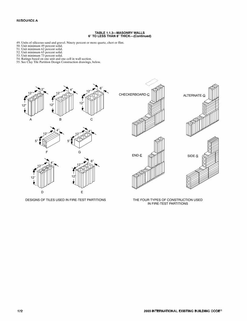
��� ���� ���������� ��� ���� �������� ���®
TABLE 1.1.3�MASONRY WALLS6� TO LESS THAN 8� THICK�(Continued)
49. Units of siliceous sand and gravel. Ninety percent or more quartz, chert or flint.50. Unit minimum 49 percent solid.51. Unit minimum 62 percent solid.52. Unit minimum 65 percent solid.53. Unit minimum 73 percent solid.54. Ratings based on one unit and one cell in wall section.55. See Clay Tile Partition Design Construction drawings, below.
6�
12�
5�
12�
12� 12�12�
12�
12� 12� 12�
12�
12� 12�
4�4�
A B C
D E
F G
4�
6�4�2�
DESIGNS OF TILES USED IN FIRE-TEST PARTITIONS THE FOUR TYPES OF CONSTRUCTION USEDIN FIRE-TEST PARTITIONS
CHECKERBOARD-C ALTERNATE-G
END-E SIDE-S
5�
�� ����
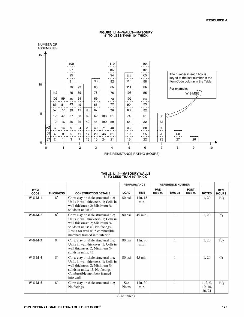
���� ���������� ��� ���� �������� ���® ���
FIGURE 1.1.4�WALLS�MASONRY8� TO LESS THAN 10� THICK
8
14
16
4
6
10
0
FIRE RESISTANCE RATING (HOURS)
NUMBER OFASSEMBLIES
1 2 3 4 5
5
10
15
01
47
2
12
The number in each box iskeyed to the last number in theItem Code column in the Table.
For example:
W-9-M-66
6 7 8 9 10
11
34
36
5
9
35
7
38
3
37
29
40
44
17
20
42
15
62
13
82
31
48
50
46
71
100
21
61
24
108
19
33
64
18
74
25
30
32
22
51
28
59
63
23
66
60
27 2687
53
54
55
52
56
65
101
104
58
86
90
105
106
113
114
111
72
73
76
70
85
94
107
110
92
67
68
69
78
96
80
9841
49
84
89
93
43
45
75
39
79
95
97
109
91
77
81
99
57
83
102
112
88
���
TABLE 1.1.4�MASONRY WALLS8� TO LESS THAN 10� THICK
PERFORMANCE REFERENCE NUMBER
ITEMCODE THICKNESS CONSTRUCTION DETAILS LOAD TIME
PRE-BMS-92 BMS-92
POST-BMS-92 NOTES
REC.HOURS
W-8-M-1 8� Core: clay or shale structural tile;Units in wall thickness: 1; Cells inwall thickness: 2; Minimum %solids in units: 40.
80 psi 1 hr. 15min.
1 1, 20 11/4
W-8-M-2 8� Core: clay or shale structural tile;Units in wall thickness: 1; Cells inwall thickness: 2; Minimum %solids in units: 40; No facings;Result for wall with combustiblemembers framed into interior.
80 psi 45 min. 1 1, 20 3/4
W-8-M-3 8� Core: clay or shale structural tile;Units in wall thickness: 1; Cells inwall thickness: 2; Minimum %solids in units: 43.
80 psi 1 hr. 30min.
1 1, 20 11/2
W-8-M-4 8� Core: clay or shale structural tile;Units in wall thickness: 1; Cells inwall thickness: 2; Minimum %solids in units: 43; No facings;Combustible members framedinto wall.
80 psi 45 min. 1 1, 20 3/4
W-8-M-5 8� Core: clay or shale structural tile;No facings.
SeeNotes
1 hr. 30min.
1 1, 2, 5,10, 18,20, 21
11/2
(Continued)
�� ����

��� ���� ���������� ��� ���� �������� ���®
TABLE 1.1.4�MASONRY WALLS8� TO LESS THAN 10� THICK�(Continued)
PERFORMANCE REFERENCE NUMBER
ITEMCODE THICKNESS CONSTRUCTION DETAILS LOAD TIME
PRE-BMS-92 BMS-92
POST-BMS-92 NOTES
REC.HOURS
W-8-M-6 8� Core: clay or shale structural tile;No facings.
SeeNotes
45 min. 1 1, 2, 5,10, 19,20, 21
3/4
W-8-M-7 8� Core: clay or shale structural tile;No facings.
SeeNotes
2 hrs. 1 1, 2, 5,13, 18,20, 21
2
W-8-M-8 8� Core: clay or shale structural tile;No facings.
SeeNotes
1 hr. 45min.
1 1, 2, 5,13, 19,20, 21
11/4
W-8-M-9 8� Core: clay or shale structural tile;No facings.
SeeNotes
1 hr. 15min.
1 1, 2, 6,9, 18,20, 21
13/4
W-8-M-10 8� Core: clay or shale structural tile;No facings.
SeeNotes
45 min. 1 1, 2, 6,9, 19,20, 21
3/4
W-8-M-11 8� Core: clay or shale structural tile;No facings.
SeeNotes
2 hrs. 1 1, 2, 6,10, 18,20, 21
2
W-8-M-12 8� Core: clay or shale structural tile;No facings.
SeeNotes
45 min. 1 1, 2, 6,10, 19,20, 21
3/4
W-8-M-13 8� Core: clay or shale structural tile;No facings.
SeeNotes
2 hrs. 30min.
1 1, 3, 6,12, 18,20, 21
21/2
W-8-M-14 8� Core: clay or shale structural tile;No facings.
SeeNotes
1 hr. 1 1, 2, 6,12, 19,20, 21
1
W-8-M-15 8� Core: clay or shale structural tile;No facings.
SeeNotes
3 hrs. 1 1, 2, 6,16, 18,20, 21
3
W-8-M-16 8� Core: clay or shale structural tile;No facings.
SeeNotes
1 hr. 15min.
1 1, 2, 6,16, 19,20, 21
11/4
W-8-M-17 8� Cored clay or shale brick; Units inwall thickness: 1; Cells in wallthickness: 1; Minimum % solids:70; No facings.
SeeNotes
2 hrs. 30min.
1 1, 44 21/2
W-8-M-18 8� Cored clay or shale brick; Unitsin wall thickness: 2; Cells in wallthickness: 2; Minimum % solids:87; No facings.
SeeNotes
5 hrs. 1 1, 45 5
W-8-M-19 8� Core: solid clay or shale brick; Nofacings.
SeeNotes
5 hrs. 1 1, 22,45
5
W-8-M-20 8� Core: hollow rolok of clay orshale.
SeeNotes
2 hrs. 30min.
1 1, 22,45
21/2
W-8-M-21 8� Core: hollow rolok bak of clay orshale; No facings.
SeeNotes
4 hrs. 1 1, 45 4
W-8-M-22 8� Core: concrete brick; No facings. SeeNotes
6 hrs. 1 1, 45 6
W-8-M-23 8� Core: sand-lime brick; No facings. SeeNotes
7 hrs. 1 1, 45 7
(Continued)
�� ����
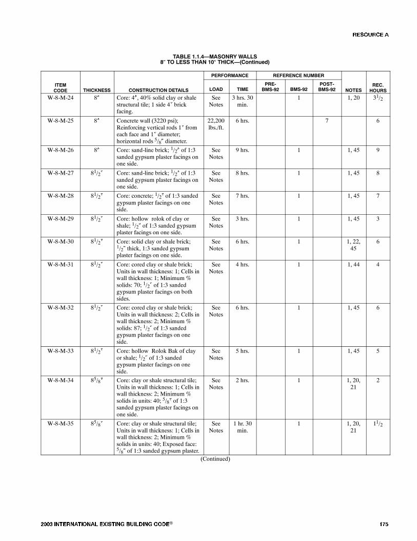
���� ���������� ��� ���� �������� ���® ���
TABLE 1.1.4�MASONRY WALLS8� TO LESS THAN 10� THICK�(Continued)
PERFORMANCE REFERENCE NUMBER
ITEMCODE THICKNESS CONSTRUCTION DETAILS LOAD TIME
PRE-BMS-92 BMS-92
POST-BMS-92 NOTES
REC.HOURS
W-8-M-24 8� Core: 4�, 40% solid clay or shalestructural tile; 1 side 4� brickfacing.
SeeNotes
3 hrs. 30min.
1 1, 20 31/2
W-8-M-25 8� Concrete wall (3220 psi);Reinforcing vertical rods 1� fromeach face and 1� diameter;horizontal rods 5/8� diameter.
22,200lbs./ft.
6 hrs. 7 6
W-8-M-26 8� Core: sand-line brick; 1/2� of 1:3sanded gypsum plaster facings onone side.
SeeNotes
9 hrs. 1 1, 45 9
W-8-M-27 81/2� Core: sand-line brick; 1/2� of 1:3sanded gypsum plaster facings onone side.
SeeNotes
8 hrs. 1 1, 45 8
W-8-M-28 81/2� Core: concrete; 1/2� of 1:3 sandedgypsum plaster facings on oneside.
SeeNotes
7 hrs. 1 1, 45 7
W-8-M-29 81/2� Core: hollow rolok of clay orshale; 1/2� of 1:3 sanded gypsumplaster facings on one side.
SeeNotes
3 hrs. 1 1, 45 3
W-8-M-30 81/2� Core: solid clay or shale brick;1/2� thick, 1:3 sanded gypsumplaster facings on one side.
SeeNotes
6 hrs. 1 1, 22,45
6
W-8-M-31 81/2� Core: cored clay or shale brick;Units in wall thickness: 1; Cells inwall thickness: 1; Minimum %solids: 70; 1/2� of 1:3 sandedgypsum plaster facings on bothsides.
SeeNotes
4 hrs. 1 1, 44 4
W-8-M-32 81/2� Core: cored clay or shale brick;Units in wall thickness: 2; Cells inwall thickness: 2; Minimum %solids: 87; 1/2� of 1:3 sandedgypsum plaster facings on oneside.
SeeNotes
6 hrs. 1 1, 45 6
W-8-M-33 81/2� Core: hollow Rolok Bak of clayor shale; 1/2� of 1:3 sandedgypsum plaster facings on oneside.
SeeNotes
5 hrs. 1 1, 45 5
W-8-M-34 85/8� Core: clay or shale structural tile;Units in wall thickness: 1; Cells inwall thickness: 2; Minimum %solids in units: 40; 5/8� of 1:3sanded gypsum plaster facings onone side.
SeeNotes
2 hrs. 1 1, 20,21
2
W-8-M-35 85/8� Core: clay or shale structural tile;Units in wall thickness: 1; Cells inwall thickness: 2; Minimum %solids in units: 40; Exposed face:5/8� of 1:3 sanded gypsum plaster.
SeeNotes
1 hr. 30min.
1 1, 20,21
11/2
(Continued)
�� ����

��� ���� ���������� ��� ���� �������� ���®
TABLE 1.1.4�MASONRY WALLS8� TO LESS THAN 10� THICK�(Continued)
PERFORMANCE REFERENCE NUMBER
ITEMCODE THICKNESS CONSTRUCTION DETAILS LOAD TIME
PRE-BMS-92 BMS-92
POST-BMS-92 NOTES
REC.HOURS
W-8-M-36 85/8� Core: clay or shale structural tile;Units in wall thickness: 1; Cells inwall thickness: 2; Minimum %solids in units: 43; 5/8� of 1:3sanded gypsum plaster facings onone side.
SeeNotes
2 hrs. 1, 20,21
2
W-8-M-37 85/8� Core: clay or shale structural tile;Units in wall thickness: 1; Cells inwall thickness: 2; Minimum %solids in units: 43; 5/8� of 1:3sanded gypsum plaster of theexposed face only.
SeeNotes
1 hr. 30min.
1 1, 20,21
11/2
W-8-M-38 85/8� Core: clay or shale structural tile;Facings: side 1; see Note 17.
SeeNotes
2 hr. 1 1, 2, 5,10, 18,20, 21
2
W-8-M-39 85/8� Core: clay or shale structural tile;Facings: exposed side only; seeNote 17.
SeeNotes
1 hr. 30min.
1 1, 2, 5,10, 19,20, 21
11/2
W-8-M-40 85/8� Core: clay or shale structural tile;Facings: exposed side only; seeNote 17.
SeeNotes
3 hrs. 1 1, 2, 5,13, 18,20, 21
3
W-8-M-41 85/8� Core: clay or shale structural tile;Facings: exposed side only; seeNote 17.
SeeNotes
2 hrs. 1 1, 2, 5,13, 19,20, 21
2
W-8-M-42 85/8� Core: clay or shale structural tile;Facings: side 1; see Note 17.
SeeNotes
2 hrs. 30min.
1 1, 2, 9,18, 20,21
21/2
W-8-M-43 85/8� Core: clay or shale structural tile;Facings: exposed side only; seeNote 17.
SeeNotes
1 hr. 30min.
1 1, 2, 6,9, 19,20, 21
11/2
W-8-M-44 85/8� Core: clay or shale structural tile;Facings: side 1, see Note 17; side2, none.
SeeNotes
3 hrs. 1 1, 2,10, 18,20, 21
3
W-8-M-45 85/8� Core: clay or shale structural tile;Facings: fire side only; see Note17.
SeeNotes
1 hr. 30min.
1 1, 2, 6,10,19,20, 21
11/2
W-8-M-46 85/8� Core: clay or shale structural tile;Facings: side 1, see Note 17; side2, none.
SeeNotes
3 hrs. 30min.
1 1, 2, 6,12, 18,20, 21
31/2
W-8-M-47 85/8� Core: clay or shale structural tile;Facings: exposed side only; seeNote 17.
SeeNotes
1 hr. 45min.
1 1, 2, 6,12, 1920, 21
13/4
W-8-M-48 85/8� Core: clay or shale structural tile;Facings: side 1, see Note 17; side2, none.
SeeNotes
4 hrs. 1 1, 2, 6,16, 18,20, 21
4
W-8-M-49 85/8� Core: clay or shale structural tile;Facings: fire side only; see Note17.
SeeNotes
2 hrs. 1 1, 2, 6,16, 19,20, 21
2
(Continued)
�� ����

���� ���������� ��� ���� �������� ���® ���
TABLE 1.1.4�MASONRY WALLS8� TO LESS THAN 10� THICK�(Continued)
PERFORMANCE REFERENCE NUMBER
ITEMCODE THICKNESS CONSTRUCTION DETAILS LOAD TIME
PRE-BMS-92 BMS-92
POST-BMS-92 NOTES
REC.HOURS
W-8-M-50 85/8� Core: 4�, 40% solid clay or shaleclay structural tile; 4� brick plus5/8� of 1:3 sanded gypsum plasterfacings on one side.
SeeNotes
4 hrs. 1 1, 20 4
W-8-M-51 83/4� 83/4� � 21/2� and 4� � 21/2�cellular fletton (1873 psi) singleand triple cell hollow brick set in1/2� sand mortar in alternatecourses.
3.6tons/ft.
6 hrs. 7 23, 29 6
W-8-M-52 83/4� 83/4� thick cement brick (2527psi) with P.C. and sand mortar.
3.6tons/ft.
6 hrs. 7 23, 24 6
W-8-M-53 83/4� 83/4� � 21/2� fletton brick (1831psi) in 1/2� sand mortar.
3.6tons/ft.
6 hrs. 7 23, 24 6
W-8-M-54 83/4� 83/4� � 21/2� London stock brick(683 psi) in 1/2� P.C. - sandmortar.
7.2tons/ft.
6 hrs. 7 23, 24 6
W-9-M-55 9� 9� � 21/2� Leicester red wire-cutbrick (4465 psi) in 1/2� P.C. - sandmortar.
6.0tons/ft.
6 hrs. 7 23, 24 6
W-9-M-56 9� 9� � 3� sand-lime brick (2603 psi)in 1/2� P.C. - sand mortar.
3.6tons/ft.
6 hrs. 7 23, 24 6
W-9-M-57 9� 2 layers 27/8� fletton brick (1910psi) with 31/4� air space; Cementand sand mortar.
1.5tons/ft.
32 min. 7 23, 25 1/3
W-9-M-58 9� 9� � 3� stairfoot brick (7527 psi)in 1/2� sand-cement mortar.
7.2tons/ft.
6 hrs. 7 23, 24 6
W-9-M-59 9� Core: solid clay or shale brick;1/2� thick; 1:3 sanded gypsumplaster facings on both sides.
SeeNotes
7 hrs. 1 1, 2245
7
W-9-M-60 9� Core: concrete brick; 1/2� of 1:3sanded gypsum plaster facings onboth sides.
SeeNotes
8 hrs. 1 1, 45 8
W-9-M-61 9� Core: hollow Rolok of clay orshale; 1/2� of 1:3 sanded gypsumplaster facings on both sides.
SeeNotes
4 hrs. 1 1, 45 4
W-9-M-62 9� Cored clay or shale brick; Units inwall thickness: 1; Cells in wallthickness: 1; Minimum % solids:70; 1/2� of 1:3 sanded gypsumplaster facings on one side.
SeeNotes
3 hrs. 1 1, 44 3
W-9-M-63 9� Cored clay or shale brick; Units inwall thickness: 2; Cells in wallthickness: 2; Minimum % solids:87; 1/2� of 1:3 sanded gypsumplaster facings on both sides.
SeeNotes
7 hrs. 1 1, 45 7
W-9-M-64 9-10� Core: cavity wall of clay or shalebrick; No facings.
SeeNotes
5 hrs. 1 1, 45 5
W-9-M-65 9-10� Core: cavity construction of clayor shale brick; 1/2� of 1:3 sandedgypsum plaster facings on oneside.
SeeNotes
6 hrs. 1 1, 45 6
(Continued)
�� ����
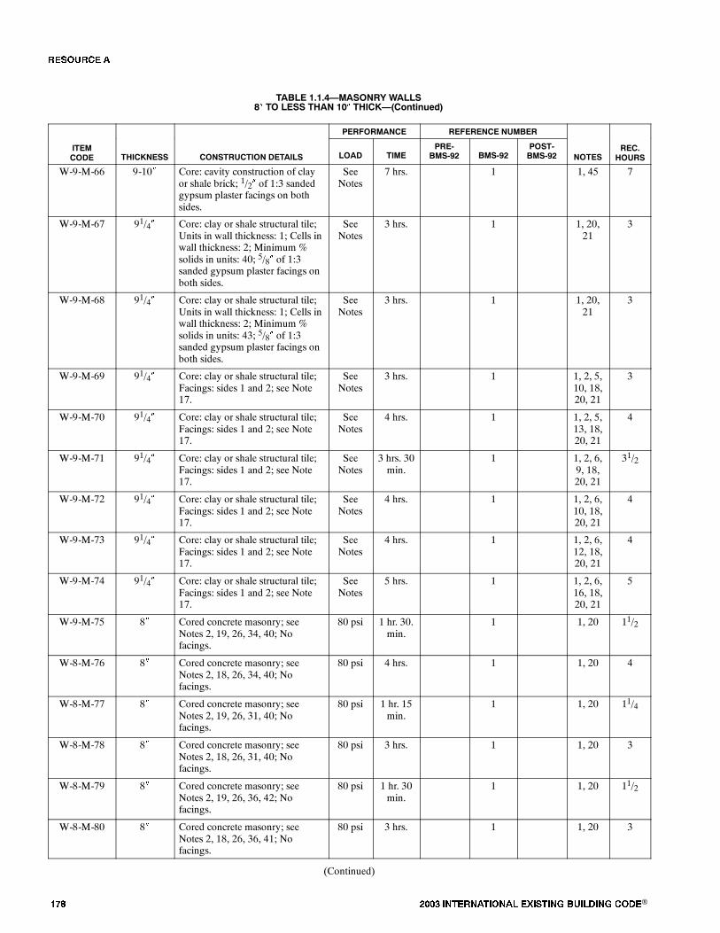
��� ���� ���������� ��� ���� �������� ���®
TABLE 1.1.4�MASONRY WALLS8� TO LESS THAN 10� THICK�(Continued)
PERFORMANCE REFERENCE NUMBER
ITEMCODE THICKNESS CONSTRUCTION DETAILS LOAD TIME
PRE-BMS-92 BMS-92
POST-BMS-92 NOTES
REC.HOURS
W-9-M-66 9-10� Core: cavity construction of clayor shale brick; 1/2� of 1:3 sandedgypsum plaster facings on bothsides.
SeeNotes
7 hrs. 1 1, 45 7
W-9-M-67 91/4� Core: clay or shale structural tile;Units in wall thickness: 1; Cells inwall thickness: 2; Minimum %solids in units: 40; 5/8� of 1:3sanded gypsum plaster facings onboth sides.
SeeNotes
3 hrs. 1 1, 20,21
3
W-9-M-68 91/4� Core: clay or shale structural tile;Units in wall thickness: 1; Cells inwall thickness: 2; Minimum %solids in units: 43; 5/8� of 1:3sanded gypsum plaster facings onboth sides.
SeeNotes
3 hrs. 1 1, 20,21
3
W-9-M-69 91/4� Core: clay or shale structural tile;Facings: sides 1 and 2; see Note17.
SeeNotes
3 hrs. 1 1, 2, 5,10, 18,20, 21
3
W-9-M-70 91/4� Core: clay or shale structural tile;Facings: sides 1 and 2; see Note17.
SeeNotes
4 hrs. 1 1, 2, 5,13, 18,20, 21
4
W-9-M-71 91/4� Core: clay or shale structural tile;Facings: sides 1 and 2; see Note17.
SeeNotes
3 hrs. 30min.
1 1, 2, 6,9, 18,20, 21
31/2
W-9-M-72 91/4� Core: clay or shale structural tile;Facings: sides 1 and 2; see Note17.
SeeNotes
4 hrs. 1 1, 2, 6,10, 18,20, 21
4
W-9-M-73 91/4� Core: clay or shale structural tile;Facings: sides 1 and 2; see Note17.
SeeNotes
4 hrs. 1 1, 2, 6,12, 18,20, 21
4
W-9-M-74 91/4� Core: clay or shale structural tile;Facings: sides 1 and 2; see Note17.
SeeNotes
5 hrs. 1 1, 2, 6,16, 18,20, 21
5
W-9-M-75 8� Cored concrete masonry; seeNotes 2, 19, 26, 34, 40; Nofacings.
80 psi 1 hr. 30.min.
1 1, 20 11/2
W-8-M-76 8� Cored concrete masonry; seeNotes 2, 18, 26, 34, 40; Nofacings.
80 psi 4 hrs. 1 1, 20 4
W-8-M-77 8� Cored concrete masonry; seeNotes 2, 19, 26, 31, 40; Nofacings.
80 psi 1 hr. 15min.
1 1, 20 11/4
W-8-M-78 8� Cored concrete masonry; seeNotes 2, 18, 26, 31, 40; Nofacings.
80 psi 3 hrs. 1 1, 20 3
W-8-M-79 8� Cored concrete masonry; seeNotes 2, 19, 26, 36, 42; Nofacings.
80 psi 1 hr. 30min.
1 1, 20 11/2
W-8-M-80 8� Cored concrete masonry; seeNotes 2, 18, 26, 36, 41; Nofacings.
80 psi 3 hrs. 1 1, 20 3
(Continued)
�� ����
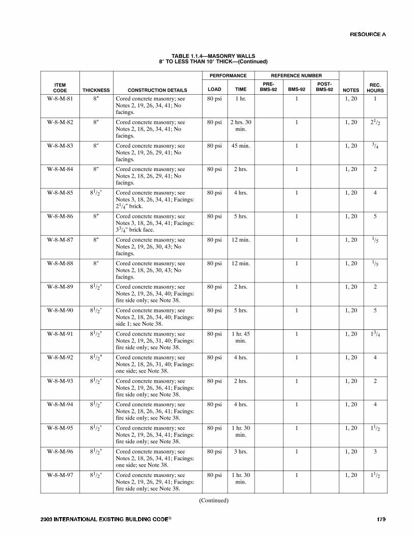
���� ���������� ��� ���� �������� ���® ���
TABLE 1.1.4�MASONRY WALLS8� TO LESS THAN 10� THICK�(Continued)
PERFORMANCE REFERENCE NUMBER
ITEMCODE THICKNESS CONSTRUCTION DETAILS LOAD TIME
PRE-BMS-92 BMS-92
POST-BMS-92 NOTES
REC.HOURS
W-8-M-81 8� Cored concrete masonry; seeNotes 2, 19, 26, 34, 41; Nofacings.
80 psi 1 hr. 1 1, 20 1
W-8-M-82 8� Cored concrete masonry; seeNotes 2, 18, 26, 34, 41; Nofacings.
80 psi 2 hrs. 30min.
1 1, 20 21/2
W-8-M-83 8� Cored concrete masonry; seeNotes 2, 19, 26, 29, 41; Nofacings.
80 psi 45 min. 1 1, 20 3/4
W-8-M-84 8� Cored concrete masonry; seeNotes 2, 18, 26, 29, 41; Nofacings.
80 psi 2 hrs. 1 1, 20 2
W-8-M-85 81/2� Cored concrete masonry; seeNotes 3, 18, 26, 34, 41; Facings:21/4� brick.
80 psi 4 hrs. 1 1, 20 4
W-8-M-86 8� Cored concrete masonry; seeNotes 3, 18, 26, 34, 41; Facings:33/4� brick face.
80 psi 5 hrs. 1 1, 20 5
W-8-M-87 8� Cored concrete masonry; seeNotes 2, 19, 26, 30, 43; Nofacings.
80 psi 12 min. 1 1, 20 1/5
W-8-M-88 8� Cored concrete masonry; seeNotes 2, 18, 26, 30, 43; Nofacings.
80 psi 12 min. 1 1, 20 1/5
W-8-M-89 81/2� Cored concrete masonry; seeNotes 2, 19, 26, 34, 40; Facings:fire side only; see Note 38.
80 psi 2 hrs. 1 1, 20 2
W-8-M-90 81/2� Cored concrete masonry; seeNotes 2, 18, 26, 34, 40; Facings:side 1; see Note 38.
80 psi 5 hrs. 1 1, 20 5
W-8-M-91 81/2� Cored concrete masonry; seeNotes 2, 19, 26, 31, 40; Facings:fire side only; see Note 38.
80 psi 1 hr. 45min.
1 1, 20 13/4
W-8-M-92 81/2� Cored concrete masonry; seeNotes 2, 18, 26, 31, 40; Facings:one side; see Note 38.
80 psi 4 hrs. 1 1, 20 4
W-8-M-93 81/2� Cored concrete masonry; seeNotes 2, 19, 26, 36, 41; Facings:fire side only; see Note 38.
80 psi 2 hrs. 1 1, 20 2
W-8-M-94 81/2� Cored concrete masonry; seeNotes 2, 18, 26, 36, 41; Facings:fire side only; see Note 38.
80 psi 4 hrs. 1 1, 20 4
W-8-M-95 81/2� Cored concrete masonry; seeNotes 2, 19, 26, 34, 41; Facings:fire side only; see Note 38.
80 psi 1 hr. 30min.
1 1, 20 11/2
W-8-M-96 81/2� Cored concrete masonry; seeNotes 2, 18, 26, 34, 41; Facings:one side; see Note 38.
80 psi 3 hrs. 1 1, 20 3
W-8-M-97 81/2� Cored concrete masonry; seeNotes 2, 19, 26, 29, 41; Facings:fire side only; see Note 38.
80 psi 1 hr. 30min.
1 1, 20 11/2
(Continued)
�� ����
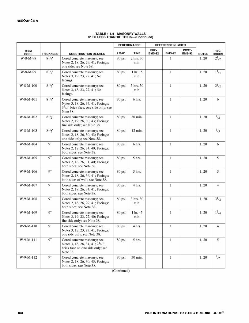
��� ���� ���������� ��� ���� �������� ���®
TABLE 1.1.4�MASONRY WALLS8� TO LESS THAN 10� THICK�(Continued)
PERFORMANCE REFERENCE NUMBER
ITEMCODE THICKNESS CONSTRUCTION DETAILS LOAD TIME
PRE-BMS-92 BMS-92
POST-BMS-92 NOTES
REC.HOURS
W-8-M-98 81/2� Cored concrete masonry; seeNotes 2, 18, 26, 29, 41; Facings:one side; see Note 38.
80 psi 2 hrs. 30min.
1 1, 20 21/2
W-8-M-99 81/2� Cored concrete masonry; seeNotes 3, 19, 23, 27, 41; Nofacings.
80 psi 1 hr. 15min.
1 1, 20 11/4
W-8-M-100 81/2� Cored concrete masonry; seeNotes 3, 18, 23, 27, 41; Nofacings.
80 psi 3 hrs. 30min.
1 1, 20 31/2
W-8-M-101 81/2� Cored concrete masonry; seeNotes 3, 18, 26, 34, 41; Facings:33/4� brick face; one side only; seeNote 38.
80 psi 6 hrs. 1 1, 20 6
W-8-M-102 81/2� Cored concrete masonry; seeNotes 2, 19, 26, 30, 43; Facings:fire side only; see Note 38.
80 psi 30 min. 1 1, 20 1/2
W-8-M-103 81/2� Cored concrete masonry; seeNotes 2, 18, 26, 30, 43; Facings:one side only; see Note 38.
80 psi 12 min. 1 1, 20 1/5
W-9-M-104 9� Cored concrete masonry; seeNotes 2, 18, 26, 34, 40; Facings:both sides; see Note 38.
80 psi 6 hrs. 1 1, 20 6
W-9-M-105 9� Cored concrete masonry; seeNotes 2, 18, 26, 31, 40; Facings:both sides; see Note 38.
80 psi 5 hrs. 1 1, 20 5
W-9-M-106 9� Cored concrete masonry; seeNotes 2, 18, 26, 36, 41; Facings:both sides of wall; see Note 38.
80 psi 5 hrs. 1 1, 20 5
W-9-M-107 9� Cored concrete masonry; seeNotes 2, 18, 26, 34, 41; Facings:both sides; see Note 38.
80 psi 4 hrs. 1 1, 20 4
W-9-M-108 9� Cored concrete masonry; seeNotes 2, 18, 26, 29, 41; Facings:both sides; see Note 38.
80 psi 3 hrs. 30min.
1 1, 20 31/2
W-9-M-109 9� Cored concrete masonry; seeNotes 3, 19, 23, 27, 40; Facings:fire side only; see Note 38.
80 psi 1 hr. 45min.
1 1, 20 13/4
W-9-M-110 9� Cored concrete masonry; seeNotes 3, 18, 23, 27, 41; Facings:one side only; see Note 38.
80 psi 4 hrs. 1 1, 20 4
W-9-M-111 9� Cored concrete masonry; seeNotes 3, 18, 26, 34, 41; 21/4�brick face on one side only; seeNote 38.
80 psi 5 hrs. 1 1, 20 5
W-9-M-112 9� Cored concrete masonry; seeNotes 2, 18, 26, 30, 43; Facings:both sides; see Note 38.
80 psi 30 min. 1 1, 20 1/2
(Continued)
�� ����
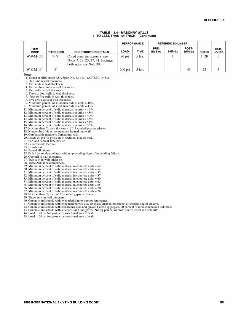
���� ���������� ��� ���� �������� ���® ���
TABLE 1.1.4�MASONRY WALLS8� TO LESS THAN 10� THICK�(Continued)
PERFORMANCE REFERENCE NUMBER
ITEMCODE THICKNESS CONSTRUCTION DETAILS LOAD TIME
PRE-BMS-92 BMS-92
POST-BMS-92 NOTES
REC.HOURS
W-9-M-113 91/2� Cored concrete masonry; seeNotes 3, 18, 23, 27, 41; Facings:both sides; see Note 38.
80 psi 5 hrs. 1 1, 20 5
W-8-M-114 8� 200 psi 5 hrs. 43 22 5
Notes:1. Tested at NBS under ASA Spec. No. 43-1934 (ASTM C 19-53).2. One unit in wall thickness.3. Two units in wall thickness.4. Two or three units in wall thickness.5. Two cells in wall thickness.6. Three or four cells in wall thickness.7. Four or five cells in wall thickness.8. Five or six cells in wall thickness.9. Minimum percent of solid materials in units = 40%.10. Minimum percent of solid materials in units = 43%.11. Minimum percent of solid materials in units = 46%.12. Minimum percent of solid materials in units = 48%.13. Minimum percent of solid materials in units = 49%.14. Minimum percent of solid materials in units = 45%.15. Minimum percent of solid materials in units = 51%.16. Minimum percent of solid materials in units = 53%.17. Not less than 5/8 inch thickness of 1:3 sanded gypsum plaster.18. Noncombustible or no members framed into wall.19. Combustible members framed into wall.20. Load: 80 psi for gross cross-sectional area of wall.21. Portland cement-lime mortar.22. Failure mode thermal.23. British test.24. Passed all criteria.25. Failed by sudden collapse with no preceding signs of impending failure.26. One cell in wall thickness.27. Two cells in wall thickness.28. Three cells in wall thickness.29. Minimum percent of solid material in concrete units = 52.30. Minimum percent of solid material in concrete units = 54.31. Minimum percent of solid material in concrete units = 55.32. Minimum percent of solid material in concrete units = 57.33. Minimum percent of solid material in concrete units = 60.34. Minimum percent of solid material in concrete units = 62.35. Minimum percent of solid material in concrete units = 65.36. Minimum percent of solid material in concrete units = 70.37. Minimum percent of solid material in concrete units = 76.38. Not less than 1/2 inch of 1:3 sanded gypsum plaster.39. Three units in wall thickness.40. Concrete units made with expanded slag or pumice aggregates.41. Concrete units made with expanded burned clay or shale, crushed limestone, air cooled slag or cinders.42. Concrete units made with calcareous sand and gravel. Coarse aggregate, 60 percent or more calcite and dolomite.43. Concrete units made with siliceous sand and gravel. Ninety percent or more quartz, chert and dolomite.44. Load: 120 psi for gross cross-sectional area of wall.45. Load: 160 psi for gross cross-sectional area of wall.
�� ����

��� ���� ���������� ��� ���� �������� ���®
FIGURE 1.1.5�WALLS�MASONRY10� TO LESS THAN 12� THICK
12 15
19
28
14
30
33
3
7
25
1
17
21
26
31
32
16
20
6
8
9
0
FIRE RESISTANCE RATING (HOURS)
NUMBER OFASSEMBLIES
1 2 3 4
5
10
04
22
2
10
The number in each box iskeyed to the last number in theItem Code column in the Table.
For example:
W-11-M-33
5 6 7
27
1318 11 5 29
23 24
TABLE 1.1.5�WALLS�MASONRY10� TO LESS THAN 12� THICK
PERFORMANCE REFERENCE NUMBER
ITEMCODE THICKNESS CONSTRUCTION DETAILS LOAD TIME
PRE-BMS-92 BMS-92
POST-BMS-92 NOTES
REC.HOURS
W-10-M-1 10� Core: two 33/4�, 40% solid clay orshale structural tiles with 2� airspace between; Facings: 3/4�portland cement plaster on stuccoon both sides.
80 psi 4 hrs. 1 1, 20 4
W-10-M-2 10� Core: cored concrete masonry, 2�air cavity; see Notes 3, 19, 27, 34,40; No facings.
80 psi 1 hr. 30min.
1 1, 20 11/2
W-10-M-3 10� Cored concrete masonry; seeNotes 3, 18, 27, 34, 40; Nofacings.
80 psi 4 hrs. 1 1, 20 4
W-10-M-4 10� Cored concrete masonry; seeNotes 2, 19, 26, 34, 40; Nofacings.
80 psi 2 hrs. 1 1, 20 2
W-10-M-5 10� Cored concrete masonry; seeNotes 2, 18, 26, 33, 40; Nofacings.
80 psi 5 hrs. 1 1, 20 5
W-10-M-6 10� Cored concrete masonry; seeNotes 2, 19, 26, 33, 41; Nofacings.
80 psi 1 hr. 30min.
1 1, 20 11/2
W-10-M-7 10� Cored concrete masonry; seeNotes 2, 18, 26, 33, 41; Nofacings.
80 psi 4 hrs. 1 1, 20 4
(Continued)
�� ����
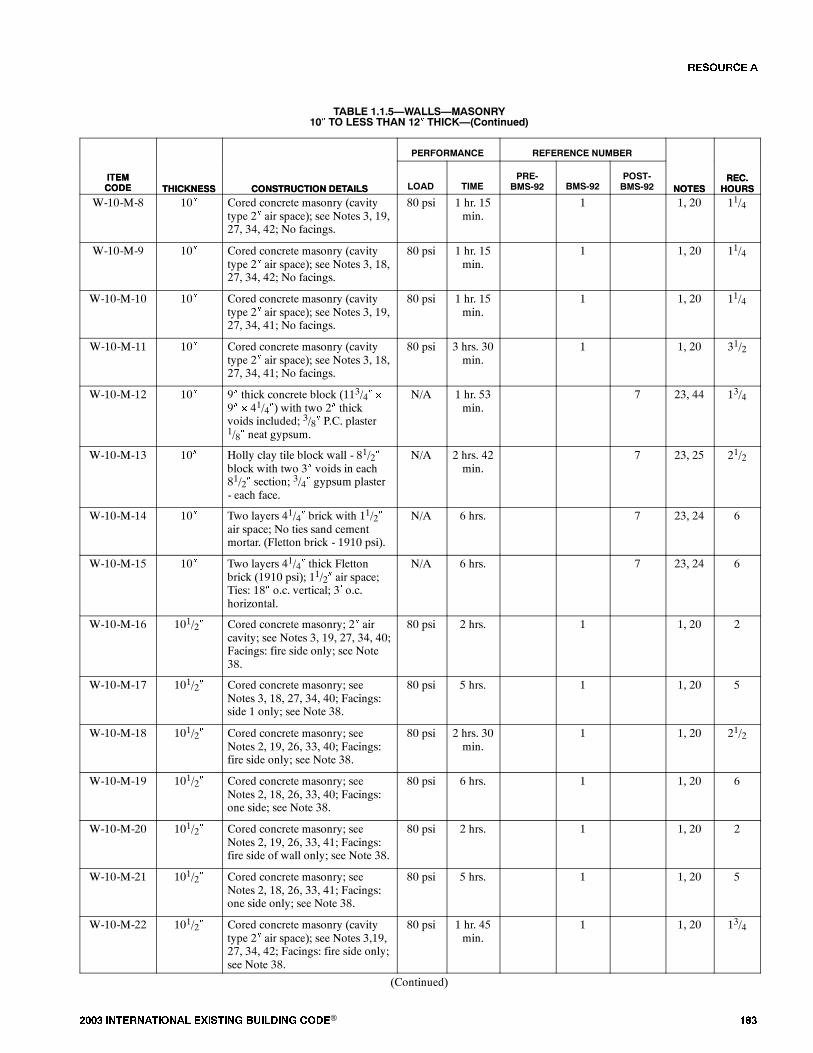
���� ���������� ��� ���� �������� ���® ���
TABLE 1.1.5�WALLS�MASONRY10� TO LESS THAN 12� THICK�(Continued)
ITEMCODE
REC.HOURSNOTES
REFERENCE NUMBERPERFORMANCE
CONSTRUCTION DETAILSTHICKNESSITEMCODE
REC.HOURSNOTES
POST-BMS-92BMS-92
PRE-BMS-92TIMELOADCONSTRUCTION DETAILSTHICKNESS
W-10-M-8 10� Cored concrete masonry (cavitytype 2� air space); see Notes 3, 19,27, 34, 42; No facings.
80 psi 1 hr. 15min.
1 1, 20 11/4
W-10-M-9 10� Cored concrete masonry (cavitytype 2� air space); see Notes 3, 18,27, 34, 42; No facings.
80 psi 1 hr. 15min.
1 1, 20 11/4
W-10-M-10 10� Cored concrete masonry (cavitytype 2� air space); see Notes 3, 19,27, 34, 41; No facings.
80 psi 1 hr. 15min.
1 1, 20 11/4
W-10-M-11 10� Cored concrete masonry (cavitytype 2� air space); see Notes 3, 18,27, 34, 41; No facings.
80 psi 3 hrs. 30min.
1 1, 20 31/2
W-10-M-12 10� 9� thick concrete block (113/4� �
9� � 41/4�) with two 2� thickvoids included; 3/8� P.C. plaster1/8� neat gypsum.
N/A 1 hr. 53min.
7 23, 44 13/4
W-10-M-13 10� Holly clay tile block wall - 81/2�block with two 3� voids in each81/2� section; 3/4� gypsum plaster- each face.
N/A 2 hrs. 42min.
7 23, 25 21/2
W-10-M-14 10� Two layers 41/4� brick with 11/2�air space; No ties sand cementmortar. (Fletton brick - 1910 psi).
N/A 6 hrs. 7 23, 24 6
W-10-M-15 10� Two layers 41/4� thick Flettonbrick (1910 psi); 11/2� air space;Ties: 18� o.c. vertical; 3� o.c.horizontal.
N/A 6 hrs. 7 23, 24 6
W-10-M-16 101/2� Cored concrete masonry; 2� aircavity; see Notes 3, 19, 27, 34, 40;Facings: fire side only; see Note38.
80 psi 2 hrs. 1 1, 20 2
W-10-M-17 101/2� Cored concrete masonry; seeNotes 3, 18, 27, 34, 40; Facings:side 1 only; see Note 38.
80 psi 5 hrs. 1 1, 20 5
W-10-M-18 101/2� Cored concrete masonry; seeNotes 2, 19, 26, 33, 40; Facings:fire side only; see Note 38.
80 psi 2 hrs. 30min.
1 1, 20 21/2
W-10-M-19 101/2� Cored concrete masonry; seeNotes 2, 18, 26, 33, 40; Facings:one side; see Note 38.
80 psi 6 hrs. 1 1, 20 6
W-10-M-20 101/2� Cored concrete masonry; seeNotes 2, 19, 26, 33, 41; Facings:fire side of wall only; see Note 38.
80 psi 2 hrs. 1 1, 20 2
W-10-M-21 101/2� Cored concrete masonry; seeNotes 2, 18, 26, 33, 41; Facings:one side only; see Note 38.
80 psi 5 hrs. 1 1, 20 5
W-10-M-22 101/2� Cored concrete masonry (cavitytype 2� air space); see Notes 3,19,27, 34, 42; Facings: fire side only;see Note 38.
80 psi 1 hr. 45min.
1 1, 20 13/4
(Continued)
�� ����

��� ���� ���������� ��� ���� �������� ���®
TABLE 1.1.5�WALLS�MASONRY10� TO LESS THAN 12� THICK�(Continued)
ITEMCODE
REC.HOURSNOTES
REFERENCE NUMBERPERFORMANCE
CONSTRUCTION DETAILSTHICKNESSITEMCODE
REC.HOURSNOTES
POST-BMS-92BMS-92
PRE-BMS-92TIMELOADCONSTRUCTION DETAILSTHICKNESS
W-10-M-23 101/2� Cored concrete masonry (cavitytype 2� air space); see Notes 3, 18,27, 34, 42; Facings: one side only;see Note 38.
80 psi 1 hr. 15min.
1 1, 20 11/4
W-10-M-24 101/2� Cored concrete masonry (cavitytype 2� air space); see Notes 3, 19,27, 34, 41; Facings: fire side only;see Note 38.
80 psi 2 hrs. 1 1, 20 2
W-10-M-25 101/2� Cored concrete masonry (cavitytype 2� air space); see Notes 3, 18,27, 34, 41; Facings: one side only;see Note 38.
80 psi 4 hrs. 1 1, 20 4
W-10-M-26 105/8� Core: 8�, 40% solid tile plus 2�furring tile; 5/8� sanded gypsumplaster between tile types;Facings: both sides 3/4� portlandcement plaster or stucco.
80 psi 5 hrs. 1 1, 20 5
W-10-M-27 105/8� Core: 8�, 40% solid tile plus 2�furring tile; 5/8� sanded gypsumplaster between tile types;Facings: one side 3/4� portlandcement plaster or stucco.
80 psi 3 hrs. 30min.
1 1, 20 31/2
W-11-M-28 11� Cored concrete masonry; seeNotes 3, 18, 27, 34, 40; Facings:both sides; see Note 38.
80 psi 6 hrs. 1 1, 20 6
W-11-M-29 11� Cored concrete masonry; seeNotes 2, 18, 26, 33, 40; Facings:both sides; see Note 38.
80 psi 7 hrs. 1 1, 20 7
W-11-M-30 11� Cored concrete masonry; seeNotes 2, 18, 26, 33, 41; Facings:both sides of wall; see Note 38.
80 psi 6 hrs. 1 1, 20 6
W-11-M-31 11� Cored concrete masonry (cavitytype 2� air space); see Notes 3, 18,27, 34, 42; Facings: both sides;see Note 38.
80 psi 5 hrs. 1 1, 20 5
W-11-M-32 11� Cored concrete masonry (cavitytype 2� air space); see Notes 3, 18,27, 34, 41; Facings: both sides;see Note 38.
80 psi 5 hrs. 1 1, 20 5
(Continued)
�� ����

���� ���������� ��� ���� �������� ���® ���
TABLE 1.1.5�WALLS�MASONRY10� TO LESS THAN 12� THICK�(Continued)
ITEMCODE
REC.HOURSNOTES
REFERENCE NUMBERPERFORMANCE
CONSTRUCTION DETAILSTHICKNESSITEMCODE
REC.HOURSNOTES
POST-BMS-92BMS-92
PRE-BMS-92TIMELOADCONSTRUCTION DETAILSTHICKNESS
W-11-M-33 11� Two layers brick (41/2� Fletton,2,428 psi) 2� air space; galvanizedties; 18� o.c. - horizontal; 3� o.c. -vertical.
3tons/ft.
6 hrs. 7 23, 24 6
Notes:1. Tested at NBS - ASA Spec. No. A2-1934.2. One unit in wall thickness.3. Two units in wall thickness.4. Two or three units in wall thickness.5. Two cells in wall thickness.6. Three or four cells in wall thickness.7. Four or five cells in wall thickness.8. Five or six cells in wall thickness.9. Minimum percent of solid materials in units = 40%.10. Minimum percent of solid materials in units = 43%.11. Minimum percent of solid materials in units = 46%.12. Minimum percent of solid materials in units = 48%.13. Minimum percent of solid materials in units = 49%.14. Minimum percent of solid materials in units = 45%.15. Minimum percent of solid materials in units = 51%.16. Minimum percent of solid materials in units = 53%.17. Not less than 5/8 inch thickness of 1:3 sanded gypsum plaster.18. Noncombustible or no members framed into wall.19. Combustible members framed into wall.20. Load: 80 psi for gross cross sectional area of wall.21. Portland cement-lime mortar.22. Failure mode - thermal.23. British test.24. Passed all criteria.25. Failed by sudden collapse with no preceding signs of impending failure.26. One cell in wall thickness.27. Two cells in wall thickness.28. Three cells in wall thickness.29. Minimum percent of solid material in concrete units = 52%.30. Minimum percent of solid material in concrete units = 54%.31. Minimum percent of solid material in concrete units = 55%.32. Minimum percent of solid material in concrete units = 57%.33. Minimum percent of solid material in concrete units = 60%.34. Minimum percent of solid material in concrete units = 62%.35. Minimum percent of solid material in concrete units = 65%.36. Minimum percent of solid material in concrete units = 70%.37. Minimum percent of solid material in concrete units = 76%.38. Not less than 1/2� of 1:3 sanded gypsum plaster.39. Three units in wall thickness.40. Concrete units made with expanded slag or pumice aggregates.41. Concrete units made with expanded burned clay or shale, crushed limestone, air cooled slag or cinders.42. Concrete units made with calcareous sand and gravel. Coarse aggregate, 60 percent or more calcite and dolomite.
�� ����
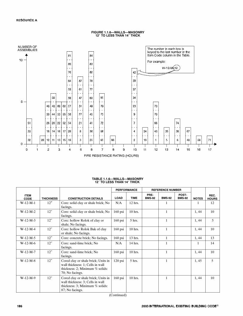
��� ���� ���������� ��� ���� �������� ���®
FIGURE 1.1.6�WALLS�MASONRY12� TO LESS THAN 14� THICK
�
���� �������� ����� � �����
����� ������������
� � � �
�
��
�
��� ������ � �!"� �#$ %&�'�( )# )�� *!%) ������ � )���)�� #(� "#*��� � )�� �!�*�+
�#� �$!�,*�-
./��/�/��
��0 1 2 3� ���� �� ��
��
�1�� �0
��
��
��
��
��
����
��
��
��
�
��
��
��
�
��
��
�
�
�
��
��
��
�
�
�
��
��
�
�
�
�
��
��
�
��
��
�
��
��
��
��
��
��
��
��
�
��
��
��
�
�
��
�
�
�
�
�
�
��
��
��
��
��
�
��
��
��
��
��
��
��
��
� ��
��
�
��
��
��
�
TABLE 1.1.6�WALLS�MASONRY12� TO LESS THAN 14� THICK
PERFORMANCE REFERENCE NUMBER
ITEMCODE THICKNESS CONSTRUCTION DETAILS LOAD TIME
PRE-BMS-92 BMS-92
POST-BMS-92 NOTES
REC.HOURS
W-12-M-1 12� Core: solid clay or shale brick; Nofacings.
N/A 12 hrs. 1 1 12
W-12-M-2 12� Core: solid clay or shale brick; Nofacings.
160 psi 10 hrs. 1 1, 44 10
W-12-M-3 12� Core: hollow Rolok of clay orshale; No facings.
160 psi 5 hrs. 1 1, 44 5
W-12-M-4 12� Core: hollow Rolok Bak of clayor shale; No facings.
160 psi 10 hrs. 1 1, 44 10
W-12-M-5 12� Core: concrete brick; No facings. 160 psi 13 hrs. 1 1, 44 13
W-12-M-6 12� Core: sand-lime brick; Nofacings.
N/A 14 hrs. 1 1 14
W-12-M-7 12� Core: sand-lime brick; Nofacings.
160 psi 10 hrs. 1 1, 44 10
W-12-M-8 12� Cored clay or shale brick; Units inwall thickness: 1; Cells in wallthickness: 2; Minimum % solids:70; No facings.
120 psi 5 hrs. 1 1, 45 5
W-12-M-9 12� Cored clay or shale brick; Units inwall thickness: 3; Cells in wallthickness: 3; Minimum % solids:87; No facings.
160 psi 10 hrs. 1 1, 44 10
(Continued)
�� ����
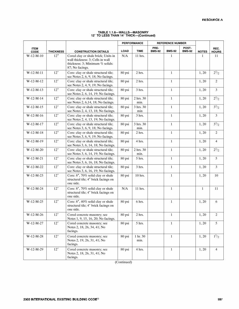
���� ���������� ��� ���� �������� ���® ���
TABLE 1.1.6�WALLS�MASONRY12� TO LESS THAN 14� THICK�(Continued)
PERFORMANCE REFERENCE NUMBER
ITEMCODE THICKNESS CONSTRUCTION DETAILS LOAD TIME
PRE-BMS-92 BMS-92
POST-BMS-92 NOTES
REC.HOURS
W-12-M-10 12� Cored clay or shale brick; Units inwall thickness: 3; Cells in wallthickness: 3; Minimum % solids:87; No facings.
N/A 11 hrs. 1 1 11
W-12-M-11 12� Core: clay or shale structural tile;see Notes 2, 6, 9, 18; No facings.
80 psi 2 hrs. 1 1, 20 21/2
W-12-M-12 12� Core: clay or shale structural tile;see Notes 2, 4, 9, 19; No facings.
80 psi 2 hrs. 1 1, 20 2
W-12-M-13 12� Core: clay or shale structural tile;see Notes 2, 6, 14, 19; No facings.
80 psi 3 hrs. 1 1, 20 3
W-12-M-14 12� Core: clay or shale structural tile;see Notes 2, 6,14, 18; No facings.
80 psi 2 hrs. 30min.
1 1, 20 21/2
W-12-M-15 12� Core: clay or shale structural tile;see Notes 2, 4, 13, 18; No facings.
80 psi 3 hrs. 30min
1 1, 20 31/2
W-12-M-16 12� Core: clay or shale structural tile;see Notes 2, 4, 13, 19; No facings.
80 psi 3 hrs. 1 1, 20 3
W-12-M-17 12� Core: clay or shale structural tile;see Notes 3, 6, 9, 18; No facings.
80 psi 3 hrs. 30min.
1 1, 20 31/2
W-12-M-18 12� Core: clay or shale structural tile;see Notes 3, 6, 9, 19; No facings.
80 psi 2 hrs. 1 1, 20 2
W-12-M-19 12� Core: clay or shale structural tile;see Notes 3, 6, 14, 18; No facings.
80 psi 4 hrs. 1 1, 20 4
W-12-M-20 12� Core: clay or shale structural tile;see Notes 3, 6, 14, 19; No facings.
80 psi 2 hrs. 30min.
1 1, 20 21/2
W-12-M-21 12� Core: clay or shale structural tile;see Notes 3, 6, 16, 18; No facings.
80 psi 5 hrs. 1 1, 20 5
W-12-M-22 12� Core: clay or shale structural tile;see Notes 3, 6, 16, 19; No facings.
80 psi 3 hrs. 1 1, 20 3
W-12-M-23 12� Core: 8�, 70% solid clay or shalestructural tile; 4� brick facings onone side.
80 psi 10 hrs. 1 1, 20 10
W-12-M-24 12� Core: 8�, 70% solid clay or shalestructural tile; 4� brick facings onone side.
N/A 11 hrs. 1 1 11
W-12-M-25 12� Core: 8�, 40% solid clay or shalestructural tile; 4� brick facings onone side.
80 psi 6 hrs. 1 1, 20 6
W-12-M-26 12� Cored concrete masonry; seeNotes 1, 9, 15, 16, 20; No facings.
80 psi 2 hrs. 1 1, 20 2
W-12-M-27 12� Cored concrete masonry; seeNotes 2, 18, 26, 34, 41; Nofacings.
80 psi 5 hrs. 1 1, 20 5
W-12-M-28 12� Cored concrete masonry; seeNotes 2, 19, 26, 31, 41; Nofacings.
80 psi 1 hr. 30min.
1 1, 20 11/2
W-12-M-29 12� Cored concrete masonry; seeNotes 2, 18, 26, 31, 41; Nofacings.
80 psi 4 hrs. 1 1, 20 4
(Continued)
�� ����
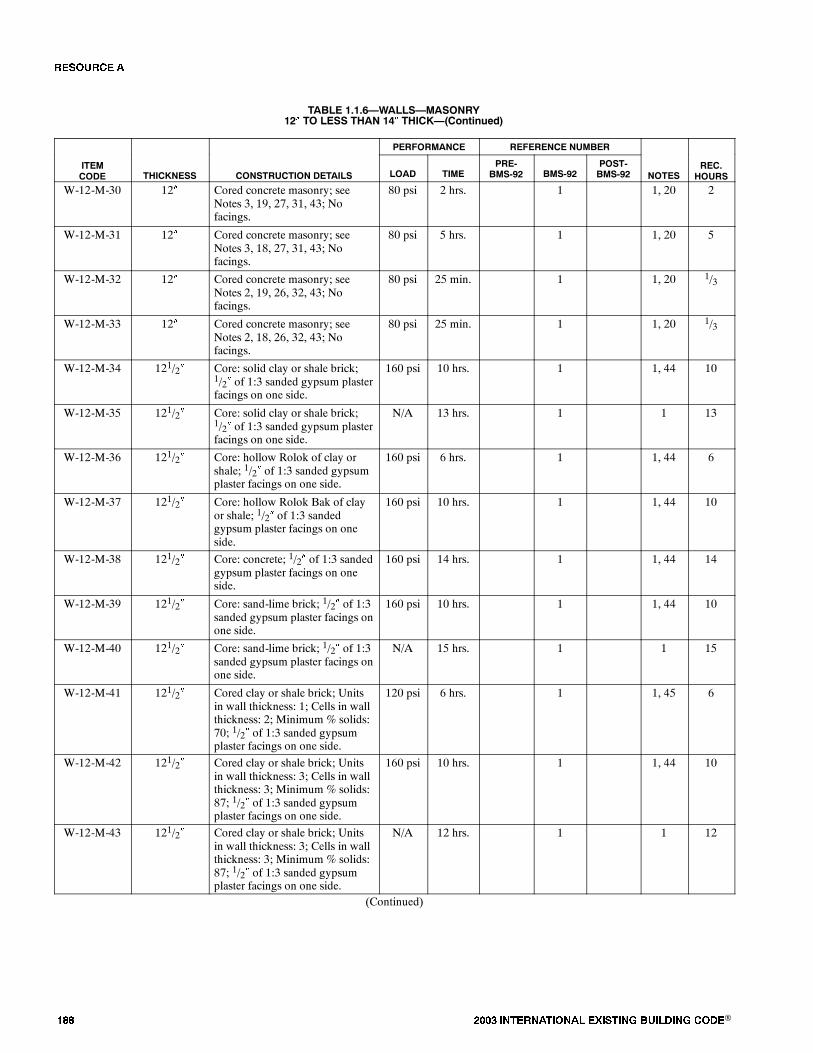
��� ���� ���������� ��� ���� �������� ���®
TABLE 1.1.6�WALLS�MASONRY12� TO LESS THAN 14� THICK�(Continued)
PERFORMANCE REFERENCE NUMBER
ITEMCODE THICKNESS CONSTRUCTION DETAILS LOAD TIME
PRE-BMS-92 BMS-92
POST-BMS-92 NOTES
REC.HOURS
W-12-M-30 12� Cored concrete masonry; seeNotes 3, 19, 27, 31, 43; Nofacings.
80 psi 2 hrs. 1 1, 20 2
W-12-M-31 12� Cored concrete masonry; seeNotes 3, 18, 27, 31, 43; Nofacings.
80 psi 5 hrs. 1 1, 20 5
W-12-M-32 12� Cored concrete masonry; seeNotes 2, 19, 26, 32, 43; Nofacings.
80 psi 25 min. 1 1, 20 1/3
W-12-M-33 12� Cored concrete masonry; seeNotes 2, 18, 26, 32, 43; Nofacings.
80 psi 25 min. 1 1, 20 1/3
W-12-M-34 121/2� Core: solid clay or shale brick;1/2� of 1:3 sanded gypsum plasterfacings on one side.
160 psi 10 hrs. 1 1, 44 10
W-12-M-35 121/2� Core: solid clay or shale brick;1/2� of 1:3 sanded gypsum plasterfacings on one side.
N/A 13 hrs. 1 1 13
W-12-M-36 121/2� Core: hollow Rolok of clay orshale; 1/2� of 1:3 sanded gypsumplaster facings on one side.
160 psi 6 hrs. 1 1, 44 6
W-12-M-37 121/2� Core: hollow Rolok Bak of clayor shale; 1/2� of 1:3 sandedgypsum plaster facings on oneside.
160 psi 10 hrs. 1 1, 44 10
W-12-M-38 121/2� Core: concrete; 1/2� of 1:3 sandedgypsum plaster facings on oneside.
160 psi 14 hrs. 1 1, 44 14
W-12-M-39 121/2� Core: sand-lime brick; 1/2� of 1:3sanded gypsum plaster facings onone side.
160 psi 10 hrs. 1 1, 44 10
W-12-M-40 121/2� Core: sand-lime brick; 1/2� of 1:3sanded gypsum plaster facings onone side.
N/A 15 hrs. 1 1 15
W-12-M-41 121/2� Cored clay or shale brick; Unitsin wall thickness: 1; Cells in wallthickness: 2; Minimum % solids:70; 1/2� of 1:3 sanded gypsumplaster facings on one side.
120 psi 6 hrs. 1 1, 45 6
W-12-M-42 121/2� Cored clay or shale brick; Unitsin wall thickness: 3; Cells in wallthickness: 3; Minimum % solids:87; 1/2� of 1:3 sanded gypsumplaster facings on one side.
160 psi 10 hrs. 1 1, 44 10
W-12-M-43 121/2� Cored clay or shale brick; Unitsin wall thickness: 3; Cells in wallthickness: 3; Minimum % solids:87; 1/2� of 1:3 sanded gypsumplaster facings on one side.
N/A 12 hrs. 1 1 12
(Continued)
�� ����
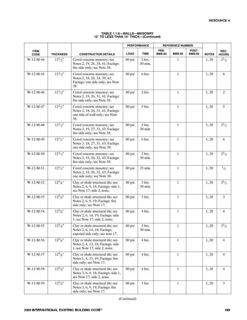
���� ���������� ��� ���� �������� ���® ���
TABLE 1.1.6�WALLS�MASONRY12� TO LESS THAN 14� THICK�(Continued)
PERFORMANCE REFERENCE NUMBER
ITEMCODE THICKNESS CONSTRUCTION DETAILS LOAD TIME
PRE-BMS-92 BMS-92
POST-BMS-92 NOTES
REC.HOURS
W-12-M-44 121/2� Cored concrete masonry; seeNotes 2, 19, 26, 34, 41; Facings:fire side only; see Note 38.
80 psi 2 hrs.30 min.
1 1, 20 21/2
W-12-M-45 121/2� Cored concrete masonry; seeNotes 2, 18, 26, 34, 39, 41;Facings: one side only; see Note38.
80 psi 6 hrs. 1 1, 20 6
W-12-M-46 121/2� Cored concrete masonry; seeNotes 2, 19, 26, 31, 41; Facings:fire side only; see Note 38.
80 psi 2 hrs. 1 1, 20 2
W-12-M-47 121/2� Cored concrete masonry; seeNotes 2, 18, 26, 31, 41; Facings:one side of wall only; see Note38.
80 psi 5 hrs. 1 1, 20 5
W-12-M-48 121/2� Cored concrete masonry; seeNotes 3, 19, 27, 31, 43; Facings:fire side only; see Note 38.
80 psi 2 hrs.30 min.
1 1, 20 21/2
W-12-M-49 121/2� Cored concrete masonry; seeNotes 3, 18, 27, 31, 43; Facings:one side only; see Note 38.
80 psi 6 hrs. 1 1, 20 6
W-12-M-50 121/2� Cored concrete masonry; seeNotes 2, 19, 26, 32, 43; Facings:fire side only; see Note 38.
80 psi 2 hrs.30 min.
1 1, 20 21/2
W-12-M-51 121/2� Cored concrete masonry; seeNotes 2, 18, 26, 32, 43; Facings:one side only; see Note 38.
80 psi 25 min. 1 1, 20 1/3
W-12-M-52 125/8� Clay or shale structural tile; seeNotes 2, 6, 9, 18; Facings: side 1,see Note 17; side 2, none.
80 psi 3 hrs.30 min.
1 1, 20 31/2
W-12-M-53 125/8� Clay or shale structural tile; seeNotes 2, 6, 9, 19; Facings: fireside only; see Note 17.
80 psi 3 hrs. 1 1, 20 3
W-12-M-54 125/8� Clay or shale structural tile; seeNotes 2, 6, 14, 19; Facings: side1, see Note 17; side 2, none.
80 psi 4 hrs. 1 1, 20 4
W-12-M-55 125/8� Clay or shale structural tile; seeNotes 2, 6, 14, 18; Facings:exposed side only; see note 17.
80 psi 3 hrs.30 min.
1 1, 20 31/2
W-12-M-56 125/8� Clay or shale structural tile; seeNotes 2, 4, 13, 18; Facings: side1, see Note 17; side 2, none.
80 psi 4 hrs. 1 1, 20 4
W-12-M-57 125/8� Clay or shale structural tile; seeNotes 1, 4, 13, 19; Facings: fireside only; see Note 17.
80 psi 4 hrs. 1 1, 20 4
W-12-M-58 125/8� Clay or shale structural tile; seeNotes 3, 6, 9, 18; Facings: side 1,see Note 17; side 2, none.
80 psi 4 hrs. 1 1, 20 4
W-12-M-59 125/8� Clay or shale structural tile; seeNotes 3, 6, 9, 19; Facings: fireside only; see Note 17.
80 psi 3 hrs. 1 1, 20 3
(Continued)
�� ����

��� ���� ���������� ��� ���� �������� ���®
TABLE 1.1.6�WALLS�MASONRY12� TO LESS THAN 14� THICK�(Continued)
PERFORMANCE REFERENCE NUMBER
ITEMCODE THICKNESS CONSTRUCTION DETAILS LOAD TIME
PRE-BMS-92 BMS-92
POST-BMS-92 NOTES
REC.HOURS
W-12-M-60 125/8� Clay or shale structural tile; seeNotes 3, 6, 14, 18; Facings: side1, see Note 17; side 2, none.
80 psi 5 hrs. 1 1, 20 5
W-12-M-61 125/8� Clay or shale structural tile; seeNotes 3, 6, 14, 19; Facings: fireside only; see Note 17.
80 psi 3 hrs.30 min.
1 1, 20 31/2
W-12-M-62 125/8� Clay or shale structural tile; seeNotes 3, 6, 16, 18; Facings: side1, see Note 17; side 2, none.
80 psi 6 hrs. 1 1, 20 6
W-12-M-63 125/8� Clay or shale structural tile; seeNotes 3, 6, 16, 19; Facings: fireside only; see Note 17.
80 psi 4 hrs. 1 1, 20 4
W-12-M-64 125/8� Core: 8�, 40% solid clay or shalestructural tile; Facings: 4� brickplus 5/8� of 1:3 sanded gypsumplaster on one side.
80 psi 7 hrs. 1 1, 20 7
W-13-M-65 13� Core: solid clay or shale brick;1/2� of 1:3 sanded gypsum plasterfacings on both sides.
160 psi 12 hrs. 1 1, 44 12
W-13-M-66 13� Core: solid clay or shale brick;1/2� of 1:3 sanded gypsum plasterfacings on both sides.
N/A 15 hrs. 1 1, 20 15
W-13-M-67 13� Core: solid clay or shale brick;1/2� of 1:3 sanded gypsum plasterfacings on both sides.
N/A 15 hrs. 1 1 15
W-13-M-68 13� Core: hollow Rolok of clay orshale; 1/2� of 1:3 sanded gypsumplaster facings on both sides.
80 psi 7 hrs. 1 1, 20 7
W-13-M-69 13� Core: concrete brick; 1/2� of 1:3sanded gypsum plaster facings onboth sides.
160 psi 16 hrs. 1 1, 44 16
W-13-M-70 13� Core: sand-lime brick; 1/2� of 1:3sanded gypsum plaster facings onboth sides.
160 psi 12 hrs. 1 1, 44 12
W-13-M-71 13� Core: sand-lime brick; 1/2� of 1:3sanded gypsum plaster facings onboth sides.
N/A 17 hrs. 1 1 17
W-13-M-72 13� Cored clay or shale brick; Unitsin wall thickness: 1; Cells in wallthickness: 2; Minimum % solids:70; 1/2� of 1:3 sanded gypsumplaster facings on both sides.
120 psi 7 hrs. 1 1, 45 7
W-13-M-73 13� Cored clay or shale brick; Unitsin wall thickness: 3; Cells in wallthickness: 3; Minimum % solids:87; 1/2� of 1:3 sanded gypsumplaster facings on both sides.
160 psi 12 hrs. 1 1, 44 12
W-13-M-74 13� Cored clay or shale brick; Unitsin wall thickness: 3; Cells in wallthickness: 2; Minimum % solids:87; 1/2� of 1:3 sanded gypsumplaster facings on both sides.
N/A 14 hrs. 1 1 14
(Continued)
�� ����
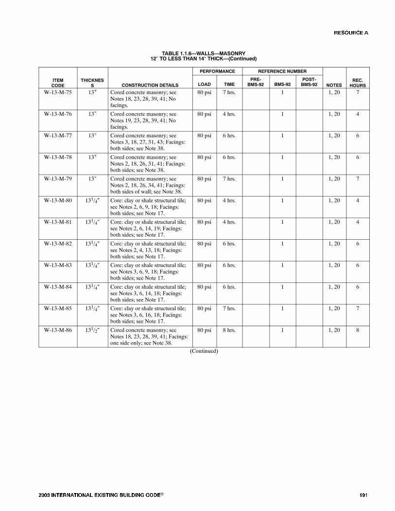
���� ���������� ��� ���� �������� ���® ���
TABLE 1.1.6�WALLS�MASONRY12� TO LESS THAN 14� THICK�(Continued)
PERFORMANCE REFERENCE NUMBER
ITEMCODE
THICKNESS CONSTRUCTION DETAILS LOAD TIME
PRE-BMS-92 BMS-92
POST-BMS-92 NOTES
REC.HOURS
W-13-M-75 13� Cored concrete masonry; seeNotes 18, 23, 28, 39, 41; Nofacings.
80 psi 7 hrs. 1 1, 20 7
W-13-M-76 13� Cored concrete masonry; seeNotes 19, 23, 28, 39, 41; Nofacings.
80 psi 4 hrs. 1 1, 20 4
W-13-M-77 13� Cored concrete masonry; seeNotes 3, 18, 27, 31, 43; Facings:both sides; see Note 38.
80 psi 6 hrs. 1 1, 20 6
W-13-M-78 13� Cored concrete masonry; seeNotes 2, 18, 26, 31, 41; Facings:both sides; see Note 38.
80 psi 6 hrs. 1 1, 20 6
W-13-M-79 13� Cored concrete masonry; seeNotes 2, 18, 26, 34, 41; Facings:both sides of wall; see Note 38.
80 psi 7 hrs. 1 1, 20 7
W-13-M-80 131/4� Core: clay or shale structural tile;see Notes 2, 6, 9, 18; Facings:both sides; see Note 17.
80 psi 4 hrs. 1 1, 20 4
W-13-M-81 131/4� Core: clay or shale structural tile;see Notes 2, 6, 14, 19; Facings:both sides; see Note 17.
80 psi 4 hrs. 1 1, 20 4
W-13-M-82 131/4� Core: clay or shale structural tile;see Notes 2, 4, 13, 18; Facings:both sides; see Note 17.
80 psi 6 hrs. 1 1, 20 6
W-13-M-83 131/4� Core: clay or shale structural tile;see Notes 3, 6, 9, 18; Facings:both sides; see Note 17.
80 psi 6 hrs. 1 1, 20 6
W-13-M-84 131/4� Core: clay or shale structural tile;see Notes 3, 6, 14, 18; Facings:both sides; see Note 17.
80 psi 6 hrs. 1 1, 20 6
W-13-M-85 131/4� Core: clay or shale structural tile;see Notes 3, 6, 16, 18; Facings:both sides; see Note 17.
80 psi 7 hrs. 1 1, 20 7
W-13-M-86 131/2� Cored concrete masonry; seeNotes 18, 23, 28, 39, 41; Facings:one side only; see Note 38.
80 psi 8 hrs. 1 1, 20 8
(Continued)
�� ����
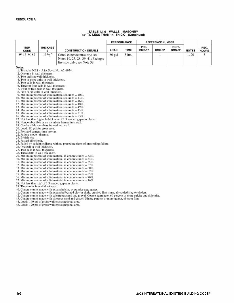
��� ���� ���������� ��� ���� �������� ���®
TABLE 1.1.6�WALLS�MASONRY12� TO LESS THAN 14� THICK�(Continued)
PERFORMANCE REFERENCE NUMBER
ITEMCODE
THICKNESS CONSTRUCTION DETAILS LOAD TIME
PRE-BMS-92 BMS-92
POST-BMS-92 NOTES
REC.HOURS
W-13-M-87 131/2� Cored concrete masonry; seeNotes 19, 23, 28, 39, 41; Facings:fire side only; see Note 38.
80 psi 5 hrs. 1 1, 20 5
Notes:1. Tested at NBS - ASA Spec. No. A2-1934.2. One unit in wall thickness.3. Two units in wall thickness.4. Two or three units in wall thickness.5. Two cells in wall thickness.6. Three or four cells in wall thickness.7. Four or five cells in wall thickness.8. Five or six cells in wall thickness.9. Minimum percent of solid materials in units = 40%.10. Minimum percent of solid materials in units = 43%.11. Minimum percent of solid materials in units = 46%.12. Minimum percent of solid materials in units = 48%.13. Minimum percent of solid materials in units = 49%.14. Minimum percent of solid materials in units = 45%.15. Minimum percent of solid materials in units = 51%.16. Minimum percent of solid materials in units = 53%.17. Not less than 5/8 inch thickness of 1:3 sanded gypsum plaster.18. Noncombustible or no members framed into wall.19. Combustible members framed into wall.20. Load: 80 psi for gross area.21. Portland cement-lime mortar.22. Failure mode - thermal.23. British test.24. Passed all criteria.25. Failed by sudden collapse with no preceding signs of impending failure.26. One cell in wall thickness.27. Two cells in wall thickness.28. Three cells in wall thickness.29. Minimum percent of solid material in concrete units = 52%.30. Minimum percent of solid material in concrete units = 54%.31. Minimum percent of solid material in concrete units = 55%.32. Minimum percent of solid material in concrete units = 57%.33. Minimum percent of solid material in concrete units = 60%.34. Minimum percent of solid material in concrete units = 62%.35. Minimum percent of solid material in concrete units = 65%.36. Minimum percent of solid material in concrete units = 70%.37. Minimum percent of solid material in concrete units = 76%.38. Not less than 1/2� of 1:3 sanded gypsum plaster.39. Three units in wall thickness.40. Concrete units made with expanded slag or pumice aggregates.41. Concrete units made with expanded burned clay or shale, crushed limestone, air cooled slag or cinders.42. Concrete units made with calcareous sand and gravel. Coarse aggregate, 60 percent or more calcite and dolomite.43. Concrete units made with siliceous sand and gravel. Ninety percent or more quartz, chert or flint.44. Load: 160 psi of gross wall cross sectional area.45. Load: 120 psi of gross wall cross sectional area.
�� ����

���� ���������� ��� ���� �������� ���® ���
FIGURE 1.1.7�WALLS�MASONRY14� OR MORE THICK
5
FIRE RESISTANCE RATING (HOURS)
NUMBER OFASSEMBLIES
1 2 3 4
5
10
0
106 7 8 90 1411 12 13
31
7
9
15
2
17
25
20
13
16
24
6
23
29
12
5
8
11
14
19
4
22
30
18
26
27
8
10
21
28
1
The number in each box iskeyed to the last number in theItem Code column in the Table.
For example:
W-17-M-28
TABLE 1.1.7�WALLS�MASONRY14� OR MORE THICK
PERFORMANCE REFERENCE NUMBER
ITEMCODE THICKNESS CONSTRUCTION DETAILS LOAD TIME
PRE-BMS-92 BMS-92
POST-BMS-92 NOTES
REC.HOURS
W-14-M-1 14� Core: cored masonry; see Notes18, 28, 33, 39, 41; Facings: bothsides; see Note 38.
80 psi 9 hrs. 1 1, 20 9
W-16-M-2 16� Core: clay or shale structural tile;see Notes 4, 7, 9, 19; No facings.
80 psi 5 hrs. 1 1, 20 5
W-16-M-3 16� Core: clay or shale structural tile;see Notes 4, 7, 9, 19; No facings.
80 psi 4 hrs. 1 1, 20 4
W-16-M-4 16� Core: clay or shale structural tile;see Notes 4, 7, 10, 18; No facings.
80 psi 6 hrs. 1 1, 20 6
W-16-M-5 16� Core: clay or shale structural tile;see Notes 4, 7, 10, 19; No facings.
80 psi 4 hrs. 1 1, 20 4
W-16-M-6 16� Core: clay or shale structural tile;see Notes 4, 7, 11, 18; No facings.
80 psi 7 hrs. 1 1, 20 7
W-16-M-7 16� Core: clay or shale structural tile;see Notes 4, 7, 11, 19; No facings.
80 psi 5 hrs. 1 1, 20 5
W-16-M-8 16� Core: clay or shale structural tile;see Notes 4, 8, 13, 18; No facings.
80 psi 8 hrs. 1 1, 20 8
W-16-M-9 16� Core: clay or shale structural tile;see Notes 4, 8, 13, 19; No facings.
80 psi 5 hrs. 1 1, 20 5
W-16-M-10 16� Core: clay or shale structural tile;see Notes 4, 8, 15, 18; No facings.
80 psi 9 hrs. 1 1, 20 9
W-16-M-11 16� Core: clay or shale structural tile;see Notes 3, 7, 14, 18; No facings.
80 psi 6 hrs. 1 1, 20 6
(Continued)
�� ����
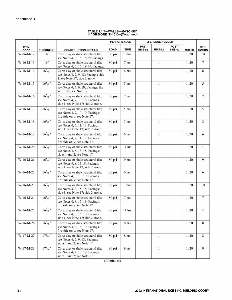
��� ���� ���������� ��� ���� �������� ���®
TABLE 1.1.7�WALLS�MASONRY14� OR MORE THICK�(Continued)
PERFORMANCE REFERENCE NUMBER
ITEMCODE THICKNESS CONSTRUCTION DETAILS LOAD TIME
PRE-BMS-92 BMS-92
POST-BMS-92 NOTES
REC.HOURS
W-16-M-12 16� Core: clay or shale structural tile;see Notes 4, 8, 16, 18; No facings.
80 psi 10 hrs. 1 1, 20 10
W-16-M-13 16� Core: clay or shale structural tile;see Notes 4, 6, 16, 19; No facings.
80 psi 7 hrs. 1 1, 20 7
W-16-M-14 165/8� Core: clay or shale structural tile;see Notes 4, 7, 9, 18; Facings: side1, see Note 17; side 2, none.
80 psi 6 hrs. 1 1, 20 6
W-16-M-15 165/8� Core: clay or shale structural tile;see Notes 4, 7, 9, 19; Facings: fireside only; see Note 17.
80 psi 5 hrs. 1 1, 20 5
W-16-M-16 165/8� Core: clay or shale structural tile;see Notes 4, 7, 10, 18; Facings:side 1, see Note 17; side 2, none.
80 psi 7 hrs. 1 1, 20 7
W-16-M-17 165/8� Core: clay or shale structural tile;see Notes 4, 7, 10, 19; Facings:fire side only; see Note 17.
80 psi 5 hrs. 1 1, 20 5
W-16-M-18 165/8� Core: clay or shale structural tile;see Notes 4, 7, 11, 18; Facings:side 1, see Note 17; side 2, none.
80 psi 5 hrs. 1 1, 20 8
W-16-M-19 165/8� Core: clay or shale structural tile;see Notes 4, 7, 11, 19; Facings:fire side only; see Note 17.
80 psi 6 hrs. 1 1, 20 6
W-16-M-20 165/8� Core: clay or shale structural tile;see Notes 4, 8, 13, 18; Facings:sides 1 and 2; see Note 17.
80 psi 11 hrs. 1 1, 20 11
W-16-M-21 165/8� Core: clay or shale structural tile;see Notes 4, 8, 13 18; Facings:side 1, see Note 17; side 2, none.
80 psi 9 hrs. 1 1, 20 9
W-16-M-22 165/8� Core: clay or shale structural tile;see Notes 4, 8, 13, 19; Facings:fire side only; see Note 17.
80 psi 6 hrs. 1 1, 20 6
W-16-M-23 165/8� Core: clay or shale structural tile;see Notes 4, 8, 15, 18; Facings:side 1, see Note 17; side 2, none.
80 psi 10 hrs. 1 1, 20 10
W-16-M-24 165/8� Core: clay or shale structural tile;see Notes 4, 8, 15, 19; Facings:fire side only; see Note 17.
80 psi 7 hrs. 1 1, 20 7
W-16-M-25 165/8� Core: clay or shale structural tile;see Notes 4, 6, 16, 18; Facings:side 1, see Note 17; side 2, none.
80 psi 11 hrs. 1 1, 20 11
W-16-M-26 165/8� Core: clay or shale structural tile;see Notes 4, 6, 16, 19; Facings:fire side only; see Note 17.
80 psi 8 hrs. 1 1, 20 8
W-17-M-27 171/4� Core: clay or shale structural tile;see Notes 4, 7, 9, 18; Facings:sides 1 and 2; see Note 17.
80 psi 8 hrs. 1 1, 20 8
W-17-M-28 171/4� Core: clay or shale structural tile;see Notes 4, 7, 10, 18; Facings:sides 1 and 2; see Note 17.
80 psi 9 hrs. 1 1, 20 9
(Continued)
�� ����
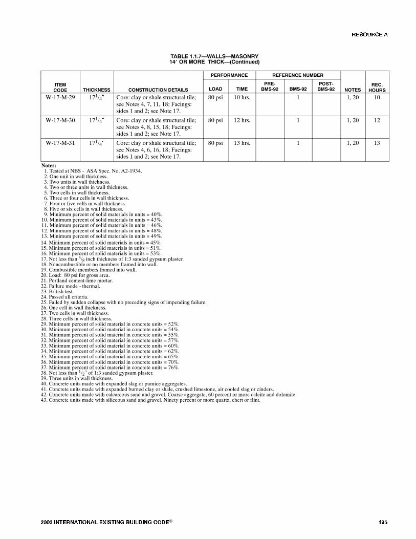
���� ���������� ��� ���� �������� ���® ���
TABLE 1.1.7�WALLS�MASONRY14� OR MORE THICK�(Continued)
PERFORMANCE REFERENCE NUMBER
ITEMCODE THICKNESS CONSTRUCTION DETAILS LOAD TIME
PRE-BMS-92 BMS-92
POST-BMS-92 NOTES
REC.HOURS
W-17-M-29 171/4� Core: clay or shale structural tile;see Notes 4, 7, 11, 18; Facings:sides 1 and 2; see Note 17.
80 psi 10 hrs. 1 1, 20 10
W-17-M-30 171/4� Core: clay or shale structural tile;see Notes 4, 8, 15, 18; Facings:sides 1 and 2; see Note 17.
80 psi 12 hrs. 1 1, 20 12
W-17-M-31 171/4� Core: clay or shale structural tile;see Notes 4, 6, 16, 18; Facings:sides 1 and 2; see Note 17.
80 psi 13 hrs. 1 1, 20 13
Notes:1. Tested at NBS - ASA Spec. No. A2-1934.2. One unit in wall thickness.3. Two units in wall thickness.4. Two or three units in wall thickness.5. Two cells in wall thickness.6. Three or four cells in wall thickness.7. Four or five cells in wall thickness.8. Five or six cells in wall thickness.9. Minimum percent of solid materials in units = 40%.10. Minimum percent of solid materials in units = 43%.11. Minimum percent of solid materials in units = 46%.12. Minimum percent of solid materials in units = 48%.13. Minimum percent of solid materials in units = 49%.14. Minimum percent of solid materials in units = 45%.15. Minimum percent of solid materials in units = 51%.16. Minimum percent of solid materials in units = 53%.17. Not less than 5/8 inch thickness of 1:3 sanded gypsum plaster.18. Noncombustible or no members framed into wall.19. Combustible members framed into wall.20. Load: 80 psi for gross area.21. Portland cement-lime mortar.22. Failure mode - thermal.23. British test.24. Passed all criteria.25. Failed by sudden collapse with no preceding signs of impending failure.26. One cell in wall thickness.27. Two cells in wall thickness.28. Three cells in wall thickness.29. Minimum percent of solid material in concrete units = 52%.30. Minimum percent of solid material in concrete units = 54%.31. Minimum percent of solid material in concrete units = 55%.32. Minimum percent of solid material in concrete units = 57%.33. Minimum percent of solid material in concrete units = 60%.34. Minimum percent of solid material in concrete units = 62%.35. Minimum percent of solid material in concrete units = 65%.36. Minimum percent of solid material in concrete units = 70%.37. Minimum percent of solid material in concrete units = 76%.38. Not less than 1/2� of 1:3 sanded gypsum plaster.39. Three units in wall thickness.40. Concrete units made with expanded slag or pumice aggregates.41. Concrete units made with expanded burned clay or shale, crushed limestone, air cooled slag or cinders.42. Concrete units made with calcareous sand and gravel. Coarse aggregate, 60 percent or more calcite and dolomite.43. Concrete units made with siliceous sand and gravel. Ninety percent or more quartz, chert or flint.
�� ����
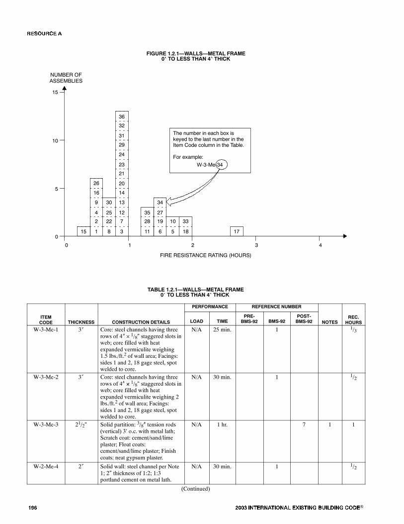
��� ���� ���������� ��� ���� �������� ���®
FIGURE 1.2.1�WALLS�METAL FRAME0� TO LESS THAN 4� THICK
2
4
9
22
25
30
7
12
13
0
FIRE RESISTANCE RATING (HOURS)
NUMBER OFASSEMBLIES
1 2 3 4
5
10
15
015 1
16
8 3
14
The number in each box iskeyed to the last number in theItem Code column in the Table.
For example:
W-3-Me-34
28
35
19
27
34
10 33
11 6 5 18 17
26
21
23
24
20
29
32
36
31
TABLE 1.2.1�WALLS�METAL FRAME0� TO LESS THAN 4� THICK
PERFORMANCE REFERENCE NUMBER
ITEMCODE THICKNESS CONSTRUCTION DETAILS LOAD TIME
PRE-BMS-92 BMS-92
POST-BMS-92 NOTES
REC.HOURS
W-3-Me-1 3� Core: steel channels having threerows of 4� � 1/8� staggered slots inweb; core filled with heatexpanded vermiculite weighing1.5 lbs./ft.2 of wall area; Facings:sides 1 and 2, 18 gage steel, spotwelded to core.
N/A 25 min. 1 1/3
W-3-Me-2 3� Core: steel channels having threerows of 4� � 1/8� staggered slots inweb; core filled with heatexpanded vermiculite weighing 2lbs./ft.2 of wall area; Facings:sides 1 and 2, 18 gage steel, spotwelded to core.
N/A 30 min. 1 1/2
W-3-Me-3 21/2� Solid partition: 3/8� tension rods(vertical) 3� o.c. with metal lath;Scratch coat: cement/sand/limeplaster; Float coats:cement/sand/lime plaster; Finishcoats: neat gypsum plaster.
N/A 1 hr. 7 1 1
W-2-Me-4 2� Solid wall: steel channel per Note1; 2� thickness of 1:2; 1:3portland cement on metal lath.
N/A 30 min. 1 1/2
(Continued)
�� ����
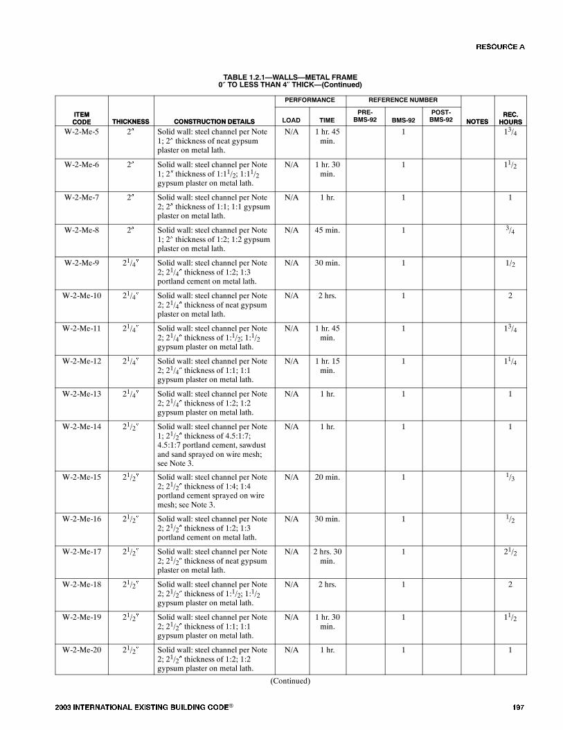
���� ���������� ��� ���� �������� ���® ���
TABLE 1.2.1�WALLS�METAL FRAME0� TO LESS THAN 4� THICK�(Continued)
ITEMCODE
REC.HOURSNOTES
REFERENCE NUMBERPERFORMANCE
CONSTRUCTION DETAILSTHICKNESSITEMCODE
REC.HOURSNOTES
POST-BMS-92BMS-92
PRE-BMS-92TIMELOADCONSTRUCTION DETAILSTHICKNESS
W-2-Me-5 2� Solid wall: steel channel per Note1; 2� thickness of neat gypsumplaster on metal lath.
N/A 1 hr. 45min.
1 13/4
W-2-Me-6 2� Solid wall: steel channel per Note1; 2� thickness of 1:11/2; 1:11/2gypsum plaster on metal lath.
N/A 1 hr. 30min.
1 11/2
W-2-Me-7 2� Solid wall: steel channel per Note2; 2� thickness of 1:1; 1:1 gypsumplaster on metal lath.
N/A 1 hr. 1 1
W-2-Me-8 2� Solid wall: steel channel per Note1; 2� thickness of 1:2; 1:2 gypsumplaster on metal lath.
N/A 45 min. 1 3/4
W-2-Me-9 21/4� Solid wall: steel channel per Note2; 21/4� thickness of 1:2; 1:3portland cement on metal lath.
N/A 30 min. 1 1/2
W-2-Me-10 21/4� Solid wall: steel channel per Note2; 21/4� thickness of neat gypsumplaster on metal lath.
N/A 2 hrs. 1 2
W-2-Me-11 21/4� Solid wall: steel channel per Note2; 21/4� thickness of 1:1/2; 1:1/2gypsum plaster on metal lath.
N/A 1 hr. 45min.
1 13/4
W-2-Me-12 21/4� Solid wall: steel channel per Note2; 21/4� thickness of 1:1; 1:1gypsum plaster on metal lath.
N/A 1 hr. 15min.
1 11/4
W-2-Me-13 21/4� Solid wall: steel channel per Note2; 21/4� thickness of 1:2; 1:2gypsum plaster on metal lath.
N/A 1 hr. 1 1
W-2-Me-14 21/2� Solid wall: steel channel per Note1; 21/2� thickness of 4.5:1:7;4.5:1:7 portland cement, sawdustand sand sprayed on wire mesh;see Note 3.
N/A 1 hr. 1 1
W-2-Me-15 21/2� Solid wall: steel channel per Note2; 21/2� thickness of 1:4; 1:4portland cement sprayed on wiremesh; see Note 3.
N/A 20 min. 1 1/3
W-2-Me-16 21/2� Solid wall: steel channel per Note2; 21/2� thickness of 1:2; 1:3portland cement on metal lath.
N/A 30 min. 1 1/2
W-2-Me-17 21/2� Solid wall: steel channel per Note2; 21/2� thickness of neat gypsumplaster on metal lath.
N/A 2 hrs. 30min.
1 21/2
W-2-Me-18 21/2� Solid wall: steel channel per Note2; 21/2� thickness of 1:1/2; 1:1/2gypsum plaster on metal lath.
N/A 2 hrs. 1 2
W-2-Me-19 21/2� Solid wall: steel channel per Note2; 21/2� thickness of 1:1; 1:1gypsum plaster on metal lath.
N/A 1 hr. 30min.
1 11/2
W-2-Me-20 21/2� Solid wall: steel channel per Note2; 21/2� thickness of 1:2; 1:2gypsum plaster on metal lath.
N/A 1 hr. 1 1
(Continued)
�� ����

��� ���� ���������� ��� ���� �������� ���®
TABLE 1.2.1�WALLS�METAL FRAME0� TO LESS THAN 4� THICK�(Continued)
ITEMCODE
REC.HOURSNOTES
REFERENCE NUMBERPERFORMANCE
CONSTRUCTION DETAILSTHICKNESSITEMCODE
REC.HOURSNOTES
POST-BMS-92BMS-92
PRE-BMS-92TIMELOADCONSTRUCTION DETAILSTHICKNESS
W-2-Me-21 21/2� Solid wall: steel channel per Note2; 21/2� thickness of 1:2; 1:3gypsum plaster on metal lath.
N/A 1 hr. 1 1
W-3-Me-22 3� Core: steel channel per Note 2;1:2; 1:2 gypsum plaster on 3/4�soft asbestos lath; plaster thickness2�.
N/A 45 min. 1 3/4
W-3-Me-23 31/2� Solid wall: steel channel per Note2; 21/2� thickness of 1:2; 1:2gypsum plaster on 3/4� asbestoslath.
N/A 1 hr. 1 1
W-3-Me-24 31/2� Solid wall: steel channel per Note2; lath over and 1:21/2; 1:21/2gypsum plaster on 1� magnesiumoxysulfate wood fiberboard;plaster thickness 21/2�.
N/A 1 hr. 1 1
W-3-Me-25 31/2� Core: steel studs; see Note 4;Facings: 3/4� thickness of 1:1/30:2;1:1/30:3 portland cement andasbestos fiber plaster.
N/A 45 min. 1 3/4
W-3-Me-26 31/2� Core: steel studs; see Note 4;Facings: both sides 3/4� thicknessof 1:2; 1:3 portland cement.
N/A 30 min. 1 1/2
W-3-Me-27 31/2� Core: steel studs; see Note 4;Facings: both sides 3/4� thicknessof neat gypsum plaster.
N/A 1 hr. 30min.
1 11/2
W-3-Me-28 31/2� Core: steel studs; see Note 4;Facings: both sides 3/4� thicknessof 1:1/2; 1:1/2 gypsum plaster.
N/A 1 hr. 15min.
1 11/4
W-3-Me-29 31/2� Core: steel studs; see Note 4;Facings: both sides 3/4� thicknessof 1:2; 1:2 gypsum plaster.
N/A 1 hr. 1 1
W-3-Me-30 31/2� Core: steel studs; see Note 4;Facings: both sides 3/4� thicknessof 1:2; 1:3 gypsum plaster.
N/A 45 min. 1 3/4
W-3-Me-31 33/4� Core: steel studs; see Note 4;Facings: both sides 7/8� thicknessof 1:1/30:2; 1:1/30:3 portlandcement and asbestos fiber plaster.
N/A 1 hr. 1 1
W-3-Me-32 33/4� Core: steel studs; see Note 4;Facings: both sides 7/8� thicknessof 1:2; 1:3 portland cement.
N/A 45 min. 1 3/4
W-3-Me-33 33/4� Core: steel studs; see Note 4;Facings: both sides 7/8� thicknessof neat gypsum plaster.
N/A 2 hrs. 1 2
W-3-Me-34 33/4� Core: steel studs; see Note 4;Facings: both sides 7/8� thicknessof 1:1/2; 1:1/2 gypsum plaster.
N/A 1 hr. 30min.
1 11/2
W-3-Me-35 33/4� Core: steel studs; see Note 4;Facings: both sides 7/8� thicknessof 1:2; 1:2 gypsum plaster.
N/A 1 hr. 15min.
1 11/4
(Continued)
�� ����
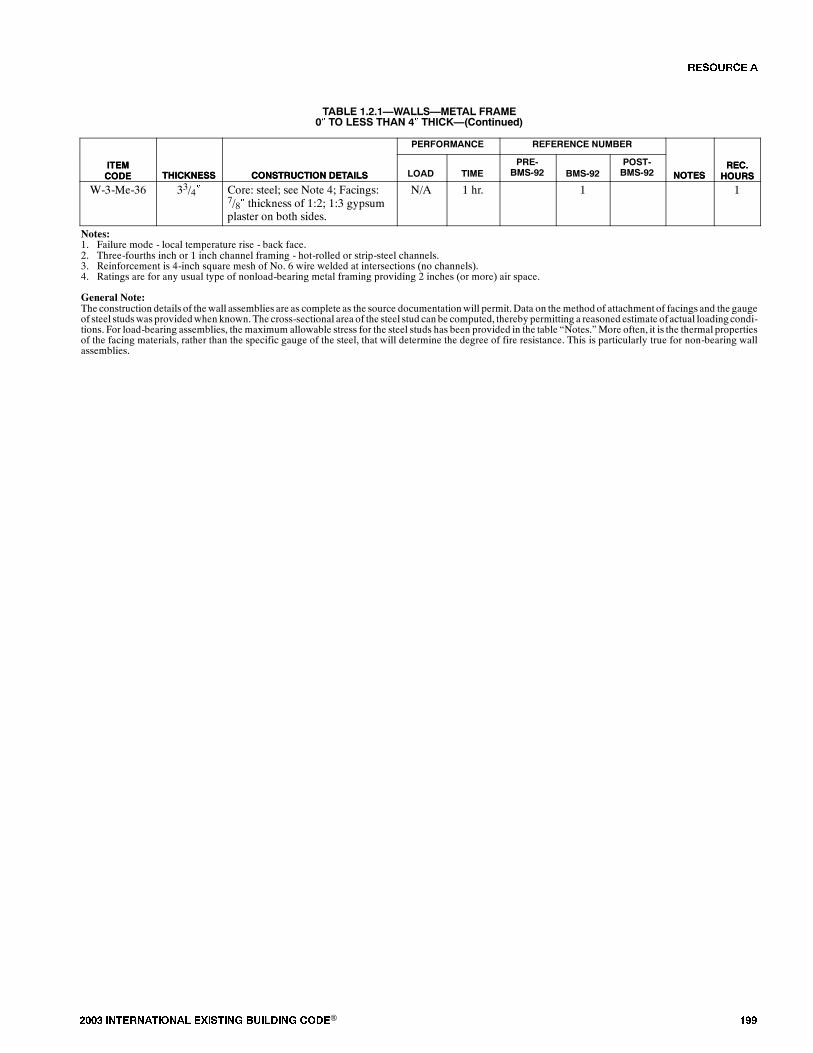
���� ���������� ��� ���� �������� ���® ���
TABLE 1.2.1�WALLS�METAL FRAME0� TO LESS THAN 4� THICK�(Continued)
ITEMCODE
REC.HOURSNOTES
REFERENCE NUMBERPERFORMANCE
CONSTRUCTION DETAILSTHICKNESSITEMCODE
REC.HOURSNOTES
POST-BMS-92BMS-92
PRE-BMS-92TIMELOADCONSTRUCTION DETAILSTHICKNESS
W-3-Me-36 33/4� Core: steel; see Note 4; Facings:7/8� thickness of 1:2; 1:3 gypsumplaster on both sides.
N/A 1 hr. 1 1
Notes:1. Failure mode - local temperature rise - back face.2. Three-fourths inch or 1 inch channel framing - hot-rolled or strip-steel channels.3. Reinforcement is 4-inch square mesh of No. 6 wire welded at intersections (no channels).4. Ratings are for any usual type of nonload-bearing metal framing providing 2 inches (or more) air space.
General Note:The construction details of thewall assemblies are as complete as the source documentationwill permit.Data on the method of attachment of facings and the gaugeof steel studswas providedwhen known.The cross-sectional area of the steel stud can be computed, thereby permitting a reasoned estimate ofactual loadingcondi-tions. For load-bearing assemblies, the maximum allowable stress for the steel studs has been provided in the table �Notes.�More often, it is the thermal propertiesof the facing materials, rather than the specific gauge of the steel, that will determine the degree of fire resistance. This is particularly true for non-bearing wallassemblies.
�� ����
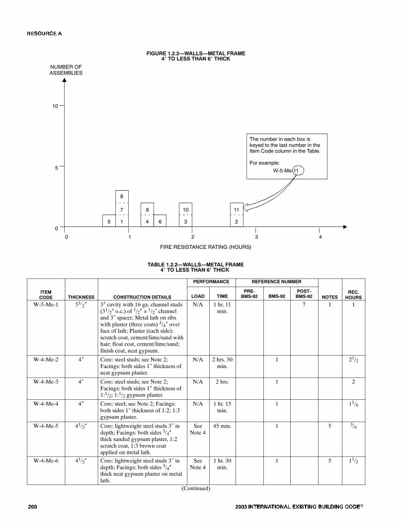
��� ���� ���������� ��� ���� �������� ���®
FIGURE 1.2.2�WALLS�METAL FRAME4� TO LESS THAN 6� THICK
7
0
FIRE RESISTANCE RATING (HOURS)
NUMBER OFASSEMBLIES
1 2 3 4
5
10
05 1
8
The number in each box iskeyed to the last number in theItem Code column in the Table.
For example:
W-5-Me-11
9 10
4 6 3 2
11
TABLE 1.2.2�WALLS�METAL FRAME4� TO LESS THAN 6� THICK
PERFORMANCE REFERENCE NUMBER
ITEMCODE THICKNESS CONSTRUCTION DETAILS LOAD TIME
PRE-BMS-92 BMS-92
POST-BMS-92 NOTES
REC.HOURS
W-5-Me-1 51/2� 3� cavity with 16 ga. channel studs(31/2� o.c.) of 1/2� � 1/2� channeland 3� spacer; Metal lath on ribswith plaster (three coats) 3/4� overface of lath; Plaster (each side):scratch coat, cement/lime/sand withhair; float coat, cement/lime/sand;finish coat, neat gypsum.
N/A 1 hr. 11min.
7 1 1
W-4-Me-2 4� Core: steel studs; see Note 2;Facings: both sides 1� thickness ofneat gypsum plaster.
N/A 2 hrs. 30min.
1 21/2
W-4-Me-3 4� Core: steel studs; see Note 2;Facings: both sides 1� thickness of1:1/2; 1:1/2 gypsum plaster.
N/A 2 hrs. 1 2
W-4-Me-4 4� Core: steel; see Note 2; Facings:both sides 1� thickness of 1:2; 1:3gypsum plaster.
N/A 1 hr. 15min.
1 11/4
W-4-Me-5 41/2� Core: lightweight steel studs 3� indepth; Facings: both sides 3/4�thick sanded gypsum plaster, 1:2scratch coat, 1:3 brown coatapplied on metal lath.
SeeNote 4
45 min. 1 5 3/4
W-4-Me-6 41/2� Core: lightweight steel studs 3� indepth; Facings: both sides 3/4�thick neat gypsum plaster on metallath.
SeeNote 4
1 hr. 30min.
1 5 11/2
(Continued)
�� ����
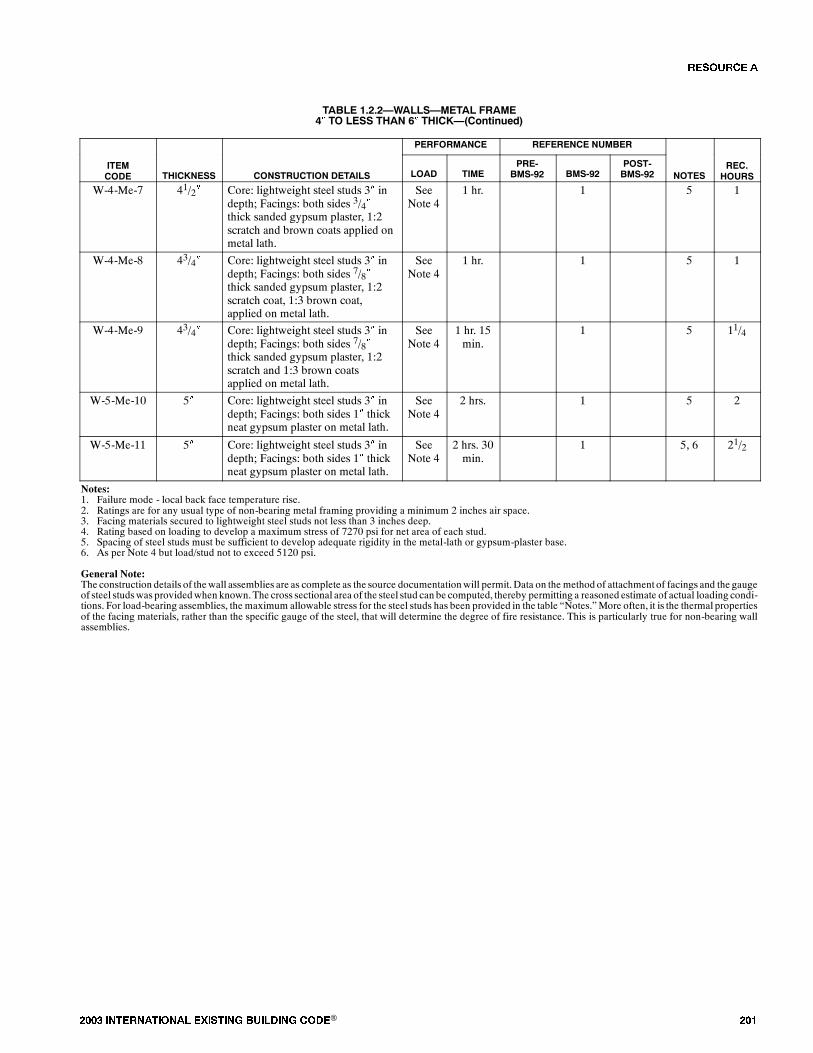
���� ���������� ��� ���� �������� ���® ���
TABLE 1.2.2�WALLS�METAL FRAME4� TO LESS THAN 6� THICK�(Continued)
PERFORMANCE REFERENCE NUMBER
ITEMCODE THICKNESS CONSTRUCTION DETAILS LOAD TIME
PRE-BMS-92 BMS-92
POST-BMS-92 NOTES
REC.HOURS
W-4-Me-7 41/2� Core: lightweight steel studs 3� indepth; Facings: both sides 3/4�thick sanded gypsum plaster, 1:2scratch and brown coats applied onmetal lath.
SeeNote 4
1 hr. 1 5 1
W-4-Me-8 43/4� Core: lightweight steel studs 3� indepth; Facings: both sides 7/8�thick sanded gypsum plaster, 1:2scratch coat, 1:3 brown coat,applied on metal lath.
SeeNote 4
1 hr. 1 5 1
W-4-Me-9 43/4� Core: lightweight steel studs 3� indepth; Facings: both sides 7/8�thick sanded gypsum plaster, 1:2scratch and 1:3 brown coatsapplied on metal lath.
SeeNote 4
1 hr. 15min.
1 5 11/4
W-5-Me-10 5� Core: lightweight steel studs 3� indepth; Facings: both sides 1� thickneat gypsum plaster on metal lath.
SeeNote 4
2 hrs. 1 5 2
W-5-Me-11 5� Core: lightweight steel studs 3� indepth; Facings: both sides 1� thickneat gypsum plaster on metal lath.
SeeNote 4
2 hrs. 30min.
1 5, 6 21/2
Notes:1. Failure mode - local back face temperature rise.2. Ratings are for any usual type of non-bearing metal framing providing a minimum 2 inches air space.3. Facing materials secured to lightweight steel studs not less than 3 inches deep.4. Rating based on loading to develop a maximum stress of 7270 psi for net area of each stud.5. Spacing of steel studs must be sufficient to develop adequate rigidity in the metal-lath or gypsum-plaster base.6. As per Note 4 but load/stud not to exceed 5120 psi.
General Note:The construction details of thewall assemblies are as complete as the source documentationwill permit.Data on the method of attachment of facings and the gaugeof steel studswas providedwhen known.The cross sectional area of the steel stud can be computed, thereby permitting a reasoned estimate of actual loading condi-tions. For load-bearing assemblies, the maximum allowable stress for the steel studs has been provided in the table �Notes.�More often, it is the thermal propertiesof the facing materials, rather than the specific gauge of the steel, that will determine the degree of fire resistance. This is particularly true for non-bearing wallassemblies.
�� ����
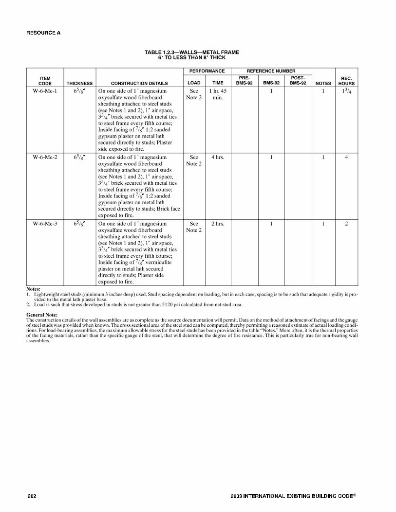
��� ���� ���������� ��� ���� �������� ���®
TABLE 1.2.3�WALLS�METAL FRAME6� TO LESS THAN 8� THICK
PERFORMANCE REFERENCE NUMBER
ITEMCODE THICKNESS CONSTRUCTION DETAILS LOAD TIME
PRE-BMS-92 BMS-92
POST-BMS-92 NOTES
REC.HOURS
W-6-Me-1 65/8� On one side of 1� magnesiumoxysulfate wood fiberboardsheathing attached to steel studs(see Notes 1 and 2), 1� air space,33/4� brick secured with metal tiesto steel frame every fifth course;Inside facing of 7/8� 1:2 sandedgypsum plaster on metal lathsecured directly to studs; Plasterside exposed to fire.
SeeNote 2
1 hr. 45min.
1 1 13/4
W-6-Me-2 65/8� On one side of 1� magnesiumoxysulfate wood fiberboardsheathing attached to steel studs(see Notes 1 and 2), 1� air space,33/4� brick secured with metal tiesto steel frame every fifth course;Inside facing of 7/8� 1:2 sandedgypsum plaster on metal lathsecured directly to studs; Brick faceexposed to fire.
SeeNote 2
4 hrs. 1 1 4
W-6-Me-3 65/8� On one side of 1� magnesiumoxysulfate wood fiberboardsheathing attached to steel studs(see Notes 1 and 2), 1� air space,33/4� brick secured with metal tiesto steel frame every fifth course;Inside facing of 7/8� vermiculiteplaster on metal lath secureddirectly to studs; Plaster sideexposed to fire.
SeeNote 2
2 hrs. 1 1 2
Notes:1. Lightweight steel studs (minimum 3 inches deep) used. Stud spacing dependent on loading, but in each case, spacing is to be such that adequate rigidity is pro-
vided to the metal lath plaster base.2. Load is such that stress developed in studs is not greater than 5120 psi calculated from net stud area.
General Note:The construction details of the wall assemblies are as complete as the source documentation will permit. Data on the method of attachment of facings and the gaugeof steel studs was provided when known. The cross sectional area of the steel stud can be computed, thereby permitting a reasoned estimate of actual loading condi-tions. For load-bearing assemblies, the maximum allowable stress for the steel studs has been provided in the table �Notes.� More often, it is the thermal propertiesof the facing materials, rather than the specific gauge of the steel, that will determine the degree of fire resistance. This is particularly true for non-bearing wallassemblies.
�� ����
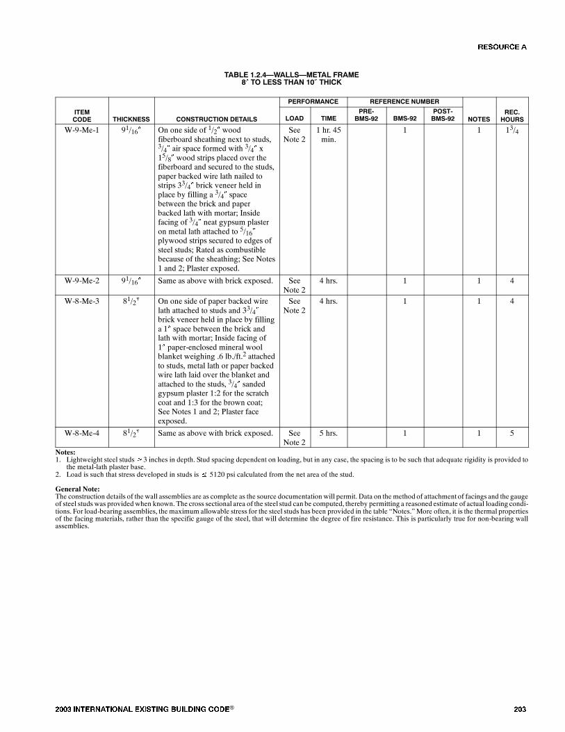
���� ���������� ��� ���� �������� ���® ���
TABLE 1.2.4�WALLS�METAL FRAME8� TO LESS THAN 10� THICK
PERFORMANCE REFERENCE NUMBER
ITEMCODE THICKNESS CONSTRUCTION DETAILS LOAD TIME
PRE-BMS-92 BMS-92
POST-BMS-92 NOTES
REC.HOURS
W-9-Me-1 91/16� On one side of 1/2� woodfiberboard sheathing next to studs,3/4� air space formed with 3/4� x15/8� wood strips placed over thefiberboard and secured to the studs,paper backed wire lath nailed tostrips 33/4� brick veneer held inplace by filling a 3/4� spacebetween the brick and paperbacked lath with mortar; Insidefacing of 3/4� neat gypsum plasteron metal lath attached to 5/16�plywood strips secured to edges ofsteel studs; Rated as combustiblebecause of the sheathing; See Notes1 and 2; Plaster exposed.
SeeNote 2
1 hr. 45min.
1 1 13/4
W-9-Me-2 91/16� Same as above with brick exposed. SeeNote 2
4 hrs. 1 1 4
W-8-Me-3 81/2� On one side of paper backed wirelath attached to studs and 33/4�brick veneer held in place by fillinga 1� space between the brick andlath with mortar; Inside facing of1� paper-enclosed mineral woolblanket weighing .6 lb./ft.2 attachedto studs, metal lath or paper backedwire lath laid over the blanket andattached to the studs, 3/4� sandedgypsum plaster 1:2 for the scratchcoat and 1:3 for the brown coat;See Notes 1 and 2; Plaster faceexposed.
SeeNote 2
4 hrs. 1 1 4
W-8-Me-4 81/2� Same as above with brick exposed. SeeNote 2
5 hrs. 1 1 5
Notes:1. Lightweight steel studs�3 inches in depth. Stud spacing dependent on loading, but in any case, the spacing is to be such that adequate rigidity is provided to
the metal-lath plaster base.2. Load is such that stress developed in studs is� 5120 psi calculated from the net area of the stud.
General Note:The construction details of the wall assemblies are as complete as the source documentation will permit. Data on the method of attachment of facings and the gaugeof steel studs was provided when known. The cross sectional area of the steel stud can be computed, thereby permitting a reasoned estimate of actual loading condi-tions. For load-bearing assemblies, the maximum allowable stress for the steel studs has been provided in the table �Notes.� More often, it is the thermal propertiesof the facing materials, rather than the specific gauge of the steel, that will determine the degree of fire resistance. This is particularly true for non-bearing wallassemblies.
�� ����
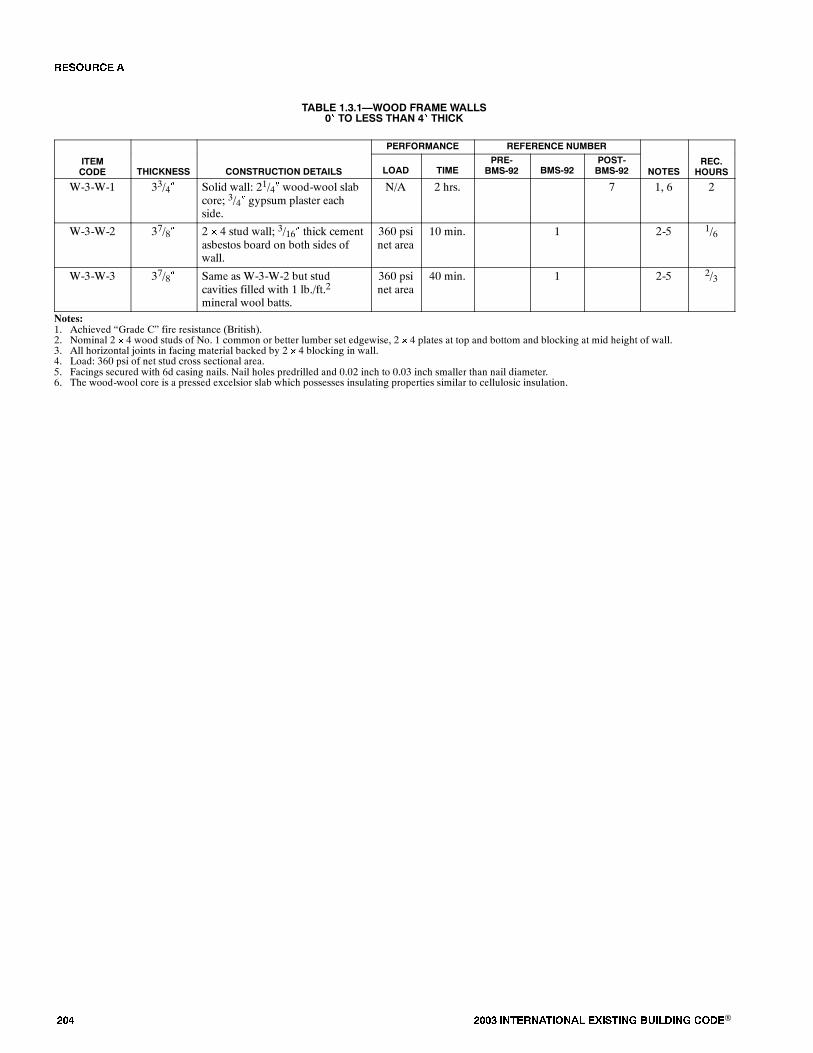
��� ���� ���������� ��� ���� �������� ���®
TABLE 1.3.1�WOOD FRAME WALLS0� TO LESS THAN 4� THICK
PERFORMANCE REFERENCE NUMBER
ITEMCODE THICKNESS CONSTRUCTION DETAILS LOAD TIME
PRE-BMS-92 BMS-92
POST-BMS-92 NOTES
REC.HOURS
W-3-W-1 33/4� Solid wall: 21/4� wood-wool slabcore; 3/4� gypsum plaster eachside.
N/A 2 hrs. 7 1, 6 2
W-3-W-2 37/8� 2 � 4 stud wall; 3/16� thick cementasbestos board on both sides ofwall.
360 psinet area
10 min. 1 2-5 1/6
W-3-W-3 37/8� Same as W-3-W-2 but studcavities filled with 1 lb./ft.2
mineral wool batts.
360 psinet area
40 min. 1 2-5 2/3
Notes:1. Achieved �Grade C� fire resistance (British).2. Nominal 2 � 4 wood studs of No. 1 common or better lumber set edgewise, 2 � 4 plates at top and bottom and blocking at mid height of wall.3. All horizontal joints in facing material backed by 2 � 4 blocking in wall.4. Load: 360 psi of net stud cross sectional area.5. Facings secured with 6d casing nails. Nail holes predrilled and 0.02 inch to 0.03 inch smaller than nail diameter.6. The wood-wool core is a pressed excelsior slab which possesses insulating properties similar to cellulosic insulation.
�� ����
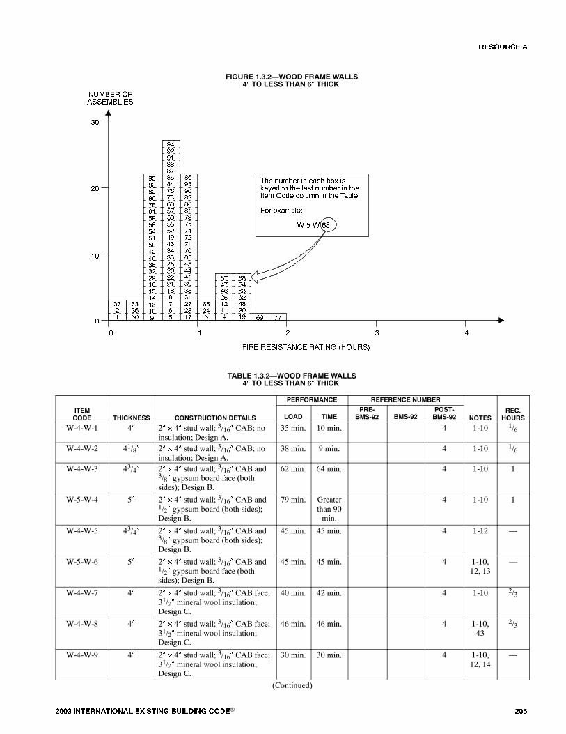
���� ���������� ��� ���� �������� ���® ���
FIGURE 1.3.2�WOOD FRAME WALLS4� TO LESS THAN 6� THICK
�
���� �������� ����� � �����
����� ������������
� � � �
��
�
��� ������ � �!"� �#$ %&�'�( )# )�� *!%) ������ � )���)�� #(� "#*��� � )�� �!�*�+
�#� �$!�,*�-
./�/./02
��
��
��
��
��
��
�
�
��
��
�
��
��
��
��
��
��
� � ��
�
��
��
��
�
��
�
�
�
�
�
�
��
�
�
��
��
��
��
��
�
��
�
��
��
��
��
��
�
�
�
�
�
�
��
��
��
��
��
��
��
�
��
��
��
�
��
��
��
�
�
�
�
�
�
�
�
�
�
��
��
��
��
��
��
��
��
��
�
��
��
��
��
��
TABLE 1.3.2�WOOD FRAME WALLS4� TO LESS THAN 6� THICK
PERFORMANCE REFERENCE NUMBER
ITEMCODE THICKNESS CONSTRUCTION DETAILS LOAD TIME
PRE-BMS-92 BMS-92
POST-BMS-92 NOTES
REC.HOURS
W-4-W-1 4� 2� � 4� stud wall; 3/16� CAB; noinsulation; Design A.
35 min. 10 min. 4 1-10 1/6
W-4-W-2 41/8� 2� � 4� stud wall; 3/16� CAB; noinsulation; Design A.
38 min. 9 min. 4 1-10 1/6
W-4-W-3 43/4� 2� � 4� stud wall; 3/16� CAB and3/8� gypsum board face (bothsides); Design B.
62 min. 64 min. 4 1-10 1
W-5-W-4 5� 2� � 4� stud wall; 3/16� CAB and1/2� gypsum board (both sides);Design B.
79 min. Greaterthan 90min.
4 1-10 1
W-4-W-5 43/4� 2� � 4� stud wall; 3/16� CAB and3/8� gypsum board (both sides);Design B.
45 min. 45 min. 4 1-12 �
W-5-W-6 5� 2� � 4� stud wall; 3/16� CAB and1/2� gypsum board face (bothsides); Design B.
45 min. 45 min. 4 1-10,12, 13
�
W-4-W-7 4� 2� � 4� stud wall; 3/16� CAB face;31/2� mineral wool insulation;Design C.
40 min. 42 min. 4 1-10 2/3
W-4-W-8 4� 2� � 4� stud wall; 3/16� CAB face;31/2� mineral wool insulation;Design C.
46 min. 46 min. 4 1-10,43
2/3
W-4-W-9 4� 2� � 4� stud wall; 3/16� CAB face;31/2� mineral wool insulation;Design C.
30 min. 30 min. 4 1-10,12, 14
�
(Continued)
�� ����

��� ���� ���������� ��� ���� �������� ���®
TABLE 1.3.2�WOOD FRAME WALLS4� TO LESS THAN 6� THICK�(Continued)
PERFORMANCE REFERENCE NUMBER
ITEMCODE THICKNESS CONSTRUCTION DETAILS LOAD TIME
PRE-BMS-92 BMS-92
POST-BMS-92 NOTES
REC.HOURS
W-4-W-10 41/8� 2� � 4� stud wall; 3/16� CAB face;31/2� mineral wool insulation;Design C.
� 30 min. 4 1-8, 12,14
�
W-4-W-11 43/4� 2� � 4� stud wall; 3/16� CAB face;3/8� gypsum strips over studs;51/2� mineral wool insulation;Design D.
79 min. 79 min. 4 1-10 1
W-4-W-12 43/4� 2� � 4� stud wall; 3/16� CAB face;3/8� gypsum strips at stud edges;71/2� mineral wool insulation;Design D.
82 min. 82 min. 4 1-10 1
W-4-W-13 43/4� 2� � 4� stud wall; 3/16� CAB face;3/8� gypsum board strips overstuds; 51/2� mineral woolinsulation; Design D.
30 min. 30 min. 4 1-12 �
W-4-W-14 43/4� 2� � 4� stud wall; 3/16� CAB face;3/8� gypsum board strips overstuds; 7� mineral wool insulation;Design D.
30 min. 30 min. 4 1-12 �
W-5-W-15 51/2� 2� � 4� stud wall; Exposed face:CAB shingles over 1� � 6�;Unexposed face: 1/8� CAB sheet;7/16� fiberboard (wood); DesignE.
34 min. � 4 1-10 1/2
W-5-W-16 51/2� 2� � 4� stud wall; Exposed face:1/8� CAB sheet; 7/16� fiberboard;Unexposed face: CAB shinglesover 1� � 6�; Design E.
32 min. 33 min. 4 1-10 1/2
W-5-W-17 51/2� 2� � 4� stud wall; Exposed face:CAB shingles over 1� � 6�;Unexposed face: 1/8� CAB sheet;gypsum at stud edges; 31/2�mineral wood insulation; DesignF.
51 min. � 4 1-10 3/4
W-5-W-18 51/2� 2� � 4� stud wall; Exposed face:1/8� CAB sheet; gypsum board atstud edges; Unexposed face: CABshingles over 1� � 6�; 31/2�mineral wool insulation; Design F.
42 min. � 4 1-10 2/3
W-5-W-19 55/8� 2� � 4� stud wall; Exposed face:CAB shingles over 1� � 6�;Unexposed face: 1/8� CAB sheet;gypsum board at stud edges; 51/2�mineral wool insulation; DesignG.
74 min. 85 min. 4 1-10 1
W-5-W-20 55/8� 2� � 4� stud wall; Exposed face:1/8� CAB sheet; gypsum board at3/16� stud edges; 7/16� fiberboard;Unexposed face: CAB shinglesover 1� � 6�; 51/2� mineral woolinsulation; Design G.
79 min. 85 min. 4 1-10 11/4
W-5-W-21 55/8� 2� � 4� stud wall; Exposed face:CAB shingles 1� � 6� sheathing;Unexposed face: CAB sheet;gypsum board at stud edges; 51/2�mineral wool insulation; Design G.
38 min. 38 min. 4 1-10,12, 14
�
(Continued)
�� ����

���� ���������� ��� ���� �������� ���® ���
TABLE 1.3.2�WOOD FRAME WALLS4� TO LESS THAN 6� THICK�(Continued)
PERFORMANCE REFERENCE NUMBER
ITEMCODE THICKNESS CONSTRUCTION DETAILS LOAD TIME
PRE-BMS-92 BMS-92
POST-BMS-92 NOTES
REC.HOURS
W-5-W-22 55/8� 2� � 4� stud wall; Exposed face:CAB sheet; gypsum board at studedges; Unexposed face: CABshingles 1� � 6� sheathing; 51/2�mineral wool insulation; DesignG.
38 min. 38 min. 4 1-12 �
W-6-W-23 6� 2� � 4� stud wall; 16� o.c.; 1/2�gypsum board each side; 1/2�gypsum plaster each side.
N/A 60 min. 7 15 1
W-6-W-24 6� 2� � 4� stud wall; 16� o.c.; 1/2�gypsum board each side; 1/2�gypsum plaster each side.
N/A 68 min. 7 16 1
W-6-W-25 67/8� 2� � 4� stud wall; 18� o.c.; 3/4�gypsum plank each side; 3/16�gypsum plaster each side.
N/A 80 min. 7 15 11/3
W-5-W-26 51/8� 2� � 4� stud wall; 16� o.c.; 3/8�gypsum board each side; 3/16�gypsum plaster each side.
N/A 37 min. 7 15 1/2
W-5-W-27 53/4� 2� � 4� stud wall; 16� o.c.; 3/8�gypsum lath each side; 1/2�gypsum plaster each side.
N/A 52 min. 7 15 3/4
W-5-W-28 5� 2� � 4� stud wall; 16� o.c.; 1/2�gypsum board each side.
N/A 37 min. 7 16 1/2
W-5-W-29 5� 2� � 4� stud wall; 1/2� fiberboardboth sides 14% M.C. with F.R.paint at 35 gm./ft.2.
N/A 28 min. 7 15 1/3
W-4-W-30 43/4� 2� � 4� stud wall; Fire side: 1/2�(wood) fiberboard; Back side: 1/4�CAB; 16� o.c.
N/A 17 min. 7 15,1 6 1/4
W-5-W-31 51/8� 2� � 4� stud wall; 16� o.c.; 1/2�fiberboard insulation with 1/32�asbestos (both sides of eachboard).
N/A 50 min. 7 16 3/4
W-4-W-32 41/4� 2� � 4� stud wall; 3/8� thickgypsum wallboard on both faces;insulated cavities.
SeeNote 23
25 min. 1 17, 18,23
1/3
W-4-W-33 41/2� 2� � 4� stud wall; 1/2� thickgypsum wallboard on both faces.
SeeNote 17
40 min. 1 17, 23 1/3
W-4-W-34 41/2� 2� � 4� stud wall; 1/2� thickgypsum wallboard on both faces;insulated cavities.
SeeNote 17
45 min. 1 17, 18,23
3/4
W-4-W-35 41/2� 2� � 4� stud wall; 1/2� thickgypsum wallboard on both faces;insulated cavities.
N/A 1 hr. 1 17, 18,24
1
W-4-W-36 41/2� 2� � 4� stud wall; 1/2� thick, 1.1lbs./ft.2 wood fiberboardsheathing on both faces.
SeeNote 23
15 min. 1 17, 23 1/4
W-4-W-37 41/2� 2� � 4� stud wall; 1/2� thick, 0.7lb./ft.2 wood fiberboard sheathingon both faces.
SeeNote 23
10 min. 1 17, 23 1/6
W-4-W-38 41/2� 2� � 4� stud wall; 1/2� thick,flameproofed 1.6 lbs./ft.2 woodfiberboard sheathing on bothfaces.
SeeNote 23
30 min. 1 17, 23 1/2
(Continued)
�� ����
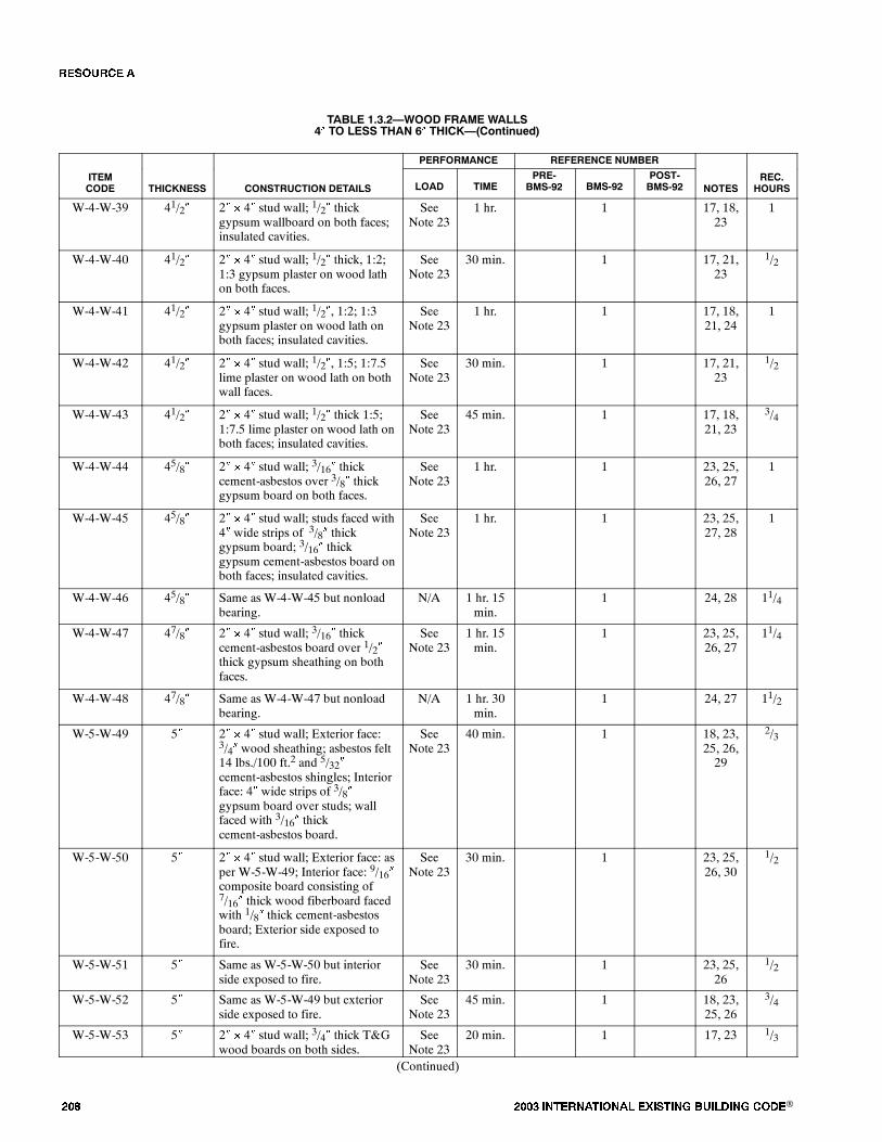
��� ���� ���������� ��� ���� �������� ���®
TABLE 1.3.2�WOOD FRAME WALLS4� TO LESS THAN 6� THICK�(Continued)
PERFORMANCE REFERENCE NUMBER
ITEMCODE THICKNESS CONSTRUCTION DETAILS LOAD TIME
PRE-BMS-92 BMS-92
POST-BMS-92 NOTES
REC.HOURS
W-4-W-39 41/2� 2� � 4� stud wall; 1/2� thickgypsum wallboard on both faces;insulated cavities.
SeeNote 23
1 hr. 1 17, 18,23
1
W-4-W-40 41/2� 2� � 4� stud wall; 1/2� thick, 1:2;1:3 gypsum plaster on wood lathon both faces.
SeeNote 23
30 min. 1 17, 21,23
1/2
W-4-W-41 41/2� 2� � 4� stud wall; 1/2�, 1:2; 1:3gypsum plaster on wood lath onboth faces; insulated cavities.
SeeNote 23
1 hr. 1 17, 18,21, 24
1
W-4-W-42 41/2� 2� � 4� stud wall; 1/2�, 1:5; 1:7.5lime plaster on wood lath on bothwall faces.
SeeNote 23
30 min. 1 17, 21,23
1/2
W-4-W-43 41/2� 2� � 4� stud wall; 1/2� thick 1:5;1:7.5 lime plaster on wood lath onboth faces; insulated cavities.
SeeNote 23
45 min. 1 17, 18,21, 23
3/4
W-4-W-44 45/8� 2� � 4� stud wall; 3/16� thickcement-asbestos over 3/8� thickgypsum board on both faces.
SeeNote 23
1 hr. 1 23, 25,26, 27
1
W-4-W-45 45/8� 2� � 4� stud wall; studs faced with4� wide strips of 3/8� thickgypsum board; 3/16� thickgypsum cement-asbestos board onboth faces; insulated cavities.
SeeNote 23
1 hr. 1 23, 25,27, 28
1
W-4-W-46 45/8� Same as W-4-W-45 but nonloadbearing.
N/A 1 hr. 15min.
1 24, 28 11/4
W-4-W-47 47/8� 2� � 4� stud wall; 3/16� thickcement-asbestos board over 1/2�thick gypsum sheathing on bothfaces.
SeeNote 23
1 hr. 15min.
1 23, 25,26, 27
11/4
W-4-W-48 47/8� Same as W-4-W-47 but nonloadbearing.
N/A 1 hr. 30min.
1 24, 27 11/2
W-5-W-49 5� 2� � 4� stud wall; Exterior face:3/4� wood sheathing; asbestos felt14 lbs./100 ft.2 and 5/32�cement-asbestos shingles; Interiorface: 4� wide strips of 3/8�gypsum board over studs; wallfaced with 3/16� thickcement-asbestos board.
SeeNote 23
40 min. 1 18, 23,25, 26,29
2/3
W-5-W-50 5� 2� � 4� stud wall; Exterior face: asper W-5-W-49; Interior face: 9/16�composite board consisting of7/16� thick wood fiberboard facedwith 1/8� thick cement-asbestosboard; Exterior side exposed tofire.
SeeNote 23
30 min. 1 23, 25,26, 30
1/2
W-5-W-51 5� Same as W-5-W-50 but interiorside exposed to fire.
SeeNote 23
30 min. 1 23, 25,26
1/2
W-5-W-52 5� Same as W-5-W-49 but exteriorside exposed to fire.
SeeNote 23
45 min. 1 18, 23,25, 26
3/4
W-5-W-53 5� 2� � 4� stud wall; 3/4� thick T&Gwood boards on both sides.
SeeNote 23
20 min. 1 17, 23 1/3
(Continued)
�� ����
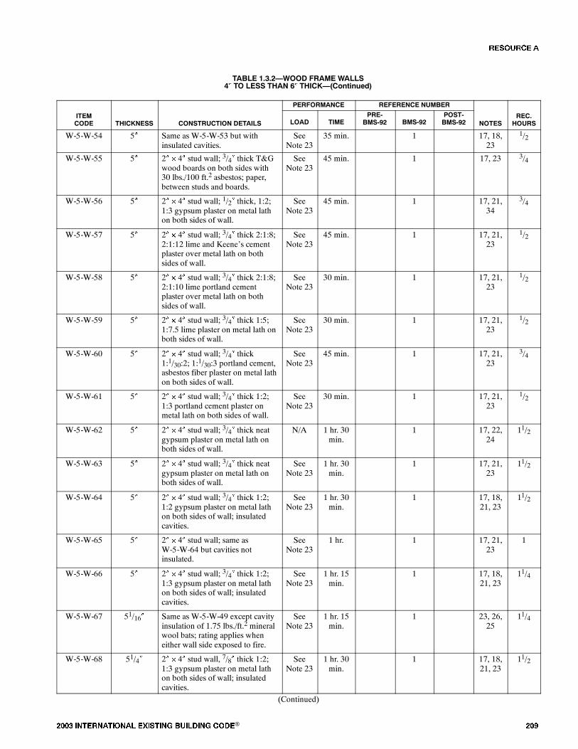
���� ���������� ��� ���� �������� ���® ���
TABLE 1.3.2�WOOD FRAME WALLS4� TO LESS THAN 6� THICK�(Continued)
PERFORMANCE REFERENCE NUMBER
ITEMCODE THICKNESS CONSTRUCTION DETAILS LOAD TIME
PRE-BMS-92 BMS-92
POST-BMS-92 NOTES
REC.HOURS
W-5-W-54 5� Same as W-5-W-53 but withinsulated cavities.
SeeNote 23
35 min. 1 17, 18,23
1/2
W-5-W-55 5� 2� � 4� stud wall; 3/4� thick T&Gwood boards on both sides with30 lbs./100 ft.2 asbestos; paper,between studs and boards.
SeeNote 23
45 min. 1 17, 23 3/4
W-5-W-56 5� 2� � 4� stud wall; 1/2� thick, 1:2;1:3 gypsum plaster on metal lathon both sides of wall.
SeeNote 23
45 min. 1 17, 21,34
3/4
W-5-W-57 5� 2� � 4� stud wall; 3/4� thick 2:1:8;2:1:12 lime and Keene�s cementplaster over metal lath on bothsides of wall.
SeeNote 23
45 min. 1 17, 21,23
1/2
W-5-W-58 5� 2� � 4� stud wall; 3/4� thick 2:1:8;2:1:10 lime portland cementplaster over metal lath on bothsides of wall.
SeeNote 23
30 min. 1 17, 21,23
1/2
W-5-W-59 5� 2� � 4� stud wall; 3/4� thick 1:5;1:7.5 lime plaster on metal lath onboth sides of wall.
SeeNote 23
30 min. 1 17, 21,23
1/2
W-5-W-60 5� 2� � 4� stud wall; 3/4� thick1:1/30:2; 1:1/30:3 portland cement,asbestos fiber plaster on metal lathon both sides of wall.
SeeNote 23
45 min. 1 17, 21,23
3/4
W-5-W-61 5� 2� � 4� stud wall; 3/4� thick 1:2;1:3 portland cement plaster onmetal lath on both sides of wall.
SeeNote 23
30 min. 1 17, 21,23
1/2
W-5-W-62 5� 2� � 4� stud wall; 3/4� thick neatgypsum plaster on metal lath onboth sides of wall.
N/A 1 hr. 30min.
1 17, 22,24
11/2
W-5-W-63 5� 2� � 4� stud wall; 3/4� thick neatgypsum plaster on metal lath onboth sides of wall.
SeeNote 23
1 hr. 30min.
1 17, 21,23
11/2
W-5-W-64 5� 2� � 4� stud wall; 3/4� thick 1:2;1:2 gypsum plaster on metal lathon both sides of wall; insulatedcavities.
SeeNote 23
1 hr. 30min.
1 17, 18,21, 23
11/2
W-5-W-65 5� 2� � 4� stud wall; same asW-5-W-64 but cavities notinsulated.
SeeNote 23
1 hr. 1 17, 21,23
1
W-5-W-66 5� 2� � 4� stud wall; 3/4� thick 1:2;1:3 gypsum plaster on metal lathon both sides of wall; insulatedcavities.
SeeNote 23
1 hr. 15min.
1 17, 18,21, 23
11/4
W-5-W-67 51/16� Same as W-5-W-49 except cavityinsulation of 1.75 lbs./ft.2 mineralwool bats; rating applies wheneither wall side exposed to fire.
SeeNote 23
1 hr. 15min.
1 23, 26,25
11/4
W-5-W-68 51/4� 2� � 4� stud wall, 7/8� thick 1:2;1:3 gypsum plaster on metal lathon both sides of wall; insulatedcavities.
SeeNote 23
1 hr. 30min.
1 17, 18,21, 23
11/2
(Continued)
�� ����
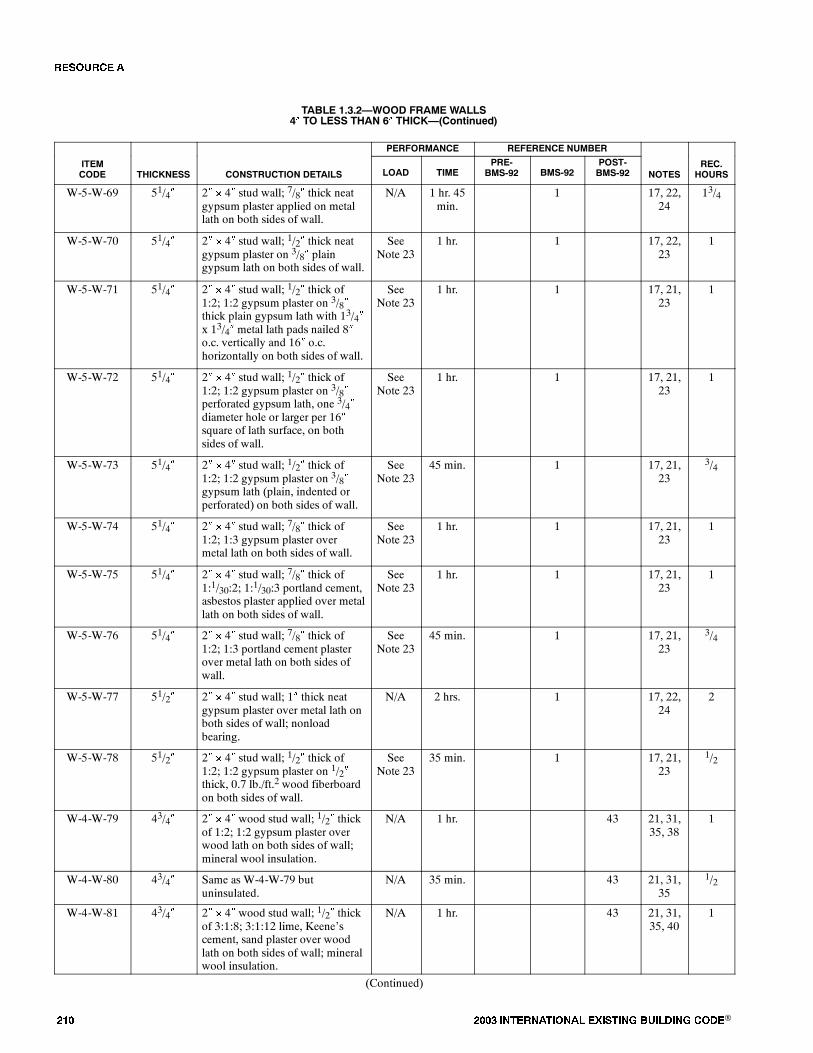
��� ���� ���������� ��� ���� �������� ���®
TABLE 1.3.2�WOOD FRAME WALLS4� TO LESS THAN 6� THICK�(Continued)
PERFORMANCE REFERENCE NUMBER
ITEMCODE THICKNESS CONSTRUCTION DETAILS LOAD TIME
PRE-BMS-92 BMS-92
POST-BMS-92 NOTES
REC.HOURS
W-5-W-69 51/4� 2� � 4� stud wall; 7/8� thick neatgypsum plaster applied on metallath on both sides of wall.
N/A 1 hr. 45min.
1 17, 22,24
13/4
W-5-W-70 51/4� 2� � 4� stud wall; 1/2� thick neatgypsum plaster on 3/8� plaingypsum lath on both sides of wall.
SeeNote 23
1 hr. 1 17, 22,23
1
W-5-W-71 51/4� 2� � 4� stud wall; 1/2� thick of1:2; 1:2 gypsum plaster on 3/8�thick plain gypsum lath with 13/4�x 13/4� metal lath pads nailed 8�o.c. vertically and 16� o.c.horizontally on both sides of wall.
SeeNote 23
1 hr. 1 17, 21,23
1
W-5-W-72 51/4� 2� � 4� stud wall; 1/2� thick of1:2; 1:2 gypsum plaster on 3/8�perforated gypsum lath, one 3/4�diameter hole or larger per 16�square of lath surface, on bothsides of wall.
SeeNote 23
1 hr. 1 17, 21,23
1
W-5-W-73 51/4� 2� � 4� stud wall; 1/2� thick of1:2; 1:2 gypsum plaster on 3/8�gypsum lath (plain, indented orperforated) on both sides of wall.
SeeNote 23
45 min. 1 17, 21,23
3/4
W-5-W-74 51/4� 2� � 4� stud wall; 7/8� thick of1:2; 1:3 gypsum plaster overmetal lath on both sides of wall.
SeeNote 23
1 hr. 1 17, 21,23
1
W-5-W-75 51/4� 2� � 4� stud wall; 7/8� thick of1:1/30:2; 1:1/30:3 portland cement,asbestos plaster applied over metallath on both sides of wall.
SeeNote 23
1 hr. 1 17, 21,23
1
W-5-W-76 51/4� 2� � 4� stud wall; 7/8� thick of1:2; 1:3 portland cement plasterover metal lath on both sides ofwall.
SeeNote 23
45 min. 1 17, 21,23
3/4
W-5-W-77 51/2� 2� � 4� stud wall; 1� thick neatgypsum plaster over metal lath onboth sides of wall; nonloadbearing.
N/A 2 hrs. 1 17, 22,24
2
W-5-W-78 51/2� 2� � 4� stud wall; 1/2� thick of1:2; 1:2 gypsum plaster on 1/2�thick, 0.7 lb./ft.2 wood fiberboardon both sides of wall.
SeeNote 23
35 min. 1 17, 21,23
1/2
W-4-W-79 43/4� 2� � 4� wood stud wall; 1/2� thickof 1:2; 1:2 gypsum plaster overwood lath on both sides of wall;mineral wool insulation.
N/A 1 hr. 43 21, 31,35, 38
1
W-4-W-80 43/4� Same as W-4-W-79 butuninsulated.
N/A 35 min. 43 21, 31,35
1/2
W-4-W-81 43/4� 2� � 4� wood stud wall; 1/2� thickof 3:1:8; 3:1:12 lime, Keene�scement, sand plaster over woodlath on both sides of wall; mineralwool insulation.
N/A 1 hr. 43 21, 31,35, 40
1
(Continued)
�� ����
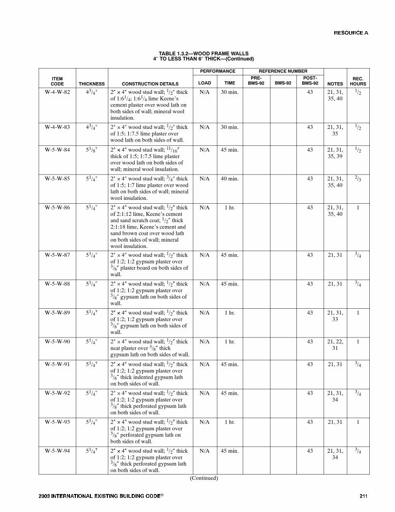
���� ���������� ��� ���� �������� ���® ���
TABLE 1.3.2�WOOD FRAME WALLS4� TO LESS THAN 6� THICK�(Continued)
PERFORMANCE REFERENCE NUMBER
ITEMCODE THICKNESS CONSTRUCTION DETAILS LOAD TIME
PRE-BMS-92 BMS-92
POST-BMS-92 NOTES
REC.HOURS
W-4-W-82 43/4� 2� � 4� wood stud wall; 1/2� thickof 1:61/4; 1:61/4 lime Keene�scement plaster over wood lath onboth sides of wall; mineral woolinsulation.
N/A 30 min. 43 21, 31,35, 40
1/2
W-4-W-83 43/4� 2� � 4� wood stud wall; 1/2� thickof 1:5; 1:7.5 lime plaster overwood lath on both sides of wall.
N/A 30 min. 43 21, 31,35
1/2
W-5-W-84 51/8� 2� � 4� wood stud wall; 11/16�thick of 1:5; 1:7.5 lime plasterover wood lath on both sides ofwall; mineral wool insulation.
N/A 45 min. 43 21, 31,35, 39
1/2
W-5-W-85 51/4� 2� � 4� wood stud wall; 3/4� thickof 1:5; 1:7 lime plaster over woodlath on both sides of wall; mineralwool insulation.
N/A 40 min. 43 21, 31,35, 40
2/3
W-5-W-86 51/4� 2� � 4� wood stud wall; 1/2� thickof 2:1:12 lime, Keene�s cementand sand scratch coat; 1/2� thick2:1:18 lime, Keene�s cement andsand brown coat over wood lathon both sides of wall; mineralwool insulation.
N/A 1 hr. 43 21, 31,35, 40
1
W-5-W-87 51/4� 2� � 4� wood stud wall; 1/2� thickof 1:2; 1:2 gypsum plaster over3/8� plaster board on both sides ofwall.
N/A 45 min. 43 21, 31 3/4
W-5-W-88 51/4� 2� � 4� wood stud wall; 1/2� thickof 1:2; 1:2 gypsum plaster over3/8� gypsum lath on both sides ofwall.
N/A 45 min. 43 21, 31 3/4
W-5-W-89 51/4� 2� � 4� wood stud wall; 1/2� thickof 1:2; 1:2 gypsum plaster over3/8� gypsum lath on both sides ofwall.
N/A 1 hr. 43 21, 31,33
1
W-5-W-90 51/4� 2� � 4� wood stud wall; 1/2� thickneat plaster over 3/8� thickgypsum lath on both sides of wall.
N/A 1 hr. 43 21, 22,31
1
W-5-W-91 51/4� 2� � 4� wood stud wall; 1/2� thickof 1:2; 1:2 gypsum plaster over3/8� thick indented gypsum lathon both sides of wall.
N/A 45 min. 43 21, 31 3/4
W-5-W-92 51/4� 2� � 4� wood stud wall; 1/2� thickof 1:2; 1:2 gypsum plaster over3/8� thick perforated gypsum lathon both sides of wall.
N/A 45 min. 43 21, 31,34
3/4
W-5-W-93 51/4� 2� � 4� wood stud wall; 1/2� thickof 1:2; 1:2 gypsum plaster over3/8� perforated gypsum lath onboth sides of wall.
N/A 1 hr. 43 21, 31 1
W-5-W-94 51/4� 2� � 4� wood stud wall; 1/2� thickof 1:2; 1:2 gypsum plaster over3/8� thick perforated gypsum lathon both sides of wall.
N/A 45 min. 43 21, 31,34
3/4
(Continued)
�� ����

��� ���� ���������� ��� ���� �������� ���®
TABLE 1.3.2�WOOD FRAME WALLS4� TO LESS THAN 6� THICK�(Continued)
PERFORMANCE REFERENCE NUMBER
ITEMCODE THICKNESS CONSTRUCTION DETAILS LOAD TIME
PRE-BMS-92 BMS-92
POST-BMS-92 NOTES
REC.HOURS
W-5-W-95 51/2� 2� � 4� wood stud wall; 1/2� thickof 1:2; 1:2 gypsum plaster over1/2� thick wood fiberboard plasterbase on both sides of wall.
N/A 35 min. 43 21, 31,36
1/2
W-5-W-96 53/4� 2� � 4� wood stud wall; 1/2� thickof 1:2; 1:2 gypsum plaster over7/8� thick flameproofed woodfiberboard on both sides of wall.
N/A 1 hr. 43 21, 31,37
1
Notes:1. All specimens 8 feet or 8 feet 8 inches by 10 feet, 4 inches, i.e. one-half of furnace size. See Note 42 for design cross section.2. Specimens tested in tandem (two per exposure).3. Test per ASA No. A2-1934 except where unloaded. Also, panels were of �half� size of furnace opening. Time value signifies a thermal failure time.4. Two-inch by 4-inch studs: 16 inches on center.; where 10 feet 4 inches, blocking at 2-foot 4-inch height.5. Facing 4 feet by 8 feet, cement-asbestos board sheets, 3/16 inch thick.6. Sheathing (diagonal): 25/22 inch by 51/2 inch, 1 inch by 6 inches pine.7. Facing shingles: 24 inches by 12 inches by 5/32 inch where used.8. Asbestos felt: asphalt sat between sheathing and shingles.9. Load: 30,500 pounds or 360 psi/stud where load was tested.10. Walls were tested beyond achievement of first test end point. A load-bearing time in excess of performance time indicates that although thermal criteria were
exceeded, load-bearing ability continued.11. Wall was rated for one hour combustible use in original source.12. Hose steam test specimen. See table entry of similar design above for recommended rating.13. Rated one and one-fourth hour load bearing. Rated one and one-half hour nonload bearing.14. Failed hose stream.15. Test terminated due to flame penetration.16. Test terminated - local back face temperature rise.17. Nominal 2-inch by 4-inch wood studs of No. 1 common or better lumber set edgewise. Two-inch by four-inch plates at top and bottom and blocking ad mid
height of wall.18. Cavity insulation consists of rock wool bats 1.0 lb./ft.2 of filled cavity area.19. Cavity insulation consists of glass wool bats 0.6 lb./ft.2 of filled cavity area.20. Cavity insulation consists of blown-in forck wool 2.0 lbs./ft.2 of filled cavity area21. Mix proportions for plastered walls as follows: first ratio indicates scratch coat mix, weight of dry plaster: dry sand; second ratio indicates brown coat mix.22. �Neat� plaster is taken to mean unsanded wood-fiber gypsum plaster.23. Load: 360 psi of net stud cross sectional area.24. Rated as nonload bearing.25. Nominal 2-inch by 4-inch studs per Note 17, spaced at 16 inches on center.26. Horizontal joints in facing material supported by 2-inch by 4-inch blocking within wall.27. Facings secured with 6d casing nails. Nail holes predrilled and were 0.02 to 0.03 inch smaller than nail diameter.28. Cavity insulation consists of mineral wool bats weighing 2 lbs./ft.2 of filled cavity area.29. Interior wall face exposed to fire.30. Exterior wall faced exposed to fire.31. Nominal 2-inch by 4-inch studs of yellow pine or Douglas-fir spaced 16 inches on center in a single row.32. Studs as in Note 31 except double row, with studs in rows staggered.33. Six roofing nails with metal-lath pads around heats to each 16-inch by 48-inch lath.34. Areas of holes less than 23/4 percent of area of lath.35. Wood laths were nailed with either 3d or 4d nails, one nail to each bearing, and the end joining broken every seventh course.36. One-half-inch thick fiberboard plaster base nailed with 3d or 4d common wire nails spaced 4 to 6 inches on center.37. Seven-eighths-inch thick fiberboard plaster base nailed with 5d common wire nails spaced 4 to 6 inches on center.38. Mineral wood bats 1.05 to 1.25 lbs./ft.2 with waterproofed-paper backing.39. Blown-in mineral wool insulation, 2.2 lbs./ft.2.40. Mineral wool bats, 1.4 lbs./ft.2 with waterproofed-paper backing.41. Mineral wood bats, 0.9 lb./ft.2.42. See wall design diagram, below.
A C E G
B D F
43. Duplicate specimen of W-4-W-7, tested simultaneously with W-4-W-7 in 18-foot test furnace.
�� ����
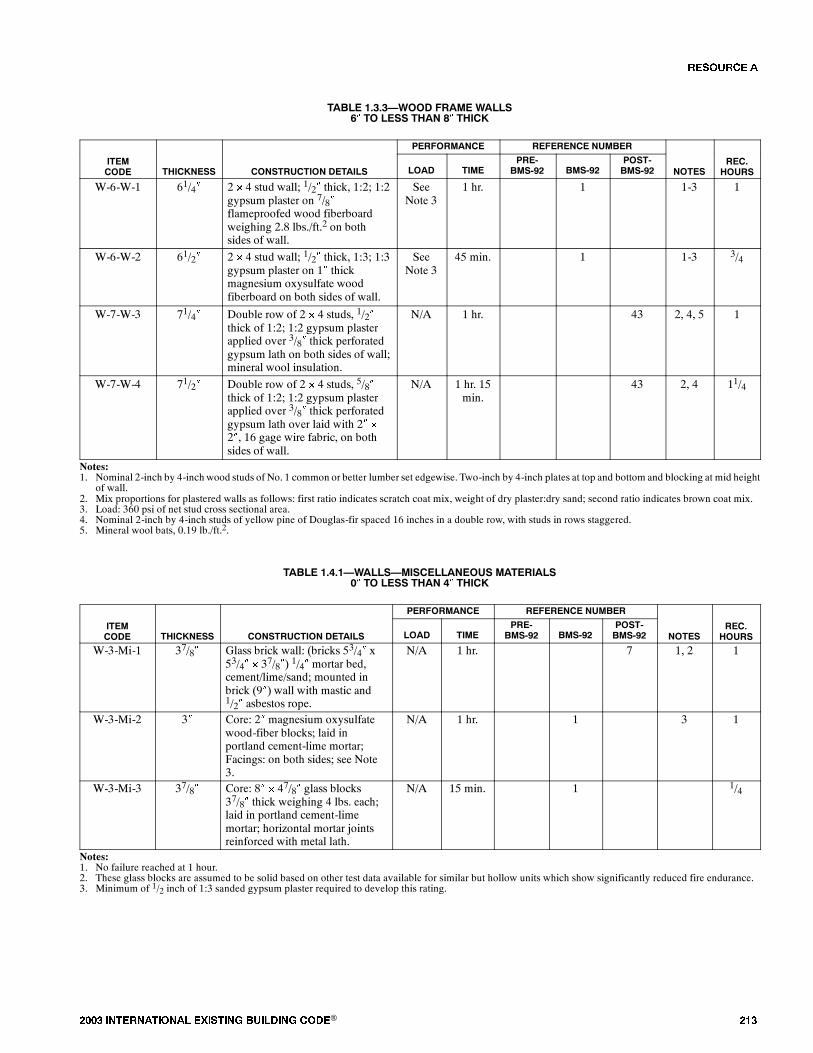
���� ���������� ��� ���� �������� ���® ���
TABLE 1.3.3�WOOD FRAME WALLS6� TO LESS THAN 8� THICK
PERFORMANCE REFERENCE NUMBER
ITEMCODE THICKNESS CONSTRUCTION DETAILS LOAD TIME
PRE-BMS-92 BMS-92
POST-BMS-92 NOTES
REC.HOURS
W-6-W-1 61/4� 2 � 4 stud wall; 1/2� thick, 1:2; 1:2gypsum plaster on 7/8�flameproofed wood fiberboardweighing 2.8 lbs./ft.2 on bothsides of wall.
SeeNote 3
1 hr. 1 1-3 1
W-6-W-2 61/2� 2 � 4 stud wall; 1/2� thick, 1:3; 1:3gypsum plaster on 1� thickmagnesium oxysulfate woodfiberboard on both sides of wall.
SeeNote 3
45 min. 1 1-3 3/4
W-7-W-3 71/4� Double row of 2 � 4 studs, 1/2�thick of 1:2; 1:2 gypsum plasterapplied over 3/8� thick perforatedgypsum lath on both sides of wall;mineral wool insulation.
N/A 1 hr. 43 2, 4, 5 1
W-7-W-4 71/2� Double row of 2 � 4 studs, 5/8�thick of 1:2; 1:2 gypsum plasterapplied over 3/8� thick perforatedgypsum lath over laid with 2� �
2�, 16 gage wire fabric, on bothsides of wall.
N/A 1 hr. 15min.
43 2, 4 11/4
Notes:1. Nominal 2-inch by 4-inch wood studs of No. 1 common or better lumber set edgewise. Two-inch by 4-inch plates at top and bottom and blocking at mid height
of wall.2. Mix proportions for plastered walls as follows: first ratio indicates scratch coat mix, weight of dry plaster:dry sand; second ratio indicates brown coat mix.3. Load: 360 psi of net stud cross sectional area.4. Nominal 2-inch by 4-inch studs of yellow pine of Douglas-fir spaced 16 inches in a double row, with studs in rows staggered.5. Mineral wool bats, 0.19 lb./ft.2.
TABLE 1.4.1�WALLS�MISCELLANEOUS MATERIALS0� TO LESS THAN 4� THICK
PERFORMANCE REFERENCE NUMBER
ITEMCODE THICKNESS CONSTRUCTION DETAILS LOAD TIME
PRE-BMS-92 BMS-92
POST-BMS-92 NOTES
REC.HOURS
W-3-Mi-1 37/8� Glass brick wall: (bricks 53/4� x53/4� � 37/8�) 1/4� mortar bed,cement/lime/sand; mounted inbrick (9�) wall with mastic and1/2� asbestos rope.
N/A 1 hr. 7 1, 2 1
W-3-Mi-2 3� Core: 2� magnesium oxysulfatewood-fiber blocks; laid inportland cement-lime mortar;Facings: on both sides; see Note3.
N/A 1 hr. 1 3 1
W-3-Mi-3 37/8� Core: 8� � 47/8� glass blocks37/8� thick weighing 4 lbs. each;laid in portland cement-limemortar; horizontal mortar jointsreinforced with metal lath.
N/A 15 min. 1 1/4
Notes:1. No failure reached at 1 hour.2. These glass blocks are assumed to be solid based on other test data available for similar but hollow units which show significantly reduced fire endurance.3. Minimum of 1/2 inch of 1:3 sanded gypsum plaster required to develop this rating.
�� ����

��� ���� ���������� ��� ���� �������� ���®
TABLE 1.4.2�WALLS�MISCELLANEOUS MATERIALS4� TO LESS THAN 6� THICK
PERFORMANCE REFERENCE NUMBER
ITEMCODE THICKNESS CONSTRUCTION DETAILS LOAD TIME
PRE-BMS-92 BMS-92
POST-BMS-92 NOTES
REC.HOURS
W-4-Mi-1 4� Core: 3� magnesium oxysulfatewood-fiber blocks; laid inportland cement mortar; Facings:both sides; see Note 1.
N/A 2 hrs. 1 2
Notes:1. One-half inch sanded gypsum plaster. Voids in hollow blocks to be not more than 30 percent.
�� ����

���� ���������� ��� ���� �������� ���® ���
FIGURE 1.5.1�FINISH RATINGS�INORGANIC MATERIALS
0
FIRE RESISTANCE RATING (HOURS)
NUMBER OFASSEMBLIES
12 24 36 48
5
10
0
The number in each box iskeyed to the last number in theItem Code column in the Table.
For example:
F.R.I.-14
11
12
16
10
60
2
5
14
14
6
7
15
3
13
9 8
TABLE 1.5.1�FINISH RATINGS�INORGANIC MATERIALS
PERFORMANCE REFERENCE NUMBERREC
ITEMCODE THICKNESS CONSTRUCTION DETAILS FINISH RATING
PRE-BMS-92 BMS-92
POST-BMS-92 NOTES
REC.F.R.(MIN.)
F.R.-I-1 9/16� 3/8� gypsum wallboard faced with3/16� cement-asbestos board.
20 minutes 1 1, 2 15
F.R.-I-2 11/16� 1/2� gypsum sheathing faced with3/16� cement-asbestos board.
20 minutes 1 1, 2 20
F.R.-I-3 3/16� 3/16� cement-asbestos board overuninsulated cavity.
10 minutes 1 1, 2 5
F.R.-I-4 3/16� 3/16� cement-asbestos board overinsulated cavities.
5 minutes 1 1, 2 5
F.R.-I-5 3/4� 3/4� thick 1:2; 1:3 gypsum plasterover paper backed metal lath.
20 minutes 1 1, 2, 3 20
F.R.-I-6 3/4� 3/4� thick portland cement plasteron metal lath.
10 minutes 1 1, 2 10
F.R.-I-7 3/4� 3/4� thick 1:5; 1:7.5 lime plasteron metal lath.
10 minutes 1 1, 2 10
F.R.-I-8 1� 1� thick neat gypsum plaster onmetal lath.
35 minutes 1 1, 2, 4 35
F.R.-I-9 3/4� 3/4� thick neat gypsum plaster onmetal lath.
30 minutes 1 1, 2, 4 30
F.R.-I-10 3/4� 3/4� thick 1:2; 1:2 gypsum plasteron metal lath.
15 minutes 1 1, 2, 3 15
F.R.-I-11 1/2� Same as F.R.-1-7, except 1/2� thickon wood lath.
15 minutes 1 1, 2, 3 15
F.R.-I-12 1/2� 1/2� thick 1:2; 1:3 gypsum plasteron wood lath.
15 minutes 1 1, 2, 3 15
(Continued)
�� ����
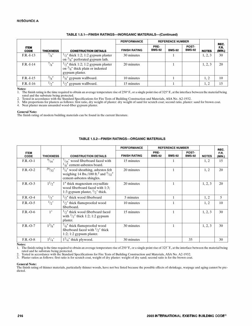
��� ���� ���������� ��� ���� �������� ���®
TABLE 1.5.1�FINISH RATINGS�INORGANIC MATERIALS�(Continued)
ITEMCODE
REC.F.R.(MIN.)NOTES
REFERENCE NUMBERPERFORMANCE
CONSTRUCTION DETAILSTHICKNESSITEMCODE
REC.F.R.(MIN.)NOTES
POST-BMS-92BMS-92
PRE-BMS-92FINISH RATINGCONSTRUCTION DETAILSTHICKNESS
F.R.-I-13 7/8� 1/2� thick 1:2; 1:2 gypsum plasteron 3/8� perforated gypsum lath.
30 minutes 1 1, 2, 3 30
F.R.-I-14 7/8� 1/2� thick 1:2; 1:2 gypsum plasteron 3/8� thick plain or indentedgypsum plaster.
20 minutes 1 1, 2, 3 20
F.R.-I-15 3/8� 3/8� gypsum wallboard. 10 minutes 1 1, 2 10
F.R.-I-16 1/2� 1/2� gypsum wallboard. 15 minutes 1 1, 2 15
Notes:1. The finish rating is the time required to obtain an average temperature rise of 250�F., or a single point rise of 325�F., at the interface between the material being
rated and the substrate being protected.2. Tested in accordance with the Standard Specifications for Fire Tests of Building Construction and Materials, ASA No. A2-1932.3. Mix proportions for plasters as follows: first ratio, dry weight of plaster: dry weight of sand for scratch coat; second ratio, plaster: sand for brown coat.4. Neat plaster means unsanded wood-fiber gypsum plaster.
General Note:The finish rating of modern building materials can be found in the current literature.
TABLE 1.5.2�FINISH RATINGS�ORGANIC MATERIALS
PERFORMANCE REFERENCE NUMBERREC
ITEMCODE THICKNESS CONSTRUCTION DETAILS FINISH RATING
PRE-BMS-92 BMS-92
POST-BMS-92 NOTES
REC.F.R.(MIN.)
F.R.-O-1 9/16� 7/16� wood fiberboard faced with1/8� cement-asbestos board.
15 minutes 1 1, 2 15
F.R.-O-2 29/32� 3/4� wood sheathing, asbestos feltweighing 14 lbs./100 ft.2 and 5/32�cement-asbestos shingles.
20 minutes 1 1, 2 20
F.R.-O-3 11/2� 1� thick magnesium oxysulfatewood fiberboard faced with 1:3;1:3 gypsum plaster, 1/2� thick.
20 minutes 1 1, 2, 3 20
F.R.-O-4 1/2� 1/2� thick wood fiberboard 5 minutes 1 1, 2 5
F.R.-O-5 1/2� 1/2� thick flameproofed woodfiberboard.
10 minutes 1 1, 2 10
F.R.-O-6 1� 1/2� thick wood fiberboard facedwith 1/2� thick 1:2; 1:2 gypsumplaster.
15 minutes 1 1, 2, 3 30
F.R.-O-7 13/8� 7/8� thick flameproofed woodfiberboard faced with 1/2� thick1:2; 1:2 gypsum plaster.
30 minutes 1 1, 2, 3 30
F.R.-O-8 11/4� 11/4� thick plywood. 30 minutes 35 30Notes:1. The finish rating is the time required to obtain an average temperature rise of 250�F., or a single point rise of 325�F., at the interface between the material being
rated and he substrate being protected.2. Tested in accordance with the Standard Specifications for Fire Tests of Building Construction and Materials, ASA No. A2-1932.3. Plaster ratios as follows: first ratio is for scratch coat, weight of dry plaster: weight of dry sand; second ratio is for the brown coat.
General Note:The finish rating of thinner materials, particularly thinner woods, have not bee listed because the possible effects of shrinkage, warpage and aging cannot be pre-dicted.
�� ����
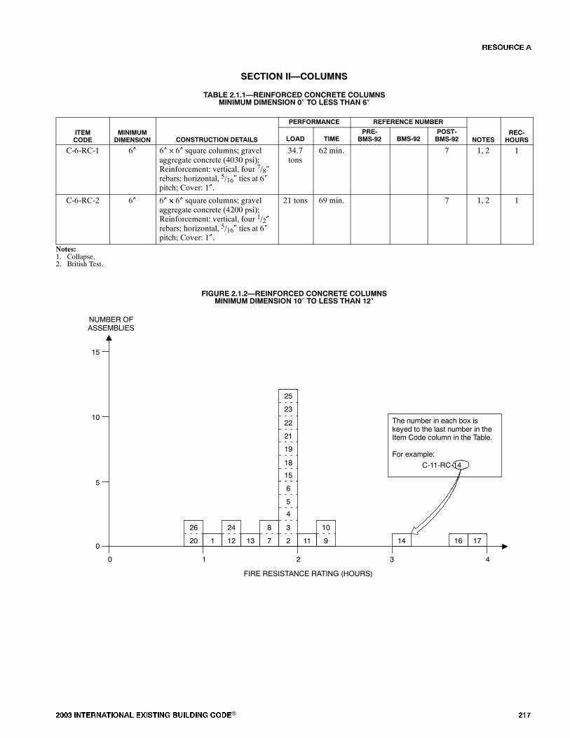
���� ���������� ��� ���� �������� ���® ���
������� ��������
TABLE 2.1.1�REINFORCED CONCRETE COLUMNSMINIMUM DIMENSION 0� TO LESS THAN 6�
PERFORMANCE REFERENCE NUMBER
ITEMCODE
MINIMUMDIMENSION CONSTRUCTION DETAILS LOAD TIME
PRE-BMS-92 BMS-92
POST-BMS-92 NOTES
REC-HOURS
C-6-RC-1 6� 6� � 6� square columns; gravelaggregate concrete (4030 psi);Reinforcement: vertical, four 7/8�rebars; horizontal, 5/16� ties at 6�pitch; Cover: 1�.
34.7tons
62 min. 7 1, 2 1
C-6-RC-2 6� 6� � 6� square columns; gravelaggregate concrete (4200 psi);Reinforcement: vertical, four 1/2�rebars; horizontal, 5/16� ties at 6�pitch; Cover: 1�.
21 tons 69 min. 7 1, 2 1
Notes:1. Collapse.2. British Test.
FIGURE 2.1.2�REINFORCED CONCRETE COLUMNSMINIMUM DIMENSION 10� TO LESS THAN 12�
3
4
5
0
FIRE RESISTANCE RATING (HOURS)
NUMBER OFASSEMBLIES
1 2 3 4
5
15
02
6
The number in each box iskeyed to the last number in theItem Code column in the Table.
For example:
C-11-RC-14
10
9 17161411
18
19
21
15
22
8
713
24
121
26
20
1023
25
�� ����
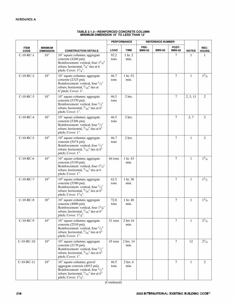
��� ���� ���������� ��� ���� �������� ���®
TABLE 2.1.2�REINFORCED CONCRETE COLUMNMINIMUM DIMENSION 10� TO LESS THAN 12�
PERFORMANCE REFERENCE NUMBER
ITEMCODE
MINIMUMDIMENSION CONSTRUCTION DETAILS LOAD TIME
PRE-BMS-92 BMS-92
POST-BMS-92 NOTES
REC-HOURS
C-10-RC-1 10� 10� square columns; aggregateconcrete (4260 psi);Reinforcement: vertical, four 11/4�rebars; horizontal, 3/8� ties at 6pitch; Cover: 11/4�.
92.2tons
1 hr. 2min.
7 1 1
C-10-RC-2 10� 10� square columns; aggregateconcrete (2325 psi);Reinforcement: vertical, four 1/2�rebars; horizontal, 5/16� ties at6�pitch; Cover: 1�.
46.7tons
1 hr. 52min.
7 1 13/4
C-10-RC-3 10� 10� square columns; aggregateconcrete (5370 psi);Reinforcement: vertical, four 1/2�rebars; horizontal, 5/16� ties at 6�pitch; Cover: 1�.
46.5tons
2 hrs. 7 2, 3, 11 2
C-10-RC-4 10� 10� square columns; aggregateconcrete (5206 psi);Reinforcement: vertical, four 1/2�rebars; horizontal, 5/16� ties at 6�pitch; Cover: 1�.
46.5tons
2 hrs. 7 2, 7 2
C-10-RC-5 10� 10� square columns; aggregateconcrete (5674 psi);Reinforcement: vertical, four 1/2�rebars; horizontal, 5/16� ties at 6�pitch; Cover: 1�.
46.7tons
2 hrs. 7 1 2
C-10-RC-6 10� 10� square columns; aggregateconcrete (5150 psi);Reinforcement: vertical, four 11/2�rebars; horizontal, 5/16� ties at 6pitch; Cover: 1�.
66 tons 1 hr. 43min.
7 1 13/4
C-10-RC-7 10� 10� square columns; aggregateconcrete (5580 psi);Reinforcement: vertical, four 1/2�rebars; horizontal, 5/16� ties at 6�pitch; Cover: 11/8�.
62.5tons
1 hr. 38min.
7 1 11/2
C-10-RC-8 10� 10� square columns; aggregateconcrete (4080 psi);Reinforcement: vertical, four 11/8�rebars; horizontal, 5/16� ties at 6�pitch; Cover: 11/8�.
72.8tons
1 hr. 48min.
7 1 13/4
C-10-RC-9 10� 10� square columns; aggregateconcrete (2510 psi);Reinforcement: vertical, four 1/2�rebars; horizontal, 5/16� ties at 6�pitch; Cover: 1�.
51 tons 2 hrs 16min.
7 1 21/4
C-10-RC-10 10� 10� square columns; aggregateconcrete (2170 psi);Reinforcement: vertical, four 1/2�rebars; horizontal, 5/16� ties at 6�pitch; Cover: 1�.
45 tons 2 hrs. 14min.
7 12 21/4
C-10-RC-11 10� 10� square columns; gravelaggregate concrete (4015 psi);Reinforcement: vertical, four 1/2�rebars; horizontal, 5/16� ties at 6�pitch; Cover: 11/8�.
46.5tons
2 hrs. 6min.
7 1 2
(Continued)
�� ����
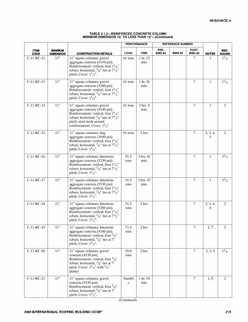
���� ���������� ��� ���� �������� ���® ���
TABLE 2.1.2�REINFORCED CONCRETE COLUMNMINIMUM DIMENSION 10� TO LESS THAN 12��(Continued)
ITEMCODE
REC-HOURSNOTES
REFERENCE NUMBERPERFORMANCE
CONSTRUCTION DETAILSMINIMUMDIMENSION
ITEMCODE
REC-HOURSNOTES
POST-BMS-92BMS-92
PRE-BMS-92TIMELOADCONSTRUCTION DETAILS
MINIMUMDIMENSION
C-11-RC-12 11� 11� square columns; gravelaggregate concrete (4150 psi);Reinforcement: vertical, four 11/4�rebars; horizontal, 3/8� ties at 71/2�pitch; Cover: 11/2�.
61 tons 1 hr. 23min.
7 1 11/4
C-11-RC-13 11� 11� square columns; gravelaggregate concrete (4380 psi);Reinforcement: vertical, four 11/4�rebars; horizontal, 3/8� ties at 71/2�pitch; Cover: 11/2�.
61 tons 1 hr. 26min.
7 1 11/4
C-11-RC-14 11� 11� square columns; gravelaggregate concrete (4140 psi);Reinforcement: vertical, four 11/4�rebars; horizontal, 3/8� ties at 71/2�pitch; steel mesh aroundreinforcement; Cover: 11/2�.
61 tons 3 hrs. 9min.
7 1 3
C-11-RC-15 11� 11� square columns; slagaggregate concrete (3690 psi);Reinforcement: vertical, four 11/4�rebars; horizontal, 3/8� ties at 71/2�pitch; Cover: 11/2�.
91 tons 2 hrs. 7 2, 3, 4,5
2
C-11-RC-16 11� 11� square columns; limestoneaggregate concrete (5230 psi);Reinforcement: vertical, four 11/4�rebars; horizontal, 3/8� ties at 71/2�pitch; Cover: 11/2�.
91.5tons
3 hrs. 41min.
7 1 31/2
C-11-RC-17 11� 11� square columns; limestoneaggregate concrete (5530 psi);Reinforcement: vertical, four 11/4�rebars; horizontal, 3/8� ties at 71/2�pitch; Cover: 11/2�.
91.5tons
3 hrs. 47min.
7 1 31/2
C-11-RC-18 11� 11� square columns; limestoneaggregate concrete (5280 psi);Reinforcement: vertical, four 11/4�rebars; horizontal, 3/8� ties at 71/2�pitch; Cover: 11/2�.
91.5tons
2 hrs. 7 2, 3, 4,6
2
C-11-RC-19 11� 11� square columns; limestoneaggregate concrete (4180 psi);Reinforcement: vertical, four 5/8�rebars; horizontal, 3/8� ties at 7�pitch; Cover: 11/2�.
71.4tons
2 hrs. 7 2, 7 2
C-11-RC-20 11� 11� square columns; gravelconcrete (4530 psi);Reinforcement: vertical, four 5/8�rebars; horizontal, 3/8� ties at 7�pitch; Cover: 11/2� with 1/2�plaster.
58.8tons
2 hrs. 7 2, 3, 9 11/4
C-11-RC-21 11� 11� square columns; gravelconcrete (3520 psi);Reinforcement: vertical, four 5/8�rebars; horizontal, 3/8� ties at 7�pitch; Cover: 11/2�.
Variable
1 hr. 24min.
7 1, 8 2
(Continued)
�� ����
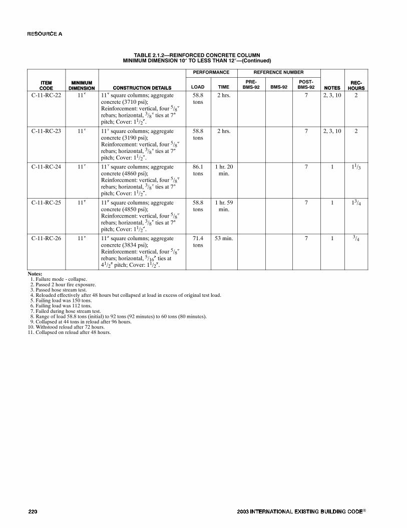
��� ���� ���������� ��� ���� �������� ���®
TABLE 2.1.2�REINFORCED CONCRETE COLUMNMINIMUM DIMENSION 10� TO LESS THAN 12��(Continued)
ITEMCODE
REC-HOURSNOTES
REFERENCE NUMBERPERFORMANCE
CONSTRUCTION DETAILSMINIMUMDIMENSION
ITEMCODE
REC-HOURSNOTES
POST-BMS-92BMS-92
PRE-BMS-92TIMELOADCONSTRUCTION DETAILS
MINIMUMDIMENSION
C-11-RC-22 11� 11� square columns; aggregateconcrete (3710 psi);Reinforcement: vertical, four 5/8�rebars; horizontal, 3/8� ties at 7�pitch; Cover: 11/2�.
58.8tons
2 hrs. 7 2, 3, 10 2
C-11-RC-23 11� 11� square columns; aggregateconcrete (3190 psi);Reinforcement: vertical, four 5/8�rebars; horizontal, 3/8� ties at 7�pitch; Cover: 11/2�.
58.8tons
2 hrs. 7 2, 3, 10 2
C-11-RC-24 11� 11� square columns; aggregateconcrete (4860 psi);Reinforcement: vertical, four 5/8�rebars; horizontal, 3/8� ties at 7�pitch; Cover: 11/2�.
86.1tons
1 hr. 20min.
7 1 11/3
C-11-RC-25 11� 11� square columns; aggregateconcrete (4850 psi);Reinforcement: vertical, four 5/8�rebars; horizontal, 3/8� ties at 7�pitch; Cover: 11/2�.
58.8tons
1 hr. 59min.
7 1 13/4
C-11-RC-26 11� 11� square columns; aggregateconcrete (3834 psi);Reinforcement: vertical, four 5/8�rebars; horizontal, 5/16� ties at41/2� pitch; Cover: 11/2�.
71.4tons
53 min. 7 1 3/4
Notes:1. Failure mode - collapse.2. Passed 2 hour fire exposure.3. Passed hose stream test.4. Reloaded effectively after 48 hours but collapsed at load in excess of original test load.5. Failing load was 150 tons.6. Failing load was 112 tons.7. Failed during hose stream test.8. Range of load 58.8 tons (initial) to 92 tons (92 minutes) to 60 tons (80 minutes).9. Collapsed at 44 tons in reload after 96 hours.10. Withstood reload after 72 hours.11. Collapsed on reload after 48 hours.
�� ����
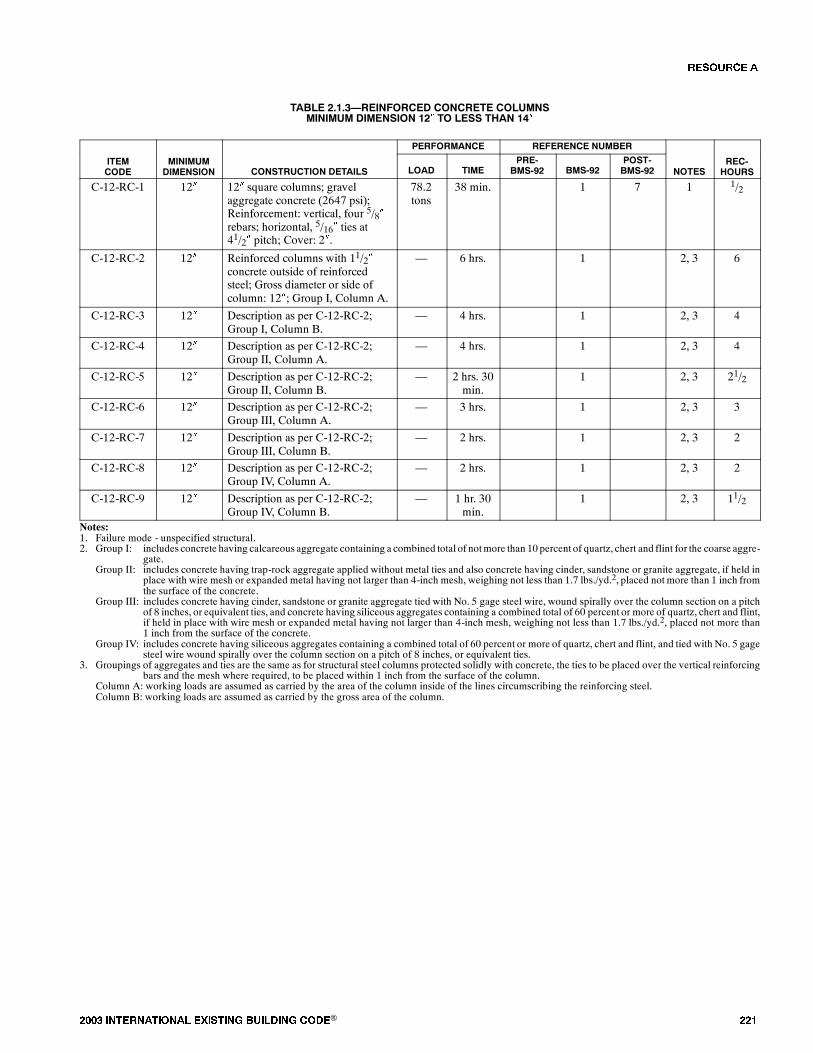
���� ���������� ��� ���� �������� ���® ���
TABLE 2.1.3�REINFORCED CONCRETE COLUMNSMINIMUM DIMENSION 12� TO LESS THAN 14�
PERFORMANCE REFERENCE NUMBER
ITEMCODE
MINIMUMDIMENSION CONSTRUCTION DETAILS LOAD TIME
PRE-BMS-92 BMS-92
POST-BMS-92 NOTES
REC-HOURS
C-12-RC-1 12� 12� square columns; gravelaggregate concrete (2647 psi);Reinforcement: vertical, four 5/8�rebars; horizontal, 5/16� ties at41/2� pitch; Cover: 2�.
78.2tons
38 min. 1 7 1 1/2
C-12-RC-2 12� Reinforced columns with 11/2�concrete outside of reinforcedsteel; Gross diameter or side ofcolumn: 12�; Group I, Column A.
� 6 hrs. 1 2, 3 6
C-12-RC-3 12� Description as per C-12-RC-2;Group I, Column B.
� 4 hrs. 1 2, 3 4
C-12-RC-4 12� Description as per C-12-RC-2;Group II, Column A.
� 4 hrs. 1 2, 3 4
C-12-RC-5 12� Description as per C-12-RC-2;Group II, Column B.
� 2 hrs. 30min.
1 2, 3 21/2
C-12-RC-6 12� Description as per C-12-RC-2;Group III, Column A.
� 3 hrs. 1 2, 3 3
C-12-RC-7 12� Description as per C-12-RC-2;Group III, Column B.
� 2 hrs. 1 2, 3 2
C-12-RC-8 12� Description as per C-12-RC-2;Group IV, Column A.
� 2 hrs. 1 2, 3 2
C-12-RC-9 12� Description as per C-12-RC-2;Group IV, Column B.
� 1 hr. 30min.
1 2, 3 11/2
Notes:1. Failure mode - unspecified structural.2. Group I: includes concrete having calcareous aggregate containing a combined total of notmore than 10 percent of quartz, chert and flint for the coarse aggre-
gate.Group II: includes concrete having trap-rock aggregate applied without metal ties and also concrete having cinder, sandstone or granite aggregate, if held in
place with wire mesh or expanded metal having not larger than 4-inch mesh, weighing not less than 1.7 lbs./yd.2, placed not more than 1 inch fromthe surface of the concrete.
Group III: includes concrete having cinder, sandstone or granite aggregate tied with No. 5 gage steel wire, wound spirally over the column section on a pitchof 8 inches, or equivalent ties, and concrete having siliceous aggregates containing a combined total of 60 percent or more of quartz, chert and flint,if held in place with wire mesh or expanded metal having not larger than 4-inch mesh, weighing not less than 1.7 lbs./yd.2, placed not more than1 inch from the surface of the concrete.
Group IV: includes concrete having siliceous aggregates containing a combined total of 60 percent or more of quartz, chert and flint, and tied with No. 5 gagesteel wire wound spirally over the column section on a pitch of 8 inches, or equivalent ties.
3. Groupings of aggregates and ties are the same as for structural steel columns protected solidly with concrete, the ties to be placed over the vertical reinforcingbars and the mesh where required, to be placed within 1 inch from the surface of the column.
Column A: working loads are assumed as carried by the area of the column inside of the lines circumscribing the reinforcing steel.Column B: working loads are assumed as carried by the gross area of the column.
�� ����

��� ���� ���������� ��� ���� �������� ���®
TABLE 2.1.4�REINFORCED CONCRETE COLUMNSMINIMUM DIMENSION 14� TO LESS THAN 16�
PERFORMANCE REFERENCE NUMBER
ITEMCODE
MINIMUMDIMENSION CONSTRUCTION DETAILS LOAD TIME
PRE-BMS-92 BMS-92
POST-BMS-92 NOTES
REC-HOURS
C-14-RC-1 14� 14� square columns; gravelaggregate concrete (4295 psi);Reinforcement: vertical four 3/4�rebars; horizontal: 1/4� ties at 9�pitch; Cover: 11/2�.
86 tons 1 hr. 22min.
7 1 11/4
C-14-RC-2 14� Reinforced concrete columns with11/2� concrete outside reinforcingsteel; Gross diameter or side ofcolumn: 12�; Group I, Column A.
� 7 hrs. 1 2, 3 7
C-14-RC-3 14� Description as per C-14-RC-2;Group II, Column B.
� 5 hrs. 1 2, 3 5
C-14-RC-4 14� Description as per C-14-RC-2;Group III, Column A.
� 5 hrs. 1 2, 3 5
C-14-RC-5 14� Description as per C-14-RC-2;Group IV, Column B.
� 3 hrs. 30min.
1 2, 3 31/2
C-14-RC-6 14� Description as per C-14-RC-2;Group III, Column A.
� 4 hrs. 1 2, 3 4
C-14-RC-7 14� Description as per C-14-RC-2;Group III, Column B.
� 2 hrs. 30min.
1 2, 3 21/2
C-14-RC-8 14� Description as per C-14-RC-2;Group IV, Column A.
� 2 hrs. 30min.
1 2, 3 21/2
C-14-RC-9 14� Description as per C-14-RC-2;Group IV, Column B.
� 1 hr. 30min.
1 2, 3 11/2
Notes:1. Failure mode - main rebars buckled between links at various points.2. Group I: includes concrete having calcareous aggregate containing a combined total of notmore than 10 percent of quartz, chert and flint for the coarse aggre-
gate.Group II: includes concrete having trap-rock aggregate applied without metal ties and also concrete having cinder, sandstone or granite aggregate, if held in
place with wire mesh or expanded metal having not larger than 4-inch mesh, weighing not less than 1.7 lbs./yd.2, placed not more than 1 inch fromthe surface of the concrete.
Group III: includes concrete having cinder, sandstone or granite aggregate tied with No. 5 gage steel wire, wound spirally over the column section on a pitchof 8 inches, or equivalent ties, and concrete having siliceous aggregates containing a combined total of 60 percent or more of quartz, chert and flint,if held in place with wire mesh or expanded metal having not larger than 4-inch mesh, weighing not less than 1.7 lbs./yd.2, placed not more than1 inch from the surface of the concrete.
Group IV: includes concrete having siliceous aggregates containing a combined total of 60 percent or more of quartz, chert and flint, and tied with No. 5 gagesteel wire wound spirally over the column section on a pitch of 8 inches, or equivalent ties.
3. Groupings of aggregates and ties are the same as for structural steel columns protected solidly with concrete, the ties to be placed over the vertical reinforcingbars and the mesh where required, to be placed within 1 inch from the surface of the column.
Column A: working loads are assumed as carried by the area of the column inside of the lines circumscribing the reinforcing steel.Column B: working loads are assumed as carried by the gross area of the column.
�� ����
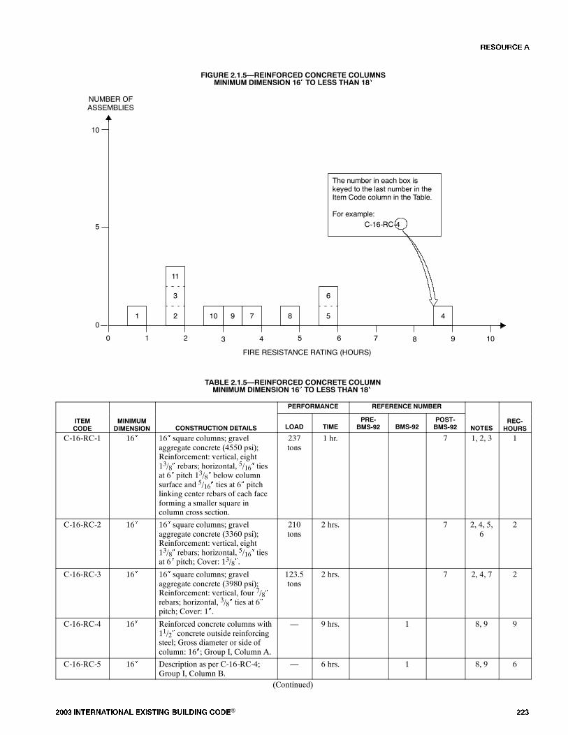
���� ���������� ��� ���� �������� ���® ���
FIGURE 2.1.5�REINFORCED CONCRETE COLUMNSMINIMUM DIMENSION 16� TO LESS THAN 18�
0
FIRE RESISTANCE RATING (HOURS)
NUMBER OFASSEMBLIES
1 2 3 4
5
10
0
The number in each box iskeyed to the last number in theItem Code column in the Table.
For example:C-16-RC-4
3
11
2
5 6 7 8 9 10
1
6
510 7 89 4
TABLE 2.1.5�REINFORCED CONCRETE COLUMNMINIMUM DIMENSION 16� TO LESS THAN 18�
PERFORMANCE REFERENCE NUMBER
ITEMCODE
MINIMUMDIMENSION CONSTRUCTION DETAILS LOAD TIME
PRE-BMS-92 BMS-92
POST-BMS-92 NOTES
REC-HOURS
C-16-RC-1 16� 16� square columns; gravelaggregate concrete (4550 psi);Reinforcement: vertical, eight13/8� rebars; horizontal, 5/16� tiesat 6� pitch 13/8� below columnsurface and 5/16� ties at 6� pitchlinking center rebars of each faceforming a smaller square incolumn cross section.
237tons
1 hr. 7 1, 2, 3 1
C-16-RC-2 16� 16� square columns; gravelaggregate concrete (3360 psi);Reinforcement: vertical, eight13/8� rebars; horizontal, 5/16� tiesat 6� pitch; Cover: 13/8�.
210tons
2 hrs. 7 2, 4, 5,6
2
C-16-RC-3 16� 16� square columns; gravelaggregate concrete (3980 psi);Reinforcement: vertical, four 7/8�rebars; horizontal, 3/8� ties at 6�pitch; Cover: 1�.
123.5tons
2 hrs. 7 2, 4, 7 2
C-16-RC-4 16� Reinforced concrete columns with11/2� concrete outside reinforcingsteel; Gross diameter or side ofcolumn: 16�; Group I, Column A.
� 9 hrs. 1 8, 9 9
C-16-RC-5 16� Description as per C-16-RC-4;Group I, Column B.
� 6 hrs. 1 8, 9 6
(Continued)
�� ����
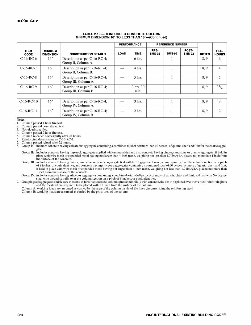
��� ���� ���������� ��� ���� �������� ���®
TABLE 2.1.5�REINFORCED CONCRETE COLUMNMINIMUM DIMENSION 16� TO LESS THAN 18��(Continued)
ITEMCODE
REC-HOURSNOTES
REFERENCE NUMBERPERFORMANCE
CONSTRUCTION DETAILSMINIMUMDIMENSION
ITEMCODE
REC-HOURSNOTES
POST-BMS-92BMS-92
PRE-BMS-92TIMELOADCONSTRUCTION DETAILS
MINIMUMDIMENSION
C-16-RC-6 16� Description as per C-16-RC-4;Group II, Column A.
� 6 hrs. 1 8, 9 6
C-16-RC-7 16� Description as per C-16-RC-4;Group II, Column B.
� 4 hrs. 1 8, 9 4
C-16-RC-8 16� Description as per C-16-RC-4;Group III, Column A.
� 5 hrs. 1 8, 9 5
C-16-RC-9 16� Description as per C-16-RC-4;Group III, Column B.
� 3 hrs. 30min.
1 8, 9 31/2
C-16-RC-10 16� Description as per C-16-RC-4;Group IV, Column A.
� 3 hrs. 1 8, 9 3
C-16-RC-11 16� Description as per C-16-RC-4;Group IV, Column B.
� 2 hrs. 1 8, 9 2
Notes:1. Column passed 1 hour fire test.2. Column passed hose stream test.3. No reload specified.4. Column passed 2 hour fire test.5. Column reloaded successfully after 24 hours.6. Reinforcing details same as C-16-RC-1.7. Column passed reload after 72 hours.8. Group I: includes concrete having calcareous aggregate containing a combined total of notmore than 10 percent of quartz, chert and flint for the coarse aggre-
gate.Group II: includes concrete having trap-rock aggregate applied without metal ties and also concrete having cinder, sandstone or granite aggregate, if held in
place with wire mesh or expanded metal having not larger than 4-inch mesh, weighing not less than 1.7 lbs./yd.2, placed not more than 1 inch fromthe surface of the concrete.
Group III: includes concrete having cinder, sandstone or granite aggregate tied with No. 5 gage steel wire, wound spirally over the column section on a pitchof 8 inches, or equivalent ties, and concrete having siliceous aggregates containing a combined total of 60 percent or more of quartz, chert and flint,if held in place with wire mesh or expanded metal having not larger than 4-inch mesh, weighing not less than 1.7 lbs./yd.2, placed not more than1 inch from the surface of the concrete.
Group IV: includes concrete having siliceous aggregates containing a combined total of 60 percent or more of quartz, chert and flint, and tied with No. 5 gagesteel wire wound spirally over the column section on a pitch of 8 inches, or equivalent ties.
9. Groupings of aggregates and ties are the same as for structural steel columnsprotected solidlywith concrete, the ties to beplaced over the vertical reinforcingbarsand the mesh where required, to be placed within 1 inch from the surface of the column.
Column A: working loads are assumed as carried by the area of the column inside of the lines circumscribing the reinforcing steel.Column B: working loads are assumed as carried by the gross area of the column.
�� ����

���� ���������� ��� ���� �������� ���® ���
TABLE 2.1.6�REINFORCED CONCRETE COLUMNSMINIMUM DIMENSION 18� TO LESS THAN 20�
PERFORMANCE REFERENCE NUMBER
ITEMCODE
MINIMUMDIMENSION CONSTRUCTION DETAILS LOAD TIME
PRE-BMS-92 BMS-92
POST-BMS-92 NOTES
REC-HOURS
C-18-RC-1 18� Reinforced concrete columns with11/2� concrete outside reinforcedsteel; Gross diameter or side ofcolumn: 18�; Group I, Column A.
� 11 hrs. 1 1, 2 11
C-18-RC-2 18� Description as per C-18-RC-1;Group I, Column B.
� 8 hrs. 1 1, 2 8
C-18-RC-3 18� Description as per C-18-RC-1;Group II, Column A.
� 7 hrs. 1 1, 2 7
C-18-RC-4 18� Description as per C-18-RC-1;Group II, Column B.
� 5 hrs. 1 1, 2 5
C-18-RC-5 18� Description as per C-18-RC-1;Group III, Column A.
� 6 hrs. 1 1, 2 6
C-18-RC-6 18� Description as per C-18-RC-1;Group III, Column B.
� 4 hrs. 1 1, 2 4
C-18-RC-7 18� Description as per C-18-RC-1;Group IV, Column A.
� 3 hrs. 30min.
1 1, 2 31/2
C-18-RC-8 18� Description as per C-18-RC-1;Group IV, Column B.
� 2 hrs. 30min.
1 1, 2 21/2
Notes:1. Group I: includes concrete having calcareous aggregate containing a combined total of notmore than 10 percent of quartz, chert and flint for the coarse aggre-
gate.Group II: includes concrete having trap-rock aggregate applied without metal ties and also concrete having cinder, sandstone or granite aggregate, if held in
place with wire mesh or expanded metal having not larger than 4-inch mesh, weighing not less than 1.7 lbs./yd.2, placed not more than 1 inch fromthe surface of the concrete.
Group III: includes concrete having cinder, sandstone or granite aggregate tied with No. 5 gage steel wire, wound spirally over the column section on a pitchof 8 inches, or equivalent ties, and concrete having siliceous aggregates containing a combined total of 60 percent or more of quartz, chert and flint,if held in place with wire mesh or expanded metal having not larger than 4-inch mesh, weighing not less than 1.7 lbs./yd.2, placed not more than1 inch from the surface of the concrete.
Group IV: includes concrete having siliceous aggregates containing a combined total of 60 percent or more of quartz, chert and flint and, tied with No. 5 gagesteel wire wound spirally over the column section on a pitch of 8 inches, or equivalent ties.
2. Groupings of aggregates and ties are the same as for structural steel columns protected solidly with concrete, the ties to be placed over the vertical reinforcingbars and the mesh where required, to be placed within 1 inch from the surface of the column.
Column A: working loads are assumed as carried by the area of the column inside of the lines circumscribing the reinforcing steel.Column B: working loads are assumed as carried by the gross area of the column.
�� ����
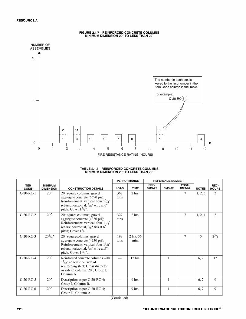
��� ���� ���������� ��� ���� �������� ���®
FIGURE 2.1.7�REINFORCED CONCRETE COLUMNSMINIMUM DIMENSION 20� TO LESS THAN 22�
0
FIRE RESISTANCE RATING (HOURS)
NUMBER OFASSEMBLIES
1 2 3 4
5
10
0
The number in each box iskeyed to the last number in theItem Code column in the Table.
For example:C-20-RC-6
5 6 7 8 9 10
4
6
510 7 89
11 12
2
1
11
3
TABLE 2.1.7�REINFORCED CONCRETE COLUMNSMINIMUM DIMENSION 20� TO LESS THAN 22�
PERFORMANCE REFERENCE NUMBER
ITEMCODE
MINIMUMDIMENSION CONSTRUCTION DETAILS LOAD TIME
PRE-BMS-92 BMS-92
POST-BMS-92 NOTES
REC-HOURS
C-20-RC-1 20� 20� square columns; gravelaggregate concrete (6690 psi);Reinforcement: vertical, four 13/4�rebars; horizontal, 3/8� wire at 6�pitch; Cover 13/4�.
367tons
2 hrs. 7 1, 2, 3 2
C-20-RC-2 20� 20� square columns; gravelaggregate concrete (4330 psi);Reinforcement: vertical, four 13/4�rebars; horizontal, 3/8� ties at 6�pitch; Cover 13/4�.
327tons
2 hrs. 7 1, 2, 4 2
C-20-RC-3 201/4� 20� squarecolumns; gravelaggregate concrete (4230 psi);Reinforcement: vertical, four 11/8�rebars; horizontal, 3/8� wire at 5�pitch; Cover 11/8�.
199tons
2 hrs. 56min.
7 5 23/4
C-20-RC-4 20� Reinforced concrete columns with11/2� concrete outside ofreinforcing steel; Gross diameteror side of column: 20�; Group I,Column A.
� 12 hrs. 1 6, 7 12
C-20-RC-5 20� Description as per C-20-RC-4;Group I, Column B.
� 9 hrs. 1 6, 7 9
C-20-RC-6 20� Description as per C-20-RC-4;Group II, Column A.
� 9 hrs. 1 6, 7 9
(Continued)
�� ����

���� ���������� ��� ���� �������� ���® ���
TABLE 2.1.7�REINFORCED CONCRETE COLUMNSMINIMUM DIMENSION 20� TO LESS THAN 22��(Continued)
C-20-RC-7 20� Description as per C-20-RC-4;Group II, Column B.
� 6 hrs. 1 6, 7 6
C-20-RC-8 20� Description as per C-20-RC-4;Group III, Column A.
� 7 hrs. 1 6, 7 7
C-20-RC-9 20� Description as per C-20-RC-4;Group III, Column B.
� 5 hrs. 1 6, 7 5
C-20-RC-10 20� Description as per C-20-RC-4;Group IV, Column A.
� 4 hrs. 1 6, 7 4
C-20-RC-11 20� Description as per C-20-RC-4;Group IV, Column B.
� 3 hrs. 1 6, 7 3
Notes:1. Passed 2 hour fire test.2. Passed hose stream test.3. Failed during reload at 300 tons.4. Passed reload after 72 hours.5. Failure mode - collapse.6. Group I: includes concrete having calcareous aggregate containing a combined total of notmore than 10 percent of quartz, chert and flint for the coarse aggre-
gate.Group II: includes concrete having trap-rock aggregate applied without metal ties and also concrete having cinder, sandstone or granite aggregate, if held in
place with wire mesh or expanded metal having not larger than 4-inch mesh, weighing not less than 1.7 lbs./yd.2, placed not more than 1 inch fromthe surface of the concrete.
Group III: includes concrete having cinder, sandstone or granite aggregate tied with No. 5 gage steel wire, wound spirally over the column section on a pitchof 8 inches, or equivalent ties, and concrete having siliceous aggregates containing a combined total of 60 percent or more of quartz, chert and flint,if held in place with wire mesh or expanded metal having not larger than 4-inch mesh, weighing not less than 1.7 lbs./yd.2, placed not more than1 inch from the surface of the concrete.
Group IV: includes concrete having siliceous aggregates containing a combined total of 60 percent or more of quartz, chert and flint, and tied with No. 5 gagesteel wire wound spirally over the column section on a pitch of 8 inches, or equivalent ties.
7. Groupings of aggregates and ties are the same as for structural steel columns protected solidly with concrete, the ties to be placed over the vertical reinforcingbars and the mesh where required, to be placed within 1 inch from the surface of the column.
Column A: working loads are assumed as carried by the area of the column inside of the lines circumscribing the reinforcing steel.Column B: working loads are assumed as carried by the gross area of the column.
TABLE 2.1.8�HEXAGONAL REINFORCED CONCRETE COLUMNSMINIMUM DIMENSION 12� TO LESS THAN 14�
PERFORMANCE REFERENCE NUMBER
ITEMCODE
MINIMUMDIMENSION CONSTRUCTION DETAILS LOAD TIME
PRE-BMS-92 BMS-92
POST-BMS-92 NOTES
REC-HOURS
C-12-HRC-1 12� 12� hexagonal columns; gravelaggregate concrete (4420 psi);Reinforcement: vertical, eight 1/2�rebars; horizontal, 5/16� helicalwinding at 11/2� pitch; Cover:1/2�.
88 tons 58 min. 7 1 3/4
C-12-HRC-2 12� 12� hexagonal columns; gravelaggregate concrete (3460 psi);Reinforcement: vertical, eight 1/2�rebars; horizontal, 5/16� helicalwinding at 11/2� pitch; Cover:1/2�.
78.7tons
1 hr. 7 2 1
Notes:1. Failure mode - collapse.2. Test stopped at 1 hour.
�� ����
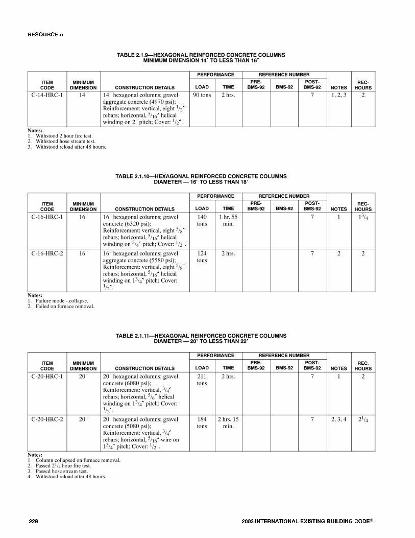
��� ���� ���������� ��� ���� �������� ���®
TABLE 2.1.9�HEXAGONAL REINFORCED CONCRETE COLUMNSMINIMUM DIMENSION 14� TO LESS THAN 16�
PERFORMANCE REFERENCE NUMBER
ITEMCODE
MINIMUMDIMENSION CONSTRUCTION DETAILS LOAD TIME
PRE-BMS-92 BMS-92
POST-BMS-92 NOTES
REC-HOURS
C-14-HRC-1 14� 14� hexagonal columns; gravelaggregate concrete (4970 psi);Reinforcement: vertical, eight 1/2�rebars; horizontal, 5/16� helicalwinding on 2� pitch; Cover: 1/2�.
90 tons 2 hrs. 7 1, 2, 3 2
Notes:1. Withstood 2 hour fire test.2. Withstood hose stream test.3. Withstood reload after 48 hours.
TABLE 2.1.10�HEXAGONAL REINFORCED CONCRETE COLUMNSDIAMETER � 16� TO LESS THAN 18�
PERFORMANCE REFERENCE NUMBER
ITEMCODE
MINIMUMDIMENSION CONSTRUCTION DETAILS LOAD TIME
PRE-BMS-92 BMS-92
POST-BMS-92 NOTES
REC-HOURS
C-16-HRC-1 16� 16� hexagonal columns; gravelconcrete (6320 psi);Reinforcement: vertical, eight 5/8�rebars; horizontal, 5/16� helicalwinding on 3/4� pitch; Cover: 1/2�.
140tons
1 hr. 55min.
7 1 13/4
C-16-HRC-2 16� 16� hexagonal columns; gravelaggregate concrete (5580 psi);Reinforcement: vertical, eight 5/8�rebars; horizontal, 5/16� helicalwinding on 13/4� pitch; Cover:1/2�.
124tons
2 hrs. 7 2 2
Notes:1. Failure mode - collapse.2. Failed on furnace removal.
TABLE 2.1.11�HEXAGONAL REINFORCED CONCRETE COLUMNSDIAMETER � 20� TO LESS THAN 22�
PERFORMANCE REFERENCE NUMBER
ITEMCODE
MINIMUMDIMENSION CONSTRUCTION DETAILS LOAD TIME
PRE-BMS-92 BMS-92
POST-BMS-92 NOTES
REC.HOURS
C-20-HRC-1 20� 20� hexagonal columns; gravelconcrete (6080 psi);Reinforcement: vertical, 3/4�rebars; horizontal, 5/6� helicalwinding on 13/4� pitch; Cover:1/2�.
211tons
2 hrs. 7 1 2
C-20-HRC-2 20� 20� hexagonal columns; gravelconcrete (5080 psi);Reinforcement: vertical, 3/4�rebars; horizontal, 5/16� wire on13/4� pitch; Cover: 1/2�.
184tons
2 hrs. 15min.
7 2, 3, 4 21/4
Notes:1 Column collapsed on furnace removal.2. Passed 21/4 hour fire test.3. Passed hose stream test.4. Withstood reload after 48 hours.
�� ����
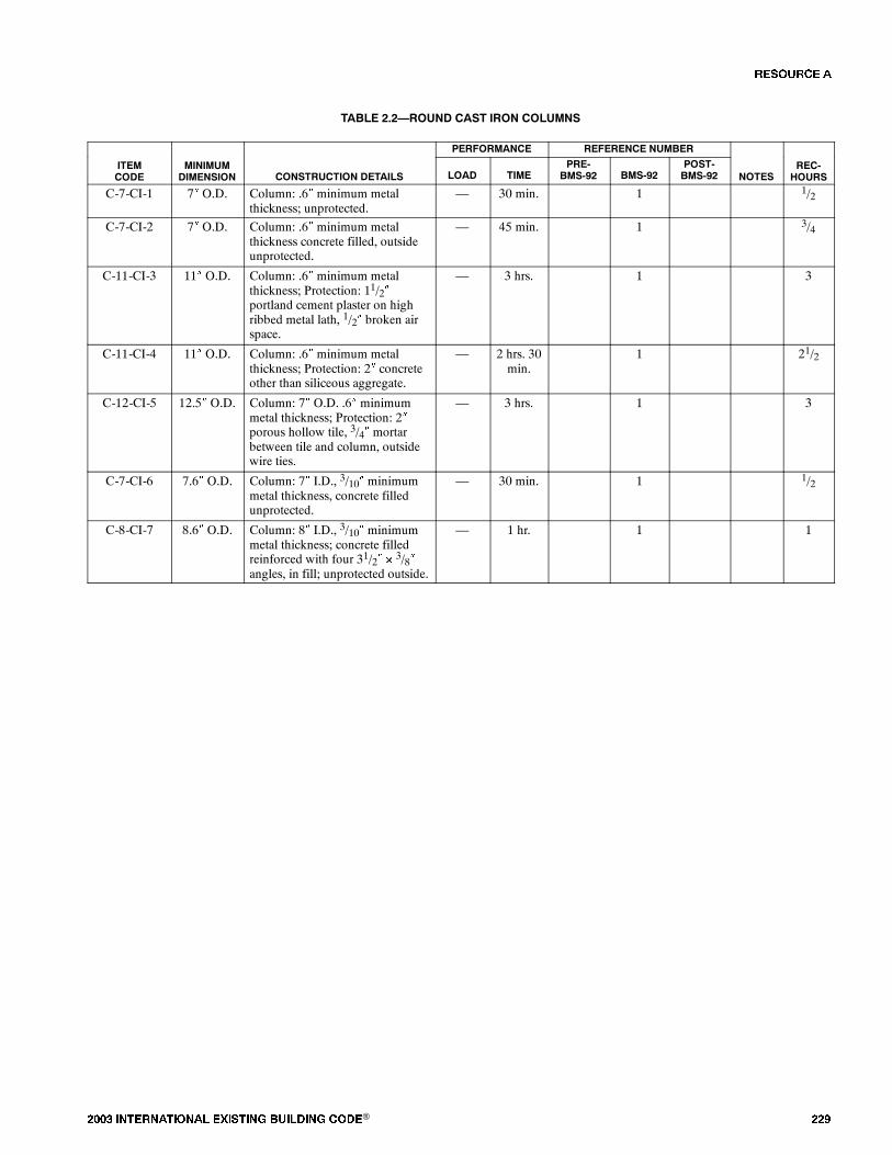
���� ���������� ��� ���� �������� ���® ���
TABLE 2.2�ROUND CAST IRON COLUMNS
PERFORMANCE REFERENCE NUMBER
ITEMCODE
MINIMUMDIMENSION CONSTRUCTION DETAILS LOAD TIME
PRE-BMS-92 BMS-92
POST-BMS-92 NOTES
REC-HOURS
C-7-CI-1 7� O.D. Column: .6� minimum metalthickness; unprotected.
� 30 min. 1 1/2
C-7-CI-2 7� O.D. Column: .6� minimum metalthickness concrete filled, outsideunprotected.
� 45 min. 1 3/4
C-11-CI-3 11� O.D. Column: .6� minimum metalthickness; Protection: 11/2�portland cement plaster on highribbed metal lath, 1/2� broken airspace.
� 3 hrs. 1 3
C-11-CI-4 11� O.D. Column: .6� minimum metalthickness; Protection: 2� concreteother than siliceous aggregate.
� 2 hrs. 30min.
1 21/2
C-12-CI-5 12.5� O.D. Column: 7� O.D. .6� minimummetal thickness; Protection: 2�porous hollow tile, 3/4� mortarbetween tile and column, outsidewire ties.
� 3 hrs. 1 3
C-7-CI-6 7.6� O.D. Column: 7� I.D., 3/10� minimummetal thickness, concrete filledunprotected.
� 30 min. 1 1/2
C-8-CI-7 8.6� O.D. Column: 8� I.D., 3/10� minimummetal thickness; concrete filledreinforced with four 31/2� � 3/8�angles, in fill; unprotected outside.
� 1 hr. 1 1
�� ����
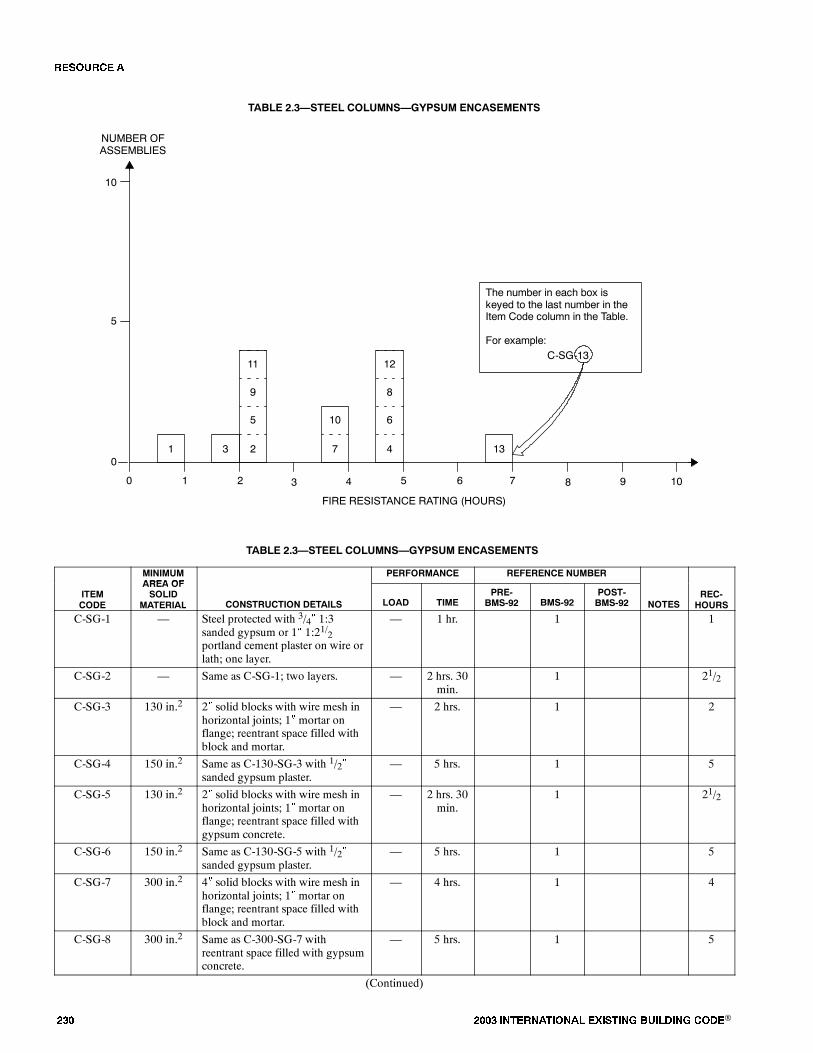
��� ���� ���������� ��� ���� �������� ���®
TABLE 2.3�STEEL COLUMNS�GYPSUM ENCASEMENTS
0
FIRE RESISTANCE RATING (HOURS)
NUMBER OFASSEMBLIES
1 2 3 4
5
10
0
The number in each box iskeyed to the last number in theItem Code column in the Table.
For example:C-SG-13
5
9
2
5 6 7 8 9 10
1 13
10
73
11
6
8
4
12
TABLE 2.3�STEEL COLUMNS�GYPSUM ENCASEMENTS
MINIMUMAREA OF
PERFORMANCE REFERENCE NUMBER
ITEMCODE
AREA OFSOLID
MATERIAL CONSTRUCTION DETAILS LOAD TIMEPRE-
BMS-92 BMS-92POST-BMS-92 NOTES
REC-HOURS
C-SG-1 � Steel protected with 3/4� 1:3sanded gypsum or 1� 1:21/2portland cement plaster on wire orlath; one layer.
� 1 hr. 1 1
C-SG-2 � Same as C-SG-1; two layers. � 2 hrs. 30min.
1 21/2
C-SG-3 130 in.2 2� solid blocks with wire mesh inhorizontal joints; 1� mortar onflange; reentrant space filled withblock and mortar.
� 2 hrs. 1 2
C-SG-4 150 in.2 Same as C-130-SG-3 with 1/2�sanded gypsum plaster.
� 5 hrs. 1 5
C-SG-5 130 in.2 2� solid blocks with wire mesh inhorizontal joints; 1� mortar onflange; reentrant space filled withgypsum concrete.
� 2 hrs. 30min.
1 21/2
C-SG-6 150 in.2 Same as C-130-SG-5 with 1/2�sanded gypsum plaster.
� 5 hrs. 1 5
C-SG-7 300 in.2 4� solid blocks with wire mesh inhorizontal joints; 1� mortar onflange; reentrant space filled withblock and mortar.
� 4 hrs. 1 4
C-SG-8 300 in.2 Same as C-300-SG-7 withreentrant space filled with gypsumconcrete.
� 5 hrs. 1 5
(Continued)
�� ����
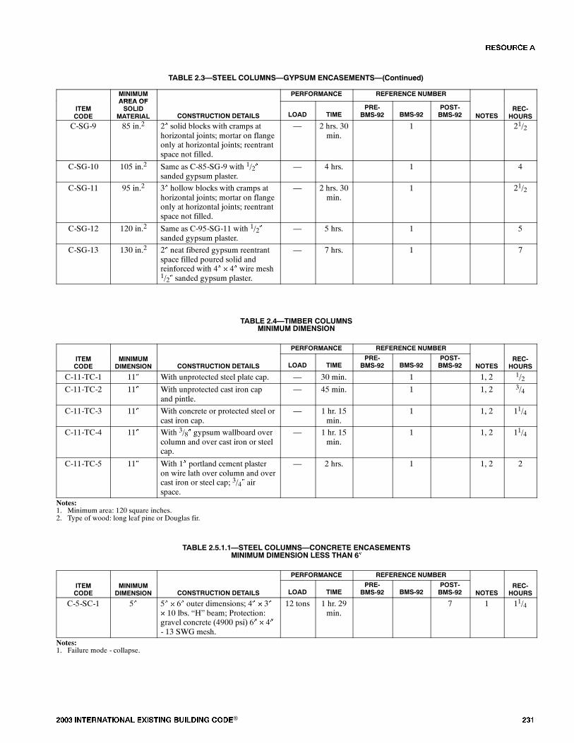
���� ���������� ��� ���� �������� ���® ���
TABLE 2.3�STEEL COLUMNS�GYPSUM ENCASEMENTS�(Continued)
MINIMUMAREA OF
PERFORMANCE REFERENCE NUMBER
ITEMCODE
AREA OFSOLID
MATERIAL CONSTRUCTION DETAILS LOAD TIMEPRE-
BMS-92 BMS-92POST-BMS-92 NOTES
REC-HOURS
C-SG-9 85 in.2 2� solid blocks with cramps athorizontal joints; mortar on flangeonly at horizontal joints; reentrantspace not filled.
� 2 hrs. 30min.
1 21/2
C-SG-10 105 in.2 Same as C-85-SG-9 with 1/2�sanded gypsum plaster.
� 4 hrs. 1 4
C-SG-11 95 in.2 3� hollow blocks with cramps athorizontal joints; mortar on flangeonly at horizontal joints; reentrantspace not filled.
� 2 hrs. 30min.
1 21/2
C-SG-12 120 in.2 Same as C-95-SG-11 with 1/2�sanded gypsum plaster.
� 5 hrs. 1 5
C-SG-13 130 in.2 2� neat fibered gypsum reentrantspace filled poured solid andreinforced with 4� � 4� wire mesh1/2� sanded gypsum plaster.
� 7 hrs. 1 7
TABLE 2.4�TIMBER COLUMNSMINIMUM DIMENSION
PERFORMANCE REFERENCE NUMBER
ITEMCODE
MINIMUMDIMENSION CONSTRUCTION DETAILS LOAD TIME
PRE-BMS-92 BMS-92
POST-BMS-92 NOTES
REC-HOURS
C-11-TC-1 11� With unprotected steel plate cap. � 30 min. 1 1, 2 1/2C-11-TC-2 11� With unprotected cast iron cap
and pintle.� 45 min. 1 1, 2 3/4
C-11-TC-3 11� With concrete or protected steel orcast iron cap.
� 1 hr. 15min.
1 1, 2 11/4
C-11-TC-4 11� With 3/8� gypsum wallboard overcolumn and over cast iron or steelcap.
� 1 hr. 15min.
1 1, 2 11/4
C-11-TC-5 11� With 1� portland cement plasteron wire lath over column and overcast iron or steel cap; 3/4� airspace.
� 2 hrs. 1 1, 2 2
Notes:1. Minimum area: 120 square inches.2. Type of wood: long leaf pine or Douglas fir.
TABLE 2.5.1.1�STEEL COLUMNS�CONCRETE ENCASEMENTSMINIMUM DIMENSION LESS THAN 6�
PERFORMANCE REFERENCE NUMBER
ITEMCODE
MINIMUMDIMENSION CONSTRUCTION DETAILS LOAD TIME
PRE-BMS-92 BMS-92
POST-BMS-92 NOTES
REC-HOURS
C-5-SC-1 5� 5� � 6� outer dimensions; 4� � 3�� 10 lbs. �H� beam; Protection:gravel concrete (4900 psi) 6� � 4�- 13 SWG mesh.
12 tons 1 hr. 29min.
7 1 11/4
Notes:1. Failure mode - collapse.
�� ����
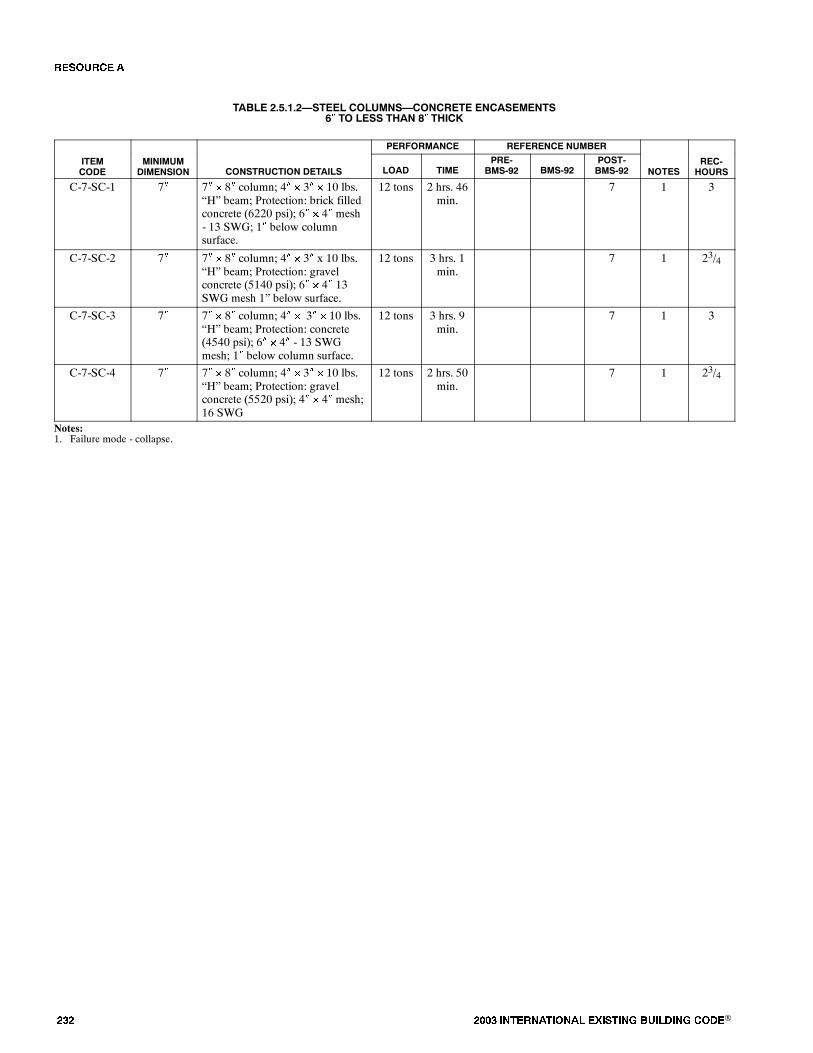
��� ���� ���������� ��� ���� �������� ���®
TABLE 2.5.1.2�STEEL COLUMNS�CONCRETE ENCASEMENTS6� TO LESS THAN 8� THICK
PERFORMANCE REFERENCE NUMBER
ITEMCODE
MINIMUMDIMENSION CONSTRUCTION DETAILS LOAD TIME
PRE-BMS-92 BMS-92
POST-BMS-92 NOTES
REC-HOURS
C-7-SC-1 7� 7� � 8� column; 4� � 3� � 10 lbs.�H� beam; Protection: brick filledconcrete (6220 psi); 6� � 4� mesh- 13 SWG; 1� below columnsurface.
12 tons 2 hrs. 46min.
7 1 3
C-7-SC-2 7� 7� � 8� column; 4� � 3� x 10 lbs.�H� beam; Protection: gravelconcrete (5140 psi); 6� � 4� 13SWG mesh 1� below surface.
12 tons 3 hrs. 1min.
7 1 23/4
C-7-SC-3 7� 7� � 8� column; 4� � 3� � 10 lbs.�H� beam; Protection: concrete(4540 psi); 6� � 4� - 13 SWGmesh; 1� below column surface.
12 tons 3 hrs. 9min.
7 1 3
C-7-SC-4 7� 7� � 8� column; 4� � 3� � 10 lbs.�H� beam; Protection: gravelconcrete (5520 psi); 4� � 4� mesh;16 SWG
12 tons 2 hrs. 50min.
7 1 23/4
Notes:1. Failure mode - collapse.
�� ����
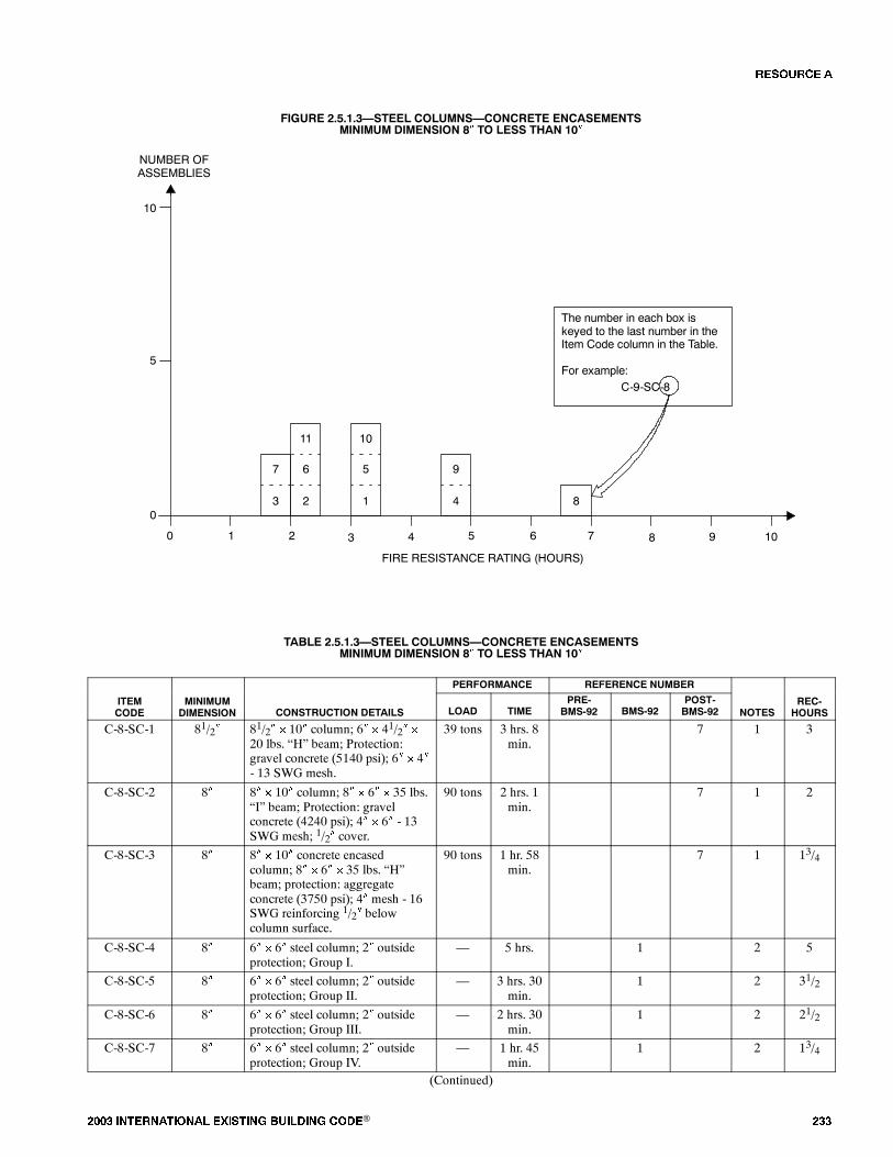
���� ���������� ��� ���� �������� ���® ���
FIGURE 2.5.1.3�STEEL COLUMNS�CONCRETE ENCASEMENTSMINIMUM DIMENSION 8� TO LESS THAN 10�
0
FIRE RESISTANCE RATING (HOURS)
NUMBER OFASSEMBLIES
1 2 3 4
5
10
0
The number in each box iskeyed to the last number in theItem Code column in the Table.
For example:C-9-SC-8
6
11
2
5 6 7 8 9 10
8
9
4
7
3
5
10
1
TABLE 2.5.1.3�STEEL COLUMNS�CONCRETE ENCASEMENTSMINIMUM DIMENSION 8� TO LESS THAN 10�
PERFORMANCE REFERENCE NUMBER
ITEMCODE
MINIMUMDIMENSION CONSTRUCTION DETAILS LOAD TIME
PRE-BMS-92 BMS-92
POST-BMS-92 NOTES
REC-HOURS
C-8-SC-1 81/2� 81/2� � 10� column; 6� � 41/2� �
20 lbs. �H� beam; Protection:gravel concrete (5140 psi); 6� � 4�- 13 SWG mesh.
39 tons 3 hrs. 8min.
7 1 3
C-8-SC-2 8� 8� � 10� column; 8� � 6� � 35 lbs.�I� beam; Protection: gravelconcrete (4240 psi); 4� � 6� - 13SWG mesh; 1/2� cover.
90 tons 2 hrs. 1min.
7 1 2
C-8-SC-3 8� 8� � 10� concrete encasedcolumn; 8� � 6� � 35 lbs. �H�beam; protection: aggregateconcrete (3750 psi); 4� mesh - 16SWG reinforcing 1/2� belowcolumn surface.
90 tons 1 hr. 58min.
7 1 13/4
C-8-SC-4 8� 6� � 6� steel column; 2� outsideprotection; Group I.
� 5 hrs. 1 2 5
C-8-SC-5 8� 6� � 6� steel column; 2� outsideprotection; Group II.
� 3 hrs. 30min.
1 2 31/2
C-8-SC-6 8� 6� � 6� steel column; 2� outsideprotection; Group III.
� 2 hrs. 30min.
1 2 21/2
C-8-SC-7 8� 6� � 6� steel column; 2� outsideprotection; Group IV.
� 1 hr. 45min.
1 2 13/4
(Continued)
�� ����

��� ���� ���������� ��� ���� �������� ���®
TABLE 2.5.1.3�STEEL COLUMNS�CONCRETE ENCASEMENTSMINIMUM DIMENSION 8� TO LESS THAN 10��(Continued)
C-9-SC-8 9� 6� � 6� steel column; 3� outsideprotection; Group I.
� 7 hrs. 1 2 7
C-9-SC-9 9� 6� � 6� steel column; 3� outsideprotection; Group II.
� 5 hrs. 1 2 5
C-9-SC-10 9� 6� � 6� steel column; 3� outsideprotection; Group III.
� 3 hrs. 30min.
1 2 31/2
C-9-SC-11 9� 6� � 6� steel column; 3� outsideprotection; Group IV.
� 2 hrs. 30min.
1 2 21/2
Notes:1. Failure mode - collapse.2. Group I: includes concrete having calcareous aggregate containing a combined total of notmore than 10 percent of quartz, chert and flint for the coarse aggre-
gate.Group II: includes concrete having trap-rock aggregate applied without metal ties and also concrete having cinder, sandstone or granite aggregate, if held in
place with wire mesh or expanded metal having not larger than 4-inch mesh, weighing not less than 1.7 lbs./yd.2, placed not more than 1 inch fromthe surface of the concrete.
Group III: includes concrete having cinder, sandstone or granite aggregate tied with No. 5 gage steel wire, wound spirally over the column section on a pitchof 8 inches, or equivalent ties, and concrete having siliceous aggregates containing a combined total of 60 percent or more of quartz, chert and flint,if held in place with wire mesh or expanded metal having not larger than 4-inch mesh, weighing not less than 1.7 lbs./yd.2, placed not more than1 inch from the surface of the concrete.
Group IV: includes concrete having siliceous aggregates containing a combined total of 60 percent or more of quartz, chert and flint, and tied with No. 5 gagesteel wire wound spirally over the column section on a pitch of 8 inches, or equivalent ties.
�� ����

���� ���������� ��� ���� �������� ���® ���
FIGURE 2.5.1.4�STEEL COLUMNS�CONCRETE ENCASEMENTSMINIMUM DIMENSION 10� TO LESS THAN 12�
0
FIRE RESISTANCE RATING (HOURS)
NUMBER OFASSEMBLIES
1 2 3 4
5
10
0
The number in each box iskeyed to the last number in theItem Code column in the Table.
For example:C-11-SC-34
5 6 7 8 9 10
26
27
6
20
9
21
32
7 33 25
8
13
5
15
16
30
35
11
17
18
14
19
22
31
36
3
4
1
12
28
10
2
24
29
23
34
TABLE 2.5.1.4�STEEL COLUMNS�CONCRETE ENCASEMENTSMINIMUM DIMENSION 10� TO LESS THAN 12�
PERFORMANCE REFERENCE NUMBER
ITEMCODE
MINIMUMDIMENSION CONSTRUCTION DETAILS LOAD TIME
PRE-BMS-92 BMS-92
POST-BMS-92 NOTES
REC-HOURS
C-10-SC-1 10� 10� � 12� concrete encased steelcolumn; 8� � 6� 35 lbs. �H�beam; Protection: gravelaggregate concrete (3640 psi);Mesh 6� � 4� 13 SWG, 1� belowcolumn surface.
90 tons 3 hrs. 7min.
7 1, 2 3
C-10-SC-2 10� 10� � 16� column; 8� � 6� � 35lbs. �H� beam; Protection: claybrick concrete (3630 psi); 6� � 4�mesh; 13 SWG, 1� below columnsurface.
90 tons 4 hrs. 6min.
7 2 4
C-10-SC-3 10� 10� � 12� column; 8� � 6� � 35lbs. �H� beam; Protection:crushed stone and sand concrete(3930 psi); 6� �
4� - 13 SWG mesh; 1� belowcolumn surface.
90 tons 3 hrs. 17min.
7 2 31/4
C-10-SC-4 10� 10� � 12� column; 8� � 6� � 35lbs. �H� beam; Protection:crushed basalt and sand concrete(4350 psi); 6� �
4� - 13 SWG mesh; 1� belowcolumn surface.
90 tons 3 hrs. 22min.
7 2 31/3
(Continued)
�� ����
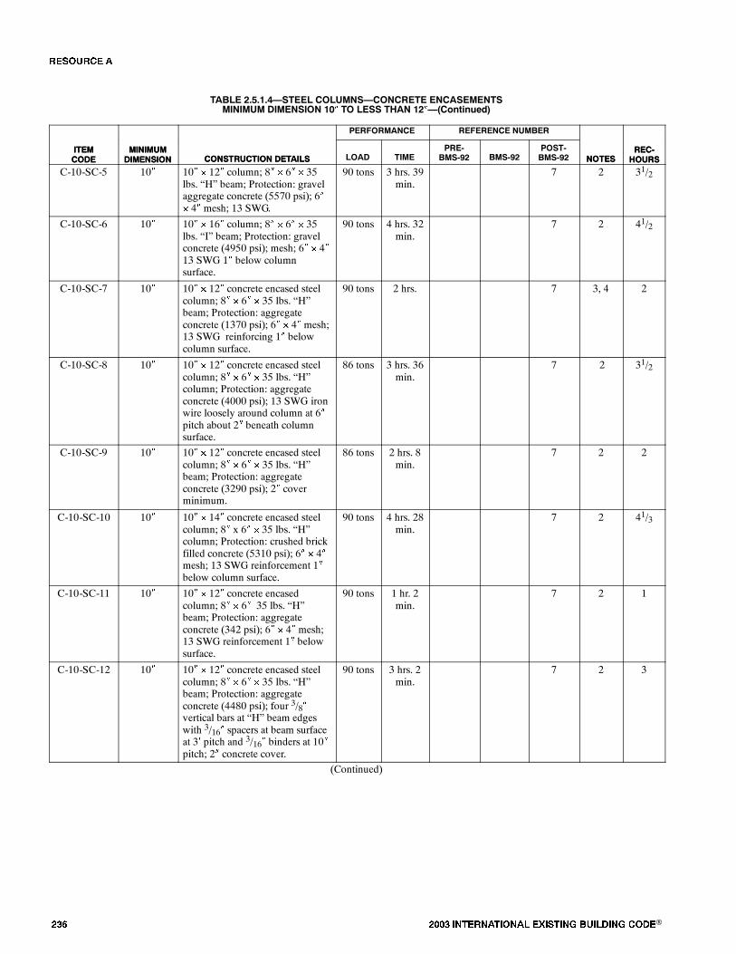
��� ���� ���������� ��� ���� �������� ���®
TABLE 2.5.1.4�STEEL COLUMNS�CONCRETE ENCASEMENTSMINIMUM DIMENSION 10� TO LESS THAN 12��(Continued)
ITEMCODE
REC-HOURSNOTES
REFERENCE NUMBERPERFORMANCE
CONSTRUCTION DETAILSMINIMUMDIMENSION
ITEMCODE
REC-HOURSNOTES
POST-BMS-92BMS-92
PRE-BMS-92TIMELOADCONSTRUCTION DETAILS
MINIMUMDIMENSION
C-10-SC-5 10� 10� � 12� column; 8� � 6� � 35lbs. �H� beam; Protection: gravelaggregate concrete (5570 psi); 6�� 4� mesh; 13 SWG.
90 tons 3 hrs. 39min.
7 2 31/2
C-10-SC-6 10� 10� � 16� column; 8� � 6� � 35lbs. �I� beam; Protection: gravelconcrete (4950 psi); mesh; 6� � 4�13 SWG 1� below columnsurface.
90 tons 4 hrs. 32min.
7 2 41/2
C-10-SC-7 10� 10� � 12� concrete encased steelcolumn; 8� � 6� � 35 lbs. �H�beam; Protection: aggregateconcrete (1370 psi); 6� � 4� mesh;13 SWG reinforcing 1� belowcolumn surface.
90 tons 2 hrs. 7 3, 4 2
C-10-SC-8 10� 10� � 12� concrete encased steelcolumn; 8� � 6� � 35 lbs. �H�column; Protection: aggregateconcrete (4000 psi); 13 SWG ironwire loosely around column at 6�pitch about 2� beneath columnsurface.
86 tons 3 hrs. 36min.
7 2 31/2
C-10-SC-9 10� 10� � 12� concrete encased steelcolumn; 8� � 6� � 35 lbs. �H�beam; Protection: aggregateconcrete (3290 psi); 2� coverminimum.
86 tons 2 hrs. 8min.
7 2 2
C-10-SC-10 10� 10� � 14� concrete encased steelcolumn; 8� x 6� � 35 lbs. �H�column; Protection: crushed brickfilled concrete (5310 psi); 6� � 4�mesh; 13 SWG reinforcement 1�below column surface.
90 tons 4 hrs. 28min.
7 2 41/3
C-10-SC-11 10� 10� � 12� concrete encasedcolumn; 8� � 6� 35 lbs. �H�beam; Protection: aggregateconcrete (342 psi); 6� � 4� mesh;13 SWG reinforcement 1� belowsurface.
90 tons 1 hr. 2min.
7 2 1
C-10-SC-12 10� 10� � 12� concrete encased steelcolumn; 8� � 6� � 35 lbs. �H�beam; Protection: aggregateconcrete (4480 psi); four 3/8�vertical bars at �H� beam edgeswith 3/16� spacers at beam surfaceat 3� pitch and 3/16� binders at 10�pitch; 2� concrete cover.
90 tons 3 hrs. 2min.
7 2 3
(Continued)
�� ����
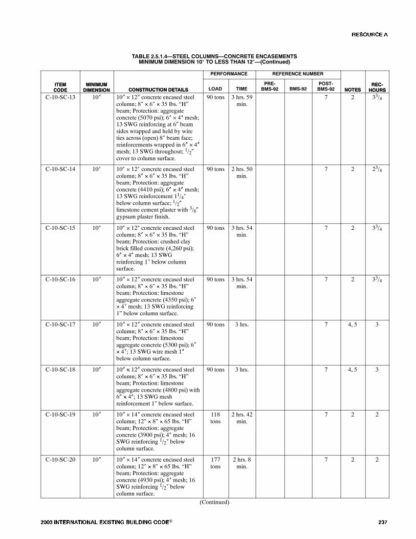
���� ���������� ��� ���� �������� ���® ���
TABLE 2.5.1.4�STEEL COLUMNS�CONCRETE ENCASEMENTSMINIMUM DIMENSION 10� TO LESS THAN 12��(Continued)
ITEMCODE
REC-HOURSNOTES
REFERENCE NUMBERPERFORMANCE
CONSTRUCTION DETAILSMINIMUMDIMENSION
ITEMCODE
REC-HOURSNOTES
POST-BMS-92BMS-92
PRE-BMS-92TIMELOADCONSTRUCTION DETAILS
MINIMUMDIMENSION
C-10-SC-13 10� 10� � 12� concrete encased steelcolumn; 8� � 6� � 35 lbs. �H�beam; Protection: aggregateconcrete (5070 psi); 6� � 4� mesh;13 SWG reinforcing at 6� beamsides wrapped and held by wireties across (open) 8� beam face;reinforcements wrapped in 6� � 4�mesh; 13 SWG throughout; 1/2�cover to column surface.
90 tons 3 hrs. 59min.
7 2 33/4
C-10-SC-14 10� 10� � 12� concrete encased steelcolumn; 8� � 6� � 35 lbs. �H�beam; Protection: aggregateconcrete (4410 psi); 6� � 4� mesh;13 SWG reinforcement 11/4�below column surface; 1/2�limestone cement plaster with 3/8�gypsum plaster finish.
90 tons 2 hrs. 50min.
7 2 23/4
C-10-SC-15 10� 10� � 12� concrete encased steelcolumn; 8� � 6� � 35 lbs. �H�beam; Protection: crushed claybrick filled concrete (4,260 psi);6� � 4� mesh; 13 SWGreinforcing 1� below columnsurface.
90 tons 3 hrs. 54min.
7 2 33/4
C-10-SC-16 10� 10� � 12� concrete encased steelcolumn; 8� � 6� � 35 lbs. �H�beam; Protection: limestoneaggregate concrete (4350 psi); 6�� 4� mesh; 13 SWG reinforcing1� below column surface.
90 tons 3 hrs. 54min.
7 2 33/4
C-10-SC-17 10� 10� � 12� concrete encased steelcolumn; 8� � 6� � 35 lbs. �H�beam; Protection: limestoneaggregate concrete (5300 psi); 6�� 4�; 13 SWG wire mesh 1�below column surface.
90 tons 3 hrs. 7 4, 5 3
C-10-SC-18 10� 10� � 12� concrete encased steelcolumn; 8� � 6� � 35 lbs. �H�beam; Protection: limestoneaggregate concrete (4800 psi) with6� � 4�; 13 SWG meshreinforcement 1� below surface.
90 tons 3 hrs. 7 4, 5 3
C-10-SC-19 10� 10� � 14� concrete encased steelcolumn; 12� � 8� � 65 lbs. �H�beam; Protection: aggregateconcrete (3900 psi); 4� mesh; 16SWG reinforcing 1/2� belowcolumn surface.
118tons
2 hrs. 42min.
7 2 2
C-10-SC-20 10� 10� � 14� concrete encased steelcolumn; 12� � 8� � 65 lbs. �H�beam; Protection: aggregateconcrete (4930 psi); 4� mesh; 16SWG reinforcing 1/2� belowcolumn surface.
177tons
2 hrs. 8min.
7 2 2
(Continued)
�� ����
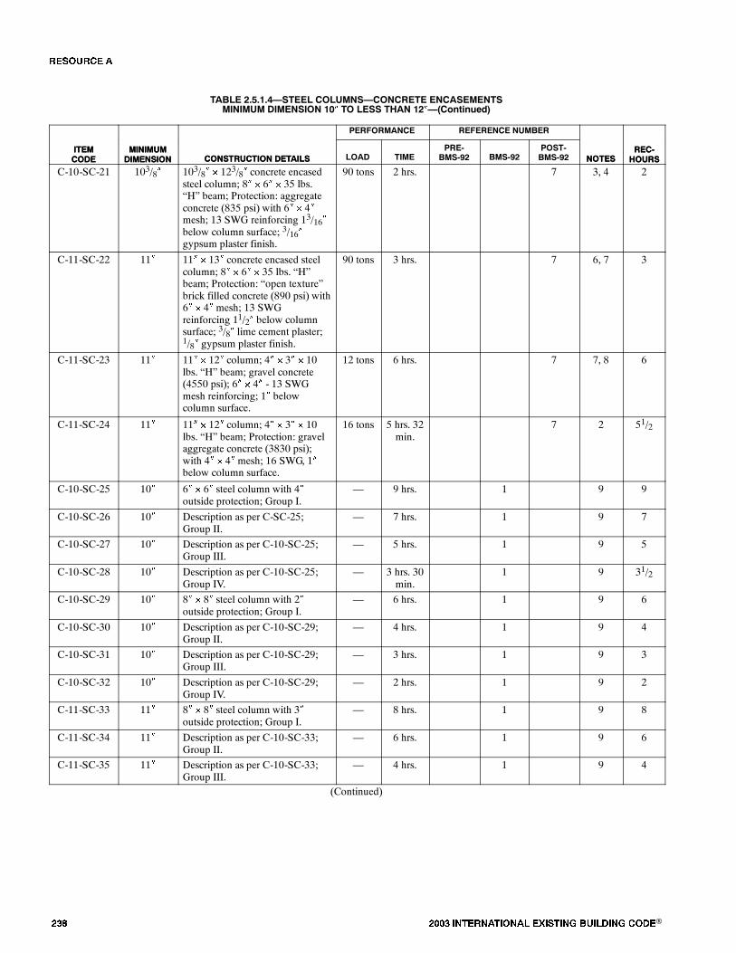
��� ���� ���������� ��� ���� �������� ���®
TABLE 2.5.1.4�STEEL COLUMNS�CONCRETE ENCASEMENTSMINIMUM DIMENSION 10� TO LESS THAN 12��(Continued)
ITEMCODE
REC-HOURSNOTES
REFERENCE NUMBERPERFORMANCE
CONSTRUCTION DETAILSMINIMUMDIMENSION
ITEMCODE
REC-HOURSNOTES
POST-BMS-92BMS-92
PRE-BMS-92TIMELOADCONSTRUCTION DETAILS
MINIMUMDIMENSION
C-10-SC-21 103/8� 103/8� � 123/8� concrete encasedsteel column; 8� � 6� � 35 lbs.�H� beam; Protection: aggregateconcrete (835 psi) with 6� � 4�mesh; 13 SWG reinforcing 13/16�below column surface; 3/16�gypsum plaster finish.
90 tons 2 hrs. 7 3, 4 2
C-11-SC-22 11� 11� � 13� concrete encased steelcolumn; 8� � 6� � 35 lbs. �H�beam; Protection: �open texture�brick filled concrete (890 psi) with6� � 4� mesh; 13 SWGreinforcing 11/2� below columnsurface; 3/8� lime cement plaster;1/8� gypsum plaster finish.
90 tons 3 hrs. 7 6, 7 3
C-11-SC-23 11� 11� � 12� column; 4� � 3� � 10lbs. �H� beam; gravel concrete(4550 psi); 6� � 4� - 13 SWGmesh reinforcing; 1� belowcolumn surface.
12 tons 6 hrs. 7 7, 8 6
C-11-SC-24 11� 11� � 12� column; 4� � 3� � 10lbs. �H� beam; Protection: gravelaggregate concrete (3830 psi);with 4� � 4� mesh; 16 SWG, 1�below column surface.
16 tons 5 hrs. 32min.
7 2 51/2
C-10-SC-25 10� 6� � 6� steel column with 4�outside protection; Group I.
� 9 hrs. 1 9 9
C-10-SC-26 10� Description as per C-SC-25;Group II.
� 7 hrs. 1 9 7
C-10-SC-27 10� Description as per C-10-SC-25;Group III.
� 5 hrs. 1 9 5
C-10-SC-28 10� Description as per C-10-SC-25;Group IV.
� 3 hrs. 30min.
1 9 31/2
C-10-SC-29 10� 8� � 8� steel column with 2�outside protection; Group I.
� 6 hrs. 1 9 6
C-10-SC-30 10� Description as per C-10-SC-29;Group II.
� 4 hrs. 1 9 4
C-10-SC-31 10� Description as per C-10-SC-29;Group III.
� 3 hrs. 1 9 3
C-10-SC-32 10� Description as per C-10-SC-29;Group IV.
� 2 hrs. 1 9 2
C-11-SC-33 11� 8� � 8� steel column with 3�outside protection; Group I.
� 8 hrs. 1 9 8
C-11-SC-34 11� Description as per C-10-SC-33;Group II.
� 6 hrs. 1 9 6
C-11-SC-35 11� Description as per C-10-SC-33;Group III.
� 4 hrs. 1 9 4
(Continued)
�� ����

���� ���������� ��� ���� �������� ���® ���
TABLE 2.5.1.4�STEEL COLUMNS�CONCRETE ENCASEMENTSMINIMUM DIMENSION 10� TO LESS THAN 12��(Continued)
ITEMCODE
REC-HOURSNOTES
REFERENCE NUMBERPERFORMANCE
CONSTRUCTION DETAILSMINIMUMDIMENSION
ITEMCODE
REC-HOURSNOTES
POST-BMS-92BMS-92
PRE-BMS-92TIMELOADCONSTRUCTION DETAILS
MINIMUMDIMENSION
C-11-SC-36 11� Description as per C-10-SC-33;Group IV.
� 3 hrs. 1 9 3
Notes:1. Tested under total restraint load to prevent expansion - minimum load 90 tons.2. Failure mode - collapse.3. Passed 2 hour fire test (Grade �C,� British).4. Passed hose stream test.5. Column tested and passed 3 hour grade fire resistance (British).6. Column passed 3 hour fire test.7. Column collapsed during hose stream testing.8. Column passed 6 hour fire test.9. Group I: includes concrete having calcareous aggregate containing a combined totalof notmore than10 percentof quartz,chert and flint for the coarse aggre-
gate.Group II: includes concrete having trap-rock aggregate applied without metal ties and also concrete having cinder, sandstone or granite aggregate, if held
in place with wire mesh or expanded metal having not larger than 4-inch mesh, weighing not less than 1.7 lbs./yd.2, placed not more than 1 inchfrom the surface of the concrete.
Group III: includes concrete having cinder, sandstone or granite aggregate tied with No. 5 gage steel wire, wound spirally over the column section on a pitchof 8 inches, or equivalent ties, and concrete having siliceous aggregates containing a combined total of 60 percent or more of quartz, chert and flint,if held in place with wire mesh or expanded metal having not larger than 4-inch mesh, weighing not less than 1.7 lbs./yd.2, placed not more than1 inch from the surface of the concrete.
Group IV: includes concrete having siliceous aggregates containing a combined total of 60 percent or more of quartz, chert and flint, and tied with No. 5 gagesteel wire wound spirally over the column section on a pitch of 8 inches, or equivalent ties.
�� ����
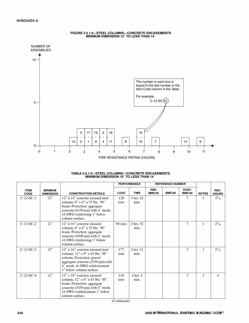
��� ���� ���������� ��� ���� �������� ���®
FIGURE 2.5.1.5�STEEL COLUMNS�CONCRETE ENCASEMENTSMINIMUM DIMENSION 12� TO LESS THAN 14�
0
FIRE RESISTANCE RATING (HOURS)
NUMBER OFASSEMBLIES
1 2 3 4
5
10
0
The number in each box iskeyed to the last number in theItem Code column in the Table.
For example:C-13-SC-15
5 6 7 8 9 10
8
11
5
4
16
11 6147
15
10
12
9
3
2
17
113
TABLE 2.5.1.5�STEEL COLUMNS�CONCRETE ENCASEMENTSMINIMUM DIMENSION 12� TO LESS THAN 14�
PERFORMANCE REFERENCE NUMBER
ITEMCODE
MINIMUMDIMENSION CONSTRUCTION DETAILS LOAD TIME
PRE-BMS-92 BMS-92
POST-BMS-92 NOTES
REC-HOURS
C-12-SC-1 12� 12� � 14� concrete encased steelcolumn; 8� � 6� � 35 lbs. �H�beam; Protection: aggregateconcrete (4150 psi) with 4� mesh;16 SWG reinforcing 1� belowcolumn surface.
120tons
3 hrs. 24min.
7 1 31/3
C-12-SC-2 12� 12� � 16� concrete encasedcolumn; 8� � 6� � 35 lbs. �H�beam; Protection: aggregateconcrete (4300 psi) with 4� mesh;16 SWG reinforcing 1� belowcolumn surface.
90 tons 2 hrs. 52min.
7 1 23/4
C-12-SC-3 12� 12� � 16� concrete encased steelcolumn; 12� � 8� � 65 lbs. �H�column; Protection: gravelaggregate concrete (3550 psi) with4� mesh; 16 SWG reinforcement1� below column surface.
177tons
2 hrs. 31min.
7 1 21/2
C-12-SC-4 12� 12� � 16� concrete encasedcolumn; 12� � 8� � 65 lbs. �H�beam; Protection: aggregateconcrete (3450 psi) with 4� mesh;16 SWG reinforcement 1� belowcolumn surface.
118tons
4 hrs. 4min.
7 1 4
(Continued)
�� ����
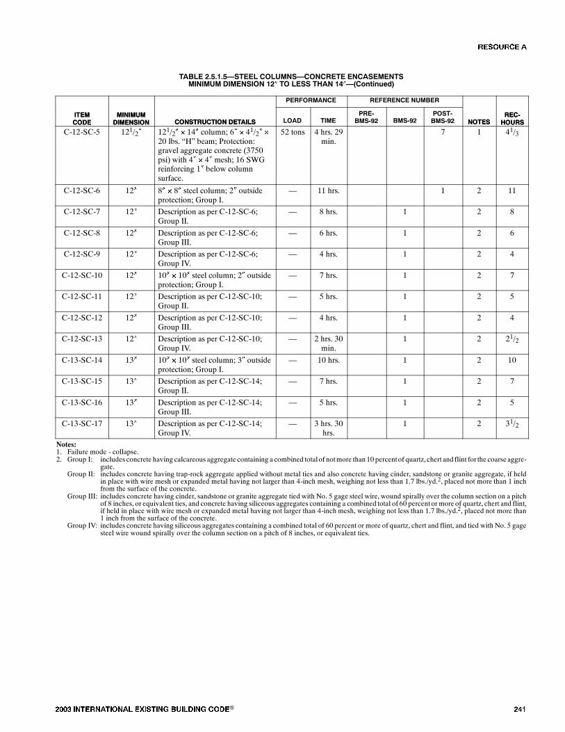
���� ���������� ��� ���� �������� ���® ���
TABLE 2.5.1.5�STEEL COLUMNS�CONCRETE ENCASEMENTSMINIMUM DIMENSION 12� TO LESS THAN 14��(Continued)
ITEMCODE
REC-HOURSNOTES
REFERENCE NUMBERPERFORMANCE
CONSTRUCTION DETAILSMINIMUMDIMENSION
ITEMCODE
REC-HOURSNOTES
POST-BMS-92BMS-92
PRE-BMS-92TIMELOADCONSTRUCTION DETAILS
MINIMUMDIMENSION
C-12-SC-5 121/2� 121/2� � 14� column; 6� � 41/2� �
20 lbs. �H� beam; Protection:gravel aggregate concrete (3750psi) with 4� � 4� mesh; 16 SWGreinforcing 1� below columnsurface.
52 tons 4 hrs. 29min.
7 1 41/3
C-12-SC-6 12� 8� � 8� steel column; 2� outsideprotection; Group I.
� 11 hrs. 1 2 11
C-12-SC-7 12� Description as per C-12-SC-6;Group II.
� 8 hrs. 1 2 8
C-12-SC-8 12� Description as per C-12-SC-6;Group III.
� 6 hrs. 1 2 6
C-12-SC-9 12� Description as per C-12-SC-6;Group IV.
� 4 hrs. 1 2 4
C-12-SC-10 12� 10� � 10� steel column; 2� outsideprotection; Group I.
� 7 hrs. 1 2 7
C-12-SC-11 12� Description as per C-12-SC-10;Group II.
� 5 hrs. 1 2 5
C-12-SC-12 12� Description as per C-12-SC-10;Group III.
� 4 hrs. 1 2 4
C-12-SC-13 12� Description as per C-12-SC-10;Group IV.
� 2 hrs. 30min.
1 2 21/2
C-13-SC-14 13� 10� � 10� steel column; 3� outsideprotection; Group I.
� 10 hrs. 1 2 10
C-13-SC-15 13� Description as per C-12-SC-14;Group II.
� 7 hrs. 1 2 7
C-13-SC-16 13� Description as per C-12-SC-14;Group III.
� 5 hrs. 1 2 5
C-13-SC-17 13� Description as per C-12-SC-14;Group IV.
� 3 hrs. 30hrs.
1 2 31/2
Notes:1. Failure mode - collapse.2. Group I: includes concrete having calcareous aggregate containing a combined totalof notmore than10 percentof quartz,chert and flint for the coarse aggre-
gate.Group II: includes concrete having trap-rock aggregate applied without metal ties and also concrete having cinder, sandstone or granite aggregate, if held
in place with wire mesh or expanded metal having not larger than 4-inch mesh, weighing not less than 1.7 lbs./yd.2, placed not more than 1 inchfrom the surface of the concrete.
Group III: includes concrete having cinder, sandstone or granite aggregate tied with No. 5 gage steel wire, wound spirally over the column section on a pitchof 8 inches, or equivalent ties, and concrete having siliceous aggregates containing a combined total of 60 percent or more of quartz, chert and flint,if held in place with wire mesh or expanded metal having not larger than 4-inch mesh, weighing not less than 1.7 lbs./yd.2, placed not more than1 inch from the surface of the concrete.
Group IV: includes concrete having siliceous aggregates containing a combined total of 60 percent or more of quartz, chert and flint, and tied with No. 5 gagesteel wire wound spirally over the column section on a pitch of 8 inches, or equivalent ties.
�� ����
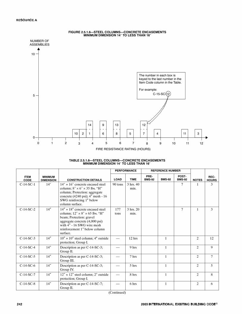
��� ���� ���������� ��� ���� �������� ���®
FIGURE 2.5.1.6�STEEL COLUMNS�CONCRETE ENCASEMENTSMINIMUM DIMENSION 14� TO LESS THAN 16�
0
FIRE RESISTANCE RATING (HOURS)
NUMBER OFASSEMBLIES
1 2 3 4
5
10
0
The number in each box iskeyed to the last number in theItem Code column in the Table.
For example:C-15-SC-12
5 6 7 8 9 10
345
11 12
9
6
13
8 11
14
110 2
12
7
TABLE 2.5.1.6�STEEL COLUMNS�CONCRETE ENCASEMENTSMINIMUM DIMENSION 14� TO LESS THAN 16�
PERFORMANCE REFERENCE NUMBER
ITEMCODE
MINIMUMDIMENSION CONSTRUCTION DETAILS LOAD TIME
PRE-BMS-92 BMS-92
POST-BMS-92 NOTES
REC-HOURS
C-14-SC-1 14� 14� � 16� concrete encased steelcolumn; 8� � 6� � 35 lbs. �H�column; Protection: aggregateconcrete (4240 psi); 4� mesh - 16SWG reinforcing 1� belowcolumn surface.
90 tons 3 hrs. 40min.
7 1 3
C-14-SC-2 14� 14� � 18� concrete encased steelcolumn; 12� � 8� � 65 lbs. �H�beam; Protection: gravelaggregate concrete (4,000 psi)with 4� - 16 SWG wire meshreinforcement 1� below columnsurface.
177tons
3 hrs. 20min.
7 1 3
C-14-SC-3 14� 10� � 10� steel column; 4� outsideprotection; Group I.
� 12 hrs 1 2 12
C-14-SC-4 14� Description as per C-14-SC-3;Group II.
� 9 hrs 1 2 9
C-14-SC-5 14� Description as per C-14-SC-3;Group III.
� 7 hrs 1 2 7
C-14-SC-6 14� Description as per C-14-SC-3;Group IV.
� 5 hrs 1 2 5
C-14-SC-7 14� 12� � 12� steel column; 2� outsideprotection; Group I.
� 8 hrs 1 2 8
C-14-SC-8 14� Description as per C-14-SC-7;Group II.
� 6 hrs 1 2 6
(Continued)
�� ����
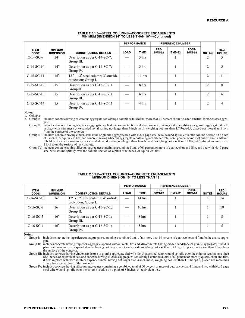
���� ���������� ��� ���� �������� ���® ���
TABLE 2.5.1.6�STEEL COLUMNS�CONCRETE ENCASEMENTSMINIMUM DIMENSION 14� TO LESS THAN 16��(Continued)
ITEMCODE
REC-HOURSNOTES
REFERENCE NUMBERPERFORMANCE
CONSTRUCTION DETAILSMINIMUMDIMENSION
ITEMCODE
REC-HOURSNOTES
POST-BMS-92BMS-92
PRE-BMS-92TIMELOADCONSTRUCTION DETAILS
MINIMUMDIMENSION
C-14-SC-9 14� Description as per C-14-SC-7;Group III.
� 5 hrs 1 2 5
C-14-SC-10 14� Description as per C-14-SC-7;Group IV.
� 3 hrs 1 2 3
C-15-SC-11 15� 12� � 12� steel column; 3� outsideprotection; Group I.
� 11 hrs 1 2 11
C-15-SC-12 15� Description as per C-15-SC-11;Group II.
� 8 hrs 1 2 8
C-15-SC-13 15� Description as per C-15-SC-11;Group III.
� 6 hrs 1 2 6
C-15-SC-14 15� Description as per C-15-SC-11;Group IV.
� 4 hrs 1 2 4
Notes:1. Collapse.2. Group I: includes concrete having calcareous aggregate containing a combined totalof notmore than10 percentof quartz,chert and flint for the coarse aggre-
gate.Group II: includes concrete having trap-rock aggregate applied without metal ties and also concrete having cinder, sandstone or granite aggregate, if held
in place with wire mesh or expanded metal having not larger than 4-inch mesh, weighing not less than 1.7 lbs./yd.2, placed not more than 1 inchfrom the surface of the concrete.
Group III: includes concrete having cinder, sandstone or granite aggregate tied with No. 5 gage steel wire, wound spirally over the column section on a pitchof 8 inches, or equivalent ties, and concrete having siliceous aggregates containing a combined total of 60 percent or more of quartz, chert and flint,if held in place with wire mesh or expanded metal having not larger than 4-inch mesh, weighing not less than 1.7 lbs./yd.2, placed not more than1 inch from the surface of the concrete.
Group IV: includes concrete having siliceous aggregates containing a combined total of 60 percent or more of quartz, chert and flint, and tied with No. 5 gagesteel wire wound spirally over the column section on a pitch of 8 inches, or equivalent ties.
TABLE 2.5.1.7�STEEL COLUMNS�CONCRETE ENCASEMENTSMINIMUM DIMENSION 16� TO LESS THAN 18�
PERFORMANCE REFERENCE NUMBER
ITEMCODE
MINIMUMDIMENSION CONSTRUCTION DETAILS LOAD TIME
PRE-BMS-92 BMS-92
POST-BMS-92 NOTES
REC-HOURS
C-16-SC-13 16� 12� � 12� steel column; 4� outsideprotection; Group I.
� 14 hrs. 1 1 14
C-16-SC-2 16� Description as per C-16-SC-1;Group II.
� 10 hrs. 1 1 10
C-16-SC-3 16� Description as per C-16-SC-1;Group III.
� 8 hrs. 1 1 8
C-16-SC-4 16� Description as per C-16-SC-1;Group IV.
� 5 hrs. 1 1 5
Notes:1. Group I: includes concrete having calcareous aggregate containing a combined total of notmore than 10 percent of quartz, chert and flint for the coarse aggre-
gate.Group II: includes concrete having trap-rock aggregate applied without metal ties and also concrete having cinder, sandstone or granite aggregate, if held in
place with wire mesh or expanded metal having not larger than 4-inch mesh, weighing not less than 1.7 lbs./yd.2, placed not more than 1 inch fromthe surface of the concrete.
Group III: includes concrete having cinder, sandstone or granite aggregate tied with No. 5 gage steel wire, wound spirally over the column section on a pitchof 8 inches, or equivalent ties, and concrete having siliceous aggregates containing a combined total of 60 percent or more of quartz, chert and flint,if held in place with wire mesh or expanded metal having not larger than 4-inch mesh, weighing not less than 1.7 lbs./yd.2, placed not more than1 inch from the surface of the concrete.
Group IV: includes concrete having siliceous aggregates containing a combined total of 60 percent or more of quartz, chert and flint, and tied with No. 5 gagesteel wire wound spirally over the column section on a pitch of 8 inches, or equivalent ties.
�� ����
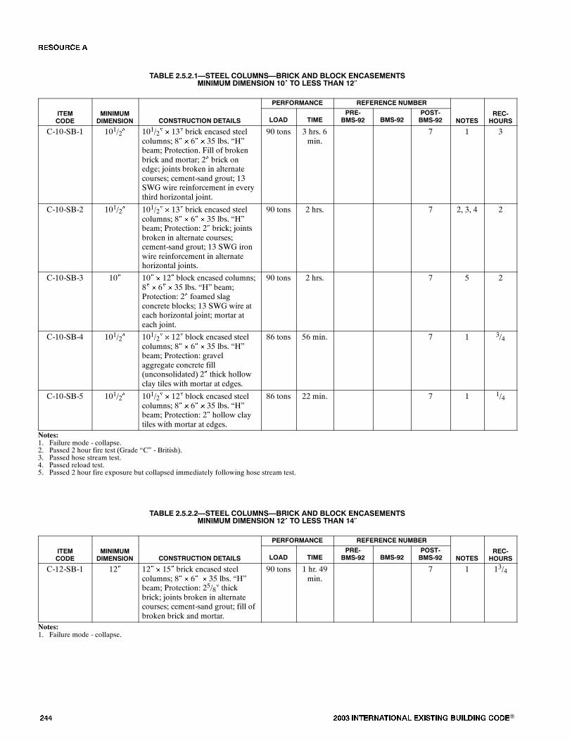
��� ���� ���������� ��� ���� �������� ���®
TABLE 2.5.2.1�STEEL COLUMNS�BRICK AND BLOCK ENCASEMENTSMINIMUM DIMENSION 10� TO LESS THAN 12�
PERFORMANCE REFERENCE NUMBER
ITEMCODE
MINIMUMDIMENSION CONSTRUCTION DETAILS LOAD TIME
PRE-BMS-92 BMS-92
POST-BMS-92 NOTES
REC-HOURS
C-10-SB-1 101/2� 101/2� � 13� brick encased steelcolumns; 8� � 6� � 35 lbs. �H�beam; Protection. Fill of brokenbrick and mortar; 2� brick onedge; joints broken in alternatecourses; cement-sand grout; 13SWG wire reinforcement in everythird horizontal joint.
90 tons 3 hrs. 6min.
7 1 3
C-10-SB-2 101/2� 101/2� � 13� brick encased steelcolumns; 8� � 6� � 35 lbs. �H�beam; Protection: 2� brick; jointsbroken in alternate courses;cement-sand grout; 13 SWG ironwire reinforcement in alternatehorizontal joints.
90 tons 2 hrs. 7 2, 3, 4 2
C-10-SB-3 10� 10� � 12� block encased columns;8� � 6� � 35 lbs. �H� beam;Protection: 2� foamed slagconcrete blocks; 13 SWG wire ateach horizontal joint; mortar ateach joint.
90 tons 2 hrs. 7 5 2
C-10-SB-4 101/2� 101/2� � 12� block encased steelcolumns; 8� � 6� � 35 lbs. �H�beam; Protection: gravelaggregate concrete fill(unconsolidated) 2� thick hollowclay tiles with mortar at edges.
86 tons 56 min. 7 1 3/4
C-10-SB-5 101/2� 101/2� � 12� block encased steelcolumns; 8� � 6� � 35 lbs. �H�beam; Protection: 2� hollow claytiles with mortar at edges.
86 tons 22 min. 7 1 1/4
Notes:1. Failure mode - collapse.2. Passed 2 hour fire test (Grade �C� - British).3. Passed hose stream test.4. Passed reload test.5. Passed 2 hour fire exposure but collapsed immediately following hose stream test.
TABLE 2.5.2.2�STEEL COLUMNS�BRICK AND BLOCK ENCASEMENTSMINIMUM DIMENSION 12� TO LESS THAN 14�
PERFORMANCE REFERENCE NUMBER
ITEMCODE
MINIMUMDIMENSION CONSTRUCTION DETAILS LOAD TIME
PRE-BMS-92 BMS-92
POST-BMS-92 NOTES
REC-HOURS
C-12-SB-1 12� 12� � 15� brick encased steelcolumns; 8� � 6� � 35 lbs. �H�beam; Protection: 25/8� thickbrick; joints broken in alternatecourses; cement-sand grout; fill ofbroken brick and mortar.
90 tons 1 hr. 49min.
7 1 13/4
Notes:1. Failure mode - collapse.
�� ����
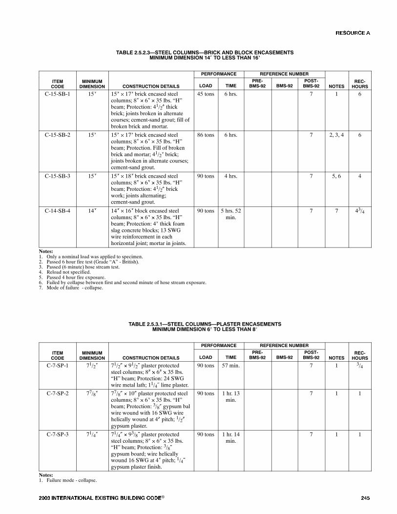
���� ���������� ��� ���� �������� ���® ���
TABLE 2.5.2.3�STEEL COLUMNS�BRICK AND BLOCK ENCASEMENTSMINIMUM DIMENSION 14� TO LESS THAN 16�
PERFORMANCE REFERENCE NUMBER
ITEMCODE
MINIMUMDIMENSION CONSTRUCTION DETAILS LOAD TIME
PRE-BMS-92 BMS-92
POST-BMS-92 NOTES
REC-HOURS
C-15-SB-1 15� 15� � 17� brick encased steelcolumns; 8� � 6� � 35 lbs. �H�beam; Protection: 41/2� thickbrick; joints broken in alternatecourses; cement-sand grout; fill ofbroken brick and mortar.
45 tons 6 hrs. 7 1 6
C-15-SB-2 15� 15� � 17� brick encased steelcolumns; 8� � 6� � 35 lbs. �H�beam; Protection. Fill of brokenbrick and mortar; 41/2� brick;joints broken in alternate courses;cement-sand grout.
86 tons 6 hrs. 7 2, 3, 4 6
C-15-SB-3 15� 15� � 18� brick encased steelcolumns; 8� � 6� � 35 lbs. �H�beam; Protection: 41/2� brickwork; joints alternating;cement-sand grout.
90 tons 4 hrs. 7 5, 6 4
C-14-SB-4 14� 14� � 16� block encased steelcolumns; 8� � 6� � 35 lbs. �H�beam; Protection: 4� thick foamslag concrete blocks; 13 SWGwire reinforcement in eachhorizontal joint; mortar in joints.
90 tons 5 hrs. 52min.
7 7 43/4
Notes:1. Only a nominal load was applied to specimen.2. Passed 6 hour fire test (Grade �A� - British).3. Passed (6 minute) hose stream test.4. Reload not specified.5. Passed 4 hour fire exposure.6. Failed by collapse between first and second minute of hose stream exposure.7. Mode of failure - collapse.
TABLE 2.5.3.1�STEEL COLUMNS�PLASTER ENCASEMENTSMINIMUM DIMENSION 6� TO LESS THAN 8�
PERFORMANCE REFERENCE NUMBER
ITEMCODE
MINIMUMDIMENSION CONSTRUCTION DETAILS LOAD TIME
PRE-BMS-92 BMS-92
POST-BMS-92 NOTES
REC-HOURS
C-7-SP-1 71/2� 71/2� � 91/2� plaster protectedsteel columns; 8� � 6� � 35 lbs.�H� beam; Protection: 24 SWGwire metal lath; 11/4� lime plaster.
90 tons 57 min. 7 1 3/4
C-7-SP-2 77/8� 77/8� � 10� plaster protected steelcolumns; 8� � 6� � 35 lbs. �H�beam; Protection: 3/8� gypsum balwire wound with 16 SWG wirehelically wound at 4� pitch; 1/2�gypsum plaster.
90 tons 1 hr. 13min.
7 1 1
C-7-SP-3 71/4� 71/4� � 93/8� plaster protectedsteel columns; 8� � 6� � 35 lbs.�H� beam; Protection: 3/8�gypsum board; wire helicallywound 16 SWG at 4� pitch; 1/4�gypsum plaster finish.
90 tons 1 hr. 14min.
7 1 1
Notes:1. Failure mode - collapse.
�� ����

��� ���� ���������� ��� ���� �������� ���®
TABLE 2.5.3.2�STEEL COLUMNS�PLASTER ENCASEMENTSMINIMUM DIMENSION 8� TO LESS THAN 10�
PERFORMANCE REFERENCE NUMBER
ITEMCODE
MINIMUMDIMENSION CONSTRUCTION DETAILS LOAD TIME
PRE-BMS-92 BMS-92
POST-BMS-92 NOTES
REC-HOURS
C-8-SP-1 8� 8� � 10� plaster protected steelcolumns; 8� � 6� � 35 lbs. �H�beam; Protection: 24 SWG wirelath; 1� gypsum plaster.
86 tons 1 hr. 23min.
7 1 11/4
C-8-SP-2 81/2� 81/2� � 101/2� plaster protectedsteel columns; 8� � 6� � 35 lbs.�H� beam; Protection: 24 SWGmetal lath wrap; 11/4� gypsumplaster.
90 tons 1 hr. 36min.
7 1 11/2
C-9-SP-3 9� 9� � 11� plaster protected steelcolumns; 8� � 6� � 35 lbs. �H�beam; Protection: 24 SWG metallath wrap; 1/8�M.S. ties at 12�pitch wire netting 11/2� � 22 SWGbetween first and second plastercoats; 11/2� gypsum plaster.
90 tons 1 hr. 33min.
7 1 11/2
C-8-SP-4 83/4� 83/4� � 103/4� plaster protectedsteel columns; 8� � 6� � 35 lbs.�H� beam; Protection: 3/4�gypsum board; wire woundspirally (#16 SWG) at 11/2� pitch;1/2� gypsum plaster.
90 tons 2 hrs. 7 2, 3, 4 2
Notes:1. Failure mode - collapse.2. Passed 2 hour fire exposure test (Grade �C� - British).3. Passed hose stream test.4. Passed reload test.
TABLE 2.5.4.1�STEEL COLUMNS�MISCELLANEOUS ENCASEMENTSMINIMUM DIMENSION 6� TO LESS THAN 8�
PERFORMANCE REFERENCE NUMBER
ITEMCODE
MINIMUMDIMENSION CONSTRUCTION DETAILS LOAD TIME
PRE-BMS-92 BMS-92
POST-BMS-92 NOTES
REC-HOURS
C-7-SM-1 75/8� 75/8� � 91/2� (asbestos plaster)protected steel columns; 8� � 6� �
35 lbs. �H� beam; Protection: 20gage 1/2� metal lath; 9/16� asbestosplaster (minimum).
90 tons 1 hr. 52min.
7 1 13/4
Notes:1. Failure mode - collapse.
TABLE 2.5.4.2�STEEL COLUMNS�MISCELLANEOUS ENCASEMENTSMINIMUM DIMENSION 8� TO LESS THAN 10�
PERFORMANCE REFERENCE NUMBER
ITEMCODE
MINIMUMDIMENSION CONSTRUCTION DETAILS LOAD TIME
PRE-BMS-92 BMS-92
POST-BMS-92 NOTES
REC-HOURS
C-9-SM-1 95/8� 95/8� � 113/8� asbestos slab andcement plaster protected columns;8� � 6� � 35 lbs. �H� beam;Protection: 1� asbestos slab; wirewound; 5/8� plaster.
90 tons 2 hrs. 7 1, 2 2
Notes:1. Passed 2 hour fire exposure test.2. Collapsed during hose stream test.
�� ����
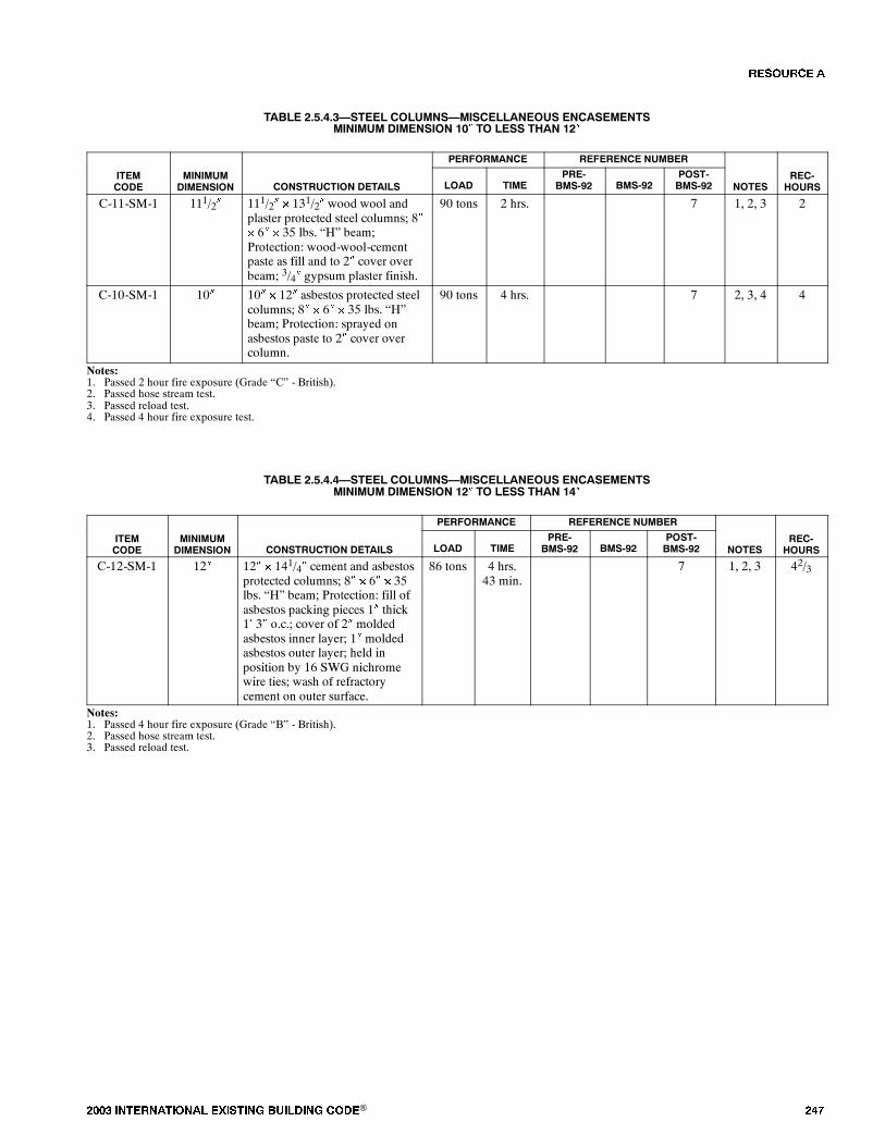
���� ���������� ��� ���� �������� ���® ���
TABLE 2.5.4.3�STEEL COLUMNS�MISCELLANEOUS ENCASEMENTSMINIMUM DIMENSION 10� TO LESS THAN 12�
PERFORMANCE REFERENCE NUMBER
ITEMCODE
MINIMUMDIMENSION CONSTRUCTION DETAILS LOAD TIME
PRE-BMS-92 BMS-92
POST-BMS-92 NOTES
REC-HOURS
C-11-SM-1 111/2� 111/2� � 131/2� wood wool andplaster protected steel columns; 8�� 6� � 35 lbs. �H� beam;Protection: wood-wool-cementpaste as fill and to 2� cover overbeam; 3/4� gypsum plaster finish.
90 tons 2 hrs. 7 1, 2, 3 2
C-10-SM-1 10� 10� � 12� asbestos protected steelcolumns; 8� � 6� � 35 lbs. �H�beam; Protection: sprayed onasbestos paste to 2� cover overcolumn.
90 tons 4 hrs. 7 2, 3, 4 4
Notes:1. Passed 2 hour fire exposure (Grade �C� - British).2. Passed hose stream test.3. Passed reload test.4. Passed 4 hour fire exposure test.
TABLE 2.5.4.4�STEEL COLUMNS�MISCELLANEOUS ENCASEMENTSMINIMUM DIMENSION 12� TO LESS THAN 14�
PERFORMANCE REFERENCE NUMBER
ITEMCODE
MINIMUMDIMENSION CONSTRUCTION DETAILS LOAD TIME
PRE-BMS-92 BMS-92
POST-BMS-92 NOTES
REC-HOURS
C-12-SM-1 12� 12� � 141/4� cement and asbestosprotected columns; 8� � 6� � 35lbs. �H� beam; Protection: fill ofasbestos packing pieces 1� thick1� 3� o.c.; cover of 2� moldedasbestos inner layer; 1� moldedasbestos outer layer; held inposition by 16 SWG nichromewire ties; wash of refractorycement on outer surface.
86 tons 4 hrs.43 min.
7 1, 2, 3 42/3
Notes:1. Passed 4 hour fire exposure (Grade �B� - British).2. Passed hose stream test.3. Passed reload test.
�� ����
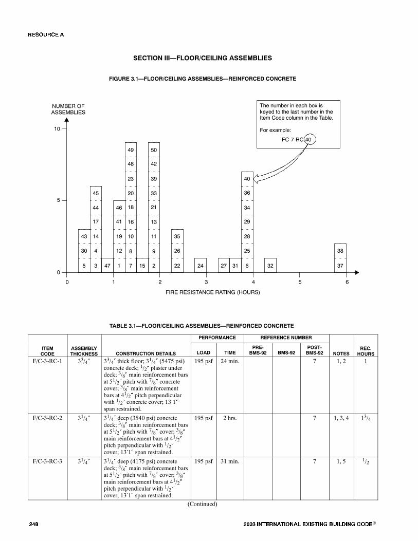
��� ���� ���������� ��� ���� �������� ���®
������� ������� ������� ���������
FIGURE 3.1�FLOOR/CEILING ASSEMBLIES�REINFORCED CONCRETE
0
FIRE RESISTANCE RATING (HOURS)
NUMBER OFASSEMBLIES
1 2 3 4
5
10
0
The number in each box iskeyed to the last number in theItem Code column in the Table.
For example:
FC-7-RC-40
11
13
21
26
35
9
33
22 37
5 6
24 32
4
14
17
30
43
3
44
5 47
12
19
41
1
46
15 2
39
42
50
38
31
25
28
29
6
34
27
36
40
10
16
18
8
20
7
23
48
49
45
TABLE 3.1�FLOOR/CEILING ASSEMBLIES�REINFORCED CONCRETE
PERFORMANCE REFERENCE NUMBER
ITEMCODE
ASSEMBLYTHICKNESS CONSTRUCTION DETAILS LOAD TIME
PRE-BMS-92 BMS-92
POST-BMS-92 NOTES
REC.HOURS
F/C-3-RC-1 33/4� 33/4� thick floor; 31/4� (5475 psi)concrete deck; 1/2� plaster underdeck; 3/8� main reinforcement barsat 51/2� pitch with 7/8� concretecover; 3/8� main reinforcementbars at 41/2� pitch perpendicularwith 1/2� concrete cover; 13�1�span restrained.
195 psf 24 min. 7 1, 2 1
F/C-3-RC-2 31/4� 31/4� deep (3540 psi) concretedeck; 3/8� main reinforcement barsat 51/2� pitch with 7/8� cover; 3/8�main reinforcement bars at 41/2�pitch perpendicular with 1/2�cover; 13�1� span restrained.
195 psf 2 hrs. 7 1, 3, 4 13/4
F/C-3-RC-3 31/4� 31/4� deep (4175 psi) concretedeck; 3/8� main reinforcement barsat 51/2� pitch with 7/8� cover; 3/8�main reinforcement bars at 41/2�pitch perpendicular with 1/2�cover; 13�1� span restrained.
195 psf 31 min. 7 1, 5 1/2
(Continued)
�� ����

���� ���������� ��� ���� �������� ���® ���
TABLE 3.1�FLOOR/CEILING ASSEMBLIES�REINFORCED CONCRETE�(Continued)
ITEMCODE
REC.HOURSNOTES
REFERENCE NUMBERPERFORMANCE
CONSTRUCTION DETAILSASSEMBLYTHICKNESS
ITEMCODE
REC.HOURSNOTES
POST-BMS-92BMS-92
PRE-BMS-92TIMELOADCONSTRUCTION DETAILS
ASSEMBLYTHICKNESS
F/C-3-RC-4 31/4� 31/4� deep (4355 psi) concretedeck; 3/8� main reinforcement barsat 51/2� pitch with 7/8� cover; 3/8�main reinforcement bars at 41/2�pitch perpendicular with 1/2�cover; 13�1� span restrained.
195 psf 41 min. 7 1, 5, 6 1/2
F/C-3-RC-5 31/4� 31/4� thick (3800 psi) concretedeck; 3/8� main reinforcement barsat 51/2� pitch with 7/8� cover; 3/8�main reinforcement bars at 41/2�pitch perpendicular with 1/2�cover; 13�1� span restrained.
195 psf 1 hr. 5min.
7 1, 5 1/4
F/C-4-RC-6 41/4� 41/4� thick; 31/4� (4000 psi)concrete deck; 1� sprayed asbestoslower surface; 3/8� mainreinforcement bars at 57/8� pitchwith 7/8� concrete cover; 3/8� mainreinforcement bars at 41/2� pitchperpendicular with 1/2� concretecover; 13�1� span restrained.
195 psf 4 hrs. 7 1, 7 4
F/C-4-RC-7 4� 4� (5025 psi) concrete deck; 1/4�reinforcement bars at 71/2� pitchwith 3/4� cover; 3/8� mainreinforcement bars at 33/4� pitchperpendicular with 1/2� cover;13�1� span restrained.
140 psf 1 hr. 16min.
7 1, 2 11/4
F/C-4-RC-8 4� 4� thick (4905 psi) deck; 1/4�reinforcement bars at 71/2� pitchwith 7/8� cover; 3/8� mainreinforcement bars at 33/4� pitchperpendicular with 1/2� cover;13�1� span restrained.
100 psf 1 hr. 23min.
7 1, 2 11/3
F/C-4-RC-9 4� 4� deep (4370 psi); 1/4�reinforcement bars at 6� pitch with3/4� cover; 1/4� mainreinforcement bars at 4� pitchperpendicular with 1/2� cover;13�1� span restrained.
150 psf 2 hrs. 7 1, 3 2
F/C-4-RC-10 4� 4� thick (5140 psi) deck; 1/4�reinforcement bars at 71/2� pitchwith 7/8� cover; 3/8� mainreinforcement bars at 33/4� pitchperpendicular with 1/2� cover;13�1� span restrained.
140 psf 1 hr. 16min.
7 1, 5 11/4
F/C-4-RC-11 4� 4� thick (4000 psi) concrete deck;3� � 11/2� � 4 lbs. R.S.J.; 2�6�C.R.S.; flush with top surface; 4�� 6� x 13 SWG meshreinforcement 1� from bottom ofslab; 6�6� span restrained.
150 psf 2 hrs. 7 1, 3 2
F/C-4-RC-12 4� 4� deep (2380 psi) concrete deck;3� � 11/2� � 4 lbs. R.S.J.; 2�6�C.R.S.; flush with top surface; 4�� 6� x 13 SWG meshreinforcement 1� from bottomsurface; 6�6� span restrained.
150 psf 1 hr. 3min.
7 1, 2 1
(Continued)
�� ����
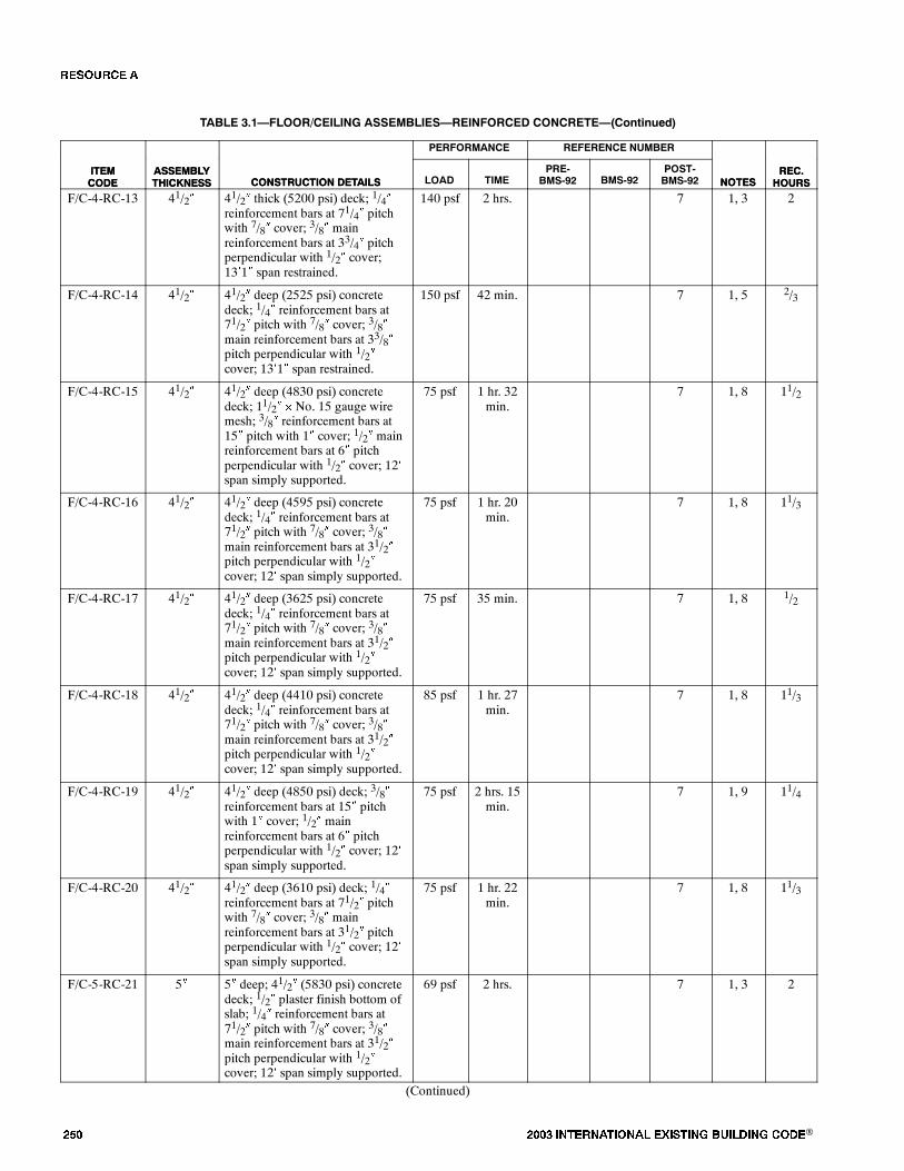
��� ���� ���������� ��� ���� �������� ���®
TABLE 3.1�FLOOR/CEILING ASSEMBLIES�REINFORCED CONCRETE�(Continued)
ITEMCODE
REC.HOURSNOTES
REFERENCE NUMBERPERFORMANCE
CONSTRUCTION DETAILSASSEMBLYTHICKNESS
ITEMCODE
REC.HOURSNOTES
POST-BMS-92BMS-92
PRE-BMS-92TIMELOADCONSTRUCTION DETAILS
ASSEMBLYTHICKNESS
F/C-4-RC-13 41/2� 41/2� thick (5200 psi) deck; 1/4�reinforcement bars at 71/4� pitchwith 7/8� cover; 3/8� mainreinforcement bars at 33/4� pitchperpendicular with 1/2� cover;13�1� span restrained.
140 psf 2 hrs. 7 1, 3 2
F/C-4-RC-14 41/2� 41/2� deep (2525 psi) concretedeck; 1/4� reinforcement bars at71/2� pitch with 7/8� cover; 3/8�main reinforcement bars at 33/8�pitch perpendicular with 1/2�cover; 13�1� span restrained.
150 psf 42 min. 7 1, 5 2/3
F/C-4-RC-15 41/2� 41/2� deep (4830 psi) concretedeck; 11/2� � No. 15 gauge wiremesh; 3/8� reinforcement bars at15� pitch with 1� cover; 1/2� mainreinforcement bars at 6� pitchperpendicular with 1/2� cover; 12�span simply supported.
75 psf 1 hr. 32min.
7 1, 8 11/2
F/C-4-RC-16 41/2� 41/2� deep (4595 psi) concretedeck; 1/4� reinforcement bars at71/2� pitch with 7/8� cover; 3/8�main reinforcement bars at 31/2�pitch perpendicular with 1/2�cover; 12� span simply supported.
75 psf 1 hr. 20min.
7 1, 8 11/3
F/C-4-RC-17 41/2� 41/2� deep (3625 psi) concretedeck; 1/4� reinforcement bars at71/2� pitch with 7/8� cover; 3/8�main reinforcement bars at 31/2�pitch perpendicular with 1/2�cover; 12� span simply supported.
75 psf 35 min. 7 1, 8 1/2
F/C-4-RC-18 41/2� 41/2� deep (4410 psi) concretedeck; 1/4� reinforcement bars at71/2� pitch with 7/8� cover; 3/8�main reinforcement bars at 31/2�pitch perpendicular with 1/2�cover; 12� span simply supported.
85 psf 1 hr. 27min.
7 1, 8 11/3
F/C-4-RC-19 41/2� 41/2� deep (4850 psi) deck; 3/8�reinforcement bars at 15� pitchwith 1� cover; 1/2� mainreinforcement bars at 6� pitchperpendicular with 1/2� cover; 12�span simply supported.
75 psf 2 hrs. 15min.
7 1, 9 11/4
F/C-4-RC-20 41/2� 41/2� deep (3610 psi) deck; 1/4�reinforcement bars at 71/2� pitchwith 7/8� cover; 3/8� mainreinforcement bars at 31/2� pitchperpendicular with 1/2� cover; 12�span simply supported.
75 psf 1 hr. 22min.
7 1, 8 11/3
F/C-5-RC-21 5� 5� deep; 41/2� (5830 psi) concretedeck; 1/2� plaster finish bottom ofslab; 1/4� reinforcement bars at71/2� pitch with 7/8� cover; 3/8�main reinforcement bars at 31/2�pitch perpendicular with 1/2�cover; 12� span simply supported.
69 psf 2 hrs. 7 1, 3 2
(Continued)
�� ����

���� ���������� ��� ���� �������� ���® ���
TABLE 3.1�FLOOR/CEILING ASSEMBLIES�REINFORCED CONCRETE�(Continued)
ITEMCODE
REC.HOURSNOTES
REFERENCE NUMBERPERFORMANCE
CONSTRUCTION DETAILSASSEMBLYTHICKNESS
ITEMCODE
REC.HOURSNOTES
POST-BMS-92BMS-92
PRE-BMS-92TIMELOADCONSTRUCTION DETAILS
ASSEMBLYTHICKNESS
F/C-5-RC-22 5� 41/2� (5290 psi) concrete deck;1/2� plaster finish bottom of slab;1/4� reinforcement bars at 71/2�pitch with 7/8� cover; 3/8� mainreinforcement bars at 31/2� pitchperpendicular with 1/2� cover; 12�span simply supported.
No load 2 hrs. 28min.
7 1, 10,11
21/4
F/C-5-RC-23 5� 5� (3020 psi) concrete deck; 3� �
11/2� � 4 lbs. R.S.J.; 2� C.R.S.with 1� cover on bottom and topflanges; 8� span restrained.
172 psf 1 hr. 24min.
7 1, 2, 12 11/2
F/C-5-RC-24 51/2� 5� (5180 psi) concrete deck; 1/2�retarded plaster underneath slab;1/4� reinforcement bars at 71/2�pitch with 13/8� cover; 3/8� mainreinforcement bars at 31/2� pitchperpendicular with 1� cover; 12�span simply supported.
60 psf 2 hrs. 48min.
7 1, 10 23/4
F/C-6-RC-25 6� 6� deep (4800 psi) concrete deck;1/4� reinforcement bars at 71/2�pitch with 7/8� cover; 3/8� mainreinforcement bars at 31/2� pitchperpendicular with 7/8� cover;13�1� span restrained.
195 psf 4 hrs. 7 1, 7 4
F/C-6-RC-26 6� 6� (4650 psi) concrete deck; 1/4�reinforcement bars at 71/2� pitchwith 7/8� cover; 3/8� mainreinforcement bars at 31/2� pitchperpendicular with 1/2� cover;13�1� span restrained.
195 psf 2 hrs. 23min.
7 1, 2 21/4
F/C-6-RC-27 6� 6� deep (6050 psi) concrete deck;1/4� reinforcement bars at 71/2�pitch 7/8� cover; 3/8�reinforcement bars at 31/2� pitchperpendicular with 1/2� cover;13�1� span restrained.
195 psf 3 hrs. 30min.
7 1, 10 31/2
F/C-6-RC-28 6� 6� deep (5180 psi) concrete deck;1/4� reinforcement bars at 8� pitch3/4� cover; 1/4� reinforcement barsat 51/2� pitch perpendicular with1/2� cover; 13�1� span restrained.
150 psf 4 hrs. 7 1, 7 4
F/C-6-RC-29 6� 6� thick (4180 psi) concrete deck;4� � 3� � 10 lbs. R.S.J.; 2�6�C.R.S. with 1� cover on both topand bottom flanges; 13�1� spanrestrained.
160 psf 3 hrs. 48min.
7 1, 10 33/4
F/C-6-RC-30 6� 6� thick (3720 psi) concrete deck;4� � 3� � 10 lbs. R.S.J.; 2�6�C.R.S. with 1� cover on both topand bottom flanges; 12� spansimply supported.
115 psf 29 min. 7 1, 5, 13 1/4
F/C-6-RC-31 6� 6� deep (3450 psi) concrete deck;4� � 13/4� � 5 lbs. R.S.J.; 2�6�C.R.S. with 1� cover on both topand bottom flanges; 12� spansimply supported.
25 psf 3 hrs. 35min.
7 1, 2 31/2
(Continued)
�� ����
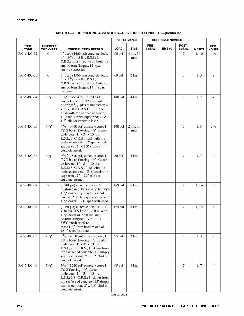
��� ���� ���������� ��� ���� �������� ���®
TABLE 3.1�FLOOR/CEILING ASSEMBLIES�REINFORCED CONCRETE�(Continued)
ITEMCODE
REC.HOURSNOTES
REFERENCE NUMBERPERFORMANCE
CONSTRUCTION DETAILSASSEMBLYTHICKNESS
ITEMCODE
REC.HOURSNOTES
POST-BMS-92BMS-92
PRE-BMS-92TIMELOADCONSTRUCTION DETAILS
ASSEMBLYTHICKNESS
F/C-6-RC-32 6� 6� deep (4460 psi) concrete deck;4� � 13/4� � 5 lbs. R.S.J.; 2�C.R.S.; with 1� cover on both topand bottom flanges; 12� spansimply supported.
60 psf 4 hrs. 30min.
7 1, 10 41/2
F/C-6-RC-33 6� 6� deep (4360 psi) concrete deck;4� � 13/4� � 5 lbs. R.S.J.; 2�C.R.S.; with 1� cover on both topand bottom flanges; 13�1� spanrestrained.
60 psf 2 hrs. 7 1, 3 2
F/C-6-RC-34 61/4� 61/4� thick; 43/4� (5120 psi)concrete core; 1� T&G boardflooring; 1/2� plaster undercoat; 4�� 3� � 10 lbs. R.S.J.; 3� C.R.S.flush with top surface concrete;12� span simply supported; 2� �
1�3� clinker concrete insert.
100 psf 4 hrs. 7 1, 7 4
F/C-6-RC-35 61/4� 43/4� (3600 psi) concrete core; 1�T&G board flooring; 1/2� plasterundercoat; 4� � 3� � 10 lbs.R.S.J.; 3� C.R.S.; flush with topsurface concrete; 12� span simplysupported; 2� � 1�3� clinkerconcrete insert.
100 psf 2 hrs. 30min.
7 1, 5 21/2
F/C-6-RC-36 61/4� 43/4� (2800 psi) concrete core; 1�T&G board flooring; 1/2� plasterundercoat; 4� � 3� � 10 lbs.R.S.J.; 3� C.R.S.; flush with topsurface concrete; 12� span simplysupported; 2� � 1�3� clinkerconcrete insert.
80 psf 4 hrs. 7 1, 7 4
F/C-7-RC-37 7� (3640 psi) concrete deck; 1/4�reinforcement bars at 6� pitch with11/2� cover; 1/4� reinforcementbars at 5� pitch perpendicular with11/2� cover; 13�1� span restrained.
169 psf 6 hrs. 7 1, 14 6
F/C-7-RC-38 7� (4060 psi) concrete deck; 4� � 3�� 10 lbs. R.S.J.; 2�6� C.R.S. with11/2� cover on both top andbottom flanges; 4� � 6� � 13SWG mesh reinforce-ment 11/2� from bottom of slab;13�1� span restrained.
175 psf 6 hrs. 7 1, 14 6
F/C-7-RC-39 71/4� 53/4� (4010 psi) concrete core; 1�T&G board flooring; 1/2� plasterundercoat; 4� � 3� � 10 lbs.R.S.J.; 2�6� C.R.S.; 1� down fromtop surface of concrete; 12� simplysupported span; 2� � 1�3� clinkerconcrete insert.
95 psf 2 hrs. 7 1, 3 2
F/C-7-RC-40 71/4� 53/4� (3220 psi) concrete core; 1�T&G flooring; 1/2� plasterundercoat; 4� � 3� � 10 lbs.R.S.J.; 2�6� C.R.S.; 1� down fromtop surface of concrete; 12� simplysupported span; 2� � 1�3� clinkerconcrete insert.
95 psf 4 hrs. 7 1, 7 4
(Continued)
�� ����

���� ���������� ��� ���� �������� ���® ���
TABLE 3.1�FLOOR/CEILING ASSEMBLIES�REINFORCED CONCRETE�(Continued)
ITEMCODE
REC.HOURSNOTES
REFERENCE NUMBERPERFORMANCE
CONSTRUCTION DETAILSASSEMBLYTHICKNESS
ITEMCODE
REC.HOURSNOTES
POST-BMS-92BMS-92
PRE-BMS-92TIMELOADCONSTRUCTION DETAILS
ASSEMBLYTHICKNESS
F/C-7-RC-41 10�(21/4�Slab)
Ribbed floor, see Note 15 fordetails; slab 21/2� deep (3020 psi);1/4� reinforcement bars at 6� pitchwith 3/4� cover; beams 71/2� deep� 5� wide; 24� C.R.S.; 5/8�reinforcement bars two rows 1/2�vertically apart with 1� cover;13�1� span restricted.
195 psf 1 hr. 4.min.
7 1, 2, 15 1
F/C-5-RC-42 51/2� Composite ribbed concrete slabassembly; see Note 17 for details.
SeeNote 16
2 hrs. 43 16, 17 2
F/C-3-RC-43 3� 2500 psi concrete; 5/8� cover;fully restrained at test.
SeeNote 16
30 min. 43 16 1/2
F/C-3-RC-44 3� 2000 psi concrete; 5/8� cover; freeor partial restraint at test.
SeeNote 16
45 min. 43 16 3/4
F/C-4-RC-45 4� 2500 psi concrete; 5/8� cover;fully restrained at test.
SeeNote 16
40 min. 43 16 2/3
F/C-4-RC-46 4� 2000 psi concrete; 3/4� cover; freeor partial restraint at test.
SeeNote 16
1 hr. 15min.
43 16 11/4
F/C-5-RC-47 5� 2500 psi concrete; 3/4� cover;fully restrained at test.
SeeNote 16
1 hr. 43 16 1
F/C-5-RC-48 5� 2000 psi concrete; 3/4� cover; freeor partial restraint at test.
SeeNote 16
1 hr. 30min.
43 16 11/2
F/C-6-RC-49 6� 2500 psi concrete; 1� cover; fullyrestrained at test.
SeeNote 16
1 hr. 30min.
43 16 11/2
F/C-6-RC-50 6� 2000 psi concrete; 1� cover; freeor partial restraint at test.
SeeNote 16
2 hrs. 43 16 2
Notes:1. British test.2. Failure mode - local back face temperature rise.3. Tested for Grade �C� (2 hour) fire resistance.4. Collapse imminent following hose stream.5. Failure mode - flame thru.6. Void formed with explosive force and report.7. Achieved Grade �B� (4 hour) fire resistance (British).8. Failure mode - collapse.9. Test was run to 2 hours, but specimen was partially supported by the furnace at 11/4 hours.10. Failure mode - average back face temperature.11. Recommended endurance for nonload bearing performance only.12. Floor maintained load bearing ability to 2 hours at which point test was terminated.13. Test was run to 3 hours at which time failure mode 2 (above) was reached in spite of crack formation at 29 minutes.14. Tested for Grade �A� (6 hour) fire resistance.15.
5/8� REINFORCEMENTBARS
1/2�5�
7 1/2�
1�
SLAB 21/2� THICK1/4� REINFORCEMENT BARSAT 6� PITCH WITH 3/4� COVER
BEAMS AT 24� CRS.
16. Load unspecified.17. Total assembly thickness 51/2 inches. Three-inch thick blocks of molded excelsior bonded with portland cement used as inserts with 21/2-inch cover (concrete)
above blocks and 3/4-inch gypsumplaster below.Nine-inch wide ribs containing reinforcing steel of unspecified size interrupted 20-inch wide segments of slabcomposite (i.e., plaster, excelsior blocks, concrete cover).
�� ����
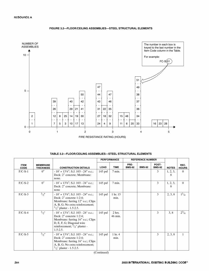
��� ���� ���������� ��� ���� �������� ���®
FIGURE 3.2�FLOOR/CEILING ASSEMBLIES�STEEL STRUCTURAL ELEMENTS
0
FIRE RESISTANCE RATING (HOURS)
NUMBER OFASSEMBLIES
1 2 3 4
5
10
0
The number in each box iskeyed to the last number in theItem Code column in the Table.
For example:
FC-S-51
19
21
17
5
258
35
30
41
42
13
50
2
1
12
26
39
7
34
36
37
33
38
49
14
29
40
10
18
22
4
32
35
46
9
47
27
31
43
24
44
47
20
48
6
15
11
51
282316
TABLE 3.2�FLOOR/CEILING ASSEMBLIES�STEEL STRUCTURAL ELEMENTS
PERFORMANCE REFERENCE NUMBER
ITEMCODE
MEMBRANETHICKNESS CONSTRUCTION DETAILS LOAD TIME
PRE-BMS-92 BMS-92
POST-BMS-92 NOTES
REC.HOURS
F/C-S-1 0� - 10� � 13�6�; S.J. 103 - 24� o.c.;Deck: 2� concrete; Membrane:none.
145 psf 7 min. 3 1, 2, 3,8
0
F/C-S-2 0� - 10� � 13�6�; S.J. 103 - 24� o.c.;Deck: 2� concrete; Membrane:none
145 psf 7 min. 3 1, 2, 3,8
0
F/C-S-3 1/2� - 10� � 13�6�; S.J. 103 - 24� o.c.;Deck: 2� concrete 1:2:4;Membrane: furring 12� o.c.; ClipsA, B, G; No extra reinforcement;1/2� plaster - 1.5:2.5.
145 psf 1 hr. 15min.
3 2, 3, 8 11/4
F/C-S-4 1/2� - 10� � 13�6�; S.J. 103 - 24� o.c.;Deck: 2� concrete 1:2:4;Membrane: furring 16� o.c.; ClipsD, E, F, G; Diagonal wirereinforcement; 1/2� plaster -1.5:2.5.
145 psf 2 hrs.46 min.
3 3, 8 23/4
F/C-S-5 1/2� - 10� � 13�6�; S.J. 103 - 24� o.c.;Deck: 2� concrete 1:2:4;Membrane: furring 16� o.c.; ClipsA, B, G; No extra reinforcement;1/2� plaster - 1.5:2.5.
145 psf 1 hr. 4min.
3 2, 3, 8 1
(Continued)
�� ����
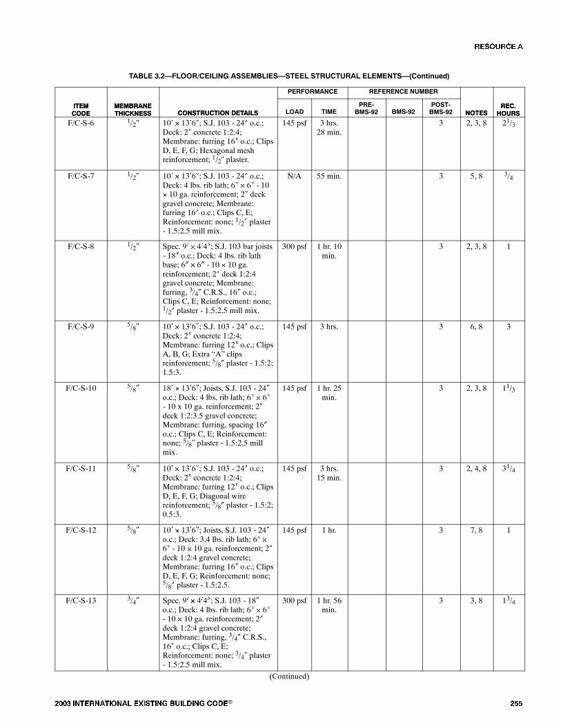
���� ���������� ��� ���� �������� ���® ���
TABLE 3.2�FLOOR/CEILING ASSEMBLIES�STEEL STRUCTURAL ELEMENTS�(Continued)
ITEMCODE
REC.HOURSNOTES
REFERENCE NUMBERPERFORMANCE
CONSTRUCTION DETAILSMEMBRANETHICKNESS
ITEMCODE
REC.HOURSNOTES
POST-BMS-92BMS-92
PRE-BMS-92TIMELOADCONSTRUCTION DETAILS
MEMBRANETHICKNESS
F/C-S-6 1/2� 10� � 13�6�; S.J. 103 - 24� o.c.;Deck: 2� concrete 1:2:4;Membrane: furring 16� o.c.; ClipsD, E, F, G; Hexagonal meshreinforcement; 1/2� plaster.
145 psf 3 hrs.28 min.
3 2, 3, 8 21/3
F/C-S-7 1/2� 10� � 13�6�; S.J. 103 - 24� o.c.;Deck: 4 lbs. rib lath; 6� � 6� - 10� 10 ga. reinforcement; 2� deckgravel concrete; Membrane:furring 16� o.c.; Clips C, E;Reinforcement: none; 1/2� plaster- 1.5:2.5 mill mix.
N/A 55 min. 3 5, 8 3/4
F/C-S-8 1/2� Spec. 9� � 4�4�; S.J. 103 bar joists- 18� o.c.; Deck: 4 lbs. rib lathbase; 6� � 6� - 10 � 10 ga.reinforcement; 2� deck 1:2:4gravel concrete; Membrane:furring, 3/4� C.R.S., 16� o.c.;Clips C, E; Reinforcement: none;1/2� plaster - 1.5:2.5 mill mix.
300 psf 1 hr. 10min.
3 2, 3, 8 1
F/C-S-9 5/8� 10� � 13�6�; S.J. 103 - 24� o.c.;Deck: 2� concrete 1:2:4;Membrane: furring 12� o.c.; ClipsA, B, G; Extra �A� clipsreinforcement; 5/8� plaster - 1.5:2;1.5:3.
145 psf 3 hrs. 3 6, 8 3
F/C-S-10 5/8� 18� � 13�6�; Joists, S.J. 103 - 24�o.c.; Deck: 4 lbs. rib lath; 6� � 6�- 10 x 10 ga. reinforcement; 2�deck 1:2:3.5 gravel concrete;Membrane: furring, spacing 16�o.c.; Clips C, E; Reinforcement:none; 5/8� plaster - 1.5:2.5 millmix.
145 psf 1 hr. 25min.
3 2, 3, 8 11/3
F/C-S-11 5/8� 10� � 13�6�; S.J. 103 - 24� o.c.;Deck: 2� concrete 1:2:4;Membrane: furring 12� o.c.; ClipsD, E, F, G; Diagonal wirereinforcement; 5/8� plaster - 1.5:2;0.5:3.
145 psf 3 hrs.15 min.
3 2, 4, 8 31/4
F/C-S-12 5/8� 10� � 13�6�; Joists, S.J. 103 - 24�o.c.; Deck: 3.4 lbs. rib lath; 6� �
6� - 10 � 10 ga. reinforcement; 2�deck 1:2:4 gravel concrete;Membrane: furring 16� o.c.; ClipsD, E, F, G; Reinforcement: none;5/8� plaster - 1.5:2.5.
145 psf 1 hr. 3 7, 8 1
F/C-S-13 3/4� Spec. 9� � 4�4�; S.J. 103 - 18�o.c.; Deck: 4 lbs. rib lath; 6� � 6�- 10 � 10 ga. reinforcement; 2�deck 1:2:4 gravel concrete;Membrane: furring, 3/4� C.R.S.,16� o.c.; Clips C, E;Reinforcement: none; 3/4� plaster- 1.5:2.5 mill mix.
300 psf 1 hr. 56min.
3 3, 8 13/4
(Continued)
�� ����
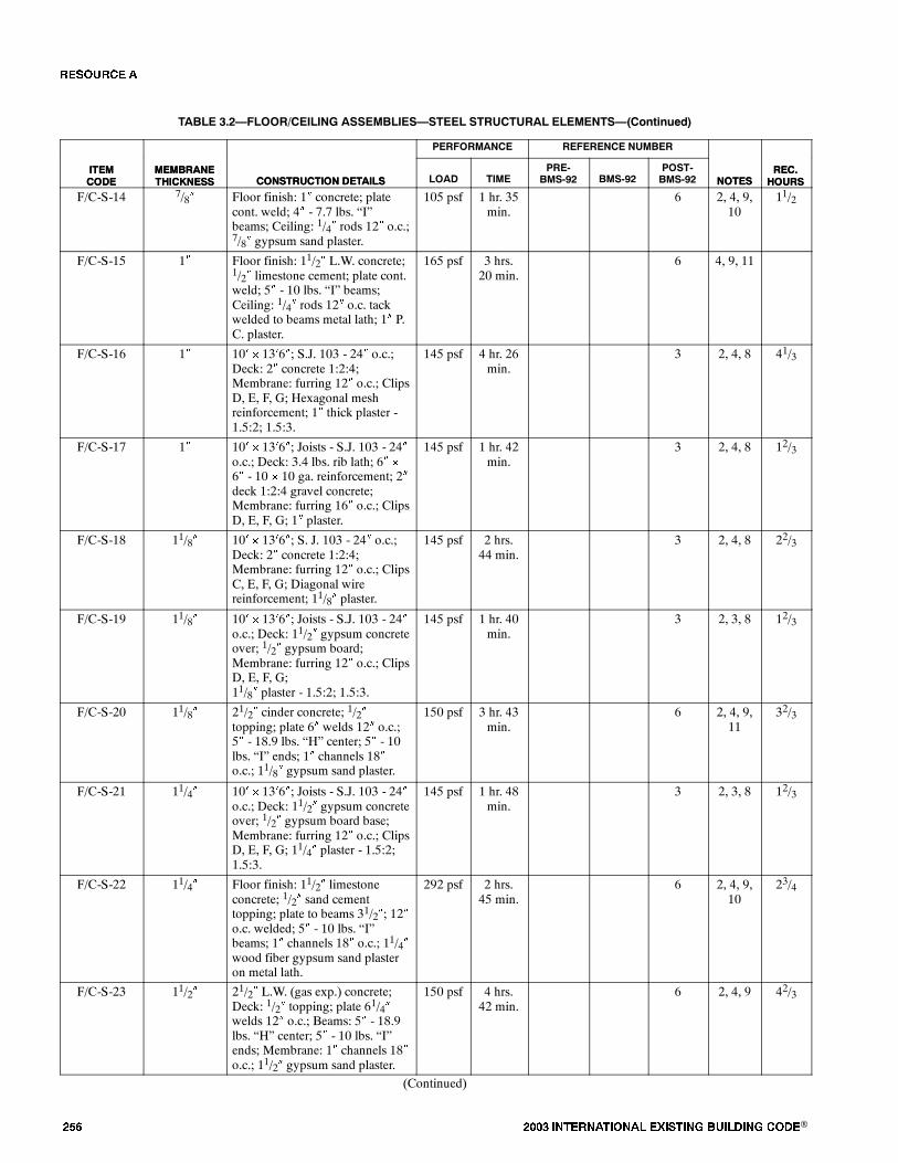
��� ���� ���������� ��� ���� �������� ���®
TABLE 3.2�FLOOR/CEILING ASSEMBLIES�STEEL STRUCTURAL ELEMENTS�(Continued)
ITEMCODE
REC.HOURSNOTES
REFERENCE NUMBERPERFORMANCE
CONSTRUCTION DETAILSMEMBRANETHICKNESS
ITEMCODE
REC.HOURSNOTES
POST-BMS-92BMS-92
PRE-BMS-92TIMELOADCONSTRUCTION DETAILS
MEMBRANETHICKNESS
F/C-S-14 7/8� Floor finish: 1� concrete; platecont. weld; 4� - 7.7 lbs. �I�beams; Ceiling: 1/4� rods 12� o.c.;7/8� gypsum sand plaster.
105 psf 1 hr. 35min.
6 2, 4, 9,10
11/2
F/C-S-15 1� Floor finish: 11/2� L.W. concrete;1/2� limestone cement; plate cont.weld; 5� - 10 lbs. �I� beams;Ceiling: 1/4� rods 12� o.c. tackwelded to beams metal lath; 1� P.C. plaster.
165 psf 3 hrs.20 min.
6 4, 9, 11
F/C-S-16 1� 10� � 13�6�; S.J. 103 - 24� o.c.;Deck: 2� concrete 1:2:4;Membrane: furring 12� o.c.; ClipsD, E, F, G; Hexagonal meshreinforcement; 1� thick plaster -1.5:2; 1.5:3.
145 psf 4 hr. 26min.
3 2, 4, 8 41/3
F/C-S-17 1� 10� � 13�6�; Joists - S.J. 103 - 24�o.c.; Deck: 3.4 lbs. rib lath; 6� �
6� - 10 � 10 ga. reinforcement; 2�deck 1:2:4 gravel concrete;Membrane: furring 16� o.c.; ClipsD, E, F, G; 1� plaster.
145 psf 1 hr. 42min.
3 2, 4, 8 12/3
F/C-S-18 11/8� 10� � 13�6�; S. J. 103 - 24� o.c.;Deck: 2� concrete 1:2:4;Membrane: furring 12� o.c.; ClipsC, E, F, G; Diagonal wirereinforcement; 11/8� plaster.
145 psf 2 hrs.44 min.
3 2, 4, 8 22/3
F/C-S-19 11/8� 10� � 13�6�; Joists - S.J. 103 - 24�o.c.; Deck: 11/2� gypsum concreteover; 1/2� gypsum board;Membrane: furring 12� o.c.; ClipsD, E, F, G;11/8� plaster - 1.5:2; 1.5:3.
145 psf 1 hr. 40min.
3 2, 3, 8 12/3
F/C-S-20 11/8� 21/2� cinder concrete; 1/2�topping; plate 6� welds 12� o.c.;5� - 18.9 lbs. �H� center; 5� - 10lbs. �I� ends; 1� channels 18�o.c.; 11/8� gypsum sand plaster.
150 psf 3 hr. 43min.
6 2, 4, 9,11
32/3
F/C-S-21 11/4� 10� � 13�6�; Joists - S.J. 103 - 24�o.c.; Deck: 11/2� gypsum concreteover; 1/2� gypsum board base;Membrane: furring 12� o.c.; ClipsD, E, F, G; 11/4� plaster - 1.5:2;1.5:3.
145 psf 1 hr. 48min.
3 2, 3, 8 12/3
F/C-S-22 11/4� Floor finish: 11/2� limestoneconcrete; 1/2� sand cementtopping; plate to beams 31/2�; 12�o.c. welded; 5� - 10 lbs. �I�beams; 1� channels 18� o.c.; 11/4�wood fiber gypsum sand plasteron metal lath.
292 psf 2 hrs.45 min.
6 2, 4, 9,10
23/4
F/C-S-23 11/2� 21/2� L.W. (gas exp.) concrete;Deck: 1/2� topping; plate 61/4�welds 12� o.c.; Beams: 5� - 18.9lbs. �H� center; 5� - 10 lbs. �I�ends; Membrane: 1� channels 18�o.c.; 11/2� gypsum sand plaster.
150 psf 4 hrs.42 min.
6 2, 4, 9 42/3
(Continued)
�� ����
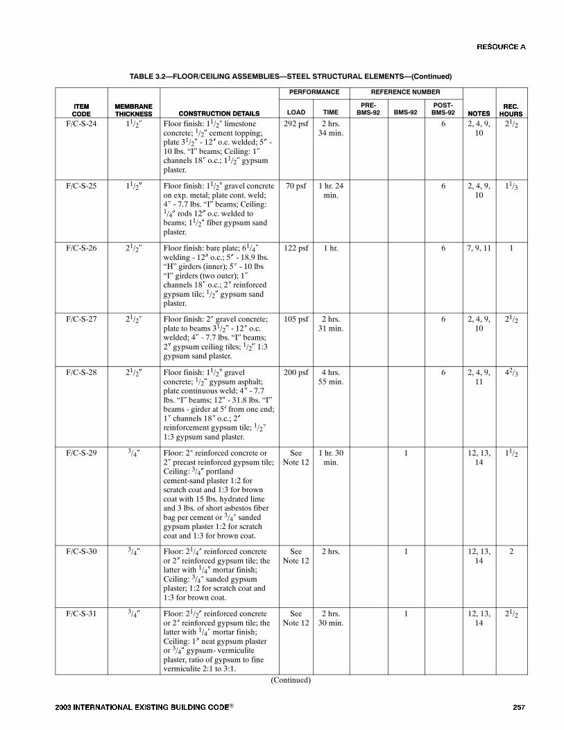
���� ���������� ��� ���� �������� ���® ���
TABLE 3.2�FLOOR/CEILING ASSEMBLIES�STEEL STRUCTURAL ELEMENTS�(Continued)
ITEMCODE
REC.HOURSNOTES
REFERENCE NUMBERPERFORMANCE
CONSTRUCTION DETAILSMEMBRANETHICKNESS
ITEMCODE
REC.HOURSNOTES
POST-BMS-92BMS-92
PRE-BMS-92TIMELOADCONSTRUCTION DETAILS
MEMBRANETHICKNESS
F/C-S-24 11/2� Floor finish: 11/2� limestoneconcrete; 1/2� cement topping;plate 31/2� - 12� o.c. welded; 5� -10 lbs. �I� beams; Ceiling: 1�channels 18� o.c.; 11/2� gypsumplaster.
292 psf 2 hrs.34 min.
6 2, 4, 9,10
21/2
F/C-S-25 11/2� Floor finish: 11/2� gravel concreteon exp. metal; plate cont. weld;4� - 7.7 lbs. �I� beams; Ceiling:1/4� rods 12� o.c. welded tobeams; 11/2� fiber gypsum sandplaster.
70 psf 1 hr. 24min.
6 2, 4, 9,10
11/3
F/C-S-26 21/2� Floor finish: bare plate; 61/4�welding - 12� o.c.; 5� - 18.9 lbs.�H� girders (inner); 5� - 10 lbs�I� girders (two outer); 1�channels 18� o.c.; 2� reinforcedgypsum tile; 1/2� gypsum sandplaster.
122 psf 1 hr. 6 7, 9, 11 1
F/C-S-27 21/2� Floor finish: 2� gravel concrete;plate to beams 31/2� - 12� o.c.welded; 4� - 7.7 lbs. �I� beams;2� gypsum ceiling tiles; 1/2� 1:3gypsum sand plaster.
105 psf 2 hrs.31 min.
6 2, 4, 9,10
21/2
F/C-S-28 21/2� Floor finish: 11/2� gravelconcrete; 1/2� gypsum asphalt;plate continuous weld; 4� - 7.7lbs. �I� beams; 12� - 31.8 lbs. �I�beams - girder at 5� from one end;1� channels 18� o.c.; 2�reinforcement gypsum tile; 1/2�1:3 gypsum sand plaster.
200 psf 4 hrs.55 min.
6 2, 4, 9,11
42/3
F/C-S-29 3/4� Floor: 2� reinforced concrete or2� precast reinforced gypsum tile;Ceiling: 3/4� portlandcement-sand plaster 1:2 forscratch coat and 1:3 for browncoat with 15 lbs. hydrated limeand 3 lbs. of short asbestos fiberbag per cement or 3/4� sandedgypsum plaster 1:2 for scratchcoat and 1:3 for brown coat.
SeeNote 12
1 hr. 30min.
1 12, 13,14
11/2
F/C-S-30 3/4� Floor: 21/4� reinforced concreteor 2� reinforced gypsum tile; thelatter with 1/4� mortar finish;Ceiling: 3/4� sanded gypsumplaster; 1:2 for scratch coat and1:3 for brown coat.
SeeNote 12
2 hrs. 1 12, 13,14
2
F/C-S-31 3/4� Floor: 21/2� reinforced concreteor 2� reinforced gypsum tile; thelatter with 1/4� mortar finish;Ceiling: 1� neat gypsum plasteror 3/4� gypsum- vermiculiteplaster, ratio of gypsum to finevermiculite 2:1 to 3:1.
SeeNote 12
2 hrs.30 min.
1 12, 13,14
21/2
(Continued)
�� ����
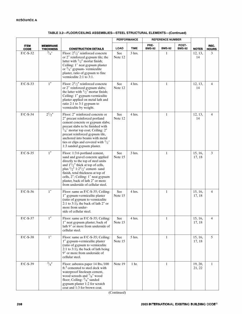
��� ���� ���������� ��� ���� �������� ���®
TABLE 3.2�FLOOR/CEILING ASSEMBLIES�STEEL STRUCTURAL ELEMENTS�(Continued)
ITEMCODE
REC.HOURSNOTES
REFERENCE NUMBERPERFORMANCE
CONSTRUCTION DETAILSMEMBRANETHICKNESS
ITEMCODE
REC.HOURSNOTES
POST-BMS-92BMS-92
PRE-BMS-92TIMELOADCONSTRUCTION DETAILS
MEMBRANETHICKNESS
F/C-S-32 3/4� Floor: 21/2� reinforced concreteor 2� reinforced gypsum tile; thelatter with 1/2� mortar finish;Ceiling: 1� neat gypsum plasteror 3/4� gypsum- vermiculiteplaster, ratio of gypsum to finevermiculite 2:1 to 3:1.
SeeNote 12
3 hrs. 1 12, 13,14
3
F/C-S-33 1� Floor: 21/2� reinforced concreteor 2� reinforced gypsum slabs;the latter with 1/2� mortar finish;Ceiling: 1� gypsum-vermiculiteplaster applied on metal lath andratio 2:1 to 3:1 gypsum tovermiculite by weight.
SeeNote 12
4 hrs. 1 12, 13,14
4
F/C-S-34 21/2� Floor: 2� reinforced concrete or2� precast reinforced portlandcement concrete or gypsum slabs;precast slabs to be finished with1/4� mortar top coat; Ceiling: 2�precast reinforced gypsum tile,anchored into beams with metalties or clips and covered with 1/2�1:3 sanded gypsum plaster.
SeeNote 12
4 hrs. 1 12, 13,14
4
F/C-S-35 1� Floor: 1:3:6 portland cement,sand and gravel concrete applieddirectly to the top of steel unitsand 11/2� thick at top of cells,plus 1/2� 1:21/2� cement- sandfinish, total thickness at top ofcells, 2�; Ceiling: 1� neat gypsumplaster, back of lath 2� or morefrom underside of cellular steel.
SeeNote 15
3 hrs. 1 15, 16,17, 18
3
F/C-S-36 1� Floor: same as F/C-S-35; Ceiling:1� gypsum-vermiculite plaster(ratio of gypsum to vermiculite2:1 to 3:1), the back of lath 2� ormore from under-side of cellular steel.
SeeNote 15
4 hrs. 1 15, 16,17, 18
4
F/C-S-37 1� Floor: same as F/C-S-35; Ceiling:1� neat gypsum plaster; back oflath 9� or more from underside ofcellular steel.
SeeNote 15
4 hrs. 1 15, 16,17, 18
4
F/C-S-38 1� Floor: same as F/C-S-35; Ceiling:1� gypsum-vermiculite plaster(ratio of gypsum to vermiculite2:1 to 3:1), the back of lath being9� or more from underside ofcellular steel.
SeeNote 15
5 hrs. 1 15, 16,17, 18
5
F/C-S-39 3/4� Floor: asbestos paper 14 lbs./100ft.2 cemented to steel deck withwaterproof linoleum cement,wood screeds and 7/8� woodfloor; Ceiling: 3/4� sandedgypsum plaster 1:2 for scratchcoat and 1:3 for brown coat.
Note 19 1 hr. 1 19, 20,21, 22
1
(Continued)
�� ����

���� ���������� ��� ���� �������� ���® ���
TABLE 3.2�FLOOR/CEILING ASSEMBLIES�STEEL STRUCTURAL ELEMENTS�(Continued)
ITEMCODE
REC.HOURSNOTES
REFERENCE NUMBERPERFORMANCE
CONSTRUCTION DETAILSMEMBRANETHICKNESS
ITEMCODE
REC.HOURSNOTES
POST-BMS-92BMS-92
PRE-BMS-92TIMELOADCONSTRUCTION DETAILS
MEMBRANETHICKNESS
F/C-S-40 3/4� Floor: 11/2�, 1:2:4 portlandcement concrete; Ceiling: 3/4�sanded gypsum plaster 1:2 forscratch coat and 1:3 for browncoat.
Note 19 1 hr. 30min.
1 19, 20,21, 22
11/2
F/C-S-41 3/4� Floor: 2�, 1:2:4 portland cementconcrete; Ceiling: 3/4� sandedgypsum plaster, 1:2 for scratchcoat and 1:3 for brown coat.
Note 19 2 hrs. 1 19, 20,21, 22
2
F/C-S-42 1� Floor: 2�, 1:2:4 portland cementconcrete; Ceiling: 1� portlandcement-sand plaster with 10 lbs.of hydrated lime for @ bag ofcement 1:2 for scratch coat and1:21/2� for brown coat.
Note 19 2 hrs. 1 19, 20,21, 22
2
F/C-S-43 11/2� Floor: 2�, 1:2:4 portland cementconcrete; Ceiling: 11/2�, 1:2sanded gypsum plaster on ribbedmetal lath.
Note 19 2 hrs.30 min.
1 19, 20,21, 22
21/2
F/C-S-44 11/8� Floor: 2�, 1:2:4 portland cementconcrete; Ceiling: 11/8�, 1:1sanded gypsum plaster.
Note 19 2 hrs.30 min.
1 19, 20,21, 22
21/2
F/C-S-45 1� Floor: 21/2�, 1:2:4 portlandcement concrete; Ceiling: 1�, 1:2sanded gypsum plaster.
Note 19 2 hrs.30 min.
1 19, 20,21, 22
21/2
F/C-S-46 3/4� Floor: 21/2�, 1:2:4 portlandcement concrete; Ceiling: 1� neatgypsum plaster or 3/4�gypsum-vermiculite plaster, ratioof gypsum to vermiculite 2:1 to3:1.
Note 19 3 hrs. 1 19, 20,21, 22
3
F/C-S-47 11/8� Floor: 21/2�, 1:2:4 portlandcement, sand and cinder concreteplus 1/2�, 1:21/2� cement-sandfinish; total thickness 3�; Ceiling:11/8�, 1:1 sanded gypsum plaster.
Note 19 3 hrs. 1 19, 20,21, 22
3
F/C-S-48 11/8� Floor: 21/2�, gas expandedportland cement- sand concreteplus 1/2�, 1:2.5 cement-sandfinish; total thickness 3�; Ceiling:11/8�, 1:1 sanded gypsum plaster.
Note 19 3 hrs.30 min.
1 19, 20,21, 22
31/2
F/C-S-49 1� Floor: 21/2�, 1:2:4 portlandcement concrete; Ceiling: 1�gypsum- vermiculite plaster; ratioof gypsum to vermiculite 2:1 to3:1.
Note 19 4 hrs. 1 19, 20,21, 22
4
F/C-S-50 21/2� Floor: 2�, 1:2:4 portland cementconcrete; Ceiling: 2� interlockinggypsum tile supported on upperface of lower flanges of beams,1/2� 1:3 sanded gypsum plaster.
Note 19 2 hrs. 1 19, 20,21, 22
2
(Continued)
�� ����
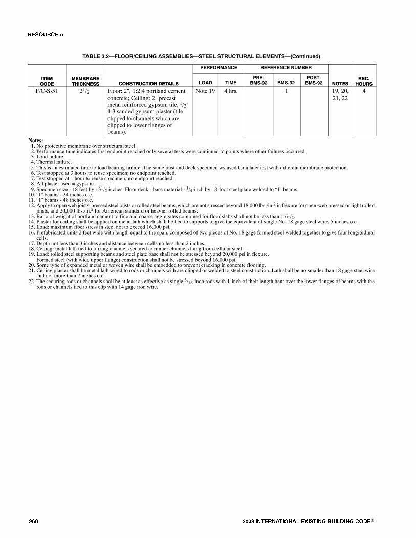
��� ���� ���������� ��� ���� �������� ���®
TABLE 3.2�FLOOR/CEILING ASSEMBLIES�STEEL STRUCTURAL ELEMENTS�(Continued)
ITEMCODE
REC.HOURSNOTES
REFERENCE NUMBERPERFORMANCE
CONSTRUCTION DETAILSMEMBRANETHICKNESS
ITEMCODE
REC.HOURSNOTES
POST-BMS-92BMS-92
PRE-BMS-92TIMELOADCONSTRUCTION DETAILS
MEMBRANETHICKNESS
F/C-S-51 21/2� Floor: 2�, 1:2:4 portland cementconcrete; Ceiling: 2� precastmetal reinforced gypsum tile, 1/2�1:3 sanded gypsum plaster (tileclipped to channels which areclipped to lower flanges ofbeams).
Note 19 4 hrs. 1 19, 20,21, 22
4
Notes:1. No protective membrane over structural steel.2. Performance time indicates first endpoint reached only several tests were continued to points where other failures occurred.3. Load failure.4. Thermal failure.5. This is an estimated time to load bearing failure. The same joist and deck specimen ws used for a later test with different membrane protection.6. Test stopped at 3 hours to reuse specimen; no endpoint reached.7. Test stopped at 1 hour to reuse specimen; no endpoint reached.8. All plaster used = gypsum.9. Specimen size - 18 feet by 131/2 inches. Floor deck - base material - 1/4-inch by 18-foot steel plate welded to �I� beams.10. �I� beams - 24 inches o.c.11. �I� beams - 48 inches o.c.12. Apply to openweb joists, pressed steel joists or rolled steel beams,which are not stressed beyond 18,000 lbs./in.2 in flexure for open-web pressed or light rolled
joists, and 20,000 lbs./in.2 for American standard or heavier rolled beams.13. Ratio of weight of portland cement to fine and coarse aggregates combined for floor slabs shall not be less than 1:61/2.14. Plaster for ceiling shall be applied on metal lath which shall be tied to supports to give the equivalent of single No. 18 gage steel wires 5 inches o.c.15. Load: maximum fiber stress in steel not to exceed 16,000 psi.16. Prefabricated units 2 feet wide with length equal to the span, composed of two pieces of No. 18 gage formed steel welded together to give four longitudinal
cells.17. Depth not less than 3 inches and distance between cells no less than 2 inches.18. Ceiling: metal lath tied to furring channels secured to runner channels hung from cellular steel.19. Load: rolled steel supporting beams and steel plate base shall not be stressed beyond 20,000 psi in flexure.
Formed steel (with wide upper flange) construction shall not be stressed beyond 16,000 psi.20. Some type of expanded metal or woven wire shall be embedded to prevent cracking in concrete flooring.21. Ceiling plaster shall be metal lath wired to rods or channels with are clipped or welded to steel construction. Lath shall be no smaller than 18 gage steel wire
and not more than 7 inches o.c.22. The securing rods or channels shall be at least as effective as single 3/16-inch rods with 1-inch of their length bent over the lower flanges of beams with the
rods or channels tied to this clip with 14 gage iron wire.
�� ����
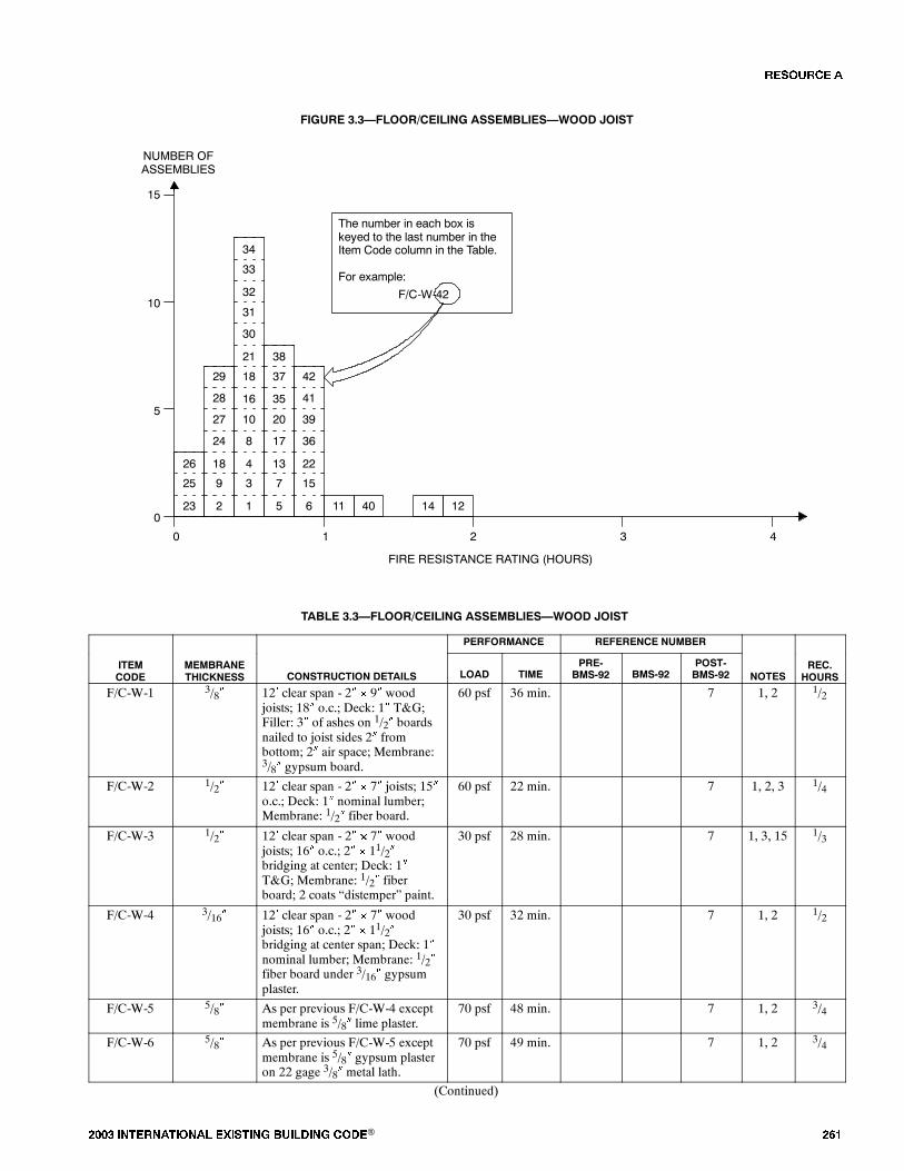
���� ���������� ��� ���� �������� ���® ���
FIGURE 3.3�FLOOR/CEILING ASSEMBLIES�WOOD JOIST
9
18
24
3
4
8
25
26
0
FIRE RESISTANCE RATING (HOURS)
NUMBER OFASSEMBLIES
1 2 3 4
5
10
15
02
27
1
10
23
The number in each box iskeyed to the last number in theItem Code column in the Table.
For example:
F/C-W-42
12144011
28
29 18
21
30
16
31
33
34
32
15
22
36
6
39
41
42
7
13
17
5
20
37
38
35
TABLE 3.3�FLOOR/CEILING ASSEMBLIES�WOOD JOIST
PERFORMANCE REFERENCE NUMBER
ITEMCODE
MEMBRANETHICKNESS CONSTRUCTION DETAILS LOAD TIME
PRE-BMS-92 BMS-92
POST-BMS-92 NOTES
REC.HOURS
F/C-W-1 3/8� 12� clear span - 2� � 9� woodjoists; 18� o.c.; Deck: 1� T&G;Filler: 3� of ashes on 1/2� boardsnailed to joist sides 2� frombottom; 2� air space; Membrane:3/8� gypsum board.
60 psf 36 min. 7 1, 2 1/2
F/C-W-2 1/2� 12� clear span - 2� � 7� joists; 15�o.c.; Deck: 1� nominal lumber;Membrane: 1/2� fiber board.
60 psf 22 min. 7 1, 2, 3 1/4
F/C-W-3 1/2� 12� clear span - 2� � 7� woodjoists; 16� o.c.; 2� � 11/2�bridging at center; Deck: 1�T&G; Membrane: 1/2� fiberboard; 2 coats �distemper� paint.
30 psf 28 min. 7 1, 3, 15 1/3
F/C-W-4 3/16� 12� clear span - 2� � 7� woodjoists; 16� o.c.; 2� � 11/2�bridging at center span; Deck: 1�nominal lumber; Membrane: 1/2�fiber board under 3/16� gypsumplaster.
30 psf 32 min. 7 1, 2 1/2
F/C-W-5 5/8� As per previous F/C-W-4 exceptmembrane is 5/8� lime plaster.
70 psf 48 min. 7 1, 2 3/4
F/C-W-6 5/8� As per previous F/C-W-5 exceptmembrane is 5/8� gypsum plasteron 22 gage 3/8� metal lath.
70 psf 49 min. 7 1, 2 3/4
(Continued)
�� ����
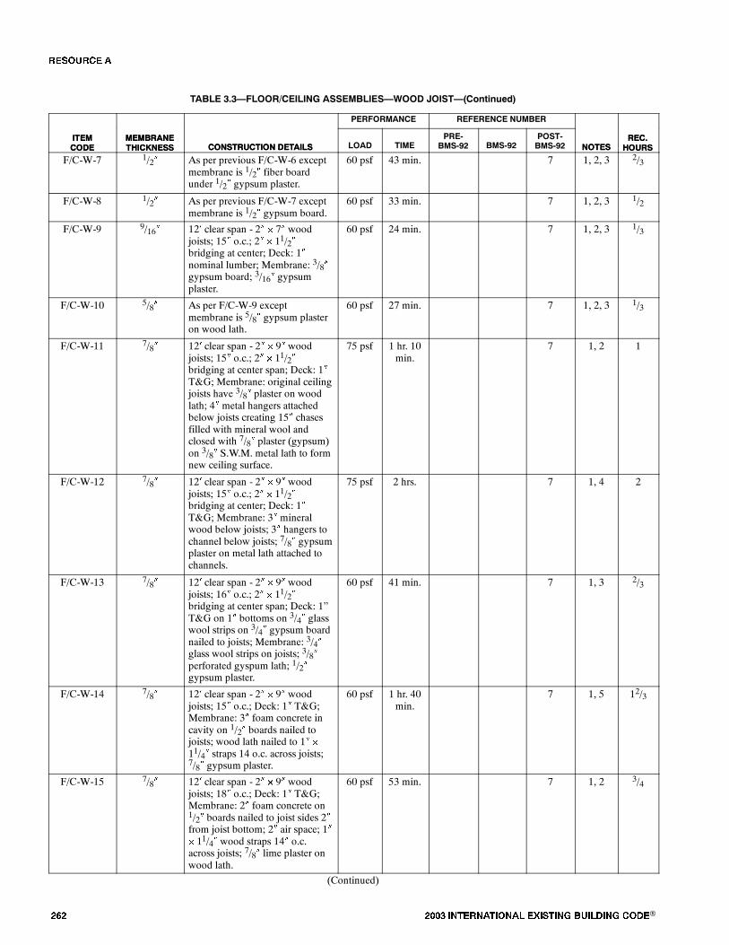
��� ���� ���������� ��� ���� �������� ���®
TABLE 3.3�FLOOR/CEILING ASSEMBLIES�WOOD JOIST�(Continued)
ITEMCODE
REC.HOURSNOTES
REFERENCE NUMBERPERFORMANCE
CONSTRUCTION DETAILSMEMBRANETHICKNESS
ITEMCODE
REC.HOURSNOTES
POST-BMS-92BMS-92
PRE-BMS-92TIMELOADCONSTRUCTION DETAILS
MEMBRANETHICKNESS
F/C-W-7 1/2� As per previous F/C-W-6 exceptmembrane is 1/2� fiber boardunder 1/2� gypsum plaster.
60 psf 43 min. 7 1, 2, 3 2/3
F/C-W-8 1/2� As per previous F/C-W-7 exceptmembrane is 1/2� gypsum board.
60 psf 33 min. 7 1, 2, 3 1/2
F/C-W-9 9/16� 12� clear span - 2� � 7� woodjoists; 15� o.c.; 2� � 11/2�bridging at center; Deck: 1�nominal lumber; Membrane: 3/8�gypsum board; 3/16� gypsumplaster.
60 psf 24 min. 7 1, 2, 3 1/3
F/C-W-10 5/8� As per F/C-W-9 exceptmembrane is 5/8� gypsum plasteron wood lath.
60 psf 27 min. 7 1, 2, 3 1/3
F/C-W-11 7/8� 12� clear span - 2� � 9� woodjoists; 15� o.c.; 2� � 11/2�bridging at center span; Deck: 1�T&G; Membrane: original ceilingjoists have 3/8� plaster on woodlath; 4� metal hangers attachedbelow joists creating 15� chasesfilled with mineral wool andclosed with 7/8� plaster (gypsum)on 3/8� S.W.M. metal lath to formnew ceiling surface.
75 psf 1 hr. 10min.
7 1, 2 1
F/C-W-12 7/8� 12� clear span - 2� � 9� woodjoists; 15� o.c.; 2� � 11/2�bridging at center; Deck: 1�T&G; Membrane: 3� mineralwood below joists; 3� hangers tochannel below joists; 7/8� gypsumplaster on metal lath attached tochannels.
75 psf 2 hrs. 7 1, 4 2
F/C-W-13 7/8� 12� clear span - 2� � 9� woodjoists; 16� o.c.; 2� � 11/2�bridging at center span; Deck: 1�T&G on 1� bottoms on 3/4� glasswool strips on 3/4� gypsum boardnailed to joists; Membrane: 3/4�glass wool strips on joists; 3/8�perforated gyspum lath; 1/2�gypsum plaster.
60 psf 41 min. 7 1, 3 2/3
F/C-W-14 7/8� 12� clear span - 2� � 9� woodjoists; 15� o.c.; Deck: 1� T&G;Membrane: 3� foam concrete incavity on 1/2� boards nailed tojoists; wood lath nailed to 1� �
11/4� straps 14 o.c. across joists;7/8� gypsum plaster.
60 psf 1 hr. 40min.
7 1, 5 12/3
F/C-W-15 7/8� 12� clear span - 2� � 9� woodjoists; 18� o.c.; Deck: 1� T&G;Membrane: 2� foam concrete on1/2� boards nailed to joist sides 2�from joist bottom; 2� air space; 1�� 11/4� wood straps 14� o.c.across joists; 7/8� lime plaster onwood lath.
60 psf 53 min. 7 1, 2 3/4
(Continued)
�� ����
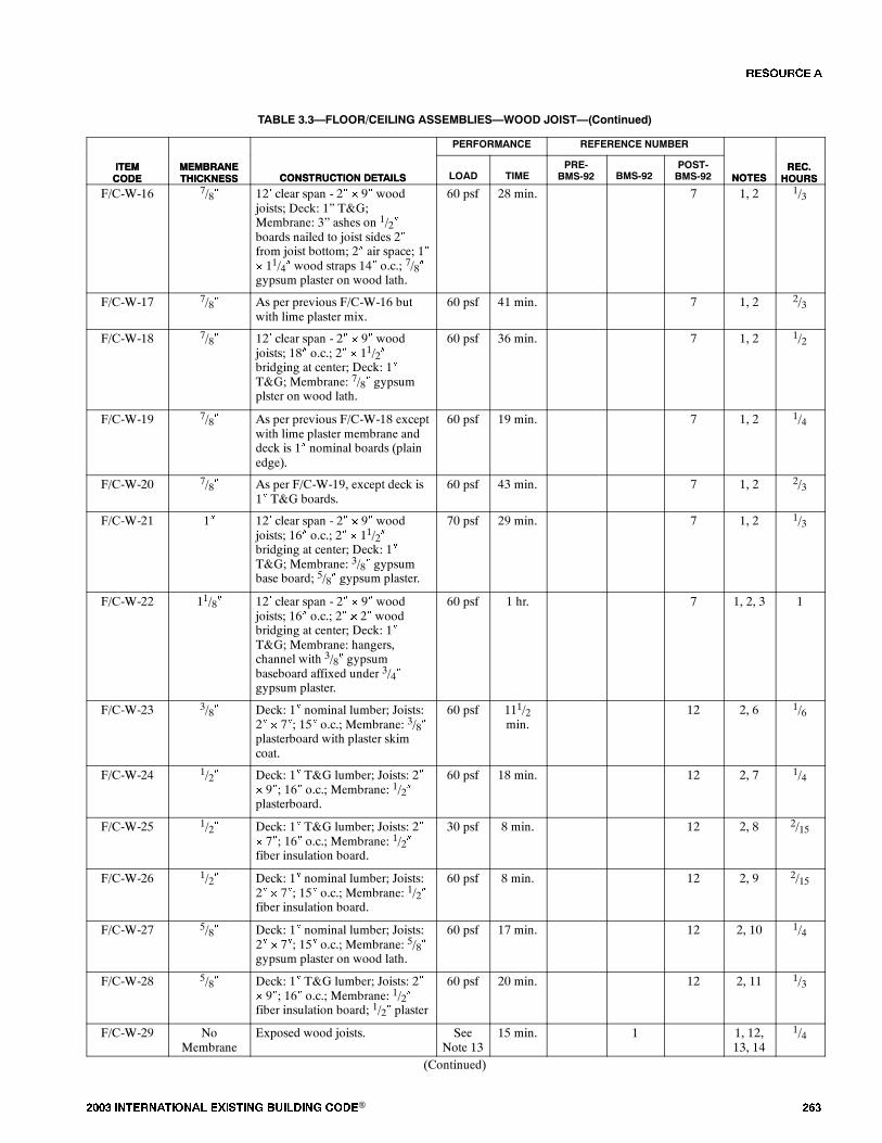
���� ���������� ��� ���� �������� ���® ���
TABLE 3.3�FLOOR/CEILING ASSEMBLIES�WOOD JOIST�(Continued)
ITEMCODE
REC.HOURSNOTES
REFERENCE NUMBERPERFORMANCE
CONSTRUCTION DETAILSMEMBRANETHICKNESS
ITEMCODE
REC.HOURSNOTES
POST-BMS-92BMS-92
PRE-BMS-92TIMELOADCONSTRUCTION DETAILS
MEMBRANETHICKNESS
F/C-W-16 7/8� 12� clear span - 2� � 9� woodjoists; Deck: 1� T&G;Membrane: 3� ashes on 1/2�boards nailed to joist sides 2�from joist bottom; 2� air space; 1�� 11/4� wood straps 14� o.c.; 7/8�gypsum plaster on wood lath.
60 psf 28 min. 7 1, 2 1/3
F/C-W-17 7/8� As per previous F/C-W-16 butwith lime plaster mix.
60 psf 41 min. 7 1, 2 2/3
F/C-W-18 7/8� 12� clear span - 2� � 9� woodjoists; 18� o.c.; 2� � 11/2�bridging at center; Deck: 1�T&G; Membrane: 7/8� gypsumplster on wood lath.
60 psf 36 min. 7 1, 2 1/2
F/C-W-19 7/8� As per previous F/C-W-18 exceptwith lime plaster membrane anddeck is 1� nominal boards (plainedge).
60 psf 19 min. 7 1, 2 1/4
F/C-W-20 7/8� As per F/C-W-19, except deck is1� T&G boards.
60 psf 43 min. 7 1, 2 2/3
F/C-W-21 1� 12� clear span - 2� � 9� woodjoists; 16� o.c.; 2� � 11/2�bridging at center; Deck: 1�T&G; Membrane: 3/8� gypsumbase board; 5/8� gypsum plaster.
70 psf 29 min. 7 1, 2 1/3
F/C-W-22 11/8� 12� clear span - 2� � 9� woodjoists; 16� o.c.; 2� � 2� woodbridging at center; Deck: 1�T&G; Membrane: hangers,channel with 3/8� gypsumbaseboard affixed under 3/4�gypsum plaster.
60 psf 1 hr. 7 1, 2, 3 1
F/C-W-23 3/8� Deck: 1� nominal lumber; Joists:2� � 7�; 15� o.c.; Membrane: 3/8�plasterboard with plaster skimcoat.
60 psf 111/2min.
12 2, 6 1/6
F/C-W-24 1/2� Deck: 1� T&G lumber; Joists: 2�� 9�; 16� o.c.; Membrane: 1/2�plasterboard.
60 psf 18 min. 12 2, 7 1/4
F/C-W-25 1/2� Deck: 1� T&G lumber; Joists: 2�� 7�; 16� o.c.; Membrane: 1/2�fiber insulation board.
30 psf 8 min. 12 2, 8 2/15
F/C-W-26 1/2� Deck: 1� nominal lumber; Joists:2� � 7�; 15� o.c.; Membrane: 1/2�fiber insulation board.
60 psf 8 min. 12 2, 9 2/15
F/C-W-27 5/8� Deck: 1� nominal lumber; Joists:2� � 7�; 15� o.c.; Membrane: 5/8�gypsum plaster on wood lath.
60 psf 17 min. 12 2, 10 1/4
F/C-W-28 5/8� Deck: 1� T&G lumber; Joists: 2�� 9�; 16� o.c.; Membrane: 1/2�fiber insulation board; 1/2� plaster
60 psf 20 min. 12 2, 11 1/3
F/C-W-29 NoMembrane
Exposed wood joists. SeeNote 13
15 min. 1 1, 12,13, 14
1/4
(Continued)
�� ����
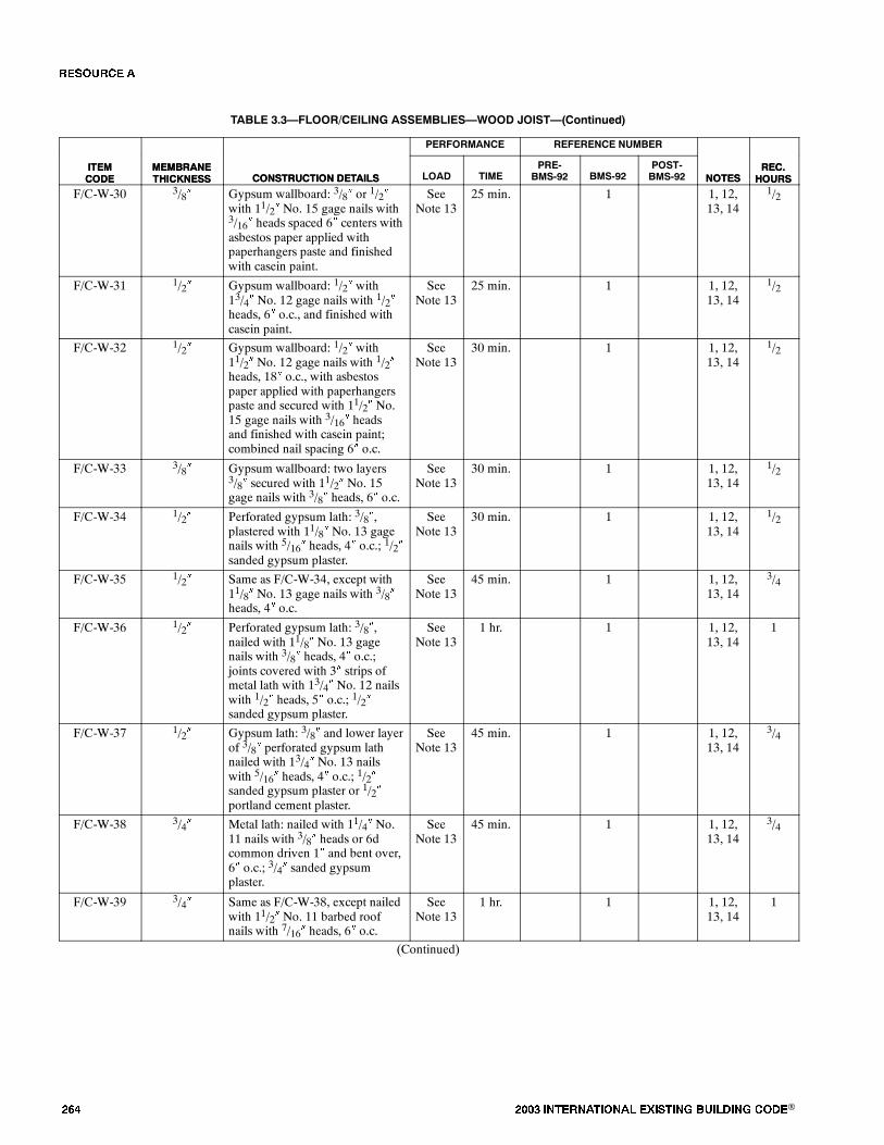
��� ���� ���������� ��� ���� �������� ���®
TABLE 3.3�FLOOR/CEILING ASSEMBLIES�WOOD JOIST�(Continued)
ITEMCODE
REC.HOURSNOTES
REFERENCE NUMBERPERFORMANCE
CONSTRUCTION DETAILSMEMBRANETHICKNESS
ITEMCODE
REC.HOURSNOTES
POST-BMS-92BMS-92
PRE-BMS-92TIMELOADCONSTRUCTION DETAILS
MEMBRANETHICKNESS
F/C-W-30 3/8� Gypsum wallboard: 3/8� or 1/2�with 11/2� No. 15 gage nails with3/16� heads spaced 6� centers withasbestos paper applied withpaperhangers paste and finishedwith casein paint.
SeeNote 13
25 min. 1 1, 12,13, 14
1/2
F/C-W-31 1/2� Gypsum wallboard: 1/2� with13/4� No. 12 gage nails with 1/2�heads, 6� o.c., and finished withcasein paint.
SeeNote 13
25 min. 1 1, 12,13, 14
1/2
F/C-W-32 1/2� Gypsum wallboard: 1/2� with11/2� No. 12 gage nails with 1/2�heads, 18� o.c., with asbestospaper applied with paperhangerspaste and secured with 11/2� No.15 gage nails with 3/16� headsand finished with casein paint;combined nail spacing 6� o.c.
SeeNote 13
30 min. 1 1, 12,13, 14
1/2
F/C-W-33 3/8� Gypsum wallboard: two layers3/8� secured with 11/2� No. 15gage nails with 3/8� heads, 6� o.c.
SeeNote 13
30 min. 1 1, 12,13, 14
1/2
F/C-W-34 1/2� Perforated gypsum lath: 3/8�,plastered with 11/8� No. 13 gagenails with 5/16� heads, 4� o.c.; 1/2�sanded gypsum plaster.
SeeNote 13
30 min. 1 1, 12,13, 14
1/2
F/C-W-35 1/2� Same as F/C-W-34, except with11/8� No. 13 gage nails with 3/8�heads, 4� o.c.
SeeNote 13
45 min. 1 1, 12,13, 14
3/4
F/C-W-36 1/2� Perforated gypsum lath: 3/8�,nailed with 11/8� No. 13 gagenails with 3/8� heads, 4� o.c.;joints covered with 3� strips ofmetal lath with 13/4� No. 12 nailswith 1/2� heads, 5� o.c.; 1/2�sanded gypsum plaster.
SeeNote 13
1 hr. 1 1, 12,13, 14
1
F/C-W-37 1/2� Gypsum lath: 3/8� and lower layerof 3/8� perforated gypsum lathnailed with 13/4� No. 13 nailswith 5/16� heads, 4� o.c.; 1/2�sanded gypsum plaster or 1/2�portland cement plaster.
SeeNote 13
45 min. 1 1, 12,13, 14
3/4
F/C-W-38 3/4� Metal lath: nailed with 11/4� No.11 nails with 3/8� heads or 6dcommon driven 1� and bent over,6� o.c.; 3/4� sanded gypsumplaster.
SeeNote 13
45 min. 1 1, 12,13, 14
3/4
F/C-W-39 3/4� Same as F/C-W-38, except nailedwith 11/2� No. 11 barbed roofnails with 7/16� heads, 6� o.c.
SeeNote 13
1 hr. 1 1, 12,13, 14
1
(Continued)
�� ����
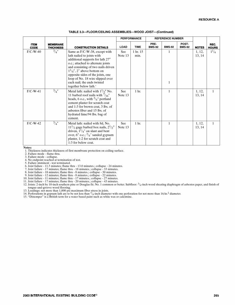
���� ���������� ��� ���� �������� ���® ���
TABLE 3.3�FLOOR/CEILING ASSEMBLIES�WOOD JOIST�(Continued)
ITEMCODE
REC.HOURSNOTES
REFERENCE NUMBERPERFORMANCE
CONSTRUCTION DETAILSMEMBRANETHICKNESS
ITEMCODE
REC.HOURSNOTES
POST-BMS-92BMS-92
PRE-BMS-92TIMELOADCONSTRUCTION DETAILS
MEMBRANETHICKNESS
F/C-W-40 3/4� Same as F/C-W-38, except withlath nailed to joists withadditional supports for lath 27�o.c.; attached to alternate joistsand consisting of two nails driven11/4�, 2� above bottom onopposite sides of the joists, oneloop of No. 18 wire slipped overeach nail; the ends twistedtogether below lath.�
SeeNote 13
1 hr. 15min.
1
1
1, 12,13, 14
11/4
F/C-W-41 3/4� Metal lath: nailed with 11/2� No.11 barbed roof nails with 7/16�heads, 6 o.c., with 3/4� portlandcement plaster for scratch coatand 1:3 for brown coat, 3 lbs. ofasbestos fiber and 15 lbs. ofhydrated lime/94 lbs. bag ofcement.
SeeNote 13
1 hr. 1 1, 12,13, 14
1
F/C-W-42 3/4� Metal lath: nailed with 8d, No.111/2 gage barbed box nails, 21/2�driven, 11/4� on slant and bentover, 6� o.c.; 3/4� sanded gypsumplaster, 1:2 for scratch coat and1:3 for below coat.
SeeNote 13
1 hr. 1 1, 12,13, 14
1
Notes:1. Thickness indicates thickness of first membrane protection on ceiling surface.2. Failure mode - flame thru.3. Failure mode - collapse.4. No endpoint reached at termination of test.5. Failure imminent - test terminated.6. Joist failure - 11.5 minutes; flame thru - 13.0 minutes.; collapse - 24 minutes.7. Joist failure - 17 minutes; flame thru - 18 minutes.; collapse - 33 minutes.8. Joist failure - 18 minutes; flame thru - 8 minutes.; collapse - 30 minutes.9. Joist failure - 12 minutes; flame thru - 8 minutes.; collapse - 22 minutes.10. Joist failure - 11 minutes; flame thru - 17 minutes.; collapse - 27 minutes.11. Joist failure - 17 minutes; flame thru - 20 minutes.; collapse - 43 minutes.12. Joists: 2-inch by 10-inch southern pine or Douglas fir; No. 1 common or better. Subfloor: 3/4-inch wood sheating diaphragm of asbestos paper, and finish of
tongue-and-groove wood flooring.13. Loadings: not more than 1,000 psi maximum fiber stress in joists.14. Perforations in gypsum lath are to be not less than 3/4-inch diameter with one perforation for not more than 16/in.2 diameter.15. �Distemper� is a British term for a water based paint such as white was or calcimine.
�� ����
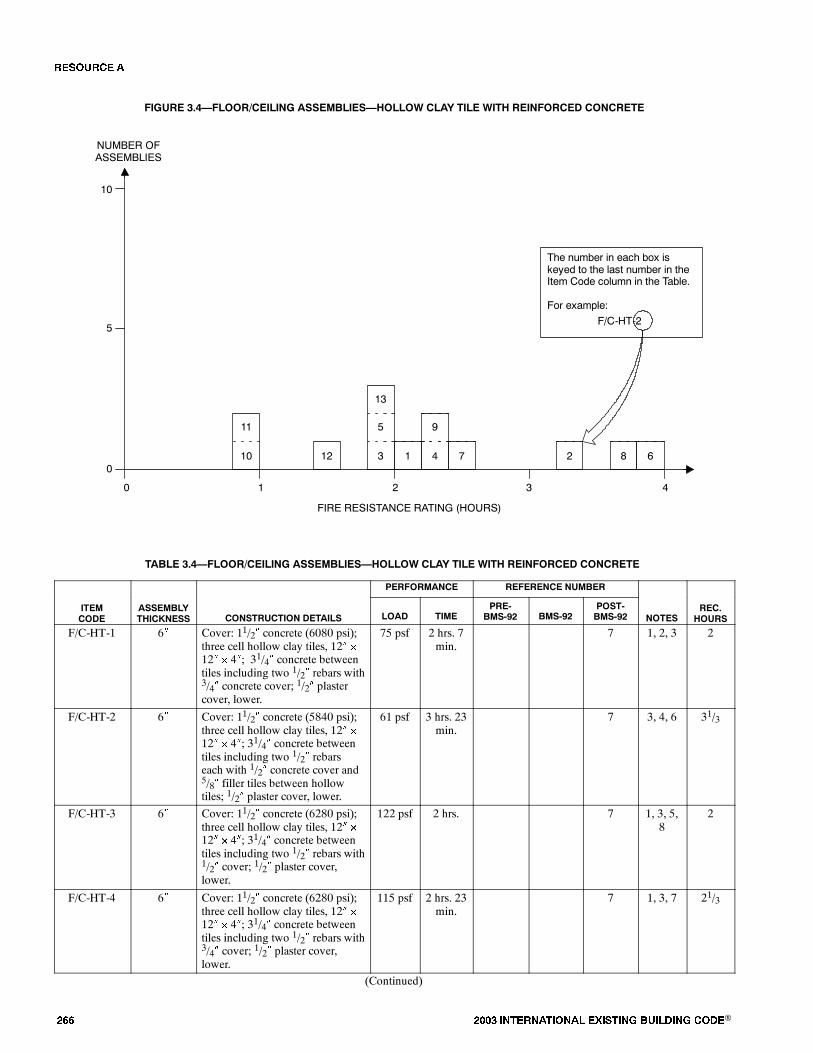
��� ���� ���������� ��� ���� �������� ���®
FIGURE 3.4�FLOOR/CEILING ASSEMBLIES�HOLLOW CLAY TILE WITH REINFORCED CONCRETE
0
FIRE RESISTANCE RATING (HOURS)
NUMBER OFASSEMBLIES
1 2 3 4
5
10
0
The number in each box iskeyed to the last number in theItem Code column in the Table.
For example:
F/C-HT-2
5
13
3 1
9
4 7
11
10 12 8 62
TABLE 3.4�FLOOR/CEILING ASSEMBLIES�HOLLOW CLAY TILE WITH REINFORCED CONCRETE
PERFORMANCE REFERENCE NUMBER
ITEMCODE
ASSEMBLYTHICKNESS CONSTRUCTION DETAILS LOAD TIME
PRE-BMS-92 BMS-92
POST-BMS-92 NOTES
REC.HOURS
F/C-HT-1 6� Cover: 11/2� concrete (6080 psi);three cell hollow clay tiles, 12� �
12� � 4�; 31/4� concrete betweentiles including two 1/2� rebars with3/4� concrete cover; 1/2� plastercover, lower.
75 psf 2 hrs. 7min.
7 1, 2, 3 2
F/C-HT-2 6� Cover: 11/2� concrete (5840 psi);three cell hollow clay tiles, 12� �
12� � 4�; 31/4� concrete betweentiles including two 1/2� rebarseach with 1/2� concrete cover and5/8� filler tiles between hollowtiles; 1/2� plaster cover, lower.
61 psf 3 hrs. 23min.
7 3, 4, 6 31/3
F/C-HT-3 6� Cover: 11/2� concrete (6280 psi);three cell hollow clay tiles, 12� �
12� � 4�; 31/4� concrete betweentiles including two 1/2� rebars with1/2� cover; 1/2� plaster cover,lower.
122 psf 2 hrs. 7 1, 3, 5,8
2
F/C-HT-4 6� Cover: 11/2� concrete (6280 psi);three cell hollow clay tiles, 12� �
12� � 4�; 31/4� concrete betweentiles including two 1/2� rebars with3/4� cover; 1/2� plaster cover,lower.
115 psf 2 hrs. 23min.
7 1, 3, 7 21/3
(Continued)
�� ����

���� ���������� ��� ���� �������� ���® ���
TABLE 3.4�FLOOR/CEILING ASSEMBLIES�HOLLOW CLAY TILE WITH REINFORCED CONCRETE�(Continued)
ITEMCODE
REC.HOURSNOTES
REFERENCE NUMBERPERFORMANCE
CONSTRUCTION DETAILSASSEMBLYTHICKNESS
ITEMCODE
REC.HOURSNOTES
POST-BMS-92BMS-92
PRE-BMS-92TIMELOADCONSTRUCTION DETAILS
ASSEMBLYTHICKNESS
F/C-HT-5 6� Cover: 11/2� concrete (6470 psi);three cell hollow clay tiles, 12� �
12� � 4�; 31/4� concrete betweentiles including two 1/2� rebars with1/2� cover; 1/2� plaster cover,lower.
122 psf 2 hrs. 7 1, 3, 5,8
2
F/C-HT-6 8� Floor cover: 11/2� gravel cement(4300 psi); three cell, 12� � 12� �
6�; 31/2� space between tilesincluding two 1/2� rebars with 1�cover from concrete bottom; 1/2�plaster cover, lower.
165 psf 4 hrs. 7 1, 3, 9,10
4
F/C-HT-7 9� (nom.) Deck: 7/8� T&G on 2� � 11/2�bottoms (18� o.c.) 11/2� concretecover (4600 psi); three cell hollowclay tiles, 12� � 12� � 4�; 3�concrete between tiles includingone 3/4� rebar 3/4� from tilebottom; 1/2� plaster cover.
95 psf 2 hrs. 26min.
7 4, 11,12, 13
21/3
F/C-HT-8 9� (nom.) Deck: 7/8� T&G on 2� � 11/2�bottoms (18� o.c.) 11/2� concretecover (3850 psi); three cell hollowclay tiles, 12� � 12� � 4�; 3�concrete between tiles includingone 3/4� rebar 3/4� from tilebottoms; 1/2� plaster cover.
95 psf 3 hrs. 28min.
7 4, 11,12, 13
F/C-HT-9 9� (nom.) Deck: 7/8� T&G on 2� � 11/2�bottoms (18� o.c.) 11/2� concretecover (4200 psi); three cell hollowclay tiles, 12� � 12� � 4�; 3�concrete between tiles includingone 3/4� rebar 3/4� from tilebottoms; 1/2� plaster cover.
95 psf 2 hrs. 14min.
7 3, 5, 8,11
F/C-HT-10 51/2� Fire clay tile (4� thick); 11/2�concrete cover; for general details,see Note 15.
SeeNote 14
1 hr. 43 15 1
F/C-HT-11 8� Fire clay tile (6� thick); 2� cover. SeeNote 14
1 hr. 43 15 1
F/C-HT-12 51/2� Fire clay tile (4� thick); 11/2�cover; 5/8� gypsum plaster, lower.
SeeNote 14
1 hr. 30min.
43 15 11/2
F/C-HT-13 8� Fire clay tile (6� thick); 2� cover;5/8� gypsum plaster, lower.
SeeNote 14
2 hrs. 43 15 11/2
Notes:1. A generalized cross section of this floor type follows:
1� 3/4�CRS.
11/2�
BASS 1/2� DIAM.WITH 3/4� COVEROF CONCRETE
1/2� PLASTER (2 COATS)1ST LIME-CEMENT-SAND2ND GYPSUM (NEAT)
2. Failure mode - structural.3. Plaster: base coat - lime-cement-sand; top coat - gypsum (neat).
(Continued)
�� ����
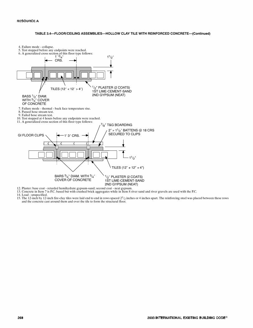
��� ���� ���������� ��� ���� �������� ���®
TABLE 3.4�FLOOR/CEILING ASSEMBLIES�HOLLOW CLAY TILE WITH REINFORCED CONCRETE�(Continued)
4. Failure mode - collapse.5. Test stopped before any endpoints were reached.6. A generalized cross section of this floor type follows:
1� 3/4�CRS.
11/2�
BASS 1/2� DIAM.WITH 3/4� COVEROF CONCRETE
1/2� PLASTER (2 COATS)1ST LIME-CEMENT-SAND2ND GYPSUM (NEAT)
TILES (12� � 12� � 4�)
7. Failure mode - thermal - back face temperature rise.8. Passed hose stream test.9. Failed hose stream test.10. Test stopped at 4 hours before any endpoints were reached.11. A generalized cross section of this floor type follows:
1� 3� CRS.GI FLOOR CLIPS
2� � 11/2� BATTENS @ 18 CRSSECURED TO CLIPS
7/8� T&G BOARDING
11/2�
TILES (12� � 12� � 4�)
1/2� PLASTER (2 COATS)1ST LIME-CEMENT-SAND2ND GYPSUM (NEAT)
BARS 3/4� DIAM. WITH 3/4�COVER OF CONCRETE
12. Plaster: base coat - retarded hemihydrate gypsum-sand; second coat - neat gypsum.13. Concrete in Item 7 is P.C. based but with crushed brick aggregates while in Item 8 river sand and river gravels are used with the P.C.14. Load - unspecified.15. The 12-inch by 12-inch fire-clay tiles were laid end to end in rows spaced 21/2 inches or 4 inches apart. The reinforcing steel was placed between these rows
and the concrete cast around them and over the tile to form the structural floor.
�� ����

���� ���������� ��� ���� �������� ���® ���
SECTION IV�BEAMS
TABLE 4.1.1�REINFORCED CONCRETE BEAMS
DEPTH 10� TO LESS THAN 12�PERFORMANCE REFERENCE NUMBER
ITEMCODE DEPTH CONSTRUCTION DETAILS LOAD TIME
PRE-BMS-92 BMS-92
POST-BMS-92 NOTES
REC.HOURS
B-11-RC-1 11� 24� wide � 11� deep reinforcedconcrete �T� beam (3290 psi);Details: see Note 5 figure.
8.8 tons 4 hrs. 2min.
7 1, 2, 14 4
B-10-RC-2 10� 24� wide � 10� deep reinforcedconcrete �T� beam (4370 psi);Details: see Note 6 figure.
8.8 tons 1 hr. 53min.
7 1, 3 13/4
B-10-RC-3 101/2� 24� wide � 101/2� deep reinforcedconcrete �T� beam (4450 psi);Details: see Note 7 figure.
8.8 tons 2 hrs. 40min.
7 1, 3 22/3
B-11-RC-4 11� 24� wide � 11� deep reinforcedconcrete �T� beam (2400 psi);Details: see Note 8 figure.
8.8 tons 3 hrs. 32min.
7 1, 3, 14 31/2
B-11-RC-5 11� 24� wide � 11� deep reinforcedconcrete �T� beam (4250 psi);Details: see Note 9 figure.
8.8 tons 3 hrs. 3min.
7 1, 3, 14 3
B-11-RC-6 11� Concrete flange: 4� deep � 2�wide (4895 psi) concrete;Concrete beam: 7� deep � 61/2�wide beam; �I� beamreinforcement; 10� � 41/2� � 25lbs. R.S.J.; 1� cover on flanges;Flange reinforcement: 3/8�diameter bars at 6� pitch parallelto �T�; 1/4� diameter barsperpendicular to �T�; Beamreinforcement: 4� � 6� wire meshNo. 13 SWG; Span: 11�restrained; Details: see Note 10figure.
10 tons 6 hrs. 7 1, 4 6
B-11-RC-7 11� Concrete flange: 6� deep � 1�61/2�wide (3525 psi) concrete;Concrete beam: 5� deep � 8� wideprecast concrete blocks 83/4� long;�I� beam reinforcement; 7� � 4� x16 lbs. R.S.J.; 2� cover on bottom;11/2� cover on top; Flangereinforcement: two rows 1/2�diameter rods parallel to �T�;Beam reinforcement: 1/8� wiremesh perpendicular to 1�; Span:1�3� simply supported; Details:see Note 11 figure.
3.9 tons 4 hrs. 7 1, 2 4
B-11-RC-8 11� Concrete flange: 4� deep � 2�wide (3525 psi) concrete;Concrete beam 7� deep � 41/2�wide; (scaled from drawing); �I�beam reinforcement; 10� � 41/2� �
25 lbs. R.S.J.; no concrete coveron bottom; Flange reinforcement:3/8� diameter bars at 6 pitchparallel to �T�; 1/4� diameter barsperpendicular to �T�; Span: 11�restricted.
10 tons 4 hrs. 7 1, 2, 12 4
(Continued)
�� ����
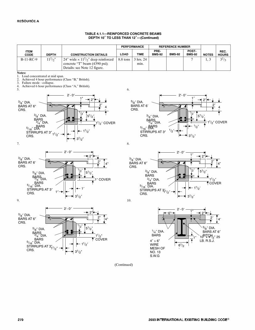
��� ���� ���������� ��� ���� �������� ���®
TABLE 4.1.1�REINFORCED CONCRETE BEAMSDEPTH 10� TO LESS THAN 12��(Continued)
PERFORMANCE REFERENCE NUMBER
ITEMCODE DEPTH CONSTRUCTION DETAILS LOAD TIME
PRE-BMS-92 BMS-92
POST-BMS-92 NOTES
REC.HOURS
B-11-RC-9 111/2� 24� wide � 111/2� deep reinforcedconcrete �T� beam (4390 psi);Details: see Note 12 figure.
8.8 tons 3 hrs. 24min.
7 1, 3 31/3
Notes:1. Load concentrated at mid span.2. Achieved 4 hour performance (Class �B,� British).3. Failure mode - collapse.4. Achieved 6 hour performance (Class �A,� British).5. 6.
2�- 0�
3/8� DIA.BARS AT 6�CRS.
5/16� DIA.STIRRUPS AT 3�CRS.
11/2�11/2�
51/2�
11/2� COVER3/4� DIA.BARS
1/2�
4�
2�
1�
31/2�
2�
3/8� DIA.BARS
2�4�
2�1�
51/2�
11/2� COVER
1/2�
1/2�
31/2�
1/2�
3/8� DIA.BARS
2�- 0�
3/4� DIA.BARS
3/8� DIA.BARS AT 6�CRS.
5/16� DIA.STIRRUPS AT 3�CRS.
7. 8.
2�- 0�
3/8� DIA.BARS AT 6�CRS.
3/8� DIA.BARS3/4� DIA.BARS
1�1�
31/2�
1/2� 51/2�
1� COVER
2�
2�
2�- 0�
3/8� DIA.BARS3/4� DIA.BARS
3/8� DIA.BARS AT 6�CRS.
2�
2�1�
11/2�COVER
1/2�
11/2�31/2�
11/2�
4�4�
51/2�
5/16� DIA.STIRRUPS AT 3�CRS.
5/16� DIA.STIRRUPS AT 3�CRS.
9. 10.
51/2�1/2�
11/2�COVER
11/2�31/2�
11/2�
3/8� DIA.BARS3/4� DIA.BARS
3/8� DIA.BARS AT 6�CRS.
2�
2�
2�- 0� 2�- 0�
4� � 6�WIREMESH OFNO. 13S.W.G
3/8� DIA.BARS AT 6�PITCH
1�
2�6�2�
1�
61/2�
1/4� DIA.BARS 10� � 41/2� 25
LB. R.S.J.
4�4�
5/16� DIA.STIRRUPS AT 3�CRS.
(Continued)
�� ����
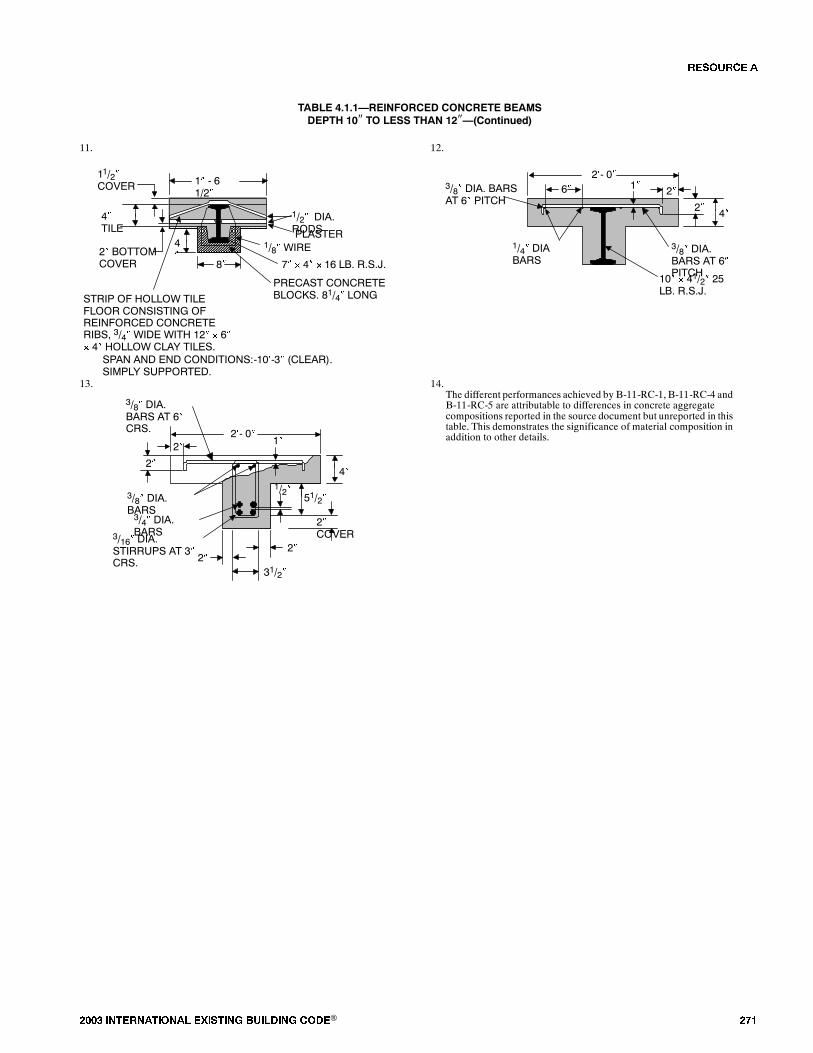
���� ���������� ��� ���� �������� ���® ���
TABLE 4.1.1�REINFORCED CONCRETE BEAMSDEPTH 10� TO LESS THAN 12��(Continued)
11. 12.
1� - 61/2�
8�
11/2�COVER
4�TILE
2� BOTTOMCOVER
4�
1/2� DIA.RODSPLASTER
1/8� WIRE
7� � 4� � 16 LB. R.S.J.
PRECAST CONCRETEBLOCKS. 81/4� LONGSTRIP OF HOLLOW TILE
FLOOR CONSISTING OFREINFORCED CONCRETERIBS, 3/4� WIDE WITH 12� � 6�� 4� HOLLOW CLAY TILES.
SPAN AND END CONDITIONS:-10�-3� (CLEAR).SIMPLY SUPPORTED.
2�- 0�
2�6�
2� 4�
1�3/8� DIA. BARSAT 6� PITCH
1/4� DIABARS
10� � 41/2� 25LB. R.S.J.
3/8� DIA.BARS AT 6�PITCH
13. 14.
2�- 0�
3/16� DIA.STIRRUPS AT 3�CRS.
3/4� DIA.BARS
3/8� DIA.BARS AT 6�CRS.
4�
1�
2�31/2�
2�
51/2�
2�COVER
2�
2�
3/8� DIA.BARS
1/2�
The different performances achieved by B-11-RC-1, B-11-RC-4 andB-11-RC-5 are attributable to differences in concrete aggregatecompositions reported in the source document but unreported in thistable. This demonstrates the significance of material composition inaddition to other details.
�� ����
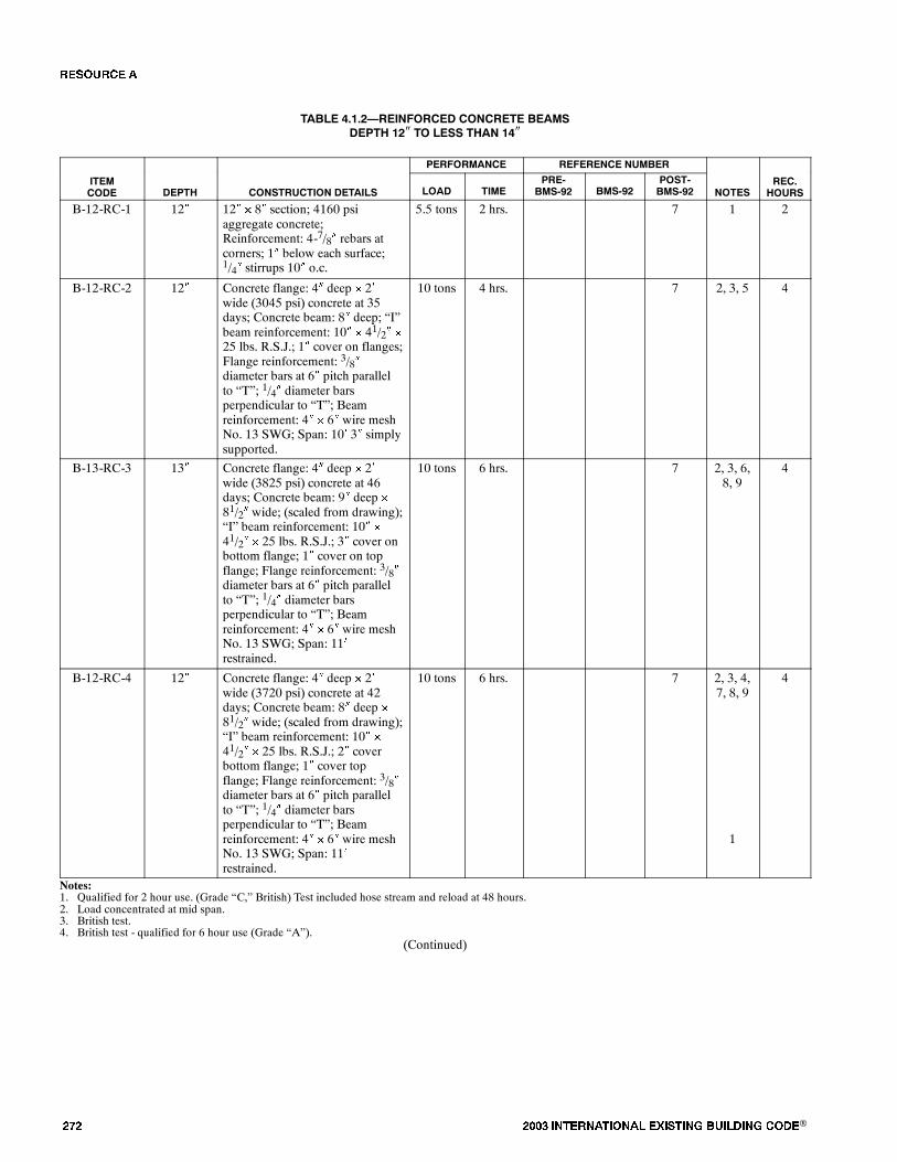
��� ���� ���������� ��� ���� �������� ���®
TABLE 4.1.2�REINFORCED CONCRETE BEAMSDEPTH 12� TO LESS THAN 14�
PERFORMANCE REFERENCE NUMBER
ITEMCODE DEPTH CONSTRUCTION DETAILS LOAD TIME
PRE-BMS-92 BMS-92
POST-BMS-92 NOTES
REC.HOURS
B-12-RC-1 12� 12� � 8� section; 4160 psiaggregate concrete;Reinforcement: 4-7/8� rebars atcorners; 1� below each surface;1/4� stirrups 10� o.c.
5.5 tons 2 hrs. 7 1 2
B-12-RC-2 12� Concrete flange: 4� deep � 2�wide (3045 psi) concrete at 35days; Concrete beam: 8� deep; �I�beam reinforcement: 10� � 41/2� �
25 lbs. R.S.J.; 1� cover on flanges;Flange reinforcement: 3/8�diameter bars at 6� pitch parallelto �T�; 1/4� diameter barsperpendicular to �T�; Beamreinforcement: 4� � 6� wire meshNo. 13 SWG; Span: 10� 3� simplysupported.
10 tons 4 hrs. 7 2, 3, 5 4
B-13-RC-3 13� Concrete flange: 4� deep � 2�wide (3825 psi) concrete at 46days; Concrete beam: 9� deep �
81/2� wide; (scaled from drawing);�I� beam reinforcement: 10� �
41/2� � 25 lbs. R.S.J.; 3� cover onbottom flange; 1� cover on topflange; Flange reinforcement: 3/8�diameter bars at 6� pitch parallelto �T�; 1/4� diameter barsperpendicular to �T�; Beamreinforcement: 4� � 6� wire meshNo. 13 SWG; Span: 11�restrained.
10 tons 6 hrs. 7 2, 3, 6,8, 9
4
B-12-RC-4 12� Concrete flange: 4� deep � 2�wide (3720 psi) concrete at 42days; Concrete beam: 8� deep �
81/2� wide; (scaled from drawing);�I� beam reinforcement: 10� �
41/2� � 25 lbs. R.S.J.; 2� coverbottom flange; 1� cover topflange; Flange reinforcement: 3/8�diameter bars at 6� pitch parallelto �T�; 1/4� diameter barsperpendicular to �T�; Beamreinforcement: 4� � 6� wire meshNo. 13 SWG; Span: 11�restrained.
10 tons 6 hrs. 7 2, 3, 4,7, 8, 9
1
4
Notes:1. Qualified for 2 hour use. (Grade �C,� British) Test included hose stream and reload at 48 hours.2. Load concentrated at mid span.3. British test.4. British test - qualified for 6 hour use (Grade �A�).
(Continued)
�� ����
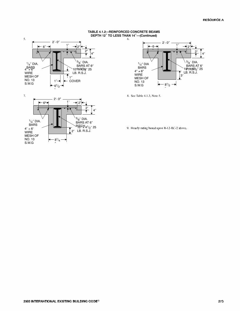
���� ���������� ��� ���� �������� ���® ���
TABLE 4.1.2�REINFORCED CONCRETE BEAMSDEPTH 12� TO LESS THAN 14��(Continued)
5. 6.2�- 0�
2�6� 2�
4�
2�- 0�
2�6�2�
4�
61/2�
1�COVER1�
1�
4� � 6�WIREMESH OFNO. 13S.W.G
1/4� DIA.BARS
10� � 41/2� 25LB. R.S.J.
1�
10� � 41/2� 25LB. R.S.J.
81/2�
3�4� � 6�WIREMESH OFNO. 13S.W.G
1/4� DIABARS
3/8� DIA.BARS AT 6�PITCH
3/8� DIA.BARS AT 6�PITCH
7. 8. See Table 4.1.3, Note 5.2�- 0�
2�6�
2�
1�
4�
81/4�
2�4� � 6�WIREMESH OFNO. 13S.W.G
1/4� DIA.BARS
10� � 41/2� 25LB. R.S.J.
�� ������ ��� ���� ���� ��������� �����
3/8� DIA.BARS AT 6�PITCH
�� ����
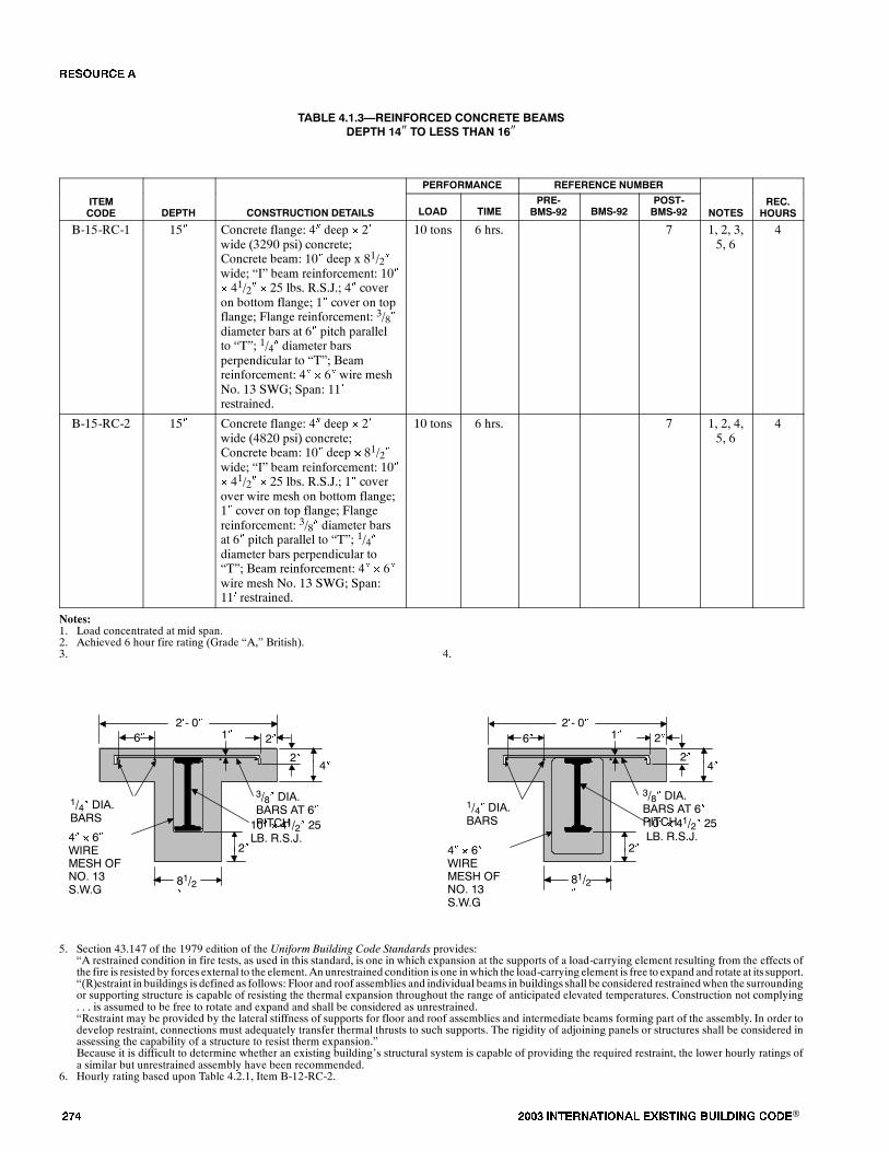
��� ���� ���������� ��� ���� �������� ���®
TABLE 4.1.3�REINFORCED CONCRETE BEAMSDEPTH 14� TO LESS THAN 16�
PERFORMANCE REFERENCE NUMBER
ITEMCODE DEPTH CONSTRUCTION DETAILS LOAD TIME
PRE-BMS-92 BMS-92
POST-BMS-92 NOTES
REC.HOURS
B-15-RC-1 15� Concrete flange: 4� deep � 2�wide (3290 psi) concrete;Concrete beam: 10� deep x 81/2�wide; �I� beam reinforcement: 10�� 41/2� � 25 lbs. R.S.J.; 4� coveron bottom flange; 1� cover on topflange; Flange reinforcement: 3/8�diameter bars at 6� pitch parallelto �T�; 1/4� diameter barsperpendicular to �T�; Beamreinforcement: 4� � 6� wire meshNo. 13 SWG; Span: 11�restrained.
10 tons 6 hrs. 7 1, 2, 3,5, 6
4
B-15-RC-2 15� Concrete flange: 4� deep � 2�wide (4820 psi) concrete;Concrete beam: 10� deep � 81/2�wide; �I� beam reinforcement: 10�� 41/2� � 25 lbs. R.S.J.; 1� coverover wire mesh on bottom flange;1� cover on top flange; Flangereinforcement: 3/8� diameter barsat 6� pitch parallel to �T�; 1/4�diameter bars perpendicular to�T�; Beam reinforcement: 4� � 6�wire mesh No. 13 SWG; Span:11� restrained.
10 tons 6 hrs. 7 1, 2, 4,5, 6
4
Notes:1. Load concentrated at mid span.2. Achieved 6 hour fire rating (Grade �A,� British).3. 4.
6�2�- 0�
4� � 6�WIREMESH OFNO. 13S.W.G
1/4� DIA.BARS
10� � 41/2� 25LB. R.S.J.
2�- 0�1�
4� � 6�WIREMESH OFNO. 13S.W.G
1/4� DIA.BARS 10� � 41/2� 25
LB. R.S.J.
1�6�
81/2�
81/2�
2�
2�4�
2�
2�4�
2� 2�
3/8� DIA.BARS AT 6�PITCH
3/8� DIA.BARS AT 6�PITCH
5. Section 43.147 of the 1979 edition of the Uniform Building Code Standards provides:�A restrained condition in fire tests, as used in this standard, is one in which expansion at the supports of a load-carrying element resulting from the effects ofthe fire is resisted by forces external to the element.An unrestrained condition is one inwhich the load-carrying element is free to expand and rotate at its support.�(R)estraint in buildings is defined as follows: Floor and roof assemblies and individual beams in buildings shall be considered restrainedwhen the surroundingor supporting structure is capable of resisting the thermal expansion throughout the range of anticipated elevated temperatures. Construction not complying. . . is assumed to be free to rotate and expand and shall be considered as unrestrained.�Restraint may be provided by the lateral stiffness of supports for floor and roof assemblies and intermediate beams forming part of the assembly. In order todevelop restraint, connections must adequately transfer thermal thrusts to such supports. The rigidity of adjoining panels or structures shall be considered inassessing the capability of a structure to resist therm expansion.�Because it is difficult to determine whether an existing building�s structural system is capable of providing the required restraint, the lower hourly ratings ofa similar but unrestrained assembly have been recommended.
6. Hourly rating based upon Table 4.2.1, Item B-12-RC-2.
�� ����
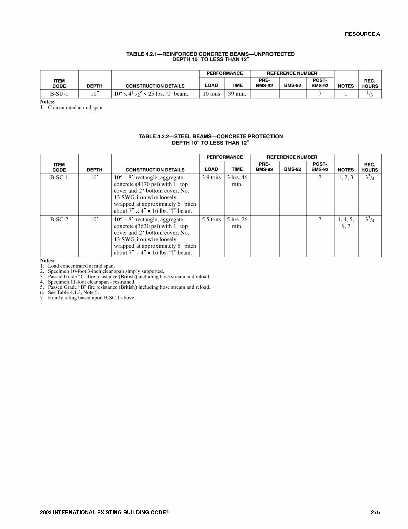
���� ���������� ��� ���� �������� ���® ���
TABLE 4.2.1�REINFORCED CONCRETE BEAMS�UNPROTECTEDDEPTH 10� TO LESS THAN 12�
PERFORMANCE REFERENCE NUMBER
ITEMCODE DEPTH CONSTRUCTION DETAILS LOAD TIME
PRE-BMS-92 BMS-92
POST-BMS-92 NOTES
REC.HOURS
B-SU-1 10� 10� � 41 /2� � 25 lbs. �I� beam. 10 tons 39 min. 7 1 1/3Notes:1. Concentrated at mid span.
TABLE 4.2.2�STEEL BEAMS�CONCRETE PROTECTIONDEPTH 10� TO LESS THAN 12�
PERFORMANCE REFERENCE NUMBER
ITEMCODE DEPTH CONSTRUCTION DETAILS LOAD TIME
PRE-BMS-92 BMS-92
POST-BMS-92 NOTES
REC.HOURS
B-SC-1 10� 10� � 8� rectangle; aggregateconcrete (4170 psi) with 1� topcover and 2� bottom cover; No.13 SWG iron wire looselywrapped at approximately 6� pitchabout 7� � 4� � 16 lbs. �I� beam.
3.9 tons 3 hrs. 46min.
7 1, 2, 3 33/4
B-SC-2 10� 10� � 8� rectangle; aggregateconcrete (3630 psi) with 1� topcover and 2� bottom cover; No.13 SWG iron wire looselywrapped at approximately 6� pitchabout 7� � 4� � 16 lbs. �I� beam.
5.5 tons 5 hrs. 26min.
7 1, 4, 5,6, 7
33/4
Notes:1. Load concentrated at mid span.2. Specimen 10-foot 3-inch clear span simply supported.3. Passed Grade �C� fire resistance (British) including hose stream and reload.4. Specimen 11-foot clear span - restrained.5. Passed Grade �B� fire resistance (British) including hose stream and reload.6. See Table 4.1.3, Note 5.7. Hourly rating based upon B-SC-1 above.
�� ����
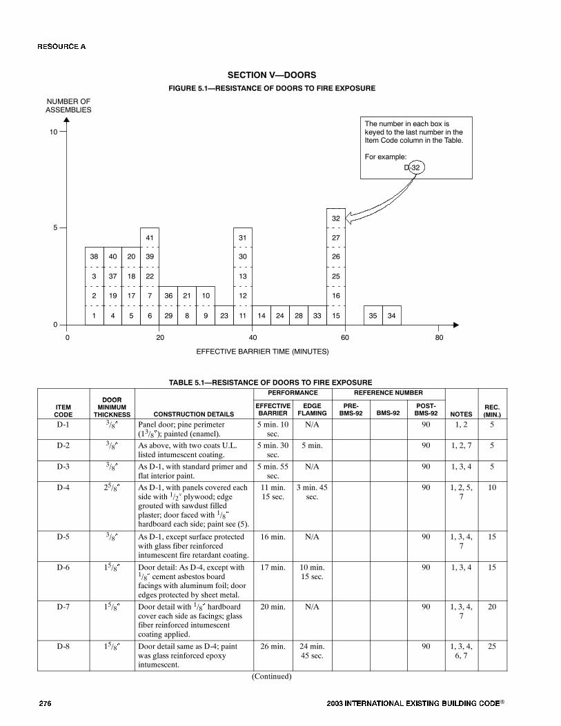
��� ���� ���������� ��� ���� �������� ���®
SECTION V�DOORSFIGURE 5.1�RESISTANCE OF DOORS TO FIRE EXPOSURE
0
EFFECTIVE BARRIER TIME (MINUTES)
NUMBER OFASSEMBLIES
20 40 60 80
5
10
0
The number in each box iskeyed to the last number in theItem Code column in the Table.
For example:
D-32
7
22
39
6
41
17
18
20
5
19
37
40
4
2
3
38
1
36
29
21
8
10
9 23
12
13
30
11
31
16
25
26
15
27
14 24 28 33 35 34
32
TABLE 5.1�RESISTANCE OF DOORS TO FIRE EXPOSURE
DOORPERFORMANCE REFERENCE NUMBER
ITEMCODE
DOORMINIMUM
THICKNESS CONSTRUCTION DETAILSEFFECTIVEBARRIER
EDGEFLAMING
PRE-BMS-92 BMS-92
POST-BMS-92 NOTES
REC.(MIN.)
D-1 3/8� Panel door; pine perimeter(13/8�); painted (enamel).
5 min. 10sec.
N/A 90 1, 2 5
D-2 3/8� As above, with two coats U.L.listed intumescent coating.
5 min. 30sec.
5 min. 90 1, 2, 7 5
D-3 3/8� As D-1, with standard primer andflat interior paint.
5 min. 55sec.
N/A 90 1, 3, 4 5
D-4 25/8� As D-1, with panels covered eachside with 1/2� plywood; edgegrouted with sawdust filledplaster; door faced with 1/8�hardboard each side; paint see (5).
11 min.15 sec.
3 min. 45sec.
90 1, 2, 5,7
10
D-5 3/8� As D-1, except surface protectedwith glass fiber reinforcedintumescent fire retardant coating.
16 min. N/A 90 1, 3, 4,7
15
D-6 15/8� Door detail: As D-4, except with1/8� cement asbestos boardfacings with aluminum foil; dooredges protected by sheet metal.
17 min. 10 min.15 sec.
90 1, 3, 4 15
D-7 15/8� Door detail with 1/8� hardboardcover each side as facings; glassfiber reinforced intumescentcoating applied.
20 min. N/A 90 1, 3, 4,7
20
D-8 15/8� Door detail same as D-4; paintwas glass reinforced epoxyintumescent.
26 min. 24 min.45 sec.
90 1, 3, 4,6, 7
25
(Continued)
�� ����

���� ���������� ��� ���� �������� ���® ���
TABLE 5.1�RESISTANCE OF DOORS TO FIRE EXPOSURE�(Continued)
ITEMCODE
REC.(MIN.)NOTES
REFERENCE NUMBERPERFORMANCE
CONSTRUCTION DETAILS
DOORMINIMUM
THICKNESSITEMCODE
REC.(MIN.)NOTES
POST-BMS-92BMS-92
PRE-BMS-92
EDGEFLAMING
EFFECTIVEBARRIERCONSTRUCTION DETAILS
DOORMINIMUM
THICKNESS
D-9 15/8� Door detail same as D-4 withfacings of 1/8� cement asbestosboard.
29 min. 3 min. 15sec.
90 1, 2 5
D-10 15/8� As per D-9. 31 min.30 sec.
7 min. 20sec.
90 1, 3, 4 6
D-11 15/8� As per D-7; painted with epoxyintumescent coating includingglass fiber roving.
36 min.25 sec.
N/A 90 1, 3, 4 35
D-12 15/8� As per D-4 with intumescent fireretardant paint.
37 min.30 sec.
24 min.40 sec.
90 1, 3, 4 30
D-13 11/2�(nom.)
As per D-4, except with 24 ga.galvanized sheet metal facings.
39 min. 39 min. 90 1, 3, 4 39
D-14 15/8� As per D-9. 41 min.30 sec.
17 min.20 sec.
90 1, 3, 4,6
20
D-15 � Class C steel fire door. 60 min. 58 min. 90 7, 8 60
D-16 � Class B steel fire door. 60 min. 57 min. 90 7, 8 60
D-17 13/4� Solid core flush door; core staveslaminated to facings but not eachother; Birch plywood facings 1/2�rebate in door frame for door;3/32� clearance between door andwood frame.
15 min. 13 min. 37 11 13
D-18 13/4� As per D-17. 14 min. 13 min. 37 11 13
D-19 13/4� Door same as D-17, except with16 ga. steel; 3/32� door frameclearance.
12 min. � 37 9, 11 10
D-20 13/4� As per D-19. 16 min. � 37 10, 11 10
D-21 13/4� Doors as per D-17; intumescentpaint applied to top and sideedges.
26 min. � 37 11 25
D-22 13/4� Door as per D-17, except with1/2�� 1/8� steel strip set into edges ofdoor at top and side facing stops;matching strip on stop.
18 min. 6 min. 37 11 18
D-23 13/4� Solid oak door. 36 min 22 min. 15 13 25
D-24 17/8� Solid oak door. 45 min. 35 min. 15 13 35
D-25 17/8� Solid teak door. 58 min. 34 min. 15 13 35
D-26 17/8� Solid (pitch) pine door. 57 min. 36 min. 15 13 35
D-27 17/8� Solid deal (pine) door. 57 min. 30 min. 15 13 30
D-28 17/8� Solid mahogany door. 49 min. 40 min. 15 13 45
D-29 17/8� Solid poplar door. 24 min. 3 min. 15 13, 14 5
D-30 17/8� Solid oak door. 40 min. 33 min. 15 13 35
D-31 17/8� Solid walnut door. 40 min. 15 min. 15 13 20
D-32 25/8� Solid Quebec pine. 60 min. 60 min. 15 13 60
D-33 25/8� Solid pine door. 55 min. 39 min. 15 13 40
D-34 25/8� Solid oak door. 69 min. 60 min. 15 13 60
D-35 25/8� Solid teak door. 65 min. 17 min. 15 13 60
D-36 11/2� Solid softwood door. 23 min. 8.5 min. 15 13 10
D-37 3/4� Panel door. 8 min. 7.5 min. 15 13 5
D-38 5/16� Panel door. 5 min. 5 min. 15 13 5
(Continued)
�� ����
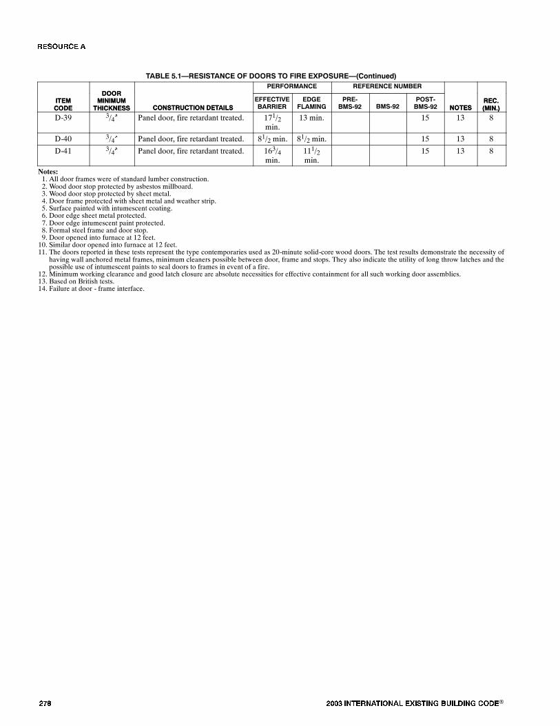
��� ���� ���������� ��� ���� �������� ���®
TABLE 5.1�RESISTANCE OF DOORS TO FIRE EXPOSURE�(Continued)
ITEMCODE
REC.(MIN.)NOTES
REFERENCE NUMBERPERFORMANCE
CONSTRUCTION DETAILS
DOORMINIMUM
THICKNESSITEMCODE
REC.(MIN.)NOTES
POST-BMS-92BMS-92
PRE-BMS-92
EDGEFLAMING
EFFECTIVEBARRIERCONSTRUCTION DETAILS
DOORMINIMUM
THICKNESS
D-39 3/4� Panel door, fire retardant treated. 171/2min.
13 min. 15 13 8
D-40 3/4� Panel door, fire retardant treated. 81/2 min. 81/2 min. 15 13 8
D-41 3/4� Panel door, fire retardant treated. 163/4min.
111/2min.
15 13 8
Notes:1. All door frames were of standard lumber construction.2. Wood door stop protected by asbestos millboard.3. Wood door stop protected by sheet metal.4. Door frame protected with sheet metal and weather strip.5. Surface painted with intumescent coating.6. Door edge sheet metal protected.7. Door edge intumescent paint protected.8. Formal steel frame and door stop.9. Door opened into furnace at 12 feet.10. Similar door opened into furnace at 12 feet.11. The doors reported in these tests represent the type contemporaries used as 20-minute solid-core wood doors. The test results demonstrate the necessity of
having wall anchored metal frames, minimum cleaners possible between door, frame and stops. They also indicate the utility of long throw latches and thepossible use of intumescent paints to seal doors to frames in event of a fire.
12. Minimum working clearance and good latch closure are absolute necessities for effective containment for all such working door assemblies.13. Based on British tests.14. Failure at door - frame interface.
�� ����
���� ���������� ��� ���� �������� ���® ���
����������
1. Central Housing Committee on Research, Design, and Construction; Subcommittee on Fire Resistance Classifications,�Fire-Resistance Classifications of Building Constructions,� Building Materials and Structures, Report BMS 92, NationalBureau of Standards, Washington, Oct. 1942. (Available from NTIS No. COM-73-10974)
2. Foster, H. D., Pinkston, E. R., and Ingberg, S. H., �Fire Resistance of Structural Clay Tile Partitions,� Building Materialsand Structures, Report BMS 113, National Bureau of Standards, Washington, Oct. 1948.
3. Ryan, J. V., and Bender, E. W., �Fire Endurance ofOpen-Web Steel-Joist Floors with Concrete Slabs and GypsumCeilings,�Building Materials and Structures, Report BMS 141, National Bureau of Standards, Washington, Aug. 1954.
4. Mitchell, N. D., �Fire Tests of Wood-FramedWalls and Partitions with Asbestos-Cement Facings,� Building Materials andStructures, Report BMS 123, National Bureau of Standards, Washington, May 1951.
5. Robinson, H. E., Cosgrove, L. A., and Powell, F. J., �Thermal Resistance of Airspace and Fibrous Insulations Bounded byReflective Surfaces,� BuildingMaterials and Structures, Report BMS 151, National Bureau of Standards, Washington, Nov.1957.
6. Shoub, H., and Ingberg, S. H., �Fire Resistance of Steel Deck Floor Assemblies,� Building Science Series, 11, NationalBureau of Standards, Washington, Dec. 1967.
7. Davey, N., and Ashton, L. A., �Investigations on Building Fires, Part V: Fire Tests of Structural Elements,� National Build-ing Studies, Research Paper, No. 12, Dept. of Scientific and Industrial Research (Building Research Station), London, 1953.
8. National Board of Fire Underwriters, Fire Resistance Ratings of Beam, Girder, and Truss Protections, Ceiling Construc-tions, Column Protections, Floor and Ceiling Constructions, Roof Constructions, Walls and Partitions, New York, April1959.
9. Mitchell, N. D., Bender, E. D., andRyan, J. V., �Fire Resistance of Shutters for Moving-StairwayOpenings,� BuildingMate-rials and Structures, Report BMS 129, National Bureau of Standards, Washington, March 1952.
10. National Board of Fire Underwriters, National Building Code; an Ordinance Providing for Fire Limits, and RegulationsGoverning the Construction, Alteration, Equipment, or Removal of Buildings or Structures, New York, 1949.
11. Department of Scientific and Industrial Research and of the Fire Offices� Committee, Joint Committee of the Building Re-search Board, �Fire Gradings of Buildings, Part I: General Principles and Structural Precautions,� Post-War Building Stu-dies, No. 20, Ministry of Works, London, 1946.
12. Lawson, D. I., Webster, C. T., and Ashton, L. A., �Fire Endurance of Timber Beams and Floors,� National Building Studies,Bulletin, No. 13, Dept. of Scientific and Industrial Research and Fire Offices� Committee (Joint Fire Research Organiza-tion), London, 1951.
13. Parker, T. W., Nurse, R. W., and Bessey, G. E., �Investigations on Building Fires. Part I: The Estimation of the MaximumTemperature Attained in Building Fires from Examination of the Debris, and Part II: The Visible Change in Concrete orMortar Exposed to High Temperatures,� National Building Studies, Technical Paper, No. 4, Dept. of Scientific and Industri-al Research (Building Research Station), London, 1950.
14. Bevan, R. C., andWebster, C. T., �Investigations on Building Fires, Part III: Radiation from Building Fires,� National Build-ing Studies, Technical Paper, No. 5, Dept. of Scientific and Industrial Research (Building Research Station), London, 1950.
15. Webster, D. J., and Ashton, L. A., �Investigations on Building Fires, Part IV: Fire Resistance of Timber Doors,� NationalBuilding Studies, Technical Paper, No. 6, Dept. of Scientific and Industrial Research (Building Research Station), London,1951.
16. Kidder, F. E., Architects� and Builders� Handbook: Data for Architects, Structural Engineers, Contractors, and Draughts-men, comp. by a Staff of Specialists and H. Parker, editor-in-chief, 18th ed., enl., J. Wiley, New York, 1936.
17. Parker, H., Gay, C. M., and MacGuire, J. W., Materials and Methods of Architectural Construction, 3rd ed., J. Wiley, NewYork, 1958.
18. Diets, A. G. H., Dwelling House Construction, The MIT Press, Cambridge, 1971.
19. Crosby, E. U., and Fiske, H. A., Handbook of Fire Protection, 5th ed., The Insurance Field Company, Louisville, Ky., 1914.
20. Crosby, E. U., Fiske, H. A., and Forster, H. W., Handbook of Fire Protection, 8th ed., R. S. Moulton, general editor, NationalFire Protection Association, Boston, 1936.
21. Kidder, F. E., Building Construction and Superintendence, rev. and enl., by T. Nolan, W. T. Comstock, New York,1909-1913, 2 vols.
�� ����
��� ���� ���������� ��� ���� �������� ���®
22. National Fire Protection Association, Committee on Fire-Resistive Construction, The Baltimore Conflagration, 2nd ed.,Chicago, 1904.
23. Przetak, L., Standard Details for Fire-Resistive Building Construction, McGraw-Hill Book Co., New York, 1977.
24. Hird, D., and Fischl, C. F., �Fire Hazard of Internal Linings,� National Building Studies, Special Report, No. 22, Dept. ofScientific and Industrial Research and Fire Offices� Committee (Joint Fire Research Organization), London, 1954.
25. Menzel, C. A., Tests of the Fire-Resistance and Strength of Walls Concrete Masonry Units, Portland Cement Association,Chicago, 1934.
26. Hamilton, S. B., �A Short History of the Structural Fire Protection of Buildings Particularly in England,� National BuildingStudies, Special Report, No. 27, Dept. of Scientific and Industrial Research (Building Research Station), London, 1958.
27. Sachs, E. O., andMarsland, E., �The Fire Resistance of Doors and Shutters being Tabulated Results of Fire Tests Conductedby the Committee,� Journal of the British Fire Prevention Committee, No. VII, London, 1912.
28. Egan, M. D., Concepts in Building Firesafety, J. Wiley, New York, 1978.
29. Sachs, E. O., andMarsland, E., �The Fire Resistance of Floors being Tabulated Results of Fire Tests Conducted by the Com-mittee,� Journal of the British Fire Prevention Committee, No. VI, London, 1911.
30. Sachs, E. O., and Marsland, E., �The Fire Resistance of Partitions being Tabulated Results of Fire Tests Conducted by theCommittee,� Journal of the British Fire Prevention Committee, No. IX, London, 1914.
31. Ryan, J. V., and Bender, E. W., �Fire Tests of Precast Cellular Concrete Floors and Roofs,� National Bureau of StandardsMonograph, 45, Washington, April 1962.
32. Kingberg, S. H., and Foster, H. D., �Fire Resistance of Hollow Load-Bearing Wall Tile,� National Bureau of Standards Re-search Paper, No. 37, (Reprint from NBS Journal of Research, Vol. 2) Washington, 1929.
33. Hull, W. A., and Ingberg, S. H., �Fire Resistance of Concrete Columns,� Technologic Papers of the Bureau of Standards,No. 272, Vol. 18, Washington, 1925, pp. 635-708.
34. National Board of Fire Underwriters, Fire Resistance Ratings of Less than One Hour, New York, Aug. 1956.
35. Harmathy, T. Z., �Ten Rules of Fire Endurance Rating,� Fire Technology, Vol. 1, May 1965, pp. 93-102.
36. Son, B. C., �Fire Endurance Test on a Steel Tubular Column Protected with Gypsum Board,� National Bureau of Standards,NBSIR, 73-165, Washington, 1973.
37. Galbreath, M., �Fire Tests of Wood Door Assemblies,� Fire Study, No. 36, Div. of Building Research, National ResearchCouncil Canada, Ottawa, May 1975.
38. Morris, W. A., �An Investigation into the Fire Resistance of Timber Doors,� Fire Research Note, No. 855, Fire ResearchStation, Boreham Wood, Jan. 1971.
39. Hall, G. S., �Fire Resistance Tests of Laminated Timber Beams,� Timber Association Research Report, WR/RR/1, HighSycombe, July 1968.
40. Goalwin, D. S., �Fire Resistance of Concrete Floors,� BuildingMaterials and Structures, Report BMS 134, National Bureauof Standards, Washington, Dec. 1952.
41. Mitchell, N. D., and Ryan, J. V., �Fire Tests of Steel Columns Encased with Gypsum Lath and Plaster,� Building Materialsand Structures, Report BMS 135, National Bureau of Standards, Washington, April 1953.
42. Ingberg, S. H., �Fire Tests of Brick Walls,� Building Materials and Structures, Report BMS 143, National Bureau of Stand-ards, Washington, Nov. 1954.
43. National Bureau of Standards, �Fire Resistance and Sound-Insulation Ratings for Walls, Partitions, and Floors,� TechnicalReport on Building Materials, 44, Washington, 195X.
44. Malhotra, H. L.,�Fire Resistance of Brick and Block Walls,� Fire Note, No. 6, Ministry of Technology and Fire Offices�Committee Joint Fire Research Organization, London, HMSO, 1966.
45. Mitchell, N. D., �Fire Tests of Steel Columns Protected with Siliceous Aggregate Concrete,� Building Materials and Struc-tures, Report BMS 124, National Bureau of Standards, Washington, May 1951.
46. Freitag, J. K., Fire Prevention and Fire Protection as Applied to Building Construction; a Handbook of Theory and Practice,2nd ed., J. Wiley, New York, 1921.
47. Ingberg, S. H., and Mitchell, N. D., �Fire Tests of Wood and Metal-Framed Partition,� Building Materials and Structures,Report BMS 71, National Bureau of Standards, Washington, 1941.
�� ����
���� ���������� ��� ���� �������� ���® ���
48. Central Housing Committee on Research, Design, and Construction, Subcommittee on Definitions, �AGlossary ofHousingTerms,� Building Materials and Structures, Report BMS 91, National Bureau of Standards, Washington, Sept. 1942.
49. Crosby, E. U., Fiske, H. A., and Forster, H. W., Handbook of Fire Protection, 7th ed., D. Van Nostrand Co., New York 1924.
50. Bird, E. L., and Docking, S. J., Fire in Buildings, A. & C. Black, London, 1949.
51. American Institute of Steel Construction, Fire Resistant Construction in Modern Steel-Framed Buildings, New York, 1959.
52. Central Dockyard Laboratory, �Fire Retardant Paint Tests - a Critical Review,� CDL Technical Memorandum, No. P87/73,H. M. Naval Base, Portsmouth, Dec. 1973.
53. Malhotra, H. L., �Fire Resistance of Structural Concrete Beams,� Fire Research Note, No. 741, Fire Research Station, Bore-hamwood, May 1969.
54. Abrams, M. S., and Gustaferro, A. H., �Fire Tests of Poke-Thru Assemblies,� Research and Development Bulletin, 1481-1,Portland Cement Association, Skokie, 1971.
55. Bullen, M. L., �A Note on the Relationship between Scale Fire Experiments and Standard Test Results,� Building ResearchEstablishment Note, N51/75, Borehamwood, May 1975.
56. The America Fore Group of Insurance Companies, Research Department, Some Characteristic Fires in Fire Resistive Buil-dings, Selected from twenty years record in the files of the N.F.P.A. �Quarterly,� New York, c. 1933.
57. Spiegelhalter, F., �Guide to Design of Cavity Barriers and Fire Stops,� Current Paper, CP 7/77, Building Research Establish-ment, Borehamwood, Feb. 1977.
58. Wardle, T. M. �Notes on the Fire Resistance of Heavy Timber Construction,� Information Series, No. 53, New ZealandForest Service, Wellington, 1966.
59. Fisher, R. W., and Smart, P. M. T., �Results of Fire Resistance Tests on Elements of Building Construction,� Building Re-search Establishment Report, G R6, London, HMSO, 1975.
60. Serex, E. R., �Fire Resistance of Alta Bates Gypsum Block Non-Load Bearing Wall,� Report to Alta Bates CommunityHospital, Structural Research Laboratory Report, ES-7000, University of Calif., Berkeley, 1969.
61. Thomas, F. G., and Webster, C. T., �Investigations on Building Fires, Part VI: The Fire Resistance of Reinforced ConcreteColumns,� National Building Studies, Research Paper, No. 18, Dept. of Scientific and Industrial Research (Building Re-search Station), London, HMSO, 1953.
62. Building Research Establishment, �Timber Fire Doors,� Digest, 220, Borehamwood, Nov. 1978.
63. Massachusetts State Building Code; Recommended Provisions, Article 22: Repairs, Alterations, Additions, and Change ofUse of Existing Buildings, Boston, Oct. 23, 1978.
64. Freitag, J. K., Architectural Engineering; with Especial Reference to High Building Construction, Including Many Exam-ples of Prominent Office Buildings, 2nd ed., rewritten, J. Wiley, New York, 1906.
65. Architectural Record, Sweet�s Indexed Catalogue of Building Construction for the Year 1906, New York, 1906.
66. Dept. of Commerce, Building Code Committee, �Recommended Minimum Requirements for Fire Resistance in Build-ings,� Building and Housing, No. 14, National Bureau of Standards, Washington, 1931.
67. British Standards Institution, �Fire Tests on BuildingMaterials and Structures,� British Standards, 476, Pt. 1, London, 1953.
68. Lönberg-Holm, K., �Glass,� The Architectural Record, Oct. 1930, pp. 345-357.
69. Structural Clay Products Institute, �Fire Resistance,� Technical Notes on Brick and Tile Construction, 16 rev., Washington,1964.
70. Ramsey, C. G., and Sleeper, H. R., Architectural Graphic Standards for Architects, Engineers, Decorators, Builders, andDraftsmen, 3rd ed., J. Wiley, New York, 1941.
71. Underwriters� Laboratories, Fire Protection Equipment List, Chicago, Jan. 1957.
72. Underwriters� Laboratories, Fire Resistance Directory; with Hourly Ratings for Beams, Columns, Floors, Roofs, Walls, andPartitions, Chicago, Jan. 1977.
73. Mitchell, N. D., �Fire Tests of Gunite Slabs and Partitions,� Building Materials and Structures, Report BMS 131, NationalBureau of Standards, Washington, May 1952.
74. Woolson, I. H., and Miller, R. P., �Fire Tests of Floors in the United States,� Proceedings International Association for Test-ing Materials, VIth Congress, New York, 1912, Section C, pp. 36-41.
�� ����
��� ���� ���������� ��� ���� �������� ���®
75. Underwriters� Laboratories, �An Investigation of the Effects of Fire Exposure upon Hollow Concrete Building Units, Con-ducted for American Concrete Institute, Concrete Products Association, Portland Cement Association, Joint Submittors,�Retardant Report, No. 1555, Chicago, May 1924.
76. Dept. of Scientific & Industrial Research and of the Fire Offices� Committee, Joint Committee of the Building ResearchBoard, �Fire Gradings of Buildings. Part IV: Chimneys and Flues,� Post-War Building Studies, No. 29, London, HMSO,1952.
77. National Research Council of Canada. Associate Committee on the National Building Code, Fire Performance Ratings,Suppl. No. 2 to the National Building Code of Canada, Ottawa, 1965.
78. Associated Factory Mutual Fire Insurance Companies, The National Board of Fire Underwriters, and the Bureau of Stand-ards, Fire Tests of Building Columns; an Experimental Investigation of the Resistance of Columns, Loaded and Exposedto Fire or to Fire and Water, with Record of Characteristic Effects, Jointly Conducted at Underwriters� Laboratories, Chica-go, 1917-19.
79. Malhotra, H. L., �Effect of Age on the Fire Resistance of Reinforced Concrete Columns,� Fire Research Memorandum, No.1, Fire Research Station, Borehamwood, April 1970.
80. Bond, H., ed., Research on Fire; a Description of the Facilities, Personnel and Management of Agencies Engaged in Re-search on Fire, a Staff Report, National Fire Protection Association, Boston, 1957.
81. California State Historical Building Code, Draft, 1978.
82. Fisher, F. L., et al., �A Study of Potential Flashover Fires in Wheeler Hall and the Results from a Full Scale Fire Test of aModified Wheeler Hall Door Assembly,� Fire Research Laboratory Report, UCX 77-3; UCX-2480, University of Calif.,Dept. of Civil Eng., Berkeley, 1977.
83. Freitag, J. K., The Fireproofing of Steel Buildings, 1st ed., J. Wiley, New York, 1906.
84. Gross, D., �Field Burnout Tests of Apartment Dwellings Units,� Building Science Series, 10, National Bureau of Standards,Washington, 1967.
85. Dunlap, M. E., and Cartwright, F. P., �Standard Fire Tests for Combustible Building Materials,� Proceedings of the Ameri-can Society for Testing Materials, vol. 27, Philadelphia, 1927, pp. 534-546.
86. Menzel, C. A., �Tests of the Fire Resistance and Stability of Walls of Concrete Masonry Units,� Proceedings of the Ameri-can Society for Testing Materials, vol. 31, Philadelphia, 1931, pp. 607-660.
87. Steiner, A. J., �Method of Fire-Hazard Classification of Building Materials,� Bulletin of the American Society for Testingand Materials, March 1943, Philadelphia, 1943, pp. 19-22.
88. Heselden, A. J. M., Smith, P. G., and Theobald, C. R., �Fires in a Large Compartment Containing Structural Steelwork;Detailed Measurements of Fire Behavior,� Fire Research Note, No. 646, Fire Research Station, Borehamwood, Dec. 1966.
89. Ministry of Technology and Fire Offices� Committee Joint Fire Research Organization, �Fire and Structural Use of Timberin Buildings; Proceedings of the Symposium Held at the Fire Research Station, Borehamwood, Herts on 25th October,1967,� Symposium, No. 3, London, HMSO, 1970.
90. Shoub, H., and Gross, D., �Doors as Barriers to Fire and Smoke,� Building Science Series, 3, National Bureau of Standards,Washington, 1966.
91. Ingberg, S. H., �The Fire Resistance of Gypsum Partitions,� Proceedings of the American Society for Testing andMaterials,vol. 25, Philadelphia, 1925, pp. 299-314.
92. Ingberg, S. H., �Influence ofMineral Composition of Aggregates on Fire Resistance of Concrete,� Proceedings of the Amer-ican Society for Testing and Materials, vol. 29, Philadelphia, 1929, pp. 824-829.
93. Ingberg, S. H., �The Fire Resistive Properties of Gypsum,� Proceedings of the American Society for Testing andMaterials,vol. 23, Philadelphia, 1923, pp. 254-256.
94. Gottschalk, F. W., �Some Factors in the Interpretation of Small-Scale Tests for Fire-RetardantWood,� Bulletin of theAmer-ican Society for Testing and Materials, October 1945, pp. 40-43.
95. Ministry of Technology and Fire Offices� Committee Joint Fire Research Organization, �Behaviour of Structural Steel inFire; Proceedings of the SymposiumHeld at the Fire Research StationBorehamwood, Herts on 24th January, 1967,� Sympo-sium, No. 2, London, HMSO, 1968.
96. Gustaferro, A. H., and Martin, L. D., Design for Fire Resistance of Pre-cast Concrete, prep. for the Prestressed ConcreteInstitute Fire Committee, 1st ed., Chicago, PCI, 1977.
97. �The Fire Endurance of Concrete; a Special Issue,� Concrete Construction, vol. 18, no. 8, Aug. 1974, pp. 345-440.
�� ����
���� ���������� ��� ���� �������� ���® ���
98. The British Constructional Steelwork Association, �Modern Fire Protection for Structural Steelwork,� Publication, No. FPl,London, 1961.
99. Underwriters� Laboratories, �Fire Hazard Classification of Building Materials,� Bulletin, No. 32, Sept. 1944, Chicago,1959.
100.Central Housing Committee on Research, Design, and Construction, Subcommittee on Building Codes, �RecommendedBuilding Code Requirements for New Dwelling Construction with Special Reference to War Housing; Report,� BuildingMaterials and Structures, Report BMS 88, National Bureau of Standards, Washington, Sept. 1942.
101.De Coppet Bergh, D., Safe Building Construction; a Treatise Giving in Simplest Forms Possible Practical and TheoreticalRules and Formulae Used in Construction of Buildings and General Instruction, new ed., thoroughly rev. Macmillan Co.,New York, 1908.
102.Cyclopedia of Fire Prevention and Insurance; a General Reference Work on Fire and Fire Losses, Fireproof Construction,Building Inspection..., prep. by architects, engineers, underwriters and practical insurance men. American School of Corre-spondence, Chicago, 1912.
103. Setchkin, N. P., and Ingberg, S. H., �Test Criterion for an Incombustible Material,� Proceedings of the American Societyfor Testing Materials, vol. 45, Philadelphia, 1945, pp. 866-877.
104.Underwriters� Laboratories, �Report on Fire Hazard Classification of Various Species of Lumber,� Retardant, 3365, Chica-go, 1952.
105. Steingiser, S., �A Philosophy of Fire Testing,� Journal of Fire & Flammability, vol. 3, July 1972, pp. 238-253.
106.Yuill, C. H., Bauerschlag, W. H., and Smith, H. M., �An Evaluation of the Comparative Performance of 2.4.1 Plywood andTwo-Inch Lumber Roof Decking under Equivalent Fire Exposure,� Fire Protection Section, Final Report, Project No.717A-3-211, Southwest Research Institute, Dept. of Structural Research, San Antonio, Dec. 1962.
107.Ashton, L. A., and Smart, P. M. T., Sponsored Fire-Resistance Tests on Structural Elements, London, Dept. of Scientific andIndustrial Research and Fire Offices� Committee, London, 1960.
108.Butcher, E. G., Chitty, T. B., and Ashton, L. A., �The Temperature Attained by Steel in Building Fires,� Fire Research Tech-nical Paper, No. 15, Ministry of Technology and Fire Offices� Committee, Joint Fire Research Organization, London,HMSO, 1966.
109.Dept. of the Environment and Fire Offices� Committee, Joint Fire Research Organization, �Fire-Resistance Requirementsfor Buildings - a New Approach; Proceedings of the Symposium Held at the Connaught Rooms, London, 28 September1971,� Symposium, No. 5, London, HMSO, 1973.
110. Langdon Thomas, G. J., �Roofs and Fire,� Fire Note, No. 3, Dept. of Scientific and Industrial Research and Fire Offices�Committee, Joint Fire Research Organization, London, HMSO, 1963.
111. National Fire Protection Association and the National Board of Fire Underwriters, Report on Fire the Edison PhonographWorks, Thomas A. Edison, Inc., West Orange, N.J., December 9, 1914, Boston, 1915.
112. Thompson, J. P., Fire Resistance of Reinforced Concrete Floors, Portland Cement Association, Chicago, 1963.
113. Forest Products Laboratory, �Fire Resistance Tests of PlywoodCoveredWall Panels,� Information reviewed and reaffirmed,Forest Service Report, No. 1257, Madison, April 1961.
114. Forest Products Laboratory, �Charring Rate of Selected Woods - Transverse to Grain,� Forest Service Research Paper, FLP69, Madison, April 1967.
115. Bird, G. I., �Protection of Structural Steel Against Fire,� Fire Note, No. 2, Dept. of Scientific and Industrial Research andFire Offices� Committee, Joint Fire Research Organization, London, HMSO, 1961.
116. Robinson, W. C., The Parker Building Fire, Underwriters� Laboratories, Chicago, c. 1908.
117. Ferris, J. E., �Fire Hazards of Combustible Wallboards,� Commonwealth Experimental Building Station Special Report,No. 18, Sydney, Oct. 1955.
118. Markwardt, L. J., Bruce, H. D., and Freas, A. D., �Brief Description of Some Fire-Test Methods Used for Wood andWood-Base Materials,� Forest Service Report, No. 1976, Forest Products Laboratory, Madison, 1976.
119. Foster, H. D., Pinkston, E. R., and Ingberg, S. H., �Fire Resistance of Walls of Gravel-Aggregate Concrete Masonry Units,�Building Materials and Structures, Report, BMS 120, National Bureau of Standards, Washington, March 1951.
120. Foster, H. D., Pinkston, E.R., and Ingberg, S. H., �Fire Resistance of Walls of Lightweight-Aggregate Concrete MasonryUnits,� Building Materials and Structures, Report BMS 117, National Bureau of Standards, Washington, May 1950.
�� ����
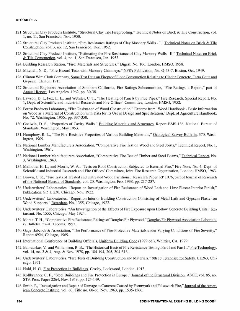
��� ���� ���������� ��� ���� �������� ���®
121. Structural Clay Products Institute, �Structural Clay Tile Fireproofing,� Technical Notes on Brick & Tile Construction, vol.1, no. 11, San Francisco, Nov. 1950.
122. Structural Clay Products Institute, �Fire Resistance Ratings of Clay Masonry Walls - I,� Technical Notes on Brick & TileConstruction, vol. 3, no. 12, San Francisco, Dec. 1952.
123. Structural Clay Products Institute, �Estimating the Fire Resistance of Clay Masonry Walls - II,� Technical Notes on Brick& Tile Construction, vol. 4, no. 1, San Francisco, Jan. 1953.
124.Building Research Station, �Fire: Materials and Structures,� Digest, No. 106, London, HMSO, 1958.
125.Mitchell, N. D., �Fire Hazard Tests with Masonry Chimneys,� NFPA Publication, No. Q-43-7, Boston, Oct. 1949.
126.ClintonWire Cloth Company, Some Test Data on Fireproof Floor ConstructionRelating to Cinder Concrete, Terra Cotta andGypsum, Clinton, 1913.
127. Structural Engineers Association of Southern California, Fire Ratings Subcommittee, �Fire Ratings, a Report,� part ofAnnual Report, Los Angeles, 1962, pp. 30-38.
128. Lawson, D. I., Fox, L. L., and Webster, C. T., �The Heating of Panels by Flue Pipes,� Fire Research, Special Report, No.1, Dept. of Scientific and Industrial Research and Fire Offices� Committee, London, HMSO, 1952.
129. Forest Products Laboratory, �Fire Resistance of Wood Construction,� Excerpt from �Wood Handbook - Basic Informationon Wood as a Material of Construction with Data for its Use in Design and Specification,� Dept. of Agriculture Handbook,No. 72, Washington, 195X, pp. 337-350.
130.Goalwin, D. S., �Properties of Cavity Walls,� Building Materials and Structures, Report BMS 136, National Bureau ofStandards, Washington, May 1953.
131.Humphrey, R. L., �The Fire-Resistive Properties of Various Building Materials,� Geological Survey Bulletin, 370, Wash-ington, 1909.
132.National Lumber Manufacturers Association, �Comparative Fire Test on Wood and Steel Joists,� Technical Report, No. 1,Washington, 1961.
133.National Lumber Manufacturers Association, �Comparative Fire Test of Timber and Steel Beams,� Technical Report, No.3, Washington, 1963.
134.Malhotra, H. L., and Morris, W. A., �Tests on Roof Construction Subjected to External Fire,� Fire Note, No. 4, Dept. ofScientific and Industrial Research and Fire Offices� Committee, Joint Fire Research Organization, London, HMSO, 1963.
135.Brown, C. R., �Fire Tests of Treated and UntreatedWood Partitions,� Research Paper, RP 1076, part of Journal of Researchof the National Bureau of Standards, vol. 20, Washington, Feb. 1938, pp. 217-237.
136.Underwriters� Laboratories, �Report on Investigation of Fire Resistance of Wood Lath and Lime Plaster Interior Finish,�Publication, SP. 1. 230, Chicago, Nov. 1922.
137.Underwriters� Laboratories, �Report on Interior Building Construction Consisting of Metal Lath and Gypsum Plaster onWood Supports,� Retardant, No. 1355, Chicago, 1922.
138.Underwriters� Laboratories, �An Investigation of the Effects of Fire Exposure upon Hollow Concrete Building Units,� Re-tardant, No. 1555, Chicago, May 1924.
139.Moran, T. H., �Comparative Fire Resistance Ratings of Douglas Fir Plywood,� Douglas Fir Plywood Association Laborato-ry Bulletin, 57-A, Tacoma, 1957.
140.Gage Babcock & Association, �The Performance of Fire-Protective Materials under Varying Conditions of Fire Severity,�Report 6924, Chicago, 1969.
141. International Conference of Building Officials, Uniform Building Code (1979 ed.), Whittier, CA, 1979.
142.Babrauskas, V., andWilliamson, R. B., �TheHistorical Basis of Fire Resistance Testing, Part I and Part II,� Fire Technology,vol. 14, no. 3 & 4, Aug. & Nov. 1978, pp. 184-194, 205, 304-316.
143.Underwriters� Laboratories, �Fire Tests of Building Construction and Materials,� 8th ed., Standard for Safety, UL263, Chi-cago, 1971.
144.Hold, H. G., Fire Protection in Buildings, Crosby, Lockwood, London, 1913.
145.Kollbrunner, C. F., �Steel Buildings and Fire Protection in Europe,� Journal of the Structural Division, ASCE, vol. 85, no.ST9, Proc. Paper 2264, Nov. 1959, pp. 125-149.
146. Smith, P., �Investigation andRepair of Damage to Concrete Caused by Formwork and Falsework Fire,� Journal of the Amer-ican Concrete Institute, vol. 60, Title no. 60-66, Nov. 1963, pp. 1535-1566.
�� ����

���� ���������� ��� ���� �������� ���® ���
147. �Repair of Fire Damage,� 3 parts, Concrete Construction, March-May, 1972.
148.National Fire Protection Association, National Fire Codes; a Compilation of NFPA Codes, Standards, Recommended Prac-tices and Manuals, 16 vols., Boston, 1978.
149. Ingberg, S. H. �Tests of Severity of Building Fires,� NFPA Quarterly, vol. 22, no. 1, July 1928, pp. 43-61.
150.Underwriters� Laboratories, �Fire Exposure Tests of Ordinary Wood Doors,� Bulletin of Research, no. 6, Dec. 1938, Chica-go, 1942.
151. Parson, H., �The Tall Building under Test of fire,� Red Book, no. 17, British Fire Prevention Committee, London, 1899.
152. Sachs, E. O., �The British Fire Prevention Committee Testing Station,� Red Book, no. 13, British Fire Prevention Commit-tee, London, 1899.
153. Sachs, E. O., �Fire Tests with Unprotected Columns,� Red Book, no. 11, British Fire Prevention Committee, London, 1899.
154.British Fire Prevention Committee, �Fire Tests with Floors a Floor by the Expended Metal Company,� Red Book, no. 14,London, 1899.
155. Engineering News, vol. 56, Aug. 9, 1906, pp. 135-140.
156. Engineering News, vol. 36, Aug. 6, 1896, pp. 92-94.
157.Bauschinger, J., Mittheilungen de Mech.-Tech. Lab. der K. Tech. Hochschule, München, vol. 12, 1885.
158. Engineering News, vol. 46, Dec. 26, 1901, pp. 482-486, 489-490.
159. The American Architect and Building News, vol. 31, March 28, 1891, pp. 195-201.
160.British Fire Prevention Committee, First International Fire Prevention Congress, Official Congress Report, London, 1903.
161.American Society for Testing Materials, Standard Specifications for Fire Tests of Materials and Construction (C19-18),Philadelphia, 1918.
162. International Organization for Standardization, Fire Resistance Tests on Elements of Building Construction (R834), Lon-don, 1968.
163. Engineering Record, vol. 35, Jan. 2, 1897, pp. 93-94; May 29, 1897, pp. 558-560; vol. 36, Sept. 18, 1897, pp. 337-340; Sept.25, 1897, pp. 359-363; Oct. 2, 1897, pp. 382-387; Oct. 9, 1897, pp. 402-405.
164.Babrauskas, Vytenis, �Fire Endurance in Buildings,� PhD Thesis. Fire Research Group, Report, No. UCB FRG 76-16, Uni-versity of California, Berkeley, Nov. 1976.
165. The Institution of Structural Engineers and The Concrete Society, Fire Resistance of Concrete Structures, London, Aug.1975.
�� ����

��� ���� ���������� ��� ���� �������� ���®

2003 INTERNATIONAL EXISTING BUILDING CODE® 287
INDEX
AACCESSIBILITY . . . . . . . . . . . . . . 104.10, 107.2, 406,
506, 606, 706, 806, 901.2, 905, 1004.1,1005.15, 1201.2.5, 1308, Appendix B
ADDITIONS . . . . . . . . . . . . . . . . . . 101.2, 101.3, 104.2,105.2.2, 106.1.2, 115.5, 202, 307,507.2.1, 812.5, Chapter 9, 1201.1,
1201.2.3, 1301.3
ADMINISTRATION . . . . . . . . . . . . . . . . . . . . Chapter 1ALTERATIONS . . . . . . . . . . . . . . . 101.2, 101.3, 101.8,
104.2, 105.1.1, 105.1.2, 108.2, 115.5,202, Chapter 5, Chapter 6, Chapter 7,
801.1, 807.3.1, 812.5, 901.3, 1004,1201.2, 1201.2.4, 1301.3
Level 1 . . . . . . . . . . . . 104.2.1, 202, 303, 304.2,305.2, Chapter 5, 601.2
Level 2 . . . . . . . . . .106.1.2, 202, 304, Chapter 6
Level 3 . . 106.1.2, 202, 305, Chapter 7, 807.3.1
ALTERNATIVE MATERIALS, DESIGN, AND METHODS OF CONSTRUCTION . . . . . . . . . . . . .104.11, 104.11.1,
401.3
APPEALS . . . . . . . . . . . . . . . . . . . . . . . . . . . . . . 116.6APPLICABILITY . . . . . . . . . . . . . . . . . . . 102, 104.2.1,
1201.2
ARCHITECT (see REGISTERED DESIGN PROFESSIONAL)
AREA (see BUILDING)
BBOARD OF APPEALS . . . . . . . . . . . . . . . 104.8, 112
BUILDINGArea . . . . . . . . . . . . . . . . 812.4.2, Table 812.4.2,
812.4.2.1, 812.4.2.2, 902, 1005.2,1201.6.2, 1201.6.11, Table 1207.1
Dangerous . . . . . . . . . . . . . . . . . . . . 202, 1002.2
Existing . . . . . . . . . . . . . 101.4, 202, 506, 606.2,802.1, 808, 812, 902, 903, 1201.2.3
Height . . . . . . . . . . . . . . . 812.4.2, Table 812.4.2,812.4.2.1, 812.4.2.2, 902, 1201.2.3,
1201.6.1, 1201.6.11, Table 1207.1
Historic . . . . . . . . . . . . . . 101.2, 202, 308, 401.1,501.1, 801.1, Chapter 10, B101.1,
B101.2, B101.3, B101.4Relocated . . . . . . . . . .101.2, 110.1, 309, 1002.3,
1102.2, 1102.2.1, 1102.7
Underground . . . . . . . . . . . . . . . . . . . . . . . . 802.2
Unsafe. . . . . . . . . . . . . . . . . . . . . . . . . . 115, 202
BUILDING ELEMENTS AND MATERIALS . . . . . . .403, 503, 603, 703, 803
CCARPET . . . . . . . . . . . . . . . . . . . . . . . . . .105.2, 503.2
CEILING . . . . . . . . . . . . . . . . . . . . . . . 601.3, 603.2.1,603.4, 608.1, 812.3.1, 1003.5, 1201.6.3.2
CERTIFICATE OF OCCUPANCY. . . . . . . . 110, 801.3
CHANGE OF OCCUPANCY . . . . . 101.2, 101.3, 104.2,106.2, 115.5, 202, 306, 707.5.1,
Chapter 8, 1001.1, 1001.2, 1001.4, 1005,1101.2, 1201.1, 1201.2.2
CODE OFFICIAL. . . . . . . . . . . . . . . . . Chapter 1, 104,202, 407.3.2.1, 605.2, 707.5.1, 807.3.1,812.4.1.1, 1001.2, 1001.3, 1003, 1005,
1102.7, 1201.3
COMPARTMENTATION . . . . . . . . . 603.3.1, 1201.6.3,Table 1201.6.3, Table 1201.7
COMPLIANCE ALTERNATIVES . . . . . 301.3, 401.3,1002.3, Chapter 12
CONFLICT . . . . . . . . . . . . . . . . . . . . . . . 102.1, 113.1
CONSTRUCTION DOCUMENTS . . . . . . 104.2, 105.3,105.4, 106, 113.4, 301.2
CONSTRUCTION SAFEGUARDS . . 101.6, Chapter 13
CORRIDOR
Dead-end . . . . . . . . . . . 601.3, 605.6, 812.4.1.1Doors . . . . . . . . . . . . 605.5.1, 812.3.2, 812.4.11Openings . . . . . . . . . 605.5.3, 605.5.4, 812.4.1.1
DDEFINITIONS . . . . . . . . . . . . . . . . . . . . . . . . . . . . 202
DEMOLITION . . . . . . . . . . . . . . . . 101.6, 104.2, 106.2,108.5, 113.2, 117, 1301.5, 1301.6,
1302.1, 1303.1, 1304.1
DEPARTMENT OF BUILDING SAFETY . . . . . . . 103,104.10, 105.3, 109.3.7, 110.2
E
EGRESS (see MEANS OF EGRESS)ELECTRICAL . . . . . . . . . . . . . . . 105.2, 408, 608, 808
INDEX
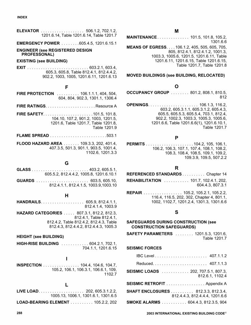
2003 INTERNATIONAL EXISTING BUILDING CODE®288
INDEX
ELEVATOR . . . . . . . . . . . . . . . . . . . 506.1.2, 702.1.2,1201.6.14, Table 1201.6.14, Table 1201.7
EMERGENCY POWER . . . . . . . .605.4.5, 1201.6.15.1
ENGINEER (see REGISTERED DESIGN PROFESSONAL)
EXISTING (see BUILDING)EXIT . . . . . . . . . . . . . . . . . . . . . . . . . . . 603.2.1, 603.4,
605.3, 605.8, Table 812.4.1, 812.4.4.2,902.2, 1003, 1005, 1201.6.11, 1201.6.13
FFIRE PROTECTION . . . . . . . . . . 106.1.1.1, 404, 504,
604, 804, 902.3, 1301.1, 1306.4
FIRE RATINGS. . . . . . . . . . . . . . . . . . . . . . Resource A
FIRE SAFETY. . . . . . . . . . . . . . . . . . . . . . 101.5, 101.8,104.10, 107.2, 901.2, 1003, 1201.5,1201.6, Table 1201.7, Table 1201.8,
Table 1201.9
FLAME SPREAD . . . . . . . . . . . . . . . . . . . . . . . . .503.1
FLOOD HAZARD AREA . . . . . . . 109.3.3, 202, 401.4,407.3.5, 501.3, 901.1, 903.5, 1001.4,
1102.6, 1201.3.3
GGLASS . . . . . . . . . . . . . . . . . . . . . . . . . 403.2, 605.5.1,
605.5.2, 812.4.4.2, 1005.8, 1201.6.10.1GUARDS . . . . . . . . . . . . . . . . . . . . . . . 603.5, 605.10,
812.4.1.1, 812.4.1.5, 1003.9,1003.10
HHANDRAILS. . . . . . . . . . . . . . . . . . . 605.9, 812.4.1.1,
812.4.1.4, 1003.9HAZARD CATEGORIES . . . . . 807.3.1, 812.2, 812.3,
812.4.1, Table 812.4.1,812.4.2, Table 812.4.2, 812.4.3, Table812.4.3, 812.4.4.2, 812.4.4.3, 1005.3
HEIGHT (see BUILDING) HIGH-RISE BUILDING . . . . . . . . . . . . 604.2.1, 702.1,
704.1.1, 1201.6.15
IINSPECTION . . . . . . . . . . . . . . . . 104.4, 104.6, 104.7,
105.2, 106.1, 106.3.1, 106.6.1, 109,1102.7
LLIVE LOAD. . . . . . . . . . . . . . . . . . . . 202, 605.3.1.2.2,
1005.13, 1006.1, 1301.6.1, 1301.6.5LOAD-BEARING ELEMENT . . . . . . . . . . 105.2.2, 202
MMAINTENANCE . . . . . . . . . . . . . . 101.5, 101.8, 105.2,
1301.6.6MEANS OF EGRESS. . . . 106.1.2, 405, 505, 605, 705,
805, 812.4.1, 812.4.1.2, 1001.3,1003.3, 1005.6, 1201.5, 1201.6.11, Table
1201.6.11, 1201.6.15, Table 1201.6.15,Table 1201.7, Table 1201.8
MOVED BUILDINGS (see BUILDING, RELOCATED)
OOCCUPANCY GROUP . . . . . . . . 801.2, 808.1, 810.5,
812
OPENINGS. . . . . . . . . . . . . . . . . . . . . . 106.1.3, 116.2,603.2, 605.3.1.1, 605.3.1.2, 605.4.3,
605.5, 605.5.3, 605.5.4, 703.1, 812.4,902.2, 1002.3, 1003.3, 1005.3, 1005.6,
1201.6.6, Table 1201.6.6(1), 1201.6.10.1,Table 1201.7
PPERMITS . . . . . . . . . . . . . . . . . . . . . 104.2, 105, 106.1,
106.2, 106.3, 107.1, 107.4, 108.1, 108.2,108.3, 108.4, 108.5, 109.1, 109.2,
109.3.9, 109.5, 507.2.2
RREFERENCED STANDARDS . . . . . . . . . . Chapter 14REHABILITATION . . . . . . . . . . . 101.7, 102.4.1, 202,
604.4.3, 807.3.1
REPAIR . . . . . . . . . . . . . . . . . 105.2, 105.2.1, 105.2.2,116.4, 116.5, 202, 302, Chapter 4, 801.1,1002, 1102.7, 1201.2.4, 1301.3, 1301.6.6
S
SAFEGUARDS DURING CONSTRUCTION (see CONSTRUCTION SAFEGUARDS)
SAFETY PARAMETERS . . . . . . . . 1201.5.3, 1201.6,Table 1201.7
SEISMIC FORCES
IBC Level . . . . . . . . . . . . . . . . . . . . . . . 407.1.1.2
Reduced. . . . . . . . . . . . . . . . . . . . . . . . 407.1.1.3
SEISMIC LOADS . . . . . . . . . . . . 202, 707.5.1, 807.3,812.6.1, 1102.4
SEISMIC RETROFIT . . . . . . . . . . . . . . . . . Appendix A
SHAFT ENCLOSURES . . . . . . . . . . 812.3.3, 812.3.4,812.4.4.3, 812.4.4.4, 1201.6.6
SMOKE ALARMS . . . . . . . . . . . 604.4.3, 812.3.5, 904
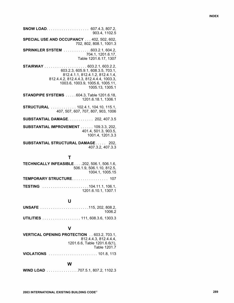
2003 INTERNATIONAL EXISTING BUILDING CODE® 289
INDEX
SNOW LOAD. . . . . . . . . . . . . . . . . . . . 607.4.3, 807.2,903.4, 1102.5
SPECIAL USE AND OCCUPANCY . . . 402, 502, 602,702, 802, 808.1, 1001.3
SPRINKLER SYSTEM . . . . . . . . . . . . .603.2.1, 604.2,704.1, 1201.6.17,
Table 1201.6.17, 1307
STAIRWAY . . . . . . . . . . . . . . . . . . . . 603.2.1, 603.2.2,603.2.3, 605.9.1, 608.3.5, 703.1,
812.4.1.1, 812.4.1.2, 812.4.1.4,812.4.4.2, 812.4.4.3, 812.4.4.4, 1003.3,
1003.6, 1003.9, 1005.6, 1005.11,1005.13, 1305.1
STANDPIPE SYSTEMS . . . . . 604.3, Table 1201.6.18,1201.6.18.1, 1306.1
STRUCTURAL . . . . . . . . . . . . 102.4.1, 104.10, 115.1,407, 507, 607, 707, 807, 903, 1006
SUBSTANTIAL DAMAGE. . . . . . . . . . . . 202, 407.3.5
SUBSTANTIAL IMPROVEMENT . . . . . . 109.3.3, 202,401.4, 501.3, 903.5,
1001.4, 1201.3.3
SUBSTANTIAL STRUCTURAL DAMAGE . . . . . 202,407.3.2, 407.3.3
TTECHNICALLY INFEASIBLE . . . .202, 506.1, 506.1.6,
506.1.9, 506.1.10, 812.5,1004.1, 1005.15
TEMPORARY STRUCTURE. . . . . . . . . . . . . . . . . 107
TESTING . . . . . . . . . . . . . . . . . . . . . .104.11.1, 106.1,1201.6.10.1, 1307.1
UUNSAFE . . . . . . . . . . . . . . . . . . . . . . .115, 202, 808.2,
1006.2UTILITIES . . . . . . . . . . . . . . . . . . 111, 608.3.6, 1303.3
VVERTICAL OPENING PROTECTION . . 603.2, 703.1,
812.4.4.3, 812.4.4.4,1201.6.6, Table 1201.6.6(1),
Table 1201.7VIOLATIONS . . . . . . . . . . . . . . . . . . . . . . . 101.8, 113�
WWIND LOAD . . . . . . . . . . . . . . .707.5.1, 807.2, 1102.3

2003 INTERNATIONAL EXISTING BUILDING CODE®290
INDEX