Existing Conditions Report Underwater Investigation ...
93
-
Upload
khangminh22 -
Category
Documents
-
view
1 -
download
0
Transcript of Existing Conditions Report Underwater Investigation ...
Existing Conditions Report Underwater Investigation
& Landside Inspection Vernon C. Bain Center
Hunts Point, New York
Prepared for:
New York City Department of Correction New York, New York
McLaren Engineering Project No. 106523.04 September, 2013
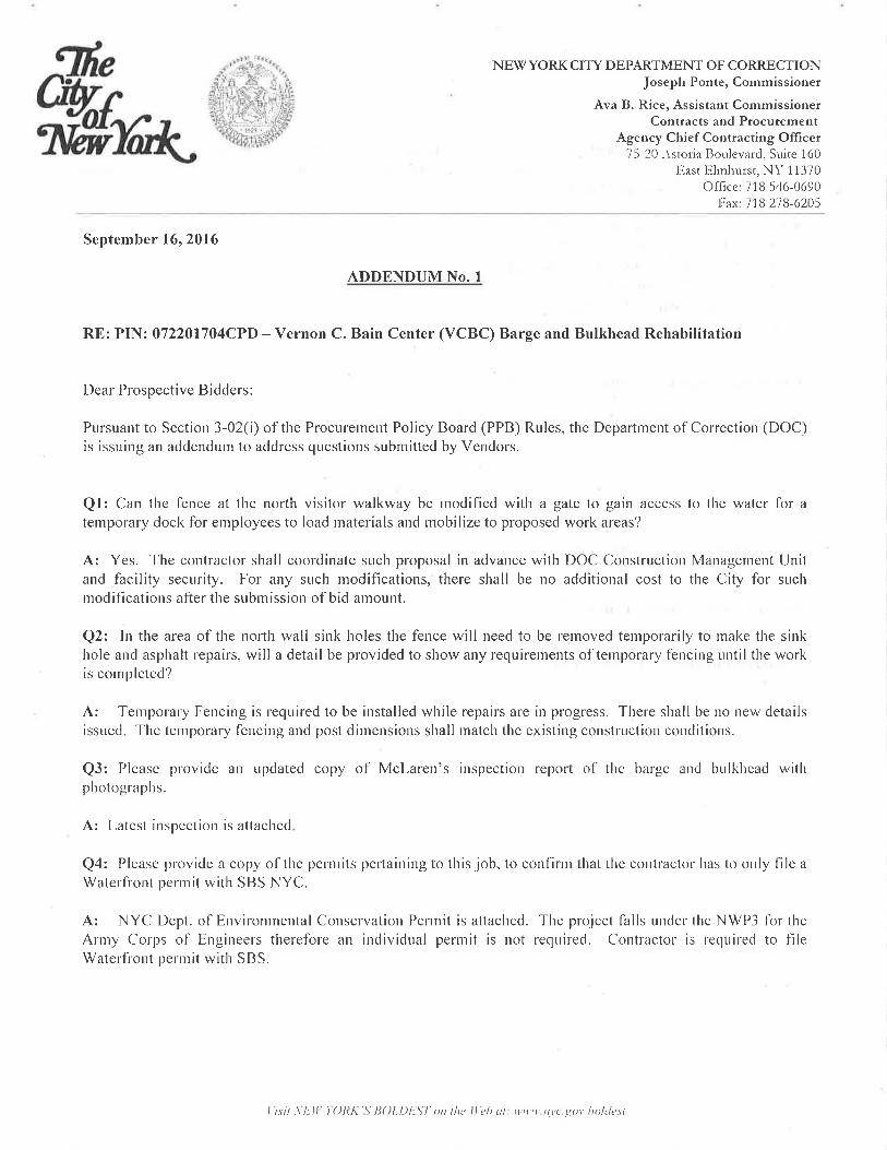
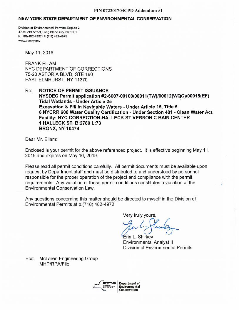
PIN 072201704CPD Addendum #1
VCBC Barge & Bulkhead Inspection 2013 Page ii New York, New York MEG File No. 106523.04
1.0 EXECUTIVE SUMMARY
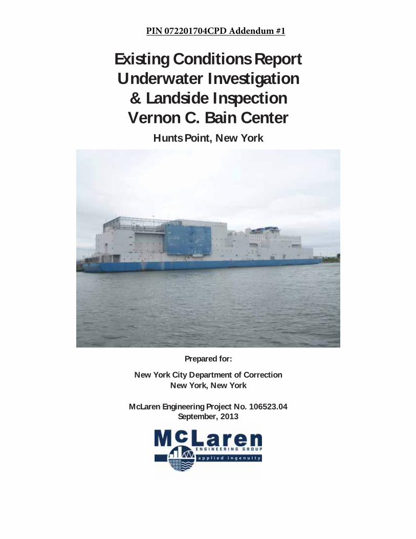
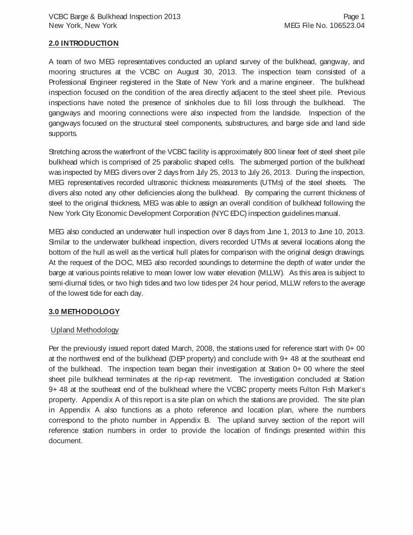
Located at 1 Halleck Street, Bronx, New York, the Vernon C. Bain Center (VCBC) is a floating barge prison facility operated by the New York City Department of Correction (DOC), see Photo 1. The prison is constructed on a 625 ft long by 125 ft wide barge with a draft of approximately 9 ft to 10 ft. McLaren Engineering Group (MEG) was retained by the DOC to perform inspection services of the upland property, adjacent bulkhead, and floating barge.
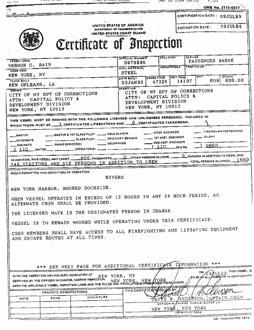
In 2008 MEG conducted a condition inspection of the aforementioned structures and as part of the investigation phase contacted the United States Coast Guard (USCG) regarding the process for renewing the Certificate of Inspection for the VCBC. The USCG responded to the inquiry stating that because of the VCBC’s permanently moored status, it is no longer subject to inspection requirements of the USCG which includes dry dock inspection under the USCG supervision. Following the guidelines implemented in 2008, the barge is to be inspected on a 5 year cycle by an accredited company.
MEG conducted the inspection of the barge and bulkhead in two phases between July 1st, 2013 and August 30th, 2013. The two phases consisted of an upland inspection and an underwater inspection. The upland inspection consisted of the gangways, winches, mooring connections, and bulkhead. The underwater inspection included the bulkhead from the tidal zone to the mudline as well as the submerged portion of the barge hull and vertical hull plates.
The gangways, winches, and mooring connections ranged from good to satisfactory condition, in which the condition grade was governed by a controlling element which will be discussed later in the report (see condition assessment rating definitions in the “Methodology” section).
The bulkhead inspection revealed 5 sinkholes located immediately inshore of the steel sheet pile bulkhead. The sinkholes were of various sizes and depths and appeared to have been caused by loss of fill through the sheeting. By comparison, the previous inspection revealed 4 sinkholes, thus an additional sinkhole was recorded during this inspection.
The majority of the steel sheets exhibited coating loss, pitting, and exfoliation. The corrosion was more severe at locations within the tidal zone, but more abundant near the mudline. MEG divers also observed five holes in the sheeting. Each sinkhole location had a corresponding hole in the sheeting in the tidal zone.
The overall condition of the bulkhead is poor which is governed by holes in the steel and areas of advanced corrosion determined through ultrasonic thickness measurements (UTMs). The holes have resulted in fill loss through the bulkhead which has produced sinkholes which have the potential to harm upland structures.
MEG recommends the installation of steel plates on the outside of the sheet pile bulkhead to cover the holes. To reduce the corrosion rate of the steel sheeting, MEG recommends installing sacrificial
VCBC Barge & Bulkhead Inspection 2013 Page iii New York, New York MEG File No. 106523.04
anodes below MLW and recoating the sheet pile above MLW with an epoxy along the length of the bulkhead.
The submerged portion of the VCBC hull appeared to be in satisfactory condition. This condition grade is governed by minor corrosion of the submerged hull plates which was determined through UTMs. Based on the condition of the hull plating below the water line, no repair is needed.
The vertical hull plates above the water line appeared to be in satisfactory condition governed by minor rusting and coating loss in isolated areas. Although this rusting will not affect the structural integrity of the barge, MEG recommends that the isolated rusted areas above the water line be cleaned and recoated with an epoxy coating as a preventative measure against more severe and advancement of widespread corrosion.
Mudline measurements recorded at specified locations beneath the barge verified that the hull rests in the river mud at MLW. The topography of the soil confirms that the northeast quadrant of the barge has flattened the mudline. MEG recommends that this be addressed by dredging beneath the barge to maintain a minimum clearance. For cost estimating purposes, MEG has assumed a minimum clearance of three feet at MLLW.
On the submerged portion of the hull there is an impressed current cathodic protection system. A visual inspection of the cathodes was performed, but the performance of the system was not verified. While the cathodic protection system appeared to be in working condition, the timber bumpers originally installed as a means of protection were severely deteriorated and missing in some areas. MEG recommends that the previously installed bumpers be replaced with a fiberglass reinforced plastic, or FRP.
In order to monitor the structural integrity of the barge and bulkhead, MEG recommends continuing the routine inspection program. As per the inspection program in place, these inspections should be performed in a similar manner to the current inspection and take place at a minimum of every five years by an accredited company. Cost estimates for recommended repair items are included in Appendix I of this report.
VCBC Barge & Bulkhead Inspection 2013 New York, New York MEG File No. 106523.04
TABLE OF CONTENTS
1.0 EXECUTIVE SUMMARY ......................................................................................................... ii
2.0 INTRODUCTION ................................................................................................................... 1
3.0 METHODOLOGY .................................................................................................................. 1
4.0 INVESTIGATION OBSERVATIONS ........................................................................................ 4
4.1 UPLAND STRUCTURE FINDINGS ..................................................................................... 4
4.2 BULKHEAD INVESTIGATION FINDINGS .......................................................................... 7
4.3 BARGE INSPECTION FINDINGS ........................................................................................ 9
5.0 REPAIR RECOMMENDATIONS ........................................................................................... 11
APPENDICES
Appendix A Site Plan and Photo Locations
Appendix B Photographs
Appendix C Drawings
Appendix D Data Tables
Appendix E Steel Grade Descriptions
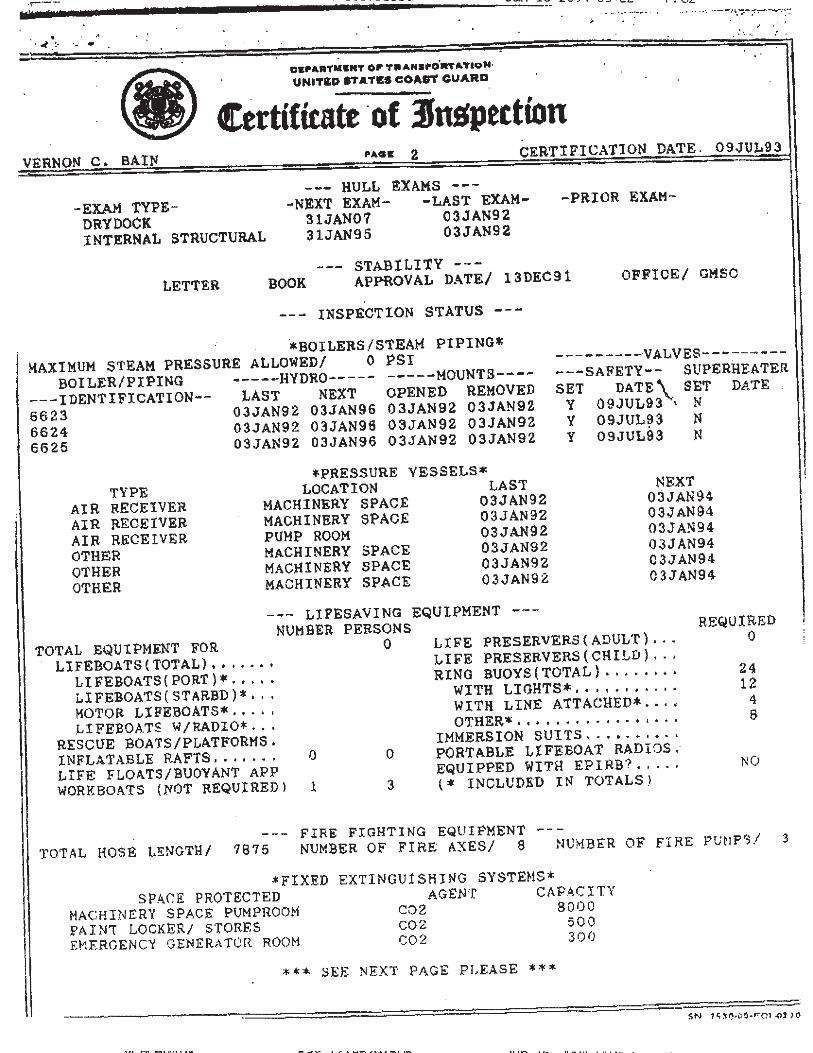
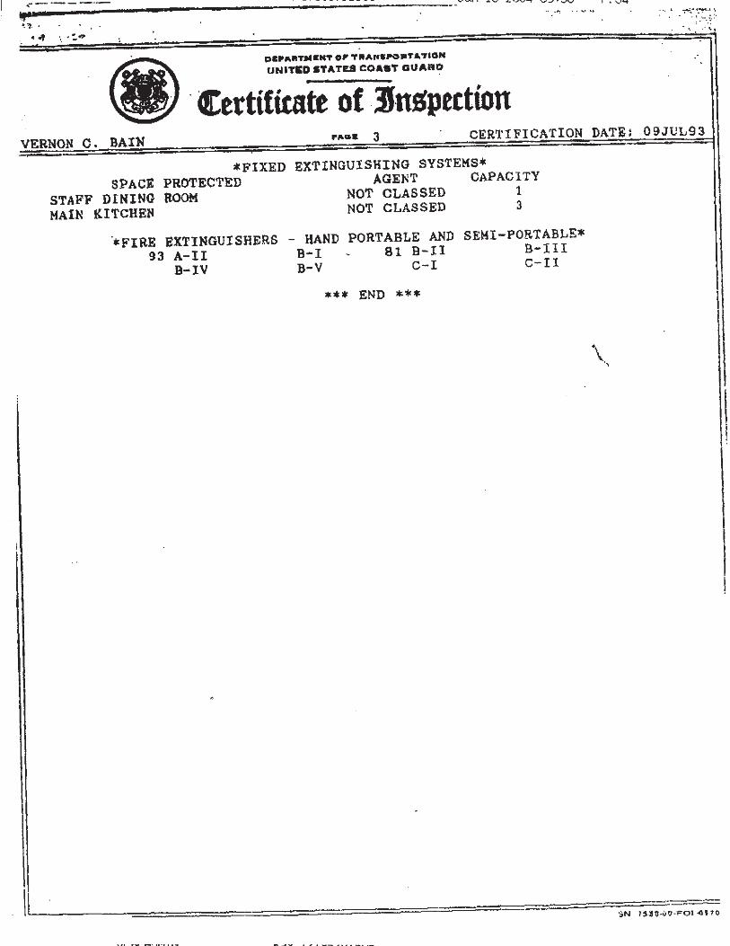
Appendix F Certificate of Inspection
Appendix G USCG E-mail Correspondence from 2007
Appendix H Original Timber Bumper Detail
Appendix I Cost Estimate
VCBC Barge & Bulkhead Inspection 2013 Page 1 New York, New York MEG File No. 106523.04
2.0 INTRODUCTION
A team of two MEG representatives conducted an upland survey of the bulkhead, gangway, and mooring structures at the VCBC on August 30, 2013. The inspection team consisted of a Professional Engineer registered in the State of New York and a marine engineer. The bulkhead inspection focused on the condition of the area directly adjacent to the steel sheet pile. Previous inspections have noted the presence of sinkholes due to fill loss through the bulkhead. The gangways and mooring connections were also inspected from the landside. Inspection of the gangways focused on the structural steel components, substructures, and barge side and land side supports.
Stretching across the waterfront of the VCBC facility is approximately 800 linear feet of steel sheet pile bulkhead which is comprised of 25 parabolic shaped cells. The submerged portion of the bulkhead was inspected by MEG divers over 2 days from July 25, 2013 to July 26, 2013. During the inspection, MEG representatives recorded ultrasonic thickness measurements (UTMs) of the steel sheets. The divers also noted any other deficiencies along the bulkhead. By comparing the current thickness of steel to the original thickness, MEG was able to assign an overall condition of bulkhead following the New York City Economic Development Corporation (NYC EDC) inspection guidelines manual.
MEG also conducted an underwater hull inspection over 8 days from June 1, 2013 to June 10, 2013. Similar to the underwater bulkhead inspection, divers recorded UTMs at several locations along the bottom of the hull as well as the vertical hull plates for comparison with the original design drawings. At the request of the DOC, MEG also recorded soundings to determine the depth of water under the barge at various points relative to mean lower low water elevation (MLLW). As this area is subject to semi-diurnal tides, or two high tides and two low tides per 24 hour period, MLLW refers to the average of the lowest tide for each day.
3.0 METHODOLOGY
Upland Methodology
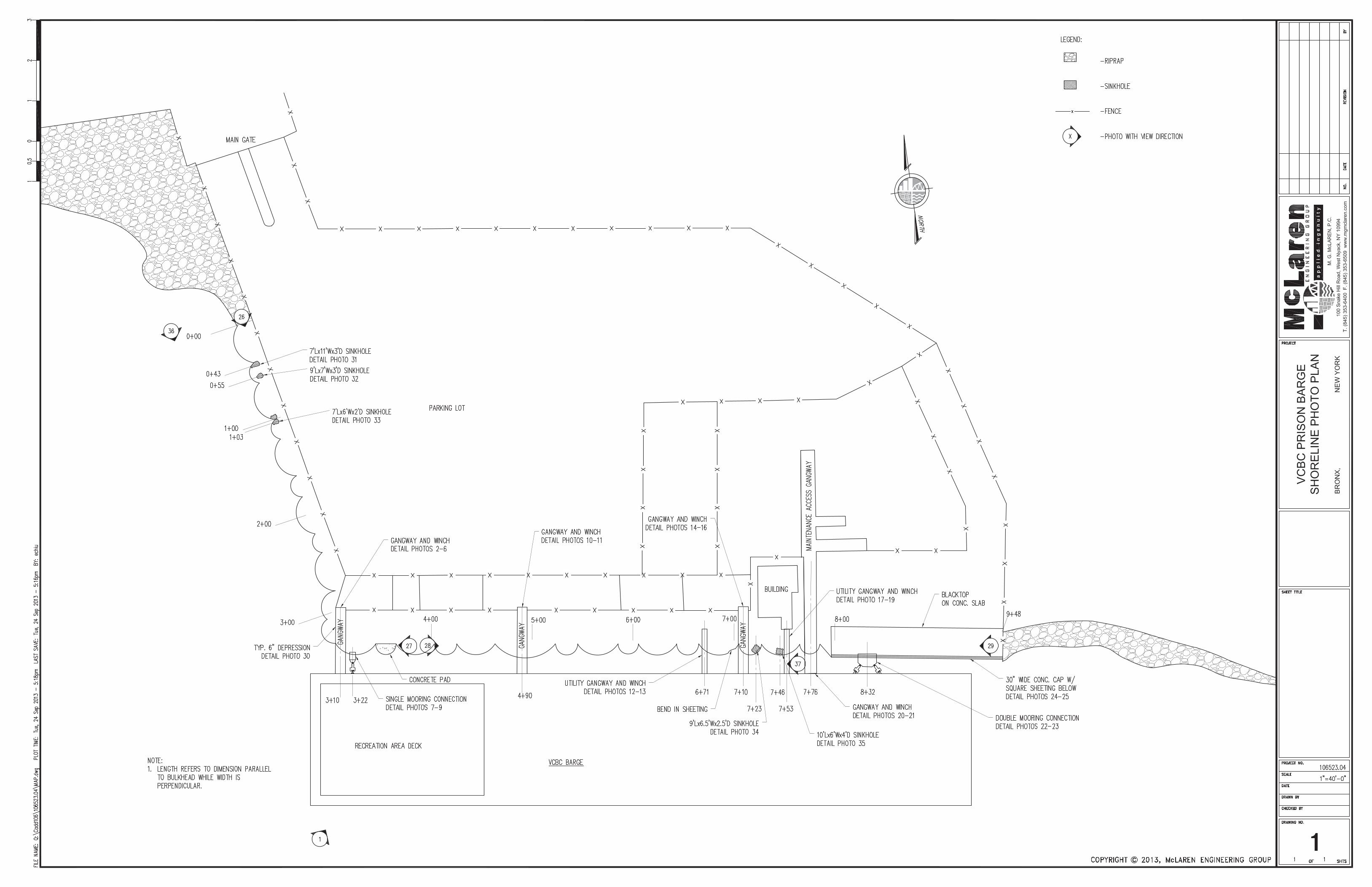
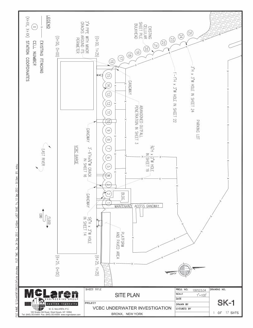
Per the previously issued report dated March, 2008, the stations used for reference start with 0+00 at the northwest end of the bulkhead (DEP property) and conclude with 9+48 at the southeast end of the bulkhead. The inspection team began their investigation at Station 0+00 where the steel sheet pile bulkhead terminates at the rip-rap revetment. The investigation concluded at Station 9+48 at the southeast end of the bulkhead where the VCBC property meets Fulton Fish Market’s property. Appendix A of this report is a site plan on which the stations are provided. The site plan in Appendix A also functions as a photo reference and location plan, where the numbers correspond to the photo number in Appendix B. The upland survey section of the report will reference station numbers in order to provide the location of findings presented within this document.
VCBC Barge & Bulkhead Inspection 2013 Page 2 New York, New York MEG File No. 106523.04
Underwater Investigation Methodology
The cellular steel sheet pile bulkhead was inspected by MEG Divers. In total, 25 steel sheet pile cells were investigated. Cell 1 refers to the cell at the east side of the VCBC and adjacent to the pile supported platform while Cell 25 is at the northwest corner and terminates at the rip-rap revetment. Please refer to Drawing SK-1 in Appendix C for a site plan showing the numbered steel sheet pile cells. UTMs were recorded near the middle of each cell, at both the water level and at the mudline. The inspection team also noted any deficiencies in the steel sheet pile bulkhead including areas with holes, pitting, rusting, or loss of coating.
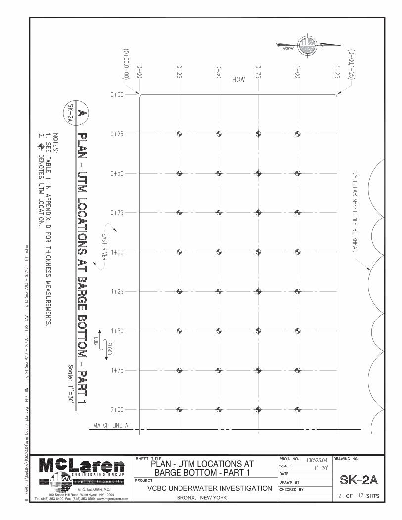
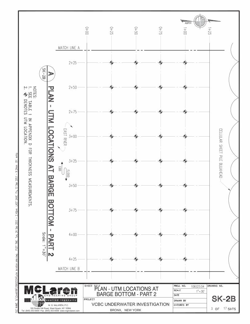
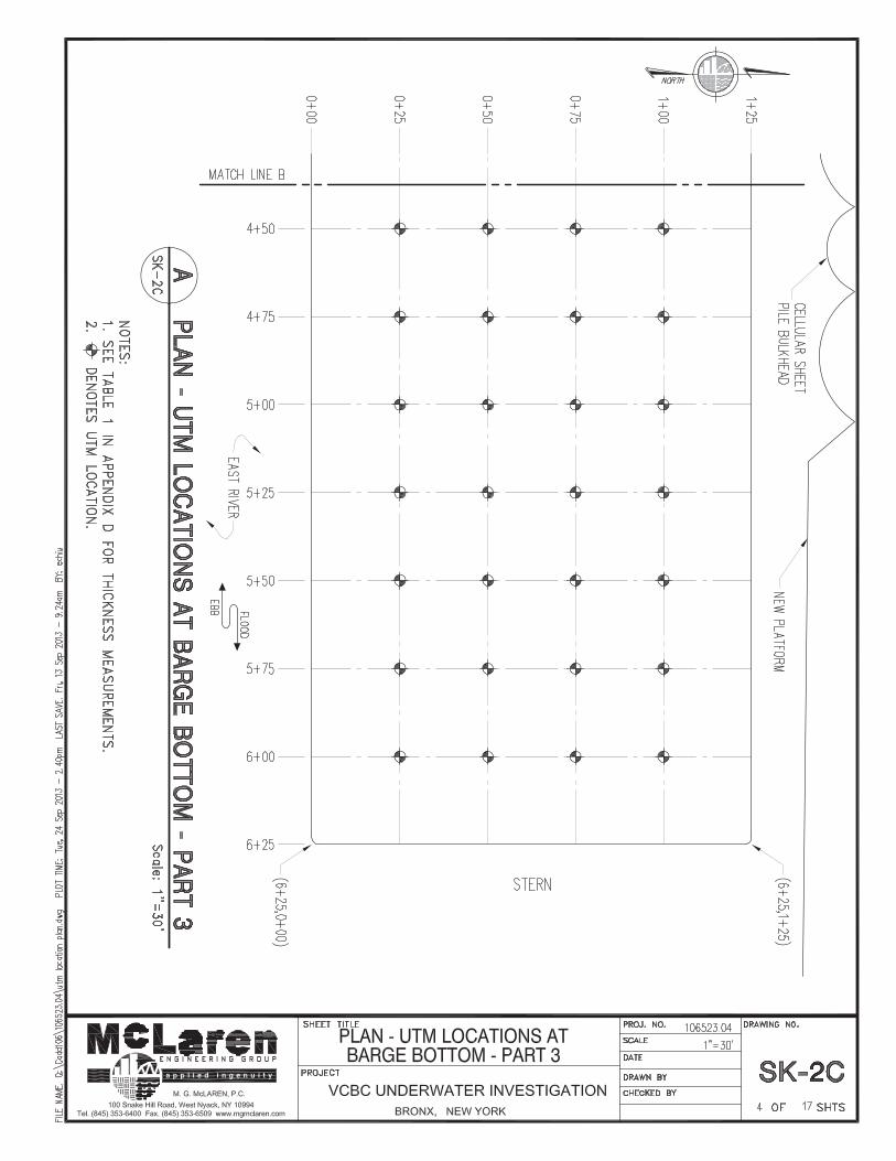
For organization and ease of reference, MEG stationed off the bottom of the barge using a grid pattern extending from 0+00 to 1+25 in the north-south (longitudinal) direction and 0+00 to 6+25 in the east-west (transverse) direction using 25 ft increments in both directions. (0+00, 0+00) corresponds to the southwest corner of the barge while (6+25,1+25) refers to the northeast corner of the barge. Please refer to Drawings SK-2A to SK-2C, attached under Appendix C, for a plan view of the grid stationing.
MEG Divers used a Cygnus Underwater Ultrasonic Thickness Gauge to measure the thickness of the barge’s steel hull plates. For each location, three readings were recorded and averaged for the final thickness for steel.
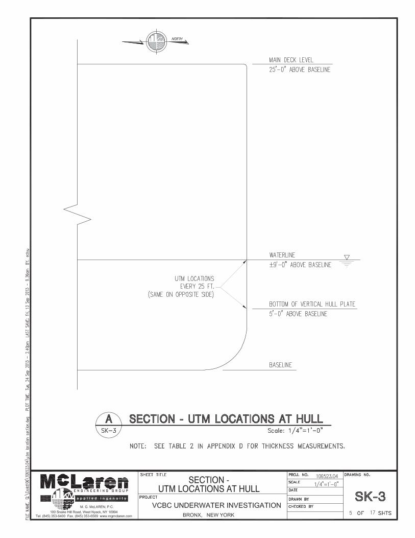
In each location where a recording was required, the MEG Divers cleaned the bottom of the barge to sound steel in order to obtain an accurate thickness measurement. The majority of the steel hull exhibited marine growth and was scraped by divers prior to obtaining the UTM. Following the aforementioned grid pattern, the divers obtained 96 measurements on the hull of the barge from stations 0+25 to 1+00 in the north-south direction, and from 0+25 to 6+00 in the east-west direction. UTMs were also taken on the vertical hull plates just below the water level and at the bottom of the vertical hull plates at the exterior stations. While taking UTMs, the divers noted the condition of the steel such as rusting, pitting, coating degradation, as well as the condition of the active cathodic protection system which exists on vertical hull plates of the barge below the water level.
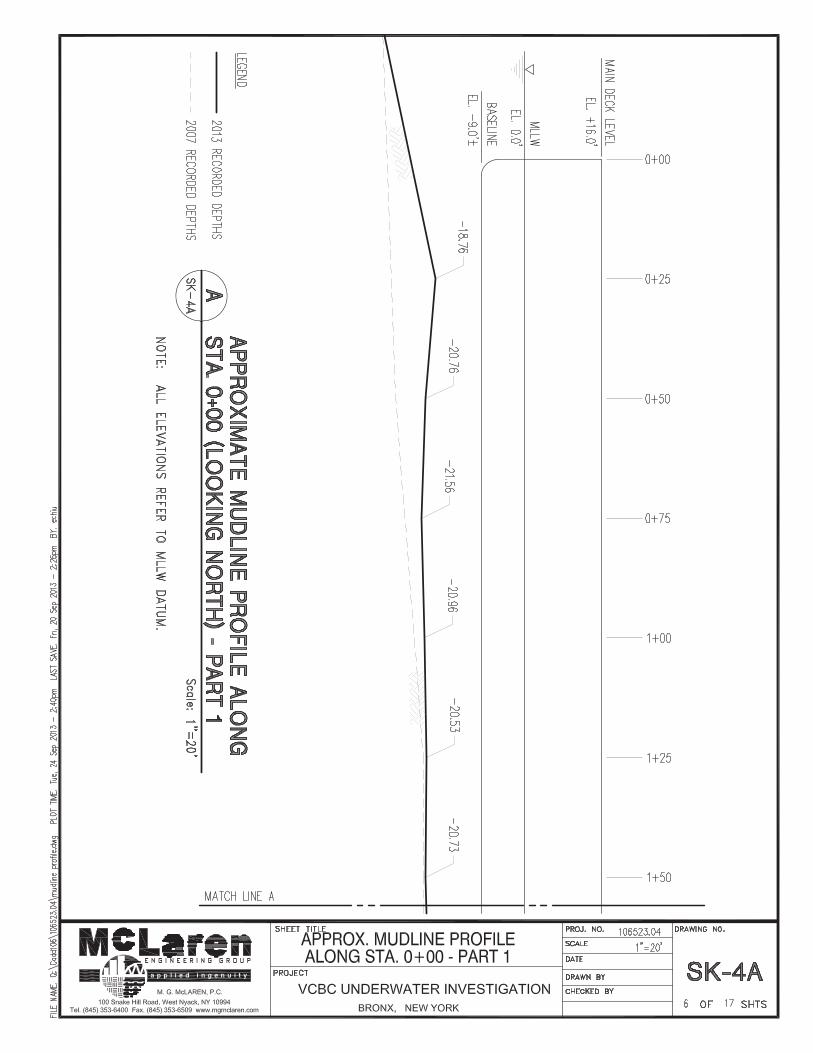
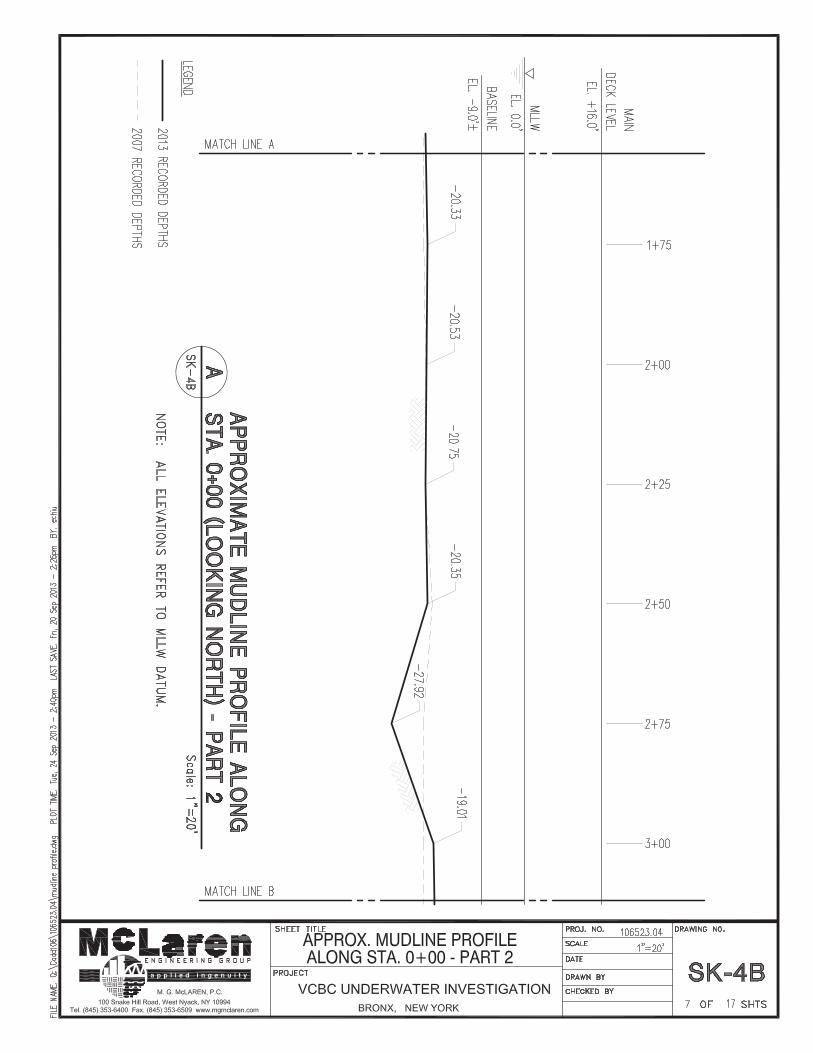
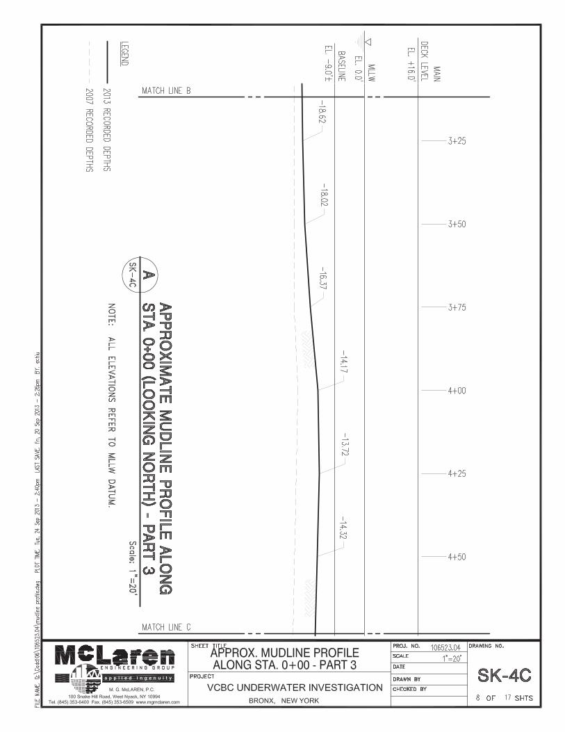
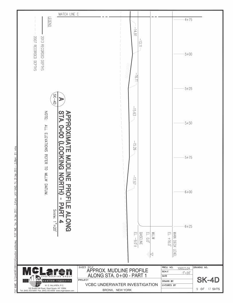
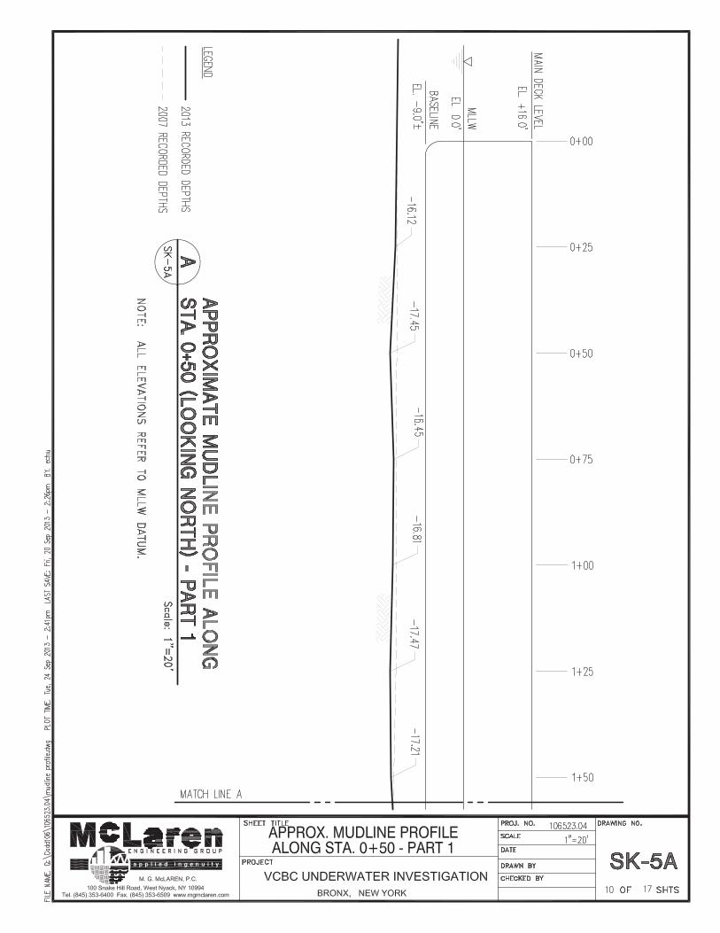
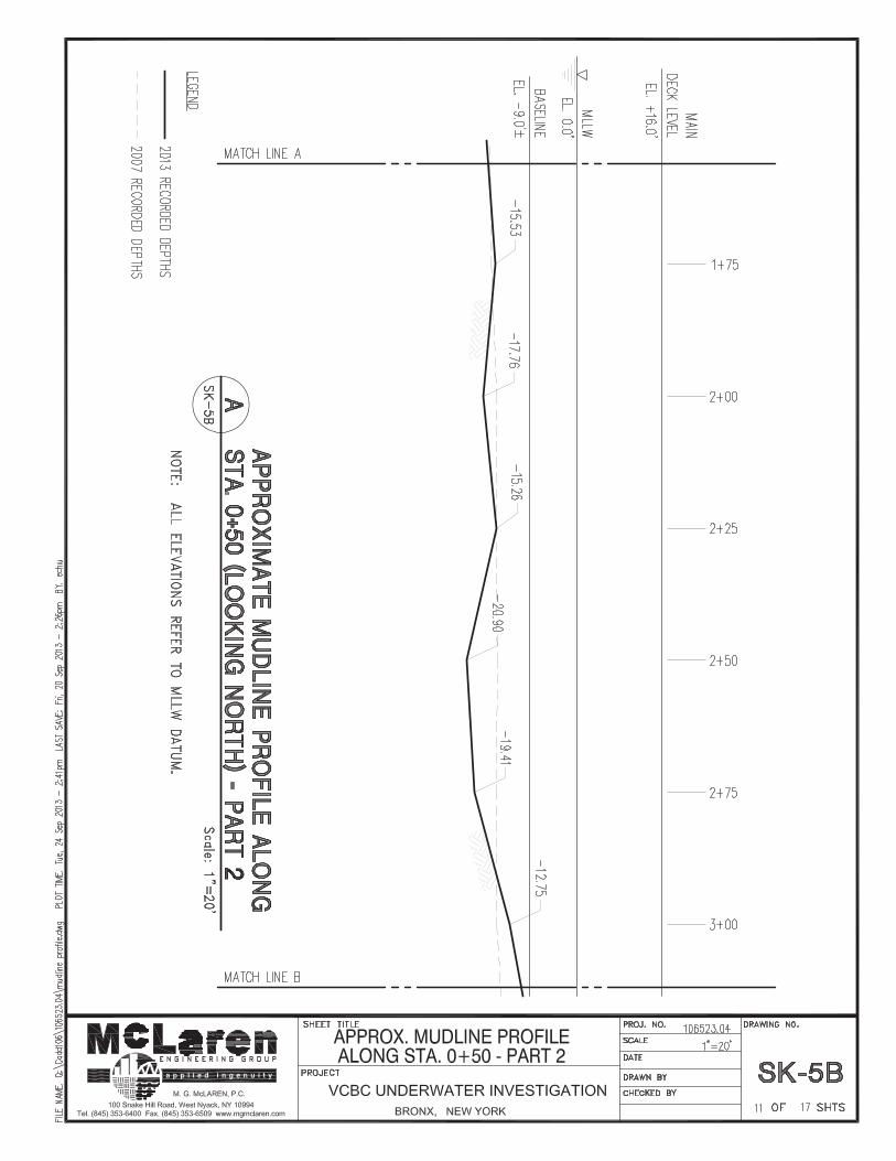
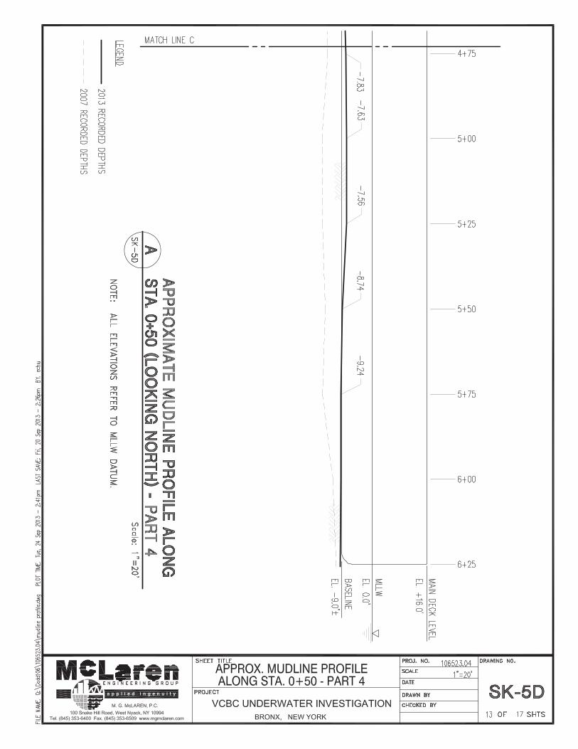
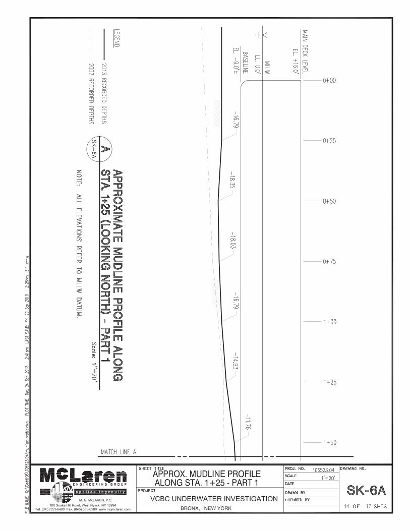
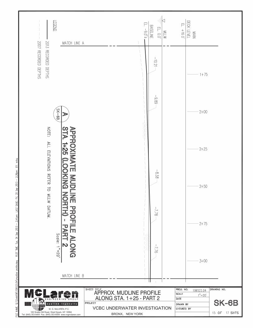
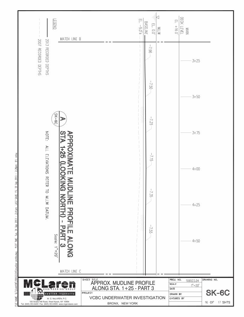
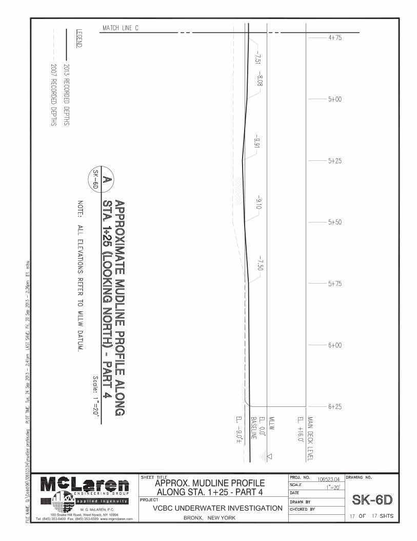
Divers recorded the depth of the mudline along the length of the barge using either a wrist gage or a measuring tape device. Depth readings were gathered at stations 0+00, 0+50, and 1+25 in the north-south direction and every 25 ft in the east-west direction along the entire length of the barge. These profiles are mapped out relative to MLLW in Appendix C.
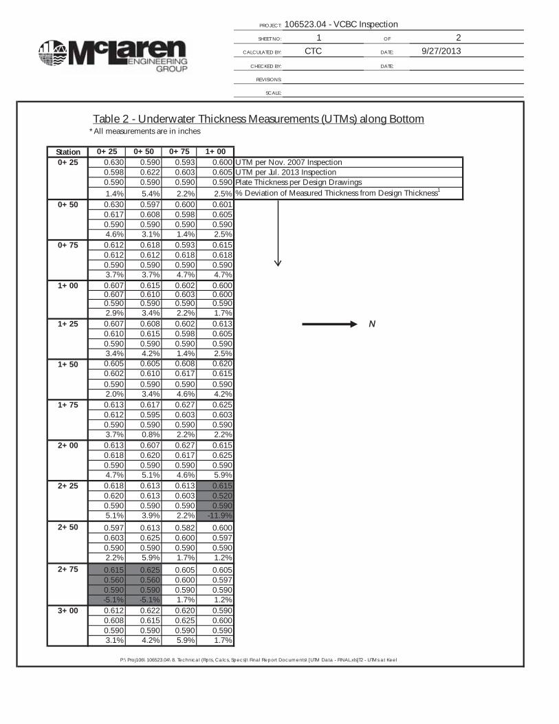
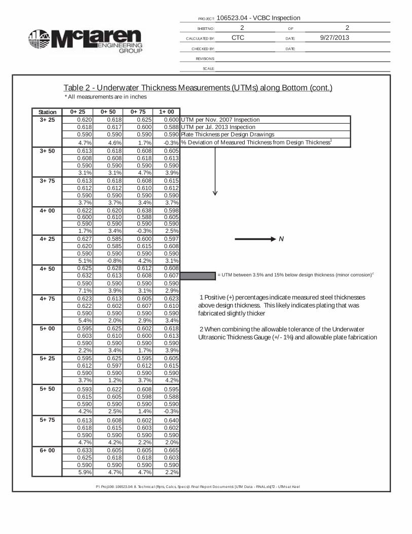
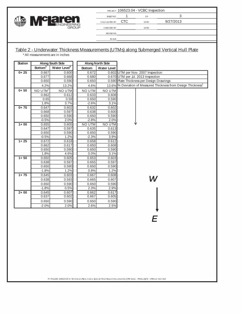
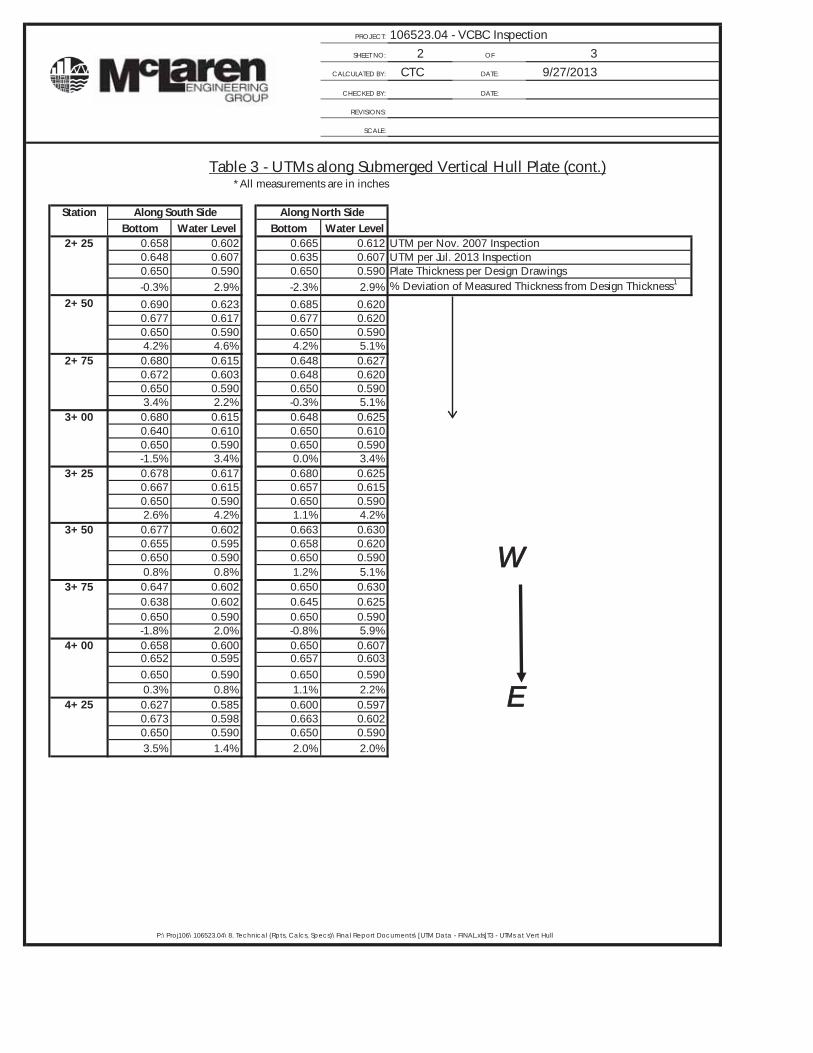
Discussion on UTM Data Tables
Located in Appendix D of this report are three tables which list all the UTMs recorded on the barge and bulkhead. In Appendix D, Table 1 contains the UTMs for the cellular sheet pile bulkhead, Table 2 contains the UTMs for the bottom of the barge, and Table 3 contains the UTMs for the submerged vertical hull plates. These three tables show a percent deviation from the design thickness for each measurement which can be applied to the EDC Inspection Guidelines for an overall condition designation.
VCBC Barge & Bulkhead Inspection 2013 Page 3 New York, New York MEG File No. 106523.04
The deficiency grades for the steel sheet pile bulkhead were graded by determining the deviation of actual thickness from the design thickness of the steel using a Cygnus Ultrasonic Measuring Gauge. The Cygnus Gauge has a tolerance of ±1%. Steel sheet pile fabrication has a relatively large fabrication thickness tolerance of ±6%. When calculating the percent deviation from the design thickness of the steel sheets, MEG used a total tolerance of ±7%.
Per the report dated March, 2008, MEG was unable to obtain design drawings for the steel sheet pile bulkhead. In order to obtain a design thickness to use in the data tables, MEG measured coated and intact portions of steel which appeared to be in sound condition. Although the actual design thickness of the sheets may be different, MEG believes the measurement of the sound portion of coated steel represents the design thickness accurately.
Per the AISC manual, plate fabrication has a tolerance of ±2.5% of the design thickness. This fabrication is combined with the Cygnus Underwater Ultrasonic Thickness gauge’s accuracy tolerance of ±1%. When determining the deviation of actual steel thickness to the design thickness on the Construction Drawings, a total tolerance of ±3.5% was taken into account for determining the damage grade of the steel per the New York City Economic Development Corporation Inspection Guidelines Manual.
For the 2008 report, MEG determined the design thickness of the steel hull by looking through design drawings obtained from the VCBC files. As there was not a specific design thickness for every location where a UTM was taken, MEG made the best possible estimate as to the design thickness for the steel plates.
Condition Assessment Ratings per the NYC EDC Inspection Guidelines Manual (1999)
Below is a list of the condition ratings used throughout this report. These ratings categorize the condition of the inspected element, as well as prioritize the need for repairs.
Good: No problems or only minor problems noted. Structural elements may show some very minor deterioration, but no overstressing observed. MEG does not believe any repairs are required.
Satisfactory: Minor to moderate defects and deterioration observed, but no overstressing observed. MEG does not believe any repairs are required.
Fair: All primary structural elements are sound; but minor to moderate defects and deterioration observed. Localized areas of moderate to advanced deterioration may be present but do not significantly reduce the load bearing capacity of the structure. MEG recommends repairs, but the priority of the recommended repairs is low.
Poor: Advanced deterioration or overstressing observed on widespread portions of the structure, but does not significantly reduce the load carrying capacity of the structure. MEG believes repairs should be carried out with moderate urgency.
VCBC Barge & Bulkhead Inspection 2013 Page 4 New York, New York MEG File No. 106523.04
Serious: Advanced deterioration, overstressing, or breakage may have significantly affected the load bearing capacity of primary structural elements. Local failures are possible and loading restrictions may be necessary. MEG believes repairs should be carried out on a high-priority basis with urgency.
Critical: Very advanced deterioration, overstressing, or breakage has resulted in localized failure(s) of primary structural elements. More widespread failures are possible or likely to occur and load restrictions should be implemented as necessary. MEG believes repairs need to be carried out on a very high-priority basis with strong urgency.
4.0 INVESTIGATION OBSERVATIONS
4.1 UPLAND STRUCTURE FINDINGS
Gangways/Platforms/Mooring Connections
The team of MEG representatives conducted an inspection of the gangways, platforms, and mooring connections from the land which included a visual assessment of all components of the aforementioned upland structures. Each gangway has a corresponding hand crank cable winch system which is meant to raise and hold the gangway in place when the barge is moved from its moorings.
Of the six gangways spanning from the south end of the bulkhead and into the barge, there are three gangways for pedestrian access, two gangways for utilities, and one for maintenance access and large deliveries. All six gangways have w-section girders of varying depth running the full span with w-section stringers and steel cross bracing angles. Every gangway is supported on the barge side by two steel rollers.
The VCBC barge is connected to the bulkhead by two fixed mooring structures. Each mooring structure allows the barge to move vertically with the tides but inhibits the barge from moving horizontally. The fixed mooring structure at Station 3+22 has one connection to the barge while the fixed mooring structure at 8+32 has two connections to the barge. The two mooring arms at Station 8+32 are positioned at an angle to restrict the barge from moving in the longitudinal direction. The barge side connection consist of a T-beam welded to the barge and a gripper which only allows vertical movement. Greased fittings on the gripper are meant to reduce noise and friction by enabling the connection to be regularly greased.
Gangway at Station 3+10:
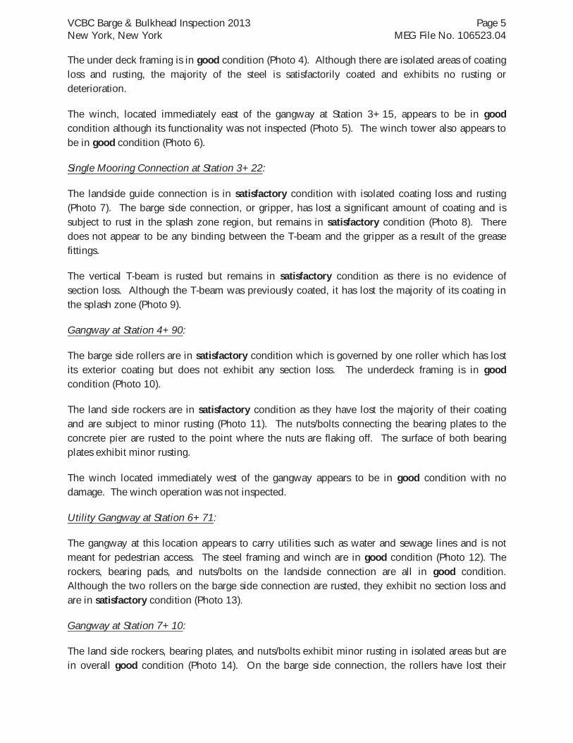
The land side rockers are subject to minor rusting but are in overall satisfactory condition (Photo 2). All of the nuts/bolts connecting the roller bearing plates to the concrete substructure are rusted to the point that the nuts are flaking off. Both of the roller bearing plates are coated with rust but not to the point of structural deficiency. The barge side rollers are in good condition although one is subject to minor rusting as a result of its deteriorated coating (Photo 3).
VCBC Barge & Bulkhead Inspection 2013 Page 5 New York, New York MEG File No. 106523.04
The under deck framing is in good condition (Photo 4). Although there are isolated areas of coating loss and rusting, the majority of the steel is satisfactorily coated and exhibits no rusting or deterioration.
The winch, located immediately east of the gangway at Station 3+15, appears to be in good condition although its functionality was not inspected (Photo 5). The winch tower also appears to be in good condition (Photo 6).
Single Mooring Connection at Station 3+22:
The landside guide connection is in satisfactory condition with isolated coating loss and rusting (Photo 7). The barge side connection, or gripper, has lost a significant amount of coating and is subject to rust in the splash zone region, but remains in satisfactory condition (Photo 8). There does not appear to be any binding between the T-beam and the gripper as a result of the grease fittings.
The vertical T-beam is rusted but remains in satisfactory condition as there is no evidence of section loss. Although the T-beam was previously coated, it has lost the majority of its coating in the splash zone (Photo 9).
Gangway at Station 4+90:
The barge side rollers are in satisfactory condition which is governed by one roller which has lost its exterior coating but does not exhibit any section loss. The underdeck framing is in good condition (Photo 10).
The land side rockers are in satisfactory condition as they have lost the majority of their coating and are subject to minor rusting (Photo 11). The nuts/bolts connecting the bearing plates to the concrete pier are rusted to the point where the nuts are flaking off. The surface of both bearing plates exhibit minor rusting.
The winch located immediately west of the gangway appears to be in good condition with no damage. The winch operation was not inspected.
Utility Gangway at Station 6+71:
The gangway at this location appears to carry utilities such as water and sewage lines and is not meant for pedestrian access. The steel framing and winch are in good condition (Photo 12). The rockers, bearing pads, and nuts/bolts on the landside connection are all in good condition. Although the two rollers on the barge side connection are rusted, they exhibit no section loss and are in satisfactory condition (Photo 13).
Gangway at Station 7+10:
The land side rockers, bearing plates, and nuts/bolts exhibit minor rusting in isolated areas but are in overall good condition (Photo 14). On the barge side connection, the rollers have lost their
VCBC Barge & Bulkhead Inspection 2013 Page 6 New York, New York MEG File No. 106523.04
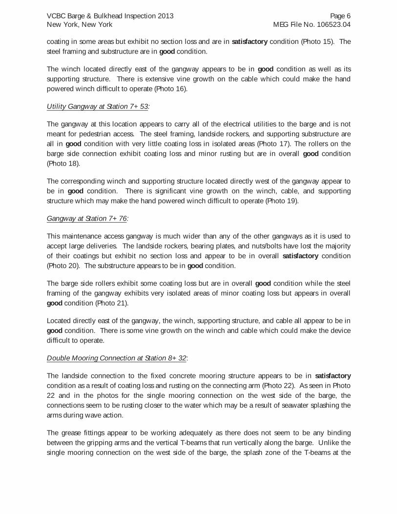
coating in some areas but exhibit no section loss and are in satisfactory condition (Photo 15). The steel framing and substructure are in good condition.
The winch located directly east of the gangway appears to be in good condition as well as its supporting structure. There is extensive vine growth on the cable which could make the hand powered winch difficult to operate (Photo 16).
Utility Gangway at Station 7+53:
The gangway at this location appears to carry all of the electrical utilities to the barge and is not meant for pedestrian access. The steel framing, landside rockers, and supporting substructure are all in good condition with very little coating loss in isolated areas (Photo 17). The rollers on the barge side connection exhibit coating loss and minor rusting but are in overall good condition (Photo 18).
The corresponding winch and supporting structure located directly west of the gangway appear to be in good condition. There is significant vine growth on the winch, cable, and supporting structure which may make the hand powered winch difficult to operate (Photo 19).
Gangway at Station 7+76:
This maintenance access gangway is much wider than any of the other gangways as it is used to accept large deliveries. The landside rockers, bearing plates, and nuts/bolts have lost the majority of their coatings but exhibit no section loss and appear to be in overall satisfactory condition (Photo 20). The substructure appears to be in good condition.
The barge side rollers exhibit some coating loss but are in overall good condition while the steel framing of the gangway exhibits very isolated areas of minor coating loss but appears in overall good condition (Photo 21).
Located directly east of the gangway, the winch, supporting structure, and cable all appear to be in good condition. There is some vine growth on the winch and cable which could make the device difficult to operate.
Double Mooring Connection at Station 8+32:
The landside connection to the fixed concrete mooring structure appears to be in satisfactory condition as a result of coating loss and rusting on the connecting arm (Photo 22). As seen in Photo 22 and in the photos for the single mooring connection on the west side of the barge, the connections seem to be rusting closer to the water which may be a result of seawater splashing the arms during wave action.
The grease fittings appear to be working adequately as there does not seem to be any binding between the gripping arms and the vertical T-beams that run vertically along the barge. Unlike the single mooring connection on the west side of the barge, the splash zone of the T-beams at the
VCBC Barge & Bulkhead Inspection 2013 Page 7 New York, New York MEG File No. 106523.04
double mooring connection still have their coatings and only exhibit minor rust stains, thus they are in good condition (Photo 23).
Pile Supported Platform from Station 8+00 to 9+48
The pile supported platform located on the east side of the VCBC site is approximately 50 ft long consisting of an asphalt topping, concrete slab, concrete pile caps, and steel pipe piles (Photo 24). A steel sheet pile cut off wall is in place at the northern extent of the platform.
The asphalt, concrete slab, and concrete pile caps appear to be in good condition. The steel sheet pile bulkhead exhibits some corrosion in the tidal zone but appears to be in satisfactory condition (Photo 25). The steel pipe piles exhibited blistering of the coating just below the bottom of the concrete pile caps and are in overall satisfactory condition. In general, the sheet pile bulkhead exhibited 25% coating loss while the piles exhibited 5% coating loss with blistering. The rip-rap revetment appears to be in good condition. Aside from minor and isolated areas of blistering and coating loss, the platform is in overall good condition.
4.2 BULKHEAD INVESTIGATION FINDINGS
Bulkhead from Station 0+00 to Station 9+48 Upland Findings:
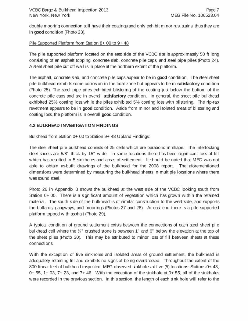
The steel sheet pile bulkhead consists of 25 cells which are parabolic in shape. The interlocking steel sheets are 5/8” thick by 15” wide. In some locations there has been significant loss of fill which has resulted in 5 sinkholes and areas of settlement. It should be noted that MEG was not able to obtain as-built drawings of the bulkhead for the 2008 report. The aforementioned dimensions were determined by measuring the bulkhead sheets in multiple locations where there was sound steel.
Photo 26 in Appendix B shows the bulkhead at the west side of the VCBC looking south from Station 0+00. There is a significant amount of vegetation which has grown within the retained material. The south side of the bulkhead is of similar construction to the west side, and supports the bollards, gangways, and moorings (Photos 27 and 28). At east end there is a pile supported platform topped with asphalt (Photo 29).
A typical condition of ground settlement exists between the connections of each steel sheet pile bulkhead cell where the ¾” crushed stone is between 1” and 6” below the elevation at the top of the sheet piles (Photo 30). This may be attributed to minor loss of fill between sheets at these connections.
With the exception of five sinkholes and isolated areas of ground settlement, the bulkhead is adequately retaining fill and exhibits no signs of being overstressed. Throughout the extent of the 800 linear feet of bulkhead inspected, MEG observed sinkholes at five (5) locations: Stations 0+43, 0+55, 1+03, 7+23, and 7+46. With the exception of the sinkhole at 0+55, all of the sinkholes were recorded in the previous section. In this section, the length of each sink hole will refer to the
VCBC Barge & Bulkhead Inspection 2013 Page 8 New York, New York MEG File No. 106523.04
dimension parallel to the bulkhead while the width will describe the dimension extending landward from the bulkhead.
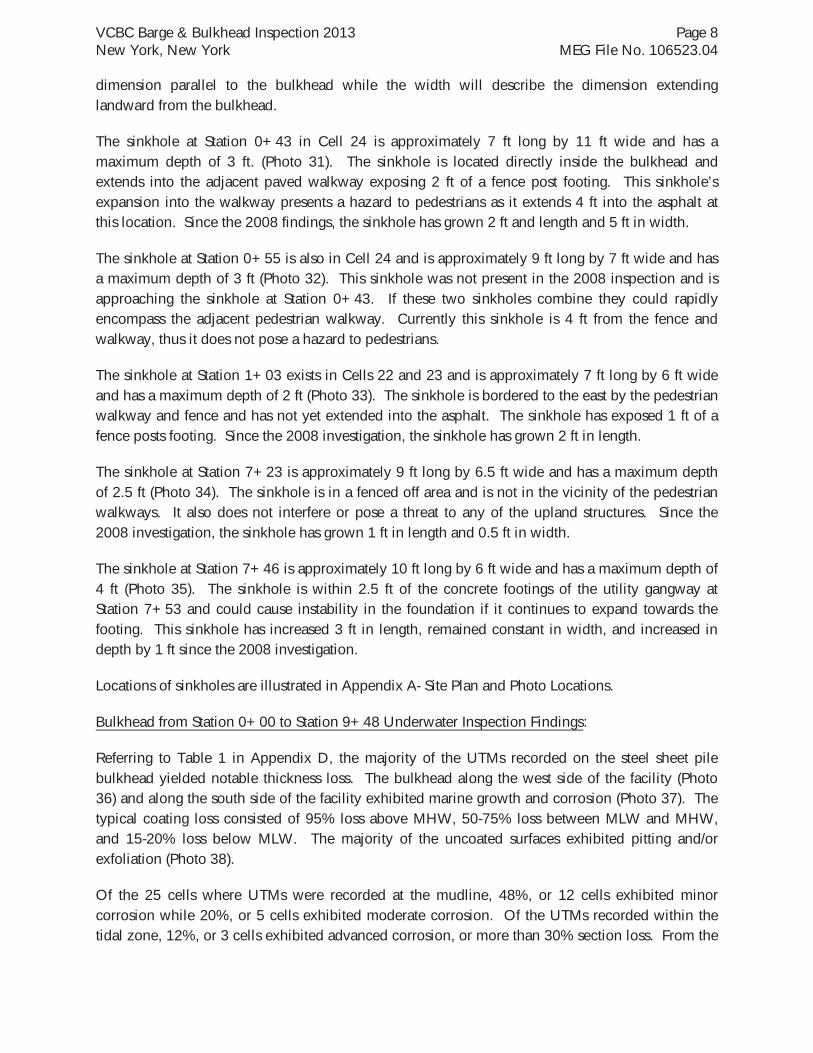
The sinkhole at Station 0+43 in Cell 24 is approximately 7 ft long by 11 ft wide and has a maximum depth of 3 ft. (Photo 31). The sinkhole is located directly inside the bulkhead and extends into the adjacent paved walkway exposing 2 ft of a fence post footing. This sinkhole’s expansion into the walkway presents a hazard to pedestrians as it extends 4 ft into the asphalt at this location. Since the 2008 findings, the sinkhole has grown 2 ft and length and 5 ft in width.
The sinkhole at Station 0+55 is also in Cell 24 and is approximately 9 ft long by 7 ft wide and has a maximum depth of 3 ft (Photo 32). This sinkhole was not present in the 2008 inspection and is approaching the sinkhole at Station 0+43. If these two sinkholes combine they could rapidly encompass the adjacent pedestrian walkway. Currently this sinkhole is 4 ft from the fence and walkway, thus it does not pose a hazard to pedestrians.
The sinkhole at Station 1+03 exists in Cells 22 and 23 and is approximately 7 ft long by 6 ft wide and has a maximum depth of 2 ft (Photo 33). The sinkhole is bordered to the east by the pedestrian walkway and fence and has not yet extended into the asphalt. The sinkhole has exposed 1 ft of a fence posts footing. Since the 2008 investigation, the sinkhole has grown 2 ft in length.
The sinkhole at Station 7+23 is approximately 9 ft long by 6.5 ft wide and has a maximum depth of 2.5 ft (Photo 34). The sinkhole is in a fenced off area and is not in the vicinity of the pedestrian walkways. It also does not interfere or pose a threat to any of the upland structures. Since the 2008 investigation, the sinkhole has grown 1 ft in length and 0.5 ft in width.
The sinkhole at Station 7+46 is approximately 10 ft long by 6 ft wide and has a maximum depth of 4 ft (Photo 35). The sinkhole is within 2.5 ft of the concrete footings of the utility gangway at Station 7+53 and could cause instability in the foundation if it continues to expand towards the footing. This sinkhole has increased 3 ft in length, remained constant in width, and increased in depth by 1 ft since the 2008 investigation.
Locations of sinkholes are illustrated in Appendix A- Site Plan and Photo Locations.
Bulkhead from Station 0+00 to Station 9+48 Underwater Inspection Findings:
Referring to Table 1 in Appendix D, the majority of the UTMs recorded on the steel sheet pile bulkhead yielded notable thickness loss. The bulkhead along the west side of the facility (Photo 36) and along the south side of the facility exhibited marine growth and corrosion (Photo 37). The typical coating loss consisted of 95% loss above MHW, 50-75% loss between MLW and MHW, and 15-20% loss below MLW. The majority of the uncoated surfaces exhibited pitting and/or exfoliation (Photo 38).
Of the 25 cells where UTMs were recorded at the mudline, 48%, or 12 cells exhibited minor corrosion while 20%, or 5 cells exhibited moderate corrosion. Of the UTMs recorded within the tidal zone, 12%, or 3 cells exhibited advanced corrosion, or more than 30% section loss. From the
VCBC Barge & Bulkhead Inspection 2013 Page 9 New York, New York MEG File No. 106523.04
UTM data, there is widespread areas of minor section loss near the mudline of the steel sheet pile bulkhead and localized areas of advanced corrosion within the tidal zone.
As stated in the upland conditions survey portion of this report, there are five sinkholes adjacent the sheet pile bulkhead, all of which are directly inland of the bulkhead.
Referring to the 2008 report, there is a hole in Cell 2 at Station 7+46 which corresponds to a sinkhole at the same location. This sinkhole is most likely the reason for the loss of fill in this location.
In Cell 3 the diver measured a 3.5’L x ¾”W crack at the knuckle of sheets 15 and 16 which corresponds to the sinkhole at Station 7+23. The crack begins at the mudline and extends 3.5’ toward the top of the bulkhead. Referring to the 2008 report, this hole has not expanded although the sinkhole at the same location has expanded in length and width.
At Cell 22, or Station 1+03, there is a 5”H x 3.5” W hole approximately 3.5’ above the mudline which penetrates through the steel sheet (Photo 39). This hole has expanded 1” in height and ½” in width since the 2008 report. Likewise, the sinkhole at this location has expanded 2’ in length along the bulkhead.
Between Cells 24 and 25, or Station 0+43, there is a hole which is 13” in height and 3” wide. This hole had remained constant in width but has grown 10” in height since the 2008 report. The hole in the steel sheet pile bulkhead at this location is most likely the cause of the two sinkholes at this location. The sinkhole at station 0+55 did not exist during the 2008 report and no additional holes were discovered in the bulkhead. The sinkhole at Station 0+43 has expanded 2 ft in length and 5 ft in width since the 2008 inspection.
Along the length of the sheet pile bulkhead there are several outfalls (Photo 40). Cell 14 contains four outfall penetrations which are approximately 12” in diameter. One of these outfalls does not contain an outfall pipe and displays a stone fill.
Overall, the steel sheet pile bulkhead is in poor condition which is governed by the areas of advanced corrosion, widespread loss of coating, deterioration through the thickness of the steel, and existence of five sinkholes directly inside the bulkhead. Refer to Drawing SK-1 for an overview of deficiencies along the length of the bulkhead.
4.3 BARGE INSPECTION FINDINGS
Please refer to Data Tables 1 and 2 in Appendix D of the report for the damage grade of steel at various locations along the hull of the barge. All of the measurements and damage grades conform to the New York City Economic Development Inspection Guidelines Manual. The steel grade descriptions are attached for reference in Appendix E of this report.
A total of 96 UTMs were recorded along the bottom, or keel of the barge. Based on the UTM Data Tables, the keel is in overall satisfactory condition with only three locations exhibiting minor
VCBC Barge & Bulkhead Inspection 2013 Page 10 New York, New York MEG File No. 106523.04
corrosion. Station 2+25, 1+00 exhibited the greatest amount of corrosion, measuring at 11.9% thickness loss which is within the minor damage grade window of -3.5% to -15% thickness loss.
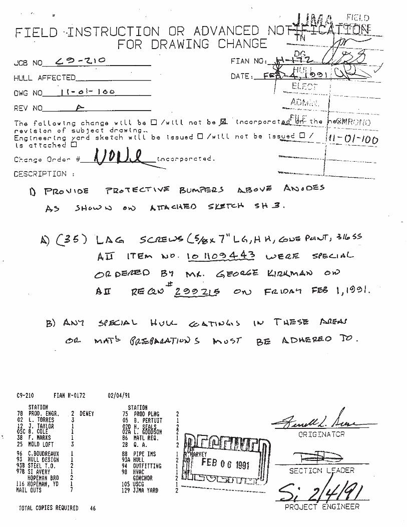
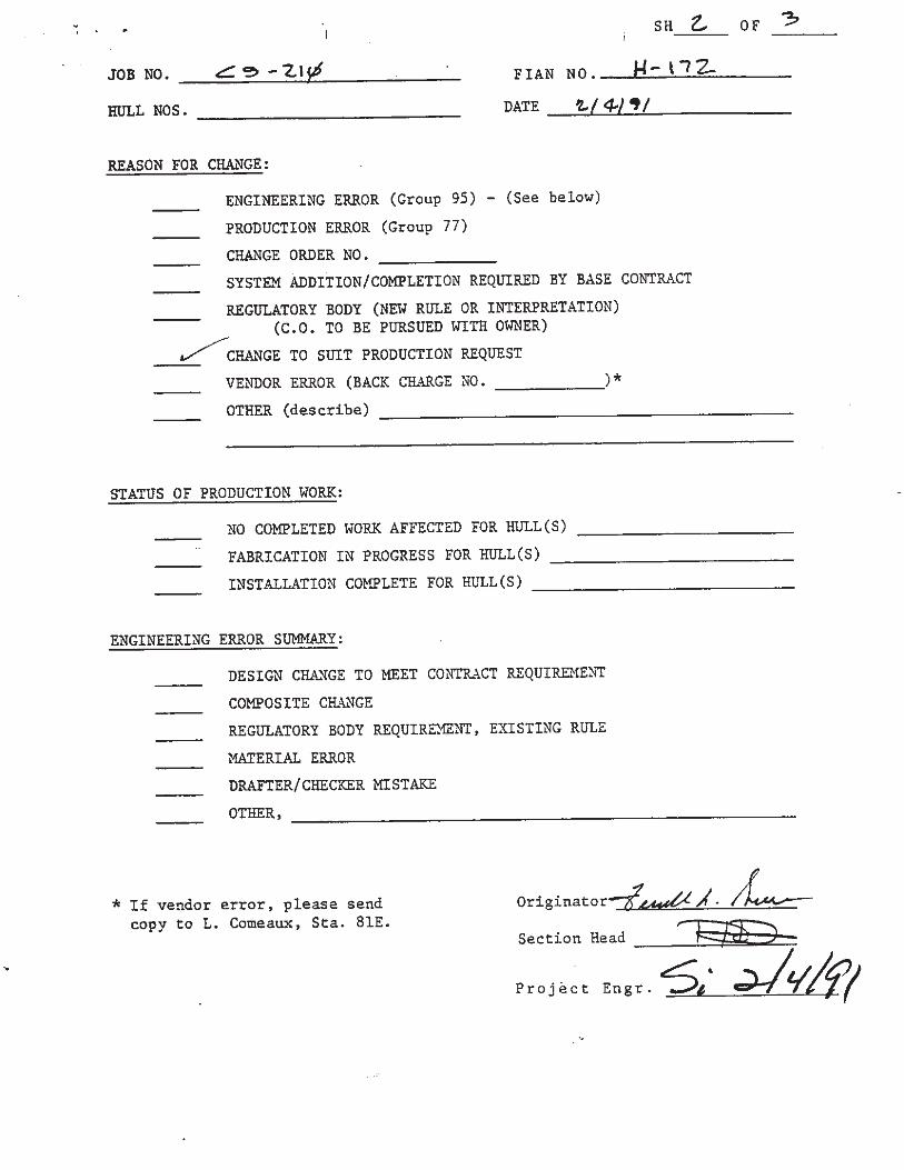
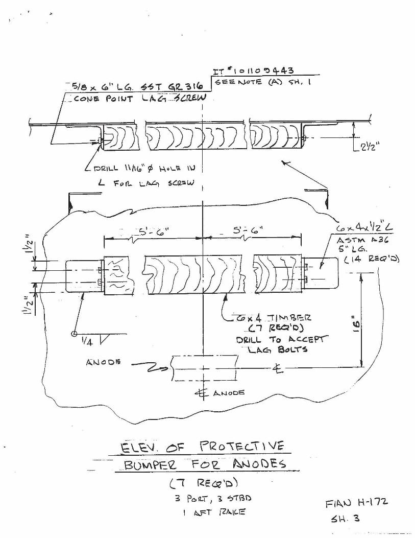
In general, the bottom of the barge was subject to significant marine growth. This marine growth can easily be removed and poses no threat to the structural soundness of the steel hull. The protective coating was observed to be intact in the cleaned areas where UTMs were recorded. As a result of the VCBC containing an impressed current cathodic protection system, MEG divers were unable to test the system’s functionality although it appeared to be working adequately (Photo 41). As per the 2008 report, the timber bumpers meant to protect the cathodic protection system were severely deteriorated and missing in several locations (Photo 42). A change order dated February 4, 1991 details the timber bumpers as 11’L x 6”W x 4”D which are confined by L6” x 4” x ½” A 36 steel angles. This change order is located in Appendix H of this report.
Overall, the bottom portion of the barge or keel, is in satisfactory condition which is governed by three measurements which were within the satisfactory limits of the NYCEDC Inspection Guidelines Manual. It should be noted that many of the UTMs were greater than or equal to the design thickness.
The vertical hull plates exhibit loss of coating within the splash zone at several locations along the length of the barge, particularly on the south side (Photos 43-45). Referring to Table 2 in the Data Tables in Appendix D of this report, out of the 96 measurements taken, only three displayed minor corrosion in terms of deviation from the original design thickness. On the south side, there was one minor corrosion measurement on the bottom of the hull plate at Sta. 6+00 and another just below the water line at Sta. 5+50. On the north side there was only one minor corrosion measurement at Sta. 5+50 on the bottom of the vertical hull plate.
Overall, the vertical hull plates are in satisfactory condition which is governed by the loss of coating on many plates on the south side as well as the three measurements which yielded satisfactory results in regards to deviation from the design thickness. It should be noted that many of the measurements were greater than the design thickness.
Depth soundings recorded by MEG along the length of the barge at Stations 0+00, 0+50, and 1+25 in the north-south direction are located in Appendix C. The findings confirm that the northeastern quadrant of the barge rests on the mudline during periods of mean lower low water. On the 0+50 gridline in the north-south direction, the barge rests on the mudline starting at 3+25 and continuing to the east. On the 1+25 gridline (north-south), the barge rests on the mudline starting at 2+50 and continuing to the east. The mudline typically consists of soft loose silt. No large obstructions that would impede the vertical movement of the barge were noted during the inspection; however, a good portion of the barge rests on the soft bottom during MLLW. Siltation will continue over time and eventually this condition may become problematic.
VCBC Barge & Bulkhead Inspection 2013 Page 11 New York, New York MEG File No. 106523.04
5.0 REPAIR RECOMMENDATIONS
Upland Structure Recommendations
All of the upland components of the gangways, including the substructure, structural steel, and supports are in overall good condition, with the exception of some satisfactory elements. MEG does not recommend any repairs for these components.
The vine overgrowth on the winches appears enough to potentially inhibit the movement of the gangways. MEG recommends the removal of this overgrowth to ensure that it will not interfere with the operation of the winches.
Bulkhead Recommendations
Over the course of the upland condition inspection, MEG observed five sinkholes directly inside the steel sheet pile bulkhead. The cause of these sinkholes is likely from the loss of fill through deficiencies in the steel sheets. MEG recommends repairing holes in the sheet pile by welding steel plates to the outboard side of the bulkhead. The plates shall be a minimum ½” thick and overlap a minimum of 2” around the perimeter of the hole. Once the holes are repaired the sinkholes in the area can be filled, and the undermined pavement can be replaced.
In addition to repairing the holes, it is recommended that provisions be installed to extend the life of the bulkhead. This would include the installation of a cathodic protection system, and coating the steel sheet piles above mean low water. The cathodic protection system would consist of sacrificial aluminum anodes placed at specified increments along the full length of the bulkhead. The anodes will reduce the rate of corrosion by establishing a galvanic cell in which the anode corrodes away rather than the steel sheeting. As part of the 5 year cyclical inspection program the anodes should be inspected, and if necessary replaced when they exhibit a greater than 50 percent section loss.
Although the corrosion to the sheet pile was observed to be moderate to severe in some areas, it is not damaged to a degree that warrants complete replacement. It is extremely important however to retard the corrosion process and maintain the structure. Referring to Appendix I – Cost Estimate 1 of 2, MEG estimates that these bulkhead repairs will cost approximately $1,420,000.
Floating Barge Recommendations
At the single mooring connection, MEG observed rusting of the vertical T-beam. Although this component was given a condition grade of satisfactory, MEG recommends recoating the T-beam in the splash zone with epoxy as this is a major component in terms of the functionality of the mooring connection. MEG also recommends coating the mooring arms which have begun to lose their original coating on the bottom near the splash zone. MEG recommends these repairs as preventative measures to negate the need for larger repairs in the future.
VCBC Barge & Bulkhead Inspection 2013 Page 12 New York, New York MEG File No. 106523.04
The submerged exterior barge plating is in satisfactory condition and does not exhibit any significant section loss at this time. The coating is also in good condition and is approximately 90 percent in-tact. The only area that does exhibit a loss of protective coating is the vertical hull, at various locations above and just below the water level. MEG recommends that the uncoated areas above the water level be recoated with an epoxy-based product designed for recoating steel barges. Any uncoated areas below the water level may be left as is and should be monitored as part of the routine underwater inspection.
MEG recommends that an in depth evaluation of the impressed current cathodic protection system be performed by a corrosion specialist to verify that it is operating effectively. In addition we recommend installing recycled plastic bumpers above the cathodic protection system to replace the existing deteriorated timber. The dimensions and mounting details would remain identical to that specified in the original design sketch (Appendix E). If the original 6x4x1/2 angles are still in place and have not been corroded significantly, they may be reused. Otherwise, MEG recommends the installation of identically sized new angles. The bolts connecting the angles to the 6x4 recycled plastic posts should be stainless steel. Referring to Appendix I – Cost Estimate 1 of 2, MEG estimates that the floating barge repairs will cost approximately $235,000. MEG estimates that the total cost of the bulkhead and barge repairs will be approximately $1,655,000.
Mudline elevations recorded beneath the prison facility have confirmed that portions of the barge rest in the mud at periods of mean low water. MEG recommends that a maintenance dredging program be developed to accommodate a minimum clear space beneath the structure. A siltation study is also recommended to estimate the need for future dredging. Referring to Appendix I – Cost Estimate 2 of 2, MEG estimates that dredging to allow for a 3 ft minimum clearance at MLLW will cost approximately $4,700,000.
Appendix A – Site Plan and Photo Locations

Appendix B - Photographs
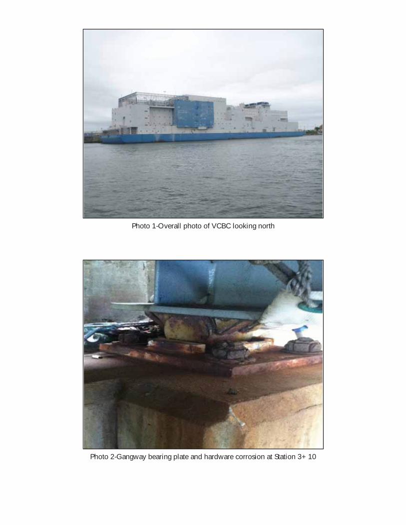
Photo 1-Overall photo of VCBC looking north
Photo 2-Gangway bearing plate and hardware corrosion at Station 3+10
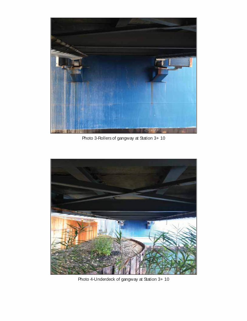
Photo 3-Rollers of gangway at Station 3+10
Photo 4-Underdeck of gangway at Station 3+10
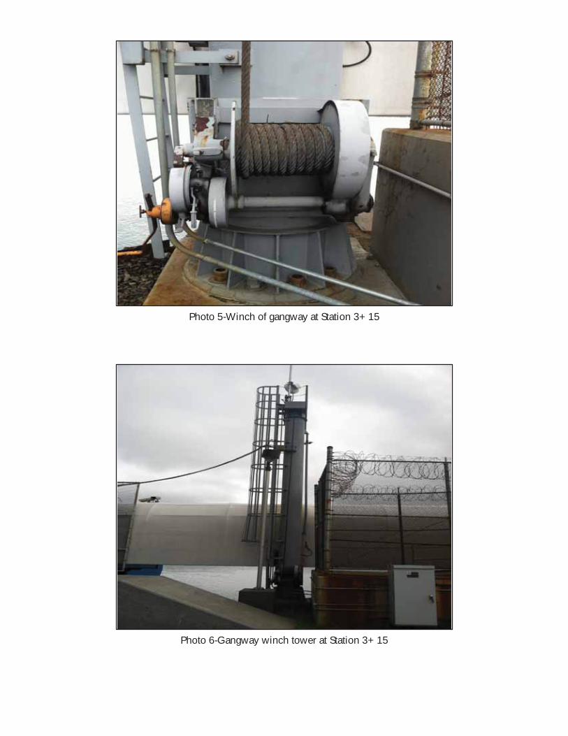
Photo 5-Winch of gangway at Station 3+15
Photo 6-Gangway winch tower at Station 3+15
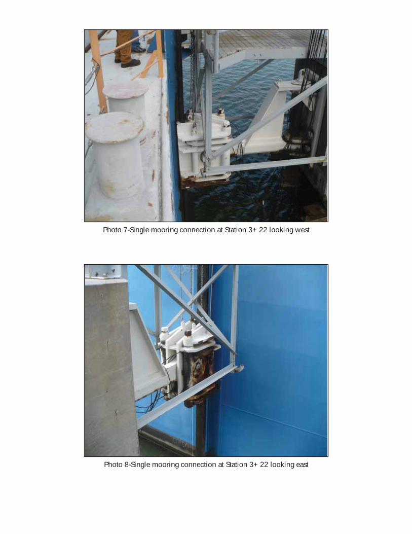
Photo 7-Single mooring connection at Station 3+22 looking west
Photo 8-Single mooring connection at Station 3+22 looking east
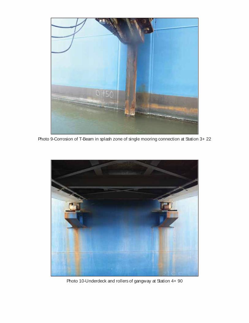
Photo 9-Corrosion of T-Beam in splash zone of single mooring connection at Station 3+22
Photo 10-Underdeck and rollers of gangway at Station 4+90
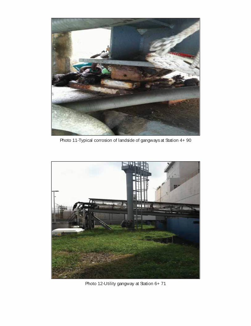
Photo 11-Typical corrosion of landside of gangways at Station 4+90
Photo 12-Utility gangway at Station 6+71
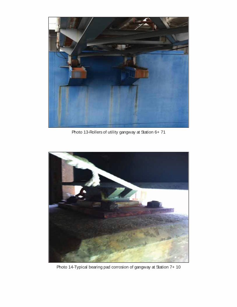
Photo 13-Rollers of utility gangway at Station 6+71
Photo 14-Typical bearing pad corrosion of gangway at Station 7+10
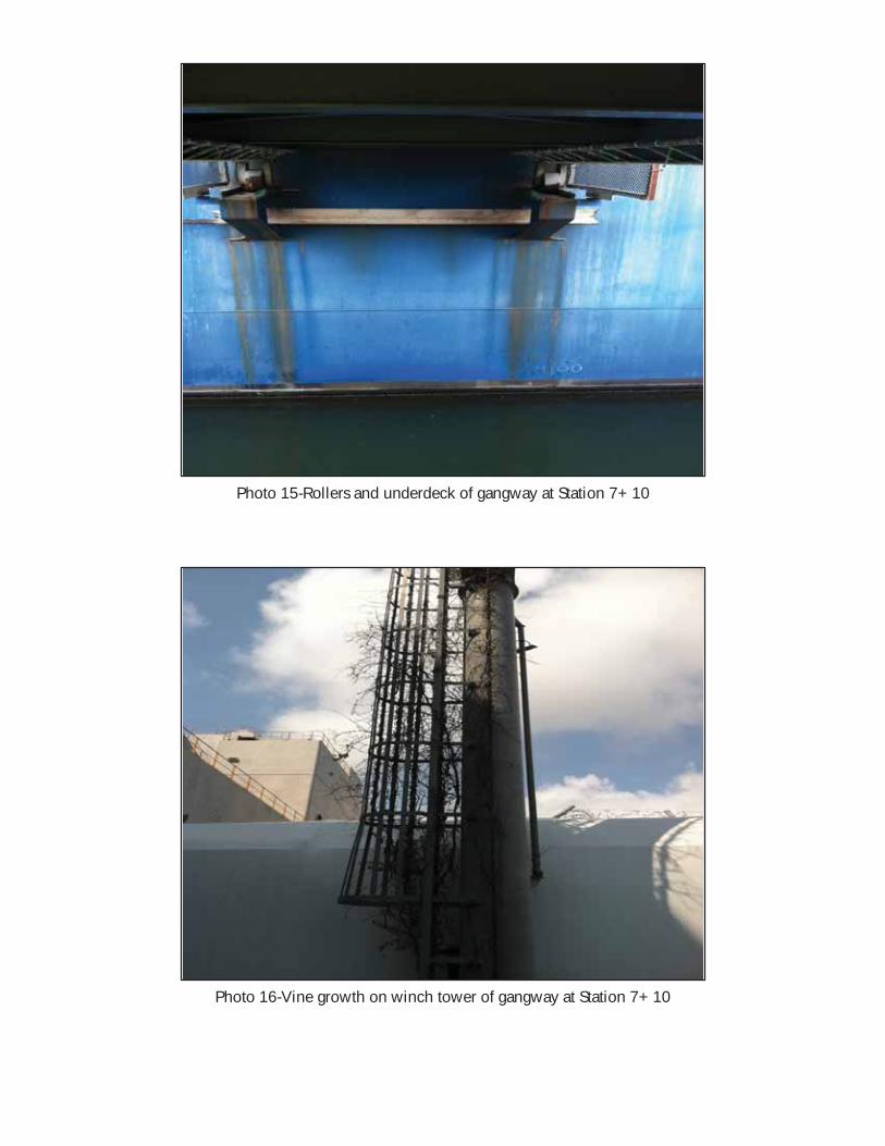
Photo 15-Rollers and underdeck of gangway at Station 7+10
Photo 16-Vine growth on winch tower of gangway at Station 7+10
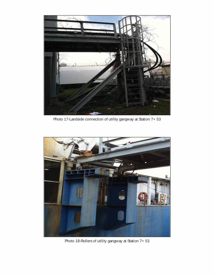
Photo 17-Landside connection of utility gangway at Station 7+53
Photo 18-Rollers of utility gangway at Station 7+53
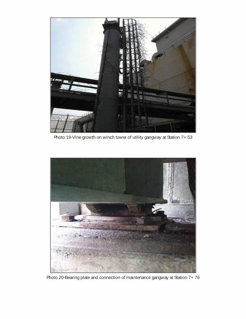
Photo 19-Vine growth on winch tower of utility gangway at Station 7+53
Photo 20-Bearing plate and connection of maintenance gangway at Station 7+76
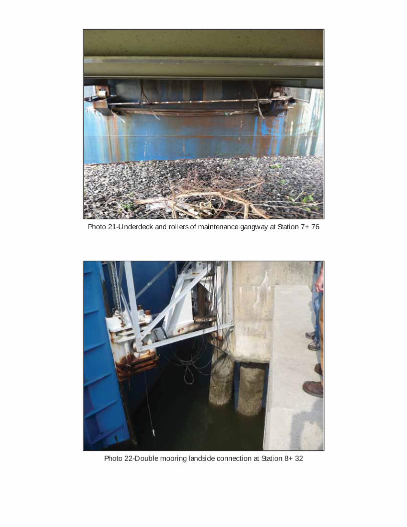
Photo 21-Underdeck and rollers of maintenance gangway at Station 7+76
Photo 22-Double mooring landside connection at Station 8+32
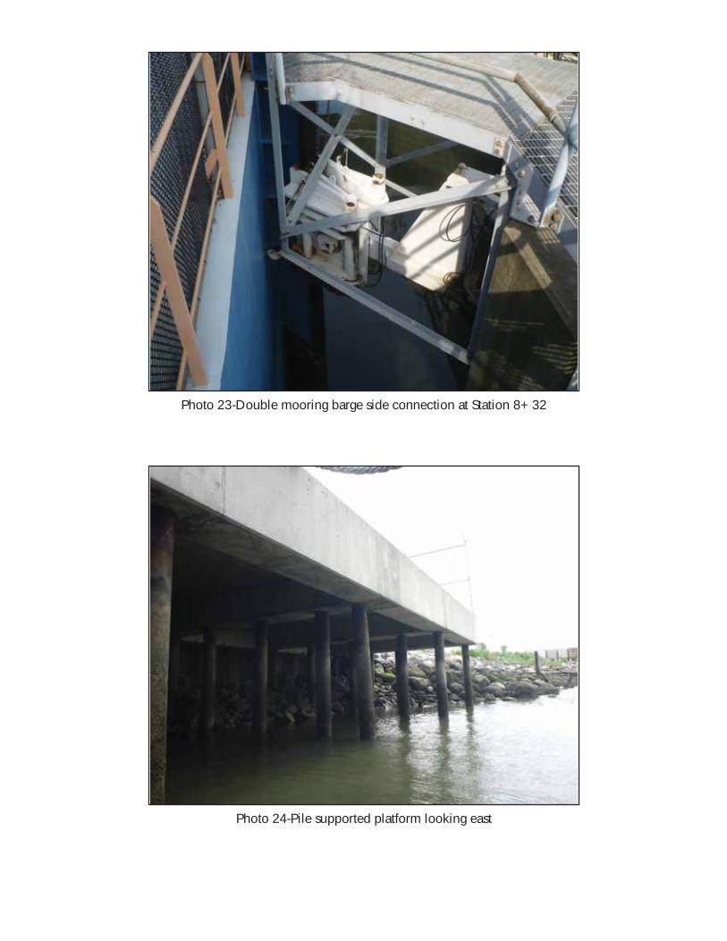
Photo 23-Double mooring barge side connection at Station 8+32
Photo 24-Pile supported platform looking east
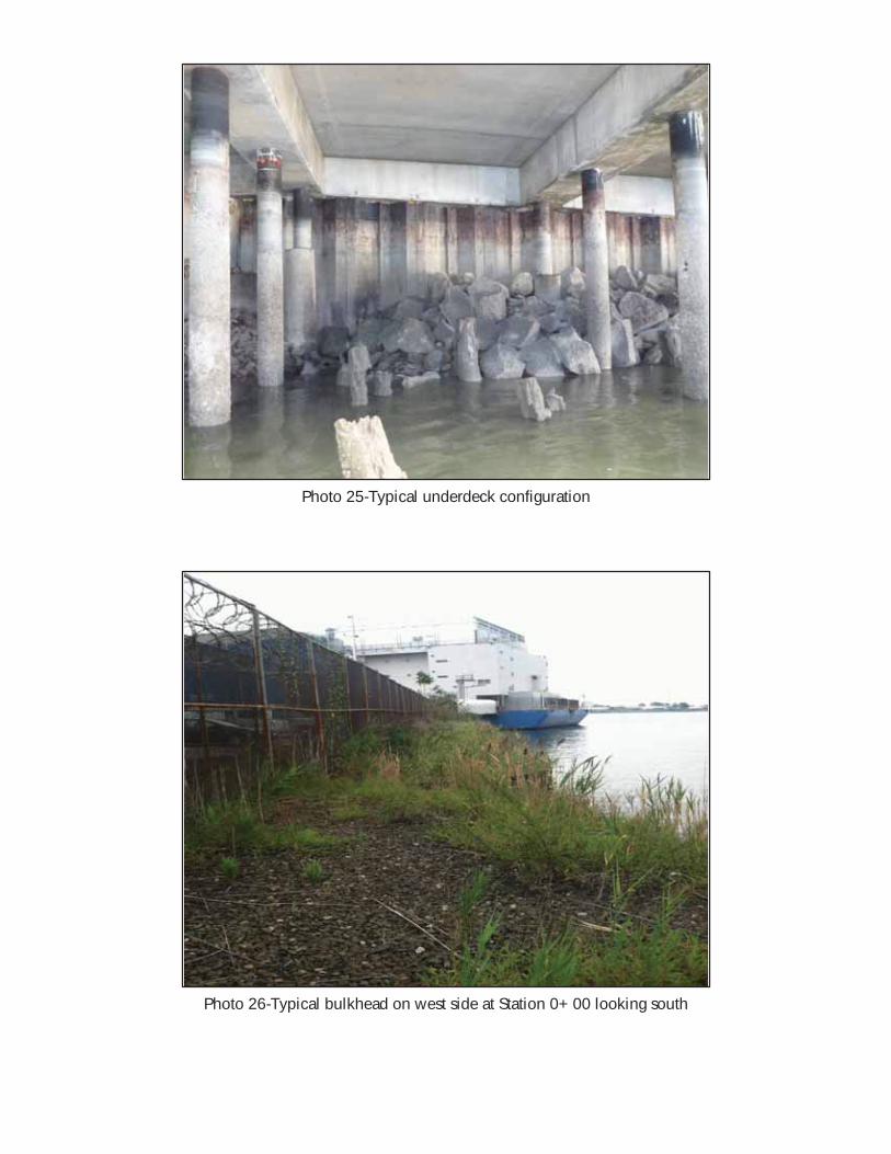
Photo 25-Typical underdeck configuration
Photo 26-Typical bulkhead on west side at Station 0+00 looking south
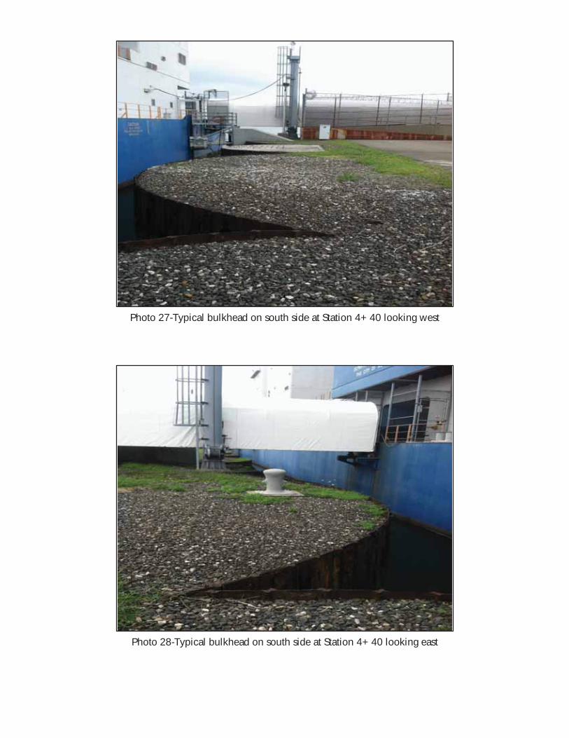
Photo 27-Typical bulkhead on south side at Station 4+40 looking west
Photo 28-Typical bulkhead on south side at Station 4+40 looking east
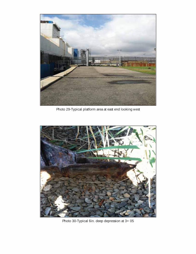
Photo 29-Typical platform area at east end looking west
Photo 30-Typical 6in. deep depression at 3+05
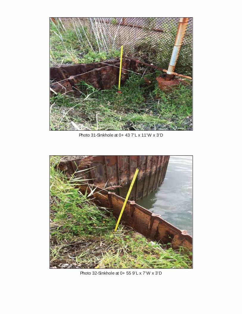
Photo 31-Sinkhole at 0+43 7'L x 11'W x 3'D
Photo 32-Sinkhole at 0+55 9'L x 7'W x 3'D
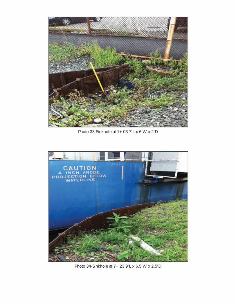
Photo 33-Sinkhole at 1+03 7'L x 6'W x 2'D
Photo 34-Sinkhole at 7+23 9'L x 6.5'W x 2.5'D
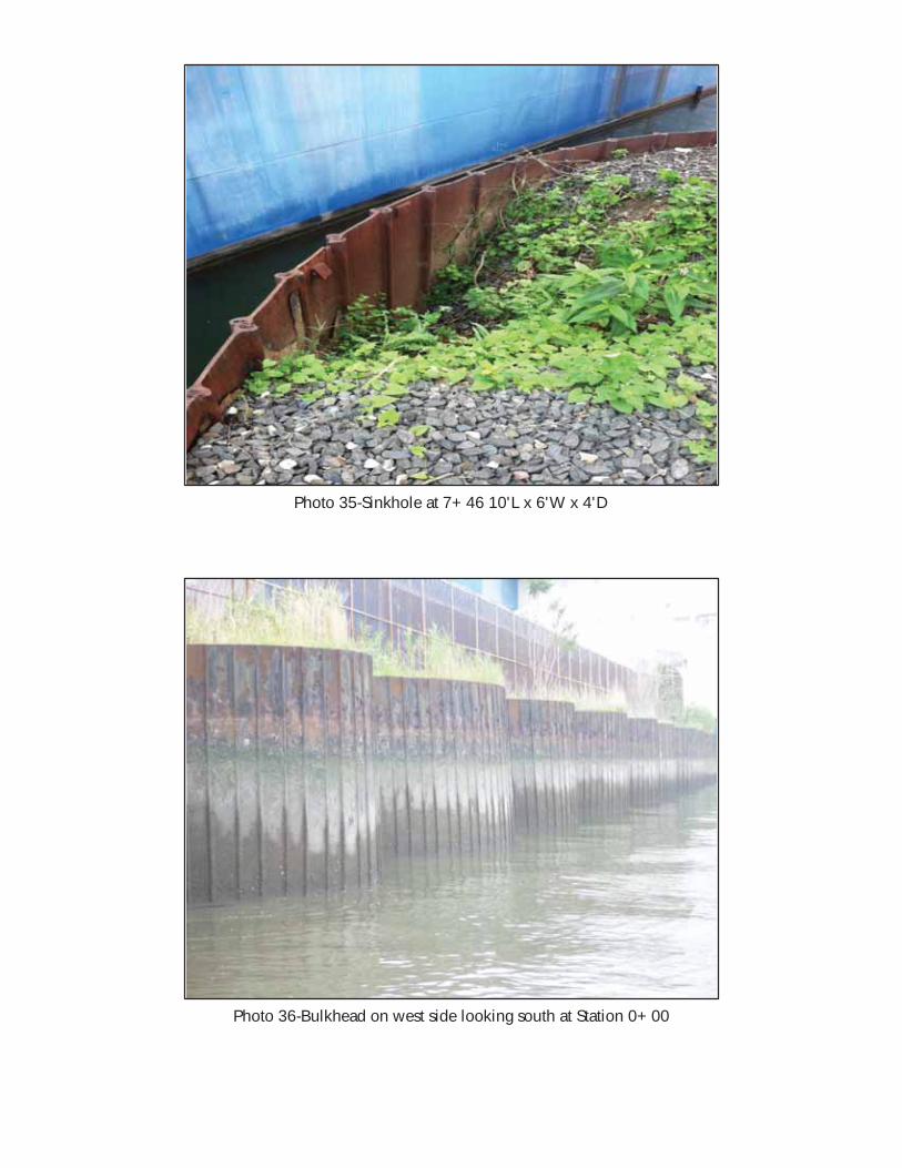
Photo 35-Sinkhole at 7+46 10'L x 6'W x 4'D
Photo 36-Bulkhead on west side looking south at Station 0+00
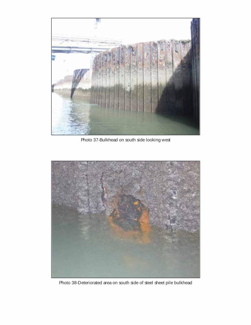
Photo 37-Bulkhead on south side looking west
Photo 38-Deteriorated area on south side of steel sheet pile bulkhead
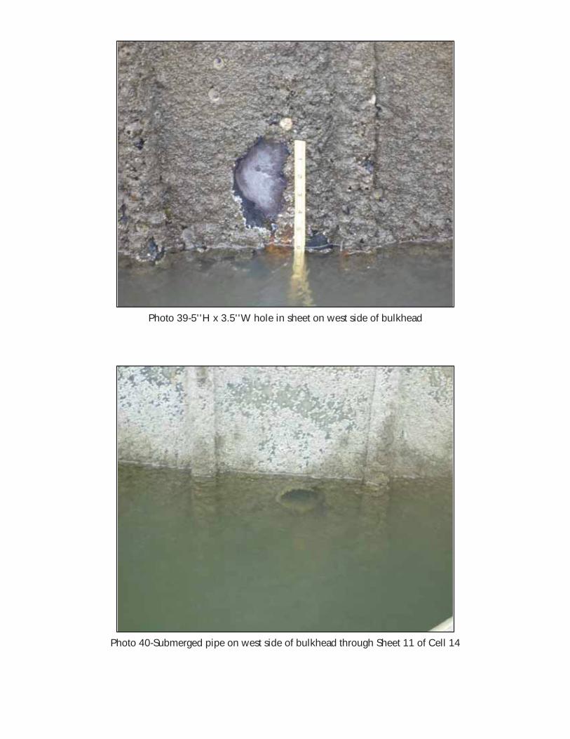
Photo 39-5''H x 3.5''W hole in sheet on west side of bulkhead
Photo 40-Submerged pipe on west side of bulkhead through Sheet 11 of Cell 14
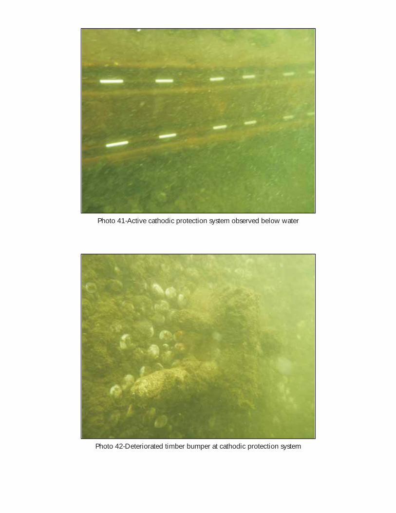
Photo 41-Active cathodic protection system observed below water
Photo 42-Deteriorated timber bumper at cathodic protection system
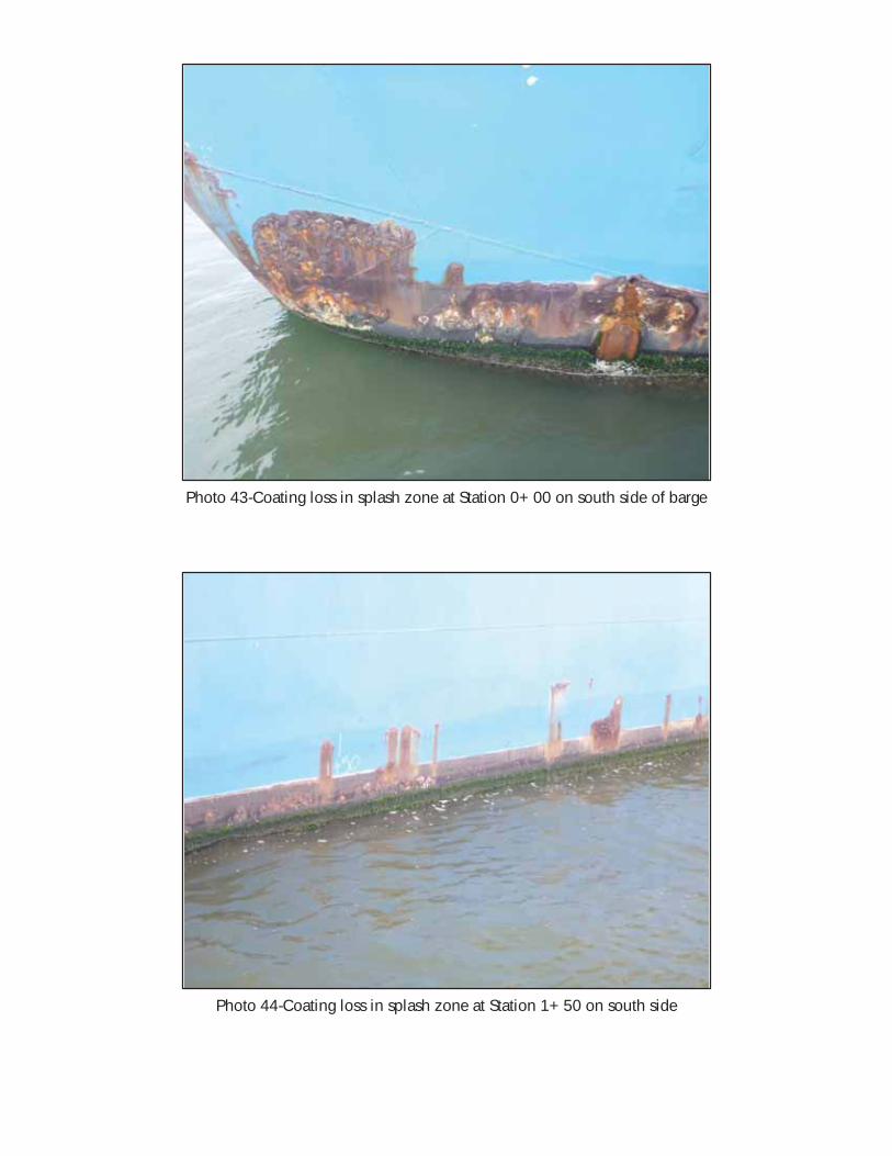
Photo 43-Coating loss in splash zone at Station 0+00 on south side of barge
Photo 44-Coating loss in splash zone at Station 1+50 on south side
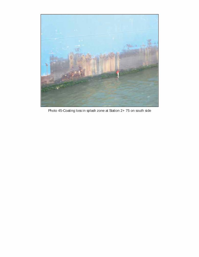
Photo 45-Coating loss in splash zone at Station 2+75 on south side

Appendix C – Drawings


Appendix D – Data Tables
PROJECT: 106523.04 - VCBC InspectionSHEET NO: 1 OF 3
CALCULATED BY: CTC DATE: 9/27/2013
CHECKED BY: DATE:
REVISIONS:
SCALE:
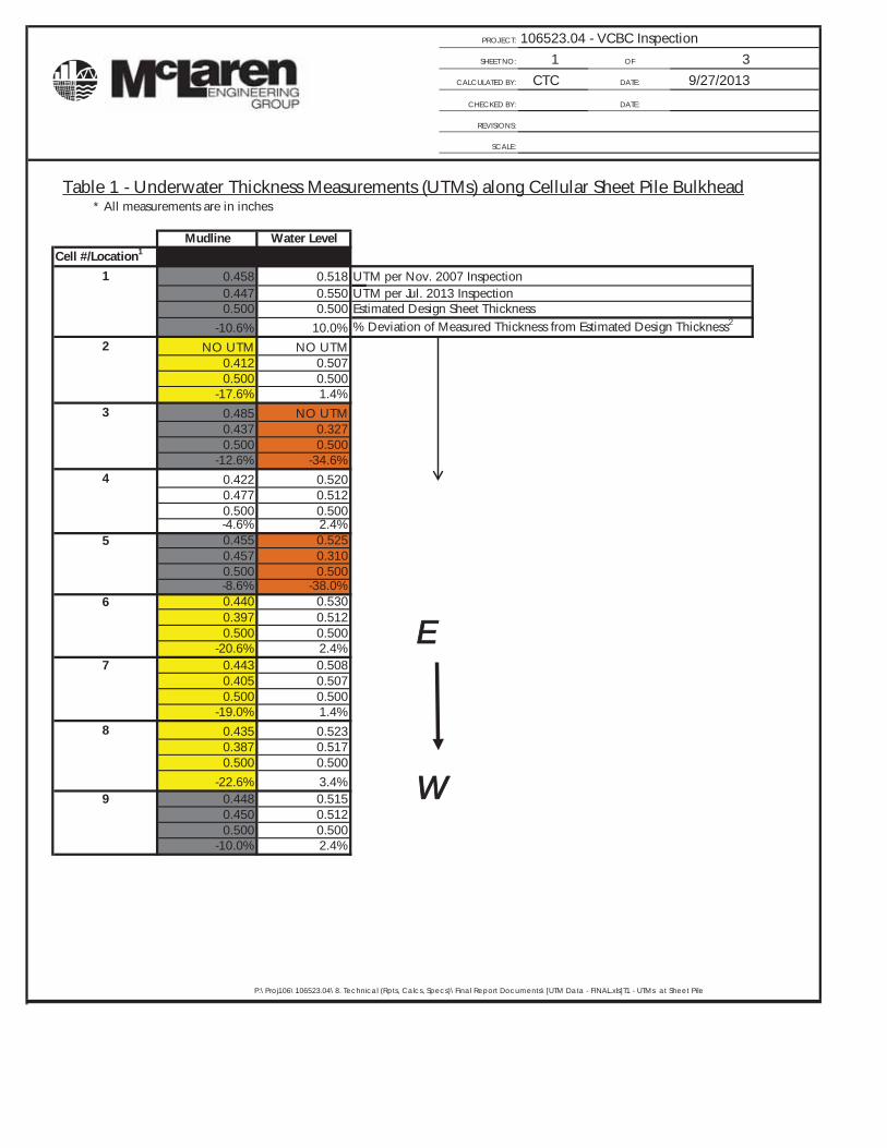
Table 1 - Underwater Thickness Measurements (UTMs) along Cellular Sheet Pile Bulkhead * All measurements are in inches
Mudline Water LevelCell #/Location1
1 0.458 0.518 UTM per Nov. 2007 Inspection0.447 0.550 UTM per Jul. 2013 Inspection0.500 0.500 Estimated Design Sheet Thickness
-10.6% 10.0% % Deviation of Measured Thickness from Estimated Design Thickness2
2 NO UTM NO UTM0.412 0.5070.500 0.500
-17.6% 1.4%3 0.485 NO UTM
0.437 0.3270.500 0.500
-12.6% -34.6%4 0.422 0.520
0.477 0.5120.500 0.500-4.6% 2.4%
5 0.455 0.5250.457 0.3100.500 0.500-8.6% -38.0%
6 0.440 0.5300.397 0.5120.500 0.500
-20.6% 2.4%7 0.443 0.508
0.405 0.5070.500 0.500
-19.0% 1.4%8 0.435 0.523
0.387 0.5170.500 0.500
-22.6% 3.4%9 0.448 0.515
0.450 0.5120.500 0.500
-10.0% 2.4%
P:\Proj106\106523.04\8. Technical (Rpts, Calcs, Specs)\Final Report Documents\[UTM Data - FINAL.xls]T1 - UTMs at Sheet Pile
E
W
PROJECT: 106523.04 - VCBC InspectionSHEET NO: 2 OF 3
CALCULATED BY: CTC DATE: 9/27/2013
CHECKED BY: DATE:
REVISIONS:
SCALE:
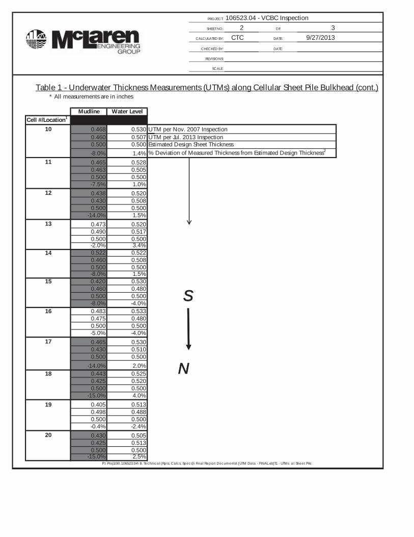
Table 1 - Underwater Thickness Measurements (UTMs) along Cellular Sheet Pile Bulkhead (cont.) * All measurements are in inches
Mudline Water LevelCell #/Location1
10 0.468 0.530 UTM per Nov. 2007 Inspection0.460 0.507 UTM per Jul. 2013 Inspection0.500 0.500 Estimated Design Sheet Thickness-8.0% 1.4% % Deviation of Measured Thickness from Estimated Design Thickness2
11 0.465 0.5280.463 0.5050.500 0.500-7.5% 1.0%
12 0.438 0.5200.430 0.5080.500 0.500
-14.0% 1.5%13 0.473 0.520
0.490 0.5170.500 0.500-2.0% 3.4%
14 0.522 0.5220.460 0.5080.500 0.500-8.0% 1.5%
15 0.420 0.5300.460 0.4800.500 0.500-8.0% -4.0%
16 0.483 0.5330.475 0.4800.500 0.500-5.0% -4.0%
17 0.465 0.5300.430 0.5100.500 0.500
-14.0% 2.0%18 0.443 0.525
0.425 0.5200.500 0.500
-15.0% 4.0%
19 0.405 0.5130.498 0.4880.500 0.500-0.4% -2.4%
20 0.430 0.5050.425 0.5130.500 0.500
-15.0% 2.5%P:\Proj106\106523.04\8. Technical (Rpts, Calcs, Specs)\Final Report Documents\[UTM Data - FINAL.xls]T1 - UTMs at Sheet Pile
S
N
PROJECT: 106523.04 - VCBC InspectionSHEET NO: 3 OF 3
CALCULATED BY: CTC DATE: 9/27/2013
CHECKED BY: DATE:
REVISIONS:
SCALE:
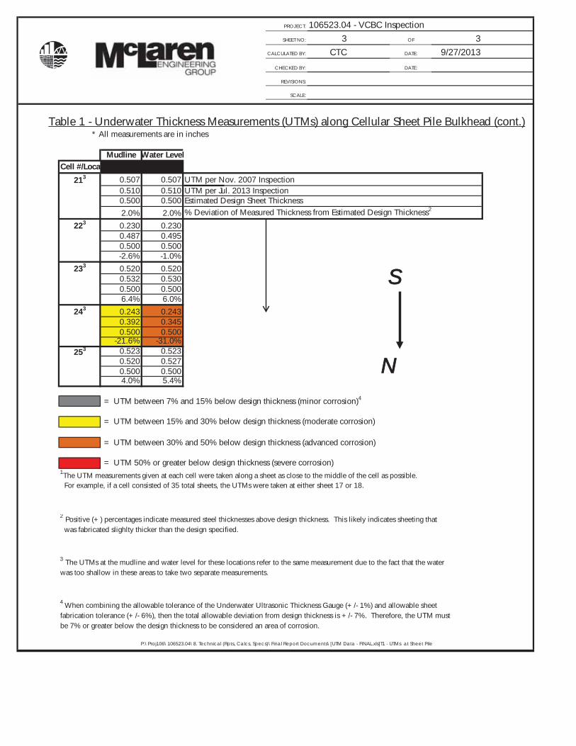
Table 1 - Underwater Thickness Measurements (UTMs) along Cellular Sheet Pile Bulkhead (cont.) * All measurements are in inches
Mudline Water LevelCell #/Location1
213 0.507 0.507 UTM per Nov. 2007 Inspection0.510 0.510 UTM per Jul. 2013 Inspection0.500 0.500 Estimated Design Sheet Thickness2.0% 2.0% % Deviation of Measured Thickness from Estimated Design Thickness2
223 0.230 0.2300.487 0.4950.500 0.500-2.6% -1.0%
233 0.520 0.5200.532 0.5300.500 0.5006.4% 6.0%
243 0.243 0.2430.392 0.3450.500 0.500
-21.6% -31.0%253 0.523 0.523
0.520 0.5270.500 0.5004.0% 5.4%
= UTM between 7% and 15% below design thickness (minor corrosion)4
= UTM between 15% and 30% below design thickness (moderate corrosion)
= UTM between 30% and 50% below design thickness (advanced corrosion)
= UTM 50% or greater below design thickness (severe corrosion)1The UTM measurements given at each cell were taken along a sheet as close to the middle of the cell as possible. For example, if a cell consisted of 35 total sheets, the UTMs were taken at either sheet 17 or 18.
2 Positive (+) percentages indicate measured steel thicknesses above design thickness. This likely indicates sheeting that was fabricated slighlty thicker than the design specified.
3 The UTMs at the mudline and water level for these locations refer to the same measurement due to the fact that the water was too shallow in these areas to take two separate measurements.
4 When combining the allowable tolerance of the Underwater Ultrasonic Thickness Gauge (+/- 1%) and allowable sheet fabrication tolerance (+/- 6%), then the total allowable deviation from design thickness is +/- 7%. Therefore, the UTM must be 7% or greater below the design thickness to be considered an area of corrosion.
P:\Proj106\106523.04\8. Technical (Rpts, Calcs, Specs)\Final Report Documents\[UTM Data - FINAL.xls]T1 - UTMs at Sheet Pile
S
N
PROJECT: 106523.04 - VCBC InspectionSHEET NO: 1 OF 2
CALCULATED BY: CTC DATE: 9/27/2013
CHECKED BY: DATE:
REVISIONS:
SCALE:
Table 2 - Underwater Thickness Measurements (UTMs) along Bottom*All measurements are in inches
Station 0+25 0+50 0+75 1+000+25 0.630 0.590 0.593 0.600 UTM per Nov. 2007 Inspection
0.598 0.622 0.603 0.605 UTM per Jul. 2013 Inspection0.590 0.590 0.590 0.590 Plate Thickness per Design Drawings1.4% 5.4% 2.2% 2.5% % Deviation of Measured Thickness from Design Thickness1
0+50 0.630 0.597 0.600 0.6010.617 0.608 0.598 0.6050.590 0.590 0.590 0.5904.6% 3.1% 1.4% 2.5%
0+75 0.612 0.618 0.593 0.6150.612 0.612 0.618 0.6180.590 0.590 0.590 0.5903.7% 3.7% 4.7% 4.7%
1+00 0.607 0.615 0.602 0.6000.607 0.610 0.603 0.6000.590 0.590 0.590 0.5902.9% 3.4% 2.2% 1.7%
1+25 0.607 0.608 0.602 0.613 N0.610 0.615 0.598 0.6050.590 0.590 0.590 0.5903.4% 4.2% 1.4% 2.5%
1+50 0.605 0.605 0.608 0.6200.602 0.610 0.617 0.6150.590 0.590 0.590 0.5902.0% 3.4% 4.6% 4.2%
1+75 0.613 0.617 0.627 0.6250.612 0.595 0.603 0.6030.590 0.590 0.590 0.5903.7% 0.8% 2.2% 2.2%
2+00 0.613 0.607 0.627 0.6150.618 0.620 0.617 0.6250.590 0.590 0.590 0.5904.7% 5.1% 4.6% 5.9%
2+25 0.618 0.613 0.613 0.6150.620 0.613 0.603 0.5200.590 0.590 0.590 0.5905.1% 3.9% 2.2% -11.9%
2+50 0.597 0.613 0.582 0.6000.603 0.625 0.600 0.5970.590 0.590 0.590 0.5902.2% 5.9% 1.7% 1.2%
2+75 0.615 0.625 0.605 0.6050.560 0.560 0.600 0.5970.590 0.590 0.590 0.590-5.1% -5.1% 1.7% 1.2%
3+00 0.612 0.622 0.620 0.5900.608 0.615 0.625 0.6000.590 0.590 0.590 0.5903.1% 4.2% 5.9% 1.7%
P:\Proj106\106523.04\8. Technical (Rpts, Calcs, Specs)\Final Report Documents\[UTM Data - FINAL.xls]T2 - UTMs at Keel
PROJECT: 106523.04 - VCBC InspectionSHEET NO: 2 OF 2
CALCULATED BY: CTC DATE: 9/27/2013
CHECKED BY: DATE:
REVISIONS:
SCALE:
Table 2 - Underwater Thickness Measurements (UTMs) along Bottom (cont.) *All measurements are in inches
Station 0+25 0+50 0+75 1+003+25 0.620 0.618 0.625 0.600 UTM per Nov. 2007 Inspection
0.618 0.617 0.600 0.588 UTM per Jul. 2013 Inspection0.590 0.590 0.590 0.590 Plate Thickness per Design Drawings4.7% 4.6% 1.7% -0.3% % Deviation of Measured Thickness from Design Thickness1
3+50 0.613 0.618 0.608 0.6050.608 0.608 0.618 0.6130.590 0.590 0.590 0.5903.1% 3.1% 4.7% 3.9%
3+75 0.613 0.618 0.608 0.6150.612 0.612 0.610 0.6120.590 0.590 0.590 0.5903.7% 3.7% 3.4% 3.7%
4+00 0.622 0.620 0.638 0.5980.600 0.610 0.588 0.6050.590 0.590 0.590 0.5901.7% 3.4% -0.3% 2.5%
4+25 0.627 0.585 0.600 0.597 N0.620 0.585 0.615 0.6080.590 0.590 0.590 0.5905.1% -0.8% 4.2% 3.1%
4+50 0.625 0.628 0.612 0.6080.632 0.613 0.608 0.607 = UTM between 3.5% and 15% below design thickness (minor corrosion)2
0.590 0.590 0.590 0.5907.1% 3.9% 3.1% 2.9%
4+75 0.623 0.613 0.605 0.6230.622 0.602 0.607 0.6100.590 0.590 0.590 0.5905.4% 2.0% 2.9% 3.4%
5+00 0.595 0.625 0.602 0.6180.603 0.610 0.600 0.6130.590 0.590 0.590 0.5902.2% 3.4% 1.7% 3.9%
5+25 0.595 0.625 0.595 0.6050.612 0.597 0.612 0.6150.590 0.590 0.590 0.5903.7% 1.2% 3.7% 4.2%
5+50 0.593 0.622 0.608 0.5950.615 0.605 0.598 0.5880.590 0.590 0.590 0.5904.2% 2.5% 1.4% -0.3%
5+75 0.613 0.608 0.602 0.6400.618 0.615 0.603 0.6020.590 0.590 0.590 0.5904.7% 4.2% 2.2% 2.0%
6+00 0.633 0.605 0.605 0.6650.625 0.618 0.618 0.6030.590 0.590 0.590 0.5905.9% 4.7% 4.7% 2.2%
P:\Proj106\106523.04\8. Technical (Rpts, Calcs, Specs)\Final Report Documents\[UTM Data - FINAL.xls]T2 - UTMs at Keel
1 Positive (+) percentages indicate measured steel thicknesses above design thickness. This likely indicates plating that was fabricated slightly thicker
2 When combining the allowable tolerance of the Underwater Ultrasonic Thickness Gauge (+/- 1%) and allowable plate fabrication
PROJECT: 106523.04 - VCBC InspectionSHEET NO: 1 OF 3
CALCULATED BY: CTC DATE: 9/27/2013
CHECKED BY: DATE:
REVISIONS:
SCALE:
Table 2 - Underwater Thickness Measurements (UTMs) along Submerged Vertical Hull Plate *All measurements are in inches
StationBottom3 Water Level4 Bottom Water Level
0+25 0.667 0.600 0.672 0.602 UTM per Nov. 2007 Inspection0.677 0.668 0.680 0.670 UTM per Jul. 2013 Inspection0.650 0.590 0.650 0.590 Plate Thickness per Design Drawings4.2% 13.2% 4.6% 13.6% % Deviation of Measured Thickness from Design Thickness1
0+50 NO UTM2 NO UTM NO UTM NO UTM0.662 0.612 0.633 0.608
0.65 0.59 0.650 0.5901.8% 3.7% -2.6% 3.1%
0+75 0.647 0.602 0.632 0.6020.668 0.597 0.638 0.6000.650 0.590 0.650 0.590-0.5% 2.0% -2.8% 2.0%
1+00 0.655 0.605 NO UTM NO UTM0.647 0.597 0.635 0.6130.650 0.590 0.650 0.590-0.5% 1.2% -2.3% 3.9%
1+25 0.672 0.618 0.658 0.6120.662 0.617 0.650 0.6080.650 0.590 0.650 0.5901.8% 4.6% 0.0% 3.1%
1+50 0.650 0.605 0.653 0.6030.638 0.597 0.655 0.5970.650 0.590 0.650 0.590-1.8% 1.2% 0.8% 1.2%
1+75 0.645 0.603 0.667 0.6080.638 0.593 0.665 0.6070.650 0.590 0.650 0.590-1.8% 0.5% 2.3% 2.9%
2+00 0.645 0.607 0.662 0.6170.637 0.602 0.667 0.6050.650 0.590 0.650 0.590-2.0% 2.0% 2.6% 2.5%
P:\Proj106\106523.04\8. Technical (Rpts, Calcs, Specs)\Final Report Documents\[UTM Data - FINAL.xls]T3 - UTMs at Vert Hull
Along South Side Along North Side
E
W
PROJECT: 106523.04 - VCBC InspectionSHEET NO: 2 OF 3
CALCULATED BY: CTC DATE: 9/27/2013
CHECKED BY: DATE:
REVISIONS:
SCALE:
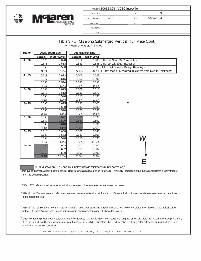
Table 3 - UTMs along Submerged Vertical Hull Plate (cont.) *All measurements are in inches
StationBottom Water Level Bottom Water Level
2+25 0.658 0.602 0.665 0.612 UTM per Nov. 2007 Inspection0.648 0.607 0.635 0.607 UTM per Jul. 2013 Inspection0.650 0.590 0.650 0.590 Plate Thickness per Design Drawings-0.3% 2.9% -2.3% 2.9% % Deviation of Measured Thickness from Design Thickness1
2+50 0.690 0.623 0.685 0.6200.677 0.617 0.677 0.6200.650 0.590 0.650 0.5904.2% 4.6% 4.2% 5.1%
2+75 0.680 0.615 0.648 0.6270.672 0.603 0.648 0.6200.650 0.590 0.650 0.5903.4% 2.2% -0.3% 5.1%
3+00 0.680 0.615 0.648 0.6250.640 0.610 0.650 0.6100.650 0.590 0.650 0.590-1.5% 3.4% 0.0% 3.4%
3+25 0.678 0.617 0.680 0.6250.667 0.615 0.657 0.6150.650 0.590 0.650 0.5902.6% 4.2% 1.1% 4.2%
3+50 0.677 0.602 0.663 0.6300.655 0.595 0.658 0.6200.650 0.590 0.650 0.5900.8% 0.8% 1.2% 5.1%
3+75 0.647 0.602 0.650 0.6300.638 0.602 0.645 0.6250.650 0.590 0.650 0.590-1.8% 2.0% -0.8% 5.9%
4+00 0.658 0.600 0.650 0.6070.652 0.595 0.657 0.6030.650 0.590 0.650 0.5900.3% 0.8% 1.1% 2.2%
4+25 0.627 0.585 0.600 0.5970.673 0.598 0.663 0.6020.650 0.590 0.650 0.5903.5% 1.4% 2.0% 2.0%
P:\Proj106\106523.04\8. Technical (Rpts, Calcs, Specs)\Final Report Documents\[UTM Data - FINAL.xls]T3 - UTMs at Vert Hull
Along South Side Along North Side
W
E
PROJECT: 106523.04 - VCBC InspectionSHEET NO: 3 OF 3
CALCULATED BY: CTC DATE: 9/27/2013
CHECKED BY: DATE:
REVISIONS:
SCALE:
Table 3 - UTMs along Submerged Vertical Hull Plate (cont.) *All measurements are in inches
StationBottom Water Level Bottom Water Level
4+50 0.625 0.628 0.612 0.608 UTM per Nov. 2007 Inspection0.675 0.613 0.683 0.588 UTM per Jul. 2013 Inspection0.650 0.590 0.650 0.590 Plate Thickness per Design Drawings3.8% 3.9% 5.1% -0.3% % Deviation of Measured Thickness from Design Thickness1
4+75 0.623 0.613 0.605 0.6230.677 0.615 0.657 0.5920.650 0.590 0.650 0.5904.2% 4.2% 1.1% 0.3%
5+00 0.595 0.625 0.602 0.6180.677 0.612 0.662 0.5730.650 0.590 0.650 0.5904.2% 3.7% 1.8% -2.9%
5+25 0.595 0.625 0.595 0.6050.668 0.608 0.682 0.5850.650 0.590 0.650 0.5902.8% 3.1% 4.9% -0.8%
5+50 0.593 0.622 0.608 0.5950.650 0.590 0.650 0.5900.600 0.618 0.678 0.5968.3% -4.5% -4.1% -1.0%
5+75 0.613 0.608 0.602 0.6400.680 0.673 0.682 0.6580.650 0.590 0.650 0.5904.6% 14.1% 4.9% 11.5%
6+00 0.633 0.605 0.605 0.6650.615 0.692 0.663 0.6070.650 0.590 0.650 0.590-5.4% 17.3% 2.0% 2.9%
= UTM between 3.5% and 15% below design thickness (minor corrosion)5
1 Positive (+) percentages indicate measured steel thicknesses above design thickness. This likely indicates plating that was fabricated slightly thicker
than the design specified.
2 ”NO UTM” refers to steel surfaces for which underwater thickness measurements were not taken.
3 UTMs in the “Bottom” column refer to underwater measurements taken at the bottom of the vertical hull plate, just above the radius that transitions to the horizontal keel.
4 UTMs in the “Water Level” column refer to measurements taken along the vertical hull plate just below the water line. Based on the typical barge draft of 9 ft, these “Water Level” measurements were taken approximately 9 ft above the baseline.
5 When combining the allowable tolerance of the Underwater Ultrasonic Thickness Gauge (+/- 1%) and allowable plate fabrication tolerance (+/- 2.5%), then the total allowable deviation from design thickness is +/- 3.5%. Therefore, the UTM must be 3.5% or greater below the design thickness to be considered an area of corrosion.
P:\Proj106\106523.04\8. Technical (Rpts, Calcs, Specs)\Final Report Documents\[UTM Data - FINAL.xls]T3 - UTMs at Vert Hull
Along South Side Along North Side
W
E

Appendix E – Steel Grade Descriptions
2-18
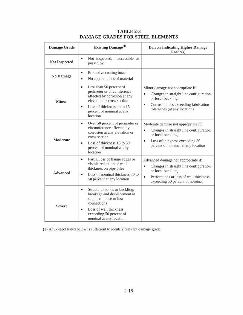
TABLE 2-3DAMAGE GRADES FOR STEEL ELEMENTS
Damage Grade Existing Damage(1) Defects Indicating Higher DamageGrade(s)
Not Inspected• Not inspected, inaccessible or
passed by
No Damage• Protective coating intact• No apparent loss of material
Minor
• Less than 50 percent ofperimeter or circumferenceaffected by corrosion at anyelevation or cross section
• Loss of thickness up to 15percent of nominal at anylocation
Minor damage not appropriate if:• Changes in straight line configuration
or local buckling• Corrosion loss exceeding fabrication
tolerances (at any location)
Moderate
• Over 50 percent of perimeter orcircumference affected bycorrosion at any elevation orcross section
• Loss of thickness 15 to 30percent of nominal at anylocation
Moderate damage not appropriate if:• Changes in straight line configuration
or local buckling• Loss of thickness exceeding 30
percent of nominal at any location
Advanced
• Partial loss of flange edges orvisible reduction of wallthickness on pipe piles
• Loss of nominal thickness 30 to50 percent at any location
Advanced damage not appropriate if:• Changes in straight line configuration
or local buckling• Perforations or loss of wall thickness
exceeding 50 percent of nominal
Severe
• Structural bends or buckling,breakage and displacement atsupports, loose or lostconnections
• Loss of wall thicknessexceeding 50 percent ofnominal at any location
(1) Any defect listed below is sufficient to identify relevant damage grade.
Appendix F – Certificate of Inspections
Appendix G – E-mail Correspondence from 2007
1
Christopher M. Mase
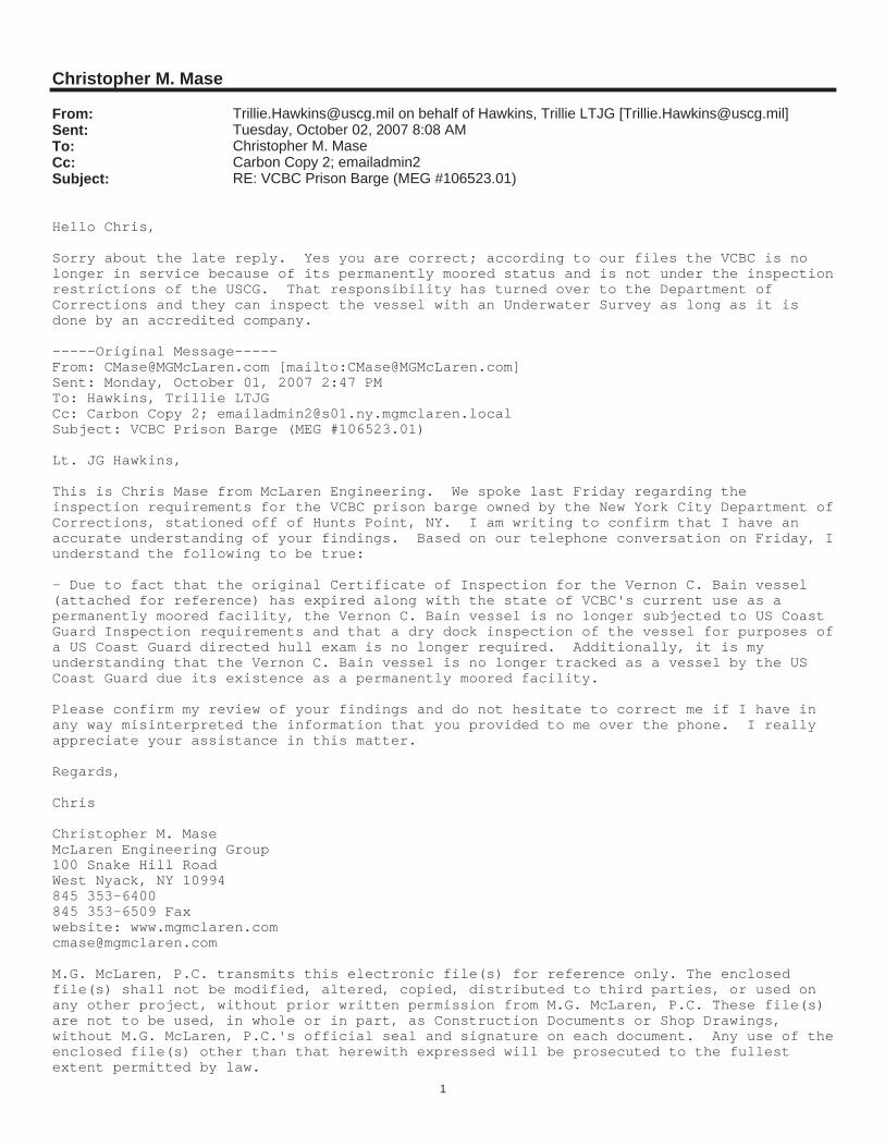
From: [email protected] on behalf of Hawkins, Trillie LTJG [[email protected]]Sent: Tuesday, October 02, 2007 8:08 AMTo: Christopher M. MaseCc: Carbon Copy 2; emailadmin2Subject: RE: VCBC Prison Barge (MEG #106523.01)
Hello Chris,
Sorry about the late reply. Yes you are correct; according to our files the VCBC is no longer in service because of its permanently moored status and is not under the inspectionrestrictions of the USCG. That responsibility has turned over to the Department of Corrections and they can inspect the vessel with an Underwater Survey as long as it is done by an accredited company.
-----Original Message-----From: [email protected] [mailto:[email protected]]Sent: Monday, October 01, 2007 2:47 PMTo: Hawkins, Trillie LTJGCc: Carbon Copy 2; [email protected]: VCBC Prison Barge (MEG #106523.01)
Lt. JG Hawkins,
This is Chris Mase from McLaren Engineering. We spoke last Friday regarding the inspection requirements for the VCBC prison barge owned by the New York City Department ofCorrections, stationed off of Hunts Point, NY. I am writing to confirm that I have an accurate understanding of your findings. Based on our telephone conversation on Friday, Iunderstand the following to be true:
- Due to fact that the original Certificate of Inspection for the Vernon C. Bain vessel (attached for reference) has expired along with the state of VCBC's current use as a permanently moored facility, the Vernon C. Bain vessel is no longer subjected to US Coast Guard Inspection requirements and that a dry dock inspection of the vessel for purposes ofa US Coast Guard directed hull exam is no longer required. Additionally, it is my understanding that the Vernon C. Bain vessel is no longer tracked as a vessel by the US Coast Guard due its existence as a permanently moored facility.
Please confirm my review of your findings and do not hesitate to correct me if I have in any way misinterpreted the information that you provided to me over the phone. I really appreciate your assistance in this matter.
Regards,
Chris
Christopher M. MaseMcLaren Engineering Group100 Snake Hill RoadWest Nyack, NY 10994845 353-6400845 353-6509 Faxwebsite: [email protected]
M.G. McLaren, P.C. transmits this electronic file(s) for reference only. The enclosed file(s) shall not be modified, altered, copied, distributed to third parties, or used on any other project, without prior written permission from M.G. McLaren, P.C. These file(s) are not to be used, in whole or in part, as Construction Documents or Shop Drawings, without M.G. McLaren, P.C.'s official seal and signature on each document. Any use of theenclosed file(s) other than that herewith expressed will be prosecuted to the fullest extent permitted by law.

Appendix H – Original Bumper Detail
PIN 072201704CPD Addendum #1