polyolefin maleation in supercritical carbon dioxide and ...
Upload
independentCategory
view
3download
0
Rc
Wa
b
a
ARRA
1
psoTticcdWtac
fsStttT
0d
Nuclear Engineering and Design 241 (2011) 2184–2203
Contents lists available at ScienceDirect
Nuclear Engineering and Design
journa l homepage: www.e lsev ier .com/ locate /nucengdes
eview and proposal for heat transfer predictions at supercritical wateronditions using existing correlations and experiments
adim Jägera,∗, Victor Hugo Sánchez Espinozaa, Antonio Hurtadob
Karlsruhe Institute of Technology, Institute for Neutron Physics and Reactor Technology, DE-76344 Eggenstein-Leopoldshafen, GermanyTechnical University of Dresden, Institute of Power Engineering, DE-01062 Dresden, Germany
r t i c l e i n f o
rticle history:eceived 6 October 2010
a b s t r a c t
This paper summarizes the activities of the TRACE code validation at the Institute for Neutron Physics and
eceived in revised form 11 March 2011ccepted 14 March 2011
Reactor Technology related to supercritical water conditions. In particular, the providing of the thermophysical properties and its appropriate use in the wall-to-fluid heat transfer models in the frame ofthe TRACE code is the object of this investigation. In a first step, the thermo physical properties of theoriginal TRACE code were modified in order to account for supercritical conditions. In a second step,existing Nusselt correlations were reviewed and implemented into TRACE and available experimentswere simulated to identify the most suitable Nusselt correlation(s).
. Introduction
The validation of computer codes, or, to be more precise, itshysical models, is one essential task for nuclear engineers andcientists since these codes will be used to predict the behaviorf nuclear installation during normal and off normal conditions.he Institute for Neutron Physics and Reactor Technology (INR) athe Karlsruhe Institute of Technology (KIT) is thereby interestedn the validation of the thermal hydraulic best-estimate systemode TRACE especially related to innovative systems like lead-alloyooled ones and to systems operated at supercritical water con-itions. Since the TRACE code was originally developed for Lightater Reactors (LWR) the validation process concerning innova-
ive systems is not as advanced as it is for LWR. Thus, post-testnalyses of experiments will be performed and the results will beompared to the experimental ones.
The present paper is focused on the wall-to-fluid heat trans-er at supercritical conditions. For that reason, six experimentalet ups with more than 20 test cases were modeled and analyzed.ince TRACE is an LWR code, the thermo physical properties andhe heat transfer models need to be reviewed and updated in ordero account for the peculiar behavior at supercritical conditions. Inotal 15 different correlations were selected, implemented in theRACE source code, and applied to the different test scenarios.
∗ Corresponding author. Tel.: +49 721 608 2 3765; fax: +49 721 608 2 3718.E-mail address: [email protected] (W. Jäger).
029-5493/$ – see front matter © 2011 Elsevier B.V. All rights reserved.oi:10.1016/j.nucengdes.2011.03.022
© 2011 Elsevier B.V. All rights reserved.
2. Heat transfer to water at supercritical conditions
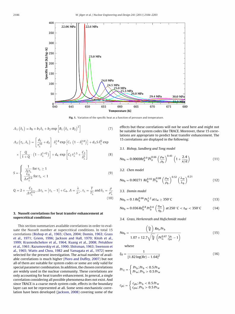
In order to increase the efficiency of the thermodynamic cycleof the nuclear power plant, the pressure and the temperature of thewater can be increased (are increased in fossil fired power plants).In the vicinity of the critical point (22.06 MPa, 647.096 K) the waterexperiences a strong change of the thermo physical properties (e.g.,density, thermal conductivity). Exemplarily, the specific heat asfunction of temperature and pressure is given in Fig. 1 (the selectedpressures correspond to the used pressures in this investigation).At the critical point (as well as at the pseudocritical point – a pointabove the critical pressure and temperature where the specific heathas its maximum) the amplitude of the specific heat has the highestvalue.
Parameters like density, thermal conductivity and dynamic vis-cosity decrease when crossing the critical point while the specificenthalpy increases. The specific heat has a peak at the criti-cal/pseudocritical point (Fig. 1). Due to these drastic changes, theheat transfer will be affected considerably. Hence, it is of crucialimportance that these parameters will be calculated in an accuratefashion. Since the parameters variation can be quite high even ata small temperature interval, bulk and wall properties may differ.While near the wall the critical point can be reached or exceededthe bulk properties are still sub critical. This could cause heat trans-fer enhancement or deterioration. If the radial temperature profileis rather homogenous the heat transfer capabilities take advan-tage of the high Prandtl number (due to the high specific heat).
Buoyancy effects can have also positive effects on the heat transferin vertical pipes due to the improved wall cooling. A low thermalconductivity at/near the wall, compared to the bulk one, indicatesa rather ineffective heat transfer. This can be caused by high heat
W. Jäger et al. / Nuclear Engineering and Design 241 (2011) 2184–2203 2185
Nomenclature
cp specific heat (kJ/kg K)d hydraulic diameter (m)G mass flux (kg/m2 s)g acceleration of gravity (m/s2)Gr Grasshof numberh specific enthalpy (kJ/kg)Nu Nusselt numberp pressure (Pa)Pr Prandtl numberq′′ heat flux (W/m2)Re Reynolds numberT temperature (K)T∗
� normalized temperature, corresponding to dynamicviscosity (T∗
� = 1 K)T∗
�Normalized temperature, corresponding to thermalconductivity (T∗
�= 647.226 K)
t temperature (◦C)x length (m)
Greek symbols˛ heat transfer coefficient (W/m2 K)ˇ thermal expansion coefficient (K−1)�� temperature difference (K)ı� reduced density, corresponding to dynamic viscos-
ityı� reduced density, corresponding to thermal conduc-
tivity� dynamic viscosity (Pa s)�* normalized dynamic viscosity
(�* = 55.071 × 10⁶ Pa s)� reduced thermal conductivity� thermal conductivity (W/m K)�* normalized thermal conductivity (�* = 1 W/m K)� density (kg/m3)�∗
� normalized density, corresponding to dynamic vis-cosity (�∗
� = 317.763 kg/m3)�∗
�normalized density, corresponding to thermal con-ductivity (�∗
�= 1 kg/m3)
�� reduced temperature, corresponding to dynamicviscosity
�� reduced temperature, corresponding to thermalconductivity
� reduced dynamic viscosity
Subscript* normalized quantityb bulki inletmin minimumo outlet
fludato
ia
Table 1Coefficients for Eq. (2).
i n0i
i n0i
0 1.000000 2 0.5798291 0.978197 3 −0.202354
Table 2Coefficients for Eq. (3).
i Ii Ji ni i Ii Ji ni
1 0 0 0.5132047 11 2 2 −0.1263184 × 101
2 0 1 0.3205656 12 3 0 0.17780643 0 4 −0.7782567 13 3 1 0.46050404 0 5 0.1885447 14 3 2 0.23403795 1 0 0.2151778 15 3 3 −0.49241796 1 1 0.7317883 16 4 0 −0.4176610 × 10⁻¹
7 1 2 1.2410440 17 4 3 0.16004358 1 3 1.4767830 18 5 1 −0.1578389 × 10⁻¹
2
�0 (��) =√
��
3∑i=0
˛i �i� (6)
Table 3Coefficients for Eqs. (6)–(10).
a0 = 0.0102811 C1 = 0.642857 d2 = 0.011852a1 = 0.0299621 C2 = −4.11717 d3 = 0.00169937a2 = 0.0156146 C3 = −6.17937 d4 = −1.02
pc pseudocriticalw wall
uxes in combination with low mass flow rates. The transition fromnheated to heated sections can be also one reason for heat transfereterioration. In some cases phenomena taking place in the bound-ry layer determine the heat transfer. In the context of this paperhe heat transfer enhancement capabilities will be investigated
nly.As mentioned in the previous section, the TRACE code was orig-nally developed for the analysis of LWR related conditions. Hence,ttention was paid to the development of physical models which
9 2 0 −0.2818100 19 6 3 −0.3629481 × 10−
10 2 1 −0.0707860 × 101
are appropriate for LWR related phenomena. The review of thethermo physical properties revealed that the transport properties,the dynamic viscosity and the thermal conductivity, are not validfor pressures above the critical point (Jaeger et al., 2008). There-fore, new routines were implemented into the TRACE source code.These new formulations are given in Eqs. (1)–(4) for the dynamicviscosity (Wagner and Kruse, 1998) and in Eqs. (5)–(10) for thethermal conductivity (Schmidt, 1989), respectively. The new proce-dure to calculate the dynamic viscosity is valid for pressures below300 MPa and for a temperature between 273.15 and 1173.15 K. Thecoefficients used in Eqs. (2) and (3) are gathered in Tables 1 and 2,respectively.
�(
ı�, ��
)= �0
(��
)�1
(ı�, ��
)(1)
where
�0(
��
)=
[�0.5
�
3∑i=0
n0i �i
�
]−1
(2)
�1(
ı�, ��
)= exp
[ı�
19∑i=0
ni
(ı� − 1
)Ii(
�� − 1)Ji
](3)
� = �
�∗ , ı� = �
�∗�
and�� = T∗�
T(4)
The new formulation for the thermal conductivity is valid upto 40 MPa and 1073.15 K. The coefficients for these equations aresummarized in Table 3.
� = �0 (��) + �1(
ı�
)+ �2
(��, ı�
)(5)
where
a3 = −0.00422464 C4 = 0.00308976 B1 = −0.171587b0 = −0.39707 C5 = 0.0822994 B2 = 2.39219b1 = 0.400302 C6 = 10.0932b2 = 1.06 d1 = 0.0701309
2186 W. Jäger et al. / Nuclear Engineering and Design 241 (2011) 2184–2203
s a fu
�
�
S
Q
3s
uce1easaasaocsll
Fig. 1. Variation of the specific heat a
1(
ı�
)= b0 + b1ı� + b2 exp
[B1
(ı� + B2
)2]
(7)
2(
��, ı�
)=
[d1
�10�
+ d2
]ı1.8
� exp[C1
(1 − ı2.8
�
)]+ d3 S ıQ
�exp
×[
Q
1 + Q·(
1 − ı1+Q�
)]+ d4 exp
[C2 �1.5
� + C3
ı5�
](8)
=
⎧⎪⎨⎪⎩
1���
for �� ≥ 1
C6
��0.6�
for �� < 1(9)
= 2 + C5
�0.6�
, �� =∣∣�� − 1
∣∣ + C4, � = �
�∗ , �� = T
T∗�
and ı� = �
�∗�
(10)
. Nusselt correlations for heat transfer enhancement atupercritical conditions
This section summarizes available correlations in order to eval-ate the Nusselt number at supercritical conditions. In total 15orrelations (Bishop et al., 1965; Chen, 2004; Domin, 1963; Grasst al., 1971; Griem, 1996; Jackson and Hall, 1979; Kitoh et al.,999; Krasnoshchekov et al., 1964; Kuang et al., 2008; Petukhovt al., 1961; Razumovskiy et al., 1990; Shitsman, 1963; Swenson etl., 1965; Watts and Chou, 1982 and Yamagata et al., 1972) wereelected for the present investigation. The actual number of avail-ble correlations is much higher (Pioro and Duffey, 2007) but notll of them are suitable for system codes or some are only valid forpecial parameter combination. In addition, the chosen correlationsre widely used in the nuclear community. These correlations arenly accounting for heat transfer enhancement. In general, a single
orrelation considering all possible phenomena does not exist. Andince TRACE is a coarse mesh system code, effects in the boundaryayer can not be represented at all. Some semi-mechanistic corre-ation have been developed (Jackson, 2008) covering some of thenction of pressure and temperature.
effects but these correlations will not be used here and might notbe suitable for system codes like TRACE. Moreover, these 15 corre-lations are appropriate to predict heat transfer enhancement. The15 correlations are displayed in the following:
3.1. Bishop, Sandberg and Tong model
Nub = 0.0069Re0.9b Pr
0.66b
(�w
�b
)0.43 (1 + 2.4
x/d
)(11)
3.2. Chen model
Nub = 0.00271 Re0.93b Pr
0.88b
(�w
�b
)0.52 (�w
�b
)0.21
(12)
3.3. Domin model
Nub = 0.1 Re0.66b Pr1.2
b at tw ≥ 350◦C (13)
Nub = 0.036 Re0.8b Pr0.4
b
(�w
�b
)at 250 ◦C < tW < 350◦C (14)
3.4. Grass, Herkenrath and Hufschmidt model
Nub =
(08
)Reb Prb
1.07 + 12.7√
08
(Pr0.67
Gcpbcpw
− 1) (15)
where
0 = 1
[1.82 log(Re) − 1.64]2(16)
PrG ={
Prb; Prb < 0.5 Prw
Prw; Prb > 0.5 Prw
cpG ={
cpb; Prb < 0.5 Prw
cpw; Prb > 0.5 Prw
W. Jäger et al. / Nuclear Engineering and Design 241 (2011) 2184–2203 2187
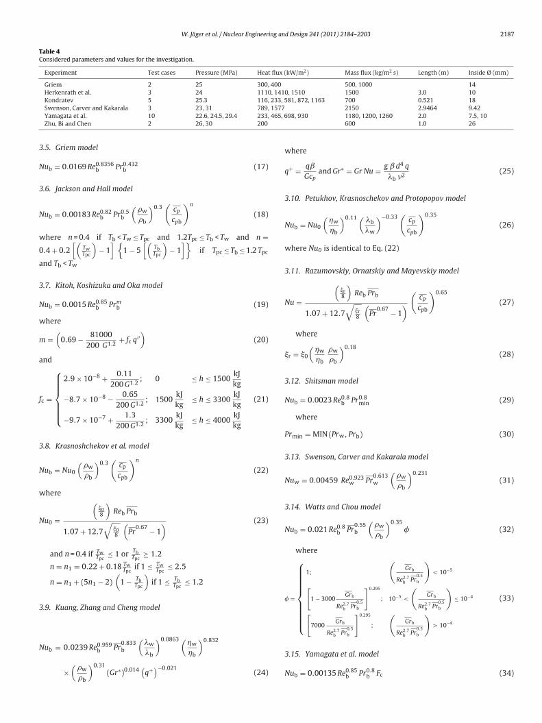
Table 4Considered parameters and values for the investigation.
Experiment Test cases Pressure (MPa) Heat flux (kW/m2) Mass flux (kg/m2 s) Length (m) Inside Ø (mm)
Griem 2 25 300, 400 500, 1000 14Herkenrath et al. 3 24 1110, 1410, 1510 1500 3.0 10Kondratev 5 25.3 116, 233, 581, 872, 1163 700 0.521 18
1577 2150 2.9464 9.42465, 6
3
N
3
N
w
0
a
3
N
w
m
a
f
3
N
w
N
3
N
Swenson, Carver and Kakarala 3 23, 31 789,Yamagata et al. 10 22.6, 24.5, 29.4 233,Zhu, Bi and Chen 2 26, 30 200
.5. Griem model
ub = 0.0169 Re0.8356b Pr0.432
b (17)
.6. Jackson and Hall model
ub = 0.00183 Re0.82b Pr0.5
b
(�w
�b
)0.3(
cp
cpb
)n
(18)
here n = 0.4 if Tb < Tw ≤ Tpc and 1.2Tpc ≤ Tb < Tw and n =.4 + 0.2
[(TwTpc
)− 1
] {1 − 5
[(TbTpc
)− 1
]}if Tpc ≤ Tb ≤ 1.2 Tpc
nd Tb < Tw
.7. Kitoh, Koshizuka and Oka model
ub = 0.0015 Re0.85b Prm
b (19)
here
=(
0.69 − 81000200 G1.2
+ fc q′′)
(20)
nd
c =
⎧⎪⎪⎪⎪⎨⎪⎪⎪⎪⎩
2.9 × 10⁻⁸ + 0.11200 G1.2
; 0 ≤ h ≤ 1500kJkg
−8.7 × 10⁻⁸ − 0.65200 G1.2
; 1500kJkg
≤ h ≤ 3300kJkg
−9.7 × 10⁻⁷ + 1.3200 G1.2
; 3300kJkg
≤ h ≤ 4000kJkg
(21)
.8. Krasnoshchekov et al. model
ub = Nu0
(�w
�b
)0.3(
cp
cpb
)n
(22)
here
u0 =
(08
)Reb Prb
1.07 + 12.7√
08
(Pr
0.67 − 1) (23)
and n = 0.4 if TwTpc
≤ 1 or TbTpc
≥ 1.2
n = n1 = 0.22 + 0.18 TwTpc
if 1 ≤ TwTpc
≤ 2.5
n = n1 + (5n1 − 2)(
1 − TbTpc
)if 1 ≤ Tb
Tpc≤ 1.2
.9. Kuang, Zhang and Cheng model
( ) ( )
ub = 0.0239 Re0.959b Pr0.833b
�w
�b
0.0863 �w
�b
0.832
×(
�w
�b
)0.31(Gr∗)0.014
(q+)−0.021
(24)
98, 930 1180, 1200, 1260 2.0 7.5, 10600 1.0 26
where
q+ = qˇ
Gcpand Gr∗ = Gr Nu = g ˇ d4 q
�b �2(25)
3.10. Petukhov, Krasnoschekov and Protopopov model
Nub = Nu0
(�w
�b
)0.11 (�b
�w
)−0.33(
cp
cpb
)0.35
(26)
where Nu0 is identical to Eq. (22)
3.11. Razumovskiy, Ornatskiy and Mayevskiy model
Nu =
(r8
)Reb Prb
1.07 + 12.7√
r8
(Pr
0.67 − 1)
(cp
cpb
)0.65
(27)
where
r = 0
(�w
�b
�w
�b
)0.18(28)
3.12. Shitsman model
Nub = 0.0023 Re0.8b Pr0.8
min (29)
where
Prmin = MIN (Prw, Prb) (30)
3.13. Swenson, Carver and Kakarala model
Nuw = 0.00459 Re0.923w Pr
0.613w
(�w
�b
)0.231(31)
3.14. Watts and Chou model
Nub = 0.021 Re0.8b Pr
0.55b
(�w
�b
)0.35� (32)
where
� =
⎧⎪⎪⎪⎪⎪⎪⎪⎨⎪⎪⎪⎪⎪⎪⎪⎩
1;
(Grb
Re2.7b Pr
0.5b
)< 10−5
[1 − 3000
Grb
Re2.7b Pr
0.5b
]0.295
; 10−5 <
(Grb
Re2.7b Pr
0.5b
)≤ 10−4
[7000
Grb
Re2.7b Pr
0.5b
]0.295
;
(Grb
Re2.7b Pr
0.5b
)> 10−4
(33)
3.15. Yamagata et al. model
Nub = 0.00135 Re0.85b Pr0.8
b Fc (34)
2188 W. Jäger et al. / Nuclear Engineering and Design 241 (2011) 2184–2203
test se
w
F
E
Fig. 2. Layout of the
here
c =
⎧⎪⎪⎪⎨⎪⎪⎪⎩
1; E > 1
0.67 Pr−0.05pc
(cp
cpb
)n1
; 0 ≤ E ≤ 1(cp
cpb
)n2
; E < 0
(35)
( )
= Tpc − TbTw − Tb, n1 = −0.77 1 + 1
Prpc+ 1.49 and n2
= 1.44
(1 + 1
Prpc
)− 0.53
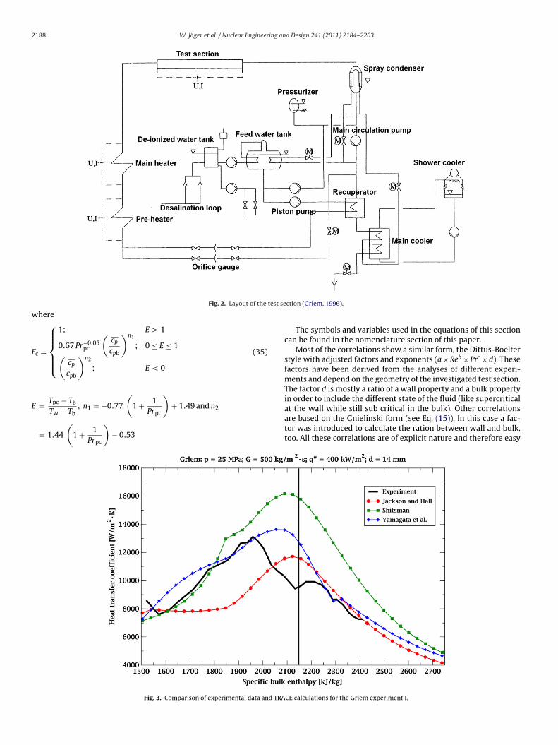
Fig. 3. Comparison of experimental data and TRA
ction (Griem, 1996).
The symbols and variables used in the equations of this sectioncan be found in the nomenclature section of this paper.
Most of the correlations show a similar form, the Dittus-Boelterstyle with adjusted factors and exponents (a × Reb × Prc × d). Thesefactors have been derived from the analyses of different experi-ments and depend on the geometry of the investigated test section.The factor d is mostly a ratio of a wall property and a bulk propertyin order to include the different state of the fluid (like supercritical
at the wall while still sub critical in the bulk). Other correlationsare based on the Gnielinski form (see Eq. (15)). In this case a fac-tor was introduced to calculate the ration between wall and bulk,too. All these correlations are of explicit nature and therefore easyCE calculations for the Griem experiment I.
W. Jäger et al. / Nuclear Engineering and Design 241 (2011) 2184–2203 2189
d TRA
tcnspwirl
icdac(bnto
Cdtot
sYbf
4
Ettt
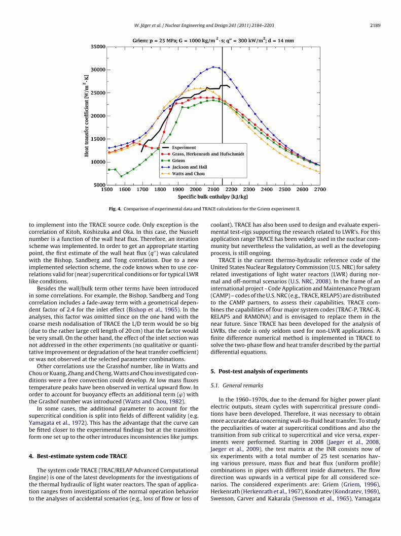
Fig. 4. Comparison of experimental data an
o implement into the TRACE source code. Only exception is theorrelation of Kitoh, Koshizuka and Oka. In this case, the Nusseltumber is a function of the wall heat flux. Therefore, an iterationcheme was implemented. In order to get an appropriate startingoint, the first estimate of the wall heat flux (q′′) was calculatedith the Bishop, Sandberg and Tong correlation. Due to a new
mplemented selection scheme, the code knows when to use cor-elations valid for (near) supercritical conditions or for typical LWRike conditions.
Besides the wall/bulk term other terms have been introducedn some correlations. For example, the Bishop, Sandberg and Tongorrelation includes a fade-away term with a geometrical depen-ent factor of 2.4 for the inlet effect (Bishop et al., 1965). In thenalyses, this factor was omitted since on the one hand with theoarse mesh nodalisation of TRACE the L/D term would be so bigdue to the rather large cell length of 20 cm) that the factor woulde very small. On the other hand, the effect of the inlet section wasot addressed in the other experiments (no qualitative or quanti-ative improvement or degradation of the heat transfer coefficient)r was not observed at the selected parameter combinations.
Other correlations use the Grasshof number, like in Watts andhou or Kuang, Zhang and Cheng. Watts and Chou investigated con-itions were a free convection could develop. At low mass fluxesemperature peaks have been observed in vertical upward flow. Inrder to account for buoyancy effects an additional term (ϕ) withhe Grashof number was introduced (Watts and Chou, 1982).
In some cases, the additional parameter to account for theupercritical condition is split into fields of different validity (e.g.amagata et al., 1972). This has the advantage that the curve cane fitted closer to the experimental findings but at the transitionorm one set up to the other introduces inconsistencies like jumps.
. Best-estimate system code TRACE
The system code TRACE (TRAC/RELAP Advanced Computational
ngine) is one of the latest developments for the investigations ofhe thermal hydraulic of light water reactors. The span of applica-ion ranges from investigations of the normal operation behavioro the analyses of accidental scenarios (e.g., loss of flow or loss ofCE calculations for the Griem experiment II.
coolant). TRACE has also been used to design and evaluate experi-mental test-rigs supporting the research related to LWR’s. For thisapplication range TRACE has been widely used in the nuclear com-munity but nevertheless the validation, as well as the developingprocess, is still ongoing.
TRACE is the current thermo-hydraulic reference code of theUnited States Nuclear Regulatory Commission (U.S. NRC) for safetyrelated investigations of light water reactors (LWR) during nor-mal and off-normal scenarios (U.S. NRC, 2008). In the frame of aninternational project - Code Application and Maintenance Program(CAMP) – codes of the U.S. NRC (e.g., TRACE, RELAP5) are distributedto the CAMP partners, to assess their capabilities. TRACE com-bines the capabilities of four major system codes (TRAC-P, TRAC-B,RELAP5 and RAMONA) and is envisaged to replace them in thenear future. Since TRACE has been developed for the analysis ofLWRs, the code is only seldom used for non-LWR applications. Afinite difference numerical method is implemented in TRACE tosolve the two-phase flow and heat transfer described by the partialdifferential equations.
5. Post-test analysis of experiments
5.1. General remarks
In the 1960–1970s, due to the demand for higher power plantelectric outputs, steam cycles with supercritical pressure condi-tions have been developed. Therefore, it was necessary to obtainmore accurate data concerning wall-to-fluid heat transfer. To studythe peculiarities of water at supercritical conditions and also thetransition from sub critical to supercritical and vice versa, exper-iments were performed. Starting in 2008 (Jaeger et al., 2008,Jaeger et al., 2009), the test matrix at the INR consists now ofsix experiments with a total number of 25 test scenarios hav-ing various pressure, mass flux and heat flux (uniform profile)combinations in pipes with different inside diameters. The flow
direction was upwards in a vertical pipe for all considered sce-narios. The considered experiments are: Griem (Griem, 1996),Herkenrath (Herkenrath et al., 1967), Kondratev (Kondratev, 1969),Swenson, Carver and Kakarala (Swenson et al., 1965), Yamagata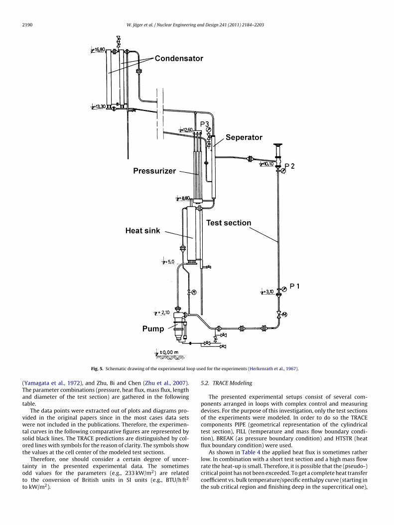
2190 W. Jäger et al. / Nuclear Engineering and Design 241 (2011) 2184–2203
op us
(Tat
vwtsot
tott
Fig. 5. Schematic drawing of the experimental lo
Yamagata et al., 1972), and Zhu, Bi and Chen (Zhu et al., 2007).he parameter combinations (pressure, heat flux, mass flux, lengthnd diameter of the test section) are gathered in the followingable.
The data points were extracted out of plots and diagrams pro-ided in the original papers since in the most cases data setsere not included in the publications. Therefore, the experimen-
al curves in the following comparative figures are represented byolid black lines. The TRACE predictions are distinguished by col-red lines with symbols for the reason of clarity. The symbols showhe values at the cell center of the modeled test sections.
Therefore, one should consider a certain degree of uncer-
ainty in the presented experimental data. The sometimesdd values for the parameters (e.g., 233 kW/m2) are relatedo the conversion of British units in SI units (e.g., BTU/h ft2o kW/m2).
ed for the experiments (Herkenrath et al., 1967).
5.2. TRACE Modeling
The presented experimental setups consist of several com-ponents arranged in loops with complex control and measuringdevises. For the purpose of this investigation, only the test sectionsof the experiments were modeled. In order to do so the TRACEcomponents PIPE (geometrical representation of the cylindricaltest section), FILL (temperature and mass flow boundary condi-tion), BREAK (as pressure boundary condition) and HTSTR (heatflux boundary condition) were used.
As shown in Table 4 the applied heat flux is sometimes ratherlow. In combination with a short test section and a high mass flow
rate the heat-up is small. Therefore, it is possible that the (pseudo-)critical point has not been exceeded. To get a complete heat transfercoefficient vs. bulk temperature/specific enthalpy curve (starting inthe sub critical region and finishing deep in the supercritical one),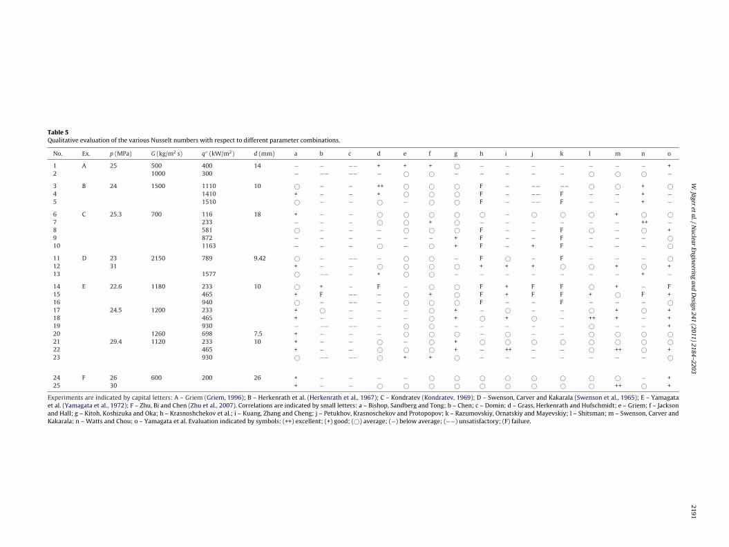
W.Jäger
etal./N
uclearEngineering
andD
esign241 (2011) 2184–2203
2191
Table 5Qualitative evaluation of the various Nusselt numbers with respect to different parameter combinations.
No. Ex. p (MPa) G (kg/m2 s) q′′ (kW/m2) d (mm) a b c d e f g h i j k l m n o
1 A 25 500 400 14 − − −− + + + © − − − − − − − +2 1000 300 − −− −− − © © − − − − − © © © −3 B 24 1500 1110 10 © − − ++ © © © F − −− −− © © + ©4 1410 + − − + © © © F − −− F − − + −5 1510 © − − © − © © F − −− F − − + −6 C 25.3 700 116 18 + − − © © © © © − © © © + © ©7 233 − − − © © + © − − − − − − ++ −8 581 © − − − © © © F − − F © − © +9 872 − − − − − − + F − − F − − − ©10 1163 − − − © − © + F − + F − − − ©11 D 23 2150 789 9.42 © − −− − © © − F © − F − − − ©12 31 + − − © © © © + + + © © + © +13 1577 © −− − + © © − − − − − − − + −14 E 22.6 1180 233 10 © + − F − © © F + F F © + − F15 465 + F −− − © + © F + F F + © F +16 940 © − −− − © © © F − − F − − − ©17 24.5 1200 233 + © − − − © + − © − − © + © +18 465 + − − − − © + © + © − ++ + − +19 930 − −− −− − © © − − − − − © − − +20 1260 698 7.5 + − − − © © © − © − − © © © ©21 29.4 1120 233 10 + − − © − © + © © © © © © © ©22 465 + − − © © © + − ++ − − © ++ © +23 930 © −− −− © + + © − − − − − − − ©
24 F 26 600 200 26 + − − − − © © © © © © © © − +25 30 + − − © © © © © © © © © ++ © +
Experiments are indicated by capital letters: A – Griem (Griem, 1996); B – Herkenrath et al. (Herkenrath et al., 1967); C – Kondratev (Kondratev, 1969); D – Swenson, Carver and Kakarala (Swenson et al., 1965); E – Yamagataet al. (Yamagata et al., 1972); F – Zhu, Bi and Chen (Zhu et al., 2007). Correlations are indicated by small letters: a – Bishop, Sandberg and Tong; b – Chen; c – Domin; d – Grass, Herkenrath and Hufschmidt; e – Griem; f – Jacksonand Hall; g – Kitoh, Koshizuka and Oka; h – Krasnoshchekov et al.; i – Kuang, Zhang and Cheng; j – Petukhov, Krasnoschekov and Protopopov; k – Razumovskiy, Ornatskiy and Mayevskiy; l – Shitsman; m – Swenson, Carver andKakarala; n – Watts and Chou; o – Yamagata et al. Evaluation indicated by symbols: (++) excellent; (+) good; (©) average; (−) below average; (−−) unsatisfactory; (F) failure.
2192W
.Jägeret
al./Nuclear
Engineeringand
Design
241 (2011) 2184–2203
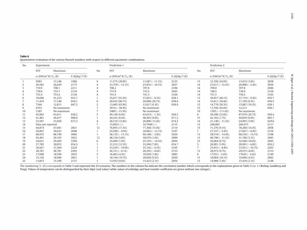
Table 6Quantitative evaluation of the various Nusselt numbers with respect to different parameter combinations.
No. Experiment Prediction 1 Prediction 2
PCP Maximum Nu PCP Maximum Nu PCP Maximum
˛ (kW/m2 K) Tw (K) h (kJ/kg) T (K) ˛ (kW/m2 K) Tw (K) h (kJ/kg) T (K) ˛ (kW/m2 K) Tw (K) h (kJ/kg) T (K)
1 9583 13,148 1960 6 11,575 (20.8%) 11,687 (−11.1%) 2125 15 12,760 (24.9%) 13,633 (3.6%) 20582 26,582 26,629 2175 4 23,378 (−12.1%) 23,952 (−10.1%) 2027 14 23,617 (−12.5%) 26,008 (−2.4%) 20303 710.9 708.1 2211 4 708.2 707.8 2106 14 709.0 707.8 20464 739.6 733.7 2134 4 737.8 733.2 2045 14 748.5 738.9 21205 753.4 753.4 2130 4 741.9 741.3 2104 14 751.5 750.2 21026 18,696 41,253 655.7 1 35,817 (91.6%) 37,825 (−8.3%) 658.1 13 36,057 (48.1%) 37,710 (−9.4%) 659.77 11,419 17,140 654.1 6 20,635 (80.7%) 20,686 (20.7%) 658.4 14 16,411 (30.4%) 17,199 (0.3%) 656.58 7344 12,813 647.2 5 13,495 (83.8%) 13,617 (6.3%) 658.9 15 14,770 (50.3%) 15,887 (19.3%) 658.19 6353 No maximum 7 3914 (−38.4%) No maximum 15 11,556 (45.0%) 12,213 658.110 3185 No maximum 7 2489 (−21.9%) No maximum 10 1505 (−111.6%) No maximum11 45,962 63,811 658.2 5 49,149 (6.9%) 63,014 (−1.3%) 650.3 6 59,508 (22.8%) 87,079 (26.7%) 650.412 41,481 44,477 690.0 1 44,222 (6.6%) 48,493 (9.0%) 671.2 15 42,182 (1.7%) 44,859 (0.9%) 683.713 23,507 23,650 673.3 4 26,519 (12.8%) 26,808 (13.4%) 674.3 14 21,140 (−11.2%) 24,905 (5.0%) 629.014 Data not reported 7 15,8921 (–) 16,7049 (–) 2115 13 248,805 266,973 211715 64,874 67,041 2021 12 76,093 (17.3%) 77,368 (15.4%) 2114 15 71,376 (9.1%) 78,260 (14.3%) 205816 28,867 29,632 2048 1 25,998 (−9.9%) 26,062 (−12.1%) 2107 7 27,337 (−5.6%) 27,847 (−6.4%) 215917 66,933 68,749 2066 1 58,135 (−13.1%) 66,168 (−3.8%) 2020 13 58,518 (−14.4%) 60,239 (−14.1%) 210818 45,491 50,193 2022 12 48,120 (5.8%) 50,670 (1.0%) 2099 15 40,790 (−11.5%) 51,786 (3.1%) 204519 24,621 29,450 1950 6 25,099 (1.9%) 25,195 (−14.5%) 2094 15 26,964 (8.7%) 32,940 (10.6%) 204320 27,785 30,853 654.3 1 31,212 (12.3%) 33,204 (7.6%) 654.7 5 28,901 (3.9%) 28,901 (−6.8%) 656.221 36,927 37,564 2224 1 33,229 (−10.0%) 35,142 (−6.5%) 2105 7 33,931 (−8.8%) 33,931 (−10.7%) 220322 28,781 28,781 2203 7 26,151 (−9.1%) 26,295 (−8.6%) 2153 13 28,972 (0.7%) 29,972 (4.0%) 215323 17,698 18,599 2035 5 18,463 (4.3%) 18,928 (1.8%) 2083 6 17252 (−2.6%) 17620 (−5.6%) 214924 15,156 18,946 2021 1 18,144 (19.7%) 20,694 (9.2%) 2030 15 18,064 (16.1%) 19,846 (4.5%) 206225 13,853 15,100 2137 1 13,933 (0.6%) 15,423 (2.1%) 2056 13 14,988 (7.6%) 15,418 (2.1%) 2148
The numbering (1–25) corresponds to Table 5 and represent the 25 scenarios. The numbers in the column Nu indicate the correlation number which corresponds to the explanations given in Table 5 (i.e. 1 = Bishop, Sandberg andTong). Values of temperature can be distinguished by their digit (real value) while values of enthalpy and heat transfer coefficient are given without one (integer).
W. Jäger et al. / Nuclear Engineering and Design 241 (2011) 2184–2203 2193
d for t
ti
sstwiflo(w
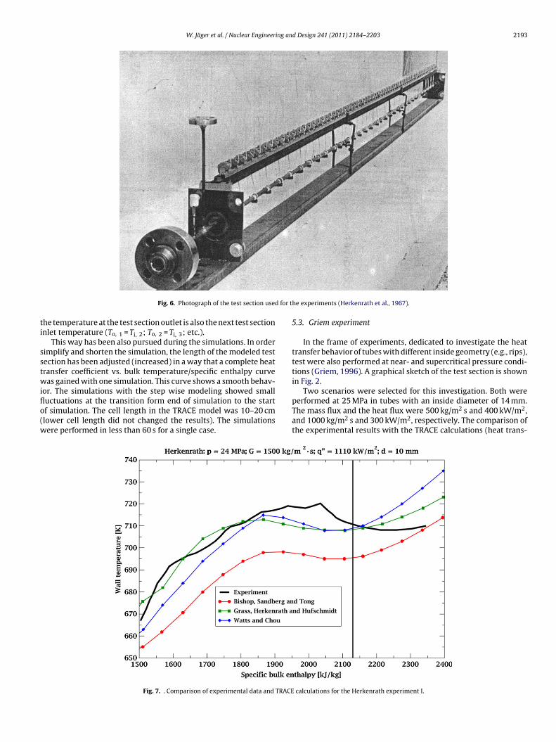
Fig. 6. Photograph of the test section use
he temperature at the test section outlet is also the next test sectionnlet temperature (To, 1 = Ti, 2; To, 2 = Ti, 3; etc.).
This way has been also pursued during the simulations. In orderimplify and shorten the simulation, the length of the modeled testection has been adjusted (increased) in a way that a complete heatransfer coefficient vs. bulk temperature/specific enthalpy curveas gained with one simulation. This curve shows a smooth behav-
or. The simulations with the step wise modeling showed small
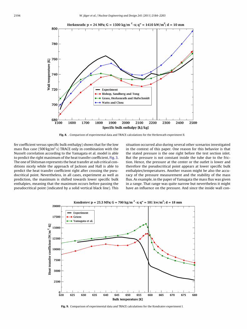
uctuations at the transition form end of simulation to the startf simulation. The cell length in the TRACE model was 10–20 cmlower cell length did not changed the results). The simulationsere performed in less than 60 s for a single case.Fig. 7. . Comparison of experimental data and TRACE
he experiments (Herkenrath et al., 1967).
5.3. Griem experiment
In the frame of experiments, dedicated to investigate the heattransfer behavior of tubes with different inside geometry (e.g., rips),test were also performed at near- and supercritical pressure condi-tions (Griem, 1996). A graphical sketch of the test section is shownin Fig. 2.
Two scenarios were selected for this investigation. Both were
performed at 25 MPa in tubes with an inside diameter of 14 mm.The mass flux and the heat flux were 500 kg/m2 s and 400 kW/m2,and 1000 kg/m2 s and 300 kW/m2, respectively. The comparison ofthe experimental results with the TRACE calculations (heat trans-calculations for the Herkenrath experiment I.
2194 W. Jäger et al. / Nuclear Engineering and Design 241 (2011) 2184–2203
RACE
fmNtTdpdpep
Fig. 8. . Comparison of experimental data and T
er coefficient versus specific bulk enthalpy) shows that for the lowass flux case (500 kg/m2 s) TRACE only in combination with theusselt correlation according to the Yamagata et al. model is able
o predict the right maximum of the heat transfer coefficient, Fig. 3.he one of Shitsman represents the heat transfer at sub critical con-itions nicely while the approach of Jackson and Hall is able toredict the heat transfer coefficient right after crossing the pseu-ocritical point. Nevertheless, in all cases, experiment as well as
rediction, the maximum is shifted towards lower specific bulknthalpies, meaning that the maximum occurs before passing theseudocritical point (indicated by a solid vertical black line). ThisFig. 9. Comparison of experimental data and TRACE
calculations for the Herkenrath experiment II.
situation occurred also during several other scenarios investigatedin the context of this paper. One reason for this behavior is thatthe stated pressure is the one right before the test section inlet.But the pressure is not constant inside the tube due to the fric-tion. Hence, the pressure at the center or the outlet is lower andtherefore the pseudocritical point appears at lower specific bulkenthalpies/temperatures. Another reason might be also the accu-racy of the pressure measurement and the stability of the mass
flux. As example, in the paper of Yamagata the mass flux was givenin a range. That range was quite narrow but nevertheless it mighthave an influence on the pressure. And since the inside wall con-calculations for the Kondratev experiment I.
W. Jäger et al. / Nuclear Engineering and Design 241 (2011) 2184–2203 2195
TRACE
deu
rcewre(
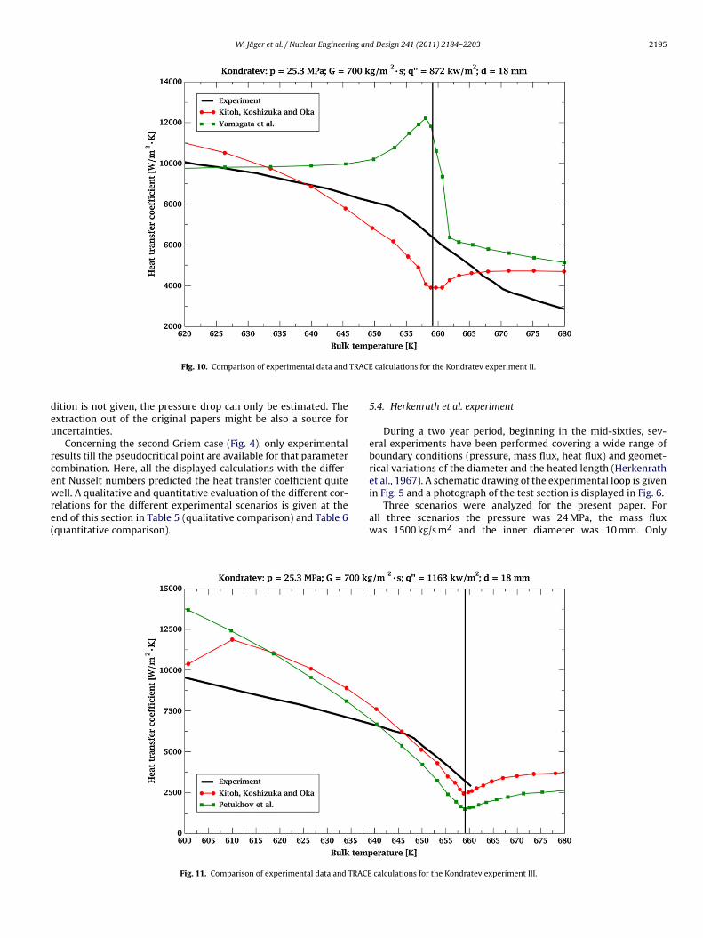
Fig. 10. Comparison of experimental data and
ition is not given, the pressure drop can only be estimated. Thextraction out of the original papers might be also a source forncertainties.
Concerning the second Griem case (Fig. 4), only experimentalesults till the pseudocritical point are available for that parameterombination. Here, all the displayed calculations with the differ-nt Nusselt numbers predicted the heat transfer coefficient quite
ell. A qualitative and quantitative evaluation of the different cor-elations for the different experimental scenarios is given at thend of this section in Table 5 (qualitative comparison) and Table 6quantitative comparison).
Fig. 11. Comparison of experimental data and TRACE
calculations for the Kondratev experiment II.
5.4. Herkenrath et al. experiment
During a two year period, beginning in the mid-sixties, sev-eral experiments have been performed covering a wide range ofboundary conditions (pressure, mass flux, heat flux) and geomet-rical variations of the diameter and the heated length (Herkenrathet al., 1967). A schematic drawing of the experimental loop is given
in Fig. 5 and a photograph of the test section is displayed in Fig. 6.Three scenarios were analyzed for the present paper. Forall three scenarios the pressure was 24 MPa, the mass fluxwas 1500 kg/s m2 and the inner diameter was 10 mm. Only
calculations for the Kondratev experiment III.
2196 W. Jäger et al. / Nuclear Engineering and Design 241 (2011) 2184–2203
xperim
t1
owteTS
anistfr
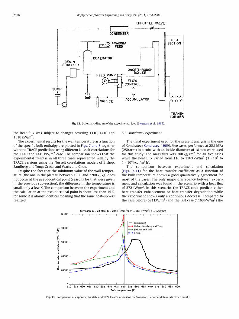
Fig. 12. Schematic diagram of the e
he heat flux was subject to changes covering 1110, 1410 and510 kW/m2.
The experimental results for the wall temperature as a functionf the specific bulk enthalpy are plotted in Figs. 7 and 8 togetherith the TRACE predictions using different Nusselt correlations for
he 1140 and 1410 kW/m2 case. The comparison shows that thexperimental trend is in all three cases represented well by theRACE versions using the Nusselt correlations models of Bishop,andberg and Tong; Grass; and Watts and Chou.
Despite the fact that the minimum value of the wall temper-ture (the one in the plateau between 1900 and 2200 kJ/kg) doesot occur at the pseudocritical point (reasons for that were given
n the previous sub-section), the difference in the temperature is
mall, only a few K. The comparison between the experiment andhe calculation at the pseudocritical point is about less than 15 K,or some it is almost identical meaning that the same heat-up wasealized.Fig. 13. Comparison of experimental data and TRACE calculati
ental loop (Swenson et al., 1965).
5.5. Kondratev experiment
The third experiment used for the present analysis is the oneof Kondratev (Kondratev, 1969). Five cases, performed at 25.3 MPa(250 atm) in a tube with an inside diameter of 18 mm were usedfor this study. The mass flux was 700 kg/s m2 for all five caseswhile the heat flux varied from 116 to 1163 kW/m2 (1 × 10⁵ to1 × 106 kcal/m2 h).
The comparison between experiment and calculation(Figs. 9–11) for the heat transfer coefficient as a function ofthe bulk temperature shows a good qualitatively agreement formost of the cases. The only major discrepancy between experi-ment and calculation was found in the scenario with a heat flux
of 872 kW/m2. In this scenario, the TRACE code predicts eitherheat transfer enhancement or heat transfer degradation whilethe experiment shows only a continuous decrease. Compared tothe case before (581 kW/m2) and the last case (1163 kW/m2) theons for the Swenson, Carver and Kakarala experiment I.
W. Jäger et al. / Nuclear Engineering and Design 241 (2011) 2184–2203 2197
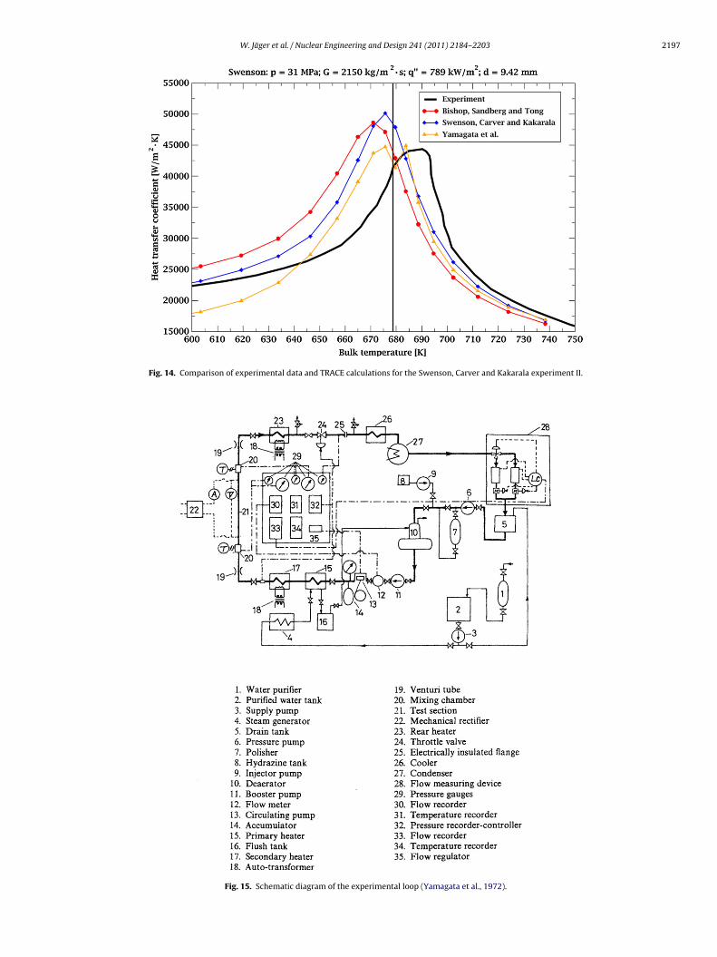
Fig. 14. Comparison of experimental data and TRACE calculations for the Swenson, Carver and Kakarala experiment II.
Fig. 15. Schematic diagram of the experimental loop (Yamagata et al., 1972).
2 ing and Design 241 (2011) 2184–2203
esBhf
aSrAs(eO1
5
fd
fli2t1
tltc6euehoab
198 W. Jäger et al. / Nuclear Engineer
xperimental curve shows a similar trend. The figures show thatome correlations are able to reproduce the experimental trend.ut it seems that the Yamagata et al. correlation is not suitable foreat fluxes higher than 581 kW/m2. A physical sound explanation
or that behavior cannot be given.Another finding is that the best fits for the scenarios were
rchived with different correlations. At 116 kW/m2, the Bishop,andberg and Tong, and the Swenson, Carver and Kakarala cor-elation show the best agreements (not given as a figure).t 233 kW/m2 the correlations of Grass, Herkenrath and Huf-chmidt of Griem and of Watts and Chou are the best onesnot given as a figure). Correlations of Griem and Yamagatat al. are good for 581 kW/m2 while Kitoh, Koshizuka andka, and Petukhov, Krasnoschekov and Protopopov are good for163 kW/m2.
.6. Swenson, Carver and Kakarala experiment
This experiment, being the oldest one out of the six, was per-ormed in the mid 1960s (Swenson et al., 1965). The schematiciagram of the experimental loop is given in Fig. 12.
The selected scenarios (three in total) have a common massux of 2150 kg/m2 s, which is the highest value of all exper-
ments, and a inside diameter of 9.42 mm. The pressure was2.75 MPa in one case and 31 MPa (highest in this investiga-ion) in the other two cases. The heat flux was either 789 or577 kW/m2.
For the first case (Fig. 13), an agreement is barely given sincehe pseudocritical point is at lower temperatures for the calcu-ations than in the experiment. For 23 MPa, the correspondingemperature at the pseudocritical point is 650.6 K as shown in thealculations. The experimental trend indicates a value of roughly60 K. The reasons for this discrepancy can be an imprecise dataxtraction or due to rounding errors when converting psi (the unitsed in the original paper, Swenson et al. (1965)) to Pascal. How-ver, when using the Griem correlation the peaking value for the
eat transfer coefficient can be calculated quite well. The peakf the heat transfer coefficients is also moved to lower temper-tures in the other two scenarios. Besides that, the comparisonetween all three calculations and experiments is quite good forFig. 17. Comparison of experimental data and TRACE c
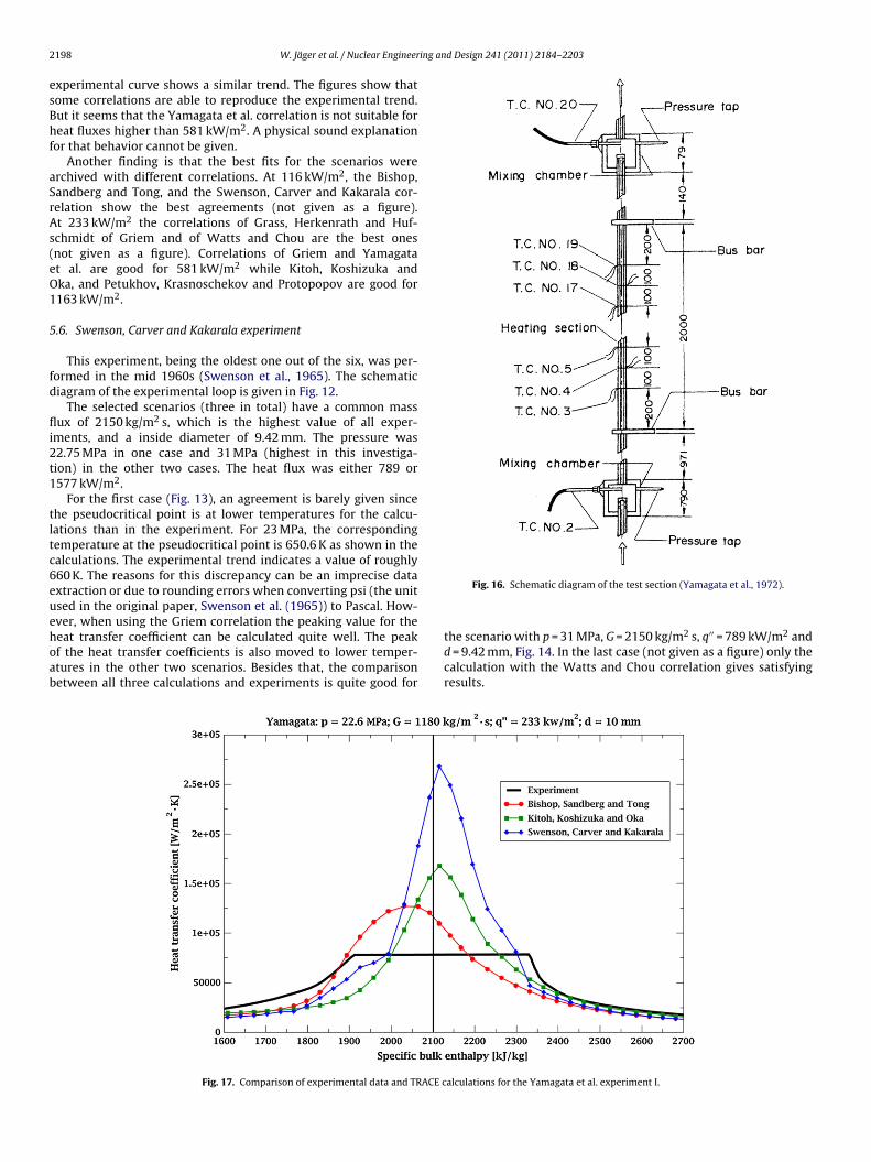
Fig. 16. Schematic diagram of the test section (Yamagata et al., 1972).
the scenario with p = 31 MPa, G = 2150 kg/m2 s, q′′ = 789 kW/m2 and
d = 9.42 mm, Fig. 14. In the last case (not given as a figure) only thecalculation with the Watts and Chou correlation gives satisfyingresults.alculations for the Yamagata et al. experiment I.
W. Jäger et al. / Nuclear Engineering and Design 241 (2011) 2184–2203 2199
ACE c
5
sii
Tr1
bt
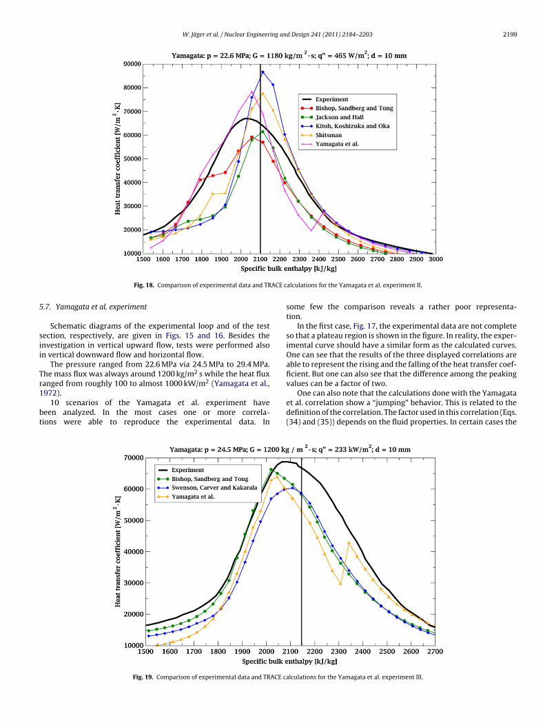
Fig. 18. Comparison of experimental data and TR
.7. Yamagata et al. experiment
Schematic diagrams of the experimental loop and of the testection, respectively, are given in Figs. 15 and 16. Besides thenvestigation in vertical upward flow, tests were performed alson vertical downward flow and horizontal flow.
The pressure ranged from 22.6 MPa via 24.5 MPa to 29.4 MPa.he mass flux was always around 1200 kg/m2 s while the heat fluxanged from roughly 100 to almost 1000 kW/m2 (Yamagata et al.,
972).10 scenarios of the Yamagata et al. experiment haveeen analyzed. In the most cases one or more correla-ions were able to reproduce the experimental data. In
Fig. 19. Comparison of experimental data and TRACE c
alculations for the Yamagata et al. experiment II.
some few the comparison reveals a rather poor representa-tion.
In the first case, Fig. 17, the experimental data are not completeso that a plateau region is shown in the figure. In reality, the exper-imental curve should have a similar form as the calculated curves.One can see that the results of the three displayed correlations areable to represent the rising and the falling of the heat transfer coef-ficient. But one can also see that the difference among the peakingvalues can be a factor of two.
One can also note that the calculations done with the Yamagataet al. correlation show a “jumping” behavior. This is related to thedefinition of the correlation. The factor used in this correlation (Eqs.(34) and (35)) depends on the fluid properties. In certain cases the
alculations for the Yamagata et al. experiment III.
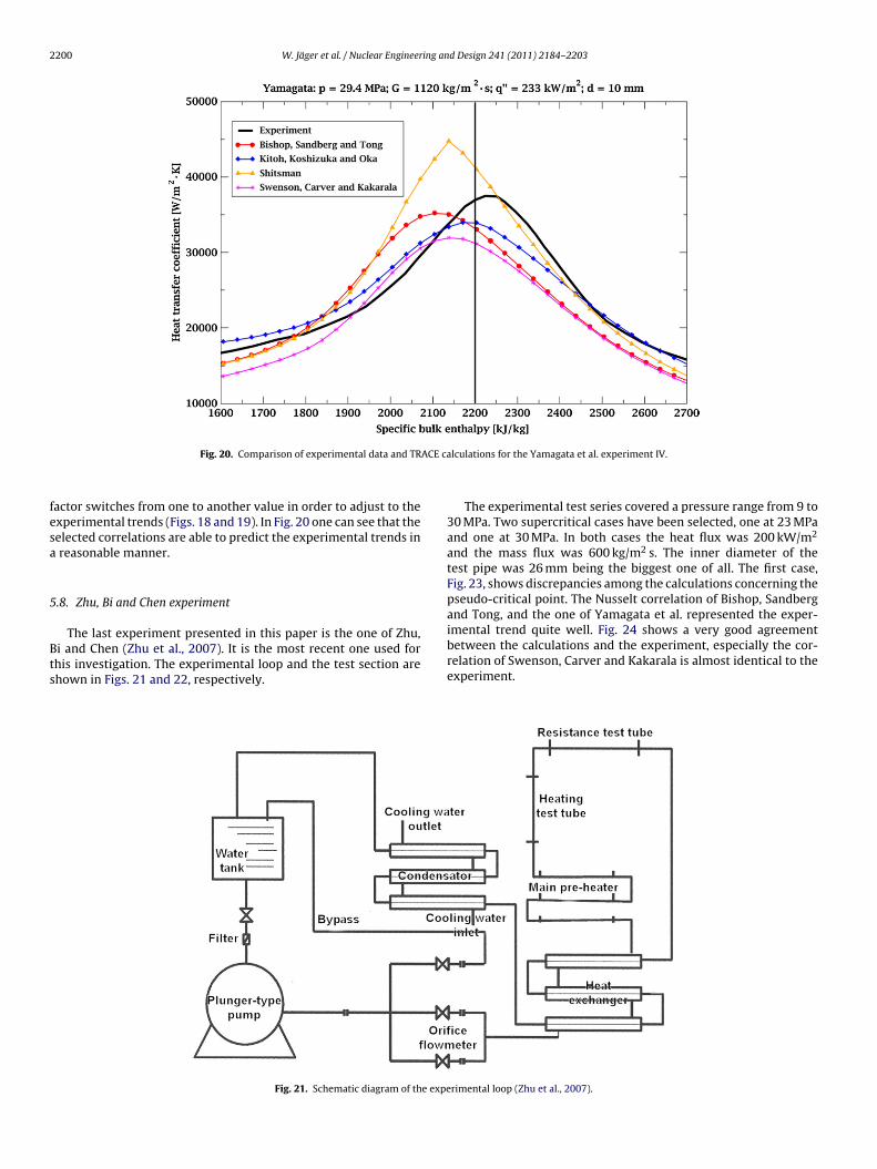
2200 W. Jäger et al. / Nuclear Engineering and Design 241 (2011) 2184–2203
ACE ca
fesa
5
Bts
Fig. 20. Comparison of experimental data and TR
actor switches from one to another value in order to adjust to thexperimental trends (Figs. 18 and 19). In Fig. 20 one can see that theelected correlations are able to predict the experimental trends inreasonable manner.
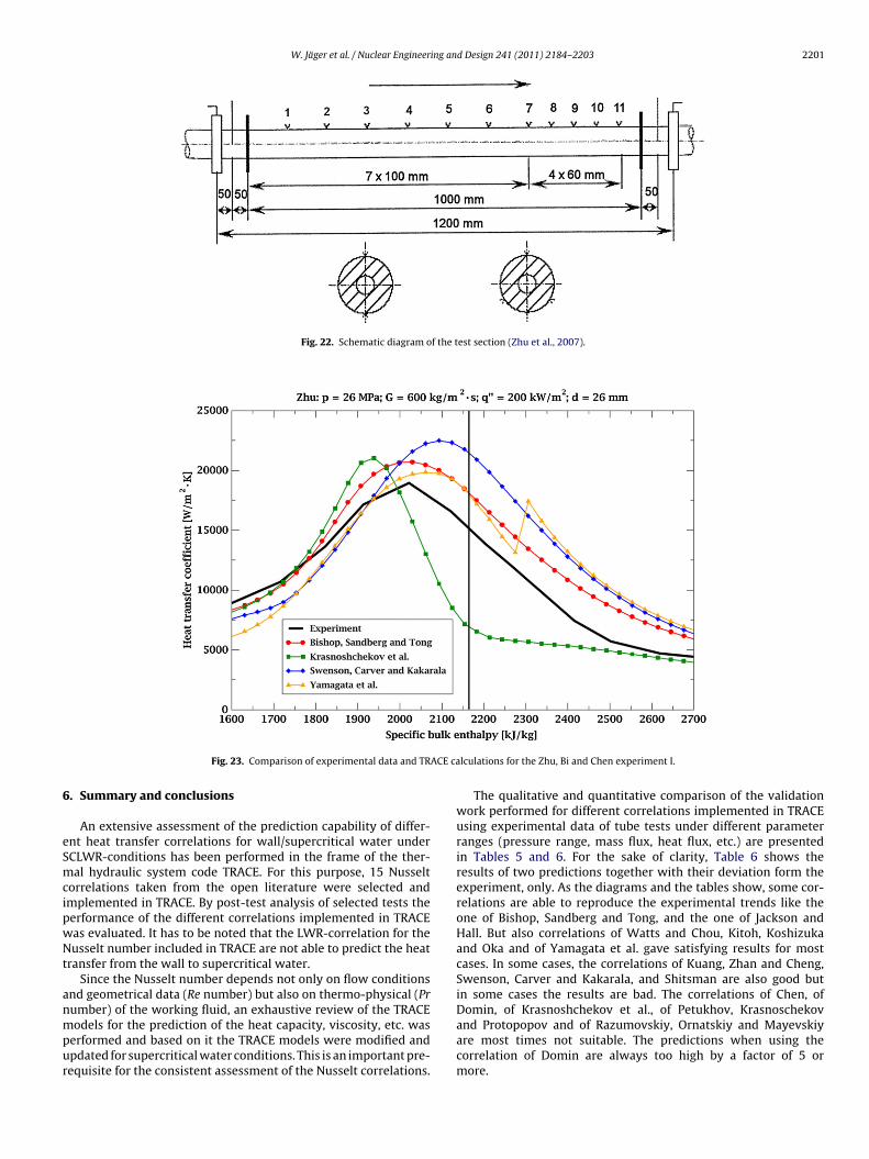
.8. Zhu, Bi and Chen experiment
The last experiment presented in this paper is the one of Zhu,i and Chen (Zhu et al., 2007). It is the most recent one used forhis investigation. The experimental loop and the test section arehown in Figs. 21 and 22, respectively.
Fig. 21. Schematic diagram of the expe
lculations for the Yamagata et al. experiment IV.
The experimental test series covered a pressure range from 9 to30 MPa. Two supercritical cases have been selected, one at 23 MPaand one at 30 MPa. In both cases the heat flux was 200 kW/m2
and the mass flux was 600 kg/m2 s. The inner diameter of thetest pipe was 26 mm being the biggest one of all. The first case,Fig. 23, shows discrepancies among the calculations concerning thepseudo-critical point. The Nusselt correlation of Bishop, Sandbergand Tong, and the one of Yamagata et al. represented the exper-
imental trend quite well. Fig. 24 shows a very good agreementbetween the calculations and the experiment, especially the cor-relation of Swenson, Carver and Kakarala is almost identical to theexperiment.rimental loop (Zhu et al., 2007).
W. Jäger et al. / Nuclear Engineering and Design 241 (2011) 2184–2203 2201
Fig. 22. Schematic diagram of the test section (Zhu et al., 2007).
ACE ca
6
eSmcipwNt
anmpur
Fig. 23. Comparison of experimental data and TR
. Summary and conclusions
An extensive assessment of the prediction capability of differ-nt heat transfer correlations for wall/supercritical water underCLWR-conditions has been performed in the frame of the ther-al hydraulic system code TRACE. For this purpose, 15 Nusselt
orrelations taken from the open literature were selected andmplemented in TRACE. By post-test analysis of selected tests theerformance of the different correlations implemented in TRACEas evaluated. It has to be noted that the LWR-correlation for theusselt number included in TRACE are not able to predict the heat
ransfer from the wall to supercritical water.Since the Nusselt number depends not only on flow conditions
nd geometrical data (Re number) but also on thermo-physical (Prumber) of the working fluid, an exhaustive review of the TRACE
odels for the prediction of the heat capacity, viscosity, etc. waserformed and based on it the TRACE models were modified andpdated for supercritical water conditions. This is an important pre-equisite for the consistent assessment of the Nusselt correlations.
lculations for the Zhu, Bi and Chen experiment I.
The qualitative and quantitative comparison of the validationwork performed for different correlations implemented in TRACEusing experimental data of tube tests under different parameterranges (pressure range, mass flux, heat flux, etc.) are presentedin Tables 5 and 6. For the sake of clarity, Table 6 shows theresults of two predictions together with their deviation form theexperiment, only. As the diagrams and the tables show, some cor-relations are able to reproduce the experimental trends like theone of Bishop, Sandberg and Tong, and the one of Jackson andHall. But also correlations of Watts and Chou, Kitoh, Koshizukaand Oka and of Yamagata et al. gave satisfying results for mostcases. In some cases, the correlations of Kuang, Zhan and Cheng,Swenson, Carver and Kakarala, and Shitsman are also good butin some cases the results are bad. The correlations of Chen, ofDomin, of Krasnoshchekov et al., of Petukhov, Krasnoschekov
and Protopopov and of Razumovskiy, Ornatskiy and Mayevskiyare most times not suitable. The predictions when using thecorrelation of Domin are always too high by a factor of 5 ormore.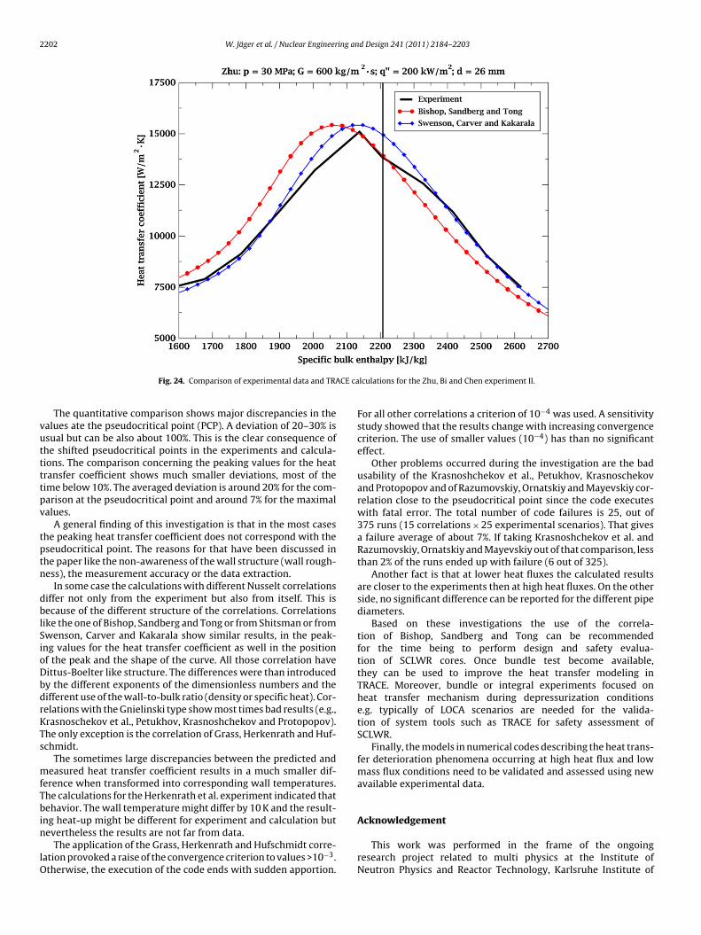
2202 W. Jäger et al. / Nuclear Engineering and Design 241 (2011) 2184–2203
CE ca
vuttttpv
tptn
dblSioDbdrKTs
mfTbin
lO
Fig. 24. Comparison of experimental data and TRA
The quantitative comparison shows major discrepancies in thealues ate the pseudocritical point (PCP). A deviation of 20–30% issual but can be also about 100%. This is the clear consequence ofhe shifted pseudocritical points in the experiments and calcula-ions. The comparison concerning the peaking values for the heatransfer coefficient shows much smaller deviations, most of theime below 10%. The averaged deviation is around 20% for the com-arison at the pseudocritical point and around 7% for the maximalalues.
A general finding of this investigation is that in the most caseshe peaking heat transfer coefficient does not correspond with theseudocritical point. The reasons for that have been discussed inhe paper like the non-awareness of the wall structure (wall rough-ess), the measurement accuracy or the data extraction.
In some case the calculations with different Nusselt correlationsiffer not only from the experiment but also from itself. This isecause of the different structure of the correlations. Correlations
ike the one of Bishop, Sandberg and Tong or from Shitsman or fromwenson, Carver and Kakarala show similar results, in the peak-ng values for the heat transfer coefficient as well in the positionf the peak and the shape of the curve. All those correlation haveittus-Boelter like structure. The differences were than introducedy the different exponents of the dimensionless numbers and theifferent use of the wall-to-bulk ratio (density or specific heat). Cor-elations with the Gnielinski type show most times bad results (e.g.,rasnoschekov et al., Petukhov, Krasnoshchekov and Protopopov).he only exception is the correlation of Grass, Herkenrath and Huf-chmidt.
The sometimes large discrepancies between the predicted andeasured heat transfer coefficient results in a much smaller dif-
erence when transformed into corresponding wall temperatures.he calculations for the Herkenrath et al. experiment indicated thatehavior. The wall temperature might differ by 10 K and the result-
ng heat-up might be different for experiment and calculation but
evertheless the results are not far from data.The application of the Grass, Herkenrath and Hufschmidt corre-ation provoked a raise of the convergence criterion to values >10−3.therwise, the execution of the code ends with sudden apportion.
lculations for the Zhu, Bi and Chen experiment II.
For all other correlations a criterion of 10−4 was used. A sensitivitystudy showed that the results change with increasing convergencecriterion. The use of smaller values (10−4) has than no significanteffect.
Other problems occurred during the investigation are the badusability of the Krasnoshchekov et al., Petukhov, Krasnoschekovand Protopopov and of Razumovskiy, Ornatskiy and Mayevskiy cor-relation close to the pseudocritical point since the code executeswith fatal error. The total number of code failures is 25, out of375 runs (15 correlations × 25 experimental scenarios). That givesa failure average of about 7%. If taking Krasnoshchekov et al. andRazumovskiy, Ornatskiy and Mayevskiy out of that comparison, lessthan 2% of the runs ended up with failure (6 out of 325).
Another fact is that at lower heat fluxes the calculated resultsare closer to the experiments then at high heat fluxes. On the otherside, no significant difference can be reported for the different pipediameters.
Based on these investigations the use of the correla-tion of Bishop, Sandberg and Tong can be recommendedfor the time being to perform design and safety evalua-tion of SCLWR cores. Once bundle test become available,they can be used to improve the heat transfer modeling inTRACE. Moreover, bundle or integral experiments focused onheat transfer mechanism during depressurization conditionse.g. typically of LOCA scenarios are needed for the valida-tion of system tools such as TRACE for safety assessment ofSCLWR.
Finally, the models in numerical codes describing the heat trans-fer deterioration phenomena occurring at high heat flux and lowmass flux conditions need to be validated and assessed using newavailable experimental data.
Acknowledgement
This work was performed in the frame of the ongoingresearch project related to multi physics at the Institute ofNeutron Physics and Reactor Technology, Karlsruhe Institute of
ing an
Tc
R
B
C
D
G
G
H
J
J
J
J
K
W. Jäger et al. / Nuclear Engineer
echnology. The help and support of N. Schneider is highly appre-iated.
eferences
ishop, A.A., Sandberg, R.O., Tong, L.S., 1965. Forced convection heat transfer towater near critical temperatures and super-critical pressures. AIChE -I. ChemicalEngineering Symposium Series 2, 77–85.
hen, T., 2004. Two-Phase Flow And Heat Transfer Study. Jiaotong University Press,China.
omin, G., 1963. Waermeuebergang in kritischen und ueberkritischen bereichenvon Wasser in Rohren. Brennstoff-WärmeKraft 15, 527–532.
rass, G., Herkenrath, H., Hufschmidt, W., 1971. Anwendung des PrandtlschenGrenzschichtmodells auf den Waermeuebergang an Fluessigkeiten mitstark temperaturabhaengigen Stoffeigenschaften bei erzwungener Stroemung.Waerme- und Stoffuebertragung 4, 113–119.
riem, H., 1996. A new procedure for the prediction of forced convection heat trans-fer at near- and supercritical pressure. Heat and Mass Transfer 31, 301–305.
erkenrath, H., Moerkenstein, P., Jung, U. and Weckman, F., 1967. Waermeueber-gang an Wasser bei erzwungener Stroemung im Druckbereich von 140 bis250bar. EURATOM, Berlin (1967). EUR 3658 d.
ackson, J.D., 2008. A Semi-empirical model of turbulent convective heat transfer tofluids at supercritical pressures. In: 16th International Conference on NuclearEngineering , Orlando, USA, May 11–15,2008.
ackson, J.D., Hall, W.B., 1979. Forced Convection Heat Transfer to Fluids at Super-critical Pressure. In: Kakac, S., Spalding, D.B. (Eds.), Turbulent Forced Convectionin Channels and Bundels. Hemisphere Publishing Corp, USA, pp. 563–612.
aeger, W., Sanchez Espinoza, V.H., Hurtado, A., 2008. Investigations of Experimentswith Supercritical H2O with the System Code TRACE. In: 7th International Top-ical Meeting on Nuclear Reactor Thermal hydraulics, Operation and Safety –NUTHOS-7 , Seoul, Korea, October 5–9, 2008.
aeger, W., Sanchez Espinoza, V.H., Schneider, N., Hurtado, A., 2009. Assessment of
heat transfer correlations for supercritical water in the frame of best-estimatecode validation. In: International Congress on Advances in Nuclear Power Plants– ICAPP , Tokyo, Japan, May 10–14, 2009.itoh, K., Koshizuka, S., Oka, Y., 1999. Refinement of transient critera and safetyanalysis for high temperature reactor cooled by supercritical water. In: 7th
d Design 241 (2011) 2184–2203 2203
International Conference on Nuclear Engineering , Tokyo, Japan, April 19–23,1999.
Kondratev, N.S., 1969. Heat transfer and hydraulic resistance with supercriticalwater flowing in tubes. Teploenergetika 16 (8), 49–51.
Krasnoshchekov, E.A., Propopov, V.S., Van, F., Kuraeva, I.V., 1964. Experimental inves-tigations of heat transfer for carbon dioxide in the supercritical region. In: 2ndAll-Union Conference on Heat Mass Transfer 1 , Minsk, Belarus.
Kuang, B., Zhang, Y., Cheng, X., 2008. A new, wide-ranged heat transfer correlationof water at supercritical pressures in vertical upward ducts. In: 7th InternationalTopical Meeting on Nuclear Reactor Thermal hydraulics, Operation and Safety –NUTHOS-7 , Seoul, Korea, October 5–9, 2008.
Petukhov, B.S., Krasnoshchekov, E.A., Protopopov, V.S., 1961. An Investigation ofHeat transfer to fluids flowing in pipes under supercritical conditions. In: 2ndInternational Heat Transfer Conference , Boulder, U.S.A.
Pioro, I.L., Duffey, R.B., 2007. Heat Transfer and Hydraulic Resistance at Supercrit-ical Pressures in Power Engineering Applications. ASME Press, New York, NY,USA.
Razumovskiy, V.G., Ornatskiy, A.P., Mayevskiy, Y.M., 1990. Local heat transfer andhydraulic behavior in turbulent channel flow of water at supercritical pressure.Heat Transfer-Soviet Research 22 (1), 91–102.
Schmidt, E., 1989. Properties of Water and Steam in SI-Units. Springer-Verlag, Berlin.Shitsman, M.E., 1963. Impairment of the heat transmission at supercritical pressures.
Teplofizika Vysokikh Temperatur 1, 267–275.Swenson, H.S., Carver, J.R., Kakarala, C.R., 1965. Heat transfer to supercritical water
in smoothbore tubes. Journal of Heat Transfer Series C 87, 477–484.U.S. NRC, 2008. TRACEV5.0 User’s Manuel – Volume 2: Modeling Guidelines.Wagner, W., Kruse, A. (Eds.), 1998. Properties of Water and Steam. Springer-Verlag,
Berlin.Watts, M.J., Chou, C.T., 1982. Mixed convection heat transfer to supercritical pressure
water. In: 7th International Heat Transfer. Conference 3 , Munich, Germany, pp.495–500.
Yamagata, K., Nishikawa, K., Hasegawa, S., Fuji, T., Yoshida, S., 1972. Forced convec-tive heat transfer to supercritical water flowing in tubes. International Journal
of Heat and Mass Transfer 15, 2575–2593.Zhu, X.J., Bi, Q.C., Chen, T.K., 2007. An investigation on heat transfer characteristics ofsteam–water at different pressure in vertical upward tube. In: 3rd InternationalSymposium on SCWR – Design and Technology , Shanghai, China, March 12–15,2007.
Copyright © 2022 FDOKUMEN