WCDMA : KPI ANALYSIS & OPTIMIZATION Network planning& Optimization
Upload
khangminh22Category
view
2download
0
Citation: Tong, Z.; Song, Z.;
Zhang, C.; Xing, H.; Sun, Y.
One-Dimensional Optimization
Design of Supercritical Carbon
Dioxide Radial Inflow Turbine and
Performance Analysis under
Off-Design Conditions. Appl. Sci.
2022, 12, 3882. https://doi.org/
10.3390/app12083882
Academic Editor: Satoru Okamoto
Received: 23 March 2022
Accepted: 10 April 2022
Published: 12 April 2022
Publisher’s Note: MDPI stays neutral
with regard to jurisdictional claims in
published maps and institutional affil-
iations.
Copyright: © 2022 by the authors.
Licensee MDPI, Basel, Switzerland.
This article is an open access article
distributed under the terms and
conditions of the Creative Commons
Attribution (CC BY) license (https://
creativecommons.org/licenses/by/
4.0/).
applied sciences
Article
One-Dimensional Optimization Design of Supercritical CarbonDioxide Radial Inflow Turbine and Performance Analysis underOff-Design ConditionsZhiting Tong 1,2, Zedong Song 1,2, Chao Zhang 1,2,* , Hao Xing 1,2 and Yuxuan Sun 3
1 Tianjin Key Laboratory for Advanced Mechatronic System Design and Intelligent Control,School of Mechanical Engineering, Tianjin University of Technology, Tianjin 300384, China;[email protected] (Z.T.); [email protected] (Z.S.); [email protected] (H.X.)
2 National Demonstration Center for Experimental Mechanical and Electrical EngineeringEducation (Tianjin University of Technology), Tianjin 300384, China
3 Institute of Engineering Thermophysics, Chinese Academy of Sciences, Beijing 100190, China;[email protected]
* Correspondence: [email protected]
Abstract: In the present study, the one-dimensional optimization design and the performance analysisbased on a three-dimensional model were performed for a 2.1 MW supercritical carbon dioxide radialinflow turbine. Firstly, an in-house code was developed with MATLAB language for one-dimensionaloptimization design to maximize the total-to-static efficiency. Then, the three-dimensional radialinflow turbine model was constructed based on the one-dimensional optimization design result.Finally, the flow field and the aerodynamic performance were studied using the commercial softwareNUMECA. It is shown that the total-to-static efficiency obtained from three-dimensional simulationunder the nominal design condition is 85.77%, with a relative deviation of 0.55%, as compared withthat from the one-dimensional optimization design. Furthermore, the static temperature and pressurefrom the turbine inlet to the outlet drop uniformly, and there is no obvious flow separation under thenominal design condition. The values of total-to-static efficiency are always higher than 75% at the80–110% relative rotating speed and the expansion ratio of 1.75–4.48, which also demonstrates goodperformance under the off-design working conditions.
Keywords: supercritical carbon dioxide; radial inflow turbine; one-dimensional optimization design;off-design performance; numerical simulation
1. Introduction
The Brayton cycle with supercritical carbon dioxide (s-CO2) as a working fluid hasraised universal attention in the last few decades [1]. The s-CO2 Brayton cycle exhibits afew advantages compared with the Brayton cycle with the working fluid. A higher cyclethermal efficiency can be achieved with a relatively lower turbine inlet temperature, whichcould enhance the operation’s dependability, reduce the system’s complexity and save oncosts. Furthermore, the lower turbine inlet temperature of the s-CO2 Brayton cycle makesthe applications possible in solar energy and geothermal power generation, waste heatrecovery, and nuclear power generation [2–6]. Moreover, because it is an environmentallyfriendly working fluid, no pollution is generated in the power generation process ofthe s-CO2 Brayton cycle. However, more challenges bring to the key power generationcomponent, i.e., the s-CO2 radial inflow turbine design, resulting from unique thermal-physical properties. The geometry scaling effect is a salient issue that needs to be resolveddue to the smaller geometry of the s-CO2 turbine [7]. Hence, the radial inflow design withhigh efficiency is a fundamental issue for applying the advanced s-CO2 Brayton cycle.
Sandia National Laboratory [8] performed the pioneering experimental work to testthe s-CO2 Brayton cycle and key component performance. In their work, the No. 2 radial
Appl. Sci. 2022, 12, 3882. https://doi.org/10.3390/app12083882 https://www.mdpi.com/journal/applsci

Appl. Sci. 2022, 12, 3882 2 of 13
inflow turbine was designed with a power of 213 kW and a total-to-static efficiency of 87%.Bechtel Marine Propulsion Corporation [9] designed the s-CO2 radial inflow turbine with atotal inlet temperature of 299 C. However, due to several confines in their experimentaltest, the turbine inlet’s total temperature was limited to 232 C, and the rotating speed couldnot achieve the nominal value. In the experimental test carried out by the Tokyo Institute ofTechnology [10], the rotating speed of the s-CO2 radial inflow was only 55,000 rpm, whichwas much lower than the design value of 100,000 rpm; this was attributed to the technicallimitations of the shaft bearing and sealing. Hence, the output power and the efficiencymeasured were lower than the designed values. The experimental tests performed by theKorea Institute of Energy Research [11] found the same astriction. The designed rotatingspeed of their s-CO2 radial inflow turbine was 70,000 rpm; however, the actual experimentalvalue was limited to 30,000 rpm.
Zhou et al. [12] designed the s-CO2 radial inflow turbine with the power of 1.5 MWand performed the performance prediction based on the Computational Fluid Dynamics(CFD) method using the software package ANSYS CFX. They found that the predictedtotal-to-static efficiency is 83.49%, with a deviation less than 5% from the calculated valuefrom their one-dimensional design code. Lv et al. [13] presented an optimization work forthe one-dimensional design of the s-CO2 radial turbine based on the Sequential QuadraticProgramming (SQP) optimization algorithm. They revealed the superiority of the optimiza-tion work with an improvement of 2.27% on the total-to-static efficiency. Saeed et al. [14]designed s-CO2 turbines using deep neural networks. Results suggest that the employedmultifaceted approach reduces computational time and resources significantly and is re-quired to completely understand the effects of various turbine design parameters on itsperformance and sizing. Lee et al. [15] developed a code to predict the aerodynamic per-formance of an s-CO2 radial inflow turbine under the off-design working condition. Thevariations were less than 10% between the one-dimensional calculations and the three-dimensional CFD predictions. The energy loss empirical or semi-empirical correlationsdetermine the predicted accuracy. However, limited correlations are available, especiallyfor the s-CO2 radial inflow turbine. Persky and Sauret [16] evaluated the analytical energyloss correlations used in the preliminary design for the air or gas radial inflow turbine indesigning the s-CO2 turbine. They found that the published loss model configurations maynot suit off-design analysis for the s-CO2 radial inflow turbine. They developed a new lossmodel configuration with less than a 2% difference in efficiency prediction over the CFDresult. With the aid of the CFD method, Keep and Jahn [17] studied the loss contributionfor a 300 kW low specific speed s-CO2 radial inflow turbine. Their results concluded thatthe end-wall viscous losses in the stator are dominated, which plays a more significant rolethan that for the gas radial inflow turbine. Yang et al. [18] focused on the leakage loss inthe impeller backface cavity for the s-CO2 radial inflow turbine and revealed the relevanceof the leakage loss to the labyrinth seal geometrical parameter.
The present paper provides an optimization design platform based on the one-dimensional design method in Shu et al. [19] to carry forward the efficient s-CO2 radialinflow turbine design. An in-house code is developed in MATLAB language. The designvariables are selected with nozzle velocity coefficient, rotor velocity coefficient, reactiondegree, diameter ratio, absolute flow angle rotor inlet, and relative flow angle at the rotoroutlet. The optimization function maximizes the total-to-static efficiency with aerodynamicand structural constraints. The build-in function, fmincon, is treated as the optimizationalgorithm. The optimization code is then applied to design the s-CO2 radial inflow turbinewith a power of 2.1 MW. The comparison of the total-to-static efficiency is performed be-tween the CFD simulation and the one-dimensional calculation under the design workingcondition to validate the current code. The flow field and the performance are also analyzedin detail under the off-design working conditions.

Appl. Sci. 2022, 12, 3882 3 of 13
2. One-Dimensional Optimization Design
The general flow chart of the current one-dimensional optimization design for thes-CO2 radial inflow turbine is shown in Figure 1. The optimization target, the designvariables and the relevant lower and upper limits, the initial values of the design variables,and the restricted conditions are required to be specified to run the optimization work. Thebuilt-in function in MATLAB, fmincon, is selected as the optimization algorithm. Becausethe fmincon function is optimized locally, the predicted optimization result strongly relieson the given starting value. Hence, the final optimization result is obtained by adjustingthe initial values and the trial. When the optimization value in the current step is equalto or larger than that in the former step, the optimization process is completed. In theone-dimensional design method for the s-CO2 radial inflow turbine, the calculated value ofthe total-to-static efficiency also depends on the thermo-physical properties of the s-CO2,the selection of the energy loss models, and the specific constrained conditions.
Appl. Sci. 2022, 12, x FOR PEER REVIEW 3 of 14
design working condition to validate the current code. The flow field and the performance are also analyzed in detail under the off-design working conditions.
2. One-Dimensional Optimization Design The general flow chart of the current one-dimensional optimization design for the s-
CO2 radial inflow turbine is shown in Figure 1. The optimization target, the design variables and the relevant lower and upper limits, the initial values of the design variables, and the restricted conditions are required to be specified to run the optimization work. The built-in function in MATLAB, fmincon, is selected as the optimization algorithm. Because the fmincon function is optimized locally, the predicted optimization result strongly relies on the given starting value. Hence, the final optimization result is obtained by adjusting the initial values and the trial. When the optimization value in the current step is equal to or larger than that in the former step, the optimization process is completed. In the one-dimensional design method for the s-CO2 radial inflow turbine, the calculated value of the total-to-static efficiency also depends on the thermo-physical properties of the s-CO2, the selection of the energy loss models, and the specific constrained conditions.
Start
Input the initial value x(n)
Define the relevant parameters of fmincon: objective function, optimization parameters, upper and lower limits of parameters, constraint conditions
Generate solution space from design parameters and restricted range, and build area scanner
Transform the objective function according to the constraints
Calculate the optimal solution that meets the constraints in the local range of the initial value, and output the optimal solution f(n) and optimized parameters
End
If f(n+1)> f(n)?
Output thermal parameters
Take the local f(n) return parameter x(n) as the initial value x(n+1)
No
Yes
Figure 1. Flow chart of the one-dimensional optimization design.
2.1. Thermo-Physical Property Calculation Unlike conventional air or gas, working fluid s-CO2 should be treated as the real
working fluid with varying thermo-physical properties. In the current code, the thermo-physical properties are acquired from a featured software package NIST REFPROP [20]. Hence, the thermodynamic parameter at the nozzle inlet, rotor inlet, and rotor exit and the total-to-static efficiency of the s-CO2 radial inflow turbine can be accurately calculated.
Figure 1. Flow chart of the one-dimensional optimization design.
2.1. Thermo-Physical Property Calculation
Unlike conventional air or gas, working fluid s-CO2 should be treated as the realworking fluid with varying thermo-physical properties. In the current code, the thermo-physical properties are acquired from a featured software package NIST REFPROP [20].Hence, the thermodynamic parameter at the nozzle inlet, rotor inlet, and rotor exit and thetotal-to-static efficiency of the s-CO2 radial inflow turbine can be accurately calculated.
2.2. Optimization Algorithm
The optimization algorithm is the fundamental part of an optimization issue, determin-ing the local or global way and the optimization time. The optimization function, fmincon,is commonly applied in constrained nonlinear multivariable nonlinear system optimizationproblems [21]. The option SQP is chosen for the algorithm option. The Hessian matrixis updated using the BFGS algorithm in the quadratic programming problem. Its major

Appl. Sci. 2022, 12, 3882 4 of 13
advantages include succinct code, simple usage, and fewer iterations. The comparison testfor the current one-dimensional optimization design showed that the iteration steps are 36,much lower than the iteration step of 120 for the Simulated Annealing Approach. Theconfinement factor is that only the local optimum result can be acquired, which maydiffer from the optimum global result. In the present study, the initialized variables arecarefully given using the screening method [22] for the radial inflow turbine design. Fur-thermore, the additional iterative process shown in Figure 1 is applied to pursue the globaloptimum solution.
2.3. One-Dimensional Design Method
The total-to-static efficiency ηs can be calculated by considering several energy losses,which is given by:
ηs = [(ηu − ζf)η∆ − ζi]ηe (1)
where ηu is the peripheral efficiency, ζf is the disk friction energy loss coefficient, η∆ is theclearance efficiency, ζi is the incidence loss coefficient, ηe is the partial admission efficiency.
From the energy standpoint, the peripheral efficiency ηu is calculated by:
ηu = 1− ζn − ζr − ζc2 (2)
where ζn, ζr, and ζc2 are the energy loss coefficients in the nozzle, rotor blade, and theleaving velocity at rotor exit.
The peripheral efficiency ηu can also be expressed by the design variables as follow:
ηu = 2xa
(ϕ cos α1
√1−Ω− D2
2xa + D2ψ cos β2
√Ω + ϕ2(1−Ω) + D2
2x2a − 2xa ϕ cos α1
√1−Ω
)(3)
where xa is the velocity ratio, ϕ and ψ are the nozzle velocity coefficient and rotor bladevelocity ratio, α1 is the absolute flow angle at rotor inlet, β2 is the relative flow angle atrotor exit, Ω is the reaction degree, D2 is wheel diameter ratio. The definitions of xa, ϕ, ψ,and D2 can be referred to in [19].
The disk friction loss coefficient ζf is given by:
ζf =1000G∆hs
·f ρ1D2
11.36
·( u1
100
)3(4)
where G is the mass flow rate, ∆hs is the turbine isentropic enthalpy drop, f is the coefficientwith a constant value of 4, ρ1, D1, and u1 are the density, diameter, and peripheral velocityat the rotor inlet.
The expression of clearance efficiency η∆ is as follows:
η∆ = 1− 1.3(∆r/lm) (5)
where ∆r is the radial clearance between the shroud and the casing, lm is the arithmeticmean blade height.
The current radial inflow design assumes the full admission pattern and the partialadmission efficiency ηe equals 1.
The incidence loss ζi is additionally considered in the current study, which is given by:
ζi =w1
2 sin2 i12∆hs
(6)
where w1 is the relative velocity and relative flow angle at the rotor inlet, i1 is the incidenceangle at the rotor inlet. The definition of i1 is as follows:
i1 = β1b − β1 (7)
where β1b is the rotor inlet blade angle of 90, β1 is the relative flow angle at the rotor inlet.

Appl. Sci. 2022, 12, 3882 5 of 13
2.4. Design Constraints and Optimization Function
As seen in the one-dimensional design method, seven design parameters influencethe final total-to-static efficiency of the radial inflow turbine. The upper and lower limits ofeach design parameter for the current design are listed in Table 1, following the suggestedvalues in [19]. Note that the design parameters vary within a wide region, providingsufficient wide design space for the following optimization.
Table 1. Design variable and the relevant value region.
Design Variable Value Region
Velocity ratio xa 0.63~0.72Reaction degree Ω 0.36~0.5
Nozzle velocity coefficient ϕ 0.92~0.97Rotor inlet absolute flow angle α1 () 14~25Rotor exit relative flow angle β2 () 20~45
Wheel diameter ratio D2 0.35~0.55Rotor blade velocity coefficient ψ 0.75~0.90
The aerodynamic limitations and structural constraints must be considered for theone-dimensional optimization design. In the current study, the followings constraints arecovered and listed in Table 2. The incidence angle limitation avoids severe reverse flow andthe excessive incidence loss at the rotor inlet. The point of the Mach number constraint is toprevent the energy loss and the secondary flow loss from the shock wave. The absoluteflow angle at the rotor exit is bounded from 85 to 95, which guarantees the close axialflow direction for the working fluid at the rotor exit to avoid excessive leaving velocityenergy loss. The meridional passage geometry depends on the specific values of the relativeshroud diameter and the hub diameter. Hence, the current constraints are assumed toavoid excessive expansion in the meridional passage. When the relative blade height issmaller than its lower limit, the blade height may be too small, especially for the s-CO2radial inflow turbine with a heavy working fluid. However, the relative blade height witha large value would influence the shape of the meridional passage.
Table 2. Constraint conditions.
Constrained Variable Value
Incidence angle at rotor inlet i1 () −20~+10Mach number at rotor inlet ≤1.4
Absolute flow angle at rotor exit () 85~95Relative shroud diameter at rotor exit ≤0.85
Relative hub diameter at rotor exit ≥0.12Relative blade height at rotor inlet 0.02~0.17
Under the consideration of the constraints mentioned above, the optimization functionis given as follows:
f mincon(1/ηs) = f(xa, Ω, α1, β2, ϕ, ψ, D2
)(8)
The fmincon function is to find the minimum. When the minimum of 1/ηs is achieved,the maximum of ηs is obtained equivalently. Hence, the reciprocal of ηs is supposed to bethe optimization function.
2.5. Optimization Result
A design case is performed to validate the current in-house one-dimensional optimiza-tion design code. The design specifications of the s-CO2 radial inflow turbine are listedin Table 3.

Appl. Sci. 2022, 12, 3882 6 of 13
Table 3. Design specifications.
Parameter Specification
Mass flow rate (kg/s) 16.0Rotating speed (r/min) 42,000
Inlet total pressure (MPa) 24.6Inlet total temperature (K) 823
Outlet static pressure (MPa) 8.5Output power (MW) 2.1
In the optimization process, the numbers of nozzle and rotor blades are fixed asconstant values of 33 and 19, respectively. The one-dimensional design results originatedfrom the initial design parameters, and the optimization results are listed in Table 4. It isseen that the optimal set of the seven design variables results in a large rotor geometryand a slightly higher specific speed than the initial design. The optimal design provides anoutput power of 2.118 MW and a total-to-static efficiency of 85.30%.
Table 4. Initial and optimum design results.
Parameter Initial Value Optimum Value
Velocity ratio xa 0.650 0.662Reaction degree Ω 0.470 0.483
Nozzle velocity coefficient ϕ 0.95 0.97Rotor inlet absolute flow angle α1 () 16.0 16.0Rotor exit relative flow angle β2 () 21.4 25.0
Wheel diameter ratio D2 0.430 0.417Rotor blade velocity coefficient ψ 0.85 0.90
Rotor inlet relative flow angle β1 () 85.55 85.00Rotor exit absolute flow angle α2 () 78.0 75.0
Nozzle exit diameter (mm) 170.3 170.4Rotor inlet diameter (mm) 163.8 166.8
Rotor inlet blade height (mm) 3.0 3.3Rotor exit hub diameter (mm) 43.1 48.6
Rotor exit shroud diameter (mm) 89.8 85.6Specific speed 13.76 13.84
Output power (MW) 2.056 2.118Total-to-static efficiency ηs (%) 83.76 85.30
3. Numerical Methodology and Setup
The steady-state, three-dimensional Navier-Stokes equations are solved using thecommercial software NUMECA. The turbulence model comparison work for the radialinflow turbine in [23] concluded that the Spalart-Allmaras turbulence model was a suitablechoice with good convergence and adaptability. Hence, the Spalart-Allmaras turbulencemodel is selected for the turbulent closure in the current study.
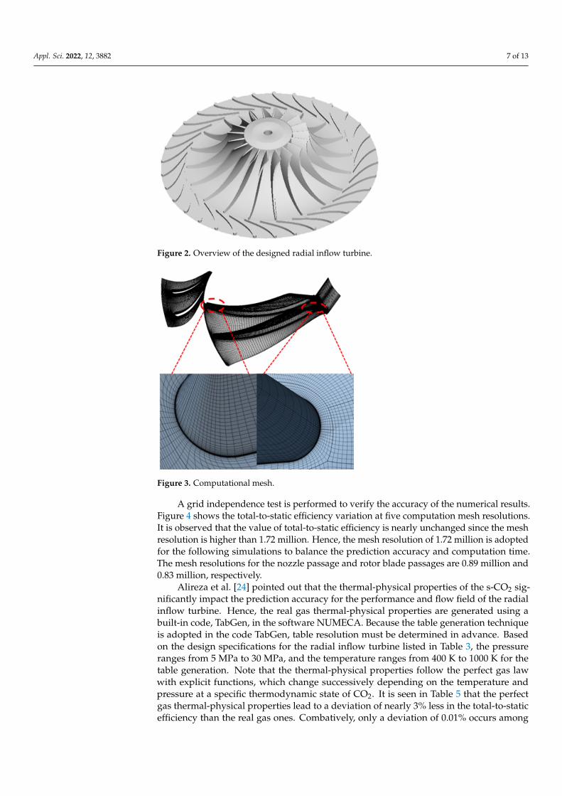
The three-dimensional model is generated based on the one-dimensional optimizationdesign geometry, as shown in Figure 2. In the current simulation, one nozzle passage andthe rotor blade passage are selected as the computational domain to save the computationalcost. The structured meshes are generated using IGG-AutoGrid5, shown in Figure 3.The O4H and HI topology structures are applied for the mesh generation in the nozzlepassage and the rotor blade passage. The meshes around the endwall, nozzle, and rotorblade surfaces are refined with an expansion ratio of 1.2 to describe the velocity boundarylayers. The computational meshes stratify the numerical simulation standards with anorthogonality angle of less than 20, an aspect ratio of less than 2500, and an extension ratioof less than 2.
Appl. Sci. 2022, 12, 3882 7 of 13
Appl. Sci. 2022, 12, x FOR PEER REVIEW 7 of 14
suitable choice with good convergence and adaptability. Hence, the Spalart-Allmaras turbulence model is selected for the turbulent closure in the current study.
The three-dimensional model is generated based on the one-dimensional optimization design geometry, as shown in Figure 2. In the current simulation, one nozzle passage and the rotor blade passage are selected as the computational domain to save the computational cost. The structured meshes are generated using IGG-AutoGrid5, shown in Figure 3. The O4H and HI topology structures are applied for the mesh generation in the nozzle passage and the rotor blade passage. The meshes around the endwall, nozzle, and rotor blade surfaces are refined with an expansion ratio of 1.2 to describe the velocity boundary layers. The computational meshes stratify the numerical simulation standards with an orthogonality angle of less than 20°, an aspect ratio of less than 2500, and an extension ratio of less than 2.
Figure 2. Overview of the designed radial inflow turbine.
Figure 3. Computational mesh.
A grid independence test is performed to verify the accuracy of the numerical results. Figure 4 shows the total-to-static efficiency variation at five computation mesh resolutions. It is observed that the value of total-to-static efficiency is nearly unchanged since the mesh resolution is higher than 1.72 million. Hence, the mesh resolution of 1.72 million is adopted for the following simulations to balance the prediction accuracy and computation time. The mesh resolutions for the nozzle passage and rotor blade passages are 0.89 million and 0.83 million, respectively.
Figure 2. Overview of the designed radial inflow turbine.
Appl. Sci. 2022, 12, x FOR PEER REVIEW 7 of 14
suitable choice with good convergence and adaptability. Hence, the Spalart-Allmaras turbulence model is selected for the turbulent closure in the current study.
The three-dimensional model is generated based on the one-dimensional optimization design geometry, as shown in Figure 2. In the current simulation, one nozzle passage and the rotor blade passage are selected as the computational domain to save the computational cost. The structured meshes are generated using IGG-AutoGrid5, shown in Figure 3. The O4H and HI topology structures are applied for the mesh generation in the nozzle passage and the rotor blade passage. The meshes around the endwall, nozzle, and rotor blade surfaces are refined with an expansion ratio of 1.2 to describe the velocity boundary layers. The computational meshes stratify the numerical simulation standards with an orthogonality angle of less than 20°, an aspect ratio of less than 2500, and an extension ratio of less than 2.
Figure 2. Overview of the designed radial inflow turbine.
Figure 3. Computational mesh.
A grid independence test is performed to verify the accuracy of the numerical results. Figure 4 shows the total-to-static efficiency variation at five computation mesh resolutions. It is observed that the value of total-to-static efficiency is nearly unchanged since the mesh resolution is higher than 1.72 million. Hence, the mesh resolution of 1.72 million is adopted for the following simulations to balance the prediction accuracy and computation time. The mesh resolutions for the nozzle passage and rotor blade passages are 0.89 million and 0.83 million, respectively.
Figure 3. Computational mesh.
A grid independence test is performed to verify the accuracy of the numerical results.Figure 4 shows the total-to-static efficiency variation at five computation mesh resolutions.It is observed that the value of total-to-static efficiency is nearly unchanged since the meshresolution is higher than 1.72 million. Hence, the mesh resolution of 1.72 million is adoptedfor the following simulations to balance the prediction accuracy and computation time.The mesh resolutions for the nozzle passage and rotor blade passages are 0.89 million and0.83 million, respectively.
Alireza et al. [24] pointed out that the thermal-physical properties of the s-CO2 sig-nificantly impact the prediction accuracy for the performance and flow field of the radialinflow turbine. Hence, the real gas thermal-physical properties are generated using abuilt-in code, TabGen, in the software NUMECA. Because the table generation techniqueis adopted in the code TabGen, table resolution must be determined in advance. Basedon the design specifications for the radial inflow turbine listed in Table 3, the pressureranges from 5 MPa to 30 MPa, and the temperature ranges from 400 K to 1000 K for thetable generation. Note that the thermal-physical properties follow the perfect gas lawwith explicit functions, which change successively depending on the temperature andpressure at a specific thermodynamic state of CO2. It is seen in Table 5 that the perfectgas thermal-physical properties lead to a deviation of nearly 3% less in the total-to-staticefficiency than the real gas ones. Combatively, only a deviation of 0.01% occurs among

Appl. Sci. 2022, 12, 3882 8 of 13
different table resolutions. Therefore, the table resolution of 201 × 201 is adopted in thefollowing simulations.
Appl. Sci. 2022, 12, x FOR PEER REVIEW 8 of 14
1.20 1.53 1.72 1.84 2.10
85.8
85.9
86.0To
tal-t
o-sta
tic e
ffici
ency
(%)
Number of cell(× milion) Figure 4. Mesh independence study.
Alireza et al. [24] pointed out that the thermal-physical properties of the s-CO2 significantly impact the prediction accuracy for the performance and flow field of the radial inflow turbine. Hence, the real gas thermal-physical properties are generated using a built-in code, TabGen, in the software NUMECA. Because the table generation technique is adopted in the code TabGen, table resolution must be determined in advance. Based on the design specifications for the radial inflow turbine listed in Table 3, the pressure ranges from 5 MPa to 30 MPa, and the temperature ranges from 400 K to 1000 K for the table generation. Note that the thermal-physical properties follow the perfect gas law with explicit functions, which change successively depending on the temperature and pressure at a specific thermodynamic state of CO2. It is seen in Table 5 that the perfect gas thermal-physical properties lead to a deviation of nearly 3% less in the total-to-static efficiency than the real gas ones. Combatively, only a deviation of 0.01% occurs among different table resolutions. Therefore, the table resolution of 201 × 201 is adopted in the following simulations.
Table 5. Table resolution test of the thermal-physical properties.
Gas Type Resolution Total-to-Static Efficiency Perfect gas / 82.82%
Real gas 101 × 101 85.78% 201 × 201 85.77% 301 × 301 85.77%
However, the thermal-physical properties with a high resolution degrade the computation stability; hence, a low value of the CFL number is required to improve the stability. The CFL number is set as 0.5 in the trade-off between the computation time and stability for the current simulations.
The boundary conditions in simulations are set up as follows. The total pressure and temperature are imposed at the nozzle inlet, and static pressure is set at the rotor exit. The domain of the nozzle passage is stationary, and the domain of the rotor blade passage is rotational. The boundary conditions can be seen in Table 3 for the simulation of the design working conditions. For the simulations under off-design working conditions, the static pressure at the rotor exit varies to achieve the given total-to-static expansion ratio, and the rotational speed differs. The wall surfaces at the hub, blade, and shroud are assumed to be adiabatic, smooth, and in no-slip condition. When the root means square residuals of all variables are lower than 10–6, and the variation of mass flow rate entering into the nozzle passage is less than 0.5%, the convergence of the CFD simulation is achieved.
4. Numerical Result Analysis and Discussion
Figure 4. Mesh independence study.
Table 5. Table resolution test of the thermal-physical properties.
Gas Type Resolution Total-to-Static Efficiency
Perfect gas / 82.82%
Real gas101 × 101 85.78%201 × 201 85.77%301 × 301 85.77%
However, the thermal-physical properties with a high resolution degrade the compu-tation stability; hence, a low value of the CFL number is required to improve the stability.The CFL number is set as 0.5 in the trade-off between the computation time and stabilityfor the current simulations.
The boundary conditions in simulations are set up as follows. The total pressure andtemperature are imposed at the nozzle inlet, and static pressure is set at the rotor exit. Thedomain of the nozzle passage is stationary, and the domain of the rotor blade passage isrotational. The boundary conditions can be seen in Table 3 for the simulation of the designworking conditions. For the simulations under off-design working conditions, the staticpressure at the rotor exit varies to achieve the given total-to-static expansion ratio, and therotational speed differs. The wall surfaces at the hub, blade, and shroud are assumed to beadiabatic, smooth, and in no-slip condition. When the root means square residuals of allvariables are lower than 10–6, and the variation of mass flow rate entering into the nozzlepassage is less than 0.5%, the convergence of the CFD simulation is achieved.
4. Numerical Result Analysis and Discussion4.1. Design Working Condition
The comparison between the predicted performance obtained from the three-dimensionalsimulation and the designed data is listed in Table 6. It is seen that the prediction of massflow rate, output power, and total-to-static pressure agree well with the designed datain the one-dimensional optimization design. The predictions are slightly higher than thedesigned data, with a maximum difference of 1.33% for the mass flow rate. The deviationof the total-to-static efficiency is only 0.47%.
Figure 5 represents the streamlines in the nozzle and rotor blade passages. It isobserved that the velocity varies gradually along the flow passage, and the streamlinesdistribute uniformly. There is no obvious swirl flow and separation, which demonstrates agood flow property for the current radial inflow turbine at the design working condition.

Appl. Sci. 2022, 12, 3882 9 of 13
Table 6. Evolution of the one-dimensional design.
Parameter Design Prediction Error (%)
Total-to-static expansion ratio 2.896 2.896 0.00Mass flow rate (kg/s) 16 16.213 1.33Output power (MW) 2.118 2.135 0.80
Total-to-static efficiency (%) 85.30 85.77 0.47
Appl. Sci. 2022, 12, x FOR PEER REVIEW 9 of 14
4.1. Design Working Condition The comparison between the predicted performance obtained from the three-
dimensional simulation and the designed data is listed in Table 6. It is seen that the prediction of mass flow rate, output power, and total-to-static pressure agree well with the designed data in the one-dimensional optimization design. The predictions are slightly higher than the designed data, with a maximum difference of 1.33% for the mass flow rate. The deviation of the total-to-static efficiency is only 0.47%.
Table 6. Evolution of the one-dimensional design.
Parameter Design Prediction Error (%) Total-to-static expansion ratio 2.896 2.896 0.00
Mass flow rate (kg/s) 16 16.213 1.33 Output power (MW) 2.118 2.135 0.80
Total-to-static efficiency (%) 85.30 85.77 0.47
Figure 5 represents the streamlines in the nozzle and rotor blade passages. It is observed that the velocity varies gradually along the flow passage, and the streamlines distribute uniformly. There is no obvious swirl flow and separation, which demonstrates a good flow property for the current radial inflow turbine at the design working condition.
Figure 5. Streamlines in the nozzle and rotor passages.
As presented in Figure 6, the Mach number at 50% blade span gradually increases along the nozzle passage, and the maximum value of 1.26 occurs at the nozzle exit. Although the transonic flow exists in the nozzle passage, the maximum is still within the limits of the Mach number in Table 2.
Figure 5. Streamlines in the nozzle and rotor passages.
As presented in Figure 6, the Mach number at 50% blade span gradually increasesalong the nozzle passage, and the maximum value of 1.26 occurs at the nozzle exit. Al-though the transonic flow exists in the nozzle passage, the maximum is still within thelimits of the Mach number in Table 2.
Appl. Sci. 2022, 12, x FOR PEER REVIEW 10 of 14
Figure 6. The contour of relative Mach number at 50% blade span.
The static pressure and temperature distribution at 50% blade span are shown in Figure 7. The static pressure and temperature drop gradually inside the turbine. The distributions of the static pressured drop and the temperature drop are reasonable with no abrupt changes.
The variations of the enthalpy and entropy in the radial inflow turbine are represented in Figure 8. It is seen that the enthalpy drops uniformly along the flow passage in Figure 8a. As shown in Figure 8b, the entropy reduction changes smoothly along most flow passages. The entropy varies from 2.667 to 2.856 kJ/(kg·K). There is an abrupt increase of about 0.1 kJ/(kg·K) at the interface between the stationary and rotational domains due to the irreversible shock wave energy at the nozzle exit.
(a) (b)
Figure 7. Contours of static pressure and temperature at 50% blade span. (a) Static pressure; (b) static temperature.
Figure 6. The contour of relative Mach number at 50% blade span.
The static pressure and temperature distribution at 50% blade span are shown inFigure 7. The static pressure and temperature drop gradually inside the turbine. Thedistributions of the static pressured drop and the temperature drop are reasonable with noabrupt changes.
Appl. Sci. 2022, 12, 3882 10 of 13
Appl. Sci. 2022, 12, x FOR PEER REVIEW 10 of 14
Figure 6. The contour of relative Mach number at 50% blade span.
The static pressure and temperature distribution at 50% blade span are shown in Figure 7. The static pressure and temperature drop gradually inside the turbine. The distributions of the static pressured drop and the temperature drop are reasonable with no abrupt changes.
The variations of the enthalpy and entropy in the radial inflow turbine are represented in Figure 8. It is seen that the enthalpy drops uniformly along the flow passage in Figure 8a. As shown in Figure 8b, the entropy reduction changes smoothly along most flow passages. The entropy varies from 2.667 to 2.856 kJ/(kg·K). There is an abrupt increase of about 0.1 kJ/(kg·K) at the interface between the stationary and rotational domains due to the irreversible shock wave energy at the nozzle exit.
(a) (b)
Figure 7. Contours of static pressure and temperature at 50% blade span. (a) Static pressure; (b) static temperature.
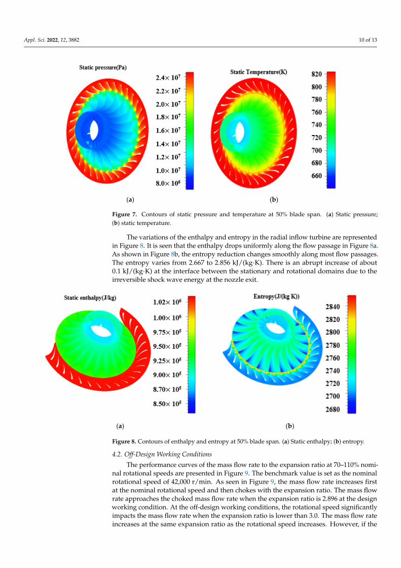
Figure 7. Contours of static pressure and temperature at 50% blade span. (a) Static pressure;(b) static temperature.
The variations of the enthalpy and entropy in the radial inflow turbine are representedin Figure 8. It is seen that the enthalpy drops uniformly along the flow passage in Figure 8a.As shown in Figure 8b, the entropy reduction changes smoothly along most flow passages.The entropy varies from 2.667 to 2.856 kJ/(kg·K). There is an abrupt increase of about0.1 kJ/(kg·K) at the interface between the stationary and rotational domains due to theirreversible shock wave energy at the nozzle exit.
Appl. Sci. 2022, 12, x FOR PEER REVIEW 11 of 14
(a) (b)
Figure 8. Contours of enthalpy and entropy at 50% blade span. (a) Static enthalpy; (b) entropy.
4.2. Off-Design Working Conditions The performance curves of the mass flow rate to the expansion ratio at 70–110%
nominal rotational speeds are presented in Figure 9. The benchmark value is set as the nominal rotational speed of 42,000 r/min. As seen in Figure 9, the mass flow rate increases first at the nominal rotational speed and then chokes with the expansion ratio. The mass flow rate approaches the choked mass flow rate when the expansion ratio is 2.896 at the design working condition. At the off-design working conditions, the rotational speed significantly impacts the mass flow rate when the expansion ratio is lower than 3.0. The mass flow rate increases at the same expansion ratio as the rotational speed increases. However, if the expansion ratio is higher than 3.0, the rotational speed variation has little impact on the mass flow rate. The radial inflow turbine is always choked with an expansion ratio higher than 3.788 regardless of the rotational speed. The maximum allowable expansion ratio is 5.47, and the corresponding choked mass flow rate is 16.358 kg/s.
1 2 3 4 5 6
10
11
12
13
14
15
16
17
n×110% n×100% n×90% n×70%
Mas
s flo
w ra
te(k
g·s-1
)
Total-to-static pressure ratio Figure 9. Performance curves of mass flow rate to expansion ratio at 70–110% nominal rotational speeds.
Figure 10 shows the variation curves of the total-to-static efficiency to the expansion ratio at different rotational speeds. At the nominal rotational speed, the value of the total-to-static efficiency increases and decreases with the expansion ratio. The total-to-static
Figure 8. Contours of enthalpy and entropy at 50% blade span. (a) Static enthalpy; (b) entropy.
4.2. Off-Design Working Conditions
The performance curves of the mass flow rate to the expansion ratio at 70–110% nomi-nal rotational speeds are presented in Figure 9. The benchmark value is set as the nominalrotational speed of 42,000 r/min. As seen in Figure 9, the mass flow rate increases firstat the nominal rotational speed and then chokes with the expansion ratio. The mass flowrate approaches the choked mass flow rate when the expansion ratio is 2.896 at the designworking condition. At the off-design working conditions, the rotational speed significantlyimpacts the mass flow rate when the expansion ratio is lower than 3.0. The mass flow rateincreases at the same expansion ratio as the rotational speed increases. However, if the
Appl. Sci. 2022, 12, 3882 11 of 13
expansion ratio is higher than 3.0, the rotational speed variation has little impact on themass flow rate. The radial inflow turbine is always choked with an expansion ratio higherthan 3.788 regardless of the rotational speed. The maximum allowable expansion ratio is5.47, and the corresponding choked mass flow rate is 16.358 kg/s.
Appl. Sci. 2022, 12, x FOR PEER REVIEW 11 of 14
(a) (b)
Figure 8. Contours of enthalpy and entropy at 50% blade span. (a) Static enthalpy; (b) entropy.
4.2. Off-Design Working Conditions The performance curves of the mass flow rate to the expansion ratio at 70–110%
nominal rotational speeds are presented in Figure 9. The benchmark value is set as the nominal rotational speed of 42,000 r/min. As seen in Figure 9, the mass flow rate increases first at the nominal rotational speed and then chokes with the expansion ratio. The mass flow rate approaches the choked mass flow rate when the expansion ratio is 2.896 at the design working condition. At the off-design working conditions, the rotational speed significantly impacts the mass flow rate when the expansion ratio is lower than 3.0. The mass flow rate increases at the same expansion ratio as the rotational speed increases. However, if the expansion ratio is higher than 3.0, the rotational speed variation has little impact on the mass flow rate. The radial inflow turbine is always choked with an expansion ratio higher than 3.788 regardless of the rotational speed. The maximum allowable expansion ratio is 5.47, and the corresponding choked mass flow rate is 16.358 kg/s.
1 2 3 4 5 6
10
11
12
13
14
15
16
17
n×110% n×100% n×90% n×70%
Mas
s flo
w ra
te(k
g·s-1
)
Total-to-static pressure ratio Figure 9. Performance curves of mass flow rate to expansion ratio at 70–110% nominal rotational speeds.
Figure 10 shows the variation curves of the total-to-static efficiency to the expansion ratio at different rotational speeds. At the nominal rotational speed, the value of the total-to-static efficiency increases and decreases with the expansion ratio. The total-to-static
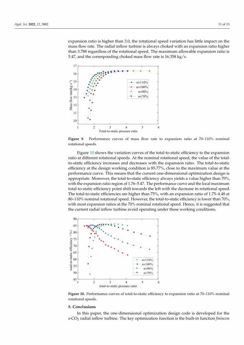
Figure 9. Performance curves of mass flow rate to expansion ratio at 70–110% nominalrotational speeds.
Figure 10 shows the variation curves of the total-to-static efficiency to the expansionratio at different rotational speeds. At the nominal rotational speed, the value of the total-to-static efficiency increases and decreases with the expansion ratio. The total-to-staticefficiency at the design working condition is 85.77%, close to the maximum value at theperformance curve. This means that the current one-dimensional optimization design isappropriate. Moreover, the total-to-static efficiency always yields a value higher than 70%,with the expansion ratio region of 1.76–5.47. The performance curve and the local maximumtotal-to-static efficiency point shift towards the left with the decrease in rotational speed.The total-to-static efficiencies are higher than 75%, with an expansion ratio of 1.75–4.48 at80–110% nominal rotational speed. However, the total-to-static efficiency is lower than 70%,with most expansion ratios at the 70% nominal rotational speed. Hence, it is suggested thatthe current radial inflow turbine avoid operating under these working conditions.
Appl. Sci. 2022, 12, x FOR PEER REVIEW 12 of 14
efficiency at the design working condition is 85.77%, close to the maximum value at the performance curve. This means that the current one-dimensional optimization design is appropriate. Moreover, the total-to-static efficiency always yields a value higher than 70%, with the expansion ratio region of 1.76–5.47. The performance curve and the local maximum total-to-static efficiency point shift towards the left with the decrease in rotational speed. The total-to-static efficiencies are higher than 75%, with an expansion ratio of 1.75–4.48 at 80–110% nominal rotational speed. However, the total-to-static efficiency is lower than 70%, with most expansion ratios at the 70% nominal rotational speed. Hence, it is suggested that the current radial inflow turbine avoid operating under these working conditions.
1 2 3 4 5 645
50
55
60
65
70
75
80
85
90
tota
l-to-
static
effi
cien
cy(
%)
total-to-static pressure ratio
n×110% n×100% n×90% n×70%
Figure 10. Performance curves of total-to-static efficiency to expansion ratio at 70–110% nominal rotational speeds.
5. Conclusions In this paper, the one-dimensional optimization design code is developed for the s-
CO2 radial inflow turbine. The key optimization function is the built-in function fmincon in MATLAB. A case study is performed using the developed code for the radial inflow turbine design with an output power of 2.1 MW. The predicted performance and detailed flow field are obtained from the simulation results for the three-dimensional model using the software package NUMECA. Several major conclusions are reached as follows: (1) The developed one-dimensional optimization design method is validated by
comparing the initial and optimum designs. The total-to-static efficiency for the optimum design is 85.30%, with an absolute improvement of 1.54%.
(2) The performance deviations between the three-dimensional prediction result and the one-dimensional design data are lower than 2%. Under the design working condition, the total-to-static efficiency is close to the maximum value at the nominal rotational speed. The static pressure, temperature, enthalpy, and entropy distribute uniformly in the nozzle and rotor blade flow passages, demonstrating good performance for the current radial inflow turbine under the designed working conditions.
(3) The performance analysis revealed that the total-to-static efficiency is higher than 75% at 80–110% nominal rotational speed.
Author Contributions: Conceptualization, formal analysis, and funding acquisition, Z.T.; validation and writing—original draft preparation, Z.S.; writing—review and editing, and supervision, C.Z.; formal analysis and visualization, H.X.; methodology, Y.S. All authors have read and agreed to the published version of the manuscript.
Funding: This research was funded by the National Natural Science Foundation of China, grant number 51976139.
Figure 10. Performance curves of total-to-static efficiency to expansion ratio at 70–110% nominalrotational speeds.
5. Conclusions
In this paper, the one-dimensional optimization design code is developed for thes-CO2 radial inflow turbine. The key optimization function is the built-in function fmincon

Appl. Sci. 2022, 12, 3882 12 of 13
in MATLAB. A case study is performed using the developed code for the radial inflowturbine design with an output power of 2.1 MW. The predicted performance and detailedflow field are obtained from the simulation results for the three-dimensional model usingthe software package NUMECA. Several major conclusions are reached as follows:
(1) The developed one-dimensional optimization design method is validated by compar-ing the initial and optimum designs. The total-to-static efficiency for the optimumdesign is 85.30%, with an absolute improvement of 1.54%.
(2) The performance deviations between the three-dimensional prediction result and theone-dimensional design data are lower than 2%. Under the design working condition,the total-to-static efficiency is close to the maximum value at the nominal rotationalspeed. The static pressure, temperature, enthalpy, and entropy distribute uniformlyin the nozzle and rotor blade flow passages, demonstrating good performance for thecurrent radial inflow turbine under the designed working conditions.
(3) The performance analysis revealed that the total-to-static efficiency is higher than 75%at 80–110% nominal rotational speed.
Author Contributions: Conceptualization, formal analysis, and funding acquisition, Z.T.; validationand writing—original draft preparation, Z.S.; writing—review and editing, and supervision, C.Z.;formal analysis and visualization, H.X.; methodology, Y.S. All authors have read and agreed to thepublished version of the manuscript.
Funding: This research was funded by the National Natural Science Foundation of China, grantnumber 51976139.
Institutional Review Board Statement: Not applicable.
Informed Consent Statement: Not applicable.
Data Availability Statement: Not applicable.
Conflicts of Interest: The authors declare no conflict of interest.
References1. Dostal, V. A Supercritical Carbon Dioxide Cycle for Next-Generation Nuclear Reactors. Ph.D. Thesis, Massachusetts Institute of
Technology, Cambridge, UK, 2004.2. Iverson, B.D.; Conboy, T.M.; Pasch, J.J.; Kruizenga, A.M. Supercritical CO2 Brayton cycles for solar-thermal energy. Appl. Energy
2013, 111, 957–970. [CrossRef]3. Sun, L.; Wang, Y.; Wang, D.; Xie, Y. Parametrized analysis and multi-objective optimization of supercritical CO2 (s-CO2) power
cycles coupled with parabolic trough collectors. Appl. Sci. 2020, 10, 3123. [CrossRef]4. Ruiz-Casanova, E.; Rubio-Maya, C.; Pacheco-Ibarra, J.J.; Ambriz-Díaz, V.M.; Romero, C.E.; Wang, X. Thermodynamic analysis
and optimization of supercritical carbon dioxide Brayton cycles for use with low-grade geothermal heat sources. Energy Convers.Manag. 2022, 216, 112978. [CrossRef]
5. Liang, Y.; Bian, X.; Qian, W.; Pan, M.; Ban, Z.; Yu, Z. Theoretical analysis of a regenerative supercritical carbon dioxide Braytoncycle/organic Rankine cycle dual loop for waste heat recovery of a diesel/natural gas dual-fuel engine. Energy Convers. Manag.2019, 197, 111845. [CrossRef]
6. Wu, P.; Ma, Y.; Gao, C.; Liu, W.; Shan, J.; Huang, Y.; Wang, J.; Zhang, D.; Ran, X. A review of research and development ofsupercritical carbon dioxide Brayton cycle technology in nuclear engineering applications. Nucl. Eng. Des. 2019, 368, 110767.[CrossRef]
7. Sashadri, L.; Raja, H.N.; Kumar, P.; Nassar, A.; Giri, G.; Moroz, L. Supercritical carbon dioxide turbomachinery options forkilowatt to gigawatt level power generation. In Proceedings of the ASME 2019 Gas Turbine India Conference, Tamil Nadu, India,5–6 December 2020. Volume 2: Combustion, Fuels, and Emissions; Renewable Energy: Solar and Wind; Inlets and Exhausts;Emerging Technologies: Hybrid Electric Propulsion and Alternate Power Generation; GT Operation and Maintenance; Materialsand Manufacturing (Including Coatings, Composites, CMCs, Additive Manufacturing), Analytics and Digital Solutions for GasTurbines/Rotating Machinery.
8. Pasch, J.; Conboy, T.; Fleming, D.; Rochau, G. Supercritical CO2 Recompression Brayton Cycle: Completed Assembly Description; Report:SAND2012-9546; Sandia National Laboratories: Albuquerque, NM, USA; Livermore, CA, USA, 2012.

Appl. Sci. 2022, 12, 3882 13 of 13
9. Pasch, J.; Conboy, T.; Fleming, D.; Carlson, M.; Rochau, G. Steady state supercritical carbon dioxide recompression closed Braytoncycle operating point comparison with predictions. In Proceedings of the ASME Turbo Expo 2014: Turbine Technical Conferenceand Exposition, Düsseldorf, Germany, 16–20 June 2014. Volume 3B: Oil and Gas Applications; Organic Rankine Cycle PowerSystems; Supercritical CO2 Power Cycles, Wind Energy.
10. Utamura, M.; Hasuike, H.; Yamamoto, T. Demonstration test plant of closed cycle gas turbine with supercritical CO2 as workingfluid. Strojarstvo 2010, 52, 459–465.
11. Cho, J.; Choi, M.; Baik, Y.J.; Lee, G.; Ra, H.S.; Kim, B.; Kim, M. Development of the turbomachinery for the supercritical carbondioxide power cycle. Int. J. Energy Res. 2016, 40, 587–599. [CrossRef]
12. Saeed, M.; Berrouk, A.S.; Burhani, B.M.; Alatyar, A.M.; Wahedi, Y.F.A. Turbine design and optimization for a supercritical CO2cycle using a multifaceted approach based on deep neural network. Energies 2021, 14, 7807. [CrossRef]
13. Zhou, A.; Song, J.; Li, X.; Ren, X.; Gu, C. Aerodynamic design and numerical analysis of a radial inflow turbine for the supercriticalcarbon dioxide Brayton cycle. Appl. Therm. Eng. 2018, 132, 245–255. [CrossRef]
14. Lv, G.; Yang, J.; Shao, W.; Wang, X. Aerodynamic design optimization of radial-inflow turbine in supercritical CO2 cycles using aone-dimensional model. Energy Convers. Manag. 2018, 165, 827–839. [CrossRef]
15. Lee, S.; Yaganegi, G.; Mee, D.J.; Guan, Z.; Gurgenci, H. Part-load performance prediction model for supercritical CO2 radialinflow turbines. Energy Convers. Manag. 2021, 235, 113964. [CrossRef]
16. Persky, R.; Sauret, E. Loss models for on and off-design performance of radial inflow turbomachinery. Appl. Ther. Eng. 2019,150, 1066–1077. [CrossRef]
17. Keep, J.A.; Jahn, I.H.J. Numerical loss investigation of a small scale, low specific speed supercritical CO2 radial inflow turbine.J. Eng. Gas Turbines Power 2019, 141, 091003. [CrossRef]
18. Yang, J.; Zhao, F.; Zhang, M.; Liu, Y.; Wang, X. Numerical analysis of labyrinth seal performance for the impeller backface cavityof a supercritical CO2 radial inflow turbine. Comput. Model. Eng. Sci. 2021, 126, 935–953. [CrossRef]
19. Shu, S.Z.; Zhu, L.; Ke, X.L.; Jiang, Z.K. Principle of Turbomachinery, 3rd ed.; Tsinghua University Press: Beijing, China,1991; pp. 150–172.
20. Lemmon, E.W.; Mclinden, M.O.; Huber, M.L. NIST Standard Reference Database 23, Version 10.0, Reference Fluid Thermodynamic andTransport Properties-REFPROP; National Institute of Standards and Technology (NIST): Boulder, CO, USA, 2018.
21. Chen, Y.; Cheng, Z.; Huang, Z. Optimal design of lifting mechanism of linkage hydraulic lifting dam based on matlab.J. Phys. Conf. Ser. 2021, 1948, 012128. [CrossRef]
22. Li, Y.S.; Lu, G. Radial Inflow Turbine and Centrifugal Compressor, 1st ed.; China Machine Press: Beijing, China, 1987; pp. 34–80.23. Ameli, A.; Uusitalo, A.; Turunen-Saaresti, T.; Backman, J. Numerical sensitivity analysis for supercritical CO2 radial turbine
performance and flow field. Energy Procedia 2017, 129, 1117–1124. [CrossRef]24. Lou, L.; Du, W.; Wang, S.T. Effect of turbulence model on the performance of a SCO2 radial turbine. Heat Transf. Res. 2020,
51, 173–192.
Copyright © 2022 FDOKUMEN