stair building code
28
Portions of this publication reproduce excerpts from the 2018 International Residential Code for One- and Two-Family Dwellings and the 2018 International Building Code, Copyright 2017, International Code Council, Inc., Washington, D.C. Reproduced with permission. All rights reserved. www.iccsafe.org © 2020 SMA, 877-500-5759 First Edition Visual Interpretation of the STAIR BUILDING CODE 2018 International Residential Code www.stairways.org Width 4⅜″ Sphere Rule 4″ Sphere Rule Guard Height Headroom Width Handrail Height Tread Depth Riser Height (C) 2020 SMA
-
Upload
khangminh22 -
Category
Documents
-
view
1 -
download
0
Transcript of stair building code

Portions of this publication reproduce excerpts from the 2018 International Residential Code for One- and Two-Family Dwellings and the 2018 International Building Code, Copyright 2017, International Code Council, Inc., Washington, D.C. Reproduced with permission. All rights reserved. www.iccsafe.org
© 2020 SMA, 877-500-5759 First Edition
Visual Interpretation of the
STAIR BUILDING CODE2018 International Residential Code
www.stairways.org
Width
4⅜″ Sphere Rule
4″ Sphere Rule
Guard Height
Headroom
Width
Handrail Height
Tread Depth
Riser Height
(C) 2020 SMA

just one of the many examples of the value of the SMA to Designers, Builders, Regulators, Stair Industry Professionals and Homeowners. SMA members know their craft and they know the building codes. Their knowledge will be an advantage in your stairway project. You can find SMA Members in your area on our website at stairways.org.
To learn more about the SMA and our code of ethics visit stairways.org, or contact us toll free at 877-500-5759 or [email protected]
Consider Membership.
If your work is related to stairs and you can prescribe to the ethics and quality standards of the SMA you may qualify for membership. Learn more about the SMA and benefits available as a member by visiting our website stairways.org. You may apply online at [email protected] or contact us toll free 877-500-5759.
About this Publication
SMA Visual Interpretation of the 2018 IRC Stairbuilding Codes.
This visual guide simplifies complex technical stair code language using drawings and renderings that exceed the limitations of often misunderstood terminology. Homeowners, Industry Professionals, and Regulators alike have praised the SMA Visual Interpretations of the Stair Building Code. Void of editorial comment they are an essential tool to accurate understanding and visualization of the stairway as it is regulated. The SMA provides these publications to aid in consistent code interpretation by all involved in the safe design, construction and functional use of beautiful stairways, with both regulatory and aesthetic requirements.
SMA and Code Development.
Since 1988, the SMA has continued as a proud participant in the model code development process. We are a member of the International Code Council (ICC) and participate on several committees including the ICC A117.1 Standard for Accessible and Usable Buildings and Facilities and the Deck Code Coalition. The SMA is recognized and respected for our responsible efforts at code reform and interpretation in addition to our trade and industry experience. Our reputation and expertise are assets as we strive to provide safe stairways while allowing freedom of design and aesthetic preference. Thank you to the ICC for providing the SMA permission to print portions of the International Residential Code (IRC) as we work to responsibly inform.
To the User.
Printed copies are available for purchase on the SMA website at stairways.org. This document is
Stair Industry ProfessionalsProudly Display theSMA Member Logo

© 2020 Stairbuilders and Manufacturers Association Interpretation of IRC 2018 • www.stairways.org • 3
TABLE OF CONTENTS
INTERNATIONAL CODE COUNCIL (ICC) DEFINITIONS
SECTION R311 MEANS OF EGRESS ............................................................................................. 5R311.7 Stairways. ....................................................................................................................... 5 R311.7.1 Width. ............................................................................................................ 5 R311.7.2 Headroom. ..................................................................................................... 6 R311.7.3 Vertical rise. .................................................................................................. 7 R311.7.4 Walkline. ........................................................................................................ 7 R311.7.5 Stair treads and risers. ................................................................................... 8 R311.7.5.1 Risers. ............................................................................................ 9 R311.7.5.2 Treads. ............................................................................................ 10 R311.7.5.2.1 Winder treads. ................................................................... 11 R311.7.5.3 Nosings. ......................................................................................... 11 R311.7.5.4 Exterior plastic composite stair treads. ........................................... 12 R311.7.6 Landings for stairways. .................................................................................. 12 R311.7.7 Stairway walking surface. .............................................................................. 12 R311.7.8 Handrails. ...................................................................................................... 13 R311.7.8.1 Height. ............................................................................................ 13 R311.7.8.2 Handrail projection. ......................................................................... 14 R311.7.8.3 Handrail clearance. ......................................................................... 14 R311.7.8.4 Continuity. ....................................................................................... 15 R311.7.8.5 Grip size. ......................................................................................... 16 R311.7.5.6 Exterior plastic composite handrails. ............................................... 17 R311.7.9 Illumination. ................................................................................................... 18 R311.7.10 Special stairways. ........................................................................................ 19 R311.7.10.1 Spiral stairways. ............................................................................ 19 R311.7.10.2 Bulkhead enclosure stairways. ...................................................... 19 R311.7.11 Alternating tread devices. ............................................................................ 20 R311.7.11.1 Treads of alternating tread devices. .............................................. 20 R311.7.11.2 Handrails of alternating tread devices. .......................................... 21 R311.7.12 Ships ladders. .............................................................................................. 21 R311.7.12.1 Treads of ships ladders. ................................................................ 22 R311.7.12.2 Handrails of ships ladders. ............................................................ 22SECTION R312 GUARDS AND WINDOW FALL PROTECTION ......................................................... 23R312.1 Guards. ........................................................................................................................... 23 R312.1.1 Where required. .................................................................................. 23 R312.1.2 Height. ............................................................................................... 23 R312.1.3 Opening limitations. ........................................................................... 24 R312.1.4 Exterior plastic composite guards. ..................................................... 24APPENDIX - GLAZING IN GUARDS AND RAILINGS ..................................................................... 25NOTES ....................................................................................................................................... 26 FULL SCALE TYPE II RAIL TEST ................................................................................................. 27

© 2020 Stairbuilders and Manufacturers Association Interpretation of IRC 2018 • www.stairways.org • 4
INTERNATIONAL CODE COUNCIL, (ICC) DEFINITIONS
INTERNATIONAL RESIDENTIAL CODE, (IRC) - Section R202 DefinitionsR201.3 Terms Defined in other codes. When terms are not defined in this code such terms shall have the meanings ascribed in other code publications of the International Code Council
ALTERNATING TREAD DEVICE. A device that has a series of steps between 50 and 70 degrees (0.87 and 1.22 rad) from horizontal, usually attached to a center support rail in an alternating manner so that the user does not have both feet on the same level at the same time.
FLIGHT. A continuous run of rectangular treads or winders or combination thereof from one landing to another.
GUARD. A building component or a system of building components located near the open sides of elevated walking surfaces that minimizes the possibility of a fall from the walking surface to a lower level
HANDRAIL. A horizontal or sloping rail intended for grasping by the hand for guidance or support.
NOSING. The leading edge of treads of stairs and of landings at the top of stairway flights.
RAMP. A walking surface that has a running slope steeper than 1 unit vertical in 20 units horizontal (5 percent slope).
RISER. The vertical component of a step or stair.
STAIR. A change in elevation, consisting of one or more risers.
STAIRWAY. One or more flights of stairs, either interior or exterior, with the necessary landings and connecting platforms to form a continuous and uninterrupted passage from one level to another within or attached to a building, porch or deck.
STAIRWAY, SPIRAL. A stairway with a plan view of closed circular form and uniform section-shaped treads radiating from a minimum-diameter circle.
WINDER. A tread with nonparallel edges.
INTERNATIONAL BUILDING CODE, (IBC) - Chapter 2 Definitions201.1 Scope. Unless otherwise expressly stated, the following words and terms shall, for the purposes of this code, have the meanings shown herein.
ALTERNATING TREAD DEVICE. (Same as IRC Definition above)
FLIGHT. A continuous run of rectangular treads, winders or combination thereof from one landing to another.
GUARD. A building component or a system of building components located at or near the open sides of elevated walking surfaces that minimizes the possibility of a fall from the walking surface to a lower level.
HANDRAIL. (Same as IRC definition above)
NOSING. (Same as IRC definition above)
RAMP. (Same as IRC definition above)
STAIR. (Same as IRC definition above)
STAIRWAY. One or more flights of stairs, either exterior or interior, with the necessary landings and platforms connecting them, to form a continuous and uninterrupted passage from one level to another.
STAIRWAY, SPIRAL. A stairway having a closed circular form in its plan view with uniform section-shaped treads attached to and radiating from a minimum-diameter supporting column.
WINDER. (Same as IRC definition above)
Note: The Terms defined above appear in italics within the document. We have listed all the stair related definitions from both the IRC and the IBC (International Building Code) to aid understanding.

© 2020 Stairbuilders and Manufacturers Association Interpretation of IRC 2018 • www.stairways.org • 5
R311.7.1 Width. Stairways shall be not less than 36 inches (914 mm) in clear width at all points above the permitted handrail height PHOTO 1 & 2 and below the required headroom height PHOTO 2. The clear width of stairways at and below the handrail height, including treads and landings, shall be not less than 31½ inches (787 mm) where a handrail is installed on one side PHOTO 3 and 27 inches (698 mm) where handrails are installed on both sides PHOTO 4.
SECTION R311 MEANS OF EGRESSR311.7 Stairways
IRC DEFINITION:STAIRWAY. One or more flights of stairs, either interior or exterior, with the necessary landings and connecting platforms to
form a continuous and uninterrupted passage from one level to another within or attached to a building, porch or deck.
Exception: The width of spiral stairways shall be in accordance with Section R311.7.10.1 See PHOTO 52, page 19.
36” MIN WIDTH
36” MIN WIDTH
31-1/2” MIN WIDTH
27” MIN WIDTH
Area above the permitted handrail height and below the required headroom height is shaded
Photo 1
Photo 2 Photo 4
REQUIRED HEADROOM
36” MINIMUM WIDTH
Photo 3
(C) 2020 SMA
(C) 2020 SMA

© 2020 Stairbuilders and Manufacturers Association Interpretation of IRC 2018 • www.stairways.org • 6
R311.7.2. Headroom. The headroom in stairways shall be not less than 6 feet 8 inches (2032 mm)measured vertically from the sloped line adjoining the tread nosing PHOTO 5 or from the floorsurface of the landing or platform on that portion of the stairway PHOTO 6.
6” - 8” MINIMUM
HEADROOM
Exceptions: 1. Where the nosings of treads at the side of a flight extend under the edge of a floor opening through
which the stair passes, the floor opening shall not project horizontally into the required headroom more than 43/4 inches (121 mm) PHOTOS 7 & 8.
2. The headroom for spiral stairways shall be in accordance with Section R311.7.10.1 PHOTO 55, page 19.
Photo 5
Photo 6
Photo 7
Photo 8
4-3/4”MAXIMUM PROJECTION OF NOSING EXTENDING UNDER FLOOR OPENING
4-3/4”MAXIMUM PROJECTION OF NOSING EXTENDING UNDER FLOOR OPENING
6” - 8” MINIMUM
HEADROOM (C) 2020 SMA
(C) 2020 SMA

© 2020 Stairbuilders and Manufacturers Association Interpretation of IRC 2018 • www.stairways.org • 7
R311.7.4 Walkline. The walkline across winder treads and landings shall be concentric to the turn DRAWING 10 Figures A-F and parallel to the direction of travel entering and exiting the turn DRAWING 10 Figures A-D. The walkline shall be located 12 inches (305 mm) from the inside of the turn. The 12-inch (305 mm) dimension shall be measured from the widest point of the clear stair width at the walking surface DRAWING 10 Figures A-F. Where winders are adjacent within the flight, DRAWING 12 (p. 8) the point of the widest clear stair width of the adjacent winders shall be used DRAWING 10 Figures E-F.
R311.7.3 Vertical rise. A flight of stairs shall not have a vertical rise larger than 151 inches (3835 mm)between floor levels or landings DRAWING 9.
Drawing 9
Drawing 10
MINIMUM HEADROOM6’-8”
FLIGHT NOT TO EXCEED 151” WITHOUT LANDINGS
FLOOR OR LANDING
FLOOR OR LANDING
Fig A Fig C
Fig B Fig DFig F
Fig ECONCENTRIC WALKLINE
WIDEST CLEAR STAIR WIDTH
12”
12”R12”
UP
CONCENTRIC WALKLINE
WIDEST CLEAR STAIR WIDTH
12” 12”
UP
12”
UP
12”CONCENTRIC
WALKLINE
WIDEST CLEAR STAIR WIDTHWIDTH
LIMITPOST
WALKLINE
RADIUS
CONCENTRIC WALKLINE RADIUS
CONCENTRIC WALKLINE
WIDEST CLEAR STAIR WIDTH
UP
12” RADIUS AT WIDEST CLEAR STAIR WIDTH
12”12”
WIDEST CLEAR STAIR WIDTH
UP
CONCENTRIC WALKLINE
WALKLINE RADIUSCONCENTRIC
WALKLINE
WIDEST CLEAR STAIR WIDTH
UP
12”
12”
12”
PARALLELWALKLINE
PARALLE
L
WALKLIN
E
PARA
LLEL
WAL
KLIN
E
PARA
LLEL
WAL
KLIN
E
PARA
LLEL
WAL
KLIN
E
PARALLELWALKLINE
(C) 2020 SMA
(C) 2020 SMA

© 2020 Stairbuilders and Manufacturers Association Interpretation of IRC 2018 • www.stairways.org • 8
Photo 11
All dimension reference surfaces; floors, treads, risers, nosing, are exclusive of carpets, rugs, or runners.
ICC DEFINITION:FLIGHT. A continuous run of rectangular treads or winders or combination thereof from one landing to another.
Drawing 12
CARPET, RUG, RUNNER
RADIUS OF NOSING
TREAD DEPTH AND UNIFORMITY
NOSING PROJECTION AND UNIFORMITY
BEVEL OF NOSING
R311.7.5 Stair treads and risers. Stair treads and risers shall meet the requirements of this section. For the purposes of this section, dimensions and dimensioned surfaces shall be exclusive of carpets, rugs or runners PHOTO 11.
LANDING/FLOOR LANDING/FLOOR LANDING/FLOOR LANDING/FLOORLANDING/FLOOR
LAN
DIN
G/FL
OO
R
LANDING OR
PLATFORM
LANDING OR
PLATFORM
UPUPUP
Fig AONE FLIGHT
Fig BONE FLIGHT
Fig CTHREE FLIGHTS
RISER HEIGHT AND UNIFORMITY
RISER HEIGHT AND UNIFORMITY
(C) 2020 SMA
(C) 2020 SMA

© 2020 Stairbuilders and Manufacturers Association Interpretation of IRC 2018 • www.stairways.org • 9
R311.7.5.1 Risers. The riser height shall be not more than 7 3/4 inches (196 mm). The riser shall be measured vertically between leading edges of the adjacent treads PHOTO 13. The greatest riser height within any flight DRAWING 12 (p. 8) of stairs shall not exceed the smallest by more than 3/8 inch (9.5 mm) PHOTO 14. Risers shall be vertical or sloped from the underside of the nosing of the tread above at an angle not more than 30 degrees (0.51 rad) from the vertical PHOTO 15. At open risers, openings located more than 30 inches (762 mm), as measured vertically, to the floor or grade below shall not permit the passage of a 4-inch-diameter (102 mm) sphere PHOTO 16.
Exceptions: 1. The opening between adjacent treads is not limited on spiral stairways PHOTO 55, Page 19. 2. The riser height of spiral stairways shall be in accordance with Section R311.7.10.1 PHOTO 52, Page 19.
7-3/4”MAXIMUM
RISERHEIGHT
EXAMPLE STAIR IS WITHINACCEPTABLE CODE LIMITS
7-3/8”
7-5/8”
7-3/4”
Photo 14
SLOPE OF RISER SHALL NOT EXCEED 30 DEGREES
OPEN RISERS ALLOWED IF NOT MORE THAN 30” ABOVE FLOOR OR GRADE.
30˚
MODIFIED TO RESTRICT PASSAGE OF 4” SPHERE
Photo 13 Photo 15
Photo 16
GREATEST RISE 7-3/4” SMALLEST RISE – 7-3/8” = 3/8”
(C) 2020 SMA
(C) 2020 SMA

© 2020 Stairbuilders and Manufacturers Association Interpretation of IRC 2018 • www.stairways.org • 10
R311.7.5.2 Treads. The tread depth shall be not less than 10 inches (254 mm). The tread depth shall be measured horizontally between the vertical planes of the foremost projection of adjacent treads PHOTO 17 and at a right angle to the tread’s leading edge. The greatest tread depth within any flight DRAWING 12 (p. 8) of stairs shall not exceed the smallest by more than 3/8 inch (9.5 mm) PHOTO 18.
Photo 17 Photo 18
10” MINIMUM TREAD DEPTH
10-1/8”
10-3/8”
10”
10”
ICC DEFINITION:WINDER. A tread with nonparallel edges.
Figures A-F illustrate common stairway designs with consistently shaped winder treads at the walkline.
EXAMPLE STAIR IS WITHINACCEPTABLE CODE LIMITS
Fig E
Fig A
Fig C Fig F
Fig B
Fig D
LANDING
GREATEST TREAD DEPTH 10-3/8” SMALLEST TREAD DEPTH – 10” = 3/8”
(C) 2020 SMA
(C) 2020 SMA

© 2020 Stairbuilders and Manufacturers Association Interpretation of IRC 2018 • www.stairways.org • 11
R311.7.5.2.1 Winder treads. Winder treads shall have a tread depth of not less than 10 inches (254 mm) measured between the vertical planes of the foremost projection of adjacent treads at the intersections with the walkline. Winder treads shall have a tread depth of not less than 6 inches (152 mm) at any point within the clear width of the stair DRAWING 19. Within any flight of stairs, DRAWING 12 (p. 8) the largest winder tread depth at the walkline shall not exceed the smallest winder tread by more than 3/8 inch (9.5 mm) DRAWING 20. Consistently shaped winders at the walkline shall be allowed within the same flight of stairs as rectangular treads and shall not be required to be within 3/8 inch (9.5 mm) of the rectangular tread depth DRAWING 20.
Exception: The tread depth at spiral stairways shall be in accordance with Section R311.7.10.1 PHOTO 54, Page 19.
Drawing 19 Drawing 20
R311.7.5.3 Nosings. Nosings at treads, landings and floors of stairways shall have a radius of curvature at the nosing not greater than 9/16 inch (14 mm) PHOTO 21 or a bevel not greater than 1/2 inch (12.7 mm) PHOTO 22. A nosing projection not less than 3/4 inch (19 mm) and not more than 11/4 inches (32 mm) shall be provided on stairways PHOTO 23. The greatest nosing projection shall not exceed the smallest nosing projection by more than 3/8 inch (9.5 mm) within a stairway PHOTO 24.
Exception: A nosing projection is not required where the tread depth is not less than 11 inches (279 mm).
Photo 21
RADIUS OF CURVATURE CANNOT EXCEED 9/16”
NOSING PROJECTION - 3/4” MIN, 1 1/4” MAX
Photo 23
1/2” MAXIMUM BEVEL
Photo 22
Photo 24
Nosing projection shall not vary more than 3/8” including nosings at floors and landings
Example stairway has consistently shaped winders at the walkline. Winder tread depths are within maximum difference. Rectangular tread depths are within maximum difference
10⅛”11⅛” 10¼”10”
11¼”
11”
11⅜”
10¼”
10⅜”
10⅛”
12”
12”
UP
ALL WINDER TREAD DEPTHS ARE UNIFORM LARGEST 11-3/8” SMALLEST – 11” = 3/8”
ALL RECTANGULAR TREAD DEPTHS ARE UNIFORM LARGEST 10-3/8” SMALLEST – 10” = 3/8”
MIN6”
12”
12”
UP
MIN 6”NOSING
NOSING
NOSING
TREAD DEPTH
TREA
D DE
PTH
(C) 2020 SMA
(C) 2020 SMA

© 2020 Stairbuilders and Manufacturers Association Interpretation of IRC 2018 • www.stairways.org • 12
STAIR WIDTH=A
MINIMUM LANDING
WIDTH=A OR MORE
STAIR WIDTH=B
UPDOWN
DIRECTION OF
TRAVEL
MINIMUM LANDING
MIN
IMUM
36”M
INIMUM
36”
R311.7.5.4 Exterior plastic composite stair treads. Plastic composite exterior stair treads shall comply with the provisions of this section and Section R507.2.2.
R311.7.6. Landings for stairways. There shall be a floor or landing at the top and bottom of each stairway. The width perpendicular to the direction of travel DRAWING 25 shall be not less than the width of the flight served DRAWING 26. For landings of shapes other than square or rectangular the depth at the walk line and the total area shall be not less than that of a quarter circle with a radius equal to the required landing width DRAWING 27. Where the stairway has a straight run, the depth in the direction of travel shall be not less than 36 inches (914 mm).
Exception: A floor or landing is not required at the top of an interior flight of stairs, including stairs in an enclosed garage, provided a door does not swing over the stairs.
Drawing 27Drawing 25
Drawing 26
R311.7.7 Stairway walking surface. The walking surface of treads and landings of stairways shall be sloped not steeper than one unit vertical in 48 inches horizontal (2-percent slope) PHOTO 29.
Photo 28
SLOPE NO STEEPER THAN ONE UNIT VERTICAL IN 48 HORIZONTAL (2% SLOPE)
2%2%
MAXIMUM SLOPE OF 10” TREAD WITH 1-1/4” PROJECTION = .2344”
WIDTH=B OR MORE
Space required to safely turn a stairway at connecting flights is regulated by depth at the walkline and area.
36”
17”
36”12”
90˚
Composite of the two examples at left illustrates equal areas.
36”
20”
36” 12”
68˚6-3/4”
(C) 2020 SMA
(C) 2020 SMA

© 2020 Stairbuilders and Manufacturers Association Interpretation of IRC 2018 • www.stairways.org • 13
ICC DEFINITION:HANDRAIL. A horizontal or sloping rail intended for grasping by the hand for guidance or support
R311.7.8 Handrails. Handrails shall be provided on not less than one side of each flight of stairs DRAWING 12 (p. 8) with four or more risers PHOTO 29.
Photo 29
FLIGHT 1
FLIGHT 2 STARTING NEWEL VOLUTE
TURNOUT
STARTING EASING
Photo 31
R311.7.8.1 Height. Handrail height, measured vertically from the sloped plane adjoining the tread nosing, or finish surface of ramp slope, shall be not less than 34 inches (864 mm) and not more than 38 inches (965 mm PHOTO 30.
Exception: 1. The use of a volute, turnout or starting easing shall be allowed over the lowest tread PHOTO 31.2. Where handrail fittings or bendings are used to provide continuous transition between flights, transitions at winder treads, the transition from handrail to guard, or used at the start of a flight, the handrail height at the fittings or bendings shall be permitted to exceed 38 inches (956 mm) DRAWING 32.
Photo 32Photo 30
38” HANDRAIL HEIGHT
FITTINGS MAY EXCEED HANDRAIL HEIGHT AT:
38” HANDRAIL HEIGHT
HANDRAIL HEIGHT
MINIMUM 34” MAXIMUM 38”
TRANSITION AT START
TRANSITION BETWEEN FLIGHTS OR AT WINDERS
TRANSITION AT GUARD
(C) 2020 SMA
(C) 2020 SMA

© 2020 Stairbuilders and Manufacturers Association Interpretation of IRC 2018 • www.stairways.org • 14
Photo 36
MINIMUM 1-1/2” HANDRAIL
CLEARANCE
Photo 33
4-1/2” MAX
PROJECTION
Photo 34
Photo 35
MINIMUM 1-1/2” HANDRAIL CLEARANCE
REQUIRED WIDTH
MAXIMUM 6-1/2” HANDRAIL PROJECTION
MINIMUM 1-1/2” HANDRAIL CLEARANCE
REQUIRED WIDTH
MAXIMUM 6-1/2” HANDRAIL PROJECTION
R311.7.8.2 Handrail projection. Handrails shall not project more than 4 1/2 inches (114 mm) on either side of the stairway PHOTO 33. Exception: Where nosings of landings, floors PHOTO 34 or passing flights PHOTO 35 project into the stairway reducing the clearance at passing handrails, handrails shall project not more than 6 1/2 inches (165 mm) into the stairway, provided that the stair width and handrail clearance are not reduced to less than that required.R311.7.8.3. Handrail clearance. Handrails adjacent to a wall shall have a space of not less than 1 1/2 inches (38 mm) between the wall and the handrails PHOTO 36.
(C) 2020 SMA
(C) 2020 SMA

© 2020 Stairbuilders and Manufacturers Association Interpretation of IRC 2018 • www.stairways.org • 15
FLIGHT 2
FLIGHT 1
R311.7.8.4 Continuity. Handrails shall be continuous for the full length of the flight, DRAWING 12 (p. 8) from a point directly above the top riser of the flight to a point directly above the lowest riser of the flight DRAWING 37 and PHOTO 38. Handrail ends shall be returned PHOTO 39 or shall terminate in newel posts PHOTOS 40, 41 and 31 (p. 13) or safety terminals.
Exception: 1. Handrail continuity shall be permitted to be interrupted by a newel post at a turn in a flight with winders PHOTO 40, at a landing PHOTO 41, or over the lowest tread PHOTO 31 (p. 13).2. A volute, turnout or starting easing shall be allowed to terminate over the lowest tread PHOTO 31 (p. 13).
Drawing 37 Photo 38
HANDRAIL MUST BE CONTINUOUS
TOP OF GUARD
HANDRAIL
HANDRAIL ENDS ...SHALL TERMINATE IN NEWEL POSTS OR SAFETY TERMINALS
Photo 40
Photo 39
HANDRAIL ENDS SHALL BE RETURNED OR...
MINIMUM 1-1/2” HANDRAIL
CLEARANCE
HANDRAIL MAY BE INTERRUPTED BY A NEWEL POST AT A TURN
HANDRAIL
HANDRAIL
Photo 41
(C) 2020 SMA
(C) 2020 SMA

© 2020 Stairbuilders and Manufacturers Association Interpretation of IRC 2018 • www.stairways.org • 16
3-1/4”
3-5/8”
1-3/4”
R311.7.8.5 Grip-size. Required handrails shall be of one of the following types or provide equivalent graspability DRAWING 42.
Profiles other than Type I and Type II may be determined to provide equivalent graspability.
Drawing 42
1. Type I. Handrails with a circular cross section shall have an outside diameter of 11/4 inches (32 mm) and not greater than 2 inches (51 mm) PHOTO 43. If the handrail is not circular, it shall have a perimeter of not less than 4 inches (102 mm) and not greater than 61/4 inches (160 mm) and a cross section of not more than 21/4 inches (57 mm). Edges shall have a radius of not less than 0.01 inches (0.25 mm) PHOTO 44.
CIRCULAR
DIAMETER
MINIMUM 1-1/4”MAXIMUM 2”
Photo 43
NON-CIRCULAR
MAX 2-1/4”
PERIMETERMINIMUM 4”
MAXIMUM 6-1/4”
MAX 2-1/4”
EDGE MINIMUM RADIUS 0.01”
Photo 44
(C) 2020 SMA
(C) 2020 SMA

© 2020 Stairbuilders and Manufacturers Association Interpretation of IRC 2018 • www.stairways.org • 17
PERIMETER GREATER THAN 6-1/4”
FINGER RECESS AREA BOTH SIDES }}
TALLEST PORTION
TO A LEVEL NOT LESS THAN 1-3/4”
5/16” DEPTH
CONTINUED FOR AT LEAST 3/8”
WIDTH ABOVE RECESSMINIMUM 1-1/4”MAXIMUM 2-3/4”
EDGE MINIMUM RADIUS 0.01”
TALLEST PORTION
WITHIN 7/8” OF WIDEST PORTION
ACHIEVE 5/16” DEPTH
WITHIN 3/4” FINGER RECESS
BEGINS
1-3/4”
R311.7.8.5 Grip-size. (continued)2. Type II. Handrails with a perimeter greater than 61/4 inches (160 mm) shall have a graspable finger recess area on both sides of the profile. The finger recess shall begin within 3/4 inch (19 mm) measured vertically from the tallest portion of the profile and have a depth of not less than 5/16 inch (8 mm) within 7/8 inch (22 mm) below the widest portion of the profile. This required depth shall continue for not less than 3/8 inch (10 mm) to a level that is not less than 13/4 inches (45 mm) below the tallest portion of the profile. The width of the handrail above the recess shall be not less than 11/4 inches (32 mm) and not more than 23/4 inches (70 mm). Edges shall have a radius of not less than 0.01 inch (0.25 mm).
Photo 45
Handrails with a perimeter greater than 6-1/4 inches (160 mm) shall have a graspable finger recess area on both sides of the profile.
This required depth shall continue for not less than 3/8 inch (10 mm) to a level that is not less than 1-3/4 inches (45 mm) below the tallest portion of the profile.
Photo 47
Photo 46
The finger recess shall begin within 3/4 inch (19 mm) measured vertically from the tallest portion of the profile and a depth of not less than 5/16 inch (8 mm) within 7/8 inch (22 mm) below the widest portion of the profile.
Photo 48
The width of the handrail above the recess shall be not less than 1-1/4 inches (32 mm) and not more than 2-3/4 inches (70 mm). PHOTO 45. Edges shall have a radius of not less than 0.01 inch (0.25 mm).
R311.7.8.6 Exterior plastic composite handrails. Plastic composite exterior handrails shall comply with the requirements of Section R507.2.2
(C) 2020 SMA
(C) 2020 SMA

© 2020 Stairbuilders and Manufacturers Association Interpretation of IRC 2018 • www.stairways.org • 18
R311.7.9 Illumination. Stairs shall be provided with illumination in accordance with Section R303.7 DRAWING 49 and R308.8
Photo 49
S
S
IRC DEFINITION:SPIRAL STAIRWAY. A stairway with a plan view of closed circular form and uniform section-shaped treads radiating from a
minimum diameter circle PHOTO 50 & 51.
Photo 50
WITHOUT SUPPORT COLUMN
Photo 51
WITH SUPPORT COLUMN
LIGHT SOURCE MUST ILLUMINATE TREADS AND LANDING TO MINIMUM 1 FOOT CANDLE
R303.7 Interior stairway illumination. Interior stairways shall be provided with an artificial light source to illuminate the landings and treads. The light source shall be capable of illuminating treads and landings to levels of not less than 1 foot-candle (11 lux) as measured at the center of treads and landings. There shall be a wall switch at each floor level to control the light source where the stairway has six or more risers.
Exception: A switch is not required where remote, central or automatic control of lighting is provided.
(C) 2020 SMA
(C) 2020 SMA

© 2020 Stairbuilders and Manufacturers Association Interpretation of IRC 2018 • www.stairways.org • 19
R311.7.10 Special stairways. Spiral stairways and bulkhead enclosure stairways shall comply with requirements of Section R311.7 except as specified in Sections R311.7.10.1 and R311.7.10.2.
R311.7.10.1 Spiral stairways. The clear width at and below the handrails at spiral stairways shall be not less than 26 inches (660 mm) PHOTO 52 and the walkline radius shall be not greater than 241/2 inches (622 mm) PHOTO 53. Each tread shall have a depth of not less than 63/4 inches (171 mm) at the walkline DRAWING 54. Treads shall be identical, PHOTO 53 and the rise shall be not more than 91/2 inches (241 mm) PHOTO 52. Headroom shall be not less than 6 feet 6 inches (1982 mm) PHOTO 55.
Photo 52 Drawing 54
12”
6-3/4”
ALL TREADS SHALL BE IDENTICAL
R311.7.10.2 Bulkhead enclosure stairways. Stairways serving bulkhead enclosures, not part of the required building egress, providing access from the outside grade level to the basement shall be exempt from the requirements of Sections R311.3 and R311.7 where the height from the basement finished floor level to grade adjacent to the stairway is not more than 8 feet (2438 mm) and the grade level opening to the stairway is covered by a bulkhead enclosure with hinged doors or other approved means.
9-1/2” MAX
Photo 53 Photo 55
ALL TREADS SHALL BE IDENTICAL
12”
MAX RADIUS 24-1/2”
WALKLINE MINIMUM HEADROOM 6’6”
NO OPENING LIMITATION
R311.7.5.1 Risers, Exception 2
26”MIN WIDTH
(C) 2020 SMA
(C) 2020 SMA
© 2020 Stairbuilders and Manufacturers Association Interpretation of IRC 2018 • www.stairways.org • 20
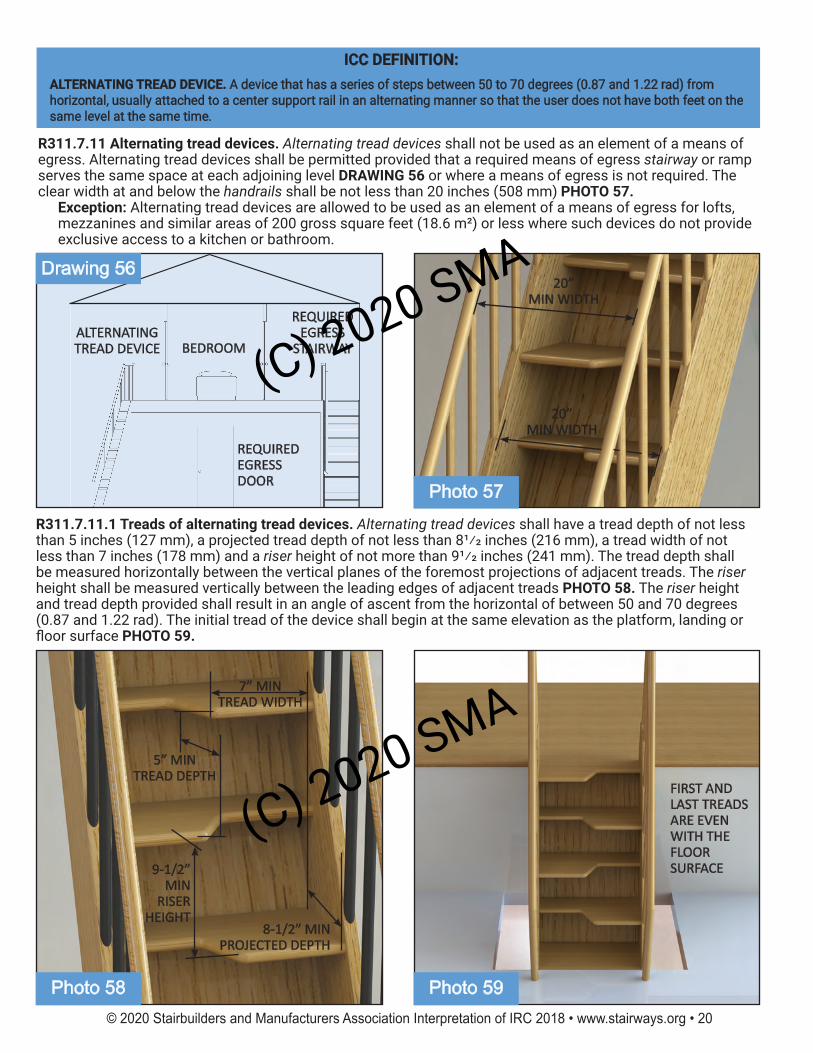
ICC DEFINITION:ALTERNATING TREAD DEVICE. A device that has a series of steps between 50 to 70 degrees (0.87 and 1.22 rad) from horizontal, usually attached to a center support rail in an alternating manner so that the user does not have both feet on the same level at the same time.
R311.7.11 Alternating tread devices. Alternating tread devices shall not be used as an element of a means of egress. Alternating tread devices shall be permitted provided that a required means of egress stairway or ramp serves the same space at each adjoining level DRAWING 56 or where a means of egress is not required. The clear width at and below the handrails shall be not less than 20 inches (508 mm) PHOTO 57.
Exception: Alternating tread devices are allowed to be used as an element of a means of egress for lofts, mezzanines and similar areas of 200 gross square feet (18.6 m²) or less where such devices do not provide exclusive access to a kitchen or bathroom.
Photo 57
20” MIN WIDTH
20” MIN WIDTH
R311.7.11.1 Treads of alternating tread devices. Alternating tread devices shall have a tread depth of not less than 5 inches (127 mm), a projected tread depth of not less than 81/2 inches (216 mm), a tread width of not less than 7 inches (178 mm) and a riser height of not more than 91/2 inches (241 mm). The tread depth shall be measured horizontally between the vertical planes of the foremost projections of adjacent treads. The riser height shall be measured vertically between the leading edges of adjacent treads PHOTO 58. The riser height and tread depth provided shall result in an angle of ascent from the horizontal of between 50 and 70 degrees (0.87 and 1.22 rad). The initial tread of the device shall begin at the same elevation as the platform, landing or floor surface PHOTO 59.
Photo 58
9-1/2” MIN
RISER HEIGHT
7” MINTREAD WIDTH
8-1/2” MIN PROJECTED DEPTH
5” MINTREAD DEPTH
Photo 59
ALTERNATING TREAD DEVICE
Drawing 56
BEDROOM
REQUIRED EGRESS
STAIRWAY
REQUIRED EGRESS DOOR
FIRST AND LAST TREADS ARE EVEN WITH THE FLOOR SURFACE
(C) 2020 SMA
(C) 2020 SMA

© 2020 Stairbuilders and Manufacturers Association Interpretation of IRC 2018 • www.stairways.org • 21
R311.7.11.2 Handrails of alternating tread devices. Handrails shall be provided on both sides of alternating tread devices and shall comply with Sections R311.7.8.2 to R311.7.8.6 PHOTO 60. Handrail height shall be uniform, not less than 30 inches (762 mm) and not more than 34 inches (864 mm) PHOTO 61.
Photo 60
RAIL HEIGHT 30” MIN 34” MAX
R311.7.12 Ships ladders. Ships ladders shall not be used as an element of a means of egress. Ships ladders shall be permitted provided that a required means of egress stairway or ramp serves the same space at each adjoining level or where a means of egress is not required PHOTO 62. The clear width at and below the handrails shall be not less than 20 inches (508 mm) PHOTO 63.
Exception: Ships ladders are allowed to be used as an element of a means of egress for lofts, mezzanines and similar areas of 200 gross square feet (18.6 m²) or less that do not provide exclusive access to a kitchen or bathroom.
Photo 63
20” MIN WIDTH
Drawing 62
Photo 61
20” MIN WIDTH
HANDRAILS MUST MEET CONTINUITY AND GRIP SIZE REQUIREMENTS
SHIPS LADDER BEDROOM
REQUIRED EGRESS
STAIRWAY
REQUIRED EGRESS DOOR
(C) 2020 SMA
(C) 2020 SMA

© 2020 Stairbuilders and Manufacturers Association Interpretation of IRC 2018 • www.stairways.org • 22
R311.7.12.1 Treads of ships ladders. Treads shall have a depth of not less than 5 inches (127 mm). The tread shall be projected such that the total of the tread depth plus the nosing projection is not less than 81/2 inches (216 mm) PHOTO 64. The riser height shall be not more than 91/2 inches (241 mm) PHOTO 65.
Photo 64
8-1/2” MIN PROJECTED
TREAD DEPTH
5” MINTREAD DEPTH
Photo 65
9-1/2” MAXRISER
HEIGHT
R311.7.12.2 Handrails of ships ladders. Handrails shall be provided on both sides of ships ladders and shall comply with Sections R311.7.8.2 to R311.7.8.6 PHOTO 66 Handrail height shall be uniform, not less than 30 inches (762 mm) and not more than 34 inches (864 mm) PHOTO 67.
Photo 66 Photo 67
HANDRAIL HEIGHT30” MIN34” MAX
HANDRAILS MUST MEET CONTINUITY
AND GRIP SIZE REQUIREMENTS
(C) 2020 SMA
(C) 2020 SMA

© 2020 Stairbuilders and Manufacturers Association Interpretation of IRC 2018 • www.stairways.org • 23
R312.1 Guards. Guards shall be provided in accordance with Sections R312.1.1 through R312.1.4.
IRC DEFINITION:GUARD. A building component or a system of building components located near the open sides of elevated walking surfaces that minimize the possibility of a fall from the walking surface to a lower level.
R312.1.1 Where required. Guards shall be provided for those portions of open-sided walking surfaces, including stairs, ramps and landings, that are located more than 30 inches (762 mm) measured vertically to the floor or grade below at any point within 36 inches (914 mm) horizontally to the edge of the open side DRAWING 68. Insect screening shall not be considered as a guard.
Drawing 68
R312.1.2. Height. Required guards at open-sided walking surfaces, including stairs, porches, balconies or landings, shall be not less than 36 inches (914 mm) in height as measured vertically above the adjacent walking surface or the line connecting the nosings PHOTOS 69 & 70.
Exceptions:1. Guards on the open sides of stairs shall have a height of not less than 34 inches (864 mm)measured vertically from a line connecting the nosings PHOTO 69.
2. Where the top of the guard serves as a handrail on the open sides of stairs, the top of theguard shall not be not less than 34 inches (864 mm) and not more than 38 inches (965 mm) asmeasured vertically from a line connecting the nosings PHOTO 69.
SECTION 312 GUARDS AND WINDOW FALL PROTECTION
GUARD AT OPEN SIDE OF WALKING SURFACE REQUIRED.AREA EXCEEDS 30” ABOVE FLOOR OR GRADE BELOW WITHIN 36” HORIZONTAL TO EDGE OF OPEN SIDE.
WALKING SURFACE
WALKING SURFACE
GUARD AT OPEN SIDE OF STAIR IS REQUIRED.AREA EXCEEDS 30” ABOVE FLOOR OR GRADE BELOWWITHIN 36” HORIZONTAL TO EDGE OF OPEN SIDE.
STAIR GUARD REQUIRED 36” MIN
GUARD REQUIRED
MORE THAN 30” WITHIN 36” OF EDGE
MORE THAN 30”
36”
REQUIRED STAIR GUARD
REQUIRED HANDRAIL
UP 7 RISERS
PLAN VIEW ELEVATION VIEW
R36”
R36”
(C) 2020 SMA

© 2020 Stairbuilders and Manufacturers Association Interpretation of IRC 2018 • www.stairways.org • 24
R312.1.2 Height. (Continued)
Photo 69 Photo 70
WALKING SURFACE
CURB
R312.1.3 Opening limitations. Required guards shall not have openings from the walking surface to the required guard height that allow passage of a sphere 4 inches (102 mm) in diameter PHOTO 71.
Exceptions:1. The triangular openings at the open side of stair, formed by the riser, tread and bottom rail of a guard, shall not allow passage of a sphere 6 inches (153 mm) in diameter PHOTO 72.2. Guards on the open side of stairs shall not have openings that allow passage of a sphere 4⅜ inches (111 mm) in diameter PHOTO 72.
Photo 71
MUST NOT ALLOW
PASSAGE OF 4” SPHERE
Photo 72
R312.1.4 Exterior plastic composite guards. Plastic composite exterior guards shall comply with the requirements of Section R317.4
REQUIRED HEIGHT
MUST NOT ALLOW PASSAGE OF 4⅜” SPHERE
MUST NOT ALLOW PASSAGE
OF 6” SPHERE
MINIMUM 34”STAIR GUARD HEIGHT
MAXIMUM HEIGHT 38” WHEN TOP OF GUARD SERVES AS HANDRAIL
(C) 2020 SMA
(C) 2020 SMA
© 2020 Stairbuilders and Manufacturers Association Interpretation of IRC 2018 • www.stairways.org • 25
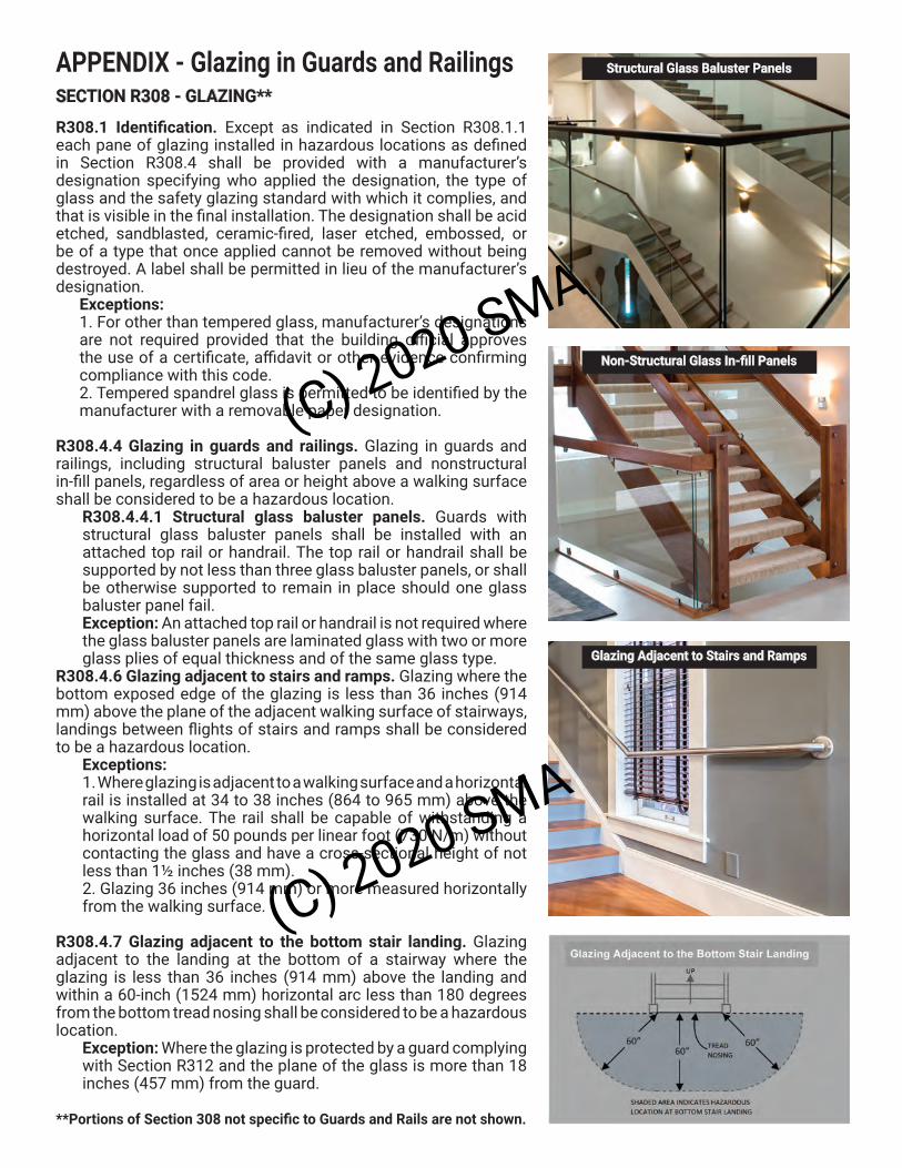
SECTION R308 - GLAZING**
APPENDIX - Glazing in Guards and Railings
R308.1 Identification. Except as indicated in Section R308.1.1 each pane of glazing installed in hazardous locations as defined in Section R308.4 shall be provided with a manufacturer’s designation specifying who applied the designation, the type of glass and the safety glazing standard with which it complies, and that is visible in the final installation. The designation shall be acid etched, sandblasted, ceramic-fired, laser etched, embossed, or be of a type that once applied cannot be removed without being destroyed. A label shall be permitted in lieu of the manufacturer’s designation.
Exceptions:1. For other than tempered glass, manufacturer’s designations are not required provided that the building official approves the use of a certificate, affidavit or other evidence confirming compliance with this code.2. Tempered spandrel glass is permitted to be identified by the manufacturer with a removable paper designation.
R308.4.4 Glazing in guards and railings. Glazing in guards and railings, including structural baluster panels and nonstructural in-fill panels, regardless of area or height above a walking surface shall be considered to be a hazardous location.
R308.4.4.1 Structural glass baluster panels. Guards with structural glass baluster panels shall be installed with an attached top rail or handrail. The top rail or handrail shall be supported by not less than three glass baluster panels, or shall be otherwise supported to remain in place should one glass baluster panel fail.Exception: An attached top rail or handrail is not required where the glass baluster panels are laminated glass with two or more glass plies of equal thickness and of the same glass type.
R308.4.6 Glazing adjacent to stairs and ramps. Glazing where the bottom exposed edge of the glazing is less than 36 inches (914 mm) above the plane of the adjacent walking surface of stairways, landings between flights of stairs and ramps shall be considered to be a hazardous location.
Exceptions:1. Where glazing is adjacent to a walking surface and a horizontal rail is installed at 34 to 38 inches (864 to 965 mm) above the walking surface. The rail shall be capable of withstanding a horizontal load of 50 pounds per linear foot (730 N/m) without contacting the glass and have a cross-sectional height of not less than 1½ inches (38 mm).2. Glazing 36 inches (914 mm) or more measured horizontally from the walking surface.
R308.4.7 Glazing adjacent to the bottom stair landing. Glazing adjacent to the landing at the bottom of a stairway where the glazing is less than 36 inches (914 mm) above the landing and within a 60-inch (1524 mm) horizontal arc less than 180 degrees from the bottom tread nosing shall be considered to be a hazardous location.
Exception: Where the glazing is protected by a guard complying with Section R312 and the plane of the glass is more than 18 inches (457 mm) from the guard.
**Portions of Section 308 not specific to Guards and Rails are not shown.
Non-Structural Glass In-fill Panels
Structural Glass Baluster Panels
Glazing Adjacent to Stairs and Ramps
(C) 2020 SMA
(C) 2020 SMA

© 2020 Stairbuilders and Manufacturers Association Interpretation of IRC 2018 • www.stairways.org • 26
NOTES:
© 2020 Stairbuilders and Manufacturers Association Interpretation of IRC 2018 • www.stairways.org • 27
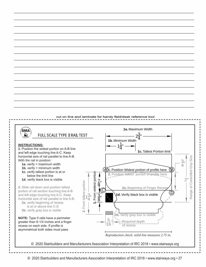
Reproduction check: solid line measures 2.75 in.
INSTRUCTIONS:1. Position the widest portion on A-B lineand left edge touching line A-C. Keephorizontal axis of rail parallel to line A-B.With the rail in position: 1a. verify < maximum width 1b. verify > minimum width 1c. verify tallest portion is at or below the limit line 1d. verify black box is visible
2. Slide rail down and position tallestportion of rail section touching line A-Band left edge touching line A-C. Keephorizontal axis of rail parallel to line A-B. 2a. verify beginning of recess is at or above line C-D 2b. verify gray box is visible
NOTE: Type II rails have a perimetergreater than 6-1/4 inches and a fingerrecess on each side. If profile isasymmetrical both sides must pass.
FULL SCALE TYPE II RAIL TEST
cut on line and laminate for handy field/desk reference tool
38"
78"
114"
234"
A
Full ScaleTYPE ll Rail Test
B1. Position Widest portion of profile here
1b. Minimum Width
1a. Maximum Width
1c. Tallest Portion limit
C D1d. Verify black box is visible
1. F
rom
wid
est p
ortio
n
516"
Ran
ge o
f Con
trolle
d G
rip S
ize
2. F
rom
talle
st p
ortio
n 2"
34"
134"
2a. Beginning of Finger Recess
2. Position Tallest portion of profile here
2b. Verify gray box is visible
Required depthof recess
© 2020 Stairbuilders and Manufacturers Association Interpretation of IRC 2018 • www.stairways.org

© 2020 Stairbuilders and Manufacturers Association Interpretation of IRC 2018 • www.stairways.org • 28
About the Stairbuilders and Manufacturers Association.
The Stairbuilders and Manufacturers Association is the greatest resource of knowledge and tools contributing to the success of our members and the stair industry. Our membership is comprised of residential and commercial stair industry professionals; stairbuilders, stair part manufacturers, installers, distributors and providers of ancillary services to the stair industry.
The SMA represents the stair industry. We ensure its growth and prosperity by promoting products and standards to design and construct safe, beautiful stairways. We offer education, a robust knowledge base, publications, certifications, code consultation and industry networking opportunities that benefit our members. Become a member of the SMA and join us as we continue to provide exceptional value in support of stair industry professionals. Please visit www.stairways.org, call 877-500-5759, or [email protected].
Visual Interpretation of the
STAIR BUILDING CODE2018 International Residential Code
Portions of this publication reproduce excerpts from the 2018 International Residential Code for One- and Two-Family Dwellings and the 2018 International Building Code, Copyright 2017, International Code Council, Inc., Washington, D.C. Reproduced with permission. All rights reserved. www.iccsafe.org
© 2020 SMA, 877-500-5759 First Edition www.stairways.org