MEVA Stair Tower MTT
30
Technical Instruction Manual MEVA Stair Tower MTT
-
Upload
khangminh22 -
Category
Documents
-
view
2 -
download
0
Transcript of MEVA Stair Tower MTT

Technical Instruction Manual
MEVA Stair Tower MTT

MEVA Stair Tower
Only use couplers that fulfil the German standard DIN 4420.
The contractor must ensure that the Technical Instruction Manual supplied by MEVA is made available to its employees.
Abbreviations, measurements, figures and tables, etc.The abbreviation MTT is used for the MEVA stair tower.DIN means Deutsche Industrie-Norm (German Industrial Standard). E DIN (E = Entwurf / draft) means that the DIN is in draft status and not yet approved. Any further abbreviations are explained where they are used for the first time.
TÜV means Technischer Überwachungsverein. This is the independent German organisation that tests the safety of technical installations, machinery and motor vehicles. If a product passes the test, it is permitted to carry the GS seal. GS stands for Geprüfte Sicherheit (approved safety).Measurements: This manual uses the metric system, i.e. m (for metre), cm (for centimetre) and mm (for millimetre).
Non-defined dimensions are in cm.
The page numbers in this manual start with MTT. The figures and tables are numbered per page. Depending on its product abbreviation, a cross reference in the text refers to a page, table or figure in this or in another manual. This is indicated by the product code with which the cross-reference begins.
The MEVA stair tower is a stationary stair assembly for construction sites. It is rectangular and measures 2.57 m by 1.40 m. Structural verification is not required up to a maximum exit height of 50.00 m.
In addition, the individual components of the MEVA stair tower can be used to create scaffolding for rebar work.
The permissible loading of the MEVA stair tower is 200 kg/m². This must not be exceeded.
The stairs with landing allow workers to ascend safely and without fatigue, even when transporting material.
The vertical load-bearing elements – hereafter referred to as MTT standards – are galvanized steel tubes.
The loads resulting from anchoring must be transferred to the existing building or structure. These must be verified in each individual case by the principal.
In most cases the friction between the base and the ground is sufficient to prevent the tower feet from sliding. If this is not the case, suitable measures must be taken to prevent the feet from sliding.
Product featuresProduct features
MTT-2 Technical Instruction Manual / Status August 2021
MTT

MEVA Stair Tower
This Technical Instruction Manual contains information, instructions and tips that describe how to use the MEVA equipment on the construction site in a proper, quick and economic way. Most examples shown are standard applications that will occur in practice most often. For more complicated or special applications not covered in this manual, please contact the MEVA experts for advice. They will help you without delay.
When using our products, the federal, state and local occupational health and safety regulations must be observed. Please observe the assembly instructions that your local contractor or employer has created for the site on which the MEVA equipment is used. Such instructions are intended to minimise site-specific risks and must contain the following details:
Æ The order in which all working steps including assembly and disassembly must be carried out
Æ The weight of the panels and other system parts Æ The type and number of ties and braces as well as the distance
between them Æ The location, number and dimensions of working scaffolds
including the working area and fall protection equipment required Æ Attachment points for panel transport by crane. With regard to
panel transport, please observe this manual. Any deviation will require structural verification.
Important: Generally, only well-maintained material may be used. Damaged parts must be replaced. Use only original MEVA spare parts for replacement.
Attention: Never wax or oil assembly locks!
Please note ContentsSafety information ............................................................................ 4Possible applications ......................................................................... 5Product overview .............................................................................. 6Foundation ....................................................................................... 7Anchoring ......................................................................................... 8Assembly .......................................................................................... 9Repositioning .................................................................................. 15Disassembly .................................................................................... 16
Product lsitStair tower material lists – Important notes .................... 18Stair tower material list ................................................................... 19Scaffolding for rebar work .............................................................. 25Material list for scaffolding for rebar work ...................................... 26Transport instructions ..................................................................... 27Inspection sheet for working and safety scaffolds ........................... 28Instructions for use ......................................................................... 29Services .......................................................................................... 30Product list ..................................................................................... 31
MTT-3Technical Instruction Manual / Status August 2021
MTT
MEVA Stair Tower
Safety informationThe stability of the MEVA stair tower (Fig. 4.1) is to be verified and ensured at all times, also during assembly.
Visually inspect all components for damage prior to installation and use. Damaged components must not be used.
There is always a risk of accidentally falling when assembling, relocating and disassembling the stair tower. Make sure that all work is performed in a way that minimises the risk of accidentally falling, e.g. by wearing personal protective equipment.
Perform the assembly steps in an order that allows the side protection to be installed immediately so that the work is carried out in a secured area most of the time.
Before starting to assemble the stair tower, ensure that there is no equipment in the vicinity of the working area that might endanger the people working there.
When assembling or disassembling the stair tower, always observe applicable federal, state and local codes and regulations.
Fig. 4.1
MTT-4 Technical Instruction Manual / Status August 2021
MTT

MEVA Stair Tower
Possible applications
Fig. 5.1
Fig. 5.2
The stair tower is rectangular with the basic dimensions 2.57 m x 1.40 m and can be assembled to reach almost any required height.
The exit can be planned and installed either on the stair tower’s long side (Fig. 5.1) or on its short side (Fig. 5.2).
Intermediate exits are possible at every level.
Exit on the long side
Exit on the short side
MTT-5Technical Instruction Manual / Status August 2021
MTT

MEVA Stair Tower
Product overviewWith only a few individual parts, the MEVA stair tower (Fig. 6.1) can be erected up to a height of 50 m without separate structural verification. The parts can be flexibly combined to adapt the tower to the existing structure or building.
Fig. 6.1
MTT base spindle 60,spindle stroke 41 cm
MTT base collar
MTT spindleattachmentwith wedge head
MTT standard
MTT hinged pin D=12 mm
MTT ledger 140 MTT ledger 257
MTT diagonal brace 140/200
MTT diagonal brace 257/200
MTT steel deck 257/32 MTT stairs with landing Alu 257/64 H200
MTT stair rail 257 H200
MTT stair rail post 130
MTT ledger 190Wedge head
MTT internal stair rail H200
MTT spigot
MTT spigotinstalled
MTT-6 Technical Instruction Manual / Status August 2021
MTT

MEVA Stair Tower
Foundation Æ Check that the ground can
support the load. Æ Position suitable load-
distributing support plates on the ground. The two base spindles on each end face must always stand on the same support plate (Figures 7.1 and 7.2).
The stair tower must be erected parallel to the building or structure and the resulting gap must be as small as possible. If the gap is less than 30 cm, it must be bridged with planks that are at least 3 cm thick and which are installed so that they cannot move or slide. If the gap is greater than 30 cm, it must be bridged with side protection.
Fig. 7.1
Load-distributing support plate
Fig. 7.2 Top view
< 30
cm
Load-distributing support plate
MTT stairs with landing Alu 257/64 H200
MTT steel deck 257/32
MTT wall tie 95
MTT standard
MTT ledger 140
MTT ledger 257
MTT swivel nut M12x350, galv.
MTT-7Technical Instruction Manual / Status August 2021
MTT

MEVA Stair Tower
AnchoringMissing anchoring or anchoring without sufficient load capacity will reduce the stair tower’s stability and the tower may collapse. Anchor material may only be installed and removed by the persons who are assembling the stair tower.
Anchors such as the MTT wall tie 95 (Fig. 8.1) are essential for the stability of the stair tower and should be installed repeatedly as the stair tower is assembled and its height increases.
For the number of MTT wall ties required as a function of the tower height refer to MTT-19 to 24.
Please observe Æ Install anchors only in
buildings or structures with sufficient load-bearing capacity. In case of doubt, check the stability of the anchoring area by means of pull-out tests.
Æ No structural verification is required if, according to expert opinion, the load-bearing capacity is sufficient and the utilisation value of the anchoring force A┴ does not exceed 1.5 kN (or 6.0 kN when anchoring in reinforced concrete according to German standard DIN 1045).
Æ The load-bearing capacity of all fasteners such as ties, swivel nuts and dowels must be verified to ensure they can withstand the anchoring force.
Æ Check dowels according to local regulations.
For further anchoring methods refer to Figures 8.2 to 8.4.
Fig. 8.1
Fig. 8.2 Fig. 8.3
MTT wall tie 95
Coupler 48/48
MTT standard
Fig. 8.4
MTT-8 Technical Instruction Manual / Status August 2021
MTT
MEVA Stair Tower
Assembly
Fig. 9.1
Fig. 9.3
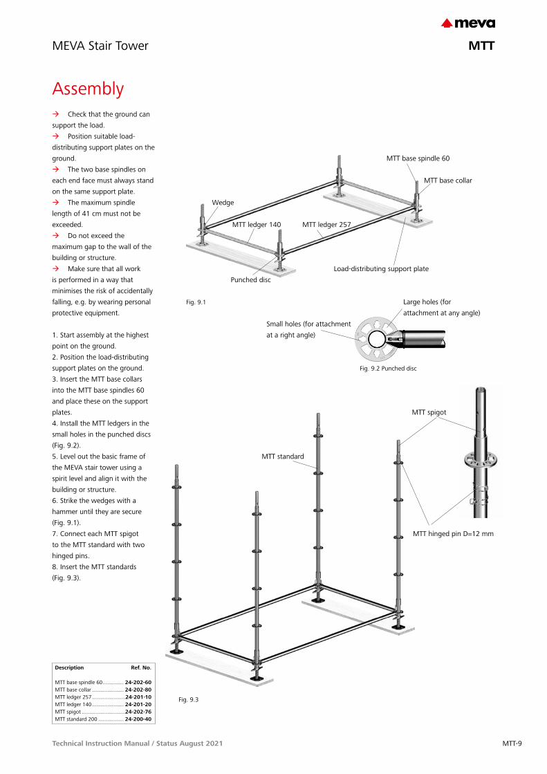
Æ Check that the ground can support the load.
Æ Position suitable load-distributing support plates on the ground.
Æ The two base spindles on each end face must always stand on the same support plate.
Æ The maximum spindle length of 41 cm must not be exceeded.
Æ Do not exceed the maximum gap to the wall of the building or structure.
Æ Make sure that all work is performed in a way that minimises the risk of accidentally falling, e.g. by wearing personal protective equipment.
1. Start assembly at the highest point on the ground.2. Position the load-distributing support plates on the ground.3. Insert the MTT base collars into the MTT base spindles 60 and place these on the support plates.4. Install the MTT ledgers in the small holes in the punched discs (Fig. 9.2).5. Level out the basic frame of the MEVA stair tower using a spirit level and align it with the building or structure.6. Strike the wedges with a hammer until they are secure (Fig. 9.1).7. Connect each MTT spigot to the MTT standard with two hinged pins.8. Insert the MTT standards (Fig. 9.3).
MTT base spindle 60
Load-distributing support plate
MTT ledger 140 MTT ledger 257
MTT base collar
Punched disc
MTT standard
Description Ref. No.
MTT base spindle 60 .............. 24-202-60MTT base collar ..................... 24-202-80MTT ledger 257 ......................24-201-10MTT ledger 140 ..................... 24-201-20MTT spigot .............................24-202-76MTT standard 200 ................. 24-200-40
Fig. 9.2 Punched disc
Wedge
Large holes (for attachment at any angle)
Small holes (for attachment at a right angle)
MTT spigot
MTT hinged pin D=12 mm
MTT-9Technical Instruction Manual / Status August 2021
MTT

MEVA Stair Tower
Assembly9. The MTT spindle attachment with wedge head is attached to the four MTT standards (Fig. 10.1) and prevents the MTT base spindle and the MTT base collar falling off when lifting tower units by crane.
10. Install MTT ledgers 257 and 140.11. Stabilise the frame with MTT diagonal braces (Fig. 10.2).
12. Hook in the steel decks.13. Place the stairs with landing onto the ledgers and close the safety device to prevent them lifting out (Fig. 10.3).
Fig. 10.2
Fig. 10.3
MTT steel deck 257/32
MTT stairs with landing Alu257/64 H200
MTT ledger 140
MTT ledger 257
MTT diagonal brace 140/200
MTT diagonal brace 257/200
Description Ref. No.
MTT spindle attachmentwith wedge head ....................24-202-70MTT ledger 257 ......................24-201-10MTT ledger 140 ..................... 24-201-20MTT diagonal brace 257/200 ..24-202-10MTT diagonal brace 140/200 . 24-202-20MTT steel deck 257/32 .......... 24-200-50MTT stairs with landing Alu 257/64 H200 ......................... 24-200-20
MTT spindle attachmentwith wedge head
Fig. 10.1
MTT-10 Technical Instruction Manual / Status August 2021
MTT

MEVA Stair Tower
Assembly
Fig. 11.1
14. Attach MTT spigots to the MTT standards for the second level and plug the MTT standards into place.15. Install MTT hinged pins D=12 mm at the bottom of the MTT standards.16. Install the MTT ledgers 140.17. Install two MTT stair rail adaptors to the punched discs of the lower MTT standard in order to attach the MTT stair rail on the the outside of the stairs (Fig. 11.1).18. Install the MTT stair rail 257 and, if required, the MTT internal stair rail.
Please observeMTT internal stair rails are mandatory for dog-leg stairs and increase the safety of stairs that are not dog-legged.
MTT stair rail 257 H200
MTT standard
MTT internal stair rail H200
Description Ref. No.
MTT standard 200 ................. 24-200-40MTT stair rail adaptor ............. 24-202-85MTT stair rail257 H200 ...............................24-200-70MTT internal stair railH200 ......................................24-200-78MTT spigot .............................24-202-76MTT hinged pinD=12 mm .............................. 24-202-90
MTT spigot
MTT stair rail adaptor
MTT hinged pin D=12 mm
MTT-11Technical Instruction Manual / Status August 2021
MTT

MEVA Stair Tower
Assembly
Fig. 12.1
19. Attach MTT spigots to the MTT standards and install the MTT standards.20. Install MTT hinged pins D=12 mm at the bottom of the MTT standards.21. Install MTT ledgers 257 and 140.22. Stabilise the frame with diagonal braces (Fig. 12.1).
MTT standard
MTT ledger 140 MTT ledger 257
MTT diagonal brace140/200
MTT diagonal brace257/200
Description Ref. No.
MTT standard 200 ................. 24-200-40MTT ledger 257 ......................24-201-10MTT ledger 140 ..................... 24-201-20MTT spigot .............................24-202-76MTT hinged pinD=12 mm .............................. 24-202-90
MTT diagonal brace257/200 .................................24-202-10140/200 ................................ 24-202-20
MTT spigot
MTT hinged pin D=12 mm
MTT-12 Technical Instruction Manual / Status August 2021
MTT
MEVA Stair Tower
Assembly
Fig. 13.1 Fig. 13.2
Fig. 13.3 Fig. 13.4
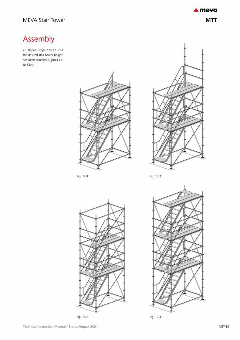
23. Repeat steps 7 to 22 until the desired stair tower height has been reached (Figures 13.1 to 13.4).
MTT-13Technical Instruction Manual / Status August 2021
MTT

MEVA Stair Tower
Assembly
Fig. 14.1
24. Once the stair tower has reached the desired height, the top level is secured with an MTT stair rail post 130 and two MTT ledgers 190 with wedge head to provide fall protection (Fig. 14.1).
If the exit is to be located on the long side, two MTT ledgers 140 are installed on the end faces (short sides) (Fig. 14.1).
If the exit is to be located on an end face (short side), two MTT ledgers 257 are installed on the long side and the two MTT ledgers 140 are not required on the exit side. Hence two MTT stair rail adaptors must be attached to the punched discs of the MTT standards in order to attach the MTT stair rail post 257 (Fig. 14.2).
If the gap is less than 30 cm, it must be bridged with planks that are at least 3 cm thick and which are installed so that they cannot move or slide. If the gap is greater than 30 cm, it must be bridged with side protection.
Fig. 14.2
MTT ledger 140
MTT stair rail post 130
MTT ledger 190Wedge head
Description Ref. No.
MTT stair rail adaptor ............. 24-202-85MTT ledger 190 wedge head . 24-201-40MTT stair rail post 130 ........... 24-200-90MTT ledger 257 ......................24-201-10MTT ledger 140 ..................... 24-201-20
MTT stair rail adaptor
MTT stair rail 257 H200
MTT standard
MTT ledger 257
MTT-14 Technical Instruction Manual / Status August 2021
MTT

MEVA Stair Tower
Repositioning
Fig. 15.1
The MEVA stair tower can be lifted and relocated with a crane, either as a complete unit or in subsections.
AttentionAll MTT standards of the complete tower or subsections of the tower must be connected with MTT hinged pins D=12 mm.
The maximum height of the tower or tower subsections to be relocated must not exceed 15 m.
To relocate subsections of the tower, first remove the MTT diagonal braces 257 and 140 as well as the MTT stairs with landing that connect the subsections.
If necessary, the free MTT tower ends have to be stabilized with bracing made up of scaffold tubes.
Make sure that all work is performed in a way that minimises the risk of accidentally falling, e.g. by wearing personal protective equipment.
MTT hinged pin D=12 mm
MTT diagonal brace 140/200
MTT stairs with landing Alu257/64 H200
MTT diagonal brace 257/200
Description Ref. No.
MTT hinged pin D=12 mm ..... 24-202-90
MTT-15Technical Instruction Manual / Status August 2021
MTT

MEVA Stair Tower
Disassembly
Fig. 16.1 Fig. 16.2 Fig. 16.3
The MEVA stair tower is disassembled in the reverse order to assembly (see pages MTT-9 to -14).
Make sure that all work is performed in a way that minimises the risk of accidentally falling, e.g. by wearing personal protective equipment.
MTT-16 Technical Instruction Manual / Status August 2021
MTT
MEVA Stair Tower
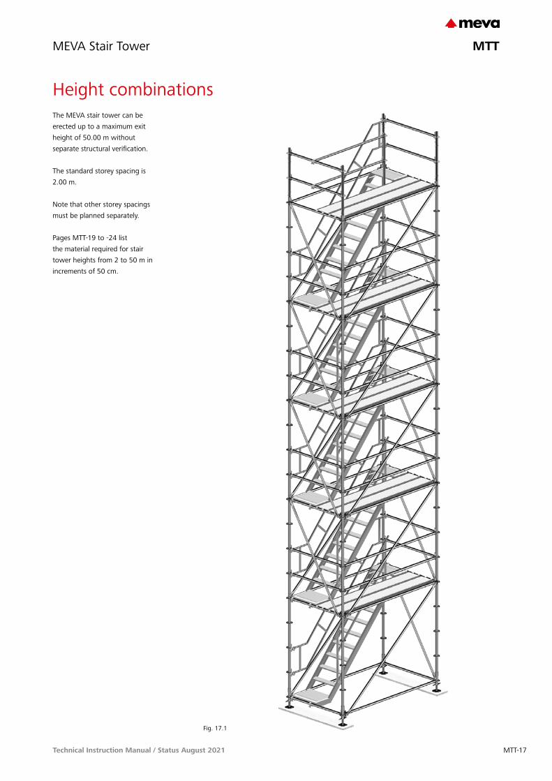
Height combinationsThe MEVA stair tower can be erected up to a maximum exit height of 50.00 m without separate structural verification.
The standard storey spacing is 2.00 m.
Note that other storey spacings must be planned separately.
Pages MTT-19 to -24 list the material required for stair tower heights from 2 to 50 m in increments of 50 cm.
Fig. 17.1
MTT-17Technical Instruction Manual / Status August 2021
MTT

MEVA Stair Tower
The tower’s top exit can be installed on the long side (Fig. 18.1) or on the short side (Fig. 18.2).
Intermediate exits are possible at every level.
The material lists on pages MTT-19 to -24 show all parts required for standard applications.
Depending on the location of the exit side (short or long side) and on the number of additional intermediate exits, the following material must be added to or subtracted from the material list.
For the exit at the top Æ Exit on the long side:
subtract two MTT ledgers 257 Æ Exit on the short side:
subtract two MTT ledgers 140 and add two MTT stair rail adaptors
For intermediate exits Æ For each intermediate exit
on the long side: subtract two MTT ledgers 257 as well as one MTT diagonal brace 257/200
Æ For each intermediate exit on the short side: subtract two MTT ledgers 140 as well as one MTT diagonal brace 140/200 and add two MTT stair rail adaptors
Stair tower material lists – Important notes
Fig. 18.1
Fig. 18.2
Exit on the long side
Exit on the short side
The access to the building or structure is job-built. If access is to be with system parts, this must be planned separately.
For anchoring details refer to page MTT-8.
Please observeMTT internal stair rails are mandatory for dog-leg stairs and increase the safety of stairs that are not dog-legged.
The material lists on pages MTT-19 to -24 are for stairs that are not dog-legged and do not include MTT internal stair rails for standard levels.
The height information in the material lists on pages MTT-19 to -24 include the MTT base spindle 60 with an extension length of 10 cm.
Description Ref. No.
MTT ledger 257 ......................24-201-10MTT ledger 140 ..................... 24-201-20MTT diagonal brace 257/200 ..24-202-10MTT diagonal brace 140/200 . 24-202-20MTT stair rail adaptor ............. 24-202-85
MTT internal stair railH200 ......................................24-200-78H150 ......................................24-200-79H100 ..................................... 24-200-80
MTT ledger 140
MTT ledger 257
MTT diagonal brace140/200
MTT diagonal brace 257/200
MTT stair rail adaptor
MTT-18 Technical Instruction Manual / Status August 2021
MTT

MEVA Stair Tower
Stair tower material list
Mat
eria
l lis
t fo
r th
e M
EVA
sta
ir t
ower
Tota
l hei
ght
(m)
Exit
hei
ght
(m)
Ref
. no.
Des
crip
tion
Com
pone
nt w
eigh
t (k
g)
24-2
02-6
0M
TT b
ase
spin
dle
603.
60
24-2
02-8
0M
TT b
ase
colla
r1.
40
24-2
02-7
0M
TT s
pind
le a
ttac
hmen
t with
wed
ge h
ead
2.00
24-2
00-4
0M
TT s
tand
ard
200
10.2
0
24-2
00-4
1M
TT s
tand
ard
150
7.80
24-2
00-4
2M
TT s
tand
ard
100
5.50
24-2
00-4
3M
TT s
tand
ard
503.
20
24-2
02-7
6M
TT s
pigo
t1.
60
24-2
02-9
0M
TT h
inge
d pi
n D
=12
mm
0.10
24-2
01-2
0M
TT le
dger
140
5.40
24-2
01-1
0M
TT le
dger
257
9.70
24-2
02-1
0M
TT d
iago
nal b
race
257
/200
9.50
24-2
02-1
1M
TT d
iago
nal b
race
257
/150
10.5
0
24-2
02-1
2M
TT d
iago
nal b
race
257
/100
8.80
24-2
02-2
0M
TT d
iago
nal b
race
140
/200
7.50
24-2
02-2
1M
TT d
iago
nal b
race
140
/150
6.87
24-2
02-2
2M
TT d
iago
nal b
race
140
/100
5.91
24-2
00-5
0M
TT s
teel
dec
k 25
7/32
18.9
0
24-2
00-2
0M
TT s
tairs
with
land
ing
Alu
257
/64
H20
023
.20
24-2
00-2
1M
TT s
tairs
with
land
ing
Alu
257
/64
H15
022
.80
24-2
00-1
0M
TT s
tart
ing
stai
r Alu
H10
014
.80
24-2
00-2
3M
TT s
tairs
with
land
ing
Alu
H50
11.2
0
24-2
00-7
0M
TT s
tair
rail
257
H20
018
.10
24-2
00-7
1M
TT s
tair
rail
257
H15
017
.00
24-2
00-9
0M
TT s
tair
rail
post
130
6.10
24-2
01-4
0M
TT le
dger
190
wed
ge h
ead
7.80
24-2
02-8
5M
TT s
tair
rail
adap
tor
0.70
24-2
00-8
0M
TT in
tern
al s
tair
rail
H10
010
.20
24-2
02-5
0M
TT w
all t
ie 9
53.
70
24-2
02-9
7M
TT s
wiv
el n
ut 1
2x35
0, g
alv.
0.40
29-4
12-5
2Sw
ivel
-join
t cou
pler
48/
481.
20
Wei
ght
(kg)
3.30
3.80
4.30
4.80
5.30
5.80
6.30
6.80
7.30
7.80
8.30
8.80
9.30
9.80
10.3
010
.80
11.3
0
2.00
2.50
3.00
3.50
4.00
4.50
5.00
5.50
6.00
6.50
7.00
7.50
8.00
8.50
9.00
9.50
10.0
0
44
44
44
44
44
44
44
44
4
44
44
44
44
44
44
44
44
4
44
44
44
44
44
44
44
44
4
44
44
88
88
1212
1212
1616
1616
20
44
44
44
84
44
84
44
84
44
84
4
44
44
48
88
812
1212
1216
1616
1620
2020
20
1632
3232
3248
4848
4864
6464
6480
8080
80
814
1414
1420
2020
2026
2626
2632
3232
32
68
88
1012
1212
1416
1616
1820
2020
22
22
22
44
44
66
66
88
88
10
11
11
11
11
12
22
34
44
56
66
78
88
9
22
22
2
22
2
46
66
68
88
810
1010
1012
1212
12
11
11
22
22
33
33
44
44
5
11
11
11
11
11
11
11
11
22
22
33
33
44
44
5
11
11
11
11
11
11
11
11
11
1
22
22
22
22
22
22
22
22
2
22
22
22
22
22
22
22
22
2
11
11
22
22
22
44
44
44
44
66
6
22
22
22
44
44
44
44
66
6
22
22
22
44
44
44
44
66
6
369
492
539
546
594
718
768
799
831
954
998
1025
1057
1180
1234
1245
1293
The material list on this page shows all parts required for the standard stair tower with the exit at a height between 2.00 m and 10.00 m.
The access to the building or structure is job-built. If access is to be with system parts, this must be planned separately.
For information about the top exit and intermediate exits refer to page MTT-18.
For anchoring details refer to page MTT-8.
MTT-19Technical Instruction Manual / Status August 2021
MTT

MEVA Stair Tower
Stair tower material list
11.8
012
.30
12.8
013
.30
13.8
014
.30
14.8
015
.30
15.8
016
.30
16.8
017
.30
17.8
018
.30
18.8
019
.30
19.8
0
10.5
011
.00
11.5
012
.00
12.5
013
.00
13.5
014
.00
14.5
015
.00
15.5
016
.00
16.5
017
.00
17.5
018
.00
18.5
0
44
44
44
44
44
44
44
44
4
44
44
44
44
44
44
44
44
4
44
44
44
44
44
44
44
44
4
2020
2024
2424
2428
2828
2832
3232
3236
36
44
44
48
44
48
44
48
44
48
44
4
44
44
4
2424
2424
2828
2828
3232
3232
3636
3636
40
9696
9696
112
112
112
112
128
128
128
128
144
144
144
144
160
3838
3838
4444
4444
5050
5050
5656
5656
62
2424
2426
2828
2830
3232
3234
3636
3638
40
1010
1012
1212
1214
1414
1416
1616
1618
18
11
11
11
11
1010
1011
1212
1213
1214
1415
1616
1617
18
22
22
22
22
1414
1414
1616
1616
1818
1818
2020
2020
22
55
56
66
67
77
78
88
89
9
11
11
11
11
11
11
1
55
56
66
67
77
78
88
89
9
11
11
11
11
11
11
11
11
11
11
1
22
22
22
22
22
22
22
22
2
22
22
22
22
22
22
22
22
2
11
11
66
66
68
88
88
88
810
1010
10
66
66
68
88
88
88
810
1010
10
66
66
68
88
88
88
810
1010
10
1459
1503
1531
1563
1693
1747
1774
1807
1921
1980
2007
2040
2169
2223
2251
2284
2413
The material list on this page shows all parts required for the standard MEVA stair tower with the exit at a height between 10.50 m and 18.50 m.
The access to the building or structure is job-built. If access is to be with system parts, this must be planned separately.
For information about the top exit and intermediate exits refer to page MTT-18.
For anchoring details refer to page MTT-8.
Mat
eria
l lis
t fo
r th
e M
EVA
sta
ir t
ower
Tota
l hei
ght
(m)
Exit
hei
ght
(m)
Ref
. no.
Des
crip
tion
Com
pone
nt w
eigh
t (k
g)
24-2
02-6
0M
TT b
ase
spin
dle
603.
60
24-2
02-8
0M
TT b
ase
colla
r1.
40
24-2
02-7
0M
TT s
pind
le a
ttac
hmen
t with
wed
ge h
ead
2.00
24-2
00-4
0M
TT s
tand
ard
200
10.2
0
24-2
00-4
1M
TT s
tand
ard
150
7.80
24-2
00-4
2M
TT s
tand
ard
100
5.50
24-2
00-4
3M
TT s
tand
ard
503.
20
24-2
02-7
6M
TT s
pigo
t1.
60
24-2
02-9
0M
TT h
inge
d pi
n D
=12
mm
0.10
24-2
01-2
0M
TT le
dger
140
5.40
24-2
01-1
0M
TT le
dger
257
9.70
24-2
02-1
0M
TT d
iago
nal b
race
257
/200
9.50
24-2
02-1
1M
TT d
iago
nal b
race
257
/150
10.5
0
24-2
02-1
2M
TT d
iago
nal b
race
257
/100
8.80
24-2
02-2
0M
TT d
iago
nal b
race
140
/200
7.50
24-2
02-2
1M
TT d
iago
nal b
race
140
/150
6.87
24-2
02-2
2M
TT d
iago
nal b
race
140
/100
5.91
24-2
00-5
0M
TT s
teel
dec
k 25
7/32
18.9
0
24-2
00-2
0M
TT s
tairs
with
land
ing
Alu
257
/64
H20
023
.20
24-2
00-2
1M
TT s
tairs
with
land
ing
Alu
257
/64
H15
022
.80
24-2
00-1
0M
TT s
tart
ing
stai
r Alu
H10
014
.80
24-2
00-2
3M
TT s
tairs
with
land
ing
Alu
H50
11.2
0
24-2
00-7
0M
TT s
tair
rail
257
H20
018
.10
24-2
00-7
1M
TT s
tair
rail
257
H15
017
.00
24-2
00-9
0M
TT s
tair
rail
post
130
6.10
24-2
01-4
0M
TT le
dger
190
wed
ge h
ead
7.80
24-2
02-8
5M
TT s
tair
rail
adap
tor
0.70
24-2
00-8
0M
TT in
tern
al s
tair
rail
H10
010
.20
24-2
02-5
0M
TT w
all t
ie 9
53.
70
24-2
02-9
7M
TT s
wiv
el n
ut 1
2x35
0, g
alv.
0.40
29-4
12-5
2Sw
ivel
-join
t cou
pler
48/
481.
20
Wei
ght
(kg)
MTT-20 Technical Instruction Manual / Status August 2021
MTT

MEVA Stair Tower
The material list on this page shows all parts required for the standard MEVA stair tower with the exit at a height between 19.00 m and 27.00 m.
The access to the building or structure is job-built. If access is to be with system parts, this must be planned separately.
For information about the top exit and intermediate exits refer to page MTT-18.
For anchoring details refer to page MTT-8.
20.3
020
.80
21.3
021
.80
22.3
022
.80
23.3
023
.80
24.3
024
.80
25.3
025
.80
26.3
026
.80
27.3
027
.80
28.3
0
19.0
019
.50
20.0
020
.50
21.0
021
.50
22.0
022
.50
23.0
023
.50
24.0
024
.50
25.0
025
.50
26.0
026
.50
27.0
0
44
44
44
44
44
44
44
44
4
44
44
44
44
44
44
44
44
4
44
44
44
44
44
44
44
44
4
3636
4040
4040
4444
4444
4848
4848
5252
52
44
44
84
44
84
44
84
44
84
44
8
44
44
4040
4044
4444
4448
4848
4852
5252
5256
56
160
160
160
176
176
176
176
192
192
192
192
208
208
208
208
224
224
6262
6268
6868
6874
7474
7480
8080
8086
86
4040
4244
4444
4648
4848
5052
5252
5456
56
1818
2020
2020
2222
2222
2424
2424
2626
26
11
11
11
11
1
1818
1920
2020
2122
2222
2324
2424
2526
26
22
22
22
22
2
2222
2224
2424
2426
2626
2628
2828
2830
30
99
1010
1010
1111
1111
1212
1212
1313
13
11
11
11
11
1
11
11
99
1010
1010
1111
1111
1212
1212
1313
13
11
11
11
11
11
11
11
11
11
11
1
22
22
22
22
22
22
22
22
2
22
22
22
22
22
22
22
22
2
11
11
1
1010
1010
1212
1212
1212
1212
1414
1414
14
1010
1010
1212
1212
1212
1212
1414
1414
14
1010
1010
1212
1212
1212
1212
1414
1414
14
2456
1484
2517
2646
2700
2727
2760
2889
2933
2960
2993
3122
3176
3204
3237
3366
3409
Stair tower parts list
Mat
eria
l lis
t fo
r th
e M
EVA
sta
ir t
ower
Tota
l hei
ght
(m)
Exit
hei
ght
(m)
Ref
. no.
Des
crip
tion
Com
pone
nt w
eigh
t (k
g)
24-2
02-6
0M
TT b
ase
spin
dle
603.
60
24-2
02-8
0M
TT b
ase
colla
r1.
40
24-2
02-7
0M
TT s
pind
le a
ttac
hmen
t with
wed
ge h
ead
2.00
24-2
00-4
0M
TT s
tand
ard
200
10.2
0
24-2
00-4
1M
TT s
tand
ard
150
7.80
24-2
00-4
2M
TT s
tand
ard
100
5.50
24-2
00-4
3M
TT s
tand
ard
503.
20
24-2
02-7
6M
TT s
pigo
t1.
60
24-2
02-9
0M
TT h
inge
d pi
n D
=12
mm
0.10
24-2
01-2
0M
TT le
dger
140
5.40
24-2
01-1
0M
TT le
dger
257
9.70
24-2
02-1
0M
TT d
iago
nal b
race
257
/200
9.50
24-2
02-1
1M
TT d
iago
nal b
race
257
/150
10.5
0
24-2
02-1
2M
TT d
iago
nal b
race
257
/100
8.80
24-2
02-2
0M
TT d
iago
nal b
race
140
/200
7.50
24-2
02-2
1M
TT d
iago
nal b
race
140
/150
6.87
24-2
02-2
2M
TT d
iago
nal b
race
140
/100
5.91
24-2
00-5
0M
TT s
teel
dec
k 25
7/32
18.9
0
24-2
00-2
0M
TT s
tairs
with
land
ing
Alu
257
/64
H20
023
.20
24-2
00-2
1M
TT s
tairs
with
land
ing
Alu
257
/64
H15
022
.80
24-2
00-1
0M
TT s
tart
ing
stai
r Alu
H10
014
.80
24-2
00-2
3M
TT s
tairs
with
land
ing
Alu
H50
11.2
0
24-2
00-7
0M
TT s
tair
rail
257
H20
018
.10
24-2
00-7
1M
TT s
tair
rail
257
H15
017
.00
24-2
00-9
0M
TT s
tair
rail
post
130
6.10
24-2
01-4
0M
TT le
dger
190
wed
ge h
ead
7.80
24-2
02-8
5M
TT s
tair
rail
adap
tor
0.70
24-2
00-8
0M
TT in
tern
al s
tair
rail
H10
010
.20
24-2
02-5
0M
TT w
all t
ie 9
53.
70
24-2
02-9
7M
TT s
wiv
el n
ut 1
2x35
0, g
alv.
0.40
29-4
12-5
2Sw
ivel
-join
t cou
pler
48/
481.
20
Wei
ght
(kg)
MTT-21Technical Instruction Manual / Status August 2021
MTT

MEVA Stair Tower
28.8
029
.30
29.8
030
.30
30.8
031
.30
31.8
032
.30
32.8
033
.30
33.8
034
.30
34.8
035
.30
35.8
036
.30
36.8
0
27.5
028
.00
28.5
029
.00
29.5
030
.00
30.5
031
.00
31.5
032
.00
32.5
033
.00
33.5
034
.00
34.5
035
.00
35.5
0
44
44
44
44
44
44
44
44
4
44
44
44
44
44
44
44
44
4
44
44
44
44
44
44
44
44
4
5256
5656
5660
6060
6064
6464
6468
6868
68
44
44
4
44
48
44
48
44
48
44
48
4
44
44
5656
6060
6060
6464
6464
6868
6868
7272
72
224
224
240
240
240
240
256
256
256
256
272
272
272
272
288
288
288
8686
9292
9292
9898
9898
104
104
104
104
110
110
110
5658
6060
6062
6464
6466
6868
6870
7272
72
2628
2828
2830
3030
3032
3232
3234
3434
34
11
11
1
11
11
2627
2828
2829
3030
3031
3232
3233
3434
34
22
22
2
22
22
3030
3232
3232
3434
3434
3636
3636
3838
38
1314
1414
1415
1515
1516
1616
1617
1717
17
11
11
1
11
11
11
11
1314
1414
1415
1515
1516
1616
1617
1717
17
11
11
1
11
11
11
11
11
11
11
11
1
22
22
22
22
22
22
22
22
2
22
22
22
22
22
22
22
22
2
11
11
1414
1416
1616
1616
1616
1618
1818
1818
18
1414
1416
1616
1616
1616
1618
1818
1818
18
1414
1416
1616
1616
1616
1618
1818
1818
18
3437
3470
3599
3653
3681
3713
3842
3886
3914
3946
4076
4130
4157
4190
4319
4363
4390
The material list on this page shows all parts required for the standard MEVA stair tower with the exit at a height between 27.50 m and 35.50 m.
The access to the building or structure is job-built. If access is to be with system parts, this must be planned separately.
For information about the top exit and intermediate exits refer to page MTT-18.
For anchoring details refer to page MTT-8.
Stair tower parts list
Mat
eria
l lis
t fo
r th
e M
EVA
sta
ir t
ower
Tota
l hei
ght
(m)
Exit
hei
ght
(m)
Ref
. no.
Des
crip
tion
Com
pone
nt w
eigh
t (k
g)
24-2
02-6
0M
TT b
ase
spin
dle
603.
60
24-2
02-8
0M
TT b
ase
colla
r1.
40
24-2
02-7
0M
TT s
pind
le a
ttac
hmen
t with
wed
ge h
ead
2.00
24-2
00-4
0M
TT s
tand
ard
200
10.2
0
24-2
00-4
1M
TT s
tand
ard
150
7.80
24-2
00-4
2M
TT s
tand
ard
100
5.50
24-2
00-4
3M
TT s
tand
ard
503.
20
24-2
02-7
6M
TT s
pigo
t1.
60
24-2
02-9
0M
TT h
inge
d pi
n D
=12
mm
0.10
24-2
01-2
0M
TT le
dger
140
5.40
24-2
01-1
0M
TT le
dger
257
9.70
24-2
02-1
0M
TT d
iago
nal b
race
257
/200
9.50
24-2
02-1
1M
TT d
iago
nal b
race
257
/150
10.5
0
24-2
02-1
2M
TT d
iago
nal b
race
257
/100
8.80
24-2
02-2
0M
TT d
iago
nal b
race
140
/200
7.50
24-2
02-2
1M
TT d
iago
nal b
race
140
/150
6.87
24-2
02-2
2M
TT d
iago
nal b
race
140
/100
5.91
24-2
00-5
0M
TT s
teel
dec
k 25
7/32
18.9
0
24-2
00-2
0M
TT s
tairs
with
land
ing
Alu
257
/64
H20
023
.20
24-2
00-2
1M
TT s
tairs
with
land
ing
Alu
257
/64
H15
022
.80
24-2
00-1
0M
TT s
tart
ing
stai
r Alu
H10
014
.80
24-2
00-2
3M
TT s
tairs
with
land
ing
Alu
H50
11.2
0
24-2
00-7
0M
TT s
tair
rail
257
H20
018
.10
24-2
00-7
1M
TT s
tair
rail
257
H15
017
.00
24-2
00-9
0M
TT s
tair
rail
post
130
6.10
24-2
01-4
0M
TT le
dger
190
wed
ge h
ead
7.80
24-2
02-8
5M
TT s
tair
rail
adap
tor
0.70
24-2
00-8
0M
TT in
tern
al s
tair
rail
H10
010
.20
24-2
02-5
0M
TT w
all t
ie 9
53.
70
24-2
02-9
7M
TT s
wiv
el n
ut 1
2x35
0, g
alv.
0.40
29-4
12-5
2Sw
ivel
-join
t cou
pler
48/
481.
20
Wei
ght
(kg)
MTT-22 Technical Instruction Manual / Status August 2021
MTT

MEVA Stair Tower
The material list on this page shows all parts required for the standard MEVA stair tower with the exit at a height between 36.00 m and 44.00 m.
The access to the building or structure is job-built. If access is to be with system parts, this must be planned separately.
For information about the top exit and intermediate exits refer to page MTT-18.
For anchoring details refer to page MTT-8.
37.3
037
.80
38.3
038
.80
39.3
039
.80
40.3
040
.80
41.3
041
.80
42.3
042
.80
43.3
043
.80
44.3
044
.80
45.3
0
36.0
036
.50
37.0
037
.50
38.0
038
.50
39.0
039
.50
40.0
040
.50
41.0
041
.50
42.0
042
.50
43.0
043
.50
44.0
0
44
44
44
44
44
44
44
44
4
44
44
44
44
44
44
44
44
4
44
44
44
44
44
44
44
44
4
7272
7272
7676
7676
8080
8080
8484
8484
88
44
44
44
84
44
84
44
84
44
84
4
44
44
7276
7676
7680
8080
8084
8484
8488
8888
88
288
304
304
304
304
320
320
320
320
336
336
336
336
352
352
352
352
110
116
116
116
116
122
122
122
122
128
128
128
128
134
134
134
134
7476
7676
7880
8080
8284
8484
8688
8888
90
3636
3636
3838
3838
4040
4040
4242
4242
44
11
11
11
11
3536
3636
3738
3838
3940
4040
4142
4242
43
22
22
22
22
3840
4040
4042
4242
4244
4444
4446
4646
46
1818
1818
1919
1919
2020
2020
2121
2121
22
11
11
11
11
11
11
1818
1818
1919
1919
2020
2020
2121
2121
22
11
11
11
11
11
11
11
11
11
11
1
22
22
22
22
22
22
22
22
2
22
22
22
22
22
22
22
22
2
11
11
1818
2020
2020
2020
2020
2222
2222
2222
22
1818
2020
2020
2020
2020
2222
2222
2222
22
1818
2020
2020
2020
2020
2222
2222
2222
22
4423
4522
4606
4634
4667
4796
4839
4867
4900
5029
5083
5110
5143
5272
5316
5343
5376
Stair tower parts list
Mat
eria
l lis
t fo
r th
e M
EVA
sta
ir t
ower
Tota
l hei
ght
(m)
Exit
hei
ght
(m)
Ref
. no.
Des
crip
tion
Com
pone
nt w
eigh
t (k
g)
24-2
02-6
0M
TT b
ase
spin
dle
603.
60
24-2
02-8
0M
TT b
ase
colla
r1.
40
24-2
02-7
0M
TT s
pind
le a
ttac
hmen
t with
wed
ge h
ead
2.00
24-2
00-4
0M
TT s
tand
ard
200
10.2
0
24-2
00-4
1M
TT s
tand
ard
150
7.80
24-2
00-4
2M
TT s
tand
ard
100
5.50
24-2
00-4
3M
TT s
tand
ard
503.
20
24-2
02-7
6M
TT s
pigo
t1.
60
24-2
02-9
0M
TT h
inge
d pi
n D
=12
mm
0.10
24-2
01-2
0M
TT le
dger
140
5.40
24-2
01-1
0M
TT le
dger
257
9.70
24-2
02-1
0M
TT d
iago
nal b
race
257
/200
9.50
24-2
02-1
1M
TT d
iago
nal b
race
257
/150
10.5
0
24-2
02-1
2M
TT d
iago
nal b
race
257
/100
8.80
24-2
02-2
0M
TT d
iago
nal b
race
140
/200
7.50
24-2
02-2
1M
TT d
iago
nal b
race
140
/150
6.87
24-2
02-2
2M
TT d
iago
nal b
race
140
/100
5.91
24-2
00-5
0M
TT s
teel
dec
k 25
7/32
18.9
0
24-2
00-2
0M
TT s
tairs
with
land
ing
Alu
257
/64
H20
023
.20
24-2
00-2
1M
TT s
tairs
with
land
ing
Alu
257
/64
H15
022
.80
24-2
00-1
0M
TT s
tart
ing
stai
r Alu
H10
014
.80
24-2
00-2
3M
TT s
tairs
with
land
ing
Alu
H50
11.2
0
24-2
00-7
0M
TT s
tair
rail
257
H20
018
.10
24-2
00-7
1M
TT s
tair
rail
257
H15
017
.00
24-2
00-9
0M
TT s
tair
rail
post
130
6.10
24-2
01-4
0M
TT le
dger
190
wed
ge h
ead
7.80
24-2
02-8
5M
TT s
tair
rail
adap
tor
0.70
24-2
00-8
0M
TT in
tern
al s
tair
rail
H10
010
.20
24-2
02-5
0M
TT w
all t
ie 9
53.
70
24-2
02-9
7M
TT s
wiv
el n
ut 1
2x35
0, g
alv.
0.40
29-4
12-5
2Sw
ivel
-join
t cou
pler
48/
481.
20
Wei
ght
(kg)
MTT-23Technical Instruction Manual / Status August 2021
MTT

MEVA Stair Tower
45.8
046
.30
46.8
047
.30
47.8
048
.30
48.8
049
.30
49.8
050
.30
50.8
051
.30
44.5
045
.00
45.5
046
.00
46.5
047
.00
47.5
048
.00
48.5
049
.00
49.5
050
.00
44
44
44
44
44
44
44
44
44
44
44
44
44
44
44
44
44
44
8888
8892
9292
9296
9696
9610
0
44
4
48
44
48
44
48
44
44
4
9292
9292
9696
9696
100
100
100
100
368
368
368
368
384
384
384
384
400
400
400
400
140
140
140
140
146
146
146
146
152
152
152
152
9292
9294
9696
9698
100
100
100
102
4444
4446
4646
4648
4848
4850
11
1
11
1
4444
4445
4646
4647
4848
4849
22
2
22
2
4848
4848
5050
5050
5252
5252
2222
2223
2323
2324
2424
2425
11
1
11
1
11
1
2222
2223
2323
2324
2424
2425
11
1
11
11
11
11
11
11
22
22
22
22
22
22
22
22
22
22
22
22
11
1
2224
2424
2424
2424
2426
2626
2224
2424
2424
2424
2426
2626
2224
2424
2424
2424
2426
2626
5505
5559
5587
5620
5749
5792
5820
5853
5982
6036
6064
6096
The material list on this page shows all parts required for the standard MEVA stair tower with the exit at a height between 44.50 m and 50.00 m.
The access to the building or structure is job-built. If access is to be with system parts, this must be planned separately.
For information about the top exit and intermediate exits refer to page MTT-18.
For anchoring details refer to page MTT-8.
Stair tower material list
Mat
eria
l lis
t fo
r th
e M
EVA
sta
ir t
ower
Tota
l hei
ght
(m)
Exit
hei
ght
(m)
Ref
. no.
Des
crip
tion
Com
pone
nt w
eigh
t (k
g)
24-2
02-6
0M
TT b
ase
spin
dle
603.
60
24-2
02-8
0M
TT b
ase
colla
r1.
40
24-2
02-7
0M
TT s
pind
le a
ttac
hmen
t with
wed
ge h
ead
2.00
24-2
00-4
0M
TT s
tand
ard
200
10.2
0
24-2
00-4
1M
TT s
tand
ard
150
7.80
24-2
00-4
2M
TT s
tand
ard
100
5.50
24-2
00-4
3M
TT s
tand
ard
503.
20
24-2
02-7
6M
TT s
pigo
t1.
60
24-2
02-9
0M
TT h
inge
d pi
n D
=12
mm
0.10
24-2
01-2
0M
TT le
dger
140
5.40
24-2
01-1
0M
TT le
dger
257
9.70
24-2
02-1
0M
TT d
iago
nal b
race
257
/200
9.50
24-2
02-1
1M
TT d
iago
nal b
race
257
/150
10.5
0
24-2
02-1
2M
TT d
iago
nal b
race
257
/100
8.80
24-2
02-2
0M
TT d
iago
nal b
race
140
/200
7.50
24-2
02-2
1M
TT d
iago
nal b
race
140
/150
6.87
24-2
02-2
2M
TT d
iago
nal b
race
140
/100
5.91
24-2
00-5
0M
TT s
teel
dec
k 25
7/32
18.9
0
24-2
00-2
0M
TT s
tairs
with
land
ing
Alu
257
/64
H20
023
.20
24-2
00-2
1M
TT s
tairs
with
land
ing
Alu
257
/64
H15
022
.80
24-2
00-1
0M
TT s
tart
ing
stai
r Alu
H10
014
.80
24-2
00-2
3M
TT s
tairs
with
land
ing
Alu
H50
11.2
0
24-2
00-7
0M
TT s
tair
rail
257
H20
018
.10
24-2
00-7
1M
TT s
tair
rail
257
H15
017
.00
24-2
00-9
0M
TT s
tair
rail
post
130
6.10
24-2
01-4
0M
TT le
dger
190
wed
ge h
ead
7.80
24-2
02-8
5M
TT s
tair
rail
adap
tor
0.70
24-2
00-8
0M
TT in
tern
al s
tair
rail
H10
010
.20
24-2
02-5
0M
TT w
all t
ie 9
53.
70
24-2
02-9
7M
TT s
wiv
el n
ut 1
2x35
0, g
alv.
0.40
29-4
12-5
2Sw
ivel
-join
t cou
pler
48/
481.
20
Wei
ght
(kg)
MTT-24 Technical Instruction Manual / Status August 2021
MTT

MEVA Stair Tower
Scaffolding for rebar workUsing the individual parts of the MEVA stair tower, it is also possible to build scaffolding for rebar work (Fig. 25.1).
Like the stair tower, assembly is performed according to pages MTT-9 to -14. The only exceptions are that MTT ledger 140 is replaced by MTT ledger 109 and the stairs with landing are replaced by MTT access hatch 257. The access ladder is integrated into the access hatch.
Fig. 25.1
MTT base spindle 60
MTT spindle holder
MTT standard 221
MTT standard 200
Ledger 109
MTT base collar
MTT ledger 257
MTT steel deck 257/32
Diagonal brace 109/200
MTT access hatch 257(with integrated ladder)
MTT diagonal brace 257/200
MTT hinged pin D=12 mm
Scaffold tube 48/200
Coupler 48/48
MTT-25Technical Instruction Manual / Status August 2021
MTT

MEVA Stair Tower
The material list for scaffolding for rebar work (Fig. 26.4) shows all parts required for the standard application.
The number of parts is shown for three variants:
Æ Complete scaffolding as shown (Fig. 26.1)
Æ First field (Fig. 26.2) Æ Lower storey (Fig. 26.3)
Material list for scaffolding for rebar work
Assembly variant
Complete scaffold-ing (Fig. 26.1)
Only the first field (Fig. 26.2)
Only the lower sto-rey (Fig. 26.3)
32 16 12
63 21 15
4 2 4
12 6 12
8 4 -
16 8 -
8 4 8
6 3 -
9 3 -
10 5 6
5 3 3
24 6 10
3 3 1
4 2 -
8 4 -
24 12 8
12 6 12
1788 727 613
Material list for scaffolding for rebar work
Ref. no. Description Component weight (kg)
24-201-25 MTT ledger 109 4.00
24-201-10 MTT ledger 257 8.50
24-202-80 MTT base collar 1.41
24-202-72 MTT spindle holder 0.80
24-200-42 MTT standard 100 5.50
24-200-40 MTT standard 200 10.20
24-200-45 MTT base standard 221 11.50
24-200-88 MTT toe board 109 2.50
24-200-86 MTT toe board 257 5.70
24-202-15 MTT diagonal brace 109/200 7.00
24-202-10 MTT diagonal brace 257/200 9.50
24-200-50 MTT steel deck 257/32 18.90
24-200-60 MTT access hatch 257 26.50
29-412-23 Scaffold tube 48/200 9.40
29-412-52 Swivel-joint coupler 48/48 1.20
24-202-90 MTT hinged pin D=12 mm 0.10
24-202-60 MTT base spindle 60 3.60
Weight (kg)
Fig. 26.1 Fig. 26.2 Fig. 26.3
Table 26.4
MTT-26 Technical Instruction Manual / Status August 2021
MTT

MEVA Stair Tower
Transport instructionsThe following must be observed for road transport: Use one ratchet strap per metre of cargo. This means that at least 14 ratchet straps are required for a fully loaded truck with a trailer length of 13.60 m.
To transport the stair tower, two straps are required for each stacking unit width (Fig. 27.1).
Fig. 27.1
MTT-27Technical Instruction Manual / Status August 2021
MTT

Inspection sheet for working and safety scaffolds
Wo
rkin
g a
nd
Saf
ety
Scaf
fold
s
Insp
ecti
on
Sh
eet
acco
rdin
g t
o G
erm
an g
uid
elin
es $
$ 10
an
d 1
1co
nce
rnin
g o
per
atio
nal
saf
ety
Insp
ecti
on
In o
rder
n/a
Yes
No
Scaf
fold
par
tsN
ot
dam
aged
(vi
sual
ch
eck)
Stab
ility
(a
gai
nst
co
llap
se)
Bea
rin
g c
apac
ity
of
gro
un
d
Bas
e sp
ind
le –
len
gth
/ ad
just
men
t ra
ng
e
Bra
cin
g /
Dia
go
nal
bra
ces
Lon
git
ud
inal
led
ger
s –
at f
oo
t le
vel
Latt
ice
gir
der
– b
raci
ng
An
cho
rin
g –
do
ne
acco
rdin
g t
o a
ssem
bly
inst
ruct
ion
s
Plan
kin
gSc
affo
ld a
rea
– co
mp
lete
are
a w
ith
pla
nki
ng
/ p
lan
kin
g
secu
red
ag
ain
st t
iltin
g a
nd
up
lifti
ng
Syst
em p
lan
kin
g –
pla
nki
ng
als
o o
n b
rack
ets
Co
rner
s –
full-
wid
th p
lan
kin
g a
rou
nd
co
rner
s
Scaf
fold
bo
ard
s –
pro
file
, su
pp
ort
Gap
s an
d o
pen
ing
s –
bet
wee
n p
lan
ks
Safe
ty a
t w
ork
an
d o
per
atio
nal
sa
fety
Sid
e p
rote
ctio
n –
incl
ud
ing
pro
tect
ion
at
fro
nt
end
s
Dis
tan
ce f
rom
wal
l ≤ 0
,30
m
Sid
e p
rote
ctio
n in
stal
led
insi
de
scaf
fold
Acc
ess,
sta
irs,
lad
der
s – ≤
50 m
Stai
r to
wer
, sca
ffo
ld s
tair
s, la
dd
er s
caff
old
(Mo
vab
le)
Lad
der
≤ 5
m
Pro
tect
ive
wal
l
Can
op
y
Traf
fic
pro
tect
ion
– li
gh
tin
g
Mo
bile
sca
ffo
lds
Wh
eels
or
cast
ors
Ad
dit
ion
al w
eig
ht
/ Wid
e as
sem
bly
Ch
arac
teri
stic
s an
d R
elea
se s
hee
t A
ttac
hed
an
d v
isib
le a
t al
l acc
ess
area
s o
f sc
affo
ld
Excl
usi
on
zo
nes
Are
as u
nd
er c
on
stru
ctio
n f
ence
d in
an
d m
arke
d w
ith
“n
o t
resp
assi
ng
” si
gn
s
No
tes
an
d c
om
men
ts: _
____
____
____
____
____
____
____
____
____
____
____
____
____
____
____
____
____
____
____
____
____
____
____
____
____
____
____
____
____
____
____
____
____
____
____
____
____
____
____
____
____
____
__
Att
ach
th
ese
sh
eets
to
th
e s
caff
old
on
ly i
f th
e s
caff
old
has
no
defe
cts
____
____
____
____
____
____
__
____
____
____
____
____
____
____
____
____
___
Dat
e N
ame
and
sig
nat
ure
of
auth
ori
sed
per
son
/ co
ntr
acto
r
Imp
ort
an
t w
ork
an
d h
an
dli
ng
ru
les
¢ A
ny
chan
ges
to t
he a
ssem
bled
sca
ffol
d on
ly t
o be
mad
e by
the
con
trac
tor.
¢ W
hen
sto
ring
mat
eria
l on
the
deck
, mak
e su
re t
o
leav
e en
ough
wal
king
are
a on
the
dec
k.
¢ D
o no
t st
ore
any
mat
eria
l on
safe
ty s
caff
olds
and
cano
pies
.
¢ D
o no
t ov
erlo
ad s
caff
old
deck
s an
d fi
elds
.
¢ D
o no
t si
mul
tane
ousl
y w
ork
in a
reas
loca
ted
abov
e ea
ch o
ther
.
¢ O
nly
use
exis
ting
ladd
ers
and
stai
rs w
hen
mov
ing
up o
r do
wn.
¢ K
eep
acce
ss h
atch
es o
f pl
atfo
rms
and
deck
s cl
osed
all t
he t
ime.
¢ D
o no
t ju
mp
onto
the
dec
k or
pla
nkin
g.
¢ O
bser
ve a
nd f
ollo
w t
he t
echn
ical
man
uals
.
¢ B
e aw
are
of t
he r
isk
of f
allin
g do
wn
in t
he g
ap
betw
een
scaf
fold
and
bui
ldin
g or
str
uctu
re.
¢ D
o n
ot e
ndan
ger
the
scaf
fold
‘s s
tabi
lity
wit
h
exca
vati
on o
r pi
ts.
¢ C
hild
ren
mus
t no
t en
ter
the
plat
form
or
scaf
fold
.
Sca
ffo
ld i
nsp
ect
ed
by a
uth
ori
sed
pers
on
of
con
tract
or
____
____
____
____
____
____
__
____
____
____
____
____
____
____
____
____
___
Insp
ecti
on
dat
e N
ame
and
sig
nat
ure
of
auth
ori
sed
per
son
Wo
rkin
g s
caff
old
(acc
. to
sta
nd
ard
DIN
EN
12811)
for
use
at
faca
des
in r
oo
ms
a
s m
ob
ile s
caff
old
Safe
ty s
caff
old
(acc
. to
sta
nd
ard
DIN
4420)
for
use
as
m
ob
ile s
caff
old
saf
ety
scaf
fold
(ro
of)
can
op
y
sta
ir t
ow
er
Lin
ing
n
on
e
can
vas
cove
r
net
Load
cla
sses
2
(15
0 kg
/m²)
3 (
200
kg/m
²)
4
(30
0 kg
/m²)
__(
____
__ k
g/m
²)
In a
sca
ffo
ld fi
eld
, th
e to
tal w
ork
ing
load
of
all s
caff
old
leve
ls u
po
n e
ach
oth
er m
ust
no
t ex
ceed
th
e
sele
cted
or
ente
red
wo
rk lo
ad.
Wid
th c
lass
es
W
06
W
09
W
___
_
SW
___
Rest
rict
ion
s o
f u
se o
r p
roh
ibit
ed
use
s: _
____
____
____
____
____
____
____
____
____
____
____
____
____
____
___
____
____
____
____
____
____
____
____
____
____
____
____
____
____
____
____
____
____
____
____
____
____
____
____
Co
nst
ruct
ion
sit
e: _
____
____
____
____
____
____
____
_
Clie
nt:
___
____
____
____
____
____
____
____
____
____
_
Au
tho
rise
d p
erso
n:
____
____
____
____
____
____
____
Use
d f
rom
/to
dat
e:
____
____
____
____
____
____
____
Co
ntr
acto
r:
____
____
____
____
____
____
____
____
___
Ad
dre
ss:
____
____
____
____
____
____
____
____
____
__
____
____
____
____
____
____
____
____
____
____
____
___
Pho
ne:
___
____
____
____
____
____
____
____
____
____
_
Wo
rkin
g a
nd
Saf
ety
Scaf
fold
sac
cord
ing
to
sta
nd
ard
s D
IN E
N 1
2811
/ D
IN 4
420
Ch
arac
teri
stic
s an
d R
elea
se S
hee
t
Imp
ort
ant:
See
no
te o
n
p. M
TT-2
bef
ore
filli
ng
in a
nd
usi
ng
th
is f
orm
ou
tsid
e G
erm
any.

MEVA Stair Tower
Instructions for use Æ Modification to the scaffold
must only be performed by the scaffold assembly worker.
Æ Always ensure that the access to the scaffold deck is wide enough when storing materials.
Æ Do not store material on safety-catch scaffolds and safety roofs.
Æ Do not overload scaffold decks and scaffold bays.
Æ Workplaces must not be located one on top of the other at the same time.
Æ Use the available ladders or steps to access and vacate the scaffold.
Æ Always keep the access hatch cover closed.
Æ Do not jump onto the scaffold deck.
Æ Observe the Technical Instruction Manual.
Æ Pay attention to the risk of falling between the scaffold and the building.
Æ Do not endanger the stability of the scaffold through excavation work.
Æ Children are not permitted on the scaffold.
MTT-29Technical Instruction Manual / Status August 2021
MTT

MEVA Stair Tower
ServicesCleaningThe stair tower is cleaned professionally upon return.
Cleaning and reconditioning of wall formworkThe formwork is cleaned using industrial equipment.
Reconditioning is carried out as follows: The frames are checked and, if necessary, repaired, coated and provided with a new facing.
As long as the formwork equipment still has its full load capacity, correct dimensions and is fully functional, reconditioning will always be a more economical solution than purchasing new formwork. Please note that the cleaning and reconditioning service is not available in all countries in which MEVA does business.
RentalsAs we have a comprehensive range of equipment in stock, we offer our customers the option of renting supplementary material at peak times. The MEVA logistics centre guarantees rapid delivery throughout Europe. We also give prospective customers the chance to test MEVA formwork so they can see its benefits for themselves in actual use.
RentalPlusFor rental formwork and equipment MEVA will bear all secondary costs that occur after return (excludes losses and write-offs) for a flat-rate fee. For the customer this means: Costing certainty instead of additional charges, an earlier end of the rental period and thus lower rental costs because you save the time required for cleaning and repairs.
Formwork drawingsOur application engineers worldwide work with CAD systems. This ensures that you always receive optimum formwork solutions and practice-oriented formwork and work cycle plans.
Special solutionsWe can help with special parts, custom-designed for your project, to supplement our standard formwork systems.
Structural calculationsGenerally, this is only necessary for applications such as single-sided formwork where the anchor parts are embedded in the foundation or the base slab. On request, we can perform structural calculations for such applications at an additional charge.
Formwork seminarsTo ensure that all our products are used properly and efficiently, we offer formwork seminars. They provide our customers with a good opportunity to keep themselves up to date and to benefit from the know-how of our engineers.
MTT-30 Technical Instruction Manual / Status August 2021
MTT