IRC-Building - International Code Council
737
2022 GROUP B PROPOSED CHANGES TO THE I-CODES ROCHESTER COMMITTEE ACTION HEARINGS March 27 - April 6, 2022 Rochester Riverside Convention Center, Rochester, NY IRC-Building
-
Upload
khangminh22 -
Category
Documents
-
view
2 -
download
0
Transcript of IRC-Building - International Code Council

2022 GROUP B PROPOSED CHANGES TO THE I-CODES ROCHESTER COMMITTEE ACTION HEARINGS
March 27 - April 6, 2022 Rochester Riverside Convention Center, Rochester, NY
IRC-Building

2021-2022 Code Development Cycle, Group B (2022) Proposed Changes to the 2021 International Codes
First Printing
Publication Date: February 2022
Copyright © 2022 by
International Code Council, Inc. ALL RIGHTS RESERVED. This 2021-2022 Code Development Cycle, Group B (2022) Proposed Changes to the 2021 International Codes is a copyrighted work owned by the International Code Council, Inc. (“ICC”). Without advance written permission from the ICC, no part of this book may be reproduced, distributed, or transmitted in any form or by any means, including, without limitations, electronic, optical or mechanical means (by way of example and not limitation, photocopying, or recording by or in an information storage retrieval system). For information on use rights and permissions, please contact: ICC Publications, 4051 Flossmoor Road, Country Club Hills IL, 60478. Phone 1-888-ICC-SAFE (422-7233). Trademarks: “International Code Council,” the “International Code Council” logo, “ICC,” the “ICC” logo and other names and trademarks appearing in this book are registered trademarks of the International Code Council, Inc., and/or its licensors (as applicable), and may not be used without permission.
PRINTED IN THE U.S.A.

TENTATIVE ORDER OF DISCUSSION 2022 PROPOSED CHANGES TO THE
INTERNATIONAL RESIDENTIAL CODE –BUILDING
The following is the tentative order in which the proposed changes to the code will be discussed at the public hearings. Proposed changes which impact the same subject have been grouped to permit consideration in consecutive changes. Proposed change numbers that are indented are those which are being heard out of numerical order. Indentation does not necessarily indicate that one change is related to another. Proposed changes may be grouped for purposes of discussion at the hearing at the discretion of the chair. Note that some RB code change proposals may not be included on this list, as they are being heard by another committee. Numbers Not Used RB21-22 RB33-22 RB50-22 RB119-22 RB128-22 RB211-22 RB301-22 RB303-22
ADM3-22 Part II ADM4-22 Part II
RB1-22 RB2-22 Part I RB3-22 RB4-22 RB5-22
ADM7-22 Part II RB6-22 RB7-22 RB8-22 RB9-22 RB10-22
ADM13-22 Part II ADM17-22 Part II
RB11-22 ADM15-22 Part II ADM24-22 Part II ADM 34-22 Part II
RB12-22 ADM16-22 Part II
RB13-22 ADM36-22 Part II ADM38-22 Part II ADM37-22 Part II
RB14-22 RB15-22 RB16-22
ADM41-22 Part II ADM43-22 Part II
RB17-22 S58-22 Part II ADM45-22 Part II
RB18-22 ADM48-22 Part II
RB19-22 RB20-22 RB22-22 RB23-22
G1-22 Part II G5-22 Part II
RB24-22 RB25-22
ADM1-22 Part II RB26-22 RB27-22 RB28-22 RB29-22
G4-22 Part II RB30-22 RB31-22 RB32-22 RB34-22 RB35-22 RB36-22
S119-22 Part II RB37-22 RB38-22 RB39-22 RB40-22
RB41-22 RB42-22 RB43-22 RB44-22 RB45-22 RB46-22 RB47-22 RB48-22 RB49-22 RB51-22 RB52-22 RB53-22 RB54-22 RB55-22 RB56-22 RB57-22 RB58-22 RB59-22 RB60-22 RB61-22 RB62-22 RB63-22 RB64-22 RB65-22 RB66-22 RB67-22 RB68-22 RB69-22 RB70-22 RB71-22
RB72-22 RB73-22 RB74-22 RB75-22 RB76-22 RB77-22 RB78-22 RB79-22 RB80-22 RB81-22 RB82-22 RB83-22 RB84-22 RB85-22 RB86-22 RB87-22 RB88-22 RB89-22 RB90-22 RB91-22 RB92-22 RB93-22 RB94-22 RB95-22 RB96-22 RB97-22 RB98-22 RB99-22 RB100-22 RB101-22
ICC COMMITTEE ACTION HEARINGS ::: March 2022 RB1
RB102-22 RB103-22 RB104-22 RB105-22 RB106-22 RB107-22 RB108-22 RB109-22 RB110-22 RB111-22 RB112-22 RB113-22 RB114-22 RB115-22 RB116-22 RB117-22 RB119-22 RB120-22 RB121-22 RB122-22 RB123-22 RB124-22 RB125-22 RB126-22 RB127-22 RB129-22 RB130-22 RB131-22 RB132-22 RB133-22 RB134-22 RB135-22 RB136-22 RB137-22 RB138-22 RB139-22 RB140-22 RB141-22 RB142-22 RB143-22 RB144-22 RB145-22 RB146-22 RB147-22 RB148-22 RB149-22 RB150-22 RB151-22 RB152-22 RB153-22 RB154-22 RB155-22 RB156-22 RB157-22 RB158-22 RB159-22
RB160-22 RB161-22 RB162-22 RB163-22 RB164-22 RB165-22 RB166-22 RB167-22 RB168-22 RB169-22 RB170-22 RB171-22
S154-22 Part II RB172-22 RB173-22 RB174-22 RB175-22 RB176-22 RB177-22 RB178-22 RB179-22 RB180-22 RB181-22 RB182-22 RB183-22 RB184-22 RB185-22 RB186-22 RB187-22 RB188-22 RB189-22 RB190-22 RB191-22 RB192-22 RB193-22 RB194-22 RB195-22 RB196-22 RB197-22 RB198-22 RB199-22 RB200-22 RB201-22 RB202-22 RB203-22 RB204-22 RB205-22 RB206-22 RB207-22 RB208-22 RB209-22 RB210-22 RB212-22 RB213-22 RB214-22 RB215-22
RB216-22 RB217-22 RB218-22 RB219-22 RB220-22 RB221-22 RB222-22 RB223-22 RB224-22
S240-22 Part II RB225-22
S241-22 Part II S243-22 Part II
RB226-22 RB227-22 RB228-22 RB229-22 RB230-22 RB231-22 RB232-22 RB233-22 RB234-22 RB235-22 RB236-22 RB237-22 RB238-22 RB239-22 RB240-22 RB241-22 RB242-22 RB243-22 RB244-22 RB245-22 RB246-22 RB247-22 RB248-22 RB249-22 RB250-22 RB251-22 RB252-22 RB253-22 RB254-22 RB255-22 RB256-22 RB257-22
S22-22 Part II S24-22 Part II
RB258-22 RB259-22 RB260-22 RB261-22 RB262-22 RB263-22 RB264-22 RB265-22 RB266-22
RB267-22 RB268-22 RB269-22 RB270-22 RB271-22 RB272-22 RB273-22 RB274-22 RB275-22 RB276-22
S35-22 Part II RB277-22 RB278-22 RB279-22 RB280-22 RB281-22
S49-22 Part II RB282-22
S48-22 Part II S59-22 Part II
RB283-22 RB284-22 RB285-22 RB286-22 RB287-22 RB288-22 RB289-22 RB290-22 RB291-22 RB292-22 RB293-22 RB294-22 RB295-22 RB296-22 RB297-22 RB298-22 RB299-22 RB300-22 RB302-22 RB304-22 RB305-22 RB306-22 RB307-22 RB308-22 RB309-22 RB310-22 RB311-22 RB312-22 RB313-22 RB314-22 RB315-22 RB316-22 RB317-22
ICC COMMITTEE ACTION HEARINGS ::: March 2022 RB2

RB1-22IRC: R101.2, R102.7.1, R105.3.1.1, R105.1, R110.2, CHAPTER 44(New)
Proponents: David Bonowitz, representing FEMA-ATC Seismic Code Support Committee ([email protected]); Kelly Cobeen, representing FederalEmergency Management Agency/Applied Technology Council - Seismic Code Support Committee ([email protected]); Michael Mahoney,representing FEMA ([email protected])
2021 International Residential CodeRevise as follows:
R101.2 Scope. The provisions of this code shall apply to the construction, alteration, movement, relocation, enlargement, addition to, replacement,repair, equipment, use and occupancy, change of occupancy, location, removal and demolition of detached one- and two-family dwellings andtownhouses not more than three stories above grade plane in height with a separate means of egress and their accessory structures not more thanthree stories above grade plane in height.
Exception: The following shall be permitted to be constructed in accordance with this code where provided with an automatic sprinkler systemcomplying with Section P2904:
1. Live/work units located in townhouses and complying with the requirements of Section 508.5 of the International Building Code.
2. Owner-occupied lodging houses with five or fewer guestrooms.
3. A care facility with five or fewer persons receiving custodial care within a dwelling unit.
4. A care facility with five or fewer persons receiving medical care within a dwelling unit.
5. A care facility for five or fewer persons receiving care that are within a single-family dwelling.
Delete without substitution:
R102.7.1 Additions, alterations or repairs. Additions, alterations or repairs to any structure shall conform to the requirements for a new structurewithout requiring the existing structure to comply with the requirements of this code, unless otherwise stated. Additions, alterations, repairs andrelocations shall not cause an existing structure to become less compliant with the provisions of this code than the existing building or structure wasprior to the addition, alteration or repair. An existing building together with its additions shall comply with the height limits of this code. Where thealteration causes the use or occupancy to be changed to one not within the scope of this code, the provisions of the International Existing BuildingCode shall apply.
Revise as follows:
R105.3.1.1 Determination of substantially improved or substantially damaged existing buildings in flood hazard areas. For applicationsfor reconstruction, rehabilitation, addition, alteration, repair or other improvement of existing buildings or structures located in a flood hazard area asestablished by Table R301.2, the building official shall examine or cause to be examined the construction documents and shall make a determinationwith regard to the value of the proposed work. For buildings that have sustained damage of any origin, the value of the proposed work shall includethe cost to repair the building or structure to its predamaged condition. If the building official finds that the value of proposed work equals or exceeds50 percent of the market value of the building or structure before the damage has occurred or the improvement is started, the proposed work is asubstantial improvement or repair of substantial damage and the building official shall require existing portions of the entire building or structure tomeet the requirements of Section R322 comply with the requirements of Chapter 44 applicable in flood hazard areas.For the purpose of this determination, a substantial improvement shall mean any repair, reconstruction, rehabilitation, addition or improvement of abuilding or structure, the cost of which equals or exceeds 50 percent of the market value of the building or structure before the improvement orrepair is started. Where the building or structure has sustained substantial damage, repairs necessary to restore the building or structure to itspredamaged condition shall be considered substantial improvements regardless of the actual repair work performed. The term shall not includeeither of the following:
1. Improvements to a building or structure that are required to correct existing health, sanitary or safety code violations identified by the buildingofficial and that are the minimum necessary to ensure safe living conditions.
2. Any alteration of a historic building or structure, provided that the alteration will not preclude the continued designation as a historic building orstructure. For the purposes of this exclusion, a historic building shall be any of the following:
2.1. Listed or preliminarily determined to be eligible for listing in the National Register of Historic Places.
2.2. Determined by the Secretary of the US Department of Interior as contributing to the historical significance of a registered historic districtor a district preliminarily determined to qualify as an historic district.
2.3. Designated as historic under a state or local historic preservation program that is approved by the Department of Interior.
ICC COMMITTEE ACTION HEARINGS ::: March 2022 RB3

R105.1 Required. Any owner or owner’s authorized agent who intends to construct, enlarge, add to, alter, repair, move, relocate, demolish orchange the occupancy of a building or structure, or to erect, install, enlarge, alter, repair, remove, convert or replace any electrical, gas, mechanicalor plumbing system, the installation of which is regulated by this code, or to cause any such work to be performed, shall first make application to thebuilding official and obtain the required permit.
Delete without substitution:
R110.2 Change in use. Changes in the character or use of an existing structure shall not be made except as specified in Sections 506 and 507 ofthe International Existing Building Code.
Add new text as follows:
CHAPTER 44EXISTING BUILDINGS
SECTION R4401GENERAL
R4401.1 Applicability. Work on any existing building within the scope of this code shall comply with this chapter.
R4401.2 Compliance. In addition to the provisions of this chapter, work on existing buildings shall comply with applicable provisions in otherchapters of this code that reference addition, alteration, repair, change of occupancy, or relocation of an existing building, including alteration orrepair of specific systems or components. Provisions in other chapters include, but are not limited to, the following:
1. Emergency escape and rescue openings: Sections R310.5, R310.6, and R310.7.
2. Automatic fire sprinkler systems: Sections R313.1 and R313.2.
3. Smoke alarms: Section R314.2.2.
4. Carbon monoxide alarms: Sections R315.2.2 and R315.5.
5. Foundations: Section R408.3.
6. Wood trusses: Sections R502.11.3 and R802.10.4.
7. Roof assemblies: R908.1 through R908.6
8. Energy efficiency: Sections N1101.5, N1101.13, and N1109 through N1113.
9. Mechanical: Sections M1202, M1411.2, M1601.5, M1801.3, and M2301.1.
10. Fuel gas: Various subsections in Sections G2412, G2417, G2425, and G2427.
11. Plumbing: Sections P2502, P2503.1, P2603.1, P2910.12, P2911.1, P2912.1, P2913.1, P3008.2, P3010, and P3011.
12. Electrical: Sections E3401.4 and E3403.2.
R4401.3 Work on existing buildings. For work on an existing building, the new work itself, whether intended by the owner or required by thiscode, shall conform to the requirements for a new building, unless otherwise stated. Portions of the building outside the intended scope of work arenot required to comply with the requirements of this code for new construction, unless otherwise stated. Work on an existing building shall not causethe existing building to become less compliant with the provisions of this code for new construction than the existing building was prior to the work.
R4401.4 Historic buildings in flood hazard areas. Where the building official has determined in accordance with Section R105.3.1.1 that alterationof a historic building or structure located in a flood hazard area constitutes substantial improvement or repair of substantial damage, the historicbuilding or structure is not required to meet the requirements of Section R322 provided the alteration or repair will not preclude the continueddesignation as a historic building or structure.
R4401.5 Design criteria. Work within the scope of this chapter shall comply with design criteria provided in Chapter 3 unless otherwise stated.
SECTION R4402ADDITIONS
R4402.1 Height limits. An existing building together with its additions shall comply with the height limits of this code.
R4402.2 Flood hazard areas. Where the building official has determined in accordance with Section R105.3.1.1 that an addition to an existingbuilding located in a flood hazard area established by Table R301.2 constitutes a substantial improvement, the entire building shall be brought intocompliance with the requirements of Section R322.
SECTION R4403
ICC COMMITTEE ACTION HEARINGS ::: March 2022 RB4

ALTERATIONS
R4403.1 Flood hazard areas. Where the building official has determined in accordance with Section R105.3.1.1 that alteration of an existing buildinglocated in a flood hazard area established by Table R301.2 constitutes a substantial improvement, the entire building shall be brought intocompliance with the requirements of Section R322.
SECTION R4404REPAIRS
R4404.1 Flood hazard areas. Where the building official has determined in accordance with Section R105.3.1.1 that an existing building located in aflood hazard area established by Table R301.2 has sustained substantial damage, the entire building shall be brought into compliance with therequirements of Section R322.
SECTION R4405CHANGE OF OCCUPANCY
R4405.1 Change of use or occupancy. Where the use or occupancy is changed to one not within the scope of this code, the provisions of theInternational Existing Building Code shall apply.
R4405.2 Change in use. Changes in the character or use of an existing building shall not be made except as specified in Sections 506 and 507 ofthe International Existing Building Code.
SECTION R4406RELOCATED BUILDINGS
R4406.1 Flood hazard areas. Where the building official has determined in accordance with Section R105.3.1.1 that the relocation of an existingbuilding into or within a flood hazard area established by Table R301.2 constitutes a substantial improvement, the entire building shall be brought intocompliance with the requirements of Section R322.
Staff Analysis: The scope and intent of the I-codes is subject to the approval of the ICC Board of Directors.
Reason Statement: This proposal does two things to improve the IRC’s usability and adaptability for existing buildings:· It creates a new IRC chapter for Existing Buildings: Chapter 44.· It moves current non-administrative Existing Building provisions out of Chapter 1 and into the new Chapter 44.
The proposal is 100% reorganization and clarification of terminology, to improve the IRC’s consistency and completeness. It makes no substantivechanges to the IRC at all. The section-by-section portion of this reason statement, below, explains how each of the proposed changes retains theIRC’s current scope and intent.Because the proposal is all reorganization and terminology, it will have no direct effect on construction cost. But it will still benefit IRC users becausethe reorganization will make it easier to introduce basic cost-reducing allowances for existing buildings into the IRC with separate proposals.
Existing Building projects are already within the IRC’s scope per Section R101.2, which already says the IRC applies to alterations, repairs, etc.Therefore, the IRC needs to be usable and adaptable as a code for existing buildings, or an “EB code.” The need for the IRC to be a functional EBcode became even more important in 2018, when the IEBC added an exception to its own scope provision (101.2) allowing almost all existingdwellings and townhouses to use the IRC instead, no matter how old, nonconforming, or deficient, and no matter what code they were built with.
So there should be no debate about the fact that the IRC intends, and needs, to regulate EB projects. The problem is that the IRC has no clear,user-friendly place to put its EB provisions. It already has dozens of EB provisions for various disciplines and systems – from smoke alarms totrusses, from plumbing to energy efficiency – but they’re scattered among its chapters, often combined in the same subsection with rules for newconstruction.
Thus, when new proposals are made for existing dwellings and townhouses – as they were with RB163-19 in the last cycle – they have no place togo, and just get tacked onto Section R102.7.1. Section R102.7.1 is a substantive EB provision with triggers and criteria. It is not an administrativeprovision, and it does not belong in Chapter 1. Similarly, Section R110.2 is a substantive (not administrative) provision, but it was tacked on to thenormal Admin provision about legal occupancy because there was nowhere else to put it. So as new ideas about existing dwellings and townhousescome forward – including cost-saving allowances common to EB codes – are we going to keep dumping them improperly into Chapter 1?
Let’s make the IRC a better EB code. In order to function as an EB code, the IRC needs more attention to three things:
· Established EB terminology· Usability, so users don’t have to hunt for provisions that might apply to their specific EB project type· Basic concepts of an EB code, such as allowances for existing non-conforming conditions.
ICC COMMITTEE ACTION HEARINGS ::: March 2022 RB5

This proposal deals with only the first two. The third idea is outside the scope of this proposal because it would make substantive changes to theIRC, but in order to bring in these key concepts, we need to take the first two steps, which is what this proposal does.
To implement established EB terminology and improve usability for EB projects, this proposal makes the following changes and additions:
R101.2: These edits ensure that the IRC scope covers the five basic EB project types, like the IEBC: addition, alteration, repair, change ofoccupancy, and relocation. These terms also match the proposed section titles in the new Chapter 44. It’s possible that “movement” (not defined)already covers relocation (also not defined), and “enlargement” (not defined) already covers additions (defined), but we add the IEBC terms forcompleteness and consistency; they change the IRC’s terminology, but not its scope, since all would agree that the IRC already intends to coverthese project types. Current R101.2 does not mention “change of occupancy” (defined) but that project type is also clearly within the intended scopeof the IRC because R102.7.1, R105.1, and R110.2 all refer to it, and Chapter 2 defines it. (A note about terminology: Even though this sectionalready uses “use and occupancy,” the code defines “change of occupancy” to include a change in use. Otherwise, the current IRC is inconsistent.For example: current Section R102.7.1 refers to “use or occupancy;” R105.1 requires a permit to “change the occupancy;” R110.1 is titled “Use andchange of occupancy” and uses “change of occupancy” as a defined term; R110.2 is titled “Change in use” and refers to “changes in the characteror use;” R310.5 and R310.7.1 use “change of occupancy.” Therefore, we propose that the best term to use is the one already defined in the code,especially since that current definition already encompasses a change of use.)
R102.7.1: This is the IRC’s current catch-all provision for existing buildings. It does not belong in Chapter 1, however, so the proposal moves it tothe new Chapter 44 and splits it to improve usability for specific project types. There is no substantive change.
R105.1: These edits ensure that the IRC permitting requirements cover at least the same scope as Section R101.2 (and IEBC Section 105.1). As inR101.2, the proposal supplements the terms “enlarge” and “move” with “add to” and “relocate” for completeness and consistency with the newChapter 44.
R105.3.1.1: For purposes of this proposal, the administrative parts of this provision will remain in Chapter 1, and the only change needed is toreplace the reference to Section R322 with a pointer to the new Chapter 44, where applicable compliance requirements are provided. There is nochange to the substance of the current provision. (Note: The second paragraph of current R105.3.1.1 -- which this proposal does not change at all -- contains the definition of "substantial improvement" used by provisions for flood hazard areas. It also includes the carve-out for historic buildings,parts of which are being copied to proposed new section R4401.4 in coordination with the FEMA Flood program.)
R110.2: This substantive provision does not belong in Chapter 1. The proposal moves it to the new Chapter 44’s section for Change of Occupancy.With respect to the wording, the IRC is inconsistent, but “change of occupancy” is the term already used in IEBC Section 506, which this IRCsection references.
Part IX – Existing Buildings. CHAPTER 44 EXISTING BUILDINGS: This is the new proposed chapter where the EB provisions currently inChapter 1 will be placed and organized for better usability. The section titles match the project type terminology from the IEBC and the proposededits to IRC Section R101.2. (There is no full section proposed for historic buildings because in the current IRC, but see the proposed new sectionR4401.4.)
R4401.1: This is a general introductory provision, modeled on IEBC Chapter 5. It makes no substantive change to the IRC. The “scope of this code”is provided in Section R101.2.
R4401.2: This new section acknowledges and coordinates with the various EB provisions currently found throughout the IRC. We feel this is thebest way to achieve that coordination during the present code cycle. The first sentence is just a reminder that the IRC has other EB provisions. Thesecond sentence is a usability provision with pointers to current EB provisions. (We believe we have pointed to all the relevant EB provisions, butnote the use of the phrase “include, but are not limited to.” In general, we are pointing to triggering provisions, not to simple mentions of materialstandards or criteria that might apply to both new construction and to EB projects.)
There are alternatives to this set of pointers, but also good reasons why we did not propose them.
· One approach is to omit the second sentence and the pointers completely. This would be consistent with the current IRC, which does notprovide any way-finding help to users with EB projects, but we felt that IRC users would benefit from this usability provision.
· Another option is to actually move the listed provisions into Chapter 44, but we felt that would be unnecessarily disruptive within the currentcycle. In future cycles, developers of the various chapters might see the benefit of presenting their EB provisions in Chapter 44. Also, for atleast the energy efficiency and fuel gas provisions, moving them to Chapter 44 would interfere in the coordination of the IRC with the IECC andIFGC, from which those EB provisions are copied.
R4401.3: This new provision replaces current Section R102.7.1. There is no substantive change to the thrust of the provision, which still limitstriggered work beyond the intended project, imposing only a basic “no less complying” requirement. Some edits have been made for logic andclarity:
· The title “Additions, alterations or repairs” has been changed to the more generic “work,” which includes the two other project types covered
ICC COMMITTEE ACTION HEARINGS ::: March 2022 RB6

in Chapter 44 – change of occupancy and relocation – both of which are already mentioned in R102.7.1 but not in its title. The term “work” isconsistent with the IEBC definition of “work area” and is already used with the same meaning in IRC flood provisions (R105.3.1.1) and otheradministrative provisions (e.g. R105.2 Work exempt from permit).
· A key concept of current R102.7.1 (and other EB codes) is that the “intended” work typically has its own work area that can be separatedfrom the rest of the building. Current R102.7.1 refers to the “rest of the building” with the phrase “existing structure,” which is confusing in thiscontext because even the intended alteration, repair, etc. is part of the existing structure. Therefore, the proposed provision refers to the newwork “itself” and borrows the concept of “intended work” from the definition of work area in the IEBC and in IRC Appendix J. The intendedwork is the scope of work before any additional scope is triggered by an EB provision like the flood provisions below.
· Consistent with the IRC’s definition of existing building, “structure” has been changed to “building.”· For readability and logic, plural nouns have been changed to singular.· The phrase “for new construction” is added in two places for logic. The distinction is necessary in a code that covers both new construction
and existing buildings.
R4401.4: In coordination with the FEMA Flood program, this proposal copies this substantive provision from current Section R105.3.1.1 into Chapter44. In format, the new section matches the other flood provisions being added to Chapter 44. There is no substantive change, since the new sectionmatches what’s already in Chapter 1 (it also matches similar provisions in IEBC Sections 507.3 and 1201.4).
R4401.5: This is a general reference to Chapter 3 that matches the IRC’s current intent about design criteria for existing building projects. It makesno substantive change to the IRC. The term “design criteria” does not change the IRC’s allowance of prescriptive criteria; the term is used simply tomatch the section title and terminology already in Chapter 3.
R4402.1: This is the “additions” sentence from Section R102.7.1, relocated.
R4402.2: This is the “additions” trigger, scope, and criteria relocated from Section R105.3.1.1. Note that IEBC Section 1103.3 provides a longer setof conditions for additions in flood hazard areas, but copying that section here would be a substantive change to the IRC, so it’s not part of thisproposal. However, by creating Chapter 44 as shown, the proposal will make it easier to bring in those cost-saving allowances with separateproposals.
R4403.1: This is the “alterations” trigger, scope, and criteria relocated from Section R105.3.1.1. The IEBC offers cost-saving allowances foralterations that are not yet in the IRC. They are not part of this proposal because adding them would be a substantive change, but again, thisproposal will make it easier to bring those cost-saving allowances in with a separate proposal.
R4404.1: This is the “repairs” trigger, scope, and criteria relocated from Section R105.3.1.1. As with alterations, this proposal will make it easierto bring in cost-saving allowances like those in the IEBC.
R4405.1: This is the “change of use or occupancy” sentence from Section R102.7.1, relocated and edited. The edit removes a confusing referenceto alteration, which is not the same as a change of occupancy and cannot by itself change the occupancy or use. It is a clarification, not asubstantive change to the current IRC.
R4405.2: This is Section R110.2, relocated and slightly edited. The edit is a change from “structure” to “building” for consistency with the IRC’scurrent definitions. There is no substantive change.
R4406.1: This is the implied meaning of the “other improvement” trigger, scope, and criteria from Section R105.3.1.1, applied to relocation projects.Note that IEBC Section 1402.6 provides a similar but more specific trigger for a building moved into a flood hazard area, but copying that here wouldbe a substantive change to the IRC. If that provisions id desirable, this proposal makes it clearer how to add it to the IRC.
Finally, separate from this Reason Statement, we have provided notes to Staff about how to coordinate this proposal with other expected proposalsthat might cover existing buildings in general or would revise the current IRC sections addressed here.
Cost Impact: The code change proposal will not increase or decrease the cost of constructionThe proposal is entirely reorganization of current IRC provisions, with a few clarifications of terminology. The Reason Statement for each relocated,revised, and new section explains how the proposal merely maintains the current IRC.
RB1-22
ICC COMMITTEE ACTION HEARINGS ::: March 2022 RB7

RB2-22 Part IPART 1 - IRC: R101.2, R102.7.1, R301.1.3, R301.1.5 (New), R301.1.5.1 (New), R301.1.5.2 (New), R301.1.5.3 (New), R322.1.11 (New), R322.1.12(New), AJ102.6
PART 2 - IEBC: [A] 101.2, [A] 101.4, 302.2
Proponents: David Bonowitz, representing FEMA-ATC Seismic Code Support Committee ([email protected]); Kelly Cobeen, representing FederalEmergency Management Agency/Applied Technology Council - Seismic Code Support Committee ([email protected]); Michael Mahoney,representing FEMA ([email protected])
THIS IS A TWO PART CODE CHANGE. PART 1 WILL BE HEARD BY THE INTERNATIONAL RESIDENTIAL CODE BUILDING COMMITTEE ANDPART 2 WILL BE HEARD BY THE ADMINISTRATIVE BUILDING CODE COMMITTEE. SEE THE TENTATIVE HEARING ORDER FOR THESECOMMITTEES.
2021 International Residential CodeRevise as follows:
R101.2 Scope. The provisions of this code shall apply to the construction, alteration, movement, enlargement, replacement, repair, equipment, useand occupancy, change of occupancy, location, removal and demolition of detached one- and two-family dwellings and townhouses not more thanthree stories above grade plane in height with a separate means of egress and their accessory structures not more than three stories above gradeplane in height.
Exception: The following shall be permitted to be constructed in accordance with this code where provided with an automatic sprinkler systemcomplying with Section P2904:
1. Live/work units located in townhouses and complying with the requirements of Section 508.5 of the International Building Code.
2. Owner-occupied lodging houses with five or fewer guestrooms.
3. A care facility with five or fewer persons receiving custodial care within a dwelling unit.
4. A care facility with five or fewer persons receiving medical care within a dwelling unit.
5. A care facility for five or fewer persons receiving care that are within a single-family dwelling.
R102.7.1 Additions, alterations or repairs Work on existing buildings. Additions, alterations or repairs to any structure shall conform to therequirements for a new structure without requiring the existing structure to comply with the requirements of this code, unless otherwise stated.Additions, alterations, repairs and relocations shall not cause an existing structure to become less compliant with the provisions of this code than theexisting building or structure was prior to the addition, alteration or , repair , or relocation. An existing building together with its additions shall complywith the height limits of this code. Where the alteration causes the use or occupancy is to be changed to one not within the scope of this code, theprovisions of the International Existing Building Code shall apply. Work on historic buildings shall be permitted to comply with Chapter 12 of theInternational Existing Building Code.
R301.1.3 Engineered design. Where a building of otherwise conventional construction contains structural elements exceeding the limits of SectionR301 or otherwise not conforming to this code, these elements shall be designed in accordance with accepted engineering practice. The extent ofsuch design need only demonstrate compliance of nonconventional elements with other applicable provisions and shall be compatible with theperformance of the conventional framed system. Engineered design in accordance with the International Building Code or, for existing buildings, theInternational Existing Building Code is permitted for buildings and structures, and parts thereof, included in the scope of this code.
Add new text as follows:
R301.1.5 Application to existing buildings. The criteria of this section shall apply to work on existing buildings, except as allowed by SectionsR301.1.5.1 through R301.1.5.3.
R301.1.5.1 Existing Materials. Materials already in use in a building in compliance with requirements or approvals in effect at the time of theirerection or installation shall be permitted to remain in use unless determined by the building official to be unsafe.
R301.1.5.2 New and replacement materials. Except as otherwise required or permitted by this code, materials permitted by this code for newconstruction shall be used. Like materials shall be permitted for repairs and alterations, provided that unsafe conditions are not created. Hazardousmaterials shall not be used where this code would not permit their use in buildings of similar occupancy, purpose, and location.
R301.1.5.3 New structural members and connections. New structural members and connections shall comply with the detailing provisions of thiscode for new buildings of similar structure, purpose, and location.Exception: Where alternative criteria are specifically permitted.
R322.1.11 Additions to existing buildings. Additions to existing buildings in flood hazard areas shall be permitted to comply with the provisions ofSection 1103.3 of the International Existing Building Code.
ICC COMMITTEE ACTION HEARINGS ::: March 2022 RB8

R322.1.12 Foundation alteration in existing buildings. Raised, extended, or replaced foundations for existing buildings in flood hazard areasshall be permitted to comply with the provisions of Section 1103.3 of the International Existing Building Code.
Revise as follows:
AJ102.6 Equivalent alternatives. Work performed in accordance with the International Existing Building Code shall be deemed to comply with theprovisions of this appendix. These provisions are not intended to prevent the use of any alternative material, alternative design or alternative methodof construction not specifically prescribed herein, provided that any alternative has been deemed to be equivalent and its use authorized by thebuilding official.
Staff Analysis: The scope and intent of the I-codes is subject to the approval of the ICC Board of Directors.
RB2-22 Part I
ICC COMMITTEE ACTION HEARINGS ::: March 2022 RB9

RB2-22 Part IIPART 1 - IRC: R101.2, R102.7.1, R301.1.3, R301.1.5 (New), R301.1.5.1 (New), R301.1.5.2 (New), R301.1.5.3 (New), R322.1.11 (New), R322.1.12(New), AJ102.6
PART 2 - IEBC: [A] 101.2, [A] 101.4, 302.2
Proponents: David Bonowitz, representing FEMA-ATC Seismic Code Support Committee ([email protected]); Kelly Cobeen, representing FederalEmergency Management Agency/Applied Technology Council - Seismic Code Support Committee ([email protected]); Michael Mahoney,representing FEMA ([email protected])
THIS IS A TWO PART CODE CHANGE. PART 1 WILL BE HEARD BY THE INTERNATIONAL RESIDENTIAL CODE BUILDING COMMITTEE ANDPART 2 WILL BE HEARD BY THE ADMINSTRATIVE COMMITTEE. SEE THE TENTATIVE HEARING ORDER FOR THESE COMMITTEES.
2021 International Existing Building CodeRevise as follows:
[A] 101.2 Scope. The provisions of this code shall apply to the repair, alteration, change of occupancy, addition to and relocation of existingbuildings , unless otherwise stated.
Exception: Detached one- and two-family dwelling and townhouses not more than three stories above grade plane in height with a separatemeans of egress, and their accessory structures not more than three stories above grade plane in height, shall comply with this code or theInternational Residential Code.
[A] 101.4 Applicability. This code shall apply to the repair, alteration, change of occupancy, addition and relocation of existing buildings, regardlessof occupancy within its scope, subject to the criteria of Sections 101.4.1 and 101.4.2.
302.2 Additional codes. Alterations, repairs, additions and changes of occupancy to, or relocation of, existing buildings and structures shall complywith the provisions for alterations, repairs, additions and changes of occupancy or relocation, respectively, in this code and the International EnergyConservation Code, International Fire Code, International Fuel Gas Code, International Mechanical Code, International Plumbing Code, InternationalPrivate Sewage Disposal Code, International Property Maintenance Code, International Residential Code and NFPA 70. Where provisions of theother codes conflict with provisions of this code, the provisions of this code shall take precedence.
Staff Analysis: The scope and intent of the I-codes is subject to the approval of the ICC Board of Directors.
Reason Statement: This proposal directs most existing dwellings and townhouses to use the IRC instead of the IEBC. It also ensures that ownersof these buildings will lose no advantages by using the IRC. By directing these buildings to the IRC, the proposal will improve the usability of bothcodes – and reduce costs – for owners, streamline the work of designers and builders, make approvals clearer and easier for code officials,simplify adoption for local jurisdictions, and eliminate potential conflicts and omissions for code developers.Here’s the problem. Say you’re looking to make a significant alteration to a house. Should you use the IRC or the IEBC? Well, it’s an existing buildingproject, so probably the IEBC? But IEBC Section 101.2 allows you to use the IRC, which is probably better for houses, no? In fact, IRC SectionR101.2 says the IRC already covers alterations so probably you should have started there in the first place? But if that’s true, then why does theexception to IEBC 101.2 make it sound like you have a choice? Maybe you need to check both codes and see which one will cost you less? Doesthe fact that your building is old and has a lot of non-conforming conditions figure into this at all? Should it?
So while well-intended, the exception to IEBC Section 101.2, which was added in 2018 to allow the IRC as an alternative, actually raises a lot ofquestions, can cause confusion, and can even raise project costs.
Let’s make this easier. The IRC already says it can cover the same existing building projects as the IEBC. So why not just send the dwellings andtownhouses to the IRC and keep the IEBC for other buildings? That is what the simple proposed change to IEBC Section 101.2 would do. Thissimple change would:
· Remove a confusing and mostly pointless “option,” thereby simplifying project planning for owners. In most cases, using the IRC will reducean owner’s project cost, so a clearer path to the IRC is to the owner’s benefit.
· Relieve designers and builders from having to check five methods – three in the IEBC, plus the IRC, plus IRC Appendix J – to make surethey’re picking the best one for their client.
· Help plan checkers by setting one basic compliance path for any given building.· Allow jurisdictions to adopt both the IRC and IEBC without having to develop their own amendments to sort out the “options.” (Of course, any
jurisdiction that currently adopts Appendix J or amends the model code to specify one compliance path or another can continue to do so.)· Facilitate future code development and remove duplication from the codes. Currently, any new proposal for existing dwellings or townhouses
needs to propose language in at least three places – the IRC, the IEBC Prescriptive method, and the IRC Work Area method. Frequently,proponents forget to include one or another, unintentionally leaving the codes out of sync.
When the exception was added to the 2018 IEBC Section 101.2, the proponents argued that the IRC should be a complete, standalone code forbuildings within its scope. This proposal now moves them closer to that goal.
ICC COMMITTEE ACTION HEARINGS ::: March 2022 RB10

There is one hitch, however, which is why this proposal also needs to make a few changes to the IRC. Currently, given the option, we can expectthe owners of most existing dwellings and townhouses to use the IRC. But there are a few cases in which the IEBC does offer advantages over theIRC. The proposal therefore adds IEBC material to the IRC or points back to the IEBC to ensure there’s no loss of advantage. The changes(detailed below) address four topics:
· Historic buildings. Since the IRC has no provisions for historic buildings (except for a highly specialized flood provision), the IEBC’sallowances should apply.
· Design criteria for engineered design. Current IRC Section 301.1.3 points primarily to the IBC, so this proposal adds a reference to the IEBCto ensure those criteria remain available.
· Existing building materials. The IEBC makes sensible allowances for existing non-conforming materials, and if the IRC wants to be afunctional code for existing buildings, it should have these allowances too.
· Additions and foundation alteration in flood hazard areas. The IRC triggers flood upgrades but does not provide the exceptions currently inthe IEBC Work Area method.
Aren’t there more allowances and waivers for existing buildings in the IEBC? Yes, there are, but we made an exhaustive review and (with a 12-pagetable) showed that all of them are moot in terms of providing an advantage over the IRC. Most of the IEBC’s allowances and exemptions are forcases where the IEBC triggers upgrades outside the intended work area. Since the IRC rarely triggers upgrades in the first place, there’s no needfor the IEBC’s allowances and exemptions. A few others (for example, the IRC does not explicitly allow a “blowout-design” water closet as the IEBCdoes) are expected to be within the easy discretion of the code official. So the four changes we make with this proposal should give current IEBCusers all of the same advantages when they use the IRC instead.
The proposal makes the following specific changes:
In the IEBC:
101.2: The proposal edits this section to change the use of the IRC from an option to a requirement. For a given building, this simple change makesclear which code is to be used for existing building projects – the IEBC or the IRC. For a dwelling, townhouse, or accessory building within the scopeof the exception, this is just a stronger version of the hope and expectation of the proponents who added this exception to the 2018 IEBC. For anyother building, this edit changes nothing.
As shown, the proposal removes the word “Exception.” We were advised by ICC staff and BCAC that if the second sentence no longer presents anoption to the user, it cannot be an “exception” by ICC rules. Therefore, the first sentence gets an “unless” clause at the end, and the secondsentence becomes a direction to go to the IRC.
101.4: This edit is consistent with the revision to Section 101.2. The phrase “regardless of occupancy” pre-dates the exception to Section 101.2 andshould have been removed when the exception was added to the 2018 IEBC. The replacement phrase, “within its scope,” refers to Section 101.2.
302.2: This proposal clearly directs any given existing building to either the IEBC or the IRC. Once that’s done, there is no need to require IEBCusers to also comply with the IRC. (Indeed, because of the last sentence regarding conflicts, the reference to the IRC probably should have beenremoved when the exception was added to 2018 IEBC Section 101.2.) The IRC does not have a similar provision listing other codes, so no parallelproposal is needed for the IRC.
In the IRC:
R101.2: The only edit here is to add the “change of occupancy” project type to the list already in this section. This ensures that the IRC scopecovers all five IEBC project types – addition (i.e. enlargement), alteration, repair, relocation (i.e. movement) and, now, change of occupancy. CurrentR101.2 already lists “use and occupancy,” so it’s possible that the current IRC already intends to cover change of occupancy, but the edit isrecommended in any case for completeness and consistency. There is no doubt that the IRC does intend to cover change of occupancy, since thatproject type is already defined in IRC Chapter 2 and mentioned in Sections R102.7.1, R105.1, and R110.2. (A note about terminology: Even thoughthis section already uses “use and occupancy,” the code defines “change of occupancy” to include a change in use. Otherwise, the current IRC isinconsistent. For example: current Section R102.7.1 refers to “use or occupancy;” R105.1 requires a permit to “change the occupancy;” R110.1 istitled “Use and change of occupancy” and uses “change of occupancy” as a defined term; R110.2 is titled “Change in use” and refers to “changes inthe character or use;” R310.5 and R310.7.1 use “change of occupancy.” Therefore, we propose that the best term to use is the one already definedin the code, especially since that current definition already encompasses a change of use.)
R102.7.1 regarding historic buildings: The main change to this section is the addition of the final sentence, which ensures that historic buildingsassigned to the IRC by this proposal will not lose any of the advantages they might have had by using the IEBC instead. In a future cycle, it might beadvisable to copy applicable provisions from IEBC Chapter 12 into the IRC, but it’s not clear where they would go, since we would not want to add awhole page of substantive provisions to Chapter 1. Therefore, this is the best solution for this cycle. Reference back to the IEBC has precedent inthe IRC. For example, see IRC Section R110.2, which sends the user back to IEBC Sections 506 and 507.
R102.7.1 miscellaneous edits: This proposal makes three other small edits to IRC Section R102.7.1:
ICC COMMITTEE ACTION HEARINGS ::: March 2022 RB11

· It changes the title of the section to match its content, which already mentions “relocation” and “change of occupancy” as potential projects.The term “work” is consistent with the IEBC definition of “work area” and is already used with the same meaning in IRC flood provisions(R105.3.1.1) and other Admin provisions (e.g. R105.2 Work exempt from permit).
· It adds “relocation” to the end of the second sentence, to match the start of the same sentence.· It corrects a confusion about project types. An alteration alone does not change a building’s occupancy. An alteration and a change of
occupancy are different project types.
R301.1.3: Adding the reference to the IEBC structural criteria ensures that when engineered design is required, the IRC user has access to thestructural design criteria allowed by the IEBC, which include reduced seismic loads and ASCE 41. One could argue that this change is not neededbecause the current provision already relies on “accepted engineering practice,” but since the IBC is specifically listed as a design basis for newconstruction, it is appropriate to list the IEBC as well.
R301.1.5: Proposed new section R301.1.5 and its subsections ensure that the IRC user has access to these basic allowances from IEBC Section302, which allow for existing materials and accommodate combinations of existing and new materials. The IEBC text has been modified only slightlyto suit the IRC, replacing “code official” with “building official;” replacing “IBC” or “code for new construction” with “this code;” and changing “designcriteria” to just “criteria.”
R301.1.5.1: This provision is basic to the IEBC and to any code that intends to function as a code for existing buildings. It is consistent with, butmore explicit than, the “unless otherwise stated” clause of IRC Section R102.7.1. (Note: This provision refers to the term unsafe, which is defined inthe IEBC. By IRC Section 201.3, the IRC incorporates the IEBC’s definitions by reference, so it does not need to be added to the IRC with thisproposal.)
R301.1.5.2: This provision allows repairs and alterations to match the existing building conditions, with reasonable limits. (Note: The exception toIEBC Section 402.1 allows glass block, louvers, and jalousies to be repaired with like materials. But that exception is not really necessary, since thismore general provision goes even further, allowing like materials for both repairs and alterations.)
R301.1.5.3: This provision addresses the question of how to repair, replace, or improve isolated structural members within a structural system. It isapproved wording from the IEBC and is consistent with the basic IRC provision in Section R102.7.1 that requires new elements to be as they wouldbe for new construction without requiring the rest of the building – or in this case, the rest of the structural system – to satisfy those same criteria.The exception goes even further, accommodating standards like ASCE 41, which would sometimes allow even the new members to be sized anddetailed differently.
R322.1.11 and R322.1.12: These added provisions ensure that the IRC user has access to the more nuanced provisions for additions andfoundation alterations in the IEBC Work Area method.
AJ102.6: This edit removes the allowance in Appendix J (an optional appendix) to use the IEBC. Since this proposal would send buildings from theIEBC to the IRC, this allowance in Appendix J is a circular reference, so it needs to be removed.
Finally, we have provided a note to ICC staff about how to coordinate this proposal with other proposals that might relocate certain IRC sectionsaddressed here.
Cost Impact: The code change proposal will not increase or decrease the cost of constructionCurrently, IEBC Section 101.2 allows the user to use either the IEBC or the IRC for an existing dwelling or townhouse. Depending on the nature ofthe project, there are cases where the IEBC is probably cheaper (because it has nuanced provisions and allowances for existing materials) andthere are other cases where the IRC is probably cheaper (because it has essentially no structural upgrade triggers outside flood hazard areas).This proposal would eliminate the option and require the IRC -- but it also adds provisions to the IRC that preserve any of the cost-savingadvantages of the IEBC. Therefore, any project that would currently opt to use the IEBC will have no change in construction cost by using theIRC. But any project that would currently opt to use the IRC will have a lower cost because it will now have access to both the IRC advantagesand the IEBC advantages. In no case would construction cost increase. Beyond construction cost, as noted in the Reason Statement, this proposalis expected to reduce overall project and regulation costs by simplifying the compliance path and removing the need for amendments to sortout the current options.
RB2-22 Part II
ICC COMMITTEE ACTION HEARINGS ::: March 2022 RB12

RB3-22IRC: SECTION 202 (New), SECTION 202, R101.2, R101.2.1 (New), R101.2.2 (New), R102.7.2 (New), R311.1, R403.1.4.1
Proponents: Mike Nugent, representing Building Code Action Committee ([email protected])
2021 International Residential CodeAdd new definition as follows:
ACCESSORY BUILDING. A secondary building detached from, and located on the same lot as a one- or two-family dwelling featuring a roofassembly and more than 50 percent enclosed exterior walls. Examples include garages, storage buildings, workshops, boat houses, treehouses,and similar structures.
Revise as follows:
[RB] ACCESSORY STRUCTURE. A structure that is accessory to and incidental to that of the dwelling(s) and that is located on the same lotand is not an accessory building. Examples of accessory structures are carports, fencing, decks, gazebos, arbors, retaining walls, barbeque pits,detached chimneys, playground equipment, yard art, docks, piers, etc..
[RB] BUILDING. Any one- or two-family dwelling or townhouse, or portion thereof, used or intended to be used for human habitation, for living,sleeping, cooking or eating purposes, or any combination thereof, or any accessory building or accessory structure. For the definition applicable inChapter 11, see Section N1101.6.
[RB] STRUCTURE. That which is built or constructed.
Revise as follows:
R101.2 Scope. The provisions of this code shall apply to the construction, alteration, movement, enlargement, replacement, repair, equipment, useand occupancy, location, removal and demolition of detached one- and two-family dwellings and townhouses not more than three stories abovegrade plane in height with a separate means of egress , and their accessory buildings and accessory structures not more than three stories abovegrade plane in height.
Exception: The following shall be permitted to be constructed in accordance with this code where provided with an automatic sprinkler systemcomplying with Section P2904:
1. Live/work units located in townhouses and complying with the requirements of Section 508.5 of the International Building Code.
2. Owner-occupied lodging houses with five or fewer guestrooms.
3. A care facility with five or fewer persons receiving custodial care within a dwelling unit.
4. A care facility with five or fewer persons receiving medical care within a dwelling unit.
5. A care facility for five or fewer persons receiving care that are within a single-family dwelling.
Add new text as follows:
R101.2.1 Accessory buildings. Accessory buildings with any dimension greater than 12 feet (3658 mm) shall meet the provisions of this code.
R101.2.2 Accessory structures. The following accessory structures shall meet the provisions of this code:
1. Decks, see Chapter 3 and Section R507.
2. Gazebos.
3. Retaining walls, see Section R404.4.
4. Detached masonry chimneys located less than 10 feet (3048 m) from other buildings or lot lines.
5. Swimming pools and spas, see Section R327.
6. Detached carports, see Section R309.2.
Exception: Portable, lightweight carports not exceeding 400 square feet (37 m ) or 12 feet (3658 mm) mean roof height.
R102.7 Existing structures. The legal occupancy of any structure existing on the date of adoption of this code shall be permitted to continuewithout change, except as is specifically covered in this code, the International Property Maintenance Code or the International Fire Code , or as isdeemed necessary by the building official for the general safety and welfare of the occupants and the public.
R102.7.1 Additions, alterations or repairs. Additions, alterations or repairs to any structure shall conform to the requirements for a new structure
2
ICC COMMITTEE ACTION HEARINGS ::: March 2022 RB13

without requiring the existing structure to comply with the requirements of this code, unless otherwise stated. Additions, alterations, repairs andrelocations shall not cause an existing structure to become less compliant with the provisions of this code than the existing building or structure wasprior to the addition, alteration or repair. An existing building together with its additions shall comply with the height limits of this code. Where thealteration causes the use or occupancy to be changed to one not within the scope of this code, the provisions of the International Existing BuildingCode shall apply.
Add new text as follows:
R102.7.2 Change of occupancy. Prior to a change of occupancy for a building, structure, accessory building or accessory structure, the owner orthe owner's authorized agent, shall first make application to the building official and obtain the required permits.
Revise as follows:
R311.1 Means of egress. Dwellings , accessory buildings larger than 400 square feet (37m ), and accessory buildings larger than one-story inheight shall be provided with a means of egress in accordance with this section. The means of egress shall provide a continuous and unobstructedpath of vertical and horizontal egress travel from all portions of the structure dwelling to the required egress door without requiring travel through agarage. The required egress door shall open directly into a public way or to a yard or court that opens to a public way.
Exception: The means of egress in an accessory building that does not include a dwelling unit shall be permitted to be through a garage.
R403.1.4.1 Frost protection. Except where otherwise protected from frost, foundation walls, piers and other permanent supports of buildings andstructures shall be protected from frost by one or more of the following methods:
1. Extended below the frost line specified in Table R301.2.
2. Constructed in accordance with Section R403.3.
3. Constructed in accordance with ASCE 32.
4. Erected on solid rock.
Footings shall not bear on frozen soil unless the frozen condition is permanent.
Exceptions:
1. Protection of free-standing accessory buildings or accessory structures with an area of 600 square feet (56 m ) or less, of light-frameconstruction, with an eave height of 10 feet (3048 mm) or less shall not be required.
2. Protection of free-standing accessory buildings or accessory structures with an area of 400 square feet (37 m ) or less, of other thanlight-frame construction, with an eave height of 10 feet (3048 mm) or less shall not be required.
3. Decks not supported by a dwelling need not be provided with footings that extend below the frost line.
Staff Analysis: The scope and intent of the I-codes is subject to the approval of the ICC Board of Directors.
Reason Statement: The ICC Building Code Action Committee was requested to review the existing code language pertaining to the means ofegress criteria applicable to accessory buildings and accessory structures. While accessory buildings and accessory structures are oftenconsidered as subordinate, secondary, and incidental to the main building on a lot, design professionals are increasingly tasked with designingoversized garages, barns, workshops, and similar spaces whose size may be comparable to the main dwelling. The proposed language is modeledon amendments adopted and promulgated by the State of North Carolina in their 2018 Residential Code with some refinement / reformatting forclarity. The additional language to Chapter 1:
· Establishes that any accessory building with a dimension larger than 12 feet (3658 mm) is subject to the same design criteria as a building.Those with smaller dimensions (effectively 144 ft or less) would not be subject to the IRC, but solely to local zoning ordinances or by-laws.
· Provides guidance for the design of accessory structures.
· Further clarifies that a prospective change of use for any type of building or structure on a lot is subject to review and permitting by theAuthority Having Jurisdiction.
The revisions to Chapter 2 definitions:
· Create a distinction between an accessory building and an accessory structure with examples provided for clarity.
· Eliminates the undefined language in the existing definition of an accessory structure regarding what constitutes “incidental” and reframes it as
2
2
2
2
ICC COMMITTEE ACTION HEARINGS ::: March 2022 RB14

secondary.
· Makes an editorial addition to the definition of a building for consistency with the other definitions.
The revisions to Chapter 3:
· Clarify that accessory buildings exceeding certain area and height dimensions shall comply with the means of egress requirements expectedin a building.
o 400 square feet (37 m ) facilitates a 20’-0” by 20’-0” detached two-car garage without triggering additional means of egress requirements.
o The single-story requirement coincides with concerns regarding the need for Emergency Escape and Rescue Openings (EERO) per R310.1which apply to basements, habitable attics, and sleeping rooms.
§ Accessory buildings rarely include a basement.
§ Per the Chapter 2 definition, a habitable attic may be finished or unfinished, therefore an accessory building with a fixed stair to an attic / loft areawould be required to provide an EERO.
§ If a carriage house or similar accessory building features a dwelling unit or sleeping room, it would require an EERO.
· Acknowledge via an Exception that if an accessory building does not include a dwelling unit, it is reasonable to allow the path of egress travelto go through a garage.
The additional language to Chapter 4:
· Insofar as free-standing accessory structures already have two exceptions pertaining to footing frost protection, the language is adjusted toinclude both accessory building and accessory structures in recognition of the new / revised definitions.
This proposal is submitted by the ICC Building Code Action Committee (BCAC).
BCAC was established by the ICC Board of Directors in July 2011 to pursue opportunities to improve and enhance assigned International Codes orportions thereof. In 2020 and 2021 the BCAC has held several virtual meetings open to any interested party. In addition, there were numerous virtualWorking Group meetings for the current code development cycle, which included members of the committee as well as interested parties. Relateddocuments and reports are posted on the BCAC website at https://www.iccsafe.org/products-and-services/i-codes/code-development/cs/building-code-action-committee-bcac/.
Cost Impact: The code change proposal will increase the cost of constructionThis proposal will increase the cost of construction associated with the design of larger accessory buildings. In scenarios where a codeinterpretation may previously have allowed an accessory building to not meet the design criteria of Chapter 3 (including EERO and Means ofEgress), henceforth said accessory buildings would be so required.
RB3-22
2
ICC COMMITTEE ACTION HEARINGS ::: March 2022 RB15

RB4-22IRC: R101.2
Proponents: Mike Nugent, representing Building Code Action Committee ([email protected])
2021 International Residential CodeRevise as follows:
R101.2 Scope. The provisions of this code shall apply to the construction, alteration, movement, enlargement, replacement, repair, equipment, useand occupancy, location, removal and demolition of detached one- and two-family dwellings and townhouses not more than three stories abovegrade plane in height with a separate means of egress and their accessory structures not more than three stories above grade plane in height.
Exception: The following uses shall be permitted to be constructed in accordance with this code where located within a dwelling unit that isprovided with an automatic sprinkler system complying with Section P2904:
1. Live/work units located in townhouses and complying with the requirements of Section 508.5 of the International Building Code.
2. Owner-occupied lodging houses with five or fewer guestrooms.
3. A care facility with five or fewer persons receiving custodial care within a dwelling unit.
4. A care facility with five or fewer persons receiving medical care within a dwelling unit.
5. A day care facility for five or fewer persons receiving care that are within a single-family dwelling.
Staff Analysis: The scope and intent of the I-codes is subject to the approval of the ICC Board of Directors.
Reason Statement: The intent of this proposal is to clarify the permitted uses of the scope within dwelling units and constructed in accordance withthe IRC, by removing repeated and redundant language in each of the exceptions (“within a dwelling unit”) and placing that in the main body of theexception.The revisions are editorial and for clarification with no technical changes included.
This proposal is submitted by the ICC Building Code Action Committee (BCAC). BCAC was established by the ICC Board of Directors in July 2011to pursue opportunities to improve and enhance assigned International Codes or portions thereof. In 2020 and 2021 the BCAC has held severalvirtual meetings open to any interested party. In addition, there were numerous virtual Working Group meetings for the current code developmentcycle, which included members of the committee as well as interested parties. Related documents and reports are posted on the BCAC website athttps://www.iccsafe.org/products-and-services/i-codes/code-development/cs/building-code-action-committee-bcac/.
Cost Impact: The code change proposal will not increase or decrease the cost of constructionThe proposed changes are only editorial. This clarification of scope for IRC has no technical changes.
RB4-22
ICC COMMITTEE ACTION HEARINGS ::: March 2022 RB16

RB5-22IRC: R101.2
Proponents: Stephen Thomas, representing Colorado Chapter ICC ([email protected])
2021 International Residential CodeRevise as follows:
R101.2 Scope. The provisions of this code shall apply to the construction, alteration, movement, enlargement, replacement, repair, equipment, useand occupancy, location, removal and demolition of detached one- and two-family dwellings and townhouses not more than three stories abovegrade plane in height with a separate means of egress and their accessory structures not more than three stories above grade plane in height.
Exception: The following shall be permitted to be constructed in accordance with this code where provided with an automatic sprinkler systemcomplying with Section P2904:
1. Live/work units located in townhouses and complying with the requirements of Section 508.5 of the International Building Code.
2. Owner-occupied lodging houses with five or fewer guestrooms.
3. A care facility with five or fewer persons receiving custodial care within a dwelling unit.
4. A care facility with five or fewer persons receiving medical care within a dwelling unit.
5. A day care facility for five or fewer persons children receiving care that are within a single-family dwelling unit.
Staff Analysis: The scope and intent of the I-codes is subject to the approval of the ICC Board of Directors.
Reason Statement: This proposal is designed to provide consistent language between the IBC and the IRC regarding small day care facilities. IBCSection 305.2.3 permits a day care facility within a dwelling unit to comply with the IRC where there ae five or fewer children receiving day care.However, there is no scoping in the IRC for this type of use. The cross references were added in the 2018 IBC but we missed the day careprovision and just made a general comment for persons receiving care. We no longer need that language since we are addressing each type ofcare that the IBC permits to comply with the IRC in the different uses in the exception.
Cost Impact: The code change proposal will not increase or decrease the cost of constructionThis change is a clarification and does not change any technical provisions.
RB5-22
ICC COMMITTEE ACTION HEARINGS ::: March 2022 RB17
RB6-22IRC: R101.3
Proponents: Mike Nugent, representing Building Code Action Committee ([email protected])
2021 International Residential CodeRevise as follows:
R101.3 Purpose. The purpose of this code is to establish minimum requirements to provide a reasonable level of safety, health and general welfarethrough affordability, structural strength, means of egress, stability, sanitation, light and ventilation, energy conservation and safety to life providing areasonable level of life safety and property protection from fire and other hazards and to provide a reasonable level of safety to fire fighters andemergency responders during emergency operations.
Reason Statement: The purpose of this proposal is for consistency in language for the sections related to the purpose of the codes throughout theICC family of codes. This would be consistent with IFC, IBC, IEBC, ISPSC, and IZC – which were passed with ADM10-19.The change in the title reflects the language in the first sentence. The IRC code development committee objected to the proposal last cycle becauseit included “explosions”; which has been removed. The revision is for consistency with “providing a reasonable level of life safety and propertyprotection”.
This proposal is submitted by the ICC Building Code Action Committee (BCAC). BCAC was established by the ICC Board of Directors in July 2011to pursue opportunities to improve and enhance assigned International Codes or portions thereof. In 2020 and 2021 the BCAC has held severalvirtual meetings open to any interested party. In addition, there were numerous virtual Working Group meetings for the current code developmentcycle, which included members of the committee as well as interested parties. Related documents and reports are posted on the BCAC website athttps://www.iccsafe.org/products-and-services/i-codes/code-development/cs/building-code-action-committee-bcac/.
Cost Impact: The code change proposal will not increase or decrease the cost of constructionThis change is for coordination across codes for the purpose statements and does not change any technical requirements.
RB6-22
ICC COMMITTEE ACTION HEARINGS ::: March 2022 RB18

RB7-22IRC: R102.7.1, R102.7.2 (New), SECTION 202, SECTION 202 (New), CHAPTER 44 (New), APPENDIX AJ
Proponents: Sue Coffman, representing Washington Association of Building Officials Technical Code Development Committee([email protected]); Hoyt Jeter, representing WABO TCD ([email protected]); Micah Chappell, representing WashingtonAssociation of Building Officials Technical Code Development Committee ([email protected])
2021 International Residential CodeRevise as follows:
R102.7.1 Additions, alterations or repairs or relocations. Additions, alterations or repairs to any structure shall conform to the requirements for anew structure without requiring the existing structure to comply with the requirements of this code, unless otherwise stated. Additions, alterations,repairs and relocations shall not cause an existing structure to become less compliant with the provisions of this code than the existing building orstructure was prior to the addition, alteration or repair or relocation. An existing building together with its additions shall comply with the height limitsof this code. Where the alteration causes the use or occupancy to be changed to one not within the scope of this code, the provisions of theInternational Existing Building Code shall apply.
Add new text as follows:
R102.7.2 Repairs, renovations, alterations, or reconstructions. Repairs, renovations, alterations, or reconstructions shall conform to therequirements of the provisions of Chapter 44. Where the renovation, alteration, or reconstruction causes the use or occupancy to be changed toone not within the scope of this code, the provisions of the International Existing Building Code shall apply.
Revise as follows:
[RB] ALTERATION. Any construction, reconfiguration, retrofit or renovation to an existing structure other than repair or addition that requires apermit. Also, a change in a building, electrical, gas, mechanical or plumbing system that involves an a reconfiguration or extension, addition, installation, or change to the equipment or arrangement, type or purpose of the original installation that requires a permit. For the definition applicablein Chapter 11, see Section N1101.6.
Add new definition as follows:
CATEGORIES OF WORK. The nature and extent of construction work undertaken in an existing building, which include repair, renovation,alteration, and reconstruction.
DANGEROUS. Where the stresses in any member; the condition of the building, or any of its components or elements or attachments; or othercondition that results in an overload exceeding 150 percent of the stress allowed for the member or material in this code.
MATERIALS AND METHODS REQUIREMENTS. Those requirements in this code that specify material standards; details of installation andconnection; joints, penetrations; and continuity of any element, component or system in the building. The required quantity, fire resistance, flamespread, acoustic or thermal performance, or other performance attribute is specifically excluded from materials and methods requirements.
RECONSTRUCTION. The reconfiguration of a space that affects an exit, a renovation or alteration where the work area is not permitted to beoccupied because existing means-of-egress and fire protection systems, or their equivalent, are not in place or continuously maintained; or thereare extensive alterations.
REHABILITATION. Any repair, renovation, alteration or reconstruction work undertaken in an existing building.
RENOVATION. The change, strengthening or addition of load-bearing elements; or the refinishing, replacement, bracing, strengthening, upgradingor extensive repair of existing materials, elements, components, equipment or fixtures. Renovation does not involve reconfiguration of spaces. Interior and exterior painting are considered refinishing for the purposes of this definition, and are not renovation.
Revise as follows:
[RB] REPAIR. The reconstruction, replacement patching, restoration, minor replacement, or renewal of any part materials, elements,components, equipment, or fixtures of an existing building for the purpose of its maintenance maintaining those materials, elements, components,equipment, or fixtures in good or sound condition, or to correct damage.For the definition applicable in Chapter 11, see Section N1101.6.
Add new definition as follows:
WORK AREA. That portion of a building affected by any renovation, alteration or reconstruction work as initially intended by the owner andindicated as such in the construction documents. Work area excludes other portions of the building where incidental work entailed by the intendedwork must be performed, and portions of the building where work not initially intended by the owner is specifically required by the provisions for therenovation, alteration or reconstruction.
ICC COMMITTEE ACTION HEARINGS ::: March 2022 RB19

Add new text as follows:
CHAPTER 44EXISTING BUILDINGS AND STRUCTURES
SECTION R4401SCOPE
R4401.1 General. The specific provisions in this chapter shall apply to the repair, renovation, alteration, and reconstruction of existing buildings andstructures. These standards shall apply where construction does not fully comply with construction standards in this code for new construction.
SECTION R4402CATEGORIES OF WORK
R4402.1 General. Work in existing buildings and structures shall be categorized as repair, renovation, alteration, and reconstruction, and complywith the requirements in this chapter. Work of more than one category shall be part of a single work project and related work permitted within a 12-month period shall be considered asingle work project. Where a project includes one category of work in one building area and another category of work in a separate and unrelatedarea of the building, each project area shall comply with the requirements of the respective category of work. Where a project with more than onecategory of work is performed in the same area or in related areas of the building, the project shall comply with the requirements of the morestringent category of work.
SECTION R4403COMPLIANCE
R4403.1 General. Regardless of the category of work being performed, the work shall not cause the structure to become unsafe or adverselyaffect the performance of the building; shall not cause an existing mechanical or plumbing system to become unsafe, hazardous, insanitary oroverloaded; and unless expressly permitted by these provisions, shall not make the building any less compliant with this code or to any previouslyapproved alternative arrangements than it was before the work was undertaken.
R4403.2 Requirements by category of work. Repairs shall conform with the requirements in Section R4405. Renovations shall conform to therequirements of Section R4406. Alterations shall conform to the requirements of Section 4407 and the requirements for renovations. Reconstructions shall conform to the requirements of Section R4408 and the requirements of alterations and renovations.
R4403.3 Smoke alarms. Regardless of the category of work, smoke alarms shall be provided where required by Section R314.2.2.
R4403.4 Replacement windows. Regardless of the category of work, where an existing window, including the sash and glazed portion, or safetyglazing is replaced, the replacement window or safety glazing shall comply with the requirements of Sections R4403.4.1 through R4403.4.3, asapplicable.
R4403.4.1 Energy efficiency. Replacement windows shall comply with the requirements of Chapter 11.
R4403.4.2 Safety glazing. Replacement glazing in hazardous locations shall comply with the safety glazing requirements of Section R308.
R4403.4.3 Replacement windows for emergency escape and rescue openings. Replacement windows for emergency escape and rescueopenings shall comply with Section R310.5.
4403.4.4 Window control devices. Window opening control devices and fall prevention devices shall be installed compliant with the requirements inR312.2 where all of the following apply to the replacement window:
1. The window is operable.
2. One of the following applies:2.1 The window replacement includes replacement of the sash and the frame.
2.2. The window replacement includes the sash only when the existing frame remains.
3. The bottom of the clear opening of the window opening is at a height less than 24 inches (610 mm) above the finished floor.
4. The window will permit openings that will allow passage of a 4-inch-diameter (102 mm) sphere where the window is in its largest openedposition.
5. The vertical distance from the top of the sill of the window opening to the finished grade or other surface below, on the exterior of the building,is greater than 72 inches (1829 mm).
R4403.5 Flood hazard areas. Work performed in existing buildings located in a flood hazard area as established by Table R301.2(1) shall be
ICC COMMITTEE ACTION HEARINGS ::: March 2022 RB20
subject to the provisions of Section R105.3.1.1.
R4403.6 Features exceeding code requirements. Elements, components and systems of existing buildings with features that exceed therequirements of this code for new construction, and are not otherwise required as part of approved alternative arrangements or deemed by thebuilding official to be required to balance other building elements not complying with this code for new construction, shall not be prevented by theseprovisions from being modified as long as they remain in compliance with the applicable requirements for new construction.
SECTION R4404EVALUATION OF AN EXISTING BUILDING
R4404.1 General. The building official shall have authority to require an existing building to be investigated and evaluated by a registered designprofessional in the case of proposed reconstruction of any portion of a building. The evaluation shall determine the existence of any potentialnonconformities to these provisions, and shall provide a basis for determining the impact of the proposed changes on the performance of thebuilding. The evaluation shall use the following sources of information, as applicable:
1. Available documentation of the existing building.1.1. Field surveys.
1.2. Tests (nondestructive and destructive).
1.3. Laboratory analysis.
Exception: Detached one- or two-family dwellings that are not irregular buildings under Section R301.2.2.6 and are not undergoing andextensive reconstruction shall not be required to be evaluated.
SECTION R4405REPAIRS
R4405.1 Materials and methods. Except as otherwise required herein, repairs shall be done using like materials or methods permitted by this codefor new construction.
R4405.1.1 Hazardous materials. Hazardous materials no longer permitted, such as asbestos and lead-based paint, shall not be used.
R4405.1.2 Plumbing materials and supplies. The following plumbing materials and supplies shall not be used:
1. All-purpose solvent cement, unless listed for the specific application.
2. Flexible traps and tailpieces, unless listed for the specific application.
3. Solder having more than 0.2-percent lead in the repair of potable water systems.
R4405.2 Water closets. Where any water closet is replaced with a newly manufactured water closet, the replacement water closet shall complywith the requirements of Section P2903.2.
R4405.3 Electrical. Repair or replacement of existing electrical wiring and equipment undergoing repair with like material shall be permitted.
Exceptions:1. Replacement of electrical receptacles shall comply with the requirements of Chapters 34 through 43.
2. Plug fuses of the Edison-base type shall be used for replacements only where there is not evidence of overfusing or tampering inaccordance with the applicable requirements of Chapters 34 through 43.
3. For replacement of nongrounding-type receptacles with grounding-type receptacles and for branch circuits that do not have anequipment grounding conductor in the branch circuity, the grounding conductor of a grounding-type receptacle outlet shall be permitted tobe grounded to any accessible point on the grounding electrode system, or to any accessible point on the grounding electrodeconductor, as allowed and described in Chapters 34 through 43.
R4405.4 Structural. The minimum design loads for the structure shall be the loads applicable at the time the building was constructed, provided thata dangerous condition is not created. Structural elements that are uncovered during the course of the alteration and that are found to be unsound ordangerous shall be made to comply with the applicable requirements of this code.
SECTION R4406RENOVATIONS
R4406.1 Materials and methods. Except as otherwise required herein, renovations shall comply with the materials and methods requirements of
ICC COMMITTEE ACTION HEARINGS ::: March 2022 RB21

this code for new construction.
R4406.2 Door and window dimensions. Minor reductions in the clear opening dimensions of replacement doors and windows that result from theuse of different materials shall be allowed, whether or not they are permitted by this code.
R4406.3 Interior finish. Wood paneling and textile wall coverings used as an interior finish shall comply with the flame spread requirements ofSection R302.9.
R4406.4 Structural. Unreinforced masonry buildings located in Seismic Design Category D2 or E shall have parapet bracing and wall anchorsinstalled at the roofline whenever a reroofing permit is issued. Such parapet bracing and wall anchors shall be of an approved design.
SECTION R4407ALTERATIONS
R4407.1 Newly constructed elements. Newly constructed elements, components and systems shall comply with the requirements of this code fornew construction.
Exceptions:1. Added openable windows are not required to comply with the light and ventilation requirements of Section R303.
2. Newly installed electrical equipment shall comply with the requirements of Section 4508.5
R4407.2 Nonconformities. Alterations shall not increase the extent of noncompliance with the requirements of Section 4408 or createnonconformity to those requirements that did not previously exist.
R4407.3 Extensive alterations. Where the total area of all of the work areas included in an alteration exceeds 50 percent of the area of the dwellingunit, the work shall be considered to be a reconstruction and shall comply with the requirements of Section 4408.
Exception: Work areas in which the alteration work is exclusively plumbing, mechanical or electrical shall not be included in the computation ofthe total area of all work areas.
R4407.4 Structural. The minimum design loads for the structure shall be the loads applicable at the time the building was constructed, provided thata dangerous condition is not created. Structural elements that are uncovered during the course of the alteration and that are found to be unsound ordangerous shall be made to comply with the applicable requirements of this code for new construction.
R4407.5 Electrical equipment and wiring. Electrical equipment and wiring in alterations shall comply with Sections R4407.5.1 through R4407.5.5.
R4407.5.1 Materials and methods. Newly installed electrical equipment and wiring relating to work done in any work area shall comply with thematerials and methods requirements of Chapters 34 through 43.
Exception: Electrical equipment and wiring in newly installed partitions and ceilings shall comply with the applicable requirements of Chapters34 through 43.
R4407.5.2 Electrical service. Service to the dwelling unit shall not be less than 100 ampere, three-wire capacity and service equipment shall bedead front having no live parts exposed that could allow accidental contact. Type “S” fuses shall be installed where fused equipment is used.
Exception: Existing service of 60 ampere, three-wire capacity, and feeders of 30 ampere or larger two- or three-wire capacity shall beaccepted if adequate for the electrical load being served.
R4407.5.3 Additional electrical requirements. Where the work area includes any of the following areas within a dwelling unit, the requirements ofSections R4407.5.3.1 through R4407.5.3.5 shall apply.
R4407.5.3.1 Enclosed areas. Enclosed areas other than closets, kitchens, basements, garages, hallways, laundry areas and bathrooms shall havenot less than two duplex receptacle outlets, or one duplex receptacle outlet and one ceiling- or wall-type lighting outlet.
R4407.5.3.2 Kitchen and laundry areas. Kitchen areas shall have not less than two duplex receptacle outlets. Laundry areas shall have not lessthan one duplex receptacle outlet located near the laundry equipment and installed on an independent circuit.
R4407.5.3.3 Ground-fault circuit interruption. Ground-fault circuit interruption shall be provided on newly installed receptacle outlets whererequired by Chapters 34 through 43.
R4407.5.3.4 Lighting outlets. Not less than one lighting outlet shall be provided in every bathroom, hallway, stairway, attached garage and
ICC COMMITTEE ACTION HEARINGS ::: March 2022 RB22

detached garage with electric power to illuminate outdoor entrances and exits, and in utility rooms and basements where these spaces are used forstorage or contain equipment requiring service.
R4407.5.3.5 Clearance. Clearance for electrical service equipment shall be provided in accordance with Chapters 34 through 43.
R4407.6 Ventilation. Reconfigured spaces intended for occupancy and spaces converted to habitable or occupiable space in any work area shallbe provided with ventilation in accordance with Section R303.
R4407.7 Ceiling height. Habitable spaces created in existing basements shall have ceiling heights of not less than 6 foot 8 inches (2032mm),except that the ceiling height at obstructions shall be not less than 6 foot 4 inches (1930 mm) from the basement or attic floor. Existing finishedceiling heights in nonhabitable basements shall not be reduced.
R4407.8 Stairs. Except as noted otherwise herein, stairs shall comply with the requirements of Section R311.
R4407.8.1 Stair width. Existing basement stairs and handrails not otherwise being altered or modified shall be permitted to maintain their currentclear width at, above and below existing handrails.
R4407.8.2 Stair headroom. Headroom height on existing basement stairs being altered or modified shall not be reduced below the existing stairwayfinished headroom. Existing basement stairs not otherwise being altered shall be permitted to maintain the current finished headroom.
R4407.8.3 Stair landing. Landings serving existing basement stairs being altered or modified shall not be reduced below the existing stairwaylanding depth and width. Existing basement stairs not otherwise being altered shall be permitted to maintain the current landing depth and width.
SECTION R4408RECONSTRUCTION
R4408.1 Materials and methods. Except as otherwise required herein, reconstruction shall be done using materials or methods permitted by thiscode for new construction.
R4408.2 Stairways. Stairways within the work area shall be provided with illumination in accordance with Section R303.6.
R4408.3 Handrails. Every required exit stairway that has four or more risers, is part of the means of egress for any work area, and does not havehandrails, or in which the existing handrails are judged to be in danger of collapsing, shall be provided with handrails designed and installed inaccordance with Section R311 for the full length of the run of steps on not less than one side.
R4408.4 Guards. Every open portion of a stair, landing or balcony that is more than 30 inches (762 mm) above the floor or grade below, is part ofthe egress path for any work area, and does not have guards, or in which the existing guards are judged to be in danger of collapsing, shall beprovided with guards designed and installed in accordance with Section R312.
R4408.5 Wall and ceiling finish. The interior finish of walls and ceilings in any work area shall comply with the requirements of Section R302.9.Existing interior finish materials that do not comply with those requirements shall be removed or shall be treated with an approved fire-retardantcoating in accordance with the manufacturer’s instructions to secure compliance with the requirements of this section.
R4408.6 Separation walls. Where the work area is in an attached dwelling unit, walls separating dwelling units that are not continuous from thefoundation to the underside of the roof sheathing shall be constructed to provide a continuous fire separation using construction materials consistentwith the existing wall or complying with the requirements for new structures. Performance of work shall be required only on the side of the wall of thedwelling unit that is part of the work area.
Revise as follows:
APPENDIX AJEXISTING BUILDINGS AND STRUCTURES
(Delete all of Appendix J)
Reason Statement: This proposed code change deletes Appendix Chapter J of the 2021 IRC and moves most of its provisions into the body of theIRC code as a new chapter 44. Definitions from the appendix chapter are also moved into the body of the code as new definitions, or modified if thedefinitions already existed in the body of the code. While there are provisions for existing buildings in the IRC, they are scattered throughout different sections of the code and it is sometimes not clearwhen certain sections apply. There is also a need for clarity surrounding code standards for existing IRC buildings to provide an understanding ofwhen the International Existing Building Code applies vs individual sections within the body of the code.
This proposal consolidates standards for alterations, renovations, reconstructions and repairs into a single chapter, which is referenced in a newsection in Chapter R102.7.1. By moving code requirements for existing buildings into a separate chapter within the body of the code, there aredistinct requirements that can be specifically applied to the variations options for modifying an existing IRC building, including repairs, renovations,alterations, and reconstructions. This is also contrasted with additions, to which only new code standards apply and the proposed code specificallyaddresses additions along with renovations in this section.
ICC COMMITTEE ACTION HEARINGS ::: March 2022 RB23

In addition to a need for consolidation and clarity of code requirements in the IRC, more reasonable standards are also needed for residentialbuildings that were built decades ago that potentially have windows, ceiling heights and stairs that don't comply with new code standards.
With many of these spaces potentially already being used for decades as habitable spaces by the homeowner who may not be familiar with buildingcode requirements, the risk of allowing these spaces to be converted to legal habitable space is small. The ability to apply reasonable codestandards with a reasonable level of safety gives the homeowner effective use these existing buildings without requiring major reconstruction suchas raising the house above the foundation, or other expensive construction techniques that may not add any substantial level of safety to the use ofthe building.
These proposed provisions also increase the sustainability of our IRC building code because they allows reasonable re-use of buildings. The abilityto add additional bedrooms or other habitable spaces to existing buildings enables the homeowner to maximize the use of their home within the samebuilding footprint. This provides additional value to the home without the high cost of new construction.
Although the existing building standards in Appendix J are available as an option for any jurisdiction to adopt, it is a burden to many jurisdictions whohave to petition their state building code councils or governing bodies to individually adopt it for their individual jurisdiction. Appendix chapters aretherefore infrequently used and most jurisdictions, especially those without a lot capacity for code development, stick to the standard provisions ofthe state codes and do not adopt optional provisions such as Appendix J. There is a need for the model codes to take the leap and incorporatethese requirements into the body of the code, which will therefore be adopted by the states and available to all jurisdictions.
Cost Impact: The code change proposal will decrease the cost of constructionMore reasonable standards to allow for existing spaces to be compliant with code requirements will not require extensive costly alterations.
RB7-22
ICC COMMITTEE ACTION HEARINGS ::: March 2022 RB24

RB8-22IRC: R102.7.1, R110.2
Proponents: Jonathan Siu, representing Washington Association of Building Officials Technical Code Development Committee; Micah Chappell,representing Washington Association of Building Officials Technical Code Development Committee ([email protected])
2021 International Residential CodeRevise as follows:
R102.7.1 Additions, alterations, change of use, or repairs. Additions, alterations or repairs to any structure shall conform to the requirements fora new structure without requiring the existing structure to comply with the requirements of this code, unless otherwise stated. Additions, alterations,repairs and relocations shall not cause an existing structure to become less compliant with the provisions of this code than the existing building orstructure was prior to the addition, alteration or repair. An existing building together with its additions shall comply with the height limits of this code.Where the alteration causes the use or occupancy to be changed to one not within the scope of this code, the provisions of the International ExistingBuilding Code shall apply. Where additions, alterations, or changes of use to an existing structure result in a use or occupancy, height, or means ofegress outside the scope of this code, the building shall comply with the International Existing Building Code.
Delete without substitution:
R110.2 Change in use. Changes in the character or use of an existing structure shall not be made except as specified in Sections 506 and 507 ofthe International Existing Building Code.
Reason Statement: The current code language for existing buildings only addresses two of the three items defining what buildings are within thescope of the IRC--height and use. It does not deal with independent means of egress. This proposal more comprehensively addresses all thechanges that can take a building out of the scope of the IRC, and directly points the user to the IEBC for those buildings. This proposal alsoremoves a conflict in the code.In order to be within the scope of the IRC, buildings must comply with three conditions (R101.2):
Use. The buildings must be one- or two-family dwellings, or townhouses. In addition to residential use, five special uses are allowed in thesebuildings.Height. Buildings must be three stories or less.Egress. The units must have separate (independent) means of egress. They are not allowed to share a stairway or an egress balcony.
The current provisions in the code address additions that make the height of the building non-compliant with the IRC (R102.7.1, third sentence), andalterations to the use or occupancy that make the use non-compliant with the code (R102.7.1, last sentence). However, the current text does notaddress changes of use that are proposed without any construction, and while they are rare, there are circumstances where alterations or additionsto the building could combine means of egress for two or more of the units.
Regarding the means of egress, in Seattle, we saw at least one project that because of topography and lot configuration, was originally designedwith an elevated egress balcony, shared by all the townhouse-style units, leading to the right of way. In order to keep the project within the scope ofthe IRC, the site was redesigned so that independent means of egress was provided from each unit, but the shared, elevated (no-longer-egress)balcony remained. Alterations to the site could make this balcony the only means of egress again, which would then take the building out of thescope of the IRC. This proposal clarifies that if such a change is made, the IEBC would govern code compliance.
We have proposed to add "change of use" to the section title and the text in order to cover the cases where there may be a desire to change theuse of a space without doing any construction. "Alterations" will not cover that case, since the definition refers to "construction, retrofit, orrenovation." "Retrofit" is only defined in two appendices in the IEBC, and in ANSI/APSP/ICC-7 (suction entrapment standard), but those definitionsimply some sort of construction is occurring. Similarly, "renovation" is only defined in IRC Appendix J and the IZC, where the definitions also implysome sort of construction.
This proposal also changes the viewpoint of the provision. Rather than saying, "In order to stay in the IRC, here's what you do," it takes theapproach of, "If you go outside of scope of the IRC, go instead to the IEBC." This is more direct than saying "the provisions of the IEBC shall apply."
We are proposing to delete Section R110.2 for three reasons:
1. Section R110.2 conflicts with the existing language in the last sentence in Section R102.7.1. R110.2 currently points the user to twoprovisions within the Prescriptive Method--Change of Use (IEBC 506) and Historic Buildings (IEBC 507). The current reference to the IEBC inR102.7.1 is more flexible, allowing use of all three methods (Prescriptive, Work Area, or Performance) at the owner's or designer's discretion. The generic reference to the IEBC in the revised R102.7.1 will also cover any historic building provisions.
2. Aside from being buried in an obscure location, this provision does not belong in a section for Certificates of Occupancy. It more appropriatelybelongs in the section dealing with existing buildings.
3. Section R110.2 only deals with changes of use/occupancy. As noted above, there are other provisions in the scope of the IRCthat are addressed by this proposal.
ICC COMMITTEE ACTION HEARINGS ::: March 2022 RB25

Cost Impact: The code change proposal will not increase or decrease the cost of constructionThis proposal is a clarification of the existing provisions, sending users to the governing code. This will not result in a change in the cost ofconstruction under the IRC, since it only addresses alterations and additions that take the building out of the scope of the IRC.
RB8-22
ICC COMMITTEE ACTION HEARINGS ::: March 2022 RB26

RB9-22IRC: 102.7.2 (New), ICC Chapter 44 (New)
Proponents: Dennis Richardson, representing self ([email protected])
2021 International Residential CodeAdd new text as follows:
102.7.2 Rebuilding from WUI fire. When a fire incident spreads outside of a wildland-urban interface area into an area that is not regulated by theInternational Wildland-Urban Interface Code, rebuilding of new replacement buildings shall comply with this code and the International Wildland-UrbanInterface Code as applicable in the area where the fire spread from.
Add new standard(s) as follows:
ICC International Code Council, Inc.500 New Jersey Avenue NW 6th Floor
Washington, DC 20001
IWUIC-2024 International Wildland-Urban Interface Code
Staff Analysis: A review of the standard proposed for inclusion in the code, ICC IWUIC-2024 International Wildland-Urban Interface Code, withregard to some of the key ICC criteria for referenced standards (Section 3.6 of CP#28) will be posted on the ICC website on or before March 16,2022.
Reason Statement: Numerous recent fires in CA have shown that destructive WUI fires are not limited to WUI areas. A misattributed quote “Thedefinition of insanity is doing the same thing over and over again and expecting different results” is applicable to WUI fires. For example: in SantaRosa, CA, the Tubbs fire traveled over 15 miles in one night before jumping a freeway and burning thousands of homes in Coffey Park as well asother neighborhoods. Nearly all of those homes are now rebuilt to non-WUI standards in Coffey Park which is located outside of the official WUIarea.
Coffey Park is a flat urban area located west of a canyon regulated by the WUI provisions. Diablo winds from the east to west appear regularly inthe fall and can serve to push embers from the WUI area into the non WUI urban area. By the time that happens there is little fire resource to protectthose non WUI areas. When portions or entire neighborhoods burn down, these homes can be reasonably be expected to exposed to a similarhazard again some day in the future. The WUI provisions are more effective if all of the homes in a group comply with this code. Clearly homesburned down in mass from a WUI fire should be rebuilt to the WUI standards. Waiting for the wheels of government to reclassify areas after aconflagration does not result in WUI hardened structures being built as replacements.
Bibliography: NFPA Journal - Build Burn Repeat, Jan Feb 2018
Cost Impact: The code change proposal will increase the cost of constructionI am the design professional for a homeowner in Coffey Park, Santa Rosa, who wanted to rebuild and have a chance of surviving the nextconflagration. Experience has shown it is very difficult and costly to design a single home that can survive such a conflagration when surrounded inclose proximity by homes that do not meet any of the International Wildland-Urban Interface provisions. Though more costly, it is more effective for aneighborhood to require the WUI provisions throughout the rebuilt neighborhood as a form of herd immunity from blowing embers rather than tryingto make single homes have the ability to withstand a future conflagration when surrounded by non WUI constructed homes in close proximity. If thecode requires the WUI provisions for all of the rebuilds, most insurance policies offer coverage for rebuilding under more stringent coderequirements.
RB9-22
ICC COMMITTEE ACTION HEARINGS ::: March 2022 RB27

RB10-22IRC: SECTION R103, R103.1, R103.2, R103.3
Proponents: Mike Nugent, representing Building Code Action Committee ([email protected])
2021 International Residential CodeRevise as follows:
SECTION R103DEPARTMENT OF BUILDING SAFETY CODE COMPLIANCE AGENCY
R103.1 Creation of enforcement agency. The department of building safety [INSERT NAME OF DEPARTMENT] is hereby created and the officialin charge thereof shall be known as the building official. The function of the agency shall be the implementation, administration and enforcement ofthe provisions of this code.
R103.2 Appointment. The building official shall be appointed by the chief appointing authority of the jurisdiction.
R103.3 Deputies. In accordance with the prescribed procedures of this jurisdiction and with the concurrence of the appointing authority, the buildingofficial shall have the authority to appoint a deputy building official, the other related technical officers, inspectors, plan examiners and otheremployees. Such employees shall have powers as delegated by the building official.
Reason Statement: The purpose of this proposal is consistency through the family of codes for Enforcement Agency. During the 2018-2019 codedevelopment cycle, ADM 16-19 Parts 1 and III was approved for inclusion of this language in the IBC, IFC, IEBC, IPC, IMC, IFGC, IPMC, ISPSC,IPSDC, IGCC and IWUIC. BCAC is proposing this change again to the IRC to complete uniformity and consistency of language among all codes.A survey of several departments across the country showed that jurisdictions choose many different names. ADM 16-19 proposed to change thename of this section to “Code Compliance Agency” and add a fill in the blank for the adopting agency to choose a name specific to their jurisdiction. In addition to these changes, all three sub-sections were modified to use language that is common in a majority of the codes. Specifically, asentence was added to the section “Creation of the Agency” to state the function of the agency. In the section titled “Appointment,” the term “chiefappointing authority of the” was inserted before “jurisdiction.” This was intended to be more specific and in line with the language in the section titled“Deputies,” which uses the phrase “appointing authority.” This language was not intended to name a specific individual or group of individuals. Itwas intended to identify anyone within the jurisdiction who has the authority to make appointments or staffing decisions. This could be anyone froman elected official or a person or group of people who have been designated to make staffing decisions. The 2019 IRC committee also felt there waspotential conflict with state and local laws. We believe it is incumbent on the jurisdiction adopting codes to make any modifications necessary toresolve conflicts that are specific for their locality.
The BCAC is working from the philosophy that ICC is a family of codes, so administrative requirements should be consistent across codes. Mostadministrative and enforcement matters are the same for any code. Those matters unique for a specific code remain unchanged. This is one of aseries of proposals relating to technical, editorial and organizational changes proposed for the Administrative chapters (Chapter 1) in all of the I-Codes.
This proposal is submitted by the ICC Building Code Action Committee (BCAC). BCAC was established by the ICC Board of Directors in July 2011to pursue opportunities to improve and enhance assigned International Codes or portions thereof. In 2020 and 2021 the BCAC has held severalvirtual meetings open to any interested party. In addition, there were numerous virtual Working Group meetings for the current code developmentcycle, which included members of the committee as well as interested parties. Related documents and reports are posted on the BCAC website athttps://www.iccsafe.org/products-and-services/i-codes/code-development/cs/building-code-action-committee-bcac/.
Cost Impact: The code change proposal will not increase or decrease the cost of constructionThis is an editorial change that provides consistency between I-codes. This may be a reduction in the administrative costs for the buildingdepartment by increasing options.
RB10-22
ICC COMMITTEE ACTION HEARINGS ::: March 2022 RB28
RB11-22IRC: R104.2
Proponents: Manny Muniz, representing Representing self ([email protected])
2021 International Residential CodeAdd new text as follows:
R104.2.1 Listed compliance. Listings required by this code shall be based on a test standard or approved listing evaluation that is germane to theprovision requiring the listing. Anything required by this code, or a reference standard, to be listed shall be installed in accordance with the listing andthe manufacturer’s instructions. Copies of the listing standard and manufacturer’s instructions shall be made available to the building official uponrequest.
Reason Statement: When the code requires something to be listed, the test standard used or the listing evaluation must be germane to the codeprovision that is requiring the listing. Additionally, the installation must be in accordance with the manufacturer’s instructions and copies of the listingstandard and manufacturer’s instructions must be made available to the building official.
Cost Impact: The code change proposal will not increase or decrease the cost of constructionThis only clarifies that when something is required to be listed, the test standard used or the listing evaluation must be germane to the code provisionthat is requiring the listing. As with any listing, the installation must be in accordance with the manufacturer’s instructions and the building official musthave access to the listing standard and manufacturer’s instructions.
RB11-22
ICC COMMITTEE ACTION HEARINGS ::: March 2022 RB29

RB12-22IRC: R104.11
Proponents: Manny Muniz, representing Representing self ([email protected])
2021 International Residential CodeRevise as follows:
R104.11 Alternative materials, design and methods of construction and equipment. The provisions of this code are not intended to preventthe installation of any material or to prohibit any design or method of construction not specifically prescribed by this code. The building official shallhave the authority to approve an alternative material, design or method of construction upon application of the owner or the owner’s authorizedagent. The building official shall first find that the proposed alternative meets all of the following:
1. The alternative material, design or method of construction is satisfactory and complies with the intent of the provisions of this code, and that
2. The the material, method or work offered is, for the purpose intended, not less than the equivalent of that prescribed in this code in as itpertains to the following:2.1. Quality. quality,
2.2. Strength. strength,
2.3. Effectiveness. effectiveness,
2.4. Fire fire resistance .,
2.5. Durability. durability, and
2.6. Safety. safety
Compliance with the specific performance-based provisions of the International Codes shall be an alternative to the specific requirements of thiscode. Where the alternative material, design or method of construction is not approved, the building official shall respond in writing, stating thereasons why the alternative was not approved.
Reason Statement: This section can be written more clearly as to the various criteria that must be met in order to be approved as an alternatematerial, design or method of construction. This will make it easier for the building official to make the necessary evaluation and decision. Should thealternate not be approved, it will also make it easier for the building official to cite the reasons for disapproval. There are no changes to the variousrequirements that the building official or fire code official must consider. During the last code cycle, this change was approved in the IBC and waswell received by the committee and membership who agreed that it made it easier to read.
Cost Impact: The code change proposal will not increase or decrease the cost of constructionThere are no changes to the requirements in this section.
RB12-22
ICC COMMITTEE ACTION HEARINGS ::: March 2022 RB30
RB13-22IRC: R104.11.2
Proponents: Manny Muniz, representing Representing self ([email protected])
2021 International Residential CodeAdd new text as follows:
R104.11.2 Research reports. Supporting data, where necessary to assist in the approval of materials or assemblies not specifically provided for inthis code, shall consist of valid research reports from an approved agency accredited to evaluate or certify products. The alternative material,design or method of construction and product evaluated shall be within the scope of accreditation and the criteria used for the evaluation shall bereferenced within the report.
Reason Statement: It is sometimes difficult to determine the legitimacy of a research report. Agency accreditation is an excellent way to determinethe legitimacy and reliability of research reports issued by such agencies. This is similar to R109.2 which authorizes the building official to acceptreports from approved agencies, provided such agencies satisfy the requirement as to qualifications and reliability. The IBC, IEBC, IFC, IFGC, IMC,IPC, IPMC, IPSDC have provisions for the use of valid research reports as an aid to alternate approval. This will be valuable when the buildingofficial reviews a research report.
Cost Impact: The code change proposal will not increase or decrease the cost of constructionThis new section does not require that a research report be submitted when requesting an alternate, only that when one is submitted to support arequest for an alternate, the issuing agency be accredited to evaluate or certify products and that the alternative material, design or method ofconstruction and product evaluated be within the scope of accreditation and the criteria used for the evaluation be referenced within the report.
RB13-22
ICC COMMITTEE ACTION HEARINGS ::: March 2022 RB31

RB14-22IRC: R105.2, SECTION 202, TABLE R301.2.1.5.1, R302.1, TABLE R302.1(2), R301.2.2.6, R302.5, R302.5.1, R302.5.2, R302.6, TABLE R302.6,R302.3, R310.6, R311.1, R311.2, R314.3, R320.2, R324.6.2.1, R324.6.3, R801.3, R1006.2
Proponents: Glenn Mathewson, representing Self ([email protected])
2021 International Residential CodeRevise as follows:
R105.2 Work exempt from permit. Exemption from permit requirements of this code shall not be deemed to grant authorization for any work to bedone in any manner in violation of the provisions of this code or any other laws or ordinances of this jurisdiction. Permits shall not be required for thefollowing:
Building:
1. Other than storm shelters, one-story detached accessory structures, provided that the floor area does not exceed 200square feet (18.58 m ).
2. Fences not over 7 feet (2134 mm) high.
3. Retaining walls that are not over 4 feet (1219 mm) in height measured from the bottom of the footing to the top of thewall, unless supporting a surcharge.
4. Water tanks supported directly upon grade if the capacity does not exceed 5,000 gallons (18 927 L) and the ratio ofheight to diameter or width does not exceed 2 to 1.
5. Sidewalks and driveways.
6. Painting, papering, tiling, carpeting, cabinets, counter tops and similar finish work.
7. Prefabricated swimming pools that are less than 24 inches (610 mm) deep.
8. Swings and other playground equipment.
9. Window awnings supported by an exterior wall that do not project more than 54 inches (1372 mm) from the exterior walland do not require additional support.
10. Decks not exceeding 200 square feet (18.58 m ) in area, that are not more than 30 inches (762 mm) above grade atany point, are not attached to a dwelling or townhouse and do not serve the exit door required by Section R311.4.
Electrical:
1. Listed cord-and-plug connected temporary decorative lighting.
2. Reinstallation of attachment plug receptacles but not the outlets therefor.
3. Replacement of branch circuit overcurrent devices of the required capacity in the same location.
4. Electrical wiring, devices, appliances, apparatus or equipment operating at less than 25 volts and not capable of supplyingmore than 50 watts of energy.
5. Minor repair work, including the replacement of lamps or the connection of approved portable electrical equipment toapproved permanently installed receptacles.
Gas:
1. Portable heating, cooking or clothes drying appliances.
2. Replacement of any minor part that does not alter approval of equipment or make such equipment unsafe.
3. Portable-fuel-cell appliances that are not connected to a fixed piping system and are not interconnected to a power grid.
Mechanical:
1. Portable heating appliances.
2. Portable ventilation appliances.
3. Portable cooling units.
2
2
ICC COMMITTEE ACTION HEARINGS ::: March 2022 RB32

4. Steam, hot- or chilled-water piping within any heating or cooling equipment regulated by this code.
5. Replacement of any minor part that does not alter approval of equipment or make such equipment unsafe.
6. Portable evaporative coolers.
7. Self-contained refrigeration systems containing 10 pounds (4.54 kg) or less of refrigerant or that are actuated by motorsof 1 horsepower (746 W) or less.
8. Portable-fuel-cell appliances that are not connected to a fixed piping system and are not interconnected to a power grid.
Plumbing:
1. The stopping of leaks in drains, water, soil, waste or vent pipe; provided, however, that if any concealed trap, drainpipe,water, soil, waste or vent pipe becomes defective and it becomes necessary to remove and replace the same with newmaterial, such work shall be considered as new work and apermit shall be obtained and inspection made as provided inthis code.
2. The clearing of stoppages or the repairing of leaks in pipes, valves or fixtures, and the removal and reinstallation of waterclosets, provided such repairs do not involve or require the replacement or rearrangement of valves, pipes or fixtures.
[RB] ACCESSORY STRUCTURE. A structure that is accessory to and incidental to that of the dwelling(s) or townhouse(s) and that is locatedon the same lot.
a, b
ICC COMMITTEE ACTION HEARINGS ::: March 2022 RB33
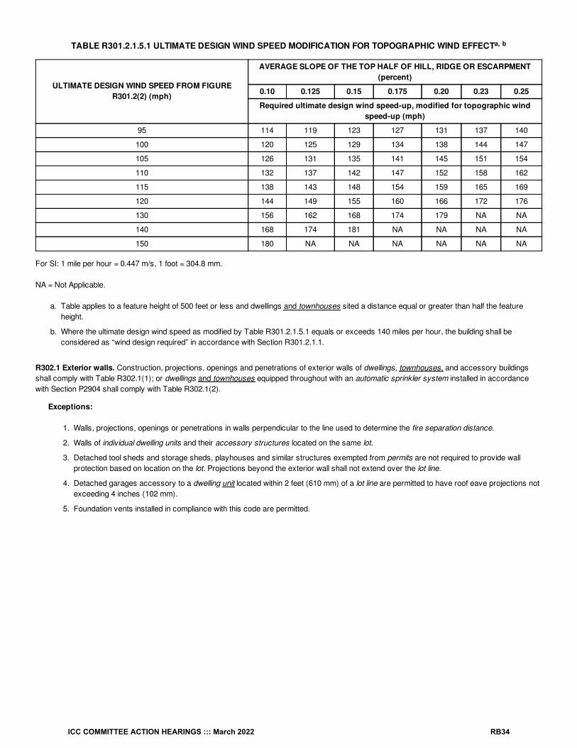
TABLE R301.2.1.5.1 ULTIMATE DESIGN WIND SPEED MODIFICATION FOR TOPOGRAPHIC WIND EFFECT
ULTIMATE DESIGN WIND SPEED FROM FIGURER301.2(2) (mph)
AVERAGE SLOPE OF THE TOP HALF OF HILL, RIDGE OR ESCARPMENT(percent)
0.10 0.125 0.15 0.175 0.20 0.23 0.25
Required ultimate design wind speed-up, modified for topographic windspeed-up (mph)
95 114 119 123 127 131 137 140
100 120 125 129 134 138 144 147
105 126 131 135 141 145 151 154
110 132 137 142 147 152 158 162
115 138 143 148 154 159 165 169
120 144 149 155 160 166 172 176
130 156 162 168 174 179 NA NA
140 168 174 181 NA NA NA NA
150 180 NA NA NA NA NA NA
For SI: 1 mile per hour = 0.447 m/s, 1 foot = 304.8 mm.
NA = Not Applicable.
a. Table applies to a feature height of 500 feet or less and dwellings and townhouses sited a distance equal or greater than half the featureheight.
b. Where the ultimate design wind speed as modified by Table R301.2.1.5.1 equals or exceeds 140 miles per hour, the building shall beconsidered as “wind design required” in accordance with Section R301.2.1.1.
R302.1 Exterior walls. Construction, projections, openings and penetrations of exterior walls of dwellings, townhouses, and accessory buildingsshall comply with Table R302.1(1); or dwellings and townhouses equipped throughout with an automatic sprinkler system installed in accordancewith Section P2904 shall comply with Table R302.1(2).
Exceptions:
1. Walls, projections, openings or penetrations in walls perpendicular to the line used to determine the fire separation distance.
2. Walls of individual dwelling units and their accessory structures located on the same lot.
3. Detached tool sheds and storage sheds, playhouses and similar structures exempted from permits are not required to provide wallprotection based on location on the lot. Projections beyond the exterior wall shall not extend over the lot line.
4. Detached garages accessory to a dwelling unit located within 2 feet (610 mm) of a lot line are permitted to have roof eave projections notexceeding 4 inches (102 mm).
5. Foundation vents installed in compliance with this code are permitted.
a, b
ICC COMMITTEE ACTION HEARINGS ::: March 2022 RB34

TABLE R302.1(2) EXTERIOR WALLS—DWELLINGS AND TOWNHOUSES WITH FIRE SPRINKLERS
EXTERIOR WALLELEMENT
MINIMUM FIRE-RESISTANCE RATING MINIMUM FIRESEPARATION DISTANCE
Walls
Fire-resistance
rated
1 hour—tested in accordance with ASTM E119, UL 263 or Section 703.2.2 of theInternational Building Code with exposure from the outside
0 feet
Not fire-resistance
rated0 hours 3 feet
Projections
Not allowed NA < 2 feet
Fire-resistance
rated1 hour on the underside, or heavy timber, or fire-retardant-treated wood 2 feet
Not fire-resistance
rated0 hours 3 feet
Openings inwalls
Not allowed NA < 3 feet
Unlimited 0 hours 3 feet
Penetrations AllComply with Section R302.4 < 3 feet
None required 3 feet
For SI: 1 foot = 304.8 mm.
NA = Not Applicable.
a. For residential subdivisions where all dwellings and/or townhouses are equipped throughout with an automatic sprinkler system installed inaccordance with Section P2904, the fire separation distance for exterior walls not fire-resistance rated and for fire-resistance-ratedprojections shall be permitted to be reduced to 0 feet, and unlimited unprotected openings and penetrations shall be permitted, where theadjoining lot provides an open setback yard that is 6 feet or more in width on the opposite side of the property line.
b. The fire-resistance rating shall be permitted to be reduced to 0 hours on the underside of the eave overhang if fireblocking is provided fromthe wall top plate to the underside of the roof sheathing.
c. The fire-resistance rating shall be permitted to be reduced to 0 hours on the underside of the rake overhang where gable vent openings arenot installed.
R301.2.2.6 Irregular buildings. The seismic provisions of this code shall not be used for structures, or portions thereof, located in Seismic DesignCategories C, D , D and D and considered to be irregular in accordance with this section. A building or portion of a building shall be considered tobe irregular where one or more of the conditions defined in Items 1 through 8 occur. Irregular structures, or irregular portions of structures, shall bedesigned in accordance with accepted engineering practice to the extent the irregular features affect the performance of the remaining structuralsystem. Where the forces associated with the irregularity are resisted by a structural system designed in accordance with accepted engineeringpractice, the remainder of the building shall be permitted to be designed using the provisions of this code.
a
b, c a
a
a
0 1 2
ICC COMMITTEE ACTION HEARINGS ::: March 2022 RB35

1. Shear wall or braced wall offsets out of plane. Conditions where exterior shear wall lines or braced wall panels are not in one planevertically from the foundation to the uppermost story in which they are required.
Exception: For wood light-frame construction, floors with cantilevers or setbacks not exceeding four times the nominal depth of thewood floor joists are permitted to support braced wall panels that are out of plane with braced wall panels below provided that all of thefollowing are satisfied:
1. Floor joists are nominal 2 inches by 10 inches (51 mm by 254 mm) or larger and spaced not more than 16 inches (406 mm) oncenter.
2. The ratio of the back span to the cantilever is not less than 2 to 1.
3. Floor joists at ends of braced wall panels are doubled.
4. For wood-frame construction, a continuous rim joist is connected to ends of cantilever joists. Where spliced, the rim joists shall bespliced using a galvanized metal tie not less than 0.058 inch (1.5 mm) (16 gage) and 1 / inches (38 mm) wide fastened with six16d nails on each side of the splice; or a block of the same size as the rim joist and of sufficient length to fit securely between thejoist space at which the splice occurs, fastened with eight 16d nails on each side of the splice.
5. Gravity loads carried at the end of cantilevered joists are limited to uniform wall and roof loads and the reactions from headershaving a span of 8 feet (2438 mm) or less.
2. Lateral support of roofs and floors. Conditions where a section of floor or roof is not laterally supported by shear walls or braced walllines on all edges.
Exception: Portions of floors that do not support shear walls, braced wall panels above, or roofs shall be permitted to extend not morethan 6 feet (1829 mm) beyond a shear wall or braced wall line.
3. Shear wall or braced wall offsets in plane. Conditions where the end of a braced wall panel occurs over an opening in the wall below andextends more than 1 foot (305 mm) horizontally past the edge of the opening. This provision is applicable to shear walls and braced wallpanels offset in plane and to braced wall panels offset out of plane in accordance with the exception to Item 1.
Exception: For wood light-frame wall construction, one end of a braced wall panel shall be permitted to extend more than 1 foot (305mm) over an opening not more than 8 feet (2438 mm) in width in the wall below provided that the opening includes a header inaccordance with all of the following:
1. The building width, loading condition and framing member species limitations of Table R602.7(1) shall apply.
2. The header is composed of:
2.1. Not less than one 2 × 12 or two 2 × 10 for an opening not more than 4 feet (1219 mm) wide.
2.2. Not less than two 2 × 12 or three 2 × 10 for an opening not more than 6 feet (1829 mm) in width.
2.3. Not less than three 2 × 12 or four 2 × 10 for an opening not more than 8 feet (2438 mm) in width.
3. The entire length of the braced wall panel does not occur over an opening in the wall below.
4. Floor and roof opening. Conditions where an opening in a floor or roof exceeds the lesser of 12 feet (3658 mm) or 50 percent of the leastfloor or roof dimension.
5. Floor level offset. Conditions where portions of a floor level are vertically offset.
Exceptions:
1. Framing supported directly by continuous foundations at the perimeter of the building.
2. For wood light-frame construction, floors shall be permitted to be vertically offset where the floor framing is lapped or tied togetheras required by Section R502.6.1.
6. Perpendicular shear wall and wall bracing. Conditions where shear walls and braced wall lines do not occur in two perpendiculardirections.
12
ICC COMMITTEE ACTION HEARINGS ::: March 2022 RB36

7. Wall bracing in stories containing masonry or concrete construction. Conditions where stories above grade plane are partially orcompletely braced by wood wall framing in accordance with Section R602 or cold-formed steel wall framing in accordance with Section R603include masonry or concrete construction. Where this irregularity applies, the entire story shall be designed in accordance with acceptedengineering practice.
Exceptions: Fireplaces, chimneys and masonry veneer in accordance with this code.8. Hillside light-frame construction. Conditions in which all of the following apply:
8.1. The grade slope exceeds 1 unit vertical in 5 units horizontal where averaged across the full length of any side of the building dwelling.
8.2. The tallest cripple wall clear height exceeds 7 feet (2134 mm), or where a post and beam system occurs at the building dwellingperimeter, the post and beam system tallest post clear height exceeds 7 feet (2134 mm).
8.3. Of the total plan area below the lowest framed floor, whether open or enclosed, less than 50 percent is living space having interior wallfinishes conforming to Section R702.
Where Item 8 is applicable, design in accordance with accepted engineering practice shall be provided for the floor immediately abovethe cripple walls or post and beam system and all structural elements and connections from this diaphragm down to and includingconnections to the foundation and design of the foundation to transfer lateral loads from the framing above.
Exception: Light-frame construction in which the lowest framed floor is supported directly on concrete or masonry walls over thefull length of all sides except the downhill side of the building dwelling need not be considered an irregular building dwelling under Item8.
R302.5 Dwelling unit-garage opening and penetration protection. Openings and penetrations through the walls or ceilings separating thedwelling unit from the garage shall be in accordance with Sections R302.5.1 through R302.5.3.
R302.5.1 Opening protection. Openings from a private garage directly into a room used for sleeping purposes shall not be permitted. Otheropenings between the garage and dwelling unit residence shall be equipped with solid wood doors not less than 1 / inches (35 mm) in thickness,solid or honeycomb-core steel doors not less than 1 / inches (35 mm) thick, or 20-minute fire-rated doors. Doors shall be self-latchingand equipped with a self-closing or automatic-closing device.
R302.5.2 Duct penetration. Ducts in the garage and ducts penetrating the walls or ceilings separating the dwelling unit from the garage shall beconstructed of a minimum No. 26 gage (0.48 mm) sheet steel or other approved material and shall not have openings into the garage.
R302.6 Dwelling unit-garage fire separation. The garage shall be separated as required by Table R302.6. Openings in garage walls shall complywith Section R302.5. Attachment of gypsum board shall comply with Table R702.3.5. The wall separation provisions of Table R302.6 shall not applyto garage walls that are perpendicular to the adjacent dwelling unit wall.
38
38
ICC COMMITTEE ACTION HEARINGS ::: March 2022 RB37

TABLE R302.6 DWELLING UNIT-GARAGE SEPARATION
SEPARATION MATERIAL
From the dwelling unit residence and attics Not less than / -inch gypsum board or equivalent applied to the garage side
From habitable rooms above the garage Not less than / -inch Type X gypsum board or equivalent
Structure(s) supporting floor/ceiling assemblies used forseparation required by this section
Not less than / -inch gypsum board or equivalent
Garages located less than 3 feet from a dwelling unit on thesame lot
Not less than / -inch gypsum board or equivalent applied to the interior side ofexterior walls that are within this area
For SI: 1 inch = 25.4 mm, 1 foot = 304.8 mm.
R302.3 Two-family dwellings. Dwelling units in two-family dwellings shall be separated from each other by wall and floor assemblies having notless than a 1-hour fire-resistance rating where tested in accordance with ASTM E119, UL 263 or Section 703.2.2 of the International Building Code.Such separation shall be provided regardless of whether a lot line exists between the two dwelling units or not. Fire-resistance-rated floor/ceiling andwall assemblies shall extend to and be tight against the exterior wall, and wall assemblies shall extend from the foundation to the underside of theroof sheathing.
Exceptions:
1. A fire-resistance rating of / hour shall be permitted in buildings equipped throughout with an automatic sprinkler system installed inaccordance with Section P2904.
2. Wall assemblies need not extend through attic spaces where the ceiling is protected by not less than / -inch (15.9 mm) Type X gypsumboard, an attic draft stop constructed as specified in Section R302.12.1 is provided above and along the wall assembly separating thedwellings dwelling units and the structural framing supporting the ceiling is protected by not less than / -inch (12.7 mm) gypsum board orequivalent.
R310.6 Dwelling additions. Where dwelling unit additions contain sleeping rooms, an emergency escape and rescue opening shall be provided ineach new sleeping room. Where dwelling unit additions have basements, an emergency escape and rescue opening shall be provided in the newbasement.
Exceptions:
1. An emergency escape and rescue opening is not required in a new basement that contains a sleeping room with an emergency escapeand rescue opening.
2. An emergency escape and rescue opening is not required in a new basement where there is an emergency escape and rescue openingin an existing basement that is accessed from the new basement.
3. An operable window complying with Section 310.7.1 shall be acceptable as an emergency escape and rescue opening.
R311.1 Means of egress. Dwellings Dwelling units shall be provided with a means of egress in accordance with this section. The means of egressshall provide a continuous and unobstructed path of vertical and horizontal egress travel from all portions of the dwelling unit to the required egressdoor without requiring travel through a garage. The required egress door shall open directly into a public way or to a yard or court that opens to apublic way.
R311.2 Egress door. Not less than one egress door shall be provided for each dwelling unit. The egress door shall be side-hinged, and shallprovide a clear width of not less than 32 inches (813 mm) where measured between the face of the door and the stop, with the door open 90degrees (1.57 rad). The clear height of the door opening shall be not less than 78 inches (1981 mm) in height measured from the top of the thresholdto the bottom of the stop. Other doors shall not be required to comply with these minimum dimensions. Egress doors shall be readily openable frominside the dwelling unit without the use of a key or special knowledge or effort.
R314.3 Location. Smoke alarms shall be installed in the following locations:
1. In each sleeping room.
2. Outside each separate sleeping area in the immediate vicinity of the bedrooms.
3. On each additional story of the dwelling unit, including basements and habitable attics and not including crawl spaces and uninhabitableattics. In dwellings or dwelling units with split levels and without an intervening door between the adjacent levels, a smoke alarm installed onthe upper level shall suffice for the adjacent lower level provided that the lower level is less than one full story below the upper level.
4. Not less than 3 feet (914 mm) horizontally from the door or opening of a bathroom that contains a bathtub or shower unless this wouldprevent placement of a smoke alarm required by this section.
12
58
12
12
12
58
12
ICC COMMITTEE ACTION HEARINGS ::: March 2022 RB38
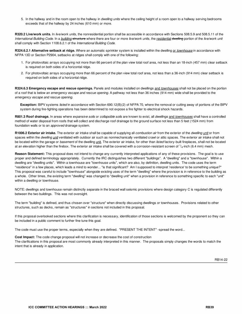
5. In the hallway and in the room open to the hallway in dwelling units where the ceiling height of a room open to a hallway serving bedroomsexceeds that of the hallway by 24 inches (610 mm) or more.
R320.2 Live/work units. In live/work units, the nonresidential portion shall be accessible in accordance with Sections 508.5.9 and 508.5.11 of theInternational Building Code. In a building structure where there are four or more live/work units, the residential dwelling portion of the live/work unitshall comply with Section 1108.6.2.1 of the International Building Code.
R324.6.2.1 Alternative setback at ridge. Where an automatic sprinkler system is installed within the dwelling or townhouse in accordance withNFPA 13D or Section P2904, setbacks at ridges shall comply with one of the following:
1. For photovoltaic arrays occupying not more than 66 percent of the plan view total roof area, not less than an 18-inch (457 mm) clear setbackis required on both sides of a horizontal ridge.
2. For photovoltaic arrays occupying more than 66 percent of the plan view total roof area, not less than a 36-inch (914 mm) clear setback isrequired on both sides of a horizontal ridge.
R324.6.3 Emergency escape and rescue openings. Panels and modules installed on dwellings and townhouses shall not be placed on the portionof a roof that is below an emergency escape and rescue opening. A pathway not less than 36 inches (914 mm) wide shall be provided to theemergency escape and rescue opening.
Exception: BIPV systems listed in accordance with Section 690.12(B)(2) of NFPA 70, where the removal or cutting away of portions of the BIPVsystem during fire-fighting operations has been determined to not expose a fire fighter to electrical shock hazards.
R801.3 Roof drainage. In areas where expansive soils or collapsible soils are known to exist, all dwellings and townhouses shall have a controlledmethod of water disposal from roofs that will collect and discharge roof drainage to the ground surface not less than 5 feet (1524 mm) fromfoundation walls or to an approved drainage system.
R1006.2 Exterior air intake. The exterior air intake shall be capable of supplying all combustion air from the exterior of the dwelling unit or fromspaces within the dwelling unit ventilated with outdoor air such as nonmechanically ventilated crawl or attic spaces. The exterior air intake shall notbe located within the garage or basement of the dwelling unit. The exterior air intake, for other than listed factory-built fireplaces, shall not be locatedat an elevation higher than the firebox. The exterior air intake shall be covered with a corrosion-resistant screen of / -inch (6.4 mm) mesh.
Reason Statement: This proposal does not intend to change any currently interpreted applications of any of these provisions. The goal is to useproper and defined terminology appropriately. Currently the IRC distinguishes two different "buildings". A "dwelling" and a "townhouse". Within adwelling are "dwelling units". Within a townhouse are "townhouse units", which are also, by definition, dwelling units. The code uses the term"residence" in a few places, which leads a mind to wonder... "is that significant? Am I supposed to interpret 'residence' to be something unique?"This proposal was careful to include "townhouse" alongside existing uses of the term "dwelling" where the provision is in reference to the building asa whole. Other times, the existing term "dwelling" was changed to "dwelling unit" when a provision in reference to something specific to each "unit"within a dwelling or townhouse.
NOTE: dwellings and townhouse remain distinctly separate in the braced wall seismic provisions where design category C is regulated differentlybetween the two buildings. This was not oversight.
The term "building" is defined, and thus chosen over "structure" when directly discussing dwellings or townhouses. Provisions related to otherstructures, such as decks, remain as "structures" in sections not included in this proposal.
If this proposal overlooked sections where this clarification is necessary, identification of those sections is welcomed by the proponent so they canbe included in a public comment to further fine tune this goal.
The code must use the proper terms, especially when they are defined. "PRESENT THE INTENT" -spread the word...
Cost Impact: The code change proposal will not increase or decrease the cost of constructionThe clarifications in this proposal are most commonly already interpreted in this manner. The proposals simply changes the words to match theintent that is already in application.
RB14-22
14
ICC COMMITTEE ACTION HEARINGS ::: March 2022 RB39

RB15-22IRC: R105.3.1.1, R322.3.1, AJ102.5
Proponents: Gregory Wilson, representing FEMA ([email protected]); Rebecca Quinn, representing DHS Federal EmergencyManagement Agency ([email protected])
2021 International Residential CodeRevise as follows:
R104.2.1R105.3.1.1 Determination of substantially improved or substantially damaged existing buildings in flood hazard areas. Forapplications for reconstruction, rehabilitation, addition, alteration, repair or other improvement of existing buildings or structures located in a floodhazard area as established by Table R301.2, the building official shall examine or cause to be examined the construction documents and shall makea determination with regard to the value of the proposed work. For buildings that have sustained damage of any origin, the value of the proposedwork shall include the cost to repair the building or structure to its predamaged condition. If the building official finds that the value of proposed workequals or exceeds 50 percent of the market value of the building or structure before the damage has occurred or the improvement is started, theproposed work is a substantial improvement or repair of substantial damage and the building official shall require existing portions of the entirebuilding or structure to meet the requirements of Section R322.For the purpose of this determination, a substantial improvement shall mean any repair, reconstruction, rehabilitation, addition or improvement of abuilding or structure, the cost of which equals or exceeds 50 percent of the market value of the building or structure before the improvement orrepair is started. Where the building or structure has sustained substantial damage, repairs necessary to restore the building or structure to itspredamaged condition shall be considered substantial improvements regardless of the actual repair work performed. The term shall not includeeither of the following:
1. Improvements to a building or structure that are required to correct existing health, sanitary or safety code violations identified by the buildingofficial and that are the minimum necessary to ensure safe living conditions.
2. Any alteration of a historic building or structure, provided that the alteration will not preclude the continued designation as a historic building orstructure. For the purposes of this exclusion, a historic building shall be any of the following:
2.1. Listed or preliminarily determined to be eligible for listing in the National Register of Historic Places.
2.2. Determined by the Secretary of the US Department of Interior as contributing to the historical significance of a registered historic districtor a district preliminarily determined to qualify as an historic district.
2.3. Designated as historic under a state or local historic preservation program that is approved by the Department of Interior.
R322.3.1 Location and site preparation. 1. New buildings and buildings that are determined to be substantially improved pursuant to SectionR104.2.1 R105.3.1.1 shall be located landward of the reach of mean high tide. 2. For any alteration of sand dunes and mangrove stands, the building official shall require submission of an engineering analysis thatdemonstrates that the proposed alteration will not increase the potential for flood damage.
AJ102.5 Flood hazard areas. Work performed in existing buildings located in a flood hazard area as established by Table R301.2 shall be subjectto the provisions of Section R104.2.1R105.3.1.1.
Reason Statement: The provision directs the building official to determine whether work proposed for existing dwellings constitutes substantialimprovement and whether repairs of damage building constitute substantial damage. The proposal simply moves the provision out of Section R105Permits to Section R104 Duties and Powers of the Building Official. The determination requirement is in the Duties and Powers sections of the IBCand IEBC.
Cost Impact: The code change proposal will not increase or decrease the cost of constructionThe code change proposal relocates a provision regarding substantial improvement determinations from one section to another section to betteralign with the organization of the same provision in the IBC and IEBC. There is no change to the technical content of the provisions. By onlyrelocating the existing requirement, there will be no cost impact when approving this proposal.
RB15-22
ICC COMMITTEE ACTION HEARINGS ::: March 2022 RB40
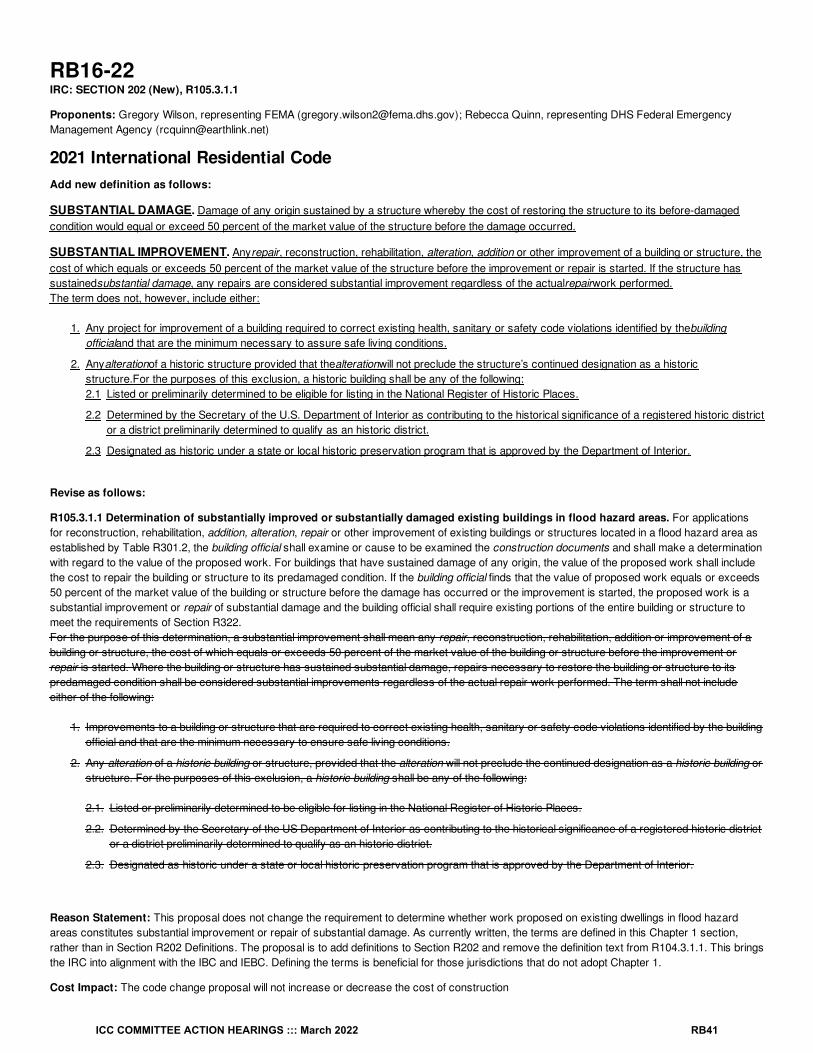
RB16-22IRC: SECTION 202 (New), R105.3.1.1
Proponents: Gregory Wilson, representing FEMA ([email protected]); Rebecca Quinn, representing DHS Federal EmergencyManagement Agency ([email protected])
2021 International Residential CodeAdd new definition as follows:
SUBSTANTIAL DAMAGE. Damage of any origin sustained by a structure whereby the cost of restoring the structure to its before-damagedcondition would equal or exceed 50 percent of the market value of the structure before the damage occurred.
SUBSTANTIAL IMPROVEMENT. Anyrepair, reconstruction, rehabilitation, alteration, addition or other improvement of a building or structure, thecost of which equals or exceeds 50 percent of the market value of the structure before the improvement or repair is started. If the structure hassustainedsubstantial damage, any repairs are considered substantial improvement regardless of the actualrepairwork performed.The term does not, however, include either:
1. Any project for improvement of a building required to correct existing health, sanitary or safety code violations identified by thebuildingofficialand that are the minimum necessary to assure safe living conditions.
2. Anyalterationof a historic structure provided that thealterationwill not preclude the structure’s continued designation as a historicstructure.For the purposes of this exclusion, a historic building shall be any of the following:2.1 Listed or preliminarily determined to be eligible for listing in the National Register of Historic Places.
2.2 Determined by the Secretary of the U.S. Department of Interior as contributing to the historical significance of a registered historic districtor a district preliminarily determined to qualify as an historic district.
2.3 Designated as historic under a state or local historic preservation program that is approved by the Department of Interior.
Revise as follows:
R105.3.1.1 Determination of substantially improved or substantially damaged existing buildings in flood hazard areas. For applicationsfor reconstruction, rehabilitation, addition, alteration, repair or other improvement of existing buildings or structures located in a flood hazard area asestablished by Table R301.2, the building official shall examine or cause to be examined the construction documents and shall make a determinationwith regard to the value of the proposed work. For buildings that have sustained damage of any origin, the value of the proposed work shall includethe cost to repair the building or structure to its predamaged condition. If the building official finds that the value of proposed work equals or exceeds50 percent of the market value of the building or structure before the damage has occurred or the improvement is started, the proposed work is asubstantial improvement or repair of substantial damage and the building official shall require existing portions of the entire building or structure tomeet the requirements of Section R322.For the purpose of this determination, a substantial improvement shall mean any repair, reconstruction, rehabilitation, addition or improvement of abuilding or structure, the cost of which equals or exceeds 50 percent of the market value of the building or structure before the improvement orrepair is started. Where the building or structure has sustained substantial damage, repairs necessary to restore the building or structure to itspredamaged condition shall be considered substantial improvements regardless of the actual repair work performed. The term shall not includeeither of the following:
1. Improvements to a building or structure that are required to correct existing health, sanitary or safety code violations identified by the buildingofficial and that are the minimum necessary to ensure safe living conditions.
2. Any alteration of a historic building or structure, provided that the alteration will not preclude the continued designation as a historic building orstructure. For the purposes of this exclusion, a historic building shall be any of the following:
2.1. Listed or preliminarily determined to be eligible for listing in the National Register of Historic Places.
2.2. Determined by the Secretary of the US Department of Interior as contributing to the historical significance of a registered historic districtor a district preliminarily determined to qualify as an historic district.
2.3. Designated as historic under a state or local historic preservation program that is approved by the Department of Interior.
Reason Statement: This proposal does not change the requirement to determine whether work proposed on existing dwellings in flood hazardareas constitutes substantial improvement or repair of substantial damage. As currently written, the terms are defined in this Chapter 1 section,rather than in Section R202 Definitions. The proposal is to add definitions to Section R202 and remove the definition text from R104.3.1.1. This bringsthe IRC into alignment with the IBC and IEBC. Defining the terms is beneficial for those jurisdictions that do not adopt Chapter 1.
Cost Impact: The code change proposal will not increase or decrease the cost of construction
ICC COMMITTEE ACTION HEARINGS ::: March 2022 RB41

The code change proposal relocates the definitions from the second paragraph of Section R105.3.1.1 to Chapter 2 Definitions. There is no changeto the technical content of the provisions. By only relocating existing definitions, there will be no cost impact when approving this proposal.
RB16-22
ICC COMMITTEE ACTION HEARINGS ::: March 2022 RB42

RB17-22IRC: R109.1.4, R109.1.4.1 (New), R109.1.4.1.1 (New), R109.1.4.2 (New), R109.1.4.3 (New), R109.1.4.4 (New), R109.1.4.5 (New)
Proponents: Matthew Dobson, representing Vinyl Siding Institute ([email protected])
2021 International Residential CodeDelete and substitute as follows:
R109.1.4 Frame and masonry inspection. Inspection of framing and masonry construction shall be made after the roof, masonry, framing,firestopping, draftstopping and bracing are in place and after the plumbing, mechanical and electrical rough inspections are approved.
R109.1.4 Building Inspections. Inspection of the structure shall include the elements in Section R109.1.4.1 through R109.1.4.5. The building officialshall determine the timing and sequencing of when inspections occur and what elements are inspected at each inspection.
Add new text as follows:
R109.1.4.1 Foundation inspection. Foundation inspections shall be made after trenches are excavated and forms erected and shall at a minimuminclude the following building components:
1. Stem-wall
2. Monolithic slab-on-grade
3. Piling/pile caps
4. Footers/grade beams
R109.1.4.1.1 Flood hazard areas. In flood hazard areas, upon placement of the lowest floor, including basement, and prior to further verticalconstruction, the elevation certification shall be submitted to the authority having jurisdiction.
R109.1.4.2 Framing inspection. Framing inspections shall be made after the roof, all framing, fire blocking and bracing is in place, all concealingwiring, all pipes, chimneys, ducts and vents are complete and shall at a minimum include the following building components:
1. Window/door framing
2. Vertical cells/columns
3. Lintel/tie beams
4. Framing/trusses/bracing/connectors
5. Draft stopping/fire blocking
6. Curtain wall framing
7. Energy insulation
8. Accessibility
9. Verify rough opening dimensions are within tolerances
R109.1.4.3 Sheathing inspection. Sheathing inspection shall be made either as part of a dry-in inspection or done separately at the request of thecontractor after all roof and wall sheathing and fasteners are complete and shall at a minimum include the following building components:
1. Roof sheathing
2. Wall sheathing
3. Sheathing fasteners
4. Roof/wall dry
5. Water-resistive barrier/flashing
R109.1.4.4 Exterior wall coverings. Exterior wall coverings shall at a minimum include the following building components in progress inspections:
1. Exterior wall coverings and veneers
2. Soffit coverings
R109.1.4.5 Roofing inspection. Roofing inspections shall at a minimum include the following building components:
ICC COMMITTEE ACTION HEARINGS ::: March 2022 RB43

1. Dry-in
2. Insulation
3. Roof coverings
4. Flashing
Reason Statement: Code should provide more detailed steps on inspection areas, other than inspecting framing and masonry. This proposalcontains the provision from the Florida Building Code has been used at least in part for several cycles and would be helpful to include in the IRC.
Cost Impact: The code change proposal will increase the cost of constructionWith additional specified inspections, this could add permitting costs from the AHJ, although many AHJs may already be conducting theseinspections currently.
RB17-22
ICC COMMITTEE ACTION HEARINGS ::: March 2022 RB44

RB18-22IRC: SECTION 202 (New), SECTION R316 (New), R316.1 (New), R316.1.1 (New), R316.2 (New), R316.2.1 (New), R316.2.2 (New), R316.3(New), R316.4 (New), R316.5 (New), R316.6 (New), R316.7 (New), R316.7.1 (New), R316.7.2 (New), R316.7.3 (New), R316.7.4 (New),R316.7.5 (New), R316.8 (New), NFPA Chapter 44 (New), UL Chapter 44 (New)
Proponents: Rick Trieste, representing Consolidated Edison Company of New York ([email protected])
2021 International Residential CodeAdd new definition as follows:
FUEL GAS ALARM. A single- or multiple-station alarm device intended to detect fuel gas and alert occupants by a distinct audible signal. Itincorporates a sensor, control components and an alarm notification appliance in a single unit.
FUEL GAS DETECTOR. A device with an integral sensor to detect fuel gas and transmit an alarm signal to a connected alarm control unit.
HOUSEHOLD FUEL GAS DETECTION SYSTEM. A system or portion of a combination system consisting of components and circuitsarranged to monitor and annunciate the status of fuel gas detectors and to initiate the appropriate response to those signals.
Add new text as follows:
SECTION R316FUEL GAS DETECTION DEVICES
R316.1 General. Fuel gas detection devices shall comply with Sections R316.
R316.1.1 Listings. Fuel gas alarms shall be listed in accordance with UL 1484. Combination carbon monoxide and fuel gas alarms shall be listed inaccordance with UL 2034 and UL 1484.
R316.2 Where required. Fuel gas alarms shall be provided in accordance with Sections R316.2.1 and R316.2.2.
R316.2.1 New construction. For new construction, fuel gas alarms shall be provided in dwelling units as follows:
1. In the same room as a permanently installed fuel-gas- burning appliance.
2. In the garage when the gas meter is located in the garage.
R316.2.2 Alterations, repairs and additions. Where alterations, repairs or additions requiring a permit occur, the individual dwelling unit shall beequipped with fuel gas alarms located as required for new dwellings.
R316.3 Location. Fuel gas alarms in dwelling units shall be located on the wall, ceiling, or other location as specified in the manufacturer’s publishedinstructions and located as follows:
1. For natural gas, the gas alarm shall be installed on the ceiling or on the wall with the top of the alarm within 12 inches (305 mm) of the ceiling.
2. For propane, the entire gas alarm shall be installed on the wall within 12 inches (305 mm) of the floor.
R316.4 Combination alarms. Combination carbon monoxide and fuel gas alarms shall be permitted to be used in lieu of fuel gas alarms.
R316.5 Power source. Fuel gas alarms shall receive their primary power from the building wiring where such wiring is served from a commercialsource, and where primary power is interrupted, shall receive power from a battery. Wiring shall be permanent and without a disconnecting switchother than those required for overcurrent protection.
Exception: Fuel gas alarms shall be permitted to be battery operated where installed in buildings without commercial power.
R316.6 Fuel gas alarm maintenance and replacement. Fuel gas alarms shall be maintained and replaced in accordance with manufacturer’srecommendations.
R316.7 Household fuel gas detection systems. Household fuel gas detection systems shall be permitted to be used in lieu of fuel gas alarms andshall comply with Sections R316.7.1 through R316.7.5.
R316.7.1 Installation. The installation of household fuel gas detection systems shall comply with NFPA 715.
R316.7.2 Listings. Fuel gas detectors shall be listed in accordance with UL 2075. Combination carbon monoxide and fuel gas detectors shall belisted in accordance with UL 2075.
R316.7.3 Location. Fuel gas detectors shall be installed in the locations specified in Section R316.3.
ICC COMMITTEE ACTION HEARINGS ::: March 2022 RB45
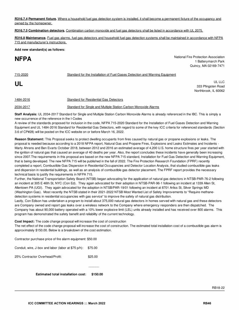
R316.7.4 Permanent fixture. Where a household fuel gas detection system is installed, it shall become a permanent fixture of the occupancy andowned by the homeowner.
R316.7.5 Combination detectors. Combination carbon monoxide and fuel gas detectors shall be listed in accordance with UL 2075.
R316.8 Maintenance. Fuel gas alarms, fuel gas detectors and household fuel gas detection systems shall be maintained in accordance with NFPA715 and manufacturer’s instructions.
Add new standard(s) as follows:
NFPA National Fire Protection Association1 Batterymarch Park
Quincy, MA 02169-7471
715-2020 Standard for the Installation of Fuel Gases Detection and Warning Equipment
UL UL LLC333 Pfingsten Road
Northbrook, IL 60062
1484-2016 Standard for Residential Gas Detectors
2034-2017 Standard for Single and Multiple Station Carbon Monoxide Alarms
Staff Analysis: UL 2034-2017 Standard for Single and Multiple Station Carbon Monoxide Alarms is already referenced in the IBC. This is simply anew occurrence of the reference in the I-CodesA review of the standards proposed for inclusion in the code, NFPA 715-2020 Standard for the Installation of Fuel Gases Detection and WarningEquipment and UL 1484-2016 Standard for Residential Gas Detectors, with regard to some of the key ICC criteria for referenced standards (Section3.6 of CP#28) will be posted on the ICC website on or before March 16, 2022.
Reason Statement: This Proposal seeks to protect dwelling occupants from fires caused by natural gas or propane explosions or leaks. Theproposal is needed because according to a 2018 NFPA report, Natural Gas and Propane Fires, Explosions and Leaks Estimates and Incidents -Marty Ahrens and Ben Evarts October 2018, between 2012 and 2016 an estimated average of 4,200 U.S. home structure fires per year started withthe ignition of natural gas that caused an average of 40 deaths per year. Also, the report concludes these incidents have generally been increasingsince 2007.The requirements in this proposal are based on the new NFPA 715 standard, Installation for Fuel Gas Detection and Warning Equipment,that is being developed. The new NFPA 715 will be published in the fall of 2022. The Fire Protection Research Foundation (FPRF) recentlycompleted a report, Combustible Gas Dispersion in Residential Occupancies and Detector Location Analysis, that studied combustible gas leaksand dispersion in residential buildings, as well as an analysis of combustible gas detector placement. The FPRF report provides the necessarytechnical basis to justify the requirements in NFPA 715. Further, the National Transportation Safety Board (NTSB) began advocating for the application of natural gas detectors in NTSB-PAR-76-2 followingan incident at 305 E 46th St, NYC (Con Ed). They again advocated for their adoption in NTSB-PAR-96-1 following an incident at 1339 Allen St,Allentown PA (UGI). They again advocated for the adoption in NTSB/PAR-19/01 following an incident at 8701 Arliss St, Silver Springs MD(Washington Gas). Most recently the NTSB stated in their 2021-2022 NTSB Most Wanted List of Safety Improvements to “Require methane-detection systems in residential occupancies with gas service” to improve the safety of natural gas distribution.Lastly, Con Edison has undertaken a program to install about 375,000 natural gas detectors in homes served with natural gas and these detectorsare Company owned and report gas leaks over a wireless network to the Company where emergency responders are then dispatched. TheCompany has about 90,000 battery operated with a 10% lower explosive limit (LEL) units already installed and has received over 800 alarms. Thisprogram has demonstrated the safety benefit and reliability of the current technology.
Cost Impact: The code change proposal will increase the cost of constructionThe net effect of the code change proposal will increase the cost of construction. The estimated total installation cost of a combustible gas alarm isapproximately $150.00. Below is a breakdown of the cost estimation.
Contractor purchase price of fire alarm equipment: $50.00
Conduit, wire, J-box and labor (labor at $75 p/h): $75.00
25% Contractor Overhead/Profit: $25.00
______
Estimated total installation cost: $150.00
RB18-22
ICC COMMITTEE ACTION HEARINGS ::: March 2022 RB46

RB19-22IRC: SECTION 202
Proponents: Jeffrey Shapiro, representing Self ([email protected])
2021 International Residential Code[RB] ATTIC. The unfinished space between the ceiling assembly and the roof assembly.
Revise as follows:
[RB] ATTIC, HABITABLE. A finished or unfinished habitable space within an attic between the ceiling assembly and the roof assembly.
Reason Statement: "Attic" is defined to be ONLY an unfinished space. So a "habitable attic" cannot rely on the definition of attic to specify part ofits parameters since a "habitable attic" can be finished. It technically doesn't qualify as an attic under the current base definition.
Cost Impact: The code change proposal will not increase or decrease the cost of constructionEditorial clarification of current intent with no intended technical change.
RB19-22
ICC COMMITTEE ACTION HEARINGS ::: March 2022 RB47

RB20-22IRC: SECTION 202, R902.3
Proponents: Larry Sherwood, representing Sustainable Energy Action Committee ([email protected]); Kevin Reinertson, representing CaliforniaFire Chiefs Association FPO ([email protected]); Benjamin Davis, representing California Solar & Storage Association([email protected]); Philip Oakes, representing National Association of State Fire Marshals; Joseph Cain, representing Solar Energy IndustriesAssociation (SEIA) ([email protected])
2021 International Residential CodeRevise as follows:
[RB] BUILDING-INTEGRATED PHOTOVOLTAIC (BIPV) PRODUCT SYSTEM. A building product system that incorporates photovoltaicmodules and functions as a an integral part component of the building envelope, such as roof assemblies and roof coverings, exterior wallenvelopes and exterior wall coverings, and fenestration.
R902.3 Building-integrated photovoltaic (BIPV) product systems. Building-integrated photovoltaic (BIPV) products systems installed as theroof covering shall be tested, listed and labeled for fire classification in accordance with UL 7103. Class A, B or C BIPV products shall be installedwhere the edge of the roof is less than 3 feet (914 mm) from a lot line.
Reason Statement: The term “BIPV product” is used twice in the I-codes, both requiring fire classification for roofing applications (IBC Section1505.8 and IRC Section R902.3). The term “BIPV system” is used four times in the I-codes, addressing roof access, rapid shutdown systems, andfire classification for roofing applications (IBC Sections 1205.2, 1205.2.3, 3111.3.2, 3113.3). IRC Section R324.5.2 directs BIPV systems to have afire classification in accordance with Section R902.3. The word “system” is defined by the dictionary as “a combination of things or parts forming a complex or unitary whole”, whereas the word “product”is defined as “the totality of goods or services that a company makes available; something produced”. “Product” infers a discrete piece, whereas“system” better describes a number of components that when installed function together for a specific purpose. This proposal also clarifies thatthese systems, when installed per the manufacturer’s installation instructions, become an integral part of the building envelope to provide a physicalseparator between internal and external environments.
The types of BIPV systems that include “exterior wall envelopes and exterior wall coverings, and fenestration” are added because FS150-21 inGroup A added these types of BIPV systems to Chapter 14 of the IBC, and there is another proposal for this cycle to add these types of systems toChapter 7 of the IRC.
This proposal was prepared by the Sustainable Energy Action Committee (SEAC), a forum for all stakeholders (including, but not limited to, AHJs,designers, engineers, contractors, first responders, manufacturers, suppliers, utilities, and testing labs) to collaboratively identify and find solutionsfor issues that affect the installation and use of solar energy systems, energy storage systems, demand response, and energy efficiency. Thepurpose is to facilitate the deployment and use of affordable, clean and renewable energy in a safe, efficient, and sustainable manner.
All recommendations from SEAC are approved by diverse stakeholders through a consensus process.
Cost Impact: The code change proposal will not increase or decrease the cost of construction
This proposal clarifies the term as it is used in the codes.
RB20-22
ICC COMMITTEE ACTION HEARINGS ::: March 2022 RB48

RB21-22 Part IPART 1 -IRC: SECTION 202;
PART 2 - IBC: SECTION 202
Proponents: THIS IS A TWO PART CODE CHANGE. PART 1 WILL BE HEARD BY THE INTERNATIONAL RESIDENTIAL CODE BUILDINGCOMMITTEE AND PART 2 WILL BE HEARD BY THE INTERNATIONAL BUILDING CODE STRUCTURAL COMMITTEE. SEE THE TENTATIVEHEARING ORDER FOR THESE COMMITTEES.
2021 International Building CodeRevise as follows:
[BS] DECORATIVE GLASS GLAZING. A carved, leaded or Dalle glass or glazing material whose purpose is decorative or artistic, notfunctional; whose coloring, texture or other design qualities or components cannot be removed without destroying the glazing material and whosesurface, or assembly into which it is incorporated, is divided into segments.
Staff Analysis: The IBC definition was added to the proposal as a modification by the CCC committee. See CCC Item IRC9-22.
RB21-22 Part I
ICC COMMITTEE ACTION HEARINGS ::: March 2022 RB49

RB21-22 Part IIPART 1 -IRC: SECTION 202;
PART 2 - IBC: SECTION 202
Proponents: THIS IS A TWO PART CODE CHANGE. PART 1 WILL BE HEARD BY THE INTERNATIONAL RESIDENTIAL CODE BUILDINGCOMMITTEE AND PART 2 WILL BE HEARD BY THE INTERNATIONAL BUILDING CODE STRUCTURAL COMMITTEE. SEE THE TENTATIVEHEARING ORDER FOR THESE COMMITTEES.
2021 International Residential CodeRevise as follows:
[RB] DECORATIVE GLAZING GLASS. A carved, leaded or Dalle glass or glazing material with a purpose that is decorative or artistic, notfunctional; with coloring, texture or other design qualities or components that cannot be removed without destroying the glazing material; and with asurface, or assembly into which it is incorporated, that is divided into segments.
Staff Analysis: The IBC definition was added to the proposal as a modification by the CCC committee. See CCC Item IRC9-22.
Reason Statement: Nowhere in the IRC does it refer to “decorative glass”. This subject only comes up in Section R308 and R609.3 and it refers to“decorative glazing” or “decorative glazed openings”. This proposal simply aligns the defined term with the term used in the body of the IRC.
Cost Impact: The code change proposal will not increase or decrease the cost of constructionThis proposal does not change the intent or application of the code as it has been customarily interpreted, therefore it has no impact on the cost ofconstruction.
RB21-22 Part II
ICC COMMITTEE ACTION HEARINGS ::: March 2022 RB50

RB22-22IRC: SECTION 202
Proponents: Timothy Pate, representing Colorado Chapter Code Change Committee ([email protected])
2021 International Residential CodeRevise as follows:
[RB] EXTERIOR WALL.An above-grade wall that defines the exterior boundaries of a building. Includes between-floor spandrels, peripheral edges of floors, roofand basement knee walls, dormer walls, gable end walls, gable end roof trusses, walls enclosing a mansard roof and basement walls with anaverage below-grade wall area that is less than 50 percent of the total opaque and nonopaque area of that enclosing side.For the definition applicable in Chapter 11, see Section N1101.6.
Reason Statement: This propsosal is to add gable end wall trusses to this definition which will clarify that these will be considered as part of theexterior walls. This is important since when determining fire ratings due to FSD the rating would need to incude these gable roof trusses. Theproposal is also to delete the RE in front of Exterior Wall and replace that with RB - This would need to be done by ICC Staff since CDP Access doesnot allow this to be done.
Cost Impact: The code change proposal will increase the cost of constructionThis change will only increase the cost of construciton in jurisdications that have not interpretated the code to include these gable end wall trusses tobe fire rated when the FSD requires the rating
RB22-22
ICC COMMITTEE ACTION HEARINGS ::: March 2022 RB51

RB23-22IRC: SECTION 202
Proponents: Kristen Owen, representing Myself ([email protected])
2021 International Residential Code[RB] FIRE-RETARDANT-TREATED WOOD. Wood products that, when impregnated with chemicals by a pressure process or other meansduring manufacture, exhibit reduced surface burning characteristics and resist propagation of fire.
Revise as follows:
Other means during manufacture. A process where the wood raw material is treated with a fire-retardant formulation while undergoingcreation as a finished product.
Pressure process. A process for treating wood using an initial vacuum followed by the introduction of pressure above atmospheric.
Reason Statement: The definition for fire-retardant-treated wood in the IRC needs to be consistent with the definition in the 2021 IBC. See G10-19(AMPC2).
Cost Impact: The code change proposal will not increase or decrease the cost of constructionBy matching the IBC definition to the IRC definition, there is no cost impact.
RB23-22
ICC COMMITTEE ACTION HEARINGS ::: March 2022 RB52

RB24-22IRC: SECTION 202 (New)
Proponents: Thomas Zuzik Jr, representing National Ornamental & Miscellaneous Metals Association (NOMMA) ([email protected])
2021 International Residential CodeAdd new definition as follows:
LANDING (for stairs and ramps). The minimum required area for a walking surface at the top and bottom of a stair flight or ramp run.
LANDINGS (for doors). The minimum required area of approach on each side of a door.
Reason Statement: The term landing is prolific throughout the model IRC, family of ICC model codes, accessibility codes and standards. Those ofus that navigate the codes and standards everyday have different views of what a landing actually is and often use the explanation, I know it when Isee it. This code proposal for the definition of a landing is directed at the heart of the term and to provide a simple precise meaning. The reality is alanding is the minimum level area of a walking surface, floor area, that is required at the tops and bottoms of stair flights and ramp runs. They arealso the minimum area on both sides of a door/doorway. The walking surface or floor area can be larger than the minimum area required for alanding and when you have connecting stair flights or ramp runs, the minimum areas can overlap, and they can also overlap with a door. However,the landing is required for each door, stair flight and ramp run, and the minimum required is the landing. To be more precise and to encompass the 2different areas within the code that center around landings being required, we listed landings with 2 term qualifiers (Stairs & Ramps) and (Doors), wesee the same split definition currently within the code for the definition of a Riser, (stair) & (plumbing).
Cost Impact: The code change proposal will not increase or decrease the cost of constructionThis is a definition and is not adding or subtracting any technical requirements within the code which the author believes will increase or decreasecost.
RB24-22
ICC COMMITTEE ACTION HEARINGS ::: March 2022 RB53

RB25-22IRC: SECTION R202 (NEW)
Proponents: David Cooper, representing Stairbuilders and Manufacturers Association ([email protected])
2021 International Residential CodeAdd new definition as follows:
LANDING. The required area of approach used to directly access an adjacent door, stair, or ramp.
Reason Statement: Landings are required throughout the code at doors, stairs and ramps but are not clearly understood in many cases as awalking surface. Egress from doors, stairs, and ramps may often be into a yard, a lawn, driveway or landscaped path. This definition purposefullyallows the size, shape, and surface requirements of the landing to regulated by the code as suits the location.
Cost Impact: The code change proposal will not increase or decrease the cost of constructionThe definition will not affect the cost of construction but may result in changes to the interpretation of existing requirements that will.
RB25-22
ICC COMMITTEE ACTION HEARINGS ::: March 2022 RB54

RB26-22IRC: SECTION 202
Proponents: Jay Crandell, P.E., ABTG/ARES Consulting, representing Foam Sheathing Committee of the American Chemistry Council([email protected])
2021 International Residential CodeRevise as follows:
[RB] PAN FLASHING. Corrosion-resistant flashing at the base of an opening that is integrated into the building exterior wall to direct water to thewater-resistive barrier surface or to the exterior and is premanufactured, fabricated, formed or applied at the job site.
Reason Statement: It is very common to direct pan flashing drainage to the WRB surface for subsequent drainage to the exterior of a wallassembly. The current definition recognizes only drainage directly to the exterior and could be interpreted as preventing many common pan flashingdrainage details that work and are being successfully used. This proposal also addresses a conflict with text in Section R703.4.1 which allowsflashing (including pan flashing) to extend to the surface of the WRB.
Cost Impact: The code change proposal will not increase or decrease the cost of constructionThis proposal corrects a definition to include common and cost-effective pan flashing drainage details.
RB26-22
ICC COMMITTEE ACTION HEARINGS ::: March 2022 RB55

RB27-22IRC: 202(New), R324.7
Proponents: Larry Sherwood, representing Sustainable Energy Action Committee ([email protected]); Kevin Reinertson, representing CaliforniaFire Chiefs Association FPO ([email protected]); Benjamin Davis, representing California Solar & Storage Association([email protected]); Philip Oakes, representing National Association of State Fire Marshals; Joseph Cain, representing Solar Energy IndustriesAssociation (SEIA) ([email protected])
2021 International Residential CodeAdd new definition as follows:
PHOTOVOLTAIC (PV) PANEL SYSTEM, GROUND-MOUNTED. An independent photovoltaic (PV) panel system without useable spaceunderneath, installed directly on the ground.
Revise as follows:
R324.7 Ground-mounted photovoltaic (PV) panel systems. Ground-mounted photovoltaic (PV) panel systems shall be designed and installed inaccordance with Section R301.
Reason Statement: The newly proposed definition is identical to the definition created in the IBC by Proposal G193-21. The existing language inIRC Section R324.7 is edited to match the newly defined term.This proposal was prepared by the Sustainable Energy Action Committee (SEAC), a forum for all stakeholders (including, but not limited to, AHJs,designers, engineers, contractors, first responders, manufacturers, suppliers, utilities, and testing labs) to collaboratively identify and find solutionsfor issues that affect the installation and use of solar energy systems, energy storage systems, demand response, and energy efficiency. Thepurpose is to facilitate the deployment and use of affordable, clean and renewable energy in a safe, efficient, and sustainable manner.
All recommendations from SEAC are approved by diverse stakeholders through a consensus process.
Cost Impact: The code change proposal will not increase or decrease the cost of constructionIt aligns with the IBC, and provides clarity of terms.
RB27-22
ICC COMMITTEE ACTION HEARINGS ::: March 2022 RB56

RB28-22IRC: SECTION 202 (New), TABLE R702.7(3)
Proponents: Theresa A Weston, The Holt Weston Consultancy, representing Rainscreen Association in North America (RAiNA)([email protected])
2021 International Residential CodeAdd new definition as follows:
RAINSCREEN SYSTEM. An assembly applied to the exterior side of an exterior wall which consists of, at minimum, an outer layer, an inner layer,and a cavity between them sufficient for the passive removal of liquid water and water vapor.
Revise as follows:
ICC COMMITTEE ACTION HEARINGS ::: March 2022 RB57
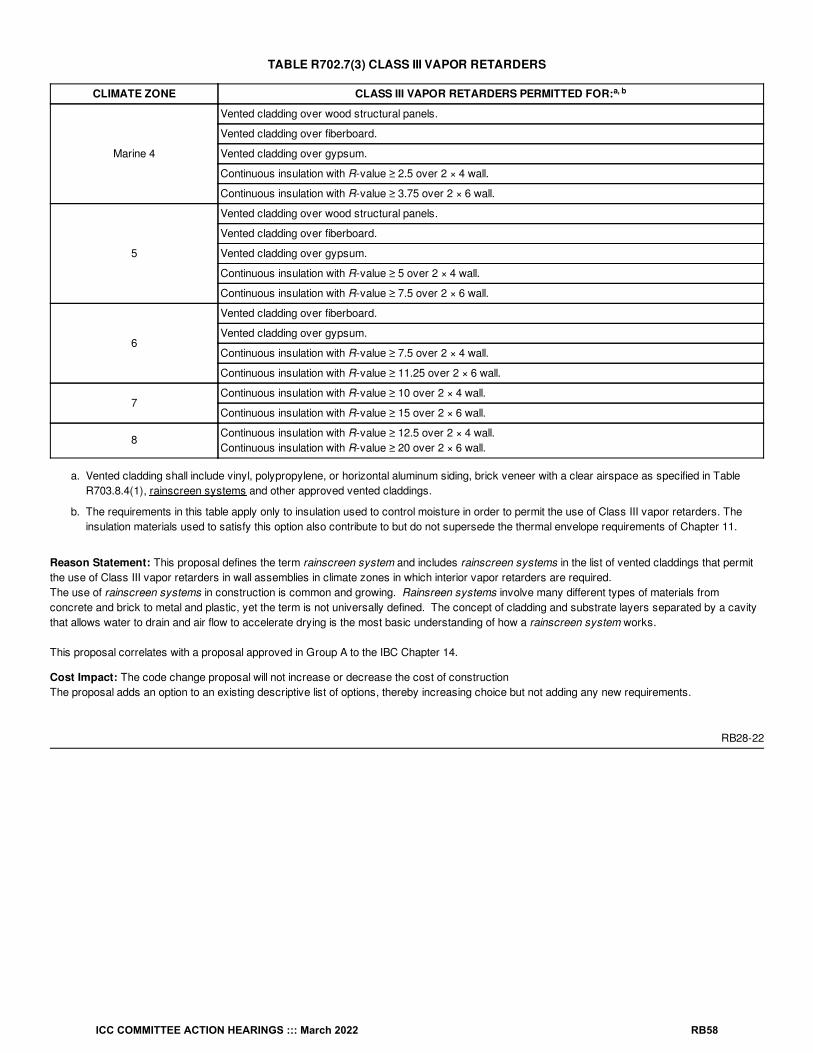
TABLE R702.7(3) CLASS III VAPOR RETARDERS
CLIMATE ZONE CLASS III VAPOR RETARDERS PERMITTED FOR:
Marine 4
Vented cladding over wood structural panels.
Vented cladding over fiberboard.
Vented cladding over gypsum.
Continuous insulation with R-value ≥ 2.5 over 2 × 4 wall.
Continuous insulation with R-value ≥ 3.75 over 2 × 6 wall.
5
Vented cladding over wood structural panels.
Vented cladding over fiberboard.
Vented cladding over gypsum.
Continuous insulation with R-value ≥ 5 over 2 × 4 wall.
Continuous insulation with R-value ≥ 7.5 over 2 × 6 wall.
6
Vented cladding over fiberboard.
Vented cladding over gypsum.
Continuous insulation with R-value ≥ 7.5 over 2 × 4 wall.
Continuous insulation with R-value ≥ 11.25 over 2 × 6 wall.
7Continuous insulation with R-value ≥ 10 over 2 × 4 wall.
Continuous insulation with R-value ≥ 15 over 2 × 6 wall.
8Continuous insulation with R-value ≥ 12.5 over 2 × 4 wall.Continuous insulation with R-value ≥ 20 over 2 × 6 wall.
a. Vented cladding shall include vinyl, polypropylene, or horizontal aluminum siding, brick veneer with a clear airspace as specified in TableR703.8.4(1), rainscreen systems and other approved vented claddings.
b. The requirements in this table apply only to insulation used to control moisture in order to permit the use of Class III vapor retarders. Theinsulation materials used to satisfy this option also contribute to but do not supersede the thermal envelope requirements of Chapter 11.
Reason Statement: This proposal defines the term rainscreen system and includes rainscreen systems in the list of vented claddings that permitthe use of Class III vapor retarders in wall assemblies in climate zones in which interior vapor retarders are required.The use of rainscreen systems in construction is common and growing. Rainsreen systems involve many different types of materials fromconcrete and brick to metal and plastic, yet the term is not universally defined. The concept of cladding and substrate layers separated by a cavitythat allows water to drain and air flow to accelerate drying is the most basic understanding of how a rainscreen system works.
This proposal correlates with a proposal approved in Group A to the IBC Chapter 14.
Cost Impact: The code change proposal will not increase or decrease the cost of constructionThe proposal adds an option to an existing descriptive list of options, thereby increasing choice but not adding any new requirements.
RB28-22
a, b
ICC COMMITTEE ACTION HEARINGS ::: March 2022 RB58

RB29-22IRC: SECTION 202
Proponents: Mark Graham, representing National Roofing Contractors Assoc. ([email protected])
2021 International Residential CodeRevise as follows:
[RB] ROOF COVERING. A system designed to The covering applied to the roof deck and provide for weather resistance, fire classification orappearance. The system consists of a membrane or water-shedding layer and can include an underlayment, a thermal barrier, insulation or a vaporretarder.
Reason Statement: This code change proposal is intended to clarify the current definition of the term "roof covering" and better coordinate it withthe defined term "roof assembly."
Cost Impact: The code change proposal will not increase or decrease the cost of constructionThis proposal re-words the definition for the term roof covering to use similar wording from the broader term roof assembly, which is also included inSection 202. There is no change to the technical content or intent of the definition. Approving this proposal will result in no change in construction orconstruction cost.
RB29-22
ICC COMMITTEE ACTION HEARINGS ::: March 2022 RB59

RB30-22IRC: SECTION 202
Proponents: Kelly Cobeen, representing Federal Emergency Management Agency/Applied Technology Council - Seismic Code Support Committee([email protected]); J Daniel Dolan, representing Seismic Code Support Committee ([email protected]); Michael Mahoney, representing FEMA([email protected])
2021 International Residential CodeRevise as follows:
[RB] SEISMIC DESIGN CATEGORY (SDC). A classification assigned to a structure based on its occupancy category and the severity of thedesign earthquake ground motion at the site.
Reason Statement: This proposal removes the archaic term “occupancy category,” which is no longer used by the I-Codes or ASCE 7, leaving thegeneric term “occupancy.” The new IBC/ASCE 7 term “Risk Category” has not been introduced because this would add an additional undefinedterm. A word search has indicated that this is the only location where the term "occupancy category" still remains in the IRC.
Cost Impact: The code change proposal will not increase or decrease the cost of constructionThe proposal is editorial and intended to maintain correct terminology.
RB30-22
ICC COMMITTEE ACTION HEARINGS ::: March 2022 RB60

RB31-22IRC: SECTION 202
Proponents: Larry Sherwood, representing Sustainable Energy Action Committee ([email protected]); Kevin Reinertson, representing CaliforniaFire Chiefs Association FPO ([email protected]); Benjamin Davis, representing California Solar & Storage Association([email protected]); Philip Oakes, representing National Association of State Fire Marshals; Joseph Cain, representing Solar Energy IndustriesAssociation (SEIA) ([email protected])
2021 International Residential CodeRevise as follows:
[RB] SOLAR ENERGY SYSTEM. A system that converts solar radiation to usable energy, including photovoltaic panel systems, BIPVsystems and solar thermal systems.
Reason Statement: BIPV systems are solar energy systems, but do not always utilize a rack support system. The definition of photovoltaic panelsystems includes a rack support system.
[RB] PHOTOVOLTAIC PANEL SYSTEM. A system that incorporates discrete photovoltaic panels that convert solar radiation into electricity,including rack support systems.
This proposal was prepared by the Sustainable Energy Action Committee (SEAC), a forum for all stakeholders (including, but not limited to, AHJs,designers, engineers, contractors, first responders, manufacturers, suppliers, utilities, and testing labs) to collaboratively identify and find solutionsfor issues that affect the installation and use of solar energy systems, energy storage systems, demand response, and energy efficiency. Thepurpose is to facilitate the deployment and use of affordable, clean and renewable energy in a safe, efficient, and sustainable manner.
All recommendations from SEAC are approved by diverse stakeholders through a consensus process.
Cost Impact: The code change proposal will not increase or decrease the cost of constructionThis provides clarity and consistency in terminology used for various solar energy systems.
RB31-22
ICC COMMITTEE ACTION HEARINGS ::: March 2022 RB61

RB32-22IRC: CHAPTER 3
Proponents: Timothy Pate, representing City and County of Broomfield ([email protected])
2021 International Residential Code
CHAPTER 3BUILDING PLANNING
Revise as follows:
SECTION 301DESIGN CRITERIA
SECTION R302FIRE-RESISTANT CONSTRUCTION
Revise as follows:
SECTION R303 R316FOAM PLASTIC
SECTION R304 R317PROTECTION OF WOOD AND WOOD-BASED PRODUCTS AGAINST DECAY
SECTION R305 R318PROTECTION AGAINST SUBTERRANEAN TERMITES
SECTION R306 R322FLOOD-RESISTANT CONSTRUCTION
SECTION R307 R323STORM SHELTERS
SECTION R308 R319SITE ADDRESS
SECTION R309 R313AUTOMATIC FIRE SPRINKLER SYSTEMS
SECTION R310 R314SMOKE ALARMS
SECTION R311 R315CARBON MONOXIDE ALARMS
SECTION R312 R304MINIMUM ROOM AREAS
SECTION R313 R305CEILING HEIGHT
SECTION R314 R325MEZZANINES
ICC COMMITTEE ACTION HEARINGS ::: March 2022 RB62
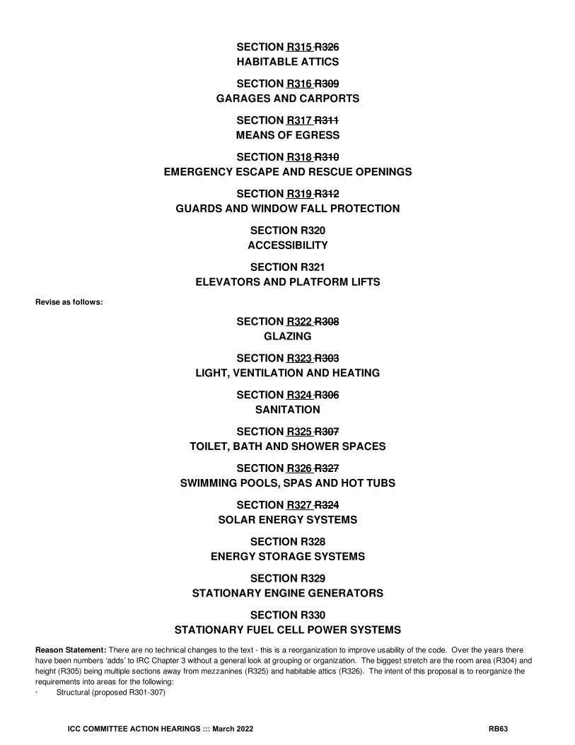
SECTION R315 R326HABITABLE ATTICS
SECTION R316 R309GARAGES AND CARPORTS
SECTION R317 R311MEANS OF EGRESS
SECTION R318 R310EMERGENCY ESCAPE AND RESCUE OPENINGS
SECTION R319 R312GUARDS AND WINDOW FALL PROTECTION
SECTION R320ACCESSIBILITY
SECTION R321ELEVATORS AND PLATFORM LIFTS
Revise as follows:
SECTION R322 R308GLAZING
SECTION R323 R303LIGHT, VENTILATION AND HEATING
SECTION R324 R306SANITATION
SECTION R325 R307TOILET, BATH AND SHOWER SPACES
SECTION R326 R327SWIMMING POOLS, SPAS AND HOT TUBS
SECTION R327 R324SOLAR ENERGY SYSTEMS
SECTION R328ENERGY STORAGE SYSTEMS
SECTION R329STATIONARY ENGINE GENERATORS
SECTION R330STATIONARY FUEL CELL POWER SYSTEMS
Reason Statement: There are no technical changes to the text - this is a reorganization to improve usability of the code. Over the years therehave been numbers ‘adds’ to IRC Chapter 3 without a general look at grouping or organization. The biggest stretch are the room area (R304) andheight (R305) being multiple sections away from mezzanines (R325) and habitable attics (R326). The intent of this proposal is to reorganize therequirements into areas for the following:· Structural (proposed R301-307)
ICC COMMITTEE ACTION HEARINGS ::: March 2022 RB63

· Fire (proposed R308 -311)
· Rooms and spaces (proposed R312-316)
· Means of egress (proposed R317-R319)
· Accessibility/Elevators (proposed R320-R321)
· MEP (proposed R322-R326)
· Energy (proposed R327-R330)
Cost Impact: The code change proposal will not increase or decrease the cost of constructionThis proposal is only to reorganize the sections in Chapter 3 for ease of use. There are no technical changes.
RB32-22
ICC COMMITTEE ACTION HEARINGS ::: March 2022 RB64
RB33-22IRC: TABLE R301.2
Proponents: Steven Orlowski, Sundowne Building Code Consultants, LLC, representing Self ([email protected])
2021 International Residential CodeRevise as follows:
ICC COMMITTEE ACTION HEARINGS ::: March 2022 RB65

TABLE R301.2 CLIMATIC AND GEOGRAPHIC DESIGN CRITERIA
GROUNDSNOWLOAD
WIND DESIGNSEISMICDESIGN
CATEGORY
SUBJECT TO DAMAGEFROM ICE BARRIER
UNDERLAYMENTREQUIRED
FLOODHAZARDS
AIRFREEZING
INDEXSpeed(mph)
Topographiceffects
Specialwind
region
Windbornedebriszone
WeatheringFrostline
depthTermite
— — — — — — — — — — — —
MANUAL J DESIGN CRITERIA
ElevationAltitude
correctionfactor
Coincidentwet bulb
Indoor winterdesign dry-
bulbtemperature
Indoor winter design dry-bulbtemperature
Outdoor winter design dry-bulbtemperture
Heating temperature difference
— — — — — —
LatitudeDailyrange
Summerdesigngains
Indoorsummerdesignrelativehumidity
Indoor summer design dry-bulbtemperature
Outdoor summer design dry-bulb temperature
Cooling temperature difference
— — — — — —
For SI: 1 pound per square foot = 0.0479 kPa, 1 mile per hour = 0.447 m/s.
a. Where weathering requires a higher strength concrete or grade of masonry than necessary to satisfy the structural requirements of thiscode, the frost line depth strength required for weathering shall govern. The weathering column shall be filled in with the weathering index,“negligible,” “moderate” or “severe” for concrete as determined from Figure R301.2(1). The grade of masonry units shall be determined fromASTM C34, ASTM C55, ASTM C62, ASTM C73, ASTM C90, ASTM C129, ASTM C145, ASTM C216 or ASTM C652.
b. Where the frost line depth requires deeper footings than indicated in Figure R403.1(1), the frost line depth strength required for weatheringshall govern. The jurisdiction shall fill in the frost line depth column with the minimum depth of footing below finish grade.
c. The jurisdiction shall fill in this part of the table to indicate the need for protection depending on whether there has been a history of localsubterranean termite damage.
d. The jurisdiction shall fill in this part of the table with the wind speed from the basic wind speed ultimate design wind speeds map [FigureR301.2(2). Wind exposure category shall be determined on a site-specific basis in accordance with Section R301.2.1.4.
e. The jurisdiction shall fill in this section of the table to establish the design criteria using Table 10A from ACCA Manual J or established criteriadetermined by the jurisdiction.
f. The jurisdiction shall fill in this part of the table with the seismic design category determined from Section R301.2.2.1.
g. The jurisdiction shall fill in this part of the table with: the date of the jurisdiction’s entry into the National Flood Insurance Program (date ofadoption of the first code or ordinance for management of flood hazard areas); and the title and date of the currently effective FloodInsurance Study or other flood hazard study and maps adopted by the authority having jurisdiction, as amended.
h. In accordance with Sections R905.1.2, R905.4.3.1, R905.5.3.1, R905.6.3.1, R905.7.3.1 and R905.8.3.1, where there has been a history oflocal damage from the effects of ice damming, the jurisdiction shall fill in this part of the table with “YES.” Otherwise, the jurisdiction shall fill inthis part of the table with “NO.”
i. The jurisdiction shall fill in this part of the table with the 100-year return period air freezing index (BF-days) from Figure R403.3(2) or from the100-year (99 percent) value on the National Climatic Data Center data table “Air Freezing Index-USA Method (Base 32°F).”
j. The jurisdiction shall fill in this part of the table with the mean annual temperature from the National Climatic Data Center data table “AirFreezing Index-USA Method (Base 32°F).”
k. In accordance with Section R301.2.1.5, where there is local historical data documenting structural damage to buildings due to topographicwind speed-up effects, the jurisdiction shall fill in this part of the table with “YES.” Otherwise, the jurisdiction shall indicate “NO” in this part ofthe table.
l. In accordance with Figure R301.2(2), where there is local historical data documenting unusual wind conditions, the jurisdiction shall fill in thispart of the table with “YES” and identify any specific requirements. Otherwise, the jurisdiction shall indicate “NO” in this part of the table.
m. In accordance with Section R301.2.1.2 the jurisdiction shall indicate the wind-borne debris wind zone(s). Otherwise, the jurisdiction shallindicate “NO” in this part of the table.
n. The jurisdiction shall fill in these sections of the table to establish the design criteria using Table 1a or 1b from ACCA Manual J or establishedcriteria determined by the jurisdiction.
o f hg
id
kl m
a
b
c
n
e
ICC COMMITTEE ACTION HEARINGS ::: March 2022 RB66

o. The jurisdiction shall fill in this section of the table using the Ground Snow Loads in Figures R301.2(3) and R301.2(4).
Reason Statement: During the development of the 2015 IRC, Proposal RB39-13 was submitted to align the wind design provisions of the residentialcode with changes that were previously approved in the 2012 International Building Code and ASCE7-10. The change was submitted to remove allreferences to the term "basic wind speed" and update the IRC using the term "ultimate design wind speed". The proposal was approved assubmitted and further revised during the public comment hearing, where additional public comment were approved to clean up additional referencesto the outdate terminology, not included in the original proposal. This proposal addresses one last clean up necessary in Footnote D of Table R301.2which still uses the outdated term "basic wind speed" and replaces it with the correct term "ultimate design wind speed" as shown in FigureR301.2(2).
Bibliography: See RB39-13, Complete Revision History to the 2015 I-Codes: Successful Changes with Public Comments. FirstPrinting: September 2014
Cost Impact: The code change proposal will not increase or decrease the cost of constructionThe proposal is editorial in nature and does not introduce any new requirements to the IRC.
RB33-22
ICC COMMITTEE ACTION HEARINGS ::: March 2022 RB67

RB34-22IRC: TABLE R301.2, FIGURE R301.2(3), FIGURE R301.2(4), R301.2.3
Proponents: Jennifer Goupil, representing Structural Engineering Institute of ASCE ([email protected])
2021 International Residential CodeRevise as follows:
ICC COMMITTEE ACTION HEARINGS ::: March 2022 RB68

TABLE R301.2 CLIMATIC AND GEOGRAPHIC DESIGN CRITERIA
GROUNDSNOWLOAD,p
WIND DESIGNSEISMICDESIGN
CATEGORY
SUBJECT TO DAMAGEFROM ICE BARRIER
UNDERLAYMENTREQUIRED
FLOODHAZARDS
AIRFREEZING
INDEXSpeed(mph)
Topographiceffects
Specialwind
region
Windbornedebriszone
WeatheringFrostline
depthTermite
— — — — — — — — — — — —
MANUAL J DESIGN CRITERIA
ElevationAltitude
correctionfactor
Coincidentwet bulb
Indoor winterdesign dry-
bulbtemperature
Indoor winter design dry-bulbtemperature
Outdoor winter design dry-bulbtemperture
Heating temperature difference
— — — — — —
LatitudeDailyrange
Summerdesigngains
Indoorsummerdesignrelativehumidity
Indoor summer design dry-bulbtemperature
Outdoor summer design dry-bulb temperature
Cooling temperature difference
— — — — — —
For SI: 1 pound per square foot = 0.0479 kPa, 1 mile per hour = 0.447 m/s.
a. Where weathering requires a higher strength concrete or grade of masonry than necessary to satisfy the structural requirements of thiscode, the frost line depth strength required for weathering shall govern. The weathering column shall be filled in with the weathering index,“negligible,” “moderate” or “severe” for concrete as determined from Figure R301.2(1). The grade of masonry units shall be determined fromASTM C34, ASTM C55, ASTM C62, ASTM C73, ASTM C90, ASTM C129, ASTM C145, ASTM C216 or ASTM C652.
b. Where the frost line depth requires deeper footings than indicated in Figure R403.1(1), the frost line depth strength required for weatheringshall govern. The jurisdiction shall fill in the frost line depth column with the minimum depth of footing below finish grade.
c. The jurisdiction shall fill in this part of the table to indicate the need for protection depending on whether there has been a history of localsubterranean termite damage.
d. The jurisdiction shall fill in this part of the table with the wind speed from the basic wind speed map [Figure R301.2(2). Wind exposurecategory shall be determined on a site-specific basis in accordance with Section R301.2.1.4.
e. The jurisdiction shall fill in this section of the table to establish the design criteria using Table 10A from ACCA Manual J or established criteriadetermined by the jurisdiction.
f. The jurisdiction shall fill in this part of the table with the seismic design category determined from Section R301.2.2.1.
g. The jurisdiction shall fill in this part of the table with: the date of the jurisdiction’s entry into the National Flood Insurance Program (date ofadoption of the first code or ordinance for management of flood hazard areas); and the title and date of the currently effective FloodInsurance Study or other flood hazard study and maps adopted by the authority having jurisdiction, as amended.
h. In accordance with Sections R905.1.2, R905.4.3.1, R905.5.3.1, R905.6.3.1, R905.7.3.1 and R905.8.3.1, where there has been a history oflocal damage from the effects of ice damming, the jurisdiction shall fill in this part of the table with “YES.” Otherwise, the jurisdiction shall fill inthis part of the table with “NO.”
i. The jurisdiction shall fill in this part of the table with the 100-year return period air freezing index (BF-days) from Figure R403.3(2) or from the100-year (99 percent) value on the National Climatic Data Center data table “Air Freezing Index-USA Method (Base 32°F).”
j. The jurisdiction shall fill in this part of the table with the mean annual temperature from the National Climatic Data Center data table “AirFreezing Index-USA Method (Base 32°F).”
k. In accordance with Section R301.2.1.5, where there is local historical data documenting structural damage to buildings due to topographicwind speed-up effects, the jurisdiction shall fill in this part of the table with “YES.” Otherwise, the jurisdiction shall indicate “NO” in this part ofthe table.
l. In accordance with Figure R301.2(2), where there is local historical data documenting unusual wind conditions, the jurisdiction shall fill in thispart of the table with “YES” and identify any specific requirements. Otherwise, the jurisdiction shall indicate “NO” in this part of the table.
m. In accordance with Section R301.2.1.2 the jurisdiction shall indicate the wind-borne debris wind zone(s). Otherwise, the jurisdiction shallindicate “NO” in this part of the table.
n. The jurisdiction shall fill in these sections of the table to establish the design criteria using Table 1a or 1b from ACCA Manual J or establishedcriteria determined by the jurisdiction.
g(asd)o
f hg
id
kl m
a
b
c
n
e
ICC COMMITTEE ACTION HEARINGS ::: March 2022 RB69

o. The jurisdiction shall fill in this section of the table using the allowable stress design Ground Snow Loads, p , in Figures R301.2(3) andR301.2(4).
g(asd)
ICC COMMITTEE ACTION HEARINGS ::: March 2022 RB70

ICC COMMITTEE ACTION HEARINGS ::: March 2022 RB71

For SI: 1 foot = 34.8 mm, 1 pound per square foot =0.0479 kPa, 1 mile =1.61 km.a. In CS areas, site-specific case studies are required to establish ground snow loads. Extreme local variations in ground snow loads in theseareas preclude mapping at this scale.b. Numbers in parentheses represent the upper elevation limits in feet for the ground snow load values presented below. Site-specific case studiesare required to establish ground snow loads at elevations not covered.
1. Location-specific ground snow load values are provided in the Ground Snow Load Geodatabase of geocoded design ground snow loadvalues, which can be accessed at the ASCE 7 Hazard Tool at https://asce7hazardtool.online/ or an approved equivalent.
2. Lines shown on the figure are contours separated by a constant ratio 1.18 with values of 10, 12, 14, 16, 19, 23, 27, 32, 38, 44, 52, 62, 73, 86,101, 119, and 140 psf.
3. Values denoted with a “+” symbol indicate design ground snow loads at state capitals or other high-population locations.
4. Areas shown in gray represent areas with ground snow loads exceeding 140 psf. Ground snow load values for these locations canbe determined from the Geodatabase.
FIGURE R301.2(3) ALLOWABLE STRESS DESIGN GROUND SNOW LOADS, p , FOR THE UNITED STATES (lb/ft )
Delete without substitution:
g(asd)2
ICC COMMITTEE ACTION HEARINGS ::: March 2022 RB72

For SI: 1 foot = 304.8 mm, 1 pound per square foot = 0.0479 kPa, 1 mile = 1.61 km.a. In CS areas, site-specific case studies are required to establish ground snow loads. Extreme local variations in ground snow loads in these areas
ICC COMMITTEE ACTION HEARINGS ::: March 2022 RB73

preclude mapping at this scale.b. Numbers in parentheses represent the upper elevation limits in feet for the ground snow load values presented below. Site-specific case studiesare required to establish ground snow loads at elevations not covered.
FIGURE R301.2(4) GROUND SNOW LOADS, P , FOR THE UNITED STATES (lb/ft )
Revise as follows:
R301.2.3 Snow loads. Ground snow loads shall be determined in accordance with Figure R301.2(3) Allowable Stress Design Ground Snow Loads,p , or shall be determined in accordance in with Section 1608 of the IBC. Wood-framed construction, cold-formed, steel-framed construction andmasonry and concrete construction, and structural insulated panel construction in regions with allowable stress design ground snow loads, p , 70 pounds per square foot (3.35 kPa) or less, shall be in accordance with Chapters 5, 6 and 8. Buildings in regions with allowable stress designground snow loads, p , greater than 70 pounds per square foot (3.35 kPa) shall be designed in accordance with accepted engineering practice.
Reason Statement: This proposal is a coordination proposal to bring the 2024 IBC up to date with the provisions of the 2022 edition of ASCE/SEI 7Minimum Design Loads and Associated Criteria for Buildings and Other Structures (ASCE/SEI 7-22). ASCE 7 will be updated to the 2022 edition fromthe 2016 edition as an Administrative update in the 2024 I-Codes. This proposal includes technical updates as well as editorial coordination. Technical updates are explained further below, along with a rationale fordeveloping the new ground snow load data.
A summary of the specific coordination changes is provided below.
Table R301.2 Climatic and Geographic Design Criteria. This table is updated to clarify that this is an allowable stress design ground snow load,p in both the header and in footnote o. The definition for “Ground Snow Loads, p . Allowable stress design ground snow load” wassubmitted to Section 202 in the IBC.
Figure R301.2(3) Ground Snow Loads. This map was replaced with a new Allowable Stress Design Ground Snow Load, p , map
Section R301.2.3 Snow Loads. This section was updated with a pointer to the Allowable Stress Design Ground Snow Loads map, as well as apointer to Section 1608 in the IBC. This was also clarified that all of the limits are for allowable stress design ground snow loads.
Technical Rationale
The previous editions of ASCE 7 included mapped values for ground snow load, p , (GSL) based on a statistical analysis using National WeatherService snowfall data from 1952 to 1992. This map was first included in the 1992 edition of ASCE 7 and was updated with additional information forthe 1995 edition. It has remained essentially as it was in 1995 for each subsequent edition through 2016. Additionally, at the time that map wasgenerated, the authors (researchers at the Cold Regions Research and Engineering Laboratory [CRREL] of the US Army Corps of Engineers)marked as Case Study or ‘CS’ several significant regions, encompassing large parts of eighteen states, where the statistical analysis had not beencompleted or the data were insufficient to perform the analysis. The CS regions place significant burden on structural engineers to do snow loadhazard analysis, and very little guidance has been provided as to how to conduct such studies.
The new GSL in ASCE 7-22 are included in four updated national GSL datasets in electronic and map form. The electronic datasets are defined inthe Ground Snow Loads Geodatabase (version 2022-1.0) in ASCE 7-22, and the maps in Chapter 7 are a representation of that data. The newsnow loads are also based on nearly 30 years of additional snow load data since the previous study and updated procedures for estimating snowloads from depth-only measurements. The loads account for site-specific variability throughout the United States in both the magnitude and variationof the annual ground snow loads. Additionally, this approach incorporates advanced spatial mapping that has reduced the number and size of casestudy regions in mountainous areas significantly and eliminates discontinuities in design values across state boundaries (Bean et al. 2021).
A very small fraction of the locations defined in the Ground Snow Loads Geodatabase indicate that a case study must be completed to determinethe ground snow load. These case-study regions are now limited and apply only to locations higher than any locally available snow measurementlocations. Database ground snow load values are still provided to the user, with a warning that the estimated value lies outside the range ofelevations of surrounding measurement locations. Information from local experts, from the Bean et al. (2021) report, or from Buska et al. (2020) canbe used to determine values at these locations.
ASCE 7-22 also includes GSL maps for each Risk Category. Each of these maps (and associated datasets) is based on reliability calculations that
g2
g(asd)
g(asd)
g(asd)
g(asd) , g(asd)
g(asd)
g
ICC COMMITTEE ACTION HEARINGS ::: March 2022 RB74

target the reliability objectives of Chapter 1 of ASCE 7-22. The adoption of reliability-targeted design ground snow loads represents a significantchange from ASCE/SEI 7-16 and prior editions, which previously used ground snow loads with a 50-year mean recurrence interval (MRI). Reliability-targeted loads are adopted to address the nonuniform reliability of roofs designed according to the 50-year snow load in different parts of thecountry, due to climatic differences. In some parts of the country, designing for the 1.6 load factor times the 50-year value does not meet thereliability targets of the standard (and, in some of these places, failures due to an underestimated ground snow load have been observed); in otherplaces, designing for the 1.6 load factor times the 50-year value is unnecessarily conservative.
Given that the values of GSL have been provided as allowable stress loads up until this point, there are many provisions within the IBC and the IRCthat rely on ASD values. Therefore this proposed new map provide a conversion from the strength-based values provided in the reliability-targetedground snow loads maps in ASCE 7 and the IBC to an ASD map for the IRC.
References
Bean, B., Maguire, M., Sun, Y, Wagstaff, J., Al-Rubaye, S., Wheeler, J., Jarman, S., and Rogers, M. (2021). “The 2020 National Snow Load Study.”Mathematics and Statistics Faculty Publications. Paper 276.
Buska, J., Greatorex, A., and Tobiasson, W. (2020). “Site-specific Case Studies for Determining Ground Snow Loads in the United States”. U.S.Army Corps of Engineers Engineer Research and Development Center. ERDC/CRREL SR-20-1.
Cost Impact: The code change proposal will increase the cost of constructionASCE 7 is a national minimum design load standard. Therefore, as the study of each hazard advances from one edition to the next, updates to thenational maps will impact the nation differently. In this case, the ground snow loads developed for ASCE 7-22 will result in some decreases in loads,but on average results in an increase in loads. The proposed code change will modestly increase the cost of construction in the areas where thesnow loads have increased.
In order to estimate this impact, roof total loads that would be used in specifying roof secondary structural members, such as open-web roof joists,were calculated for approximately 80 locations throughout the portion of the conterminous US affected by snow loading. The box plot in Figure 1shows the ratio of these Total Load results.
The average change in Total Load is a 5% increase. At most locations, the change is between a 5% reduction to a 15% increase. Regarding theeffect of this average 5% increase, the increase in Total Load would generally equate to an increase in weight of these secondary members of +5%and a structural cost impact of about +2-3%. Extending this to the effects on the total in-place cost of the structure, we expect an estimated impactof +0.5-0.7%.
Figure 1. Box plot of ratio of roof-joist total loads of ASCE 7-16 vs. ASCE 7-22.
Included in the final report (Bean et al. 2021) comparisons were made between the ASCE 7-16 ground snow loads and the ASCE 7-22 ground snowloads maps after adjusting for ASD values; Figure 2 shows a map of the ratio between the ASCE 7-22 Risk Category II map and the ASCE 7-16
ICC COMMITTEE ACTION HEARINGS ::: March 2022 RB75
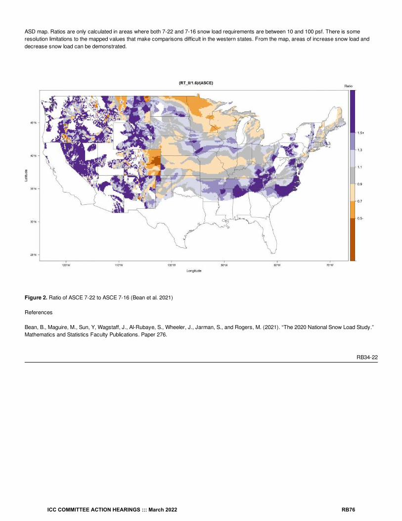
ASD map. Ratios are only calculated in areas where both 7-22 and 7-16 snow load requirements are between 10 and 100 psf. There is someresolution limitations to the mapped values that make comparisons difficult in the western states. From the map, areas of increase snow load anddecrease snow load can be demonstrated.
Figure 2. Ratio of ASCE 7-22 to ASCE 7-16 (Bean et al. 2021)
References
Bean, B., Maguire, M., Sun, Y, Wagstaff, J., Al-Rubaye, S., Wheeler, J., Jarman, S., and Rogers, M. (2021). “The 2020 National Snow Load Study.”Mathematics and Statistics Faculty Publications. Paper 276.
RB34-22
ICC COMMITTEE ACTION HEARINGS ::: March 2022 RB76

RB35-22IRC: FIGURE R301.2.1, TABLE R301.2.1(1), TABLE R301.2.1(2), FIGURE R301.2.1.1, FIGURE R301.2(2), R301.2.1.5
Proponents: T. Eric Stafford, representing Insurance Institute for Business and Home Safety ([email protected]); Jennifer Goupil,representing Structural Engineering Institute of ASCE ([email protected]); Don Scott, representing ASCE 7 Wind Load Subcommittee ([email protected])
2021 International Residential CodeDelete and substitute as follows:
ICC COMMITTEE ACTION HEARINGS ::: March 2022 RB77

For SI: 1 foot = 304.8 mm, 1 degree = 0.0175 rad.Note: a = 4 feet in all cases.
FIGURE R301.2.1 COMPONENT AND CLADDING PRESSURE ZONES
ICC COMMITTEE ACTION HEARINGS ::: March 2022 RB78

ICC COMMITTEE ACTION HEARINGS ::: March 2022 RB79

FIGURE R301.2.1 COMPONENT AND CLADDING PRESSURE ZONES
Revise as follows:
ICC COMMITTEE ACTION HEARINGS ::: March 2022 RB80
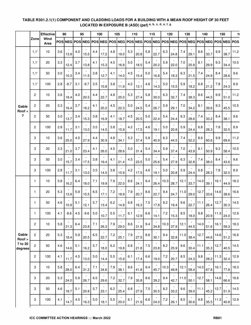
TABLE R301.2.1(1) COMPONENT AND CLADDING LOADS FOR A BUILDING WITH A MEAN ROOF HEIGHT OF 30 FEETLOCATED IN EXPOSURE B (ASD) (psf)
ZoneEffective
WindArea
90 95 100 105 110 115 120 130 140 150 160
POS NEG POS NEG POS NEG POS NEG POS NEG POS NEG POS NEG POS NEG POS NEG POS NEG POS
GableRoof <
7
1,1' 10 3.6-
13.94.0
-15.5
4.4-
17.24.8
-19.0
5.3-
20.85.8
-22.7
6.3-
24.87.4
-29.1
8.6-
33.79.9
-38.7
11.2
1,1' 20 3.3-
12.43.7
-13.8
4.1-
15.34.5
-16.8
5.0-
18.55.4
-20.2
5.9-
22.07.0
-25.8
8.1-
29.99.3
-34.4
10.5
1,1' 50 3.0-
10.33.4
-11.5
3.8-
12.74.1
-14.0
4.5-
15.45.0
-16.8
5.4-
18.36.3
-21.5
7.4-
24.98.4
-28.6
9.6
1,1' 100 2.8 -8.7 3.1 -9.7 3.5-
10.83.8
-11.9
4.2-
13.14.6
-14.3
5.0-
15.55.9
-18.2
6.8-
21.27.8
-24.3
8.9
2 10 3.6-
18.44.0
-20.5
4.4-
22.74.8
-25.0
5.3-
27.45.8
-30.0
6.3-
32.77.4
-38.3
8.6-
44.59.9
-51.0
11.2
2 20 3.3-
16.43.7
-18.2
4.1-
20.24.5
-22.3
5.0-
24.55.4
-26.7
5.9-
29.17.0
-34.2
8.1-
39.69.3
-45.5
10.5
2 50 3.0-
13.73.4
-15.3
3.8-
16.94.1
-18.7
4.5-
20.55.0
-22.4
5.4-
24.46.3
-28.6
7.4-
33.28.4
-38.1
9.6
2 100 2.8-
11.73.1
-13.0
3.5-
14.53.8
-15.9
4.2-
17.54.6
-19.1
5.0-
20.85.9
-24.4
6.8-
28.37.8
-32.5
8.9
3 10 3.6-
25.04.0
-27.9
4.4-
30.94.8
-34.1
5.3-
37.45.8
-40.9
6.3-
44.57.4
-52.2
8.6-
60.69.9
-69.6
11.2
3 20 3.3-
21.03.7
-23.4
4.1-
26.04.5
-28.6
5.0-
31.45.4
-34.4
5.9-
37.47.0
-43.9
8.1-
50.99.3
-58.4
10.5
3 50 3.0-
15.73.4
-17.5
3.8-
19.44.1
-21.4
4.5-
23.55.0
-25.6
5.4-
27.96.3
-32.8
7.4-
38.08.4
-43.6
9.6
3 100 2.8-
11.73.1
-13.0
3.5-
14.53.8
-15.9
4.2-
17.54.6
-19.1
5.0-
20.85.9
-24.4
6.8-
28.37.8
-32.5
8.9
GableRoof >7 to 20
degrees
1 10 5.8-
16.26.4
-18.0
7.1-
19.97.9
-22.0
8.6-
24.19.4
-26.4
10.3-
28.712.1
-33.7
14.0-
39.116.1
-44.9
18.3
1 20 5.3-
13.95.9
-15.5
6.5-
17.17.2
-18.9
7.9-
20.78.6
-22.7
9.4-
24.711.0
-29.0
12.7-
33.614.6
-38.6
16.6
1 50 4.6-
10.95.1
-12.1
5.7-
13.46.2
-14.8
6.8-
16.37.5
-17.8
8.2-
19.49.6
-22.7
11.1-
26.412.7
-30.3
14.5
1 100 4.1 -8.6 4.5 -9.6 5.0-
10.75.5
-11.7
6.1-
12.96.6
-14.1
7.2-
15.38.5
-18.0
9.8-
20.911.3
-24.0
12.9
2 10 5.8-
21.36.4
-23.8
7.1-
26.37.9
-29.0
8.6-
31.99.4
-34.8
10.3-
37.912.1
-44.5
14.0-
51.616.1
-59.3
18.3
2 20 5.3-
18.45.9
-20.5
6.5-
22.77.2
-25.1
7.9-
27.58.6
-30.1
9.4-
32.811.0
-38.4
12.7-
44.614.6
-51.2
16.6
2 50 4.6-
14.65.1
-16.2
5.7-
18.06.2
-19.8
6.8-
21.87.5
-23.8
8.2-
25.99.6
-30.4
11.1-
35.312.7
-40.5
14.5
2 100 4.1-
11.74.5
-13.0
5.0-
14.45.5
-15.9
6.1-
17.46.6
-19.0
7.2-
20.78.5
-24.3
9.8-
28.211.3
-32.4
12.9
3 10 5.8-
28.06.4
-31.2
7.1-
34.67.9
-38.1
8.6-
41.89.4
-45.7
10.3-
49.812.1
-58.4
14.0-
67.816.1
-77.8
18.3
3 20 5.3-
24.05.9
-26.7
6.5-
29.67.2
-32.7
7.9-
35.88.6
-39.2
9.4-
42.711.0
-50.1
12.7-
58.114.6
-66.6
16.6
3 50 4.6-
18.75.1
-20.8
5.7-
23.16.2
-25.4
6.8-
27.97.5
-30.5
8.2-
33.29.6
-39.0
11.1-
45.212.7
-51.9
14.5
3 100 4.1-
14.74.5
-16.3
5.0-
18.15.5
-20.0
6.1-
21.96.6
-24.0
7.2-
26.18.5
-30.6
9.8-
35.511.3
-40.8
12.9
a, b, c, d, e, f, g
ICC COMMITTEE ACTION HEARINGS ::: March 2022 RB81

GableRoof >20 to 27degrees
1 10 5.8-
12.4 6.4-
13.9 7.1-
15.4 7.9-
16.9 8.6-
18.6 9.4-
20.3 10.3-
22.1 12.1-
26.0 14.0-
30.1 16.1-
34.6 18.3
1 20 5.3-
11.25.9
-12.5
6.5-
13.97.2
-15.3
7.9-
16.88.6
-18.4
9.4-
20.011.0
-23.5
12.7-
27.214.6
-31.2
16.6
1 50 4.6 -9.7 5.1-
10.85.7
-11.9
6.2-
13.16.8
-14.4
7.5-
15.88.2
-17.2
9.6-
20.211.1
-23.4
12.7-
26.814.5
1 100 4.1 -8.5 4.5 -9.4 5.0-
10.45.5
-11.5
6.1-
12.66.6
-13.8
7.2-
15.08.5
-17.7
9.8-
20.511.3
-23.5
12.9
2 10 5.8-
19.96.4
-22.1
7.1-
24.57.9
-27.0
8.6-
29.79.4
-32.4
10.3-
35.312.1
-41.4
14.0-
48.016.1
-55.2
18.3
2 20 5.3-
17.05.9
-18.9
6.5-
20.97.2
-23.1
7.9-
25.38.6
-27.7
9.4-
30.111.0
-35.4
12.7-
41.014.6
-47.1
16.6
2 50 4.6-
13.15.1
-14.6
5.7-
16.26.2
-17.9
6.8-
19.67.5
-21.4
8.2-
23.39.6
-27.4
11.1-
31.812.7
-36.5
14.5
2 100 4.1-
10.24.5
-11.4
5.0-
12.65.5
-13.9
6.1-
15.36.6
-16.7
7.2-
18.28.5
-21.3
9.8-
24.711.3
-28.4
12.9
3 10 5.8-
23.66.4
-26.3
7.1-
29.17.9
-32.1
8.6-
35.29.4
-38.5
10.3-
41.912.1
-49.2
14.0-
57.016.1
-65.4
18.3
3 20 5.3-
20.05.9
-22.3
6.5-
24.77.2
-27.2
7.9-
29.98.6
-32.6
9.4-
35.511.0
-41.7
12.7-
48.414.6
-55.5
16.6
3 50 4.6-
15.35.1
-17.0
5.7-
18.96.2
-20.8
6.8-
22.87.5
-24.9
8.2-
27.29.6
-31.9
11.1-
37.012.7
-42.4
14.5
3 100 4.1-
11.74.5
-13.0
5.0-
14.55.5
-15.9
6.1-
17.56.6
-19.1
7.2-
20.88.5
-24.4
9.8-
28.311.3
-32.5
12.9
GableRoof >27 to 45degrees
1 10 8.0-
14.78.9
-16.3
9.9-
18.110.9
-20.0
12.0-
21.913.1
-24.0
14.2-
26.116.7
-30.6
19.4-
35.522.2
-40.8
25.3
1 20 7.3-
12.48.2
-13.9
9.0-
15.410.0
-16.9
10.9-
18.611.9
-20.3
13.0-
22.115.3
-26.0
17.7-
30.120.3
-34.6
23.1
1 50 6.4 -9.5 7.1-
10.67.9
-11.7
8.7-
12.99.6
-14.2
10.5-
15.511.4
-16.9
13.4-
19.815.5
-23.0
17.8-
26.420.3
1 100 5.7 -7.3 6.4 -8.1 7.1 -9.0 7.8 -9.9 8.6-
10.89.3
-11.9
10.2-
12.911.9
-15.1
13.9-
17.615.9
-20.2
18.1
2 10 8.0-
16.28.9
-18.0
9.9-
19.910.9
-22.0
12.0-
24.113.1
-26.4
14.2-
28.716.7
-33.7
19.4-
39.122.2
-44.9
25.3
2 20 7.3-
14.48.2
-16.1
9.0-
17.810.0
-19.7
10.9-
21.611.9
-23.6
13.0-
25.715.3
-30.1
17.7-
34.920.3
-40.1
23.1
2 50 6.4-
12.27.1
-13.6
7.9-
15.08.7
-16.6
9.6-
18.210.5
-19.9
11.4-
21.613.4
-25.4
15.5-
29.517.8
-33.8
20.3
2 100 5.7-
10.56.4
-11.7
7.1-
12.97.8
-14.2
8.6-
15.69.3
-17.1
10.2-
18.611.9
-21.8
13.9-
25.315.9
-29.0
18.1
3 10 8.0-
19.98.9
-22.1
9.9-
24.510.9
-27.0
12.0-
29.713.1
-32.4
14.2-
35.316.7
-41.4
19.4-
48.022.2
-55.2
25.3
3 20 7.3-
17.38.2
-19.3
9.0-
21.310.0
-23.5
10.9-
25.811.9
-28.2
13.0-
30.715.3
-36.1
0.0-
41.820.3
-48.0
23.1
3 50 6.4-
13.97.1
-15.5
7.9-
17.18.7
-18.9
9.6-
20.710.5
-22.7
11.4-
24.713.4
-29.0
15.5-
33.617.8
-38.6
20.3
3 100 5.7-
11.36.4
-12.6
7.1-
14.07.8
-15.4
8.6-
16.99.3
-18.5
10.2-
20.111.9
-23.6
13.9-
27.415.9
-31.4
18.1
1 10 6.5-
14.77.3
-16.3
8.0-
18.18.9
-20.0
9.7-
21.910.6
-24.0
11.6-
26.113.6
-30.6
15.8-
35.518.1
-40.8
20.6
1 20 5.6-
13.06.3
-14.4
6.9-
16.07.7
-17.6
8.4-
19.49.2
-21.2
10.0-
23.011.7
-27.0
13.6-
31.315.6
-36.0
17.8
ICC COMMITTEE ACTION HEARINGS ::: March 2022 RB82

HipRoof >7 to 20
degrees
1 50 4.4-
10.75.0
-11.9
5.5-
13.26.1
-14.5
6.6-
16.07.3
-17.5
7.9-
19.09.3
-22.3
10.8-
25.912.4
-29.7
14.1
1 100 3.6 -9.0 4.0-
10.04.4
-11.1
4.8-
12.25.3
-13.4
5.8-
14.76.3
-16.0
7.4-
18.78.6
-21.7
9.9-
24.911.2
2 10 6.5-
19.17.3
-21.3
8.0-
23.68.9
-26.0
9.7-
28.610.6
-31.2
11.6-
34.013.6
-39.9
15.8-
46.318.1
-53.1
20.6
2 20 5.6-
17.26.3
-19.2
6.9-
21.37.7
-23.5
8.4-
25.79.2
-28.1
10.0-
30.611.7
-35.9
13.6-
41.715.6
-47.9
17.8
2 50 4.4-
14.75.0
-16.4
5.5-
18.26.1
-20.1
6.6-
22.07.3
-24.1
7.9-
26.29.3
-30.7
10.8-
35.712.4
-40.9
14.1
2 100 3.6-
12.94.0
-14.3
4.4-
15.94.8
-17.5
5.3-
19.25.8
-21.0
6.3-
22.87.4
-26.8
8.6-
31.19.9
-35.7
11.2
3 10 6.5-
20.67.3
-22.9
8.0-
25.48.9
-28.0
9.7-
30.810.6
-33.6
11.6-
36.613.6
-43.0
15.8-
49.818.1
-57.2
20.6
3 20 5.6-
18.56.3
-20.7
6.9-
22.97.7
-25.2
8.4-
27.79.2
-30.3
10.0-
33.011.7
-38.7
13.6-
44.915.6
-51.5
17.8
3 50 4.4-
15.85.0
-17.6
5.5-
19.56.1
-21.5
6.6-
23.67.3
-25.8
7.9-
28.19.3
-33.0
10.8-
38.312.4
-43.9
14.1
3 100 3.6-
13.84.0
-15.3
4.4-
17.04.8
-18.7
5.3-
20.65.8
-22.5
6.3-
24.57.4
-28.7
8.6-
33.39.9
-38.2
11.2
HipRoof >20 to 27degrees
1 10 6.5-
11.77.3
-13.0
8.0-
14.58.9
-15.9
9.7-
17.510.6
-19.1
11.6-
20.813.6
-24.4
15.8-
28.318.1
-32.5
20.6
1 20 5.6-
10.46.3
-11.6
6.9-
12.87.7
-14.1
8.4-
15.59.2
-16.9
10.0-
18.411.7
-21.6
13.6-
25.115.6
-28.8
17.8
1 50 4.4 -8.6 5.0 -9.6 5.5-
10.66.1
-11.7
6.6-
12.87.3
-14.0
7.9-
15.39.3
-17.9
10.8-
20.812.4
-23.9
14.1
1 100 3.6 -7.3 4.0 -8.1 4.4 -9.0 4.8 -9.9 5.3-
10.85.8
-11.9
6.3-
12.97.4
-15.1
8.6-
17.69.9
-20.2
11.2
2 10 6.5-
16.27.3
-18.0
8.0-
19.98.9
-22.0
9.7-
24.110.6
-26.4
11.6-
28.713.6
-33.7
15.8-
39.118.1
-44.9
20.6
2 20 5.6-
13.96.3
-15.5
6.9-
17.27.7
-18.9
8.4-
20.89.2
-22.7
10.0-
24.711.7
-29.0
13.6-
33.715.6
-38.7
17.8
2 50 4.4-
11.05.0
-12.2
5.5-
13.56.1
-14.9
6.6-
16.47.3
-17.9
7.9-
19.59.3
-22.9
10.8-
26.612.4
-30.5
14.1
2 100 3.6 -8.7 4.0 -9.7 4.4-
10.84.8
-11.9
5.3-
13.15.8
-14.3
6.3-
15.57.4
-18.2
8.6-
21.29.9
-24.3
11.2
3 10 6.5-
16.27.3
-18.0
8.0-
19.98.9
-22.0
9.7-
24.110.6
-26.4
11.6-
28.713.6
-33.7
15.8-
39.118.1
-44.9
20.6
3 20 5.6-
13.96.3
-15.5
6.9-
17.27.7
-18.9
8.4-
20.89.2
-22.7
10.0-
24.711.7
-29.0
13.6-
33.715.6
-38.7
17.8
3 50 4.4-
11.05.0
-12.2
5.5-
13.56.1
-14.9
6.6-
16.47.3
-17.9
7.9-
19.59.3
-22.9
10.8-
26.612.4
-30.5
14.1
3 100 3.6 -8.7 4.0 -9.7 4.4-
10.84.8
-11.9
5.3-
13.15.8
-14.3
6.3-
15.57.4
-18.2
8.6-
21.29.9
-24.3
11.2
1 10 6.5-
12.47.3
-13.9
8.0-
15.48.9
-16.9
9.7-
18.610.6
-20.3
11.6-
22.113.6
-26.0
15.8-
30.118.1
-34.6
20.6
1 20 5.6-
10.76.3
-11.9
6.9-
13.27.7
-14.5
8.4-
15.99.2
-17.4
10.0-
19.011.7
-22.2
13.6-
25.815.6
-29.6
17.8
1 50 4.4 -8.3 5.0 -9.3 5.5-
10.36.1
-11.3
6.6-
12.47.3
-13.6
7.9-
14.89.3
-17.3
10.8-
20.112.4
-23.1
14.1
1 100 3.6 -6.5 4.0 -7.3 4.4 -8.0 4.8 -8.9 5.3 -9.7 5.8-
10.66.3
-11.6
7.4-
13.68.6
-15.8
9.9-
18.111.2
ICC COMMITTEE ACTION HEARINGS ::: March 2022 RB83

HipRoof =
45degrees
2 10 6.5-
14.77.3
-16.3
8.0-
18.18.9
-20.0
9.7-
21.910.6
-24.0
11.6-
26.113.6
-30.6
15.8-
35.518.1
-40.8
20.6
2 20 5.6-
12.46.3
-13.9
6.9-
15.47.7
-16.9
8.4-
18.69.2
-20.3
10.0-
22.111.7
-26.0
13.6-
30.115.6
-34.6
17.8
2 50 4.4 -9.5 5.0-
10.65.5
-11.7
6.1-
12.96.6
-14.2
7.3-
15.57.9
-16.9
9.3-
19.810.8
-23.0
12.4-
26.414.1
2 100 3.6 -7.3 4.0 -8.1 4.4 -9.0 4.8 -9.9 5.3-
10.85.8
-11.9
6.3-
12.97.4
-15.1
8.6-
17.69.9
-20.2
11.2
3 10 6.5-
19.17.3
-21.3
8.0-
23.68.9
-26.0
9.7-
28.610.6
-31.2
11.6-
34.013.6
-39.9
15.8-
46.318.1
-53.1
20.6
3 20 5.6-
16.06.3
-17.8
6.9-
19.77.7
-21.8
8.4-
23.99.2
-26.1
10.0-
28.411.7
-33.4
13.6-
38.715.6
-44.4
17.8
3 50 4.4-
11.95.0
-13.2
5.5-
14.66.1
-16.1
6.6-
17.77.3
-19.4
7.9-
21.19.3
-24.8
10.8-
28.712.4
-33.0
14.1
3 100 3.6 -8.7 4.0 -9.7 4.4-
10.84.8
-11.9
5.3-
13.15.8
-14.3
6.3-
15.57.4
-18.2
8.6-
21.29.9
-24.3
11.2
Walls
4 10 8.7 -9.5 9.7-
10.610.8
-11.7
11.9-
12.913.1
-14.2
14.3-
15.515.5
-16.9
18.2-
19.821.2
-22.9
24.3-
26.327.6
4 20 8.3 -9.1 9.3-
10.110.3
-11.2
11.4-
12.412.5
-13.6
13.6-
14.814.8
-16.2
17.4-
19.020.2
-22.0
23.2-
25.226.4
4 50 7.8 -8.6 8.7 -9.5 9.7-
10.610.7
-11.7
11.7-
12.812.8
-14.0
13.9-
15.216.3
-17.9
18.9-
20.721.7
-23.8
24.7
4 100 7.4 -8.2 8.3 -9.1 9.2-
10.110.1
-11.1
11.1-
12.212.1
-13.3
13.2-
14.515.5
-17.1
18.0-
19.820.7
-22.7
23.5
5 10 8.7-
11.79.7
-13.0
10.8-
14.511.9
-15.9
13.1-
17.514.3
-19.1
15.5-
20.818.2
-24.4
21.2-
28.324.3
-32.5
27.6
5 20 8.3-
10.99.3
-12.2
10.3-
13.511.4
-14.9
12.5-
16.313.6
-17.8
14.8-
19.417.4
-22.8
20.2-
26.423.2
-30.3
26.4
5 50 7.8 -9.9 8.7-
11.09.7
-12.2
10.7-
13.411.7
-14.8
12.8-
16.113.9
-17.6
16.3-
20.618.9
-23.9
21.7-
27.424.7
5 100 7.4 -9.1 8.3-
10.19.2
-11.2
10.1-
12.411.1
-13.6
12.1-
14.813.2
-16.2
15.5-
19.018.0
-22.0
20.7-
25.223.5
For SI: 1 foot = 304.8 mm, 1 square foot = 0.0929 m2, 1 mile per hour = 0.447 m/s, 1 pound per square foot = 0.0479 kPa.
a. The effective wind area shall be equal to the span length multiplied by an effective width. This width shall be not less than one-third the spanlength. For cladding fasteners, the effective wind areas shall not be greater than the area that is tributary to an individual fastener.
b. For effective areas between those given, the load shall be interpolated or the load associated with the lower effective areas shall be used.
c. Table values shall be adjusted for height and exposure by multiplying by the adjustment coefficient in Table R301.2.1(2).
d. See Figure R301.2.1 for locations of zones.
e. Plus and minus signs signify pressures acting toward and away from the building surfaces.
f. Positive and negative design wind pressures shall not be less than 10 psf.
g. Roof overhang loads shall be determined by summing the aplicable roof zone pressure with the adjacent wall zone pressure.
ICC COMMITTEE ACTION HEARINGS ::: March 2022 RB84

TABLE R301.2.1(2) HEIGHT AND EXPOSURE ADJUSTMENT COEFFICIENTS FOR Table R301.2.1(1)
MEAN ROOF HEIGHTEXPOSURE
B C D
15 0.82 1.21 1.47
20 0.89 1.29 1.55
25 0.94 1.35 1.61
30 1.00 1.40 1.66
35 1.05 1.45 1.70
40 1.09 1.06 1.49 1.74
45 1.12 1.10 1.53 1.78
50 1.16 1.13 1.56 1.81
55 1.19 1.16 1.59 1.84
60 1.22 1.19 1.62 1.87
Delete and substitute as follows:
ICC COMMITTEE ACTION HEARINGS ::: March 2022 RB85

FIGURE R301.2.1.1 REGIONS WHERE WIND DESIGN IS REQUIRED
ICC COMMITTEE ACTION HEARINGS ::: March 2022 RB86

FIGURE R301.2.1.1 REGIONS WHERE WIND DESIGN IS REQUIRED
ICC COMMITTEE ACTION HEARINGS ::: March 2022 RB87

FIGURE R301.2(2) ULTIMATE DESIGN WIND SPEEDS
ICC COMMITTEE ACTION HEARINGS ::: March 2022 RB88

Notes:
1. Values are 3-second gust wind speeds in miles per hour (m/s) at 33 ft (10 m) above ground for Exposure Category C.
2. Linear interpolation is permitted between contours. Point values are provided to aid with interpolation.
3. Islands, coastal areas, and land boundaries outside the last contour shall use the last wind speed contour.
4. Location-specific basic wind speeds shall be permitted to be determined using the ASCE Wind Design Geodatabase.
5. Wind speeds for Hawaii, US Virgin Islands, and Puerto Rico shall be determined from the ASCE Wind Design Geodatabase.
6. Mountainous terrain, gorges, ocean promontories, and special wind regions shall be examined for unusual wind conditions. Sitespecific values for selected special wind regions shall be permitted to be determined using the ASCE Wind Design Geodatabase.
7. Wind speeds correspond to approximately a 15% probability of exceedance in 50 years (Annual Exceedance Probability = 0.00143, MRI =700 years).
8. The ASCE Wind Design Geodatabase can be accessed at the ASCE 7 Hazard Tool (https://asce7hazardtool.online) or approved equivalent.
FIGURE R301.2(2) ULTIMATE DESIGN WIND SPEEDS
Revise as follows:
R301.2.1.5 Topographic wind effects. In areas designated in Table R301.2 as having local historical data documenting structural damage tobuildings caused by wind speed-up at isolated hills, ridges and escarpments that are abrupt changes from the general topography of the area,topographic wind effects shall be considered in the design of the building in accordance with Section R301.2.1.5.1 or in accordance with theprovisions of ASCE 7. See Figure R301.2.1.5.1(1) for topographic features for wind speed-up effect.In these designated areas, topographic wind effects shall apply only to buildings sited on the top half of an isolated hill, ridge or escarpment where all
ICC COMMITTEE ACTION HEARINGS ::: March 2022 RB89

of the following conditions exist:
1. The average slope of the top half of the hill, ridge or escarpment is 10 percent or greater.
2. The hill, ridge or escarpment is 60 feet (18 288 mm) or greater in height for Exposure B, 30 feet (9144 mm) or greater in height for ExposureC, and 15 feet (4572 mm) or greater in height for Exposure D.
3. The hill, ridge or escarpment is isolated or unobstructed by other topographic features of similar height in the upwind direction for a distancemeasured from its high point of 100 times its height or 2 miles (3.2 km), whichever is less. See Figure R301.2.1.5.1(3) for upwind obstruction.
4. The hill, ridge or escarpment protrudes by a factor of two or more above the height of other upwind topographic features located in anyquadrant within a radius of 2 miles (3.2 km) measured from its high point.
Reason Statement: This proposal is a coordination proposal to bring the 2024 IRC up to date with the provisions of the 2022 edition of ASCE/SEI 7Minimum Design Loads and Associated Criteria for Buildings and Other Structures (ASCE/SEI 7-22). ASCE 7 will be updated to the 2022 edition fromthe 2016 edition as an Administrative update in the 2024 I-Codes. This proposal includes technical updates as well as editorial corrections or re-organizations. Technical updates to the wind speed maps withinASCE/SEI 7-22 include new hurricane coastline wind speed contours from the Carolina’s through Texas, as well as, new Special Wind Regiondefinitions in Southern California and Northern Colorado. All of these updates are based upon recent wind studies conducted in these areas. Thesewind speeds for the contiguous United States and Alaska are available from the maps in ASCE 7-22, which are updated in Figure R301.2(2) of thisproposal.
Along with the continental United States, the wind speeds for US Virgin Island and Puerto Rico were also updated based upon recent wind studies ofthese islands. The resulting wind speeds accounting for the steep terrain of these island created a very dense contour map that is not easily read bya map that is sized practically for inclusion into a printed standard. Therefore the wind speeds for US Virgin Islands and Puerto Rico - along withwind speeds for Hawaii - are only included in the ASCE Wind Design Geodatabase and therefore are no longer represented with maps in ASCE/SEI7-22. Consequently, Hawaii and Puerto Rico maps - as well as values for US Virgin Islands - are being removed from the IBC and replaced with apointer to the ASCE Wind Design Geodatabase. The wind speeds within the updated Special Wind Regions also are available for the designer ASCEWind Design Geodatabase. This database of geocoded wind speed design data is freely available and accessed at the ASCE 7 Hazard Tool athttps://asce7hazardtool.online/, or from an approved equivalent.
A summary of the coordination changes is provided below.
Figure R301.2(2) Ultimate design wind speed: This section updates the basic wind speed map for the 700 MRI map (Risk Category II) for thecontiguous United States and Alaska, as well as the Notes, to match what is in ASCE/SEI 7-22. The pointer to the ASCE Wind Design Geodatabaseis added for Hawaii, US Virgin Islands, and Puerto Rico, and because maps for these three areas are no longer produced in ASCE/SEI 7-22, themaps have been removed from the IBC and are not replaced.
Figure R301.2.1 Component and Cladding Pressure Zones.
The zones for roof design have been simplified, see the changes in the Plan View diagrams. The corresponding simplification is updated in TableR301.2.1(1).
Table R301.2.1(2) Height and Exposure Adjustment Coefficients.
Vales for exposure B at 40 feet and above have been slightly reduced.
Figure R301.2.1.1 Regions where wind design is required.
This figure has been updated with the new base map from 7-22.
Section R302.2.1.5 Topographic wind effects.
The designated conditions identified in 3., and in 4., were removed from the requirements in ASCE 7-22.
ICC COMMITTEE ACTION HEARINGS ::: March 2022 RB90

Cost Impact: The code change proposal will increase the cost of constructionASCE 7 is a national minimum design load standard. Therefore as the study of each hazard advances from one edition to the next, updates to thenational maps will impact the nation differently. In this case, the wind speeds for ASCE 7-22 largely remain unchanged, therefore the is no impact tothe cost of construction from the updated maps. However, in some areas the wind speeds decrease and in other areas the wind speeds increase.
The proposed code change will modestly increase the cost of construction along in some areas along the hurricane coastline between the Carolinasand Texas where the windspeeds have increased. Although the wind speeds do increase in some locations along the hurricane coastline, the higherwind speeds influence less than 3% of the United States. The wind speeds decrease in most areas along the hurricane coastline (as shown by thewind speed contours moving closer to the coastline), while in the Gulf Coast area of the Florida Panhandle the contours extend further inland, whichindicates higher wind speeds for this area. And most of the rest of the continental United States the speeds do not change and therefore the cost ofconstruction will be unchanged; see the Risk Category II map below that compared ASCE 7-22 to ASCE 7-16. ASCE 7 Wind speeds are available atthe ASCE 7 Hazard Tool (https://asce7hazardtool.online/), which is free to all users, to view and compare various locations.
FIGURE: Comparison of ASCE/SEI 7-22 basic wind speeds for Risk Category II (700 Year MRI) to ASCE/SEI 7-16. (Courtesy ARA)
All of the other proposed changes are editorial and will not impact the cost of construction.
RB35-22
ICC COMMITTEE ACTION HEARINGS ::: March 2022 RB91

RB36-22IRC: R301.2.1.1
Proponents: T. Eric Stafford, representing Insurance Institute for Business and Home Safety
2021 International Residential CodeRevise as follows:
R301.2.1.1 Wind limitations and wind design required. The wind provisions of this code shall not apply to the design of buildings where winddesign is required in accordance with Figure R301.2.1.1, or where the ultimate design wind speed, V , in Figure R301.2(2) equals or exceeds 140miles per hour (225 kph) in a special wind region.
Exceptions:
1. For concrete construction, the wind provisions of this code shall apply in accordance with the limitations of Sections R404 and R608.
2. For structural insulated panels, the wind provisions of this code shall apply in accordance with the limitations of Section R610.
3. For cold-formed steel light-frame construction, the wind provisions of this code shall apply in accordance with the limitations of SectionsR505, R603 and R804.
In regions where wind design is required in accordance with Figure R301.2.1.1 or where the ultimate design wind speed, V , in Figure R301.2(2)equals or exceeds 140 miles per hour (225 kph) in a special wind region, the structural design of buildings for wind loads shall be in accordance withone or more of the following methods:
1. AWC Wood Frame Construction Manual (WFCM).
2. ICC Standard for Residential Construction in High-Wind Regions (ICC 600).
3. ASCE Minimum Design Loads for Buildings and Other Structures (ASCE 7).
4. AISI Standard for Cold-Formed Steel Framing—Prescriptive Method for One- and Two-Family Dwellings (AISI S230).
5. International Building Code.
Exceptions:1. For concrete construction, the wind provisions of this code shall apply in accordance with the limitations of Sections R404 and R608.2.
2. For structural insulated panels, the wind provisions of this code shall apply in accordance with the limitations of Section R610.2.
3. For cold-formed steel light-frame construction, the wind provisions of this code shall apply in accordance with the limitations of SectionsR505.1.1, R603.1.1 and R804.1.1.
4. The seismic provisions of this code apply in accordance with the scope of Section R301.2.2.
5. Exterior wall coverings, roof coverings, and fenestrations shall comply with the provisions of this code.
6. The design of exterior decks for dead, live, and snow loads shall be in accordance with Section R507.
The elements of design not addressed by the methods in Items 1 through 5 shall be in accordance with the provisions of this code. Where ASCE 7 or the International Building Code is used for the design of the building, the wind speed map and exposure category requirements asspecified in ASCE 7 and the International Building Code shall be used.
Reason Statement: This proposal is one of two proposals intended to clarify the wind limitations in the IRC. Currently, the IRC contains anassortment of requirements for wind loads scattered throughout the code. While Section R301.2.1.1 intends to limit the applicability of the IRC toareas where wind design is not required in accordance with Figure R301.2.1.1, it’s not very clear what exactly applies in the IRC in regions wherewind design is required. Current Section R301.2.1.1 states that the “wind provisions” of this code do not apply where wind design is required but isnot clear anywhere in the code as to what the wind provisions in this code do apply to. The use of the phrase “wind provisions of this code” is veryconfusing. Clearly the prescriptive fastening schedule in Table R602.3(1) should not apply where wind design is required. However, it’s not veryclear that this table is actually part of the “wind provisions in this code.” This proposal makes it clear that the prescriptive provisions in Chapters 4through 9 do not apply where wind design is required except as identified in the proposed new exceptions. Provisions in the IRC that do apply inwind design required regions have been consolidated into the Exceptions to Section R301.2.1.1. New language clarifies that it is the “structuraldesign of buildings for wind loads” that is limited in IRC. Therefore, Section R405 (foundation drainage), Section R406 (dampproofing andwaterproofing provisions), Section R702 (interior coverings), Section R806 (roof ventilation), Section R807 (attic access) and others would apply asspecified in the code. Additionally, this proposal reorders the language so that the code tells the user directly what is required to be used when located in a wind designrequired region (WFCM, ICC 600, ASCE 7, AISI S230, and/or IBC). This improves the flow of the code text and is similar to the approach used in the
ult
ult
ICC COMMITTEE ACTION HEARINGS ::: March 2022 RB92

2000, 2003, 2006 and 2009 IRC.
A new exception is proposed to be added that clarifies that the seismic requirements in the code, including the scope as specified in SectionR301.2.2, apply regardless.
A new exception is proposed to be added for roof coverings, wall coverings, and fenestrations which have specific wind limitations and/or specificwind design requirements in the IRC.
A new exception is proposed for decks that clarifies that the design of exterior decks for dead, live, and snow loads is to be in accordance withSection R507.
A similar proposal was submitted last cycle that, with a few modifications, had broad support. However, a couple of points could not be agreed uponprior to the item being brought to the floor. This proposal addresses those concerns from the last cycle.
This proposal is not intended to change any technical requirements in the IRC related to wind design. It is intended to simply clarify the windlimitations in the IRC.
Cost Impact: The code change proposal will not increase or decrease the cost of constructionThis code change proposal will not impact the cost of construction as it is simply a clarification.
RB36-22
ICC COMMITTEE ACTION HEARINGS ::: March 2022 RB93
RB37-22IRC: R301.2.2
Proponents: Julie Furr, representing FEMA-ATC Seismic Code Support Committee ([email protected]); Kelly Cobeen, representing FederalEmergency Management Agency/Applied Technology Council - Seismic Code Support Committee ([email protected]); Michael Mahoney,representing FEMA ([email protected])
2021 International Residential CodeRevise as follows:
R301.2.2 Seismic provisions. Buildings within the scope of this code as defined in Section R101.2 in Seismic Design Categories C, D , D and Dshall be constructed in accordance with the requirements of this section and other seismic requirements of this code. The seismic provisions of thiscode shall apply as follows:
1. Townhouses and buildings as permitted by the exceptions to Section R101.2 containing three or more dwelling units in Seismic DesignCategories C, D , D and D .
2. Detached one- and two-family dwellings and buildings as permitted by the exceptions to Section R101.2 containing less than three dwellingunits in Seismic Design Categories, D , D and D .
Buildings in Seismic Design Category E shall be designed to resist seismic loads in accordance with the International Building Code , except wherethe Seismic Design Category seismic design category is reclassified to a lower Seismic Design Category seismic design category in accordancewith Section R301.2.2.1. Components of buildings not required to be designed to resist seismic loads shall be constructed in accordance with theprovisions of this code.
Reason Statement: This proposal clarifies when seismic design provisions are required for buildings that are not clearly identifiable as a traditionaltownhouse or one- or two-family designation. Three dwelling units was selected as the threshold based on the current definition of townhouse whichis “A building that contains three or more attached townhouse units.” The IRC seismic provisions have always been required for all buildings within the scope of this code, based upon the Seismic Design Category anduse. In Seismic Design Category C, certain seismic provisions are only required for townhouses or similar structures and do not apply to one- andtwo-family dwellings. However, under Section R101.2, building uses that fall within the scope of the IRC are not always clearly identifiable as one ofthese traditional designations: townhouses or one- or two-family dwellings. Specifically, Section R101.2 exception 2, identifies “lodging houses” aswithin the IRC scope but there is no guidance that specifies if this should comply with requirements for townhouse or one- or two-family dwellings,where they diverge. The current language leaves the application of seismic provisions for non-traditional designations (other than townhouses orone- or two-family dwellings) open to interpretation by the code official when the project is located in Seismic Design Category C. The proposedlanguage clearly states when seismic provisions are required for these buildings.
Cost Impact: The code change proposal will not increase or decrease the cost of constructionThis proposal revises the language used to determine when seismic design provisions are required, to accommodate the intended scope of the IRCwhich includes non-traditional uses that cannot be clearly classified as either a townhouse or one- or two-family dwelling. There is no change to thetechnical content of the provisions or the intended scope of seismic provisions. Seismic provisions have always been determined based on theSeismic Design Category and number of dwelling units, so there will be no cost impact when approving this proposal.
RB37-22
0 1 2
0 1 2
0 1 2
ICC COMMITTEE ACTION HEARINGS ::: March 2022 RB94

RB38-22IRC: R301.2.2.1, R301.2.2.1.2, R301.2.2.1.1, FIGURE R301.2.2.1(1), FIGURE R301.2.2.1(2), FIGURE R301.2.2.1(3), FIGURE R301.2.2.1(4),FIGURE R301.2.2.1(5), FIGURE R301.2.2.1(6), FIGURE R301.2.2.1(7) (New)
Proponents: Kelly Cobeen, representing Federal Emergency Management Agency/Applied Technology Council - Seismic Code Support Committee([email protected]); J Daniel Dolan, representing Seismic Code Support Committee ([email protected]); Michael Mahoney, representing FEMA([email protected]); Sanaz Rezaeian, representing USGS ([email protected]); Nicolas Luco, representing U.S. Geological Survey
2021 International Residential CodeRevise as follows:
R301.2.2.1 Determination of seismic design category. Buildings shall be assigned a seismic design category in accordance withFigures R301.2.2.1(1) through R301.2.2.1(6) R301.2.2.1(7).
R301.2.2.1.2 Alternative determination of Seismic Design Category E. Buildings located in Seismic Design Category E in accordance withFigures R301.2.2.1(1) through R301.2.2.1(7) R301.2.2.1(6), or Figures R301.2.2.1.1(1)through R301.2.2.1.1(6) where applicable, are permitted tobe reclassified as being in Seismic Design Category D provided that one of the following is done:
1. A more detailed evaluation of the seismic design category is made in accordance with the provisions and maps of the International BuildingCode . Buildings located in Seismic Design Category E in accordance with Table R301.2.2.1.1, but located in Seismic Design Category D inaccordance with the International Building Code , shall be permitted to be designed using the Seismic Design Category D requirements ofthis code.
2. Buildings located in Seismic Design Category E that conform to all of the following additional restrictions are permitted to be constructed inaccordance with the provisions for Seismic Design Category D of this code:
2.1. All exterior shear wall lines or braced wall panels are in one plane vertically from the foundation to the uppermost story.
2.2. Floors shall not cantilever past the exterior walls.
2.3. The building is within the requirements of Section R301.2.2.6 for being considered as regular.
R301.2.2.1.1 Alternate determination of seismic design category Seismic Design Category. If soil conditions are determined by the buildingofficial to be Site Class A, B, or D, the The Seismic Design Category seismic design category and short-period design spectral responseaccelerations, S , for a site shall be allowed to be determined in accordance with Figures R301.2.2.1.1(1) through R301.2.2.1.1(6), or Section 16131613.2 of the International Building Code. The value of S determined in accordance with Section 1613.2 of the International Building Code ispermitted to be used to set the Seismic Design Category seismic design category in accordance with Table R301.2.2.1.1, and to interpolate betweenvalues in Tables R602.10.3(3) and R603.9.2(1) and other seismic design requirements of this code.
2
2
2
DS
DS
ICC COMMITTEE ACTION HEARINGS ::: March 2022 RB95

ICC COMMITTEE ACTION HEARINGS ::: March 2022 RB96

a. The seismic design categories and corresponding short-period design spectral response accelerations, S , shown in Figures R301.2.2.1(1)through R301.2.2.1(6) R301.2.2.1(7) are based on the default Site Class as defined in Chapter 11 of ASCE 7. soil Site Class D, used as anassumed default, as defined in Section 1613.2.2 of the International Building Code.
FIGURE R301.2.2.1(5) R301.2.2.1(1) SEISMIC DESIGN CATEGORIES FOR DEFAULT SITE CLASS FOR THE CONTERMINOUS UNITEDSTATES
DS
a
ICC COMMITTEE ACTION HEARINGS ::: March 2022 RB97

ICC COMMITTEE ACTION HEARINGS ::: March 2022 RB98

a. The seismic design categories and corresponding short-period design spectral response accelerations, S , shown in Figures R301.2.2.1(1)through R301.2.2.1(6) R301.2.2.1(7), are based on the default Site Class as defined in Chapter 11 of ASCE 7. soil Site Class D, used as anassumed default, as defined in Section 1613.2.2 of the International Building Code.
FIGURE R301.2.2.1(6) R301.2.2.1(2) SEISMIC DESIGN CATEGORIES FOR DEFAULT SITE CLASS FOR THE CONTERMINOUS UNITEDSTATES - CONTINUED
DS
a
ICC COMMITTEE ACTION HEARINGS ::: March 2022 RB99

a. The Seismic Design Categories and corresponding short-period design spectral response accelerations, S , shown in Figures R301.2.2.1(1)through R301.2.2.1(6) R301.2.2.1(7) are based on the default Site Class as defined in Chapter 11 of ASCE 7. soil Site Class D, used as an assumed
DS
ICC COMMITTEE ACTION HEARINGS ::: March 2022 RB100

default, as defined in Section 1613.2.2 of the International Building Code.FIGURE R301.2.2.1(1) R301.2.2.1(3) SEISMIC DESIGN CATEGORIES FOR DEFAULT CLASS FOR ALASKAa
ICC COMMITTEE ACTION HEARINGS ::: March 2022 RB101

ICC COMMITTEE ACTION HEARINGS ::: March 2022 RB102

a. The seismic design categories and corresponding short-period design spectral response accelerations, S , shown in Figures R301.2.2.1(1)through R301.2.2.1(6) R301.2.2.1(7) are based on the default Site Class as defined in Chapter 11 of ASCE 7. soil Site Class D, used as anassumed default, as defined in Section 1613.2.2 of the International Building Code.
FIGURE R301.2.2.1(2) R301.2.2.1(4) SEISMIC DESIGN CATEGORIES FOR DEFAULT SITE CLASS FOR HAWAII
DS
a
ICC COMMITTEE ACTION HEARINGS ::: March 2022 RB103

a. The seismic design categories and corresponding short-period design spectral response accelerations, S , shown in Figures R301.2.2.1(1)through R301.2.2.1(6) R301.2.2.1(7) are based on the default Site Class as defined in Chapter 11 of ASCE 7. soil Site Class D, used as an
DS
ICC COMMITTEE ACTION HEARINGS ::: March 2022 RB104

assumed default, as defined in Section 1613.2.2 of the International Building Code.FIGURE R301.2.2.1(3) R301.2.2.1(5) SEISMIC DESIGN CATEGORIES FOR DEFAULT SITE CLASS FOR PUERTO RICOa
ICC COMMITTEE ACTION HEARINGS ::: March 2022 RB105

ICC COMMITTEE ACTION HEARINGS ::: March 2022 RB106

a. The seismic design categories and corresponding short-period design spectral response accelerations, S , shown in Figures R301.2.2.1(1)through R301.2.2.1(6) R301.2.2.1(7) are based on the default Site Class as defined in Chapter 11 of ASCE 7. soil Site Class D, used as an assumeddefault, as defined in Section 1613.2.2 of the International Building Code.
FIGURE R301.2.2.1(4) R301.2.2.1(6) SEISMIC DESIGN CATEGORIES FOR DEFAULT SITE CLASS FOR GUAM AND THE NORTHERNMARIANA ISLANDS AND AMERICAN SAMOA
Add new text as follows:
DS
a
ICC COMMITTEE ACTION HEARINGS ::: March 2022 RB107

a. The seismic design categories and corresponding short-period design spectral response accelerations, S , shown in Figures R301.2.2.1(1)through R301.2.2.1(7), are based on the default Site Class as defined in Chapter 11 of ASCE 7.
FIGURE R301.2.2.1(7) SEISMIC DESIGN CATEGORIES FOR DEFAULT SITE CLASS FOR AMERICAN SAMOA
Delete without substitution:
DS
a
ICC COMMITTEE ACTION HEARINGS ::: March 2022 RB108

a. The seismic design categories and corresponding short-period design spectral response accelerations, S , shown in Figures R301.2.2.1.1(1)through 301.2.2.1.1(6) are permitted to be used where soil conditions are determined by the building official to be Site Class A, B or D.
FIGURE R301.2.2.1.1(1) ALTERNATE SEISMIC DESIGN CATEGORIES—ALASKA
DS
a
ICC COMMITTEE ACTION HEARINGS ::: March 2022 RB109
a. The seismic design categories and corresponding short-period design spectral response accelerations, S , shown in Figures R301.2.2.1.1(1)through 301.2.2.1.1(6) are permitted to be used where soil conditions are determined by the building official to be Site Class A, B or D.
FIGURE R301.2.2.1.1(2) ALTERNATE SEISMIC DESIGN CATEGORIES—HAWAII
DS
a
ICC COMMITTEE ACTION HEARINGS ::: March 2022 RB110

a. The seismic design categories and corresponding short-period design spectral response accelerations, S , shown in Figures R301.2.2.1.1(1)through 301.2.2.1.1(6) are permitted to be used where soil conditions are determined by the building official to be Site Class A, B or D.
FIGURE R301.2.2.1.1(3) ALTERNATE SEISMIC DESIGN CATEGORIES—PUERTO RICO
DS
a
ICC COMMITTEE ACTION HEARINGS ::: March 2022 RB111

a. The seismic design categories and corresponding short-period design spectral response accelerations, S , shown in Figures R301.2.2.1.1(1)through 301.2.2.1.1(6) are permitted to be used where soil conditions are determined by the building official to be Site Class A, B or D.
FIGURE R301.2.2.1.1(4) ALTERNATE SEISMIC DESIGN CATEGORIES—NORTHERN MARIANA ISLANDS AND AMERICAN SAMOA
DS
a
ICC COMMITTEE ACTION HEARINGS ::: March 2022 RB112

a. The seismic design categories and corresponding short-period design spectral response accelerations, S , shown in Figures R301.2.2.1.1(1)through 301.2.2.1.1(6) are permitted to be used where soil conditions are determined by the building official to be Site Class A, B or D.
FIGURE R301.2.2.1.1(5) ALTERNATE SEISMIC DESIGN CATEGORIES—UNITED STATES
DS
a
ICC COMMITTEE ACTION HEARINGS ::: March 2022 RB113

a. The seismic design categories and corresponding short-period design spectral response accelerations, S , shown in Figures R301.2.2.1.1(1)through 301.2.2.1.1(6) are permitted to be used where soil conditions are determined by the building official to be Site Class A, B or D.
FIGURE R301.2.2.1.1(6) ALTERNATE SEISMIC DESIGN CATEGORIES—UNITED STATES
DS
a
ICC COMMITTEE ACTION HEARINGS ::: March 2022 RB114

Reason Statement: This proposal updates the IRC Seismic Design Category (SDC) maps to be consistent with updates to the seismic designmaps proposed for the IBC (in a separate proposal) and already included in the 2020 NEHRP Recommended Seismic Provisions for New Buildingsand Other Structures and ASCE/SEI 7-22. As in past updates, the proposed IRC maps have been developed in collaboration with the U.S.Geological Survey (USGS) and are based on their National Seismic Hazard Models (NSHMs), the site-specific ground motion procedures of the2020 NEHRP Provisions and ASCE/SEI 7-22 (Chapter 21), and the IRC definition of SDC (Table R301.2.2.1.1). Adoption of these maps will result ina consistent technical basis for the IRC and IBC seismic design maps. Figures at the bottom of this reason statement, prepared by USGS,illustrates the locations where SDC is increasing and decreasing due to this update.While based on the same mapping of risk-targeted spectral response accelerations as the seismic maps in the 2020 NEHRP Provisions andASCE/SEI 7-22, for greater ease of use in the IRC, the Seismic Design Category (SDC) is mapped directly. In order to directly map the SDC, thesame simplifying assumptions as in prior IRC map updates have been used. First, it is assumed that the dwelling seismic demand is controlled byshort-period behavior, allowing mapping based on the short-period design spectral response acceleration parameter, S , ignoring the one-secondparameter additionally considered in the IBC, S . Second, default site (soil) conditions (most critical of Site Classes C, CD, and D) are assumed.With these two assumptions, the mapping information from the 2020 NEHRP Provisions and ASCE/SEI 7-22 are translated to SDC, using TableR301.2.2.1.1. The intent of adopting SDC maps is to spare the non-technical user of the IRC from having to implement the provisions of ASCE/SEI 7Chapter 11.
In the 2018 and 2021 editions of the IRC, two separate sets of SDC maps were incorporated. These were identified as the Seismic Design CategoryMaps (Figures R301.2.2.1(1) through R301.2.2.1(6)) and the Alternate Seismic Design Category Maps (Figures R301.2.2.1.1(1) throughR301.2.2.1.1(6)). The Seismic Design Category Maps, consistent with ASCE/SEI 7-16, were determined using default site conditions, defined as themost conservative of Site Classes C and D. Because concern was expressed that use of the SDC maps would cause conservative SDCassignments in some locations relative to the use of Site Class D in previous editions of IRC, Alternate Seismic Design Category Maps weredeveloped based on Site Class D alone and permitted to be used where information was available to justify, to the satisfaction of the building official,that Site Classes A, B, or D could be assigned. These provided reduced SDCs in some locations.
For the 2024 IRC, a single SDC map set is proposed that can be conservatively used for any site, excepting poor soil sites as discussed in SectionR401. Because of further changes occurring to site class assignments and default site conditions in the 2020 NEHRP Provisions and ASCE/SEI 7-22, the proposed 2024 IRC maps incorporate the most critical of Site Classes C, CD, and D. This is consistent with default site conditions of the2020 NEHRP Provisions and ASCE/SEI 7-22, as well as the proposed 2024 IBC maps. The need for an alternative SDC map set was investigatedduring the development of the proposed 2024 IRC SDC maps; it was found that differences that would occur between the map sets if the alternativemap set was developed were in very few locations and of limited effect. As a result, the creation of a second map set was judged to beunnecessary. It is hoped that the return to a single map set will simplify use of the IRC seismic provisions. As in the past, use of the IBC provisionsto determine SDC and seismic design parameters is permitted.
For the conterminous U.S., the proposed updates to the IRC SDC (and IBC) maps, like the map updates already adopted by the 2020 NEHRPProvisions and ASCE/SEI 7-22 are based on (1) recommendations of the Project 17 collaboration between the Building Seismic Safety Council(BSSC) and the USGS (BSSC, 2019), and (2) the 2018 update of the USGS NSHM (Petersen et al., 2020) for the conterminous U.S. The Project 17recommendations include modifications to (1) site-class effects, (2) spectral periods defining short-period and one-second ground-motionparameters, (3) deterministic caps on the otherwise probabilistic ground motions, and (4) maximum-direction scale factors. The updates in the 2018USGS NSHM from the previous (2014) version (used in the 2018 and 2021 versions of the IRC) include incorporation of (1) new NGA-East andother ground-motion models for the central and eastern U.S., (2) deep sedimentary basin effects in the Los Angeles, Seattle, San Francisco, andSalt Lake City regions, (3) earthquakes that occurred in 2013 through 2017, and (4) updated weights for the western U.S. ground-motion models.
For the states and territories outside of the conterminous U.S., where the existing USGS NSHMs did not yet support direct development of multi-period response spectra (MPRS) needed for the above-mentioned modifications to site-class effects and spectral periods, MPRS were developedusing the FEMA P-2078 “Procedures for developing multi-period response spectra at non-conterminous United States sites” (Applied TechnologyCouncil, 2020). Via these procedures, the ground motion parameter values for default site conditions were approximated from Site Class BC valuesof short-period and one-second parameters, using the existing USGS seismic hazard models for Alaska (Wesson et al., 2007), Hawaii (Klein et al.,2001), Puerto Rico and the U.S. Virgin Islands (Mueller et al., 2003), Guam and the Northern Mariana Islands (Mueller et al., 2012), and AmericanSamoa (Petersen et al., 2012). Other relatively minor updates were made to the short-period and one-second Site Class BC values for each regionso that they are consistent with the risk-targeted calculations and maximum-direction scale factors used for the conterminous U.S.
DS
D1
ICC COMMITTEE ACTION HEARINGS ::: March 2022 RB115

ICC COMMITTEE ACTION HEARINGS ::: March 2022 RB116

ICC COMMITTEE ACTION HEARINGS ::: March 2022 RB117

Cost Impact: The code change proposal will not increase or decrease the cost of constructionThe updated maps result in changes to SDC both upward and downward in a limited number of locations, but do not broadly increase SDC or thecost of construction. An attached file prepared by USGS illustrates the specific locations where SDC is increasing and decreasing. An increase inSDC can result in a nominal increase in cost due to an increase in required amount of seismic bracing, whereas a decrease in SDC will result in adecrease in cost. An increase to SDC E will result in increased cost for seismic design using engineered methods.
RB38-22
ICC COMMITTEE ACTION HEARINGS ::: March 2022 RB118

RB39-22IRC: SECTION 202 (New), R301.2.2.10, R301.2.2.10 (New), R301.2.2.10.1 (New), M1307.2, M2301.2.13, G2404.8, P2801.8
Proponents: Julie Furr, representing FEMA-ATC Seismic Code Support Committee ([email protected]); Kelly Cobeen, representing FederalEmergency Management Agency/Applied Technology Council - Seismic Code Support Committee ([email protected]); Michael Mahoney,representing FEMA ([email protected])
2021 International Residential CodeAdd new definition as follows:
SYSTEM COMPONENTS. Mechanical, electrical, plumbing, fuel-gas, fire-protection, photovoltaic, thermal energy, and other components. Suchcomponents shall include but are not limited to: utilities and appliances such as water heaters, thermal storage units, HVAC cabinets, andcomponents of a similar height and weight.
Delete without substitution:
R301.2.2.10 Anchorage of water heaters. In Seismic Design Categories D , D and D , and in townhouses in Seismic Design Category C, waterheaters and thermal storage units shall be anchored against movement and overturning in accordance with Section M1307.2 or P2801.8.
Add new text as follows:
R301.2.2.10 Seismic restraint of system components required. In Seismic Design Categories D , D , and D and in townhouses in SDC C,system components that are designed to be fixed in position shall be supported and braced or anchored to the structure in accordance with thecomponent manufacturer’s recommendations or per Section R301.2.2.10.1.
Exception: Seismic support, bracing, and anchorage are not required for the following:
1. Suspended mechanical ducts, electrical conduit, and plumbing systems that are not part of a fire-suppression or other life-safety system.
2. Where the component or housing is bearing on an elevated floor or roof and the housing height is not greater than 1.5 times the width ofthe housing base in either direction.
3. Where the component or housing is suspended from the structure less than 7-inches (152.4 mm) below the supporting structuralelement and the net operating weight is less than 50 pounds per support.
4. Where the operating weight of the component and its housing is less than 400 pounds and is less than 4 feet above floor level.
R301.2.2.10.1 Seismic restraint resistance. Supports, bracing, and anchorage of system components in Seismic Design Categories D , D andD , and in townhouses in Seismic Design Category C, shall resist a horizontal force equal to one-third times the operating weight of the component,acting in any direction. Bracing shall comply with the following:
1. Components supported at the base shall be braced with strapping at points within the upper one-third of the component’s verticaldimensions, or the component anchorage shall be designed to resist overturning.
2. Components suspended from the structure shall be braced to the structure, using either flexible or rigid bracing. Flexible bracing such aswires or straps shall be provided in each of the four orthogonal directions. Rigid bracing such as struts or bars may be provided in twoorthogonal directions.
Revise as follows:
M1307.2 Anchorage of appliances. Appliances designed to be fixed in position shall be fastened or anchored in an approved manner. In SeismicDesign Categories D , D and D , and in townhouses in Seismic Design Category C, water heaters and thermal storage units shall be anchored orstrapped to resist horizontal displacement caused by earthquake motion in accordance with Section R301.2.2.10.one of the following:
1. Anchorage and strapping shall be designed to resist a horizontal force equal to one-third of the operating weight of the water heater storagetank, acting in any horizontal direction. Strapping shall be at points within the upper one-third and lower one-third of the appliance’s verticaldimensions. At the lower point, the strapping shall maintain a minimum distance of 4 inches (102 mm) above the controls.
2. The anchorage strapping shall be in accordance with the appliance manufacturer’s recommendations.
M2301.2.13 Thermal storage unit seismic bracing. In Seismic Design Categories D , D and D and in townhouses in Seismic Design CategoryC, thermal storage units shall be anchored in accordance with Section R301.2.2.10. M1307.2.
G2404.8 Seismic resistance. Where earthquake loads are applicable in accordance with this code, the supports shall be designed and installed forthe seismic forces in accordance with Section R301.2.2.10 this code.
P2801.8 Water heater seismic bracing. In Seismic Design Categories D , D and D and townhouses in Seismic Design Category C, water
0 1 2
0 1 2
0 1
2
0 1 2
0 1 2
0 1 2
ICC COMMITTEE ACTION HEARINGS ::: March 2022 RB119

heaters shall be anchored in accordance with Section R301.2.2.10. or strapped in the upper one-third and in the lower one-third of the appliance toresist a horizontal force equal to one-third of the operating weight of the water heater, acting in any horizontal direction, or in accordance with theappliance manufacturer’s recommendations.
Reason Statement: This proposal clarifies currently undefined IRC seismic restraint requirements for non-structural systems that pose a hazard ifdisplaced during an earthquake. This proposal provides prescriptive direction that does NOT require a registered design professional, but stillallows compliance with the intent of the IRC.The new Section R301.2.2.10 makes use of current IRC language, while adjusting the provisions to better suit a variety of sizes and shapes. Exceptions have been added to limit the scope so that only larger and heavier components are subject to the required restraint. The limits on theseexceptions have been correlated with ASCE 7 Chapter 13, which in some instances reduced the scope of the requirements (i.e. 300 lb limit hasbeen increased to a 400 lb limit). These exclusions prevent components like common ductwork, electrical conduit, etc. from being subject toadditional and unnecessary restraints.
By consolidating the seismic restraint requirements into Chapter 3, users no longer have to jump between chapters and the requirements can beuniformly defined without contradictions. This also follows the established precedent to define applicable scope criteria for seismic provisions withinChapter 3.
Issue this Addresses
While sections such as G2404.8 reference “seismic forces in accordance with this code”, the IRC does not provide direction on how to determinethe “seismic forces” or how to select anchorage and bracing that will support that force. As a result, the user is left with a choice between theresponsibility of properly selecting the anchorage and bracing themselves or turning to an engineered solution to truly comply with the IRC.
Utility and non-structural systems other than water heaters (M1307.2) and thermal storage units (M2301.2.13) are just as vulnerable todisplacement during an earthquake but are not explicitly covered by the current language. Displacements of these systems pose as much or moreof a hazard than water heaters, from falling debris, containment failure of systems, or gas leaks within the residence. The current IRC provisionsprovide insufficient direction on how to adequately brace non-structural systems other than water heaters.
Cost Impact: The code change proposal will increase the cost of constructionThe cost increase will be small since the anchorage and bracing can be achieved with typical construction materials readily available from localhardware stores. Non-structural items subject to this proposal can be braced with coil strapping, wire bracing, or rigid struts with approximate costsas follows:
$9 - $15 => basic water heater strap kit$36 - $42 => 25-feet of 20-gage coil strapping$6 - $10 => 175-feet of 20-gage galvanized steel wire$21 - $35 => 10-foot long 14-gage channel strut
RB39-22
0 1 2
ICC COMMITTEE ACTION HEARINGS ::: March 2022 RB120

RB40-22IRC: R301.2.2.11 (New), ICC Chapter 44 (New)
Proponents: Kelly Cobeen, representing Federal Emergency Management Agency/Applied Technology Council - Seismic Code Support Committee([email protected]); J Daniel Dolan, representing Seismic Code Support Committee ([email protected]); Michael Mahoney, representing FEMA([email protected])
2021 International Residential CodeAdd new text as follows:
R301.2.2.11 Voluntary lateral force-resisting system alterations.. Structural alterations that are intended exclusively to strengthen the lateralforce-resisting system and are not required by other provisions of this code shall be permitted in accordance with one of the following:
1. ICC 1300, for buildings that meet its eligibility requirements.
2. Appendix A Chapter A3 of the International Existing Building Code.
3. Appendix A Chapter A4 of the International Existing Building Code.
4. Section 503.13 or 806.4 of the International Existing Building Code.
Such alterations shall not trigger compliance with other requirements of this code.
Add new standard(s) as follows:
ICC International Code Council, Inc.500 New Jersey Avenue NW 6th Floor
Washington, DC 20001
1300-2022 Vulnerability-Based Seismic Assessment and Retrofit of One- and Two-Family Dwellings
Staff Analysis: A review of the standard proposed for inclusion in the code, ICC 1300-2022 Vulnerability-Based Seismic Assessment and Retrofit ofOne and Two Family Dwellings, with regard to some of the key ICC criteria for referenced standards (Section 3.6 of CP#28) will be posted on theICC website on or before March 16, 2022.
Reason Statement: The recently published document Vulnerability-Based Seismic Assessment and Retrofit of One- and Two-Family DwellingsVolume 1 - Prestandard (FEMA P-1100, 2018) is in the process of being converted to Standard ICC-1300 by the ICC Residential Assessment andSeismic Retrofit Standard Committee. The FEMA prestandard and the ICC standard have used state of the art analysis tools and performance-based methods to develop seismic retrofit provisions for cripple wall, living-space-over-garage, and hillside dwellings as well as residential brickmasonry chimneys. This proposal recognizes voluntary seismic retrofit and allows such retrofit to be provided without triggering other code provisions. This is intendedto facilitate use of the ICC-1300 retrofit standard on a voluntary basis by interested persons. Two existing IEBC appendix chapters that containprescriptive voluntary retrofit provisions are also listed as acceptable voluntary improvement methods, as are the IEBC prescriptive complianceprovisions (IEBC Section 503.13) or Level 2 alterations provisions (IEBC Section 806.4).
Bibliography: ICC-1300, Vulnerability-Based Seismic Assessment and Retrofit of One- and Two-Family Dwellings, Under development (ICC, 2022)
Vulnerability-Based Seismic Assessment and Retrofit of One- and Two-Family Dwellings (FEMA P-1100), Federal Emergency ManagementAgency, Washington, D.C, 2018.
Cost Impact: The code change proposal will not increase or decrease the cost of constructionBecause this proposal only provides a new alternative method for voluntary retrofit, it will not impact the cost of construction.
RB40-22
ICC COMMITTEE ACTION HEARINGS ::: March 2022 RB121

RB41-22IRC: R301.2.2.11 (New), ICC Chapter 44 (New)
Proponents: Kelly Cobeen, representing ICC Residential Seismic Assessment and Retrofit Standard Consensus Committee (IS-RSARC)([email protected])
2021 International Residential CodeAdd new text as follows:
R301.2.2.11 Voluntary seismic alterations. Structural alterations that are intended exclusively for strengthening of the seismic force-resistingsystem or masonry chimneys and are not required by other provisions of this code shall be permitted in accordance with ICC-1300.
Add new standard(s) as follows:
ICC International Code Council, Inc.500 New Jersey Avenue NW 6th Floor
Washington, DC 20001
1300-2022 Vulnerability-Based Seismic Assessment and Retrofit of One- and Two-Family Dwellings
Staff Analysis: A review of the standard proposed for inclusion in the code, ICC 1300-2022 Vulnerability-Based Seismic Assessment and Retrofit ofOne and Two Family Dwellings, with regard to some of the key ICC criteria for referenced standards (Section 3.6 of CP#28) will be posted on theICC website on or before March 16, 2022.
Reason Statement: This proposal adds to IRC Section R303.2.2 “Seismic provisions" a new Section R301.2.2.11 to reference new standard ICC1300-2022, Vulnerability-Based Seismic Assessment and Retrofit of One- and Two-Family Dwellings. Section R301.2.2.11 recognizes the standardand authorizes its use for owners, contractors, registered design professionals, and building officials where seismic retrofits may be desired. Thenew standard is also added to Chapter 44, Reference Standards. It is the general intent that voluntary seismic retrofit per ICC 1300 be permittedwithout triggering other requirements of the IEBC or the IRC, but discretion is left to the building official. A companion proposal provides a similaradoption of ICC 1300 into the IEBC.ICC 1300-2022 is an optional design and construction standard that allows, under certain circumstances, one- and two-family dwelling units andtownhouses to be assessed and retrofitted to provide a higher level of seismic resistance than structures built to legacy codes or prior to buildingcodes being in effect. Damage assessments from earthquakes and application of modern seismic design standards and modeling techniques haveshown hillside homes, crawl space homes, homes with living areas over garages, and brick masonry chimneys to be vulnerable to significantearthquake damage. Prestandard FEMA P-1100, Vulnerability-Based Seismic Assessment and Retrofit of One- and Two-Family Dwellings,developed by the Applied Technology Council, was used as the basis of the new ICC 1300 standard. Also included is the evaluation and retrofit ofmasonry chimneys.
As an ANSI accredited standards developing organization, the Code Council is developing New ICC 1300-2022. The Residential SeismicAssessment and Retrofit Standard Consensus Committee (IS-RSARC) has the primary responsibility for the development of minimum requirementsto safeguard the public health, safety, general welfare by providing a methodology for the identification, evaluation and retrofit of specific knownvulnerabilities for one- and two-family wood light-frame dwellings up to 2 stories in height located in Seismic Design Categories B through E. Thisincludes the use of the best available seismic numerical modeling tools and engineering practices to assist in development of assessment methodsand to identify retrofit criteria to best achieve targeted performance objectives. Use of the provisions is anticipated to improve earthquakeperformance but is not necessarily intended to prevent earthquake damage. IS-RSARC was appointed by the ICC Board of Directors in June 2020and has primary responsibility for the development as an American National Standard. All standards development is subject to ICC's ANSIApproved Consensus Procedures. The development of the standard is currently ongoing. The first public ballot version is included with thisproposal; the final version is anticipated to be available in late 2022, as required by ICC.
Cost Impact: The code change proposal will not increase or decrease the cost of constructionThe code proposal does not increase nor decrease cost of construction, as the standard and the charging language is voluntary.
RB41-22
ICC COMMITTEE ACTION HEARINGS ::: March 2022 RB122

RB42-22IRC: R301.2.4, R322.1
Proponents: Gregory Wilson, representing FEMA ([email protected]); Rebecca Quinn, representing DHS Federal EmergencyManagement Agency ([email protected])
2021 International Residential CodeRevise as follows:
R301.2.4 Floodplain construction. Buildings and structures constructed in whole or in part in flood hazard areas (including A or V Zones) asestablished in Table R301.2, and substantial improvement and repair of substantial damage of buildings and structures located in whole or in part inflood hazard areas, shall be designed and constructed in accordance with Section R322. Buildings and structures that are located in more than oneflood hazard area , including A Zones, Coastal A Zones, and V Zones, shall comply with the provisions associated with the most restrictive floodhazard area. Buildings and structures located in whole or in part in identified floodways shall be designed and constructed in accordance with ASCE24.
R322.1 General. Buildings and structures constructed in whole or in part in flood hazard areas, including A or V Zones and Coastal A Zones, asestablished in Table R301.2, and substantial improvement and repair of substantial damage of buildings and structures located in whole or in part inflood hazard areas, shall be designed and constructed in accordance with the provisions contained in this section. Buildings and structures that arelocated in more than one flood hazard area , including A Zones, Coastal A Zones, and V Zones, shall comply with the provisions associated with themost restrictive flood hazard area. Buildings and structures located in whole or in part in identified floodways shall be designed and constructed inaccordance with ASCE 24.
Reason Statement: This proposal makes it clearer that the flood provisions that apply to both new dwellings and substantially improved orsubstantially damaged dwellings must comply when located in whole or in part in flood hazard areas. It further clarifies what is meant by “located inmore than one flood hazard area.” The NFIP requires buildings that straddle a boundary between two zones meet the requirements of the morerestrictive flood zone. The proposal also results in R301.2.4 and R322.1 using the same phrasing.
Cost Impact: The code change proposal will not increase or decrease the cost of constructionThe code change proposal relocates and explains what is meant by “located in more than one flood hazard area.” There is no change to thetechnical content of the provisions. By clarifying existing requirements, there will be no cost impact when approving this proposal.
RB42-22
ICC COMMITTEE ACTION HEARINGS ::: March 2022 RB123

RB43-22IRC: TABLE R301.7
Proponents: David Cooper, representing Stairbuilders and Manufacturers Association ([email protected])
2021 International Residential CodeR301.7 Deflection. The allowable deflection of any structural member under the live load listed in Sections R301.5 and R301.6 or wind loadsdetermined by Section R301.2.1 shall not exceed the values in Table R301.7.
Revise as follows:
b, c
ICC COMMITTEE ACTION HEARINGS ::: March 2022 RB124

TABLE R301.7 ALLOWABLE DEFLECTION OF STRUCTURAL MEMBERS
STRUCTURAL MEMBER ALLOWABLE DEFLECTION
Rafters having slopes greater than 3:12 with finished ceiling not attached to rafters L/180
Interior walls and partitions H/180
Floors L/360
Ceilings with brittle finishes (including plaster and stucco) L/360
Ceilings with flexible finishes (including gypsum board) L/240
All other structural members L/240
Guards
Horizontal Deflection
Vertical Deflection
H/24 + L/96
L/96
Handrails L/96
Exterior walls—wind loads with plaster or stucco finish H/360
Exterior walls—wind loads with other brittle finishes H/240
Exterior walls—wind loads with flexible finishes H/120
Lintels supporting masonry veneer walls L/600
Note: L = span length, H = span height.
a. For the purpose of the determining deflection limits herein, the wind load shall be permitted to be taken as 0.7 times the component andcladding (ASD) loads obtained from Table R301.2.1(1).
b. For cantilever members, L shall be taken as twice the length of the cantilever.
c. For aluminum structural members or panels used in roofs or walls of sunroom additions or patio covers, not supporting edge of glass orsandwich panels, the total load deflection shall not exceed L/60. For continuous aluminum structural members supporting edge of glass, thetotal load deflection shall not exceed L/175 for each glass lite or L/60 for the entire length of the member, whichever is more stringent. Forsandwich panels used in roofs or walls of sunroom additions or patio covers, the total load deflection shall not exceed L/120.
d. Deflection for exterior walls with interior gypsum board finish shall be limited to an allowable deflection of H/180.
e.
Refer to Section R703.8.2. The dead load of supported materials shall be included when calculating the deflection of these members.
f. Deflection shall be measured at the top of the guard
g. Vertical, horizontal, and longitudinal deflection.
h. For longitudinal deflection L = the span of the support bracket/post
Reason Statement: This proposal provides reasonable deflection allowance for guards and handrails based upon long accepted standards forguards and handrails (as noted below) responsible for a long history of serviceable products without safety issues in the built environment. Guardsand handrails are structural members listed in Table R301.5. They are without a specific listing for allowable deflection in Table R301.7 and arecaught in the catch all of “All other structural members” by default. It is our belief that guards and handrails fall in this category as an unintentionaloversight. The allowances in this table are intended for elements of the building's envelope and core structure, e.g., floor, ceilings, roof, and walls tolimit vibration and prevent cracking of applied finishes. As stated in R301.7 the deflection allowances in the table are to be considered under therequired live load, which for these elements are uniformly distributed live loads. However, the loads on guards and handrails are concentrated loadsto correlate with their function that is uniquely different from floors, walls, etc.The default "All other..." allowed deflection of only L/240 is simply not enforceable nor is it being enforced. L/240 is over restrictive for the length ofany guard system, as guards are not susceptible to the same kind of loading as floors, nor does regulating deflection of length address deflection ofheight which is a far more critical parameter when applying the required load to a guard. Any horizontal deflection of the guard system as the userexperiences is dependent upon the vertical support when the required live load is applied to the top of the guard system. Height may not be a factorin deflection of a handrail system depending upon how it is mounted as with a rail mounted to a wall with brackets. In any case it is plain to see thatL/240 has not factored in height.
Guards are commonly made of many different materials, wood, steel, aluminum, miscellaneous metals, glass, composites, plastics, etc. each havingunique properties affecting deflection. Guards and handrails of each of these materials have been manufactured based upon the requirements oflong accepted standards:
b, c
f
g h
a
a
a d
e
ICC COMMITTEE ACTION HEARINGS ::: March 2022 RB125

ASTM E985, Standard Specification for Permanent Metal Railing Systems and Rails for Buildings,
ASTM D7032, Standard Specification for Establishing Performance Ratings for Wood-Plastic Composite Deck Boards and Guardrail Systems(Guards or Handrails),
ICC-ES AC273, Acceptance Criteria for Handrails and Guards.
These standards represent current practice for testing the deflection of manufactured guard systems and their approval by ICC-ES acceptancecriteria as well as other product evaluators that use the same ASTM Tests. Such approved products are common throughout the builtenvironment. If enforced L/240 would eliminate these products without any evidence contrary to their serviceability. Furthermore in the supportingstatement of RB61-13, Cole Graveen PE, SE, the proponent stated:
“It should be noted that if the current deflection limit of L/240 for All other structural members is applied to wood guards on common residentialdecks, as it should be per the current text of the IRC, it is highly likely that many of the typical wood guard constructions would not comply withL/240. The deflection of a typical mid-grade wood 4x4 post connected to a 2x10 band joist will exceed L/240 when both the bending deflection ofthe post and the rotation of the support is considered.”
RB61-13 (as shown below) suggested that L/240 be replaced with the requirements set forth in the standards cited above that are used to approveproduct by the ICC. This proposal however makes two modifications:
1. The test standards allow for independent testing of posts and rails however in use the deflection realized is due to loads applied to theassembled guard system. Such systems may or may not have posts as supports. Furthermore a requirement for post deflection isunnecessary because the deflection of the guard system includes deflection due to the supports when loads are applied to the top of theguard system.
2. We have included a limit for handrails of L/96 comparable to the vertical deflection of the top of the guard. Since handrails must resist the liveload in any direction footnote 'g' states that the deflection would be applicable in all primary axes vertical, horizontal and longitudinal. Footnote'h' clarifies that for longitudinal deflection "L= the span of the support for handrails, e.g., bracket length or post length.
ICC COMMITTEE ACTION HEARINGS ::: March 2022 RB126

Bibliography: 1. ICC-ES AC273, Acceptance Criteria for Handrails and Guards, Corrected January 20092. ICC-ES AC273, Acceptance Criteria for Handrails and Guards, Corrected January 2017 (updated 2021)3. ASTM E985-00(2006), Standard Specification for Permanent Metal Railing Systems and Rails for Buildings4. ASTM E985-00 E1, Standard Specification for Permanent Metal Railing Systems and Rails for Buildings5. ASTM D7032-08, Standard Specification for Establishing Performance Ratings for Wood-Plastic Composite Deck Boards and Guardrail Systems(Guards or Handrails)6. Loferski, J., Albright, D., and Woeste, F. (July 2007) Tested Guardrail Post Connections for Residential Decks, Structure Magazine7. Review of Fall Safety of Children Between the Ages of 18 Months and 4 Years in Relation to Guards and Climbing in the Built Environment,Prepared for National Ornamental & Miscellaneous Metals Association (NOMMA), Prepared by NAHB Research Center, Inc., December 20078. Horizontal Static Forces Exerted by Men Standing in Common Working Positions on Surfaces of Various Tractions - Including Coefficients ofFriction Between Various Floor and Shoe Materials, K. H. E. Kroemer, et al, Aerospace Medical Research Laboratory, Wright-Patterson Air ForceBase, Ohio, January 19719. RB61-13, 2013 Code Development Cycle of the 2015 International Residential Code
Cost Impact: The code change proposal will decrease the cost of constructionBased upon the premise that the code will be enforced as written this will at the very least prevent a landslide of re-evaluation and testingsubsequent to obsolescence of many guard and handrail products, all at an undetermined increase in cost.
RB43-22
ICC COMMITTEE ACTION HEARINGS ::: March 2022 RB127

RB44-22IRC: TABLE R301.7
Proponents: David Cooper, representing Stairbuilders and Manufacturers Association ([email protected])
2021 International Residential CodeR301.7 Deflection. The allowable deflection of any structural member under the live load listed in Sections R301.5 and R301.6 or wind loadsdetermined by Section R301.2.1 shall not exceed the values in Table R301.7.
Revise as follows:
b, c
ICC COMMITTEE ACTION HEARINGS ::: March 2022 RB128

TABLE R301.7 ALLOWABLE DEFLECTION OF STRUCTURAL MEMBERSPortions of table not shown remain unchanged.
STRUCTURAL MEMBER ALLOWABLE DEFLECTION
All other structural members excluding guards and handrails. L/240
Note: L = span length, H = span height.
a. For the purpose of the determining deflection limits herein, the wind load shall be permitted to be taken as 0.7 times the component andcladding (ASD) loads obtained from Table R301.2.1(1).
b. For cantilever members, L shall be taken as twice the length of the cantilever.
c. For aluminum structural members or panels used in roofs or walls of sunroom additions or patio covers, not supporting edge of glass orsandwich panels, the total load deflection shall not exceed L/60. For continuous aluminum structural members supporting edge of glass, thetotal load deflection shall not exceed L/175 for each glass lite or L/60 for the entire length of the member, whichever is more stringent. Forsandwich panels used in roofs or walls of sunroom additions or patio covers, the total load deflection shall not exceed L/120.
d. Deflection for exterior walls with interior gypsum board finish shall be limited to an allowable deflection of H/180.
e. Refer to Section R703.8.2. The dead load of supported materials shall be included when calculating the deflection of these members.
Reason Statement: This proposal eliminates guards and handrails from the IRC allowed deflection table and removes the requirement that conflictswith the long accepted standards related to Guards and Handrails.
Guards and handrails are structural members listed in Table R301.5. However without a specific listing for allowable deflection in Table R301.7 theyare caught in the catch all of “All other structural members” by default. It is our belief that guards and handrails fall in this category as anunintentional oversight. The allowances in this table are intended for elements of the building's envelope and core structure, e.g., floor, ceilings, roof,and walls to limit vibration and prevent cracking of applied finishes. As stated in R301.7 the deflection allowances in the table are to be consideredunder the required live load, which for these elements are uniformly distributed live loads. However, the loads on guards and handrails areconcentrated loads to correlate with their function that is uniquely different from floors, walls, etc.
The default "All other..." allowed deflection of only L/240 is simply not enforceable nor is it being enforced. L/240 is over restrictive for the length ofany guard system, as guards are not susceptible to the same kind of loading as floors, nor does regulating deflection of length address deflection ofheight which is a critical parameter when applying the required load to the top of the guard. Any horizontal deflection of the guard system as theuser experiences it is dependent upon the vertical support when the required live load is applied to the top of a guard system. Height may not be afactor in deflection of a handrail system depending upon how it is mounted as with a rail mounted to a wall with brackets. However, in any case it isplain to see L/240 does not factor in height of the guard.Guards are commonly made of many different materials, wood, steel, aluminum, miscellaneous metals, glass, composites, plastics, etc. each havingunique properties affecting deflection. Guards and handrails of each of these materials have been manufactured based upon the requirements oflong accepted standards:
ASTM E985, Standard Specification for Permanent Metal Railing Systems and Rails for Buildings,
ASTM D7032, Standard Specification for Establishing Performance Ratings for Wood-Plastic Composite Deck Boards and Guardrail Systems(Guards or Handrails),
ICC-ES AC273, Acceptance Criteria for Handrails and Guards.
These standards represent current practice for testing the deflection of manufactured guard systems and their approval by ICC-ES acceptancecriteria as well as other product evaluators that use the same ASTM Tests. Such approved products are common throughout the builtenvironment. If enforced L/240 would eliminate these products without any evidence contrary to their serviceability. Furthermore in the supportingstatement of RB61-13, Cole Graveen PE, SE, the proponent stated:
“It should be noted that if the current deflection limit of L/240 for All other structural members is applied to wood guards on common residentialdecks, as it should be per the current text of the IRC, it is highly likely that many of the typical wood guard constructions would not comply withL/240. The deflection of a typical mid-grade wood 4x4 post connected to a 2x10 band joist will exceed L/240 when both the bending deflection ofthe post and the rotation of the support is considered.”
RB61-13 suggested that L/240 be replaced with the requirements set forth in the standards cited above that are used to approve product by theICC. RB61-13 was disapproved. This proposal however simply eliminates guards and handrails from the IRC allowed deflection Table R301.7andremoves any conflict with the long accepted standards.
b, c
ICC COMMITTEE ACTION HEARINGS ::: March 2022 RB129

We will also propose an amended version of RB16-13 with a substitution for L/240 in an attempt to harmonize the IRC with the long existingstandards cited above and as the proponent it is our intention to ask that it be heard first.
Bibliography: 1. ICC-ES AC273, Acceptance Criteria for Handrails and Guards, Corrected January 20092. ICC-ES AC273, Acceptance Criteria for Handrails and Guards, Corrected January 2017 (updated 2021)3. ASTM E985-00(2006), Standard Specification for Permanent Metal Railing Systems and Rails for Buildings4. ASTM E985-00 E1, Standard Specification for Permanent Metal Railing Systems and Rails for Buildings5. ASTM D7032-08, Standard Specification for Establishing Performance Ratings for Wood-Plastic Composite Deck Boards and Guardrail Systems(Guards or Handrails)6. Loferski, J., Albright, D., and Woeste, F. (July 2007) Tested Guardrail Post Connections for Residential Decks, Structure Magazine7. Review of Fall Safety of Children Between the Ages of 18 Months and 4 Years in Relation to Guards and Climbing in the Built Environment,Prepared for National Ornamental & Miscellaneous Metals Association (NOMMA), Prepared by NAHB Research Center, Inc., December 20078. Horizontal Static Forces Exerted by Men Standing in Common Working Positions on Surfaces of Various Tractions - Including Coefficients ofFriction Between Various Floor and Shoe Materials, K. H. E. Kroemer, et al, Aerospace Medical Research Laboratory, Wright-Patterson Air ForceBase, Ohio, January 19719. RB61-13, 2013 Code Development Cycle of the 2015 International Residential Code
Cost Impact: The code change proposal will decrease the cost of constructionBased upon the premise that the code will be enforced as written this will at the very least prevent a landslide of re-evaluation and testingsubsequent to obsolescence of many guard and handrail products, all at an undetermined increase in cost.
RB44-22
ICC COMMITTEE ACTION HEARINGS ::: March 2022 RB130

RB45-22IRC: R301.9 (New), R502.3, R802.4.1, R802.5
Proponents: Mike Nugent, representing Building Code Action Committee ([email protected])
2021 International Residential CodeAdd new text as follows:
R301.9 Framing Member Splices. Splices in floor, ceiling, or roof framing members shall occur over vertical supports or shall be designed bya registered design professional in accordance with Section R301.1.3. Purlins, purlin braces, and collar ties shall not be considered a verticalsupport for determining splice locations.
Revise as follows:
R502.3 Allowable joist spans. Spans for floor joists shall be in accordance with Tables R502.3.1(1) and R502.3.1(2). For other grades andspecies and for other loading conditions, refer to the AWC STJR. Joist splices shall comply with Section R301.9.
R802.4.1 Rafter size. Rafters shall be sized based on the rafter spans in Tables R802.4.1(1) through R802.4.1(8). Rafter spans shall be measuredalong the horizontal projection of the rafter. For other grades and species and for other loading conditions, refer to the AWC STJR. Joist splices shallcomply with Section R301.9.
R802.5 Ceiling joists. Ceiling joists shall be continuous across the structure or securely joined where they meet over interior partitions inaccordance withSection R802.5.2.1. Ceiling joists shall be fastened to the top plate in accordance with Table R602.3(1). Rafter splices shall complywith Section R301.9.
Reason Statement: This proposal adds language to address members spliced between bearing walls. The clear spans and loads providedin all IRC tables assume a continuous condition between supports. Although a continuous member can be achieved by splicing two memberstogether, the splice must be properly designed to transfer forces across the spliced connection and avoid a hinge condition. Where splices have notbeen properly designed, members (especially rafters) have displayed visible out-of-plane deformation. In these situations, the membershave required repair or replacement to stop and reverse the deformation process. This proposal clarifies that framing member splices between bearing walls need to be engineered and references section R301.1.3. Engineereddesign.
“Where a building of otherwise conventional construction contains structural elements exceeding the limits of Section R301 or otherwise notconforming to this code, these elements shall be designed in accordance with accepted engineering practice. The extent of such design need onlydemonstrate compliance of nonconventional elements with other applicable provisions and shall be compatible with the performance of theconventional framed system. Engineered design in accordance with the International Building Code is permitted for buildings and structures, andparts thereof, included in the scope of this code.”
This proposal is submitted by the ICC Building Code Action Committee (BCAC).
BCAC was established by the ICC Board of Directors in July 2011 to pursue opportunities to improve and enhance assigned International Codes orportions thereof. In 2020 and 2021 the BCAC has held several virtual meetings open to any interested party. In addition, there were numerous virtualWorking Group meetings for the current code development cycle, which included members of the committee as well as interested parties. Relateddocuments and reports are posted on the BCAC website at https://www.iccsafe.org/products-and-services/i-codes/code-development/cs/building-code-action-committee-bcac/.
Cost Impact: The code change proposal will not increase or decrease the cost of constructionThis proposal is a clarification change only; the intent is to clarify Rafter splices need to be engineered which is what required currently but it is notaddressed in the code text.
RB45-22
ICC COMMITTEE ACTION HEARINGS ::: March 2022 RB131

RB46-22IRC: R302.1
Proponents: Timothy Pate, representing Colorado Chapter Code Change Committee ([email protected])
2021 International Residential CodeRevise as follows:
R302.1 Exterior walls. Construction, projections, openings and penetrations of exterior walls of dwellings and accessory buildings shall comply withTable R302.1(1); or dwellings equipped throughout with an automatic sprinkler system installed in accordance with Section P2904 shall comply withTable R302.1(2). Fire-resistant rated exterior walls shall extend from the top of the foundation to the underside of the roof sheathing. Where thesoffit is protected with one hour fire rated construction the fire-resistant rated exterior wall shall be permitted to terminate in line with the level of thesoffit protection.
Exceptions:
1. Walls, projections, openings or penetrations in walls perpendicular to the line used to determine the fire separation distance.
2. Walls of individual dwelling units and their accessory structures located on the same lot.
3. Detached tool sheds and storage sheds, playhouses and similar structures exempted from permits are not required to provide wallprotection based on location on the lot. Projections beyond the exterior wall shall not extend over the lot line.
4. Detached garages accessory to a dwelling located within 2 feet (610 mm) of a lot line are permitted to have roof eave projections notexceeding 4 inches (102 mm).
5. Foundation vents installed in compliance with this code are permitted.
Reason Statement: This proposal is a companion change to go with the proposed change to the definitiion of exterior wall with adding gable endwall trusses to be included as an exterior wall. This proposal is to clarify that when a fire rated exterior wall is required due to FSD it needs to extendall the way from top of foundation to the underside of the roof sheathing unless the soffit projection is protected with one hour rated construction.
Cost Impact: The code change proposal will increase the cost of constructionThis change will increase the cost of construction only for jurisdictions that have not interpreted that the requirement for the fire rating should becontinuous from top of foundation to the roof sheathing.
RB46-22
ICC COMMITTEE ACTION HEARINGS ::: March 2022 RB132

RB47-22IRC: R302.1
Proponents: David Renn, PE, SE, City and County of Denver, representing Code Change Committee of Colorado Chapter of ICC([email protected])
2021 International Residential CodeRevise as follows:
R302.1 Exterior walls. Construction, projections, openings and penetrations of exterior walls of dwellings, townhouses and accessory buildingsaccessory structures shall comply with Table R302.1(1) based on fire separation distance; or dwellings and townhouses equipped throughout withan automatic sprinkler system installed in accordance with Section P2904 shall comply with Table R302.1(2) based on fire separation distance. For the purposes of determining fire separation distance, buildings on the same lot shall be assumed to have an imaginary line between them. Wherea new building is to be erected on the same lot as an existing building, the location of the assumed imaginary line with relation to the existingbuilding shall be such that the existing building meets requirements of this section.
Exceptions:
1. Walls, projections, openings or penetrations in walls perpendicular to the line used to determine the fire separation distance.
2. Walls of individual dwelling units and their accessory structures that face each other and are located on the same lot.
3. Detached tool sheds and storage sheds, playhouses and similar structures exempted from permits are not required to provide wallprotection based on location on the lot. Projections beyond the exterior wall shall not extend over the lot line.
4. Detached garages accessory to a dwelling or townhouse located within 2 feet (610 mm) of a lot line are permitted to have roof eaveprojections not exceeding 4 inches (102 mm).
5. Foundation vents installed in compliance with this code are permitted.
Reason Statement: The main purpose of this proposal is to add language into the body of the code that specifically dictates where imaginary linesmust be assumed to determine fire separation distance. Currently, the definition of fire separation distance includes a distance to an imaginary linebetween two buildings on a lot, but the code doesn't tell you where an imaginary line must be assumed. Without specific language in the code thatstates where an imaginary line must be assumed, this part of the fire separation distance definition is somewhat moot. The proposed languageaddresses projects with multiple buildings on a lot, as well as when a new building is added to an existing lot. It should be noted that Exception 2exempts walls between dwelling units and their accessory structures from fire-resistant exterior wall requirements and this proposal doesnot change this as the exception still applies.There is a definite need to measure fire separation distance to an imaginary line between two buildings on lot as there are many projects with multipledwellings or townhouses on the same lot and this requirement helps to prevent spread of fire from one building to the next (safety to property fromfire is part of the intent of the code per Section 101.3). Furthermore, the alarm systems of these buildings are not tied together so it is appropriate toprovide these buildings with the same protection as would be provided if the buildings were on separate lots (safety to life from fire is part of theintent of the code per Section 101.3).
This proposal also provides other improvements to this section as follows:
1. Adds the defined term "fire separation distance" into the body of this section. This defined term currently only occurs in an exception and in thetables referenced, which is not typical code language.
2. "accessory buildings" is changed to the defined term "accessory structures".
3. Townhouses are added to the scoping of the exterior wall requirements.
4. Exception 2 is revised to clarify that the exception only applies to walls of individual dwelling units and their accessory structures that face eachother. As currently written, this exception could be read to apply to all walls of the dwelling units and accessory structures.
5. "Individual" in Exception 2 is revised to not be in italics as this is not a defined term.
6. Exception 4 for detached garages is revised to include garages accessory to a townhouse.
I urge your support of this proposal as it brings much needed clarity to the code regarding where imaginary lines must be assumed and providesseveral other improvements to the language of this section. These changes will aid in consistent interpretation and enforcement of fire-resistantexterior wall requirements.
ICC COMMITTEE ACTION HEARINGS ::: March 2022 RB133

Cost Impact: The code change proposal will not increase or decrease the cost of constructionAlong with miscellaneous editorial changes, this proposal adds requirements to the body of the code that are already in the definition of 'fireseparation distance', with no change in technical content of the code, therefore, there will be no change in cost of construction.
RB47-22
ICC COMMITTEE ACTION HEARINGS ::: March 2022 RB134

RB48-22IRC: SECTION 202, R302.1
Proponents: David Renn, PE, SE, City and County of Denver, representing Code Change Committee of Colorado Chapter of ICC([email protected])
2021 International Residential CodeRevise as follows:
[RB] FIRE SEPARATION DISTANCE. The distance measured from the building face to one of the following:1. To the closest interior lot line.
2. To the centerline of a street, an alley or public way.
3. To an imaginary line between two buildings or townhouse units on the lot.
The distance shall be measured at a right angle from the face of the wall.
R302.1 Exterior walls. Construction, projections, openings and penetrations of exterior walls of dwellings and accessory buildings shall comply withTable R302.1(1); or dwellings equipped throughout with an automatic sprinkler system installed in accordance with Section P2904 shall comply withTable R302.1(2). Where lot lines do not exist between townhouse units, an imaginary line shall be assumed between the townhouse units for the purpose ofdetermining fire separation distance.
Exceptions:
1. Walls, projections, openings or penetrations in walls perpendicular to the line used to determine the fire separation distance.
2. Walls of individual dwelling units and their accessory structures located on the same lot.
3. Detached tool sheds and storage sheds, playhouses and similar structures exempted from permits are not required to provide wallprotection based on location on the lot. Projections beyond the exterior wall shall not extend over the lot line.
4. Detached garages accessory to a dwelling located within 2 feet (610 mm) of a lot line are permitted to have roof eave projections notexceeding 4 inches (102 mm).
5. Foundation vents installed in compliance with this code are permitted.
Reason Statement: Per definitions in Chapter 2, a "lot" is a measured portion of a parcel of land considered as a unit having fixed boundaries, anda "lot line" is a line that bounds a plot of ground described as a lot in the title to a property. For townhouse units that are individually owned, a lot lineis the property line that describes the lot in the title to the property, and this lot line would be used for the purposes of determining fire separationdistance and fire-resistance rated exterior wall requirements. However, the IRC does not require townhouse units to be individually owned and doesnot require lot lines, or property lines, between units. In many cases, a townhouse building is owned by one entity and the townhouse units arerented instead of owned. In this case, the lot is the larger parcel of land that the townhouse building is on and there are no lot lines between the units,which results in no exterior wall requirements for exterior walls close to another townhouse unit.It should be noted that the commentary for Section R302.2, which gives requirements for walls separating townhouses, indicates that the applicationof this section has its basis in the exterior wall requirements of R302.1 that deal with the building's location on a lot, and goes on to discuss "Whereadjacent townhouse dwelling units meet at common or imaginary lot lines...". Based on this it is clear the intent of the code is to assume imaginarylines where common lot lines do not exist, but there is no code requirement for this. To clarify the intent of the code, this proposal adds specificlanguage to require an imaginary line between townhouse units where a lot line does not exist. The result is that the protection from fire betweenindividual units is always provided, regardless of whether a lot line exists or not.
The figures below show the fire hazard this proposal is intended to address. Note that this configuration of townhouse units is from a real project - itis not hypothetical. Figure 1 shows the configuration of townhouse units on a lot where lot lines do not exist between units. Figure 2 shows exteriorwalls from two units that are perpendicular to each other with garage door openings adjacent to the intersection of these two walls. A fire originatingin one garage could easily spread to the next since these large door openings are adjacent to each other (a similar condition occurs betweenGarage 6 door and Garage 5 window). Note that this condition is completely compliant with exterior wall requirements of the IRC since fireseparation distance of these walls is measured to the lot lines of the lot the building is on. Figure 3 shows this same condition with an assumedimaginary line for fire separation distance, which results in a fire-resistance rated wall with no openings at this wall intersection, helping to prevent thespread of fire between units.
Please support this proposal to bring clarity to the intent of the code regarding exterior walls of adjacent townhouse units.
ICC COMMITTEE ACTION HEARINGS ::: March 2022 RB135

Cost Impact: The code change proposal will not increase or decrease the cost of constructionThe intent of the code is to provide townhouse units with protection from fire in other units and this is typically provided by measuring fire separationdistances to lot lines between townhouse units. This proposal applies this intent to townhouse units without lot lines to provide consistentrequirements for all townhouse units, which matches common enforcement practices. Since there is not change to the intent of the codes, thereshould be no change in the cost of construction.
ICC COMMITTEE ACTION HEARINGS ::: March 2022 RB136

RB48-22
ICC COMMITTEE ACTION HEARINGS ::: March 2022 RB137

RB49-22IRC: TABLE R302.1(1)
Proponents: Ali Fattah, representing City of San Diego Development Services Department ([email protected])
2021 International Residential CodeR302.1 Exterior walls. Construction, projections, openings and penetrations of exterior walls of dwellings and accessory buildings shall comply withTable R302.1(1); or dwellings equipped throughout with an automatic sprinkler system installed in accordance with Section P2904 shall comply withTable R302.1(2).
Exceptions:
1. Walls, projections, openings or penetrations in walls perpendicular to the line used to determine the fire separation distance.
2. Walls of individual dwelling units and their accessory structures located on the same lot.
3. Detached tool sheds and storage sheds, playhouses and similar structures exempted from permits are not required to provide wallprotection based on location on the lot. Projections beyond the exterior wall shall not extend over the lot line.
4. Detached garages accessory to a dwelling located within 2 feet (610 mm) of a lot line are permitted to have roof eave projections notexceeding 4 inches (102 mm).
5. Foundation vents installed in compliance with this code are permitted.
Revise as follows:
ICC COMMITTEE ACTION HEARINGS ::: March 2022 RB138

TABLE R302.1(1) EXTERIOR WALLS
EXTERIOR WALL ELEMENT MINIMUM FIRE-RESISTANCE RATINGMINIMUM FIRESEPARATION
DISTANCE
Walls
Fire-resistance rated1 hour—tested in accordance with ASTM E119, UL 263 or Section 703.3 of the
International Building Code with exposure from both sides0 feet
Not fire-resistancerated
0 hours ≥ 5 feet
Projections
Not allowed NA < 2 feet
Fire-resistance rated 1 hour on the underside, or heavy timber, or fire-retardant-treated wood ≥ 2 feet to < 5 feet
Not fire-resistancerated
0 hours ≥ 5 feet
Openings inwalls
Not allowed NA < 3 feet
25% maximum of wallarea in any story
0 hours 3 feet
Unlimited 0 hours 5 feet
Penetrations AllComply with Section R302.4 < 3 feet
None required 3 feet
For SI: 1 foot = 304.8 mm.NA = Not Applicable.
a. The fire-resistance rating shall be permitted to be reduced to 0 hours on the underside of the eave overhang if fireblocking is provided fromthe wall top plate to the underside of the roof sheathing.
b. The fire-resistance rating shall be permitted to be reduced to 0 hours on the underside of the rake overhang where gable vent openings arenot installed.
Reason Statement: The proposed code change addresses a significant omission in the IRC in that where the area of exterior openings isrestricted based on fire separation distance the IRC does not identify the method of measurement. The IRC regulates 3 story townhouses and it isnot reasonable to permit a large 10 ft by 7 ft opening located at a FSD of 3 ft in a non-sprinkler protected building to be located adjacent to a similarbuilding on an adjacent lot. IBC Section 705.8.1 regulates the area of the exterior wall per story and it makes no sense that a 4-story dwellingregulated under the IBC differently than a 3-story dwelling or townhouse under the IRC since the fire exposure is the same and not impacted by thethird dimension, building height.The attached figure shows a dwelling with two dwelling units where the east and west sides are located at an FSD of 3 feet. If the proposed codchange is adopted the wall area on the first story will be 380 sq ft and not 808 sq ft and the permitted allowable area of wall openings on the firststory will be 95 sq ft and the large opening to the first patio will be reduce to 50 sq ft from 83 sq ft. The area of exterior wall openings on the secondstory will be unchanged.
We request the committee's support for approval as submitted this simple code change.
a, b
ICC COMMITTEE ACTION HEARINGS ::: March 2022 RB139
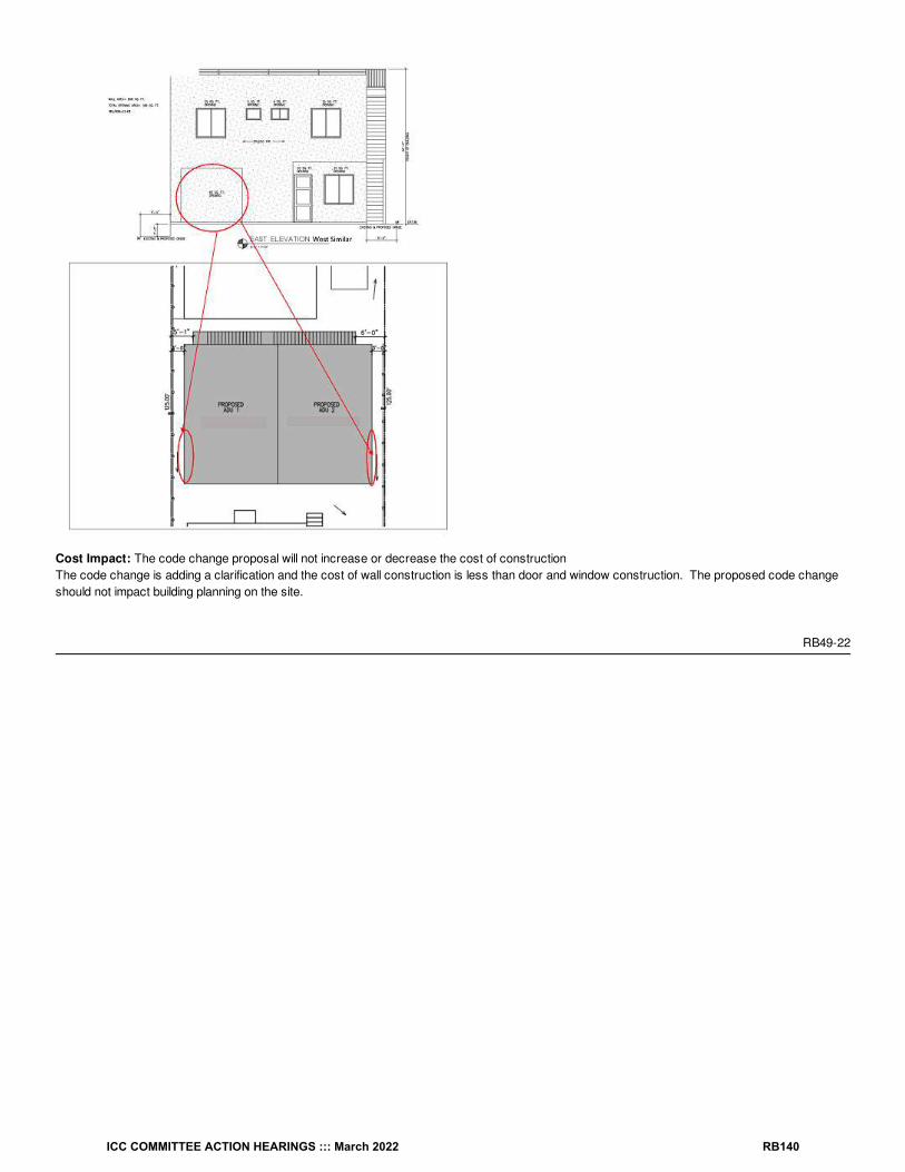
Cost Impact: The code change proposal will not increase or decrease the cost of constructionThe code change is adding a clarification and the cost of wall construction is less than door and window construction. The proposed code changeshould not impact building planning on the site.
RB49-22
ICC COMMITTEE ACTION HEARINGS ::: March 2022 RB140

RB50-22IRC: TABLE R302.1(2), R302.2.6, SECTION R313, R313.1, R326.3, TABLE AG101.1, P2902.5.4, SECTION P2904, P2904.3.1
Proponents: John Swanson, representing National Fire Sprinkler Association ([email protected])
2021 International Residential CodeRevise as follows:
ICC COMMITTEE ACTION HEARINGS ::: March 2022 RB141

TABLE R302.1(2) EXTERIOR WALLS—DWELLINGS WITH A FIRE SPRINKLERS AN AUTOMATIC SPRINKLER SYSTEM
EXTERIOR WALLELEMENT
MINIMUM FIRE-RESISTANCE RATING MINIMUM FIRESEPARATION DISTANCE
Walls
Fire-resistance
rated
1 hour—tested in accordance with ASTM E119, UL 263 or Section 703.2.2 of theInternational Building Code with exposure from the outside
0 feet
Not fire-resistance
rated0 hours 3 feet
Projections
Not allowed NA < 2 feet
Fire-resistance
rated1 hour on the underside, or heavy timber, or fire-retardant-treated wood 2 feet
Not fire-resistance
rated0 hours 3 feet
Openings inwalls
Not allowed NA < 3 feet
Unlimited 0 hours 3 feet
Penetrations AllComply with Section R302.4 < 3 feet
None required 3 feet
For SI: 1 foot = 304.8 mm.
NA = Not Applicable.
a. For residential subdivisions where all dwellings are equipped throughout with an automatic sprinkler system installed in accordance withSection P2904, the fire separation distance for exterior walls not fire-resistance rated and for fire-resistance-rated projections shall bepermitted to be reduced to 0 feet, and unlimited unprotected openings and penetrations shall be permitted, where the adjoining lot provides anopen setback yard that is 6 feet or more in width on the opposite side of the property line.
b. The fire-resistance rating shall be permitted to be reduced to 0 hours on the underside of the eave overhang if fireblocking is provided fromthe wall top plate to the underside of the roof sheathing.
c. The fire-resistance rating shall be permitted to be reduced to 0 hours on the underside of the rake overhang where gable vent openings arenot installed.
R302.2.6 Structural independence. Each townhouse unit shall be structurally independent.
Exceptions:
1. Foundations supporting exterior walls or common walls.
2. Structural roof and wall sheathing from each unit fastened to the common wall framing.
3. Nonstructural wall and roof coverings.
4. Flashing at termination of roof covering over common wall.
5. Townhouse units separated by a common wall as provided in Section R302.2.2, Item 1 or 2.
6. Townhouse units protected by a fire an automatic sprinkler system complying with Section P2904 or NFPA 13D.
SECTION R313AUTOMATIC FIRE SPRINKLER SYSTEMS
R313.1 Townhouse automatic fire sprinkler systems. An automatic sprinkler system shall be installed in townhouses.
Exception: An automatic sprinkler system shall not be required where additions or alterations are made to existing townhouses that do not havean automatic sprinkler system installed.
R326.3 Story above grade plane. A habitable attic shall be considered a story above grade plane.Exceptions: A habitable attic shall not be considered to be a story above grade plane provided that the habitable attic meets all the following:
a
b, c a
a
a
ICC COMMITTEE ACTION HEARINGS ::: March 2022 RB142

1. The aggregate area of the habitable attic is either of the following:
1.1. Not greater than one-third of the floor area of the story below.
1.2. Not greater than one-half of the floor area of the story below where the habitable attic is located within a dwelling unit equipped with a firean automatic sprinkler system in accordance with Section P2904.
2. The occupiable space is enclosed by the roof assembly above, knee walls, if applicable, on the sides and the floor-ceiling assembly below.
3. The floor of the habitable attic does not extend beyond the exterior walls of the story below.
4. Where a habitable attic is located above a third story, the dwelling unit or townhouse unit shall be equipped with a fire an automatic sprinklersystem in accordance with Section P2904.
a, b
ICC COMMITTEE ACTION HEARINGS ::: March 2022 RB143

TABLE AG101.1 PLASTIC PIPING STANDARDS FOR VARIOUS APPLICATIONS
APPLICATION LOCATION
TYPE OF PLASTIC PIPING
ABS CPVC PEPE-AL-PE
PE-RT PEXPEX-AL-PEX
PP PVC
Central vacuum System piping — — — — — — — — ASTM F2158
Foundationdrainage
System pipingASTMF628
— ASTM F405 — — — — —ASTM D2665;ASTM D2729;ASTM D3034
Geothermalground loop
System piping —
ASTM D2846;ASTM F441;ASTM F442;ASTM F2855;CSA B137.6
ASTMD2239;ASTMD2737;ASTMD3035
ASTMF1282
ASTMF2623;ASTMF2769;CSA
B137.18
ASTMF876;CSA
B137.5
ASTMF1281
ASTMF2389;CSA
B137.11
ASTM D1785;ASTM D2241;CSA B137.3
Loop piping — —
ASTMD2239;ASTMD2737;ASTM
D3035; NSF358-1
ASTMF1282
ASTMF2623;ASTMF2769;CSA
B137.18
ASTMF876;CSA
B137.5
—
ASTMF2389;CSA
B137.11
—
Graywater
Nonpressuredistribution/collection
ASTMF628
—
ASTMD2239;ASTMD2737;ASTMD3035;ASTMF2306
— — — —
ASTMF2389;CSA
B137.11
ASTM D1785;ASTM D2729;ASTM D2949;ASTM D3034;ASTM F891;
ASTM F1760 ;CSA B137.3
Pressure/distribution —
ASTM D2846;ASTM F441;ASTM F442;ASTM F2855;CSA B137.6
ASTMD2239;ASTMD2737;ASTMD3035
ASTMF1282
ASTMF2623;ASTMF2769;CSA
B137.18
ASTMF876;CSA
B137.5
ASTMF1281
ASTMF2389;CSA
B137.11
ASTM D1785;ASTM D2241;CSA B137.3
Radiant cooling Loop piping —ASTM D2846;ASTM F441;ASTM F442;ASTM F2855
ASTMD2239;ASTMD2737;ASTMD3035
ASTMF1282
ASTMF2623;ASTMF2769;CSA
B137.18
ASTMF876;CSA
B137.5
ASTMF1281
ASTMF2389;CSA
B137.11
—
Radiant heating Loop piping —
ASTM D2846;ASTM F441;ASTM F442;ASTM F2855
—ASTMF1282
ASTMF2623;ASTMF2769;CSA
B137.18
ASTMF876;CSA
B137.5
ASTMF1281
ASTMF2389;CSA
B137.11
—
Nonpressure/collectionASTMF628
—ASTMF1901
— — — —
ASTMF2389;CSA
B137.11
ASTM D1785;ASTM D2729;ASTM D2949;ASTM F891;
ASTM F1760 ;CSA B137.3
a, b
ICC COMMITTEE ACTION HEARINGS ::: March 2022 RB144

Rainwaterharvesting
Pressure/distribution —
ASTM D2846;ASTM F441;ASTM F442;ASTM F2855;CSA B137.6
ASTMD2239ASTMD2737;ASTMD3035
ASTMF1282
ASTMF2623;ASTMF2769;CSA
B137.18
ASTMF876;CSA
B137.5
ASTMF1281
ASTMF2389;CSA
B137.11
ASTM D1785;ASTM D2241;CSA B137.3
Radon venting System pipingASTMF628
— — — — — — —ASTM D1785;ASTM F891;ASTM F1760
Reclaimedwater
Main to building service —
ASTM D2846;ASTM F441;ASTM F442;ASTM F2855;CSA B137.6
ASTMD3035;AWWA
C901; CSAB137.1
ASTMF1282
ASTMF2623;ASTMF2769;CSA
B137.18
ASTMF876;AWWAC904;CSA
B137.5
—
ASTMF2389;CSA
B137.11
ASTM D1785;ASTM D2241;AWWA C905;CSA B137.3
Pressure/distribution/irrigation —
ASTM D2846;ASTM F441;ASTM F442;ASTM F2855;CSA B137.6
ASTMD2239;ASTMD2737;ASTMD3035
ASTMF1282
ASTMF2623;ASTMF2769;CSA
B137.18
ASTMF876;CSA
B137.5
ASTMF1281
ASTMF2389;AWWAC900 ;CSA
B137.11
ASTM D1785;ASTM D2241;AWWA C900
Residential firesprinklersAutomaticSprinklerSystems
Sprinkler piping —
ASTM F441;ASTM F442;CSA B137.6;
UL 1821
— —
ASTMF2769;CSA
B137.18
ASTMF876;CSA
B137.5;UL
1821
—
ASTMF2389;CSA
B137.11
—
Solar heating Pressure/distribution —
ASTM D2846;ASTM F441;ASTM F442;ASTM F2855
— —
ASTMF2623;ASTMF2769;CSA
B137.18
ASTMF876;CSA
B137.5
ASTMF1281
ASTMF2389;CSA
B137.11
—
APPLICATION LOCATION
TYPE OF PLASTIC PIPING
ABS CPVC PEPE-AL-PE
PE-RT PEXPEX-AL-PEX
PP PVC
a. This table indicates manufacturing standards for plastic piping materials that are suitable for use in the applications indicated. Suchapplications support green and sustainable building practices. The system designer or the installer of piping shall verify that the pipingchosen for an application complies with local codes and the recommendations of the manufacturer of the piping.
b. Fittings applicable for the piping shall be as recommended by the manufacturer of the piping.
c. Piping systems for fire automatic sprinkler systems applications shall be listed for the application.
P2902.5.4 Connections to automatic fire sprinkler systems. The potable water supply to automatic fire sprinkler systems shall be protectedagainst backflow by a double-check backflow prevention assembly, a double-check fire protection backflow prevention assembly, a reducedpressure principle backflow prevention assembly or a reduced pressure principle fire protection backflow prevention assembly.
Exception: Where an automatic sprinkler systems are is installed in accordance with Section P2904.1, backflow protection for the water supplysystem shall not be required.
SECTION P2904DWELLING UNIT FIRE AUTOMATIC SPRINKLER SYSTEMS
P2904.3.1 Nonmetallic pipe and tubing. Nonmetallic pipe and tubing, such as CPVC, PEX, and PE-RT shall be listed for use in residential fire automatic sprinkler systems.
Reason Statement: The intent of this code change proposal is to coordinate terminology between the IBC, IFC, IEBC and IRC when referring to“automatic sprinkler system” since this term is used and defined in the International Building Code and International Fire Code. This change is
c
ICC COMMITTEE ACTION HEARINGS ::: March 2022 RB145

intended to coordinate terminology in the IRC so the term is used consistently throughout the document. It is not the intent of this proposal to makeany substantive changes to automatic sprinkler system requirements in the IRC. Existing code sections referencing specific components orappurtenances of an automatic sprinkler system were left untouched. For example, this proposal is not recommending any changes to R302.2.2,R302.4.1, or any other section referencing "water-filled sprinkler piping", since these sections are referring to specific components of an automaticsprinkler system. This proposal also attempts to mirror F75-21 Part II (attached) in relation to clarifying terminology relating to automatic sprinklersystems in the IRC.
Cost Impact: The code change proposal will not increase or decrease the cost of constructionThere are no technical changes to this code section. This proposal is being made for correlation purposes with the terminology used.
RB50-22
ICC COMMITTEE ACTION HEARINGS ::: March 2022 RB146

RB51-22IRC: TABLE R302.1(1), TABLE R302.1(2)
Proponents: Mike Nugent, representing Building Code Action Committee ([email protected])
2021 International Residential CodeRevise as follows:
ICC COMMITTEE ACTION HEARINGS ::: March 2022 RB147

TABLE R302.1(1) EXTERIOR WALLS
EXTERIOR WALL ELEMENT MINIMUM FIRE-RESISTANCE RATING MINIMUM FIRESEPARATION DISTANCE
Walls
Fire-resistancerated
1 hour—tested in accordance with ASTM E119, UL 263 or Section 703.3 of theInternational Building Code with exposure from both sides
0 feet
Not fire-resistance rated
0 hours ≥ 5 feet
Projections
Not allowed NA < 2 feet
Fire-resistancerated
1 hour on the underside, or heavy timber, or fire-retardant-treated wood ≥ 2 feet to < 5 feet
Not fire-resistance rated
0 hours ≥ 5 feet
Openings inwalls
Not allowed NA < 3 feet
25% maximumof wall area
0 hours 3 feet
Unlimited 0 hours 5 feet
Penetrations AllComply with Section R302.4 < 3 feet
None required 3 feet
For SI: 1 foot = 304.8 mm.NA = Not Applicable.
a. The fire-resistance rating shall be permitted to be reduced to 0 hours on the underside of the eave overhang if fireblocking is provided fromthe wall top plate to the underside of the roof sheathing.
b. The fire-resistance rating shall be permitted to be reduced to 0 hours on the underside of the rake overhang where gable vent openings arenot installed in the overhang or in any gable end walls that are common to attic areas .
a, b
ICC COMMITTEE ACTION HEARINGS ::: March 2022 RB148

TABLE R302.1(2) EXTERIOR WALLS—DWELLINGS WITH FIRE SPRINKLERS
EXTERIOR WALLELEMENT
MINIMUM FIRE-RESISTANCE RATING MINIMUM FIRESEPARATION DISTANCE
Walls
Fire-resistance
rated
1 hour—tested in accordance with ASTM E119, UL 263 or Section 703.2.2 of theInternational Building Code with exposure from the outside
0 feet
Not fire-resistance
rated0 hours 3 feet
Projections
Not allowed NA < 2 feet
Fire-resistance
rated1 hour on the underside, or heavy timber, or fire-retardant-treated wood 2 feet
Not fire-resistance
rated0 hours 3 feet
Openings inwalls
Not allowed NA < 3 feet
Unlimited 0 hours 3 feet
Penetrations AllComply with Section R302.4 < 3 feet
None required 3 feet
For SI: 1 foot = 304.8 mm.
NA = Not Applicable.
a. For residential subdivisions where all dwellings are equipped throughout with an automatic sprinkler system installed in accordance withSection P2904, the fire separation distance for exterior walls not fire-resistance rated and for fire-resistance-rated projections shall bepermitted to be reduced to 0 feet, and unlimited unprotected openings and penetrations shall be permitted, where the adjoining lot provides anopen setback yard that is 6 feet or more in width on the opposite side of the property line.
b. The fire-resistance rating shall be permitted to be reduced to 0 hours on the underside of the eave overhang if fireblocking is provided fromthe wall top plate to the underside of the roof sheathing.
c. The fire-resistance rating shall be permitted to be reduced to 0 hours on the underside of the rake overhang where gable vent openings arenot installed in the overhang or in any gable end walls that are common to attic areas .
Reason Statement: The intent of this proposed code change is to address conditions where if there were no vents at the underside ofthe roof overhang, or in any gable end walls (both of which would allow fire to freely move into attic areas), then there should be no requirement torate the underside of the overhang. This could be applied to gable, hip, and any other roof style overhangs. Where additional attic ventilation isrequired to make up for the loss of vents at overhangs where fire-separation distance is an issue in accordance with these tables and footnotes,additional vents could be added at the underside of eaves in other areas of the dwelling where fire-separation distance is not an issue, or at ridgevents. This proposal change was submitted during the 2019 Group B code cycle but was disapproved. It was disapproved not based on the intent orprinciple, but on an editorial error to correlate the footnotes for both tables.
This proposal is submitted by the ICC Building Code Action Committee (BCAC).
BCAC was established by the ICC Board of Directors in July 2011 to pursue opportunities to improve and enhance assigned International Codes orportions thereof. In 2020 and 2021 the BCAC has held several virtual meetings open to any interested party. In addition, there were numerous virtualWorking Group meetings for the current code development cycle, which included members of the committee as well as interested parties. Relateddocuments and reports are posted on the BCAC website at https://www.iccsafe.org/products-and-services/i-codes/code-development/cs/building-code-action-committee-bcac/.
Cost Impact: The code change proposal will not increase or decrease the cost of constructionThis code change is a clarification of current code requirements.
a
b, c a
a
a
ICC COMMITTEE ACTION HEARINGS ::: March 2022 RB149

RB51-22
ICC COMMITTEE ACTION HEARINGS ::: March 2022 RB150

RB52-22IRC: R302.2
Proponents: David Renn, PE, SE, City and County of Denver, representing Code Change Committee of Colorado Chapter of ICC([email protected])
2021 International Residential CodeRevise as follows:
R302.2 Townhouses. Townhouse units shall have a yard or public way on the entire length of one side and on at least two-thirds the length ofanother side. Walls separating townhouse units shall be constructed in accordance with Section R302.2.1 or R302.2.2 and shall comply withSections 302.2.3 through 302.2.5.
Reason Statement: Per definition, a "townhouse unit" must have a yard or public way on not less than two sides; however, the definition does notdictate the length required for a yard or public way. Per the IRC commentary, these open sides are intended to provide some degree ofindependence from other townhouse units. Ideally these two sides would have a yard or public way along the entire length of each side, but this isnot always feasible, such as when townhouse units change direction at a corner of a townhouse as shown below. This proposal requires one side tohave a yard or public way along the entire length of one side, which is easily achieved at the front side of the unit, and requires a yard or public wayalong at least two-thirds of another side - we feel this provides the independence intended while also allowing for the common unit configuration showbelow. We don't believe the short overlap of units allowed in this proposal is enough justification to require the building to be designed to the IBCinstead of the IRC. Since the code is silent on how much of the sides are to have a yard or public way, some jurisdictions may require the full lengthof these sides to be open, while others may allow as little as 3 feet (width of a door). This proposal will bring consistency to the interpretation of thisrequirement which will benefit developers, designers and building officials.
Cost Impact: The code change proposal will decrease the cost of constructionFor jurisdictions where the full length of a side is required to be open, this proposal will decrease the cost of construction since more structures willbe allowed to be designed under the IRC instead of the IBC. For jurisdictions that allow some townhouse unit overlap on an open side, this proposalis simply a clarification of how much overlap is allowed and will have little or no impact on the cost of construction.
RB52-22
ICC COMMITTEE ACTION HEARINGS ::: March 2022 RB151

RB53-22IRC: R302.2, R302.2.1, R302.2.2, R302.2.3, R302.2.4, R302.2.5, R302.2.6
Proponents: Jeffrey Shapiro, representing Self ([email protected])
2021 International Residential CodeAdd new text as follows:
R302.2 Townhouses. Townhouses shall comply with Sections R302.2.1 through R302.2.3.
R302.2.1 Open sides. Each townhouse unit shall have not less than two open sides adjoining a yard or public way. The wall on one open side shallhave a length that is not less than 20 percent of the total perimeter of the townhouse unit, and the wall the second open side shall have a length thatis not less than 10 percent of the total perimeter of the townhouse unit.
Exception: Walls on open sides of townhouse units in townhouses that are provided with automatic sprinklersthroughout in accordance withSection P2904 shall have a length of not less than 10 feet (3048 mm) on one open side and 3 feet (914 mm) on the second open side.
Revise as follows:
R302.2 R302.2.2 Townhouses Separation walls. Walls separating townhouse units shall be constructed in accordance with Section R302.2.1 orR302.2.2 R302.2.2.1 or R302.2.2.2 and shall comply with Sections R302.2.3 through R302.2.5 R302.2.2.3 through R302.2.2.4.1.
R302.2.2.1 R302.2.1 Double walls. Each townhouse unit shall be separated from other townhouse units by two 1-hour fire-resistance-rated wallassemblies tested in accordance with ASTM E119, UL 263 or established by an analytical method in accordance with Section 703.2.2 of theInternational Building Code.
R302.2.2.2 R302.2.2 Common walls. Common walls separating townhouse units shall be assigned a fire-resistance rating in accordance with Item1 or 2 and shall be rated for fire exposure from both sides. Common walls shall extend to and be tight against the exterior sheathing of the exteriorwalls, or the inside face of exterior walls without stud cavities, and the underside of the roof sheathing. The common wall shared by two townhouseunits shall be constructed without plumbing or mechanical equipment, ducts or vents, other than water-filled fire sprinkler piping in the cavity of thecommon wall. Electrical installations shall be in accordance with Chapters 34 through 43. Penetrations of the membrane of common walls forelectrical outlet boxes shall be in accordance with Section R302.4.
1. Where ean automatic sprinkler system in accordance with Section P2904 is provided, the common wall shall be not less than a 1-hour fire-resistance-rated wall assembly tested in accordance with ASTM E119, UL 263 or established by an analytical method in accordancewith Section 703.2.2 of the International Building Code.
2. Where an automatic sprinkler system in accordance with Section P2904 is not provided, the common wall shall be not less than a 2-hour fire-resistance-rated wall assembly tested in accordance with ASTM E119, UL 263 or established by an analytical method in accordancewith Section 703.2.2 of the International Building Code.
Exception: Common walls are permitted to extend to and be tight against the inside of the exterior walls if the cavity between the end of thecommon wall and the exterior sheathing is filled with a minimum of two 2-inch nominal thickness wood studs.
R302.2.2.3 R302.2.3 Continuity. The fire-resistance-rated wall or assembly separating townhouse units shall be continuous from the foundation tothe underside of the roof sheathing, deck or slab. The fire-resistance rating shall extend the full length of the wall or assembly, including wallextensions through and separating attached enclosed accessory structures.
R302.2.2.4 R302.2.4 Parapets for townhouses. Parapets constructed in accordance with Section R302.2.5 shall be constructed for townhousesas an extension of exterior walls or common walls separating townhouse units in accordance with the following:
1. Where roof surfaces adjacent to the wall or walls are at the same elevation, the parapet shall extend not less than 30 inches (762 mm) abovethe roof surfaces.
2. Where roof surfaces adjacent to the wall or walls are at different elevations and the higher roof is not more than 30 inches (762 mm) abovethe lower roof, the parapet shall extend not less than 30 inches (762 mm) above the lower roof surface.
Exception: A parapet is not required in the preceding two cases where the roof covering complies with a minimum Class C rating astested in accordance with ASTM E108 or UL 790 and the roof decking or sheathing is of noncombustible materials or fire-retardant-treated wood for a distance of 4 feet (1219 mm) on each side of the wall or walls, or one layer of / -inch (15.9 mm) Type X gypsumboard is installed directly beneath the roof decking or sheathing, supported by not less than nominal 2-inch (51 mm) ledgers attached tothe sides of the roof framing members, for a distance of not less than 4 feet (1219 mm) on each side of the wall or walls and anyopenings or penetrations in the roof are not within 4 feet (1219 mm) of the common walls. Fire-retardant-treated wood shall meet therequirements of Sections R802.1.5 and R803.2.1.2.
58
ICC COMMITTEE ACTION HEARINGS ::: March 2022 RB152

3. A parapet is not required where roof surfaces adjacent to the wall or walls are at different elevations and the higher roof is more than 30inches (762 mm) above the lower roof. The common wall construction from the lower roof to the underside of the higher roof deck shall havenot less than a 1-hour fire-resistance rating. The wall shall be rated for exposure from both sides.
R302.2.2.4.1R302.2.5 Parapet construction. Parapets shall have the same fire-resistance rating as that required for the supporting wall or walls.On any side adjacent to a roof surface, the parapet shall have noncombustible faces for the uppermost 18 inches (457 mm), to includecounterflashing and coping materials. Where the roof slopes toward a parapet at slopes greater than 2 units vertical in 12 units horizontal (16.7-percent slope), the parapet shall extend to the same height as any portion of the roof within a distance of 3 feet (914 mm), and the height shall be notless than 30 inches (762 mm).
R302.2.3 R302.2.6 Structural independence. Each townhouse unit shall be structurally independent.
Exceptions:
1. Foundations supporting exterior walls or common walls.
2. Structural roof and wall sheathing from each unit fastened to the common wall framing.
3. Nonstructural wall and roof coverings.
4. Flashing at termination of roof covering over common wall.
5. Townhouse units separated by a common wall as provided in Section R302.2.2.2 R302.2.2, Item 1 or 2.
6. Townhouse units protected by a fire sprinkler system complying with Section P2904 or NFPA 13D.
Reason Statement: This proposal builds on discussions of Proposal RB22-19 in the last cycle. Constructive discussion of that proposal took placeat the Technical Committee Hearing, but at the Public Comment Hearing, consensus could not be reached among different interested parties. Nevertheless, there was clear support by the Technical Committee and ICC members and chapters for coming up with a fix that addressesshortcomings in the current text. Bearing in mind that the original concept of townhouses was rectangular units in a linear configuration that was open on three sides for end units andfront/rear for center units, the current code remains sufficient for its original purpose. However, over time, townhouse designers have gotten verycreative in interpreting what constitutes a "side" that adjoins a yard or public way. Odd shapes and configurations that have townhouse units partiallysurrounded by other units, sometimes sharing walls with 3 or more neighboring units, have evolved. What constitutes a "side" in such cases hasled to disagreements between code officials and designers, and lacking guidance in the code, code officials have little to fall back on beyond "I'm thecode official," which that puts the code official in a difficult situation. These varied perspectives were clearly on display at last cycle's hearings, asdifferent individuals testified with different interpretations and different perspectives on what is "reasonable."
In addition to improving the structure of the existing provisions in Section R302.2 and clarifying text referencing the IBC for fire resistance ratings(IBC Section 703.2.2 is not a test method, so the current IRC text referencing the IBC is incorrect), this proposal adds a new section 302.2.1 tosupport the definition of "townhouse unit" with respect to establishing minimum requirements for open sides.
The 20% requirement for the first side is derived from a typical 20x30 townhouse and follows the logic that the front side would traditionally beentirely open (20 foot front wall / 100 foot total unit perimeter = 20%); whereas, the 10% requirement for the second side generously allows the backor adjacent side to be partially blocked (10% is half of the 20-foot rear wall) by another unit or units. The exception for townhouses that areequipped with fire sprinklers, technically always required by the IRC but not enforced in some jurisdictions, is appropriate because, with sprinklersbeing provided, the need for large open sides for fire department access and suppression activity is drastically reduced. The allowance for aminimum of 10 feet on the primary side is considered to be a reasonable accommodation of the occasional need for narrow infill units. The allowancefor the second open side to be as small as 3 feet for sprinklered townhouse units correlates with R310.1 in the 2021 IRC (from Proposal RB86-19),which clarified that emergency escape and rescue openings require a minimum of 36-inches of clear space between the opening and a public way.
Although there is no "perfect" fix to this issue given the multitude of configurations that designers might come up with, this proposal provides afair, reasonable and flexible basis for quantifying a level of openness for townhouses that should be acceptable given the history of thetownhouse provisions and interests of today's designers.
For disclosure, I am a consultant to NFSA, but this proposal is not submitted on NFSA's behalf and was not provided to NFSA prior to submittal. It issubmitted as a personal proposal based on my personal interest in this topic.
Cost Impact: The code change proposal will not increase or decrease the cost of constructionThere is no way to universally quantify any cost impact of this change because of the ambiguity in existing text with respect to what constitutes anopen side. Applied in jurisdictions that interpret the IRC such that two sides of a townhouse unit must be open to a yard or public way for the entirelength of both sides, this change would reduce the cost of construction by adding clarity to the IRC that would relax application of the open siderequirement. On the other hand, in jurisdictions that might interpret the IRC such that there is minimal length required to constitute an open side, thischange would make application of the code more stringent.
ICC COMMITTEE ACTION HEARINGS ::: March 2022 RB153

RB53-22
ICC COMMITTEE ACTION HEARINGS ::: March 2022 RB154

RB54-22IRC: R302.2.2
Proponents: Ali Fattah, representing City of San Diego Development Services Department ([email protected])
2021 International Residential CodeRevise as follows:
R302.2.2 Common walls. Common walls separating townhouse unitsshall be assigned a fire-resistance rating in accordance with Item 1 or 2 andshall be rated for fire exposure from both sides. Common walls shall extend to and be tight against the exterior sheathing of the exterior walls, or theinside face of exterior walls without stud cavities, and the underside of the roof sheathing. The common wall shared by two townhouse units shall beconstructed without openings, plumbing or mechanical equipment, ducts or vents, other than water-filled fire sprinkler piping in the cavity of thecommon wall. Electrical installations shall be in accordance with Chapters 34 through 43. Penetrations of the membrane of common walls forelectrical outlet boxes shall be in accordance with Section R302.4.
1. Where ean automatic sprinkler system in accordance with Section P2904 is provided, the common wall shall be not less than a 1-hour fire-resistance-rated wall assembly tested in accordance with ASTM E119, UL 263 or Section 703.2.2 of the International Building Code.
2. Where an automatic sprinkler system in accordance with Section P2904 is not provided, the common wall shall be not less than a 2-hour fire-resistance-rated wall assembly tested in accordance with ASTM E119, UL 263 or Section 703.2.2 of the International Building Code.
Exception: Common walls are permitted to extend to and be tight against the inside of the exterior walls if the cavity between the end of thecommon wall and the exterior sheathing is filled with a minimum of two 2-inch nominal thickness wood studs.
Reason Statement: This code change is a necessary clarification in the IRC that unlike the IBC the IRC does not intend for openings such asdoors to be located within common walls. The section being modified restricts penetrations in the common wall and limits what can be placed withinthe common wall. It therefore stands to reason that the IRC should also address openings that are not explicitly prohibited. A common wall is treatedlike an exterior wall located at a zero fire separation distance. Unlike the IRC, the IBC does not address townhouses and requires that dwelling units and sleeping units be separated with fire partitions since thedwelling units are no considered attached single family dwellings like Townhouses in the IRC. As a result the IBC requires in Section 708.6and TABLE 716.1(2) that openings in fire partitions separating dwelling or sleeping units units be protected for 1/3 or 3/4 hour opening protectives.
The IRC does not require protected openings and restricts the location of openings and in the case of protection based on fire separation distancelimits opening size through % of wall are limits.
Cost Impact: The code change proposal will not increase or decrease the cost of constructionThe proposed code change is a clarification and reflects current regulatory practice.
RB54-22
ICC COMMITTEE ACTION HEARINGS ::: March 2022 RB155

RB55-22IRC: R302.2.2
Proponents: Shane Nilles, representing Self ([email protected])
2021 International Residential CodeRevise as follows:
R302.2.2 Common walls. Common walls separating townhouse unitsshall be assigned a fire-resistance rating in accordance with Item 1 or 2 andshall be rated for fire exposure from both sides. Common walls shall extend to and be tight against the exterior sheathing of the exterior walls, or theinside face of exterior walls without stud cavities, and the underside of the roof sheathing. The common wall shared by two townhouse units shall beconstructed without plumbing or mechanical equipment, ducts or vents, other than water-filled fire sprinkler piping in the cavity of the common wall.Electrical installations shall be in accordance with Chapters 34 through 43. Penetrations of the membrane of common walls for electrical outlet boxesshall be in accordance with Section R302.4.
1. Where ean automatic sprinkler system in accordance with Section P2904 is provided, the common wall shall be not less than a 1-hour fire-resistance-rated wall assembly tested in accordance with ASTM E119, UL 263 or Section 703.2.2 of the International Building Code.
2. Where an automatic sprinkler system in accordance with Section P2904 is not provided, the common wall shall be not less than a 2-hour fire-resistance-rated wall assembly tested in accordance with ASTM E119, UL 263 or Section 703.2.2 of the International Building Code.
Exceptions:
1. Common walls are permitted to extend to and be tight against the inside of the exterior walls if the cavity between the end of the commonwall and the exterior sheathing is filled with a minimum of two 2-inch nominal thickness wood studs.
2. Plumbing and mechanical piping is permitted to pass directly through common walls provided they are protected in accordance withSection R302.4.
Reason Statement: As the 2021 code now recognizes the entire structure as the townhouse building, and each townhouse as a unit within thebuilding, piping serving plumbing and mechanical systems in townhouse buildings need to be able to pass through townhouse separation walls. Thelanguage as currently written in Section R302.2.2 to say that no such piping is permitted within the cavity of the wall at all, which would thereforeprohibit piping that is simply passing directly through it. This proposal adds an exception to the section to make it consistent with the intent oftownhouse units being able to share utility services as they are in a single building, with the condition that they are protected as penetrations perR302.4 which thereby maintains the required protection of the wall.
Cost Impact: The code change proposal will decrease the cost of constructionThe proposal creates an exception that allows for additional options and therefore decreases the cost of construction
RB55-22
ICC COMMITTEE ACTION HEARINGS ::: March 2022 RB156

RB56-22IRC: R302.2.3
Proponents: David Renn, PE, SE, City and County of Denver, representing Code Change Committee of Colorado Chapter of ICC([email protected])
2021 International Residential CodeRevise as follows:
R302.2.3 Continuity. The fire-resistance-rated wall or assembly separating townhouse units shall be continuous from the foundation to theunderside of the roof sheathing, deck or slab. and shall be continuous through attached enclosed accessory structures. The fire-resistance-ratedwall or assembly shall extend through concealed roof overhangs to separate the attics of adjacent townhouse units.The fire-resistance rating shallextend the full length of the wall or assembly, including wall extensions through and separating attached enclosed accessory structures.
Reason Statement: This proposal is intended to clarify the continuity requirements of townhouse separation walls in two ways:1. As currently written, this section requires wall extensions through attached enclosed accessory structures to have a fire-resistance-rating, butdoesn't actually require the extensions. It is clear the intent of the code is to provide separation walls through attached enclosed accessorystructures, such as garages, and this proposal makes this a specific requirement.
2. This section requires separation walls to continue to the roof sheathing and Section R302.2.2 requires common walls to continue to the exteriorsheathing of exterior walls, but there are no code requirements for continuity through concealed roof overhangs. If a common wall in an attic spacestops in line with the exterior wall sheathing below the attic, there is a gap in the continuity of this wall as fire in one attic could wrap around the end ofthe wall through the enclosed roof overhang. This proposal remedies this by requiring the separation wall to continue through this concealed spaceto separate the attics of adjacent units. It is believed that this is common practice to provide the separation intended.
Please support this proposal to bring clarity to continuity requirements for townhouse walls.
Cost Impact: The code change proposal will not increase or decrease the cost of constructionThe intent of the code is to require separation walls to extend through enclosed accessory structures and this proposal rewords the current wordingto require this. Also, the intent of the code is to provide a fire-rated separation wall between units to prevent the spread of fire between units. Thisproposal adds requirements to provide a separation through roof overhangs which is common construction practice and is commonly enforced. Since the intent of the code, common construction practice and common enforcement isn't changing, this proposal will not change the cost ofconctruction.
RB56-22
ICC COMMITTEE ACTION HEARINGS ::: March 2022 RB157

RB57-22IRC: R302.2, R302.2.3 (New), R302.2.3.1 (New)
Proponents: Tim Earl, representing the Gypsum Association ([email protected])
2021 International Residential CodeRevise as follows:
R302.2 Townhouses. Walls separating townhouse units shall be constructed in accordance with Section R302.2.1 , or R302.2.2 , or R302.2.3 andshall comply with Sections 302.2.3 through 302.2.5.
Add new text as follows:
R302.2.3 Area Separation Walls. Area separation wall assemblies separating townhouses shall consist of the following:
1. A central wall consisting of two (2) 1-inch (25.4 mm) Type X gypsum shaft liner panels inserted between steel H-studs and rated for twohours per ASTM E119, UL 263 or Section 703.3 of the International Building Code.
2. A non-fire-resistance rated flanking wall on one or both sides attached to the steel H-studs via aluminum clips set a minimum of ¾-inch (19mm) off the central wall. The flanking walls shall consist of minimum ½-inch (12.7 mm) gypsum panels attached to minimum nominal 2 x 4wood studs or minimum 15 mil (0.38 mm) 3-5/8” (92 mm) steel studs.
R302.2.3.1 Penetrations. The central wall shall not be penetrated. The non-fire-resistance rated flanking walls shall be permitted to be penetratedas needed to allow for utilities, ducts or vents in the wall cavity.
Reason Statement: This proposal provides needed clarification regarding area separation walls and allowable penetrations in the flanking walls,which are not fire-rated. Adjacent townhomes are separated in one of three ways:
1. Double walls (two 1-hour fire-resistance-rated wall assemblies)
2. A common wall (fire-resistance rated, 1 or 2 hours depending on sprinklers)
3. An “area separation wall” (ASW), consisting of one central two-hour fire-resistance-rated wall with a flanking wall attached with aluminum clipson one or both sides.
For various reasons, each of these options is more common in different regions of the US. #1 and #2 are already addressed in Section R302.2. ASWs are currently being built, but not mentioned in the code. Further clarification is required, particularly with regards to penetrations of the non-rated flanking walls, as some users have believed that the space between the central fire-rated wall and the non-rated flanking walls cannot containplumbing or mechanical equipment. In fact, an ICC staff interpretation took this position
In an ASW system, the fire-rated central wall meets all requirements of Section R302.2 by:
Providing a 2- hour fire resistance rating when built to the applicable designNot allowing penetrationsMaintaining continuityAllowing for parapetsMaintaining structural independence
This proposal provides a clear description of Area Separation Walls and where penetrations are allowed. Specifically, it makes it clear that the non-rated flanking walls may be penetrated, but the fire-rated central wall may not.
The figure below illustrates the typical installed system.
ICC COMMITTEE ACTION HEARINGS ::: March 2022 RB158

Cost Impact: The code change proposal will not increase or decrease the cost of constructionThis proposal adds to the IRC a type of wall which is already being built today. It is simply another option.
RB57-22
ICC COMMITTEE ACTION HEARINGS ::: March 2022 RB159
RB58-22IRC: R302.2.4
Proponents: Ali Fattah, representing City of San Diego Development Services Department ([email protected])
2021 International Residential CodeRevise as follows:
R302.2.4 Parapets for townhouses. Parapets constructed in accordance with Section R302.2.5 shall be constructed for townhouses as anextension of exterior walls or common walls separating townhouse units in accordance with the following:
1. Where roof surfaces adjacent to the wall or walls are at the same elevation, the parapet shall extend not less than 30 inches (762 mm) abovethe roof surfaces.
2. Where roof surfaces adjacent to the wall or walls are at different elevations and the higher roof is not more than 30 inches (762 mm) abovethe lower roof, the parapet shall extend not less than 30 inches (762 mm) above the lower roof surface.
Exception: A parapet is not required in the preceding two cases where the roof covering complies with a minimum Class C rating astested in accordance with ASTM E108 or UL 790 and the roof decking or sheathing is of noncombustible materials or fire-retardant-treated wood for a distance of 4 feet (1219 mm) on each side of the wall or walls, or one layer of / -inch (15.9 mm) Type X gypsumboard is installed directly beneath the roof decking or sheathing, supported by not less than nominal 2-inch (51 mm) ledgers attached tothe sides of the roof framing members, for a distance of not less than 4 feet (1219 mm) on each side of the wall or walls and anyopenings or penetrations in the roof are not within 4 feet (1219 mm) of the common walls. Fire-retardant-treated wood shall meet therequirements of Sections R802.1.5 and R803.2.1.2.
3. A parapet is not required where roof surfaces adjacent to the wall or walls are at different elevations and the higher roof is more than 30inches (762 mm) above the lower roof. The common wall construction from the lower roof to the underside of the higher roof deck shall havenot less than a 1-hour fire-resistance rating. The wall shall be rated for exposure from both sides. Openings shall not be permitted in thewall.
Reason Statement: The code change is necessary to address a significant omission in the IRC that predates the 2005 edition where exterior wallopenings located in common walls extending above a lower roof in a stepped Townhouse are neither prohibited nor required to be protected. Whilethe common wall is not a party-wall that is regulated in the IBC as a fire wall, common walls are protected similar to exterior walls located at zero fireseparation distance; Section R302.2.2 does not permit openings in the common wall and restricts penetrations. Additionally, communicatingopenings are not permitted between dwelling units it would seem reasonable to prohibit exterior wall openings in exterior portions of the common wall.The proposed code change takes an approach to solving the problem caused by the regulatory omission that is consistent with Table R302.1(1)and R302.1(2) where the IRC does not require fire protection for exterior wall openings but accomplishes the desired level of protection eitherprohibiting exterior wall openings or restricting their area. Additionally, the proposed code change is also consistent in the way that the IBC regulatesparty walls. Since the FSD at a common wall is zero the proposed code change takes the simplest solution to prevent fire from the dwelling unitbelow from reaching the dwelling unit above by prohibiting the exterior wall opening. This is consistent with approach R202.2.3 and R302.3.4 and it'ssub parts.
The attached figures 1 and 2 attempt to illustrate the issue. Figure one shows a plan view of the third story and roof and figure 2 shows a buildingsection depicting the elevation difference. The common wall is depicted in the dotted blue line.Proponent feels that the code change to be editorialand to add clarity for consistent and uniform code application.
58
ICC COMMITTEE ACTION HEARINGS ::: March 2022 RB160

ICC COMMITTEE ACTION HEARINGS ::: March 2022 RB161

Cost Impact: The code change proposal will not increase or decrease the cost of constructionThis code change is editorial however it may be considered to increase the cost of construction in jurisdictions that previously considered theregulatory omission to be justification to permit exterior wall openings.
RB58-22
ICC COMMITTEE ACTION HEARINGS ::: March 2022 RB162

RB59-22IRC: R302.2.4
Proponents: Ali Fattah, representing City of San Diego Development Services Department ([email protected])
2021 International Residential CodeRevise as follows:
R302.2.4 Parapets for townhouses. Parapets constructed in accordance with Section R302.2.5 shall be constructed for townhouses as anextension of exterior walls or common walls separating townhouse units in accordance with the following:
1. Where roof surfaces adjacent to the wall or walls are at the same elevation, the parapet shall extend not less than 30 inches (762 mm) abovethe roof surfaces.
2. Where roof surfaces adjacent to the wall or walls are at different elevations and the higher roof is not more than 30 inches (762 mm) abovethe lower roof, the parapet shall extend not less than 30 inches (762 mm) above the lower roof surface.
Exception: A parapet is not required in the preceding two cases where the roof covering complies with a minimum Class C rating astested in accordance with ASTM E108 or UL 790 and the roof decking or sheathing is of noncombustible materials or fire-retardant-treated wood for a distance of 4 feet (1219 mm) on each side of the wall or walls, or one layer of / -inch (15.9 mm) Type X gypsumboard is installed directly beneath the roof decking or sheathing, supported by not less than nominal 2-inch (51 mm) ledgers attached tothe sides of the roof framing members, for a distance of not less than 4 feet (1219 mm) on each side of the wall or walls and anyopenings or penetrations in the roof are not within 4 feet (1219 mm) of the common walls. Fire-retardant-treated wood shall meet therequirements of Sections R802.1.5 and R803.2.1.2.
3. A parapet is not required where roof surfaces adjacent to the wall or walls are at different elevations and the higher roof is more than 30inches (762 mm) above the lower roof. The common wall construction from the lower roof to the underside of the higher roof deck shall havenot less than a 1-hour fire-resistance rating. The wall shall be rated for exposure from both sides. Openings in the wall shall be protectedwith assemblies having a fire protection rating of not less than 3/4 hour. Portions of the exterior walls greater than 15 feet (4572 mm) abovethe lower roof shall be of non fire-resistance- rated construction. Openings in the wall shall be protected with assemblies having a fireprotection rating of not less than 3/4 hour.
Reason Statement: The proposed code change is necessary to address a significant omission in the IRC that predates the 2005 edition whereexterior wall openings located in common walls extending above a lower roof in a stepped Townhouse are neither prohibited nor required to beprotected.While the common wall is not a party-wall that is regulated in the IBC as a fire wall, common walls are protected similar to exterior walls located atzero fire separation distance; IRC Section R302.2.2 does not permit openings in the common wall and restricts penetrations. Additionally,communicating openings are not permitted between dwelling units it would seem reasonable to prohibit exterior wall openings in exterior portions ofthe common wall.
The proposed code change takes an approach to solving the problem caused by the regulatory omission that is consistent with method in which theIBC regulates fire walls. While communicating openings are not permitted between dwelling units it would seem onerous to prohibit exterior wallopenings in exterior portions of the common wall. The proposed modification and addition to item # 3 adds regulatory language from IBCSection 706.6.1.
The attached figures 1 and 2 attempt to illustrate the issue. Figure one shows a plan view of the third story and roof and figure 2 shows a buildingsection depicting the elevation difference. The common wall is depicted in the dotted blue line.
This code change is option 2 in the event that the committee prefers to permit a protected opening however proponent feels the other optionsubmitted whereby openings in the wall are prohibited is the preferred option.
58
ICC COMMITTEE ACTION HEARINGS ::: March 2022 RB163

ICC COMMITTEE ACTION HEARINGS ::: March 2022 RB164

Cost Impact: The code change proposal will increase the cost of constructionThe proposed change is a clarification however if the project chooses to add an opening in the wall then the code of a fire protection rated openingwill increase the cost of construction.
RB59-22
ICC COMMITTEE ACTION HEARINGS ::: March 2022 RB165

RB60-22IRC: SECTION 202 (New), R302.3, R314.4
Proponents: Jeffrey Shapiro, representing Self ([email protected])
2021 International Residential CodeAdd new definition as follows:
ACCESSORY DWELLING UNIT (ADU). An additional, subordinate dwelling unit on the same lot, that is entirely within a dwelling unit, attached toa dwelling unit, or in a detached structure.
Revise as follows:
R302.3 Two-family dwellings. Dwelling units in two-family dwellings , including dwelling units with an attached accessory dwelling unit, shall beseparated from each other by wall and floor assemblies having not less than a 1-hour fire-resistance rating where tested in accordance with ASTME119, UL 263 or Section 703.2.2 of the International Building Code. Such separation shall be provided regardless of whether a lot line exists betweenthe two dwelling units or not. Fire-resistance-rated floor/ceiling and wall assemblies shall extend to and be tight against the exterior wall, and wallassemblies shall extend from the foundation to the underside of the roof sheathing.
Exceptions:
1. A fire-resistance rating of / hour shall be permitted in buildings equipped throughout with an automatic sprinkler system installed inaccordance with Section P2904.
2. Wall assemblies need not extend through attic spaces where the ceiling is protected by not less than / -inch (15.9 mm) Type X gypsumboard, an attic draft stop constructed as specified in Section R302.12.1 is provided above and along the wall assembly separating thedwellings and the structural framing supporting the ceiling is protected by not less than / -inch (12.7 mm) gypsum board or equivalent.
3. A fire-resistance rated separation is not required where one of the dwelling units is an accessory dwelling unit and the other is an owner-occupied dwelling unit.
R314.4 Interconnection. Where more than one smoke alarm is required to be installed within an individual dwelling unit in accordance with SectionR314.3, the alarm devices shall be interconnected in such a manner that the actuation of one alarm will activate all of the alarms in the individualdwelling unit. Where an owner-occupied dwelling unit and an accessory dwelling unit create a two-family dwelling without a fire separation inaccordance with Section R302.3, alarm devices in both dwelling units shall be interconnected in such a manner that the actuation of one alarm willactivate all of the alarms in both dwelling units. Physical interconnection of smoke alarms shall not be required where listed wireless alarms areinstalled and all alarms sound upon activation of one alarm.
Reason Statement: In Group A, Code Change Z1-21 added a new definition of Accessory Dwelling Unit, or ADU, with the apparent intent offormally recognizing what has become an increasingly common practice of adding additional dwelling unit(s) to a property or building that wasoriginally intended and limited to function as a single family dwelling unit. The proliferation of ADUs in many jurisdictions as a means of increasingavailable housing has had an undiscussed consequence of often creating buildings that essentially constitute illegal two-family dwellings / duplexes,in that such buildings do not meet adopted IRC provisions for a two-family dwelling.The trend essentially allows construction of a single-family dwelling, issuance of a certificate of occupancy, then subdividing the floorplan to providean additional dwelling unit, completely circumventing the fire safety considerations in the IRC, particularly the requirement for a fire-rated separation. There is no logic behind requiring a building permitted as a two-family dwelling to provide a suitable fire barrier between units, but not requiring thatseparation for a building permitted as a one-family dwelling that immediately or thereafter adds an ADU. This proposal will return parity between thefire separation requirements for two-family dwellings and dwellings with an ADU. An exception is provided for ADUs in owner occupied housingbecause, like lodging houses these situations at least provide some level of on-site oversight of the ADU.
To those who might argue that "owner occupied" is not something that's enforceable under the IRC or otherwise, note that the concept of using thisas a limitation is already baked into other portions of the IRC for lodging houses (see R101.2, Exception 2 and R320.1). The intent here is to simplyduplicate that precedent for ADUs.
Cost Impact: The code change proposal will decrease the cost of constructionThe code currently requires all two-family dwellings to have a fire separation between dwelling units, and there is currently no differentiation thatapplies to dwelling units with an added ADU. This proposal provides a limited reduction in the code requirements by allowing an ADU to beunseparated when the primary dwelling unit is owner-occupied, thereby reducing the cost of construction for such cases.
RB60-22
12
58
12
ICC COMMITTEE ACTION HEARINGS ::: March 2022 RB166

RB61-22IRC: R302.3, R302.3.1 (New), R302.3.2 (New), R302.2.1
Proponents: Quyen Thai, representing Washington Association of Building Officials Technical Code Committee ([email protected]); MicahChappell, representing Washington Association of Building Officials Technical Code Development Committee ([email protected])
2021 International Residential CodeRevise as follows:
R302.3 Two-family dwellings. Dwelling units in two-family dwellings shall be separated from each other by wall and floor assemblies having notless than a 1-hour fire-resistance rating where tested in accordance with ASTM E119, UL 263 or Section 703.2.2 of the International Building Code constructed in accordance with Section R302.3.1 through R302.3.3. Such separation shall be provided regardless of whether a lot line existsbetween the two dwelling units or not. Fire-resistance-rated floor/ceiling and wall assemblies shall extend to and be tight against the exterior wall, andwall assemblies shall extend from the foundation to the underside of the roof sheathing.
Exceptions:
1. A fire-resistance rating of / hour shall be permitted in buildings equipped throughout with an automatic sprinkler system installed inaccordance with Section P2904.
2. Wall assemblies need not extend through attic spaces where the ceiling is protected by not less than / -inch (15.9 mm) Type X gypsumboard, an attic draft stop constructed as specified in Section R302.12.1 is provided above and along the wall assembly separating thedwellings and the structural framing supporting the ceiling is protected by not less than / -inch (12.7 mm) gypsum board or equivalent.
Add new text as follows:
R302.3.1 Separation. Dwelling units in two-family dwellings shall be separated from each other by wall and floor assemblies having not less than a1-hour fire-resistance rating where tested in accordance with ASTM E 119, UL 263 or Section 703.3 of the International Building Code.
Exception: A fire-resistance rating of 1/2 hour shall be permitted in buildings equipped throughout with an automatic sprinkler system installed inaccordance with Section P2904.
R302.3.2 Continuity. Fire-resistance-rated floor/ceiling and wall assemblies shall extend to and be tight against the exterior wall, and wallassemblies shall extend from the foundation to the underside of the roof sheathing.
Exception: Wall assemblies need not extend through attic spaces where the ceiling is protected by not less than 5/8-inch (15.9 mm) Type-Xgypsum board, an attic draft stop constructed as specified in Section R302.12.1 is provided above and along the wall assembly separating thedwellings and the structural framing supporting the ceiling is protected by not less than 1/2-inch (12.7 mm) gypsum board or equivalent.
Revise as follows:
R302.3.3 R302.2.1 Supporting construction. Where floor assemblies are required to be fire-resistance rated by Section R302.3, the supportingconstruction of such assemblies shall have an equal or greater fire-resistance rating.
Reason Statement: The intent of this change is to pull out the construction requirement of the common wall as a subsection to align with propercode location. There is already a construction subsection in R302.3.1 and this just creates another subsection that discusses the construction ofthe common wall. All three subsections are not new language to the code but rather a reorganization.
Cost Impact: The code change proposal will not increase or decrease the cost of constructionThere is no cost impact to this proposal because the language did not change. This is just a reorganization to create better readability.
RB61-22
12
58
12
ICC COMMITTEE ACTION HEARINGS ::: March 2022 RB167

RB62-22IRC: R302.3, R302.3.2 (New)
Proponents: Mike Nugent, representing Building Code Action Committee ([email protected])
2021 International Residential CodeRevise as follows:
R302.3 Two-family dwellings. Dwelling units in two-family dwellings shall be separated from each other by wall and floor assemblies having notless than a 1-hour fire-resistance rating where tested in accordance with ASTM E119, UL 263 or Section 703.2.2 of the International Building Code.Such separation shall be provided regardless of whether a lot line exists between the two dwelling units or not. Fire-resistance-rated floor/ceiling andwall assemblies shall extend to and be tight against the exterior wall, and wall assemblies shall extend from the foundation to the underside of theroof sheathing.
Exceptions:
1. A fire-resistance rating of / hour shall be permitted in buildings equipped throughout with an automatic sprinkler system installed inaccordance with Section P2904.
2. Wall assemblies need not extend through attic spaces where the ceiling is protected by not less than / -inch (15.9 mm) Type X gypsumboard, an attic draft stop constructed as specified in Section R302.12.1 is provided above and along the wall assembly separating thedwellings and the structural framing supporting the ceiling is protected by not less than / -inch (12.7 mm) gypsum board or equivalent.
Add new text as follows:
R302.3.2 Continuity. The fire-resistance-rated floor/ceiling and wall assemblies separatingdwelling units shall include extensions through andseparating attached enclosed accessory structures. The fire-resistance rated assemblies shall extend to and be tight against the exterior wall, andwall assemblies shall extend from the foundation to the underside of the roof sheathing.
Reason Statement: This proposal aligns the rated assembly requirements for a two-family dwelling in R302.3 with the current requirements fortownhouses in R302.2.3. Rated assembly extensions through and separating attached enclosed accessory structures are not currently addressedfor two-family dwellings, which allows for the creation of a discontinuity in the rated barrier. Individual dwelling units may be separated in a two-family dwelling by a horizontal floor assembly (stacked duplex) or the more traditional vertical wallassemblies. Where attached enclosed accessory structures project above a horizontal or vertical assembly, careful consideration is required in theplanning and construction to extend the assembly through/around the accessory structure in order to maintain the rated assembly continuity.Therefore, this proposal adds a new sub-section, R302.3.2, for Continuity. The new 302.3.2 for Continuity includes the last sentence of R302.3 andthe text required for townhouses to the two-family dwelling section since the need to maintain such separation is equally necessary for both buildingtypes.
This proposal is submitted by the ICC Building Code Action Committee (BCAC).
BCAC was established by the ICC Board of Directors in July 2011 to pursue opportunities to improve and enhance assigned International Codes orportions thereof. In 2020 and 2021 the BCAC has held several virtual meetings open to any interested party. In addition, there were numerous virtualWorking Group meetings for the current code development cycle, which included members of the committee as well as interested parties. Relateddocuments and reports are posted on the BCAC website at https://www.iccsafe.org/products-and-services/i-codes/code-development/cs/building-code-action-committee-bcac/.
Cost Impact: The code change proposal will increase the cost of constructionThis is a technical change to two-family dwellings, despite the fact that the original intent has always been for the separation assemblies to continuethrough two-family attached accessory structures. Depending on the layout, this may require a longer wall to separate the units.
RB62-22
12
58
12
ICC COMMITTEE ACTION HEARINGS ::: March 2022 RB168
RB63-22IRC: R302.3, R302.3.1, R302.3.2 (New), R302.3.3 (New), R302.3.3.1 (New), R302.3.3.2 (New), R302.3.5 (New)
Proponents: Jeffrey Shapiro, representing Self ([email protected])
2021 International Residential CodeDelete and substitute as follows:
R302.3 Two-family dwellings. Dwelling units in two-family dwellings shall be separated from each other by wall and floor assemblies having notless than a 1-hour fire-resistance rating where tested in accordance with ASTM E119, UL 263 or Section 703.2.2 of the International Building Code.Such separation shall be provided regardless of whether a lot line exists between the two dwelling units or not. Fire-resistance-rated floor/ceiling andwall assemblies shall extend to and be tight against the exterior wall, and wall assemblies shall extend from the foundation to the underside of theroof sheathing.
Exceptions:
1. A fire-resistance rating of / hour shall be permitted in buildings equipped throughout with an automatic sprinkler system installed inaccordance with Section P2904.
2. Wall assemblies need not extend through attic spaces where the ceiling is protected by not less than / -inch (15.9 mm) Type X gypsumboard, an attic draft stop constructed as specified in Section R302.12.1 is provided above and along the wall assembly separating thedwellings and the structural framing supporting the ceiling is protected by not less than / -inch (12.7 mm) gypsum board or equivalent.
R302.3 Two-family dwellings. Dwelling units in two-family dwellings shall be separated from each other in accordance with Sections 302.3.1through 302.3.5, regardless of whether a lot line exists between two dwelling units.
Add new text as follows:
R302.3.1 Dwelling unit separation. The two dwelling units shall be separated by fire-resistance rated assemblies that are vertical, horizontal, or acombination thereof.
R302.3.2 Fire-resistance rating. Vertical and horizontal assemblies separating dwelling units shall have a fire-resistance rating of 1-hour, or a fire-resistance rating of 1/2 hour in buildings equipped throughout with an automatic sprinkler system installed in accordance with Section P2904. Fire-resistance ratings shall be based on testing in accordance with ASTM E119 or UL 263, or an analytical method in accordance with Section 703.2.2of the International Building Code.
R302.3.3 Continuity. Vertical and horizontal assemblies separating dwelling units shall be constructed in a manner that provides a continuous andcomplete separation between the dwelling units.
R302.3.3.1 Horizontal assemblies. Horizontal assemblies separating dwelling units shall extend to and be tight against exterior walls or verticalseparation assemblies complying with Section 302.3.2.
R302.3.3.2 Vertical assemblies. Vertical assemblies separating dwelling units shall extend to and be tight against any combination of the following: 1. The foundation.
2. A horizontal assembly complying with Section 302.3.2
3. The underside of roof sheathing.
4. The ceiling beneath an uninhabitable attic, provided that the ceiling is constructed using not less than 5/8-inch (15.9 mm) Type X gypsumboard, an attic draft stop constructed as specified in Section R302.12.1 is provided above and along the vertical assembly terminating at theceiling, and the structural framing supporting the ceiling is protected by not less than 1/2-inch (12.7 mm) gypsum board or equivalent.
Revise as follows:
R302.3.4 R302.3.1 Supporting construction. Where floor assemblies are required to be fire-resistance rated by Section R302.3, the supportingconstruction of such assemblies have Vertical and horizontal assemblies separating dwelling units shall be supported by construction having anequal or greater fire-resistance rating.
Add new text as follows:
R302.3.5 Vertically stacked dwelling units. Where one dwelling unit in a two-family dwelling is located above the other and an automatic sprinklersystem complying with Section P2904 is not provided in both dwelling units, both of the following shall apply:
1. Horizontal and vertical assemblies separating the dwelling units, including an interior stairway serving as the means of egress for the upperdwelling unit, shall be constructed in a manner that limits the transfer of smoke.
2. A notification appliance connected to smoke alarms in the other dwelling unit shall be provided in each dwelling unit.
12
58
12
ICC COMMITTEE ACTION HEARINGS ::: March 2022 RB169

Reason Statement: This proposal accomplishes two things. First, it provides a cleanup and update of Section R302.3, including moving theexceptions to the main code text. Provisions have been reorganized and divided into subsections to more clearly delineate current requirements,and the section has been broadened to recognize that separations between dwelling units might not be limited to either a floor assembly or a wallassembly. The current text restricts horizontal assemblies to only include floors, as opposed to floor-ceiling or ceiling-only assemblies, and it fails toclearly recognize and accommodate that separations may involve a combination of vertical and horizontal elements, which always occurs if aninterior stairway is used as the means of egress for the upper unit. Terminology in IBC Section 707.3.10 has been used as guidance for theproposed IRC text.Second, Section 302.3.5 has been added to recognize that stacked duplexes are inherently more hazardous than side-by-side duplexes,particularly with respect to the upper unit due to the tendency of smoke and flames to spread vertically, which increases the risk of charging theupper unit with smoke and cutting off the means of egress and the means of escape if/when fire vents through exterior doors or windows. Providinga smoke separation, in addition to the current requirement for a fire-rated separation, will delay smoke transmission to the upper unit. The proposedtext related to construction of the smoke separation is derived from the IBC definition of "smoke partition," which establishes the performancerequirement "...is constructed to limit the transfer of smoke."
Providing a remote sounder for the opposite dwelling unit will allow more escape time for occupants who are not in the unit of origin, recognizing thatsmoke alarms are designed to provide sufficient warning to escape an incipient fire but not necessarily a well-developed fire spreading from anotherpart of the building. Additional warning is particularly important where: 1) The downstairs unit occupants are not home or are home but don't or areunable to warn the upstairs occupants, and 2) The upstairs unit is two stories tall, perhaps even with a habitable attic above, which increasesescape distance and the associated escape time, particularly for individuals who may have difficulty rapidly traversing stairs or using a means ofescape window that would be 3 or 4 stories above grade.
For disclosure, I am a consultant to NFSA, but this proposal is not submitted on NFSA's behalf and was not provided to NFSA prior to submittal. It issubmitted as a personal proposal based on my personal interest in this topic.
Cost Impact: The code change proposal will not increase or decrease the cost of constructionTechnically, the IRC requires all buildings to be sprinklered, so this doesn't have a cost impact with respect to the model code. However, injurisdictions that choose to amend the IRC by removing the sprinkler requirement, there would be a cost. Alternately, the increased flexibilityprovided for using additional types of separation assemblies and a combination of vertical and horizontal assemblies may provide a reduction in thecost of construction.
RB63-22
ICC COMMITTEE ACTION HEARINGS ::: March 2022 RB170

RB64-22IRC: R302.3.2 (New), TABLE R302.3.2 (New), R302.3.2.1 (New), R302.3.2.2 (New), R302.3.2.3 (New)
Proponents: Quyen Thai, representing Washington Association of Building Officials Technical Code Committee ([email protected]); MicahChappell, representing Washington Association of Building Officials Technical Code Development Committee ([email protected])
2021 International Residential CodeAdd new text as follows:
R302.3.2 Common accessory rooms. A common accessory room shall be separated as required by Table R302.3.2. Openings in a commonaccessory room shall comply with Section R302.3.2.1. Attachment of gypsum board shall comply with Table R702.3.5. The wall separationprovisions of Table R302.3 shall not apply to common accessory room walls that are perpendicular to the adjacent dwelling unit wall.
ICC COMMITTEE ACTION HEARINGS ::: March 2022 RB171

TABLE R302.3.2 DWELLING-COMMON ACCESSORY ROOM SEPERATION
SEPERATION MATERIAL
From the dwelling units and atticsNot less than 1/2-inch gypsum board or equivalent applied to the accessory room side wall
From habitable rooms above or below the common accessoryroom
Not less than 5/8-inch Type X gypsum board or equivalent
Structures supporting floor/ceiling and wall assemblies used forseparation required by this section
Not less than 1/2-inch gypsum board or equivalent
Common accessory rooms located less than 3 feet from adwelling unit on the same lot
Not less than 1/2-inch gypsum board or equivalent applied to the interior side ofexterior walls that are within this area
For SI: 1 inch=25.4 m, 1 foot=304.8 mm
R302.3.2.1 Opening protection. Openings from a common accessory room or area directly into a room used for sleeping purposes shall not bepermitted. Other openings between the shared common accessory room or area and dwelling units shall be equipped with solid wood doors not lessthan 1 3/8 inches in thickness, solid or honeycomb core steel doors not less than 1 3/8 inches thick, or a fire door assembly with a 20-minute fire-protection rating, equipped with a self-closing or automatic-closing device.
R302.3.2.2 Duct penetration. Ducts penetrating the walls or ceilings separating the dwelling from the common accessory room shall beconstructed of a minimum No. 26 gage (0.48 mm) sheet steel or other approved material and shall not have openings into the common accessoryroom.
R302.3.2.3 Other penetrations. Penetrations through the walls, ceiling, and floor level separation required in Section R302.3.2 shall be protected asrequired by Section R302.11, Item 4.
Reason Statement: Designers are beginning to incorporate optional design common accessory rooms such as common laundry facilities andstorage rooms that are connected to both dwelling units in their design. The IRC is currently silent on such a room but due to potential storagehazards as well as gas appliances of the washer/dryers and other appliances, there is a need to provide clear directions to protect the dwelling unitsfrom a shared common accessory space. The proposal is to treat these common rooms similar to garages and therefore, much of the proposedlanguage draws from the dwelling-garage provision of the code.
Cost Impact: The code change proposal will not increase or decrease the cost of constructionSince this is just a clarifying addition where the code is silent, several jurisdictions have already required the construction of the separation wallbetween habitable space and their accessory spaces. Therefore no increase in cost is noted.
RB64-22
ICC COMMITTEE ACTION HEARINGS ::: March 2022 RB172

RB65-22IRC: R302.3.2 (New)
Proponents: Quyen Thai, representing Washington Association of Building Officials Technical Code Committee ([email protected]); MicahChappell, representing Washington Association of Building Officials Technical Code Development Committee ([email protected])
2021 International Residential CodeAdd new text as follows:
R302.3.2 Opening Protection. Openings in the common fire resistance-rated wall assembly separating dwelling units shall be equipped with a firedoor assembly with not less than a 45-minute fire-protection-rating.
Exception: A fire door assembly with a 20-minute fire-protection-rating is permitted in buildings equipped throughout with an automatic sprinklersystem installed in accordance with Section P2904.
Reason Statement: Currently the IRC is silent on when there are openings (doors) between units of a duplex. Some designers have begundesigning duplexes with a door in the common fire-rated wall assembly to access both dwelling units. This code addition provides direction andclarity to both the designer and reviewer when this situation comes up to maintain the intended minimum fire-rating of the common wall assembly andremain consistent with the required 1-hour fire assembly separation between the two dwelling units. This requirement is also consistent with therequired unit separation in the IBC.With two-family dwellings being designed for flexibility, the use of doors between the dwelling units is becoming a common design feature. Thisproposal provides clarity for maintaining appropriate dwelling unit separation when an opening between dwelling units is desired and also aligns withthe IBC requirements for openings in a fire partition. In addition, it clarifies that the only opening permitted within the common fire-resistance ratedwall separating dwelling units is a door.
The residential and building code treats openings and penetrations separately. And all we're doing here is clarifying the requirements when adesigner wants to incorporate a door opening into that common wall.
Cost Impact: The code change proposal will not increase or decrease the cost of constructionThere will not be any additional cost. This is a design option and not a specific requirement when and only when an opening is included in the designof the two-family dwelling units.
RB65-22
ICC COMMITTEE ACTION HEARINGS ::: March 2022 RB173

RB66-22IRC: R302.3.2 (New)
Proponents: Chad Sievers, representing Deparment of State ([email protected]); Jeanne Rice, representing NYSDOS([email protected])
2021 International Residential CodeAdd new text as follows:
R302.3.2 Opening Protectives. Where there are openings in the fire-rated wall or floor assemblies required by Section R302.3 the opening shallhave a fire-protection rating of 3/4 hour as determined by tests specified in Section 716 of the International Building Code. Doors shall be self-latching and equipped with a self-closing or automatic closing device.
Exception: Solid wood doors not less than 1-3/8 inches (35 mm) in thickness, solid or honeycomb-core steel doors not less than 1-3/8 inches(35mm) thick, or a door with a 20-minute fire protection rating shall be permitted in buildings equipped throughout with an automatic sprinklersystem installed in accordance with Section P2904. Doors shall be self-latching.
Reason Statement: The code is currently silent on openings between dwelling units in a two-family dwelling. This silence neither prohibits norallows doorways between the units, leaving the code enforcement officer unsure of their requirements when one is proposed. Often the codeenforcement officer must use personal discretion to decide what is appropriate. The wall between the dwelling units is required to have a one-hourfire protection rating period to ensure the separation between the dwellings is not compromised.There are several occasions when door openings between dwelling units of two-family dwellings are appropriate. The first instance is most common:the dwelling units share a common foyer for their entrance, either side-by-side unit entrances on a single story with a shared vestibule entrance; ora two-story building with a vestibule entrance on the first floor, an entrance to the first floor unit on the ground floor, and an entrance to the secondfloor unit at the top of a stairway that is within the vestibule. Another instance is the addition of a full mother-in-law apartment to a single-familydwelling unit. Less commonly, a single-family dwelling may be converted to a two-family dwelling with the option to convert the home back to asingle-family dwelling depending on the occupant. Finally, other situations can arise where the occupants, typically extended families, may wish toshare living space in a manner similar to the mother-in-law apartment situation but with a more traditional two-family home.
To stay consistent with the code, the language is mirrored after R302.3 including the leniency for sprinklers. The fire protection ratings werereferenced from Table 716.1(2) of the IBC for “Other Fire Partitions” and language was utilized from R302.5 to maintain the prescriptive nature of thecode and the allowance of “practical solutions”. A requirement for a self-closing mechanism was not included because
Cost Impact: The code change proposal will increase the cost of constructionThe cost of a two-family home may slightly increase, but only when a door between the two units is installed, as the door is now specifically requiredto be a fire-rated door. This code change will not have any impact on most two-family dwellings because and openings are not typically installedwithin the fire-rated wall assembly between dwelling units.
RB66-22
ICC COMMITTEE ACTION HEARINGS ::: March 2022 RB174

RB67-22IRC: R302.4.1, R302.4.2
Proponents: Tony Crimi, A.C. Consulting Solutions Inc., representing International Firestop Council
2021 International Residential CodeRevise as follows:
R302.2.2 Common walls. Common walls separating townhouse unitsshall be assigned a fire-resistance rating in accordance with Item 1 or 2 andshall be rated for fire exposure from both sides. Common walls shall extend to and be tight against the exterior sheathing of the exterior walls, or theinside face of exterior walls without stud cavities, and the underside of the roof sheathing. The common wall shared by two townhouse units shall beconstructed without plumbing or mechanical equipment, ducts or vents, other than water-filled fire sprinkler piping in the cavity of the common wall.Electrical installations shall be in accordance with Chapters 34 through 43. Penetrations of the membrane of common walls for electrical outlet boxesshall be in accordance with Section R302.4.
1. Where an automatic sprinkler system in accordance with Section P2904 is provided, the common wall shall be not less than a 1-hour fire-resistance-rated wall assembly tested in accordance with ASTM E119, UL 263 or Section 703.2.2 of the International Building Code.
2. Where an automatic sprinkler system in accordance with Section P2904 is not provided, the common wall shall be not less than a 2-hour fire-resistance-rated wall assembly tested in accordance with ASTM E119, UL 263 or Section 703.2.2 of the International Building Code.
Exception: Common walls are permitted to extend to and be tight against the inside of the exterior walls if the cavity between the end of thecommon wall and the exterior sheathing is filled with a minimum of two 2-inch nominal thickness wood studs.
R302.4.1 Through penetrations. Through penetrations of fire-resistance-rated wall or floor assemblies shall comply with Section R302.4.1.1 orR302.4.1.2.
Exceptions:
1. Where the penetrating items are steel, ferrous or copper pipes, tubes or conduits, the annular space shall be protected as follows:
1.1. In concrete or masonry wall or floor assemblies, concrete, grout or mortar shall be permitted where installed to the full thickness ofthe wall or floor assembly or the thickness required to maintain the fire-resistance rating, provided that both of the following arecomplied with:
1.1.1. The nominal diameter of the penetrating item is not more than 6 inches (152 mm).
1.1.2. The area of the opening through the wall does not exceed 144 square inches (92 900 mm ).
1.2. The material used to fill the annular space shall prevent the passage of flame and hot gases sufficient to ignite cotton waste wheresubjected to ASTM E119 or UL 263 time temperature fire conditions under a positive pressure differential of not less than 0.01 inchof water (3 Pa) at the location of the penetration for the time period equivalent to the fire-resistance rating of the constructionpenetrated.
2. The annular space created by the penetration of water-filled plastic fire sprinkler piping, provided that the annular space is filled using amaterial complying with Item 1.2 of Exception 1. the penetration complies with Section R302.4.1.1 or R302.4.1.2.
R302.4.2 Membrane penetrations. Membrane penetrations shall comply with Section R302.4.1. Where walls are required to have a fire-resistancerating, recessed fixtures shall be installed so that the required fire-resistance rating will not be reduced.
Exceptions:
2
ICC COMMITTEE ACTION HEARINGS ::: March 2022 RB175

1. Membrane penetrations of not more than 2-hour fire-resistance-rated walls and partitions by steel electrical boxes that do not exceed 16square inches (0.0103 m ) in area provided that the aggregate area of the openings through the membrane does not exceed 100 squareinches (0.0645 m ) in any 100 square feet (9.29 m ) of wall area. The annular space between the wall membrane and the box shall notexceed / inch (3.1 mm). Such boxes on opposite sides of the wall shall be separated by one of the following:
1.1. By a horizontal distance of not less than 24 inches (610 mm) where the wall or partition is constructed with individualnoncommunicating stud cavities.
1.2. By a horizontal distance of not less than the depth of the wall cavity where the wall cavity is filled with cellulose loose-fill, rockwool orslag mineral wool insulation.
1.3. By solid fireblocking in accordance with Section R302.11.
1.4. By protecting both boxes with listed putty pads.
1.5. By other listed materials and methods.
2. Membrane penetrations by listed electrical boxes of any materials provided that the boxes have been tested for use in fire-resistance-rated assemblies and are installed in accordance with the instructions included in the listing. The annular space between the wallmembrane and the box shall not exceed / inch (3.1 mm) unless listed otherwise. Such boxes on opposite sides of the wall shall beseparated by one of the following:
2.1. By the horizontal distance specified in the listing of the electrical boxes.
2.2. By solid fireblocking in accordance with Section R302.11.
2.3. By protecting both boxes with listed putty pads.
2.4. By other listed materials and methods.
3. The annular space created by the penetration of a fire sprinkler or water-filled fire sprinkler piping, provided that the annular space iscovered by a metal escutcheon plate.
4. Ceiling membrane penetrations by listed luminaires or by luminaires protected with listed materials that have been tested for use in fire-resistance-rated assemblies and are installed in accordance with the instructions included in the listing.
Reason Statement: RB67-19 introduced new text to R302.2.2 to permit water filled sprinkler piping to penetrate townhouse separation walls. Theneed to penetrate a common wall with water filled sprinkler pipping is reasonable, however any penetrations of fire-resistance rated assemblies needto be properly protected, even if water filled sprinkler piping is used. This modification will provide language that would require sprinkler pipingpenetrations to be protected with a tested system, in lieu of an untested material solution. The concern with a material solution is that it would be difficult for an AHJ to validate the effectiveness of the installation without any testing. As anexample, there was rationale provided with RB67-19 that plastic sprinkler pipe is ignition resistant and would therefore minimize the need forfirestopping materials. Common plastic sprinkler pipe does ignite, has a flame spread rating when tested to ASTM E84 or UL 723, and will melt ordecompose when subjected to the exposure of an ASTM E119 fire. When protection of plastic pipe penetrations fails in an ASTM E814 or UL 1479test, it is because the pipe will melt (or decompose) at the penetration, allowing flames and hot gases to enter into and through the breach. Theignition resistance and flame spread rating are not relevant to the fire resistance performance required to protect penetrations when successfulmembrane or through-penetration firestop systems are tested. Our experience with testing thousands of assemblies with plastic pipe penetrationsclearly confirms this.
Section R302.4.2 for membrane penetrations does not require annular space protection for water filled sprinkler piping. In lieu of protection, it wouldrely on a metal escutcheon plate. This approach does not work based on fire testing and will create a condition where the fire resistance rated wallcan readily be compromised. Although a sprinkler head has long been permitted to penetrate a fire resistance rated wall with only a metalescutcheon plate to cover the annular space, the justification has been that 1) the sprinkler is the point of discharge, so we are assured water will beavailable, and 2) it was a specific allowance to minimize the potential to impact the sprinkler discharge pattern.
There are many proven systems available for these conditions. Based on years of collective fire testing experience, we are very concerned thatthe existing language will not provide the protection assumed, and required, for these townhome common walls. The protection of penetrations in firerated wall assemblies is independent of whether a sprinkler system is installed or not.
Cost Impact: The code change proposal will increase the cost of constructionThe material solution presented R302.4.1 already requires labor costs to install the material. The actual material cost increase to construction issmall.
RB67-22
2
2 2
18
18
ICC COMMITTEE ACTION HEARINGS ::: March 2022 RB176

RB68-22IRC: R302.5.2
Proponents: Mike Moore, representing Broan-NuTone ([email protected])
2021 International Residential CodeRevise as follows:
R302.5.2 Duct penetration. Ducts in the garage and ducts penetrating the walls or ceilings separating the dwelling from the garage shall beconstructed of a minimum No. 26 gage (0.48 mm) sheet steel or other approved material and shall not have openings into the garage. Ductsserving heating or cooling appliances and penetrating walls or ceilings separating the dwelling from the garage shall not have openings into thegarage. Exhaust fan inlets or ducts terminating outside the building and penetrating the walls or ceiling separating the dwelling from the garage shallbe protected as required by Section R302.11, Item 4.
Reason Statement: As written, this section could be read to prohibit installation of exhaust fans in garages when such fans are ducted through agarage ceiling, through an attic that opens to an adjacent dwelling, and terminating outside the building. Presumably, the intention of this section is notto prohibit exhaust ventilation from garages to the exterior but to prevent communication of air between garages and the dwelling. This proposalprovides greater specificity for how to protect exhaust fan inlets or ducts (which should be permitted to open into the garage to perform theirfunction) while continuing to prohibit heating and cooling appliance ducts serving dwelling units from opening into garages. The proposal introduces arequirement for exhaust fan inlets or ducts penetrating the walls or ceiling separating the dwelling from the garage to be "protected as required bySection 302.11, Item 4." This requirement is identical to the Section 302.5.3 protection requirement for "other penetrations," as follows: R302.11 Fireblocking. Item 4: "At openings around vents, pipes, ducts, cables and wires at ceiling and floor level, with an approved material to resistthe free passage of flame and products of combustion. The material filling this annular space shall not be required to meet the ASTM E136requirements."
Cost Impact: The code change proposal will not increase or decrease the cost of constructionThis proposal clarifies how to protect exhaust ventilation fan openings and ducts when installed in garages by referencing the protectionrequirements for "other penetrations" within the code.
RB68-22
ICC COMMITTEE ACTION HEARINGS ::: March 2022 RB177

RB69-22IRC: R302.6, TABLE R302.6
Proponents: China Clarke, representing NYS DOS Division of Building Standards and Codes ([email protected]); Gerard Hathaway,representing self ([email protected])
2021 International Residential CodeRevise as follows:
R302.6 Dwelling-garage Garage fire separation. The garage Private garages attached to dwelling units and detached garages containinghabitable space shall be separated as required by Table R302.6. Openings in garage walls shall comply with Section R302.5. Attachment of gypsumboard shall comply with Table R702.3.5. The wall separation provisions of Table R302.6 shall not apply to garage walls that are perpendicular to theadjacent dwelling unit wall.
a
ICC COMMITTEE ACTION HEARINGS ::: March 2022 RB178

TABLE R302.6 DWELLING-GARAGE SEPARATION
SEPARATION MATERIAL
From the residence and attics Not less than / -inch gypsum board or equivalent applied to the garage side
From habitable rooms above the garage Not less than / -inch Type X gypsum board or equivalent
Structure(s) supporting floor/ceiling assemblies used forseparation required by this section
Not less than / -inch gypsum board or equivalent
Garages located less than 3 feet from a dwelling unit on thesame lot
Not less than / -inch gypsum board or equivalent applied to the interior side ofexterior walls that are within this area
For SI: 1 inch = 25.4 mm, 1 foot = 304.8 mm.
a. Includes habitable space-detached garage separation.
b. Includes the separation from habitable rooms and associated attics attached to detached garages.
Reason Statement: The residential code allows for structures accessory to buildings constructed to the residential code to also be constructed tothe residential code; however, the residential code is then lacking some essential safety provisions that are necessary to make these detachedaccessory structures safe.In this code change proposal, we are addressing the concern of a detached accessory garage structure that may also have habitable space. InNew York, we frequently see large, detached garages that are accessory to single-family homes, but with habitable space within them, such asrecreational rooms, private art studios, exercise spaces, or even sleeping rooms.
Without this code change proposal, those garage spaces are not required to have any fire separation from the habitable space or vice versa.Without first interpreting that the accessory nature of the spaces means they are all in fact part of the dwelling, therefore triggering the dwellinggarage separation requirements. This change simply requires any habitable space attached to both a detached and attached garage built to theresidential code have the same fire separation.
Cost Impact: The code change proposal will increase the cost of constructionSome jurisdictions either already interpret the habitable space of a detached accessory garage to be part of the dwelling or do not permit habitablespace in a detached accessory garage. In these instances, the cost of construction would not increase, or, in the case of the second option where itis not permitted, the cost of construction would likely decrease due to the building needing to be constructed to the more stringent InternationalBuilding Code.
However, if jurisdictions interpret that the code as written permits habitable spaces in detached accessory garage structures to not need fireseparation, the cost of construction would increase between $1 and $2 per square foot of wall/ceiling to provide the separation. This would varywidely based on the size of the spaces being separated and the region in which the construction is occurring.
RB69-22
a
b 12
58
12
12
ICC COMMITTEE ACTION HEARINGS ::: March 2022 RB179
RB70-22IRC: R302.6
Proponents: Raymond Steadward Jr, representing Town Of Enfield CT ([email protected])
2021 International Residential CodeRevise as follows:
R302.6 Dwelling-garage fire separation. The garage shall be separated as required by Table R302.6.
Exception: Wood structural members of the minimum dimension specified in the International Building Code for Type IV construction shall notrequire additional protection.
Openings in garage walls shall comply with Section R302.5. Attachment of gypsum board shall comply with Table R702.3.5. The wall separationprovisions of Table R302.6 shall not apply to garage walls that are perpendicular to the adjacent dwelling unit wall.
Reason Statement: It makes sense to allow heavy timber that is "equivalent" to one hour construction (in certain instances of the IBC) to be usedin an area with no real fire rating and a 20 minute opening protective commonly found in 1 hour walls. This would allow log homes and similar Type IVIRC structures to forgo a prescriptive layer of gypsum and save unnecessary cost.Table 601
c. In all occupancies, heavy timber complying with Section 2304.11 shall be allowed for roof construction, including primary structural framemembers, where a 1-hour or less fire-resistance rating is required.
705.2.3 Projection protection. Projections extending to within 5 feet (1524 mm) of the line used to determine the fire separation distance shall beone of the following:
1. Noncombustible materials.
2. Combustible materials of not less than 1-hour fire resistance-rated construction.
3. Heavy timber construction complying with Section 2304.11
2304.11.2.1 Exterior walls. Exterior walls shall be permitted to be cross-laminated timber not less than 4 inches (102 mm) in thickness meeting therequirements of Section 2303.1.4.
2304.11.2.2 Interior walls and partitions. Interior walls and partitions shall be of solid wood construction formed by not less than two layers of 1-inch (25 mm) matched boards or laminated construction 4 inches (102 mm) thick, or of 1-hour fire-resistance-rated construction.
Cost Impact: The code change proposal will decrease the cost of constructionEliminating a prescriptive layer of drywall will reduce costs.
RB70-22
ICC COMMITTEE ACTION HEARINGS ::: March 2022 RB180
RB71-22IRC: TABLE R302.6
Proponents: Glenn Mathewson, representing Self ([email protected])
2021 International Residential CodeRevise as follows:
ICC COMMITTEE ACTION HEARINGS ::: March 2022 RB181

TABLE R302.6 DWELLING-GARAGE SEPARATION
SEPARATION MATERIAL
From the residence and attics Not less than / -inch gypsum board or equivalent applied to the garage side
From living space habitable rooms above the garage Not less than / -inch Type X gypsum board or equivalent
Structure(s) supporting floor/ceiling assemblies used forseparation required by this section
Not less than / -inch gypsum board or equivalent
Garages located less than 3 feet from a dwelling unit on thesame lot
Not less than / -inch gypsum board or equivalent applied to the interior side ofexterior walls that are within this area
For SI: 1 inch = 25.4 mm, 1 foot = 304.8 mm.
Reason Statement: Habitable space is a defined term that specifically does not apply to bathrooms or storage rooms. This is a critical part of thedefinition so that code provisions related specifically to habitable space won't unnecessarily apply to rooms not typically inhabited for long periods,like bathrooms and storage rooms. However, this section is about protecting the dwelling from the fire hazard of the garage and that does not seemlike a concern specific to "habitable space". If a bedroom connected to the remaining dwelling unit was over the garage, is there really a greater firehazard than if the bathroom off the bedroom is the only thing over the garage? There may be no door between the two, as is common in masterbedrooms. Use of the defined term "living space" will include rooms like a laundry room or bathroom when located over the garage. A storage roomover the garage would still not be affected by this proposal. If others believe it should, please consider a public comment modification at that time.
Cost Impact: The code change proposal will increase the cost of constructionThis proposal will increase the cost of construction when bathrooms or laundry rooms are built over a garage but no other habitable rooms are. Thecost increase will depend on how large these spaces are and which walls are supporting the floor/ceiling separation, as they will require 5/8" type Xgypsum board instead of 1/2".
The following prices were found online at a major home improvement retailer in Colorado. A standard 1/2" 4x8 sheet of gypsum board is listed at$13.94. A 5/8" 4x8 type X sheet is listed at $16.23. This is an approximately 16% increase in material costs. Assuming upwards of a 500 squarefoot master bathroom and laundry room, this would be approximately 16 to 17 sheets for the ceiling. If this area was 20 x 25 with the 20 foot lengthdown two outside walls of the garage approximately 10 feet tall, this would be another 400 square feet and approximately 14 more sheets. This wallprotection is required to support the horizontal assembly. If 32 sheets total were estimated at an increase of $2.29 per sheet the cost increase formaterials is approximately $73.28 There would likely be a minimal increase in the labor costs for installing the heavier sheets. Total cost increasefor a very large example should be under $500 conservatively. However, I welcome any better cost analysis from professional cost estimators.
RB71-22
12
58
12
12
ICC COMMITTEE ACTION HEARINGS ::: March 2022 RB182
RB72-22IRC: R302.9.3
Proponents: Marcelo Hirschler, representing GBH International ([email protected])
2021 International Residential CodeR302.9 Flame spread index and smoke-developed index for wall and ceiling finishes. Flame spread and smoke-developed indices for walland ceiling finishes shall be in accordance with Sections R302.9.1 through R302.9.4.
R302.9.1 Flame spread index. Wall and ceiling finishes shall have a flame spread index of not greater than 200.
Exception: Flame spread index requirements for finishes shall not apply to trim defined as picture molds, chair rails, baseboards and handrails;to doors and windows or their frames; or to materials that are less than / inch (0.91 mm) in thickness cemented to the surface of walls orceilings if these materials exhibit flame spread index values not greater than those of paper of this thickness cemented to a noncombustiblebacking.
R302.9.2 Smoke-developed index. Wall and ceiling finishes shall have a smoke-developed index of not greater than 450.
Revise as follows:
R302.9.3 Testing. Tests shall be made in accordance with ASTM E84 or UL 723. Specimen preparation and mounting shall comply withthe applicable standard practice referenced in ASTM E84 when the test method requires it.
Reason Statement: Section 6.8 of ASTM E84 provides instructions on specimen preparation and mounting for a variety of specific materials andproducts, as shown below.The use of these standard practices is very important because they give specific instructions as to how to mount materials or products in the ASTME84 Steiner tunnel. For example, ASTM E2404 explains that wall and ceiling covering materials must be tested using the substrate the material isintended for and the adhesive intended for actual use. By doing this it prevents testing the wall covering material (which is typically quite thin) oncement with a high fire performance adhesive, which would make it look much better than it will look in practice. The same concept applies to somespecialized products (like site-fabricated stretch systems and radiant barriers) and to wood panels with veneers or facings.
In fact, this is clarification because ASTM E84 already requires it but the guidance is often ignored. Also, some materials may be accompanied byvery old test reports, with tests conducted before the standard practices were issued.
Language in ASTM E84 (2021a)
6.8 In addition to the above provisions, the standard practices listed below shall be used for specimen preparation, mounting and reporting of therelevant test materials.
E2231 for pipe and duct insulation materials.
E2404 for paper, polymeric (including vinyl and expanded vinyl) and textile wall and ceiling covering materials, facings or wood veneers intended tobe applied on site over a wood substrate.
E2573 for site-fabricated stretch systems.
E2579 for the following wood products: solid board, lumber and timber products (including solid boards, lumber, timber, fingerjoined lumber, glulam,laminate wood, laminated veneer lumber and parallel strand lumber products), panel products (including fibreboard, hardboard,oriented strandboard, waferboard, and plywood panel products), decorative wood products (including fine woodwork, millwork and moulding) andshingles and shakes used as interior wall and ceiling finish and interior trim as well as to laminated products factory-produced with a wood substrate.
E2599 for reflective insulation, radiant barrier and vinyl stretch ceiling materials for building applications.
E2688 for tapes.
E2690 for caulks or sealants.
E2988 for flexible fibrous glass insulation for metal buildings.
E3202 for plastic composites for use as deck boards, stair treads, guards or handrails.
Cost Impact: The code change proposal will not increase or decrease the cost of constructionThis is clarification, because ASTM E84 already requires it.
128
ICC COMMITTEE ACTION HEARINGS ::: March 2022 RB183

RB72-22
ICC COMMITTEE ACTION HEARINGS ::: March 2022 RB184

RB73-22IRC: R302.10.4, R302.10.5
Proponents: Tim Earl, representing Self ([email protected])
2021 International Residential CodeRevise as follows:
R302.10.4 Exposed attic insulation. Exposed insulation materials installed on attic floors shall have a critical radiant flux of not less than 0.12 wattper square centimeter when tested in accordance with ASTM E970.
Delete without substitution:
R302.10.5 Testing. Tests for critical radiant flux shall be made in accordance with ASTM E970.
Reason Statement: Editorial cleanup. There is no reason to have a separate paragraph to tell readers which test applies to the precedingparagraph.
Cost Impact: The code change proposal will not increase or decrease the cost of constructionSimple editorial cleanup.
RB73-22
ICC COMMITTEE ACTION HEARINGS ::: March 2022 RB185
RB74-22IRC: R302.13, ASTM Chapter 44 (New)
Proponents: Jason Smart, representing American Wood Council ([email protected]); David Tyree, representing American Wood Council([email protected]); Raymond O’Brocki, representing American Wood Council ([email protected])
2021 International Residential CodeRevise as follows:
R302.13 Fire protection of floors. Floor assemblies that are not required elsewhere in this code to be fire-resistance rated, shall be provided witha / -inch (12.7 mm) gypsum wallboard membrane, / -inch (16 mm) wood structural panel membrane, or equivalent on the underside of the floorframing member. Penetrations or openings for ducts, vents, electrical outlets, lighting, devices, luminaires, wires, speakers, drainage, piping andsimilar openings or penetrations shall be permitted.
Exceptions:
1. Floor assemblies located directly over a space protected by an automatic sprinkler system in accordance with Section P2904, NFPA13D, or other approved equivalent sprinkler system.
2. Floor assemblies located directly over a crawl space not intended for storage or for the installation of fuel-fired or electric-poweredheating appliances.
3. Portions of floor assemblies shall be permitted to be unprotected where complying with the following:
3.1. The aggregate area of the unprotected portions does not exceed 80 square feet (7.4 m ) per story.
3.2. Fireblocking in accordance with Section R302.11.1 is installed along the perimeter of the unprotected portion to separate theunprotected portion from the remainder of the floor assembly.
4. Wood floor assemblies using dimension lumber or structural composite lumber equal to or greater than 2-inch by 10-inch (50.8 mm by254 mm) nominal dimension, or other approved floor assemblies demonstrating equivalent fire performance in accordance with ASTMD8391.
Add new standard(s) as follows:
ASTM ASTM International100 Barr Harbor Drive, P.O. Box C700
West Conshohocken, PA 19428
D8391-22 Specification for Demonstrating Equivalent Fire Performance for Wood-Based Floor Framing Members toUnprotected 2 by 10 Dimension Lumber or Equal-Sized Structural Composite Lumber
Staff Analysis: A review of the standard proposed for inclusion in the code, ASTM D8391-22 Specification for Demonstrating Equivalent FirePerformance for Wood-Based Floor Framing Members to Unprotected 2 by 10 Dimension Lumber or Equal-Sized Composite Lumber, with regard tosome of the key ICC criteria for referenced standards (Section 3.6 of CP#28) will be posted on the ICC website on or before March 16, 2022.
Reason Statement: To provide code and fire officials with a standardized approach to “… approve floor assemblies as demonstrating equivalentfire performance…” as permitted by Exception #4, a new standard, ASTM D8391-22, Specification for Demonstrating Equivalent Fire Performanceof Wood-Based Floor Framing Members to Unprotected 2x10 Dimension lumber or Equal-Sized Structural Composite Lumber has been developed.The ASTM standard referenced in this proposal uses the same method as currently used by the International Code Council Evaluation Service(ICC-ES). Adding the standard to Exception #4 will establish a universal baseline for how products are tested and safeguards to ensure theirdurability.ASTM D8391-22 leverages the current criteria provided by ICC-ES. Specifically, it expands the scope from trusses (ICC-ES AC224) and I-joists(ICC-ES AC14) to include “any wood-based residential framing member.” Additionally, the scope includes “floor framing members with or withoutapplied treatments or materials used to increase fire resistance, including fire-resistive paints, coatings, or chemical treatments, and includingmechanically attached or adhered fire protection materials.” Robust quality control criteria for applied treatments are included in the standard.
Cost Impact: The code change proposal will not increase or decrease the cost of constructionIt provides additional clarity for demonstrating equivalent performance under one option of complying with the code.
RB74-22
12
58
2
ICC COMMITTEE ACTION HEARINGS ::: March 2022 RB186

RB75-22IRC: R302.13
Proponents: Raymond Steadward Jr, representing Town Of Enfield CT ([email protected])
2021 International Residential CodeRevise as follows:
R302.13 Fire protection of floors. Floor assemblies that are not required elsewhere in this code to be fire-resistance rated, shall be provided witha / -inch (12.7 mm) gypsum wallboard membrane, / -inch (16 mm) wood structural panel membrane, or equivalent on the underside of the floorframing member. Penetrations or openings for ducts, vents, electrical outlets, lighting, devices, luminaires, wires, speakers, drainage, piping andsimilar openings or penetrations shall be permitted.
Exceptions:
1. Floor assemblies located directly over a space protected by an automatic sprinkler system in accordance with Section P2904, NFPA13D, or other approved equivalent sprinkler system.
2. Floor assemblies located directly over a crawl space not intended for storage or for the installation of fuel-fired or electric-poweredheating appliances.
3. Portions of floor assemblies shall be permitted to be unprotected where complying with the following:
3.1. The aggregate area of the unprotected portions does not exceed 80 square feet (7.4 m ) per story.
3.2. Fireblocking in accordance with Section R302.11.1 is installed along the perimeter of the unprotected portion to separate theunprotected portion from the remainder of the floor assembly.
4. Wood floor assemblies using dimension lumber or structural composite lumber equal to or greater than 2-inch by 10-inch (50.8 mm by254 mm) nominal dimension, or other approved floor assemblies demonstrating equivalent fire performance.
5. Wood floor assemblies less than 600 square feet (55.7 m ) within detached accessory structures with no habitable space above them.
Reason Statement: Small haylofts or other small/ low/ limited occupancy or risk floor systems should not have to be held to the same standards asa dwelling unit because the likely-hood of an egress issue or the need for entrance to rescue or for fire suppression is so small in non-habitablespaces and structures. This will also close a small gap for "on-grade" prefab type structures that may not exempted by Exemption #2
Cost Impact: The code change proposal will decrease the cost of constructionThis will lower the cost of construction for some small accessory structures.
RB75-22
12
58
2
2
ICC COMMITTEE ACTION HEARINGS ::: March 2022 RB187

RB76-22IRC: R303.1, R303.1.1 (New), R303.1.2 (New), R303.2, R303.9, R303.9.1
Proponents: Glenn Mathewson, representing Self ([email protected])
2021 International Residential CodeRevise as follows:
R303.1 Habitable rooms. Habitable space rooms shall be provided natural light and natural ventilation in accordance with Sections R303.1.1through R303.1.3. have an aggregate glazing area of not less than 8 percent of the floor area of such rooms. Natural ventilation shall be throughwindows, skylights, doors, louvers or other approved openings to the outdoor air. Such openings shall be provided with ready access or shallotherwise be readily controllable by the building occupants. The openable area to the outdoors shall be not less than 4 percent of the floor area beingventilated.
Exceptions:
1. For habitable rooms other than kitchens, the glazed areas need not be openable where the opening is not required by Section R310 anda whole-house mechanical ventilation system or a mechanical ventilation system capable of producing 0.35 air changes per hour in thehabitable rooms is installed in accordance with Section M1505.
2. For kitchens, the glazed areas need not be openable where the opening is not required by Section R310 and a local exhaust system isinstalled in accordance with Section M1505.
3. The glazed areas need not be installed in rooms where Exception 1 is satisfied and artificial light is provided that is capable of producingan average illumination of 6 footcandles (65 lux) over the area of the room at a height of 30 inches (762 mm) above the floor level.
4. Use of sunroom and patio covers, as defined in Section R202, shall be permitted for natural ventilation if in excess of 40 percent of theexterior sunroom walls are open, or are enclosed only by insect screening.
Add new text as follows:
R303.1.1 Natural light. Habitable rooms shall have an aggregate area of glazed openings not less than 8 percent of the floor area of such rooms. Required glazed openings shall open directly onto a street, alley or public way, or a yard or court located on the same lot as the building.
Exceptions:1. Required glazed openings shall be permitted to face into a roofed porch, deck or patio adjacent to a street, alley, public way, yard or
court, where there the longer side of the roofed area is not less than 65 percent unobstructed and the ceiling height is not less than 7 feet(2134 mm).
2. Required glazed openings shall be permitted to face into a sunroom adjacent to a street, alley, public way, yard or court.
3. Glazed openings are not required where artificial light is provided that is capable of producing an average illumination of 6 footcandles (65lux) over the area of the room at a height of 30 inches (762 mm) above the floor level.
4. Eave projections shall not be considered as obstructing the clear open space of a yard or court.
R303.1.2 Natural ventilation. Habitable rooms shall have an aggregate area openable to the outdoors not less than 4 percent of the floor area ofsuch rooms. Openings shall be through windows, skylights, doors, louvers or other approved openings to the outdoor air. Such openings shall beprovided with ready access or shall otherwise be readily controllable by the building occupants.
Exceptions:1. Natural ventilation shall not be required in habitable rooms other than kitchens where a whole-house mechanical ventilation system or a
mechanical ventilation system capable of producing 0.35 air changes per hour in the habitable rooms is installed in accordance withSection M1505.
2. Natural ventilation shall not be required in kitchens where a local exhaust system is installed in accordance with Section M1505.
3. Required ventilation openings shall be permitted to open into a thermally isolated sunroom or roofed porch, deck, or patio where not lessthan 40 percent of the roofed area perimeter is open to the outdoor air.
4. Required ventilation openings shall be permitted to open into a thermally isolated sunroom provided there is an openable area betweenthe adjoining room and the sunroom of not less than one-tenth of the floor area of the interior room and not less than 20 square feet (2m ). The minimum openable area of the sunroom to outdoor air shall be based on the total floor area of the adjoining room and thesunroom.
Revise as follows:
2
ICC COMMITTEE ACTION HEARINGS ::: March 2022 RB188

R303.2 R303.1.3 Adjoining rooms. For the purpose of determining light and ventilation requirements, rooms shall be considered to be a portion ofan adjoining room where not less than one-half of the area of the common wall is open and unobstructed and provides an opening of not less thanone-tenth of the floor area of the interior room and not less than 25 square feet (2.3 m ).
Exception: Openings required for light or ventilation shall be permitted to open into a sunroom with thermal isolation or a patio cover, providedthat there is an openable area between the adjoining room and the sunroom or patio cover of not less than one-tenth of the floor area of theinterior room and not less than 20 square feet (2 m ). The minimum openable area to the outdoors shall be based on the total floor area beingventilated.
Delete without substitution:
R303.9 Required glazed openings. Required glazed openings shall open directly onto a street or public alley, or a yard or court located on thesame lot as the building.
Exceptions:
1. Required glazed openings that face into a roofed porch where the porch abuts a street, yard or court and the longer side of the porch isnot less than 65 percent unobstructed and the ceiling height is not less than 7 feet (2134 mm).
2. Eave projections shall not be considered as obstructing the clear open space of a yard or court.
3. Required glazed openings that face into the area under a deck, balcony, bay or floor cantilever where a clear vertical space not less than36 inches (914 mm) in height is provided.
R303.9.1 Sunroom additions. Required glazed openings shall be permitted to open into sunroom additions or patio covers that abut a street, yardor court if in excess of 40 percent of the exterior sunroom walls are open, or are enclosed only by insect screening, and the ceiling height of thesunroom is not less than 7 feet (2134 mm).
Reason Statement: In the 1800's natural light and ventilation were married in the only feature to provide them, windows. Today, the IRC offersother ways to provide light and ventilation that are no longer the same feature, yet they are still married together in Section R303.1. It's time for theIRC to modernize and allow light and ventilation to be separately addressed. Currently, the provisions and choices for light and ventilation areincredibly difficult to understand and scattered throughout sections that have been modified in pieces since the 2000 edition. Nothing reveals justhow confusion these provisions are presented than when you are trying to teach them to new professionals. Very little has been removed or changed in the application of these provisions, but you have to carefully look them over to realize this. The majorityof the deletions have simply been moved and reworded. They have been applied to what they are meant to apply to, light, ventilation, or both.
SOME MOTIVATION FOR THIS PROPOSAL.
1) Glazed openings are required in Section R301.1. However, you have to skip ahead to R301.9 to get the full story of what they face into.
2) Ventilation can be provided through windows, skylights, doors and louvers, yet there is language like "the glazed area need not be openable". This would not need to be said if glazed openings and ventilation openings were looked at individually.
3) "Roofed porches" (R303.9) have different requirements for obstructed perimeters than "patio covers" (R303.1). I am unable to find anyway tointerrupt these two features distinctly using the IRC. These terms are similar jargon.
4) Sunroom provisions are just plain confusing. There is no reason to site a definition, such as "as defined in Section R202". That is not standardform.
COMMENTARY EXPLAINING THE INTENT OF EACH MODIFICATION [WRITTEN AS IF APPROVED]
R303.1 Habitable rooms: Habitable space shall be provided natural light and natural ventilation in accordance with Sections R303.1.1 throughR303.1.3.
This purposefully begins with the defined term "habitable space" which connects the entire section and use of the term "habitable rooms" back tothe definition of habitable space. This sets the general requirement that they shall have light and ventilation.
R303.1.1 Natural light: Habitable rooms shall have an aggregate area of glazed openings not less than 8 percent of the floor area of such rooms.Required glazed openings shall open directly onto a street, alley or public way, or a yard or court located on the same lot as the building.
This allows the methods for natural light to be presented independently of them being an option for ventilation as well. "habitable room" is nowused when referencing measurements of floor area, speaking to the presence of dividing walls that create "rooms" and affect where natural lightwill reach.
R303.1.1, Exception 1: Required glazed openings shall be permitted to face into a roofed porch, deck or patio adjacent to a street, alley, public
2
2
ICC COMMITTEE ACTION HEARINGS ::: March 2022 RB189

way, yard or court, where there the longer side of the roofed area is not less than 65 percent unobstructed and the ceiling height is not less than7 feet (2134 mm).
[relocated from R303.9 Ex. 1] This clarifies when the glazed openings face into an area covered with a roof. All jargon terms for the floor havebeen included as to not confuse interpretation (porch, deck, patio). This exception is from R303.9 which is specific to "glazed openings" notventilation.
R303.1.1, Exception 2: Required glazed openings shall be permitted to face into a sunroom adjacent to a street, alley, public way, yard or court.
By definition, sunrooms have 40% of their wall and ceiling area in glazed openings. Sunrooms are sunny inside. Section R303.9.1 Sunroomadditions is a subsection to "required glazed openings". These provisions appear to be about natural light. A sunroom that needs to bring lightin to the room it adjoins need not be open to the outside air (ventilation). Glazed openings can open into sunrooms.
R303.1.1, Exception 3: Glazed openings are not required where artificial light is provided that is capable of producing an average illumination of 6footcandles (65 lux)over the area of the room at a height of 30 inches (762 mm) above the floor level.
[relocated from R303.1, ex 3] The original exception is rewritten simply in reference to glazed openings for natural light. It no longer mustaddress the other exception about ventilation.
R303.1.1, Exception 4: Eave projections shall not be considered as obstructing the clear open space of a yard or court.
[relocated from R303.9, exception 2] Text unchanged.
R303.1.2 Natural ventilation: Habitable rooms shall have an aggregate area openable to the outdoors not less than 4 percent of the floor area ofsuch rooms. Openings shall be through windows, skylights, doors, louvers or other approved openings to the outdoor air. Such openings shall beprovided with ready access or shall otherwise be readily controllable by the building occupants.
This language from R303.1 related to ventilation has been relocated to it's own section. Text is unchanged.
R303.1.2, Exception 1: Natural ventilation shall not be required in habitable rooms other than kitchens where a whole-house mechanicalventilation system or a mechanical ventilation system capable of producing 0.35 air changes per hour in the habitable rooms is installed inaccordance with Section M1505.
[relocated from R303.1, ex. 1] The original text is relocated as an exception only to ventilation, so the reference to "glazed areas need not beopenable" is deleted.
R303.1.2, Exception 2: Natural ventilation shall not be required in kitchens where a local exhaust system is installed in accordance with SectionM1505.
[relocated from R303.1, ex. 2] The original text is relocated as an exception only to ventilation, so the reference to "glazed areas need not beopenable" is deleted.
R303.1.2, Exception 3: Required ventilation openings shall be permitted to open into a thermally isolated sunroom or roofed porch, deck, or patiowhere not less than 40 percent of the roofed area perimeter is open to the outdoor air.
[intent relocated from R303.1, ex 4 and 303.9.1] This change will require more explanation. This exception is for "exterior floor areas coveredin a roof and partially enclosed with walls" and addresses how enclosed the walls are and if ventilation can get through. This is why thelocation of the openings in the walls are not important, as they are in the "roof porch exception for light to hit the windows under the naturallighting provisions". This is why thermally isolated sunrooms and roofed porch, deck, or patio is referenced. Often these floor areas will belarger than the portion that is covered. Therefore the proposed exception refers to the "roofed area perimeter". Using the term "area" is inlieu of repeating all the jargon terms.
R303.1.2 Exception 4: Required ventilation openings shall be permitted to open into a thermally isolated sunroom provided there is an openablearea between the adjoining room and the sunroom of not less than one-tenth of the floor area of the interior room and not less than 20 square feet(2 m2). The minimum openable area of the sunroom to outdoor air shall be based on the total floor area of the adjoining room and the sunroom.
[relocated from R303.2] Though this exception is about an adjoining space, it is better suited in the exceptions for ventilation. A sun room has40% glazing, so it's sunny glazed openings can open into any of them under proposed R303.1.1, ex 2. A thermally isolated sunroomaccording to the categories in R301.2.1.1.1 is always nonhabitable. Therefore the sunroom does not require ventilation. The goal of thisexception is for fully enclosed sunrooms and how much openable area is required to pass through the sunroom and reach the adjoininghabitable space. The original motivation for this exception is related to sunroom additions and not requiring relocation of windows for
ICC COMMITTEE ACTION HEARINGS ::: March 2022 RB190

ventilation. Thus the provisions for a large opening between the two that occupants can open to "connect" the air of the sunroom andadjoining room. Though the sunroom is not "required" to be ventilated, the air does not know this and the sunroom is ventilated regardless. Therefore the minimum openable area of the sunroom walls must account for 4% percent of the floor area for the sunroom and the adjoiningroom combined.
DELETIONS THAT WERE NOT REWRITTEN.
Exception 3 of R303.9 is unnecessary. 303.9 is about glazed openings which is about natural light reaching the opening. It makes no sense toexpect a window under a deck of unlimited size and unlimited percent of perimeter enclosed to the ground would provide natural light to a window. For a glazed opening under a "roofed porch" to get sunlight, the ceiling must be seven feet high and open around 65% of the perimeter. This doesNOT equate to burying a glazed opening under a deck. This exception appears to be included due to emergency escape and rescue openingprovisions, which is unnecessary and confusing. This has been deleted.
Mentions of "insect screening" has been deleted. There is no mention of screens on windows, a common practice and requirement of the IPMC. Any reasonable interpretation of ventilation should not be affected by screens.
A FEW MORE NOTES:
All mentions of glazed openings toward obstructions have been worded as "facing into". The term "glazed openings" is a noun. When used in asentence as "Required glazed openings shall be permitted to OPEN into a..." the term "open" is read more as a verb, an action and appears to beabout ventilation. Therefore all glazed opening provisions are written as "facing into"
All mention of ventilation opens are phrased "open into" to further assist in interpretation.
The goal of this proposal is for the provisions to make logical sense, to be specific in language, and to most effectively "Present the Intent"
Cost Impact: The code change proposal will not increase or decrease the cost of constructionThis proposal is editorial in nature and does not change the original intent in any manner that creates a substantial cost impact in either direction. Readers will save money on headache medicine from not reading these sections as is ever again.
RB76-22
ICC COMMITTEE ACTION HEARINGS ::: March 2022 RB191

RB77-22IRC: R303.3
Proponents: Mike Moore, representing Broan-NuTone ([email protected]); Anthony Floyd, representing City of Scottsdale([email protected]); Kevin Gore, representing Borough of West Chester ([email protected])
2021 International Residential CodeRevise as follows:
R303.3 Bathrooms. Bathrooms, water closet compartments toilet rooms, and other similar rooms shall be provided with aggregate glazing area inwindows of not less than 3 square feet (0.3 m ), one-half of which shall be openable a local exhaust system in accordance with Section M1505 andwith artificial light.
Exception: A local exhaust system is not required in spaces exempt from the mechanical ventilation requirement of Section R303.4 andprovided with a window having an opening area not less than 1.5 square feet (0.14 m ). The glazed areas shall not be required where artificiallight and a local exhaust system are provided. The minimum local exhaust rates shall be determined in accordance with Section M1505. Exhaustair from the space shall be exhausted directly to the outdoors.
Reason Statement: Section R303.4 requires mechanical ventilation in accordance with Section M1505 for dwelling units and buildings complyingwith Section N1102.4.1 (building envelope air sealing provisions). Section M1505 establishes requirements for ventilation of bathrooms and toiletrooms (referred to as water closet compartments within R303.3). To correlate with Section R303.4 requirements for ventilation of bathrooms andtoilet rooms, this proposal modifies Section R303.3 to reference the R303.4 requirements. Where R303.4 requirements for mechanical ventilation donot apply, this proposal maintains the option to use local exhaust or window openings for ventilation. For safety reasons, the proposal introduces arequirement for artificial light in all cases, and because artificial light is required, the exception for natural ventilation can be distilled to 1.5 square feetof opening area (the additional 1.5 feet of inoperable glazing area would not be required). Finally, this proposal replaces the term "water closetcompartment," (used only here within the IRC) with the term, "toilet room," to better coordinate with the terminology in Section M1505.
Cost Impact: The code change proposal will not increase or decrease the cost of constructionMechanical ventilation of bathrooms and water closet compartments/toilet rooms is required by R303.4 under certain conditions. By aligningventilation requirements of R303.3 with R303.4, there is no additional cost. In the case where artificial light is not provided in bathrooms, this codechange could increase the cost of construction by requiring artificial light. In the case where artificial light is provided in bathrooms and ventilation ofbathrooms is not required by R303.4, this code change could decrease the cost of construction by reducing the minimum glazing area required from3.0 square feet total (with 1.5 square feet of openable area) to 1.5 square feet of openable area.
RB77-22
2
2
ICC COMMITTEE ACTION HEARINGS ::: March 2022 RB192

RB78-22IRC: R303.5.1
Proponents: Mike Moore, representing Broan-NuTone ([email protected])
2021 International Residential CodeRevise as follows:
R303.5.1 Intake openings. Mechanical and gravity outdoor air intake openings shall be located not less than 10 feet (3048 mm) from anyhazardous or noxious contaminant, such as vents, chimneys, plumbing vents, streets, alleys, parking lots and loading docks.For the purpose of this section, the exhaust from dwelling unit living space toilet rooms, bathrooms and kitchensshall not be considered ashazardous or noxious.
Exceptions:
1. The 10-foot (3048 mm) separation is not required where the intake opening is located 3 feet (914 mm) or greater below the contaminantsource.
2. Vents and chimneys serving fuel-burning appliances shall be terminated in accordance with the applicable provisions of Chapters 18 and24.
3. Clothes dryer exhaust ducts shall be terminated in accordance with Section M1502.3.
Reason Statement: Through action on RM12-21, IRC M1504.3 was modified to eliminate the requirement for maintaining a minimum separationdistance between exhaust terminations and mechanical air intake openings where a "factory-built intake/exhaust combination termination fitting (is)installed in accordance with the fan manufacturer's instructions, and the exhaust air is drawn from a living space." This proposed modification toSection R303.5.1 is needed to correlate with the change to M1504.3. By replacing "dwelling unit toilet rooms, bathrooms, and kitchens" with "dwellingunit living space," these sections are better correlated. For reference, the IRC definition of living space provided below. Living space includes toilet rooms, bathrooms, and kitchens (currently identifiedwithin R303.5.1 as spaces that are not considered to be sources of hazardous or noxious exhaust) as well as other areas that are expected tohave lower concentrations of pollutants, water vapor, or odors than these rooms.
LIVING SPACE. Space within a dwelling unit utilized for living, sleeping, eating, cooking, bathing, washing and sanitation purposes.
Cost Impact: The code change proposal will not increase or decrease the cost of constructionThis proposal may reduce the cost of construction by correlating with M1504.3, clarifying the conditions under which factory-built intake/exhaustcombination termination fittings may be used to separate exhaust from mechanical outdoor air intakes.
RB78-22
ICC COMMITTEE ACTION HEARINGS ::: March 2022 RB193

RB79-22IRC: R303.8
Proponents: Glenn Mathewson, representing Self ([email protected])
2021 International Residential CodeRevise as follows:
R303.8 Exterior stairway illumination. Exterior stairways shall be provided with an artificial light source located at the top landing of the stairway.Exterior stairways providing access to a basement from the outdoor grade level shall be provided with an artificial light source located at the bottomlanding of the stairway.
Exception: A light source shall not be required at the top of exterior stairways less than 30 inches (762 mm) in total rise.
Reason Statement: This section was considerably revised in the 2015 edition to only require illumination at the top of exterior stairways. Using anexterior stairway in the dark is a conscience choice of the occupant and with an assumption of risk they must make themselves aware of. It is notthe job of the local government to mandate protection from this hazard. However, the top of a stairway is often an opening in a required guard. There is always a fall hazard at this opening, but in the dark it is greater. Therefore the minimum required lighting for exterior stairways is only a lightsource at the top landing. This change has remained with no challenge in the 2018 and 2021 edition. This proposed exception addresses decks that are low to the ground and do not require guards. A small stairway from these decks do not createmore of a fall hazard from the deck when there are no required guards. A multilevel deck, with a few steps between is not a greater fall hazard ofthe upper deck than if no stair existed between the two. Therefore, if it is reasonable to not require guards for fall protection it is also reasonable tonot provide a light for fall protection.
For a risk assessment comparison, Section R303.7 for interior stairway lighting only requires a switch at the top and bottom of interior stairways with6 or more risers. At a conventional riser height of 7 ¾ inches, a five riser stairway could be 38 ¾ inches high. If it is reasonable for an occupant toascend or descend an interior stairway at this height without access to a switch and therefore without light, then it is reasonable for a 30 inch highexterior stairway much less frequently used in the evening to also have no light.
Cost Impact: The code change proposal will decrease the cost of constructionExterior floor surfaces such as decks and porches with stairways less than 30 inches in height will be less expensive to construction without arequired light. There is no requirement for the operation or type of lighting, so the most conservative choice would be using low voltage lighting. Thislighting does not typically require a licensed electrician to install. In the least, this proposal will reduce the cost of construction for certain deck andporch designs by perhaps a couple hundred dollars. However, it is difficult to assume what type of lighting requirements are being interpreted bybuilding authorities with the current provision. If non-permanent solar lighting is being accepted, such as plastic "post cap lights" the cost reductioncould be under $50.
RB79-22
ICC COMMITTEE ACTION HEARINGS ::: March 2022 RB194

RB80-22IRC: R305.1
Proponents: Glenn Mathewson, representing Self ([email protected])
2021 International Residential CodeRevise as follows:
R305.1 Minimum height. Habitable space, hallways and portions of basements containing these spaces shall have a ceiling height of not less than7 feet (2134 mm). Bathrooms, toilet rooms and laundry rooms shall have a ceiling height of not less than 6 feet 8 inches (2032 mm).
Exceptions:
1. For rooms with sloped ceilings, the required floor area of the room shall have a ceiling height of not less than 5 feet (1524 mm) and notless than 50 percent of the required floor area shall have a ceiling height of not less than 7 feet (2134 mm).
2. The ceiling height above bathroom and toilet room fixtures shall be such that the fixture is capable of being used for its intended purpose.A shower or tub equipped with a showerhead shall have a ceiling height of not less than 6 feet 8 inches (2032 mm) above an area of notless than 30 inches (762 mm) by 30 inches (762 mm) at the showerhead or an area in accordance with Section P2708.1.
3. Beams, girders, ducts or other obstructions in basements containing habitable space shall be permitted to project to within 6 feet 4 inches(1931 mm) of the finished floor.
4. Beams and girders spaced apart not less than 36 inches (914 mm) in clear finished width shall project not more than 78 inches (1981mm) from the finished floor.
Reason Statement: Section P2708.1 provides more variety in shower pan area than is provided in exception 2 of this section for the ceiling heightarea. A requirement for a 6 feet 8 inch ceiling height in a 30 inch by 30 inch square area under a shower head is not possible in many commonshower arrangements. The inside clear distance of most bathtubs is not 30 inches and while a 30 inch diameter circle will fit in a 36 inch neo angleshower pan, a 30 inch by 30 inch square will not. However, Section P2708.1 and its exceptions provide for these showers. By referencing SectionP2708.1 in Section 305.1 we eliminate a conflict between the two provisions.The exception to P2708.1 is provided below for your reference.
P2708.1 General. Shower compartments shall have not less than 900 square inches (0.6 m2) of interior cross-sectional area. Showercompartments shall be not less than 30 inches (762 mm) in minimum dimension measured from the finished interior dimension of the showercompartment, exclusive of fixture valves, shower heads, soap dishes, and safety grab bars or rails. The minimum required area and dimension shallbe measured from the finished interior dimension at a height equal to the top of the threshold and at a point tangent to its centerline and shall becontinued to a height of not less than 70 inches (1778 mm) above the shower drain outlet. Hinged shower doors shall open outward. The wall areaabove built-in tubs having installed shower heads and in shower compartments shall be constructed in accordance with Section R702.4. Such wallsshall form a watertight joint with each other and with either the tub, receptor or shower floor.Exceptions:1. Fold-down seats shall be permitted in the shower, provided that the required 900-square-inch (0.6 m2) dimension is maintained when the seat isin the folded-up position.2. Shower compartments having not less than 25 inches (635 mm) in minimum dimension measured from the finished interior dimension of thecompartment provided that the shower compartment has a cross-sectional area of not less than 1,300 square inches (0.838 m2).
Cost Impact: The code change proposal will not increase or decrease the cost of constructionThis proposal has no effect on the cost of construction, as most sensible building officials are likely already interpreting the provision in this manner.
RB80-22
ICC COMMITTEE ACTION HEARINGS ::: March 2022 RB195

RB81-22IRC: R305.1
Proponents: Martin Hammer, representing Martin Hammer, Architect ([email protected]); David Eisenberg, representing DCAT([email protected])
2021 International Residential CodeRevise as follows:
R305.1 Minimum height. Habitable space, hallways and portions of basements containing these spaces shall have a ceiling height of not less than7 feet (2134 mm). Bathrooms, toilet rooms and laundry rooms shall have a ceiling height of not less than 6 feet 8 inches (2032 mm).
Exceptions:
1. For rooms with sloped ceilings, the required floor area of the room shall have a ceiling height of not less than 5 feet (1524 mm) and notless than 50 percent of the required floor area shall have a ceiling height of not less than 7 feet (2134 mm).
2. The ceiling height above bathroom and toilet room fixtures shall be such that the fixture is capable of being used for its intended purpose.A shower or tub equipped with a showerhead shall have a ceiling height of not less than 6 feet 8 inches (2032 mm) above an area of notless than 30 inches (762 mm) by 30 inches (762 mm) at the showerhead.
3. Beams, girders, ducts or other obstructions in basements containing habitable space shall be permitted to project to within 6 feet 4 inches(1931 mm) of the finished floor.
4. Beams and girders spaced apart not less than 36 inches (914 mm) in clear finished width shall project not more than 78 inches (1981mm) from the finished floor.
5. Habitable spaces created in existing non-habitable basements in buildings not less than 5 years old, established with approveddocumentation, shall be permitted to have a ceiling height of not less than 6 feet 8 inches (2032 mm) and their bathrooms, toilet roomsand laundry rooms a ceiling height of not less than 6 feet 4 inches (2032 mm). Beams, girders, ducts, light fixtures and other obstructionsare not permitted to project below these minimum ceiling heights.
Reason Statement: In many locations the need for additional, more affordable housing, or other habitable space, is driving increasing conversion ofnon-habitable basements into habitable spaces. Many of these spaces have height limitations between those in the proposed exception and what iscurrently required, meaning they are cannot be converted or are done so without permits. In these cases, the work is not plan checked or inspectedfor electrical, plumbing, fire safety, lighting, ventilation, and egress, potentially creating hazardous conditions. This code change would reduce thenumber of these occurrences and their associated hazards.This proposal allows reduced minimum ceiling heights when creating habitable space in a non-habitable basement in a building not less than fiveyears old. The five-year minimum is intended to prevent owners from constructing a new building with a non-habitable basement, then applying thisexception immediately after the building is completed. Though somewhat arbitrary, five years is long enough to dissuade owners from abusing thisexception for financial or other advantage, without preventing its intended valid use.
The onus for establishing the minimum 5-year age of the building is placed on the owner or owner’s agent, to provide documentation that must beapproved by the building official. Common forms could be property tax records, a certificate of occupancy, final inspection records, or otherdocumentation deemed acceptable.
The proposed reduced heights are reasonable because they are already allowed in some circumstances. The proposed 6'8" minimum for habitablespace is the same as currently allowed for all bathrooms and laundry rooms. The proposed 6'4" minimum for bathrooms and laundry rooms is thesame as currently allowed for beams, ducts and other projections in habitable basements. Beams and other obstructions would not be allowed toproject below these reduced minimum ceiling heights. This eliminates use of exception #3 (that allows beam, ducts, etc. to project within 6'4" of thefloor) for basement spaces with ceiling heights less than 7 feet, and can be seen as a tradeoff that attempts to preserve a similar and reasonablevolume of space for habitability.
The space would need to satisfy all other current code requirements for egress, natural light and ventilation, sanitation, energy conservation, etc.,including Section R311.2 for egress doors. The 78-inch egress door height requirement is achievable from rooms with a 6'8"(80") ceiling height.Section R311.2 explicitly has no dimensional requirement for non-egress doors, so doors shorter than 78 inches into a bathroom or laundry roomwith a 6'4" (76") ceiling height would be acceptable.
Cost Impact: The code change proposal will decrease the cost of constructionThis code change would reduce construction costs in some cases by allowing the creation of low-cost habitable space in existing basements, thatunder the current code is not permitted.
RB81-22
ICC COMMITTEE ACTION HEARINGS ::: March 2022 RB196

RB82-22IRC: R305.1.2 (New), AJ109.7
Proponents: Ardel Jala, representing Seattle Department of Construction & Inspections ([email protected]); Micah Chappell, representingSeattle Department of Construction & Inspections ([email protected])
2021 International Residential CodeR305.1 Minimum height. Habitable space, hallways and portions of basements containing these spaces shall have a ceiling height of not less than7 feet (2134 mm). Bathrooms, toilet rooms and laundry rooms shall have a ceiling height of not less than 6 feet 8 inches (2032 mm).
Exceptions:
1. For rooms with sloped ceilings, the required floor area of the room shall have a ceiling height of not less than 5 feet (1524 mm) and notless than 50 percent of the required floor area shall have a ceiling height of not less than 7 feet (2134 mm).
2. The ceiling height above bathroom and toilet room fixtures shall be such that the fixture is capable of being used for its intended purpose.A shower or tub equipped with a showerhead shall have a ceiling height of not less than 6 feet 8 inches (2032 mm) above an area of notless than 30 inches (762 mm) by 30 inches (762 mm) at the showerhead.
3. Beams, girders, ducts or other obstructions in basements containing habitable space shall be permitted to project to within 6 feet 4 inches(1931 mm) of the finished floor.
4. Beams and girders spaced apart not less than 36 inches (914 mm) in clear finished width shall project not more than 78 inches (1981mm) from the finished floor.
R305.1.1 Basements. Portions of basements that do not contain habitable space or hallways shall have a ceiling height of not less than 6 feet 8inches (2032 mm).
Exception: At beams, girders, ducts or other obstructions, the ceiling height shall be not less than 6 feet 4 inches (1931 mm) from the finishedfloor.
Add new text as follows:
R305.1.2 Habitable attics and basements in existing buildings. Where a change of occupancy creates a habitable attic or habitable space in abasement, ceiling height shall not be less than 6 foot 8 inches (2032 mm
Exceptions:
1. For rooms with sloped ceilings, the required floor area of the room shall have a ceiling height of not less than 5 feet (1524 mm) and notless than 50 percent of the required floor area shall have a ceiling height of not less than 6 feet 8 inches (2134 mm).
2. At beams, girders, ducts or other obstructions, the ceiling height shall be not less than 6 feet 4 inches (1931 mm) from the finished floor.
Delete without substitution:
AJ109.7 Ceiling height. Habitable spaces created in existing basements shall have ceiling heights of not less than 6 feet, 8 inches (2032 mm),except that the ceiling height at obstructions shall be not less than 6 feet 4 inches (1930 mm) from the basement floor. Existing finished ceilingheights in nonhabitable spaces in basements shall not be reduced.
Reason Statement: This is one of (4) proposals that pulls existing "breaks" found in Appendix J for Existing Buildings into the main body of thecode. Each proposal permits flexibility from meeting full code compliance for existing construction while maintaining a reasonable level of safety. This proposal deletes the provision for ceiling height in existing buildings from Appendix J section AJ109.7 and moves it into the ceiling heightprovisions of section R305. This proposal permits a lower ceiling height in basements and habitable attics in existing buildings.
Historic minimum ceiling heights varied across the legacy codes over time. For example, the Uniform Building codes prior to 1979 permittedhabitable space ceiling height as low as 6 foot 4 inches. The 1979 Uniform Building Code established minimum ceiling heights of 7 feet 6 inches inhabitable spaces and 7 feet in other spaces. This was the UBC standard until the 1997 Uniform Building Code which adopted 7 feet as the minimumceiling height. Habitable spaces under current code must maintain 7 feet minimum ceiling height per section R305.1.Homeowners regularly convert unfinished attics and basements into habitable space as a way to maximize the usable square footage intheir existing home. Though the space may have been established with a legal ceiling height per a legacy code, it is often impractical to lowerexisting basement floors or raise existing roof construction to achieve the ceiling heights for habitable space in new construction as per currentcode. The code's ceiling height requirements for new construction also make it difficult to incorporate attached accessory dwelling units into existingbuildings, which runs counter to the goals of many zoning codes. In response some jurisdictions, including Seattle, approve lower ceiling heights forconverting to habitable space in existing buildings when they were constructed and met ceiling heights allowed in previous legacy codes.
ICC COMMITTEE ACTION HEARINGS ::: March 2022 RB197

This proposal provides flexibility for ceiling height in basements and habitable attics in existing buildings. It permits a ceiling height of not less than 6feet 8 inches as is currently permitted in Appendix J section AJ109.7. It extends this flexibility to habitable attics. The first exception maintains thesloped ceiling height provisions per R305.1 for new construction but lowers the minimum ceiling height requirement for 50% of the room from 7 feetto 6 feet 8 inches. The second exception maintains the allowance for beams, girders, and other obstructions that is permitted in new construction.
Cost Impact: The code change proposal will decrease the cost of constructionThis code change proposal reduces when a basement floor must be lowered or an existing roof raised to meet ceiling height requirements whenconverting existing basements or habitable attics to habitable space.
RB82-22
ICC COMMITTEE ACTION HEARINGS ::: March 2022 RB198
RB83-22IRC: R308.4.4
Proponents: Thomas Zuzik Jr, representing National Ornamental & Miscellaneous Metals Association (NOMMA) ([email protected])
2021 International Residential Code
SECTION R308GLAZING
Revise as follows:
R308.4.4 Glazing in guards and railings handrails. Glazing in guards and railings handrails, including structural baluster panels and nonstructuralin-fill panels, regardless of area or height above a walking surface shall be considered to be a hazardous location.
Reason Statement: The title and charging statement reference "railings" however the code does not define the word railing nor does it use thisdescription anywhere else within the IRC. The correct terms that this section is referencing are "Guards & Handrails". Thus the title and chargingstatement should align with the intent of the enforcement.
Cost Impact: The code change proposal will not increase or decrease the cost of constructionThere is no change to the actual requirements of the code, the title name change provides alignment of the intent of the requirement already in place.
RB83-22
ICC COMMITTEE ACTION HEARINGS ::: March 2022 RB199

RB84-22IRC: R308.4.6
Proponents: Glenn Mathewson, representing North American Deck and Railing Association ([email protected])
2021 International Residential CodeRevise as follows:
R308.4.6 Glazing adjacent to stairs and ramps. Glazing where the bottom exposed edge of the glazing is less than 36 inches (914 mm) abovethe plane of the adjacent walking surface of stairs stairways, landings between flights of stairs and ramps shall be considered to be a hazardouslocation.
Exceptions:
1. Where glazing is adjacent to a walking surface and a horizontal rail is installed at 34 to 38 inches (864 to 965 mm) above the walkingsurface. The rail shall be capable of withstanding a horizontal load of 50 pounds per linear foot (730 N/m) without contacting the glass andhave a cross-sectional height of not less than 1 / inches (38 mm).
2. Glazing 36 inches (914 mm) or more measured horizontally from the walking surface.
Reason Statement: The title of this section references “stairs”. A “stairway” includes all necessary landings, such as top, bottom, andintermediate. In this section, after listing “stairways” it then refers to “landings between flights”. This is because the intent of this section is not“stairways”, but rather “stairs”.There is already a hazardous location at the bottom of a stairway, as specified in Section R308.4.7, which extends for 5 feet horizontally from thenosing. There is no need for section 308.4.6 to reference “stairways” and capture the bottom landing, as otherwise it would result in a hazardouslocation 3 feet from the outer edge of the 3-foot landing, effectively 6 feet from the bottom tread nosing. This would result in a larger area at thebottom of stairways than the section specifically addressing the bottom of stairways.
If the top landing were included in this using the term “stairway” as defined, it would require glazing just under 6 feet away from the top of thestairway to be safety glazed. This does not sound like the intent of this section. Changing stairway to stairs clarifies a better minimum application ofthe code.
Cost Impact: The code change proposal will decrease the cost of constructionWhere this section is interpreted precisely as the terms are defined, this proposal will reduce the cost of construction by reducing the area at the topand bottom of stairways where safety glazing is required. Where this is interpreted more practically, there will be no change in the cost ofconstruction.
RB84-22
12
ICC COMMITTEE ACTION HEARINGS ::: March 2022 RB200

RB85-22IRC: R308.6.5
Proponents: Mike Nugent, representing Building Code Action Committee ([email protected])
2021 International Residential CodeRevise as follows:
R308.6.5 Screens not required. Screens shall not be required where laminated glass complying with Item 1 of Section R308.6.2 is used as singleglazing or the inboard pane in multiple glazing. Screens shall not be required where fully tempered glass is used as single glazing or the inboardpane in multiple glazing and either of the following conditions is met:
1. The glass area is 16 square feet (1.49 m ) or less; the highest point of glass is not more than 12 feet (3658 mm) above a walking surface;the nominal glass thickness is not more than / inch (4.8 mm); and for multiple glazing only the other pane or panes are fully tempered,laminated or wired glass.
2. The glass area is greater than 16 square feet (1.49 m ); the glass is sloped 30 degrees (0.52 rad) or less from vertical; and the highest pointof glass is not more than 10 feet (3048 mm) above a walking surface.
Reason Statement: Reason: R308.6.5, Item 2 is not consistent with IBC 2405.3, Item 1. This change would provide consistency and eliminate anissue in the IRC where glass areas smaller than 16 square feet would require a screen if glass thickness exceeds 3/16”. See below 2405.3 2405.3 Screening
. Exception: In monolithic and multiple-layer sloped glazing systems, the following applies:
1. Fully tempered glass installed without protective screens where glazed between intervening floors at a slope of 30 degrees (0.52 rad) or less fromthe vertical plane shall have the highest point of the glass 10 feet (3048 mm) or less above the walking surface.
For clarification, the tables below show Examples R308.6.5 Glass Retention Screens NOT Required, and IBC 2405.3 Glass Retention ScreensNOT Required:
2
316
2
ICC COMMITTEE ACTION HEARINGS ::: March 2022 RB201

ICC COMMITTEE ACTION HEARINGS ::: March 2022 RB202

This proposal is submitted by the ICC Building Code Action Committee (BCAC).
BCAC was established by the ICC Board of Directors in July 2011 to pursue opportunities to improve and enhance assigned International Codes orportions thereof. In 2020 and 2021 the BCAC has held several virtual meetings open to any interested party. In addition, there were numerous virtualWorking Group meetings for the current code development cycle, which included members of the committee as well as interested parties. Relateddocuments and reports are posted on the BCAC website at https://www.iccsafe.org/products-and-services/i-codes/code-development/cs/building-code-action-committee-bcac/.
Cost Impact: The code change proposal will not increase or decrease the cost of constructionThis is for clarification and consistency between codes only. There are no technical changes.
RB85-22
ICC COMMITTEE ACTION HEARINGS ::: March 2022 RB203

RB86-22IRC: R309.4
Proponents: Mike Fischer, representing International Door Association ([email protected])
2021 International Residential CodeRevise as follows:
R309.4 Automatic garage door openers. Automatic garage door openers, if provided, shall be listed and labeled in accordance with UL 325, andshall be installed in accordance with UL 325 and the manufacturer’s installation instructions.
Reason Statement: Garage door openers are required to comply with UL 325. Typical residential garage door openers include devices such asphotoelectric sensors, wall-mounted controls, and release mechanisms. It is important that the installer follow the manufacturers instructions and therequirements of UL 325. DASMA publishes a series of technical data sheets covering a variety of topics related to garage door opener safety andcompliance to UL 325.One example included in the DASMA TDS 364 is the following: "to reduce the risk of severe injury or death, it is essential that photoelectric sensorsbe installed properly according to manufacturer's instructions."
IDA supports the proper installation of garage doors and automatic openers to help ensure that appropriate safety standards are met. This proposalwill help improve compliance and safety of installed products.
Bibliography: DASMA TDS 364: Installation Location of Photoelectric Sensors on Residential Garage Doors https://www.dasma.com/wp-content/uploads/2021/12/TDS364.pdf
DASMA TDS 369: Frequently Asked Questions Regarding Automated Residential Garage Door Systems
https://www.dasma.com/wp-content/uploads/pubs/TechDataSheets/OperatorElectronics/TDS369.pdf
DASMA TDS 167: Residential Sectional Garage Door and Electric Operator Checklist for Home Inspectors and Consumers
https://www.dasma.com/wp-content/uploads/2021/06/TDS167.pdf
Cost Impact: The code change proposal will not increase or decrease the cost of constructionProper installation of garage door openers is part of the requirements to meet listings and labels. The proposal does not add additional requirementsbut clarifies the intent of the code and referenced standards.
RB86-22
ICC COMMITTEE ACTION HEARINGS ::: March 2022 RB204

RB87-22IRC: 309.6 (New), 309.6.1 (New), 309.6.2 (New), ALI (New)
Proponents: Dale Soos, representing Automotive Lift Institute, Inc. (ALI) ([email protected]); RW Bob O'Gorman, representing Automotive LiftInstitute (ALI) ([email protected])
2021 International Residential CodeAdd new text as follows:
309.6 Automotive Lifts. Where provided, automotive lifts shall comply with ANSI/ALI ALCTV and Sections 309.6.1 and 309.6.2.
309.6.1 Installation. Automotive lifts shall be installed in accordance with ANSI/ALI ALIS, the lift manufacturer's installation instructions, and listingand labeling requirements. Consideration shall be given to the foundation where an automotive lift will be affixed, to ensure it will support the weightand structural reactions of an installed automotive lift. Automotive lifts shall not be installed within the habitable space of a dwelling unit.
309.6.2 Electrical Installation. Automotive lifts shall be installed in accordance with NFPA 70, and shall be listed and labeled to UL 201 and otherstandards as determined by the listing agency when evaluated to the requirements of ANSI/ALI ALCTV.
Add new standard(s) as follows:
ALI Automotive Lift Institute, Inc.P. O. Box 85
Cortland, NY 13045
ALI ALCTV-2017. Standard for Automotive Lifts-Safety Requirements for Construction, Testing and Validation (ANSI)
Staff Analysis: The proposal is referencing an updated version of an existing referenced standard. Therefore the updated version is considered annew standard. A review of the standard proposed for inclusion in the code, ALI ALCTV-2017 Standard for Automotive Lifts - Safety Requirements forConstruction, Testing and Validation (ANSI), with regard to some of the key ICC criteria for referenced standards (Section 3.6 of CP#28) will beposted on the ICC website on or before March 16, 2022.
Reason Statement: The reason for adding this new section to the IRC is to close the loophole where uncertified products with a real threat to life-safety are being installed in the residence and bypassing all safety requirements and to make sure that automotive lift products are safe. Uncertifiedautomotive lift products are available to the homeowner, who assumes that all products on the marketplace must be tested and certified to meetapplicable product standards. This is not the case for automotive lift products. Retailers are often not aware they are marketing uncertifiedproducts. They are being dumped on the marketplace and the unsuspecting homeowner purchases these, to his detriment. By including already arequirement in the International Building Code, the homeowner can have a product which is backed by a valid certification such as those available inthe workplace.
Other life-safety devices such as furnaces, boilers, water heaters, A/C units & heat pumps and more mundane products such as fans, waterheaters, computers, televisions, luminaires, home appliances, etc. now carry product safety listings. The ANSI/ALI ALCTV automotive liftstandard does not have separate performance criteria to establish or define commercial, industrial or homeowner categories .Chapter 30 of the International Building Code specifies in both Section & Table 3001.3 the ANSI/ALI ALCTV standard is used for the design,construction, installation, alteration, repair and maintenance of these automotive lifting products. This entry is an attempt toharmonize the International Building Code and the International Residential Code for these products.
Cost Impact: The code change proposal will not increase or decrease the cost of constructionOther industries have discovered that, by making mandatory certification of products a requirement, there has been little to no increase in the overallcost to the consumer by increasing manufacturing efficiencies and having a defined standard to work toward. There are currently 21 reputablemanufacturer's producing automotive lifts for the marketplace, both commercial and residential. Any impact created by inclusion of theserequirements will be to those importers that are skirting North America's safety standards.
RB87-22
ICC COMMITTEE ACTION HEARINGS ::: March 2022 RB205

RB88-22IRC: R309.6 (New), UL Chapter 44 (New)
Proponents: Larry Sherwood, representing Solar Energy Action Committee ([email protected]); Kevin Reinertson, representing California FireChiefs Association FPO ([email protected]); Benjamin Davis, representing California Solar & Storage Association ([email protected]);Philip Oakes, representing National Association of State Fire Marshals; Joseph Cain, representing Solar Energy Industries Association (SEIA)([email protected]); Mike Nugent, representing Building Code Action Committee ([email protected])
2021 International Residential CodeAdd new text as follows:
R309.6 Electric vehicle charging stations and systems. Where provided, electric vehicle charging systems shall be installed in accordance withNFPA 70. Electric vehicle charging system equipment shall be listed and labeled in accordance with UL 2202. Electric vehicle supply equipment shallbe listed and labeled in accordance with UL 2594.
Add new standard(s) as follows:
UL UL LLC333 Pfingsten Road
Northbrook, IL 60062
2202—2009 Electric Vehicle (EV) Charging System Equipment—with Revisions through February 2018
2594—2016 Electric Vehicle Supply Equipment
Staff Analysis: UL 2202-2009 Electric Vehicle Charging System Equipment - with revisions through February 2018 and UL 2594-2016 ElectricVehicle Supply Equipment are already referenced in the IBC. These are simply new occurrences of the references in the I-Codes
Reason Statement: Electric vehicles are rapidly becoming more common. This proposal is in alignment with the requirements in both the 2018 and2021 IBC for motor vehicle-related occupancies (IBC Section 406.2.7), which includes private garages. These requirements on how to install thesesystems should also be in the IRC, for those installations where these systems are provided.This proposal was prepared by the Sustainable Energy Action Committee (SEAC), a forum for all stakeholders (including, but not limited to, AHJs,designers, engineers, contractors, first responders, manufacturers, suppliers, utilities, and testing labs) to collaboratively identify and find solutionsfor issues that affect the installation and use of solar energy systems, energy storage systems, demand response, and energy efficiency. Thepurpose is to facilitate the deployment and use of affordable, clean and renewable energy in a safe, efficient, and sustainable manner.
All recommendations from SEAC are approved by diverse stakeholders through a consensus process.
BCAC REASON: Electric vehicles are rapidly becoming more common. This proposal is in alignment with the requirements in both the 2018 and2021 IBC for motor vehicle-related occupancies (IBC Section 406.2.7), which includes private garages. These requirements on how to install thesesystems should also be in the IRC, for those installations where these systems are provided.
This proposal is submitted by the ICC Building Code Action Committee (BCAC).
BCAC was established by the ICC Board of Directors in July 2011 to pursue opportunities to improve and enhance assigned International Codes orportions thereof. In 2020 and 2021 the BCAC has held several virtual meetings open to any interested party. In addition, there were numerous virtualWorking Group meetings for the current code development cycle, which included members of the committee as well as interested parties. Relateddocuments and reports are posted on the BCAC website at https://www.iccsafe.org/products-and-services/i-codes/code-development/cs/building-code-action-committee-bcac/.
Bibliography: Reference:IBC 406.2.7 Electric vehicle charging stations and systems. Where provided, electric vehicle charging systems shall be installed in accordancewith NFPA 70. Electric vehicle charging system equipment shall be listed and labeled in accordance with UL 2202. Electric vehicle supply equipmentshall be listed and labeled in accordance with UL 2594. Accessibility to electric vehicle charging stations shall be provided in accordance withSection 1108.
Cost Impact: The code change proposal will not increase or decrease the cost of constructionThis proposal aligns with the requirements in the IBC. These systems are not mandated to be installed, but if they are, the installation should bedone properly.
BCAC Cost Impact: This proposal aligns with the requirements in the IBC. These systems are not mandated to be installed, but if they are, theinstallation should be done properly.
ICC COMMITTEE ACTION HEARINGS ::: March 2022 RB206

RB88-22
ICC COMMITTEE ACTION HEARINGS ::: March 2022 RB207

RB89-22IRC: SECTION R310.1
Proponents: Mike Nugent, representing Building Code Action Committee ([email protected])
2021 International Residential Code
SECTION R310EMERGENCY ESCAPE AND RESCUE OPENINGS
Revise as follows:
R310.1 Emergency escape and rescue opening required. Basements, habitable attics and every sleeping room shall have not less than oneoperable emergency escape and rescue opening. Where basements contain one or more sleeping rooms, an emergency escape and rescueopening shall be required in each sleeping room. Emergency escape and rescue openings shall open directly into a public way, or to a yard or courthaving a minimum width of 36 inches (914 mm) that opens to a public way.
Exceptions:
1. Storm shelters and basements used only to house mechanical equipment not exceeding a total floor area of 200 square feet (18.58 m ).
2. Where the dwelling unit or townhouse unit is equipped with an automatic sprinkler system installed in accordance with Section P2904,sleeping rooms in basements shall not be required to have emergency escape and rescue openings provided that the basement has oneof the following:
2.1. One means of egress complying with Section R311 and one emergency escape and rescue opening.
2.2. Two means of egress complying with Section R311.
3. A yard shall not be required to open directly into a public way where the yard opens to an unobstructed path from the yard to the publicway. Such path shall have a width of not less than 36 inches (914 mm).
Reason Statement: The intent is to remove redundant language Code change RB86-19 AM added a 36” wide route to the public way to the maintext, and RB87-19 AS added exception 3 which is intended to also require a 36” wide route to the public way. The exception addresses a specificconcern, so the 36” requirement is not needed in the main paragraph. This proposal is submitted by the ICC Building Code Action Committee (BCAC).
BCAC was established by the ICC Board of Directors in July 2011 to pursue opportunities to improve and enhance assigned International Codes orportions thereof. In 2020 and 2021 the BCAC has held several virtual meetings open to any interested party. In addition, there were numerous virtualWorking Group meetings for the current code development cycle, which included members of the committee as well as interested parties. Relateddocuments and reports are posted on the BCAC website at https://www.iccsafe.org/products-and-services/i-codes/code-development/cs/building-code-action-committee-bcac/.
Cost Impact: The code change proposal will not increase or decrease the cost of constructionThere are not changes to construction requirements for the route from the EERO to the public way. These are clarifications only by a removal ofduplicate language.
RB89-22
2
ICC COMMITTEE ACTION HEARINGS ::: March 2022 RB208

RB90-22IRC: R310.1
Proponents: Quyen Thai, representing Washington Association of Building Officials Technical Code Committee ([email protected]); MicahChappell, representing Washington Association of Building Officials Technical Code Development Committee ([email protected])
2021 International Residential CodeRevise as follows:
R310.1 Emergency escape and rescue opening required. Basements, habitable attics and every sleeping room shall have not less than oneoperable emergency escape and rescue opening. Where basements contain one or more sleeping rooms, an emergency escape and rescueopening shall be required in each sleeping room. Emergency escape and rescue openings shall open directly into a public way, or to a yard or courthaving a minimum width of 36 inches (914 mm) and provides an unobstructed path of egress travel that opens to a public way. Such anunobstructed path of egress travel shall have a minimum clear width of 3-feet and a minimum height of 7-feet.
Exceptions:
1. Storm shelters and basements used only to house mechanical equipment not exceeding a total floor area of 200 square feet (18.58 m ).
2. Where the dwelling unit or townhouse unit is equipped with an automatic sprinkler system installed in accordance with Section P2904,sleeping rooms in basements shall not be required to have emergency escape and rescue openings provided that the basement has oneof the following:
2.1. One means of egress complying with Section R311 and one emergency escape and rescue opening.
2.2. Two means of egress complying with Section R311.
3. A yard shall not be required to open directly into a public way where the yard opens to an unobstructed path from the yard to the publicway. Such path shall have a width of not less than 36 inches (914 mm).
4. Gates with operational constraints and opening control devices without the use of keys, tools or special knowledge.
5. Window wells equipped with a cover complying with Section R310.4.4.
Reason Statement: It is recognized that as development density increases, site yards are being utilized for a variety of purposes, includinglandscaping and amenity requirements, on-site drainage retention, and mechanical installations. In addition to topographic constraints, theseinstallations may become barriers for EERO use, preventing occupants from self-evacuating to the public way or access by emergency personnel.Section R310.1 is silent on what constitutes an acceptable path from an EERO to the public way which leads to inconsistency in what is permittedwithin these yards and courts.This proposal clarifies that an unobstructed path is required to have minimum physical dimensions for safe and timely occupant self-evacuation andemergency rescue personnel access. These 36-inch x 7-ft dimensions align with the requirements for egress courts under the International BuildingCode and the minimum height accounts for cantilever and projection conditions common in residential construction. In addition, Exceptions 4 & 5allow for flexibility by permitting common gate and window well features within the unobstructed path with conditions that ensure timely evacuationand access along the path.
Cost Impact: The code change proposal will not increase or decrease the cost of constructionThis proposal only clarifies what is unobstructed and not obstructed and does not create any construction requirements to a project.
RB90-22
2
ICC COMMITTEE ACTION HEARINGS ::: March 2022 RB209

RB91-22IRC: R310.1, R310.1.1 (New), R310.1.1
Proponents: Jenifer Gilliland, representing Seattle Department of Construction and Inspections ([email protected]); Richard Pellinger,representing Seattle Department of Construction and Inspections ([email protected])
2021 International Residential CodeRevise as follows:
R310.1 Emergency escape and rescue opening required. Basements, habitable attics and every sleeping room shall have not less than oneoperable emergency escape and rescue opening. Where basements contain one or more sleeping rooms, an emergency escape and rescueopening shall be required in each sleeping room. Emergency escape and rescue openings shall open directly into a public way, or to a yard or courthaving a minimum width of 36 inches (914 mm) that opens to a public way.
Exceptions:
1. Storm shelters and basements used only to house mechanical equipment not exceeding a total floor area of 200 square feet (18.58 m ).
2. Where the dwelling unit or townhouse unit is equipped with an automatic sprinkler system installed in accordance with Section P2904,sleeping rooms in basements shall not be required to have emergency escape and rescue openings provided that the basement has oneof the following:
2.1. One means of egress complying with Section R311 and one emergency escape and rescue opening.
2.2. Two means of egress complying with Section R311.
3. A yard shall not be required to open directly into a public way where the yard opens to an unobstructed path from the yard to the publicway. Such path shall have a width of not less than 36 inches (914 mm).
Add new text as follows:
R310.1.1 Access. Emergency escape and rescue openings shall open directly into a public way, or to a yard or court that provides an unobstructedpath with a minimum width of 36 inches (914 mm) that opens to a public way. The following are permitted within the unobstructed path:
1. Gates readily operable without the use of a key or special knowledge or effort.
2. Window wells equipped with a cover complying with Section R310.4.4.
Revise as follows:
R310.1.1 R310.1.2 Operational constraints and opening control devices. Emergency escape and rescue openings shall be operational fromthe inside of the room without the use of keys, tools or special knowledge. Window opening control devices and fall prevention devices complyingwith ASTM F2090 shall be permitted for use on windows serving as a required emergency escape and rescue opening and shall be not more than70 inches (178 cm) above the finished floor.
Reason Statement: For clarity, this proposal separates the provisions and exceptions for where Emergency Escape and Rescue Openings(EERO) are required under Section R310.1 from the access/evacuation path conditions under new Section R310.1.1. In addition, Exception #3 hasbeen removed as it is now covered under Section R310.1.1. This proposal also provides for flexibility by identifying which objects are permittedwithin the unobstructed path.Currently, Section R310.1 is silent on what constitutes an acceptable path from an EERO to the public way, which leads to inconsistency in theapplication of this code section. As development density increases, yards are used to satisfy a variety of landscaping, amenity, on-site drainageretention, and mechanical requirements. In addition to topographic features, these objects and physical features can prevent occupants from self-evacuating or impede access to the EERO by fire service personnel.
This proposal limits obstructions to gates and window wells with conditions. It is reasonable to permit a gate, typically associated with privacyfencing, to be located within the unobstructed path. The associated conditions ensure that the gate allows for free passage and does not impedeoccupants self-evacuating to the public way or access by emergency personnel. In addition, window wells are commonly located within narrow sideyards which can encroach into the required 36-inch wide path. The requirement that the cover complies with Section R310.4.4 eliminates anyfall/tripping hazard, removes the potential hazard of a window well within the path of EEROs to the ROW, and ensures the continuity of theevacuation/access path.
Cost Impact: The code change proposal will not increase or decrease the cost of constructionThe proposal clarifies what is permitted in the unobstructed path and does not create any additional construction requirements for a project.
RB91-22
2
ICC COMMITTEE ACTION HEARINGS ::: March 2022 RB210

RB91-22
ICC COMMITTEE ACTION HEARINGS ::: March 2022 RB211

RB92-22IRC: R310.1
Proponents: Mike Nugent, representing Building Code Action Committee ([email protected])
2021 International Residential Code
CHAPTER 3BUILDING PLANNING
SECTION R310EMERGENCY ESCAPE AND RESCUE OPENINGS
Revise as follows:
R310.1 Emergency escape and rescue opening required. Basements, habitable attics and every sleeping room shall have not less than oneoperable emergency escape and rescue opening. Where basements contain one or more sleeping rooms, an emergency escape and rescueopening shall be required in each sleeping room. Emergency escape and rescue openings shall open directly into a public way, or to a yard or courthaving a minimum width of 36 inches (914 mm) that opens to a public way.
Exceptions:
1. Storm shelters and basements Basements used only to house mechanical equipment not exceeding a total floor area of 200 squarefeet (18.58 m ).
2. Storm shelters constructed in accordance with ICC 500.
2. 3. Where the dwelling unit or townhouse unit is equipped with an automatic sprinkler system installed in accordance with Section P2904,sleeping rooms in basements shall not be required to have emergency escape and rescue openings provided that the basement hasone of the following:
2.1. 3.1. One means of egress complying with Section R311 and one emergency escape and rescue opening.
2.2. 3.2. Two means of egress complying with Section R311.
3. 4. A yard shall not be required to open directly into a public way where the yard opens to an unobstructed path from the yard to the publicway. Such path shall have a width of not less than 36 inches (914 mm).
Reason Statement: The intent of this proposal is to eliminate a possible mis-interpretation. The 200 sq.ft. limit is meant to be only for basementsused to house mechanical equipment. The EERO should not be installed in any size residential shelter because the additional opening is a reductionin safety for the occupants in the storm shelter during a tornado. Residential shelters have specific criteria in ICC 500. This proposal is submitted by the ICC Building Code Action Committee (BCAC).
BCAC was established by the ICC Board of Directors in July 2011 to pursue opportunities to improve and enhance assigned International Codes orportions thereof. In 2020 and 2021 the BCAC has held several virtual meetings open to any interested party. In addition, there were numerous virtualWorking Group meetings for the current code development cycle, which included members of the committee as well as interested parties. Relateddocuments and reports are posted on the BCAC website at https://www.iccsafe.org/products-and-services/i-codes/code-development/cs/building-code-action-committee-bcac/.
Cost Impact: The code change proposal will not increase or decrease the cost of constructionThere are no changes to construction requirements. These are clarifications only for storm shelters.
RB92-22
2
ICC COMMITTEE ACTION HEARINGS ::: March 2022 RB212

RB93-22IRC: R310.1.1, R310.4.4, R311.2
Proponents: Glenn Mathewson, representing Self ([email protected])
2021 International Residential CodeRevise as follows:
R310.1.1 Operational constraints and opening control devices. Emergency escape and rescue openings shall be operational from the inside ofthe room without the use of a key, tool, keys, tools or special knowledge , or effort. Window opening control devices and fall prevention devicescomplying with ASTM F2090 shall be permitted for use on windows serving as a required emergency escape and rescue opening and shall be notmore than 70 inches (178 cm) above the finished floor.
R310.4.4 Bars, grilles, covers and screens. Where bars, grilles, covers, screens or similar devices are placed over emergency escape andrescue openings, bulkhead enclosures or area wells that serve such openings, the minimum net clear opening size shall comply withSections R310.2 through R310.2.2 and R310.4.1. Such devices shall be releasable or removable from the inside without the use of a key , tool,special knowledge or effort. or tool or force greater than that required for the normal operation of the escape and rescue opening.
R311.2 Egress door. Not less than one egress door shall be provided for each dwelling unit. The egress door shall be side-hinged, and shallprovide a clear width of not less than 32 inches (813 mm) where measured between the face of the door and the stop, with the door open 90degrees (1.57 rad). The clear height of the door opening shall be not less than 78 inches (1981 mm) in height measured from the top of the thresholdto the bottom of the stop. Other doors shall not be required to comply with these minimum dimensions. Egress doors shall be readily openable frominside the dwelling without the use of a key , tool, or special knowledge or effort.
Reason Statement: The operational constraints of these three features need to be functional to one person. I presume this person's cognitiveability to operate these three features as described is not as varied as the requirements in these three sections.The door can require a tool, but not effort. The EERO can't require special knowledge, but can require unlimited effort. The area well cover canrequire special knowledge but it can't require force. Well it can, but not more than the force to open the window... which is unlimited... What if I get anew window that opens easier? Now I have to get a new lighter cover?
In this proposal, no expectations of this occupant to free themselves from a building have been altered. The capabilities of the human are the same. The only terms proposed for modification are terms already used. I expect some may have small opposition to certain words in certain sections, butthose words are capabilities that we already expect or don't expect of the occupant.
My motivation for this proposal was from developing and teaching a course specific to sections 310 and 311 where the complete intent of eachsection is discussed. I was unable to explain the rationale behind these three sections without leaving the student rolling their eyes and distrustingthe inconsistency and seemingly arbitrary requirements. I was also quite surprised when "special knowledge" was removed from covers in 2021.
No effort, tools, keys or special knowledge to get you out of the house. Easy. Reliable. Understandable.
Cost Impact: The code change proposal will not increase or decrease the cost of constructionNothing in this proposal changes minimum code in a manner that would require the purchase or increase of cost of a construction product orrequired installation.
RB93-22
ICC COMMITTEE ACTION HEARINGS ::: March 2022 RB213

RB94-22IRC: R310.2, R310.2.5 (New)
Proponents: Mike Nugent, representing Building Code Action Committee ([email protected])
2021 International Residential CodeRevise as follows:
R310.2 Emergency escape and rescue openings. Emergency escape and rescue openings shall have minimum dimensions in accordance withSections R310.2.1 through R310.2.5 R310.2.4.
R310.2.1 Minimum size. Emergency escape and rescue openings shall have a net clear opening of not less than 5.7 square feet (0.530 m ).
Exception: The minimum net clear opening for grade-floor emergency escape and rescue openings shall be 5 square feet (0.465 m ).
R310.2.2 Minimum dimensions. The minimum net clear opening height dimension shall be 24 inches (610 mm). The minimum net clear openingwidth dimension shall be 20 inches (508 mm). The net clear opening dimensions shall be the result of normal operation of the opening.
R310.2.3 Maximum height from floor. Emergency escape and rescue openings shall have the bottom of the clear opening not greater than 44inches (1118 mm) above the floor.
R310.2.4 Emergency escape and rescue openings under decks, porches and cantilevers. Emergency escape and rescue openings installedunder decks, porches and cantilevers shall be fully openable and provide a path not less than 36 inches (914 mm) in height and 36 inches (914 mm)in width to a yard or court.
Add new text as follows:
R310.2.5 Emergency escape and rescue openings to a carport.. Emergency escape and rescue openings discharging to a carport shall be fullyopenable and provide an unobstructed path not less than 80 inches (2032 mm) in height and 36 inches (914 mm) in width to a yard or court.
Reason Statement: The ICC Building Code Action Committee reviewed the existing code language pertaining to the possible location of anEmergency Escape and Rescue Opening (EERO) to a balcony, porch, under a carport, or to a similar location. There is a separate code changefor balconies and porches.The purpose of an EERO is to facilitate two (2) actions in the event of an emergency, the first is to provide a viable path for a building occupant outto a public way, and the second is for a first responder such as a firefighter in full garb to enter the building for rescue efforts.
As presently codified, there is question whether a carport constitutes an interior or exterior space, and by extension whether an EERO can legallydischarge thereto. Carports are effectively defined in Section R309 as “open on not less than two sides” and with “floor surfaces of… approvednoncombustible material,” those with additional enclosure being considered a garage. It is the opinion of the ICC BCAC that a carport is an exteriorspace benefiting from open-air conditions and access to a public way, and therefore provides a suitable location for an EERO.
One specific hazardous condition was identified with an EERO below a carport; the possibility of a parked vehicle obstructing either the EERO or thepath to a yard or court. The word “unobstructed” is added as a qualifier to describe the exterior path of egress travel. Accordingly, the planning foran EERO below a carport will require planning that accommodates the practical egress concerns with the sheltering of a vehicle; the maintenance ofthis condition in perpetuity being the responsibility of the building Owner.
The 36 inches (914 mm) width is consistent with previous parts of the Section.
The 80 inches (2032 mm) height along the path of travel is in accordance with the minimum ceiling height permitted for a non-habitable room perSection R305.1 or a habitable space created in existing basements per Appendix J (AJ110.4). It is also very unlikely that a carport would beprovided with less ceiling height.
This proposal is submitted by the ICC Building Code Action Committee (BCAC).
BCAC was established by the ICC Board of Directors in July 2011 to pursue opportunities to improve and enhance assigned International Codes orportions thereof. In 2020 and 2021 the BCAC has held several virtual meetings open to any interested party. In addition, there were numerous virtualWorking Group meetings for the current code development cycle, which included members of the committee as well as interested parties. Relateddocuments and reports are posted on the BCAC website at https://www.iccsafe.org/products-and-services/i-codes/code-development/cs/building-code-action-committee-bcac/.
Cost Impact: The code change proposal will increase the cost of constructionThis proposal will incidentally increase the cost of construction as a result of the likely increased clear floor area required for an egress path thatotherwise served only as a parking area. Dwelling units will still be required to provide an EERO in the same locations, and to the same overalldimension, but now there is clarity that a carport is a viable location.
2
2
ICC COMMITTEE ACTION HEARINGS ::: March 2022 RB214

RB94-22
ICC COMMITTEE ACTION HEARINGS ::: March 2022 RB215

RB95-22IRC: R310.2, R310.2.4, R310.2.5 (New)
Proponents: Mike Nugent, representing Building Code Action Committee ([email protected])
2021 International Residential CodeRevise as follows:
R310.2 Emergency escape and rescue openings. Emergency escape and rescue openings shall have minimum dimensions in accordance withSections R310.2.1 through R310.2.4 R310.2.5.
R310.2.1 Minimum size. Emergency escape and rescue openings shall have a net clear opening of not less than 5.7 square feet (0.530 m ).
Exception: The minimum net clear opening for grade-floor emergency escape and rescue openings shall be 5 square feet (0.465 m ).
R310.2.2 Minimum dimensions. The minimum net clear opening height dimension shall be 24 inches (610 mm). The minimum net clear openingwidth dimension shall be 20 inches (508 mm). The net clear opening dimensions shall be the result of normal operation of the opening.
R310.2.3 Maximum height from floor. Emergency escape and rescue openings shall have the bottom of the clear opening not greater than 44inches (1118 mm) above the floor.
Revise as follows:
R310.2.4 Emergency escape and rescue openings under decks, and porches and cantilevers. Emergency escape and rescue openingsinstalled under decks, and porches and cantilevers shall be fully openable and provide a path not less than 80 inches (2032 mm) 36 inches (914mm) in height and 36 inches (914 mm) in width to a yard or court.
Add new text as follows:
R310.2.5 Emergency escape and rescue openings below cantilevers. Emergency escape and rescue openings installed below cantilevers andsimilar projections not exceeding 36 inches (914 mm) in depth shall be fully openable and provide a path not less than 36 inches (914 mm) in heightand 36 inches (914 mm) in width to a yard or court. Emergency escape and rescue openings installed below cantilevers and similar projectionsmeasuring 36 inches (914 mm) or more in depth shall be fully openable and provide a path not less than 80 inches (2032 mm) in height and 36inches (914 mm) in width to a yard or court.
Reason Statement: The ICC Building Code Action Committee reviewed the existing code language pertaining to the possible location of anEmergency Escape and Rescue Opening (EERO) to a balcony, porch, under a carport, or to a similar location. There is a separate change toaddress carports.The purpose of an EERO is to facilitate two (2) actions in the event of an emergency, the first is to provide a viable path for a building occupant outto a public way, and the second is for a first responder such as a firefighter in full garb to enter the building for rescue efforts. As presently codified,the height requirements applicable to an EERO under a deck, porch or cantilever pose credible threats to both aforementioned parties.
1. Depending on the field conditions, an EERO located beneath or below a building / structure could easily be concealed from the view of a firstresponder.
1. Consider a scenario where the first floor of a dwelling is 42” above grade, and there is an enclosed porch to the front and a wood deck to therear. It is plausible that a 36” high and wide path could be provided underneath these structures, but it is questionable whether a firstresponder could readily identify said EERO; if a skirting material was provided it would be nearly impossible.
1. An EERO to / from a subgrade location necessitates a presumed level of occupant mobility, and this difficulty in maneuvering is exacerbatedwithin a confined space.
1. This also necessitates an additional property maintenance burden on the owner to ensure that concealed spaces serving as part of an egresspathway are free of obstructions at all times; a condition that is likely only to be discovered as non-compliant in the event of a tragic loss of lifeor injury.
1. An EERO to a confined exterior space poses secondary challenges regarding air circulation, and increases the risk of incidental self-harm(such as hitting one’s head). A person with compromised faculties in a perilous situation is less likely to maintain the necessary level of self-preservation if their evacuation pathway is effectively an obstacle course.
1. A first-responder should be able to approach a situation without volunteering additional risk of personal harm. In the same sense as fireservices tending to avoid driving / parking emergency vehicles under building cantilevers, porte-cochère, etc. for fear of potential structuralcompromise, an individual should be presented a reasonably safe path at the dwelling without concern of portions of the building collapsingabove.
2
2
ICC COMMITTEE ACTION HEARINGS ::: March 2022 RB216

There are scenarios wherein an EERO could safely be provided below another structure. For example, an EERO below a second-story deck,balcony, or sunroom would not be concealed from view, nor would someone going in / out need to navigate a confined space.
The proposed increase to an 80-inch (2032 mm) recommended height along the path of travel is in accordance with the minimum ceiling heightpermitted for a non-habitable room per Section R305.1 or a habitable space created in existing basements per Appendix J (AJ110.4).
The existing 36-inch (914 mm) height is maintained to accommodate shallower projections such as a balcony or bay window, where there is areasonable expectation that the EERO is visible to a first responder, said first responder can effectively maneuver to gain access to the EERO, andan occupant exiting the EERO will rapidly find themselves in an open-air exterior environment. Less common deeper projections held to the higherheight established in R310.2.4.
A building may still be provided with a window or crawlspace access opening below a deck, porch, or similar structure; however, it would not qualifyas an EERO unless the above-mentioned criteria are provided.
This proposal is submitted by the ICC Building Code Action Committee (BCAC).
BCAC was established by the ICC Board of Directors in July 2011 to pursue opportunities to improve and enhance assigned International Codes orportions thereof. In 2020 and 2021 the BCAC has held several virtual meetings open to any interested party. In addition, there were numerous virtualWorking Group meetings for the current code development cycle, which included members of the committee as well as interested parties. Relateddocuments and reports are posted on the BCAC website at https://www.iccsafe.org/products-and-services/i-codes/code-development/cs/building-code-action-committee-bcac/.
Cost Impact: The code change proposal will not increase or decrease the cost of constructionDwelling units will still be required to provide an EERO in the same locations, and to the same overall dimension. The clarification of the language isto provide a safer path of egress travel for all parties as experienced outside of the building enclosure.
RB95-22
ICC COMMITTEE ACTION HEARINGS ::: March 2022 RB217
RB96-22IRC: R310.2.3 (New), R310.2.3
Proponents: Shane Nilles, representing Self ([email protected])
2021 International Residential CodeAdd new text as follows:
R310.2.3 Landing required. There shall be a floor or landing at the interior side of the emergency escape and rescue opening. The width of thelanding shall be no less than the width of the clear opening. The depth of the landing perpendicular to the opening shall be not less than 36 inches(914 mm).
Revise as follows:
R310.2.3 R310.2.4 Maximum height from floor. Emergency escape and rescue openings shall have the bottom of the clear opening not greaterthan 44 inches (1118 mm) above the floor or landing.
Reason Statement: The code currently only makes reference to a floor as where the height of an EERO must be measured to, but does not clarifyhow much area of floor there must be. So it is unclear if there can simply be a small step that the opening is measured to, or an area of floor that isrestricted on one or more sides by a wall or other obstruction. This proposal adds the requirement that there must be a landing on the interior side ofthe EERO and provides minimum dimensions for the landing. This will clarify for code users what is permissible on the interior side of the EERO andprevent greater variety in interpretation.
Cost Impact: The code change proposal will not increase or decrease the cost of constructionIt is not clear whether the proposal will increase or decrease the cost of construction. It is possible that there may be some scenarios where abuilding may have been constructed with less area at the interior side of an EERO than the proposal will require, though it is unlikely, in suchscenario the proposal increases the cost of construction by requiring additional floor area. In scenarios where a window may have been built toohigh, or in more common cases where the an existing building is undergoing renovations where the EERO may not be able to meet the heightrequirement easily due to a roof on the exterior side, this will give the option to provide a landing that is raised above the adjacent floor instead ofaltering the roof structure, which would reduce the cost of construction.
RB96-22
ICC COMMITTEE ACTION HEARINGS ::: March 2022 RB218

RB97-22IRC: R310.4.3, R405.3 (New)
Proponents: Joseph Summers, representing ICC Region VI ([email protected])
2021 International Residential CodeRevise as follows:
R310.4.3 Drainage. Area wells shall be designed for proper drainage by connecting to the building’s foundation drainage system required by SectionR405.1.
Exception: A drainage system for area wells is not required where the foundation is on well-drained soil or sand-gravel mixture soils inaccordance with the United Soil Classification System, Group I Soils, as detailed in Table R405.1.
Add new text as follows:
R405.3 Above Grade Drainage. Above grade drainage systems, including but not limited to, gutters and downspouts, roof drains, area wells andyard drains, shall not be connected to the foundation drainage system.
Reason Statement: Foundation drainage systems are intended to divert ground water away from below grade spaces. Connecting area wells, yarddrains and gutters to a foundation drainage system will overload the system and cause water migration into below grade spaces.
Cost Impact: The code change proposal will increase the cost of constructionThe increase cost would the installation of additional drainage piping, which can be installed in the same trench as the foundation drainage pipe.
RB97-22
ICC COMMITTEE ACTION HEARINGS ::: March 2022 RB219

RB98-22IRC: R310.5
Proponents: Mike Nugent, representing Building Code Action Committee ([email protected])
2021 International Residential CodeRevise as follows:
R310.5 Replacement windows for emergency escape and rescue openings. Replacement windows installed in buildings meeting the scope ofthis code shall be exempt from Sections R310.2 and R310.4.4, provided that the replacement window meets the following conditions:
1. The replacement window is the manufacturer's largest standard size window that will fit within the existing frame or existing rough opening.The replacement window is shall be permitted to be of the same operating style as the existing window or a style that provides for an equalor greater window opening area than the existing window.
2. Thereplacement window is not part of a change of occupancy.
Reason Statement: The change to shall be permitted is for two reasons: 1)Consistency with IEBC 505.3, 702.5.1 and IRC R310.7.1 and Appendix J AJ102.4.3.1
2) Allows for the largest window with or without a change in the style of the window.
This proposal is submitted by the ICC Building Code Action Committee (BCAC).
BCAC was established by the ICC Board of Directors in July 2011 to pursue opportunities to improve and enhance assigned International Codes orportions thereof. In 2020 and 2021 the BCAC has held several virtual meetings open to any interested party. In addition, there were numerous virtualWorking Group meetings for the current code development cycle, which included members of the committee as well as interested parties. Relateddocuments and reports are posted on the BCAC website at https://www.iccsafe.org/products-and-services/i-codes/code-development/cs/building-code-action-committee-bcac/.
Cost Impact: The code change proposal will not increase or decrease the cost of constructionThis increases options for the designer for replacement windows.
RB98-22
ICC COMMITTEE ACTION HEARINGS ::: March 2022 RB220

RB99-22IRC: R310.5.1 (New), AJ102.4.3, AJ102.4.3.1
Proponents: Ardel Jala, representing Seattle Department of Construction & Inspections ([email protected]); Micah Chappell, representingSeattle Department of Construction & Inspections ([email protected])
2021 International Residential CodeR310.5 Replacement windows for emergency escape and rescue openings. Replacement windows installed in buildings meeting the scope ofthis code shall be exempt from Sections R310.2 and R310.4.4, provided that the replacement window meets the following conditions:
1. The replacement window is the manufacturer's largest standard size window that will fit within the existing frame or existing rough opening.The replacement window is of the same operating style as the existing window or a style that provides for an equal or greater windowopening area than the existing window.
2. The replacement window is not part of a change of occupancy.
Add new text as follows:
R310.5.1 Window opening control device and fall protection device height. Window opening control devices or fall protection device shall belocated at a height in accordance with Section R310.1.1 or at as low a height as the device can be installed within the existing clear opening.
Delete without substitution:
AJ102.4.3 Replacement windows for emergency escape and rescue openings. Where windows are required to provide emergency escapeand rescue openings, replacement windows shall be exempt from Sections R310.2 and R310.4.4 provided that the replacement window meets thefollowing conditions:
1. The replacement window is the manufacturer’s largest standard size window that will fit within the existing frame or existing rough opening.The replacement window shall be permitted to be of the same operating style as the existing window or a style that provides for an equal orgreater window opening area than the existing window.
2. Where the replacement window is not part of a change of occupancy.
Window opening control devices and fall prevention devices complying with ASTM F2090 shall be permitted for use on windows serving as requiredemergency escape and rescue openings.
AJ102.4.3.1 Control devices. Emergency escape and rescue openings with window opening control devices or fall prevention devices complyingwith ASTM F2090, after operation to release the control device allowing the window to fully open, shall not reduce the net clear opening area of thewindow unit. Emergency escape and rescue openings shall be operational from the inside of the room without the use of keys or tools.
Reason Statement: This is one of (4) proposals that pulls existing "breaks" found in Appendix J for Existing Buildings into the main body of thecode. Each proposal permits flexibility from meeting full code compliance for existing construction while maintaining a reasonable level of safety. Appendix J section AJ102.4.3 and section R310.5 both provide a break on full compliance for replacement windows for emergency escape andrescue openings. This proposal provides flexibility for the vertical height of the window opening control devices and fall protection devices in existingconstruction. This proposal deletes Appendix J section AJ102.4.3 which is already covered in sections R310.5 and R310.1.1.
The maximum height to the bottom of the clear opening, i.e. the sill height, of an emergency escape and rescue opening is 44" per section R310.2.3.Under limited conditions, section R310.5 permits replacement windows to re-use the existing frame or existing rough opening and waives therequirements of section R310.2 including the maximum height from floor requirement of section R310.2.3.The maximum height of window opening control devices and fall prevention devices for emergency escape and rescue openings is 70 inches abovethe finished floor per section R310.1.1. However since replacement windows for emergency escape and rescue openings have no maximum sillheight requirement, the existing sill height could be located at a height 70 inches above the finished floor or higher.
This proposal adds a new section R310.5.1 that permits window opening control devices and fall prevention devices for replacement windows inemergency escape and rescue openings to be installed at the lowest height that the device can be installed within the clear opening when the bottomof the clear opening is higher than 70 inches and cannot be installed at the maximum height of 70 inches above the finished floor as per sectionR310.1.1. The proposal aligns the required window opening control device or fall prevention device height for a replacement window with the breakgiven to replacement windows on maximum sill height.
Cost Impact: The code change proposal will not increase or decrease the cost of constructionThis proposal clarifies the height the window control device or fall prevention device may be installed under certain conditions. It does not changethe technical requirements for when a control window device is required so there is no cost impact.
RB99-22
ICC COMMITTEE ACTION HEARINGS ::: March 2022 RB221

RB99-22
ICC COMMITTEE ACTION HEARINGS ::: March 2022 RB222

RB100-22IRC: R311.3.2, R311.7.6
Proponents: Mike Nugent, representing Building Code Action Committee ([email protected])
2021 International Residential CodeR311.3 Floors and landings at exterior doors. There shall be a landing or floor on each side of each exterior door. The width of each landing shallbe not less than the door served. Landings shall have a dimension of not less than 36 inches (914 mm) measured in the direction of travel. Theslope at exterior landings shall not exceed / unit vertical in 12 units horizontal (2 percent).
Exception: Exterior balconies less than 60 square feet (5.6 m ) and only accessed from a door are permitted to have a landing that is less than36 inches (914 mm) measured in the direction of travel.
R311.3.1 Floor elevations at the required egress doors. Landings or finished floors at the required egress door shall be not more than 1 /inches (38 mm) lower than the top of the threshold.
Exception: The landing or floor on the exterior side shall be not more than 7 / inches (196 mm) below the top of the threshold provided that thedoor does not swing over the landing or floor.
Where exterior landings or floors serving the required egress door are not at grade, they shall be provided with access to grade by means of a rampin accordance with Section R311.8 or a stairway in accordance with Section R311.7.
Revise as follows:
R311.3.2 Floor elevations at other exterior doors. At exterior Doors doors other than the required egress door , the exterior side shall beprovided with landings or floors not more than 7 / inches (196 mm) below the top of the threshold.
Exception: A top An exterior landing or floor is not required at the exterior doorway where a stairway of not more than two risers is located onthe exterior side of the door, provided that the door does not swing over the stairway.
R311.3.3 Storm and screen doors. Storm and screen doors shall be permitted to swing over exterior stairs and landings.
Revise as follows:
R311.7.6 Landings for stairways. There shall be a floor or landing at the top and bottom of each stairway. The width perpendicular to the directionof travel shall be not less than the width of the flight served. For landings of shapes other than square or rectangular, the depth at the walk line andthe total area shall be not less than that of a quarter circle with a radius equal to the required landing width. Where the stairway has a straight run,the depth in the direction of travel shall be not less than 36 inches (914 mm).
Exception Exceptions:
1. A floor or landing is not required at the top of an interior flight of stairs, including stairs in an enclosed garage, provided that a door doesnot swing over the stairs.
2. At an enclosed garage, the top landing at the stair shall be permitted to be not more than 7 3/4 inches (196 mm) below the top of thethreshold.
3. At exterior doors, a top landing is not required for an exterior stairway of not more than two risers, provided that the door does not swingover the stairway.
R311.7.8 Handrails. Handrails shall be provided on not less than one side of each flight of stairs with four or more risers.
Reason Statement: This proposal started as question – Can the landing or steps into a garage be the same as permitted for exterior doors ornot? The following are current requirements - There is a requirement for landings at exterior doors (R311.3) and a requirement for landings at the top andbottom of stairways (R311.7.6). The required egress door has to open directly into a public way, yard or court (R311.1), so it has to be an exteriordoor. Egress is not permitted through a garage (R311.1).
Interior doors not have requirements for landings, so going out to a single step or multiple steps would be covered by the stairway landingrequirement in Section R311.7.6. The current exception clarifies that steps into a garage are considered interior stairways.
The modifications –
R311.3.2 – This is a requirement for a landing or floor at both sides of an exterior doorway. This section has ‘exterior’ in the title, and is a subsectionof ‘exterior doors’, but does not have ‘exterior’ in the text. Since titles are not part of the text, this could be read as all door, or it could be read toallow a 7-3/4” drop between the floor and the threshold on both sides of the door. The modification to the body of the text would limit this to exteriordoors and the exterior side for the step down. The current exception is for a stairway landing, not a door landing, so this needs to be more specific
14
2
12
34
34
ICC COMMITTEE ACTION HEARINGS ::: March 2022 RB223

to door landings to match the requirement in the main paragraph. “Floor” is added to address balconies and decks.
This is what is permitted with current text for exterior doors other than the means of egress doorway. While perhaps there should be a thresholdlimit (not proposed here), the current allowances is a serious tripping hazard.
Was this not the intended allowance?
R311.7.6 – This is the section for stairway landings. Interior doors do not have a doorway landing requirement in the IRC. The newexception #2 allows for a garage access door to swing out over a landing that is a step down, similar to an exterior door. The current exception #1says the door has to swing in. Exception 3 for stairway landings at exterior stairways is added so that R311.3.2 and R311.7.6 are coordinated forlandings at exterior doors with steps – literally this is the same landing space, but from two different requirements.
This is an example of the R311.7.6 with the current Exception 1.
ICC COMMITTEE ACTION HEARINGS ::: March 2022 RB224

This is an example of R311.7.6 new exception 2 – allowing for a step down to a landing or floor in a garage – the door can swing in or out. This iscurrently permitted for exterior doors (R311.3.2)
ICC COMMITTEE ACTION HEARINGS ::: March 2022 RB225
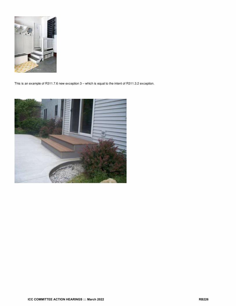
This is an example of R311.7.6 new exception 3 – which is equal to the intent of R311.3.2 exception.
ICC COMMITTEE ACTION HEARINGS ::: March 2022 RB226

This proposal is submitted by the ICC Building Code Action Committee (BCAC)..
BCAC was established by the ICC Board of Directors in July 2011 to pursue opportunities to improve and enhance assigned International Codes orportions thereof. In 2020 and 2021 the BCAC has held several virtual meetings open to any interested party. In addition, there were numerous virtualWorking Group meetings for the current code development cycle, which included members of the committee as well as interested parties. Relateddocuments and reports are posted on the BCAC website at https://www.iccsafe.org/products-and-services/i-codes/code-development/cs/building-code-action-committee-bcac/.
Cost Impact: The code change proposal will not increase or decrease the cost of constructionThis proposal clarifies existing requirements and provides additional design options for door leading into attached garages. This option couldimprove safety without additional costs.
RB100-22
ICC COMMITTEE ACTION HEARINGS ::: March 2022 RB227

RB101-22IRC: R311.4
Proponents: Kevin Duerr-Clark, representing New York State Department of State ([email protected]); Gerard Hathaway,representing self ([email protected]); Daniel Carroll, representing New York State Department of State ([email protected])
2021 International Residential CodeRevise as follows:
R311.4 Vertical egress. Egress from basements andhabitable levels including habitable attics and basements that are not provided with an egressdoor in accordance with Section R311.2 shall be by a ramp in accordance with Section R311.8 or a stairway in accordance with Section R311.7.
Reason Statement: The way this section is worded has provided some confusion in interpretation by the code enforcement community. Byplacing basements at the end, and including the term habitable attics before it, some have interpreted that the word habitable applies to both atticsand basements. As supported by the ICC commentary to this section of code, this is intended to apply to all basements, not just habitable ones. Additionally, by saying habitable levels, habitable attics is already included. Therefore, to make it even cleaner, habitable attics can be removed fromthe statement. If it is preferred to leave habitable attics in to insure it is included, moving basements to the beginning is still necessary.
Cost Impact: The code change proposal will not increase or decrease the cost of constructionThis change is simply a clean up of existing text to increase clarity. It does not change the actual provision based on how the ICC commentaryinterprets the text.
RB101-22
ICC COMMITTEE ACTION HEARINGS ::: March 2022 RB228

RB102-22IRC: R311.7.5.2 (New), R311.7.5.2, R311.7.5.2.1
Proponents: David Cooper, representing Stairbuilders and Manufacturers Association ([email protected])
2021 International Residential CodeAdd new text as follows:
R311.7.5.2 Stair treads. Treads of stairs shall comply with section R311.7.5.2.1 or R311.7.5.2.2.
Revise as follows:
R311.7.5.2 R311.7.5.2.1 Treads Rectangular treads. The tread depth shall be not less than 10 inches (254 mm). The tread depth shall bemeasured horizontally between the vertical planes of the foremost projection of adjacent treads and at a right angle to the tread’s leading edge. Thegreatest tread depth within any flight of stairs shall not exceed the smallest by more than / inch (9.5 mm).
R311.7.5.2.1 R311.7.5.2.2 Winder treads. Winder treads shall have a tread depth of not less than 10 inches (254 mm) measured between thevertical planes of the foremost projection of adjacent treads at the intersections with the walkline. Winder treads shall have a tread depth of not lessthan 6 inches (152 mm) at any point within the clear width of the stair. Within any flight of stairs, the largest winder tread depth at the walkline shallnot exceed the smallest winder tread by more than / inch (9.5 mm). Consistently shaped winders at the walkline shall be allowed within the sameflight of stairs as rectangular treads and shall not be required to be within / inch (9.5 mm) of the rectangular tread depth.
Exception: The tread depth at spiral stairways shall be in accordance with Section R311.7.10.1.
Reason Statement: Rectangular treads are not clearly identified in the code except by reference . Although both Rectangular and Winder aretypes of stair treads the code currently creates confusion by associating the winder requirements as a subsection of the requirements forrectangular treads.The tread section title has been changed and a charging statement added to reference a new subsection for rectangular treads as well as thewinder tread subsection. The text of the tread section has been moved without change to a new subsection titled "Rectangular treads". Rectangular treads, and winders are two uniquely different types of stair treads. The term “rectangular treads” is used in the last sentence of thewinder requirements to differentiate the two types of treads by their shape and is also used within the definition of flight.
[RB] FLIGHT. A continuous run of rectangular treads or winders or combination thereof from one landing to another. (Emphasis added)
The code is easier to understand as suggested here. It clearly identifies two separate sections with titles precisely correlated with each of thedescribed requirements. This proposal is editorial in nature and makes no changes to the requirements.We would appreciate your approval as submitted.
Cost Impact: The code change proposal will not increase or decrease the cost of constructionThis proposal is editorial in nature by providing charging language to separate requirements for stairway treads. There are no technical change tothe requirements.
RB102-22
38
38
38
ICC COMMITTEE ACTION HEARINGS ::: March 2022 RB229

RB103-22IRC: R311.7.5.3
Proponents: David Cooper, representing Stairbuilders and Manufacturers Association ([email protected])
2021 International Residential CodeRevise as follows:
R311.7.5.3 Nosings. Nosings at treads Treads, landings and floors of stairways shall have a radius of curvature at the nosing not greater than /inch (14 mm) or a bevel not greater than / inch (12.7 mm). A nosing projection not less than / inch (19 mm) and not more than 1 / inches (32mm) shall be provided on stairways. The greatest nosing projection shall not exceed the smallest nosing projection by more than / inch (9.5 mm)within a stairway.
Exception: A nosing projection is not required where the tread depth is not less than 11 inches (279 mm).
Reason Statement: Nosing is a defined term in both the IRC and IBC as: "The leading edge of treads of stairs and of landings at the top of stairwayflights". Deleting the confusing redundant use of the term at the beginning of the sentence is editorial and clarifies. Please approve as submitted.
Cost Impact: The code change proposal will not increase or decrease the cost of constructionThis change is and editorial revision for clarification with no technical changes to the requirements for nosings.
RB103-22
916
12
34
14
38
ICC COMMITTEE ACTION HEARINGS ::: March 2022 RB230

RB104-22IRC: R311.7.5.3
Proponents: Glenn Mathewson, representing North American Deck and Railing Association ([email protected])
2021 International Residential CodeRevise as follows:
R311.7.5.3 Nosings. Nosings at treads, landings and floors of stairways shall have a radius of curvature at the nosing not greater than / inch (14mm) or a bevel not greater than / inch (12.7 mm). A nosing projection not less than / inch (19 mm) and not more than 1 / inches (32 mm) shallbe provided on stairways. The greatest nosing projection shall not exceed the smallest nosing projection by more than / inch (9.5 mm) within aflight of stairs stairway.
Exception: A nosing projection is not required where the tread depth is not less than 11 inches (279 mm).
Reason Statement: Both riser height in R311.7.5.1 and tread depth in R311.7.5.2 are only required to be uniform “within any flight of stairs” butnosing projection references “stairway” which would include all the flights in a single stairway. If the riser height and tread depth can change after alanding, so should the nosing projection be permitted to change.It is not uncommon for a single flight of exterior deck stairs to land on a concrete landing. It is also not uncommon for this landing to have a singletread and two risers down to grade, making it another stair in the stairway. It is common to use an 11 inch concrete tread depth to eliminate anosing projection. There is no reason that the concrete flight of stairs would need a nosing projection simply because the deck stair flight has themand they share a path in a stairway to reach grade.
Cost Impact: The code change proposal will not increase or decrease the cost of constructionThis proposal expands the design freedom of stairway construction without reducing safety. In itself, this does not affect the cost of construction.
RB104-22
916
12
34
14
38
ICC COMMITTEE ACTION HEARINGS ::: March 2022 RB231

RB105-22IRC: R311.7.5.3
Proponents: Thomas Zuzik Jr, representing National Ornamental & Miscellaneous Metals Association (NOMMA) ([email protected])
2021 International Residential Code
SECTION R311MEANS OF EGRESS
Revise as follows:
R311.7.5.3 Nosings. Nosings at treads, landings and floors of stairways shall have a radius of curvature at the nosing not greater than / inch (14mm) or a bevel not greater than / inch (12.7 mm). A nosing projection not less than / inch (19 mm) and not more than 1 / inches (32 mm) shallbe provided on stairways. The greatest nosing projection shall not exceed the smallest nosing projection by more than / inch (9.5 mm) within astairway flight and the landing at the top of the flight.
Exception: A nosing projection is not required where the tread depth is not less than 11 inches (279 mm).
[RB] FLIGHT. A continuous run of rectangular treads or winders or combination thereof from one landing to another.
[RB] NOSING. The leading edge of treads of stairs and of landings at the top of stairway flights.
[RB] RISER (STAIR). The vertical component of a step or stair.
[RB] STAIR. A change in elevation, consisting of one or more risers.
[RB] STAIRWAY. One or more flights of stairs, either interior or exterior, with the necessary landings and connecting platforms to form acontinuous and uninterrupted passage from one level to another.
Reason Statement: Both the IRC & the IBC regulate tread depth, riser height and nosing projection within a flight of stairs. Stairways are made upof multiple flights of stairs with landings in between. Each flight is allowed to have different riser heights and tread depths, however the currentlanguage locks in the nosing projection to all the flights within the stairway, rather than just the flight. The reason the current language uses stairwayover flight is that the nosing on the top landing needs to be included with the flight to make sure the nosing projection on both meet the criteria withinR311.7.5.3. Because the top landing's nosing is not a part of the definition of a flight, see definition, the additional text "and the landing at the top of theflight" is being added to tie-in the top landing's nosing to the flight it serves and clarify that the 3/8" maximum between the smallest and largest nosingprojection includes the top landing for the flight.
Cost Impact: The code change proposal will not increase or decrease the cost of constructionThe proposal is not adding or subtracting any technical requirements within the code which will increase or decrease cost.
RB105-22
916
12
34
14
38
ICC COMMITTEE ACTION HEARINGS ::: March 2022 RB232
RB106-22IRC: R311.7.5.3
Proponents: Thomas Zuzik Jr, representing National Ornamental & Miscellaneous Metals Association (NOMMA) ([email protected])
2021 International Residential Code
SECTION R311MEANS OF EGRESS
Revise as follows:
R311.7.5.3 Nosings. Nosings at treads, landings and floors of stairways shall have a radius of curvature at the nosing not greater than / inch (14mm) or a bevel not greater than / inch (12.7 mm). A nosing projection not less than / inch (19 mm) and not more than 1 / inches (32 mm) shallbe provided on stairways. The greatest nosing projection shall not exceed the smallest nosing projection by more than / inch (9.5 mm) within astairway.
Exception Exceptions:
1. A nosing projection is not required where the tread depth is not less than 11 inches (279 mm).
2. Where risers are open, the maximum nosing projection shall be permitted to exceed 1 1/4 inches (32 mm).
[RB] FLIGHT. A continuous run of rectangular treads or winders or combination thereof from one landing to another.
[RB] NOSING. The leading edge of treads of stairs and of landings at the top of stairway flights.
[RB] STAIR. A change in elevation, consisting of one or more risers.
[RB] STAIRWAY. One or more flights of stairs, either interior or exterior, with the necessary landings and connecting platforms to form acontinuous and uninterrupted passage from one level to another.
Reason Statement: This is the second of 2 code change proposals to allow an exception to the code to exceed the maximum nosing projectionlimit of 1-1/4" on stair treads when open risers are allowed and installed within a stair flight. The first code change was submitted during the Part Aportion of this current code cycle, proposal number E64-21 was approved by the means of egress committee in the spring of 2021, the final actionhearing vote in the fall of 2021 and the government members vote in 2021 and is slated to be published in the model 2024 IBC. The code changeallows for when open risers are within a stair flight, a user's foot can exceed the end of the tread on ascent. Allowing the tread to be extended furtherunder the tread above, nosing, allows for more tread surface and foot support. This code change will provide uniformity between the IBC and IRC.
Bibliography: Approved Code Change E64-21 for the PART A Means of Egress 2024 Code Cycle
Cost Impact: The code change proposal will decrease the cost of constructionAny cost impact will be through the non-alteration of stock materials by the manufacture and or installer during fabrication and or installation, whichwould now not be required to be altered.
EX: Stock 12-inch tread, where the location can only accommodate a 10-inch tread depth, the material would not be required to be cut down oraltered for the 3/4-inch, to reduce the nosing projection to meet the maximum 1.25-inch current requirement (10” + 1.25” = 11.25”).
RB106-22
916
12
34
14
38
ICC COMMITTEE ACTION HEARINGS ::: March 2022 RB233

RB107-22IRC: R311.7.6
Proponents: Glenn Mathewson, representing Self ([email protected])
2021 International Residential CodeRevise as follows:
R311.7.6 Landings for stairways. There shall be a floor or landing at the top and bottom of each flight of stairs stairway. The width perpendicular tothe direction of travel shall be not less than the width of the flight served. For landings of shapes other than square or rectangular, the depth at thewalk line and the total area shall be not less than that of a quarter circle with a radius equal to the required landing width. Where the stairway has astraight run, the depth in the direction of travel shall be not less than 36 inches (914 mm).
Exception. The top landing of an interior stairway, including those in an enclosed garage, shall be permitted to be on the other side of a doorlocated at the top of the stairway A floor or landing is not required at the top of an interior flight of stairs, including stairs in an enclosed garage,provided that a the door does not swing over the stairs.
Reason Statement: A stairway is defined as all stairs and necessary landings. It may be made up of multiple stairs/flights. Therefore, it is actuallyeach “flight of stairs” that requires a landing at top and bottom. The current exception for interior stairway top landings is poorly worded and doesnot present the intent. The intent is that there is still a landing surface at the top of interior stairways, but that it can be on the other side of a door. As worded, the sentence literally states that a landing is not required at the top of the stairway. Period. The mention of a door is only that it can’tswing over the stairs, not that there must be a door at all. But worse… it says a landing is not required at the top of a “flight of stairs” not the wholestairway. So that could be an intermediate landing between two “flights of stairs” that is not required, when the real intent is on the top landing of the“stairway” The top landing of the top flight of stairs.
Cost Impact: The code change proposal will not increase or decrease the cost of constructionThis proposal clarifies the intent of the code as it is most likely already being interpreted. Therefore there is no definitive change in the cost ofconstruction in any direction.
RB107-22
ICC COMMITTEE ACTION HEARINGS ::: March 2022 RB234

RB108-22IRC: R311.7.6
Proponents: Glenn Mathewson, representing Self ([email protected])
2021 International Residential CodeRevise as follows:
R311.7.6 Landings for stairways. There shall be a floor or landing at the top and bottom of each stairway. The width perpendicular to the directionof travel shall be not less than the width of the flight served. For landings of shapes other than square or rectangular, the depth at the walk line andthe total area shall be not less than that of a quarter circle with a radius equal to the required landing width. Where the stairway has a straight run,the depth in the direction of travel shall be not less than 36 inches (914 mm).
Exception: Exceptions:
1. A floor or landing is not required at the top of an interior flight of stairs, including stairs in an enclosed garage, provided that a door doesnot swing over the stairs.
2. Exterior stairways to grade with three or fewer risers serving a deck, porch or patio shall have a minimum bottom landing width of 36inches, provided the stairway is not the required access to grade serving the required egress door.
Reason Statement: This proposal specifically addresses the popular design of ground level backyard decks desired by your fellow Americans. Ground level decks with monumental wrap-around stairs are a wonderful way to create a deck that is an extension of the house and an extension ofthe yard. However, once a single tread is built around the edge of a deck only 14 inches above grade, two risers are created and you now have aflight of stairs and a stairway, and that means a landing at the bottom. In increasing frequency, building authorities across the country areinterpreting the bottom landing of a stairways to require a solid, manufactured surface, such as concrete, flagstone, or other hardscaping. Some ofthese authorities would require the lawn cut out and a manufactured surface installed around the entire edge of the deck (width of the stairs) and 3feet out into the yard. For a single tread this is nearly four feet into the yard. It is my opinion that this is excessive guidance to governments for theregulation of our backyards, and will only serve to further alienate the public's trust in the code.
This proposal will retain a "landing", however interpreted, for only a minimum width of 36 inches on very specific stairways. It is expected thatoccupants seeking a safer stairway portion in a private home will choose this portion of the stairway. The IBC acknowledges an expectation for thegeneral public in an unfamiliar location to similarly recognize the safer place for their travel on monumental stairways. Though in regard to handrailsand not landings, the idea of reduced safety features dependent on the purposefully choice of travel by the occupant is identical. Section 1014.9 ofthe IBC does not require intermediate handrails on monumental stairways outside of the direct path of egress travel, regardless of the number ofrisers.I think we cant trust our neighbors to navigate their own backyard monumental stairways without our complete protection.
The limit of 3 risers was selected as another recognition of reduced hazard, as a handrail is not required. The photo below is just one example ofmany found in happy backyards across the US. This is an example of how a minimum width landing, as required or interpreted, is provided. However, the remaining edge of the deck can flow into the yard without removing the yard. To tell this homeowner that to meet the minimum safetycodes they need to either remove the steps and leave a 20 inch drop, or cut out the grass and install pavers is likely the last conversation anyinspector will ever have with them.
ICC COMMITTEE ACTION HEARINGS ::: March 2022 RB235

Cost Impact: The code change proposal will decrease the cost of constructionThis proposal will decrease the cost of construction by whatever excessive expense of landing material and labor is being required by certainbuilding officials.
RB108-22
ICC COMMITTEE ACTION HEARINGS ::: March 2022 RB236

RB109-22IRC: R311.7.7.1 (New)
Proponents: Timothy Pate, representing City and County of Broomfield ([email protected])
2021 International Residential CodeR311.7.7 Stairway walking surface. The walking surface of treads and landings of stairways shall be sloped not steeper than 1 unit vertical in 48units horizontal (2-percent slope).
Exception: Where the surface of a landing is required elsewhere in the code to drain surface water, the walking surface of the landing shall besloped not steeper than 1 unit vertical in 20 units horizontal (5-percent slope) in the direction of travel.
Add new text as follows:
R311.7.7.1 Landings at grade. Stairway landings located at grade shall be solid and stable.
Reason Statement: This proposal is to add language for what type of surface a stair landing at grade needs to be. Currently the IRC would allowany surface which would include grass or dirt and only says the maximum slope. Grass will not always be there if homeowner does not take care ofit and dirt turns into mud when wet. Landings are a very important component of the stairway and surface needs to be solid and stable to allow a safe area when exiting the flight ofstairs.
Cost Impact: The code change proposal will increase the cost of constructionThis code change will increase construction in jurisdictions that now allow grass or dirt for stair landings at grade
RB109-22
ICC COMMITTEE ACTION HEARINGS ::: March 2022 RB237

RB110-22IRC: R311.7.8, R311.7.11.2, R311.7.12.2, R311.8.3, R311.8.3.1, R311.8.3.2, R311.8.3.3, SECTION R312 (New), R312.1 (New), R311.7.8.1,R311.7.8.2, R311.7.8.3, R311.7.8.4, R311.7.8.5, R311.7.8.6
Proponents: Thomas Zuzik Jr, representing National Ornamental & Miscellaneous Metals Association (NOMMA) ([email protected])
2021 International Residential Code[RB] HANDRAIL. A horizontal or sloping rail intended for grasping by the hand for guidance or support.
SECTION R311MEANS OF EGRESS
Revise as follows:
R311.7.8 Handrails. Handrails shall be provided on not less than one side of each flight of stairs with four or more risers and shall comply withSection R312.
R311.7.11.2 Handrails of alternating tread devices. Handrails shall be provided on both sides of alternating tread devices and shall comply withSection R312. Sections R311.7.8.2 through R311.7.8.6. Handrail height shall be uniform, not less than 30 inches (762 mm) and not more than 34inches (864 mm).
R311.7.12.2 Handrails of ship's ladders. Handrails shall be provided on both sides of ship's ladders and shall comply with Section R312.Sections R311.7.8.2 through R311.7.8.6. Handrail height shall be uniform, not less than 30 inches (762 mm) and not more than 34 inches (864 mm).
R311.8.3 Handrails required. Handrails shall be provided on not less than one side of ramps exceeding a slope of 1 unit vertical in 12 unitshorizontal (8.33-percent slope) and shall comply with Section R312.
Delete without substitution:
R311.8.3.1 Height. Handrail height, measured above the finished surface of the ramp slope, shall be not less than 34 inches (864 mm) and notmore than 38 inches (965 mm).
R311.8.3.2 Grip size. Handrails on ramps shall comply with Section R311.7.8.5.
R311.8.3.3 Continuity. Handrails where required on ramps shall be continuous for the full length of the ramp. Handrail ends shall be returned orshall terminate in newel posts or safety terminals. Handrails adjacent to a wall shall have a space of not less than 1 / inches (38 mm) between thewall and the handrails.
Add new text as follows:
SECTION R312HANDRAILS
R312.1 General. Handrails shall comply with Section R312.
Revise as follows:
R311.7.8.1 R312.2 Height. Handrail height, measured vertically from the sloped plane adjoining the tread nosing, or finish surface of ramp slope,shall be not less than 34 inches (864 mm) and not more than 38 inches (965 mm). Handrail height on alternating tread devices and ship'sladders shall be uniform and not less than 30 inches (762 mm) and not more than 34 inches (864 mm).
Exceptions:
1. The use of a volute, turnout or starting easing shall be allowed over the lowest tread.
2. Where handrail fittings or bendings are used to provide continuous transition between flights, transitions at winder treads, the transitionfrom handrail to guard, or used at the start of a flight, the handrail height at the fittings or bendings shall be permitted to exceed 38 inches(965 mm).
R311.7.8.2 R312.3 Handrail projection. Handrails shall not project more than 4 / inches (114 mm) on either side of the stairway or ramp.
Exception: Where nosings of landings, floors or passing flights project into the stairway reducing the clearance at passing handrails, handrailsshall project not more than 6 / inches (165 mm) into the stairway, provided that the stair width and handrail clearance are not reduced to lessthan that required.
12
12
12
1
ICC COMMITTEE ACTION HEARINGS ::: March 2022 RB238

R311.7.8.3 R312.4 Handrail clearance. Handrails adjacent to a wall shall have a space of not less than 1 / inches (38 mm) between the wall andthe handrails.
R311.7.8.4 R312.5 Continuity. Handrails shall be continuous for the full length of the flight, from a point directly above the top riser of the flight to apoint directly above the lowest riser of the flight. Handrails where required for ramps shall be continuous for the full length of the ramp. Handrail endsshall be returned toward a wall, guard walking surface continuous to itself, or terminate to a post.
Exceptions:
1. Handrail continuity shall be permitted to be interrupted by a newel post at a turn in a flight with winders, at a landing, or over the lowesttread.
2. A volute, turnout or starting easing shall be allowed to terminate over the lowest tread and over the top landing.
R311.7.8.5 R312.6 Grip size. Required handrails shall be of one of the following types or provide equivalent graspability.
1. Type I. Handrails with a circular cross section shall have an outside diameter of not less than 1 / inches (32 mm) and not greater than 2inches (51 mm). If the handrail is not circular, it shall have a perimeter of not less than 4 inches (102 mm) and not greater than 6 / inches(160 mm) and a cross section of not more than 2 / inches (57 mm). Edges shall have a radius of not less than 0.01 inch (0.25 mm).
2. Type II. Handrails with a perimeter greater than 6 / inches (160 mm) shall have a graspable finger recess area on both sides of the profile.The finger recess shall begin within / inch (19 mm) measured vertically from the tallest portion of the profile and have a depth of not lessthan / inch (8 mm) within / inch (22 mm) below the widest portion of the profile. This required depth shall continue for not less than / inch(10 mm) to a level that is not less than 1 / inches (45 mm) below the tallest portion of the profile. The width of the handrail above the recessshall be not less than 1 / inches (32 mm) and not more than 2 / inches (70 mm). Edges shall have a radius of not less than 0.01 inch (0.25mm).
R311.7.8.6 R312.7 Exterior plastic composite handrails. Plastic composite exterior handrails shall also comply with the requirements of SectionR507.2.2.
Reason Statement: Currently the 2021 IRC and prior editions duplicated the requirements for handrails under both the stairway and ramp sections,while also duplicating height requirements under alternating treads and ships ladders.This proposal creates a separate new section for all Handrail's and consolidates the duplicated information in the code, without changing any of theparameters except as noted below.
Specific changes to the text Noted:
1. When moving section R311.8.3.3 to R311.9.4, changed "on" to "for"1. "required on ramps" now reads "required for ramps"
2. In the 2021 IRC code cycle Section R311.7.8.4 removed the catch all wording Safety Terminals, and replaced it with "shall be returned towarda wall, guard walking surface continuous to itself, or terminate to a post.". However, the same change was not updated to Section R311.8.3.3for ramps. This left the code with 2 different termination requirements, one for stairs and one for ramps. This code change returns handrailson stairways and ramps to the same requirements.
3. The pointers in R311.11.2 and R311.12.2 text deleted and moved to Section R312.2 Height.4. "or ramp" was added to the section R312.3 Handrail Projection, this does add a new requirement to ramp handrails within the IRC, it is the
same in the IBC.5. We inserted "also" in Section R312.7 which was moved from R311.7.8.6, this was done to clarify that plastic composite handrails need to
comply with R312 and R507.2.2, not just R507.2.2.
This code change clarifies and consolidates the handrail requirements under one area within the code and we believe simplifies the code byremoving all the duplications.
Cost Impact: The code change proposal will not increase or decrease the cost of constructionThis proposal consolidates duplicate information spread out over many sections and rearranges the provisions into one logical section. There isonly one slight technical change is section R312.3, which I believe does not increase cost, as the same pre-manufactured handrail bracket materialsare used on stairs as ramps, and stairs have the requirement already in place. Except for this one technical change the rest of the content is justeditorial and rearrangement of the text into a more logical order and therefore, there will be no cost impact when approving this proposal.
RB110-22
12
14
14
14
14
34
516
78
38
34
14
34
ICC COMMITTEE ACTION HEARINGS ::: March 2022 RB239
RB111-22IRC: R311.7.8.4, R311.8.3.3
Proponents: David Cooper, representing Stairbuilders and Manufacturers Association ([email protected])
2021 International Residential CodeRevise as follows:
R311.7.8.4 Continuity. Handrails shall be continuous for the full length of the flight, from a point directly above the top riser of the flight to a pointdirectly above the lowest riser of the flight. Handrail ends shall be returned toward or terminate at a post, wall, guard , walking surface , or wrapcontinuous to itself or terminate to a post. The end of the handrail shall not form a gap more than 1/4 inch (6.4 mm) from the adjacent surface.
Exceptions:
1. Handrail continuity shall be permitted to be interrupted by a newel post at a turn in a flight with winders, at a landing, or over the lowesttread.
2. A volute, turnout or starting easing shall be allowed to terminate over the lowest tread and over the top landing.
R311.8.3.3 Continuity. Handrails where required on ramps shall be continuous for the full length of the ramp. Handrail ends shall be returnedtoward or shall terminate in at newel posts or safety terminals a post, wall , guard, walking surface, or wrap continuous to itself. The end of thehandrail shall not form a gap more than 1/4 inch (6.4 mm) from the adjacent surface. Handrails adjacent to a wall shall have a space of not less than1 / inches (38 mm) between the wall and the handrails.
Reason Statement: In addition to providing for a continuous handrail the intent of this section has been to restrict open handrails such that they donot snag loose clothing or objects carried that might cause an accidental fall. In the last cycle we worked with others to successfully eliminate theterm safety terminal that had been open to wide interpretation. In doing so we tried to better define what should be considered safe terminations ofthe end of the handrail. This change clarifies that a handrail can terminate at any of the described surfaces not just a post as well as be returnedtoward all these same surfaces. In the added sentence we have included a limitation for any gap that might be formed between the end of thehandrail and the adjacent surface when handrails are returned toward a surface to maintain the intent to restrict the possibility of snagging looseclothing or carried objects. ICC staff pointed out that the term safety terminal still remained in the ramp section under continuity and requested we address this in this cycle. This proposal does so and if passed both sections will have parallel language.
This proposal provides needed clarification for interpretation and enforcement of handrail terminations on both stairs and ramps.
Cost Impact: The code change proposal will not increase or decrease the cost of constructionThis proposal follows the original intent of the provisions for handrail extensions and provides additional information on what is required to meet thatintent, however, there are no technical changes to the requirements that will result in an increase in cost.
RB111-22
12
ICC COMMITTEE ACTION HEARINGS ::: March 2022 RB240

RB112-22IRC: R311.7.8.4
Proponents: Thomas Zuzik Jr, representing National Ornamental & Miscellaneous Metals Association (NOMMA) ([email protected])
2021 International Residential Code
SECTION R311MEANS OF EGRESS
Revise as follows:
R311.7.8.4 Continuity. Handrails shall be continuous for the full length of the flight, from a point directly above the top riser nosing of the flight to apoint directly above the lowest riser nosing of the flight. Handrail ends shall be returned toward a wall, guard walking surface continuous to itself, orterminate to a post.
Exceptions:
1. Handrail continuity shall be permitted to be interrupted by a newel post at a turn in a flight with winders, at a landing, or over the lowesttread.
2. A volute, turnout or starting easing shall be allowed to terminate over the lowest tread and over the top landing.
Reason Statement: With the addition of the defined term nosing in both the IRC and IBC the use of "riser" for the vertical and horizontal intersectionpoint of the lowest tread edge and top landing edge is no longer correct and the correct term is nosing. This term and measuring point werechanged in the Part A cycle and will be the point of measurement where handrail extensions are to be measured from in the 2024 IBC. Keeping theterminology, the same in both codes will prevent confusion within the industry as adoption of the newest model codes are done over time.
Cost Impact: The code change proposal will not increase or decrease the cost of constructionThis is an editorial reorganization of two defined terms within the requirement to the more appropriate term and does not change any technicalrequirements that will increase or decrease cost.
RB112-22
ICC COMMITTEE ACTION HEARINGS ::: March 2022 RB241

RB113-22IRC: R311.7.8.4
Proponents: Thomas Zuzik Jr, representing National Ornamental & Miscellaneous Metals Association (NOMMA) ([email protected])
2021 International Residential CodeRevise as follows:
R311.7.8.4 Continuity. Handrails shall be continuous for the full length of the flight, from a point directly above the top riser of the flight to a pointdirectly above the lowest riser of the flight. Handrail ends shall be returned toward a wall, guard, walking surface, continuous to itself, or terminate toa post.
Exceptions:
1. Handrail continuity shall be permitted to be interrupted by a newel post at a turn in a flight with winders, at a landing, or over the lowesttread.
2. A volute, turnout or starting easing shall be allowed to terminate over the lowest tread and over the top or bottom landings landing.
Reason Statement: Exception 2 for volutes, turnouts and starting easing's, added terminating over the top landing allowed. However, it left outbottom landings for volutes, turnouts and starting easing's. This proposal adds the clarification to the exception.
Cost Impact: The code change proposal will not increase or decrease the cost of constructionThe proposal is adding minimal technical clarification which was removed with the deletion of the generalized term “Safety Termination” last model2021 IRC publication within the code and just reaffirming an implied allowance which will not increase or decrease cost.
RB113-22
ICC COMMITTEE ACTION HEARINGS ::: March 2022 RB242

RB114-22IRC: R311.7.9 (New), R311.7.9.1 (New), R311.7.9.2 (New), R311.7.9.3 (New), R311.7.9.4 (New), AJ109.8, AJ109.8.1, AJ109.8.2, AJ109.8.3
Proponents: Ardel Jala, representing Seattle Department of Construction & Inspections ([email protected]); Micah Chappell, representingSeattle Department of Construction & Inspections ([email protected])
2021 International Residential CodeAdd new text as follows:
R311.7.9 Stairways in existing buildings. Where an existing stair is completely reconstructed or an existing stair serves habitable space createdby a change of occupancy, the stairs shall comply with the requirements of this code for new construction. Alterations to existing stairs shall complywith the Sections R311.7.8 and R311.7.9.1 through R311.7.9.4.
R311.7.9.1 Stair width. Existing stairs not otherwise being altered or modified shall be permitted to maintain their current clear width at, above andbelow existing handrails.
R311.7.9.2 Stair headroom. Headroom height on existing stairs being altered or modified shall not be reduced below the existing stairway finishedheadroom. Existing stairs not otherwise being altered shall be permitted to maintain the current finished headroom.
R311.7.9.3 Stair landing. Landings serving existing stairs being altered or modified shall not be reduced below the existing stairway landing depthand width. Existing stairs not otherwise being altered shall be permitted to maintain the current landing depth and width.
R311.7.9.4 Stair treads and risers. An existing stairway shall not be required to comply with Section R311.7.5 where the existing space andconstruction does not allow a reduction in pitch or slope. Where risers are added to an existing stair, the tread and riser dimensions of the addedrisers shall match the existing stair.
Revise as follows:
AJ109.8 Stairs. .
Delete without substitution:
AJ109.8.1 Stair width. Existing basement stairs and handrails not otherwise being altered or modified shall be permitted to maintain their currentclear width at, above and below existing handrails.
AJ109.8.2 Stair headroom. Headroom height on existing basement stairs being altered or modified shall not be reduced below the existing stairwayfinished headroom. Existing basement stairs not otherwise being altered shall be permitted to maintain the current finished headroom.
AJ109.8.3 Stair landing. Landings serving existing basement stairs being altered or modified shall not be reduced below the existing stairwaylanding depth and width. Existing basement stairs not otherwise being altered shall be permitted to maintain the current landing depth and width.
Reason Statement: This is one of (4) proposals that pull existing "breaks" found in Appendix J for Existing Buildings into the main body of the code. Each proposal permits flexibility from meeting full code compliance for existing construction while maintaining a reasonable level of safety. This proposal creates a new section for existing stairs that incorporates provisions from Section AJ109.8 into the main body of the code and alignsthe IRC existing stair requirements with flexibility currently found in IEBC. The proposal provides breaks on full compliance for stair width, headroomand landings for alterations to existing stairs. The proposal also gives a break for stair treads and risers that is consistent with a more general breakfor existing stairs in IEBC Section 506.3.
Alterations, repairs, and reconfiguration of spaces often require altering, extending or completely rebuilding the existing stairs. However, existingstairs may not conform to current code though they were compliant at the time they were built. For example, legacy codes permitted a residentialstair to have an 8 inch riser and a 9 inch tread versus today's rise/run requirements of 7 3/4 inches and 10 inches. Reducing the pitch to make thestair comply requires enlarging the stair footprint. It can be impractical to reframe the stair opening or reconfigure the floor plan where the existingspace and construction does not easily accommodate a larger stair footprint.
In this proposal, alterations to existing stairs are permitted some flexibility. Existing stairs not being altered are allowed to remain as existing non-conforming. Sections R311.7.9.1 through R311.7.9.3 brings the code provisions from Appendix J Sections AJ109.8.1 through AJ109.8.3 into themain body of the code and deletes them from Appendix J. These sections state that stair width, headroom, and landing shall not be made more non-conforming but otherwise are permitted to maintain their current dimensions. While the breaks in Appendix J apply to existing basement stairs only,these allowances seemed reasonable to extend to all existing stairs.
Section R311.7.9.4 of this proposal applies to stair treads and risers in existing buildings. This section is based on IEBC Section 506.3 which permitsa stair to not comply with new stair provisions when the existing space does not permit the reduced pitch or slope. In the proposal, I did not copythe IEBC language over in its entirety because the other sections of this proposal already provide breaks on stair width, headroom and landing. Forclarity, I revised the IEBC language to apply to the tread and riser requirements for the existing stairs.
ICC COMMITTEE ACTION HEARINGS ::: March 2022 RB243

Section R311.7.9.4 also adds an allowance to match the tread and riser dimensions of an existing stair when extending the run of a stair. Thisallows an owner to extend an existing stair that has an 8 inch rise and 9 inch tread to be extended with risers that match the existing rise and runand that do not create a tripping hazard by a reduction in pitch mid-run.
Section R311.7.9 makes it clear that when a stair in an existing building is completely rebuilt, those stairs must be made fully compliant. Forexample, an existing stair is demolished and a new stair constructed as part of alterations. This should be regulated as a new stair as this is anopportunity for the stair to be built compliant to current code.
Section R3117.9 also makes it clear that when a stair is serving an area where a change of occupancy creates habitable space, that the existingstair must be made fully compliant. This requirement is consistent with Section R102.7.1 which states the alterations shall not cause an existingstructure to become less compliant.
In summary, while Section R104.10 allows the building official discretion to offer flexibility where full compliance is not practical, the code does notprovide explicit relief from full compliance with new code requirements for alterations to existing stairs. This proposal clarifies when full compliance isrequired and provides flexibility from full code compliance for alterations to an existing stair. This proposal provides greater flexibility for existing staircode compliance to homeowners wanting to maximize the usable square footage in their home.
Cost Impact: The code change proposal will decrease the cost of constructionThis code change proposal reduces the extent that an existing stair must be altered to meet new code requirements for an existing building that fallsunder the scoping of the IRC. With this additional flexibility explicitly stated in the code it eliminates the need for reframing floor openings toaccommodate larger stairs to meet current code, resulting in a savings in construction cost.
RB114-22
ICC COMMITTEE ACTION HEARINGS ::: March 2022 RB244
RB115-22IRC: R311.8.2
Proponents: Thomas Zuzik Jr, representing National Ornamental & Miscellaneous Metals Association (NOMMA) ([email protected])
2021 International Residential Code
SECTION R311MEANS OF EGRESS
Revise as follows:
R311.8 Ramps. Where required by this code or provided, ramps shall comply with this section.
Exception: Ramps not within or serving a building, porch or deck.
R311.8.1 Maximum slope. Ramps serving the egress door required by Section R311.2 shall have a slope of not more than 1 unit vertical in 12 unitshorizontal (8.3-percent slope).Other ramps shall have a maximum slope of 1 unit vertical in 8 units horizontal (12.5 percent).
Exception: Where it is technically infeasible to comply because of site constraints, ramps shall have a slope of not more than 1 unit vertical in 8units horizontal (12.5 percent).
Add new text as follows:
R311.8.2 Vertical Rise. The rise for any ramp run shall be 30 inches (762 mm) maximum.
Revise as follows:
R311.8.2 R311.8.3 Landings required. There shall be a floor or landing at the top and bottom of each ramp, where doors open onto ramps, andwhere ramps change directions. The width of the landing perpendicular to the ramp slope shall be not less than the width of the ramp. The depth ofthe landing in the direction of the ramp slope shall be not less than 36 inches (914 mm).
R311.8.3 R311.8.4 Handrails required. Handrails shall be provided on not less than one side of ramps exceeding a slope of 1 unit vertical in 12units horizontal (8.33-percent slope).
R311.8.3.1 R311.8.4.1 Height. Handrail height, measured above the finished surface of the ramp slope, shall be not less than 34 inches (864 mm)and not more than 38 inches (965 mm).
R311.8.3.2 R311.8.4.2 Grip size. Handrails on ramps shall comply with Section R311.7.8.5.
R311.8.3.3 R311.8.4.3 Continuity. Handrails where required on ramps shall be continuous for the full length of the ramp. Handrail ends shall bereturned or shall terminate in newel posts or safety terminals. Handrails adjacent to a wall shall have a space of not less than 1 / inches (38 mm)between the wall and the handrails.
2021 International Building Code1012.4 Vertical rise. The rise for any ramp run shall be 30 inches (762 mm) maximum.
Reason Statement: The 2021 IRC and previous editions do not require handrails on any ramp with a slope of 1:12 or less, and also do not set alimit to the maximum vertical rise that a ramp can be between landings.The combination of a ramp with an infinite elevation incline and no handrails when the slope is 1:12 or less is perplexing.
This proposal is aiming to add a limit to the vertical rise a ramp can be and is basing the limit on the same maximum vertical rise set in Section1012.4 Vertical Rise of the IBC. Section included for reference above.
Though one might contend that it is unnecessary, the IRC only requires the Ramp serving the egress door required by Section R311.2 be limited tothe 1:12 maximum slope, and as thus allows ramps to not only exceed 30 inches of rise between landings, but you also have the possibility that asecondary ramp with a slope greater than 1:12 up to 1:8 can be installed to an unlimited vertical rise between landings also, even though the steeperslope would require a handrail on one side.
The vertical limit between landings for the rise of a ramp run is proposed to provide resting locations and control the possibility of never-ending rampruns between landings.
Bibliography: 2021 IBC Section 1012.4 Vertical Rise
Cost Impact: The code change proposal will increase the cost of construction
12
ICC COMMITTEE ACTION HEARINGS ::: March 2022 RB245

This requirement will increase the cost of initial construction when extremely long ramp runs are designed to be installed by requiring the addition ofanother landing, estimated cost to be $200.00 - $500.00, depending on geographical location and materials used.
RB115-22
ICC COMMITTEE ACTION HEARINGS ::: March 2022 RB246

RB116-22IRC: R311.8.3
Proponents: Thomas Zuzik Jr, representing National Ornamental & Miscellaneous Metals Association (NOMMA) ([email protected])
2021 International Residential Code[RB] RAMP. A walking surface that has a running slope steeper than 1 unit vertical in 20 units horizontal (5-percent slope).
SECTION R311MEANS OF EGRESS
Revise as follows:
R311.8 Ramps. Where required by this code or provided, ramps shall comply with this section.
Exception: Ramps not within or serving a building, porch or deck.
R311.8.1 Maximum slope. Ramps serving the egress door required by Section R311.2 shall have a slope of not more than 1 unit vertical in 12 unitshorizontal (8.3-percent slope).Other ramps shall have a maximum slope of 1 unit vertical in 8 units horizontal (12.5 percent).
Exception: Where it is technically infeasible to comply because of site constraints, ramps shall have a slope of not more than 1 unit vertical in 8units horizontal (12.5 percent).
R311.8.2 Landings required. There shall be a floor or landing at the top and bottom of each ramp, where doors open onto ramps, and whereramps change directions. The width of the landing perpendicular to the ramp slope shall be not less than the width of the ramp. The depth of thelanding in the direction of the ramp slope shall be not less than 36 inches (914 mm).
Revise as follows:
R311.8.3 Handrails required. Handrails shall be provided on not less than one side of ramps exceeding a slope of 1 unit vertical in 12 unitshorizontal (8.33-percent slope) or with a vertical rise greater than 16 1/2 inches (419 mm) between landings.
Reason Statement: The current language within the 2021 IRC has not changed since the publication of the 2000 IRC. The question as to why the IBC, ANSI 117.1 & ADA/ABA mandate handrails for ramps with a rise over 6 inches between landings but require nonefor any ramp within the IRC that does not exceed a slope of 1:12 has been a mystery in our research for this code change proposal, especiallysince the IRC does not limit the vertical rise between landings either.
The assumption we have found is that since entry walkways are not regulated under the IRC, and only the transition from grade to entry doorlanding. Most changes in elevation leading up to a new home are accomplished prior to the regulated area of the entry to the home.
Additionally, the IRC exempts handrails on stair flights with less than 4 risers, thus if we look at (4) 7.75" risers equaling 31", and this height beingmore than the 30" maximum rise for triggering guards, the common thought path is, that handrails are not normally required until reaching anelevation change that guards maybe required on the upper landing, and as thus handrails on ramps should follow suit with the precedent set for stairflights.
However, stair flights and ramps are different in their area of coverage. Stair flights ascend vastly quicker in a much smaller footprint than rampsdo. As thus the user transverses a much small distance to achieve the goal from landing to landing on a stair flight, then on a ramp run. Thequestion we sought was why does the IRC not require handrails at all on ramps of the same design that the IBC, ANSI A117.1 and ADA/ABArequires for ramps till exceeding a slope of 1:12 between landings? That is ramps starting at 1:20 up to 1:12 don't require handrails period. However,once you exceed 1:12 even for just 3 feet you are now required to have a handrail on the ramp within the IRC.
The trigger for when a handrail for a ramp is required is the pitch of the ramp exceeding a slope over 1:12 and up to 1:8 and has always beenrequired within the IRC. This is even for ramps technically below a rise of 6-inches. In reviewing all this information, we found a large disconnectbetween the IRC and every other requirement for when handrails are required on ramps.
As thus we looked for a limiting factor as to when a trigger would become reasonable for any ramp within the IRC to require a handrail and we usedthe formula of half the height of the trigger for stair flights, or 2 risers. We based our conclusion on that a ramp run at 1:12 would travelapproximately 8 times the distance to transverse half the height. With the 2-riser trigger for requiring a handrail for any ramp settled on forsubmitting this proposal, we next looked at the 15.5" height of 2 risers, and researched if the 7.75" riser height was being modified on adoption andfound that a good number of adopting jurisdictions modify the 7.75" riser height to allow for 8" standard masonry units to be used, and as thus to limitthis number would only invite more modification on adoption, as thus we selected 16.5-inches, as the additional 1-inch of height between landings ina ramp run is minimal and works also with the 7.75" model code maximum riser limit and also covers any jurisdiction modifying the code on adoptionto allow use of standard 8-inch masonry units.
ICC COMMITTEE ACTION HEARINGS ::: March 2022 RB247

Cost Impact: The code change proposal will increase the cost of constructionSince the code does not require the handrails for ramps of 1:12 or less slope, there is technically a definitely an increase in cost. However, due tothe limited nature of when the majority of ramps are installed for residences, our limited research believes that handrails are already being installed,and as thus, the cost increase is minimal in reality.
RB116-22
ICC COMMITTEE ACTION HEARINGS ::: March 2022 RB248
RB117-22IRC: R311.8.3.3, R311.8.3.4 (New)
Proponents: David Cooper, representing Stairbuilders and Manufacturers Association ([email protected])
2021 International Residential CodeRevise as follows:
R311.8.3.3 Continuity. Handrails where required on ramps shall be continuous for the full length of the ramp. Handrail ends shall be returned orshall terminate in newel posts or safety terminals.Handrails adjacent to a wall shall have a space of not less than 1 / inches (38 mm) between thewall and the handrails.
Add new text as follows:
R311.8.3.4 Handrail clearance. Handrails adjacent to a wall shall have a space of not less than 1 / inches (38 mm) between the wall and thehandrails.
Reason Statement: This proposal moves the last sentence related to handrail clearance to a new section with the intent to create a separate Handrail Clearance requirement within the ramp section. This change parallels the format of the same requirement in the stairway section for thepurpose of consistent formatting of requirements throughout the code.
Cost Impact: The code change proposal will not increase or decrease the cost of constructionThis is an editorial relocation of requirements for consistency with handrails for stairways and ramps. There will be no technical change to the coderequirements.
RB117-22
12
12
ICC COMMITTEE ACTION HEARINGS ::: March 2022 RB249

RB118-22IRC: R312.1.3
Proponents: Thomas Zuzik Jr, representing National Ornamental & Miscellaneous Metals Association (NOMMA) ([email protected])
2021 International Residential Code
SECTION R312GUARDS AND WINDOW FALL PROTECTION
Revise as follows:
R312.1.3 Opening limitations. Required guards shall not have openings from the walking surface to the required guard height that allow passageof a sphere 4 inches (102 mm) in diameter. Opening Limitations shall be determined without any force applied to the sphere.
Exceptions:
1. The triangular openings at the open side of stair, formed by the riser, tread and bottom rail of a guard, shall not allow passage of a sphere6 inches (153 mm) in diameter.
2. Guards on the open side of stairs shall not have openings that allow passage of a sphere 4 / inches (111 mm) in diameter.
Reason Statement: This code change simplifies any current and future debates by prescriptively clarifying that there is no force or load test on thesphere directly within the text of the IRC and is intended as written to be a simple dimensional measurement for pass or fail only.The Misconception
For as long as the sphere measurement method for opening limitations in guards has been in the model codes and adopted by jurisdictions therehas been a back room and front room debate as to the process.
It has been well established that the 4-inch, 4.375-inch and 6-inch sphere dimension is a dimensional measurement and not a load test.
Even with this, questions continue to be discussed across multiple local jurisdictions, forums and other forms of communication questioning if youare to take the correct dimensionally sized sphere and apply a force to shove it through the in-fill of guards and pool barriers, and what that forcelevel should be. The direction of these debates goes on within many jurisdictions and amongst the building enforcement industry less and less astime passes, but as with anything as new eyes enter the field, this discussion returns to the debate floor.
Standards & Criteria
For years, fabricators within the guard industry used the in-fill (part C) method for load testing in-fill in ASTM E935-00 to the loads specified in theR301.5 table of the IRC and some also applied the cone test (part D) methodology published in ASTM Standard E935-00, the part D cone test inE935-00 and prior versions was a methodology to verify the in-fill spread of balusters, however this has never been required in or by the model IRCor IBC codes. When the Part D test methodology was removed from the standard and not included in the ASTM E935-13 edition, and furthermorewas not replaced with any other similar in-fill load test directed at in-fill spread specifically, any pathway moving forward was removed as the newerstandard signifies progress.
ICC-ES AC-273-17, Acceptance Criteria for Handrails and Guards, in sections 4.2.1, 4.2.4 & 4.5 directs and points to follow the 1sqft area methodin Section 10.4 in ASTM E935-13, with no spread test on in-fill under load. Furthermore, the 1 square foot area is also repeated in ASTM D7032Section 6.2.2 In-Fill Load Test for the Wood-Plastic Composite and Plastic Lumber.
The guard industry follows established engineering practices and when engineers are presented to review projects and prepare project calculationpackages and sealed drawings, per the requirements set forth within the IRC, loads being applied to the 4-inch sphere are not within therequirements, nor is there a test method spelled out to follow for physical testing a load on the sphere directly. With the deletion of Part D of ASTME935-00 in ASTM E935-13, the only similar in-fill spread testing method was removed. Why it was removed is not known to this author, but one canextrapolate or assume it was because the model codes, nor ASCE-7 provide a direction or requirement for this type of load being applied to guardin-fill. With the lack of a requirement, the Part D test method was deleted to streamline the standard to follow the model codes and ASCE-7.
What has been followed by engineers and industry is to apply the loads with designated safety factors designated in the test standards, acceptancecriteria and within the code over a 1sqft area and then MEASURE for if a 4-inch sphere would pass through the in-fill without a load applied to thesphere directly, a simple measurement. This code change proposal removes any straying into whether inspectors should be carrying a certifiedfish-scale with an attachment method for 3 sizes of spheres for testing in-fill spreading and removes any mystery number pulled from the sky forimprovised field test hanging 50-lbs kettle bells or even requesting a special inspection without a standard for the engineers to follow.
NON-Applicable theories and information not in the Model Codes, Current Standards or ES Acceptance Criteria
38
ICC COMMITTEE ACTION HEARINGS ::: March 2022 RB250

To further extrapolate on a small and limited number of posts on forums that theorize applying a load directly to the sphere, we will theories howdoes one define the load? The requirements within the model 2021 IRC Table R301.5, under Guard in-fill components with note f, directs you to usea normal load of 50 pounds on an area equal to 1 square foot.
Now with the only in-fill load listed within the IRC in table R301.5 being for an area equal to 1 square foot established.
How does one extrapolate a number from this, we stipulate that it is not the intent of the code, nor listed in R301.5 for in-fill, however there are stillinspectors who inject this undesignated structural failure test as being required by code and to use the 50 pounds listed for a 1 square foot area, onthe sphere directly! We know the IRC does not specify this so,
Even if you pull from the sky and hypothesize a load should be applied to a sphere, which is only a portion of the 1 square foot area. Continuing withthis unsupported hypothesis that the area of the sphere is somehow connected, what number do you use? Do you use the area of a 4-inch circle,or do you use half the surface area of a 4-inch sphere, both are an area measurement of the sphere?
If we first start a theory with using 1 square foot covers both non-contact and contact area of the in-fill area, and then input the area of a 4-inchdiameter circle which is approximately 12.57 square inches, then divide the area of the circle by the area of 1square foot, 144 square inches, we get8.73%, and 8.73% of 50 pounds equals 4.367 lbs. Thus, we have extrapolated a hypothetical force for the sphere in direct proportion of 50 poundson the area of 1 square foot to be equivalent to 4.367 pounds for the area of the circle.
However, some will argue that the actual number should be half the surface area of the sphere. If we follow this direction and start with a 4-inchsphere has an approximate surface area of 50.27 square inches, and since the 1 square foot area is not doubled for front and back, we need toremove the back half of the sphere and divide the sphere's surface area by 2. This reduces the surface area to 25.135 square inches. Next wedivide the 25.135 square inches by 144 square inches, and we get 17.5% and applying this percentage to the 50 pounds, we extrapolate 8.75pounds applied to a theoretical testing device not specified in any current testing standard or Acceptance Criteria published in the 2021 IRC Part IX -Referenced Standards or prior model IRC codes as a requirement.
We have walked through theories hypothesizing a 4-inch sphere's load, and we haven't even touched the surface as do these values change foreach sphere designated in the exceptions? The simple thing is to return to reality and remember that none of these theories are actual codelanguage within the IRC. For those inspectors that question that a guard's in-fill meets the requirements of the IRC, they can request that the ownersupply engineering documents be provided establishing compliance with the code adopted in their jurisdiction, and the reality is none of thesetheories will be reviewed as they have never been a part of the model IRC.
The reason statement submitted for this proposal has walked through more than a few theories, however the defining facts are that the most currenteditions of ASTM E935 and ICC ES-AC273, and all published editions of the model IRC do not provided direction or a standard to follow for testing aload directly applied on any sphere for a measurement for guards.
Bibliography: ASTM Editions: ASTM E935-13ɛ1, ASTM E935-00 & E935-83
ASTM E935-xx Current edition approved Aug. 1, 2021. Published September 2021. Originally approved in 1983. Last previous edition approved in2013 as E935–13ɛ1.
ICC ES AC273 Current edition editorially revised May 2021. Originally approved in 2004. Last previous edition approved in June 2017.
Cost Impact: The code change proposal will not increase or decrease the cost of constructionNo cost change, as this code change just clarifies that the dimensional measurement is not a load test.
RB118-22
ICC COMMITTEE ACTION HEARINGS ::: March 2022 RB251

RB119-22IRC: R312.1.4
Proponents: Glenn Mathewson, representing North American Deck and Railing Association ([email protected])
2021 International Residential CodeRevise as follows:
R312.1.4 Exterior plastic composite guards. Plastic composite exterior guards shall comply with the requirements of Section R507.2.2 R317.4.
Reason Statement: Section R317.4 is about decay resistance of wood and wood-based products. Plastic composites are often wood based, soR317.4 is simply a pointer to R507.2.2 where all the details for plastic composite are provided. This proposal simple points the guard section directlyto the plastic composite provisions. This is the same reference as R311.7.5.4 for stair treads and R311.7.8.6 for handrails.
Cost Impact: The code change proposal will not increase or decrease the cost of constructionThis proposal is only editorial and will not affect the cost of construction.
RB119-22
ICC COMMITTEE ACTION HEARINGS ::: March 2022 RB252

RB120-22IRC: R312.2, R312.2.1, R312.2.2 (New), R312.2.2, AJ102.4.4
Proponents: Ardel Jala, representing Seattle Department of Construction & Inspections ([email protected]); Micah Chappell, representingWashington Association of Building Officials Technical Code Development Committee ([email protected])
2021 International Residential CodeRevise as follows:
R312.2 Window fall protection. Window fall protection shall be provided in accordance with Sections R312.2.1 and R312.2.2. through R312.2.3.
R312.2.1 Window opening height. In dwelling units, where the bottom of the clear opening of an operable window opening is located less than 24inches (610 mm) above the finished floor and greater than 72 inches (1829 mm) above the finished grade or other surface below on the exterior ofthe building, the operable window shall comply with one of the following:
1. Operable window openings will not allow a 4-inch-diameter (102 mm) sphere to pass through where the openings are in their largest openedposition.
2. Operable windows are provided with window opening control devices or fall prevention devices that comply with ASTM F2090.
3. Operable windows are provided with window opening control devices that comply with Section R312.2.2. R312.2.3.
Add new text as follows:
R312.2.2 Fall protection at replacement windows. Window fall protection is not required where window replacement is of glazing only.
Revise as follows:
R312.2.2 R312.2.3 Emergency escape and rescue openings. Where an operable window serves as an emergency escape and rescue opening,a window opening control device or fall prevention device, after operation to release the control device or fall prevention device allowing the windowto fully open, shall not reduce the net clear opening area of the window unit to less than the area required by Sections R310.2.1 and R310.2.2.
Delete without substitution:
AJ102.4.4 Window control devices. Window opening control devices or fall prevention devices complying with ASTM F2090 shall be installedwhere an existing window is replaced and where all of the following apply to the replacement window:
1. The window is operable.
2. One of the following applies:
2.1. The window replacement includes replacement of the sash and the frame.
2.2. The window replacement includes the sash only when the existing frame remains.
3. The bottom of the clear opening of the window opening is at a height less than 24 inches (610 mm) above the finished floor.
4. The window will permit openings that will allow passage of a 4-inch-diameter (102 mm) sphere where the window is in its largest openedposition.
5. The vertical distance from the top of the sill of the window opening to the finished grade or other surface below, on the exterior of the building,is greater than 72 inches (1829 mm).
Reason Statement: This is one of (4) proposals that pulls existing "breaks" found in Appendix J for Existing Buildings into the main body of thecode. Each proposal permits flexibility from meeting full code compliance for existing construction while maintaining a reasonable level of safety. This proposal deletes Appendix J section AJ102.4.4, most of which is already in section R312.2. This proposal clarifies when opening controldevices and fall protection are not required for a replacement window.
Section AJ102.4.4 provides criteria for when window opening control devices or fall protection devices are required for window replacement. Items1 through 5 of this provision must be met to trigger the installation requirement for a window opening control or fall prevention device at areplacement window. Items 1, 3, 4 and 5 are already included in section R312.2.1 as criteria for when a window opening control device or fallprevention device is required at a new window. The criteria of item 2 is satisfied when the window replacement includes replacement of either thesash and frame or when the sash only is replaced and the existing frame remains. Another way to say that is if you meet the criteria of 1, 3, 4 and 5but only the glass is being replaced than you do not have to install a window opening control device or fall prevention device at the replacementwindow. That's the same as saying window fall protection is not required when you replace the glass only at a replacement window. This is areasonable break to give existing construction when replacing the glazing and should be part of the main body of the code.
Cost Impact: The code change proposal will decrease the cost of construction
ICC COMMITTEE ACTION HEARINGS ::: March 2022 RB253

This proposal eliminates a base code requirement that requires a window control device when replacing the window glazing only in existingwindows.
RB120-22
ICC COMMITTEE ACTION HEARINGS ::: March 2022 RB254

RB121-22IRC: R314.1, R314.3.1
Proponents: Mike Nugent, representing Building Code Action Committee ([email protected])
2021 International Residential Code
SECTION R314SMOKE ALARMS
Revise as follows:
R314.1 General. Smoke alarms shall comply with NFPA 72, and Section R314 and the manufacturer’s installation instructions .
R314.1.1 Listings. Smoke alarms shall be listed in accordance with UL 217. Combination smoke and carbon monoxide alarms shall be listed inaccordance with UL 217 and UL 2034.
Revise as follows:
R314.3.1 Installation near cooking appliances. Smoke alarms shall not be installed a minimum of 10 ft. (3.0 m) horizontally from a permanentlyinstalled cooking appliance. in the following locations unless this would prevent placement of a smoke alarm in a location required by Section R314.3.
1. Ionization smoke alarms shall not be installed less than 20 feet (6096 mm) horizontally from a permanently installed cooking appliance.
2. Ionization smoke alarms with an alarm-silencing switch shall not be installed less than 10 feet (3048 mm) horizontally from a permanentlyinstalled cooking appliance.
3. Photoelectric smoke alarms shall not be installed less than 6 feet (1828 mm) horizontally from a permanently installed cooking appliance.
4. Smoke alarms listed and marked “helps reduce cooking nuisance alarms” shall not be installed less than 6 feet (1828 mm) horizontally froma permanently installed cooking appliance.
Exception: Smoke alarms shall be permitted to be installed a minimum of 6 ft. (1.8 m) horizontally from a permanently installed cookingappliance where necessary to comply with Section R314.3.
Reason Statement: This change correlates the IRC requirements for smoke alarms with the changes to the IFC and IPMC as approved by F89-21. This proposal simply aligns the code requirements in the I-Codes with the current edition of NFPA 72 and the 8th Edition of UL 217.
This proposal removes the outdated requirements related to specifying ionization or photoelectric smoke alarm technologies because all smokealarms will be listed for resistance to common nuisance sources from cooking when the 2024 edition of the IRC is published.
NFPA 72 Section 29.11.3.4(4)(2) requires smoke alarms to be listed for resistance to common nuisance sources from cooking in accordancewith the 8th Edition of UL 217 or subsequent editions. The reason UL smoke alarm and detector standards have new performance tests is to reducethe frequency of unwanted alarm activation from normal cooking activities such as pan-frying, sauteing or baking. The new cooking resistancetests are necessary because normal cooking activities are the leading cause of unwanted alarm activations that result in homeowners removingor deactivating their smoke alarms. Therefore, the technology specific requirement for devices installed between 6 and 20 feet are nowlonger relevant.
This proposal is submitted by the ICC Building Code Action Committee (BCAC).
BCAC was established by the ICC Board of Directors in July 2011 to pursue opportunities to improve and enhance assigned International Codes orportions thereof. In 2020 and 2021 the BCAC has held several virtual meetings open to any interested party. In addition, there were numerous virtualWorking Group meetings for the current code development cycle, which included members of the committee as well as interested parties. Relateddocuments and reports are posted on the BCAC website at https://www.iccsafe.org/products-and-services/i-codes/code-development/cs/building-code-action-committee-bcac/.
Cost Impact: The code change proposal will not increase or decrease the cost of constructionThis proposal simply aligns the IRC with NFPA 72 and UL 217. Since this is already required by the standards, this change to the code will notchange the technical requirements.
RB121-22
ICC COMMITTEE ACTION HEARINGS ::: March 2022 RB255

RB121-22
ICC COMMITTEE ACTION HEARINGS ::: March 2022 RB256

RB122-22IRC: R314.1.1, R314.1.2 (New)
Proponents: Jonathan Roberts, representing UL ([email protected])
2021 International Residential CodeRevise as follows:
R314.1.1 Listings. Smoke alarms shall be listed and labeled in accordance with UL 217. Combination smoke and carbon monoxide alarms shall belisted in accordance with UL 217 and UL 2034.
Add new text as follows:
R314.1.2 Installation. Smoke alarms shall be installed in accordance with their listing and the manufacturer’s instructions.
Reason Statement: This proposal adds requirement for these devices to be listed and labeled, since listed alarms will include a listing mark (label).It also requires smoke alarms to be installed in accordance with the listing and the manufacturer’s installation instructions. "Listed" and "Labeled" areboth defined terms.
Cost Impact: The code change proposal will not increase or decrease the cost of constructionListed smoke alarms are already identified by a label, and there is no additional cost associated with verifying they are installed in accordance withtheir listing and the manufacturer's instructions.
RB122-22
ICC COMMITTEE ACTION HEARINGS ::: March 2022 RB257
RB123-22IRC: R314.4 (New), R314.7.3 (New)
Proponents: Mark Larson, representing National Disability Rights Network ([email protected])
2021 International Residential CodeAdd new text as follows:
R314.4 Smoke alarm audible alarm signal in sleeping rooms. The audible alarm signal activated by single- or multiple-station smoke alarms inthe sleeping rooms shall be a 520-Hz signal complying NFPA 72. Where a sleeping room smoke alarm is unable to produce a 520-Hz signal, the520-Hz alarm signal shall be provided by a listed notification appliance or a smoke detector with an integral 520-Hz sounder.
R314.7.3 Audible alarm signal in sleeping rooms. The audible alarm signal activated by a fire alarm system in the sleeping rooms shall be a 520-Hz low-frequency signal complying with NFPA 72.
Reason Statement: This Proposal seeks to enhance the waking effectiveness of high-risk segments of the population in the InternationalResidential Code (IRC) by requiring the 520 Hz low frequency audible fire alarm signal in sleeping rooms. Peer-reviewed research has concludedthe 520 Hz low frequency is six times more effective than the standard 3 kHz signal at waking high risk segments of the population (people over 65,people who are hard of hearing, school age children and people who are alcohol impaired). The standard 3 kHz audible alarm signal has been usedin the majority of fire alarm horns and smoke alarms for the past 30 years.Currently there are no smoke alarms available with an integral sounder capable of producing the low frequency signal because of the higher currentrequired by the low frequency sounding appliance. A recent Fire Protection Research Foundation report FPRF concluded that the sound pressurelevel of low frequency sounders could be decreased from 85 dBA to 79 dBA and still achieve greater waking performance than traditional 3 kHzsounders. This level of sound output reduction will allow for significantly reduced power consumption without compromising life safety.
After the FPRF report, a modification to the UL 217 product listing standard that lowered the sound pressure level of low frequency sounders insmoke alarm from decreased from 85 dBA to 79 dBA. The new reduced power consumption in UL 217 will eliminate the high current challenge thatsmoke alarm manufacturers have experienced for the past 15 years and provide a cost-effective solution for waking high-risk segments of thepopulation.
Peer-Reviewed Research:
· Ian R. Thomas and Dorothy Bruck, Waking Effectiveness of Alarms for Adults Who Are Hard of Hearing (Melbourne, Australia: VictoriaUniversity), National Fire Protection Association, 2007.
· 2020-04, “Audible Alarm Signal Waking Effectiveness: Literature Review,”
Cost Impact: The code change proposal will increase the cost of constructionThe code change proposal will increase the cost of construction. The estimated total installation price increase is $57 per sleeping room. This isbased on the cost impact statement in the 2021 IFC proposal F144-18. Proposal F144-18 was submitted by the ICC Fire Code Action Committee(FCAC) and approved during the Committee Action Hearing.
RB123-22
ICC COMMITTEE ACTION HEARINGS ::: March 2022 RB258

RB124-22IRC: R315.1.1, R315.1.2 (New)
Proponents: Jonathan Roberts, representing UL ([email protected])
2021 International Residential CodeRevise as follows:
R315.1.1 Listings. Carbon monoxide alarms shall be listed and labeled in accordance with UL 2034. Combination carbon monoxide and smokealarms shall be listed and labeled in accordance with UL 2034 and UL 217.
Add new text as follows:
R315.1.2 Installation. Carbon monoxide alarms shall be installed in accordance with their listing and the manufacturer’s instructions.
Reason Statement: This proposal adds requirement for these devices to be listed and labeled, since listed alarms will include a listing mark (label).It also requires CO alarms to be installed in accordance with the listing and the manufacturer’s installation instructions. "Listed" and "Labeled" areboth defined terms.
Cost Impact: The code change proposal will not increase or decrease the cost of constructionListed carbon monoxide alarms are already identified by a label, and there is no additional cost associated with verifying they are installed inaccordance with their listing and the manufacturer's instructions.
RB124-22
ICC COMMITTEE ACTION HEARINGS ::: March 2022 RB259

RB125-22IRC: R315.7.1, R315.7.2, NFPA Chapter 44
Proponents: John Swanson, representing National Fire Sprinkler Association ([email protected])
2021 International Residential CodeRevise as follows:
R315.7.1 General. Household carbon monoxide detection systems shall comply with NFPA 720 72. Carbon monoxide detectors shall be listed inaccordance with UL 2075.
R315.7.2 Location. Carbon monoxide detectors shall be installed in the locations specified in Section R315.3. These locations supersede thelocations specified in NFPA 720 72.
Delete without substitution:
NFPA National Fire Protection Association1 Batterymarch Park
Quincy, MA 02169-7471
720—15 Standard for the Installation of Carbon Monoxide (CO) Detectors and Warning Equipment
Reason Statement: NFPA 720 has been discontinued after the 2015 edition. All carbon monoxide alarm and detection criteria has been relocatedand is now addressed in NFPA 72.
Cost Impact: The code change proposal will not increase or decrease the cost of constructionThere are no technical changes to this code section. This proposal is being made to clarify the NFPA standard now addressing carbon monoxidealarms/detection equipment.
RB125-22
ICC COMMITTEE ACTION HEARINGS ::: March 2022 RB260

RB126-22IRC: SECTION R111.1, R111.2, R111.3
Proponents: Mike Nugent, representing Building Code Action Committee ([email protected])
2021 International Residential Code
SECTION R111SERVICE UTILITIES
Revise as follows:
R111.1 Connection of service utilities. A person shall not make connections from a utility, a source of energy, fuel, or power , or water system orsewer system to any building or system that is regulated by this code for which a permit is required, until approved by the building official.
R111.2 Temporary connection. The building official shall have the authority to authorize the temporary connection of the building or system to theutility, source of energy, fuel , or power , or the water system or sewer system for the purpose of testing systems for use under a temporaryapproval.
R111.3 Authority to disconnect service utilities. The building official shall have the authority to authorize disconnection of utility service to thebuilding, structure or system regulated by this code and the referenced codes and standards set forth in Section R102.4 in case of emergencywhere necessary to eliminate an immediate hazard to life or property or where such utility connection has been made without the approval requiredby Section R111.1 or R111.2. The building official shall notify the serving utility and where possible the owner or the owner’s authorized agent andoccupant of the building, structure or service system of the decision to disconnect prior to taking such action. If not notified prior to disconnection,the owner, the owner’s authorized agent or occupant of the building, structure or service system shall be notified in writing as soon as practicalthereafter.
Reason Statement: ADM39-19 was a 2 part proposal. The revised text for service utilities was approved for IBC, IPC, IMC, IFGC, IEBC, IPSDC,IWUIC, ISPSC. The reason for disapproval by the IRC code development committee was “This would be in violation of the requirements of manypublic utilities across the country. (Vote 6-4).” The BCAC respectively disagrees with the IRC development committee. The code official is not making the connection or disconnection, he just hasthe power to approve it were warranted. This is not over riding the public utility companies.
The main purpose of this proposal is coordination IRC with the other codes for the section on connection to services – including those coming fromutilities or generated on-site
· R111.3 - Codes have references to codes and standards throughout the document, so a reference back to the list at the beginning of Chapter1 is not inclusive.
· R111.1 and R111.2 - The list should include all the systems –including water and sewer.
The BCAC is working from the philosophy that ICC is a family of codes, so administrative requirements should be consistent across books. Mostadministrative and enforcement matters are the same for any code. Those matters unique for a specific code remain unchanged. This is one of aseries of proposals being submitted relating to technical, editorial and organizational changes proposed for the Administrative chapters (Chapter 1)in all of the I-Codes.
This proposal is submitted by the ICC Building Code Action Committee (BCAC). BCAC was established by the ICC Board of Directors in July 2011to pursue opportunities to improve and enhance assigned International Codes or portions thereof. In 2020 and 2021 the BCAC has held severalvirtual meetings open to any interested party. In addition, there were numerous virtual Working Group meetings for the current code developmentcycle, which included members of the committee as well as interested parties. Related documents and reports are posted on the BCAC website athttps://www.iccsafe.org/products-and-services/i-codes/code-development/cs/building-code-action-committee-bcac/.
Cost Impact: The code change proposal will not increase or decrease the cost of constructionThis is an editorial change that provides consistency between I-codes. This is an administrative provision that provides options for code officials forsystem testing and response in emergencies. Delays in waiting for a response from utilities could be costly.
RB126-22
ICC COMMITTEE ACTION HEARINGS ::: March 2022 RB261

RB127-22IRC: SECTION R316.1.1 (New), R316.1.2 (New), TABLE R316.1.2 (New), ICC Chapter 44 (New)
Proponents: Jay Crandell, P.E., ABTG/ARES Consulting, representing Foam Sheathing Committee of the American Chemistry Council([email protected])
2021 International Residential Code
SECTION R316FOAM PLASTIC
R316.1 General. The provisions of this section shall govern the materials, design, application, construction and installation of foam plastic materials.
Add new text as follows:
R316.1.1 Spray-applied foam plastic. Single- and multiple-component spray-applied foam plastic insulation shall comply with the provisions ofSection R316 and ICC 1100-2018.
R316.1.2 Insulating sheathing. Foam plastic materials used as insulating sheathing shall comply with the provisions of Section R316 and thematerial standards in Table R316.1.2.
ICC COMMITTEE ACTION HEARINGS ::: March 2022 RB262

TABLE R316.1.2 MATERIAL STANDARDS FOR FOAM PLASTIC INSULATING SHEATHING
Expanded Polystyrene (EPS) ASTM C578
Extruded Polystyrene (XPS) ASTM C578
Polyisocyanurate ASTM C1289
Add new standard(s) as follows:
ICC International Code Council, Inc.500 New Jersey Avenue NW 6th Floor
Washington, DC 20001
1100-2018 Standard for Spray-applied Foam Plastic Insulation
Staff Analysis: ICC 1100-2018, Standard Practice for the Installation of Roof Mounted Photovoltaic Arrays on Steep-Slope Roofs, is alreadyreferenced in the IBC. This is simply a new occurrence of the reference in the I-Codes
Reason Statement: This proposal provides references to applicable standards that govern material characteristics in addition to the requirementsin Section R316. This proposal also coordinates with identical provisions in the 2021 IBC Section 2603.1 including revisions that were approved assubmitted by FS152-21 for the 2024 IBC.
Cost Impact: The code change proposal will not increase or decrease the cost of constructionThis proposal consolidates reference material standards that are applicable to foam plastic materials already addressed in the code.
RB127-22
ICC COMMITTEE ACTION HEARINGS ::: March 2022 RB263

RB128-22IRC: R316.3
Proponents: Tim Earl, representing Self ([email protected])
2021 International Residential CodeRevise as follows:
R316.3 Surface burning characteristics. Unless otherwise allowed in Section R316.5, foam plastic, or foam plastic cores used as a component inmanufactured assemblies, used in building construction shall comply with Section R316.3.1 or R316.3.2. Loose-fill-type foam plastic insulation shallbe tested as board stock for the flame spread index and smoke-developed index.
Exception: Spray foam plastic insulation more than 4 inches (102 mm) in thickness shall have a flame spread index of not more than 25 and asmoke-developed index of not more than 450 where tested at a thickness of 4 inches (102 mm) and at the density intended for use. Such sprayfoam plastic shall be separated from the interior of a building by / -inch (12.7 mm) gypsum wallboard or by a material that has been tested inaccordance with NFPA 275, and shall meet the acceptance criteria of both the Temperature Transmission Fire Test and the Integrity Fire Test. is tested in accordance with and meets the acceptance criteria of both the Temperature Transmission Fire Test and the Integrity Fire Test ofNFPA 275.
R316.4 Thermal barrier. Unless otherwise allowed in Section R316.5, foam plastic shall be separated from the interior of a building by an approvedthermal barrier of not less than / -inch (12.7 mm) gypsum wallboard, / -inch (18.2 mm) wood structural panel or a material that is tested inaccordance with and meets the acceptance criteria of both the Temperature Transmission Fire Test and the Integrity Fire Test of NFPA 275.
Reason Statement: This is editorial cleanup. The exception to R316.3 and the text of R316.4 say the same thing in different ways. The languagein R316.4 is better code language, so this proposal revises the exception to R316.3 to match.
Cost Impact: The code change proposal will not increase or decrease the cost of constructionSimple editorial cleanup.
RB128-22
12
12
2332
ICC COMMITTEE ACTION HEARINGS ::: March 2022 RB264

RB129-22IRC: R316.6
Proponents: Jeffrey Shapiro, representing Self ([email protected])
2021 International Residential CodeRevise as follows:
R316.6 Specific approval. Foam plastic not meeting the requirements of Sections R316.3 through R316.5 shall be specifically approved on thebasis of one of the following approved tests: NFPA 286 with the acceptance criteria of Section R302.9.4, FM 4880, UL 1040 or UL 1715, or fire testsrelated to actual end-use configurations. Approval shall be based on a large-scale test reflecting the actual end-use configuration and shall beperformed on the finished foam plastic assembly in the maximum thickness intended for use. Assemblies tested shall include seams, joints andother typical details used in the installation of the assembly and shall be tested in the manner intended for use.
Reason Statement: This change correlates with a change made to the IBC by F60-21, Part II, which eliminated a loophole in the IBC that permittedcreative testing of foam plastics without use of controls in Chapter 1 that are applicable to every other case where someone would want to proposean alternative method or material. When this "loose" code text was added to legacy codes, standardized testing of foam plastics had not yet reachedmaturity. Today however, we have several recognized and standardized tests for this purpose cited in the code text and additional optionsdeveloped by evaluation services that can be considered as alternative methods under Chapter 1. Continuing to maintain "loose" text in this sectionthat circumvents Chapter 1 is unjustified. If the general alternative methods provisions are good enough for everything else in the code, there is noreason for foam plastics to be treated differently. The technical committee agreed with this in Group A (vote 13-0), and the members rejected apublic comment asking for that action to be overturned and upheld the committee in the OGCV.
Cost Impact: The code change proposal will not increase or decrease the cost of constructionThe proposal does not add any requirements but deletes a permitted approach for approval of foam plastic materials. There is the potentialthat materials that had been approved based on non-standard tests would have to be retested.
RB129-22
ICC COMMITTEE ACTION HEARINGS ::: March 2022 RB265
RB130-22IRC: R316.6, R316.6.1 (New)
Proponents: Eric Banks, representing North American Modern Building Alliance (NAMBA) ([email protected])
2021 International Residential CodeRevise as follows:
R316.6 Specific approval. Foam plastic not meeting the requirements of Sections R316.3 through R316.5 shall be specifically approved on thebasis of one of the following approved tests:
1. NFPA 286 with the acceptance criteria of Section R302.9.4,
2. FM 4880,
3. UL 1040, or
4. UL 1715, or fire tests related to actual end-use configurations.
Alternatively, foam plastics shall be permitted on the basis of the other approved large scale test.
R316.6.1 Conditions of testing and approval. Approval shall be based on tests of the actual end-use configuration and shall be performed onof the finished foam plastic assembly in with the foam plastic installed at the maximum thickness intended for use. Assemblies tested shall includeseams, joints and other typical details used in the installation of the assembly and shall be tested in the manner intended for use. Foam plasticsused as interior finish on the basis of these tests shall also conform to the flame spread and smoke developed requirements of Section R302.9.
Reason Statement: This proposal is provided to improve and clarify guidance provided under IRC Section R316.6 regarding requirements for largescale tests required for the Specific Approval of foam plastics not meeting the requirements of Section R316.3 (surface burning characteristics),Section R316.4 (thermal barrier), and Section R316.5 (specific requirements).Section R316.6 identifies five (5) testing options for the specific approval of foam plastics; four (4) standard test methods and, “…fire tests related toactual end-use configurations.” Tests other than the four identified methods become necessary when the four standard methods are eitherinappropriate, inadequate, or cannot be configured to evaluate the actual intended end-use configuration. This proposed revision clarifies a hierarchyfor testing whereby the four standard test methods are the requirement with the use of other large-scale tests (standard or non-standard) as apermitted alternate that must be approved by the building official.
The proposal also restructures Section R316.6 to (1) present the four identified standard test methods in a list format and (2) move requirementsregarding conditions of testing and approval to a new sub-section R316.6.1. Moving the conditions of testing and approval in this fashion ensurestheir application to any testing conducted under Section R316.6.
Finally, a reference to Section R302.9 is included to ensure that conformance with interior finish requirements, when applicable, is required for theseSpecific Approvals.
The North American Modern Building Alliance (NAMBA) is focused on addressing fire safety through the development and enforcement of buildingcodes. Members of NAMBA are: ACC Center for the Polyurethanes Industry, ACC North American Flame Retardant Alliance, Atlas Roofing Corp.,BASF Corporation, Carlisle Construction Materials, Covestro, DuPont, EIFS Industry Members Association, EPS Industry Alliance, GAF, Huntsman,Kingspan Insulation LLC, Metal Construction Association, Owens Corning, Polyisocyanurate Insulation Manufacturers Association, Rmax - ABusiness Unit of the Sika Corporation.
Cost Impact: The code change proposal will not increase or decrease the cost of constructionThe proposal does not change existing performance or construction requirements.
RB130-22
ICC COMMITTEE ACTION HEARINGS ::: March 2022 RB266

RB131-22IRC: R316.8
Proponents: Jay Crandell, P.E., ABTG/ARES Consulting, representing Foam Sheathing Committee of the American Chemistry Council([email protected])
2021 International Residential CodeRevise as follows:
R316.8 Wind resistance. Foam plastic insulation complying with ASTM C578 and ASTM C1289 and used as exterior wall sheathing on framed wallassemblies shall comply with SBCA FS 100 for wind pressure resistance unless installed directly over or under a sheathing material that isseparately capable of resisting the wind load or otherwise exempted from the scope of SBCA FS 100.
Reason Statement: This proposal adds “under” sheathing which is another method by which foam sheathing is installed with structural sheathingmaterials that are separately capable of resisting the wind load. This addresses an omission when Section R316.8 was first brought into the code.
Cost Impact: The code change proposal will not increase or decrease the cost of constructionThe proposal adds an option for installation of foam sheathing to resist wind load and will not increase cost.
RB131-22
ICC COMMITTEE ACTION HEARINGS ::: March 2022 RB267
RB132-22IRC: R317.1.1, R317.1.1.1 (New)
Proponents: Glenn Mathewson, representing North American Deck and Railing Association ([email protected])
2021 International Residential CodeRevise as follows:
R317.1.1 Field treatment. Field-cut ends, notches and drilled holes of preservative-treated wood shall be treated in the field in accordance withSection R317.1.1.1 or AWPA M4.
Add new text as follows:
R317.1.1.1 Preservatives. Field treatment preservatives shall be the same type as the wood treatment and applied in accordance with the field-treatment manufacturer’s installation instructions. Where the type of preservative of the treated wood cannot be effectively applied as a fieldtreatment, the following treatments shall be permitted:
1. Copper naphthenate preservatives containing a minimum of 1.0% copper metal shall be permitted in above or below grade, interior orexterior applications.
2. Oilborne oxine copper preservatives containing a minimum 0.675% oxine copper (0.12% copper metal) shall be permitted in above grade,interior or exterior applications.
3. Inorganic boron preservatives having a minimum concentration of 1.5% shall be permitted for above grade, interior applications.
4. Coal-tar roofing cement complying with ASTM D5643 shall be permitted for treatment of holes in above or below grade, interior or exteriorapplications.
Reason Statement: The reference to the AWPA M4 standard for field treatment of treated lumber has been in the IRC since the 2006 edition. However, 15 years later, it is far from an industry standard. Very few builders and even less building authorities are requiring field treatment or evenaware of it. Unlike ICC, NFPA, UL, AWC, AISI, and many other standard publishers, the AWPA M4 standard is not viewable for free and is currently$40. It is less than three pages of information and very little of it is of significance to the residential construction industry. This $40 standard isessentially the building code (i.e. government) mandated installation instructions for treated lumber available at every lumberyard and homeimprovement store across the country. Treated lumber is heavily purchased by average DIY owners and deck builders, yet the instructions forproper installation to achieve the expected useful life is behind a paywall and inconvenient to access. The instructions to build an entire house and deck are available for free view in the 2021 IRC. In the preface of the IRC under the title “Effective Useof the International Residential Code” the text twice refers to the IRC in this manner: “It has been said that the IRC is the complete cookbook forresidential construction.” “This is consistent with the cookbook philosophy of the IRC.” I do not believe the IRC is effective as a cookbook if acommon ingredient requires the purchase of another cookbook.
It is, however, appropriate for the IRC to reference the many manufacturing standards that it does, such as the AWPA U1 standard. The purchaseand use of these standards are not required by the consumer end user. Investment in proper manufacturing standards is an investment in abusiness with a financial return. For nearly all other products, the manufacturer is referenced for the installation instructions, and they are generallyprovided with the purchase of the product. Treated lumber though… not the same.
As for the copyright of the AWPA standard, this proposal is written in different form and without many of the unnecessary details in the M4 standard. Terms have been changed, requirements simplified and minimized, and the general presentation of the information is formatted uniquely. Theknowledge of appropriate field treatments for preservative treated lumber is not solely in the possession of the AWPA. The following information(below) can be found for free from the United States Forest Service, a Federal Government entity and thus public domain information. However, it ismy expectation that the AWPA membership and leadership will recognize the need to make this information more readily available to the public andrecognize that the IRC is the most appropriate document to do so. I believe in the professionalism of their membership and that they will positivelycontribute their knowledge to the development of the IRC, ultimately helping their customers use their treated lumber as effectively and correctly aspossible.
One important note. The AWPA M4 standard requires copper naphthenate to have a minimum of 2% copper, but allows only 1% where 2%formulations are not regionally available. It does not seem appropriate to have different minimum standards based on the availability of a retailproduct to a region. If a 2% copper content product is not available everywhere in the US, it should not be the minimum. The end user of this codewill purchase what is available to them. It is unlikely to presume they will be offered two choice or investigate the difference between them. Fieldtreatment is not even standard practice, so a 1% formulation that's actually used is better than nothing.
The following information is available for FREE from the United States Forest Service at this link:
ICC COMMITTEE ACTION HEARINGS ::: March 2022 RB268

https://www.fs.fed.us/t-d/pubs/htmlpubs/htm06772809/page02.htm#oc Copper Naphthenate
Copper naphthenate is effective when used in ground contact, water contact, or aboveground. It is not standardized for use in saltwaterapplications. Copper naphthenate's effectiveness as a preservative has been known since the early 1900s, and various formulations have beenused commercially since the 1940s. It is an organometallic compound formed as a reaction product of copper salts and naphthenic acids derivedfrom petroleum. Unlike other commercially applied wood preservatives, small quantities of copper naphthenate can be purchased at retail hardwarestores and lumberyards. Cuts or holes in treated wood can be treated in the field with copper naphthenate.
Wood treated with copper naphthenate has a distinctive bright green color that weathers to light brown. The treated wood also has an odor thatdissipates somewhat over time. Depending on the solvent used and treatment procedures, it may be possible to paint wood treated with coppernaphthenate after it has been allowed to weather for a few weeks.
Copper naphthenate can be dissolved in a variety of solvents. The heavy oil solvent (specified in AWPA Standard P9, Type A) or the lighter solvent(AWPA Standard P9, Type C) are the most commonly used. Copper naphthenate is listed in AWPA standards for treatment of major softwoodspecies that are used for a variety of wood products. It is not listed for treatment of any hardwood species, except when the wood is used forrailroad ties. The minimum copper naphthenate retentions (as elemental copper) range from 0.04 pounds per cubic foot (0.6 kilograms per cubicmeter) for wood used aboveground, to 0.06 pounds per cubic foot (1 kilograms per cubic meter) for wood that will contact the ground and 0.075pounds per cubic foot (1.2 kilograms per cubic meter) for wood used in critical structural applications
When dissolved in No. 2 fuel oil, copper naphthenate can penetrate wood that is difficult to treat. Copper naphthenate loses some of its ability topenetrate wood when it is dissolved in heavier oils. Copper naphthenate treatments do not significantly increase the corrosion of metal fastenersrelative to untreated wood.
Copper naphthenate is commonly used to treat utility poles, although fewer facilities treat utility poles with copper naphthenate than with creosote orpentachlorophenol. Unlike creosote and pentachlorophenol, copper naphthenate is not listed as an RUP by the EPA. Even though human healthconcerns do not require copper naphthenate to be listed as an RUP, precautions such as the use of dust masks and gloves should be used whenworking with wood treated with copper naphthenate.
Oxine Copper (Copper-8-Quinolinolate)
Oxine copper is effective when used aboveground. Its efficacy is reduced when it is used in direct contact with the ground or with water. It has notbeen standardized for those applications. Oxine copper (copper-8-quinolinolate) is an organometallic compound. The formulation consists of at least10 percent copper-8-quinolinolate, 10 percent nickel-2-ethylhexanoate, and 80 percent inert ingredients. It is accepted as a standalone preservativefor aboveground use to control sapstain fungi and mold and also is used to pressure-treat wood.
Oxine copper solutions are greenish brown, odorless, toxic to both wood decay fungi and insects, and have a low toxicity to humans and animals.Oxine copper can be dissolved in a range of hydrocarbon solvents, but provides protection much longer when it is delivered in heavy oil. Oxinecopper is listed in the AWPA standards for treating several softwood species used in exposed, aboveground applications. The minimum specifiedretention for these applications is 0.02 pounds per cubic foot (0.32 kilograms per cubic meter, as elemental copper).
Oxine copper solutions are somewhat heat sensitive, which limits the use of heat to increase penetration of the preservative. However, oxinecopper can penetrate difficult-to-treat species, and is sometimes used to treat Douglas-fir used aboveground in wooden bridges and deck railings.Oilborne oxine copper does not accelerate corrosion of metal fasteners relative to untreated wood. A water-soluble form can be made withdodecylbenzene sulfonic acid, but the solution corrodes metals. Oxine copper is not widely used by pressure-treatment facilities, but is availablefrom at least one plant on the West Coast.
Wood treated with oxine copper presents fewer toxicity or safety and handling concerns than oilborne preservatives that can be used in groundcontact. Sometimes, it is used as a preservative to control sapstain fungi or incorporated into retail stains for siding, shingles, and cabin logs. Oxinecopper is listed by the U.S. Food and Drug Administration (FDA) as an indirect additive that can be used in packaging that may come in directcontact with food.
Precautions such as wearing gloves and dust masks should be used when working with wood treated with oxine copper. Because of its somewhatlimited use and low mammalian toxicity, there has been little research to assess the environmental impact of wood treated with oxine copper.
Borates
Borate compounds are the most commonly used unfixed waterborne preservatives. Unfixed preservatives can leach from treated wood. They areused for pressure treatment of framing lumber used in areas with high termite hazard and as surface treatments for a wide range of wood products,such as cabin logs and the interiors of wood structures. They are also applied as internal treatments using rods or pastes. At higher rates ofretention, borates also are used as fire-retardant treatments for wood.
ICC COMMITTEE ACTION HEARINGS ::: March 2022 RB269

Boron has some exceptional performance characteristics, including activity against fungi and insects, but low mammalian toxicity. It is relativelyinexpensive. Another advantage of boron is its ability to diffuse with water into wood that normally resists traditional pressure treatment. Woodtreated with borates has no added color, no odor, and can be finished (primed and painted).
While boron has many potential applications in framing, it probably is not suitable for many Forest Service applications because the chemical willleach from the wood under wet conditions. It may be a useful treatment for insect protection in areas continually protected from water.
Inorganic boron is listed as a wood preservative in the AWPA standards, which include formulations prepared from sodium octaborate, sodiumtetraborate, sodium pentaborate, and boric acid. Inorganic boron is also standardized as a pressure treatment for a variety of species of softwoodlumber used out of contact with the ground and continuously protected from water. The minimum borate (B2O3) retention is 0.17 pounds per cubicfoot (2.7 kilograms per cubic meter). A retention of 0.28 pounds per cubic foot (4.5 kilograms per cubic meter) is specified for areas with Formosansubterranean termites.
Borate preservatives are available in several forms, but the most common is disodium octaborate tetrahydrate (DOT). DOT has higher watersolubility than many other forms of borate, allowing more concentrated solutions to be used and increasing the mobility of the borate through thewood. With the use of heated solutions, extended pressure periods, and diffusion periods after treatment, DOT can penetrate species that arerelatively difficult to treat, such as spruce. Several pressure treatment facilities in the United States use borate solutions.
Although borates have low mammalian toxicity, workers handling borate-treated wood should use standard precautions, such as wearing glovesand dust masks. The environmental impact of borate-treated wood for construction projects in sensitive areas has not been evaluated. Becauseborate-treated wood is used in areas protected from precipitation or water, little or no borate should leach into the environment. Borates have lowtoxicity to birds, aquatic invertebrates, and fish. Boron occurs naturally at relatively high levels in the environment. Because borates leach readily,extra care should be taken to protect borate-treated wood from precipitation when it is stored at the jobsite. Precipitation could deplete levels ofboron in the wood to ineffective levels and harm vegetation directly below the stored wood.
Borate-treated wood should be used only in applications where the wood is kept free from rainwater, standing water, and ground contact.
Cost Impact: The code change proposal will decrease the cost of constructionThis proposal will decrease the cost of the knowledge necessary for code compliant installations of treated lumber. This is a design cost. Thereforethe overall cost of construction will be reduced.
RB132-22
ICC COMMITTEE ACTION HEARINGS ::: March 2022 RB270

RB133-22IRC: R317.3, ASTM Chapter 44
Proponents: Rick Allen, representing ISANTA ([email protected])
2021 International Residential CodeRevise as follows:
R317.3 Fasteners and connectors in contact with preservative-treated and fire-retardant-treated wood. Fasteners, including nuts andwashers, and connectors in contact with preservative-treated wood and fire-retardant-treated wood shall be in accordance with this section. Thecoating weights for zinc-coated fasteners shall be in accordance with ASTM A153. The coating weight for zinc-coated nails shall be in accordancewith ASTM A153 Class D (1 oz / ft²) or ASTM A641 Class 3S (1 oz / ft²). Stainless steel driven fasteners shall be in accordance with the materialrequirements of ASTM F1667.
ASTM ASTM International100 Barr Harbor Drive, P.O. Box C700
West Conshohocken, PA 19428
A641/A641M—09a(2014) 2019 Specification for Zinc-coated (Galvanized) Carbon Steel Wire
Staff Analysis: The proposal is referencing an updated version of an existing referenced standard. Therefore the updated version is considered annew standard. A review of the standard proposed for inclusion in the code, ASTM A641/A641M-2019 Specification for Zinc-coated (Galvanized)Carbon Steel Wire, with regard to some of the key ICC criteria for referenced standards (Section 3.6 of CP#28) will be posted on the ICC website onor before March 16, 2022.
Reason Statement: Galvanized nails are made from wire. The wire may be uncoated or galvanized. Nails that are made from uncoated wire arehot-dip galvanized after forming to specification A153 Class D which provides a minimum average coating weight of 1 oz./ft². Nails that are madefrom galvanized wire are made from wire coated to specification A641 Class 3S which provides a minimum average coating weight of 1 oz/ft².Although commercially available and used for many years, Class 3S was added to Specification A641 in 2019
Specification A641 Class 3S was added to ASTM F1667 in 2020.
Bibliography: ASTM F1667/F1667M-21a: Standard Specification for Driven Fasteners: Nails, Spikes and StaplesASTM A153/A153M-16a: Standard Specification for Zinc Coating (Hot-Dip) on Iron and Steel Hardware
ASTM A641/A641-19 Standard Specification for Zinc-Coated (Galvanized) Carbon Steel Wire
Cost Impact: The code change proposal will not increase or decrease the cost of constructionNails have been made by both methods for a very long time. This just formalizes what is/has been done and will not add cost to construction.
RB133-22
ICC COMMITTEE ACTION HEARINGS ::: March 2022 RB271

RB134-22IRC: SECTION R320.1, R320.3(New)
Proponents: Marsha Mazz, representing United Spinal Association ([email protected])
2021 International Residential Code
SECTION R320ACCESSIBILITY
Revise as follows:
R320.1 Scope Dwelling units or sleeping units. Where there are four or more dwelling units or sleeping units in a single structure, the provisionsof Chapter 11 of the International Building Code for Group R-3 shall apply.
Exception: Owner-occupied lodging houses with five or fewer guestrooms are not required to be accessible.
R320.2 Live/work units. In live/work units, the nonresidential portion shall be accessible in accordance with Sections 508.5.9 and 508.5.11 of theInternational Building Code. In a structure where there are four or more live/work units, the dwelling portion of the live/work unit shall comply withSection 1108.6.2.1 of the International Building Code.
Add new text as follows:
R320.3 Care facilities. Where care facilities are permitted to be constructed in accordance with this code, the portions of the dwelling used tooperate a business providing care shall be accessible in accordance with Chapter 11 of the International Building Code.
Reason Statement: The Department of Justice Americans with Disabilities Act (ADA) regulations require home businesses that are defined as"public accommodations" or "commercial facilities" to be accessible. Care facilities would be defined under the ADA as public accommodations,either Category #6 (a service establishment) or Category #11 (a day care center, senior citizen center, homeless shelter, or other social servicecenter establishment). Areas of the home that are not part of a public accommodation or commercial facility are not required to be accessible. A linkto these requirements is included in the bibliography. The only exception to these ADA requirements is reflected in Exception #1 to Section R101.2and the Exception to R320.1 for owner-occupied transient lodging facilities. Change to the title of R320.1
Section R320.1 does not limit application of subsequent sections e.g., R320.2 because these sections have equal weight (i.e., one is not asubsection of the other). For this reason, the title “Scope” is misleading in that it does not establish the scope of the entire section. We elected touse the title “Dwelling units or sleeping units” because it describes the units covered by the provision and coordinates well with the titles of thesubsequent section(s).
New R320.2
We have elected to describe the non-residential portion of the dwellings as a "business" operated to
provide care. We have done this so as not to net-up facilities where people elect to co-cohabitate and share resources such as care givers, as witha family that does not provide care to applicants that are members of the public. Such an arrangement would not fall into the DOJ category of "publicaccommodation" because it is not a business with services available to the public.
Consistent with the ADA, we have proposed to require only those portions of one- and two-family dwellings used to provide care to comply withChapter 11 of the International Building Code. New construction and alterations to portions of the dwelling unit or single-family dwelling that are notpart of the care facility are outside the scope of the IBC and would not be required to be accessible.
It has been argued that the facilities addressed in proposed new Section R320.3 Care facilities are live/work units addressed in Section R320.2. While we agree that a care facility could be constructed as a live/work unit, the IRC does not require this. Exceptions 3, 4, and 5 to Section R101.2Scope permit certain types of care facilities to comply with the IRC provided they have an automatic sprinkler system. Exceptions 3, 4, and 5 do notrequire compliance with IBC Section 508.5 as does Exception 1. Furthermore, Exception #1 only addresses live/work units located in "townhouses"which are unlikely to include care facilities of any type. IBC Section 508.5.1 imposes a number of limitations on live/work units not imposed by theIRC on the care facilities addressed by Section R101.2 including: a 3,000 square foot max. limitation where the nonresidential portion is not greaterthan 50 percent of the overall area; location of the non-residential portion on the "first" or "main" floor; and, no more than five non-residential workersor employees can occupy the non-residential area(s).
Exceptions 3, 4 and 5 to Section R102.1 appear to exempt care facilities for five or fewer persons without any of the limitations applicable tolive/work units and, more importantly, without reference IBC Sections 508.5.9 Accessibility (for live/work units) or Chapter 11, including Section1108.6.2.1 also requiring accessibility to the non-residential portions of a live/work unit. This proposal remedies this inconsistency with theAmericans with Disabilities Act.
ICC COMMITTEE ACTION HEARINGS ::: March 2022 RB272

Bibliography: See 28 CFR 36.207 Places of public accommodation located in a private residence; 28 CFR 36.401(b) Commercial facilities locatedin a private residence; and the definition of "place of public accommodation" at 28 CFR 36.104. All are availableat https://www.ada.gov/regs2010/titleIII_2010/titleIII_2010_regulations.htm.
Cost Impact: The code change proposal will not increase or decrease the cost of constructionUnder the ADA, when someone designs or constructs a private home containing a public accommodation or commercial facility, the portions of thehome used for the public accommodation or commercial facility must be accessible. Similarly, if a home is altered to include a publicaccommodation or commercial facility, the alteration must comply with the ADA Standards unless technically infeasible. Consequently, thesefacilities are covered by federal law and failure to comply with the federal law has a potential cost to the owner, operator, and individuals involved inthe design and construction of such facilities.
RB134-22
ICC COMMITTEE ACTION HEARINGS ::: March 2022 RB273

RB135-22IRC: SECTION R321.1.1 (New), R321.1.1.1 (New), R321.1.1.2 (New)
Proponents: Kevin Brinkman, representing National Elevator Industry, Inc. ([email protected])
2021 International Residential Code
SECTION R321ELEVATORS AND PLATFORM LIFTS
R321.1 Elevators. Where provided, passenger elevators, limited-use and limited-application elevators or private residence elevators shall complywith ASME A17.1/CSA B44.
Add new text as follows:
R321.1.1 Private Residence Elevators. The design, construction, and installation of private residence elevators installed within a residential unit orproviding access to one individual dwelling unit shall conform to ASME A17.1/CSA B44, Section 5.3.
R321.1.1.1 Hoistway Enclosures.. Hoistway enclosures for private residence elevators shall comply with ASME A17.1/CSA B44, Requirement5.3.1.1
R321.1.1.2 Hoistway Opening Protection. Hoistway landing doors for private residence elevators shall comply with ASME A17.1/CSA B44,Requirements 5.3.1.8.1 through 5.3.1.8.3.
R321.2 Platform lifts. Where provided, platform lifts shall comply with ASME A18.1.
R321.3 Accessibility. Elevators or platform lifts that are part of an accessible route required by Chapter 11 of the International Building Code, shallcomply with ICC A117.1.
Reason Statement: Excessive clearances between the car door and the hoistway door on private residence elevators presents a serious hazardto young children and slight built adolescents or adults. Proper installation of the hoistway landing doors is critical to ensuring the gap between thehoistway door and the car door or gate does not exceed a 4 inch gap. The 4 inch maximum clearance is based on anthropometric data for youngchildren. However, private residence elevators are not inspected by elevator inspectors in most jurisdictions and the few jurisdictions that doinspect them are mostly limited to the installation of new equipment. On the other hand, almost all private residence construction is inspected byconstruction officials. The General Contractor typically constructs the hoistway enclosure and installs the hoistway doors on private residence elevators. Ensuring theinstallation of the hoistway doors to the 0.75 inch requirement, will greatly increase the likelihood that the clearance between the hoistway and cardoors will comply with the 4 inch gap. The proposed language increases awareness for the building designers, contractors and building codeofficials to the need to mitigate this serious hazard, while retaining the actual code requirements in A17.1/B44.
The proposed changes are consistent with similar changes approved for Chapter 30 of the IBC during the Group A hearings.
Cost Impact: The code change proposal will not increase or decrease the cost of constructionThere is no additional cost because these requirements are already contained in the A17.1/B44 code referenced in Section 3001.3. This is beingadded to alert builders to these requirements.
RB135-22
ICC COMMITTEE ACTION HEARINGS ::: March 2022 RB274
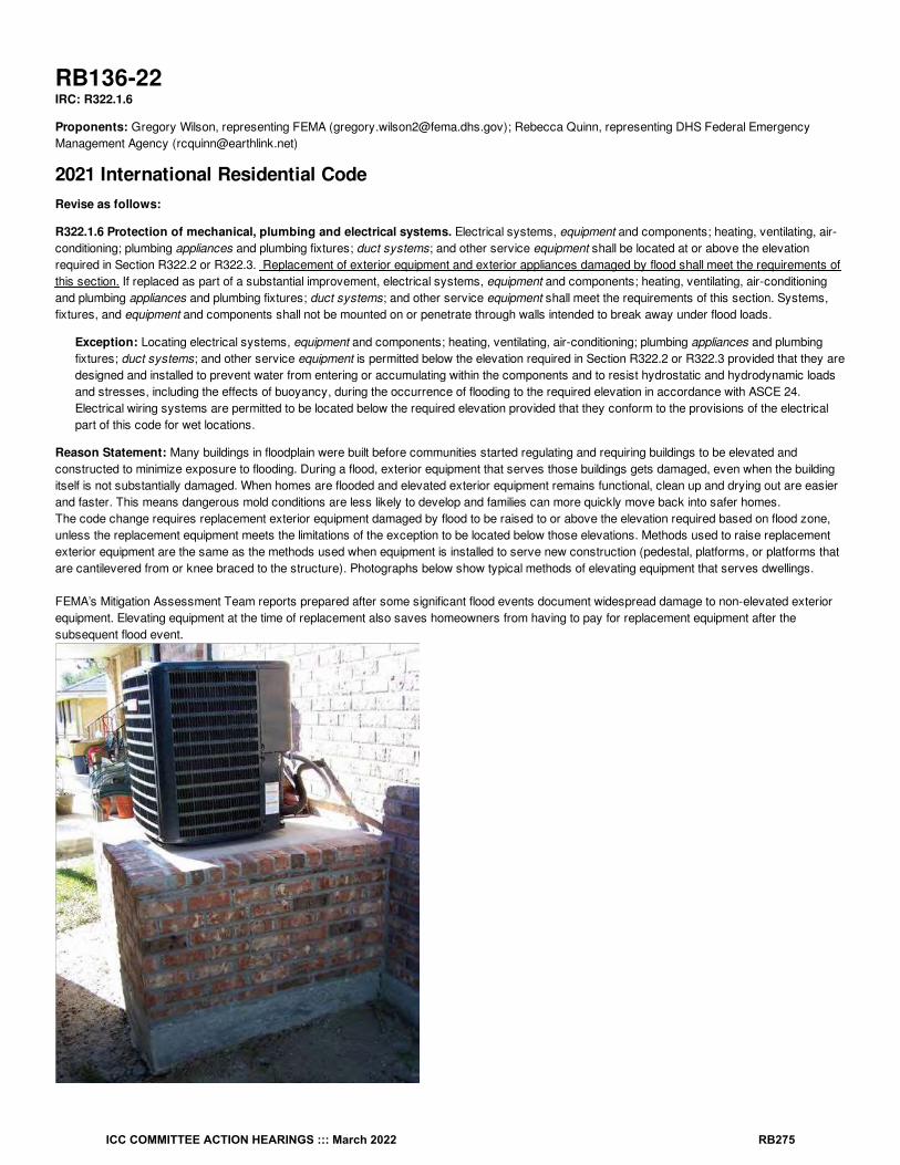
RB136-22IRC: R322.1.6
Proponents: Gregory Wilson, representing FEMA ([email protected]); Rebecca Quinn, representing DHS Federal EmergencyManagement Agency ([email protected])
2021 International Residential CodeRevise as follows:
R322.1.6 Protection of mechanical, plumbing and electrical systems. Electrical systems, equipment and components; heating, ventilating, air-conditioning; plumbing appliances and plumbing fixtures; duct systems; and other service equipment shall be located at or above the elevationrequired in Section R322.2 or R322.3. Replacement of exterior equipment and exterior appliances damaged by flood shall meet the requirements ofthis section. If replaced as part of a substantial improvement, electrical systems, equipment and components; heating, ventilating, air-conditioningand plumbing appliances and plumbing fixtures; duct systems; and other service equipment shall meet the requirements of this section. Systems,fixtures, and equipment and components shall not be mounted on or penetrate through walls intended to break away under flood loads.
Exception: Locating electrical systems, equipment and components; heating, ventilating, air-conditioning; plumbing appliances and plumbingfixtures; duct systems; and other service equipment is permitted below the elevation required in Section R322.2 or R322.3 provided that they aredesigned and installed to prevent water from entering or accumulating within the components and to resist hydrostatic and hydrodynamic loadsand stresses, including the effects of buoyancy, during the occurrence of flooding to the required elevation in accordance with ASCE 24.Electrical wiring systems are permitted to be located below the required elevation provided that they conform to the provisions of the electricalpart of this code for wet locations.
Reason Statement: Many buildings in floodplain were built before communities started regulating and requiring buildings to be elevated andconstructed to minimize exposure to flooding. During a flood, exterior equipment that serves those buildings gets damaged, even when the buildingitself is not substantially damaged. When homes are flooded and elevated exterior equipment remains functional, clean up and drying out are easierand faster. This means dangerous mold conditions are less likely to develop and families can more quickly move back into safer homes. The code change requires replacement exterior equipment damaged by flood to be raised to or above the elevation required based on flood zone,unless the replacement equipment meets the limitations of the exception to be located below those elevations. Methods used to raise replacementexterior equipment are the same as the methods used when equipment is installed to serve new construction (pedestal, platforms, or platforms thatare cantilevered from or knee braced to the structure). Photographs below show typical methods of elevating equipment that serves dwellings.
FEMA’s Mitigation Assessment Team reports prepared after some significant flood events document widespread damage to non-elevated exteriorequipment. Elevating equipment at the time of replacement also saves homeowners from having to pay for replacement equipment after thesubsequent flood event.
ICC COMMITTEE ACTION HEARINGS ::: March 2022 RB275

Photographs are provided courtesy of: FEMA P-348, Rebecca Quinn, and Rebecca Quinn
Cost Impact: The code change proposal will increase the cost of constructionWhen nonconforming dwellings have non-elevated exterior equipment, this code change proposal requires compliance when the exterior equipmentis replaced after being damaged by flooding. Most equipment is elevated; although most typical exterior equipment is not designed to satisfy therequirements and limitations of the exception, that option remains available. Increased costs incurred would be the cost of the pedestal or platformon which the replacement equipment is raised elevated and minor costs to extend wiring and piping, if necessary. The actual cost increase dependson the method of elevation (pedestal, platform, cantilevered/knee braced platform), how high above grade is necessary to meet the elevationrequirements of R322.2 or R322.3, as applicable, and other factors such as soil type. The cost of a professionally built 6-foot high wooden platformis approximately $500, with an additional estimated $100 for 10 feet of copper refrigerant line, for a total of approximately $600. At least two long-termbenefits off-set the upfront additional installation costs: damage avoided and cost of complete replacement if flooded, and faster drying, clean-up,and reoccupancy after subsequent flood events.
RB136-22
ICC COMMITTEE ACTION HEARINGS ::: March 2022 RB276

RB137-22IRC: R322.2.1, R322.3.2
Proponents: Gregory Wilson, representing FEMA ([email protected]); Rebecca Quinn, representing DHS Federal EmergencyManagement Agency ([email protected])
2021 International Residential CodeRevise as follows:
R322.2.1 Elevation requirements.1. Buildings and structures in flood hazard areas, not including flood hazard areas designated as Coastal A Zones, shall have the lowest floors
elevated to or above the base flood elevation plus 1 foot (305 mm), or the design flood elevation, whichever is higher.
2. In areas of shallow flooding (AO Zones), buildings and structures shall have the lowest floor (including basement) elevated to a height abovethe highest adjacent grade of not less than the depth number specified in feet (mm) on the FIRM plus 1 foot (305 mm), or not less than 3 feet(915 mm) if a depth number is not specified.
3. Basement floors that are below grade on all sides shall be elevated to or above base flood elevation plus 1 foot (305 mm), or the design floodelevation, whichever is higher.
4. Attached garages and carports Garage and carport floors shall comply with one of the following:
4.1. They The floors shall be elevated to or above the elevations required in Item 1 or Item 2, as applicable.
4.2. They The floors shall be at or above grade on not less than one side. Where a an attached garage or carport is enclosed by walls , thewalls shall have flood openings that comply with Section R322.2.2 and the attached garage or carport shall be used solely for parking,building access or storage.
5. Detached accessory structures and detached garages shall comply with either of the following:5.1. The floors shall be elevated to or above the elevations required in Item 1 or Item 2, as applicable.
5.2. The floors are permitted below the elevations required in Item 1 or Item 2, as applicable, provided such detached structures comply withall of the following:5.2.1. Are used solely for parking or storage.
5.2.2. Are one story and not larger than 600 square feet (55.75 m ).
5.2.3. Are anchored to resist flotation, collapse or lateral movement resulting from design flood loads.
5.2.4. Have flood openings that comply with Section R322.2.2.
5.2.5. Are constructed of flood damage-resistant materials that comply with Section R322.1.8.
5.2.6. Have mechanical, plumbing and electrical systems, if applicable, that comply with Section R322.1.6.
Exception: Enclosed areas below the elevation required in this section, including basements with floors that are not below grade on all sides,shall meet the requirements of Section R322.2.2.
R322.3.2 Elevation requirements.1. Buildings and structures erected within coastal high-hazard areas and Coastal A Zones, shall be elevated so that the bottom of the lowest
horizontal structural members supporting the lowest floor, with the exception of piling, pile caps, columns, grade beams and bracing, iselevated to or above the base flood elevation plus 1 foot (305 mm) or the design flood elevation, whichever is higher.
2. Basement floors that are below grade on all sides are prohibited.
3. Attached garages Garages used solely for parking, building access or storage, and carports shall comply with Item 1 or shall be at orabove grade on not less than one side and, if enclosed with walls, such walls shall comply with Item 6 7.
2
ICC COMMITTEE ACTION HEARINGS ::: March 2022 RB277

4. Detached accessory structures and detached garages shall comply with either of the following:4.1. The bottom of the lowest horizontal structural member supporting the floors shall be elevated to or above the elevation required in
Item 1.
4.2. The floors are permitted below the elevations required in Item 1, provided such detached structures comply with all of the following:4.2.1. Are used solely for parking or storage.
4.2.2. Are one story and not larger than 100 square feet (9.29 m ).
4.2.3. Are anchored to resist flotation, collapse or lateral movement resulting from design flood loads.
4.2.4. Are constructed of flood damage-resistant materials that comply with Section R322.1.8.
4.2.5. Have mechanical, plumbing and electrical systems, if applicable, that comply with Section R322.1.6.
4. 5. The use of fill for structural support is prohibited.
5. 6. Minor grading, and the placement of minor quantities of fill, shall be permitted for landscaping and for drainage purposes under and aroundbuildings and for support of parking slabs, pool decks, patios and walkways.
6. 7. Walls and partitions enclosing areas below the elevation required in this section shall meet the requirements of Sections R322.3.5 andR322.3.6.
Reason Statement: The regulations of the National Flood Insurance Program require all structures to be elevated or dry floodproofed(nonresidential only). The regulations do not explicitly address accessory structures and detached garages. FEMA guidance issued in 1993 (NFIPTechnical Bulletin 7) states that communities must use variances to authorize non-elevated detached accessory structures that are wetfloodproofed. Wet floodproofing measures minimize flood damage by allowing certain areas to flood, relieving hydrostatic loads and using materialsresistant to flood damage.In 2020, FEMA issued a policy and bulletin specifying requirements for communities to issue permits for non-elevated, wet floodproofed accessorystructures rather than variances. Notably, the policy and bulletin establish size limits as a function of flood zone. In flood hazard areas identified asZone A (all zones that start with “A”), the size limit is one-story two car garage (600 sq ft) and in areas identified as Zone V (start with “V”), the sizelimit is 100 sq ft. Detached accessory structures that are larger than these sizes must fully comply with the elevation or dry floodproofingrequirements for buildings in flood hazard areas. Alternatively, communities may consider individual variances for those larger accessory structures(local floodplain management regulations have criteria for considering variances). FEMA expects to reissue Technical Bulletin 7 in early 2022,revised to be consistent with the policy.
The proposal adds provisions to the elevation requirements of Section R322, Flood-Resistant Construction, specifically to allow wet floodproofedaccessory structures and detached garages in flood hazard areas with floors below the required lowest floor elevations. The IRC Section 105.2states that accessory structures smaller than 200 square feet are exempt from permits but must not “be done in any manner in violation” of thecode. Therefore, strictly read, accessory structures in flood hazard areas must be fully elevated or dry floodproofed. This proposal provides somerelief to full compliance by allowing some accessory structures to be wet floodproofed (based on size). The proposal also modifies the requirementsof R322.2.1 and R322.3.2 to apply to attached garages, with no size limits. Note that for floodplain management purposes, enclosures underelevated buildings used solely for parking, storage and building access are enclosures, not garages.
The proposal specifies that detached accessory structures and detached garages are allowed below the elevations required for other structures (orwithout dry floodproofing in Zone A/AE) if wet floodproofed and:·
In flood hazard areas other than coastal high hazard areas, the structures are one-story and not larger than 600 sq. ft. (approximately a two-car garage). Detached garages and accessory structures larger than the size limit are allowed if elevated and otherwise comply with therequirements or if dry floodproofed (treated as nonresidential), or if communities authorize them by variance. Note that Section R403.1.4.1does not require footings for “free-standing accessory structures with an area of 600 square feet or less, of light-frame construction” toextend meet the frost protection requirements.In coastal high hazard areas (Zone V), the structures are not larger than 100 sq. ft. Note that breakaway walls and flood openings are notrequired. Detached accessory structures larger than the size limit are allowed if elevated and otherwise comply with the requirements, or ifcommunities authorize them by variance.
Bibliography: The Floodplain Management Agricultural Structures Policy and FEMA P-2140, Floodplain Management Bulletin: Requirements forAgricultural Structures and Accessory Structures, are available here: https://www.fema.gov/media-collection/floodplain-management-requirements-agricultural-and-accessory-structures
Cost Impact: The code change proposal will decrease the cost of constructionCosts for many detached accessory structures will decrease because they will no longer be required to be elevated or dry floodproofed when theyare smaller than the specified limits, and there are cost savings because communities will not be expected to approve non-elevated accessorystructures by variance. The code change proposal limits the size of detached accessory structures and detached garages that can be wetfloodproofed rather than elevated or dry floodproofed. An increase in costs occurs only when property owners want accessory structures ordetached garages in flood hazard areas that are larger than the specified limits because those larger structures must be installed on elevatedfoundations (or dry floodproofed in Zone A/AE), unless approved by individually considered variances to be wet floodproofed. However, it is
2
ICC COMMITTEE ACTION HEARINGS ::: March 2022 RB278

reasonable to assume that the larger the size, the more costly would be the losses resulting from flooding. Additional costs for those largerstructures to be elevated depend on the type of foundation chosen. In the report “Natural Hazard Mitigation Saves,” the National Institute of BuildingSciences estimated that for elevating a single-family home, the cost is $33 per foot of elevation per pile and $325 per foot of elevation for stairs.Therefore, for a 1152 square foot accessory structure (24 ft by 48 ft) with 15 piles spaced 12 feet on center, the added cost of elevation would be$820 per foot of elevation. It is reasonable to assume the cost would be less when more typical pier foundation elements and anchoring are used.
Bibliography: Natural Hazard Mitigation Saves (2019), National Institute of Building Sciences. https://www.nibs.org/projects/natural-hazard-mitigation-saves-2019-report.
RB137-22
ICC COMMITTEE ACTION HEARINGS ::: March 2022 RB279

RB138-22IRC: R322.2.2, R322.3.5
Proponents: Gregory Wilson, representing FEMA ([email protected]); Rebecca Quinn, representing DHS Federal EmergencyManagement Agency ([email protected])
2021 International Residential CodeRevise as follows:
R322.2.2 Enclosed area below required elevation. Enclosed areas, including crawl spaces, that are below the elevation required in SectionR322.2.1 shall:
1. Be used solely for parking of vehicles, building access or storage.
2. Be provided with flood openings that meet the following criteria and are installed in accordance with Section R322.2.2.1:
2.1. The total net area of nonengineered openings shall be not less than 1 square inch (645 mm ) for each square foot (0.093 m ) ofenclosed area where the enclosed area is measured on the exterior of the enclosure walls, or the openings shall be designed asengineered openings and the construction documents shall include a statement by a registered design professional that the design ofthe openings will provide for equalization of hydrostatic flood forces on exterior walls by allowing for the automatic entry and exit offloodwaters as specified in Section 2.7.2.2 of ASCE 24.
2.2. Openings shall be not less than 3 inches (76 mm) in any direction in the plane of the wall.
2.3. The presence of louvers, blades, screens and faceplates or other covers and devices shall allow the automatic flow of floodwater intoand out of the enclosed areas and shall be accounted for in the determination of the net open area.
Exceptions: The following shall not be required to comply with this section:
1. Elevator shafts.
2. Utility chases that protect utility lines from freezing, provided the utility chases are the minimum size necessary to protect the utility linesand do not provide access for a person to enter the space.
R322.3.5 Walls below required elevation. Walls and partitions are permitted below the elevation required in Section R322.3.2, provided that suchwalls and partitions are not part of the structural support of the building or structure and:
1. Electrical, mechanical and plumbing system components are not to be mounted on or penetrate through walls that are designed to breakaway under flood loads; and
2. Are constructed with insect screening or open lattice; or
3. Are designed to break away or collapse without causing collapse, displacement or other structural damage to the elevated portion of thebuilding or supporting foundation system. Such walls, framing and connections shall have a resistance of not less than 10 (479 Pa) and notmore than 20 pounds per square foot (958 Pa) as determined using allowable stress design; or
4. Where wind loading values of this code exceed 20 pounds per square foot (958 Pa), as determined using allowable stress design, theconstruction documents shall include documentation prepared and sealed by a registered design professional that:
4.1. The walls and partitions below the required elevation have been designed to collapse from a water load less than that which would occurduring the base flood.
4.2. The elevated portion of the building and supporting foundation system have been designed to withstand the effects of wind and floodloads acting simultaneously on structural and nonstructural building components. Water-loading values used shall be those associatedwith the design flood. Wind-loading values shall be those required by this code.
5. Walls intended to break away under flood loads as specified in Item 3 or 4 have flood openings that meet the criteria in Section R322.2.2,Item 2.
Exceptions: The following shall not be required to comply with this section:
1. Elevator shafts.
2 2
ICC COMMITTEE ACTION HEARINGS ::: March 2022 RB280
2. Utility chases that protect utility lines from freezing, provided the utility chases are the minimum size necessary to protect the utility linesand do not provide access for a person to enter the space.
Reason Statement: FEMA regularly responds to questions about whether utility chases and elevator shafts that extend below elevated buildingsare enclosures. Strictly read, Sections R322.2.2 and R322.3.5 apply to elevator shafts and utility chases that extend below elevated buildings,which means the walls must have flood openings and breakaways wall (Zone V and Coastal A Zones). This code change relaxes thoserequirements, with some limits, in line with IRC Commentary, ASCE 24, and published FEMA guidance. Those sources explain that elevator shaftsdo not require openings and breakaway walls, but the shafts must meet other requirements (materials, resistance to flood loads). Those sourcesalso explain that utility chases do not require openings and breakaway walls as long as the chases are the minimize size necessary and are notsized or constructed to allow a person to enter the space. If chases allow entry by a person, they must fully comply with the requirements forenclosures, including the use limitations. Chases must meet other requirements (materials, resistance to flood loads).
Bibliography: NFIP Technical Bulletin 9, Design and Construction Guidance for Breakaway Walls (2021), https://www.fema.gov/emergency-managers/risk-management/building-science/national-flood-insurance-technical-bulletins
Cost Impact: The code change proposal will decrease the cost of constructionThe code change proposal explicitly allows elevator shafts and utility chases to be conventionally built without the installation of flood openings oruse of breakaway walls which are required for enclosures below elevated buildings in flood hazard areas. The code change proposal will decreasethe cost of construction by avoiding the installation of at two flood openings in each chase and shaft. Engineered flood opening devices costapproximately $100-$150 each, not including the cost of installation (nonengineered openings, such as typical air vent device disabled in the openposition, cost less). Cost data for fabrication of breakaway walls is not available. NFIP Technical Bulletin 9 contains prescriptive solutions forbreakaway walls that do not require certification of design. A typical utility chase is on the order of two to three feet square, thus cost savings areattributable to not having to fabricate approximately eight to twelve feet of breakaway wall.
RB138-22
ICC COMMITTEE ACTION HEARINGS ::: March 2022 RB281

RB139-22IRC: R322.3.2
Proponents: Gregory Wilson, representing FEMA ([email protected]); Rebecca Quinn, representing DHS Federal EmergencyManagement Agency ([email protected])
2021 International Residential CodeRevise as follows:
R322.3.2 Elevation requirements.1. Buildings and structures erected within coastal high-hazard areas and Coastal A Zones, shall be elevated so that the bottom of the lowest
horizontal structural members supporting the lowest floor, with the exception of piling, pile caps, columns, grade beams and bracing, iselevated to or above the base flood elevation plus 1 foot (305 mm) or the design flood elevation, whichever is higher. Where stem wallfoundations are permitted in Coastal A Zones in accordance with Section R322.3.3, the bottom of the lowest horizontal structural membersupporting the lowest floor is the top of the foundation wall, or top of the portion of the foundation wall, supporting the slab.
2. Basement floors that are below grade on all sides are prohibited.
3. Garages used solely for parking, building access or storage, and carports shall comply with Item 1 or shall be at or above grade on not lessthan one side and, if enclosed with walls, such walls shall comply with Item 6.
4. The use of fill for structural support is prohibited.
5. Minor grading, and the placement of minor quantities of fill, shall be permitted for landscaping and for drainage purposes under and aroundbuildings and for support of parking slabs, pool decks, patios and walkways.
6. Walls and partitions enclosing areas below the elevation required in this section shall meet the requirements of Sections R322.3.5 andR322.3.6.
Reason Statement: Section R322.3.3 Foundations, by exception, allows backfilled stem wall foundations in flood hazard areas designated asCoastal A Zones. Coastal A Zones are areas subject to waves that are between 3 feet and 1.5 feet high. Section R322.3.2 specifies elevation of the“bottom of the lowest horizontal structural members supporting the lowest floor.” This proposal does not change the requirement. It clarifies wherethe “bottom of the lowest horizontal structural member” is located when applicants elect to use backfilled stem wall foundations so that designers,builders, and building officials can readily determine compliance. Relating the required elevation to the wall also removes any confusion should a slabhave varying thicknesses at points interior to the perimeter walls. There are different ways to configure the foundation wall and slab connection.Three common options are shown in the figures, with arrows pointing to the top of the foundation wall, or top of the portion of the wall, supporting theslab.
ICC COMMITTEE ACTION HEARINGS ::: March 2022 RB282

ICC COMMITTEE ACTION HEARINGS ::: March 2022 RB283

Cost Impact: The code change proposal will not increase or decrease the cost of constructionThe code change proposal clarifies where the “bottom of the lowest horizontal structural member” is when backfilled stem wall foundations are usedin Coastal A Zones. There is no change to the actual requirements for elevation of the bottom of the lowest horizontal structural member. Byclarifying existing requirements, there will be no cost impact when approving this proposal.
RB139-22
ICC COMMITTEE ACTION HEARINGS ::: March 2022 RB284

RB140-22IRC: R322.3.3
Proponents: Gregory Wilson, representing FEMA ([email protected]); Rebecca Quinn, representing DHS Federal EmergencyManagement Agency ([email protected])
2021 International Residential CodeRevise as follows:
R322.3.3 Foundations. Buildings and structures erected in coastal high-hazard areas and Coastal A Zones shall be supported on pilings orcolumns and shall be adequately anchored to such pilings or columns and shall comply with the following:
1. The space below the elevated building shall be either free of obstruction or, if enclosed with walls, the walls shall meet the requirements ofSection R322.3.5.
2. Pilings shall be designed in accordance with ASCE 24 to have adequate soil penetrations to resist the combined wave and wind loads (lateraland uplift) and pile embedment shall include consideration of decreased resistance capacity caused by scour of soil strata surrounding thepiling.
3. Columns and their supporting foundations shall be designed in accordance with ASCE 24 to resist combined wave and wind loads, lateraland uplift, and shall include consideration of decreased resistance capacity caused by scour of soil strata surrounding the columns. Spreadfooting, mat, raft or other foundations that support columns shall not be permitted where soil investigations that are required in accordancewith Section R401.4 indicate that soil material under the spread footing, mat, raft or other foundation is subject to scour or erosion from wave-velocity flow conditions. If permitted, spread footing, mat, raft or other foundations that support columns shall be designed in accordance withASCE 24.
4. Flood and wave loads shall be determined in accordance with ASCE 7 and shall include loads those associated with the design flood. Windloads shall be those required by this code.
5. Foundation designs and construction documents shall be prepared and sealed in accordance with Section R322.3.9.
Exception: In Coastal A Zones, stem wall foundations supporting a floor system above and backfilled with soil or gravel to the underside of thefloor system shall be permitted provided that the foundations are designed to account for wave action, debris impact, erosion and local scour.Where soils are susceptible to erosion and local scour, stem wall foundations shall have deep footings to account for the loss of soil.
Reason Statement: Section R322.3.3 applies to buildings in coastal high hazard areas and Coastal A Zones. Those are flood zones with waveaction. In coastal high hazard areas, also called V Zones, waves are 3 feet and higher during base flood conditions. Wave heights in Coastal AZones range from 3 ft to 1.5 feet. FEMA has delineated the inland extent of 1.5 foot waves on many Flood Insurance Rate Maps for coastalcommunities, labeling the line as the Limit of Moderate Wave Action. Section R322.3.9 requires construction documents to be prepared and sealedby registered design professionals. Section R322.3.3 describes the performance expectations for pilings and columns. This proposal requirespilings and columns to be designed in accordance ASCE 24 Flood Resistant Design and Construction, which is the standard of practice for designand construction in flood hazard areas. Relying on the recognized standard of practice facilitates the design professional’s task to satisfy theperformance expectations.
Cost Impact: The code change proposal will not increase or decrease the cost of constructionThere is no change to the technical content of the section. The code already requires foundations in coastal high hazard areas and Coastal A Zonesto be designed by registered design professionals to satisfy the performance expectations of Sec. R322.3.3. The change requires designs inaccordance with the recognized standard of practice, which facilitates the design professional’s task. There will be no cost impact when thisproposal is approved.
RB140-22
ICC COMMITTEE ACTION HEARINGS ::: March 2022 RB285

RB141-22IRC: R322.2.3, TABLE R322.2.3 (New), R404.1.1
Proponents: Gregory Wilson, representing FEMA ([email protected]); Rebecca Quinn, representing DHS Federal EmergencyManagement Agency ([email protected])
2021 International Residential CodeDelete and substitute as follows:
R322.2.3 Foundation design and construction. Foundation walls for buildings and structures erected in flood hazard areas shall meet therequirements of Chapter 4.
Exception: Unless designed in accordance with Section R404:
1. The unsupported height of 6-inch (152 mm) plain masonry walls shall be not more than 3 feet (914 mm).
2. The unsupported height of 8-inch (203 mm) plain masonry walls shall be not more than 4 feet (1219 mm).
3. The unsupported height of 8-inch (203 mm) reinforced masonry walls shall be not more than 8 feet (2438 mm).
For the purpose of this exception, unsupported height is the distance from the finished grade of the under-floor space to the top of the wall.
R322.2.3 Foundation design and construction. Foundation walls shall meet the following limitations and requirements:
1. Plain masonry foundation walls are not permitted in flood hazard areas.
2. Concrete foundation walls shall meet the requirements of Chapter 4.
3. Reinforced masonry foundation walls shall meet the requirements of Chapter 4 and Table R322.2.3, where applicable, or shall be designed inaccordance with ASCE 24.
Add new text as follows:
ICC COMMITTEE ACTION HEARINGS ::: March 2022 RB286

TABLE R322.2.3 Foundation design and construction
WALL THICKNESS MAXIMUM UNSUPPORTED WALLHEIGHT
MINIMUM VERTICAL REINFORCEMENT ANDSPACING (INCHES)
8-inch, with reinforcing in accordance with TableR404.1.1(2)
7 feet 4 inches #4 at 48
8-inch, with reinforcing in accordance with TableR404.1.1(2)
8 feet #4 at 40
8-inch, with reinforcing in accordance with TableR404.1.1(2)
8 feet 8 inches #4 at 32
8-inch, with reinforcing in accordance with TableR404.1.1(2)
9 feet 4 inches #4 at 24 or #5 at 40
8-inch, with reinforcing in accordance with TableR404.1.1(2)
10 feet #4 at 24 or #5 at 40
10-inch, with reinforcing in accordance with TableR404.1.1(3)
7 feet 4 inches #4 at 56
10-inch, with reinforcing in accordance with TableR404.1.1(3)
8 feet #4 at 48
10-inch, with reinforcing in accordance with TableR404.1.1(3)
8 feet 8 inches #4 at 40
10-inch, with reinforcing in accordance with TableR404.1.1(3)
9 feet 4 inches #4 at 32 or #5 at 56
10-inch, with reinforcing in accordance with TableR404.1.1(3)
10 feet #4 at 32 or #5 at 48
12-inch, with reinforcing in accordance with TableR404.1.1(4)
7 feet 4 inches #4 at 72
12-inch, with reinforcing in accordance with TableR404.1.1(4)
8 feet #4 at 64
12-inch, with reinforcing in accordance with TableR404.1.1(4)
8 feet 8 inches #4 at 48
12-inch, with reinforcing in accordance with TableR404.1.1(4)
9 feet 4 inches #4 at 40 or #5 at 72
12-inch, with reinforcing in accordance with TableR404.1.1(4)
10 feet #4 at 40 or #5 at 64
a. Unsupported wall height is the difference in height between the top of foundation wall and the lower of the top of the concrete footing thatsupports the foundation wall or the interior finish ground level.
b. Where unbalanced fill conditions exist, then vertical reinforcement shall be the greater of that required by this table or referenced table inSection R404 (Tables R404.1.2(2) through R404.1.2(4)).
Revise as follows:
R404.1.1 Design required. Concrete or masonry foundation walls shall be designed in accordance with accepted engineering practice where oneor more either of the following conditions exists:
1. Walls are subject to hydrostatic pressure from ground water.
2. Walls supporting more than 48 inches (1219 mm) of unbalanced backfill that do not have permanent lateral support at the top or bottom.
3. Walls in flood hazard areas other than coastal high hazard areas and Coastal A Zones that do not conform to Section R322.2.3.
Reason Statement: The code change proposal would no longer allow unreinforced plain masonry walls in flood hazard areas and would replace asingle prescriptive wall thickness and wall height for reinforced masonry with a table that offers many combinations of wall thickness and wall height,along with vertical reinforcement and spacing specifications. Wall heights in the proposed table are in 8” increments to match the Chapter 4reinforcement tables (Tables R404.1.1(2-4)), which corresponds to standard concrete masonry unit height. The table also prescribes reinforcementas a function of wall thickness and wall height, increasing the maximum wall height for 8” wall thickness from 8 feet to 10 feet. The table will facilitatefield application for builders and subsequent verification by code officials.The current wall height limitations in R322.2.3 are based on analysesperformed in 1998 for a range of flood depths and velocities. After observing foundation wall damage during post-disaster investigations, FEMA re-
a b
ICC COMMITTEE ACTION HEARINGS ::: March 2022 RB287
examined those limitations in 2012. The analyses produced at that time were developed through collaboration with industry groups, and evaluatedthe resistance of masonry walls of different heights, with flood openings, over a range of velocities, in combination with wind loading conditionscovered in the IRC, using Allowable Stress Design (ASD) Load Combination 7, according to ASCE 7-10 and ASCE 7-16 Section 2.4.2 (2), which isLoad Combination 7b, according to ASCE 7-22.The proposal removes the plain masonry wall provisions because they are structurally deficient for a range of flood depths and velocities. Theanalyses demonstrated the need to specify minimal reinforcement, which is not included in two of the current options for plain masonry. Theanalyses used the flood depth to determine flood loads and used a basic wind speed of 115 mph for Exposure Category B (ASCE 7-10) for windloads. Those loads result in net tension at the top of the foundation wall. Higher design wind speeds result in greater uplift. The design criteria ofSection 2.2.4 of ACI 530 (used for the 2012 analyses) specify that the tensile strength of unreinforced masonry is neglected when subjected to axialtension forces. ACI 530 commentary for Section 2.2.4 stated that “Net axial tension in unreinforced masonry walls due to axially applied load are notpermitted. If axial tension develops in walls due to uplift of connected roofs or floors, the walls must be reinforced to resist the tension. Compressivestress from dead load can be used to offset axial tension” (emphasis added). Accordingly, unreinforced wall sections analyzed with net axial tensionat the top of wall from the combined effects of wind and flood loading did not perform.Preventing failure of masonry foundation walls by providing prescriptive solutions that specifically address flood hazards meets the intent of the IRCto provide affordable solutions for structural strength and to safeguard property from hazards.
Evidence from FEMA’s post-disaster Mitigation Assessment Team (MAT) reports indicates unreinforced masonry wall failures occur under designwind loads (see FEMA P-908 Spring 2011 Tornadoes) and flood loads (see FEMA P-765 Midwest Floods of 2008 in Iowa and Wisconsin, FEMA P-942 Hurricane Sandy in New Jersey and New York).
Bibliography: FEMA MAT reports are accessible online: https://www.fema.gov/emergency-managers/risk-management/building-science/mitigation-assessment-team
Cost Impact: The code change proposal will increase the cost of constructionThe only situations where costs will slightly increase are those where plain masonry is currently permitted by both Chapter 4 and Section R322.2.3.Because of those limitations, and because wind and seismic conditions in many areas require reinforced foundations, the aggregate cost increaseacross all flood hazard areas should be minimal. Offsetting costs for reinforcement are reduced risk of flood damage.
Section R322.2.1 requires lowest floors to be at or above the base flood elevation plus one foot, which means the current allowance for plainmasonry walls applies only where flood depths are 3 to 4 feet or less (assuming the floor system is approximately 12” deep, a 4 ft high foundationwalls puts the floor surface at about 5 ft. The cost increase includes rebar, grout, and labor. Considering only the rebar, a 2,400 square footfoundation that is 40x60 has 200 linear feet of foundation wall. Reinforcing 200 linear feet of 4-tall foundation wall with #4 rebar at 48” spacingrequires approximately 250 ft of rebar. Based on cost estimates available online, 20 feet of #4 rebar costs about $13. The increase for rebar is lessthan $300. Based on the same wall scenario, using a homeowner cost estimating online application, the cost of grout is less than $400 and theincrease in labor is approximately 9 hours.
RB141-22
ICC COMMITTEE ACTION HEARINGS ::: March 2022 RB288

RB142-22IRC: R322.3.5
Proponents: Gregory Wilson, representing FEMA ([email protected]); Rebecca Quinn, representing DHS Federal EmergencyManagement Agency ([email protected])
2021 International Residential CodeRevise as follows:
R322.3.5 Walls below required elevation. Walls and partitions are permitted below the elevation required in Section R322.3.2, provided that suchwalls and partitions are not part of the structural support of the building or structure and:
1. Electrical, mechanical and plumbing system components are not to be mounted on or penetrate through walls that are designed to breakaway under flood loads; and
2. Are constructed with insect screening or open lattice; or
3. Are designed to break away or collapse without causing collapse, displacement or other structural damage to the elevated portion of thebuilding or supporting foundation system. Such walls, framing and connections shall have a resistance of not less than 10 (479 Pa) and notmore than 20 pounds per square foot (958 Pa) as determined using allowable stress design, or a resistance to an ultimate load of not lessthan 17 (814 Pa) and not more than 33 pounds per square foot (1580 Pa); or
4. Where wind loading values of this code exceed 20 pounds per square foot (958 Pa), as determined using allowable stress design or anultimate load of 33 pounds per square foot (1580 Pa), the construction documents shall include documentation prepared and sealed by aregistered design professional that:
4.1. The walls and partitions below the required elevation have been designed to collapse from a water load less than that which would occurduring the base flood.
4.2. The elevated portion of the building and supporting foundation system have been designed to withstand the effects of wind and floodloads acting simultaneously on structural and nonstructural building components. Water-loading values used shall be those associatedwith the design flood. Wind-loading values shall be those required by this code.
5. Walls intended to break away under flood loads as specified in Item 3 or 4 have flood openings that meet the criteria in Section R322.2.2,Item 2.
Reason Statement: This code change does not change the loads used to design breakaway walls. It just shows how the loads expressed usingallowable stress design are expressed as ultimate loads, which is used in ASCE 7 for seismic design and wind loads. One of the reasons for thelower load shown in the existing section is to avoid breakaway walls that might fail under wind loads. Showing the loads expressed as ultimate loadswill make it easier to compare to calculated wind loads and seismic loads.
Cost Impact: The code change proposal will not increase or decrease the cost of constructionThe code change proposal shows how the loads expressed using allowable stress design are expressed as ultimate loads to better align with ASCE7. There is no change to the technical content of the provisions. By showing how existing load values are expressed as ultimate loads, there will beno cost impact when approving this proposal.
RB142-22
ICC COMMITTEE ACTION HEARINGS ::: March 2022 RB289

RB143-22IRC: SECTION 202, R323.1, R323.2 (New), R323.1.1
Proponents: Mike Nugent, representing Building Code Action Committee ([email protected]); Marc Levitan, representing ICC 500 Storm ShelterStandard Development Committee ([email protected])
2021 International Residential CodeRevise as follows:
[RB] IMPACT PROTECTIVE SYSTEM. Impact protective systems are defined as follows:1. Construction that has been shown by testing to withstand the impact of test missiles and that is applied, attached, or locked over exterior
glazing.
2. For storm shelters, an assembly or device, subject to static or cyclic pressure and impact testing as detailed in ICC 500, installed to protectan opening in the storm shelter envelope.
R323.1 General. This section applies to the design, construction and installation of storm shelters where constructed as either separate detachedbuildings or where constructed as safe rooms or spaces within buildings for the purpose of providing refuge protection from storms that producehigh winds, such as tornados , and hurricanes and other severe windstorms. In addition to other applicable requirements in this code, stormshelters shall be constructed in accordance with ICC 500.
Add new text as follows:
R323.2 Construction. Storm shelters shall be constructed in accordance with this code and ICC 500.
Revise as follows:
R323.1.1 R323.2.1 Sealed documentation. The construction documents for all structural components and impact protective systems of theinstalled in storm shelters shall be prepared and sealed by a registered design professional indicating that the design meets the criteria ofcompliance with ICC 500.
Exception: Storm shelters, structural components and impact-protective systems that are listed and labeled to indicate compliance with ICC500.
Reason Statement: The purpose of this proposal is to correlate IRC Section 323 with the 2020 edition of ICC 500 and with the corresponding IBCSection 423. The changes are editorial and match editorial revisions to the scope of ICC 500, including recognizing extratropical storms are knownas hurricanes, typhoons or cyclones depending on the region of the world where they occur. To match changes made to IBC Section 423 as modified for the 2024 IBC by approved proposal G94-19, and to reflect the division betweenscoping requirements and construction requirements in ICC 500, a new Section R323.2 is created to hold the basic requirement to construct stormshelters per ICC 500 and the requirement for signed and sealed storm shelter construction documents added to the 2021 IRC.
The current IRC definition of Impact Protective Systems differs from ICC 500 as the IRC definition only applies to protection of exteriorglazing from the typical wind-borne debris associated with design-level hurricane events in the IRC and IBC. ICC 500 requires the entire stormshelter envelope – including solid doors, louvers, and other openings – resist debris impacts associated with severe tornadoes and hurricanesexceeding code-level design wind speeds. Since this difference could be misleading for someone unfamiliar with ICC 500, it is suggested to modifythe IRC definition. The format matches other definitions such as Wind-Borne Debris Regions, Story Above Grade Plane and Mechanical Joint.
This proposal is submitted by the ICC Building Code Action Committee (BCAC).
BCAC was established by the ICC Board of Directors in July 2011 to pursue opportunities to improve and enhance assigned International Codes orportions thereof. In 2020 and 2021 the BCAC has held several virtual meetings open to any interested party. In addition, there were numerous virtualWorking Group meetings for the current code development cycle, which included members of the committee as well as interested parties. Relateddocuments and reports are posted on the BCAC website at https://www.iccsafe.org/products-and-services/i-codes/code-development/cs/building-code-action-committee-bcac/.
Cost Impact: The code change proposal will not increase or decrease the cost of constructionThe changes are editorial and correlate with the current edition of ICC 500. The changes do not impact how a storm shelter is designed,constructed, or installed and thus do not affect the cost of providing a storm shelter.
RB143-22
ICC COMMITTEE ACTION HEARINGS ::: March 2022 RB290

RB144-22IRC: SECTION 202 (New), R323.1.2 (New)
Proponents: Stephen Skalko, representing Masonry Alliance for Codes and Standards ([email protected]); Scott Campbell,representing NRMCA ([email protected])
2021 International Residential Code[RB] STORM SHELTER. A building, structure or portion thereof, constructed in accordance with ICC 500 and designated for use during a severewind storm event, such as a hurricane or tornado.
Add new definition as follows:
Community storm shelter. A storm shelter not defined as a “Residential storm shelter.” This includes storm shelters intended for use by thegeneral public, by building occupants or a combination of both.
Residential storm shelter. A storm shelter serving occupants of dwelling units and having a design occupant capacity not exceeding 16persons.
Add new text as follows:
R323.1.2 Shelters required. In areas where the shelter design wind speed for tornados is 250 mph in accordance with Figure 304.2(1) of ICC 500,a storm shelter shall be provided in accordance with ICC 500. Residential storm shelters serving dwelling units shall be located in accordance withICC 500 Section 403.2. Community storm shelters shall be located where the maximum distance of travel from not fewer than one exterior door ofeach dwelling unit to a door of the shelter serving that dwelling unit does not exceed 1,000 feet (305 m).
Exception: Dwellings meeting the requirements for shelter design in ICC 500.
Reason Statement: Section R323 of the IRC tells the code user to use ICC 500, Standard for the Design and Construction of Storm Shelters forrequirements to be met if storm shelters associated with one-and two-family dwellings are provided. However, the code does not require that suchshelters be provided. Recent tornado events continue to show the need to provide such shelters for one-and two-family dwellings in high tornadowind regions. Experience has shown that storm shelters in high tornado wind regions provide protection for persons from injury or death due tostructural collapse and/or wind-borne debris. This proposal will require storm shelters be provided for one-and two-family dwellings built in areas where the tornado wind speeds are 250 mph orhigher according to ICC 500 Figure 304.2(1). The area covered by this tornado wind speed is consistent with the areas in five states that recentlyexperienced devastating damage, reportedly over 100 deaths and many more injured from a series of tornado events occurring within a 24-hourperiod December 10-11, 2021.
The proposal also permits a stand-alone shelter, either as an accessory building to the dwelling or a community shelter, to meet the requirements ofthis section. Where a stand-alone storm shelter is provided, the proposal limits the travel distance to the stand-alone shelter based on ICC 500Section 403.2 for Residential storm shelters, or within 1000 feet from at least one exterior door of the dwelling unit to a Community storm shelterdoor.
Bibliography: Satellites Spot Tornado Tracks Across Midwest (nasa.gov)
Cost Impact: The code change proposal will increase the cost of constructionIncluding a storm shelter within a dwelling unit or as a stand-alone structure will increase the cost of construction. The actual costs will depend onthe materials of choice and design features of the shelter. Insofar as any cost-benefit conclusion, that is extremely difficult to quantify whenconsidering actions to save lives. However, it can be stated that a shelter does increase the probability that persons are more likely to survive anevent with the shelter rather than being exposed to the elements outside the shelter.
RB144-22
ICC COMMITTEE ACTION HEARINGS ::: March 2022 RB291

RB145-22IRC: R324.3.1
Proponents: Larry Sherwood, representing Sustainable Energy Action Committee ([email protected]); Kevin Reinertson, representing CaliforniaFire Chiefs Association FPO ([email protected]); Benjamin Davis, representing California Solar & Storage Association([email protected]); Philip Oakes, representing National Association of State Fire Marshals; Joseph Cain, representing Solar Energy IndustriesAssociation (SEIA) ([email protected])
2021 International Residential CodeRevise as follows:
R324.3.1 Equipment listings. Photovoltaic panels and modules shall be listed and labeled in accordance with UL 1703 or with both UL 61730-1 andUL 61730-2. Inverters shall be listed and labeled in accordance with UL 1741. Systems connected to the utility grid shall use inverters listed for utilityinteraction. Mounting systems listed and labeled in accordance with UL 2703 shall be installed in accordance with the manufacturer’s installationinstructions and their listings. BIPV roof coverings and BIPV roof assemblies shall be listed and labeled in accordance with UL 7103.
Reason Statement: This aligns with the 2021 IRC, where UL 7103 replaced UL 1703 as the standard for listing BIPV roofing in Chapter 9.This proposal was prepared by the Sustainable Energy Action Committee (SEAC), a forum for all stakeholders (including, but not limited to, AHJs,designers, engineers, contractors, first responders, manufacturers, suppliers, utilities, and testing labs) to collaboratively identify and find solutionsfor issues that affect the installation and use of solar energy systems, energy storage systems, demand response, and energy efficiency. Thepurpose is to facilitate the deployment and use of affordable, clean and renewable energy in a safe, efficient, and sustainable manner.
All recommendations from SEAC are approved by diverse stakeholders through a consensus process.
Cost Impact: The code change proposal will not increase or decrease the cost of constructionThis aligns with requirements covered in Chapter 9 of the IRC, and provides clarity as to the applicable standard to be used.
RB145-22
ICC COMMITTEE ACTION HEARINGS ::: March 2022 RB292

RB146-22IRC: R324.5, R324.5.1, R324.5.2, R324.5.3, R324.5.2 (New)
Proponents: Larry Sherwood, representing Sustainable Energy Action Committee ([email protected]); Kevin Reinertson, representing CaliforniaFire Chiefs Association FPO ([email protected]); Benjamin Davis, representing California Solar & Storage Association([email protected]); Philip Oakes, representing National Association of State Fire Marshals; Joseph Cain, representing Solar Energy IndustriesAssociation (SEIA) ([email protected])
2021 International Residential CodeRevise as follows:
R324.5 Building-integrated photovoltaic systems. Building-integrated photovoltaic (BIPV) systems that serve as roof coverings shall bedesigned and installed in accordance with Section R905 Sections R324.5.1 through R324.5.2.
R324.5.1 Photovoltaic shingles BIPV roofing systems. Photovoltaic shingles BIPV roofing systems shall comply with Section R905.16. BIPVroof panels shall comply with Section R905.17.
R324.5.2 R324.5.1.1 Fire classification. Building-integrated photovoltaic systems shall have a fire classification in accordance with Section R902.3.
R324.5.3 BIPV roof panels. BIPV roof panels shall comply with Section R905.17.
Add new text as follows:
R324.5.2 BIPV Exterior wall coverings and fenestration. BIPV exterior wall coverings and fenestration shall comply with Section R705.
Reason Statement: This proposal recognizes that BIPV systems can be in the form of roofing, exterior wall coverings, or fenestration.This proposal was prepared by the Sustainable Energy Action Committee (SEAC), a forum for all stakeholders (including, but not limited to, AHJs,designers, engineers, contractors, first responders, manufacturers, suppliers, utilities, and testing labs) to collaboratively identify and find solutionsfor issues that affect the installation and use of solar energy systems, energy storage systems, demand response, and energy efficiency. Thepurpose is to facilitate the deployment and use of affordable, clean and renewable energy in a safe, efficient, and sustainable manner.
All recommendations from SEAC are approved by diverse stakeholders through a consensus process.
Cost Impact: The code change proposal will not increase or decrease the cost of constructionThis recognizes other types of BIPV systems that are available for installation, and does not limit to just roofing applications.
RB146-22
ICC COMMITTEE ACTION HEARINGS ::: March 2022 RB293

RB147-22IRC: R324.6, R324.6.3, UL Chapter 44 (New)
Proponents: Larry Sherwood, representing Sustainable Energy Action Committee ([email protected]); Kevin Reinertson, representing CaliforniaFire Chiefs Association FPO ([email protected]); Benjamin Davis, representing California Solar & Storage Association([email protected]); Philip Oakes, representing National Association of State Fire Marshals; Joseph Cain, representing Solar Energy IndustriesAssociation (SEIA) ([email protected])
2021 International Residential CodeRevise as follows:
R324.6 Roof access and pathways. Roof access, pathways and setback requirements shall be provided in accordance with Sections R324.6.1through R324.6.2.1. Access and minimum spacing shall be required to provide emergency access to the roof, to provide pathways to specific areasof the roof, provide for smoke ventilation opportunity areas, and to provide emergency egress from the roof.
Exceptions:
1. Detached, nonhabitable structures, including but not limited to detached garages, parking shade structures, carports, solar trellises andsimilar structures, shall not be required to provide roof access.
2. Roof access, pathways and setbacks need not be provided where the code official has determined that rooftop operations will not beemployed.
3. These requirements shall not apply to roofs with slopes of 2 units vertical in 12 units horizontal (17-percent slope) or less.
4. BIPV systems listed in accordance with Section 690.12(B)(2) of NFPA 70 UL 3741, where the removal or cutting away of portions of theBIPV system during fire-fighting operations has been determined to not expose a fire fighter to electrical shock hazards.
R324.6.3 Emergency escape and rescue openings. Panels and modules installed on dwellings shall not be placed on the portion of a roof that isbelow an emergency escape and rescue opening. A pathway not less than 36 inches (914 mm) wide shall be provided to the emergency escapeand rescue opening.
Exception: BIPV systems listed in accordance with Section 690.12(B)(2) of NFPA 70 UL 3741, where the removal or cutting away of portions ofthe BIPV system during fire-fighting operations has been determined to not expose a fire fighter to electrical shock hazards.
Add new standard(s) as follows:
UL UL LLC333 Pfingsten Road
Northbrook, IL 60062
3741-2020 Photovoltaic Hazard Control
Staff Analysis: A review of the standard proposed for inclusion in the code, UL 3741-2020 Photovoltaic Hazard Control, with regard to some of thekey ICC criteria for referenced standards (Section 3.6 of CP#28) will be posted on the ICC website on or before March 16, 2022.
Reason Statement: This aligns with the revisions made in F129-21 in the Group A cycle to the IFC.UL 3741 is the national test standard developedto address Section 690.12(B)(2) of NFPA 70. It is a consensus standard developed specifically for the evaluation and testing of rapid shutdownsystems and equipment. This proposal will provide clarity on the specific requirements to be used for listing these systems and equipment, andprovide the performance anticipated by rapid shutdown operations.This proposal was prepared by the Sustainable Energy Action Committee (SEAC), a forum for all stakeholders (including, but not limited to, AHJs,designers, engineers, contractors, first responders, manufacturers, suppliers, utilities, and testing labs) to collaboratively identify and find solutionsfor issues that affect the installation and use of solar energy systems, energy storage systems, demand response, and energy efficiency. Thepurpose is to facilitate the deployment and use of affordable, clean and renewable energy in a safe, efficient, and sustainable manner.
All recommendations from SEAC are approved by diverse stakeholders through a consensus process.
Bibliography: F129-21IFC: 1205.2.3, UL Chapter 80
Cost Impact: The code change proposal will not increase or decrease the cost of constructionThis is identifying the standard already referred to indirectly within the code.
RB147-22
ICC COMMITTEE ACTION HEARINGS ::: March 2022 RB294

RB148-22IRC: R324.6.1
Proponents: Jason Laws - VBCOA, Chesterfield County, Virginia, representing VBCOA ([email protected])
2021 International Residential CodeDelete and substitute as follows:
R324.6.1 Pathways. Not fewer than two pathways, on separate roof planes from lowest roof edge to ridge and not less than 36 inches (914 mm)wide, shall be provided on all buildings. Not fewer than one pathway shall be provided on the street or driveway side of the roof. For each roof planewith a photovoltaic array, a pathway not less than 36 inches wide (914 mm) shall be provided from the lowest roof edge to ridge on the same roofplane as the photovoltaic array, on an adjacent roof plane, or straddling the same and adjacent roof planes. Pathways shall be over areas capable ofsupporting fire fighters accessing the roof. Pathways shall be located in areas with minimal obstructions such as vent pipes, conduit, or mechanicalequipment.
R324.6.1 Pathways. A minimum 36" wide pathway shall be provided on all roof planes with photovoltaic arrays. Each pathway shall provide accessfrom the lowest roof edge to the ridge and be free of obstructions such as vent pipes, conduit, or mechanical equipment.
Reason Statement: The purpose of this proposal is for clarification. The current code provision includes excessive, unneeded language whichmakes this section confusing and hard to follow.The language requiring a pathway "on the street or driveway side of the roof" is not needed. If you have a pathway where ever a photovoltaic panelis installed, you will always meet this requirement. If panels are only on the rear of the house, the entire front roof plane is clear and creates apathway by default. If you have panels on the front of the house, then a pathway is needed and would still meet this requirement.
The language requiring a pathway "on an adjacent roof plane, or straddling the same and adjacent roof planes." only creates confusion and couldresult in "pathways" that are not functional.
The language requiring "Pathways shall be over areas capable of supporting fire fighters accessing the roof." is not needed. The minimum designloads in R301.6 already cover this.
The intent of the code would remain the same but this proposal makes it much easier to understand, making it easier to design and enforce.
Cost Impact: The code change proposal will not increase or decrease the cost of constructionThe proposal does not increase or decrease the cost of construction. This proposal keeps the intent of the code the same, simply makes it easierfor everyone to understand and apply.
RB148-22
ICC COMMITTEE ACTION HEARINGS ::: March 2022 RB295

RB149-22IRC: R324.6.4 (New), UL Chapter 44 (New)
Proponents: Larry Sherwood, representing Sustainable Energy Action Committee ([email protected]); Kevin Reinertson, representing CaliforniaFire Chiefs Association FPO ([email protected]); Benjamin Davis, representing California Solar & Storage Association([email protected]); Philip Oakes, representing National Association of State Fire Marshals; Joseph Cain, representing Solar Energy IndustriesAssociation (SEIA) ([email protected])
2021 International Residential CodeAdd new text as follows:
R324.6.4 Building-integrated photovoltaic (BIPV) systems. Where building-integrated photovoltaic (BIPV) systems are installed in a manner thatcreates areas with electrical hazards to be hidden from view, markings shall be provided to identify the hazardous areas to avoid for ladderplacement. The markings shall be reflective and be visible from grade beneath the eaves or other location approved by the fire code official.
Exception: BIPV systems listed in accordance with UL 3741, where the removal or cutting away of portions of the BIPV system during fire-fighting operations have been determined to not expose a fire fighter to electrical shock hazards.
Add new standard(s) as follows:
UL UL LLC333 Pfingsten Road
Northbrook, IL 60062
3741-2020 Photovoltaic Hazard Control
Staff Analysis: A review of the standard proposed for inclusion in the code, UL 3741-2020 Photovoltaic Hazard Control, with regard to some of thekey ICC criteria for referenced standards (Section 3.6 of CP#28) will be posted on the ICC website on or before March 16, 2022.
Reason Statement:This aligns with IFC Section 1205.2.3 and F129-21 from the Group A cycle.
This provides fire fighters with means to determine where the BIPV is on the roof, and aligns with the requirements in the 2021 IFC Section1205.2.3. The original intent is for reflective marking that could be under an eave and visible from grade, or could be in some other location visiblefrom grade, such that the reflective marking identifies locations where a ladder should not be placed. The BIPV roof covering products themselvesdo not all need to be reflectorized.
This proposal was prepared by the Sustainable Energy Action Committee (SEAC), a forum for all stakeholders (including, but not limited to, AHJs,designers, engineers, contractors, first responders, manufacturers, suppliers, utilities, and testing labs) to collaboratively identify and find solutionsfor issues that affect the installation and use of solar energy systems, energy storage systems, demand response, and energy efficiency. Thepurpose is to facilitate the deployment and use of affordable, clean and renewable energy in a safe, efficient, and sustainable manner.
All recommendations from SEAC are approved by diverse stakeholders through a consensus process.
Bibliography: F129-21IFC: 1205.2.3, UL Chapter 80 (New)
Cost Impact: The code change proposal will not increase or decrease the cost of constructionThis proposal aligns with the fire code requirements.
RB149-22
ICC COMMITTEE ACTION HEARINGS ::: March 2022 RB296

RB150-22IRC: SECTION 202 (New), R324.7 (New), R324.7.1 (New), 324.7.2 (New)
Proponents: Larry Sherwood, representing Sustainable Energy Action Committee ([email protected]); Kevin Reinertson, representing CaliforniaFire Chiefs Association FPO ([email protected]); Benjamin Davis, representing California Solar & Storage Association([email protected]); Philip Oakes, representing National Association of State Fire Marshals; Joseph Cain, representing Solar Energy IndustriesAssociation (SEIA) ([email protected])
2021 International Residential CodeAdd new definition as follows:
PHOTOVOLTAIC (PV) SUPPORT STRUCTURE, ELEVATED. An independent photovoltaic (PV) panel support structure designed withuseable space underneath with minimum clear height of 7 feet 6 inches (2286 mm), intended for secondary use such as providing shade or parkingof motor vehicles.
Add new text as follows:
R324.7 Elevated photovoltaic (PV) support structures. Elevated PV support structures used as an accessory structure shall comply with eitherSection R324.7.1 or R324.7.2.
R324.7.1 PV panels installed over open-grid framing or non-combustible deck. Elevated PV support structures with PV panels installed overopen-grid framing or over a noncombustible deck shall have PV panels tested, listed, and labeled with a fire type rating in accordance with UL 1703or with both UL 61730-1 and UL 61730-2. Photovoltaic panels marked “not fire rated” shall not be installed on elevated PV support structures.
324.7.2 PV panels installed over a roof assembly. Elevated PV support structures with a PV panel system installed over a roof assembly shallhave a fire classification in accordance with Section R902.4.
Reason Statement:This is in alignment with G193-21 for the IBC in the Group A cycle.
The primary purpose of this proposal is to establish appropriate fire testing and listing criteria for overhead photovoltaic (PV) support structures thatcould have people or vehicles in the space beneath them. Sometimes referred to as “solar shade structures,” they are most commonly constructedover vehicle parking spaces of surface parking lots, but could be built in a variety of locations with or without cars parked beneath.
This addresses structures with open grid framing and without a roof deck or sheathing, which supports the photovoltaic panel systems.
Most PV panels in the marketplace have been fire tested and assigned a “type rating” in accordance with UL 1703. However, some PV panels mightnot have that fire testing, and could be marked “not fire rated.” This proposal clarifies that PV panels marked “not fire rated” cannot be used onelevated/overhead PV structures that could have people or cars beneath them, with or without a full roof assembly.
This proposal was prepared by the Sustainable Energy Action Committee (SEAC), a forum for all stakeholders (including, but not limited to, AHJs,designers, engineers, contractors, first responders, manufacturers, suppliers, utilities, and testing labs) to collaboratively identify and find solutionsfor issues that affect the installation and use of solar energy systems, energy storage systems, demand response, and energy efficiency. Thepurpose is to facilitate the deployment and use of affordable, clean and renewable energy in a safe, efficient, and sustainable manner.
All recommendations from SEAC are approved by diverse stakeholders through a consensus process.
Cost Impact: The code change proposal will not increase or decrease the cost of constructionThe code change proposal will not increase or decrease the cost of construction. This proposal provides more options in construction with clearrequirements for another type of photovoltaic installation (i.e. an alternative to rooftop mounted PV or building-integrated PV).
RB150-22
ICC COMMITTEE ACTION HEARINGS ::: March 2022 RB297
RB151-22IRC: R325.2
Proponents: Mike Nugent, representing Building Code Action Committee ([email protected])
2021 International Residential Code
SECTION R325MEZZANINES
Revise as follows:
R325.2 Mezzanines. The clear height above and below mezzanine floor construction shall be not less than 7 feet (2134 mm).
Exception: The ceiling height above the mezzanine shall be permitted to comply with Section 305.1 where the mezzanine meets the minimumroom size in Section R304.
SECTION R326HABITABLE ATTICS
R326.2 Minimum dimensions. A habitable attic shall have a floor area in accordance with Section R304 and a ceiling height in accordance withSection R305.
Reason Statement: The provisions for minimum room area (R304) and ceiling height (R305) provide criteria for with habitable rooms/spaces andbasements, but neither specifically mentions mezzanines (R325) or habitable attics (R326). Habitable attics does reference R304 and R305 forminimum size and height, so you can do sloped ceilings or beams in the habitable attic. However, the current text does not address a sloped ceilingor beams in a mezzanine. While I do not believe it is the intent to require a mezzanine to be at least 70 sq.ft. or at least 7 feet in each direction thesame as a room (per R304), the proposal would allow for mezzanines with sloped ceilings beams where the mezzanine was the size of a room.Below are sections R304 and R305 for reference. Mezzanines are habitable spaces.
SECTION R304MINIMUM ROOM AREASR
304.1 Minimum area. Habitable rooms shall have a floor area of not less than 70 square feet (6.5 m2).
Exception: Kitchens.
R304.2 Minimum dimensions. Habitable rooms shall be not less than 7 feet (2134 mm) in any horizontal dimension.
Exception: Kitchens.
R304.3 Height effect on room area. Portions of a room with a sloping ceiling measuring less than 5 feet (1524 mm) or a furred ceiling measuringless than 7 feet (2134 mm) from the finished floor to the finished ceiling shall not be considered as contributing to the minimum required habitablearea for that room.
SECTION R305CEILING HEIGHT
R305.1 Minimum height. Habitable space, hallways and portions of basements containing these spaces shall have a ceiling height of not less than7 feet (2134 mm). Bathrooms, toilet rooms and laundry rooms shall have a ceiling height of not less than 6 feet 8 inches (2032 mm).
Exceptions:
1. For rooms with sloped ceilings, the required floor area of the room shall have a ceiling height of not less than 5 feet (1524 mm) and not lessthan 50 percent of the required floor area shall have a ceiling height of not less than 7 feet (2134 mm).
2. The ceiling height above bathroom and toilet room fixtures shall be such that the fixture is capable of being used for its intended purpose. Ashower or tub equipped with a showerhead shall have a ceiling height of not less than 6 feet 8 inches (2032 mm) above an area of not less than30 inches (762 mm) by 30 inches (762 mm) at the showerhead.
3. Beams, girders, ducts or other obstructions in basements containing habitable space shall be permitted to project to within 6 feet 4 inches(1931 mm) of the finished floor.
4. Beams and girders spaced apart not less than 36 inches (914 mm) in clear finished width shall project not more than 78 inches (1981 mm)
ICC COMMITTEE ACTION HEARINGS ::: March 2022 RB298

from the finished floor.
R305.1.1 Basements. Portions of basements that do not contain habitable space or hallways shall have a ceiling height of not less than 6 feet 8inches (2032 mm).
Exception: At beams, girders, ducts or other obstructions, the ceiling height shall be not less than 6 feet 4 inches (1931 mm) from the finishedfloor.
This proposal is submitted by the ICC Building Code Action Committee (BCAC).
BCAC was established by the ICC Board of Directors in July 2011 to pursue opportunities to improve and enhance assigned International Codes orportions thereof. In 2020 and 2021 the BCAC has held several virtual meetings open to any interested party. In addition, there were numerous virtualWorking Group meetings for the current code development cycle, which included members of the committee as well as interested parties. Relateddocuments and reports are posted on the BCAC website at https://www.iccsafe.org/products-and-services/i-codes/code-development/cs/building-code-action-committee-bcac/.
Cost Impact: The code change proposal will not increase or decrease the cost of constructionThis is a clarification only for mezzanines constructed under sloped roofs. It will increase design options without increasing requirements.
RB151-22
ICC COMMITTEE ACTION HEARINGS ::: March 2022 RB299

RB152-22IRC: R325.3, R325.5
Proponents: Gary Ehrlich, representing NAHB ([email protected])
2021 International Residential Code
SECTION R325MEZZANINES
R325.1 General. Mezzanines shall comply with Sections R325 through R325.5.
R325.2 Mezzanines. The clear height above and below mezzanine floor construction shall be not less than 7 feet (2134 mm).
Revise as follows:
R325.3 Area limitation. The aggregate area of a mezzanine or mezzanines shall be not greater than one-third of the floor area of the room orspace in which they are located. The enclosed portion of a room shall not be included in a determination of the floor area of the room in which themezzanine is located.
Exception: The aggregate area of a mezzanine located within a dwelling unit equipped with an automatic sprinkler system in accordance withSection P2904 shall not be greater than one-half of the floor area of the room, provided that the mezzanine meets all of the followingrequirements:
1. Except for enclosed closets and bathrooms, the mezzanine is open to the room in which such mezzanine is located.
2. The opening to the room is unobstructed except for walls not more than 36 42 inches ( 914 1067 mm) in height, columns and posts.
3. The exceptions to Section R325.5 are not applied.
R325.4 Means of egress. The means of egress for mezzanines shall comply with the applicable provisions of Section R311.
Revise as follows:
R325.5 Openness. Mezzanines shall be open and unobstructed to the room in which they are located except for walls not more than 36 inches(914 mm) in height, columns and posts.
Exceptions Exception:
1. Mezzanines or portions thereof are not required to be open to the room in which they are located, provided that the aggregate floor areaof the enclosed space is not greater than 10 percent of the mezzanine area.
2. In buildings that are not more than two stories above grade plane and equipped throughout with an automatic sprinkler system inaccordance with Section R313, a mezzanine shall not be required to be open to the room in which the mezzanine is located.
Reason Statement:This amendment reduces the allowable height of a wall enclosing a mezzanine that is greater than one-third of the room below but less than one-halfof the room below to 36” to match the standard guard height required in the IBC as well as matching the allowable wall height in section R325.5 andadds beams to exception #2 and section R325.5 as part of the list of structural components.
This change also deletes exception #2 to the openness requirements of the mezzanine. This exception was extracted directly from the IBC andaddresses mezzanines in office buildings, supermarkets, industrial facilities, and other types of buildings where it may be desirable to fully enclose amezzanine to provide office space, employee breakrooms, storage rooms, or similar uses. In a typical one- and two-family dwelling or a townhouse,mezzanines are generally open to the floor below except for the guard required by code or any closets or bathrooms. If a homeowner or builderdesires an enclosed mezzanine, they could apply IBC Section 505 to the construction of the mezzanine.
Cost Impact: The code change proposal will not increase or decrease the cost of constructionThis proposed change should provide some reduction in cost by allowing a 36" wall in lieu of the current requirement of 42".
RB152-22
ICC COMMITTEE ACTION HEARINGS ::: March 2022 RB300

RB153-22IRC: SECTION 202 (New), SECTION R314.3, SECTION R325.1, SECTION R326 (New), R326.1 (New), R326.2 (New), R326.3 (New), R326.4(New), R326.5 (New), R326.5.1 (New), R326.5.2 (New), R326.5.2.1 (New), R326.5.2.2 (New), R326.5.2.3 (New), R326.5.3 (New), R326.5.3.1(New), R326.5.3.2 (New)
Proponents: Jonathan Siu, representing Washington Association of Building Officials Technical Code Development Committee; Micah Chappell,representing Washington Association of Building Officials Technical Code Development Committee ([email protected])
2021 International Residential CodeAdd new definition as follows:
SLEEPING LOFT. A space on an intermediate level or levels between the floor and ceiling of a story, open on one or more sides to the room inwhich the space is located, and in accordance with Section R326.
Add new text as follows:
SECTION R326SLEEPING LOFTS
R326.1 Sleeping lofts. Where provided in dwelling units or sleeping units, sleeping lofts shall comply with this code as modified by Sections R326.2through R326.5. Sleeping lofts constructed in compliance with this section shall be considered a portion of the story below. Such sleeping lofts shallnot contribute to the number of stories as regulated by this code.
Exception: Sleeping lofts need not comply with Section R326 where they meet any of the following conditions:1. The sleeping loft has a maximum depth of less than 3 feet (914 mm).
2. The sleeping loft has a floor area of less than 35 square feet (3.3 m ).
3. The sleeping loft is not provided with a permanent means of egress.
R326.2 Sleeping loft limitations. Sleeping lofts shall comply with the following conditions:
1. The sleeping loft floor area shall be less than 70 square feet (6.5 m ).
2. The sleeping loft ceiling height shall not exceed 7 feet (2134 mm) for more than one-half of the sleeping loft floor area.
The provisions of Sections R326.3 through R326.5 shall not apply to sleeping lofts that do not comply with Items 1 and 2.
R326.3 Sleeping loft ceiling height. The clear height below the sleeping loft floor construction shall not be less than 7 feet (2134 mm). The ceilingheight above the finished floor of the sleeping loft shall not be less than 3 feet (914 mm). Spaces adjacent to the sleeping loft with a sloped ceilingmeasuring less than 3 feet (914 mm) from the finished floor to the finished ceiling shall not contribute to the sleeping loft floor area.
R326.4 Sleeping loft area. The aggregate area of all sleeping lofts and mezzanines within a room shall comply with Section R325.3.
Exception: The area of a single sleeping loft located within a dwelling unit or sleeping unit equipped with an automatic sprinkler system inaccordance with Section P2094 shall not be greater than two-thirds of the area of the room in which it is located, provided that no other sleepinglofts or mezzanines are open to the room in which the sleeping loft is located.
R326.5 Permanent egress for sleeping lofts. A permanent means of egress shall be provided for sleeping lofts. The means of egress shallcomply with Section 311 as modified by Sections R326.5.1 through R326.5.3.
R326.5.1 Ceiling height at sleeping loft means of egress. A minimum ceiling height of 3 feet (914 mm) shall be provided for the entire width of themeans of egress from the sleeping loft.
R326.5.2 Stairways. Stairways providing egress from sleeping lofts shall be permitted to comply with Sections R326.5.2.1 through R326.5.2.3.
R326.5.2.1 Width. Stairways providing egress from a sleeping loft shall not be less than 17 inches (432 mm) in clear width at or above the handrail.The width below the handrail shall be not less than 20 inches (508 mm).
R326.5.2.2 Treads and risers. Risers for stairs providing egress from a sleeping loft shall be not less than 7 inches (178 mm) and not more than 12inches (305 mm) in height. Tread depth and riser height shall be calculated in accordance with one of the following formulas:
1. The tread depth shall be 20 inches (508 mm) minus four-thirds of the riser height.
2. The riser height shall be 15 inches (381 mm) minus three-fourths of the tread depth.
R326.5.2.3 Landings. Landings at stairways providing egress from sleeping lofts shall comply with Section R311.7.6, except that the depth of
ICC COMMITTEE ACTION HEARINGS ::: March 2022 RB301

landings in the direction of travel shall be not less than 24 inches (508 mm).
R326.5.3 Ladders. Ladders complying with Sections R326.5.3.1 and R326.5.3.2 shall be permitted as a means of egress from sleeping lofts.
R326.5.3.1 Size and capacity. Ladders providing egress from sleeping lofts shall have a rung width of not less than 12 inches (305 mm), and 10-inch (254 mm) to 14-inch (356 mm) spacing between rungs. Ladders shall be capable of supporting a 300-pound (136 kg) load on any rung. Rungspacing shall be uniform within 3/8 inch (9.5 mm).
R326.5.3.2 Incline. Ladders shall be inclined at 70 to 80 degrees from horizontal.
SECTION R314SMOKE ALARMS
Revise as follows:
R314.3 Location. Smoke alarms shall be installed in the following locations:
1. In each sleeping room.
2. Outside each separate sleeping area in the immediate vicinity of the bedrooms and sleeping lofts.
3. On each additional story of the dwelling, including basements and habitable attics and not including crawl spaces and uninhabitable attics. Indwellings or dwelling units with split levels and without an intervening door between the adjacent levels, a smoke alarm installed on the upperlevel shall suffice for the adjacent lower level provided that the lower level is less than one full story below the upper level.
4. Not less than 3 feet (914 mm) horizontally from the door or opening of a bathroom that contains a bathtub or shower unless this wouldprevent placement of a smoke alarm required by this section.
5. In the hallway and in the room open to the hallway in dwelling units where the ceiling height of a room open to a hallway serving bedroomsexceeds that of the hallway by 24 inches (610 mm) or more.
SECTION R325MEZZANINES
Revise as follows:
R325.1 General. Mezzanines shall comply with Sections R325 through R325.5.
Exception: Sleeping lofts in dwelling units and sleeping units shall be permitted to comply with Section R326, subject to the limitations in SectionR326.2.
Reason Statement: Lofts in dwelling units and sleeping units are being designed and built around the country, but there is nothing in the codes togive designers or code officials guidance as to what’s acceptable. This proposal places provisions into the body of the code that balance flexibility ofdesign with maintaining a reasonable minimum standard of safety for these spaces. A similar proposal placing this option into the appendix of the IBC was approved in Group A (G112-21, AMPC 2). Because we believe the issue ofhow to reasonably regulate sleeping lofts is prevalent and important enough to warrant placement in the body of the code, and because there wassubstantial support from a range of stakeholders at the Group A Public Comment Hearings (61% of the voters at the PCH supported the publiccomment that would have placed this in the body of the code), we are placing these provisions into the main body of the IRC, not in an appendix.
Figure 1 below shows a very recent example of an as-built (but not as-approved) sleeping loft constructed as part of a larger bedroom in a one-family dwelling in eastern Washington State. Figure 2 shows the same photo with an approximation of an IRC-compliant guard added.
Technical features of this proposal:
We’ve inserted the sleeping loft provisions into a new Section R326, between mezzanines and habitable attics. We think sleeping lofts aremore closely related to mezzanines (R325) than they are to habitable attics (current R326). (Note: This does not replace the existing SectionR326. We expect ICC Staff will renumber the remaining sections in the chapter.)Sleeping lofts are an option (R326.1, “Where provided….”) It will be up to the designer to decide whether or not to designate these areas assleeping lofts.Sleeping lofts are required to comply with the base code, except where the provisions of this new section modify them (R326.1).Small spaces that might technically meet the definition of a sleeping loft, or sleeping loft-like spaces that don’t have a permanent means ofegress are exempt from the requirements of this section (R326.1, Exception).
ICC COMMITTEE ACTION HEARINGS ::: March 2022 RB302

Similar to mezzanines, sleeping lofts are considered a portion of the story to which they open, and do not add to the number of stories of thebuilding (R326.1).Sleeping lofts must be smaller than 70 square feet, and any ceiling height above the sleeping loft cannot exceed 7 feet for more than half of itsarea. The intent is to keep sleeping lofts as small spaces. Once the space is provided with dimensions that are equivalent to habitableresidential living spaces, the breaks for height, ceiling height, area, and means of egress in this section no longer apply, and the space mustmeet the full requirements of the code (R326.2)The requirement for 7 feet below the sleeping loft (R326.3) is drawn from Section R325.2 regarding clear height below mezzanines. This wasadded in our Group A proposal last year in response to comments we received from a General Committee member. We actually don’t see anissue with having shorter, usable spaces below sleeping lofts, but the 7-foot dimension is consistent with the required height of spaces belowmezzanines, and also reflects what we have seen in real-world project proposals (see Figure 1 below). Ceiling heights in sleeping lofts can beas little as 3 feet.One or more sleeping lofts and mezzanines are allowed, but only if the cumulative area complies with the Section R325.3 area limitations formezzanines (R326.4). The exception allows a single sleeping loft in a smaller room in a sprinklered dwelling unit up to 69.9 square feet(R326.2), as long as the sleeping loft area does not exceed two-thirds of the area of the main room. The two-thirds figure is based on IBCallowances for mezzanines and equipment platforms (see IBC 505.2.1.1).A permanent means of egress is required for sleeping lofts complying with this new section (R326.5). (The exception to R326.1 kicks you outof this section if you don’t have a permanent means of egress.) Although for the most part, the means of egress is required to comply withSection R311, this section allows some modifications:
Steeper and narrower stairs (R236.5.2) are allowed, based on the stair requirements in IRC Appendix Q for lofts in tiny houses.Permanently installed ladders are permitted as the means of egress (R326.5.3), again using the tiny house parameters from IRCAppendix Q.Note: Sections R311.7.11 and R311.7.12 already allow the use of alternating tread devices or ship’s ladders “to be used as an elementof the means of egress for lofts [emphasis added] … of 200 gross square feet or less …,” and therefore do not need to be mentioned inthis section.
Smoke alarms are required to be installed in the “immediate vicinity” of sleeping lofts (revised R314.3, Item 2). At the Group A PCH last year,we received feedback from two former fire officials that smoke alarms shouldn’t be required in the sleeping loft itself, but because there arecases where a smoke alarm may not be nearby, we believe one should be located in the vicinity of the loft to provide early warning. Lookingat Figure 1 below, because this is a bedroom, a smoke alarm is required to be located in the vaulted area per the smoke alarm listing, not inthe hallway as constructed. However, if instead this sleeping loft opened to a living room, the current Section R314.3 would not require asmoke alarm in the vaulted ceiling area.Sleeping lofts may be confused with mezzanines, so the exception to R325.1 points the user from the mezzanine section to the sleeping loftsection.
FIGURE 1: Sleeping loft in a bedroom (as built)
ICC COMMITTEE ACTION HEARINGS ::: March 2022 RB303

FIGURE 2: Sleeping loft in a bedroom, with code-compliant guard
Cost Impact: The code change proposal will not increase or decrease the cost of constructionBecause sleeping lofts are an option, not a requirement, this proposal has no impact on the cost of construction. When a sleeping loft is provided,this proposal provides a uniform set of requirements.
RB153-22
ICC COMMITTEE ACTION HEARINGS ::: March 2022 RB304
RB154-22IRC: R326.3
Proponents: Jeffrey Shapiro, representing Self ([email protected])
2021 International Residential CodeRevise as follows:
R326.3 Story above grade plane. A habitable attic shall be considered a story above grade plane.Exceptions: A habitable attic shall not be considered to be a story above grade plane provided that the habitable attic meets all the following:
1. The aggregate area of the habitable attic is either of the following:
1.1. Not greater than one-third of the floor area of the story below.
1.2. Not greater than one-half of the floor area of the story below where the habitable attic is located within a dwelling unit equipped with a firesprinkler system in accordance with Section P2904.
2. The occupiable space is enclosed by the roof assembly above, knee walls, if applicable, on the sides and the floor-ceiling assembly below.
3. The floor of the habitable attic does not extend beyond the exterior walls of the story below.
4. Where a habitable attic is located above a third story, the dwelling unit or townhouse unit shall be equipped with a fire sprinkler system inaccordance with Section P2904 shall be installed in the habitable attic and the townhouse unit or dwelling unit or units located beneath thehabitable attic.
Reason Statement: This revision corrects an oversight in the existing text that could be interpreted to not require sprinklers in both dwelling unitsbeneath a habitable attic if the attic were located above a stacked duplex. This was the intent of the current provision but was not clearly stated.
Cost Impact: The code change proposal will not increase or decrease the cost of constructionThis is intended as a clarification of how the existing provisions are to be applied.
RB154-22
ICC COMMITTEE ACTION HEARINGS ::: March 2022 RB305

RB155-22IRC: R328.3.1, R328.4
Proponents: Larry Sherwood, representing Sustainable Energy Action Committee ([email protected]); Kevin Reinertson, representing CaliforniaFire Chiefs Association FPO ([email protected]); Benjamin Davis, representing California Solar & Storage Association([email protected]); Philip Oakes, representing National Association of State Fire Marshals; Joseph Cain, representing Solar Energy IndustriesAssociation (SEIA) ([email protected])
2021 International Residential CodeRevise as follows:
R328.3.1 Spacing. Individual units shall be separated from each other by not less than 3 feet (914 mm) except where smaller other separationdistances are documented to be adequate based on large-scale fire testing complying with Section 1207.1.5 of the International Fire Code specifiedby the ESS listing and the manufacturer's installation instructions.
R328.4 Locations. ESS shall be installed only in the following locations:1. Detached garages and detached accessory structures.
2. Attached garages separated from the dwelling unit living space in accordance with Section R302.6.
3. Outdoors or on the exterior side of exterior walls located not less than 3 feet (914 mm) from doors and windows directly entering the dwellingunit, except where smaller separation distances are permitted by the UL 9540 listing and manufacturer’s installation instructions.
4. Enclosed utility closets, basements, storage or utility spaces within dwelling units with finished or noncombustible walls and ceilings. Wallsand ceilings of unfinished wood-framed construction shall be provided with not less than / -inch (15.9 mm) Type X gypsum wallboard.
ESS shall not be installed in sleeping rooms, or closets or spaces opening directly into sleeping rooms.
Reason Statement: UL 9540 is in the process of being revised to strengthen the connection to UL 9540A large scale fire testing. UL 9540Acaptures data and introduces pass/fail performance criteria for spacings between units, and between unit and window/door openings, minimum roomsizes, and clearances from combustible mounting substrates. The UL 9540 listing is contingent on this pass/fail criteria and the results are requiredto be included in the manufacturer’s installation instructions.This proposal was prepared by the Sustainable Energy Action Committee (SEAC), a forum for all stakeholders (including, but not limited to, AHJs,designers, engineers, contractors, first responders, manufacturers, suppliers, utilities, and testing labs) to collaboratively identify and find solutionsfor issues that affect the installation and use of solar energy systems, energy storage systems, demand response, and energy efficiency. Thepurpose is to facilitate the deployment and use of affordable, clean and renewable energy in a safe, efficient, and sustainable manner.
All recommendations from SEAC are approved by diverse stakeholders through a consensus process.
Cost Impact: The code change proposal will not increase or decrease the cost of constructionThis proposal provides an alternative in accordance with UL 9540, and part of the required listing.
RB155-22
58
ICC COMMITTEE ACTION HEARINGS ::: March 2022 RB306

RB156-22IRC: R328.4
Proponents: Larry Sherwood, representing Solar Energy Action Committee ([email protected]); Kevin Reinertson, representing California FireChiefs Association FPO ([email protected]); Benjamin Davis, representing California Solar & Storage Association ([email protected]);Philip Oakes, representing National Association of State Fire Marshals; Joseph Cain, representing Solar Energy Industries Association (SEIA)([email protected])
2021 International Residential CodeRevise as follows:
R328.4 Locations. ESS shall be installed only in the following locations:1. Detached garages and detached accessory structures.
2. Attached garages separated from the dwelling unit living space in accordance with Section R302.6.
3. Outdoors or on the exterior side of exterior walls located not less than 3 feet (914 mm) from doors and windows directly entering the dwellingunit.
4. Enclosed utility closets, basements, storage or utility spaces within dwelling units with finished or noncombustible walls and ceilings. Wallsand ceilings of unfinished wood-framed construction shall be provided with not less than / -inch (15.9 mm) Type X gypsum wallboard orequivalent.
ESS shall not be installed in sleeping rooms, or closets or spaces opening directly into sleeping rooms.
Reason Statement: The “or equivalent” language allows contractors to use other materials that may be more durable or easier to work with incertain situations. AHJs have approved the use of cementitious board, fire-retardant-treated wood, and other rated materials, for example. This proposal was prepared by the Sustainable Energy Action Committee (SEAC), a forum for all stakeholders (including, but not limited to, AHJs,designers, engineers, contractors, first responders, manufacturers, suppliers, utilities, and testing labs) to collaboratively identify and find solutionsfor issues that affect the installation and use of solar energy systems, energy storage systems, demand response, and energy efficiency. Thepurpose is to facilitate the deployment and use of affordable, clean and renewable energy in a safe, efficient, and sustainable manner.
All recommendations from SEAC are approved by diverse stakeholders through a consensus process.
Cost Impact: The code change proposal will not increase or decrease the cost of constructionIt provides additional options for installers.
RB156-22
58
ICC COMMITTEE ACTION HEARINGS ::: March 2022 RB307

RB157-22IRC: R328.4
Proponents: Chad Sievers, representing Deparment of State ([email protected])
2021 International Residential CodeRevise as follows:
R328.4 Locations. ESS shall be installed only in the following locations:1. Detached garages and detached accessory structures.
2. Attached garages separated from the dwelling unit living space in accordance with Section R302.6.
3. Outdoors or on the exterior side of exterior walls located not less than 3 feet (914 mm) from doors and windows directly entering the dwellingunit.
4. Enclosed utility closets, basements, storage or utility spaces within dwelling units with finished or noncombustible walls and ceilings. Wallsand ceilings of unfinished wood-framed construction shall be provided with not less than / -inch (15.9 mm) Type X gypsum wallboard. Openings shall be equipped with solid wood doors not less than 1-3/8 inches (35 mm) in thickness, solid or honeycomb-core steel doors notless than 1-3/8 inches (35 mm) thick, or door with a 20-minute fire protection rating. Doors shall be self-latching and equipped with a self-closing or automatic-closing device. Penetrations through the required gypsum wallboard shall be protected as required by Section R302.11,Item 4.
ESS shall not be installed in sleeping rooms, or closets or spaces opening directly into sleeping rooms.
Reason Statement: The energy storage system presents a fire hazard to the occupants of the dwelling. The code already requires a fire protectiveenvelope around ESS but the code has left holes in this envelope, including penetrations and the door. To reduce the chance of fire spread and allowits occupants ample amount of time to evacuate the building the envelope must be sealed. This can easily be done by requiring a fire-rated door orequivalent and to seal any penetrations.
Cost Impact: The code change proposal will increase the cost of constructionThe additional cost of the door and sealants will increase the cost of a dwelling with an energy storage system but will be a small fraction of the totalcost for an ESS installed.
RB157-22
58
ICC COMMITTEE ACTION HEARINGS ::: March 2022 RB308

RB158-22IRC: R328.1
Proponents: Larry Sherwood, representing Sustainable Energy Action Committee ([email protected]); Kevin Reinertson, representing CaliforniaFire Chiefs Association FPO ([email protected]); Benjamin Davis, representing California Solar & Storage Association([email protected]); Philip Oakes, representing National Association of State Fire Marshals; Joseph Cain, representing Solar Energy IndustriesAssociation (SEIA) ([email protected])
2021 International Residential CodeRevise as follows:
R328.1 General. Energy storage systems (ESS) shall comply with the provisions of this section.
Exceptions:
1. ESS listed and labeled in accordance with UL 9540 and marked “For Suitable for use in residential dwelling units habitable spaces”where installed in accordance with the manufacturer’s instructions and NFPA 70.
2. ESS less than 1 kWh (3.6 megajoules).
Reason Statement: Intended to clarify what the product marking actually is. To align with the wording that will ultimately be in the standard. This proposal was prepared by the Sustainable Energy Action Committee (SEAC), a forum for all stakeholders (including, but not limited to, AHJs,designers, engineers, contractors, first responders, manufacturers, suppliers, utilities, and testing labs) to collaboratively identify and find solutionsfor issues that affect the installation and use of solar energy systems, energy storage systems, demand response, and energy efficiency. Thepurpose is to facilitate the deployment and use of affordable, clean and renewable energy in a safe, efficient, and sustainable manner.
All recommendations from SEAC are approved by diverse stakeholders through a consensus process.
Cost Impact: The code change proposal will not increase or decrease the cost of constructionIt aligns with the marking requirements in UL 9540.
RB158-22
ICC COMMITTEE ACTION HEARINGS ::: March 2022 RB309

RB159-22IRC: R328.5, TABLE R328.5 (New)
Proponents: Larry Sherwood, representing Sustainable Energy Action Committee ([email protected]); Kevin Reinertson, representing CaliforniaFire Chiefs Association FPO ([email protected]); Benjamin Davis, representing California Solar & Storage Association([email protected]); Philip Oakes, representing National Association of State Fire Marshals; Joseph Cain, representing Solar Energy IndustriesAssociation (SEIA) ([email protected])
2021 International Residential CodeRevise as follows:
R328.5 Energy ratings. Individual ESS units shall have a maximum rating of 20 kWh. The aggregate rating ratings of the ESS in each location shallnot exceed the ratings in Table R328.5. : The total aggregate ratings of ESS on the property shall not exceed 600 kWh.
1. 40 kWh within utility closets, basements, and storage or utility spaces.
2. 80 kWh in attached or detached garages and detached accessory structures.
3. 80 kWh on exterior walls.
4. 80 kWh outdoors on the ground.
ESS installations exceeding the permitted individual or aggregate ratings shall be installed in accordance with Section 1207 of the International FireCode.
Add new text as follows:
ICC COMMITTEE ACTION HEARINGS ::: March 2022 RB310

TABLE R328.5 MAXIMUM AGGREGATE RATINGS OF ESS
LOCATION MAXIMUM AGGREGATERATINGS (kWh)
INSTALLATION REQUIREMENTS
Within utility closets, basements and storage orutility spaces located within dwellings
40
In attached garages 100
On or within 3 feet of exterior walls of dwellingsand attached garages
100
200Exterior walls and eaves are constructed withnoncombustible surfaces
In detached garages and detached accessorystructures
200
600Detached garage or detached accessory structure is a minimum10 feet away from property lines and dwellings.
Outdoors on the ground200 ESS is a minimum 3 feet away from property lines and dwellings.
600 ESS is a minimum 10 feet away from property lines and dwellings.
For SI: 1 foot = 304.8 mm
a. Noncombustible wall surface shall extend in accordance with all of the following:
1. A minimum of 5 feet horizontally from the edge of the ESS.
2. A minimum of 1 foot vertically below the bottom edge of the ESS.
3. A minimum of 8 feet vertically above the ESS, or to a non combustible eave, whichever is less.
The code official is authorized to approve reductions based on large-scale fire testing complying with Section 1207.1.5 of the International FireCode.
Reason Statement: The proposed changes to the first three sentences of R328.5 clarify the original intent for this section, which was to provide amaximum threshold for each location. It was not the intent to limit installations to one location on the property, or to limit to only 80 kWh for all ESSinstalled on the property. Providing the various maximum thresholds in tabular form provides an easier method for the code user to determine the limits for each location.
This proposal was prepared by the Sustainable Energy Action Committee (SEAC), a forum for all stakeholders (including, but not limited to, AHJs,designers, engineers, contractors, first responders, manufacturers, suppliers, utilities, and testing labs) to collaboratively identify and find solutionsfor issues that affect the installation and use of solar energy systems, energy storage systems, demand response, and energy efficiency. Thepurpose is to facilitate the deployment and use of affordable, clean and renewable energy in a safe, efficient, and sustainable manner.
All recommendations from SEAC are approved by diverse stakeholders through a consensus process.
Within utility closets, basements and storage or utility spaces
:
The 40 kWh limit is unchanged from the 2021 IRC. That language clarifies that the 40 kWh limit does not apply to spaces or closets located withingarages or accessory structures. It only applies to within the dwelling.
In attached garages
As the ESS industry has gained more experience with the needs of their customers and the grid, and the building safety community has gained moreexperience with ESS, it is becoming clear that the arbitrary capacity restrictions in the residential code are a hinderance to the deployment of cleanenergy technologies and are unneeded for safety. Hundreds of thousands of residential batteries have been installed and constructed to standardsleading to greater levels of safety. Taken together these facts support a reasonable increase in kWh capacity to align with other anticipated hazardsand fuel loads that may be present in a residential garage.
A modest increase in the allowable aggregate ESS capacity from 80 kWh to 100 kWh does not pose a significant elevated fire risk in the garage.Manufacturers design ESS to well-established safety standards, have proven track records of operating without igniting in homes, and are built in
a
ICC COMMITTEE ACTION HEARINGS ::: March 2022 RB311

ways to resist adding fuel to fires from other sources. In the rare event of an ESS fire, a fire from 100 kWh of energy storage does not pose asignificantly greater threat to occupant safety and is not significantly more difficult to extinguish than a fire from 80 kWh of energy storage.
The fuel energy density and heat release rate potential presented by a 100-kWh energy storage system are comparable to that of vehicles parkedin garages. 100 kWh is a typical capacity of currently available electric vehicles (EVs), which use lithium-ion chemistries as do many stationaryESS. EVs also present significant additional fuel load through materials like upholstered seating and plastic trim. Internal combustion engine (ICE)vehicles have fuel, engine lubricants, and other components with the potential for very significant heat release rates. While the fuel load in a vehiclefueled by a gaseous fuel such as CNG or hydrogen can be less than that of a 100-kWh ESS in total energy output, the dynamics of a designedquick release of a gaseous fuel due to fire exposure in an attached garage can pose a significant concentrated fire exposure, or potentially adeflagration hazard risk to occupants and emergency responders.
This proposal allows homes to add an aggregate of 100 kWh of energy storage to an attached garage, while keeping the content fuel loads at safelevels. While actual fuel loads in garages can vary widely, this can be demonstrated using typical and conservative figures:
A reasonable fuel load for a garage is approximately 22,300 MJ. This assumes the garage is 20’ x 20’ and that a reasonable fuel load density is 600MJ/m . Parking two gasoline powered cars in the garage makes up approximately 10,600 MJ of fuel load. Other garage items can make upapproximately 3,300 MJ of fuel load. The remaining fuel load available to an ESS (22,300 MJ minus 10,600 MJ minus 3,300 MJ) is 8,400 MJ. 8,400MJ is equivalent to an ESS with an aggregate capacity of 100 kWh, assuming the ESS has a fuel load of 84 MJ/kWh.
On or within 3 feet (914 mm) of exterior walls of dwellings and attached garages
ESS on the exterior side of exterior walls pose less of a safety risk than ESS inside attached garages. If an ESS with an aggregate rating of 100 kWhin an attached garage is considered reasonable, then an ESS with an aggregate rating of 100 kWh on the exterior side of exterior walls should alsobe reasonable.
If an ESS with an aggregate rating of more than 100 kWh catches on fire, the non-combustible surface would protect occupant safety. Batteries thatundergo burn tests on non-combustible surfaces, including masonry and cementitious board, perform well. Some tests have been done as part of9540A.
In detached garages and detached accessory structures
This scenario poses minimal risk to occupant safety, considering the distance from the dwelling and testing required of ESS. ESS in detachedstructures pose less of a safety risk than ESS on the exterior side of the dwelling. If an ESS with an aggregate rating of 200 kWh on the exterior sideof the dwelling is considered reasonable, then an ESS with an aggregate rating of 200 kWh should be reasonable for ESS in detached structures.
600 kWh matches Table 1207.5 of the IFC. ESS in structures separated from the dwelling by 10 feet do not pose demonstrable risk to occupants.
Outdoors on the ground
This scenario poses minimal risk to occupant safety, considering the distance from the dwelling and the testing required of ESS. Ground mount ESSpose less of a safety risk than ESS on the exterior side of the dwelling. If an ESS with an aggregate rating of 200 kWh on the exterior side of thedwelling is considered reasonable, then an ESS with an aggregate rating of 200 kWh should be reasonable for ESS mounted on the ground.
Additionally, 200 kWh is equivalent to two typical EVs that can be parked anywhere on the property.
600 kWh matches Table 1207.5 of the IFC. ESS separated from the dwelling by 10 feet do not pose demonstrable risk to occupants.
Endnotes
1. Tesla Model X has a capacity of 100 kWh. Tesla Model S has a capacity of 70-85 kWh. Chevy Bolt has a capacity of 66 kWh. The electric FordF150 has a capacity of 110-130 kWh or 150-180 kWh with extended range. Sources: https://www.forbes.com/wheels/cars/tesla/model-x/,https://www.tesla.com/sites/default/files/tesla-model-s.pdf, https://media.chevrolet.com/media/us/en/chevrolet/vehicles/bolt-ev/2021.tab1.html,https://www.forbes.com/wheels/news/2022-ford-f-150-lightning-ev-pickup-debuts-300-mile-range-priced-at-40k.
2. Builders’ websites show the typical two-garage is around 20' x 20'. For example, HWS Garages' website states that "The average 2-car garagesize is anywhere from 18’ x 20’ to 22′ x 22’.” While some garages are one-car and some are three-car, a poll conducted by Garage Living showsthat 61 percent of garages are two-car. Sources: www.hwsgarage.com/average-garage-sizes/ and www.garageliving.com/blog/home-garage-stats.
1
2
2 3 4
5
6
ICC COMMITTEE ACTION HEARINGS ::: March 2022 RB312

3. The average fuel load of a living room is 600 MJ/m . 600 MJ/m^2 is also the business standard in NFPA 557. Sources: Alex Bwalya et al., "A PilotSurvey of Fire Loads in Canadian Homes," National Research Council Canada, March 9, 2004; National Fire Protection Association, "NFPA 557:Standard for Determination of Fire Loads for Use in Structural Fire Protection Design," 2020 Edition, Section 6.1.3.
4. 10,577 MJ (rounded to 10,600 MJ) assumes a small car (2,909 MJ) and large car (7,648 MJ). Sources: Mohd Tohir and Michael Spearpoint,"Distribution analysis of the fire severity characteristics of single passenger road vehicles using heat release rate data," Fire Science Reviews,2013. Also see M.J. Spearpoint, et. al., "Fire load energy densities for risk-based design of car parking buildings," Case Studies in Fire Safety, 29April 2015.
5. 3,341 MJ (rounded to 3,300 MJ) is equivalent to half the fuel load items in a typical basement living room. Source: Bwalya, A.C., et. al., "SurveyResults of Combustible Contents and Floor Areas in Multi-Family Dwellings," National Research Council Canada, 24 October 2008.
6. 84 MJ/kWh is derived from the estimated fuel load of the gases released by an ESS in thermal runaway (44 MJ/kWh) and the estimated fuel loadof the burnable contents inside the ESS (40 MJ/kWh). 44 MJ/kWh was derived from reviewing several studies referenced below. 40 MJ/kWh wasderived from multiplying 2 kg/kWh (a conservative figure for burnable contents inside the ESS – the weight of internal contents for some ESS is 1.0-1.5 kg/kWh) by 20 MJ/kg (the typical fuel load of a computer). Sources for fuel load of gases: Frederik Larsson, "Toxic fluoride gas emissions fromlithium-ion battery fires," Scientific Reports, 30 August 2017; David Sturk et. al., “Fire Tests on E-vehicle Battery Cells and Packs,” Traffic InjuryPrevention, 25 February 2015. Sources for kg/kWh weight of internal burnable contents: Tesla, SimpliPhi, and Solaredge. Source for fuel load of acomputer: Alex Bwalya et al., "A Pilot Survey of Fire Loads in Canadian Homes," National Research Council Canada, March 9, 2004.
Cost Impact: The code change proposal will not increase or decrease the cost of constructionIt clarifies how the maximum thresholds are applied. Allows for more ESS while maintaining a level of safety.
RB159-22
2
ICC COMMITTEE ACTION HEARINGS ::: March 2022 RB313
RB160-22IRC: R328.7
Proponents: Larry Sherwood, representing Sustainable Energy Action Committee ([email protected]); Kevin Reinertson, representing CaliforniaFire Chiefs Association FPO ([email protected]); Benjamin Davis, representing California Solar & Storage Association([email protected]); Philip Oakes, representing National Association of State Fire Marshals; Joseph Cain, representing Solar Energy IndustriesAssociation (SEIA) ([email protected])
2021 International Residential CodeRevise as follows:
R328.7 Fire detection. ESS installed in dwellings and attached garages shall comply with the following:
1. Rooms and areas within dwelling units, sleeping units , basements and attached garages in which ESS are installed shall be protected bysmoke alarms in accordance with Section R314.
2. A heat detector, listed and interconnected to the smoke alarms, listed heat alarm shall be installed in locations within dwelling units andattached garages where smoke alarms cannot be installed based on their listing.
Reason Statement:This proposal aligns with F154-21 in the Group A cycle for the IFC.
The purpose of this proposal is to:
1. Divide the single paragraph into distinct parts for clarity, separating the charging language from the provisions to provide single-station or multi-station smoke alarms per the code.
2. Correct the section pointer to section 907.2.10 to the revised location in the 2021 IFC, 907.2.11.
3. Clarify the intent is to provide both heat detection and alarm annunciation in the ESS location through the use of listed heat alarms.
The term heat detector was replaced because the heat detectors do not include a local annunciator. A heat detector is only required to detect a heatevent, and safety officials want an audible alarm.The term interconnected is removed from this section as the requirements for interconnection areprovided in section 907.2.11 of the code.
This proposal was prepared by the Sustainable Energy Action Committee (SEAC), a forum for all stakeholders (including, but not limited to, AHJs,designers, engineers, contractors, first responders, manufacturers, suppliers, utilities, and testing labs) to collaboratively identify and find solutionsfor issues that affect the installation and use of solar energy systems, energy storage systems, demand response, and energy efficiency. Thepurpose is to facilitate the deployment and use of affordable, clean and renewable energy in a safe, efficient, and sustainable manner.
All recommendations from SEAC are approved by diverse stakeholders through a consensus process.
Cost Impact: The code change proposal will not increase or decrease the cost of constructionThis proposal clarifies existing code language, and aligns with the IFC.
RB160-22
ICC COMMITTEE ACTION HEARINGS ::: March 2022 RB314

RB161-22IRC: R328.8, R328.8.1 (New), FIGURE R328.8.1 (New), R328.8.2 (New), R328.8.3 (New)
Proponents: Larry Sherwood, representing Sustainable Energy Action Committee ([email protected]); Kevin Reinertson, representing CaliforniaFire Chiefs Association FPO ([email protected]); Benjamin Davis, representing California Solar & Storage Association([email protected]); Philip Oakes, representing National Association of State Fire Marshals; Joseph Cain, representing Solar Energy IndustriesAssociation (SEIA) ([email protected])
2021 International Residential CodeRevise as follows:
R328.8 Protection from impact. ESS installed in a location subject to vehicle damage shall be protected by approved barriers in accordance withSection R328.8.1 or R328.8.2.
Add new text as follows:
R328.8.1 Garages. Where an ESS is installed in the normal driving path of vehicle travel within a garage, impact protection complying with SectionR328.8.3 shall be provided. The normal driving path is a space between the garage vehicle opening and the interior face of the back wall to a heightof 48 inches (1219 mm) above the finished floor. The width of the normal driving path shall be equal to the width of the garage door opening. Impactprotection shall also be provided for an ESS installed at either of the following locations (see Figure R328.8.1):
1. On the interior face of the back wall and located within 36 inches (914 mm) to the left or to the right of the normal driving path.
2. On the interior face of a side wall and located within 24 inches (610 mm) from the back wall and 36 inches (914 mm) of the normal drivingpath.
Exception: Where the clear height of the vehicle garage opening is 7 feet 6 inch (2286 mm) or less, ESS installed not less than 36 inches (914mm) above finished floor are not subject to vehicle impact protection requirements.
ICC COMMITTEE ACTION HEARINGS ::: March 2022 RB315

FIGURE R328.8.1 ESS VEHICLE IMPACT PROTECTION
R328.8.2 Other locations subject to vehicle impact. Where an ESS is installed in a location other than as defined in Section R328.8.1, and issubject to vehicle damage, impact protection shall be provided in accordance with Section R328.8.3.
R328.8.3 Impact protection options. ESS protection shall comply with one of the following:
ICC COMMITTEE ACTION HEARINGS ::: March 2022 RB316
1. Bollards constructed in accordance with one of the following:1.1. Minimum 48 inches (1219 mm) in length by 3 inches (76 mm) in diameter schedule 80 steel pipe embedded in a concrete pier not less
than 12 inches (304 mm) deep and 6 inches (152 mm) in diameter, with at least 36 inches (914 mm) of pipe exposed, filled withconcrete, and spaced at a maximum interval of 5 feet (1524 mm). Each bollard shall be located not less than 6 inches (152 mm) from anESS.
1.2. Minimum 36 inches (914 mm) in height by 3 inches (76 mm) in diameter schedule 80 steel pipe fully welded to a minimum 8 inches (203mm) by ¼ inch (6.4 mm) thick steel plate and bolted to a concrete floor by means of 4-1/2 inch (114 mm) concrete anchors with 3 inch(76 mm) minimum embedment. Spacing shall be not greater than 60 inches (1524 mm), and each bollard shall be located not less than 6inches (152 mm) from the ESS.
1.3. Pre-manufactured steel pipe bollards filled with concrete and anchored in accordance with the manufacturer’s installation instructions,with spacing not greater than 60 inches (1524 mm). Each bollard shall be located not less than 6 inches (152 mm) from the ESS.
2. Wheel barriers constructed in accordance with one of the following:2.1. Four inches (102 mm) in height by 5 inches (127 mm) in width by 70 inches (1778 mm) in length wheel barrier made of concrete or
polymer, anchored to the concrete floor not less than every 36 inches (914 mm) and located not less than 54 inches (1372 mm) fromthe ESS. Minimum 3– ½ inch (90 mm) diameter concrete anchors with 3 inch (76 mm) embedment per barrier shall be used. Spacingbetween barriers shall be no greater than 36 inches (914 mm).
2.2. Pre-manufactured wheel barriers shall be anchored in accordance with the manufacturer’s installation instructions.
3. Approved method designed to resist a 2000 pounds per square foot (8899 Newtons) impact in the direction of travel at 24 inches (608 mm)above grade.
Reason Statement: This proposal aligns with F155-21 in the Group A cycle for the IFC. The intent is to provide clear methods for providing vehicleimpact protection.This proposal was prepared by the Sustainable Energy Action Committee (SEAC), a forum for all stakeholders (including, but not limited to, AHJs,designers, engineers, contractors, first responders, manufacturers, suppliers, utilities, and testing labs) to collaboratively identify and find solutionsfor issues that affect the installation and use of solar energy systems, energy storage systems, demand response, and energy efficiency. Thepurpose is to facilitate the deployment and use of affordable, clean and renewable energy in a safe, efficient, and sustainable manner.
All recommendations from SEAC are approved by diverse stakeholders through a consensus process.
Technical JustificationAn engineering review of the impact protection guidance found across the I-Codes and ASCE 7-16 was completed. Specifically Section 312 of boththe prior and existing IFC, Section 4.5.3 of ASCE 7-16, and commentary language and figures associated with Section 304.6 of the IMC.
It is important to recognize that the prescription of the IFC Section 312 for bollards in public driving areas does not lead to a bollard that will resist 12klbs. as prior editions of the code suggested.. In actual testing ((Harrison (SwRI), Evaluation of collision protection provided by vehicle impact bollardsand propane cylinder exchange cabinets 2013)) the static resistance was between 900 lbs. at 36” (2.7k lbs. reaction) and 11k lbs. at 36” (33k lbs.reaction).
ASCE 7-16 specifies vehicle barrier systems must resist 6k lbs. load at between 18” and 27” (9k to 13.5k lbs. reaction.) There are no commonlyavailable retrofittable bollards that can do this in an average residential garage without adding thickness to the concrete.
The IMC commentary figure when back calculated sets a bar of physical resistance which seems more appropriate to this risk and allows forsolutions that are more practical to apply. For example, the bollard shown in IMC commentary Figure 304.6(2) will take an impact of about 625 lbs.load applied at 24", resulting in a 1250 lb reaction force at the post to base plate connection. Likely outcomes based on this force include:
No damage at 0.5 mph impact from an average passenger car.
Bollard would deflect permanently a few inches at a 2 mph collision speed
Anchor bolts would shear off or blowout at a 5 mph collision speed.
The limitation is mostly the concrete to base plate connection. The IRC requires a 2500-3000 psi mix for garages, and garages are often of strongermix, especially in freeze prone areas. The average garage concrete slab will fall within these specifications: 2500 - 4000 psi concrete with 5" minthickness. Using 1/2" epoxy anchors this equates to roughly a 2mph impact that could be sustained without significant damage to the bollard. This isaligned with a standard Uline 4.5" bollard with 1/8" wall thickness and a 8x8x3/8" base plate. More strength requires a larger base plate, as thelimitation is the connection to the concrete.
ICC COMMITTEE ACTION HEARINGS ::: March 2022 RB317

The bolt down bollard specified in this proposal will take a 2000 lb impact, 24" off the ground with no damage, given 3000 psi concrete. More than 6"of permanent deflection would require a very significant force, and then only touching the face of the ESS. This seems a reasonable level ofprotection, and clearance distance.
This proposal was prepared by the Sustainable Energy Action Committee (SEAC), a forum for all stakeholders (including, but not limited to, AHJs,designers, engineers, contractors, first responders, manufacturers, suppliers, utilities, and testing labs) to collaboratively identify and find solutionsfor issues that affect the installation and use of solar energy systems, energy storage systems, demand response, and energy efficiency. Thepurpose is to facilitate the deployment and use of affordable, clean and renewable energy in a safe, efficient, and sustainable manner.
All recommendations from SEAC are approved by diverse stakeholders through a consensus process.
Bibliography: Harrison, O. (2013). Evaluation of Collision Protection provided by vehicle impact bollards and propane cylinder exchange cabinets(Rep. No. 18.19083.01.107.FR1). Southwest Research Institute.
Cost Impact: The code change proposal will not increase or decrease the cost of constructionThis proposal clarifies existing code language, and aligns with the IFC.
RB161-22
ICC COMMITTEE ACTION HEARINGS ::: March 2022 RB318

RB162-22IRC: SECTION R331 (New), R331.1 (New), R331.1.1 (New), R331.1.2 (New), R331.1.2.1 (New), R331.1.2.2 (New), R331.1.2.3 (New),R331.1.2.4 (New), R331.1.2.5 (New)
Proponents: Julie Furr, representing FEMA-ATC Seismic Code Support Committee ([email protected]); Kelly Cobeen, representing FederalEmergency Management Agency/Applied Technology Council - Seismic Code Support Committee ([email protected]); Michael Mahoney,representing FEMA ([email protected])
2021 International Residential CodeAdd new text as follows:
SECTION R331ALTERATIONS
R331.1 Alterations to an existing building. Where an existing building with the alteration is within the scope of the International Residential Code,alterations to the existing building shall comply with this section and other applicable provisions of this code. New elements shall meet all of therequirements of this code for new construction. Engineered design in accordance with Section R301.1.3 shall be permitted to meet the requirementsof this section. Alterations shall not cause the existing building to become less compliant with the provisions of this code for new construction thanthe existing building was prior to the work.
R331.1.1 Alterations that decrease structural capacity. Where an alteration causes a decrease in capacity in any structural component, thatstructural component shall be shown to comply or shall be altered to comply with the applicable provisions of Chapters 3, 4, 5, 6, and 8.
R331.1.2 Alterations that increase structural loads. Where an alteration causes an increase in loads as described in this section, the existingstructural components that support the increased load, including the foundation, shall be shown to comply or shall be altered to comply with theapplicable provisions of Chapters 3, 4, 5, 6, and 8. Existing structural components that do not provide support for the increased loads shall not berequired to comply with this section.
R331.1.2.1 Dead load increase. Dead load shall be considered to be increased for purposes of this section when the weight of materials used forthe alteration exceeds the weight of the materials replaced, or when new materials or elements are added.
Exception: Buildings in which the increase in dead load is due entirely to the addition of a second layer of roof covering weighing 3 pounds persquare foot (0.1437 kN/m2) or less over an existing single layer of roof covering.
R331.1.2.2 Live load increase. An increase in live load shall be determined based on Table R301.5.
R331.1.2.3 Snow load increase. Snow load shall be considered to be increased for purposes of this section when alteration of the roofconfiguration creates new areas that accumulate drifted snow.
R331.1.2.4 Wind load increase. Wind load shall be considered to be increased for purposes of this section when the surface area of any exteriorelevation subject to wind pressure is increased by more than 5%.
R331.1.2.5 Seismic load increase. Seismic load shall be considered to be increased for purposes of this section where the actual dead load hasincreased by more than 5% in existing buildings assigned to Seismic Design Category C, D , D , or D and subject to the seismic provisions ofSection R301.2.2.
Reason Statement: This proposal clarifies current IRC provisions as they apply to structural alterations of existing buildings within the scope of theIRC. IRC Section R102.7.1 provides broad guidance for alterations but does not provide clear direction on how to apply this guidance in commonand specific circumstances. Use of the IEBC is permitted but is not consistent with the intent of the IRC to function as a standalone code. Thisproposal facilitates use of the IRC as a standalone code for both new and existing buildings within the scope of the IRC.The language used in this proposal has been laid out to be consistent with the IRC approach and to keep the intended users (not engineers) inmind. The alteration provisions have been separated into 2 conditions:
A decrease in structural capacityAn increase in the supported loads
Cost Impact: The code change proposal will not increase or decrease the cost of constructionThis proposal is a clarification of existing, but ambiguous, rules already provided in Section R102.7.1.
RB162-22
0 1 2
ICC COMMITTEE ACTION HEARINGS ::: March 2022 RB319

RB163-22IRC: SECTION R331 (New), R331.1 (New), R331.1.1 (New), R331.1.2 (New), R331.1.3 (New)
Proponents: Julie Furr, representing FEMA-ATC Seismic Code Support Committee ([email protected]); Kelly Cobeen, representing FederalEmergency Management Agency/Applied Technology Council - Seismic Code Support Committee ([email protected]); Michael Mahoney,representing FEMA ([email protected])
2021 International Residential CodeAdd new text as follows:
SECTION R331ADDITIONS
R331.1 Additions to an existing building. Where existing buildings with the addition are within the scope of the International Residential Code,additions shall comply with this section and other applicable provisions of this code. Engineered design in accordance with Section R301.1.3 shallbe permitted to meet the requirements of this section.
R331.1.1 Horizontal Attached Addition. Where an addition involves new construction next to and attached to an existing building and includesalterations to the existing building, the new construction shall meet all of the requirements of this code for new construction. Alterations to theexisting building shall comply with the requirements governing alterations within this code. The addition structural components shall be connected tothe existing building in accordance with accepted engineering practice.
Exception: In wood light-frame additions, connection of the structural components shall be permitted to be provided using wall top plates andaddition studs that abut the existing building. Wall top plates shall be lapped and spliced in accordance with Section R602.3.2. Abutting studsshall be fastened in accordance with Table R602.3(1).
R331.1.2 Horizontal Detached Addition. Where an addition involves new construction next to an existing building, without structural alterations tothe existing building, the existing building need not comply with the requirements of this code for new construction. The addition shall meet all of therequirements of this code for new construction and a minimum clear space not less than 6-inches shall be provided between the addition structuralcomponents and the existing building. Exterior and interior finish materials and non-structural framing infill shall be permitted to bridge the clearspace between the addition and existing building. Existing foundations shall not be used to support the addition.
Exceptions:
1. At parallel wall lines between the existing building and the addition, the existing foundation is permitted to be altered to support the additionprovided the modified foundation is designed in accordance with Section R301.1.3.
2. At parallel wall lines between the existing building and the addition, an existing window opening is permitted to be altered to create ashared door, provided there are no modifications to the existing wall framing above and beside the existing opening, or to the existingbraced wall panels.
R331.1.3 Vertical Addition. Where an addition involves new construction that adds a story to any part of the existing building or vertically increasesthe height of any part of the existing building, the new construction and the existing building together shall meet all of the requirements of this code fornew construction.
Reason Statement: This proposal provides model prescriptive provisions for additions to existing buildings within the scope of the IRC. Thecurrent governing language on existing IRC buildings (R102.7.1) leaves significant questions open to broad interpretation by the user and AHJ,which is clarified by these provisions. The language used in this proposal has been laid out to be consistent with the IRC approach and to keep theintended users (not engineers) in mind. This code change proposal does not add new requirements, but rather explains in more detail how theexisting general requirements should be implemented.The addition provisions have been separated into 3 conditions:
Horizontal Attached Addition – additions that do rely on the existing structure for stabilityHorizontal Detached Addition – additions that do not rely on the existing structure for stabilityVertical Addition – vertical additions that rely on the existing structure below to provide adequate support without failure or excessivedeformation.
The model code that governs existing buildings (IEBC) includes multiple exceptions that allow the user to use the IRC for one- and two-familydwellings and townhouses. Once under IRC Section R102.7.1, questions arise on how to apply new code provisions to an existing structure, shortof triggering a full upgrade or engaging a registered design professional. The ambiguity of R102.7.1 has resulted in AHJ’s developing their own localamendments, to establish when existing conditions must be upgraded to comply with new code provisions.
Note:
ICC COMMITTEE ACTION HEARINGS ::: March 2022 RB320

A separate proposal has been submitted to create a new IRC Chapter 44 for Existing Buildings with new sections for existing provisions. If bothproposals are approved, the sections proposed here would be relocated into Chapter 44 and appropriately renumbered.
Cost Impact: The code change proposal will not increase or decrease the cost of constructionThis proposal is a clarification of existing, but ambiguous, rules already provided in R102.7.1.
RB163-22
ICC COMMITTEE ACTION HEARINGS ::: March 2022 RB321

RB164-22IRC: R301.2.2.1, R401.4
Proponents: Kelly Cobeen, representing Federal Emergency Management Agency/Applied Technology Council - Seismic Code Support Committee([email protected]); J Daniel Dolan, representing Seismic Code Support Committee ([email protected]); Michael Mahoney, representing FEMA([email protected])
2021 International Residential CodeRevise as follows:
R301.2.2.1 Determination of seismic design category. Buildings shall be assigned a seismic design category in accordance withFigures R301.2.2.1(1)through R301.2.2.1(6), except as otherwise required by Section R401.4.
R401.4 Soil tests. Where quantifiable data created by accepted soil science methodologies indicate expansive soils, compressible soils, shiftingsoils or other questionable soil characteristics are likely to be present, the building official shall determine whether to require a soil test to determinethe soil’s characteristics at a particular location. This test shall be done by an approved agency using an approved method. Where soil testing isperformed, the geotechnical report shall include the determination of the Site Class and the short-period spectral response acceleration, S , inaccordance with Section 1613 of the International Building Code. The Seismic Design Category shall be assigned in accordance with TableR301.2.2.1.1.
Reason Statement: In accordance with the seismic provisions of IBC Section 1613 and ASCE 7, sites with what the IRC describes as questionablesoils would trigger the requirement for a site-specific site response analysis to identify the applicable Site Class and Seismic Design Category. Forconsistency with the IBC and ASCE 7, this proposal expands the already required geotechnical investigation to include determination of the SiteClass and short-period spectral response acceleration, S . Providing this information will help ensure that the correct Seismic Design Category isassigned, resulting in the seismic performance intended by the IRC. Once a geotechnical investigation is to be provided, it is a small increment ineffort to make a determination of the Site Class and S . This information is already very commonly included in geotechnical reports. To help directthe user to this provision, a pointed is added from Section R301.2.2.1 to Section R401.4.
Cost Impact: The code change proposal will increase the cost of constructionThis proposal will result in a small increase in cost of construction where a soil test is already required.
RB164-22
DS
DS
DS
ICC COMMITTEE ACTION HEARINGS ::: March 2022 RB322

RB165-22IRC: R310.4.3, R401.4.1, TABLE R405.1, R403.3.3, TABLE R403.4, TABLE R404.1.1(1), TABLE R404.1.1(2), TABLE R404.1.1(3), TABLER404.1.1(4), TABLE R404.1.2(2), TABLE R404.1.2(3), TABLE R404.1.2(4), TABLE R404.1.2(5), TABLE R404.1.2(6), TABLE R404.1.2(7),TABLE R404.1.2(8), R405.1, R506.2.2
Proponents: Gary Ehrlich, representing NAHB ([email protected])
2021 International Residential CodeRevise as follows:
R310.4.3 Drainage. Area wells shall be designed for proper drainage by connecting to the building’s foundation drainage system required by SectionR405.1.
Exception: A drainage system for area wells is not required where the foundation is on well-drained soil or sand-gravel mixture soils inaccordance with the United Soil Classification System, Group I Soils, as detailed in Table R401.4.1(2) R405.1.
R401.4.1 Geotechnical evaluation. In lieu of a complete geotechnical evaluation, the load-bearing values in Table R401.4.1(1) and the soilclassifications in Table R401.4.1(2) shall be assumed.
ICC COMMITTEE ACTION HEARINGS ::: March 2022 RB323

TABLE R401.4.1(2) R405.1 PROPERTIES OF SOILS CLASSIFIED ACCORDING TO THE UNIFIED SOIL CLASSIFICATIONSYSTEM
SOILGROUP
UNIFIED SOILCLASSIFICATIONSYSTEM SYMBOL
SOIL DESCRIPTIONUSDA
TEXTURAL SOILCLASSIFICATION
DRAINAGECHARACTERISTICS
FROSTHEAVE
POTENTIAL
VOLUMECHANGE
POTENTIALEXPANSION
Group I
GWWell-graded gravels, gravel sand
mixtures, little or no finesN/A Good Low Low
GPPoorly graded gravels or gravel sand
mixtures, little or no finesN/A Good Low Low
SWWell-graded sands, gravelly sands, little
or no finesN/A Good Low Low
SPPoorly graded sands or gravelly sands,
little or no finesSand Good Low Low
GM Silty gravels, gravel-sand-silt mixtures N/A Good Medium Low
SM Silty sand, sand-silt mixturesLoamy Sand,Sandy Loam
Good Medium Low
Group II
GCClayey gravels, gravel-sand-clay
mixturesN/A Medium Medium Low
SC Clayey sands, sand-clay mixtureSandy Clay Loam,
Sandy ClayMedium Medium Low
MLInorganic silts and very fine sands, rockflour, silty or clayey fine sands or clayey
silts with slight plasticitySilt, Silt Loam Medium High Low
CLInorganic clays of low to medium
plasticity, gravelly clays, sandy clays,silty clays, lean clays
Loam, Clay Loam,Silty Clay Loam
Medium MediumMedium to
Low
GroupIII
CHInorganic clays of high plasticity, fat
claysClay, Silty Clay Poor Medium High
MH
Inorganic silts, micaceous ordiatomaceous fine sandy or silty soils,
elastic siltsN/A Poor High High
GroupIV
OLOrganic silts and organic silty clays of
low plasticityN/A Poor Medium Medium
OHOrganic clays of medium to high
plasticity, organic siltsN/A Unsatisfactory Medium High
Pt Peat and other highly organic soils N/A Unsatisfactory Medium High
For SI: 1 inch = 25.4 mm.
a. The percolation rate for good drainage is over 4 inches per hour, medium drainage is 2 inches to 4 inches per hour, and poor is less than 2inches per hour.
b. Soils with a low potential expansion typically have a plasticity index (PI) of 0 to 15, soils with a medium potential expansion have a PI of 10 to35 and soils with a high potential expansion have a PI greater than 20.
c. Unsuitable as backfill material.
R403.3.3 Drainage. Final grade shall be sloped in accordance with Section R401.3. In other than Group I Soils, as detailed in Table R401.4.1(2)R405.1, gravel or crushed stone beneath horizontal insulation below ground shall drain to daylight or into an approved sewer system.
a
b
c
c
c
c
c
a, b
ICC COMMITTEE ACTION HEARINGS ::: March 2022 RB324

TABLE R403.4 MINIMUM DEPTH (D) AND WIDTH (W) OF CRUSHED STONE FOOTINGS (inches)Portions of table not shown remain unchanged.
For SI: 1 inch = 25.4 mm, 1 plf = 14.6 N/m, 1 pound per square foot = 47.9 N/m .
a. Linear interpolation of stone depth between wall widths is permitted within each Load-Bearing Value of Soil (psf).
b. Crushed stone must be consolidated in 8-inch lifts with a plate vibrator.
c. Soil classes are in accordance with the Unified Soil Classification System. Refer to Table R401.4.1(2) R405.1.
a, b
2
f
ICC COMMITTEE ACTION HEARINGS ::: March 2022 RB325

TABLE R404.1.1(1) PLAIN MASONRY FOUNDATION WALLSPortions of table not shown remain unchanged.
For SI: 1 inch = 25.4 mm, 1 foot = 304.8 mm.
a. Mortar shall be Type M or S and masonry shall be laid in running bond. Ungrouted hollow masonry units are permitted except whereotherwise indicated.
b. Soil classes are in accordance with the Unified Soil Classification System. Refer to Table R401.4.1(2) R405.1.
c. Unbalanced backfill height is the difference in height between the exterior finish ground level and the lower of the top of the concrete footingthat supports the foundation wall or the interior finish ground level. Where an interior concrete slab-on-grade is provided and is in contact withthe interior surface of the foundation wall, measurement of the unbalanced backfill height from the exterior finish ground level to the top of theinterior concrete slab is permitted.
d. Solid indicates solid masonry unit; grout indicates grouted hollow units.
e. Wall construction shall be in accordance with Table R404.1.1(2), R404.1.1(3) or R404.1.1(4), or a design shall be provided.
f. The use of this table shall be prohibited for soil classifications not shown.
f
a, c, f
ICC COMMITTEE ACTION HEARINGS ::: March 2022 RB326
TABLE R404.1.1(2) 8-INCH MASONRY FOUNDATION WALLS WITH REINFORCING WHERE d ≥ 5 INCHESPortions of table not shown remain unchanged.
For SI: 1 inch = 25.4 mm, 1 foot = 304.8 mm, 1 pound per square foot per foot = 0.157 kPa/mm.
a. Mortar shall be Type M or S and masonry shall be laid in running bond.
b. Alternative reinforcing bar sizes and spacings having an equivalent cross-sectional area of reinforcement per lineal foot of wall shall bepermitted provided the spacing of the reinforcement does not exceed 72 inches in Seismic Design Categories A, B and C, and 48 inches inSeismic Design Categories D , D and D .
c. Vertical reinforcement shall be Grade 60 minimum. The distance, d, from the face of the soil side of the wall to the center of verticalreinforcement shall be not less than 5 inches.
d. Soil classes are in accordance with the Unified Soil Classification System and design lateral soil loads are for moist conditions withouthydrostatic pressure. Refer to Table R401.4.1(2) R405.1.
e. Unbalanced backfill height is the difference in height between the exterior finish ground level and the lower of the top of the concrete footingthat supports the foundation wall or the interior finish ground level. Where an interior concrete slab-on-grade is provided and is in contact withthe interior surface of the foundation wall, measurement of the unbalanced backfill height from the exterior finish ground level to the top of theinterior concrete slab is permitted.
f. The use of this table shall be prohibited for soil classifications not shown.
a, c, f
0 1 2
a, c, f
ICC COMMITTEE ACTION HEARINGS ::: March 2022 RB327

TABLE R404.1.1(3) 10-INCH MASONRY FOUNDATION WALLS WITH REINFORCING WHERE d ≥ 6.75 INCHESPortions of table not shown remain unchanged.
For SI: 1 inch = 25.4 mm, 1 foot = 304.8 mm, 1 pound per square foot per foot = 0.157 kPa/mm.
a. Mortar shall be Type M or S and masonry shall be laid in running bond.
b. Alternative reinforcing bar sizes and spacings having an equivalent cross-sectional area of reinforcement per lineal foot of wall shall bepermitted provided the spacing of the reinforcement does not exceed 72 inches in Seismic Design Categories A, B and C, and 48 inches inSeismic Design Categories D , D and D .
c. Vertical reinforcement shall be Grade 60 minimum. The distance, d, from the face of the soil side of the wall to the center of verticalreinforcement shall be not less than 6.75 inches.
d. Soil classes are in accordance with the Unified Soil Classification System and design lateral soil loads are for moist conditions withouthydrostatic pressure. Refer to Table R401.4.1(2) R405.1.
e. Unbalanced backfill height is the difference in height between the exterior finish ground level and the lower of the top of the concrete footingthat supports the foundation wall or the interior finish ground level. Where an interior concrete slab-on-grade is provided and is in contact withthe interior surface of the foundation wall, measurement of the unbalanced backfill height from the exterior finish ground level to the top of theinterior concrete slab is permitted.
f. The use of this table shall be prohibited for soil classifications not shown.
a, c, f
0 1 2
a, c, f
ICC COMMITTEE ACTION HEARINGS ::: March 2022 RB328

TABLE R404.1.1(4) 12-INCH MASONRY FOUNDATION WALLS WITH REINFORCING WHERE d ≥ 8.75 INCHESPortions of table not shown remain unchanged.
For SI: 1 inch = 25.4 mm, 1 foot = 304.8 mm, 1 pound per square foot per foot = 0.157 kPa/mm.
a. Mortar shall be Type M or S and masonry shall be laid in running bond.
b. Alternative reinforcing bar sizes and spacings having an equivalent cross-sectional area of reinforcement per lineal foot of wall shall bepermitted provided the spacing of the reinforcement does not exceed 72 inches in Seismic Design Categories A, B and C, and 48 inches inSeismic Design Categories D , D and D .
c. Vertical reinforcement shall be Grade 60 minimum. The distance, d, from the face of the soil side of the wall to the center of verticalreinforcement shall be not less than 8.75 inches.
d. Soil classes are in accordance with the Unified Soil Classification System and design lateral soil loads are for moist conditions withouthydrostatic pressure. Refer to Table R401.4.1(2) R405.1.
e. Unbalanced backfill height is the difference in height between the exterior finish ground level and the lower of the top of the concrete footingthat supports the foundation wall or the interior finish ground levels. Where an interior concrete slab-on-grade is provided and in contact withthe interior surface of the foundation wall, measurement of the unbalanced backfill height is permitted to be measured from the exterior finishground level to the top of the interior concrete slab is permitted.
f. The use of this table shall be prohibited for soil classifications not shown.
a, c, f
0 1 2
b, c,
ICC COMMITTEE ACTION HEARINGS ::: March 2022 RB329
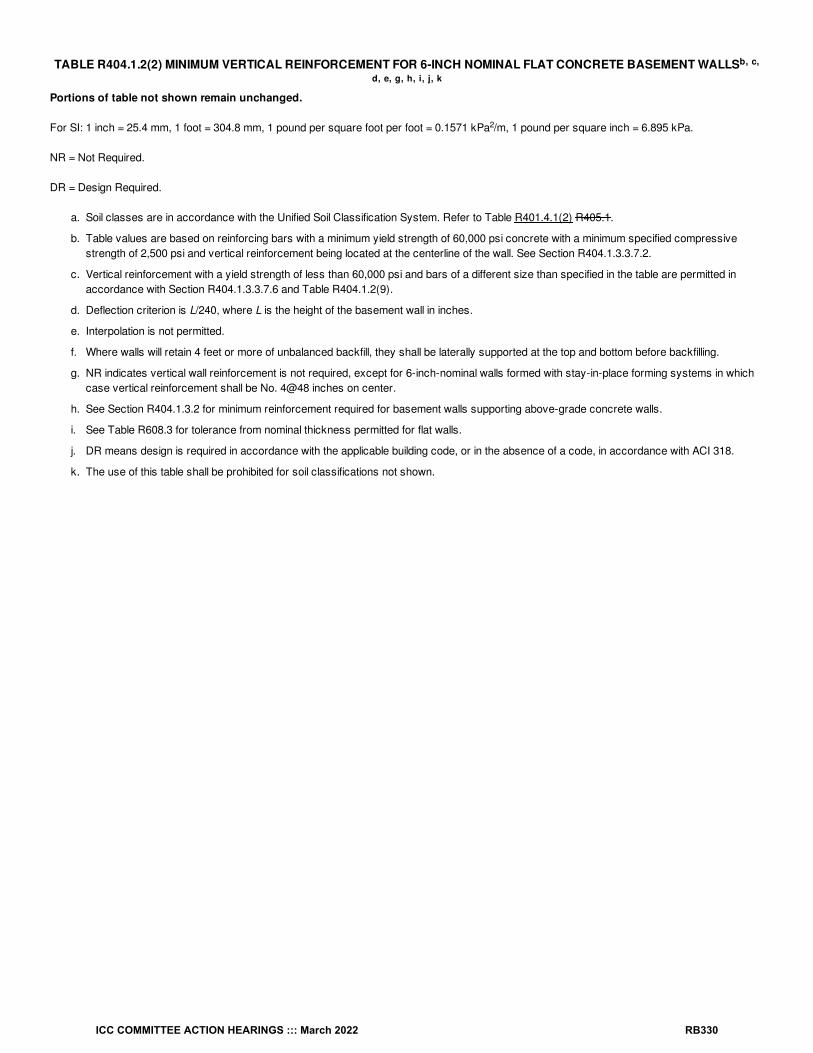
TABLE R404.1.2(2) MINIMUM VERTICAL REINFORCEMENT FOR 6-INCH NOMINAL FLAT CONCRETE BASEMENT WALLS
Portions of table not shown remain unchanged.
For SI: 1 inch = 25.4 mm, 1 foot = 304.8 mm, 1 pound per square foot per foot = 0.1571 kPa /m, 1 pound per square inch = 6.895 kPa.
NR = Not Required.
DR = Design Required.
a. Soil classes are in accordance with the Unified Soil Classification System. Refer to Table R401.4.1(2) R405.1.
b. Table values are based on reinforcing bars with a minimum yield strength of 60,000 psi concrete with a minimum specified compressivestrength of 2,500 psi and vertical reinforcement being located at the centerline of the wall. See Section R404.1.3.3.7.2.
c. Vertical reinforcement with a yield strength of less than 60,000 psi and bars of a different size than specified in the table are permitted inaccordance with Section R404.1.3.3.7.6 and Table R404.1.2(9).
d. Deflection criterion is L/240, where L is the height of the basement wall in inches.
e. Interpolation is not permitted.
f. Where walls will retain 4 feet or more of unbalanced backfill, they shall be laterally supported at the top and bottom before backfilling.
g. NR indicates vertical wall reinforcement is not required, except for 6-inch-nominal walls formed with stay-in-place forming systems in whichcase vertical reinforcement shall be No. 4@48 inches on center.
h. See Section R404.1.3.2 for minimum reinforcement required for basement walls supporting above-grade concrete walls.
i. See Table R608.3 for tolerance from nominal thickness permitted for flat walls.
j. DR means design is required in accordance with the applicable building code, or in the absence of a code, in accordance with ACI 318.
k. The use of this table shall be prohibited for soil classifications not shown.
b, c,
d, e, g, h, i, j, k
2
ICC COMMITTEE ACTION HEARINGS ::: March 2022 RB330

TABLE R404.1.2(3) MINIMUM VERTICAL REINFORCEMENT FOR 8-INCH (203 mm) NOMINAL FLAT CONCRETE BASEMENTWALLS
Portions of table not shown remain unchanged.
For SI: 1 inch = 25.4 mm, 1 foot = 304.8 mm, 1 pound per square foot per foot = 0.1571 kPa /m, 1 pound per square inch = 6.895 kPa.
NR = Not Required.
a. Soil classes are in accordance with the Unified Soil Classification System. Refer to Table R401.4.1(2) R405.1.
b. Table values are based on reinforcing bars with a minimum yield strength of 60,000 psi, concrete with a minimum specified compressivestrength of 2,500 psi and vertical reinforcement being located at the centerline of the wall. See Section R404.1.3.3.7.2.
c. Vertical reinforcement with a yield strength of less than 60,000 psi and bars of a different size than specified in the table are permitted inaccordance with Section R404.1.3.3.7.6 and Table R404.1.2(9).
d. NR indicates vertical reinforcement is not required.
e. Deflection criterion is L/240, where L is the height of the basement wall in inches.
f. Interpolation is not permitted.
g. Where walls will retain 4 feet or more of unbalanced backfill, they shall be laterally supported at the top and bottom before backfilling.
h. See Section R404.1.3.2 for minimum reinforcement required for basement walls supporting above-grade concrete walls.
i. See Table R608.3 for tolerance from nominal thickness permitted for flat walls.
j. The use of this table shall be prohibited for soil classifications not shown.
b, c, d, e, f, h, i, j
2
b, c,
ICC COMMITTEE ACTION HEARINGS ::: March 2022 RB331

TABLE R404.1.2(4) MINIMUM VERTICAL REINFORCEMENT FOR 10-INCH NOMINAL FLAT CONCRETE BASEMENT WALLS
Portions of table not shown remain unchanged.
For SI: 1 inch = 25.4 mm, 1 foot = 304.8 mm, 1 pound per square foot per foot = 0.1571 kPa /m, 1 pound per square inch = 6.895 kPa.
NR = Not Required.
a. Soil classes are in accordance with the Unified Soil Classification System. Refer to Table R401.4.1(2) R405.1.
b. Table values are based on reinforcing bars with a minimum yield strength of 60,000 psi concrete with a minimum specified compressivestrength of 2,500 psi and vertical reinforcement being located at the centerline of the wall. See Section R404.1.3.3.7.2.
c. Vertical reinforcement with a yield strength of less than 60,000 psi and bars of a different size than specified in the table are permitted inaccordance with Section R404.1.3.3.7.6 and Table R404.1.2(9).
d. NR indicates vertical reinforcement is not required.
e. Deflection criterion is L/240, where L is the height of the basement wall in inches.
f. Interpolation is not permitted.
g. Where walls will retain 4 feet or more of unbalanced backfill, they shall be laterally supported at the top and bottom before backfilling.
h. See Section R404.1.3.2 for minimum reinforcement required for basement walls supporting above-grade concrete walls.
i. See Table R608.3 for tolerance from nominal thickness permitted for flat walls.
j. The use of this table shall be prohibited for soil classifications not shown.
b, c,
d, e, f, h, i, j
2
b, c, d, e, g, h,
ICC COMMITTEE ACTION HEARINGS ::: March 2022 RB332

TABLE R404.1.2(5) MINIMUM VERTICAL WALL REINFORCEMENT FOR 6-INCH WAFFLE-GRID BASEMENT WALLS
Portions of table not shown remain unchanged.
For SI: 1 inch = 25.4 mm, 1 foot = 304.8 mm, 1 pound per square foot per foot = 0.1571 kPa /m, 1 pound per square inch = 6.895 kPa.
DR = Design Required.
a. Soil classes are in accordance with the Unified Soil Classification System. Refer to Table R401.4.1(2) R405.1.
b. Table values are based on reinforcing bars with a minimum yield strength of 60,000 psi concrete with a minimum specified compressivestrength of 2,500 psi and vertical reinforcement being located at the centerline of the wall. See Section R404.1.3.3.7.2.
c. Maximum spacings shown are the values calculated for the specified bar size. Where the bar used is Grade 60 and the size specified in thetable, the actual spacing in the wall shall not exceed a whole-number multiple of 12 inches (12, 24, 36 and 48) that is less than or equal to thetabulated spacing. Vertical reinforcement with a yield strength of less than 60,000 psi and bars of a different size than specified in the tableare permitted in accordance with Section R404.1.3.3.7.6 and Table R404.1.2(9).
d. Deflection criterion is L/240, where L is the height of the basement wall in inches.
e. Interpolation is not permitted.
f. Where walls will retain 4 feet or more of unbalanced backfill, they shall be laterally supported at the top and bottom before backfilling.
g. See Section R404.1.3.2 for minimum reinforcement required for basement walls supporting above-grade concrete walls.
h. See Table R608.3 for thicknesses and dimensions of waffle-grid walls.
i. DR means design is required in accordance with the applicable building code, or in the absence of a code, in accordance with ACI 318.
j. The use of this table shall be prohibited for soil classifications not shown.
b, c, d, e, g, h,
i, j
2
b, c, d, e, f, h, i, j, k
ICC COMMITTEE ACTION HEARINGS ::: March 2022 RB333

TABLE R404.1.2(6) MINIMUM VERTICAL REINFORCEMENT FOR 8-INCH WAFFLE-GRID BASEMENT WALLSPortions of table not shown remain unchanged.
For SI: 1 inch = 25.4 mm, 1 foot = 304.8 mm, 1 pound per square foot per foot = 0.1571 kPa /m, 1 pound per square inch = 6.895 kPa.
NR = Not Required.
DR = Design Required.
a. Soil classes are in accordance with the Unified Soil Classification System. Refer to Table R401.4.1(2) R405.1.
b. Table values are based on reinforcing bars with a minimum yield strength of 60,000 psi concrete with a minimum specified compressivestrength of 2,500 psi and vertical reinforcement being located at the centerline of the wall. See Section R404.1.3.3.7.2.
c. Maximum spacings shown are the values calculated for the specified bar size. Where the bar used is Grade 60 (420 MPa) and the sizespecified in the table, the actual spacing in the wall shall not exceed a whole-number multiple of 12 inches (12, 24, 36 and 48) that is less thanor equal to the tabulated spacing. Vertical reinforcement with a yield strength of less than 60,000 psi and bars of a different size thanspecified in the table are permitted in accordance with Section R404.1.3.3.7.6 and Table R404.1.2(9).
d. NR indicates vertical reinforcement is not required.
e. Deflection criterion is L/240, where L is the height of the basement wall in inches.
f. Interpolation shall not be permitted.
g. Where walls will retain 4 feet or more of unbalanced backfill, they shall be laterally supported at the top and bottom before backfilling.
h. See Section R404.1.3.2 for minimum reinforcement required for basement walls supporting above-grade concrete walls.
i. See Table R608.3 for thicknesses and dimensions of waffle-grid walls.
j. DR means design is required in accordance with the applicable building code, or in the absence of a code, in accordance with ACI 318.
k. The use of this table shall be prohibited for soil classifications not shown.
b, c, d, e, f, h, i, j, k
2
b, c, d, e,
ICC COMMITTEE ACTION HEARINGS ::: March 2022 RB334

TABLE R404.1.2(7) MINIMUM VERTICAL REINFORCEMENT FOR 6-INCH (152 mm) SCREEN-GRID BASEMENT WALLS
Portions of table not shown remain unchanged.
For SI: 1 inch = 25.4 mm, 1 foot = 304.8 mm, 1 pound per square foot per foot = 0.1571 kPa /m, 1 pound per square inch = 6.895 kPa.
DR = Design Required.
a. Soil classes are in accordance with the Unified Soil Classification System. Refer to Table R401.4.1(2) R405.1.
b. Table values are based on reinforcing bars with a minimum yield strength of 60,000 psi, concrete with a minimum specified compressivestrength of 2,500 psi and vertical reinforcement being located at the centerline of the wall. See Section R404.1.3.3.7.2.
c. Maximum spacings shown are the values calculated for the specified bar size. Where the bar used is Grade 60 and the size specified in thetable, the actual spacing in the wall shall not exceed a whole-number multiple of 12 inches (12, 24, 36 and 48) that is less than or equal to thetabulated spacing. Vertical reinforcement with a yield strength of less than 60,000 psi and bars of a different size than specified in the tableare permitted in accordance with Section R404.1.3.3.7.6 and Table R404.1.2(9).
d. Deflection criterion is L/240, where L is the height of the basement wall in inches.
e. Interpolation is not permitted.
f. Where walls will retain 4 feet or more of unbalanced backfill, they shall be laterally supported at the top and bottom before backfilling.
g. See Sections R404.1.3.2 for minimum reinforcement required for basement walls supporting above-grade concrete walls.
h. See Table R608.3 for thicknesses and dimensions of screen-grid walls.
i. DR means design is required in accordance with the applicable building code, or in the absence of a code, in accordance with ACI 318.
j. The use of this table shall be prohibited for soil classifications not shown.
b, c, d, e,
g, h, i, j
2
ICC COMMITTEE ACTION HEARINGS ::: March 2022 RB335

TABLE R404.1.2(8) MINIMUM VERTICAL REINFORCEMENT FOR 6-, 8-, 10- AND 12-INCH NOMINAL FLAT BASEMENTWALLS
Portions of table not shown remain unchanged.
For SI: 1 inch = 25.4 mm, 1 foot = 304.8 mm, 1 pound per square foot per foot = 0.1571 kPa /m, 1 pound per square inch = 6.895 kPa.
NR = Not Required.
DR = Design Required.
a. Soil classes are in accordance with the Unified Soil Classification System. Refer to Table R401.4.1(2) R405.1.
b. Table values are based on reinforcing bars with a minimum yield strength of 60,000 psi.
c. Vertical reinforcement with a yield strength of less than 60,000 psi and bars of a different size than specified in the table are permitted inaccordance with Section R404.1.3.3.7.6 and Table R404.1.2(9).
d. NR indicates vertical wall reinforcement is not required, except for 6-inch nominal walls formed with stay-in-place forming systems in whichcase vertical reinforcement shall be No. 4@48 inches on center.
e. Allowable deflection criterion is L/240, where L is the unsupported height of the basement wall in inches.
f. Interpolation is not permitted.
g. Where walls will retain 4 feet or more of unbalanced backfill, they shall be laterally supported at the top and bottom before backfilling.
h. Vertical reinforcement shall be located to provide a cover of 1 / inches measured from the inside face of the wall. The center of the steelshall not vary from the specified location by more than the greater of 10 percent of the wall thickness or / inch.
i. Concrete cover for reinforcement measured from the inside face of the wall shall be not less than / inch. Concrete cover for reinforcementmeasured from the outside face of the wall shall be not less than 1 / inches for No. 5 bars and smaller, and not less than 2 inches for largerbars.
j. DR means design is required in accordance with the applicable building code, or in the absence of a code, in accordance with ACI 318.
k. Concrete shall have a specified compressive strength, f′ , of not less than 2,500 psi at 28 days, unless a higher strength is required by Notel or m.
l. The minimum thickness is permitted to be reduced 2 inches, provided that the minimum specified compressive strength of concrete, f′ , is4,000 psi.
m. A plain concrete wall with a minimum nominal thickness of 12 inches is permitted, provided that the minimum specified compressive strengthof concrete, f′ , is 3,500 psi.
n. See Table R608.3 for tolerance from nominal thickness permitted for flat walls.
o. The use of this table shall be prohibited for soil classifications not shown.
R405.1 Concrete or masonry foundations. Drains shall be provided around concrete or masonry foundations that retain earth and enclosehabitable or usable spaces located below grade. Drainage tiles, gravel or crushed stone drains, perforated pipe or other approved systems ormaterials shall be installed at or below the top of the footing or below the bottom of the slab and shall discharge by gravity or mechanical means intoan approved drainage system. Gravel or crushed stone drains shall extend not less than 1 foot (305 mm) beyond the outside edge of the footingand 6 inches (152 mm) above the top of the footing and be covered with an approved filter membrane material. The top of open joints of drain tilesshall be protected with strips of building paper. Except where otherwise recommended by the drain manufacturer, perforated drains shall besurrounded with an approved filter membrane or the filter membrane shall cover the washed gravel or crushed rock covering the drain. Drainagetiles or perforated pipe shall be placed on not less than 2 inches (51 mm) of washed gravel or crushed rock not less than one sieve size larger thanthe tile joint opening or perforation and covered with not less than 6 inches (152 mm) of the same material.
Exception: A drainage system is not required where the foundation is installed on well-drained ground or sand-gravel mixture soils according tothe Unified Soil Classification System, Group I soils, as detailed in Table R401.4.1(2) R405.1.
R506.2.2 Base. A 4-inch-thick (102 mm) base course consisting of clean graded sand, gravel, crushed stone, crushed concrete or crushed blast-furnace slag passing a 2-inch (51 mm) sieve shall be placed on the prepared subgrade where the slab is below grade.
Exception: A base course is not required where the concrete slab is installed on well-drained or sand-gravel mixture soils classified as Group Iaccording to the United Soil Classification System in accordance with Table R401.4.1(2) R405.1.
Reason Statement: This proposal accomplishes three things. First, it relocates existing IRC Table R405.1 to Section R401.4.1. The soilclassifications in the table are referred to repeatedly throughout IRC Section R401 and R402, yet somehow the user must flip all the way to SectionR405 to find where the classifications are defined.
b, c, d, e, f, h, i, k, n, o
2
14
38
34
12
c
c
c
ICC COMMITTEE ACTION HEARINGS ::: March 2022 RB336

Secondly, a column is added providing U.S. Department of Agriculture (USDA) soil classifications in addition to the traditional Unified SoilClassification System (USCS) soil classifications. This provides a readily accessible resource which can be referenced if a geotechnicalinvestigation is not being done, which is often the case in residential projects as such investigations can be cost-prohibitive. In the absence of ageotechnical investigation, enabling the use of the USDA data and textural descriptions may help ensure builders select a proper soil classificationwhich is used to size footings based on assumed bearing pressures and determine foundation wall thickness and reinforcing. The latter is especiallycritical as assuming a higher quality soil than is actually present could lead to a foundation wall failure, creating a life safety issue.
The U.S. Army Corps of Engineers Engineer Research and Development Center conducted a study in 2015 to develop a consensus methodologyfor relating the USCS system to the USDA classification scheme. The USACE study compiled data from six soil databases containing thousands ofsoil samples with recorded properties, including water capacity, soil reaction, electrical conductivity, textural class, PH, salinity, clay fraction, andsand fraction. Using these records USASCE was able to identify samples classified under both the USDA and UCSC systems, determine thefrequency of USDA classified soils occurring in the various UCSC categories, and reach a consensus scheme mapping between USDA soil typesand USGS soil classifications. It is noted the mapping scheme does not apply to gravelly soils or to organic soils.
Lastly, a new footnote "c" is added to clarify certain soil types are unsuitable for backfill due to their poor drainage characteristics. A similar footnoteappears in the IBC.
Bibliography:García-Gaines, R. A., & Frankenstein, S. (2015). USCS and the USDA Soil Classification System, Development of a Mapping Scheme. Vicksburg,MS: U.S. Army Engineer Research and Development Center. Accessed at https://erdc-library.erdc.dren.mil/jspui/bitstream/11681/5485/1/ERDC-CRREL-TR-15-4.pdf.
Cost Impact: The code change proposal will increase the cost of constructionThe proposal will increase the cost of construction where use of the USDA textural soil classifications leads to an identification of soils with lessstiffness or lower drainage characteristics than what would have previously been assumed, resulting in additional foundation wall thickness,additional foundation wall reinforcing, or wider footing widths. Conversely, a cost savings may occur if better soil conditions are identified. Further, ageotechnical investigation typically costs around $1,000-$1,500 for a single-family dwelling project. Additional savings could accrue to the builder andhomeowner if consideration of the USDA data suggests a site-specific investigation is not necessary.
RB165-22
ICC COMMITTEE ACTION HEARINGS ::: March 2022 RB337

RB166-22IRC: R403.1.1, R403.5 (New), FIGURE R403.5(1) (New), FIGURE R403.5(2) (New)
Proponents: Anthony Dente, representing Verdant Structural Engineers ([email protected]); Martin Hammer, representing MartinHammer, Architect ([email protected]); David Eisenberg, representing DCAT ([email protected])
2021 International Residential CodeRevise as follows:
R403.1.1 Minimum size. The minimum width, W, and thickness, T, for concrete footings shall be in accordance with Tables R403.1(1) throughR403.1(3) and Figure R403.1(1) or R403.1.3, as applicable, but not less than 12 inches (305 mm) in width and 6 inches (152 mm) in depth. Thefooting width shall be based on the load-bearing value of the soil in accordance with Table R401.4.1. Footing projections, P, shall be not less than 2inches (51 mm) and shall not exceed the thickness of the footing. Footing thickness and projection for fireplaces shall be in accordance with SectionR1001.2. The size of footings supporting piers and columns shall be based on the tributary load and allowable soil pressure in accordance withTable R401.4.1. Footings for wood foundations shall be in accordance with the details set forth in Section R403.2, and Figures R403.1(2) andR403.1(3). Footings for precast foundations shall be in accordance with the details set forth in Section R403.4, Table R403.4, and Figures R403.4(1)and R403.4(2). Crushed stone footings for masonry or cast-in-place concrete foundations shall be in accordance with Section R403.5.
Add new text as follows:
R403.5 Crushed stone footings for cast-in-place foundations. Crushed stone footings for masonry or cast-in-place concrete foundationscomplying with Section R404.1 shall comply with Section R403.4.1 except they shall be installed in accordance with Figures R403.5(1) or R403.5(2).
ICC COMMITTEE ACTION HEARINGS ::: March 2022 RB338

FIGURE R403.5(1) CRUSHED STONE FOOTINGS FOR CAST-IN-PLACE FOUNDATIONS IN SEISMIC DESIGN CATEGORIES A, B, AND C -MASONRY OR CAST-IN-PLACE CONCRETE FOUNDATION WALL
ICC COMMITTEE ACTION HEARINGS ::: March 2022 RB339
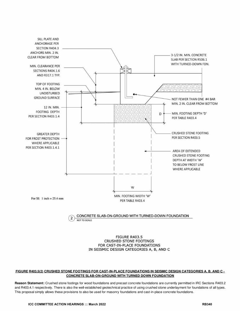
FIGURE R403.5(2) CRUSHED STONE FOOTINGS FOR CAST-IN-PLACE FOUNDATIONS IN SEISMIC DESIGN CATEGORIES A, B, AND C -CONCRETE SLAB-ON-GROUND WITH TURNED DOWN FOUNDATION
Reason Statement: Crushed stone footings for wood foundations and precast concrete foundations are currently permitted in IRC Sections R403.2and R403.4.1 respectively. There is also the well-established geotechnical practice of using crushed stone underlayment for foundations of all types.This proposal simply allows these provisions to also be used for masonry foundations and cast-in-place concrete foundations.
ICC COMMITTEE ACTION HEARINGS ::: March 2022 RB340

This proposal uses identical requirements for crushed stone and its placement as those for analogous pre-cast concrete foundations inSection R403.4.1 (by reference), and for footing width and depth in the associated Table R403.4. The proposal limits the proposed use of crushedstone to Seismic Design Categories A, B, and C, by reference as stated in Section R403.4.1. New Figures R403.5(1) and (2) illustrate therequirements, including minimums regarding the top of the footing relative to undisturbed ground surface. The Figures illustrate two conditions forcrushed stone footings: 1) masonry or concrete wall foundation, and 2) slab-on-ground with turned down foundation.Conservatively, not less than one #4 bar is required for these foundations over a crushed stone footing. This is not currently required for plainconcrete footings or turned-down footings in Seismic Design Categories A, B, and C. Minimum clearances for the #4 bar and the sill plate anchor arealso stated in the Figures.
Cost Impact: The code change proposal will decrease the cost of constructionThis proposal adds a less material-intensive, less labor-intensive and therefore less expensive foundation option, by allowing the use of crushedstone instead of concrete for footings in some situations.
RB166-22
ICC COMMITTEE ACTION HEARINGS ::: March 2022 RB341

RB167-22IRC: FIGURE R403.1(1)
Proponents: Mike Nugent, representing Building Code Action Committee ([email protected])
2021 International Residential CodeRevise as follows:
ICC COMMITTEE ACTION HEARINGS ::: March 2022 RB342

ICC COMMITTEE ACTION HEARINGS ::: March 2022 RB343

For SI: 1 inch = 25.4 mm. W = Width of footing, T = Thickness of footing and P = Projection per Section R403.1.1.
a. See Section R404.3 for sill requirements.
b. See Section R403.1.6 for sill attachment.
c. See Section R506.2.3 for vapor barrier requirements.
d. See Section R403.1 for base.
e. See Figure R403.1.3 for additional footing requirements for structures in Seismic Design Categories D , D and D and townhouses inSeismic Design Category C.
f. See Section R408 for under-floor ventilation and access requirements.
FIGURE R403.1(1) PLAIN CONCRETE FOOTINGS WITH MASONRY AND CONCRETE STEM WALLS IN SEISMIC DESIGN CATEGORIES A,B AND C
Reason Statement: All basement walls tables assumed the wall is laterally supported at the top and bottom. See foot notes in all concrete wallstables. Footnote g. states “Where walls will retain 4 feet or more of unbalanced backfill, they shall be laterally supported at the top and bottom beforebackfilling”. R403.1.1 Minimum size for footing reference Figure R403.1(1). Figure R403.1(1) does not show any connection requirements. Thisproposal gives options for footing to wall connections in FIGURE R403.1(1) by adding a pointer states “Provide lateral restraint at the base of wallssupporting more than 48 inches of unbalance backfill in accordance with R404.1.3.2”.This lateral restraint can be provided by a keyway, footing dowels, or by a slab-on-ground poured against the base of the wall.
This proposal is submitted by the ICC Building Code Action Committee (BCAC).
BCAC was established by the ICC Board of Directors in July 2011 to pursue opportunities to improve and enhance assigned International Codes orportions thereof. In 2020 and 2021 the BCAC has held several virtual meetings open to any interested party. In addition, there were numerous virtualWorking Group meetings for the current code development cycle, which included members of the committee as well as interested parties. Relateddocuments and reports are posted on the BCAC website at https://www.iccsafe.org/products-and-services/i-codes/code-development/cs/building-code-action-committee-bcac/.
0 1 2
a, b, c, d, e, f
ICC COMMITTEE ACTION HEARINGS ::: March 2022 RB344

Cost Impact: The code change proposal will not increase or decrease the cost of constructionThis proposal clarifies the requirements in the current code text. All basement walls tables assumed the wall is laterally supported at the top andbottom. This proposal clarifies the options for connections. There is no change in the cost since this is based on the current practice.
RB167-22
ICC COMMITTEE ACTION HEARINGS ::: March 2022 RB345

RB168-22IRC: TABLE R404.1.1(1)
Proponents: Gary Ehrlich, representing NAHB ([email protected])
2021 International Residential CodeRevise as follows:
f
ICC COMMITTEE ACTION HEARINGS ::: March 2022 RB346
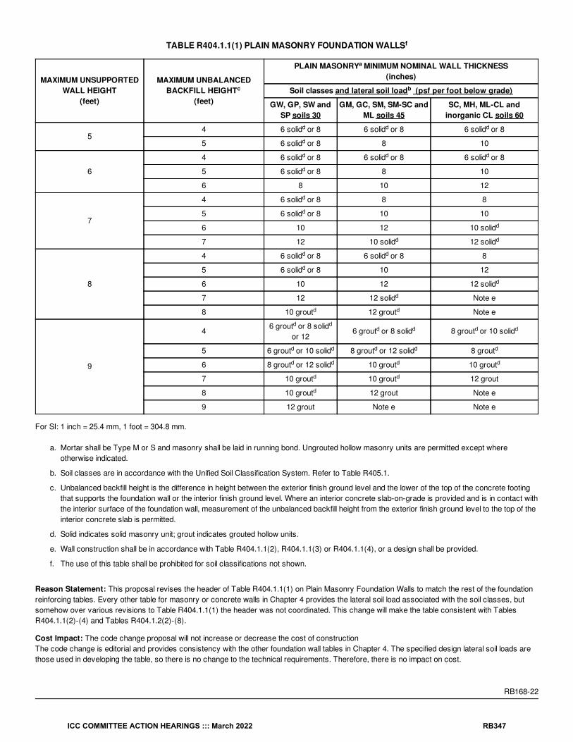
TABLE R404.1.1(1) PLAIN MASONRY FOUNDATION WALLS
MAXIMUM UNSUPPORTEDWALL HEIGHT
(feet)
MAXIMUM UNBALANCEDBACKFILL HEIGHT
(feet)
PLAIN MASONRY MINIMUM NOMINAL WALL THICKNESS(inches)
Soil classes and lateral soil load (psf per foot below grade)
GW, GP, SW andSP soils 30
GM, GC, SM, SM-SC andML soils 45
SC, MH, ML-CL andinorganic CL soils 60
54 6 solid or 8 6 solid or 8 6 solid or 8
5 6 solid or 8 8 10
6
4 6 solid or 8 6 solid or 8 6 solid or 8
5 6 solid or 8 8 10
6 8 10 12
7
4 6 solid or 8 8 8
5 6 solid or 8 10 10
6 10 12 10 solid
7 12 10 solid 12 solid
8
4 6 solid or 8 6 solid or 8 8
5 6 solid or 8 10 12
6 10 12 12 solid
7 12 12 solid Note e
8 10 grout 12 grout Note e
9
46 grout or 8 solid
or 126 grout or 8 solid 8 grout or 10 solid
5 6 grout or 10 solid 8 grout or 12 solid 8 grout
6 8 grout or 12 solid 10 grout 10 grout
7 10 grout 10 grout 12 grout
8 10 grout 12 grout Note e
9 12 grout Note e Note e
For SI: 1 inch = 25.4 mm, 1 foot = 304.8 mm.
a. Mortar shall be Type M or S and masonry shall be laid in running bond. Ungrouted hollow masonry units are permitted except whereotherwise indicated.
b. Soil classes are in accordance with the Unified Soil Classification System. Refer to Table R405.1.
c. Unbalanced backfill height is the difference in height between the exterior finish ground level and the lower of the top of the concrete footingthat supports the foundation wall or the interior finish ground level. Where an interior concrete slab-on-grade is provided and is in contact withthe interior surface of the foundation wall, measurement of the unbalanced backfill height from the exterior finish ground level to the top of theinterior concrete slab is permitted.
d. Solid indicates solid masonry unit; grout indicates grouted hollow units.
e. Wall construction shall be in accordance with Table R404.1.1(2), R404.1.1(3) or R404.1.1(4), or a design shall be provided.
f. The use of this table shall be prohibited for soil classifications not shown.
Reason Statement: This proposal revises the header of Table R404.1.1(1) on Plain Masonry Foundation Walls to match the rest of the foundationreinforcing tables. Every other table for masonry or concrete walls in Chapter 4 provides the lateral soil load associated with the soil classes, butsomehow over various revisions to Table R404.1.1(1) the header was not coordinated. This change will make the table consistent with TablesR404.1.1(2)-(4) and Tables R404.1.2(2)-(8).
Cost Impact: The code change proposal will not increase or decrease the cost of constructionThe code change is editorial and provides consistency with the other foundation wall tables in Chapter 4. The specified design lateral soil loads arethose used in developing the table, so there is no change to the technical requirements. Therefore, there is no impact on cost.
RB168-22
f
c
a
b
d d d
d
d d d
d
d
d
d
d d
d d
d
d
d
d d
d dd d d d
d d d d d
d d d d
d d
d
ICC COMMITTEE ACTION HEARINGS ::: March 2022 RB347

RB169-22IRC: R403.1.2, TABLE R403.1.2 (New)
Proponents: Borjen Yeh, representing APA - The Engineered Wood Association ([email protected])
2021 International Residential CodeRevise as follows:
R403.1.2 Continuous footing in Seismic Design Categories D , D and D . Exterior walls of buildings located in Seismic Design Categories D ,D and D shall be supported by continuous solid or fully grouted masonry or concrete footings in accordance with Table R403.1.2. Other footingmaterials or systems shall be designed in accordance with accepted engineering practice. Required interior braced wall panels in buildings located inSeismic Design Categories D , D and D with plan dimensions greater than 50 feet (15 240 mm) shall be supported by continuous solid or fullygrouted masonry or concrete footings in accordance with Section R403.1.3.4, except for two-story buildings in Seismic Design Category D , inwhich all braced wall panels, interior and exterior, shall be supported on continuous foundations.
Exception: Two-story buildings shall be permitted to have interior braced wall panels supported on continuous foundations at intervals notexceeding 50 feet (15 240 mm) provided that:
1. The height of cripple walls does not exceed 4 feet (1219 mm).
2. First-floor braced wall panels are supported on doubled floor joists, continuous blocking or floor beams.
3. The distance between bracing lines does not exceed twice the building width measured parallel to the braced wall line.
Add new text as follows:
0 1 2 0
1 2
0 1 2
2
ICC COMMITTEE ACTION HEARINGS ::: March 2022 RB348

TABLE R403.1.2 CONTINUOUS FOOTING REQUIREMENTS IN SEISMIC DESIGN CATEGORIES D , D AND D
PLAN DIMENSIONS 1-STORY 2-STORY
50 feet or less > 50 feet 50 feet or less > 50 feet
SDC D D D D D D D D D D D D
Exterior Brace Wall Panel
Continuous Footings R R R R R R R R R R R R
Interior Brace Wall Panel
Continuous Footings NR NR NR R R R NR NR R R R R
R = Continuous solid or fully grouted masonry or concrete footings in accordance with Section R403.1.3.4 required.NR = Continuous footings not required.
a. NR when the following conditions are all met:1. The height of cripple walls does not exceed 4 feet (1219 mm).
2. First-floor braced wall panels are supported on doubled floor joists, continuous blocking or floor beams.
3. The distance between bracing lines does not exceed twice the building width measured parallel to the braced wall line.
Reason Statement: Section R403.1.2 contains exceptions over exceptions and is confusing with various possible interpretations. The intent of thischange proposal is to tabulate the provision in the new Table R403.1.2 without changing the intent of the existing provisions. Please note thatFootnote (1) to Table R403.1.2 are identical to the exceptions contained in the existing Section R403.1.2.Table R403.1.2 is consistent with the IRCwith the only exception for the 1‑story with plan dimension of greater than 50 feet in interior brace wall panels, in which the "IRC Commentary FigureR403.1.2" indicates continuous footings are required. However, under the same conditions, the IRC indicates continuous footings are not requiredfor 2-story buildings if the exceptions listed in the existing Section R403.1.2 are met. It seems irrational that 2-story buildings (more mass in seismicloading) are not required to have continuous footings, while 1‑story buildings (less mass in seismic loading) are required to have continuous footingsunder the same plan dimension and interior brace wall panel. Therefore, the proposed new Table R403.1.2 conservatively applies the same 2-storybuilding requirements to 1-story buildings.
Cost Impact: The code change proposal will not increase or decrease the cost of constructionThis code change proposal will not increase or decrease the cost of construction because the proposal is intended to present the current coderequirements in a tabulated format for ease of understanding and implementation.
RB169-22
0 1 2
0 1 2 0 1 2 0 1 2 0 1 2
a a a a a a a
ICC COMMITTEE ACTION HEARINGS ::: March 2022 RB349

RB170-22IRC: R403.1.6
Proponents: Randy Shackelford, representing Simpson Strong-Tie Co. ([email protected])
2021 International Residential CodeRevise as follows:
R403.1.6 Foundation anchorage. Wood sill plates and wood walls supported directly on continuous foundations shall be anchored to thefoundation in accordance with this section.Cold-formed steel framing shall be anchored directly to the foundation or fastened to wood sill plates in accordance with Section R505.3.1 orR603.3.1, as applicable. Wood sill plates supporting cold-formed steel framing shall be anchored to the foundation in accordance with this section.
Wood sole plates at all exterior walls on monolithic slabs, wood sole plates of braced wall panels at building interiors on monolithic slabs and all woodsill plates shall be anchored to the foundation with minimum / -inch-diameter (12.7 mm) anchor bolts spaced not greater than 6 feet (1829 mm) oncenter or approved anchors or anchor straps spaced as required to provide equivalent anchorage to / -inch-diameter (12.7 mm) anchor bolts.Bolts shall extend not less than 7 inches (178 mm) into concrete or grouted cells of concrete masonry units. The bolts shall be located in the middlethird of the width of the plate. A nut and washer shall be tightened on each anchor bolt. There shall be not fewer than two bolts per plate section withone bolt located not more than 12 inches (305 mm) or less than seven bolt diameters from each end of the plate section. Interior bearing wall soleplates on monolithic slab foundation that are not part of a braced wall panel shall be positively anchored with approved fasteners. Sill plates and soleplates shall be protected against decay and termites where required by Sections R317 and R318. Anchor bolts shall be permitted to be locatedwhile concrete is still plastic and before it has set. Where anchor bolts resist placement or the consolidation of concrete around anchor bolts isimpeded, the concrete shall be vibrated to ensure full contact between the anchor bolts and concrete.
Exceptions:
1. Walls 24 inches (610 mm) total length or shorter connecting offset braced wall panels shall be anchored to the foundation with not fewerthan one anchor bolt located in the center third of the plate section and shall be attached to adjacent braced wall panels at corners asshown in Item 9 of Table R602.3(1).
2. Connection of walls 12 7 inches (305 178 mm) total length or shorter connecting offset braced wall panels to the foundation withoutanchor bolts shall be permitted. The wall shall be attached to adjacent braced wall panels at corners as shown in Item 9 of TableR602.3(1).
Reason Statement: Exception 2 needs to be either eliminated or reduced. Wall corners at braced wall panels are required to have specialfastening by Table R602.3(1) because the overturning uplift of the braced wall panel is partially resisted by the connection to the perpendicular wall,which is anchored to the foundation with anchor bolts. If the perpendicular wall is not anchored to the foundation, it can not resist this uplift force. Aswritten, this exception allows omission of anchor bolts on certain walls that are perpendicular to braced wall panels, so the walls will not be able toresist the overturning in the perpendicular wall. Anchor bolts are required to be placed so that they are no more than 12" from the end of a plate, and no closer than 7 anchor bolt diameters, whichis 3-1/2" for a 1/2" diameter anchor bolt. So for Exception 1, the single bolt is properly located within 12" from each end of the plate when the plate is24" long or less, so it is effective. Exception 2 should only allow the omission of the anchor bolt when it is not effective. It is possible to install aneffective anchor bolt in plates over 7" in length. For plates less than 7" in length, the bolt will be closer than the 7 bolt diameters so its effectivenesswill be reduced, so therefore it might make sense to allow its omission.
Cost Impact: The code change proposal will increase the cost of constructionIt is possible in very limited cases that this would increase the cost of construction if it required an anchor bolt where the 2021 IRC would not requireone (for plates between 7" and 12" long).
RB170-22
12
12
ICC COMMITTEE ACTION HEARINGS ::: March 2022 RB350

RB171-22IRC: R404.1.2, R404.1.2.1, TABLE R404.1.1(1), TABLE R404.1.1(2), TABLE R404.1.1(3), TABLE R404.1.1(4), R404.1.3.2, TABLE R404.1.2(1),TABLE R404.1.2(2), TABLE R404.1.2(3), TABLE R404.1.2(4), TABLE R404.1.2(5), TABLE R404.1.2(6), TABLE R404.1.2(7), TABLER404.1.2(8), TABLE R404.1.2(9), R404.1.3.3.7.2, R404.1.3.3.7.6, R404.1.4.1, R404.1.4.2, R404.1.5.2
Proponents: Mike Nugent, representing Building Code Action Committee ([email protected])
2021 International Residential CodeR404.1.2 Design of masonry foundation walls. Masonry foundation walls shall be designed and constructed in accordance with the provisions ofthis section or in accordance with the provisions of TMS 402. Where TMS 402 or the provisions of this section are used to design masonryfoundation walls, project drawings, typical details and specifications are not required to bear the seal of the architect or engineer responsible fordesign, unless otherwise required by the state law of the jurisdiction having authority.
Revise as follows:
R404.1.2.1 Masonry foundation walls. Concrete masonry and clay masonry foundation walls shall be constructed as set forth in TableR404.1.1(1) R404.1.2.1(1), R404.1.1(2) R404.1.2.1(2), R404.1.1(3) R404.1.2.1(3) or R404.1.1(4) R404.1.2.1(4) and shall comply with applicableprovisions of Section R606. In buildings assigned to Seismic Design Categories D , D and D , concrete masonry and clay masonry foundationwalls shall also comply with Section R404.1.4.1. Rubble stone masonry foundation walls shall be constructed in accordance with Sections R404.1.8and R606.4.2. Rubble stone masonry walls shall not be used in Seismic Design Categories D , D and D , or in townhouses in Seismic DesignCategory C.
0 1 2
0 1 2
f
ICC COMMITTEE ACTION HEARINGS ::: March 2022 RB351

TABLE R404.1.1(1) R404.1.2.1(1) PLAIN MASONRY FOUNDATION WALLS
MAXIMUM UNSUPPORTEDWALL HEIGHT
(feet)
MAXIMUM UNBALANCEDBACKFILL HEIGHT
(feet)
PLAIN MASONRY MINIMUM NOMINAL WALL THICKNESS(inches)
Soil classes
GW, GP, SW andSP
GM, GC, SM, SM-SCand ML
SC, MH, ML-CL andinorganic CL
54 6 solid or 8 6 solid or 8 6 solid or 8
5 6 solid or 8 8 10
6
4 6 solid or 8 6 solid or 8 6 solid or 8
5 6 solid or 8 8 10
6 8 10 12
7
4 6 solid or 8 8 8
5 6 solid or 8 10 10
6 10 12 10 solid
7 12 10 solid 12 solid
8
4 6 solid or 8 6 solid or 8 8
5 6 solid or 8 10 12
6 10 12 12 solid
7 12 12 solid Note e
8 10 grout 12 grout Note e
9
46 grout or 8 solid
or 126 grout or 8 solid 8 grout or 10 solid
56 grout or 10
solid8 grout or 12 solid 8 grout
68 grout or 12
solid 10 grout 10 grout
7 10 grout 10 grout 12 grout
8 10 grout 12 grout Note e
9 12 grout Note e Note e
For SI: 1 inch = 25.4 mm, 1 foot = 304.8 mm.
a. Mortar shall be Type M or S and masonry shall be laid in running bond. Ungrouted hollow masonry units are permitted except whereotherwise indicated.
b. Soil classes are in accordance with the Unified Soil Classification System. Refer to Table R405.1.
c. Unbalanced backfill height is the difference in height between the exterior finish ground level and the lower of the top of the concrete footingthat supports the foundation wall or the interior finish ground level. Where an interior concrete slab-on-grade is provided and is in contact withthe interior surface of the foundation wall, measurement of the unbalanced backfill height from the exterior finish ground level to the top of theinterior concrete slab is permitted.
d. Solid indicates solid masonry unit; grout indicates grouted hollow units.
e. Wall construction shall be in accordance with Table R404.1.1(2) R404.1.2.1(2), R404.1.1(3) R404.1.2.1(3) or R404.1.1(4) R404.1.2.1(4), ora design shall be provided.
f. The use of this table shall be prohibited for soil classifications not shown.
f
c
a
b
d d d
d
d d d
d
d
d
d
d d
d d
d
d
d
d d
d dd d d d
d
dd d d
d
d d d
d d
d
a, c, f
ICC COMMITTEE ACTION HEARINGS ::: March 2022 RB352

TABLE R404.1.1(2) R404.1.2.1(2) 8-INCH MASONRY FOUNDATION WALLS WITH REINFORCING WHERE d ≥ 5 INCHES
MAXIMUM UNSUPPORTEDWALL HEIGHT
HEIGHT OF UNBALANCEDBACKFILL
MINIMUM VERTICAL REINFORCEMENT AND SPACING (INCHES)
Soil classes and lateral soil load (psf per foot below grade)
GW, GP, SW and SPsoils 30
GM, GC, SM, SM-SC andML soils 45
SC, ML-CL and inorganicCL soils 60
6 feet 8 inches
4 feet (or less) #4 at 48 #4 at 48 #4 at 48
5 feet #4 at 48 #4 at 48 #4 at 48
6 feet 8 inches #4 at 48 #5 at 48 #6 at 48
7 feet 4 inches
4 feet (or less) #4 at 48 #4 at 48 #4 at 48
5 feet #4 at 48 #4 at 48 #4 at 48
6 feet #4 at 48 #5 at 48 #5 at 48
7 feet 4 inches #5 at 48 #6 at 48 #6 at 40
8 feet
4 feet (or less) #4 at 48 #4 at 48 #4 at 48
5 feet #4 at 48 #4 at 48 #4 at 48
6 feet #4 at 48 #5 at 48 #5 at 48
7 feet #5 at 48 #6 at 48 #6 at 40
8 feet #5 at 48 #6 at 48 #6 at 32
8 feet 8 inches
4 feet (or less) #4 at 48 #4 at 48 #4 at 48
5 feet #4 at 48 #4 at 48 #5 at 48
6 feet #4 at 48 #5 at 48 #6 at 48
7 feet #5 at 48 #6 at 48 #6 at 40
8 feet 8 inches #6 at 48 #6 at 32 #6 at 24
9 feet 4 inches
4 feet (or less) #4 at 48 #4 at 48 #4 at 48
5 feet #4 at 48 #4 at 48 #5 at 48
6 feet #4 at 48 #5 at 48 #6 at 48
7 feet #5 at 48 #6 at 48 #6 at 40
8 feet #6 at 48 #6 at 40 #6 at 24
9 feet 4 inches #6 at 40 #6 at 24 #6 at 16
10 feet
4 feet (or less) #4 at 48 #4 at 48 #4 at 48
5 feet #4 at 48 #4 at 48 #5 at 48
6 feet #4 at 48 #5 at 48 #6 at 48
7 feet #5 at 48 #6 at 48 #6 at 32
8 feet #6 at 48 #6 at 32 #6 at 24
9 feet #6 at 40 #6 at 24 #6 at 16
10 feet #6 at 32 #6 at 16 #6 at 16
For SI: 1 inch = 25.4 mm, 1 foot = 304.8 mm, 1 pound per square foot per foot = 0.157 kPa/mm.
a. Mortar shall be Type M or S and masonry shall be laid in running bond.
b. Alternative reinforcing bar sizes and spacings having an equivalent cross-sectional area of reinforcement per lineal foot of wall shall bepermitted provided the spacing of the reinforcement does not exceed 72 inches in Seismic Design Categories A, B and C, and 48 inches inSeismic Design Categories D , D and D .
c. Vertical reinforcement shall be Grade 60 minimum. The distance, d, from the face of the soil side of the wall to the center of verticalreinforcement shall be not less than 5 inches.
d. Soil classes are in accordance with the Unified Soil Classification System and design lateral soil loads are for moist conditions withouthydrostatic pressure. Refer to Table R405.1.
a, c, f
e
b, c
d
0 1 2
ICC COMMITTEE ACTION HEARINGS ::: March 2022 RB353

e. Unbalanced backfill height is the difference in height between the exterior finish ground level and the lower of the top of the concrete footingthat supports the foundation wall or the interior finish ground level. Where an interior concrete slab-on-grade is provided and is in contact withthe interior surface of the foundation wall, measurement of the unbalanced backfill height from the exterior finish ground level to the top of theinterior concrete slab is permitted.
f. The use of this table shall be prohibited for soil classifications not shown.
a, c,
ICC COMMITTEE ACTION HEARINGS ::: March 2022 RB354

TABLE R404.1.1(3) R404.1.2.1(3) 10-INCH MASONRY FOUNDATION WALLS WITH REINFORCING WHERE d ≥ 6.75 INCHES
MAXIMUM UNSUPPORTEDWALL HEIGHT
HEIGHT OF UNBALANCEDBACKFILL
MINIMUM VERTICAL REINFORCEMENT AND SPACING (INCHES)
Soil classes and later soil load (psf per foot below grade)
GW, GP, SW and SPsoils 30
GM, GC, SM, SM-SC andML soils 45
SC, ML-CL and inorganicCL soils 60
6 feet 8 inches
4 feet (or less) #4 at 56 #4 at 56 #4 at 56
5 feet #4 at 56 #4 at 56 #4 at 56
6 feet 8 inches #4 at 56 #5 at 56 #5 at 56
7 feet 4 inches
4 feet (or less) #4 at 56 #4 at 56 #4 at 56
5 feet #4 at 56 #4 at 56 #4 at 56
6 feet #4 at 56 #4 at 56 #5 at 56
7 feet 4 inches #4 at 56 #5 at 56 #6 at 56
8 feet
4 feet (or less) #4 at 56 #4 at 56 #4 at 56
5 feet #4 at 56 #4 at 56 #4 at 56
6 feet #4 at 56 #4 at 56 #5 at 56
7 feet #4 at 56 #5 at 56 #6 at 56
8 feet #5 at 56 #6 at 56 #6 at 48
8 feet 8 inches
4 feet (or less) #4 at 56 #4 at 56 #4 at 56
5 feet #4 at 56 #4 at 56 #4 at 56
6 feet #4 at 56 #4 at 56 #5 at 56
7 feet #4 at 56 #5 at 56 #6 at 56
8 feet 8 inches #5 at 56 #6 at 48 #6 at 32
9 feet 4 inches
4 feet (or less) #4 at 56 #4 at 56 #4 at 56
5 feet #4 at 56 #4 at 56 #4 at 56
6 feet #4 at 56 #5 at 56 #5 at 56
7 feet #4 at 56 #5 at 56 #6 at 56
8 feet #5 at 56 #6 at 56 #6 at 40
9 feet 4 inches #6 at 56 #6 at 40 #6 at 24
10 feet
4 feet (or less) #4 at 56 #4 at 56 #4 at 56
5 feet #4 at 56 #4 at 56 #4 at 56
6 feet #4 at 56 #5 at 56 #5 at 56
7 feet #5 at 56 #6 at 56 #6 at 48
8 feet #5 at 56 #6 at 48 #6 at 40
9 feet #6 at 56 #6 at 40 #6 at 24
10 feet #6 at 48 #6 at 32 #6 at 24
For SI: 1 inch = 25.4 mm, 1 foot = 304.8 mm, 1 pound per square foot per foot = 0.157 kPa/mm.
a. Mortar shall be Type M or S and masonry shall be laid in running bond.
b. Alternative reinforcing bar sizes and spacings having an equivalent cross-sectional area of reinforcement per lineal foot of wall shall bepermitted provided the spacing of the reinforcement does not exceed 72 inches in Seismic Design Categories A, B and C, and 48 inches inSeismic Design Categories D , D and D .
c. Vertical reinforcement shall be Grade 60 minimum. The distance, d, from the face of the soil side of the wall to the center of verticalreinforcement shall be not less than 6.75 inches.
d. Soil classes are in accordance with the Unified Soil Classification System and design lateral soil loads are for moist conditions withouthydrostatic pressure. Refer to Table R405.1.
a, c,
f
e
b, c
d
0 1 2
ICC COMMITTEE ACTION HEARINGS ::: March 2022 RB355

e. Unbalanced backfill height is the difference in height between the exterior finish ground level and the lower of the top of the concrete footingthat supports the foundation wall or the interior finish ground level. Where an interior concrete slab-on-grade is provided and is in contact withthe interior surface of the foundation wall, measurement of the unbalanced backfill height from the exterior finish ground level to the top of theinterior concrete slab is permitted.
f. The use of this table shall be prohibited for soil classifications not shown.
a, c,
ICC COMMITTEE ACTION HEARINGS ::: March 2022 RB356

TABLE R404.1.1(4) R404.1.2.1(4) 12-INCH MASONRY FOUNDATION WALLS WITH REINFORCING WHERE d ≥ 8.75 INCHES
MAXIMUM UNSUPPORTEDWALL HEIGHT
HEIGHT OF UNBALANCEDBACKFILL
MINIMUM VERTICAL REINFORCEMENT AND SPACING (INCHES)
Soil classes and lateral soil load (psf per foot below grade)
GW, GP, SW and SPsoils 30
GM, GC, SM, SM-SC andML soils 45
SC, ML-CL and inorganicCL soils 60
6 feet 8 inches
4 feet (or less) #4 at 72 #4 at 72 #4 at 72
5 feet #4 at 72 #4 at 72 #4 at 72
6 feet 8 inches #4 at 72 #4 at 72 #5 at 72
7 feet 4 inches
4 feet (or less) #4 at 72 #4 at 72 #4 at 72
5 feet #4 at 72 #4 at 72 #4 at 72
6 feet #4 at 72 #4 at 72 #5 at 72
7 feet 4 inches #4 at 72 #5 at 72 #6 at 72
8 feet
4 feet (or less) #4 at 72 #4 at 72 #4 at 72
5 feet #4 at 72 #4 at 72 #4 at 72
6 feet #4 at 72 #4 at 72 #5 at 72
7 feet #4 at 72 #5 at 72 #6 at 72
8 feet #5 at 72 #6 at 72 #6 at 64
8 feet 8 inches
4 feet (or less) #4 at 72 #4 at 72 #4 at 72
5 feet #4 at 72 #4 at 72 #4 at 72
6 feet #4 at 72 #4 at 72 #5 at 72
7 feet #4 at 72 #5 at 72 #6 at 72
8 feet 8 inches #5 at 72 #7 at 72 #6 at 48
9 feet 4 inches
4 feet (or less) #4 at 72 #4 at 72 #4 at 72
5 feet #4 at 72 #4 at 72 #4 at 72
6 feet #4 at 72 #5 at 72 #5 at 72
7 feet #4 at 72 #5 at 72 #6 at 72
8 feet #5 at 72 #6 at 72 #6 at 56
9 feet 4 inches #6 at 72 #6 at 48 #6 at 40
10 feet
4 feet (or less) #4 at 72 #4 at 72 #4 at 72
5 feet #4 at 72 #4 at 72 #4 at 72
6 feet #4 at 72 #5 at 72 #5 at 72
7 feet #4 at 72 #6 at 72 #6 at 72
8 feet #5 at 72 #6 at 72 #6 at 48
9 feet #6 at 72 #6 at 56 #6 at 40
10 feet #6 at 64 #6 at 40 #6 at 32
For SI: 1 inch = 25.4 mm, 1 foot = 304.8 mm, 1 pound per square foot per foot = 0.157 kPa/mm.
a. Mortar shall be Type M or S and masonry shall be laid in running bond.
b. Alternative reinforcing bar sizes and spacings having an equivalent cross-sectional area of reinforcement per lineal foot of wall shall bepermitted provided the spacing of the reinforcement does not exceed 72 inches in Seismic Design Categories A, B and C, and 48 inches inSeismic Design Categories D , D and D .
c. Vertical reinforcement shall be Grade 60 minimum. The distance, d, from the face of the soil side of the wall to the center of verticalreinforcement shall be not less than 8.75 inches.
d. Soil classes are in accordance with the Unified Soil Classification System and design lateral soil loads are for moist conditions withouthydrostatic pressure. Refer to Table R405.1.
a, c,
f
e
b, c
d
0 1 2
ICC COMMITTEE ACTION HEARINGS ::: March 2022 RB357

e. Unbalanced backfill height is the difference in height between the exterior finish ground level and the lower of the top of the concrete footingthat supports the foundation wall or the interior finish ground levels. Where an interior concrete slab-on-grade is provided and in contact withthe interior surface of the foundation wall, measurement of the unbalanced backfill height is permitted to be measured from the exterior finishground level to the top of the interior concrete slab is permitted.
f. The use of this table shall be prohibited for soil classifications not shown.
R404.1.3.2 Reinforcement for foundation walls. Concrete foundation walls shall be laterally supported at the top and bottom. Horizontalreinforcement shall be provided in accordance with Table R404.1.2(1) R404.1.3.2(1). Vertical reinforcement shall be provided in accordance withTable R404.1.2(2) R404.1.3.2 (2), R404.1.2(3) R404.1.3.2 (3), R404.1.2(4) R404.1.3.2(4), R404.1.2(5) R404.1.3.2(5), R404.1.2(6) R404.1.3.2(6),R404.1.2(7) R404.1.3.2(7) or R404.1.2(8) R404.1.3.2(8). Vertical reinforcement for flat basement walls retaining 4 feet (1219 mm) or more ofunbalanced backfill is permitted to be determined in accordance with Table R404.1.2(9) R404.1.3.2(9). For basement walls supporting above-gradeconcrete walls, vertical reinforcement shall be the greater of that required by Tables R404.1.2(2) R404.1.3.2(2) through R404.1.2(8)R404.1.3.2(8) or by Section R608.6 for the above-grade wall. In buildings assigned to Seismic Design Category D , D or D , concrete foundationwalls shall also comply with Section R404.1.4.2.
0 1 2
a, b
ICC COMMITTEE ACTION HEARINGS ::: March 2022 RB358

TABLE R404.1.2(1) R404.1.3.2(1) MINIMUM HORIZONTAL REINFORCEMENT FOR CONCRETE BASEMENT WALLS
MAXIMUM UNSUPPORTED WALL HEIGHT(feet)
LOCATION OF HORIZONTAL REINFORCEMENT
≤ 8One No. 4 bar within 12 inches of the top of the wall story and one No. 4 bar near mid-height of thewall story.
> 8One No. 4 bar within 12 inches of the top of the wall story and one No. 4 bar near third points in thewall story.
For SI: 1 inch = 25.4 mm, 1 foot = 304.8 mm, 1 pound per square inch = 6.895 kPa.
a. Horizontal reinforcement requirements are for reinforcing bars with a minimum yield strength of 40,000 psi and concrete with a minimumconcrete compressive strength of 2,500 psi.
b. See Section R404.1.3.2 for minimum reinforcement required for foundation walls supporting above-grade concrete walls.
a, b
ICC COMMITTEE ACTION HEARINGS ::: March 2022 RB359

TABLE R404.1.2(2) R404.1.3.2(2) MINIMUM VERTICAL REINFORCEMENT FOR 6-INCH NOMINAL FLAT CONCRETEBASEMENT WALLS
MAXIMUM UNSUPPORTEDWALL HEIGHT
(feet)
MAXIMUM UNBALANCEDBACKFILL HEIGHT
(feet)
MINIMUM VERTICAL REINFORCEMENT-BAR SIZE AND SPACING(inches)
Soil classes and design lateral soil (psf per foot of depth)
GW, GP, SW,SP 30
GM, GC, SM, SM-SCand ML 45
SC, ML-CL andinorganic CL 60
8
4 NR NR NR
5 NR 6 @ 39 6 @ 48
6 5 @ 39 6 @ 48 6 @ 35
7 6 @ 48 6 @ 34 6 @ 25
8 6 @ 39 6 @ 25 6 @ 18
9
4 NR NR NR
5 NR 5 @ 37 6 @ 48
6 5 @ 36 6 @ 44 6 @ 32
7 6 @ 47 6 @ 30 6 @ 22
8 6 @ 34 6 @ 22 6 @ 16
9 6 @ 27 6 @ 17 DR
10
4 NR NR NR
5 NR 5 @ 35 6 @ 48
6 6 @ 48 6 @ 41 6 @ 30
7 6 @ 43 6 @ 28 6 @ 20
8 6 @ 31 6 @ 20 DR
9 6 @ 24 6 @ 15 DR
10 6 @ 19 DR DR
For SI: 1 inch = 25.4 mm, 1 foot = 304.8 mm, 1 pound per square foot per foot = 0.1571 kPa /m, 1 pound per square inch = 6.895 kPa.
NR = Not Required.
DR = Design Required.
a. Soil classes are in accordance with the Unified Soil Classification System. Refer to Table R405.1.
b. Table values are based on reinforcing bars with a minimum yield strength of 60,000 psi concrete with a minimum specified compressivestrength of 2,500 psi and vertical reinforcement being located at the centerline of the wall. See Section R404.1.3.3.7.2.
c. Vertical reinforcement with a yield strength of less than 60,000 psi and bars of a different size than specified in the table are permitted inaccordance with Section R404.1.3.3.7.6 and Table R404.1.2(9) R404.1.3.2(9).
d. Deflection criterion is L/240, where L is the height of the basement wall in inches.
e. Interpolation is not permitted.
f. Where walls will retain 4 feet or more of unbalanced backfill, they shall be laterally supported at the top and bottom before backfilling.
g. NR indicates vertical wall reinforcement is not required, except for 6-inch-nominal walls formed with stay-in-place forming systems in whichcase vertical reinforcement shall be No. 4@48 inches on center.
h. See Section R404.1.3.2 for minimum reinforcement required for basement walls supporting above-grade concrete walls.
i. See Table R608.3 for tolerance from nominal thickness permitted for flat walls.
j. DR means design is required in accordance with the applicable building code, or in the absence of a code, in accordance with ACI 318.
k. The use of this table shall be prohibited for soil classifications not shown.
b, c, d, e, g, h, i, j, k
f a
2
ICC COMMITTEE ACTION HEARINGS ::: March 2022 RB360

TABLE R404.1.2(3) R404.1.3.2(3) MINIMUM VERTICAL REINFORCEMENT FOR 8-INCH (203 mm) NOMINAL FLAT CONCRETEBASEMENT WALLS
MAXIMUM UNSUPPORTEDWALL HEIGHT
(feet)
MAXIMUM UNBALANCEDBACKFILL HEIGHT
(feet)
MINIMUM VERTICAL REINFORCEMENT-BAR SIZE ANDSPACING (inches)
Soil classes and design lateral soil (psf per foot of depth)
GW, GP, SW,SP 30
GM, GC, SM, SM-SCand ML 45
SC, ML-CL andinorganic CL 60
8
4 NR NR NR
5 NR NR NR
6 NR NR 6 @ 37
7 NR 6 @ 36 6 @ 35
8 6 @ 41 6 @ 35 6 @ 26
9
4 NR NR NR
5 NR NR NR
6 NR NR 6 @ 35
7 NR 6 @ 35 6 @ 32
8 6 @ 36 6 @ 32 6 @ 23
9 6 @ 35 6 @ 25 6 @ 18
10
4 NR NR NR
5 NR NR NR
6 NR NR 6 @ 35
7 NR 6 @ 35 6 @ 29
8 6 @ 35 6 @ 29 6 @ 21
9 6 @ 34 6 @ 22 6 @ 16
10 6 @ 27 6 @ 17 6 @ 13
For SI: 1 inch = 25.4 mm, 1 foot = 304.8 mm, 1 pound per square foot per foot = 0.1571 kPa /m, 1 pound per square inch = 6.895 kPa.
NR = Not Required.
a. Soil classes are in accordance with the Unified Soil Classification System. Refer to Table R405.1.
b. Table values are based on reinforcing bars with a minimum yield strength of 60,000 psi, concrete with a minimum specified compressivestrength of 2,500 psi and vertical reinforcement being located at the centerline of the wall. See Section R404.1.3.3.7.2.
c. Vertical reinforcement with a yield strength of less than 60,000 psi and bars of a different size than specified in the table are permitted inaccordance with Section R404.1.3.3.7.6 and Table R404.1.2(9) R404.1.3.2(9).
d. NR indicates vertical reinforcement is not required.
e. Deflection criterion is L/240, where L is the height of the basement wall in inches.
f. Interpolation is not permitted.
g. Where walls will retain 4 feet or more of unbalanced backfill, they shall be laterally supported at the top and bottom before backfilling.
h. See Section R404.1.3.2 for minimum reinforcement required for basement walls supporting above-grade concrete walls.
i. See Table R608.3 for tolerance from nominal thickness permitted for flat walls.
j. The use of this table shall be prohibited for soil classifications not shown.
b, c, d, e, f, h, i, j
g a
2
ICC COMMITTEE ACTION HEARINGS ::: March 2022 RB361
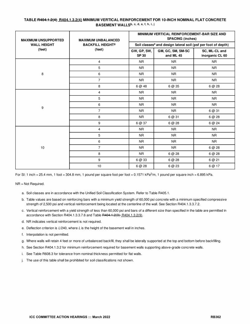
TABLE R404.1.2(4) R404.1.3.2(4) MINIMUM VERTICAL REINFORCEMENT FOR 10-INCH NOMINAL FLAT CONCRETEBASEMENT WALLS
MAXIMUM UNSUPPORTEDWALL HEIGHT
(feet)
MAXIMUM UNBALANCEDBACKFILL HEIGHT
(feet)
MINIMUM VERTICAL REINFORCEMENT-BAR SIZE ANDSPACING (inches)
Soil classes and design lateral soil (psf per foot of depth)
GW, GP, SW,SP 30
GM, GC, SM, SM-SCand ML 45
SC, ML-CL andinorganic CL 60
8
4 NR NR NR
5 NR NR NR
6 NR NR NR
7 NR NR NR
8 6 @ 48 6 @ 35 6 @ 28
9
4 NR NR NR
5 NR NR NR
6 NR NR NR
7 NR NR 6 @ 31
8 NR 6 @ 31 6 @ 28
9 6 @ 37 6 @ 28 6 @ 24
10
4 NR NR NR
5 NR NR NR
6 NR NR NR
7 NR NR 6 @ 28
8 NR 6 @ 28 6 @ 28
9 6 @ 33 6 @ 28 6 @ 21
10 6 @ 28 6 @ 23 6 @ 17
For SI: 1 inch = 25.4 mm, 1 foot = 304.8 mm, 1 pound per square foot per foot = 0.1571 kPa /m, 1 pound per square inch = 6.895 kPa.
NR = Not Required.
a. Soil classes are in accordance with the Unified Soil Classification System. Refer to Table R405.1.
b. Table values are based on reinforcing bars with a minimum yield strength of 60,000 psi concrete with a minimum specified compressivestrength of 2,500 psi and vertical reinforcement being located at the centerline of the wall. See Section R404.1.3.3.7.2.
c. Vertical reinforcement with a yield strength of less than 60,000 psi and bars of a different size than specified in the table are permitted inaccordance with Section R404.1.3.3.7.6 and Table R404.1.2(9) R404.1.3.2(9).
d. NR indicates vertical reinforcement is not required.
e. Deflection criterion is L/240, where L is the height of the basement wall in inches.
f. Interpolation is not permitted.
g. Where walls will retain 4 feet or more of unbalanced backfill, they shall be laterally supported at the top and bottom before backfilling.
h. See Section R404.1.3.2 for minimum reinforcement required for basement walls supporting above-grade concrete walls.
i. See Table R608.3 for tolerance from nominal thickness permitted for flat walls.
j. The use of this table shall be prohibited for soil classifications not shown.
b, c, d, e, f, h, i, j
g a
2
ICC COMMITTEE ACTION HEARINGS ::: March 2022 RB362

TABLE R404.1.2(5) R404.1.3.2(5) MINIMUM VERTICAL WALL REINFORCEMENT FOR 6-INCH WAFFLE-GRID BASEMENTWALLS
MAXIMUM UNSUPPORTEDWALL HEIGHT
(feet)
MAXIMUM UNBALANCEDBACKFILL HEIGHT
(feet)
MINIMUM VERTICAL REINFORCEMENT-BAR SIZE AND SPACING(inches)
Soil classes and design lateral soil (psf per foot of depth)
GW, GP, SW,SP 30
GM, GC, SM, SM-SCand ML 45
SC, ML-CL andinorganic CL 60
8
4 4 @ 48 4 @ 46 6 @ 39
5 4 @ 45 5 @ 46 6 @ 47
6 5 @ 45 6 @ 40 DR
7 6 @ 44 DR DR
8 6 @ 32 DR DR
9
4 4 @ 48 4 @ 46 4 @ 37
5 4 @ 42 5 @ 43 6 @ 44
6 5 @ 41 6 @ 37 DR
7 6 @ 39 DR DR
> 8 DR DR DR
10
4 4 @ 48 4 @ 46 4 @ 35
5 4 @ 40 5 @ 40 6 @ 41
6 5 @ 38 6 @ 34 DR
7 6 @ 36 DR DR
> 8 DR DR DR
For SI: 1 inch = 25.4 mm, 1 foot = 304.8 mm, 1 pound per square foot per foot = 0.1571 kPa /m, 1 pound per square inch = 6.895 kPa.
DR = Design Required.
a. Soil classes are in accordance with the Unified Soil Classification System. Refer to Table R405.1.
b. Table values are based on reinforcing bars with a minimum yield strength of 60,000 psi concrete with a minimum specified compressivestrength of 2,500 psi and vertical reinforcement being located at the centerline of the wall. See Section R404.1.3.3.7.2.
c. Maximum spacings shown are the values calculated for the specified bar size. Where the bar used is Grade 60 and the size specified in thetable, the actual spacing in the wall shall not exceed a whole-number multiple of 12 inches (12, 24, 36 and 48) that is less than or equal to thetabulated spacing. Vertical reinforcement with a yield strength of less than 60,000 psi and bars of a different size than specified in the tableare permitted in accordance with Section R404.1.3.3.7.6 and Table R404.1.2(9) R404.1.3.2(9).
d. Deflection criterion is L/240, where L is the height of the basement wall in inches.
e. Interpolation is not permitted.
f. Where walls will retain 4 feet or more of unbalanced backfill, they shall be laterally supported at the top and bottom before backfilling.
g. See Section R404.1.3.2 for minimum reinforcement required for basement walls supporting above-grade concrete walls.
h. See Table R608.3 for thicknesses and dimensions of waffle-grid walls.
i. DR means design is required in accordance with the applicable building code, or in the absence of a code, in accordance with ACI 318.
j. The use of this table shall be prohibited for soil classifications not shown.
b, c, d, e, g, h, i, j
f a
i
2
b, c,
ICC COMMITTEE ACTION HEARINGS ::: March 2022 RB363

TABLE R404.1.2(6) R404.1.3.2(6) MINIMUM VERTICAL REINFORCEMENT FOR 8-INCH WAFFLE-GRID BASEMENT WALLS
MAXIMUM UNSUPPORTEDWALL HEIGHT
(feet)
MAXIMUM UNBALANCEDBACKFILL HEIGHT
(feet)
MINIMUM VERTICAL REINFORCEMENT-BAR SIZE ANDSPACING (inches)
Soil classes and design lateral soil (psf per foot of depth)
GW, GP, SW,SP 30
GM, GC, SM, SM-SCand ML 45
SC, ML-CL andinorganic CL 60
8
4 NR NR NR
5 NR 5 @ 48 5 @ 46
6 5 @ 48 5 @ 43 6 @ 45
7 5 @ 46 6 @ 43 6 @ 31
8 6 @ 48 6 @ 32 6 @ 23
9
4 NR NR NR
5 NR 5 @ 47 5 @ 46
6 5 @ 46 5 @ 39 6 @ 41
7 5 @ 42 6 @ 38 6 @ 28
8 6 @ 44 6 @ 28 6 @ 20
9 6 @ 34 6 @ 21 DR
10
4 NR NR NR
5 NR 5 @ 46 5 @ 44
6 5 @ 46 5 @ 37 6 @ 38
7 5 @ 38 6 @ 35 6 @ 25
8 6 @ 39 6 @ 25 DR
9 6 @ 30 DR DR
10 6 @ 24 DR DR
For SI: 1 inch = 25.4 mm, 1 foot = 304.8 mm, 1 pound per square foot per foot = 0.1571 kPa /m, 1 pound per square inch = 6.895 kPa.
NR = Not Required.
DR = Design Required.
a. Soil classes are in accordance with the Unified Soil Classification System. Refer to Table R405.1.
b. Table values are based on reinforcing bars with a minimum yield strength of 60,000 psi concrete with a minimum specified compressivestrength of 2,500 psi and vertical reinforcement being located at the centerline of the wall. See Section R404.1.3.3.7.2.
c. Maximum spacings shown are the values calculated for the specified bar size. Where the bar used is Grade 60 (420 MPa) and the sizespecified in the table, the actual spacing in the wall shall not exceed a whole-number multiple of 12 inches (12, 24, 36 and 48) that is less thanor equal to the tabulated spacing. Vertical reinforcement with a yield strength of less than 60,000 psi and bars of a different size thanspecified in the table are permitted in accordance with Section R404.1.3.3.7.6 and Table R404.1.2(9) R404.1.3.2(9).
d. NR indicates vertical reinforcement is not required.
e. Deflection criterion is L/240, where L is the height of the basement wall in inches.
f. Interpolation shall not be permitted.
g. Where walls will retain 4 feet or more of unbalanced backfill, they shall be laterally supported at the top and bottom before backfilling.
h. See Section R404.1.3.2 for minimum reinforcement required for basement walls supporting above-grade concrete walls.
i. See Table R608.3 for thicknesses and dimensions of waffle-grid walls.
j. DR means design is required in accordance with the applicable building code, or in the absence of a code, in accordance with ACI 318.
k. The use of this table shall be prohibited for soil classifications not shown.
b, c,
d, e, f, h, i, j, k
g a
2
ICC COMMITTEE ACTION HEARINGS ::: March 2022 RB364

TABLE R404.1.2(7) R404.1.3.2(7) MINIMUM VERTICAL REINFORCEMENT FOR 6-INCH (152 mm) SCREEN-GRID BASEMENTWALLS
MAXIMUM UNSUPPORTEDWALL HEIGHT
(feet)
MAXIMUM UNBALANCEDBACKFILL HEIGHT
(feet)
MINIMUM VERTICAL REINFORCEMENT-BAR SIZE AND SPACING(inches)
Soil classes and design lateral soil (psf per foot of depth)
GW, GP, SW,SP 30
GM, GC, SM, SM-SCand ML 45
SC, ML-CL andinorganic CL 60
8
4 4 @ 48 4 @ 48 5 @ 43
5 4 @ 48 5 @ 48 5 @ 37
6 5 @ 48 6 @ 45 6 @ 32
7 6 @ 48 DR DR
8 6 @ 36 DR DR
9
4 4 @ 48 4 @ 48 4 @ 41
5 4 @ 48 5 @ 48 6 @ 48
6 5 @ 45 6 @ 41 DR
7 6 @ 43 DR DR
> 8 DR DR DR
10
4 4 @ 48 4 @ 48 4 @ 39
5 4 @ 44 5 @ 44 6 @ 46
6 5 @ 42 6 @ 38 DR
7 6 @ 40 DR DR
> 8 DR DR DR
For SI: 1 inch = 25.4 mm, 1 foot = 304.8 mm, 1 pound per square foot per foot = 0.1571 kPa /m, 1 pound per square inch = 6.895 kPa.
DR = Design Required.
a. Soil classes are in accordance with the Unified Soil Classification System. Refer to Table R405.1.
b. Table values are based on reinforcing bars with a minimum yield strength of 60,000 psi, concrete with a minimum specified compressivestrength of 2,500 psi and vertical reinforcement being located at the centerline of the wall. See Section R404.1.3.3.7.2.
c. Maximum spacings shown are the values calculated for the specified bar size. Where the bar used is Grade 60 and the size specified in thetable, the actual spacing in the wall shall not exceed a whole-number multiple of 12 inches (12, 24, 36 and 48) that is less than or equal to thetabulated spacing. Vertical reinforcement with a yield strength of less than 60,000 psi and bars of a different size than specified in the tableare permitted in accordance with Section R404.1.3.3.7.6 and Table R404.1.2(9) R404.1.3.2(9).
d. Deflection criterion is L/240, where L is the height of the basement wall in inches.
e. Interpolation is not permitted.
f. Where walls will retain 4 feet or more of unbalanced backfill, they shall be laterally supported at the top and bottom before backfilling.
g. See Sections R404.1.3.2 for minimum reinforcement required for basement walls supporting above-grade concrete walls.
h. See Table R608.3 for thicknesses and dimensions of screen-grid walls.
i. DR means design is required in accordance with the applicable building code, or in the absence of a code, in accordance with ACI 318.
j. The use of this table shall be prohibited for soil classifications not shown.
b, c, d, e, g, h, i, j
f a
2
ICC COMMITTEE ACTION HEARINGS ::: March 2022 RB365

TABLE R404.1.2(8) R404.1.3.2(8) MINIMUM VERTICAL REINFORCEMENT FOR 6-, 8-, 10- AND 12-INCH NOMINAL FLATBASEMENT WALLS
MAXIMUM UNSUPPORTEDWALL HEIGHT
(feet)
MAXIMUM UNBALANCEDBACKFILL HEIGHT
(feet)
MINIMUM VERTICAL REINFORCEMENT-BAR SIZE AND SPACING(inches)
Soil classes and design lateral soil (psf per foot of depth)
GW, GP, SW, SP 30 GM, GC, SM, SM-SCand ML 45
SC, ML-CL andinorganic CL 60
Minimum nominal wall thickness (inches)
6 8 10 12 6 8 10 12 6 8 10 12
54 NR NR NR NR NR NR NR NR NR NR NR NR
5 NR NR NR NR NR NR NR NR NR NR NR NR
6
4 NR NR NR NR NR NR NR NR NR NR NR NR
5 NR NR NR NR NR NR NR NR4 @35
NR NR NR
6 NR NR NR NR5 @48
NR NR NR5 @36
NR NR NR
7
4 NR NR NR NR NR NR NR NR NR NR NR NR
5 NR NR NR NR NR NR NR NR5 @47
NR NR NR
6 NR NR NR NR5 @42
NR NR NR6 @43
5 @48
NR NR
75 @46
NR NR NR6 @42
5 @46
NR NR6 @34
6 @48
NR NR
8
4 NR NR NR NR NR NR NR NR NR NR NR NR
5 NR NR NR NR4 @38
NR NR NR5 @43
NR NR NR
64 @37
NR NR NR5 @37
NR NR NR6 @37
5 @43
NR NR
75 @40
NR NR NR6 @37
5 @41
NR NR6 @34
6 @43
NR NR
86 @43
5 @47
NR NR6 @34
6 @43
NR NR6 @27
6 @32
6 @44
NR
9
4 NR NR NR NR NR NR NR NR NR NR NR NR
5 NR NR NR NR4 @35
NR NR NR5 @40
NR NR NR
64 @34
NR NR NR6 @48
NR NR NR6 @36
6 @39
NR NR
75 @36
NR NR NR6 @34
5 @37
NR NR6 @33
6 @38
5 @37
NR
86 @38
5 @41
NR NR6 @33
6 @38
5 @37
NR6 @24
6 @29
6 @39
4 @48
96 @34
6 @46
NR NR6 @26
6 @30
6 @41
NR6 @19
6 @23
6 @30
6 @39
4 NR NR NR NR NR NR NR NR NR NR NR NR
5 NR NR NR NR4 @33
NR NR NR5 @38
NR NR NR
65 @48
NR NR NR6 @45
NR NR NR6 @34
5 @37
NR NR
76 @47
NR NR NR6 @34
6 @48
NR NR6 @30
6 @35
6 @48
NR
b, c, d, e, f, h, i, k, n, o
g
a
l l
l
l
l
l l
l
l
l
l l
l
l lm
l
l
l
ICC COMMITTEE ACTION HEARINGS ::: March 2022 RB366

10
86 @34
5 @38
NR NR6 @30
6 @34
6 @47
NR6 @22
6 @26
6 @35
6 @45
96 @34
6 @41
4 @48
NR6 @23
6 @27
6 @35
4 @48
DR6 @22
6 @27
6 @34
106 @28
6 @33
6 @45
NR DR6 @23
6 @29
6 @38
DR6 @22
6 @22
6 @28
MAXIMUM UNSUPPORTEDWALL HEIGHT
(feet)
MAXIMUM UNBALANCEDBACKFILL HEIGHT
(feet)
MINIMUM VERTICAL REINFORCEMENT-BAR SIZE AND SPACING(inches)
Soil classes and design lateral soil (psf per foot of depth)
GW, GP, SW, SP 30 GM, GC, SM, SM-SCand ML 45
SC, ML-CL andinorganic CL 60
Minimum nominal wall thickness (inches)
6 8 10 12 6 8 10 12 6 8 10 12
For SI: 1 inch = 25.4 mm, 1 foot = 304.8 mm, 1 pound per square foot per foot = 0.1571 kPa /m, 1 pound per square inch = 6.895 kPa.
NR = Not Required.
DR = Design Required.
a. Soil classes are in accordance with the Unified Soil Classification System. Refer to Table R405.1.
b. Table values are based on reinforcing bars with a minimum yield strength of 60,000 psi.
c. Vertical reinforcement with a yield strength of less than 60,000 psi and bars of a different size than specified in the table are permitted inaccordance with Section R404.1.3.3.7.6 and Table R404.1.2(9) R404.1.3.2(9).
d. NR indicates vertical wall reinforcement is not required, except for 6-inch nominal walls formed with stay-in-place forming systems in whichcase vertical reinforcement shall be No. 4@48 inches on center.
e. Allowable deflection criterion is L/240, where L is the unsupported height of the basement wall in inches.
f. Interpolation is not permitted.
g. Where walls will retain 4 feet or more of unbalanced backfill, they shall be laterally supported at the top and bottom before backfilling.
h. Vertical reinforcement shall be located to provide a cover of 1 / inches measured from the inside face of the wall. The center of the steelshall not vary from the specified location by more than the greater of 10 percent of the wall thickness or / inch.
i. Concrete cover for reinforcement measured from the inside face of the wall shall be not less than / inch. Concrete cover for reinforcementmeasured from the outside face of the wall shall be not less than 1 / inches for No. 5 bars and smaller, and not less than 2 inches for largerbars.
j. DR means design is required in accordance with the applicable building code, or in the absence of a code, in accordance with ACI 318.
k. Concrete shall have a specified compressive strength, f′ , of not less than 2,500 psi at 28 days, unless a higher strength is required by Notel or m.
l. The minimum thickness is permitted to be reduced 2 inches, provided that the minimum specified compressive strength of concrete, f′ , is4,000 psi.
m. A plain concrete wall with a minimum nominal thickness of 12 inches is permitted, provided that the minimum specified compressive strengthof concrete, f′ , is 3,500 psi.
n. See Table R608.3 for tolerance from nominal thickness permitted for flat walls.
o. The use of this table shall be prohibited for soil classifications not shown.
lm
lm
j
2
14
38
34
12
c
c
c
a, b, c
ICC COMMITTEE ACTION HEARINGS ::: March 2022 RB367

TABLE R404.1.2(9) R404.1.3.2(9) MINIMUM SPACING FOR ALTERNATE BAR SIZE AND ALTERNATE GRADE OF STEEL
BAR SPACING FROM APPLICABLE TABLE IN SECTION R404.1.3.2(inches)
BAR SIZE FROM APPLICABLE TABLE IN SECTION R404.1.3.2
#4 #5 #6
Alternate bar size and alternate grade of steel desired
Grade 60 Grade 40 Grade 60 Grade 40 Grade 60 Grade 40
#5 #6 #4 #5 #6 #4 #6 #4 #5 #6 #4 #5 #4 #5 #6
Maximum spacing for alternate bar size and alternate grade of steel(inches)
8 12 18 5 8 12 5 11 3 5 8 4 6 2 4 5
9 14 20 6 9 13 6 13 4 6 9 4 6 3 4 6
10 16 22 7 10 15 6 14 4 7 9 5 7 3 5 7
11 17 24 7 11 16 7 16 5 7 10 5 8 3 5 7
12 19 26 8 12 18 8 17 5 8 11 5 8 4 6 8
13 20 29 9 13 19 8 18 6 9 12 6 9 4 6 9
14 22 31 9 14 21 9 20 6 9 13 6 10 4 7 9
15 23 33 10 16 22 10 21 6 10 14 7 11 5 7 10
16 25 35 11 17 23 10 23 7 11 15 7 11 5 8 11
17 26 37 11 18 25 11 24 7 11 16 8 12 5 8 11
18 28 40 12 19 26 12 26 8 12 17 8 13 5 8 12
19 29 42 13 20 28 12 27 8 13 18 9 13 6 9 13
20 31 44 13 21 29 13 28 9 13 19 9 14 6 9 13
21 33 46 14 22 31 14 30 9 14 20 10 15 6 10 14
22 34 48 15 23 32 14 31 9 15 21 10 16 7 10 15
23 36 48 15 24 34 15 33 10 15 22 10 16 7 11 15
24 37 48 16 25 35 15 34 10 16 23 11 17 7 11 16
25 39 48 17 26 37 16 35 11 17 24 11 18 8 12 17
26 40 48 17 27 38 17 37 11 17 25 12 18 8 12 17
27 42 48 18 28 40 17 38 12 18 26 12 19 8 13 18
28 43 48 19 29 41 18 40 12 19 26 13 20 8 13 19
29 45 48 19 30 43 19 41 12 19 27 13 20 9 14 19
30 47 48 20 31 44 19 43 13 20 28 14 21 9 14 20
31 48 48 21 32 45 20 44 13 21 29 14 22 9 15 21
32 48 48 21 33 47 21 45 14 21 30 15 23 10 15 21
33 48 48 22 34 48 21 47 14 22 31 15 23 10 16 22
34 48 48 23 35 48 22 48 15 23 32 15 24 10 16 23
35 48 48 23 36 48 23 48 15 23 33 16 25 11 16 23
36 48 48 24 37 48 23 48 15 24 34 16 25 11 17 24
37 48 48 25 38 48 24 48 16 25 35 17 26 11 17 25
38 48 48 25 39 48 25 48 16 25 36 17 27 12 18 25
39 48 48 26 40 48 25 48 17 26 37 18 27 12 18 26
40 48 48 27 41 48 26 48 17 27 38 18 28 12 19 27
41 48 48 27 42 48 26 48 18 27 39 19 29 12 19 27
42 48 48 28 43 48 27 48 18 28 40 19 30 13 20 28
43 48 48 29 44 48 28 48 18 29 41 20 30 13 20 29
44 48 48 29 45 48 28 48 19 29 42 20 31 13 21 29
45 48 48 30 47 48 29 48 19 30 43 20 32 14 21 30
a, b, c
ICC COMMITTEE ACTION HEARINGS ::: March 2022 RB368

46 48 48 31 48 48 30 48 20 31 44 21 32 14 22 31
47 48 48 31 48 48 30 48 20 31 44 21 33 14 22 31
48 48 48 32 48 48 31 48 21 32 45 22 34 15 23 32
BAR SPACING FROM APPLICABLE TABLE IN SECTION R404.1.3.2(inches)
BAR SIZE FROM APPLICABLE TABLE IN SECTION R404.1.3.2
#4 #5 #6
Alternate bar size and alternate grade of steel desired
Grade 60 Grade 40 Grade 60 Grade 40 Grade 60 Grade 40
#5 #6 #4 #5 #6 #4 #6 #4 #5 #6 #4 #5 #4 #5 #6
Maximum spacing for alternate bar size and alternate grade of steel(inches)
For SI: 1 inch = 25.4 mm.
a. This table is for use with tables in Section R404.1.3.2 that specify the minimum bar size and maximum spacing of vertical wall reinforcementfor foundation walls and above-grade walls. Reinforcement specified in tables in Section R404.1.3.2 is based on Grade 60 steelreinforcement.
b. Bar spacing shall not exceed 48 inches on center and shall be not less than one-half the nominal wall thickness.
c. For Grade 50 steel bars (ASTM A996, Type R), use spacing for Grade 40 bars or interpolate between Grades 40 and 60.
R404.1.3.3.7.2 Location of reinforcement in wall. The center of vertical reinforcement in basement walls determined from Tables R404.1.2(2)R404.1.3.2(2) through R404.1.2(7) R404.1.3.2(7) shall be located at the centerline of the wall. Vertical reinforcement in basement walls determinedfrom Table R404.1.2(8) R404.1.3.2(8) shall be located to provide a maximum cover of 1 / inches (32 mm) measured from the inside face of thewall. Regardless of the table used to determine vertical wall reinforcement, the center of the steel shall not vary from the specified location by morethan the greater of 10 percent of the wall thickness and / inch (10 mm). Horizontal and vertical reinforcement shall be located in foundation walls toprovide the minimum cover required by Section R404.1.3.3.7.4.
R404.1.3.3.7.6 Alternate grade of reinforcement and spacing. Where tables in Section R404.1.3.2 specify vertical wall reinforcement based onminimum bar size and maximum spacing, which are based on Grade 60 (414 MPa) steel reinforcement, different size bars or bars made from adifferent grade of steel are permitted provided that an equivalent area of steel per linear foot of wall is provided. Use of Table R404.1.2(9) R404.1.3.2(9) is permitted to determine the maximum bar spacing for different bar sizes than specified in the tables or bars made from a differentgrade of steel. Bars shall not be spaced less than one-half the wall thickness, or more than 48 inches (1219 mm) on center.
R404.1.4.1 Masonry foundation walls. In buildings assigned to Seismic Design Category D , D or D , as established in Table R301.2, masonryfoundation walls shall comply with this section. In addition to the requirements of Table R404.1.1(1) R404.1.2.1(1), plain masonry foundation wallsshall comply with the following:
1. Wall height shall not exceed 8 feet (2438 mm).
2. Unbalanced backfill height shall not exceed 4 feet (1219 mm).
3. Minimum nominal thickness for plain masonry foundation walls shall be 8 inches (203 mm).
4. Masonry stem walls shall have a minimum vertical reinforcement of one No. 4 (No. 13) bar located not greater than 4 feet (1219 mm) oncenter in grouted cells. Vertical reinforcement shall be tied to the horizontal reinforcement in the footings.
Foundation walls, supporting more than 4 feet (1219 mm) of unbalanced backfill or exceeding 8 feet (2438 mm) in height shall be constructed inaccordance with Table R404.1.1(2) R404.1.2.1(2), R404.1.1(3) R404.1.2.1(3) or R404.1.1(4) R404.1.2.1(4). Masonry foundation walls shall havetwo No. 4 (No. 13) horizontal bars located in the upper 12 inches (305 mm) of the wall.
R404.1.4.2 Concrete foundation walls. In buildings assigned to Seismic Design Category D , D or D , as established in Table R301.2, concretefoundation walls that support light-frame walls shall comply with this section, and concrete foundation walls that support above-grade concrete wallsshall comply with ACI 318, ACI 332 or PCA 100 (see Section R404.1.3). In addition to the horizontal reinforcement required by Table R404.1.2(1) R404.1.3.2(1), plain concrete walls supporting light-frame walls shall comply with the following:
1. Wall height shall not exceed 8 feet (2438 mm).
2. Unbalanced backfill height shall not exceed 4 feet (1219 mm).
3. Minimum thickness for plain concrete foundation walls shall be 7.5 inches (191 mm) except that 6 inches (152 mm) is permitted where themaximum wall height is 4 feet, 6 inches (1372 mm).
Foundation walls less than 7.5 inches (191 mm) in thickness, supporting more than 4 feet (1219 mm) of unbalanced backfill or exceeding 8 feet
14
38
0 1 2
0 1 2
ICC COMMITTEE ACTION HEARINGS ::: March 2022 RB369

(2438 mm) in height shall be provided with horizontal reinforcement in accordance with Table R404.1.2(1) R404.1.3.2(1), and vertical reinforcementin accordance with Table R404.1.2(2) R404.1.3.2(2), R404.1.2(3) R404.1.3.2(3), R404.1.2(4) R404.1.3.2(4), R404.1.2(5) R404.1.3.2(5),R404.1.2(6) R404.1.3.2(6), R404.1.2(7) R404.1.3.2(7) or R404.1.2(8) R404.1.3.2(8). Where Tables R404.1.2(2) R404.1.3.2(2) throughR404.1.2(8) R404.1.3.2(8) permit plain concrete walls, not less than No. 4 (No. 13) vertical bars at a spacing not exceeding 48 inches (1219 mm)shall be provided.
R404.1.5.2 Concrete wall thickness. The thickness of concrete foundation walls shall be equal to or greater than the thickness of the wall in thestory above. Concrete foundation walls with corbels, brackets or other projections built into the wall for support of masonry veneer or otherpurposes are not within the scope of the tables in this section.Where a concrete foundation wall is reduced in thickness to provide a shelf for thesupport of masonry veneer, the reduced thickness shall be equal to or greater than the thickness of the wall in the story above. Verticalreinforcement for the foundation wall shall be based on Table R404.1.2(8) R404.1.3.2(8) and located in the wall as required by SectionR404.1.3.3.7.2 where that table is used. Vertical reinforcement shall be based on the thickness of the thinner portion of the wall.
Exception: Where the height of the reduced thickness portion measured to the underside of the floor assembly or sill plate above is less than orequal to 24 inches (610 mm) and the reduction in thickness does not exceed 4 inches (102 mm), the vertical reinforcement is permitted to bebased on the thicker portion of the wall.
Reason Statement: This proposal fixes the masonry and concrete tables issue in IRC 2021. Currently, the masonry tables are listed underR404.1.1 Design required for general concrete and masonry accepted engineering practice, which is inaccurate. The concrete tables are listedunder R404.1.2 Design of masonry foundation walls which is not accurate. This proposal relocates the tables to the correct technical sections theybelong to. All Masonry tables moved to section R404.1.2.1 Masonry foundation walls, and all concrete tables moved to section R404.1.3.2Reinforcement for foundation walls. This proposal is submitted by the ICC Building Code Action Committee (BCAC).
BCAC was established by the ICC Board of Directors in July 2011 to pursue opportunities to improve and enhance assigned International Codes orportions thereof. In 2020 and 2021 the BCAC has held several virtual meetings open to any interested party. In addition, there were numerous virtualWorking Group meetings for the current code development cycle, which included members of the committee as well as interested parties. Relateddocuments and reports are posted on the BCAC website at https://www.iccsafe.org/products-and-services/i-codes/code-development/cs/building-code-action-committee-bcac/.
Cost Impact: The code change proposal will not increase or decrease the cost of constructionThe proponent is proposing the relocation of the tables. The tables are relocated under the first related subsections mentioned in the code. Theproposal does not make any technical changes in the tables that could affect construction costs.
RB171-22
ICC COMMITTEE ACTION HEARINGS ::: March 2022 RB370

RB172-22IRC: R502.3.3, TABLE R502.3.3(1), TABLE R502.3.3(2)
Proponents: Randy Shackelford, representing Simpson Strong-Tie Co. ([email protected])
2021 International Residential CodeRevise as follows:
R502.3.3 Floor cantilevers. Floor cantilever spans shall not exceed the nominal depth of the wood floor joist. Floor cantilevers constructed inaccordance with Table R502.3.3(1) shall be permitted where supporting a light-frame bearing wall and roof only. Floor cantilevers constructed inaccordance with Table R502.3.3(2) shall be permitted where supporting an exterior balcony are permitted to be constructed in accordance withTable R502.3.3(2). A full-depth rim joist shall be provided at the unsupported end of the cantilever joists. Solid blocking shall be provided at thesupport for the cantilever. Where the cantilever length is 24 inches (610 mm) or less and the building is assigned to Seismic Design Category A, B orC, solid blocking at the support for the cantilever shall not be required.
ICC COMMITTEE ACTION HEARINGS ::: March 2022 RB371

TABLE R502.3.3(1) CANTILEVER SPANS FOR FLOOR JOISTS SUPPORTING LIGHT-FRAME EXTERIOR BEARING WALL ANDROOF ONLY (Floor live load ≤ 40 psf, roof live load ≤ 20 psf)
MEMBER &SPACING
MAXIMUM CANTILEVER SPAN (uplift force at backspan support in lb)
Ground Snow Load
≤ 20 psf 30 psf 50 psf 70 psf
Roof Width Roof Width Roof Width Roof Width
24 ft 32 ft 40 ft 24 ft 32 ft 40 ft 24 ft 32 ft 40 ft 24 ft 32 ft 40 ft
2 × 8 @ 12″ 20″(177)
15″ (227) — 18″ (209) — — — — — — — —
2 × 10 @ 16″ 29″(228)
21″ (297) 16″ (364) 26″ (271) 18″ (354) — 20″ (375) — — — — —
2 × 10 @ 12″ 36″(166)
26″ (219) 20″ (270) 34″ (198) 22″ (263) 16″ (324) 26″ (277) — — 19″ (356) — —
2 × 12 @ 16″ — 32″ (287) 25″ (356) 36″ (263) 29″ (345) 21″ (428) 29″ (367) 20″ (484) — 23″ (471) — —
2 × 12 @ 12″ — 42″ (209) 31″ (263) — 37″ (253) 27″ (317) 36″ (271) 27″ (358) 17″ (447) 31″ (348) 19″ (462) —
2 × 12 @ 8″ — 48″ (136) 45″ (169) — 48″ (164) 38″ (206) — 40″ (233) 26″ (294) 36″ (230) 29″ (304) 18″ (379)
For SI: 1 inch = 25.4 mm, 1 foot = 304.8 mm, 1 pound per square foot = 0.0479 kPa.
a. Tabulated values are for clear-span roof supported solely by exterior bearing walls.
b. Spans are based on No. 2 Grade lumber of Douglas fir-larch, Southern pine, hem-fir and spruce-pine-fir for repetitive (three or more)members.
c. Ratio of backspan to cantilever span shall be not less than 3:1.
d. Connections capable of resisting the indicated uplift force shall be provided at the backspan support.
e. Uplift force is for a backspan to cantilever span ratio of 3:1. Tabulated uplift values are permitted to be reduced by multiplying by a factorequal to 3 divided by the actual backspan ratio provided (3/backspan ratio).
f. See Section R301.2.2.6, Item 1, for additional limitations on cantilevered floor joists for detached one- and two-family dwellings in SeismicDesign Category D , D or D and townhouses in Seismic Design Category C, D , D or D .
g. A full-depth rim joist shall be provided at the unsupported end of the cantilever joists. Solid blocking shall be provided at the supported end.Where the cantilever length is 24 inches or less and the building is assigned to Seismic Design Category A, B or C, solid blocking at thesupport for the cantilever shall not be required.
h g. Linear interpolation shall be permitted for building widths and ground snow loads other than shown.
a, b, c, f, g, h
d, e
0 1 2 0 1 2
a, b, e, f
ICC COMMITTEE ACTION HEARINGS ::: March 2022 RB372

TABLE R502.3.3(2) CANTILEVER SPANS FOR FLOOR JOISTS SUPPORTING EXTERIOR BALCONY
MEMBER SIZE SPACING
MAXIMUM CANTILEVER SPAN (uplift force at backspan support in lb)
Ground Snow Load
≤ 30 psf 50 psf 70 psf
2 × 8 12″ 42″ (139) 39″ (156) 34″ (165)
2 × 8 16″ 36″ (151) 34″ (171) 29″ (180)
2 × 10 12″ 61″ (164) 57″ (189) 49″ (201)
2 × 10 16″ 53″ (180) 49″ (208) 42″ (220)
2 × 10 24″ 43″ (212) 40″ (241) 34″ (255)
2 × 12 16″ 72″ (228) 67″ (260) 57″ (268)
2 × 12 24″ 58″ (279) 54″ (319) 47″ (330)
For SI: 1 inch = 25.4 mm, 1 pound per square foot = 0.0479 kPa.
a. Spans are based on No. 2 Grade lumber of Douglas fir-larch, Southern pine, hem-fir, and spruce-pine-fir for repetitive (three or more)members.
b. Ratio of backspan to cantilever span shall be not less than 2:1.
c. Connections capable of resisting the indicated uplift force shall be provided at the backspan support.
d. Uplift force is for a backspan to cantilever span ratio of 2:1. Tabulated uplift values are permitted to be reduced by multiplying by a factorequal to 2 divided by the actual backspan ratio provided (2/backspan ratio).
e. A full-depth rim joist shall be provided at the unsupported end of the cantilever joists. Solid blocking shall be provided at the supported end.Where the cantilever length is 24 inches or less and the building is assigned to Seismic Design Category A, B or C, solid blocking at thesupport for the cantilever shall not be required.
f e. Linear interpolation shall be permitted for ground snow loads other than shown.
Reason Statement: This code change is meant to do three things: move a construction-related requirement from a table footnote to theappropriate text section, clarify the location of the required blocking, and make the sentence structures parallel in the two cantilever cases. Theintent is for this to be editorial, with no change to actual requirements.Footnote g in Table R502.3.3(1) and Footnote e in Table R502.3.3(2) are both identical and state "A full-depth rim joist shall be provided at theunsupported end of the cantilever joists. Solid blocking shall be provided at the supported end. Where the cantilever length is 24 inches or less andthe building is assigned to Seismic Design Category A, B or C, solid blocking at the support for the cantilever shall not be required." This is aconstruction requirement that is not related to the use of the table, so it is more appropriately placed in the charging text section. The secondsentence is a bit unclear, in that it states that the blocking must be provided "at the supported end". Actually both ends of the joist are the supportedend. So it is proposed to take the wording from the next sentence and state that the blocking must be provided "at the support for the cantilever". The requirements of R502.7 will apply to the supported end at the interior of the building.
Finally, the language of R502.3.3 is slightly revised so that each sentence has the same structure and meaning.
Cost Impact: The code change proposal will not increase or decrease the cost of constructionThere is no intent to change the requirements. So there should be no cost impact.
RB172-22
a, b, e, f
c, d
ICC COMMITTEE ACTION HEARINGS ::: March 2022 RB373
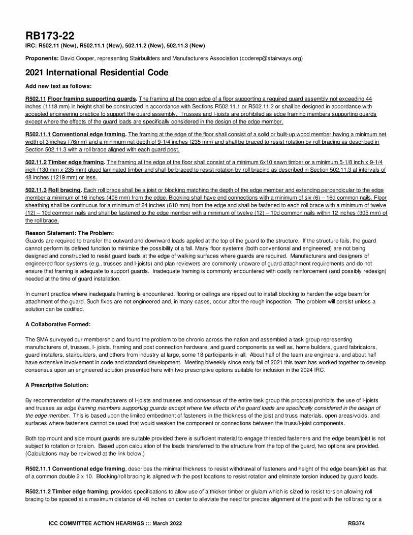
RB173-22IRC: R502.11 (New), R502.11.1 (New), 502.11.2 (New), 502.11.3 (New)
Proponents: David Cooper, representing Stairbuilders and Manufacturers Association ([email protected])
2021 International Residential CodeAdd new text as follows:
R502.11 Floor framing supporting guards. The framing at the open edge of a floor supporting a required guard assembly not exceeding 44inches (1118 mm) in height shall be constructed in accordance with Sections R502.11.1 or R502.11.2 or shall be designed in accordance withaccepted engineering practice to support the guard assembly. Trusses and I-joists are prohibited as edge framing members supporting guardsexcept where the effects of the guard loads are specifically considered in the design of the edge member.
R502.11.1 Conventional edge framing. The framing at the edge of the floor shall consist of a solid or built-up wood member having a minimum netwidth of 3 inches (76mm) and a minimum net depth of 9-1/4 inches (235 mm) and shall be braced to resist rotation by roll bracing as described inSection 502.11.3 with a roll brace aligned with each guard post.
502.11.2 Timber edge framing. The framing at the edge of the floor shall consist of a minimum 6x10 sawn timber or a minimum 5-1/8 inch x 9-1/4inch (130 mm x 235 mm) glued laminated timber and shall be braced to resist rotation by roll bracing as described in Section 502.11.3 at intervals of48 inches (1219 mm) or less.
502.11.3 Roll bracing. Each roll brace shall be a joist or blocking matching the depth of the edge member and extending perpendicular to the edgemember a minimum of 16 inches (406 mm) from the edge. Blocking shall have end connections with a minimum of six (6) – 16d common nails. Floorsheathing shall be continuous for a minimum of 24 inches (610 mm) from the edge and shall be fastened to each roll brace with a minimum of twelve(12) – 10d common nails and shall be fastened to the edge member with a minimum of twelve (12) – 10d common nails within 12 inches (305 mm) ofthe roll brace.
Reason Statement: The Problem:Guards are required to transfer the outward and downward loads applied at the top of the guard to the structure. If the structure fails, the guardcannot perform its defined function to minimize the possibility of a fall. Many floor systems (both conventional and engineered) are not beingdesigned and constructed to resist guard loads at the edge of walking surfaces where guards are required. Manufacturers and designers ofengineered floor systems (e.g., trusses and I-joists) and plan reviewers are commonly unaware of guard attachment requirements and do notensure that framing is adequate to support guards. Inadequate framing is commonly encountered with costly reinforcement (and possibly redesign)needed at the time of guard installation.
In current practice where inadequate framing is encountered, flooring or ceilings are ripped out to install blocking to harden the edge beam forattachment of the guard. Such fixes are not engineered and, in many cases, occur after the rough inspection. The problem will persist unless asolution can be codified.
A Collaborative Formed:
The SMA surveyed our membership and found the problem to be chronic across the nation and assembled a task group representingmanufacturers of, trusses, I- joists, framing and post connection hardware, and guard components as well as, home builders, guard fabricators,guard installers, stairbuilders, and others from industry at large, some 18 participants in all. About half of the team are engineers, and about halfhave extensive involvement in code and standard development. Meeting biweekly since early fall of 2021 this team has worked together to developconsensus upon an engineered solution presented here with two prescriptive options suitable for inclusion in the 2024 IRC.
A Prescriptive Solution:
By recommendation of the manufacturers of I-joists and trusses and consensus of the entire task group this proposal prohibits the use of I-joistsand trusses as edge framing members supporting guards except where the effects of the guard loads are specifically considered in the design ofthe edge member. This is based upon the limited embedment of fasteners in the thickness of the joist and truss materials, open areas/voids, andsurfaces where fasteners cannot be used that would weaken the component or connections between the truss/I-joist components.
Both top mount and side mount guards are suitable provided there is sufficient material to engage threaded fasteners and the edge beam/joist is notsubject to rotation or torsion. Based upon calculation of the loads transferred to the structure from the top of the guard, two options are provided.(Calculations may be reviewed at the link below.)
R502.11.1 Conventional edge framing, describes the minimal thickness to resist withdrawal of fasteners and height of the edge beam/joist as thatof a common double 2 x 10. Blocking/roll bracing is aligned with the post locations to resist rotation and eliminate torsion induced by guard loads.
R502.11.2 Timber edge framing, provides specifications to allow use of a thicker timber or glulam which is sized to resist torsion allowing rollbracing to be spaced at a maximum distance of 48 inches on center to alleviate the need for precise alignment of the post with the roll bracing or a
ICC COMMITTEE ACTION HEARINGS ::: March 2022 RB374

joist.
Although the minimum guard height in the IRC is 36 inches it is not unusual that portions of the guard, post caps, or finials extend above the guardheight. We agreed that a height of 44 inches would be reasonably conservative to use for the purpose of calculating the edge beam size and rollbracing requirements. To restrict outward movement of the top of the edge beam, specific nailing of the floor sheathing is called out at the location ofroll bracing. Floor sheathing must be continuous for a minimum distance from the open edge to assure the structural integrity of the bracing andedge beam. The nailing requirements for attachment of the blocking used as roll bracing to the joists prevents uplift of the blocking, and the minimumlength allows it to fit into one joist bay where joist spacing is taken from the open edge of the edge beam. These details are specified in R502.11.3Roll Bracing.
This proposal has been clearly and carefully constructed to be understood and enforced without figures referenced in the code text. We haveincluded drawings to aid understanding among the many proposals to be considered in this cycle. The drawings submitted would however besuitable for inclusion in the commentary.
Engineering Calculations supporting this proposal can be found at this link: https://stairways.org/guard-calculations/
Cost Impact: The code change proposal will decrease the cost of constructionThis proposal will decrease the cost of construction due to the elimination of necessary after-the-fact demolition and repair to install blocking at eachpost location. An average job with guards has three or more posts with 1 to 2 hours each for blocking plus repairs to finish surfaces estimated atapproximately $400 - $800 in extra charges per 3 post job. This does not include any engineering fees if applicable.
RB173-22
ICC COMMITTEE ACTION HEARINGS ::: March 2022 RB375

RB174-22IRC: R506.1, R506.2 (New), PTI (New), Chapter 44
Proponents: Paul Armstrong, representing Post-Tensioned Institute; Kerry Sutton, representing American Concrete Institute([email protected]); Stephen Szoke, representing American Concrete Institute ([email protected])
2021 International Residential CodeRevise as follows:
R506.1 General. Concrete slab-on-ground floors shall be designed and constructed in accordance with the provisions of this section or ACI 332.Such floors Floors shall be a minimum 3 / inches (89 mm) thick (for expansive soils, see Section R403.1.8). The specified compressive strength ofconcrete shall be as set forth in Section R402.2.
Add new text as follows:
R506.2 Post-tensioned slab-on-ground floors. Post-tensioned concrete slabs-on-ground floors placed on expansive or stable soils shall bedesigned in accordance with PTI DC10.5.
Add new standard(s) as follows:
PTI Post-Tensioning Institute38800 Country Club DriveFarmington Hills, MI 48331
PTI DC10.5-19. Standard Requirements for Design and Analysis of Shallow Concrete Foundations on Expansive and Stable Soils
Staff Analysis: A review of the standard proposed for inclusion in the code, PTI DC10.5-19 Standard Requirements for Design and Analysis ofShallow Concrete Foundations on Expansive and Stable Soils, with regard to some of the key ICC criteria for referenced standards (Section 3.6 ofCP#28) will be posted on the ICC website on or before March 16, 2022.
Reason Statement: There are currently no provisions for designing post-tensioned slabs on expansive or stable soils in the IRC. This proposalincludes a new reference to PTI standard PTI DC10.5-19, Standard Requirements for Design and Analysis of Shallow Concrete Foundations onExpansive and Stable Soils. Post-tensioned slabs are commonly used on stable soils for crack control as well as reduced slab thickness and non-prestressed steel use. This reduction in material use typically offsets the cost of the post-tensioning materials and labor. Additional documentationcan be viewed at http://www.post-tensioning.org/Portals/13/Files/PDFs/Committees/PTI_DC10.5-19.pdf.
Cost Impact: The code change proposal will not increase or decrease the cost of constructionPost-tensioned slabs are commonly used on expansive and stable soils for crack control as well as reduced slab thickness and non-prestressedsteel use. This reduction in material use typically offsets the cost of the posttensioning materials and labor.
RB174-22
12
ICC COMMITTEE ACTION HEARINGS ::: March 2022 RB376
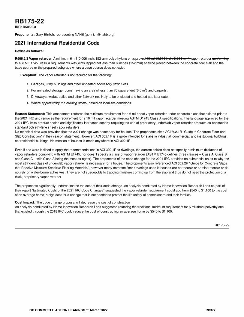
RB175-22IRC: R506.2.3
Proponents: Gary Ehrlich, representing NAHB ([email protected])
2021 International Residential CodeRevise as follows:
R506.2.3 Vapor retarder. A minimum 6 mil (0.006 inch; 152 μm) polyethylene or approved 10-mil (0.010 inch; 0.254 mm) vapor retarder conformingto ASTM E1745 Class A requirements with joints lapped not less than 6 inches (152 mm) shall be placed between the concrete floor slab and thebase course or the prepared subgrade where a base course does not exist.
Exception: The vapor retarder is not required for the following:
1. Garages, utility buildings and other unheated accessory structures.
2. For unheated storage rooms having an area of less than 70 square feet (6.5 m ) and carports.
3. Driveways, walks, patios and other flatwork not likely to be enclosed and heated at a later date.
4. Where approved by the building official, based on local site conditions.
Reason Statement: This amendment restores the minimum requirement for a 6 mil sheet vapor retarder under concrete slabs that existed prior tothe 2021 IRC and removes the requirement for a 10 mil vapor retarder meeting ASTM D1745 Class A specifications. The language approved for the2021 IRC limits product choice and significantly increases cost by requiring the use of proprietary underslab vapor retarder products as opposed tostandard polyethylene sheet vapor retarders.No technical data was provided that the 2021 change was necessary for houses. The proponents cited ACI 302.1R “Guide to Concrete Floor andSlab Construction” in their reason statement. However, ACI 302.1R is a guide intended for slabs in industrial, commercial, and institutional buildings,not residential buildings. No mention of houses is made anywhere in ACI 302.1R.
Even if one were inclined to apply the recommendations in ACI 302.1R to dwellings, the current edition does not specify a minimum thickness ofvapor retarders complying with ASTM E1745, nor does it specify a class of vapor retarder (ASTM E1745 defines three classes – Class A, Class Band Class C – with Class A being the most stringent). The proponents of the code change for the 2021 IRC provided no substantiation as to why themost stringent class of underslab vapor retarder is necessary for a house. The proponents also referenced ACI 302.2R “Guide for Concrete Slabsthat Receive Moisture-Sensitive Flooring Materials”, however many common floor coverings used in houses are permeable or semipermeable or donot rely on water-borne adhesives. They are not susceptible to trapping moisture coming up from the slab and thus do not need the protection of athick, proprietary vapor retarder.
The proponents significantly underestimated the cost of their code change. An analysis conducted by Home Innovation Research Labs as part oftheir report “Estimated Costs of the 2021 IRC Code Changes” suggested the vapor retarder requirement could add from $540 to $1,100 to the costof an average home, a high cost for a change that is not needed to protect the life safety of homeowners and their families.
Cost Impact: The code change proposal will decrease the cost of constructionAn analysis conducted by Home Innovation Research Labs suggested restoring the traditional minimum requirement for 6 mil sheet polyethylenethat existed through the 2018 IRC could reduce the cost of constructing an average home by $540 to $1,100.
RB175-22
2
ICC COMMITTEE ACTION HEARINGS ::: March 2022 RB377

RB176-22IRC: R317.1, R507.2.1, R507.9.1.1
Proponents: Glenn Mathewson, representing North American Deck and Railing Association ([email protected])
2021 International Residential CodeRevise as follows:
R317.1 Location required. Protection of wood and wood-based products from decay shall be provided in the following locations by the use ofdecay-resistant naturally durable wood or wood that is preservative-treated in accordance with AWPA U1.
1. In crawl spaces or unexcavated areas located within the periphery of the building foundation, wood joists or the bottom of a wood structuralfloor where closer than 18 inches (457 mm) to exposed ground, wood girders where closer than 12 inches (305 mm) to exposed ground,and wood columns where closer than 8 inches (204 mm) to exposed ground.
2. Wood framing members, including columns, that rest directly on concrete or masonry exterior foundation walls and are less than 8 inches(203 mm) from the exposed ground.
3. Sills and sleepers on a concrete or masonry slab that is in direct contact with the ground unless separated from such slab by an imperviousmoisture barrier.
4. The ends of wood girders entering exterior masonry or concrete walls having clearances of less than / inch (12.7 mm) on tops, sides andends.
5. Wood siding, sheathing and wall framing on the exterior of a building having a clearance of less than 6 inches (152 mm) from the ground orless than 2 inches (51 mm) measured vertically from concrete steps, porch slabs, patio slabs and similar horizontal surfaces exposed to theweather.
6. Wood structural members supporting moisture-permeable floors or roofs that are exposed to the weather, such as concrete or masonryslabs, unless separated from such floors or roofs by an impervious moisture barrier.
7. Wood furring strips or other wood framing members attached directly to the interior of exterior masonry walls or concrete walls below gradeexcept where an approved vapor retarder is applied between the wall and the furring strips or framing members.
8. Portions of wood structural members that form the structural supports of buildings, decks, balconies, porches or similar permanent buildingappurtenances where those members are exposed to the weather without adequate protection from a roof, eave, overhang or othercovering that prevents would prevent moisture or water accumulation on the surface or at joints between members.
Exception: Sawn lumber used in structures buildings located in a geographical region where experience has demonstrated that climaticconditions preclude the need to use naturally durable or preservative-treated wood where the structure is exposed to the weather.
9. Wood columns in contact with basement floor slabs unless supported by concrete piers or metal pedestals projecting not less than 1 inch(25 mm) above the concrete floor and separated from the concrete pier by an impervious moisture barrier.
R507.2.1 Wood materials. Wood structural members for joists, beams, and posts materials shall be No. 2 grade or better lumber, protected fromdecay where required by Section R317.1 and R317.1.2, and protected from termites where required by Section R318.1. preservative-treated inaccordance with Section R317, or approved, naturally durable lumber, and termite protected where required in accordance with Section R318.Where design in accordance with Section R301 is provided, wood structural members shall be designed using the wet service factor defined in AWCNDS. Cuts, notches and drilled holes of preservative-treated wood members shall be treated in accordance with Section R317.1.1. All preservative-treated wood products in contact with the ground shall be labeled for such usage.
R507.9.1.1 Ledger details. Deck ledgers shall be a minimum 2-inch by 8-inch (51 mm by 203 mm) nominal, No. 2 grade or betterpressure-preservative-treated Southern pine, incised pressure-preservative-treated hem-fir, or approved, decay-resistant naturally durable wood,No. 2 grade or better lumber. Deck ledgers shall not support concentrated loads from beams or girders. Deck ledgers shall not be supported onstone or masonry veneer.
Reason Statement: The intent of Section R507.2.1 when first added to the IRC was to require wood materials of deck construction to be decayresistant, whether treated or natural species. However, rather than repeat the AWPA referenced standard for treatment, the section pointed back toR317 in general. In 2021 the IRC was modified by other proponents in Section R317.1 item #8 where “balconies and porches” is discussed inregard to decay resistance. This section is not definitive that all materials must be decay resistant in the way R507.2.1 is for decks. This has led toconfusion regarding the required decay resistance of deck wood materials. Is it required or not?Item 8 provides more flexibility to jurisdictions to evaluate the exact minimum threshold of each project design to determine if the characteristicscontributing to decay are present. For this reason, it is most reasonable to change R507.2.1 to reference R317.1 for determining when decayresistance is required. However, note that R507.9.1.1 specifically requires deck ledgers to be decay resistant. This section is more specific andwould thus always be required, universally, on deck ledgers. Deck ledger decay is not always visible, as it may be occurring on the backside due toa failure in the flashing detail. There is no redundant connection to the ledger. Therefore the hazard associated with decay is a greater risk anddecay resistance is specifically required.
12
ICC COMMITTEE ACTION HEARINGS ::: March 2022 RB378

Terms were changed to “wood structural member” to match the language in the remaining text. “Buildings” was changed to “structures” in theexception since decks and porches are not buildings and the last sentence of the exception speaks to “structures”. Clarification that SectionR507.2.1 and the reference to R317.1 only applies to joists, beams, and posts, allows for decking not to be included for required decay resistance orgrading. Many tropical hardwoods and other alternative wood decking materials are not graded lumber or naturally durable yet have had no historyof insufficient performance as decking in the American market for at least two decades. Decay in decking is more easily visible to the occupant thanthe other structural members. The requirement for decay resistance is not to provide a greater useful service life, it is to reduce safety hazards dueto unseen decay.
The modifications proposed to R507.9.1.1 are simply clean up associated with the subject of this proposal. The AWPA U1 standard providesmethods of treatment that do not require “pressure” and the required field treatment in Section R317.1.1 is not a “pressure” treatment. Using thisterm is unnecessary. All lumber for ledgers using these prescriptive methods of attachment must be “No. 2 grade or better”. Where currentlylocated in the provision, it appears the grade requirement is only related to naturally durable wood. The definition is “naturally durable wood” so theterm in the body of the code should be as defined and not “lumber”. It also doesn’t need to be “approved” because it is a defined term.
Cost Impact: The code change proposal will decrease the cost of constructionThis code change will decrease the cost of deck construction in regions and designs where the wood materials are not subject to decay and inaccordance with Section R317.1 do not require decay resistant materials.
RB176-22
ICC COMMITTEE ACTION HEARINGS ::: March 2022 RB379

RB177-22IRC: TABLE R507.2.3, ASTM Chapter 44
Proponents: Rick Allen, representing ISANTA ([email protected])
2021 International Residential CodeRevise as follows:
a, b
ICC COMMITTEE ACTION HEARINGS ::: March 2022 RB380
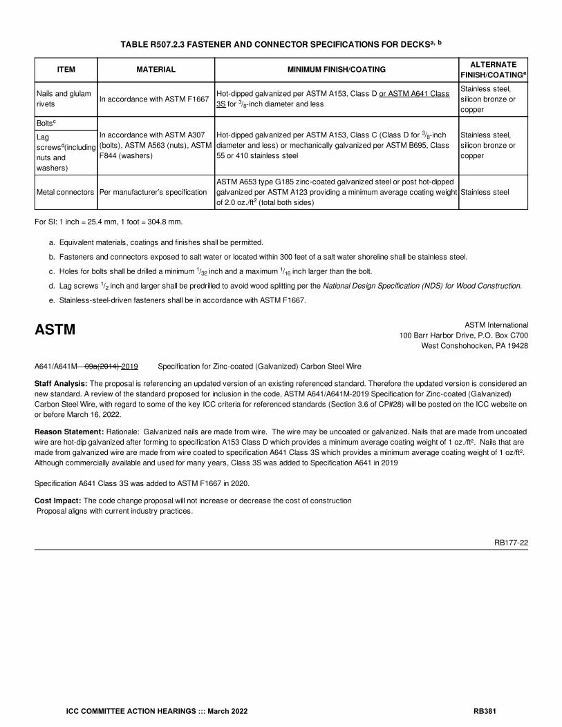
TABLE R507.2.3 FASTENER AND CONNECTOR SPECIFICATIONS FOR DECKS
ITEM MATERIAL MINIMUM FINISH/COATING ALTERNATEFINISH/COATING
Nails and glulamrivets
In accordance with ASTM F1667Hot-dipped galvanized per ASTM A153, Class D or ASTM A641 Class3S for / -inch diameter and less
Stainless steel,silicon bronze orcopper
BoltsIn accordance with ASTM A307(bolts), ASTM A563 (nuts), ASTMF844 (washers)
Hot-dipped galvanized per ASTM A153, Class C (Class D for / -inchdiameter and less) or mechanically galvanized per ASTM B695, Class55 or 410 stainless steel
Stainless steel,silicon bronze orcopper
Lagscrews (includingnuts andwashers)
Metal connectors Per manufacturer’s specificationASTM A653 type G185 zinc-coated galvanized steel or post hot-dippedgalvanized per ASTM A123 providing a minimum average coating weightof 2.0 oz./ft (total both sides)
Stainless steel
For SI: 1 inch = 25.4 mm, 1 foot = 304.8 mm.
a. Equivalent materials, coatings and finishes shall be permitted.
b. Fasteners and connectors exposed to salt water or located within 300 feet of a salt water shoreline shall be stainless steel.
c. Holes for bolts shall be drilled a minimum / inch and a maximum / inch larger than the bolt.
d. Lag screws / inch and larger shall be predrilled to avoid wood splitting per the National Design Specification (NDS) for Wood Construction.
e. Stainless-steel-driven fasteners shall be in accordance with ASTM F1667.
ASTM ASTM International100 Barr Harbor Drive, P.O. Box C700
West Conshohocken, PA 19428
A641/A641M—09a(2014) 2019 Specification for Zinc-coated (Galvanized) Carbon Steel Wire
Staff Analysis: The proposal is referencing an updated version of an existing referenced standard. Therefore the updated version is considered annew standard. A review of the standard proposed for inclusion in the code, ASTM A641/A641M-2019 Specification for Zinc-coated (Galvanized)Carbon Steel Wire, with regard to some of the key ICC criteria for referenced standards (Section 3.6 of CP#28) will be posted on the ICC website onor before March 16, 2022.
Reason Statement: Rationale: Galvanized nails are made from wire. The wire may be uncoated or galvanized. Nails that are made from uncoatedwire are hot-dip galvanized after forming to specification A153 Class D which provides a minimum average coating weight of 1 oz./ft². Nails that aremade from galvanized wire are made from wire coated to specification A641 Class 3S which provides a minimum average coating weight of 1 oz/ft².Although commercially available and used for many years, Class 3S was added to Specification A641 in 2019
Specification A641 Class 3S was added to ASTM F1667 in 2020.
Cost Impact: The code change proposal will not increase or decrease the cost of construction Proposal aligns with current industry practices.
RB177-22
a, b
e
38
c
38
d
2
132
116
12
ICC COMMITTEE ACTION HEARINGS ::: March 2022 RB381

RB178-22IRC: TABLE R507.2.3, R507.9.1.3
Proponents: Glenn Mathewson, representing North American Deck and Railing Association ([email protected])
2021 International Residential CodeRevise as follows:
a, b
ICC COMMITTEE ACTION HEARINGS ::: March 2022 RB382

TABLE R507.2.3 FASTENER AND CONNECTOR SPECIFICATIONS FOR DECKS
ITEM MATERIAL MINIMUM FINISH/COATING ALTERNATEFINISH/COATING
Nails and glulamrivets
In accordance with ASTM F1667Hot-dipped galvanized per ASTM A153, Class D for / -inch diameterand less
Stainless steel,silicon bronze orcopper
BoltsIn accordance with ASTM A307(bolts), ASTM A563 (nuts), ASTMF844 (washers)
Hot-dipped galvanized per ASTM A153, Class C (Class D for / -inchdiameter and less) or mechanically galvanized per ASTM B695, Class55 or 410 stainless steel
Stainless steel,silicon bronze orcopper
Lagscrews (includingnuts andwashers)
Metal connectors Per manufacturer’s specificationASTM A653 type G185 zinc-coated galvanized steel or post hot-dippedgalvanized per ASTM A123 providing a minimum average coating weightof 2.0 oz./ft (total both sides)
Stainless steel
For SI: 1 inch = 25.4 mm, 1 foot = 304.8 mm.
a. Equivalent materials, coatings and finishes shall be permitted.
b. Fasteners and connectors exposed to salt water or located within 300 feet of a salt water shoreline shall be stainless steel.
c Holes for bolts shall be drilled a minimum / inch and a maximum / inch larger than the bolt.
d Lag screws / inch and larger shall be predrilled to avoid wood splitting per the National Design Specification (NDS) for Wood Construction.
e. Stainless-steel-driven fasteners shall be in accordance with ASTM F1667.
R507.9.1.3 Ledger to band joist details. Fasteners used in deck ledger connections Where ledgers are fastened in accordance with TableR507.9.1.3(1) , fasteners shall comply with Section R507.2.3 be hot-dipped galvanized or stainless steel and shall be installed in accordance withTable R507.9.1.3(2) and Figures R507.9.1.3(1) and R507.9.1.3(2). Holes ½-inch (12.7 mm) in diameter shall be drilled through the ledger and holes5/16-inch (7.9 mm) in diameter shall be drilled through the band joist prior to lag screw installation. Holes ½-inch (12.7 mm) in diameter shall bedrilled through the ledger and band joist prior to bolt installation.
Reason Statement: 1) R507.9.3.1 is redundant and does not need to specify the properties of lag screws and bolts as this is the purpose ofTable R507.2.3. 2) Table R507.2.3 is titled “Fastener and connector specifications for decks”. This table provides material specifications for metal fasteners andconnectors. It is not the appropriate place to present installation requirements in the footnotes (drilling of holes).
3) The NDS is a design document for engineers. It is not appropriate to reference such a document from the IRC for “installation” requirements ofa prescriptive design.
4) The 2018 NDS provisions for lag screw installation are provided below. It is unrealistic to expect an IRC user to reference these engineeringprovisions and determine the specific gravity of the species of band joist the lag screw is fastening to.
NDS provisions“12.1.4.2 Lead holes for lag screws loaded laterally and in withdrawal shall be bored as follows to avoid splitting of the wood member duringconnection fabrication.A) The clearance hole for the shank shall have the same diameter as the shank, and the same depth of penetration as the length of theunthreaded shank.B) The lead hole for the threaded portion shall have a diameter equal to 65% to 85% of the shank diameter in wood with G > 0.6, 60% to 75%in wood with 0.5 < G <= 0.6, and 40% to 70% in wood with G <= 0.5 (see Table 12.3.3A) and a length equal to at least the length of the threadedportion. The larger percentile in each range shall apply to lag screws of greater diameters.”
5) 65% of a 1/2-inch diameter lag screw falls within the range for all three specific gravity and is thus an acceptable value for basic prescriptivecode. This results in a 5/16-inch hole in the band joist as proposed in the relocated footnotes.
6) The allowable tolerance for holes for bolts being measured to a 32 of an inch is not practical for rough framing construction. A slight side-to-sidemovement of a hand tool while drilling is greater than a 32 of an inch. It is not necessary or realistic to require such precise values in prescriptivewood framing.
a, b
e
38
c
38
d
2
132
116
12
ICC COMMITTEE ACTION HEARINGS ::: March 2022 RB383

Cost Impact: The code change proposal will not increase or decrease the cost of constructionThere is no cost impact to this proposal, as it simply clarifies the intent of the IRC as currently written.
RB178-22
ICC COMMITTEE ACTION HEARINGS ::: March 2022 RB384

RB179-22IRC: R507.3.1, TABLE R507.3.1
Proponents: Glenn Mathewson, representing North American Deck and Railing Association ([email protected])
2021 International Residential CodeRevise as follows:
R507.3.1 Minimum size. The minimum size of concrete deck footings shall be in accordance with Table R507.3.1, based on the tributary area andallowable soil-bearing pressure in accordance with Table R401.4.1.
ICC COMMITTEE ACTION HEARINGS ::: March 2022 RB385

TABLE R507.3.1 MINIMUM FOOTING SIZE FOR DECKS
LIVE ORGROUND
SNOWLOAD (psf)
TRIBUTARYAREA (ft )
LOAD-BEARING VALUE OF SOILS (psf)
1,500 2,000 ≥ 3,000
Side of asquarefooting(inches)
Diameter ofa roundfooting(inches)
Plainconcrete
Thickness(inches)
Side of asquarefooting(inches)
Diameter ofa roundfooting(inches)
Plainconcrete
Thickness(inches)
Side of asquarefooting(inches)
Diameter ofa roundfooting(inches)
Plainconcrete
Thickness(inches)
40
5 7 8 6 7 8 6 7 8 6
20 10 12 6 9 9 6 7 8 6
40 14 16 6 12 14 6 10 12 6
60 17 19 6 15 17 6 12 14 6
80 20 22 7 17 19 6 14 16 6
100 22 25 8 19 21 6 15 17 6
120 24 27 9 21 23 7 17 19 6
140 26 29 10 22 25 8 18 21 6
160 28 31 11 24 27 9 20 22 7
50
5 7 8 6 7 8 6 7 8 6
20 11 13 6 10 11 6 8 9 6
40 15 17 6 13 15 6 11 13 6
60 19 21 6 16 18 6 13 15 6
80 21 24 8 19 21 6 15 17 6
100 24 27 9 21 23 7 17 19 6
120 26 30 10 23 26 8 19 21 6
140 28 32 11 25 28 9 20 23 7
160 30 34 12 26 30 10 21 24 8
60
5 7 8 6 7 8 6 7 8 6
20 12 14 6 11 12 6 9 10 6
40 16 19 6 14 16 8 12 14 6
60 20 23 7 17 20 6 14 16 6
80 23 26 9 20 23 7 16 19 6
100 26 29 10 22 25 8 18 21 6
120 28 32 11 25 28 9 20 23 7
140 31 35 12 27 30 10 22 24 8
160 33 37 13 28 32 11 23 26 9
70
5 7 8 6 7 8 6 7 8 6
20 12 14 6 11 13 6 9 10 6
40 18 20 6 15 17 6 12 14 6
60 21 24 8 19 21 6 15 17 6
80 25 28 9 21 24 8 18 20 6
100 28 31 11 24 27 9 20 22 7
120 30 34 12 26 30 10 21 24 8
140 33 37 13 28 32 11 23 26 9
160 35 40 15 30 34 12 25 28 9
For SI: 1 inch = 25.4 mm, 1 square foot = 0.0929 m , 1 pound per square foot = 0.0479 kPa.
a. Interpolation permitted, extrapolation not permitted.
b. Based on highest load case: Dead + Live or Dead + Snow.
b
2
a, c, d
e e e
f f f
2
ICC COMMITTEE ACTION HEARINGS ::: March 2022 RB386

c. Footing dimensions shall allow complete bearing of the post.
d. If the support is a brick or CMU pier, the footing shall have a minimum 2-inch projection on all sides.
e. Area, in square feet, of deck surface supported by post and footings.
f. Minimum thickness shall only apply to plain concrete footings.
Reason Statement: Table R507.3.1 provides a minimum bearing area for round and square footings based on the loads and the soil bearingcapacity. Only the minimum footing thickness column is based on the material of the footing being plain concrete footings (no reinforcing steel orother). Modifying section R507.3.1 by replacing “concrete” with “deck” where referencing Table R507.3.1 is a subtle alignment and reminder thatthe table simply provides a minimum horizontal bearing area sufficient for the loads and the soil type, independent of the footing material. Prescriptive design language in the IRC should be as generic as possible. There are proprietary footing products on the market made of alternativematerials. The bearing area for these products need not be different than that of a concrete footing. This proposal would allow a bearing area to beselected from the code that can be used to select an appropriate size footer of any material. Including the term “plain concrete” in the thickness column achieves two goals. It makes it clear that the minimum thickness is only in relation toconcrete footings, and it makes it clear that reinforcing steel (“rebar”) is not required. Footnotes are often overlooked so footnote f can be easilyeliminated with the simply clarification in the column titles.
Cost Impact: The code change proposal will not increase or decrease the cost of constructionThis proposal clarifies and expands the usefulness and potential application of prescriptive design methods. In itself, this does not affect the cost ofconstruction
RB179-22
ICC COMMITTEE ACTION HEARINGS ::: March 2022 RB387

RB180-22IRC: R507.4.1
Proponents: Glenn Mathewson, representing North American Deck and Railing Association ([email protected])
2021 International Residential CodeRevise as follows:
R507.4.1 Deck post to deck footing connection. Where posts bear on concrete footings in accordance with Section R403 and Figure R507.3,lateral restraint shall be provided by manufactured connectors or a minimum post embedment of 12 inches (305 mm) in surrounding soils orconcrete piers. Other footing systems shall be permitted.
Exception: Where expansive, compressible, shifting or other questionable soils are present, surrounding soils shall not be relied on for lateralsupport.
Reason Statement: Though this line is supportive of alternative footing systems, it is unnecessary. Section R507.3 Footings, already states that“other approved structural systems…” are permitted. And, of course, R104.11 allows for alternative means, methods, and materials. As it iscurrently written, this line states that these "other systems" "shall be permitted". There is no mention of them having to be reviewed and approved. It just directly states that they "shall be permitted". This is inappropriate.
Cost Impact: The code change proposal will not increase or decrease the cost of constructionAlternative methods of construction are always able to be reviewed and possibly approved. This proposal does not change that, therefore it doesnot affect the cost of construction.
RB180-22
ICC COMMITTEE ACTION HEARINGS ::: March 2022 RB388

RB181-22IRC: R507.4.1
Proponents: Glenn Mathewson, representing North American Deck and Railing Association ([email protected])
2021 International Residential CodeRevise as follows:
R507.4.1 Deck post to deck footing connection. Where posts bear on concrete footings in accordance with Section R403 and Figure R507.3,lateral restraint shall be provided by manufactured approved connectors or a minimum post embedment of 12 inches (305 mm) in surrounding soilsor concrete piers. Other footing systems shall be permitted.
Exception: Where expansive, compressible, shifting or other questionable soils are present, surrounding soils shall not be relied on for lateralsupport.
Reason Statement: There is no known or defined magnitude of minimum lateral load resistance between a post and a footing utilizing any standardpractices, codes, or design standards. The intent of this provision is to simply ensure some connection is made. Stating that it “shall be provided bymanufactured connectors” provides no characteristics of this connection other than it being something “manufactured”. Replacing “manufactured”with “approved” allows a building authority to make a rational determination as to whether a particular connection will provide sufficient lateralrestraint to retain the post on the footing under normal usage. Until further research can provide an agreeable, minimum, measurable magnitude ofresistance, we must continue to rely on the professional discretion of the building authority to determine acceptable connections.
Cost Impact: The code change proposal will not increase or decrease the cost of constructionThis proposal does not have a definitive affect on the cost of construction. Use of the term "approved" as opposed to "manufactured" simplyprovides more discretion to the building official to approve this connection that is otherwise not provided for prescriptively in the IRC.
RB181-22
ICC COMMITTEE ACTION HEARINGS ::: March 2022 RB389

RB182-22IRC: FIGURE R507.5
Proponents: Mike Nugent, representing Building Code Action Committee ([email protected])
2021 International Residential CodeRevise as follows:
ICC COMMITTEE ACTION HEARINGS ::: March 2022 RB390

FIGURE R507.5 TYPICAL DECK JOIST BEAM SPANS
Reason Statement: This proposal clarifies that FIGURE R507.5 shows TYPICAL DECK BEAM SPANS, not TYPICAL DECK JOIST SPANS. It alsoreferences the code users to the correct figure and table for TYPICAL DECK JOIST SPANS by adding “For spans of wood deck joists See FIGURER507.6 & Table R507.6”. Also, the arrow of the beam is pointing to the joist, which is not correct. Therefore, the proposal changes the pointer to thebeam to point to the beam. This proposal is submitted by the ICC Building Code Action Committee (BCAC).
BCAC was established by the ICC Board of Directors in July 2011 to pursue opportunities to improve and enhance assigned International Codes orportions thereof. In 2020 and 2021 the BCAC has held several virtual meetings open to any interested party. In addition, there were numerous virtualWorking Group meetings for the current code development cycle, which included members of the committee as well as interested parties. Relateddocuments and reports are posted on the BCAC website at https://www.iccsafe.org/products-and-services/i-codes/code-development/cs/building-code-action-committee-bcac/.
Cost Impact: The code change proposal will not increase or decrease the cost of constructionThis proposal is a clarification only for the requirements for wood deck joist in Figure R507.5.
ICC COMMITTEE ACTION HEARINGS ::: March 2022 RB391

RB182-22
ICC COMMITTEE ACTION HEARINGS ::: March 2022 RB392
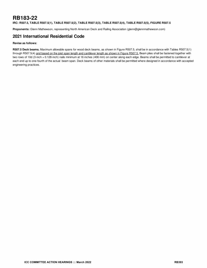
RB183-22IRC: R507.5, TABLE R507.5(1), TABLE R507.5(2), TABLE R507.5(3), TABLE R507.5(4), TABLE R507.5(5), FIGURE R507.5
Proponents: Glenn Mathewson, representing North American Deck and Railing Association ([email protected])
2021 International Residential CodeRevise as follows:
R507.5 Deck beams. Maximum allowable spans for wood deck beams, as shown in Figure R507.5, shall be in accordance with Tables R507.5(1)through R507.5(4) and based on the joist span length and cantilever length as shown in Figure R507.5. Beam plies shall be fastened together withtwo rows of 10d (3-inch × 0.128-inch) nails minimum at 16 inches (406 mm) on center along each edge. Beams shall be permitted to cantilever ateach end up to one-fourth of the actual beam span. Deck beams of other materials shall be permitted where designed in accordance with acceptedengineering practices.
c
ICC COMMITTEE ACTION HEARINGS ::: March 2022 RB393

TABLE R507.5(1) MAXIMUM DECK BEAM SPAN—40 PSF LIVE LOAD
JOIST SPAN JOIST SPAN LENGTH & JOIST CANTILEVER LENGTH (feet & feet)
6 6 & 0 6 & 1.5
8 8 & 0 8 & 1 8 & 2
10 10 & 0 10 & 1 10 & 2.5
12 12 & 0 12 & 1 12 & 2 12 & 3
14 14 & 0 14 & 1 14 & 2 14 & 3.5
16 16 & 0 16 & 1 16 & 2.5 16 & 4
18 18 & 0 18 & 1.5 18 & 3 18 & 4.5
BEAM SPECIES BEAM SIZE
EFFECTIVE DECK JOIST SPAN LENGTH (feet)
6 8 10 12 14 16 18
MAXIMUM DECK BEAM SPAN LENGTH (feet-inches)(feet-inches)
Southern pine
1 – 2 × 6 4-10 4-7 4-3 4-0 3-7 3-5 3-3 3-0 2-10 2-8
1 – 2 × 8 6-4 5-11 5-6 5-1 4-7 4-4 4-2 3-10 3-7 3-5
1 – 2 × 10 7-6 7-0 6-6 6-0 5-5 5-2 4-11 4-7 4-3 4-0
1 – 2 × 12 8-8 8-3 7-8 7-1 6-4 6-1 5-10 5-5 5-0 4-9
2 – 2 × 6 7-4 6-11 6-5 5-11 5-4 5-1 4-10 4-6 4-3 4-0
2 – 2 × 8 9-4 8-9 8-2 7-7 6-9 6-5 6-2 5-9 5-4 5-0
2 – 2 × 10 11-0 10-4 9-8 9-0 8-0 7-8 7-4 6-9 6-4 6-0
2 – 2 × 12 13-0 12-2 11-4 10-7 9-5 9-0 8-7 8-0 7-5 7-0
3 – 2 × 6 9-0 8-6 7-11 7-5 6-8 6-4 6-1 5-8 5-3 4-11
3 – 2 × 8 11-7 10-11 10-3 9-6 8-6 8-1 7-9 7-2 6-8 6-4
3 – 2 × 10 13-11 13-0 12-1 11-2 10-0 9-7 9-2 8-6 7-11 7-6
3 – 2 × 12 16-3 15-3 14-3 13-3 11-10 11-3 10-9 10-0 9-4 8-10
Douglas fir-larchHem-firSpruce-pine-fir
1 – 2 x 6 4-5 4-1 3-9 3-6 3-0 2-10 2-8 2-5 2-3 2-1
1 – 2 × 8 5-11 5-6 5-1 4-8 4-0 3-9 3-6 3-2 2-11 2-9
1 – 2 × 10 7-1 6-8 6-3 5-10 5-1 4-9 4-6 4-1 3-9 3-6
1 – 2 × 12 8-3 7-9 7-3 6-9 6-0 5-9 5-6 5-0 3-9 3-6
2 – 2 × 6 6-6 6-1 5-8 5-3 4-9 4-6 4-4 3-11 3-7 3-3
2 – 2 × 8 8-8 8-2 7-7 7-1 6-4 6-0 5-9 5-2 4-8 4-4
2 – 2 × 10 10-8 10-0 9-3 8-7 7-9 7-4 7-0 6-6 6-0 5-6
2 – 2 × 12 12-4 11-7 10-9 10-0 8-11 8-6 8-2 7-7 7-1 6-8
3 – 2 × 6 8-2 7-8 7-2 6-8 6-0 5-9 5-6 5-1 4-9 4-6
3 – 2 × 8 10-11 10-3 9-6 8-10 7-11 7-7 7-3 6-8 6-3 5-11
3 – 2 × 10 13-4 12-6 11-8 10-10 9-8 9-3 8-10 8-2 7-8 7-2
3 – 2 × 12 15-6 14-6 13-6 12-7 11-3 10-9 10-3 9-6 8-11 8-5
1 – 2 × 6 4-5 4-2 3-10 3-7 3-1 2-11 2-9 2-6 2-3 2-2
1 – 2 × 8 5-8 5-4 4-11 4-7 4-1 3-10 3-7 3-3 3-0 2-10
1 – 2 × 10 6-11 6-6 6-0 5-7 5-0 4-9 4-7 4-2 3-10 3-7
1 – 2 × 12 8-0 7-6 7-0 6-6 5-10 5-7 5-4 4-11 4-7 4-4
2 – 2 × 6 6-7 6-2 5-9 5-4 4-10 4-7 4-5 4-0 3-8 3-4
2 – 2 × 8 8-4 7-10 7-4 6-10 6-1 5-10 5-7 5-2 4-10 4-5
2 – 2 × 10 12-2 9-7 8-11 8-4 7-5 7-1 6-9 6-3 5-10 5-6
2 – 2 × 12 11-9 11-1 10-4 9-8 8-7 8-2 7-10 7-3 6-10 6-5
3 – 2 × 6 8-1 7-8 7-2 6-9 6-0 5-9 5-6 5-1 4-9 4-6
3 – 2 × 8 10-6 9-10 9-2 8-6 7-7 7-3 6-11 6-5 6-0 5-8
c
a, i
d e
a, i, j
a, b, f
a, b, f
g
g
ICC COMMITTEE ACTION HEARINGS ::: March 2022 RB394

RedwoodWestern cedarsPonderosa pineRed pine
3 – 2 × 10 12-9 12-0 11-2 10-5 9-4 8-11 8-6 7-10 7-4 6-11
3 – 2 × 12 14-10 13-11 13-0 12-1 10-9 10-3 9-10 9-1 8-6 8-1
JOIST SPAN JOIST SPAN LENGTH & JOIST CANTILEVER LENGTH (feet & feet)
6 6 & 0 6 & 1.5
8 8 & 0 8 & 1 8 & 2
10 10 & 0 10 & 1 10 & 2.5
12 12 & 0 12 & 1 12 & 2 12 & 3
14 14 & 0 14 & 1 14 & 2 14 & 3.5
16 16 & 0 16 & 1 16 & 2.5 16 & 4
18 18 & 0 18 & 1.5 18 & 3 18 & 4.5
BEAM SPECIES BEAM SIZE
EFFECTIVE DECK JOIST SPAN LENGTH (feet)
6 8 10 12 14 16 18
MAXIMUM DECK BEAM SPAN LENGTH (feet-inches)(feet-inches)
For SI: 1 inch = 25.4 mm, 1 foot = 304.8 mm, 1 pound per square foot = 0.0479 kPa, 1 pound = 0.454 kg.
a. Interpolation permitted for conditions with zero joist cantilever length. Extrapolation not permitted.
b. Beams supporting a single span of joists with or without cantilever.
c. Dead load = 10 psf, L/Δ = 360 at main span, L/Δ = 180 at cantilever. Snow load is not assumed to be concurrent with live load.
b. Beams supporting deck joists from one side only.
d. No. 2 grade, wet service factor included.
e. Beam depth shall be equal to or greater than the depth of intersecting joist for a flush beam connection.
f. Beam cantilevers are limited to the adjacent beam’s span divided by 4.
g. Includes incising factor.
h. Incising factor not included.
i. Deck joist span as shown in Figure R507.5.
j. For calculation of effective deck joist span, the actual joist span length shall be multiplied by the joist span factor in accordance with TableR507.5(5).
h
h
h
h
c
ICC COMMITTEE ACTION HEARINGS ::: March 2022 RB395

TABLE R507.5(2) MAXIMUM DECK BEAM SPAN—50 PSF GROUND SNOW LOAD
JOIST SPAN JOIST SPAN LENGTH & JOIST CANTILEVER LENGTH (feet & feet)
6 6 & 0 6 & 1.5
8 8 & 0 8 & 1 8 & 2
10 10 & 0 10 & 1 10 & 2.5
12 12 & 0 12 & 1 12 & 2 12 & 3
14 14 & 0 14 & 1 14 & 2 14 & 3.5
16 16 & 0 16 & 1 16 & 2.5
18 18 & 0 18 & 1.5 18 & 3 18 & 4.5
BEAM SPECIES BEAM SIZE
EFFECTIVE DECK JOIST SPAN LENGTH (feet)
6 8 10 12 14 16 18
MAXIMUM DECK BEAM SPAN LENGTH (feet-inches)(feet-inches)
Southern pine
1 – 2 × 6 4-9 4-6 4-2 3-11 3-6 3-4 3-2 2-11 2-9 2-7
1 – 2 × 8 6-2 5-9 5-4 4-11 4-5 4-2 4-0 3-9 3-6 3-3
1 – 2 × 10 7-2 6-9 6-3 5-10 5-3 5-0 4-9 4-5 4-2 3-11
1 – 2 × 12 8-6 8-0 7-5 6-11 6-2 5-11 5-8 5-3 4-11 4-7
2 – 2 × 6 7-1 6-8 6-2 5-9 5-2 4-11 4-9 4-4 4-1 3-10
2 – 2 × 8 9-1 8-6 7-11 7-4 6-7 6-3 6-0 5-7 5-2 4-11
2 – 2 × 10 10-9 10-1 9-5 8-9 7-10 7-5 7-1 6-7 6-2 5-10
2 – 2 × 12 12-9 11-11 11-1 10-3 9-2 8-9 8-5 7-9 7-3 6-10
3 – 2 × 6 8-3 7-11 7-6 7-2 6-6 6-2 5-11 5-6 5-1 4-10
3 – 2 × 8 11-0 10-5 9-10 9-3 8-3 7-10 7-6 6-11 6-6 6-2
3 – 2 × 10 13-6 12-8 11-9 10-11 9-9 8-4 8-11 8-3 7-9 7-3
3 – 2 × 12 15-11 14-11 13-11 12-11 11-6 11-0 10-6 9-9 9-1 8-7
Douglas fir-larchHem-firSpruce-pine-fir
1 – 2 × 6 4-3 4-0 3-8 3-5 2-11 2-9 2-7 2-4 2-2 2-0
1 – 2 × 8 5-9 5-4 4-11 4-7 3-11 3-8 3-5 3-1 2-10 2-8
1 – 2 × 10 7-0 6-7 6-1 5-8 4-11 4-8 4-5 4-0 3-8 3-5
1 – 2 × 12 8-1 7-7 7-1 6-7 5-11 5-7 5-4 4-10 4-6 4-2
2 – 2 × 6 6-5 6-0 5-7 5-2 4-7 4-4 4-2 3-10 3-5 3-2
2 – 2 × 8 8-6 8-0 7-5 6-11 6-2 5-11 5-8 5-0 4-7 4-2
2 – 2 × 10 10-5 9-9 9-1 8-5 7-7 7-3 6-11 6-4 5-10 5-4
2 – 2 × 12 12-1 11-4 10-7 9-10 8-9 8-4 8-0 7-5 6-11 6-6
3 – 2 × 6 8-0 7-6 7-0 6-6 5-9 5-6 5-3 4-11 4-7 4-4
3 – 2 × 8 10-8 10-0 9-4 8-8 7-9 7-5 7-1 6-6 6-1 5-8
3 – 2 × 10 13-1 12-3 11-5 10-7 9-6 9-1 8-8 8-0 7-6 7-0
3 – 2 × 12 15-2 14-3 13-3 12-4 11-0 10-6 10-1 9-4 8-9 8-3
RedwoodWestern cedarsPonderosa pineRed pine
1 – 2 × 6 4-4 4-1 3-9 3-6 3-0 2-10 2-8 2-5 2-3 2-1
1 – 2 × 8 5-6 5-2 4-10 4-6 4-0 3-9 3-6 3-2 2-11 2-9
1 – 2 × 10 6-9 6-4 5-11 5-6 4-11 4-8 4-6 4-1 3-9 3-6
1 – 2 × 12 7-10 7-4 6-10 6-4 5-8 5-5 5-2 4-10 4-6 4-3
2 – 2 × 6 6-6 6-1 5-8 5-3 4-8 4-6 4-4 3-11 3-6 3-3
2 – 2 × 8 8-2 7-8 7-2 6-8 5-11 5-8 5-5 5-0 4-8 4-3
2 – 2 × 10 10-0 9-5 8-9 8-2 7-3 6-11 6-8 6-2 5-9 5-5
2 – 2 × 12 11-8 10-11 10-2 9-5 8-5 8-0 7-8 7-2 6-8 6-3
3 – 2 × 6 7-5 7-1 6-9 6-5 5-11 5-8 5-5 5-0 4-8 4-5
c
a, i
d e
a, i, j
a, b, f
a, b, f
g
g
g
h
h
h
h
ICC COMMITTEE ACTION HEARINGS ::: March 2022 RB396

3 – 2 × 8 9-10 9-4 8-10 8-4 7-5 7-1 6-10 604 5-11 5-7
3 – 2 × 10 12-6 11-9 10-11 10-2 9-1 8-8 8-4 7-8 7-2 6-9
3 – 2 × 12 14-7 13-8 12-9 11-10 10-7 10-1 9-8 8-11 8-4 7-10
For SI: 25.4 mm, 1 foot = 304.8 mm, 1 pound per square foot = 0.0479 kPa, 1 pound = 0.454 kg.
a. Interpolation allowed permitted for conditions with zero joist cantilever length. Extrapolation not permitted. is not allowed.
b. Beams supporting a single span of joists with or without cantilever.
c. Dead load = 10 psf, L/Δ = 360 at main span, L/Δ = 180 at cantilever. Snow load not assumed to be concurrent with live load.
d. No. 2 grade, wet service factor included.
e. Beam depth shall be equal to or greater than the depth of intersecting joist for a flush beam connection.
f. Beam cantilevers are limited to the adjacent beam’s span divided by 4.
g. Includes incising factor.
h. Incising factor not included.
i. Deck joist span as shown in Figure R507.5.
j. For calculation of effective deck joist span, the actual joist span length shall be multiplied by the joist span factor in accordance with TableR507.5(5).
c
ICC COMMITTEE ACTION HEARINGS ::: March 2022 RB397

TABLE R507.5(3) MAXIMUM DECK BEAM SPAN—60 PSF GROUND SNOW LOAD
JOIST SPAN JOIST SPAN LENGTH & JOIST CANTILEVER LENGTH (feet & feet)
6 6 & 0 6 & 1.5
8 8 & 0 8 & 1 8 & 2
10 10 & 0 10 & 1 10 & 2.5
12 12 & 0 12 & 1 12 & 2 12 & 3
14 14 & 0 14 & 1 14 & 2 14 & 3.5
16 16 & 0 16 & 1 16 & 2.5 16 & 4
18 18 & 0 18 & 1.5 18 & 3 18 & 4.5
BEAM SPECIES BEAM SIZE
EFFECTIVE DECK JOIST SPAN LENGTH(feet)
6 8 10 12 14 16 18
MAXIMUM DECK BEAM SPAN LENGTH (feet-inches)(feet-inches)
Southern pine
1 – 2 × 6 4-5 4-2 3-10 3-7 3-3 3-1 2-11 2-9 2-6 2-5
1 – 2 × 8 5-7 5-3 4-11 4-7 4-1 3-11 3-9 3-5 3-3 3-0
1 – 2 × 10 6-8 6-3 5-10 5-5 4-10 4-7 4-5 4-1 3-10 3-7
1 – 2 × 12 7-11 7-5 6-11 6-5 5-9 5-6 5-3 4-10 4-6 4-3
2 – 2 × 6 6-7 6-2 5-9 5-4 4-9 4-6 4-4 4-0 3-9 3-7
2 – 2 × 8 8-4 7-10 7-4 6-10 6-1 5-10 5-7 5-2 4-10 4-6
2 – 2 × 10 9-10 9-4 8-8 8-1 7-3 6-11 6-7 6-1 5-8 5-4
2 – 2 × 12 11-9 11-0 10-3 9-6 8-6 8-1 7-9 7-2 6-9 6-4
3 – 2 × 6 7-9 7-5 7-1 6-9 6-0 5-9 5-6 5-1 4-9 4-6
3 – 2 × 8 10-4 9-9 9-1 8-6 7-8 7-3 6-11 6-5 6-0 5-8
3 – 2 × 10 12-5 11-8 10-11 10-2 9-1 8-8 8-3 7-8 7-2 6-9
3 – 2 × 12 14-8 13-9 12-10 11-11 10-8 10-2 9-9 9-0 8-5 7-11
Douglas fir-larchHem-firSpuce-pine-fir
1 – 2 × 6 3-11 3-8 3-4 3-1 2-8 2-6 2-4 2-2 2-0 1-10
1 – 2 × 8 5-5 5-0 4-6 4-1 3-6 3-3 3-1 2-10 2-7 2-5
1 – 2 × 10 6-6 6-1 5-7 5-2 4-6 4-3 4-0 3-7 3-4 3-2
1 – 2 × 12 7-7 7-1 6-7 6-1 5-5 5-1 4-10 4-5 4-1 3-10
2 – 2 × 6 5-10 5-6 5-1 4-9 4-3 4-0 3-10 3-5 3-1 2-10
2 – 2 × 8 7-11 7-5 6-11 6-5 5-9 5-4 5-0 4-6 4-1 3-9
2 – 2 × 10 9-7 9-0 8-5 7-10 7-0 6-8 6-4 5-9 5-2 4-10
2 – 2 × 12 11-2 10-6 9-9 9-1 8-1 7-9 7-5 6-10 6-4 5-10
3 – 2 × 6 7-4 6-11 6-5 6-0 5-4 5-1 4-11 4-6 4-2 3-10
3 – 2 × 8 9-10 9-3 8-7 8-0 7-2 6-10 6-6 6-1 5-6 5-0
3 – 2 × 10 12-1 11-4 10-7 9-10 8-9 8-4 8-0 7-5 6-11 6-5
3 – 2 × 12 13-6 13-2 11-9 11-5 10-2 9-9 9-4 8-7 8-1 7-7
RedwoodWestern cedarsPonderosa pineRed pine
1 – 2 × 6 4-0 3-9 3-5 3-2 2-9 2-7 2-5 2-2 2-0 1-11
1 – 2 × 8 5-2 4-10 4-6 4-2 3-7 3-4 3-2 2-11 2-8 2-6
1 – 2 × 10 6-2 5-10 5-5 5-1 4-6 4-3 4-1 3-8 3-5 3-3
1 – 2 × 12 7-3 6-10 6-4 5-11 5-3 5-0 4-10 4-5 4-2 3-11
2 – 2 × 6 5-11 5-7 5-2 4-10 4-4 4-1 3-11 3-6 3-2 2-11
2 – 2 × 8 7-6 7-1 6-7 6-2 5-6 5-3 5-0 4-7 4-2 3-10
2 – 2 × 10 9-3 8-8 8-1 7-6 6-9 6-5 6-2 5-8 5-4 4-11
2 – 2 × 12 10-8 10-1 9-5 8-9 7-10 7-6 7-2 6-7 6-2 5-10
c
a, i
d e
a, i, j
a, b, f
a, b, f
g
g
g
h
h
h
h
ICC COMMITTEE ACTION HEARINGS ::: March 2022 RB398

3 – 2 × 6 6-11 6-8 6-4 6-1 5-5 5-2 5-0 4-7 4-3 3-11
3 – 2 × 8 9-3 8-9 8-3 7-9 6-11 6-7 6-4 5-10 5-5 5-3
3 – 2 × 10 11-8 10-11 10-2 9-5 8-5 8-0 7-8 7-3 6-8 6-3
3 – 2 × 12 13-6 12-8 11-9 10-11 9-9 8-4 8-11 8-3 7-9 7-3
For SI: 1 inch = 25.4 mm, 1 foot = 304.8 mm, 1 pound per square foot = 0.0479 kPa, 1 pound = 0.454 kg.
a. Interpolation allowed permitted for conditions with zero joist cantilever length. Extrapolation not permitted. is not allowed.
b. Beams supporting a single span of joists with or without cantilever.
c. Dead load = 10 psf, L/Δ = 360 at main span, L/Δ = 180 at cantilever. Snow load not assumed to be concurrent with live load.
d. No. 2 grade, wet service factor included.
e. Beam depth shall be equal to or greater than the depth of intersecting joist for a flush beam connection.
f. Beam cantilevers are limited to the adjacent beam’s span divided by 4.
g. Includes incising factor.
h. Incising factor not included.
i. Deck joist span as shown in Figure R507.5.
j. For calculation of effective deck joist span, the actual joist span length shall be multiplied by the joist span factor in accordance with TableR507.5(5).
c
ICC COMMITTEE ACTION HEARINGS ::: March 2022 RB399

TABLE R507.5(4) MAXIMUM DECK BEAM SPAN—70 PSF GROUND SNOW LOAD
JOIST SPAN JOIST SPAN LENGTH & CANTILEVER LENGTH (feet & feet)
6 6 & 0 6 & 1.5
8 8 & 0 8 & 1 8 & 2
10 10 & 0 10 & 1 10 & 2.5
12 12 & 0 12 & 1 12 & 2 12 & 3
14 14 & 0 14 & 1 14 & 2 14 & 3.5
16 16 & 0 16 & 1 16 & 2.5 16 & 4
18 18 & 0 18 & 1 18 & 3 18 & 4.5
BEAM SPECIES BEAM SIZE
EFFECTIVE DECK JOIST SPAN LENGTH (feet)
6 8 10 12 14 16 18
MAXIMUM DECK BEAM SPAN LENGTH (feet-inches)(feet-inches)
Southern pine
1 – 2 × 6 4-2 3-11 3-7 3-4 3-0 2-10 2-9 2-6 2-4 2-3
1 – 2 × 8 5-4 4-11 4-8 4-3 3-10 3-8 3-6 3-3 3-0 2-10
1 – 2 × 10 6-2 5-10 5-5 5-1 4-6 4-4 4-2 3-10 3-7 3-4
1 – 2 × 12 7-4 6-11 6-5 6-0 5-4 5-1 4-11 4-6 4-3 4-0
2 – 2 × 6 6-3 5-9 5-4 5-0 4-6 4-3 4-1 3-9 3-6 3-4
2 – 2 × 8 7-10 7-4 6-10 6-4 5-8 5-5 5-2 4-10 4-6 4-3
2 – 2 × 10 9-6 8-9 8-2 7-7 6-9 6-5 6-2 5-8 5-4 5-0
2 – 2 × 12 10-11 10-3 9-7 8-11 8-0 7-7 7-3 6-9 6-3 5-11
3 – 2 × 6 7-4 7-0 6-7 6-3 5-7 5-4 5-1 4-9 4-5 4-2
3 – 2 × 8 9-10 9-3 8-7 8-0 7-2 6-10 6-6 6-0 5-8 5-4
3 – 2 × 10 11-7 10-11 10-2 9-6 8-6 8-1 7-9 7-2 6-8 6-4
3 – 2 × 12 13-9 12-11 12-0 11-2 10-0 9-6 9-1 8-5 7-11 7-5
Douglas fir-larchHem-firSpruce-pine-fir
1 – 2 × 6 3-8 3-5 3-1 2-10 2-5 2-3 2-2 2-0 1-10 1-9
1 – 2 × 8 4-10 4-7 4-1 3-8 3-2 3-0 2-10 2-7 2-5 2-4
1 – 2 × 10 6-1 5-8 5-2 4-9 4-1 3-10 3-8 3-4 3-1 2-11
1 – 2 × 12 7-0 6-7 6-1 5-8 5-0 4-9 4-6 4-1 3-10 3-7
2 – 2 × 6 5-6 5-2 4-10 4-6 4-0 3-8 3-5 3-1 2-10 2-7
2 – 2 × 8 7-4 6-11 6-5 6-0 5-3 4-11 4-7 4-1 3-8 3-5
2 – 2 × 10 8-11 8-5 7-10 7-4 6-6 6-2 5-10 5-2 4-9 4-5
2 – 2 × 12 10-6 9-10 9-2 8-6 7-7 7-3 6-11 6-4 5-9 5-4
3 – 2 × 6 6-11 6-6 6-0 5-7 5-0 4-9 4-7 4-2 3-9 3-5
3 – 2 × 8 9-3 8-8 8-1 7-6 6-8 6-4 6-1 5-6 5-0 4-7
3 – 2 × 10 11-3 10-7 9-10 9-2 8-2 7-10 7-6 6-11 6-4 5-10
3 – 2 × 12 13-2 12-4 11-6 10-8 9-7 9-2 8-9 8-1 7-7 7-1
RedwoodWestern cedarsPonderosa pineRed pine
1 – 2 × 6 3-9 3-6 3-2 2-11 2-6 2-4 2-3 2-0 1-11 1-9
1 – 2 × 8 4-10 4-6 4-2 3-10 3-3 3-1 2-11 2-8 2-6 2-4
1 – 2 × 10 5-10 5-6 5-1 4-9 4-2 3-11 3-9 3-5 3-2 3-0
1 – 2 × 12 6-9 6-4 5-11 5-6 4-11 4-8 4-6 4-2 3-11 3-8
2 – 2 × 6 5-7 5-3 4-11 4-7 4-1 3-9 3-6 3-2 2-11 2-8
2 – 2 × 8 7-1 6-8 6-2 5-9 5-2 4-11 4-8 4-2 3-10 3-6
2 – 2 × 10 8-8 8-2 7-7 7-1 6-4 6-0 5-9 5-4 4-10 4-6
2 – 2 × 12 10-0 9-5 8-9 8-2 7-4 7-0 6-8 6-2 5-9 5-5
3 – 2 × 6 6-8 6-4 6-0 5-8 5-1 4-10 4-8 4-3 3-10 3-6
3 – 2 × 8 8-10 8-4 7-9 7-3 6-5 6-2 5-11 5-5 5-1 4-8
c
a, i
d e
a, i, j
a, b, f
a, b, f
g
g
g
h
h
h
h
ICC COMMITTEE ACTION HEARINGS ::: March 2022 RB400

3 – 2 × 10 10-10 10-2 9-6 8-10 7-11 7-6 7-2 6-8 6-3 5-11
3 – 2 × 12 12-7 11-10 11-0 10-3 9-2 8-9 8-4 7-9 7-3 6-10
For SI: 1 inch = 25.4 mm, 1 foot = 304.8 mm, 1 pound per square foot = 0.0479 kPa, 1 pound = 0.454 kg.
a. Interpolation allowed permitted for conditions with zero joist cantilever length. Extrapolation not permitted. is not allowed.
b. Beams supporting a single span of joists with or without cantilever.
c. Dead load = 10 psf, L/Δ = 360 at main span, L/Δ = 180 at cantilever. Snow load not assumed to be concurrent with live load.
d. No. 2 grade, wet service factor included.
e. Beam depth shall be equal to or greater than the depth of intersecting joist for a flush beam connection.
f. Beam cantilevers are limited to the adjacent beam’s span divided by 4.
g. Includes incising factor.
h. Incising factor not included.
i. Deck joist span as shown in Figure R507.5.
j. For calculation of effective deck joist span, the actual joist span length shall be multiplied by the joist span factor in accordance with TableR507.5(5).
Delete without substitution:
ICC COMMITTEE ACTION HEARINGS ::: March 2022 RB401

TABLE R507.5(5) JOIST SPAN FACTORS FOR CALCULATING EFFECTIVE DECK JOIST SPAN [for use with Note j in TablesR507.5(1), R507.5(2), R507.5(3) and R507.5(4)]
C/J JOIST SPAN FACTOR
0 (no cantilever) 0.66
1/12 (0.87) 0.72
1/10 (0.10) 0.80
1/8 (0.125) 0.84
1/6 (0.167) 0.90
1/4 (0.250) 1.00
For SI: 1 foot = 304.8 mm.
a. C = actual joist cantilever length (feet); J = actual joist span length (feet).
Revise as follows:
a
ICC COMMITTEE ACTION HEARINGS ::: March 2022 RB402

FIGURE R507.5 TYPICAL DECK JOIST BEAM SPANS
Reason Statement: Since first appearing in the the 2015 IRC, Table R507.5 for deck beam sizing has always assumed a load from joistscantilevering their maximum amount beyond the beam. In most conditions, joists can cantilever beyond a beam up to 1/4 their back span, and thisentire load is placed on the beam. This places up to 50 percent more load on the beam than a joist that does not cantilever beyond. For example, ajoist that spans 12 feet with no cantilever loads the beam with 6 feet. But with an additional 3-foot cantilever, the beam is now loaded with 9 feet. Currently, Table R507,5 sizes every beam based only on the joist span, and simply includes the additional maximum cantilever loading every time. When there is no cantilever, or less than the maximum, the beam is being oversized or overly restricted in maximum span. For a 12 foot joist spanwith no cantilever, the beam is sized for 9 feet of joist. This is equivalent to an 18-foot joist span with no cantilever.It is woefully inaccurate to size a minimum beam for a 12-foot joist span based on loads from a 18-foot span.
In 2021 a new table was added in the footnotes of Table R507.5 that provided a factor based on the actual cantilever to joist span ratio. This factorcould then be used for the input joist span value in order to generate an accurately sized beam. Though this adjustment method works, it isincredibly inconvenient and not user friendly. This proposal eliminates this footnote and its table and embeds various joist span and cantilevercombinations in an expanded heading that is currently shown as only joist span. Each column that currently represent a joists span and it'smaximum cantilever has been expanded to show equivalent spans and cantilever combinations. Each combination in the same column loads thebeam equivalent or slightly less. Note that under the previous "effective joist span length" column for 12 feet, the new heading reveals that thiscolumn covers four different designs, an 18 foot span with no cantilever (18 & 0), a 16 foot span with a 1 foot cantilever (16 & 1), and 14 foot spanwith a 2 foot cantilever (14 & 2), and a 12 foot span with a 3 foot cantilever (12 & 3).
A 6 foot joist span with a 1.5 foot cantilever was the first column in the current table. In order to provide a beam size for each joist span length from6 feet to 18 feet and with zero cantilever length, a new column was added at the left of the table.
The footnote for interpolation was modified to only permit interpolation between columns for evaluating joists with no cantilever. For example, a 13foot joist span with no cantilever, could be easily interpolated by taking the value between the (12 & 0) and (14 & 0) columns. However, trying tointerpolate a 13 foot span with a 2 foot cantilever is not quite so simply and would invite error.
To further clarify the use of the beam span table, Section R507.5 was modified to reference the joist span length and joist cantilever length and pointthe reader to Figure R507.6 which illustrates these terms.
Figure R507.5 for deck BEAMS is incorrectly titled "JOIST". This merely editorial, perhaps errata, perhaps mistake. Let's fix it!
Cost Impact: The code change proposal will decrease the cost of constructionThis proposal provides three new columns of maximum beam spans within the table, which allows beams to be sized more accurately, and thus notoversized and more expensive. The current beam span table sizes beams with the assumption that the joists are fully cantilevered beyond thebeam. This is 50% more loading on the beam than when there is no joist cantilever. When there is no joist cantilever or less than the maximum, thebeam is oversized and more expensive. A footnote with a complicated cantilever to joist ratio table yielding a factor to adjust the input joist span for amore accurate beam size is available. However, it is very difficult to use and not convenient. Offering a way to quickly size the beam based on afew different cantilever lengths, allows a more affordable beam to be sized and purchased.
RB183-22
ICC COMMITTEE ACTION HEARINGS ::: March 2022 RB403

RB184-22IRC: R507.5, R507.5.1, R507.5.2, FIGURE R507.5.1(1), FIGURE R507.5.1(2), R507.6.1
Proponents: Glenn Mathewson, representing North American Deck and Railing Association ([email protected])
2021 International Residential CodeRevise as follows:
R507.5 Deck beams. Maximum allowable spans for wood deck beams, as shown in Figure R507.5, shall be in accordance with Tables R507.5(1)through R507.5(4). Beam plies shall be fastened together with two rows of 10d (3-inch × 0.128-inch) nails minimum at 16 inches (406 mm) on centeralong each edge. Beams shall be permitted to cantilever at each end up to one-fourth of the actual beam span. Deck beams of other materials shallbe permitted where designed in accordance with accepted engineering practices.
R507.5.1 Deck beam bearing. Beams and individual beam plies of built-up beams shall be continuous between bearing locations and continuousacross bearing locations supporting beam cantilevers. Beams shall be permitted to cantilever beyond bearing locations up to one fourth of theactual beam span. The ends of beams shall have not less than 1 / inches (38 mm) of bearing length on wood or metal and not less than 3 inches(76 mm) of bearing length on concrete or masonry for the entire width of the beam. Where multiple-span beams bear on intermediate posts, each plymust have full bearing on the post in accordance with Figures R507.5.1(1) and R507.5.1(2).
R507.5.2 Deck beam connection to supports. Deck beams shall be connected to supporting members to prevent lateral attached to supports ina manner capable of transferring vertical loads and resisting horizontal displacement. Deck beam connections to wood posts shall be in accordancewith Figures R507.5.2(1) and R507.5.2(2) R507.5.1(1) and R507.5.1(2). Manufactured post-to-beam connectors shall be sized for the post andbeam sizes. Bolts shall have washers under the head and nut.
12
ICC COMMITTEE ACTION HEARINGS ::: March 2022 RB404
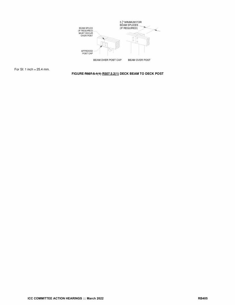
For SI: 1 inch = 25.4 mm.FIGURE R507.5.1(1) R507.5.2(1) DECK BEAM TO DECK POST
ICC COMMITTEE ACTION HEARINGS ::: March 2022 RB405

For SI: 1 inch = 25.4 mm.FIGURE R507.5.1(2) R507.5.2(2) NOTCHED POST-TO-BEAM CONNECTION
R507.6.1 Deck joist bearing. The ends of joists shall have not less than 1 / inches (38 mm) of bearing length on wood or metal and not less than 3inches (76 mm) of bearing length on concrete or masonry over its entire width. Joists bearing on top of a multiple-ply beam or ledger shall befastened in accordance with Table R602.3(1). Joists bearing on top of a single-ply beam or ledger shall be attached by a mechanical connector.Joist framing into the side of a beam or ledger board shall be supported by approved joist hangers.
Reason Statement: 1) There is still uncertainty by some code readers as to whether each end of each ply of a multi-ply (“built-up”) beam mustbe supported on a bearing location. This is indeed the intent and is what this proposal attempts to clarify. Please note that in prescriptive woodframe construction, this has always been the rule. The 1931 edition of “Light Frame House Construction” by the Federal Board of VocationalEducation” provides the following on page 40: “At the point of bearing the beam should be carefully sized, so that every piece of the built-up girder isin full contact with the support”.2) The term “length” was included to clarify the direction of the minimum bearing measurement. This term compliments the existing term “width”regarding the beam.3) The reference to Figures R507.5.1(1) and (2) was removed in section R507.5.1 “deck beam bearing”, because those figures speak to theconnection of the beam to the post and not the bearing. A reference to those figures is already provided in the section on beam connections,Section R507.5.2. Along with this change, the two Figures need to be given a new section number title that matches the section they are referencedfrom (deck beam connection). (Table R507.5.2(1) and (2))4) The allowance for beam cantilevers was moved to the section about beam bearing, as it is related to the need for all beam plies to be continuousover the last bearing point to support the cantilever.
Cost Impact: The code change proposal will not increase or decrease the cost of constructionThis proposal only clarifies the existing intent of these sections and therefore does not directly affect the cost of construction.
RB184-22
12
ICC COMMITTEE ACTION HEARINGS ::: March 2022 RB406

RB185-22IRC: R507.7
Proponents: Glenn Mathewson, representing North American Deck and Railing Association ([email protected])
2021 International Residential CodeRevise as follows:
R507.7 Decking. Maximum allowable spacing for joists supporting wood decking, excluding stairways, shall be in accordance with Table R507.7.Wood decking shall be attached to each supporting member with not less than two 8d deformed threaded nails or two No. 8 wood screws. Maximumallowable spacing for joists supporting plastic composite decking shall be in accordance with Section R507.2. Other approved decking or fastenersystems shall be installed in accordance with the manufacturer’s installation requirements.
Reason Statement: The fasteners specified are not based on any known magnitude of load resistance, thus they need not be so specific. “Threaded” is a very specific nail shank design, however the intent of this IRC provision is simply to provide additional friction between the shankand the wood than a smooth shank provides. The term “threaded nails” is not used anywhere else in the IRC. The term “deformed nails” is moregeneric, as it could be ring, threaded, or otherwise designed to increase friction. This term is used in the following IRC provisions: Table R602.3(1),R703.3.3, and Table R905.1.1(3). Using the term “deformed” will broaden the allowable products available for use in decking fastening and increasethe consistency of terms used in the IRC.
Cost Impact: The code change proposal will not increase or decrease the cost of constructionThis proposal simply broadens the available shank design of nails in prescriptive design methods. In itself, this does not affect the cost ofconstruction. It simply provides greater freedom in construction.
RB185-22
ICC COMMITTEE ACTION HEARINGS ::: March 2022 RB407

RB186-22IRC: R507.7
Proponents: Glenn Mathewson, representing North American Deck and Railing Association ([email protected])
2021 International Residential CodeRevise as follows:
R507.7 Decking. Maximum allowable spacing for joists supporting wood decking, excluding stair treads stairways, shall be in accordance withTable R507.7. Wood decking shall be attached to each supporting member with not less than two 8d threaded nails or two No. 8 wood screws.Maximum allowable spacing for joists supporting plastic composite decking shall be in accordance with Section R507.2. Other approved decking orfastener systems shall be installed in accordance with the manufacturer’s installation requirements.
Reason Statement: The decking spans (joist spacing) provided in R507.7 are not designed to support the 300 pound concentrated design loadrequired for “stair treads” under footnote c in Table R301.5. This additional load is only required on “stair treads”, as specifically stated in TableR301.5.A “stairway” includes the top, bottom, and intermediate landings. These landings are often constructed like decks and the landings do not requirethe additional concentrated load required on "stair treads". Therefore, the exclusion for using Table R507.7 should be for “stair treads” and not“stairways”. The construction of the stairway landing decking does not need to be excluded from the provisions of R507.7
Cost Impact: The code change proposal will decrease the cost of constructionThe code change proposals has the potential to reduce construction costs by allowing for prescriptive design of decking for stairway landings that isnot currently provided in the IRC.
RB186-22
ICC COMMITTEE ACTION HEARINGS ::: March 2022 RB408

RB187-22IRC: TABLE R507.9.1.3(2)
Proponents: Glenn Mathewson, representing North American Deck and Railing Association ([email protected])
2021 International Residential CodeRevise as follows:
ICC COMMITTEE ACTION HEARINGS ::: March 2022 RB409
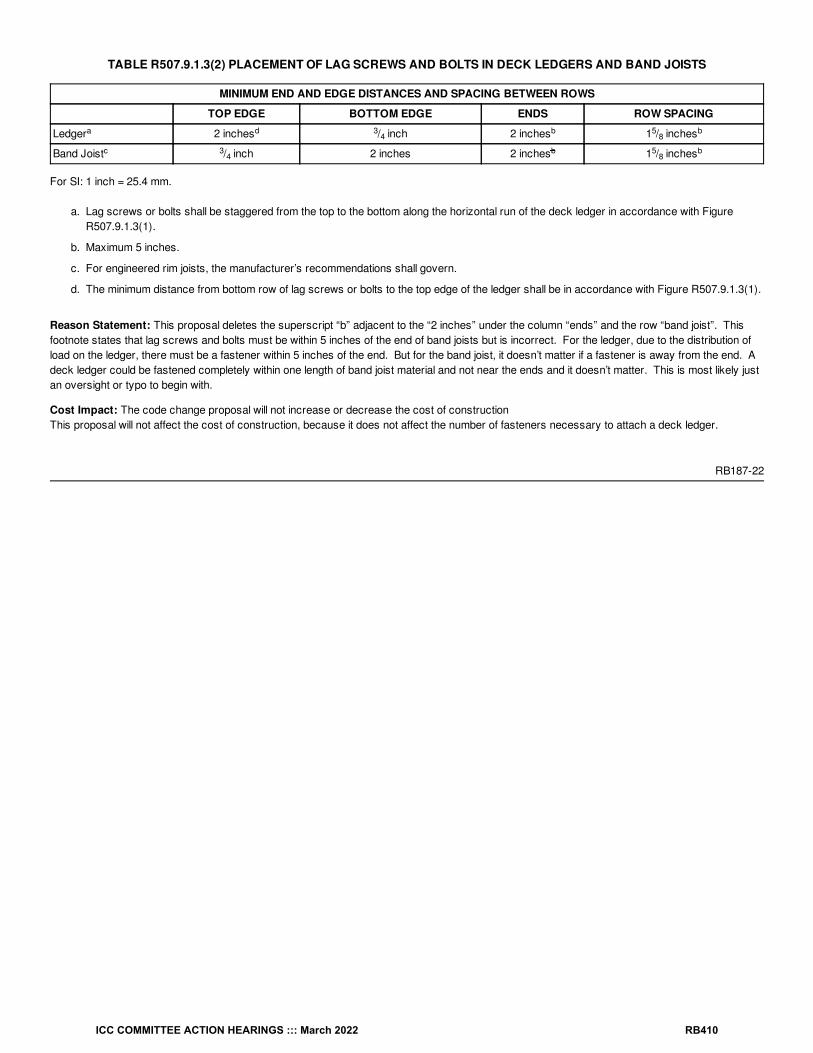
TABLE R507.9.1.3(2) PLACEMENT OF LAG SCREWS AND BOLTS IN DECK LEDGERS AND BAND JOISTS
MINIMUM END AND EDGE DISTANCES AND SPACING BETWEEN ROWS
TOP EDGE BOTTOM EDGE ENDS ROW SPACING
Ledger 2 inches / inch 2 inches 1 / inches
Band Joist / inch 2 inches 2 inches 1 / inches
For SI: 1 inch = 25.4 mm.
a. Lag screws or bolts shall be staggered from the top to the bottom along the horizontal run of the deck ledger in accordance with FigureR507.9.1.3(1).
b. Maximum 5 inches.
c. For engineered rim joists, the manufacturer’s recommendations shall govern.
d. The minimum distance from bottom row of lag screws or bolts to the top edge of the ledger shall be in accordance with Figure R507.9.1.3(1).
Reason Statement: This proposal deletes the superscript “b” adjacent to the “2 inches” under the column “ends” and the row “band joist”. Thisfootnote states that lag screws and bolts must be within 5 inches of the end of band joists but is incorrect. For the ledger, due to the distribution ofload on the ledger, there must be a fastener within 5 inches of the end. But for the band joist, it doesn’t matter if a fastener is away from the end. Adeck ledger could be fastened completely within one length of band joist material and not near the ends and it doesn’t matter. This is most likely justan oversight or typo to begin with.
Cost Impact: The code change proposal will not increase or decrease the cost of constructionThis proposal will not affect the cost of construction, because it does not affect the number of fasteners necessary to attach a deck ledger.
RB187-22
a d 34
b 58
b
c 34
b 58
b
ICC COMMITTEE ACTION HEARINGS ::: March 2022 RB410

RB188-22IRC: R311.5, R507.8, R507.9, R507.9.1, R507.9.1.1, R507.9.1.2, R507.9.1.3, R507.9.1.4, R507.9.2, R507.9.1 (New)
Proponents: Glenn Mathewson, representing Self ([email protected])
2021 International Residential CodeDelete without substitution:
R311.5 Landing, deck, balcony and stair construction and attachment. Exterior landings, decks, balconies, stairs and similar facilities shall bepositively anchored to the primary structure to resist both vertical and lateral forces or shall be designed to be self-supporting. Attachment shall notbe accomplished by use of toenails or nails subject to withdrawal.
Revise as follows:
R507.8 Vertical and lateral supports Deck ledgers. Where supported by attachment to an exterior wall, decks shall be positively anchored to theprimary structure and designed for both vertical and lateral loads. Such attachment shall not be accomplished by the use of toenails or nails subjectto withdrawal. For decks with cantilevered framing members, connection to exterior walls or other framing members shall be designed andconstructed to resist uplift resulting from the full live load specified in Table R301.5 acting on the cantilevered portion of the deck. Where positiveconnection to the primary building structure cannot be verified during inspection, decks shall be self-supporting. Deck ledgers shall not be supportedon stone or masonry veneer.
Delete without substitution:
R507.9 Vertical and lateral supports at band joist. Vertical and lateral supports for decks shall comply with this section.
Revise as follows:
R507.9.1 R507.8.1 Vertical supports Ledger attachment. Where Vertical loads are shall be transferred to band joists with ledgers in accordancewith this section, ledgers shall be installed in accordance with Sections R507.8.1.1 through R507.8.3.
R507.9.1.1 R507.8.1.1 Ledger details. Deck ledgers shall be a minimum 2-inch by 8-inch (51 mm by 203 mm) nominal, pressure-preservative-treated Southern pine, incised pressure-preservative-treated hem-fir, or approved, naturally durable, No. 2 grade or better lumber. Deck ledgersshall not support concentrated loads from beams or girders. Deck ledgers shall not be supported on stone or masonry veneer.
R507.9.1.2 R507.8.1.2 Band joist details. Band joists supporting a ledger shall be a minimum 2-inch-nominal (51 mm), solid-sawn, spruce-pine-firor better lumber or a minimum 1-inch (25 mm) nominal engineered wood rim boards in accordance with Section R502.1.7. Band joists shall bear fullyon the primary structure capable of supporting all required loads.
R507.9.1.3 R507.8.1.3 Ledger to band joist Fastener details. Fasteners used in deck ledger connections in accordance with Table R507.9.1.3(1)shall be hot-dipped galvanized or stainless steel and shall be installed in accordance with Table R507.9.1.3(2) R507.8.1.3(2) and FiguresR507.9.1.3(1) and R507.9.1.3(2). R507.8.1.3(1) and R507.8.1.3(2)
R507.9.1.4 R507.8.2 Alternate ledger details. Alternate framing configurations, fasteners, or hardware supporting a ledger constructed to meet theload requirements of Section R301.5 shall be permitted , where approved.
R507.9.2 R507.9 Lateral connection. Decks shall be designed to transfer Lateral loads shall be transferred to the ground or to a structure capableof transmitting them to the ground. Bracing shall be required in all lateral directions in accordance with accepted engineering practice, utilizingapproved braced wall panels, knee braces, cross braces, K braces, moment frame post connections, embedded support posts, horizontaldiaphragms, lateral connections in accordance with Section R507.9.1, or through other approved methods. Where the lateral load connection isprovided in accordance with Figure R507.9.2(1), hold-down tension devices shall be installed in not less than two locations per deck, within 24inches (610 mm) of each end of the deck. Each device shall have an allowable stress design capacity of not less than 1,500 pounds (6672 N).Where the lateral load connections are provided in accordance with Figure R507.9.2(2), the hold-down tension devices shall be installed in not lessthan four locations per deck, and each device shall have an allowable stress design capacity of not less than 750 pounds (3336 N).
Add new text as follows:
R507.9.1 Lateral connection. Lateral bracing perpendicular to a ledger shall be permitted in accordance with the following connection methods:
1. Tension devices with a minimum allowable stress design capacity of not less than 1,500 pounds (6672 N) shall be installed in not less thantwo locations per deck, in accordance with Figure R507.9.1 (1), and within 24 inches (610 mm) of each end of the deck
2. Tension devices with a minimum allowable stress design capacity of not less than 750 pounds (3336 N) shall be installed in not less than fourlocations per deck, in accordance with Figure R507.9.1 (2), and with one within 24 inches (610 mm) of each end of the deck.
Reason Statement: The lateral load connection methods included in the 2009 IRC and 2015 IRC have stopped the important discussion andrealization that connections on one side of a deck to another structure is not a complete lateral load design. This is like a braced wall panel with only
ICC COMMITTEE ACTION HEARINGS ::: March 2022 RB411

hold-down anchors yet no bracing in the panel. Incomplete. Though lateral loads and design methods are not yet standardized, the IRC has aresponsibility to not elude to providing a complete structural system when it does not. This proposal reorganizes the ledger and lateral connectionprovisions so they can be more transparent and ready for further development. It makes it clear that some type of bracing of the deck in alldirections is necessary.Section R311.5 is out of place in chapter three now that Section 507 address decks more comprehensively.
Section R507.9.1 is modified into a "general" ledger attachment section with requirements for all ledger attachments.
Section R507.8.1 provides a prescriptive method of ledger attachment and references the critical subsections.
Cost Impact: The code change proposal will not increase or decrease the cost of constructionThis proposal will not change the cost of construction, because it does not create any additional requirements that a sound structure would alreadyrequire.
RB188-22
ICC COMMITTEE ACTION HEARINGS ::: March 2022 RB412

RB189-22IRC: FIGURE R507.9.1.3(2), FIGURE R507.9.2(1), FIGURE R507.9.2(2)
Proponents: Glenn Mathewson, representing North American Deck and Railing Association ([email protected])
2021 International Residential CodeDelete and substitute as follows:
ICC COMMITTEE ACTION HEARINGS ::: March 2022 RB413

For SI: 1 inch = 25.4 mm.FIGURE R507.9.1.3(2) PLACEMENT OF LAG SCREWS AND BOLTS IN BAND JOISTS
For SI: 1 inch = 25.4 mm.FIGURE R507.9.1.3(2) PLACEMENT OF LAG SCREWS AND BOLTS IN BAND JOISTS
ICC COMMITTEE ACTION HEARINGS ::: March 2022 RB414
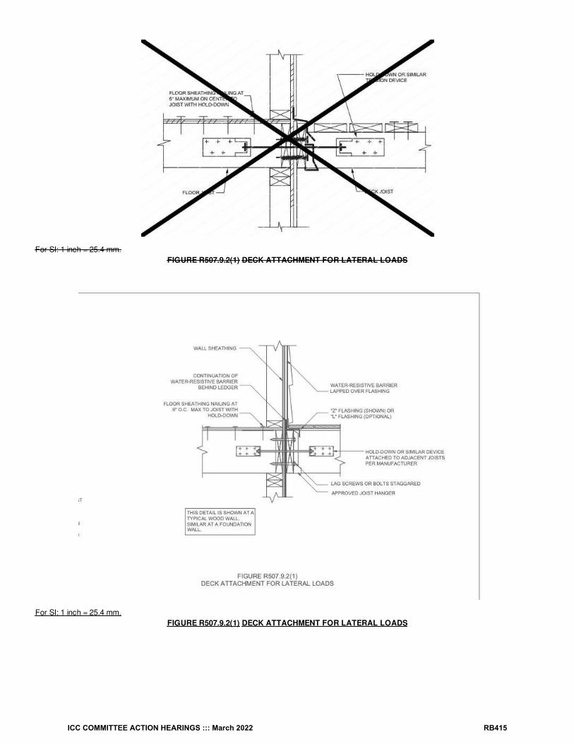
For SI: 1 inch = 25.4 mm.FIGURE R507.9.2(1) DECK ATTACHMENT FOR LATERAL LOADS
For SI: 1 inch = 25.4 mm.FIGURE R507.9.2(1) DECK ATTACHMENT FOR LATERAL LOADS
ICC COMMITTEE ACTION HEARINGS ::: March 2022 RB415
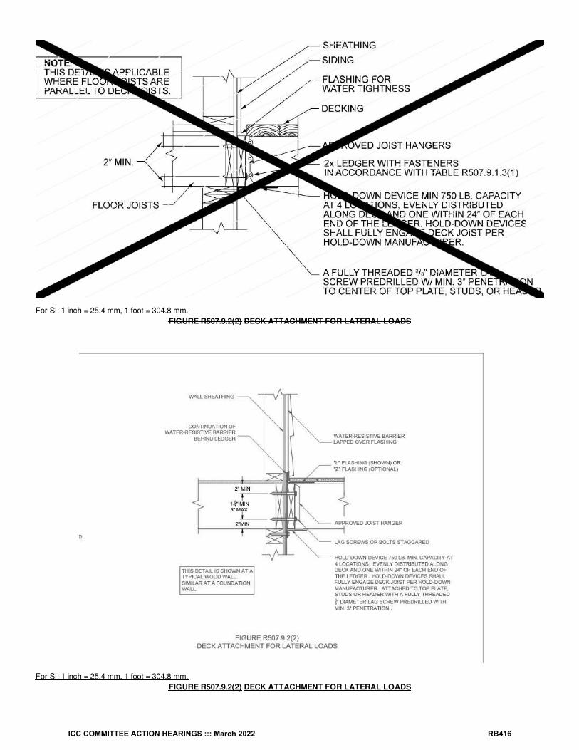
For SI: 1 inch = 25.4 mm, 1 foot = 304.8 mm.FIGURE R507.9.2(2) DECK ATTACHMENT FOR LATERAL LOADS
For SI: 1 inch = 25.4 mm, 1 foot = 304.8 mm.FIGURE R507.9.2(2) DECK ATTACHMENT FOR LATERAL LOADS
ICC COMMITTEE ACTION HEARINGS ::: March 2022 RB416

Reason Statement: Three details related to structural connection of ledgers were included in the IRC from three different proponents over threedifferent editions and differ in their style. As a proud and professional standard, it seemed appropriate for this sixth edition of IRC deck codes toclean these up and bring some consistency.
Notably, the flashing depictions in the original figures varied incredibly and some were not good guidance. The flashing was never the intent of thesefigures, yet as a graphic, they still sent a confusing and contradictory message to readers.We have submitted a different proposal that describes new deck ledger flashing methods. Rather than create specific flashing details to support thenewly suggested code text, it seemed more efficient to include more appropriate flashing depictions in these structural figures. However, thesefigures are submitted as a separate proposal for the value of better structural details.
If the flashing proposal is not approved, the flashing details in these figures are still better depictions than the current figures. No structuralconnection is sufficient if the materials connected prematurely decay. The flashing in these details do contribute to the longevity and reliability of thestructural performance.
Cost Impact: The code change proposal will not increase or decrease the cost of constructionThe modifications of this proposal do not affect the cost of construction.
RB189-22
ICC COMMITTEE ACTION HEARINGS ::: March 2022 RB417
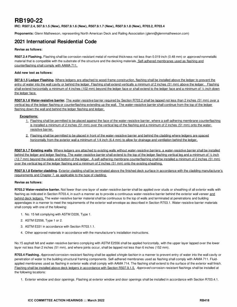
RB190-22IRC: R507.2.4, 507.9.1.5 (New), R507.9.1.6 (New), R507.9.1.7 (New), R507.9.1.8 (New), R703.2, R703.4
Proponents: Glenn Mathewson, representing North American Deck and Railing Association ([email protected])
2021 International Residential CodeRevise as follows:
R507.2.4 Flashing. Flashing shall be corrosion-resistant metal of nominal thickness not less than 0.019 inch (0.48 mm) or approved nonmetallicmaterial that is compatible with the substrate of the structure and the decking materials. Self-adhered membranes used as flashing andcounterflashing shall comply with AAMA 711.
Add new text as follows:
507.9.1.5 Ledger Flashing. Where ledgers are attached to wood-frame construction, flashing shall be installed above the ledger to prevent theentry of water into the wall cavity or behind the ledger. Flashing shall extend vertically a minimum of 2 inches (51 mm) above the ledger. Flashingshall extend horizontally a minimum of 4 inches (102 mm) beyond the ledger face or shall extend to the ledger face and a minimum of ¼ inch downthe ledger face.
R507.9.1.6 Water-resistive barrier. The water-resistive barrier required by Section R703.2 shall be lapped not less than 2 inches (51 mm) over avertical leg of the ledger flashing or counterflashing extending up the wall. The water-resistive barrier shall continue from the top of the ledgerflashing down the wall and behind the ledger flashing and ledger.
Exceptions:1. Flashing shall be permitted to be placed against the face of the water-resistive barrier, where a self-adhering membrane counterflashing
is installed a minimum of 2 inches (51 mm) over the vertical leg of the flashing and a minimum of 2 inches (51 mm) onto the water-resistive barrier.
2. Flashing shall be permitted to be placed in front of the water-resistive barrier and behind the cladding where ledgers are spacedhorizontally from the exterior wall a minimum of 1/4 inch (6.4 mm) to allow for drainage and ventilation behind the ledger.
R507.9.1.7 Existing walls. Where ledgers are attached to existing walls without water-resistive barriers, a water-resistive barrier shall be installedbehind the ledger and ledger flashing. The water-resistive barrier shall extend to the top of the ledger flashing vertical leg and a minimum of ½ inch(12.7 mm) beyond the sides and bottom of the ledger. A self-adhering membrane counterflashing shall be installed a minimum of 2 inches (51 mm)over the vertical leg of the ledger flashing and a minimum of 2 inches (51 mm) onto the existing sheathing.
R507.9.1.8 Exterior cladding. Exterior cladding shall be terminated above the finished deck surface in accordance with the cladding manufacturer’srequirements and Chapter 7, as applicable to the type of cladding.
Revise as follows:
R703.2 Water-resistive barrier. Not fewer than one layer of water-resistive barrier shall be applied over studs or sheathing of all exterior walls withflashing as indicated in Section R703.4, in such a manner as to provide a continuous water-resistive barrier behind the exterior wall veneer andbehind deck ledgers. The water-resistive barrier material shall be continuous to the top of walls and terminated at penetrations and buildingappendages in a manner to meet the requirements of the exterior wall envelope as described in Section R703.1. Water-resistive barrier materialsshall comply with one of the following:
1. No. 15 felt complying with ASTM D226, Type 1.
2. ASTM E2556, Type 1 or 2.
3. ASTM E331 in accordance with Section R703.1.1.
4. Other approved materials in accordance with the manufacturer's installation instructions.
No.15 asphalt felt and water-resistive barriers complying with ASTM E2556 shall be applied horizontally, with the upper layer lapped over the lowerlayer not less than 2 inches (51 mm), and where joints occur, shall be lapped not less than 6 inches (152 mm).
R703.4 Flashing. Approved corrosion-resistant flashing shall be applied shingle-fashion in a manner to prevent entry of water into the wall cavity orpenetration of water to the building structural framing components. Self-adhered membranes used as flashing shall comply with AAMA 711. Fluid-applied membranes used as flashing in exterior walls shall comply with AAMA 714. The flashing shall extend to the surface of the exterior wall finish. Flashing shall be installed above deck ledgers in accordance with Section R507.9.1.5. Approved corrosion-resistant flashings shall be installed atthe following locations:
1. Exterior window and door openings. Flashing at exterior window and door openings shall be installed in accordance with Section R703.4.1.
ICC COMMITTEE ACTION HEARINGS ::: March 2022 RB418

2. At the intersection of chimneys or other masonry construction with frame or stucco walls, with projecting lips on both sides under stuccocopings.
3. Under and at the ends of masonry, wood or metal copings and sills.
4. Continuously above all projecting wood trim.
5. Where exterior porches, decks or stairs attach to a wall or floor assembly of wood-frame construction.
6. At wall and roof intersections.
7. At built-in gutters.
Reason Statement: The sound connection of a deck ledger to a house band joist depends on materials that are free from decay. Ledger flashingis critical to ensuring the band joist of the house floor system does not decay, resulting in a failure of the deck fasteners. The IRC has long requireddeck ledgers to be flashed when attached to wood construction, but other than requiring they prevent the entry of water, there is no guidance. Deckbuilders from around the country have learned methods of flashing that are effective in their region and methods that aren't. This proposal attemptsto provide more details about the interface between the deck ledger, ledger flashing, water resistive barrier and cladding type, while providing themost flexibility in assembly choice.The primary goals of this proposal are:
1) Support the variety of flashing methods currently in use.
2) Recognize the different ledger fastening methods in Section 507: Fastened in contact with the sheathing/water-resistive barrier and fastened with1/2-inch of stacked washer spacing the ledger off the sheathing/water-resistive barrier.
3) Recognize the different cladding materials and types of installations (drainage plane, back-vented)
4) Recognize the higher risk of cutting into an existing water resistive barrier for a deck attachment.
5) Recognize that many houses do not have a water resistive barrier.
6) Protect the house framing when cladding is replaced with a deck ledger.
NOTE: There is a companion, but stand alone, proposal that helps to further clarify the intent of this proposal. Figures R507.9.1.3(2), R507.9.2(2),and R507.9.2(1) depict the structural connection of a ledger but also show an illustrative example of ledger flashing... very poor ones currently. Rather than propose specific, new ledger flashing figures, the flashing in those figures were altered to support the language in this proposal.
COMMENTARY FOR EACH SECTION MODIFICATION:
R703.2 Water-resistive barrier: In this section it is made clear that the water reistive barrier is to continue behind deck ledgers and not terminatedon top of them as a "building appendage" as seen in the next sentence in this section.
R703.4 Flashing: A reference to the new sections specifically for deck ledgers is added. Item 5 in the list could not be removed at this time becauseit includes the terms porches and stairs. There is no harm in item 5 remaining, though future modifications could address this. The IRC does not dowell at distinguishing between a "deck" and "porch" or if there even is a distinction.
R507.2.4 Flashing: A reference to AAMA 711 is included for flashing and counterflashing. This standard is already included in Section R703.4
507.9.1.5 Ledger flashing. This section requires flashing to extend at least 2 inches above the ledger which coincides with standard "shingle fashion"laps required in the water resistive barrier (R703.2). Two common flashing practices are recognized regarding the lower termination of the ledgerflashing. An "L" flashing can extend out 4 inches beyond the face of the ledger, which provides added protection to the hardware from moisture. This distance has been found sufficient through practice to sufficiently break the surface tension of water rolling under the flashing such that it dripsin front of the ledger. 4 inches was selected to accommodate a 1.5 inch thick ledger spaced 1/2" from the sheathing as provided for in the ledgerfastening methods of the IRC. A common "4x6 L flashing" works for this method. Another option provided is for "Z" flashing that turns down theface of the ledger. 1/4 inch was selected as it is the minimum required downward distance of drip edge flashing at the edges of roofs (R905.2.8.5). This vertical leg must be installed between the joist and ledger so it is not bent out horizontally on top of the joist.
R507.9.1.6 Water resistive barrier. The "general" provision is for the barrier to lap a minimum of two inches over the top of the flashing orcounterflashing on the wall, regardless of the height of this flashing above the ledger (min 2 inches). In this option, the vertical leg of the ledgerflashing must be aligned in a lap in the WRB so that the upper sheet of barrier laps both the flashing and the next sheet by a minimum of 2 inches. The WRB shall be continuous behind the ledger.
ICC COMMITTEE ACTION HEARINGS ::: March 2022 RB419
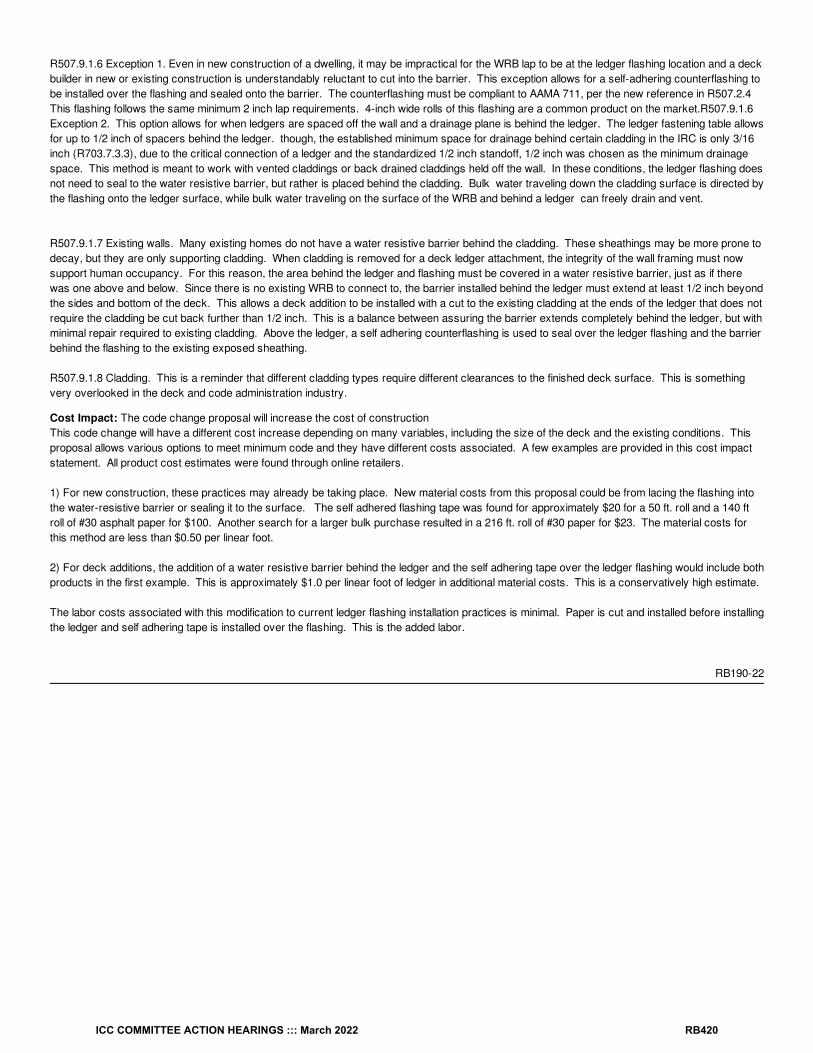
R507.9.1.6 Exception 1. Even in new construction of a dwelling, it may be impractical for the WRB lap to be at the ledger flashing location and a deckbuilder in new or existing construction is understandably reluctant to cut into the barrier. This exception allows for a self-adhering counterflashing tobe installed over the flashing and sealed onto the barrier. The counterflashing must be compliant to AAMA 711, per the new reference in R507.2.4 This flashing follows the same minimum 2 inch lap requirements. 4-inch wide rolls of this flashing are a common product on the market.R507.9.1.6Exception 2. This option allows for when ledgers are spaced off the wall and a drainage plane is behind the ledger. The ledger fastening table allowsfor up to 1/2 inch of spacers behind the ledger. though, the established minimum space for drainage behind certain cladding in the IRC is only 3/16inch (R703.7.3.3), due to the critical connection of a ledger and the standardized 1/2 inch standoff, 1/2 inch was chosen as the minimum drainagespace. This method is meant to work with vented claddings or back drained claddings held off the wall. In these conditions, the ledger flashing doesnot need to seal to the water resistive barrier, but rather is placed behind the cladding. Bulk water traveling down the cladding surface is directed bythe flashing onto the ledger surface, while bulk water traveling on the surface of the WRB and behind a ledger can freely drain and vent.
R507.9.1.7 Existing walls. Many existing homes do not have a water resistive barrier behind the cladding. These sheathings may be more prone todecay, but they are only supporting cladding. When cladding is removed for a deck ledger attachment, the integrity of the wall framing must nowsupport human occupancy. For this reason, the area behind the ledger and flashing must be covered in a water resistive barrier, just as if therewas one above and below. Since there is no existing WRB to connect to, the barrier installed behind the ledger must extend at least 1/2 inch beyondthe sides and bottom of the deck. This allows a deck addition to be installed with a cut to the existing cladding at the ends of the ledger that does notrequire the cladding be cut back further than 1/2 inch. This is a balance between assuring the barrier extends completely behind the ledger, but withminimal repair required to existing cladding. Above the ledger, a self adhering counterflashing is used to seal over the ledger flashing and the barrierbehind the flashing to the existing exposed sheathing.
R507.9.1.8 Cladding. This is a reminder that different cladding types require different clearances to the finished deck surface. This is somethingvery overlooked in the deck and code administration industry.
Cost Impact: The code change proposal will increase the cost of constructionThis code change will have a different cost increase depending on many variables, including the size of the deck and the existing conditions. Thisproposal allows various options to meet minimum code and they have different costs associated. A few examples are provided in this cost impactstatement. All product cost estimates were found through online retailers.
1) For new construction, these practices may already be taking place. New material costs from this proposal could be from lacing the flashing intothe water-resistive barrier or sealing it to the surface. The self adhered flashing tape was found for approximately $20 for a 50 ft. roll and a 140 ftroll of #30 asphalt paper for $100. Another search for a larger bulk purchase resulted in a 216 ft. roll of #30 paper for $23. The material costs forthis method are less than $0.50 per linear foot.
2) For deck additions, the addition of a water resistive barrier behind the ledger and the self adhering tape over the ledger flashing would include bothproducts in the first example. This is approximately $1.0 per linear foot of ledger in additional material costs. This is a conservatively high estimate.
The labor costs associated with this modification to current ledger flashing installation practices is minimal. Paper is cut and installed before installingthe ledger and self adhering tape is installed over the flashing. This is the added labor.
RB190-22
ICC COMMITTEE ACTION HEARINGS ::: March 2022 RB420

RB191-22IRC: TABLE R602.3(1)
Proponents: Mike Nugent, representing Building Code Action Committee ([email protected])
2021 International Residential CodeRevise as follows:
ICC COMMITTEE ACTION HEARINGS ::: March 2022 RB421

TABLE R602.3(1) FASTENING SCHEDULE
DESCRIPTION OF BUILDINGELEMENTSsss
NUMBER AND TYPE OFFASTENER
SPACING AND LOCATION
Roof
Blocking between ceiling joists,rafters or trusses to top plate orother framing below
4-8d box (2 / ″ × 0.113″); or3-8d common (2 / ″ × 0.131″); or3-10d box (3″ × 0.128″); or3-3″ × 0.131″ nails
Toe nail
Blocking between rafters or truss notat the wall top plates, to rafter ortruss
2-8d common (2 / ″ × 0.131″); or2-3″ × 0.131″ nails
Each end toe nail
2-16d common (3 / ″ × 0.162″); or3-3″ × 0.131″ nails
End nail
Flat blocking to truss and web filler16d common (3 / ″ × 0.162″); or(3″ × 0.131″ nails
6″ o.c. face nail
Ceiling joists to top plate
4-8d box (2 / ″ × 0.113″); or3-8d common (2 / ″ × 0.131″); or3-10d box (3″ × 0.128″); or3-3″ × 0.131″ nails
Per joist, toe nail
Ceiling joist not attached to parallelrafter, laps over partitions [seeSection R802.5.2 and TableR802.5.2(1)]
4-10d box (3″ × 0.128″); or3-16d common (3 / ″ × 0.162″); or4-3″ × 0.131″ nails
Face nail
Ceiling joist attached to parallel rafter(heel joint) [see Section R802.5.2 andTable R802.5.2(1)]
Table R802.5.2(1) Face nail
Collar tie to rafter, face nail4-10d box (3″ × 0.128″); or3-10d common (3″ × 0.148″); or4-3″ × 0.131″ nails
Face nail each rafter
Rafter or roof truss to plate
3-16d box (3 / ″ × 0.135″); or3-10d common (3″ × 0.148″); or4-10d box (3″ × 0.128″); or 4-3″ × 0.131″ nails
2 toe nails on one side and 1toe nail on opposite side of
each rafter or truss
Roof rafters to ridge, valley or hiprafters or roof rafter to minimum 2″ridge beam
4-16d box (3 / ″ × 0.135″); or3-10d common (3″ × 0.148″); or4-10d box (3″ × 0.128″); or 4-3″ × 0.131″ nails
Toe nail
3-16d box (3 / ″ × 0.135″); or2-16d common (3 / ″ × 0.162″); or3-10d box (3″ × 0.128″); or 3-3″ × 0.131″ nails
End nail
Wall
Stud to stud (not at braced wallpanels)
16d common (3 / ″ × 0.162″) 24″ o.c. face nail
10d box (3″ × 0.128″); or3″ × 0.131″ nails
16″ o.c. face nail
Stud to stud and abutting studs atintersecting wall corners (at bracedwall panels)
16d box (3 / ″ × 0.135″); or3″ × 0.131″ nails
12″ o.c. face nail
16d common (3 / ″ × 0.162″) 16″ o.c. face nail
Built-up header (2″ to 2″ header with
16d common (3 / ″ × 0.162″) 16″ o.c. each edge face nail
16d box (3 / ″ × 0.135″) 12″ o.c. each edge face nail
a, b, c
12
12
12
12
12
12
12
12
12
i
12
12
12
12
12
12
1
12
12
ICC COMMITTEE ACTION HEARINGS ::: March 2022 RB422

/ ″ spacer)
Continuous header to stud5-8d box (2 / ″ × 0.113″); or4-8d common (2 / ″ × 0.131″); or4-10d box (3″ × 0.128″)
Toe nail
Adjacent full-height stud to end ofheader
4-16d box (3 / ″× 0.135″); or3-16d common (3 / ″ × 0.162″); or4-10d box (3″ × 0.128″); or4-3″ × 0.131″ nails
End nail
Top plate to top plate
16d common (3 / ″ × 0.162″) 16″ o.c. face nail
10d box (3″ × 0.128″); or3″ × 0.131″ nails
12″ o.c. face nail
Double top plate splice
8-16d common (3 / ″ × 0.162″); or12-16d box (3 / ″ × 0.135″); or12-10d box (3″ × 0.128″); or12-3″ × 0.131″ nails
Face nail on each side of endjoint (minimum 24″ lap splicelength each side of end joint)
Bottom plate to joist, rim joist, bandjoist or blocking (not at braced wallpanels)
16d common (3 / ″ × 0.162″) 16″ o.c. face nail
16d box (3 / ″ × 0.135″); or3″ × 0.131″ nails
12″ o.c. face nail
Bottom plate to joist, rim joist, bandjoist or blocking (at braced wallpanel)
3-16d box (3 / ″ × 0.135″); or2-16d common (3 / ″ × 0.162″); or4-3″ × 0.131″ nails
16″ o.c. face nail
Top or bottom plate to stud
4-8d box (2 / ″ × 0.113″); or3-16d box (3 / ″ × 0.135″); or4-8d common (2 / ″ × 0.131″); or 4-10d box (3″ × 0.128″); or 4-3″ × 0.131″ nails
Toe nail
3-16d box (3 / ″ × 0.135″); or2-16d common (3 / ″ × 0.162″); or3-10d box (3″ × 0.128″); or 3-3″ × 0.131″ nails
End nail
Top plates, laps at corners andintersections
3-10d box (3″ × 0.128″); or2-16d common (3 / ″ × 0.162″); or3-3″ × 0.131″ nails
Face nail
1″ brace to each stud and plate
3-8d box (2 / ″ × 0.113″); or2-8d common (2 / ″ × 0.131″); or2-(3” x 0.131”): or2-10d box (3″ × 0.128″)
Face nail
1″ × 6″ sheathing to each bearing
3-8d box (2 / ″ × 0.113″); or2-8d common (2 / ″ × 0.131″); or2-10d box (3″ × 0.128″); or 2 staples, 1″ crown, 16 ga., 1 / ″long
Face nail
3-8d box (2 / ″ × 0.113″); or3-8d common (2 / ″ × 0.131″); or3-10d box (3″ × 0.128″); or 3 staples, 1″ crown, 16 ga., 1 / ″long
DESCRIPTION OF BUILDINGELEMENTSsss
NUMBER AND TYPE OFFASTENER
SPACING AND LOCATION1
2
12
12
12
12
12
12
12
12
12
12
12
121
21
2
12
12
12
12
12
12
12
34
12
12
34
ICC COMMITTEE ACTION HEARINGS ::: March 2022 RB423

1″ × 8″ and wider sheathing to eachbearing
Face nail
Wider than 1″ × 8″4-8d box (2 / ″ × 0.113″); or3-8d common (2 / ″ × 0.131″); or 3-10d box (3″ × 0.128″); or 4 staples, 1″ crown, 16 ga., 1 / ″long
Floor
Joist to sill, top plate or girder
4-8d box (2 / ″ × 0.113″); or3-8d common (2 / ″ × 0.131″); or3-10d box (3″ × 0.128″); or 3-3″ × 0.131″ nails
Toe nail
Rim joist, band joist or blocking to sillor top plate (roof applications also)
8d box (2 / ″ × 0.113″) 4″ o.c. toe nail
8d common (2 / ″ × 0.131″); or10d box (3″ × 0.128″); or3″ × 0.131″ nails
6″ o.c. toe nail
1″ × 6″ subfloor or less to each joist
3-8d box (2 / ″ × 0.113″); or2-8d common (2 / ″ × 0.131″); or3-10d box (3″ × 0.128″); or 2 staples, 1″ crown, 16 ga., 1 / ″long
Face nail
Floor
2″ subfloor to joist or girder3-16d box (3 / ″ × 0.135″); or2-16d common (3 / ″ × 0.162″) Blind and face nail
2″ planks (plank & beam—floor &roof)
3-16d box (3 / ″ × 0.135″); or2-16d common (3 / ″ × 0.162″) At each bearing, face nail
Band or rim joist to joist
3-16d common (3 / ″ × 0.162″); or 4-10 box (3″ × 0.128″); or4-3″ × 0.131″ nails; or 4-3″ × 14 ga. staples, / ″ crown
End nail
Built-up girders and beams, 2-inchlumber layers
20d common (4″ × 0.192″); orNail each layer as follows: 32″
o.c. at top and bottom andstaggered.
10d box (3″ × 0.128″); or 3″ ×0.131″ nails
24″ o.c. face nail at top andbottom staggered on opposite
sides
And:2-20d common (4″ × 0.192″); or3-10d box (3″ × 0.128″); or 3-3″ × 0.131″ nails
Face nail at ends and at eachsplice
Ledger strip supporting joists orrafters
4-16d box (3 / ″ × 0.135″); or3-16d common (3 / ″ × 0.162″); or4-10d box (3″ × 0.128″); or 4-3″ × 0.131″ nails
At each joist or rafter, face nail
Bridging or blocking to joist, rafter ortruss
2-10d box (3″ × 0.128″); or2-8d common (2 / ″ × 0.131″); or
2-3″ × 0.131″ nailsEach end, toe nail
DESCRIPTION OF BUILDINGELEMENTS
NUMBER AND TYPE OFFASTENER
SPACING OF FASTENERS
Edges(inches)
Intermediatesupports
(inches)
Wood structural panels, subfloor, roof and interior wall sheathing to framing and particleboardwall sheathing to framing [see Table R602.3(3) for wood structural panel exterior wall sheathing
to wall framing]
DESCRIPTION OF BUILDINGELEMENTSsss
NUMBER AND TYPE OFFASTENER
SPACING AND LOCATION
12
12
34
12
12
12
12
12
12
34
12
12
12
12
12
716
12
12
12
a, b, c hc,
e
ICC COMMITTEE ACTION HEARINGS ::: March 2022 RB424

/ ″ − / ″
6d common or deformed (2″ ×0.113″ × 0.266″ head);2 / ″ ×0.113″ × 0.266″ head nail (subfloor,wall)
6 6
8d common (2 / ″ × 0.131″) nail(roof); orRSRS-01 (2 / ″ × 0.113″) nail(roof)
6 6
/ " – / ″
8d common (2-2 / ″ × 0.131″) nail(subfloor, wall)
6 12
8d common (2 / ″ × 0.131″) nail(roof); orRSRS-01; (2 / ″ × 0.113″) nail(roof)
6 6
Deformed 2 / ″ × 0.113″ × 0.266″head (wall or subfloor)
6 12
/ ″ – 1 / ″10d common (3″ × 0.148") nail; or(2 / ″ × 0.131 × 0.281″ head)deformed nail
6 12
Other wall sheathing
/ ″ structural cellulosic fiberboardsheathing
1 / ″ × 0.120″ galvanized roofingnail, / ″ head diameter, or1 ″ long 16 ga. staple with / ″ or1″ crown
3 6
/ ″ structural cellulosic fiberboardsheathing
1 / ″ × 0.120″ galvanized roofingnail, / ″ head diameter, or1 / ″ long 16 ga. staple with / ″ or1″ crown
3 6
/ ″ gypsum sheathing
1 / ″ × 0.120″ galvanized roofingnail, / ″ head diameter, or1 / ″long 16 ga.;staple galvanized, 1 / ″ long; / ″or 1″ crown or 1 / ″ screws, TypeW or S
7 7
/ ″ gypsum sheathing
1 / ″ × 0.120″ galvanized roofingnail, / ″ head diameter, or 1 / ″long 16 ga.;staple galvanized, 1 / ″ long; / ″or 1″crown or 1 / ″ screws, TypeW or S
7 7
Wood structural panels, combination subfloor underlayment to framing
/ ″ and lessDeformed (2″ × 0.113″) orDeformed (2″ × 0.120″) nail; or8d common (2 / ″ × 0.131″) nail
6 12
/ ″ – 1″8d common (2 / ″ × 0.131″) nail; orDeformed (2 / ″ x 0.131″); orDeformed (2 / ″ × 0.120″) nail
6 12
1 / ″ − 1 / ″10d common (3″ × 0.148″ ) nail; orDeformed (2 / ″ x 0.131″); orDeformed (2 / ″ × 0.120″) nail
6 12
DESCRIPTION OF BUILDINGELEMENTSsss
NUMBER AND TYPE OFFASTENER
SPACING AND LOCATION
For SI: 1 inch = 25.4 mm, 1 foot = 304.8 mm, 1 mile per hour = 0.447 m/s; 1 ksi = 6.895 MPa.
38
12
38
i
f
12
38
b
f
1932
34
12
12
38
b
f
38
78
14
12
g
12
12
716
1/4
716
2532
34
716
14
716
12
d
12
716
14
12
716
14
58
d
34
716
14
12
716
14
34
12
78
12
12
12
18
14
12
12
ICC COMMITTEE ACTION HEARINGS ::: March 2022 RB425

a. Nails are smooth-common, box or deformed shanks except where otherwise stated. Nails used for framing and sheathing connections arecarbon steel and shall have minimum average bending yield strengths as shown: 80 ksi for shank diameter of 0.192 inch (20d common nail),90 ksi for shank diameters larger than 0.142 inch but not larger than 0.177 inch, and 100 ksi for shank diameters of 0.142 inch or less.Connections using nails and staples of other materials, such as stainless steel, shall be designed by accepted engineering practice orapproved under Section R104.11.
b. RSRS-01 is a Roof Sheathing Ring Shank nail meeting the specifications in ASTM F1667.
c. Nails shall be spaced at not more than 6 inches on center at all supports where spans are 48 inches or greater.
d. Four-foot by 8-foot or 4-foot by 9-foot panels shall be applied vertically.
e. Spacing of fasteners not included in this table shall be based on Table R602.3(2).
f. For wood structural panel roof sheathing attached to gable end roof framing and to intermediate supports within 48 inches of roof edges andridges, nails shall be spaced at 4 inches on center where the ultimate design wind speed is greater than 130 mph in Exposure B or greaterthan 110 mph in Exposure C.
g. Gypsum sheathing shall conform to ASTM C1396 and shall be installed in accordance with ASTM C1280 or GA 253. Fiberboard sheathingshall conform to ASTM C208.
h. Spacing of fasteners on floor sheathing panel edges applies to panel edges supported by framing members and required blocking and atfloor perimeters only. Spacing of fasteners on roof sheathing panel edges applies to panel edges supported by framing members andrequired blocking. Blocking of roof or floor sheathing panel edges perpendicular to the framing members need not be provided except asrequired by other provisions of this code. Floor perimeter shall be supported by framing members or solid blocking.
i. Where a rafter is fastened to an adjacent parallel ceiling joist in accordance with this schedule, provide two toe nails on one side of the rafterand toe nails from the ceiling joist to top plate in accordance with this schedule. The toe nail on the opposite side of the rafter shall not berequired.
j. The sketches shown in this column are for illustration purposes only. Refer to the “NUMBER AND TYPE OF FASTENER” column of thistable for the actual requirements.
Attached Files
updated fig- cdp-C #21-Update-Table R602.3(1) with figures.pdfhttps://cdpaccess.com/proposal/8511/24827/files/download/2974/
Reason Statement: This proposal adds sketches clarifying the connecting building elements used in wood-framed construction described in tableR602.3(1) FASTENING SCHEDULE. The proposal also adds a footnote explaining that “The sketches shown in this column are for illustrationpurposes only. Refer to the “NUMBER AND TYPE OF FASTENER” column of this table for the actual requirements. This proposal is submitted by the ICC Building Code Action Committee (BCAC).
BCAC was established by the ICC Board of Directors in July 2011 to pursue opportunities to improve and enhance assigned International Codes orportions thereof. In 2020 and 2021 the BCAC has held several virtual meetings open to any interested party. In addition, there were numerous virtualWorking Group meetings for the current code development cycle, which included members of the committee as well as interested parties. Relateddocuments and reports are posted on the BCAC website at https://www.iccsafe.org/products-and-services/i-codes/code-development/cs/building-code-action-committee-bcac/.
Cost Impact: The code change proposal will not increase or decrease the cost of constructionThe graphics are a visual clarification for existing requirments.
RB191-22
ICC COMMITTEE ACTION HEARINGS ::: March 2022 RB426

RB192-22IRC: TABLE R602.3(1)
Proponents: David Tyree, representing American Wood Council ([email protected]); Philip Line, representing American Wood Council([email protected])
2021 International Residential CodeRevise as follows:
ICC COMMITTEE ACTION HEARINGS ::: March 2022 RB427

TABLE R602.3(1) FASTENING SCHEDULEPortions of table not shown remain unchanged.
ITEM DESCRIPTION OFBUILDING ELEMENTS
NUMBER AND TYPE OF FASTENERSPACING OF FASTENERS
Edges(inches)
Intermediatesupports (inches)
Wood structural panels, subfloor, roof and interior wall sheathing to framing and particleboard wall sheathing to framing [see TableR602.3(3) for wood structural panel exterior wall sheathing to wall framing]
31 / ″ − / ″
6d common or deformed (2″ × 0.113″ × 0.266″ head);2 / ″ × 0.113″ ×0.266″ head nail (subfloor, wall)
6 12 6
8d common (2 / ″ × 0.131″) nail (roof); orRSRS-01 (2 / ″ × 0.113″) nail (roof)
6 6
32 / " – / ″
8d common (2-2 / ″ × 0.131″) nail (subfloor, wall) 6 12
8d common (2 / ″ × 0.131″) nail (roof); orRSRS-01; (2 / ″ × 0.113″) nail (roof)
6 6
Deformed 2 / ″ × 0.113″ × 0.266″ head (wall or subfloor) 6 12
For SI: 1 inch = 25.4 mm, 1 foot = 304.8 mm, 1 mile per hour = 0.447 m/s; 1 ksi = 6.895 MPa.
a. Nails are smooth-common, box or deformed shanks except where otherwise stated. Nails used for framing and sheathing connections arecarbon steel and shall have minimum average bending yield strengths as shown: 80 ksi for shank diameter of 0.192 inch (20d common nail),90 ksi for shank diameters larger than 0.142 inch but not larger than 0.177 inch, and 100 ksi for shank diameters of 0.142 inch or less.Connections using nails and staples of other materials, such as stainless steel, shall be designed by accepted engineering practice orapproved under Section R104.11.
b. RSRS-01 is a Roof Sheathing Ring Shank nail meeting the specifications in ASTM F1667.
c. Nails shall be spaced at not more than 6 inches on center at all supports where spans are 48 inches or greater.
d. Four-foot by 8-foot or 4-foot by 9-foot panels shall be applied vertically.
e. Spacing of fasteners not included in this table shall be based on Table R602.3(2).
f. For wood structural panel roof sheathing attached to gable end roof framing and to intermediate supports within 48 inches of roof edges andridges, nails shall be spaced at 4 inches on center where the ultimate design wind speed is greater than 130 mph in Exposure B or greaterthan 110 mph in Exposure C.
g. Gypsum sheathing shall conform to ASTM C1396 and shall be installed in accordance with ASTM C1280 or GA 253. Fiberboard sheathingshall conform to ASTM C208.
h. Spacing of fasteners on floor sheathing panel edges applies to panel edges supported by framing members and required blocking and atfloor perimeters only. Spacing of fasteners on roof sheathing panel edges applies to panel edges supported by framing members andrequired blocking. Blocking of roof or floor sheathing panel edges perpendicular to the framing members need not be provided except asrequired by other provisions of this code. Floor perimeter shall be supported by framing members or solid blocking.
i. Where a rafter is fastened to an adjacent parallel ceiling joist in accordance with this schedule, provide two toe nails on one side of the rafterand toe nails from the ceiling joist to top plate in accordance with this schedule. The toe nail on the opposite side of the rafter shall not berequired.
Reason Statement: This proposal places footnote f on edge spacing values for roof sheathing fastening to be consistent with the original changeproposal (RB196-16) and the 2018 Wood Frame Construction Manual. The occurrence of footnote f to modify (subfloor, wall) spacing of 6 inches atintermediate supports is removed because footnote f applies to roof sheathing fastening, and the 6 inch value is revised to 12 inch as a correctiongiven the entry is for subfloor and wall applications. An extra "2-" is proposed for editorial removal in the first row of item 32.
Cost Impact: The code change proposal will not increase or decrease the cost of constructionThe changes are clarifications for roof sheathing attachment consistent with the original change (RB196-19) and the 2018 Wood FrameConstruction Manual and corrections to footnote locations and fastener spacing at intermediate supports for subfloor and wall applications.
RB192-22
a, b, c h
c, e
38
12
38
if
12
38
bf f
1932
34
12
12
38
bf f
38
ICC COMMITTEE ACTION HEARINGS ::: March 2022 RB428

RB193-22IRC: TABLE R602.3(1)
Proponents: David Tyree, representing American Wood Council ([email protected]); Philip Line, representing American Wood Council([email protected])
2021 International Residential CodeRevise as follows:
ICC COMMITTEE ACTION HEARINGS ::: March 2022 RB429

TABLE R602.3(1) FASTENING SCHEDULEPortions of table not shown remain unchanged.
ITEM DESCRIPTION OFBUILDING ELEMENTS
NUMBER AND TYPE OF FASTENERSPACING OF FASTENERS
Edges(inches)
Intermediatesupports (inches)
Wood structural panels, subfloor, roof and interior wall sheathing to framing and particleboard wall sheathing to framing [see TableR602.3(3) for wood structural panel exterior wall sheathing to wall framing]
31 / ″ − / ″
6d common or deformed (2″ × 0.113″ × 0.266″ head);2 / ″ × 0.113″ ×0.266″ head nail (subfloor, wall)
6 6
8d common (2 / ″ × 0.131″ × 0.281″ head) nail (roof); orRSRS-01 (2 / ″ × 0.113″ × 0.281″ head) nail (roof)
6 6
32 / " – / ″
8d common (2-2 / ″ × 0.131″) nail (subfloor, wall) 6 12
8d common (2 / ″ × 0.131″ × 0.281″ head) nail (roof); orRSRS-01; (2 / ″ × 0.113″ × 0.281″ head) nail (roof)
6 6
Deformed 2 / ″ × 0.113″ × 0.266″ head (wall or subfloor) 6 12
For SI: 1 inch = 25.4 mm, 1 foot = 304.8 mm, 1 mile per hour = 0.447 m/s; 1 ksi = 6.895 MPa.
a. Nails are smooth-common, box or deformed shanks except where otherwise stated. Nails used for framing and sheathing connections arecarbon steel and shall have minimum average bending yield strengths as shown: 80 ksi for shank diameter of 0.192 inch (20d common nail),90 ksi for shank diameters larger than 0.142 inch but not larger than 0.177 inch, and 100 ksi for shank diameters of 0.142 inch or less.Connections using nails and staples of other materials, such as stainless steel, shall be designed by accepted engineering practice orapproved under Section R104.11.
b. RSRS-01 is a Roof Sheathing Ring Shank nail meeting the specifications in ASTM F1667.
c. Nails shall be spaced at not more than 6 inches on center at all supports where spans are 48 inches or greater.
d. Four-foot by 8-foot or 4-foot by 9-foot panels shall be applied vertically.
e. Spacing of fasteners not included in this table shall be based on Table R602.3(2).
f. For wood structural panel roof sheathing attached to gable end roof framing and to intermediate supports within 48 inches of roof edges andridges, nails shall be spaced at 4 inches on center where the ultimate design wind speed is greater than 130 mph in Exposure B or greaterthan 110 mph in Exposure C. Spacing exceeding 6 inches on center at intermediate supports shall be permitted where the fastening isdesigned in accordance with AWC NDS. Where the specific gravity of the wood species used for roof framing is greater than or equal to 0.35but less than 0.42 in accordance with AWC NDS, fastening of roof sheathing shall be with RSRS-03 (2-1/2″× 0.131″× 0.281″head) nailsunless alternative fastening is designed in accordance with AWC NDS. Where the specific gravity of the wood species used for roof framingis less than 0.35, fastening of the roof sheathing shall be designed in accordance with AWC NDS.
g. Gypsum sheathing shall conform to ASTM C1396 and shall be installed in accordance with ASTM C1280 or GA 253. Fiberboard sheathingshall conform to ASTM C208.
h. Spacing of fasteners on floor sheathing panel edges applies to panel edges supported by framing members and required blocking and atfloor perimeters only. Spacing of fasteners on roof sheathing panel edges applies to panel edges supported by framing members andrequired blocking. Blocking of roof or floor sheathing panel edges perpendicular to the framing members need not be provided except asrequired by other provisions of this code. Floor perimeter shall be supported by framing members or solid blocking.
i. Where a rafter is fastened to an adjacent parallel ceiling joist in accordance with this schedule, provide two toe nails on one side of the rafterand toe nails from the ceiling joist to top plate in accordance with this schedule. The toe nail on the opposite side of the rafter shall not berequired.
Reason Statement: Fastening of roof sheathing to resist wind uplift forces is based on wood framing of species with specific gravity equal to 0.42(per proposal RB196-19). To address possible applications using lower specific gravity wood species for roof framing (i.e., specific gravity less than0.42 but equal to or greater than 0.35), the footnote is expanded to require use of the RSRS-03 nail unless alternative fastening is designed. The useof RSRS-03 nail (a standard ring shank nail) will maintain the same fastener spacing recommendations within the scope of applicability which is up to140 mph wind speed. Engineered design of the fastening is required when specific gravity of the species used for roof framing is less than 0.35.
Cost Impact: The code change proposal will increase the cost of constructionIncreased cost of construction will occur where low specific gravity wood species are used. For wood species with specific gravity of 0.35, theadded ring shank nail option for resisting ASCE 7 wind uplift forces will provide equivalent withdrawal performance to the 0.42 specific gravity andsmooth nail basis of the existing fastening schedule without requiring engineered design. The added language for permissible use of engineereddesign for fastener spacing greater than 6 inches on center at intermediate supports may reduce amount of required nailing such as in lower wind
a, b, c h
c, e
38
12
38
if
12
38
bf
1932
34
12
12
38
bf
38
ICC COMMITTEE ACTION HEARINGS ::: March 2022 RB430

speed zones.
RB193-22
ICC COMMITTEE ACTION HEARINGS ::: March 2022 RB431

RB194-22IRC: TABLE R602.3(2)
Proponents: David Tyree, representing American Wood Council ([email protected]); Philip Line, representing American Wood Council([email protected])
2021 International Residential CodeRevise as follows:
ICC COMMITTEE ACTION HEARINGS ::: March 2022 RB432

TABLE R602.3(2) ALTERNATE ATTACHMENTS TO TABLE R602.3(1)Portions of table not shown remain unchanged.
NOMINAL MATERIAL THICKNESS(inches)
DESCRIPTION OF FASTENER AND LENGTH(inches)
SPACING OF FASTENERS
Edges(inches)
Intermediate supports(inches)
Wood structural panels subfloor, roof and wall sheathing to framing and particleboard wall sheathing to framing
Up to /
Staple 15 ga. 1 / 4 8
0.097–0.099 Nail 2 / 3 6
Staple 16 ga. 1 / 3 6
/ and /
0.113 Nail 2 3 6
Staple 15 and 16 ga. 2 4 8
0.097–0.099 Nail 2 / 4 8
/ and /
Staple 14 ga. 2 4 8
Staple 15 ga. 1 / 3 6
0.097–0.099 Nail 2 / 4 8
Staple 16 ga. 2 4 8
1
Staple 14 ga. 2 / 4 8
0.113 Nail 2 / 3 6
Staple 15 ga. 2 / 4 8
0.097–0.099 Nail 2 / 4 8
For SI: 1 inch = 25.4 mm.
a. Nail is a general description and shall be permitted to be T-head, modified round head or round head.
b. Staples shall have a minimum crown width of / -inch except as noted.
c. Nails or staples shall be spaced at not more than 6 inches on center at all supports where spans are 48 inches or greater. Nails or staplesshall be spaced at not more than 12 inches on center at intermediate supports for floors.
d. Fasteners shall be placed in a grid pattern throughout the body of the panel.
e. For 5-ply panels, intermediate nails shall be spaced not more than 12 inches on center each way.
f. Hardboard underlayment shall conform to CPA/ANSI A135.4.
g. Alternate fastening is only permitted for roof sheathing where the ultimate design wind speed is less than or equal to 110 mph, and wherefasteners are installed 3 inches on center at all supports, and where fastening is to wood framing of a species with specific gravity greaterthan or equal to 0.42 in accordance with AWC NDS.
h. Fiber-cement underlayment shall conform to ASTM C1288 or ISO 8336, Category C.
Reason Statement: Fastening of roof sheathing to resist wind uplift forces is based on wood framing of a species with specific gravity equal to 0.42(per proposal RB198-19). To address possible applications using species with lower specific gravity, the footnote is expanded to limit applicability towood framing species with specific gravity equal to 0.42 or greater. Lack of design information in AWC NDS on staple withdrawal is why a lowerspecific gravity option is not prescribed for staples as part of this change. Prescriptive options for fastening with nails in wood with specific gravity of0.35 or greater are proposed for Table R602.3(1) and include an option for design of reduced fastener spacing.
Cost Impact: The code change proposal will not increase or decrease the cost of constructionThis proposal clarifies the specific gravity limit for the prescribed alternative fastening. Prescriptive fastening options for wood species of lowerspecific gravity are proposed for inclusion in Table R602.3(1).
RB194-22
a, bc
g f
12
34
14
34
1932
58
14
2332
34
34
14
14
14
14
12
716
ICC COMMITTEE ACTION HEARINGS ::: March 2022 RB433

RB195-22IRC: TABLE R602.3(3)
Proponents: David Tyree, representing American Wood Council ([email protected]); Philip Line, representing American Wood Council([email protected])
2021 International Residential CodeRevise as follows:
ICC COMMITTEE ACTION HEARINGS ::: March 2022 RB434
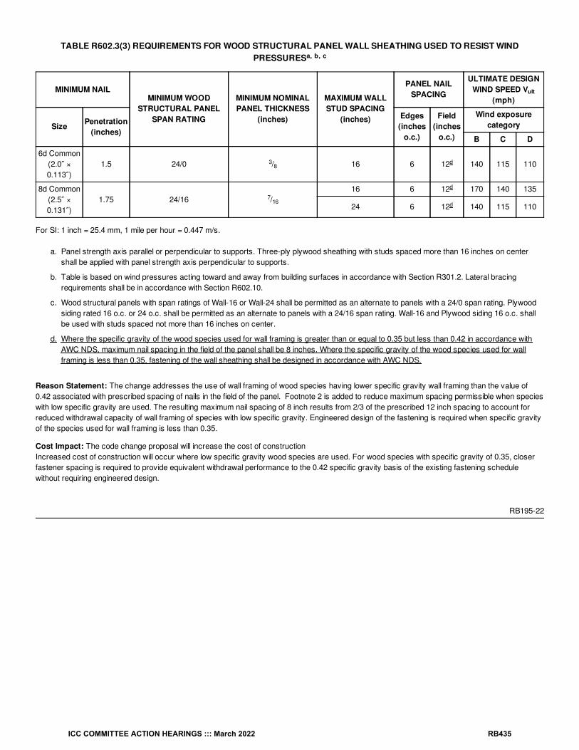
TABLE R602.3(3) REQUIREMENTS FOR WOOD STRUCTURAL PANEL WALL SHEATHING USED TO RESIST WINDPRESSURES
MINIMUM NAILMINIMUM WOOD
STRUCTURAL PANELSPAN RATING
MINIMUM NOMINALPANEL THICKNESS
(inches)
MAXIMUM WALLSTUD SPACING
(inches)
PANEL NAILSPACING
ULTIMATE DESIGNWIND SPEED V
(mph)
Size Penetration(inches)
Edges(inches
o.c.)
Field(inches
o.c.)
Wind exposurecategory
B C D
6d Common(2.0″ ×0.113″)
1.5 24/0 / 16 6 12 140 115 110
8d Common(2.5″ ×0.131″)
1.75 24/16 /16 6 12 170 140 135
24 6 12 140 115 110
For SI: 1 inch = 25.4 mm, 1 mile per hour = 0.447 m/s.
a. Panel strength axis parallel or perpendicular to supports. Three-ply plywood sheathing with studs spaced more than 16 inches on centershall be applied with panel strength axis perpendicular to supports.
b. Table is based on wind pressures acting toward and away from building surfaces in accordance with Section R301.2. Lateral bracingrequirements shall be in accordance with Section R602.10.
c. Wood structural panels with span ratings of Wall-16 or Wall-24 shall be permitted as an alternate to panels with a 24/0 span rating. Plywoodsiding rated 16 o.c. or 24 o.c. shall be permitted as an alternate to panels with a 24/16 span rating. Wall-16 and Plywood siding 16 o.c. shallbe used with studs spaced not more than 16 inches on center.
d. Where the specific gravity of the wood species used for wall framing is greater than or equal to 0.35 but less than 0.42 in accordance withAWC NDS, maximum nail spacing in the field of the panel shall be 8 inches. Where the specific gravity of the wood species used for wallframing is less than 0.35, fastening of the wall sheathing shall be designed in accordance with AWC NDS.
Reason Statement: The change addresses the use of wall framing of wood species having lower specific gravity wall framing than the value of0.42 associated with prescribed spacing of nails in the field of the panel. Footnote 2 is added to reduce maximum spacing permissible when specieswith low specific gravity are used. The resulting maximum nail spacing of 8 inch results from 2/3 of the prescribed 12 inch spacing to account forreduced withdrawal capacity of wall framing of species with low specific gravity. Engineered design of the fastening is required when specific gravityof the species used for wall framing is less than 0.35.
Cost Impact: The code change proposal will increase the cost of constructionIncreased cost of construction will occur where low specific gravity wood species are used. For wood species with specific gravity of 0.35, closerfastener spacing is required to provide equivalent withdrawal performance to the 0.42 specific gravity basis of the existing fastening schedulewithout requiring engineered design.
RB195-22
a, b, c
ult
38
d
716
d
d
ICC COMMITTEE ACTION HEARINGS ::: March 2022 RB435

RB196-22IRC: TABLE R602.3(6)
Proponents: Aaron Dodds, representing City of Cedar Rapids Building Department ([email protected])
2021 International Residential CodeRevise as follows:
ICC COMMITTEE ACTION HEARINGS ::: March 2022 RB436
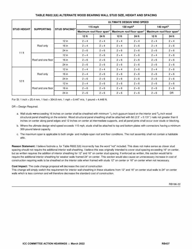
TABLE R602.3(6) ALTERNATE WOOD BEARING WALL STUD SIZE, HEIGHT AND SPACING
STUD HEIGHT SUPPORTING STUD SPACING
ULTIMATE DESIGN WIND SPEED
115 mph 130 mph 140 mph
Maximum roof/floor span Maximum roof/floor span Maximum roof/floor span
12 ft 24 ft 12 ft 24 ft 12 ft 24 ft
11 ft
Roof only
12 in 2 × 4 2 × 4 2 × 4 2 × 4 2 × 4 2 × 4
16 in 2 × 4 2 × 4 2 × 4 2 × 6 2 × 4 2 × 6
24 in 2 × 6 2 × 6 2 × 6 2 × 6 2 × 6 2 × 6
Roof and one floor
12 in 2 × 4 2 × 6 2 × 4 2 × 6 2 × 4 2 × 6
16 in 2 × 6 2 × 6 2 × 6 2 × 6 2 × 6 2 × 6
24 in 2 × 6 2 × 6 2 × 6 2 × 6 2 × 6 2 × 6
12 ft
Roof only
12 in 2 × 4 2 × 4 2 × 4 2 × 6 2 × 4 2 × 6
16 in 2 × 4 2 × 6 2 × 6 2 × 6 2 × 6 2 × 6
24 in 2 × 6 2 × 6 2 × 6 2 × 6 2 × 6 2 × 6
Roof and one floor
12 in 2 × 4 2 × 6 2 × 6 2 × 6 2 × 6 2 × 6
16 in 2 × 6 2 × 6 2 × 6 2 × 6 2 × 6 2 × 6
24 in 2 × 6 2 × 6 2 × 6 2 × 6 2 × 6 DR
For SI: 1 inch = 25.4 mm, 1 foot = 304.8 mm, 1 mph = 0.447 m/s, 1 pound = 4.448 N.
DR = Design Required.
a. Wall studs not exceeding 16 inches on center shall be sheathed with minimum / -inch gypsum board on the interior and / -inch woodstructural panel sheathing on the exterior. Wood structural panel sheathing shall be attached with 8d (2.5″ × 0.131″) nails not greater than 6inches on center along panel edges and 12 inches on center at intermediate supports, and all panel joints shall occur over studs or blocking.
b. Where the ultimate design wind speed exceeds 115 mph, studs shall be attached to top and bottom plates with connectors having a minimum300-pound lateral capacity.
c. The maximum span is applicable to both single- and multiple-span roof and floor conditions. The roof assembly shall not contain a habitableattic.
Reason Statement: I believe footnote a. for Table R602.3(6) incorrectly has the word "not" included. This does not make sense as closer studspacing should not require the additional interior wall sheathing. I believe this was originally intended to cover stud spacing exceeding 16" on center,but as written requires the addition of interior sheathing for 12" and 16" on center stud spacing. If enforced as written, this section would fail torequire the additional interior sheathing for weaker walls framed 24" on center. This section would also cause an unnecessary increase in cost ofconstruction requiring walls to be sheathed on the interior side when framed with studs 12" on center or 16" on center when not necessary.
Cost Impact: The code change proposal will decrease the cost of constructionThis change will simply switch the requirement for interior wall sheathing in these situations from 12" and 16" on center stud walls to 24" on centerwalls which is less common and will therefore decrease the standard cost of construction.
RB196-22
ab b
c c c
12
38
ICC COMMITTEE ACTION HEARINGS ::: March 2022 RB437

RB197-22IRC: R602.7.2
Proponents: Randy Shackelford, representing Simpson Strong-Tie Co. ([email protected])
2021 International Residential CodeRevise as follows:
R602.7.2 Rim board headers. Rim board header size, material and span shall be in accordance with Table R602.7(1). Rim board headers shall beconstructed in accordance with Figure R602.7.2 and shall be supported at each end by full-height studs. The number of full-height studs at each endshall be not less than one plus the number of studs displaced by half of the header span based on the maximum stud spacing in accordance withTable R602.3(5). Rim board headers supporting concentrated loads shall be designed in accordance with accepted engineering practice.
Reason Statement: The reason for this change is to correct the number of full-height studs required at the edge of openings using rim boardheaders. The code currently says that the number of full-height studs needs to be half the number of studs displaced by the opening. But thatneglects the single stud that is already required to be at the edge of the opening. The total number of full height studs needs to be the one already atthe opening edge, PLUS half the number of studs displaced by the opening. This is actually shown correctly in Figure R602.7.2. It shows two studsat each end of the opening. Note that there are two cripple studs in the opening, so half that number would go to each side of the opening. Using theexisting text, only one stud would be required at each edge of the opening. But the number needs to be one (existing stud) PLUS one (half thenumber of studs displaced), or two total at each edge.
Cost Impact: The code change proposal will increase the cost of constructionThis proposal could increase the cost of construction by requiring an additional stud at the edge of each opening using rim board headers. However, I think that what is contained in this change is common practice so there may not be any actual increase in cost. The extra cost isbalanced by the safety of having adequate bearing for the rim board header and adequate out of plane wind load resistance by the wall.
RB197-22
ICC COMMITTEE ACTION HEARINGS ::: March 2022 RB438

RB198-22IRC: R602.7.5
Proponents: Randy Shackelford, representing Simpson Strong-Tie Co. ([email protected])
2021 International Residential CodeRevise as follows:
R602.7.5 Supports for headers. Headers shall be supported on each end with one or more jack studs or with approved framing anchors inaccordance with Table R602.7(1) or R602.7(2). The full-height stud adjacent to each end of the header shall be end nailed to each end of the headerin accordance with Table R602.3(1). The minimum number of full-height studs at each end of a header shall be in accordance with Table R602.7.5. Columns supporting exterior porches shall be restrained to prevent lateral displacement at the bottom end.
Reason Statement: This proposal is to provide the same restraint at the bottom of posts for porch beams as is required for columns support afoundation.Porch posts are structural members that support loads from the roof. If porch posts are accidentally displaced it could cause collapse of a sectionof the roof. Requirements were added to this section in the 2015 IRC for beams/girders supporting porches, but nothing was added regarding theposts supporting the beams.
This change proposes language almost exactly the same as required in Section R403.7 for foundation columns. R407.3 states "The columns shallbe restrained to prevent lateral displacement at the bottom end." If anything, porch columns are more likely to be damaged by accidental collisionthan foundation columns would be.
Cost Impact: The code change proposal will not increase or decrease the cost of constructionThis proposal will not increase the cost of construction in most cases. Most of the time, a manufactured post base will be used anyway to providethe 1 inch standoff so that the post does not have to be treated. However, in the case where a standoff base is not used, this proposal wouldincrease costs.
RB198-22
ICC COMMITTEE ACTION HEARINGS ::: March 2022 RB439

RB199-22IRC: FIGURE R602.10.2.2
Proponents: Mike Nugent, representing Building Code Action Committee ([email protected])
2021 International Residential CodeDelete and substitute as follows:
ICC COMMITTEE ACTION HEARINGS ::: March 2022 RB440

For SI: 1 foot = 304.8 mm.FIGURE R602.10.2.2 LOCATION OF BRACED WALL PANELS
ICC COMMITTEE ACTION HEARINGS ::: March 2022 RB441

For SI: 1 foot = 304.8 mm.FIGURE R602.10.2.2 LOCATION OF BRACED WALL PANELS
Reason Statement: Figure R602.10.2.2 is no longer accurate with the change to BWL placement in IRC 2021 Section R602.10.1.2. This proposalcorrects two graphical inaccuracies in Figure R602.10.2.2: 1. The 10’ dimension along BWL A between the top right corner and BWL 1. Per R602.10.1.1, the 10’ should be measured from theperpendicular wall at the end of the BWL, not the perpendicular BWL centerline. <= We found this while looking closely at the figure
2. BWL 1 was improperly shown with all panels on one side of BWL 1. Per R602.10.1.2, no more than 2/3 of the required braced wall panellength is allowed to be located on one side of the BWL. <= this was the 2021 change
3. In addition, the existing pair of side-by-side braced wall panels along BWL 1 were combined into one large braced wall panel. This was done toemphasize the requirement in Section R602.10.2.3 that a braced wall line greater than 16 feet in length must be provided with a minimum of twobraced wall panels, regardless of the size of those panels. This change also eliminates the misconception that installation of 2 braced wall panelsside-by-side in a > 16-foot BWL provides equal performance to having the 2 braced wall panels spaced further apart. Installation of side-by-sidebraced wall panels runs counter to the function and purpose of requiring a minimum of 2 braced wall panels in the longer BWLs.
This proposal is submitted by the ICC Building Code Action Committee (BCAC).
BCAC was established by the ICC Board of Directors in July 2011 to pursue opportunities to improve and enhance assigned International Codes orportions thereof. In 2020 and 2021 the BCAC has held several virtual meetings open to any interested party. In addition, there were numerous virtualWorking Group meetings for the current code development cycle, which included members of the committee as well as interested parties. Relateddocuments and reports are posted on the BCAC website at https://www.iccsafe.org/products-and-services/i-codes/code-development/cs/building-code-action-committee-bcac/.
ICC COMMITTEE ACTION HEARINGS ::: March 2022 RB442

Cost Impact: The code change proposal will not increase or decrease the cost of constructionThis proposal is a clarification change only; the intent is to update Figure R602.10.2.2 to match the updated requirements in IRC 2021 SectionR602.10.1.2.
RB199-22
ICC COMMITTEE ACTION HEARINGS ::: March 2022 RB443
RB200-22IRC: R602.10.2.2, TABLE R602.10.5, R602.10.6
Proponents: Randy Shackelford, representing Simpson Strong-Tie Co. ([email protected])
2021 International Residential CodeRevise as follows:
R602.10.2.2 Locations of braced wall panels. A The nearest edge of a braced wall panel shall begin be located within 10 feet (3810 mm) fromeach end of a braced wall line as determined in Section R602.10.1.1. The distance between adjacent edges of braced wall panels along a bracedwall line shall be not greater than 20 feet (6096 mm) as shown in Figure R602.10.2.2.
Exceptions:
1. Braced wall panels in Seismic Design Categories D , D and D shall comply with Section R602.10.2.2.1.
2. Braced wall panels with continuous sheathing in Seismic Design Categories A, B or C shall comply with Section R602.10.7.
0 1 2
ICC COMMITTEE ACTION HEARINGS ::: March 2022 RB444

TABLE R602.10.5 MINIMUM LENGTH OF BRACED WALL PANELS
METHOD (See Table R602.10.4)
MINIMUM LENGTH (inches)
CONTRIBUTING LENGTH (inches)Wall Height
8feet
9feet
10feet
11feet
12feet
DWB, WSP, SFB, PBS, PCP, HPS, BV-WSP 48 48 48 53 58 Actual
GB 48 48 48 53 58Double sided = ActualSingle sided = 0.5 ×
Actual
LIB 55 62 69 NP NP Actual
ABW
SDC A, B and C, ultimate design wind speed < 140mph
28 32 34 38 42
48SDC D , D and D , ultimate design wind speed <
140 mph32 32 34 NP NP
CS-G 24 27 30 33 36 Actual
CS-WSP, CS-SFB
Adjacent clear opening height (inches)
≤ 64 24 27 30 33 36
Actual
68 26 27 30 33 36
72 27 27 30 33 36
76 30 29 30 33 36
80 32 30 30 33 36
84 35 32 32 33 36
88 38 35 33 33 36
92 43 37 35 35 36
96 48 41 38 36 36
100 — 44 40 38 38
104 — 49 43 40 39
108 — 54 46 43 41
112 — — 50 45 43
116 — — 55 48 45
120 — — 60 52 48
124 — — — 56 51
128 — — — 61 54
132 — — — 66 58
136 — — — — 62
140 — — — — 66
144 — — — — 72
METHOD (See Table R602.10.4)Portal header height
8feet
9feet
10feet
11feet
12feet
PFH
Supporting roof only 16 16 16Note
cNote
c48
Supporting one story and roof 24 24 24Note
cNote
c
PFG 24 27 30Note
dNote
d1.5 × Actual
SDC A, B and C 16 18 20Note
eNote
e1.5 × Actual
a
b
b
0 1 2
b
b
b
b
ICC COMMITTEE ACTION HEARINGS ::: March 2022 RB445

CS-PF
SDC D , D and D 16 18 20Note
eNote
eActual
METHOD (See Table R602.10.4)
MINIMUM LENGTH (inches)
CONTRIBUTING LENGTH (inches)Wall Height
8feet
9feet
10feet
11feet
12feet
For SI: 1 inch = 25.4 mm, 1 foot = 304.8 mm, 1 mile per hour = 0.447 m/s.NP = Not Permitted.
a. Linear interpolation shall be permitted.
b. Use the actual length where it is greater than or equal to the minimum length. The actual length of Methods CS-G, CS-WSP, CS-SFB, PFH,PFG, and CS-PF is the length of the full-height sheathed section.
c. Maximum header height for PFH is 10 feet in accordance with Figure R602.10.6.2, but wall height shall be permitted to be increased to 12feet with pony wall.
d. Maximum header height for PFG is 10 feet in accordance with Figure R602.10.6.3, but wall height shall be permitted to be increased to 12feet with pony wall.
e. Maximum header height for CS-PF is 10 feet in accordance with Figure R602.10.6.4, but wall height shall be permitted to be increased to 12feet with pony wall.
R602.10.6 Construction of Methods ABW, PFH, PFG, CS-PF and BV-WSP. Methods ABW, PFH, PFG, CS-PF and BV-WSP shall beconstructed as specified in Sections R602.10.6.1 through R602.10.6.5. For the purposes of determining braced wall panel spacing, the edge ofMethods PFH, PFG, and CS-PF shall be defined as the end of the header.
Reason Statement: There has been confusion by users on where to locate the edge of a single portal frame when applying the braced wall panelspacing rules in R602.10.2.2. There is disagreement whether the spacing should be measured from the vertical sheathed portal located at one end,or the end of the header. Since the full length of the header is taking shear loads out of the top plate, and the purpose of the braced wall panelspacing requirements is to ensure that excessive load does not accumulate in the top plate, it makes sense that the edge of the portal is the end ofthe header.Since the term “edge” is now being used for portals, Section R602.10.2.2 should be revised to be consistent and use the term “edge” instead ofsaying “begin”. Note b in Table R602.10.5 is amended to clarify that the “actual length” is the length of the vertical sheathed portion of a portalframe. If the edges are defined as the ends of the header, that might lead to confusion on what is the “actual length” of the portal frame. Theminimum length is indicated in the Figures so it does not need clarification.
Cost Impact: The code change proposal will not increase or decrease the cost of constructionThis proposal will definitely not increase the cost of construction. It could decrease the cost of construction if a user was interpreting the code tosay that the edge of a portal frame is measured from the sheathing edge. That would require a closer spacing of braced wall panels than necessaryusing the new proposed interpretation.
RB200-22
0 1 2b
ICC COMMITTEE ACTION HEARINGS ::: March 2022 RB446

RB201-22IRC: SECTION 202 (New), R602.10.3.1 (New), FIGURE R602.10.3.1 (New), TABLE R602.10.3(2), TABLE R602.10.3(4)
Proponents: Julie Furr, representing FEMA-ATC Seismic Code Support Committee ([email protected]); Kelly Cobeen, representing FederalEmergency Management Agency/Applied Technology Council - Seismic Code Support Committee ([email protected]); Michael Mahoney,representing FEMA ([email protected])
2021 International Residential CodeAdd new definition as follows:
HEIGHT, LIGHT-FRAME STUD WALL. The vertical distance from the lower edge of the bottom plate to the upper edge of the upper top plate.
Add new text as follows:
R602.10.3.1 Wall Height for Wood Framing. For determination of braced wall and panel adjustment factors in accordance with Section R602.10,wall height shall be the light-frame stud wall height determined in accordance with Figure R602.10.3.1.
ICC COMMITTEE ACTION HEARINGS ::: March 2022 RB447

FIGURE R602.10.3.1 Wall Height for Wood Framing
Revise as follows:
ICC COMMITTEE ACTION HEARINGS ::: March 2022 RB448

TABLE R602.10.3(2) WIND ADJUSTMENT FACTORS TO THE REQUIRED LENGTH OF WALL BRACING
ITEMNUMBER
ADJUSTMENTBASED ON STORY/SUPPORTING CONDITION
ADJUSTMENT FACTOR[multiply length from TableR602.10.3(1) by this factor]
APPLICABLEMETHODS
1Exposurecategory
One-story structure
B 1.00
All methods
C 1.20
D 1.50
Two-story structure
B 1.00
C 1.30
D 1.60
Three-story structure
B 1.00
C 1.40
D 1.70
2Roof eave-to-ridge
height
Roof only
≤ 5 feet 0.70
10 feet 1.00
15 feet 1.30
20 feet 1.60
Roof + 1 floor
≤ 5 feet 0.85
10 feet 1.00
15 feet 1.15
20 feet 1.30
Roof + 2 floors
≤ 5 feet 0.90
10 feet 1.00
15 feet 1.10
20 feet Not permitted
3
Wall Height (Section
R601.10.3.1)
Story height(Section R301.3)
Any story
8 feet 0.90
9 feet 0.95
10 feet 1.00
11 feet 1.05
12 feet 1.10
4Number of bracedwall lines (per plan
direction)Any story
2 1.00
3 1.30
4 1.45
≥ 5 1.60
5Additional 800-
pound hold-downdevice
Top story onlyFastened to the end studs of
each braced wall panel and to thefoundation or framing below
0.80DWB, WSP, SFB,PBS, PCP, HPS
6Interior gypsumboard finish (or
equivalent)Any story
Omitted from inside face ofbraced wall panels
1.40DWB, WSP, SFB,
PBS, PCP, HPS, CS-WSP, CS-G, CS-SFB
7Gypsum board
fasteningAny story
4 inches o.c. at panel edges,including top and bottom plates,and all horizontal joints blocked
0.7 GB
8 Horizontal blocking Any story Horizontal block is omitted 2.0 WSP, PBS, CS-WSP
For SI: 1 inch = 25.4 mm, 1 foot = 304.8 mm, 1 pound = 4.48 N.
a. Linear interpolation shall be permitted.
b. The total adjustment factor is the product of all applicable adjustment factors.
a, b
d
c
ICC COMMITTEE ACTION HEARINGS ::: March 2022 RB449

c. The adjustment factor is permitted to be 1.0 when determining bracing amounts for intermediate braced wall lines provided the bracingamounts on adjacent braced wall lines are based on a spacing and number that neglects the intermediate braced wall line.
d. The same adjustment factor shall be applied to all braced wall lines on all floors of the structure, based on the worst-case exposurecategory.
ICC COMMITTEE ACTION HEARINGS ::: March 2022 RB450

TABLE R602.10.3(4) SEISMIC ADJUSTMENT FACTORS TO THE REQUIRED LENGTH OF WALL BRACING
ITEMNUMBER ADJUSTMENT BASED ON STORY CONDITION
ADJUSTMENT FACTOR[Multiply length from TableR602.10.3(3) by this factor]
APPLICABLEMETHODS
1Wall Height (Section R601.10.3.1)
Story height (Section 301.3)Any story
≤ 10 feet 1.0
All methods
> 10 feet and ≤ 12 feet 1.2
2Braced wall line spacing,townhouses in SDC C
Any story≤ 35 feet 1.0
> 35 feet and ≤ 50 feet 1.43
3Braced wall line spacing, in SDC
D , D , DAny story
> 25 feet and ≤ 30 feet 1.2
> 30 feet and ≤ 35 feet 1.4
4 Wall dead load Any story> 8 psf and < 15 psf 1.0
< 8psf 0.85
5Roof/ceiling dead load for wall
supporting
1-, 2- or 3-storybuilding
≤15 psf 1.0
2- or 3-storybuilding
> 15 psf and ≤ 25 psf 1.1
1-story buildingor top story
> 15 psf and ≤ 25 psf 1.2
6Walls with stone or masonry
veneer, townhouses in SDC C
1.0
All methods1.5
1.5
7Walls with stone or masonry
veneer, detached one- and two-family dwellings in SDC D – D
Any story See Section R602.10.6.5.4 BV-WSP
8Walls with stone or masonry
veneer, detached one- and two-family dwellings in SDC D – D
First andsecond story of
two-storydwelling
Limited brick veneer onsecond story. See
Section R602.10.6.5.3.1.2 WSP, CS-WSP
9Interior gypsum board finish (or
equivalent)Any story
Omitted from inside faceof braced wall panels
1.5DWB, WSP, SFB,
PBS, PCP, HPS, CS-WSP, CS-G, CS-SFB
10 Horizontal blocking Any storyHorizontal blocking
omitted2.0 WSP, PBS, CS-WSP
For SI: 1 foot = 304.8 mm, 1 pound per square foot = 0.0479 kPa.
a. Linear interpolation shall be permitted.
b. The total length of bracing required for a given wall line is the product of all applicable adjustment factors.
c. The length-to-width ratio for the floor/roof diaphragm shall not exceed 3:1.
d. Applies to stone or masonry veneer exceeding the first story height.
e. The adjustment factor for stone or masonry veneer shall be applied to all exterior braced wall lines and all braced wall lines on the interior ofthe building, backing or perpendicular to and laterally supporting veneered walls.
f. See Section R602.10.6.5 for requirements where stone or masonry veneer does not exceed the first-story height.
g. One- and two-family dwellings in Seismic Design Category D exceeding two stories shall be designed in accordance with acceptedengineering practice.
g
a, b
0 1 2c
d, e
0 2d, f
0 2d, f
2
ICC COMMITTEE ACTION HEARINGS ::: March 2022 RB451
Reason Statement: This proposal clarifies how to determine the vertical dimension of the wall height for wood stud framing, which has been subjectto varying interpretations. It also cleans up braced wall adjustment factor table references (story heights) that are currently in conflict with the listedwall height dimensions.Requirements such as braced wall line lengths and adjustment factors are based on the “wall height”, which can be ambiguous when using cofferedceilings, knee-walls, and other common framing features and techniques. Because shorter wall heights are allowed to use lower factors, there is aneconomic incentive to classify the wall height as short as possible. This requires a clear and concise definition of “wall height” to eliminate confusionand varying interpretations.
Braced Wall Design Basis - Seismic
The seismic design basis calculations for the IRC rely upon expected relationships between the story height, top of “wall height”, and the braced wallpanel heights. Use of shorter wall heights in combination with taller story heights will lead to unconservative lengths of braced walls and wall panelsand will compromise the structural integrity during a seismic event.
Places that Wall Height is Used
The following tables in Chapter 6 are keyed on variations of story height, wall height, or a similar vertical measurement:
Table R602.10.3(1) Bracing Requirements Based on Wind SpeedTable R602.10.5 Minimum Length of Braced Wall PanelsTable R602.10.5.2 Partial Credit for Braced Wall Panels Less than 48 inches in Actual LengthTABLE R602.10.3(3) Bracing Requirements Based on Seismic Design Category
Cost Impact: The code change proposal will not increase or decrease the cost of constructionThis is a clarification of intent and does not impose new requirements.
RB201-22
ICC COMMITTEE ACTION HEARINGS ::: March 2022 RB452

RB202-22IRC: FIGURE R602.10.6.2
Proponents: Randy Shackelford, representing Simpson Strong-Tie Co. ([email protected])
2021 International Residential CodeRevise as follows:
ICC COMMITTEE ACTION HEARINGS ::: March 2022 RB453

ICC COMMITTEE ACTION HEARINGS ::: March 2022 RB454

For SI: 1 inch = 25.4 mm, 1 foot = 304.8 mm.FIGURE R602.10.6.2 METHOD PFH—PORTAL FRAME WITH HOLD-DOWNS
Reason Statement: This proposal is made to correct the PFH Figure to reflect how the portal frame was originally tested. In the original testing, thehorizontal bearing block beneath the end of the header extended the full bearing width of the vertical section. That is reflected in the photo shownbelow, taken from the original APA testing as reported in T2002-46. Currently it appears as if the vertical studs extend completely up to the header. A note is also needed to be added that in the event that there is not a pony wall above the header, the header and the bearing block need to extendcompletely to the end of the portal frame, again to reflect the original testing. Note that if this is accepted, the illustration will match those of the PFGand CS-PF.
ICC COMMITTEE ACTION HEARINGS ::: March 2022 RB455

Cost Impact: The code change proposal will not increase or decrease the cost of constructionThis code change just clarifies how the bearing of the header at each end is constructed. It should not result in any increase or decrease in costs.
RB202-22
ICC COMMITTEE ACTION HEARINGS ::: March 2022 RB456

RB203-22IRC: FIGURE R602.10.6.2, FIGURE R602.10.6.3, FIGURE R602.10.6.4
Proponents: Borjen Yeh, representing APA - The Engineered Wood Association ([email protected])
2021 International Residential CodeRevise as follows:
ICC COMMITTEE ACTION HEARINGS ::: March 2022 RB457

For SI: 1 inch = 25.4 mm, 1 foot = 304.8 mm.
ICC COMMITTEE ACTION HEARINGS ::: March 2022 RB458

Note: Header shall not extend over more than one opening.FIGURE R602.10.6.2 METHOD PFH—PORTAL FRAME WITH HOLD-DOWNS
ICC COMMITTEE ACTION HEARINGS ::: March 2022 RB459

For SI: 1 inch = 25.4 mm, 1 foot = 304.8 mm.NOTE: Header shall not extend over more than one opening.
FIGURE R602.10.6.3 METHOD PFG—PORTAL FRAME AT GARAGE DOOR OPENINGS IN SEISMIC DESIGN CATEGORIES A, B AND C
ICC COMMITTEE ACTION HEARINGS ::: March 2022 RB460

ICC COMMITTEE ACTION HEARINGS ::: March 2022 RB461

For SI: 1 inch = 25.4 mm, 1 foot = 304.8 mm.NOTE: Header shall not extend over more than one opening.
FIGURE R602.10.6.4 METHOD CS-PF—CONTINUOUSLY SHEATHED PORTAL FRAME PANEL CONSTRUCTION
Reason Statement: The intent of this change proposal is to clarify the header requirement for portal frames and to limit the header to a single-spanconfiguration, as originally tested, with double portal frames. This question has been frequently raised in the field and is worth clarification in theIRC.Portal frames first appeared in the 2009 IRC and were based on tests conducted by APA and NAHB, in which the headers were tested in asingle-span configuration. While it can be argued that this is reflected in the detailed drawings of the existing Figures R602.10.6.2, R602.10.6.3, andR602.10.6.4, a careful examination is usually required to spot such a subtle difference. The addition of the clarification note as proposed will makethese figures easier to follow and less prone to confusion. In practical applications, continuous headers if purchased for double portal frames can becut into 2 single-span headers before installation into each portal frame.
Cost Impact: The code change proposal will not increase or decrease the cost of constructionThis code change proposal will not increase or decrease the cost of construction because it clarifies the double portal frame construction asoriginally intended.
RB203-22
ICC COMMITTEE ACTION HEARINGS ::: March 2022 RB462

RB204-22IRC: FIGURE R602.10.6.2, FIGURE R602.10.6.3, FIGURE R602.10.6.4
Proponents: Borjen Yeh, representing APA - The Engineered Wood Association ([email protected])
2021 International Residential CodeRevise as follows:
ICC COMMITTEE ACTION HEARINGS ::: March 2022 RB463

ICC COMMITTEE ACTION HEARINGS ::: March 2022 RB464

For SI: 1 inch = 25.4 mm, 1 foot = 304.8 mm.FIGURE R602.10.6.2 METHOD PFH—PORTAL FRAME WITH HOLD-DOWNS
ICC COMMITTEE ACTION HEARINGS ::: March 2022 RB465

For SI: 1 inch = 25.4 mm, 1 foot = 304.8 mm.FIGURE R602.10.6.3 METHOD PFG—PORTAL FRAME AT GARAGE DOOR OPENINGS IN SEISMIC DESIGN CATEGORIES A, B AND C
ICC COMMITTEE ACTION HEARINGS ::: March 2022 RB466

ICC COMMITTEE ACTION HEARINGS ::: March 2022 RB467

For SI: 1 inch = 25.4 mm, 1 foot = 304.8 mm.FIGURE R602.10.6.4 METHOD CS-PF—CONTINUOUSLY SHEATHED PORTAL FRAME PANEL CONSTRUCTION
Reason Statement: The length of panel in portal frames should be based on the length of the portal segment, as measured between the outermoststud surfaces in the portal. This was how the portal frame was tested and published in previous editions of the IRC (e.g., Figure R602.10.6.2 of the2006 IRC, and Figures R602.10.3.3 and R602.10.3.4 of the 2009 IRC). Unfortunately, these figures have been redrawn many times over the years,resulting in Figures R602.10.6.2, R602.10.6.3, and R602.10.6.4 of the current (2021) IRC, which seem to show the distance between the outermostrows of nails. There have been no code change proposals to make such a subtle change over the years and it is believed that this is simply a detailin those figures that were overlooked. However, this has caused some questions by some code users to ICC staff who contacted APA forclarification. The intent of this proposal is to clarify it, as shown by the double-headed arrows in those figures, for consistency with the original portalframe figures that were previously approved by the IRC.
Cost Impact: The code change proposal will not increase or decrease the cost of constructionThis code change proposal will not increase or decrease the cost of construction because it clarifies the length of panel in the portal frames asoriginally intended without changing the material or labor requirements.
RB204-22
ICC COMMITTEE ACTION HEARINGS ::: March 2022 RB468
RB205-22IRC: R606.1.1, R606.2.10, R606.12.2.3.1, R606.12.2.3.2, R703.12, TMS Chapter 44
Proponents: Phillip Samblanet, representing The Masonry Society ([email protected]); Jason Thompson, representing MasonryAlliance for Codes and Standards ([email protected])
2021 International Residential CodeRevise as follows:
R606.1.1 Professional registration not required. Where the empirical design provisions of Appendix A of TMS 402, the provisions of TMS 403, orthe provisions of this section are used to design masonry, project drawings, typical details and specifications are not required to bear the seal of thearchitect or engineer responsible for design, unless otherwise required by the state law of the jurisdiction having authority.
R606.2.10 Mortar for AAC masonry. Thin-bed mortar for AAC masonry shall comply with Article 2.2 D.12.1 C.1 of TMS 602. Mortar used for theleveling courses of AAC masonry shall comply with Article 2.2 D.2 2.1 C.2 of TMS 602.
R606.12.2.3.1 Connections to masonry shear walls. Connectors shall be provided to transfer forces between masonry walls and horizontalelements in accordance with the requirements of Chapter 4 Section 4.1.4 of TMS 402. Connectors shall be designed to transfer horizontal designforces acting either perpendicular or parallel to the wall, but not less than 200 pounds per linear foot (2919 N/m) of wall. The maximum spacingbetween connectors shall be 4 feet (1219 mm). Such anchorage mechanisms shall not induce tension stresses perpendicular to grain in ledgers ornailers.
R606.12.2.3.2 Connections to masonry columns. Connectors shall be provided to transfer forces between masonry columns and horizontalelements in accordance with the requirements of Chapter 4 Section 4.1.4 of TMS 402. Where anchor bolts are used to connect horizontal elementsto the tops of columns, the bolts shall be placed within lateral ties. Lateral ties shall enclose both the vertical bars in the column and the anchor bolts.There shall be not less than two No. 4 lateral ties provided in the top 5 inches (127 mm) of the column.
R703.12 Adhered masonry veneer installation. Adhered masonry veneer shall comply with the requirements of Section R703.7.3 and therequirements in Sections 13.112.1 and 13.3 12.3 of TMS 402. Adhered masonry veneer shall be installed in accordance with Section R703.7.1,Article 3.3D3.3C of TMS 602 or the manufacturer’s instructions.
TMS The Masonry Society105 South Sunset Street, Suite Q
Longmont, CO 80501
402—2016 2022 Building Code Requirements for Masonry Structures
602—2016 2022 Specification for Masonry Structures
Staff Analysis: The proposal is referencing an updated version of an existing referenced standard. Therefore the updated version is considered annew standard. A review of the standard proposed for inclusion in the code, TMS 402-2022 Building Code Requirements for Masonry Structures andTMS 602-2022 Specification for Masonry Structures, with regard to some of the key ICC criteria for referenced standards (Section 3.6 of CP#28)will be posted on the ICC website on or before March 16, 2022.
Reason Statement: This change updates the IRC references and requirements to TMS 402-22 and TMS 602-22. In most cases, the changes areentirely related to moving provisions and updating the references. The deletion of the permission to use empirical design is needed because thatappendix has been removed from TMS 402-22 as the Committee no longer supports the provisions for new construction.
Cost Impact: The code change proposal will not increase or decrease the cost of constructionThis change simply updates references. As such, there is no impact on construction costs.
RB205-22
ICC COMMITTEE ACTION HEARINGS ::: March 2022 RB469
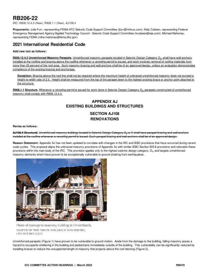
RB206-22IRC: R606.12.4.3 (New), R908.1.1 (New), AJ108.4
Proponents: Julie Furr, representing FEMA-ATC Seismic Code Support Committee ([email protected]); Kelly Cobeen, representing FederalEmergency Management Agency/Applied Technology Council - Seismic Code Support Committee ([email protected]); Michael Mahoney,representing FEMA ([email protected])
2021 International Residential CodeAdd new text as follows:
R606.12.4.3 Unreinforced Masonry Parapets. Unreinforced masonry parapets located in Seismic Design Category D , shall have wall anchorsinstalled at the roofline and bracing above the roofline whenever a reroofing permit is issued, and work involves removal of roofing materials frommore than 25 percent of the roof area. Such masonry bracing and wall anchors shall be of an approved design, unless an evaluation demonstratescompliance of the existing bracing and anchorage.
Exception: Bracing above the roof line shall not be required where the maximum height of unbraced unreinforced masonry does not exceed aheight-to-width ratio of 2.5. Height shall be measured from the top of the parapet down to the highest existing brace or anchor point attached tothe structure.
R908.1.1 Structure. Whenever a reroofing permit is issued for work done in Seismic Design Category D , parapets constructed of unreinforcedmasonry shall comply with R606.12.4.3.
APPENDIX AJEXISTING BUILDINGS AND STRUCTURES
SECTION AJ108RENOVATIONS
Revise as follows:
AJ108.4 Structural. Unreinforced masonry buildings located in Seismic Design Category D or E shall have parapet bracing and wall anchorsinstalled at the roofline whenever a reroofing permit is issued. Such parapet bracing and wall anchors shall be of an approved design.
Reason Statement: Appendix AJ has not been updated to correlate with changes in the IRC and IEBC provisions that have occurred during recentcode cycles. This proposal aligns the unbraced masonry provisions of Appendix AJ with similar IEBC Section 503.6 provisions and relocates theseprovisions within the main body of the IRC. This provision applies only to the highest seismic design category, D , and targets unreinforcedmasonry elements which have proven to be exceptionally vulnerable to ground shaking from earthquakes.
Unreinforced parapets (Figure 1) have proven to be vulnerable to ground motion. Aside from the damage to the building, falling masonry poses ahazard to occupants sheltering in the building and pedestrians immediately outside of the building. This vulnerability can be significantly reduced byinstalling braces to reduce the unsupported length of masonry that projects above the roof decking (Figure 2).
2
2
2
2
ICC COMMITTEE ACTION HEARINGS ::: March 2022 RB470

Figure 2 Caption: Parapet bracing and added tension ties to the roof/floor framing. FEMA P-530
Cost Impact: The code change proposal will increase the cost of constructionThis proposal will increase the cost of construction by moving this provision within the main body of the IRC. However, this provision has beenrevised from the current Appendix AJ provision and is limited to SDC D2 only, applies only if roof work involves more than 25% of the roof area, andprovides an exception for shorter more squat URM parapets.
RB206-22
ICC COMMITTEE ACTION HEARINGS ::: March 2022 RB471

RB207-22IRC: R609.1, R609.4.1
Proponents: Mike Fischer, representing International Door Association ([email protected])
2021 International Residential CodeRevise as follows:
R609.1 General. This section prescribes performance and construction requirements for exterior windows, and doors, and garage doors installed inwalls. Windows and doors shall be installed in accordance with the fenestration manufacturer’s written instructions. Window and door openings shallbe flashed in accordance with Section R703.4. Written installation instructions shall be provided by the fenestration manufacturer for each window ordoor.
R609.4 Garage doors. Garage doors shall be tested in accordance with either ASTM E330 or ANSI/DASMA 108, and shall meet the pass/failcriteriaof ANSI/DASMA 108.
Revise as follows:
R609.4.1 Garage door labeling. Garage doors shall be labeled with a permanent label provided by the garage door manufacturer.The label shall identify the garage door manufacturer, the garage door model/series number, the positive and negative design wind pressure rating,the installation instruction drawing reference number, and the applicable test standard. Garage doors shall be installed in accordance with themanufacturer’s installation instructions.
Reason Statement: The proposal makes two changes. The first change in Section R609.1 is editorial; Section R609 includes provisions for exteriorwindows and doors, and also for garage doors. The proposed text includes garage doors within the scope of Section R609 to clarify the intent of thesection. The second proposed change is in R609.4.1 adds a requirement that garage doors be installed in accordance with the manufacturer's installationinstructions. Note that R609.4 includes product testing requirements, and R609.4.1 includes labeling details with a reference to the "installationinstruction drawing", but does not specifically state that the garage door be installed in accordance with the installation instructions. Thoseinstructions often contain additional information regarding jamb attachments and anchoring and other details necessary to ensure proper installationand compliance with the intent of the code. The proposal clarifies the intent and is consistent with the provisions for exterior windows and doors inSection R609.1.
Cost Impact: The code change proposal will not increase or decrease the cost of constructionThe proposal clarifies the current expectation that tested garage doors be installed in accordance with the manufacturers installation instructions. Itadds no new requirements.
RB207-22
ICC COMMITTEE ACTION HEARINGS ::: March 2022 RB472

RB208-22IRC: R702.7, R702.7.1 (New)
Proponents: Theresa Weston, representing Air Barrier Association of America (ABAA) ([email protected])
2021 International Residential CodeRevise as follows:
R702.7 Vapor retarders. Vapor retarder materials shall be classified in accordance with Table R702.7(1). A vapor retarder shall be provided on theinterior side of frame walls of the class indicated in Table R702.7(2), including compliance with Table R702.7(3) or R702.7(4) where applicable. Anapproved design using accepted engineering practice for hygrothermal analysis shall be permitted as an alternative. Vapor retarders shall beinstalled in accordance with Section R702.7.1 The climate zone shall be determined in accordance with Section N1101.7 .
Exceptions:
1. Basement walls.
2. Below-grade portion of any wall.
3. Construction where accumulation, condensation or freezing of moisture will not damage the materials.
4. A vapor retarder shall not be required in Climate Zones 1, 2 and 3.
Add new text as follows:
R702.7.1 Vapor Retarder Installation. Vapor retarders shall be installed in accordance with the manufacturer’s instructions or an approveddesign. Where a vapor retarder also functions as a component of a continuous air barrier, the vapor retarder shall be installed as an air barrier inaccordance with Section N1102.4.1.1.
Reason Statement: This proposal recognizes the challenge of materials that serve multiple functions. In addition to protection from condensation,vapor retarders may also function as a component in an air barrier assembly. This proposal seeks coordination of the installation of vapor retardersbetween Part III - Building Planning and Construction and Part IV -- Energy Conservation of the IRC in order to streamline the compliance with bothsections. Vapor retarders are commonly installed as part of or in conjunction with an air barrier. Air leakage control is currently addressed withinthe I-codes based on energy efficiency considerations, but it also critical to the protection against moisture condensation. This proposal correlates with a proposal that was approved for the IBC in Group A.
Cost Impact: The code change proposal will not increase or decrease the cost of constructionThis proposal will neither increase nor decrease the cost of construction as it does not add new technical requirements, but rather coordinatesbetween existing requirements in two Parts of the code. The coordination is to ensure that existing requirements are implemented in an effectivemanner.
RB208-22
ICC COMMITTEE ACTION HEARINGS ::: March 2022 RB473
RB209-22IRC: SECTION 202 (New), R702.7, TABLE R702.7(2), TABLE R702.7(3), TABLE R702.7(4), R702.7(5) (New), R702.7.2 (New)
Proponents: Jay Crandell, P.E., ABTG/ARES Consulting, representing Foam Sheathing Committee of the American Chemistry Council([email protected])
2021 International Residential CodeAdd new definition as follows:
RESPONSIVE VAPOR RETARDER. A vapor retarder material complying with a vapor retarder class of Class I or Class II but which also has avapor permeance of 1 perm or greater in accordance with ASTM E96, water method (Procedure B).
Revise as follows:
R702.7 Vapor retarders. Vapor retarder materials shall be classified in accordance with Table R702.7(1). A vapor retarder shall be provided on theinterior side of frame walls of the class indicated in Table R702.7(2), including compliance with Table R702.7(3) or R702.7(4) where applicable. Anapproved design using accepted engineering practice for hygrothermal analysis shall be permitted as an alternative. The climate zone shall bedetermined in accordance with Section N1101.7 .
Exceptions:
1. Basement walls.
2. Below-grade portion of any wall.
3. Construction where accumulation, condensation or freezing of moisture will not damage the materials.
4. A vapor retarder shall not be required in Climate Zones 1, 2 and 3.
5. In Climate Zones 4 through 8, a vapor retarder shall not be required where the assembly complies with Table R702.7(5).
ICC COMMITTEE ACTION HEARINGS ::: March 2022 RB474

TABLE R702.7(1) VAPOR RETARDER MATERIALS AND CLASSES
CLASS ACCEPTABLE MATERIALS
I Sheet polyethylene, nonperforated aluminum foil or other approved materials with a perm rating less than or equal to 0.1.
IIKraft-faced fiberglass batts, vapor retarder paint or other approved materials applied in accordance with the manufacturer's installationinstructions for a perm rating greater than 0.1 and less than or equal to 1.0.
IIILatex paint, enamel paint or other approved materials applied in accordance with the manufacturer's installation instructions for a permrating greater than 1.0 and less than or equal to 10.0.
ICC COMMITTEE ACTION HEARINGS ::: March 2022 RB475

TABLE R702.7(2) VAPOR RETARDER OPTIONS
CLIMATE ZONEVAPOR RETARDER CLASS
CLASS I CLASS II CLASS III
1, 2 Not Permitted Not Permitted Permitted
3, 4 (except Marine 4) Not Permitted Permitted Permitted
Marine 4, 5, 6, 7, 8 Permitted Permitted See Table R702.7(3)
a. A responsive vapor retarder Class I and II vapor retarders with vapor permeance greater than 1 perm when measured by ASTM E96 watermethod (Procedure B) shall be allowed on the interior side of any frame wall in all climate zones.
b. Use of a Class I interior vapor retarder, that is not a responsive vapor retarder, in frame walls with a Class I vapor retarder on the exteriorside shall require an approved design.
c. Where a Class I or II vapor retarder is used in combination with foam plastic insulating sheathing installed as continuous insulation on theexterior side of frame walls, the continuous insulation shall comply with Table R702.7(4) and the Class I or II vapor retarder shall be aresponsive vapor retarder have a vapor permeance greater than 1 perm when measured by ASTM E96 water method (Procedure B).
a a
c
b,c c
ICC COMMITTEE ACTION HEARINGS ::: March 2022 RB476

TABLE R702.7(3) CLASS III VAPOR RETARDERS
CLIMATE ZONE CLASS III VAPOR RETARDERS PERMITTED FOR:
Marine 4
Vented cladding over wood structural panels.
Vented cladding over fiberboard.
Vented cladding over gypsum.
Continuous insulation with R-value ≥ 2.5 over 2 × 4 wall.
Continuous insulation with R-value ≥ 3.75 over 2 × 6 wall.
5
Vented cladding over wood structural panels.
Vented cladding over fiberboard.
Vented cladding over gypsum.
Continuous insulation with R-value ≥ 5 over 2 × 4 wall.
Continuous insulation with R-value ≥ 7.5 over 2 × 6 wall.
6
Vented cladding over fiberboard.
Vented cladding over gypsum.
Continuous insulation with R-value ≥ 7.5 over 2 × 4 wall.
Continuous insulation with R-value ≥ 11.25 over 2 × 6 wall.
7Continuous insulation with R-value ≥ 10 over 2 × 4 wall.
Continuous insulation with R-value ≥ 15 over 2 × 6 wall.
8Continuous insulation with R-value ≥ 12.5 over 2 × 4 wall.Continuous insulation with R-value ≥ 20 over 2 × 6 wall.
a. Vented cladding shall include vinyl, polypropylene, or horizontal aluminum siding, brick veneer with a clear airspace as specified in TableR703.8.4(1), rainscreen systems, and other approved vented claddings.
b. The requirements in this table apply only to insulation used to control moisture in order to permit the use of Class III vapor retarders. Theinsulation materials used to satisfy this option also contribute to but do not supersede the thermal envelope requirements of Chapter 11.
a, b
ICC COMMITTEE ACTION HEARINGS ::: March 2022 RB477

TABLE R702.7(4) CONTINUOUS INSULATION WITH CLASS I OR II RESPONSIVE VAPOR RETARDER
CLIMATE ZONE CLASS II VAPOR RETARDERS PERMITTED CONDITIONS FOR:
3 Continuous insulation with R-value ≥ 2.
4, 5 and 6Continuous insulation with R-value ≥ 3 over 2 × 4 wall.Continuous insulation with R-value ≥ 5 over 2 × 6 wall.
7Continuous insulation with R-value ≥ 5 over 2 × 4 wall.Continuous insulation with R-value ≥ 7.5 over 2 × 6 wall.
8Continuous insulation with R-value ≥ 7.5 over 2 × 4 wall.Continuous insulation with R-value ≥ 10 over 2 × 6 wall.
a. The requirements in this table apply only to insulation used to control moisture in order to permit the use of Class II vapor retarders. Theinsulation materials used to satisfy this option also contribute to but do not supersede the thermal envelope requirements of Chapter 11.
Add new text as follows:
a
a
ICC COMMITTEE ACTION HEARINGS ::: March 2022 RB478

R702.7(5) CONTINUOUS INSULATION ON WALLS WITHOUT A CLASS I, II, OR III INTERIOR VAPOR RETARDER
CLIMATE ZONE PERMITTED CONDITIONS:
4 Continuous insulation with R-value >= 4.5
5 Continuous insulation with R-value >= 6.5
6 Continuous insulation with R-value >= 8.5
7 Continuous insulation with R-value >= 11.5
8 Continuous insulation with R-value >= 14
a. The total insulating value of materials to the interior side of the exterior continuous insulation, including any cavity insulation, shall not exceedR-5. Where the R-value of materials to the interior side of the exterior continuous insulation exceed R-5, an approved design shall berequired.
b. A water vapor control material layer having a permeance not greater than 1 perm in accordance with ASTM E96, Procedure A (dry cup) shallbe placed on the exterior side of the wall and to the interior side of the exterior continuous insulation. The exterior continuous insulation shallbe permitted to serve as the vapor control layer where, at its installed thickness or with a facer on its interior face, the exterior continuousinsulation is a Class I or II vapor retarder.
c. The requirements in this table apply only to insulation used to control moisture in order to allow walls without a Class I, II, or III interior vaporretarder. The insulation materials used to satisfy this option also contribute to but do not supersede the thermal envelope requirements of theInternational Energy Conservation Code.
R702.7.1 Spray foam plastic insulation for moisture control with Class II and III vapor retarders. For purposes of compliance with TablesR702.7(3) and R702.7(4), spray foam with a maximum permeance of 1.5 perms at the installed thickness applied to the interior side of woodstructural panels, fiberboard, insulating sheathing or gypsum shall be deemed to meet the continuous insulation moisture control requirement inaccordance with one of the following conditions:
1. The spray foam R-value is equal to or greater than the specified continuous insulation R-value.
2. The combined R-value of the spray foam and continuous insulation is equal to or greater than the specified continuous insulation R-value.
Add new text as follows:
R702.7.2 Vapor retarder installation. Vapor retarders shall be installed in accordance with the manufacturer's instructions or an approved design.Where a vapor retarder also functions as a component of a continuous air barrier, the vapor retarder shall be installed as an air barrier inaccordance with the International Energy Conservation Code.
Reason Statement: The purpose of this proposal is to coordinate the IRC vapor retarder provisions with incremental improvements made for the2024 IBC vapor retarder provisions in the 2021 code as a result of FS138-21 approved as modified. The major improvements include:1. inclusion of a definition for responsive vapor retarders and correlating changes to text to streamline use of the definition,
2. the ability to use Class I or II responsive vapor retarders with Table R702.7(4),
3. inclusion of a new exception and option (Table R702.7(5)) to control water vapor using exterior continuous insulation without an interior vaporretarder,
4. recognition of rainscreen systems as a vented cladding for use with Table R702.7(3), and
5. addition of a new subsection R702.7.2 for vapor retarder installation.
These changes will make the IBC and IRC consistent with the one exception being that the Class III vapor retarder provisions in Table R702.7(3)remain unchanged with regard to applying only to the Marine 4 climate zone and not all of Climate Zone 4 as in the 2021 and 2024 IBC. Thisdifference was the result of a compromise made in the prior code development cycle for the IRC based on builder experience. Outside of thatexception, all of the changes made are consistent with and expand on the original research and technical basis of the existing vapor retarderprovisions.
Cost Impact: The code change proposal will not increase or decrease the cost of constructionThe proposal coordinates with the 2024 IBC provisions by providing clarifications and additional options for compliance.
RB209-22
a
b,c
ICC COMMITTEE ACTION HEARINGS ::: March 2022 RB479

RB210-22IRC: TABLE R702.7(2)
Proponents: Matthew Dobson, representing Vinyl Siding Institute ([email protected])
2021 International Residential CodeRevise as follows:
ICC COMMITTEE ACTION HEARINGS ::: March 2022 RB480

TABLE R702.7(2) VAPOR RETARDER OPTIONS
CLIMATE ZONEVAPOR RETARDER CLASS
CLASS I CLASS II CLASS III
1, 2 Not Permitted Not Permitted Permitted
3, 4 (except Marine 4) Not Permitted Permitted Permitted
Marine 4, 5, 6, 7, 8 Permitted Permitted See Table R702.7(3)
a. Class I and II vapor retarders with vapor permeance greater than 1 perm when measured by ASTM E96 water method (Procedure B) shallbe allowed on the interior side of any frame wall in all climate zones.
b. Use of a Class I interior vapor retarder in frame walls with a Class I vapor retarder on the exterior side shall require an approved design.
c. Where a Class II vapor retarder is used in combination with foam plastic insulating sheathing or insulated siding installed as continuousinsulation on the exterior side of frame walls, the continuous insulation shall comply with Table R702.7(4) and the Class II vapor retarder shallhave a vapor permeance greater than 1 perm when measured by ASTM E96 water method (Procedure B).
Reason Statement: This is a simple change to include other forms of continuous insulation in this footnote in addition to insulated sheathing.
Cost Impact: The code change proposal will not increase or decrease the cost of constructionThis simply adds an option when this section of the code is applied.
RB210-22
a a
c
b c
ICC COMMITTEE ACTION HEARINGS ::: March 2022 RB481

RB211-22IRC: R703.1.1
Proponents: Martin Hammer, representing Martin Hammer, Architect ([email protected]); David Eisenberg, representing DCAT([email protected])
2021 International Residential CodeRevise as follows:
R703.1.1 Water resistance. The exterior wall envelope shall be designed and constructed in a manner that prevents the accumulation of waterwithin the wall assembly by providing a water-resistant barrier water-resistive barrier behind the exterior cladding as required by Section R703.2 anda means of draining to the exterior water that penetrates the exterior cladding.
Exceptions:
1. A weather-resistant exterior wall envelope shall not be required over concrete or masonry walls designed in accordance with Chapter 6and flashed in accordance with Section R703.4 or R703.8.
2. Compliance with the requirements for a means of drainage, and the requirements of Sections R703.2 and R703.4, shall not be requiredfor an exterior wall envelope that has been demonstrated to resist wind-driven rain through testing of the exterior wall envelope, includingjoints, penetrations and intersections with dissimilar materials, in accordance with ASTM E331 under the following conditions:
2.1. Exterior wall envelope test assemblies shall include at least one opening, one control joint, one wall/eave interface and one wall sill.All tested openings and penetrations shall be representative of the intended end-use configuration.
2.2. Exterior wall envelope test assemblies shall be at least 4 feet by 8 feet (1219 mm by 2438 mm) in size.
2.3. Exterior wall assemblies shall be tested at a minimum differential pressure of 6.24 pounds per square foot (299 Pa).
2.4. Exterior wall envelope assemblies shall be subjected to the minimum test exposure for a minimum of 2 hours.
The exterior wall envelope design shall be considered to resist wind-driven rain where the results of testing indicate that water did not penetratecontrol joints in the exterior wall envelope, joints at the perimeter of openings penetration or intersections of terminations with dissimilar materials.
Reason Statement: This proposal changes the term "water-resistant barrier" in Section R703.1.1 to "water-resistive barrier", because the sectionand sentence using that term directly references Section R703.2 Water-resistive barriers. "Water-resistive barrier" is a defined termwhereas "water-resistant barrier" is not.
Cost Impact: The code change proposal will not increase or decrease the cost of constructionThis proposal replaces an improper term with the proper term, and does not affect construction costs.
RB211-22
ICC COMMITTEE ACTION HEARINGS ::: March 2022 RB482

RB212-22IRC: R703.2
Proponents: Theresa Weston, representing Air Barrier Association of America (ABAA) ([email protected])
2021 International Residential CodeRevise as follows:
R703.2 Water-resistive barrier. Not fewer than one layer of water-resistive barrier shall be applied over studs or sheathing of all exterior walls withflashing as indicated in Section R703.4, in such a manner as to provide a continuous water-resistive barrier behind the exterior wall veneer. Thewater-resistive barrier material shall be continuous to the top of walls and terminated at penetrations and building appendages in a manner to meetthe requirements of the exterior wall envelope as described in Section R703.1. Where the water-resistive barrier also functions as a component of acontinuous air barrier, the water-resistive barrier shall be installed as an air barrier in accordance with Section N1102.4.1.1. Water-resistive barriermaterials shall comply with one of the following:
1. No. 15 felt complying with ASTM D226, Type 1.
2. ASTM E2556, Type 1 or 2.
3. ASTM E331 in accordance with Section R703.1.1.
4. Other approved materials in accordance with the manufacturer's installation instructions.
No.15 asphalt felt and water-resistive barriers complying with ASTM E2556 shall be applied horizontally, with the upper layer lapped over the lowerlayer not less than 2 inches (51 mm), and where joints occur, shall be lapped not less than 6 inches (152 mm).
Reason Statement: This proposal recognizes the challenge of materials that serve multiple functions. In many applications a water-resistivebarrier also serves as a major component of an air barrier assembly. This proposal seeks coordination of installation of water-resistive barrierbetween Part III - Building Planning and Construction and Part IV -- Energy Conservation of the IRC in order to streamline the compliance with bothsections.
Cost Impact: The code change proposal will not increase or decrease the cost of constructionThis proposal will neither increase nor decrease the cost of construction, as it only coordinates between existing requirements that are in differentParts of the code and does not add new technical requirements. The coordination is to ensure that existing requirements are implemented in aneffective manner.
RB212-22
ICC COMMITTEE ACTION HEARINGS ::: March 2022 RB483

RB213-22IRC: R703.2
Proponents: Jay Crandell, P.E., ABTG/ARES Consulting, representing Foam Sheathing Committee of the American Chemistry Council([email protected])
2021 International Residential CodeRevise as follows:
R703.2 Water-resistive barrier. Not fewer than one layer of water-resistive barrier shall be applied over studs or sheathing of all exterior walls withflashing as indicated in Section R703.4, in such a manner as to provide a continuous water-resistive barrier behind the exterior wall veneer. Thewater-resistive barrier material shall be continuous to the top of walls and terminated at penetrations and building appendages in a manner to meetthe requirements of the exterior wall envelope as described in Section R703.1. Water-resistive barrier materials shall comply with one of thefollowing:
1. No. 15 felt complying with ASTM D226, Type 1.
2. ASTM E2556, Type 1 or 2.
3. Foam plastic insulating sheathing water-resistive barrier systems complying with Section R703.1.1 and installed in accordance with themanufacturer's installation instructions.
4.3. ASTM E331 in accordance with Section R703.1.1.
5.4. Other approved materials in accordance with the manufacturer's installation instructions.
No.15 asphalt felt and water-resistive barriers complying with ASTM E2556 shall be applied horizontally, with the upper layer lapped over the lowerlayer not less than 2 inches (51 mm), and where joints occur, shall be lapped not less than 6 inches (152 mm).
Reason Statement: This proposal coordinates the IRC language with the IBC 2024 language approved as submitted in accordance with proposalFS128-21. Foam sheathing has been used successfully for many years as an approved WRB system when qualified for this application andinstalled in accordance with manufacturer instructions. It is appropriate to recognize this WRB method in the code because it has consistentlydemonstrated at least equivalent performance of other materials prescriptively recognized in this list (e.g., No. 15 felt, Grade D papers, and wrapsper ASTM E2556). Section R703.1.1 is referenced because those performance criteria have been historically applied as the water-resistancerequirements of foam sheathing WRB system – tested in an exposed condition on full-scale wall assemblies for qualification purposes. Installation inaccordance with the manufacturer’s instructions also is required because those instructions address the use of qualified components, such as jointtreatments (e.g., tapes) and installation procedures consistent with tested performance.
Cost Impact: The code change proposal will not increase or decrease the cost of constructionThe proposal has no cost impact because it simply adds a WRB option to the code. The performance and installation requirements are consistentwith current successful use.
RB213-22
ICC COMMITTEE ACTION HEARINGS ::: March 2022 RB484

RB214-22IRC: R703.2
Proponents: Matthew Hunter, representing Wood Manufacturing ([email protected])
2021 International Residential CodeRevise as follows:
R703.2 Water-resistive barrier. Not fewer than one layer of water-resistive barrier shall be applied over studs or sheathing of all exterior walls withflashing as indicated in Section R703.4, in such a manner as to provide a continuous water-resistive barrier behind the exterior wall veneer. Thewater-resistive barrier material shall be continuous to the top of walls and terminated at penetrations and building appendages in a manner to meetthe requirements of the exterior wall envelope as described in Section R703.1. Water-resistive barrier materials shall comply with one of thefollowing:
1. No. 15 felt complying with ASTM D226, Type 1.
2. ASTM E2556, Type 1 or 2.
3. ASTM E331 in accordance with Section R703.1.1.
4. Other approved materials in accordance with the manufacturer's installation instructions.
No.15 asphalt felt and water-resistive barriers complying with ASTM E2556 shall be applied horizontally, with the upper layer lapped over the lowerlayer not less than 2 inches (51 mm), and where joints occur, shall be lapped not less than 6 inches (152 mm).
Exception: A water-resistive barrier shall not be required in unconditioned detached tool sheds, storage sheds, playhouses, and other similaraccessory structures provided all of the following requirements are met:
1. Exterior wall covering is limited to siding that is attached direct to studs.
2. Exterior walls are uninsulated.
3. Interior side of exterior walls has no wall covering or wall finishes.
Reason Statement: This proposal takes into account feedback from prior code development cycles on the omission of water-resistive barriers(WRB) for detached accessory structures. For many years, the code exempted accessory structures from the requirement for a water-resistivebarrier. The exception was removed in the 2018 code development cycle (RB284-16), but the exception that was removed applied to all accessorystructures, regardless of their purpose and regardless of whether they were heated or cooled. Unconditioned detached accessory structures suchas tool sheds and storage sheds with open stud construction have a proven record of performance when complying with the normal sidinginstallation requirements without a water-resistive barrier. The Committee was split (6-4) in favor of a previous proposal (RB231-19) to reinstate theexemption of accessory structures from WRB requirement during the 2019 Group B cycle, but there were objections raised during the PublicComment Hearings regarding the lack of requirements for open stud construction (i.e., no insulation, wall coverings, or wall finishes) on the inside ofthese structures to facilitate drying action from both sides of the wall. The three proposed exceptions are very clear as to when a WRB is notrequired. The permissible omission or the WRB does not waive requirements for WRB installation where WRB use is required by the sidingmanufacturer's installation instructions. Should an uninsulated, not fit for human occupancy tool shed, storage shed, playhouse, or other equipmentshed be proposed to serve as a future tiny home or home office, compliance with all applicable building code provisions associated with that specificuse and occupancy would be required. Please refer to Section R302 for use of terms detached tool sheds, storage sheds, and playhouses alsoused in this proposal to describe types of detached accessory structures.
Cost Impact: The code change proposal will decrease the cost of constructionThe proposal clarifies where water-resistive barriers (WRB) may be omitted.
RB214-22
ICC COMMITTEE ACTION HEARINGS ::: March 2022 RB485

RB215-22IRC: TABLE R703.3(1)
Proponents: Rick Allen, representing ISANTA ([email protected])
2021 International Residential CodeRevise as follows:
ICC COMMITTEE ACTION HEARINGS ::: March 2022 RB486

TABLE R703.3(1) SIDING MINIMUM ATTACHMENT AND MINIMUM THICKNESSPortions of table not shown remain unchanged.
SIDINGMATERIAL
NOMINALTHICKNESS
(inches)
JOINTTREATMENT
TYPE OF SUPPORTS FOR THE SIDING MATERIAL AND FASTENERS
Wood or woodstructural
panelsheathing into
stud
Fiberboardsheathing into
stud
Gypsumsheathing into
stud
Foamplastic
sheathinginto stud
Direct tostuds
Number orspacing offasteners
Fibercementsiding
Panelsiding (seeSectionR703.10.1)
/Section
R703.10.16d common (2″
× 0.113″)6d common (2″
× 0.113″)6d common (2″
× 0.113″)
6dcommon
(2″ ×0.113″)
4dcommon(1 / ″ ×0.099″)
6″ panel edges 12″inter. sup.
Lap siding(seeSectionR703.10.2)
/Section
R703.10.26d common (2″
× 0.113″)6d common (2″
× 0.113″)6d common (2″
× 0.113″)
6dcommon
(2″ ×0.113″)
6dcommon
(2″ ×0.113″) or0.120" dia.(11 gage)roofing nail
Note f
Insulated vinylsiding
0.035 (vinylsiding layer
only)Lap
0.120 " nail(shank) with a0.313 " head or16-gage staplewith / - to / -
inch crown
0.120" nail(shank) with a
0.313 " head or 16- gage staplewith / - to /-inch crown
0.120" nail(shank) with a0.313 " head or16-gage staplewith / - to / -
inch crown
0.120" nail(shank)with a0.313 "head
SectionR703.11.2
Notallowed
16 inches on centeror specified bymanufacturer
instructions, testreport or othersections of this
code
Vinyl siding (seeSection R703.11)
0.035 Lap
0.120″ nail(shank) with a0.313″ head or16-gage staplewith / - to / -inch crown
0.120″ nail(shank) with a0.313″ head or16-gage staplewith / - to / -inch crown
0.120″ nail(shank) with a0.313″ head or16- gage staplewith / - to / -inch crown
0.120″ nail(shank)with a0.313head
SectionR703.11.2
Notallowed
16 inches on centeror as specified bythe manufacturer
instructions or testreport
For SI: 1 inch = 25.4 mm.
a. Aluminum nails shall be used to attach aluminum siding.
b. Aluminum (0.019 inch) shall be unbacked only where the maximum panel width is 10 inches and the maximum flat area is 8 inches. Thetolerance for aluminum siding shall be +0.002 inch of the nominal dimension.
c. Shall be of approved type.
d. Where used to resist shear forces, the spacing must be 4 inches at panel edges and 8 inches on interior supports.
e. Vertical end joints shall occur at studs and shall be covered with a joint cover or shall be caulked.
f. Face nailing: one 6d common nail through the overlapping planks at each stud. Concealed nailing: one 11-gage 0.120" diameter 1 / -inch-long galv. roofing nail through the top edge of each plank at each stud in accordance with the manufacturer’s installation instructions.
g. Vertical joints, if staggered, shall be permitted to be away from studs if applied over wood structural panel sheathing.
h. Minimum fastener length must be sufficient to penetrate sheathing other nailable substrate and framing a total of a minimum of 1 / inches orin accordance with the manufacturer’s installation instructions.
i. Where specified by the manufacturer’s instructions and supported by a test report, fasteners are permitted to penetrate into or fully throughnailable sheathing or other nailable substrate of minimum thickness specified by the instructions or test report, without penetrating intoframing.
j. Insulated vinyl siding shall comply with ASTM D7793.
k. Polypropylene siding shall comply with ASTM D7254.
l.
Cladding attachment over foam sheathing shall comply with the additional requirements and limitations of Sections R703.15, R703.16 andR703.17.
l
516 1
2
516
j,m
38
12
h, i
38
12
h
38
12h
m
38
12
h, i
38
12h
38
12h
12
14
ICC COMMITTEE ACTION HEARINGS ::: March 2022 RB487

m Fastener shall be aluminum, galvanized steel or stainless steel.
Reason Statement: ASTM F1667 requires a decimal diameter to be indicated when gage is used as a nail diameter.Staples shown in table did not have crown widths indicated. The Vinyl Siding Institute (VSI) standard provided the appropriate crown widths.
Cost Impact: The code change proposal will not increase or decrease the cost of constructionThis change clarified information already provided.
RB215-22
ICC COMMITTEE ACTION HEARINGS ::: March 2022 RB488

RB216-22IRC: R703.3.1 (New)
Proponents: Matthew Dobson, representing Vinyl Siding Institute ([email protected])
2021 International Residential CodeAdd new text as follows:
R703.3.1 Siding clearance at wall and adjacent surfaces. Unless otherwise specified by the cladding manufacturer or this code, cladding shallhave clearance of at least 6 inches (152 mm) from grade and at least 1/2 inch (13 mm) from other adjacent surfaces (decks, roofs, slabs).
Reason Statement: This code contains various clearance between grade, slabs, and other horizontal surfaces. With siding there are severalreasons to require this spacing including heat building up on horizontal surfaces, expansion and contraction issues that come along with certainsidings like polymeric siding, and moisture management issues. A 1/2” clearance will provide a good distance between materials and intersectionsurfaces/planes and 6” is consistent with specific codes requirements in R317.1, protection of wood products including wood siding.
Cost Impact: The code change proposal will not increase or decrease the cost of constructionThis is a common practice but worth noting in the code to ensure proper siding performance and moisture / heat issues.
RB216-22
ICC COMMITTEE ACTION HEARINGS ::: March 2022 RB489

RB217-22IRC: R703.3.4
Proponents: Matthew Dobson, representing Vinyl Siding Institute ([email protected])
2021 International Residential CodeRevise as follows:
R703.3.4 Minimum fastener length and penetration. Fasteners shall have the greater of the minimum length specified in Table R703.3(1) or asrequired to provide a minimum penetration into framing as follows:
1. Fasteners for horizontal aluminum siding, steel siding, particleboard panel siding, wood structural panel siding in accordance withANSI/APA-PRP 210, fiber-cement panel siding and fiber-cement lap siding installed over foam plastic sheathing shall penetrate not lessthan 1 / inches (38 mm) into framing or shall be in accordance with the manufacturer’s installation instructions.
2. Fasteners for hardboard panel and lap siding shall penetrate not less than 1 / inches (38 mm) into framing.
3. Fasteners for vinyl siding and insulated vinyl siding shall be installed in accordance with Section R703.11 or R703.13. over wood or woodstructural panel sheathing shall penetrate not less than 1 / inches (32 mm) into sheathing and framing combined. Vinyl siding andinsulated vinyl siding shall be permitted to be installed with fasteners penetrating into or through wood or wood structural sheathing ofminimum thickness as specified by the manufacturer’s instructions or test report, with or without penetration into the framing. Where thefastener penetrates fully through the sheathing, the end of the fastener shall extend not less than / inch (6.4 mm) beyond the oppositeface of the sheathing. Fasteners for vinyl siding and insulated vinyl siding installed over foam plastic sheathing shall be in accordance withSection R703.11.2. Fasteners for vinyl siding and insulated vinyl siding installed over fiberboard or gypsum sheathing shall penetrate notless than 1 / inches (32 mm) into framing.
4. Fasteners for polypropylene siding shall be installed in accordance with Section R703.14.
4. 5. Fasteners for vertical or horizontal wood siding shall penetrate not less than 1 / inches (38 mm) into studs, studs and wood sheathingcombined, or blocking.
5. 6. Fasteners for siding material installed over foam plastic sheathing shall have sufficient length to accommodate foam plastic sheathingthickness and to penetrate framing or sheathing and framing combined, as specified in Items 1 through 4.
Reason Statement: This change shortens the code and points to the appropriate section for these two product categories for minimum fastenerlength and penetration. These same requirements are in the pointed to sections in the change.
Cost Impact: The code change proposal will not increase or decrease the cost of constructionSimple clean up and reduces code size!
RB217-22
12
12
14
14
14
12
ICC COMMITTEE ACTION HEARINGS ::: March 2022 RB490

RB218-22IRC: R703.4
Proponents: Jay Crandell, P.E., ABTG/ARES Consulting, representing Foam Sheathing Committee of the American Chemistry Council([email protected])
2021 International Residential CodeRevise as follows:
R703.4 Flashing. Approved corrosion-resistant flashing shall be applied shingle-fashion in a manner to prevent entry of water into the wall cavity orpenetration of water to the building structural framing components. Overlapped flashing shall be applied in shingle-fashion. Self-adhered membranesused as flashing shall comply with AAMA 711. Fluid-applied membranes used as flashing in exterior walls shall comply with AAMA 714. The flashingshall extend to the surface of the exterior wall finish. Approved corrosion-resistant flashings shall be installed at the following locations:
1. Exterior window and door openings. Flashing at exterior window and door openings shall be installed in accordance with Section R703.4.1.
2. At the intersection of chimneys or other masonry construction with frame or stucco walls, with projecting lips on both sides under stuccocopings.
3. Under and at the ends of masonry, wood or metal copings and sills.
4. Continuously above all projecting wood trim.
5. Where exterior porches, decks or stairs attach to a wall or floor assembly of wood-frame construction.
6. At wall and roof intersections.
7. At built-in gutters.
Reason Statement: "Shingle fashion" describes only one method of flashing. However, it is not the only method of installing flashing in a manner toprevent entry of water. For example, while adhered flexible flashing can be lapped shingle fashion and should be in cases where they are lapped,there are many applications where they rely on sealing to prevent water entry, including vertical seams, horizontal seams, and head seams (just asis the case with adhered joints in roofing membranes). In addition, fluid applied flashings are applied continuously to a joint, rely on sealing, andcannot be applied "shingle fashion". Therefore, this proposal distinguishes "shingle fashion" as a separate requirement where flashing is installed inan overlapping manner. The first sentence is revised by deleting "shingle fashion" so that it focuses on describing the performance intent of flashingin a non-exclusive manner irrespective of the type, material, or method of installation.
Cost Impact: The code change proposal will not increase or decrease the cost of constructionThis proposal allows for flashing options and, consequently, may decrease the cost of construction or improve performance in some flashingapplications.
RB218-22
ICC COMMITTEE ACTION HEARINGS ::: March 2022 RB491

RB219-22IRC: R703.4.1
Proponents: Jay Crandell, P.E., ABTG/ARES Consulting, representing Foam Sheathing Committee of the American Chemistry Council([email protected])
2021 International Residential CodeRevise as follows:
R703.4.1 Flashing installation at exterior window and door openings . Flashing at exterior window and door openings shall extend to thesurface of the exterior wall finish or to a water-resistive barrier complying with Section 703.2 for subsequent drainage. Air sealing shall be installedaround all window and door openings on the interior side of the rough opening gap. Mechanically attached flexible flashings shall comply with AAMA712. Flashing at exterior window and door openings shall be installed in accordance with one or more of the following:
1. The fenestration manufacturer’s installation and flashing instructions, or for applications not addressed in the fenestration manufacturer’sinstructions, in accordance with the flashing or water-resistive barrier manufacturer’s instructions. Where flashing instructions or details arenot provided, pan flashing shall be installed at the sill of exterior window and door openings. Pan flashing shall be sealed or sloped in such amanner as to direct water to the surface of the exterior wall finish or to the water-resistive barrier for subsequent drainage. Openings usingpan flashing shall incorporate flashing or protection at the head and sides.
2. In accordance with the flashing design or method of a registered design professional.
3. In accordance with other approved methods.
Reason Statement: This proposal coordinates the IRC language with the IBC 2024 language approved as submitted in accordance with proposalFS145-21. Flashing of window and door penetrations involves multiple products including the window or door product, the flashing materials, andWRB materials used on a wall assembly. Each of these product manufacturers have a vested interest to ensure that their products are properlyintegrated with other wall components to ensure continuity of water resistance of the whole wall assembly. Currently, the WRB manufacturer ismissing from Item 1 as a source for flashing installation instructions. This proposal is needed to ensure that all manufacturers, including the WRBmanufacturer, have a means to communicate their flashing instructions for interfacing walls with windows and doors. This is needed becauseinstructions from any one manufacturer may not include instructions for appropriate use of materials manufactured by others, but which is part ofthe overall flashing system.
Cost Impact: The code change proposal will not increase or decrease the cost of constructionThe proposal adds another important option for flashing instructions to be used where needed.
RB219-22
ICC COMMITTEE ACTION HEARINGS ::: March 2022 RB492

RB220-22IRC: R703.6.1
Proponents: Jay Crandell, P.E., ABTG/ARES Consulting, representing Foam Sheathing Committee of the American Chemistry Council([email protected])
2021 International Residential CodeRevise as follows:
R703.6.1 Application. Wood shakes or shingles shall be applied either single course or double course over nominal / -inch (12.7 mm) wood-basedsheathing or to furring strips over / -inch (12.7 mm) nominal nonwood sheathing. A water-resistive barrier shall be provided over all sheathing, withhorizontal overlaps in the membrane of not less than 2 inches (51 mm) and vertical overlaps of not less than 6 inches (152 mm). Where horizontalfurring strips are used, they shall be 1 inch by 3 inches or 1 inch by 4 inches (25 mm by 76 mm or 25 mm by 102 mm) and shall be fastened to thestuds with minimum 7d or 8d box nails and shall be spaced a distance on center equal to the actual weather exposure of the shakes or shingles, notto exceed the maximum exposure specified in Table R703.6.1. When installing shakes or shingles over a nonpermeable water-resistive barrier,furring strips shall be placed first vertically over the barrier and in addition, horizontal furring strips shall be fastened to the vertical furring strips priorto attaching the shakes or shingles to the horizontal furring strips. Where installed over foam plastic insulating sheathing, furring attachments shallcomply with Sections R703.15, R703.16, or R703.17. The spacing between adjacent shingles to allow for expansion shall be / inch (3.2 mm) to /inch (6.4 mm) apart, and between adjacent shakes shall be / inch (9.5 mm) to / inch (12.7 mm) apart. The offset spacing between joints inadjacent courses shall be not less than 1 / inches (38 mm).
Reason Statement: This proposal ensures that furring installed over foam sheathing complies with the attachment requirements found in othersections of the code.
Cost Impact: The code change proposal will not increase or decrease the cost of constructionThis proposal does not change requirements or cost, and ensures compliance with existing furring attachment requirements.
RB220-22
12
12
18
14
38
12
12
ICC COMMITTEE ACTION HEARINGS ::: March 2022 RB493

RB221-22IRC: R703.6.1
Proponents: Jay Crandell, P.E., ABTG/ARES Consulting, representing Foam Sheathing Committee of the American Chemistry Council([email protected])
2021 International Residential CodeRevise as follows:
R703.6.1 Application. Wood shakes or shingles shall be applied either single course or double course over nominal / -inch (12.7 mm) wood-basedsheathing or to furring strips over / -inch (12.7 mm) nominal nonwood sheathing. A water-resistive barrier shall be provided in accordance withSection R703.2 over all sheathing, with horizontal overlaps in the membrane of not less than 2 inches (51 mm) and vertical overlaps of not less than6 inches (152 mm). Where horizontal furring strips are used, they shall be 1 inch by 3 inches or 1 inch by 4 inches (25 mm by 76 mm or 25 mm by102 mm) and shall be fastened to the studs with minimum 7d or 8d box nails and shall be spaced a distance on center equal to the actual weatherexposure of the shakes or shingles, not to exceed the maximum exposure specified in Table R703.6.1. When installing shakes or shingles over anonpermeable water-resistive barrier, furring strips shall be placed first vertically over the water-resistive barrier and in addition, horizontal furringstrips shall be fastened to the vertical furring strips prior to attaching the shakes or shingles to the horizontal furring strips. The spacing betweenadjacent shingles to allow for expansion shall be / inch (3.2 mm) to / inch (6.4 mm) apart, and between adjacent shakes shall be / inch (9.5 mm)to / inch (12.7 mm) apart. The offset spacing between joints in adjacent courses shall be not less than 1 / inches (38 mm).
Reason Statement: This proposal is a clean-up to ensure WRB requirements and installation are based on Section R703.2 which more completelyaddresses the subject. This avoids redundant requirements in the code that can become out of sync. It also corrects the term "barrier" by replacingit with the defined term "water-resistive barrier".
Cost Impact: The code change proposal will not increase or decrease the cost of constructionThis proposal removes a redundancy and coordinates with existing requirements in the code for WRB installation.
RB221-22
12
12
18
14
38
12
12
ICC COMMITTEE ACTION HEARINGS ::: March 2022 RB494

RB222-22IRC: R703.6.1
Proponents: Jay Crandell, P.E., ABTG/ARES Consulting, representing Foam Sheathing Committee of the American Chemistry Council([email protected])
2021 International Residential CodeRevise as follows:
R703.6.1 Application. Wood shakes or shingles shall be applied either single course or double course over nominal / -inch (12.7 mm) wood-basedsheathing or to furring strips over / -inch (12.7 mm) nominal nonwood sheathing. A water-resistive barrier shall be provided over all sheathing, withhorizontal overlaps in the membrane of not less than 2 inches (51 mm) and vertical overlaps of not less than 6 inches (152 mm). Where horizontalfurring strips are used, they shall be 1 inch by 3 inches or 1 inch by 4 inches (25 mm by 76 mm or 25 mm by 102 mm) and shall be fastened to thestuds with minimum 7d or 8d box nails and shall be spaced a distance on center equal to the actual weather exposure of the shakes or shingles, notto exceed the maximum exposure specified in Table R703.6.1. When installing shakes or shingles over a nonpermeable water-resistive barrier,furring strips shall be placed first vertically over the barrier and in addition, horizontal furring strips shall be fastened to the vertical furring strips priorto attaching the shakes or shingles to the horizontal furring strips. Alternatively, horizontal furring shall be gapped a minimum of 3/16-inch from thesurface of the water-resistive barrier without the requirement for a vertical furring strip. The spacing between adjacent shingles to allow forexpansion shall be / inch (3.2 mm) to / inch (6.4 mm) apart, and between adjacent shakes shall be / inch (9.5 mm) to / inch (12.7 mm) apart.The offset spacing between joints in adjacent courses shall be not less than 1 / inches (38 mm).
Reason Statement: This proposal provides an alternative horizontal furring installation that provides a gap for drainage and ventilation for verticalfurring installed over a nonpermeable water-resistive barrier. The minimum 3/16-in gap is consistent with minimum drainage and ventilation spaceprovided for other claddings in moist and marine climate zones (e.g., see R703.7.3.3).
Cost Impact: The code change proposal will decrease the cost of constructionThe proposal provides a means to maintain the intended drainage and back ventilation that is less costly and more easily constructed.
RB222-22
12
12
18
14
38
12
12
ICC COMMITTEE ACTION HEARINGS ::: March 2022 RB495

RB223-22IRC: R703.6.3, ASTM Chapter 44
Proponents: Rick Allen, representing ISANTA ([email protected])
2021 International Residential CodeRevise as follows:
R703.6.3 Attachment. Wood shakes or shingles shall be installed according to this chapter and the manufacturer’s instructions. Each shake orshingle shall be held in place by two stainless steel Type 304, Type 316 or hot-dipped zinc-coated galvanized corrosion-resistant box nails inaccordance with Table R703.6.3(1) or R703.6.3(2). The hot-dipped zinc-coated galvanizing shall be in compliance with ASTM A153 Class D orASTM A641 Class 3S, 1.0 ounce per square foot . Alternatively, 16-gage stainless steel Type 304 or Type 316 staples with crown widths / inch(11 mm) minimum, / inch (19 mm) maximum, shall be used and the crown of the staple shall be placed parallel with the butt of the shake or theshingle. In single-course application, the fasteners shall be concealed by the course above and shall be driven approximately 1 inch (25 mm) abovethe butt line of the succeeding course and / inch (19 mm) from the edge. In double-course applications, the exposed shake or shingle shall beface-nailed with two fasteners, driven approximately 2 inches (51 mm) above the butt line and / inch (19 mm) from each edge. Fasteners installedwithin 15 miles (24 km) of saltwater coastal areas shall be stainless steel Type 316. Fasteners for fire-retardant-treated shakes or shingles inaccordance with Section R902 or pressure-impregnated-preservative-treated shakes or shingles in accordance with AWPA U1 shall be stainlesssteel Type 316. The fasteners shall penetrate the sheathing or furring strips by not less than / inch (13 mm) and shall not be overdriven. Fastenersfor untreated (natural) and treated products shall comply with ASTM F1667.
ASTM ASTM International100 Barr Harbor Drive, P.O. Box C700
West Conshohocken, PA 19428
A641/A641M—09a(2014) 2019 Specification for Zinc-coated (Galvanized) Carbon Steel Wire
Staff Analysis: The proposal is referencing an updated version of an existing referenced standard. Therefore the updated version is considered annew standard. A review of the standard proposed for inclusion in the code, ASTM A641/A641M-2019 Specification for Zinc-coated (Galvanized)Carbon Steel Wire, with regard to some of the key ICC criteria for referenced standards (Section 3.6 of CP#28) will be posted on the ICC website onor before March 16, 2022.
Reason Statement: Galvanized nails are made from wire. The wire may be uncoated or galvanized. Nails that are made from uncoated wire arehot-dip galvanized after forming to specification A153 Class D which provides a minimum average coating weight of 1 oz./ft². Nails that are madefrom galvanized wire are made from wire coated to specification A641 Class 3S which provides a minimum average coating weight of 1 oz/ft².Although commercially available and used for many years, Class 3S was added to Specification A641 in 2019
Specification A641 Class 3S was added to ASTM F1667 in 2020.
Bibliography: Referenced standardASTM F1667/F1667M-21a: Standard Specification for Driven Fasteners: Nails, Spikes and Staples
ASTM A153/A153M-16a: Standard Specification for Zinc Coating (Hot-Dip) on Iron and Steel Hardware
ASTM A641/A641-19 Standard Specification for Zinc-Coated (Galvanized) Carbon Steel Wire
Cost Impact: The code change proposal will not increase or decrease the cost of constructionNails have been made by both methods for a very long time. This just formalizes what is/has been done and will not add cost to construction.
RB223-22
716
34
34
34
12
ICC COMMITTEE ACTION HEARINGS ::: March 2022 RB496

RB224-22IRC: R703.7.1
Proponents: Rick Allen, representing ISANTA ([email protected])
2021 International Residential CodeRevise as follows:
R703.7.1 Lath. Lath and lath attachments shall be of corrosion-resistant materials in accordance with ASTM C1063. Expanded metal, weldedwire, or woven wire lath shall be attached to wood framing members or furring. Where the exterior plaster is serving as wall bracing in accordancewith Table R602.10.4, the lath shall be attached directly to framing. The lath shall be attached with 1 / -inch-long (38 mm), 0.120 inch (3 mm)diameter (11-gage) nails having a / -inch (11.1 mm) head, or / -inch-long (22.2 mm), 16-gage staples, spaced not more than 7 inches (178 mm)on center along framing members or furring and not more than 24 inches (610 mm) on center between framing members or furring, or as otherwiseapproved. Additional fastening between wood framing members shall not be prohibited. Lath attachments to cold-formed steel framing or to masonry,stone, or concrete substrates shall be in accordance with ASTM C1063. Where lath is installed directly over foam sheathing, lath connections shallalso be in accordance with Section R703.15, R703.16 or R703.17. Where lath is attached to furring installed over foam sheathing, the furringconnections shall be in accordance with Section R703.15, R703.16 or R703.17.
Exception: Lath is not required over masonry, cast-in-place concrete, precast concrete or stone substrates prepared in accordance withASTM C1063.
Reason Statement: Multiple wire gage tables are in existence and sometimes conflict with one another. Because of this, ASTM F1667 wasupdated in 2017 with the requirement that when gage is used for a nail diameter, the equivalent decimal diameter is to also be indicated. Thisproposal addresses the F1667 requirement.
Cost Impact: The code change proposal will not increase or decrease the cost of constructionThis proposal only add clarity to the diameter requirement and will not change costs.
RB224-22
12
716
78
ICC COMMITTEE ACTION HEARINGS ::: March 2022 RB497

RB225-22IRC: R703.7.3, R703.7.3.1
Proponents: Emily Lorenz, representing International Institute of Building Enclosure Consultants ([email protected])
2021 International Residential CodeRevise as follows:
R703.7.3 Water-resistive barriers. Water-resistive barriers shall be installed as required in Section R703.2 and, where applied over wood-basedsheathing, shall comply with Section R703.7.3.1 or R703.7.3.2 i.
Exception: Where the water-resistive barrier that is applied over wood-based sheathing has a water resistance equal to or greater than that of60-minute Grade D paper and is separated from the stucco by an intervening, substantially nonwater-absorbing layer or designed drainagespace.
R703.7.3.1 Dry climates . In Dry (B) climate zones indicated in Figure N1101.7, water-resistive barriers shall comply with one of the following:1. The water-resistive barrier shall be two layers of 10-minute Grade D paper or have a water resistance equal to or greater than two layers of
a water-resistive barrier complying with ASTM E2556, Type I. The individual layers shall be installed independently such that each layerprovides a separate continuous plane. Flashing installed in accordance with Section R703.4 and intended to drain to the water-resistivebarrier shall be directed between the layers over the top of the water-resistive barrier.
2. The water-resistive barrier shall be 60-minute Grade D paper or have a water resistance equal to or greater than one layer of a water-resistive barrier complying with ASTM E2556, Type II. The water-resistive barrier shall be separated from the stucco by a layer of foamplastic insulating sheathing or other non-water-absorbing layer, or a designed drainage space.
Reason Statement:Option 1 of Section R703.7.3.1 of the IRC currently specifies that any flashing is to be installed between the two layers of building paper. This currentdirection by the IRC causes the bulk water to be trapped between the layers of paper/water-resistive barrier, and not expeditiously exiting the wallcavity, which can lead to unintended water migration to structural components within the wall assembly. With this simple change, the code statementis modified to require flashing to be applied over the top of the water-resistive barrier so that water effectively drains to its downstream weepassembly.
Cost Impact: The code change proposal will not increase or decrease the cost of constructionThis should be standard practice, thus will not impact the cost of construction.
RB225-22
ICC COMMITTEE ACTION HEARINGS ::: March 2022 RB498

RB226-22IRC: R703.8.2.2, FIGURE R703.8.2.2, FIGURE R703.8.2.2(2) (New)
Proponents: Charles Clark Jr, representing Brick Industry Association ([email protected])
2021 International Residential CodeRevise as follows:
R703.8.2.2 Support by ledger or roof construction. A steel angle shall be placed directly on top of the ledger or roof construction. The ledgeror roof supporting construction for supporting the steel angle shall consist of not fewer than three 2-inch by 6-inch (51 mm by 152 mm) woodmembers for wood construction or three 550S162 cold-formed steel members for cold-formed steel light frame construction. A The wood memberabutting the vertical wall stud construction shall be anchored with not fewer than three / -inch (15.9 mm) diameter by 5-inch (127 mm) lag screws toevery wood stud spacing. Each additional wood roof member shall be anchored by the use of two 10d nails at every wood stud spacing. A cold-formed steel member abutting the vertical wall stud shall be anchored with not fewer than nine No. 8 screws to every cold-formed steel stud. Eachadditional cold-formed steel roof member shall be anchored to the adjoining roof member using two No. 8 screws at every stud spacing. Not lessthan two-thirds the width of the masonry veneer thickness shall bear on the steel angle. Flashing and weep holes shall be located in the masonryveneer wythe in accordance with Figure R703.8.2.2 (1) or Figure R703.8.2.2(2). The maximum height of the masonry veneer above the steel anglesupport shall be 12 feet 8 inches (3861 mm). The airspace separating the masonry veneer from the wood backing shall be in accordance withSections R703.8.4 and R703.8.4.2. The support for the masonry veneer shall be constructed in accordance with Figure R703.8.2.2 (1) or FigureR703.8.2.2(2).The maximum slope of the a steel angle installed roof construction without stops shall be 7:12. A steel angle installed Roof construction with a slopesgreater than 7:12 but not more than 12:12 shall have stops of a minimum 3-inch by 3-inch by / -inch (76 mm by 76 mm by 6.4 mm) steel platewelded to the angle at 24 inches (610 mm) on center along the angle or as approved by the building official.
58
14
ICC COMMITTEE ACTION HEARINGS ::: March 2022 RB499

FIGURE R703.8.2.2(1) EXTERIOR MASONRY VENEER SUPPORT BY ROOF MEMBERS
Add new text as follows:
ICC COMMITTEE ACTION HEARINGS ::: March 2022 RB500

FIGURE R703.8.2.2(2) EXTERIOR MASONRY VENEER SUPPORT BY LEDGER
Reason Statement: This code change proposal provides an option for placing a triple ledger above the roof construction instead of within the roofconstruction. As a result, one continuous piece of flashing can be installed between the top of the steel angle and the bottom of the veneer instead ofmultiple pieces of step flashing between the masonry veneer courses such that it follows the slope of the roof. Doing so simplifies the installation ofthe flashing and the masonry veneer.
Cost Impact: The code change proposal will decrease the cost of constructionThe code change proposal will decrease the cost of construction by simplifying the laying of the masonry veneer by allowing one continuous pieceof flashing to be installed instead of multiple pieces of step flashing. This allows the construction of the masonry veneer to proceed at a quicker paceresulting in a reduction in cost.
RB226-22
ICC COMMITTEE ACTION HEARINGS ::: March 2022 RB501

RB227-22IRC: TABLE R703.8.3.1
Proponents: Charles Clark Jr, representing Brick Industry Association ([email protected])
2021 International Residential CodeRevise as follows:
a, b, c, d
ICC COMMITTEE ACTION HEARINGS ::: March 2022 RB502
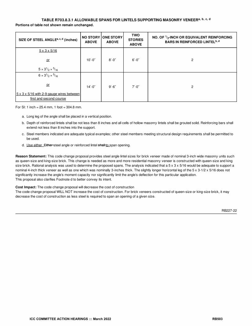
TABLE R703.8.3.1 ALLOWABLE SPANS FOR LINTELS SUPPORTING MASONRY VENEERPortions of table not shown remain unchanged.
SIZE OF STEEL ANGLE (inches)NO STORY
ABOVEONE STORY
ABOVE
TWOSTORIESABOVE
NO. OF / -INCH OR EQUIVALENT REINFORCINGBARS IN REINFORCED LINTEL
5 x 3 x 5/16
or
5 × 3 / × /
10′-0″ 8′-0″ 6′-0″ 2
6 × 3 / × /
or
5 x 3 x 5/16 with 2-9 gauge wires betweenfirst and second course
14′-0″ 9′-6″ 7′-0″ 2
For SI: 1 inch = 25.4 mm, 1 foot = 304.8 mm.
a. Long leg of the angle shall be placed in a vertical position.
b. Depth of reinforced lintels shall be not less than 8 inches and all cells of hollow masonry lintels shall be grouted solid. Reinforcing bars shallextend not less than 8 inches into the support.
c. Steel members indicated are adequate typical examples; other steel members meeting structural design requirements shall be permitted tobe used.
d. Use either Either steel angle or reinforced lintel shall to span opening.
Reason Statement: This code change proposal provides steel angle lintel sizes for brick veneer made of nominal 3-inch wide masonry units suchas queen-size and king-size brick. This change is needed as more and more residential masonry veneer is constructed with queen-size and kingsize brick. Rational analysis was used to determine the proposed spans. The analysis indicated that a 5 x 3 x 5/16 would be adequate to support anominal 4-inch thick veneer as well as one which was nominally 3-inches thick. The slightly longer horizontal leg of the 5 x 3-1/2 x 5/16 does notsignificantly increase the angle’s moment capacity nor significantly limit the angle’s deflection for this particular application.This proposal also clarifies Footnote d to better convey its intent.
Cost Impact: The code change proposal will decrease the cost of constructionThe code change proposal WILL NOT increase the cost of construction. For brick veneers constructed of queen-size or king-size brick, it maydecrease the cost of construction as less steel is required to span an opening of a given size.
RB227-22
a, b, c, d
a, c, d1
2b, d
12
516
12
516
ICC COMMITTEE ACTION HEARINGS ::: March 2022 RB503
RB228-22IRC: R703.11, R703.13, R703.14, R902.2
Proponents: Sara Krompholz, representing Vinyl Siding Institute (VSI) ([email protected])
2021 International Residential CodeRevise as follows:
R703.11 Vinyl siding. Vinyl siding shall be certified and labeled as conforming to the requirements of ASTM D3679 by an approved quality controlagency.
R703.13 Insulated vinyl siding. Insulated vinyl siding shall be certified and labeled as conforming to the requirements of ASTM D7793 by anapproved quality control agency.
R703.14 Polypropylene siding. Polypropylene siding shall be certified and labeled as conforming to the requirements of ASTM D7254, and those ofSection R703.14.2 or Section R703.14.3, by an approved quality control agency.
R902.2 Fire-retardant-treated shingles and shakes. Fire-retardant-treated wood shakes and shingles shall be treated by impregnation withchemicals by the full-cell vacuum-pressure process, in accordance with AWPA C1. Each bundle shall be marked to identify the manufactured unitand the manufacturer, and shall be labeled to identify the classification of the material in accordance with the testing required in Section R902.1, thetreating company and the quality control approved agency.
Reason Statement: This is a simple change to make the correct reference to the defined term "approved agency". The term "quality control" is notcorrect nor defined.
Cost Impact: The code change proposal will not increase or decrease the cost of constructionThis is simply an edit to correct a defined term in the code.
RB228-22
ICC COMMITTEE ACTION HEARINGS ::: March 2022 RB504

RB229-22IRC: R703.11.1, R703.11.1.1, R703.11.1.2, R703.11.1.3
Proponents: Matthew Dobson, Vinyl Siding Institute, representing Vinyl Siding Institute ([email protected])
2021 International Residential CodeRevise as follows:
R703.11.1 Installation. Vinyl siding, soffit insulated vinyl siding, and accessories shall be installed in accordance with the manufacturer’s installationinstructions.
R703.11.1.1 Fasteners. Unless specified otherwise by the manufacturer’s instructions, fasteners for vinyl siding shall be 0.120-inch (3 mm) shankdiameter nail with a 0.313-inch (8 mm) head or 16-gage staple with a / -inch (9.5 mm) to / -inch (12.7 mm) crown or in accordance with TableR703.3(1).
R703.11.1.2 Penetration depth. Unless specified otherwise by the manufacturer’s instructions or in accordance with Table R703.3(1), fastenersshall penetrate into building framing. The total penetration into sheathing, furring, framing or other nailable substrate shall be a minimum 1 / inches(32 mm). Where specified by the manufacturer’s instructions and supported by a test report, fasteners are permitted to penetrate into or fullythrough nailable sheathing or other nailable substrate of minimum thickness specified by the instructions or test report without penetrating intoframing. Where the fastener penetrates fully through the sheathing, the end of the fastener shall extend a minimum of / inch (6.4 mm) beyond theopposite face of the sheathing or nailable substrate.
R703.11.1.3 Spacing. Unless specified otherwise by the manufacturer’s instructions, the maximum spacing between fasteners for horizontal sidingshall be 16 inches (406 mm), and for vertical siding 12 inches (305 mm) both horizontally and vertically. Where specified by the manufacturer’sinstructions and supported by a test report, 24 inches (610 mm) greater fastener spacing is permitted.
Reason Statement: This change is a clean-up and will help to understand what is necessary should alternative fastening like 24” oc becomenecessary. It also points to alternative fasteners in table R703.3.3 which is helpful to use when hitting studs becomes difficult. Finally, it brings ininstallation provisions for insulated vinyl siding as it is the same as vinyl siding.
Cost Impact: The code change proposal will not increase or decrease the cost of constructionThis is editorial clean up and also offers alternative installation techniques as an option.
RB229-22
38
12
14
14
ICC COMMITTEE ACTION HEARINGS ::: March 2022 RB505

RB230-22IRC: R703.11.1, R703.11.1.1 (New), Figure R703.11.1.1 (1) (New), R703.11.1.2 (New), Figure R703.11.1.2 (1) (New), Figure R703.11.1.2 (2) (New), R703.13.1
Proponents: Matthew Dobson, representing Vinyl Siding Institute ([email protected]); Glenn Overcash, representing Federal EmergencyManagement Agency ([email protected]); Pataya Scott, representing Federal Emergency Management Agency([email protected])
2021 International Residential CodeRevise as follows:
R703.11.1 Installation. Vinyl siding, soffit insulated vinyl siding, and compatible accessories shall be installed in accordance with the manufacturer’sinstallation instructions.
Add new text as follows:
R703.11.1.1 Starter Strip. The first course of horizontal siding shall be secured using a starter strip as specified in the manufacturer’s installationinstructions. See Figure R703.1.1 (1).
ICC COMMITTEE ACTION HEARINGS ::: March 2022 RB506

a. Figure R703.11.1.1(1) illustrates typical installation details. See manufacturer's installation instructions for actual installation details.
Figure R703.11.1.1 (1) Typical Starter Strip
R703.11.1.2 Utility Trim. Where horizontal siding has to be cut or trimmed below windows and at the top of walls, the top edge of the siding shall besecured with utility trim and snap locks or as specified by the manufacturer’s installation instructions. See Figures R703.11.1.2 (1) and R703.11.1.2(2).
a
ICC COMMITTEE ACTION HEARINGS ::: March 2022 RB507

a. Figure R703.11.2.(1) illustrates typical installation details. See manufacturer's installation instructions for actual installation details.
Figure R703.11.1.2 (1) Typical Snap Lock & Utility Trima
ICC COMMITTEE ACTION HEARINGS ::: March 2022 RB508

a. Figure R703.11.1.2(2) illustrates typical installation details. See manufacturer's installation instructions for actual installation details
Figure R703.11.1.2 (2) Typical Snap Lock & Utility Trim Under Window
Revise as follows:
R703.13.1 Insulated vinyl siding and accessories. Insulated vinyl siding and compatible accessories shall be installed in accordance with Sections R703.11.1, R703.11.2, and the manufacturer’s installation instructions.
Reason Statement: This code change proposal provides requirements for starter strips and utility trim, two critical installation elements for vinylsiding, insulated vinyl siding, and polypropylene siding that are sometime ignored by installers. Including these provisions will help to ensure properinstallation. Starter strips and utility trim are important to highlight as they are part of the wind performance system, and when omittedor installed incorrectly, have resulted in product performance failure in high wind events. The proposed requirements reflect standard installationprocedures for horizontal polymeric cladding. As part of the response to Hurricane Irma in Florida, the Federal Emergency Management Agency (FEMA) deployed a Mitigation AssessmentTeams (MAT) composed of national and regional building science experts who assess building performance after a disaster. These experts thenincorporate lessons learned to make recommendations on improving the resilience of new construction and repairs and retrofits of existing buildings.
The following MAT-related conclusion and supporting observations are included in FEMA P-2023, Hurricane Irma in Florida MAT Report(https://www.fema.gov/sites/default/files/2020-07/mat-report_hurricane-irma_florida.pdf). The Hurricane Irma in Florida MAT observed evidence ofinadequate resistance to wind pressures for certain wall coverings of residential buildings (Conclusion FL11). In particular, failure of vinyl sidingon residential structures was widespread. The MAT observed several instances of vinyl siding wind damage on buildings that appeared to havebeen due to installation issues addressed in this code change proposal. The image below (FL MAT Report Figure 4-28) shows a Marathon Keyduplex building (built 2017) with vinyl siding loss across the front and left exterior walls. Vinyl siding loss inside the red outline (above the front porch)appears to have been initiated where a J-channel was installed instead of the manufacturer’s specified starter strip.
a
ICC COMMITTEE ACTION HEARINGS ::: March 2022 RB509

The Marathon Key house shown in the image below (FL MAT Report Figure 4-29) was permitted to have its vinyl siding replaced in 2015, with workcompleted in 2016. As shown in the red outline, the house appeared to lack utility trim under the window where siding was lost. Notably, theestimated maximum wind speed on Marathon Key during Hurricane Irma was 120 mph, so within the wind limitations of the IRC.
Vinyl Siding Institute (VSI) conducted several recent post-hurricane analyses and noted the need to have these requirements added to the IRC toavoid future cladding system failures. An example showing failure from Hurricane Irma that resulted from improper installation is shown below.
Cost Impact: The code change proposal will not increase or decrease the cost of constructionThe proposed requirements are standard practices that are sometimes neglected during construction, so this code change should not affect cost.
RB230-22
ICC COMMITTEE ACTION HEARINGS ::: March 2022 RB510

RB231-22IRC: R703.14, R703.14.2, R703.14.3
Proponents: Matthew Dobson, representing Vinyl Siding Institute ([email protected])
2021 International Residential CodeRevise as follows:
R703.14 Polypropylene siding. Polypropylene siding shall be certified and labeled as conforming to the requirements of ASTM D7254, and those ofSection R703.14.2 or Section R703.14.3, by an approved quality control agency.
Delete without substitution:
R703.14.2 Fire separation. Polypropylene siding shall not be installed on walls with a fire separation distance of less than 5 feet (1524 mm) andwalls closer than 10 feet (3048 mm) to a building on another lot.
Exception: Walls perpendicular to the line used to determine the fire separation distance.
R703.14.3 Flame spread index. The certification of the flame spread index shall be accompanied by a test report stating that all portions of the testspecimen ahead of the flame front remained in position during the test in accordance with ASTM E84 or UL 723.
Reason Statement: Currently polypropylene siding is the only cladding in both the IBC and IRC that requires an ASTM E84 test respective tospecific Fire Separation Distance areas; 10 feet or closer to another building.Sections proposed for deletion do not provide any additional protection as the code already requires that if the product is used in these settings, it willneed to be a part of an ASTM E119 fire rated assembly, typically a 1-hour rated assembly. In addition, as part of the ASTM product standard,D7254, the product is required to meet an E84 tested fire performance property (max flame spread of 200) that is consistent with other exterior,combustible building materials.
The current code language proposed for deletion is superfluous. The code has adequate provisions for regulating building materials used with FireSeparation Distance areas, for example as specified in Tables 601 and 705.5.
To help the committee understand the fire properties of polypropylene siding better, which has been questioned, VSI conducted a series of tests, atthe Western Fire Center, that provide good fire safe characteristic insights by using ASTM E2707 Standard Test Method for Determining FirePenetration of Exterior Wall Assemblies Using a Direct Flame Impingement Exposure and an exposed wall to this test. Attached is a VSI TechnicalReport from these tests to help the committee better understand the fire characteristics of this product category.Also, here is a link to the report.
https://www.vinylsiding.org/wp-content/uploads/2022/01/PolypropyleneFireTest.2020reportsubmitted-004.pdf
The following is an overview of these tests:-The product was tested in a setting and application that represents tight lot line settings (close Fire Separation Distance) by having a burner walland exposed (receiver wall) facing each other – tests were spaced at 4’ and 6’ with gypsum backing to represent a rated assembly
-The product was also tested at a typical unprotected separation distance 10+’ apart
-The product was tested with gypsum sheathing as on a protected wall assembly, and as part of an unprotected, combustible material wallassembly.
Based on the results of the test, it is worth noting the following:-Polypropylene typically melts, spits, and falls off the wall and, in some cases, will collect and continue to burn on the ground within 18 inches of theburner wall
-At no point did any portion of the receiver wall with polypropylene siding combust, even at the 4’ wall spacing
-The heat release rate of the polypropylene siding / gypsum sheathing (protected) base wall was about 65% less than the heat release rate of thepolypropylene siding / fully combustible wood wall-Heat release peaks occurred faster into the tests and at higher magnitudes for the polypropylenesiding /wood combustible wall vs. the wall with polypropylene siding / gypsum assembly-Observation of the reaction of all the wall assemblies to thefire exposures during the tests clearly show and confirm that the respective fire resistive and fire separation distance sections within the buildingcode provide the intended protection of exterior walls with polypropylene siding.
There are no examples of the hazard this specific product presents. All data provides has not been in the application of siding.
ICC COMMITTEE ACTION HEARINGS ::: March 2022 RB511

In fact the below is an example of a house fire that occurred in close proximity to another house (approximately 15 feet) during Hurricane Isaias.The resulting fire cause no hazard to the house next to it with polypropylene siding on it other than melting the cladding. This is exactly what theprovision is supposedly highlighting as a problem. It clearly is not.
Cost Impact: The code change proposal will decrease the cost of constructionThis change will remove unwarranted additional testing procedures which could reduce the overall cost of material testing requirements.
RB231-22
ICC COMMITTEE ACTION HEARINGS ::: March 2022 RB512

RB232-22IRC: R703.14.1.1, R703.14.1.1.1 (New), R703.14.1.1.2 (New), Figure R703.14.1.1.2 (1) (New), R703.14.1.2
Proponents: Matthew Dobson, representing Vinyl Siding Institute ([email protected])
2021 International Residential CodeRevise as follows:
R703.14.1.1 Installation. Unless otherwise specified in the manufacturer’s installation instructions, polypropylene siding shall be installed over andattached to wood structural panel sheathing with minimum thickness of / inch (11.1 mm), or other nailable substrate, composed of wood or wood-based material and fasteners having equivalent withdrawal resistance. Accessories shall be installed in accordance with the manufacturer’sinstallation instructions.
Add new text as follows:
R703.14.1.1.1 Starter Strip. Horizontal siding shall be installed with a starter strip at the initial course at any location.
R703.14.1.1.2 Under Windows and Top of Walls. Where nail hem is removed such as under windows and at top of walls, nail slot punch orpredrilled holes shall be constructed as shown in Figure R703.14.1.1.2 (1).
716
ICC COMMITTEE ACTION HEARINGS ::: March 2022 RB513

Figure R703.14.1.1.2 (1) Trim Under Window and Top of Walls Polypropylene Siding
Revise as follows:
R703.14.1.2 Fastener requirements. Unless otherwise specified in the approved manufacturer’s installation instructions, nails shall be corrosionresistant, with a minimum 0.120-inch (3 mm) shank and minimum 0.313-inch (8 mm) head diameter. Nails shall be a minimum of 1 / inches (32 mm)long or as necessary to penetrate sheathing or nailable substrate not less than / inch (19.1 mm). Where the nail fully penetrates the sheathing ornailable substrate, the end of the fastener shall extend not less than / inch (6.4 mm) beyond the opposite face of the sheathing or nailablesubstrate. Staples are not permitted. Spacing of fasteners shall be installed in accordance with the manufacturer’s installation instructions.
Reason Statement: This change cleans up the section on polypropylene siding. This type of siding is unique in that it has varying installationspacing for fasteners and because of the must be installed over some type of nailble substrate sheathing as defined by the code. In some cases theproduct can be installed using staples, with proper testing information so that prohibition should be removed. It is also important the installationinstructions be referenced be because of the unique panel sizes with each manufacturer.
Cost Impact: The code change proposal will not increase or decrease the cost of constructionThese changes are editorial and also adds standard installation practices.
RB232-22
14
34
14
ICC COMMITTEE ACTION HEARINGS ::: March 2022 RB514

RB233-22IRC: TABLE R703.15.1, TABLE R703.15.2
Proponents: Jay Crandell, P.E., ABTG/ARES Consulting, representing Foam Sheathing Committee of the American Chemistry Council([email protected]); Philip Line, representing American Wood Council ([email protected])
2021 International Residential CodeRevise as follows:
ICC COMMITTEE ACTION HEARINGS ::: March 2022 RB515

TABLE R703.15.1 CLADDING MINIMUM FASTENING REQUIREMENTS FOR DIRECT ATTACHMENT OVER FOAM PLASTICSHEATHING TO SUPPORT CLADDING WEIGHT
CLADDING FASTENER MINIMUMPENETRATION INTO WOOD WALL
FRAMINGTHROUGH FOAM SHEATHING
CLADDINGFASTENER TYPE
AND MINIMUMSIZE
CLADDINGFASTENERVERTICAL
SPACING (inches)
MAXIMUM THICKNESS OF FOAM SHEATHING(inches)
16″ o.c. FastenerHorizontal Spacing
24″ o.c. FastenerHorizontal Spacing
Cladding Weight : Cladding Weight :
3psf
11psf
15psf
18psf
25psf
3psf
11psf
15psf
18psf
25psf
Wood framing (minimum 1 / -inch penetration)
0.113″ diameter nail
6 2.00 1.45 1.00 0.75 DR 2.00 0.85 0.55 DR DR
8 2.00 1.00 0.65 DR DR 2.00 0.55 DR DR DR
12 2.00 0.55 DR DR DR 1.85 DR DR DR DR
0.120″ diameternail
6 3.00 1.70 1.15 0.90 0.55 3.00 1.05 0.65 0.50 DR
8 3.00 1.20 0.80 0.60 DR 3.00 0.70 DR DR DR
12 3.00 0.70 DR DR DR 2.15 DR DR DR DR
0.131″ diameter nail
6 4.00 2.15 1.50 1.20 0.75 4.00 1.35 0.90 0.70 DR
8 4.00 1.55 1.05 0.80 DR 4.00 0.90 0.55 DR DR
12 4.00 0.90 0.55 DR DR 2.70 0.50 DR DR DR
0.162″ diameter nail
6 4.00 3.55 2.50 2.05 1.40 4.00 2.25 1.55 1.25 0.80
8 4.00 2.55 1.80 1.45 0.95 4.00 1.60 1.10 0.85 0.50
12 4.00 1.60 1.10 0.85 0.50 4.00 0.95 0.60 DR DR
For SI: 1 inch = 25.4 mm, 1 pound per square foot = 0.0479 kPa, 1 pound per square inch = 6.895 kPa.
DR = Design Required.
o.c. = On Center.
a. Wood framing shall be Spruce-pine-fir or any wood species with a specific gravity of 0.42 or greater in accordance with AWC NDS.
b. The thickness of wood structural panels complying with the specific gravity requirement of Note a shall be permitted to be included insatisfying the minimum penetration into framing. For cladding connections to wood structural panels, refer to Table R703.3.3. For brickveneer tie connections to wood structural panels, refer to Table R703.8.4(2).
c. Nail fasteners shall comply with ASTM F1667, except nail length shall be permitted to exceed ASTM F1667 standard lengths.
d. Fastener vertical spacing is an average spacing associated with the following nail count per foot: 6 inch spacing is associated with 2 nailsper foot, 8 inch spacing is associated with 1.5 nails per foot, and 12 inch spacing is associated with 1 nail per foot.
d. e. Foam sheathing shall have a minimum compressive strength of 15 psi in accordance with ASTM C578 or ASTM C1289.
f. Cladding weight is the maximum weight of cladding materials in pounds per square foot of wall area. The 3 psf category typically applies topanel and lap siding materials; the 11 psf category typically applies to conventional 3-coat stucco of not more than 7/8-inch thickness; and15 psf to 25 psf categories typically apply to adhered masonry veneers.
a
bc d
d e
f f
14
ICC COMMITTEE ACTION HEARINGS ::: March 2022 RB516

TABLE R703.15.2 FURRING MINIMUM FASTENING REQUIREMENTS FOR APPLICATION OVER FOAM PLASTIC SHEATHINGTO SUPPORT CLADDING WEIGHT
Portions of table not shown remain unchanged.
FURRINGMATERIAL
FRAMINGMEMBER
FASTENER TYPEAND MINIMUM
SIZE
MINIMUM PENETRATIONINTO WALL FRAMING
(inches)
FASTENER SPACINGIN FURRING (inches)
MAXIMUM THICKNESS OF FOAMSHEATHING (inches)
16″ o.c. Furring 24″ o.c. Furring
Siding Weight: Siding Weight:
3psf
11psf
15psf
18psf
25psf
3psf
11psf
15psf
18psf
25psf
For SI: 1 inch = 25.4 mm, 1 pound per square foot = 0.0479 kPa, 1 pound per square inch = 6.895 kPa.
DR = Design Required.
o.c. = On Center.
g. Cladding weight is the maximum weight of cladding materials in pounds per square foot of wall area. The 3 psf category typically applies topanel and lap siding materials; the 11 psf category typically applies to conventional 3-coat stucco of not more than 7/8-inch thickness; and 15psf to 25 psf categories typically apply to adhered masonry veneers.
Reason Statement: This proposal is a clarification of three items related to proper application of the Table R703.15.1 requirements. First, thecolumn heading for minimum fastener penetration is revised to clearly indicate its focus on minimum fastener penetration into wood framing. Second, a new footnote 'd' is added to clarify application of prescribed vertical spacing requirements for cladding fasteners. Third, a new footnote 'f'is added to clarify application of the cladding weight categories used in the table. These clarifications are based on field experience, questions, andfeedback in the use of the tables. For Table R703.15.2, the addition of footnote 'g' is proposed to clarify weight categories consistent with therevision proposed for Table R703.15.1.
Cost Impact: The code change proposal will not increase or decrease the cost of constructionThe proposal is a clarification and has no cost impact.
RB233-22
a, b
c
e
f f
g g
ICC COMMITTEE ACTION HEARINGS ::: March 2022 RB517

RB234-22IRC: TABLE R703.16.1
Proponents: Jay Crandell, P.E., ABTG/ARES Consulting, representing Foam Sheathing Committee of the American Chemistry Council([email protected])
2021 International Residential CodeRevise as follows:
ICC COMMITTEE ACTION HEARINGS ::: March 2022 RB518
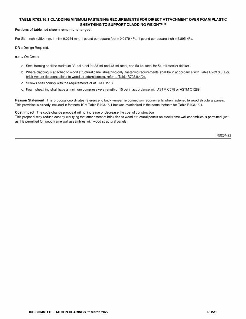
TABLE R703.16.1 CLADDING MINIMUM FASTENING REQUIREMENTS FOR DIRECT ATTACHMENT OVER FOAM PLASTICSHEATHING TO SUPPORT CLADDING WEIGHT
Portions of table not shown remain unchanged.
For SI: 1 inch = 25.4 mm, 1 mil = 0.0254 mm, 1 pound per square foot = 0.0479 kPa, 1 pound per square inch = 6.895 kPa.
DR = Design Required.
o.c. = On Center.
a. Steel framing shall be minimum 33-ksi steel for 33-mil and 43-mil steel, and 50-ksi steel for 54-mil steel or thicker.
b. Where cladding is attached to wood structural panel sheathing only, fastening requirements shall be in accordance with Table R703.3.3. Forbrick veneer tie connections to wood structural panels, refer to Table R703.8.4(2).
c. Screws shall comply with the requirements of ASTM C1513.
d. Foam sheathing shall have a minimum compressive strength of 15 psi in accordance with ASTM C578 or ASTM C1289.
Reason Statement: This proposal coordinates reference to brick veneer tie connection requirements when fastened to wood structural panels. This provision is already included in footnote ‘b’ of Table R703.15.1 but was overlooked in the same footnote for Table R703.16.1.
Cost Impact: The code change proposal will not increase or decrease the cost of constructionThis proposal may reduce cost by clarifying that attachment of brick ties to wood structural panels on steel frame wall assemblies is permitted, justas it is permitted for wood frame wall assemblies with wood structural panels.
RB234-22
a, b
ICC COMMITTEE ACTION HEARINGS ::: March 2022 RB519

RB235-22IRC: R703.18 (New)
Proponents: Michael Gardner, representing National Gypsum Company ([email protected])
2021 International Residential CodeAdd new text as follows:
R703.18 Fiber-mat reinforced cementitious backer units. Fiber-mat reinforced cementitious backer units used on exterior walls as a substratefor the application of exterior finish materials shall comply with ASTM C1325. Installation shall be in accordance with manufacturer’s installationinstructions. Backer units shall be installed using corrosion-resistant fasteners. Finish materials shall be installed in accordance with manufacturer’sinstructions.
Reason Statement: ASTM C1325 cement board (technically, fiber-mat reinforced cementitious backer unit) was incorporated into the IRC in themid-2000s when it was added to Section 702 as a substrate for interior wall tile in shower and tub areas.In the interim period, C1325 cement board has gained use as an exterior substrate. It is primarily used for architectural stone and direct-appliedfinish system applications.
Exterior use of cement board is permitted by the C1325 standard and the two applicable Acceptance Criteria for cement board: AC 376, whichaddresses the cement board itself, and AC 59, which addresses direct-applied finish systems.
But because the only IRC reference to the material is the interior use described in Section 702 confusion occurs regarding the ability to use cementboard as an exterior substrate. This proposal intends to clarify that cement board conforming with the ASTM C1325 standard can be used as asubstrate in exterior applications by expanding the existing IRC reference to apply to exterior applications under Section R703.
A change to the IBC with the same intent was approved during the 'A' Cycle.
Cost Impact: The code change proposal will not increase or decrease the cost of constructionThe proposal has no cost impact. The intent of the proposal is to clarify that C1325 material can be used in an exterior application.
RB235-22
ICC COMMITTEE ACTION HEARINGS ::: March 2022 RB520

RB236-22IRC: SECTION 202 (New), SECTION 202, R703.1.2, R703.3.1, R703.11.1, SECTION R704, R704.1, R704.2, R704.2.1, FIGURE R704.2.1(1),FIGURE R704.2.1(2), R704.2.2, R704.2.3, R704.2.4, R704.3, R704.3.1, R704.3.2, R704.3.3, R704.3.4, TABLE R704.3.4
Proponents: Matthew Dobson, representing Vinyl Siding Institute ([email protected])
2021 International Residential CodeAdd new definition as follows:
EXTERIOR SOFFIT. A material or assembly of materials applied on the underside of exterior overhangs, decks and floors, porches, and carportceilings.
Revise as follows:
[RB] EXTERIOR WALL COVERING. A material or assembly of materials applied on the exterior side of exterior walls for the purpose ofproviding a weather-resistive barrier, insulation or for aesthetics, including but not limited to, veneers, siding, exterior insulation and finish systems,architectural trim and embellishments such as cornices, soffits, and fascias.
R703.1.2 Wind resistance. Wall coverings, backing materials and their attachments shall be capable of resisting wind loads in accordance withTables R301.2.1(1) and R301.2.1(2). Wind-pressure resistance of the siding, exterior soffit and backing materials shall be determined by ASTME330 or other applicable standard test methods. Where wind-pressure resistance is determined by design analysis, data from approved designstandards and analysis conforming to generally accepted engineering practice shall be used to evaluate the siding, exterior soffit and backingmaterial and its fastening. All applicable failure modes including bending rupture of siding, fastener withdrawal and fastener head pull-through shall beconsidered in the testing or design analysis. Where the wall covering, exterior soffit and backing material resist wind load as an assembly, use of thedesign capacity of the assembly shall be permitted.
R703.3.1 Exterior Soffit installation. Exterior Soffits shall comply with Section R704.
R703.11.1 Installation. Vinyl siding, exterior soffit and accessories shall be installed in accordance with the manufacturer’s instructions.
SECTION R704EXTERIOR SOFFITS
R704.1 General wind limitations. Where the design wind pressure is 30 pounds per square foot (1.44 kPa) or less, exterior soffits shall complywith Section R704.2. Where the design wind pressure exceeds 30 pounds per square foot (1.44 kPa), exterior soffits shall comply with SectionR704.3. The design wind pressure on exterior soffits shall be determined using the component and cladding loads specified in Table R301.2.1(1) forwalls using an effective wind area of 10 square feet (0.93 m ) and adjusted for height and exposure in accordance with Table R301.2.1(2).
R704.2 Exterior Soffit installation where the design wind pressure is 30 psf or less. Where the design wind pressure is 30 pounds per squarefoot (1.44 kPa) or less, exterior soffit installation shall comply with Section R704.2.1, R704.2.2, R704.2.3 or R704.2.4. Exterior Soffit materials notaddressed in Sections R704.2.1 through R704.2.4 shall be in accordance with the manufacturer’s installation instructions.
R704.2.1 Vinyl exterior soffit panels. Vinyl exterior soffit panels shall be installed using fasteners specified by the manufacturer and shall befastened at both ends to a supporting component such as a nailing strip, fascia or subfascia component in accordance with Figure R704.2.1(1).Where the unsupported span of exterior soffit panels is greater than 16 inches (406 mm), intermediate nailing strips shall be provided in accordancewith Figure R704.2.1(2). Vinyl exterior soffit panels shall be installed in accordance with the manufacturer’s installation instructions. Fascia coversshall be installed in accordance with the manufacturer’s installation instructions.
2
ICC COMMITTEE ACTION HEARINGS ::: March 2022 RB521

(Add 'exterior' in front of 'soffit' in three locations.)FIGURE R704.2.1(1) TYPICAL SINGLE-SPAN VINYL SOFFIT PANEL SUPPORT
ICC COMMITTEE ACTION HEARINGS ::: March 2022 RB522

(Add 'exterior' in front of 'soffit' in three locations.)FIGURE R704.2.1(2) TYPICAL DOUBLE-SPAN VINYL SOFFIT PANEL SUPPORT
R704.2.2 Fiber-cement exterior soffit panels. Fiber-cement exterior soffit panels shall be a minimum of / inch (6.4 mm) in thickness and shallcomply with the requirements of ASTM C1186, Type A, minimum Grade II, or ISO 8336, Category A, minimum Class 2. Panel joints shall occur overframing or over wood structural panel sheathing. Exterior Soffit panels shall be installed with spans and fasteners in accordance with themanufacturer’s installation instructions.
R704.2.3 Hardboard exterior soffit panels. Hardboard exterior soffit panels shall be not less than / inch (11.11 mm) in thickness and shall befastened to framing or nailing strips with 2 / -inch by 0.113-inch (64 mm by 2.9 mm) siding nails spaced not more than 6 inches (152 mm) on centerat panel edges and 12 inches (305 mm) on center at intermediate supports.
R704.2.4 Wood structural exterior panel soffit. The minimum nominal thickness for wood exterior structural panel soffits shall be / inch (9.5mm) and shall be fastened to framing or nailing strips with 2-inch by 0.099-inch (51 mm by 2.5 mm) nails. Fasteners shall be spaced not less than 6inches (152 mm) on center at panel edges and 12 inches (305 mm) on center at intermediate supports.
R704.3 Exterior Soffit installation where the design wind pressure exceeds 30 psf. Where the design wind pressure is greater than 30psf, exterior soffit installation shall comply with Section R704.3.1, R704.3.2, R704.3.3 or R704.3.4. Exterior Soffit materials not addressed inSections R704.3.1 through R704.3.4 shall be in accordance with the manufacturer’s installation instructions.
R704.3.1 Vinyl exterior soffit panels. Vinyl exterior soffit panels and their attachments shall be capable of resisting wind loads specified in TableR301.2.1(1) for walls using an effective wind area of 10 square feet (0.929 m ) and adjusted for height and exposure in accordance with TableR301.2.1(2) . Vinyl exterior soffit panels shall be installed using fasteners specified by the manufacturer and shall be fastened at both ends to asupporting component such as a nailing strip, fascia or subfascia component in accordance with Figure R704.2.1(1). Where the unsupported spanof exterior soffit panels is greater than 12 inches (305 mm), intermediate nailing strips shall be provided in accordance with Figure R704.2.1(2). Vinylexterior soffit panels shall be installed in accordance with the manufacturer’s installation instructions. Fascia covers shall be installed in accordancewith the manufacturer’s installation instructions.
14
716
12
38
2
ICC COMMITTEE ACTION HEARINGS ::: March 2022 RB523

R704.3.2 Fiber-cement exterior soffit panels. Fiber-cement exterior soffit panels shall comply with Section R704.2.2 and shall be capable ofresisting wind loads specified in Table R301.2.1(1) for walls using an effective wind area of 10 square feet (0.929 m ) and adjusted for height andexposure in accordance with Table R301.2.1(2).
R704.3.3 Hardboard exterior soffit panels. Hardboard exterior soffit panels shall comply with the manufacturer’s installation instructions and shallbe capable of resisting wind loads specified in Table R301.2.1(1) for walls using an effective wind area of 10 square feet (0.929 m ) and adjusted forheight and exposure in accordance with Table R301.2.1(2) .
R704.3.4 Wood structural panel exterior soffit. Wood structural panel exterior soffits shall be capable of resisting wind loads specified in TableR301.2.1(1) for walls using an effective wind area of 10 square feet (0.929 m ) and adjusted for height and exposure in accordance with TableR301.2.1(2). Alternatively, wood structural panel exterior soffits shall be installed in accordance with Table R704.3.4.
2
2
2
b, c, d, e
ICC COMMITTEE ACTION HEARINGS ::: March 2022 RB524

TABLE R704.3.4 PRESCRIPTIVE ALTERNATIVE FOR WOOD STRUCTURAL PANEL EXTERIOR SOFFIT
MAXIMUM DESIGNPRESSURE (+ or - psf)
MINIMUM PANELSPAN RATING
MINIMUM PANELPERFORMANCE
CATEGORY
NAIL TYPE ANDSIZE
FASTENER SPACING ALONG EDGESAND INTERMEDIATE SUPPORTS
Galvanized Steel Stainless Steel
30 24/0 3/86d box
(2 × 0.099 × 0.266head diameter)
6 4
40 24/0 3/86d box
(2 × 0.099 × 0.266head diameter)
6 4
50 24/0 3/8
6d box(2 × 0.099 × 0.266
head diameter)4 4
8d common(2 / × 0.131 × 0.281
head diameter)6 6
60 24/0 3/8
6d box(2 × 0.099 × 0.266
head diameter)4 3
8d common(2 / × 0.131 × 0.281
head diameter)6 4
70 24/16 7/16
8d common(2 / × 0.131 × 0.281
head diameter)4 4
10d box(3 × 0.128 × 0.312
head diameter)6 4
80 24/16 7/16
8d common(2 / × 0.131 × 0.281
head diameter)4 4
10d box(3 × 0.128 × 0.312
head diameter)6 4
90 32/16 15/32
8d common(2 / × 0.131 × 0.281
head diameter)4 3
10d box(3 × 0.128 × 0.312
head diameter)6 4
For SI: 1 inch = 25.4 mm, 1 pound per square foot = 0.0479 kPa.
a. Fasteners shall comply with Sections R703.3.2 and R703.3.3.
b. Maximum spacing of exterior soffit framing members shall not exceed 24 inches.
c. Wood structural panels shall be of an exterior exposure grade.
d. Wood structural panels shall be installed with strength axis perpendicular to supports with not fewer than two continuous spans.
e. Wood structural panels shall be attached to exterior soffit framing members with specific gravity of at least 0.42. Framing members shall beminimum 2 × 3 nominal with the larger dimension in the cross section aligning with the length of fasteners to provide sufficient embedmentdepths.
f. Spacing at intermediate supports shall be not greater than 12 inches on center.
Reason Statement: Over the past few cycles the treatment of exterior wall coverings and soffits has become separated and addressed in differentsections of the code. R704 is now an entire section of the code dedicated to soffit and now fascia. The construction methods for these parts of theexterior of the structure are unique and prior to the last few cycles were not addressed at all. This has been a noticeable area in need of
b, c, d, e
a
f
12
12
12
12
12
ICC COMMITTEE ACTION HEARINGS ::: March 2022 RB525
requirements based on wind performance failures due to lack of direction. With this change in definitions and resulting other areas of the code, it willhelp builders, installers and building officials better understand how R704 applies and how R703 applies. These definitions create clearerunderstanding of application.
Cost Impact: The code change proposal will increase the cost of constructionThis code change will bring a necessary broadening of installation requirement for non-traditionally considered soffit applications. But without thechange there is limited guidance on how this should be handled and regulated.
RB236-22
ICC COMMITTEE ACTION HEARINGS ::: March 2022 RB526

RB237-22IRC: SECTION R703, SECTION R704, FIGURE R704.2.1(1), FIGURE R704.2.1(2), R704.3.1, R704.4 (New), R704.4.1 (New), R704.4.1.1 (New),R704.4.1.2 (New)
Proponents: Matthew Dobson, representing Vinyl Siding Institute ([email protected]); T. Eric Stafford, representing Insurance Institute forBusiness and Home Safety ([email protected])
2021 International Residential CodeRevise as follows:
SECTION R703EXTERIOR WALL COVERING
SECTION R704EXTERIOR SOFFITS AND FASCIAS
ICC COMMITTEE ACTION HEARINGS ::: March 2022 RB527

ICC COMMITTEE ACTION HEARINGS ::: March 2022 RB528

ICC COMMITTEE ACTION HEARINGS ::: March 2022 RB529

FIGURE R704.2.1(1) TYPICAL SINGLE-SPAN VINYL SOFFIT PANEL SUPPORT
ICC COMMITTEE ACTION HEARINGS ::: March 2022 RB530

ICC COMMITTEE ACTION HEARINGS ::: March 2022 RB531

ICC COMMITTEE ACTION HEARINGS ::: March 2022 RB532

FIGURE R704.2.1(2) TYPICAL DOUBLE-SPAN VINYL SOFFIT PANEL SUPPORT
R704.3.1 Vinyl soffit panels. Vinyl soffit panels and their attachments shall be capable of resisting wind loads specified in Table R301.2.1(1) forwalls using an effective wind area of 10 square feet (0.929 m ) and adjusted for height and exposure in accordance with Table R301.2.1(2) . Vinylsoffit panels shall be installed using fasteners specified by the manufacturer and shall be fastened at both ends to a supporting component such asa nailing strip, fascia or subfascia component in accordance with Figure R704.2.1(1). Where the unsupported span of soffit panels is greater than 12inches (305 mm), intermediate nailing strips shall be provided in accordance with Figure R704.2.1(2). Vinyl soffit panels shall be installed inaccordance with the manufacturer’s installation instructions. Fascia covers shall be installed in accordance with the manufacturer’s installationinstructions.
Add new text as follows:
R704.4 Fascia. Fascia shall be installed in accordance with manufacturer’s installation instructions.
R704.4.1 Aluminum Fascia. Aluminum Fascia shall be installed in accordance with manufacturer’s installation instructions and comply withSections R704.4.1.1 or R704.4.1.2.
R704.4.1.1 Fascia installation where the design wind pressure is 30 psf or less. Where the design wind pressure is 30 pounds per square foot(1.44kPA) or less, aluminum fascia shall be a attached with one finish nail (1 ¼ x 0.057 x 0.177 head diameter) in the return leg spaced a maximumof 24 inches (610 mm) on center, and the fascia shall be inserted under the drip edge with at least 1 inch (305 mm) of fascia material covered by thedrip edge. Where the fascia can not be inserted under the drip edge, the top edge of the fascia shall be secured using one finish nail (1 ¼ x 0.057 x0.177 head diameter) located not more than 1 inch (25 mm) below the drip edge and spaced a maximum of 24 inches (610 mm) on center.
R704.4.1.2 Fascia installation where the design wind pressure exceeds 30 psf. Where the design wind pressure is greater than 30 poundsper square foot (1.44kPA), aluminum fascia shall be attached with one finish nail (1 ¼ x 0.057 x 0.177 head diameter) in the return leg spaced amaximum of 16 inches (406 m) on center and one finish nail located no more than 1 inch (25 mm) below the drip edge spaced a maximum of 16inches (406 mm) on center. As an alternative, the top edge of the fascia is permitted to be secured using utility trim installed beneath the drip edgewith snap locks punched into the fascia spaced no more than 6 inches (152 mm) on center.
Reason Statement: Currently the code does not provide specific instructions for the installation of fascia at the eaves and rakes. This is an areathe code needs to address, as it has been identified as a point of weakness for failure during wind events. Based on results of recent testing,aluminum fascia can be installed with one fastener at the leg with a 1” or more coverage at the drip edge, although issues with fascia in non-highwind areas is not a noted issue.In high wind conditions fascia will be required to have two fasteners, at the face and leg, or using utility trim and punch locks at drip edge.
Attached are results from those tests and here is a link to the report as well.
https://www.vinylsiding.org/wp-content/uploads/2022/01/m9254.01-109-40-r0.pdf
Example from FEMA MAT reports include noted issues that this change will address.
· H-Harvey: See Section 4.1.4: “Being the leading edge of the roof system, soffits and fascia are particularly vulnerable to high winds.”
· H-Irma: Multiple observations of fascia failure that appeared to initiate soffit and roof covering damage.
Here are examples of a failure from Hurricane Laura from 2020 where the fascia failed and also led to fascia and soffit failure.
2
ICC COMMITTEE ACTION HEARINGS ::: March 2022 RB533

Cost Impact: The code change proposal will increase the cost of constructionThis change will increase the cost of construction in high wind areas. The increase would be the addition of finish nails and labor for installation whichif fairly minimal consider how fascia is installed today or a more significant cost would be the addition of utility trim and punch locks. But again thiswould be for just high wind areas and this change really completes the exterior wall covering / roof connection point of the building where failureshave been noted during hurricane and high wind conditions.'
The change will not increase the cost of construction in non-coastal areas as the proposed prescription is already being done in many cases.
RB237-22
ICC COMMITTEE ACTION HEARINGS ::: March 2022 RB534

RB238-22IRC: R703.3.1, R703.3.2, R703.3.3, R704.2.1, FIGURE R704.2.1(1), FIGURE R704.2.1(2)
Proponents: Matthew Dobson, representing Vinyl Siding Institute ([email protected]); Glenn Overcash, representing Federal EmergencyManagement Agency ([email protected])
2021 International Residential CodeDelete without substitution:
R703.3.1 Soffit installation. Soffits shall comply with Section R704.
Revise as follows:
R703.3.2 Wind limitations. Where the design wind pressure exceeds 30 psf or where the limits of Table R703.3.2 are exceeded, the attachment ofwall coverings and soffits shall be designed to resist the component and cladding loads specified in Table R301.2.1(1) for walls, adjusted for heightand exposure in accordance with Table R301.2.1(2). For the determination of wall covering and soffit attachment, component and cladding loadsshall be determined using an effective wind area of 10 square feet (0.93 m ).
R703.3.3 Fasteners. Exterior wall coverings and roof overhang soffits shall be securely fastened with aluminum, galvanized, stainless steel or rust-preventative coated nails or staples in accordance with Table R703.3(1) or with other approved corrosion-resistant fasteners in accordance with thewall covering manufacturer’s installation instructions. Nails and staples shall comply with ASTM F1667. Nails shall be T-head, modified round head,or round head with smooth or deformed shanks. Staples shall have a minimum crown width of / inch (11.1 mm) outside diameter and bemanufactured of minimum 16-gage wire. Where fiberboard, gypsum, or foam plastic sheathing backing is used, nails or staples shall be driven intothe studs. Where wood or wood structural panel sheathing is used, fasteners shall be driven into studs unless otherwise permitted to be driven intosheathing in accordance with either the siding manufacturer’s installation instructions or Table R703.3.3.
R704.2.1 Vinyl and aluminum soffit panels. Vinyl and aluminum soffit panels shall be installed using aluminum, galvanized, stainless steel or rust-preventative coated nails or staples or other approved corrosion-resistant fasteners specified by the manufacturer and shall be fastened at bothends to a supporting component such as a nailing strip, fascia or subfascia component in accordance with Figure R704.2.1(1). Where theunsupported span of soffit panels is greater than 16 inches (406 mm), intermediate nailing strips shall be provided in accordance with FigureR704.2.1(2). Vinyl and aluminum soffit panels shall be installed in accordance with the manufacturer’s installation instructions. Fascia covers shall beinstalled in accordance with the manufacturer’s installation instructions.
Delete and substitute as follows:
2
716
ICC COMMITTEE ACTION HEARINGS ::: March 2022 RB535

FIGURE R704.2.1(1) TYPICAL SINGLE-SPAN VINYL SOFFIT PANEL SUPPORT
ICC COMMITTEE ACTION HEARINGS ::: March 2022 RB536

FIGURE R704.2.1(1) TYPICAL SINGLE-SPAN VINYL SOFFIT PANEL SUPPORT
ICC COMMITTEE ACTION HEARINGS ::: March 2022 RB537

FIGURE R704.2.1(2) TYPICAL DOUBLE-SPAN VINYL SOFFIT PANEL SUPPORT
ICC COMMITTEE ACTION HEARINGS ::: March 2022 RB538

FIGURE R704.2.1(2) TYPICAL DOUBLE-SPAN VINYL SOFFIT PANEL SUPPORT
Reason Statement: Currently the code does not provide specific requirements for the installation of aluminum soffit. This code change proposaladds aluminum soffit requirements to the existing vinyl soffit subsection because provisions for both materials are essentially the same. In addition,this change includes some correlation edits to remove soffit references from Section R703 where soffits were addressed prior to development ofSection R704.
Cost Impact: The code change proposal will not increase or decrease the cost of constructionThis simple change brings common practice into the code without any technical changes.
RB238-22
ICC COMMITTEE ACTION HEARINGS ::: March 2022 RB539

RB239-22IRC: TABLE R704.3.4
Proponents: David Tyree, representing American Wood Council ([email protected]); Philip Line, representing American Wood Council([email protected])
2021 International Residential CodeRevise as follows:
b, c, d, e
ICC COMMITTEE ACTION HEARINGS ::: March 2022 RB540

TABLE R704.3.4 PRESCRIPTIVE ALTERNATIVE FOR WOOD STRUCTURAL PANEL SOFFIT
MAXIMUM DESIGNPRESSURE (+ or - psf)
MINIMUM PANELSPAN RATING
MINIMUM PANELPERFORMANCE
CATEGORY
NAIL TYPE ANDSIZE
FASTENER SPACING ALONG EDGES ANDINTERMEDIATE SUPPORTS , inches
Galvanized Steel Stainless Steel
30 24/0 3/86d box
(2 × 0.099 × 0.266head diameter)
6 4
40 24/0 3/86d box
(2 × 0.099 × 0.266head diameter)
6 4
50 24/0 3/8
6d box(2 × 0.099 × 0.266
head diameter)4 4
8d common(2 / × 0.131 ×
0.281 headdiameter)
6 6
60 24/0 3/8
6d box(2 × 0.099 × 0.266
head diameter)4 3
8d common(2 / × 0.131 ×
0.281 headdiameter)
6 4
70 24/16 7/16
8d common(2 / × 0.131 × 0.281
head diameter)4 4
10d box(3 × 0.128 × 0.312
head diameter)6 4
80 24/16 7/16
8d common(2 / × 0.131 ×
0.281 headdiameter)
4 4
10d box(3 × 0.128 × 0.312
head diameter)6 4
90 32/16 15/32
8d common(2 / × 0.131 ×
0.281 headdiameter)
4 3
10d box(3 × 0.128 × 0.312
head diameter)6 4
For SI: 1 inch = 25.4 mm, 1 pound per square foot = 0.0479 kPa.
a. Fasteners shall comply with Sections R703.3.2 and R703.3.3.
b. Maximum spacing of soffit framing members shall not exceed 24 inches.
c. Wood structural panels shall be of an exterior exposure grade.
d. Wood structural panels shall be installed with strength axis perpendicular to supports with not fewer than two continuous spans.
b, c, d, e
a e
f
12
12
12
12
12
ICC COMMITTEE ACTION HEARINGS ::: March 2022 RB541

e. Wood structural panels shall be attached to soffit framing members with specific gravity of at least 0.42 Where the specific gravity of thewood species used for soffit framing members is greater than or equal to 0.35 but less than 0.42 in accordance with AWC NDS, the fastenerspacing shall be multiplied by 0.67 or the same fastener spacing as prescribed for galvanized steel nails shall be permitted to be used whereRSRS-01 (2″× 0.099″× 0.266″ head) nails replace 6d box nails and RSRS-03 (2-1/2″× 0.131″× 0.281″ head) nails replace 8d common nails or10d box nails or alternative fastening shall be designed in accordance with AWC NDS. RSRS is a Roof Sheathing Ring Shank nail meetingthe specifications in ASTM F1667. Framing members shall be minimum 2 × 3 nominal with the larger dimension in the cross section aligningwith the length of fasteners to provide sufficient embedment depths.
f. Spacing at intermediate supports shall be not greater than 12 inches on center.
Reason Statement: The change addresses the use of soffit framing of wood species having lower specific gravity than the value of 0.42associated with prescribed spacing of nails. The expanded footnote e provides equivalent performing prescriptive fastening options for caseswhere specific gravity is as low as 0.35 in accordance with AWC NDS. Withdrawal design values are provided in the AWC NDS for the RSRS nail (astandard ring shank nail) and the RSRS nail sizes prescribed in the footnote align with proposed RSRS nail options for roof sheathing fastening. Anoption for design of alternative fastening is also provided.
Cost Impact: The code change proposal will not increase or decrease the cost of constructionThis change provides prescriptive fastening options for soffit attachment to wood species with lower specific gravity than that existing 0.42 baselinefor the tabulated requirements.
RB239-22
ICC COMMITTEE ACTION HEARINGS ::: March 2022 RB542

RB240-22IRC: SECTION R705 (New), R705.1 (New)
Proponents: Larry Sherwood, representing Sustainable Energy Action Committee ([email protected]); Kevin Reinertson, representing CaliforniaFire Chiefs Association FPO ([email protected]); Benjamin Davis, representing California Solar & Storage Association([email protected]); Philip Oakes, representing National Association of State Fire Marshals; Joseph Cain, representing Solar Energy IndustriesAssociation (SEIA) ([email protected])
2021 International Residential CodeAdd new text as follows:
SECTION R705BIPV SYSTEMS FOR EXTERIOR WALL COVERINGS AND FENESTRATION
R705.1 Listing required.. In addition to complying with other provisions of this code, BIPV systems used as exterior wall coverings or fenestrationshall be listed and labeled in accordance with UL 1703 or both UL 61730-1 and UL 61730-2.
Reason Statement: Building Integrated Photovoltaic (BIPV) Systems are increasingly becoming popular due to efforts to achieve Net Zero Energy.Requirements for BIPV Systems used as roof assemblies and roof coverings are already addressed in Chapter 9. New applications for BIPVsystems are systems that are used as either exterior wall coverings or fenestration. The IRC is silent on the requirements for suchsystems.Chapter 7 contains a variety of requirements for exterior wall coverings and exterior wall assemblies. Clearly, if BIPV systems are includedin exterior walls they should comply with all such requirements (including fire tests and weather protection). In addition to those requirements, thisproposal requires that BIPV systems be listed and labeled in accordance with the applicable UL standards. Note these UL standards are alreadyaddressed in the IRC.This proposal was prepared by the Sustainable Energy Action Committee (SEAC), a forum for all stakeholders (including, but not limited to, AHJs,designers, engineers, contractors, first responders, manufacturers, suppliers, utilities, and testing labs) to collaboratively identify and find solutionsfor issues that affect the installation and use of solar energy systems, energy storage systems, demand response, and energy efficiency. Thepurpose is to facilitate the deployment and use of affordable, clean and renewable energy in a safe, efficient, and sustainable manner.
All recommendations from SEAC are approved by diverse stakeholders through a consensus process.
Bibliography: Reference:FS150-21
IBC Section 1410 and 1410.1
Cost Impact: The code change proposal will not increase or decrease the cost of constructionThis proposal clarifies what requirements apply to BIPV systems used as an exterior wall covering or fenestration.
RB240-22
ICC COMMITTEE ACTION HEARINGS ::: March 2022 RB543

RB241-22IRC: R802.1.5, R802.1.5.1, R802.1.5.2, R802.1.5.3, R802.1.5.3.1, R802.1.5.4, R802.1.5.5, R802.1.5.6, R802.1.5.7, R802.1.5.8, R802.1.5.9,R802.1.5.10
Proponents: Marcelo Hirschler, representing GBH International ([email protected])
2021 International Residential CodeRevise as follows:
R802.1.5 R302.15 Fire-retardant-treated wood. Fire-retardant-treated wood (FRTW) is any wood product that, when impregnated with chemicalsby a pressure process or other means during manufacture, shall have, when tested in accordance with ASTM E84 or UL 723, a listed flame spreadindex of 25 or less. In addition, the ASTM E84or UL 723 test shall be continued for an additional 20-minute period and the flame front shall notprogress more than 10.5 feet (3200 mm) beyond the center line of the burners at any time during the test.
R802.1.5.1 R302.15.1 Pressure process. For wood products impregnated with chemicals by a pressure process, the process shall be performedin closed vessels under pressures not less than 50 pounds per square inch gauge (psig) (344.7 kPa).
R802.1.5.2 R302.15.2 Other means during manufacture. For wood products impregnated with chemicals by other means duringmanufacture, the treatment shall be an integral part of the manufacturing process of the wood product. The treatment shall provide permanentprotection to all surfaces of the wood product. The use of paints, coating, stains or other surface treatments is not an approved method of protectionas required by this section.
R802.1.5.3 R302.15.3 Testing. For fire-retardant-treated wood products, the front and back faces of the wood product shall be tested inaccordance with and produce the results required in Section R302.15 R802.1.5.
R802.1.5.3.1 R302.15.3.1 Fire testing of wood structural panels. Wood structural panels shall be tested with a ripped or cut longitudinal gap of/ inch (3.2 mm).
R802.1.5.4 R302.15.4 Labeling. In addition to the labels required by Section 802.1.1 for sawn lumber and Section 803.2.1 for wood structuralpanels, each piece of fire-retardant-treated lumber and wood structural panel shall be labeled. The label shall contain:
1. The identification mark of an approved agency in accordance with Section 1703.5 of the International Building Code.
2. Identification of the treating manufacturer.
3. The name of the fire-retardant treatment.
4. The species of wood treated.
5. Flame spread index and smoke-developed index.
6. Method of drying after treatment.
7. Conformance to applicable standards in accordance with Sections R302.15.5 through R302.15.10 R802.1.5.5 through R802.1.5.10.
8. For FRTW exposed to weather, or a damp or wet location, the words “No increase in the listed classification when subjected to the StandardRain Test” (ASTM D2898).
R802.1.5.5 R302.15.5 Strength adjustments. Design values for untreated lumber and wood structural panels as specified in Section R802.1 shallbe adjusted for fire-retardant-treated wood. Adjustments to design values shall be based on an approved method of investigation that takes intoconsideration the effects of the anticipated temperature and humidity to which the fire-retardant-treated wood will be subjected, the type of treatmentand redrying procedures.
R802.1.5.6 R302.15.6 Wood structural panels. The effect of treatment and the method of redrying after treatment, and exposure to hightemperatures and high humidities on the flexure properties of fire-retardant-treated softwood plywood shall be determined in accordance with ASTMD5516. The test data developed by ASTM D5516 shall be used to develop adjustment factors, maximum loads and spans, or both for untreatedplywood design values in accordance with ASTM D6305. Each manufacturer shall publish the allowable maximum loads and spans for service asfloor and roof sheathing for their treatment.
R802.1.5.7 R302.15.7 Lumber. For each species of wood treated, the effect of the treatment and the method of redrying after treatment andexposure to high temperatures and high humidities on the allowable design properties of fire-retardant-treated lumber shall be determined inaccordance with ASTM D5664. The test data developed by ASTM D5664 shall be used to develop modification factors for use at or near roomtemperature and at elevated temperatures and humidity in accordance with ASTM D6841. Each manufacturer shall publish the modification factorsfor service at temperatures of not less than 80°F (27°C) and for roof framing. The roof framing modification factors shall take into consideration theclimatological location.
R802.1.5.8 R302.15.8 Exposure to weather. Where fire-retardant-treated wood is exposed to weather or damp or wet locations, it shall beidentified as “Exterior” to indicate there is not an increase in the listed flame spread index as defined in Section R302.15 R802.1.5 when subjected to
18
ICC COMMITTEE ACTION HEARINGS ::: March 2022 RB544

ASTM D2898.
R802.1.5.9 R302.15.9 Interior applications. Interior fire-retardant-treated wood shall have a moisture content of not over 28 percent when tested inaccordance with ASTM D3201 procedures at 92-percent relative humidity. Interior fire-retardant-treated wood shall be tested in accordance withSection R302.15.6 or R302.15.7 R802.1.5.6 or R802.1.5.7. Interior fire-retardant-treated wood designated as Type A shall be tested in accordancewith the provisions of this section.
R802.1.5.10 R302.15.10 Moisture content. Fire-retardant-treated wood shall be dried to a moisture content of 19 percent or less for lumber and15 percent or less for wood structural panels before use. For wood kiln dried after treatment (KDAT) the kiln temperatures shall not exceed thoseused in kiln drying the lumber and plywood submitted for the tests described in Section R802.1.5.6 R302.15.6 for plywood and R302.15.7 R802.1.5.7 for lumber.
Reason Statement: This proposal literally does not make any changes in code language, other than moving the entire section R802.1.5, on fire-retardant-treated wood, into chapter 3 as a new section R302.15 (and ensure the correct sections are referenced). The reason is chapter 3 is thechapter containing all the fire test requirements for materials. On the other hand, chapter 8 addresses roof-ceiling construction and fire-retardant-treated wood has applicability way beyond roofs and ceilings and it should be placed where all products that have fire safety requirements areplaced.The present section R302.9 addresses flame spread index and smoke developed index for wall and ceiling finishes. The section in front of it,R302.8, addresses a particular type of product (foam plastics), and, therefore, creating a new section R302.9 might have been a reasonablelocation for fire-retardant treated wood, which is a particular product, requiring fire testing, but is not restricted to wall and ceiling finishes (or to roofsand ceilings). The proposal instead just places the "moved" section to a new section at the end, so as not to renumber existing sections.
This proposal does not intend to replace any existing section or any existing requirements but just to add a new section, taken from chapter 8,unchanged.
Cost Impact: The code change proposal will not increase or decrease the cost of constructionThis proposal simply relocates the section on fire-retardant-treated wood, without changing any of the language.
RB241-22
ICC COMMITTEE ACTION HEARINGS ::: March 2022 RB545

RB242-22IRC: R802.1.5, R802.1.5.1 (New), ASTM Chapter 44 (New)
Proponents: Marcelo Hirschler, representing GBH International ([email protected])
2021 International Residential CodeRevise as follows:
R802.1.5 Fire-retardant-treated wood. Fire-retardant-treated wood (FRTW) is any wood product that, when impregnated with chemicals by apressure process or other means during manufacture, shall have, when tested in accordance with ASTM E84 or UL 723, a listed flame spread indexof 25 or less. In addition, the The ASTM E84 or UL 723 test shall be continued for an additional 20-minute period and the flame front shall notprogress more than 10.5 feet (3200 mm) beyond the center line of the burners at any time during the test.
Add new text as follows:
R802.1.5.1 Alternate fire testing. A wood product impregnated with chemicals by a pressure process or other means during manufacture, which,when tested to ASTM E2768, has a listed flame spread index of 25 or less and where the flame front does not progress more than 10.5 feet (3200mm) beyond the centerline of the burners at any time during the test, shall also be considered fire-retardant-treated wood.
Add new standard(s) as follows:
ASTM ASTM International100 Barr Harbor Drive, P.O. Box C700
West Conshohocken, PA 19428
E2768-11 (2018) Standard Test Method for Extended Duration Surface Burning Characteristics of Building Materials (30 minTunnel Test)
Staff Analysis: ASTM E2768-11(2018), Standard Test Method for Extended Duration Surface Burning Characteristics of Building Materials (30 minTunnel Test), is already referenced in the IWUIC. This is simply a new occurrence of the reference in the I-Codes
Reason Statement: ASTM E2768 was developed specifically intended for code use. It is a standardized version of ASTM E84 with the extensionfrom 10 minutes to 30 minutes (meaning an additional 20 minutes) and it measures exactly what the extended ASTM E84 does, namely flamespread index and flame front progression beyond the centerline of the burners. This standard is already included in the IWUIC and the languageproposed is consistent with the IWUIC language.
The change to the existing section is for language consistency (the exact same language is being proposed in the IBC). The wording of "In addition"as well as "additionally" is redundant.Note that this change adds a new section without deleting any existing section. Thus, sections 802.1.5.1 through 802.1.5.10 will have to berenumbered as 802.1.5.2 through 802.1.5.11.
Cost Impact: The code change proposal will not increase or decrease the cost of construction This is simple clarification: ASTM E2768 is the same as the extended ASTM E84 test.
RB242-22
ICC COMMITTEE ACTION HEARINGS ::: March 2022 RB546
RB243-22IRC: R802.1.5.3, R802.1.5.3.1, R802.1.5.4, R802.1.5.6, R802.1.5.7, R802.1.5.10
Proponents: Marcelo Hirschler, representing GBH International ([email protected])
2021 International Residential CodeR802.1.5.3 Testing. For fire-retardant-treated wood products, the front and back faces of the wood product shall be tested in accordance with andproduce the results required in Section R802.1.5.
Revise as follows:
R802.1.5.3.1 Fire testing of fire-retardant-treated wood structural panels. Wood Fire-retardant-treated wood structural panels shall be testedwith a ripped or cut longitudinal gap of / inch (3.2 mm).
R802.1.5.4 Labeling. In addition to the labels required by Section 802.1.1 for sawn lumber and Section 803.2.1 for wood structural panels, eachpiece of fire-retardant-treated lumber and fire-retardant-treated wood structural panel shall be labeled. The label shall contain:
1. The identification mark of an approved agency in accordance with Section 1703.5 of the International Building Code.
2. Identification of the treating manufacturer.
3. The name of the fire-retardant treatment.
4. The species of wood treated.
5. Flame spread index and smoke-developed index.
6. Method of drying after treatment.
7. Conformance to applicable standards in accordance with Sections R802.1.5.5 through R802.1.5.10.
8. For FRTW exposed to weather, or a damp or wet location, the words “No increase in the listed classification when subjected to the StandardRain Test” (ASTM D2898).
R802.1.5.5 Strength adjustments. Design values for untreated lumber and wood structural panels as specified in Section R802.1 shall be adjustedfor fire-retardant-treated wood. Adjustments to design values shall be based on an approved method of investigation that takes into considerationthe effects of the anticipated temperature and humidity to which the fire-retardant-treated wood will be subjected, the type of treatment and redryingprocedures.
R802.1.5.6 Wood Fire-retardant-treated wood structural panels. The effect of treatment and the method of redrying after treatment, andexposure to high temperatures and high humidities on the flexure properties of fire-retardant-treated softwood plywood shall be determined inaccordance with ASTM D5516. The test data developed by ASTM D5516 shall be used to develop adjustment factors, maximum loads and spans,or both for untreated plywood design values in accordance with ASTM D6305. Each manufacturer shall publish the allowable maximum loads andspans for service as floor and roof sheathing for their treatment.
R802.1.5.7 Lumber Fire-retardant-treated lumber. For each species of wood treated, the effect of the treatment and the method of redrying aftertreatment and exposure to high temperatures and high humidities on the allowable design properties of fire-retardant-treated lumber shall bedetermined in accordance with ASTM D5664. The test data developed by ASTM D5664 shall be used to develop modification factors for use at ornear room temperature and at elevated temperatures and humidity in accordance with ASTM D6841. Each manufacturer shall publish themodification factors for service at temperatures of not less than 80°F (27°C) and for roof framing. The roof framing modification factors shall takeinto consideration the climatological location.
R802.1.5.10 Moisture content. Fire-retardant-treated wood shall be dried to a moisture content of 19 percent or less for fire-retardanttreated lumber and 15 percent or less for fire-retardant-treated wood structural panels before use. For wood kiln dried after treatment (KDAT) thekiln temperatures shall not exceed those used in kiln drying the fire-retardant-treated wood structural panels and fire-retardant-treated lumber andplywood submitted for the tests described in Section R802.1.5.6 for fire-retardant-treated wood structural panels plywood and R802.1.5.7 for fire-retardant-treated lumber.
Reason Statement: This section deals with fire-retardant-treated wood of two kinds and it is important to distinguish between them: fire-retardant-treated lumber and fire-retardant-treated wood structural panels. Also, section R802.1.5.3.1 talks about requirements for "fire testing of woodstructural panels" but this should refer purely to fire-retardant-treated wood structural panels and not to other wood structural panels.
Note that section R802.1.5.4 (Labeling) addresses labeling of all types of wood structural panels (as required by R803.2.1) and then clarifies that theadditional labels in this section apply to both fire-retardant-treated lumber and fire-retardant-treated wood structural panels.
The proposal addresses distinguishing these products without changing requirements, making it basically editorial clarification.
Cost Impact: The code change proposal will not increase or decrease the cost of construction
18
ICC COMMITTEE ACTION HEARINGS ::: March 2022 RB547

This is basically editorial clarification.
RB243-22
ICC COMMITTEE ACTION HEARINGS ::: March 2022 RB548

RB244-22IRC: TABLE R802.5.2(1)
Proponents: Randy Shackelford, representing Simpson Strong-Tie Co. ([email protected])
2021 International Residential CodeRevise as follows:
g
ICC COMMITTEE ACTION HEARINGS ::: March 2022 RB549

TABLE R802.5.2(1) RAFTER/CEILING JOIST HEEL JOINT CONNECTIONS
RAFTER SLOPE RAFTER SPACING (inches)
GROUND SNOW LOAD (psf)
20 30 50 70
Roof span (feet)
12 24 36 12 24 36 12 24 36 12 24 36
Required number of 16d common nails per heel joint splices connection
3:12
12 3 5 8 3 6 9 5 9 13 6 12 17
16 4 7 10 4 8 12 6 12 17 8 15 23
19.2 4 8 12 5 10 14 7 14 21 9 18 27
24 5 10 15 6 12 18 9 17 26 12 23 34
4:12
12 3 4 6 3 5 7 4 7 10 5 9 13
16 3 5 8 3 6 9 5 9 13 6 12 17
19.2 3 6 9 4 7 11 6 11 16 7 14 21
24 4 8 11 5 9 13 7 13 19 9 17 26
5:12
12 3 3 5 3 4 6 3 6 8 4 7 11
16 3 4 6 3 5 7 4 7 11 5 9 14
19.2 3 5 7 3 6 9 5 9 13 6 11 17
24 3 6 9 4 7 11 6 11 16 7 14 21
7:12
12 3 3 4 3 3 4 3 4 6 3 5 8
16 3 3 5 3 4 5 3 5 8 4 7 10
19.2 3 4 5 3 4 6 3 6 9 4 8 12
24 3 5 7 3 5 8 4 8 11 5 10 15
9:12
12 3 3 3 3 3 3 3 3 5 3 4 6
16 3 3 4 3 3 4 3 4 6 3 5 8
19.2 3 3 4 3 4 5 3 5 7 3 6 9
24 3 4 5 3 4 6 3 6 9 4 8 12
12:12
12 3 3 3 3 3 3 3 3 4 3 3 5
16 3 3 3 3 3 3 3 3 5 3 4 6
19.2 3 3 3 3 3 4 3 4 6 3 5 7
24 3 3 4 3 3 5 3 5 7 3 6 9
For SI: 1 inch = 25.4 mm, 1 foot = 304.8 mm, 1 pound per square foot = 0.0479 kPa.
a. 10d common (3″ × 0.148″) nails shall be permitted to be substituted for 16d common (3 / ″ × 0.162″) nails where the required number of nailsis taken as 1.2 times the required number of 16d common nails, rounded up to the next full nail.
b. Heel joint connections are not required where the ridge is supported by a load-bearing wall, header or ridge beam.
c. Where intermediate support of the rafter is provided by vertical struts or purlins to a load-bearing wall, the tabulated heel joint connectionrequirements shall be permitted to be reduced proportionally to the reduction in span.
d. Equivalent nailing patterns are required for ceiling joist to ceiling joist lap splices.
e. Applies to roof live load of 20 psf or less.
f. Tabulated heel joint connection requirements assume that ceiling joists or rafter ties are located at the bottom of the attic space. Whereceiling joists or rafter ties are located higher in the attic, heel joint connection requirements shall be increased by the adjustment factors inTable 802.5.2(2).
g. Tabulated requirements are based on 10 psf roof dead load in combination with the specified roof snow load and roof live load.
Reason Statement: This is a simple editorial change. Currently the table column heading calls out the number of nails in "heel joint splices". Thisconnection is not a splice. This is a connection between the ends of the ceiling joists and the rafters. So it is proposed to simply change "splices"to "connections" to match the wording used in the Table title.
g
e
a, b, c, d, f
12
ICC COMMITTEE ACTION HEARINGS ::: March 2022 RB550
Cost Impact: The code change proposal will not increase or decrease the cost of constructionNo cost impact. Just an editorial change.
RB244-22
ICC COMMITTEE ACTION HEARINGS ::: March 2022 RB551
RB245-22IRC: R802.10.1, R802.10.3, FIGURE R802.10.3(1) (New), FIGURE R802.10.3(2) (New), FIGURE R802.10.3(3) (New), FIGURE R802.10.3(4)(New)
Proponents: John Grenier, representing National Council of Structural Engineers Associations (NCSEA) ([email protected]); LarryWainright, representing DrJ Engineering ([email protected])
2021 International Residential CodeRevise as follows:
R802.10.1 Truss design drawings. Truss design drawings, prepared in conformance to Section R802.10.1, shall be provided to the building officialand approved prior to installation. Truss design drawings shall be provided with the shipment of trusses delivered to the job site. Truss designdrawings shall include, at a minimum, the following information:
1. Slope or depth, span and spacing.
2. Location of all joints.
3. Required bearing widths.
4. Design loads as applicable.
4.1. Top chord live load (as determined from per Section R301.6 R301.5)
4.2 Roof live load (per section R301.6).
4.3 Snow load (per section R301.2.3)
4.4. 4.2. Top chord dead load.
4.5. 4.3. Bottom chord live load.
4.6. 4.4. Bottom chord dead load.
4.7. 4.5. Concentrated loads and their points of application.
4.8 4.6. Controlling wind and earthquake loads.
5. Adjustments to lumber and joint connector design values for conditions of use.
6. Each reaction force and direction.
7. Joint connector type and description such as size, thickness or gage and the dimensioned location of each joint connector except wheresymmetrically located relative to the joint interface.
8. Lumber size, species and grade for each member.
9. Connection requirements for:
9.1. Truss to girder-truss.
9.2. Truss ply to ply.
9.3. Field splices.
10. Calculated deflection ratio or maximum description for live and total load.
11. Maximum axial compression forces in the truss members to enable the building designer to design the size, connections and anchorage ofthe permanent continuous lateral bracing. Forces shall be shown on the truss design drawing or on supplemental documents.
12. Required permanent truss member bracing location. individual truss member restraint location and the method and details of restraint anddiagonal bracing to be used in accordance with Section R802.10.3.
R802.10.3 Bracing. Trusses shall be braced to prevent rotation and provide lateral stability in accordance with the requirements specified in theconstruction documents for the building and on the individual truss design drawings. In the absence of specific bracing requirements, trusses shallbe braced in accordance with accepted industry practice such as the SBCA Building Component Safety Information (BCSI) Guide to Good Practicefor Handling, Installing & Bracing of Metal Plate Connected Wood Trusses. All trusses shall be installed with a fully sheathed top chord (roof or floor)with wood structural panels, and a fully sheathed bottom chord (ceiling) with gypsum board ceilings. Any trusses installed without fully sheathed topand bottom chords shall require a project specific bracing design prepared by any registered design professional. Permanent individual trussmember restraint where shown on the truss design drawings shall be accomplished by one of the following methods:
ICC COMMITTEE ACTION HEARINGS ::: March 2022 RB552

1. Permanent individual truss member restraint (PITMR) and permanent individual truss member diagonal bracing (PITMDB) shall be installedusing standard industry lateral restraint and diagonal bracing details in accordance with TPI 1, Section 2.3.3.1.1; or Figures R802.10.3 (1)and R802.10.3(3).
2. Individual truss member reinforcement in place of the specified lateral restraints (such as buckling reinforcement such as T-reinforcement,L- reinforcement, proprietary reinforcement) such that the buckling of any individual truss member is resisted internally by the individualtruss. The buckling reinforcement of individual truss members shall be installed as shown on the truss design drawing; on supplementaltruss member buckling reinforcement details provided by the truss designer; or in accordance with Figures R802.10.3 (2) and R802.10.3(4).
3. A project-specific PITMR and PITMDB design provided by any registered design professional.
Add new text as follows:
ICC COMMITTEE ACTION HEARINGS ::: March 2022 RB553

FIGURE R802.10.3(1) PITMR AND PITMB FOR TRUSS MEMBERS REQUIRING ONE ROW OF PITMR
ICC COMMITTEE ACTION HEARINGS ::: March 2022 RB554

FIGURE R802.10.3(2) ALTERNATE INSTALLATION USING BUCKLING REINFORCEMTN FOR TRUSS WEB MEMBERS REQUIRED ONEROW OF PITMR
ICC COMMITTEE ACTION HEARINGS ::: March 2022 RB555

FIGURE R802.10.3(3) PITMR AND PITMDB FOR TRUSS WEB MEMBERS REQUIRING MULTIPLE ROWS OF PITMR
ICC COMMITTEE ACTION HEARINGS ::: March 2022 RB556

FIGURE R802.10.3(4) ALTERNATIVE INSTALLATION USING BUCKLING REINFORCEMENT FOR TRUSS WEB MEMBERS REQUIRINGTWO ROWS OF PITMR
Reason Statement: 1. The change to R802.10.1 #4.1 simply clarifies that floor live, roof live and roof snow loads must be listed on the TrussDesign Drawings. The current language only says top chord live load.2. A reference to TPI-1, section 2.3.3.1.1 was missing in section R802.10.3 Bracing, and has been added. TPI-1 section 2.3.3.1.1 Standard IndustryDetails, references BCSI-B3, and the redundant reference in IRC section R802.10.3 was removed.
3. Section R802.10.3 Bracing has been modified to state that the top and bottom chords must be fully sheathed for this prescriptive method to beused. If the chords are not fully sheathed, then a project specific Bracing Design must be provided. For the majority of residential projects, this isalready being done, so it is no change to the normal practice. For jobs that don't have fully sheathed top and bottom chords, there could be a stabilityand a safety issue if all of the required bracing and restraints are not installed. This is especially important for roof trusses without a ceiling attachedand the stability concerns due to wind uplift.
4. By having the new sections for bracing methods 1,2 and 3 2 added, that include new figures, will provide options to the Home Owner andContractor regarding bracing installation, and allows for a variety of project types and field conditions.
5. For projects where the SBCA Building Component Safety Information (BCSI) Guide to Good Practice for Handling, Installing & Bracing of MetalPlate Connected Wood Trusses is not available or was not provided to the project, then having in the bracing details in the Code will help ensure thatthe trusses are installed and braced as required by the truss design.
Cost Impact: The code change proposal will not increase or decrease the cost of constructionThe cost of construction will not change for typical residential projects since permanent individual truss member restraint and diagonal bracing ofwood truss members is already required by the Code when required by the Truss Design Drawings.
RB245-22
ICC COMMITTEE ACTION HEARINGS ::: March 2022 RB557

RB246-22IRC: R802.10.1, R802.10.3
Proponents: Stephanie Young, representing National Council of Structural Engineers Associations (NCSEA) ([email protected]);Larry Wainright, representing DrJ Engineering ([email protected])
2021 International Residential CodeRevise as follows:
R802.10.1 Truss design drawings. Truss design drawings, prepared in conformance to Section R802.10.1, shall be provided to the building officialand approved prior to installation. Truss design drawings shall be provided with the shipment of trusses delivered to the job site. Truss designdrawings shall include, at a minimum, the following information:
1. Slope or depth, span and spacing.
2. Location of all joints.
3. Required bearing widths.
4. Design loads as applicable.
4.1. Top chord live load (as determined from per Section R301.6 R301.5).
4.2. Roof live load (per section R301.6).
4.3. Snow load (per section R301.2.3).
4.4. 4.2. Top chord dead load.
4.5. 4.3. Bottom chord live load.
4.6. 4.4. Bottom chord dead load.
4.7. 4.5. Concentrated loads and their points of application.
4.8. 4.6. Controlling wind and earthquake loads.
5. Adjustments to lumber and joint connector design values for conditions of use.
6. Each reaction force and direction.
7. Joint connector type and description such as size, thickness or gage and the dimensioned location of each joint connector except wheresymmetrically located relative to the joint interface.
8. Lumber size, species and grade for each member.
9. Connection requirements for:
9.1. Truss to girder-truss.
9.2. Truss ply to ply.
9.3. Field splices.
10. Calculated deflection ratio or maximum description for live and total load.
11. Maximum axial compression forces in the truss members to enable the building designer to design the size, connections and anchorage ofthe permanent continuous lateral bracing. Forces shall be shown on the truss design drawing or on supplemental documents.
12. Required permanent truss member bracing location. individual truss member restraint location and the method and details of restraint anddiagonal bracing to be used in accordance with Section R802.10.3.
R802.10.3 Bracing. Trusses shall be braced to prevent rotation and provide lateral stability in accordance with the requirements specified in theconstruction documents for the building and on the individual truss design drawings. In the absence of specific bracing requirements, trusses shallbe braced in accordance with accepted industry practice such as the SBCA Building Component Safety Information (BCSI) Guide to Good Practicefor Handling, Installing & Bracing of Metal Plate Connected Wood Trusses. All trusses shall be installed with a fully sheathed top chord (roof orfloor) with wood structural panels, and a fully sheathed bottom chord (ceiling) with gypsum board ceilings. Any Trusses installed without fullysheathed top and bottom chords shall require a project specific Bracing Design prepared by any registered design professional. Permanentindividual truss member restraint where shown on the truss design drawings shall be accomplished in accordance with Section 2303.4.1.2 of theInternational Building Code.
Reason Statement: 1. The change to R802.10.1 #4.1 simply clarifies that floor live, roof live and roof snow loads must be listed on the Truss
ICC COMMITTEE ACTION HEARINGS ::: March 2022 RB558

Design Drawings. The current language only says top chord live load. 2. Section R802.10.3 Bracing has been modified to state that the top and bottom chords must be fully sheathed for this prescriptive method to beused. If the chords are not fully sheathed, then a project specific Bracing Design must be provided. For the majority of residential projects, this isalready being done, so it is no change to the normal practice. For jobs that don't have fully sheathed top and bottom chords, there could be a stabilityand a safety issue if all of the required bracing and restraints are not installed. This is especially important for roof trusses without a ceiling attachedand the stability concerns due to wind uplift. 3. Instead of adding new bracing details and figures to the IRC, this proposal is referencing IBC Section 2303.4.1.2. Having access to those detailsand figures will provide options to the Home Owner and Contractor regarding bracing installation, and allows for a variety of project types and fieldconditions.
4. A reference to TPI-1, section 2.3.3.1.1 is in IBC Section 2303.4.1.2, and TPI-1 references Standard Industry Details as BCSI-B3, and theredundant reference to SBCA Building Component Safety Information (BCSI) Guide to Good Practice for Handling, Installing & Bracing of Metal PlateConnected Wood Trusses in IRC section R802.10.3 is removed.
5. For projects where the SBCA Building Component Safety Information (BCSI - B3) Guide to Good Practice for Handling, Installing & Bracing ofMetal Plate Connected Wood Trusses is not available or was not provided to the project, then having access to the bracing details in the IBC willhelp ensure that the trusses are safely installed and braced as required by the truss design.
Cost Impact: The code change proposal will not increase or decrease the cost of constructionThe cost of construction will not change for typical residential projects since permanent individual truss member restraint and diagonal bracing ofwood truss members is already required by the Code when required by the Truss Design Drawings.
RB246-22
ICC COMMITTEE ACTION HEARINGS ::: March 2022 RB559
RB247-22IRC: R802.11
Proponents: David Tyree, representing American Wood Council ([email protected]); Philip Line, representing American Wood Council([email protected])
2021 International Residential CodeRevise as follows:
R802.11 Roof tie uplift resistance. Roof assemblies shall have uplift resistance in accordance with Sections R802.11.1 and R802.11.2.
Exceptions: Rafters or trusses shall be permitted to be attached to their supporting wall assemblies in accordance with Table R602.3(1) whereeither of the following occur:
1. Where the specific gravity of the wood species used for wall framing is greater than or equal to 0.42 in accordance with AWC NDSand the uplift force per rafter or truss does not exceed 200 pounds (90.8 kg) as determined by Table R802.11.
2. Where the basic wind speed does not exceed 115 miles per hour (51.4 m/s), the wind exposure category is B, the roof pitch is 5 unitsvertical in 12 units horizontal (42-percent slope) or greater, the roof span is 32 feet (9754 mm) or less, and rafters and trusses arespaced not more than 24 inches (610 mm) on center.
Reason Statement: The change addresses the potential use of wall framing of wood species having lower specific gravity than the value of 0.42which is associated with the 200 pound capacity for prescriptive nailing of rafter/ceiling joist to top plates. With this change, Exception 1 is limited tomost commonly used wood species with a minimum specific gravity of 0.42. For wall framing of species with low specific gravity (i.e., 0.35) thewithdrawal capacity is approximately only 2/3 of that associated with specific gravity of 0.42. While a 133 pound capacity for prescriptive nailingcould be associated with wood species having specific gravity of 0.35, the approach to limit application of the exception to specific gravity of 0.42 orgreater associated with commonly used wood species is proposed for simplicity of requirements.
Cost Impact: The code change proposal will increase the cost of constructionIncreased cost are associated with use of lower specific gravity wood species where the exception will not apply because this change identifies theexisting specific gravity basis for the 200 lb capacity. For lower specific gravity framing, provisions for uplift connections to meet forces contained inexisting Table R802.11 are applicable.
RB247-22
ICC COMMITTEE ACTION HEARINGS ::: March 2022 RB560

RB248-22IRC: R806.5, R806.6 (New), R806.7 (New)
Proponents: Craig Conner, representing self ([email protected]); Joseph Lstiburek, representing Self ([email protected])
2021 International Residential CodeRevise as follows:
R806.5 Unvented attic and unvented enclosed rafter assemblies where thermal boundary located at roof deck. Unvented attics createdwhere the thermal boundary is located at the roof deck and unvented enclosed roof framing assemblies created by ceilings that are applied directlyto the underside of the roof framing members and structural roof sheathing applied directly to the top of the roof framing members/rafters, shall bepermitted where all the following conditions are met:
1. The unvented attic space is completely within the building thermal envelope.
2. Interior Class I vapor retarders are not installed on the ceiling side (attic floor) of the unvented attic assembly or on the ceiling side of theunvented enclosed roof framing assembly.
3. Where wood shingles or shakes are used, a minimum / -inch (6.4 mm) vented airspace separates the shingles or shakes and the roofingunderlayment above the structural sheathing.
4. In Climate Zones 5, 6, 7 and 8, any air-impermeable insulation shall be a Class II vapor retarder, or shall have a Class II vapor retardercoating or covering in direct contact with the underside of the insulation.
5. Insulation shall comply with Item 5.3 and either Item 5.1 or 5.2:
5.1. Item 5.1.1, 5.1.2, 5.1.3 or 5.1.4 shall be met, depending on the air permeability of the insulation directly under the structural roofsheathing.
5.1.1. Where only air-impermeable insulation is provided, it shall be applied in direct contact with the underside of the structural roofsheathing.
5.1.2. Where air-permeable insulation is installed directly below the structural sheathing, rigid board or sheet insulation shall be installeddirectly above the structural roof sheathing in accordance with the R-values in Table R806.5 for condensation control.
5.1.3. Where both air-impermeable and air-permeable insulation are provided, the air-impermeable insulation shall be applied in directcontact with the underside of the structural roof sheathing in accordance with Item 5.1.1 and shall be in accordance with the R-values in Table R806.5 for condensation control. The air-permeable insulation shall be installed directly under the air-impermeable insulation.
5.1.4. Alternatively, sufficient rigid board or sheet insulation shall be installed directly above the structural roof sheathing to maintain themonthly average temperature of the underside of the structural roof sheathing above 45°F (7°C). For calculation purposes, aninterior air temperature of 68°F (20°C) is assumed and the exterior air temperature is assumed to be the monthly averageoutside air temperature of the three coldest months.
14
ICC COMMITTEE ACTION HEARINGS ::: March 2022 RB561
5.2. In Climate Zones 0, 1, 2 and 3, air-permeable insulation installed in unvented attics shall meet the following requirements:
5.2.1. An approved vapor diffusion port shall be installed not more than 12 inches (305 mm) from the highest point of the roof,measured vertically from the highest point of the roof to the lower edge of the port.
5.2.2. The port area shall be greater than or equal to 1:600 1:150 of the ceiling area. Where there are multiple ports in the attic, thesum of the port areas shall be greater than or equal to the area requirement.
5.2.3. The vapor-permeable membrane in the vapor diffusion port shall have a vapor permeance rating of greater than or equal to 20perms when tested in accordance with Procedure A of ASTM E96.
5.2.4. The vapor diffusion port shall serve as an air barrier between the attic and the exterior of the building.
5.2.5. The vapor diffusion port shall protect the attic against the entrance of rain and snow.
5.2.6. Framing members and blocking shall not block the free flow of water vapor to the port. Not less than a 2-inch (51 mm) spaceshall be provided between any blocking and the roof sheathing. Air-permeable insulation shall be permitted within that space.
5.2.7. The roof slope shall be greater than or equal to 3:12 (vertical/horizontal).
5.2.8. Where only air-permeable insulation is used, it shall be installed directly below the structural roof sheathing, on top of the atticfloor, or on top of the ceiling.
5.2.9. Air-impermeable insulation, where used in conjunction with air-permeable insulation, shall be directly above or below thestructural roof sheathing and is not required to meet the R-value in Table R806.5. Where directly below the structural roofsheathing, there shall be no space between the air-impermeable insulation and air-permeable insulation.
5.2.10. Where air-permeable insulation is used and is installed directly below the roof structural sheathing, air shall be supplied at a flowrate greater than or equal to 50 CFM (23.6 L/s) per 1,000 square feet (93 m ) of ceiling. The air shall be supplied from ductworkproviding supply air to the occupiable space when the conditioning system is operating. Alternatively, the air shall be supplied bya supply fan when the conditioning system is operating.
Exceptions Exception:
1. Where both air-impermeable and air-permeable insulation are used, and the R-value in Table 806.5 is met, air supplyto the attic is not required.
2. Where only air-permeable insulation is used and is installed on top of the attic floor, or on top of the ceiling, air supplyto the attic is not required.
5.3. Where preformed insulation board is used as the air-impermeable insulation layer, it shall be sealed at the perimeter of each individualsheet interior surface to form a continuous layer.
Add new text as follows:
R806.6 Sealed attic plus vapor diffusion port where air-permeable insulation and thermal boundary located at the attic floor or ceiling. InClimate Zones 0, 1, 2 & 3, sealed attics with vapor diffusion ports where air-permeable insulation and thermal boundary are located at the attic flooror ceiling shall be permitted where all the following conditions are met:
1. An approved vapor diffusion port shall be installed not more than 12 inches (305 mm) from the highest point of the roof, measured verticallyfrom the highest point of the roof to the lower edge of the port.
2. The port area shall be greater than or equal to 1:150 of the ceiling area. Where there are multiple ports in the attic, the sum of the port areasshall be greater than or equal to the area requirement.
3. The vapor-permeable membrane in the vapor diffusion port shall have a vapor permeance rating of greater than or equal to 20 perms whentested in accordance with Procedure A of ASTM E96.
4. The vapor diffusion port shall serve as an air barrier between the attic and the exterior of the building.
5. The vapor diffusion port shall protect the attic against the entrance of rain and snow.
6. Framing members and blocking shall not block the free flow of water vapor to the port. Not less than a 2-inch (51 mm) space shall beprovided between any blocking and the roof sheathing. Air-permeable insulation shall be permitted within that space.
7. The roof slope shall be greater than or equal to 3:12 (vertical/horizontal).
8. Air-permeable insulation shall be installed on top of the attic floor, or on top of the ceiling.
9. Air-permeable insulation shall be installed on top of the attic floor, or on top of the ceiling.
R806.7 Enclosed Rafter Spaces. Enclosed roof framing assemblies created by ceilings that are applied directly to the underside of the roof framingmembers and structural roof sheathing applied directly to the top of the roof framing members/rafters, shall comply with the following:
1. Interior Class I vapor retarders shall not be installed on the ceiling side of the unvented enclosed roof framing assembly.
2. Where wood shingles or shakes are used, a minimum 1/4 -inch (6.4 mm) vented airspace separates the shingles or shakes and the roofingunderlayment above the structural sheathing.
3. Enclosed rafter spaces shall comply with Sections R806.1, R806.2 and R806.3 of this Code.
Reason Statement: R806.5 / Unvented Attic-- Needed revision as the language was not easily understoodDetermined that we needed 3 sections for clarity-- R806.5 – Unvented attic where thermal boundary located at roof deckAll applications where
2
ICC COMMITTEE ACTION HEARINGS ::: March 2022 RB562

insulation is at roof deck would be addressed here (SPF, CI, Hybrid & Air-Permeable with Diffusion port plus air supply)R806.6 – Sealed attic plusvapor diffusion port where air-permeable insulation and thermal boundary located at the attic floor or ceiling -- Would now provide clarity for attic floorapplications with diffusion port at ridge. Removes Condition #1 which could not be met with this application.
R806.7 – Enclosed rafter spaces - - This application is regularly confused with a traditional unvented attic
R806.5 – Subject name adjustment & removed language that was relevant to enclosed rafter spaces
R806.5.2 – Removed language that was relevant to enclosed rafter spaces
R806.5.5.2.2 – changed 1:600 to 1:150
R806.5.5.2.8 & exception 2 – removed language for air-permeable insulation to be allowed on attic floor/ceiling (will be addressed in R806.6)
Added section R806.6 – Sealed attic plus vapor diffusion port where air-permeable insulation and thermal boundary located at the attic floor or ceiling
Used same language from 806.5 but now language is specific to air permeable insulation at attic floor or ceiling
Added section R806.7 – Enclosed rafter spaces
Used same language just separated out language from R806.5. Makes it clearer to understand application language.
Cost Impact: The code change proposal will not increase or decrease the cost of constructionIn some situations this may increase costs. In other situations this may create options. Options can reduce costs.
RB248-22
ICC COMMITTEE ACTION HEARINGS ::: March 2022 RB563

RB249-22IRC: R807.1
Proponents: Timothy Pate, representing Colorado Chapter Code Change Committee ([email protected])
2021 International Residential CodeRevise as follows:
R807.1 Attic access. Buildings with combustible ceiling or roof construction attics shall have an attic access opening to attic areas that have avertical height of 30 inches (762 mm) or greater over an area of not less than 30 square feet (2.8 m ). The vertical height shall be measured fromthe top of the ceiling framing members to the underside of the roof framing members.The rough-framed opening shall be not less than 22 inches by 30 inches (559 mm by 762 mm) and shall be located in a hallway or other locationwith ready access. Where located in a wall, the opening shall be not less than 22 inches wide by 30 inches high (559 mm wide by 762 mm high).Where the access is located in a ceiling, minimum unobstructed headroom in the attic space shall be 30 inches (762 mm) at some point above theaccess measured vertically from the bottom of ceiling framing members. See Section M1305.1.2 for access requirements where mechanicalequipment is located in attics.
Reason Statement: This proposal would expand the requirements for attic access to not only combustible construction but any type ofconstruction. Currently if a house was built out of metal framing the code would not require the attic access. The intent of the existing code languageas explained in the Code Commentary is "The requirement for attic access is predicated on the likelihood that during the life of the structure, accessto an attic space for repair of piping, electrical, and mechanical systems will be required." Also these attic accesses allow homeowners andcontractors ability to install new equipment such as ductwork for swamp coolers, radon fans, whole house fans, solar piping, etc. Since the Codenow allows the use of non combustible materials to frame a house this section needs to change to accomodate that.
Cost Impact: The code change proposal will increase the cost of constructionThis proposed new language would increase construction cost since it would now apply to structures not built out of combustible construction.
RB249-22
2
ICC COMMITTEE ACTION HEARINGS ::: March 2022 RB564

RB250-22IRC: R807.1
Proponents: Timothy Pate, representing Colorado Chapter Code Change Committee ([email protected])
2021 International Residential CodeRevise as follows:
R807.1 Attic access. Buildings with combustible ceiling or roof construction shall have an attic access opening to attic areas that have a verticalheight of 30 inches (762 mm) or greater over an area of not less than 30 square feet (2.8 m ). The vertical height shall be measured from the top ofthe ceiling framing members to the underside of the roof framing members.The rough-framed opening shall be not less than 22 inches by 30 inches (559 mm by 762 mm) and shall be located in a hallway or other locationwith ready access. Where located in a wall, the opening shall be not less than 22 inches wide by 30 inches high (559 mm wide by 762 mm high).Where the access is located in a ceiling, minimum unobstructed headroom in the attic space shall be 30 inches (762 mm) along at least one side atsome point above the access measured vertically from the bottom of the ceiling framing members. See Section M1305.1.2 for access requirementswhere mechanical equipment is located in attics.
Reason Statement: This proposal is to change the language to show that you would measure for the requirement for 30" minimum height above theceiling framing member which could be from top of the bottom web of an engineered roof truss and to measure from top of the vertical framingmember around the opening which is used as a barrier to hold back the insulation which is always taller than the bottom web. It also changes thelanguage in second paragraph to match the first paragraph for the upper roof framing members.
Cost Impact: The code change proposal will not increase or decrease the cost of constructionThis proposal is to just clarify how to get the required 30" minimum headroom height.
RB250-22
2
ICC COMMITTEE ACTION HEARINGS ::: March 2022 RB565

RB251-22IRC: R902.1
Proponents: Aaron Phillips, representing Asphalt Roofing Manufacturers Association (ARMA) ([email protected])
2021 International Residential CodeRevise as follows:
R902.1 Roof covering materials. Roofs shall be covered with materials as set forth in Sections R904 and R905. Class A, B or C roofassembliesroofing shall be installed in jurisdictions designated by law as requiring their use or where the edge of the roof is less than 3 feet (914mm) from a lot line. Where Class A, B, or C roof assemblies are required, they shall be tested in accordance with ASTM E108 or UL 790. Whererequired, the roof assembly shall be listed and identified as to Class by an approved testing agency. Class A, B and C roofing required by thissection to be listed shall be tested in accordance with ASTM E108 or UL 790.
Exceptions:
1. Class A roof assemblies include those with coverings of brick, masonry and exposed concrete roof deck.
2. Class A roof assemblies include ferrous or copper shingles or sheets, metal sheets and shingles, clay or concrete roof tile, or slateinstalled on noncombustible decks.
3. Class A roof assemblies include minimum 16 ounces per square foot copper sheets installed over combustible decks.
4. Class A roof assemblies include slate installed over underlayment over combustible decks.
Reason Statement: Changing "roofing" to "roof assemblies" in Section R902.1 is important to recognize that roof assemblies are classified,not "roofing." The additional changes create a logical progression of thought that establishes when fire classification is required, what tests are to bedone when fire classification is necessary, and provisions for listing when that additional step is appropriate.
Cost Impact: The code change proposal will not increase or decrease the cost of constructionThis proposal corrects language and restates and reorders existing provisions to reduce opportunities for confusion. Since there are no technicalchanges introduced, no change in cost of construction is anticipated if the proposal is approved.
RB251-22
ICC COMMITTEE ACTION HEARINGS ::: March 2022 RB566

RB252-22IRC: R902.1
Proponents: Marcelo Hirschler, representing GBH International ([email protected])
2021 International Residential CodeRevise as follows:
R902.1 Roof covering materials assemblies. Roofs shall be covered with materials as set forth in Section Sections R904 and or with roofcoverings as set forth in Section R905. Class A, B or C roofing roof assemblies shall be installed in jurisdictions designated by law as requiring theiruse or where the edge of the roof is less than 3 feet (914 mm) from a lot line. Where Class A, B or C roof assemblies are required, they shall betested in accordance with ASTM E108 or UL 790. Where required, the roof assembly shall be listed Class A, B and C roofing required by this sectionto be listed shall be tested in accordance with ASTM E108 or UL 790.
Exceptions:
1. Class A roof assemblies include those with coverings of brick, masonry and exposed concrete roof deck.
2. Class A roof assemblies include ferrous or copper shingles or sheets, metal sheets and shingles, clay or concrete roof tile, or slateinstalled on noncombustible decks.
3. Class A roof assemblies include minimum 16 ounces per square foot copper sheets installed over combustible decks.
4. Class A roof assemblies include slate installed over underlayment over combustible decks.
Reason Statement: This proposal clarifies the section and makes the terminology consistent with chapter 2 definitions, with the subsections (all ofwhich describe roof assemblies) and with sections 904 and 905.
Chapter 2 defines "roof assembly" as "A system designed to provide weather protection and resistance to design loads. The system consists of aroof covering and roof deck or a single component serving as both the roof covering and the roof deck. A roof assembly can include anunderlayment, thermal barrier, ignition barrier, insulation or a vapor retarder. For the definition applicable in Chapter 11, see Section N1101.6."Chapter 2 does not define "roofing" or "roof covering material" but it defines "roof covering" as "The covering applied to the roof deck for weatherresistance, fire classification or appearance."
The section contains the words "roof covering materials" and "roofing" as well as "roof assembly" (or actually its plural, roof assemblies).
The fire test in ASTM E108 or UL 790 must be conducted on the "roof assembly", meaning that it must be conducted on the entire roof coveringsystem and not on the individual roofing material or roof covering (the chapter on definitions clarifies that "roof covering system" is the same as"roof assembly").
Cost Impact: The code change proposal will not increase or decrease the cost of constructionThis proposal simply corrects the terminology for consistency.
RB252-22
ICC COMMITTEE ACTION HEARINGS ::: March 2022 RB567

RB253-22IRC: R324.4.2, R324.5.2, R703.6.3, R806.4, SECTION R901, R901.1, R901.2 (New), SECTION R902, R902.1, R902.2, R902.3, R902.4, SECTIONR903, R903.1, R903.2, R903.2 (New), R903.2.2, R903.3, R903.3 (New), R903.4, R903.4 (New), R903.4.1, R905.7.5, R905.8.6, R908.1
Proponents: Mike Nugent, representing Building Code Action Committee ([email protected])
2021 International Residential Code
SECTION R901GENERAL
R901.1 Scope. The provisions of this chapter shall govern the design, materials, construction and quality of roof assemblies.
Add new text as follows:
R901.2 Roof covering. Roofs shall be covered with materials as set forth in Sections R904 and R905.
Revise as follows:
SECTION R903 R902WEATHER PROTECTION
R903.1 R902 .1 General. Roof decks shall be covered with approved roof coverings secured to the building or structure in accordance with theprovisions of this chapter. Roof assemblies shall be designed and installed in accordance with this code and the approved manufacturer’sinstructions such that the roof assembly shall serve to protect the building or structure.
R903.2 R902.2 Flashing. Flashings shall be installed in a manner that prevents moisture from entering the wall and roof through joints in copings,through moisture permeable materials and at intersections with parapet walls and other penetrations through the roof plane.
R903.2.1 R902.2.1 Locations. Flashings shall be installed at wall and roof intersections, wherever there is a change in roof slope or direction andaround roof openings. A flashing shall be installed to divert the water away from where the eave of a sloped roof intersects a vertical sidewall. Whereflashing is of metal, the metal shall be corrosion resistant with a thickness of not less than 0.019 inch (0.5 mm) (No. 26 galvanized sheet).
R903.2.2 R902.2.2 Crickets and saddles. A cricket or saddle shall be installed on the ridge side of any chimney or penetration more than 30inches (762 mm) wide as measured perpendicular to the slope. Cricket or saddle coverings shall be sheet metal or of the same material as the roofcovering.
Exception: Unit skylights installed in accordance with Section R308.6 and flashed in accordance with the manufacturer’s instructions shall bepermitted to be installed without a cricket or saddle.
R903.3 R902.3 Coping. Parapet walls shall be properly coped with noncombustible, weatherproof materials of a width not less than the thicknessof the parapet wall.
R903.4 R902.4 Roof drainage. Unless roofs are sloped to drain over roof edges, roof drains shall be installed at each low point of the roof.
R903.4.1 R902.4.1 Secondary (emergency overflow) drains or scuppers. Where roof drains are required, secondary emergency overflow roofdrains or scuppers shall be provided where the roof perimeter construction extends above the roof in such a manner that water will be entrapped ifthe primary drains allow buildup for any reason. Overflow drains having the same size as the roof drains shall be installed with the inlet flow linelocated 2 inches (51 mm) above the low point of the roof, or overflow scuppers having three times the size of the roof drains and having a minimumopening height of 4 inches (102 mm) shall be installed in the adjacent parapet walls with the inlet flow located 2 inches (51 mm) above the low point ofthe roof served. The installation and sizing of overflow drains, leaders and conductors shall comply with Sections 1106 and 1108 of the InternationalPlumbing Code, as applicable.Overflow drains shall discharge to an approved location and shall not be connected to roof drain lines.
SECTION R902 R903FIRE CLASSIFICATION
R902.1 R903.1 Roof covering materials General. Roofs shall be covered with materials as set forth in Sections R904 and R905. Fireclassification of roof assemblies shall be in accordance with Section R903. Class A, B or C roof assemblies and roof coverings roofing shall beinstalled in jurisdictions designated by law as requiring their use or where the edge of the roof is less than 3 feet (914 mm) from a lot line. Class A, Band C roof assemblies and roof coverings roofing required to be listed by this section to be listed shall be tested in accordance with ASTM E108or UL 790. In addition, fire-retardant-treated wood roof coverings shall be tested in accordance with ASTM D2898.
Exceptions:
ICC COMMITTEE ACTION HEARINGS ::: March 2022 RB568

1. Class A roof assemblies include those with coverings of brick, masonry and exposed concrete roof deck.
2. Class A roof assemblies include ferrous or copper shingles or sheets, metal sheets and shingles, clay or concrete roof tile, or slateinstalled on noncombustible decks.
3. Class A roof assemblies include minimum 16 ounces per square foot copper sheets installed over combustible decks.
4. Class A roof assemblies include slate installed over underlayment over combustible decks.
Add new text as follows:
R903.2 Class A roof assemblies. Class A roof assemblies are those that are effective against severe fire test exposure. Class A roof assembliesand roof coverings shall be listed and identified as Class A by an approved testing agency. Class A roof assemblies shall be permitted for use inbuildings or structures of all types of construction.
Exceptions:
1. Class A roof assemblies include those with coverings of brick, masonry or an exposed concrete roof deck.
2. Class A roof assemblies also include ferrous or copper shingles or sheets, metal sheets and shingles, clay or concrete roof tile or slateinstalled on noncombustible decks or ferrous, copper or metal sheets installed without a roof deck on noncombustible framing.
3. Class A roof assemblies include minimum 16 ounce per square foot (0.0416 kg/m2) copper sheets installed over combustible decks.
4. Class A roof assemblies include slate installed over ASTM D226, Type II underlayment over combustible decks or ASTM D4869, TypeIV.
R903.3 Class B roof assemblies. Class B roof assemblies are those that are effective against moderate fire-test exposure. Class B roofassemblies and roof coverings shall be listed and identified as Class B by an approved testing agency.
R903.4 Class C roof assemblies.Class C roof assemblies are those that are effective against light fire-test exposure. Class C roof assemblies and roof coverings shall be listed andidentified as Class C by an approved testing agency.
Revise as follows:
R902.2 R903.5 Fire-retardant-treated shingles and shakes. Fire-retardant-treated wood shakes and shingles shall be treated by impregnationwith chemicals by the full-cell vacuum-pressure process, in accordance with AWPA C1. Each bundle shall be marked to identify the manufacturedunit and the manufacturer, and shall be labeled to identify the classification of the material in accordance with the testing required in Section R902.1 R903.1, the treating company and the quality control agency.
R902.3 R903.6 Building-integrated photovoltaic (BIPV) product . Building-integrated photovoltaic (BIPV) products installed as the roof coveringshall be tested, listed and labeled for fire classification in accordance with UL 7103. Class A, B or C BIPV products shall be installed where requiredin accordance with Section R903.1. the edge of the roof is less than 3 feet (914 mm) from a lot line.
R902.4 R903.7 Rooftop-mounted photovoltaic (PV) panel systems. Rooftop-mounted photovoltaic panel systems installed on or above theroof covering shall be tested, listed and identified with a fire classification in accordance with UL 2703. Systems tested, listed and identified with afire classification shall be installed in accordance with the manufacturer’s installation instructions and their listing. Class A, B or C rooftop-mountedphotovoltaic panel systems and modules shall be installed where required in accordance with Section R903.1 in jurisdictions designated by law asrequiring their use or where the edge of the roof is less than 3 feet (914 mm) from a lot line.
R324.4.2 Fire classification. Rooftop-mounted photovoltaic panel systems shall have the same fire classification as the roof assembly required inSection R902 R903.
R324.5.2 Fire classification. Building-integrated photovoltaic systems shall have a fire classification in accordance with Section R902.3 R903.3.
R703.6.3 Attachment. Wood shakes or shingles shall be installed according to this chapter and the manufacturer’s instructions. Each shake orshingle shall be held in place by two stainless steel Type 304, Type 316 or hot-dipped zinc-coated galvanized corrosion-resistant box nails inaccordance with Table R703.6.3(1) or R703.6.3(2). The hot-dipped zinc-coated galvanizing shall be in compliance with ASTM A153, 1.0 ounce persquare foot. Alternatively, 16-gage stainless steel Type 304 or Type 316 staples with crown widths / inch (11 mm) minimum, / inch (19 mm)maximum, shall be used and the crown of the staple shall be placed parallel with the butt of the shake or the shingle. In single-course application, thefasteners shall be concealed by the course above and shall be driven approximately 1 inch (25 mm) above the butt line of the succeeding courseand / inch (19 mm) from the edge. In double-course applications, the exposed shake or shingle shall be face-nailed with two fasteners, drivenapproximately 2 inches (51 mm) above the butt line and / inch (19 mm) from each edge. Fasteners installed within 15 miles (24 km) of saltwatercoastal areas shall be stainless steel Type 316. Fasteners for fire-retardant-treated shakes or shingles in accordance with Section R902 R903 orpressure-impregnated-preservative-treated shakes or shingles in accordance with AWPA U1 shall be stainless steel Type 316. The fasteners shallpenetrate the sheathing or furring strips by not less than / inch (13 mm) and shall not be overdriven. Fasteners for untreated (natural) and treatedproducts shall comply with ASTM F1667.
716
34
34
34
12
ICC COMMITTEE ACTION HEARINGS ::: March 2022 RB569

R806.4 Installation and weather protection. Ventilators shall be installed in accordance with manufacturer’s instructions. Installation of ventilatorsin roof systems shall be in accordance with the requirements of Section R903 R902 . Installation of ventilators in wall systems shall be inaccordance with the requirements of Section R703.1.
R905.7.5 Application. Wood shingles shall be installed in accordance with this chapter and the manufacturer’s instructions. Wood shingles shall belaid with a side lap not less than 1 / inches (38 mm) between joints in courses, and two joints shall not be in direct alignment in any three adjacentcourses. Spacing between shingles shall be not less than / inch to / inch (6.4 mm to 9.5 mm). Weather exposure for wood shingles shall notexceed those set in Table R905.7.5(1). Fasteners for untreated (naturally durable) wood shingles shall be box nails in accordance with TableR905.7.5(2). Nails shall be stainless steel Type 304 or 316 or hot-dipped galvanized with a coating weight of ASTM A153 Class D (1.0 oz/ft ).Alternatively, two 16-gage stainless steel Type 304 or 316 staples with crown widths / inch (11.1 mm) minimum, / inch (19.1 mm) maximum,shall be used. Fasteners installed within 15 miles (24 km) of saltwater coastal areas shall be stainless steel Type 316. Fasteners for fire-retardant-treated shingles in accordance with Section R902 R903 or pressure-impregnated-preservative-treated shingles of naturally durable wood inaccordance with AWPA U1 shall be stainless steel Type 316. Fasteners shall have a minimum penetration into the sheathing of / inch (19.1 mm).For sheathing less than / inch in (19.1 mm) thickness, each fastener shall penetrate through the sheathing. Wood shingles shall be attached to theroof with two fasteners per shingle, positioned in accordance with the manufacturer’s installation instructions. Fastener packaging shall bear a labelindicating the appropriate grade material or coating weight.
R905.8.6 Application. Wood shakes shall be installed in accordance with this chapter and the manufacturer’s installation instructions. Woodshakes shall be laid with a side lap not less than 1 / inches (38 mm) between joints in adjacent courses. Spacing between shakes in the samecourse shall be / inch to / inch (9.5 mm to 15.9 mm) including tapersawn shakes. Weather exposures for wood shakes shall not exceed thoseset in Table R905.8.6. Fasteners for untreated (naturally durable) wood shakes shall be box nails in accordance with Table R905.7.5(2). Nails shallbe stainless steel Type 304, or Type 316 or hot-dipped with a coating weight of ASTM A153 Class D (1.0 oz/ft ). Alternatively, two 16-gage Type304 or Type 316 stainless steel staples, with crown widths / inch (11.1 mm) minimum, / inch (19.1 mm) maximum, shall be used. Fastenersinstalled within 15 miles (24 km) of saltwater coastal areas shall be stainless steel Type 316. Wood shakes shall be attached to the roof with twofasteners per shake positioned in accordance with the manufacturer’s installation instructions. Fasteners for fire-retardant-treated (as defined inSection R902 R903) shakes or pressure-impregnated-preservative-treated shakes of naturally durable wood in accordance with AWPA U1 shall bestainless steel Type 316. Fasteners shall have a minimum penetration into the sheathing of / inch (19.1 mm). Where the sheathing is less than /inch (19.1 mm) thick, each fastener shall penetrate through the sheathing. Fastener packaging shall bear a label indicating the appropriate gradematerial or coating weight.
R908.1 General. Materials and methods of application used for recovering or replacing an existing roof covering shall comply with the requirementsof Chapter 9.
Exceptions:
1. Reroofing shall not be required to meet the minimum design slope requirement of one-quarter unit vertical in 12 units horizontal (2-percentslope) in Section R905 for roofs that provide positive roof drainage.
2. For roofs that provide positive drainage, recovering or replacing an existing roof covering shall not require the secondary (emergencyoverflow) drains or scuppers of Section R903.4.1 R902 .4.1 to be added to an existing roof.
Reason Statement: Reason: This proposal is intended to provide consistency and clarification within Section R902 Fire Classification. SectionR902.1 has been revised several times since the initial 2000 IRC, and Sections R902.3 on BIPV and R902.4 on rooftop PV added recently. Thisproposal includes the below elements:
1) The first sentence of R902.1 “Roofs shall be covered with materials as set forth in Sections R904 and R905” is relocated to a new subsectionunder R901 using the same text. This requirement applies to all roofs, not only ones where a fire classification is required. While the first sentence ofR903.1 under Weather Protection similarly requires all roof decks to be provided with approved roof coverings, it was felt best to state right from thestart that roof assemblies are expected to have roof coverings, and that material and installation requirements can be found in R904 and R905respectively. 2) Since R902.1 is generic to all roof covering materials and specifies when and where Class A, B or C roofing is required, it is not necessary torestate in R902.3 and R902.4 where such classifications are required. The redundant requirements for where BIPV products or rooftop PV systemsare required to be Class A, B or C are deleted and replaced with references to R902.1.
3) The proposal moves Section R902 behind Section R903 Weather Protection. In addition to the fact Section R903.1 requires roof decks beprovided with a roof covering, this will provide consistency with IBC Chapter 15 where Section 1505 Fire Classification follows Section 1503 WeatherProtection and Section 1504 Performance Requirements.
4) The proposed revisions Iin section R902.1 old (R903.1 new)within this Section are in alignment with IBC Section 1505.1, and the actions taken onS1-21 from Group A.
5) The IRC is missing how fire-retardant-treated wood roof coverings are to be tested. Therefore, a sentence have been added to section R902.1old (R903.1 new) states "fire-retardant-treated wood roof coverings shall be tested in accordance with ASTM D2898."
12
14
38
2
716
34
34
34
12
38
58
2
716
34
34
34
ICC COMMITTEE ACTION HEARINGS ::: March 2022 RB570

6) The exception in section R902.1 old (R903.1 new) are not correct as exceptions to R902.1 old (R903.1 new). These are exceptions to thedifferent fire classifications of A, B, and C. Furthermore, these are not aligned with the conditions for these exceptions in IBC Section 1505.2.
7) Class A, B, and C have been added as R903.2, R903.3 and R903.4. This would align more appropriately with IBC Sections 1505.2, 1505.3, and1505.4.
8) In the new section R903.2, exception #4, " ASTM D4869, Type IV" have been added based on the approved S2-21.
9) In section (R902.4 old) (R903.7 new), "installed in accordance with the manufacturer’s installation instructions and their listing." have beenadded. Aligns with the wording in IBC Section 1505.910) In section (R902.4 old) (R903.7 new), "modules" have been deleted. This clarifies what hasthe fire classification. PV modules do not have any fire classification. Only the rooftop mounted PV panel systems do. If modules were left in, itwould be very confusing and inaccurate.
This proposal is submitted by the ICC Building Code Action Committee (BCAC).
BCAC was established by the ICC Board of Directors in July 2011 to pursue opportunities to improve and enhance assigned International Codes orportions thereof. In 2020 and 2021 the BCAC has held several virtual meetings open to any interested party. In addition, there were numerous virtualWorking Group meetings for the current code development cycle, which included members of the committee as well as interested parties. Relateddocuments and reports are posted on the BCAC website at https://www.iccsafe.org/products-and-services/i-codes/code-development/cs/building-code-action-committee-bcac/.
Cost Impact: The code change proposal will not increase or decrease the cost of constructionThis proposal is intended to provide editorial clarification to the fire classification requirements for roof coverings. No technical changes areintended.
RB253-22
ICC COMMITTEE ACTION HEARINGS ::: March 2022 RB571

RB254-22IRC: R302.2.3, R302.2.4, R902.1, R905.1.1, R905.2.1, R905.3.1, R905.3.2, R905.3.6, R905.4.1, R905.4.2, R905.4.4.1, R905.5.1, R905.5.2,R905.6.1, R905.6.2, R905.7.1, R905.7.1.1, R905.7.2, R905.8.1, R905.8.1.1, R905.8.2, R905.10.1, R905.16.1, R905.16.2, R905.17.1, R905.17.2
Proponents: Glenn Mathewson, representing Self ([email protected])
2021 International Residential CodeRevise as follows:
R302.2.3 Continuity. The fire-resistance-rated wall or assembly separating townhouse units shall be continuous from the foundation to theunderside of the roof sheathing, roof deck or slab. The fire-resistance rating shall extend the full length of the wall or assembly, including wallextensions through and separating attached enclosed accessory structures.
R302.2.4 Parapets for townhouses. Parapets constructed in accordance with Section R302.2.5 shall be constructed for townhouses as anextension of exterior walls or common walls separating townhouse units in accordance with the following:
1. Where roof surfaces adjacent to the wall or walls are at the same elevation, the parapet shall extend not less than 30 inches (762 mm) abovethe roof surfaces.
2. Where roof decks surfaces adjacent to the wall or walls are at different elevations and the higher roof deck is not more than 30 inches (762mm) above the lower roof deck, the parapet shall extend not less than 30 inches (762 mm) above the lower roof deck surface.
Exception: A parapet is not required in the preceding two cases where the roof covering complies with a minimum Class C rating astested in accordance with ASTM E108 or UL 790 and the roof decking roof deck or sheathing is of noncombustible materials or fire-retardant-treated wood for a distance of 4 feet (1219 mm) on each side of the wall or walls, or one layer of / -inch (15.9 mm) Type Xgypsum board is installed directly beneath the roof decking or sheathing, supported by not less than nominal 2-inch (51 mm) ledgersattached to the sides of the roof framing members, for a distance of not less than 4 feet (1219 mm) on each side of the wall or walls andany openings or penetrations in the roof deck are not within 4 feet (1219 mm) of the common walls. Fire-retardant-treated wood shallmeet the requirements of Sections R802.1.5 and R803.2.1.2.
3. A parapet is not required where roof surfaces adjacent to the wall or walls are at different elevations and the higher roof deck is more than 30inches (762 mm) above the lower roof deck. The common wall construction from the lower roof deck to the underside of the higher roof deckshall have not less than a 1-hour fire-resistance rating. The wall shall be rated for exposure from both sides.
R902.1 Roof covering materials. Roofs Roof decks shall be covered with materials as set forth in Sections R904 and R905. Class A, B or Croofing shall be installed in jurisdictions designated by law as requiring their use or where the edge of the roof deck is less than 3 feet (914 mm) froma lot line. Class A, B and C roofing required by this section to be listed shall be tested in accordance with ASTM E108 or UL 790.
Exceptions:
1. Class A roof assemblies include those with coverings of brick, masonry and exposed concrete roof deck.
2. Class A roof assemblies include ferrous or copper shingles or sheets, metal sheets and shingles, clay or concrete roof tile, or slateinstalled on noncombustible roof decks.
3. Class A roof assemblies include minimum 16 ounces per square foot copper sheets installed over combustible roof decks.
4. Class A roof assemblies include slate installed over underlayment over combustible roof decks.
R905.1.1 Underlayment. Underlayment for asphalt shingles, clay and concrete tile, metal roof shingles, mineral-surfaced roll roofing, slate andslate-type shingles, wood shingles, wood shakes, metal roof panels and photovoltaic shingles shall conform to the applicable standards listed in thischapter. Underlayment materials required to comply with ASTM D226, D1970, D4869 and D6757 shall bear a label indicating compliance to thestandard designation and, if applicable, type classification indicated in Table R905.1.1(1). Underlayment shall be applied in accordance with TableR905.1.1(2). Underlayment shall be attached in accordance with Table R905.1.1(3).
Exceptions:
1. As an alternative, self-adhering polymer-modified bitumen underlayment bearing a label indicating compliance with ASTM D1970 andinstalled in accordance with both the underlayment manufacturer’s and roof covering manufacturer’s instructions for the roof deckmaterial, roof ventilation configuration and climate exposure for the roof covering to be installed, shall be permitted.
2. As an alternative, a minimum 4-inch-wide (102 mm) strip of self-adhering polymer-modified bitumen membrane bearing a label indicatingcompliance with ASTM D1970, installed in accordance with the manufacturer’s installation instructions for the roof deck material, shall beapplied over all joints in the roof deck decking. An approved underlayment complying with Table R905.1.1(1) for the applicable roofcovering
58
ICC COMMITTEE ACTION HEARINGS ::: March 2022 RB572

R905.2.1 Sheathing requirements. Asphalt shingles shall be fastened to wood structural panels or solid lumber sheathing. solidly sheathed decks.
R905.3.1 Deck Sheathing requirements. Concrete and clay tile shall be installed only over solid sheathing. wood structural panels or solid lumbersheathing.
Exception: Spaced lumber sheathing in accordance with Section R803.1 shall be permitted in Seismic Design Categories A, B and C.
R905.3.2 Deck slope Slope. Clay and concrete roof tile shall be installed on roof slopes of 2 / units vertical in 12 units horizontal (25-percent slope)or greater. For roof slopes from 2 / units vertical in 12 units horizontal (25-percent slope) to 4 units vertical in 12 units horizontal (33-percent slope),double underlayment application is required in accordance with Section R905.3.3.
R905.3.6 Fasteners. Nails shall be corrosion resistant and not less than 11-gage [0.120 inch (3 mm)], / -inch (11 mm) head, and of sufficientlength to penetrate the roof deck not less than / inch (19 mm) or through the thickness of the roof deck, whichever is less. Attaching wire for clayor concrete tile shall not be smaller than 0.083 inch (2 mm). Perimeter fastening areas include three tile courses but not less than 36 inches (914mm) from either side of hips or ridges and edges of eaves and gable rakes.
R905.4.1 Deck Sheathing requirements. Metal roof shingles shall be fastened to wood structural panels, solid lumber sheathing, or closely-fittedlumber sheathing applied to a solid or closely fitted deck, except where the roof covering is specifically designed to be applied to spaced lumbersheathing.
R905.4.2 Deck slope Slope. Metal roof shingles shall not be installed on roof slopes below 3 units vertical in 12 units horizontal (25-percent slope).
R905.4.4.1 Wind resistance of metal roof shingles. Metal roof shingles applied fastened to wood structural panels, solid lumber sheathing orclosely-fitted lumber sheathing a solid or closely fitted deck shall be tested in accordance with ASTM D3161, FM 4474, UL 580 or UL 1897. Metalroof shingles tested in accordance with ASTM D3161 shall meet the classification requirements of Table R905.4.4.1 for the appropriate maximumbasic wind speed and the metal shingle packaging shall bear a label to indicate compliance with ASTM D3161 and the required classification in TableR905.2.4.1.
R905.5.1 Deck Sheathing requirements. Mineral-surfaced roll roofing shall be fastened to wood structural panels or solid lumber sheathing. solidlysheathed roofs.
R905.5.2 Deck slope Slope. Mineral-surfaced roll roofing shall not be applied on roof slopes below 1 unit vertical in 12 units horizontal (8-percentslope).
R905.6.1 Deck Sheathing requirements. Slate shingles shall be fastened to wood structural panels or solid lumber sheathing. solidly sheathedroofs.
R905.6.2 Deck slope Slope. Slate shingles shall be used only on slopes of 4 units vertical in 12 units horizontal (33-percent slope) or greater.
R905.7.1 Deck Sheathing requirements. Wood shingles shall be fastened to wood structural panels, solid lumber sheathing, or spaced lumbersheathing. installed on solid or spaced sheathing. Where spaced lumber sheathing is used, sheathing boards shall be not less than 1-inch by 4-inch(25 mm by 102 mm) nominal dimensions and shall be spaced on centers equal to the weather exposure to coincide with the placement of fasteners.
R905.7.1.1 Solid sheathing required. In areas where the average daily temperature in January is 25°F (-4°C) or less, wood structural panels orsolid lumber sheathing is required on that portion of the roof deck requiring the application of an ice barrier.
R905.7.2 Deck slope Slope. Wood shingles shall be installed on slopes of 3 units vertical in 12 units horizontal (25-percent slope) or greater.
R905.8.1 Deck Sheathing requirements. Wood shakes shall be fastened to wood structural panels, solid lumber sheathing, or spaced lumbersheathing. used only on solid or spaced sheathing. Where spaced lumber sheathing is used, sheathing boards shall be not less than 1-inch by 4-inch (25 mm by 102 mm) nominal dimensions and shall be spaced on centers equal to the weather exposure to coincide with the placement offasteners. Where 1-inch by 4-inch (25 mm by 102 mm) spaced lumber sheathing is installed at 10 inches (254 mm) on center, additional 1-inch by4-inch (25 mm by 102 mm) boards shall be installed between the sheathing boards.
R905.8.1.1 Solid sheathing required. In areas where the average daily temperature in January is 25°F (-4°C) or less, wood structural panels orsolid lumber sheathing is required on that portion of the roof deck requiring an ice barrier.
R905.8.2 Deck slope Slope. Wood shakes shall only be used on slopes of 3 units vertical in 12 units horizontal (25-percent slope) or greater.
R905.10.1 Deck Sheathing requirements. Metal roof panel roof coverings shall be fastened to wood structural panels, solid lumber sheathing, orapplied to solid or spaced lumber sheathing, except where the roof covering is specifically designed to be applied to spaced supports.
12
12
516
34
ICC COMMITTEE ACTION HEARINGS ::: March 2022 RB573

R905.16.1 Deck Sheathing requirements. Photovoltaic shingles shall be fastened to wood structural panels, solid lumber sheathing, or closely-fitted lumber sheathing. applied to a solid or closely-fitted deck, except where the roof covering is specifically designed to be applied over spacedlumber sheathing.
R905.16.2 Deck slope Slope. Photovoltaic shingles shall be used only on roof slopes of 2 units vertical in 12 units horizontal (2:12) or greater.
R905.17.1 Deck Sheathing requirements. BIPV roof panels shall be fastened to wood structural panels, solid lumber sheathing, or closely-fittedlumber sheathing. applied to a solid or closely-fitted deck, except where the roof covering is specifically designed to be applied over spaced lumbersheathing.
R905.17.2 Deck slope Slope. BIPV roof panels shall be used only on roof slopes of 2 units vertical in 12 units horizontal (17-percent slope) orgreater.
Reason Statement: The purpose of this proposal is to use common terminology throughout section 905 in regard to roof decks and sheathing. The subsections under 905 cover different roof coverings and are organized similar to each other, but with variation in titles. The IRC is aprofessional standard, but developed piece by piece in cycles. Every so often non glamorous code proposals are necessary to correlate themess. We just have to wait for someone to take the time to do the work. 1) "Roof deck" has been defined in the IRC since the first draft over two decades ago. However, over time, proposals have used the term "deck" or"roof" in references that would fall under the defined term. Where "roof deck" is appropriate, it has been corrected in this proposal.
2) Use of the term "solid sheathing" in the IRC is often misunderstood as implying "wood structural panel" and not permitting "lumber sheathing". "Spaced sheathing" in the IRC is not interpreted or understood consistently either. Many incorrectly believe this to be any "lumber sheathing" due tothe inconsistencies of milled width and shrinkage that result in small gaps (1/8 to 1/4) between boards, "spaces". This incorrect interpretation haslead to many existing roof decks constructed with lumber sheathing to be unnecessarily re-sheathed with wood structural panel sheathing duringroof replacement projects with asphalt shingles. This proposal clarifies three different lumber sheathing applications that affect different roofcoverings.
"Spaced lumber sheathing". This term has a very specific meaning for wood shake and wood shingles. This is an installation method where thelumber boards are spaced upward of 10 inches on center and only function as nailing strips for the ends of the shingles. Spaced lumber sheathing,also referred to in the industry as "skip sheathing" is an older method of construction, but is still provided for in the IRC today. However, it is veryimportant that the IRC be more specific in references to this sheathing method so the various provisions can be appropriately understood. It is theobservation of this proponent that fewer professionals in the industry have the historical understanding of "spaced sheathing" and thus moderntimes require more clarification to support accurate intepretations. Please reference Sections R905.7.1 and 905.8.1 for applications of spacedsheathing.
"Solid lumber sheathing" and wood structural panel sheathing are now terms used in place of "solid sheathing" in order to clarify that this applies toboth lumber sheathing and wood structural panels.
"closely-fitted lumber sheathing" is a term this proponent finds a little ambiguous and inconsistent, yet this proposal does not intend to challenge anyexisting intent or application. Therefore only "lumber" was added anywhere this term was used in order to stay consistent with the other installationsof lumber sheathing.
3) The section titles for slope were both "Deck slope" and "Slope". This proponent simply chose one and it was "Slope". If opponents disagree,please draft a public comment to change it. Just make it consistent, please.
4) The section titles for the "deck or sheathing requirements" were not consistent. Since these sections specifically discuss the different sheathingproducts and installations, this proponent chose "Sheathing requirements'. If opponents disagree, please draft a public comment to change it. Justmake it consistent, please.
Cost Impact: The code change proposal will not increase or decrease the cost of constructionThis proposal only clarifies the current intent of the IRC roof covering applications and does not directly affect the cost of construction. However, itwill reduce the cost of construction where the inconsistent terms are better understood and roof decks with lumber sheathing are no longer requiredto be re-sheathed due to inaccurate interpretations no longer occurring.
RB254-22
ICC COMMITTEE ACTION HEARINGS ::: March 2022 RB574

RB255-22IRC: R903.2.3 (New)
Proponents: Joseph Cain, representing Solar Energy Industries Association (SEIA) ([email protected])
2021 International Residential CodeR903.1 General. Roof decks shall be covered with approved roof coverings secured to the building or structure in accordance with the provisionsof this chapter. Roof assemblies shall be designed and installed in accordance with this code and the approved manufacturer’s instructions suchthat the roof assembly shall serve to protect the building or structure.
R903.2 Flashing. Flashings shall be installed in a manner that prevents moisture from entering the wall and roof through joints in copings, throughmoisture permeable materials and at intersections with parapet walls and other penetrations through the roof plane.
R903.2.1 Locations. Flashings shall be installed at wall and roof intersections, wherever there is a change in roof slope or direction and around roofopenings. A flashing shall be installed to divert the water away from where the eave of a sloped roof intersects a vertical sidewall. Where flashing isof metal, the metal shall be corrosion resistant with a thickness of not less than 0.019 inch (0.5 mm) (No. 26 galvanized sheet).
R903.2.2 Crickets and saddles. A cricket or saddle shall be installed on the ridge side of any chimney or penetration more than 30 inches (762mm) wide as measured perpendicular to the slope. Cricket or saddle coverings shall be sheet metal or of the same material as the roof covering.
Exception: Unit skylights installed in accordance with Section R308.6 and flashed in accordance with the manufacturer’s instructions shall bepermitted to be installed without a cricket or saddle.
Add new text as follows:
R903.2.3 Photovoltaic (PV) panel systems. Flashing shall be installed in a manner that prevents moisture from entering the roof at attachmentpoints for rooftop-mounted photovoltaic (PV) panel systems. A metallic or nonmetallic flashing material or system shall be installed in accordancewith manufacturers installations instructions.
Reason Statement: While flashing and weather-sealing is required in IRC Section R903, this section is silent on specific requirements for rooftop-mounted photovoltaic (PV) panel systems. This proposal clarifies that flashing or weathersealing of rooftop attachments for PV systems can bemetallic or nonmetallic, and requires them to be installed in accordance with manufacturers installation instructions.
Cost Impact: The code change proposal will not increase or decrease the cost of constructionThis proposal does not change cost of construction. It only serves to clarify requirements.
RB255-22
ICC COMMITTEE ACTION HEARINGS ::: March 2022 RB575

RB256-22IRC: R903.2
Proponents: Mark Graham, representing National Roofing Contractors Assoc. ([email protected])
2021 International Residential CodeRevise as follows:
R903.2 Flashing. Flashings shall be installed in accordance with the roof covering manufacturer's installation instructions to prevent in a mannerthat prevents moisture from entering the wall and roof through joints in copings, through moisture permeable materials and at intersections withparapet walls and other penetrations through the roof plane.
Reason Statement: The code change proposal is intended to add clarity to the code by specifically indicating flashings are to be installed by theroof covering manufacturer's installation instructions.
Cost Impact: The code change proposal will not increase or decrease the cost of constructionThis code change proposal is a clarification of existing requirements; there are no changes to the code's technical requirements.
RB256-22
ICC COMMITTEE ACTION HEARINGS ::: March 2022 RB576

RB257-22IRC: R903.5 (New)
Proponents: Emily Lorenz, representing International Institute of Building Enclosure Consultants ([email protected])
2021 International Residential CodeAdd new text as follows:
R903.5 Waterproofing weather-exposed areas. Balconies, decks, landings, exterior stairways, occupied roofs, and similar surfaces exposed tothe weather and sealed underneath shall be waterproofed and sloped a minimum of 1/4 unit vertical in 12 units horizontal (2% slope) for drainage.
Reason Statement:To ensure life-safety of users of balconies in cold climates, and to promote bulk water flow away from exterior walls or assemblies that adjoinbalconies, so that ponding does not occur. Proper drainage on balconies, decks, etc., is an important performance requirement to aid in drainingliquid water away from the building. In cold climates, any ponding that may occur could potentially freeze, causing a safety issue. Add the originalcode reference from 1997 UBC Chapter 14 under the roof drainage sections of IBC Chapter 15 (1502) and IRC Chapter 9 (R903.4). Section 1402.3of the 1997 Uniform Building Code (UBC) stated:
1402.3 Waterproofing Weather-exposed Areas.
Balconies, landings, exterior stairways, occupied roofs, and similar surfaces exposed to the weather and sealed underneath shall be waterproofedand sloped a minimum of 1/4 unit vertical in 12 units horizontal (2% slope) for drainage.
Section 1402.3 of the 1997 Uniform Building Code (UBC) is what most waterproofing consultants considered the gold standard for ensuring thatarchitects and builders constructed balcony and stairways with a minimum of 2% slope. The 2% slope requirement referenced in the Section 1402.3of the 1997 UBC does not exist at any location within any version of IBC from 2000 through 2018. Decks were also listed as an area that should bewaterproofed and sloped.
During the transition from the UBC to the IBC, this valuable and useful reference to require a minimum 2% surface slope for balconies, landings, andexterior stairways was omitted from the IBC and IRC. There are no referenced statements or definitions anywhere in the current codes on thisissue.
Cost Impact: The code change proposal will not increase or decrease the cost of constructionThis should be standard practice, thus will not impact the cost of construction
RB257-22
ICC COMMITTEE ACTION HEARINGS ::: March 2022 RB577

RB258-22IRC: R905.1.1
Proponents: T. Eric Stafford, representing Insurance Institute for Business and Home Safety
2021 International Residential CodeRevise as follows:
R905.1.1 Underlayment. Underlayment for asphalt shingles, clay and concrete tile, metal roof shingles, mineral-surfaced roll roofing, slate andslate-type shingles, wood shingles, wood shakes, metal roof panels and photovoltaic shingles shall conform to the applicable standards listed in thischapter. Underlayment materials required to comply with ASTM D226, D1970, D4869 and D6757 shall bear a label indicating compliance to thestandard designation and, if applicable, type classification indicated in Table R905.1.1(1). Underlayment shall be applied in accordance with TableR905.1.1(2). Underlayment shall be attached in accordance with Table R905.1.1(3).
Exceptions:
1. As an alternative, self-adhering polymer-modified bitumen underlayment bearing a label indicating compliance with ASTM D1970 andinstalled in accordance with both the underlayment manufacturer’s and roof covering manufacturer’s instructions for the deck material,roof ventilation configuration and climate exposure for the roof covering to be installed, shall be permitted.
2. As an alternative, a minimum 4-inch-wide (102 mm) strip of self-adhering polymer-modified bitumen membrane bearing a label indicatingcompliance with ASTM D1970, installed in accordance with the manufacturer’s installation instructions for the deck material, shall beapplied over all joints in the roof decking. An approved underlayment complying with Table R905.1.1(1) for the applicable roof covering and design wind speed areas where wind design is not required in accordance with Figure R301.2.1.1 shall be applied over the entireroof over the 4-inch-wide (102 mm) membrane strips. Underlayment shall be applied in accordance with Table R905.1.1(2) using theapplication requirements for areas where wind design is not required in accordance with Figure R301.2.1.1. Underlayment shall beattached in accordance with Table R905.1.1(3) for the applicable roof covering and design wind speed.
Reason Statement: This proposal corrects an error in the 2021 IRC that technically was corrected during the 2019 cycle but was correlatedincorrectly by staff. The public comment to RB274 did two things. It added the exception back to this section for a fully adhered underlayment thatwas mistakenly deleted by the original proponent. It also corrected an error in Exception 2 related to underlayment types permitted over the 4-inch-wide strips of self-adhering polymer modified bitumen membrane. However, when RB274-19 was correlated with RB275-19, the correctionapproved in the public comment to RB274-19 was not implemented in the printed version of the 2021 IRC. Staff was notified and a request wasmade to include it as an errata. However, at this point, we have not received clear confirmation from staff either way about the status of this item. This code change clarifies the underlayment types permitted, underlayment application and underlayment fastening for Exception 2 as staffapparently is not considering this an errata.
Cost Impact: The code change proposal will not increase or decrease the cost of constructionThis code change is a clarification of a code change that was previously approved in the 2019 code cycle.
RB258-22
ICC COMMITTEE ACTION HEARINGS ::: March 2022 RB578

RB259-22IRC: TABLE R905.1.1(1)
Proponents: Aaron Phillips, representing Asphalt Roofing Manufacturers Association (ARMA) ([email protected])
2021 International Residential CodeRevise as follows:
ICC COMMITTEE ACTION HEARINGS ::: March 2022 RB579

TABLE R905.1.1(1) UNDERLAYMENT TYPES
ROOFCOVERING
SECTION AREAS WHERE WIND DESIGN IS NOT REQUIRED INACCORDANCE WITH FIGURE R301.2.1.1
AREAS WHERE WIND DESIGN IS REQUIRED INACCORDANCE WITH FIGURE R301.2.1.1
Asphalt shingles R905.2ASTM D226 Type I or IIASTM D4869 Type I, II, III or IVASTM D6757
ASTM D226 Type IIASTM D4869 Type III or Type IV
Clay andconcrete tile
R905.3ASTM D226 Type IIASTM D2626 Type IASTM D6380 Class M mineral-surfaced roll roofing
ASTM D226 Type II
Metal roofshingles
R905.4ASTM D226 Type I or IIASTM D4869 Type I, II, III or IV
ASTM D226 Type IIASTM D4869 Type III or Type IV
Mineral-surfacedroll roofing
R905.5ASTM D226 Type I or IIASTM D4869 Type I, II, III or IV
ASTM D226 Type IIASTM D4869 Type III or Type IV
Slate and slate-type shingles
R905.6ASTM D226 Type IASTM D4869 Type I, II, III or IV
ASTM D226 Type IIASTM D4869 Type III or Type IV
Wood shingles R905.7ASTM D226 Type I or IIASTM D4869 Type I, II, III or IV
ASTM D226 Type IIASTM D4869 Type III or Type IV
Wood shakes R905.8ASTM D226 Type I or IIASTM D4869 Type I, II, III or IV
ASTM D226 Type IIASTM D4869 Type III or Type IV
Metal panels R905.10 Manufacturer’s instructionsASTM D226 Type IIASTM D4869 Type III or Type IV
Photovoltaicshingles
R905.16
ASTM D226 Type I or II
ASTM D4869 Type I, II, III or IVASTM D6757
ASTM D226 Type II
ASTM D4869 Type III or Type IV
For SI: 1 mile per hour = 0.447 m/s.
Reason Statement: Underlayment options for photovoltaic shingles in Table R905.1.1(1) are updated to include ASTM D226 saturated felts. Thisaligns options in the International Residential Code with the ones already present in the International Building Code in Table 1507.1.1(1). In areaswhere wind design is required, ASTM D226 Type II is added as an alternative to ASTM D4869, Types III and IV, This is technically justified becausethe minimum net masses of saturated felt, saturant, and desaturated felt are equivalent for both ASTM D226 Type II and ASTM D4869 Type IV.Equivalent composition can be expected to yield equivalent results. In areas where wind design is not required, ASTM D226 Types I and II areproposed for addition. Felts meeting D226, Type I exceed the minimum saturated felt, saturant, and desaturated felt net masses of D4869 Type I,making both D226 Types I and II suitable for recognition as an alternative to ASTM D4869 Types I, II, III, and IV.
Cost Impact: The code change proposal will not increase or decrease the cost of constructionThe addition of underlayment options is not expected to affect the cost of construction.
RB259-22
ICC COMMITTEE ACTION HEARINGS ::: March 2022 RB580

RB260-22IRC: R905.1.1, TABLE R905.1.1(1)
Proponents: Mark Graham, representing National Roofing Contractors Assoc. ([email protected])
2021 International Residential CodeRevise as follows:
R905.1.1 Underlayment. Underlayment for asphalt shingles, clay and concrete tile, metal roof shingles, mineral-surfaced roll roofing, slate andslate-type shingles, wood shingles, wood shakes, metal roof panels and photovoltaic shingles shall conform to the applicable standards listed in thischapter. Underlayment materials required to comply with ASTM D226, D1970, D4869 , and D6757 ASTM D2626 Type I and ASTM D6380 ClassM shall bear a label indicating compliance to the standard designation and, if applicable, type classification indicated in Table R905.1.1(1).Underlayment shall be applied in accordance with Table R905.1.1(2). Underlayment shall be attached in accordance with Table R905.1.1(3).
Exceptions:
1. As an alternative, self-adhering polymer-modified bitumen underlayment bearing a label indicating compliance with ASTM D1970 andinstalled in accordance with both the underlayment manufacturer’s and roof covering manufacturer’s instructions for the deck material,roof ventilation configuration and climate exposure for the roof covering to be installed, shall be permitted.
2. As an alternative, a minimum 4-inch-wide (102 mm) strip of self-adhering polymer-modified bitumen membrane bearing a label indicatingcompliance with ASTM D1970, installed in accordance with the manufacturer’s installation instructions for the deck material, shall beapplied over all joints in the roof decking. An approved underlayment complying with Table R905.1.1(1) for the applicable roof covering
ICC COMMITTEE ACTION HEARINGS ::: March 2022 RB581
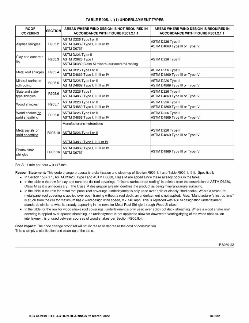
TABLE R905.1.1(1) UNDERLAYMENT TYPES
ROOFCOVERING
SECTION AREAS WHERE WIND DESIGN IS NOT REQUIRED INACCORDANCE WITH FIGURE R301.2.1.1
AREAS WHERE WIND DESIGN IS REQUIRED INACCORDANCE WITH FIGURE R301.2.1.1
Asphalt shingles R905.2ASTM D226 Type I or IIASTM D4869 Type I, II, III or IVASTM D6757
ASTM D226 Type IIASTM D4869 Type III or Type IV
Clay and concretetile
R905.3ASTM D226 Type IIASTM D2626 Type IASTM D6380 Class M mineral-surfaced roll roofing
ASTM D226 Type II
Metal roof shingles R905.4ASTM D226 Type I or IIASTM D4869 Type I, II, III or IV
ASTM D226 Type IIASTM D4869 Type III or Type IV
Mineral-surfacedroll roofing
R905.5ASTM D226 Type I or IIASTM D4869 Type I, II, III or IV
ASTM D226 Type IIASTM D4869 Type III or Type IV
Slate and slate-type shingles
R905.6ASTM D226 Type IASTM D4869 Type I, II, III or IV
ASTM D226 Type IIASTM D4869 Type III or Type IV
Wood shingles R905.7ASTM D226 Type I or IIASTM D4869 Type I, II, III or IV
ASTM D226 Type IIASTM D4869 Type III or Type IV
Wood shakes onsolid sheathing
R905.8ASTM D226 Type I or IIASTM D4869 Type I, II, III or IV
ASTM D226 Type IIASTM D4869 Type III or Type IV
Metal panels onsolid sheathing
R905.10
Manufacturer’s instructions
ASTM D226 Type I or II
ASTM D4869 Type I, II III or IV
ASTM D226 Type IIASTM D4869 Type III or Type IV
Photovoltaicshingles
R905.16ASTM D4869 Type I, II, III or IVASTM D6757 ASTM D4869 Type III or Type IV
For SI: 1 mile per hour = 0.447 m/s.
Reason Statement: This code change proposal is a clarification and clean-up of Section R905.1.1 and Table R905.1.1(1). Specifically:In Section 1507.1.1, ASTM D2626, Type I and ASTM D6380, Class M are added since these already occur in the table.In the table in the row for clay and concrete tile roof coverings, "mineral surface roof roofing" is deleted from the description of ASTM D6380,Class M as it is unnecessary. The Class M designation already identifies the product as being mineral granule-surfacing.In the table in the row for metal roof panel roof coverings, underlayment is only used over solid or closely fitted decks. Where a structuralmetal panel roof covering is applied over open framing without a roof deck, an underlayment is not applied. Also, "Manufacturer's instructions"is stuck from the cell for maximum basic wind design wind speed, V < 140 mph. This is replaced with ASTM designation underlaymentstandards similar to what is already appearing in the rows for Metal Roof Shingle through Wood Shakes.In the table for the row for wood shake roof coverings, underlayment is only used over solid roof deck sheathing. Where a wood shake roofcovering is applied over spaced sheathing, an underlayment is not applied to allow for downward venting/drying of the wood shakes. Aninterlayment is unused between courses of wood shakes per Section R905.8.4.
Cost Impact: The code change proposal will not increase or decrease the cost of constructionThis is simply a clarification and clean-up of the table.
RB260-22
ICC COMMITTEE ACTION HEARINGS ::: March 2022 RB582

RB261-22IRC: SECTION 202, R324.5.1, R905.1.1, TABLE R905.1.1(1), TABLE R905.1.1(2), R905.16, R905.16.1, R905.16.2, R905.16.4, R905.16.5,R905.16.6, TABLE R905.16.6,
Proponents: Larry Sherwood, representing Sustainable Energy Action Committee ([email protected]); Kevin Reinertson, representing CaliforniaFire Chiefs Association FPO ([email protected]); Benjamin Davis, representing California Solar & Storage Association([email protected]); Philip Oakes, representing National Association of State Fire Marshals; Joseph Cain, representing Solar Energy IndustriesAssociation (SEIA) ([email protected])
2021 International Residential CodeDelete without substitution:
[RB] PHOTOVOLTAIC SHINGLES. A roof covering that resembles shingles and that incorporates photovoltaic modules.
Add new definition as follows:
BUILDING-INTEGRATED PHOTOVOLTAIC (BIPV) ROOF COVERING. A BIPV system that also functions as a roof covering.Coverings include, but not limited to, shingles, tiles, and roof panels.
Revise as follows:
R905.1.1 Underlayment. Underlayment for asphalt shingles, clay and concrete tile, metal roof shingles, mineral-surfaced roll roofing, slate andslate-type shingles, wood shingles, wood shakes, metal roof panels and photovoltaic shingles BIPV roof coverings shall conform to the applicablestandards listed in this chapter. Underlayment materials required to comply with ASTM D226, D1970, D4869 and D6757 shall bear a label indicatingcompliance to the standard designation and, if applicable, type classification indicated in Table R905.1.1(1). Underlayment shall be applied inaccordance with Table R905.1.1(2). Underlayment shall be attached in accordance with Table R905.1.1(3).
Exceptions:
1. As an alternative, self-adhering polymer-modified bitumen underlayment bearing a label indicating compliance with ASTM D1970 andinstalled in accordance with both the underlayment manufacturer’s and roof covering manufacturer’s instructions for the deck material,roof ventilation configuration and climate exposure for the roof covering to be installed, shall be permitted.
2. As an alternative, a minimum 4-inch-wide (102 mm) strip of self-adhering polymer-modified bitumen membrane bearing a label indicatingcompliance with ASTM D1970, installed in accordance with the manufacturer’s installation instructions for the deck material, shall beapplied over all joints in the roof decking. An approved underlayment complying with Table R905.1.1(1) for the applicable roof covering
ICC COMMITTEE ACTION HEARINGS ::: March 2022 RB583

TABLE R905.1.1(1) UNDERLAYMENT TYPES
ROOF COVERING SECTION AREAS WHERE WIND DESIGN IS NOT REQUIREDIN ACCORDANCE WITH FIGURE R301.2.1.1
AREAS WHERE WIND DESIGN IS REQUIRED INACCORDANCE WITH FIGURE R301.2.1.1
Asphalt shingles R905.2ASTM D226 Type I or IIASTM D4869 Type I, II, III or IVASTM D6757
ASTM D226 Type IIASTM D4869 Type III or Type IV
Clay and concrete tile R905.3ASTM D226 Type IIASTM D2626 Type IASTM D6380 Class M mineral-surfaced roll roofing
ASTM D226 Type II
Metal roof shingles R905.4ASTM D226 Type I or IIASTM D4869 Type I, II, III or IV
ASTM D226 Type IIASTM D4869 Type III or Type IV
Mineral-surfaced rollroofing
R905.5ASTM D226 Type I or IIASTM D4869 Type I, II, III or IV
ASTM D226 Type IIASTM D4869 Type III or Type IV
Slate and slate-typeshingles
R905.6ASTM D226 Type IASTM D4869 Type I, II, III or IV
ASTM D226 Type IIASTM D4869 Type III or Type IV
Wood shingles R905.7ASTM D226 Type I or IIASTM D4869 Type I, II, III or IV
ASTM D226 Type IIASTM D4869 Type III or Type IV
Wood shakes R905.8ASTM D226 Type I or IIASTM D4869 Type I, II, III or IV
ASTM D226 Type IIASTM D4869 Type III or Type IV
Metal panels R905.10 Manufacturer’s instructionsASTM D226 Type IIASTM D4869 Type III or Type IV
Photovoltaic shinglesBIPV roof coverings
R905.16ASTM D4869 Type I, II, III or IVASTM D6757
ASTM D4869 Type III or Type IV
For SI: 1 mile per hour = 0.447 m/s.
ICC COMMITTEE ACTION HEARINGS ::: March 2022 RB584

TABLE R905.1.1(2) UNDERLAYMENT APPLICATION
ROOFCOVERING SECTION
AREAS WHERE WIND DESIGN IS NOT REQUIRED IN ACCORDANCE WITHFIGURE R301.2.1.1
AREAS WHERE WIND DESIGN ISREQUIRED IN ACCORDANCE
WITH FIGURE R301.2.1.1
Asphaltshingles
R905.2
For roof slopes from 2 units vertical in 12 units horizontal (2:12), up to 4 units verticalin 12 units horizontal (4:12), underlayment shall be two layers applied in the followingmanner: apply a 19-inch strip of underlayment felt parallel to and starting at theeaves. Starting at the eave, apply 36-inch-wide sheets of underlayment, overlappingsuccessive sheets 19 inches. Distortions in the underlayment shall not interfere withthe ability of the shingles to seal. End laps shall be 4 inches and shall be offset by 6feet. For roof slopes of 4 units vertical in 12 units horizontal (4:12) or greater,underlayment shall be one layer applied in the following manner: underlayment shallbe applied shingle fashion, parallel to and starting from the eave and lapped 2 inches,Distortions in the underlayment shall not interfere with the ability of the shingles toseal. End laps shall be 4 inches and shall be offset by 6 feet.
Underlayment shall be two layersapplied in the following manner:apply a 19-inch strip ofunderlayment felt parallel to andstarting at the eaves. Starting at theeave, apply 36-inch-wide sheets ofunderlayment, overlappingsuccessive sheets 19 inches.Distortions in the underlayment shallnot interfere with the ability of theshingles to seal. End laps shall be 4inches and shall be offset by 6 feet.
Clay andconcrete tile
R905.3
For roof slopes from 2 / units vertical in 12 units horizontal (2 / :12), up to 4 unitsvertical in 12 units horizontal (4:12), underlayment shall be not fewer than two layersapplied as follows: starting at the eave, apply a 19-inch strip of underlayment parallelwith the eave. Starting at the eave, apply 36-inch-wide strips of underlayment felt,overlapping successive sheets 19 inches. End laps shall be 4 inches and shall beoffset by 6 feet. For roof slopes of 4 units vertical in 12 units horizontal (4:12) orgreater, underlayment shall be not fewer than one layer of underlayment felt appliedshingle fashion, parallel to and starting from the eaves and lapped 2 inches. End lapsshall be 4 inches and shall be offset by 6 feet.
Underlayment shall be two layersapplied in the following manner:apply a 19-inch strip ofunderlayment felt parallel to andstarting at the eaves. Starting at theeave, apply 36-inch-wide sheets ofunderlayment, overlappingsuccessive sheets 19 inches.Distortions in the underlayment shallnot interfere with the ability of theshingles to seal. End laps shall be 4inches and shall be offset by 6 feet.
Metal roofshingles
R905.4
Apply in accordance with the manufacturer’s installation instructions.
Underlayment shall be two layersapplied in the following manner:apply a 19-inch strip ofunderlayment felt parallel to andstarting at the eaves. Starting at theeave, apply 36-inch-wide sheets ofunderlayment, overlappingsuccessive sheets 19 inches. Endlaps shall be 4 inches and shall beoffset by 6 feet.
Mineral-surfacedroll roofing
R905.5
Slate andslate-typeshingles
R905.6
Woodshingles
R905.7
Woodshakes
R905.8
Metalpanels
R905.10
PhotovoltaicshinglesBIPV roofcoverings
R905.16
For roof slopes from 2 units vertical in 12 units horizontal (2:12), up to 4 units verticalin 12 units horizontal (4:12), underlayment shall be two layers applied in the followingmanner: apply a 19-inch strip of underlayment felt parallel to and starting at theeaves. Starting at the eave, apply 36-inch-wide sheets of underlayment, overlappingsuccessive sheets 19 inches. Distortions in the underlayment shall not interfere withthe ability of the shingles to seal. End laps shall be 4 inches and shall be offset by 6feet. For roof slopes of 4 units vertical in 12 units horizontal (4:12) or greater,underlayment shall be one layer applied in the following manner: underlayment shallbe applied shingle fashion, parallel to and starting from the eave and lapped 2 inches.Distortions in the underlayment shall not interfere with the ability of the shingles toseal. End laps shall be 4 inches and shall be offset by 6 feet.
Underlayment shall be two layersapplied in the following manner:apply a 19-inch strip ofunderlayment felt parallel to andstarting at the eaves. Starting at theeave, apply 36-inch-wide sheets ofunderlayment, overlappingsuccessive sheets 19 inches.Distortions in the underlayment shallnot interfere with the ability of theshingles to seal. End laps shall be 4inches and shall be offset by 6 feet.
For SI: 1 inch = 25.4 mm, 1 foot = 304.8 mm, 1 mile per hour = 0.447 m/s.
R905.16 Photovoltaic BIPV shingles. The installation of photovoltaic BIPV shingles shall comply with the provisions of this section, Section R324and NFPA 70.
12
12
ICC COMMITTEE ACTION HEARINGS ::: March 2022 RB585

R905.16.1 Deck requirements. Photovoltaic BIPV shingles shall be applied to a solid or closely-fitted deck, except where the roof covering isspecifically designed to be applied over spaced sheathing.
R905.16.2 Deck slope. Photovoltaic BIPV shingles shall be used only on roof slopes of 2 units vertical in 12 units horizontal (2:12) or greater.
R905.16.4 Material standards. Photovoltaic BIPV shingles shall be listed and labeled in accordance with UL 7103 or with both UL 61730-1 and UL61730-2.
R905.16.5 Attachment. Photovoltaic BIPV shingles shall be attached in accordance with the manufacturer’s installation instructions.
R905.16.6 Wind resistance. Photovoltaic BIPV shingles shall comply with the classification requirements of Table R905.16.6 for the appropriatemaximum basic wind speed.
ICC COMMITTEE ACTION HEARINGS ::: March 2022 RB586

TABLE R905.16.6 Classification of Photovoltaic BIPV Shingles
MAXIMUM ULTIMATE DESIGN WIND SPEED, V , FROMFIGURE R301.2(2) (mph)
MAXIMUM BASIC WIND SPEED, V , FROMTABLE R301.2.1.3 (mph)
UL 7103 SHINGLECLASSIFICATION
110 85 A, D or F
116 90 A, D or F
129 100 A, D or F
142 110 F
155 120 F
168 130 F
181 140 F
194 150 F
For SI: 1 mile per hour = 1.609 kph.
R324.5.1 Photovoltaic BIPV shingles. Photovoltaic BIPV shingles shall comply with Section R905.16.
Reason Statement: For the definitions, there are different forms of BIPV roof coverings, just as there are different forms of traditional roofcoverings. The code defines roof coverings in general, and the different forms are described in Chapter 9 for their specific application. This changealigns with the change to the definition of BIPV Systems, which clarifies this type of photovoltaic solar energy system.This proposal was prepared by the Sustainable Energy Action Committee (SEAC), a forum for all stakeholders (including, but not limited to, AHJs,designers, engineers, contractors, first responders, manufacturers, suppliers, utilities, and testing labs) to collaboratively identify and find solutionsfor issues that affect the installation and use of solar energy systems, energy storage systems, demand response, and energy efficiency. Thepurpose is to facilitate the deployment and use of affordable, clean and renewable energy in a safe, efficient, and sustainable manner.
All recommendations from SEAC are approved by diverse stakeholders through a consensus process.
Cost Impact: The code change proposal will not increase or decrease the cost of constructionThis provides clarity and consistency in terminology related to BIPV used as roof assemblies and roof coverings.
RB261-22
ult ASD
ICC COMMITTEE ACTION HEARINGS ::: March 2022 RB587
RB262-22IRC: R905.1.2
Proponents: Aaron Phillips, representing Asphalt Roofing Manufacturers Association (ARMA) ([email protected])
2021 International Residential CodeRevise as follows:
R905.1.2 Ice barriers. In areas where there has been a history of ice forming along the eaves causing a backup of water as designated in TableR301.2, an ice barrier shall be installed for asphalt shingles, metal roof shingles, mineral-surfaced roll roofing, slate and slate-type shingles, woodshingles and wood shakes. The ice barrier shall consist of not fewer than two layers of underlayment cemented together, or a self-adheringpolymer-modified bitumen sheet shall be used in place of normal underlayment and extend from the lowest edges of all roof surfaces to a point notless than 24 inches (610 mm) inside the exterior wall line of the building. On roofs with slope equal to or greater than 8 units vertical in 12 unitshorizontal (67-percent slope), the ice barrier shall also be applied not less than 36 inches (914 mm) measured along the roof slope from the eaveedge of the building.
Exception: Detached accessory structures not containing conditioned floor area.
Reason Statement: Ice dams form at or downslope of the transition between above freezing and below freezing sections of the roof deck. Warmair rising from the interior of the building into the attic space may raise the roof deck temperature and cause snow or ice on the roof tomelt, run downslope, and possibly refreeze if the roof deck temperature downslope is low enough. Building characteristics, including roof slope,determine where that transition occurs and affect whether and where an ice dam forms.The special guideline for roofs at or above 8:12 slope overlooks many building construction variations. This proposal strikes the special language forroofs above 8:12 slope to ensure the minimum requirement causes installation of the ice dam protective membrane over an appropriate portion ofthe roof that includes extension within the exterior wall line. The existing language could create situations where the ice dam membrane terminateswell before the location on the roof deck where there is a transition from above freezing to below freezing conditions, which could allow ice damformation at an area not covered by an ice barrier and lead to water infiltration into the building.
Additionally, the existing language can be interpreted in multiple fashions due to use of the word "also" in the last sentence of Section R905.1.2,suggesting there may be a requirement for two layers of ice barrier for roofs 8:12 and higher in slope.
Cost Impact: The code change proposal will not increase or decrease the cost of constructionIf people interpret the existing provisions to require two layers of ice barrier for slopes 8:12 and above, one that runs at least 36" parallel to slope andone that runs at least 24" inside the exterior wall line, this proposal could result in a decrease in cost of construction by permitting one layer that runsat least 24" inside the exterior wall line. If people interpret the existing provisions to require only a single layer running at least 36" parallel to theslope, this proposal could result in an increase in cost of construction for situations in which more than a single 36" width of ice barrier will berequired to reach 24" inside the exterior wall line. On balance for all projects, the proposal is expected to be approximately cost neutral.
RB262-22
ICC COMMITTEE ACTION HEARINGS ::: March 2022 RB588

RB263-22IRC: TABLE R905.1.1(1), TABLE R905.1.1(2), TABLE R905.1.1(3), R905.1.1
Proponents: T. Eric Stafford, representing Insurance Institute for Business and Home Safety
2021 International Residential CodeRevise as follows:
ICC COMMITTEE ACTION HEARINGS ::: March 2022 RB589

TABLE R905.1.1(1) UNDERLAYMENT TYPES
ROOFCOVERING SECTION
AREAS NOT WITHIN HURRICANE-PRONE REGIONSWHERE WIND DESIGN IS NOT REQUIRED IN
ACCORDANCE WITH FIGURE R301.2.1.1
AREAS WITHIN HURRICANE-PRONE REGIONSWHERE WIND DESIGN IS REQUIRED IN
ACCORDANCE WITH FIGURE R301.2.1.1
Asphaltshingles
R905.2ASTM D226 Type I or IIASTM D48696 Type I, II, III or IVASTM D6757
ASTM D226 Type IIASTM D4869 Type III or Type IV
Clay andconcrete tile
R905.3ASTM D226 Type IIASTM D2626 Type IASTM D6380 Class M mineral-surfaced roll roofing
ASTM D226 Type II
Metal roofshingles
R905.4ASTM D226 Type I or IIASTM D4869 Type I, II, III or IV
ASTM D226 Type IIASTM D4869 Type III or Type IV
Mineral-surfacedroll roofing
R905.5ASTM D226 Type I or IIASTM D4869 Type I, II, III or IV
ASTM D226 Type IIASTM D4869 Type III or Type IV
Slate andslate-typeshingles
R905.6ASTM D226 Type IASTM D4869 Type I, II, III or IV
ASTM D226 Type IIASTM D4869 Type III or Type IV
Woodshingles
R905.7ASTM D226 Type I or IIASTM D4869 Type I, II, III or IV
ASTM D226 Type IIASTM D4869 Type III or Type IV
Woodshakes
R905.8ASTM D226 Type I or IIASTM D4869 Type I, II, III or IV
ASTM D226 Type IIASTM D4869 Type III or Type IV
Metalpanels
R905.10 Manufacturer’s instructionsASTM D226 Type IIASTM D4869 Type III or Type IV
Photovoltaicshingles
R905.16ASTM D4869 Type I, II, III or IVASTM D6757 ASTM D4869 Type III or Type IV
For SI: 1 mile per hour = 0.447 m/s.
ICC COMMITTEE ACTION HEARINGS ::: March 2022 RB590

TABLE R905.1.1(2) UNDERLAYMENT APPLICATION
ROOFCOVERING SECTION
AREAS NOT WITHIN HURRICANE-PRONE REGIONS WHERE WIND DESIGN ISNOT REQUIRED IN ACCORDANCE WITH FIGURE R301.2.1.1
AREAS WITHIN HURRICANE-PRONE REGIONS WHERE WIND
DESIGN IS REQUIRED INACCORDANCE WITH FIGURE
R301.2.1.1
Asphaltshingles
R905.2
For roof slopes from 2 units vertical in 12 units horizontal (2:12), up to 4 units verticalin 12 units horizontal (4:12), underlayment shall be two layers applied in the followingmanner: apply a 19-inch strip of underlayment felt parallel to and starting at theeaves. Starting at the eave, apply 36-inch-wide sheets of underlayment, overlappingsuccessive sheets 19 inches. Distortions in the underlayment shall not interfere withthe ability of the shingles to seal. End laps shall be 4 inches and shall be offset by 6feet. For roof slopes of 4 units vertical in 12 units horizontal (4:12) or greater,underlayment shall be one layer applied in the following manner: underlayment shallbe applied shingle fashion, parallel to and starting from the eave and lapped 2 inches,Distortions in the underlayment shall not interfere with the ability of the shingles toseal. End laps shall be 4 inches and shall be offset by 6 feet.
Underlayment shall be two layersapplied in the following manner:apply a 19-inch strip ofunderlayment felt parallel to andstarting at the eaves. Starting at theeave, apply 36-inch-wide sheets ofunderlayment, overlappingsuccessive sheets 19 inches.Distortions in the underlayment shallnot interfere with the ability of theshingles to seal. End laps shall be 4inches and shall be offset by 6 feet.
Clay andconcrete tile
R905.3
For roof slopes from 2 / units vertical in 12 units horizontal (2 / :12), up to 4 unitsvertical in 12 units horizontal (4:12), underlayment shall be not fewer than two layersapplied as follows: starting at the eave, apply a 19-inch strip of underlayment parallelwith the eave. Starting at the eave, apply 36-inch-wide strips of underlayment felt,overlapping successive sheets 19 inches. End laps shall be 4 inches and shall beoffset by 6 feet. For roof slopes of 4 units vertical in 12 units horizontal (4:12) orgreater, underlayment shall be not fewer than one layer of underlayment felt appliedshingle fashion, parallel to and starting from the eaves and lapped 2 inches. End lapsshall be 4 inches and shall be offset by 6 feet.
Underlayment shall be two layersapplied in the following manner:apply a 19-inch strip ofunderlayment felt parallel to andstarting at the eaves. Starting at theeave, apply 36-inch-wide sheets ofunderlayment, overlappingsuccessive sheets 19 inches.Distortions in the underlayment shallnot interfere with the ability of theshingles to seal. End laps shall be 4inches and shall be offset by 6 feet.
Metal roofshingles
R905.4
Apply in accordance with the manufacturer’s installation instructions.
Underlayment shall be two layersapplied in the following manner:apply a 19-inch strip ofunderlayment felt parallel to andstarting at the eaves. Starting at theeave, apply 36-inch-wide sheets ofunderlayment, overlappingsuccessive sheets 19 inches. Endlaps shall be 4 inches and shall beoffset by 6 feet.
Mineral-surfacedroll roofing
R905.5
Slate andslate-typeshingles
R905.6
Woodshingles
R905.7
Woodshakes
R905.8
Metalpanels
R905.10
Photovoltaicshingles
R905.16
For roof slopes from 2 units vertical in 12 units horizontal (2:12), up to 4 units verticalin 12 units horizontal (4:12), underlayment shall be two layers applied in the followingmanner: apply a 19-inch strip of underlayment felt parallel to and starting at theeaves. Starting at the eave, apply 36-inch-wide sheets of underlayment, overlappingsuccessive sheets 19 inches. Distortions in the underlayment shall not interfere withthe ability of the shingles to seal. End laps shall be 4 inches and shall be offset by 6feet. For roof slopes of 4 units vertical in 12 units horizontal (4:12) or greater,underlayment shall be one layer applied in the following manner: underlayment shallbe applied shingle fashion, parallel to and starting from the eave and lapped 2 inches.Distortions in the underlayment shall not interfere with the ability of the shingles toseal. End laps shall be 4 inches and shall be offset by 6 feet.
Underlayment shall be two layersapplied in the following manner:apply a 19-inch strip ofunderlayment felt parallel to andstarting at the eaves. Starting at theeave, apply 36-inch-wide sheets ofunderlayment, overlappingsuccessive sheets 19 inches.Distortions in the underlayment shallnot interfere with the ability of theshingles to seal. End laps shall be 4inches and shall be offset by 6 feet.
For SI: 1 inch = 25.4 mm, 1 foot = 304.8 mm, 1 mile per hour = 0.447 m/s.
12
12
ICC COMMITTEE ACTION HEARINGS ::: March 2022 RB591

TABLE R905.1.1(3) UNDERLAYMENT APPLICATION
ROOFCOVERING
SECTION
AREAS NOTWITHIN
HURRICANE-PRONE REGIONS
WHERE WINDDESIGN IS NOTREQUIRED IN
ACCORDANCEWITH FIGURE
R301.2.1.1
AREAS WITHIN HURRICANE-PRONE REGIONS WHERE WIND DESIGN IS REQUIRED INACCORDANCE WITH FIGURE R301.2.1.1
Asphaltshingles
R905.2
Fastened sufficientlyto hold in place
The underlayment shall be attached with corrosion-resistant fasteners in a grid pattern of 12 inchesbetween side laps with a 6-inch spacing at side and end laps. Underlayment shall be attached usingannular ring or deformed shank nails with 1-inch-diameter metal or plastic caps. Metal caps shallhave a thickness of not less than 32-gage sheet metal. Power-driven metal caps shall have aminimum thickness of 0.010 inch. Minimum thickness of the outside edge of plastic caps shall be0.035 inch. The cap nail shank shall be not less than 0.083 inch. The cap nail shank shall have alength sufficient to penetrate through the roof sheathing or not less than / inch into the roofsheathing.
Clay andconcrete tile
R905.3
Photovoltaic R905.16
Metal roofshingles
R905.4
Manufacturer’sinstallationinstructions.
The underlayment shall be attached with corrosion-resistant fasteners in a grid pattern of 12 inchesbetween side laps with a 6-inch spacing at side and end laps. Underlayment shall be attached usingannular ring or deformed shank nails with 1-inch-diameter metal or plastic caps. Metal caps shallhave a thickness of not less than 32-gage sheet metal. Power-driven metal caps shall have aminimum thickness of 0.010 inch. Minimum thickness of the outside edge of plastic caps shall be0.035 inch. The cap nail shank shall be not less than 0.083 inch. The cap nail shank shall have alength sufficient to penetrate through the roof sheathing or not less than / inch into the roofsheathing.
Mineral-surfacedroll roofing
R905.5
Slate andslate-typeshingles
R905.6
Woodshingles
R905.7
Woodshakes
R905.8
Metalpanels
R905.10
For SI: 1 inch = 25.4 mm, 1 mile per hour = 0.447 m/s.
R905.1.1 Underlayment. Underlayment for asphalt shingles, clay and concrete tile, metal roof shingles, mineral-surfaced roll roofing, slate andslate-type shingles, wood shingles, wood shakes, metal roof panels and photovoltaic shingles shall conform to the applicable standards listed in thischapter. Underlayment materials required to comply with ASTM D226, D1970, D4869 and D6757 shall bear a label indicating compliance to thestandard designation and, if applicable, type classification indicated in Table R905.1.1(1). Underlayment shall be applied in accordance with TableR905.1.1(2). Underlayment shall be attached in accordance with Table R905.1.1(3).
Exceptions:
1. As an alternative, self-adhering polymer-modified bitumen underlayment bearing a label indicating compliance with ASTM D1970 andinstalled in accordance with both the underlayment manufacturer’s and roof covering manufacturer’s instructions for the deck material,roof ventilation configuration and climate exposure for the roof covering to be installed, shall be permitted.
2. As an alternative, a minimum 4-inch-wide (102 mm) strip of self-adhering polymer-modified bitumen membrane bearing a label indicatingcompliance with ASTM D1970, installed in accordance with the manufacturer’s installation instructions for the deck material, shall beapplied over all joints in the roof decking. An approved underlayment complying with Table R905.1.1(1) for the applicable roofcovering areas where wind design is not required in accordance with Figure R301.2.1.1 shall be applied over the entire roof over the 4-inch-wide (102 mm) membrane strips. Underlayment shall be applied in accordance with Table R905.1.1(2) using the applicationrequirements for areas not within Hurricane-prone Regions where wind design is not required in accordance with Figure R301.2.1.1.Underlayment shall be attached in accordance with Table R905.1.1(3).
Reason Statement: This proposal expands the requirements for improved roof covering underlayment from the Wind Design Required Region to
34
34
ICC COMMITTEE ACTION HEARINGS ::: March 2022 RB592
the Hurricane-prone Region. This effectively expands the secondary roof underlayment strategies recommended by the IBHS Fortified Home -Hurricane program (sealed roof deck) from areas where the design wind speed is 130 mph and greater to areas where the design wind speed is115 mph and greater.Damage due to water intrusion continues to be a significant problem for buildings impacted by hurricanes. Water entry can occur where it is able toinfiltrate through the roof, walls, vents, windows, and/or doors, or at interfaces between these items. The roof deck, where the roof covering is lostor damaged, is particularly susceptible. Water intrusion can cause extensive damage to interior finishes, furnishings, and other contents, and canlead to ceiling collapse when attic insulation is saturated. When power is lost and/or a building cannot otherwise be dried out within 24–48 hours,additional issues such as mold can develop, potentially extending the period during which the property may not be available for use.
Tests performed by IBHS at the Research Center have consistently shown that a sealed roof deck as recommended by the IBHS Fortified Home -Hurricane program consistently show significantly reduced water intrusion rates when one of these strategies was employed. A summary of theresults of the demonstration can be viewed at the following link:
http://ibhstest.wpengine.com/ibhsnews- releases/ibhs-hurricane-demonstration-illustrates-importance-of-sealed-roof-deck-3/.
The wind driven rain demonstration can be viewed at the following link:https://disastersafety.org/thunderstorms/winddriven-rain-demo/.
These underlayment strategies required reduce water entry into the attic space by 70% or more.
This expansion is being proposed primarily for 2 reasons. It is anticipated that ASCE 7 will be updated to the 2022 edition this cycle. ASCE 7-22includes numerous changes to the wind design requirements including changes to the wind speed maps. While some wind speeds in the hurricane-prone region are increasing, notably, the 130 mph contour, which is the Wind Design Required Region trigger in the Hurricane-prone Region, isbeing reduced in many areas near the Gulf coast and North Atlantic coast. The following figures overlays the ASCE 7-22 design wind speeds forRisk Category II over the ASCE 7-16 design wind speeds for Risk Category II near the Gulf and Atlantic coasts. The areas shaded in blue indicatewhere the 130 mph contour has shifted more towards the coast effectively reducing wind speeds in these areas. As shown, the North Atlantic coasthas been completely removed from the Wind Design Required Region. Without this proposed expansion, these hurricane-prone areas wouldno longer be required to use the improved underlayment strategies.
ICC COMMITTEE ACTION HEARINGS ::: March 2022 RB593

Figure 1
Loss of Wind Design Required Region in the Gulf Region Due to ASCE 7-22 Wind Speed Updates
ICC COMMITTEE ACTION HEARINGS ::: March 2022 RB594

Figure 2
Loss of Wind Design Required Region in the North Atlantic Region Due to ASCE 7-22 Wind Speed Updates
Additionally, a recent report published by David Roueche with Auburn University for Home Innovation Research Labs shows that roof coveringdamage is by far the most common cladding damage and that even at lower wind speeds roof covering damage is frequently observed. The fullreport is attached to this proposal. The report is a curation of the windstorm building performance dataset collected by the StEER (StructuralExtreme Events Reconnaissance) network. The dataset quantifies common wind damage patterns from recent windstorms. The followingwindstorm events were included in the dataset:
· Joplin Tornado
· Garland Tornado
· Hurricane Harvey
· Hurricane Irma
· Hurricane Michael
· Nashville/Cookeville Tornadoes
· Hurricane Laura
ICC COMMITTEE ACTION HEARINGS ::: March 2022 RB595
When stratified by hazard intensity, the data shows for wind speeds between 116 mph and 140 mph the frequency of roof covering damage is near80%. Even for wind speeds between 91 mph and 115 mph the frequency of roof covering damage is near 70%.
The report notes that “considering all hazard intensities and years of construction, 26-50% of the roof cover on a single-family home is typicallydamaged in an extreme windstorm.”It should also be noted that the 7 Edition (2020) Florida Building Code adopted these underlayment strategiesfor the entire state. For Risk Category II buildings, design wind speeds in the state of Florida range from approximately 115 mph to 180 mph.
https://www.cdpaccess.com/proposal/7975/25356/files/download/2803/
Bibliography: Brown, T.M., Quarles, S.L., Giammanco, I.M., Brown, R., Insurance Institute for Business and Home Safety,"Building Vulnerability to Wind-Driven Rain Entry and Effectiveness of Mitigation Techniques." 14th International Conferenceon Wind Engineering (ICWE).
Roueche, D.B., Nakayama, J., Department of Civil Engineering, Auburn University Ginn College of Engineering, "Quantification of Common WindDamage Patterns in Recent Windstorms." May 2021
Cost Impact: The code change proposal will increase the cost of constructionThis proposal will only increase costs in the Hurricane-prone Regions for wind speeds between 115 mph and 129 mph. Exceptions 1 and 2 haveexisted in the IRC for several editions. If the double layer of underlayment option is used, the cost of the additional layer of underlayment will vary byregion. However, for a 2000 square foot roof, the cost increase for the additional layer of underlayment will be between $100 to $200. Additionalfasteners will be required in addition to theadditional layer of underlayment.
RB263-22
th
ICC COMMITTEE ACTION HEARINGS ::: March 2022 RB596
RB264-22IRC: R905.2.8.2
Proponents: Aaron Phillips, representing Asphalt Roofing Manufacturers Association (ARMA) ([email protected])
2021 International Residential CodeRevise as follows:
R905.2.8.2 Valleys. Valley linings shall be installed in accordance with the manufacturer’s instructions before applying shingles. Valley linings of thefollowing types shall be permitted:
1. For open valleys (valley lining exposed) lined with metal, the valley lining shall be not less than 24 inches (610 mm) wide and of any of thecorrosion-resistant metals in Table R905.2.8.2.
2. For open valleys, valley lining of two plies of mineral-surfaced roll roofing, complying with ASTM D3909 or ASTM D6380 Class M, shall bepermitted. The bottom layer shall be 18 inches (457 mm) and the top layer not less than 36 inches (914 mm) wide.
3. For closed valleys (valley covered with shingles), valley lining of one ply of smooth roll roofing complying with ASTM D6380 and not less than36 inches wide (914 mm) or valley lining as described in Item 1 or 2 shall be permitted. Self-adhering polymer-modified bitumen underlaymentcomplying with ASTM D1970 and not less than 36 inches (914 mm) wide shall be permitted in lieu of the lining material.
Reason Statement: Although implied, the minimum width of ASTM D1970 valley lining is not provided in the existing language of the IRC. Thisproposal establishes that ASTM D1970 underlayment used as closed valley lining must be at least 36" wide.
Cost Impact: The code change proposal will not increase or decrease the cost of constructionThis proposal defines an implied requirement to remove ambiguity. No change in cost of construction is expected if this proposal is approved.
RB264-22
ICC COMMITTEE ACTION HEARINGS ::: March 2022 RB597

RB265-22IRC: R905.2.8.4
Proponents: Aaron Phillips, representing Asphalt Roofing Manufacturers Association (ARMA) ([email protected])
2021 International Residential CodeRevise as follows:
R905.2.8.4 Other flashing. Flashing against a vertical front wall, as well as soil stack, vent pipe and chimney flashing, shall be applied inaccordance with the asphalt shingle manufacturer’s printed instructions.
Reason Statement: Manufacturer's instructions are increasingly made available in media other than printed versions. This proposal removes theword “printed” from the only instance in IRC Chapter 9 where it is used in conjunction with "instructions." Removal of the word “printed” will permitalternative methods for providing instructions, including digital formats that support greater sustainability. The proposed change is important in light ofevents such as the COVID-19 pandemic, which brought attention to the need to deliver information using alternative methods.
Cost Impact: The code change proposal will not increase or decrease the cost of constructionThe proposal expands available options for delivering manufacturer's instructions, which allows manufacturers to select the option that best servestheir customers. There is no basis to expect either a general increase or decrease in cost of construction if this proposal is approved.
RB265-22
ICC COMMITTEE ACTION HEARINGS ::: March 2022 RB598

RB266-22IRC: R905.3.6 (New), R905.5.6 (New), R905.6.5 (New), R905.6.5, TABLE R905.6.5, R905.7.5 (New), R905.7.5, TABLE R905.7.5(1), TABLER905.7.5(2), R905.8.6 (New), R905.8.6, TABLE R905.8.6, R905.9.4 (New), R905.10.5 (New), R905.11.4 (New), R905.12.4 (New), R905.13.4(New), R905.14.4 (New), R905.15.4 (New), R905.17.7 (New), ASTM Chapter 44 (New)
Proponents: T. Eric Stafford, representing Insurance Institute for Business and Home Safety ([email protected])
2021 International Residential CodeAdd new text as follows:
R905.3.6 Wind resistance of concrete and clay tile. In regions where wind design is required in accordance with Figure R301.2.1.1, wind loadson concrete and clay tile shall be determined in accordance with Section 1504.3 of the International Building Code. In regions where wind design isnot required in accordance with Figure R301.2.1.1, concrete and clay tiles shall be attached in accordance with this Sections R905.3.7 andR905.3.8.
R905.5.6 Wind resistance of mineral-surfaced roll roofing. Mineral-surfaced roll roofing shall be installed to resist the component and claddingloads specified in Table R301.2.1(1), adjusted for height and exposure in accordance with Table R301.2.1(2).
R905.6.5 Wind resistance of slate shingles. Slate shingles shall be installed to resist the component and cladding loads specified in TableR301.2.1(1), adjusted for height and exposure in accordance with Table R301.2.1(2). In regions where wind design is not required in accordancewith Figure R301.2.1.1, slate shingles shall be attached in accordance with Section R905.6.6.
Revise as follows:
R905.6.6 R905.6.5 Application. Minimum headlap for slate shingles shall be in accordance with Table R905.6.6 R905.6.5 . Slate shingles shall besecured to the roof with two fasteners per slate. Slate shingles shall be installed in accordance with this chapter and the manufacturer’s instructions.
ICC COMMITTEE ACTION HEARINGS ::: March 2022 RB599

TABLE R905.6.6 R905.6.5 SLATE SHINGLE HEADLAP
SLOPE HEADLAP (inches)
4:12 ≤ slope < 8:12 4
8:12 ≤ slope < 20:12 3
Slope ≥ 20:12 2
For SI: 1 inch = 25.4 mm.
Add new text as follows:
R905.7.5 Wind resistance of wood shingles. In regions where wind design is required in accordance with Figure R301.2.1.1, Wood shingles shallbe installed to resist the component and cladding loads specified in Table R301.2.1(1), adjusted for height and exposure in accordance with TableR301.2.1(2). In regions where wind design is not required in accordance with Figure R301.2.1.1, wood shingles are permitted to be attached inaccordance with Section R905.7.6.
Revise as follows:
R905.7.6 R905.7.5 Application. Wood shingles shall be installed in accordance with this chapter and the manufacturer’s instructions. Woodshingles shall be laid with a side lap not less than 1 / inches (38 mm) between joints in courses, and two joints shall not be in direct alignment in anythree adjacent courses. Spacing between shingles shall be not less than / inch to / inch (6.4 mm to 9.5 mm). Weather exposure for woodshingles shall not exceed those set in Table R905.7.6(1) R905.7.5(1). Fasteners for untreated (naturally durable) wood shingles shall be box nails inaccordance with Table R905.7.6(2) R905.7.5(2). Nails shall be stainless steel Type 304 or 316 or hot-dipped galvanized with a coating weight ofASTM A153 Class D (1.0 oz/ft ). Alternatively, two 16-gage stainless steel Type 304 or 316 staples with crown widths / inch (11.1 mm) minimum,/ inch (19.1 mm) maximum, shall be used. Fasteners installed within 15 miles (24 km) of saltwater coastal areas shall be stainless steel Type 316.
Fasteners for fire-retardant-treated shingles in accordance with Section R902 or pressure-impregnated-preservative-treated shingles of naturallydurable wood in accordance with AWPA U1 shall be stainless steel Type 316. Fasteners shall have a minimum penetration into the sheathing of /inch (19.1 mm). For sheathing less than / inch in (19.1 mm) thickness, each fastener shall penetrate through the sheathing. Wood shingles shall beattached to the roof with two fasteners per shingle, positioned in accordance with the manufacturer’s installation instructions. Fastener packagingshall bear a label indicating the appropriate grade material or coating weight.
12
14
38
2 716
34
34
34
ICC COMMITTEE ACTION HEARINGS ::: March 2022 RB600

TABLE R905.7.6(1) R905.7.5(1) WOOD SHINGLE WEATHER EXPOSURE AND ROOF SLOPE
ROOFING MATERIAL LENGTH (inches) GRADEEXPOSURE (inches)
3:12 pitch to < 4:12 4:12 pitch or steeper
Shingles of naturally durable wood
16
No. 1 3 / 5
No. 2 3 / 4
No. 3 3 3 /
18
No. 1 4 / 5 /
No. 2 4 4 /
No. 3 3 / 4
24
No. 1 5 / 7 /
No. 2 5 / 6 /
No. 3 5 5 /
For SI: 1 inch = 25.4 mm.
34
12
12
14
12
12
12
34
12
12
12
12
ICC COMMITTEE ACTION HEARINGS ::: March 2022 RB601

TABLE R905.7.6(2) R905.7.5(2) NAIL REQUIREMENTS FOR WOOD SHAKES AND WOOD SHINGLES
PRODUCT TYPE NAIL TYPE, MINIMUM LENGTH AND SHANK DIAMETER (inches)
Shakes
18″ straight-split 5d box 1 / ″ × 0.080
18″ and 24″ handsplit and resawn 6d box 2″ × 0.099
24″ taper-split 5d box 1 / ″ × 0.080
18″ and 24″ tapersawn 6d box 2″ × 0.099
Shingles
16″ and 18″ 3d box 1 / ″ × 0.076
24″ 4d box 1 / ″ × 0.076
For SI: 1 inch = 25.4 mm.
Add new text as follows:
R905.8.6 Wind resistance of wood shakes. In regions where wind design is required in accordance with Figure R301.2.1.1, Wood shakes shall beinstalled to resist the component and cladding loads specified in Table R301.2.1(1), adjusted for height and exposure in accordance with TableR301.2.1(2). In regions where wind design is not required in accordance with Figure R301.2.1.1, wood shakes are permitted to be attached inaccordance with Section R905.8.7.
Revise as follows:
R905.8.7 R905.8.6 Application. Wood shakes shall be installed in accordance with this chapter and the manufacturer’s installation instructions.Wood shakes shall be laid with a side lap not less than 1 / inches (38 mm) between joints in adjacent courses. Spacing between shakes in thesame course shall be / inch to / inch (9.5 mm to 15.9 mm) including tapersawn shakes. Weather exposures for wood shakes shall not exceedthose set in Table R905.8.7 R905.8.6. Fasteners for untreated (naturally durable) wood shakes shall be box nails in accordance with TableR905.7.6(2) R905.7.5(2). Nails shall be stainless steel Type 304, or Type 316 or hot-dipped with a coating weight of ASTM A153 Class D (1.0oz/ft ). Alternatively, two 16-gage Type 304 or Type 316 stainless steel staples, with crown widths / inch (11.1 mm) minimum, / inch (19.1 mm)maximum, shall be used. Fasteners installed within 15 miles (24 km) of saltwater coastal areas shall be stainless steel Type 316. Wood shakes shallbe attached to the roof with two fasteners per shake positioned in accordance with the manufacturer’s installation instructions. Fasteners for fire-retardant-treated (as defined in Section R902) shakes or pressure-impregnated-preservative-treated shakes of naturally durable wood inaccordance with AWPA U1 shall be stainless steel Type 316. Fasteners shall have a minimum penetration into the sheathing of / inch (19.1 mm).Where the sheathing is less than / inch (19.1 mm) thick, each fastener shall penetrate through the sheathing. Fastener packaging shall bear a labelindicating the appropriate grade material or coating weight.
34
34
14
12
12
38
58
2 716
34
34
34
ICC COMMITTEE ACTION HEARINGS ::: March 2022 RB602

TABLE R905.8.7 R905.8.6 WOOD SHAKE WEATHER EXPOSURE AND ROOF SLOPE
ROOFING MATERIAL LENGTH (inches) GRADEEXPOSURE (inches)
4:12 pitch or steeper
Shakes of naturally durable wood18 No. 1 7 /
24 No. 1 10
Preservative-treated tapersawn shakes of Southern Yellow Pine
18 No. 1 7 /
24 No. 1 10
18 No. 2 5 /
24 No. 2 7 /
Taper-sawn shakes of naturally durable wood
18 No. 1 7 /
24 No. 1 10
18 No. 2 5 /
24 No. 2 7 /
For SI: 1 inch = 25.4 mm.
a. For 24-inch by / -inch handsplit shakes, the maximum exposure is 7 / inches.
Add new text as follows:
R905.9.4 Wind resistance of built-up roofs. Built-up roof coverings shall be tested in accordance with FM 4474, UL1897 or UL 580 and installedto resist the component and cladding loads specified in Table R301.2.1(1), adjusted for height and exposure in accordance with Table R301.2.1(2).
R905.10.5 Wind resistance of metal roof panels. Metal roof panels shall be installed to resist the component and cladding loads specified in TableR301.2.1(1), adjusted for height and exposure in accordance with Table R301.2.1(2). Metal roof panels applied to a solid or closely fitted deck shallbe tested for wind resistance in accordance with FM 4474, UL 580, or UL 1897. Structural standing seam metal panel roof systems shall be testedfor wind resistance in accordance with ASTM E1592 or FM 4474. Structural through-fastened metal panel roof systems shall be tested for windresistance in accordance with ASTM E1592, FM 4474 or UL 580.
Exceptions:1. Metal roofs constructed of cold-formed steel shall be permitted to be designed and tested in accordance with the applicable referenced
structural design standard in Section 2210.1 of the International Building Code.
2. Metal roofs constructed of aluminum shall be permitted to be designed and tested in accordance with the applicable referenced structuraldesign standard in Section 2002.1 of the International Building Code.
R905.11.4 Wind resistance of modified bitumen roofing. Modified bitumen roofing shall be tested in accordance with FM 4474, UL1897 or UL580 and installed to resist the component and cladding loads specified in Table R301.2.1(1), adjusted for height and exposure in accordance withTable R301.2.1(2).
R905.12.4 Wind resistance of thermoset single-ply roofing. Thermoset single-ply roofing shall be tested in accordance with FM 4474, UL1897or UL 580 and installed to resist the component and cladding loads specified in Table R301.2.1(1), adjusted for height and exposure in accordancewith Table R301.2.1(2).
R905.13.4 Wind resistance of thermoplastic single-ply roofing. Thermoplastic single-ply roofing shall be tested in accordance with FM 4474,UL1897 or UL 580 and installed to resist the component and cladding loads specified in Table R301.2.1(1), adjusted for height and exposure inaccordance with Table R301.2.1(2).
R905.14.4 Wind resistance of sprayed polyurethane foam roofing. Sprayed polyurethane foam roofing shall be tested in accordance with FM4474, UL1897 or UL 580 and installed to resist the component and cladding loads specified in Table R301.2.1(1), adjusted for height and exposure inaccordance with Table R301.2.1(2).
R905.15.4 Wind resistance of liquid-applied roofing. Liquid-applied roofing shall be tested in accordance with FM 4474, UL1897 or UL 580 andinstalled to resist the component and cladding loads specified in Table R301.2.1(1), adjusted for height and exposure in accordance with TableR301.2.1(2).
R905.17.7 Wind resistance of BIPV roof panels. BIPV roof panels shall be tested in accordance with UL 1897 and installed to resist thecomponent and cladding loads specified in Table R301.2.1(1), adjusted for height and exposure in accordance with Table R301.2.1(2).
Add new standard(s) as follows:
12
a
12
12
12
12
12
12
38
12
ICC COMMITTEE ACTION HEARINGS ::: March 2022 RB603

ASTM ASTM International100 Barr Harbor Drive, P.O. Box C700
West Conshohocken, PA 19428
E1592-2005(2017) Test Method for Structural Performance of Sheet Metal Roof and Siding Systems by Uniform Static AirPressureDifference
Staff Analysis: ASTM E1592-2005(2017) is already referenced in the IBC. This is simply a new occurrence of the reference in the I-Codes
Reason Statement: This proposal is one of two proposals intended to clarify the wind limitations in the IRC. Section R301.2.1.1 intends to limit theapplicability of the IRC to areas where wind design is not required in accordance with Figure R301.2.1.1. However, Chapter 9 contains high windrequirements for asphalt, metal, and photovoltaic shingles and for underlayment in wind design required regions, but for no other roof coverings.While Section R905.1 states that unless otherwise specified, roof coverings have to resist the component and cladding loads specified in TableR302(2), that requirement is not necessarily correct for all roof coverings. Prescriptive attachment methods are provided for concrete and clay tilebut the code does not specify any wind limitations on the use of this prescriptive method.Therefore, new sections are proposed for many roof coverings that specifically addresses the wind limitations in the IRC for roof coveringattachment and specifies the performance requirements for roof coverings in wind design required regions. Where prescriptive attachment methodsare provided, the proposal limits their use to areas where wind design is not required. The performance requirements specified are consistent withSection 1504 in the IBC. This proposal is not intended to change any technical requirements in the IRC related to wind design. It is intended to simplyclarify the wind requirements for roof coverings in the IRC.
Cost Impact: The code change proposal will not increase or decrease the cost of constructionThis code change proposal will not increase the cost of construction as it is primarily a clarification.
RB266-22
ICC COMMITTEE ACTION HEARINGS ::: March 2022 RB604

RB267-22IRC: TABLE R905.3.7
Proponents: Glenn Mathewson, representing Self ([email protected])
2021 International Residential CodeRevise as follows:
ICC COMMITTEE ACTION HEARINGS ::: March 2022 RB605

TABLE R905.3.7 CLAY AND CONCRETE TILE ATTACHMENT
SHEATHING ROOF SLOPE NUMBER OF FASTENERS
Solid without battens All One per tile
Spaced or solid with battens and slope < 5:12Fasteners not required
slope < 5:12Fasteners not required
Spaced sheathing without battens5:12 ≤ slope < 12:12 One per tile/every other row
12:12 ≤ slope < 24:12 One per tile
Reason Statement: At first glance, the data in the row “spaced or solid with battens and slope <5:12” appears to be shifted to the left and not in thecorrect columns. In researching, this table has been in this form since the 2000 IRC. This proposals suggests that the slope conditions for this rowbe placed under the column titled “roof slope” and the number of fasteners required should be under the column titled “number of fasteners”. In reviewing the Concrete and Clay Roof Tile Installation Manual (2015-latest edition) by the Tile Roofing Institute and Western States RoofingContractors Association, Table IB, it would appear that this shift of data in the IRC table is supported. This can be viewed online at this link: https://tileroofing.org/wp-content/uploads/TRI-Installation-Guide-2015-1.pdf
The clay and concrete tile industry is welcome to further refine this proposal with floor modifications and/or public comments. The goal of thisproposal is simply to make the presentation of the data in the cells align sensibly with the column titles.
Cost Impact: The code change proposal will not increase or decrease the cost of constructionThis proposal is editorial and does not change the application of the IRC provisions.
RB267-22
ICC COMMITTEE ACTION HEARINGS ::: March 2022 RB606

RB268-22IRC: R905.6.5 (New), TABLE R905.6.5 (New)
Proponents: Mark Graham, representing National Roofing Contractors Assoc. ([email protected])
2021 International Residential CodeAdd new text as follows:
R905.6.5 Wind resistance of slate shingles. Slate shingles shall be tested in accordance with ASTM D3161. Slate shingle packaging shall bear alabel indicating compliance with ASTM D3161 and the required classification in Table R905.6.5.
ICC COMMITTEE ACTION HEARINGS ::: March 2022 RB607

TABLE R905.6.5 CLASSIFICATION OF SLATE SHINGLES TESTED IN ACCORDACNE WITH ASTM D3161
MAXIMUM ULTIMATE DESIGN WIND SPEED, V , FROMFIGURE R301.2(2) (mph)
MAXIMUM BASIC WIND SPEED, V , FROMTABLE R301.2.1.3 (mph)
ASTM D3161CLASSIFICATION
110 85 A, D or F
116 90 A, D or F
129 100 A, D or F
142 110 F
155 120 F
168 130 F
181 140 F
194 150 F
For SI: 1 mph=0.447 m/s
Reason Statement: This code change proposal is intended to provide building officials and users of the code guidance regarding the windresistance of slate roof covings. Wind resistance of slate roof coverings is not currently addressed in the IRC. This code change adds windresistance testing in accordance with ASTM D3161 and its classification designations similar to what is already provided for in the IBC for asphaltshingles and metal roof shingles. A new table is added, Table R905.6.5 providing the required wind resistance classification based on the maximumultimate design wind speed, V , or maximum basic wind speed, V . Slate package labeling is required to facilitate classification identification andenforcement. Such package labeling would be slate supplier specific, but most likely would be in the form of of a pallet tag.
Cost Impact: The code change proposal will not increase or decrease the cost of constructionWhile this code change proposal adds a requirement for wind resistance testing, it will not result in an increase in the cost of construction. Slatesuppliers have indicating they already have ASTM D3161 testing in-place and classifications available.
RB268-22
ult asd
ult asd
ICC COMMITTEE ACTION HEARINGS ::: March 2022 RB608

RB269-22IRC: R905.7.1
Proponents: Chadwick Collins, representing Cedar Shake & Shingle Bureau ([email protected])
2021 International Residential CodeRevise as follows:
R905.7.1 Deck requirements. Wood shingles shall be installed on solid or spaced sheathing. Where spaced sheathing is used, sheathing boardsshall be not less than 1-inch by 4-inch (25 mm by 102 mm) nominal dimensions and shall be spaced on centers equal to the weather exposure tocoincide with the placement of fasteners. Where 1-inch by 4-inch (25 mm by 102 mm) spaced sheathing is installed at 10 inches (254 mm) orgreater, additional 1-inch by 4-inch (25 mm by 102 mm) boards shall be installed between the sheathing boards. When wood shingles are installedover spaced sheathing and the underside of the shingles are exposed to the attic space the attic shall be ventilated in accordance with SectionsR806.1, R806.2, R806.3 and R806.4. The shingles shall not be backed with materials that prevent the free movement of air on the interior side ofthe spaced sheathing.
Reason Statement: When shingles are installed over spaced sheathing, the underlayment is interwoven as the installation progresses. Due to thisconfiguration, moisture can reach the underlayment. While much of the drying of the underlayment occurs in the direction of the exterior, some ofthe drying process occurs toward the interior. The exposure of this surface (the backside of the shingles and underlayment) to the ventilationspace is necessary to facilitate this process. This language is proposed to ensure this configuration is maintained and not compromised with theinstallation of other building components, such as spray foam insulation, that would otherwise occupy this air space and eliminate this process. Further, installation of components such as spray foam insulation also eliminates one surface for shingles to release heat gained through exposure.This slows the release of heat energy, requiring the shingle to hold on to heat load for longer durations, which leads to shorter service life cycles
Cost Impact: The code change proposal will not increase or decrease the cost of constructionThis proposal does not add any requirements to current construction practices, but clarifies the configuration of the installation.
RB269-22
ICC COMMITTEE ACTION HEARINGS ::: March 2022 RB609

RB270-22IRC: R905.7.5, ASTM Chapter 44
Proponents: Rick Allen, representing ISANTA ([email protected])
2021 International Residential CodeRevise as follows:
R905.7.5 Application. Wood shingles shall be installed in accordance with this chapter and the manufacturer’s instructions. Wood shingles shall belaid with a side lap not less than 1 / inches (38 mm) between joints in courses, and two joints shall not be in direct alignment in any three adjacentcourses. Spacing between shingles shall be not less than / inch to / inch (6.4 mm to 9.5 mm). Weather exposure for wood shingles shall notexceed those set in Table R905.7.5(1). Fasteners for untreated (naturally durable) wood shingles shall be box nails in accordance with TableR905.7.5(2). Nails shall be stainless steel Type 304 or 316 or hot-dipped galvanized with a coating weight of ASTM A153 Class D or ASTM A641Class 3S (1.0 oz/ft ). Alternatively, two 16-gage stainless steel Type 304 or 316 staples with crown widths / inch (11.1 mm) minimum, / inch(19.1 mm) maximum, shall be used. Fasteners installed within 15 miles (24 km) of saltwater coastal areas shall be stainless steel Type 316.Fasteners for fire-retardant-treated shingles in accordance with Section R902 or pressure-impregnated-preservative-treated shingles of naturallydurable wood in accordance with AWPA U1 shall be stainless steel Type 316. Fasteners shall have a minimum penetration into the sheathing of /inch (19.1 mm). For sheathing less than / inch in (19.1 mm) thickness, each fastener shall penetrate through the sheathing. Wood shingles shall beattached to the roof with two fasteners per shingle, positioned in accordance with the manufacturer’s installation instructions. Fastener packagingshall bear a label indicating the appropriate grade material or coating weight.
ASTM ASTM International100 Barr Harbor Drive, P.O. Box C700
West Conshohocken, PA 19428
A641/A641M—09a(2014) 2019 Specification for Zinc-coated (Galvanized) Carbon Steel Wire
Staff Analysis: The proposal is referencing an updated version of an existing referenced standard. Therefore the updated version is considered annew standard. A review of the standard proposed for inclusion in the code, ASTM A641/A641M-2019 Specification for Zinc-coated (Galvanized)Carbon Steel Wire, with regard to some of the key ICC criteria for referenced standards (Section 3.6 of CP#28) will be posted on the ICC website onor before March 16, 2022.
Reason Statement: Galvanized nails are made from wire. The wire may be uncoated or galvanized. Nails that are made from uncoated wire arehot-dip galvanized after forming to specification A153 Class D which provides a minimum average coating weight of 1 oz./ft². Nails that are madefrom galvanized wire are made from wire coated to specification A641 Class 3S which provides a minimum average coating weight of 1 oz/ft².Although commercially available and used for many years, Class 3S was added to Specification A641 in 2019
Specification A641 Class 3S was added to ASTM F1667 in 2020.
Bibliography: ASTM F1667/F1667M-21a: Standard Specification for Driven Fasteners: Nails, Spikes and StaplesASTM A153/A153M-16a: Standard Specification for Zinc Coating (Hot-Dip) on Iron and Steel Hardware
ASTM A641/A641-19 Standard Specification for Zinc-Coated (Galvanized) Carbon Steel Wire
Cost Impact: The code change proposal will not increase or decrease the cost of constructionProposal will not add or reduce cost. The proposal aligns with current industry practices
RB270-22
12
14
38
2 716
34
34
34
ICC COMMITTEE ACTION HEARINGS ::: March 2022 RB610

RB271-22IRC: R905.8.1
Proponents: Chadwick Collins, representing Cedar Shake & Shingle Bureau ([email protected])
2021 International Residential CodeRevise as follows:
R905.8.1 Deck requirements. Wood shakes shall be used only installed on solid or spaced sheathing. Where spaced sheathing is used, sheathingboards shall be not less than 1-inch by 4-inch (25 mm by 102 mm) nominal dimensions and shall be spaced on centers equal to the weatherexposure to coincide with the placement of fasteners. Where 1-inch by 4-inch (25 mm by 102 mm) spaced sheathing is installed at 10 inches (254mm) on center, additional 1-inch by 4-inch (25 mm by 102 mm) boards shall be installed between the sheathing boards. When wood shakes areinstalled over spaced sheathing and the underside of the shakes are exposed to the attic space, the attic shall be ventilated in accordance withSections R806.1, R806.2, R806.3 and R806.4. The shakes shall not be backed with materials that prevent the free movement of air on the interiorside of the spaced sheathing.
Reason Statement: When shakes are installed over spaced sheathing, the underlayment is interwoven as the installation progresses. Due to thisconfiguration, moisture can reach the underlayment. While much of the drying of the underlayment occurs in the direction of the exterior, some ofthe drying process occurs toward the interior. The exposure of this surface (the backside of the shakes and underlayment) to the ventilation spaceis necessary to facilitate this process. This language is proposed to ensure this configuration is maintained and not compromised with theinstallation of other building components, such as spray foam insulation, that would otherwise occupy this air space and eliminate this process. Further, installation of components such as spray foam insulation also eliminates one surface for shakes to release heat gained through exposure.This slows the release of heat energy, requiring the shake to hold on to heat load for longer durations, which leads to shorter service life cycles.
Cost Impact: The code change proposal will not increase or decrease the cost of constructionThis proposal does not add any requirements to current construction practices, but clarifies the configuration of the installation.
RB271-22
ICC COMMITTEE ACTION HEARINGS ::: March 2022 RB611

RB272-22IRC: R905.8.6, ASTM Chapter 44
Proponents: Rick Allen, representing ISANTA ([email protected])
2021 International Residential CodeRevise as follows:
R905.8.6 Application. Wood shakes shall be installed in accordance with this chapter and the manufacturer’s installation instructions. Woodshakes shall be laid with a side lap not less than 1 / inches (38 mm) between joints in adjacent courses. Spacing between shakes in the samecourse shall be / inch to / inch (9.5 mm to 15.9 mm) including tapersawn shakes. Weather exposures for wood shakes shall not exceed thoseset in Table R905.8.6. Fasteners for untreated (naturally durable) wood shakes shall be box nails in accordance with Table R905.7.5(2). Nails shallbe stainless steel Type 304, or Type 316 or hot-dipped with a coating weight of ASTM A153 Class D or ASTM A641 Class 3S (1.0 oz/ft ).Alternatively, two 16-gage Type 304 or Type 316 stainless steel staples, with crown widths / inch (11.1 mm) minimum, / inch (19.1 mm)maximum, shall be used. Fasteners installed within 15 miles (24 km) of saltwater coastal areas shall be stainless steel Type 316. Wood shakes shallbe attached to the roof with two fasteners per shake positioned in accordance with the manufacturer’s installation instructions. Fasteners for fire-retardant-treated (as defined in Section R902) shakes or pressure-impregnated-preservative-treated shakes of naturally durable wood inaccordance with AWPA U1 shall be stainless steel Type 316. Fasteners shall have a minimum penetration into the sheathing of / inch (19.1 mm).Where the sheathing is less than / inch (19.1 mm) thick, each fastener shall penetrate through the sheathing. Fastener packaging shall bear a labelindicating the appropriate grade material or coating weight.
ASTM ASTM International100 Barr Harbor Drive, P.O. Box C700
West Conshohocken, PA 19428
A641/A641M—09a(2014) 2019 Specification for Zinc-coated (Galvanized) Carbon Steel Wire
Staff Analysis: The proposal is referencing an updated version of an existing referenced standard. Therefore the updated version is considered annew standard. A review of the standard proposed for inclusion in the code, ASTM A641/A641M-2019 Specification for Zinc-coated (Galvanized)Carbon Steel Wire, with regard to some of the key ICC criteria for referenced standards (Section 3.6 of CP#28) will be posted on the ICC website onor before March 16, 2022.
Reason Statement: Galvanized nails are made from wire. The wire may be uncoated or galvanized. Nails that are made from uncoated wire arehot-dip galvanized after forming to specification A153 Class D which provides a minimum average coating weight of 1 oz./ft². Nails that are madefrom galvanized wire are made from wire coated to specification A641 Class 3S which provides a minimum average coating weight of 1 oz/ft².Although commercially available and used for many years, Class 3S was added to Specification A641 in 2019
Specification A641 Class 3S was added to ASTM F1667 in 2020.
Referenced standard
ASTM F1667/F1667M-21a: Standard Specification for Driven Fasteners: Nails, Spikes and Staples
ASTM A153/A153M-16a: Standard Specification for Zinc Coating (Hot-Dip) on Iron and Steel Hardware
ASTM A641/A641-19 Standard Specification for Zinc-Coated (Galvanized) Carbon Steel Wire
Cost Impact: The code change proposal will not increase or decrease the cost of constructionProposal will not add or reduce to cost. Proposal aligns with current industry practice.
RB272-22
12
38
58
2
716
34
34
34
ICC COMMITTEE ACTION HEARINGS ::: March 2022 RB612

RB273-22IRC: SECTION 202, R905.10.3, TABLE R905.10.3(1), R908.2
Proponents: Mark Graham, representing National Roofing Contractors Assoc. ([email protected])
2021 International Residential CodeDelete without substitution:
[RB] ROOF COVERING SYSTEM. See “Roof assembly.”
Revise as follows:
[RB] ROOF COATING. A fluid-applied, adhered coating used for roof maintenance or roof repair, or as a component of a roof covering system orroof assembly.
R905.10.3 Material standards. Metal-sheet roof covering systems that incorporate supporting structural members shall be designed in accordancewith the International Building Code . Metal-sheet roof coverings installed over structural decking shall comply with Table R905.10.3(1). Thematerials used for metal-sheet roof coverings shall be naturally corrosion resistant or provided with corrosion resistance in accordance with thestandards and minimum thicknesses shown in Table R905.10.3(2).
ICC COMMITTEE ACTION HEARINGS ::: March 2022 RB613

TABLE R905.10.3(1) METAL ROOF COVERING STANDARDS
ROOFCOVERING TYPE
STANDARD APPLICATION RATE/THICKNESS
Cold-rolled copperASTM B370 minimum 16 oz/sq ft and 12 oz/sq ft high-yield copper for metal-sheet roof-coverings roof-covering systems; 12oz/sq ft for preformed metal shingle systems.
For SI: 1 ounce per square foot = 0.305 kg/m , 1 pound per square foot = 4.214 kg/m , 1 inch = 25.4 mm, 1 pound = 0.454 kg.
R908.2 Structural and construction loads. The structural roof components shall be capable of supporting the roof covering system and thematerial and equipment loads that will be encountered during installation of the roof covering system.
Reason Statement: This code change proposal is intended to clarify the code's intent by eliminating the term "roof covering systems" in its fiveuses in the IRC. While the term "roof covering system" is defined in Chapter 2-Definitions, its definition provide a see-reference to the term anddefinition for roof assembly as follows:
ROOF COVERING SYSTEM: See "Roof assembly."
This change eliminates the need for the see-reference and is not intended to change the technical requirements of the code. The existing five usesof the current term are revised with this proposal.
Cost Impact: The code change proposal will not increase or decrease the cost of constructionThis is a clarification of an existing definition. There is no change in the code's technical requirements.
RB273-22
2 2
ICC COMMITTEE ACTION HEARINGS ::: March 2022 RB614

RB274-22IRC: R905.12, R905.12.1, R905.12.2, TABLE R905.12 (New), R905.12.3, R905.13, R905.13.1, R905.13.2, R905.13.3
Proponents: Mark Graham, representing National Roofing Contractors Assoc. ([email protected])
2021 International Residential CodeRevise as follows:
R905.12 Thermoset single Single-ply roofing. The installation of thermoset single-ply roofing single-ply membrane roof coverings shall complywith the provisions of this section.
R905.12.1 Slope. Thermoset single Single-ply membrane roofs roof coverings shall have a design slope of not less than / unit vertical in 12 unitshorizontal (2-percent slope) for drainage.
R905.12.2 Material standards. Thermoset single Single-ply membrane roof coverings shall comply with ASTM D4637 or ASTM D5019 the materialstandards in Table R905.12.
Add new text as follows:
14
ICC COMMITTEE ACTION HEARINGS ::: March 2022 RB615

TABLE R905.12 SINGLE-PLY ROOFING MATERIAL STANDARDS
MATERIAL MATERIAL STANDARD
Chlorosulfanted polyethylene (CSPE) or polyisobutylene (PIB) ASTM D5019
Ethylene propylene diene monomer (EPDM) ASTM D4637
Ketone Ethylene Ester (KEE) ASTM D6754
Polyvinyl chlorine (PVC) or (PVC/KEE) ASTM D4434
Thermosplastic polyolefin (TPO) ASTM D6878
Revise as follows:
R905.12.3 Application. Thermoset single Single-ply membrane roof roofs coverings shall be installed in accordance with this chapter and themanufacturer’s installation instructions.
R905.13 Thermoplastic single-ply roofing. The installation of thermoplastic single-ply roofing shall comply with the provisions of this section.
R905.13.1 Slope. Thermoplastic single-ply membrane roofs shall have a design slope of not less than / unit vertical in 12 units horizontal (2-percent slope).
R905.13.2 Material standards. Thermoplastic single-ply roof coverings shall comply with ASTM D4434, D6754 or D6878.
R905.13.3 Application. Thermoplastic single-ply roofs shall be installed in accordance with this chapter and the manufacturer’s instructions.
Reason Statement: This code change proposal is intended to clarify the code's requirements regarding single-ply membrane roof coverings.Currently, requirements for thermoset single-ply roofing are address in Section R905.12 and thermoplastic single-ply roofing are addressed inSection R905.13. Other than the material standards for specific membrane types, the requirements are identical in both sections.
This code change proposal combines the two sections into a new section, Section R905.12-Single-ply Roofing and combines the material standardsin a new table, Table R905.12-Single-ply Roofing Material Standards.
This code change proposal makes no changes to the code's requirements for single-ply membrane roof coverings; it is simply a reformat of thecode's already existing requirements.
This same consolidation and new table has already been incorporated into IBC 2021.
Cost Impact: The code change proposal will not increase or decrease the cost of constructionSince this code change proposal makes no changes to the code's technical requirements, there is no cost impact.
RB274-22
14
ICC COMMITTEE ACTION HEARINGS ::: March 2022 RB616

RB275-22IRC: R905.15.2
Proponents: Mark Graham, representing National Roofing Contractors Assoc. ([email protected])
2021 International Residential CodeRevise as follows:
R905.15.2 Material standards. Liquid-applied roofing shall comply with ASTM C836, C957, D1227, or D3468, D6083, D6694 or D6947.
Reason Statement: This code change proposal is intended to clarify the code's requirements for liquid-applied roof coverings. This proposalremoves roof coating products from this section as these, in themselves, are not liquid-applied roof coverings. The following roof coatings productsare being removed:
ASTM D1227, "Standard Specification for Emulsified Asphalt Used as a Protective Roof Coating"ASTM D6083,"Standard Specification for Liquid Applied Acrylic Coating Used in Roofing"ASTM D6694, "Standard Specification for Liquid-applied Silicone Coating Use din Spray Polyurethane Foam Roofing Systems" ASTM D6947, "Standard Specification for Liquid Applied Moisture Cured Polyurethane Coating Used in Spray Polyurethane Foam RoofingSystems"
ASTM D6694 and ASTM D6947 already appear in Section R905.14-Sprayed Polyurethane Foam Roofing's Table R905.14.3-Protective CoatingMaterial Material Standard's.
A separate code change proposal will move these material standards for roof coating products to a new code section specific to roof coatings.
This same removal of roof coating-specific standards from the material standards list for liquid-applied roof coverings has already been incorporatedinto IBC 2021.
Cost Impact: The code change proposal will not increase or decrease the cost of constructionThis code change proposal is a clarification to the code's requirements and has no cost impact.
RB275-22
ICC COMMITTEE ACTION HEARINGS ::: March 2022 RB617

RB276-22IRC: R905.15.4 (New)
Proponents: Chadwick Collins, Kellen Company, representing Roof Coating Manufacturers Association (RCMA) ([email protected])
2021 International Residential CodeAdd new text as follows:
R905.15.4 Flashings. Flashings shall be applied in accordance with the liquid applied roofing manufacturer’s installation instructions.
Reason Statement: This proposal provides clarity and direction that is missing from section R905.15 regarding flashings. The manufacturer'sinstallation instructions have the specifics for each specific product and should be the source material to consult for proper application and flashingguidance with these materials.
Cost Impact: The code change proposal will not increase or decrease the cost of constructionThis proposal updates R905.15 to ensure that the needed guidance for installation is pointed to by the code.
RB276-22
ICC COMMITTEE ACTION HEARINGS ::: March 2022 RB618

RB277-22IRC: TABLE R906.2, ASTM Chapter 44 (New)
Proponents: Greg Keeler, Owens Corning, representing Owens Corning ([email protected])
2021 International Residential CodeRevise as follows:
ICC COMMITTEE ACTION HEARINGS ::: March 2022 RB619

TABLE R906.2 MATERIAL STANDARDS FOR ROOF INSULATION
Cellular glass board ASTM C552 or ASTM C1902
Composite boards ASTM C1289, Type III, IV, V or VI
Expanded polystyrene ASTM C578
Extruded polystyrene board ASTM C578
Fiber-reinforced gypsum board ASTM C1278
Glass-faced gypsum board ASTM C1177
Mineral wool board ASTM C726
Perlite board ASTM C728
Polyisocyanurate board ASTM C1289, Type I or II
Wood fiberboard ASTM C208
Add new standard(s) as follows:
ASTM ASTM International100 Barr Harbor Drive, P.O. Box C700
West Conshohocken, PA 19428
C1902-20 Standard Specification for Cellular Glass Insulation Used in Building and Roof Applications
Staff Analysis: A review of the standard proposed for inclusion in the code, ASTM C1902-20 Standard Specification for Cellular Glass InsulationUsed in Building and Roof Applications, with regard to some of the key ICC criteria for referenced standards (Section 3.6 of CP#28) will be posted onthe ICC website on or before March 16, 2022.
Reason Statement: Today, the scope of ASTM C552, “Standard Specification for Cellular Glass Thermal Insulation”, encompasses applicationswhere the cellular glass is intended to be used on surfaces that operate between -450 F and 800 F. While useful in industrial and pipe applications,this temperature range is much broader than needed for typical building material applications and limits the flexibility in the manufacturing operation tomodify the formulation or process to tailor the properties to the needs of the building materials market. Therefore, the new material specification ofASTM C1902, “Standard Specification for Cellular Glass Insulation Used in Building and Roof Applications”, is being proposed that is better aligned toservice the building materials market. This specification would be differentiated from the existing ASTM C552 specification in the following ways:1. Narrow the scope of the service temperature range to that of typical building applications
a. From the industrial temperature of -450 F to 800 F to the building temperature range of -50 F to 200 F
2. Remove properties that are not pertinent to the building materials market
a. Hot-surface performance warpage – This test refers primarily to high-temperature insulations that are applicable to hot-side temperatures ashigh as 800°F to determine material warpage or cracking and is not relevant to buildings.
b. Stress corrosion – This test is for insulation in contact with austenitic stainless-steel piping to assess corrosion of a stressed component andis not relevant to buildings.
3. Add properties that are pertinent to the building materials market
a. Dimensional stability – This is a measurement of a material’s change in dimensions in response to various environmental exposure conditions,which can be important to building systems.
Cost Impact: The code change proposal will decrease the cost of constructionThe current code language requires products to be over-engineered for the building application and does not address dimensional stability, a keycharacteristic for building insulation. This proposed change addresses dimensional stability, over-engineering, and enables the product density tobe reduced to enable lower cost and improved thermal resistance of the cellular glass. The improved thermal resistance further enables reducedenergy usage for the occupied building.
RB277-22
ICC COMMITTEE ACTION HEARINGS ::: March 2022 RB620

RB278-22IRC: R907.2 (New), ASTM Chapter 44 (New)
Proponents: Mark Graham, representing National Roofing Contractors Assoc. ([email protected])
2021 International Residential Code
SECTION R907ROOFTOP-MOUNTED PHOTOVOLTAIC PANEL SYSTEMS
R907.1 Rooftop-mounted photovoltaic panel systems. Rooftop-mounted photovoltaic panel systems shall be designed and installed inaccordance with Section R324 and NFPA 70.
Add new text as follows:
R907.2 Roof penetration flashing. Flashing shall be installed in accordance with the roof covering manufacturer's installation instructions toprevent moisture from entering through roof penetrations.
Exception: The application of flashing in accordance with ASTM E2766 shall be permitted.
Add new standard(s) as follows:
ASTM ASTM International100 Barr Harbor Drive, P.O. Box C700
West Conshohocken, PA 19428
E2766-13(2019) Standard Practice for the Installation of Roof Mounted Photovoltaic Arrays on Steep-Slope Roofs
Staff Analysis: A review of the standard proposed for inclusion in the code, ASTM E2766-13(2019) Standard Practice for the Installation of RoofMounted Photovoltaic Arrays on Steep-Slope Roofs, with regard to some of the key ICC criteria for referenced standards (Section 3.6 of CP#28) willbe posted on the ICC website on or before March 16, 2022.
Reason Statement: This code change proposal is intended to provide additional guidance to building officials and users of the code regardingproper flashing for rooftop-mounted photovoltaic panel systems. Section R324.4.3-Roof Penetrations directs users to Chapter 9, yet Chapter 9provides little guidance other than Section R903.2 and any requirements that are provided in the individual roof covering sections. The newsubsection requires flashing installation to be in accordance with the roof covering manufacturer's installation instructions and provides theperformance direction "...to prevent moisture from entering..." through the roof penetration. The new requirement also allows flashing installationaccording to ASTM E2766, "Standard Practice for Installation of Roof Mounted Photovoltaic Arrays on Steep-slope Roofs."
Cost Impact: The code change proposal will not increase or decrease the cost of constructionThis code change provides additional additional guidance.
RB278-22
ICC COMMITTEE ACTION HEARINGS ::: March 2022 RB621

RB279-22IRC: SECTION R908 (New), R908.1 (New), R908.2 (New), TABLE R908.2 (New), R908.3 (New), R908.4 (New)
Proponents: Chadwick Collins, representing Roof Coating Manufacturers Association (RCMA) ([email protected])
2021 International Residential CodeAdd new text as follows:
SECTION R908ROOF COATINGS
R908.1 General. The installation of a roof coating on a roof covering shall comply with the requirements of Section R902 and this section.
R908.2 Material Standards. Roof coating materials shall comply with the standards in Table R908.2.
ICC COMMITTEE ACTION HEARINGS ::: March 2022 RB622

TABLE R908.2 ROOF COATING MATERIAL STANDARDS
MATERIAL STANDARD
Acrylic coating ASTM D6083
Asphaltic emulsion coating ASTM D1227
Asphalt coating ASTM D2823
Asphalt roof coating ASTM D4479
Aluminum-pigmented asphalt coating ASTM D2824
Silicone coating ASTM D6694
Moisture-cured polyurethane coating ASTM D6947
R908.3 Application. Roof coatings shall be installed in accordance with the manufacturer's installation instructions.
R908.4 Flashings. Roof coatings shall be applied to flashing in accordance with the roof coating manufacturer’s installation instructions.
Reason Statement: The aim of this proposal is to provide specific requirements regarding the use of roof coating materials. Roof coating is definedin Chapter 2 - Definitions and is used in R908.3.1.4 but the code has little guidance or requirements for roof coatings use and application.The proposed new section provides that coatings be tested as a part of a fire-classified assemblies or covering in accordance with section R902-Fire Classification and comply with applicable material standards.
Further, this mimics a code change from 2019 (S35-19) that was approved as modified, with the modification being the full table that is included inthis proposal which would bring agreement between both documents.
Cost Impact: The code change proposal will not increase or decrease the cost of constructionThis proposal reformats the code's existing requirements for roof coatings without any increase or decrease to construction costs, nor thestringency of the code.
RB279-22
ICC COMMITTEE ACTION HEARINGS ::: March 2022 RB623

RB280-22IRC: SECTION R908 (New), R908.1 (New), R908.2 (New), TABLE R908.2 (New)
Proponents: Mark Graham, representing National Roofing Contractors Assoc. ([email protected])
2021 International Residential CodeAdd new text as follows:
SECTION R908ROOF COATINGS
R908.1 General. The installation of a roof coating on a roof covering shall comply with the requirements of Section R902, R904 and this section.Roof coatings shall be installed in accordance with the manufacturer's installation instructions.
R908.2 Material standards. Roof coating materials shall comply with one of the standards in Table R908.2.
ICC COMMITTEE ACTION HEARINGS ::: March 2022 RB624

TABLE R908.2 ROOF COATING MATERIAL STANDARDS
COATING MATERIAL STANDARD
Acrylic coating ASTM D6083
Asphaltic emulsion coating ASTM D1227
Asphalt coating ASTM D2823
Asphalt roof coating ASTM D4479
Aluminum-pigmented asphalt coating ASTM D2824
Silicone coating ASTM D6694
Moisture-cured polyurethane coating ASTM D6947
Reason Statement: This code change proposal provides guidance to building officials and users of the code regarding the use of roof coatings.While the IRC already provides a definition for the term "roof coating" and a number of material standards for roof coating products are alreadyreferenced in the various roof covering sections of the code, the code currently provides little guidance regarding roof coating use. This code change proposal adds a new section, Section R908-Roof Coatings, specific to roof coating used on roof coverings. The new sectionrequires roof coating use to comply with the code's fire classification requirements, material requirements and the specific material standard for theroof coating product being used. Also, the installation is required to comply with the manufacturer's installation instructions.
The material standards for the roof coating products included in the table are already included elsewhere in Chapter 9.
This new code section is similar to Section 1509-Roof Coatings that first appears in IBC 2021.
Cost Impact: The code change proposal will not increase or decrease the cost of constructionThis code change proposal clarifies the code's requirements regarding the use of roof coatings.
RB280-22
ICC COMMITTEE ACTION HEARINGS ::: March 2022 RB625

RB281-22IRC: R908.3
Proponents: T. Eric Stafford, representing Insurance Institute for Business and Home Safety
2021 International Residential CodeRevise as follows:
R908.3 Roof replacement. Roof replacement shall include the removal of existing layers of roof coverings down to the roof deck.
Exception Exceptions:
1. Where the existing roof assembly includes an ice barrier membrane that is adhered to the roof deck and the existing sheathing is notwater soaked or deteriorated to the point that it is not adequate as a base for additional roofing, the existing ice barrier membrane shall bepermitted to remain in place and covered with an additional layer of ice barrier membrane in accordance with Section R905 wherepermitted by the roof covering manufacturer and self-adhered underlayment manufacturer.
2. Where the existing roof includes a self-adhered underlayment and the existing sheathing is not water soaked or deteriorated to the pointthat it is not adequate as a base for additional roofing , the existing self-adhered underlayment shall be permitted to remain in place andcovered with an underlayment complying with Table R905.1.1(1), Table R905.1.1(2),and Table R905.1.1(3).
3. Where the existing roof includes one layer of self-adhered underlayment and the existing layer cannot be removed without damaging theroof deck, a second layer of self-adhered underlayment is permitted to be installed over the existing self-adhered underlayment providedthe following conditions are met:3.1. It is permitted by the roof covering manufacturer and self-adhered underlayment manufacturer.
3.2. The existing sheathing is not water soaked or deteriorated to the point that it is not adequate as a base for additional roofing.
3.3. The second layer of self-adhered underlayment is installed such that buildup of material at walls, valleys, roof edges, end laps, andside laps does not exceed two layers.
Reason Statement: The use of a self-adhered polymer modified bitumen membrane complying with ASTM D1970 is one of several underlaymentoptions permitted for roof coverings in the IRC. ASTM D1970 self-adhered membranes were first recognized in the 2000 IBC and IRC as anunderlayment and as an option for an ice barrier. After 20 years of code implementation, it remains approved by shingle manufacturers,underlayment manufacturers and building codes, and has been consistently observed to perform very well as a method for preventing waterintrusion in the event the roof covering is lost or damage. While the code requires materials and methods for roof replacement to comply with Chapter 9, it doesn’t provide any specific requirements for whatto do where a roof is being replaced and there is an existing self-adhered underlayment other than ice barrier membranes. Section R908.3 requiresroof replacement to include the removal of all roof covering layers down to the roof deck. An exception permits one additional layer of an ice barriermembrane where the existing roof has an ice barrier membrane.
As currently written, the code would imply that a self-adhered membrane would have to be removed during a roof replacement. However, dependingon the decking material, many self-adhered membranes can be difficult to remove. Some may not be able to be removed without damaging orremoving the roof deck. Damaging the deck and/or removing the roof decking can be expensive and unnecessary.
This proposal is a collaboration between the Insurance Institute for Business and Home Safety (IBHS), the Asphalt Roofing ManufacturersAssociation (ARMA), and the National Roofing Contractors Association (NRCA). It provides specific requirements on acceptable methods fordealing with existing self-adhered membranes during a roof replacement. The underlayment methods in the 2021 IRC include specific methods forpreventing water intrusion in the event the roof covering is damaged or lost in high wind regions. The changes proposed herein seek to maintainthat level of protection during roof replacement.
ARMA provides guidance on the removal of self-adhered membrane in their Technical Bulletin, Self-Adhering Underlayment Removal Prior to SteepSlope Re-Roofing: “Removal of self-adhering underlayment is always recommended in situations in which it can be removed without damaging thedeck….If one layer of self-adhering underlayment is in place, and it is not possible to remove it without damaging the deck, installation of a secondlayer of underlayment over the existing membrane may be permissible: Check with the underlayment manufacturer’s installation instructions andlocal building codes for details. Offset end and side laps in the new and existing underlayment to minimize thickness build-up and “feather in” thenew underlayment by extending the new material a minimum of 8” up the slope onto the bare deck. This will reduce the likelihood of problems withdrainage and aesthetics. If two or more layers of self-adhering underlayment are in place, all layers should be removed.”
In lieu of an additional layer of self-adhered underlayment, this proposal also permits felt underlayment to be installed in accordance with TablesR905.1.1(1), R905.1.1(2), and R905.1.1(3).
This proposal also provides industry recommended clarifications regarding the installation of an additional layer of an ice barrier membrane.
ICC COMMITTEE ACTION HEARINGS ::: March 2022 RB626
Cost Impact: The code change proposal will decrease the cost of constructionFor existing roofs with one layer of self-adhered membrane underlayment, this proposal would reduce the cost of construction by permitting theexisting layer to remain in place.
RB281-22
ICC COMMITTEE ACTION HEARINGS ::: March 2022 RB627

RB282-22IRC: R908.3
Proponents: Gregory Keeler, representing Owens Corning ([email protected])
2021 International Residential CodeRevise as follows:
R908.3 Roof replacement. Roof replacement shall include the removal of existing layers of roof coverings down to the roof deck.
Exception Exceptions:
1. Where the existing roof assembly includes an ice barrier membrane that is adhered to the roof deck, the existing ice barrier membraneshallbe permitted to remain in place and covered with an additional layer of ice barrier membrane in accordance with self-adhering modifiedbitumen membrane complying with ASTM D1970 in accordance with the new ice barrier membrane manufacturer's installationinstructions and Section R905.
2. Where the existing roof assembly includes a self-adhered underlayment that cannot be removed from the roof deck, the existingmembrane shall be permitted to remain in place and covered with an additional layer of underlayment in accordance with SectionR905.1.1.
Reason Statement: It is increasingly common to encounter an existing self-adhered membrane on a roof deck on which the roofing is beingreplaced. In manycases, especially in high wind regions, the self-adhering underlayment is covering the entire deck. This modification adds additional language to dealwith both ice dam and whole-roof self-adhered underlayment situations.
Cost Impact: The code change proposal will not increase or decrease the cost of constructionRoofing contractors have been searching for guidance on how to handle these situations for years. This proposal simply codifies requirements thatare consistent with how these situations have been handled historically.
RB282-22
ICC COMMITTEE ACTION HEARINGS ::: March 2022 RB628

RB283-22IRC: R1001.11
Proponents: James Buckley, representing MACS, CFLI ([email protected])
2021 International Residential CodeRevise as follows:
R1001.11 Fireplace clearance. Wood beams, joists, studs and other combustible material shall have a clearance of not less than 2 inches (51 mm)from the front faces and sides of masonry fireplaces and not less than 4 inches (102 mm) from the back faces of masonry fireplaces. The airspaceshall not be filled, except for noncombustible insulation or to provide fireblocking in accordance with Section R1001.12.
Exceptions:
1. Masonry fireplaces listed and labeled for use in contact with combustibles in accordance with UL 127 and installed in accordance with themanufacturer’s instructions are permitted to have combustible material in contact with their exterior surfaces.
2. Where masonry fireplaces are part of masonry or concrete walls, combustible materials shall not be in contact with the masonry orconcrete walls less than 12 inches (306 mm) from the inside surface of the nearest firebox lining.
3. Exposed combustible trim and the edges of sheathing materials such as wood siding, flooring and gypsum board shall be permitted toabut the masonry fireplace sidewalls and hearth extension in accordance with Figure R1001.11, provided such combustible trim orsheathing is not less than 12 inches (305 mm) from the inside surface of the nearest firebox lining.
4. Exposed combustible mantels or trim is permitted to be placed directly on the masonry fireplace front surrounding the fireplace openingproviding such combustible materials are not placed within 6 inches (152 mm) of a fireplace opening. Combustible material within 12inches (306 mm) of the fireplace opening shall not project more than / inch (3 mm) for each 1-inch (25 mm) distance from such anopening.
Reason Statement: Studies have shown that the heat transferred through an insulated space is less than through an airspace because the heattransfer in air is by convection - not conduction. see engineering report at https://www.rumford.com/articleairspace.html
Bibliography: See engineering report at https://www.rumford.com/articleairspace.html
Cost Impact: The code change proposal will not increase or decrease the cost of constructionThis change provides an opting to include noncombustible insulation but it is not required.
RB283-22
18
ICC COMMITTEE ACTION HEARINGS ::: March 2022 RB629
RB284-22IRC: R1001.11
Proponents: James Buckley, representing MACS, CFLI ([email protected])
2021 International Residential CodeRevise as follows:
R1001.11 Fireplace clearance. Wood beams, joists, studs and other combustible material shall have a clearance of not less than 2 inches (51 mm)from the front faces and sides of masonry fireplaces and not less than 4 inches (102 mm) from the back faces of masonry fireplaces. The airspaceshall not be filled, except to provide fireblocking in accordance with Section R1001.12.
Exceptions:
1. Masonry fireplaces listed and labeled for use in contact with combustibles in accordance with UL 127 and installed in accordance with themanufacturer’s instructions are permitted to have combustible material in contact with their exterior surfaces.
2. Where masonry fireplaces are part of masonry or concrete walls, combustible materials shall not be in contact with the masonry orconcrete walls less than 12 inches (306 mm) from the inside surface of the nearest firebox lining.
3. Exposed combustible trim and the edges of sheathing materials such as wood siding, flooring and gypsum board shall be permitted toabut the masonry fireplace sidewalls and hearth extension in accordance with Figure R1001.11, provided such combustible trim orsheathing is not less than 12 inches (305 mm) 8 inches (203 mm) from the inside surface of the nearest firebox lining. Where thefireplace opening is 6 square feet (0.6 m2) or larger such combustible or sheathing shall be permitted to abut the masonry fireplacesidewalls and hearth extension provided such combustible or sheathing is not less than 12 inches (305 mm) from the inside surface ofthe nearest firebox lining.
4. Exposed combustible mantels or trim is permitted to be placed directly on the masonry fireplace front surrounding the fireplace openingproviding such combustible materials are not placed within 6 inches (152 mm) of a fireplace opening. Combustible material within 12inches (306 mm) of the fireplace opening shall not project more than / inch (3 mm) for each 1-inch (25 mm) distance from such anopening.
Reason Statement: To make this section of code consistent with Section R1001.10. If a fireplace with an opening 6 square feet or smaller is builtwith the hearth extension only 8” beyond each side of the fireplace opening, as is permitted by R1001.10, then the flooring and trim cannot abut thehearth extension if it must be 12 inches from the inside surface of the firebox lining.
Cost Impact: The code change proposal will not increase or decrease the cost of constructionThis proposal is just a change in required dimensions which will cost nothing.
RB284-22
18
ICC COMMITTEE ACTION HEARINGS ::: March 2022 RB630
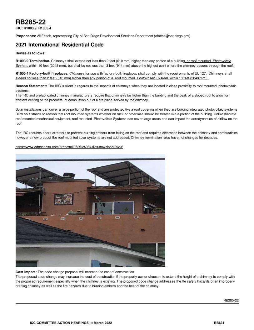
RB285-22IRC: R1003.9, R1005.4
Proponents: Ali Fattah, representing City of San Diego Development Services Department ([email protected])
2021 International Residential CodeRevise as follows:
R1003.9 Termination. Chimneys shall extend not less than 2 feet (610 mm) higher than any portion of a building, or roof mounted PhotovoltaicSystem, within 10 feet (3048 mm), but shall be not less than 3 feet (914 mm) above the highest point where the chimney passes through the roof.
R1005.4 Factory-built fireplaces. Chimneys for use with factory-built fireplaces shall comply with the requirements of UL 127. Chimneys shallextend not less than 2 feet (610 mm) higher than any portion of a roof mounted Photovoltaic System, within 10 feet (3048 mm).
Reason Statement: The IRC is silent in regards to the impacts of chimneys when they are located in close proximity to roof mounted photovoltaicsystems.The IRC and prefabricated chimney manufacturers require that chimneys be higher than the building and the peak of a sloped roof to allow forefficient venting of the products of combustion out of a fire place served by the chimney.
Solar installations can cover a large portion of the roof and are protected like a roof covering when they are building integrated photovoltaic systemsBIPV so it stands to reason that roof mounted systems whether on rack or otherwise should be treated like a portion of the building. Unlike discreteroof mounted mechanical equipment, roof mounted Photovoltaic Systems can cover large areas and can impact the aerodynamics of airflow on theroof.
The IRC requires spark arrestors to prevent burning embers from falling on the roof and requires clearance between the chimney and combustibleshowever a new product like roof mounted solar systems are not addressed. Chimney termination rules have not changed for decades.
https://www.cdpaccess.com/proposal/8525/24964/files/download/2923/
Cost Impact: The code change proposal will increase the cost of constructionThe proposed code change may increase the cost of construction if the property owner chooses to extend the height of a chimney to comply withthe proposed requirement especially when the chimney is existing. The proposed code change addresses the life safety hazards of an improperlydrafting chimney as well as the fire hazards due to burning embers and the heat of the chimney.
RB285-22
ICC COMMITTEE ACTION HEARINGS ::: March 2022 RB631

RB286-22IRC: R1003.18
Proponents: James Buckley, representing MACS, CFLI ([email protected])
2021 International Residential CodeRevise as follows:
R1003.18 Chimney clearances. Any portion of a masonry chimney located in the interior of the building or within the exterior wall of the building shallhave a minimum airspace clearance to combustibles of 2 inches (51 mm). Chimneys located entirely outside the exterior walls of the building,including chimneys that pass through the soffit or cornice, shall have a minimum airspace clearance of 1 inch (25 mm). The airspace shall not befilled, except for noncombustible insulation or to provide fire blocking in accordance with Section R1003.19.
Exceptions:
1. Masonry chimneys equipped with a chimney lining system listed and labeled for use in chimneys in contact with combustibles inaccordance with UL 1777 and installed in accordance with the manufacturer’s instructions are permitted to have combustible material incontact with their exterior surfaces.
2. Where masonry chimneys are constructed as part of masonry or concrete walls, combustible materials shall not be in contact with themasonry or concrete wall less than 12 inches (305 mm) from the inside surface of the nearest flue lining.
3. Exposed combustible trim and the edges of sheathing materials, such as wood siding and flooring, shall be permitted to abut the masonrychimney side walls, in accordance with Figure R1003.18, provided such combustible trim or sheathing is not less than 8 inches (203 mm)from the inside surface of the nearest flue lining.
Reason Statement: Studies have shown that the heat transferred through an insulated space is less than through an airspace because the heattransfer in air is by convection - not conduction. See engineering report at https://www.rumford.com/articleairspace.html
Bibliography: See engineering report at https://www.rumford.com/articleairspace.html
Cost Impact: The code change proposal will not increase or decrease the cost of constructionThis proposals clarifies that noncombustible insulation does not require insulation in air space.
RB286-22
ICC COMMITTEE ACTION HEARINGS ::: March 2022 RB632

RB287-22IRC: R1003.18
Proponents: James Buckley, representing MACS, CFLI ([email protected])
2021 International Residential CodeRevise as follows:
R1003.18 Chimney clearances. Any portion of a masonry chimney located in the interior of the building or within the exterior wall of the building shallhave a minimum airspace clearance to combustibles of 2 inches (51 mm). Chimneys located entirely outside the exterior walls of the building,including chimneys that pass through the soffit or cornice, shall have a minimum airspace clearance of 1 inch (25 mm). The airspace shall not befilled, except to provide fire blocking in accordance with Section R1003.19.
Exceptions:
1. Masonry chimneys equipped with a chimney lining system listed and labeled for use in chimneys in contact with combustibles inaccordance with UL 1777 and installed in accordance with the manufacturer’s instructions are permitted to have combustible material incontact with their exterior surfaces.
2. Where masonry chimneys are constructed as part of masonry or concrete walls, combustible materials shall not be in contact with themasonry or concrete wall less than 12 inches (305 mm) from the inside surface of the nearest flue lining.
3. Exposed combustible trim and the edges of sheathing materials, such as wood siding and flooring, Combustible materials shall bepermitted to abut the masonry chimney side walls, in accordance with Figure R1003.18, provided such combustible trim or sheathing material is not less than 8 inches (203 mm) from the inside surface of the nearest flue lining.
Reason Statement: The engineering study - https://www.rumford.com/code/EightInchThickTestReport.pdf - supporting the change from 12” to 8”in 2013 (RB458 - 13) compared an 8” thick chimney in contact with a combustible frame wall to a code-compliant 4” masonry wall plus 2” of airspace to the framing and found the 8” thick masonry wall in contact with combustible framing was safer. There is no reason to limit the requirementfor 8” thick chimney walls to “Exposed combustible trim and the edges of sheathing materials, such as wood siding and flooring”.
Bibliography: Engineering study - https://www.rumford.com/code/EightInchThickTestReport.pdf
Cost Impact: The code change proposal will not increase or decrease the cost of constructionThis change is just a clarification consistent with testing.
RB287-22
ICC COMMITTEE ACTION HEARINGS ::: March 2022 RB633

RB288-22IRC: R1003.18
Proponents: James Buckley, representing MACS, CFLI ([email protected])
2021 International Residential CodeRevise as follows:
R1003.18 Chimney clearances. Any portion of a masonry chimney located in the interior of the building or within the exterior wall of the building shallhave a minimum airspace clearance to combustibles of 2 inches (51 mm). Chimneys located entirely outside the exterior walls of the building,including chimneys that pass through the soffit or cornice, shall have a minimum airspace clearance of 1 inch (25 mm). The airspace shall not befilled, except to provide fire blocking in accordance with Section R1003.19.
Exceptions:
1. Masonry chimneys equipped with a chimney lining system listed and labeled for use in chimneys in contact with combustibles inaccordance with UL 1777 and installed in accordance with the manufacturer’s instructions are permitted to have combustible material incontact with their exterior surfaces.
2. Where masonry chimneys are constructed as part of masonry or concrete walls, combustible materials shall not be in contact with themasonry or concrete wall less than 12 inches (305 mm) 8 inches (203 mm) from the inside surface of the nearest flue lining.
3. Exposed combustible trim and the edges of sheathing materials, such as wood siding and flooring, shall be permitted to abut the masonrychimney side walls, in accordance with Figure R1003.18, provided such combustible trim or sheathing is not less than 8 inches (203 mm)from the inside surface of the nearest flue lining.
Reason Statement: The engineering study - https://www.rumford.com/code/EightInchThickTestReport.pdf - supporting the change from 12” to 8”in Exception 3 in 2013 (RB458 - 13) compared an 8” thick chimney in contact with a combustible frame wall to a code-compliant 4” masonry wallplus 2” of air space to the framing and found the 8” thick masonry wall in contact with combustible framing was safer. This is just a special case.Keeping combustibles at least 8”of solid masonry away from the inside surface of the nearest flue lining to make Exception 2 consistent withException 3.
Bibliography: The engineering study - https://www.rumford.com/code/EightInchThickTestReport.pdf
Cost Impact: The code change proposal will not increase or decrease the cost of constructionThis is a change in dimension only that will cost nothing.
RB288-22
ICC COMMITTEE ACTION HEARINGS ::: March 2022 RB634

RB289-22IRC: R1004.4
Proponents: Jonathan Roberts, representing UL ([email protected])
2021 International Residential CodeRevise as follows:
R1004.4 Unvented gas log heaters. An unvented gas log heater or a fireplace insert shall not be installed in a factory-built fireplace unless thefireplace system has been specifically tested, listed and labeled for such use in accordance with UL 127.
Reason Statement: An unvented gas log heater is not permitted in a factory-built fireplace, unless the fire place system has been specificallytested, listed and labeled for such use in accordance with UL 127. This is because the addition of an unvented gas log heater within a firebox canalter the temperatures on the outside of the factory-built fireplace, which are typically installed with zero clearances to combustible materials. Thesame fire safety concern applies to the addition of a fireplace insert within a factory-built fireplace.
Cost Impact: The code change proposal will increase the cost of constructionIt is possible that listed fireplace inserts might be slightly more expensive than unlisted units, but we are not aware of specific cost differencesbetween the two.
RB289-22
ICC COMMITTEE ACTION HEARINGS ::: March 2022 RB635

RB290-22IRC: AF103.6.1
Proponents: David Kapturowski, representing American Association of Radon Scientists and Technologists; Jane Malone, American Association ofRadon Scientists and Technologists, representing American Association of Radon Scientists and Technologists; Jonathan Wilson, representingNational Center for Healthy Housing ([email protected]); Kevin Stewart, representing American Lung Association ([email protected]);Thomas Bowles, representing EPA ([email protected]); Ruth McBurney, representing Conference of Radiation Control Program Directors([email protected])
2021 International Residential CodeRevise as follows:
AF103.6.1 Subslab Vent pipe. A minimum 3-inch-diameter (76 mm) ABS, PVC or equivalent gastight pipe shall be embedded vertically into thesubslab aggregate or other permeable material before the slab is cast. A “T” fitting or equivalent method shall be used to ensure that the pipeopening remains within the subslab permeable material. Not less than 4 feet (102 cm) of perforated pipe or geotextile matting shall be connected toeach of the horizontal openings of the tee fitting. Alternatively, the 3-inch (76 mm) pipe shall be inserted directly into an interior perimeter drain tileloop or through a sealed sump cover where the sump is exposed to the subslab aggregate or connected to it through a drainage system. The pipeshall be extended up through the building floors, and terminate not less than 12 inches (305 mm) above the surface of the roof in a location not lessthan 10 feet (3048 mm) away from any window or other opening into the conditioned spaces of the building that is less than 2 feet (610 mm) belowthe exhaust point, and 10 feet (3048 mm) from any window or other opening in adjoining or adjacent buildings. All above ground material used shallcomply with Section P3002.1.
Reason Statement: This proposal prevents a common field problem where the plumbing "tee" fitting fills with concrete when the slab is cast andclarifies that the pipe and fitting material requirements shall be consistent with the IRC.
Cost Impact: The code change proposal will increase the cost of constructionAdditional 10-foot pipe, costing approximately $10-15, is required.
RB290-22
ICC COMMITTEE ACTION HEARINGS ::: March 2022 RB636

RB291-22IRC: AF103.8
Proponents: David Kapturowski, representing American Association of Radon Scientists and Technologists; Jane Malone, representing AmericanAssociation of Radon Scientists and Technologists ([email protected]); Thomas Bowles, representing EPA ([email protected]);Jonathan Wilson, representing National Center for Healthy Housing ([email protected]); Kevin Stewart, representing American Lung Association([email protected]); Ruth McBurney, representing Conference of Radiation Control Program Directors ([email protected])
2021 International Residential CodeRevise as follows:
AF103.8 Vent pipe accessibility. Radon vent pipes shall be accessible for future fan installation through an attic or other area outside the habitablespace. The pipe shall be centered in an unobstructed cylindrical space having a height of not less than 36 inches (91 cm) and a diameter of not lessthan 18 inches (46 cm) in the location where the fan would be installed.
Exception: The radon vent pipe need not be accessible accessed from in an attic space where an approved roof-top electrical supply isprovided for future use on the roof top or other area outside the habitable space.
Reason Statement: This change simply reserves adequate space in the attic for future installation of a radon fan. If there is not enough room toadd a fan if needed then the entire piping system must be abandoned and redone. This is a common field failure where the pipe is run too close tothe eave and is inaccessible.
Cost Impact: The code change proposal will not increase or decrease the cost of constructionThis proposal defines a volume of space in an attic location where a radon fan can be installed, if necessary. No new material costs are added,however, the defined volume space requirement assists with proper pipe layout design to facilitate any future fan installation.
RB291-22
ICC COMMITTEE ACTION HEARINGS ::: March 2022 RB637
RB292-22IRC: AF103.5.3
Proponents: David Kapturowski, representing American Association of Radon Scientists and Technologists; Jane Malone, representing AmericanAssociation of Radon Scientists and Technologists ([email protected]); Thomas Bowles, representing EPA ([email protected]);Jonathan Wilson, representing National Center for Healthy Housing ([email protected]); Kevin Stewart, representing American Lung Association([email protected]); Ruth McBurney, representing Conference of Radiation Control Program Directors ([email protected])
2021 International Residential CodeRevise as follows:
AF103.5.3 Submembrane Vent pipe. A plumbing tee or other approved connection shall be inserted horizontally beneath the sheeting andconnected to a 3- or 4-inch-diameter (76 or 102 mm) fitting with a vertical vent pipe installed through the sheeting. Not less than 10 feet (254 cm) ofperforated pipe or geotextile matting shall be connected to each of the horizontal openings of the tee fitting or the two hoizontal openings shall beconnected to the interior drain tile system. The vent pipe shall be extended up through the building floors, and terminate not less than 12 inches (305mm) above the roof in a location not less than 10 feet (3048 mm) away from any window or other opening into the conditioned spaces of the buildingthat is less than 2 feet (610 mm) below the exhaust point, and 10 feet (3048 mm) from any window or other opening in adjoining or adjacentbuildings. Above ground pipe material shall comply with Section P3002.1.
Reason Statement: It is a common field problem where the horizontal openings of the "tee" fitting will be closed off by suction on the membrane. This makes the suction point non-functional. The proposal further clarifies the piping material consistent with the IRC plumbing section.
Cost Impact: The code change proposal will increase the cost of construction(2)10 foot stick of perforated pipe are additionally required for the system. This will cost $20-$25.
RB292-22
ICC COMMITTEE ACTION HEARINGS ::: March 2022 RB638

RB293-22IRC: AF103.3
Proponents: David Kapturowski, representing American Association of Radon Scientists and Technologists; Jane Malone, representing AmericanAssociation of Radon Scientists and Technologists ([email protected]); Thomas Bowles, representing EPA ([email protected]);Jonathan Wilson, representing National Center for Healthy Housing ([email protected]); Kevin Stewart, representing American Lung Association([email protected]); Ruth McBurney, representing Conference of Radiation Control Program Directors ([email protected])
2021 International Residential CodeRevise as follows:
AF103.3 Soil-gas-retarder. A minimum 6-mil (0.15 mm) [or 3-mil (0.075 mm) cross-laminated] polyethylene ASTM E1745 Class A or equivalentflexible sheeting material shall be placed on top of the gas-permeable layer prior to casting the slab or placing the floor assembly to serve as a soil-gas-retarder by bridging any cracks that develop in the slab or floor assembly, and to prevent concrete from entering the void spaces in theaggregate base material. The sheeting shall cover the entire floor area with separate sections of sheeting lapped not less than 12 inches (305 mm).The sheeting shall fit closely around any pipe, wire or other penetrations of the material. Punctures or tears in the material shall be sealed or coveredwith additional sheeting.
Reason Statement: This change makes the Appendix consistent with the material requirements in the body of the code.
Cost Impact: The code change proposal will not increase or decrease the cost of constructionAn ASTM 1745 Class A vapor retarder is already required in R506.2.3.
RB293-22
ICC COMMITTEE ACTION HEARINGS ::: March 2022 RB639

RB294-22IRC: AF101.1, FIGURE AF101.1, TABLE AF101.1
Proponents: Thomas Bowles, representing EPA ([email protected]); Jane Malone, representing American Association of Radon Scientistsand Technologists ([email protected]); Jonathan Wilson, representing National Center for Healthy Housing ([email protected]); KevinStewart, representing American Lung Association ([email protected]); Ruth McBurney, representing Conference of Radiation ControlProgram Directors
2021 International Residential CodeRevise as follows:
AF101.1 General. This appendix contains requirements for new construction in jurisdictions where radon-resistant construction is required.Inclusion of this appendix by jurisdictions shall be determined through the use of locally available data or determination of Zone 1 designation inFigure AF101.1 and Table AF101.1.
Delete without substitution:
ICC COMMITTEE ACTION HEARINGS ::: March 2022 RB640

1. a.pCi/L stands for picocuries per liter of radon gas. The US Environmental Protection Agency (EPA) recommends that homes that measure 4pCi/L and greater be mitigated.
The EPA and the US Geological Survey have evaluated the radon potential in the United States and have developed a map of radon zonesdesigned to assist building officials in deciding whether radon-resistant features are applicable in new construction.
The map assigns each of the 3,141 counties in the United States to one of three zones based on radon potential. Each zone designationreflects the average short-term radon measurement that can be expected to be measured in a building without the implementation of radon-control methods. The radon zone designation of highest priority is Zone 1. Table AF101.1 lists the Zone 1 counties illustrated on the map. More detailed information can be obtained from state-specific booklets (EPA-401-R-93-021 through 070) available through the State RadonOffices or from the EPA Regional Offices.
FIGURE AF101.1 EPA MAP OF RADON ZONES
a
ICC COMMITTEE ACTION HEARINGS ::: March 2022 RB641

TABLE AF101.1 HIGH RADON-POTENTIAL (ZONE 1) COUNTIES
ALABAMA
Calhoun
Clay
Cleburne
Colbert
Coosa
Franklin
Jackson
Lauderdale
Lawrence
Limestone
Madison
Morgan
Talladega
CALIFORNIA
Santa Barbara
Ventura
COLORADO
Adams
Arapahoe
Baca
Bent
Boulder
Chaffee
Cheyenne
Clear Creek
Crowley
Custer
Delta
Denver
Dolores
Douglas
El Paso
Elbert
Fremont
Garfield
Gilpin
Grand
Gunnison
Huerfano
Jackson
Jefferson
Kiowa
Kit Carson
Lake
Larimer
Las Animas
Lincoln
a
ICC COMMITTEE ACTION HEARINGS ::: March 2022 RB642

Logan
Mesa
Moffat
Montezuma
Montrose
Morgan
Otero
Ouray
Park
Phillips
Pitkin
Prowers
Pueblo
Rio Blanco
San Miguel
Summit
Teller
Washington
Weld
Yuma
CONNECTICUT
Fairfield
Middlesex
New Haven
New London
GEORGIA
Cobb
De Kalb
Fulton
Gwinnett
IDAHO
Benewah
Blaine
Boise
Bonner
Boundary
Butte
Camas
Clark
Clearwater
Custer
Elmore
Fremont
Gooding
Idaho
Kootenai
Latah
Lemhi
Shoshone
ICC COMMITTEE ACTION HEARINGS ::: March 2022 RB643
Valley
ILLINOIS
Adams
Boone
Brown
Bureau
Calhoun
Carroll
Cass
Champaign
Coles
De Kalb
De Witt
Douglas
Edgar
Ford
Fulton
Greene
Grundy
Hancock
Henderson
Henry
Iroquois
Jersey
Jo Daviess
Kane
Kendall
Knox
La Salle
Lee
Livingston
Logan
Macon
Marshall
Mason
McDonough
McLean
Menard
Mercer
Morgan
Moultrie
Ogle
Peoria
Piatt
Pike
Putnam
Rock Island
Sangamon
ICC COMMITTEE ACTION HEARINGS ::: March 2022 RB644

Schuyler
Scott
Stark
Stephenson
Tazewell
Vermilion
Warren
Whiteside
Winnebago
Woodford
INDIANA
Adams
Allen
Bartholomew
Benton
Blackford
Boone
Carroll
Cass
Clark
Clinton
De Kalb
Decatur
Delaware
Elkhart
Fayette
Fountain
Fulton
Grant
Hamilton
Hancock
Harrison
Hendricks
Henry
Howard
Huntington
Jay
Jennings
Johnson
Kosciusko
LaGrange
Lawrence
Madison
Marion
Marshall
Miami
Monroe
Montgomery
Noble
ICC COMMITTEE ACTION HEARINGS ::: March 2022 RB645

Orange
Putnam
Randolph
Rush
Scott
Shelby
St. Joseph
Steuben
Tippecanoe
Tipton
Union
Vermillion
Wabash
Warren
Washington
Wayne
Wells
White
Whitley
IOWA
All Counties
KANSAS
Atchison
Barton
Brown
Cheyenne
Clay
Cloud
Decatur
Dickinson
Douglas
Ellis
Ellsworth
Finney
Ford
Geary
Gove
Graham
Grant
Gray
Greeley
Hamilton
Haskell
Hodgeman
Jackson
Jewell
Johnson
Kearny
Kingman
ICC COMMITTEE ACTION HEARINGS ::: March 2022 RB646

Kiowa
Lane
Leavenworth
Lincoln
Logan
Marion
Marshall
McPherson
Meade
Mitchell
Nemaha
Ness
Norton
Osborne
Ottawa
Pawnee
Phillips
Pottawatomie
Pratt
Rawlins
Republic
Rice
Riley
Rooks
Rush
Saline
Scott
Sheridan
Sherman
Smith
Stanton
Thomas
Trego
Wallace
Washington
Wichita
Wyandotte
KENTUCKY
Adair
Allen
Barren
Bourbon
Boyle
Bullitt
Casey
Clark
Cumberland
Fayette
Franklin
ICC COMMITTEE ACTION HEARINGS ::: March 2022 RB647

Green
Harrison
Hart
Jefferson
Jessamine
Lincoln
Marion
Mercer
Metcalfe
Monroe
Nelson
Pendleton
Pulaski
Robertson
Russell
Scott
Taylor
Warren
Woodford
MAINE
Androscoggin
Aroostook
Cumberland
Franklin
Hancock
Kennebec
Lincoln
Oxford
Penobscot
Piscataquis
Somerset
York
MARYLAND
Baltimore
Calvert
Carroll
Frederick
Harford
Howard
Montgomery
Washington
MASS.
Essex
Middlesex
Worcester
MICHIGAN
Branch
Calhoun
Cass
ICC COMMITTEE ACTION HEARINGS ::: March 2022 RB648

Hillsdale
Jackson
Kalamazoo
Lenawee
St. Joseph
Washtenaw
MINNESOTA
Becker
Big Stone
Blue Earth
Brown
Carver
Chippewa
Clay
Cottonwood
Dakota
Dodge
Douglas
Faribault
Fillmore
Freeborn
Goodhue
Grant
Hennepin
Houston
Hubbard
Jackson
Kanabec
Kandiyohi
Kittson
Lac Qui Parle
Le Sueur
Lincoln
Lyon
Mahnomen
Marshall
Martin
McLeod
Meeker
Mower
Murray
Nicollet
Nobles
Norman
Olmsted
Otter Tail
Pennington
Pipestone
Polk
ICC COMMITTEE ACTION HEARINGS ::: March 2022 RB649

Pope
Ramsey
Red Lake
Redwood
Renville
Rice
Rock
Roseau
Scott
Sherburne
Sibley
Stearns
Steele
Stevens
Swift
Todd
Traverse
Wabasha
Wadena
Waseca
Washington
Watonwan
Wilkin
Winona
Wright
Yellow Medicine
MISSOURI
Andrew
Atchison
Buchanan
Cass
Clay
Clinton
Holt
Iron
Jackson
Nodaway
Platte
MONTANA
Beaverhead
Big Horn
Blaine
Broadwater
Carbon
Carter
Cascade
Chouteau
Custer
Daniels
ICC COMMITTEE ACTION HEARINGS ::: March 2022 RB650
Dawson
Deer Lodge
Fallon
Fergus
Flathead
Gallatin
Garfield
Glacier
Granite
Hill
Jefferson
Judith Basin
Lake
Lewis and Clark
Madison
McCone
Meagher
Missoula
Park
Phillips
Pondera
Powder River
Powell
Prairie
Ravalli
Richland
Roosevelt
Rosebud
Sanders
Sheridan
Silver Bow
Stillwater
Teton
Toole
Valley
Wibaux
Yellowstone
NEBRASKA
Adams
Boone
Boyd
Burt
Butler
Cass
Cedar
Clay
Colfax
Cuming
ICC COMMITTEE ACTION HEARINGS ::: March 2022 RB651

Dakota
Dixon
Dodge
Douglas
Fillmore
Franklin
Frontier
Furnas
Gage
Gosper
Greeley
Hamilton
Harlan
Hayes
Hitchcock
Hurston
Jefferson
Johnson
Kearney
Knox
Lancaster
Madison
Nance
Nemaha
Nuckolls
Otoe
Pawnee
Phelps
Pierce
Platte
Polk
Red Willow
Richardson
Saline
Sarpy
Saunders
Seward
Stanton
Thayer
Washington
Wayne
Webster
York
NEVADA
Carson City
Douglas
Eureka
Lander
Lincoln
ICC COMMITTEE ACTION HEARINGS ::: March 2022 RB652

Lyon
Mineral
Pershing
White Pine
NEW HAMPSHIRE
Carroll
NEW JERSEY
Hunterdon
Mercer
Monmouth
Morris
Somerset
Sussex
Warren
NEW MEXICO
Bernalillo
Colfax
Mora
Rio Arriba
San Miguel
Santa Fe
Taos
NEW YORK
Albany
Allegany
Broome
Cattaraugus
Cayuga
Chautauqua
Chemung
Chenango
Columbia
Cortland
Delaware
Dutchess
Erie
Genesee
Greene
Livingston
Madison
Onondaga
Ontario
Orange
Otsego
Putnam
Rensselaer
Schoharie
Schuyler
Seneca
ICC COMMITTEE ACTION HEARINGS ::: March 2022 RB653

Steuben
Sullivan
Tioga
Tompkins
Ulster
Washington
Wyoming
Yates
N. CAROLINA
Alleghany
Buncombe
Cherokee
Henderson
Mitchell
Rockingham
Transylvania
Watauga
N. DAKOTA
All Counties
OHIO
Adams
Allen
Ashland
Auglaize
Belmont
Butler
Carroll
Champaign
Clark
Clinton
Columbiana
Coshocton
Crawford
Darke
Delaware
Fairfield
Fayette
Franklin
Greene
Guernsey
Hamilton
Hancock
Hardin
Harrison
Holmes
Huron
Jefferson
Knox
ICC COMMITTEE ACTION HEARINGS ::: March 2022 RB654

Licking
Logan
Madison
Marion
Mercer
Miami
Montgomery
Morrow
Muskingum
Perry
Pickaway
Pike
Preble
Richland
Ross
Seneca
Shelby
Stark
Summit
Tuscarawas
Union
Van Wert
Warren
Wayne
Wyandot
PENNSYLVANIA
Adams
Allegheny
Armstrong
Beaver
Bedford
Berks
Blair
Bradford
Bucks
Butler
Cameron
Carbon
Centre
Chester
Clarion
Clearfield
Clinton
Columbia
Cumberland
Dauphin
Delaware
Franklin
Fulton
ICC COMMITTEE ACTION HEARINGS ::: March 2022 RB655

Huntingdon
Indiana
Juniata
Lackawanna
Lancaster
Lebanon
Lehigh
Luzerne
Lycoming
Mifflin
Monroe
Montgomery
Montour
Northampton
Northumberland
Perry
Schuylkill
Snyder
Sullivan
Susquehanna
Tioga
Union
Venango
Westmoreland
Wyoming
York
RHODE ISLAND
Kent
Washington
S. CAROLINA
Greenville
S. DAKOTA
Aurora
Beadle
Bon Homme
Brookings
Brown
Brule
Buffalo
Campbell
Charles Mix
Clark
Clay
Codington
Corson
Davison
Day
Deuel
Douglas
ICC COMMITTEE ACTION HEARINGS ::: March 2022 RB656

Edmunds
Faulk
Grant
Hamlin
Hand
Hanson
Hughes
Hutchinson
Hyde
Jerauld
Kingsbury
Lake
Lincoln
Lyman
Marshall
McCook
McPherson
Miner
Minnehaha
Moody
Perkins
Potter
Roberts
Sanborn
Spink
Stanley
Sully
Turner
Union
Walworth
Yankton
TENNESEE
Anderson
Bedford
Blount
Bradley
Claiborne
Davidson
Giles
Grainger
Greene
Hamblen
Hancock
Hawkins
Hickman
Humphreys
Jackson
Jefferson
Knox
ICC COMMITTEE ACTION HEARINGS ::: March 2022 RB657

Lawrence
Lewis
Lincoln
Loudon
Marshall
Maury
McMinn
Meigs
Monroe
Moore
Perry
Roane
Rutherford
Smith
Sullivan
Trousdale
Union
Washington
Wayne
Williamson
Wilson
UTAH
Carbon
Duchesne
Grand
Piute
Sanpete
Sevier
Uintah
VIRGINIA
Alleghany
Amelia
Appomattox
Augusta
Bath
Bland
Botetourt
Bristol
Brunswick
Buckingham
Buena Vista
Campbell
Chesterfield
Clarke
Clifton Forge
Covington
Craig
Cumberland
Danville
ICC COMMITTEE ACTION HEARINGS ::: March 2022 RB658

Dinwiddie
Fairfax
Falls Church
Fluvanna
Frederick
Fredericksburg
Giles
Goochland
Harrisonburg
Henry
Highland
Lee
Lexington
Louisa
Martinsville
Montgomery
Nottoway
Orange
Page
Patrick
Pittsylvania
Powhatan
Pulaski
Radford
Roanoke
Rockbridge
Rockingham
Russell
Salem
Scott
Shenandoah
Smyth
Spotsylvania
Stafford
Staunton
Tazewell
Warren
Washington
Waynesboro
Winchester
Wythe
WASHINGTON
Clark
Ferry
Okanogan
Pend Oreille
Skamania
Spokane
Stevens
ICC COMMITTEE ACTION HEARINGS ::: March 2022 RB659

W. VIRGINIA
Berkeley
Brooke
Grant
Greenbrier
Hampshire
Hancock
Hardy
Jefferson
Marshall
Mercer
Mineral
Monongalia
Monroe
Morgan
Ohio
Pendleton
Pocahontas
Preston
Summers
Wetzel
WISCONSIN
Buffalo
Crawford
Dane
Dodge
Door
Fond du Lac
Grant
Green
Green Lake
Iowa
Jefferson
Lafayette
Langlade
Marathon
Menominee
Pepin
Pierce
Portage
Richland
Rock
Shawano
St. Croix
Vernon
Walworth
Washington
Waukesha
Waupaca
ICC COMMITTEE ACTION HEARINGS ::: March 2022 RB660

Wood
WYOMING
Albany
Big Horn
Campbell
Carbon
Converse
Crook
Fremont
Goshen
Hot Springs
Johnson
Laramie
Lincoln
Natrona
Niobrara
Park
Sheridan
Sublette
Sweetwater
Teton
Uinta
Washakie
a. The EPA recommends that this county listing be supplemented with other available state and local data to further understand the radonpotential of a Zone 1 area.
Reason Statement: The EPA map and Zone 1 county list are based in part on a 1993 survey that measured radon in 5694 homes, less than twoper each of the 3141 counties in the US. As more recent data have been compiled by states and the US Centers for Disease Control andPrevention, it is evident that more counties' average radon test results equal or exceed the EPA action level.
Radon Zone 1 counties are defined as having a predicted year-round average indoor radon screening level in the lowest livable area of a structuregreater than or equal to four picocuries per liter of air (pCi/L). Relying on an average radon level does not address the full range of risk within a givencounty. Levels greater than 4 have been found in 85% of US counties tested.
Restricting localities as to when or how they may include the appendix ("shall be determined through") can cause this appendix to conflict with localauthority.
While opponents may suggest otherwise, deleting the county information does not impose a requirement for adoption in Zones 2 and 3. Appendix Fwill remain an optional appendix that is only in effect where the jurisdiction has adopted it.
In response to stakeholder feedback EPA has been deemphasizing the use of the EPA zone map as a reference for building codes andspecifications. The purpose of the EPA radon zone map, since its inception, has been to show potential of risk not ACTUAL risk. While it is still auseful tool, it unintentionally creates a false sense of security for those in Zone 2 and Zone 3 that risk in those areas is non-existent. With this inmind, the EPA Indoor airPLUS program (a voluntary partnership and labeling program that helps new home builders improve the Indoor AirQuality) plans to include testing in ALL ZONES in its upcoming Version 2 update. The fact remains that radon is found in all zones and to trulyprotect against radon you need to test regardless of zone.
It is suggested that the following information be added to the Commentary for the IRC: Code officials seeking radon risk information may consult with
ICC COMMITTEE ACTION HEARINGS ::: March 2022 RB661

the state radon programs listed at https://www.crcpd.org/page/Radon or information listed at https://www.epa.gov/radon/epa-map-radon-zones-and-supplemental-information#datainfo.
Cost Impact: The code change proposal will increase the cost of constructionAdoption of the Appendix adds to the cost of construction. According to results from the Home Innovations Research Lab’s survey of homebuilders,the average installation cost for a passive system in 2019 for a single‐family detached home was approximately $463, up from the $377 reported for2018 and $367 reported for 2017.
RB294-22
ICC COMMITTEE ACTION HEARINGS ::: March 2022 RB662

RB295-22IRC: AF103.2
Proponents: David Kapturowski, representing American Association of Radon Scientists and Technologists; Jane Malone, representing AmericanAssociation of Radon Scientists and Technologists ([email protected]); Thomas Bowles, representing EPA ([email protected]);Jonathan Wilson, representing National Center for Healthy Housing ([email protected]); Kevin Stewart, representing American Lung Association([email protected]); Ruth McBurney, representing Conference of Radiation Control Program Directors ([email protected])
2021 International Residential CodeRevise as follows:
AF103.2 Subfloor preparation. A layer of gas-permeable material shall be placed under all concrete slabs and other floor systems that directlycontact the ground and are within the walls of the living spaces of the building, to facilitate future installation of a subslab depressurization system, ifneeded. The gas-permeable layer shall consist of one of the following:
1. A uniform layer of clean aggregate, not less than 4 inches (102 mm) thick. The aggregate shall consist of material that will pass through a 2-inch (51 mm) sieve and be retained by a / -inch (6.4 mm) sieve.
2. A uniform layer of sand (native or fill), not less than 4 inches (102 mm) thick, overlain by a layer or strips of geotextile drainage mattingdesigned to allow the lateral flow of soil gases.
Exception: A sand base course is not required under geotextile drainage matting where the concrete slab is installed on well-drained orsand-gravel mixture soil classified as Group 1 according to the United Soil Classification in accordance with Table R405.1
3. Other materials, systems or floor designs with demonstrated capability to permit depressurization across the entire subfloor area.
Reason Statement: Well drained soils do not require a sand layer and the matting can be laid right on the native soils, where applicable.
Cost Impact: The code change proposal will decrease the cost of constructionThis will eliminate the requirement for a sand base layer where appropriate soils exist.
RB295-22
14
ICC COMMITTEE ACTION HEARINGS ::: March 2022 RB663

RB296-22IRC: SECTION AJ108.1
Proponents: Jay Crandell, P.E., ABTG/ARES Consulting, representing Foam Sheathing Committee of the American Chemistry Council([email protected])
2021 International Residential Code
SECTION AJ108RENOVATIONS
Revise as follows:
AJ108.1 Materials and methods. The work shall comply with the materials and methods requirements of this code. For the purpose of compliancewith Chapter 11 of this code, a renovation shall be included within the scope of an alteration as defined in Chapter 11.
Reason Statement: Chapter 11 does not address energy efficiency requirements separately for “renovations” as it considers them in a morebroadly defined category of “alterations” (see Chapter 11 and Appendix AJ definitions below). For example, the definition of “alteration” in Chapter11 is inclusive of renovation but the connection to a separate use of the defined term “renovation” in Appendix AJ is not obvious. This proposalprovides a necessary clarification to avoid conflict between requirements in Chapter 11 of the IRC for existing building (particularly Section N1111)and in Appendix AJ in relation to work performed on existing buildings.The following are definitions for Alternation and Renovation in Appendix AJ Section 106:
ALTERATION. The reconfiguration of any space; the addition or elimination of any door or window; the reconfiguration or extension of anysystem; or the installation of any additional equipment.
RENOVATION. The change, strengthening or addition of load-bearing elements; or the refinishing, replacement, bracing, strengthening,upgrading or extensive repair of existing materials, elements, components, equipment or fixtures. Renovation does not involve reconfiguration ofspaces. Interior and exterior painting are not considered refinishing for purposes of this definition, and are not renovation.
The following is the definition for Alteration in Chapter 11 of the IRC:
ALTERATION. Any construction, retrofit or renovation to an existing structure other than repair or addition. Also, a change in a building, electrical,gas, mechanical or plumbing system that involves an extension, addition or change to the arrangement, type or purpose of the originalinstallation.
Renovation is not separately defined in Chapter 11 of the IRC.
Cost Impact: The code change proposal will not increase or decrease the cost of constructionThis proposal establishes the proper usage of terms and their alignment between Appendix AJ and IRC Chapter 11 so that the application of theexisting requirements are better coordinated. The proposal does not change the existing technical requirements in Chapter 11 or in Appendix AJ sothere is no change in cost.
RB296-22
ICC COMMITTEE ACTION HEARINGS ::: March 2022 RB664

RB297-22IRC: APPENDIX AJ, SECTION AJ101.1, AJ102.1, AJ102.2 (New), AJ104.1, AJ107.4 (New), AJ108.4, AJ109.4, AJ110.5 (New)
Proponents: Julie Furr, representing FEMA-ATC Seismic Code Support Committee ([email protected]); Kelly Cobeen, representing FederalEmergency Management Agency/Applied Technology Council - Seismic Code Support Committee ([email protected]); Michael Mahoney,representing FEMA ([email protected])
2021 International Residential CodeRevise as follows:
APPENDIX AJEXISTING BUILDINGS AND STRUCTURES
SECTION AJ101PURPOSE AND INTENT
Revise as follows:
AJ101.1 General. The purpose of these provisions is to encourage the continued use or reuse of legally existing buildings and structures. Theseprovisions are intended to permit work in existing buildings that is consistent with the purpose of this code. Compliance with these provisions shall bedeemed to meet the requirements of this code. Structural elements and systems shall comply with Section R102.7.1 and Chapter 3 through Chapter10 of the International Residential Code.
SECTION AJ102COMPLIANCE
Revise as follows:
AJ102.1 General. Regardless of the category of work being performed, the work shall not cause the building structure to become unsafe oradversely affect the performance of the building; shall not cause an existing mechanical or plumbing system to become unsafe, hazardous,insanitary or overloaded; and unless expressly permitted by these provisions, shall not make the building any less compliant with this code or to anypreviously approved alternative arrangements than it was before the work was undertaken.
Add new text as follows:
AJ102.2 Structural. Structural elements and systems that are altered, repaired, or replaced shall comply with Section R102.7.1 and the structuralprovisions of Chapter 3 through Chapter 10 of the International Residential Code. The work performed shall not cause the structure to become lesscompliant with the International Residential Code than it was before the work was undertaken.
SECTION AJ104EVALUATION OF AN EXISTING BUILDING
Revise as follows:
AJ104.1 General. The building official shall have the authority to require an existing building to be investigated and evaluated by a registered designprofessional in the case of proposed reconstruction of any portion of a building. The evaluation shall determine the existence of any potentialnonconformities to these provisions and Section R102.7.1 and structural provisions of the International Residential Code, and shall provide a basisfor determining the impact of the proposed changes on the performance of the building. The evaluation shall use the following sources of information,as applicable:
1. Available documentation of the existing building.
1.1. Field surveys.
1.2. Tests (nondestructive and destructive).
1.3. Laboratory analysis.
Exception: Detached one- or two-family dwellings that are not irregular buildings under Section R301.2.2.6 and are not undergoing an extensivereconstruction shall not be required to be evaluated.
SECTION AJ107REPAIRS
ICC COMMITTEE ACTION HEARINGS ::: March 2022 RB665
Add new text as follows:
AJ107.4 Structural. Repaired structural elements and systems shall comply with Section R102.7.1 and the structural provisions of Chapter 3through Chapter 10 of the International Residential Code.
SECTION AJ108RENOVATIONS
Revise as follows:
AJ108.4 Structural. Structural elements and systems modified by the renovation shall comply with Section R102.7.1 and the structural provisions ofChapter 3 through Chapter 10 of the International Residential Code. Unreinforced masonry buildings located in Seismic Design Category D or Eshall have parapet bracing and wall anchors installed at the roofline whenever a reroofing permit is issued. Such parapet bracing and wall anchorsshall be of an approved design.
SECTION AJ109ALTERATIONS
Revise as follows:
AJ109.4 Structural. Altered structural elements and systems shall comply with Section R102.7.1 and the structural provisions of Chapter 3 throughChapter 10 of the International Residential Code. The minimum design loads for the structure shall be the loads applicable at the time the buildingwas constructed, provided that a dangerous condition is not created. Structural elements that are uncovered during the course of the alteration andthat are found to be unsound or dangerous shall be made to comply with the applicable requirements of this code.
SECTION AJ110RECONSTRUCTION
Add new text as follows:
AJ110.5 Structural. Reconstructed structural elements and systems shall comply with Section R102.7.1 and the structural provisions of Chapter 3through Chapter 10 of the International Residential Code for new construction.
Reason Statement: This proposal aligns the structural provisions of Appendix AJ with the main body of the IRC. Appendix AJ has not beenupdated to correlate with changes in the IRC and IEBC provisions that have occurred during recent code cycles. However, Section AJ101.1 states:“Compliance with these provisions shall be deemed to meet the requirements of this code.” Given both the limitations of the structural requirementsoutlined in Appendix AJ and the disconnect between the appendix and main body of the codes (IRC and IEBC), allowing this Appendix to beconsidered “deemed to comply” is dangerous with regard to the structure.
Cost Impact: The code change proposal will not increase or decrease the cost of constructionThis proposal will not increase the cost of construction within the IRC, since the main body of the IRC is the default resource used given the presentlimitations of Appendix AJ.
RB297-22
2
ICC COMMITTEE ACTION HEARINGS ::: March 2022 RB666

RB298-22IRC: AJ102.4.3, AJ102.4.3.1
Proponents: Mike Nugent, representing Building Code Action Committee ([email protected])
2021 International Residential CodeRevise as follows:
AJ102.4.3 Replacement windows for emergency escape and rescue openings. Where windows are required to provide emergency escapeand rescue openings, replacement windows shall be exempt from Sections R310.2 and R310.4.4 provided that the replacement window meets thefollowing conditions:
1. The replacement window is the manufacturer’s largest standard size window that will fit within the existing frame or existing rough opening.The replacement window shall be permitted to be of the same operating style as the existing window or a style that provides for an equal orgreater window opening area than the existing window.
2. Where the replacement window is not part of a change of occupancy.
3. Window opening control devices complying with F409—2017 shall be permitted for use on windows required to provide emergency escapeand rescue openings.
Window opening control devices and fall prevention devices complying with ASTM F2090 shall be permitted for use on windows serving as requiredemergency escape and rescue openings.
AJ102.4.3.1 Control devices. Window opening control devices or fall prevention devices complying with ASTM F2090 shall be permitted for use onwindows required to provide emergency escape and rescue openings. Emergency escape and rescue openings with window opening controldevices or fall prevention devices complying with ASTM F2090, Aafter operation to release the control device allowing the window to fully open, thecontrol device shall not reduce the net clear opening area of the window unit. Emergency escape and rescue openings shall be operational from theinside of the room without the use of keys or tools.
Reason Statement: This is a coordination item. The proposed text is what is found in IEBC Section 505.3.1 and 702.5.1 for control devices onexisting windows that are used for emergency escape and rescue. The same phraseology/intent is in appendix J, but is written differently. Thiscould be read as asking for something different, which is not the case. This also better coordinates with R310.5. This proposal is submitted by the ICC Building Code Action Committee (BCAC).
BCAC was established by the ICC Board of Directors in July 2011 to pursue opportunities to improve and enhance assigned International Codes orportions thereof. In 2020 and 2021 the BCAC has held several virtual meetings open to any interested party. In addition, there were numerous virtualWorking Group meetings for the current code development cycle, which included members of the committee as well as interested parties. Relateddocuments and reports are posted on the BCAC website at https://www.iccsafe.org/products-and-services/i-codes/code-development/cs/building-code-action-committee-bcac/.
Cost Impact: The code change proposal will not increase or decrease the cost of constructionThis is a clarification/coordination of requirements. It has no technical changes.
RB298-22
ICC COMMITTEE ACTION HEARINGS ::: March 2022 RB667

RB299-22IRC: AJ110.5 (New)
Proponents: Matthew Dobson, representing Vinyl Siding Institute ([email protected])
2021 International Residential CodeAdd new text as follows:
AJ110.5 Exterior Wall Coverings. Exterior wall coverings shall comply with the requirements of Chapter 7. Exterior wall coverings shall beattached to a nailable substrate.
Reason Statement: This is a simple addition to the existing building appendix, it is similar to how the IEBC handles wall coverings, as it points to theexterior wall covering chapter. In addition, a short provision is added on the importance of a nailable substrate.
Cost Impact: The code change proposal will not increase or decrease the cost of constructionJust highlights an important component to re-siding installation.
RB299-22
ICC COMMITTEE ACTION HEARINGS ::: March 2022 RB668

RB300-22IRC: AQ101.1
Proponents: Martin Hammer, representing Martin Hammer, Architect ([email protected]); David Eisenberg, representing DCAT([email protected])
2021 International Residential CodeRevise as follows:
AQ101.1 Scope. This appendix shall be applicable to tiny houses used as single dwelling units that are detached or are attached to anotherdwelling unit. Tiny houses shall comply with this code the International Residential Code except as otherwise stated in this appendix.
Reason Statement: This proposal changes the scope section of Appendix AQ to clarify that it applies to dwelling units either detached from orattached to another dwelling unit. The same relaxation of particular code requirements in the IRC justified by the small size of tiny houses (≤ 400 sf)is equally justified for detached and attached situations. Insufficient quantity of dwellings in many U.S. regions and states, especially affordable units,requires and has resulted in a variety of solutions. Allowing Appendix AQ to be used for detached and attached tiny houses provides a very helpfulmeans of creating more dwelling units, especially more affordable ones.
Cost Impact: The code change proposal will decrease the cost of constructionClarifying that Appendix AQ applies to tiny houses detached from or attached to another dwelling will tend to decrease construction costs, becauseattached tiny houses share parts of another dwelling's building envelope or foundation, and utilities such as water or sewer lines can often be sharedor are less costly by proximity. This is the case in new construction, but even more so when creating a new dwelling unit within an existing structure.In general, all tiny houses provide a low cost means of constructing a dwelling unit, by virtue of their small size and efficiency.
RB300-22
ICC COMMITTEE ACTION HEARINGS ::: March 2022 RB669

RB301-22IRC: TABLE N1105.4.2(1)
Proponents: Jeffrey Shapiro, representing Self ([email protected])
2021 International Residential CodeRevise as follows:
ICC COMMITTEE ACTION HEARINGS ::: March 2022 RB670

TABLE N1105.4.2(1) SPECIFICATIONS FOR THE STANDARD REFERENCE AND PROPOSED DESIGNSPortions of table not shown remain unchanged.
h. For residences with conditioned basements, R-2 and R-4 residences, and for townhouses units, the following formula shall be used todetermine glazing area:
. AF = A × FA × F
. where:
. AF = Total glazing area.
. A = Standard reference design total glazing area.
. FA = (Above-grade thermal boundary gross wall area)/(above-grade boundary wall area + 0.5 × below-grade boundary wall area).
. F = (above-grade thermal boundary wall area)/(above-grade thermal boundary wall area + common wall area) or 0.56, whichever isgreater.
. and where:
. Thermal boundary wall is any wall that separates conditioned space from unconditioned space or ambient conditions.
. Above-grade thermal boundary wall is any thermal boundary wall component not in contact with soil.
. Below-grade boundary wall is any thermal boundary wall in soil contact.
. Common wall area is the area of walls shared with an adjoining dwelling unit.
Reason Statement: Last cycle, ADM5-19 Part 2 revised the IRC by dividing the term "townhouse" into either "townhouse" for the entire building, or"townhouse unit" for individual dwelling units in a townhouse. Although I had previously reviewed each occurrence of the term "townhouse" in theIRC at that time to make changes that appeared necessary to fully execute the terminology improvement under ADM5-19, I committed to repeat thisreview when the committee discussed that change. Initially, it was my intent to list each occurrence in the IRC in a public comment last cycle andexplain the basis for using one term vs. the other. That time consuming exercise no longer seems necessary, given that the 2021 IRC has sincebeen published with ADM5-19 included based on membership action on a public comment submitted by the Washington Association of BuildingOfficials that overturned the committee recommendation.Given that the term "townhouse" applies to a structure containing three or more "townhouse units," and by extension, it therefore applies to eachindividual townhouse unit in a townhouse building, I found only this one section in the IRC requiring further action in my opinion. This review andproposal fulfills my commitment to revisit this issue, and anyone with additional concerns is welcome to contact me to discuss drafting a flooramendment for consideration at the committee action hearing if any other changes are considered necessary.
Cost Impact: The code change proposal will not increase or decrease the cost of constructionThe change is considered to be editorial to update terminology without changing intent or application of the code.
RB301-22
s
s
ICC COMMITTEE ACTION HEARINGS ::: March 2022 RB671

RB302-22IRC: AR103.1.1 (New)
Proponents: Gregory Wilson, representing FEMA ([email protected]); Rebecca Quinn, representing DHS Federal EmergencyManagement Agency ([email protected])
2021 International Residential CodeAdd new text as follows:
AR103.1.1 Flood hazard areas. In flood hazard areas established in Table R301.2, light straw-clay infill shall comply with the flood damage-resistant materials requirements of Section R322.1.8.
Reason Statement: Section R322 contains requirements for dwellings in flood hazard areas. Section R322.1.8 requires materials used for walls tobe flood damage-resistant materials that conform to NFIP Technical Bulletin 2, Flood Damage-Resistant Materials Requirements. Light straw-claymaterials that are inundated by floodwater, especially floodwater that remains high for more than a few hours, could deteriorate. Thus, referring tothe flood-damage resistant materials requirement is not a new requirement. Similar “reminders” of the flood provisions appear in Appendix AE(manufactured housing used as dwellings) and Appendix AJ (existing buildings and structures).We note that the current edition of TB 2 does not include light straw-claw materials. However, an ASTM testing standard is in development(expected to be available for the 2027 I-Codes). When the ASTM standard is cited in a future edition of the codes, that will allow for tested materialsthat are not specifically listed in TB 2.
Cost Impact: The code change proposal will not increase or decrease the cost of constructionBecause dwellings in flood hazard areas must already comply with Section R322, a reminder of compliance with the flood-resistant materialsrequirements is not a change. By referring to the existing requirement, there will be no cost impact when approving this proposal.
RB302-22
ICC COMMITTEE ACTION HEARINGS ::: March 2022 RB672

RB303-22IRC: AR104.1, FIGURE AR103.2.4(2), FIGURE AR103.2.4(3)
Proponents: Martin Hammer, representing Martin Hammer, Architect ([email protected]); David Eisenberg, representing DCAT([email protected]); Anthony Dente, representing Verdant Structural Engineers ([email protected]); David Arkin, representingCalifornia Straw Building Association ([email protected])
2021 International Residential CodeRevise as follows:
AR104.1 Thermal characteristics. Walls with light straw-clay infill of densities of greater than or equal to 20 pounds per cubic foot (480.6 kg/m )shall be classified as mass walls in accordance with Section N1102.2.5 (R402.2.5) and shall meet the R-value requirements for mass walls in TableN1102.1.3 (R402.1.2). Walls with light straw-clay infill of densities less than 20 pounds per cubic foot (480.6 kg/m ) shall meet the R-valuerequirements for wood frame walls in Table N1102.1.3 (R402.1.2).
3
3
ICC COMMITTEE ACTION HEARINGS ::: March 2022 RB673

ICC COMMITTEE ACTION HEARINGS ::: March 2022 RB674

ICC COMMITTEE ACTION HEARINGS ::: March 2022 RB675

FIGURE AR103.2.4(2) LIGHT STRAW-CLAY WALL SINGLE STUD WIDTH
ICC COMMITTEE ACTION HEARINGS ::: March 2022 RB676

ICC COMMITTEE ACTION HEARINGS ::: March 2022 RB677

ICC COMMITTEE ACTION HEARINGS ::: March 2022 RB678

Note for errata in figure - 3rd note -
Wood or Metal strap bracing (lib) per.....FIGURE AR103.2.4(3) LIGHT STRAW-CLAY WALL WITH BLIND STUDS
Reason Statement: This proposal removes an unnecessary word in Section AR104.1, and corrects typographical errors in Figures AR103.2.4(2)& (3). The words “WOOD METAL BRACING” are replaced with “WOOD OR METAL BRACING” in the third from top call-out note in those Figures.
Cost Impact: The code change proposal will not increase or decrease the cost of constructionThe improvements to code language and the correction of typographical errors do not affect the cost of construction.
RB303-22
ICC COMMITTEE ACTION HEARINGS ::: March 2022 RB679

RB304-22IRC: AS101.2 (New)
Proponents: Gregory Wilson, representing FEMA ([email protected]); Rebecca Quinn, representing DHS Federal EmergencyManagement Agency ([email protected])
2021 International Residential CodeAdd new text as follows:
AS101.2 Flood hazard areas. In flood hazard areas established in Table R301.2, buildings using strawbale wall systems shall meet therequirements of Section R322.
Reason Statement: Section R322 contains requirements for dwellings in flood hazard areas. Thus, referring to Section R322 is not a newrequirement. Similar “reminders” of the flood provisions appear in Appendix AE (manufactured housing used as dwellings) and Appendix AJ (existingbuildings and structures).
Cost Impact: The code change proposal will not increase or decrease the cost of constructionBecause dwellings in flood hazard areas must already comply with Section R322, a reminder of compliance with the flood-resistant requirements isnot a change. By referring to the existing requirements, there will be no cost impact when approving this proposal.
RB304-22
ICC COMMITTEE ACTION HEARINGS ::: March 2022 RB680
RB305-22IRC: AS108.2, TABLE AS109.1
Proponents: Jonathan Roberts, representing UL ([email protected])
2021 International Residential CodeRevise as follows:
AS108.2 Compliance with Section R302101. Straw bales meet the requirements for insulation materials in Section R302.10.1 for flame spreadindex and smoke-developed index as tested in accordance with ASTM E84 or UL 723.
AS109.1 General. See Table AS109.1 for standards that are referenced in various sections of this appendix. Standards are listed by the standardidentification with the effective date, the standard title and the section or sections of this appendix that reference the standard.
Revise as follows:
ICC COMMITTEE ACTION HEARINGS ::: March 2022 RB681

TABLE AS109.1 REFERENCED STANDARDS
STANDARD ACRONYM STANDARD NAME SECTIONS HEREINREFERENCED
ASTM C5—10 Standard Specification for Quicklime for Structural Purposes AS104.4.6.1
ASTM C109/C109M—2015el Standard Test Method for Compressive Strength of Hydraulic Cement Mortars AS106.6.1
ASTM C141/C141M—14 Standard Specification for Hydrated Hydraulic Lime for Structural Purposes AS104.4.6.1
ASTM C206—14 Standard Specification for Finishing Hydrated Lime AS104.4.6.1
ASTM C926—15B Standard Specification for Application of Portland Cement Based Plaster AS104.4.8, AS104.4.9
ASTM C1707—11 Standard Specification for Pozzolanic Hydraulic Lime for Structural Purposes AS104.4.6.1
ASTM E2392/ASTM E2392M—10
Standard Guide for Design of Earthen Wall Building Systems AS104.4.3.2
CEN EN 459—2015Part 1: Building Lime. Definitions, Specifications and Conformity Criteria; Part 2:
Test MethodsAS104.4.6.1
UL 723-2018 Standard for Test for Surface Burning Characteristics of Building Materials AS108.2
Staff Analysis: UL 723-2018 is already referenced in the IRC and IBC. This is simply a new occurrence of the reference in the I-Codes
Reason Statement: This change is purely editorial and provides correlation with ASTM E84 references in other sections of the codes. The phrase"E84" is followed by "or UL723" over one hundred times throughout the family of codes.
Cost Impact: The code change proposal will not increase or decrease the cost of constructionThis proposed change actually provides an additional design option by referencing compliance with one of two standards. The reference to UL 723is consistently found throughout the codes as an already acceptable compliance alternative where referencing compliance with ASTM E84 thereforeapproval of this proposal results is a zero dollar ($0.00) increase or decrease in construction costs.
RB305-22
ICC COMMITTEE ACTION HEARINGS ::: March 2022 RB682

RB306-22IRC: SECTION AS102.1, AS104.4.2, AS104.4.6.1, AS104.4.6.3, AS105.3.1, AS105.4.1, TABLE AS105.4, AS105.6.1, AS105.6.2, AS105.6.3
Proponents: Martin Hammer, representing Martin Hammer, Architect ([email protected]); David Eisenberg, representing DCAT([email protected]); Anthony Dente, representing Verdant Structural Engineers ([email protected]); David Arkin, representingCalifornia Straw Building Association ([email protected])
2021 International Residential CodeRevise as follows:
FINISH. Completed combination of materials on the interior or exterior faces of a strawbale wall.stacked bales.
ON-EDGE. The orientation of a bale with its largest faces vertical, its longest dimension horizontal and parallel with the wall plane, its ties on theface of the wall and its straw lengths oriented predominantly vertically. See Figure AS102.1.
SHEAR WALL. A strawbale wall designed and constructed to resist in-plane lateral seismic and wind forces in accordance with SectionAS106.13. This term is synonymous Synonymous with “ Braced wall panel. ”
SKIN. The compilation of plaster Plaster and its reinforcing, if any, applied to the surface of a strawbale wall. stacked bales.
AS104.4.2 Lath and mesh for plaster. The surface of the straw bales functions as lath, and other lath or mesh shall not be required, except asrequired for out-of-plane load resistance by Table AS105.4 or for structural walls by Tables AS106.12 and AS106.13(1).
AS104.4.6.1 General. Lime plaster is any plaster with a binder that is composed of calcium hydroxide (CaOH) (Ca(OH) ) including Type N or Shydrated lime, hydraulic lime, natural hydraulic lime or slaked quicklime. Hydrated lime shall comply with ASTM C206. Hydraulic lime shall complywith ASTM C1707. Natural hydraulic lime shall comply with ASTM C141 and CEN EN 459. Quicklime shall comply with ASTM C5.
AS104.4.6.3 On structural walls. Lime plaster on strawbale structural walls in accordance with Table AS106.12 or AS106.13(1) shall use hydraulicor natural hydraulic lime.
Exception: A non-hydraulic lime plaster demonstrating the minimum compressive strength in accordance with Section AS106.6.1 and TableAS106.6.1.
AS105.3.1 Exterior sill plate flashing. Exterior sill plates shall receive flashing across the joint between the sill plate to and the slab or foundationjoints.
AS105.4.1 Determination of out-of-plane loading. Out-of-plane loading for the use of Table AS105.4 shall be in terms of the ultimate design windspeed and seismic design category as determined in accordance with Sections R301.2.1 and R301.2.2 respectively. An approved engineereddesign for out-of-plane load resistance in accordance with Section R301.2.1 shall be required where when the building is located in a special windregion or where wind design is required in accordance with Figure R301.2(2) and Section R301.2.1.1, respectively.
2
ICC COMMITTEE ACTION HEARINGS ::: March 2022 RB683

TABLE AS105.4 OUT-OF-PLANE LOAD RESISTANCE METHODS AND UNRESTRAINED WALL DIMENSION LIMITS
METHOD OF OUT-OF-PLANE LOADRESISTANCE
FOR ULTIMATEDESIGN WIND SPEEDS
(mph)
FOR SEISMICDESIGN
CATEGORIES
UNRESTRAINED WALLDIMENSIONS, H
MESH STAPLE SPACINGATBOUNDARY RESTRAINTSAbsolute
limit infeet
Limit based on balethickness T in feet
(mm)
Nonplaster finish orunreinforced plaster
≤ 130 A, B, C, D H ≤ 8 H ≤ 5T None required
Pins per Section AS105.4.2 ≤ 130 A, B, C, D H ≤ 12 H ≤ 8T None required
Pins per Section AS105.4.2 ≤ 140 A, B, C, D , D , D H ≤ 10 H ≤ 7T None required
Reinforced clay plaster ≤ 140 A, B, C, D , D , D H ≤ 10H ≤ 8T
(H ≤ 140T )≤ 6 inches
Reinforced clay plaster ≤ 140 A, B, C, D , D , D10 < H ≤
12H ≤ 8T
(H ≤ 140T )≤ 4 inches
Reinforced cement, cement-lime, lime or soil-cementplaster
≤ 140 A, B, C, D , D , D H ≤ 10H ≤ 9T
(H ≤ 157T )≤ 6 inches
Reinforced cement, cement-lime, lime or soil-cementplaster
≤ 155 A, B, C, D , D , D H ≤ 12H ≤ 9T
(H ≤ 157T )≤ 4 inches
2×6 load-bearing wood studsat max. 6′ o.c.
≤ 140 A, B, C, D , D , D H ≤ 9 NA None required
2×6 load-bearing wood studsat max. 4′ o.c.
≤ 140 A, B, C, D , D , D H ≤ 10 NA None required
2×6 load-bearing wood studsat max. 2′ o.c.
≤ 140 A, B, C, D , D , D H ≤ 12 NA None required
2×4 load-bearing wood studsat max. 2′ o.c.
≤ 140 A, B, C, D , D , D H ≤ 10 NA None required
2×6 nonload-bearing woodstuds at max. 6′ o.c.
≤ 140 A, B, C, D , D , D H ≤ 12 NA None required
For SI: 1 inch = 25.4 mm, 1 foot = 304.8 mm, 1 mile per hour = 0.447 m/s.
NA = Not Applicable.
a. Finishes applied to both sides of stacked bales. Where different finishes are used on opposite sides of a wall, the more restrictiverequirements shall apply.
b. H = Stacked bale height in feet (mm) between sill plate and top plate or other approved horizontal restraint, or the horizontal distance in feet(mm) between approved vertical restraints. For load-bearing walls, H refers to vertical height only.
c. T = Bale thickness in feet (mm).
d. Plaster reinforcement shall be any mesh allowed in Table AS106.13(1) for the matching plaster type, and with staple spacing in accordancewith this table. Mesh shall be installed in accordance with Section AS106.9.
e. Sill plate attachment shall be with / -inch anchor bolts or approved equivalent at not more than 48 inches on center where staple spacing isrequired to be ≤ 4 inches.
f. Bales shall be attached to the studs by an approved method. Horizontal framing and attachment at top and bottom of studs shall be inaccordance with Section R602 or an approved alternative. Table R602.7(1) shall be used to determine the top framing member where load-bearing stud spacing exceeds 24 inches o.c.
g. H is vertical height only.
AS105.6.1 Water-resistant Water-resistive barriers and vapor permeance ratings. Plastered bale walls shall be constructed without anymembrane barrier between straw and plaster to facilitate transpiration of moisture from the bales, and to secure a structural bond between strawand plaster, except as permitted or required elsewhere in this appendix. Where a water-resistant water-resistive barrier is placed behind an exteriorfinish, it shall have a vapor permeance rating of not less than 5 perms, except as permitted or required elsewhere in this appendix.
AS105.6.2 Vapor Interior vapor retarders. Wall finishes shall have an equivalent vapor permeance rating of a Class III vapor retarder on the
a
b
c
0
0
0 1 2
d0 1 2
0.5
0.5
d0 1 2
0.5
0.5e
d
0 1 2
0.5
0.5
d
0 1 2
0.5
0.5e
f
0 1 2g
f
0 1 2g
f
0 1 2g
f
0 1 2g
f 0 1 2g
58
ICC COMMITTEE ACTION HEARINGS ::: March 2022 RB684

interior side of exterior strawbale walls in Climate Zones 5, 6, 7, 8 and Marine 4, as defined in Chapter 11. Bale Balesin walls enclosing showers orsteam rooms shall be protected on the interior side by a Class I or Class II vapor retarder.
AS105.6.3 Penetrations in exterior strawbale walls. Penetrations in exterior strawbale walls shall be sealed with an approved sealant or gasketon the exterior side of the wall in all climate zones ., and Penetrations, and joints at the floor and ceiling shall be sealed on the interior side of the wallin Climate Zones 5, 6, 7, 8 and Marine 4, as defined in Chapter 11.
Reason Statement: This proposal does the following:1. Removes ambiguous language, and modifies language in some sections for clarity and consistency with other IRC appendices.2. Adds needed detail for requirements for plaster on strawbale structural walls.3. Clarifies requirements for determination of out-of-plane loading.4. Corrects a terminology error replacing “water-resistant” with “water-resistive.”5. Improves the section title for AS105.6.2 from “Vapor” to “Interior vapor retarders,” and improves language in the section.6. Adds requirement for sealing penetrations and joints at the floor and ceiling for exterior walls.7. Adds an alternative method for satisfying compressive strength requirement for natural hydraulic lime plasters.
Cost Impact: The code change proposal will not increase or decrease the cost of constructionThe removal of ambiguous language, the modification of language for consistency with other IRC appendices, and clarification of requirements donot affect construction costs.
RB306-22
ICC COMMITTEE ACTION HEARINGS ::: March 2022 RB685

RB307-22IRC: AS106.6.1
Proponents: Martin Hammer, representing Martin Hammer, Architect ([email protected]); Anthony Dente, representing Verdant StructuralEngineers ([email protected]); David Eisenberg, representing DCAT ([email protected]); David Arkin, representing CaliforniaStraw Building Association ([email protected])
2021 International Residential CodeRevise as follows:
AS106.6.1 Compressive strength. For plaster on strawbale structural walls, the building official is authorized to require a 2-inch (51mm) cube testconforming to ASTM C109 to demonstrate a minimum compressive strength in accordance with Table AS106.6.1. For natural hydraulic lime (NHL)plasters, the compressive strength in the NHL manufacturer's specifications is permitted to be used to satisfy the requirements in Table AS106.6.1,when the plaster mix used for the project is identical to that in the manufacturer's specifications.
Reason Statement: The time for lime plasters to develop 90% or more of their compressive strength is considerably longer (6 months or more)than those containing Portland cement, or those using a clay binder. This can create significant delays in construction if a sample demonstratingcompressive strength of lime plaster is required. Natural hydraulic limes have proven highly reliable in producing plasters with compressivestrengths that meet the values in the manufacturer's specifications. Therefore those specifications can be used to satisfy the compressive strengthrequired in Table AS106.1.1, in lieu of a compressive strength test. The plaster used in the project must be identical to the manufacturer'sspecifications.
Cost Impact: The code change proposal will not increase or decrease the cost of constructionAllowing a manufacturer's specification to be used to demonstrate an NHL plaster's compressive strength will not affect construction costs. Anytendency would be to reduce construction cost, because of time saved, as well as cost of testing no longer required.
RB307-22
ICC COMMITTEE ACTION HEARINGS ::: March 2022 RB686

(Equation AU-2)
RB308-22IRC: AU105.3.4.2, AU106.6.1, AU106.8
Proponents: Anthony Dente, representing Verdant Structural Engineers ([email protected]); Martin Hammer, representing MartinHammer, Architect ([email protected]); David Eisenberg, representing DCAT ([email protected]); Kevin Donahue, representing VerdantStructural Engineers ([email protected])
2021 International Residential CodeRevise as follows:
AU105.3.4.2 Horizontal reinforcing. Two-inch by 2-inch (51 mm by 51 mm) 14-gage galvanized steel mesh shall be embedded 4 inches (102 mm)in the cob above the rough opening and below the rough opening for windows, and shall extend 12 inches (305 mm) beyond the sides of theopening. Walls below rough window openings greater than 4 feet 6 inches (1372 mm) in height shall be provided with additional horizontal reinforcingat midheight.
AU106.6.1 Demonstration of compressive strength. The compressive strength of the cob mix to be used in structural walls and nonstructuralwalls as required in Section AU106.6 shall be demonstrated to the building official before the placement of cob onto walls, with compressive strengthtests and an associated report by an approved laboratory or with an approved on-site test as follows:
1. Five samples of the proposed cob mix shall be placed moist to completely fill a 4-inch by 4-inch by 4-inch 8-inch (102 mm by 102 mm by102 203 mm) form and dried to ambient moisture conditions.
2. Samples shall not be oven dried.
3. Any opposite The 4-inch by 4-inch (102 mm by 102 mm) faces shall be faced capped with plaster of paris if needed to achieve smooth,parallel faces, after which the sample shall reach ambient moisture conditions before testing.
4. Samples shall be constructed, dried, and tested with the long dimension vertical.
5.4. The horizontal cross section of the dried sample as tested, and the maximum applied load at failure shall be used to calculate the sample’scompressive strength.
6.5. The fourth-lowest value shall be used to determine the mix’s compressive strength.
AU106.8 Bearing capacity. The allowable bearing capacity for cob load-bearing walls supporting vertical roof and/or ceiling loads imposed inaccordance with Section R301 shall not exceed 2200 plf and shall be determined by Equation AU-2. Use of bearing capacities determined withEquation AU-2 exceeding 2200 plf requires an approved design prepared by a registered design professional that accounts for buckling.
BC = Allowable bearing capacity of wall (in pounds per lineal foot of wall).C = Compressive strength (in psi) as determined in accordance with Section AU106.6.T = Thickness of wall (in feet inches) at its minimum.H = Height of cob portion of wall (in feet).T = Average thickness of wall (in feet inches).D = Density of cob = 110 (in pounds per cubic foot), unless a lesser value at equilibrium moisture content is demonstrated.
Reason Statement: The proposed code changes in this proposal create new or revised requirements relative to the appendix as first approved forthe 2021 IRC. These changes are based on further experience, laboratory testing, and additional information from prominent cob design andconstruction professionals. Reasons for proposed changes in this section are as follows:
1. Adjusted required compression test size as a result of University of California, Berkeley and University of San Francisco testing.2. Limitations of allowable bearing loads of cob walls based on buckling considerations.
Cost Impact: The code change proposal will increase the cost of constructionThe increase sample size for compression testing could increase cost of testing slightly. The limitation on loading due to buckling effects will notaffect cost compared to systems that already exist in this code.
RB308-22
min
avg
ICC COMMITTEE ACTION HEARINGS ::: March 2022 RB687

RB309-22IRC: SECTION AU102 (NEW), SECTION AU102, AU103.8, AU104.1.2, AU104.4, AU104.4.1, AU105.2, TABLE AU105.3, AU105.4.1, AU105.4.2,AU105.4.5, FIGURE AU105.4.5 (New), AU106.1, AU106.6, AU106.8.2, AU109.2
Proponents: Anthony Dente, representing Verdant Structural Engineers ([email protected]); Martin Hammer, representing MartinHammer, Architect ([email protected]); David Eisenberg, representing DCAT ([email protected])
2021 International Residential CodeAdd new definition as follows:
BUCK. A frame, typically wood, anchored in a wall system, that creates the rough opening into which a window or door frame is installed.
Revise as follows:
COB. A composite building material consisting of refined clay or clay subsoil wet-mixed with loose straw and sometimes sand. Also known as“Monolithic adobe.”
COB CONSTRUCTION. A wall system of layers or lifts of moist cob placed to create monolithic walls, typically without formwork. Also known as"Monolithic Adobe."
UNSTABILIZED. A cob Cob or other earthen material that does not contain admixtures such as Portland cement, lime, asphalt emulsion or oil.
AU103.8 Drying holes. Where holes to facilitate drying are used, such holes shall be permitted to beof any depth and shall not exceed exceeding/ inch (19 mm) in diameter on the face of cob walls. Drying holes shall not be spaced closer than 10 hole-diameters , and. Drying holes shall not be
placed in braced wall panels. The design load on load-bearing walls with drying holes shall not exceed 90 percent of the allowable bearing capacityas determined in accordance with Section AU106.8. Drying holes shall be filled with cob before final inspection.
AU104.1.2 Exterior wall finishes. Where installed, exterior wall finishes shall be plasters in accordance with Section AU104.4, nonplaster exteriorwall coverings in accordance with Section R703, or other finish systems in accordance with the following:
1. Specifications and details of the finish system’s means of attachment to the wall or its independent support, and of its means of draining orevaporating water that penetrates the exterior finish, shall be providedapproved.
2. The vapor permeance of the combination of finish materials shall be 5 perms or greater to allow the transpiration of water vapor from the wall.
3. Finish systems with weights greater than 10 pounds per square foot (48.9 kg/m) and less than or equal to 20 pounds per square foot (97.8kg/m) of wall area shall require that the minimum total length of cob braced wall panels in Table AU106.11(3) be multiplied by a factor of 1.2.
4. Finish systems with weights greater than 20 pounds per square foot (97.8 kg/m) of wall area shall require an engineered design.
AU104.4 Plaster. Plaster applied to cob walls shall be any type described in this section. Plaster thickness shall not exceed 3 inches (76 mm) oneach face except where with an approved engineered design is provided.
AU104.4.1 Plaster and membranes. Plaster shall be applied directly to cob walls to facilitate transpiration of moisture from the walls and to securea mechanical bond between the plaster and the cob , and shall comply with Section AU105.4.1. A membrane shall not be located between the cobwall and the plaster.
AU105.2 Building limitations and requirements for cob wall construction. Cob walls shall be subject to the following limitations andrequirements:
1. Number of stories: not more than one.
2. Building height: not more than 20 feet (6096 mm).
3. Seismic design categories: limited to use in Seismic Design Categories A, B and C, except where with an approved engineered design isprovided.
4. Wall height: in accordance with Table AU105.3, and with Table AU106.11(1) for braced wall panels.
5. Wall thickness, excluding finish, shall be not less than 10 inches (254 mm), not greater than 24 inches (610 mm) at the top two-thirds, notlimited at the bottom third and, for structural walls, shall comply with Section AU106.2, Item 2. Wall taper is permitted in accordance withSection AU106.5, Item 1.
6. Interior cob walls shall require an approved engineered design that accounts for the seismic load of the interior cob walls, except in SeismicDesign Category A for walls with a height to thickness ratio less than or equal to to 6.
34
ICC COMMITTEE ACTION HEARINGS ::: March 2022 RB688

TABLE AU105.3 OUT-OF-PLANE RESISTANCE METHODS AND UNRESTRAINED WALL HEIGHT LIMITS
WALL TYPE AND METHOD OF OUT-OF-PLANE LOAD RESISTANCE
FOR ULTIMATEDESIGN WINDSPEEDS (mph)
FOR SEISMICDESIGN
CATEGORIES
UNRESTRAINED COBWALL HEIGHT H TOP
ANCHORSPACING(inches)
TENSIONTIE
SPACING(inches)
AbsoluteLimit(feet)
Limit Basedon Wall
Thickness T (feet)
Wall 1 : no anchors, no steel wall reinforcing ≤ 110 A H ≤ 8 H ≤ 6T None 48
Wall 2: top anchors, continuous vertical 6″ × 6″ × 6″gage steel mesh in center of wall embedded infoundation 12 inches
≤ 140 A, B, C H ≤ 8 H ≤ 8T 12 24
Wall A : top anchors, no vertical steel reinforcing ≤ 120 A, B H ≤ 8 H ≤ 6T 12 48
Wall B : top and bottom anchors, no vertical steelreinforcing
≤ 130 A, B H ≤ 8 H ≤ 6T 12 48
Wall C: top and bottom anchors, continuous verticalthreaded rod at 4 feet on center embedded infoundation and connected to bond beam
≤ 140 A, B, C H ≤ 8 H ≤ 8T 12 24
Wall D: continuous vertical threaded rod at 1 foot oncenter embedded in foundation and connected tobond beam
≤ 140 A, B, C H ≤ 8 H ≤ 8T N/A 24
Wall E: top anchors, continuous vertical 6″ × 6″ × 6″gage steel mesh 2 inches from each face of wallembedded in foundation
≤ 140 A, B, C H ≤ 8 H ≤ 8T 12 24
For SI: 1 inch = 25.4 mm, 1 foot = 304.8 mm, 1 mile per hour = 0.447 m/s.N/A = Not Applicable
a. See Table AU106.11(1) for reinforcing and anchorage specifications for wall Types A, B, C, D and E.
b. H = height of the cob portion of the wall only. See Figure AU101.4. The maximum H is the absolute limit or the limit based on wall thickness,whichever is more restrictive.
c. Bond beams or other horizontal restraints are capable of separating permitted to divide a wall into more than one unrestrained wall height withan approved engineered design.
d. T = Cob wall thickness (in feet) at its minimum, without plaster.
e. / -inch threaded rod anchors at prescribed spacing with 12-inch embedment in cob, full embedment in concrete bond beams or fullpenetration in wood bond beam with a nut and washer.
f. Attach rafters to bond beam with 4-inch by 3-inch by 3-inch by 18 gage tension tie angles at prescribed spacing. See Figure AU106.9.5.Where rafters are attached to tension ties, roof sheathing shall be edge nailed.
g. All walls shall be tested for compressive strength in accordance with Section AU106.6.
h. For curved walls with an arc length (ARC ) to radius (R ) ratio of 1.5:1 or greater, the H/T factor shall be increased by 1, and the absoluteheight limit by 1 foot. See Section AU106.11.3.
i. Wall type requires a modulus of rupture test in accordance with Section AU106.7.
j. See wall Type A in Table AU106.11(1) for top anchor requirements.
AU105.4.1 Water-resistant Water-resistive barriers and vapor permeance. Cob walls shall be constructed without a membrane barrier betweenthe cob wall and plaster to facilitate transpiration of water vapor from the wall, and to secure a mechanical bond between the cob and plaster, exceptas otherwise required elsewhere in this appendix. Where a water-resistant water-resistive barrier is placed behind an exterior finish, it shall beconsidered part of the finish system and shall comply with Item 2 of Section AU104.1.2 for the combined vapor permeance rating.
AU105.4.2 Horizontal surfaces. Cob walls and other cob elements shall be provided with a water-resistant water-resistive barrier at weather-exposed horizontal surfaces. The water-resistant water-resistive barrier shall be of a material and installation that will prevent erosion and preventwater from entering the wall system. Horizontal surfaces, including exterior window sills, sills at exterior niches and exterior buttresses, shall besloped not less than 1 unit vertical in 12 units horizontal to drain away from cob walls or other cob elements.
AU105.4.5 Installation of windows and doors. Windows and doors shall be installed in accordance with the manufacturer’s instructions to awooden framebuck of not less than nominal 2-inch by 4-inch (51 mm by 102 mm) wood members. The installation of windows and doors and their
a, g, h
b, c
e f
d
i
j
i
i
58
c c
ICC COMMITTEE ACTION HEARINGS ::: March 2022 RB689

bucks shall prevent the passage of air and water into or through the wall system. anchored into the cob wall with 16d galvanized nails half-driven ata maximum 6-inch (152 mm) spacing, with the protruding half embedded in the cob. The wood frame shall be embedded not less than 1 / inches(38 mm) in the cob and shall be set in from each face of the wall not less than 3 inches (76 mm). Alternative window and door installation methodsshall be capable of resisting the wind loads in Table R301.2.1(1). Windows and doors in cob walls shall be installed so as to mitigate the passage ofair or moisture into or through the wall system. Window sills shall comply with Section AU105.4.2. Window and door bucks shall be installed inaccordance with Figure AU105.4.5 and one of the following methods:
1. Side members of the bucks shall be anchored into the cob wall by embedding the protruding half of half-driven 16d galvanized nails at amaximum 6-inch (152mm) spacing. The buck shall be embedded into the cob not less than 1½ inches (38mm) and set in from each face ofthe wall not less than 3 inches (76mm).
2. Wood stiffeners not less than nominal 2-inch by 4-inch (51mm by 102mm) shall be attached on-edge to the sides of the buck and embeddedin the cob wall a minimum of 3½ inches (89mm). Stiffeners shall anchor into the cob wall with the protruding end of half-driven 16d galvanizednails at a maximum 6-inch (152mm) spacing. Stiffeners shall be set back not less than 3 inches (76mm) from each wall face. Bucks arepermitted to be exposed and do not require anchoring nails when stiffeners are used with this method.
3. Other approved methods satisfying the performance requirements of Section AU105.4.5.
Exception: Windows and unframed glass shall be permitted to be embedded directly into a cob wall with an approved design.
Add new text as follows:
12
ICC COMMITTEE ACTION HEARINGS ::: March 2022 RB690

FIGURE AU105.4.5 WINDOW INSTALLATION (DOOR INSTALLATION SIMILAR)
Revise as follows:
AU106.1 General. Cob structural walls shall be in accordance with the prescriptive provisions of this section. Designs or portions of designs notcomplying with this section shall require an approved design by a registered design professional except where an engineered design is required.
AU106.6 Compressive strength of cob structural and nonstructural walls. All cob walls shall have a minimum compressive strength of 60 psi(414 kPa). Cob , and cob in walls used as braced wall panels shall have a minimum compressive strength of 85 psi (586 kPa) except with anapproved engineered design.
AU106.8.2 Support of concentrated loads. Concentrated roof and ceiling loads shall be distributed by structural elements capable of distributingthe loads to the cob load-bearing wall and within its allowable bearing capacity as determined in accordance with Section AU106.8. Concentratedloads over lintels or over bond beams spanning openings shall require an approved engineered design by a registered design professional.
AU109.2 Thermal resistance. The unit R-value for cob walls with a density of 110 pounds per cubic foot (1762 kg/m ) shall be R-0.22 (RSI0.0387) per inch of cob thickness. The unit R-value for cob walls with a density of 75 pounds per cubic foot (1762kg/m ) shall be R-0.54 (RSI 0.095)per inch of cob thickness. Linear interpolation is permitted. Extrapolation is not permitted. Walls that vary in thickness along their height or lengthshall use the average thickness of the wall to determine its R-value. The thermal resistance values of air films and finish materials or additionalinsulation shall be added to the cob wall's thermal resistance value to determine the R-value of the wall assembly. Cob density shall be measured atequilibrium moisture content.
Reason Statement: This proposal does the following: 1. Removes ambiguous language, improves wording, and corrects errors.2. Several existing definitions are modified for clarity, accuracy and consistency with other appendices.3. Adds a definition for the term “buck” which, though used in Section R609.7.2.1, is currently not a defined term. This is the proper term
associated with the predominant method of installing windows and doors in cob walls, and is used in conventional masonry construction in theIRC.
3
3
ICC COMMITTEE ACTION HEARINGS ::: March 2022 RB691

4. Moves a Commentary Figure related to window and door installation into the Appendix. This greatly assists the understanding of window anddoor installations in cob walls.
5. Provides historically successful options for anchoring and embedding window and door bucks, and installing windows without bucks.6. Clarifies when an approved or engineered design is required.7. Adds a unit R-value for cob laboratory tested at a density of 75 pcf. Linear interpolation is permitted between this density point and the 110 pcf
point currently in Appendix U (based on previous testing). Linear interpolation is consistent with established R-values of the analogousmaterial of straw-clay at densities 50 pcf and below. The R-value in the proposal for the newly tested 75 pcf is the lowest of three samples,therefore conservative, and fits on the line between 110 pcf and the 50 pcf and lower straw-clay values. Extrapolation is not permitted. Testingreports can be found at https://www.cobcode.org/cobcode-documents.
8. Removes redundancies in requirements for finishes and moisture control.
Cost Impact: The code change proposal will not increase or decrease the cost of constructionThe proposal's corrections, improved clarity and consistency, additional design options for windows and a new Figure to illustrate windowinstallation, do not affect costs.
RB309-22
ICC COMMITTEE ACTION HEARINGS ::: March 2022 RB692

RB310-22IRC: AU108.1, TABLE AU108.1 (New), TABLE AU105.3
Proponents: Anthony Dente, representing Verdant Structural Engineers ([email protected]); Martin Hammer, representing MartinHammer, Architect ([email protected]); David Eisenberg, representing DCAT ([email protected]); Kevin Donahue, representing VerdantStructural Engineers ([email protected]); David Rich, representing Reax Engineering Inc. ([email protected])
2021 International Residential CodeRevise as follows:
AU108.1 Fire-resistance rating. Cob walls are not fire-resistance rated. Cob walls that comply with Table AU108.1 shall be considered to provide atwo-hour fire-resistance rating.
Add new text as follows:
ICC COMMITTEE ACTION HEARINGS ::: March 2022 RB693

TABLE AU108.1 TWO-HOUR FIRE-RESISTANCE RATED COB WALLS
Allowablesuperimposedload (plf)
Density (pcf)Minimum compressivestrength per SectionAU106.6.1 (psi)
Wall typereinforcement perTable AU105.3
Minimum thicknessat top of wall(inches)
Minimum thicknessat bottom of wall(inches)
1,200 100 85 E 9 12
475
50 pcf for the top 40inches of wall height,maximum
40
E or F 8 1270 pcf for the top 80inches of wall height,maximum
55
non load-bearing 50 to 100>60 psi
<60 psiE or F 9 9
For SI: 1 inch = 25.4 mm, 1 foot = 304.8 mm, 1 pound = 0.45 kg
a. Density is to be measured at equilibrium moisture content. Average wall density shall be within +/- 5 pcf of the tabulated value.
b. Requires an approved engineered design per Section AU106.6.
c. Cob thickness only. The interior and exterior cob faces shall be permitted to be unfinished or receive any plaster finish allowed by thisappendix.
d. Cob walls with more than one density shall be built with heavier densities below lighter densities.
Revise as follows:
a
c c
b
b
d
b
ICC COMMITTEE ACTION HEARINGS ::: March 2022 RB694

TABLE AU105.3 OUT-OF-PLANE RESISTANCE METHODS AND UNRESTRAINED WALL HEIGHT LIMITS
WALL TYPE AND METHOD OF OUT-OF-PLANE LOAD RESISTANCE
FOR ULTIMATEDESIGN WINDSPEEDS (mph)
FOR SEISMICDESIGN
CATEGORIES
UNRESTRAINED COBWALL HEIGHT H TOP
ANCHORSPACING(inches)
TENSIONTIE
SPACING(inches)
AbsoluteLimit(feet)
Limit Basedon Wall
Thickness T (feet)
Wall 1 : no anchors, no steel wall reinforcing ≤ 110 A H ≤ 8 H ≤ 6T None 48
Wall 2: top anchors, continuous vertical 6″ × 6″ × 6″ 6-inch x 6-inch 6-gage steel mesh in center of wallembedded in foundation 12 inches
≤ 140 A, B, C H ≤ 8 H ≤ 8T 12 24
Wall A : top anchors, no vertical steel reinforcing ≤ 120 A, B H ≤ 8 H ≤ 6T 12 48
Wall B : top and bottom anchors, no vertical steelreinforcing
≤ 130 A, B H ≤ 8 H ≤ 6T 12 48
Wall C: top and bottom anchors, continuous verticalthreaded rod at 4 feet on center embedded infoundation and connected to bond beam
≤ 140 A, B, C H ≤ 8 H ≤ 8T 12 24
Wall D: continuous vertical threaded rod at 1 foot oncenter embedded in foundation and connected to bondbeam
≤ 140 A, B, C H ≤ 8 H ≤ 8T N/A 24
Wall E: top anchors, continuous vertical 6″ × 6″ × 6″ 6-inch x 6-inch 6-gage steel mesh 2 inches from eachface of wall embedded in foundation
≤ 140 A, B, C H ≤ 8 H ≤ 8T 12 24
Wall F: top anchors, continuous vertical 6-inch × 6-inch10-gage steel mesh 2 inches from each face of wallembedded in foundation
≤ 140 A, B, C H ≤ 8 H ≤ 8T 12 24
For SI: 1 inch = 25.4 mm, 1 foot = 304.8 mm, 1 mile per hour = 0.447 m/s.N/A = Not Applicable
a. See Table AU106.11(1) for reinforcing and anchorage specifications for wall Types A, B, C, D and E.
b. H = height of the cob portion of the wall only. See Figure AU101.4. The maximum H is the absolute limit or the limit based on wall thickness,whichever is more restrictive.
c. Bond beams or other horizontal restraints are capable of separating a wall into more than one unrestrained wall height with an approvedengineered design.
d. T = Cob wall thickness (in feet) at its minimum, without plaster.
e. / -inch threaded rod anchors at prescribed spacing with 12-inch embedment in cob, full embedment in concrete bond beams or fullpenetration in wood bond beam with a nut and washer.
f. Attach rafters to bond beam with 4-inch by 3-inch by 3-inch by 18 gage tension tie angles at prescribed spacing. See Figure AU106.9.5.Where rafters are attached to tension ties, roof sheathing shall be edge nailed.
g. All walls shall be tested for compressive strength in accordance with Section AU106.6.
h. For curved walls with an arc length to radius ratio of 1.5:1 or greater, the H/T factor shall be increased by 1, and the absolute height limit by 1foot.
i. Wall type requires a modulus of rupture test in accordance with Section AU106.7.
j. See wall Type A in Table AU106.11(1) for top anchor requirements.
Reason Statement: A fire-resistance-rated cob wall assembly is added based on ASTM E119 test reports and an accompanying letter from theNTA/ICC testing engineers as well as Reax Engineering, which can be found at: https://www.cobcode.org/cobcode-documents. All Elements of Row1 and 2, except for column 1 row 1 are references to the exact assembly tested in the ASTM E119 test with a field-common, 5% margin allowancefor density. The requirement of column 1, row 1 is based on the ASTM E119 test and accompanying Engineering Judgment letters from NTA/ICCengineers and Reax Engineering. The requirement in footnote c is based on the unplastered assembly that was tested in the ASTM E119 test withthe conservative allowance of the optional addition of plaster. The final row on the chart is based on conservatively removing the allowablesuperimposed load for the range of densities (50-100 pcf) tested in the ASTM E119 test. The reinforcing matches the ASTM E119 tests and theminimum thickness matches the minimum thickness of the ASTM E119 test for the highest density present (100pcf). An additional wall assembly
a, g, h
b, c
e f
d
i
j
i
i
58
ICC COMMITTEE ACTION HEARINGS ::: March 2022 RB695
was added to Table AU105.3 to allow for the exact gauge of reinforcing steel used in one of the ASTM E119 tests. Concerning out-of-plane loading,this system is stronger than the one tested and governing Table AU105.3, therefore this addition is conservative.
Cost Impact: The code change proposal will not increase or decrease the cost of constructionThis change simply offers options for tested fire-resistance-rated cob walls, which are no more costly than other non-rated cob walls.
RB310-22
ICC COMMITTEE ACTION HEARINGS ::: March 2022 RB696
RB311-22IRC: AU108.1
Proponents: Anthony Dente, representing Verdant Structural Engineers ([email protected]); David Eisenberg, representing DCAT([email protected]); Martin Hammer, representing Martin Hammer, Architect ([email protected]); Kevin Donahue, representing VerdantStructural Engineers ([email protected]); David Rich, representing Reax Engineering Inc. ([email protected]); NicholasBartlett, representing Self ([email protected])
2021 International Residential CodeRevise as follows:
AU108.1 Fire-resistance rating. Cob walls are not fire-resistance rated. Cob walls that comply with all of the following shall be considered toprovide a two-hour fire-resistance rating:
1. The reinforcing requirements of wall type E in Table AU106.11(1).
2. A minimum bottom of wall thickness of 12 inches (305 mm) and a minimum top of wall thickness of 10 inches (254 mm).
3. An average cob density at equilibrium moisture content, between 95 and 105 pounds per cubic foot (1602 kg/m ).
4. A minimum compressive strength of 85 psi (586 kPa) per Section AU106.6.1.
5. The superimposed design load shall not exceed 1200 pounds per linear foot (2790 kg/m).
6. The interior and exterior cob faces shall be unfinished or receive a plaster finish permitted by this appendix.
Reason Statement: A fire-resistance-rated cob wall assembly is added based on ASTM E119 test reports and an accompanying letter from theNTA/ICC testing engineers as well as Reax Engineering, which can be found at: https://www.cobcode.org/cobcode-documents. Requirements inItems 1-4 are references to the exact assembly tested in the ASTM E119 test, with a field-common 5% margin allowance for density. Therequirement in Item 5 is based on the ASTM E119 test and accompanying Engineering Judgment letters from NTA/ICC engineers and ReaxEngineering. The requirement in Item 6 is based on the unplastered assembly that was tested in the ASTM E119 test with the conservativeallowance of the optional addition of plaster.
Cost Impact: The code change proposal will not increase or decrease the cost of constructionThis change simply offers an option for a tested fire-resistance-rated cob wall, which is no more costly than other non-rated cob walls.
RB311-22
ICC COMMITTEE ACTION HEARINGS ::: March 2022 RB697

RB312-22IRC: AW101.1
Proponents: Stephen Szoke, representing American Concrete Institute ([email protected]); Scott Campbell, representing NRMCA([email protected])
2021 International Residential CodeRevise as follows:
AW101.1 Scope. Buildings, structures and building elements fabricated in whole or in part using 3D-printed construction techniques shall bedesigned, constructed and inspected in accordance with the provisions contained in this appendix and other applicable requirements in this code.
Exception: This Appendix shall not be applicable to 3D printed buildings constructed of concrete.
Reason Statement: Experience in the field of construction 3D printing of concrete, an understanding of research in that field, and an understandingof the construction industry demonstrates that there is no consensus indicating that the material property tests called out in UL 3401 arerepresentative of 3D printing technologies used for construction or that this particular standard in its current state considers all of the materialproperties necessary for a structural engineer to properly perform design calculations or ensure the safety of personnel during construction.If this approach remains in the IRC, the concern is that this technology will be implemented for a short period of time, but will ultimately meet itsdemise due to issues in construction as there is not a consensus regarding construction and engineering design procedures that are addressed bythis appendix. There is a lot to consider when a manufacturing method is adopted for use in construction, especially when expectations are oftenthat structural systems are intended to last 100 years. There are many cases in construction where lack of oversite of construction considerations,such as connection or proper building energy performance (both of which have not been addressed for 3D printed construction), have led to failuresin building systems. In an industry that can’t accept failure, early adoption may lead early abandonment of the technology.
UL 3401 called out in this appendix does not incorporate the conclusions of current research in the field of 3D printed concrete construction. Interms of cementitious materials there is consensus that the act of 3D printing results in a difference in material strength from cast materials and thatthis strength differs based on element orientation (Ma et al 2018, Wolfs et al 2019, Panda et al 2017, Sanjayan et al 2018). The tests called out inUL3401 only account for vertical loading of elements with layers perpendicular to the load direction and does not account for other loading directionsthat may result in differences in material performance. This assumes that either this is the worst-case scenario or that buildings only undergoloading in the vertical direction. Not accounting for anisotropy does not provide an engineer with enough information to properly design for all loadingconditions that a structure may experience.
Additionally, research has shown that material properties of printed materials are not the same as cast materials since they are extruded and notconsolidated in a mold, which results in variation in materials performance. Therefore, tests like ASTM C157 Standard Test Method for LengthChange of Hardened Hydraulic-Cement Mortar and Concrete are not applicable, since the test requires casting and consolidation of materials sothat steel studs can be embedded for placement in the measuring device. Material performance also depends on layer height and so the testspecimen sizes need to be sufficient enough to account for statistical variation in material properties due to layer height or variation in specimendimensions based on layer height. As the ASTM tests referenced in the standard are intended for cast specimens, and such variations are notaddressed in the standard, this material variation cannot be addressed by this proposal in its current state.
The most critical omission is that the UL 3401 does not account for very early age properties of cementitious materials, which is a potentialconstruction site or facility safety issue. The standard specifically calls out slump tests (ASTM C143 or ASTM C1611). This type of test, while widelyused in the field, is not applicable to printable concrete/mortars. It does not provide measurements required for determine stability of prints. Relianceon this test will lead to materials that are not printable or result in on-site safety issues. Concrete 3D printing processes can be done safely but relyon stability of the print, as there is no formwork. This requires an understanding of the yield strength, flow characteristics, elastic modulus gain overtime, and strength gain over time (Perrot 2015, Roussel 2018, Wolfs 2018, Suiker 2020, Jayathilakage 2020). The slump test does not provide thelevel of detail required for an engineer to perform construction load and stability calculations.
While it is understood that this appendix is intended to only address the determination of material properties and printer systems, it is unclear basedon the tests if design considerations were included in the determination of the material tests chosen. In general, whether for cementitious orpolymeric type materials, there is a lack of publicly available studies or understanding in the structural load testing of representative components orsystems for engineering applications found in construction that conclude that results from these tests can be used for design purposes. This applieswhether these items are being used for structural or architectural applications. With this gap in research, it is unclear whether 3D printed elements ortheir connections using material values from this proposal can be properly designed for structural applications. Properties being investigated byconcrete industry experts include but are not limited to: analytical methods; anchorage; bond between layers; cleanouts; durability; rheology;reinforcement types, placement and positioning; shrinkage; strength; thixotropy; time to bond; time to set; use of polymers; and viscosity.
While the appendix might be appropriate for other materials, it is not appropriate for additive manufacturing using concrete. Test and evaluationtechniques used for conventional cast-in-place concrete are not sufficient and may not be appropriate for additive manufacturing using concrete. 3Dprinting of concrete buildings should remain an alternative means and methods until such time that the concrete industry experts developappropriate inspection, testing, design, materials, and construction practices with an understanding of properties and performance. Designs and
ICC COMMITTEE ACTION HEARINGS ::: March 2022 RB698

construction using 3D printers still can comply through Section R104.11 Alternative materials, design and methods of construction and equipment.
Bibliography: Ma et al 2018, Wolfs et al 2019, Panda et al 2017, Sanjayan et al 2018, Perrot 2015, Roussel 2018, Wolfs 2018, Suiker 2020,Jayathilakage 2020
Cost Impact: The code change proposal will not increase or decrease the cost of constructionThis proposal excludes concrete systems from compliance with Appendix AW. It does not preclude the use of 3D printed buildings, but based oncurrent concrete technology, encourages alternative means and methods for approval of 3D printed concrete buildings.
RB312-22
ICC COMMITTEE ACTION HEARINGS ::: March 2022 RB699

RB313-22IRC: AW103.1
Proponents: Scott Campbell, representing NRMCA ([email protected])
2021 International Residential CodeRevise as follows:
AW103.1 Design processorganization. 3D-printed buildings, structures and building elements shall be designed by an organization certified inaccordance with UL 3401 by an approved agency and approved by the building official in accordance with this section. Designs shall be completedin accordance with the professional licensing requirements of the local jurisdiction and building code and designs shall be approved pursuant to thelocal jurisdiction's planning and review process.
Reason Statement: The requirement that the design of buildings, structures and building elements be performed by entities approved by a 3 partyorganization is contrary to the professional licensing laws in all jurisdictions. A professional license is the legal requirement to perform design in thearea of expertise of the licensee and, along with compliance with the building code, is sufficient for the design of any structure.
Cost Impact: The code change proposal will not increase or decrease the cost of constructionNo change to construction practice is proposed. If anything, this proposal will decrease the cost of construction by eliminating a requirement for 3rdparty certification of the design professional.
RB313-22
rd
ICC COMMITTEE ACTION HEARINGS ::: March 2022 RB700

RB314-22IRC: (New), APPENDIX AY (New), AY101 (New), AY101.1 (New), AY101.1.1 (New), AY101.2 (New), AY102 (New), AY201.1 (New), SECTION202 (New), AY103 (New), AY103.1 (New), AY104 (New), AY104.1 (New), AY104.1.2 (New), AY104.1.3 (New), AY104.1.4 (New), AY105 (New),A105.1 (New), AY105.2 (New), AY105.3 (New), AY105.4 (New)
Proponents: Mike Nugent, representing Building Code Action Committee ([email protected])
2021 International Residential CodeAdd new text as follows:
Users note. The provisions contained in this appendix are not mandatory unless specifically referenced in the adopting ordinance.About this appendix: Appendix AY provides for the design and construction of accessory dwelling units (ADUs), an alternative to two- and multi-family residential construction that promotes increased housing supply and affordability.
APPENDIX AYACCESSORY DWELLING UNITS (ADUs)
AY101GENERAL
AY101.1 Scope. ADUs proposed for existing residential construction shall be in accordance with this appendix, other applicable requirements in thiscode and shall not exceed the scoping limitations of Section R101.2.
AY101.1.1 Prohibited Conditions. An ADU shall not be permitted within:
1. Live/work units located in townhouses.
2. Owner-occupied lodging houses with five or fewer guestrooms.
3. A care-facility with five or fewer persons receiving medical care or custodial care within a dwelling unit.
4. A care-facility with five or fewer persons receiving care within a single-family dwelling.
AY101.2 Conditions. ADUs shall be permitted without requiring a change of occupancy to either a two-or multi-family dwelling where in compliancewith all of the following:
1. Only one ADU shall be permitted for each primary dwelling unit.
2. The owner of a property containing an ADU shall reside in either the primary dwelling unit or the ADU, as of the date of permit approval.
3. An ADU shall have a separate house number from the primary dwelling unit.
4. ADUs shall be secondary in size and function to the primary dwelling unit and shall comply with all of the following limits.
4.1. Not less than 190 square feet (17.65 m ) in area.
4.2. Not more than 50 percent of the area of the primary dwelling unit.
4.3. Not more than 1,200 square feet (111 m ) in area.
5. An ADU shall be provided with a separate entrance than that serving the primary dwelling unit either from the exterior of the building or from acommon hallway located within the building.
6. An ADU shall have a maximum number of two bedrooms.
7. The location of a detached ADU shall comply with Section R302.
8. An ADU shall be provided with adequate provisions for electricity, water supply and sewage disposal.
AY102DEFINITIONS
AY201.1 Definitions. The following words and terms shall, for the purposes of this appendix, have the meanings shown herein.
Add new definition as follows:
ACCESSORY DWELLING UNIT (ADU). An additional, subordinate dwelling unit on the same lot, that is entirely within a dwelling unit, attached to
2
2
ICC COMMITTEE ACTION HEARINGS ::: March 2022 RB701

a dwelling unit, or in a detached structure.
Add new text as follows:
AY103PERMITS
AY103.1 Required. Any owner or owner's agent who intends to construct an ADU within an existing or proposed building or structure shall firstmake application to the building official and obtain the required permit.
AY104ADU PLANNING
AY104.1 Design. Except as modified by this section, building planning shall be in accordance with Chapter 3 and building structure shall complywith Part III of this code.
AY104.1.2 Means of egress. The path of egress travel from an ADU to a public way or to a yard or court that opens to a public way shall beindependent of, and not pass through the primary dwelling unit.
AY104.1.3 Fire separation. For ADUs adjoining the primary dwelling unit, the 1-hour fire-resistance rated wall and floor assembly provisions ofSection R302.3 shall not be required provided that both of the following conditions have been met:
1. The interconnection of smoke alarms per Section R314.4 activates the smoke alarms in both the primary dwelling unit and the ADU.
2. The interconnection of carbon monoxide alarms per Section R315.5 activates the carbon monoxide alarms in both the primary dwelling unitand the ADU.
AY104.1.4 Smoke and carbon monoxide alarms. For ADUs adjoining the primary dwelling unit, the interconnectivity of smoke alarms and carbonmonoxide alarms may be independent for the primary dwelling unit and the ADU provided that a 1-hour fire-resistance rating is provided for wallsand floor assemblies as per R302.3.
AY105UTILITIES
A105.1 Heating, ventilation and air-conditioning systems. A primary dwelling unit and an ADU shall be provided with:
1. A separate heating system.
2. Separate ducting for heating and cooling systems. Return air openings for heating, ventilation and air-conditioning shall not be taken fromanother dwelling unit.
3. Separate climate controls.
AY105.2 Electrical systems. A primary dwelling unit and an ADU shall be provided with:
1. Ready access to the service disconnecting means serving the dwelling unit.
2. Ready access for each occupant to all overcurrent devices protecting the conductors supplying the dwelling unit in which they reside.
AY105.3 Gas piping. A primary dwelling unit and an ADU shall be provided with:
1. Ready access to shutoff valves serving the dwelling unit in which they reside.
2. Ready access to appliance shutoff valves serving appliances in the dwelling unit in which they reside.
AY105.4 Water service. A primary dwelling unit and an ADU may share a common potable water system provided that there are separate,accessible main shutoff valves allowing the water to be turned off on one-side without affecting the other.
Reason Statement: Accessory dwelling unit (ADU) is a term already in use across the United States – including Alabama, Alaska, Arizona,Arkansas, California, Colorado, Connecticut, Delaware, the District of Columbia, Florida, Hawaii, Idaho, Illinois, Indiana, Louisiana, Maryland,Massachusetts, Michigan, Minnesota, Missouri, New Hampshire, North Carolina, Ohio, Oregon, Pennsylvania, Tennessee, Texas, Utah, Vermont,Virginia, Washington, and Wisconsin. However, the definition of an ADU and associated code requirements vary significantly not only state to state,but from jurisdiction to jurisdiction. Changes were made to the International Zoning Code (IZC) during the recent Group A Code Development Cycleto provide a definition and framework of requirements in an effort to create a uniform understanding of ADUs. It is also important to note the lack ofbuilding codes and standards has created circumstances where the requirements are being determined through local and state legislativeprocesses, instead of ICC’s code change process, which is a consensus process driven by the knowledge and experience of code officials.This code change proposal to create a new voluntary appendix to the IRC incorporates those portions adopted into the IZC that are not inextricably
ICC COMMITTEE ACTION HEARINGS ::: March 2022 RB702

tied to zoning conditions, while adding fundamental building design criteria affecting life safety.
Section A__101
is nearly identical to the parameters established in the IZC. The distinctions being:
1) Clarifying language that creating / proposing an ADU does not automatically trigger a change of occupancy from a one-family to a two-family, orfrom a two-family to a multi-family, provided all conditions are met.
2) The IZC included one requirement affecting off-street parking which is beyond the scope of the IRC.
3) New language is provided that the additional design parameters for an ADU not addressed in this Appendix default back to the IRC.
4) New language makes it clear that ADUs within existing residential dwellings shall not be in addition to live/work units, lodging houses, or carefacilities with five or fewer people.
As explained in the reason statement provided previously to the IZC:
Section A__101.1 Conditions
propose eight (8) requirements that ensure the ADU does not become a “duplex” or second single-family home on the same lot. Should theseconditions not be met, the proposed ADU must be considered as a separate dwelling unit with all applicable regulations of the IBC, IEBC, or IRC ineffect.
· Item 1 re-affirms the subordinate nature of the ADU to the primary dwelling unit;
· Item 2 establishes an Owner-occupancy requirement;
· Item 3 requires a separate address for the ADU from the primary unit.
· Item 4 sets size parameters for the ADU.
o The minimum square footage of 190 SF aligns with the IBC minimum for an efficiency unit.
o The maximum size is based on a comparison of requirements in effect in CO, OR, MA, CA, and VA which ranged from 750 SF to 1,400 SF; mostbetween 1,000 SF and 1,200 SF.
o A similar comparison between percentages of the primary unit showed 30% to 50% with more jurisdictions favoring the higher value.
· Item 5 requires a separate entrance to prevent a house that has a second kitchen (such as a recreation room in a basement with a cookingarea), but are not an ADU from being mandated to meet the ADU requirements.
· Item 6 limits the unit to two bedrooms to minimize parking demands normally associated with zoning ordinances while still allowing the ADU toaddress housing market demands and cost concerns.
· Item 7 is a pointer to the multiple buildings on a single lot requirements of Section R302.
· Item 8 recognizes the need for an ADU to have adequate utilities.
Section A__102 creates two definitions matching those added to the IZC. The first recognizes the common parlance of an Accessory Dwelling Unit(ADU) and points to the second definition, which describes the use more accurately as a subset of a dwelling unit defined in Chapter 2.
The content of the definition for an ADU was developed based on similarities found in existing Zoning ordinances in effect around the UnitedStates, and distinguishing the difference between and ADU and a Two-Family Dwelling; i.e., the subordinate nature of the size and function to theprimary or second dwelling unit. Though subordinate is not a defined term in Chapter 2, there is precedent in the I-Codes for using the term (forexample see the IZC definitions for Accessory Building – “an incidental subordinate building…” and Home Occupation – “the partial use of a homefor commercial or nonresidential uses by a resident thereof, which is subordinate and incidental…”
The definition is intended for integration throughout the I-Codes, as further code development cycles address specific code regulations for the IBC,and IEBC, depending on the type of ADU proposed. This definition recognizes that an ADU features the same components of a dwelling unit in termsof living, sleeping, eating, cooking and sanitation which presently can only be defined in the I-Codes as a dwelling unit. The reality is that theapplication of the ADU concept in different jurisdictions is inconsistent, and at times may allow deviation from the full requirements the code
ICC COMMITTEE ACTION HEARINGS ::: March 2022 RB703
prescribes for a two-family dwelling unit arrangement. It is necessary to recognize the unique circumstances wherein an ADU must comply withthose two-family dwelling unit requirements, and when alternative arrangements are acceptable that do not compromise the health, safety, andwelfare of the Public. The definition also recognizes that the ADU can either be within the primary dwelling unit (such as in the basement of a single-family home) or a detached accessory structure (similar to a detached garage).
The definition avoids non-enforceable provisions such as if the ADU is rented, the relationship between the person(s) in the ADU and the primarydwelling, and characteristics that would preclude placement within the IBC, IEBC, IRC, and IZC.
Section A__103
establishes consistent permitting criteria for an ADU as is expected for a dwelling unit.
Section A__104 establishes that the design of an ADU is similar in most respects to a dwelling unit but with a few allowances to avoid triggering achange of occupancy. The most important distinction pertains to an ADU that adjoins the primary dwelling unit whereby the design professional mayconsider an either / or proposition regarding the installation of fire-resistance rated separations tantamount to a two-family dwelling or making thesmoke alarm and carbon monoxide alarms interconnected between both the primary and accessory dwelling units.
Section A__105 establishes consistency for both the primary and accessory dwelling units to access to / control of the utility connections affectingtheir respective spaces.
This proposal is submitted by the ICC Building Code Action Committee (BCAC).
BCAC was established by the ICC Board of Directors in July 2011 to pursue opportunities to improve and enhance assigned International Codes orportions thereof. In 2020 and 2021 the BCAC has held several virtual meetings open to any interested party. In addition, there were numerous virtualWorking Group meetings for the current code development cycle, which included members of the committee as well as interested parties. Relateddocuments and reports are posted on the BCAC website at https://www.iccsafe.org/products-and-services/i-codes/code-development/cs/building-code-action-committee-bcac/.
Cost Impact: The code change proposal will not increase or decrease the cost of constructionThis proposal does not increase nor decrease the cost of construction. The proposal creates a voluntary appendix allowing someone to build anaccessory dwelling unit within a building legally constructed in accordance with the IRC. No one is under any obligation to build an ADU, nor are theyrequired to plan for the construction of a future ADU.
For someone choosing not to construct an ADU these code provisions will not be applicable; there are no cost implications.
For someone choosing to construct an ADU these code provisions are applicable; the cost of construction will increase proportionally to the size ofthe project. According to an article titled Calculating the Costs of Building an ADU published on the BuildinganADU.com blog, the average cost for anADU from 2016-2019 based on their research is as follows:
· Detached New Construction: $305/SF
· Basement ADU: $265/ SF
· Attached ADU: $300/ SF
· Garage Conversion: $297/ SF
· Detached New Construction Above a Garage: $212/ SF
RB314-22
ICC COMMITTEE ACTION HEARINGS ::: March 2022 RB704

RB315-22IRC: APPENDIX AY (New)
Proponents: Jay Crandell, P.E., ABTG/ARES Consulting, representing Foam Sheathing Committee of the American Chemistry Council([email protected]); Rob Brooks, representing DuPont ([email protected])
2021 International Residential CodeAdd new text as follows:
APPENDIX AYEXTENDED PLATE WALL CONSTRUCTION
SECTION AY101GENERAL
AY101.1 General. Detached one- and two-family or townhome buildings using extended plate wall (EPW) construction shall comply with theInternational Residential Code and all of the following:
1. Not more that two stories above grade plane in height.
2. Limited to Seismic Design Categories A and B as determined from Figures R301.2.2.1(1) through (6).
3. Limited to ultimate design wind speeds no more than 115 mph as determined from Figure R301.2(2).
4. Comply with the provisions of Section R602 of the International Residential Code, except as modified by the provisions of this Appendix.
Exception: Buildings using EPW construction in accordance with an approved design by a registered design professional.
SECTION AY102CONSTRUCTION REQUIREMENTS
AY102.1 Framing. The 2x6 top and bottom plates and 2x4 studs shall be used in accordance with Figures AY102.1(1) and AY102.1(2). A single topplate shall not be permitted. Wall framing shall comply with requirements for 2x4 framing in accordance with Section R602 of the InternationalResidential Code.
ICC COMMITTEE ACTION HEARINGS ::: March 2022 RB705

(Reference in note on bottom left should be to AY102.4)FIGURE AY102.1(1) Extended Plate Wall (EPW) Construction, Section View
ICC COMMITTEE ACTION HEARINGS ::: March 2022 RB706

(Reference in Figure should be to AY102.2 (6 locations))FIGURE AY102.1(2) Extended Plate Wall, Elevation View
AY102.2 Wood structural panel sheathing. Wood structural panel sheathing with a nominal thickness of 7/16-inch (11 mm) to 1/2-inch (12.7mm)shall be installed vertically and attached to wall plates and studs in accordance with Table AY102.2 and Figure AY102.1(2). The vertical jointsbetween adjacent wood structural panels shall occur only at framing members. Where used as part of wall bracing, each wood structural panel shallbe installed without horizontal joints between the extended top and bottom plates.
ICC COMMITTEE ACTION HEARINGS ::: March 2022 RB707

TABLE AY102.2 Sheathing Fastener Requirements for EPW
Minimum Nail Length and DiameterMaximum Fastener Spacing
At Perimeter of Wood Structural Panels(inches)
In Field of Wood Structural Panels(inches)
No. 37 Power-tool Driven Common Nail (3-1/2" x0.131")
3" O.C. 6" O.C.
16d Box Nail (3-1/2" x0.135") 3" O.C. 6" O.C.
For SI: 1-inch = 25.4 mm
a. At top and bottom plates where the wood structural panel is in direct contact with the framing, 8d common nail (2-1/2" x 0.131") shall bepermitted.
b. Full round head nail with minimum head diameter of 0.281 inches (7 mm).
c. Nails are in accordance with ASTM F1667.
AY102.3 Wall bracing. Wall bracing for EPW construction shall comply with the requirements for WSP or CS-WSP or CS-G bracing methods inSection R602.10 of the International Residential Code, except that the sheathing fasteners shall comply with Table AY102.2.
AY102.3.1 Simplified wall bracing. With the exception of Section R602.12.2 Item 2, provisions of Section R602.12 of the International ResidentialCode shall be applicable to EPW construction. The fastening schedule for wood structural panels shall comply with Table AY102.2.
AY102.4 Rim joist. Rim joists supporting an EPW shall comply with Figure AY102.4(1) or Figure AY102.4(2). Sawn 2x lumber or engineered woodrim board shall be used to construct rim (band) joists. Engineered wood rim board shall comply with Section R602.1.7 of the International ResidentialCode. The minimum bearing length requirements for the floor joists shall be satisfied or joists shall be supported with metal hangers.
a,b,c
a,cd
ICC COMMITTEE ACTION HEARINGS ::: March 2022 RB708

FIGURE AY102.4(1) Rim Joist Construction for EPW - Double Member
ICC COMMITTEE ACTION HEARINGS ::: March 2022 RB709

FIGURE AY102.4(2) Rim Joist Construction for EPW - Inset Double Member
AY102.4.1 Rim joist used as rim header. Wood rim boards, or band joists, that serve as rim board headers shall be constructed in accordancewith Section R602.7.2 of the International Residential Code.
AY102.5 Foam plastic insulating sheathing. Foam plastic insulating sheathing with a total thickness of 2 inches (51 mm) shall be installedbetween top and bottom plates directly to the exterior surface of the 2x4 studs and flush with the 2x6 top and bottom plates as shown in FigureAY102.1(1). The foam plastic insulating sheathing shall comply with ASTM C578 or ASTM C1289 with a minimum compressive strength of 15 psiand shall be permitted to be installed in one or more layers.
AY102.6 Cladding attachment. Cladding shall be specified and installed in accordance with Section R703 of the International Residential Code andone of the following:
1. Table R703.3.3 for siding attachment to wood structural panels only.
2. Table R703.8.4(2) for brick tie-spacing and attachment to wood structural panels only.
3. Fastening schedule and fasteners as required by Table R703.3(1), except fastener length shall be selected to meet or exceed the minimumrequired penetration into framing.
AY102.7 Uplift connections. Where roof uplift tie-downs are required in accordance with Section R802.11 of the International Residential Code, theroof tie-downs shall be fastened to either side of the double top plate or, where required to be fastened to studs, shall be installed on the interior faceof the EPW in accordance with manufacturer's installation instructions. Where uplift forces determined in accordance with Section R602.3.5 requireapproved uplift connectors between floors or between foundation and the floor, these uplift connectors shall not rely on wood structural panelsheathing for resisting the wind uplift forces.
Reason Statement: Jay Crandell, P.E., representing FSC:
ICC COMMITTEE ACTION HEARINGS ::: March 2022 RB710
This proposal includes requirements for Extended Plate Wall (EPW) construction in a non-mandatory appendix to the IRC, alongside otherinnovative construction methods found in other appendices. Where this proposed appendix is adopted, EPW construction will provide a practicalcompliance option for meeting energy code requirements for above-grade walls using conventional wood framing materials. EPW construction usesstandard framing, sheathing, fastening and insulating materials configured for optimized constructibility and performance. The EPW framing systemhas been extensively evaluated in the lab and in practice for its structural performance, moisture performance, energy performance andconstructibility in the field by the Home Innovation Research labs (see website link in the Bibliography for various technical reports, guides, andresources). The evaluations were funded by the USDA's Forest Products Laboratory, U.S. Department of Energy, New York State EnergyResearch and Development Authority, and the American Chemistry Council. Four demonstration homes have been constructed and have beenoccupied and in successful use for many years. The wall system can be assembled in the field or fabricated in a factory for on-site installation.Based on the scope of the evaluations, the proposed system is limited to low-seismic and low-wind areas. For conditions outside of the scopelimitations, the proposal requires an approved engineering design.
Rob Brooks, RBA, representing DuPont:
The 2021 IECC has expanded the optional prescriptive use of continuous insulation to include much of the US covered by Climate Zones 3-8. Thishas increased interest in, and the need for, cost-effective and innovative methods to construct wood frame, above-grade residential walls withcontinuous insulation. DuPont, together with the government agencies listed in the FSC reason statement have partnered to offer an alternative wallframing method that uses 2x4 studs and 2x6 plates, complete with installation instructions. The construction method was designed to impact thefewest possible trades.
Testing of the EPW method was completed in 2017, training guides were produced in 2018, and a 2021 IRC code change proposal was introducedin 2019 for Section R602. The proposal was disapproved citing the need for engineering oversight of a system that could go up to 3 stories in height,higher wind and seismic areas with wind uplift.
This code change proposal adds further conservatism to the 2021 IRC proposal by using the following:
1) Adding these provisions through an Appendix, giving jurisdictions the option to adopt this construction method.
2) Limited the applicable areas to Seismic A and B, and wind speeds less than 115 mph.
3) Limit the building height to two stories or less.
4) Adding language to address wind uplift.
Bibliography: www.homeinnovation.com/EPW
Cost Impact: The code change proposal will not increase or decrease the cost of constructionThis framing method is an alternative to existing framing methods and will not increase the cost of construction. Where continuous insulation is to beinstalled, this method will decrease the cost of construction.
RB315-22
ICC COMMITTEE ACTION HEARINGS ::: March 2022 RB711

RB316-22IRC: AY101 (New)
Proponents: Jacob Waddell, representing US Hemp Building Association ([email protected]); Martin Hammer, representing Martin Hammer,Architect ([email protected]); David Eisenberg, representing DCAT ([email protected]); Mary Dempsey, representing Mpactful Ventures,PBLLC ([email protected]); Anthony Dente, representing Verdant Structural Engineers ([email protected]); Kiko Thébaud,representing Kiko Thébaud, Architect ([email protected]); Cameron McIntosh, representing Americhanvre LLC([email protected]); Matt Marino, representing Homeland Hempcrete ([email protected]); Anastasiya Konopitskaya,representing Coexist Build LLC ([email protected]); Chris Magwood, representing Endeavour Centre ([email protected]); GrahamDurrant, representing Hemp-Lime Spray Limited ([email protected]); Timothy Callahan, representing Self ([email protected]);Matthew Mead, representing Hempitecture Inc. ([email protected]); Jennifer Martin, representing HempStone LLC([email protected]); Tom Rossmassler, representing Hempstone, LLC ([email protected]); C Michael Donoghue, representing MaritechEngineering, Inc ([email protected]); Anthony Néron, representing DuChanvre ([email protected]); Marilynn Hill, representing Self([email protected]); Laurent Goudet, representing Expert hemp concrete builder; Sergiy Kovalenkov, Hempire International,representing Hempire International ([email protected]); Dion Lefebvre, representing Divita Hemp Block ([email protected])
2021 International Residential CodeAdd new text as follows:
SECTION AY101GENERAL
AY101.1 Scope. This appendix shall govern the use of hemp-lime as a nonbearing building material, and wall infill system in Seismic DesignCategories A, B, and C, and in Seismic Design Categories D , D , and D with an approved engineered design by a registered design professional inaccordance with Section R301.1.3.
SECTION AY102DEFINITIONS
AY102.1 General. The following words and terms shall, for the purposes of this appendix, have the meanings shown herein. Refer to Chapter 2 forgeneral definitions.
BINDER. The material that binds the hemp hurd in a hemp-lime mix.
BONDING COAT. The initial thin layer of binder-rich granulated plaster used in lined applications of hemp-lime construction to ensure adhesiveand/or mechanical bonding. Also known as gobetis.
CAST-IN-PLACE. Installation of hemp-lime mix by hand or by spraying into forms in its permanent location.
CASTING. Placing wet hemp-lime into forms.
CLAY. Inorganic soil with particle sizes less than 0.00008 inch (0.002 mm) and having the characteristics of high dry strength and medium to highplasticity, used as a binder of other component materials in clay plaster.
CLAY SUBSOIL. Subsoil sourced directly from the earth, containing clay, sand and silt, and containing not more than trace amounts of organicmatter.
FIBER CLUMPS. Long fibers that are attached to hemp hurd, or for other reasons, cause clumping of fibrous balls when agitated.
FINISH. Exposed surface material on the interior or exterior face of a hemp-lime infill wall.
FORM. The material into which hemp-lime infill, panels, or blocks are cast.
FORMWORK. The system of forms, their bracing and fasteners assembled for casting of hemp-lime infill.
HAND CAST. Hemp-lime infill cast by placing hemp-lime mix into formwork and evenly tamping by hand or with a tool.
HEMP. A class of the Cannabis sativa plant grown for industrial purposes in which the concentration of total delta-9 tetrahydrocannabinol (THC) inthe flowering tops is equal to or less than the regulated maximum level established by authorities having jurisdiction.
HEMPCRETE. Common usage term for hemp-lime.
HEMP-LIME. A bio-aggregate composite consisting of hemp hurd and a lime-based binder. Also known as hempcrete.
HEMP HURD. The chopped woody core of the stalks of the hemp plant, stripped of its surrounding hemp fibers. Also known as hemp shiv or shive.
0 1 2
ICC COMMITTEE ACTION HEARINGS ::: March 2022 RB712

INFILL. Hemp-lime placed between or around the structural or nonstructural framing of a building as insulation, thermal mass, and a substrate forfinish.
LIFT. A horizontal layer of hemp-lime infill.
LIME. Lime is composed of calcium hydroxide (Ca(OH)₂) including Type N or S hydrated lime, hydraulic lime, natural hydraulic lime or slakedquicklime.
LINED APPLICATION. Installation of a vertical hemp-lime layer, lining a masonry or concrete wall.
NATURAL CEMENT. Hydraulic cement made from naturally occurring limestone.
NONBEARING. Not bearing the weight of the building other than the weight of the hemp-lime infill and its finish.
PLASTER. Lime, clay, clay-lime, or hemp-lime plaster as described in Section AY104.3, applied to the interior or exterior face of hemp-lime walls.
POZZOLAN. A siliceous or alumino-siliceous material that when finely divided and combined with hydrated lime in the presence of water forms newchemical compounds with cementitious properties.
PRECAST. Blocks or panels of hemp-lime formed and cured before installation.
SCREEDING. Removal of excess material to form a planar surface.
REED MAT. A mat consisting of reed, cane, bamboo, or other similar plant material.
SPRAY-APPLIED. A method of mechanical projection of hemp-lime applied onto or into a form using compressed air.
TADELAKT. A lime-plaster which is compressed, polished, and treated with oil-based soap to make it water-repellant.
UNIT WALL WEIGHT. The unit wall weight is the calculated weight of a 1 foot by 1 foot (305 mm by 305 mm) section of wall surface area times thefull wall thickness, including finishes. The unit wall weight is the sum of the weight of each constituent material times its volume, expressed as psf.
VOID. Any space in a hemp-lime wall greater than ¼ inch (6 mm) wide, 2 inches (51mm) long and 2 inches (51 mm) deep.
SECTION AY103HEMP-LIME CONSTRUCTION
AY103.1 General. Hemp-lime construction shall be limited to the non-structural, solid infill mix of hemp hurd and its binder between or aroundstructural and non-structural wall framing. Hemp-lime infill shall have a density ranging from 12.5 lb/ft to 25 lb/ft (200 kg/m to 400 kg/m ). Hemp-lime walls shall be designed and constructed in accordance with Section AY103 and with Figures AY103.1(1) through AY103.1(4) or an approvedalternative design.
3 3 3 3
ICC COMMITTEE ACTION HEARINGS ::: March 2022 RB713

AY103.1(1) TYPICAL HEMP-LIME WITH INTERIOR STUD FRAMING
ICC COMMITTEE ACTION HEARINGS ::: March 2022 RB714

AY103.1(2) TYPICAL HEMP-LIME WITH CENTER STUD FRAMING
ICC COMMITTEE ACTION HEARINGS ::: March 2022 RB715

AY103.1(3) TYPICAL HEMP-LIME WITH EXTERIOR STUD FRAMING
ICC COMMITTEE ACTION HEARINGS ::: March 2022 RB716

AY103.1(4) TYPICAL HEMP-LIME WITH DOUBLE STUD WALL FRAMING
AY103.2 Materials. Materials to be used in hemp-lime construction shall be in accordance with Sections AY103.2 through AY103.2.3.
AY103.2.1 Hemp hurd. Hemp hurd shall match the specifications of the approved test samples in Sections AY106.3 and AY107.1. Hemp hurd shallbe substantially free from dust and fiber clumps such that the installed hemp-lime maintains its integrity.
AY103.2.2 Binders. Acceptable binders, singular or in combination, include hydraulic lime, hydrated lime, pozzolans, natural cements, or otherbinders that match the specification of the approved test samples in Sections AY106.3 and AY107.1.
AY103.2.3 Water and water additives. Water and any water additives shall match the specifications of the approved test samples in SectionsAY106.3 and AY107.1.
AY103.3 Structure. The structure of buildings using hemp-lime infill shall be in accordance with the IRC and Sections AY103.3.1 through AY103.3.9or with an approved engineered design by a registered design professional.
AY103.3.1 Limitations and requirements for buildings using hemp-lime infill. Buildings using hemp-lime infill shall be subject to the following
ICC COMMITTEE ACTION HEARINGS ::: March 2022 RB717

limitations and requirements:1. Number of stories: not more than one story above grade plane.
2. The building height shall not be more than 25 feet (7620 mm).
3. Braced wall panel lengths: in accordance with Section R602.10.3 and Section AY103.3.2.
4. Unit wall height: Hemp-lime walls shall not exceed an average unit wall weight of 65 pounds per square foot (217 kg/m ).
AY103.3.2 Bracing. Bracing for buildings with hemp-lime infill in Seismic Design Categories A, B, and C shall be in accordance with Section R602.10and in accordance with the following. Walls with hemp-lime infill shall use Method LIB and shall not be braced with solid sheathing. Hemp-lime infillwalls utilizing Method LIB shall not require gypsum board to be installed and the minimum braced wall lengths listed in Section R602.10. Adjustmentfactors in Table R602.10.3(4) shall be used as applicable. Alternatively, hemp-lime infill walls shall comply with Section R301.1. Walls or wallsections without hemp-lime infill shall be permitted to use any bracing method allowed in Section R602.10.
AY103.3.3 Connection of light-frame walls to hemp-lime walls. Light-frame walls perpendicular to, or at an angle to a hemp-lime wall assembly,shall be fastened to the hemp-lime wall in accordance with Section R602 or R603.
AY103.3.4 Hemp-lime thickness. Hemp-lime infill shall be not less than 3 inches (76 mm) thick between face of framing and finish. Maximumhemp-lime wall thickness is limited by the average unit wall weight limit of 65 pounds per square foot (317 kg/m ) in Section AY103.3.1, Item 4.
AY103.3.5 Contact with structural metal. Structural metal members and components in contact with hemp-lime shall be protected in accordancewith Section AY103.4.
AY103.3.6 Contact with wood members. Hemp-lime shall be permitted to be in contact with untreated wood members.
AY103.3.7 Openings in walls. Door, window, and similar openings in hemp-lime walls shall be in accordance with the following:
1. Rough framing for doors and windows shall be part of, or be fastened to the wall framing in accordance with the IRC.
2. An approved water-resistive barrier shall be installed at openings in hemp-lime walls in accordance with Sections AY103.7.4 and AY104.5.1.
3. Header size and their maximum span above openings in bearing walls with hemp-lime infill shall be determined with Table R602.7(1) andTable AY103.3.7 or a design approved by a registered design professional
4. Cast-in-place hemp-lime over and overhanging the face of a header more than 3 inches (76 mm) shall require an approved design of itssupport by a registered design professional.
5. Hemp-lime blocks overhanging headers shall require an approved design of their support by a registered design professional.
2
2
a
ICC COMMITTEE ACTION HEARINGS ::: March 2022 RB718

TABLE AY103.3.7 ALLOWABLE HEADER SPAN MULTIPLIER
WALL HEIGHT ABOVE HEADER UNIT WALL WEIGHT (psf)
15 30 45 65
1'-0" 1.00 1.00 1.00 1.00
1'-6" 1.00 1.00 0.90 0.90
2'-0" 1.00 0.90 0.90 0.85
2'-6" 1.00 0.90 0.90 0.85
3'-0" 1.00 0.90 0.90 0.80
a. Multiply the maximum allowable spans from Table R602.7(1) by the applicable factor to determine the adjusted maximum allowable headerspan.
AY103.3.8 Voids. Voids shall be filled with hemp-lime or other approved material before application of finish.
AY103.3.9 Anchorage of hemp-lime. Hemp-lime for interior and exterior stud walls shall be anchored, or shall be in accordance with an approveddesign by a registered design professional. Horizontal anchorage rails shall be installed at not more than 24 inches (610 mm) on center and inaccordance with Figure AY103.1(1) and AY103.1(3). Horizontal anchorage rails shall be no less than 1 inch by 2 inch (25 mm by 51 mm).Anchorage rails shall be wood, metal per Section AY103.4, or other approved material. Anchorage rails should be attached to the side of the studfacing the interior of the wall with (1) - 8d box nail to each stud and run the entire length of the wall.
AY103.4 Contact with metal. Metal in contact with hemp-lime shall be stainless steel or primed and painted with a coating in accordance withSection AY103.4.1.
AY103.4.1 Protective coatings. Metal shall be painted with an epoxy, oil, bituminous paint or other approved coating. Water based paints shall notbe used.
Exception: Heads of pneumatically driven hot-dip galvanized nails.
AY103.5 Mechanical, electrical and plumbing in hemp-lime infill. Electrical and telecommunication wiring, panels, and boxes, mechanical ducts,plumbing pipes, and other mechanical, electrical and plumbing components in or in contact with hemp-lime infill shall be isolated in sleeves, pipes,conduits, or tubing made of plastic, or of metal in accordance with Section AY103.4, or separated from hemp-lime with an approved alkaline-resistantmaterial.
AY103.6 Hemp-lime installation methods. Hemp-lime shall be installed in accordance with Sections AY103.6.1 and AY103.6.2, and one ofSections AY103.6.3 through AY103.6.7.
AY103.6.1 Mix and mixing. The materials and ratio of hemp hurd to binder to water shall match the specifications of the approved test samples inSections AY106.3 and AY107.1. The water to binder ratio shall be not less than 1:1 and not greater than 2:1 by weight or by binder manufacturer’srecommendations. The hemp hurd, binder, and water shall be thoroughly and uniformly mixed by manual or mechanical means.
AY103.6.2 Formwork for hand cast and spray-applied methods. Forms shall be removable or permanent and shall not deform under the lateralpressure of the installed wet hemp-lime.
AY103.6.2.1 Permanent forms. Permanent forms shall be permitted to be installed on only one side. Permanent forms shall be reed mats, or otherapproved materials with an open weave. Sheet materials shall not be used as permanent forms. Permanent forms remain after curing as a finish orsubstrate for another finish.
Exception: Permanent forms of any material shall be permitted at the jambs, heads, and sills of openings.
AY103.6.2.2 Removable forms. Removable forms shall be removed within 24 hours after hemp-lime placement or per the binder manufacturer’sspecifications.
Exception: Removable forms temporarily supporting hemp-lime infill above wall openings shall not be removed for a minimum of 3 days or perbinder manufacturer’s specifications.
AY103.6.3 Hand cast. Hand cast hemp-lime infill shall be installed in uniform lifts not greater than 4 inches (102 mm) in height. Each lift shall betamped to achieve stable walls free of voids.
AY103.6.4 Spray-applied. Spray-applied hemp-lime infill shall be installed in accordance with Sections AY103.6.4.1 through AY103.6.4.4.
AY103.6.4.1 Forms. Forms shall be installed on one side in accordance with Section AY103.6.2 or AY103.6.7.2 for lined applications.
AY103.6.4.2 Mixing. Mixing shall be in accordance with Sections AY103.6.1 or the spray equipment manufacturer’s instructions.
AY103.6.4.3 Installation. Hemp-lime shall be sprayed from the base up and per the spray equipment manufacturer’s and/or binder manufacturer’sinstructions.
a
ICC COMMITTEE ACTION HEARINGS ::: March 2022 RB719
AY103.6.4.4 Screeding. Excess hemp-lime shall be removed by screeding per the spray equipment manufacturer’s and/or binder manufacturer’sinstructions.
AY103.6.5 Precast blocks. Precast hemp-lime blocks shall be cast and installed in accordance with Sections AY103.6.5.1 through AY103.6.5.5 orper manufacturer's specifications:
AY103.6.5.1 Block dimensions. Hemp-lime blocks shall be a minimum thickness of 3 inches (76 mm) in all dimensions and shall not exceed themaximum thickness in accordance with Section AY103.3.4.
AY103.6.5.2 Casting. Hemp-lime blocks shall be cast in accordance with Sections AY103.6.1 through AY103.6.6 as applicable, or by other meansthat produce approved blocks.
AY103.6.5.3 Mortar. Mortar shall consist of lime and sand or other aggregate with a ratio of not less than 1:1 and not greater than 1:3, or otherapproved mortar. The lime shall be hydrated Type N or S, or hydraulic lime.
AY103.6.5.4 Installation. Hemp-lime blocks shall be installed in a running bond between and around wall framing members. Mortar shall fill all voidsbetween blocks and shall not be not less than ⅛ inch (3 mm) thick. Spaces between blocks and framing shall be not more than ¾ inch (19 mm) andshall be filled with mortar.
AY103.6.5.5 Hemp-lime block veneer. Hemp-lime block veneer shall not exceed 50 pounds per square foot (244 kg/m ) of veneer only unit wallweight, shall be limited to 5-inch (127 mm) thickness, and shall be anchored to the supporting wall studs in accordance with Section R703.8.4 orsecured with approved ties and fasteners to an approved backing. Metal ties and fasteners shall be protected in accordance with Section AY103.4.
AY103.6.6 Hemp-lime panels. Hemp-lime panels shall require an approved design by a registered design professional.
AY103.6.7 Lined application. Interior and exterior hemp-lime lined applications shall be installed in accordance with Section AY103.6.7.1 throughAY103.6.7.6 and Sections AY103.6.3 through AY103.6.6 as applicable.
AY103.6.7.1 General. Prior to installation, the concrete or masonry walls receiving the installation shall be clean, and free of loose mortar. Linedinstallations on basement walls shall require an approved design by a registered design professional. Exterior applications shall be in accordancewith Section AY103.7.6. Attachment of precast blocks to the receiving wall shall be in accordance with Section AY103.6.5.5. Attachment of hemp-lime panels to the receiving wall shall be in accordance with Section AY103.6.6.
AY103.6.7.2 Formwork. Forms shall be in accordance with Section AY103.6.2. Permanent formwork shall not be allowed on the non-receiving wallside.
AY103.6.7.3 Thin lining. Thin linings are from 3 to 4¾ inches (76 to 121 mm) thick. Hand troweled hemp-lime shall be installed over a bonding coat.
AY103.6.7.4 Medium lining. Medium linings exceed 4¾ inches (121 mm) and are not greater than 6½ inches (165 mm) thick. For hand cast orspray-applied, 1½ inch (38 mm) X 1½ inch (38 mm) dovetail shaped vertical anchorage rails shall be attached with the narrowest face to thereceiving wall, spaced not less than 20 inches (508 mm) and not greater than 32 inches (813 mm), with fasteners not less than 2 feet (610 mm) andnot greater than 3 feet (914 mm) apart. Hand cast medium linings shall be installed over a bonding coat on the receiving wall. See FigureAY103.6.7.4.
2
ICC COMMITTEE ACTION HEARINGS ::: March 2022 RB720

FIGURE AY103.6.7.4 TYPICAL HEMP-LIME MEDIUM LINING
AY103.6.7.5 Thick lining. Thick linings exceed 6½ inches (165 mm) and shall not be greater than 8 inches (203 mm) thick or per the bindermanufacturer’s specifications. For hand cast or spray-applied, 1½ inch (38 mm) x 2½ inch (64 mm) vertical anchorage rails shall be attached withthe 2½ inch (64 mm) face parallel to the receiving wall and spaced not less than 20 inches (508 mm) and not greater than 32 inches (813 mm). Theanchorage rails shall be fastened to and separated from the receiving wall with 2 inch (51 mm) spacers not less than 3 feet (914 mm) and notgreater than 4 feet (1,219 mm) apart. Hand cast thick linings shall be installed over a bonding coat on the receiving wall. See Figure AY103.6.7.5.
ICC COMMITTEE ACTION HEARINGS ::: March 2022 RB721

FIGURE AY103.6.7.5 TYPICAL HEMP-LIME THICK LINING
AY103.6.7.6 Minimum thickness at anchorage rails. The minimum thickness of hemp-lime between the exterior face of vertical anchorage railsand finished face of hemp-lime shall be 3 inches (76 mm) or in accordance with the binder manufacturer’s specifications.
AY103.7 Moisture Control. Hemp-lime assemblies shall be protected from water intrusion and damage in accordance with Section AY103.7.1through AY103.7.9.
AY103.7.1 Water-resistive barriers. Water-resistive barriers are prohibited on hemp-lime walls, except as permitted or required elsewhere in thisappendix.
AY103.7.2 Vapor retarders. Vapor retarders are prohibited on hemp-lime walls, except as permitted or required elsewhere in this appendix.
AY103.7.3 Penetrations in hemp-lime walls. Penetrations in exterior hemp-lime walls shall be sealed with an approved sealant or gasket on theexterior side of the wall in all climate zones, and on the interior side of the wall in Climate Zones 5, 6, 7, 8 and Marine 4, as defined in Chapter 11.
AY103.7.4 Horizontal surfaces. Hemp-lime walls and other hemp-lime assemblies shall be provided with a water-resistive barrier at weather-exposed horizontal surfaces. The water-resistive barrier shall be of a material and installation that will prevent water from entering the wall system.Horizontal surfaces shall include exterior window sills, and sills at exterior niches. Horizontal surfaces shall be sloped not less than 1 unit vertical in12 units horizontal (8-percent slope) and shall drain away from hemp-lime walls and other assemblies. Where the water-resistive barrier is below thefinish material, it shall be sloped not less than 1 unit vertical in 12 units horizontal (8-percent slope) and shall drain to the exterior surface of thehemp-lime wall’s vertical finish.
AY103.7.5 Air barrier. Exterior hemp-lime walls shall have a vapor permeable air barrier on all exterior and interior surfaces, except as permitted orrequired elsewhere in this appendix. Plaster in accordance with Section AY104.3 shall be acceptable as an air barrier.
AY103.7.6 Separation of hemp-lime and earth or paved areas. Hemp-lime shall be not less than 8 inches (203 mm) above exposed earth orpaved areas.
AY103.7.7 Separation of exterior plaster and earth or paved areas. Exterior plaster applied to hemp-lime shall be not less than 8 inches (203mm) above exposed earth or paved areas.
AY103.7.8 Separation of hemp-lime and exterior plaster from foundation. Hemp-lime and exterior plaster shall be separated from thefoundation with an approved moisture barrier.
AY103.7.9 Base of wall flashing. Outer face of exterior walls shall be flashed to prevent water intrusion at the base of the wall.
SECTION AY104FINISHES
ICC COMMITTEE ACTION HEARINGS ::: March 2022 RB722

AY104.1 General. The interior and exterior surfaces of hemp-lime walls shall be protected with a finish in accordance with Section AY104. Finishesshall have a vapor permeance rating of 5 perms or greater tested in accordance with Procedure B of ASTM E96.
AY104.2 Moisture content prior to application of finish. Hemp-lime infill shall have an average moisture content of no more than 20 percent at adepth of 1½ inches (38 mm), as measured from the face of the wall to which the finish will be applied for each wall. Moisture content shall bemeasured with a probe style wood moisture equivalent (WME) meter.
AY104.3 Plaster Finish. Exterior plaster shall be lime plaster, clay plaster in accordance with Section AY104.3.6.3, or other approved plaster.Interior plasters shall be any plaster permitted in Sections AY104.3.1 through AY104.3.9. Plasters shall be permitted to be applied directly to thesurface of the hemp-lime infill without reinforcement, except that the juncture of dissimilar substrates shall be in accordance with Section AY104.5.Plasters shall have a thickness of not less than ½ inch (13 mm) on the interior and ¾ inch (19 mm) on the exterior, and shall be installed in not lessthan two coats, or per binder manufacturer's instructions. Not less than ⅜ inch (10 mm) exterior plaster is permitted behind exterior cladding inaccordance with Section AY104.6.
AY104.3.1 Membranes. Membranes are prohibited between plaster and hemp-lime except where a membrane is allowed or required elsewhere inthis appendix.
AY104.3.2 Lath and mesh for plaster. The surface of the hemp-lime functions as lath, and other lath or mesh shall not be required, except asrequired in Section AY104.5.
AY104.3.3 Plaster additives. Additives shall be permitted to increase plaster workability, durability, strength or water resistance. Additives shall notreduce the plaster vapor permeance rating to less than 5 perms. Additives containing polymers are prohibited.
AY104.3.4 Plaster reinforcing fibers. Reinforcing fibers shall be permitted in plaster. Acceptable reinforcing fibers include hemp fiber, choppedstraw, sisal, animal hair and fiberglass.
AY104.3.5 Lime plaster. Lime plaster is any plaster with a binder primarily composed of calcium hydroxide (Ca(OH) ) including Type N or Shydrated lime, hydraulic lime, natural hydraulic lime or slaked quicklime. Hydrated lime shall comply with ASTM C206. Hydraulic lime shall complywith ASTM C1707. Natural hydraulic lime shall comply with ASTM C141 and CEN EN 459. Quicklime shall comply with ASTM C5. Lime plaster shallcontain sufficient lime to fully bind the sand or other aggregate, and shall be permitted to contain pozzolans.
AY104.3.6 Clay plaster. Clay plaster shall be any plaster having a clay or clay subsoil binder. Such plaster shall contain sufficient clay to fully bindthe sand or other aggregate.
AY104.3.6.1 Clay subsoil requirements. The suitability of clay subsoil shall be determined in accordance with the Figure 2 Ribbon Test and theFigure 3 Ball Test in the appendix of ASTM E2392/E2392M.
AY104.3.6.2 Thickness and coats. Clay plaster shall be not less than ¾ inch (19 mm) thick, and shall be applied in not less than two coats.
AY104.3.6.3 Rain-exposed. Clay plaster, where exposed to rain, shall be finished with an approved erosion-resistant finish.
AY104.3.6.4 Prohibited finish coat. Plaster containing Portland cement shall not be permitted as a finish coat over clay plasters.
AY104.3.7 Clay-lime plaster. Clay-lime plaster shall be composed of refined clay or clay subsoil, sand, and lime.
AY104.3.8 Hemp-lime plaster. Hemp-lime plaster shall be composed of hemp hurd and lime, and shall be permitted to contain sand or otheraggregate, and pozzolans.
AY104.3.9 Hemp-clay plaster. Hemp-clay plaster shall be composed of hemp hurd and clay or clay subsoil, and shall be permitted to contain sandor other aggregate.
AY104.4 Separation of wood and plaster. Wood framing at the exterior surface of hemp-lime walls shall be separated from exterior plaster withGrade D paper or other approved material, except where the wood is naturally durable.
Exception: Exterior clay plaster shall not be required to be separated from wood.
AY104.5 Bridging across dissimilar substrates. Bridging shall be installed onto and across dissimilar substrates prior to the application of plasteron the interior or exterior. Acceptable bridging materials include expanded metal lath, woven wire mesh, welded wire mesh, fiberglass mesh, reedmat, burlap, or other approved material. Bridging shall extend not less than 3 inches (76 mm), on both sides of the juncture.
AY104.5.1 Returns on recessed openings. Plaster or other exterior finish returns at recessed windows and doors shall require an approveddesign that prevents the intrusion of moisture.
AY104.6 Non-plaster exterior cladding. Non-plaster exterior cladding shall be spaced not less than 1 inch (25 mm) from the face of the water-resistive barrier or air barrier to the back of the cladding to allow for ventilation. The ventilation space shall be open at the top and bottom and beprovided with insect screening.
AY104.6.1 Water-resistive and air barriers. Water-resistive barriers and air barriers, when vapor permeable, are permitted to be applied directly tothe hemp-lime when exterior cladding is installed in accordance with Section AY104.6.
2
ICC COMMITTEE ACTION HEARINGS ::: March 2022 RB723

(Equation AY-1)
AY104.7 High moisture interior environments. Exterior hemp-lime walls enclosing showers or steam rooms shall be lined on the interior side withceramic tiles on an approved tile backer board, ceramic tiles on a lime plaster, or a tadelakt finish.
SECTION AY105FIRE RESISTANCE
AY105.1 Fire-resistance rating. Hemp-lime walls do not have a fire-resistance rating. Fire-resistance ratings for hemp-lime wall assemblies shallbe determined in accordance with the required testing in Section R302.9.3.
AY105.2 Clearance to fireplaces and chimneys. Hemp-lime surfaces adjacent to fireplaces or chimneys shall be finished with not less than ⅜inch (10 mm) thick plaster of any type permitted by this appendix. Clearance from the face of such plaster to fireplaces and chimneys shall bemaintained as required from fireplaces and chimneys to combustibles in Chapter 10, or as required by manufacturer’s instructions, whichever ismore restrictive.
SECTION AY106THERMAL PERFORMANCE
AY106.1 Mass Walls. Walls with hemp-lime infill shall be classified as mass walls in accordance with Section N1102.2.5 (R402.2.5) and shall meetthe R-value requirements for mass walls in Table N1102.1.3 (R402.1.2), when their heat capacity (C) is greater than or equal to 6 Btu/ft × °F (123kJ/m × K) in Equation AY-1.
C = ⍴ x t x 0.299 Btu/lb× °Fwhere:
C = Heat capacity (Btu/ft × °F).
⍴ = Density of hemp-lime infill (pounds per cubic foot).
t = Thickness of hemp-lime infill (in feet).
AY106.2 Thermal resistance. Hemp-lime has the unit thermal resistance values in accordance with Table AY106.2. Alternatively, the unit R-valueof hemp-lime shall be determined with one of the following tests by an approved laboratory: ASTM C518, ASTM C1363, ASTM C177, or ASTMC1114. Test results from a specific hemp-lime mix shall be permitted to be used for multiple projects.
2
2
2
a
ICC COMMITTEE ACTION HEARINGS ::: March 2022 RB724

(Equation AY-2)
Table AY106.2 Thermal Resistance of Hemp-Lime
Density (pounds per cu.ft.) R-value (ft ·°F·h/BTU per inch of thickness)
12.5 R-2.10
15 R-1.86
20 R-1.54
25 R-1.20
a. Linear interpolation is permitted. Extrapolation is not permitted.
AY106.3 Density measurement. Hemp-lime density shall be measured based on approved test samples as follows:1. Three samples of the proposed hemp-lime mix shall be placed moist to completely fill a 6-inch by 6-inch by 12-inch (152 mm by 152 mm by
305 mm) form, a 6 inch (152mm) diameter x 12 inch (305 mm) length form or other approved form, following the application method andprocedure that will be used during construction.
2. Samples shall be removed from the forms within 24 hours after hemp-lime placement or per the binder manufacturer’s specifications.
3. Samples shall be cured/dried for a minimum of 14 days in indoor ambient conditions before density determination.
4. Density shall be determined by Equation AY-2.
⍴ = w / Vwhere: ⍴ = Density of hemp-lime infill (pounds per cubic foot).
w = Weight of hemp-lime infill sample (pounds).
V = Volume of hemp-lime sample (in cubic feet).
AY106.4 Compliance with Section R302.10.1. Hemp-lime infill meet the requirements for insulation materials in Section R302.10.1 for flame spreadindex and smoke-developed index as tested in accordance with ASTM E84.
SECTION AY107MECHANICAL PERFORMANCE
AY107.1 Hemp-lime infill integrity. The integrity of hemp-lime infill and its ability to hold a plaster finish shall be demonstrated with a minimumcompressive strength of 29 psi (0.2 MPa). Test results from a specific hemp-lime mix shall be permitted to be used for multiple projects.
AY107.1.1 Demonstration of compressive strength. The compressive strength of the hemp-lime mix shall be demonstrated to the building officialbefore the placement of hemp-lime infill, with compressive strength tests and an associated report by an approved laboratory tested as follows:
1. Three samples of the proposed hemp-lime mix shall be placed moist to completely fill a 6-inch by 6-inch by 12-inch (152 mm by 152 mm by305 mm) form, a 6 inch (152mm) diameter x 12 inch (305 mm) length form, or other approved form, following the application method andprocedure that will be used during construction.
2. Samples shall be removed from the forms within 24 hours after hemp-lime placement or per the binder manufacturer’s specifications.
3. Samples shall be cured/dried for a minimum of 14 days in indoor ambient conditions before testing.
4. The opposite faces shall be capped with plaster of paris to achieve smooth and parallel faces, after which the sample shall reach ambientmoisture conditions before testing.
5. The horizontal cross section of the dried sample as tested, and the maximum applied load at failure shall be used to calculate the sample’scompressive strength.
6. The average value of the samples shall be used to determine the mix’s compressive strength.
SECTION AY108REFERENCED STANDARDS
AY108.1 General. See Table AY108.1 for standards that are referenced in various sections of this appendix. Standards are listed by the standardidentification with the effective date, the standard title, and the section or sections of this appendix that reference this standard.
a
2
ICC COMMITTEE ACTION HEARINGS ::: March 2022 RB725

TABLE AY108.1 REFERENCED STANDARDS
STANDARDACRONYM
STANDARD NAME SECTIONS HEREINREFERENCED
ASTM E96-00 Standard Test Methods for Water Vapor Transmission of Materials AY104.1
ASTM C5-10 Standard Specification for Quicklime for Structural Purposes AY104.3.5
ASTM C141/C141M-14
Standard Specification for Hydrated Hydraulic LIme for Structural Purposes AY104.3.5
ASTM C206-14 Standard Specification for Finishing Hydrated Lime AY104.3.5
ASTM C1707-11 Standard Specification for Pozzolanic Hydraulic LIme for Structural Purposes AY104.3.5
ASTM E2392/ ASTME2392M-10
Standard Guide for Design of Earth Wall Building Systems AY104.3.6.1
CEN EN 459-2015 Part 1: Building LIme. Definitions, Specifications and Conformity Criteria; Part 2: Test Methods AY104.3.5
ASTM C518-21 Transmission Properties by Means of the Heat Flow Meter Apparatus AY106.2
ASTM C1363-19Standard Test Method for Thermal Performance of Building Materials and Envelope Assemblies byMeans of a Hot Box Apparatus
AY106.2
ASTM C177-19Standard Test Method for Steady-State Heat Flux Measurements and Thermal TransmissionProperties by Means of the Guarded-Hot-Plate Apparatus
AY106.2
ASTM C1114-06(2019)
Standard Test Method for Steady-State Thermal Transmission Properties by Means of the Thin-Heater Apparatus
AY106.2
ASTM E84-21a Standard Test Method for Surface Burning Characteristics of Building Materials AY106.4
Staff Analysis: The following standards are already referenced in the IBC:CEN/EN 459-2015 Part 1: Building Lime. Definitions, Specifications and Conformity Criteria; Part 2: Test MethodsASTM C141/C141M-14 Standard Specification for Hydrated Hydraulic Lime for Structural PurposesASTM C206-14 Standard Specification for Finishing Hydrated LimeASTM E2392/E2392M-10 Standard Guide for Design of Earthen Wall Building Systems.
Also, the following are are also referenced in the current codes but under newer versions. These are simply new occurrences of the references inthe I-Codes.
ASTM E96-00 Standard Test Methods for Water Vapor Transmission of MaterialsASTM C5-10 Standard Specification for Quicklime for Structural PurposesASTM C1707-11 Standard Specification for Pozzolanic Hydraulic Lime for Structural Purposes
A review of the following standards proposed for inclusion in the code, and , with regard to some of the key ICC criteria for referenced standards(Section 3.6 of CP#28) will be posted on the ICC website on or before March 16, 2022.
ASTM C518-21 Transmission Properties by Means of the Heat Flow Meter ApparatusASTM 1363-19 Standard Test Method for Thermal Performance of Building Materials and Envelope Assemblies by Means of a Hot BoxApparatusASTM C177-19 Standard Test Method for Steady-State Heat Flux Measurements and Thermal Transmission Properties by Means of theGuarded-Hot-Plate ApparatusASTM C1114-06(2019) Standard Test Method for Steady-State Thermal Transmission Properties by Means of the Thin-Heater Apparatus,
The proposal is referencing an updated version of an existing referenced standard . Therefore the updated version is considered an new standard.A review of the standard proposed for inclusion in the code, with regard to some of the key ICC criteria for referenced standards (Section 3.6 ofCP#28) will be posted on the ICC website on or before March 16, 2022.
ASTM E84-21a Standard Test Method for Surface Burning Characteristics of Building Materials,
Reason Statement: Hemp-lime, commonly referred to as hempcrete, is a non-structural, bio-composite insulation infill material composed of hemphurd and a lime-based binder. Hemp-lime originated in the mid-1980s in France as a method for renovating historic buildings that required theaddition of insulation with sufficient vapor permeability to preserve the structure's integrity. Since then, hemp-lime has been utilized and studiedaround the world, with its viability demonstrated in thousands of single-family homes, multi-family housing and commercial buildings. The benefitsof hemp-lime include high thermal performance, low embodied carbon emissions in production, high carbon sequestration in service, healthy livingenvironments, and high fire-resistance. These benefits, along with the 2018 U.S. legalization of hemp as a commercial crop, are driving rapid growthin interest and projects across the U.S. Hemp-lime provisions in the building code are greatly needed to remove obstacles to its safe and proper
ICC COMMITTEE ACTION HEARINGS ::: March 2022 RB726

use.
Coastal Compound photo courtesy of Tim Callhan
Triangle Housing Project source image
New Castle stairs photo courtesy of Cameron McIntosh
Examples of hemp-lime homes have existed in the U.S. for over a decade, but not until industrial hemp became legal to grow via the AgriculturalImprovement Act of 2018 was there the potential for a U.S. hemp-lime industry. This emerging industry requires the development and availability ofregulations in order to expand in a safe and controlled manner. The proposed Hemp-lime (Hempcrete) Construction appendix for the IRC is animportant step in this process. This document has been reviewed and has received input from over 25 hemp-lime design and building professionalsin the US and around the world, as well as experts in ICC code development.
ICC COMMITTEE ACTION HEARINGS ::: March 2022 RB727

Hemp-lime modulates interior temperature and humidity, creating a comfortable living environment with its low thermal conductivity, thermal mass,and dynamic hygrothermal effects. Hemp-lime’s excellent thermal performance reduces energy use, lowering utility bills while broadly benefiting theenvironment.
Current construction methods often rely on vapor-closed building envelopes that can promote mold and mildew growth, which reduces interior airquality. Hemp-lime offers a non-toxic insulation option that resists or prevents mold growth. Hemp-lime buildings allow the free passage of watervapor through the exterior walls without creating a point where it becomes trapped to condense. As the binder for hemp-lime is composed primarilyof lime, the entire wall system resists mold and mildew growth due to the alkalinity of the lime. This is a major benefit to occupants sensitive to suchtoxins, as well as others who want to minimize their exposure to mold.
Hemp-lime walls provide a high level of fire resistance because the lime encapsulates the hemp in the matrix. Hemp-lime does not emit smoke orignite when exposed to direct flame, as demonstrated by European fire tests and an ASTM E84 test where hemp-lime recorded the lowest possibleindex for flame spread and smoke development.
Though this proposal does not seek a fire-resistance rating, the U.S. hemp industry is planning to conduct an ASTM E119 test to establish a ratingfor hemp-lime wall assemblies.
The U.S. government has made lowering its carbon footprint a priority as it tries to meet its global environmental commitments. The building industryaccounts for up to 40% of the world’s carbon footprint, including both the embodied carbon of materials and the operational impact of buildings.Hemp-lime construction can have an enormous impact with its negative embodied carbon and its high thermal performance that reduces energyuse. Industrial-scale hemp crops absorb significant quantities of carbon from the atmosphere, and when used in hemp-lime, its carbon issequestered for the life of the building. Hydrated lime in the binder also absorbs carbon dioxide as it cures. This presents a major reversal in impactcompared with some carbon intensive materials currently used in the building industry.
Supporting documents for the proposed Hemp-lime (Hempcrete) Construction appendix are available at:
https://ushba.org/icc-supporting-documents/
Appeldorn photo courtesy of Tim Callahan
Cape Cod Hemp House photo courtesy of Mpactful Ventures, PBLLC=
Hand Casting photo courtesy of Graham Durrant
ICC COMMITTEE ACTION HEARINGS ::: March 2022 RB728

CCHH photo courtesy of Mpactful Ventures
Rationale for Specific Sections of Proposed Appendix Y – Hemp-Lime (Hempcrete) Construction
SECTION AY101 - GENERAL:
Hemp-lime is limited to use as a nonbearing, wall infill material. It primarily functions as insulation and a substrate for finish. Until further seismictesting is done, hemp-lime construction is restricted to use in Seismic Design Categories (SDCs) A, B, and C, except with an approved engineereddesign. Engineering analysis based on structural and materials tests and accepted engineering practice have determined hemp-lime’s safeprescriptive use in SDCs A, B, and C, within the limits of the IRC’s structural provisions and this appendix. Testing reports, structural analysis, andother supporting documents are available at: https://ushba.org/icc-supporting-documents/
SECTION AY102 - DEFINITIONS:
Hemp-lime specific terms not found in the IRC are defined. Some definitions are consistent with identical or related terms defined in IRC appendicesAR – Light Straw-Clay Construction, AS - Strawbale Construction, and AU - Cob Construction.
SECTION AY103 - HEMP-LIME CONSTRUCTION:
Hemp-lime as a non-structural infill must comply with the Figures in Section AY103 or an approved alternative. The four Figures show differentlocations of the structural stud wall framing; interior, center, exterior, or double (interior and exterior). These Figures indicate the IRC sections thatthe foundation, wall framing, floor, and roof/ceiling assembly must comply with, unless otherwise stated in the appendix. They also identify codesections for other elements of a hemp-lime wall. Hemp-lime infill is limited to densities within a range of 12.5 to 25 pcf. This range encompasses thepractical and commonly used hemp-lime densities.
The description and requirements of hemp-lime materials in this appendix are based on ASTM standards currently under development, and on inputfrom hemp-lime building professionals and researchers. The binder is restricted to lime based binders because of their well establishedperformance. Most importantly, all materials used in hemp-lime projects must match the materials used in the approved density and integrity testsamples required in Sections AY106.3 and AY107.1.
Section AY103.3 contains provisions related to structure. General limits and requirements are given for all hemp-lime buildings, including: 1)maximum one story; 2) maximum building height of 25 feet; 3) braced wall panel lengths, and 4) maximum unit wall weight. Bracing is restricted tothe IRC’s Method LIB due to the low vapor permeability of braced wall panel sheathing options in the IRC. Structural metal, and all metal in contactwith hemp-lime, must be stainless steel or coated to prevent corrosion. Door and window openings are addressed, including the support of hemp-lime by headers with required adjustments. Anchorage rails must be fastened to studs for interior or exterior wall designs, to anchor the hemp-limeto resist out-of-plane forces. Anchorage rails are not required for center and double wall designs, because those stud locations provide sufficientout-of-plane resistance by containment (double wall) or anchoring the hemp-lime in both directions (center wall).
The required minimum spacing between studs is to allow sufficient space to insert the hemp-lime. The required minimum thickness of hemp-lime isto ensure a cohesive infill. Window and door openings must be designed and constructed to prevent water intrusion.
Hemp-lime infill can be installed by hand casting or spray applying on site, or by precasting blocks or panels. Mixing of the material must allow thebinder to coat the hemp hurd and to hydrate. Formwork must be vapor permeable or removed within 24 hours to allow the hemp-lime to dry. Handcast hemp-lime infill must be installed in lifts of no more than 4” to allow a uniform density consistent with approved samples. Spray applied hemp-lime must be installed per the manufacturer’s directions for the spray equipment.
Precast blocks and panels are a developing market with great potential. They can be cast by hand, spray equipment, or mechanical means, andcan provide highly consistent materials that can be installed ready to be finished. Lined applications provide an easy way to use hemp-lime infill toincrease the performance of existing homes. Lined applications must not be used in areas with high moisture content. The appropriateness of hemp-lime lined applications must be evaluated and designed by a registered design professional before use below grade.
Though lime is excellent at inhibiting mold growth and preserving the hemp and wood framing, hemp-lime requires vapor permeable finishes andprotection from water intrusion. Water-resistive barriers and vapor retarders are generally prohibited because they interfere with the required vaporpermeability and the mechanical bond of plaster. They are allowed only where necessary to prevent water intrusion, for example at horizontalsurfaces such as window sills. Interior and exterior air barriers, typically plaster, are essential for optimal thermal performance of hemp-lime wallsand to satisfy IRC Section N11024.1.1. Adequate distance between hemp-lime infill and its plaster and the exterior grade is required to protectagainst water intrusion.
ICC COMMITTEE ACTION HEARINGS ::: March 2022 RB729

SECTION AY104 - FINISHES:
Hemp-lime infill requires vapor permeable finishes on the interior and exterior of the wall. The finish is necessary to create an air barrier and the highvapor permeability is required to allow vapor to move through the wall. As with many other building materials, hemp-lime infill must be sufficiently drybefore finishes are applied.
Hemp-lime is most commonly finished with plaster. Plaster is best applied directly to the hemp-lime infill.
Membranes must not be applied between the hemp-lime infill and plaster to ensure adequate vapor permeability and a mechanical bond for plaster.Other lath or mesh is not required. Plaster additives are allowed if they do not reduce vapor permeability below the required minimum of 5 perms (theIRC definition of vapor permeable). Reinforcing fibers are allowed to strengthen the plaster. Lime plaster is the most common plaster used on hemp-lime, because of its high vapor permeability and compatibility with the hemp-lime substrate. Clay plaster, with its even higher vapor permeability, isalso acceptable for hemp-lime. Exterior clay plaster must be protected with a more durable material. Clay-lime and hemp-lime plasters have alsobeen successfully used on hemp-lime.
When wood members are on the surface of the wall where plaster is to be applied, it is necessary to cover the wood with a water-resistive barrierunless the wood is otherwise protected from water. Exterior clay plaster can be in direct contact with wood, because clay’s hygroscopic propertiesprotect wood from moisture damage.
Where plaster is to be applied to hemp-lime adjacent to another material, a bridging material is required to reinforce the plaster. The bridging materialstrengthens the plaster, improves bonding, and prevents cracking. Recessed window and door openings in hemp-lime infill must be designed toprevent water intrusion.
Non-plaster exterior cladding can be used over hemp-lime infill. The hemp-lime must be covered with a vapor permeable air barrier such as limeplaster, and an air gap must be provided between the hemp-lime wall and the exterior cladding that is vented to allow air movement. The exteriorcladding can have a water-resistive barrier behind it.
In high moisture conditions, such as showers or steam rooms, a water-resistant finish must be applied on the interior side of exterior hemp-limewalls.
SECTION AY105 - FIRE RESISTANCE:
Hemp-lime is known for its fire-resistive properties through tests in Europe. When structural members are surrounded by hemp-lime infill, it canprotect them from fire. However because ASTM E119 or UL263 tests have not yet been performed, a fire-resistance rating is not included in thisproposal.
SECTION AY106 - THERMAL PERFORMANCE:
Hemp-lime walls provide well-balanced thermal performance, with a combination of low thermal conductivity, thermal mass, and hygrothermaleffects. Hemp-lime walls in this appendix are classified as mass walls per Section N1102.2.5, if their heat capacity is greater than 6 Btu/ft2 x°F. AnEquation is given to calculate a mix’s heat capacity.Hemp-lime infill’s density is a determining factor of its R-value. The lower the density, the higherthe R-value per inch. The relationship of density to unit R-value in Table AY106.2 was determined from a thorough review of research and testing.
In order to determine the density of the hemp-lime infill, samples are made from the materials to be used to construct the hemp-lime infill and testedfollowing a specified procedure representative of the planned installation method.A hemp-lime ASTM E84 test conducted in 2020 yielded the lowestpossible values, thus easily meeting the IRC requirements in R302.10.1 for flame spread index and smoke-developed index for insulating materialsin wall assemblies.
SECTION AY107 - MECHANICAL PERFORMANCE:
Though hemp-lime infill is not structural, it must be capable of bearing its own weight and maintaining its integrity for the lifetime of the wall. Todetermine the integrity of the hemp-lime infill, a compression test must be performed on a representative sample made with the materials to be usedto construct the hemp-lime infill, created using a procedure representative of the planned installation method.
Bibliography: Abdellatef, Yaser & Kahn, Mohammad & Khan, Asif & Alam, Mehdi & Kavgic, Miroslava. (2020) Mechanical, Thermal, and MoistureBuffering Properties of Novel Insulating Hemp-Lime Composite Building Materials. Materials. 13. 10.3390/ma13215000.https://www.researchgate.net/publication/345689026_Mechanical_Thermal_and_Moisture_Buffering_Properties_of_Novel_Insulating_Hemp-Lime_Composite_Building_Materials/citation/downloadAllin, Steve (2005) Building with Hemp, Seed PressAmziane, Sofiane, Laurent Arnaud, and Noël Challamel, (2013) Bio-aggregate-based BuildingMaterials, John Wiley and Sons, Inc
Bevan, Rachel and Tom Woolley (2008) Hemp Lime Construction: A Guide to Building With Hemp Lime Composites, BRE Press
ICC COMMITTEE ACTION HEARINGS ::: March 2022 RB730

Dhakal, Ujwal (2016): The effect of different mix proportions on the hygrothermal performance of hempcrete in the Canadian context. RyersonUniversity. Thesis. https://doi.org/10.32920/ryerson.14648961.v1
Evrard, Arnaud & Herde, André. (2005). Bioclimatic envelopes made of lime and hemp concrete.https://www.researchgate.net/publication/266467019_Bioclimatic_envelopes_made_of_lime_and_hemp_concrete
Florence Collet, Sylvie Prétot. THERMAL CONDUCTIVITY OF HEMP CONCRETES: VARIATION WITH FORMULATION, DENSITY AND WATERCONTENT. Construction and Building Materials, Elsevier, 2014, 65, pp.612-619. ff10.1016/j.conbuildmat.2014.05.039ff. Ffhal-01003739f
Intertek Building & Construction (2020) Hempitecture Inc Fire Test Report: ASTM E84 Testing on Hemp Lime Biocomposite (Report No.104239128SAT-001) https://74c0aa31-2e6f-4774-8d0b-a6aa50ce720d.filesusr.com/ugd/43628e_ba3ea1927648472a8112d713648f2f0f.pdf
Komsi, Jere (2018) Thermal Properties of Hempcrete, a Case Study, Bachelor’s Thesis, Helsinki Metropolia University of Applied Sciences,https://www.theseus.fi/bitstream/handle/10024/149515/Komsi_Jere.pdf?sequence=1&isAllowed=y
Magwood, Chris (2016) Essential Hempcrete Construction: The Complete Step-by-Step Guide, New Society Publishers
Sparrow, Alex and William Stanwix (2014) The Hempcrete Book: Designing and Building with Hemp-Lime, Green Books
Tradical (2018) Tradical Hempcretes [Brochure] https://www.bcb-tradical.com/wp-content/uploads/2018/02/Tradical-Hempcrete-brochure.pdf
Cost Impact: The code change proposal will not increase or decrease the cost of constructionAs a wall system, hemp-lime construction can be more costly or less costly than conventional wall systems in the IRC, depending on manyvariables. Hemp is inexpensive, some lime binders are of modest expense while some proprietary lime binders are expensive. Installing hemp-limeis labor intensive, but in one installation it provides insulation, thermal mass, and a substrate for finish.
Clay plasters use the inexpensive materials of clay subsoil (often from the site) and sand. The lime binder in lime plasters is more costly than claysubsoil, as well as the Portland cement binder used in conventional cement plaster. Clay, lime, and cement plasters all require a similar amount oflabor. However unlike cement plaster over wood-frame walls, clay and lime plasters applied to hemp-lime infill do not require wire lath or a water-resistive barrier.
Other elements or systems in a hemp-lime building such as the foundation, roof/ceiling, electrical, plumbing and mechanical are typically similar tothose used in conventional construction and therefore of similar cost.
On average, this proposal will not affect the cost of construction.
RB316-22
ICC COMMITTEE ACTION HEARINGS ::: March 2022 RB731

RB317-22IRC: APPENDIX AY (New)
Proponents: Eirene Knott, representing Metropolitan Kansas City Chapter of the ICC ([email protected]); Ron Olberding, representingEdward Wayne Inc. ([email protected])
2021 International Residential CodeAdd new text as follows:
APPENDIX AYPHYSICAL SECURITY
SECTION AY101GENERAL
AY101.1 Purpose. The purpose of this appendix is to establish minimum standards that incorporate physical security to make dwelling unitsresistant to unlawful entry.
AY101.2 Application. The provisions of this appendix shall apply to all new structures and to additions and alterations made to existing buildings asprovided for in Section R102.7.1.
SECTION AY102DOORS
AY102.1 Doors. All exterior doors and doors leading from the garage area into the dwelling unit, shall comply with Sections AY102.1.1 throughAY102.1.5 based on the type of door installed.
Exceptions:
1. Vehicle access doors
2. Storm or screen doors
AY102.1.1 Wood doors. Wood doors shall be of solid core construction such as high-density particleboard, solid wood, or wood block core with aminimum thickness of 1-3/4 inches (45 mm) when measured at the locking device or hinge.
AY102.1.2 Steel doors. Steel doors shall be a minimum skin thickness of 24 gauge and have reinforcement material at the location of the deadbolt.
AY102.1.3 Fiberglass doors. Fiberglass doors shall have a minimum skin thickness of 1/16 inch (1.6 mm) and have reinforcement material at thelocation of the deadbolt.
AY102.1.4 Double doors. The inactive leaf of an exterior double door shall be provided with flush bolts having an engagement of not less than 1-inch (25.4 mm) into the head and threshold of the door frame, or by other approved methods.
AY102.1.5 Sliding doors. Sliding doors shall be installed to prevent the removal of the panels from the exterior.
SECTION AY103DOOR FRAMES
AY103.1 Door frames. The exterior door frames shall be installed prior to the rough-in inspection. One and one-half inch (38 mm) nominal woodblocking shall be placed horizontally between studs at the door lock height for at least one stud space on each side of the door opening. Doorframes shall comply with ATSM F476 Grade 40 for the bolt and hinge impact. Door frames shall comply with Sections AY103.1.1 through AY103.1.3based on the type of door installed.
AY103.1.1 Wood frames. Wood frame doors shall be set in frame openings constructed of double studding or equivalent construction. Doorframes, including those with sidelites, shall be reinforced.
AY103.1.2 Steel frames. Steel door frames shall be constructed of 18 gauge or heavier steel. Doors shall be anchored to the wall in accordancewith the manufacturer's instructions.
AY103.1.3 Sidelite entry doors. Sidelite door units shall have framing of double stud construction or equivalent construction. Double studconstruction or equivalent construction shall exist between the glazing unit of the sidelite and the wall structure of the dwelling.
SECTION AY104
ICC COMMITTEE ACTION HEARINGS ::: March 2022 RB732

DOOR HARDWARE
AY104.1 Door hardware. Exterior door hardware shall comply with Sections AY104.1.1 through AY104.1.4.
AY104.1.1 Hinges. Hinges for exterior swinging doors shall comply with the following:
1. At least two screws, 3 inches (76 mm) in length, penetrating at least 1-inch (25.4 mm) into the wall structure. Solid wood fillers or shims shallbe used to eliminate any space between the wall structure and the door frame behind each hinge.
2. Hinges for out-swinging doors shall be equipped with mechanical interlock to prevent removal of the door from the exterior.
Exception: Sidelite doors complying with ASTM F476 for the bolt and hinge impact test.
AY104.1.2 Escutcheon plates. All exterior doors shall have escutcheon plates protecting the door's edge at the location of the deadbolt.
AY104.1.3 Locks. Exterior doors shall be provided with a deadbolt with a minimum grade B as determined by ANSI/BHMA A156.40.
AY104.1.4 Entry vision and glazing. Front entry doors to dwelling units shall be arranged so that the occupant has a 180 degree view of the areaimmediately outside the door without opening the door.
SECTION AY105REFERENCED STANDARDS
AY105.1 General. See Table AY105.1 for standards that are referenced in various sections of this appendix. Standards are listed by the standardidentification with the effective date, the standard title, and the section or sections of this appendix that references the standard.
ICC COMMITTEE ACTION HEARINGS ::: March 2022 RB733

TABLE AY105.1 REFERENCED STANDARDS
STANDARD ACRONYM STANDARD NAME SECTIONS HEREIN REFERENCED
ASTM F476-14 Standard Test Methods for Security of Swinging Door Assemblies AY103.1, AY104.1.1
ANSI/BHMA A156.40-2020 Residential Deadbolts AY104.1.3
Staff Analysis: A review of the standards proposed for inclusion in the code, ASTM F476-14, Standard Test Methods for Security of Swinging DoorAssemblies and ANSI/BHMA A156.40-2020, Residential Deadbolts Standard for the Protection of Records, with regard to some of the key ICCcriteria for referenced standards (Section 3.6 of CP#28) will be posted on the ICC website on or before March 16, 2022.
Reason Statement: This change was originally submitted as RB300-19. What is being presented for this cycle is language that addressed theconcerns of the committee members at the time. The committee agreed that language such as this should be placed in the appendix so thatjurisdictions can make their choice of whether or not to adopt this code language that can provide for a minimum level of protection for the publicsafety in their own homes. This code change will provide for minimal provisions to be made to a new home under construction that will give thehomeowner safety and peace of mind, while delaying and frustrating the criminal. Since this proposal is not dependent on electrical power, theseprovisions will always be available to the homeowner and will require no further action after installation. There is no on-going cost to the homeownerand these provisions will not affect the overall aesthetics of the home.Much like a smoke detector provides the homeowner ample time to respond to a possible fire, this code change is an attempt to provide thehomeowner ample time to respond to an attempted break-in. What helps to prevent crime is witness potential. By delaying the potential entry into ahome, the probability of a witness increases. Whether you live in a rural or urban environment, this code change provides the homeowner ampletime to respond.In the summer of 1996, Overland Park, Kansas, experienced a series of home invasions resulting in the sexual assault of several women. For thevictims of a home invasion, it's more than a property crime; it scares the victim into thinking that the criminal will return only to commit a more violentor heinous crime. To have an emotional investment in their residence is priceless. As a result of these home invasions, the City's Police Departmentconducted hundreds of surveys of residents in an effort to develop a solution to the home invasions. The results of the surveys lead the City todevelop a building code that makes homes more safe and secure. You may ask, why secure the front door? What about installing an alarm?Communities across the country continue to report a growing increase in false alarms. In an effort to provide physical security to the homeowner,there needs to be a more reliable option available. The longer a criminal spends trying to gain access to a home, the greater the risk of detection. Inaddition, most home invaders will not attempt to break a window, as that makes noise that neighbors could potentially hear. Rather than face theserisks, the invader is more likely to try to kick in an exterior door, where they can easily gain access without being detected. What about cameras,which are growing in popularity today? Those are a great help for after the fact; after the house has been broken into and the damage has alreadybeen done to not only the home but potentially the home owner.
The changes here reflect concerns and comments expressed from the committee for their decision on RB 161. The committee agreed this languagebelongs in the Appendix so the items presented in this public comment should address the concerns expressed by the committee members as wellas others who spoke in opposition at the committee hearings.
Another concern expressed by the committee was that the building code is not a crime prevention code. We agree with the committee. However, thecode does address life safety, which is what we believe this code change covers.
Cost Impact: The code change proposal will increase the cost of constructionThe cost to secure a single door ranges from $40-60 for a single door unit and between $140-180 for a double sidelite unit.
RB317-22
ICC COMMITTEE ACTION HEARINGS ::: March 2022 RB734

ICC COMMITTEE ACTION HEARINGS ::: March 2022 RB735