
D NIÂT! ; ^ - IRC Wash
158
7 3 E S C A P 7 6 Pm U.ïr- D NIÂT! ; ^ 13
-
Upload
khangminh22 -
Category
Documents
-
view
6 -
download
0
Transcript of D NIÂT! ; ^ - IRC Wash
7 3
E S C A P 7 6 Pm
U.ïr-
D NIÂT!
; ̂
13

The designations employed and the presentation ofmaterial in this publication do not imply the expressionof any opinion whatsoever on the part of the Secretariatof the United Nations concerning the legal status ofany country, territory, city or area or of its authorities,or concerning the delimitation of its frontiers orboundaries. The mention of any commercial firm,industrial enterprise or licensed process in this publica-tion does not imply endorsement by the United Nations.

Ib
ECONOMIC AND SOCIAL COMMISSION
FOR ASIA AND THE PACIFIC
Bangkok, Thailand
PROCEEDINGS OF THE MEETING OF THE EXPERTWORKING GROUP ON THE USE OFSOLAR AND WIND ENERGY
ENERGY RESOURCES DEVELOPMENT SERIES
No. 16
{ܧUNITED NATIONS
New York, 1976

ST/ESCAP/7
UNITED NATIONS PUBLICATION
Sales No.: E.76.II.F.13
Price: $US 9.00 or equivalent in other currencies
ii

FOREWORD
This publication contains the report and documents of the
meeting of the Expert Working Group on the Use of Solar and
Wind Energy (2-9 March 1976), held, as part of the continuing
programme on the utilization of non-conventional energy resources,
by the United Nations Economic and Social Commission for Asia
and the Pacific (ESCAP) at Bangkok, Thailand, with the financial
assistance of the United Nations Development Programme (UNDP).
It consists of four parts. Part one includes the report of the
meeting. Parts two, three and four contain technical documents,
presented by the secretariat and contributed by the experts, on
solar energy, wind energy and integrated systems utilizing solar
and/or wind devices, respectively.
Owing to limitations of space and budget, it has not been
possible to reproduce all the papers contributed by the experts in
full; some papers have been abridged, and selected information
given in the papers has been collated and re-presented.

CONTENTS
Part One
REPORT OF THE MEETING
Page
I. Introduction 1
II. Discussion, conclusions and recommendations 3
Annexes
I. Report of the Solar Energy Sectoral Group 4
II. Report of the Wind Energy Sectoral Group 8
III. Report of the Solar/Wind Energy Sectoral Group 17
IV. List of experts 18
V. List of documents 19
Part Two
DOCUMENTATION ON SOLAR ENERGY
I. Working paper presented by the secretariat
Solar energy: its relevance to developing countries 21
II. Information papers prepared by participants
Solar energy research in the Philippines 34
Solar energy in India: research, development and utilization 34
Recent research and development on solar energy applications in Japan 38
Solar energy in Australia 39
Solar energy in southeast Asia 41
Solar energy and energy conservation in Australian buildings 42
Research, development and use of solar energy in Thailand 45
Programme and progress for solar house development in Korea 46
The prospects of solar energy utilization : the Indonesian case 46
The Sunshine Project: solar energy research and development * .. .. 47
Solar energy work in Pakistan 47
III. Consolidated list of references on solar energy 49
IV. Organizations concerned with solar energy 53
/v

Part Three
DOCUMENTATION ON WIND ENERGY
Page
I. Working papers presented by the secretariat
Development of wind energy utilization in Asia and the Pacific 61
The design and construction of low-cost wind-powered water pumping systems 76
II. Information papers prepared by participants
A review of efforts made in India for wind power utilization 105
Research, development and use of wind energy in Thailand 108
The utilization of wind energy in Australia 115
A review of renewable energy in New Zealand with emphasis on wind power utilization . . . . 117
Windpower studies in Korea 121
Research and prospects of wind energy utilization in Indonesia a 125
III. Consolidated list of references on wind energy 130
IV. Organizations concerned with wind energy 134
Part Four
DOCUMENTATION ON INTEGRATED SYSTEMS
I. Working paper presented by the secretariat
An introduction to integrated solar-wind systems 139
II. Information paper prepared by participant
Planning for small-scale use of renewable energy sources in Fiji 144
III. Consolidated list of references on integrated systems 147

Part One
REPORT OF THE MEETING

I. INTRODUCTION
Background and objectives of theExpert Working Group
The ESCAP programme on energy involves twomain streams of activity — a long-term programmeinvolving the co-ordinated planning of the investigation,development and management of energy resources, anda short-term programme aimed at accelerated develop-ment of selected non-conventional energy resourceswith emphasis on the needs of rural areas. The latterprogramme was initiated in December 1974, with areconnaissance mission to 14 developing countries tomake a preliminary assessment of energy programmesand needs, and was completed in September 1975.Two workshops on the technology and utilization ofbio-gas were also completed in 1975.
The other component of the programme involvessolar and wind energy, under which the original planto provide advisory services to developing countrieswas changed to arranging an expert working groupwhen the reconnaissance mission indicated that a greatdeal of research and development had been undertakenin a number of member countries in the region. Inview of the significant interactions between solar energyand wind energy, it was decided to arrange one expertworking group on those two topics. Participants wouldcomprise mainly experts selected from countries whichwere known to have considerable experience in eitheror both of the two fields, but some experts fromoutside the region were also included.
The objectives of the meeting were to identify theexisting technology and devices for the use of solarand wind energy which could be recommended forimmediate application, mainly but not exclusively inrural areas, and to recommend research and develop-ment activities likely to yield practical results in theshort term, so as to improve the use of those resources.It was also intended to issue a publication setting outguidelines for the use of solar and wind energy inthe variety of situations considered by the WorkingGroup. With the financial support of UNDP, theWorking Group was held from 2 to 9 March 1976at Bangkok.
Attendance
The meeting was attended by 23 experts from 13countries, as listed in annex IV.
Opening address
In his opening address, Mr. J. B. P. Maramis,Executive Secretary, stressed the importance of themeeting in the context of the decisions of the sixth
and seventh special sessions of the General Assemblyand those of the Commission, particularly at its thirty-first session in 1975, all of which emphasized the needto develop scientific and technological co-operation inall sectors of development activity. He referred to theESCAP programme in the energy field and the back-ground of the Expert Working Group, and stressedthat the Group had been arranged to make the bestuse of the extensive knowledge and experience availablewithin the region on the use of solar and wind energy.At the same time it was pleasing to have the participa-tion of some experts from outside the region.
Since the majority of the population in the deve-loping countries of the ESCAP region lived in ruralareas, the main objective of those activities was tofoster the small-scale and medium-scale development ofthose non-commercial but renewable forms of energyin rural areas. Following the Expert Working Groupmeeting, it was intended to organize in 1977 a rovingseminar on rural energy development under which asmall team would spend about three weeks in eachof the interested countries to assist in the developmentof practical measures to improve the availability ofenergy in rural areas. That would include considera-tion of bio-gas, solar and wind energy, rural electrifica-tion and mini-hydroelectricity.
In the light of those objectives, the Expert WorkingGroup had before it an important task which, althoughrelated specifically to solar and wind energy, wouldcontribute to integrated energy development program-mes in regional countries in a more comprehensiveway. He expressed confidence that the recommenda-tions to be put forward by the Working Group wouldbe so specific and practical that they could be con-sidered for immediate implementation by the ESCAPmember countries.
Election of officers
Mr. R. V. Dunkle, Chief Research Scientist,Division of Mechanical Engineering, CommonwealthScientific and Industrial Research Organization, Aus-tralia, was elected Chairman and Mr. Prapath Prem-mani, Director of the Technical Division, NationalEnergy Administration, Thailand, was elected Vice-Chairman.
Mr. C. L. Gupta, Professor, Applied ScienceGroup, Sri Aurobindo International Centre of Educa-tion, Pondicherry, India, was elected Moderator forthe Solar Energy Sectoral Group and Mr. R. E. Chilcott,Lincoln College, Canterbury, New Zealand, was electedModerator for the Wind Energy Sectoral Group.

Part One. Report of the meeting
Agenda
The Expert Working Group adopted the followingagenda:
1. Opening address
2. Election of officers
3. Adoption of the agenda
4. Presentation of summaries of the consultants'and participants' papers
5. Group discussions
(a) Solar energy sectoral group
(/) Small- and medium-scale thermalapplications; design, construction,operation, socio-economic aspects,further research and development,and recommendations: water heat-ing, distillation, cooking, drying,refrigeration and air-conditioning,pumping
(H) Promising fields of application andresearch and development
Small and medium-scale conver-sion to electrical and mechanicalpower
Large-scale power productionby photovoltaic and photother-mal devices
Other fields: high temperaturefurnace, solar house, green-house, algal pond
Recommendations
(///) Solar energy characteristics, measure-ments and data evaluation, recom-mendations
(iv) Recommended actions, and priorities
(v) Adoption of the report
(b) Wind energy sectoral group
(i) Demands for and limitations in useof wind energy
(«) Evaluation of local environmentaldeterminants
(HI) Water pumping systems: availabledesigns, capabilities, constraints, re-commendations
(iv) Electricity generating systems: avail-able designs, capabilities, constraints,recommendations
(v) Analysis of basic components: rotor,hub shaft, bearings, tower, controlmechanisms, power transfer mechan-isms, power utilization devices, stor-age; recommendations on hybriddesigns
(vi) Other uses and advanced conceptsrequiring research and development
(vii) Recommended actions and priorities
(viii) Adoption of the report
(c) Discussion of solar/wind interactions
(¿) Uses where either is appropriate
(«) Integrated uses
(Hi) Recommended actions and priorities
(iv) Adoption of the report
6. Consideration of reports and formulation ofrecommendations by the Working Group
7. Adoption of the report of the Working Group
Organization of work
As a background for consideration of the two maintopics, the papers which had been prepared by theconsultants and participants were presented in summaryby the authors. Those papers are listed in annex V.The substance of those papers was considered in detailin sectoral group meetings.
The programme of meetings included field trips tothe Asian Institute of Technology, to salt farms (wind-mill-pumps) in Samut Songkram province and to SamutPrakarn (windmills).

IL DISCUSSION, CONCLUSIONS AND RECOMMENDATIONS
Members of the Working Group, meeting both insectoral groups and in plenary meetings, had in minda number of considerations which influenced theirthinking on programmes associated with solar and windenergy. The principal considerations are summarizedbelow.
Increased availability of energy was an importantfactor in any effort to improve the well-being of therural poor, who comprised a large sector in the totalpopulation of the region. While manual labour waslikely to remain a significant component in most coun-tries of the region, other forms of energy were neededto avoid drudgery, increase productivity and improvethe quality of life. There was an over-all need for anincrease in the availability of energy per capita. Thebenefits from improved energy supplies were oftendifficult to measure in strictly economic terms, butthere were generally large social benefits associatedwith such developments as provision of adequate light-ing, improved water supply or crop-drying facilities.
Rural areas were often the most costly and difficultto supply with conventional energy forms, whereas non-conventional forms of energy, including solar and windenergy, were not necessarily subject to the same con-straints. The development of those energy forms hadthe advantage of aiding decentralization and self-sufficiency in rural communities. Generally, however,solar and wind energy were available only intermittently,so that there was an incentive for integration withother energy forms, conventional as well as non-conven-tional. Thus, there was a need for integration ofplanning for the development of non-conventionalenergy resources in rural areas, in over-all nationalenergy planning.
Because the problems in terms of human needand energy deficiency tended to be greater in ruralareas, the emphasis should be on meeting the needsof those areas. However, solar and wind energy couldalso play useful roles in contributing to meeting energyrequirements in urban and metropolitan areas in appro-priate circumstances.
It was important that any devices and systemsintended for widespread application in rural communi-ties should be simple and rugged, and make the bestuse of locally available materials and skills. Involve-ment of local people as far as feasible improved theprospects for acceptability and had a variety of signi-ficant supplementary benefits.
In addition to improving living conditions, the useof solar and wind energy, if properly designed and
managed, had no significant environmental disadvant-ages.
Many solar and wind energy devices currentlyavailable tended to be capital-intensive, thus restrictingtheir widespread application. Their potential value,however, was such that high priority should be givento carefully selected and managed programmes aimedat reducing costs and extending the use of those energyresources.
The Working Group in plenary session endorsedthe reports of the three Sectoral Groups and thedetailed recommendations made, as given in annexesI, II and III. Based on those recommendations, theWorking Group put forward a number of proposalsin different areas of activity.
National planning and surveys
National energy planning should take into accountthe availability of renewable resources and their de-velopment to complement any existing energy systems.
Energy surveys should be carried out and shouldinclude assessment of:
(a) Solar and wind energy (and bio-mass whereapplicable) ;
(b) Energy needs of rural areas to achieve areasonable quality of life.
National meteorological networks should be streng-thened to bring solar radiation and wind measurementsto at least the World Meteorological Organization(WMO) standards.
Research and development
Research and development by and for the respec-tive countries of the region should be encouraged andpromoted with particular reference to selected solardevices (recommendation No. 7 (c) of annex I),wind-powered pumps and electric units (recommenda-tion No. 8 of annex II), and integrated solar-winduses (recommendation No. 2 of annex III). Effortsshould also be made to stimulate commercial andindustrial involvement in research and developmentprojects in those fields.
Training
ESCAP should initiate and encourage training inthe fields of solar and wind energy use at variouslevels, seeking support from international agencies andcountries outside the region as appropriate:

Part One. Report of the meeting
(a) At universities and technological institutionsin the region, by assistance in development of coursesand text materials, and provision of fellowships;
(b) By further expert technical meetings, androving seminars, at intervals as appropriate;
(c) By assisting countries to produce texts andillustrated material for use in schools and extensionservices.
Demonstration units
ESCAP should encourage the setting up in selectedlocations of demonstrations of selected solar and windenergy utilization devices, in separate and in integratedsystems, for the purposes of providing information forpotential users, ensuring the necessary system reliabilityunder normal conditions and obtaining socio-economicdata needed for local and commercial development(recommendations Nos. 7 (a) and (¿>) of annex I,recommendation No. 16 of annex II, and recommenda-tion No. 3 of annex III).
Research directory
A regional directory of research institutions andorganizations engaged in work on renewable energysources should be compiled and published. The direc-tory should include research programmes and personnel,and sources of commercially available hardware.
Documentation
A regional documentation and dissemination centreon solar and wind energy technologies should beestablished, preferably at an existing library or tech-nological institution within the region.
Guide-books
Technical guide-books on the design of solar andwind energy utilization devices should be compiledand published in a format appropriate for use bydevelopment workers and field extension agents. Theguide-books should include sufficient information forthe design and construction of those devices by localworkers.
Annex I
REPORT OF THE SOLAR ENERGY SECTORAL GROUP
Solar water-heating
The Group noted that domestic solar water-heaterswere currently within the reach of affluent people inthe developing countries, and, in appropriate circum-stances, could provide energy more economically thanconventional energy forms. Reliable designs in theregion were commercially available from Australia,India, Japan and New Zealand.
With respect to urban and metropolitan areas,heating of water for industrial as well as domestic useshould be explored further.
There was scope for solar water-heating, parti-cularly in rural areas, for community use, such as forhealth centres, tourist hotels and hostels, and for somecottage industries. Solar energy could also be usedmore extensively for heating slurry of bio-gas plants.
The Group suggested that the following action betaken in order to foster the development of solarwater-heaters:
(a) Selection of appropriate locations and con-ditions for installation of demonstration plants;
(b) Design of water-heating systems to take ad-vantage of the most cost-effective collector panels;
(c) Demonstration of selected systems for thepurpose of providing information for potential users,
ensuring the necessary system reliability, and obtainingsocio-economic data needed for commercial develop-ment;
(d) Dissemination of information and feedbackof the experience among regional countries.
Research and development should be undertakenon the following aspects:
(a) Use of locally available material and skills;
(¿>) Building up of criteria for socio-economicviability of solar water-heating;
(c) Solar water-heating system for multiple uses,for example, combined solar water-heating and solarstills and integration of roof and collector systems.
Solar distillation
The Group considered the application of solardistillation mainly for two purposes, one for producingpotable water and the other for providing distilledwater for other uses. It reviewed the current statusof solar distillation development, and the experiencedeveloped, in the region.
Solar stills were being used to provide drinkingwater for domestic use in some low-rainfall areas andisolated areas, such as salt farms, light-houses, andvillages where fresh water was not available.

II. Discussion, conclusions and recommendations
Solar stills had also proved to be cost-effective incertain circumstances for providing distilled water foruse in garages, workshops, laboratories and healthcentres, and should be promoted for the developingcountries of the region.
Nevertheless, solar stills were satisfactory only inspecial circumstances, and there was a need for furtherresearch and development with a view to wideningtheir applicability and use, particularly by reducingoperational cost and maintenance.
Solar cooking
The Group considered that solar cooking hardwarecould be classified in three main types: (a) solarsteam cooker which only boils but cooking can bedone inside; (b) solar hot box which can boil andbake but needs occasional tracking, although no con-tinuous attendance is required; (c) reflector type cookerwhich can bake, boil and roast but needs trackingand attendance.
The discussion revealed that, within the region,there was little experience in the field of solar cookingexcept in India. However, it was felt that there couldbe scope for greater use of solar cookers of types(a) or (h) for which proven designs were available,in situations where other forms of energy were notreadily available or not reliable, and the cost was notprohibitive.
Research and development were needed to reducethe cost of cookers and to develop designs involvingstorage or auxiliary heating in order to increase thereliability of the cooker, extend the cooking time andallow indoor cooking.
Solar drying
The Group noted that there was considerableexperience in the use of solar drying in the region,ranging from small-scale cabinet driers to sophisticatedsystems incorporating storage, automatic control andauxiliary power. The availability of radiation duringthe wet season in most of the southeast Asian countriesappeared to offer scope for more extensive use ofsolar drying.
The Group recommended that demonstrations bearranged of solar convective driers for drying ofgrains in multiple-cropping systems and for cash crops,such as cashew nut, copra, pepper and tea, and fortimber where other fuels were currently used.
In forced-draft systems, research and developmentwere needed to develop autonomous systems whichcould replace power-operated blowers by thermalchimneys, windmills or manual pedalling.
With respect to natural solar drying, existingpractices should be studied with a view to improvingthe performance and the quality of the product.
Solar pumping
Considerable interest was expressed in the potentialfor use of solar energy for pumping. Reference wasmade to two systems:
(a) The solar thermal system; and
(¿>) Using solar cells to produce electricity todrive electrically-powered pumps.
Electricity conversion was discussed later.
With regard to the solar thermal system, it wasnoted that technological solutions were already avail-able, although the cost was high. It was also notedthat research and development were being carried outin the region, particularly for low-lift pumping, whichseemed promising.
Developmental trials of existing solar thermalpumps of about 1 kW that were available commerciallyoutside the region should be undertaken in order todetermine their techno-economic feasibility in thecountries of the region.
Research and development were needed to developeconomic prototype solar pumping systems, based pre-ferably on flat-plate collectors and stationary concen-trators, servicing farm units of about 1 hectare each.
Solar refrigeration
The Group considered that there was a widespreadneed for ice and /or cold storage for various purposesin rural areas. Use of solar energy was technicallyfeasible, but the economics were not known. Researchand development were needed to determine theapplicability of solar energy for that purpose.
Space heating and cooling
The Group emphasized the importance of care inbuilding design and selection of materials with a viewto minimizing heating and cooling requirements.
Solar heating could be promoted in some colderparts of the region, using systems based on solarcollectors which were already available for heatingliquids or air.
Space cooling with solar collectors was alsotechnically feasible, but the outlook for its applicationin developing countries was not promising. Its com-bination with space heating, which was being pursuedin some countries of the region, could improve itsviability.

Part One. Report of the meeting
"Passive" heating and cooling, incorporating forinstance roof pools, heat storage elements and panelsdesigned to allow controlled movement of heat (thermaldiodes), appeared to have considerable promise in thedrier parts of the region. Work being carried out inAustralia and India should be encouraged.
In the humid tropics, the outlook for passivecooling systems was not promising, and emphasis shouldbe on architectural design.
A handbook of data to assist in the thermaldesign of houses, and solar heating and cooling systems,should be compiled.
Solar energy conversion to electrical andmechanical power
The Group considered solar power systems of thefollowing scales:
Small-scale : 100 W to 2 kW
(Individual houses, farms, workshops)
Medium-scale : 20 kW to 100 kW
(Village power supply)
Large-scale : 200 kW to 1 MW and above
(Power for small industries, small town powersupply)
For small-scale power requirements, photovoltaicdirect conversion systems using 5 to 8 W solar cellswhich were available in the region had proved successfulin isolated localities in Pakistan. In order to reducecosts, research and development were needed to developnew system components, including cells, concentrators,controlling devices and cooling systems. There mightbe scope for heating water with the coolant.
In the absence of experience within the region formedium-scale power production, developmental trialsfor imported solar/thermal units from outside the re-gion could be conducted in order to determine viabilityunder different conditions.
For large-scale power production, base-line systemstudies should be carried out only after some experienceon the medium-scale system had been gained.
Photosynthesis (bio-mass)
While the matter was not examined in detail,attention was drawn to the potential for energy pro-duction from waste organic materials and from "energyplantations."
Solar evaporation
The Group noted that solar evaporation of solu-tions for salt recovery and concentration of wasteliquids represented a significant major use of solarenergy.
Solar ponds
Research and development for solar ponds couldbe carried out as a long-term programme, using bittern(mother liquor of salt production) from a salt farm.The solar pond might be used for thermal collectionand energy storage, and for the recovery of valuablechemicals.
Greenhouses
The technology for greenhouses was well estab-lished in colder parts of the region. Research anddevelopment were needed for inexpensive heat storageand the reduction of heat losses.
Solar radiation measurment and data evaluation
The networks of solar radiation stations in coun-tries of the region should be strengthened, using thestandards laid down by WMO.
A regional solar radiation data book with specificreference to the utilization of solar energy should becompiled.
Recommendations
The following recommendations were made:
1. Surveys of energy availability and requirementsshould be carried out in representative rural com-munities in the countries of the region. Available datashould be published.
2. A handbook of solar radiation data shouldbe compiled for the region, based on available records.The data should be specific to solar energy utilization,including conversion factors for optimum tilted sur-faces, solar positions, frequency analysis etc.
3. A handbook of data to assist thermal designof houses and heating and cooling systems should becompiled.
4. The networks of solar radiation stations incountries of the region should be strengthened, usingthe standards laid down by WMO.
5. To assist collaborative efforts in this field,exchange of information and personnel and the plan-ning of non-conventional energy programmes, ESCAPshould publish a regional directory of personnel,

II. Discussion, conclusions and recommendations
institutions, research programmes and commerciallyavailable hardware. This directory should contain re-ferences to directories available for other parts of theworld and also the literature on energy bibliographies.Updating supplements should be provided biennially.
6. In view of the needs and socio-economicpriorities, as well as the current state of solar technologyand trends for the future, work on research, develop-ment and demonstration for and by the developingcountries of the region should preferably be groupedaccording to the following priorities:
Priority I: Crop drying, water pumping, small-scale electricity generation, solar-assisted bio-gas generators;
Priority II: Distillation, water-heaters, passiveheating systems, passive cooling systems;
Priority III: Refrigeration, cooking, active heat-ing systems, active cooling systems.
7. The specific research and development workrequired in each of these areas as well as the demon-stration/developmental trials required for promotingimmediate applications are stated below:
(a) Demonstration trials are required in thefollowing priority areas to promote immediate applica-tion of available solar technology within the region :
(t) Solar convective driers for grains in multiple-cropping systems and for cash crops;
(//) Solar water-heating systems for communityuses, such as health centres, tourist hotels,hostels, cottage industries and heating ofbio-gas plants in rural areas.
(b) Evaluation trials are required in the follow-ing to introduce and test the viability of solar technologyavailable outside the region for priority needs withinthe region:
(/) Solar thermal pumps of 1 kW size;
(//) Solar thermal power stations of 20 to 100kW size for electrification at village level.
The chosen sites should not only be suitableclimatically but should represent the possibility ofeconomically and environmentally satisfactory solutions.
(c) Research and development are required priorto application of potentially available technology forthe following:
(i) Autonomous drying systems;
(i/) Solar pumping system for 1 hectare sizefarms, primarily based on flat-plate collectorsand stationary concentrators;
(Hi) Systems and components for 100 W — 2 kWsmall-scale power, using direct photovoltaicconversion;
(iv) Development of criteria for socio-economicviability and relevance of specific uses ofsolar energy;
(v) Multiple use and architecturally integratedsolar water-heating systems;
(vz) Reduction of maintenance and operationalproblems of solar stills;
(vzï) Integration of optimized building design withpassive heating/cooling systems in buildings;
(V/H) Economic viability of solar refrigeration forproven needs of ice or cold storage in ruralareas;
(ix) Reliable cookers which would cook indoorsand do not need continuous attention;
(x) Inexpensive thermal storage in greenhouses;
(xi) Use of bittern from salt farms for solarponds.
8. Countries of the region in the initial stagesof solar energy research work should be assisted withthe provision of training fellowships, seminars, work-shops and advisory services.
9. The Group recommended that ESCAP takean immediate lead in organizing short-term courses inthe region on the application of solar-energy devicesfor domestic and commercial buildings and for agricul-tural and industrial uses.
10. The Group recommended that countries pro-duce attractive and well-illustrated material on thebasics and applications of solar energy, for secondaryschools. That would probably be the best way tocreate intelligent awareness as well as provide futuresources of trained personnel for solar energy work.

Part One. Report of the meeting
Annex II
REPORT OF THE WIND ENERGY SECTORAL GROUP
1. Limitations in the use of wind energy.
It was agreed that, for preliminary design purposes,it was appropriate to use an approximate formulasuch as:
Useful power output per unit swept area= 0.1 v3 watts/m2,
where v = instantaneous wind velocity in m/sec
That formula included the Betz aerodynamic, mechani-cal and hydraulic or electrical efficiencies.
In estimating the actual energy output, it wasnecessary to know the average wind speed over thedesired period and the hourly wind speed frequencycurve.
It was considered that the existing internationalpractice of hourly wind data collection was adequate,provided the anemometer height was 10 m aboveground level. In places where insufficient wind datawere available, interpolation techniques for correlatingshort-term measurement at the site with the completedata of a nearby standard meteorological installationwere suggested. In places where no wind data wereavailable, it was suggested that portable anemometersmight be used for a first assessment of wind powerpotential, supplemented by qualitative information ob-tained by local enquiry. Need was expressed forsimple, cheap and reliable anemometers, such as thosebeing developed in New Zealand. It was pointed outthat the maximum gust speed was a significant designcriterion for survival.
It was recognized that an important considerationin the use of wind energy was to be able to supply agiven quantity of energy of given quality during statedperiods with a known probability level, and it mightnot be necessary to endeavour to provide continuoussupplies of energy. It was emphasized that the deter-mination of rated wind speed depended on the modeof utilization, i.e. whether maximum energy output ormaximum reliability was required. In practice, therewould generally be a compromise solution which wouldinvolve cost considerations.
The over-all economic evaluation of wind powerutilization should consider capital cost, interest rate,foreign exchange, depreciation, inflation, maintenance,local materials and operation costs, related to theoptions available for each situation.
2. Local environmental determinants
It was noted that, for most development projects,classical economic evaluation criteria were not likelyto be applicable to wind energy utilization at thevillage level, where local material and labour mightbe freely available, or where a small input of energymight result in a significant social impact; socio-economic considerations require further study.
In general, the erection of small structures in arural area was not regarded as a terrain disfigurement,and in many cases might become a tourist attraction.
Energy production by windmills was a non-pollutant procedure, and as such was preferred tosome other means of energy production.
3. Water pumping systems
It was suggested that water pumping windmillsshould be adaptable to the existing pumps and wellsand should not interfere with the traditional powersource, which should be maintained as an alternative.However, some improvement in the efficiency of thetraditional pumps might be desirable. Greek sail rotoradaptations or Chinese vertical-axis variations mightbe most adaptable to traditional pumps, such as Persianwheels, rope and bucket lifts, and square-pallet woodenchain pumps.
In a situation where there was no existing pump,the ideal installation should have an integrated systemcomprising a well-matched rotor and pump. It wasrecommended that urgent consideration be given to thedevelopment of design specifications and prototypetesting of wind pumping systems most appropriate forwater lifting in conditions most typical of the region,particularly for units of 1 kW for irrigation and 0.1kW for domestic water supply. It was recommendedthat a detailed classification of the performance andconstruction characteristics of rotors and slow-speedpumps be urgently compiled in order to facilitate andoptimize the design of suitably matched wind-poweredpumping systems.
The design procedure given in the consultant'spaper was discussed and found to be a reasonablechecklist of design criteria. The importance of carefulpreliminary investigations of local design determinantswas stressed.
Performance specifications and design requirementswere drawn up for wind-powered water pumping sys-tems for immediate use in rural development:

II. Discussion, conclusions and recommendations
Type 1: mechanical power output at shaft: lkW,to suit existing pumps.
Rated wind speeds:
low — 3.5 m/sec
medium — 5 m/sec
high — 7 m/sec
Rotor diameters: typically 5 to 20 m;
Power transfer: rotary power output near ground;
Starting torque: high torque required;
Normal operating shaft speed: low;
Fail safe gust protection : the windmill should havethe ability to survive occasional extreme windspeeds;
Operational control: the windmill should have theability to be occasionally manually adjustedfrom ground level.
Type 2: as above, but with matched high, mediumand low head pumps.
Type 3: 0.1 kW as type 2.
Minimum cost would be most easily realized byusing labour-intensive construction and local materialsand skills; for instance, where almost constant atten-dance was feasible, construction cost may be reducedby simplification of control mechanisms.
4. Electricity generating systems
Available designs were reviewed and found to beexpensive and generally not practical for rural use.It was considered that a real need existed for low-costplants suitable for the relatively low average windspeeds characteristic of much of the region. It wasagreed that 5 m/sec should be taken as a reasonablerated wind speed applicable to the region.
Development of a series of three types of wind-electric generators with rated capacities of 0.250, 1-2and 5-6 kW was suggested as a practical means ofsupplying power for remote areas. Critical uses in-cluded lighting, educational TV, radio, microwave re-peaters, various agricultural uses, and food refrigeration.
At or above 1 kW it was agreed that three-phase/AC 380-440 volt generation appeared to be the mosteconomical. It was considered that, for wind-electricgenerating systems, over-all efficiency was a morecritical consideration than in water pumping systems.
Performance specifications and design requirementsfor wind-electric generating systems were drawn upfor immediate development in the region:
Type I: 250 W delivered to battery;
Voltage output: to suit lead-acid batteries 12-36 V;
Rated wind speed 5 m/sec;
Utilization: village lighting and TV, remote com-munications etc.;
DC generator or alternator-rectifier.
Type 2: 1-2 kW at load;
Voltage rating: 380-440 V AC three-phase;
Load: 12-36 V batteries, or loads such as electricpumps, resistive heating and small appliances.
Type 3: 5-6 kW at load;
Voltage rating: 380-440 V AC three-phase;
Load: 12-36 V batteries or loads such as electricpumps, resistive heating, and small appliances;
Rated wind speed 7 m/sec.
5. Analysis of basic components
It was considered that regional development ofwind energy was restricted because of a lack of appro-priate design information for the guidance of techniciansand decision-makers, and that priority should be givento the compilation and dissemination of suitabletechnical reference material, including aerodynamicdesign data, performance estimation and guidance onconstruction using available technology.
Rotors
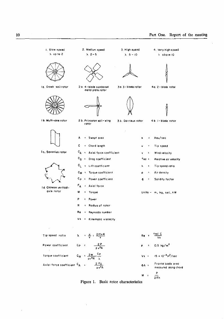
It was agreed that optimum rigid aerofoil designswere best for practical wind-electric generation, butsimple and less efficient rotors were satisfactory forwater lifting by wind power. It was considered thatwind-powered water pumping systems comprising high-speed rotors matched with appropriate pumps hadconsiderable potential for future development. Forimmediate application in water pumping, the Greekconfiguration sail rotor was considered the most appro-priate. Cambered metal plate rotors seemed wellsuited to applications where greater durability andincreased efficiency were desired, provided the greatercost and weight could be tolerated. The Darrieusand Savonius rotors were not recommended for waterpumping use, but the classic Chinese vertical-axis rotormight have some potential for low-cost water pumpingin rural areas. A guide to application of the varioustypes of rotors is given in figures 1-7. In general,down-wind rotors were considered desirable from theviewpoint of elimination of the tail cost and theelimination of the danger of the rotor hitting thetower in high winds.
10 Part One. Report of the meeting
I. Slow-speed
X up to 2
la. Greek sail rotor
I b. Multi-vane rotor
Ic. Savonius rotor
T
Id. Chinese vertical-axis rotor
2. Medium-speed
X 2 - 5
3. High-speed
X 5 - 10
2 a. 4-blade camberedmetal plate rotor
3a. 3-blade rotor
4. Very-high-speed
X above 10
4a. 2-blade rotor
2 b. Princeton sail-wing 3 b. Dorrieus rotor 4 b. I-blade rotorrotor
A = Swept area
C : Chord length
^A - Axial force coefficient
^D = Drag coefficient
C L = Lift coefficient
C M : Torque coefficient
Cp : Power coefficient
^A = Axial force
M = Torque
P = Power
R = Radius of rotor
Re = Reynolds number
Vk = Kinematic viscocity
n =
u =
v =
vrel =
x =
p =
6 =
Rev/sec
Tip speed
Wind velocity
Relative air velocity
Tip speed ratio
Air density
Solidity factor
Units - m, kg, sec, kW
Tip speed ratio X = -H- =
Power coefficient Cp =
Torque coefficient Cy =
Axial force coefficient ^A =
u .V
2Mpv2R
2TTnRV
2 PP v'A
Cp
X
2 FApv2A
Re =
Vk =
6A =
vrel CVk
0.5 kg/m2
15 x IO"6m2/sec
Frontal blade areameasured along chord
Figure 1. Basic rotor characteristics
p
2TTn

II. Discussion, conclusions and recommendations 11
0.6 -i
0 5 -
T» 0.4 -
*O
0.3 -
0.2 -
0.1 -
Procticol maximum
Tip speed ratio
Figure 2. Power coefficient
Regionof good performance
10 II 12
0.6 -
0.5 -
•S 0.4 H
ooo 0.3 -
0.2 -
0.1 -
Note : Starting torque withoutpitch adjustment
Region of good performance
5 6 7 8
Tip speed ratio
Figure 3. Torque coefficient

12 Part One. Report of the meeting
i .o 4
ÍÍ o.eo
0.7 H
0.6 4
0.5 4
0.4 -I
0.3 4
0.2 4
o.i 4
may
10 II-r -r r 1
T i p s p e e d r a t i o
Figure 4. Axial force on spinning rotor
13 14
100 4
u
a.c
o
a
10 4
O.I ©
Region of goodperformance
10 II 12 13 14
Rated tip speed ratio
Figure 5. Solidity ratio for optimum performance
II. Discussion, conclusions and recommendations 13
Best obtainable £k ratiosÜD
200-
150 -
200 -i
ocoeft
c
T3
OO
eno
150 -
100 -
50 -
¿jo 100-
50 -
IO 5 IO6 IO7
Reynolds number
.-H-• I -
Optimum required -̂ — ratio near t ipCD
0 I 2 | 3 4 5 6 7 8 9 10 II 12 13 14
AerofoilsSail wing
Metal1 platesSails, bomboo mats T i p s p e e d r a t i o
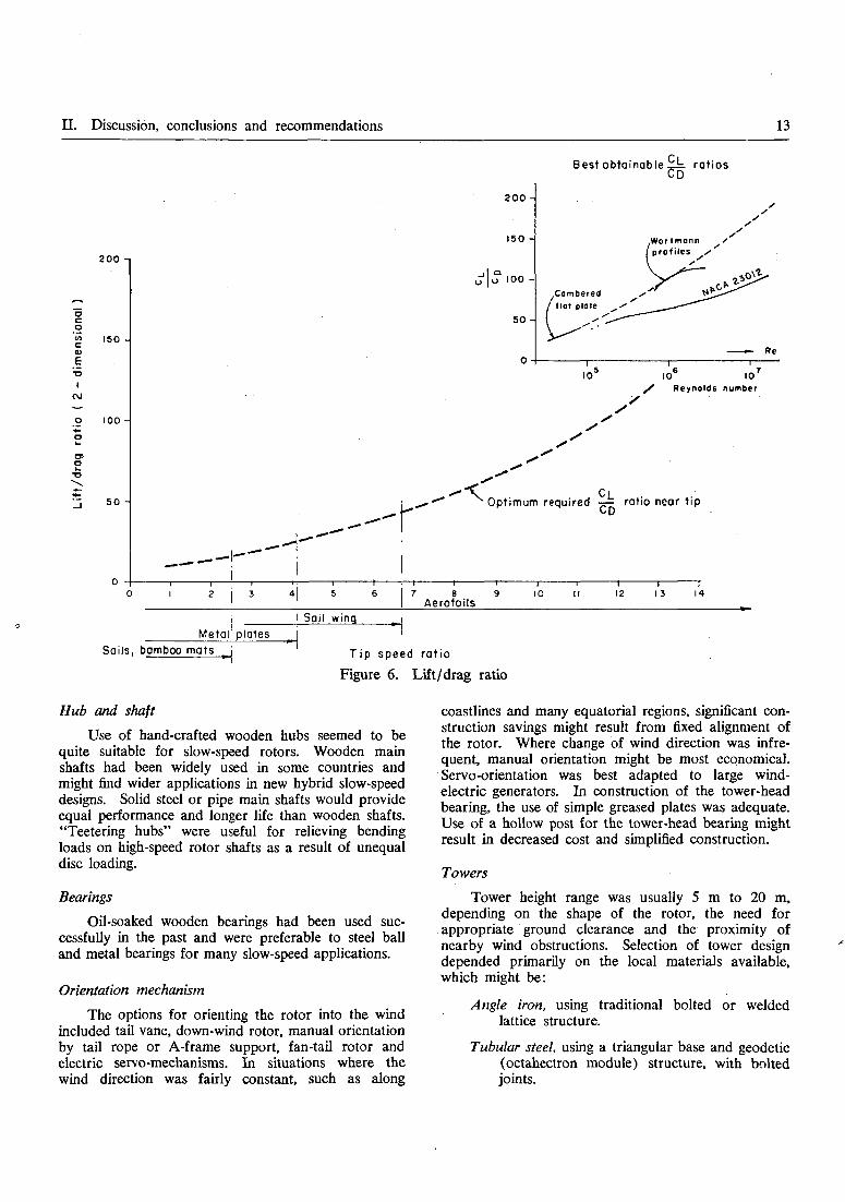
Figure 6. Lift/drag ratio
Hub and shaft
Use of hand-crafted wooden hubs seemed to bequite suitable for slow-speed rotors. Wooden mainshafts had been widely used in some countries andmight find wider applications in new hybrid slow-speeddesigns. Solid steel or pipe main shafts would provideequal performance and longer life than wooden shafts."Teetering hubs" were useful for relieving bendingloads on high-speed rotor shafts as a result of unequaldisc loading.
Bearings
Oil-soaked wooden bearings had been used suc-cessfully in the past and were preferable to steel balland metal bearings for many slow-speed applications.
Orientation mechanism
The options for orienting the rotor into the windincluded tail vane, down-wind rotor, manual orientationby tail rope or A-frame support, fan-tail rotor andelectric servo-mechanisms. In situations where thewind direction was fairly constant, such as along
coastlines and many equatorial regions, significant con-struction savings might result from fixed alignment ofthe rotor. Where change of wind direction was infre-quent, manual orientation might be most economical.Servo-orientation was best adapted to large wind-electric generators. In construction of the tower-headbearing, the use of simple greased plates was adequate.Use of a hollow post for the tower-head bearing mightresult in decreased cost and simplified construction.
Towers
Tower height range was usually 5 m to 20 m,depending on the shape of the rotor, the need forappropriate ground clearance and the proximity ofnearby wind obstructions. Selection of tower designdepended primarily on the local materials available,which might be:
Angle iron, using traditional bolted or weldedlattice structure.
Tubular steel, using a triangular base and geodetic(octahectron module) structure, with boltedjoints.

14 Part One. Report of the meeting
Type
1. Slow-speed rotors
la. Greek sail rotor .
lb. Muld-vane rotor .
Fabricationtechnology
Local
Medium(as now made)
Could belocal
Initialcost
Low
Medium
Low
Main-tenance
Regularlocal
Trainedpersonnel
Local
lc. Savonius rotor . Local
Id. Chinese vertical- Localaxis rotor
Low
Low
Local
Control
Manual
Ufe
Medium
Automatic Long
Semi- Mediumautomatic
Nil Medium
Regular Manual Mediumlocal
Typicalapplica-
tion
Waterpumping
Water
pumping
Water
pumping
Waterpumping
Waterpumping
Ratedwind-speed
Low,medium
Low,medium
Low,medium
Medium,high
Low,medium
Diameter
Up to10 m
Up to8 m
Up to6 m
Up to3 m
Up to10 m
2. Medium-speed rotors
2a. 4-blade cambered Mediummetal plate rotor technology
or local
2b. Princeton sailwing Local, mediumrotor . . . . or high
3. High-speed rotors
3a. 3-blade rotor .
3b. Darrieus rotor
Local woodor metal
Fibreglassreinforcedplastic
Extruded alumi-num or fibreglassreinforcedplastic
Medium
Low,medium
Low
Medium
Medium
Low,trainedpersonnel
Regular,trainedpersonnel
Regularlocal
Low,trainedpersonnel
Low,trainedpersonnel
Automaticor semi-automatic
Automatic
Automatic
Automatic
Automatic
Long
Medium
Medium
" Medium
Long
Long
Waterpumping
Waterpumping,electricity
Electricity,waterpumping
Electricity•
Electricity
Medium
Medium,high
Medium,high
Medium,high
High
Up to6 m
Up to8 m
Up to5 m
Up to10 m
Up to24 m
4. Very-high-speed rotors
4a. 2-blade rotor . .
4b. 1-blade rotor .
Metal or fibreglass Highreinforcedplastic
Metal or fibreglass Highreinforcedplastic
Low, Automatic Long Electricity High Greatertrained thanpersonnel 10 m
Low, Automatic Long Electricity High Greaterpersonnel thantrained 10 m
Figure 7. Practical aspects of some rotors
II. Discussion, conclusions and recommendations 15
Multiple wood-pole structure with cross-bracing ofwood or tensioned cable, with base bolted tofoundation.
Concrete pipes stacked end to end, with centraltensioning between end plates against the topand bottom of the column of concrete pipes.Concrete fill might be used. The upper endplate was incorporated for mounting of thewindmill. The entire column might be stabil-ized by guy wires attached to a ring atmaximum height to allow rotor clearance.
Single wood-poles, which might be self-supportingor hinged at the ground and guyed.
Approved local building practices should be fol-lowed in regard to foundation construction. Ease oferection and lowering, for maintenance of the rotor, wasessential. The single column, with three stays, wasconvenient, particularly for electricity generation. Inthe case of a water pumping windmill, the pump shaft(whether reciprocating or rotary) could be led downone side of the column, with the vertical axis of thewindmill offset to the side accordingly.
Control mechanisms
Allowance should be made for either manual orautomatic control of starting, stopping, òverspeeding(governing) furling or reefing of sails, and protection
against unexpected high wind speeds (fail safe device).Maximum use of manual control devices would leadto savings in construction cost. Automatic controlswere necessary for unattended operation. The dyna-mics of variable-pitch control of rigid aerodynamicrotors was not well understood and required moredetailed technical study. Adjustment of piston strokein water pumps could be provided by a horizontallever arm.
Power transfer mechanisms
It was agreed that the use of rotary power transferwas most desirable for optimal matching of rotor-torque characteristics with many types of pumps. Thattransfer might be accomplished by long vee-belts,chains, shaft and gears, chains and cowhide belts.Electric transmission should be considered only forloads greater than 1 kW.
Power utilization
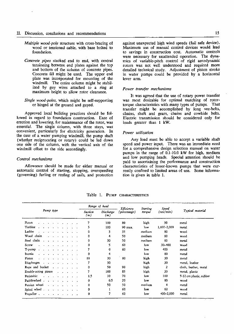
Any load must be able to accept a variable shaftspeed and power input. There was an immediate needfor a comprehensive design selection manual on waterpumps in the range of 0.1-10.0 kW for high, mediumand low pumping heads. Special attention should bepaid to ascertaining the performance and constructioncharacteristics of lesser-known pumps that were cur-rently confined to limited areas of use. Some informa-tion is given in table 1.
Table 1. P U M P CHARACTERISTICS
Pump typeRange
Suction(m)
75
0
0
0
0
70
10
70
71.5
0
0
0
0
of head
Discharge(m)
100
100
3
4
30
5
0
4
30
30
50
100
10
0.550
1
7
- Efficiency(percentage)
80
90 max.
35
50
50
60
60
80
90
85
7020
50
60
60
Startingtorque
high
low
medium
medium
medium
low
low
low
high
high
high
high
low
low
medium
low
low
Speed(rev/min)
30
1,400-2,000
80
80
80
30-400
400
80
30
30
2
30
100
80
4
60
400-2,000
Typical material
metal
metal
wood
wood
metal
wood
metal
metal
metal
metal, leather
cloth, leather, metal
metal, plastic
5-12 cm plastic, rubber
wood
metal
wood
metal
Piston . . . .
Turbine . . .
Ladder .
Wood chain
Steel chain .
Screw .
T-pump . . .
Inertia . . .
Piston .
Diaphragm .
Rope and bucket
Double-acting piston
Peristaltic . . .
Paddlewheel .
Persian wheel . .
Spiral wheel .
Propeller . . .
16 Part One. Report of the meeting
Electric generators
It was suggested that in order to formulate properrotor matching guidelines, torque-speed characteristicsof alternators and generators should be compiled. Itwas agreed that brushless low-speed 380-440 V ACthree-phase alternators were most appropriate for usein wind-electric generation. Generators from trucks,railway carriages and automobiles might be adaptedto wind-electric generation.
Storage
Wind energy utilization was most economicalwhere storage was not required. Storage requirementsmight be minimized by adopting changes in usagepatterns. Secondary use of water-storage tanks forbathing, washing and fish culture might be considered.Pumped water storage for energy conversion by asmall water turbine and generator might be practicalin some limited situations. Compressed air productionand storage might be feasible in some cases.
Hybrid designs
Development of new hybrid windmill designs wasconsidered. Some suggested possibilities were the useof classical Greek and Chinese slow-speed rotors forelectricity generation, Thai high-speed wooden rotorsfor electric generation, high-speed rotors for waterpumping and Thai sail rotors with A-frame manualorientation.
6. Other uses and advanced concepts
It was considered that there was potential forfurther development of wind-generated energy supplyfor grain grinding, cane crushing, oilseed pressing, aircirculation in crop driers, refrigerator operation, woodsawing, water aeration for sewage oxidation andaeration of intensive aquaculture ponds. Maximumwindmill economy might be achieved by multipurposeuse.
Several advanced concepts suggested for deve-lopment in the region were: large-scale wind-electricgenerators for supply to an electric distribution grid;regional manufacture and use of high-efficiency solidstate inverters for use with variable DC wind-electricgenerators; regional manufacture and use of variablespeed input, constant frequency output alternators;development of special rotors, such as the single-bladehigh-speed type; and development of regional batchand mass production of aerodynamic rotor blades usingavailable materials.
Continuing research and development outside theregion should be monitored by ESCAP and informationon relevant developments disseminated to appropriateorganizations in the region for regional adaptation.
7. Field trips
During the field trips, preliminary performancemeasurements were made on a Thai bomboo-mat sailrotor in Samut Songkram and a Thai high-speedwooden rotor in Samut Prakarn. Each machine wascoupled to a wooden-pallet chain pump for lifting saltwater to salt-production ponds. Time did not allowa complete analysis of those observations.
The Group felt that reliable measurement of theperformance characteristics of local windmill systemsshould be encouraged throughout the region.
8. Conclusions and recommendations
It was concluded that the current level of expertiseand technology available in the region was sufficientfor immediate implementation of selected wind-energyutilization devices. However, additional activities mustbe initiated to further expand its use.
The following recommendations were made:
1. A systematic survey of existing wind velocitydata in the region should be made with a view toits use for standard wind energy analysis.
2. A variety of simple cheap anemometers shouldbe developed and produced within the region.
3. Standard methodology should be developed forthe analysis and extrapolation of incomplete windspeed data.
4. A detailed classification of the performanceand construction characteristics of all wind rotorsshould be compiled in order to facilitate and optimizethe design of properly matched wind-powered systems.
5. A detailed survey of component characteristicsshould be undertaken on an international scale in orderto provide an illustrated "catalogue" of proven com-ponents which could be. used in the design of newhybrid wind-powered systems.
6. A detailed classification of the performanceand construction of all water pumping devices between0.1 and 10 kW should be compiled in order to facilitateand optimize the design of properly matched wind-power pumping systems.
7. A guide-book on windmill design processesshould be compiled and made available to developmentworkers.
8. Efforts should be made to encourage research,development and training in universities, technicalcolleges and research institutes, including fellowships,development of courses and text material.

II. Discussion, conclusions and recommendations 17
9. Efforts should be made to stimulate immediateutilization of proven wind-energy technology via exist-ing industry and non-governmental organizations, ruraldevelopment and extension services.
10. Efforts should be made to stimulate com-mercial and industrial involvement in production andpromotion of wind-energy utilization devices.
11. Expert engineering advice should be madeavailable for optimization of water pumping andelectric generating windmills currently available in theregion.
12. Socio-economic considerations should be fur-ther studied where local labour and renewable materialsmay be freely available.
13. Continuing research and development outsidethe region should be monitored by ESCAP and in-formation on relevant developments disseminated to
appropriate organizations in the region for regionaladaptation. This may take the form of a regionalwind-energy documentation centre.
14. ESCAP should follow up this meeting byfurther expert technical meetings to report and evaluatecurrent progress in the field.
15. An effort should be made to ensure that thewind energy section in the proposed regional technologytransfer centre be adequate for the needs of the region.
16. ESCAP should encourage and co-ordinate thesetting up of field demonstrations of wind-energyutilization devices in the region.
Highest priority should be given to recommenda-tion number 16, which implies that work related tosome of the other recommendations would have beeninitiated.
Annex DI
REPORT OF THE SOLAR/WIND ENERGY SECTORAL GROUP
Discussion revealed that, while attention had beengiven to the integration of both solar and wind energyinto other energy systems, there was little experiencein the integration of those two energy forms.
The Group considered that, given the variabilityin availability of both solar and wind energy in anylocation, the potential for use of bio-gas in many ruralsituations, and the possible use of each of those energyforms to complement each other, and in conjunctionwith other forms of energy, there was a need to exploreways in which the use of various types of integratedenergy systems might be stimulated.
Accordingly, the Group recommended:
1. That studies be made of:
(a) Meteorological data;
(b) Availability of the appropriate materialsand skills for construction, operation and main-tenance;
(c) Present and potential demands for energyin its various forms; and
(d) The ways in which these demands mightappropriately be met, having regard to likely
availability of both conventional and non-conven-tional energy resources, singly or in combination;in representative rural communities in variouscountries of the region, to assist in planning thedevelopment of energy resources in rural com-munities.
2. That research and development be carried outon integrated energy systems for small rural com-munities with a view to:
(a) Establishing technological and environ-mental feasibility in favourable circumstances;
(¿>) Making the best use of materials andskills available in various local environments; and
(c) Optimization of systems performancewith due regard to energy balance and cost-effectiveness.
3. That demonstrations of selected integratedenergy systems be carried out in selected localitiesfor the purposes of providing information forpotential users, ensuring the necessary system re-liability under normal operating conditions, andobtaining socio-economic data needed for com-mercial development.

18 Part One. Report of the meeting
Annex IV
LIST OF EXPERTS
R. V. Dunkle, Chief Research Scientist, Division ofMechanical Engineering, CSIRO, Highett, Victoria3190, Australia
N. R. Sheridan, Reader in Mechanical Engineering,University of Queensland, Brisbane, Australia
P. Johnston, Energy Unit, Central Planning Office,Government Buildings, Suva, Fiji
C. L. Gupta, Professor, Applied Science Group, SriAurobindo International Centre of Education,Pondicherry 605002, India
S. K. Tewari, Scientist, National Aeronautical Labora-tory, Bangalore 560017, India
Filino Harahap, Director, Development TechnologyCentre, Institut Teknologi Bandung (1TB), Ban-dung, Indonesia
Harijono Djojodihardjo, Lecturer, Mechanical Engin-eering Department, Institut Teknologi Bandung(ITB), Bandung, and Head, Aerospace Techno-logy Centre, the National Institute of Aeronauticsand Space (LAPAN), Djakarta, Indonesia
T. Noguchi, Chief, Solar Research Laboratory, Govern-ment Industrial Research Institute, Hirate-machi,Kita-ku, Nagoya, Japan
P.' T. Smulders, Steering Committee Wind EnergyDeveloping Countries, c/o Physics Department,Wind Energy Group, University of Technology,Post Box 513, Eindhoven, Netherlands
R. E. Chilcott, Department of Agricultural Engineering,Lincoln College, Canterbury, New Zealand
Mian Masoul Anwar, Principal Scientific Officer,Pakistan Atomic Energy Commission, Islamabad,Pakistan
Ernesto N. Terrado, Supervising Nuclear Technologist,Philippine Atomic Energy Commission, Diliman,Quezon City, Philippines
Jong Hee Cha, Head, Thermal-Hydraulics Laboratory,Korea Atomic Energy Research Institute, Seoul,Republic of Korea
Chung-Oh Lee, Professor, Department of MechanicalEngineering, Korea Advanced Institute of Science,Seoul, Republic of Korea
Prapath Premmani, Director, Technical Division, Na-tional Energy Administration, Bangkok, Thailand
Sompongse Chantavorapap, Chief, Design and EnergyResearch Section, National Energy Administration,Bangkok, Thailand
Chalermchai Suksri, Chief, Power Resource ResearchUnit, Agricultural Engineering Division, Depart-ment of Agriculture, Kasetsart University Grounds,Bangkhen, Bangkok-9, Thailand
Suthin Nopparat, Agricultural Engineering Division,Department of Agriculture, Kasetsart UniversityGrounds, Bangkhen, Bangkok-9, Thailand
P. A. Cowell, Chairman, Division of Community andRegional Development, Asian Institute of Tech-nology, P. O. Box 2754, Bangkok, Thailand
R. H. B. Exell, Division of Community and RegionalDevelopment, Asian Institute of Technology, P. O.Box 2754, Bangkok, Thailand
Ray Wijewardene, Farming Systems Engineering, Inter-national Institute of Tropical Agriculture, OyoRoad, P.M.B. 5320, Ibadan, Nigeria
R. L. Datta, Central Salt and Marine ChemicalResearch Institute, Bhavnagar, Gujarat, India(consultant)
M. M. Sherman, New Alchemy Institute-East, Box432, Woods Hole, Massachusetts, 02543, UnitedStates of America (consultant)

II. Discussion, conclusions and recommendations 19
Symbol number
NR/ERD/EWGSW/1
NR/ERD/EWGSW/2
NR/ERD/EWGSW/3
NR/ERD/EWGSW/4
NR/ERD/EWGSW/5
NR/ERD/EWGSW/6
Annex V
LIST OF DOCUMENTS
Title
Provisional agenda
Annotated provisional agenda
Development of wind energy utilization in Asia andthe Pacific
An introduction to integrated solar-wind systems
Solar energy; its relevance to developing countries
The design and construction of low-cost wind-poweredwater pumping systems
NR/ERD/EWGSW/CR.l Solar energy research in the Philippines
NR/ERD/EWGSW/CR.2
NR/ERD/EWGSW/CR.3
NR/ERD/EWGSW/CR.4
NR/ERD/EWGSW/CR.5
NR/ERD/EWGSW/CR.6
NR/ERD/EWGSW/CR.7
NR/ERD/EWGSW/CR.8
NR/ERD/EWGSW/CR.9
NR/ERD/EWGSW/CR.10
NR/ERD/EWGSW/CR.11
NR/ERD/EWGSW/CR.12
NR/ERD/EWGSW/CR.l 3
Solar energy in India: research, development andutilization
A review of efforts made in India for wind powerutilization
Recent developments in solar energy research andapplication in Japan
Research, development and use of wind energy inThailand
Recent research and development on solar energyapplications in Japan
Solar energy in Australia
Solar energy in southeast Asia
Solar energy and energy conservation in Australianbuildings
Research, development and use of solar energy inThailand
Programme and progress for solar house developmentin Korea
Solar energy as a natural resource
The utilization of wind energy in Australia
Source
Secretariat
Secretariat
Secretariat
Secretariat
Secretariat
Secretariat
E. N. Terrado(Philippines)
C. L. Gupta (India)
S. K. Tewari (India)
T. Noguchi (Japan)
National EnergyAdministration, Thailand
T. Noguchi (Japan)
R. V. Dunkle (Australia)
R. H. B. Exell, AsianInstitute of Technology
N. R. Sheridan (Australia)
National EnergyAdministration, Thailand
Jong Hee Cha(Republic of Korea)
N. R. Sheridan (Australia)
Department of Science,Australia
NR/ERD/EWGSW/CR.14 The prospects of solar energy utilization:the Indonesian case
F. Harahap (Indonesia)

20 Part One. Report of the meeting
Symbol number Title
NR/ERD/EWGSW/CR.15 A review of renewable energy in New Zealand withemphasis on wind power utilization
NR/ERD/EWGSW/CR.16 Windpower studies in Korea
NR/ERD/EWGSW/CR.17 Research and prospects of wind energy utilization inIndonesia
NR/ERD/EWGSW/CR.18 The Sunshine Project: solar energy research anddevelopment
NR/ERD/EWGSW/CR.19 Solar energy work in Pakistan
NR/ERD/EWGSW/CR.20* Planning for small-scale use of renewable energysources in Fiji
Source
R. E. Chilcott(New Zealand)
Chung-Oh Lee(Republic of Korea)
H. Djojodihardjo(Indonesia)
Agency of IndustrialScience and Technology,Japan
M. M. Anwar (Pakistan)
P. Johnston (Fiji)
• Delayed in transit and not distributed.

Part Two
DOCUMENTATION ON SOLAR ENERGY

21
I. WORKING PAPER PRESENTED BY THE SECRETARIAT
SOLAR ENERGY: ITS RELEVANCE TO DEVELOPING COUNTRIES (NR/ERD/EWGSW/5)*
INTRODUCTION
Over 1,000 million people live in underdevelopedeconomic conditions around the world between latitudes35°N and 35°S; that area also receives the highestconcentration of solar radiation. Most of the deve-loping countries in the ESCAP region lie between thoselatitudes; the relatively high population densities inrural areas, and high exposure to the sun, suggestthat the use of solar energy should be explored whenconsidering energy problems in the region.
In planning applications for solar energy, a dis-tinction must first be drawn between the energyrequirements in rural and in urban areas. The ruralpopulation needs energy primarily for cooking, lighting,irrigation and household water supply, water purifica-tion, processing of agricultural products and recreation.Solar power devices to serve those purposes mightinclude cookers, pumps, driers, and solar stills.
In small-to-medium urban areas, the most im-portant uses for energy are in agriculture, householdmaintenance, industry, and transportation, amongothers. Those needs might someday be met withmini-generators powered under the "energy plantation"concept or by photothermal devices (use of selectivesurfaces), but, in the meantime, available solar energydevices include those for water and space heating,cooking, refrigeration and distillation.
Energy consumption in metropolitan areas followsan entirely different pattern, with industrial and manu-facturing plants taking a major share of availablepower; the commercial, transport and domestic sectorsconsume varying but smaller percentages. Solar de-vices appear to have a relatively less significant rolein metropolitan areas, being used mainly for heatingof water and space, and cooling. In time, direct con-version processes for large-scale power generation,either photovoltaic or photothermal, may be developed.Promising fields for further research and developmentalso include solar ponds for small-scale power pro-duction, high-temperature furnaces, thermoelectric andthermo-ionic conversion processes, algal ponds, andsuch integrated systems as solar houses.
• Prepared by Mr. R. L. Datta, consultant on solar energy, at therequest of the ESCAP secretariat. The views expressed in this paperare the author's own and do not necessarily reflect those of thesecretariat or the United Nations.
Solar energy characteristics
In general, the greatest amount of solar energy isfound in two broad bands around the earth betweenlatitudes 15° and 35° north and south (references S 1,S 2). In the best regions, there is a minimum monthlymean radiation of 500 calories per square centimetreper day (cal/cm2/day). These regions are on theequatorial side of the world's arid deserts. They haveless than 25 cm of rain in a year. In some countries,more than two thirds of the area is arid, and thereis usually over 3,000 hours of sunshine per year, over90 per cent of which comes as direct radiation. Theseareas are well suited for applied solar energy.
The next most favourable region for the purposeis in the equatorial belt between latitudes 15°N and15°S. There the humidity is high, cloud cover isfrequent, and the proportion of scattered radiation ishigh. There are about 2,500 hours of sunshine peryear, with very little seasonal variation. Radiation isfrom 300 to 500 cal/cm2/day throughout the year.Between latitudes 35° and 45°, at the edge of thedesert areas, the radiation can average 400 to 500cal/cm2/day on a horizontal surface throughout theyear, but there is a marked seasonal effect, and thewinter months have low solar radiation. The seasonalvariation can be greatly minimized by tilting thereceiving surfaces to face the sun. The regions beyondlatitudes 45 °N and 45 °S are limited in their year-rounddirect use of solar energy.
Several types of instruments are known formeasuring and recording solar characteristics. Someinstruments give instantaneous readings and others giveintegrated readings over periods of an hour or a day.Some measure the total radiation and others measureonly direct radiation on horizontal, vertical, normal orinclined surfaces. The principles used in the operationof different types of instruments include thermoelectricmeasurement of the rise of temperature on a blacksolar receiver; balancing the heat with measuredelectrical Peltier cooling; direct calorimetric measure-ments; evaporation of a measured volume of liquid;photovoltaic measurements, photographic measure-ments; and photochemical actinometers. Examplesare the Eppley phraheliometer, the Moll-Goczynskisolarimeter, the integrating solarimeter developed inAustralia, and the Campbell-Stokes sunshine recorder.
There is ample scope for development of verymuch simpler and portable types of solarimeters

22 Part Two. Documentation on solar energy
sufficiently accurate (within ± 5 per cent or so) forplanning the development of solar energy. Evaluationof solar radiation is a prerequisite for sound plans forsolar energy use.
A number of solar radiation stations exist in afew countries of the ESCAP region. In India, thereare more than 26 stations, operated by the IndianMeteorological Department, and there are some 60stations measuring duration of sunshine with Campbell-Stokes recorders. Indonesia currently has 15 radiationstations, most of which are operated by the Meteor-ological and Geophysical Institute, and others byeducational and research institutions. Each of theESCAP countries involved in solar energy applicationsmight well have a chain of solar radiation stationsselected on the basis of geographical /meteorological/climatic peculiarities; these stations could be the controlpoints for solar radiation data collected by portablesolarimeters. ESCAP should therefore co-operate withthe World Meteorological Organization (WMO) inassisting countries to set up radiation stations, and toprepare solar maps for each country.
I. TECHNOLOGY OF SOLAR DEVICES
There are three broad approaches to the utilizationof solar devices and processes: (a) low-grade solarheat, (b) direct conversion to electric energy, and (c)photosynthetic and biological conversion processes.Of these, the technology of low-grade heat deviceshas been developed to such an extent that they haveimmediate applications, particularly in rural and smallurban areas. However, a realistic assessment on acontinuous basis is required regarding the impact ofthese devices on social and economic conditions;moreover, the need for research and development toimprove these devices should be kept under review.
Although the technology has been developed fordirect conversion and biological processes, extensiveresearch and development is required to put these ona satisfactory basis for general use.
A. PRODUCTION OF LOW-GRADE HEAT
Devices for conversion of solar energy for theproduction of low-grade heat include water-heaters,solar stills, cookers, driers, refrigerators and pumps.Most of these devices use a collector or concentratorof solar energy, utilizing the energy produced to heata working fluid with varying degrees of efficiency.The status of these devices should be reassessed withreference to rural areas in the region; technological,economic and social constraints; potential uses; andfeedback of problems.
1. Solar water-heaters
Basically, a solar water-heater comprises a black,metal flat-plate collector (absorber) containing waterchannels, facing the general direction of the sun, to-gether with an insulated storage. There can be one ormore transparent covers for the collector at intervalsof about 2 cm above the plate, and thermal insulationat the rear. The higher the number of covers, thehigher is the temperature reached in the collector, butthe less is the energy that reaches the plate. Materialsfor collectors differ around the world : copper is mainlyused in Australia, and galvanized iron in India andIsrael. The heating selective surface of the collectorshould have durable coating with a high ratio ofabsorbtivity to emissivity; for example, Australianselective surface coatings have a ratio of 6. The threebasic types of solar heaters are described below.
(a) Domestic water-heaters consist of a flat-platecollector and a separate water storage tank connectedto the public water supply either directly in pressurizedunits, e.g. as found in Israel and Australia, or througha float valve such as developed in India. The watercirculates by convection. Normally, the absorber is asheet of copper or galvanized iron to which is solderedor brazed a continuous zigzag tube, the main directionof the tubing being slightly off the horizontal to preventair-locks at the bends. Water flows either by gravityor from a pump into the lower end of the tube, andback and forth across the surface of the sheet, issuingat the upper opening. The spacing between the bendsof this tubing may vary, and in some designs may be15 cm. In some versions, the collector is in the formof a sandwich which consists of corrugated galvanizediron sheet backed with a plain sheet of the samematerial, the two being secured by rivets: the edgesalong the length are hammered together with anoverlap, and sealed with soft solder. The openingsalong the width at the two ends are formed into pipesby folding the plane sheet over the corrugated sheet,then welding or soldering. In this manner, headerpipes are formed at the two ends. The corrugated faceis blackened and the whole assembly can be put ina wooden box containing insulating material. Theupper face of the box is glazed with a sheet of windowglass, with an air gap of perhaps 5 cm. Water froman insulated cylindrical reservoir is allowed to enter thecollector from its lower header, and flows up throughthe channels formed by the corrugations out to theupper header, and then on to the upper end of thereservoir. In this manner, closed-cycle thermosyphoncirculation is established and the water temperaturerises in the reservoir. This corrugated type of flat-plate collector has good heat-exchange efficiency, ofabout 50 per cent, and heats water to 50°C to 60°C.Alternatively, the collector may consist of galvanizedtubes fitted at 10 cm centre-to-centre spacing on two

I. Working paper presented by the secretariat 23
pipe headers; aluminium sheet is wrapped around thepipe network; each tube is kept in good thermalcontact with this sheet; the collector is encased in anairtight, mild steel box having insulation on the rearside and ordinary window glass on the front side.The water level in the storage tank is maintained by afloat valve, the storage tank being insulated by thickmineral wool which is protected from the weather by acover box of mild steel sheet. Figure I1 shows adomestic heater with natural water circulation.
(b) Built-in storage-type heaters, with an integratedstorage and absorber facility, consist of a galvanizediron, rectangular tank placed in a rectangular, mildsteel sheet tray with ordinary window glass on thefront and an insulating layer (5 cm) of glass wool onthe back and sides. Tank bulging under pressure isreduced by using steel sections bolted to the sides ofthe tray. The front face of the tray is blackened.The hot water is removed at the top by opening thegate valve from the inlet pipe at the bottom. A ventpipe is also provided at the outlet pipe of the heaterfor safety purposes. A large funnel (bucket-size) canbe fixed at the top of the heater and connected tothe inlet tube so that this type of water-heater canbe used in rural areas where there is no regular watersupply. The efficiency of this type of heater mayrise to 80 per cent conversion of solar energy to heat.In this heater, hot water is not normally available inthe early morning.
(c) Large-size water-heaters for hotels, hospitalsand other public uses, involve a number of absorbertanks and can heat water in quantities larger than600 litres at temperatures up to 55°C in winter. Thistype also has an auxiliary heating system. The meanwater temperature in the storage tank is controlledby a differential circuit. Efficiency of such heaterscan be 55 per cent or higher. Australian scientistshave developed multistage, high-temperature solarwater-heaters which can possibly supply water com-mercially at as high a temperature as 95°C. Thismultistage type of solar heater uses different types ofabsorbers with different selective coatings as high-,medium- and low-temperature absorbers.
In a number of countries, including Australia,Israel, Japan and the United States of America, solarwater-heaters are manufactured commercially. Certainfactors must first be considered for critical evaluationof the different types of water-heaters: (i) a per-unitcapacity which may be 0.01 m2/litre; (ii) provisionof supplementary electrical heating, controlled bythermostat; (iii) the life of the heater; (iv) watersupply: except in the case of the built-in storage design;(v) ease of operation; (vi) application in multistoreybuildings; (vii) cost per unit of thermal energy; (viii)adaptability for customers' specifications; and (ix)product design, including finish.
1 Figures at end of paper.
One of the inhibiting factors in the utilization ofsolar water-heaters is high capital costs. ReferenceS 3 indicates a number of factors upon which feasibilityof solar water-heaters depends, e.g. cost, availabilityand cost of alternate sources of heating, efficiency ofcollection, and local cost of materials, and suggeststhat solar water-heaters generally prove competitivewith fuel plants for small and medium-sized install-ations, e.g. for hotels and schools. Certain types ofheaters, e.g. built-in storage type, may be moreeconomic even with a relatively short life. Uses forsolar heating exist in such industries as foods andPharmaceuticals, where the range of temperaturerequired may reach 90 °C or more; the developmentwork on high-temperature water-heaters is significantin this context.
Technical/economic studies should be undertakento improve the efficiency of solar water-heaters by(i) use of reflectors, (ii) selective coatings, (iii)modified collector design, and (iv) architecturalintegration. There is also scope for research anddevelopment on heaters for different temperatures andcapacities, and on improving the durability of sealants,paints and other materials used in manufacture.
2. Solar distillation
Solar distillation can produce fresh water inisolated areas where natural water is too saline forordinary use, for instance, salt farms, lighthouses andremote rural areas. Pure water is needed for lead-acidaccumulators, engineering and chemical laboratoriesand pharmaceutical preparations. Solar stills havebeen known for a long time; design features are nowwell established, and desirable materials for con-struction are available. Figure 2 indicates the varietyof uses of water so derived.
Currently, not more than about 30 per cent ofthe total solar energy can be used in distillation. Thedisadvantages of current models, with respect to theextent of useable solar energy and the high spacerequirement, are substantially reduced through the useof the humidification/dehumidification (HD) technique.
(a) In solar stills for distillation of sea or salinewater, the water to be distilled is kept in black-bottomstills covered with airtight glass or plastic enclosures.Incident solar rays pass through the glass cover and areabsorbed on the black bottom and heat the water.Vapour is formed and moves upward towards thecovers which are relatively cool, condensing on theunderside of the glass sheet. This condensed waterslides on the sloping glass sheets and is collected inthe channels provided at the lower edge of the cover.This technique depends on steady availability of high-intensity solar energy.

24 Part Two. Documentation on solar energy
The first plant of large capacity based on thisprinciple was built at Las Salinas, Chile, in 1874, witha surface area of 4,757 m2 and a daily production of22.5 m3 per day of fresh water, and operated forsome 40 years. Research contributions, mainly fromthe United States of America, the USSR, Algeria,Australia, Greece and India in recent years, areresponsible for popularization of this method inlocations lacking both potable water and power, butrich in sunshine and saline ground water or seawater.Production from the solar stills depends mainly onsolar radiation intensity, and humidity has no effecton production. A gentle wind is favourable, and pro-duction increases with ambient temperature. Depth ofsaline water in the still and the angle of inclination ofthe glass cover affect production. Smaller angle andsmaller depth increase productivity (expressed as litres/m2/day). Either glass or plastic can be used asmaterial for the cover, although glass is often preferredfor durability and ease of cleaning. A glass cover withdiameter smaller than about 2 m is convenient toreduce breakage. PVC and polythene are not verydesirable as covers on account of their shorter life anddecreasing transmittivity. With a radiation intensity of550 cal/cm2/day, the annual average productivity of asolar still can be 3 Htres/m2/day, the productivity beinghigher in summer and lower in winter.
Many solar stills have capacities in the range of5 to 10 litres per day. The construction materialsrequired include wood, asbestos cement sheet, al-uminium sections, and glass or plastics. For thebottom of the still,1 a thick, black polythene filmspread on an insulating layer is used as liner, and awater depth of 2 to 3 cm can be maintained. Inpermanent, higher-capacity stills, cement and similarconstruction materials, including sealant materials (e.g.silicone/tar plastics), are required.
Clean glass covers offer a good surface for rain-water collection, and if sufficient storage is provided,the collected rainwater can supply additional waterfor use. Places with low rainfall distributed throughoutthe year are more suitable for such units than areaswith heavy rainfall concentrated in certain parts of theyear. A few units have been installed in lighthouses,and their satisfactory performance suggests a potentialfor wider use.
Generally, two types of design have been adoptedfor the basins of large solar stills: (i) a single, largewater basin covering the whole still area (i.e. pond type,as adopted in the pilot plant at Dayton beach); (ii) theplant is divided into many units with varying lengthshaving uniform width (bay type construction inAustralia, Greece and India). Pond construction isthe cheaper type. Although cotton adhesive tape isreasonably durable for about a year or so for glass-
to-glass joints, tar plastic (a product of coal tardistillation) has been found to be more suitable forthe purpose. Silting on the surface and algae growthsometimes cause maintenance problems. In the absenceof availability of butyl rubber sheets at a reasonableprice, and in view of the short life of jute-impregnatedasphalt mat-liners and black plastic film, it is necessaryto adopt complete concrete or brick masonry flooringwith black asphalt coatings for the bottom of permanentinstallations. In some plants, precast items were usedfor the top ridge, and bottom supports were combinedwith rainwater gutter and ridge-supporting pillars.Water vapour leakage is one of the major problemsaffecting the performance of solar stills duringoperation. Use of silicone sealant in Australian solarstills has proved to be a solution, but silicone, apartfrom its very high cost, is not available in manycountries.
Costs vary with the types of stills constructed.' Generally, for estimates, the efficiency of solar energyutilization is assumed to be 30 per cent, and withthe value of average annual radiation intensity, thecalculated productivity is taken as the basis forcalculation of surface area required for solar stills.The investment cost can be calculated on the basisof cost of construction of unit surface area of stillsthat collect rainwater and have a water supply tank.The operating cost of the plant can be calculated onthe basis of 20 years' life, an appropriate interest rate,1 per cent of investment as annual operation andmaintenance cost, and an additional 100 man days peryear per 930 m2 area. It may also be assumed that80 per cent of the rainwater is collected. In anygiven situation, of course, these assumptions mayrequire modification. Since the solar energy is freelyavailable, the interest on capital costs contributes themajor portion of the product water cost. The outputis independent of salt concentration in the feed water.Regarding increases in labour and materials costs, thecapital cost per m2 increased in India from $US 7.50in 1966 to $US 11.50 in 1975, including the cost ofstorage tanks.
Attempts have been made to improve the yield ofproduct water per unit area with the use of green dyesfor evaporation enhancement in India, and with theuse of industrial waste heat in Australia and Canada.Further development should enable these results tobe applied in stills under different conditions.
Solar radiation is the principal energy source forsalt farms, which treat seawater/inland brine in threestages to produce common salt: (i) reservoir (3°to 6° Baume) wherein seawater in taken in, (ii)condensers wherein brine is concentrated to precipitateout calcium salts, and (iii) crystallizers (24° to 29°Baume) wherein common salt is precipitated. The

I. Working paper presented by the secretariat 25
area required in the manufacturing process is high,e.g. nearly 35 per cent of the area will be used forreservoirs, 45 per cent for condensers, and 10 percent for crystallizers. The exact area requirementsare determined by the rate of evaporation and reductionin volume at various concentrations of seawater/brine.For every ton of salt produced, 45 m3 of water mustbe evaporated. Evaporation depends mainly on theintensity of solar radiation, meteorological variableslike air temperature and humidity, direction andvelocity of wind, number of cloudy and rainy days,and total rainfall. The evaporation rate decreases athigher densities of brine; this rate is increased byoperational variables such as decreased brine depthand addition of green dyes. The mother liquor(bittern) can be processed to obtain fertilizer-gradepotassium chloride or pure potassium chloride forindustrial uses, as well as bromine and magnesiumsalt.
(b) The humidification — dehumidification (HD)technique of solar distillation offers significant advant-ages over the solar still in terms of efficiency in use ofsolar energy, and space requirements. The principleconsists in using solar energy (or waste heat) to heatthe feed water, spraying the heated water through apacked tower against an airstream blown up from thebottom of the tower, stripping off the vapour fromthe airstream at the top of the tower by means of acondenser, and recovering the condensed water. HDrequires power for blowing the air and for sprayingheated brine at the top of the packed tower. Thesolar energy collector consists of a shallow, rectangulartank containing feed water over which a transparentplastic sheet is laid, and the heated seawateris pumped to the top of the packed tower; feedwater heated by other means, such as industrial wasteheat, can be fed directly to the top of the packedtower. There is scope for reducing the cost of initialinvestment by design improvements in the tower,selection of common construction materials, use ofthe multiple-tower system for high capacity, and alsowith higher operating temperatures.
3. Cooking
Efforts to design and introduce solar cookers havefor many years concentrated on two main types: thecooker with a fixed-plane collector, and the cookerwith a spherical/parabolic mirror of average precision.Operating temperatures can exceed 400°C. A numberof materials can be used, namely, glass plastics,aluminized plastics, steel or aluminium. Taking intoaccount the conditions of use and aiming at a cookerof reasonable working life (five years or more), andadequate versatility for the types of cooking which arefeasible, research has tended to favour the cooker witha parabolic mirror of polished aluminium, the detailed
design being subject to variation (moulded in plasticsor artificial resin or constructed entirely from metal).In India, a concentrator-type solar cooker wasdeveloped which essentially consists of a parabolicdisc of about 1 m diameter made of aluminium sheetwith a reflectivity of 75 per cent, a stand being providedat the focus for the cooking pot. An Israeli versionused mirrors of very pure (99.98 per cent) aluminiumelectrolytically polished and anodized as recommendedfor streetlight reflectors, with a life or more than fiveyears, but at a higher cost. As the cost of these unitswas too high to be used economically in developingcountries, a great deal of work has been done in theUnited States of America and Israel in an attempt toreduce the per-unit cost by substituting less expensivematerials. Recent efforts have been directed towardmaking an umbrella-type solar cooker using aluminizedplastics; these can be folded and kept indoors whennot in use. Figures 3 and 4 illustrate the box andparabolic mirror types of solar cookers.
Units with an area of 1 to 3 m2 for solar radiationcollection with diameter 1 to 2 m and power rangingbetween 0.7 and 2.0 kW seem well suited for familycooking and pose no insurmountable problem inproduction. Different investigators give cost prices formass production ranging from $US 10 to 20. Anotherestimate for a parabolic cooker of diameter 1.5 m isabout $US 30, which could be brought down to $US 22if mass produced.
The effectiveness of a solar cooker can be enhancedby coupling with a heat storage system. The heatstorage must be provided in a volume small enoughso as not to shadow an appreciable part of the solarcollector, and of weight small enough to be supportedon the grill. Insulation must be sufficient to preventserious loss of heat during solar exposure. It must becapable of storing heat equivalent to one kWh or moreat a temperature high enough to permit effective cookinglater. It is desirable to be able to regulate the rateof heat release for cooking. These requirements arenot easy to meet.
Although quite a few designs are functionallysatisfactory, there are not very many solar cookersin use. The main reasons stem from (a) socialhabits, (b) technical drawbacks, and (c) inadequatepromotional efforts. Among the socio-economic factorsinhibiting the large-scale utilization of solar cookers,initial investment cost is one obstacle to the purchaseof a solar cooker. Families in rural areas can gatherwood and cow dung for fuel for conventional cooking.Furthermore, solar cooking involves alteration in thehousehold routine, since the housewife must preparethe evening meal during daylight, well before thetraditional time, which incurs the additional problemof keeping the food hot. Secondly, the housewifemust remain in the hot sun while cooking. As the

26 Part Two. Documentation on solar energy
community becomes able to acquire kerosene orelectric facilities, solar cooking might not be considered.The application of solar cookers appears to be limitedmainly to the low-income group and poor communitieswith no alternative fuel and who are prepared to havetheir midday meal as the major meal. Nonetheless,considerable promotional and extension work is in-volved, preferably undertaken by government and localauthorities. A promising approach to overcome thedifficulties is to combine the introduction of solarcooking with other programmes for rural development(e.g. education, public health, cultivation techniquesand home economics). Such an integrated approachshould help to bring solar cooking into general use incountries with a tropical climate; the resulting advant-ages appear so extensive in social and geographicalterms as to justify the necessary effort.
4. Solar drying
Solar drying has been used for agricultural andother products since time immemorial. The traditionaltechniques, though cheap, often yield inferior products,and cleanliness cannot be ensured. By applyingmodern technology to solar drying, substantial improve-ments can be made. Products traditionally dried bysolar energy include various kinds of vegetables andfruits, palm nuts, copra, soya bean, meat and fish.The systematic application of modern solar drying tocarefully selected, high-value goods for export or forconsumption by high-income people should lead toclean and refined materials, substantial reduction inweight, and improved preservation and taste. Thesefactors can have a major influence on marketing.
Solar drying systems can be classified mainly onthe basis of the mode of heat transfer employed, i.e.radiation or forced convection (free convection ispresent in both cases). The type of heating collectoremployed, the availability of thermal storage duringsundown hours, the transport medium and its cir-culation, and the rate of drying are important foroperational and cost efficiency.
Radiation driers have a common space for collect-ing solar energy and for drying the product (figure 5).There are holes in the bottom and top of the space toallow for ventilation of evaporated moisture. Thematerials for drying are spread thinly in trays, usuallyat one level, and exposed to direct radiation from thesun. There are no controls beyond adjusting theorientation. The area per unit weight of the productmav be calculated from the heat-balance equation fordifferent products, but often the average area per unitweight is calculated and used in the design. Suchdriers are easy to manufacture on a small scale, andhave been used for drying copra in Fiji, grapes inthe USSR, France and Australia, corn and yarn in the
United States of America and the West Indies, and anumber of products in Turkey and Middle Easterncountries.
Convective driers have separate areas for collectionof solar energy and for drying the product. Heat canbe transferred from one area to the other by air orby water. In the latter case, a heat exchanger isused, and storage or supplementary heating may ormay not be provided. The collectors, mostly the flattype, have features in common with solar heating.A two-stage drier, using an inflatable collector coupledto a mobile van has been field-tested at Barbados bythe Brace Research Institute of Canada. A solar kilnfor seasoning timber, using separate air heater androckbed thermal storage, is under development inAustralia; a similar kiln, without storage, is undertrial at the Forest Research Institute, India (see alsoreference S 4).
Where other supplementary power is not available,a windmill can be added to a drying system forcirculating air. Thermal chimneys are also possible,with the difference in density of the heated air insideand the cooler air outside creating an upward move-ment of the enclosed air, but they must be tall toobtain sufficient difference in air temperature, andlarge in cross-section to prevent undue resistance tothe flow of air.
Extensive developmental efforts are required forheat-storage devices, collector-drier combinations andflat-plate air-heaters to supply hot air to driers.
5. Pumping
Among the possible uses of solar energy, thelifting of water for drinking or irrigation purposes isof interest in dry regions and other rural areas,particularly where underground water is available ata depth not exceeding 30 m. Requirements of small-scale irrigation and domestic purposes will be wellwithin the reach of solar energy pumps in the fairlynear future. A pair of bullocks working continuouslycan raise 1 m3 of water per hour from a depth of30 m. The equivalent of this work can be done byan electric motor pump rated at 0.8 kW, for whicha solar pump can be designed.
Solar pumps can be operated with solar energydirectly converted into electricity, or by using thermalenergy itself to heat a working substance which mayoperate the engine. The direct conversion of solarinto electrical energy does not at this stage seem tobe an economic proposition. However, solar pumpsrun by thermal energy from the sun have beenconstructed in France, the United States of America,the USSR and Israel. In these pumps, flat-plate

I. Working paper presented by the secretariat 27
collectors have been used for raising the temperatureof the working substance. A solar pump developedat the University of Florida in the United States ofAmerica has two check valves with no moving parts.A boiler is connected by straight and U-shaped tubesto a chamber with check valves at the inlet andoutlet. The liquid in the boiler is vaporized bypushing the liquid out of the system; when the vapourreaches the bottom of the tube, it suddenly streamsinto the chamber filled with cold liquid where thesteam rapidly condenses. While the steam is produced,the top check-valve is open and the liquid is pushedout. When the vapour condenses, the valve closes dueto the low pressure created, and the bottom check-valveopens to let in more liquid to be transported. TheSOFRETES Company of France has developed asolar pump which consists of the heating circuit wherethe water is heated with the help of solar radiation,and the fluid circuit wherein the hot water passesthrough the tubular heat exchangers where heat isgiven to a volatile liquid. The colder water thenreturns to the heating circuit. The working fluid,in gaseous form at high pressure, leaves the heatexchanger and expands in the piston motor, and passesinto a condenser cooled by the pumped water. Thegaseous fluid is liquefied and is returned to the heatexchanger by a reinjection pump driven by the engineitself. In the final phase, the pumped water circuit,the engine drives a hydraulic press which operates
a pump immersed in the water in the well. TheSOFRETES pump is illustrated in figure 6.
The working fluid is low-boiling point methylchloride. Several different models of the solar pumphave been made and tested. Some of the maincharacteristics of these pumps, and test locations,appear in the following table. In addition to these,further exhaustive trials in the village areas of theRepublic of Chad show that such pumps can liftwater up to a height of 60 m or more. One of themam features of SOFRETES solar pumps is that thecomponents can be manufactured in the user country.This type of pump has been in service at the laboratoryof Dakar University, Senegal, since 1969, and hasfunctioned without any trouble. Similar solar pumpshave been used by farmers in Israel. In addition tomethyl chloride, a wide variety of fluorinated organiccompounds including fréons can be used at lowertemperature ranges (reference S 5). The average costof the SOFRETES pump is about $US 22,000 for0.3 to 0.5 kW. Solar engines of the ThermoelectronicCorporation of the United States of America cost$US 20,000 in 1972 yielding 2 to 5 kW. Undoubtedly,mass production could reduce prices considerably.Nearly 50 per cent of the cost is the collector. Anothertype of pump, based on the Stirling cycle, is describedin reference S 6. Solar pumps for lift irrigation areunder development in India (see reference S 7).
Collector area (m2)
Rate of pumping (m3/hour)
Height (m)
Speed (rev/min)
Nadie
12
1.2
15
180/150
Availability of small and medium-sized units(corresponding to a fraction of 1 kW to several kW)at reasonable production costs, e.g. $US 1,000 to 1,500per kW installed, could provide the basis for economicand social changes, but it does not seem possiblethat this goal can be achieved unless the developingcountries themselves participate in the process ofresearch, development and industrial production.
6. Refrigeration and air-conditioning
In many tropical and developing countries, asubstantial quantity of foodstuffs cannot be preservedand spoils. For some foods, refrigeration is required;and, for areas without electricity, solar refrigerationand/or solar cooling may well be the answer.
The coldness from night-time air can be storedand, in some areas, produced by radiation to the nightsky. In dry climates, cooling can be effected byevaporating water from cloth wicks. In moist climates,
Onersol Senegal Quara Chinguetti Sccra
60 88 30 88 6
10 6 2 10 0.6
12 25 20 20 14
100/150 100/150 100/150 100/150 80
the moisture in the air can be partially removed, andthe dried air cooled by evaporation of water. Mostcooling systems depend on the evaporation of a liquidin a closed system. The household refrigerator workson the principle of alternate vaporization under reducedpressure, and condensation under increased pressure,of a fluid such as ammonia or freon. Vaporizationextracts heat from the surrounding environment andcools the refrigerator cabin, or freezes water to ice;the system is regenerated by compressing the vaporizedworking fluid to liquid, the heat produced beingdissipated to a stream of circulating air or water;the two operations of cooling and regeneration arecombined into continuous operation.
Solar energy could be used to operate a heatengine, which in turn can operate a compression-typerefrigerator or air-conditioner. The solar engine has,however, low efficiency for producing power. It isusually simpler and cheaper to use the sun directlyin an absorption-desorption cycle for the purpose. A

28 Part Two. Documentation on solar energy
number of systems (e.g. ammonia/water, ammonia/sodium thiocyanate) could be used. Figure 7 showsrefrigeration using an ammonia/sodium thiocyanatesystem.
For the purpose of refrigeration and producingice, the weight proportions of ammonia and waterare in the ratio of 1:1.3, and the maximum heatingtemperature is about 130°C, with a special valveseparating the water from the liquefied ammonia; theover-all coefficient of performance (COP), i.e. theheat absorbed by vaporizing coolant, divided by solarheat incident on collector, is about 0.10. Flat-platecollectors can also be used for the system, in whichcase the COP is further reduced. The ammonia/watersystem has the disadvantage that some of the watervaporizes with ammonia, requiring a rectifying arrange-ment for separation, and at intervals the water mustbe returned to the larger vessel containing ammonia/water solution. It is desirable to eliminate water,which can be done by using very concentratedsolutions of salt in liquid ammonia. The vapourpressure of liquid ammonia can thus be reduced atroom temperature from 10 atmospheres to less than1 atmosphere, and the salts have negligible vapourpressure even at high temperatures. Ammonia/sodiumthiocyanate solutions have suitable thermodynamicproperties with very high solubility, low vapourpressure, and high heats of vaporization; they arechemically stable and inert, comparatively inexpensiveand can be used in steel vessels; they have high heatconductivities and low viscosities. The COP of thissystem is approximately three times that of theammonia/water system. Although solar refrigerationis normally more expensive than refrigeration withordinary fuel or electricity, it can be considered whereelectricity and fuel are very expensive or unavailable,as in many rural areas of the developing countries.
Large industrial refrigeration plants can have aCOP as high as 0.7, but smaller plants are lessefficient. If household labour for domestic coolingis considered free, small solar cooling units may beviable, but operation of a solar cooling machine isfairly complicated, requiring experience and skill inmechanical operations. In view of this, solar coolingand ice production as a village industry may be morepractical than individual hand-operated domestic solarrefrigerators in homes. One of the difficulties in iceproduction is the slow growth of ice crystals, and itmay be advisable to operate several regeneration unitswhile the sun is shining, and carry out the freezingoperations at night.
There is great demand for air-conditioning in hotclimates, and air-conditioning by solar energy istechnically feasible. In a typical flat-roofed, one-storeybuilding, much of the roof area would be covered with
solar collectors, and capital investment would thereforebe high.
The characteristics of water make it satisfactoryfor cooling and air-conditioning. A lithium bromide/water system can be used for cooling in that theabsorption of water vapour by concentrated lithiumbromide solutions produces cooling in the same wayas the ammonia/sodium thiocyanate system. Thissystem is well suited to solar operation because itcan be regenerated with hot water above 77 °C, butbelow the boiling point of water. With indirect heatingthrough a heat exchanger, it is possible to have extraheat storage for cloudy weather. The average COP ofsuch a system is about 0.18. At very low temperatures,lithium bromide may crystallize, but this can beprevented by temperature control. The general trendof results with such a system is such that, on a bright,calm day, a solar collector of 20 m2 should produceone ton of refrigeration. Improvement in collectionefficiency by a selective surface like nickel black mayreduce the collector area.
Dehumidification in moist hot climates is almostas important as cooling. Removal of moisture fromthe air is much easier to achieve than cooling the air,and dehumidifiers operated by electricity are cheaperthan air-conditioners. Active silica gel has been usedfor the purpose, followed by regeneration. In hot,dry climates, air can be cooled by evaporating water,and it is common practice to blow air through coarsecloth saturated with water. Even in humid climates,considerable cooling can be effected by dehumidificationof the air followed by evaporation of the waterand restoration of part of the humidity. Such de-humidification can be effected by an ethylene glycol/
' air/solar collector system, as proposed by the Universityof Wisconsin, United States of America, wherebymoisture in the air is absorbed by passing it througha spray tower of falling drops of ethylene glycol, thenon-volatile glycol absorbing water and giving drierair, and the glycol being regenerated with a stream ofhot air heated by the sun.
Cooling of houses can be achieved in hot, clearclimates by radiation to the sky during the night, usinga black cloth radiator; such a radiator may act as asolar collector for heating during day-time. Largebuildings, such as hospitals, factories and schools, maybe fitted economically with roof-mounted, combinedsolar heating and radiative cooling systems, in whichthe same panel operates as a collector during day anda radiator at night, using separate storage.
As a supporting activity to space heating andcooling, considerable work has been done on the studyof indoor temperature as a function of architecture,orientation of the building, insulation, shading andselective paints. A detailed consideration of these

I. Working paper presented by the secretariat 29
factors can considerably reduce the load on the heatingand cooling system that may be developed. Onealternative system for residential heating and coolingis illustrated in figure 8. A number of experimentsinvolving the absorption cooling cycle have been con-ducted in the United States of America, Australia,the USSR, France, Japan and other countries, andhave shown that the concept is fully feasible, butconsiderable design engineering works will have tobe done before the system can be used widely.
A convective cooling system, using lower wet-bulbtemperatures at night and coupled to rockpile thermalstorage, is under development in Australia and Indiaas a component of a hybrid heating-cum-cooling system.Comparative studies of economics and reliability ofthe rockpile and natural air-conditioning systems needto be undertaken for hot, dry climates, and theirareas of application specified.
B. GENERAL CONCLUSIONS ANDSUGGESTIONS
There has been considerable work in manycountries of the world on low-grade thermal devices,such as solar water-heaters, solar stills, driers, spaceheating, refrigeration and air-conditioning, and pumping.Except for water-heaters and solar stills, which arecommercial propositions in some developed countries,other devices have not found any large-scale utilizationmainly because of their high cost and low efficiency.
(a) Solar water-heaters: Data on commerciallyavailable solar water-heaters of small, medium andlarge capacities should be widely disseminated with aview to selection of appropriate types. Stepsshould then be taken to encourage their productionand use. Governments might assist in setting updemonstration units in representative locations.
(b) Solar stills: Similar approaches should bemade for solar distillation, including small, portableequipment. In addition, there is scope for improvedmeans for trapping the water vapour which escapesduring salt production (the HD principle can be usedfor this purpose).
(c) Solar driers: Programmes might be developedto make solar driers useful for drying agriculturalproducts through demonstration units and otherpromotional efforts.
A recommended design for a solar timber kilnshould be developed, and a few such kilns fabricatedfor typical locations.
(d) Cooking: Extensive promotional activitiesshould be initiated in rural areas; simultaneously,suitable storage device and heatpipe systems need to
be evolved for coupling with the cooker to removecertain short-comings.
(e) Solar space heating and cooling: A pilotprogramme for introducing solar heating in a fewselected villages and at high-altitude areas should beundertaken.
For preservation of food materials, a few prototypeammonia/water solar refrigeration units should beset up in remote rural areas for developmentalinvestigations. More extensive developmental investi-gations should be carried out for use of the lithiumbromide/water system in solar air-conditioning.
(f) Pumping: The SOFRETES solar pumpshould be tried out in selected rural areas, anddevelopmental investigations for its adoption under-taken, using indigenously available materials.
II. SMALL- AND MEDIUM-SCALE CONVERSIONTO ELECTRICAL AND MECHANICAL POWER
The possibilities which have been explored, andwhich have proved rewarding for small-scale andmedium-scale applications, are solar engines, and tur-bines working on the Rankine cycle, producingmechanical power, and various solar photooatteriesand thermobatteries for conversion into electric power,and solar ponus.
A solar thermal power unit is simnar to anyconventional, external heat engine, except that theheat is provided by solar collectors. High-temperatureunits use focusing collectors that have to follow tuesun, and in general such collectors are expensive anddifficult to maintain. To avoid the complicationsof sun-following devices, many types of stationarycollectors have been proposed: the flat type asused for water heating, or very low-concentratingmirrors limited to a concentration factor of 2 or 3.Such collectors generally produce relatively verylow temperatures, thereby resulting in much lowerthermodynamic efficiency of the heat engine; Dut tnesystem is simple. Apart from the cost ot the collectors,and the preparation of the ground site on which theseare erected, the absence of a satisfactory and cheapsolution to the problem of solar heat storage greatlyincreases the capital cost of installation.
1. Solar engines
Many designs of solar engines, both piston andturbine types, have been proposed, and several havebeen demonstrated, but they have not yet beenproduced commercially. Investigations are currentlybeing carried out in Israel, Italy and the United Statesof America.

30 Part Two. Documentation on solar energy
2. Thermoelectric conversion
Thermoelectric conversion methods may be usedfor converting solar energy into electricity directly.Thermobatteries with semiconductors of antimony,bismuth tellurides, selenium tellurides, etc., are beingproduced on a large scale, and have an efficiency ofthermal energy conversion of 6 to 7 per cent. Thisthermoelectric process requires concentration of normalsolar radiation, and thus requires development of acheap concentrator; a heat storage device is alsorequired. Solar thermobatteries have a number ofsmall-scale and medium-scale applications with pro-duction of power in the range of a few watts to afew kilowatts, particularly for power communicationapparatus.
3. Photovoltaic power
In photovoltaic power generation, a voltage isproduced at a metal/semiconductor junction. Arsenic-doped silicon and boron-doped silicon semiconductorscan be used to form a good junction for the purpose.Currently, silicon cells have an efficiency of about10 to 12 per cent, but this can be improved by specialprocessing and increasing the purity of the material,and an efficiency of conversion in such cells ashigh as 30 per cent has been predicted. Conversionefficiency of a solar cell is a function of the geometryof the cell, and increases with its thickness. Siliconcells are used in space ships, but the cost is at presentprohibitive for terrestrial applications.
Cadmium sulphide (CdS) is a good photovoltaicmaterial, and efficiency up to 7 per cent has beenattained; this seems to be more attractive for relativelyhigh-temperature photovoltaic cells, but it appearsthat there is some amount of degradation at highertemperature. Nevertheless, efforts are in progress touse it in combination with other materials. A cross-section of a typical cadmium sulphide/copper sulphidesolar cell is displayed in figure 9. The main advantageof the CdS cell is that it can be made from micro-crystalline thin film rather from single crystals; thecells are capable of being manufactured continuouslyby vacuum deposition of the materials on plastics.Gallium arsenide is also a good photovoltaic material,but it is not abundant. Cadmium telluride is anothergood photovoltaic material with potentially a muchhigher efficiency, but its manufacture and availabilitypose problems. Technological developments are inprogress to prepare cells of this from both singlecrystals and thin films.
In recent years, organic semiconductors have beeninvestigated in development of photovoltaic cells.Organic dyes and such materials as magnesiumphthalocyanine have been used in organic photovoltaic
cells. A chlorophyl semiconductor photocell is pro-mising.
4. Solar pond
In principle, the solar pond is a convenient devicefor collection and storage of solar heat. It compriseshalf a hectare or more in area, with a blackenedbottom overlain by layers of concentrated saltwater,above which is placed, without mixing, a layer ofpure water. The lower salt solution is heavier thanthe upper water and does not mix with it; when thebottom layer becomes heated, it does not rise to thetop. Thus, the upper layer of water remains coolwhile the lower layer heats up to 90°C or more. Alow-temperature steam turbine is operated by a boilerplaced at the bottom of the pond.
As a collector for low-temperature heat, the pondis very much cheaper per unit area than the con-ventional solar collector used for water heating, sinceno metal, plastic or glass is used in its construction.Despite low efficiency, a low-temperature turbine canbe used to produce small power. Depending on theinvestment needed in the construction of the pond andits plumbing, the estimated cost of power producedwould be about 2 US cents per kWh. Thus, for thesupply of power from smaller sources, especially inremote rural or coastal areas, the solar pond appearsto be a feasible proposition. The solar pond can becoupled with production of common salt from seawater,particularly in areas of heavy rainfall. Israel, Australiaand Canada have done extensive work in that field.Although the heat extraction problem in solar pondshas substantially been solved, there remains the mixingproblems of the layers of the pond : chemical engineer-ing studies need to establish for each case the properdesign to yield the desired amount of low-temperatureheat, power and salt.
III. LARGE-SCALE POWER PRODUCTION
1. Solar power via satellite
For any practical use of solar energy for large-scale power production, the two main and basic hurdlesto be overcome are (a) atmospheric reduction of theintensity of solar radiation, and (b) storage of thesolar energy. A concept evolved in the United Statesof America to overcome both those hurdles, knownas the Satellite Solar Power System, envisages that asatellite synchronized with the earth's movement outsidethe geosphere would transmit solar power to receivingstations on earth for conversion into electrical power(see figure 10). In such an orbit, solar radiationwould be received continuously and would be ofan intensity on an average six times that on theearth's surface. Solar batteries would convert it into

I. Working paper presented by the secretariat 31
electricity, which in turn would be converted tomicrowaves for transmission to earth where it wouldfinally be reconverted to electric power. The tentativecost estimate for a system of 5,000 MW is $US 1040per kW.
Pinasco (Mexico) greenhouse experiment, designed onthe same basis, produces similar results. The experi-ment has now been extended to Abu Dhabi, andhas started operation. Such greenhouses have realpossibilities for many developing countries.
2. Photothermal conversion
Use of selective surfaces of high absorptivity (verythin film of silicon and silver) and low emissivity, onthe exterior of steel pipes in evacuated glass envelopesand operating at elevated temperatures, has beenproposed as a concept of thin-film photothermalconversion of solar energy for power production.This concept mainly comprises a solar collection area,a thermal storage, a heat exchanger, a boiler, and apower plant. Liquid sodium has been suggested asthe thermal fluid, but some organic fluids and salteutectics could also serve the purpose. Concentratingcollectors in the solar farm with high absorptivity/emissivity ratios of 10 to 15 could give temperaturesin the range of 350° to 550°C; or flat-plate collectorswith no concentration but with high ratios of 20 to 40could give a temperature of 250° to 350°C. Economicprojections have been carried out for a collector areaof 1 km2, to produce 80 MW.
IV. OTHER FIELDS OF SOLAR ENERGY USE
A number of other applications or suggestedsystems have not been elaborated here, either becausethey are not as yet directly relevant to the conditionsin developing countries or because they are as yettheoretical.
1. Energy plantation
The recent concept of an energy plantation coversthe planting of fast-growing, woody plants or treeswhich have a high photosynthetic efficiency. The treeswould be harvested, cured in direct sunlight, and burntto produce power. Investigation is still required ontechnical and non-technical aspects.
2. Controlled environmental greenhouses
At the Environmental Research Laboratory ofTucson in the United States of America, vegetablesare grown in the controlled environment of an air-inflated, plastic greenhouse. The large-scale Puerto
3. Algal ponds
Fuel derived from pond-grown algae can drivegas turbines and reciprocating heat engines. Thepotential of algae for fuel is about the same asfor higher plants. When growing in conditions inwhich ample carbon dioxide and suitable nutrients areprovided, the process of repeated subdivision provideslarge quantities of organic matter. When the energypotentially available in the dried algae is related tothe solar energy incident upon the growth tanks, ithas been shown that up to 8 per cent can be recovered.
4. Solar furnaces
Solar furnaces which give a very high concentrationof focused radiation have been used for scientificinvestigations. Those with high optical precision givetemperatures of over 3,000°C and may cost over$US 1,000 per m2. Such furnaces have been con-structed and studied in France (reference S 8), Japan,the USSR, the United States of America and Algeria.
V. CONCLUDING REMARKS
In each country, there is a need to identify thefuture role of solar energy. Many solar devices dependheavily on the collector system, and there is a con-tinuous need for testing and scientific assessment ofcollectors with a view to using local materials forconstruction.
There is scope for immediate transfer of technologyon small-scale special purpose uses of direct energyconversion processes, and this will assist future transferof technology on larger-scale processes.
For effective utilization of solar energy in theregion, a broad spectrum of activities will be required,involving existing and new research and developmentinstitutions, scientific training, educational and promo-tional activities, and dissemination of information, andESCAP is well qualified to lead and co-ordinate nationaland regional efforts in these respects.

32 Part Two. Documentation on solar energy
S u n s r a y s
Insulation around —tonfc on d oll pipes j
Glass cover
Condensed vapour
Saline water
Product woter
Product water
Figure 1. Domestic solar water heater
Distilled water
Figure 2. Solar still for water desalination
Folding 1
Jnsulotedbo*
Figure 3. "Hot box" type of solar cooker
Figure 4. Solar cooker with parabolic mirror
Boiltr
- Interior surfaces Qpointed block
/
Wire mesh troy
a5 3?3<^?v ^NXV-X
Ï
Ventilation holes Insulation
Figure 6. Solar pump (SOFRETES type)
Figure 5. Tray-type solar drier

I. Working paper presented by the secretariat
Rectifyingcolumn ..On- off valves
sLower header
^—Condenserevaporator
Õ n - off valve
Condensóte todrain line
during refrigeration
Figure 7. Refrigeration system(ammonia/sodium thiocyanate refrigerant)
Dry N2
-Positivep-type electrode
_ p-njunctionn-type
Negative electrode
Figure 9. Cross-section of typicalCdS/Cu2S solar cell -
33
WinterOperation
lI
Summeroperation
'^¿y Automatic valveHotwater
Hotwater
Wormair Cooloif(winter) (Summer)
Pump
Figure 8. Residential heating and cooling
Ptime «jie'qyconversion ro
DC power
DC powerconversion tomicrowave power
Microwave beomlink
Collection andconversion to
Receivinq antenno
Solar collector5 x 5 miles
Sun
Rotaryjoint
Electrical'transmissionfine 2 miles
Waste neat radiatorSlot arraymicrowave ontennoI « I mile
Control station
Coolingequipment
Figure 10. Satellite solar power system

34
IL INFORMATION PAPERS PREPARED BY PARTICIPANTS
SOLAR ENERGY RESEARCH IN THE PHILIPPINES (NR/ERD/EWGSW/CR.1)*
by
Mr. E. N. Terrado (Philippines)
In spite of the announcement that the national goalof the country for future power development wouldcentre around nuclear reactors, geothermal and hydro-electric potential, alternative sources of energy, such assolar energy and wind energy, were given an importantplace in national energy planning. However, theabsence of pertinent survey data makes it difficult todetermine the exact role to be played by these sourcesin the energy picture for the next 25 years or so.Extensive survey work is therefore necessary in thePhilippines, as in other countries of the region.
Low-grade heat derived from solar devices hasconsiderable and immediate possibilities in the region.Such devices comprise: (a) refrigeration for the pre-servation of vegetables, fish and other materials on asub-community scale; (b) water heating for schools,hotels, hospitals, etc.; (c) pumping for irrigation; (d)drying of agricultural products; and (e) distillation forpotable water and other specialized uses such as water
Summarized.
for lead-acid batteries. Developmental efforts are tobe made for adoption of the devices in many of thecountries of the region. In the long term, the develop-ment of large-scale power production from solar energywill benefit both the developing and the advancedcountries, and collaboration should be established onregional and international levels.
At present there are four ongoing research pro-jects in the country, related to: (a) solar engine foragro-industrial purposes, water heating, distillation,and refrigeration, work on which commenced in 1974;and (b) flat-plate collectors and ammonia absorption-desorption system for the development of an ice-makingmachine. The National Science Development Boardis considering financing for other projects, namely, adrier for lumber, solar-powered open-cycle gas turbine,and silicon cells. It plans to establish a NationalEnergy Institute in order to co-ordinate all research onnon-conventional energy sources. The country is inneed of a chain of solar radiation stations to recordsolar radiation data.
SOLAR ENERGY IN INDIA: RESEARCH, DEVELOPMENT AND UTILIZATION
(NR/ERD/EWGSW/CR.2)*
by
Mr. C. L. Gupta (India)
A. DEVELOPMENT OF SOLAR ENERGYIN INDIA
Systematic efforts to harness solar energy wereinitiated in the early 1950s. Since then, the variouslaboratories have concentrated on low-grade thermalprocesses, such as solar water-heating, solar distillation,space heating, solar drying and solar cooking. Fromsuch research, useful data have been made available forindigenous flat-plate collector design and technology(references S 9 to S 11). However, social non-acceptance of the technically successful solar cookerdeveloped by the National Physical Laboratorypractically closed all financial and scientific support tosolar work until 1962. This scepticism remained until
Abridged.
the 1972 Stockholm United Nations EnvironmentalConference. Since that time, an expert panel has beenconstituted in the Ministry of Science and Technology(reference S 12), and open, enthusiastic support hasbeen given by the Prime Minister in an attempt to finda place for solar energy in the country's energyeconomy. Solar water-heaters and solar stills are nowmanufactured and sold commercially.
Specific fields of investigation have now beendefined by the Government as priority sectors whichare to be developed at least to the demonstration stage(reference S 12). In addition, work in the areas ofsolar cells is being funded. The greatest stress is onpower for domestic use, cottage industries and agricul-tural areas, being developed according to the schemebelow.

IL Information papers prepared by participants 35
(a) Rural sector (villages with a population ofless than 1,000)
(i) Water pumping
(ii) Drying of agricultural produce (e.g.food grains, forest products)
(iii) Conversion of brackish water intopotable water
(iv) Use of solar slurry heaters for in-tegrated bio-gas plants
(b) Urban sector (small towns with a populationof 1,000 to 10,000)
(i) Mini-power plants ( 10 kW — 50 kWsize)
(ii) Solar water-heaters (domestic size)
(iii) Space heating and cooling, mainlyfor health centres, tourist bungalows,etc.
(iv) Solar ice-making for fisheries, healthcentres, etc.
(c) Metropolitan sector (cities with a populationexceeding 0.5 million)
(i) Solar cells for television, radios, etc.
(ii) Bioconversion of waste into trans-portable fuels
(iii) Process steam
(iv) Factory heating and cooling
(v) Solar water-heaters (large size forcafeterias, hotels, etc.)
During 1974, in the wake of the oil price crisisand the publication of the report of a solar energyexpert panel, the idea that large industrial concernsshould sponsor or conduct in-house research anddevelopment projects became policy, and the Govern-ment permitted all expenses incurred on solar applica-tions in industry to be treated as research expenses.
Solar research and development in India is sup-ported by a network of radiation stations run by theIndian Meteorological Department (reference S 13).There are 26 such stations, 13 of which are principalstations measuring global, diffuse, normal beam radia-tion and hours of sunshine. The remainder areordinary stations measuring global radiation and hoursof sunshine only. Most principal stations use Moll-Goczynski pyranographs, Eppley pyroheliometers andCampbell-Stokes sunshine recorders, while mostordinary stations use bimetallic pyranographs andCampbell-Stokes sunshine recorders. All these in-struments are manufactured in India under licence orwith indigenous designs.
B. PRESENT STATE OF SOLAR ENERGYIN INDIA
1. Solar pumping
Eight institutions are currently working in thistopmost priority area.
(a) 1 kW and 4 kW solar pumps using flat-platecollectors and organic-fluid Rankine cycle (AurovilleCentre for Environmental Studies, Pondicherry). A 1kW pump is being designed as the intermediate stageof a project to be completed in 1978. In addition topumping, solar collectors are meant to be used as partof farm building roofs which could heat air to dryagricultural produce. Also, the solar pump is meantto be coupled to a low-speed generator/compressor toproduce power/cooling on non-pumping days.
(b) Low-temperature direct-contact vapour pumpfor lift irrigation (Birla Institute of Technology, Pilani).The vapour pump uses flat-plate collectors and anorganic-fluid vapour (immiscible with water) in directcontact with water. Feasibility studies and costanalyses for heads up to 30 m with a capacity of100 m3/day have been completed. Prototypes arebeing developed for both air-cooled and water-cooledtypes of pumps. Except for the valves, there are nomovable parts in this pump design.
(c) Medium-temperature 4 kW pump usingcompound parabolic/wedge stationary concentratorsand steam Rankine cycle (Punjab Agricultural Univer-sity, Ludhiana). Theoretical and optimization studieshave been completed on generating and tracking re-quirements of compound parabolic/wedge stationaryconcentrators, designed for a concentration factor upto 3 with monthly adjustment. A small steam engineoperating with a head of 5 kg/cm2 pressure has beenfabricated and operated off this concentrator.
(d) Medium-temperature 200 W hot-air engineusing tracking concentrators and Stirling cycle (CentralSalt and Marine Chemicals Research Institute,Bhavnagar). An indigenous version similar to thePhilips hot-air engine is planned, to be completed byJuly 1977.
(e) / kW solar pump using medium-temperature,flat-plate collectors and organic-vapour turbine or ex-pander (National Physical Laboratory, New Delhi).Flat-plate collectors will be developed to operate at120°C, with an instantaneous efficiency of 70 per cent.Selective windows, selective black-on-copper substrates,and convection suppression by honeycombs will becoupled to a once-a-month adjusting reflector hinged toa double glass flat-plate collector. On the power side,the freon group of organic liquids would be used asworking fluids in an indirect system using thermic fluidas a transport medium from the solar collectors and anexpander.
36 Part Two. Documentation on solar energy
(f) Solar pump using Cds/silicone solar cells(Indian Institute of Technology and National PhysicalLaboratory, New Delhi). A long-term project isintended to develop direct conversion of solar energyto electricity by indigenously-fabricated cheap and re-liable solar cells encapsulated for long life.
(g) Fluidyne engine with liquid piston operatingon Stirling cycle (Metal Box (India) with AtomicEnergy Research Establishment, Harwell, UnitedKingdom). Practical commercial development isenvisaged for lift irrigation in the field, from smalllaboratory models pumping 300 litres/hour alreadydeveloped at Harwell.
(h) 1 kW pump using cylindrical, parabolic,stationary concentrator and steam Rankine cycle (JyotiLtd., Baroda). A leading pump manufacturer ofIndia has undertaken development of a solar pumpusing conventional solar principles, with a view to massproduction.
2. Solar drying
Work on small cabinet driers of 5 to 10 kgcapacity using a combined radiation/natural convec-tion/storage principle has been in progress in manyinstitutions (reference S 14 to S 20). However, forany significant input to post-harvest technology, theminimum size needed is 100 kg/day for cash crops anda metric ton/day for grain-drying, even for smallfarmers (reference S 21).
(a) One ton/day capacity solar paddy drier(Annamalai University, Chidambaram). Laboratorystudies and pilot plant studies in a rice mill have beencompleted. The pilot plant dries 10 kg/h of paddyby blowing solar-heated air from an air-heater of area4.25 m2 with an electrical blower. A prototype isbeing fabricated.
(b) Solar kiln for timber drying (Forest Re-search Institute, Dehradun). A kiln was designed anddeveloped in 1971-1972 for air-seasoning of timbersections (10 cm x7.5 cm) used for frames of windowsand doors (reference S 22). The kiln is of nearly10 m2 area. Drying can be done in 40 per cent ofthe time taken for normal air-drying, and with 40 percent of the operating cost of a steam-heated kiln at aninitial capital cost of only 20 per cent.
3. Conversion of brackish into potable water
Many institutions have experimented withdomestic models of solar stills having 5 to 7 litrescapacity and 1.5 to 2.0 m2 area, primarily for supplyingdistilled water. Recently, figures were published (re-ference S 23) for explicit multiple correlation of dis-tillate ouput with three climatic variables: solarradiation, dry bulb temperature and wind velocity.
The major work on supplying potable water has beendone by the Central Salt and Marine Chemical ResearchInstitute, Bhavnagar, during the last decade (referenceS 24).
A 1,000 litres/day pilot plant was built on theground in masonry of 1.7 x 2.5 m bays covering atotal area of 350 m2 with glass covers at varying angles.For sealing materials, tar plastic, commercially availablein India, was found reliable. The bottom liner wasmade of masonry plaster covered with black asphaltcoating or black cement. For top ridges, bottom sup-ports combined with rainwater gutters and pillarssupporting ridges, factory-finished precast items werefound best. It has been found (reference S 25) that,if the freshwater source is more than 24 km away andthe community requirements are less than 22 m3/day,solar distillation is competitive and in some cases eveneconomical. Costs of solar stills-cum-rainf all collectionsystems are dominated by storage costs because of theprevalent monsoon type of rainfall. In areas of rainfallless than 200 mm/year, solar distillation alone iseconomical.
4. Mini-power plants
There has been a recent emphasis on developingmini-power plants in the 5 kW-50 kW range suitablefor supplying electricity to existing tube-well pumps andto villages with populations of 500 to 1,000. Abaseline study (reference S 26) for choosing an initialconcept for further development of a solar plant hashighlighted the need for developing hybrid planarcollectors in the range 120° to 150°C and stationaryconcentrators up to 300°C. Two recent feasibilitystudies have been carried out (references S 27 andS 28). A 10 kW power plant is being assembled on acollaborative basis with the Republic of Germany.
5. Solar water-heaters
Research began in India in 1955 at the NationalPhysical Laboratory (reference S 29).
A mathematical model to predict the performanceof a natural circulation system, using a corrugatedNPL-type collector or wire-wound pipes with a plateCBRI-type collector, was developed in 1967 (re-ferences S 30 and S 31). Both gave comparable per-formance, but they are costly for an average-incomehousehold. In spite of some drawbacks, the industrytook up the sale and manufacture of the CBRI design.A recent innovation has been the use of aluminiumtube-in-strip panels with built-in headers in collectorsize of 1.5 x 0.4 m.
Remaining problems in water-heater design andproduction appear to be solvable (references S 32, S 33,S 34).

II. Information papers prepared by participants 37
6. Building heating and cooling
Building heating for high altitudes was tried in1963 (reference S 35) as a simple extension of thesolar water-heater, in which a flat storage tank formedthe heating panel inside a high-capacity, well-insulatedroom, and the results were very encouraging. The useof forced air circulation and a rock pile storage werealso tried.
For sophisticated, active cooling systems, theUniversity of Roorkee has developed a one ton capacityabsorption air-conditioning system (reference S 36),using ammonia/water as the refrigerant and water fromflat-plate collectors. The Indian Institute ofTechnology, Madras, (reference S 37) has developedan inexpensive system which combines the de-humidification of room air by an absorbent, followedby adiabatic evaporative cooling with the solar desorp-tion of the absorbent in a flat-plate collector open toambient air.
The systems described above are either for heatingor for cooling. But in latitudes between 25° and 35°N,both summer cooling and winter heating are required. Ahigh utilization factor makes such a system practicable,if collectors can form the building roof and ducting canbe avoided. This may be achieved in pond-type, low-capacity sheet roofs with movable shades. A thermaldesign model for this system has been developed (re-ference S 38) to optimize the operating and designparameters. Another composite system (referenceS 39) uses rock beds for heating and cooling.
7. Solar ice-making
Recently, an ammonia/sodium thiocyanate systemcapable of producing 75 kg of ice per day has beendeveloped (reference S 40) with a high designcoefficient of performance.
8. Solar cells
Thin, wafer-type silicone solar cells from importedsilicone crystals were developed with efficiency of 8 to10 per cent in 1972, but these were very costly. Pro-duction of thin-film CdS solar cells, which are reliable,efficient and cheap, is now the major field of develop-ment.
9. Process steam
Development of suitable collectors is of prime im-portance in this field, and several institutions areengaged in this activity. Industry supplies the majorfinancial support.
(a) Medium-temperature flat-plate collectors(National Physical Laboratory, New Delhi). Stagna-tion temperatures up to 200 °C have been obtained
with flat-plate collectors (reference S 41), usinga selective black on copper absorber, a honeycomb ofglass tubes and a selectively coated collector window(tin dioxide) to reduce radiation losses. Work hasalso been started on evacuated-tube collectors whichcould be mass produced if successful technically andviable economically.
(b) Medium-temperature planar collectors (TataEnergy Research Institute Unit, Pondicherry).Truncated, compound parabolic collectors (referenceS 42), with a concentration of 4 and a height of 10 cmfor receiver size of 3 cm have been designed to achieve150°C within three hours of the solar noon, whenbimonthly adjustments are made. Selective surfaces,coated windows and plastic honeycombs are contem-plated to increase the efficiency from the current valueof nearly 15 per cent.
(c) Compound wedge/stationary concentrators(Punjab Agricultural University, Ludhiana). Com-pound wedge/stationary concentrators (reference S 43)have been produced as discretized versions of compoundparabolic collectors. Efficiencies of 56 per cent havebeen achieved with a concentration factor of 2.8, andsteam has been produced at pressures up to 5 atmos-pheres. Work is continuing on these concentrators withabsorbers in the range of 30 to 40 cm and correspondingheights of the aluminium reflector panels exposeddirectly to the atmospheric elements.
10. Factory heating and cooling
No special problems arise as distinct from buildingheating and cooling. However, large roof areas of thinelements must be designed as energy generators. Alarge engineering company has installed a system inwhich water can be heated by solar energy and air canbe blown past hot-water coils mounted on the wallsbelow windows. Water pumps as well as blower fansare needed.
11. Industrial drying
Drying of palm jaggery juice, drying of coal finesand spray-drying of baby milk have been explored.
12. Solar ponds
Temperatures up to 80° to 90 °C have beenobtained in shallow ponds; use of this process in saltflats for preheating the water for process steam or forvery hot water may soon be undertaken.
13. Solar cookers
Step-type reflector cookers have been experimentedwith, along with steam cookers which can only dolimited types of cooking. Solar hot-boxes and ovens

38 Part Two. Documentation on solar energy
have been developed in many parts of the country; thecompound wedge/conical type is original and probablythe most successful in terms of lowest cost-per-unitefficiency.
C. FUTURE PROSPECTS OF SOLAR ENERGYAPPLICATIONS
In the national solar energy plan (reference S 12),some of the targets have been explicitly stated. Theauthor estimates, in the light of the last two years ex-ecution of this plan, that most of these targets will beachieved during the period 1978-1983, the likelyfirst achievements being the installation of a solardesalination system for potable water supply in 100villages, the production of solar water-heaters for bio-
gas plants as a village handicraft, a 10 kW solarthermal power plant and 1 kW solar pumps.
Solar energy research efforts are being co-ordinated by the National Committee on Science andTechnology. Funds are provided to research labora-tories, universities, industrial associations and othervoluntary organizations by the Department of Scienceand Technology, by government-supported researchcouncils and by the Tata Energy Research Institute.For co-ordinated work, it may be desirable to have asingle, over-all planning, funding and evaluating unitto cover the whole field of renewable energy or onlythat of solar energy. A single research institute forsolar energy research would be useful if the currentgroups become constituent regional units for field-testingand centres of excellence in one specific field each.
RECENT RESEARCH AND DEVELOPMENT ON SOLAR ENERGY APPLICATIONS IN JAPAN(NR/ERD/EWGSW/CR.4 and NR/ERD/EWGSW/CR.6)*
by
Mr. T. Noguchi (Japan)
During the 10-year period ending in 1971, re-search and development in the solar energy field wasrelated to agricultural applications, water-heating,space heating and cooling, small-scale power genera-tion, solar furnaces and investigation of materials.Subsequent developments have been fairly fast becauseof the oil crisis, and the budget of the "SunshineProject" (see document NR/ERD/EWGSW/CR.18)includes 874 million yen for research and developmenton solar energy. The work programme includes majorinvestigations on thermal and photo-voltaic conversion,water-heating, space heating and cooling, solar furnacesand solar process heating.
During the earlier period, solar radiation measure-ments and their statistical correlation, assessment ofturbidity coefficients, intensities on titled surfaces, andstudies of the relation between sunshine hours and solarradiation were carried out in considerable detail.
Work on agricultural applications of solar energyincluded: establishing the relationship between thequantity of ripening rice, sunshine hours and ambienttemperature (critical air temperature is found to beabout 22°C for ripening rice); warming cool irrigationwater for paddy fields by means of a solar pond;lowering the temperature of water for paddy fields bydispersing carbon black or white plastic film orpolystyrene flakes; study of an open-cycle algae pond;production of cattle feed; mulching in fruit orchardsto prevent the growth of weeds; investigation of in-
Summarized.
expensive greenhouses with plastic films; snow meltingby the use of calcium silicate and development of asolarimeter for the measurement of photosyntheticallyactive radiation.
Solar water-heating is a large and growing industryin Japan, with some six companies manufacturing solarheaters of the closed-cycle type or natural-circulationtype. For some 15 years, silicon-cell solar batterieshave been used in large numbers for microwave relaystations, unattended navigation lighthouses, buoys, androbot rain gauges. Solar furnaces giving very hightemperatures of the order of 3,000°C have mainly beenconcerned with temperature and emissivity measure-ments of metal oxides, freezing points of ceramicoxides, high-temperature phase diagram studies, forobtaining single crystals, and for studies on sinteringof ferrite compacts. A feasibility study of the use ofa large-scale solar furnace as a heat source for industryis under way.
Architectural glass materials (heat absorbing andreflecting glass, combined with aluminium-sputteredpolyster film) are commercially available. Recentlyconstructed solar houses in Japan use flat-platecollectors with selective surfaces of copper oxide oncopper sheet, and black chrome on stainless steel sheet,and are operated with lithium bromide water absorptionunits for heating, cooling and hot water supply.
Energy demands in many of the developingcountries have not been assessed, and comprehensive

II. Information papers prepared by participants 39
surveys are essential to find the areas in which solarenergy can play a part. It seems likely that there willbe requirements for extensive applications of solarenergy for salt production, water desalination, and cropdrying, with possible requirements for food and timberprocessing, heating and cooling and thermal and photo-voltaic conversion. Part of the research and develop-ment facilities in Japan will be devoted to these pro-
cesses in order to be able to assist the developingcountries by transfer of technology.
Reliability criteria of solar devices, availabilityand cost problems require investigation under inter-regional co-operative research and development, and itis suggested that a world research and development in-stitution for solar energy be set up as well as a localregional centre for training and education.
SOLAR ENERGY IN AUSTRALIA (NR/ERD/EWGSW/CR.7)*
by
Mr. R. V. Dunkle (Australia)
A. RESEARCH AND DEVELOPMENT
Solar energy research in Australia was initiatednearly 30 years ago, mainly in the fields of low-gradethermal applications. Since 1973 there has been asharp increase in interest in solar energy utilization.Current research and development covers the followingfields: (a) preparation of radiation standards, and ofsolar tables and diagrams; (b) thermal performanceand behaviour in dwellings and plastic greenhouses; (c)integrated system design for solar house-heating; (d)selective surfaces; (e) cost reduction in water heatingthrough use of aluminium instead of copper; (f)drying kiln for timber; (g) energy plantation; (h)generating high temperatures (60° to 80 °C) for thefood-processing industry; (i) small power systems (upto 20 watts) for remote telecommunications; (j)swimming-pool heating; (k) air-conditioning; (1) useof reversible chemical reactions to transfer energy fromsolar radiation collection systems; (m) heat pipe studies;(n) linear concentrators; (o) photothermal conversion;and (p) solar-operated water pumps. Funds aremostly provided by the Australian Government eitherdirectly, or through statutory bodies, such as theAustralian Research Grants Committee (which supportsuniversities) and the Australian Industrial Research andDevelopment Grants Board (research in industry).
(a) Commonwealth Scientific and Industrial ResearchOrganization (CSIRO)
During the 1950s, pioneering work was carriedout in the Division of Mechanical Engineering on aprototype solar water-heater (reference S 44) whichled to the development of a solar water-heating industryin Australia. A simple solar still (reference S 45)was developed, but this did not reach the commercialstage. Other work included crop drying and solarponds. In 1959, the Division expanded its programmeto include the fields of thermal radiation and solar
Abridged.
energy research. Work was carried out on selectivesurfaces, solar distillation, solar air-conditioning, water-heaters and air-heaters.
The Division of Atmospheric Physics has tackledsolar measurement problems and developed excellentcalibration facilities for both solar and long-waveradiometers, and several new types of radiometers.
The Division of Irrigation Research has in-vestigated solar measurements in connexion with theirfield-work in irrigation evaporation and plant growth,and developed a useful evaporated film thermopile andpyranometer (reference S 46).
(b) Australian universities
Australian universities have lagged somewhatbehind CSIRO in commencing solar energy research,concentrating on basic rather than applied research.Most programmes were initiated in the 1960s, butthere has been a recent sharp upsurge in activity.
University of New South Wales. Primary con-cern has been with solar measurements, and the use ofsilicon cells for this purpose.
University of Queensland. The most significantwork has been in the area of solar air-conditioning, andthis has involved development and testing of a solarair-conditioned dwelling using solar-heated water witha lithium bromide absorption system (reference S 47) .
University of Melbourne. Primary concern hasbeen with heat transfer mechanisms in solar systems,and this has included such problems as asymmetric ductheating (reference S 48), free convection in inclinedcells, entrance effects in air-heaters, and the theoreticaland experimental evaluation of the heat loss from flat-plate absorbers (reference S 49).

40 Part Two. Documentation on solar energy
Monash University. The most relevant researchhas been fundamental work on heat and mass transfer,for example on heat transfer in asymmetrically heatedtriangular ducts (reference S 50). More recent studieson energy storage using desiccant beds (reference S 51)and problems of regenerator design for a system withcoupled heat and mass transfer in porous beds (re-ferences S 52 and S 53) have also been directed towardsunderstanding the performance of components of solarsystems.
University of Western Australia. Although locatedin the centre of the greatest concentration of manu-facturers of solar water-heaters, and in the area wheresolar energy is most competitive, the only significantwork has been on a theoretical and experimental studyof solar stills (references S 54 and S 55).
(c) Industry
The solar water-heating field represents the onlysolar manufacturing industry of importance inAustralia. Several manufacturers commenced pro-duction between 1955 and I960, large firms alreadyproducing conventional hot-water systems and alsosmall firms which have built up successful and growingbusinesses over the years. Although based on theoriginal copper tube and plate CSIRO developments,significant innovation has taken place and many varieddesigns are on the market. Sales have been mainlywithin Australia and the islands to the north, but onecompany has recently licensed a Japanese manufacturerto produce hot-water systems based on the Australiandesign.
(d) Department of Housing and Construction
An experimental solar system was installed late in1956 in Coolgardie, Western Australia. The successof this installation, and economic analysis of solar re-lative to other water-heating systems, led to the decisionthat the installation of solar water-heating should berecommended in both homes and institutional buildingsin the Northern Territory of Australia and mostlocations in Papua New Guinea. Users are generallysatisfied with both the amount and temperature of hotwater available; boosters are not normally called uponexcept where systems serve large families.
B. INDUSTRIAL, COMMERCIAL ANDDOMESTIC UTILIZATION
The current status of solar energy utilization inAustralia for industrial, commercial and domestic pur-poses has been summarized in reference S 56.
Australian per capita consumption of energy ishigh by world standards, about 50 per cent of thetotal being supplied by petroleum products, with trans-portation becoming increasingly dependent on liquidfuels.
The percentage contribution of petroleum is ex-pected to decrease significantly as indigeneous oil re-serves are limited, while the use of natural gas (whichis present in some abundance) should increase veryrapidly. Coal reserves are very large, and coalprovides the primary energy for about 75 per cent ofthe country's electric power production, the remainderbeing hydroelectricity.
The major contribution of solar energy in industrycurrently is in salt production. In 1972/73, the totalsalt production in Australia was 3,774,000 tons,essentially all produced by solar evaporation of seawater. The energy input required to evaporate thewater to produce this much salt amounts to about 12per cent of the total annual Australian energy con-sumption. This large amount of energy is neglectedby government statisticians as it is not bought, sold ormetered. Similarly, agricultural solar energy used doesnot appear in any energy input tabulation.
Solar water-heating is growing rapidly in Australia,although the total energy supplied is negligibly small interms of the total energy consumed in Australia. Themajority of the installations are in private homes, but asignificant number supply hot water to schools,hospitals, motels and hostels.
The total solar water-heater area installed inAustralia can be approximated by summing the annualproduction figures since 1969, which total 58,000 m2.Although some of the water-heaters have been ex-ported, this estimate is likely to be somewhat low asthe production figures before 1969 are not available.Moreover, many collectors have been home made andthere is no way to estimate their area. However, thisfigure can be used to approximate the solar energy usedfor water-heating in Australia at about 0.0047 per centof the total energy consumption. Although this presentcontribution is negligible, it could become important ifcurrent growth rates continue.
Another, and even more rapidly increasing use, isin swimming-pool heating. Largely as a result of theincreasing affluence and leisure time in Australia, homeswimming pools are becoming very common. Becauseof the low temperature needed, 20° to 27 °C, the solarheaters can be very simple and yet highly efficient, anda great many home made solar swimming-pool heatersare being installed. No figures are available, but it islikely that this application will soon exceed other solarwater-heating in terms of solar energy utilized.
C. FUTURE TRENDS
A very large amount of low-grade thermal energyis used by industry at temperatures below 120°C (re-ference S 56). This is a promising area for solarenergy utilization in the future.

II. Information papers prepared by participants 41
A significant and rapidly growing use of energyin Australia is for the heating and air-conditioning ofhomes. This is an area wherein a viable solar-energyindustry can develop similar to the water-heatingindustry. Both solar space heating and air-conditioningcan be achieved (references S 47, S 57, S 58, S 59,S 60), but the economic question is unresolved. With
good engineering design, solar space heating shouldbecome important in Australia, but economical solarair-conditioning could prove to be a more difficultproblem. It is likely that most installations, at leastinitially, will be on new dwellings specifically designedfor solar heating.
SOLAR ENERGY IN SOUTHEAST ASIA (NR/ERD/EWGSW/CR.8)*
by
Mr. R. H. B. Exell, Asian Institute of Technology
As Thailand occupies a central position in thesoutheast Asian peninsula, the solar energy data of thiscountry can be extended, with some amount ofapproximation, to other neighbouring countries of theregion. Although a network of solar radiation stationsis necessary for a comprehensive assessment of theavailable solar intensity in a country or a region, it ispossible to calculate approximately, with the help ofthe Angstrom regression equation, the intensity ofsolar radiation from data on the duration of sunshine.This relationship has been used to calculate the solardata for a number of areas in Thailand from theradiation data obtained in Bangkok and Chiang Mai,where the average values of global solar radiation arefrom 450 to 350 cal/cm2/day. Nevertheless, it isdesirable to set up at least a few measurement stationsin Thailand for making accurate and detailed measure-ments of solar radiation on a continuing basis, followingthe pattern of standards set up by the WorldMeteorological Organization.
Inexpensive devices for solar data measurement,such as simple portable solar water-heaters of standarddesign can be used to obtain data in individual locationsand rural areas with reasonable accuracy. Survey andanalysis of such data for the region would be of greatassistance in choosing sites for solar installations andin the design of suitable collecting systems.
In the Asian Institute of Technology, there arefour ongoing research projects of relevance to theregion:
(a) Solar-power water pump to be used for low-lift irrigation, with a lift of about 3 m. With averagesolar radiation of 400 cal/cm2/day, and an estimated
Summarized.
over-all efficiency of 5 per cent (2 per cent at present),a collector area of 3.5 m2 per hectare will be requiredfor 100 m3 of water per day.
(b) Solar ice-maker to be used for cold storageof food and for ice making. An intermittent ammonia/water system with a collector area of 2 m2 is beingused to obtain preliminary data and practical ex-perience; the future prototype design will be for 100 kgof ice per day.
(c) Solar stills for producing potable water forrural areas. Several solar stills of wooden constructionhave been experimented with. One unit, equippedwith external mirror attachments, is capable of pro-ducing 3.2 litres of fresh water per square metre perday. Another of the units, of concrete design with aglass surface area of 3.5 m2, has a stirring device(powered by a windmill) to facilitate investigation ofthe effects of seeding the feed water with varyingdosages of carbon particles. There is also provisionfor rainwater collection on some units.
(d) Solar drying units for drying agriculturaland marine products. At present, one unit, with amoving bed and a total glass surface area of 7 m2 isunder study for residence time, drier configuration, massfeed rate, etc.
ESCAP is well suited to give a lead to the coun-tries of the region in the promotion of utilization ofsolar energy. The establishment of an informationand service centre at ESCAP is suggested, to act as aclearing-house for dissemination of information onsolar energy publications and projects, to organize shortcourses, workshops and conferences, and to assist inarranging finance for the various countries of the region.

42 Part Two. Documentation on solar energy
SOLAR ENERGY AND ENERGY CONSERVATION IN AUSTRALIAN BUILDINGS
(NR/ERD/EGWSW/CR.9)*
by
Mr. N. R. Sheridan (Australia)
A. A DISTINCTIVE AUSTRALIAN DESIGNOF COLLECTOR
The Australian domestic water-heater has evolvedfrom an original design of the Commonwealth Scientificand Industrial Research Organization (CSIRO). Witha single pass through several parallel tubes, the absorberplate has changed little with development. It is usuallyfabricated from copper tube and sheet by soft and/orhard soldering. Specialized materials, such as "tube-in-strip" and "roll-bond", have been used, but themarket is hardly large enough for the production invest-ment of these special materials. Besides, both thesematerials have corrosion problems resulting fromcarbon inclusions in copper tube-in-strip and pinholingof aluminium roll-bond.
Originally, black-painted absorbing surface wasused with two glass covers. However, the copperoxide selective surface, produced by chemical treat-ment, has been simple to produce in the small plants,is reliable in service and achieves with only one glasscover a similar performance to the original design. Itis usually used. The radiation properties of theselective surface are absorptance 0.89 and emittance0.17 and are stable up to a temperature of 150°C,which is about the equilibrium temperature for thecollectors when dry.
Simplicity has been a basic design criterion, sothe systems generally have thermosyphon circulation ofthe potable water at low pressure. The resultingadvantages include no circulation pump, a minimum ofcontrols, no heat exchanger, and no risk of contamina-tion of potable water with heat transfer fluid. Againstthis must be weighed the disadvantages of the tanklocation, which must be above the collectors and highenough to supply pressure to the water outlets.
B. ENERGY NEEDS OF AN AUSTRALIANRESIDENCE
The Australian people are concentrated on thecoastal fringe between Brisbane in the north andAdelaide, with Melbourne being the most southerlymajor city. In this area, about 10 per cent of theAustralian land surface, live 90 per cent of the popula-tion. The climate is mild throughout. Only a smallamount of heating is required, and there is little realneed for summer air-conditioning.
• Abridged, and including "Solar energy as a natural resource"(NR/ERD/EGWSW/CR.12).
An analysis of energy use per household shows aconsiderable difference between two cities at theextremes of the well-populated region, though thisdifference is due mainly to the heating load. Low-grade energy defined as heat energy up to a maximumtemperature of 120°C, is a large part of the energydemand, 2,400 kWh (49 per cent) in Queensland, and10,000 kWh (67 per cent) in Victoria.
Energy costs for Australian residences have notrisen dramatically in the last decade as the proportionof energy supplied by high-cost petroleum is relativelysmall. Natural gas has not been available until re-cently, so that electricity, which is mainly generated fromcoal, has obtained a major share of the load. Electricalenergy is sold on an incremental cost basis at off-peakhours for domestic hot water and thermal energy stores,which are used in space heating. The discount fromregular prices is 25 to 40 per cent. Control of off-peakpower is by time clock or audio-frequency switchingwith a signal superimposed on the power circuit.
C. ENERGY CONSERVATION IN BUILDINGS
Energy conservation in buildings has many aspects,including the use of solar energy. The various systemsmay be classified as follows:
(a) Non-solar
(i) Thermal conductance: insulation, per-centage glass
(ii) Thermal capacitance
(iii) Layout: area of outside wall per unitfloor area, zoning
(iv) Infiltration: heat exchange betweenventilation and exhaust air
(v) Heat pump, total energy, etc.
(vi) Evaporative cooling: roof sprays, roofpool, natural wind coolers, forcedventilation coolers
(vii) Operational techniques on air-conditioning and water systems
(viii) Performance of equipment
(b) Passive solar
(i) Orientation: sun control
(ii) Aspect ratio
II. Information papers prepared by participants 43
(iii) Thermal conductance: variable con-ductance, roof pool
(iv) Thermal reflectance: wall surface, glass
(v) Radiant transmittance: variable trans-mittance, south wall collector
(vi) Shading: parasol roof, roof overhang,louvres
(vii) Wind: attic ventilators, Altenkirch de-humidification system
(c) Active solar
(i) No-utility energy: electricity generation,heating and cooling.
(ii) Low-utility energy:
a. Domestic hot water
b. Swimming-pool heating
c. Space heating: forced air,hydronic
d. Space cooling: nocturnal radia-tion, absorption refrigeration,Rankine refrigeration, ejector re-frigeration, open-cycle systems
(iii) Unlimited utility energy: solar heatpump
D. AUSTRALIAN CONTRIBUTIONS TOENERGY CONSERVATION
1. Tropical house design
In the underdeveloped tropical north of Australia,refrigerated air-conditioning for residences can bejustified on currently accepted comfort standards, butit costs more than the inhabitants can afford. Costfactors include: the high number of cooling degreedays, the high cost of electricity generated in relativelysmall diesel plants, the inadequate buildings for re-trofitting of equipment, and the high cost of main-tenance in a remote area. One study showed that thecost of air-conditioning a residence was as much as 20per cent of the family income.
In the past, the houses have been built of light-weight, uninsulated construction on stilts, high stumpswhich allow the underneath section to be used forlaundry, storage, garage, etc. Shading, reflection,orientation and other energy-saving ideas have notgenerally been considered. It has been shown that,since the ground temperature at 1 m depth is alwaysbelow the comfort temperature, a concrete slab on theground acts as a heat sink. Coupled with an insulatedenvelope and masonry partitions to increase the thermalcapacitance, a slab will considerably reduce day-timetemperatures. Such houses would also be satisfactory
for future air-conditioning. Proposed standards forthermal performance for Australian government housesare given in reference S 61.
2. Heat pump
The heat pump cycle has been used in windowair-conditioners for many years, and has been used inthe air-conditioning of several large buildings. In themild Australian climate, the outdoor coil has littletrouble with icing, especially if arranged for solarassistance. There have been problems with the com-pressors under the higher temperature of operation, butthey will be overcome as equipment designed for thepurpose becomes more readily available.
3. Evaporative processes
Evaporative cooling should be applicable to energyconservation, as it is capable of providing space coolingwith much less energy than refrigerated systems. Suchsystems need to achieve a room air change every one ortwo minutes to utilize the small available temperaturedrop between supply air and room temperature. Theresulting relatively high air quantities must be deliveredby properly sized registers to insure good distributionand satisfactory noise levels. Further, to achieve asaturation efficiency of 80 per cent as is desirable, theevaporative system must be carefully designed.
Several compound or staged cycles can bedeveloped, which improve the cooling capabilities ofevaporative processes, or extend their usefulness toareas of higher wet-bulb temperatures. These cyclesmake use of heat exchangers and dehumidificationdevices in addition to the evaporative cooler.
The aim of much CSIRO research has been toimprove the efficiency or effectiveness of the com-ponents. A target of 80 per cent for saturationefficiency of evaporative coolers, effectiveness of heatexchangers and effectiveness of dehumidifiers seemsreasonable.
(a) Use oj rock piles. The rock pile, areasonably inexpensive heat exchanger and heat storagedevice, can be used in several ways as a component ofevaporative systems.
As a long-term storage device, it can be cooleddown over-night by evaporatively cooled air. In theday-time, outside air can be drawn through the pile topre-cool it. Subsequently, it can be evaporativelycooled for supply to the room.
CSIRO has developed a rockbed regenerativecooler which consists of a rockbed heat exchanger anda rockbed evaporative cooling matrix, each in twoparts. These are used alternatively: one being cooled

44 Part Two. Documentation on solar energy
by evaporation, while the other is cooling the supplyair. The heat exchanger consists of two beds, each4.5 m2 in area and 127 mm thick. The rocks are6 mm screenings which are treated with bitumasticmaterial to restrict the absorption of moisture.Associated with each heat exchanger bed is anevaporating matrix of area 3.9 m2 and 38 mm thickness.Untreated 6 mm screenings are used for the matrix.A motor-driven damper reverses the direction throughthe heat exchangers every five minutes, and theevaporating bed is sprayed for 12 seconds every secondcycle. In appropriately insulated buildings, thesystems produce satisfactory conditions, with an airchange every 2 minutes in areas where the design wet-bulb temperature at the 2.5 per cent level is 24°C orless. With limited batch production, the units costabout 20 per cent more than equivalent refrigeratedunits, but the energy cost is about half.
(b) Dehumidification cycles. The basic de-humidification cycle uses an adsorbent or absorbentchemical to dry the air at constant enthalpy. Sub-sequently, it can be cooled to approach the dry-bulb orwet-bulb temperatures and then evaporatrvely cooled.The chemical can be regenerated by solar-heated air.Lithium chloride solution is a suitable absorbent, whileadsorbent cycles use silica gel or alumina (referenceS 57).
4. Roof pool
The thermal capacitance and the evaporativeeffects are two properties of water that can be ex-ploited in the roof pool. For heating, the pool can becovered by a transparent cover, and acts like a solarcollector which stores its energy in the water. Circula-tion through a slab floor further enhances the storage.For cooling, the pool should be covered with an opaquematerial in the day-time and uncovered at night to lowerits temperature by radiation and evaporative cooling.A research project is being undertaken and preliminaryresults are encouraging.
5. Isolated homestead
In Australia, there are perhaps 50,000 residenceswhich are so far from electrical supply lines that it isuneconomical to supply them. Thus, it appears that asolar generating plant could be a desirable alternative.It would be convenient if the device could supplyheating and cooling as well as electricity. A study hascommenced at the University of Queensland on thepossibility of meeting the required load from a concen-trating collector using photovoltaic cells. Water forcooling the cells would supply the heating and/orcooling loads. As the concentration ratio is 40:1, thecost of the cells should be reasonable. However, it isprobable that gallium arsenide or some similar hightemperature cell will be needed.
6. Domestic hot water
Research of interest to domestic water-heaters iscontinuing at several establishments. Materials re-search aims at improving selective surfaces as regardstheir optical performance, their corrosion resistance andtheir ability to be applied to different materials. Thereis also the problem of corrosion on the heat-transportfluid side of the plate. Much effort is being expendedon a chromium oxide coating for mild steel, a productthat is in commercial use as a corrosion-protectioncoating. The aim is to improve its selective properties.
For small, forced-circulation systems, only a fewwatts of pump power are needed and would seem to bewithin the capability of photovoltaic cells. CSIRO hasdeveloped a small centrifugal pump driven by a solarbattery. The system has the advantage that it is self-controlling, the pump starting to operate when solarenergy is available, and has a mass flow rate related tointensity of insolation. The cost is comparable withthe combined cost of available pumps and controllers.
Plane reflectors can improve the output of flat-plate collectors. Provided they are simple to install,they may be cost-effective. Their use has been in-vestgated for Brisbane at latitude 27.5°S. It has beenshown that vertical specular reflectors mounted behindthe absorber plate and with three times its area willincrease winter output about 15 per cent.
7. Swimming-pool heating
A study showed that the desirable features for thecollector were: an area as large as the poolarea, an inclination equal to the latitude plus15°, an operating collector temperature only3°C above pool temperature, and a simple, cheapconstruction. The experimental collector was madefrom black-painted corrugated aluminium roofing withthe water running down the corrugations. A three-month extension to the swimming season was obtained(reference S 62).
Plastic pool-covers made from ultra-violetstabilized, clear PVC film are sold commercially. Theyneed to be custom-made to ensure a good fit and toreduce convection losses.
8. Space heating
Very few solar space heating systems have beenapplied to buildings in Australia. CSIRO reports theuse of a solar heater with an area of 56 m2 on abuilding in Melbourne in association with a rock pile of32 m3. When the outlet air temperature from thecollector is controlled to 55 °C, an average dailyefficiency of 30 per cent is claimed (reference S 63 ).

II. Information papers prepared by participants 45
9. Space cooling
A solar air-conditioned house was operated inBrisbane for several years (reference S 64). Thesystem used a lithium bromide water absorption re-frigerator supplied with water at temperatures up to95 °C from a flat-plate solar collector. Water storagewas provided for the hot water and a rock pile was usedin the conditioned air circuit. The system was shownto be technically feasible.
E. POTENTIAL FOR SOLAR ENERGYDEVELOPMENT IN SOUTHEAST ASIA
The changing pattern of the world energy resourcebase must inevitably affect countries in the region.The developing countries have a relatively low percapita energy usage, but this will increase withindustrial growth. Commercial energy production isnot as centralized as in more developed countries,leading to relatively high per unit cost, which has en-couraged conservatism in utilization. The argumentsfor energy independence are equally applicable as inany other part of the world, and the advantages ofhaving diverse sources of energy also apply, while thedevelopmental options might not be restricted byprevious major commitments.
There is a need to consider alternative sources ofenergy, especially those that are locally available, andsolar energy is attractive, particularly in tropical areas
where the solar radiation is relatively uniform on aseasonal basis, subject to some reduction due to cloudsand the water-vapour content of the atmosphere duringheavy rainfall periods.
In any country, the contribution of solar energy isunlikely to exceed 6 to 8 per cent of total energy bythe end of the century, and most of this will come fromhigh technology devices which still require considerabledevelopmental work. Considering the high risk andlong-term aspects of research and development of suchdevices, and the capital intensive nature of the likelyproducts, it is doubtful if such work is warranted in thedeveloping countries.
Solar domestic hot water is a possible applicationof social significance, but of limited benefit as a meansof reducing non-renewable fuel consumption; there islittle need for further basic research in this field. Low-energy devices for "comfort conditioning" are suitablefor widespread application; considerable local research,development and demonstration would be needed toachieve any reasonable level of market penetration.
The limited funds available locally for solar energyand related research and development would probablybe best channelled into those projects which can be in-troduced in the short term. Domestic hot water andlow-energy comfort conditioning are two candidatesystems.
RESEARCH, DEVELOPMENT AND USE OF SOLAR ENERGY IN THAILAND
(NR/ERD/EWGSW/CR.10)*
by
The National Energy Administration (Thailand)
Owing to the increasing demand for energy andthe rise in the price of oil, solar energy is now con-sidered as an important alternative source of energy inthe country. Some solar radiation data for Bangkokand Chiang Mai are available (average values 410 and432 cal/cm2/day respectively) from meteorologicalstations. Data for other areas, particularly rural areas,would be necessary for a realistic assessment of thepossible uses of solar energy, and a network of solarradiation measuring stations has been planned by theNational Energy Administration which is responsiblefor the over-all planning of energy. A comprehensivesurvey is planned, followed by analysis, and it is ex-pected that substantial use will be made of thisabundant non-polluting source of energy.
Summarized.
Solar energy is already in use in the country in afairly primitive way for drying foodstuffs and industrialraw materials, and for common salt production. TheKing Mongkut Institute of Technology has recentlycarried out some investigations on small-scale solarwater-heating and steam-generation; flat-plate collectors(1.2 m2) of aluminium and copper have been used.The Asian Institute of Technology is carrying out in-vestigations on solar distillation, drying of crops, waterpumping, and refrigeration.
As investigation on solar energy is at an earlystage in Thailand, technical assistance will be useful forthe development of solar devices for urban and ruralareas; particularly for cooling of houses and largebuildings, heating of water and air, and small powergeneration.
46 Part Two. Documentation on solar energy
PROGRAMME AND PROGRESS FOR SOLAR HOUSE DEVELOPMENT IN KOREA
(NR/ERD/EWGSW/CR.11)*
by
Mr. Jong Hee Cha (Republic of Korea)
With increasing demand for commercial forms ofenergy, and the rise in the price of oil, the plannersconsidered possible uses of alternative sources ofenergy, such as solar energy and wind energy. Froma brief survey of heat insulation practices in the country,and the available materials for building construction, itwas possible to visualize effective use being made ofsolar energy for space heating of residences and largebuildings. More comprehensive surveys of a similarnature will be needed before the status of solarenergy in the spectrum of sources of energy can befirmly established.
The plan of action for development of a solarhouse includes an exhaustive survey of geographicclimatology, experiments with solar collectors usingboth water and air as the heated medium, studies of
Summarized.
available construction materials, consideration ofmaintenance problems, the design of a prototype house,investigation of a suitable solar heating system for largebuildings, economic evaluation of solar heating ofhouses and large buildings and collaboration with in-dustrial firms for design and manufacture of heatingsystems.
The results of initial experiments in the prototypesolar house indicate that solar energy can meet about85 per cent of the heat load, the rest being met by theauxiliary heating system. In the cost structure of thesolar heating system, the investment cost of the solarcollector accounts for about 75 per cent of the total,with a cost of $US 46 per m2. In order to obtainoptimum technical and economic benefits from theheating system, further developmental investigations areplanned, particularly on the selectivity of the heat-collecting surfaces.
THE PROSPECTS OF SOLAR ENERGY UTILIZATION: THE INDONESIAN CASE
(NR/ ERD/ EWGSW/ CR.14)*
by
Mr. F. Harahap (Indonesia)
Indonesia is characterized by archipelago con-ditions, dispersed and sometimes inaccessible popula-tion, abundant labour and limitations on capital, and isfaced with high investments for conventional powerstations and electrical transmission.
There is great concern in the country at the sub-stantial use of non-commercial forms of energy, par-ticularly wood, and commercial energy (mainly oilproducts) accounts for only about one third of totalenergy consumption. On the other hand, the sale priceof oil available for export is high, and it is not desiredto increase local usage of oil products. At the sametime, energy requirements are increasing, especially inthe rural areas.
Solar energy is an abundant resource, and may beable to meet a significant part of the energy require-ments. The Center for Meteorology and Geophysicsmeasures solar radiation only at its main stations atJakarta, Bandung, Medan and Kupang. Based on
* Summarized.
measurements at these four stations, the estimated solarradiation data is about 402 cal/cm2/day. For thetital area of the country of 1.9 million square km, thetotal incident solar radiation is the equivalent of3.2 x 1015 kWh per year, which is 42,000 times therate of energy consumption in the country in 1972.
The possible uses of solar energy under considera-tion relate to:
(a) Space heating and cooling, water-heating,food preservation and solar pumping;
(b) The drying of agricultural products;
(c) Biochemical conversion in methane gasplants to produce fuel for cooking and/or lighting.
At present, the ongoing research and developmentprojects in the country are the development of a solarrice-drier, a bio-gas-powered ice-machine, and a water-heater at the Institute of Technology, Bandung, andinvestigation of direct conversion of solar energy at theNational Institute of Physics and Electronics.

II. Information papers prepared by participants 47
THE SUNSHINE PROJECT: SOLAR ENERGY RESEARCH AND DEVELOPMENT(NR/ERD/EWGSW/CR.18)*
by
The Agency of Industrial Science andTechnology (Japan)
The Sunshine Project was announced by theGovernment of Japan in 1973 and commenced in July1974. It covers research and development for severalenergy sources, with an initial budget of 2,200 millionyen, of which 874 million yen is set aside for solar
Summarized.
energy. The total budget, for work up to the year2000, is estimated to be 430,000 million yen.
The solar energy programme includes major in-vestigations on several devices and processes. Initialactivity has been directed towards space heating andprocedures by which this can be applied to existingnouses and larger buildings.
SOLAR ENERGY WORK IN PAKISTAN (NR/ERD/EWGSW/CR.19)*
by
Mr. M. M. Anwar (Pakistan)
Introduction
Pakistan must import coal and oil as sources ofheat and power, which is mainly consumed by industryand in urban areas. The rural population, which com-prises more than 80 per cent of the total, meets its heatenergy needs from cattle dung, farm wastes and wood;the power requirements are met by human and animalmuscular energy. In the province of Punjab, 40,000villages lack electricity. In a span of three years,about 1,000 villages have been electrified. Electricpower has become a basic need, bringing new life andeducation to villages.
Looking to new sources of cheap energy, thosewhich offer promise are nuclear energy, wind energyand solar energy.
In Pakistan, research and development on variousproblems of solar energy was first taken up by a fewscientists at the Atomic Energy Centre at Lahore in1964. The success of "solar-lights" in remote villagesaroused much interest.
Solar energy work in Pakistan has been carriedout at the Atomic Energy Centre (Lahore), the Sea-water Desalination Project (Gwadar), and the En-gineering and Technology Universities of Lahore andPeshawar. A brief account of the fields and progressof the work follows below.
A. WORK DONE AT A.E.C., LAHORE
(a) Solar-lights for rural areasIn experiments on new lighting systems, silicon
solar cells were used with nickel-cadmium storage
Abridged.
batteries. After a number of trials, a system of solar-cell lighting with a small panel of 5 watt rating wasdeveloped (references S 65, S 66). The systemprovides lighting, and can also be used for operatingtransistor radios at all hours. Sixteen solar lightingkits were installed in various regions of Pakistan. Theirperformance over a period of 10 to 11 years has beenencouraging. One house was supplied with a televisionset which operated for three years. Another has beenoperating for the last five years (reference S 67).
(b) Fabrication of silicon solar cells
During 1970-1972, a small laboratory was set upto develop solar-cell processes. Cut-wafers of siliconwere used as starting material, yielding solar-cells of 8per cent efficiency at a cost of $US 30 per watt. Itwas estimated that the choice of silicon rods as startingmaterial would bring the cost down to about $ 20 perwatt.
(c) Solar water-pump
A solar water-pump was designed (reference S 68)which utilized an 8-m diameter paraboloid fitted withflat mirrors, a boiler and a steam engine. The com-plete system was made with locally available material,and it provided 1.5 kW to the water-pump. In orderto study smaller portable units, 1.5-m diameter mosaicmirrors were constructed and connected to a steamengine and bolier.
(d) Solar water-chillers
The purpose of this project was to produce chilledwater by solar energy. A rectangular paraboloidmounted with flat mirrors was used to concentrate the

48 Part Two. Documentation on solar energy
solar radiation on a water/ammonia container of anabsorption machine (reference S 69). The systemproduced 22 litres of cold water (5°C). Later modelsused flat-plate absorbers of the water-heater type.
(e) Solar water-heaters
In December 1969, three solar water-heaters wereinstalled on the roof to supply hot water in the wash-rooms (reference S 70) . One model was supplementedwith an electric element to keep the water hot (at 40°to 45°C) on cloudy days. The other models suppliedwater at 60° to 70 °C to be mixed with cold water.The efficiency of the solar water-heaters was 80 percent, and the cost of the model with a i m 2 face was$US 20. Several large and small models werefabricated, including some which supplied steam.
(f) Family-size water stills
In numerous areas of Pakistan there is a shortageof water for human and animal consumption. Solarstills were developed, 5 m x 1 m, to supply about15 litres of water per day for a small family (referenceS 71). The demand for such stills is very large, andthe laboratory cannot meet it. Development of pre-fabricated stills would be most desirable.
(g) Solar driers
The customary technique of open drying exposesthe products to dust and contamination, and the dryingprocess takes several days. A well-designed solardrier cuts the period of drying and results in high-quality products. Solar driers (reference S 72) werefabricated from locally available material, with a traysize 2.5 m x 0.6 m, costing $US 10.
B. DESALINATION PLANT AT GWADAR
Gwadar lies about 300 miles west of Karachialong the Arabian seacoast and has a population of20,000. For this remote but important fishing village,the Government approved a scheme for the construction
of a solar desalination plant with a capacity of 70 m3
per day. The plant (reference S 73) has 250still units, each 20 m long with a rectangular framestructure of aluminium alloy, and a reinforced concretesupporting structure. The plant currently supplies 36to 45 m3 of water per day at a cost of $US 0.3 to 0.5per m3. Previously, the cost of fresh water broughtfrom Karachi was $US 10 per m3.
C. WORK IN THE UNIVERSITIES
The Engineering and Technology Universities atLahore and Peshawar have been taking a great interestin harnessing solar energy by giving problems in thisfield to students for thesis material. The problemsthat have been tackled are: a portable, 1.5-m mosaicparaboloid mirror as concentrator; a 2 m mirror foruse with a boiler and turbine; a solar ice-machine andwater-chiller; a solar-operated model aeroplane; asolar-operated flat-plate thermoelectric generator; andsolar cookers and water-heaters.
D. FUTURE WORK
Considering the above review of solar energy re-search and development, it should be possible to starta programme in solar energy on a more organized basis.Instead of scattered attempts and duplication of work,it would be desirable to establish an exclusive instituteof solar energy in Pakistan.
A roving seminar should be held in Pakistan inorder to arouse the interest of large sections of theGovernment and the public, teachers and students.Universities and research institutes in Karachi, Sind,Lahore, Peshawar and Islamabad could serve as hoststo the seminar.
Funds should be allocated to building workingmodels, thereby enabling engineers and industrialists toacquire a first-hand knowledge of how a solar energydevice looks, its size, portability, and constructionmaterial.

49
m. CONSOLIDATED LIST OF REFERENCES ON SOLAR ENERGY
S I . J. A. Duffie, C. Smith and G. O. G. Löf,Bulletin 21 (Engineering Experimental Station,Wisconsin University, 1964).
S 2. N. Robinson, Solar Radiation (Elsevier, 1967).
S 3 . H. Tabor, Report of the UNESCO WorkingParty on Solar Energy (Paris, 1973).
S 4. S. Akyml and K. Selcuk, Solar Energy, 14, 3/3,1973.
S 5. United Nations Conference on New Sources ofEnergy, Rome, 1961; report in two volumes.
S 6. Atomic Energy Research Establishment(Harwell) Report, R. 6775, 1971.
S 7. Solar Use Now — A Resource for People, SolarEnergy Congress, Los Angeles, 1975.
S 8. Proceedings of the International Conference onSolar Energy, Maryland, 1971.
S 9. H. P. Garg and C. L. Gupta, "Design of flat-plate solar collectors for India", Journal of In-stitution of Engineers (India), XLVIII (9),MES, 1967.
S 10. H. P. Garg and A. Krishnan, "Solar energyutilization potential in India," Sun in the Serviceof Markind, International Solar Energy Society,Congress paper E12, Paris, 1973.
S 11. C L . Gupta, "Field design methods and datafor solar energy applications", Sun in theService of Mankind, International Solar EnergySociety, Congress paper E45, Paris, 1973.
S 12. V. G. Bhide, Report of the National Committeefor Science and Technology Expert Panel onSolar Energy (New Delhi, Government of India,Department of Science and Technology, 1974).
S 13. S. Rangarajan and V. Desikan, "A review ofsolar radiation measurements in India", preprintfor 7th National Solar Energy Convention,Punjab Agricultural University, Ludhiana, 1975.
S 14. R. K. Bhardwaj, "Solar drying in food-processing industry", IVth meeting of the SolarEnergy Working Group, Roorkee, 1972.
S 15. H. P. Garg and A. Krishnan, "Solar drying ofagricultural products, Pt. I: Drying of chillies in
a solar cabinet dryer", Annals of Arid Zone,13(4), 1974.
S 16. V. R. Muthuveerappan and others, "Design ofsolar paddy dryer", Vlth meeting of the SolarEnergy Working Group, Allahabad, 1974.
S 17. B. Kempe-Gowde, "Grain drying by solarheated air", Vllth meeting of the Solar EnergyWorking Group, Ludhiana, 1975.
S 18. R. Lawlor, "Algae research in India", Alterna-tive Sources of Energy, No. 16, 1974.
S 19. A. K. Bhatia and S. L. Gupta, "Drying ofapricots in Ladakh by solar energy", Vllthmeeting of the Solar Energy Working Group,Ludhiana, 1975.
S 20. C. L. Gupta and H. P. Garg, "Performancestudies on solar air-heaters", Solar Energy,II (1), 1967.
S 21. C L . Gupta, "Action plan for solar drying",ACES occasional report No. 5, 1973.
S 22. S. N. Sharma and others, "A solar timber kiln",Journal of Timber Development Association ofIndia, 17(2), 1972.
S 23. H. P. Garg and H. S. Mann, "Effect of climate,operational and design parameters on the year-round performance of single-slope and double-slope solar stills under India arid-zone con-ditions", International Solar Energy SocietyConference, Los Angeles, 1975.
S 24. R. L. Datta, "Solar energy utilization indeveloping countries", Appendix B in SolarEnergy in Developing Countries: Perspectivesand Prospects (Washington, D.C., NationalAcademy of Sciences, 1972).
S 25. R. L. Datta and others, "Evaporation of sea-water in solar stills and its development fordesalination", Proceedings of First InstituteSymposium on Water Desalination, Washington,D.C., 1967.
S 26. C. L. Gupta, "A baseline concept for solarpower generation in India", Proceedings of theNational Seminar on Energy Conservation,Paper N-l, Madras, 1975.

50 Part Two. Documentation on solar energy
S 27. H. C. Agarwal and B. S. Sandhu, "Feasibilityof running a large-scale power plant using waterlenses", Vllth meeting of the Solar EnergyWorking Group, Ludhiana, 1975.
S 28. Raju Kanaka, and others, "20 kW solardynamic power system — a feasibility study",Vllth meeting of the Solar Energy WorkingGroup, Ludhiana, 1975.
S 29. K. N. Mathur and M. L. Khanna, "Someobservations on a domestic solar water-heater",Proceedings of the UNESCO Symposium onWind and Solar Energy, New Delhi, 1956,pp. 202 ff; also United Nations Conference onNew Sources of Energy, Rome, 1961.
S 30. C. L. Gupta and H. P. Garg, "System design insolar water-heaters with natural circulation",Solar Energy, 12, 1968.
S 31. C. L. Gupta and others, "Solar-cum-electricwater-heater", Indian and Eastern Engineer,III (1), 1969.
S 32. A. Pandya, "Experience with solar energyutilization", IVth meeting of the Solar EnergyWorking Group, Roorkee, 1972.
S 33. T. A. Reddy and C. L. Gupta, "Solar Water-heater, Design and Cost Optimization Studies",higher course project report (Pondicherry, SriAurobindo International Centre of Education,1975).
S 34. H. P. Garg and others, "Design and per-formance prediction of a built-in, low-cost solarwater-heater", Research and Industry, 17, 1972.
S 35. J. P. Gupta and others, "Solar space-heating athigh altitudes", Illrd meeting of the SolarEnergy Working Group, Kanpur, 1971.
S 36. V. Charan and others, "Development of a roomair-conditioner using solar energy", Vth meetingof the Solar Energy Working Group, Madras,1973.
S 37. S. C. Mullick and M. C. Gupta, "Solar desorp-tion of absorbent solutions for air-conditioning",Solar Energy, 16, 1974, pp. 19-24.
S 38. C. L. Gupta, "A thermal design model for anatural air-conditioning system", Proceedings,International Solar Energy Society Conference,Los Angeles, 1975.
S 39. P. Chandra and others, "Performance of rock-pile storage in cooling of buildings", Vllthmeeting of the Solar Energy Working Group,Ludhiana, 1975.
S 40. R. L. Datta, "Solar energy; its relevance toIndia", Invention Intelligence, 9, 1974.
S 41. V. G. Bhide, "Solar energy utilization in Indiaand abroad", Proceedings, Seminar on IndustrialApplications of Solar Energy, Madras, 1975.
S 42. S. C. Mullick and C. L. Gupta, private com-munication.
S 43. K. D. Mannan and L. S. Cheema, "High-temperature water-heater using a new stationaryconcentrator", Vllth meeting of the SolarEnergy Working Group, Ludhiana, 1975.
S 44. R. N. Morse, "Solar water-heaters", Pro-ceedings, World Symposium on Applied SolarEnergy, Phoenix, Arizona, 1955.
S 45. B. W. Wilson, "Solar distillation in Australia",Trans. Conference on the Use of Solar Energy,Tucson, Arizona, 1955; 3: Thermal Processes,II, 1958.
S 46. D. J. Norris and E. S. Trickett, "A simple,low-cost pyranometer", Solar Energy, 12(2),1968.
S 47. N. R. Sheridan, "On solar operation of absorp-tion air-conditioners", Ph.D. thesis, Universityof Queensland, 1968.
S 48. H. M. Tan and W. W. S. Charters, "Effect ofthermal entrance region on turbulent, forcedconvective heat transfer for an asymmetricallyheated rectangular duct with uniform heat flux",Solar Energy, 12(4), 1969.
S 49. A. D. Rankine and W. W. S. Charters, "Com-" bined convective"a"nd~radiätiVe"heät losses "from"
flat-plate solar air-heaters", Solar Energy,12(4), 1969.
S 50. P. C. Bandopadhayay, J. B. Hinwood and C. W.Ambrose, "Turbulent heat transfer in isoscelestriangular ducts of small apex angle", FirstAustralasian Conference on Heat and MassTransfer, Monash University, Melbourne, 1973.
S 51. D. J. Close and R. V. Dunkle, "Energy storageusing desiccant beds", paper No. 7/24, Inter-national Solar Energy Society Conference,Melbourne, 1970.
S 52. R. V. Dunkle and I. L. MacLaine-Cross,"Theory and design of rotary regenerators for̂air-conditioning", Mech. Chem. Engng. Trans.,Instn. Engrs. Aust., 6(1), 1970.

III. Consolidated list of references on solar energy 51
S 53. I. L. MaCIaine-Cross and P. J. Banks, "Coupledheat and mass transfer in regenerators: predic-tion using an analogy with heat transfer", Int. J.Heat Mass Transfer, 15(6), 1972.
S 54. P. I. Cooper, "Digital simulation of transientsolar still processes", Solar Energy, 12(3),1969.
S 55. P. I. Cooper, "The absorption of radiation insolar stills", Solar Energy, 12(3), 1969.
S 56. R. N. Morse, P. I. Cooper and D. Proctor,"The status of solar energy utilization inAustralia for industrial, commercial anddomestic purposes", report No. 74/1, CSIROSolar Energy Studies, 1974.
S 57. R. V. Dunkle, "A method of solar air-conditioning", Mech. Chem. Engng. Trans.,Instn. Engrs. Aust., 1(1), 1965.
S 58. D. J. Close, R. V. Dunkle and K. A. Robeson,"Design and performance of a thermal storageair-conditioning system", Mech. Chem. Engng.Trans., Instn. Engrs. Aust., 4(1), 1968.
S 59. D. J. Close, "Solar air-heaters for low andmoderate-temperature applications", SolarEnergy, 7(3), 1963.
S 60. R. V. Dunkle, "Design considerations and per-formance predictions for an integrated solar air-heater and gravelbed thermal store in adwelling", International Solar Energy Society,ANZ Section, Symposium on Applications ofSolar Energy Research and Development inAustralia, Melbourne, 1975.
S 61. F. Wickham, "Programs of the Australian De-partment of Housing and Construction", Pro-ceedings, United States-Australia Joint Seminar,Durham, N. C, 1975.
S 62. N. R. Sheridan, The Heating of SwimmingPools, Solar Research Notes No. 4, (Brisbane,University of Queensland, 1972).
S 63. D. J. Close and others, "Design and per-formance of a thermal storage air-conditioningsystem", Mech. Chem. Engng. Trans., Instn.Engrs. Aust., 4(1), 1968.
S 64. N. R. Sheridan, "Performance of the Brisbanesolar house", Solar Energy Journal, vol. 13,1972.
S 65. M. M. Anwar, "Rural electrification utilizingSi-solar cells", PAEC/Elect-8 (Lahore, AtomicEnergy Centre, 1966).
S 66. M. M. Anwar, "Role of silicon solar cells forproviding lights in rural areas of Pakistan",paper No. 2/28, International Solar EnergySociety Conference, Melbourne, 1970.
S 67. M. M. Anwar, "Silicon solar-cell generator foroperating transistorized television", PAEC/Sol-5(Lahore, Atomic Energy Centre, 1973).
S 68. M. M. Anwar, "Final technical report on deve-lopment of solar-powered equipment foroperating a small irrigation water pump",PAEC/Sol-3 (Lahore, Atomic Energy Centre,1967).
S 69. A. L. Taseer and others, "Solar water-chiller",PAEC/Elect-25, (Lahore, Atomic EnergyCentre, 1971).
S 70. G. Nabi, "A technical report on the performanceof solar water-heater", PAEC/Elect-27 (Lahore,Atomic Energy Centre, 1972).
S 71. M. Saif-ur-Rehman and others, "A technicalreport on the family size solar still",PAEC/Desal-J (Lahore, Atomic Energy Centre,1971).
S 72. A. M. Cheems, "Solar dryer for agriculturalproducts", PAEC/Sol-29 (Lahore, AtomicEnergy Centre, 1972).
S 73. M. Saif-ur-Rehman, "Solar desalination, per-formance, comparison and cost analysis of con-crete-base and wooden-base solar stills",PAEC/Desal-2 (Lahore, Atomic Energy Centre,1972).
Other useful references
The Sun in the Service of Mankind, Proceedings of theUNESCO-International Solar Energy Congress,(Paris, UNESCO, 1973).
G. O. G. Löf, J. A. Duffie and C. O. Smith, WorldDistribution of Solar Radiation, (Solar EnergyLaboratory, University of Wisconsin, 1966).
F. Daniels, Direct Use of the Sun's Energy, (NewHaven, Yale University Press, 1964).
B. J. Brinkworth, Solar Energy for Man, (ComptonPress, 1972).
A. Zarem and D. Erway, Introduction to the Utilizationof Solar Energy, (McGraw-Hill, 1973).

52 Part Two. Documentation on solar energy
Solar Energy in Developing Countries: Perspectives andProspects, (Washington, D. C, NationalAcademy of Sciences, 1972).
S. G. Talbert, J. A. Eibling and G. O. G. Lof, Manualof Solar Distillation (Columbus, Ohio; BattelleMemorial Institute, 1971).
Solar Distillation (United Nations Publication, SalesNo. E.70.II.B.1).
J. A. Duffie and W. A. Beckman, Solar Energy ThermalProcesses, (Wiley International, 1972).
Proceedings of International Conference on Photo-voltaic Power Generation, Hamburg, 1974(UNESCO).
Periodicals
Solar Energy, International Solar Energy Society,Pergam Press, Oxford, UK.
Solar Energy Digest, Solar Energy Digest, San Diego,California, USA.
Heliotechnology, Russian language periodical translatedby USA Department of Commerce, NationalTechnical Information Service, USA.
Comples, Co-opération Méditerranéenne Pour l'ÉnergieSolaire, Service De La Comples, Marseille,France.
Synergy Access, 21st Century Media, New York,USA.

53
IV. ORGANIZATIONS CONCERNED WITH SOLAR ENERGY
(Preliminary List)
Organization Officer concerned Fields of work.
A. Research Centres in the ESCAP Region
1. Australia
Directorate of Solar Energy Studies, Melbourne R. N. Morse
Commonwealth Scientific and Industrial Research Organization(CSIRO)
Mechanical Engineering Division, P.O. Box 26, R. V. DunkleHighett, Victoria 3190
Division of Atmospheric Physics, P.O. Box 77, B. G. CollinsMordialloc, Victoria 3195
Division of Building Research, P.O. Box 56, E. R. BallantyneHighctt, Victoria 3190
Division of Mineral Chemistry, P.O. Box 124, A. F. ReidPort Melbourne, Victoria 3207
Division of Irrigation Research, Private Bag, K. V. GartoliGriffith, N.S.W. 2680
Division of Plant Industry, P.O. Box 1600, R. M. GifTordCanberra City, A.C.T. 2601 •
Postmaster-General's Department, Building Branch, A. L. Holderness140 Bourke Street, Melbourne, Victoria 3000
Australian National University, Department of Engineering Physics, P. O. CardewP.O. Box 4, Canberra, A.C.T. 2600
University of Melbourne, Parkville, Victoria 3052 W. W. S. Charters
University of Sydney, Energy Research Centre, Sydney, D. R. McKenzieN.S.W. 2006
University of New South Wales, P.O. Box 1, Kensington,N.S.W. 2033
School of Engineering L. W. Davics
School of Mechanical Engineering C. M. Sapsford
School of Physics L. B. Harris
N.S.W. Institute of Technology, School of Physics and Materials, T. M. SabineP.O. Box 123, Broadway, N.S.W. 2007
University of Queensland, Department of Mechanical Engineering, M. K. PeckSt. Lucia, Queensland 4067
James Cook University of North Queensland, Department of D. J. CloseEngineering, P.O. James Cook University, Queensland 4811
Capricórnia Institute of Advanced Education, M.S. 76, J. W. BuglerRockhampton, Queensland 4700
University of Adelaide, Mechanical Engineering Department, R. E. LuxtonAdelaide, South Australia 5001
University of Western Australia, Department of Physical andInorganic Chemistry, Nedlands, Western Australia, 6009 T. I. Quickenden
Co-ordination of solar energy studiesin Australia
Solar collectors, selective surfaces,water heating, space heating, storage,solar stills, timber kilns
Radiation standards
Solar tables, thermal performance ofdwellings
Selective surfaces
Plastic greenhouses
Plant conversion
Small power systems
Reversible chemical reactions
Air heaters, heat pipes, heat pump,mirror, boiler, honeycomb, graindrying
Selective surfaces, photo-thermalconversion, plant conversion
Photo-voltaic conversion
Air heaters, water-heaters, radiation
Refrigeration, hydrogen production,thermo-electric generation, photo-lysis, linear concentrators, concentra-tors for industry
High-temperature absorber, cad-mium sulphide cells
Thermo-electric module, climaticcontrol, building heating and cooling
Air heating, cooling, storage, timberdrying
Insolation
Computer-based building thermalenergy system
Photo-electro-chemical effects

54 Part Two. Documentation on solar energy
Organization Officer concerned Fields of work.
2. India
Meteorological Department, New Delhi
National Physical Laboratory, New Delhi
Solid State Physics Laboratory, Delhi
Central Salt and Marine Chemicals Research Institute, Bhavnagar
Defence Science Laboratory, Jodhpur
Central Building Research Institute, Roorkee
University of Roorkee, Roorkcc
Sri Aurobindo Ashram, Pondichcrry 2
Indian Institute of Technology, Delhi
Indian Institute of Technology, Madras
Indian Institute of Technology, Kanpur
Annamalai University, Annamalai, Chidambaram
Punjab Agricultural University, Ludhiana
Central Arid Zone Research Institute, Jodhpur
Forest Research Institute, Dchradun
Khadi and Village Industries, Allahabad
Regional Engineering College, Ahmcdabad
Birla Institute of Technology and Science, Pilani
Bangalore Agricultural University, Bangalore, Kornataka
Indian Institute of Science, Bangalore, Kornataka, 560012
Jadavpur University, Calcutta
Space Technology Centre, Trivandrum
Bhabha Atomic Research Centre, Trombay
Tata Institute of Fundamental Research, Bombay
3. Indonesia
Bandung Institute of Technology
National Institute of Physics and Electronics
4. Japan
Government Industrial Research Institute,Solar Research Laboratory, 1 Hirati-Machi, Kita-Ku, Nagoya
Waseda University, Department of Architecture, Tokyo
Osaka Institute of Technology, 5-16-1 Omiya, Asahi-ku, Osaka 535
Osaka University, Faculty of Engineering Science, Toyonaka,Tokyo
Kagakin University, 1-24 Nishi-shinjuku, Shinjuku, Tokyo
Electrotechnica] Laboratory, Tanashi, Tokyo
5. Malaysia
University of Malaysia, Engineering Faculty, Kuala Lumpur 22-11
6. Nepal
Balaju Yantra Shala, Plumbing Division, Kathmandu
A. Mam
V. G. Bhide
I. C. Mathur
R. L. Datta
J. P. Gupta
Dincsh Mohan
C. P. Gupta
C. L. Gupta
K. L. Chopra
M. C. Gupta
H. C. Agarwal
V. R. Muthuveerappan
K. D. Mannan
H. P. Garg
S. N. Sharma
A. Pandya
B. K. Gupta
D. P. Rao
B. Kempe-Govde
K. Prasad
S. Deb
M. R. Mukherji
M. R. Srinivasan
G. Swarup
F. Harahap "
Radiation, measurements
Flat-plate medium-temperaturecollectors
Siliconc cell
Desalination
Space heating
Water-heaters
Air-conditioning
Mini-power plants
Cells
Space heating and cooling
Power, using water lenses
Rice drying
Stationary concentrators for power
Agricultural uses
Timber kiln
Slurry heater
Large frcsnel lenses
Pump
Drying
Small engines
Cadmium sulphide cells
Cells
Concentration of wastes by heating
Ray tracing in dish-typeconcentrators
Refrigeration, water heating, graindrying
F. Harahap Direct conversion
T. Noguchi High-temperature furnace, heatingand cooling, power production
K. Kimura Heating, cooling, solar house
Y. Saito Collectors
H. Tsubomura Cells
Y. Nakajima Storage tanks
S. Sawata Selective surfaces, thermal power
K. S. Ong Water-heater
Rajesh Prasad Water-heater

IV. Organizations concerned with solar energy 55
Organization Officer concerned Fields of work.
7. New Zealand
Department of Scientific and Industrial Research, R. F. BcnscmanPhysics and Engineering Laboratory, Private Bag, Lower Hutt
8. Papua New Guinea
Papua New Guinea University of Technology,Department of Mechanical Engineering, P.O. Box 793, Lac
9. Pakistan
Atomic Energy Research Centre, Lahore M. M. Anwar
Sea Water Desalination Project, Gwadar M. Saif-ur-Rchman
Engineering and Technology University, Lahore —
Engineering and Technology University, Peshawar —
10. Philippines
National Science Development Board, Bicutau, Taguig, Rizal
University of the Philippines, Quezon City
De La Salle University, Manila
Project Santa Barbara, Sanglcy Point, Cavité City
11. Republic of Korea
Korea Atomic Energy Research Institute, Thermal-HydraulicsLaboratory, P.O. Box 7, Cheong Ryang, Seoul
Korea Advanced Institute of Science, P.O. Box 150,Cheong-Ryang-Ri, Seoul
12. Thailand
Asian Institute of Technology, P.O. Box 2754, Bangkok P. A. Cowcll
The King Mongkut Institute of Technology, C. RithipukDepartment of Mechanical Engineering, Thonburi
Water-heaters
J. C. V. Chinappa Pump, refrigerator
Lighting, cells, pump, heating, cool-ing, drier, solar still
Desalination
Various student projects
Various student projects
V. Jose
L. Abis
Martinez
E. Terrado
J. H. Cha
S. Bae
Water heatinc
Desalination
Engine for agro-industrial purposes
Refrigeration
Flat-plate collectors
Solar house
Pump, ice-maker, grain driers, solarstills
Water-heater, steam generation
B. Other Organizations
1. Argentina
Division Heliocnergetica, Commission Nacional de Estudios J. L. GnerreroGeo-heliofisicos, Av. Mitre 3100 San Miguel, Peia de Buenos Aires
2. Belgium
Section of Radiometrie, Institut Royal Météorologique de Belgique, R. Dogniaux3 Avenue Circulaire, 1180 Bruxelles
3. Brazil
Fisica ESALQ, Caixa Postal 9, 13400 Piracicaba SP
4. Bulgaria
Ecole Supérieure de Sylviculture, Sofia
J. C. Ometto
R. J. Florov
5. Canada
Brace Research Institute, MacDonald College of McGill University, T. A. LawandP.O. B 900, Stc. Anne de Bcllcvue 800, Quebec H9X 3M1
University of Waterloo, Waterloo, Ontario K. G. T. Hollands
Faculty of Engineering Science, University of Western Ontario, R. K. SwartmanLondon, Ontario N6A 5B9
Department of Chemistry, University of Western Ontario, J. R. BoltonLondon, Ontario N6A 5B7
Solar devices
Research
Solar devices
Solar devices
All solar technologies
Solar devices
Refrigeration
Solar devices

56 Part Two. Documentation on solar energy
Organization Officer concerned Fields of work.
6. Chile
9.
Solar Energy Laboratory, University of Técnica, Casilla 110 V,Federico Santarcira, Valparaiso
Czechoslovakia
Department of Building Physics, Slovak Technical University,Bratislava
Institute of Experimental Endocvinology,Slovak Academy of Science, Bratislava
Institute of Botany, Department of Hydrobotany,Czechoslovak Academy of Science, 37982 Trebon
Denmark
Thermal Insulation Laboratory, Technical University of Denmark,Building 118, DK-2800 Lyngby
Egypt
Solar Energy Laboratory, National Research Centre, Sh.El-Tahrir,Dokki, Cairo
J. R. Hirsman
10. Federal Republic of Germany
University of Eye Clinic, Munster
11. France
Solar Energy Laboratory, Centre National de la RechercheScientifique, 66, Odcllo
Laboratoire de Magnétisme et de Physique du Solide du CNRS,Bcllevue
Laboratoire des Ultra-Rcfractaircs, Centre National de laRecherche Scientifique, b.p. 5, 66120 Odello-Fontromcu
Laboratoire de La Roquette, 34, St. Bauzille de Putois
Association Française Pour l'Étude et la Développement del'Énergie Solaire (AFEDES), 28 Rue de la Source, Paris
Laboratoire d'Héliophysique, Université de Provence,13-Marseillc
Université de Paris VI, Géophysique Spatiale —Option Environnement, 2 Place Jussicn, 75005 Paris
Centre Université, d'Études Spatiales
Station de Sylviculture et de Production, Centre National deRecherches Forestières, INRA, Nancy
La Station de Physiologie de la Reproduction, INRA,37389 Nouzilly
Office Français de Recherches de Bioclimatnlogic and SociétéMétéorologique de France, 196 rue de l'Université, 75007 Paris
Station de Bioclimatologie, INRA, 84 Montfavct
Observatoire Leon Teisserenc de Bort, 78190 Trappers
INRA, Route de Saint-Cry, 78000 Versailles
12. French West Indies
INRA Bioclimatologie, 97170 Petit-Bourg, Guadeloupe
13. Greece
Institut des Études Avancés Sur Les Énergies Solaire et Eolienne,Athens
University of Athens, P.O. Box 1199, Omonia, Athens
National Technical University, Athens
Solar Energy Research Centre, N.R.C. Democritos, Athens
M. Fatranska
D. Dykyjova
T. V. Esebcnscn
I. A. Sakr
F. Hollwich
F. Trombe
M. Rodot
M. Foex
R. D. Fox
I. Peyches
G. Peri
M. Cabanat
M. P. Vasseur
M. Ducrey
R. Ortavant
J. Damagncz
J. L. Plazy
P. Chartier
R. Bonhomme
A. Spanides
A. A. Delyannis
N. G. Koumoutsos
A. Spyridonos
Solar devices
Solar devices
Solar devices
Solar devices
Solar devices
Solar devices
Solar devices
Solar devices
Solar devices
Solar devices
Solar devices
All solar technologies
Solar devices
Solar devices
Solar devices
Solar devices
Solar devices
Solar devices
Solar devices
Solar devices
Solar devices
Solar devices
Solar devices
Solar devices
Solar devices
Solar devices

IV. Organization concerned with solar energy 57
Organization Officer concerned Fields of work.
14. Israel
The Scientific Research Foundation, P.O. Box 3745, Jerusalem H. Tabor
Department o£ Building Climatology, Building Research Station, B. GivoniTechnion, Israel Institute of Technology, Haifa
9
15. Italy
Dircttoirc Instituto di Mcrccologia, Univcrsita dcgli Studi, B. NebbiaLargo A. Fraccacrcta-1, 1-70122 Bari
Solar Energy Laboratory, University of Naples, Via. F. Crispi-72, V. StorelliNapoli
Instituto de Física Técnica e Impianti Tcrmotcchnici, C. PisoniFacolta d'Ingcgneria — Univcrsita degli Studi,di Genova via all Opcrapia 11, 1-16145 Genova
Instituto Chimico "G. Ciamician", de l'Univcrsita, Bolonga V. Balzam
16. Niger
Institute of Solar Energy, Niamey A. Moumouni
17. Poland
PIHM — Division of Hydrology and Meteorology, Krakow J. Lewinka
18. Saudi Arabia
College of Petroleum and Minerals, Dhahran A. Kettani
College of Engineering, University of Riyadh E. M. A. El-Salam
19. Spain
La Commission National des Énergies Spéciales, Madrid P. Blanco
20. Switzerland
Physikalisch Meteorologisches, Observatorium Davos, P. Bcuer• Weltstrahlungszcntrum, 7270 Davos — Platz
Institut d'Hygiène et de Physiologie du Travail, Ecole Polytechnique E. GrandjeanFederale, Clausiusstrasse 25, CH-8006 Zurich
21. USSR
All Union Institute on the Source of Electricity, N. S. LiderenkoAcademy of Sciences, Moscow
Solar Energy Laboratory, Kryzhanovsky Institute of Energy, Y. N. MalevskyMoscow
Physical Institute, Academy of Sciences of the Turkmenian SSSR, V. A. BaumAshkabad
Institute of Plant Physiology, Academy of Sciences, A. A. ShakhovBotanitcheskaya 35, Moscow 1-273
Kryzhanovsky Institute of Energy, Avenue Lenin 19, Moscow R. K. Baranova
22. United Kingdom
Royal Institution of Great Britain, 21 Albemarle Street, M. ArcharLondon, WIX 4BS
Martin Centre for Architectural and Urban Studies, J. G. F. Littler1 Scroopc Terrace, Cambridge
Department of Architecture, University of Sheffield, Sheffield J. K. Page
Department of Mechanical Engineering and Production J. C. McVeighEngineering, Brighton Polytechnic, Brighton, BN2 4GJ, Sussex
Department of Building Engineering, University of Liverpool, M. G. Davics
Liverpool
Department of Agricultural Science, University of Oxford, Oxford J. R. Clarke
Department of Photobiology, Institute of Dermatology, R. G. HarrisonHomcrtone Grove, London
Medium-temperature collectors
Research, semiconductors, spaceheating and cooling
Solar devices
Solar devices
Solar devices
Solar devices
Solar devices
Solar devices
Solar devices
Solar devices
Solar devices
Solar devices
Solar devices
Solar devices
Solar devices
Solar devices
Solar devices
Solar devices
Solar devices
Solar devices
Solar devices
Solar devices
Solar devices
Solar devices
Solar devices

58 Part Two. Documentation on solar energy
Organization Officer concerned Fields of wor\
23. United States of America
Energy Research and Development Administration, L. O. Herwig Solar devicesDivision of Solar Energy, 1800 6th Street, Washington, D.C.20545
NASA Goddard Code 322, Goddard Space Flight Center, Grcenbelt, M. P. Thckackara Solar devicesMaryland 20771
Lewis Research Center, NASA, 21000 Brookpark Road, Cleveland, H. B. Curtis Solar devicesOhio 44135
Thermal Engineering Section, Center for Building Technology, E. R. Strecd Solar devices
National Bur. of Standards, Washington, D.C. 20234
Fermi National Accelerator Laboratory, Batavia, Illinois 60510 H. Hintcnberger Solar devices
Smithsonian Radiation Biology Laboratory, 12441 Parklawn Drive, W. H. Klein Solar devices
Rockville, Maryland 20852
Mid West Research Institute, Kansas City, Missouri M. C. Noland Solar devices
Solar Energy Systems Division 5717, Sandia Laboratories, R. W. Harringan Solar devices
Albuquerque, New Mexico 87115
Franklin Institute, Philadelphia, Pennsylvania 19101 — Solar devices
Solar Energy Applications Laboratory, Colorado State University, G. O. G. Loi Solar devicesFort Collins, Colorado 80523Solar Energy Laboratory, University of Wisconsin, Madison, J. A. Duffie Solar devices
Wisconsin 53706Solar Energy and Energy Conversion Laboratories, E. A. Färber Solar devices
University of Florida, Gainesville, Florida 32611Environmental Research Laboratory, University of Arizona, C. N. Hodges Solar devices
Tucson Air Port, Tucson, Arizona 85706Optical Science Center, University of Arizona, Tucson, A. Mcincl Solar devices
Arizona 85706
Department of Mechanical Engineering, University of Maryland, F. H. Morse Solar devicesCollege Park, Maryland 20742
Mechanical Engineering Department, College of Engineering j . I. Yellot Solar devicesScience and College of Architecture, Arizona State University,Tempe, Arizona 85281
Department of Materials Science and Engineering, Hearst Mining M. F. Merriam Solar devicesBuilding, University of California, Berkeley, California 94720
Department of Animal Physiology and the Institute of Ecology, R. G. Schwab Solar devicesUniversity of California, Davics, California 95616
Institute of Energy Conversion, University of Delaware, Newark, K. W. Boer Solar devicesDelaware 19711
Energy and Kinetics Department, University of California, D. K. Edwards Solar devicesLos Angeles, California 90024
Department of Mechanical Engineering, Bradley University, Y. B. Safdari Solar devicesPcoria, Illinois 61625
Department of Mechanical Engineering, University of Minnesota, E. R. G. Eckert Solar devicesMinneapolis, Minnesota
School of Mechanical Engineering, Georgia Institute of Technology, G. M. Kaplan Solar devices
Atlanta, Georgia 30332
City College, University of New York, New York, N.Y. 10031 H. Lustig Solar devices
Laboratory of Atmospheric Physics, Desert Research Institute, V. N. Smiley Solar devicesUniversity of Nevada System, Reno, Nevada 89507

IV. Organizations concerned with solar energy 59
Organization Officer concerned Fields of work.
23. United States of America (continued)
National Center for Energy, Management and Power, N. Lior Solar devices
University of Pennsylvania, Philadelphia, Pennsylvania 19174
Texas A and M University, College Station, Texas R. R. Davidson Solar devices
Department of Agricultural Engineering, Purdue University, R. M. Peart Solar devicesWest Lafayette, Indiana 47907
Solar Energy Laboratory, University of Houston, Houston, A. F. Hildebrandt Solar devicesTexas 77004
Massachusetts Institute of Technology, Department of Civil H. C. Hottel Solar devicesEngineering, Cambridge, Massachusetts
Massachusetts Institute of Technology, Lincoln Laboratory, P. O. Jarvinen Solar devicesLexington, Massachusetts 02173
Institute for Energy Conversion, University of Pennsylvania, M. Wolf Solar devicesPhiladelphia, Pennsylvania
24. West Indies
Department of Mechanical Engineering, University of the West S. Satcunathan Solar devicesIndies, St. Augustine, Trinidad
25. Yugoslavia
Department of Plant Physiology, University of Novi Sad, M. R. Saric Solar devicesAkadcmska Street 2
26. Zambia
Department of Civil Engineering, University of Zambia, Lusaka J. M. K. Dake Solar devices

Part Three
DOCUMENTATION ON WIND ENERGY

61
I. WORKING PAPERS PRESENTED BY THE SECRETARIAT
DEVELOPMENT OF WIND ENERGY UTILIZATION IN ASIA AND THE PACIFIC(NR/ERD/EWGSW/3)*
INTRODUCTION
About 10,000,000 MW is continuously availablein the earth's winds, and attempts have been madefrom time to time to use some of this power. It ismentioned in reference W 1 that the Babylonian rulerHammurabi planned to use wind pumps for large-scaleirrigation in the seventeenth century B. C. The raisingof water by contrivances worked by wind power ismentioned in a Hindu classic (reference W 2) dated400 B. C. By the fourth century A. D., windmillswere widely used in Persia, and applications spreadwidely through the Moslem civilization and into China.From 1,100 A. D. onwards, wind energy utilizationdeveloped in Europe and, by the nineteenth century,was a significant source of industrial power, especiallyin the Netherlands.
Approximately 80 per cent of the population ofthe developing countries of the ESCAP region isengaged in agricultural production in rural areas, anduses mainly non-commercial sources of energy, such ashuman and animal muscle power, firewood andcharcoal, cow dung and agricultural waste, and, to alimited extent, wind energy and solar energy (see re-ference W 3).
In any evaluation of energy utilization patterns inrural areas, it is noted that wind and solar energy have
•Prepared by Mr. M. M. Sherman, consultant on wind energy, at therequest of the ESCAP secretariat. The views expressed in this paper arethe author's own and do not necessarily reflect those of the secretariat orthe United Nations.
several important characteristics that make them welladapted to rural utilization: they are renewable sources;they are widely distributed and do not require a dis-tribution network; they are under the direct control ofthe user; and their development and use can be basedlargely on local resources.
I. POTENTIAL INCREASE INENERGY UTILIZATION
A. LOCAL ENERGY NEEDS
Assuming that an increase in energy utilization isdesirable in a particular rural area where transmittedelectricity or energy based on oil products is not freelyavailable, the first requirement is to quantify the pre-sent supplies and uses of energy and then to determinethe additional uses and the minimum increase in energyrequired. Demand data should preferably be arrangedin a form similar to the hypothetical examples of figure1 and figure 2.
When the amount of increased energy supplies re-quired has been determined, all available energy sourcesshould be evaluated for their ability to satisfy the de-mand, proceeding in turn from increased efficiency inthe use of currently-used sources to increased usage oflocally available energy supplies, including biologicalfuels, solar energy and wind energy, before consideringthe use of transmitted electricity or oil products.
500 » 2,000
Figure 1. Monthly energy demand forelectric lighting (50 families)
Jon. Dec.
Figure 2. Monthly demand for irrigation pumping

62 Part Three. Documentation on wind energy
B. CALCULATION OF WIND ENERGY
The wind velocity is continually varying in bothmagnitude and direction, but is broadly predictableover significant periods of time, and the power in thewindstream is proportional to the cube of the velocity.The equation for total available wind power isP = K A v3 where A is the cross-sectional area of thewindstream and v is the velocity. The value of theconstant K is 0.0000137 where the units used are kW,m2 and km/h. (See reference W 4) .
Theoretically, 0.5926 per unit of the availablewind power could be extracted by a wind rotor, butallowance must also be made for the practical efficiencyof the rotor, transmission and power utilization device,which is normally in the range of 0.3 to 0.7 per unit.Expressing the over-all efficiency as E, the practicalequation becomes:
C.
P = 0.0000137 A v3 x 0.5926 E
RELEVANT WIND MEASUREMENTINSTRUMENTS
Much valuable work has been done by the WorldMeteorological Organization on standardization of winddata collection for meteorological and navigational pur-poses. Preliminary efforts have been made at windenergy assessment (reference W 5) , and it is hopedthat further work will be carried out on standardizationof instruments and methods of analysis of data forwind energy.
The most complete information on wind velocitybehaviour is gained from anemometers giving con-tinuous records of speed and direction. The Dinespressure tube anemograph is widely used as the standardwind-measuring device in many permanently establishedmeteorological stations, but determination of averagehourly wind velocities from the charts of this type ofanemograph is difficult and time-consuming.
The electric cup-contact recording anemometer isextensively used for accurate determination of averagehourly wind velocities. This device incorporatesrotating cups which drive a device which makes a con-tact in an electric circuit once for some selected valueof wind run, preferably 1 km. The circuit causes apen to mark a continuous chart recorder, thus makingit possible to determine the hourly run of the wind bycounting the marks on each hourly segment of the chart.However, instruments of this kind are expensive topurchase and install and need skilled daily maintenance.
In a variant, a narrow paper tape is moved for-ward a short distance for each contact produced by theanemometer. A time switch is used to operate a penor marker so that a mark is made on the tape at hourlyintervals, and the distance between successive marks
represents the run of the wind. This type of instru-ment is designed particularly for economy and forsimplicity in operation and chart interpretation.
An inexpensive method of wind recording used atsome stations is a Robinson cup or propeller type ofanemometer which is connected to a cyclometer typeof digital indicator. The difference between any tworeadings indicates the run of the wind during the timeinterval, and hourly averages can be readily obtained.
Anemometers which give "instantaneous" windspeeds are used at many minor observation stations, in-cluding airports. These are indicating instruments, notrecorders, and their readings are noted at certainspecified times in the day, usually once per hour. Thewind speed values thus measured are useful as a generalguide, but do not give a good basis for an accuratestatement of hourly average wind velocities.
There is a great need for a standardized, simpleand inexpensive wind recording device specificallydesigned for the purpose of wind energy estimation.It has been reported (reference W 6) that a battery-powered energy sampling unit has recently beendeveloped which counts the numbers of hours of dura-tion of each wind velocity and also records solar energyintensity. This device is intended for use in remotelocations and is expected to be commercially availablein 1976.
D. COLLECTION OF WIND VELOCITY DATA
It is highly desirable to determine accurately thetotal hourly duration of each wind velocity during eachmonth of the year at the proposed windmill sites for aperiod of at least three years, in order to quantify thewind energy potential and to provide a basis for wind-mill selection and design. However, recording at theexact location and height of each proposed windmill isusually practicable only for the siting of large electricgenerating windmills.
When undertaking a comprehensive wind surveycovering a large area with a similar weather patternthroughout, a reasonable procedure is to locate onecontinuous recording anemometer at a fully exposedprimary site in conjunction with simple run of the windunattended digital recording anemometers at severalsecondary locations where windmills, are needed. Com-parison of the average weekly or monthly wind velocityat the primary site and each secondary location willyield correlation factors which can be applied to thesecondary site data to estimate the detailed windcharacteristics. If data are available from a stationwhich has a similar wind regime to a proposed site, asimilar correlation procedure can be applied by makingaccurate hourly average measurements with a portableinstrument at the proposed site for a fixed period and

I. Working papers presented by the secretariat 63
comparing the results with the recording station hourlyaverage measurements for the same period. Such amethod has limitations, as the correlation factor mayvary widely with different wind directions according toterrain differences between the primary site and thesecondary recording station.
If adequate data are not available, an approximateassessment of wind patterns may be made by takingshort-period observations of wind velocity with a por-table instrument, in conjunction with individual dis-cussions with several local inhabitants. Such discus-sions should seek to determine the relative windinesson a month-to-month basis (especially the months, withmost and least wind), the periods and times of daywhen the wind is most and least and the direction andrelative velocities of these winds, the maximum velocityduring the year and the maximum length of time withno wind. This method is easy to undertake and maybe the most appropriate for immediate widespread im-plementation of low-cost hand-crafted windmills.
E. ANALYSIS OF WIND VELOCITY DATA
Using the average monthly or annual wind velocityfor determining the energy potential of a site may notgive an accurate result, because some of the velocitiesincluded in the average may be above the rated windvelocity of a windmill and because (A + B + C)3 doesnot equal (A3) + (B3) + (C3).
A duration curve should be prepared as a graphof (v3), which is proportional to power, against timeas shown in figure 3. It is also useful for determinationof the optimum rated wind velocity of a windmillto plot a graph of wind velocity against time, as shownin figure 4.
For a particular wind pump at a particular loca-tion, the following basic data are required in order topredict the monthly and annual water output:
(a) Hourly average wind velocity records pro-cessed to become monthly and annual power durationcurves of the type shown in figure 3;
(b) Water pumping rates of the wind pumpunder consideration within the range of minimum andmaximum operating wind velocities when workingagainst any fixed gross head, corrected for the actualgross head. These output rates may be depicted asin figure 5.
Multiplication of the number of hours durationper month at each wind velocity by the relevant hourlyoutput rate will give a series of quantities which, when
summed, will yield the total monthly output. Theresult of calculations for each month of the year maythen be shown as in figure 6. A comparison betweenfigure 6 and figure 2 will indicate the seasonal correla-tions between water pumping demand and windpumping capacity. It should.be noted however that itmay also be necessary to consider minimum outputs forshorter periods in order to assess storage requirements.
For estimates of wind-electric generator output, itis usual to assume that the total windmill efficiency isconstant for all wind speeds. For a given tentativedesign, the wind velocity for starting, rated windvelocity and maximum allowable wind velocity areassumed, and figure 7 can be constructed from figure 3.Referring to figure 7, the shaded area (bcfgh) repre-sents the actual output of energy, which will be someproportion of the rectangle (adeo) which represents theoutput if the windmill were running at full rated powerthroughout the period, the proportion being the loadfactor. Using data on a month-by-month basis, figure8 may be constructed, indicating monthly productionof wind energy.
II. STATUS OF WINDMILLS FORWATER PUMPING1
Priority consideration should be given to utiliza-tion of windmills for water pumping to supply theincreasingly critical needs of domestic consumption,animal husbandry, agriculture and aquaculture.
Water pumping windmill systems can be broadlyclassified into three major categories: manually pro-duced, mechanical drive; industrially produced,mechanical drive; and electric pumps powered by wind-generated electricity.
A. MANUALLY PRODUCED, MECHANICALDRIVE TYPES
Several different types of simple hand-craftedwater pumping windmills have been developed and arenow in seasonal use in various parts of the world.However, construction of each of these non-commercialtypes has tended to be localized because of communica-tion barriers. These wind pumps have several commoncharacteristics: they are constructed of locally availablematerials (often wood) and are produced with localskills, using simple hand tools; they may operate at lowwind velocity; they require daily attendance when inoperation; they require frequent but low-cost main-tenance; and they are generally used for irrigation ordrainage requiring relatively low lift.
1 Illustrations of the basic types of windmills may be found in thesecond secretariat paper in this section.

64 Part Three. Documentation on wind energy
60,000 '
50,000
40,000 '
30,000-
S 20,000
10,000
0
\
Hours in the year 8,760
Figure 3. Power duration curve
//
f-1 \\\\\\ —
15 30 45 60Wind velocity in km/h
75 90
Figure 4. Velocity distribution (annual or monthly)
2,000-
3 6 9 12 15 18 21 24 27Wind velocity in km/h
Figure 5. Wind pump performance
Dec.
Figure 6. Monthly output of water per wind pump
• Hours abovemaximum operatingvelocity
Power duration curve
Hours aDovestartingvelocity
500
- d
0 h Hours in the year g 8 7 6 0
Figure 7. Estimate of energy output
Dec.
Figure 8. Monthly distribution of energy in the wind

I. Working papers presented by the secretariat 65
1. The wind pumps of Lassithiou, Crete (Greece)
(a) Usage
In the Mediterranean region, large stone towermono-directional windmills with triangular cloth sailswere historically used for grinding corn and pressingolive oil. Shortly before 1913 this traditional designwas adapted in Crete to smaller lightweight structuresfor pumping water for seasonal irrigation of intensivelycultivated plots of vegetables and grains. At least6,000 of these devices are now in use in the broadfertile plain of Lassithiou which is isolated in themountains, and some hundreds are also in use in otherparts of Crete (see references W 7 and W 8).
(b) Components
Viewed from a distance, all Cretan wind pumpslook alike, but large variations in construction becomeapparent upon close examination. The componentsdescribed here are generally accepted by the localfarmers as being the most successful. The Lassithiouwindmill design consists of 11 basic elements; sails,spars, hub, crankshaft, main bearings, tail, carriage,turntable, tower, storage tank and base-well.
Sails — A triangular cloth sail measuring 2.6 m x1.2 m x 2.4 m is attached to each of the radial spars.The loose corner of each sail is secured by a rope tothe tip of the adjacent spar, thus forming a stronguniform surface for catching the wind. The sails canbe wrapped around the spars to control the amount ofsail area exposed to the wind.
Spars—Commonly, eight wooden spars, each 2.7 mlong, radiate out from the hub to form a total windmilldiameter of 5.4 m. Stones are attached to the tips ofsome spars for balancing if required. An axial sparof angle iron extends 2 m out in front of the hub alongthe main axis of the crankshaft. Steel wires radiatingback and out from the end of the axial spar to the tipsof the radial spars provide bracing against strongwinds, and steel wires between the tips of all the radialspars provide additional bracing. A 60-cm diameterflat steel ring around the hub is bolted to each spar tokeep them secured tightly within the hub.
Hub — The front end of the crankshaft is insertedthrough a 30-cm diameter, 15-cm thick wooden hubwith eight 5-cm square holes chiselled in the perimeterto receive the squared ends of the spars. The hub is fixedto the end of the shaft by a bolt passing through both.An improved hub made of two 30-cm diameter, 0.5-cmthick steel discs separated 5-cm apart by 16 smallrectangles of 10-cm x 0.5-cm steel plate welded to formeight square holes has recently been adopted.
Crankshaft — The crankshaft is made of a 5-cmdiameter, 160-cm long mild steel rod incorporating aU-shaped crank. The U-shape, which was formerlyfashioned by bending, but more recently by welding,has an inside width of 7 cm and a height of 7.5 cm,giving a stroke of 15 cm. A 2-cm diameter steel con-necting rod attached with two bolts to a wooden crankbearing transfers the rotary motion of the crankshaftinto vertically reciprocating motion of the pump piston.
Main bearings — Two 34-cm wide, 15-cm high,8-cm thick blocks of hardwood, each with a 5-cmdiameter hole in the centre of the large surface, arebolted to the front and rear of the carriage to supportthe crankshaft.
Tail — A triangular tail of corrugated sheet steel1.5 m x 1.5 m x 1 m is supported by two 2-m longpieces of angle iron from the rear of the carriage.(Some units have a manually-operated tail pole with novane).
Carriage — The carriage is a rectangular angle ironframe 3 5-cm wide and 140-cm long, connected by fourbolts to two 35-cm long pieces of angle iron riveted toa 45-cm diameter flat steel ring which rotates on thebottom inside surface of the turntable ring. Thisarrangement keeps the carriage firmly attached to thetop of the tower, while, at the same time, allowing itand the attached shaft, sails, etc. to rotate when thewind direction changes.
Turntable — The turntable, riveted to the top ofthe four tower legs, is made of a 160-cm long pieceof 5-cm mild steel angle iron bent into a 50-cmdiameter ring to form a flat horizontal greased bearingsurface for the carriage.
Tower — Normally the four-legged 5-m hightower is made from 5-cm mild steel angle iron, withflat steel riveted cross bracing, and is bolted and wiredto the 1.5-m square base. (In some of the coastalvillages several wind pumps are mounted on stonetowers offset from the well.) Projecting stones orstepping holes in the tower give access to the sails andtop mechanism.
Storage tank — A 13-cm diameter, 15-cm strokepiston pump, made from a discarded cannon shell andfitted with a leather foot valve and a leather-sealedpiston, is mounted on the base in the centre of thetower.
Base-well — A 15-cm thick concrete slab coveringa 2-m diameter, 7-m deep well forms the base of thewindmill.

66 Part Three. Documentation on wind energy
(c) Construction materials and skills
All the wooden bearings and spars are of localorigin. The metal shaft and lengths of angle iron arefabricated using ordinary blacksmith's tools and skills.Recently, some electric welding has been utilized forconstruction of improved crankshafts and hubs.
(d) Operation and maintenance
To decrease sail area during periods of high wind,the operator wraps each cloth sail one or more timesaround its spar. During periods of very high winds,and when the operator is not in attendance, the sailsare fully wrapped around the spars. The windmillcan be stopped during operation by pulling the tail cordso that the surface of the sails is parallel to the wind.The sails are fully removed from the spars and storedduring seasons when the wind pump is not required forirrigation. All bearings are greased twice a month.Sails and pump valves are normally replaced every twoyears. Spars and main bearings are replaced everyfive years.
(e) Performance
The Cretan windmills start pumping at a windvelocity of 8 km/h and reach optimum performance of25 rev/min at 13 km/h. The wind pump will in-crease speed up to about 40 rev/min in higher windsbefore it controls itself through excessive tip drag andsail fluttering, although the sails are usually reefed atspeeds above 25 rev/min. Lifting water as much as5 m, this type of windmill pumps 3,000 litres per hour,10-12 hours per day, 4-5 months per year, and has anexpected lifetime of about 20 years.
(f) Economics
Each wind pumping system costs about $US 480(windmill $US 320, storage tank $US 120, pump$US 40). The cost of water pumped is approximatelyone US cent per m3. The widespread success of theCretan windmill design can be attributed to severalfactors, namely: the use of lightweight and inexpensivecloth as efficient aerofoils, the use of simple woodenbearings, availability of skilled local carpenters andblacksmiths for construction, large rotor diameter inrelation to tower height, favourable local winds, highwater-table, intensive agricultural production of cashcrops and high cost of petroleum fuels and electricity.
In the 20-year period up to 1973, many of theoriginal 10,000-12,000 windmills on Crete were retiredowing to increased availability and low cost of oil pro-ducts and electricity. Recently, however, many of the"retired" windmills have been put back in service.
2. Adaptations of the Greek windmill configuration
(a) United States of America
A 7.6-m diameter sail windmill with six triangularsails of the classical Greek configuration has beendesigned by Windworks (reference W 9) and tested bythe Brace Research Institute, Canada (see referenceW 10). This adaptation incorporates durable sails ofdacron polyester fibre, mounted on wooden spars. Therotor is mounted on a used automobile differential geardrive which transfers rotary motion with a speed in-crease ratio of 4:1. A vertical drive shaft delivers thisrotary motion to the ground where it can be used fora variety of mechanical tasks, including water pumping.A unique steel octahedron truss tower design, with veryhigh strength to weight ratio, is used. The completeunit costs about $US 600 for materials plus 400 hoursof skilled labour, and may be constructed by the owner.
(b) India
A 10-m diameter sail windmill with eighttriangular cloth sails of the Greek configuration wasconstructed and tested by the Madurai Windmill Com-mittee for irrigation pumping in low winds in southernIndia. This design utilizes a maximum of localmaterials and skills in an effort to keep the price withinreach of common farmers. The eight sails, of khakicanvas, are fitted to bamboo spars which are clampedto a central hub adapted from an oxcart wheel. Asteel crankshaft mounted in ball bearings transfers re-ciprocating motion, via a wooden connecting rod anda variable-stroke lever arm, to a 10-cm bore pistonpump with a stroke of 30 cm. 6,000 litres of waterper hour can be lifted 10 m at a rated wind velocity of16 km/h. The welded steel turntable carriage, sup-porting the crankshaft and bamboo-mat tail, rests upona turntable base made from a steel truck tyre rimwhich is bolted to the top of a tower made from six8-m long teak poles. The total construction cost ofthis windmill was $US 400. Construction plans areavailable from the TOOL Foundation (reference W 11).
Further design optimization and testing is currentlyin progress at the Agricultural Engineering Division ofthe Indian Agricultural Research Institute.
A 6-m diameter, six-sail adaptation of this windpump has been constructed for second crop rice irriga-tion, and is currently undergoing trials with a 20-cmdiameter piston pump at the Sarvodaya EducationalDevelopment Institute, Sri Lanka (see reference W 12).
(c) Ethiopia
The American Christian Mission at Omo, nearLake Rudolph, Ethiopia, has established a projectcalled Food from Wind and is selling 6-blade Greek-type sail rotor wind pumps at a subsidized price to

I. Working papers presented by the secretariat 67
local farmers for lifting river water for irrigation. InAugust 1975, 19 of these windmills were being operatedby the local villagers and five more were being operatedby the mission. This project, sponsored by theBritish charity organization OXFAM, intends to builda total of 100 wind pumps for use in the area. Thisadaptation may be utilized in areas where there is ashortage of wooden construction materials, and metalworking facilities are available. A detailed report anddrawings of the design are available from the Inter-mediate Technology Development Group, UnitedKingdom (see reference W 13).
3. Wind pumps of China
(a) Luffing-sail type
Simple hand-crafted windmills have been used inChina for many centuries (see references W 14, W 15and W 16). Reportedly the first of these were thehand-crafted luffing-sail vertical-axis wind pumps whichare still extensively used along the eastern coast northof the Yangtze River, particularly near Tientsin, forlifting salt water into evaporating ponds. A minutelydetailed study of these pumps has recently been made(reference W 17). The windmill has a central verticalwooden drive shaft from which radiate two sets of eightequally-spaced wooden poles, to give a total diameterof about 9 m. Eight vertical masts suspended betweenthe tips of the 16 poles support eight 3 m x 1.8 m sailssimilar in construction and rigging to those on Chinesejunks. When being pushed down-wind, each sail pre-sents its full surface to the wind, being held in positionby a rope. When returning against the wind, the sailturns automatically on the mast so that it presents onlyits edge, and no surface, to the wind. At the base ofthe vertical shaft, a 3-m diameter drive wheel with 88wooden teeth engages a 15-tooth pinion gear mountedon one end of a horizontal shaft. At the other end ofthe horizontal shaft is a wheel with nine arms whichdrives the wooden chain of a square-pallet ladderpump. The whole unit is simple and inexpensive.
Further developments, including a more compactand economical arrangement, were shown at theAgricultural Machinery Exhibition at Peking in 1958.
Prototype construction of adaptations of thisdesign has recently been undertaken in Thailand by theDivision of Agricultural Engineering, Department ofAgriculture.
(b) Adaptation of Greek design
In northeastern China, Greek-type windmills ofwooden construction, with 12 cloth sails, are connectedto paternoster pumps to lift irrigation water (referenceW 18). These windmills use an eight-blade automaticfan tail for directional control, and each windmill isfitted with a simple wooden anemometer.
(c) Oblique-axis type
In some of the eastern provinces, especiallybetween Shanghai and Hangchow, oblique-axis windpumps similar to the Tjasker type (Netherlands) havebeen used for water lifting (reference W 19). Thesedevices are fitted with six mat and batten type sails atthe top end of the shaft, pointed into the wind. Asteel wheel with 19 or 20 steel teeth, fitted to thebottom of the shaft, engages a similar toothed wheelfixed to the top of a vertical drive shaft supported by ashort wooden four-legged tower. The vertical driveshaft is connected to a square-pallet ladder pump.The rotor can be pivoted around the vertical drive shaftto point into the wind by changing the position of thetwo wooden poles which form an A-frame supportingthe top end of the shaft.
4. Hand-crafted wind pumps of Thailand
Several types of low-cost wind pumps are used inThailand for pumping water for rice irrigation and saltproduction. These devices are explained in the paperpresented by the National Energy Administration ofThailand. (See also reference W 20).
5. Wind pumps of the Netherlands
(a) Hollow post type
The wipmolen or hollow post type of wind pump(reference W 21) was developed in the fifteenth centuryand used extensively for drainage. It consists of fourcloth-covered wooden lattice frames up to 10 m long,fixed to a wooden main shaft. The main shaft carriesa large drive wheel with wooden teeth, driving awooden toothed wheel fixed at the top of a verticaldriveshaft, which extends down through a large hollowwooden post to the bottom, where its weight rests on athrust bearing. At the lower end of the vertical shaft,a'small wooden gear wheel meshes with the teeth of alarge gear wheel which is fixed to the pump shaft onwhich the pump is mounted.
In the second half of the sixteenth century, therelatively simple hollow post units evolved into verylarge smock and cap tower units used extensively forland reclamation projects. Although proportionatelylarger than the hollow post units, the internal machineryis similar. Each of these units could pump as muchas 57 m3 of water per minute to a height of 1.5 m.The Archimedean screw, consisting of a wooden spiralenclosed in a wooden casing, was adapted to drainagewind pumps in 1634. Using such a device, it waspossible to increase the lift to 5 m.
(b) Meadow type
The meadow type with a 4-m diameter, four-bladerotor, is an adaptation of the hollow post type, and isstill widely used in the northern area. This unit has a

68 Part Three. Documentation on wind energy
wooden body resting on a concrete foundation. Steelball bearings are used on the shafts of the traditionalpower transfer system of wooden gearing. At the rearof the movable cap is a large tail vane which incor-porates a spring-operated control mechanism for turningthe rotor out of the wind during periods of very highwind. The base of the structure encloses a large-diameter, slow-speed, centrifugal pump.
(c) Tjasker type
The Tjasker type is the simplest and smallest ofthe Netherlands water pumping windmills. It consistsessentially of a long wooden shaft mounted at an angleof 30° to the horizontal, the upper end of the shaftcarrying four cloth sails on a wooden framework, 6 min diameter, and the lower end terminating in a closedArchimedean screw. The shaft is supported by awooden A-frame and the assembly can be moved in acircle around a central pivot pole to point the sails intothe wind.
6. Tanzanian design
A low-cost locally-constructed windmill suited fordeep borehole water pumping has been developed by ateam in co-operation with the Ministry of Lands, Settle-ment, and Water Development, Tanzania (referenceW 22). Twelve of these windmills are being con-structed for use in Tanzanian villages, and one unit willbe displayed in June 1976 at the UNICEF AppropriateTechnology Centre, Nairobi.
The 5-m diameter rotor consists of six 0.9 m x0.7 m corrugated, galvanized metal sheets mountedwith a root pitch angle of 45° and a tip pitch angle of30° on six steel spars. Each blade is cambered alongits chord to a 2.7-m radius, and blade pitch control isincorporated into the hub mechanism. The tail vaneis of sheet steel. The tower is constructed from three6-m long galvanized steel pipes. Power transfer by anadjustable eccentric wheel permits adjustment of thereciprocating stroke for different pumping conditions.
7. French design
A low-cost multi-blade windmill intended forlocal construction has been developed by a group ofFrench engineers and tested over a period of 30months. Prototypes have been on trial at Ougadougou,Upper Volta, and at Agades, Niger, since the end of1973. A pilot series of 20 windmills was manufacturedin 1974 and 1975 and sent for trial and demonstrationto Chad, Cape Verde Islands, Niger, Haiti, Laos,Democratic Yemen, Mali and Senegal.
The 3-m diameter rotor has 16 canvas vanesmounted on wooden spars with a variable pitch andself-feathering control mechanism, and a canvas and
bamboo tail vane. A steel crankshaft mounted inmetal/teflon bearings converts the rotary motion tovertically reciprocating motion, which is transferred bya wooden connecting rod to an adjustable balance arm.At the starting wind velocity of 7 km/h, with the rotorturning at 10 rev/min, the unit will lift water 6 m atthe rate of 120 litres per hour. The maximumrotational speed in higher winds is 60 rev/min. Thesimple wooden guyed pole structure is 4 m high. Thecost of this windmill is somewhat greater than $US 400.Details of construction and assembly are available (seereference W 23).
8. Savonius rotorThe Savonius rotor has been widely publicized as
being appropriate for use in developing countries (re-ference W 24). This vertical-axis rotor incorporatestwo semi-cylindrical surfaces, mounted on a verticalshaft so that the view from above presents the shape ofthe letter S. Typical models of this design are madefrom two halves of an oil drum split longitudinally.The potential advantages of this system are that it willaccept the wind from any direction, and the rotor issimple and inexpensive to build. Many organizationsand individuals throughout the world have experimentedwith this design and found it to be generally unsatis-factory for practical application (reference W 25).The disadvantages are small collection area, largeweight/surface area ratio, low aerodynamic efficiency,vibration problems and difficulty in making a connexionto a pump. Potential is seen for this design only inapplications requiring very little power, such as thestirring of algae cultures and the starting of Darrieusrotors.
B. INDUSTRIALLY PRODUCED MECHANICALWIND PUMPS
1. Multi-vane wind pumps
(a) UsageThe most commonly used and widely dis-
tributed type of wind pump is the slow-running multi-vane metal fan driving a piston pump. Originallydeveloped in France, the multi-vane windmill firstattained widespread use in the United States of Americain the late 1800s for domestic and livestock watersupply. Use and manufacture have gradually spreadto many parts of the world, especially the UnitedKingdom, Australia, South Africa and South America.Local adaptations of this design have been developedin the Philippines, India, Syria, Indonesia and Thailand,but have not been widely used in those countries be-cause of the high cost of all-metal construction andeconomic and technical limitations on the capability ofthe owners to undertake proper maintenance. Manymulti-vane wind pumps made in the United States ofAmerica and Australia have been exported todeveloping countries throughout the world, often on a

I. Working papers presented by the secretariat 69
subsidized basis, but these units often cease functioningwithin 10 years because of the lack of skilled main-tenance.
(b) Components
Although there may be variations betweendifferent manufacturers, the basic components are asfollows:
Rotor — The windwheel or fan consists of 8 to 24galvanized sheet steel vanes which are cambered toprovide optimum aerodynamic efficiency. The vanesare carefully balanced, and fastened to two concentricsteel rings which are supported by five or six tensionedsteel spokes connected to a cast steel hub. Thisassembly is mounted on a shaft which runs inautomatically-oiled ball or babbitt bearings, or woodenbearings. The diameter of the rotors available rangesfrom 1.8 m to 9 m.
Gearbox — The shaft is mounted in a cast ironhead unit incorporating a reciprocating crank system.In smaller models, a speed reduction gearing of ratio2:1 to 4:1 permits the rotor to turn with a relativelylow torque load and deliver a longer stroke to the pumpconnecting rod than if it were connected directly to acrankshaft.
Turntable — The gearbox is mounted on a turn-table, through which passes the reciprocating steelconnecting rod and the tail pullout chain.
Tower — A three-legged or four-legged angle ironlattice tower is used, varying in height from 5.5 to 18 m.The large quantity of steel used for the towers is amajor expense. The tower is mounted directly above,or adjacent to, the water supply, on a concretefoundation.
Control devices — The rotor is pointed into thewind by a galvanized sheet steel tail vane. The rotormay be turned parallel to the wind, when necessaryduring exceptionally strong winds (above 60 km/h),by means of a cable winch or lever fitted at the base ofthe tower and connected to the tail pullout chain. Insome models, a brake on the rotor operates simul-taneously with the tail pullout mechanism.
The main shaft is often offset slightly from thecentre of rotation of the turntable, so that in higherwinds the rotor is automatically turned partially out ofthe wind by the unbalanced distribution of windpressure at the centre of rotation.
Pump — Pumps are commonly of the single-actingreciprocating piston type. The piston cylinder isusually of brass or PVC plastic 5-15 cm inside diameter.The piston incorporates a single or double leather sealand a one-way valve. A steel ball or leather flap valveis fitted at the base of the cylinder and a third one-wayvalve may be fitted at the bottom of the inlet pipe.
Storage tank — Water is usually stored in anelevated steel tank for domestic water supply and in aground-level tank or pond for stock watering.
(c) Construction materials and skills
Multi-vane windmills are shipped from the manu-facturer complete and ready for assembly, with ordinarymechanic's wrenches and screwdrivers, by semi-skilledworkers. Considerable skill and dexterity are requiredto lift up the tower, the gearbox assembly and the rotor,which are each quite heavy.
(d) Operation and maintenance
Once assembled, the only normal maintenancerequired is annual replacement of the oil in thegearbox. After several years, the replacement ofdamaged rotor blades, worn bearings and worn pumpvalves and seals may be required. These tasks maypresent some difficulty in rural areas, especially whenthe new part must be obtained from the manufacturer.
(e) Performance
The standard types start working with awind velocity of 6-8 km/h and have a constantoperational speed and output for wind velocity of 28km/h and above. (It should be noted that therotational speed decreases as the rotor diameter in-creases, so that selection of a rotor larger than thatrequired to supply the necessary torque to the pumpto start operating may have a negative effect onpumping rate).
Table 1 gives an example of the performance of atypical multi-vane wind pump (Comet) operating at amean hourly wind velocity of 12.4 km/h.
Table 1. PERFORMANCE OF COMET WIND PUMP
Pump diameter(cm)
Ufl(m)
2.44 m
Output(m3 per day)
Uli(m)
Rotor diameter
4.88 m
Output Lift(m3 per day) (m)
7.32 m
Output(m3 per âc'y)
un(m)
9.14 m
Output(m3 per day)
5.08 . . .7.62 . . .
10.16 . . .15.24 . . .20.32 . . .30.48 . . .45.72 . . .
3819115
——
—
5.813.123.247.7——
—
16783492111—
—
9.621.838.286.4
154—
—
—2371365834157
—23.441.493.4
163366832
——
236109612812
——37.684.3
149336746

70 Part Three. Documentation on wind energy
2. Lubing wind pump
The Lubing company in the Federal Republic ofGermany manufactures a highly reliable precision-madewind pump, which has three aerodynamically-shapedhigh speed rotor blades mounted down-wind in a coningangle. Speed control is achieved through radialfeathering of the rotor blades by centrifugal weightsmounted on each blade shaft. The single guyed steelpole tower is hinged at the base so that the completeunit may be easily lowered to the ground by means ofa winch at the base of one of the three guy cables,which is a useful feature in typhoon areas. This windpump will operate unattended for long periods of timebut it is very expensive.
generator may be used to operate several pumps; (c)several generators may supply a single pumping station,e.g. in Germany a 64 kW pumping station is suppliedby eight Allgaier wind power plants; (d) the manu-facture of wind-e!ectric generators may be carried onindependently of the manufacture of the pumps or theintended application; (e) the efficiency of high-speedwind rotors and high-speed centrifugal pumps is greaterthan the efficiency of slow-speed wind rotors and pistonpumps; (f) energy may be used from time to time forother purposes.
Despite these advantages, the method has not beenwidely used, because of the high capital cost of largewind-electric generators.
3. Sparco wind pump
The Sparco wind pump, manufactured inDenmark, is intended for cattle watering. It ismounted on a single guyed steel pole tower, and hascurved plate steel alloy blades individually mounted onsteel shafts, and self-regulating, with a tail fordirectional orientation. All moving parts are mountedin sealed ball bearings.
4. Bosnian wind pump
The Bosman wind pump is manufactured in theNetherlands for small-scale drainage pumping on farmsand grazing land. It consists of four flat steel plates,twisted to achieve a low pitch angle at the tip and highpitch angle at the root, and fixed to four steel arms togive an effective diameter of 3 m. The rotary motionof the horizontal main shaft is transferred through 90°by a sealed oil-bath gear system to a vertical shaft,which runs down the centre of the 4-m high steellattice tower to a submerged centrifugal low-lift pump.A unique control system incorporates two tails mounted90° apart and capable of simultaneous radial twist, sothat only one tail is vertical at any time, the operationbeing controlled by the water level.
Detailed studies are being made at EindhovenUniversity, Netherlands, on the potential for furtherdevelopment of plate blades such as those used on theSparco and Bosman wind pumps.
C. ELECTRIC PUMPS POWERED BYWIND-GENERATED ELECTRICITY
High-speed wind-electric generators can be usedto pump water by transmitting power to electric motorsconnected to centrifugal immersion pumps (referenceW 26) . This method has several advantages: (a) thepump and wind motor need not be mounted at thesame location, e.g. the generator may be located on awindy hill and the pump on a river flat; (b) one
i n . STATUS OF WIND-DRIVEN ELECTRICGENERATORS
The first wide-scale use of wind-generatedelectricity occurred in the 1930s, following the develop-ment of medium-speed generators for automobiles, andusing the increased knowledge available of aerofoilsand aircraft propellers.
Wind-electric generators can be broadly classifiedas suitable for small-scale generation for localized use,or large-scale generation for supply to a distributiongrid.
A. SMALL-SCALE GENERATION
During the late 1930s more than 300 companiesaround the world were producing various types ofsmall wind-electric generators with rated output ashigh as 3 kW. Following the rapid development offossil-fueled central electric-generating stations and thedevelopment of distribution systems, wind-electricgenerators tended to become uneconomical. At presentthere is a much smaller number of manufacturers, butmany new developments are taking place (see referenceW 27).
1. Elecktro wind generators
The Elecktro company in Switzerland, establishedin 1938, manufactures a large range of DC wind-electric generators with specifications as summarized intable 2.
Most models are available with special dust-proofbearings, and insect-proof wiring for use in tropicalareas. A DC/AC inverter is also available.
These highly reliable windmills are used aroundthe world in all extremes of climate to supply powerfor communications relay stations and navigation aids.
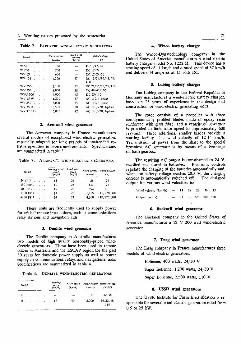
I. Working papers presented by the secretariat 71
Table 2. ELECKTRO WIND-ELECTRIC GENERATORS
Model
W50 . . .W250 . .WV 05 . .WV 156 . .
WV256 . .WV356 . .WVG 506 .WV15W .WV250 . .WV 35 D .WVG 50 D .
Rated output
(watts)
50250600
1,200
2,2004,0006,0001,2002,0003,5005,000
Rated windvelocity(Km/h)
—
—
37
35384237353842
Rated voltage
(V)
DC 6/12/24DC 12/24DC 12/24/36DC 12/24/36/48/65/110DC 24/36/48/65/110DC 48/65/110DC 65/110AC 110, 1-phaseAC T10, 3-phaseAC 110/220, 3-phaseAC 110/220, 3-phase
2. Aerowatt wind generator
The Aerowatt company in France manufacturesseveral models of exceptional wind-electric generatorsespecially adapted for long periods of unattended re-liable operation in severe environments. Specificationsare summarized in table 3.
Table 3. AEROWATT WIND-ELECTRIC GENERATORS
Model
24 FP 7 . .150FRP7 .300 FP 7 . .1100 FP 7 .4100 FP 7 .
Starling windspeed
(km/h)
1411111114
Rated windspeed
(Km/h)
2525252527
Rated output
(watts)
28130350
1,1254,100
Rated voltage
(V)
2424
110110,220,380110,220,380
These units are frequently used to supply powerfor critical remote installations, such as communicationsrelay stations and navigation aids.
3. Dunlite wind generator
The Dunlite company in Australia manufacturestwo models of high quality reasonably-priced wind-electric generators. These have been used in remoteplaces in Australia and the ESCAP region for the past30 years for domestic power supply as well as powersupply to communications relays and navigational aids.Specifications are summarized in table 4.
Table 4. DUNLITE WIND-ELECTRIC GENERATORS
Model
L
M . . .
Startingspeed
(Km/h)
. . 16
Rated speed
(Km/h)
40
Rated output
(watts)
14
2,000
Rated voltage
(VDC)
32,36
24,32,48,115
4. Winco battery charger
The Winco-Dynatechnology company in theUnited States of America manufactures a wind-electricbattery charger model No. 1222 H. This device has astarting speed of 11 km/h and a rated speed of 37 km/hand delivers 14 amperes at 15 volts DC.
5. Lifting battery charger
The Lubing company in the Federal Republic ofGermany manufactures a wind-electric battery charger,based on 25 years of experience in the design andconstruction of wind-electric generating units.
The rotor consists of a propeller with threeaerodynamically profiled blades made of epoxy resinreinforced with glass fibre, and a centrifugal governoris provided to limit rotor speed to approximately 600rev/min. Three additional smaller blades provide astarting facility at a wind velocity of 12-14 km/h.Transmission of power from the shaft to the specialbrushless AC generator is by means of a two-stageoil-bath gearbox.
The resulting AC output is transformed to 24 V,rectified and stored in batteries. Electronic controlsregulate the charging of the batteries automatically and,when the battery voltage reaches 28.5 V, the chargingcurrent is automatically switched off. The designedoutput for various wind velocities is:
Wind velocity (km/h) — 14 22 29 36 43
Output (watts) — 24 136 325 400 400
6. Bucknell wind generator
The Bucknell company in the United States ofAmerica manufactures a 12 V 200 watt wind-electricgenerator.
7. Enag wind generator
The Enag company in France manufactures threemodels of wind-electric generators:
Eolienne, 400 watts, 24/30 V
Super Eolienne, 1,200 watts, 24/30 V
Super Eolienne, 2,500 watts, 110 V
8. USSR wind generators
The USSR Institute for Farm Electrification is re-sponsible for several wind-electric generators rated from0.5 to 25 kW.

72 Part Three. Documentation on wind energy
9. NOAH wind generators
NOAH company in the Federal Republic ofGermany has recently tested several pre-productionprototype wind-electric generators with maximum out-puts up to 90 kW with variable voltage and variablefrequency AC, suitable for electrical heating andcooling, water pumping and hydrogen production.
10. DAF wind generators
The DAF company in Canada is currently under-taking the manufacture of two models of vertical-axisDarrieus rotor wind-electric generators. Selectedcharacteristics are given in table 5.
This type of unit has been especially designed fordeveloping countries and a preliminary economicanalysis (reference W 28) indicates that this designhas an economic advantage over some other machines.
11. Sencenbough wind generator
The Sencenbough company in the United States ofAmerica provides a complete kit for construction ofModel 750-14 wind-electric generator. This 790 watt,14.4 V DC device has a starting velocity of 12 km/hrated wind velocity of 29-32 km/h and maximumoperating velocity of 48 km/h, and is equipped with a3.7-m diameter propeller.
Table 5. CHARACTERISTICS OF DAF WIND GENERATORS
Average wind velocity per month (km/h) . 14.4 17.6 20.8 24.0 28.8
Average monthly kWh output at 110 V(4.6-m diameter) 110 210 360 560 1,000
Average monthly kWh output at 24 V(4.6-m diameter) 110 190 290 420 680
Average monthly kWh output at 24 V(6-m diameter) 210 400 680 1,070 1,900
12. Windworks battery charger
The Windworks company in the United States ofAmerica has prepared a plan for a 12 volt DC wind-electric generator (reference W 9) . The estimatedpower output is as follows:
Average wind velocity per month (km/h)
Average monthly output (kWh)
16 19 22 26
86 150 236 350
Considerable time, skill, specialized power equip-ment and some special materials are required for con-struction of this unit.
13. Brace wind generator
The Brace Research Institute in Canada hasdesigned and tested a 9 kW 110-230 V AC wind-electric generator for use in developing countries (re-ference W 10). This design, intended for localassembly, utilizes automobile and truck components anda 9.8-m fibreglass rotor manufactured in Canada. Theestimated electrical output is as follows:
Average wind velocity per month (km/h) 16 19 22 26
Average monthly output (kWh) 740 1,278 2,030 3,030
14. Kedco battery charger
The Kedco company in the United States ofAmerica has begun production of a simple, reliable
wind-electric generator. Model 1200 produces 1,200watts, 85 amps at 14.4 V DC at a rated wind velocityof 34 km/h, the starting wind velocity being 11 km/h.
15. Models no longer manufactured
Many of the wind-electric generators previouslymanufactured in the United States of America were ofsimple reliable construction, and several of these unitsare still providing reliable service. A detailed studyof the components of these units is recommended priorto finalization of any design of wind-electric generatorsfor manufacture and use in the region.
B. LARGE-SCALE GENERATION FOR SUPPLYTO DISTRIBUTION GRIDS
From 1930 to the late 1950s, many large prototypewind-electric generators, the largest of which was ratedat 1,250 kW, were constructed and tested in a numberof countries, including Denmark, the United Kingdom,France, Germany, the USSR and the United States ofAmerica. Although technically successful, they werenot generally adopted because they were not cost-competitive with large-scale fossil-fueled generation.New activities in this field have occurred recently (re-ference W 29).

I. Working papers presented by the secretariat 73
1. ERDA projects
In 1973, considering recent technological develop-ments in related fields, the United States NationalAeronautical and Space Administration (NASA) andthe National Science Foundation undertook a majorwind energy development programme which wasfollowed up by the Energy Research and DevelopmentAdministration (ERDA) in 1975.
The first ERDA prototype wind-electric generatorcommenced operation in November 1975. The generalspecifications of this Model 0, 100 kW experimentalunit were:
Cut-in wind speed (first load applied) 13 km/h
Rated wind speed (100 kW at busbar) 28 km/h
Maximum operating wind speed 95 km/h
In 1976, ERDA is planning construction of twoprototypes each rated 200 kW, and commencement ofa significant programme for development of smallwind-electric generators.
2. Danish wind-electric generators
In 1941-1943, the Smidth company in Denmarkmanufactured twelve 60 kW and six 70 kW DC wind-electric generators which supplied a local electricitygrid for about 10 years. In 1957, the same companyinstalled a 200 kW AC wind-electric generator, whichsupplied electricity to the national distribution grid for10 years.
In 1974-1975, the Danish Academy of TechnicalScience re-examined the possibilities of large-scalewind-electric generation and concluded that wind energycould supply 10 per cent of the country's electricity.Large Darrieus rotors supported on icosahedron frameswere proposed as an appropriate design.
3. French wind-electric generator
In 1957 an 800 kW 3,000 V wind-electricgenerator was constructed and operated for 5,000 hours,including 600 hours connected to the distribution grid.In the early 1960s, the NEYRPIC organization con-structed a 1,000 kW, 3,000 V asynchronous AC wind-electric generator which supplied a maximum output of220,000 kWh in November 1963. A reduction inpetroleum prices discouraged plans for widespread useof these machines.
4. Canadian wind-electric generator
The Canadian National Research Council is pro-ceeding with a plan for erection of a 200 kW Darrieus
rotor wind-electric generator which is expected tosupply 500,000 kWh per year to a local distributiongrid.
5. New Zealand study
The New Zealand Aerospace company is studyinga 10 kW version of the Darrieus rotor design as amodel for a larger unit intended to be connected to thenational grid.
IV. WINDMILLS FOR OTHER USES
In many countries, windmills have beentraditionally used for grinding grains, oilseed pressing,sugarcane crushing, wood cutting and other semi-industrial tasks. Construction and performance detailsof some of these machines are available in the literatureand present some potential for adaptation for use inthe region.
A. MULTIPLE USAGE
Considerable potential appears to exist foradaptation of wind rotors already used in the regionfor water pumping, such as the Greek sail configurationand the Thai high-speed type, to tasks able to usevariable intermittent mechanical power, including grainthreshing, winnowing and grinding, concrete mixing,load lifting and compost grinding.
It would be desirable to consider development ofwind utilization systems that can be used for severalpurposes, thus allowing the windmill to be used when-ever wind is available, and this would depend largelyon the proper selection or development of the utiliza-tion devices. Some activity in this field has beeninitiated by the Social Work and Research Centre atTilonia in India, and some commercial applicationsare being developed by the Bharat Heavy Electricalscompany in India.
B. CHINESE WIND-POWERED PLOUGH
The use of a wind-powered cable plough in Chinahas been reported in reference W 30. This device incor-porates a wind-powered winch consisting of an upperand a lower capstan and a coupler capable of changingdirection. A bi-directional plough is connected to acontinuous cable which passes through a pulley at theend of the field. The system is operated by two per-sons, one person operating the windwheel and winchand the other person operating the plough, and canplough 0.25 to 0.8 hectares of land per day, dependingon wind velocity.
74 Part Three. Documentation on wind energy
V. SELECTION AND MATCHING OFTRADITIONAL COMPONENTS FOR DESIGN
OF NEW HYBRID WINDMILLS
Components may be broadly classified as follows:
The rotor consists of a surface area for receivingthe pressure of the wind and a support structure whichconverts the horizontal pressure of the wind to rotarymotion.
The hub connects the rotor to the main shaft.
The main shaft and bearings support the weightof the rotor and carry the rotary motion to a powertransfer mechanism.
The power transfer mechanism carries the rotarymotion of the shaft to the power utilization device.
The power utilization device converts themechanical power delivered to it into some form ofuseful work.
The tower supports the rotor above the ground ata height where it can receive a useful amount of windand in most cases rotate freely.
The orientation system consists of a turntable,shaft carriage and sometimes a tail. It is required onhorizontal axis devices to maintain the plane of rota-tion of the rotor perpendicular to the direction of windflow.
The control system is required to match the per-formance of the windmill to the available wind and theenergy demand, and to prevent structural damage inhigh winds.
The primary factors determining the design ofeach component are: function, physical stress relatedto wind speed and load demand, materials available andthe skills and tools required to work with thesematerials. The matching of individual componentsinto a system should aim to have all components ableto withstand similar maximum stress loads and to re-quire a minimum number of different materials, skillsand tools for assembly of the system.
A large number of successful components isdescribed in detail in the literature. The constructionand performance characteristics of an appropriateselection of these, and others not reported, could becarefully documented for each major use (mechanical,electrical) for two power ranges (less than 5 kW,greater than 5 kW). Such documents would be mostuseful for the development of hybrid wind-energysystems for specific applications.
VI. CURRENT INTERNATIONAL ACTIVITIES
Several international organizations are involved inthe development and promotion of small-scale windutilization devices.
A. UNITED NATIONS
The Centre for Natural Resources, Energyand Transport of the Department of Economic andSocial Affairs in New York has an expert adviser onnon-conventional resources on its staff. In 1974, aneconomic evaluation of wind-power systems was made.
The Economic and Social Commission for Asiaand the Pacific will conduct a roving seminar on ruralenergy development in 1977.
The Economic Commission for Africa issponsoring the Second African Meeting on Energy in1976. This meeting will include discussions on thefuture role of wind energy utilization in Africa.
The Economic Commission for Latin America isundertaking a study, and experts are being hired toundertake the implementation of wind-electricgenerators in rural areas of Paraguay.
The Food and Agriculture Organization of theUnited Nations is currently updating reference W 4.
The United Nations Environment Programme isundertaking the establishment of a few demonstrationcentres which will integrate solar, wind and bio-massenergy sources into self-sufficient energy systems forcommunities in some of the typical rural areas of Asia,Latin America and Africa. Sri Lanka has been chosenas the site of the Asian centre.
Although the United Nations Industrial Develop-ment Organization is concerned primarily with in-dustrial development, it has several programmes relatedto energy, and is supplying expert advice to the Govern-ment of the Sudan on the utilization of wind energy.A small production unit for the manufacture of waterpumping windmills is being set up in Kenya.
The United Nations Children's Fund is establishinga village technology demonstration unit in Nairobi thatis expected to be completed by the end of May 1976,and is sponsoring a seminar, commencing 10 June1976, that will include demonstrations of local renew-able energy resources, including two types of windmills,and simple technology for the rural family.
The United Nations Educational, Scientific andCultural Organization has been supporting activitiesrelated to non-conventional energy resources includingwind energy and has established a committee to co-ordinate this activity.

I. Working papers presented by the secretariat 75
B. UNITED STATES OF AMERICA
The New Alchemy Institute-East is developing a6 kW wind-electric generator to be demonstrated aspart of the United Nations Human Settlement Pro-gramme in Canada. They have also been involved inthe development of low-cost wind pumps in India.
Volunteers for International Technical Assistancepublishes details on the construction of several varietiesof windmill appropriate for construction and use indeveloping countries and has several voluntary wind-energy experts who respond to enquiries regardingwind energy utilization.
The Energy Research and DevelopmentAdministration is actively collaborating with severalcountries in the development of large-scale wind-electricgenerating devices.
The Technical Assistance Information ClearingHouse has recently devoted some effort to internationalco-ordination of work on small-scale wind energyutilization.
The Wind Energy Society of America is concernedwith dissemination of wind energy information withinthe academic and research community. The Societyhas several international members.
C. NETHERLANDS
The Netherlands development foundation TOOLpublishes an international newsletter with the aim ofincreasing communication between technical workers.TOOL is providing direct technical collaboration onwind energy development projects in India, Indonesiaand Sri Lanka and has published technical informationon windmill construction for use by rural developmentworkers.
D. CANADA
The Brace Research Institute has been activelyinvolved in the development of windmill designs and
their implementation in developing countries for severalyears, and has issued several relevant technicalpublications.
E. UNITED KINGDOM
The Intermediate Technology Development Grouphas provided direct technical assistance on wind pumpsin Africa and has prepared a technical report on thiswork. It is currently building a prototype wind pumpwith a 6-m diameter rotor with three metal aerofoilblades, a fail-safe governing device and an improvedpump, primarily for irrigation.
The Oxford Committee for Famine Relief(OXFAM) has been active in promoting and financingthe development of windmills in India and Africa.
F. FEDERAL REPUBLIC OF GERMANY
The Foundation for International Developmentorganized a conference in September 1975.
A Wind Energy Research Institute has recentlybeen established at the University of Stuttgart. Thisinstitute will consider problems of wind energy utiliza-tion and will hold regular classes in wind energytechniques.
G. MALAYSIA
The Malaysian Agricultural Research and Develop-ment Institute has recently developed a 6-m diameter,tail-less (down-wind) Greek type sail rotor andperistaltic pump suitable for rural construction, and usefor irrigation and drainage of rice fields.
H. SWITZERLAND
The World Council of Churches publishes originalinformation on windmill construction for use bydevelopment workers.

76 Part Three. Documentation on wind energy
THE DESIGN AND CONSTRUCTION OF LOW-COST WIND-POWEREDWATER PUMPING SYSTEMS (NR/ERD/EWGSW/6)*
INTRODUCTION
Recently there has been an increasing demand forinformation on designs of water pumping windmillsystems suitable for construction with low-cost locally-available materials and skills, and it appears that thegeneral unavailability of properly-documented technicalinformation on indigenous wind pumps is a majorfactor limiting more widespread implementation ofwind pumps in rural areas.
Because of the complex interrelationships of thevariables of wind characteristics, water supply, materialsand skills at each different locality, adaptation of low-cost wind pumps to new areas without modification orredesign has had limited success in the past. However,such interrelationships may be identified andrationalized, and the design process presented as asequential flow of information analysis, rational de-cisions, and calculations, as in the flow chart figure 1.
I. PRELIMINARY INVESTIGATIONS
A. SURVEY OF LOCAL WINDCHA RA CTERISTICS
A reliable determination of local windcharacteristics is required, especially for the periodwhen water pumping is most needed. Summarizedaverage hourly wind velocities (figure 2) are requiredfor preparation of velocity and power frequency curves(figure 3) and power duration curves (figure 4) . Themaximum wind velocity, and directional distribution ofwinds (figure 5) should also be determined.
B. SURVEY OF LOCAL WATER PUMPINGNEEDS
A survey of local water pumping needs should becarried out to determine the total pumping head andthe daily water demand on a monthly basis for eachlikely agricultural and domestic requirement.
C. CLASSIFICATION OF WIND ROTORS
Several different types of wind rotors are well-known, but their construction and performancecharacteristics have not been comprehensively classifiedin a format suitable for design purposes. Completeinformation for comparative analysis of rotors shouldinclude: starting velocity, rated velocity, maximumoperating velocity, tip speed ratio, rated efficiency,
• Prepared by Mr. M. M. Sherman, consultant on wind energy, at therequest of the ESCAP secretariat. The views expressed in this paper arethe author's own and do not necessarily reflect those o£ the secretariat orthe United Nations.
range of diameters, construction materials, rotor solidity(total swept area divided by total frontal area of blades),control mechanisms, velocity/power graph, and, whererelevant, root chord, tip chord, root angle, tip angle andaerofoil section. Compilation of these parameters forexisting wind rotors would greatly assist the design anddevelopment of new hybrid wind-pumping systems.
1. Horizontal-axis rotors
(a) The classic Greek type sail rotor (figure 6)is widely used in Greece (references W 7, W 8, W 31),and adaptations are widely used in Thailand (figure7 and reference W 20) and China (reference W 18).It is suitable for wind pumps because of its highstarting torque, low starting speed, low weight andcost, and its ability to be easily adjusted on theoccurrence of higher wind velocities. It consists of 6to 12 triangular cloth sails, each attached to a woodenspar along its longest edge and held tight by a ropeleading from the free corner to the adjacent spar tip orcircumferential wire between spar tips. Radial wires,leading from the tip of each spar to the tip of acentral axial spar, brace the spars against wind pressure.Maximum rotor solidity is about 45-50 per cent. Sailarea can be reduced by wrapping each sail one or moretimes around its spar. This type of rotor appears tobe the most appropriate design for use in areas withlimited resources of materials and skill. It has beenfurther developed by several organizations for use inIndia (figure 8 and references W 11, W 32), Malaysia(figure 9), Sri Lanka (reference W 12), Ethiopia (re-ference W 13) and other developing countries (figure10 and references W 9 and W 10).
(b) The steel multi-vane fan rotor (figure 11)consists of 8 to 24 curved sheet metal blades mountedon two concentric steel rings supported by 5 or 6tensioned steel spokes. Rotor solidity is 90-100 percent. Local adaptations of this design have beendeveloped by the National Aeronautical Laboratory inIndia, the General Administration for the Developmentof the Euphrates Basin in Syria, a private company inThailand, the Bandung Institute of Technology inIndonesia (reference W 33) and USAID (referenceW 34). A cloth multi-vane rotor has also beendeveloped (reference W 23).
Multi-vane rotors are characterized by a very lowstarting wind velocity of 6-8 km/h, and high startingtorque, and are normally used in conjunction with apiston pump. They are most appropriate for industrialmanufacture and use in areas where the necessity forlong-time durability and reliable unattended operationcan justify the large capital expenditure required.

I . Preliminary investigations HI . Component design and matching
A.
Suvey of
local wind
characteristics
c.Classification
of wind
rotors
Designorientationmechanismandturntable( if needed
E.
Survey of
local materials
and skills
D.
Classification
of
water pumps
Determinetype,sireand strengthof tower
Designcarriageassembly
B.
Survey of
local water
pumping needs
H Data analysis and critical decisions
Designstoragetankif needed)
Construct
and test
Modeland prototype
Í
'S"8
Q.
CO
Figure 1. Sequential flow chart for design of water pumping windmill systems

78 Part Three. Documentation on wind energy
v1 ( knots )
v ( km/h )
t( hours duration
v3x t
0
0
291
0
1
1.85
32
202
2
3.70
619
31,354
3
5 55
331
56,585
4
7.41
8 5 7
348,687
5
9.26
387
307,287
6
11.11
6 0 4
828,281
7
12 96
219
476,714
8
14.81
517
1,679,402
9
16.67
92
426,180
v1 ( knots)
v ( km/h)
t(hours duration)
v 3 * t
10
18.52
293
1,861,187
II
20.37
23
194,401
12
22.22
104
1,140,943
13
24.07
25348,631
14
25.93
14
244,081
15
27.78
5
107,193
16
29.63
1
26,013
17
31.48
0
0
18
33.33
2
74,052
Figure 2. Summary of Vi hourly wind velocity readings at Don Muang airport,Bangkok, for March, April and May 1975
9 0 0
8 0 0
-—Rated veloc ity
-Starting velocity
Maximum velocityMaximum power
.2 500
2 0 0
'Wind vehcity
\
^ Power
IS 20
Wind velocity in km/h
Figure 3. Velocity and power frequency curves
12,500
10,000-Hours above maximum rated
operating velocity, plusmaintenance time, 25
bcfqh '
2 5 0 500
Hours above startingvelocity, 1,406
-Rated velocity, 20 km/h
.. 750Hours duration
Figure 4. Shape of power duration curve
1,250 2,206

I. Working papers presented by the secretariat 79
O I 2
8 5 % o f a l l w i n d a r e o t e r t h a n
8 k m / h b l o w s f r o m S E , S or S W
Figure 5. Wind rose, Bangkok, March, April, May
Figure 6. Greek sail rotor water pump
Bamboo mat sail
Steel chain,driving woodenladder pump
Figure 7. Thai sail rotor water pump

80 Part Three. Documentation on wind energy
Oicorr«heelKub
Figure 8. Madurai prototype sail rotor water pump
(c) A very simple and durable rotor consists offour rectangular cambered steel plate blades twisted togive low pitch angle at the tip and high pitch angleat the root (figure 12). Rotor solidity is about35 per cent. It is commonly used in the Netherlandsand Denmark for small-scale drainage and cattlewatering, and has also been used on low-cost windpumps at some salt works in France (figure 13).Optimization investigations are being carried out at theTechnical University, Eindhoven, the Netherlands. A6-blade cambered metal plate rotor has been developedin Tanzania (reference W 22). This type of rotorseems to have considerable potential for use in low-costwater pumping systems because of simplicity of contruc-tion, durability and good aerodynamic efficiency.
(d) The Princeton sail wing rotor (figure 14)was developed in 1960 at Princeton University, UnitedStates of America. It consists of two blades, eachhaving a double thickness of sailcloth supported by arigid straight leading edge, rigid tip and root chordsections and a trailing edge cable stretched between thetip and root sections. The ratio of root chord to tipchord is about 3:1. The sail is cut with a catenary arctrailing edge, which allows equal chord tensions to bedeveloped along the length of the sail as a function ofthe tension at the trailing edge cable. The aerodynamicperformance of this rotor is similar to that of con-ventional rigid rotors, but the weight, cost and com-plexity of construction are all substantially reduced.Detailed plans of the original Princeton design and an
adaptation for water pumping are available (see re-ferences W 35 andW 36).
(e) High-speed propeller-type rotors are notusually considered for water pumping, but they aresuccessfully used for this purpose in Thailand (figure15) and they may be adapted to high-speed centrifugalpumps. A rotor of this type for use with a wind pumpis proposed in reference W 37. These rotors arecharacterized by high starting velocity, high rotationalspeed and low starting torque. Most high-speed rotorsare carved from wood, although some are made fromaluminium by casting or rib construction (referenceW 38) or fibreglass (references W 39 and W 40).High-speed rotors for pumping applications wouldnormally be used in conjunction with pumps requiringlow starting and constant operating torques, such assquare-pallet chain pumps, centrifugal pumps, chainpumps and archimedean screws.
(f) The classic Netherlands type of rotor, con-sisting of four spars supporting a wooden lattice coveredwith cloth sails, is best adapted to very large machineswhere high power output at low rotational speed andhigh torque are required. Recent use of this type ofrotor for water pumping is rare, and its use in newhybrid designs will be limited primarily by the largeamount of skilled carpentering required to construct thelattice structure.
(g) Several other horizontal-axis rotors havebeen used that incorporate four to eight fixed rect-angular blades of wood or fibre mat construction;their cost, efficiency and durability are each quite low.Generally speaking, a rotor blade can be made from anyflat thin material, including metal, cloth, wood, plastic,bamboo and fibre mats, with appropriate supports.
2. Vertical-axis rotors
Many different varieties of vertical-axis windmachines rotating in a horizontal plane have been re-ported (reference W 41). The primary advantage ofthese rotors is that they can accept wind from anydirection and thus do not require any orientationmechanism, but their construction is usually very bulkyand requires a large quantity of material in relation tothe effective collection area. These rotors have main-tenance difficulties as a result of the large weight restingon one thrust bearing at the base of the main shaft.Aerodynamic efficiency is low because the rotor turnsas a result of direct wind pressure which is a functionof the square of the wind velocity, unlike horizontal-axis rotors which extract wind energy as a function ofthe cube of wind velocity. Also, only about half ofthe rotor blades are doing work while the other half arereturning up-wind. However, two classic vertical-axisrotors which may have some practical importance formodern applications, because of their light construction.

I. Working papers presented by the secretariat 81
Figure 10. Brace Institute-Windworks sailrotor with octahedron module tower
Figure 9. Malaysian Agricultural Research andDevelopment Institute down-wind sail rotor water pump
Figure 11. Multi-vane metal rotor Figure 12. 4-blade metal rotor

82 Part Three. Documentation on wind energy
- 4 m
- 3 m
- 2 m
- I m
Alternative crankshaft4 sheet-iron «ails,
surface I m2,
span 3 m
Wind shaft
Direction of / \rotation *—s Framework ( timber and strut)
-—Counterweight(when fitted)
Access ladder ( when fitted)Fixed sub-structuretower
Support for pipe
Wooden or ironspout
Iron pumping \ \rod \ \
\ \Wooden pump \barrel and bucket
wStaves
Evaporation
t -r t,**"•' Level of final salt basirr ' •
Copper inlet valve'
Figure 13. 4-blade metal rotor water pump at Ile de Noirmoutier, France

I. Working papers presented by the secretariat 83
Dacron sailcloth
Fixed rigid tip
Rigid leadingedge(spar)
Wire cable^roiling
Rigid root
Figure 14. Princeton sail wing rotor blade
Wooden pulley
\\ \ ^ _ — Highspeedwooden blade,6 m diameter
Figure 15. Thai high-speed rotor water pump — wooden mounting assembly

84 Part Three. Documentation on wind energy
are the Chinese type (figure 16) and the Turks andCaicos Islands type (figure 17). These rotors may beparticularly adaptable to Persian wheel and buckettypes of water lifts in addition to continued traditionaluse with square-wooden-pallet chain pumps.
(a) The rotors used in the Turks and CaicosIslands, British West Indies, for pumping salt water toevaporating ponds consist of six triangular cloth jibsails supported along their long edge by a vertical pole,and held by a rope tied from the loose corner to theadjacent vertical pole. Each vertical pole is supportedby two horizontal wooden poles which radiate outfrom the central vertical main shaft. A similar jib-sailrotor utilizing eight sails has been proposed for use inThailand (figure 18). :
(b) The Savonius rotor (figure 19) has beenwell documented (reference W 25). Its use forpractical water pumping and electricity generation hasmet with limited success only.
(c) The Darrieus rotor (figure 20) consists oftwo or three constant-chord aerofoil blades bent into acatenary curve and fixed at each end to a vertical axiswhich is supported by guy wires at the top and con-nected to a power utilization device at the base (re-ference W 42). The advantages of this rotor are that,unlike other vertical-axis rotors, a minimal supportstructure is required, the proportion of materials to totalswept area is very low (solidity about 5 per cent), andefficiency is high. The main disadvantage is that it isnot self-starting, and construction of the blades fromfibreglass reinforced plastics or extruded aluminium isquite expensive. Although it has only recently beendeveloped for electricity generation (reference W 43),it may have some potential for water pumping. Ex-perimental work with a Darrieus rotor powered waterpump has recently been undertaken at the NationalAeronautical Laboratory in India.
(d) The gyro vertical-axis rotor (figure 21 andreference W 44) is similar to the Darrieus rotor in thatit has a high efficiency of about 60 per cent, a verylow solidity factor and minimal support structure re-quirements. This rotor consists of two or three straightsymmetrical aerofoil blades supported vertically fromhorizontal support arms fixed to a vertical centralpower shaft. Orientation of the blades is reversedtwice during each rotation so that maximum lift isachieved. High-speed small-diameter designs haveconsiderable vibration. Further development of thisrotor is currently in progress at the Cranfield Collegeof Technology, United Kingdom.
3. Three novel concepts
Three novel concepts for utilizing wind power forwater pumping have recently been proposed. Althoughthese ideas have not yet been given full-scale demonstra-
tion, their simplicity of operation and low-cost con-struction makes them worthy of further consideration.
(a) The flapping-vane wind pump (figure 22and reference W 45) has beeen designed for use withdeep well piston-type water pumps, although it may beadapted to diaphragm pumps,or to a crankshaft flywheelto produce rotary motion. This device consists of along lever arm with a cloth vane mounted on ahorizontal axis at the outer end and a vertical recipro-cating power rod at the fulcrum end. The vane canswing freely about its axis within the range of an upperand lower angular stop. Action of the wind on thevane alternatively depresses and lifts the lever armwith resultant power applied to the reciprocating rod.The lever fulcrum is mounted on a pedestal which canrotate on top of the tower in order to allow the vaneto automatically orient itself to the direction of thewind. This device is expected to pump 100 m3 perday from a depth of 40 m with a wind velocity of 16km/h when the vane area is 29 m2 and the lever armis 20 m long. With increasing wind velocity, theamplitude of the up and down motion of the lever armdecreases and the frequency increases, so that thesystem is self-regulating.
(b) A tree pump has been proposed thatconverts the horizontal motion of a tree trunk swayingin the wind to reciprocating vertical motion of a pistonpump, via cables and pulleys. Tn this device, the onlycost is for the power transfer mechanism and pump.This method is limited to sites with tall unshelteredtrees.
(c) A parachute pump (figure 23) has beenproposed as a low-cost method of supplyingpower to traditional animal-powered bucket pumps.This system comprises a large parachute whosecircumference ropes are tied to the lift rope.The force of the wind on the parachute pulls thebucket to the top of the well, at which point a ropeattached to the centre of the parachute becomestightened and collapses the parachute so that it may bereturned to the starting point by the operator, and thebucket can return down to the base of the well. Theparachute is then again allowed to fill with wind tobegin another lifting cycle. With this system the onlyexpense is the wind collection device (parachute).The pump and transfer mechanism exist and there isno need for a support structure.
D. CLASSIFICATION OF WATER PUMPSA comprehensive international classification of all
types of small pumps used for water pumping isurgently needed. Such a classification could includethe following information regarding each type ofpump; typical schematic diagram, normal range ofsuction and discharge heads, normal range of output,construction materials and skills required, usual modeof power supply, efficiency, range of operating speedand torque.

I. Working papers presented by the secretariat 85
View from above
Figure 16. Chinese vertical-axis rotor
View from above
Figure 17. Turks and Caicos islands vertical-axis rotor

86 Part Three. ' Documentation on wind energy
Figure 18. Thai jib-sail rotor
Wooden template
Sheetmetal wing
Figure 19. Three-tiered Savonius rotor
Plywooddisc
Plywoodtemplate
Sheetmetal
V j Blade flip region
Gyro rotor blade modulation
Figure 21. Gyro rotor
Figure 20. Darrieus rotor

I. Working papers presented by the secretariat 87
Wind
I. Canvas sail
2 Lever arm, wood
3. Lever fulcrum
4. Wooden frame tower
5. Sail framework
6. Swivel stop
7. Balancing weights
8. Universal joint
9. Pump rod
Figure 22. Flapping-vane rotor water pump
Wind
Figure 23. Parachute-type water pump

Part Three. Documentation on wind energy
1. Reciprocating pomps
Most reciprocating pumps have the disadvantagethat the torque load is not constant, thus requiring ahigher wind velocity for starting, and variable stresseson the system when in operation.
(a) The single-acting cylindrical piston pump ismost frequently used in wind-powered pumpingsystems. It consists of a cylinder with an inlet pipeand valve at the base, a leather-sealed piston with aone-way valve and a water outlet at the top, waterpassing through the pump only on the lifting stroke ofthe piston. This type of pump is used to pump waterfrom any depth, with an operating speed of up to 40strokes per minute.
(b) A square wooden single-acting piston pumpis commonly used by fishermen in eastern Canada(figure 24) and has recently been adapted to windpower (reference W 46). A square wooden pumppowered by the wind has been proposed for use inThailand (reference W 47). The height of lift islimited by the amount of water pressure that can besustained by the wooden joints, although the simpleconstruction is well adapted to basic carpenteringskills.
(c) The double-acting piston pump (figure 25)is similar to the single-acting pump, except thatthere is no valve or passage of water throughthe piston, the water by-passing the piston cylinderthrough pipes and valves under pressure duringboth the upstroke and the downstroke. Theadvantage of this pump over the single-acting pump isthat the load on the power source is more constant, butit is not usually used in wind pumping systems becauseany compression load during the downstroke couldbuckle the long piston rod leading from the top of thetower: this problem could be avoided if a very shortpiston rod were connected to an immediately adjacentrotary power transfer mechanism powered by a longbelt leading directly from the rotor shaft.
(d) The diaphragm pump (figure 26) consistsof a cylinder closed at the lower end, with a circulardiaphragm of rubber or some other flexible materialfixed at the top end. A reciprocating connecting rodis fixed to the centre of the diaphragm and, uponvertical movement, causes volumetric displacement inthe cylinder. An arrangement of valves allows watermovement in only one direction through the cylinder.The difficulty with this type of pump is the high rateof wear on the diaphragm at its connexions with thecylinder and connecting rod. A diaphragm pump hasbeen developed for use with a Savonius rotor (re-ference W 24).
(e) The inertia pump (figure 27 and referenceW 48) is a very simple and efficient device that depends
upon the vertical inertia of a body of water in a re-ciprocating pipe to expel water at the end of theupstroke of the pipe. A one-way flap valve in thepipe is closed during the upstroke, and inertia is im-parted to a fresh volume of water by the lifting forceon the pipe. This pump must operate at a constantfrequency which is dependent upon the mass of waterin the pipe and the pipe itself. This recently popularizedpump has probably not yet been used with wind power.
2. Rotary-motion pomps
Continuous rotary-motion pumps are well adaptedto operation by wind power because they require aconstant torque load and generally operate at a variablelow speed.
(a) The square-wooden-pallet chain pump(figure 28 and reference W 49) is commonly used inChina and southeast Asia for lifts up to 3 m andconsists of rectangular wooden pallets or paddlesmounted on a continuous wooden chain that runs upan inclined square-section open wooden trough. Thepaddles and chain pass around a large wooden drivinggear wheel at the top and around a small passive gearwheel at the base of the trough which is submerged inwater. This type of pump is commonly used withChinese vertical-axis wind pumping systems and withThai high-speed wooden rotors and Thai sail rotors.
(b) The round-steel-washer chain pump (figure29 and references W 12, W 15) is used in conjunctionwith human and animal power, and consists of a con-tinuous steel chain upon which are mounted steel discswith rubber or leather washers. The chain passesaround an upper gear wheel, down the well, under thewater source, around and then up into the bottom of apipe with inner diameter the same as the washers.Water is lifted up within the pipe and expelled at thetop. A square wooden adaptation of this pump isshown in figure 30.
(c) Large-diameter slow-speed centrifugal pumps(figure 31) have good potential for low-lift pumping.The meadow type wind pumps of the Netherlandsare fitted with centrifugal pumps 1 m in diameter and0.2 m high, with four wooden blades, and have anefficiency of 30 per cent and an output of up to 100 m3
per hour in a strong wind. Further design develop-ment and quantification of design variables of thesepumps could be undertaken.
Another type of centrifugal pump is the centrifugalreaction pump (figure 32) which consists of a verticalpipe with a T-joint at the top, from which extend twopipes whose length is dependent upon the rate ofrotation of the assembly in operation. An orifice atthe end of each pipe arm points 90° away from thearm. When the assembly is filled with water and

I. Working papers presented by the secretariat 89
Wooden rodconnected at topto crankshaft
Weighted wooden block
or steel plate bolted
to leather flap
Figure 24. Square wooden piston-type water pump
Outlet •
Connecting rodRubber or leather
diaphragm
Inlet valve
-»—iniet Figure 26. Diaphragm-type water pump
Reversed lower washer
^Plugged bucket orifice
••Foot valve removed
-Non-return valve
Figure 25.Double-acting piston-type water pump

90 Part Three. Documentation on wind energy
litude80 strokes/min
Pipe dio.
cm
7 6
10.2
15.2
PERFORMANCE
Litt
m42
1
OF INERTIA
l/h6,8409,0601,704
PUMP
Output
kW0.090.060.06
Figure 27. Inertia-type water pump

I. Working papers presented by the secretariat 91
Wooden pallets
Scale
Figure 28. Wooden-pallet-type water pump
rotated in the direction opposite to the orifices, thewater is forced out through the orifices by centrifugalforce and replenished by water coming up through avalve in the bottom of the vertical pipe. This pump iswell adapted to variable low speeds, and constructionis simple. One of these pumps, connected to a 3-mdiameter high-speed wind rotor, pumped 30 m3 perhour at a head of 4.5 m in a 29-km/h wind (referenceW 5 0 ) .
(d) Axial-flow pumps have good potential forlow-lift pumping because of their relatively simple con-struction and high efficiency. No use of these pumpswith wind rotors is recorded, but it has been suggestedthat axial-flow pumps would be appropriate for high-volume pumping of sewage wastes in oxidation ponds(reference W 51). Theoretical studies of wind-powered axial-flow pumps are being carried out at theNational Aeronautical Laboratory in India.
(e) Archimedean screws are very simple, andhave efficiencies up to 80 per cent. They have beenused in the Netherlands for large-scale drainage re-quiring a lift of up to 5 m. Three basic versions areknown (reference W 48) :
(i) The type with a rotating cylinder madeof strips of wood and having a spiral partition inside(figure 33), as in the Tjasker type of wind pump in theNetherlands, requires a footstep bearing below thewater level, and demands a fairly sophisticated level ofconstruction skill. It can be made large in diameterand so suitable for slow-speed operation. Such a
screw, 2.7 m long, 0.56 m diameter and lifting through1.3 m at a speed of about 30 rev/min, gives an outputof 32.4 m3 per hour.
(ii) The type in which the outer casing isstationary and the helical rotor is supported on bearingsat either end, attached to the casing, are normally ofsmaller diameter and run at a high speed, e.g. 12-cmdiameter up to 200 rev/min, 40-cm diameter up to 127rev/min. An advantage of this type is that the casingand rotor form a self-contained assembly which doesnot require external bearings but only simple supportsto maintain it at the correct angle and axial position.The screw is made by rolling a flat steel strip betweenrollers set at an inclination to each other to squeezeone edge of the strip and hence cause it to curl intoa helix, which is then welded to an inner cylindricalpipe.
(iii) A third method of constructing anArchimedean screw is to coil a section of pipe into acylindrical helix. A particular type has recently beenevolved for field drainage in which the tubing is cor-rugated with a fine pitch to strengthen it and to allowcoiling to a small radius. This could form the basisof a simple low-cost pump, since most of the construc-tion could be done locally. For example, a stoutbamboo could serve as the main axle, and the coils ofpipe could be held in place by lashing with rope, wireor any suitable local fibre, using longitudinal strips ofbamboo or other wood to form a supporting cage onthe inside of the coils.

92 Part Three. Documentation on wind energy
Figure 29. Steel-washer chain-type water pump
VFigure 30. Square wooden enclosed
chain-type water pump

I. Working papers presented by the secretariat 93
0.95 i
Pip«5cmdio. I • Pipe 7.5cmdio. I . S i
; «J^rtf—Foo? volve
.Anis of rototion
.Sliding shutter
iy--1. ¡i
Inlet
•>•! Spring
¡(orifice
Figure 31.Large-diameter slow-speed centrifugal-type water pump
^Orifice in Slidinq shutter
Figure 32.Centrifugal reaction-type water pump Wind
Wheel for turningthe mill into the wind
Ring conol
Figure 33.Netherlands "Tjasker"-type rotor and water pump

94 Part Three. Documentation on wind energy
(f) The peristaltic pump (figure 34) consists ofa flexible hose with a series of rollers rolled along thelength of the hose in order to squeeze water throughthe hose. This type of pump has reportedly beenadapted to a Greek sail wind rotor at the MalaysianAgricultural Research and Development Institute.
Roller
Inlet
Figure 34. Peristaltic-type water pump
(g) A simple water pump operated by com-pressed air (figure 35 and reference W 46) is currentlybeing tested. The advantages of this pump are that itcan be located some distance from the compressor, twoor more pumps could be operated by one compressor,or one large pump could be operated by two or moresmaller compressors.
(h) A hydraulically operated water pump (figure36) is currently under development by the Ministry ofLands, Settlement and Water Development in Tanzania.This pump was designed to solve the problems of usingpiston pumps in very deep and narrow borehole wells.
ni. DATA ANALYSIS AND CRITICALDECISIONS
A. DETERMINATION OF RATED WINDVELOCITY AND WATER DEMAND
For the months of greatest water pumping de-mand, graphs such as those in figures 3 and 4 shouldbe prepared on a monthly basis. If continuity of watersupply is important, the rated wind velocity chosenwould be somewhat lower than if maximum outputwere the only goal. Daily water demand should besummarized on a monthly basis.
B. SELECTION OF ROTOR
The selection of the type of rotor requires carefulconsideration of local skills and materials as well asoperating and performance characteristics, bearing in
mind that the precise characteristics of the main typesof low-cost locally-constructed rotors are not readilyavailable. A reasonable compromise must be madebetween high reliability, durability and maintenance-free operation on the one hand, and low constructioncost on the other hand, taking into account that in-creased labour input will generally result in lowercapital input.
Selection of a rotor is also dependent upon thetype of pump to be used. To maximize the efficiencyof power transfer, the torque, speed and power charac-teristics of the rotor and pump should be as similar aspossible.
C. SELECTION OF PUMP
Selection of the type of pump depends on the totalpumping head, the type of rotor and the local materialsand skills available for construction. The use oftraditional local pumps, whenever possible, will reducethe problems of introducing a new technology.
D. DETERMINATION OF DESIRED PUMPOUTPUT
The starting, rated and maximum operating windvelocities of the rotor must be known to determine theload factor (figure 4). Division of the daily waterdemand by the load factor will yield the desired ratedoutput of the pump. If this rate is greater than themaximum output of the type of pump selected, theneed for a pump with greater output or the use of morethan one pump is indicated if the total demand is tobe met.
E. DETERMINATION OF THE RATED POWERREQUIREMENT OF THE PUMP
The rated power requirement of the pump maybe obtained from the following relation:
Power (kW) = •Desired output in m3/sec X head in m X 9.8
Pump efficiency in per unit
F. DETERMINATION OF THE NEED FOR ANORIENTATION MECHANISM
The need for an orientation mechanism may bedetermined by analysing the frequency of each winddirection as in figure 5. In many tropical, and especiallycoastal, areas, the wind blows mainly in either of twoopposite directions. In such cases, the use of a fixed-axis rotor can save considerable construction expense.If an orientation mechanism is required, the choice ofmanual or automatic orientation will depend on thenumber of changes in wind direction.

I. Working papers presented by the secretariat 95
Reciprocating pistondrive rod
Piston
Hydralic pressurechamber
Hydraulic pressuredelivery pipe
Delivery
Non-return valve(open position}
• Non-return, valve( open position )
Valve seat
Inlet screen
Compressedair inlet(continuous)
Air exhaustvalve
sWater inlet valve(closed position)
Figure 35. Water pump driven by compressed air
Figure 36. Hydraulic-drive water pump

96 Part Three. Documentation on wind energy
TV. COMPONENT DESIGN AND MATCHING
A. CONTROL MECHANISMS
Mechanisms to stop the rotor and to control rotor-blade pitch angle, blade area and pump stroke shouldbe incorporated in the design in order to allow opera-tion under a maximum range of wind velocities, withoutdamage. The pitch angle of rigid blades may be con-trolled by centrifugal governors or blade coning. Thepitch angle of non-rigid sails may be controlled bymanual or spring adjustment of the trailing edge tension.The area of sails may be controlled by furling. Pumpstroke may be adjusted by changing the fulcrum pointof a lever.
B. ROTOR RADIUS
The required radius of the rotor in metres dependson the power output required in kW, the rated windvelocity in km/h, and the rotor and power transferefficiency according to the relation:
Power = 0.0000255 R2 v3 (effr X efft)
where: effr = efficiency of rotor in per unit
efft = efficiency of power transfer in per unit
The maximum size of the rotor may be limited bythe maximum length of spar material available or bythe type of tower materials.
C. PUMP SIZE
The size of the pump is a direct function of thedesired rated output, speed of operation and efficiency.Materials or power available will usually determinethe maximum pump size.
D. POWER TRANSFER MECHANISM
The function of the power transfer mechanism isto transfer the rotary motion of the rotor to the pump,and the design depends upon the type of pump used(reciprocating or rotary motion) and the type of rotor(horizontal- or vertical-axis).
For rotary pumps, differences in speed betweenrotor and pump up to a ratio of 4:1 can be com-pensated for by a single-step pulley or a gear transfer.Rotary motion of a horizontal shaft can be convertedto vertical rotary motion by gears and transferred toground level by a rotating power shaft, or horizontalrotary motion at ground level can be obtained by theuse of large diameter upper and lower pulleys and asteel chain or cowhide belt.
Vertical reciprocating motion is usually obtainedfrom a crankshaft, and passed down through the centreof the turntable to the pump by a steel or wooden con-necting rod which incorporates a swivel to prevent the
rod from being twisted when the carriage assembly androtor shaft turn in response to change in wind direction.It is desirable to keep the stroke of a crankshaft assmall as possible in order to minimize turntablediameter but, with commonly available piston pumps,it is desirable to make the stroke as long as possible.This apparent conflict can be resolved by using a leverarm as shown in figure 8.
E. ORIENTATION MECHANISM
The orientation mechanism can take the form ofa classic tail vane for automatic orientation or, wherechanges in wind direction are not frequent, a manually-operated tail rope as in Thai wooden-blade windmills,(figure 15) or manually-shifted A-frame axis supportsas in the Netherlands Tjasker type (figure 33) andChinese diagonal-axis type (figure 37).
The function of the turntable is to allow the rotor,main shaft and carriage assembly to rotate only abouta fixed point in a horizontal plane on top of the fixedtower and to prevent any vertical or horizontal move-ment. Vertical power transfer usually passes throughthe centre of the turntable, but a considerable savingin turntable construction cost may be achieved byhaving the power transfer outside the turntable.
Multi-blade wind pumps incorporate a ball-bearingturntable, but a simple greased circular steel ring hasproved adequate for Greek type wind pumps. TheThai wooden-rotor wind pump (figure 15) uses atapered wooden post inserted into a wooden hole in thecarriage assembly, with the power going down outsidethe post.
F. HUB, MAIN SHAFT, BEARINGS
The selection of hub, main shaft and bearings ismost important because rotor load stresses are concen-trated on these components.
The function of the hub is to connect the root endof the rotor spars firmly to the main shaft. The hubmust withstand the centrifugal force of the rotor, andbending loads of the rotor spar caused by wind pressureand rotor torque. These forces (indicated in figure38) are quantified in the following formulae:
Centrifugal force (kg) = 0.00219 W t2 v2
Torque (m - kg) = 367 RP_tv~~
Wind pressure (kg) = 0.00142 v2 R2
for a spinning rotor, and is increased by twicethe solidity factor for a stationary rotor

I. Working papers presented by the secretariat 97
A- frame support
Power shaftto wooden-palletchain pump
Figure 37. Chinese diagonal-axis rotor water pump

98 Part Three. Documentation on wind energy
Wind
Figure
where: P =R =
Rj =
t =ti =
w =
38. Loads on rotor
power in kWradius of rotor blade in mradius to centre of gravity of rotorblade in mtip speed ratio at tiptip speed ratio at centre of gravityof rotor bladewind velocity in km/hweight of the blade in kg
The main shaft must bear the weight of the rotorand withstand the torque and bending forces appliedby the power transfer mechanism. The shaft may bemade from wood, steel rod or steel pipe.
Simple wooden bearings or steel ball or thrustbearings may be used. If steel bearings are used,adequate protection must be provided against dust andrain. Wooden bearings should be capable of easy re-placement. Provision must be made for lubrication.
G. TOWER
Determination of the type of tower is primarily afunction of the materials and skills available. TheWindworks octahedron module design (figure 10) hasthe highest strength-to-weight ratio of any non-guyedtower, but construction is complex and must be precise.Lattice steel towers (figure 6) are strong and wellproven but quite expensive. Single wooden poletowers (figures 7 and 15) are the cheapest, butcan only be used when it is not necessary to have thepower transfer down the centre of the tower. Multiplewood pole towers (figure 8) are cheap, strong andeasy to construct, and use is limited primarily byresistance to wood ants and termites. The use of guy
wires, when possible, will significantly increase over-alltower strength at little cost.
The minimum tower height should be at leastequal to the rotor radius plus 1.8 m (for safety of per-sonnel). Efforts to make the tower much higher thanthis should be avoided because the additional cost islikely to be greater than the increase in benefit, exceptin locations with nearby wind obstructions.
H. CARRIAGE ASSEMBLY
The carriage assembly provides a firm but movablefoundation for the main shaft bearings upon the tower,and may be of wood or steel. It must be fastened tothe turntable in such a way that it may turn in responseto changing wind direction. The tail is fastened to thecarriage assembly.
I. STORAGE TANKThe maximum capacity of the storage tank is
determined by multiplying the longest period of windless than starting velocity by the daily water demand.Overhead storage is not economical unless pres-surized supply is required. A ground-level tank maybe constructed of stone masonry about 1 m high.Possible additional uses of the storage tank for bathingand fish culture should be taken into consideration.
J. WORKING DRAWINGS, MODELAfter preliminary sketches of each component
have been prepared, the final working drawings shouldbe made, showing the details of and connexionsbetween each component.
A 1/5 scale model should be made and tested inorder to gain familiarity with the construction processand to carry out design optimization trials. Onlyafter a model has been tested to full satisfaction shouldconstruction of a full-scale prototype proceed.
V. A HYBRID ASIAN WIND-POWEREDWATER PUMP
In this section, an example is given of the designof a low-cost wind-powered water pump according tothe sequential flow design process suggested in figure 1.An effort has been made to base the design on con-ditions common to many parts of Asia.
A. PRELIMINARY INVESTIGATION1. Survey of local wind characteristics
The average wind velocity at Don Muang Airport,Bangkok, for 5 minutes of each half hour is recordedby the Meteorological Department of Thailand. Asnoted, the data for the months of March, April, May1975 had been summarized and analysed as shown infigures 2, 3 and 4. Data from the airport were selectedbecause of its exposed location in a rice-growing area

I. Working papers presented by the secretariat 99
and its proximity to the Asian Institute of Technologyand the proposed National Energy Administrationwindmill test location.
2. Survey of local water pumping needs
March, April and May were chosen as the periodwhen irrigation pumping would be most beneficialbecause the first crop of rice is already harvested byFebruary and, in the virtual absence of rain, the fieldsare normally not used until the onset of the monsoonin June.
3. Classification of wind rotors and pumps
As a complete classification of wind rotors andpumps is not available, reference will be made toprevious sections of this report.
B. DATA ANALYSIS AND CRITICALDECISIONS
1. Wind data analysis
(a) Consideration of the velocity and powerfrequency curves (figure 3) indicates an optimum
starting velocity of 6 km/h and an optimum ratedvelocity of 20 km/h in order to obtain maximumoutput.
(b) The raw wind data indicate that the longestperiod of wind below optimum starting velocity of 6km/h is 6 hours.
(c) Study of the wind power rose (figure 5)indicates that an orientation mechanism would beuseful but not necessary; but, for the benefit of otherareas with more variable wind direction, it is assumedthat there is a need for an orientation mechanism.
(d) Analysis of the power duration curve (figure4) yields a load factor of 0.30.
2. Selection of rotor
Based on the widespread success, low cost andlight weight of the Greek sail rotor, this configurationwas selected (figure 39). An alternative configurationthat may be used in areas of higher wind speeds isbased on the Princeton sail wing (figure 40).
Wire loop
Detail of emergency,
sail release
Figure 39. Greek cloth sail rotor configuration

100 Part Three. Documentation on wind energy
Figure 40.Hybrid Princeton — Greek sail rotor configuration
3. Selection of pomp
For generalized design purposes, a total head of10 m is assumed. Owing to its simplicity of construc-tion and adaptability to variable low-speed rotarymotion, the steel-washer chain pump was selected(figure 29). However, the square-pallet chain pump(figure 28) may be best for areas where this pump istraditionally used and only a low lift is required.
4. Determination of desired pumping rate
Assuming a daily requirement of 6.5-mm depthper day for rice cultivation and a desired irrigated areaof 2 hectares, the daily water demand is 130 m3 perday. Multiplication by the reciprocal of the load factorindicates that the rated capacity of the pump shouldbe 18 m3 per hour.
5. Determination of rated power requirementof the pomp
Assuming 0.70 pump efficiency, the rated powerrequirement of the pump would be 0.703 kW (sectionIII. E).
C. COMPONENT DESIGN AND MATCHING
1. Control mechanism
Assuming frequent presence of the operator,furling of the sails would be the primary controlmechanism. An emergency sail-release mechanismsimilar to that used on Thai sail rotors would be incor-porated (figure 39).
2. Size of rotorAssuming 0.25 and 0.50 for the efficiencies of the
rotor and power transfer respectively, the requiredrotor diameter from section IV. B would be 10.5 m.
This size is within the range of bamboo sparsavailable in Thailand and most Asian places. Sailrotors have been operated successfully up to 10-mdiameter so this size is acceptable.
3. Size of pumpGiven the rated output of 18 m3 per hour and
pump efficiency 0.70, the basis of calculation is 25.7 m3
per hour. Assuming a rated rotor speed of 12 rev/min

I. Working papers presented by the secretariat 101
with a 2:1 speed increase and a 0.5-m diameter pumpdrive wheel, the size of the pipe within which water islifted by the washers on the chain should be 12.0 cm.The size of the pipe may be decreased by increasing thespeed of the chain, which may be effected by providinga higher drive speed ratio or by increasing the diameterof the pump drive wheel. The optimum speed ofchain pumps is not known.
4. Orientation mechanism
Orientation of the main shaft by manual relocationof an A-frame support structure (figure 41) supportingone end of an extended shaft is suggested because ofits simplicity and proven feasibility on the NetherlandsTjasker type (figure 33) and Chinese diagonal-axis type(figure 37). The opposite end of the shaft rotatesabout a fixed, guyed turntable post (figure 42).
5. Power transfer mechanism
Because horizontal rotary motion is required tooperate the chain pump, only a simple direct pulleydrive to ground level is required. Pulley wheels madeof several laminations of wood boards are suggested(figure 42). Chains are widely used in Thailand asthe transfer connexion and would be suitable.
6. Hob, main shaft and bearings
(a) A laminated wooden hub was selected(figure 43) because of its simplicity of constructionand successful use on Thai sail rotors.
(b) An extended square wooden main shaft issuccessfully used on Thai sail rotors and has beenselected for this hybrid design (figure 43). The shaftis rounded only at the point where it rests in the bearing(figures 41, 42) .
(c) Simple wooden bearings have been wellproven on Greek and Thai sail rotors and AustralianComet wind-powered pumps. An improved versionof Greek wood bearings with increased bearing surfaceand provision for lubrication has been designed for bothmain bearings (figures 41, 42).
7. Tower
The tower in this case consists only of the two legsof the movable A-frame at one end of the shaft and theturntable post at the other end. The turntable post isguyed to the ground and the A-frame is guyed to thebase of the turntable post so that it is stabilized but stillfree to move.
8. Carriage assembly
The large wooden bearing blocks also functionas the carriage assembly.
9. Storage tank
Because the longest period of wind below startingvelocity is only six hours, a storage tank is not con-sidered necessary, although it would be useful forirrigation control.
10. Final drawings
An over-all sketch of this hybrid design (figure44) is proposed as the basis for construction of modelsfor testing only. For further development of thisdesign, model test results should be evaluated anddesign modifications incorporated into final workingdrawings for prototype construction and testing.

102 Part Three. Documentation on wind energy
20 cm
Wedge to tighten wire
2 0 cm
. Support legs
Isometric view
Alignment peg
Isometric view
Turntoble post
/Rubber surfoce
,Steel friction discs
Woodenstop Wooden
stop
.Steel friction discss,GreaseN
hole
Bearingblock
Vertical cross-section
Bearing -block
Figure 41. Double leg support bearing block Turntable post-
Vertical cross-section
Figure 42. Turntable post bearing block

I. Working papers presented by the secretariat 103
o
CD

104 Part Three. Documentation on wind energy
Cloth or bamboomat sails
Circumference wires
Radial wires
1.0 m dia
laminatedwood pulleys
- a m
Figure 44. Hybrid Asian wind-powered water pumping system
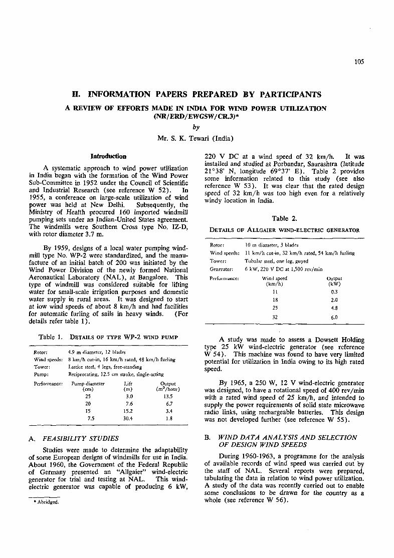
105
H. INFORMATION PAPERS PREPARED BY PARTICIPANTS
A REVIEW OF EFFORTS MADE IN INDIA FOR WIND POWER UTILIZATION(NR/ERD/EWGSW/CR.3)*
by
Mr. S. K. Tewari (India)
Introduction
A systematic approach to wind power utilizationin India began with the formation of the Wind PowerSub-Committee in 1952 under the Council of Scientificand Industrial Research (see reference W 52). In1955, a conference on large-scale utilization of windpower was held at New Delhi. Subsequently, theMinistry of Health procured 160 imported windmillpumping sets under an Indian-United States agreement.The windmills were Southern Cross type No. IZ-D,with rotor diameter 3.7 m.
By 1959, designs of a local water pumping wind-mill type No. WP-2 were standardized, and the manu-facture of an initial batch of 200 was initiated by theWind Power Division of the newly formed NationalAeronautical Laboratory (NAL), at Bangalore. Thistype of windmill was considered suitable for liftingwater for small-scale irrigation purposes and domesticwater supply in rural areas. It was designed to startat low wind speeds of about 8 km/h and had facilitiesfor automatic furling of sails in heavy winds. (Fordetails refer table 1).
Table 1. DETAILS OF TYPE WP-2 WIND PUMP
Rotor:Wind speeds:Tower:Pump:
Performance:
4.9 m diameter, 12 blades8 km/h cut-in, 16 km/h rated, 48 km/h furlingLattice steel, 4 legs, free-standingReciprocating, 12.5 cm stroke, single-acting
Pump diameter(cm)
2520157.5
Lift(m)3.07.6
15.230.4
Output(mD/hour)
13.56.73.41.8
A. FEASIBILITY STUDIES
Studies were made to determine the adaptabilityof some European designs of windmills for use in India.About 1960, the Government of the Federal Republicof Germany presented an "Allgaier" wind-electricgenerator for trial and testing at NAL. This wind-electric generator was capable of producing 6 kW,
220 V DC at a wind speed of 32 km/h. It wasinstalled and studied at Porbandar, Saurashtra (latitude21°38' N, longitude 69°37' E). Table 2 providessome information related to this study (see alsoreference W 53). It was clear that the rated designspeed of 32 km/h was too high even for a relativelywindy location in India.
Table 2.
DETAILS OF ALLGAIER WIND-ELECTRIC GENERATOR
Rotor: 10 m diameter, 3 blades
' Abridged.
Wind speeds: 11 km/h cut-in, 32 km/h rated, 54 km/h furling
Tower: Tubular steel, one leg, guyed
Generator: 6 kW, 220 V DC at 1,500 rcv/min
Performance: Wind speed Output
(km/h) (kW)
11 0.3
18 2.0
25 4.832 6.0
A study was made to assess a Dowsett Holdingtype 25 kW wind-electric generator (see referenceW 54). This machine was found to have very limitedpotential for utilization in India owing to its high ratedspeed.
By 1965, a 250 W, 12 V wind-electric generatorwas designed, to have a rotational speed of 400 rev/minwith a rated wind speed of 25 km/h, and intended tosupply the power requirements of solid state microwaveradio links, using rechargeable batteries. This designwas not developed further (see reference W 55).
B. WIND DATA ANALYSIS AND SELECTIONOF DESIGN WIND SPEEDS
During 1960-1963, a programme for the analysisof available records of wind speed was carried out bythe staff of NAL. Several reports were prepared,tabulating the data in relation to wind power utilization.A study of the data was recently carried out to enablesome conclusions to be drawn for the country as awhole (see reference W 56).

106 Part Three. Documentation on wind energy
A report (reference W 57) was published in1963, in which an attempt was made to derive theoptimum rated speed for maximum energy output andminimum cost. Minimum cost criteria were based onan earlier empirical study (reference W 58), accordingto which the capital cost of wind power installationsincreases in proportion to the design wind speed.There is some doubt about the general applicability ofsuch an observation.
C. UTILIZATION-ORIENTED STUDIES
An urgent need for the supply of water fordrinking and minor irrigation purposes in widely dis-tributed villages was identified. It was considered thatcheap water pumping windmills, starting at windspeeds as low as 8 km/h, and capable of being con-structed indigenously, could readily meet this need (seereference W 59).
A report published in 1963 (reference W 60)showed that distribution of rainfall and wind speedsduring the year was such that peak wind speeds occurone to two months prior to the peak rainfall, andanother report (reference W 61) showed that, for aridand semi-arid areas, the peak of wind power precedesthe peak of rainfall by nearly two months. Anotheranalysis (reference W 62) indicated that some villagesin acute need of drinking water during summer couldutilize wind power.
The possibility of extensive utilization of windmill-driven water pumping for irrigation has also beenstudied. The wind energy distribution during the yearis such that about 58 per cent is available during thekharif crop when the need for water pumping is low,and about 22 per cent is available in the rabi seasonwhen the need for water pumping is at its maximum(see reference W 62).
Incorporation of wind power into the electricitygrid on a substantial basis could add reliability andconsistency to the electricity generated from hydro-electric stations (see reference W 63).
By 1973, about 26 per cent of the nearly half amillion villages in India had been electrified. Mostvillages, not yet electrified, are scattered, and distantfrom the existing main load centres. An analysis isin progress at NAL to determine the feasibility ofwind-electric generators located to meet the localenergy requirements in these villages. The economicsof wind-electric systems, compared with existingmethods, are also being assessed. The preliminaryestimates are in favour of uitilizing wind power for thisapplication.
D. ECONOMICS
The question of economics is fairly involved. Itis necessary to consider capital cost, interest rates, de-preciation, maintenance and operating costs, and alsoto consider the reliability of energy supply in relationto the demand for energy for a given application. Thelatter relation is difficult to calculate.
An analysis was recently published in which energycost was plotted against the maximum permissibleinvestment for a variety of hypothetical windmills (seereference W 62). The conclusion of the analysis wasthat wind energy utilization at selected windy sites forcentralized generation of electricity appeared to be thebest proposition. The analysis was not very exhaustiveand did not include any forecasts about rises in pricesof materials, labour, fuels and rate of inflation. Amore exhaustive study along similar lines is beingattempted at NAL.
E. RECENT DESIGN AND DEVELOPMENTEFFORTS
1. Darrieus rotor
A design and development project was commencedin 1975 at NAL for a Darrieus rotor type windmill (seereference W 64). The investigation aimed at con-structing a prototype to develop about 1 kW at a windspeed of 25 km/h. The purposes of the exercisewere to understand and try to overcome the design andfabrication problems, and to test directly in the windsnormally prevailing in India. Abridged specificationsare given in figure 1. A self-priming, commerciallyavailable, centrifugal pump rated 1 hp at 1,440 rev/min was coupled to this windmill through a speed-raisingmechanism of ratio 1:9.3.
The design and operation of this experimentalprototype has provided some very useful information(see reference W 64). Attempts are being made toreduce the friction in the bearing system, to design anautomatic clutch for coupling with electric generatorsand pumps, and to improve compatibility between thestarting device and the main rotor.
A simplified method for calculating mean powercoefficients was developed at NAL. A theory ofuniform induced velocity was restated as a linearfunction for high tip speed ratios, and a simple formulawas obtained. It was also found that predictions basedon the uniform induced velocity theory appeared to beoptimistic when compared with experimental results.The discrepancy was greater at tip speed ratios closeto peak power output, and was considerably reducedby applying a simple non-uniform induced velocitytheory (see reference W 65).

II. Information papers prepared by participants 107
Figure 1.Prototype vertical-axis wind-electric generator
Frontal area
Blades
Starters
Output
17.2 m2
— 5-m diameter catenary
NACA 0012 25-cm chord aerofoil
— 2 Savonius rotors, 1 m x 1 m
— 1 kW at rated wind speed 25 km/h
2. Modified Savonius rotor
At the Indian Institute of Science, Bangalore, alow-cost modified Savonius rotor type windmill hasbeen developed for rural application. The rotor uses
sails, supported by wires in tension. A prototypewindmill 4 m high and 3 m diameter has been con-structed, costing Rs. 1,500, excluding pumps. It isestimated that its efficiency is about 16 to 20 per cent,and that it produces 0.1 hp with a 15 km/h wind.
3. Permanent magnet generator
Bharat Heavy Electricals Ltd. have designed a5 kW, 400 V, 3-phase, 50 Hz, 1,500 rev/min generatorfor windmills. The salient feature of this generator isthe absence of a field winding on the rotor, thusavoiding slip rings, exciter and voltage regulator.The performance tests indicated that the permanentmagnet generator was more efficient and inherentlybetter regulated than a conventional AC generator (seereference W 66).
4. Further development of the WP-2 windmill
The Central Power Research Institute, Bangalore,has recently made some studies on the early WP-2windmill. Some operational problems were identified,such as the frequent loosening of the pump rod,leakage of lubricating oil in the head mechanism andrather high sensitivity of the tail vane, and remedialmeasures are being incorporated. It was also foundthat this windmill had an over-all efficiency of 48.9per cent for a 6 km/h wind, which was reduced to 6.4per cent for a 16 km/h wind. For a lifting head of5.8 m, the quantity of water pumped was 1,000 and2,400 litres per hour with wind speeds of 6 and 16km/h respectively.
5. Low-cost windmill
A 10-m diameter sail-wing type windmill waserected at Madurai as a demonstration of low-costwindmills (see reference W 31). This windmill hadeight blades and used bamboo for the arms and canvasfor the sails. The quantity of water pumped wasestimated to be 1,635 litres per hour from a depth of9.2 m, in low wind speeds of the order of 6 to 8 km/h.It was felt that this windmill could pump more waterif a better-matching reciprocating pump were available.

108 Part Three. Documentation on wind energy
RESEARCH, DEVELOPMENT AND USE OF WIND ENERGY IN THAILAND(NR/ERD/EWGSW/CR.5)*
by
The National Energy Administration (Thailand)
Introduction
Several types of windmills are commonly used forwater lifting in some parts of Thailand. Most arelocally constructed, using simple wood, bamboo andcloth materials and ordinary carpentering skills andtools, but some multi-bladed windmills are fabricatedof metal in Bangkok. Considerable developmentalwork on improved windmills has recently been initiated,and international collaboration is sought for develop-ment of a medium-scale wind-electric generatorappropriate for manufacture in the country.
A. WINDMILLS USED IN THAILAND
The locations of windmills in Thailand areindicated in figure 1. Locally-constructed windmillshave been used for brine pumping along the Gulf ofThailand and for rice irrigation in the Chao Phrayadelta for at least 40 years. Some details on these haverecently been reported in reference W 20. Severaltypes of windmills no longer in use have been reportedby the Royal Irrigation Department (reference W 47).Since the introduction and large-scale adoption ofsmall diesel and gasoline engine pumps by farmers, theconstruction and use of traditional windmills continuesat a reduced rate. With some technical modificationsand improvements, it is hoped that these windmills willbe used more widely by farmers.
There is no evidence, at present, that any wind-mills are used in Thailand for electricity generation,although some people have tried to connect two-bladedwood rotor windmills to DC generators.
At present there are three basic types of windmillsin active use for water pumping; the slow-speed sailrotor type, the high-speed wooden rotor type, and themulti-blade steel rotor type.
1. Slow-speed sail rotor type
Several hundred 7 to 8-m diameter bamboo-matsail rotors (figure 2) are used for brine pumping atthe salt farms along both sides of a 10-km section ofthe highway near Samut Songkram. Each of the sixsails of these windmills consists of a triangular matwoven from split bamboo and reinforced with nyloncord. Each sail is fastened by wooden slats andnails along its long edge to a bamboo spar radiating
from a 30-cm diameter wooden hub mounted in thecentre of a 5-m long 10-cm square main shaft. Theapex of each sail is held tight by a nylon cord loopconnected to a 1-cm diameter nylon rope which isstretched around the rotor circumference between thetips of each spar. A manually-activated, quick-releasesail-feathering device is incorporated at each loopconnexion (see figure 3). The tips of each spar arebraced by steel wires to points near the opposite endsof the main shaft. Each end of the main shaft isrounded to fit in a notch (journal bearing) cut in thetop of each of the two vertical wooden supporting poles.
The stationary support structure of two woodenpoles is set in the ground in a fixed direction to receivethe winds of the southwest monsoon from one side andthe winds of the northeast monsoon from the otherside. Power is transmitted 12 m diagonally by a steelchain of 2.5-cm long open links from a 0.7-m diameterwooden pulley mounted at one end of the main shaftto a 0.5-m diameter wooden pulley near the groundwhich drives the power shaft of an open-troughwooden-pallet chain pump (reference W 49).
The results of two series of performance trials onone of these traditional Thai wind-powered waterpumping systems is summarized in table 1 below.
Table 1. RESULTS OF PERFORMANCE TRIALS
Numberoj trials
Average Average Pumping Averagetrial period wind speed head discharge
(sec) (Km/h) (m) (litres/sec)
Series 1
Series 2
10
6
39.1
35.0
17
13
0.55
0.60
17.3
12.8
Abridged.
Detailed technical drawings of this type of wind-mill have been prepared by the Agricultural EngineeringDivision, Ministry of Agriculture and Co-operative.
These bamboo-mat sail windmills are constructedon site by their owner/operators, using a minimum ofcarpentry skills and tools. The lifetime and cost ofthe components are enumerated in table 2.
Assuming that a Thai bamboo-mat sail wind-powered pump operates 8 hours per day, 20 days permonth, 8 months of the year at an average pumpingrate of 15 litres per second, the cost of water pumpingis 0.0167 baht per cubic metre, which is equivalent to$US 0.83 per 1,000 m3 (at the exchange rate of 20.15baht per $US 1.00).

II. Information papers prepared by participants 109
r* -^r i*
i" o Chjangrai
o Chiangmair
Nong Kai
Khon Kaen
So Nakom Sawan
Nakornratchasima°Saraburi
inset /
oiNakorn Phanom
\
Ubon Rachathanee
— .̂y
o Rang Sit°DonMuang
Nakorn^athom | B A N G K 0 K
Chachoeifosqo
Figure 1. Map of Thailand indicating windmill locations

110 Part Three. Documentation on wind energy
Table 2. TYPICAL COST AND LIFETIME OF
COMPONENTS OF BAMBOO-MAT SAIL WINDMILL
Component
Rotor-sail, bamboo mat .
Wood slats
Nylon cord
Nylon rope
Steel wire . . . .
Bamboo spars .
Wood main shaft .
Wood hub . . . .
Supporting poles
Power transmission .
Upper pulley .
Lower pulley .
Wooden-pallet chain pump
Total . . . .
Quantity/cost(baht)
6 @ 23
6 and nails
2.5 kg @ 35
4.0 kg @ 35
5.0 kg @ 30
(5.0 kg @ 5
10 cm X 10 cm X 5 m
1
2 @ 250
chain 24 m
1
1
1
Initial cost(ballt)
138
85
88
140
150
30
200
100
500
800
200
200
3,000
5,631
Ten year cost(baht)
1,380
170
880
1,400
300
100
200
200
500
800
666
666
4,286
11,548
Lifetime(years)
1
51
1
53
10
5
10
10
3
3
7
Figure 2. Bamboo-mat sail windmill
About 30 cloth sail windmills are used for brinepumping at three salt farm areas near Choi Buri, alongthe Bangkok-Choi Buri highway. This type of wind-mill is also known to have been used at Ban Laem,Petchaburi, the largest salt-producing area in Thailand,but they have been replaced with diesel and gasolineengine pumps because of the advantages of portabilityand greater control over water pumping. The ChoiBuri sail windmills vary from those near SamutSongkram in that the 7-m diameter rotor consists ofeight trapezoidal cloth sails (see figure 4 ) . The costof the cloth sail variation of the bamboo-mat windmillsis about 5,000 baht including the wooden-pallet chainpump.
2. High-speed wooden-rotor type
High-speed wooden-rotor type windmills arecommonly used for water pumping in the coastalprovinces of Chachoengsao and Samut Prakarn,southeast of Bangkok. These windmills are used forlifting brine at the salt farms near Bang Pakong, andfor water lifting for rice irrigation in the Chao Phrayadelta, especially in the paddy areas surroundingChachoengsao (see figure 5) .
The rotors of these windmills consist of two orfour wooden blades. Two blades are generally usednearest the coast in higher winds, while four blades areused inland where lower wind speeds would cause self-starting problems for the two-blade rotors. Fourblade rotors are sometimes used near the coast for

II. Information papers prepared by participants 111
Figure 3. Quick-release sail-feathering device
Figure 4. Cloth sail windmill
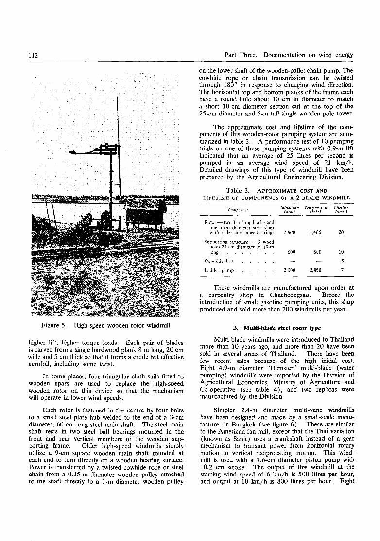
112 Part Three. Documentation on wind energy
Figure 5. High-speed wooden-rotor windmill
higher lift, higher torque loads. Each pair of bladesis carved from a single hardwood plank 8 m long, 20 cmwide and 5 cm thick so that it forms a crude but effectiveaerofoil, including some twist.
In some places, four triangular cloth sails fitted towooden spars are used to replace the high-speedwooden rotor on this device so that the mechanismwill operate in lower wind speeds.
Each rotor is fastened in the centre by four boltsto a small steel plate hub welded to the end of a 3-cmdiameter, 60-cm long steel main shaft. The steel mainshaft rests in two steel ball bearings mounted in thefront and rear vertical members of the wooden sup-porting frame. Older high-speed windmills simplyutilize a 9-cm square wooden main shaft rounded ateach end to turn directly on a wooden bearing surface.Power is transferred by a twisted cowhide rope or steelchain from a 0.35-m diameter wooden pulley attachedto the shaft directly to a 1-m diameter wooden pulley
on the lower shaft of the wooden-pallet chain pump. Thecowhide rope or chain transmission can be twistedthrough 180° in response to changing wind direction.The horizontal top and bottom planks of the frame eachhave a round hole about 10 cm in diameter to matcha short 10-cm diameter section cut at the top of the25-cm diameter and 5-m tall single wooden pole tower.
The approximate cost and lifetime of the com-ponents of this wooden-rotor pumping system are sum-marized in table 3. A performance test of 10 pumpingtrials on one of these pumping systems with 0.9-m liftindicated that an average of 25 litres per second ispumped in an average wind speed of 21 km/h.Detailed drawings of this type of windmill have beenprepared by the Agricultural Engineering Division.
Table 3. APPROXIMATE COST ANDLIFETIME OF COMPONENTS OF A 2-BLADE WINDMILL
Component Initial cost Ten year con(baht) {baht)
Lifetime(years)
Rotor — two 3-m long blades andone 5-cm diameter steel shaftwith roller and taper bearings 2,800 1,400 20
Supporting structure — 3 woodpoles 25-cm diameter X 10-mlong 600 600 10
Cowhide belt — — 5
Ladder pump 2,000 2,850 7
These windmills are manufactured upon order ata carpentry shop in Chacheongsao. Before theintroduction of small gasoline pumping units, this shopproduced and sold more than 200 windmills per year.
3. Multi-blade steel rotor type
Multi-blade windmills were introduced to Thailandmore than 10 years ago, and more than 20 have beensold in several areas of Thailand. There have beenfew recent sales because of the high initial cost.Eight 4.9-m diameter "Demster" multi-blade (waterpumping) windmills were imported by the Division ofAgricultural Economics, Ministry of Agriculture andCo-operative (see table 4 ) , and two replicas weremanufactured by the Division.
Simpler 2.4-m diameter multi-vane windmillshave been designed and made by a small-scale manu-facturer in Bangkok (see figure 6) . These are similarto the American fan mill, except that the Thai variation(known as Sanit) uses a crankshaft instead of a gearmechanism to transmit power from horizontal rotarymotion to vertical reciprocating motion. This wind-mill is used with a 7.6-cm diameter piston pump with10.2 cm stroke. The output of this windmill at thestarting wind speed of 6 km/h is 500 litres per hour,and output at 10 km/h is 800 litres per hour. Eight

II. Information papers prepared by participants 113
of these windmills have been distributed to severallocations (see table 4) within the past five years(including some provided to the villagers in thenortheast provinces by the Military Mobile Develop-ment Unit), and the manufacturer hopes for furthersales. It is probable that expert design optimizationcould result in significant cost reduction of this device.
It was reported by the manufacturer's representa-tive that 300 Southern Cross multi-blade windmillshave been sold in Thailand in the past 15 years but thelocation of these mills has not been determined.
Figure 6. Locally-made multi-vane windmill
B. CURRENT ACTIVITIES
After the energy crisis, much attention has beengiven to harnessing wind energy in Thailand. Thesimple traditional windmills have been re-examined,and other types are being developed for both pumpingwater and DC electricity generation. Several organiza-tions are concerned in these developments.
Development of improved water pumping wind-mills within the Ministry of Agriculture and Co-operative is actively patronized by his Majesty KingBhumipol.
1. The Agricultural Engineering Division, Ministryof Agriculture and Co-operative, has a programmeunder way for experimental wind-powered waterpumping units. One of the experimental windmills isa variation of the Chinese vertical-axis type constructedfrom a combination of metal, wood and bamboo mats.It is the intention to develop this type of windmill forlow-cost operation on farms.
2. The Division of Agricultural Economics, Ministryof Agriculture and Co-operative, has conductedeconomic trials of windmill pumps for farms in fourprovinces, using ten Demster windmill pumps (eightimported and two copies made by the Division). Theresults, analysed from data collected over four years,indicated very successful operation. The cost of eachlocally-made windmill can be recouped out of the in-cremental agricultural production in about four years.The Division strongly suggests that more farmers usethese windmills.
3. The Royal Irrigation Department, Ministry ofAgriculture and Co-operative, has recently installed animproved four-bladed water pumping windmill at WatBang Chak, Ang Tong province, for lifting water fromthe Noi River to irrigate a bean crop of 16 acres toreplace a crop lost in the floods.
4. The Meteorological Department, Ministry ofCommunications, has more than 50 weather stationsthroughout Thailand, from which wind velocity databased on hourly readings are available, for preliminaryevaluation of wind energy potential. These existingweather stations can be modified to record wind datacontinuously, as required for comprehensive windenergy evaluation prior to extensive windpowerdevelopment in the country.
Table 4.LOCATION AND NUMBER OF MULTI-VANE WINDMILLS
Demster Sank Others
Nong Kai (4)Petchaburi (1)Saraburi (3)Nakorn Phanom (2)
Udorn Thanee (2)Burirum (1)Surin (1)Bang Sarac, Choi Buri (1)Bang Khen, Bangkok (3)
Ban Dan, Samut Prakarn (2)Pattaya (1)Hua Hin ( l )

114 Part Three. Documentation on wind energy
5. The National Energy Administration (NEA),Office of the Prime Minister, is interested in thedevelopment of small-scale renewable energy sources,and, in September 1975, established an EnergyResearch and Development Unit. NEA has gatheredmuch relevant literature concerning wind energy andother renewable forms of energy, and has assessed winddata obtained from the Meteorological Department.A group of NEA engineers has been investigatingtraditional uses of windmills in several areas and is alsopreparing detailed questionnaires. A research centre(which will carry out testing of different types ofwindmills) is under construction at Rang Sit, near theAsian Institute of Technology.
NEA has also proposed a five-year plan, startingfrom the year 1977, on research and development ofalternative energy sources, which includes wind energy.This proposal is under consideration by the NationalEconomic Development Board. The goals of the windenergy section are to:
(a) Carry out research and improve efficiency ofwind energy use for water pumping in salt farming, fishculture, irrigation, and domestic use in villages;
(b) Develop wind energy units for mechanicaland electrical power sources in the villages as a sub-stitute for sources of energy based on petroleumproducts.
The programme of research and development forthe five-year plan includes:
(a) Gather all available literature concerningwind energy;
(b) Purchase wind-measuring instruments, andinstall at locations of interest;
(c) Collect, compile, analyse and assess winddata from the Meteorological Department and NEAstations;
(d) Survey the present use of wind energy inThailand;
(e) Make improvements on traditional Thaiwindmills;
(f) Design, construct and test a slow-speed wind-mill for multiple uses;
(g) Purchase and test a small-scale wind-electricDC generator;
(h) Install several improved windmills asdemonstration units (water pumping and provision ofmechanical power);
(i) Survey the electricity demand in the remoteareas where wind data have been collected;
(j) Design, construct and evaluate a large-scalewindmill pump at the NEA electrical pumping stationon the Mekong River; followed by adaptation of thedesign, and construction of a 5-10 kW wind-electricgenerator;
(k) Apply similar units where appropriate;
(1) Evaluate over-all progress in wind researchand plan developments in the next five-year plan.
6. Private industry. The small-scale manufacturerin Bangkok which has successfully designed and con-structed multi-blade type windmills plans to developless expensive wooden-blade type windmills for farmers,and has also developed a sail-type windmill (withaluminium sheet sails) which can be used with eithera ladder pump or a piston pump.
Australian multi-blade windmill's are distributedin Thailand.
A manufacturer in Chachoengsao has designedand constructed two-blade and four-blade windmills formany years, and also produces all sizes of ladderpumps.
C. REQUIREMENT FOR COLLABORATIONASSISTANCE
Wind energy utilization is a new field of technologydevelopment in Thailand. Technical assistance in thedevelopment of windmills for generation of electricityin rural areas, and pumping from the Mekong Riverfor large-scale irrigation, would be welcomed.Assistance will be needed in the supply of medium-scalewind-electric generators and related testing equipmentfor further development and tests.

II. Information papers prepared by participants 115
THE UTILIZATION OF WIND ENERGY IN AUSTRALIA(NR/ERD/ EWGS W/ CR.13) *
by
The Department of Science, Australia
Introduction
The wind has been harnessed as a source ofpower in Australia since early colonial times, whenwindmills of traditional European design were used togrind wheat. The manufacture of windmill pumps ona large scale was stimulated by the discovery ofextensive artesian and sub-artesian basins, and designswere evolved to meet the high standard of reliabilityrequired for long periods of unattended operation, farfrom maintenance facilities. Today, it is estimatedthat more than 250,000 windmill pumps are in use,supplying bore, well and surface water for irrigation,stock watering and domestic use on farms and stationsthroughout Australia.
Until recently, wind-driven generators were alsowidely used, but they have now been largely supplantedby diesel generators and extended rural mains electricitysupplies, and only one Australian firm continues tomanufacture them. A large proportion of thegenerators is exported, chiefly to the United States andsoutheast Asia. The major user of wind-drivengenerators in Australia today is the Australian Tele-communications Commission (ATC), which employsthem to supply electricity to isolated telephoneexchanges and radio repeaters.
A. WINDMILL PUMPS
The products of the various Australian manu-facturers of windmill pumps vary in the details of theirdesign, but in general follow a basic pattern. Therotary motion of a multi-blade rotor is converted bymeans of a crank mechanism to reciprocating motionof a vertical pump rod connected to a piston pump atthe bottom of the supporting tower. Reduction gearingis frequently employed in some models, while in otherwindmills the rotor is directly coupled to the crank-shaft. The windmill head can rotate freely about avertical axis defined by the pump rod and is aligned bya tail vane according to wind direction.
Wind pressure on the rotor exerts a torque aboutthe vertical axis of rotation due to the offset dispositionof the rotor axle, and, at potentially destructive windspeeds, the windmill head turns so as to spill wind andlimit the speed of rotation.
1 Abridged.
No major research or development programme isbeing carried out in Australia in connexion with wind-mill pumps. Manufactured pumps have operationallifetimes of more than 30 years, and pumping capacitiesare matched to the requirements of the Australianmarket. There is little incentive for manufacturers,who also produce competing diesel and electric pumps,to commit large sums to development work in this area.There are, of course, occasional minor changes indesign, resulting in increased efficiency or reliability, orreduced costs.
B. WIND-DRIVEN GENERATORS
The "Dunlite" generator employs a three-phaserotating field alternator with a rated maximum outputof 2 kW. Current for the rotating field is supplied bya small exciter armature. The alternator is driven bya three-blade variable-pitch propeller through 5:1 ratiogearing, and a vane maintains the correct position ofthe propeller in relation to wind direction, the wholemachine being able to rotate in a horizontal planeabove a fixed base. The alternator output is rectifiedbefore being transmitted to the base by a set of sliprings. Solid-state automatic voltage regulation andcontrol equipment holds the generator output voltagesteady, between 12 and 110 volts depending on themodel, under all conditions of load and windmill speed,and channels power to the load or to storage batteriesas required. The operation of a back-up dieselgenerator can also be controlled automatically. Thegenerator starts to deliver power at a wind speed ofabout 16 km/h and full output is obtained at a windspeed of 40 km/h. The power output of a generator,as modified by ATC, is plotted against wind speed infigure 1.
At high wind speeds, the speed of rotation of thepropeller is governed by the centrifugal force on a setof weights attached to the propeller assembly, actingto feather the blades. A system of magnetic latchingmay be fitted to prevent operation of the featheringdevice, and the consequent loss of efficiency, in thenormal operating range of the generator. It is claimedthat, when fitted with the standard 3.69-m diameterpropeller, the unit will withstand wind speeds of up to130 km/h. Shorter blades are available if higherwind speeds are likely to be encountered.
ATC has also monitored the performance of thegenerators under operational conditions. About 30

116 Part Three. Documentation on wind energy
o
••-3a.
oo
cV
2.6
2.4
2.2 -
2.0 -
1.8 -
1.6 •
1.4 -
1.2 -
1.0 -
0.8 -
0.6 -
0.4
0.2
Normaloperatingcurve
Feathered'operatingcurve
10 30 50 60 7020 30 40
W ind speed km/h
Figure 1. Characteristics of modified Dunlite generator
generators are used to meet part of the power require-ments of repeater stations on a microwave route linkingWestern Australia and South Australia. The wind-driven generators each operate in conjunction with a4 kW diesel generator, and storage batteries of 1,000Ah capacity, the normal load being a continuous0.5 kW at 24 V. With average wind speeds in theregion of 18 km/h, the wind generators were found tobe meeting about 66 per cent of the load, and, atmany stations, the total running time of the dieselgenerator over five years was limited to 3,000 hours.
Simultaneous measurements of the output of astandard Dunlite generator and wind speed are cur-rently being conducted at the Flinders University inSouth Australia. The results, when available, willserve as a data base for the manufacturer's developmentprogramme. A 5 kW generator is currently underdevelopment, and a prototype is expected to be readyfor testing within a year. Future work will be con-
cerned with improving the efficiency of the propellerso that better performance is obtained at low windspeeds.
C. OTHER RESEARCH
Research and development associated with the ex-ploitation of wind energy is almost exclusively con-ducted by manufacturers of wind-driven machinery.There is no official wind energy research programmein Australia, and no university or other researchorganization is formally engaged in research in this field.However, a few university scientists have a personalinterest in the subject, and at least one has publishedsome general ideas on the large-scale utilization of windenergy (reference W 67). The topic is an attractiveone for private inventors, one of whom recently re-ceived a government grant for the construction of aprototype of a modified version of the vertical-axisSavonius rotor.

II. Information papers prepared by participants 117
A REVIEW OF RENEWABLE ENERGY IN NEW ZEALAND WITH EMPHASIS ONWIND POWER UTILIZATION (NR/ERD/EWGSW/CR.15)*
by
Mr. R. E. Chilcott (New Zealand)
I. RENEWABLE ENERGY IN NEW ZEALANDIn New Zealand, oil, coal, natural gas and
electricity are consumed at a rate equivalent to about3.5 kW of continuous power per person (referenceW 68). Oil supplies about 60 per cent of the primaryenergy requirements. Tn 1975, the generation ofelectricity per head of population was about 6,000 kWh,which is equivalent to a continuous electrical power ofnearly 700 W per person. Renewable hydroelectric andgeothermal sources supplied 78 per cent and 7 per centrespectively, the remaining 15 per cent being suppliedfrom fossil-fired thermal-electric power stations. Abouthalf of the electricity generated flows into the home:the annual amount of electrical energy consumed byan average family is about 8,000 kWh, half of whichflows down the drain in the form of hot water.
A. SOLAR ENERGYThe intensity of solar radiation is about 1,400
W/m2; this figure is known as the "solar constant."
As the surface area of a sphere is four times itscross-sectional area, the global average intensity ofsolar radiation perpendicular to the top of theatmosphere is one quarter of the solar constant, orabout 350 W/m2. Owing to reflection from cloudtops, diffusion and absorption in the atmosphere, theglobal average intensity of solar radiation incident ona horizontal plane at the surface of the earth is abouthalf this value. The annual average value of solarradiation in the region of the Tasman Sea and PacificOcean near New Zealand is about 150 W/m2. Moreprecise figures for North Island and South Islandstations are shown in table 1 (see reference W 69).The typical annual cycle of solar radiation and tempera-ture, in which temperature lags behind radiation, isshown for Wellington in figure 1.
B. HYDRO AND THERMAL ELECTRICITY
Hydroelectric energy is a familiar form, derivedfrom solar energy through the hydrologie cycle.Hydroelectric works currently planned will increase thetotal national installed hydroelectric capacity to about4,500 MW by 1983. Ultimately, the capacity may bestretched to about 6,000 MW, but the later projectswould become increasingly expensive and limited byenvironmental considerations (see reference W 70).By the end of the century, hydropower may only meetabout 5 per cent of the projected total energy demand(see reference W 71).
• Abridged.
C. GROWING ENERGY
Solar energy is captured by photosynthesis andstored as wood fuel which is virtually sulphur-free.The ash can be returned to the land and the global heatbalance will not be disturbed. Typically, an annualaverage solar radiation intensity of 170 W/m2 isassumed to give an over-all photosynthetic conversionefficiency of about 0.4 per cent. It has been suggestedthat 0.7 per cent could easily be achieved by appropriateplanting and double cropping and that ultimately anefficiency of 1 per cent may be possible (see referenceW 72). The success of the solar forest or fuel planta-tion concept depends on many factors, including theselection of trees that grow fast on poor soils.
Research on the production of fuel from NewZealand crops is currently under way (see referenceW 71). Indications in the United States are thatalcohol from grain may soon become cost-competitivewith ethyl-alcohol derived from oil. However, graincrops may be heavily subsidized by fertilizers dependenton fossil fuels, in which case the net fuel energy costneeds careful analysis (see references W 73, W 74,W 75). Similarly, growing and harvesting algae orgiant kelp for alcohol production is likely to havesignificant energy costs for harvesting and processing.Research into the energy costs of crop production isbeing undertaken at Lincoln College. It appears that,without careful planning, processing and management,the net energy production may well be zero.
In Canterbury, energy-conversion efficiency ofwheat at the farm gate is about 0.1 per cent. At thisefficiency, to produce the food energy consumed by theaverage resident requires a land area of about 0.1 ha.The population density should therefore not exceed 10persons per hectare of agricultural land (see referenceW 76). Among other things, this highlights potentialconflicts between energy, food and populationrequirements.
D. SOLAR HEAT
One of the most effective uses of solar energy isthe direct heating of water for non-domestic anddomestic purposes (see references W 77, W 78, W 79).
An installation currently under test at the NationalDairy Laboratory, Ruakura, consists of a 16 m2 bankof collectors inclined at 35° to the horizontal andmounted on a milking shed roof to face north-northwest(see figure 2). A circulating pump and an 800-litre

118 Part Three. Documentation on wind energy
500-
400-
300-
£
O)ca>
| 200 -\o
o
100 -
-336
-162
Wind energy
Solar energyon a horizontalsurface
J X-*
12.4— i —
10— 1 —
15 20
Monthly mean température °C
Figure 1. Wellington monthly average solar and wind energy
storage tank are located under the roof. The heatedwater is used to fill two conventional 200-litre hot-waterheaters twice a day, and the electrical supply is usedonly to boost the water temperature to 90 °C or more.From March to August 1975, the installation averageda solar input of about 200 W/m2 of collector area.
If required, collectors can be designed to producelow-pressure steam for food processing, industrial pro-cessing and power production. A solar-to-electricalenergy conversion efficiency sometimes quoted is10 per cent, which on 1 per cent of landarea implies an over-all energy conversion efficiency,
on a total land area base, of 0.1 per cent.More conventional uses of solar heat includeglasshouses, air heating for drying fruit, grain andtimber, and the production of solar salt, for examplefrom Lake Grassmere. With collectors in the form oflarge non-convecting ponds, it is possible to derivepower, particularly where sea water and land areavailable (see reference W 71). Marine solar-derivedthermal energy can be tapped only where sufficienttemperature difference exists, usually more than 20°C,and is unlikely to find wide application in New Zealandwaters (see reference W 80).

II. Information papers prepared by participants 119
Many small-scale solar water-heater installations,which take advantage of the distributed nature of solarenergy and do not take up valuable land area, areoperating successfully in a variety of applicationsranging from ice-prevention for stock-water troughs tosolar water-heating at the Kaikoura youth hostel. Solarwater-heaters will probably become widely accepted asarchitectural features of new towns, factories, schools,swimming pools and homes. Department of Scientific
and Industrial Research estimates indicate that abouthalf the total domestic hot water used in New Zealandcould be heated by solar energy; the fraction varieswith locality and is typically about 50 per cent forDunedin and 60 per cent for Blenheim. Ideally, asolar system, in addition to being economically viable,should generate more energy than is needed for itsmanufacture, installation and maintenance (seereference W 71).
Figure 2. Solar collectors at National Dairy Laboratory
E. WIND POWER
The long-term average value of the kinetic energyof the atmosphere is fairly constant and is estimated atabout 3 x 10¹⁷ kJ (see reference W 81).
The flight path of a balloon released from Christ-church gives a graphic indication of the circulation ofthe atmosphere around the southern hemisphere at thatlatitude (see figure 3). A rough estimate of theballoon's average speed during three circuits of theearth in 33 days, at a height of 12 km, is 130 km/h.
From observations of the isobar spacing on weathermaps, it is seen that gradient wind speeds of up to100 m/s may occur occasionally. Near the surfaceof the earth, in the lowest 500 m, the surface exerts africtional drag on the air and reduces the wind speed:this effect is greater over forests and lesser over the sea.
Surface wind speed is usually measured byanemometers at a height of 10 m. Zones of mediumwind speed, such as the Canterbury Plains, have anannual average wind speed of 14 to 22 km/h, whilemore exposed locations, such as the Wellington area,

120 Part Three. Documentation on wind energy
Figure 3. Flight path of a balloon launched from Christchurch (33 days)
Stewart Island and the Chatham Islands, have higherannual average wind speeds, in the range 22 to 33km/h (see reference W 82). An over-all annualaverage wind speed at 10 m height for New Zealandmight be taken as 18 km/h. The annual average windpower intensity at 10 m is about 150 W/m2; above10 m it would be greater. There are of coursesignificant variations in wind speed, wind frequencyand wind energy between stations, for exampleWellington has about three times as much wind energyavailable as at Christchurch (see table 1). A con-servative estimate of the allowable installed wind-electrical capacity of a zone of medium wind speed isabout 5 kW/ha, with a load factor of about one third.This means that, in such a zone in New Zealand, theavailable annual average wind-electric energy is about0.1 per cent of the annual average solar energy incidenton a horizontal plane.
Small windmills have been in use in New Zealandfor at least a century. Typically, they were used tolift water for steam locomotives and are still used ex-tensively for watering stock. In remote areas, smallwind generators are used with storage batteries for
Table 1.ANNUAL AVERAGE TEMPERATURE, SOLAR ENERGY,
WIND ENERGY AND WIND SPEED IN NEW ZEALAND
StaltenTempera-
tureSolar
energy(W/2)
Windenergy"(W/m'j
Windspeed*(Km/h)
Auckland .Ohakca .WellingtonChristchurchInvcrcargill
14.013.112.410.99.5
171173162165147
108178336114214
1317221417
Sources: New Zealand Meteorological Service MiscellaneousPublication No. 143 and references W69 and W82.
* Nominally at 10 m height.
electric fence energizing, communications and marinenavigation lights. It has been suggested that windgenerators could be integrated into existing electricalnetworks in order to supplement hydroelectric sourcesand conserve fossil fuel. In order to determine ifsufficient wind energy potential exists, a national windenergy resource survey is currently under way (seereference W 82). Detailed wind surveys of Canterburyand Otago are being carried out.

II. Information papers prepared by participants 121
n. NEW ZEALAND WIND ENERGY TASKFORCE ACTIVITIES, 1974-1976
A. PROJECTS SPONSORED BY THE NEWZEALAND RESEARCH ANDDEVELOPMENT COMMITTEE
1. Wind energy resource survey of New Zealand(references W82, W83)
A two-year project has been authorized, with fundsof $NZ 41,000, to be carried out by Lincoln College,the University of Canterbury, Otago University and theNew Zealand Meteorological Service, and is intendedto:
(a) Identify advanced farm, rural and remotesystems in which significant energy demands can bemet by the use of wind power;
(b) Detail the specific output and operating re-quirements of such systems;
(c) Prepare specifications for wind-poweredsystems to meet such requirements.
2. The utilization of wind energy(references W84, W85)
At Auckland University, with committed funds of$NZ 25,000, an analysis is being undertaken of thetechnical and economic feasibility of the integration ofwind power into the New Zealand electricity supplysystem.
B. PROJECTS SPONSORED BY THEUNIVERSITY GRANTS COMMITTEE
1. Performance characteristics of wind turbinesystems for advanced farm, rural and remote use
This project is related to project A. 1. above, withadditional funds of $NZ 5,150, and has resulted in theestablishment of a generalized method to predictenergy output performance of typical wind turbines in
arbitrary wind regimes. Confirmation is to be obtainedwith an 8 kW machine, currently at an early stage ofconstruction.
2. Investigation of the rural boundary layer
This project is also related to project A. 1. above,with additional funds of $NZ 3,400, and has resultedin the design and production of a 20-m guyed, weldedsteel instrumentation mast.
C. PROJECTS SPONSORED BY THE MINISTRYOF WORKS AND DEVELOPMENT
1. Wind power for Chatham Island
Funds of $NZ 1,500 have enabled preliminaryinvestigation to be completed.
2. Wind power for Stewart Island
Funds of $NZ 2,000 have been allocated toLincoln College for an investigation similar to projectC. 1. above.
3. Water pumping on Mana Island
Funds of $NZ 500 have been allocated to LincolnCollege for a preliminary assessment of the use of windfor pumping water on the island.
D. MISCELLANEOUS PROJECTS
1. Vertical-axis windmill
A Canadian-made vertical-axis wind-electricmachine is currently under test at Auckland University.
2. Windmill and pump
A commercially available windmill and pump areto be installed at Lincoln College for test anddemonstration purposes.
WINDPOWER STUDIES IN KOREA (NR/ERD/EWGSW/CR.16)*
by
Mr. Chung-Oh Lee (Republic of Korea)
In recent years, the possible utilization of wind-power has been receiving close attention in the Republicof Korea, especially for the electrification of off-shoreislands. There are more than seven hundred islandsaround the Korean peninsula, but only a small numberhave electricity supply, generated by diesel-electric sets
' Abridged.
or similar conventional methods. The meteorologicaldata supplied by the Korean Weather Bureau indicatethat these areas have dependable wind sources, and, in1974, the Ministry of Science and Technology awardeda research grant to the Korea Advanced Institute ofScience for the preliminary study, design and testingof a small experimental windpower system capable ofproducing 2 kW maximum continuous output.

122 Part Three. Documentation on wind energy
A. ANALYSIS OF WIND DATAThe quantitative analysis of wind data for the
previous five years provided information on the averageyearly frequency of wind velocities and the monthlyfrequency of usable winds (see reference W 86).Based on this analysis, several islands were selected forfurther study. As tpyical examples, the average yearlyfrequency of wind velocities are shown in figure 1 forthe stations at Cheju Island, Ulnung Island, andChupungryung. The distribution of the hours ofusable wind (velocity greater than 16 km/h) for theselocations is shown in figure 2. Since the power avail-able depends on the cube of wind velocity, the annualrelative energy of wind at these locations may be shownas in figure 3, where the values assigned to the ordinateare relative.
The conclusions drawn from the analysis of recordsfrom 27 stations along the coastline were:
. (a) The southern coastal area is extremelyfavourable for windpower systems;
(b) Winter is considered to be the mostfavourable season;
(c) The number of consecutive calm days neverexceeds three in the southern islands.
B. MAIN DESIGN FEA TURESThe 4-m diameter rotor consists of a three-bladed
propeller in which each blade is twisted appropriately,with a fully feathering hub controlled by centrifugalweights. The special brushless generator produces2 kW, three-phase, 400 V AC (reference W 87),which in the experimental unit was fed through arectifier to 16 lead-acid 12 V batteries, arranged to givea storage of 1.92 kWh at 96 V. Other design andaerodynamic features are:
Maximum propeller rev/min — 200Maximum generator rev/min— 1,000Voltage regulation — automatic constant voltage
regulationTower height — 12 m
,_ 1,200o
Ho
urs
p
er y
eCD
"O
8 8
600
4 00
200
©
<D\ \ \
\\
V
\
1. Cheju Island2.Ulnung Island3 Chupungryung
L;
N,
""*•MMl '
II 22 33
Wind velocity in km/hFigure 1. Wind velocity hourly duration curve
44

II. Information papers prepared by participants 123
I .Cheju Is land2.Ulnung Is land
Chupungryung
1 2 3 4 5 6 7 8Months of the year
Figure 2. Monthly distribution of hours of usable wind (above 16 km/h)
Starting wind speed— 16 km/hMaximum output wind velocity — 43 km/h
C. INSTALLATION
A series of laboratory tests was conducted to checkthe performance of the generator and the featheringhub. A test for the durability of the whole systemwas then undertaken in non-uniform air currents pro-duced by a 2.5-m diameter propeller attached to a200 hp engine (see reference W 88).
After the completion of the laboratory tests, awind-power system was installed in February 1975 onan island in the Yellow Sea for actual testing andevaluation. Figure 4 shows the output against windvelocity as measured in the field test.
D. REINFORCEMENT OF THE PROPELLER
After operation of the system for three months,two blades broke and the hub was destroyed by the
resultant unbalanced torque. A thorough study ofpossible causes of the accident, including investigationof stress distribution in the blades, led to the design ofappropriate reinforcement (see reference W 89).Blades constructed to the modified design have beenoperating satisfactorily since installation.
On the assumption that one of the contributorycauses of the initial fracture might have been the veryfast action of the feathering system, with a rapid changeof stress, further work is being carried out on a possiblemodification in the design of the feathering system.
E. FUTURE WORK
Details of a follow-up project are now being pre-pared, the objective being to develop a reliable andcost-competitive wind energy conversion system ofrelatively small scale (2-5 kW) for lighting and com-munication purposes in off-shore islands.

124 Part Three. Documentation on wind energy
0)
O
a.
D
c
13
12
I I
10
9
8
7
6
5
4
0
.Cheju Is land2.Ulnung Is land3.Chupungryun g
22 33
Wind velocity in km/h
Figure 3. Relative annual energy in winds

II. Information papers prepared by participants 125
2,300
2,100
1,900
¿2 1,700o
I 1,500
« 1,300o
^ 1,100
I 900
700
500
300/
—
/
1• - -
I1>
i/ /
.....
II 22 33 44 55Wind velocity in km/h
Figure 4. Output against wind velocity
RESEARCH AND PROSPECTS OF UTILIZATION OF WIND ENERGY IN INDONESIA(NR/ERD/EWGSW/CR.17)*
by
Mr. H. Djojodihardjo (Indonesia)
The possible increase in wind energy utilizationin Indonesia is a challenging problem (reference W 90)because:
(a) There is a scarcity of wind data, althoughit has been believed that Indonesia is a low-velocitywind area;
(b) There is no precedent or available expertisein Indonesia;
(c) Wind energy could be economical in thesense that foreign exchange could be saved;
(d) There has been a growing public concern topreserve the ecological balance of the environment.
• Abridged.
A. REVIEW OF WIND ENERGY CONVERSIONSYSTEM CHARACTERISTICS
Table 1 indicates the theoretical dependence ofavailable energy on wind speed and rotor diameter(references W 42 and W 51 ). The actual power outputthat can be delivered to the output system that utilizes
Table 1
Wind speedin kjnjh
91827364554
. THEORETICAL
4
0.0700.5591.8874.4748.738
15.100
(inWIND ENERGY AVAILABLEkW)
Diameter oj rotor in m
6
0.1571.2584.246
10.07019.66033.970
8
0.2802.2367.548
17.88034.95060.390
10
0.4373.493
11.79027.96054.61094.360
20
1.74813.97047.180
111.900218.500377.500

126 Part Three. Documentation on wind energy
the wind energy is further reduced by a power coefficientwhich can vary up to the order of 0.7 for the mostaerodynamically efficient windmills.
Furthermore, the output system usually has anefficiency substantially less than unity (see referenceW 91). The maximum over-all efficiency of the windconversion system would be of the order of 20 to 25per cent. Table 2 indicates the actual power outputof a wind energy conversion system with over-allefficiency of 20 per cent, for different wind velocitiesand rotor diameters.
Table 2. TYPICAL ACTUAL MAXIMUM OUTPUT POWERAVAILABLE
(in kW)
7.2 . . .
9.0 . . .
10.8 . . .
12.6 . . .
14.4 . . .
18.0 . . .
21.6 . . .
28.8 . . .
36.0 . . .
2
0.003
0.006
0.011
0.017
0.026
0.050
0.087
0.206
0.402
i
0.013
0.025
0.044
0.069
0.103
0.201
0.347
0.823
1.610
Diameter of
6
0.0290.0560.0980.1550.2310.4520.7811.8503.620
rotor in m
S
0.0510.1010.1720.2760.4120.8041.3903.2906.430
10
0.0800.1570.2720.4310.6431.2602.1705.150
10.000
20
0.3200.6281.0861.7202.5705.0208.680
20.60040.200
It is noted that, for a typical windmill applicationto provide 1 kW of power, at a site with a design windspeed 18 km/h, a rotor diameter of the order of 10 m
is required. Figure 1 shows a typical spectrum ofhorizontal wind speed near the ground for an extensivefrequency range, taken from reference W 92.
B. WIND DATA IN INDONESIA
In Indonesia, wind data, rainfall, solar radiationand other climatic factors are compiled by the Centerfor Meteorology and Geophysics (PMG) frommeasurements made by meteorological stations at mostaerodromes, agricultural and maritime meteorologicalstations and meteorological stations of other agencies inco-operation with PMG. The Indonesian NationalInstitute of Aeronautics and Space (LAPAN) alsoconducts meteorological studies, mostly for the upperatmosphere, at its premises in Bandung and Cilaut-Eureun. A sample of wind records for various selectedplaces in Indonesia taken at an elevation about 10 mabove the ground is shown in table 3.
Table 4 shows average values of wind velocitiesand predominant wind direction for Jakarta duringthe period 1961 — 1970. These data illustrate relativewind intensity prevailing at most places in Indonesia,i.e. of the order of 2 to 5 m/sec (7 to 18 km/h),although it is well understood that both the locationsof observation stations and the method used are notvery useful for the assessment of windpower pos-sibilities, and higher values of wind speed may occurat other locations. From table 3, some locations likeBanda Aceh, Semarang and Madiun seem to have amean wind speed of 5 m/sec (18 km/h). It is also
ÎO
ilII
i!¡s
iiiii
Van der Hoven (at 100 metre height)
Speculative (Davenport)
Cycles/hr IO"4
Hr 10,000I I
II yr sun-spot Annual
Macrometeorological range -
Weather-map tluctuations )
20 5OIOO 5001,0000.02 0.005 0.001
I I I5 min I min 5sec
• M¡crometeorological range
(Gusts)
Time s c a l e
Figure 1. Spectrum of horizontal wind speed near the ground for an extensive frequency range

II. Information papers prepared by participants 127
Table 3. SAMPLE OF WIND VELOCITY DATA IN INDONESIA, 1974
(in km/h)
S lotion
Java:Bandung
Jakarta (H) . .Madiun .Jakarta (K) . .Scmarang
Sumatra:
Banda Acch .Bcngkulu
McdanPadang
Palembang .Pangkalpinang .
Nusa Tenggara:
DenpasarPasirpanjang .
/
17
1128
922
156
136
1517
24
33
F
15131511
19
156
139
1313
1911
M
1311
177
19
136
179
1315
1517
A
7
7
156
15
11
6137
911
79
M
67
197
15
1149
79
11
1724
Mean wind velocity
1
7
7
247
15
136
1179
15
1931
/
76
28
713
154
119
11
15
1526
A
7
7
247
15
19497
1117
1722
97
287
15
154
11
99
11
1922
0
97
247
13
NA
711
99
13
1719
N
9
7
24
711
11
711
9
99
915
D
9
7
15
911
13
9NA
69
9
911
Maximumvelocity
40585341
41
5041
33605841
5883
Table 4.
WIND VELOCITY DATA IN JAKARTA, 1961 — 1970
Month
February .
March
April
May . . . .
June . . . .
July . .
August
September
October .
November
December
Yearly average .
Prevailingdirection
NW
. . NW
. . NW
E
. . E
. . E
. . E
. . E
. . N
. . N
. . N
. . NW
. . E
Meanvelocity(Km/h)
5.8
6.1
5.4
5.4
5.8
5.8
6.5
6.1
6.5
6.5
5.4
5.4
5.8
Maxim urn
(Km/h)
47
43
36
41
41
41
36
36
43
50
49
50
50
velocity
(year)
1965
1966
1970
1965
1965
1965
1966
1966
1967
1969
1967
1970
1970
known that the surface wind is intensified in flowingover mountain ridges, which can be regarded as favour-able places for windmill utilization in view of theunavailability of transmitted electricity in many ruralmountain regions. In order to be able to predict thepossible amount of windpower, there is a need forwind distribution curves at various locations inIndonesia.
C. RESEARCH AND DEVELOPMENT
In 1968, the Department of Mechanical En-gineering of the Institute of Technology, Bandung, wasinvolved in the design and construction of a multi-vanefan type windmill (see reference W 33). The windenergy conversion system was constructed for waterpumping, with rotor diameter 4.2 m, tower height 42 m,head 15 m and pump capacity 20 m3/day; and wasinstalled at Pangarasan in central Java. The windvelocity was measured as 12 km/h while wind gustvelocities could reach 40 km/h. The unit was con-structed without research and developmental work, andno provision was made for feedback of technical pro-blems which occurred.
Motivated partly by the need for conducting amore systematic effort for wind energy conversionsystem design, construction and utilization, a small-scale research effort was started at the Aero andHydrodynamics Laboratory of the Institute in 1973.The work has been performed in conjunction withstudent projects and has been restricted by scarcity offunds and lack of supporting literature. The work wasgeared to small-scale wind energy conversion systemsfor rural areas, and the objectives were, briefly, toinitiate research and development effort in this field,and to explore the development of local technology inwind energy conversion systems. Good progress hasbeen made on an experimental study of vertical-axis(Darrieus) type rotors (figure 2) , followed by designand construction of a prototype 2-blade rotor wind-

128 Part Three. Documentation on wind energy
mill (reference W 93), an experimental study of apropeller type windmill model and analysis and designof a sail-type windmill (reference W 94).
The Darrieus-type windmill rotor blades weremade from locally available steel, and were machinedto shape at the army industrial workshop. The bladeshave a symmetrical aerofoil cross section to UnitedStates standard (NACA 0012), with maximum aerofoil
thickness of 3 mm and a chord length of 2.5 cm.Torque measurements were made with a simple pony-type brake with a piece of string to provide the frictionfor lifting a weight.
Test results on the prototype gave an outputcoefficient curve similar in shape to that from testsmade on a large unit at the National Research Council,Canada, but the peak value was lower by about 30 percent.
Figure 2. 3-blade Darrieus rotor model in wind tunnel
„"••¿.'

II. Information papers prepared by participants 129
The blades for the propeller-type windmill weremade of laminated wood, with a diameter of 0.7 m, aconstant chord length of 0.07 m and hub diameter of0.07 m. The pitch angle setting of the propeller bladeis shown in table 5.
Table 5. BLADE THICKNESS
AND ANGLE SETTING OF THE TEST PROPELLER
Radius at measuring point(cm)
3.5
7
10.5
14
17.5
21
24.5
28
31.5
35
Maximum thic\ness(cm)
1.12
1.12
0.98
0.98
0.70
0.56
0.42
0.42
0.42
0.42
Pitch angle setting(degrees)
28.4
18.6
15.0
9.2
7.0
7.0
5.0
5.0
4.9
4.5
The following conclusions have been drawn fromthe work to date:
(a) Multi-vane, propeller, sail, and Darrieustypes of windmills, and Savonius rotors, could bemanufactured locally due to their simplicity of con-struction, and yet could provide suitable power outputat rated wind speeds of 14 to 18 km/h.
(b) Propeller and Darrieus type windmills haveexcellent aerodynamic efficiency at relatively high tip
velocities and would be attractive for wider applicationin Indonesia. Further development would be neces-sary in order to reduce the cost.
(c) Sail-type windmills and Savonius rotors arealso attractive for wider application in rural areas.
D. POTENTIAL APPLICATIONS IN INDONESIA
The current cost of transmitted electric power inIndonesia is about 3 - 4 US cents/kWh, while alocally-manufactured propeller-type windmill mayproduce electricity at about 15 US cents/kWh, but thiscost could probably be reduced by large-scale produc-tion. At present, windmills would not be economic iftransmitted electric supply were available.
E. CONCLUSIONS AND RECOMMENDATIONS
Wind energy conversion systems are attractivebecause of their non-polluting nature, utilization ofrenewable energy resources, low maintenance andsimplicity of operation, and could have potentialapplications in Indonesia, particularly for rural areasand islands.
Hardware development work should be initiatedand encouraged in order that technological capabilitiescan be developed for local manufacture of economical,simple and efficient windmills.

130
III. CONSOLIDATED LIST OF REFERENCES ON WIND ENERGY
W 1. E. W. Golding, The Generation of Electricity byWind Power, (London, E and F.N. Spon Ltd.,1955), pp. 22.
W 2. Arthasastra of Kautilya, quoted from Studies inAncient Hindu Polity by Narenda Nath.
W 3. A. Makhijani and A. Poole, Energy andAgriculture in the Third World, (Cambridge,Massachusetts, USA, Ballinger, 1975).
W 4. E. W. Golding, "Windmills for water liftingand the generation of electricity on the farm",FAO Internal Working Bulletin No. 17.
W 5. "Energy from the wind — assessment of suit-able winds and sites", WMO Technical NoteNo. 4, Geneva, 1954.
W 6. Communication from J. Park, (Helion), USA.
W 7. Calvert, 'Wind power in eastern Crete",Transactions of the Newcomen Society, UK,1972, vol. XLIV, pp. 137-144.
W 8. M. M. Sherman, "6,000 handcrafted sail wingwindmills of the Lassithiou, Greece, and theirrelevance to windmill development in ruralIndia", Proceedings, Wind and Solar Energyfor Water Supply, German Foundation forInternational Development, Berlin, 1975.
W 9. "Plans for 25 foot diameter sail windmill",Windworks, USA.
W 10. "Performance data for 25 foot diameter sailwindmill", Brace Research Institute, Canada.
W 11. "Construction plans for 10 m diameter sailwindmill", TOOL Foundation, Netherlands.
W 12. "Note on 6 m diameter sail windmill",Sarvodaya Educational Development Institute,Sri Lanka.
W 13. P. Fraenkel, "Food from windmills", Inter-mediate Technology Development Group, UK.
W 14. F. H. King, Farmers of Forty Centuries,(Wisconsin, USA, Madison, 1911).
W 15. J. Needam, Science and Civilization in China,(Cambridge University Press, UK, 1955), vol.4:2, pp. 555-567.
W 16. Nognye Jixie (Agricultural Machines),Northeastern Machinery Institute of China,Nos. 11 and 12, 1958.
W 17. Chen Li, "Why has the windmill not been morewidely used in North China? A report on theconstruction of the windmill (of the Salterns)used on the coast of the Gulf of Chilli (nearTientsin)", Kho Hsueh Thung Paro (ScienceCorrespondent), 1951, vol. 2, No. 3, p. 266.
W 18. Water Conservancy in New China, Ministry ofWater Conservancy, (Shanghai, People's ArtPublishing House, 1956).
W 19. Nogyne Jishu (Agricultural Techniques) China,No. 9, 1958, pp. 15-16).
W 20. W. E. Heronemus, "A survey of the possibleuse of wind power in Thailand and thePhilippines", USAID, Contract No. TA-C1143, 1974.
W 21. F. Stokhuyzen, The Dutch Windmill, (NewYork, Universe Books, Inc., 1963), pp. 21-46.
W 22. R. Garcia, "Low-cost windmill", VolunteerTechnical Assistance, USA.
W 23. Report by the commission on the Church's par-ticipation in development, World Council ofChurches, Switzerland.
W 24. A. Bodek, "How to construct a cheap windmachine for pumping water", Brace ResearchInstitute, Publication No. 5, Canada.
W 25. Koslowski, "Investigation of whether a Savoniusrotor is a suitable prime mover", IntermediateTechnology Development Group, UK.
W 26. U. Hutter, "Planning and balancing of energyof small output wind plant", Proceedings of theSymposium on Wind and Solar Energy,(UNESCO, October 1954), p. 85.
W 27. Energy Primer, (USA, Portóla Institute, 1974),pp. 74-105.
W 28. P. Johnston, "Notes on rural electrification bywindpower", report to the Ministry of Finance,Fiji Government, 1975.
W 29. Proceeding of the Second Workshop on WindEnergy Conversion Systems, Energy Researchand Development Administration, USA.

III. Consolidated list of references on wind energy 131
W 30. Nognye Jishu (Agricultural techniques), China,No. 19, p. 11.
W 31. M. M. Sherman, "The design and constructionof an appropriate water pumping windmill foragriculture in India", Transactions, Wind andSolar Energy for Water Supply, GermanFoundation for International Development,Berlin, 1975.
W 32. D. K. Biswas, report to the Indian AgriculturalResearch Institute, India.
W 33. F. Harahap, "Design and construction of awindmill: an experience of the Mechanical En-gineering Department of ITB", workshoppaper, Bandung Institute of Technology,Indonesia, 1972.
W 34. "Wind pump for lifting water", InformationKit Section II-Part B, vol. II, No. 5, USAIDTechnical Digest Service, Washington, USA,1962.
W 35. Detailed plans of Princeton sail wing rotorwindmill design, (New York, Flanagan Plans).
W 36. M. M. Sherman, "A water pumping windmillthat works", Journal II of the New Alchemists,USA, 1973.
W 37. H. Stam, "Adaptation of windmill designs,with special regard to the needs of the lessindustrialized areas", Proceedings of UnitedNations Conference on New Sources ofEnergy, Rome, 1961, vol. 7, paper No. W/40,pp. 347-357.
W 38. J. Park, "Simplified wind power systems forexperimenters" and "12/16 complete plansand instructions", Helion, USA.
W 39. H. Meyer, "12 footer plans", Windworks,USA.
W 40. R. E. Chilcott, "The design, development andtesting of a low cost 10 hp windmill primemover", Brace Research Institute, PublicationNo. 7, Canada, 1970.
W 41. R. Wailes, "Horizontal windmills", Transactionsof the Newcomen Society, London, 1967/8,vol. XL, pp. 125-145.
W 42. P. South and R. S. Rangi, "An experimentalinvestigation of a 12 ft. diameter high speedvertical axis wind turbine", National ResearchCouncil Report LTR-LA-166, Canada, 1975.
W 43. J. R. Godfrey, DAF Company report, Canada.
W 44. R. V. Brülle, H. C. Lavsen, "Gyromill(cydogyro windmill) investigation for genera-tion of electrical power", Proceedings of theSecond Workshop on Wind Energy ConversionSystems, Mitre Corporation, Washington, USA,1975, pp. 452-457.
W 45. P. Bade, "Flapping vane wind machine androd-piston pump" and "Flapping vane windmachine", Transactions, Wind and Solar Energyfor Water Supply, German Foundation forInternational Development, Berlin, 1975.
W 46. Communication from E. Barnhart, NewAlchemy Institute-East, USA.
W 47. "Water lifting for agriculture using non-conventional power equipment", Ministry ofAgriculture and Co-operative, Government ofThailand, 1974.
W 48. S. Wilson, "Note on low lift irrigationpumping", Department of Engineering Science,Oxford University, UK.
W 49. R. L. Pendleton, Thailand, Aspects of Land-scape and Life — An American GeographicSociety Handbook, (New York, Duell, Sloanand Pearce, 1963).
W 50. I. A. Rubinski and A. I. Rubinsky, "A lowspecific speed pump for small discharges",Civil Engineering and Public Works Review,vol. 50, No. 591, September 1955, pp. 987-990.
W 51. M. F. Merriam, Wind Energy for HumanNeeds, (UC 1 D —3724), (Berkely,California, USA, Lawrence Berkely Laboratory,1974).
W 52. "Review of progress on utilization of windpower", National Aeronautical Laboratory,India, Report No. SR-WP-1-60, 1960.
W 53. S. P. Venkiteshwaran, "Operation of Allgaiertype wind electric generator at Porbandar",National Aeronautical Laboratory, India,Report No. TN-WP-2-61, 1961.
W 54. R. Ramanathan and S. Viswanath, "Estimatedannual energy output of two types of windelectric generators at selected stations in India",National Aeronautical Laboratory, India,Report No. TN-WP-4-62, 1962.
W 55. S. P. Venkiteshwaran, K. R. Silvaraman andC. G. Gupte, "A note on the feasibility of windgeneration of electric power for communicationlinks in India", National AeronauticalLaboratory, India, Report No. TN-WP-36-65,1965.
132 Part Three. Documentation on wind energy
W 56. S. K. Tewari and L. S. Srinath, "A systemsapproach towards utilization of wind energy (apreliminary study)", National AeronauticalLaboratory, India, 1975.
W 57. S. Janardhan, "Some preliminary considerationsin the choice of rated speeds for windmachines", National Aeronautical Laboratory,India, Report No. TN-WP-20-63, 1963.
W 58. E. W. Golding, Electrical Research Association,UK, Report No. C/T 118, 1956.
W 59. P. Nilakantan, K. P. Ramakrishnan and S. P.Venkiteshwaran, "Windmill types consideredfor large scale use in India", NationalAeronautical Laboratory, India, Report No.TN-WP-3-61, 1961.
W 60. K. R. Silvaraman and S. P. Venkiteshwaran,"Utilization of wind power for irrigation ofcrops in India with special reference to thedistribution of wind and rainfall", NationalAeronautical Laboratory, India, Report No.TN-WP-30-63, 1963.
W 61. S. P. Venkiteshwaran and K. R. Silvaraman,"Utilization of wind power in arid and semi-arid areas in India", National AeronauticalLaboratory, India, Report No. TN-WP-35-64,1964.
W 62. S. K. Tewari, "How feasible is the substantialutilization of wind power in India?", NationalAeronautical Laboratory, India, 1975.
W 63. S. K. Tewari, "It's time to talk about windpower", Science Today, November 1975.
W 64. P. N. Shankar, "The design, fabrication andpreliminary testing of NAL'S 1 kW verticalaxis wind turbine", National AeronauticalLaboratory, India, Report No. AE-TM-22-75,1975.
W 65. P. N. Shankar, "On the aerodynamic per-formance of a class of vertical axis windmills",National Aeronautical Laboratory, India,Report No. AE-TM-13-75, 1975.
W 66. BHEL Research and Development News,Second Annual Day Issue, January, 1976.
W 67. J. O'M. Bockris, "The case for sea-borne wind-based power", Search, July 1975.
W 68. "The role of research and development in NewZealand's energy economy", Department ofScientific and Industrial Research, NewZealand, March 1974.
W 69. R. F. Benseman and F. W. Cook, "Solarradiation in New Zealand — the standard yearand radiation on inclined slopes", New ZealandJournal of Science, No. 12, December 1969,pp. 696-708.
W 70. H. I. Odum, Environment, Power and Society,(New York, Wiley Interscience, 1971).
W 71. Proceedings of the Second New Zealand EnergyConference, University of Canterbury, NewZealand, May 1975.
W 72. G. C. Szego and C. C. Kemp, "Energy Forestsand Fuel Plantations", Chemical Technology,May 1973, pp. 275-284.
W 73. E. Flatteau and J. Stansbury, "It takes energyto produce energy: the net's the thing",Washington Monthly, March 1974, pp. 20-26,and "Net Energy", April 1974, p. 6.
W 74. N. Geogescu—Roegen, "Energy and economicmyths", Southern Economic Journal, vol. 41,January 1975, pp. 347-381.
W 75. J. G. R. Stevens, "Energy and agriculture",Span (Shell Oil Company), vol. 18, No. 1,1975.
W 76. M. Slesser, "How many can we feed?",Ecologist, 3, 1973, pp. 216-220.
W 77. "Solar water heaters", Consumer, New Zealand,No. 114, January-February 1975, pp. 16-19.
W 78. D. A. Hüls and G. L. Allen, "Solar waterheating", Department of Scientific and In-dustrial Research, New Zealand (Christchurch),Technical Bulletin No. 1 (revised edition),June 1975.
W 79. "The status of solar energy utilization inAustralia for industrial, commercial anddomestic purposes", Commonwealth Scientificand Industrial Research Organization, Australia,Solar Studies Report No. 74/1, 1974.
W 80. Proceedings of the New Zealand Energy Con-ference, University of Auckland, New Zealand,May 1974.
W 81. J. van Meighem, Atmospheric Energetics,Oxford, 1973.
W 82. N. J. Cherry, "Preliminary analysis of meteo-rological data", Lincoln College, Canterbury,New Zealand, Report No. WER-1, 1975.

III. Consolidated list of references on wind energy 133
W 83. N. J. Cherry, D. J. Edwards and A. J.Roxburgh, "Low-cost instrumentation for awind energy survey", paper to be presented atthe 22nd International InstrumentationSymposium, San Diego, California, USA, May1976.
W 84. J. R. Wood, "Wind energy utilization in NewZealand", University of Auckland, NewZealand, 1975.
W 85. D. Lindley, "New Zealand's place in the energyeconomics of the Pacific basin countries", Con-ference on Energy in the Pacific Basin,Pepperdine University, California, USA,December 1975.
W 86. C. O. Lee, "Study on windpower utilization asa source of energy", Ministry of Science andTechnology, Republic of Korea, Report No.STF-74-2, 1974.
W 87. K. Z. Cho, "Performance analysis of a self-excited brushless generator", Korea AdvancedInstitute of Science, M. S. thesis, 1976.
W 88. H. V. O, "Frame analysis of structural designsystem", Korea Advanced Institute of Science,M. S. thesis, 1976.
W 89. T. S. Ahn, "Stress analysis of a windmill pro-peller", Korea Advanced Institute of Science,M. S. thesis, 1976.
W 90. A. Arismunandar, "The Indonesian energydemand in the year 2000: views and com-ments", Symposium on Energy and theEnvironment, Jakarta, Indonesia, February1975.
W 91. D. J. Grace and others, Report of the TaskForce on wind energy, Alternate EnergySources for Hawaii, 1975, Hawaii NaturalEnergy Institute, February 1975.
W 92. D. E. Walshe, Wind Excited Oscillations ojStructures, London, H. M. S. O., 1972.
W 93. Asyaman, Final project, Department of En-gineering Physics, Bandung Institute ofTechnology, Indonesia, 1976.
W 94. R. Rosad, Final project, Department ofMechanical Engineering, Bandung Institute ofTechnology, Indonesia, 1976.
Other useful references
R. van Steyn, Wind Energy, A Bibliography withAbstracts and Keywords, Parts I and II, De-partment of Physics, Eindhoven University,Netherlands.
Wind Energy Utilization, a Bibliography with Abstracts,National Aeronautical and Space Administra-tion, USA, 1974.
Wind Energy Bibliography (USA, Windworks).
Wind Power, (J. G. Symons, Mankato, Minnesota,USA).
Wind Powered Machines, (USA, National TechnicalInformation Service).
T. Savino, Wind Energy Conversion Systems, Work-shop Proceedings, Washington, D.C., June1973, (USA, National Technical InformationService).
T. Savino, Status of Wind Energy Conversion, (USA,National Technical Information Service).
Soedergard, Analysis of Possible Use of Wind Powerin Sweden, part I, Resources, Theory, Model 1and 10 MW, (USA, National Technical Infor-mation Service).
Christaller, "Exploitation of wind energy", parts I andII, National Technical Information Service,USA.
U. Hutter, "The development of wind power installa-tions for electrical power generation inGermany", National Technical InformationService, USA.
Bettlgnies, "Wind energy — its utilization in isolatedareas of the Americas, Vi -100 kW",Northern Engineering Centre, EcolePolytechnique, Montreal, Canada.
M. F. Merriam, "Is there a place for the windmill in lessdeveloped countries", Working Paper SeriesNo. 20, East West Centre, Honolulu, Hawaii,USA.
G. Smith, "List of manufacturers of water pumping andelectric generating windmills", School ofArchitecture, Technical Research Division,Cambridge, UK.

134
ORGANIZATIONS CONCERNED WITH WIND ENERGY
(Preliminary List)
Organization Officer concerned Fields of work.
A. Research Centres in the ESCAP Region
1. Australia
Flinders University, Bedford Park, South Australia 5042 Wind generators
2. Fiji
Central Planning Office, Energy Unit, Government Buildings, P. JohnstonP.O. Box 2351, Suva
Wind generators, integrated systems
3. India
Ministry of Industry and Civil Supplies B. BehariAppropriate Technology Cell, 268 Udyog Bharan, New Delhi-1
National Council of Science and Technology, Technology Bharan, C. S. ChatterjeeNew Mehravlcy Road, New Delhi
National Aeronautical Laboratory, Post Bag 1779, Bangalore, S. K. TewariKornataka, 560017
Indian Institute of Science, Cell for the Application of Science and A. K. N. ReddyTechnology to Rural Areas, Bangalore, Kornataka, 560012
Indian Agricuhural Research Institute, Agricultural Engineering D. K. BiswasDivision, Dairy Road, New Delhi 110012
Central Arid Zone Research Institute, Wind and Solar Division, A. KrishnanJodhpur
Auroville Centre for Environmental Studies, C. L. GuptaPondicherry-2, 605001
Organization of the Rural Poor, Kosumihkalan, H. PrasadP.O. Madnahi Urf Pahonehi, Ghazipur District, Uttar Pradesh
Social Work and Research Centre, Tilonia, Admer District, S. RoyRajasthan
Promotion
Research co-ordination
Wind generators, wind pumps,Darrieus rotor
Vertical-axis rotors, integratedsystems
Greek sail rotor, Savonius rotor
Data analysis
Low-cost windmills, integrated
systems
Renewable energy systems
Multi-use sail rotor
4. Indonesia
Bandung Institute of Technology, Aero and HydrodynamicLaboratory, Bandung
H. Djojodihardjo Darrieus rotor, sail rotor water pump
5. Malaysia
Malaysian Agricultural Research and Development Institute,P.O. Box 208, Sungai Bcsi, Serdang, Selangor
6. New Zealand
Lincoln College, Department of Mechanical Engineering,Canterbury
Auckland University, Department of Mechanical Engineering,Auckland
R. E. Chilcott
J. R. Wood
Sail rotor, peristaltic pump
Wind generators, low-costanemograph
Large-scale wind generators
7. Philippines
International Rice Research Institute, Agricultural EngineeringDepartment, P.O. Box 933, Los Banos, Manila
A. Khan Savonius rotor
8. Republic of Korea
Korea Advanced Institute of Science, Department of MechanicalEngineering, P.O. Box 150, Cheong-Ryang-Ri, Seoul
Chung-Oh Lee Wind generator

ÍV, Organizations concerned with wind energy 135
Organization Officer concerned Fields of work.
9. Sri Lanka
Ministry of Irrigation, Power and Highways, Secretariat Building, A. D. N. FernandoColombo 1
Sarvodaya Educational Development Institute, Appropriate A. J. AriyaratncTechnology Project, 77 De Soysa Road, Moratuwa
Development programme
Low-cost wind pumps anddemonstration
10. Thailand
National Energy Administration, Design and Energy Research S. ChantavorapopSection, Pibultham Villa, Kasatsuke Bridge, Bangkok
Ministry of Agriculture and Co-operative, Agricultural C. SuksriEngineering Division, Kasetsart University Grounds, Bangkhen,Bangkok 9
Development programme,wind generator
Low-cost wind pumps developmentand demonstration
B. Other Organizations
1. Canada
Brace Research Institute, MacDonald College of McGill University, T. LawandP.O.B. 900, St. Anne de Bellcvue 800, Quebec H9x 3M1
National Research Council, Low Speed Aerodynamics Laboratory, R. J. TemplinMontreal Road, Ottawa K1H 6R6
Consultancy services, research fordeveloping countries
Darrieus rotor
2. Denmark
Folketeknik, Christiansmindeus 11, Copenhagen 2100 E. Hauncrik Low-cost windmills
3. Ethiopia
Christian Relief and Development Association, P.O. Box 5674,Addis Ababa
E. Ressler Low-cost windmills
4. Federal Republic of Germany
Scientific Research Institute for Wind Energy Technique, U. HutterInstitute of Applied Science, University of Stuttgart, E.U.,Pfaffenwaldring 31, D-7000 Stuttgart 80
Technical University of Berlin, Institut fur Wasserbau und P. BadeWasserwirtschaft, Strabe des 17 Juni 135, D-1000, Berlin 12
Research on windmills
Flapping-vane wind pump
5. Netherlands
Eindhoven Technical University, Steering Group, Wind Energy P. T. Smuldcrsfor Developing Countries (Physics Department), Postbox 513,Eindhoven 1076326
TOOL Foundation, Postbox 525, Eindhoven T. de Wilde
T.N.O. Project Group Turbine Machines, P.O. Box 496, Delft P. van Staveren
Comprehensive developmentprogramme
Wind pumps, advisory service
Co-ordination, optimization
6. Niger
International Institute of Tropical Agriculture, P.M.B. 5320,Ibadan
R. Wijewardenc Integrated systems
7. Switzerland
World Council of Churches, Commission of the Church'sParticipation in Development, 150 Route de ferney, P.O. Box 66,
1211 Geneva 20
P. de Pury Low-cost windmills
8. Syria
General Administration for the Development of the Euphrates Basin,Daria, Ragga
W. Khalayhi Wind pumps
9. Tanzania
Ministry of Lands, Settlement and Water Development,Water Development and Irrigation Division, P.O. Box 3030,Arusha
R. Stamley Cambered flat plate rotor, UNICEFdemonstration

136 Part Three. Documentation on wind energy
Organization Officer concerned Fields of work.
10. United Kingdom
Electrical Research Association, Power Engineering Division, M. E. HadlowCleeve Road, Leatherhead, Surrey KT 227 SA
Intermediate Technology Development Group Ltd., Parnell House, P. Fraenkel25 Wilton Road, London SW1 1JS
Oxford University, Department of Engineering Science, S. S. WilsonParks Road, Oxford, OXI 3PJ
University of Liverpool, Department of Mechanical Engineering, N. G. CalvertLiverpool 3
Royal College of Art, School of Industrial Design, Kensington, D. TaylorLondon SW7 2EV
Oxford Committee for Famine Relief, 274 Banbury Road, A. PaceyOxford OX2 7OZ
Co-ordination for United Kingdom,technical publications
Wind pumps, advisory service
Sail windmill, low-cost wind pumps
Aerodynamic studies
Low-cost windmill design anddemonstration
Advisory services
11. United Slates of America
Energy Research and Development Administration, Wind Energy L. V. DivoncConversion Branch, 1800 6th Street, Washington, D.C. 20545
Technical Assistance Information Clearing House, 200 Park J. M. MeskillAvenue South, New York, N.Y. 10003
Department of State, Agency for International Development, H. A. ArnoldOffice of Science and Technology, Washington, D.C. 20523
Wind Energy Society of America, 1700 East Walnut, Pasadena, —California 91106
Alternative Sources of Energy, Route 2, Box 90-A, Milaca, D. MarierMincsota 56353
New Alchemy Institute-East, Box 432, Woods Hole, J. ToddMassachusetts 02543
Princeton University, Flight Concepts Laboratory, Princeton, T. E. SweeneyNew Jersey 08540
University of Massachusetts, Department of Civil Engineering, W. E. HeronemusAmherst, Massachusetts 01002
Oklahoma State University, School of Electrical Engineering, W. L. HughesSouth Stillwatcr, Oklahoma 74074
Volunteers in Technical Assistance, 3706 Rhode Island Avenue, R. GarciaMt. Rainier, Maryland 20822
Volunteers in Asia Inc., Appropriate Technology Project, K. DarrowBox 4543, Stanford, California 94305
Co-ordination for USA
Technical information
Technical assistance
High-speed rotor aerodynamics,system optimization
Intermediate technology, advisoryservice
Low-cost windmills, integratedsystems
Rotor research
Large-scale wind generators
Wind-electric systems
Technical consultation service
Technical assistance
12. Upper Volta
L'École Inter-États d'Ingénieurs de l'Équipement Rural,B.P. 7023, Ouagadougou
Low-cost windmill demonstration
13. United Nations
Centre for Natural Resources, Energy and Transport, —Department of Economie and Social Affairs, New York, N.Y.,USA
Economie and Social Commission for Asia and the Pacific, A. I. McCutchanNatural Resources Division, United Nations Building, Bangkok,Thailand
Economie Commission for Africa, Nairobi, Kenya
Food and Agriculture Organization of the United Nations, W. J. Van GilstAgricultural Services Division, Via délie terme di Cavacalla,00100, Rome, Italy
United Nations Environment Programme, P.O. Box 20, J. H. UsmaniGrand Central Station, New York, N.Y. 10017, USA
Advisory service
Regional co-ordination (expertworking group, 1976; rovingseminar, 1977)
Second African meeting on energy,1976
Publications
Demonstration centres

IV. Organizations concerned with wind energy 137
Organization Officer concerned Fields of work.
United Nations Industrial Development Organization, M. DcllosSalingcrgassc 40, A-1190, Vienna, Austria
United Nations International Childrcns Emergency Fund, Food A. RobinsonEngineering and Technology Section, 866 United Nations Plaza,New York, N.Y. 10017, USA
United Nations Educational, Scientific and Cultural Organization, —New York, N.Y., USA
United Nations Office for Science and Technology, United Nations B. ChatelPlaza, New York, N.Y. 10017, USA
United Nations Development Programme, United Nations Plaza, J. ScllcwNew York, N.Y. 10017, USA
United Nations Development Programme, 200 Park Avenue, B. P. KellySuite 303, East New York, N.Y. 10017, USA
Programmes related to energy
Demonstration unit (Nairobi, June1976)
Supports non-conventional energyactivities
Co-ordination
Planning and funding
Wind-electric, Paraguay

Part Four
DOCUMENTATION ON INTEGRATED SYSTEMS

139
I. WORKING PAPER PRESENTED BY THE SECRETARIAT
AN INTRODUCTION TO INTEGRATED SOLAR-WIND SYSTEMS (NR/ERD/EWGSW/4)*
INTRODUCTION
Many rural villages in Asia cannot be integratedeffectively within the larger regional or national systemsbecause of the economic limitations on energy distribu-tion. In order to increase the net productivity of thesevillages, it is desirable to increase the net energyavailable by increased and more effective use of alllocal energy resources, including solar energy and windenergy.
Diversity of energy sources is desirable becauseeach source is available in a form that is compatiblewith certain tasks only, and some energy sources areavailable only for limited periods and/or on an inter-mittent basis. An integrated energy system may usea combination of different local sources at differenttimes for different uses, in order to satisfy the totalenergy requirements of the village.
The careful addition of appropriate solar energyand wind energy conversion devices to an integratedenergy system can increase the net productivity of avillage in three ways: (a) the total amount of pro-ductive energy available may be increased withoutnecessarily causing an increase in the flow of capitaland operating funds out of the system; (b) traditionalsources may be freed from some unsuitable tasks; and(c) new uses of energy may become practicable.Table 1, taken from reference T 1, indicates theapplicability of renewable resources of energy in ruralcommunities.
A. SOLAR AND WIND ENERGY-COMBINED USES
Several production processes may use a combina-tion of solar energy and wind energy.
1. Salt production
Salt production by solar evaporation of sea wateris an ancient process. Thirty-six m3 of sea water arerequired for every metric ton of common salt produced,and a considerable amount of low-lift pumping is re-quired at each of the three stages of the process.Wind-powered pumping performs this job admirably inmany countries, as in exposed coastal areas, where saltfarms are located, wind velocity is invariably high.
* Prepared by Mr. R. L. Datta and Mr. M. M. Sherman, consultants onsolar energy and wind energy respectively, at the request of the ESCAPsecretariat. The views expressed in this paper are the authors' own anddo not necessarily reflect those of the secretariat or the United Nations.
In many instances, salt crystals/lumps must becrushed, reduced in size and washed, and a wind-powered mill may be used for this purpose. In somesalt farm areas in different countries, solar distillationis used to produce fresh drinking water from sea water,and wind pumping may be used for distribution.
2. Solar drying chambers
In solar drying chambers, utilization of windmillshas been considered for creating the necessary draughtas an alternative to solar chimneys or electric blowers.Processes for seasoning of wood and solar drying offood are being developed in the United States ofAmerica, Australia and India, and mechanical powerfrom windmills is being used for air circulation.
Although windmills are effective in areas with awind velocity of 10 km/h or more, wind funnelsoperate with a wind velocity of 6.5 km/h, and theremay be applications in which the wind funnel'spotentiality to increase the velocity of air flow withreduction in duct size could be useful.
3. Rural electricity supply
A combination of wind and solar energy has somepotential for rural electric supply. A 500 kW powersystem for electricity supply to small communities inthe Philippines is suggested in reference T 2, consistingof three elements: (a) two three-blade high-speedrotors to drive a 500 kW three-phase constant frequencyAC generator; (b) a boiler, designed to burn municipalgarbage, supplying steam to an auxiliary 375 kWturbine generator during the night or when the windgenerator is operating below rated capacity; (c) solarconcentrators to focus the sun's rays on a 200 kW solarboiler, co-ordinated with the garbage-fueled boiler foreconomic parallel supply of steam to the auxiliaryturbine generator. It was estimated that this tri-energy system might produce electric energy at abouthalf the cost of an equivalent isolated diesel-fuelledgenerator.
4. Solar housing design
In several industrialized countries, complex solarhousing systems are being developed, which use solarenergy for water heating, cooking, space heating andcooling. Integration of wind energy devices couldmake the over-all system more versatile by providingpower for water pumping, refrigeration, lighting, andsmall appliances.

140 Part Four. Documentation on integrated systems
Table 1. ENERGY DEMANDS OF RURAL COMMUNITIES ANDTHEIR POTENTIAL SUPPLY FROM RENEWABLE ENERGY SOURCES
Energy use Time requirements
Energy supply
Traditional Solar-wind-methanepotential
Solar-wind-methaneenergy storage
Domestic
Water heating DailyCooking Precise dailyLighting Precise nightly
Water supply Constant
Agriculture
Ploughing Precise seasonalSowing Precise seasonalCultivation Precise seasonalHarvesting Precise seasonalThreshing Precise seasonalWinnowing Precise seasonalDrying Precise seasonalGrinding Random daily
Crushing Precise seasonal
Water pumping . . . . Precise seasonal
Aquaculture Constant
Wood, cowdungWood, cowdung
Human
SolarSolar, methaneWind-electric,methaneWind, solar
Insulated tankGas holderBattery, gas holder
Tank
Human, animalHumanHuman, animalHumanHuman, animalHumanSolarHuman, animal,wind, waterHuman, animal,windHuman, animal,wind, waterHuman
Wind
WindWindSolar, windWind
Wind
Wind, solar
Wind, solar
Reservoir
Reservoir
Community development
Communication and education Precise daily —
Transport Precise daily Human, animalHousing Seasonal HumanRefrigeration Constant —
Salt production . . . . Random Solar, windEntertainment (radio, televi-
sion, cinema) . . . . Precise daily Human
Wind, solar(electric)
Solar designSolar, wind-electricSolar, wind
Wind, solar(electric)
Battery
Solar wallBattery
Reservoir
Battery
B. INTEGRATED BIO-ENERGETICECOSYSTEMS
Several experimental projects aimed at thedevelopment of integrated food-producing ecosystemsincorporating intensive agriculture and aquaculturetechniques with solar energy and wind energy supplieshave recently been undertaken. The continuing in-crease of activity in this field indicates a significantfuture for bio-energetic ecosystems in economical foodproduction.
1. Asian polyculture
Unlike modern Western agriculture, Asian agricul-tural production is typified by polyculture, diverse kindsof useful plants and animals living together with menin ecologically balanced and stable communities (seereferences T 3, T 4 and figure 1).
Rubber/coconutsOrchards/tobacco
. , , . , Root vegetables ILeafy vegetob es ,- • . l
Popaya Fruit, vegetablesr
Fish ^ E L L r - ^ ^ - " ' " ^ Chicken coopsPigsty Farm house
pond
Figure 1.Integrated agriculture-aquaculture system in Singapore
The stability and productivity of these classicagricultural-acquacultural systems can be increased byproviding more energy input from solar energy andwind energy. This bio-energetic farming concept hasbeen practically demonstrated at the University of thePhilippines (reference T 5) where an experiment in-corporated several biological and energy subsystemsintegrated on a total area of 164 m2 (see figure 2).

I. Working paper presented by the secretariat 141
S o l a r e n e r g y
A l g a e c u l t u r e
Figure 2.University of the Philippines integrated farming system
(a) Ten pigs to produce meat for humanconsumption were each confined in a 4.5-m2 pen.Dried and ground hog manure was obtained as the basicnutrient supply for Chlorella algae culture, and hogmanure was supplied to digesters;
(b) A Chlorella algae culture pond of 20 m2
was constructed on top of the pig pens to supply afood supplement to the pigs, food for tilapia fish andgarden fertilizer;
(c) A methane gas generator, incorporatingtwo digesters and a 2.5-m3 gas holder, was located nearthe pig pens. The effluent of the digesters was avail-able as garden fertilizer;
(d) A tilapia fish culture pond of 12 m2 wasadded to provide storage of water required for the algaeculture. Water from the fish pond was found to havehigh value as garden fertilizer;
(e) A vegetable garden of 54 m2 was plantedwith lettuce, tomatoes and pechay and used for a con-trolled study of different fertilizers;
(f) A Savonius rotor wind pump was used toprovide intermittent stirring of the algae culture and topump water from the fish culture pond to the algaeculture pond.
It was concluded that, by using such a scheme ofintegrated farming, food and fuel can be producedefficiently at a low operating cost.
Solar
B ¡of ¡Hers
Aquaculture
Pish food
Pump
Figure 3.New Alchemy Institute integrated backyard fish farm
2. New Alchemy Institute
The New Alchemy Institute, in the United Statesof America, has a programme of experiments todifferent integrated food-producing systems geared tothe needs of families and small communities. Thesystems are modelled after Asian polyculture farms,but are adapted to northern temperature climates.One system, a backyard fish farm (see figure 3), isprimarily an intensive fish-culture system incorporating:(a) 22,000-litre tilapia fish culture pool (first stage)supplied with Daphnia grown in a second stage andwith vegetable wastes from the adjacent garden, whilea biological filter (third stage) removes harmful fishwastes; (b) insulated translucent covers over all threestages retain solar heat, and the pond water is circulatedthrough a large flat-plate solar collector to provideadditional heating; (c )a windmill constructed of locallyavailable materials circulates water through the solarheater and three pools; and (d) enclosed within thetranslucent greenhouse, adjacent to the primary culturepool, is an area for year-round cultivation of saladvegetables.
The research group has also recently developed asolar pond concept that integrates solar energy collec-tion and storage, algae culture and fish culture inindividual cylindrical translucent fibre-glass pools,1.5 m high and 1.5 m diameter. Planktonic algaecollect solar energy for their own growth, and at thesame time heat the water. The algae are eaten by

142 Part Four. Documentation on integrated systems
tilapia fish. An air compressor powered by a Savoniusrotor provides intermittent circulation of the waterthrough biologically active sub-sand filters to metabolizefish wastes into nutrients for algae growth. Algae pro-duction in these solar ponds is ten times greater than inthe backyard fish farm system. Forty of these pondswill be used in the Canadian Ark, which is under con-struction at Prince Edward Island, Canada, as a projectof the United Nations Human Settlements Year.
The Ark has been designed as a completelyautonomous and self-controlled system for living,research and food production. This system will in-corporate: (a) an aquaculture component (the 40solar ponds) for protein production; (b) a greenhousesection for year-round vegetable production; (c) largesolar collectors for heating all components of thesystem; and (d) a 25 kW wind-electric generatingsystem for supply to lights, small appliances, systemcontrol devices and scientific recording instruments, andto provide supplemental heat during the windy winterseason.
3. Solar aquafarms
A private company (Solar Aquafarms) in theUnited States of America has developed a greenhouseaquaculture system intended to supply the animalprotein needs of a large number of people (see referenceT 6). The semi-cylindrical 30-m x 9-m insulated plastic
greenhouse incorporates solar water heaters in its walls.A wind-electric generator supplies power for waterpumping. Aquaculture tanks inside the structurehouse gaint Malaysian freshwater prawns (macro-brachiom Rosenbergi), common carp, freshwater clamsand Daphnia in proper proportions so that there is abalanced food chain established with a minimum ofwastes in the system. Vegetables growing inhydroponic tanks utilize the animals' metabolic wastesas their growth nutrients (see figure 4).
4. Centre for Maximum Potential Building Systems
The Centre for Maximum Potential BuildingSystems at Texas University, United States of America,has constructed several integrated living systems incor-porating wind pumping, wind-electric generation, solarwater-heaters, solar heating walls, methane gas genera-tion, algae culture and intensive agriculture. TheCentre conducts research into the design potentials ofeconomical integrated housing systems (see figure 5).
5. Integrated Living Systems
Integrated Living Systems, in Tijeras, New Mexico,United States of America, is a research laboratory thathas successfully integrated solar collectors and wind-electric generators into autonomous living units. Thesystems are designed for autonomous communities in-dependent of outside energy supplies (see figure 6).

I. Working paper presented by the secretariat 143
Windgenerator
Waterhyacinths
Prawns
Solar waterheaters
Hydroponicvegetables
Biological filterand dann culture
Earthwormculture
Commoncarp
Fishbreeding
Figure 4. A 30-m x 9-m "Aquasolarium" solar/wind-powered aquatic food production unit
Solar collector
Heat storage
DigesterSludge
D Pump
Hydroponicgreenhouse
Batteries
-'Windgenerator
Food
Solar collector
Figure 5. Maximum potential building systems Figure 6. Integrated living systems

144
H. INFORMATION PAPER PREPARED BY PARTICIPANT
PLANNING FOR SMALL-SCALE USE OF RENEWABLE ENERGY SOURCES IN FIJI(NR/ERD/EWGSW/CR.20)*
by
Mr. P. Johnston (Fiji)
Introduction
The South Pacific islands generally have limitedconventional energy resources. Practically allelectricity production is by diesel sets, and all the oilis imported. Petroleum prospecting is under way inseveral island groups but there have been no com-mercial finds. Oil will be the predominant energysource for electricity production for some time, althoughthere are medium- to long-term alternatives. Windenergy and solar energy should have considerablepotential for the small isolated communities.
Water pumping, lighting, and communicationsenergy needs are met in a few island locations by windsystems. Two Australian Dunlite 2 kW aero-generatorswere recently installed on Pitcairn Island, several areplanned for village lighting in Fiji, and other territories(Tahiti, Cook Islands) have used similar equipment.
In Fiji, solar energy is used for copra drying, saltproduction, timber drying, and solar water-heating.Water heating has become a thriving industry; 400locally-assembled units have been installed since 1974and an additional 50 exported to other islands. Thereare probably 4,000 solar water-heaters, predominantlyof Australian manufacture, in the South Pacific islands.
I. ENERGY AND DEVELOPMENT PLANNINGIN FIJI
There was little serious concern with energypolicy in Fiji until the energy crisis of 1973/74. Acommittee established in May 1974 reported to theCabinet in mid-1975 on energy policies and technologieslikely to reduce petroleum imports and conserve foreignexchange, and this led to the formation of an EnergyUnit within the Central Planning Office.
Even allowing for a greatly expanded programmefor rural electrification, approximately 40 per cent ofrural areas could not be supplied with transmittedelectricity, and it is considered that renewable uncon-ventional energy sources may be viable. The EnergyUnit has been allocated $F 350,000 ($US 400,000)over the 1976-1980 development plan period toinvestigate, evaluate and develop possible alternativeenergy sources. Two specific objectives are:
• Abridged.
(a) To assist communities and individuals, par-ticularly in the rural areas, to exploit the sun, wind,water, and wastes as energy sources;
(b) To encourage research into small-scaleenergy conversion equipment, such as windmills andsolar water-heaters, in order to develop cheaper andsimpler designs which can be made and maintainedlocally.
II. HYPOTHETICAL SOLAR/WIND/BIO-GAS/HYDRO ENERGY CENTRE
A hypothetical solar/wind/bio-gas/hydro ruralenergy centre has been postulated, in a community toosmall for a diesel generator to be viable, too isolatedfor connexion to an electricity grid, in an area withreasonably good winds and solar radiation, andaccessible enough for monitoring.
The assumptions include: a community of 90people in 15 family dwellings, a mean wind speed of19 km/h, and mean insolation of 450 cal/cm2/day(typically, about 30 per cent more useful wind energyoccurs in June/July than in December/January, whileinsolation values in December/January will be about60 per cent higher than in June/July), a stream witha useful flow of 2.27 m3/min and head of 3 m and thewastes of 60 pigs and 5 kg/day of dry vegetable waste(equivalent to 16 kg of fresh vegetation) available forfuel gas production.
The expected availability of energy would be:
Wind — 2,660 kWh/year electrical, or
4,380 kWh/year mechanical;
Solar — 970 kWh/year/m2 low-grade heat;
Hydro — 4,380 kWh/year electrical;
Bio-gas — 12,000 kWh/year high-grade heat.
The extent to which any of the sources would beharnessed, and in what combinations, would dependupon numerous factors, including initial cost, importcontent, reliability, maintenance costs, and likely dis-ruption of village social patterns, and only a crudecomparison can be made of the energy potentiallyavailable and the energy needs of the community.

II. Information paper prepared by participant 145
A. LIGHTING FOR FOUR HOURS DAILY
Because fluorescent tubes are not generally avail-able in Fiji, assume the use of incandescent bulbs.Two lights/house x 15 houses x 60 watts/light wouldrequire 2,628 kWh/year, i.e. nearly all the usefuloutput of the wind generator, or 60 per cent of theoutput of the water turbine. If a wind unit is installed,recall that output in winter (June/July) is 15 per centabove average, while that in summer (Dec/Jan) isabout 15 per cent less than average. This meanstypically 4Vi hours/day of light in winter and 3Vihours/day in summer; availability of energy is consistentwith demand.
Alternatively, two bio-gas mantles would requireabout 13,500 kWh/year, rather more than the expectedoutput.
B. COOKING FOR TWO HOURS DAILY
For efficiency, cleanliness and ease of use, bio-gaswould be ideal, but requirements would be well beyondexpected output.
Solar cookers are a possible alternative at midday,but the sun is intermittent and social acceptability islikely to be low. Electric cooking would require2 kWh/day/family, which is approximately 2.5 timesthe water turbine output.
If wood were burned directly for cooking, thevillage would require about 140 kg of wood daily. Ifwood gas generators could be used, about 70 kg ofwood would be needed.
Assuming a village wood gas generator and abio-gas digester feeding the same reticulation system,fuel gas needs could be met by a combination of wood,faeces, and vegetation waste. In Fiji, there are a greatmany coconut trees beyond economic bearing age, andthese could be a good fuel source. Younger trees arealso of use, as one ton of mature coconuts (750-1,000nuts) yields 450 kg of husk and 160 kg of shell.
C. WATER PUMPING
Generally, water pumping is not necessary in Fiji.However, assume the village must be supplied from asource 9 m deep. A requirement of 45 litres/person/day plus extra water for the digester would needapproximately 78 kWh/year, which would be noproblem electrically or mechanically.
D. FOOD REFRIGERATION
A communal unit of 10 cubic feet capacity, runon bio-gas, would take less than half of the bio-gasoutput, or an electric unit would need about 800
kWh/year. An alternative would be ice block pro-duction by using mechanical power to drive a freezercompressor, or solar radiation to run an absorptionunit.
E. SUMMARY OF REQUIREMENTS
Assuming lighting and water pumping weresupplied by electricity, either solar energy or bio-gascould be used for food cooling, and some bio-gas couldbe used for cooking, supplemented by wood as required.On the basis that needs do not greatly outstrip potentialsupply, a more rigorous technical-social-economicanalysis is seen to be worth-while.
m. APPROACH TO PRACTICAL RURALENERGY CENTRE
In line with exploratory investigations by theMinistry of Finance and the Central Planning Office ofthe Government of Fiji, a detailed memorandum wasprepared to assist in the selection of a suitable villageas a test site.
The memorandum sets out requirements in linewith those suggested for the hypothetical energy centre,and gives information on the possible use of renewableenergy resources, including some availability data andstandard methods of calculating probable energy out-puts, and some typical costs.
IV. AVAILABLE DATA ON WIND ANDSOLAR INSOLATION IN FIJI
A. WIND
Annual meteorological summaries from 1947 to1970 are available for two stations on the main islandof Viti Levu, at Nadi airport and Laúcala Bayrespectively. The results have been analysed in termsof annual and monthly average wind speed, and varia-tion of wind during the day (at Nadi airport the ratiobetween wind speed in the afternoon and during thenight may be 3:1).
Anemometer records for about 10 years are avail-able for two locations on smaller islands, indicatingfairly constant mean wind speeds of the order of18 km/h, and this result may be typical for many areasin the Pacific.
Some other records have been taken at variouslocations from time to time, but the reliability of thefigures is considered to be somewhat doubtful.

146 Part Four. Documentation on integrated systems
B. SOLAR INSOLATION
There is very little information on solar insolationin Fiji, with the exception of Nadi airport on the dryside of Viti Levu, where Eppley pyronometers andBrown recorders have been in operation since 1957.There are about ten years of solarimeter data for thesugarmill at Lautoka and limited amounts for twostations in the wet zone: Koronivia Research Station near
Suva and the University of the South Pacific, LaúcalaBay, Suva. Mean daily sunshine hours during the periodup to 1970 were: Suva, 5.2 hours; Sigatoka, 5.2 hours;Labasa, 5.9 hours, Nadi, 6.9 hours; and Lautoka, 6.9hours. For Lautoka, the mean insolation from 1959to 1969 exceeded 570 cal/cm2/day. For Nadi, from1957 to 1973, the mean was about 440 cal/cm2/day.However, insolation, as calculated from bright sunshinehours, is about 12 per cent higher at 490 cal/cm2/day.

147
m . CONSOLIDATED LIST OF REFERENCES ON INTEGRATED SYSTEMS
T 1. E. W. Golding, "The combination of local sourcesof energy for isloated communities", Solar EnergyJournal, II (1), 1958.
T 2. M. I. Felizardo, "A new tri-energy electric powersystem for small Philippine communities",Mechanical Electrical Engineering (Philippines),second quarter, 1974.
T 3. J. E. Bardach, J. H. Ryther and W. O. Mclarney,"Aquaculture: the farming and husbandry offresh water and marine organisms", WileyInterscience, 1972.
T 4. R. Ho, "Mixed farming and multiple cropping inMalaya", Proceedings of the Symposium on LandUse and Mineral Deposits in Hong Kong,Southern China and Southeast Asia, S. G. Davis(ed.), Hong Kong University Press, 1961.
T 5. J. A. Eusebio, "Chlorella — Manure and gas-fishpond recycling system in integrated farming",University of the Philippines, Los Banos College,Philippines, 1975.
T 6. Energy Primer, (USA, Portóla Institute, 1975),p. 181.

ENERGY RESOURCES DEVELOPMENT SERIES
1. RURAL ELECTRIFICATION- United Nations publication, Sales No. 54.II.F.I. Price $US 0.80or equivalent in other currencies. Available in English.
2. PROCEEDINGS OF THE REGIONAL SEMINAR ON ENERGY RESOURCES AND ELECTRICPOWER DEVELOPMENT. United Nations publication, Sales No. 62.II.F.8. Price $US 5.00 orequivalent in other currencies. Available in English.
3. RURAL ELECTRIFICATION IN ASIA AND THE FAR EAST. United Nations publication No.ST/TAO/SER.C/63. Available in English.
4. PUBLIC ELECTRICITY SUPPLY —A MANUAL ON MANAGEMENT. United Nations publica-tion, Sales No. 66.II.F.3. Price $US 2.00 or equivalent in other currencies. Available in English.
5. THE ROLE AND APPLICATION OF ELECTRIC POWER IN THE INDUSTRIALIZATIONOF;ASIA AND THE FAR EAST. United Nations publication, Sales No. 66.II.F.4. Price $US 1.50or equivalent in other currencies; Available in English.
6. COMPREHENSIVE ENERGY SURVEYS —AN OUTLINE OF PROCEDURE. United Nationspublication, Sales No. 67.II.F.14. Price $US 1.00 or equivalent in other currencies. Available inEnglish.
7. PUBLIC ELECTRICITY SUPPLY—A MANUAL ON UNIFORM SYSTEM OF ACCOUNTING.United Nations publication, Sales No. 67.II.F.16. Price $US 2.00 or equivalent in other currencies.Available in English.
8. THERMAL POWER STATIONS—A TECHNO-ECONOMIC STUDY. United Nations publica-tion, Sales No. E.70.II.F.2. Price $US 1.50 or equivalent in other currencies. Available in English.
9. REPORT OF THE SEMINAR-CUM-STUDY TOUR ON LOAD DESPATCH TECHNIQUESAND APPLICATION OF COMPUTER TECHNOLOGY TO POWER SYSTEM ENGINEERINGPROBLEMS. United Nations publication, Sales No. E.71.H..F.14. Price $US 4.00 or equivalent inother currencies. Available in English.
10. BOILER CODES IN THE ECAFE REGION: SUGGESTED GUIDELINES FOR THE OPERA-TION, CARE AND INSPECTION OF BOILERS. United Nations publication, Sales No. E.72.II.F.21.Price $US 1.50 or equivalent in other currencies. Available in English.
11. PROCEEDINGS OF THE TWELFTH SESSION OF THE SUB-COMMITTEE ON ENERGYRESOURCES AND ELECTRIC POWER. United Nations publication, Sales No. E.74.II.F.14.Price $US 12.00 or equivalent in other currencies. Available in English.
12. URBAN ELECTRIFICATION—PLANNING. United Nations publication, Sales No. E.75.II.F.6.Price $US 6.00 or equivalent in other currencies. Available in English.
13. PROCEEDINGS OF THE INTERGOVERNMENTAL MEETING ON THE IMPACT OF THE CUR-RENT ENERGY CRISIS ON THE ECONOMY OF THE ESCAP REGION. United Nationspublication, Sales No. E.75.II.F.7. Price $US 10.00 or equivalent in other currencies. Availablein English.
14. NATIONAL POWER GRIDS AND EXTRA-HIGH-VOLTAGE SYSTEMS IN THE ESCAPREGION. United Nations publication, Sales No. E.75.II.F.13. Price $US 4.00 or equivalent in othercurrencies. Available in English.
15. PROCEEDINGS OF THE SECOND SESSION OF THE COMMITTEE ON NATURAL RE-SOURCES. United Nations publication, Sales No. E.76.II.F.11. Price $US 8.00 or equivalent inother currencies. Available in English.
Note: Publications Nos. 1-10 were issued without an Energy Resources Development Scries number.

HOW TO OBTAIN UNITED NATIONS PUBLICATIONS
United Nations publTcations may ho obtained from bookstores and distributorsthroughout the world. Consult your bookstore or write to: United Nations, SalesSection, New York or Geneva.
COMMENT SE PROCURER LES PUBLICATIONS DES NATIONS UNIES
Les publications des Nations Unies sont en vente dans les librairies et les agencesdépositaires du monde entier. Informez-vous^auprès de votre libraire ou adressez-vousà : Nations Unies, Section des ventes. New York ou Genève.
KAK nO.I}mm.H34AHHfl OPrAHH3AH,IIH On-LEílHHEHIIMX HAU.HH
Hnaamin Opr.iimsiimiH O6teflmie"Hkix Hamifi MO*HO Kymm> B KHIMKIIMX Mara-.iiiiiax H areiiTCTBax BO neex pafioH.ix Miipa. HanoA»Te cnpasKH oö n3,iaHHHx BmuncM KHiixdioM M.ira;>iine H.III minniTe no ,-iApecy : OpraHH3amm 06'beAHiienm.ixHauHfi, CeKi<iifi no npoA<i»<c usaamifi, Hi.io-FlopK «.m >KencBa.
COMO CONSEGUIR PUBLICACIONES DE LAS NACIONES UNIDAS
Las publicaciones de las Naciones Unidas estó.n en venta en librerías y casas distri-buidoras en todas paites del mundo. Consulte a su librero o diríjase a: NacionesUnidas. Sección de Ventas, Nueva York o Ginebra.
Printed in Hong KongOctober 1976-3,500
Price: $US 9.00 or equivalent in other currencies United Nations PublicationSales No.: E.76.II.F.13ST/ESCAP/7