N-VIROMOTIVE Locomotive Service Manual Manuscript ...
184
N-VIROMOTIVE Locomotive Service Manual Manuscript Version 3.0 NATIONAL RAILWAY EQUIPMENT CO.
-
Upload
khangminh22 -
Category
Documents
-
view
1 -
download
0
Transcript of N-VIROMOTIVE Locomotive Service Manual Manuscript ...
N-VIROMOTIVE Locomotive Service Manual
Manuscript Version 3.0
NATIONAL RAILWAY EQUIPMENT CO.

2010-06-29 GENERAL INFORMATION
NATIONAL RAILWAY EQUIPMENT CO. N-VIRO LOCOMOTIVE SERVICE MANUAL
CONTENTS Section 0 General Information Section 1 Engine Starting Section 2 Fuel System and Lube Oil Retention Tank Section 3 Central Air System Section 4 Compressed Air System Section 5 Electrical Equipment Section 6 Electrical Control System Section 7 Genset Section 8 Load Test Section 9 High Potential Testing Section 10 Troubleshooting
Section 11 Maintenance Schedule TABLE OF CONTENTS
General Data 0-1 Weights 0-2 General Description 0-5 Introduction 0-5 Locomotive Operation 0-5 Description 1-1 Starting the Locomotive 1-1 Prestart Inspections 1-1 Engine Starting Procedure 1-1 Fuel Tank 2-1 Description 2-1 Emergency Fuel Cutoff Switch 2-2 Electronic Fuel Gauge Control Unit 2-2 Maintenance 2-3 Lube Oil Retention Tank 2-3 Description 2-3 Equipment Blower 3-1 Maintenance 3-1 Blower Assembly Troubles/Source 3-1 Service Data 3-3 Air Compressor 4-1 Operation of the Unloading/Loading System 4-2 Operation of the Start/Stop System 4-4 Maintenance 4-6 Problem Solving 4-7 Main Reservoir Air Filters 4-8 Description 4-8 Maintenance 4-8 Main Reservoir Drain Valves 4-9

2010-06-29 GENERAL INFORMATION
Description 4-9 Maintenance 4-9 Draining the Air System 4-9 Air Brake Equipment 4-9 CCB26* Air Brake System 4-9 EPCU 4-9 EBV 4-10 Emergency Brake Valve 4-11 Setting Up the CCB26 System 4-11 Calibrating the CCB26 System 4-13 Maintaining the CCB26 System 4-14 Troubleshooting the CCB26 System 4-15 CCB26 EBV Crew Messages 4-16 CCB26 EBV Crew Message Fault Code Diagnostics 4-17 26L* Air Brake System 4-19 Release Position 4-19 Minimum Reduction Position 4-19 Service Zone 4-19 Suppression Position 4-19 Handle Off Position 4-19 Emergency Position 4-19 Independent Brake Valve Handle 4-19 Release Position 4-19 Full Application Position 4-20 Multiple Unit Valve 4-20 Sanding System 4-21 Description 4-21 Manual Sanding 4-21 Automatic Sanding 4-21 Emergency Sanding 4-21 Maintenance 4-22 Sander Control Valve 4-22 Sand Trap 4-22 Air System Accessory Equipment 4-23 Windshield Wiper Assembly 4-23 Service Data 4-27 Introduction 5-1 General Maintenance 5-1 Digital Telemetry System* 5-1 Traction Motors 5-1 Air Conditioner 5-1 Maintenance 5-2 Troubleshooting 5-3 Refrigerator* 5-4 FINV; Fridge Inverter* 5-4 Operator’s Control Stand 5-4 Controller Assembly 5-5 Load Current Indicating Meter 5-6 Indicating Light Panel 5-6 Air Gauges 5-7

2010-06-29 GENERAL INFORMATION
Operator’s Radio 5-7 Sidewall Heater Switch- Engineer* 5-7 Air Horn Pushbutton 5-7 Sanding Switches 5-8 Electronic Bell Switch 5-8 Headlight Switches 5-8 Operating Switches 5-8 Light Switches 5-8 Attendant Call Pushbutton* 5-9 Ground Relay Reset Pushbutton 5-9 Engine Start Pushbutton 5-9 Air Conditioner Reset Pushbutton 5-9 Resistors 5-10 Gauge Light Rheostat 5-10 Electric Hand Brake 5-10 Description 5-10 Safety Warnings 5-10 Maintenance 5-11 Hand Brake Remote Pushbutton* 5-13 Power Electronic Equipment 5-13 Equipment Overview 5-13 Theory of Operation 5-14 Basic Troubleshooting 5-15 Event Recorder 5-16 Speed Indicator 5-17 Configuration 5-17 Operation 5-18 Functional Testing 5-19 Maintenance 5-20 Main Electrical Cabinet 5-20 Engine Control Panel 5-25 Circuit Breaker Panel 5-29 Operational Interface Panel 5-32 Main Electrical Cabinet Devices 5-32 Contactors 5-32 Current Rectifiers 5-34 Current Transducers 5-34 Relays 5-35 Resistors 5-36 Misc. Main Electrical Cabinet Equipment 5-36 AC Outlet 5-36 BZZRP; Buzzer Panel 5-36 CCP1,CCP2,CCP3,CCP4; Chopper Download Port Assembly 5-36 DCVP; DC Voltage Panel 5-37 ECM; Electronic Control module 5-37 FSHSW; Sidewall Heater Switch- Assistant 5-37 LTN & LTP; Load Test Negative and Positive 5-37 MCO1,MCO2,MCO3,MCO4; Traction Motor Cutouts 5-37 T1; AC Voltage Transformer 5-37 TRP; Trainline Resistor Panel 5-37

2010-06-29 GENERAL INFORMATION
Misc. electrical Devices 5-37 AATS; Ambient Air Temp. Sensor 5-37 ACOMP; Air Compressor 5-37 Alarm Bell 5-37 Auxiliary Sidewall Heaters 5-37 AXDR; Axle Generators 5-37 Batteries 5-38 CCB26; Air Brake System* 5-38 BCPT; Brake Cylinder Pressure Transducer 5-38 CMO3; Event Recorder Current Module 5-38 DNHTR1,DNHTR2,DNHTR3,DNHTR4; Blowdown Heaters 5-38 EBELL; Electronic Bell 5-38 EBM; Equipment Blower Motor 5-38 EFGC; Electronic Fuel Gauge Control Kit 5-38 EIM; Emergency Interface Module* 5-38 LCU; Locomotive Control Unit 5-38 Magnet Valves 5-39 MRPT; Main Reservoir Pressure Sensor 5-39 SBSW; 24VDC Starting Battery Knife Switch 5-39 SBF; Starting Battery Fuse 5-39 Scope 6-1 Interface and Control Requirements 6-1 Alarm Bell Control 6-1 DC Rectifier Control 6-2 Directional Control (Magnetic) 6-2 Excitation Control 6-3 Ground Relay Control 6-4 Idle Limiting Control 6-5 Load Meter Control 6-6 LVPS; Low Voltage Power Supply Control 6-6 Main Reservoir Compressor Control 6-7 User Initiated Locomotive Tests 6-9 Power Mode Control 6-12 Sanding Control 6-12 Traction Motor Current Chopper Control 6-13 Traction Motor Cutout Control 6-15 Traction Motor Protection Control 6-15 Throttle and Engine Control 6-17 Wheel Slip/Creep Control 6-20 PC Communications & Analysis Software 6-22 Connecting to the NForce Using Hyper Terminal 6-22 Communicating with the NFORCE & NFORCE Help Menu 6-24 Downloading NFORCE Fault Log to PC 6-27 Downloading the NFORCE Diagnostic Log to PC 6-29 Downloading the NFORCE Statistics Log to PC 6-31 Viewing NFORCE Log Download Files with PC 6-33 Statistics Log Content 6-35 Viewing & Setting NFORCE Locomotive Parameters 6-37 Uploading New System Firmware 6-40 Setting Up External EEPROM Memory 6-43

2010-06-29 GENERAL INFORMATION
MCM System Hardware 6-44 Input/Output Summary 6-45 Digital Signal Processing Board (DSP) 6-45 Power Supply Board (P/S) 6-46 Input/Output Board (I/O) 6-46 QSK19 Engine 7-1 572RDL Generator 7-1 Maintenance 7-1 Air Cleaners 7-4 HC025S19 Radiator 7-4 Maintenance 7-4 Radiator Fan Motor 7-4 Coolant Level Sensor 7-4 Circuit Breaker Panel 7-4 24CB; 24DC Circuit Breaker 7-5 BHR; Block Heater Relay 7-5 Buzzer Panel 7-5 ECMP; Engine Control module Power Relay 7-5 EE; Engine Enable Relay 7-5 EFC; Engine Fan Control Relay 7-5 FC; Fan Contactor 7-5 FCOL; Fan Contactor Overload 7-6 MCB; Main Circuit Breaker 7-6 SHT; Shunt Trip Relay 7-6 VR; Voltage Regulator 7-6 VRO; Voltage Regulator on Relay 7-6 Genset Electrical Devices 7-6 BTHR; Block Heater 7-6 DC Rect; DC Rectifier 7-6 RECAN; J1939 Can Bus Resistor 7-6 ST; Starting Contactor 7-7 Oil Change System 7-7 Fresh Oil Supply Tank 7-7 OCM; Oil Change Module 7-7 OLR; Oil Level Regulator 7-7 OLS; Oil Limit Switch 7-7 Introduction 9-1 Load Box 9-1 Preliminary Preparation for Load Test 9-1 Load Test Procedure for All 3 Gensets 9-1 Load Test Procedure for 1 Genset 9-1 Introduction 10-1 Genset, DC Choppers, Traction Motors, and Auxiliary Bus 10-1 Air Compressor Motor 10-1 Equipment Blower Motor 10-1 Low Voltage Power Supply 10-1 Auxiliary and Block Heater Circuits 10-2 Genset Radiator Fan 10-2 Genset Block Heater 10-2 NFORCE Alarms & Messages 11-1

2010-06-29 GENERAL INFORMATION
Maintenance Schedule 12-1

Section 0
1 GENERAL INFORMATION
*= IF EQUIPPED
GENERAL DATA Model Designation _________________________________________ 1GS7B or 2GS14B or 3GS21B* Locomotive Power (Gross)_________________________________________ 700 or1400 or 2100* hp Wheel Arrangement (AAR Symbol) _________________________________________________ B-B Diesel Engines 2 or 3*
Model __________________________________________________________________ QSK19C Number of Cylinders______________________________________________________________ 6
Compression Ratio ____________________________________________________________ 16:1 Fuel System________________________________________________________________ MCRS Emission Certification _______________________ U.S. EPA Tier 3, CARB Tier 3, EU Stage IIIA Displacement_______________________________________________________1,159 in3 (19.0 L)
Bore and Stroke________________________________6.25 in x 6.25 in (158.75 mm x 158.75 mm) Aspiration ________________________________________ Turbocharged and Charge Air Cooled Engine Speed (Rated) _____________________________________________________1,800 RPM
Output Power (Rated) ________________________________________________________ 700 hp Minimum Low Idle Speed __________________________________________________ 600 RPM
Alternators__________________________________________________3 Phase 240 VAC (Rail Duty) Generator Model ______________________________________________________________ 572RDL Supplies
Lube Oil System Capacity per Genset ____________________________________________ 78 gal Used Oil Reservoir Capacity __________________________________________________ 200 gal
Coolant Capacity per Genset (contains 50% Ethylene Glycol) _________________________ 45 gal Sand Capacity (Total) _________________________________________________________ 48 ft3 Fuel Capacity ___Basic _________________________________________________________________ 2900 gal ___Retention Tank __________________________________________________________ 100 gal
Major Dimensions Height Over Horn ________________________________________________________ 194 (16’ 2) Width Over Handrail Supports _________________________________________ 126.5 (10’ 6-1/2) Length Over Coupler Pulling Faces __________________________________________ 536 (44’ 8)
Weight Fully Serviced __________________________________________268,000 lbs (121563 kg) ** Traction Motors
Model ____________________________________________________________________D77-78 Number ________________________________________________________________________ 4 Type ________________________________ DC Series Wound, Axle Hung, Forced Air Ventilated
Maximum Locomotive Speed (Based on rated RPM of traction motors) Gear ratio __________________________________________________________________ 62:15 Wheel Dia. ___________________________________________________________________ 40” Max. Speed ________________________________________________________________65 mph
* = Number of Gensets vary with the model.
** = 258,000 lbs for the 2GS14B on GP9 Frame. ** = 250,000 lbs for the 1GS7B Locomotive

Section 0
2 GENERAL INFORMATION
*= IF EQUIPPED
Air Compressor Model ____________________________________________________________________GAR37 Type ______________________________________________________ Single-Stage, Oil-Injected Compressor Cooling ____________________________________________________________ Air Lube Oil Capacity______________________________________________________ 2.38 gal (9 L) Motor Shaft Speed _______________________________________________________ 3000 RPM Shaft Power Output_________________________________________________ 40.5 hp (30.2 kW)
Air Brakes Model ___________________________________________________________ 26L* or CCB26*
Storage Battery Lighting and Cab Equipment
Voltage ____________________________________________________________________ 64 Rating (8 Hour)_____________________________________________________________ 450 Starting Voltage ____________________________________________________________________ 64 Rating (8 Hour)_____________________________________________________________ 450
Minimum Curve Negotiation Capability Single Unit _________________________________________________100 ft. Radius - 60° Curve Coupled to N-VIRO __________________________________________100 ft. Radius - 60° Curve Coupled to a standard 50ft. boxcar _______________________________195 ft. Radius - 31° Curve
WEIGHTS
The weights as listed below are approximate and are intended as an aid in determining the handling procedure to be used.
kg lbs.
Genset _________________________________________________________________7861 17,330 Engine _________________________________________________________________2191 4830
Radiator Assembly ____________________________________________________1170 2580 Generator____________________________________________________________1588 3500 Exhaust Silencer _______________________________________________________268 590
Equipment Blower ________________________________________________________645 1422 Air Brake________________________________________________________________239 526 Fuel Tank (Basic) ________________________________________________________4627 10,200 Truck Assembly ________________________________________________________17917 39,500 Traction Motor __________________________________________________________2722 6,000 Axle____________________________________________________________________601 1325 Wheel 40” _______________________________________________________________485 1070 Gear____________________________________________________________________186 409 Bearing – Inner Race _______________________________________________________15 33 Air Compressor___________________________________________________________500 1100 Storage Battery ___________________________________________________________134 296 Air Conditioner ____________________________________________________________40 88
* = If 3rd Genset Equipped

Section 0
3 GENERAL INFORMATION
*= IF EQUIPPED
* 3rd Genset may not be installed in all models.
48

Section 0
4 GENERAL INFORMATION
*= IF EQUIPPED
GE
NSE
T G
EN
ER
AL
AR
RA
NG
EM
EN
T
1. N
ew E
ngin
e O
il Tan
k
4.
Eng
ine
6. M
ain
Circ
uit B
reak
er C
abin
et2.
Exh
aust
Sile
ncer
5. D
C R
ectif
ier C
abin
et
7. E
ngin
e Ai
r Filte
r3.
Rad
iato
r Ass
embl
y

Section 0
5 GENERAL INFORMATION
*= IF EQUIPPED
GENERAL DESCRIPTION
INTRODUCTION
The National Railway Equipment Co. multiple engine/generator assemblies (genset), diesel-electric locomotives, illustrated in the introduction, are equipped with multiple Cummins QSK19 model diesel engines that each drive a main generator. Electrical power from the main generators is distributed to the traction motors from a common DC buss through a DC Chopper control system.
The locomotive is arranged and equipped so that the short hood or cab end is considered the front.
The locomotive is designed for single unit or multiple unit operation. When coupled together for multiple unit operation, all units are controlled simultaneously, through jumper cables, from the control stand in the cab of the lead unit.
LOCOMOTIVE OPERATION
The main sources of power for the locomotive are the diesel engines. A separate 24volt DC power system is arranged to provide necessary battery power for starting the diesel engines. This 24 volt battery is isolated and separate from all other control system circuitry including the 64 volt battery system. This allows the 64 volt battery system to provide necessary battery power for control system, lighting, air conditioning, and heating without draining the starting battery.
Once the first engine is started, the engine supplies the power to drive its own main generator. This main generator then provides necessary electrical power to drive the air compressor, equipment blower, cooling fan, and provides 3-phase AC power for battery charging and other control system functionality.
The air compressor is a rotary screw type compressor driven by a multi-stage three phase AC electric motor.
The equipment blower provides cooling air for the traction motors, DC Choppers, low voltage power supply, air conditioning inverter, and electric cabinet pressurization and is driven by a variable speed 3-phase AC electric motor.
Each Genset is equipped with its own cooling fan driven by a variable speed three phase AC motor.
A Low Voltage Power Supply (LVPS) is provided to convert power from the main generator to 74 volts DC for the 64 volt battery charging and 27 volts DC for the 24 volt battery charging.
A DC to AC inverter is provided to convert battery power to 115 volt AC power to operate the heating, ventilation, and air conditioning (HVAC) units in the operator’s cab.
Each main generator rotates at engine speed and provides AC to a rectifier assembly which then delivers high voltage DC power to the common buss. DC Choppers provide power from the DC buss to each traction motor that’s directly geared to an axle and a pair of driving wheels. The trucks, which house the motor and wheel arrangements, support all of the locomotive weight, and provide for flexibility to turn the locomotive and absorb many of the shocks while maintaining maximum traction for the wheels.

Section 1
1 ENGINE STARTING
*= IF EQUIPPED
DESCRIPTION
Each Genset is equipped with one electric starting motor. The starting motor engages the ring gear to supply rotation necessary to start the engine.
For the starter motor to engage, the locomotive electrical system must be properly set up. Both the 24VDC and 64VDC battery switches must be closed. In the gensets, the MCB and 24VDC circuit breakers must be in the ON position. In the electric cabinet the control, local control, and electronic control circuit breakers must be in the ON position. The isolation switch must be in the START/STOP position. On the control stand, the control and fuel pump switch must be in the ON position.
When the Engine Start pushbutton is depressed and held in, the NForce system will initiate the genset starting process. The NForce system will activate the idle limiting buzzers to indicate the starting sequence has commenced and the Engine Start pushbutton should be released. The NForce system will then energize the ECMP relay in each Genset. After a short period of time it will energize the EE relay and then the ST relay, which will engage the starting motor.
Once the first genset is running, the NForce system will determine the appropriate time to start the second and third gensets. Pressing the start button will only start the first genset.
STARTING THE LOCOMOTIVE
Perform the following Prestart Inspections before attempting to start each Genset.
PRESTART INSPECTIONS GENSET INSPECTION
The engine room equipment of each genset can be inspected by opening the access doors along the sides.
1. Check for visible fresh oil in each Genset’s oil tank sight glass.
2. Observe for leakage of fuel oil, lube oil, water, or air.
AIR COMPRESSOR INSPECTION
The air compressor should be inspected before starting the engine.
1. Check air compressor for proper oil supply. 2. Check for oil leaks. 3. Check the air intake filter clamps are
secure.
ENGINE STARTING PROCEDURE
After the preceding inspections have been completed, the diesel engine may be started. After engine starts, close all Genset access doors.
1. Ensure that all circuit breakers are in the UP or ON position.
2. At the operator’s control stand, make certain that the generator field switch is off (down). Verify that the control/fuel pump switch and engine run switch is on (up).
NOTE When starting trailing unit diesel engines and control cables have been connected between units, the control and fuel pump switch should remain off.
3. At the engine control panel, verify that the isolation switch is in the START position.
4. At the operator’s control stand depress the engine start pushbutton and hold for 2 seconds. An engine starting warning buzzer will sound for 5 seconds and the engine with the least hours of service will start.
5. To start a specific Genset push in and hold the Air Conditioner Reset Pushbutton and the Engine Start Pushbutton simultaneously. A series of beeps will sound.
One beep for Genset 1.
Two beeps for Genset 2.
Three beeps for Genset 3.

Section 1
2 ENGINE STARTING
*= IF EQUIPPED
When the desired Genset tone is heard, release the Air Conditioner Reset Pushbutton while continuing to hold in the Engine Start Pushbutton. Release the Engine Start button when the engine start alarm sounds.
NOTE If any problems with the starting of
the diesel engines occur, refer to Diagnostic Mode in sect. 11 of this
manual.
TRAILING UNIT CAB INSPECTION
Switches, circuit breakers, and controls located in the cab of a trailing unit should be checked for proper positioning as follows:
CIRCUIT BREAKER AND BATTERY SWITCH COMPARTMENT 1. Main battery knife switch closed. 2. All circuit breakers are in UP or ON
position.
CIRCUIT BREAKER PANEL 1. All circuit breakers should be in the UP or
ON position. 2. Verify that the ground relay cutout switch is
closed.
ENGINE CONTROL PANEL 1. Isolation switch in START position. 2. Headlight switch in proper position to
correspond with unit position in the consist. 3. Miscellaneous light switches positioned as
required. 4. Load test switch in OFF position. 5. Traction motor cutout switches are in ON
position.
NOTE The electrical cabinet is pressurized with filtered air. Cabinet doors must be securely closed during locomotive operation.
OPERATOR’S CONTROL STAND
Switches and operating handles on the control stand should be positioned as follows:
1. Control and fuel pump switch, generator field switch, and engine run switch must be off.
2. Move throttle to IDLE. 3. Position reverser handle to neutral and
remove to lock other handles. 4. Light and miscellaneous switches
positioned as desired.
AIR BRAKE EQUIPMENT 1. Set CCB26 brake valve (EBV) to TRAIL
CUTOUT position. 2. Place automatic brake handle in HANDLE
OFF position. 3. Move independent brake handle to
RELEASE position.
STARTING TRAILING UNIT DIESEL ENGINES
Engines in trailing units are started in the same manner as the engine in the lead unit. Refer to the STARTING THE LOCOMOTIVE paragraph of this section.
NOTE If control jumper cables are already connected between units, ensure that the control and fuel pump, generator field, and engine run switches are off. This will allow these systems to be controlled from the lead unit.

Section 2
1 FUEL TANK & LUBE OIL RETENTION TANK
*= IF EQUIPPED
FUEL TANK
DESCRIPTION
Each Genset contains its own fuel system located on the diesel engine (Fig. 2-4). Refer to Cummins Operation and Maintenance Manual for QSK19 Series Engine for details. This section describes the fuel tank and its components. See Figure 2-1.
Each Genset diesel engine is connected to the fuel tank. A Fuel Return and Fuel Suction line is provided for each engine. A Fuel Filler and Fuel Level Sight Glass is located on each side of the tank and an Electronic Fuel Gauge is located on the right side of the tank. Also included on the tank are Retention Tank Lines and a Fuel Tank Water Drain. Emergency Fuel Cutoff Switches are located on both sides of the locomotive frame in the vicinity of the fuel fillers. See Figure 2-2.
Figure 2-1– Fuel Tank End Views: Rear (top) & Front (bottom)

Section 2
2 FUEL TANK & LUBE OIL RETENTION TANK
*= IF EQUIPPED
Figure 2-2 – Fuel Tank Components
EMERGENCY FUEL CUTOFF SWITCHES
In the event of an emergency, the fuel supply to the engine can be stopped by pressing any one of the three emergency fuel cutoff switches. Two switches, one on each side of the locomotive, are located on the underframe in the vicinity of the fuel fillers, and the third switch is located on the engine control panel. The switches are connected in series with the fuel pump control relay (FPCR). Pressing any of the switch buttons will de-energize FPCR, stop the fuel pump, and shut down the engine. The buttons are spring loaded and do not need to be reset.
ELECTRONIC FUEL GAUGE CONTROL UNIT
The fuel monitoring system provides a reliable method to accurately measure and report the amount of fuel in the tank. It includes a Level Sensor, Interface and Power Module, and Digital Display.
LEVEL SENSOR
The Level Sensor is comprised of three main sections:
Figure 2-3 – Electronic Fuel Gauge
3
2
1

Section 2
3 FUEL TANK & LUBE OIL RETENTION TANK
*= IF EQUIPPED
1. Probe (Stainless Steel Waveguide) – this section of the Level Sensor is situated inside the tank.
2. Mounting Plate with insulating gasket
3. Sensor Base – the head of the unit is a mil spec gray aluminum housing for control and measurement circuits and one (1) backlit Digital Display.
The sensor operates on the principle of sending a guided microwave pulse along the waveguide. The pulse is then reflected from the surface of the fuel and back to the sensor base of the unit. The travel time of the pulse is measured, and using the profile of the tank pre-programmed from the factory, converted to a volume of fuel. The volume is then transmitted to the digital display(s) and to the communication module.
Interface and Power Module
The Interface and Power module is located in the Air Brake Compartment on the right side of the locomotive. It contains an isolated DC/DC converter providing 24VDC to the Level Sensor and Digital Display. The DC/DC converter is powered from standard 74VDC Locomotive systems.
Additionally, a 4-20mA signal, proportional to the fuel level (4 mA = empty, 20mA = full tank), is provided to send fuel level data to the ARC system.
Digital Display
The level sensor comes with a single digital display. The display is mounted in the base of the sensor. The display provides a clear, 4 digit value of the tank volume in either gallons or liters. The display is also backlit for high visibility in low light conditions.
An optional, additional digital display can be mounted on the left side of the fuel tank near the fuel filler.
FUEL STORAGE FACILITIES
The presence of slime in fuel filters indicates that bacteria and fungi are present in troublesome quantities. Water in the fuel storage tanks should be kept at the lowest possible level. Contact fuel oil supplier for recommendations regarding antiseptic treatment of fuel storage facilities.
DRAINING CONDENSATE FROM THE FUEL TANK
Condensate should be drained from the locomotive fuel tank at intervals specified in the N-VIROMOTIVE Maintenance Schedule, or more frequently if conditions warrant. During draining, the locomotive should be placed on an incline with the drain end of the tank facing downhill to ensure condensate accumulation at the water drain valve and adequate drainage without loss of fuel.
FILLING THE FUEL TANK
The fuel tank can be filled from either side of the locomotive. A short sight level gauge is located next to each fuel filler. This gauge indicates the fuel level from the top of the tank to about 4-1/2” below the top and should be observed while filling the tank to prevent overfilling.
RETENTION TANK
A 100 gallon tank for retention of materials is included within the fuel tank. Drain the retention tank by means of the retention tank drain pipe assembly. First remove the plug from the end of the pipe assembly, attach the drain hose, if used, and then open the drain valve in the pipe assembly. Close the valve and replace the plug after draining the tank.

Section 2
4 FUEL TANK & LUBE OIL RETENTION TANK
*= IF EQUIPPED
Fig. 2-4 Fuel Circuit

Section 3
1 CENTRAL AIR SYSTEM
*= IF EQUIPPED
DESCRIPTION
Air is taken into the carbody (equipment compartment) of the locomotive to supply air to separate systems.
1. Traction motors 2. Main electric cabinet 3. DC Choppers 4. Low Voltage Power Supply (LVPS) 5. Rectifiers 6. Inverter
Ambient air enters the equipment compartment through the filters that are located on each compartment door. There are two filters per door and four doors total per side (8 filters per locomotive). Outside air is drawn through the filters and into the blower. The blower distributes the air into the main duct located under the floor of the equipment compartment.
In addition to supplying air for cooling, air is supplied under pressure to help keep dirt from entering the main electric cabinet, the chopper compartment and the LVPS compartment.
NOTE When the primary engine is at 1800
RPM (3rd notch and above), the blower is producing maximum air
flow.
EQUIPMENT BLOWER
MAINTENANCE
1. Check the operation of the equipment blower every 3 months.
2. Foundation bolts and all set screws should be inspected for tightness.
3. Fans should be inspected for wear and dirt accumulation periodically. The fan wheel may have to be cleaned if dirt, grease, etc. has coated the wheel severely to hinder performance or operating requirements.
Dirt piled in the housing should also be removed. Fan wheels having badly worn blades should be replaced. Wheels require careful balancing before being returned to service.
4. If excessive vibration or bearing temperature occurs above operating limits, corrective action must be taken immediately. It may be due to unbalance, misalignment, poor lubrication, or dirt build-up on the wheel, etc.
5. Repainting of exterior and interior parts of fans and ducts will extend the service life of the installation.
6. If the fan and/or housing require cleaning, steps must be taken to prevent cleaning materials and dirt/debris from entering the blower duct system.
Blower Assembly Troubles / Source
Capacity or Pressure Below Rating 1. Poor fan inlet or outlet conditions. 2. Air leaks in system. 3. Damaged wheel. 4. Incorrect direction of rotation. 5. Wheel mounted backwards on shaft.
Vibration and Noise 1. Bearings or wheel misaligned. 2. Unstable foundation. 3. Foreign material in fan or material build-up
on the wheel causing unbalance. 4. Worn bearings. 5. Damaged wheel or motor. 6. Broken or loose bolts and set screws. 7. Bent shaft. 8. Fan wheel or drive unbalanced. 9. Speed too high or fan rotating in wrong
direction.

Section 3
2 CENTRAL AIR SYSTEM
*= IF EQUIPPED
Overheated Bearing 1. Too much grease in bearings. 2. Poor alignment. 3. Damaged wheel or drive. 4. Abnormal end thrust. 5. Dirt in bearing.
Overload on Motor 1. Wrong direction of rotation. 2. Poor alignment. 3. Wheel wedging or binding on inlet bell. 4. Motor improperly wired.
AIR FILTERS These air filters are mounted in the louvered doors of the equipment room (Fig. 3-1). These filters should be changed during the 92 day inspection. In order for these filters to perform properly a secure fit is essential and must be checked frequently.
Fig. 3-1 - Air Filters
Fig. 3- 2 - Equipment Blower

Section 3
CENTRAL AIR SYSTEM *= IF EQUIPPED
3
SERVICE DATA
CENTRAL AIR SYSTEM
FILTERS
Equipment Compartment door (30/30, 20 x 20 x 2).................................................................. 155002003
Electrical Cabinet (6-1/2 x 29-3/8) ............................................................................................ 449001017

Section 3
4 CENTRAL AIR SYSTEM
*= IF EQUIPPED
Fig. 3-3 - Air Flow
* Number of Rectifiers & Choppers May Vary Due to Model

Section 4
1 COMPRESSED AIR SYSTEM
* = IF EQUIPPED
DESCRIPTION
Compressed air is used for operating the locomotive air brakes and auxiliary devices such as sanders, horn and windshield wipers.
AIR COMPRESSOR
Air is compressed by an air-cooled, single-stage, oil-injected screw compressor. The unit is comprised of the compressor element, an enclosed cooling fan, an oil separator, air and oil cooler, gearbox and flexible coupling. The compressor element houses two rotors mounted in a special bearing arrangement. The module is driven by a motor through the flexible coupling. Oil is injected to lubricate and seal the rotors as well as to absorb compressor heat.
AIR FLOW
Air drawn through filter (AF) and open inlet valve (IV) into compressor element (E) is compressed. Compressed air and oil flow through check valve (CV) into air receiver/oil separator (OT). The air is discharged through minimum pressure valve (Vp1) and air cooler (Ca).
Check valve (CV) prevents backflow of compressed air when the compressor is stopped.
Minimum pressure valve (Vp1) prevents the receiver pressure from dropping below a minimum pressure, needed for lubrication of compressor element (E). See Fig. 4-1.
OIL SYSTEM
In air receiver/oil separator (OT), most of the oil is removed from the air/oil mixture
centrifugally. The balance is removed by oil separator element (OS). The lower part of the receiver serves as the oil tank.
Air pressure forces the oil from the oil tank through oil cooler (Co) and filter (OF) to compressor element (E).
The oil system is provided with a by-pass valve (BV1). When the oil temperature is below 75 degrees Celsius, by-pass valve (BV1) shuts off the oil supply from oil cooler (Co). Air pressure forces the oil from oil tank (OT) through oil filter (OF) and oil stop valve (Vs) to compressor element (E). Oil cooler (Co) is by-passed.
By-pass valve (BV1) starts opening the oil supply to cooler (Co) when the oil temperature has increased to the above mentioned value.
Oil stop valve (Vs) prevents the compressor element from flooding with oil when the compressor is stopped. The valve is opened by element outlet pressure when the compressor is started. See Fig. 4-1.
A heater (Hro) can be provided in the oil sump if operating in low ambient temperatures (below -25 degrees Celsius) or in high relative humidity conditions.
COOLING SYSTEM
The cooling system comprises air cooler (Ca) and oil cooler (Co). The cooling air flow is generated by the fan (FN). The cooling fan is mounted on the shaft of the motor. The cooling air is drawn in through the coolers and leaves the compressor unit via the bottom, left, or right side depending on the fan housing orientation.

Section 4
2 COMPRESSED AIR SYSTEM
* = IF EQUIPPED
AF BV1 Ca* Co CV DP1 E FC FN Gl IV M1 OF OS OT SV Vp1 Vs MVCC 1 2
Air filter Oil cooler by-pass valve Air cooler Oil cooler Check valve Oil drain plug Compressor element Oil filler plug Fan Oil sight-glass Air intake valve Drive motor Oil filter Oil separator element Air receiver/oil separator Safety valve Minimum pressure valve Oil stop valve Solenoid valve Oil pipe Oil pipe
Figure 4-1 - General View of Air Compressor
Operation of the Unloading/Loading System
Unloading
If the air consumption is less than the air output of the compressor, the net pressure increases. When the net pressure reaches the unloading pressure, solenoid valve (MVCC) is de-energized. The plunger of the valve returns by spring force:
1. The control pressure present in the chambers of loading plunger (LP) and unloading valve (UV) is vented to atmosphere via solenoid valve (MVCC).
2. Loading plunger (LP) moves by spring force causing inlet valve (IV) to close the air inlet opening.
3. Unloading valve (UV) is opened by receiver pressure. The pressure from air receiver/oil separator (OT) is released towards the unloader (UA).
4. The pressure is stabilized at a low value. A small amount of air is kept drawn in through valve (BV2) and is blown to the unloader.
Air output is stopped (0 %), the compressor runs unloaded.

Section 4
3 COMPRESSED AIR SYSTEM
* = IF EQUIPPED
Loading
1. When the net pressure decreases to the loading pressure, solenoid valve (MVCC) is energized. The plunger of solenoid valve (MVCC) moves against spring force.
2. Control pressure is fed from air receiver/oil separator (OT) via solenoid valve (MVCC) to loading plunger (LP) and unloading valve (UV).
3. Unloading valve (UV) closes the air blow-off opening. Loading plunger (LP) moves against spring force causing inlet valve (IV) to open fully.
Air output is resumed (100 %), the compressor runs loaded.
AF BV1 BV2 Ca Co CV DP1 E FC
Air filter Oil cooler by-pass valve By-pass valve Air cooler* Oil cooler Check valve Oil drain plug Compressor element Oil filler plug
FN Gl IV LP M1 OF OS OT SV
Fan Oil sight-glass Air intake valve Loading Plunger Drive motor Oil filter Oil separator element Air receiver/oil separator Safety valve
UA UV Vp1 Vs V1 V2 MVCC
Unloader Unloading valve Minimum pressure valve Oil stop valve Oil drain valve Air outlet valve Solenoid valve
Figure 4-2 - Unloading/loading system, compressor loaded

Section 4
4 COMPRESSED AIR SYSTEM
* = IF EQUIPPED
Operation of the Start/Stop System
The operation of the air compressor is regulated by the NFORCE. The NFORCE receives an electrical signal from the Main Reservoir Pressure Transducer (MRPT) proportional to the pressure of the main reservoir. When the pressure drops below 130 psi, the NFORCE closes contactors CC1 and CC2 to start the air compressor. After approximately 2 seconds of operation, the NFORCE opens contactor CC2 and approximately 50 milliseconds later closes contactor CC3. It then energizes the MVCC magnet valve to allow the air compressor to load. Once the air pressure in the main reservoir reaches 140 psi, the NFORCE de-energizes the MVCC magnet valve to unload the compressor. The compressor motor runs for 1 minute and if in that time period the main reservoir pressure does not drop below 135 psi, the compressor motor will shut down. If the pressure drops below 135 psi, the MVCC will
be energized to allow the compressor to build main reservoir pressure to 140 psi.
Starting
After starting of the motor, air intake valve (IV) is opened fully by the pressure difference over the valve created by the rotating rotors. Air output is resumed (100 %), the compressor runs loaded.
The plunger of the solenoid valve moves against spring force, closing the blow-off line.
Stopping
Air intake valve (IV) moves by spring force closing the air inlet opening. Air output is stopped (0 %).
The plunger of the solenoid valve returns by spring force, opening the blow-off line. The pressure from air receiver/oil separator (OT) is released through the solenoid valve into the housing of air intake valve (IV).

Section 4
5 COMPRESSED AIR SYSTEM
* = IF EQUIPPED
AF BV1 Ca Co CV DP1 E
Air filter Oil cooler by-pass valve Air cooler* Oil cooler Check valve Oil drain plug Compressor element
FC FN Gl IV M1 OF OS
Oil filler plug Fan Oil sight-glass Air intake valve Drive motor Oil filter Oil separator element
OT SV Vp1 Vs V1 V2 MVCC
Air receiver/oil separator Safety valve Minimum pressure valve Oil stop valve Oil drain valve Air outlet valve Solenoid valve
Figure 4-3 - Start/stop system, compressor loaded

Section 4
6 COMPRESSED AIR SYSTEM
* = IF EQUIPPED
MAINTENANCE
ATTENTION:
Before carrying out any maintenance or repair on the compressor, press an emergency fuel cutoff switch and open the 64VDC battery switch. Close the air outlet valve and depressurize the air system.
MAINTENANCE SCHEDULE
Consult the N-VIRO Maintenance Schedule for service intervals. The schedule comprises a summary of the maintenance instructions. Read the related section before taking maintenance measures.
OIL AND OIL FILTER CHANGE
1. Run the compressor until warm. Stop it and close the compressor outlet valve. Switch off the power. Wait a few minutes. Depressurize the oil system by opening oil filler plug (FC) one turn to permit any pressure to escape.
2. Remove plug (DP1). Drain the oil by opening drain valve (V1). Collect the oil in a collector and deliver it to the local oil collection service. Close the valve and reinstall the plug. Drain the cooler, if possible.
3. Remove the oil filter (OF).
4. Clean the filter seat on the manifold. Oil the gasket of the new element. Screw the element into place until the gasket contacts its seat, and then tighten by hand (approx. half a turn).
5. Remove plug (FC) and fill receiver/oil separator (OT) with oil until the level reaches the filler neck. Take care that no dirt drops into the system. Fit and tighten plug (FC).
6. Run the compressor for a few minutes. Stop the compressor and wait a few minutes to
allow the oil to settle. Depressurize the system by opening oil filler plug (FC) one turn to permit any pressure to escape. Remove filler plug (FC) and fill with oil until the level reaches the filler neck. Reinstall and tighten plug (FC). Open the compressor outlet valve.
OIL SEPARATOR CHANGE
1. If the oil and oil filter are also to be changed, first carry out steps 1 up to 4 of the OIL AND OIL FILTER CHANGE section.
2. Stop the compressor, close the compressor outlet valve and depressurize the oil system by opening oil filler plug (FC) one turn to permit any pressure to escape. Switch off the power.
3. Remove the oil separator cover (6 bolts).
4. Remove oil separator element (OS).
5. Clean the oil separator compartment (if necessary).
If the oil separator compartment is wet on the inside (moisture), the compressor element may be operating at too low temperatures. Consult NREC.
If the bottom cup of the oil separator element is completely filled with oil, the oil scavenging line is clogged. Inspect the parts and replace, if necessary.
6. Fit a new oil separator element.
7. Refit the cover. Use two new O-rings.
8. If the oil and the oil filter are changed: carry out steps 5 and 6 of the OIL AND OIL FILTER CHANGE section. Check for leaks.
AIR FILTER
Inspecting

Section 4
7 COMPRESSED AIR SYSTEM
* = IF EQUIPPED
If the cartridge is excessively dirty, the change interval should be adapted. Always replace dirty or damaged elements.
Replacing
1. Stop the compressor. Switch off the power. Release the clips and remove the cover.
2. Unscrew the nut and take out the filter element.
3. Remove the dust from the cover.
4. Fit the new filter element.
5. Refit the cover. Observe the indication “TOP” (if applicable).
COOLERS
Keep the coolers clean to maintain the cooling efficiency.
Remove any dirt from the coolers with a fibre brush. Never use a wire brush or metal objects. Then clean by air jet in reverse direction of normal flow. If it is necessary to wash the coolers with a cleansing agent, consult NREC.
SAFETY VALVE
Operating
Operate the safety valve by unscrewing the cap one turn and retightening it or by pulling the valve lifting lever, depending on the type of valve.
Testing
Safety valves can be tested in the workshop for correct opening pressure.
Important
No adjustments are allowed. Never run the compressor without safety valve.
1. Stop the compressor. Close the outlet valve and switch off the power. Open plug (FC-
Figure 4-3) one turn to permit any pressure to escape.
2. Remove the safety valve and replace it by a tested one, so that the compressor may be restarted.
3. Fit the valve to a pipe to which an accurate pressure gauge is fitted.
4. Connect the pipe to a depressurized part of the compressed air net via a pressure regulator.
5. Pressurize the valve gradually while observing the pressure gauge.
6. The valve should not leak until the opening pressure is reached (maximum allowed tolerance is 7.25 psi or 0.5 bar).
7. If the valve does not open at a pressure of 167 psi (11.5 bar), consult NREC or replace the valve.
BY-PASS VALVE
When the oil temperature is below 50 degrees Celsius, start the compressor. Measure the temperature of pipe 1, Figure 4-1.
1. This pipe should remain more or less cold until the oil temperature reaches approx. 75 degrees Celsius.
2. Replace the by-pass valve if it opens too quickly. Observe the correct direction of mounting.
PROBLEM SOLVING
MECHANICAL FAULTS AND SUGGESTED REMEDIES 1. Compressor starts running, but does not
deliver air a. Solenoid valve (MVCC) out of order
• Have valve inspected b. Air intake valve (IV) stuck
• Consult NREC

Section 4
8 COMPRESSED AIR SYSTEM
* = IF EQUIPPED
c. Minimum pressure valve (Vp1) leaking (when net is depressurized) • Have valve checked
2. Compressor air output or pressure below normal a. Air consumption exceeds air output of
compressor • Check equipment connected
b. Choked air inlet filter element (AF) • Replace filter element
c. Air intake valve (IV) does not fully open • Have valve checked
d. Oil separator element (OS) clogged • Have element replaced
e. Air leakage • Check and correct as necessary
f. Safety valve (SV) leaking • Have valve replaced
3. Safety valve (SV) blows a. Minimum pressure valve (Vp1)
malfunctioning • Have valve checked
b. Oil separator element (OS) clogged • Have element replaced
c. Safety valve (SV) out of order • Have valve replaced
d. Pressure switch not functioning • Check and replace if necessary
e. Discharge line clogged Clear debris from line
4. Element outlet or air outlet temperature above normal a. Insufficient cooling air or cooling air
temperature too high • Check for cooling air restriction or
improve ventilation of compressor compartment. Avoid recirculation of cooling air. If installed, check capacity of compressor room fan
b. Oil level too low • Check and correct as necessary
c. Coolers (Co/Ca) clogged
• Clean cooler block d. By-pass valve (BV1) malfunctioning
• Have valve tested 5. Excessive oil consumption; oil carry-over
through discharge line a. Oil level (Gl) too high
• Check for overfilling. Release pressure and drain oil to correct level
b. Incorrect oil causing foam • Change to correct oil
c. Oil separator element (OS) defective • Have element checked. Replace, if
necessary 6. Compressor does not blow off and cannot
restart a. Solenoid valve (MVCC) stuck in closed
position • Check solenoid valve, replace if
necessary. Also check control pipe to valve for leakage
MAIN RESERVOIR AIR FILTERS
DESCRIPTION
The compressed air system has two centrifugal type filters, the main reservoir and auxiliary main reservoir filters. Both the main reservoir and auxiliary main reservoir filters are equipped with an automatic electric drain valve which operates on a signal from the NFORCE.
MAINTENANCE
The auxiliary main reservoir centrifugal filter contains a replaceable type filter element which should be changed at intervals stated in the applicable N-VIRO Maintenance Schedule. See Service Data for correct filter element.
Before removing the sump bowl on the bottom of the filter, be sure the cutout located between the main reservoir and the filter is shut off. Once the sump bowl is removed, the element can be removed by unscrewing the wing nut that holds the element in place.

Section 4
9 COMPRESSED AIR SYSTEM
* = IF EQUIPPED
The sump bowl on both the centrifugal filters may be cleaned out if necessary by removing the bowl. The drain valves should be cleaned and inspected when maintenance is performed on the filters as stated in the N-VIRO Maintenance Schedule.
MAIN RESERVOIR DRAIN VALVES
DESCRIPTION
The No. 1 & No. 2 main reservoirs are equipped with a combination automatic/manual drain valve. When set on automatic, it operates as the compressor loads or unloads to allow moisture to be drained from the reservoir before it is carried into the air system.
MAINTENANCE
The seat of each drain valve needs to be checked regularly to ensure there are no air leaks. Both the seals and the pistons must be greased periodically.
DRAINING THE AIR SYSTEM
It is recommended that both the MR filters and drains be operated manually once a day to make certain of the operation of the automatic function.
AIR BRAKE EQUIPMENT
CCB26 AIR BRAKE SYSTEM*
The N-Viro locomotives can be equipped with type CCB26 air brake equipment (Fig 4-9). The system is a microprocessor based electro-pneumatic brake control system. Equalizing Reservoir, Brake Pipe Control and Independent Application and Release Pipe control are managed by computer electronics. Brake Cylinder control is fully pneumatic and Actuating Pipe control is electro-pneumatic. The system does not include Passenger mode (graduated release) functionality.
The CCB26 system controls Lead/Trail
functions and brake pipe cut-in and cut-out through the use of rotary selector knobs mounted on the Driver’s Brake Valve (EBV).
The system includes standard penalty pipe logic for 3-pipe suppressible penalty requests, 10-pipe non-suppressible penalty requests and 26-pipe suppression functionality.
EPCU
The CCB26 system is comprised of distributed electronics that are linked via a network. The electro-pneumatic control unit (EPCU), Figure 4-4, consists of modularized line replaceable units (LRU’s) that control the development of all pneumatic control pressures.
Four of the LRU’s are ‘intelligent’ and communicate via the network. They are:
Brake Pipe Control Portion (BPCP) - The primary function of the brake pipe control portion is supply, exhaust, maintaining and cut-off of trainline brake pipe. The BPCP includes the brake pipe relay valve, emergency magnet valve and vent valve, and brake pipe cut-out function as well as break-in-two detection and brake pipe pressure sensing.
Equalizing Reservoir Control Portion (ERCP) – The primary function of the ERCP is control of the brake pipe relay. The ERCP controls equalizing reservoir pressure. The pneumatic and electrical control portions of the ERCP include emulation of the #3, #10, and #26 pipes. Optional penalty magnet valves can be piped to the manifold #3 pipe port for suppressible penalties, and to the #10 pipe port for non-suppressible penalties. In this manner, the penalty interface is identical to a 26L pneumatic braking system.
20 Control Portion (20CP) – The 20CP provides independent application and release pipe pressure.
Relay Control Portion (RCP) – Mounted on the EPCU, the RCP contains the systems relays, and provides discrete signal interface to Locomotive controls and sanding equipment.

Section 4
10 COMPRESSED AIR SYSTEM
* = IF EQUIPPED
The EPCU also contains:
Brake Cylinder Control Portion (BCCP) - The brake cylinder control portion provides brake cylinder pressure based upon the level of pipe 16 and pipe 20 pressures. Various BCCP
portions are available depending upon the required brake ratio of the applied locomotive. The example in Table 4-1 lists typical BCCP applications and pressures for reference only.
Table 4-1 - Typical BCCP applications and pressures for reference only
Brake Application Single Shoe (psi)
Min Brake 10-16
Full Service BC Pressure 58-64
**Emergency BC Pressure 70-82
Full Independent BC pressure 68-74
20 pipe pressure 42-48 Pressures indicated above are for reference only **- Emergency BC pressure determined by ELV setting
DB Triple Valve Portion (DBTV) – The DBTV develops brake cylinder pilot pressure during service brake applications, sensed by reduction of brake pipe pressure.
Power Supply Junction Box (PSJB) – Contains the EPCU power supply.
13 Control Portion (13CP) – Provides Bail Off (Actuating) pipe pressure.
Penalty Control Portion (PCP) – Used on Single Pipe Systems instead of a 13CP. Provides Split Penalty Functions.
16 Control Portion (16CP) – Provides brake cylinder limiting and brake cylinder assurance in emergency.
Figure 4-4 - EPCU
EBV
The operator commands the computer through
the Electronic Brake Valve Controller (EBV, Driver’s Brake Valve) Fig. 4-5. The EBV is also on the network and signals the handle position for Automatic and Independent

Section 4
11 COMPRESSED AIR SYSTEM
* = IF EQUIPPED
braking. An exception is the initiation of an emergency brake application which is propagated mechanically through a vent valve by placing the automatic handle into the Emergency position.
Equalizing Reservoir (ER) pressure is set via a normally centered switch with momentary positions on each side of center located at the top of the EBV.
Lead/Trail Mode and Cut-In and Cut-Out functions are provided on the EBV via a 3 position selector switch located at the bottom of the EBV.
Figure 4-5 - Vertical (Bulkhead) EBV
The CCB26 system performs several diagnostic functions.
Faults are enunciated to the operator via an LCD screen mounted on the Driver’s Brake Valve (EBV). This screen is also used for routine advisory instructions such as penalty reset and emergency reset.
Emergency Brake Valve
The emergency brake valve is located in the left side of the cab by the entry door. When operated, this valve will initiate an emergency brake application.
Setting up the CCB26 Brake System
The CCB26 brake system may be set-up in Lead (brake pipe cut-in or cut-out) or in Trail
(brake pipe cut-out). The system is set-up via the EBV’s 3 position selector switch.
There are five modes of operation for the CCB26 Electronic Air Brake (EAB) system. They are:
LEAD CUT-IN or SINGLE UNIT - Independent brake control is available via the electronic brake valve (EBV) Independent handle. Equalizing reservoir (ER) control is available via the EBV Automatic handle. The brake pipe pressure is ‘Cut-In’ and follows equalizing reservoir pressure. When the Auto handle is moved to Release (REL), ER and brake pipe (BP) will charge to the ER release pressure determined during Air Brake setup.
LEAD CUT-OUT - Independent brake control is available via the EBV Independent handle. ER control is available via the EBV Automatic handle. The brake pipe pressure is ‘Cut-Out’ and is not controlled by equalizing reservoir pressure. Automatic brakes apply and release in response to trainline brake pipe pressure reductions and increases.
TRAIL CUT-OUT - Equalizing reservoir is exhausted. The brake pipe pres sure is ‘Cut-Out’ and is not controlled by equalizing reservoir pressure. Independent brakes apply only in response to pressure in the Independent Application and Release (IA&R) pipe. The EBV will not respond to handle movement except to create an emergency application when the Auto handle is moved to ‘EMER’. Automatic brakes apply and release in response to trainline brake pipe pressure reductions and increases.
DEAD-IN-TRAIN - The EAB system is unpowered and the locomotive is being towed in a train (away from a controlling consist). Brakes will apply same as a freight car.

Section 4
12 COMPRESSED AIR SYSTEM
* = IF EQUIPPED
DEAD-IN-CONSIST - The EAB system is unpowered and the locomotive is within the controlling consist. Brakes will apply same as a freight car. Independent brakes will also apply via IA&R pipe. Auto brakes may be bailed off.
LEAD CUT-IN OR SINGLE UNIT
NOTE
If Lead locomotive is in MU with other locomotives, ensure all trailing units are in ‘TRAIL’ and not in ‘Emergency’ before attempting to set lead locomotive up in ‘LEAD’ operation.
1. Place Auto handle in Release ‘REL’ (this will ensure that an EMERGENCY application does not occur) and Independent handle in ‘FULL’ application.
2. Place Reverser handle in ‘Neutral’.
3. Turn Mode switch on EBV to indicate Lead.
4. The EBV screen displays the following message: “MODE CHANGE; MODE =LEAD CUT-IN”.
5. Check for proper Equalizing Reservoir pressure on EBV screen display (ER psi should equal specified railroad operating pressure). If it doesn’t, turn knob on EBV to raise or lower the ER pressure as needed.
NOTE Pushing the knob momentarily to the “Inc.” position will increase the ER set pressure by 1 psi. Holding the knob in the “Inc.” position continuously will cause a higher rate of increase until the knob is released. The “Dec.” position causes ER to decrease in a similar manner.
6. Observe Brake Pipe has charged to ER pressure (BP should be within ± 2 psi of ER).
7. Independent and Automatic brakes are now ‘Cut-In’. Auto ‘Service’ brake, ‘Emergency’ application, and Independent handle operation is now available.
LEAD CUT-OUT OR HELPER UNIT
NOTE Ensure all units are in ‘TRAIL’ and not in ‘Emergency’ before attempting to set up in LEAD CUT-OUT. Make sure BP, MR, A&R, and Actuating hoses are connected between Lead Cut-Out unit and trailing units.
1. Place Auto handle in ‘CS/HO (Continuous Service/Handle Off)’ and Independent handle in FULL’ application.
2. Place Reverser handle in ‘Neutral’.
3. Turn Mode switch on EBV to indicate Lead Cut-Out.
4. The EBV screen displays the following message: “MODE CHANGE; MODE = LEAD CUT-OUT”.
5. Independent brakes are now ‘Cut-In’ and Automatic Brakes are ‘Cut-Out’. Auto ‘Service’ brake is disconnected but an ‘Emergency’ application and Independent handle operation are still available.
TRAIL CUT-OUT
1. Ensure Throttle handle is in ‘IDLE’ and Reverser handle is in ‘Neutral’. Remove Reverser handle.
2. Place Independent handle in ‘REL’ and Auto handle in ‘Handle Off (HO)’ position.
3. Turn Mode switch on EBV to indicate Trail.
4. The EBV screen displays the following message: “MODE CHANGE; MODE =TRAIL CUT-OUT”.
5. Observe ER pressure reduces to zero psi.

Section 4
13 COMPRESSED AIR SYSTEM
* = IF EQUIPPED
6. Auto and Independent brakes are now Cut-Out.
NOTE ‘EMERGENCY’ is the only handle position that is functional on the EBV. Brakes will apply same as a freight car.
7. Ensure BP, MR, A&R and Actuating hoses are connected.
8. Open BP, MR, A&R, and Actuating ball valves starting at the head unit and continuing on down the consist until all remaining ball valves are open.
DEAD IN TRAIN
1. Ensure Throttle handle is in ‘IDLE’ and Reverser handle is in ‘Neutral’. Remove Reverser handle.
2. Place Independent handle in Release ‘REL‘and Auto handle in ‘Handle Off (HO)’.
3. Set handbrake, turn AB circuit breaker off and make sure that Brake Pipe is connected to preceding unit.
WARNING: ANGLE COCKS ON INDEPENDENT APPLICATION AND RELEASE (20 PIPE) AND ACTUATING (13 PIPE) MUST BE OPEN TO PREVENT TRAPPING AIR PRESSURE THAT CAN CAUSE AN UNDESIRED BRAKE APPLICATION.
NOTE At this point, engine should be run as a ‘Dead’ locomotive per railroad guidelines.
4. Drain MR air pressure.
5. Open brake bay door and drain all quick disconnect nipples on all control portions.
6. Cut wire or release locking mechanism on ERCP dead engine fixture handle, and switch it to ‘IN/OPEN’ position.
7. Slowly open BP angle cock to prevent a ‘Emergency’ application. MR will charge (approximately 15-20 minutes) to a preset pressure determined by the railroad.
8. Release handbrake.
NOTE ‘EMERGENCY’ is the only handle position that is functional on the EBV. Brakes will apply same as a freight car.
DEAD IN CONSIST
1. Ensure Throttle handle is in ‘IDLE’ and Reverser handle is in ‘Neutral’. Remove Reverser handle.
2. Turn AB circuit breaker off and make sure that brake pipe is connected to preceding unit.
3. Ensure BP, MR, A&R and Actuating hoses are connected.
EQUALIZING RESERVOIR SETUP
Equalizing Reservoir (ER) setup is accomplished via the EBV-mounted normally centered switch with momentary positions on each side of center. When the switch is held in either the increase or decrease position, the set pressure will change in 1 psi increments at an initial rate of 1 psi per second. If the switch is held in the same position for longer than 5 seconds, the rate will increase to 5 psi per second, with incremental changes occurring at multiples of 5 psi. ER operating range is 60 - 110 psi; the system will ignore increment/decrement requests outside this range. Position changes of this switch in trail or when the automatic handle is not in release will be ignored.

Section 4
14 COMPRESSED AIR SYSTEM
* = IF EQUIPPED
CALIBRATING THE CCB26 BRAKE SYSTEM
The following instructions are intended to familiarize the user with the calibration procedures for CCB26 EAB (Electronic Air Brake) System. They include: Flow calibration, Gauge calibration, and Electronic Brake Valve (EBV) Controller calibration instructions.
EQUIPMENT REQUIRED 1. Wheel Chocks. 2. Calibrated Air Gauge (Digital, 1-200 psi
‘or’ Analog, 0-160 psi w/1 psi increments) 3. Calibrated Flow Orifice (0.220" - 0.228")
SETUP OF THE SYSTEM
1. Set the hand brake and chock the locomotive’s wheels.
2. Ensure that the Air Brake (AB) Circuit Breaker is in the ‘ON’ position.
3. Isolate the locomotive by removing Trainline Multiple Unit (MU) Cable and closing all MU Train end cocks. Set locomotive to ‘Lead \ Cut-In’ operation.
4. Make sure the Throttle handle is in the ‘IDLE' position and the Reverser handle is in the ‘Neutral’ position.
5. Ensure the locomotive compressor is operative, Main Reservoir is charged (130 psi, minimum) and brake pipe (BP) is charged to 90 psi (this may require feed valve to be set above 90 psi).
Flow Calibration
1. Verify flow orifice serial number and install calibration flow orifice onto the brake pipe hose glad hand on short hood end of locomotive. Set Independent EBV controller handle to ‘FULL’ and Auto handle to ‘REL’.
2. Secure BP hose and slowly open brake pipe angle cock (open cock slowly to prevent an emergency application). If an Emergency application does occur, place the Automatic brake handle in ‘Emergency’. Recover Emergency by waiting for the Emergency message to ‘timeout’ on the Main Operating screen and then place the Auto brake handle to ‘Release’.
NOTE: While brake pipe angle cock is open, make sure that BP pressure is set to 90 psi on the BP gauge. If it is not, make necessary adjustment to feed valve setting in order to achieve BP pressure of exactly 90 psi (see Chapter 2, section F).
3. Observe flow indication on the flowrator. If flow reads 5 psid at 130 psi main reservoir no recalibration is required. If flow meter does not indicate 5 psid, calibrate flowmeter per manufacturer’s instructions.
Gauge Calibration
1. Install reference digital gauge on ERTP fitting on ERCP.
2. Place Automatic handle in REL.
3. Compare digital gauge to operator gauge. Recalibrate as necessary per standard railroad operational procedure.
4. Repeat comparing BPTP to BP operator gauge and BCTP to BC operator gauge.
Maintaining the CCB26 Brake System
The CCB26 Brake system requires little periodic maintenance. To keep the system performing optimally, refer to the N-VIRO Maintenance Schedule. Refer to the Service Data for the replacement filters.

Section 4
15 COMPRESSED AIR SYSTEM
* = IF EQUIPPED
TROUBLESHOOTING CCB26 ELECTRONIC AIR BRAKE SYSTEM
The following table identifies locomotive trouble symptoms related to Electronic Air Brake (EAB) operation. Troubleshooting steps are listed for each symptom and should be followed in numbered sequence.
Table 4-2 – Troubleshooting CCB26 Electronic Air Brake System
Symptom Troubleshooting Steps
An ‘Air Brake Fault’ is posted on the EBV’s LCD display screen.
The crew message fault display will include a three digit failure code (immediately following text). Note the three digit failure code and refer to CCB26 EBV CREW MESSAGES for corrective actions.
Power cutoff switch (PCS) does not clear. Or Cannot release brakes.
1) Place Automatic brake handle in Suppression (SUP) and wait for penalty to clear. If a ’Fault XX Active’ message appears, it will be necessary to reset the source of the penalty (cab signal, ATP, alerter, etc.). Check Main Reservoir Gauge to insure air is being supplied to the brake system. After any penalties are reset, move the Automatic brake handle to Release (REL). Check to see if both ER and BP pressures rise. If ER rises and BP does not, see symptom ‘Cannot charge brake pipe’. If ER and BP rise, but PCS still does not reset, go to step 2.
2) Ensure throttle handle is in ‘IDLE’ position and reverser handle is centered. Place the Automatic handle in Suppression (SUP). Power cycle the Electro-Pneumatic Control Unit (EPCU). If problem persists, an ‘Emergency’ or ‘Penalty’ source is active and must be cleared. If BP can be charged but PCS can not reset, replace the RCP. If problem persists, replace BPCP.
Cannot charge brake pipe.
1) Ensure locomotive set-up is ‘Lead Cut-In’ (see Chapter 2 for Set-Up instructions), and isolated from other locomotives and cars. Move Automatic brake handle to release (REL). Ensure ER charges to release setting (60 - 110 psi). If ER does not charge, see symptom ‘Power cutoff switch (PCS) does not clear’.
2) Isolate locomotive (close end angle cocks) and repeat step 1. If BP charges now but wouldn’t before, check train for leakage or de-coupling.
3) Place Electronic Brake Valve (EBV) Automatic handle ‘sharply’ into and out of emergency ‘EMER’ position at least ten times. Reset emergency and move Automatic brake handle to release (REL). If BP pressure rises, the problem was a stuck 21 vent valve on the EBV.
4) If BP rises partially toward ER but fails to reach ER (and a blow of air is heard at EPCU), replace BPCP (there may be contamination in the relay or emergency valve). If problem persists, replace locomotive vent valves.
Automatic brake cannot be bailed off on the locomotive.
1) Ensure Actuating pipe angle cocks are closed. 2) Ensure EBV’s mode selector switch is set to “Lead Cut-In”. 3) Replace 13CP. If problem persists, replace 20CP.
Automatic brake doesn't bail off when dynamic braking is achieved.
1) Put locomotive in dynamic brake position 1 and ensure voltage is present at power supply junction box (PSJB). Measure voltage at cable connector to J102, pins ‘C’ and ‘E’. If no voltage is present, problem is outside of air brake system. If voltage is present, replace the LRU with the DBI magnet valve mounted on it. (BCCP or DBTV, depending on the system)
2) If problem persists, replace PSJB (MOV failure) or LON cable.

Section 4
16 COMPRESSED AIR SYSTEM
* = IF EQUIPPED
CCB26 EBV Crew Messages
The following messages are transmitted to the EBV display. These crew messages are provided to assist the operator in operating the brake system. They are not intended to be maintenance instructions.
Table 4-3 – CCB26 EBV Crew Messages
Line 1 Line 2 Meaning WAIT Powering Up The system is booting up. Set Hand Brake PTU is ON PTU disabled the brakes
Unable to Boot Service xxCP During power-up a problem was detected with the xxCP. Perform maintenance.
Unable to Boot S/W Mismatch Display when software version check fails on power-up
Fireman Emer Put Auto in Emer Display if emer and handle < emer Operator Emer Put Auto in Emer Display if emer and handle < emer Trainline Emer Put Auto in Emer Display if emer and handle < emer
Fireman Emer Wait Display if in emergency and handle in Emer., and timer < 60 sec.
Operator Emer Wait Display if in emergency and handle in Emer., and timer < 60 sec.
Trainline Emer Wait Display if in emergency and handle in Emer., and timer < 60 sec.
Faulty Penalty Put Auto in Supp Display if penalty and auto is < Supp Safety Penalty Put Auto in Supp Display if penalty and auto is < Supp
Faulty Penalty Keep in Supp Display if in penalty and handle in Supp., and timer < 10 seconds
Safety Penalty Keep in Supp Display if in penalty and handle in Supp., and timer < 10 seconds
Fault xx Active Shut AB Off Fault xx Active Check BC Gauge Display when fault 23 is active. Fault xx Active Trail Use Only Display when a disabling fault is active. Fault xx Active Ind Full or Rel Display when fault 20 is active. Okay to Run Service Soon - xx Display when a non-critical fault is active.
WAIT - recharging Reservoirs Display until auxiliary reservoir is 98% charged, based on a formula developed from actual hardware performance. Only displayed while auto = REL.
Okay to Run ER Target = xx psi This is the default screen.
Flow = xxx SCFM ER Target = xx psi Alternate (optional) default screen for systems w/o pneumatic flowmeter.

Section 4
17 COMPRESSED AIR SYSTEM
* = IF EQUIPPED
CCB26 EBV Crew Message Fault Code Diagnostics
CCB26 diagnostic fault codes are reported to the operator on the EBV’s LCD display screen. The three digit fault codes will be displayed as part of an air brake crew message. Fault codes are displayed at the end of a crew message. For example: the following crew message:
Would indicate fault code ‘001’. Refer to Table 4-4 for corrective actions.
NOTE Only one ‘Fault’ can be displayed in an EBV crew message at any given time, even though multiple faults may be active. The user can access the ‘LRU Fault Summary’ list from the PTU Tool.
Diagnostics will be incorporated in accordance with the table below. Crew messaging will be limited to those listed in Table 4-3.

Section 4
18 COMPRESSED AIR SYSTEM
* = IF EQUIPPED
Table 4-4 – EBV Crew Message Fault Codes
Fault Code Description Detected
By Reason for
Fault Corrective Action If Still Bad, Try:
001 ERCN Fault RCP, BP Loss of ERCN heartbeat for 4 seconds
Insure LON Cable is positively seated at ERCP. Cycle AB circuit breaker.
If not corrected, must be used in Trail Mode until repair. Replace ERCP at shop.
002
ERCP AW4 Fault ERCP ER > 120 or pressure not within +/- 5 psi in 10 seconds.
Place mode switch in TRAIL, Automatic handle in EMER, and Independent handle in FULL to clear fault.
If not corrected, must be used in Trail Mode until repair. Replace ERCP at shop.
005 MVER De-energized Closed
ERCP Output feedback indicates de-energized
Must be used in Trail Mode until repair. Replace ERCP.
010 BPT Fault BRCP
Transducer output voltage > 4.5 or < 0.5.
If fault remains after power cycling AB circuit breaker, replace BPCP at next shopping. Set power off and us e in pneumatic backup until repair.
016 BPCN Fault (BP Comm Loss)
EBV, ER
Loss of BPCN heartbeat for 4 seconds.
Inspect LON cable connection to BPCP on the EPCU and tighten as needed. Cycle AB circuit breaker.
Check for yellow light on BP control node. If steady or blinking, reprogram or replace BPCP. If red light remains on after power cycle, replace BPCP. Must be used in Trail Mode until repair.
055 20CP AW4 FAULT
20CP Pressure not within +/- 5 psi in 10 seconds.
Place Mode switch to TRAIL, Automatic handle in EMER, and Independent handle in FULL to clear fault.
If fault remains use in Trail Mode until repair. Replace 20CP.
062 20CN Fault (20 Comm Loss Fault)
EBV
Loss of 20CN heartbeat for 10 seconds.
Insure LON cable is positively seated at 20CP. Cycle AB circuit breaker. If fault remains, set ABCB off and use in trail on pneumatic backup.
Check for yellow light on 20 control node. If steady or blinking, reprogram or replace 20CP. If red light remains on after power cycle, replace 20CP.
075 Automatic Handle Open
EBV Potentiometer output voltage < min.
Set to trail. Replace EBV
076 Ind Handle Open EBV Potentiometer output voltage < min.
Set to trail. Replace EBV
085 EBVCN Fault
ER, BP
Loss of EBVCN heartbeat for 6 seconds.
Insure LON cable is positively seated at EBV connector and PSJB J100. Cycle AB circuit breaker.
Check for yellow light on EBV control node. If steady or blinking, reprogram or replace EBV. If red light remains on after power cycle, replace EBV.

Section 4
19 COMPRESSED AIR SYSTEM
* = IF EQUIPPED
26L AIR BRAKE EQUIPMENT*
The 26L brake equipment (Fig. 4-10) when used on a road switcher type locomotives consist primarily of the automatic and independent brake valves, the brake valve cutoff valve, control air valve, and the MU-2 valve. Details of this equipment vary on different railroads to meet specific operating requirements.
A dead engine feature is also part of the 26L air brake equipment. The dead engine cutout cock and pressure regulator are accessible from outside the locomotive through side doors provided. The pressure regulator is set by maintenance personnel and is not to be set by the operator.
AUTOMATIC BRAKE VALVE HANDLE
The automatic brake valve has six positions: RELEASE, MINIMUM REDUCTION, SERVICE, SUPPRESSION, HANDLE OFF, and EMERGENCY.
RELEASE POSITION The RELEASE position is located to the extreme left and causes the brake valve to charge the brake pipe at the control air valve setting without the liability of overcharge.
MINIMUM REDUCTION POSITION
The MINIMUM REDUCTION position provides a reduction of approx. 6-8 psi pressure in the equalizing reservoir which also causes the same reduction in the brake pipe pressure. This position is located with the handle against the first raised portion on the quadrant to the right of release position.
SERVICE ZONE
SERVICE position is the area of movement starting at the MINIMUM REDUCTION
position and continues till it ends at the FULL APPLICATION position. Brake application is increased as the handle is moved to the right through this area.
SUPPRESSION POSITION
The SUPRESSION position is located to the right of RELEASE position against the second raised portion of the valve and provides full braking effort as well as suppression of the overspeed and safety controls.
HANDLE OFF POSITION
The HANDLE OFF position is located to the right of SUPPRESSION position against the third raised portion of the valve. This position is used for the trailing units in a consist or for hauling a locomotive DEAD in train.
EMERGENCY POSITION
The EMERGENCY position is the extreme right position of the brake valve handle in which the brake pipe is vented as rapidly as possible to induce an emergency brake application.
INDEPENDENT BRAKE VALVE HANDLE
The independent brake valve is the self-lapping type with 2 positions: RELEASE and APPLICATION. This is located directly underneath the automatic brake valve.
RELEASE POSITION
The RELEASE position is located to the left and will release the locomotive’s brakes as long as the automatic brake handle is also in the RELEASE position.
If the handle is pushed downward while in this position, the any automatic brake application existing on the locomotive will be released.

Section 4
20 COMPRESSED AIR SYSTEM
* = IF EQUIPPED
FULL APPLICATION POSITION
The FULL APPLICATION position is located by moving the handle from left to right through the service zone. As the handle is moved further to the right, the locomotive brake application increases until maximum effort is obtained.
If the handle is pushed downward while in the service zone, brake application will be released by the amount indicated by the position of the independent brake handle.
MULTIPLE UNIT VALVE
There are three different types of multiple unit valves, but all allow the air brake equipment to be controlled by that of another unit.
The two position valve type has a “LEAD or DEAD” and a “TRAIL 26 or 24” positions.
The three position multiple unit valves have two variations identified by the color of the text on the nameplate.
The black lettered nameplate valve has the “LEAD or DEAD”, “TRAIL 6 or 26”, and “TRAIL 24” positions.
The red lettered nameplate valve has the “LEAD or DEAD”, “TRAIL 6”, and “TRAIL 26 or 24” positions.
CUT-OFF PILOT VALVE
The cut-off pilot valve is located directly underneath the automatic brake handle and has an OUT position used for hauling the locomotive “DEAD” in a consist and IN position for using the locomotive as a controlling unit.
There is a variation of the cut-off pilot valve that has an OUT, FRT (freight), and PASS (passenger) position.
It is still operated by pushing in and turning the indicator to the desired setting.
TRAINLINE AIR PRESSURE ADJUSTMENT VALVE
The trainline air pressure adjustment valve is used to obtain the desired brake pipe pressure and is maintained against overcharging or leaking by the automatic brake valve.
BEING CUT OUT
1. The automatic brake handle should be moved to SERVICE position and a 20 lb reduction of brake pipe pressure should be completed.
2. Once the brake pipe exhaust ceases, the cut-off valve needs to be moved to the OUT position..
3. Place independent handle in REL and auto handle in HANDLE OFF (HO) position.
4. Place the multiple unit valve in the necessary TRAIL position.
5. The throttle must be placed into the IDLE position while the reverser handle is put into NEUTRAL and removed to lock the controls.
6. Place all switches in the off position. Be absolutely certain that the control and fuel pump switch, generator field switch, and engine run switch are in the off position.
7. At the engine control panel, place headlight control switch in proper position for trailing unit operation. Place other switches on as needed.
8. After completing the operations outlined in the proceeding steps, move to the cab of the new lead unit.
BEING CUT IN
1. The generator field switch must be in the OFF position.
2. The reverser handle must be inserted, but remain in the NEUTRAL position.
3. Place auto handle in REL (this ensures that an EMERGENCY application does not occur) and independent handle in FULL application.

Section 4
21 COMPRESSED AIR SYSTEM
* = IF EQUIPPED
4. Put the cut-off valve into the IN position (if the unit has a three position valve, it must be in either the FRT or PASS depending on the consist).
5. The multiple unit valve must be placed into the LEAD position.
6. All circuit breakers in the black areas on the circuit breaker panel need to be in the ON position.
7. At the engine control panel, place the headlight control switch in proper position and other switches on as needed.
8. Place the engine run, control and fuel pump, and generator field switch in on position. Other switches may be placed on as needed.
9. Release all handbrakes.
SANDING SYSTEM
DESCRIPTION
The sanding system of the locomotive is provided to improve wheel/rail adhesion.
MANUAL SANDING
The operator may apply sand to the rails manually, by using either the SANDING LEAD TRUCK toggle switch, or the MANUAL SAND switch, both of which are located on the operator’s control stand.
The following manual sand switches are located on the operator’s control stand.
SAND LEAD TRUCK TOGGLE SWITCH
The switch provides sand to both the lead truck and *intermediate sanders in the direction of travel as indicated by the position of the reverser handle. The Sand indicator light will illuminate if this switch is engaged. The locomotive microprocessor control system, N-Force, will only allow for 10 second sanding with no speed.
MANUAL SAND SWITCH
When operated, this lever supplies a signal to the trainline and to the N-Force. The N-Force determines which direction the locomotive is moving and directs the signal to the appropriate sanding magnet valves. The basic switch is non-latching and may be operated in any direction for correct sanding. The NFORCE will only allow for 15 seconds of sanding at all times with this switch activated.
AUTOMATIC SANDING
The NFORCE system provides automatic sanding based on wheel slip conditions. Automatic sanding for wheel slip control can occur at any speed. The direction of the reverser handle determines the direction of sanding. Automatic sanding is done on the front truck in Forward, and the rear truck in Reverse. If the locomotive is equipped with intermediate sanders, these will also function in the direction of the reverser handle during automatic sanding. Automatic sanding is applied for the duration of the wheel slip detection, and is continued for 2 seconds after the wheel slip is corrected.
EMERGENCY SANDING
When the emergency sand switch is activated by the air brake system, the NFORCE activates all sanding magnet valves. The circuits from the switch are arranged so that emergency sanding from all traps will continue even though the reverser handle may be placed in the opposite direction of travel. The NFORCE monitors for zero locomotive speed for twenty seconds. If zero speed is established, the NFORCE will pick up the No Speed Relay (NSR), which will interrupt the feed from the emergency sand switch to the sanding magnet valves.
MAINTENANCE
Before any operation of the locomotive occurs the sanding equipment should be checked to ensure all of the components are functioning properly. Complete the following steps while the locomotive is set up for power operation

Section 4
22 COMPRESSED AIR SYSTEM
* = IF EQUIPPED
with the engine at idle.
1. Select which sanders to check first by placing the reverser handle in either the forward or reverse position.
2. Use the MANUAL SAND switch to trigger the sanding function the sanders designated by the position of the reverser handle. The SAND light should indicate sanding. Once proper sanding has been confirmed, move the reverser handle to check the sanders at the opposite end of the locomotive.
3. Once the sanding function has been confirmed, release the MANUAL SAND switch and make sure the sanding stops and the SAND light goes out.
4. Use the SANDING LEAD TRUCK switch to test the lead truck sanding function. Sand should coat the rails in front of the lead truck only as the SAND light comes on. The lead truck is determined by the position of the reverser handle. Once the sanding is confirmed, move the reverser handle and check for sanding at the opposite end of the locomotive.
NOTE
If the locomotive is equipped with intermediate sanders, the rails in front of the lead axle of the trailing truck will also be coated with sand as the SAND light indicates.
5. Release the SANDING LEAD TRUCK switch and confirm the sanding function has ceased and the SAND light has gone out on the control stand.
SANDER CONTROL VALVE
DESCRIPTION
In both the shortnose and endhood there is a sander control valve that, when energized electrically, will open allowing main reservoir air to be introduced to the sand traps.
NOTE
The electrical stimulation will be provided from the MANUAL SAND switch,
SANDING LEAD TRUCK switch, or the NFORCE.
MAINTENANCE
If the sand control valve’s functionality is in question, check the following areas:
1. Check all electrical connections
2. Check the condition of the wires leading to the connections.
3. Push in the plunger on the side of the valve. This will engage the clean-out jets.
NOTE
The jets clean out the orifice and will automatically reset at the beginning of the
next sanding cycle.
If the valve continues to function improperly, remove and replace the valve with qualified equipment.
SAND TRAP
DESCRIPTION
The sand trap is a gravity fed valve. As the sand enters the top of the valve air is introduced proportionately to provide an even distribution of sand to the rail through the trap outlet.
A sand shutoff assembly is mounted to the top of the trap. It is normally open but can be used to shut off the flow of sand to the trap for maintenance purposes. See Fig 4-6.
MAINTENANCE
If the sander fails to operate, close the rotary sand shutoff valve, which is mounted to the top of the trap. For ease in closing, a handle is provided on both sides of sand shutoff. Using

Section 4
23 COMPRESSED AIR SYSTEM
* = IF EQUIPPED
the sliding T handle wrench provided in the bottom plug and quick flange disconnect, remove as indicated in Figure 4-9. Clean the various areas as indicated. After replacing the bottom plug and quick flange disconnect, turn the shutoff valve to the vertical (OPEN) position.
Figure 4-6 - Sand Trap Cleaning
The Sand Trap is adjustable. See Figure 4-7. Positioning the adjustable paddle determines the amount of sand delivered to the rail. To adjust the paddle, insert a 7/32” hex key wrench in the end of the paddle and turn the indicator toward “3” to increase or toward “LO” to decrease sand flow. Stamped numbers 1-2-3 merely indicate a guide for setting sand flow. When the indicator points between 1 and 2, the sander will deliver approximately 1 lb. of sand per minute.
Figure 4-7 - Sand Trap Adjusting
AIR SYSTEM ACCESSORY EQUIPMENT
WINDSHIELD WIPER ASSEMBLY
DESCRIPTION
On each cab door and the opposite cab corner window is a separate, yet identical, wiper motor assembly. The motor of each assembly has a lever that can be used to manually operate the assembly in case of emergency or maintenance situations.
The wiper control valves for each motor are located directly above the sliding window units on the side of the cab.
MAINTENANCE
If the wiper motor is not functioning properly, trouble shoot by following these procedures:
1. Check all the air fittings and connections to ensure there are no leaks.
2. Utilizing the lever on the wiper motor, manually operate the assembly with the air on.
3. The line could be obstructed. Turn off the air at the control valve above the sliding window and use the lever to operate the motor assembly manually.
4. Remove the exhaust fitting and check that the valve is free of dirt and obstructions.
5. Remove the ball housing and check that the spring is in good working condition.
6. The valve could be obstructed. Remove the end caps and thoroughly flush the valve with air to remove any unwanted material.
7. Check that the exhaust hole is free from any obstructions.
If the motor is still not functioning properly, remove and replace the item with a qualified motor.

Section 4
24 COMPRESSED AIR SYSTEM
* = IF EQUIPPED
To remove the wiper connecting arm, do the following procedures:
1. Remove the acorn nut.
2. Pull the connecting arm from the splined shaft.
3. Slide new wiper arm onto the shaft being sure to line up the spline on the shaft.
4. Replace the acorn nut onto the shaft being careful not to over tighten.
The wiper assembly is designed to operate at 60-65 cycles per minute. The number of cycles per minute can be adjusted as follows:
1. A piece of paper underneath the wiper blade to simulate wet glass will help provide an accurate count of cycles.
2. With the wiper valve fully open, check to make sure the main reservoir pressure is at 130-140 psi.
3. Use the adjuster screw located on the exhaust restrictor to reach and maintain the desired number of cycles per minute.
AIR HORN DESCRIPTION
The air horn system consists of horn switch, the control circuitry, front and rear horn magnet valves, and two three-chime horns, Figure 4-8. The Air Horn Pushbutton is a momentary switch that, when depressed, energizes the appropriate horn magnet valve and supplies compressed air to the locomotive air horn. The reverser handle position will indicate whether the forward or rear horn will sound. In the event that the reverser handle isn’t in the forward or reverse position, then the forward horn will sound. The electronic bell is also energized when the air horn pushbutton is depressed and can only be de-energized by depressing the electronic bell operator button.
Figure 4-8 - Air Horn
MAINTENANCE
It is good practice to clean and inspect the horn diaphragm regularly. To do so utilize the following procedures:
1. Remove the bolts and rear horn cover to gain access to the diaphragm and ring.
2. Remove the diaphragm ring screws.
3. Carefully remove the ring and diaphragm. Open the air horn

Section 4
25 COMPRESSED AIR SYSTEM
* = IF EQUIPPED
operating valve with full reservoir pressure on the line to blow out the lines and clean the orifice dowel pin.
4. After cleaning the diaphragm and ring, re-install the components and secure with the ring screws.
5. Re-install the back cover with the bolts. Tighten to the appropriate torque specifications.

Section 4
26 COMPRESSED AIR SYSTEM
* = IF EQUIPPED
SERVICE DATA
COMPRESSED AIR SYSTEM
SPECIFICATIONS
AIR COMPRESSOR
Model ...................................................................................................................................GAR30 Type ....................................................................................................... Single-Stage, Oil-Injected Compressor Cooling ...................................................................................................................Air Lube Oil Capacity ...................................................................................................... 2.38 gal (9 L) Motor Shaft Speed ..........................................................................................................3000 RPM Shaft Power Output.............................................................................................40.5 hp (30.2 kW)
Compressor Oil Compressor lube oil must be Atlas-Copco Roto-H Fluid only. **
**No approved equivalent lubricant or oil has been established for use in the air compressor.

Section 4
27 COMPRESSED AIR SYSTEM
* = IF EQUIPPED
Fig 4-9 Typical CCB26 Schematic*

Section 4
28 COMPRESSED AIR SYSTEM
* = IF EQUIPPED
Fig 4-10 26L Air Brake Schematic*

Section 5
2 ELECTRICAL EQUIPMENT
* = IF EQUIPPED
INTRODUCTION
The intent of this section is to describe all electrical components of the locomotive that are not exclusive to each Genset. Refer to the Genset section of this manual for information on any component that is included as a component of the Genset Assembly.
There are different models of the genset locomotives. Any item that is subject to change will be notified by a (*).
GENERAL MAINTENANCE
All devices should be kept free of dust, dirt, or any foreign material. The Main Electric Cabinet is pressurized to keep the interior of the cabinet from collecting dust and dirt. Therefore, all doors must be latched and all covers must be bolted during locomotive operation.
DIGITAL TELEMETRY SYSTEM*
The DIGITAL TELEMETRY (DT) system is an optional system. Examples of some standard components are listed below.
NOTE The DT system is customer specific and no maintenance or service information pertaining to that system is included in this manual.
• 802.11 Antenna • ER; Event Recorder (Accuspeed UPRR
Template) • ERF; Engine Run In-line Fuse • FLF; Fuel Monitor In-line Fuse • GPS Antenna • MAR; Control Device • MCP; Communication Device • Power Supply • RIU; System Interface Device • SDM1200 Antenna • SPEC 200 Antenna
TRACTION MOTORS
Electrical power from the genset generators is distributed to traction motors mounted in the trucks, designated TM1, TM2, TM3 and TM4. Each motor is geared to a pair of wheels, with a 62:15 gear ratio. The motors are cooled by means of an external blower.
The motor fields and armatures are connected in series to provide the high starting torque required for locomotive service.
Motor rotation is changed by reversing the flow of the current through the field windings. This is accomplished by switchgear in the main electric cabinet.
The brush holder assembly is formed with a heavy cross section to minimize flexing and fatigue damage and to enable the assembly to withstand motor operating conditions. Brush holder cabling is arranged and clamped for increased mechanical strength.
The maximum continuous current rating is controlled by the NFORCE so that maximum tractive effort can be achieved.
Inspection and maintenance should be performed on a systematic basis as outlined in the N-VIRO Maintenance Schedule (Section 12).
Air Conditioner*
The dual roof mounted heating and air conditioning units (HVAC1 and HVAC2) provide fresh air heating/cooling to the cab. In addition, the unit will also filter and dehumidify the cab’s air.
The single roof mounted air conditioning unit provides fresh air cooling to the cab. No heat application is available, but provided by the cab heaters. The unit will also filter and dehumidify the cab’s air.

Section 5
3 ELECTRICAL EQUIPMENT
* = IF EQUIPPED
Operating Instructions for the Dual Roof Mounted A/C’s*
The HVAC units are equipped with an Automatic Thermostat Control, Air Sweep Control, and Master Control (See figure below). Descriptions of each function are listed below.
Figure 5-4 – HVAC Control Symbols
OFF
When the dial is turned to the OFF position the unit will NOT operate.
LOW FAN
LOW FAN will circulate small quantities of air WITHOUT cooling. Choose the LOW FAN setting by rotating the dial to this position
HIGH FAN
HIGH FAN will circulate large quantities of air WITHOUT cooling. Choose the HIGH FAN setting by rotating the dial to this position.
LOW COOL
LOW COOL will provide light cooling. Choose
the LOW COOL setting by rotating the dial to this position.
HIGH COOL
HIGH COOL provides maximum cooling. Choose HIGH COOL by rotating the dial to this position. Once the cab is cooled, switch to a lower setting.
THERMOSTAT CONTROL
The thermostat maintains the room temperature automatically. Turn the thermostat toward COOLER for lower temperature control, or toward WARMER if a higher temperature setting is desired. The cooling operation automatically starts when the room temperature rises above your desired thermostat setting and stops when the room temperature reached your desired setting. (NOTE: The fan will operate continuously to maintain optimum temperature control.)
AIR SWEEP CONTROL
The units provide an automatic air sweep to cool the room more efficiently. When the air sweep is set on (|), the horizontal blade moves slowly up and down and distributes the air around the room. The direction of the vertical blades can be adjusted manually (make sure the air sweep is off). With the air sweep in the off position, the horizontal blade can be closed by pushing the PUSH mark on the blade, and can be opened again by pushing it again.
OPERATING INSTRUCTIONS FOR A SINGLE ROOF MOUNTED A/C*
The controls for the single roof mounted air conditioner unit are very similar and essentially function in the same manner as the dual unit.
MAINTENANCE
Refer to the N-VIRO Maintenance Schedule for normal maintenance procedures on the HVAC units.
Automatic Thermostat Control
Air Sweep Control
Master Control
Air Sweep Control

Section 5
4 ELECTRICAL EQUIPMENT
* = IF EQUIPPED
TROUBLESHOOTING
Refer to the following table for basic troubleshooting of the HVAC units.
Table 5-1 HVAC Troubleshooting Guide
TROUBLE POSSIBLE CAUSES SOLUTION
The unit does not start
The unit may not be connected to the power supply correctly.
Check the inverter output.
There could be blockage of unit’s air output.
Make sure that there are no obstacles restricting or blocking the unit’s output.
The temperature setting is too high.
Reset the Air V to a lower temperature setting.
The air filter is dirty. Remove and clean the filter.
The cab was already very hot before the unit was turned on.
Allow a sufficient amount of time for unit to cool the cab.
The unit is not cooling the cab
The unit is clicking and gurgling.
These noises are normal during the operation of the unit.
The unit is making noises
The basepan gasket has not been evenly compressed to about 60%.
Mounting bolts should be tightened evenly by compressing the basepan gasket to the sixty percent requirement.
The unit has water dripping inside
The temperature is low inside. Adjust the thermostat control knob to a warmer setting. Should frosting continue, operate on LOW or HIGH FAN setting until the cooling coil is free of frost.
The filter is dirty. Remove and clean the filter. The unit has ice or frost on the coils

Section 5
5 ELECTRICAL EQUIPMENT
* = IF EQUIPPED
Refrigerator*
This optional, electrically operated unit is located in the cab. The fridge inverter (FINV) converts 64VDC battery voltage to 110VAC to operate the refrigerator.
FINV; Fridge Inverter*
This inverter converts 64VDC battery voltage to 110VAC to operate the refrigerator unit.
Operator’s Control Stand
The Operator’s Control Stand, Figure 5-2 (Standard control stand pictured. See operator’s
manual for specific type.), contains operating handles, switches, gauges, and indicating lights used by the operator of the locomotive. The air brake valves and handles are on the left side of the stand, with the controller assembly to the right. Various gauges and indicating lights are located above the controller, and various operating switches are adjacent to it or below.
NOTE Air Brake controls and gauges are described under the COMPRESSED AIR SYSTEM – Section 4 of this manual.
1
2
7
8
1011
12
14
13
5
4
3 6
9
15 16
17
18 19
20
9
1. EBV (Driver’s Brake Valve)
2. Operator’s Radio
3. Air Gauges
4. Control & Operating Switches
5. Gauge Light Dimmer
6. Load Current Indicating Meter
7. Step & Gauge Light Switches
8. Engine Start Pushbutton
9. Front Headlight Switch
10. Sidewall Heater Switch - Engineer
11. Electronic Bell Operator Button
12. Air Conditioner Reset Switch
13. Air Horn Pushbutton
14. Lead Truck Sand Switch
15. Manual Sand Switch
16. Controller Assembly
17. Indicator Light Panels
18. Attendant Call Button
19. Ground Reset Switch
20. Rear Headlight Switch
Figure 5-2 – Operator’s Control Stand

Section 5
6 ELECTRICAL EQUIPMENT
* = IF EQUIPPED
CONTROLLER ASSEMBLY
Figure 5-3 – Controller Assembly
The Controller, Figure 5-3, contains the two main operating handles: Throttle and Reverser. Nameplates identify each handle, and the position of the throttle is indicated in an illuminated window located directly above the handle. The controller assembly is hinged to the control stand, and can be swung down for maintenance and troubleshooting.
THROTTLE HANDLE The throttle handle, which controls the engine speed, has an IDLE position, eight running notches, and a STOP position. The IDLE position is as far as the handle can go to the right without pulling the handle out toward the operator. The throttle handle can only be moved from IDLE position with the reverser handle installed in the reverser switch. Immediately to the left of the IDLE position are the throttle positions starting with notch 1 and progressing left through to notch 8. As the handle is sequentially advanced through the notches, the horsepower and RPM’s will increase with each movement. The STOP position is obtained by pulling out on the handle and pushing right, past the IDLE
position. This position will shut down all engines in a consist and should be used for emergency purposes only.
REVERSER HANDLE
CAUTION: The reverser direction should ONLY be changed when the locomotive is completely stopped. If the direction is changed while the locomotive is moving, serious damage to the traction motors
and/or choppers may occur.
The reverser handle determines the direction of locomotive movement and has three positions:
1. NEUTRAL is located in the center. 2. FORWARD is located to the right of
NEUTRAL. 3. REVERSE is located to the left of
NEUTRAL. The handle can be installed or removed from the reverser switch only in OFF position and the throttle handle is in IDLE position. The reverser handle can only be move to designate locomotive direction when the throttle handle is in IDLE or STOP. The reverser handle is centered and removed to lock the throttle handle in IDLE.
NOTE When the unit is in IDLE limiting shutdown mode, moving the reverser to forward or reverse will initiate engine starting.
MECHANICAL INTERLOCKS ON THE CONTROLLER The handles on the controller are interlocked to limit the use of both handles. By being interlocked, they limit the use of both to protect against improper operation. If the reverser handle is in the neutral position and the handle is installed, the throttle handle can be moved throughout positions freely. If the

Section 5
7 ELECTRICAL EQUIPMENT
* = IF EQUIPPED
handle is removed, however, the throttle is locked in IDLE position.
The reverser handle can be moved freely from NEUTRAL to FORWARD or REVERSE with the throttle handle in IDLE. But if the throttle handle is advanced into 1-8 positions the reverser is locked in whatever position it was in when the throttle was advanced.
LOAD CURRENT INDICATING METER
This meter reports pulling force of the locomotive and is graduated to read a maximum of 1500 amperes. The reading on the gauge will relay the average electrical current in the traction motors. Fig. 5-5.
Traction motor protection is provided by the NFORCE so the load current indicating meter does not indicate short-term current ratings or continuous current rating.
Figure 5-5 – Load Current Indicating Meter
NOTE
The wheel slip control system functions to correct slips by instantaneous reduction of
power in small increments and by application of sand. The cumulative effect of a large
number of power reductions in rapid succession is to cause the locomotive to maintain power
at a level where adhesion can be maintained. Do not misinterpret this loss
of power as a defect in the control system.
INDICATING LIGHTS PANEL
There are two Indicating Lights Panels (ILP1, ILP2) on the operators control stand, Figure 5-6. The indicating lights alert the locomotive operator of various operating conditions.
Figure 5-6 – Indicating Lights Panel
NOTE The following indicating lights have a press-to-test feature which allows testing of the lamp circuit alone, isolated from its operation in the power control system. When the lens cap is depressed, the supply voltage is impressed across the lamp circuit. After a one second delay the light should go on.
PCS OPEN INDICATOR LIGHT PCS OPEN light indicates when the pneumatic control device has cut power to the traction motors due to a emergency air brake or safety control application. To reset the PCS the throttle must be placed in IDLE and control of the air brake must be regained. When this has been accomplished, power to the traction motors will be returned automatically. SAND INDICATOR LIGHT SAND indicator light shows when the Sanding Lead Truck Switch has been applied which provides sand to the lead truck only in the

Section 5
8 ELECTRICAL EQUIPMENT
* = IF EQUIPPED
direction specified by the position of the reverser handle. This light will not indicate any other sanding function such as manual, emergency, or wheel slip sanding. GRD RELAY INDICATOR LIGHT GRD RELAY light indicates that an electrical path to ground has occurred. The control system will automatically reset the ground relay two times without operator action. After the third occurrence of ground relay the operator must take action by depressing the ground reset pushbutton located on the control stand. WHEEL SLIP INDICATOR LIGHT WHEEL SLIP light indicates moderate to severe wheel slip, locked sliding wheels, or circuit difficulty. An intermittent indication by the wheel slip light simply means the control system is operating correctly to regain traction on the rail. Minor slips will not trigger the light but will cause an automatic sanding and a possible momentary drop in power to the traction motors of the slipping wheels. This is normal and requires no action by the operator.
WARNING Any persistent or continual indication by the wheel slip light could mean a serious problem and the locomotive should be stopped immediately. An inspection should be done to ensure all the wheels rotate freely.
AUX POWER FAULT INDICATOR LIGHT
AUX POWER FAULT light indicates that either the 24VDC or 64VDC batteries are not fully charged. If the light stays on continuously for more than 5 minutes, then that could be an indication that the LVPS is not providing charging power to either 24VDC or 64VDC batteries.
MOTOR FAIL INDICATOR LIGHT
MOTOR FAIL light indicates that a DC Chopper or traction motor is not operating properly. Use railroad approved procedures to cutout the traction motor to identify the problem.
GNST 1 FAULT, GNST 2 FAULT, AND GNST 3 FAULT* INDICATOR LIGHTS
GNST 1 FAULT, GNST 2 FAULT, AND GNST 3 FAULT* red lights will illuminate if the respective engine (1, 2, or 3*) has reported a fault condition which cannot be resolved without shutting the engine down and making repairs. It can only be reset by the control system after proper repairs have been made. Those conditions are as follows:
1. Hot Engine Coolant 2. Hot Engine Oil 3. Low Engine Oil Pressure 4. Low Engine Coolant 5. Insufficient Fuel Pressure
GNST 1 SRV ENG, GNST 2 SRV ENG, AND GNST 3 SRV ENG* INDICATOR LIGHTS
GNST 1 SRV ENG, GNST 2 SRV ENG, AND GNST 3 SRV ENG* amber lights will illuminate anytime a condition exists in the engine that, if not corrected soon, could cause a shutdown FAULT. If this light is illuminated, the engine should be serviced as soon as possible.
AIR GAUGES
Air gauges to indicate main reservoir air pressure as well as various pressures concerned with the air brakes are located along the top of the control stand.
OPERATOR’S RADIO
Provisions have been provided to mount an AAR standard radio into the control stand.

Section 5
9 ELECTRICAL EQUIPMENT
* = IF EQUIPPED
SIDEWALL HEATER SWITCH – Engineer*
The Engineer’s Sidewall Heater Switch (ESHSW) is a three-position rotary snap switch located to the left and beneath the controller assembly. The switch includes OFF, LOW, HIGH settings to provide control of the Engineer’s sidewall heater.
AIR HORN PUSHBUTTON When the air horn pushbutton is depressed, compressed air is supplied to the front or rear locomotive air horn via a magnet valve in the direction of travel as indicated by reverser handle position. Also, the electronic bell is energized and can only be de-energized by depressing the electronic bell operator button.
SANDING SWITCHES
SANDING LEAD TRUCK Toggle Switch (LTSSW)
The signal from this switch is not trainlined. The switch provides sand to only the lead truck in the direction of travel as indicated by the position of the reverser handle. This method of sanding dresses the rail and is adequate for most conditions. The SAND light will come on when this switch is activated. The NFORCE will only allow for 15 second sanding with this switch activated.
SAND SWITCH (MSSW)
When operated, this switch supplies a signal to the trainline and to the NFORCE. The control system determines which direction the locomotive is moving and directs the signal to the appropriate (forward or reverse) sanding magnet valves. The basic switch is non-latching and may be operated in any direction for correct sanding. The NFORCE will allow sanding up to 5 MPH for 15 seconds with this switch activated.
ELECTRONIC BELL SWITCH This mushroom type, multi-position operator button controls the locomotive electronic warning bell. The operator is a “PULL-ON” and “PUSH-OFF” type that is spring loaded to maintain a center position. The electronic bell is also energized when the horn pushbutton is depressed, and can only be de-energized by depressing the electronic bell operator button.
HEADLIGHT SWITCHES
Two three-position rotary snap switches are provided for independent control of the front (FHSW) and rear (RHSW) headlights. Each switch has OFF, DIM, and BRT & DITCH LTS positions. All positions of each switch are operative, but in a multiple unit consist, the headlight control switches on the engine control panels of each unit must be properly positioned, and only the lead unit controls the headlights.
OPERATING SWITCHES The three operating switches at the upper right corner of the control stand are crucial in the starting and operation of the locomotive. Fig 5-4.
Figure 5-7 – Operating Switches
ENGINE RUN SWITCH (ERSW) In order to obtain throttle control of the engines, the Engine Run Switch must be placed in the up or ON position. Otherwise the engines will remain at IDLE regardless of the Throttle Handle position.

Section 5
10 ELECTRICAL EQUIPMENT
* = IF EQUIPPED
GENERATOR FIELD SWITCH (GFSW) In order for the generator to produce power the Generator Field Switch must be in the up or ON position. Otherwise the generator will not produce power even though the engines respond to the throttle.
CONTROL AND FUEL PUMP SWITCH (CFPSW) In order to start and operate the engines this switch must be in the up or ON position. Otherwise there will be no power to the various low voltage control circuits.
LIGHT SWITCHES
Switches for the GAUGE LIGHTS (GASW) and STEP LIGHTS (SLSW) are located to the right of the controller assembly in the vicinity of the Operating Switches, and are placed ON as needed.
NOTE
The ground lights are controlled by the GASW if equipped.
ATTENDANT CALL PUSHBUTTON*
When the attendant call pushbutton (ATCSW) is depressed, in any unit coupled in consist, the alarm bell will ring in all units.
GROUND RELAY RESET PUSHBUTTON
The NFORCE monitors the Ground Relay Reset switch (GRRTSW). The operator can close the ground relay reset switch to reset the NFORCE fault counts, allowing the various ground relay limits and lockouts to be manually reset. This switch does not reset the ground relay coils. If the NFORCE detects this switch to be closed the fault counters are reset to two and a GR RESET alarm is set.
NOTE
This describes a standard GRRTSW. Refer to your Operator’s Manual if there
are any questions to the style on the locomotive.
ENGINE START PUSHBUTTON
CAUTION Proper precaution should be made to ensure all personnel are in safe positions away from rotating and electrical equipment before engine starting is initiated.
When necessary to manually start an engine, the engine start pushbutton (EONSW) should be depressed until engine start warning buzzers are audible. The control system will then automatically start the engine that has the least amount of service hours.
The EONSW has additional functionality. It can be used to enter:
1. Diagnostic Mode
2. Selective Engine Starting Mode
DIAGNOSTIC MODE In order to enter the Diagnostic Mode, the Engine Start and the Ground Relay Pushbuttons must be held for 5 seconds. The operators Interface Panel will indicate that the Diagnostic Mode has been entered.
On the top left side of each circuit breaker box mounted on the Gensets is a LED panel that will display any fault codes. See the Trouble Shooting Section at the end of this manual for the complete listing of the fault codes.
NOTE Upon entering the Diagnostic Mode the lift
pumps will run for 30 seconds.

Section 5
11 ELECTRICAL EQUIPMENT
* = IF EQUIPPED
SELECTIVE ENGINE STARTING MODE In order to enter the Selective Engine Starting mode, the Engine Start and Air Conditioner Reset push buttons must be depressed together and held until an audible tone is heard. Every 5 seconds a series of beeps will sound. The number of beeps will correspond with the genset number.
When the desired genset is signified by the correct number of beeps, the A/C Reset pushbutton is released while maintaining the depression of the Engine Start button. An alert will sound to notify the starting of the genset.
AIR CONDITIONER RESET PUSHBUTTON
In the event that the locomotive has been in idle limiting mode for a length of time specified by the railroad, the control system will activate its load shedding strategy and discontinue the use of air conditioning and heating. The air conditioner reset pushbutton (ACRSW) should be depressed in order to cancel the load shedding mode.
RESISTORS
RE50, REGA1, REGA2, REGA3, REGB1, REGB2, REGB3
These resistors perform voltage dropping functions in the gauge lights.
GAUGE LIGHT RHEOSTAT
The gauge light rheostat (RH51) functions to adjust the intensity of the gauge lights.
Electric Hand Brake
DESCRIPTION
The locomotive parking brake (HNDBK) is an automated, electric motor driven system. The primary operator interface is a control panel incorporating two push buttons: SET & RELEASE. In the event electrical power is
unavailable, the brake can be operated using a manual interface.
In the automatic mode, the force in the chain is initiated by the electric motor and delivered through a gear train to the output chain sprocket. The electric motor is coupled to the gear train through an electrically actuated clutch that allows the gear train to free wheel in the reverse direction. Electronic controls automatically stop the actuation sequence when the force in the chain has reached a pre-set level.
The force in the chain is maintained through the use of a mechanical pawl and ratchet type latch. In automatic operation, the detent mechanism is actuated and released with an electric solenoid. A manual lever release is also provided.
Safety Warnings
Always check to make sure personnel are clear of brake rigging prior to setting or releasing the hand brake.
Make sure the HAND BRAKE circuit breaker is in the off position before changing brake shoes on the truck equipped with parking brake rigging. To assure safety, the breaker must be turned off in the event the handbrake is wired to the hot side of the locomotive battery knife switch.
The parking brake chain should always be covered in an appropriate manner.
Fig. - 5-7- Hand Brake
Front Cover
Chain Cover

Section 5
12 ELECTRICAL EQUIPMENT
* = IF EQUIPPED
Do not operate the handbrake with the front cover removed. The parking brake should never be set or released, either manually or by use of the push buttons, when the front cover is removed.
Do not attempt to operate the handbrake by holding onto or pulling either manual control lever once chain is in motion.
When using the manual release handle, pull the handle to release the brake and then let go of the handle. Do not push the handle back towards the brake. Allow the weight of the handle to return it to the “at rest” position.
When installing the brake chain, make sure the HAND BRAKE circuit breaker is in the off position.
Never use the automatic controls to install brake chain.
Use best shop practices when installing the handbrake. The parking brake weighs 210 lbs.
In the event the parking brake requires service while installed on the locomotive, make sure electrical power is disconnected.
Make sure parking brake chain load is released prior to performing any type of ON LOCOMOTIVE maintenance or service. The locomotive must be properly secured before releasing the parking brake chain load.
Turn the HAND BRAKE circuit breaker off before removing the front cover.
Turn the HAND BRAKE circuit breaker off before opening the control box.
Turn the HAND BRAKE circuit breaker off before opening the electrical box.
Maintenance
The design intent of the handbrake is for minimal end user maintenance.
On Locomotive
Review above section, SAFETY WARNINGS
During scheduled locomotive maintenance, the parking brake should be checked for normal operation, both manual and automatic.
During scheduled locomotive maintenance, all mounting bolts should be checked and tightened if necessary.
During scheduled locomotive maintenance, the parking brake chain should be checked for excessive wear (reference railroad maintenance standards). Excessive wear will cause binding of the parking brake. Catastrophic chain failure can lead to injury or locomotive rollaway.
It is recommended that the following components be lubricated at a minimum every 3 years or when necessary (based on service cycles): all spur gears, all ratchet gears, chain sprocket, and all moving pins. See Figure 5-8.
A. Make sure the parking brake circuit breaker is in the off position.
B. Use Loctite Super Lube Grease with PTFE, Loctite P/N 82328 (14 oz container).
C. Before lubricating, make sure to clean any dirt or debris from the gear teeth.
D. Apply 3 to 4 ounces of grease using a small applicator brush. Make sure to apply the grease evenly to all gear teeth.
E. Do not allow lubrication to contact the clutch assembly. In the event lubricant does contaminate the clutch, clean the clutch

Section 5
13 ELECTRICAL EQUIPMENT
* = IF EQUIPPED
plates using a fast drying, non-residue forming electrical contact cleaner.
F. Apply lubrication to the portion of the chain which makes contact with the chain sprocket during operation of the brake. This will help minimize chain wear.
G. Operate the brake several times (manually and automatically) to assure lubrication is evenly dispersed and to assure the clutch has not been contaminated.
H. Remove any lubrication that may have inadvertently come in contact with the manual set handle, the manual release handle, the locomotive walkway / platform, and any locomotive railing.
Off Locomotive
There is no maintenance activity which requires the parking brake to be removed from the locomotive.
Figure 5-8 – Electric Hand Brake Lubrication

Section 5
14 ELECTRICAL EQUIPMENT
* = IF EQUIPPED
HAND BRAKE REMOTE PUSHBUTTON*
This optional switch (HNDBSW) is located on the left side of the locomotive underframe under the cab entry door. There are set and release buttons that operate the hand brake in the same manner as the controls mounted on the hand brake.
POWER ELECTRONIC EQUIPMENT
EQUIPMENT OVERVIEW
The GENSET locomotive has three variable speed diesel engines coupled to AC generators that are connected to three uncontrolled 3-phase rectifiers. The outputs of the rectifiers from each genset are connected in series to form a common DC bus for the four, 350kW, Chopper drives.
During periods of low traction effort, only one of the diesel engines will be running and its speed will increase, as more tractive effort is required. The second and third diesels will provide additional power during times of high tractive effort or higher locomotive speed. As the diesel engines may operate at a variable speed, the output of the generators may also vary both in terms of frequency and voltage.
Each of the four Chopper Drives is connected to the common DC bus via an external contactor such that in the event of a fault condition an individual chopper can be isolated allowing the remaining three choppers to operate. The chopper drive will provide a fixed frequency variable pulse width output in response to an external demand from the NFORCE to four DC series wound traction motors.
RECTIFIER MODULE (DC RECT)
A rectifier is used to convert alternating current (AC) from the generator, to direct current (DC), for the chopper modules.
Fig. 5-9 - Rectifier
There are three rectifier modules on the locomotive, one for each genset. The AC from the generators is then rectified, and the DC outputs from the three modules are connected in series to form the DC bus, DCP and 1DCP.
CHOPPER MODULE (DCH1, DCH2, DCH3, DCH4)
The DC Chopper converts the DC bus voltage, from the rectifier modules, to the required level to control the traction motor speed. The NFORCE interfaces to the chopper via a 4-20mA control loop, to set the chopper duty cycle to obtain the required traction motor speed.
Fig. 5-10 – DC Chopper
AIR CONDITIONER INVERTER (ACINV)
The inverter is used to convert DC voltage, from the 74VDC battery, to 115VAC voltage to

Section 5
15 ELECTRICAL EQUIPMENT
* = IF EQUIPPED
power the two HVAC units for cab heating and cooling.
LOW VOLTAGE POWER SUPPLY (LVPS)
The LVPS is comprised of a rectifier and two inverters. The ac output from the generators is firstly rectified to dc, changed to ac before being transformed and rectified down to a low voltage dc level for the purpose of battery charging. There are two controlled outputs from the module; one for the 74VDC battery and the other for the 27.2VDC battery.
THEORY OF OPERATION
BASIC TECHNICAL DESCRIPTION OF RECTIFIER AND CHOPPER
The output from each of the three generators is protected by a circuit breaker, and connected to the Rectifier Module. The rectifier module consists of two, six pulse rectifiers with two separate DC positive and two DC negative outputs.
The rectifier modules are connected in series on the vehicle to provide a DC bus for the chopper modules. The rectifier module has normally closed temperature switches mounted on the heat sink to provide a shutdown signal in the event of a high heat sink temperature.
The DC bus is fed to the four chopper drives via the P and M contactors, which can be opened in the event of a fault to enable vehicle operation to continue with the remaining choppers. These contactors MUST NOT be closed when the generator excitation is applied as this will cause an over voltage of the chopper capacitors.
The DC bus, via the contactors, is connected to the chopper drive and DC Film capacitors reduce the ripple content of the rectified supply. The input current to the chopper is monitored by a DC Current Transformer that provides a signal in the event of a major fault causing an over current on the output of the unit. This will enable
the input P contactor to be opened and operation of the vehicle to resume until servicing.
The chopper drive interfaces with the external Vehicle control system via a 4 to 20mA ‘Duty Cycle Demand’ signal in response to the speed demand from the driver’s control. The chopper drive control card will alter the duty cycle of the series IGBT from 0 to 100% duty in response to the demand signal. The overall control of the chopper module is from the NFORCE.
The Chopper Control Card monitors the voltage and current to the traction motor and these feedback signals are transmitted over 4 to 20mA current loops to the NFORCE. The Chopper Control Card will provide electronic overload and short circuit protection in the event of a fault.
In the event of a major fault such as output over current or a loss of control of the chopper IGBT, that could result in damage to the equipment, the chopper drive ‘Fatal fault’ output is set high and latched in this position.
The NFORCE monitors this contact so that it can open the P contactor feeding the respective chopper module.
LVPS BASIC TECHNICAL DESCRIPTION
The Low Voltage Power Supply (LVPS) function is to charge the locomotive batteries and to provide low voltage DC power.
The LVPS is powered from the locomotive’s auxiliary 3-phase AC Supply; a circuit breaker provides protection. The AC input is rectified and a filtered DC link supply provides the input to two, high frequency IGBT H-bridges, provide a fixed pulse width modulated square wave supply to two LVPS isolation transformers.
The output of the transformers is rectified and filtered and the regulated 74VDC and 27.2VDC LVPS outputs provide both the low voltage power and battery charging requirements of the locomotive. The LVPS control circuit provides

Section 5
16 ELECTRICAL EQUIPMENT
* = IF EQUIPPED
current limit and short circuit protection and in the event of an over current type fault, the circuit shuts down for 10 seconds, then a restart is attempted. If the fault is no longer present then normal output is restored, if not, five attempts are made before the equipment shuts down permanently. To reset the module the input power should be removed for 30 seconds.
Protection is also provided against reverse battery connection before the output contactors are closed. LED Status indicators are fitted as standard to aid in troubleshooting.
INVERTER BASIC TECHNICAL DESCRIPTION
The 4kW single Phase Inverter Unit provides power for the two roof mounted HVAC units and a convenience outlet in the main electric cabinet. The input circuit, connected directly to the On-board Battery Supply (74VDC), incorporates an Input Contactor and a LC Filter providing protection against input transients. Link Capacitors feed a Heatsink Mounted H-Bridge to drive the Output Transformer. The Secondary Winding provides the required 115Vrms Output Voltage, to supply the HVAC units. The 115Vrms Output is protected by a 40A Circuit Breaker, located through the cut out in the front panel of the module.
INDICATIONS AND ALARMS
The following LED Indicators are mounted on the front of the Inverter Unit Enclosure in order to display the current status of the unit whilst also helping in fault analysis. These are as follows:
a. Control Supply OK (Green): This LED will illuminate when the internal power supply is established
b. Main Capacitor Live (Blue): This LED will illuminate when the input contactor has closed and the input filter capacitors are charged.
c. Converter ON (Green): This LED will illuminate when the Inverter Unit is providing Output Voltage.
d. 115Vrms Output OK (Blue): This LED will illuminate when the Output Transformer is providing Output Voltage to Air Conditioning Units. The LED is connected across the 115Vrms output.
e. Fault Condition (Amber): This LED will illuminate if the Driver / Control Card detects a fault condition. It is controlled via a digital output from the Driver / Control Card.
BASIC TROUBLESHOOTING
OVERVIEW
This section covers the basic troubleshooting” fault finding on the power electronic equipment and is designed to be used as a guide by the operator.
The operator is provided with a software package, “NRE – Portable Test Equipment” software.
The Portable Test Equipment (P.T.E.) is a diagnostic tool for viewing the running parameters and the fault conditions of the chopper drives, inverter and the LVPS. The equipment required is an IBM compatible Personal Computer with a serial port and Windows 98 operating system.
This P.C. along with the installed software will be referred to as the P.T.E. In addition, a communication lead is required which links the P.T.E. to the listed unit. This consists of a screened cable fitted with the appropriate “D” type and LEMO connector. The LEMO connector will be plugged into the following sockets located in the locomotive cab:
a. DCH1 – for Chopper 1 and the LVPS b. DCH2 – for Chopper 2 and the Inverter c. DCH3 – for Chopper 3 d. DCH4 – for Chopper 4

Section 5
17 ELECTRICAL EQUIPMENT
* = IF EQUIPPED
When the P.T.E. is connected to a functioning unit, the fault history can be viewed in the Fault Logs. The actual running parameters can be viewed and a snapshot can be taken of any time frame required in the Real Time Display.
This information can be stored on disk or transferred to other locations for further analysis.
To obtain the most effective use of the P.T.E., an understanding of the unit’s circuitry configuration and operation will be required.
Please Note: The P.T.E. is a data logging system as such it is not possible to affect the operation of the listed units by the inadvertent operation of the P.T.E
RECTIFIER
The rectifier is designed to operate over an input voltage range of 120V 30Hz to 267V 67Hz, and give a DC voltage equivalent to the AC input voltage.
If input voltage is present from the generator / generators and no output voltage is present. Change the rectifier unit.
DC CHOPPER
If a chopper fault occurs an alarm bell will sound within the cab. The NFORCE will inform the operator which chopper drive has faulted.
An attempt should be made to reset the chopper drive and attempt to run the motor again. If the unit has persistent faults, cut out the motor. Replace the chopper drive at the earliest opportunity.
LVPS
The LVPS is designed to operate over an input voltage range of 160V 40Hz to 266V 66Hz and give two output voltages; 72VDC and 27VDC.
If the LVPS unit develops a fault, check the input voltage and ensure it is with in the listed range. If the input voltage is out of spec or not
present, refer to Locomotive wiring schedules.
If the input voltage is correct, but there is no output voltage on either or both of the output terminals remove the power from the input wait 30 seconds and apply the power once more. If the fault persists then replace the LVPS unit.
INVERTER
The Inverter is designed to operate over an input voltage range of 55VDC to 80VDC and give an output voltage of 115V AC rms at 60Hz
If the HVAC or the AC receptacle fails to operate, the inverter may be at fault. The LED indication panel on the front of the enclosure can be used to help diagnosis the fault with the inverter.
a. Control Supply OK (Green): If this LED is “out” ensure that the inverter environmental contact is closed, i.e. inverter is called for.
b. Main Capacitor Live (Blue): If this LED is “out’ ensure battery voltage is within specifications as detailed above
c. Converter ON (Green): If this is “out” the inverter has developed and internal problem
d. 115Vrms Output OK (Blue): If this is “out” – there is no 115V output, check the circuit breaker located through the panel cutout is closed. Wait one minute before closing the breaker to allow the HVAC compressor to discharge.
e. Fault Condition (Amber): if this LED is “on” the inverter has developed a fault.
If any of the LEDS are out as listed above and the Fault LED is illuminated, remove power from the inverter; check and reset the breaker, situated on the front of the enclosure. Wait one minute before powering up, power up and check LED and system performance.
If the inverter unit does not operate or indicates a fault, replace the inverter unit.

Section 5
18 ELECTRICAL EQUIPMENT
* = IF EQUIPPED
EVENT RECORDER
This optional recorder provides the ability to record the overall operation of the locomotive.
A minimum of 48 hours of recorded data is stored in non-volatile flash Random Access Memory (NVRAM). As the memory is filled to capacity, the oldest data is overwritten with newly acquired data. No batteries are required to retain recorded data in the event recorder.
The integrated alerter system controller assures that the locomotive Engineer is attentive to the operation of the train at all times. The alerter has been designed as a fully redundant system for maximum train protection and minimum line-of-road failures.
For more information, refer to the event recorder manual.
SPEED INDICATOR
The Speed Indicator (SPD IND) incorporates two digital displays for the Engineer and Conductor, an odometer, and an accelerometer. The Speed Indicator provides each crewmember with a speed indication directed toward their normal cab position.
The Speed Indicator automatically provides two speed display ranges. Speeds below 10 MPH are displayed in miles and tenths of miles, and speeds above 10 MPH are displayed in whole miles.
The Speed Indicator controls an overspeed circuit that provides an output to the Overspeed Magnet Valve (MVOS) when the speed of the locomotive matches or exceeds the overspeed setting of the Speed Indicator. Once the locomotive has reached the overspeed set point and has remained at or above that point for 5 seconds, the overspeed circuit will be de-energized. The overspeed point is adjustable from 5 MPH to 120 MPH.
The odometer will increment and decrement based on the direction of the locomotive. True
net distance can be obtained from any locomotive movement. The four and a half digit odometer displays readings in the range +/-19,999 feet in one-foot increments.
The accelerometer display will report positive or negative acceleration in the range 0.0 to +/-99.9 MPH/min, with changes in 1/10 MPH/min increments.
A four-position dimmer control is included on the speed indicator.
The wheel size is adjustable in ½ inch increments. The measurement of the wheel diameter is entered directly into the speed indicator.
CONFIGURATION
DISPLAY ILLUMINATION ADJUSTMENT
To change the brightness level of the display, depress the DIM button. The illumination adjustment works in a circular fashion: each press of the DIM button will reduce the brightness of all displays until the lowest setting is reached, and then the next press will return the brightness to the highest setting. Example: Bright -> High -> Med -> Low -> Bright -> etc.
OVERSPEED SET POINT ADJUSTMENT
To adjust the overspeed setting of the Speed Indicator:
• Ensure the locomotive speed is 0 MPH.
• Press and hold the DIM button for 10 seconds. The Engineer's display will show the current overspeed setting in MPH, and the odometer display will display "OSPd" to signify that the Speed Indicator is in the "overspeed set-point" display mode.
• While still keeping the DIM button depressed, turn the key in the key switch provided on the back of the Speed Indicator. Once the key switch has been turned, the Indicator is placed in the OVERSPEED SET mode. Release the DIM button.

Section 5
19 ELECTRICAL EQUIPMENT
* = IF EQUIPPED
• Pressing the DIM button will decrease the overspeed set-point, and pressing the COUNT button will increase the overspeed set-point. Changes to the overspeed set-point are made in 1 MPH increments with each press of DIM or COUNT.
NOTE Holding the DIM or COUNT buttons depressed will result in the overspeed setting being scrolled quickly.
• Once the desired overspeed setting is shown on the display, return the key switch to the normal position and remove the key. The new overspeed setting is stored in non-volatile memory and will remain the overspeed setting until it is changed again by this procedure.
• To verify the new overspeed setting, confirm that the locomotive is still stopped. Push and hold the DIM button for 10 seconds. The Engineer's display will show the current overspeed setting in MPH.
Wheel size adjustment
Measurement Display
To check the wheel size stored in the Speed Indicator, turn the key in the key switch provided on the back of the Speed Indicator. The Engineer's display will report the wheel diameter setting.
Adjustment
• Ensure the locomotive is stopped.
• Measure the wheel diameter of the wheel connected to the axle drive that the Speed Indicator uses.
• Insert the key into the key switch provided on the back of the speed indicator and turn the key. The current wheel setting will be displayed in the Engineer's speed display. The odometer will display "dIA" to signify
that the Speed Indicator is in the wheel size adjustment mode.
• Modify the wheel setting by pressing either the DIM or COUNT button. Each time the DIM button is pressed, the wheel diameter setting will decrement half of an inch. Each time the COUNT button is pressed, the wheel diameter setting will increment half of an inch.
NOTE Holding the DIM or COUNT buttons depressed will result in the overspeed setting being scrolled quickly.
• When the desired wheel diameter is displayed, turn the key switch to the normal position and remove the key. The new wheel size setting is stored in non-volatile memory and will remain the wheel size setting until it is changed again by this procedure.
• The wheel size setting can be confirmed during the power-up self-test, found in the Functional Testing Section of this manual.
OPERATION
ACCELEROMETER
The normal operation of the accelerometer/odometer display is in the accelerometer mode. Any acceleration/deceleration of the locomotive will be shown on this display in 1/10th MPH/min increments. As an example, if the display shows -14.5 MPH/min, it indicates that the locomotive speed is decreasing by 14.5 miles per hour per minute. At this deceleration rate, if the locomotive were traveling 29 MPH, it would take two minutes for the locomotive to reach 0 MPH. Similarly, if the accelerometer read +12.0 MPH/min, it would take one minute for the locomotive to increase its speed by 12 miles per hour. Whenever the odometer is used, the accelerometer display will be replaced by the odometer reading.

Section 5
20 ELECTRICAL EQUIPMENT
* = IF EQUIPPED
ODOMETER
To use the odometer, perform the following operations:
• Place the locomotive reverser in either the forward or reverse position.
NOTE If the locomotive is moved before selecting the direction of the locomotive with the reverser, the odometer display will automatically switch to the accelerometer mode.
• Press the COUNT-HOLD-DONE BUTTON once. The display will show the current state of the odometer (0 feet if not moving).
NOTE Once movement commences, the elapsed distance will be displayed as a positive distance, REGARDLESS OF THE REVERSER POSITION. When a movement that is opposite to the START of movement is performed, the distance will decrement in a similar fashion.
• To freeze the odometer display, depress the COUNT-HOLD-DONE button once. The odometer will cease counting and will flash the display.
• To turn off the odometer from a frozen odometer display, press the COUNT-HOLD-DONE button once. If the odometer display is not currently frozen, press the COUNT-HOLD-DONE button twice to exit the odometer mode. The odometer/accelerometer display will return to its normal accelerometer function.
NOTE After +/- 19,999 feet, the odometer display will blink, indicating an over-range condition.
FUNCTIONAL TESTING
Power-Up Self-Test Operations
During the Speed Indicator power-up, diagnostic checks are made of the electronics and the speed indicator program memory. The digital displays on the Speed Indicator are used to show the following information.
NOTE The Conductor's speed display will not illuminate until the power-up self-test is complete.
Fig. 5-2 Display Information
Information Displayed
Display Location
Display Duration
Software Version (1-19)
Engineer’s Speed Display
3 Seconds
Axle Drive Type (20 or 60)
Accelerometer Display
3 Seconds
Wheel Size (1/2” increments)
Engineer’s Speed Display
3 Seconds
Overspeed Setting
Engineer’s Speed Display
See Note Below
NOTE
The Speed Indicator will "ramp" the speed display from 5 MPH below the overspeed setting up to the overspeed setting and then flash the overspeed setting for 30 seconds. While the overspeed setting is displayed, the user may press either of the buttons located on the front of the Speed Indicator. This will cause the Overspeed Magnet Valve (MVOS) to de-energize for 5 seconds to test the overspeed penalty brake application system. After 30 seconds has elapsed or one of the buttons has been pressed to test the MVOS, the Indicator enters the "run" mode of operation.

Section 5
21 ELECTRICAL EQUIPMENT
* = IF EQUIPPED
NOTE If a speed signal is detected upon power-up, the speed indicator will immediately enter the run mode and bypass the power-up operations.
LED TEST MODE
To test all LED displays, turn power off to the Speed Indicator. Press and hold the DIM button and return power to the Speed Indicator. The Indicator will automatically step through a test of all display segments and then return to the normal operating mode when finished (approximately 30 seconds).
MAINTENANCE
The Speed Indicator does not require periodic maintenance for any internal components. There
are no user-serviceable parts internal to the Speed Indicator housing. Periodic inspection of the overspeed setting/function and adjustment of the wheel diameter setting should be performed during scheduled locomotive maintenance intervals.
MAIN ELECTRICAL CABINET
The main electric cabinet is a portion of the back wall of the cab, and houses the Low and High Voltage electrical devices necessary for the operation of the locomotive.
WARNING Never open any electric cabinet doors other than to gain access to the circuit breaker and switch panels. High voltage and current are present throughout the control cabinet.

Section 5
22 ELECTRICAL EQUIPMENT
* = IF EQUIPPED
Figure 5-9 – Electrical Cabinet, Front View

Section 5
23 ELECTRICAL EQUIPMENT
* = IF EQUIPPED
Figure 5-110 – Electrical Cabinet with Terminal Board Cover Removed, Rear View

Section 5
24 ELECTRICAL EQUIPMENT
* = IF EQUIPPED
Figure 5-13 – Electrical Cabinet with Doors Removed, Front View

Section 5
25 ELECTRICAL EQUIPMENT
* = IF EQUIPPED
* = If ACC3 is Equipped
Figure 5-14 – AC Contactor Panel & Compressor Control / Equipment Blower Contactor Panel, Front View

Section 5
26 ELECTRICAL EQUIPMENT
* = IF EQUIPPED
ENGINE CONTROL PANEL The engine control panel, Figure 5-15* and Figure 5-16*, contains various devices that are used in the operation of the locomotive. Following is a brief description of their individual functions. The locomotive will have either version 1 or version 2 of the engine control panel.
Figure 5-15 – Engine Control Panel version 1*

Section 5
27 ELECTRICAL EQUIPMENT
* = IF EQUIPPED
Figure 5-16 – Engine Control Panel version 2*
LOAD TEST SWITCH & INDICATOR LIGHT (LTSW, LTIL)
The load test indicator light will illuminate anytime the load test switch is placed in the Test position, with the isolation switch in START/STOP position and the reverser centered. This is an indication that the NFORCE indicates a load test mode and the unit will not apply power to the traction motors.
TRACTION MOTOR CUTOUT SWITCHES (MC1SW, MC2SW, MC3SW, MC4SW)
The traction motor cutout switches operate to electrically isolate a defective traction motor or it’s associated DC Chopper. There is a cutout switch for each traction motor. When in the OUT position, the respective traction motor is electrically isolated permitting operation with the remaining good motors. The NFORCE will automatically limit power to prevent overloading
the operative motors. The isolated motors will continue to rotate as the train moves.
The isolation switch must be placed in START/STOP position and the reverser in center position before operating a traction motor cutout switch.
WARNING Make certain that all wheels freely rotate before operating the locomotive with a motor that has been cutout.
HORN CUTOUT SWITCH (HCSW)
This switch is exclusive to version 2. When placed in the OUT position, the horns on the locomotive will not sound regardless if the horn switch on the control stand is pressed. With the Horn Cutout Switch in the OUT position, the electronic bell will still sound.

Section 5
28 ELECTRICAL EQUIPMENT
* = IF EQUIPPED
ISOLATION SWITCH (ISSW)
This switch allows any unit in a locomotive consist to be “taken off the line” regardless of the control signals from the controlling unit. The switch has two positions.
START/STOP POSITION In order to manually start any engine, the Isolation Switch must be placed in the START/STOP position.
This position is also used to isolate the unit. When isolated, the unit will not develop power and will run at IDLE. However, if a controlling unit of a multiple unit consist is isolated, all trailing units will still respond to the controls of the controlling unit.
The isolation switch must be placed in the START/STOP position before the NFORCE will respond to a traction motor cutout switch being placed in the OUT position.
RUN POSITION The RUN position is used to remove the unit from isolation after the engines have been started. Once in this position, the unit will respond and operate at full capacity.
REMOTE HEADLIGHT SWITCH (HSSW) The front and rear headlight switches, located on the control stand, operate the twin sealed-beam headlights. In order for these switches to operate properly, the headlight circuit breaker must be engaged. The remote headlight control switch is mounted on the engine control panel and allows the lead unit to operate the headlight of the rear unit. This switch has three positions: A. On lead unit When locomotive is being used individually this switch should be in the SINGLE UNIT position.
If the locomotive is being used as the lead unit and the trailing units are coupled to the No. 2 or long hood end of the unit, this switch should be placed in the CONTROLLING – COUPLED AT LONG HOOD END position.
If the locomotive is being used as lead unit and the trailing units are coupled to the No. 1 or short hood end of the unit, this switch should be placed in CONTROLLING – COUPLED AT SHORT HOOD END position. B. On Intermediate Units When the locomotive is being used in a multiple consist, this switch should be placed in the INTERMEDIATE Unit position. C. On Trailing Units If the locomotive is placed in the last trailing unit in a multiple consist, this switch should be placed in the CONTROLLED – COUPLED AT EITHER END position.
The twin sealed-beam front and rear headlights are controlled by the front and rear headlight switches on the operator’s control stand. Before these switches will function, the headlight circuit breaker must be placed on.
The remote headlight switch mounted on the engine control panel provides for operation of the rear unit headlight from the lead unit. The switch positions are set on each unit as follows:
ON LEAD UNIT
If only a single locomotive unit is being used, place the switch in SINGLE UNIT position.
In multiple unit service, if trailing units are coupled to the No. 2 or long hood end of the lead unit, place the switch in the CONTROLLING – COUPLED AT LONG HOOD END position.
In multiple unit service, if trailing units are coupled to the No. 1 or short hood end of the lead unit, place switch in CONTROLLING –

Section 5
29 ELECTRICAL EQUIPMENT
* = IF EQUIPPED
COUPLED AT SHORT HOOD END position.
ON INTERMEDIATE UNITS
On units operating in between other units in a multiple unit consist, place the switch in the INTERMEDIATE UNIT position.
ON TRAILING UNITS
The last unit in a multiple unit consist should have the headlight control switch placed on CONTROLLED – COUPLED AT EITHER END position.
EMERGENCY FUEL CUTOFF & ENGINE STOP Switch (EFCSW) The EFCO pushbutton allows for immediate shut down of engines with the press of this
button and can be locked out for unit maintenance purposes.
MISCELLANEOUS LIGHT SWITCHES (SHLSW, FNLSW, RNLSW, ERLSW, PFLSW)
Switches are included in circuits for various lights on the locomotive. The switches are closed as desired to operate the short hood lights (SHLSW), number lights (FNLSW and RNLSW), engine room lights (ERLSW), and platform lights (PFLSW).
NOTE Rear Number Lights (RNLSW) are exclusive to version 2 of the panel.

Section 5
30 ELECTRICAL EQUIPMENT
* = IF EQUIPPED
CIRCUIT BREAKER PANEL The circuit breaker panel is used to operate, isolate, and protect various systems on a locomotive. The breakers contained in the panel can be operated by the levers on the front of the panel. These breakers protect equipment and alert the operator of a problem by tripping when such an event occurs. If a breaker has a guard installed, it is meant to stay on at all times. Fig 5-17* and Fig 5-18*.
Figure 5-17 – Circuit Breaker Panel version 1*
Figure 5-18 – Circuit Breaker Panel version 2*

Section 5
31 ELECTRICAL EQUIPMENT
* = IF EQUIPPED
AUXILIARY A/C CIRCUIT BREAKER (AACCB)
This 5amp circuit breaker controls the power to the AC Outlet in the main electrical cabinet.
CONTROL (CTCB)
This breaker sets up the control circuits for engine starting. Once the engine is running, power is supplied through this breaker from the LVPS to maintain operating control.
LOCAL CONTROL (LCCB)
This circuit breaker establishes “local” power from the LVPS to operate heavy duty switchgear and various control devices.
ELECTRONIC CONTROL (ECCB)
This circuit breaker supplies power to the NFORCE and event recorder and, if open, will not allow the locomotive to operate.
CHOPPER CONTROL (CHCB)
This circuit breaker supplies power to the DC Choppers. If open, power to the traction motors will be disabled.
LIGHTS (LTCB) This breaker supplies power to the switches that control the lights and it must be on for the lights to function properly.
HEADLIGHTS (HLCB) This breaker provides current to both headlights and ditch lights and provides power for headlight trainline control.
AIR BRAKE (ABCB) This supplies power to the electronic air brake system and must remain on for proper operation of the electronic air brakes.
REVERSER CONTROL (RVCB)
This breaker is exclusive to version 2 (Fig 5-18). It supplies power to the reverser module (RV) and must remain ON for proper operation of the locomotive.
24 VOLT CONTROL (24vcb) This breaker supplies power for the Genset control system and must remain on in order for the engines to start and operate properly.
AUXILIARY CAB HEATER LEFT & RIGHT (AHLCB & AHRCB) The switches that operate the two auxiliary cab heaters are located on the control stand and the main electrical cabinet. These switches and heaters are protected by these breakers.
COMMUNICATION DEVICES (CDCB) This breaker supplies power to the Digital Telemetry System equipment and Fuel Gauge system. It must remain on at all times for proper satellite communication.
ENGINEER SIDE CAB HEATER CIRCUIT BREAKER (ECHCB)
The ECHCB protects the engineer side cab heater from over current.
FIREMAN SIDE CAB HEATER CIRCUIT BREAKER (FCHCB)
The FCHCB protects the fireman’s side cab heater from over current.
Fuel Gauge (FGCB)
This breaker is exclusive to version 2 (Fig 5-18). It supplies power to the fuel gauge system.

Section 5
32 ELECTRICAL EQUIPMENT
* = IF EQUIPPED
RADIO (RACB)
This breaker protects circuits that supply the communication radio.
UTILITIES (UTCB) This circuit breaker provides power for the auto drain valve heaters on the main reservoirs in the air system and also to the air compressor heater.
WARNING DEVICES (WNCB)
This breaker protects the horn and electronic bell circuits.
HAND BRAKE (HBCB)
This breaker supplies power to the electric operated hand brake.
BLOCK HEATER (BHCB) This breaker supplies A/C power to each Genset’s block heater used for preheating engine coolant in preparation for start. The locomotive will not operate if this breaker is open or OFF.
GROUND RELAY CUTOUT SWITCH (GCSW) The ground relay cutout switch is used to isolate the locomotive from the ground relay for safety during locomotive maintenance procedures. When in down or CUTOUT position, this will keep the engines from responding to throttle and prevent the excitation of the gensets.
CIRCUIT BREAKER AND BATTERY SWITCH COMPARTMENT
The circuit breaker and battery switch compartment, Figure 5-19, is located beneath the circuit breaker panel. It contains the equipment described in the following paragraphs.
Figure 5-19 – Circuit Breaker and Battery
Switch Compartment
BATTERY SWITCH (MBSW)
This switch is used to connect the 64VDC batteries to the locomotive low voltage electrical system and should be kept closed at all times during operation.
The 64VDC main battery knife switch may be opened during certain shop maintenance procedures and in instances where the engine is shut down and the locomotive taken out of service for an extended layover. This will prevent the battery from being discharged in the event the lights or other low voltage devices are inadvertently left operating during the layover.
BATTERY CHARGING CIRCUIT BREAKER (BCCB)
This circuit breaker protects the battery charging system from over current. It must remain closed during normal locomotive operation.
STARTING BATTERY CIRCUIT BREAKER (SBCB)
This circuit breaker protects the 24VDC starting battery charging from over current similar to the battery charging circuit breaker. This breaker should also remain closed during all normal locomotive operations.

Section 5
33 ELECTRICAL EQUIPMENT
* = IF EQUIPPED
AC INVERTER CIRCUIT BREAKER (INVCB)
This breaker protects the AC Inverter used to convert 64VDC battery power to AC power for the air conditioner operation. The air conditioners cannot be used if this breaker is in the open position.
BUZZER (BZZR)
The Buzzer is the physical buzzer portion of the Buzzer Panel.
OPERATOR INTERFACE PANEL
This optional panel is a visual display unit that provides information from the NFORCE for locomotive operators and locomotive maintenance personnel.
MAIN ELECTRICAL CABINET DEVICES Devices not listed on the Engine Control Panel, Circuit Breaker Panel or Circuit Breaker and Battery Switch Compartment, and are located in the Main Electric Cabinet, are described in these paragraphs.
CONTACTORS
ACC1, ACC2, ACC3; AC CONTACTOR
The ACC1 Contactor connects the Genset 1 Auxiliary AC bus output to the BHCB Circuit Breaker, CC1 Contactor and EBC Contactor.
The ACC2 Contactor connects the Genset 2 Auxiliary AC bus output to the BHCB Circuit Breaker, CC1 Contactor and EBC Contactor.
The ACC3 * Contactor connects the Genset 3 Auxiliary AC bus output to the BHCB Circuit Breaker, CC1 Contactor and EBC Contactor.
BSC; BATTERY SHED CONTACTOR
This contactor disconnects all 64V DC loads from the 64V batteries by working in
conjunction with the BATTERY VOLTAGE MONITOR (BVM) and the BATTERY TIME DELAY RELAY (BTD) to keep the batteries from being discharged.
CC1, CC2, CC3; COMPRESSOR CONTROL CONTACTOR
The CC1, CC2 and CC3 contactors are utilized to control the air compressor motor. The CC1 contactor supplies AC voltage to the compressor T1, T2 and T3 motor leads. The CC2 contactor closes to start the motor in slow speed. Approximately 2 seconds after the compressor starts, CC2 is de-energized and then the CC3 contactor is closed to bring the compressor motor to full speed operation.
EBC; EQUIPMENT BLOWER CONTACTOR
The EBC is controlled by the NFORCE and is used to turn on the equipment blower motor.
Fig. 5-20– Contactors (CC1, 2, 3, and EBC)

Section 5
34 ELECTRICAL EQUIPMENT
* = IF EQUIPPED
LSC; LOAD SHED CONTACTOR
The LSC is controlled by the NFORCE and turns off the AC inverter and/or the cab heater after a predetermined period of time to conserve energy in the 64VDC battery system.
Fig. 5-21 – Load Shed Contactor
M1, M2, M3, M4; MOTOR CONTACTORS
The M1, M2, M3, M4 contactors connect the output of the DC Choppers to the traction motors. M1 is connected in series with number 1 traction motor and only provides power to this motor. M2, M3, M4 contactors are connected in the same manner. See Fig. 5-23.
Fig. 5-23 – Motor Contactors
P1, P2, P3, P4; POWER CONTACTORS
P1, P2, P3, P4 power contactors are controlled by the NFORCE and supply high voltage to the DC Choppers. P1 is connected in series with DCH1 and only provides power to this chopper. P2, P3, P4 contactors are connected in the same manner.
RV1, RV2, RV3, RV4; REVERSING CONTACTOR
The N-VIRO locomotives are equipped with magnetically operated reversers. These reversing contactors are magnetically operated. RV1 is used to reverse the current flowing through number 1 traction motor thus providing directional control for the locomotive. RV2, RV3, and RV4 operate in the same manner. Each reverser is equipped with a Motor Cutout.
Fig. 5-22 – Reversing Contactors
RV1/L2, RV2/L1, RV3/R1, RV4/R2; REVERSING CONTACTORS*
The N-VIRO locomotives are equipped with motorized reversing contactors. These reversing contactors are operated by a motorized module RV. RV1/L2 is used to reverse the current flowing through number 1 traction motor thus providing directional control for the locomotive. RV2/L1, RV3/R1, and RV4/R2 operate in the same manner. Each reverser is equipped with a Motor Cutout.
RV; REVERSING MODULE*
The reversing module is operated by the RVR relay. The module has a motor that operates a cam arrangement that causes the motorized reversing contactors to change position.

Section 5
35 ELECTRICAL EQUIPMENT
* = IF EQUIPPED
Current Rectifiers
Fig. 5-24 – Current Rectifiers
CR26, CR27, CR28, CR29
These current rectifiers are used in the sanding control circuits. The rectifiers separate manual sand control circuits from emergency sand control circuits. See E – H on Fig. 5-24.
CR40, CR41, CR42, CR43
These current rectifiers are used to separate control power for the programming of DCH1, DCH2, DCH3, and DCH4. See A – D on Fig. 5-24.
CRBC; BATTERY CHARGING CURRENT RECTIFIER
This current rectifier is used to block the 64VDC battery voltage from supplying energy to the Engineer and Fireman sidewall heaters. Energy for the Engineer and Fireman sidewall heaters are supplied directly from the LVPS.
CURRENT TRANSDUCERS
CTA; AIR COMPRESSOR CURRENT TRANSDUCER
This current transducer provides 4-20mA to the
NFORCE proportional to the current flowing to the air compressor motor.
CTB; EQUIPMENT BLOWER CURRENT TRANSDUCER
This current transducer provides 4-20mA to the NFORCE proportional to the current flowing to the equipment blower motor.
CTC; CHARGING CURRENT TRANSDUCER
This current transducer provides 4-20mA to the NFORCE proportional to the current flowing to the low voltage power supply (LVPS).
CTD; BATTERY CHARGING CURRENT TRANSDUCER
This current transducer provides 4-20mA to the NFORCE proportional to the currents flowing through the 64VDC battery charging system.
CTE; RECTIFIER DC OUT CURRENT TRANSDUCER
This current transducer provides 4-20mA to the NFORCE proportional to the currents flowing through the 24VDC battery charging system.
CTF; DC TRACTION CURRENT TRANSDUCER
This current transducer provides 4-20mA to the NFORCE proportional to the currents being produced in the high voltage system.
CTP; CURRENT TRANSDUCER PANEL
This panel provides an interface between the current transducers and the NFORCE. It provides the control voltage used by the current transducers to produce the 4-20mA outputs.
STEP DOWN TRANSDUCER
This transducer supplies power to the LVPS .It also provides 240 volts to the T1 transformer. It provides 480 a volts primarily & 240 volts secondarily.

Section 5
36 ELECTRICAL EQUIPMENT
* = IF EQUIPPED
RELAYS
Fig. 5-26 - Relays
ABR; ALARM BELL RELAY
This relay is operated by the NFORCE to sound the alarm bell in the locomotive cab.
AC1P, AC2P, AC3P; PILOT RELAYS
These relays are energized one at a time by the NFORCE. The AC1P relay energizes ACC1 and connects the ground relay circuit to Genset 1. The AC2P relay energizes ACC2 and connects the ground relay circuit to Genset 2. The AC3P relay energizes ACC3 and connects the ground relay circuit to Genset 3.
BTD; BATTERY TIME DELAY RELAY
This relay is provided to give a 5 minute time delay to the BATTERY SHED CONTACTOR (BSC).
CER; CHOPPER ENABLE RELAY
This relay supplies control power to DCH1, DCH2, DCH3, DCH4. The CER responds to generator field (ON) trainline six commands.
CR24, CR25 RELAYS
These relays are part of the No Heat Relay circuit that serves to block energy from the Engineer’s Side Cab Heater circuit breaker and the Fireman’s Side Cab Heater circuit breaker.
CRL; COMPRESSOR RELAY
This relay is controlled by the NFORCE. It applies a control voltage to the 22 trainline to activate compressors on other locomotives connected to the trainline.
EBR; ELECTRONIC BELL RELAY
This relay is activated by pulling the Electronic Bell Switch (EBSW) or by depressing the Horn Switch (HNSW). The EBR will remain energized until the EBSW is pushed in.
FPCR; FUEL PUMP CONTROL RELAY
This relay is energized by pressing the engine start switch (EONSW) on the control stand, and is held up by its own interlocks. There are three emergency fuel cutoff switches (EFCSW, EFCO1, EFCO2) connected in series with the FPCR coil. Pressing any one of these switches will shut the locomotive engine down.
GR; GROUND RELAY
This relay detects a ground fault in the AC and DC high voltage circuits.
MCOR; MOTOR CUTOUT RELAY
This optional relay is controlled by the NFORCE and causes the magnetic reversers to cycle so that the motor cutout mechanisms can
A. Pneumatic Control Relay B. Motor Cutout Relay C. Fuel Pump Control Relay D. AC1P Relay E. Reverser Forward Relay F. Compressor Relay G. Electronic Bell Relay H. AC2P Relay I. Motor Relay J. Reverser Relay K. Alarm Bell Relay L. AC3P Relay M. Chopper Enable Relay N. Motor Fail Relay O. No Speed Relay

Section 5
37 ELECTRICAL EQUIPMENT
* = IF EQUIPPED
be locked out.
MFR; Motor Fail Relay
This relay is controlled by the NFORCE to indicate that a DC Chopper has failed. The MFR turns on the motor fail light located on the control stand.
MTR; Motor Relay
This relay is controlled by the NFORCE to control the M1, M2, M3, M4 motor contactors.
NHR; NO HEAT RELAY*
This relay is controlled by the engine and fireman cab heater circuit breakers. When energized, this relay opens the control circuit to the air conditioner to stop operation.
NSR; No Speed Relay
This relay is controlled by the NFORCE and turns off Emergency Sand operation when the locomotive speed is zero.
PCR; Pneumatic Control Relay
This relay is controlled by the air brake system and is de-energized with the initiation of a penalty or emergency brake application. Engine speed and power is reduced to idle when the PCR is de-energized.
RVF; Reverser Forward Relay*
This optional relay is controlled by the NFORCE to control the RV1, RV2, RV3, RV4 magnetic reversing contactors.
RVR; Reverser Relay
This optional relay is controlled by the NFORCE to control the motorized module RV.
WLR; Wheel Slip Light Relay
This relay is controlled by the NFORCE to turn on the wheel slip light on the control stand and supplies a signal to the wheel slip trainline (10T).
Resistors
RE2
This resistor is inserted in series with the load test light to provide proper voltage to the lamp.
RE31
This resistor is inserted in series with the Ground Relay (GR) operational coil to limit current flow through the coil.
RECAN
This resistor is used to terminate the J1939 communications bus.
REHLA & REHLB
THESE RESISTORS ARE USED TO DIM THE HEADLIGHTS.
Misc. Main Electric Cabinet Devices
AC OUTLET *
115VAC convenience outlet has been provided for charging of diagnostic equipment.
BZZRP; Buzzer Panel
The buzzer panel is controlled by the NFORCE and is used to provide an auditory warning that the locomotive is in Idle Limiting. The warning is sounded before the Genset engine is shut down by the NFORCE, while the Genset engines are shut down and prior to the Genset engine being automatically started by the NFORCE.
CCP1, CCP2, CCP3, CCP4; Chopper Download Port Assembly
The CCP1, CCP2, CCP3 and CCP4 Chopper Download Ports provide a computer access point to obtain data from the four propulsion system choppers, LVPS and Inverter. CCP1 provides access to the number 1 chopper and the LVPS. CCP2 provides access to the

Section 5
38 ELECTRICAL EQUIPMENT
* = IF EQUIPPED
number 2 chopper and the Inverter. CCP3 provides access to the number 3 chopper. CCP4 provides access to the number 4 chopper.
DCVP; DC Voltage Panel
The DCVP monitors the voltage contained in the high voltage system and provides a 4-20mA signal to the NFORCE proportional to the voltage of the DC buss.
ECM; Electronic Control Module
The ECM is referred to as the NFORCE. The NFORCE system is a computer control system that monitors and controls all functions of locomotive operation.
FSHSW; Sidewall Heater Switch – Assistant
This switch is a three-position rotary snap switch located outside the MEC on the assistant’s side of the cab. The switch includes OFF, LOW, HIGH settings to provide control of the assistant’s sidewall heater.
LTN & LTP; Bus Bar, Load Test Negative & Positive
These bus bars are provided to be the connection point between the locomotive and an external load box.
MCO1, MCO2, MCO3, MCO4; Traction Motor Cutouts
The MCO1 motor cutout locks RV1 in the center position to isolate number 1 traction motor. MCO2, MCO3, MCO4 perform the same function on the respective reversers; RV2, RV3, RV4.
T1; AC Voltage Transformer
The T1 AC voltage transformer provides an input signal to the NFORCE proportional to the AC voltage on the auxiliary bus.
TRP; Trainline Resistor Panel
This panel consists of a series of resistors connected to the trainline circuits to provide transient suppression.
MISC. ELECTRICAL DEVICES
AATS; Ambient Air Temperature Sensor
The ambient air temperature sensor provides a 4-20mA signal to the NFORCE proportional to ambient air temperature. The sensor is mounted in the LVPS compartment. The probe extends through the bottom of the compartment to read the ambient air temperature.
ACOMP; Air Compressor
The air compressor is provided to supply compressed air to the air brake and auxiliary systems on the locomotive.
ALARM BELL
The alarm bell is located in the control stand and is provided to produce an audible warning of a malfunctioning system on the locomotive. It also can be utilized for signaling between locomotive cabs.
Auxiliary Sidewall Heaters
ESH; Sidewall Heater - Engineer
This auxiliary heater is located on the Engineer’s side of the cab and is operated by the sidewall heater switch (ESHSW) located on the control stand.
FSH; Sidewall Heater – Assistant
This auxiliary heater is located on the Assistant’s side of the cab and is operated by the sidewall heater switch (FSHSW) located on the outside of the main electric cabinet.
AXDR; Axle Generator
The axle generator provides the NFORCE with a signal proportional to locomotive speed. The

Section 5
39 ELECTRICAL EQUIPMENT
* = IF EQUIPPED
axle generator is mounted on the R2 journal box and produces 500 pulses per revolution of the axle
Batteries
24BAT; 24VDC Starting Battery
The 24VDC battery system is used to provide control voltage and engine starting voltage for the Gensets.
64BAT; 64VDC Locomotive Batteries
The 64VDC battery system is used to provide control voltage for the trainline control systems, the NFORCE system and locomotive lighting.
CCB26; Air Brake System *
The CCB26 electronic air brake system controls the locomotive air brake system. See the COMPRESSED AIR SYSTEM section of this manual for more information.
BCPT; Brake Cylinder Pressure Transducer
This transducer provides a 4-20mA signal to the NFORCE proportional to the air pressure applied to the locomotive brake cylinders of the lead truck.
CMO3; Event Recorder Current Module
The current module converts the voltage applied to the load ammeter into an electronic signal. This signal is supplied to the event recorder.
DNHTR1, DNHTR2, DNHTR3, DNHTR4; Blowdown Heaters
These optional blowdown heaters are thermostatically controlled heating elements attached to the blowdown valves to prevent its respective valve from freezing.
EBELL; Electronic Bell
The electronic bell is located under the underframe on the left side of the locomotive. It is activated by either the horn switch or bell switch.
EBM; Equipment Blower motor
The equipment blower motor is used to supply air for cooling of various components of the locomotive. In addition, the air is used to provide positive pressure to the LVPS, Chopper and Main Electric compartments to prevent dirt and dust buildup in the compartments. See the CENTRAL AIR SYSTEM section of this manual for more information.
EFGC; Electronic Fuel Gauge Control Kit
The EFGC monitors and reports the amount of fuel in the fuel tank. It displays the fuel level on the digital display (REFG) located on the fuel tank.
EIM; Emergency Interface Module *
The emergency interface module provides a digital output to the LCU when the CCB26 air brake system initiates an emergency sand command.
LCU; Locomotive Control Unit
The LCU is the head-of-train unit.
Magnet Valves
Fig. 2-27– Magnet Valves

Section 5
40 ELECTRICAL EQUIPMENT
* = IF EQUIPPED
MV1Sf; Front Sander Magnet Valve
This Magnet Valve is located in the short hood and is controlled by the NFORCE system. Refer to Section 4 for a complete description of sanding operations.
MV2SR; Rear Sander Magnet Valve
This Magnet Valve is located in the end hood and is controlled by the NFORCE system. Refer to Section 4 for a complete description of sanding operations. See Fig. 2-28.
MVHF, MVHR; Horn Magnet Valves
These Magnet Valves are energized by the Horn Switch, HNSW. When energized, air is supplied to the appropriate horn. Front Horn Magnet Valve, MVHF, is located in the Air Brake Compartment. Rear Horn Magnet Valve, MVHR, is located in the End Hood. See Fig.’s 2-27 and 2-28.
Fig. 2-28 – Rear Horn and Sander Magnet Valves
MVOS; Overspeed Magnet Valve
When an overspeed condition is detected, this Magnet Valve is energized by the Speed Indicator to initiate a penalty brake application. The MVOS is located in the Air Brake Compartment. See Fig. 2-27.
MVA; ALERTER MAGNET VALVE
If the locomotive engineer fails to respond to the Alertness Control System, the MVA will be de-energized by the event recorder to cause a penalty brake application.
MRPT; Main Reservoir Pressure Sensor
This sensor is located in the control stand and provides the NFORCE with a 4-20mA signal proportional to the air pressure contained in the main reservoir.
SBSW; 24VDC STARTING battery Knife Switch
This knife switch is provided to interrupt the 24VDC battery voltage used by the Gensets and the NFORCE. The switch should not be opened when the Gensets are in operation.
SBF; Starting Battery Fuse
This 900A fuse is located in the right side battery box behind the 24VDC battery switch.
The fuse protects locomotive wiring in the event of a short circuit in a genset starting motor.
A. Horn Mag. Valve (Front) B. Main Blowdown Mag. Valve C. Over Speed Mag. Valve D. Alerter Mag Valve

Section 6
ELECTRICAL CONTROL SYSTEM 1
* = IF EQUIPPED
Introduction
The electrical control system of the N-VIRO locomotive is handled by the electronic control module (ECM). The ECM is referred to as the NFORCE.
SCOPE
The NFORCE software will perform the following functions
• Read input information from the locomotive • Drive digital and analog outputs for
locomotive Power control • Perform locomotive wheel slip control • Locomotive equipment protection • Store alarm information for retrieval • All alarm information shall be time stamped • Diagnostic download resolution will be 0.1
seconds • Perform self-diagnostics on the system • Communicate information via RS-232/USB
or 9 pin D serial port of a personal computer • Allow new software to be uploaded
Interface and Control Requirements
The NFORCE uses various software routines for monitoring and controlling the locomotive. These software routines, alarms, and messages are described in the following pages.
Alarm Bell Control
The alarm circuit alerts the operator to abnormal conditions or protective device activity. The alarm bell can be activated be either closing the Attended Call button or when the NFORCE energizes the ABR relay.
Events that will activate the alarm bell are as follows:
GROUND RELAY DETECTION
The alarm bell rings when the NFORCE detects that the Ground Relay is active. The alarm bell will continue to ring until the Ground Relay is reset.
AIR COMPRESSOR FAULT
The alarm bell rings 2 seconds on then off repeatedly when the NFORCE detects an Air Compressor alarm.
TM BLOWER FAILED
The alarm bell rings for 5 seconds when the NFORCE detects a TM BLOWER FAILED alarm.
OPEN TRACTION MOTOR & PINION SLIP FAULTS
The alarm bell rings when the NFORCE detects either an open traction motor or pinion slip alarm. The alarm bell will continue to ring until these alarm are cleared.
GEN SET FAULT
If the NFORCE senses that the Cummins Control System has activated the GEN SET “Fail” indication, the NFORCE will ring the alarm bell for five seconds.
GEN SET START FAILURE
If the NFORCE senses that the Cummins Control System has activated the GEN SET “NO ST” indicator the NFORCE will ring the alarm bell for five seconds.
LVPS FAULT or LVPS OVERTEMP
If the LVPS Fault indicator is on the NFORCE will set a LVPS FAULT alarm, and ring the alarm bell for 5 seconds.

Section 6
ELECTRICAL CONTROL SYSTEM 2
* = IF EQUIPPED
DC RECTIFIER FAULT
If the DC Rectifier Fault indicator is on the NFORCE will ring the alarm bell for 5 seconds.
EXCITATION FAULT
If the NFORCE determines that it can not control any of the Traction Motor Current Choppers it will ring the alarm bell for five seconds.
24 VOLT SUPPLY FAULT
The alarm bell will ring continuously until the Isolate switch is placed in the isolate position when this alarm is active.
BATTERY VOLTS FAILED
If the NFORCE monitor a BATTERY VOLTS FAILED alarm the alarm bell will ring for 5 seconds.
ALARM NOT THIS LOCO
If another locomotive in the consist activates the Attendant Call and Alarm MU line (2T), this alarm is set
MU LINE FAILED 2T
When the NFORCE energizes ABR relay to drive a MU 2T line it checks to ensure the MU line becomes active. This alarm is set if the MU line fails to become active.
DC Rectifier Control
The DC Rectifier converts AC power supplied from the AC BUS to DC power for the traction motor circuits.
The DC Rectifier will supply a 74 volt digital output to the NFORCE to indicate that it has over heated. If this input is LOW the rectifier is operating as intended. If this digital should go HIGH the NFORCE will set a DC RECTIFIER FAULT alarm, shut down the engines, and turn
on the AUX PWR Fault indicator light. The NFORCE will also ring the alarm bell for 5 seconds.
DC RECTIFIER OVERTEMP
If the DC Rectifier over temperature signal from the rectifier is off, the NFORCE will set a DC RECTIFIER OVERTEMP alarm, ring the alarm bell for 5 seconds, shut down the engines, and turn on the AUX PWR Fault indicator.
Directional Control (Magnetic)
The NFORCE will monitor the directional train lines 8T (forward) and 9T (reverse). If the Isolate switch is in the “RUN” position the NFORCE will determine the operating direction based on the status of these two train lines.
When 8T is high and 9T is low the NFORCE will pickup the RVF relay which will set the magnetic reversers in the forward direction. If 8T is low and 9T is high the NFORCE will de-energized the RVF relay setting the reversers in the reverse direction. Once the direction has been set, if both 8T and 9T are low the current direction will be held.
If both 8T and 9T are high at the same time the NFORCE will disable the traction motor chopper control and set a MU 8T AND 9T HIGH alarm.
No directional changes will be allowed unless the locomotive speed is zero.
The NFORCE will not control the reversers directly. In the case of magnetic configurations the NFORCE will control one standard general purpose EMD relay called RVF, which in turn will control the reversers. When the RVF relay is picked up the locomotive is set to operate in the forward direction.

Section 6
ELECTRICAL CONTROL SYSTEM 3
* = IF EQUIPPED
CONTACTOR FAILED RV1 CONTACTOR FAILED RV2 CONTACTOR FAILED RV3 CONTACTOR FAILED RV4
If a contactor fails to pick up or drop out, a CONTACTOR FAILED RVF‘*’ alarm is set, where ‘*’ is the contactor that failed. The NFORCE senses the auxiliary contacts on these contactors. When the NFORCE energizes or releases the coil through the RVF relay, it checks for the correct feedback from the auxiliary contacts on the reverser contactors. If the correct feedback is not received, one of these alarms is set.
MU 8T AND 9T HIGH
This alarm is set if the MU lines command both Forward (8T) and Reverse (9T) at the same time. The traction motor chopper control is disabled if this occurs. Loading is prevented until only one of these lines is high.
RELAY FAILED RVF
If the RVF relay is picked up and RV1, RV2, RV3, and RV4 do not pickup or if RVF is dropped and RVF1, RVF2, RVF3, and RVF4 do not drop out, a RELAY FAILED RVF alarm is set. The NFORCE senses the auxiliary contacts on RV1, RV2, RV3, and RV4. When the NFORCE energizes or releases the RVF relay coil, it checks for the correct feedback from the auxiliary contacts of the reverser contactors. If the correct feedback is not received, this alarm is set.
Excitation Control
For this application the NFORCE will not regulate the main generator output. Each Cummins engine provides 700 HP at maximum RPM. With all engines at maximum RPM the total brake horse power is 2100 HP.
While the engines are operating the NFORCE will verify that the AC voltage supplied to the AC bus is operating between 160-240 VAC.
The NFORCE will also monitor the auxiliary AC BUS load by means of the following:
• CTA – Air Compressor Motor Current Load Current Sensor.
• CTB – Traction motor Blower Motor Load Current Sensor.
• CTC – Low Voltage Power Supply Load Current Sensor.
The NFORCE calculates the total AC power used by the ancillary equipment in order to determine the available AC power used for traction power (AC BUS Power – [CTA+CTB+CTC] = Traction Power).
Excitation Enable Mode
The NFORCE will set the excitation control to the requested kilowatt reference as determined by throttle position once ALL of the following conditions are met.
• Isolate switch is in the “RUN” position. • No fatal fault alarms reported by the
Traction Motor Choppers. • The power contactors are picked up. • Direction is set. • The PCR relay is picked up. • The 6T MU is high and the throttle position
1-8. • Ground Relay Cutout Switch is closed. • The AC bus is operating between 160 - 240
VAC.

Section 6
ELECTRICAL CONTROL SYSTEM 4
* = IF EQUIPPED
Excitation Output Regulation
Excitation will be based on the Throttle Schedule as outlined below (Table 6-1). This table outlines excitation output if the following conditions are true:
• All traction motors are cut in. • All traction motors are operating within the traction motor protection parameters. If locomotive speed is below 2.5 MPH, the second and third engines will not be started, as one GEN SET will be able to provide enough traction motor current to meet the maximum limits of the Traction Motor Choppers and Traction Motors.
Table 6-1– Throttle Schedule
Throttle Notch
Eng 1 BHP
Eng 1 THP
Eng 1 RPM
Eng 2 BHP
Eng 2 THP
Eng 2 RPM
Eng 3 BHP
Eng 3 THP
Eng 3 RPM
LocoBHP
Loco THP
Idle 67 0 1200 67 0
1 228 145 1500 228 145
2 388 305 1500 388 305
3 685 585 1800 685 585
4 547 447 1800 390 373 1500 937 820
5 661 651 1800 485 469 1500 1146 1030
6 594 494 1800 514 494 1800 429 412 1500 1537 1400
7 667 567 1800 587 567 1800 587 567 1800 1841 1701
8 697 597 1800 686 664 2000 686 664 2000 2069 1925
LOW AC BUS VOLTAGE
If AC bus voltage is less than 100 VAC while the engines are operating for 30 seconds, and the NFORCE has not nullified AC excitation the NFORCE will set this alarm.
EXCESSIVE PHASE I GS # If the average phase current for any operational Genset (1, 2, or 3*) exceeds 1750A for 2 seconds continuously or 1950A for 200 milliseconds the NFORCE will set this alarm and shut down the offending Genset. PHASE I IMBALANCE GS # If the phase currents for any operational Genset (1, 2, or 3*) differ from one another by more
than 250A for at least one second continuously the NFORCE will set this alarm and shut down the offending Genset.
Ground Relay Control
The purpose of the Ground Relay (GR) protection system is to protect the main generators, traction motors, and high voltage wiring, and reduce the possibility of electrical fires by removing excitation when a ground faults occur in the high voltage system.
The ground fault detection circuit is connected the same as a conventional locomotive. If a high voltage ground is detected by this circuit, the GR picks up and latches and the NFORCE will then set a GR TRIPPED alarm. The reset coil of this relay is connected to the NFORCE, allowing for automatic reset as required.

Section 6
ELECTRICAL CONTROL SYSTEM 5
* = IF EQUIPPED
The NFORCE monitors the GR Reset switch. The operator can close the GR Reset switch to reset the NFORCE fault counts allowing the various ground relay limits and lockouts to be manually reset. This switch does not reset the ground relay coils. If the NFORCE detects this switch to be closed the fault counter are reset to two and a GR RESET alarm is set.
A Ground Relay Cutout Switch (GRCO) is provided to disable the ground relay protection circuit during certain shop maintenance procedures. If the NFORCE detects this switch to be open, excitation will be disabled and a NO LOAD GR CUT OUT alarm is set.
If the ground relay circuit trips the NFORCE will set the traction motor current chopper control to zero, nullify AC generator excitation, idle the engines, and ring the alarm bell. The NFORCE will then automatically reset the ground relay up to two times and restore the locomotive back to normal operation. Each time the ground relay trips, the GR fault counter increases by one.
If the GR fault counter reaches three with no more than one hour between ground faults, the NFORCE will lock out automatic ground relay reset, ring the alarm bell, set the alarm NO POWER GR, and not allow motoring operation.
If the GR fault counter reaches three, the fault counter can be reset to two by the operator activating the GR Reset switch. The NFORCE monitors the position of the switch, and will automatically reset the counters if the switch is activated.
GR RESET
This alarm is set if the NFORCE senses the GR Reset switch is closed. Activating the GR Reset reverts the fault counters back to two.
GR TRIPPED
When the NFORCE senses a Ground Relay picked up a GR TRIPPED alarm is set. When
this alarm is set the NFORCE will set the traction motor current chopper control to zero, nullify AC generator excitation, idle the engines, and ring the alarm bell.
NO LOADING GR CUT OUT
If the NFORCE senses the Ground Relay Cutout switch is open, this alarm is set and prevents loading. Throttle is limited to the Idle position.
NO POWER DUE TO GR
If the GR fault counter reaches three with no more than one hour between ground faults, the NFORCE locks out the automatic ground relay reset and sets this alarm. The traction motor chopper control is disabled preventing loading to regain normal operation use the GR Reset switch.
Idle Limiting Control
The NFORCE reduces fuel consumption and exhaust emissions by monitoring locomotive operating parameters and automatically shutting down and restarting the engines during locomotive idle times.
Before the NFORCE will shut down the engines, the engines must idle for at least 15 minutes, regardless of any other system condition. After this idling period has elapsed, the following parameters must be met before the engines will be shut down:
• Battery charging current is less than 25 amps.
• Battery voltage is greater than 69V. • Ambient Air temperature is greater than
10ºF. • Reverser handle is centered (no direction). • BC Pressure above 22psi
When all of these conditions are met, the following shutdown sequence occurs:
The locomotive Warning Buzzers sound for one second on, and one second off for 30 seconds,

Section 6
ELECTRICAL CONTROL SYSTEM 6
* = IF EQUIPPED
warning the operator that the engines are about to shutdown. If any of the shut down parameters becomes invalid during this 30-second period, the engine shutdown is aborted. After the engines have shut down, the Warning Buzzers sound intermittently at 30-second intervals to indicate the locomotive is in Idle Limiting mode.
One of the engines will restart when any ONE of the following conditions exist:
• Battery voltage is less than 60V. • Ambient Air temperature is less than 0ºF. • Reverser handle is in Forward or Reverse. • BC Pressure below 18.5psi. • The Engine Start button has been closed.
If one or more of the engine restart requirements exist, the Warning Buzzers will ring for 30 seconds (one second on/one second off), and then begin standard engine startup sequence. During the startup sequence the Warning Buzzers will sound continuously. Following the engine restart, loading is disabled for 60 seconds to allow the locomotive to stabilize before continuing with normal operations.
The NFORCE will also load shed the air conditioning during Idle Limiting if the locomotive remains at idle and no direction has been set for 60 minutes. If this is the case the NFORCE will drop the LSC contactor shutting down the air conditioning. The operator can reactivate the air conditioning by pressing the AC Reset Button.
ENG UNEXPECTED SHUTDOWN
This alarm is set if the engine has been shut down for a reason that the NFORCE is unable to determine. This will occur when the GEN SET READY output drops while the FPCR and NFORCE Start/Run outputs are high. This alarm will clear once the engine has successfully started.
ENG STOP BY CONTROL STND
This alarm is set if an engine shutdown has been
requested from the throttle handle on the control stand. This is detected by observing that the 3T MU line is high while the 15T, 12T, and 7T MU lines remain low for a period of at least 1 second. This alarm clears once the throttle control handle is moved back to Idle, and the FPCR has been dropped by pressing the EFCO button.
TRANSDUCER FAILED CTD
When the NFORCE detects the signal from CTD is less than 4mA a TRANSDUCER FAILED CTD alarm is set.
AMBIENT AIR TEMP FAIL
When the NFORCE detects the signal from the temperature sensor is less than 4mA an AMBIENT AIR TEMP FAIL alarm is set.
BC PRESSURE SENSOR FAIL
When the NFORCE detects the signal from the pressure sensor is less than 4mA a MR PRESSURE SENSOR FAILED alarm is set.
CONTACTOR FAILED LSC
If the LSC contactor fails to pick up or drop out, a CONTACTOR FAILED LSC alarm is set. The NFORCE senses the auxiliary contacts on these contactors. When the NFORCE energizes or releases the coil, it checks for the correct feedback from the auxiliary contacts. If the correct feedback is not received, this alarm is set.
LOAD METER CONTROL
The NFORCE provides an analog output to drive a standard GM load meter located on the control stand. The output is an average of all the traction motors measured by the NFORCE current transducer sensors. If a traction motor is cutout, the average current is taken from the remaining motors

Section 6
ELECTRICAL CONTROL SYSTEM 7
* = IF EQUIPPED
LOW VOLTAGE POWER SUPPLY (LVPS 12KW) CONTROL
While the engines are operating, the NFORCE will verify that the AC voltage is operating between 160 and 240 VAC.
The Low Voltage Power Supply will convert power from the AC BUS in order to supply 74 VDC to the low voltage circuits. The NFORCE will monitor the current loading for the LVPS using current transducer CTC. If the current rises above 40 amps the NFORCE will set a LVPS FAULT alarm. Additionally the NFORCE will monitor the locomotive battery voltage. If the voltage drops below 65 volts while the AC BUS is above 160 VAC a LVPS FAULT alarm will also be set. When a LVPS FAULT is set, the NFORCE will turn on the AUX PWR Fault indicator and ring the alarm bell for 5 seconds. This alarm is cleared when the current monitored by CTC drops below the current limit and/or the battery voltage is above 70 volts. If the AC voltage is below 160 volts this alarm is disabled.
If the NFORCE monitors the battery voltage below 55 volts, while the engines are running a BATTERY VOLTS FAILED alarm is set. The NFORCE will disable loading, return the engines to idle, turn on the alarm bell for 5 seconds, and turn on the AUX PWR Fault indicator. This alarm is cleared when the battery voltage is above 60 volts.
The LVPS also supplies 24 VDC for the Cummins engines. The NFORCE will use one digital input to verify the status of the 24 volt supply. If this input is low, the NFORCE will disable engine starting and sets a NO 24 VOLTS alarm. If the 24 VDC digital goes low while the engines are running the NFORCE will shut down the engines.
The LVPS will supply a 74 volt digital output to the NFORCE to indicate that it has over heated. If this input is high the NFORCE will also set a LVPS OVERTEMP alarm.
NO 24 VOLTS
If the digital input used to monitor the 24 volt supply from the LVPS is low, engine starting will be disabled and this alarm will be set.
BATTERY VOLTAGE TOO LOW If the NFORCE monitors the battery voltage below 50 volts a BATTERY VOLTAGE TOO LOW alarm is set. Any operating Genset will be shutdown and engine starting will be inhibited. This alarm is cleared when the battery voltage is above 55 volts.
BATTERY NO CHARGE
If the NFORCE monitors the battery voltage below 69 volts while the engines are running for 15 seconds a BATTERY NO CHARGE alarm is set. The NFORCE will turn on the AUX PWR Fault indicator. This alarm is cleared when the battery voltage is above 70 volts.
LVPS FAULT
If the NFORCE monitor the LVPS current load monitored by current transducer CTC above 40 amps, and/or battery voltage below 65 volts while the engines are running a LVPS FAULT alarm is set. The NFORCE will ring the alarm bell for 5 seconds and turn on the AUX PWR Fault indicator. This alarm is cleared when the current drops below the current limit amps and/or the battery voltage is above 70 volts.
TRANSDUCER FAILED CTC
When the NFORCE detects the signal from CTC is less than 4mA a TRANSDUCER FAILED CTC alarm is set.
MAIN RESERVOIR COMPRESSOR CONTROL
Compressed air is used for operating the locomotive air brakes and auxiliary devices such as sanders. The air compressor on most locomotives is mechanically driven by the diesel

Section 6
ELECTRICAL CONTROL SYSTEM 8
* = IF EQUIPPED
engine. However this locomotive air compressor will be driven by an AC motor. Once one of the engines is operating and there is 160 - 240 VAC supplied to the AC bus, the NFORCE will enable the compressor.
The air compressor is not always building air pressure when turning. An un-loader piston cuts out the compressing action and is controlled by a magnet valve call MV-CC. When MV-CC is energized the air compressor begins to build pressure. The MV-CC will be energized if the main reservoir pressure drops below a low pressure set point of 130 psi and re-energized at a maximum pressure set point of 140psi.
This locomotive is also equipped with Compressor Synchronizing which allows the compressor on each unit in the consist to help build main reservoir pressure if any other compressor in the consist is active. This is done by using a general purpose relay (CRL) to apply 74 volts to trainline 22T when any of the air compressors are building pressure.
Using a 200 PSI pressure sensor the NFORCE monitors and maintains main reservoir air pressure. The NFORCE also monitors the Air Compressor Synchronizing MU line (22T). If any of the locomotives in the consist activate their air compressor this train line is driven high. If 22T is high all of the locomotives will activate their air compressors allowing each locomotive to help maintain main reservoir pressure. When this MU is high the NFORCE will activate the air compressor by energizing MV-CC. If the NFORCE activates the air compressor and 22T is low the NFORCE will also pickup a relay called CRL which will apply 74 volts to 22T. Regardless of the status of 22T if the main reservoir pressure has reached 145psi MV-CC will be de-energized.
When the main reservoir pressure drops below 130 PSI or train line 22T is driven high the NFORCE will first verify that contactors CC1, CC2, and CC3 are open and MV-CC is de-energized. The NFORCE monitors the current loading from the air compressor motor using
current transducer CTA. With CC1, CC2, and CC3 open the current should be zero amps. The NFORCE will then close contactor CC1, followed by CC2. Monitoring CTA the NFORCE will wait for the current loading to stabilize. Once the current has stabilized the NFORCE will drop CC2 and pickup CC3. The NFORCE again waits for the current loading to stabilize. Once the current loading has stabilized the NFORCE will pick up CRL, which will drive 22T high. The NFORCE will also pickup MV-CC, which allows the air compressor to build pressure.
If the current monitored by CTA rises above 200 amps the NFORCE will drop CC1/CC2/CC3, and drop MV-CC. The NFORCE will then try to reactivate the air compressor as described above up to two additional times. If the current is still above 200 amps on the third attempt the NFORCE will drop the CC1/CC2/CC3 contactors, set an AIR COMPRESSOR FAULT alarm, ring the alarm bell for 5 seconds, disable the traction motor choppers, and flashes the AUX PWR Fault indicator. This alarm can only be cleared by shutting down the engines.
AIR COMPRESSOR FAULT If the current monitored by CTA rises above 200 amps the NFORCE will drop CC1/CC2/CC3, and pick up MV-CC. The NFORCE will then try to reactivate the air compressor as described above up to two additional times. If the current is still above 200 amps on the third attempt the NFORCE will drop the CC1/CC2/CC3 contactors, set an AIR COMPRESSOR FAULT alarm, ring the alarm bell for 2 seconds on and off, disable the traction motor choppers, and flashes the AUX PWR Fault indicator. This alarm can only be cleared by shutting down the engines. This will also be set if a compressor contactor faults (CC1, CC2, and CC3). This fault is also set during COMPRESSOR MOTOR OVERLOAD and COMPRESSOR MOTOR UNDERLOAD conditions. Once set the alarm bell will ring 2 seconds on and off and flash the AUX PWR fault indicator.

Section 6
ELECTRICAL CONTROL SYSTEM 9
* = IF EQUIPPED
CONTACTOR FAILED CC1 CONTACTOR FAILED CC2 CONTACTOR FAILED CC3
If a contactor fails to pick up or drop out, a CONTACTOR FAILED CC‘*’ alarm is set, where ‘*’ is the contactor that failed to pick up or drop out. The NFORCE senses the auxiliary contacts on these contactors. When the NFORCE energizes or releases the coil, it checks for the correct feedback from the auxiliary contacts. If the correct feedback is not received, one of these alarms is set and can only be cleared by shutting down the engine. This alarm also sets the AIR COMPRESSOR FAULT alarm.
MR PRESSURE SENSOR FAIL
When the NFORCE detects the signal from a pressure sensor is less than 4mA a MR PRESSURE SENSOR FAILED alarm is set.
MU LINE FAILED 22T (CRL)
When the NFORCE energizes the CRL relay to drive the 22T MU line it checks to ensure the MU line becomes active. This alarm is set if the MU line status does not match the status of the CRL relay.
COMPRESSOR MOTOR OVERLOAD When the NFORCE detects air compressor motor load current on CTA in excess of 65 A for 10 seconds continuously this fault is set. If the NFORCE detects CTA current in excess of 120A for 500 ms continuously this fault is set. Once this fault is set the air compressor is disabled and removed from the auxiliary bus. If excessive current persists once the compressor is disabled engines will be shutdown. Note that once this fault is latched it will not be cleared until the next manual engine start attempt.
COMPRESSOR MOTOR UNDERLOAD When the NFORCE detects air compressor motor load current on CTA less than 15 A for 10 seconds continuously this fault is set. Once this fault is set the air compressor is disabled and removed from the auxiliary bus. Note that once this fault is latched it will not be cleared until the next manual engine start attempt
TRANSDUCER FAILED CTA
When CC1, CC2, and CC3 are dropped and there is no AC power supplied to the air compressor motor the NFORCE checks for near zero current on current transducer CTA. If CTA indicates more than 10 amps or less than -5 amps, a TRANSDUCER FAILED CTA alarm is set.
User-Initiated Locomotive Tests
The operator can initiate one of the preprogrammed locomotive tests by using the laptop interface. The TEST Screen available are Input/Output Test and Load Test. To enter the Input Output test enter “FSD” in capital letters. To enter Load Test enter “FSE.” in capital letters.
The mode, displayed at the bottom right of the screen, indicates which mode is active and/or the status of the locomotive. The mode changes to display the current state of the locomotive after the test is complete.
The mode information consists of one of the following:
• Input/Output Test • Load Test • Motoring
Input/Output Test
This test cycles the locomotive contactors, light indicators, relays, and sanders which are controlled by the NFORCE. The load meter will

Section 6
ELECTRICAL CONTROL SYSTEM 10
* = IF EQUIPPED
also be tested at the end of this test. The NFORCE analysis software will display on the laptop screen instructions on setting up the locomotive to start the testing. If any of the contactors or relays fail to pick up, or if the feedback to the NFORCE fails, an alarm will be displayed indicating the failure. The test can be paused when a contactor or relay alarm is displayed, to ensure that the problem is corrected before continuing, and to keep the NFORCE output active to allow for troubleshooting.
For all sanders, indicator lights, and the load meter, the operator will need to visually verify that the device is operating as intended.
The test will be cancelled if the operator interrupts the test by pressing E to end, or if any of the locomotive setup conditions change.
To access the Input/Output test screen enter FSD.
Field value descriptions include:
High refers to the device being on. Low refers to the device being off.
LOAD METER: ##### is displayed during testing of the load meter, the Load Meter is driven from 0–1500 amps in 300-amp increments.
To set up and start the test:
1. Ensure the locomotive is in Isolate.
2. Ensure the locomotive engines are shut down.
3. Center the reverser handle.
4. Ensure the locomotive is at a standstill and the air brakes are applied.
5. Wait for the pressure cutout switch (PCS) to reset, if it hasn’t already (the control stand PCS OPEN light must be off). The PCS resets if the Throttle handle is in Idle and if the air brake control has recovered.
6. Press B to begin the test.
The test can be left to complete itself, or you can interrupt it by pressing P to pause or E to end. The test typically allows 5 seconds between each step to verify proper operation. During the test, the NFORCE will pick up and drop out each relay, contactor, and indicator one by one.
The following will be tested and verified using feedbacks:
P1, P2, P3, P4, ACC1, ACC2, ACC3, RVF {RV1, RV2, RV3, RV4}, EBC, CC1, CC2, CC3, ABR, CRL, NSR, MTR, LSC, MFR, WARNING BUZZERS
The following will be tested and verified visually:
GEN SET1 FAULT, GEN SET2 FAULT, GEN SET3 FAULT, GEN1 SERVICE, GEN2 SERVICE, GEN3 SERVICE, WL, AUX PWR FAULT, LOAD METER (0 – 1500 AMPS), SPEED (10MPH)
Messages which can appear on the screen during the test include:
• ALL CONTACTORS MUST BE DROPPED OUT appears if one or more of the contactors are not dropped prior to initializing this test.
• CONTACTOR TEST INITIALIZING replaces PRESS B TO BEGIN TEST when the test is activated. This message is displayed momentarily and then is replaced by TESTING: XXXX, PRESS P TO PAUSE, E TO STOP where ‘XXXX’ is the signal being tested.
• SHUT DOWN ENGINES appears if any of the engines are still running when you try to initialize this test.
• LOCOMOTIVE IS MOVING appears if speed is not zero.

Section 6
ELECTRICAL CONTROL SYSTEM 11
* = IF EQUIPPED
• PCS NOT READY appears if the PCS has not been reset.
• PLACE REVERSER IN FORWARD appears if the Reverser handle is not in the forward position when you try to initialize this tests.
• PRESS B TO BEGIN TEST appears when all of the conditions to start the test are met.
• PRESS E TO END PAUSE appears when the test is paused during testing.
• PRESS P TO PAUSE appears while the test is in progress.
• LOAD TEST SWITCH MUST BE TURNED ON appears when the load test switch is in the off position.
• PUT ISOLATION SWITCH IN ISOLATE POSITION appears if this switch is not in the Isolate position.
• TESTING: COMPLETE appears when the test is finished. This message appears momentarily and then is replaced by PRESS B TO START TEST.
• Testing XXXX: PRESS P TO PAUSE, E TO STOP appears when the test is in
progress, where ‘XXXX’ is the item being tested.
Load Box Operation
The NFORCE monitors the status of the Load Test Switch. If the digital monitoring this switch goes high the NFORCE will set the mode of operation to Load Test.
When selecting this test mode the traction motor current choppers are connected manually across an external load box.
The NFORCE will not enter load test mode unless the following conditions are met:
• M Contactors are dropped • 8T and 9T are low • Engine(s) are running and are at idle • 6T is low • The Isolate switch is in the “Run” position. • Locomotive speed is zero
If a laptop is connected to the NFORCE during this test, Figure shows what will be displayed on screen FSE:
1. Current and voltage from each chopper 2. Total Current and Voltage 3. Current BHP, THP and AHP

Section 6
ELECTRICAL CONTROL SYSTEM 12
* = IF EQUIPPED
Figure 6-1 – FSE screen during load test
If a laptop is connected to the NFORCE while the test switch is closed, instructions on setting up the locomotive to start the testing will be displayed.
To set up and start the Load Test: 1. Ensure the locomotive is at a standstill and
the air brakes are applied.
2. Disconnect the MU jumper cables from both ends of the locomotive.
3. Move the Throttle handle to Idle and the Reverser handle to Neutral.
4. Run the diesel engine and ensure it is warm enough to provide full power.
5. Set all other locomotive operator controls for Power control (Isolation switch in run, generator field switch up).
6. Set the Test Switch to “Test Mode.”
7. After the test switch has been closed move the throttle as required to perform the Load Test.
8. Note that the DC bus current transducer CTF may be calibrated to an external source using this interface.
IMPORTANT NOTE THAT THE LOAD TEST WILL NOT END AUTOMATICALLY. To stop loading during this test, move the throttle to Idle and set the test switch to “Normal” operation.
Messages which can appear if using a laptop during the test include:
ENGINE MUST BE RUNNING appears if the engine is off when you try to initialize this test.

Section 6
ELECTRICAL CONTROL SYSTEM 13
* = IF EQUIPPED
LOCOMOTIVE IS MOVING appears if the locomotive is moving. The Load Test aborts if this occurs.
LOCOMOTIVE NOT IN IDLE appears if the locomotive is not in Idle when you attempt to start the test.
PLACE REVERSER IN NEUTRAL appears if the Reverser handle is not in Neutral.
POWER MODE CONTROL
The NFORCE will monitor the MU 6T (Motoring Excitation) and Isolate switch. If the Isolate switch is in the “RUN” position, the direction is set, and 6T is high, the mode of operation will be set to Motoring. Once Motoring has been enabled the NFORCE will pickup the MTR Relay, which will pickup the motoring contactor M1 through M2.
The NFORCE will pick up those power contactors that are not associated with traction motors that are cut out as soon as the NFORCE has been powered. The only time a power contactor will be dropped is in association with a motor that has been cutout.
RELAY FAILED MTR
If the MTR Relay fails to pick up or drop out, a RELAY FAILED MTR alarm is set. The NFORCE senses the auxiliary contacts on this relay. When the NFORCE energizes or releases the coil, it checks for the correct feedback from the auxiliary contacts. If the correct feedback is not received, this alarm is set.
CONTACTOR FAILED P1 CONTACTOR FAILED P2 CONTACTOR FAILED P3 CONTACTOR FAILED P4
If a contactor fails to pick up or drop out, a CONTACTOR FAILED P‘*’ alarm is set, where ‘*’ is the contactor that failed to pick up or drop out. The NFORCE senses the auxiliary contacts on these contactors. When the NFORCE
energizes or releases the coil, it checks for the correct feedback from the auxiliary contacts. If the correct feedback is not received, one of these alarms is set.
SANDING CONTROL
The NFORCE will monitor and control the locomotive sanders directly based on the status of the Manual Sand MU (23T) and the Lead Truck Sand switches. This system provides Automatic Sanding based on wheel slip condition when operating in motoring.
This system also monitors the Emergency Sand MU (5T). When the Emergency Sand switch is closed, 13T is supplied to all of the sanding magnet valves. The NFORCE monitors for zero locomotive speed for twenty seconds. If zero speed is established the NFORCE will pick up the No Speed Relay (NSR), which will interrupt the 13T feed from the Emergency Sand switch to the sanding magnet valves.
The Manual Sand switch (23T MU) allows sanding up to 5 MPH for 15 seconds. Depending on locomotive direction, sanding control enables the leading sanders on all trucks.
The Lead Truck Sand Switch allows sanding at all times for 15 seconds. Depending on locomotive direction, sanding control enables sanding on the leading sander of the leading truck only.
Automatic sanding for wheel slip control can occur at any speed. Automatic sanding is done on the front truck in Forward, and the rear truck in Reverse. Automatic sanding is applied for the duration of the wheel slip detection, and is continued for 2 seconds after the wheel slip is corrected.
RELAY FAILED NSR
If the No Speed Relay fails to pick up or drop out, a RELAY FAILED NSR alarm is set. The NFORCE senses the auxiliary contacts on this relay. When the NFORCE energizes or releases

Section 6
ELECTRICAL CONTROL SYSTEM 14
* = IF EQUIPPED
the coil, it checks for the correct feedback from the auxiliary contacts. If the correct feedback is not received, this alarms is set.
TRACTION MOTOR CURRENT CHOPPER CONTROL
This application is equipped with three Cummins engine/AC Generator sets. This AC power is rectified and placed on a common DC BUS. Each traction motor circuit is equipped with a current chopper that will provide DC power to the traction motor based on a 4-20mA current loop signal supplied by the NFORCE.
The following is a description of the signals used to control the Traction Motor Choppers:
• Traction Motor Current – This 4-20mA current loop output signal is provided by the chopper to allow the NFORCE to monitor the current supplied to the traction motors. (4mA = 0 amps, 20ma = 1666 amps)
• Traction Motor Voltage – This 4-20mA current loop output signal is provided by the chopper to allow the NFORCE to monitor the voltage supplied to the traction motors. (4mA = 0 volts, 20ma = 1000 volts)
• Fatal Fault – The Chopper will turn on this 74 volt digital output if it determines that it can NOT regulate the current and voltage as requested from the NFORCE (Chopper output shorted indication).
• Chopper Failed – The Chopper will turn on this 74 volt digital output if it determines that it has over heated.
• Duty Cycle – This 4-20mA current loop output signal from the NFORCE supplied to the chopper determines how much current is allowed to flow from the chopper. (4mA = 0% Duty Cycle, 20mA = 100% Duty Cycle)
• Chopper Enable – The Chopper requires 74 volts to enable the Chopper output. These 74 volts will be supplied by the 6T train line.
The NFORCE will enable the 4-20mA duty cycle control outputs to each of the Traction Motor Current Chopper inputs once ALL of the following conditions are met.
• Confirm the status power & motoring contactors are picked up.
• Confirm that the appropriate reversers contactors are picked based on the status of 8T and 9T.
• Ensure that the locomotive is not in emergency by verifying that the PCR relay is picked up.
• If the 6T MU is high, Generator Field Switch up, and the throttle handle in position 1-8. The NFORCE will drive the throttle to the requested RPM.
• AC BUS is operating between 160-240 volt..
• Ground Relay Cutout Switch is closed, which is monitored by an NFORCE digital input.
• There are no active Traction Motor Chopper Fatal Faults outputs.
• There are no active Traction Motor Chopper Failed outputs.
• There are not active traction motor current or voltage sensor failures.
If any of these conditions are not met for any of the Traction Motor Current Choppers that chopper will not be enabled.
If the NFORCE determines that it can not control the Traction Motor Choppers, it will nullify the AC power, ring the alarm bell for five seconds, and set an EXCITATION FAULT alarm. To continue operation any traction motor circuits with active Traction Motor Current Chopper fatal faults must be cut out.
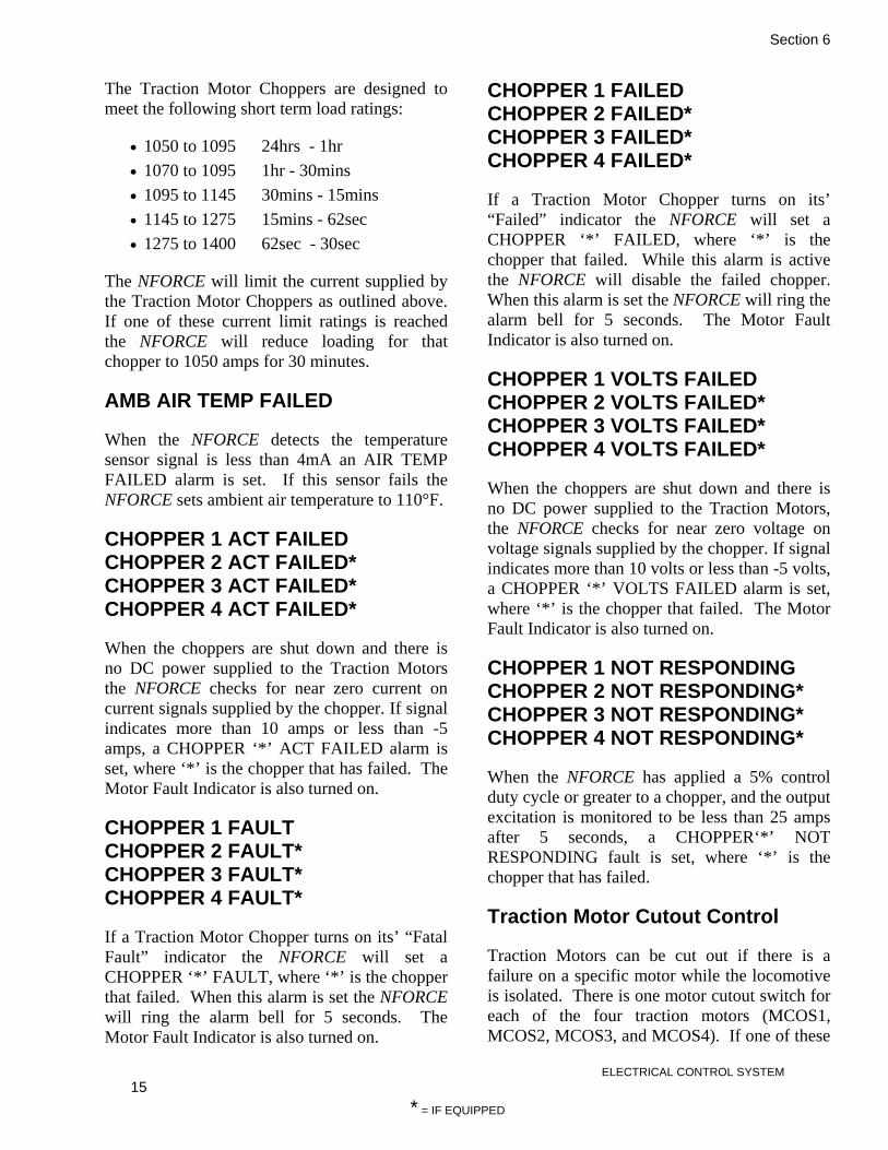
Section 6
ELECTRICAL CONTROL SYSTEM 15
* = IF EQUIPPED
The Traction Motor Choppers are designed to meet the following short term load ratings:
• 1050 to 1095 24hrs - 1hr • 1070 to 1095 1hr - 30mins • 1095 to 1145 30mins - 15mins • 1145 to 1275 15mins - 62sec • 1275 to 1400 62sec - 30sec
The NFORCE will limit the current supplied by the Traction Motor Choppers as outlined above. If one of these current limit ratings is reached the NFORCE will reduce loading for that chopper to 1050 amps for 30 minutes.
AMB AIR TEMP FAILED
When the NFORCE detects the temperature sensor signal is less than 4mA an AIR TEMP FAILED alarm is set. If this sensor fails the NFORCE sets ambient air temperature to 110°F.
CHOPPER 1 ACT FAILED CHOPPER 2 ACT FAILED* CHOPPER 3 ACT FAILED* CHOPPER 4 ACT FAILED*
When the choppers are shut down and there is no DC power supplied to the Traction Motors the NFORCE checks for near zero current on current signals supplied by the chopper. If signal indicates more than 10 amps or less than -5 amps, a CHOPPER ‘*’ ACT FAILED alarm is set, where ‘*’ is the chopper that has failed. The Motor Fault Indicator is also turned on.
CHOPPER 1 FAULT CHOPPER 2 FAULT* CHOPPER 3 FAULT* CHOPPER 4 FAULT*
If a Traction Motor Chopper turns on its’ “Fatal Fault” indicator the NFORCE will set a CHOPPER ‘*’ FAULT, where ‘*’ is the chopper that failed. When this alarm is set the NFORCE will ring the alarm bell for 5 seconds. The Motor Fault Indicator is also turned on.
CHOPPER 1 FAILED CHOPPER 2 FAILED* CHOPPER 3 FAILED* CHOPPER 4 FAILED*
If a Traction Motor Chopper turns on its’ “Failed” indicator the NFORCE will set a CHOPPER ‘*’ FAILED, where ‘*’ is the chopper that failed. While this alarm is active the NFORCE will disable the failed chopper. When this alarm is set the NFORCE will ring the alarm bell for 5 seconds. The Motor Fault Indicator is also turned on.
CHOPPER 1 VOLTS FAILED CHOPPER 2 VOLTS FAILED* CHOPPER 3 VOLTS FAILED* CHOPPER 4 VOLTS FAILED*
When the choppers are shut down and there is no DC power supplied to the Traction Motors, the NFORCE checks for near zero voltage on voltage signals supplied by the chopper. If signal indicates more than 10 volts or less than -5 volts, a CHOPPER ‘*’ VOLTS FAILED alarm is set, where ‘*’ is the chopper that failed. The Motor Fault Indicator is also turned on.
CHOPPER 1 NOT RESPONDING CHOPPER 2 NOT RESPONDING* CHOPPER 3 NOT RESPONDING* CHOPPER 4 NOT RESPONDING*
When the NFORCE has applied a 5% control duty cycle or greater to a chopper, and the output excitation is monitored to be less than 25 amps after 5 seconds, a CHOPPER‘*’ NOT RESPONDING fault is set, where ‘*’ is the chopper that has failed.
Traction Motor Cutout Control
Traction Motors can be cut out if there is a failure on a specific motor while the locomotive is isolated. There is one motor cutout switch for each of the four traction motors (MCOS1, MCOS2, MCOS3, and MCOS4). If one of these

Section 6
ELECTRICAL CONTROL SYSTEM 16
* = IF EQUIPPED
switches is closed while the locomotive is isolated the NFORCE will drop the power contactor associated with the traction motor to be cutout, pick up the corresponding MCO coil and cycle MCR, which will cycle all of the magnetic reversers allowing the selected contacts to be centered, cutting out the motor. Additionally if any motor is cut out the NFORCE will also pick up the MFR relay turning on the Motor Failed Indicator. When cutting a traction motor back in, the NFORCE will nullify AC power during the process.
The NFORCE will only pick up the power contactors for those motors that are cut in. The NFORCE will also disable traction motor chopper control for the traction motors that are cut out.
The NFORCE will limit the current output from the traction motor choppers when traction motors are cut out to allow full use of the remaining traction motors. This limit is calculated as the number of motors cut in multiplied by the current limit of each traction motor, or the maximum power available on the DC bus, whichever is less.
When a traction motor is cutout the NFORCE will still monitor the corresponding traction motor armature current transducer. If the current is sensed from the cutout traction motor a TM CUTOUT FAULT alarm is set and traction motor chopper control for all traction motors is disabled. The alarm is reset 3 seconds after the average current drops below 100 amps.
SOLENOID FAILED MCO1 SOLENOID FAILED MCO2 SOLENOID FAILED MCO3 SOLENOID FAILED MCO4
When the NFORCE energizes a solenoid, it checks for the correct feedback from the coil sense inputs. If the correct feedback is not received a SOLENOID FAILED MCO‘*’ alarm is set, where ‘*’ is the solenoid that failed.
TM 1 CUT OUT TM 2 CUT OUT TM 3 CUT OUT TM 4 CUT OUT
The NFORCE determines traction motor cutout status based on the status from the Cutout switches and motor cutout solenoids. If a traction motor is cutout, a TM ‘*’ CUT OUT alarm is set, where ‘*’ is the specific traction motor that is cutout. The Motor Fault Indicator is also turned on.
TRACTION MOTOR PROTECTION CONTROL
The NFORCE continually monitors traction motor current and voltage. This is accomplished with the use of 4-20mA signals provided by each Traction Motor Chopper. The NFORCE will regulate the current to not be more than 1400 amps. Additionally the voltage will be regulated to be less than 600 volts. If a traction motor current and/or voltage exceeds these safe levels, a TM CURRENT EXCEEDED or TM VOLTAGE EXCEEDED alarm will be set.
The NFORCE will compare the currents through each of the traction motors, and if the average traction motor current is greater than 100 amps, and any traction motor current is lower than 50 amps, loading to that traction motor is dropped and a OPEN TM alarm will be set. The alarm is reset 3 seconds after the average current drops below 100 amps. If this alarm occurs three times on the same traction motor within five minutes the Traction Motor Current Chopper associated with that traction motor will be disabled and a CHOPPER DISABLED OPEN TM alarm will be set. This alarm can be reset by placing the Isolate switch in the isolate position.
Normally the NFORCE calculates traction motor temperature based on traction motor cooling air temperature, amount of cooling air (calculated), traction motor current & voltage, and locomotive speed. However for this application the Traction Motor Current Choppers not able to

Section 6
ELECTRICAL CONTROL SYSTEM 17
* = IF EQUIPPED
withstand as much current as the traction motors, and therefore will be the limiting factor. This application is equipped with axle speed sensing equipment installed on axle two. The NFORCE will limit wheel speed in order to limit the locomotive speed. The default setting is 73 MPH, which is typically the maximum speed specification for the traction motors. If this speed is exceeded the NFORCE sets an OVER SPEED alarm, and will decrease excitation until the over speed is corrected. The excitation is reapplied if the speed drops below the set speed.
The NFORCE controls traction motor cooling by controlling the AC contactor called EBC, which connects the TM Blower motor to the AC bus. The NFORCE will not pickup the EBC two seconds after one of the ACC contactors is confirmed as closed. The NFORCE will then pickup VRO allowing the AC bus voltage to build to between 160 and 240 VAC.
The NFORCE also monitors the current loading from the TM Blower Motor using current transducer CTB. If the current is operating above 199 amps for 4 seconds the NFORCE will drop the EBC contactor. The NFORCE will attempt to re-engage the TM Blower up to three times, if the loading current is still operating above this limit the NFORCE will disable the TM Blower and set an TM BLOWER FAILED alarm. If this alarm is active, the traction current will be limited to a maximum of 525 amps. This alarm can be reset by shutting down the engines.
CHOPPER DISABLED OPEN TM1 CHOPPER DISABLED OPEN TM2* CHOPPER DISABLED OPEN TM3* CHOPPER DISABLED OPEN TM4*
If an open traction motor alarm occurs three times on the same traction motor within five minutes the Traction Motor Current Chopper associated with that traction motor will be disabled and a CHOPPER DISABLED OPEN TM‘*’ alarm will be set, where ‘*’ is the specific traction motor that failed. This alarm can be reset by placing the Isolate switch in the isolate position.
CONTACTOR FAILED EBC
If the EBC contactor fails to pick up or drop out, a CONTACTOR FAILED EBC alarm is set. The NFORCE senses the auxiliary contacts on these contactors. When the NFORCE energizes or releases the coil, it checks for the correct feedback from the auxiliary contacts. If the correct feedback is not received, one of these alarms is set. This alarm also sets TM BLOWER FAILED alarm.
TM BLOWER OVERLOAD If the NFORCE monitors the TM Blower Motor loading current is operating above expected levels with respect to primary engine RPM this alarm will be set after 10 consecutive seconds. If the current exceeds 165A for 200 ms the alarm will be set before the 10 second timer expires. This alarm sets the TM BLOWER FAILED alarm. This fault is latched until the next engine start attempt is made. The following list shows the overload current levels with respect to primary engine rpm:
• 65A @ 1200 RPM • 100A @ 1500 RPM • 140A @ 1800 RPM
TM BLOWER UNDERLOAD If the NFORCE monitors the TM Blower Motor loading current is operating below expected levels with respect to primary engine RPM this alarm will be set after 10 consecutive seconds. This alarm sets the TM BLOWER FAILED alarm. This fault is latched until the next engine start attempt is made. The following list shows the underload current levels with respect to primary engine rpm:
• 15A @ 1200 RPM • 45A @ 1500 RPM • 63A @ 1800 RPM

Section 6
ELECTRICAL CONTROL SYSTEM 18
* = IF EQUIPPED
TM BLOWER FAILED When this alarm is set the NFORCE will ring the alarm bell for 5 seconds, turn on the AUX PWR Fault indicator light and drop the EBC contactor to disconnect the blower motor from the auxiliary bus. This alarm can be reset by shutting down the engines. This alarm is also set when CONTACTOR FAILED EBC is set. Once this alarm is set and the EBC contactor is dropped the system checks that blower motor load current has fallen below acceptable levels. If the current has not dropped below 165A within 1 second of the EBC contactor opening all engines are shutdown.
TRANSDUCER FAILED CTB
When EBC is dropped and there is no AC power supplied to the Traction Motor Blower motor the NFORCE checks for near zero current on current transducer CTB. If CTB indicates more than 10 amps or less than -5 amps, a TRANSDUCER FAILED CTB alarm is set.
THROTTLE & ENGINE CONTROL
The NFORCE will monitor & control the engines by use of J1939 CAN BUS protocol.
The engines cannot start if the Control and Fuel Pump (13T) and Local Control (PA) circuit breakers are open. The NFORCE monitors both of these breakers with 74 volt digital inputs, and will set an alarm if either of these breakers are open.
The NFORCE also monitors the 24 VDC for the Cummins engines supplied by the Low Voltage Power Supply (LVPS). If the 24 VDC supply is not present, the engine starting is disabled. If the 24 VDC supply fails while the engines are running, the NFORCE will turn off all RPM outputs returning the engines to idle. In either case the alarm bell will be activated until the Isolate switch is placed in the Isolate position.
The NFORCE monitors the loading time for each engine and regulates the engine start up
sequence to maintain equal loading between the two engines.
STARTING PRIMARY ENGINE
The NFORCE monitors the START switch to determine when to start the first engine. The switch is a normally open momentarily closed switch. If the START switch is closed the NFORCE will verify the following:
• Isolate switch is in the isolate position • 8T, 9T, and 6T are low • FPCR is picked up. • 24 volt breaker is closed
If all of the above conditions are met the NFORCE will turn on the Warning Buzzer and ECMP (Engine Control Module Power). Then the NFORCE will pickup EE (Engine Enable). The NFORCE will then pickup the ST relay associated with that engine. This will start the engine cranking. The NFORCE will allow cranking for 6 seconds. If the engine RPM rises above 400 within this time period the NFORCE will drop the ST relay. The NFORCE will pickup the ACC contactor associated with that engine after the engine RPM has reached 1200 RPM (IDLE). The EBC is picked up after the ACC contactor, then VRO (Voltage Regulator Output) allowing the AC generator to operate. Following the engine startup loading is disabled for 5 seconds to allow the locomotive to stabilize before continuing with normal operations.
NOTE ACC1, ACC2, and ACC3 contactors are used to connect the auxiliary power loads to the AC BUS
The engine should now be running at 1200 RPM, and 160 VAC should be available from the generator. This can be verified using the AC Bus input included as part of the Excitation control.
If the engine does not start during the first 8 second period the NFORCE will drop the starters and wait 18 seconds before retying to

Section 6
ELECTRICAL CONTROL SYSTEM 19
* = IF EQUIPPED
start. The NFORCE will try up to three times to start the engine. If the engine fails to start on the third attempt the NFORCE will lock out that engine.
Once the engine(s) are running, if the FPCR should drop, the NFORCE will automatically shut down the engines all engines.
If the NFORCE should want to shut down the engines for fuel savings, it would drop the EE output to each engine. If the Cummins Control Systems monitors this input go low it will shut down the engine independently of the status of FPCR.
Starting Secondary Engine When notch 4 or higher is requested the seconded engine is required provided the first engine is developing motor currents of 600A or more. Starting is the same as described for the first engine start up. However the START switch is not required to close. Additionally the Warning Buzzers will not sound when starting the second engine. Once the NFORCE has verified that the requested RPM has been reached it will pickup VRO allowing that generator to produce power.
When the throttle demand has been reduced to notch 4 or lower the second engine will be returned to idle for 5 minutes. If no request loading request are made for notch 4 or higher the engine is shut down by dropping the EE output to that engine.
Tertiary Engine
When notch 6 or higher is requested and locomotive track speed is above 4.5 MPH the
third engine is required provided the first & second engines are developing full power. Starting is the same as described for the first engine start up. Again the START switch is not required to close. Additionally the Warning Buzzers will not sound when starting the second engine. Once the NFORCE has verified that the requested RPM has been reached it will pickup VRO allowing that generator to produce power.
When the throttle demand has been reduced to notch 6 or lower, the third engine will be returned to idle for 1 minute. If no loading requests are made for notch 6 or higher, the engine is shut down by dropping the EE output to that engine.
RPM Control
As with most of the locomotive controls, the throttle handle switches (THS) operate in the 74 VDC system. When one of the throttle switches is closed 74 volts is applied to a NFORCE digital input.
For throttle control, the NFORCE senses the following:
• Isolate Switch • AV throttle (15T) • BV throttle (12T) • CV throttle (7T) • DV throttle (3T) • Engine Run Relay (16T). • Generator Field (GF) Control (6T)
The following table (Table 6-1) shows trainline verses throttle position, and engine running
verses Throttle.

Section 6
ELECTRICAL CONTROL SYSTEM 20
* = IF EQUIPPED
Table 6-1 – Trainline vs. Throttle Position & Engine Running vs. Throttle Throttle Notch
Eng 1 BHP
Eng 1 THP
Eng 1 RPM
Eng 2 BHP
Eng 2 THP
Eng 2 RPM
Eng 3 BHP
Eng 3 THP
Eng 3 RPM
Loco BHP
Loco THP
Idle 67 0 1200 67 0 1 228 145 1500 228 145 2 388 305 1500 388 305 3 685 585 1800 685 585 4 547 447 1800 390 373 1500 937 820 5 661 651 1800 485 469 1500 1146 1030 6 594 494 1800 514 494 1800 429 412 1500 1537 1400 7 667 567 1800 587 567 1800 587 567 1800 1841 1701 8 697 597 1800 686 664 2000 686 664 2000 2069 1925
The notch position, determined from the throttle trainlines, is then passed on to the Rate Control module which is used as a reference for maximum loading for that throttle position. For Notch 1 through 4, the NFORCE will run one engine. For notches 4 through 5 two engines, and for notches 6 through 8 the NFORCE will run all engines.
If any of the following conditions are true, the engines are returned to idle:
• Engine Run switch (16T) – If 15T 12T, 7T, or 3T are high and 16T remains low, the NFORCE will determine that the Engine Run switch is open, the throttle will be limited to idle.
• Generator Field (6T) – If 15T 12T, 7T, or 3T are high and 6T remains low, and the Isolate switch is in the “RUN” position the NFORCE will determine that the GEN FLD switch is open, the throttle will be limited to idle. NOTE – If the Isolate switch is in the “ISOLATE” position the NFORCE will allow engine RPM without loading.
• PCS switch – If the Pneumatic Control switch drops out with the loss of locomotive air pressure, the PCR relay will drop out. This will interrupt the positive feed to the throttle handle, and force the engine to idle. The NFORCE monitors the status of the PCR relay with a digital input, and will display a PCS alarm when this occurs.
• The NFORCE also monitors the ground relay circuits, if a ground fault has occurred on the locomotive the NFORCE will reduce the engine RPM to idle.
• The NFORCE monitors the status of the GRCO. If this input is low the NFORCE will limit throttle to idle.
Locomotive track speed limiting engines running to one is disabled during Load Test.
If 3T is high while 6T, 15T, 12T, and 7T are low all engines will be shut down by dropping the EE signals to all engines.
ENGINE SHUT DOWN BY FPCR
This message is set if the NFORCE senses that the FPCR goes low while the engines are running.
ENGINE RUN SWITCH DOWN
The ENG RUN switch (ER) is down. The engine will not be allowed above Idle and will not load.
GEN FLD SWITCH DOWN.
This message is set when the NFORCE senses that the throttle has been moved from the idle position causing some of the governor solenoids to pickup while the 6T MU remains low.
LOCAL BREAKER OFF
This message indicates that the Local Control

Section 6
ELECTRICAL CONTROL SYSTEM 21
* = IF EQUIPPED
Breaker is Off.
NO CONTROL AND FUEL PUMP
The NFORCE senses that the Positive Control and Fuel Pump on the 13T string is not energized. When this occurs, the train lined control functions won’t operate and the engine won’t load. After a short delay, the engine shuts down because the fuel pump is Off.
PCS
The Pneumatic Control Relay (PCR) has dropped out. If it is the lead locomotive, the feed to the throttle handle switches is dropped out. This prevents the throttle MU lines (6T, 3T,7T, 12T, 15T) from picking up, effectively preventing loading on all locomotives in the consist. This occurs after an emergency brake application. The NFORCE only displays the status of the PCR; loading is prevented by loss of GF (through open PCR interlocks).
NO LOAD GR CUT OUT
If the NFORCE senses the Ground Relay Cutout switch is open, this alarm is set and prevents loading. Throttle is limited to the Idle position.
GEN SET #1 FAULT GEN SET #2 FAULT* GEN SET #3 FAULT*
If the Cummins Control system turns on the “FAULT” output the NFORCE will set a GEN SET‘*’ FAULT, where ‘*’ is the GEN SET that failed. While this alarm is active the NFORCE will not allow the failed GEN SET to start. When this alarm is set, the NFORCE will ring the alarm bell for 5 seconds.
GEN SET #1 SERVICE ENGINE GEN SET #2 SERVICE ENGINE* GEN SET #3 SERVICE ENGINE*
If the Cummins Control system turns on the “WARN” output the NFORCE will set a GEN SET‘*’ SERV ENG, where ‘*’ is the GEN SET
that requires service.
GEN SET #1 START FAILURE GEN SET #2 START FAILURE* GEN SET #3 START FAILURE*
If the Cummins Control system turns on the “NO ST” output, the NFORCE will set a GEN SET‘*’ START FAILURE, where ‘*’ is the GEN SET that failed to start. While this alarm is active the NFORCE will not allow the failed GEN SET to start. When this alarm is set the NFORCE will ring the alarm bell for 5 seconds.
CONTACTOR FAILED ACC1 CONTACTOR FAILED ACC2 CONTACTOR FAILED ACC2
If a contactor fails to pick up or drop out, a CONTACTOR FAILED ACC‘*’ alarm is set, where ‘*’ is the contactor that failed to pick up or drop out. The NFORCE senses the auxiliary contacts on these contactors. When the NFORCE energizes or releases the coil, it checks for the correct feedback from the auxiliary contacts. If the correct feedback is not received, one of these alarms is set.
GEN SET #1 MAINTENANCE GEN SET #2 MAINTENANCE* GEN SET #3 MAINTENANCE*
If the Cummins Control system turns on the “MAINT” output the NFORCE will set a GEN SET‘*’ MAINTENANCE, where ‘*’ is the GEN SET that requires maintenance.
WHEEL SLIP/CREEP CONTROL
Wheel-rail studies have shown that after the initial slip of a powered wheel there is still a considerable amount of frictional force between the wheel and the rail. In fact, if the wheel slip is allowed to increase, the force on the rail will increase to some peak value then decrease. This increased frictional force can be utilized for increased tractive effort, and is known as wheel creep.
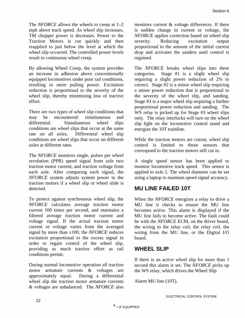
Section 6
ELECTRICAL CONTROL SYSTEM 22
* = IF EQUIPPED
The NFORCE allows the wheels to creep at 1–2 mph above track speed. As wheel slip increases, TM chopper power is decreases. Power to the Traction Motors is cut quickly and then reapplied to just below the level at which the wheel slip occurred. The controlled power levels result in continuous wheel creep.
By allowing Wheel Creep, the system provides an increase in adhesion above conventionally equipped locomotives under poor rail conditions, resulting in more pulling power. Excitation reduction is proportional to the severity of the wheel slip, thereby minimizing loss of tractive effort.
There are two types of wheel slip conditions that may be encountered: simultaneous and differential. Simultaneous wheel slips conditions are wheel slips that occur at the same rate on all axles. Differential wheel slip conditions are wheel slips that occur on different axles at different rates.
The NFORCE monitors single, pulses per wheel revolution (PPR) speed signal from axle two traction motor current, and traction voltage from each axle. After comparing each signal, the NFORCE system adjusts system power to the traction motors if a wheel slip or wheel slide is detected.
To protect against synchronous wheel slip, the NFORCE calculates average traction motor current 100 times per second, and maintains a filtered average traction motor current and voltage signal. If the actual traction motor current or voltage varies from the averaged signal by more than ±100, the NFORCE reduces excitation proportional to the excess signal in order to regain control of the wheel slip, providing as much tractive effort as rail conditions permit.
During normal locomotive operation all traction motor armature currents & voltages are approximately equal. During a differential wheel slip the traction motor armature currents & voltages are unbalanced. The NFORCE also
monitors current & voltage differences. If there is sudden change in current or voltage, the NFORCE applies correction based on wheel slip severity. Reducing excitation output proportional to the amount of the initial current drop and activates the sanders until control is regained.
The NFORCE breaks wheel slips into three categories. Stage #1 is a slight wheel slip requiring a slight power reduction of 2% to correct. Stage #2 is a minor wheel slip requiring a minor power reduction that is proportional to the severity of the wheel slip, and sanding. Stage #3 is a major wheel slip requiring a further proportional power reduction and sanding. The WS relay is picked up for Stage #3 wheel slips only. The relay interlocks will turn on the wheel slip light on the locomotive control stand and energize the 10T trainline.
While the traction motors are cutout, wheel slip control is limited to those sensors that correspond to the traction motors still cut in.
A single speed sensor has been applied to monitor locomotive track speed. This sensor is applied to axle 2. The wheel diameter can be set using a laptop to maintain speed signal accuracy.
MU LINE FAILED 10T
When the NFORCE energizes a relay to drive a MU line it checks to ensure the MU line becomes active. This alarm is displayed if the MU line fails to become active. The fault could be with the NFORCE ECM, on the driver board, the wiring to the relay coil, the relay coil, the wiring from the MU line, or the Digital I/O board.
WHEEL SLIP
If there is an active wheel slip for more than 1 second this alarm is set. The NFORCE picks up the WS relay, which drives the Wheel Slip
Alarm MU line (10T).

Section 6
ELECTRICAL CONTROL SYSTEM 23
* = IF EQUIPPED
WHEEL SLIP NOT THIS LOCO
Another locomotive in the consist activated the Wheel Slip Alarm MU line (10T).
PC Communications & Analysis Software
The analysis software allows communication via RS-232 serial link to the NFORCE system.
The NFORCE System has an integrated recording function which is continually operating while the system is functional. The NFORCE system records information and stores it in three types of log (Alarm, Diagnostic, & Statistics Logs). This information can be viewed using the analysis software program. The NFORCE system scans all inputs and outputs – digitals and analogs – 10 times each second, and updates each log as required.
Connecting To the NFORCE Using Hyper Terminal
The NFORCE system uses RS 232 serial communications to transfer information to and from the PC. A standard VT100 terminal emulation is employed allowing common, easy to operate Windows programs such as Hyper Terminal to communicate with the NFORCE.
Any Windows based serial terminal program may be used to talk to the NFORCE system.
These instructions will describe how to use Hyper Terminal to transfer log data from the NFORCE to a laptop PC running Microsoft ® Windows ®.
• Connect the communications cable from the front connector of the NFORCE CPU board to the serial port of your laptop computer.
• Run Hyper Terminal from your laptop computer. This is commonly found by going to Start -> Programs -> Accessories -> Communications. If your laptop does not have Hyper Terminal, you must install it before continuing.
• If this is the first time you have connected to the NFORCE with Hyper Terminal, create a new connection. Give the connection the name NFORCE as shown in Figure 6-2. Click OK when you have entered the name and chosen an icon.

Section 6
ELECTRICAL CONTROL SYSTEM 24
* = IF EQUIPPED
Figure 6-2 – Naming the NFORCE HyperTerminal Connection
• Hyper Terminal must now be configured with the correct communications settings to talk to the NFORCE. Hyper Terminal should now be showing the Connect To window (Figure 6-3). Using the drop down box provided for Connect Using select the COM port you have connected the NFORCE cable to. This is commonly COM1. Click OK when ready.
Figure 6-3 – HyperTerminal Communications Settings

Section 6
ELECTRICAL CONTROL SYSTEM 25
* = IF EQUIPPED
• Hyper Terminal should now be displaying the COM Properties window (Figure 6-4) which contains the configurable port settings. Set the fields to the following:
Figure 6-4 – COM Properties window
NOTE It is very important that these settings are correct to ensure successful communications with the NFORCE system.
Click OK when ready.
Communicating With the NFORCE & NFORCE Help Menu
• Starting if the NFORCE is powered down:
Now that the PC is configured to talk to the NFORCE, power up the NFORCE system if it is not already powered. You should see some messages on the Hyper Terminal screen as the NFORCE performs system checks (Fig. 6-5). This is normal. If you do not see anything on the screen, you should check your physical cable connection and your COM port settings.

Section 6
ELECTRICAL CONTROL SYSTEM 26
* = IF EQUIPPED
Figure 6-5 – Startup System Checks
When the NFORCE has finished its system checks it will run the terminal interface automatically. See below (Figure 6-5):
Figure 6-6 –Terminal Interface

Section 6
ELECTRICAL CONTROL SYSTEM 27
* = IF EQUIPPED
• The NFORCE is now running and is ready for user input. Press the ‘h’ key on your laptop keyboard to launch the Help Menu. Note that not all NFORCE systems have identical help menu contents as some items are specific to certain locomotive types. If you do not see anything on the screen, you should check your physical cable connection and your COM port settings.
Figure 6-7 – Help Menu
All of the commands are listed in the help menu. Note the commands for transferring log information.

Section 6
ELECTRICAL CONTROL SYSTEM 28
* = IF EQUIPPED
Downloading the NFORCE Fault Log to the PC
The NFORCE system is capable of sending comma delimited ASCII text file fault logs via the RS 232 serial port. These logs must be captured and saved by the terminal program in use to be viewed following the completion of the download.
• Choose a file name and save location for the Fault Download.
In Hyper Terminal, select Transfer->Capture Text. The Capture Text window should appear:
Figure 6-8 – Capture Text Window
Click Browse to select the location on the computer you wish to save the file. Choose a unique name for the file to distinguish it from other previous downloads and files. Click Save when done selecting a file name and save location (Figure 6-8). Click Start when ready to download.
Figure 6-9 – Capture File Save Location
• Ensure that the locomotive is isolated and is not loading. Initiate the file transfer by entering the GF command. The NFORCE will immediately begin downloading the Fault Log to the PC. Note that this can take several minutes to complete. Also note that the terminal window will be very

Section 6
ELECTRICAL CONTROL SYSTEM 29
* = IF EQUIPPED
rapidly updating seemingly meaningless information. This is simply the fault data passing into the file and is normal.
• Upon completion, the NFORCE will display the message Transfer Complete!! and the command prompt:
Figure 6-10 – Transfer Complete
The Fault Log download is now finished. Stop the file capture in Hyper Terminal by selecting Transfer->Capture Text->stop.
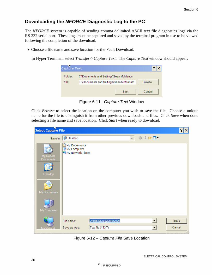
Section 6
ELECTRICAL CONTROL SYSTEM 30
* = IF EQUIPPED
Downloading the NFORCE Diagnostic Log to the PC
The NFORCE system is capable of sending comma delimited ASCII text file diagnostics logs via the RS 232 serial port. These logs must be captured and saved by the terminal program in use to be viewed following the completion of the download.
• Choose a file name and save location for the Fault Download.
In Hyper Terminal, select Transfer->Capture Text. The Capture Text window should appear:
Figure 6-11– Capture Text Window
Click Browse to select the location on the computer you wish to save the file. Choose a unique name for the file to distinguish it from other previous downloads and files. Click Save when done selecting a file name and save location. Click Start when ready to download.
Figure 6-12 – Capture File Save Location

Section 6
ELECTRICAL CONTROL SYSTEM 31
* = IF EQUIPPED
• Ensure that the locomotive is isolated and is not loading. Initiate the file transfer by entering the GF command.
The NFORCE will immediately begin downloading the Diagnostic Log to the PC. Note that the terminal window will be very rapidly updating seemingly meaningless information. This is simply the data passing into the file and is normal.
• Upon completion, the NFORCE will display the message Transfer Complete!! and the command prompt:
Figure 6-13 – Transfer Complete
The Diagnostics Log download is now finished. Stop the file capture in Hyper Terminal by selecting Transfer->Capture Text->stop.

Section 6
ELECTRICAL CONTROL SYSTEM 32
* = IF EQUIPPED
DOWNLOADING THE NFORCE STATISTICS LOG TO THE PC
The NFORCE system is capable of sending comma delimited ASCII text file diagnostics logs via the RS 232 serial port. These logs must be captured and saved by the terminal program in use to be viewed following the completion of the download.
• Choose a file name and save location for the Statistics Download.
In Hyper Terminal, select Transfer->Capture Text. The Capture Text window should appear:
Figure 6-14 – Capture Text Window
Click Browse to select the location on the computer you wish to save the file. Choose a unique name for the file to distinguish it from other previous downloads and files. Click Save when done selecting a file name and save location. Click Start when ready to download.
Figure 6-15 – Capture File Save Location

Section 6
ELECTRICAL CONTROL SYSTEM 33
* = IF EQUIPPED
• Ensure that the locomotive is isolated and is not loading. Initiate the file transfer by entering the GS command.
The NFORCE will immediately begin downloading the Statistics Log to the PC. Note that the terminal window will be very rapidly updating seemingly meaningless information. This is simply the data passing into the file and is normal.
• Upon completion, the NFORCE will display the message Transfer Complete!! and the command prompt:
Figure 6-16 – Transfer Complete
The Statistics Log download is now finished. Stop the file capture in Hyper Terminal by selecting Transfer->Capture Text->stop.

Section 6
ELECTRICAL CONTROL SYSTEM 34
* = IF EQUIPPED
VIEWING NFORCE LOG DOWNLOAD FILES WITH A PC
The NFORCE formats all downloads into ASCII comma delimited text files for easy import into popular spreadsheet programs such as Microsoft ® Excel ®.
Most spread sheet programs are capable of importing delimited text files. These instructions will describe how to import and view NFORCE comma delimited text files using Microsoft ® Excel ®. NRE Electronics recommends using Microsoft ® Excel ®.
• Launch Excel and open the saved log file (.txt extension) captured by Hyper Terminal. Excel will post a warning window indicating that the file is not in the standard Excel format.
Figure 6-17 – Excel File Warning Window
Click OK to start the import wizard:
Figure 6-18 – Excel Text Import Wizard (Step 1)
Set the Original Data Type radio button to Delimited as above. Adjust the ‘Start import at row’ to the labels row, typically this is row 12. Use the slide bar provided to find the label row number if you are not sure.
Click Next > when ready.

Section 6
ELECTRICAL CONTROL SYSTEM 35
* = IF EQUIPPED
• Set the comma delimiter to allow Excel to prepare the data columns. Note the vertical bars that are inserted to distinguish the data fields.
Click Finish when ready.
Figure 6-19 – Excel Text Import Wizard (Step 2)
• The file is now ready for viewing! The data is unsorted. Excel may be used to sort the data to your liking. Users typically sort the data set using the time stamp in the first column then sort according to the data of interest. Macros may be constructed to assist with repetitive sorts. Please refer to Excel help material for more information regarding sorting and macros.
• An example of an imported fault log is below. The diagnostic log file is identical with the exception of the DATE and TYPE columns are removed as all diagnostic data records are the same type (DATA) and all diagnostic data records occur on the same date over a span of several minutes.

Section 6
ELECTRICAL CONTROL SYSTEM 36
* = IF EQUIPPED
Figure 6-20 – Imported Fault Log Example
STATISTICS LOG CONTENT
The Statistics Log records various information that relates to the locomotive and its operation. Most of this information is accumulative and is referred to as statistics, while some information defines the parameters of the locomotive and the NFORCE System. All Lifetime Statistics are also stored in an external, non-volatile memory device which remains on the locomotive at all times.
The Statistics Report contains the following information:
• Date/Time (settable parameter) is the time and date of the download computer when data was downloaded from the NFORCE.
• Firmware Version indicates the version and revision of the NFORCE internal operating software.
• Loco ID (settable parameter) is the ID number of the locomotive from which data was removed. The ID number is composed of 5 alpha-numeric characters. Acceptable characters include numbers 0-9, letters a-z and letters A-Z. Space is used for blanks in the event the ID number is less than 5 characters in length.
• Wheel Diameter (settable parameter) is the diameter of the locomotive wheel in inches.
• Axle Gen PPR (settable parameter) is the pulses per revolution (PPR) of the incoming speed signal from the installed speed pick-up equipment.
• Idle Parked indicates the number of hours that the locomotive has spent with the engine at idle and the reverser in neutral.
• Idle Working indicates the number of hours the locomotive has spent with the engine at idle and the reverser set in either forward or reverse.

Section 6
ELECTRICAL CONTROL SYSTEM 37
* = IF EQUIPPED
• Idle Limit Shutdown indicates the total hours the engine spent in NFORCE Shutdown mode.
• Isolated indicates the total hours the locomotive spent with the isolate/run switch in the isolate position.
• Running indicates the total engine run hours.
• Shutdown indicates the total engine shutdown hours (manual and automatic.)
• Stop, Notch 1-8 displays the time in hours spent at various throttle positions.
• Engine Run Times displays hours and minutes spent at each RPM setting.
• Distance displays miles traveled in forward, reverse and neutral.
• Energy displays total energy consumed in kWh.
• RESTART COUNTS (ENGINE RESTART COUNTS) displays the Reason for each engine NFORCE, each recorded for the Lifetime the Trip.
• SHUTDOWN TIMES (UNABLE TO SHUTDOWN TIMES) displays the Reason for each engine shutdown failure and the associated number of hours accumulated.

Section 6
ELECTRICAL CONTROL SYSTEM 38
* = IF EQUIPPED
VIEWING & SETTING NFORCE LOCOMOTIVE PARAMETERS
There are several settable parameters that the NFORCE system uses to operate. These parameters (with the exception of the real time clock) are stored in a memory unit that is permanently installed on the locomotive external to the NFORCE module in the NFORCE wire harness. This allows the operating parameters to remain with the locomotive in the event that the NFORCE module is changed or replaced.
WARNING It is very important that all of the parameters be set before the locomotive is put into service!
The following parameters are settable:
• Locomotive ID • Wheel diameter • Time and Date
The parameters may be viewed by launching the ‘FS0’ Serial EEPROM monitor screen: Figure 6-21.
Figure 6-21 – FS0 Serial EEPROM Monitor Screen

Section 6
ELECTRICAL CONTROL SYSTEM 39
* = IF EQUIPPED
All of the settable parameters may be set from the NFORCE command prompt. A list of the set commands may be found by activating the NFORCE Help Menu (Figure 6-22) by pushing the ‘H’ key at the command prompt:
Figure 6-22 – Help Menu
Note that all of the set commands begin with the letter ‘S’.
REAL TIME CLOCK
To set the real time clock, enter the date and time in the following format:
SC YYMMDDhhmmss Where:
• YY = The last two digits of the calendar year
• MM = The two digit representation of the calendar month
• DD = The day of the month • hh = The hour in 24-hour nomenclature (i.e.
23 = 11 PM.) • mm = The current minutes value. • ss = The current seconds value.
If accepted, the NFORCE will reply with:
RTC time set!
WHEEL DIAMETER (inches)
Wheel diameter settings are accepted in inches. To set the wheel diameter to 40 inches (for example) enter the following command at the NFORCE command prompt:
SD 40
The acceptable range of wheel diameters is from 36 to 42 inches. If accepted, the NFORCE will reply with:
New Wheel Diameter set!
LOCOMOTIVE ID
The locomotive ID is represented by 5 alpha-numeric characters. Acceptable values for each character are the numbers 0-9, letters a-z and

Section 6
ELECTRICAL CONTROL SYSTEM 40
* = IF EQUIPPED
letters A-Z. Blank is represented by a space in the event that the locomotive ID is less than 5 characters long. To enter an ID of 12345 (for example), enter the following command at the NFORCE command prompt:
SI 12345
If accepted, the NFORCE will reply with:
New Loco ID set!
CLEARING STATISITICS LOGS
Both the long term and short term statistics logs may be cleared from the FS0 Serial EEPROM Monitor Screen (Figure 6-21). To clear the short term log, press ‘1’. To clear the long term log, press ‘2’.

Section 6
ELECTRICAL CONTROL SYSTEM 41
* = IF EQUIPPED
UPLOADING NEW SYSTEM FIRMWARE
The internal firmware installation procedures described here can be used to install the NFORCE system firmware for the first time, to re-install it if start-up problems occur, or to upload revised firmware if changes are required. Installing the firmware is done using a portable computer and the analysis software program.
The program required to communicate with the NFORCE is called Hyper Terminal and is included with the Microsoft Windows operating system.
To upgrade the NFORCE firmware, you must do the following:
• Isolate the locomotive and shut down the engine(s).
• Connect the communications cable to the front of the CPU board and your laptop.
• Within the Hyper Terminal window (setup as above) type RESET at the NFORCE command prompt. This should look like this: NFORCE 820-0022-a19:> RESET
• The NFORCE system will reset and run the bootloader. Press ‘L’ on your laptop keyboard to bring up the bootloader menu (Figure 6-23):
Figure 6-23 – Bootloader Menu
• Select option ‘1’ to load a new program with 1k-XMODEM. The NFORCE will then begin the 1k-XMODEM file transfer process. Note this step is time sensitive as the NFORCE will allow 30 seconds for the file transfer to begin. The letter ‘C’ appearing on the terminal window is normal and denotes the NFORCE is waiting for the file (Figure 6-24).

Section 6
ELECTRICAL CONTROL SYSTEM 42
* = IF EQUIPPED
• From Hyper Terminal, select the ‘Transfer->Send File’ drop down menu.
• Browse to the location of the NFORCE firmware on your laptop. The NFORCE firmware has an .ecm extension. Make sure to select 1k-XMODEM as the protocol to transfer the file with. Click ‘Send’ when the correct file has been chosen.
Figure 6-24 – 1k-XMODEM File Transfer
• The file transfer progress window should appear within Hyper Terminal. Once the file transfer is successful, the NFORCE will ask if you wish to apply the program, press the ‘Y’ key on the laptop to say yes and accept the new program into memory:
Figure 6-25 – Program Application

Section 6
ELECTRICAL CONTROL SYSTEM 43
* = IF EQUIPPED
• Once the file has been successfully loaded into memory, the NFORCE will start automatically. Press the ENTER key on your laptop to confirm that the NFORCE is communicating, it should respond with the command prompt.
Figure 6-26 – Terminal Interface
• If the file was corrupted during the transfer or is in any way invalid, the NFORCE will reject the file and post a warning message indicating that the file was corrupted and it will not use the bad file.
Figure 6-27 – Corrupted Program File Transfer

Section 6
ELECTRICAL CONTROL SYSTEM 44
* = IF EQUIPPED
SETTING UP EXTERNAL EEPROM MEMORY
The NFORCE Power Supply Harness is equipped with external non-volatile memory, used to store locomotive and NFORCE parameters.
To verify the EEPROM is setup correctly, you must do the following:
• Connect to the NFORCE as described in PC Communications & Analysis Software p.23
• Enter “FS0” and terminal. A screen similar to that shown in Figure below should be displayed.
• Verify that “KEY GOOD” is displayed as “1” and “LOG DISABLED” is displayed as “0”. If this is not the case reset EEPROM as follows.
• Enter “$” followed be “E” to exit FSO screen. Reset NFORCE.
WARNING DO NOT SHUT DOWN NFORCE DURING THIS PROCESS.
Figure 6-28 – FS0 Serial EEPROM Monitor Screen

Section 6
ELECTRICAL CONTROL SYSTEM 45
* = IF EQUIPPED
MCM SYSTEM HARDWARE
Many train interface and ancillary equipment options are available for NFORCE Systems. The N-VIRO Low Emissions Switcher system includes the equipment listed below:
Table 6-3 – N-VIRO Low Emissions Switcher NFORCE Equipment
Item Part Number Qty. NFORCE System 901-0002-000 1 NFORCE CPU Harness 725-0002-000 1 NFORCE Power Supply Harness 725-0007-000 1 NFORCE IO Harness 725-0001-000 4 Water/AMB Temperature Sensor 775-0001-000 1 Ambient Temperature Mounting Plate 665-0017-000 1 Temperature Sensor Cable 057-0001-000 1 Low Current Sensor 775-0007-000 4 Transformer (480VAC to 120VAC) 445-0001-000 1 Pressure Sensor 775-0005-000 2 Pressure Sensor Cable 057-0002-000 2 Train Line Load Resistor Panel 904-0001-000 1 NFORCE Communication Cable 058-0001-000 1 Axle Generator Cable 051-0001-000 1 Axle Generator Drive shaft 680-0001-000 1 Axle Generator Cable Support Bracket 665-0015-000 1 Axle Generator 908-0001-000 1

Section 6
ELECTRICAL CONTROL SYSTEM 46
* = IF EQUIPPED
INPUT/OUTPUT SUMMARY
The NFORCE contains conditioning circuitry to interface to both digital (On/Off) and analog devices on the locomotive. All sensing, logic, communications, and control functions of the locomotive are interfaced to the NFORCE system via the cables/harnesses on the back of the NFORCE. The NFORCE hardware primarily consists of a series of printed circuit boards which perform the various tasks.
Each board that plugs into the NFORCE electronic control unit typically has a 9-pin connector for a proprietary system bus and two 41-pin connectors for the input/output (I/O).
DIGITAL SIGNAL PROCCESSING BOARD (DSP)
The Digital Signal Processing board contains the computer memory to process all input data and output data. The Statistics, Alarm, and Diagnostic Logs are all stored in on-board memory, with the alarms and statistics in non-volatile (battery-backed) memory for long-term storage.
This board also contains the serial ports and drivers for the NFORCE to communicate with the Operator Interface Panel and a laptop computer.
In addition, it contains the (16) 4-20mA inputs, (6) 4-20mA outputs, and (8) speed input channels.
Table 6-4 – DSP Board Inputs/Outputs Ch Hardware Function Ch Hardware Function
01 4-20mA Current Loop Input #1 DCH4 VOLTS 16 4-20mA Current Loop
Input #16 AIR COMP AMPS
02 4-20mA Current Loop Input #2 DCH4 AMPS 17 0-20mA Current loop
Output #1 DCH1 CONTROL
03 4-20mA Current Loop Input #3 DCH3 VOLTS 18 0-20mA Current loop
Output #2 DCH2 CONTROL
04 4-20mA Current Loop Input #4 DCH3 AMPS 19 0-20mA Current loop
Output #3 DCH3 CONTROL
05 4-20mA Current Loop Input #5 DCH2 VOLTS 20 0-20mA Current loop
Output #4 DCH4 CONTROL
06 4-20mA Current Loop Input #6 DCH2 AMPS 21 0-20mA Current loop
Output #5 SPARE
07 4-20mA Current Loop Input #7 DCH1 VOLTS 22 0-20mA Current loop
Output #6 SPARE
08 4-20mA Current Loop Input #8 DCH1 AMPS 23 Speed Input #1 SPEED IN
09 4-20mA Current Loop Input #9 BCPT 24 Speed Input #2 SPARE
10 4-20mA Current Loop Input #10 BAT CHR AMPS 25 Speed Input #3 SPARE
11 4-20mA Current Loop Input #11 DC BUS AMPS 26 Speed Input #4 SPARE
12 4-20mA Current Loop Input #12 DC BUS VOLTS 27 Speed Input #5 SPARE
13 4-20mA Current Loop Input #13 MRPT 28 Speed Input #6 SPARE
14 4-20mA Current Loop Input #14 LVPS AMPS 29 Speed Input #7 SPARE
15 4-20mA Current Loop Input #15 EQP BW AMPS 30 Speed Input #8 SPARE

Section 6
ELECTRICAL CONTROL SYSTEM 47
* = IF EQUIPPED
POWER SUPPLY BOARD (P/S)
The Power Supply board contains the circuits required to supply isolated filtered power for each of the boards in the NFORCE cabinet. It receives a 74V supply from the locomotive batteries and outputs a 12V signal to power all system boards.
In addition to the power supply function this board also contains an AC Voltage Analog Input, Load Meter Drive, (2) 100V Analog Inputs, (2) 100V Analog Outputs, VR Control, SE Control, and one Speed Output.
Table 6-5 – Power Supply Board Ch Hardware Function 01 AC Voltage/Hz AC BUS VOLTS 02 0-200mA Output LOAD METER 03 100V Analog Input #1 BATTERY VOLTS 04 100V Analog Input #2 SPARE 05 100V Analog Input #3 SPARE 06 100V Analog Input #4 SPARE 07 100V Analog Output #1 SPARE 08 100V Analog Output #2 SPARE 09 Voltage Regulation VR Control 10 SE Control SCR Control 11 Speed Output SPEED INDICATOR
INPUT/OUTPUT BOARD (I/O)
The NFORCE will have four Input/Output boards installed. All the Input/Output boards are physically the same. Each board has (2) 4-20mA Current Loop Inputs, and (12) digital outputs. Each digital output is capable of driving either 24 or 74 volts.
Table 6-6 Board Readings
Ch Hardware Board 3 Board 4 Board 5 Board 6
1 4-20mA Current Loop Input #1 24V AMPS GENSET3 PH1
AMPS GENSET3 PH3 AMPS ATS
2 4-20mA Current Loop Input #2
GENSET1 PH3 AMPS
GENSET1 PH1 AMPS
GENSET2 PH1 AMPS
GENSET2 PH3 AMPS
3 Digital Outputs #1 P1 GENSET1 FAULT SPARE GENSET1 EE
4 Digital Outputs #2 P2 GENSET1 SERV MCOR GENSET1 VRO
5 Digital Outputs #3 P3 GENSET 3 SERV GR RESET GENSET1 ST
6 Digital Outputs #4 P4 GENSET 2 FAULT CRL GENSET11-3 SHT
7 Digital Outputs #5 SPARE GENSET2 SERV WLR GENSET1-3 EMCP
8 Digital Outputs #6 RVF GENSET3 FAULT NSR GENSET2 EE
9 Digital Outputs #7 MTR AC1P ABR GENSET2 VRO

Section 6
ELECTRICAL CONTROL SYSTEM 48
* = IF EQUIPPED
10 Digital Outputs #8 MCO4 AC2P MFR GENSET2 ST
11 Digital Outputs #9 MCO1 EBC AUX PWR FAULT LSC
12 Digital Outputs #10 MCO2 CC1 MVCC GENSET 3 EE
13 Digital Outputs #11 MCO3 CC2 MV2SR GENSET 3 VRO
14 Digital Outputs #12 BUZZERS CC3 MV1SF GENSET 3 ST
INPUT/OUTPUT BOARD (I/O) CONTINUED
The NFORCE will have four Input/Output boards installed. All the Input/Output boards are physically the same. Each board has (24) digital inputs. The digital inputs are capable of reading 20 volts.
Table 6-7 Board Readings
Ch Hardware Board 3 Board 4 Board 5 Board 6 15 Digital Inputs #1 P1 IS AC RESET CHCB 16 Digital Inputs #2 P2 MCO1 6T DCH1 Failed 17 Digital Inputs #3 P3 MCO2 3T DCH1 Fatal Fault 18 Digital Inputs #4 P4 MCO3 7T DCH1 Aux Fault 19 Digital Inputs #5 RV1 MCO4 12T DCH2 Aux Fault 20 Digital Inputs #6 RV2 GR 15T DCH2 Failed 21 Digital Inputs #7 RV3 LSF 8T DCH2 Fatal Fault 22 Digital Inputs #8 RV4 GRCO 9T DCH3 FAILED 23 Digital Inputs #9 M
CONTACTORS EBC 16T DCH3 FATAL
FAULT 24 Digital Inputs #10 SPARE CC1 LD TRK SND DCH4 FAILED 25 Digital Inputs #11 FPCR CC2 2T DCH4 FATAL
FAULT 26 Digital Inputs #12 LTS CC3 10T DCH Power 27 Digital Inputs #13 MCOS1 SPARE 13T SPARE 28 Digital Inputs #14 MCOS2 SPARE 5T SPARE 29 Digital Inputs #15 MCOS3 SPARE NSR SPARE 30 Digital Inputs #16 MCOS4 SPARE 23T SPARE 31 Digital Inputs #17 ACC1 SPARE PCR SPARE 32 Digital Inputs #18 ACC2 SPARE ENG START SPARE 33 Digital Inputs #19 ACC3 SPARE 26T SPARE 34 Digital Inputs #20 PA SPARE 22T SPARE 35 Digital Inputs #21 GENSET1 BRK SPARE SPARE SPARE 36 Digital Inputs #22 GENSET2 BRK SPARE SPARE SPARE 37 Digital Inputs #23 GENSET3 BRK 24V SUP SPARE SPARE 38 Digital Inputs #24 DC RECT TEMP SPARE SPARE SPARE

Section 7
1 GENSET
* = IF EQUIPPED
DESCRIPTION
The genset is a self-contained diesel engine, generator assembly that is mounted on its own frame. This will allow for the interchanging of gensets for maintenance.
The genset produces DC voltage for the traction system and AC voltage for the locomotive auxiliary systems. The design intent of the locomotive is to start and run only those gensets required to move the train. For example, in low notches, only one genset will be started and run. As the throttle is increased and more power is required, the NFORCE will start and run the remaining gensets as necessary. This method of operation maximizes fuel economy and minimizes air pollution.
The genset contains the followings items:
• Diesel engine • Generator • Radiator and fan assembly • Fresh oil supply tank and oil change system • Fuel filter and pump assembly • Air cleaners • Engine block heater • Circuit breaker panel • DC rectifier
QSK19 ENGINE
Refer to Cummins Operation and Maintenance Manual for QSK19 Series Engine.
Fig. 7-1 – QSK19 Engine (Installed)
572RDL GENERATOR
MAINTENANCE
Dirt, heat, moisture, and vibration are common enemies of a generator. Keeping the generator clean and dry, maintaining proper alignment of the generator and its prime mover, and preventing overloads will result in efficient operation and long life.
Generators that are outdoors should be protected from the elements by suitable houses or enclosures.
Dirt and dust will conduct electricity between points of different electrical potential. Moisture will aggravate the problem further. Insulation system failure can result if corrective action is not taken. The condition of the insulation system can be tested by measuring insulation resistance.
Insulation resistance should be checked when putting the generator into service after it has been in storage and any time contamination by moisture and dirt is suspected. Normally, moisture buildup is not a problem when the generator is running since heat produced internally will tend to keep it dry. Moisture can collect in the generator when it is shut down. The problem will be worse in humid environments or in areas where extreme temperature changes cause condensation (dew) to form inside the generator. Space heaters, air filters, and premium insulation systems, such as our VPI process, should be considered in difficult environments.
Accumulations of dust and dirt not only contribute to insulation breakdown, but they can also increase temperature by restricting ventilation and by blocking the dissipation of heat. Some machines are exposed to accumulations of materials such as talc, lint, rock dust, or cement dust which may obstruct the ventilation. The most harmful type of foreign materials include carbon black, metallic dust and chips, and similar substances which not only impede the ventilation, but also form a

Section 7
2 GENSET
* = IF EQUIPPED
conductive film over the insulation, increasing the possibility of insulation failure. Machines operating in dirty places should be disassembled and cleaned periodically.
AIR INTAKE AND EXHAUST
Check the area around the air intake and exhaust openings to be sure they are clean and unobstructed. Remove all foreign material and clean all screens.
ELECTRICAL CONNECTIONS AND WINDINGS
Inspect for loose or contaminated connections. Check wires for cracked or frayed insulation. Tighten connections and replace defective or oil-soaked insulation.
If inspection shows that varnish coating on the windings have deteriorated, they should be recoated with insulating varnish. Please refer to NREC for insulation system requirements.
LUBRICATION
All generators are lubricated before leaving the factory and are ready for operation. No routine relubrication is required of the bearings.
During an overhaul, the bearings and grease should be replaced.
DRYING ELECTRICAL INSULATION
Electrical components must be dried before placing in operation if tests indicate that the insulation resistance is below a safe value (see GENERATOR TESTING for test procedure).
Machines that have been idle for sometime in unheated and damp locations may have absorbed moisture. Sudden changes in temperature can cause condensation or the generator may have become wet by accident. Windings should be dried out thoroughly before being put into service. The following are recommended drying methods.
SPACE HEATERS
Electric Space heaters can be installed inside of the generator. When energized (from a power source other than the generator), they will heat and dry the inside of the generator. If an alternate source of electricity is not available, enclose the generator with a covering and insert heating units to raise the temperature 15-18°F (8-10°C) above the temperature outside of the enclosure. Leave a hole at the top of the enclosure to permit the escape of moisture.
OVEN
Place the machine in an oven and bake it at a temperature not to exceed 194°F (90°C). The voltage regulator and any electronic component accessories must be removed from the generator when using this method.
FORCED AIR
A portable forced air heater can be used by directing heat into the air intake (conduit box) and running the generator with no load and without excitation (this can be accomplished by removing the regulator fuse). Heat at point of entry should not exceed 150°F (66°C).
“SHORT CIRCUIT” METHOD
The generator can be dried out quickly and thoroughly by using this method.
WARNING Be sure that all of the following steps are performed and all precautions taken as personal injury or serious damage to the generator could result.
1. Disconnect exciter leads F1 and F2 from the regulator.
2. Connect a battery or other DC power source of approximately 20-35 volts to the exciter leads F1 and F2. An adjustable voltage source is desirable; however a rheostat (rated approximately 2 amps) in series with the DC power source will work.
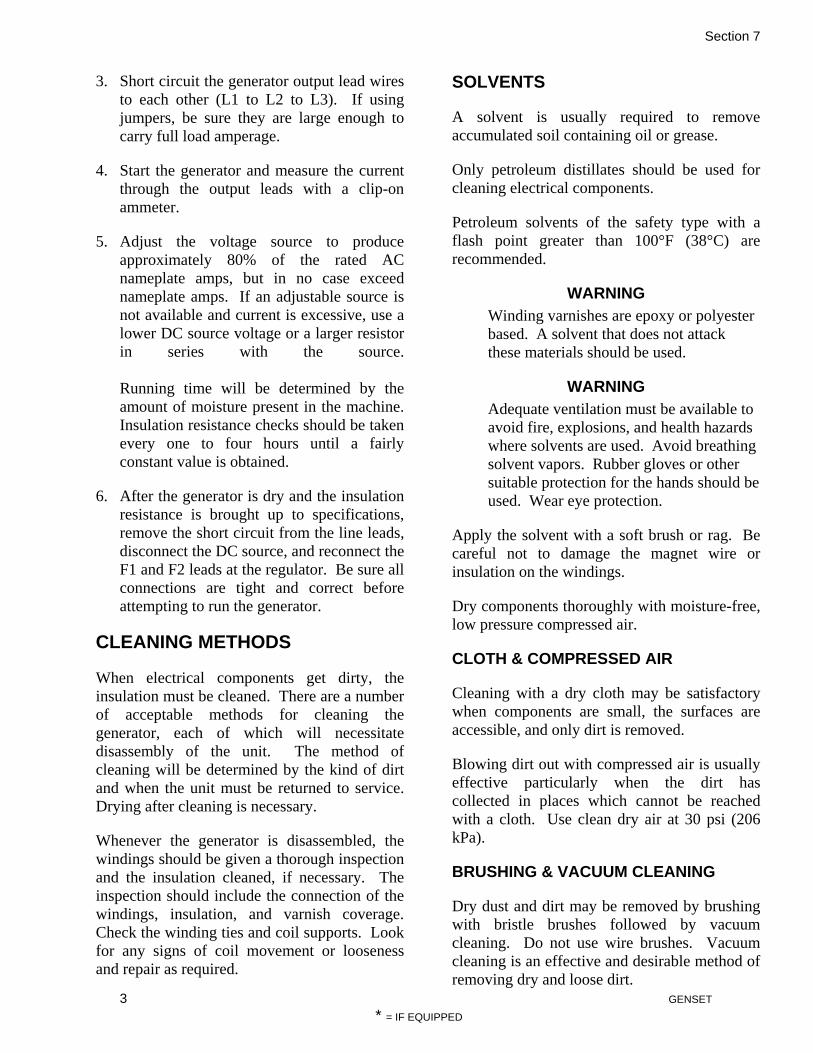
Section 7
3 GENSET
* = IF EQUIPPED
3. Short circuit the generator output lead wires to each other (L1 to L2 to L3). If using jumpers, be sure they are large enough to carry full load amperage.
4. Start the generator and measure the current through the output leads with a clip-on ammeter.
5. Adjust the voltage source to produce approximately 80% of the rated AC nameplate amps, but in no case exceed nameplate amps. If an adjustable source is not available and current is excessive, use a lower DC source voltage or a larger resistor in series with the source. Running time will be determined by the amount of moisture present in the machine. Insulation resistance checks should be taken every one to four hours until a fairly constant value is obtained.
6. After the generator is dry and the insulation resistance is brought up to specifications, remove the short circuit from the line leads, disconnect the DC source, and reconnect the F1 and F2 leads at the regulator. Be sure all connections are tight and correct before attempting to run the generator.
CLEANING METHODS
When electrical components get dirty, the insulation must be cleaned. There are a number of acceptable methods for cleaning the generator, each of which will necessitate disassembly of the unit. The method of cleaning will be determined by the kind of dirt and when the unit must be returned to service. Drying after cleaning is necessary.
Whenever the generator is disassembled, the windings should be given a thorough inspection and the insulation cleaned, if necessary. The inspection should include the connection of the windings, insulation, and varnish coverage. Check the winding ties and coil supports. Look for any signs of coil movement or looseness and repair as required.
SOLVENTS
A solvent is usually required to remove accumulated soil containing oil or grease.
Only petroleum distillates should be used for cleaning electrical components.
Petroleum solvents of the safety type with a flash point greater than 100°F (38°C) are recommended.
WARNING Winding varnishes are epoxy or polyester based. A solvent that does not attack these materials should be used.
WARNING Adequate ventilation must be available to avoid fire, explosions, and health hazards where solvents are used. Avoid breathing solvent vapors. Rubber gloves or other suitable protection for the hands should be used. Wear eye protection.
Apply the solvent with a soft brush or rag. Be careful not to damage the magnet wire or insulation on the windings.
Dry components thoroughly with moisture-free, low pressure compressed air.
CLOTH & COMPRESSED AIR
Cleaning with a dry cloth may be satisfactory when components are small, the surfaces are accessible, and only dirt is removed.
Blowing dirt out with compressed air is usually effective particularly when the dirt has collected in places which cannot be reached with a cloth. Use clean dry air at 30 psi (206 kPa).
BRUSHING & VACUUM CLEANING
Dry dust and dirt may be removed by brushing with bristle brushes followed by vacuum cleaning. Do not use wire brushes. Vacuum cleaning is an effective and desirable method of removing dry and loose dirt.

Section 7
4 GENSET
* = IF EQUIPPED
SHELL BLASTING
Air blasting with ground nut shells may be satisfactory for removal of hard dirt deposits from insulation. Use mild abrasives such as 12-20 mesh ground walnut shells.
STEAM CLEANING
If the generator is completely disassembled, including bearings and electronic components, steam cleaning of the major parts and windings is very effective. However, before the generator can be put back into service, the machine must be thoroughly dried in an oven to remove all moisture.
AIR CLEANERS
The genset is equipped with two, canister style air cleaners. During periodic locomotive maintenance, inspect the air cleaner housing and filter element. Replace any dirty or defective filters.
AIRSEP CRANKCASE BREATHER
Fig. 7-5 – Airsep Crankcase Breather
The Airsep System only requires that the filter to be changed after every 750 hours of use.
HC025S19 RADIATOR
MAINTENANCE
The radiator is nearly maintenance free. Minor
maintenance items should be performed to ensure the radiator operates at top performance and to avoid hazards.
CLEANING
Periodically inspect the radiator core for signs of damage, corrosion, and clogging. Straighten any fins that have become bent or have been flattened. If the radiator core appears to be clogged with debris, it should be cleaned using water and mild detergent that does not react with copper or aluminum. Clean the cores from the AIR DISCHARGE side of the radiator to avoid pushing the debris further into the core. Clean the outside of the radiator, if dirty, to aid in routine inspection of the cooling system. Take care to keep all sight glasses clean to ease system fluid inspection. Repair or replacement of the core should be performed by qualified service personnel. If any air filters are used upstream of the core, inspect and replace as needed. Periodically test coolant fluid samples to assure it is free of sediment, corrosive products, and/or biological contaminants. If automatic air vents are not used in the cooling system, periodic air venting should be performed to remove accumulated air. CAUTION should be exercised when venting the cooling system to avoid injury. High pressure and/or high temperature fluids can cause serious injury.
RADIATOR FAN MOTOR
The radiator fan motor is a 20 HP induction motor capable of running on 3-phase voltages and frequencies between 120VAC 30 Hz and 240VAC 60Hz.
Coolant Level Sensor
The radiator is equipped with a low coolant sensor. The sensor supplies a signal to the engine control module when the water level in the radiator is below operating levels.
Circuit Breaker Panel
The circuit breaker panel contains the genset

Section 7
5 GENSET
* = IF EQUIPPED
control system. On the bottom left side of the panel, there is a 36 pin connector that serves to connect the genset control system to the locomotive control system. The circuit breaker contains the items described in the following paragraphs.
Fig. 7-3 – CB Box Components
Fig. 7-4 – Circuit Breaker Box
24CB; 24VDC CIRCUIT BREAKER
This 24VDC 32A breaker provides a means to turn off battery power to the genset control circuits. It also provides over current protection for the genset control system.
BHR; BLOCK HEATER RELAY
This relay is controlled by the ECMP and EE relays and is energized whenever the genset is not running. The BHR receives power from the block heater circuit breaker in the MEC and supplies power to the block heater from any other genset that is running.
BUZZER PANEL
This panel is controlled by the NFORCE and provides an audible warning that the genset is in idle limiting mode of operation or signaling the starting of an engine.
ECMP; ENGINE CONTROL MODULE POWER RELAY
This relay is controlled by the NFORCE and supplies 24VDC battery voltage to the genset engine control module.
EE; ENGINE ENABLE RELAY
This relay is controlled by the NFORCE and the FPCR relay. When the ECMP and EE relays are energized, the engine control module of the genset is powered, and will control the engine’s operation.
EFC; ENGINE FAN CONTROL RELAY This relay is controlled by the engine control module. When the engine water temperature reaches a specified temperature, the engine control module energizes the EFC relay to energize the FC contactor.
FC; FAN CONTACTOR
This contactor is controlled by the EFC relay
A. Voltage Regulator On Relay B. Block Heater Relay C. 24Volt Circuit Breaker D. Engine Fan Control Relay E. Engine Enable Relay F. Engine Control Module Power Relay G. Fan Contactor Overload H. Fan Contactor I. Main Circuit Breaker

Section 7
6 GENSET
* = IF EQUIPPED
and connects genset 3-phase AC voltage to the radiator fan motor.
FCOL; FAN CONTACTOR OVERLOAD
The fan contactor overload monitors current being supplied to the radiator fan motor. It interrupts the control circuitry to the FC contactor if the fan motor is operating in an overload condition.
MCB; MAIN CIRCUIT BREAKER
This 1600A 3PH breaker, when opened, disconnects the generator from the DC rectifier and all auxiliary system loads. The breaker contains an electronic trip unit to provide over current protection for the generator and locomotive wiring. The breaker contains an electrical shunt trip coil that is controlled by the NFORCE. This coil allows the NFORCE to instantly interrupt generator output in response to overload situations.
SHT; SHUNT TRIP RELAY
This relay is operated by the NFORCE to energize the shunt trip coil and open the main circuit breaker.
VR; VOLTAGE REGULATOR
The voltage regulator is an electronic, solid-state, microprocessor based control device. It regulates the output voltage the generator by controlling the current into the generator exciter field. Input power to the voltage regulator is from the permanent magnet section of the generator.
Front panel indicators (LED’s) annunciate regulator status and system conditions. A 9-pin DB-9 style connector on the rear panel provides communication between the voltage regulator and an IBM compatible PC.
The voltage regulator is programmed to provide an output voltage of the generator dependant on the speed of the engine. For example, at 1500
RPM the generator voltage will be approximately 167VAC and at 1800 RPM the generator voltage will be 240VAC.
VRO; VOLTAGE REGULATOR ON RELAY
This relay is controlled by the NFORCE to turn on the voltage regulator of the genset, when it is determined that an output voltage is required from the genset. In fault conditions, the NFORCE turns off the VRO to stop generator excitation.
GENSET ELECTRICAL DEVICES
BTHR; BLOCK HEATER
The block heater is mounted on the genset frame on the right side of the engine. The heater is thermostatically controlled to maintain the engine water temperature to 120°F to facilitate engine starting and reduce engine emissions when the engine is first started. When the block heater is energized, coolant is circulated through the engine block and back into the heater. The heater pressurizes the coolant, without the use of a mechanical pump, to provide the circulation into and out of the engine.
DC RECT; DC RECTIFIER
A rectifier is used to convert alternating current (AC) from the generator, to direct current (DC), for the chopper modules. The DC rectifier has two separate rectifiers and a over-temperature sensor.
The AC from the generators is separated into two circuits and rectified. The Dc outputs from each side or the rectifier are then connected in series to the other rectifiers of the adjacent gensets.
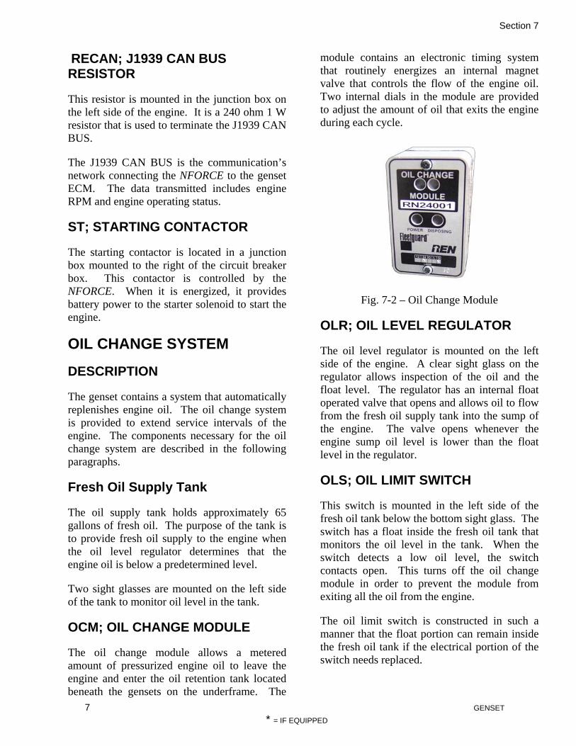
Section 7
7 GENSET
* = IF EQUIPPED
RECAN; J1939 CAN BUS RESISTOR
This resistor is mounted in the junction box on the left side of the engine. It is a 240 ohm 1 W resistor that is used to terminate the J1939 CAN BUS.
The J1939 CAN BUS is the communication’s network connecting the NFORCE to the genset ECM. The data transmitted includes engine RPM and engine operating status.
ST; STARTING CONTACTOR
The starting contactor is located in a junction box mounted to the right of the circuit breaker box. This contactor is controlled by the NFORCE. When it is energized, it provides battery power to the starter solenoid to start the engine.
OIL CHANGE SYSTEM
DESCRIPTION
The genset contains a system that automatically replenishes engine oil. The oil change system is provided to extend service intervals of the engine. The components necessary for the oil change system are described in the following paragraphs.
Fresh Oil Supply Tank
The oil supply tank holds approximately 65 gallons of fresh oil. The purpose of the tank is to provide fresh oil supply to the engine when the oil level regulator determines that the engine oil is below a predetermined level.
Two sight glasses are mounted on the left side of the tank to monitor oil level in the tank.
OCM; OIL CHANGE MODULE
The oil change module allows a metered amount of pressurized engine oil to leave the engine and enter the oil retention tank located beneath the gensets on the underframe. The
module contains an electronic timing system that routinely energizes an internal magnet valve that controls the flow of the engine oil. Two internal dials in the module are provided to adjust the amount of oil that exits the engine during each cycle.
Fig. 7-2 – Oil Change Module
OLR; OIL LEVEL REGULATOR
The oil level regulator is mounted on the left side of the engine. A clear sight glass on the regulator allows inspection of the oil and the float level. The regulator has an internal float operated valve that opens and allows oil to flow from the fresh oil supply tank into the sump of the engine. The valve opens whenever the engine sump oil level is lower than the float level in the regulator.
OLS; OIL LIMIT SWITCH
This switch is mounted in the left side of the fresh oil tank below the bottom sight glass. The switch has a float inside the fresh oil tank that monitors the oil level in the tank. When the switch detects a low oil level, the switch contacts open. This turns off the oil change module in order to prevent the module from exiting all the oil from the engine.
The oil limit switch is constructed in such a manner that the float portion can remain inside the fresh oil tank if the electrical portion of the switch needs replaced.

Section 7
8 GENSET
* = IF EQUIPPED
LUBE OIL RETENTION TANK
DESCRIPTION
Each locomotive is equipped with a 200 gallon used oil retention tank. The tank is located underneath genset 2 and is a self-contained system. Drain the used oil retention tank by means of the retention tank drain pipe assembly. First remove the plug from the end of the pipe assembly, attach the drain hose, if used, and then open the drain valve in the pipe assembly. Close the valve and replace the plug after draining the tank.
Each Genset contains a lube oil system.

Section 7
9 GENSET
* = IF EQUIPPED
Fig. 7-6 Fuel Circuit

Section 8
1 LOAD TEST
*= IF EQUIPPED
INTRODUCTION
This section contains procedures to load test and determine the horsepower of the locomotive. To properly test the operation of the locomotive electrical system, the field circuits of the traction motors are utilized during the load test procedure. Table is the horsepower schedule for the N-VIRO locomotive.
LOAD BOX
The load box shall have four grid resistors. Each resistor shall be 0.86 ohms. One or more of the grids can be tapped to operate a cooling motor to cool the load box. The total resistance of the grid and the motor must be 0.86 ohms.
CAUTION The leads connecting the grids to the locomotive shall connect the grid directly to the locomotive. Under no circumstances are there to be any electrical connections between any of the four grids.
PRELIMINARY PREPARATION FOR LOAD TEST
1. Stop the genset engines and turn off the control, local control, electronic control and chopper control circuit breakers.
2. Check that the fuel tank contains sufficient fuel (minimum 500 gallons) for the period of the load test.
3. Inspect the genset engines for proper coolant and engine oil level. Service if required before starting the testing.
4. Connect a load box that contains four 0.86 ohm resistive grids and a cooling fan for the grids. One of the four grids may be a center tapped grid to operate the cooling fan.
5. Connect one grid cable to the load test positive (LTP) bus bar on the top of the M1 contactor and the other cable of the same grid to the load test negative (LTN) bus bar on terminal 3 of the RV1 reverser. Perform the same procedure to the number 2, 3, and 4 traction motor circuits. The cable used to connect the load box grids to the locomotive
should be minimum of 1100/24 EXANE cable. See Figure
6. To provide ground relay protection, connect a cable from the load box frame to the locomotive underframe with a minimum of a 6AWG EXANE cable.
LOAD TEST PROCEDURE FOR ALL 3 GENSETS
1. Set the Hand Brake on the locomotive.
2. Turn on the control, local control, electronic control and chopper control circuit breakers.
3. Connect a laptop computer utilizing HyperTerminal software to connect to the NFORCE.
4. Select the FS6 screen.
5. Place the LOAD TEST switch on the engine control panel to the TEST position.
6. Start a genset by pressing the start switch on the control stand.
7. Place the Isolation Switch in the RUN position. The LOAD TEST light should illuminate.
8. Place reverser handle in center position.
9. Turn the generator field switch on.
10. Place the power throttle in notch 1 position. The engine will start loading.
11. Inspect the load box to ensure the cooling fan is operational.
12. On the FS6 screen, the NFORCE will display the brake horsepower being produced.
13. Advance the throttle one step at a time. The NFORCE will start the secondary and tertiary engines as the throttle is increased.
14. It is recommended that the total time in load test be limited to one hour. When the throttle is in notch 3, the primary engine is operating at rated horsepower. At notch 8, all engines are operating at rated horsepower.

Section 8
2 LOAD TEST
*= IF EQUIPPED
15. At the conclusion of the test, shut the engines down. Open the control, local control, electronic control and chopper control circuit breakers. Disconnect the load box.
LOAD TEST PROCEDURE FOR 1 GENSET
1. Set the Hand Brake on the locomotive.
2. Turn on the control, local control, electronic control and chopper control circuit breakers.
3. Connect a laptop computer utilizing HyperTerminal software to connect to the NFORCE.
4. Select the FS6 screen.
5. Place the LOAD TEST switch on the engine control panel to the TEST position.
6. Simultaneously press the engine start and the air conditioning reset switches. The NFORCE will indicate which engine can be started by a series of beeps. One beep indicates genset 1, two beeps indicates genset 2, three beeps indicates genset 3. When the desired number of beeps is heard, release the air conditioner reset switch and continue to hold the engine start switch for 3 seconds. The NFORCE will then start the indicated engine.
7. Place the Isolation Switch in the RUN position. The LOAD TEST light should illuminate.
8. Place reverser handle in center position.
9. Turn the generator field switch on.
10. Place the power throttle in notch 1 position. The engine will start loading.
11. Inspect the load box to ensure the cooling fan is operational.
12. On the FS6 screen, the NFORCE will display the brake horsepower being produced.
13. Advance the throttle one step at a time. The NFORCE will start the secondary and tertiary engines as the throttle is increased.
14. It is recommended that the total time in load test be limited to one hour. When the throttle is in notch 3, the engine is operating at rated horsepower.
NOTE If the throttle is advanced higher than notch 3, the NFORCE will start the secondary engine.
15. At the conclusion of the test, shut the engine down. Open the control, local control, electronic control and chopper control circuit breakers.
WARNING
Wait at least 20 minutes for the choppers to discharge completely before beginning to
disconnect the load box.
16. Disconnect the load box.
Table 9-1– N-VIRO Throttle Schedule
Throttle Notch
Eng 1 BHP
Eng 1 THP
Eng 1 RPM
Eng 2 BHP
Eng 2 THP
Eng 2 RPM
Eng 3 BHP
Eng 3 THP
Eng 3 RPM
Loco BHP
Loco THP
Idle 67 0 1200 67 0 1 228 145 1500 228 145 2 388 305 1500 388 305 3 685 585 1800 685 585 4 547 447 1800 390 373 1500 937 820 5 661 561 1800 485 469 1500 1146 1030 6 594 494 1800 514 494 1800 429 412 1500 1537 1400 7 667 567 1800 587 567 1800 587 567 1800 1841 1701 8 697 597 1800 686 664 2000 686 664 2000 2069 1925

Section 8
3 LOAD TEST
*= IF EQUIPPED
Figure 9-1– Load Test Grid Connection

Section 9
1 HIGH POTENTIAL TESTING
*=IF EQUIPPED
INTRODUCTION
The High Voltage System of the 3GS21B locomotive contains the three genset generators, the three genset rectifier assemblies, the four DC choppers, the four traction motors, the equipment blower motor, the air compressor and the LVPS. The best method of performing high potential testing is to test each segment of the system.
GENSET, DC CHOPPERS, TRACTION MOTORS & AUXILIARY BUS
1. Shut the genset engine(s) down.
2. Open the 64 VDC battery switch.
3. Open the 24 VDC battery switch.
4. Connect a jumper wire(s) between Genset 1 terminals INS1, INS2, INS3 and INS4. Perform the same procedure on Genset 2 and Genset 3.
5. Connect a jumper wire(s) Genset 1 MCB terminals 1, 3 and 5 to Genset insulator INS1.
6. Close the MCB on Genset 1. Perform the same procedure on Genset 2 and Genset 3.
7. Connect a jumper wire to between the top and bottom (main contacts) of P1. Perform the same procedure to P2, P3, P4, M1, M2, M3 and M4.
8. Connect a jumper(s) between the DCH1, DC+, DC+ IN and DC-IN terminals. Perform the same procedure to DCH2, DCH3 and DCH4.
9. Remove the control cable from the DCH1 chopper. Perform the same procedure to DCH2, DCH3 and DCH4.
10. Connect a jumper(s) between the LVPS L1, L2 and L3 terminals.
11. Close the Block Heater circuit breaker.
12. All traction motor reversers are to be “CUT IN”.
13. Connect a 500 VDC meggohmmeter positive lead to the AC2P relay 3C terminal; connect the meggohmmeter negative terminal to ground. A reading of one megohm or more indicates satisfactory insulation resistance.
14. Connect a 1,000 VDC meggohmmeter positive lead to the AC2P relay 3C terminal; connect the meggohmmeter negative terminal to ground. A reading of one megohm or more indicates satisfactory insulation resistance.
15. Reading less than one megohm should be investigated and the locomotive not returned to service until insulation resistance is above one megohm.
16. Remove all jumper wires applied to perform the test.
AIR COMPRESSOR MOTOR
1. Shut the genset engine(s) down.
2. Open the 64 VDC battery switch.
3. Open the 24 VDC battery switch.
4. Connect a jumper wires between CC3 contactor 1, 2, 3, 4, 5, and 6 terminals.
5. Connect a 1,000 VDC meggohmmeter positive lead to the CC3 contactor terminal 6; connect the meggohmmeter negative terminal to ground. A reading of one megohm or more indicates satisfactory insulation resistance.
6. Remove all jumper wires applied to perform the test.
EQUIPMENT BLOWER MOTOR
1. Shut the genset engine(s) down.
2. Open the 64 VDC battery switch.
3. Open the 24 VDC battery switch.
4. Connect a jumper wires between EBC contactor 2, 4, and 6 terminals.

Section 9
2 HIGH POTENTIAL TESTING
*=IF EQUIPPED
5. Connect a 1,000 VDC meggohmmeter positive lead to the EBC contactor number terminal 6; connect the meggohmmeter negative terminal to ground. A reading of one megohm or more indicates satisfactory insulation resistance.
6. Remove all jumper wires applied to perform the test.
LOW VOLTAGE POWER SUPPLY
1. Shut the genset engine(s) down.
2. Open the 64 VDC battery switch.
3. Open the 24 VDC battery switch.
4. Connect a jumper wires between LVPS L1, L2 and L3 terminals.
5. Connect a 1,000 VDC meggohmmeter positive lead to the LVPS L1 terminal; connect the meggohmmeter negative terminal to ground. A reading of one megohm or more indicates satisfactory insulation resistance.
6. Remove all jumper wires applied to perform the test.
AUXILIARY & BLOCK HEATER CIRCUITS
1. Shut the genset engine(s) down.
2. Open the 64 VDC battery switch.
3. Open the 24 VDC battery switch.
4. Turn on the block heater circuit breaker.
5. Connect a jumper wires between EBC contactor 1, 3, and 5 terminals.
6. Connect a 1,000 VDC meggohmmeter positive lead to the EBC contactor number terminal 5; connect the meggohmmeter negative terminal to ground. A reading of one megohm or more indicates satisfactory insulation resistance.
7. Remove all jumper wires applied to perform the test.
GENSET RADIATOR FAN
NOTE This procedure can be used on Genset 1, 2 or 3*.
1. Shut the genset engine(s) down.
2. Open the 64 VDC battery switch.
3. Open the 24 VDC battery switch.
4. Connect a jumper wires between FC contactor 1, 3, and 5 terminals.
5. Connect a 1,000 VDC meggohmmeter positive lead to the FC contactor number terminal 5; connect the meggohmmeter negative terminal to ground. A reading of one megohm or more indicates satisfactory insulation resistance.
6. Remove all jumper wires applied to perform the test.
GENSET BLOCK HEATER
NOTE This procedure can be used on Genset 1, 2 or 3*.
1. Shut the genset engine(s) down.
2. Open the 64 VDC battery switch.
3. Open the 24 VDC battery switch.
4. Connect a jumper wire between terminal board TB2L4 and TB2R4 terminals.
5. Connect a 1,000 VDC meggohmmeter positive lead to the TB2L4 terminal; connect the meggohmmeter negative terminal to ground. A reading of one megohm or more indicates satisfactory insulation resistance.
6. Remove all jumper wires applied to perform the test.

Section 10
1 NFORCE ALARMS & MESSAGES
*=IF EQUIPPED
GROUND RELAY TEST PROCEDURE
Follow the steps listed below to test the ground relay:
1. Shut engines down and wait for at least 20 minutes for all components to discharge all energy.
2. Once the time has passed, connect a jumper wire from the DCVP HVP terminal to a chassis ground.
3. Start the engine and look for the ground indication.
4. The ground relay should trip within 10 seconds of the EBV Contactor closing.
5. When this occurs, shut the engine down and wait for at least 20 minutes before removing the jumper wire.
TROUBLESHOOTING A GROUND RELAY FAULT
The key to troubleshooting a GR fault is determining at what point in the locomotive process the fault occurred. If the GR trips as soon as the engine is started, complete the following steps:
1. Shut down the locomotive. 2. Complete a visual inspection of the
MEC, traction motors, and traction motor leads.
3. If all looks to be in good condition, cut out the #1 traction motor. Start the engine and check to see if the GR fault reoccurs.
4. If the GR fault reappears, repeat steps 1 and 3 with the #2 traction motor while keeping #1 cut out.
5. If the GR fault persists, repeat these steps with the #3 traction motor.
6. If the GR fault persists, repeat these steps with the #4 traction motor.
If the GR trips as the A/C contactors close: 1. Shut down the locomotive.
2. Wait for at least 20 minutes for the components to discharge the remaining energy.
3. Disconnect the output leads to the equipment blower.
4. Restart engines to see if the GR fault remains.
5. Shut down the engine and wait for at least 20 minutes before reinstalling the output leads.
WHEELSLIP TEST
PROCEDURE In order to test the wheel slip function complete the following steps:
1. Shut down the engines. 2. Wait at least 20 minutes for the
components to shed stored energy. 3. Remove the Arc Shoot from the M1
contactor. 4. Insert a small piece of paper between
the main contactor tips for insulation. 5. Reapply the Arc Shoot. 6. Restart the engine. 7. Load with the reverser in FORWARD. 8. The wheel slip indicator light should
light within 45-60 seconds. 9. Shut down engines and wait at least 20
minutes again. 10. Remove the Arc Shoot and the paper
from between the contactor tips. 11. Reinstall the Arc Shoot.

Section 10
1 NFORCE ALARMS & MESSAGES
*=IF EQUIPPED
N-FORCE ALARMS & MESSAGES
INTRODUCTION Purpose The purpose of this document is to describe the requirements for the N-Viromotive N-FORCE System. Interface and Control
Requirements The N-FORCE uses various software routines for monitoring and controlling the locomotive. These software routines, alarms, and messages are described in the following pages.
Alarm Bell Control The alarm circuit alerts the operator to abnormal conditions or protective device activity. The alarm bell can be activated be either closing the Attended Call button or when the N-FORCE energizes the ABR relay. Events that will activate the alarm bell are as follows: GROUND RELAY DETECTION The alarm bell rings when the N-FORCE detects that the Ground Relay is active. The alarm bell will continue to ring until the Ground Relay is reset. AIR COMPRESSOR FAULT The alarm bell rings 2 seconds on then off repeatedly when the N-FORCE detects an Air Compressor alarm.
TM BLOWER FAILED The alarm bell rings for 5 seconds when the N-FORCE detects a TM BLOWER FAILED alarm. OPEN TRACTION MOTOR & PINION SLIP FAULTS The alarm bell rings when the N-FORCE detects either an open traction motor or pinion slip alarm. The alarm bell will continue to ring until this alarm is cleared. SERVICE ENGINE SOON This alarm sounds for 5 seconds when the N-FORCE detects a fault. GEN SET FAULT If the N-FORCE senses that an engine ECM has activated an engine fault indication, the N-FORCE will ring the alarm bell for five seconds. GEN SET START FAILURE If the N-FORCE senses that the engine ECM has activated the GEN SET “NO ST” indicator the N-FORCE will ring the alarm bell for five seconds. LVPS FAULT or LVPS OVERTEMP If the LVPS Fault indicator is on the N-FORCE will set a LVPS FAULT alarm, and ring the alarm bell for 5 seconds. DC RECTIFIER FAULT If the DC Rectifier Fault indicator is on the N-FORCE will ring the alarm bell for 5 seconds.

Section 10
2 NFORCE ALARMS & MESSAGES
*=IF EQUIPPED
EXCITATION FAULT If the N-FORCE determines that it can not control any of the Traction Motor Current Choppers it will ring the alarm bell for five seconds. 24 VOLT SUPPLY FAULT The alarm bell will ring continuously until the Isolate switch is placed in the isolate position when this alarm is active. BATTERY VOLTS FAILED If the N-FORCE monitors a BATTERY VOLTS FAILED alarm the alarm bell will ring for 5 seconds. CHOPPER # FAULT If the NFORCE detects a faulted chopper (represented here by #) the alarm bell will ring for 5 seconds (see Traction Motor Current Chopper Control).
ALARM NOT THIS LOCO If another locomotive in the consist activates the Attendant Call and Alarm MU line (2T), this alarm is set MU LINE FAILED 2T When the N-FORCE energizes ABR relay to drive a MU 2T line it checks to ensure the MU line becomes active. This alarm is set if the MU line fails to become active. DC RECTIFIER OVERTEMP If the DC Rectifier over temperature signal from the rectifier is off, the N-FORCE will set a DC RECTIFIER OVERTEMP alarm, ring the alarm bell for 5 seconds, shut down the engines, and turn on the AUX PWR Fault indicator.
CONTACTOR FAILED RV1 CONTACTOR FAILED RV2 CONTACTOR FAILED RV3 CONTACTOR FAILED RV4 If a contactor fails to pick up or drop out, a CONTACTOR FAILED RVF‘*’ alarm is set, where ‘*’ is the contactor that failed. The N-FORCE senses the auxiliary contacts on these contactors. When the N-FORCE energizes or releases the coil through the RVF relay, it checks for the correct feedback from the auxiliary contacts on the reverser contactors. If the correct feedback is not received, one of these alarms is set. MU 8T AND 9T HIGH This alarm is set if the MU lines command both Forward (8T) and Reverse (9T) at the same time. The traction motor chopper control is disabled if this occurs. Loading is prevented until only one of these lines is high. RELAY FAILED RVR If a contactor fails to pick up or drop out, a CONTACTOR FAILED RVF‘*’ alarm is set, where ‘*’ is the contactor that failed. The NFORCE senses the auxiliary contacts on these contactors. When the NFORCE energizes or releases the coil through the RVF relay, it checks for the correct feedback from the auxiliary contacts on the reverser contactors. If the correct feedback is not received, one of these alarms is set. LOW AC BUS VOLTAGE If AC bus voltage is less than 100 VAC while the engines are operating for 30 seconds, and the N-FORCE has not nullified AC excitation the N-FORCE will set this alarm. EXCESSIVE PHASE I GS # If the average phase current for any operational Genset (1,2 or 3*) exceeds 1750A for 2 seconds continuously or 1950A for 200 milliseconds the

Section 10
3 NFORCE ALARMS & MESSAGES
*=IF EQUIPPED
NFORCE will set this alarm and shut down the offending Genset. PHASE I IMBALANCE GS # If the phase currents for any operational Genset (1,2 or 3*) differ from one another by more than 250A for at least one second continuously the NFORCE will set this alarm and shut down the offending Genset. EXCESSIVE PHASE I GS1 If the average phase current of the gen set exceeds 1750A for 2 seconds continuously or 1950A for 200 milliseconds the NFORCE will set this alarm and shut down the gen set. GR RESET This alarm is set if the N-FORCE senses the GR Reset switch is closed. Activating the GR Reset reverts the fault counters back to two. GR TRIPPED When the N-FORCE senses a Ground Relay picked up a GR TRIPPED alarm is set. When this alarm is set the N-FORCE will set the traction motor current chopper control to zero, nullify AC generator excitation, idle the engines, and ring the alarm bell. NO LOADING GR CUT OUT If the N-FORCE senses the Ground Relay Cutout switch is open, this alarm is set and prevents loading. Throttle is limited to the IDLE position. NO POWER DUE TO GR If the GR fault counter reaches three with no more than one hour between ground faults, the N-FORCE will lock out the automatic ground relay reset and sets this alarm. The traction motor chopper control is disabled preventing loading. In order to regain normal operation use the GR RESET switch.
ENG UNEXPECTED SHUTDOWN This alarm is set if the engine has been shut down for a reason that the N-FORCE is unable to determine. This will occur when the GEN SET READY output drops while the FPCR and N-FORCE Start/Run outputs are high. This alarm will clear once the engine has successfully started . ENG STOP BY CONTROL STAND This alarm is set if an engine shutdown has been requested from the throttle handle on the control stand. This is detected by observing that the 3T MU line is high while the 15T, 12T, and 7T MU lines remain low for a period of at least 1 second. This alarm clears once the throttle control handle is moved back to Idle, and the FPCR has been dropped by pressing the EFCO button. TRANSDUCER FAILED CTD When the N-FORCE detects the signal from CTD is less than 4mA a TRANSDUCER FAILED CTD alarm is set. AMBIENT AIR TEMP FAIL When the N-FORCE detects the signal from the temperature sensor is less than 4mA an AMBIENT AIR TEMP FAIL alarm is set. BC PRESSURE SENSOR FAIL When the N-FORCE detects the signal from the pressure sensor is less than 4mA a MR PRESSURE SENSOR FAILED alarm is set. CONTACTOR FAILED LSC If the LSC contactor fails to pick up or drop out, a CONTACTOR FAILED LSC alarm is set. The N-FORCE senses the auxiliary contacts on these contactors. When the N-FORCE energizes or releases the coil, it checks for the

Section 10
4 NFORCE ALARMS & MESSAGES
*=IF EQUIPPED
correct feedback from the auxiliary contacts. If the correct feedback is not received, this alarm is set. NO 24 VOLTS If the digital input used to monitor the 24 volt supply from the LVPS is low, engine starting will be disabled and this alarm will be set. BATTERY VOLTAGE TOO LOW If the NFORCE monitors the battery voltage below 50 volts a BATTERY VOLTAGE TOO LOW alarm is set. Any operating Genset will be shutdown and engine starting will be inhibited. This alarm is cleared when the battery voltage is above 55 volts. BATTERY NO CHARGE If the N-FORCE monitors the battery voltage below 69 volts while the engines are running for 15 seconds a BATTERY NO CHARGE alarm is set. The N-FORCE will turn on the AUX PWR Fault indicator. This alarm is cleared when the battery voltage is above 70 volts. LVPS FAULT If the N-FORCE monitor the LVPS current load monitored by current transducer CTC above 40 amps, and/or battery voltage below 65 volts while the engines are running a LVPS FAULT alarm is set. The N-FORCE will ring the alarm bell for 5 seconds and turn on the AUX PWR Fault indicator. This alarm is cleared when the current drops below the current limit amps and/or the battery voltage is above 70 volts. TRANSDUCER FAILED CTC When the N-FORCE detects the signal from CTC is less than 4mA a TRANSDUCER FAILED CTC alarm is set.
AIR COMPRESSOR FAULT If the current monitored by CTA rises above 200 amps the N-FORCE will drop CC1/CC2/CC3, and pick up MV-CC. The N-FORCE will then try to reactivate the air compressor as described above up to two additional times. If the current is still above 200 amps on the third attempt the N-FORCE will drop the CC1/CC2/CC3 contactors, set an AIR COMPRESSOR FAULT alarm, ring the alarm bell for 2 seconds on and off, disable the traction motor choppers, and flashes the AUX PWR Fault indicator. This alarm can only be cleared by shutting down the engines. This will also be set if a compressor contactor faults (CC1, CC2, and CC3). This fault is also set during COMPRESSOR MOTOR OVERLOAD and COMPRESSOR MOTOR UNDERLOAD conditions. CONTACTOR FAILED CC1 CONTACTOR FAILED CC2 CONTACTOR FAILED CC3 If a contactor fails to pick up or drop out, a CONTACTOR FAILED CC‘*’ alarm is set, where ‘*’ is the contactor that failed to pick up or drop out. The N-FORCE senses the auxiliary contacts on these contactors. When the N-FORCE energizes or releases the coil, it checks for the correct feedback from the auxiliary contacts. If the correct feedback is not received; one of these alarms is set and can only be cleared by shutting down the engine. This alarm also sets the AIR COMPRESSOR FAULT alarm. MR PRESSURE SENSOR FAIL When the N-FORCE detects the signal from a pressure sensor is less than 4mA a MR PRESSURE SENSOR FAILED alarm is set. MU LINE FAILED 22T (CRL) When the N-FORCE energizes the CRL relay to drive the 22T MU line it checks to ensure the MU line becomes active. This alarm is set if the

Section 10
5 NFORCE ALARMS & MESSAGES
*=IF EQUIPPED
MU line status does not match the status of the CRL relay. COMPRESSOR MOTOR OVERLOAD When the NFORCE detects air compressor motor load current on CTA in excess of 65 A for 10 seconds continuously this fault is set. If the NFORCE detects CTA current in excess of 120A for 500 ms continuously this fault is set. Once this fault is set the air compressor is disabled and removed from the auxiliary bus. If excessive current persists once the compressor is disabled engines will be shutdown. Note that once this fault is latched it will not be cleared until the next manual engine start attempt.
COMPRESSOR MOTOR UNDERLOAD When the NFORCE detects air compressor motor load current on CTA less than 15 A for 10 seconds continuously this fault is set. Once this fault is set the air compressor is disabled and removed from the auxiliary bus. Note that once this fault is latched it will not be cleared until the next manual engine start attempt. TRANSDUCER FAILED CTA When CC1, CC2, and CC3 are dropped and there is no AC power supplied to the air compressor motor the N-FORCE checks for near zero current on current transducer CTA. If CTA indicates more than 10 amps or less than -5 amps, a TRANSDUCER FAILED CTA alarm is set. RELAY FAILED MTR If the MTR Relay fails to pick up or drop out, a RELAY FAILED MTR alarm is set The N-FORCE senses the auxiliary contacts on this relay. When the N-FORCE energizes or releases the coil, it checks for the correct feedback from the auxiliary contacts. If the correct feedback is not received, this alarm is set.
CONTACTOR FAILED P1 CONTACTOR FAILED P2 CONTACTOR FAILED M1 CONTACTOR FAILED M2 If a contactor fails to pick up or drop out, a CONTACTOR FAILED P‘*’ alarm is set, where ‘*’ is the contactor that failed to pick up or drop out. The N-FORCE senses the auxiliary contacts on these contactors. When the N-FORCE energizes or releases the coil, it checks for the correct feedback from the auxiliary contacts. If the correct feedback is not received, one of these alarms is set. RELAY FAILED NSR If the No Speed Relay fails to pick up or drop out, a RELAY FAILED NSR alarm is set. The N-FORCE senses the auxiliary contacts on this relay. When the N-FORCE energizes or releases the coil, it checks for the correct feedback from the auxiliary contacts. If the correct feedback is not received, this alarm is set. AMB AIR TEMP FAILED When the N-FORCE detects the temperature sensor signal is less than 4mA an AIR TEMP FAILED alarm is set. If this sensor fails the N-FORCE sets ambient air temperature to 110°F. CHOPPER 1 ACT FAILED CHOPPER 2 ACT FAILED CHOPPER 3 ACT FAILED* CHOPPER 4 ACT FAILED* When the choppers are shut down and there is no DC power supplied to the Traction Motors the N-FORCE checks for near zero current on current signals supplied by the chopper. If signal indicates more than 10 amps or less than -5 amps, a CHOPPER ‘*’ ACT FAILED alarm is set, where ‘*’ is the chopper that has failed. The Motor Fault Indicator is also turned on.

Section 10
6 NFORCE ALARMS & MESSAGES
*=IF EQUIPPED
CHOPPER 1 FAULT CHOPPER 2 FAULT CHOPPER 3 FAULT* CHOPPER 4 FAULT* If a Traction Motor Chopper turns on its’ “Fatal Fault” indicator the N-FORCE will set a CHOPPER ‘*’ FAULT, where ‘*’ is the chopper that failed. When this alarm is set the N-FORCE will ring the alarm bell for 5 seconds. The Motor Fault Indicator is also turned on. CHOPPER 1 FAILED CHOPPER 2 FAILED CHOPPER 3 FAILED* CHOPPER 4 FAILED* If a Traction Motor Chopper turns on its’ “Failed” indicator the N-FORCE will set a CHOPPER ‘*’ FAILED, where ‘*’ is the chopper that failed. While this alarm is active the N-FORCE will disable the failed chopper. When this alarm is set the N-FORCE will ring the alarm bell for 5 seconds. The Motor Fault Indicator is also turned on. CHOPPER 1 VOLTS FAILED CHOPPER 2 VOLTS FAILED CHOPPER 2 VOLTS FAILED* CHOPPER 4 VOLTS FAILED* When the choppers are shut down and there is no DC power supplied to the Traction Motors, the N-FORCE checks for near zero voltage on voltage signals supplied by the chopper. If signal indicates more than 10 volts or less than -5 volts, a CHOPPER ‘*’ VOLTS FAILED alarm is set, where ‘*’ is the chopper that failed. The Motor Fault Indicator is also turned on. CHOPPER 1 NOT RESPONDING CHOPPER 2 NOT RESPONDING CHOPPER 3 NOT RESPONDING* CHOPPER 4 NOT RESPONDING* When the N-FORCE has applied a 5% control duty cycle or greater to a chopper and the
output excitation is monitored to be less than 25 amps after 5 seconds a CHOPPER‘*’ NOT RESPONDING fault is set, where ‘*’ is the chopper that has failed. SOLENOID FAILED MCO1 SOLENOID FAILED MCO2 SOLENOID FAILED MCO3* SOLENOID FAILED MCO4* When the N-FORCE energizes a solenoid, it checks for the correct feedback from the coil sense inputs. If the correct feedback is not received a SOLENOID FAILED MCO‘*’ alarm is set, where ‘*’ is the solenoid that failed. TM 1 CUT OUT TM 2 CUT OUT TM 3 CUT OUT* TM 4 CUT OUT* The N-FORCE determines traction motor cutout status based on the status from the Cutout switches and motor cutout solenoids. If a traction motor is cutout, a TM ‘*’ CUT OUT alarm is set, where ‘*’ is the specific traction motor that is cutout. The Motor Fault Indicator is also turned on. CHOPPER DISABLED OPEN TM1 CHOPPER DISABLED OPEN TM2 CHOPPER DISABLED OPEN TM3* CHOPPER DISABLED OPEN TM4* If an open traction motor alarm occurs three times on the same traction motor within five minutes the Traction Motor Current Chopper associated with that traction motor will be disabled and a CHOPPER DISABLED OPEN TM‘*’ alarm will be set, where ‘*’ is the specific traction motor that failed. This alarm can be reset by placing the Isolate switch in the isolate position. CONTACTOR FAILED EBC If the EBC contactor fails to pick up or drop out, a CONTACTOR FAILED EBC alarm is

Section 10
7 NFORCE ALARMS & MESSAGES
*=IF EQUIPPED
set. The N-FORCE senses the auxiliary contacts on these contactors. When the N-FORCE energizes or releases the coil, it checks for the correct feedback from the auxiliary contacts. If the correct feedback is not received, one of these alarms is set. This alarm also sets TM BLOWER FAILED alarm. TM BLOWER OVERLOAD If the NFORCE monitors the TM Blower Motor loading current is operating above expected levels with respect to primary engine RPM this alarm will be set after 10 consecutive seconds. If the current exceeds 165A for 200 ms the alarm will be set before the 10 second timer expires. This alarm sets the TM BLOWER FAILED alarm. This fault is latched until the next engine start attempt is made. The following list shows the overload current levels with respect to primary engine rpm:
• 65A @ 1200 RPM • 100A @ 1500 RPM • 140A @ 1800 RPM
TM BLOWER UNDERLOAD If the NFORCE monitors the TM Blower Motor loading current is operating below expected levels with respect to primary engine RPM this alarm will be set after 10 consecutive seconds. This alarm sets the TM BLOWER FAILED alarm. This fault is latched until the next engine start attempt is made. The following list shows the underload current levels with respect to primary engine rpm:
• 15A @ 1200 RPM • 45A @ 1500 RPM • 63A @ 1800 RPM
TM BLOWER FAILED When this alarm is set the NFORCE will ring the alarm bell for 5 seconds, and turn on the AUX PWR Fault indicator light and drop the EBC contactor to disconnect the blower motor from the auxiliary bus. This alarm can be reset
by shutting down the engines. This alarm is also set when CONTACTOR FAILED EBC is set. Once this alarm is set and the EBC contactor is dropped the system checks that blower motor load current has fallen below acceptable levels. If the current has not dropped below 165A within 1 second of the EBC contactor opening all engines are shutdown. TRANSDUCER FAILED CTB When EBC is dropped and there is no AC power supplied to the Traction Motor Blower motor the N-FORCE checks for near zero current on current transducer CTB. If CTB indicates more than 10 amps or less than -5 amps, a TRANSDUCER FAILED CTB alarm is set. ENGINE SHUT DOWN BY FPCR This message is set if the N-FORCE senses that the FPCR goes low while the engines are running. ENGINE RUN SWITCH DOWN The ENG RUN switch (ER) is down. The engine will not be allowed above Idle and will not load. GEN FLD SWITCH DOWN This message is set when the N-FORCE senses that the throttle has been moved from the idle position causing some of the governor solenoids to pickup while the 6T MU remains low. LOCAL BREAKER OFF This message indicates that the Local Control Breaker is Off.

Section 10
8 NFORCE ALARMS & MESSAGES
*=IF EQUIPPED
NO CONTROL AND FUEL PUMP The N-FORCE senses that the Positive Control and Fuel Pump on the 13T string are not energized. When this occurs, the train lined control functions won’t operate and the engine won’t load. After a short delay, the engine shuts down because the fuel pump is Off. PCS The Pneumatic Control Relay (PCR) has dropped out. If it is the lead locomotive, the feed to the throttle handle switches is dropped out. This prevents the throttle MU lines (6T, 3T, 7T, 12T, 15T) from picking up, effectively preventing loading on all locomotives in the consist. This occurs after an emergency brake application. The N-FORCE only displays the status of the PCR; loading is prevented by loss of GF (through open PCR interlocks). NO LOAD GR CUT OUT If the N-FORCE senses the Ground Relay Cutout switch is open, this alarm is set and prevents loading. Throttle is limited to the Idle position. GEN SET #1 FAULT GEN SET #2 FAULT* GEN SET #3 FAULT* If the engine ECM turns on the “FAULT” output the N-FORCE will set a GEN SET‘*’ FAULT, where ‘*’ is the GEN SET that failed. While this alarm is active the N-FORCE will not allow the failed GEN SET to start. When this alarm is set, the N-FORCE will ring the alarm bell for 5 seconds. GEN SET #1 SERVICE ENGINE GEN SET #2 SERVICE ENGINE* GEN SET #3 SERVICE ENGINE* If the engine ECM turns on the “WARN” output the N-FORCE will set a GEN SET‘*’ SERV ENG, where ‘*’ is the GEN SET that requires service.
GEN SET #1 START FAILURE GEN SET #2 START FAILURE* GEN SET #3 START FAILURE* If the engine ECM turns on the “NO ST” output, the N-FORCE will set a GEN SET‘*’ START FAILURE, where ‘*’ is the GEN SET that failed to start. While this alarm is active the N-FORCE will not allow the failed GEN SET to start. When this alarm is set the N-FORCE will ring the alarm bell for 5 seconds. CONTACTOR FAILED ACC1 CONTACTOR FAILED ACC2* CONTACTOR FAILED ACC3* If a contactor fails to pick up or drop out, a CONTACTOR FAILED ACC‘*’ alarm is set, where ‘*’ is the contactor that failed to pick up or drop out. The N-FORCE senses the auxiliary contacts on these contactors. When the N-FORCE energizes or releases the coil, it checks for the correct feedback from the auxiliary contacts. If the correct feedback is not received, one of these alarms is set. MU LINE FAILED 10T When the N-FORCE energizes a relay to drive a MU line it checks to ensure the MU line becomes active. This alarm is displayed if the MU line fails to become active. The fault could be with the N-FORCE ECM, on the driver board, the wiring to the relay coil, the relay coil, the wiring from the MU line, or the Digital I/O board. WHEEL SLIP If there is an active wheel slip for more than 1 second this alarm is set. The N-FORCE picks up the WS relay, which drives the Wheel Slip Alarm MU line (10T).

Section 10
9 NFORCE ALARMS & MESSAGES
*=IF EQUIPPED
WHEEL SLIP NOT THIS LOCO Another locomotive in the consist activated the Wheel Slip Alarm MU line (10T). GEN SET #1 START FAILURE GEN SET #2 START FAILURE* GEN SET #3 START FAILURE* If the engine ECM turns on the “NO ST” output, the N-FORCE will set a GEN SET‘*’ START FAILURE, where ‘*’ is the GEN SET that failed to start. While this alarm is active the N-FORCE will not allow the failed GEN SET to start. When this alarm is set the N-FORCE will ring the alarm bell for 5 seconds. CONTACTOR FAILED ACC1 CONTACTOR FAILED ACC2* CONTACTOR FAILED ACC3* If a contactor fails to pick up or drop out, a CONTACTOR FAILED ACC‘*’ alarm is set, where ‘*’ is the contactor that failed to pick up or drop out. The N-FORCE senses the auxiliary contacts on these contactors. When the N-FORCE energizes or releases the coil, it checks for the correct feedback from the auxiliary contacts. If the correct feedback is not received, one of these alarms is set. GEN SET #1 MAINTENANCE GEN SET #2 MAINTENANCE* GEN SET #3 MAINTENANCE* If the engine ECM turns on the “MAINT” output the N-FORCE will set a GEN SET‘*’ MAINTENANCE, where ‘*’ is the GEN SET that requires maintenance. GEN SET #1 SERVICE ENGINE GEN SET #2 SERVICE ENGINE* GEN SET #3 SERVICE ENGINE* If the engine ECM turns on the “WARN” output the N-FORCE will set a GEN SET‘*’ SERV ENG, where ‘*’ is the GEN SET that requires service.
IDLE LIMITING CONTROL The N-FORCE reduces fuel consumption and exhaust emissions by monitoring locomotive operating parameters and automatically shutting down and restarting the engines during locomotive idle times. Before the N-FORCE will shut down the engines, the engines must idle for at least 15 minutes, regardless of any other system condition. After this idling period has elapsed, the following parameters must be met before the engines will be shut down: 1. Battery charging current is less than 25
amps. 2. Battery voltage is greater than 69V. 3. Ambient Air temperature is greater than
10ºF. 4. Reverser handle is centered (no direction). 5. BC Pressure above 22psi
When all of these conditions are met, the following shutdown sequence occurs: The locomotive Warning Buzzers sound for one second on, and one second off for 30 seconds, warning the operator that the engines are about to shutdown. If any of the shut down parameters becomes invalid during this 30-second period, the engine shutdown is aborted. After the engines have shut down, the Warning Buzzers sound intermittently at 30-second intervals to indicate the locomotive is in Idle Limiting mode. One of the engines will restart when any ONE of the following conditions exists: 1. Battery voltage is less than 60V. 2. Ambient Air temperature is less than 0ºF. 3. Reverser handle is in Forward or Reverse. 4. BC Pressure below 18.5psi 5. The Engine Start button has been closed. If one or more of the engine restart requirements exist, the Warning Buzzers will ring for 30 seconds (one second on/one second off), and then begin standard engine startup

Section 10
10 NFORCE ALARMS & MESSAGES
*=IF EQUIPPED
sequence. During the startup sequence the Warning Buzzers will sound continuously. Following the engine restart, loading is disabled for 60 seconds to allow the locomotive to stabilize before continuing with normal operations. The N-FORCE will also load shed the air conditioning during Idle Limiting if the locomotive remains at idle and no direction has been set for 60 minutes. If this is the case the N-FORCE will drop the LSC contactor shutting down the air conditioning. The operator can reactivate the air conditioning by pressing the AC Reset Button. DIAGNOSTIC MODE In order to enter the Diagnostic Mode, the Engine Start and the Ground Relay Pushbuttons must be held for 5 seconds. The operators Interface Panel will indicate that the Diagnostic Mode has been entered.
NOTE Upon entering the Diagnostic Mode the lift
pumps will run for 30 seconds.
On the top left side of each circuit breaker box mounted on the Gensets is a LED panel that will display any fault codes. The genset fault codes are as follows:
GENSET FAULT CODES 115 Engine speed/position circuit lost both of two signals from the magnetic pickup sensor causing the engine to be shutdown and unable to run. 122 Intake Manifold Pressure Sensor Circuit- voltage is below normal or shorted to the high source causing engine power derate to no air setting. 123 Intake Manifold Pressure Sensor Circuit- voltage is below normal or shorted to the low source causing engine power derate to no air setting. 124 Intake Manifold Pressure High- Data is valid but above the normal operational range. Moderately severe level. No action is taken by the ECM. 135 Oil Pressure Sensor Circuit- Voltage is above normal or shorted to a low source. No action is taken by the ECM. 141 Oil Pressure Sensor Circuit- Voltage is below normal or shorted to a low source. No action is taken by the ECM.

Section 10
11 NFORCE ALARMS & MESSAGES
*=IF EQUIPPED
143 Oil Pressure Low- Data valid but below the normal operational range. Moderately severe level causing the calibration dependent power derate and the engine shutdown with increasing time after alert. 144 Coolant Temperature Sensor Circuit- Voltage is above normal or shorted to a high source causing white smoke (possibly). The fan will remain on if controlled by the ECM and there will be no protection for the engine coolant temperature. 145 Coolant Temperature Sensor Circuit- Voltage is below normal or shorted to a low source causing white smoke (possibly). The fan will remain on if controlled by the ECM and there will be no protection for the engine coolant temperature. 146 Coolant Temperature High- Data valid but is above normal operational range. Moderately severe level causing progressive power derate increasing in severity from the time of the alert. 151 Coolant Temperature High- Data valid but is above normal operational range. Most severe level causing calibration dependent progressive power derate and engine shutdown with the increasing time after alert. 153 Intake Manifold Air Temperature Sensor Circuit- Voltage above normal or shorted to a high source causing white smoke (possibly). The fan will remain on if controlled by the
ECM and there will be no protection for the engine coolant temperature. 154 Intake Manifold Air Temperature Sensor Circuit- Voltage below normal or shorted to a low source causing white smoke (possibly). The fan will remain on if controlled by the ECM and there will be no protection for the engine coolant temperature. 155 Intake Manifold Air Temperature High- Data valid but above normal operational range. Most severe level causing calibration dependent progressive power derate and engine shutdown with the increasing time after alert. 187 Sensor Supply 2 Circuit- Voltage below normal or shorted to a low source causing the loss of some sensor functionality. 195 Coolant Level Sensor Circuit- Voltage above normal or shorted to a high source. No action is taken by the ECM. 196 Coolant Level Sensor Circuit- Voltage below normal or shorted to a low source. No action is taken by the ECM. 197 Coolant Level Low- Data valid but below the normal operational range. Moderately severe level. No action is taken by the ECM.

Section 10
12 NFORCE ALARMS & MESSAGES
*=IF EQUIPPED
221 Barometric Pressure Sensor Circuit- Voltage above normal or shorted to a high source causing calibration specific power derate. 222 Barometric Pressure Sensor Circuit- Voltage below normal or shorted to a low source causing calibration specific power derate. 223 Engine Oil Burn Valve Solenoid Driver Circuit- Voltage below normal or shorted to a low source causing the ECM to turn off the burn valve supply voltage and Centinel system to be disabled. 224 Engine Oil Burn Valve Solenoid Driver Circuit- Voltage above normal or shorted to a high source causing the ECM to turn off the burn valve supply voltage and Centinel system to be disabled. 227 Sensor Supply 2 Circuit- Voltage above normal or shorted to a high source causing a loss of some sensor functionality. 234 Engine Speed High- Data valid but below normal operational range. Most severe level causing the fuel injection to be disabled until the engine speed falls below the overspeed limit. 235 Coolant Level Low- Data valid but below normal operational range. Most severe level causing calibration dependent progressive
power and speed derate and engine shutdown with the increasing time after the alert. 237 External Speed Input (Multiple Unit Synchronization)- Data is erratic, intermittent, or incorrect causing the primary and secondary engines to shutdown with the increasing time after the alert if hard coupled. ONLY the secondary engine shuts down if it is soft coupled. 238 Sensor Supply 3 Circuit- Voltage is below normal or shorted to a low source causing the loss of some sensor functionality. 239 Sensor Supply 3 Circuit- Voltage is above normal or shorted to a high source causing the loss of some sensor functionality. 245 Fan Control Circuit- Voltage is below normal or shorted to a low source. No action is taken by the ECM. 261 Engine Fuel Temperature High- Data valid but above the normal operational range. Moderately severe level causing the engine speed to derate. 263 Engine Fuel Temperature Sensor Circuit- Voltage is above normal or shorted to a high source. No action is taken by the ECM.

Section 10
13 NFORCE ALARMS & MESSAGES
*=IF EQUIPPED
265 Engine Fuel Temperature Sensor Circuit- Voltage is below normal or shorted to a low source. No action is taken by the ECM. 266 Engine Fuel Temperature High- Data valid but above normal operational range. Most severe level causing the engine to shut down. 271 High Fuel Pressure Solenoid Valve Circuit- Voltage is below normal or shorted to a low source causing the engine to run poorly at idle, have less power, and have a higher fuel pressure than commanded. 272 High Fuel Pressure Solenoid Valve Circuit- Voltage is above normal or shorted to a high source causing to run poorly if at all. 285 SAE J1939 Multiplexing PGN Timeout Error- Abnormal update rate causing one or more multiplexed devices to not operate properly. One or more symptoms will occur. 286 SAE J1939 Multiplexing Configuration Error- Out of calibration causing at least one multiplexed device to not operate properly. 287 SAE J1939 Multiplexed Accelerator Pedal or Lever Position Sensor System- Received network data in error causing the engine to only idle or not accelerate to full speed.
288 SAE J1939 Multiplexing Remote Accelerator Pedal or Lever Position Sensor System- Received network data in error stopping the engine from responding to the remote throttle, although the cab or primary throttle can be utilized. 296 Auxiliary Pressure Sensor Input 1- Special instructions. OEM and calibration dependent progressive power and speed derate with engine shutdown as time progresses after alert. 319 Real Time Clock Power Interrupt- Data is erratic, intermittent, or incorrect causing the time and date to be incorrect in the ECM. 322 Injector Solenoid Cylinder 1 Circuit- The current is below normal or has an open circuit causing the engine to run rough and/or misfire. 323 Injector Solenoid Cylinder 5 Circuit- The current is below normal or has an open circuit causing the engine to run rough and/or misfire. 324 Injector Solenoid Cylinder 3 Circuit- The current is below normal or has an open circuit causing the engine to run rough and/or misfire. 325 Injector Solenoid Cylinder 6 Circuit- The current is below normal or has an open circuit causing the engine to run rough and/or misfire.

Section 10
14 NFORCE ALARMS & MESSAGES
*=IF EQUIPPED
331 Injector Solenoid Cylinder 2 Circuit- The current is below normal or has an open circuit causing the engine to run rough and/or misfire. 332 Injector Solenoid Cylinder 4 Circuit- The current is below normal or has an open circuit causing the engine to run rough and/or misfire. 343 Engine Control Module Warning Internal Hardware Failure- Bad intelligent device or component causing either severe derate or possibly no loss of performance. 351 Injector Power Supply- Bad intelligent device or component causing possible smoke, low power, engine misfire, and/or engine starting difficulties. 352 Sensor Supply 1 Circuit- Voltage below normal or shorted low source causing loss of some sensor functionality. 386 Sensor Supply 1 Circuit- Voltage above normal or shorted high source causing loss of some sensor functionality. 415 Oil Pressure Low- Data valid but below the normal operational range. Most severe level causing calibration dependent progressive power and speed derate with engine shutdown as time from the alert increases.
418 Water in Fuel Indicator- Data valid but below the normal operational range. Most severe level causing white smoke (possible). 426 SAE J1939 Datalink can not Transmit- Data is erratic, intermittent, or incorrect. No action is taken by the ECM. 431 Accelerator Pedal or Lever Idle Validation Circuit- The data is erratic, intermittent, or incorrect. No action is taken by the ECM. 432 Accelerator Pedal or Lever Idle Validation Circuit- Out of calibration causing the engine to run at idle only and not respond to the accelerator pedal. 435 Engine Oil Rifle Pressure- The data is erratic, intermittent, or incorrect causing no protection for the engine oil pressure. 441 Battery 1 Voltage Low- Data is valid but below the normal operational range. Moderately severe level causing the ECM voltage supply to approach level at which unpredictable operation will occur.

Section 10
15 NFORCE ALARMS & MESSAGES
*=IF EQUIPPED
442 Battery 1 Voltage High- Data is valid but above the normal operational range. Moderately severe level causing possible damage to all electrical components. 449 Fuel Pressure High- Data valid but above the normal operational range. Moderately severe level that can cause engine noise associated with higher injection pressures (especially at idle or light load situations). Engine power will be reduced. 451 Injector Metering Rail 1 Pressure Sensor Circuit- Voltage above normal or shorted to a high source causing a power and/or speed derate. 452 Injector Metering Rail 1 Pressure Sensor Circuit- Voltage below normal or shorted to a low source causing a power and/or speed derate. 487 Start Enable Device 1 Canister Empty (Ether Injection)- Data valid but below normal operational range. Moderately severe level causing the ether system to be disabled. 488 Intake Manifold Air Temperature High- Data is valid but above normal operational range. Moderately severe level causing a calibration specific derate. 489 Transmission Output Shaft (Tailshaft) Speed Low- Data is valid but below normal
operational range. Moderately severe level causing the ECM to change speed to a calibration dependent set point. 497 Multiple Unit Synchronization Switch Circuit- The data is erratic, intermittent, or incorrect causing the multiple unit synchronization feature to be disabled. 523 Auxiliary Intermediate (PTO) Speed Switch Validation- The data is erratic, intermittent, or incorrect causing the loss of the PTO functionality. 527 Auxiliary Input/Output 2 Circuit- Voltage is above normal or shorted to a high source. No action is taken by the ECM. 529 Auxiliary Input/Output 3 Circuit- Voltage is above normal or shorted to a high source. No action is taken by the ECM. 546 Fuel Delivery Pressure Sensor Circuit- Voltage is above normal or shorted to a high source. No action is taken by the ECM. 547 Fuel Delivery Pressure Sensor Circuit- Voltage is below normal or shorted to a low source. No action is taken by the ECM.
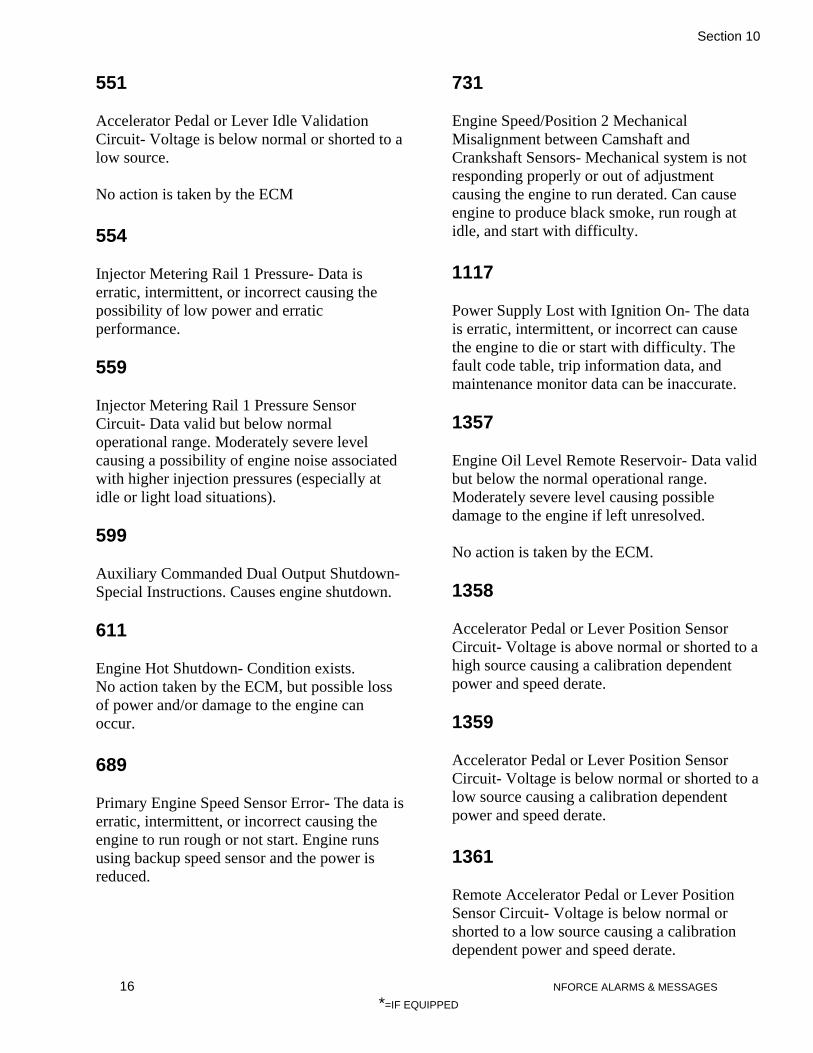
Section 10
16 NFORCE ALARMS & MESSAGES
*=IF EQUIPPED
551 Accelerator Pedal or Lever Idle Validation Circuit- Voltage is below normal or shorted to a low source. No action is taken by the ECM 554 Injector Metering Rail 1 Pressure- Data is erratic, intermittent, or incorrect causing the possibility of low power and erratic performance. 559 Injector Metering Rail 1 Pressure Sensor Circuit- Data valid but below normal operational range. Moderately severe level causing a possibility of engine noise associated with higher injection pressures (especially at idle or light load situations). 599 Auxiliary Commanded Dual Output Shutdown- Special Instructions. Causes engine shutdown. 611 Engine Hot Shutdown- Condition exists. No action taken by the ECM, but possible loss of power and/or damage to the engine can occur. 689 Primary Engine Speed Sensor Error- The data is erratic, intermittent, or incorrect causing the engine to run rough or not start. Engine runs using backup speed sensor and the power is reduced.
731 Engine Speed/Position 2 Mechanical Misalignment between Camshaft and Crankshaft Sensors- Mechanical system is not responding properly or out of adjustment causing the engine to run derated. Can cause engine to produce black smoke, run rough at idle, and start with difficulty. 1117 Power Supply Lost with Ignition On- The data is erratic, intermittent, or incorrect can cause the engine to die or start with difficulty. The fault code table, trip information data, and maintenance monitor data can be inaccurate. 1357 Engine Oil Level Remote Reservoir- Data valid but below the normal operational range. Moderately severe level causing possible damage to the engine if left unresolved. No action is taken by the ECM. 1358 Accelerator Pedal or Lever Position Sensor Circuit- Voltage is above normal or shorted to a high source causing a calibration dependent power and speed derate. 1359 Accelerator Pedal or Lever Position Sensor Circuit- Voltage is below normal or shorted to a low source causing a calibration dependent power and speed derate. 1361 Remote Accelerator Pedal or Lever Position Sensor Circuit- Voltage is below normal or shorted to a low source causing a calibration dependent power and speed derate.

Section 10
17 NFORCE ALARMS & MESSAGES
*=IF EQUIPPED
1363 Intake Manifold Pressure Low- Data is valid but below normal operational range. Moderately severe level causing an engine power derate. 1369 Auxiliary Temperature Sensor Input 1 Circuit- Voltage is above normal or shorted to a high source causing no engine protection for OEM temperature. 1371 Auxiliary Pressure Sensor Input 1 Circuit- Voltage is above normal or shorted to a high source causing no engine protection for OEM pressure. 1372 Auxiliary Pressure Sensor Input 1 Circuit- Voltage is below normal or shorted to a low source causing no engine protection for OEM pressure. 1373 Start Assist Device Control Circuit Error (Ether Injection)- Root cause NOT known. Ether injection feature is disabled with a possibility of white smoke and hard starting in colder temperatures. 1374 Turbo charger 1 Speed Sensor Circuit- Voltage is above normal or shorted to a high source. No action is taken by the ECM. 1375 Turbo charger 1 Speed Sensor Circuit- Voltage is below normal or shorted to a low source.
No action is taken by the ECM. 1376 Engine Speed Sensor (Camshaft) Error- The data is erratic, intermittent, or incorrect. No action is taken by the ECM. 1381 Auxiliary Temperature Sensor Input 1- Special instructions. It causes a calibration dependent progressive power and speed derate with engine shutdown as the time increases from the alert. 1383 Intake Manifold 1 Pressure Sensor Circuit- Voltage above normal or shorted to a high source causing an engine power derate to no air setting. 1384 Intake Manifold 1 Pressure Sensor Circuit- Voltage below normal or shorted to a low source causing an engine power derate to no air setting. 1387 Engine Shutdown Commanded by J1939- Condition exists. No action is taken by the ECM. 1514 Accelerator Pedal or Lever Position Sensor 1 Circuit Frequency- Above normal frequency, pulse width, or period. The engine operates at idle. 1516 Engine Crankshaft Speed/Position- Data is valid but above the normal operational range.

Section 10
18 NFORCE ALARMS & MESSAGES
*=IF EQUIPPED
Least severe level causing the fuel injection to be disabled until the engine speed drops below the overspeed limit. 1595 Remote Accelerator Pedal or Lever Position Sensor Circuit- Voltage above normal or shorted to a high source causing a calibration dependent power and speed derate. 1596 Auxiliary Temperature Sensor Input 1- Voltage is below normal or shorted to a low source causing no engine protection for OEM temperature. 1597 Engine Control Module Critical Internal Failure- Bad intelligent device or component resulting in the failure of the engine to start. 1845 Water in Fuel Indicator Sensor Circuit- Voltage is above normal or shorted to a high source causing no inhibition to performance. 1846 Water in Fuel Indicator Sensor Circuit- Voltage is below normal or shorted to a low source causing no inhibition to performance. 1891 Engine Oil Change Interval- Condition exists. Causes a maintenance reminder only with no inhibition on performance. 1911 Injector Metering Rail 1 Pressure- Data is valid but above the normal operational range. Most severe level causing an engine power derate.
2185 Sensor Supply 4 Circuit- Voltage is above normal or shorted to a high source causing a loss of sensor functionality. 2186 Sensor Supply 4 Circuit- Voltage is below normal or shorted to a low source causing a loss of sensor functionality. 2215 Fuel Pump Delivery Pressure- Data is valid but below normal operational range. Moderately severe level causing the engine to start with difficulty, loss of power, and possibly smoke. 2261 Fuel Pump Delivery Pressure- Data is valid but above normal operational range. Least severe level causing the engine to start with difficulty, loss of power, and possibly smoke. 2262 Fuel Pump Delivery Pressure- Data is valid but above normal operational range. Least severe level causing the engine to start with difficulty, loss of power, and possibly smoke. 2265 Fuel Priming Pump Control Signal Circuit- Voltage is above normal or shorted to a high source causing the engine to start with difficulty. 2266 Fuel Priming Pump Control Signal Circuit- Voltage is below normal or shorted to a low source causing the engine to start with difficulty.
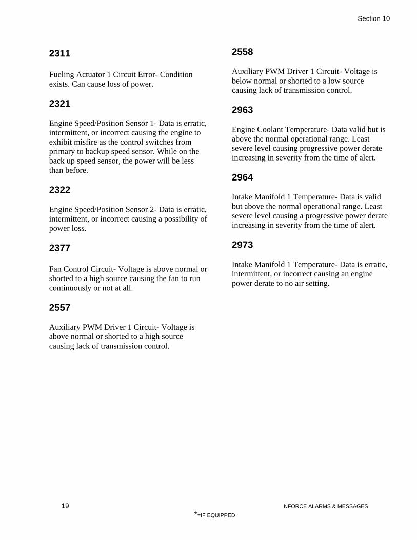
Section 10
19 NFORCE ALARMS & MESSAGES
*=IF EQUIPPED
2311 Fueling Actuator 1 Circuit Error- Condition exists. Can cause loss of power. 2321 Engine Speed/Position Sensor 1- Data is erratic, intermittent, or incorrect causing the engine to exhibit misfire as the control switches from primary to backup speed sensor. While on the back up speed sensor, the power will be less than before. 2322 Engine Speed/Position Sensor 2- Data is erratic, intermittent, or incorrect causing a possibility of power loss. 2377 Fan Control Circuit- Voltage is above normal or shorted to a high source causing the fan to run continuously or not at all. 2557 Auxiliary PWM Driver 1 Circuit- Voltage is above normal or shorted to a high source causing lack of transmission control.
2558 Auxiliary PWM Driver 1 Circuit- Voltage is below normal or shorted to a low source causing lack of transmission control. 2963 Engine Coolant Temperature- Data valid but is above the normal operational range. Least severe level causing progressive power derate increasing in severity from the time of alert. 2964 Intake Manifold 1 Temperature- Data is valid but above the normal operational range. Least severe level causing a progressive power derate increasing in severity from the time of alert. 2973 Intake Manifold 1 Temperature- Data is erratic, intermittent, or incorrect causing an engine power derate to no air setting.

Section 11
MAINT. SCHEDULE
INTRODUCTION
This document provides average recommendations which should ensure satisfactory locomotive operation and economical maintenance cost where average load factors and average climatic conditions are encountered. It is intended to serve as a guide when establishing maintenance schedules that will meet the particular requirements of the individual operations, and planned life of the locomotive.
These recommendations are based on the following conditions:
1. Lubricating oil used will meet the specifications of Maintenance Instructions 1764 and will be changed at the intervals specified in this M.I.
2. Lubricating oil filters will be of a quality equal to original equipment and will be changed at the intervals specified in this M.I.
3. Procedures listed in M.I. 1705 or 1707 will be followed for new locomotives and newly installed replacement assemblies.
4. Traction motors and truck maintenance will coincide with standard EMD MI’s such as: 3912-A, 3900, 3902, etc. for the traction motors and 1520 and 1504 for truck frames.
This Maintenance Instruction describes a program of locomotive maintenance to be performed on a “calendar period” basis or an “hourly usage” basis, whichever occurs first. The following charts illustrate these requirements by distinguishing which components are monitored on a “calendar period” or “hourly usage” basis.

Section 11
2 MAINT. SCHEDULE
*=IF EQUIPPED
Fig. 11-1 Hourly Maintenance Requirements
1190
0100
4
1190
0100
8
1690
0300
1
1190
0100
3
1190
0100
2
1640
0101
3
1640
0101
4
1190
0100
1
1690
0300
2
1190
0100
6
1710
0200
1
1710
0300
0
1400
0200
8
1620
0100
2
1710
0200
0
1620
0900
0
1710
0200
2
1170
0100
1
1710
0200
3
RES
ISTO
R, C
OR
RO
SIO
N F
ILTE
R
INH
IBIT
OR
, CO
RR
OSI
ON
WA
TER
TES
T K
IT
FILT
ER, F
UEL
FILT
ER, F
UEL
/ W
ATE
R S
EPA
RA
TOR
PRIM
AR
Y E
LEM
ENT,
AIR
INTA
KE
SAFE
TY E
LEM
ENT,
AIR
INTA
KE
FILT
ER, L
UB
RIC
ATI
NG
OIL
OIL
SA
MPL
E K
IT( R
EQU
IRED
EV
ERY
375
HR
S)
ENG
INE
OIL
CH
AN
GE
15w
40
ELEM
ENT,
BR
EATH
ER
FILT
ER K
IT, A
IR C
OM
PRES
SOR
A/C
OIL
CH
AN
GE
RO
TO H
OIL
(5 G
AL
DR
UM
S)
BR
USH
, GR
OU
ND
ING
CA
P FI
LLER
2" 1
5 PS
I
AIR
CO
MPR
ESSO
R V
ALV
ES K
ITS
CO
OLA
NT
CH
AN
GE
KIT
, CO
UPL
ING
AIR
CO
MPR
ESSO
R
INJE
CTO
RS
KIT
, GEA
RB
OX
OV
ERH
AU
L A
IR C
OM
PRES
SOR
750 HOURS
1500 HOURS
2250 HOURS
3000 HOURS
3750 HOURS
4500 HOURS
5250 HOURS
6000 HOURS 6750 HOURS 7500 HOURS
8250 HOURS
9000 HOURS
9750 HOURS
10500 HOURS
11250 HOURS
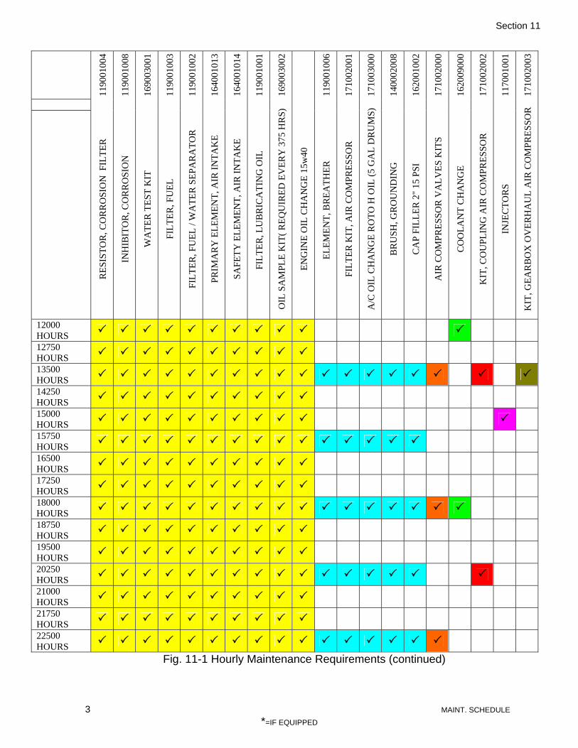
Section 11
3 MAINT. SCHEDULE
*=IF EQUIPPED
1190
0100
4
1190
0100
8
1690
0300
1
1190
0100
3
1190
0100
2
1640
0101
3
1640
0101
4
1190
0100
1
1690
0300
2
1190
0100
6
1710
0200
1
1710
0300
0
1400
0200
8
1620
0100
2
1710
0200
0
1620
0900
0
1710
0200
2
1170
0100
1
1710
0200
3
RES
ISTO
R, C
OR
RO
SIO
N F
ILTE
R
INH
IBIT
OR
, CO
RR
OSI
ON
WA
TER
TES
T K
IT
FILT
ER, F
UEL
FILT
ER, F
UEL
/ W
ATE
R S
EPA
RA
TOR
PRIM
AR
Y E
LEM
ENT,
AIR
INTA
KE
SAFE
TY E
LEM
ENT,
AIR
INTA
KE
FILT
ER, L
UB
RIC
ATI
NG
OIL
OIL
SA
MPL
E K
IT( R
EQU
IRED
EV
ERY
375
HR
S)
ENG
INE
OIL
CH
AN
GE
15w
40
ELEM
ENT,
BR
EATH
ER
FILT
ER K
IT, A
IR C
OM
PRES
SOR
A/C
OIL
CH
AN
GE
RO
TO H
OIL
(5 G
AL
DR
UM
S)
BR
USH
, GR
OU
ND
ING
CA
P FI
LLER
2" 1
5 PS
I
AIR
CO
MPR
ESSO
R V
ALV
ES K
ITS
CO
OLA
NT
CH
AN
GE
KIT
, CO
UPL
ING
AIR
CO
MPR
ESSO
R
INJE
CTO
RS
KIT
, GEA
RB
OX
OV
ERH
AU
L A
IR C
OM
PRES
SOR
12000 HOURS
12750 HOURS
13500 HOURS
14250 HOURS
15000 HOURS
15750 HOURS
16500 HOURS
17250 HOURS
18000 HOURS
18750 HOURS
19500 HOURS
20250 HOURS
21000 HOURS
21750 HOURS
22500 HOURS
Fig. 11-1 Hourly Maintenance Requirements (continued)

Section 11
4 MAINT. SCHEDULE
*=IF EQUIPPED
1190
0100
4
1190
0100
8
1690
0300
1
1190
0100
3
1190
0100
2
1640
0101
3
1640
0101
4
1190
0100
1
1690
0300
2
1190
0100
6
1710
0200
1
1710
0300
0
1400
0200
8
1620
0100
2
1710
0200
0
1620
0900
0
1710
0200
2
1170
0100
1
1710
0200
3
RES
ISTO
R, C
OR
RO
SIO
N F
ILTE
R
INH
IBIT
OR
, CO
RR
OSI
ON
WA
TER
TES
T K
IT
FILT
ER, F
UEL
FILT
ER, F
UEL
/ W
ATE
R S
EPA
RA
TOR
PRIM
AR
Y E
LEM
ENT,
AIR
INTA
KE
SAFE
TY E
LEM
ENT,
AIR
INTA
KE
FILT
ER, L
UB
RIC
ATI
NG
OIL
OIL
SA
MPL
E K
IT( R
EQU
IRED
EV
ERY
375
HR
S)
ENG
INE
OIL
CH
AN
GE
15w
40
ELEM
ENT,
BR
EATH
ER
FILT
ER K
IT, A
IR C
OM
PRES
SOR
A/C
OIL
CH
AN
GE
RO
TO H
OIL
(5 G
AL
DR
UM
S)
BR
USH
, GR
OU
ND
ING
CA
P FI
LLER
2" 1
5 PS
I
AIR
CO
MPR
ESSO
R V
ALV
ES K
ITS
CO
OLA
NT
CH
AN
GE
KIT
, CO
UPL
ING
AIR
CO
MPR
ESSO
R
INJE
CTO
RS
KIT
, GEA
RB
OX
OV
ERH
AU
L A
IR C
OM
PRES
SOR
23250 HOURS
24000 HOURS
24750 HOURS
25500 HOURS
26250 HOURS
27000 HOURS
27750 HOURS
28500 HOURS
29250 HOURS
30000 HOURS OVERHAUL ENGINE
Fig. 11-1 Hourly Maintenance Requirements (continued)

Section 11
5 MAINT. SCHEDULE
*=IF EQUIPPED
PART NUMBER
PART FAMILY PART
EVERY 92 DAY
EVERY YEAR EVERY 5 YEARS
155002003 AIR
SYSTEM CAR BODY FILTERS
449001017 AIR SYSTEM MAIN ELECTRICAL CABINET FILTERS
172001015 AIR
BRAKE AIR BRAKE AIR FILTER ASSY. KIT
172001006 AIR
BRAKE EQUALIZING RESERVOIR CONTROL PORTION
172001007 AIR
BRAKE 16 CONTROL PORTION
172001008 AIR
BRAKE 20 CONTROL PORTION
172001009 AIR
BRAKE 13 CONTROL PORTION
172001010 AIR
BRAKE BRAKE CYLINDER CONTROL PORTION
172001011 AIR
BRAKE BRAKE PIPE CONTROL PORTION
172001017 AIR
BRAKE RELAY CONTROL PORTION Fig. 11-2 Daily & Yearly Maintenance Requirements

Section 11
6 MAINT. SCHEDULE
*=IF EQUIPPED
PART NUMBER PART FAMILY PART HOURS ON ENGINE 750 1500 2250 3000 3750
119001004 ENGINE/ WATER RESISTOR, CORROSION FILTER 119001008 ENGINE WATER INHIBITOR, CORROSION 169003001 ENGINE/ WATER WATER TEST KIT 119001003 ENGINE/ FUEL FILTER, FUEL 119001002 ENGINE/ FUEL FILTER, FUEL / WATER SEPARATOR 164001013 ENGINE/ AIR PRIMARY ELEMENT, AIR INTAKE 164001014 ENGINE/ AIR SAFETY ELEMENT, AIR INTAKE 119001001 ENGINE/ OIL FILTER, LUBRICATING OIL 169003002 ENGINE/ OIL OIL SAMPLE KIT( REQUIRED EVERY 375 HRS)
VALV PREM. BLUE ENGINE/ OIL ENGINE OIL CHANGE 15w40
119001006 ENGINE/
BREATHER ELEMENT, BREATHER
171002001 AIR COMPRESSOR FILTER KIT, AIR COMPRESSOR 171003000 AIR COMPRESSOR A/C OIL CHANGE ROTO H OIL (5 GAL DRUMS) 140002008 GENERATOR BRUSH, GROUNDING 162001002 RADIATOR CAP FILLER 2" 15 PSI 171002000 AIR COMPRESSOR AIR COMPRESSOR VALVES KITS 162009000 ENGINE/ WATER COOLANT CHANGE 171002002 AIR COMPRESSOR KIT, COUPLING AIR COMPRESSOR 117001001 ENGINE INJECTORS 171002003 AIR COMPRESSOR KIT, GEARBOX OVERHAUL AIR COMPRESSOR
Fig. 11-3 Projected Maintenance Schedule

Section 11
7 MAINT. SCHEDULE
*=IF EQUIPPED
PART NUMBER PART FAMILY PART HOURS ON ENGINE 4500 5250 6000 6750 7500
119001004 ENGINE/ WATER RESISTOR, CORROSION FILTER
119001008 ENGINE WATER INHIBITOR, CORROSION 169003001 ENGINE/ WATER WATER TEST KIT 119001003 ENGINE/ FUEL FILTER, FUEL 119001002 ENGINE/ FUEL FILTER, FUEL / WATER SEPARATOR 164001013 ENGINE/ AIR PRIMARY ELEMENT, AIR INTAKE 164001014 ENGINE/ AIR SAFETY ELEMENT, AIR INTAKE 119001001 ENGINE/ OIL FILTER, LUBRICATING OIL 169003002 ENGINE/ OIL OIL SAMPLE KIT( REQUIRED EVERY 375 HRS)
VALV PREM. BLUE ENGINE/ OIL ENGINE OIL CHANGE 15w40
119001006 ENGINE/
BREATHER ELEMENT, BREATHER
171002001 AIR COMPRESSOR FILTER KIT, AIR COMPRESSOR 171003000 AIR COMPRESSOR A/C OIL CHANGE ROTO H OIL (5 GAL DRUMS) 140002008 GENERATOR BRUSH, GROUNDING 162001002 RADIATOR CAP FILLER 2" 15 PSI 171002000 AIR COMPRESSOR AIR COMPRESSOR VALVES KITS 162009000 ENGINE/ WATER COOLANT CHANGE 171002002 AIR COMPRESSOR KIT, COUPLING AIR COMPRESSOR 117001001 ENGINE INJECTORS 171002003 AIR COMPRESSOR KIT, GEARBOX OVERHAUL AIR COMPRESSOR
Fig. 11-3 Projected Maintenance Schedule (continued)

Section 11
8 MAINT. SCHEDULE
*=IF EQUIPPED
PART NUMBER PART FAMILY PART HOURS ON ENGINE 8250 9000 9750 10500 11250 119001004 ENGINE/ WATER RESISTOR, CORROSION FILTER 119001008 ENGINE WATER INHIBITOR, CORROSION 169003001 ENGINE/ WATER WATER TEST KIT 119001003 ENGINE/ FUEL FILTER, FUEL 119001002 ENGINE/ FUEL FILTER, FUEL / WATER SEPARATOR 164001013 ENGINE/ AIR PRIMARY ELEMENT, AIR INTAKE 164001014 ENGINE/ AIR SAFETY ELEMENT, AIR INTAKE 119001001 ENGINE/ OIL FILTER, LUBRICATING OIL 169003002 ENGINE/ OIL OIL SAMPLE KIT( REQUIRED EVERY 375 HRS)
VALV PREM. BLUE ENGINE/ OIL ENGINE OIL CHANGE 15w40
119001006 ENGINE/
BREATHER ELEMENT, BREATHER
171002001 AIR COMPRESSOR FILTER KIT, AIR COMPRESSOR 171003000 AIR COMPRESSOR A/C OIL CHANGE ROTO H OIL (5 GAL DRUMS) 140002008 GENERATOR BRUSH, GROUNDING 162001002 RADIATOR CAP FILLER 2" 15 PSI 171002000 AIR COMPRESSOR AIR COMPRESSOR VALVES KITS 162009000 ENGINE/ WATER COOLANT CHANGE 171002002 AIR COMPRESSOR KIT, COUPLING AIR COMPRESSOR 117001001 ENGINE INJECTORS 171002003 AIR COMPRESSOR KIT, GEARBOX OVERHAUL AIR COMPRESSOR
Fig. 11-3 Projected Maintenance Schedule (continued)

Section 11
9 MAINT. SCHEDULE
*=IF EQUIPPED
PART NUMBER PART FAMILY PART HOURS ON ENGINE 12000 12750 13500 14250 15000 119001004 ENGINE/ WATER RESISTOR, CORROSION FILTER 119001008 ENGINE WATER INHIBITOR, CORROSION 169003001 ENGINE/ WATER WATER TEST KIT 119001003 ENGINE/ FUEL FILTER, FUEL 119001002 ENGINE/ FUEL FILTER, FUEL / WATER SEPARATOR 164001013 ENGINE/ AIR PRIMARY ELEMENT, AIR INTAKE 164001014 ENGINE/ AIR SAFETY ELEMENT, AIR INTAKE 119001001 ENGINE/ OIL FILTER, LUBRICATING OIL 169003002 ENGINE/ OIL OIL SAMPLE KIT( REQUIRED EVERY 375 HRS)
VALV PREM. BLUE ENGINE/ OIL ENGINE OIL CHANGE 15w40
119001006 ENGINE/
BREATHER ELEMENT, BREATHER
171002001 AIR COMPRESSOR FILTER KIT, AIR COMPRESSOR 171003000 AIR COMPRESSOR A/C OIL CHANGE ROTO H OIL (5 GAL DRUMS) 140002008 GENERATOR BRUSH, GROUNDING 162001002 RADIATOR CAP FILLER 2" 15 PSI 171002000 AIR COMPRESSOR AIR COMPRESSOR VALVES KITS 162009000 ENGINE/ WATER COOLANT CHANGE 171002002 AIR COMPRESSOR KIT, COUPLING AIR COMPRESSOR 117001001 ENGINE INJECTORS 171002003 AIR COMPRESSOR KIT, GEARBOX OVERHAUL AIR COMPRESSOR
Fig. 11-3 Projected Maintenance Schedule (continued)

Section 11
10 MAINT. SCHEDULE
*=IF EQUIPPED
PART NUMBER PART FAMILY PART HOURS ON ENGINE 15750 16500 17250 18000 18750 119001004 ENGINE/ WATER RESISTOR, CORROSION FILTER 119001008 ENGINE WATER INHIBITOR, CORROSION 169003001 ENGINE/ WATER WATER TEST KIT 119001003 ENGINE/ FUEL FILTER, FUEL 119001002 ENGINE/ FUEL FILTER, FUEL / WATER SEPARATOR 164001013 ENGINE/ AIR PRIMARY ELEMENT, AIR INTAKE 164001014 ENGINE/ AIR SAFETY ELEMENT, AIR INTAKE 119001001 ENGINE/ OIL FILTER, LUBRICATING OIL 169003002 ENGINE/ OIL OIL SAMPLE KIT( REQUIRED EVERY 375 HRS)
VALV PREM. BLUE ENGINE/ OIL ENGINE OIL CHANGE 15w40
119001006 ENGINE/
BREATHER ELEMENT, BREATHER
171002001 AIR COMPRESSOR FILTER KIT, AIR COMPRESSOR 171003000 AIR COMPRESSOR A/C OIL CHANGE ROTO H OIL (5 GAL DRUMS) 140002008 GENERATOR BRUSH, GROUNDING 162001002 RADIATOR CAP FILLER 2" 15 PSI 171002000 AIR COMPRESSOR AIR COMPRESSOR VALVES KITS 162009000 ENGINE/ WATER COOLANT CHANGE 171002002 AIR COMPRESSOR KIT, COUPLING AIR COMPRESSOR 117001001 ENGINE INJECTORS 171002003 AIR COMPRESSOR KIT, GEARBOX OVERHAUL AIR COMPRESSOR
Fig. 11-3 Projected Maintenance Schedule (continued)

Section 11
11 MAINT. SCHEDULE
*=IF EQUIPPED
PART NUMBER PART FAMILY PART HOURS ON ENGINE 19500 20250 21000 21750 22500 119001004 ENGINE/ WATER RESISTOR, CORROSION FILTER 119001008 ENGINE WATER INHIBITOR, CORROSION 169003001 ENGINE/ WATER WATER TEST KIT 119001003 ENGINE/ FUEL FILTER, FUEL 119001002 ENGINE/ FUEL FILTER, FUEL / WATER SEPARATOR 164001013 ENGINE/ AIR PRIMARY ELEMENT, AIR INTAKE 164001014 ENGINE/ AIR SAFETY ELEMENT, AIR INTAKE 119001001 ENGINE/ OIL FILTER, LUBRICATING OIL 169003002 ENGINE/ OIL OIL SAMPLE KIT( REQUIRED EVERY 375 HRS)
VALV PREM. BLUE ENGINE/ OIL ENGINE OIL CHANGE 15w40
119001006 ENGINE/
BREATHER ELEMENT, BREATHER
171002001 AIR COMPRESSOR FILTER KIT, AIR COMPRESSOR 171003000 AIR COMPRESSOR A/C OIL CHANGE ROTO H OIL (5 GAL DRUMS) 140002008 GENERATOR BRUSH, GROUNDING 162001002 RADIATOR CAP FILLER 2" 15 PSI 171002000 AIR COMPRESSOR AIR COMPRESSOR VALVES KITS 162009000 ENGINE/ WATER COOLANT CHANGE 171002002 AIR COMPRESSOR KIT, COUPLING AIR COMPRESSOR 117001001 ENGINE INJECTORS 171002003 AIR COMPRESSOR KIT, GEARBOX OVERHAUL AIR COMPRESSOR
Fig. 11-3 Projected Maintenance Schedule (continued)

Section 11
12 MAINT. SCHEDULE
*=IF EQUIPPED
PART NUMBER PART FAMILY PART HOURS ON ENGINE 23250 24000 24750 25500 26250 119001004 ENGINE/ WATER RESISTOR, CORROSION FILTER 119001008 ENGINE WATER INHIBITOR, CORROSION 169003001 ENGINE/ WATER WATER TEST KIT 119001003 ENGINE/ FUEL FILTER, FUEL 119001002 ENGINE/ FUEL FILTER, FUEL / WATER SEPARATOR 164001013 ENGINE/ AIR PRIMARY ELEMENT, AIR INTAKE 164001014 ENGINE/ AIR SAFETY ELEMENT, AIR INTAKE 119001001 ENGINE/ OIL FILTER, LUBRICATING OIL 169003002 ENGINE/ OIL OIL SAMPLE KIT( REQUIRED EVERY 375 HRS)
VALV PREM. BLUE ENGINE/ OIL ENGINE OIL CHANGE 15w40
119001006 ENGINE/
BREATHER ELEMENT, BREATHER
171002001 AIR COMPRESSOR FILTER KIT, AIR COMPRESSOR 171003000 AIR COMPRESSOR A/C OIL CHANGE ROTO H OIL (5 GAL DRUMS) 140002008 GENERATOR BRUSH, GROUNDING 162001002 RADIATOR CAP FILLER 2" 15 PSI 171002000 AIR COMPRESSOR AIR COMPRESSOR VALVES KITS 162009000 ENGINE/ WATER COOLANT CHANGE 171002002 AIR COMPRESSOR KIT, COUPLING AIR COMPRESSOR 117001001 ENGINE INJECTORS 171002003 AIR COMPRESSOR KIT, GEARBOX OVERHAUL AIR COMPRESSOR
Fig. 11-3 Projected Maintenance Schedule (continued)

Section 11
13 MAINT. SCHEDULE
*=IF EQUIPPED
PART NUMBER PART FAMILY PART HOURS ON ENGINE 27000 27750 28500 29250 30000
119001004 ENGINE/ WATER RESISTOR, CORROSION FILTER 119001008 ENGINE WATER INHIBITOR, CORROSION 169003001 ENGINE/ WATER WATER TEST KIT 119001003 ENGINE/ FUEL FILTER, FUEL 119001002 ENGINE/ FUEL FILTER, FUEL / WATER SEPARATOR 164001013 ENGINE/ AIR PRIMARY ELEMENT, AIR INTAKE 164001014 ENGINE/ AIR SAFETY ELEMENT, AIR INTAKE 119001001 ENGINE/ OIL FILTER, LUBRICATING OIL 169003002 ENGINE/ OIL OIL SAMPLE KIT( REQUIRED EVERY 250 HRS)
VALV PREM. BLUE ENGINE/ OIL ENGINE OIL CHANGE 15w40
119001006 ENGINE/ BREATHER ELEMENT, BREATHER 171002001 AIR COMPRESSOR FILTER KIT, AIR COMPRESSOR 171003000 AIR COMPRESSOR A/C OIL CHANGE ROTO H OIL (5 GAL DRUMS) 140002008 GENERATOR BRUSH, GROUNDING 162001002 RADIATOR CAP FILLER 2" 15 PSI 171002000 AIR COMPRESSOR AIR COMPRESSOR VALVES KITS 162009000 ENGINE/ WATER COOLANT CHANGE 171002002 AIR COMPRESSOR KIT, COUPLING AIR COMPRESSOR 117001001 ENGINE INJECTORS 171002003 AIR COMPRESSOR KIT, GEARBOX OVERHAUL AIR COMPRESSOR
OV
ERH
AU
L ENG
INE
Fig. 11-3 Projected Maintenance Schedule (continued)