SIMGAP704 The Ergonomics of locomotive design.pdf - Mine ...
216
Safety in Mines Research Advisory Committee Second Revised Draft The Ergonomics of Locomotive Design in South African Gold and Platinum Mines JR Smith - Ergotech MN Shaba – Ergotech P Marais - Ergotech PC Schutte - CSIR, Mining Technology L Mac Duff - Ergotech NC Malapane - Ergotech GS Harper – CSIR, Mining Technology J Romoshebi – CSIR, Mining Technology Research agency : Ergotech Ergonomics Consultants, a business unit of Gerotek Test Facilities (Pty) Ltd in association with the CSIR, Mining Technology Project number : SIMGAP 704 Date : March 2002
-
Upload
khangminh22 -
Category
Documents
-
view
0 -
download
0
Transcript of SIMGAP704 The Ergonomics of locomotive design.pdf - Mine ...

Safety in Mines Research Advisory Committee
Second Revised Draft
The Ergonomics of Locomotive Design inSouth African Gold and
Platinum Mines
JR Smith - ErgotechMN Shaba – ErgotechP Marais - Ergotech
PC Schutte - CSIR, Mining TechnologyL Mac Duff - Ergotech
NC Malapane - ErgotechGS Harper – CSIR, Mining Technology
J Romoshebi – CSIR, Mining Technology
Research agency : Ergotech Ergonomics Consultants,a business unit of Gerotek Test Facilities (Pty)Ltd in association with the CSIR, MiningTechnology
Project number : SIMGAP 704
Date : March 2002

2
Executive summary
This research report discusses the ergonomics of locomotive designs in South African gold andplatinum mines. The purpose of the study was to identify safety aspects of the existing fleet ofmine locomotives and rolling stock that could be improved through ergonomics interventions.
In order to obtain this objective it was, firstly, necessary to determine the types of locomotivesused at gold and platinum mines. This was followed by the objective and subjective evaluation ofthe existing fleet to determine the ergonomic aspects affecting human performance and human-machine interaction. The key ergonomics characteristics related to safety and work performancewere identified for the mine locomotive, and based on this information, an ideal design wasformulated. The practical implication of implementing the ideal design was defined, and therequired changes and modifications to improve the safety aspects of the existing fleet weredetermined. Finally, a practical strategy was devised for the improvement of the current fleet.
Aspects covered during the study included:
• analysis of the locomotive operator tasks.• identification of the ergonomics aspects and mechanical engineering characteristics of the
locomotives, which could affect the safety and task performance for the locomotiveoperators.
• evaluation of the perceptual assessments of the locomotive operator.• three-dimensional CAD assessments of the current locomotive designs to determine reach,
posture, field of view and control locations for the operator.• determining the design modifications, which would improve the overall operation of the mine
locomotives in South African gold and platinum mines• formuIation of an ergonomics intervention strategy that would address the deficiencies in the
current design (based on the anthropometric data for the South African user population, andlocal mining conditions).
The ergonomics assessment of the existing fleet of mine locomotives at gold and platinummines highlighted various deficiencies in the design of the working system (most typically at theoperator-machine interface). Poorly designed workstations make the operator’s tasks moredifficult and thus render him more error-prone. A number of safety related design deficiencieswere also identified that can be improved through ergonomics intervention.
The ergonomics interventions required to improve the safety aspects of the existing fleet shouldaddress the following aspects:
• access to the cab of the locomotives• forward visual access• seating and posture• communication and warning systems• labeling of controls and displays• equipment storage• pre-operational safety and mechanical checks, and• modification of the park brake.
The ergonomics interventions required to improve the safety aspects of the existing rolling stockshould address access, seating and space provisions of man carriages.
In terms of ergonomics, the ideal design for a locomotive is considered to be one that follows thestereotype of motor vehicles. This incorporates the use of hand and foot controls, a bodyorientation facing in the direction of travel and adequate body support in the form of a well-

3
designed seat. The ideal design also makes provision for two locomotives per train, one at eachend.
Practical considerations frequently influence the “ideal” design concepts to ensure safe as wellas cost-effective workable solutions. This can be done while still incorporating soundergonomics. A practical design for a locomotive include an enclosed cab, the use of currentrailbound stereotypes (i.e. hand control of direction and speed), and as far as the train isconcerned, a single locomotive with a guard car at the other end. The guard car replicates thecontrols and the control system of the locomotive, but is not self-propelled.
In order to reduce the safety risks involved with locomotive operations as a result of poorergonomics, the following strategy is proposed. Firstly, priority should be given to theimplementation of the proposed ergonomic interventions for the existing fleet. The second phaseshould focus on the development of locomotive cabs, incorporating the proposed ergonomics ofthe practical design, which can be retrofitted to the existing fleet. Finally, attention should begiven to the development of new locomotives according to the ideal design proposals.
It is further recommended that all interested and affected parties (manufacturers and suppliers)be involved in the practical implementation, manufacture and installation of the proposedergonomics interventions and conceptual designs. This is essential in terms of Section 21 (1) (c)of the Mine Health and Safety Act (Act 29 of 1996).

4
Acknowledgements
Invaluable contributions from the following people are acknowledged:
Mr J Annandale Impala Platinum Ltd., Shaft No. 1Mr W Birmingham Joel Gold Mining Company Ltd.Mr W Brits Anglogold Ltd., Savuka MineMr G Burger Anglogold Ltd, West Wits OperationsMr R Calvert Bateman Trident (Pty) LtdMr D Chapman Dorbyl RSD LtdMr H Collins Anglogold Ltd., Tshepong MineMr J de Beer Kloof Gold Mining Company Ltd , Kloof Division,Mr E Dreyer Anglo American Technical ServicesMr W Embert DBT MaschinenfabrikMr P Frank Eastern Platinum Ltd.Mr L Fourie Harmony Gold Mining Company Ltd., Brand 5 MineMr A Greyling Anglogold Ltd., Tautona MineMr A Hunt Department of Minerals and Energy-PretoriaMr F King Battery Electric (Pty) LtdMr B Kleynhans Anglogold Ltd., Tshepong MineMr A Kolesky Placer Dome, South DeepMr H Maree Anglogold Ltd., Kopanong MineMr E Matthee Thauh Mining (Pty) Ltd.Mr D Muller Impala Platinum Ltd., Shaft No. 1Mr W Nehrling DBT South AfricaMr K Nicholl TouchtronicsMr C Pretorius Walter Becker SA (Pty) Ltd.Mr R Pretorius Joel Gold Mining Company Ltd.Mr B Robinson Anglogold Limited, Electrical Engineering SectionMr R Steele Bateman Trident (Pty) Ltd.Mr R S van der Spuy PROF (Pty) Ltd.Mr T van der Walt Angloplatinum Ltd., Rustenburg SectionMr J van Rensburg Battery Electric (Pty) Ltd.Mr N van Schalhwyk Walter Becker SA (Pty) LtdMr B K Weingerl Harmony Gold Mining Company Ltd.Mr F Wilmans Department of Minerals and Energy, PretoriaMr R Zorab Harmony Gold Mining Company Ltd., Brand 5 Mine

5
Table of Contents Page
Executive summary ...................................................................................................................2
Acknowledgements ...................................................................................................................4
List of figures...............................................................................................................................9
List of tables...............................................................................................................................14
Glossary of terms .....................................................................................................................16
1. Introduction........................................................................................................................17
2. Overview of track bound transportation ....................................................................18
2.1 Powering systems...........................................................................................................18
3. Dimensional and physical characteristics of the existing fleet of minelocomotives........................................................................................................................20
3.1 Results of the dimensional evaluation ........................................................................20
3.2 Discussion on the dimensional evaluation .................................................................22
3.2.1 Access.......................................................................................................................22
3.2.2 Seats and posture .....................................................................................................22
3.2.3 Controls and displays ................................................................................................25
3.2.4 Visual distances and angles......................................................................................25
3.3 Dimensional evaluation and physical characteristics summary...............................25
4. Task analysis of locomotive operation.......................................................................26
4.1 Description of the operator tasks.................................................................................26
4.1.1 Pre-operational procedures.......................................................................................27
4.1.2 Operational procedures.............................................................................................27
4.1.3 Post operational procedures .....................................................................................28
4.2 Evaluation of the operator tasks ..................................................................................28
4.2.1 Inspect safety in the work area..................................................................................29
4.2.2 Examine the mechanical condition of the locomotive...............................................29
4.2.3 Inspect the required equipment and tools .................................................................31
4.2.4 Inspect the locomotive lights .....................................................................................32
4.2.5 Examination of the propulsion mechanism...............................................................33
4.2.6 Entry to and exit from the cab ...................................................................................36
4.2.7 Start-up the locomotive motor or engine...................................................................37
4.2.8 Drive off and stop the locomotive..............................................................................37
4.2.9 Re-railing the locomotive...........................................................................................40
4.2.10 Parking the locomotive and preparing the locomotive for the next shift....................41

6
4.3 Task analysis summary...................................................................................................41
5. Perceptual assessment of the locomotive operators .............................................42
5.1 Perceptual assessment and results.............................................................................42
5.2 Summary of the comments from the locomotive operators......................................43
5.2.1 Access.......................................................................................................................43
5.2.2 Seats and Posture.....................................................................................................44
5.2.3 Controls and Displays ...............................................................................................44
5.2.4 Viewing angles...........................................................................................................44
5.2.5 Safety hazards ..........................................................................................................44
5.2.6 Environmental exposure............................................................................................45
5.2.7 Method of Communication ........................................................................................45
5.3 Additional Remarks.........................................................................................................45
5.4 Summary of perceptual assessment ............................................................................46
6. Summary of the design deficiencies in the existing fleet ofmine locomotives .............................................................................................................47
6.1 Access provisions...........................................................................................................47
6.2 Seating .............................................................................................................................47
6.3 Body posture and orientation .......................................................................................47
6.4 Workspace .......................................................................................................................47
6.5 Controls and displays.....................................................................................................47
6.6 Visual access...................................................................................................................47
6.7 Communication................................................................................................................48
6.8 Inspection requirements................................................................................................48
6.9 Storage provisions .........................................................................................................48
6.10 Changing and retaining the battery..........................................................................48
6.11 Re-railing and jacking.................................................................................................48
6.12 Operator protection....................................................................................................48
6.13 Rolling stock................................................................................................................48
7. Ideal design for a mine locomotive ..............................................................................49
7.1 Ergonomics requirements for ideal design.................................................................49
7.2 International locomotive design status .......................................................................49
7.3 Ergonomics guidelines for mine locomotive and rolling stock design...................50
7.4 Ideal locomotive design.................................................................................................54
7.4.1 Access and workspace.............................................................................................56
7.4.2 Seating.......................................................................................................................56
7.4.3 Controls .....................................................................................................................56
7.4.4 Displays .....................................................................................................................57
7.4.5 Body orientation and visual access...........................................................................57
7.4.6 Operational concept ..................................................................................................58
7.4.7 Warning systems ......................................................................................................59

7
7.4.8 Locomotive head and tail lights .................................................................................59
7.4.9 Guard personal protective lights................................................................................59
7.4.10 Battery retaining mechanisms and jacking points ....................................................59
7.4.11 Operator protection ...................................................................................................59
7.4.12 Layout drawings ........................................................................................................60
8. Practical design for a mine locomotive.......................................................................61
8.1 Practical influences........................................................................................................61
8.2 Practical locomotive .......................................................................................................61
8.2.1 Cab............................................................................................................................63
8.2.2 Controls and control stereotype ................................................................................64
8.2.3 Single locomotive per train ........................................................................................64
8.2.4 Layout drawings ........................................................................................................66
9. Proposed interventions on the existing fleet ............................................................67
9.1 Access ..............................................................................................................................67
9.2 Seating and posture .......................................................................................................67
9.3 Controls and displays.....................................................................................................68
9.4 Visual access...................................................................................................................68
9.5 Communication................................................................................................................68
9.6 Safety inspections ..........................................................................................................68
9.7 Equipment storage .........................................................................................................68
9.8 Other safety aspects ......................................................................................................69
9.9 Intervention proposal.....................................................................................................69
9.10 Rolling stock................................................................................................................69
10. Strategy for implementation of the recommended ergonomicsinterventions for the existing fleet................................................................................71
11. Conclusions and recommendations...........................................................................72
References .................................................................................................................................73
Appendix 1 : Distribution of locomotive.............................................................................74
Appendix 2 : Mines and manufacturers..............................................................................79
Appendix 3 : Dimensional evaluation .................................................................................81
Appendix 4 : Detailed task analysis.................................................................................. 181
Appendix 5 : Perceptual Questionnaire........................................................................... 190
Appendix 6 : International locomotive assessment..................................................... 200
Appendix 7 : Ideal design layout drawings .................................................................... 207
Appendix 8 : Practical design layout drawings............................................................. 213

8

9
List of figuresPage
Figure 2.1: Distribution of mine locomotives ................................................................................18
Figure 3.1.1: General layout of functional areas in a locomotive .................................................20
Figure 3.1.2: Primary dimensions on locomotives.......................................................................21
Figure 3.2.2.1: Wooden seat with sharp edges ...........................................................................23
Figure 3.2.2.2: T-shape backrest with horizontal adjustability .....................................................23
Figure 2.3.3.3: Worn seat base....................................................................................................24
Figure 4.1.1: General breakdown of operator’s tasks ..................................................................27
Figure 4.1.1.1: Pre-operational procedures .................................................................................26
Figure 4.1.2.1: Operational procedures .......................................................................................27
Figure 4.1.3.1: Post-operational procedures................................................................................28
Figure 4.2.2.1: Visual accessibility to chain drive components ...................................................30
Figure 4.2.3.1: Jack, chain and other equipment encrouching on foot support and space........31
Figure 4.2.3.2: Dedicated jack storage space .............................................................................32
Figure 4.2.3.3: Equipment storage bins .......................................................................................32
Figure 4.2.5.1: Battery pack lifting operation ................................................................................33
Figure 4.2.5.2: Battery pack lowering operation...........................................................................34
Figure 4.2.5.3: Isolating switch location .......................................................................................34
Figure 4.2.5.4: Battery isolation switch accessibility....................................................................35
Figure 4.2.5.5: Rope attachment on pantograph .........................................................................35
Figure 4.2.6.1: Modified locomotive with enclosed cab................................................................36
Figure 4.2.6.2: Electrical locomotive with enclosed cab..............................................................36
Figure 4.2.8.1: Directional controller opposite and brake handwheel to the right
(note the cable limiting free access to the wheel)................................................37
Figure 4.2.8.2: Control layout with master controller opposite seat.............................................38
Figure 4.2.8.3: Additional direction selection controls ..................................................................39
Figure 4.2.9.1: Standard locomotive jack.....................................................................................40
Figure 4.2.9.2: A mechanically assistive re-railing device ...........................................................41
Figure 7.4.1: Ideal design – cab side view ...................................................................................54
Figure 7.4.2: Ideal design – cab top view .....................................................................................55
Figure 7.4.3: Ideal design – cab isometric ...................................................................................55
Figure 7.4.1.1: Ideal design – operator accommodations, 95th percentile male and
5th percentile female.............................................................................................56
Figure 7.4.5.1: Forward visual angles ..........................................................................................57
Figure 7.4.5.2: Sideways visual angles ........................................................................................58
Figure 8.2.1: Practical design – cab side view.............................................................................62
Figure 8.2.2: Practical design – cab top view ..............................................................................62
Figure 8.2.3: Practical design – cab isometric.............................................................................63
Figure 8.2.3.1: Guard car – cab side view ...................................................................................65
Figure 8.2.3.2: Guard car – cab top view .....................................................................................65
Figure 8.2.3.3: Guard car – isometric view ..................................................................................66
Figure 9.9.1: Interventions proposed for the existing fleet............................................................70

10
Appendix 3
Figure 1.1: 3D CAD representation of the locomotive 1 ..............................................................81
Figure 1.2: Battery powered mine locomotive 1...........................................................................81
Figure 1.3: Viewing angle and distance for battery powered mine locomotive 1.........................82
Figure 1.4: Side viewing angle from an aerial plane.....................................................................83
Figure 2.1: 3D CAD representative of locomotive 2......................................................................85
Figure 2.2: Battery powered mine locomotive 2...........................................................................85
Figure 2.3: Viewing angle and distance for battery powered mine locomotive 2.........................86
Figure 2.4: Side viewing angle from an aerial plane.....................................................................87
Figure 3.1: 3D CAD representation of the locomotive 3 ..............................................................89
Figure 3.2: Battery powered mine locomotive 3...........................................................................89
Figure 3.3: Viewing angle and distance for battery powered mine locomotive 3.........................90
Figure 3.4: Side viewing angle from an aerial plane.....................................................................91
Figure 4.1: 3D CAD representation of the locomotive 4 ..............................................................93
Figure 4.2: Viewing angles and distance for battery powered mine locomotive 4.......................93
Figure 4.3: Viewing angles and distance for battery powered mine locomotive 4.......................94
Figure 4.4: Side view angle from an aerial plane .........................................................................95
Figure 5.1: 3D CAD representation of the locomotive 5 ..............................................................97
Figure 5.2: Battery powered mine locomotive 5...........................................................................97
Figure 5.3: Viewing angle and distance for battery powered mine locomotive 5.........................98
Figure 5.4: Side viewing angle from an aerial plane.....................................................................99
Figure 6.1: 3D CAD representation of the locomotive 6 ............................................................101
Figure 6.2: Viewing angles and distance for battery powered mine locomotive 6.....................101
Figure 6.3: Viewing angle and distance for battery powered mine locomotive 6.......................102
Figure 6.4: Side viewing angle from an aerial plane...................................................................103
Figure 7.1: 3D CAD representation of the locomotive 7 ............................................................105
Figure 7.2: Battery powered mine locomotive 7.........................................................................105
Figure 7.3: Viewing angle and distance for battery powered mine locomotive 7.......................106
Figure 7.4: Side viewing angle from an aerial plane...................................................................107
Figure 8.1: 3D CAD representation of the locomotive 8 ............................................................108
Figure 8.2: Battery powered mine locomotive 8.........................................................................108
Figure 8.3: Viewing angle and distance for battery powered mine locomotive 8.......................109
Figure 8.4: Side viewing angles from an aerial plane.................................................................110
Figure 9.1: 3D CAD representation of the locomotive 9 ............................................................112
Figure 9.2: Battery powered mine locomotive 9.........................................................................112
Figure 9.3: Viewing angle and distance for battery powered mine locomotive 9.......................113
Figure 9.4: Side view angle from an aerial plane .......................................................................114
Figure 10.1: 3D CAD representation of the locomotive 10 ........................................................116
Figure 10.2: Battery powered mine locomotive 10.....................................................................116
Figure 10.3: Visual angle and distance for battery powered mine locomotive 10......................117
Figure 10.4: Side view angle from an aerial plane .....................................................................118
Figure 11.1: 3D CAD representation of the locomotive 11 ........................................................120
Figure 11.2: Diesel powered mining locomotive 11 ...................................................................120
Figure 11.3: Visual angle and distance for diesel powered mining locomotive 11 ....................121

11
Figure 11.4: Side view angles from an aerial plane ...................................................................122
Figure 12.1: 3D CAD representation of the locomotive 12 ........................................................124
Figure 12.2: Diesel powered mining locomotive 12 ...................................................................124
Figure 12.3: Viewing angle and distance for diesel powered mining locomotive 12..................125
Figure 12.4: Side view angle from an aerial plane .....................................................................126
Figure 13.1: 3D CAD representation of the locomotive 13 ........................................................128
Figure 13.2: Diesel powered mining locomotive 13 ...................................................................128
Figure 13.3: Viewing angle and distance for diesel powered mining locomotive.......................129
Figure 13.4: Side viewing angle from an aerial plane.................................................................130
Figure 14.1: 3D CAD representation of the locomotive 14 ........................................................132
Figure 14.2: Diesel powered mining locomotive 14 ...................................................................132
Figure 14.3: Viewing angle and distance for diesel powered mining locomotive 14..................133
Figure 14.4: Side view angle from an aerial plane .....................................................................134
Figure 15.1: 3D CAD representation of the locomotive 15 ........................................................135
Figure 15.2: Electric powered mining locomotive 15 .................................................................135
Figure 15.3: Visual angles and distance for electric powered mining locomotive 15 ................136
Figure 15.4: Side viewing angle from an aerial plane.................................................................137
Figure 16.1: 3D CAD representation of the locomotive 16 ........................................................139
Figure 16.2: Electric powered mining locomotive 16 .................................................................139
Figure 16.3: Viewing angle and distance for electric powered mining locomotive 16 ...............140
Figure 16.4: Side viewing angle from an aerial plane.................................................................141
Figure 17.1: 3D CAD representation of the locomotion 17 ........................................................143
Figure 17.2: Electrical powered monorail mining locomotive 17 ...............................................143
Figure 17.3: Visual angle and distance for monorail powered mining locomotive 17...............144
Figure 17.4: Side viewing angle from an aerial plane.................................................................145
Figure 18.1: 3D CAD representation of the locomotive 18 ........................................................146
Figure 18.2: Electrical powered monorail mining locomotive 18 ...............................................146
Figure 18.3: Visual angle and distance for locomotive 18..........................................................147
Figure 18.4: Side viewing angle from an aerial plane.................................................................148
Figure 19.1: 3D CAD representation of the of the locomotive 19 ..............................................149
Figure 19.2: Modified mine locomotive 19..................................................................................149
Figure 19.3: Viewing angle and distance for modified mine locomotive 19...............................150
Figure 19.4: Side view angles from a top view...........................................................................151
Figure 20.1: 3D CAD representation of the locomotive 20 ........................................................152
Figure 20.2: Modified mine locomotive 20..................................................................................152
Figure 20.2: Visual angle and distance modified mine locomotive 20.......................................153
Figure 20.3: Side viewing angles from a top view......................................................................154
Figure 21.1: 3D CAD representation of the locomotive 21 ........................................................156
Figure 21.2: Modified mine locomotive 21..................................................................................156
Figure 21.3: Viewing angle and distance form modified mine locomotive 21............................157
Figure 21.4: Side viewing angles from a top view......................................................................158
Figure 22.1: 3D CAD representation of the locomotion 22 ........................................................159
Figure 22.2: Modified mine locomotive 22..................................................................................159
Figure 22.3: Viewing angle and distance modified mine locomotive 22 ....................................160

12
Figure 22.4: Side viewing from a top view..................................................................................161
Figure 23.1: 3D CAD representation of the locomotive 23 ........................................................163
Figure 23.2: Modified mine locomotive 23..................................................................................163
Figure 23.3: Viewing angle and distance for modified mine locomotive 23...............................164
Figure 23.4: Side viewing angle from a top view........................................................................165
Figure 24.1: 3D CAD representation of the locomotive 24 ........................................................167
Figure 24.2: Modified mine locomotive 24..................................................................................167
Figure 24.3: Forward viewing angle and distance modified mine locomotive 24 ......................168
Figure 24.4: Side viewing angles from a top view......................................................................169
Figure 25.1: 3D CAD representation of the locomotive 25 ........................................................170
Figure 25.2: Modified mine locomotive 25..................................................................................170
Figure 25.3: Visual angle and distance for modified mine locomotive 25..................................171
Figure 25.4: Side viewing angles from a top view......................................................................172
Figure 26.1: 3D CAD representation of the rolling stock............................................................174
Figure 26.2: Typical Hopper .......................................................................................................174
Figure 27.1: Man carriage rolling stock 2 ...................................................................................176
Figure 28.1: 3D CAD representation of man carriage rolling stock 3 ........................................177
Figure 28.2: Man carriage rolling stock 3 ...................................................................................177
Figure 29.1: 3D CAD representation of the man carriage rolling stock 4 ..................................179
Figure 29.2: Man carriage rolling stock 4 ...................................................................................179
Appendix 6
Figure 1.1.1: Battery locomotive (North America)......................................................................197
Figure 1.1.2: Trolley locomotive (Europe) ..................................................................................197
Figure 1.1.3: Battery locomotive (Europe) .................................................................................198
Figure 1.1.4: Battery locomotive (North America)......................................................................198
Figure 1.1.5: Trolley locomotive (North America).......................................................................198
Figure 1.1.6: Battery locomotive (Europe) .................................................................................199
Figure 1.1.7: Monorail (Europe)..................................................................................................199
Figure 1.2.1: Trolley locomotive (Europe) ..................................................................................199
Figure 1.2.2: Trolley locomotive (Europe) ..................................................................................199
Figure 1.2.3: Battery locomotive (Europe) .................................................................................200
Figure 1.2.4: Battery locomotive (North America)......................................................................200
Figure 1.2 5: Trolley locomotive (Europe) ..................................................................................200
Figure 1.3.1: Diesel locomotive (North America) .......................................................................201
Figure 1.3.2: Monorail (Europe)..................................................................................................201
Figure 1.3.3: Trolley locomotive (Europe) ..................................................................................202
Figure 1.3.4: Trolley locomotive (Europe) ..................................................................................202
Figure 1.3.5: Monorail (Europe)..................................................................................................202
Figure 1.5.1: Trolley control panel (Europe)...............................................................................203
Figure 1.5.2: Hand controller (North America) ...........................................................................203
Figure 1.6.1: Battery locomotive (Euorpe) .................................................................................204
Figure 1.6.2: Battery locomotive (North America)......................................................................204

13
Appendix 7
Figure 1: Dimensions – side view ..............................................................................................211
Figure 2: Dimensions – top view................................................................................................212
Appendix 8
Figure 1: Dimensions – side view ..............................................................................................213
Figure 2: Dimensions – top view................................................................................................214

14
List of tablesPage
Table 1.1: Main contributing factors for the accidents involving trains.........................................17
Table 3.1.1: Primary dimensions and characteristics used for dimensional evaluation .............21
Table 5.1.1: Summary of the result of perceptual assessment with the locomotive operators ..42
Table 7.3.1: Ergonomics guidelines for mine locomotive design ................................................50
Table 7.3.2: Ergonomic guidelines for rolling stock .....................................................................53
Table 10.1: Priority of ergonomics interventions on the existing fleet..........................................71
Appendix 2
Table 1.1: Assistance from mines ...............................................................................................79
Appendix 3
Table 1.1: Dimensions for battery powered mine locomotive 1...................................................82
Table 2.1: Dimensions for battery powered mine locomotive 2...................................................86
Table 3.1: Dimensions for battery powered mine locomotive 3...................................................90
Table 4.1: Dimensions for battery powered mine locomotive 4...................................................94
Table 5.1: Dimensions for battery powered mine locomotive 5...................................................98
Table 6.1: Dimensions for battery powered mine locomotive 6.................................................102
Table 7.1: Dimensions for battery powered mine locomotive 7.................................................106
Table 8.1: Dimensions for battery powered mine locomotive 8.................................................109
Table 9.1: Dimensions for battery powered mine locomotive 9.................................................113
Table 10.1: Dimensions for battery powered mine locomotive 10.............................................117
Table 11.1: Dimensions for diesel powered mining locomotives 11 .........................................121
Table 12.1: Dimensions for diesel powered mining locomotives 12 .........................................125
Table 13.1: Dimensions for diesel powered mining locomotives 13 .........................................129
Table 14.1: Dimensions for diesel powered mining locomotives 14 .........................................133
Table 15.1: Dimensions for electric powered mining locomotives 15 .......................................136
Table 16.1: Dimensions for electric powered mining locomotives 16 .......................................140
Table 17.1: Dimensions for monorail powered mining locomotives 17.....................................144
Table 18.1: Dimensions for modified powered mining locomotives 18 .....................................147
Table 19.1: Dimensions for modified mine locomotive 19.........................................................150
Table 20.1: Dimensions for modified mine locomotive 20.........................................................153
Table 21.1: Dimensions for modified mine locomotive 21.........................................................157
Table 22.1: Dimensions for modified mine locomotive 22.........................................................160
Table 23.1: Dimensions for modified mine locomotive 23.........................................................164
Table 24.1: Dimensions for modified mine locomotive 24.........................................................168
Table 25.1: Dimensions for modified mine locomotive 25.........................................................171

15
Table 26.1: Dimensions for rolling stock....................................................................................175
Table 27.1: Dimensions for man carriage rolling stock 2 ..........................................................176
Table 28.1: Dimensions for man carriage rolling stock 3 ..........................................................178
Table 29.1: Dimensions for man carriage rolling stock 4 ..........................................................180

16
Glossary of terms
Anthropometry: The branch of ergonomics that deals with the measurement andapplication of human body dimensions and human physicalcharacteristics to the design of products or systems that people use.
Control: Device that allows the operator to change the status of the system.Examples are handwheels, cranks, levers, push buttons, joysticks andlever switches.
Display: A feedback device that allows the operator to monitor the status of thesystem such as gauges and indication lights.
Front driver train: A train where the operator is on the leading end of the train and in controlof the
train.
Guard car: A railbound car coupled to a train for the purpose of accommodating aguard.
Locomotive: A railbound machine that is self-propelled, requires an operator and isused for the purpose of horizontal transport in or on a mine.
Percentile: Statistical term referred to in this report as a body dimensionmeasurement percentage in relation to a population. Percentiles arespecific to the population it describes. A 20th percentile bodymeasurement value would indicate that 20 % of the population would haveequal or smaller measurements for that body dimension.
Rolling stock: Any railbound car that is not self-propelled. Typical rolling stock includehoppers, man carriages and material cars.
Task analysis: The study of what a user is required to do, in terms of actions andcognitive processes, to achieve task objectives. Task analysis is used totest the human-machine system interface to ensure compatibilities withoperator abilities.
Train: A locomotive with rolling stock attached to and pulled or pushed by it.

17
1. Introduction
According to the South African Mines Reportable Accidents Statistics System (SAMRASS) trainscontributed to approximately 16 percent of all reportable accidents in the gold and platinummines in South Africa over the period 1 January 1998 to 31 October 2000. The main causalfactors for these accidents are given in Table 1.1.
Table 1.1: Main contributing factors for the accidents involving trains
NUMBER OF ACCIDENTSContributing factor 1998 1999 2000 TOTAL
1. Bad driving practices 234 208 154 5962. Lack of caution (signalling) 61 79 114 2543. Failure to use safety provisions 53 28 16 974. Obstruction (visibility) 42 37 - 795. Mental or physical limitation 29 28 11 686. Inadequate preventative maintenance 28 20 8 567. Inadequate examination or inspection 7 12 6 25
The information contained in Table 1.1 suggest that human factors and the current design of thelocomotives used in mines could, at least in part, have played a significant roles in the causationof these accidents.
Ergonomics can be defined as the study of human abilities and characteristics which affect thedesign of equipment, systems and jobs and its aims are to improve efficiency, safety, and wellbeing (Clark and Corlett, 1984). It is therefore, essential to consider man’s limitations andabilities when looking at the interface between people and machines in systems. ErgotechErgonomics Consultants was commissioned by the Safety in Mines Research AdvisoryCommittee (SIMRAC) to conduct research on the ergonomics of locomotive design in the goldand platinum mines in South Africa. The purpose of the study was to identify safety aspects ofthe existing fleet of mine locomotives and the rolling stock that could be improved throughergonomics intervention.
In order to achieve the above objective it was, firstly, necessary to determine the types oflocomotives used at gold and platinum mines. This was followed by the objective and subjectiveevaluation of the existing fleet to determine the ergonomic aspects affecting human performanceand the human-machine interaction. The key ergonomics characteristics related to safety andwork performance were identified for the mine locomotive, and based on this information, anideal design was formulated. The practical implication of the ideal design was defined, and thechanges and modifications to improve the safety aspects of the existing fleet were determined.Finally, a practical strategy was devised for the improvement of the existing fleet.
This report deals with the findings of the above phases of the project and is detailed in therespective sections of the report.

18
2. Overview of track bound transportation
The number of mine locomotives currently used in the underground gold and platinum mines inSouth Africa is approximately 6 750. A detailed list of the distribution of these locomotives ispresented in Appendix 1. Fifty-nine percent of these locomotives are battery powered, 34percent are diesel powered and seven percent are electricity powered. The distribution of themine locomotives according to the manufacturer and propulsion type is presented in Figure 2.1.
Figure 2.1: Distribution of mine locomotives
As shown in Figure 2.1 above, Goodman locomotives are the commonly used battery andelectrical locomotives. Funkey locomotives are the most commonly used diesel locomotives.Based on these statistics, this study aimed at addressing the safety aspects of the commonlyused locomotives.
2.1 Powering systems
Locomotives are classified according to their size, since ultimately it is the weight of thelocomotive that will constrain its maximum traction and braking effort. Two basic powersystems are available, namely diesel and electric. Electric power is derived from either anoverhead trolley line or a battery unit.
A wide range of locomotive sizes is available, from small five ton units to 18 ton locomotives,larger or smaller units can also be produced. The ultimate constraint on size is the maximumpermissible axle load, which is set according to the standard of the track. Speeds vary from 8km/h to the maximum of 16 km/h allowed by law for underground use.
The common types of locomotives currently in use are listed below.
• Diesel powered locomotives♦ Diesel hydrostatic♦ Diesel hydrokinetic

19
♦ Diesel Mechanical
• Electrical powered locomotives♦ Battery powered♦ Overhead trolley♦ Combined battery and overhead trolley
The different powering system influence the human-machine interface, primarily with regard tothe type of controls employed for operation of the locomotives. These interfaces are discussedin more detail in the following sections.

20
3. Dimensional and physical characteristics of the existing fleet of mine locomotives
The ergonomics of mine locomotive driving depends largely on the design features of theworkstation of the operator. The design features typically include aspects such as access to thecabin, protection, controls and displays, and the support provided for the human body to maintaina posture from which sensory input can be received and control actions be performed.Furthermore the required body posture, sensory input and control actions must be within theoperator’s physical and psychological capabilities.
In order to objectively determine the ergonomics factors affecting the safety of locomotives androlling stock, a dimensional evaluation was carried out on a range of locomotives and rollingstock.
The dimensional evaluation of the commonly used locomotives and rolling stock was carried outat a number of gold and platinum mines and at the manufacturer’s plant. Appendix 2 presentsthe mines that participated and also provides the manufacturer detail. The main focus of theevaluation was the functional areas inside the operators cabin. This included the position, sizeand layout of the protection structures, controls, displays, seating, storage space, access to andfrom the operator position and viewing characteristics afforded to the operator. Modificationsmade to the cab or the general layout of the controls were also noted.
3.1 Results of the dimensional evaluation
The general positioning and layout of the functional areas in the mine locomotives are illustratedin Figure 3.1.1. From the illustration it is apparent that for a locomotive with the cab at theleading end, seating is located towards the left, directional and speed controls towards the rightand the brake control centrally to the rear. Variations to this layout were observed for somediesel locomotives and monorails.
Figure 3.1.1: General layout of functional areas in a locomotive

21
Table 3.1.1 presents the primary dimensions of the areas within a locomotive that was used inthe evaluation of the suitability of the size and layout configuration for operation of the locomotive.The dimensions are also referred to in Figure 3.1.2.
Figure 3.1.2: Primary dimensions on locomotives
Table 3.1.1: Primary dimensions and characteristics used for dimensionalevaluation
A Seat height from floor
B Seat dimensions (WxD) or (∅)
Seat material
C Surface to entrance height
D Entrance to floor height
E Controller handle height
F Seat to front wall distance
G Seat to controller distance
H Seat to rear wall distance
I Seat to side wall distance
J Park brake height from floor
K Foot brake height from floor
L Hand brake height from floor
M Park brake dimensions
Canopy (Yes/No)
N Canopy to seat height
Viewing distance in front of the locomotive for the 95th percentile sitting eye
height
Viewing distance in front of the locomotive for the 5th percentile sitting eye
height
In addition to the primary dimensions, forward viewing angles from a static point and the dynamicside viewing angles were determined for the seated position and is presented for eachlocomotive. A discussion on the results for each locomotive and addressing access, controlsand displays, posture and seating and viewing angles are also included. The results of the
22
dimensional evaluation of all the locomotives are presented in Appendix 3. The threedimensional computer aided design modelling of the cab areas of the locomotives was used toaddress the ergonomics requirements for workspace, posture, reach and layout of controls anddisplays. Workspace, reach and posture requirements were based on the anthropometricdimensions of the South African population as referenced in RSA-MIL-STD-127, ErgonomicDesign: Anthropometry and Environment, 1995. The representations of the computer modelsare also presented in Appendix 3. A total number of 25 locomotives and 3 types of rolling stockwere evaluated.
3.2 Discussion on the dimensional evaluation
Analysis of the dimensional evaluation indicates that dimensional differences exist among thesize, types and makes of locomotives. It was also found that dimensional differences existbetween locomotives of the same type, size and make. This indicates that the dimensionallayouts of the locomotive cabs are not standard and could therefore influence operability.
3.2.1 Access
Entry level access to most of the locomotives was found to be more than the recommendedvalue of 380 mm from the floor surface. Entrance cut outs on the side panels to facilitate entrywas not consistently applied to the cab design. This frequently resulted in the operation to stepover the high ledge onto the cab floor, which was often cluttered with loose equipment. Only onemodified locomotive had an entrance height below the recommended value. Handholds orhandrails could facilitate entry into and exiting from the cab, but were not frequently observed.Cabs with canopies were restricted at roof level, which would induce a crouched posture onentry.
Access to and from the cab was therefore identified as a safety design aspect, which couldbenefit from ergonomics intervention.
Man carriages differed in size and access provisions. Entry level access was found to varysignificantly. Entry to some of the carriages was severely restricted by narrow doors, only355 mm wide and unacceptably high entry level. This is unsuitable for the South African adultpopulation.
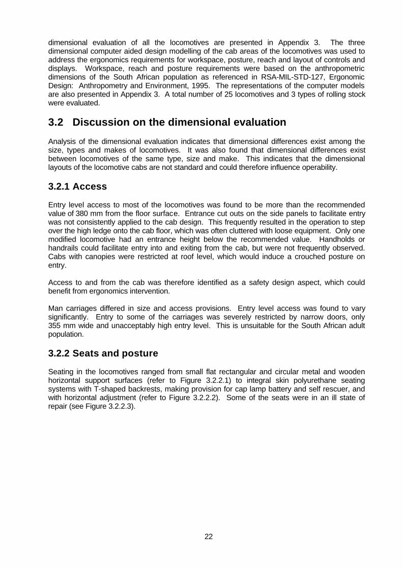
3.2.2 Seats and posture
Seating in the locomotives ranged from small flat rectangular and circular metal and woodenhorizontal support surfaces (refer to Figure 3.2.2.1) to integral skin polyurethane seatingsystems with T-shaped backrests, making provision for cap lamp battery and self rescuer, andwith horizontal adjustment (refer to Figure 3.2.2.2). Some of the seats were in an ill state ofrepair (see Figure 3.2.2.3).

23
Figure 3.2.2.1: Wooden seat with sharp edges
Figure 3.2.2.2: T-shape backrest with horizontal adjustability

24
Figure 2.3.3.3: Worn seat base
For accurate and fine control of hand and arm actions it is necessary to support the bodyeffectively. This is even more important when the platform on which the control and human bodyis located, is moving. Except for the monorail and modified locomotives, seat backrest supportwas generally absent. Backrest support is important to reduce fatigue and provide stability to thetrunk to allow the upper extremities to effectively operate the controls. Armrests wereoccasionally included in the seating design. Several of the cabs had cables and connectorsimpeding on the natural seating posture of the operator.
The seat heights for the stool type seats ranged from 430 mm to 750 mm with most of themapproximately 600 mm high. As these heights are beyond the popliteal heights (lower leg length)of the 5th and even the 95th percentile user, the seats can only be used in a semi-standing bodyposture with some weight supported by the feet. Sitting on the seat with unsupported feet is notsuitable for mobile machinery. Most of the seats were not adjustable and would therefore notaccommodate the operator population effectively.
The layout of the controls in relations to the seat position and available workspace causes orrequires the operator to use a sideways body orientation to the direction of travel. Thisorientation induces a sustained rotated neck posture towards the direction of movement. Theconcern is neck muscle fatigue and musculo-skeletal discomfort. Except for the monorail andsome of the modified locomotives, the body posture of the operators would not be reconcilablewith the task requirements.
The seating provisions in man carriages were bunk type seats of various configurations. Theposture of users was upright and awkward due to restrictive seat depths and even roof heights.The number of personnel required to fit into some of the man carriages was more than would beadvised based on the body sizes of the South African population. The restrictive sitting posturewas also negatively influenced by the cap lamp battery and self rescuer worn at waist levelwhich resulted in side sitting rotated trunk postures.

25
3.2.3 Controls and displays
The two primary controls were the master controller (usually directional and speed control) andthe hand operated park brake. As frequent interaction with these controls is required, thelocation of the controls within the reach envelope (reach distances) of the operator is important.The hand reach envelope is dependent on the position of the seat and body posture of theoperator. The sideways body orientation that is required for some locomotives induces awkwardoperation of the master controller, because of excessive reach and force exertion with anextended arm across the centre of the body. Operation of the park brake should typically be atwo handed operation while facing the brake. Once again, the brake position in relation to theseat forces one-handed operation and in some instances with an extended arm.
Labelling of controls and displays was frequently absent or illegible but was typically within visualaccess. Obscured positioning restricted physical access to the siren and the headlight controls.
3.2.4 Visual distances and angles
Visibility of the track, switches and warning signs provide important sensory input to the operator.Most of the locomotives had open cabs with mostly unrestricted view to the front and sides of thelocomotive. The sideways driving posture influenced the forward view although head and eyemovement (dynamic viewing) overcomes this. For locomotives with canopy covered cabs theforward viewing to the track was limited, and in cases, severely limited. Blind spots at thecorners of the enclosed cabs also restricted the visual angles. For one locomotive, the 5th
percentile operator in the driving posture is incapable of seeing the track. It is proposed that theobscured distance in front of the locomotive for the 5th percentile eye height not exceed 1,5 mand that dynamic side viewing angle be at least 90 degrees to each side of the movement axis.
The forward view of the seated operator is severely restricted when the locomotive is pushingthe train or with the locomotive cab at the rear. However, the natural adaptation for the operatorto improve his visual field by standing upright is against mining regulations.
3.3 Dimensional evaluation and physical characteristicssummary
The purpose of the dimensional evaluation was to assess objectively the physical characteristicsof the locomotive to identify safety aspects that can be addressed through ergonomicsintervention. Although some locomotives had or made adequate provisions the generaldimensional assessment indicated that the following aspects were inadequately addressed:
• Access provisions• Seating• Body posture• Control location and layout• Control movement in relation to posture• Forward viewing• Rearward viewing
Access height and width and seat depth were identified as aspects which should be addressedon man carriages.

26
4. Task analysis of locomotive operation
The purpose of task analysis is to assess human–machine interfaces to ensure compatibilitieswith operator abilities. This is achieved thorough systematic analysis of the user’s activities andtask behaviour. The approach involves the analysis of the activities in existing systems. Theresults of the analysis are then applied in the design or recommendations of a new system(Wilson and Corlett, 1992).
The process of task analysis can be broken down into three main phases. The first phase of theanalysis is the data collection and involves the collection and documentation of various sourcesof information about the tasks of the operators. The second phase is the description of thetasks. A task description contains task requirements and a process that analyses thebehavioural implications of the identified tasks. The final analysis phase generates simplecognitive or physical activities, also called operations.
The task analysis in this study focused on the locomotive operator tasks. It facilitated the safetyassessment process by identifying the implications of the tasks for design or modificationpurposes. This approach was particularly useful when considering the results of thedimensional evaluation discussed in section 3. The two techniques are complimentary inidentifying safety deficiencies.
The information on the tasks of the operators was obtained from the mines that were visitedduring the study. The collaborating mines are listed in Appendix 2. The major tasks of theoperators were identified through verbal interviews with training managers and operators, fromoperator training manuals and related documentation and direct observation of the operatorsperforming the tasks during training sessions as well as during the actual production processesunderground. From the task data collected, the overall task requirements of the operators wereclassified into three main procedures: pre-operational, operational and post-operationalprocedures.
The main procedural task requirements were broken down into subsidiary tasks. Each of theselower level tasks were then subdivided to give a further level of subtasks. All these tasks at eachlevel fit into the general concept of operator’s tasks. This process was continued up to a levelconsisting of simple cognitive or physical actions. The gross analysis of tasks is presented inthe following paragraphs. More detailed analysis is presented in Appendix 3.
4.1 Description of the operator tasks
A locomotive operator normally carries out a variety of activities to effectively and safely run alocomotive under the various operational conditions. The operator’s tasks include some of thetasks which do not involve direct interaction with the locomotive, such as when removing thestop blocks, opening the ventilation doors and other tramming tasks. Although these tasks areimportant safety aspects in the actual operation of the locomotive, the tasks per se have minimalinfluence on the design of the locomotive. In this study, these tasks were not analysed to greatdepth.
The emphasis of this study was on the tasks that are directly influenced by the design of thelocomotive, specifically human-machine interfaces. Figure 4.1.1 shows the general breakdownof the major tasks of the operator. It should be noted that the lower level tasks may varyaccording to the operating procedures of the mine, make of the locomotive used, and the type ofpropulsion mechanism the locomotive uses. However, the gross tasks are universallyapplicable.

27
Figure 4.1.1: General breakdown of operator’s tasks
4.1.1 Pre-operational procedures
Pre-operational procedures are tasks that are performed at the start of the shift. These tasksinclude the physical inspection of the working area, inspection of the safety provisions in thelocomotive as well as in the work room, examination of the propulsion mechanism of thelocomotive, and the examination of the mechanical condition of the locomotive such as thephysical condition of the controls and displays, the condition of equipment, and locomotive lights.Figure 4.1.1.1 provides a summary of the pre-operational procedures. The detailed task analysisis presented in Appendix 3.
TASK DESCRIPTION FOR ALOCOMOTIVE DRIVER
PRE-OPERATIONPROCEDURES
OPERATIONPROCEDURES
POST-OPERATIONPROCEDURES
INSPECTWORKING
AREA
EXAMINE THEMECHANICAL
CONDITION OF THELOCOMOTIVE
INSPECT THEEQUIPMENT
INSPECT THELIGHTS
TESTPROPULSIONMECHANISM
ENTRY ANDEXIT FROM CAB
START-UP THELOCOMOTIVE
MOTOR
DRIVE OFF ANDSTOP THE
LOCOMOTIVE
PERFORMCONTINGENCYPROCEDURES
PARK THELOCOMOTIVE
PREPARE THELOCOMOTIVE FORTHE NEXT SHIFT

26
Figure 4.1.1.1: Pre-operational procedures
PRE-OPERATIONPROCEDURES
INSPECTWORKING
AREA
EXAMINE THEMECHANICAL
CONDITIONOF THE
LOCOMOTIVE
INSPECT THEEQUIPMENT
INSPECT THELIGHTS
EXAMINEPROPULSIONMECHANISM
INSPECTCLEANLINESS OF
ENVIRONMENT
INSPECTPRESENCE OF
WARNING SIGNS
INSPECT AREAFOR HAZARDS
EXAMINELOCOMOTIVE CAB
EXAMINECONTROLS
BRAKES
PUSH BUTTONFOR SIREN
EXAMINE DRIVECHAIN
INSPECT SECURINGBOLTS AND SPRING
OF THE MOTOR
INSPECT WHEELBEARING COVER
PLATE
INSPECT PRESENCEOF PEA WHISTLE
INSPECT PRESENCEOF COW BELL
INSPECT PRESENCEOF TRIANGLE
INSPECT PRESENCEOF CHAINS
INSPECT PRESENCEOF SPRAGS
INSPECT PRESENCEOF JACK AND
HANDLE
INSPECT PRESENCEOF S-HOOK
INSPECT PRESENCEOF FIRE
EXTINGUISHER
INSPECT PRESENCEOF SAND BUCKET
INSPECT FORFUNCTION
INSPECT FORBRIGHTNESS
INSPECT FORCLEANLINESS
PERFORMBATTERYSPECIFIC
EXAMINATIONSAND ACTIONS
PERFORMELECTRICITY
SPECIFICEXAMINATIONSAND ACTIONS
PERFORMDIESEL SPECIFICEXAMINATIONSAND ACTIONS
CONTROLLER
OR
OR

27
4.1.2 Operational procedures
The operational procedures are those tasks performed by the operator during the operationalprocesses. These tasks include accessing and exiting from the cab, controlling the locomotiveand the contingency procedures aimed at keeping the locomotive in operation, such as “quick-fix” repairs and re-railing. Contingency procedures also include the stopping of the locomotivefor other operational tasks such as observing the safety rules. Figure 4.1.2.1 shows the generalbreakdown of the major tasks. The detailed task analysis is presented in Appendix 3.
Figure 4.1.2.1: Operational procedures
OPERATIONAL PROCEDURES
ENTRY ANDEXIT FROMTHE CAB
START-UP THELOCOMOTIVE
DRIVE OFFAND STOP THELOCOMOTIVE
PERFORMCONTINGENCYPROCEDURES
PERFORM PRESTART-UP
PROCEDURE
PEFORMSTART-UP
PROCEDURE
PERFORM POSTSTART-UP
PROCEDURE
PERFORMCOMMUNICATION
SIGNALING
WARNING
CONTROL THELOCOMOTIVE
MANIPULATETHE
ANCILLARYCONTROLS
OBSERVESAFETY RULES
PERFORMQUICK FIXREPAIRS
PERFORMRE-RAILING
STOP
PERFORMENTRY
PERFORMEXIT

28
4.1.3 Post operational procedures
Post-operational procedures are the tasks performed at the end of the shift. These tasks includethe parking of the locomotive at the area where it is prepared or “made-ready” for the next shift,such as parking the locomotive at the battery charge bay or re-fuelling station. It also includesthe stopping or switching off of the locomotive motor or engine. Figure 4.1.3.1 shows thegeneral breakdown of the major tasks. The detailed task analysis is presented in Appendix 3.
Figure 4.1.3.1: Post-operational procedures
4.2 Evaluation of the operator tasks
The operator tasks were evaluated in terms of the human’s ability to perform the tasks. Theseabilities include physical and psychological factors and include, physical size and reach, physicaland visual access, biomechanical considerations, sensory capabilities, physiologicalcharacteristics, cognitive ability, language and culture influences, educational level, decisionmaking abilities, skills, experience and motivation. The derivatives of these factors are theergonomics concepts of likelihood of errors, ambiguity, effective feedback, reliability of systemperformance and required precision, time and sensitivity of displays and controls. Analysis ofthese concepts for the locomotive operator tasks provided the basis for proposing possibledesign alternatives or improvements, enhancing safety while at the same time enhance ormaintain operator performance. This was done for each of the high level tasks listed below:
• Inspect safety provisions in the work area.• Examine the mechanical condition of the locomotive.• Inspect the required equipment and tools.• Inspect the locomotive lights.• Examine the propulsion mechanism.• Entry to and exit from the cab.• Start-up the locomotive motor or engine.• Drive off and stop the locomotive.
• Perform contingency procedures.• Park the locomotive and prepare the locomotive for the next shift.
POST-OPERATIONAL PROCEDURES
PARK THE LOCOMOTIVEPREPARE THE LOCOMOTIVE
FOR THE NEXT SHIFT

29
To assist operators, most mines make use of checklists to guide operators through routineexamination and inspection tasks. Some checklists would concentrate on equipment only whileothers would be more comprehensive and include locomotive component and system checks.
4.2.1 Inspect safety in the work area
The inspection of safety in the work area is conducted at the start of the shift. This task wasfound to be easy to perform for of all the operators. Potential emergencies could however arisebecause of the poor housekeeping and can be aggravated by limited workspace in theworkrooms underground.
From the interviews with the operators it was found that there are diverse interpretations of thepresented information among operators. In order to improve the effectiveness of the safetyprovisions only nationally or internationally recognised standard symbols or safety signs shouldbe used, the visibility of the safety signs should be maintained by regular cleaning, safety signsshould be displayed in the unobstructed visual field, other safety equipment should bemaintained regularly and special attention should be given to language compatibility of theoperators.
4.2.2 Examine the mechanical condition of the locomotive
Generally, it was found that the task of examining the mechanical condition of the locomotivewas difficult, especially those tasks requiring interpretation of the status of mechanicalcomponents. Restrictive visual and physical access to some of the mechanical parts of thelocomotive are the main reasons for this.
Examination of the drive chain forms part of the subtask. As only a part of the chain is visuallyaccessible when performing the inspection, the judgement on wear and tear and chain tensioncan only be based on the visually accessible part. Assistive devices or tools may however beemployed to assist the operator in judging the mechanical condition. An example is a hook typetool used to hook and lift the chain to judge chain tension according to physical deviation whenvisual access is inappropriate or not possible. Another method of facilitating inspection tasks isto mark (even with paint) all the required inspection points. However, to inspect a chain fordamaged or broken links requires more actions.
Figure 4.2.2.1 shows typical restrictions of visual access to mechanical components.

30
Figure 4.2.2.1: Visual accessibility to chain drive components
The decision making criteria for this task is also presented in a format that is unsuitable for mostof the operators because of the relative low mechanical educational, skill or training levels. Forexample, there are no definitive prescriptions to determine the acceptable degree of wear for thedrive chain or brake shoes. Without prescriptive objective methods, this task is executed basedon subjective assessment alone.
4.2.2.1 Examine brake shoe wear and tear
Potential incidences could arise from running the locomotive with defective brakes. Therefore,accurate brake shoe wear identification is critical. Currently the task of brake shoe examinationis difficult do to the restrictive visual access. Inaccurate reading of the level of shoe wear canmore easily occur when based on subjective assessment. Marking or painting the break shoeson a scale up to the wear limit is recommended to provide an objective method for the operatorto evaluate brake shoe wear. They can then objectively determine break shoe wear and identifywhen replacement is required.
4.2.2.2 Examine drive chain wear and tear, and slackness
These tasks were found to be mostly beyond the knowledge of most of the operators. Toexamine the wear of the drive chain, the operator would require mechanical knowledge andtraining. Due to the inability of most of the operators to perform these tasks effectively, it isrecommended that a mechanic do these tasks during routine weekly maintenance schedules.

31
4.2.3 Inspect the required equipment and tools
The information required by the operators to carry out this task was usually available onchecklists in pictogram format as well as text in “Fanakalo” and English. It was found thatpictogram presentation of the information was more effective than structured text. This could bedue to a lack of common names for the tools used in the text where identical tools were identifiedby different names. For example, the “T-sprag” is also called “aeroplane sprag”.
On most of the locomotives there was a lack of dedicated storage space for the equipment andtools required to be carried. As a result of the lack of the storage space, it was found that theequipment and tools were placed anywhere inside the cab. Figure 4.2.3.1 shows a typicalsituation where tools and equipment are placed on the cab floor. The safety implications as aresult of this hazard typically include stumbling and tripping and can therefore influence the safecontrol of the locomotive. The practice of carrying equipment on the floor would also affect theefficiency and productivity of the operator negatively.
Figure 4.2.3.1: Jack, chain and other equipment encrouching on foot support and space
As shown in Figure 4.2.3.2, the front part of the cab has been modified to carry the locomotivejack. Figure 4.2.3.3 shows storage bins at the front of the locomotive. These are typicalexamples where the deficiencies of storage space are being addressed through retrofit atminimal cost. Dedicated storage space improves the utilization of workspace inside the cab andcan reduce the risks of an accident.

32
Figure 4.2.3.2: Dedicated jack storage space
Figure 4.2.3.3: Equipment storage bins
4.2.4 Inspect the locomotive lights
The task requirements for the operators in the examination of the locomotive lights includeinspections for functioning, brightness and cleanliness. The task of cleaning the locomotivelamps was found to be simple and easy for all the operators. The task of examining thefunctioning of the lamps was found to be more intricate on some of the locomotives because ofthe inaccessibility of the switch positions. The lack of labelling and inconsistent layout of theswitches were also found to be problematic.
The task of examining the brightness of locomotive lights was found to be ineffective asoperators had to rely on subjective assessment of the brightness of the lights. The practice ofbrightness inspection was however not implemented at all the mines. Brightness of lights canonly be inspected effectively by measurement with suitable test equipment. It is recommendedthat the locomotive operators not be expected to inspect the brightness of the locomotive lights

33
but only for operation and cleanliness. Brightness measurement should be performed bypersonnel with approved test equipment.
Consistency among locomotives in the location and layout of the switches would also contributeto simplify the tasks.
4.2.5 Examination of the propulsion mechanism
There are three types of propulsion mechanisms for the locomotives used in South African goldand platinum mines. These are battery, electrical and diesel propulsion mechanisms. The taskrequirements for the operator in the examination of the propulsion mechanism varies accordingto the type of the locomotive. More difficulties for the operator in performing this task wereobserved for the battery-powered locomotives. It was found that the task of examining thebattery and loading it onto the locomotive chassis could potentially expose the operator tohazardous conditions.
The task of lifting the battery using a manually operated chain block was found to be lesscontrolled than when electrically operated hoists were employed. Battery attachments for liftingpurposes differed among locomotives. One system used a jig with four hooks to attach to thecorners of the battery pack. Another system consisted of a single permanent hooking point atthe centre of the battery pack, so that no jig was required. It was noted that the jig systemrequired more co-ordination among operators to effectively hook up the battery. A hazardouscondition can occur if all the hooks are not positively attached to the battery pack. Figure 4.2.5.1shows a jig system with hooks at the corners of the battery pack.
Figure 4.2.5.1: Battery pack lifting operation
Figure 4.2.5.2 shows the battery lowering process onto the locomotive. The task of placing thebattery on the locomotive chassis was observed to be potentially dangerous as the operatorcould sustain finger injuries when manually aligning the battery pack with the brackets on thereceiving locomotive. Various retaining mechanisms were used to restrict battery packmovement in collisions. Most of the mechanisms restricted horizontal movement of the batterypack and relied on the mass of the pack to keep it in position vertically. It has been reported thatbattery packs have been dislodged from its retaining mechanisms during severe collisions. Arecommendation here is the use of a corner casting and twist lock mechanism as used onfreight containers to retain battery packs. This could also reduce the risk of hand injuries on the

34
lowering of the packs onto the locomotive as alignment is facilitated by the peg type protrusion ofthe mechanism.
Figure 4.2.5.2: Battery pack lowering operation
Figure 4.2.5.3: Isolating switch location
The operation, access, colour coding and location of the battery isolating switch was found to beinconsistent. Figure 4.2.5.3 and 4.2.5.4 show the location of the battery isolating switch on thebattery pack. The switch in Figure 4.2.5.4 is not easily accessible due to the cable positions.Isolation switches were also found to be positioned in any orientation (i.e. horizontally andvertically) and did not follow a stereotype consistently. Examples were found where switchactivation up is on, up is off, left is on and left is off.
The South African stereotype is down or left or towards the operator as on and up or right oraway from the operator is off.

35
Figure 4.2.5.4: Battery isolation switch accessibility
Figure 4.2.5.5 illustrates a rope attached to the pantograph of an electrical overhead poweredlocomotive. The rope was used for lowering and swinging the pantograph away from theconductor. The makeshift modification indicates task procedure and equipment deficiencies andincreases the risk of electrocution.
Figure 4.2.5.5: Rope attachment on pantograph
It was found that the information for operators to examine the propulsion mechanism was mainlyavailable in structured text. This was found to be inappropriate for illiterate operators.Furthermore, basic theoretical knowledge is required to perform the task requirementseffectively.

36
4.2.6 Entry to and exit from the cab
The task of entering and exiting the locomotive cab was found to be simple and easy. However,it was observed that there were potential risks in accessing the cab. These risks include theoperator stumbling, tripping or slipping either on the track or on the cab surfaces of thelocomotive.
Figure 4.2.6.1 a modified version of a mine locomotive. Although the fully enclosed canopyprovides protection for the operator, entering and exiting the cab was found to be difficult,especially for taller operators due to the low roof height.
Figure 4.2.6.2 shows a typical fully enclosed canopy of an electrical locomotive. The absence ofhandholds, and high entrance level increases the hazards of entry and exiting. It was observedthat even for open cab locomotives the risk of slipping and tripping was high during the entry andexiting actions. This was due to the high entrance level and the absence of handholds.
Figure 4.2.6.1: Modified locomotive with enclosed cab
Figure 4.2.6.2: Electrical locomotive with enclosed cab

37
4.2.7 Start-up the locomotive motor or engine
The task requirements in starting the locomotive vary according to the type of the locomotive.The task of starting the battery and electricity powered locomotives was found to be fairly easybecause these locomotives were started by a magnetic switch key, which enables the mastercontroller.
The task of starting the diesel engine locomotives with crank handles was observed to bedifficult. The operator had to manually crank the handle and then remove the cranking handle asthe engine started. There are however few of these locomotives still running on the SouthAfrican mines. Newer diesel engine locomotives were found to be easy to start as electric orpneumatic starters were used.
4.2.8 Drive off and stop the locomotive
The primary task here is to control the locomotive effectively. Various types of controls areimplemented on the different types of locomotives. Battery operated locomotives made use of aL-shaped spring loaded directional controller (master controller) and handwheel operated parkbrake (refer to Figure 4.2.8.1 and Figure 4.2.8.2). Electrical locomotives used deadman controls(two actions required to activate) and rotary two position brake levers and monorails and dieselpowered locomotives employed levers of various configurations.
Figure 4.2.8.1: Directional controller opposite and brake handwheel to the right(note the cable limiting free access to the wheel)

38
Figure 4.2.8.2: Control layout with master controller opposite seat
Activation of the directional movement controls did follow the accepted movement stereotype.The locomotive movement would mimic the direction of control activation (e.g. forwardmovement of the control caused forward movement of the locomotive). In addition to this controlaction the control deviation also relates to the speed of the locomotive. Control movement awayfrom the neutral (vehicle stationary) position increases the speed of the locomotiveincrementally.
Although the directional controls did not in themselves have major ergonomics deficiencies, itwas observed that the location of the controller did have serious implications for effectiveoperation of the locomotive control task. The operator would typically sit directly across thecontroller and facing it. Control activation is then a medial and lateral hand and arm action. Thiscontrol activation posture was observed to be strenuous for operators, especially forconfigurations requiring extended arm reach.
Some of the locomotives also had additional controls for direction selection. An example of thisis shown in Figure 4.2.8.3. In this example an additional control panel with two push-buttons waslocated on top of the master controller. To operate this configuration the locomotive operatorhas to first select the appropriate direction push-button before the controller lever is activated. Itis though that the intention of the modification was to provide an additional safety device toreduce the possibility of unintentional selection of direction. However, as can be seen in Figure4.2.8.3, the push-buttons are mounted the wrong way round. The forward movement button(marked with “F”) is mounted to the rear of the reverse push-button. This is contrary to anyaccepted stereotype and totally defeats the intention of the modification. Operator disorientationin control selection would be expected and control effectiveness would be negatively influenced.

39
Figure 4.2.8.3: Additional direction selection controls
The controls for ancillary functions such as the lights and sirens were observed to be placedrandomly within the cab. The location of these controls caused operators to use awkward hand,arm and even body postures to activate and added to the ineffective control of the locomotive.
The use of a handwheel as park brake was found to reduce the effectiveness of the control task.The handwheel was also used as service brake and was observed to be operated with a singlehand while sitting in the operator position. Handwheels are intended to be operated with bothhands. The best position to perform this action would be when facing the handwheel. This isdifficult to achieve in the locomotive. Forces to activate the brake of up to 350N were measured.A maximum force of 100N would be more appropriate. Access to the wheel was also observedto be restricted on some locomotives. Figure 4.2.8.1 shows the handwheel surrounded to theright and top by control boxes and in front by a power cable. Park brake status feedback to theoperator is also required. No handwheel operated park brake during this study was observed toprovide feedback to the operator regarding the status of brake activation. Because thehandwheel brake control action is progressive, it was frequently observed that operators wereoperating the locomotives with partially activated brakes. This is ascribed to the fact that noindication of brake activation status is available to the operator. Furthermore, handwheels arenot suitable for functions where speed of control operation is critical, i.e. braking duringemergencies. The use of a handwheel as service brake for mine locomotives is judged to beergonomically inappropriate. This is also thought to contribute towards the operator not feeling incontrol of the locomotive (refer also to paragraph 5.2.5) and to rather opt for jumping free on theimminent risk of a collision.
The inconsistency in the layout of locomotive controls, the lack of appropriate labelling and thephysical access to controls are negatively influencing the control task of the operator. Theinconsistencies were found not to be limited to different manufacturers or locomotive types butamong mines and even within a mine. Locomotives used for training could therefore besubstantially different from the locomotive used for production. This could also negativelyinfluence the safety and effectiveness of the control task execution.
Communication with pea whistles between the locomotive operator and guard was observed tobe effective in quiet surroundings and where production pressure was low, typically the trainingenvironment. It was also observed that under production pressure, in high ambient noiseenvironments the whistle communication was less effective. This was aggravated by any non-standard type of shunting task where it was found that verbal commands would increaseeffectiveness. Unassisted verbal communication underground is not feasible, generally due tothe high ambient noise levels. A communication system with two way communication capacitywould however contribute to the effectiveness and safety of all communication related tasks.

40
It was noted that locomotive operators carefully observed the statuary and operational safetyregulations such as stopping at prescribed points and sounding the siren before driving off. Theoperation of the lights and the use of a red taillight was however not carefully observed andlocomotive head lights were, for example, switched on independently of the direction of travel.
4.2.9 Re-railing the locomotive
Re-railing a locomotive or rolling stock was observed to require strenuous physical activity.Furthermore, because of the potentially unstable support, either due to the derailment or as aresult of the jacking actions, the operator and guard are frequently exposed to the risk of injury bya shifting, falling, or sliding locomotive or rolling stock. Figure 4.2.9.1 shows a locomotive jack,which is usually carried as standard equipment on the locomotive. Figure 4.2.9.2 shows a re-railing mechanism, which attaches securely to the buffer for jacking up the locomotive and atransverse mounted lever-operated jack to move the locomotive sideways onto the track. Thesemechanical assistive devices were observed to lower the risk of injury as it reduces oreliminates the physical manoeuvring of the locomotive and rolling stock when under unstablesupport. With the standard jack it was observed that there is a risk of the jack slipping fromunderneath locomotive on rolling stock chassis. A number of special jacking points on thechassis of the locomotive and rolling stock could reduce this risk.
Figure 4.2.9.1: Standard locomotive jack

41
Figure 4.2.9.2: A mechanically assistive re-railing device
4.2.10 Parking the locomotive and preparing the locomotive forthe next shift
The parking task is essentially similar to the control of the locomotive tasks described inparagraph 4.2.8. The additional actions include the removal of the magnetic switch key, closingfuel valves or connecting plugs and securing the locomotive with skid sprags.
Next shift preparations depend on the type of locomotive. Where applicable, pantographs arechecked and diesel refuelled. For battery powered locomotive, specific inspections of the batterycondition and charging procedures are prescribed. The tasks are all within the capabilities of theoperators.
4.3 Task analysis summary
The purpose of the task analysis was to determine compatibility of operator actions with theinherent abilities of operator in performing the operator tasks and in using the human-machineinterfaces of the locomotive and associated equipment. Some tasks were found to be simple innature and easy to perform. Task executions and design features influencing the tasks that canbenefit from ergonomics intervention were identified as:
• inspection of mechanical components♦ brake shoes♦ chain wear
• storage provisions for tools and equipment• battery pack lifting, retention and battery isolation switch coding and stereotype• entry to and exit from the cab• the control of the locomotive
♦ master controller location and operation♦ inappropriate service brake control type♦ ancillary control layout
• communication
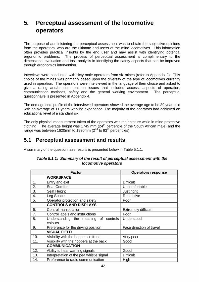
42
5. Perceptual assessment of the locomotive operators
The purpose of administering the perceptual assessment was to obtain the subjective opinionsfrom the operators, who are the ultimate end-users of the mine locomotives. This informationoften provides practical insights by the end user and may assist with identifying potentialergonomic problems. The process of perceptual assessment is complimentary to thedimensional evaluation and task analysis in identifying the safety aspects that can be improvedthrough ergonomics intervention.
Interviews were conducted with sixty male operators from six mines (refer to Appendix 2). Thischoice of the mines was primarily based upon the diversity of the type of locomotives currentlyused in operation. The operators were interviewed in the language of their choice and asked togive a rating and/or comment on issues that included access, aspects of operation,communication methods, safety and the general working environment. The perceptualquestionnaire is presented in Appendix 4.
The demographic profile of the interviewed operators showed the average age to be 39 years oldwith an average of 11 years working experience. The majority of the operators had achieved aneducational level of a standard six.
The only physical measurement taken of the operators was their stature while in mine protectiveclothing. The average height was 1745 mm (24th percentile of the South African male) and therange was between 1620mm to 1930mm (2nd to 93rd percentiles).
5.1 Perceptual assessment and results
A summary of the questionnaire results is presented below in Table 5.1.1.
Table 5.1.1: Summary of the result of perceptual assessment with thelocomotive operators
Factor Operators responseWORKSPACE
1. Entry and exit Difficult2. Seat Comfort Uncomfortable3. Seat Height Just right4. Leg Space Restrictive5. Operator protection and safety Poor
CONTROLS AND DISPLAYS6. Control manipulation Extremely difficult7. Control labels and instructions Poor8. Understanding the meaning of controls
coloursUnderstood
9. Preference for the driving position Face direction of travelVISUAL FIELD
10. Visibility with the hoppers in front Very poor11. Visibility with the hoppers at the back Good
COMMUNICATION12. Ability to hear warning signals Good13. Interpretation of the pea whistle signal Difficult14. Preference to radio communication High

43
Factor Operators responseENVIRONMENT
15. Noise levels in:Electricity poweredBattery poweredDiesel powered
LowLowHigh
16. Vibration levels High
With regard to questions rated by the operators regarding the workspace, the access and legspace were poorly rated due to restrictive available space. The seats were almost withoutexception rated as uncomfortable to extremely uncomfortable due to the materials used, poorrepair and the lack of backrest supports. Interesting to note, the operators rated the height of theseats to be ‘just right’, which does not coincide with the ergonomic dimensional evaluation. Allindications are that this rating was based upon visual access from the seated position, as visualaccess was perceived to be imperative for operability and to ensure safety. It was moreimportant to the operators to be able to see the track and guards than to be seated in a stableand supported posture. The cabs without canopies are perceived as leaving the operatorvulnerable to dangers.
There was a strong preference to be forward facing in the direction of motion and to be pullingthe hoppers and other rolling stock. This orientation was requested by the operators primarily forvisual access for safety reasons, but would indeed be recommendable for an improved bodyposture.
The controls were rated as difficult to manipulate, particularly the handwheel brake and the crankhandle starter. Understanding or reading of the labels of the controls was ‘poor’ as they wereoften illegible or absent. The communication system of the pea whistle was rated ‘good’ forhearing, although in additional comments it was noted that there were instances of limitations tothis fact. The interpretation of the auditory signals however, was poor due to ambient noise. Theoperators rated a high preference to verbal communication suggested to be through a form ofradio communication.
The environmental factors that received high ratings were exposure to vibration level (which wasnot specifically related to only one type of locomotive or mine) and noise levels on the dieselpowered locomotives.
The majority of the questions requiring rating were rated poorly (low scores) and the issues ofseating, orientation and visual access were indicated as extremely important to the operators.
5.2 Summary of the comments from the locomotiveoperators
The following information is derived from comments made by the operators additional to therating responses to the standard questions discussed above.
5.2.1 Access
Operators perceived the available leg space in the cab to be inadequate to sit comfortably or beable to change their leg position. The space was further reduced by the use of the leg space forthe storage of tools and emergency equipment.

44
5.2.2 Seats and Posture
The majority of the operators rated the seats of the locomotive as being uncomfortable. Manycomplained of the condition and poor repair of the seats and indeed reported that certainlocomotives had had the seat completely removed. Seats that were constructed of metal orwood were rated as extremely uncomfortable. There were wooden seats that were observed tohave sharp, geometric edges to the seatbase (refer to Figure 3.2.2.1). The operators describedan adjustable, well-cushioned seat that had a back rest, as being suitable for their job.
5.2.3 Controls and Displays
The operators complained of being unable to easily access the brake or to apply the necessaryforces quickly under emergency conditions. They did not report having problems understandingthe controls or the displays. The cranking method of starting the locomotive was described asstrenuous. The method of choice was a key start. They also made note that they prefer a footbrake to the handwheel system as they perceive the latter to be too slow to effectively apply intimes of emergency.
5.2.4 Viewing angles
The operators reported a strong preference for facing the direction of locomotive movementwhile in transit. They would always want to pull rather than push the hoppers. There wasperceived danger in having the guard use a hopper as a guard car, as the operator could notclearly see the guard to react to an emergency situation. There was also a perception that theguard was at risk of falling out of the hopper and sustaining critical if not fatal injuries.
There were complaints of the operators’ restricted field of view of the guard when the guardstands in front of the hoppers. The size and position of the battery in relation to the operator inthe cab was identified as the primary cause.
5.2.5 Safety hazards
The operators were concerned about the potential hazard of the loose lying equipment at theirfeet, flying and striking them in the event of an accident. The request for a dedicated storage, outof the cab for the tools was often noted. Likewise, they reported being concerned about thepotential hazard of falling rocks and water while operating locomotives that did not havecanopies. The operators requested a cab with a canopy for protection.
Operators were dissatisfied with maintenance and service of the locomotives and at timesperceived the operation of said locomotives to be unsafe. The operators identified the poormaintenance of the rails and the locomotive as being the major cause of derailment accidents.They considered re-railing a locomotive or hopper as time consuming, strenuous and interferingwith production.
The operators rated the task of changing the battery using the chain block method as verystrenuous, time consuming and dangerous. They requested the availability of improved systemsand/or equipment to safely change batteries. They voiced a preference for the remote controlmethod (electric hoist) of changing the battery.

45
The battery was perceived as being a danger to themselves during a collision or derailing. Theyreported the battery as not being securely clamped to the chassis, which under emergencyconditions may result in a shearing action towards the operator. This perception may contributetowards the reaction of the operators to jump clear of the cab in emergency conditions.
5.2.6 Environmental exposure
Operators of the diesel powered locomotive complained of exposure to smoke from the dieselengine. The same operators complained of the exposure to the high level of noise from theengine as being disturbing, as well as the noise from the ventilation fans interfering withcommunication.
They also reported visibility in the haulage as poor due to excessive smoke from the diesel-powered engine.
Vibration was reported by some of the operators as causing body discomfort, particularly aroundthe kidney area. They perceived the cause of the vibration to be as a result of poor maintenanceof the rails.
5.2.7 Method of Communication
The operators reported the pea whistle communication method as becoming increasinglyineffectual when locomotives are pushing a long line of hoppers.
The operators reported the misinterpretation of the pea whistle signal in areas of high ambientnoise such as near the fans or when in travelling through bends. The operators preferred theconcept of radio communication to pea whistle communication particularly in instances of highnoise levels and long distances between the guard and the operator.
5.3 Additional Remarks
The operators identified other factors that were affecting his operational tasks and safety, butwhich were not directly related to the interface with the locomotives as the following:
• The spaces at the ore passes are too small and/or filled with water for an operator to easilyescape if there were imminent danger.
• The handheld locomotive tail end battery lamp was reported as being too heavy and bulky tocarry during the entire shift. The lamp was also noted to be of a disturbance to otherpassengers when being transported in the cage. The operators recommended having thelamp charged on the same charging system as the locomotive battery i.e. keeping the lampwith the locomotive rather than returning it to the cap lamp battery charging area on thesurface.
• Jacking equipment was heavy and requires extremely high forces to operate.

46
5.4 Summary of perceptual assessment
The main factors perceived by the operators to be the common contributing causes of accidentswere:
• Restricted visual field leading to collision• Misinterpretation of the pea whistle• Braking system being difficult to apply• Heavy load haulage of the locomotive causing ineffectual braking• Jack slipping from the attachment surface• Procedure of re-railing the locomotive or hopper• Procedure for changing the battery.
In general, the operators perceived the locomotive operator’s job to be dangerous and haveidentified several factors that confirm the ergonomic deficiencies of the locomotives.

47
6. Summary of the design deficiencies in theexisting fleet of mine locomotives
The objective and subjective evaluations on the existing fleet of mine locomotives indicatedsafety related design deficiencies that can be improved through ergonomics intervention. Thedimensional evaluations related the physical dimensional characteristics of the locomotives tothe physical characteristics of the design population and ergonomics design standards,guidelines and recommendations. Complimentary to this, the task analysis of locomotiveoperator tasks indicated operability issues that require intervention. Lastly, the locomotiveoperator’s subjective perceptual rating on ergonomic aspects contributed towards formulatingthe safety, design and operability deficiencies of mine locomotives. These deficiencies arediscussed briefly in the following paragraphs.
6.1 Access provisions
Entry to and exit from the locomotive cabin were identified as a deficiency of the existing fleet.High entrance heights and low roof restrictions in the absence of handholds and handrails werenoted.
6.2 Seating
Seating in mine locomotives was found to be generally poor. The stool type seats providedinadequate support due to the seat size, provided no support for the back, were not adjustableand were in a poor state of repair. Deficiencies of other seats included the lack of provision forthe cap lamp battery and self-rescue devices.
6.3 Body posture and orientation
It was found that locomotive operators adopted awkward body postures to perform the requiredtasks safely, effectively and comfortably. This was caused by the control location, seat positionand body orientation to the direction of travel. Standing, semi-standing or seated postures withunsupported feet were deficiencies as a result of the absence of a seat or the seat height.
6.4 Workspace
Legroom inside the locomotive cabs was found to be restrictive due to the cab size and layoutand equipment being carried on the cab floor.
6.5 Controls and displays
Control and display layout coding and stereotype were found to be inconsistently applied to thedesign of the locomotives. The application of a handwheel as service brake is a majordeficiency. Physical reach to controls and labelling were also identified as deficiencies.
6.6 Visual access
Forward and rearward visual access to the track were identified as deficiencies. This wasattributed in part to the body orientation in relation to the travel direction and restrictive cabstructures.

48
6.7 Communication
The current guard and locomotive operator method of communication with pea whistle werefound to be deficient.
6.8 Inspection requirements
The inspection and examination requirements for mechanical components were found to beincompatible with operator abilities.
6.9 Storage provisions
Provisions for tool and equipment storage on the locomotive were inadequate.
6.10 Changing and retaining the battery
The battery handling methods and retaining mechanisms were identified as deficiencies.
6.11 Re-railing and jacking
The requirement for manual handling and the risk of the jack slipping during re-railing procedureswere found to be deficiencies.
6.12 Operator protection
Frequent remarks concerning the requirement for operator protection from falling rocks, waterand accidents were noted. This concern is related to the operator’s perception of safety, wellbeing, and ability to be in control under normal and emergency conditions.
6.13 Rolling stock
Access, seating and space provisions of man carriages were identified as deficiencies.

49
7. Ideal design for a mine locomotive
The ergonomically ideal design of a mine locomotive should address the aspects of efficiency,safety and operator satisfaction for the South African user population and local miningconditions. The objectives of the ideal design are to provide work surroundings which fostereffective procedures, work patterns, operator safety and health and minimise aspects whichdegrade human performance or increase error. The design must ensure that operator workload,accuracy, time constraints, mental processing and communication requirements do not exceedoperator capabilities.
7.1 Ergonomics requirements for ideal design
The ideal design of a mine locomotive must reflect the following ergonomics factors:
• Adequate space for operators, equipment and free volume for the activities and movementsthey require to perform the task under normal and emergency conditions.
• Adequate physical, visual, auditory and other communication links between operator andbetween the operator and the locomotive and between the operator and the outside undernormal and emergency conditions.
• Efficient arrangement of controls, displays and equipment, and compatibility of the design,location and layout of controls, displays and workspaces with the clothing and personalequipment to be worn by operators.
• Safe and adequate provisions for entry and exit under normal and adverse conditions.• Body orientation to facilitate safe and effective task performance.• Protection from thermal, electrical, mechanical and electromagnetic hazards.• Safeguards against uncontrolled vibration, acceleration, noise and toxic fumes.• Adequate illumination for inspecting, operating and controlling the locomotive.• Provision of acceptable body support in the form of seating.• Adequate emergency systems for contingencies, escape, survival and rescue.• Fail-safe design to protect against damage to equipment, injury to operators or inadvertent
operation of critical controls.• Simplest design consistent with functional requirements and service conditions.• Applicable system and operator safety factors to minimise human error, particularly under
non-routine and emergency conditions.
7.2 International locomotive design status
In order to come to a more workable design solution for a mine locomotive it is required toconciliate these high level design requirements discussed above with the current best practicesworld-wide and the deficiencies identified for the current fleet. The international survey of minelocomotives included extensive literature and internet searches, product information brochures,catalogues and personal correspondence. Information was obtained from manufacturers oflocomotives in the United States of America, United Kingdom, Canada, Germany, Sweden andRussia. The investigation into the design status of the international fleet of mine locomotivesinvolved two approaches : firstly, how and to what degree the international locomotivemanufacturers addressed and overcame the major design deficiencies identified for the localfleet and secondly, to what extent the local ergonomics requirements for the ideal design havebeen met. Paragraph 6 provides a summary of the design deficiencies in the existing fleet whileparagraph 7.1 list the ergonomics factors that should be addressed and should be reflected inthe ideal design. It should be noted that there is a close relationship between these approaches.The deficiencies were identified and analysed and this led into the requirements for an idealdesign. The levels of the approaches are however significantly different with the ideal locomotiverequirements being rather at systems safety and efficiency level rather than a detail componentlevel. As the deficiencies of the existing fleet were to a large degree generic in nature across the

50
spectrum of locomotive types (i.e. battery, diesel and trolley/electric) the different types were notaddressed individually.
The assessment of the international locomotives is presented in Appendix 6. A discussion onthe generic deficiencies among the locomotives and features of the ideal design are alsoincluded. The detail results and findings are not repeated here. The results indicate thatinternational designs still include locomotives that are, with regard to ergonomics comparablewith the local fleet, including some of the deficiencies. Ergonomics advances include atendency towards body orientation in the direction of travel, semi-enclosed and fully enclosedcabs and improved driver protection structures.
From the results it is clear that the current international locomotive ergonomics characteristicsare not universally superior to that of the local fleet. There is also no one locomotive currently inproduction that addresses all the deficiencies of the local locomotives or satisfy all therequirements of the ideal locomotive design. It was apparent that for the smaller tonnagelocomotives, the same deficiencies as for the local fleet were identified. However, for the largertonnage locomotives the locomotive ergonomics improved, but still incorporated design featuresthat cannot be reconciled with sound ergonomics.
From this assessment it is also concluded that the monorail type of locomotive manufactured inEurope currently provides the “best practice” regarding the ergonomics of the locomotive cabindesigns even though same changes are indicated in order to accommodate the South Africanuser population. The challenge is to convert or modify the design of the monorail cabin to that ofconventional rail bound locomotives. It should further be noted that the introduction of foreigndesigns into South Africa would nevertheless require a thorough ergonomics evaluation toassess the compliance to South African anthropometric and biomechanic characteristics andthereafter the modification to rectify deficiencies. An alternative approach would be to providethe international manufacturer with detailed specifications and guidelines (as contained in thisreport) according to which the equipment that would be suitable for the South African work forcecan be manufactured.
7.3 Ergonomics guidelines for mine locomotive androlling stock design
Table 7.3.1 presents the ergonomics guidelines for the design of locomotives. The guidelinesare based on the anthropometry and biomechanics of the South African population and toaccommodate the 5th percentile to 95th percentile male and female user. Other guidelines arederived from national, international, commercial and military standards. Table 7.3.2 presentsergonomics guidelines for the design of man carriages.
Table 7.3.1: Ergonomics guidelines for mine locomotive design
Parameter Range of Values PreferredAccess
Surface to entrance level height 380 mm (maximum)Entrance level to floor height 0 mm – 200 mm 0 mmEntrance width 500 mm – 760 mm 760 mmEntrance level to roof line 1300 mm
(minimum)Handgrips:• length 150 mm – 300 mm 200 mm• diameter 25 mm – 32 mm 32 mm• hand clearance between the retaining surfaceto inner surface of handgrip
76 mm

51
Parameter Range of Values Preferred• hand clearance area surrounding thehandgrip
76 mm
• centre of handgrip to ground 1000 mm-1470 mm 1250 mmWorkspace
• leg clearance (forward horizontal distancefrom SRP to cab panel)
910 mm – 1000 mm 1000 mm
• head clearance (vertical distance from SRPto roof line)
Erect seated statureof the 95th percentileman +100 mm
1070 mm
• arm clearance (dynamic elbow/abducted armspace, the minimum width of the cab)
910 mm (minimum)
• foot clearance (the envelop surrounding thefeet on the floor line)
64 mm x 64 mm to100 mm x100 mm
100 mm x 100 mm
Seating
Type Cushioned seat withbackrest that canaccommodate thepersonal protectiveequipment, no sharpedges
T-back cut out
Vertical adjustment range from recommendedmidrange
0 mm – 40 mm upand down
80 mm
Horizontal adjustment to the fore and aftpositions
150 mm – 200 mm 150 mm
Seat base:• cushion thickness 25 mm – 50 mm 38 mm• width 485 mm – 510 mm• depth 420 mm – 445 mm• height (SRP to floor) 300 mm – 550 mm 350 mm• Slope down towards the SRP 5° - 8°Seat back:• height (from SRP) 300 mm – 650 mm 600 mm• width 480 mm – 510 mm
200 mm minimumonly in area whereprovision forpersonal protectiveequipment at waistlevel is required
485 mm
• Angle from vertical plane 6.5° - 30°Arm rest:• SRP to top surface of the armrest 235 mm• width 50 mm – 120 mm 75 mm• length 210 mm – 300 mm 220 mm• Spacing 480 mm – 510 mm 480 mm
Controls
Angle between the upper arm and the trunk link(abduction)
0° - 45° 30°
Forward reach distance (from SRP to handcontrols in the most forward seat position for the5th percentile person and in the most rear seat
Forward seatposition: 180 mm –330 mm

52
Parameter Range of Values Preferredposition for the 95th percentile person Rear seat position:
350 mm – 500 mmVertical distance from SRP to the hand controls 300 mm – 380 mm 320 mmHand controls• clearance area around the control 76 mm 76 mm• clearance – front 75 mm• minimum length of hand control portion 115 mm – 150 mm 150 mm• hand control diameter 25 mm – 32 mm 32 mm• diameter of push button controls 13 mm – 19 mm 19 mm• force activation of lever hand controls 200 N (maximum) 150 N• force activation of push buttons 0.26 N – 4.5 N 1 N
Foot controls
• distance from SRP to bottom of foot pedals 690 mm – 860 mm• angle of foot pedals < 30° 20°• width of foot pedals and depth 75 mm x 100 mm• force of activation of foot pedals 400 N (maximum)• clearance between pedals (must allow
sufficient space to avoid inadvertentapplication or sufficient space to pass a bootin between the pedals.)
50 mm or 150 mm 50 mm
Viewing angles
Eyeview above 0° horizontal 15°Eyeview below 0° horizontal 30°Eyeview to either side 90° / 90°Distance obscured in front of the vehicle 1500 mm
(maximum)Parameter Range of Values Preferred
Body orientation in direction ofmovement
Method of communication
Verbal and auditory RadioStorage provision• Personal protective equipment Dedicated area
• Personal items such as food and water Dedicated storagearea
Environmental influences
Noise Hearing protection >85 dB
Enclosed cab <65dB
Vibration Attenuation ofvibration should behandled by seatsuspension andmaterial to reduceexposure tovibration
Smoke, dust Half mask withcartridge filter
Safety warning systems Red flashing caplightRed/white light on

53
Parameter Range of Values Preferredlocomotive
Controlled environmental factors
Airflow
Ventilation for cab space < 4.25 m3 0.85 m3 air perminute
Air-conditioning
Air-conditioning used for temperaturesexceeding (air must not be positioned to directlyflow onto operator)
> 29°C >25°C
Humidity 45% relative humidityat 21°C, value willreduce down to 15%with increasingtemps
Heating
Required for dry bulb temperature (air must notbe directed onto operator)
< 10 °C
Illumination
Interior enclosed cab Instrumentationlighting
Displays - backlit Red or white floodlight 0.07 cd/m² –0.35 cd/m²
Forward headlight 20 lux (minimum) 80 luxDisplays
Label placement Above the controlsLabel type SymbolsAlphanumeric characters and displays• Width 70% of the height• Height 5 mm (minimum)Viewing angle from centre axis 0° - 65° 0° - 45°Viewing distance from eye reference point 330 mm – 630 mmOrientation of display from normal line of vision >45°and 90°<
*SRP = is the point of reference where the threeaxis intersect between the seatbase andseatback.
Table 7.3.2: Ergonomic guidelines for rolling stock
Parameter Range of Values PreferredAccess height to entrance level 380 mm (maximum)Access width 610 mm (minimum) 760 mm
(minimum)Seat depth 380 mm to 445 mm 425 mmSeat width required with self rescuer and batteryat waist level
500 mm (minimum)
Handgrips at doorways Refer to Access inTable 7.3.1

54
7.4 Ideal locomotive design
The ideal locomotive design is intended to include the ergonomics requirements and guidelinespresented in the preceding paragraphs into a workable concept while at the same timeaddressing the deficiencies identified for the current fleet.
The design follows the stereotype of motor vehicles. This incorporates the use of hand and footcontrols, body orientation facing in the direction of travel and adequate body support. The layoutand major components of the cab are presented in Figure 7.4.1, Figure 7.4.2 and Figure 7.4.3.The features of the design is presented in the paragraphs below.
Figure 7.4.1: Ideal design – cab side view

55
Figure 7.4.2: Ideal design – cab top view
Figure 7.4.3: Ideal design – cab isometric

56
7.4.1 Access and workspace
Access to the cab and seat is provided from the right hand side of the cab. An emergency exit isavailable towards the left over the control box and equipment storage bin. The workspace isadequate for the 95th percentile user (refer to Figure 7.4.1.1). Provision is made for equipmentstorage, personal protective equipment storage and hand portable protection devices (fireextinguisher).
Figure 7.4.1.1: Ideal design – operator accommodations, 95th percentile male and 5th percentile female
7.4.2 Seating
An integral skin flame retardant polyurethane foam type seat with horizontal adjustment and T-shape backrest is provided. Horizontal adjustment provides adequate movement to effectivelysupport the 5th percentile to 95th percentile male and female operator. As forward vision wasfound adequate, vertical adjustment is not required. The T-shaped backrest provides space forthe belt worn cap lamp battery and self-rescuer. As whole body vibration can negativelyinfluence health, a mechanical or pneumatic suspension is included in the seat configuration.
7.4.3 Controls
A magnetic switch key or access card switch system affording the same level of accesssecurity is used to activate the controller. A directional controller is provided for left handoperation and with palm activated (switch on top) deadman switch in the location indicated inFigure 7.4.1 and Figure 7.4.2. The controller is spring loaded with neutral centre position. Thedirection of control movement relates to intended locomotive movement. The warning sirenpushbutton is incorporated on the right side of the directional controller for thumb operation, evenwhen operating the controller. The directional controller controls only direction, the acceleration

57
and speed component is provided through a floor mounted, right foot operated pedal (similar tothe accelerometer pedal in a motor vehicle). The sequence of operation is fixed so that thedirectional controller has to be operated (direction selection) before the speed control(accelerator) would have any effect. The combination of control actions where the speed controlis depressed and the directional controller moved to the opposite direction would disconnect orswitch off propulsion to the wheels. Releasing of the speed control will have the same effect.
A floor mounted, foot operated power assisted service brake in the location indicated in Figure3.4.2 is provided. A hand operated power assisted park brake is provided to the left of thedirectional controller. An emergency stop hand operated push button switch is provided to theleft of the park brake. The switch will cut the propulsion to the wheels and apply the brakesautomatically. Resetting will require an intentional action from the operator.
7.4.4 Displays
All controls and displays are labelled with symbols rather than text. Displays for speedindication, hydraulic or pneumatic pressure, voltage, amperage and charge condition (asappropriate for the propulsion type) are functionally grouped on the display panel. Primarydisplays are positioned towards the right on the display panel.
7.4.5 Body orientation and visual access
The operator orientation is in the primary direction of travel for a front driven train. The angles ofview are presented in Figure 7.4.5.1 and Figure 7.4.5.2. Rear view mirrors are provided only toconfirm the guard’s position during shunting operations. It is not intended to be used as drivingaids.
Figure 7.4.5.1: Forward visual angles

58
Figure 7.4.5.2: Sideways visual angles
7.4.6 Operational concept
The operational concept for this locomotive is to always employ two locomotives with a train, oneat each end and with the cabs at the leading ends (similar to dedicated haulage type trains).Each locomotive would have an operator, but control will only be executed from one cab at anyone time. Control over the train is transferred between the operators through a simpleprocedure; operator A requests control of the train, the request is acknowledged by B, only afterA has acknowledged B’s acknowledgement will control be transferred to A. This procedure isproposed as an indication light logic control system being displayed on the display panel.
The two locomotive trains will enable longer trains and handle increased tonnage in shorter timeperiods and thus increase production. The train configuration does not only provide visualaccess in the direction of travel but would allow the train to be always in a pulling configuration(front driven train). However, a single locomotive will still have to shunt hoppers intodevelopment areas where hoppers are required to move into end positions for the loading of ore.
No coupling system or buffer is provided at the front end of the cab. The locomotive is notintended to be operated as pushing a load with the cab leading.

59
7.4.7 Warning systems
An amber flashing light is mounted on the roof of the locomotive. The light is connected to thelogic device monitoring which locomotive of the train has operational control. The amber light willflash on the roof of the locomotive which has no control over the train, irrespective of thedirection in which the train is travelling. This additional signal will provide warning to personnelof oncoming or departing trains where special caution is required because the train operatorwould not be able to keep a proper lookout at the end of the train where the light is flashing.
The locomotives should still be provided with reflective material at least at the front and rear.
7.4.8 Locomotive head and tail lights
The design incorporates an automatic light system, which operates according to the direction oftravel. On the insertion of the switch key or card the headlamps at both ends of the trainilluminates with white light. Upon operation of the hand operated directional controller and thespeed control pedal the headlights will remain illuminated at the leading end of the train andswitch off at the trailing end while the red tail light will be illuminated at the end. Head light–taillight activation will occur independently of the operator. A head and tail light test switch isincorporated in the design to facilitate inspection.
7.4.9 Guard personal protective lights
As visibility of the guard remains a safety issue, a small flashing red light (high efficiency lightemitting diode) is attached to the back of the hard hat. This red light will provide additionalfeedback to the operator and other miners as to the position of the guard. The white cap light, infront and the red flashing light at the back will adhere to the stereotype used on the locomotivelighting system.
7.4.10 Battery retaining mechanisms and jacking points
Corner casting with twist lock retaining mechanism is used in the design to ensure that thebattery is retained under emergency conditions. Dedicated areas are required to reduce the riskof jack slipping during re-railing procedures.
7.4.11 Operator protection
A solid frame cab with a roof, a single sliding door and safety glass windows are used fortemperature, humidity and air flow for optimal operator protection. To the left of the operator, aglass panel divides the cab from the equipment storage. This panel is used as emergency exit.Although glass introduces potential hazards, the use of shatter resistant polymers is not adviseddue to its low scratch resistance. The enclosed cab will be environmentally controlled fortemperature, humidity and air flow.
This cab design protects the operator from exposure to potential hazards such as smoke, noise,falling rocks and water. The closed cab configuration provides a stable seated posture, anextended legs position and the ability to quickly activate the floor service brake, will provide theoperator with sufficient psychological confidence in his working environment. A positiveperception of the safety and protection of his cab environment will substantially reduce theircurrent reaction to jump clear of the cab in times of crisis.
The design of the cab interior incorporates rounded edges and corners throughout to reduce therisk of injury. The protection structure height and width as indicated in the layout drawings arewithin the generally acceptable limits for mine locomotives.

60
7.4.12 Layout drawings
Layout drawings with major dimensions are presented in Appendix 6.

61
8. Practical design for a mine locomotive
Practical considerations frequently influence ergonomics design concepts in order to generatecost effective workable solutions. The considerations may include legislative and other statuaryrequirements, mechanical and electrical limitations and requirements, availability of systemcomponents (off the shelf vs development of), acquisition cost and cost of maintenance. Newguidelines for railbound transport equipment is in development. Two documents of theDepartment of Minerals and Energy, Mine Health and Safety Inspectorate “Guideline for theCompilation of a Mandatory Code of Practice for Underground Railbound Transport Equipment”,dated 27 September 2000 and “Proposed Regulations for the Operation of Surface andUnderground Railbound Transport Equipment”, dated 27 September 2000 provides pertinentguidance on a number or ergonomics factors, both directly and indirectly. Mining groups havealso developed guidelines on trackbound operations and locomotives and have includedergonomics factors for consideration. Examples are “Guidelines for Locomotives used forTramming Operations”, Anglogold Limited (2000) and “Underground Locomotive Practice”, GoldFields Limited (1998). The following paragraphs address the influence of the practicalconsiderations in the generation of the design while still incorporating sound ergonomics.
8.1 Practical influences
The major practical influences on the ideal design were identified as the following:
• Enclosed cab• Application of motor vehicle stereotypes to railbound equipment stereotypes• Two locomotives per train
8.2 Practical locomotive
The practical design follows the concept of the ideal design closely but with the exception of thepractical provisions. Figure 8.2.1 to Figure 8.2.3 show the practical design.

62
Figure 8.2.1: Practical design – cab side view
Figure 8.2.2: Practical design – cab top view

63
Figure 8.2.3: Practical design – cab isometric
8.2.1 Cab
The major cab changes is related to the enclosed nature of the ideal design cab. Although thenormal disadvantages of an enclosed cab have been overcome in the ideal design by providingadequate vision from the cab and easy access, other factors influence the practicality thereof.Due to the low speed of the locomotives, a glass windshield is not an absolute requirement.Cleaning and demisting of the windows, especially with airconditioning provisions, will placeadditional and tedious tasks on the operator. The use of glass underground remains problematicbecause it is fragile when applied for large surfaces and, although safety glass, breakage andsplinters continue to be a hazard. As cap lamps will, in all probability, still be worn by operatorsinside the enclosed cab, reflection of the light source from the glass surfaces can reduceoperator vision to the outside. Cap lamps will therefore have to be switched off. Anotherinfluence is that the operator is partially denied the ability to use olfactory (sense of smell) inputas warning of impending danger of smoke, fuel or other vapours.
The design now incorporates a semi-enclosed cab in which the glass windshield has beenreplaced with protection bars and the sliding side door and glass panel removed altogether. Thesame protection is still provided against collision. The seat position and operator postureensures restraint of the operator within the cab.
Entry to the cab is now from the left to enable access to the seat and controls as discussed inthe next paragraph.

64
8.2.2 Controls and control stereotype
In the practical design the major elements of the railbound equipment stereotype are retained,i.e. hand control of direction and speed and hand operated park brake. However, the servicebrake is allocated to a foot operated pedal due to the high force requirements of the brakingmechanism.
The stereotype also calls for right handed operation. As shown in Figure 8.2.1 and Figure 8.2.2the current master controller type directional and speed control device is used. Activation of thecontroller is with magnetic isolator or card system as described for the ideal design. Anemergency switch is provided in close proximity to the right hand position.
A hand operated long levered park brake is provided. This type of control is appropriate for highforce exertion with the hand and arm and power assistance is therefore not necessarily required.A short finger operated release lever is provided at the end of the brake lever. The advantage ofthe control is also related to the positive visual and tactile feedback that is provided to theoperator on the position of the control. In the released position the lever will be down and inhorizontal orientation. Driving with the brake partially engaged will be easily recognisable.
A single foot operated service brake is provided.
8.2.3 Single locomotive per train
The ideal design proposed two locomotives per train. This may not be cost effective. Thepractical design incorporates a single locomotive with a guard car at the other end. The guardcar replicates the controls and control systems of the locomotive but is not self-propelled.Figure 8.2.3.1 to Figure 8.2.3.3 show the general layout and configuration of the guard car. Thecar is electronically connected to the locomotive by cable or radio link and can fully control thelocomotive. A redundant braking system is proposed. Due to the relative low mass of the guardcar, it cannot effectively brake a fully loaded train and locomotive. Therefore the guard car musthave capabilities simultaneously activate the brakes of the locomotive and the guard car.Electronic interlocks are required to preclude the locomotive from driving off with the guard carpark brake engaged.
It would still be possible to operate the locomotive alone in the typical configuration used for minedevelopment processes. All other design features of the ideal design, including flashing ambientlights, personal flashing lights and transfer of locomotive control between operators areapplicable for the practical design.

65
Figure 8.2.3.1: Guard car – cab side view
Figure 8.2.3.2: Guard car – cab top view

66
Figure 8.2.3.3: Guard car – isometric view
8.2.4 Layout drawings
Layout drawings with major dimensions are presented in Appendix 7.

67
9. Proposed interventions on the existing fleet
The ergonomic interventions required to improve the safety aspects of the current fleet arederived from the deficiencies identified from the objective and subjective evaluations andstatutory requirements. Section 6 provides the summary of the deficiencies. The interventionshave also been deemed as practicable and reasonable adaptations. All of the deficiencies couldnot be addressed, as many of the current configurations did not allow for further changes withoutincurring extensive costs. The practical and ideal designs would comprehensively address theentire range of deficiencies.
9.1 Access
Provide a cut-out on the front panel of the leading end of the cab and provide a hinged door. Thesurface to entrance height should not exceed 380 mm and the width of the access should not beless than 450 mm.
An equipment bin of approximately 450 mm x 1200 mm x 240 mm with a hinged lid can beconstructed or attached to the bottom of the entrance level. Tread plates placed on top surfaceof the lid will reduce slippage. The bin will act a dual capacity as a step to improve access fromthe side of the locomotive and to store equipment. The present access side panels should beincreased in height or replaced with a panel that will be above the level of the seated operator’selbow. Safety provisions would dictate that the operator must access from the side of thelocomotive only. The side entry onto the step and then through the access door is safer andeasier than stepping over a panel that is too high. Handgrip rails should be attached on the oneside of the access opening to assist with safe entry.
The coupling system at the front of the locomotive should be removed so that the train cannot beused for pushing with the cab end leading.
Health and safety implication: The improved access will result in a deduction of slips and fallsand awkward postures during entry to and exit from the cab.
9.2 Seating and posture
As the orientation of the operator cannot be changed within the workspace of the existing fleet,an improved seat type and availability of support for the body must be introduced.
It is recommended that a padded seat with a backrest be provided that will allow space forpersonal protective equipment. The height of the stool from the floor level should beapproximately 500 mm. This type of seat will improve comfort and provide support to the trunk.To further improve stability of the operator in an upright seated posture for the 5th to 95th
percentile operator, a foot rest should be included in the cab. The rest surface should beapproximately 200 mm high by 30 mm wide and be hinged so that it can be folded away andout of the foot space when not needed.
Raising the control box to allow for kick space (space that can accommodate the front part of thefeet) underneath the box, in the locomotive configurations that allow for this intervention, willimprove the utilisation of the workstation. Kick space would typically be at least 100 mm by100 mm.
Health and safety implication: The improved seating will provide improved body support whileaccommodating personal protective equipment for the trunk and lower back it will reducemuscular fatigue. However, the risk remains for musculoskeletal stresses and strains to theneck region due to the lateral rotation of the neck for vision in the direction of travel.

68
9.3 Controls and displays
There must be a braking mechanism besides the handwheel park brake for service brakepurposes. The handwheel brake must be dedicated for parking purposes only. The problem willstill exist of the locomotive operating under a partially applied park brake, but reducing thefrequency of used of the handwheel brake will reduce the incidence of this problem. Theintroduction of a T-bar or inverted L-bar hand operated lever as service brake will improve thecontrol afforded to the operator. Where space allows in some configurations, a combined hand-foot operated service brake could be implemented and assist with high force application requiredfor braking.
A siren must be placed within easy reach and visual access in close proximity to the mastercontroller. All labels must be replaced with clearly legible and understood symbols.
Health and safety implication: These interventions will decrease the application of high forceswith the upper extremities in awkward postures and result in the reduction of fatigue, trauma tothe shoulder, cumulative trauma and other chronic conditions. Proper placement and labelling ofcontrols will reduce operator error and increase speed of activation.
9.4 Visual access
In locomotive configurations where forward visual access is severely restricted, the restrictingpanel should be reduced to above the elbow level of the 95th percentile operator, which istypically 450 mm from the seat reference point (SRP).
Health and safety implication: Improved visual access will enhance direct visual contact with thesurrounding areas and will improve the perceptual capability of the operator and thereby reducereaction times for unexpected incidents and emergencies.
9.5 Communication
Personal verbal communication systems should be implemented to improve communicationbetween operator and guard. A short distance radio communication device carried on theperson is proposed.
Health and safety implication: Verbal communication will improve operator perception ofinstructions to improve the basis for decision making and reduce the margin for operator error.
9.6 Safety inspections
The mechanical inspection points should be appropriately marked with coloured paint to providevisual guidelines to operators on inspection points.
Health and safety implication: This intervention will improve the perceptual feedback for decisionmaking and lead to a reduction of interpretation errors.
9.7 Equipment storage
A dedicated storage bin for tools should be provided as described in paragraph 9.1. This willeliminate the loose lying equipment on the cab floor as a safety hazard. The fire extinguishershould be removed out of the operator’s workspace and securely fastened on the outer wall ofthe cab.

69
Health and safety implication: Proper storage of equipment will reduce slips, falls, contusionsand the hazards associated with moving objects.
9.8 Other safety aspects
To improve visibility and therefore protection of the guard, a small flashing red light (flashing highefficiency light emitting diode) should be fixed to the back of the guards hard hat.
To comply with statutory regulations a red tail light and white head light system can beimplemented on locomotives. Similar to the automatic light system discussed for the idealdesign to replace the portable battery operated tail-head light combination. The light system onthe hopper end can be cable fed from the locomotive and rolled up onto a winder when notrequired.
The retaining mechanism for the battery-powered locomotives should be changed to a cornercasting with twist lock mechanisms.
Health and safety implication: Improved visibility provides additional feedback for perceptualdecision making and reducing the margin for omission or error. Additional safety features on thebattery retaining mechanism will reduce the perceived danger experienced by operators. It willtherefore reduce the inclination of operators to jump from the cab in emergencies.
9.9 Intervention proposal
Figure 9.9.1 shows the interventions proposed in the preceding paragraphs.
9.10 Rolling stock
Man carriages should be modified according to the guidelines presented in Table 7.3.2 in order toprovide adequate access to and from the carriage, adequate seat depth for support during transitand space for personnel wearing personal protective equipment. Specific attention must begiven to the relationship between the space availability and the number of personnel transportedon the man carriage.

70
Figure 9.9.1: Interventions proposed for the existing fleet

71
10. Strategy for implementation of the recommendedergonomics interventions for the existing fleet
The strategy to implement the recommended ergonomics interventions for the existing fleet ofmining locomotives will involve the support of manufacturers, rebuilders, mining groups andindividual mines but also employees and statutory bodies.
The goals of the strategy are to ultimately implement the ideal and practical locomotive designsin order to substantially reduce the safety risks involved with mine locomotive operations. Thedevelopment of a new generation of mine locomotives incorporating the proposed ergonomicsfeatures, will probably be in the domain of manufacturers and the larger mining groups.Rebuilders and mine workshops can be involved with interim interventions and retrofittingexercises while locomotive operators will have the responsibility to execute the tasks withmodified or new equipment and procedures.
The proposal for the strategy involves firstly, the structured implementation of ergonomicinterventions to the existing fleet. Secondly, it involves the development of locomotive cabsincorporating the proposed ergonomics features of the practical design that can be retrofitted onthe existing fleet. And thirdly, it involves the development of new locomotives according to theideal design proposal. Intervention actions to the existing fleet were prioritised according to thecriticality of the deficiency. It should be clear that some interventions would not be practical toimplement, because of limitations that would require major modification and where retrofitting ofa practical design cab may be more cost effective. A point in case here is the process ofchanging the body orientation of the operation from sideways to the direction of travel. Thecharacteristics of existing locomotives are such that the modification to implement it is notpractical and not cost effective. Nevertheless, substantial benefit can be obtained by introducingmodifications to affected locomotives by following the priority of intervention. The interventionsare listed in Table 10.1 in priority order. Section 9 discusses the design modifications forobtaining the intended ergonomics benefit.
Table 10.1: Priority of ergonomics interventions on the existing fleet1. Modification of park brake to incorporate hand and foot operated service brake2. Increase of forward visual access to track (where applicable)3. Seating4. Equipment storage provisions and removal of coupling system at the leading
end5. Access to the cab6. Communication and warning systems (amber flashing lights and personal
flashing lights for guards and operators)7. Battery retaining mechanism and provision of jacking points8. Labelling of displays and controls9. Inspection provisions
The cost to implement the strategy should be regarded as an investment with short and longterm benefits. There will be benefits that are not easily expressed in monetary terms. Thesewould include health, safety, comfort, well-being and operator task effectiveness, which arereally the main aims of the ergonomics interventions. Other benefits are directly related to cost.For example, the cost of fatalities, compensation payments and medical costs, mechanical andelectrical repairs and loss of production as a result of preventable equipment downtime. Thefunding required to support a strategy for intervention on this scale may well depend on anumber of factors but the success of implementation will ultimately reside on the mining roleplayers’ support and acceptance of the priority the strategy should receive.

72
11. Conclusions and recommendations
The ergonomics assessment of the existing fleet of mine locomotives at gold and platinummines highlighted various deficiencies in the design of the working system (most typically at theoperator-machine interface). Poorly designed workstations make the operator’s tasks moredifficult and thus render him more error-prone. A number of safety related design deficiencieswere also identified that can be improved through ergonomics intervention.
The ergonomics interventions required to improve the safety aspects of the existing fleet oflocomotive should address the following aspects:
Ergonomics intervention Improved health and safety
Access to the cab of the locomotives Reduce slips, falls, awkward posturesForward visual access Improve perceptual capabilitySeating and posture Reduce muscular fatigue, improve body
supportCommunication and warning systems Reduce margin for errorsLabelling of controls and displays Reduce error, improve speed of activationEquipment storage Reduce slips, falls and impact injuriesPre-operational safety and mechanicalchecks
Reduce interpretation errors
Modification of park brake. Reduce fatigue, shoulder trauma, increasespeed of activation
The ergonomics interventions required to improve the safety aspects of the existing rolling stockshould address access, seating and space provisions of man carriages.
In order to reduce the safety risks involved with locomotive operations as result of poorergonomics, the following strategy is proposed. Firstly, priority should be given to theimplementation of the proposed ergonomic interventions (see Section 9) for the existing fleet.The second phase should focus on the development of locomotive cabs, incorporating theproposed ergonomics of the practical design (see Section 8), which can be retrofitted to theexisting fleet. Finally, attention should be given to the development of new locomotives accordingto the ideal design proposals (see Section 7).
It is further recommended that all interested and affected parties (manufacturers and suppliers)be involved in the practical design, manufacture and installation of the proposed ergonomicsinterventions and conceptual designs. This is essential in terms of Section 21 (1) (c) of the MineHealth and Safety Act (Act 29 of 1996).

73
References
Anglogold Limited. 2000. Guideline for Locomotives used for Tramming Operations. AGTE8.2.2.
Clark, T.S. and Corlett, E.N. 1984. The Ergonomics of Workspace and Machines: A DesignManual. Taylor & Francis. London.
Department of Minerals and Energy (Republic of South Africa). 2000. Guideline for theCompilation of a Mandatory Code of Practice for Underground Railbound Transport Equipment.MRAC Circular unnumbered.
Department of Minerals and Energy (Republic of South Africa). 2000. ProposedRegulations for the operation of surface and Underground Railbound Transport Equipment.MRAC circular unnumbered.
Gold Fields Limited. 1998. Code of Practice GFL 0071 – Undergound Locomotive Practice.
Republic of South Africa. Mine Health and Safety Act, Act 29 of 1996.
RSA Military Standards Steering Committee (RMSS), 1995. RSA-MIL-STD-127: , Volume 1.Ergonomic Design: Anthropometry and Environment.
Wilson, J.R. and Corlett, E.N. 1992. Evaluation of Human work. Taylor & Francis, London.

74
Appendix 1Distribution of locomotives
While the distribution of locomotives presented here provides useful statistical information, it isself evident that the data, having originally been produced in 1991, has by now several omissionsand errors. In the past decade new locomotives were added, older models disposed of or usedfor spares while some became redundant as a result of curtailed operations.
Mine No Size Power MakerBARBERTON 4 6 Diesel FunkeyBARBERTON 10 2.5 Battery GoodmanBARBERTON 4 6 Diesel UnknownBARBERTON 6 6 Diesel UnknownBEATRIX 28 9 Diesel FunkeyBEATRIX 52 10 Battery GoodmanBLYVOOR 2 14 Trolley Bateman TridentBLYVOOR 10 5 Battery FunkeyBLYVOOR 4.5 Diesel FunkeyBLYVOOR 9.5 Diesel FunkeyBLYVOOR 5 8 Trolley General ElectricBLYVOOR 3 14 Trolley General ElectricBLYVOOR 12 4.5 Trolley GoodmanBLYVOOR 18 8 Trolley GoodmanBLYVOOR 3 8 Trolley GreenbatBLYVOOR 3 14 Trolley GreenbatBUFFELSFONTEIN 2 8 Battery Bateman TridentBUFFELSFONTEIN 4 3.6 Diesel Bateman TridentBUFFELSFONTEIN 24 3.6 Diesel FunkeyBUFFELSFONTEIN 54 5.4 Diesel FunkeyBUFFELSFONTEIN 36 7.3 Diesel FunkeyBUFFELSFONTEIN 33 8.2 Diesel FunkeyBUFFELSFONTEIN 4 5 Battery GoodmanBUFFELSFONTEIN 17 8 Battery GoodmanBUFFELSFONTEIN 4 12 Trolley GoodmanBUFFELSFONTEIN 3 15 Trolley GoodmanBUFFELSFONTEIN 1 5.4 Diesel Hunslett TaylorBUFFELSFONTEIN 2 7.3 Battery UnknownBUFFELSFONTEIN 9 6 Diesel UnknownBUFFELSFONTEIN 10 8.2 Diesel UnknownBUFFELSFONTEIN 24 9 Diesel UnknownBUFFELSFONTEIN 1 10 Diesel UnknownCONS MURCH. 10 2.5 Battery FunkeyCONS MURCH. 18 6 Battery FunkeyCONSOLIDATED MODDER 5 6 Battery GoodmanCONSOLIDATED MODDER 14 5 Diesel UnknownCROMORE MOOINOOI 9 6 Battery BessingerDBN ROODEPOORT DEEP 83 5 Battery BessingerDBN ROODEPOORT DEEP 63 5 Battery GoodmanDBN ROODEPOORT DEEP 42 15 Trolley GoodmanDEELKRAAL 5 9.1 Battery UnknownDEELKRAAL 39 5 Diesel Anton TypeDEELKRAAL 38 9 Battery GoodmanDOORNFONTEIN 66 5 Diesel Anton TypeDOORNFONTEIN 5 6 Diesel General ElectricDOORNFONTEIN 5 10 Diesel General Electric

75
Mine No Size Power MakerDOORNFONTEIN 60 2 Battery GoodmanDOORNFONTEIN 1 4 Diesel GoodmanDOORNFONTEIN 96 6 Diesel FunkeyDOORNFONTEIN 2 8 Trolley GoodmanDOORNFONTEIN 4 12 Trolley GoodmanDOORNFONTEIN 2 10 Trolley GreenbatDOORNFONTEIN 50 3 Diesel Hunslett TaylorDRIE CONS 25 60 Diesel Anton TypeDRIE CONS 14 5 Battery BessingerDRIE CONS 27 5 Battery BessingerDRIE CONS 54 10 Battery BessingerDRIE CONS 9 10 Battery FunkeyDRIE CONS 6 10 Trolley GoodmanDRIE CONS 10 10 Trolley GoodmanDRIE CONS 53 5 Diesel Hunslett TaylorDRIE CONS 82 10 Diesel Hunslett TaylorDRIE CONS 7 10 Diesel UnknownE.R.P.M 6 10 Trolley General ElectricE.R.P.M 3 3 Battery GoodmanE.R.P.M 25 6 Battery GoodmanE.R.P.M 3 12.5 Battery GoodmanE.R.P.M 78 4 Trolley GoodmanE.R.P.M 19 8 Trolley GoodmanE.R.P.M 14 10 Trolley GoodmanE.R.P.M 3 10 Trolley GreenbatE.R.P.M 2 1.5 Battery UnknownELANDSRAND 3 10 Diesel FunkeyELANDSRAND 2 10 Trolley FunkeyELANDSRAND 1 5 Battery GoodmanELANDSRAND 47 8 Battery GoodmanELANDSRAND 15 9 Battery GoodmanERFDEEL 1 8 Battery Bateman TridentERFDEEL 10 8 Battery FunkeyERFDEEL 12 9 Battery FunkeyERFDEEL 49 10 Battery GoodmanERFDEEL 21 5 Battery Hunslett TaylorERFDEEL 2 8 Battery Hunslett TaylorERFDEEL 6 5 Diesel Hunslett TaylorF.S.G. 180 5 Battery GoodmanFREDDIES 5 Battery FunkeyFREDDIES 5 5 Diesel FunkeyFREDDIES 2 8 Trolley General ElectricFREDDIES 1 10 Trolley General ElectricFREDDIES 64 8 Battery GoodmanFREDDIES 8 10 Trolley GoodmanFREDDIES 72 6 Battery Hunslett TaylorFREDDIES 10 10 Battery Hunslett TaylorFREDDIES 2 12 Battery Hunslett TaylorFREDDIES 1 5 Diesel Hunslett TaylorFREDDIES 4 8 Diesel Hunslett TaylorGRASS VALLEY CHROME 8 6 Battery GoodmanGRASS VALLEY CHROME 2 6 Diesel unknownGROOTVLEI MINE 2 8 Trolley General ElectricGROOTVLEI MINE 5 4 Battery GoodmanGROOTVLEI MINE 50 6 Battery Goodman

76
Mine No Size Power MakerGROOTVLEI MINE 15 4 Trolley GoodmanGROOTVLEI MINE 5 6 Trolley GoodmanGROOTVLEI MINE 4 20 Trolley GreenbatGROOTVLEI MINE 25 6 Diesel Hunslett TaylorHARMONY 4 6 Battery FunkeyHARMONY 61 5 Diesel FunkeyHARMONY 117 6 Diesel FunkeyHARMONY 129 9 Diesel FunkeyHARMONY 33 5 Battery GoodmanHARMONY 78 5 Battery GoodmanHARMONY 42 5 Battery GoodmanHARMONY 13 10 Battery GoodmanHARMONY 13 10 Battery GoodmanHARMONY 4 10 Battery GoodmanHARMONY 12 6 Trolley GoodmanHARMONY 7 10 Trolley GoodmanHARMONY 21 10 Trolley GoodmanHARMONY 4 15 Trolley GoodmanHARMONY 15 15 Trolley GoodmanHARMONY 4 15 Trolley GoodmanHARMONY 14 12 Trolley GreenbatHARMONY 7 6 Battery Hunslett TaylorHARMONY 6 10 Battery Hunslett TaylorHARMONY 6 6 Diesel Hunslett TaylorHARTEBEESFONTEIN 33 5 Battery Bateman TridentHARTEBEESFONTEIN 5 5 Diesel FunkeyHARTEBEESFONTEIN 42 6 Diesel FunkeyHARTEBEESFONTEIN 63 5 Battery GoodmanHARTEBEESFONTEIN 8 8 Battery GoodmanHARTEBEESFONTEIN 5 10 Trolley GoodmanHARTEBEESFONTEIN 4 15 Trolley GoodmanHARTEBEESFONTEIN 2 10 Diesel Hunslett TaylorHARTEBEESFONTEIN 42 3.5 Diesel UnknownHENRY GOLD 4 6 Battery Bateman TridentHENRY GOLD 2 6 Battery BessingerHENRY GOLD 2 6 Battery GoodmanIMPALA BAF NORTH 79 10 Battery Bateman TridentIMPALA BAF SOUTH 83 10 Battery Bateman TridentIMPALA BAF SOUTH 1 6 Diesel FunkeyIMPALA BAF SOUTH 3 10 Battery GoodmanIMPALA WILD NORTH 105 6 Battery GoodmanIMPALA WILD SOUTH 70 6 Battery GoodmanKINROSS MINE 7 6 Battery BessingerKINROSS MINE 57 6 Battery FunkeyKLOOF 65 5 Battery BessingerKLOOF 11 10 Trolley GoodmanKLOOF 192 5 Diesel Hunslett TaylorKLOOF 33 10 Diesel Hunslett TaylorLESLIE MINES 17 6 Battery FunkeyLESLIE MINES 15 6 Diesel FunkeyLESLIE MINES 41 8 Diesel FunkeyLESLIE MINES 2 10 Battery GoodmanLIBANON 3 5 Battery BessingerLIBANON 19 5 Diesel FunkeyLIBANON 17 5 Trolley Goodman

77
Mine No Size Power MakerLIBANON 35 5 Diesel Hunslett TaylorLIBANON 46 5 Diesel Hunslett TaylorLIBANON 8 5 Diesel Hunslett TaylorLIBANON 43 5 Diesel Hunslett TaylorMARIEVALE 3 6 Battery GoodmanMARIEVALE 5 6 Trolley GoodmanMARIEVALE 7 6 Diesel Hunslett TaylorMARIEVALE 1 15 Battery UnknownMPONENG 10 10 Battery Bateman TridentMPONENG 3 11 Trolley FunkeyMPONENG 49 5 Battery GoodmanMPONENG 9 5 Battery GoodmanMPONENG 150 5 Battery GoodmanMPONENG 30 8 Battery GoodmanMPONENG 21 8 Battery GoodmanMPONENG 37 8 Battery GoodmanMPONENG 5 10 Battery GoodmanMPONENG 128 5 Battery GreenbatPRESIDENT BRANDT 141 6 Battery GoodmanPRESIDENT BRANDT 91 10 Battery GoodmanPRESIDENT BRANDT 1 6 Trolley GoodmanPRESIDENT BRANDT 9 10 Trolley GoodmanPRESIDENT BRANDT 1 15 Trolley GoodmanPRESIDENT BRANDT 18 5 Diesel UnknownPRESIDENT STEYN 199 6 Battery GoodmanPRESIDENT STEYN 3 10 Trolley GoodmanPRESIDENT STEYN 31 8 Battery UnknownPRP 2 6 Battery BessingerPRP 13 6 Battery GoodmanRPM AMANDEBULT CONS 51 6 Battery GoodmanRPM AMANDEBULT CONS 3 10 Battery GoodmanRPM RUSTENBURG CONS 4 6 Battry FunkeyRPM RUSTENBURG CONS 2 Unknown Trolley General ElectricRPM RUSTENBURG CONS 212 6 Battery GoodmanRPM RUSTENBURG CONS 2 Unknown Trolley GoodmanRPM UNION (CONS) 52 6 Battery BessingerRPM UNION (CONS) 17 10 Battery GoodmanSAAIPLAAS 57 6 Battery GoodmanSOUTH DEEP 139 5 Battery GoodmanSOUTH DEEP 27 10 Trolley GoodmanSOUTH DEEP 64 10 Diesel Hunslett TaylorSOUTH ROODEPOORT 1 5 Battery BessingerSOUTH ROODEPOORT 14 5 Diesel Hunslett TaylorSPRINGS DAGGA 1 10 Battery GoodmanSPRINGS DAGGA 2 6 Diesel GoodmanST HELENA 54 6 Diesel FunkeyST HELENA 23 9 Diesel FunkeyST HELENA 30 6 Battery GoodmanST HELENA 27 6 Diesel Hunslett TaylorST HELENA 20 10 Battery UnknownSTAR DIAMONDS 3 5 Diesel FunkeySTAR DIAMONDS 4 1.5 Battery UnknownSTILFONTEIN 2 10 Trolley General ElectricSTILFONTEIN 4 15 Trolley GoodmanTARGET 10 6 Battery Bessinger

78
Mine No Size Power MakerTARGET 53 13 Diesel FunkeyTARGET 42 6 Battery GoodmanTARGET 10 10 Trolley GoodmanTARGET 47 5 Diesel UnknownUNISEL 11 5 Battery GoodmanVAAL RIVER OPS 1 8 Battery Bateman TridentVAAL RIVER OPS 10 3.51 Diesel Bateman TridentVAAL RIVER OPS 5 5 Battery BessingerVAAL RIVER OPS 1 5 Battery FunkeyVAAL RIVER OPS 12 6 Diesel FunkeyVAAL RIVER OPS 7 10 Trolley General ElectricVAAL RIVER OPS 6 3 Battery GoodmanVAAL RIVER OPS 206 5 Battery GoodmanVAAL RIVER OPS 314 8 Battery GoodmanVAAL RIVER OPS 9 10 Trolley GoodmanVAAL RIVER OPS 4 12 Trolley GoodmanVAAL RIVER OPS 7 15 Trolley GoodmanVAAL RIVER OPS 2 3 Battery GreenbatVAAL RIVER OPS 69 5 Diesel Hunslett TaylorVAAL RIVER OPS 9 3.5 Diesel UnknownWEST RAND CONS 28 5 Battery BessingerWEST RAND CONS 38 5 Battery GoodmanWEST RAND CONS 4 15 Trolley GoodmanWEST WITWATERSRAND 2 5 Battery GoodmanWEST WITWATERSRAND 17 5 Diesel Hunslett TaylorWESTERN HOLDINGS 3 5 Diesel UnknownWESTERN PLATS 5 6 Battery GoodmanWESTERN PLATS 7 7.5 Battery GoodmanWESTERN PLATS 5 8 Battery UnknownWINKELHAAK 21 6 Battery BessingerWINKELHAAK 37 6 Diesel FunkeyWINKELHAAK 51 8 Diesel FunkeyWINKELHAAK 14 6 Battery GoodmanWINKELHAAK 3 27 Trolley GoodmanWINKELHAAK 1 27 Trolley GoodmanWITS NIGEL 8 6 Battery FunkeyWITS NIGEL 1 10 Battery FunkeyWITS NIGEL 4 5 Diesel Funkey

79
Appendix 2Mines and manufacturers
Table 1 presents the mines assisting the project team by making locomotives available fordimensional evaluation, knowledgeable personnel for task analysis elements and operators forperceptual evaluation.
Table 1.1: Assistance from mines
Mine Dimensional Task analysis PerceptualAnglo Gold Ltd, Kopanong Mine X XAnglo Gold Ltd, Savuka Mine XAnglo Gold Ltd, Tautona Mine X XAnglo Gold Ltd, Tshepong Mine X X XAnglo Gold Ltd, West Wits Operations X XEastern Platinum Ltd XHarmony Gold Mining Company Ltd,Brand 5 Mine
X X X
Impala Platinum, Shaft No. 1 X X XJoel Gold Mining Company Ltd X XRustenburg Platinum Mines Ltd,Rustenburg Section
X X
Placer Dome, South Deep X X
1. Location of Manufacturers
Locomotive Type PROF Donza (Diesel)Supplier Name PROF Engineering (Pty) LtdPhysical Address 13 Basalt Road
Alrode Ext. 7Alberton
Postal Address PO Box 124142AlrodeAlberton1451
Province GautengTelephone Number (011) 864 4773/4/5Fax Number (011) 864 3321Email Address [email protected]
Locomotive type Funkey (Diesel)Supplier Name Dorbyl RSDPhysical Address Victor Street
Industrial SitesBoksburg East
Postal Address PO.Box 229BoksburgJohannesburg1460
Province GautengTelephone Number (011) 914 1400Fax Number (011) 914 4280Email Address [email protected]

80
Locomotive Type Goodman (Battery and Electric)Supplier Name Bateman Trident LocomotivesPhysical Address 414 Peddie Street
Wadeville Ext. 6Germiston
Postal Address PO Box 7198Albermarie1410
Province GautengTelephone Number (011) 902 6735/6/7/8/9Fax Number (011) 902 8988Email Address [email protected]
Locomotive type Scharf (Monorail)Supplier Name DBT South Africa (Pty) LimitedPhysical Address Duncanville
VereenigingPostal Address PO Box 1509
Vereeniging1930
Province FreestateTelephone Number (016) 421 3190/1/2Fax Number (016) 421 1267Website http://www.dbt.co.za
Locomotive type Walter Becker (Monorail)Supplier Name Walter Becker South Africa (Pty) LimitedPhysical Address 42 van ECK Street
ChamdorKrugersdorp
Postal Address P.O. Box 1339Krugersdorp1740
Province GautengTelephone Number (011) 762 5551/9Fax Number (011) 762 5550E-mail [email protected]
Locomotive Type RebuildersSupplier Name Tau Mining (Pty) LimitedPostal Address PO Box 1011
Randfontein1760
Province GautengTelephone Number (011) 762 4210Fax Number (011) 762 5748

81
Appendix 3Dimensional evaluation
1. Locomotive 1
Figure 1.1: 3D CAD representation of the locomotive 1
Figure 1.2: Battery powered mine locomotive 1

82
Table 1.1: Dimensions for battery powered mine locomotive 1
Manufacturer Goodman
Weight class (tons) 5
Mine visited A
A Seat height from floor 600
B Seat dimensions (WxD) ∅300
Seat material Wood
C Surface to entrance height 450
D Entrance to floor height 320
E Controller handle height 755
F Seat to front wall distance 150
G Seat to controller distance 580
H Seat to rear wall distance 500
I Seat to side wall distance 235
J Park brake height from floor 570
K Foot brake height from floor N/A
L Hand brake height from floor N/A
M Park brake dimensions ∅320
Canopy (Yes/No) No
N Canopy to seat height N/A
Viewing distance in front of the locomotivefor the 95th percentile sitting eye height
200
Viewing distance in front of the locomotivefor the 5th percentile sitting eye height
300
Figure 1.3: Viewing angle and distance for battery powered mine locomotive 1

83
Figure 1.4: Side viewing angle from an aerial plane
1.1 Access
The surface to entrance level was above the recommended height for easy entry into the cab forthe 5th percentile up to the 95th percentile male South African. The dedicated storage bin islocated along the entrance which partially obstructs access.
1.2 Seat and posture
The wooden seatbase was not height adjustable and did not have back or arm supports. Theseat width was too narrow to accommodate the 95th percentile male South African. The heightof the seatbase from the cab floor was too high for a comfortable sitting posture for the 5th
percentile. The feet of the operator cannot be placed onto the cab floor which results in theoperator adopting a semi-standing posture that is unstable for controlling a locomotive.
The operator faces sideways. This induces a sustained twisted neck posture when facingtowards the direction of the locomotive movement. When reversing the locomotive, the operatorstands up, which is an unacceptable driving practice according to the Mine Health and SafetyAct, 1996 (Regulation 18.2.1).
1.3 Controls
All the controls were within the reach envelop and visual field of the seated 5th percentile to the95th percentile male South African. With the exception of the LED indicators for trip and resetwhich were obstructed from the operator’s visual field.
1.4 Visual field

84
Forward and side viewing angles and distance are excellent when the operator is seated in frontof the hoppers. Visual field to the back from the seated posture is restricted.
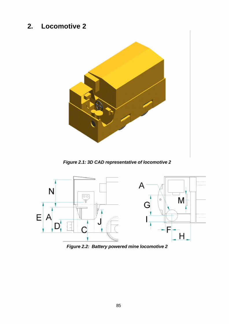
85
2. Locomotive 2
Figure 2.1: 3D CAD representative of locomotive 2
Figure 2.2: Battery powered mine locomotive 2

86
Table 2.1: Dimensions for battery powered mine locomotive 2
Manufacturer Goodman
Weight class (tons) 5
Mine visited A
A Seat height from floor 620
B Seat dimensions (WxD) ∅ 250
Seat material Vinyl covered Cushion
C Surface to entrance height 520
D Entrance to floor height 390
E Controller handle height 685
F Seat to front wall distance 325
G Seat to controller distance 380
H Seat to rear wall distance 385
I Seat to side wall distance 295
J Park brake height from floor 580
K Foot brake height from floor N/A
L Hand brake height from floor N/A
M Park brake dimensions ∅ 320
Canopy (Yes/No) No
N Canopy to seat height N/A
Viewing distance in front of thelocomotive for the 95th percentilesitting eye height
400
Viewing distance in front of thelocomotive for the 5th percentilesitting eye height
500
Figure 2.3: Viewing angle and distance for battery powered mine locomotive 2

87
Figure 2.4: Side viewing angle from an aerial plane
2.1 Access
The surface to entrance level was higher than the recommended height for easy access andwas without handgrips. The operator steps over the cutout side panel whilst holding onto theledge of the locomotive when entering into the cab. Three point contact for safe access into thecab was not available. The dedicated storage bin is located across the full width of the entrancefurther obstructing entry.
2.2 Seat and posture
The seatbase was neither adjustable, nor provided back or arm support. The diameter of theseat was too narrow to comfortably accommodate the 5th percentile up to the 95th percentilemale South African. The height of the seat base from the cab floor was too high for comfortablesitting posture. The operator cannot place the feet onto the cab floor and there was no footrest.The operator adopts a semi-standing posture to place the feet onto the cab floor, which is anunstable work posture for controlling the locomotive.
To accommodate the location of the fire extinguisher secured in front of the operator’s seatcauses the operator to adopt an abducted lower extremity posture. The operator facessideways. This induces a sustained twisted neck posture when facing towards the direction ofthe locomotive movement. When reversing the locomotive, the operator stands up, which isunacceptable driving practice according to the Mine Health and Safety Act, 1996 (Regulation18.2.1).

88
2.3 Controls
All the controls are within the reach envelop, for the 5th percentile up to the 95th percentile SouthAfrican male.
The labelling of the switches for the master controller was illegible with the exception of theemergency controls. Most of the controls were placed within the reach of the 5th to the 95th
percentile South African. The exceptions were the placement of the emergency stop button andthe main isolator switch which were placed behind the operator on the right hand side. Thispositioning required an awkward posture in which to apply forces.
The labelling was often illegible and in places was absent. Displays and controls were within thevisual field of this operator with the exception of the controls used to be placed behind theoperator.
2.4 Visual Field
Forward viewing angle and distance are within the recommended range. The 5th percentile up tothe 95th percentile can easily see onto the track. Visual field to the back from the seated postureis restricted.

89
3. Locomotive 3
Figure 3.1: 3D CAD representation of the locomotive 3
Figure 3.2: Battery powered mine locomotive 3

90
Table 3.1: Dimensions for battery powered mine locomotive 3
Manufacturer Goodman
Weight class (tons) 5
Mine visited B
A Seat height from floor 570
B Seat dimensions (WxD) 240 X 240
Seat material Metal
C Surface to entrance height 530
D Entrance to floor height 400
E Controller handle height 635
F Seat to front wall distance 330
G Seat to controller distance 540
H Seat to rear wall distance 420
I Seat to side wall distance 210
J Park brake height from floor 600
K Foot brake height from floor N/A
L Hand brake height from floor N/A
M Park brake dimensions ∅ 320
Canopy (Yes/No) No
N Canopy to seat height N/A
Viewing distance in front of thelocomotive for the 95th percentilesitting eye height
900
Viewing distance in front of thelocomotive for the 5th percentile sittingeye height
1400
Figure 3.3: Viewing angle and distance for battery powered mine locomotive 3

91
Figure 3.4: Side viewing angle from an aerial plane
3.1 Access
The surface to entrance level was higher than the recommended height for easy access withouthandgrips. The operator has to step over the cutout entry panel and holds onto the locomotiveside panels when entering or exiting the cab. There were no handgrips available to ensure athree-point contact for safe entry into the cab.
3.2 Seats and posture
The square metal seat base was not adjustable in any orientation and did not have back or armsupports. There was however, a rounded surface in the console to be used by the operator torest his left arm while manipulating the controls. The seat base was too narrow toaccommodate the 5th to 95th percentile South African user. The seat height was too high forstable, comfortable sitting posture for the 5th percentile South African male. The 5th percentilemale cannot place his feet on the floor when seated and as a result, adopts a semi-standingposture.
The operator is facing sideways. This induces a sustained twisted neck posture when facingtowards the direction of the locomotive movement. The operator stands up when reversing thelocomotive, which is unacceptable driving practice according to the Mine Health and Safety Act,1996 (Regulation 18.2.1).
Workspace in the cab was restrictive for legroom and low sitting configuration for the 75th
percentile South African male.

92
3.3 Controls and displays
All the controls are within the reach envelope of the 5th percentile to 95th percentile South Africanmale. The master controller was legibly labeled and within the visual field, but the two otherswitches were not labeled.
3.4 Visual angle and distance
Forward and side viewing angles and distance are within the recommended range. The 5th
percentile to the 95th percentile male South African can see the track in front of the locomotivefrom the seated position, but visual field to the rear is restricted such that the operator had tostand when reversing.

93
4 Locomotive 4
Figure 4.1: 3D CAD representation of the locomotive 4
Figure 4.2: Viewing angles and distance for battery powered mine locomotive 4

94
Table 4.1: Dimensions for battery powered mine locomotive 4
Manufacturer Goodman
Weight class (tons) 6
Mine visited C
A Seat height from floor 610
B Seat dimensions (WxD) ∅ 295
Seat material Metal
C Surface to entrance height 550
D Entrance to floor height 410
E Controller handle height 890
F Seat to front wall distance 240
G Seat to controller distance 620
H Seat to rear wall distance 450
I Seat to side wall distance 140
J Park brake height from floor 575
K Foot brake height from floor N/A
L Hand brake height from floor N/A
M Park brake dimensions ∅320
Canopy (Yes/No) No
N Canopy to seat height N/A
Viewing distance in front of thelocomotive for the 95th percentilesitting eye height
400
Viewing distance in front of thelocomotive for the 5th percentile sittingeye height
500
Figure 4.3: Viewing angles and distance for battery powered mine locomotive 4

95
Figure 4.4: Side view angle from an aerial plane
4.1 Access
The surface to entrance level was higher than the recommended height for easy access withouthandgrips. The operator has to step over the cutout entry panel and holds onto the locomotiveside panels when entering or exiting the cab. There were no handgrips available to ensure athree-point contact for safe entry into the cab.
4.2 Seats and posture
The metal seat base was not adjustable in any orientation and did not have back or armsupports. The seat base was too narrow to accommodate the 5th to 95th percentile SouthAfrican user. The seat height was too high for stable, comfortable sitting posture for the 5th
percentile South African male. The 5th percentile male cannot place his feet on the floor whenseated and as a result, adopts a semi-standing posture.
The operator is facing sideways. This induces a sustained twisted neck posture when facingtowards the direction of the locomotive movement. The operator stands up when reversing thelocomotive, which is unacceptable driving practice according to the Mine Health and Safety Act,1996 (Regulation 18.2.1).
The left sided body space would be restrictive even for the 5th percentile male. Legroom wouldbe restrictive for the 75th percentile South African male.

96
4.3 Controls and displays
All the controls are within the reach envelope of the 5th percentile to 95th percentile South Africanmale with the exception of the master controller which would require for the 5th percentile male,an extended reach, beyond the reach envelop. All controls and displays were within the visualfield.
4.4 Visual Angle and distance
Forward viewing angle and distance are within the recommended range. The 5th percentile tothe 95th percentile male South African can see the track in front of the locomotive from theseated position, but visual field to the rear is restricted.

97
5. Locomotive 5
Figure 5.1: 3D CAD representation of the locomotive 5
Figure 5.2: Battery powered mine locomotive 5

98
Table 5.1: Dimensions for battery powered mine locomotive 5
Manufacturer Goodman
Weight class (tons) 6
Mine visited D
A Seat height from floor 520
B Seat dimensions (WxD) 400 X 340
Seat material Polyurethane
C Surface to entrance height 540
D Entrance to floor height 410
E Controller handle height 440
F Seat to front wall distance 270
G Seat to controller distance 430
H Seat to rear wall distance 440
I Seat to side wall distance 430
J Park brake height from floor 600
K Foot brake height from floor 135
L Hand brake height from floor 890
M Park brake dimensions ∅ 320
Canopy (Yes/No) Yes
N Canopy to seat height 1185
Viewing distance in front of thelocomotive for the 95th percentile sittingeye height
500-1400
Viewing distance in front of thelocomotive for the 5th percentile sittingeye height
700-6000
Figure 5.3: Viewing angle and distance for battery powered mine locomotive 5

99
Figure 5.4: Side viewing angle from an aerial plane
5.1 Access
The surface to entrance level was higher than that is recommended for safe access withouthandgrips. The operator has to step over the cut out side panel to enter into the cab. Handgripswere not available for a three point contact access.
5.2 Seats and posture
A saddle type seat without back or arm support was provided which swivels around themounting, but it is not height adjustable. The seat height would be too high for the 5th percentilemale to place the feet on the cab floor for a stable seated posture. The lamp connector directlybehind the operator impeded his head when sitting fully upright. The operator did not face thedirection of the locomotive movement. The position of the control panel causes the operator toface backwards. This includes a sustained twisted neck posture when facing towards thedirection of forward movement. When reversing the locomotive, the operator leans out of thecab to the right with unsupported lateral flexed trunk or he stands up to face the direction ofmovement. The latter to postures are not acceptable practices according to the Mine Health andSafety Act, 1996, (Regulation 18.2.1).
5.3 Controls
The hand and foot controls were within easy access for the 5th percentile to the 95th percentileSouth African male. With the exception of the hand brake which was positioned such that theoperator had to swivel the seat or twist his body to access. All controls were operated by theleft-hand.

100
5.4 Visual field
The fully enclosed cab severely restricts forward visual angle and distance. There are blindspots to the left and right corners of the enclosed cab. Visual field to the back from the seatedposture was restricted.

101
6. Locomotive 6
Figure 6.1: 3D CAD representation of the locomotive 6
Figure 6.2: Viewing angles and distance for battery powered mine locomotive 6

102
Table 6.1: Dimensions for battery powered mine locomotive 6
Manufacturer GoodmanWeight class (tons) 8
Mine visited FA Seat height from floor 740B Seat dimensions (WxDxH) ∅ 290
Seat material CushionC Surface to entrance height 520D Entrance to floor height 400E Controller handle height 700F Seat to front wall distance 235G Seat to controller distance 535H Seat to rear wall distance 675I Seat to side wall distance 245J Park brake height from floor 590K Foot brake height from floor N/AL Hand brake height from floor N/AM Park brake dimensions ∅ 320
Canopy (Yes/No) NoN Canopy to seat height N/A
Viewing distance in front of thelocomotive for the 95th percentilesitting height
900
Viewing distance in front of theLocomotive for the 5th percentilesitting eye height
1500
Figure 6.3: Viewing angle and distance for battery powered mine locomotive 6

103
Figure 6.4: Side viewing angle from an aerial plane
6.1 Access
The surface to entrance level was higher than the recommended height for safe access withouthandgrips. The operator steps over the cutout side panel to enter into the cab. Three pointcontact for safe entry was not available due to the lack of handgrips. The operator made up ofthe barrier as a handgrip.
6.2 Seats and posture
The operator is not facing the direction of locomotive movement, but to the rear. This induces asustained twisted neck posture when facing towards the direction of the locomotive movement.When reversing the locomotive, the operator stands up or leans out of the cab profile, whichwere unsafe driving practices.
The round cushioned seat was neither adjustable nor had back or arm supports. The seatheight was such that the 5th percentile up to the 95th percentile male South African would have toadopt a semi-standing work posture, which was unstable for comfortable driving of thelocomotive. The seat width would accommodate only the 5th percentile South African malecomfortably.

104
6.3 Controls
The controls were within easy reach for the 5th percentile to the 95th percentile male SouthAfrican. However, manipulation and access to the brake handwheel was impeded by the batterycable that is routed directly over the brake handwheel. A video display to give text command tothe operator from the control room was well within visual field.
6.4 Visual field
The visual field to the back from a seated posture was restrictive.

105
7. Locomotive 7
Figure 7.1: 3D CAD representation of the locomotive 7
Figure 7.2: Battery powered mine locomotive 7

106
Table 7.1: Dimensions for battery powered mine locomotive 7
Manufacturer GoodmanWeight class (tons) 8
Mine visited BA Seat height from floor N/AB Seat dimensions (WxDxH) N/A
Seat material No seatC Surface to entrance height 545D Entrance to floor height 425E Controller handle height 940F Seat to front wall distance N/AG Seat to controller distance 730H Seat to rear wall distance 870I Seat to side wall distance N/AJ Park brake height from floor 600K Foot brake height from floor N/AL Hand brake height from floor N/AM Park brake dimensions ∅ 320
Canopy (Yes/No) NoN Canopy to seat height N/A
Viewing distance in front of thelocomotive for the 95th percentilestanding eye height
1000
Viewing distance in front of thelocomotive for the 5th percentilestanding eye height
1600
Figure 7.3: Viewing angle and distance for battery powered mine locomotive 7

107
Figure 7.4: Side viewing angle from an aerial plane
7.1 Access
The surface to entrance level was higher than the recommended height for easy entrance. Theoperator uses the locomotive ledge as handgrip when entering into the cab as there was nohandgrip available for a safe three point entry.
7.2 Seats and posture
There was no seat provided for the operator. Thus he must stand while operating the locomotivewhich is unacceptable practice under the mine regulations. The location of the controls doesallow for a forward facing posture. Upon reversing, the trunk and neck would be rotated to thedirection of movement and the arm would be extended from the side of the body to operate thecontrols.
7.3 Controls
The controls located onto the control panel were within the reach envelop from the operator’sstanding work posture of the 5th to 95th percentile South African male. The location of the mainisolator switch and the light switch at the far left corner was too far to reach while operating thelocomotive for even the 5th percentile male.
7.4 Visual field
The forward and side viewing angle and distance were within the recommended range. Visualfield to the rear was restricted.

108
8. Locomotive 8
Figure 8.1: 3D CAD representation of the locomotive 8
Figure 8.2: Battery powered mine locomotive 8

109
Table 8.1: Dimensions for battery powered mine locomotive 8
Manufacturer GoodmanWeight class (tons) 8
Mine visited EA Seat height from floor 500B Seat dimensions (WxDxH) ∅250
Seat material MetalC Surface to entrance height 530D Entrance to floor height 400E Controller handle height 675F Seat to front wall distance 300G Seat to controller distance 700H Seat to rear wall distance 680I Seat to side wall distance 50J Park brake height from floor 565K Foot brake height from floor N/AL Hand brake height from floor N/AM Park brake dimensions ∅ 320
Canopy (Yes/No) NoN Canopy to seat height N/A
Viewing distance in front of thelocomotive for the 95th percentile sittingeye height
2300
Viewing distance in front of the 27200locomotive for the 5th percentile sittingeye height
Figure 8.3: Viewing angle and distance for battery powered mine locomotive 8

110
Figure 8.4: Side viewing angles from an aerial plane
8.1 Access
The surface to entrance level was higher than the recommended height. A handgrip bar isprovided on the right-hand side of the cutout side panel for the cab, which enables easy accessinto the cab for the 5th to 95th percentile South African male.
8.2 Seats and posture
The position of the control panel is such that the operator must face sideways. The operatoradopts a sustained twisted neck posture when facing towards the direction of the locomotivemovement. When reversing the locomotive, the operator stands up or leans out of the cabprofile. Standing posture when operating a locomotive is unacceptable driving practice.
The seat height is too high for a traditional sitting posture. The operator would adopt a semi-standing work posture, which is unstable for proper control of the locomotive. The lampconnector is positioned that the operator often contacts it with his trunk.
8.3 Controls
The location of the control panel from the operator’s seat was not within the reach envelop of the50th percentile South African male population.

111
8.4 Visual field
Forward and side viewing angles and distance were within the recommended range for the 95th
percentile male South African. Forward visual field was severely restricted by the frontprotection plate for the 5th percentile. This operator cannot see in front of the locomotive withinthe recommended range and therefore cannot safely drive the locomotive. Rear visual field forthe 5th percentile to the 95th percentile was restricted.

112
9. Locomotive 9
Figure 9.1: 3D CAD representation of the locomotive 9
Figure 9.2: Battery powered mine locomotive 9

113
Table 9.1: Dimensions for battery powered mine locomotive 9
Manufacturer GoodmanWeight class (tons) 10
Mine visited GA Seat height from floor 580B Seat dimensions (WxDxH) 400 X 360
Seat material PolyurethaneC Surface to entrance height 615D Entrance to floor height 495E Controller handle height 780F Seat to front wall distance 290G Seat to controller distance (seat at furthest backward
position)740
H Seat to rear wall distance 650I Seat to side wall distance 12 (can swivel outside
the cabin envelope)J Park brake height from floor 585K Foot brake height from floor N/AL Hand brake height from floor N/AM Park brake dimensions ∅320
Canopy (Yes/No) NoN Canopy to seat height N/A
Viewing distance in front of the locomotive for the 95thpercentile sitting eye height
4300
Viewing distance in front of the locomotive 27500for the 5th percentile sitting eye height
Figure 9.3: Viewing angle and distance for battery powered mine locomotive 9

114
Figure 9.4: Side view angle from an aerial plane
9.1 Access
The surface to entrance level was higher than the recommended height for easy access withouthandgrips. The operator steps over the cutout side panel to enter into the cab. Three pointcontact for safe entry into the cab was not available.
9.2 Seat and posture
A swivel type saddle seat with no back and arm support was provided for the operator. The seatswings outside of the locomotive cab profile to allow easy entry. The adjustability to change thehorizontal seated position allows for easy access to the controls.
The location of the control panel induces the operator to sit sideways. When facing towards thedirection of the locomotive movement, the operator adopts a sustained twisted neck posture.When reversing the locomotive, the operator stands up.

115
The height of the seatbase from the cab floor was high for comfortable sitting posture for the 5th
percentile South African male. The operator adopts a semi-standing posture, which is anunstable posture for locomotion operation. The operator’s feet cannot be placed onto the cabfloor for a stable seated posture.
9.3 Controls
All controls were within easy reach and manipulation for the 5th percentile to the 95th percentileseated South African male. This was achieved by the horizontal adjustability of the seat for theoperator. All controls were clearly labelled.
9.4 Visual field
Forward viewing distance was within the recommended range for the 95th percentile SouthAfrican male. Forward visual field was severely restricted by the front protection plate for the 5th
percentile. He can therefore not safely drive the locomotive. There are blind spots to frontcorners of protection plate limiting front visual field within a 45 degrees radius. The operatorcannot see in front of the locomotive within the recommended range.

116
10. Locomotive 10
Figure 10.1: 3D CAD representation of the locomotive 10
Figure 10.2: Battery powered mine locomotive 10

117
Table 10.1: Dimensions for battery powered mine locomotive 10
Manufacturer GoodmanWeight class (tons) 10
Mine visited HA Seat height from floor 680-740B Seat dimensions (WxDxH) ∅265
Seat material WoodC Surface to entrance height 510D Entrance to floor height 410E Controller handle height 755F Seat to front wall distance 568G Seat to controller distance 480H Seat to rear wall distance 297I Seat to side wall distance 68J Park brake height from floor 575K Foot brake height from floor 135L Hand brake height from floor 890M Park brake dimensions ∅ 320
Canopy (Yes/No) NoN Canopy to seat height N/A
Viewing distance in front of the locomotivefor the 95th percentile sitting eye height
600
Viewing distance in front of the 800locomotive for the 5th percentile sitting eyeheight
Figure 10.3: Visual angle and distance for battery powered mine locomotive 10

118
Figure 10.4: Side view angle from an aerial plane
10.1 Access
The surface to entrance level was higher than recommended without handgrips. The operatorsteps over the cutout side panel and holds onto the locomotive ledge when entering into the cab.Three point contract for safe entering into the cab was not available.
10.2 Seats and posture
The seat was too narrow to accommodate the 5th percentile South African male users. The seatheight was adjustable but the range was still too high for comfortable sitting for the 5th percentileup to the 95th percentile male South African. The operator’s feet cannot be placed onto the cabfloor for a stable seated posture. The operator adopts a semi-standing posture, which is notstable for controlling the locomotive.
The operator does not face towards the direction of the locomotive movement, but to the side ofthe cab, which includes a sustained twisted neck posture when facing towards the front of thelocomotive. To reverse the locomotive the operator must stand up which are against mininghealth and safety regulations.

119
10.3 Controls
All the controls were within the reach envelop the 5th percentile to the 95th percentile seated maleSouth African. A hand operated service brake with foot pedal is provided. All displays werelegible and within the visual field of the seated operator.
10.4 Visual field
Forward and side viewing angle and distance are within the recommended range. The 5th
percentile up to the 95th percentile South African male can see onto the track. Visual field to therear from the seated posture is restricted.

120
11. Locomotive 11
Figure 11.1: 3D CAD representation of the locomotive 11
Figure 11.2: Diesel powered mining locomotive 11

121
Table 11.1: Dimensions for diesel powered mining locomotives 11
Manufacturer Hunslett Taylor
Weight class (tons) 10
Mine visited ?
A Seat height 660-900
B Seat dimensions (WxDxH) ∅300
Seat material Wood
C Surface to entrance height 770
D Entrance to floor height 640
E Controller handle height 930
F Seat to front wall distance 310
G Seat to controller distance 270
H Seat to rear wall distance 315
I Seat to side wall distance 960
Canopy (Yes/No) No
Viewing distance in front of the locomotivefor the 95th percentile sitting eye height
200
Viewing distance in front of the locomotivefor the 5th percentile sitting eye height
300
Figure 11.3: Visual angle and distance for diesel powered mining locomotive 11

122
Figure 11.4: Side view angles from an aerial plane
11.1 Access
The surface to entrance level was higher than the recommended height for easy access withouthandgrips. The operator has to step up onto or over the entry panel, which did not have a cutout.He holds onto the locomotive side panels when entering or exiting the cab, as there were nohandgrips available to ensure a three-point contact for safe entry into the cab. Footing on entryis limited due to the tools and equipment being stored on the cab floor.
11.2 Seats and posture
The wooden seat base was height adjustable but did not have back or arm supports. The seatheight was too high for the 5th percentile to the 95th South African male to be able to place hisfeet on the cab floor. The operator places his feet onto ledges on either side of the cab toprovide some stability.
The operator is facing sideways. This induces a sustained twisted neck posture when facingtowards the direction of the locomotive movement. The operator stands up when reversing thelocomotive, which is unacceptable driving practice according to the Mine Health and Safety Act,1996 (Regulation 18.2.1).

123
11.3 Controls and displays
All the controls are within the reach envelope of the 5th percentile to 95th percentile South Africanmale. All controls and displays were legibly labeled and within the visual field.
11.4 Visual angle and distance
Forward viewing angle and distance are within the recommended range. The 5th percentile tothe 95th percentile male South African can see the track in front of the locomotive from theseated position, but visual field to the rear is restricted such that the operator had to stand whenreversing to have visual access.

124
12. Locomotive 12
Figure 12.1: 3D CAD representation of the locomotive 12
Figure 12.2: Diesel powered mining locomotive 12

125
Table 12.1: Dimensions for diesel powered mining locomotives 12
Manufacturer Funkey
Weight class (tons) 15
Mine visited ?
A Seat height 660
B Seat dimensions (WxDxH) 530x370x260
Seat material Polyurethane
C Surface to entrance height 580
D Entrance to floor height 400
E Controller handle height 950
F Seat to front wall distance 335
G Seat to controller distance 255
H Seat to rear wall distance 265
I Seat to side wall distance 895
Canopy (Yes/No) No
Viewing distance in front of thelocomotive for the 95th percentilesitting eye height
500
Viewing distance in front of thelocomotive for the 5th percentilesitting eye height
700
Figure 12.3: Viewing angle and distance for diesel powered mining locomotive 12

126
Figure 12.4: Side view angle from an aerial plane
12.1 Access
The surface to entrance level was higher than the recommended height for easy access withouthandgrips. The operator has to step over the entry panel, which did have a cutout. He holdsonto the locomotive side panels when entering or exiting the cab, as there were no handgripsavailable to ensure a three-point contact for safe entry into the cab.
12.2 Seats and posture
The polyurethane seat was not height adjustable but did have back and arm supports. The seatheight was too high for the 5th percentile to the 95th South African male to be able to place hisfeet on the cab floor. The operator places his feet onto ledges on either side of the cab toprovide some stability
The operator is facing sideways. This induces a sustained twisted neck posture when facingtowards the direction of the locomotive movement. The operator stands up when reversing thelocomotive, which is unacceptable driving practice according to the Mine Health and Safety Act,1996 (Regulation 18.2.1).
12.3 Controls and displays
All the controls are within the reach envelope of the 5th percentile to 95th percentile South Africanmale. All controls and displays were legibly labeled and within the visual field.

127
12.4 Visual angle and distance
Forward viewing angle and distance are within the recommended range. The 5th percentile tothe 95th percentile male South African can see the track in front of the locomotive from theseated position, but visual field to the rear is restricted such that the operator had to stand whenreversing.

128
13. Locomotive 13
Figure 13.1: 3D CAD representation of the locomotive 13
Figure 13.2: Diesel powered mining locomotive 13

129
Table 13.1: Dimensions for diesel powered mining locomotives 13
Manufacturer Funkey
Weight class (tons) 15
Mine visited ?
A Seat height 660
B Seat dimensions (WxDxH) 530x370x260
Seat material Polyurethane
C Surface to entrance height 580
D Entrance to floor height 400
E Controller handle height 950
F Seat to front wall distance 335
G Seat to controller distance 255
H Seat to rear wall distance 265
I Seat to side wall distance 895
Canopy (Yes/No) No
Viewing distance in front of the locomotive for the95th percentile sitting eye height
500
Viewing distance in front of the locomotive for the5th percentile sitting eye height
700
Figure 13.3: Viewing angle and distance for diesel powered mining locomotive
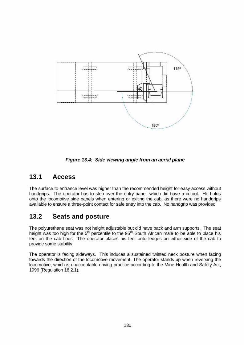
130
Figure 13.4: Side viewing angle from an aerial plane
13.1 Access
The surface to entrance level was higher than the recommended height for easy access withouthandgrips. The operator has to step over the entry panel, which did have a cutout. He holdsonto the locomotive side panels when entering or exiting the cab, as there were no handgripsavailable to ensure a three-point contact for safe entry into the cab. No handgrip was provided.
13.2 Seats and posture
The polyurethane seat was not height adjustable but did have back and arm supports. The seatheight was too high for the 5th percentile to the 95th South African male to be able to place hisfeet on the cab floor. The operator places his feet onto ledges on either side of the cab toprovide some stability
The operator is facing sideways. This induces a sustained twisted neck posture when facingtowards the direction of the locomotive movement. The operator stands up when reversing thelocomotive, which is unacceptable driving practice according to the Mine Health and Safety Act,1996 (Regulation 18.2.1).

131
13.3 Controls and displays
All the controls are within the reach envelope of the 5th percentile to 95th percentile South Africanmale. All controls and displays were legibly labeled and within the visual field. There were novisual warning lights on the control panel in working order and the labels were eroded or illegible.
13.4 Visual angle and distance
Forward and side viewing angles and distance are within the recommended range. The 5th
percentile to the 95th percentile male South African can see the track in front of the locomotivefrom the seated position, but visual field to the rear is restricted such that the operator had tostand when reversing.

132
14. Locomotive 14
Figure 14.1: 3D CAD representation of the locomotive 14
Figure 14.2: Diesel powered mining locomotive 14

133
Table 14.1: Dimensions for diesel powered mining locomotives 14
Manufacturer PROF Donsa
Weight class (tons) 15
Mine visited ?
A Seat height 560
B Seat dimensions (WxDxH) 480x330x250
Seat material Polyurethane
C Surface to entrance height 510
D Entrance to floor height 295
E Controller handle height 1030
F Seat to front wall distance 300
G Seat to controller distance 630
H Seat to rear wall distance 240
I Seat to side wall distance 1015
Canopy (Yes/No) No
Viewing distance in front of the locomotivefor the 95th percentile sitting eye height
900
Viewing distance in front of the locomotivefor the 5th percentile sitting eye height
700
Figure 14.3: Viewing angle and distance for diesel powered mining locomotive 14

134
Figure 14.4: Side view angle from an aerial plane
14.1 Access
The access level for higher than the recommended height, however there was cut out in theentry panel and used with the sided bumper rail as a hand rail allowed for safe and easy access.
14.2 Seat and posture
The operator did not face the direction of the locomotive movement which induced a sustainedtwisted neck posture, towards the direction of movement, when reversing the operator had tolean out of the cab to the left with an unsupported laterally flexed trunk or to stand and face thedirection of movement, neither of which are acceptable mine practices. The seat providesadequate back and foot support but no arm support. However the layout of the cab is such thatthe operator can use the panel to the left-hand side and the bumper rail to the right hand side torest his arms.
14.3 Controls
The hand and foot controls were within access for the 5th to 95th percentile South African male.The visual display was within visual access.
14.4 Visual field and angles
The angles and distances were within acceptable ranges.

135
15. Locomotive 15
Figure 15.1: 3D CAD representation of the locomotive 15
Figure 15.2: Electric powered mining locomotive 15

136
Table 15.1: Dimensions for electric powered mining locomotives 15
Manufacturer Goodman
Weight class (tons) 20
A Seat height 750
B Seat dimensions (WxDxH) 400x340
Seat material Polyurethane
C Entrance to floor height 640
D Surface to entrance height 800
E Controller handle height 990
F Seat to front wall distance 620
G Seat to controller distance 220
H Seat to rear wall distance 280
I Seat to side wall distance 635
J Park brake height from floor 845
M Park brake diameter N/A
Canopy (Yes/No) Yes
N Canopy to seat height 990
Viewing distance in front of the locomotive for the 95thpercentile sitting eye height
2500-6800
Viewing distance in front of the locomotive for the 5thpercentile sitting eye height
4200-infinite
Figure 15.3: Visual angles and distance for electric powered mininglocomotive 15

137
Figure 15.4: Side viewing angle from an aerial plane
15.1 Access
The surface to entrance level was higher than the recommended height and still required theoperator to step over the cut out entry panel. There was one handgrip on the left-hand side onlywhich does not allows for a safe three point entry.
15.2 Seats and posture
The saddle type swivel seat base was not adjustable. At its present height the 5th percentile malewould have problems with their feet not reaching the ground. There were no back or armsupports. The operator is forward facing at all times, due to the two engine locomotive systems.Occasionally the operator would lean outside the cab with a rotated neck and trunk posture tocheck for signals. Cab due to the restricted cab roof height, the operators will be in a crouchedposture during entry or exit.
15.3 Controls
The forward facing, centred control box is positioned too close to the operator without allowingsufficient leg and foot clearance. As a result the operator adopts a variety of postures includingforward facing with feet/legs abducted, rotating the seat to one side, with a rotated spine and thearm operating at from their side or across the body. These are sustained and awkwardpostures. The instrument panel was within visual access. The controls appear to be designedto be entered to the side of the operator and not front centred.

138
15.4 Visual field
The forward visual distance is excellent within a 60 degree radius. There are however “blind”spots to the left and right hand angles as all four corners of the enclosed cabs. Due to the heightof the window, visual field would be restricted for the 5th percentile South African females whenseated.

139
16. Locomotive 16
Figure 16.1: 3D CAD representation of the locomotive 16
Figure 16.2: Electric powered mining locomotive 16

140
Table 16.1: Dimensions for electric powered mining locomotives 16
Manufacturer Goodman
Weight class (tons) 15
A Seat height 430
B Seat dimensions (WxDxH) ∅300
Seat material Metal
C Surface to entrance height 605
D Entrance to floor height 405
E Controller handle height 700
F Seat to front wall distance 540
G Seat to controller distance 480
H Seat to rear wall distance 370
I Seat to side wall distance 220
J Park brake height from floor 1045
M Park brake diameter N/A
Canopy (Yes/No) Yes
N Canopy to seat height 1090
Viewing distance in front of the locomotive for the95th percentile sitting eye height
5400
Viewing distance in front of the locomotive for the5th percentile sitting eye height
Cannot see the track
Figure 16.3: Viewing angle and distance for electric poweredmining locomotive 16

141
Figure 16.4: Side viewing angle from an aerial plane
16.1 Access
The surface to entrance level was higher than the recommended height for easy access withouthandgrips. The operator steps over the cut-out panel and holds onto the locomotive ledge whenentering in the cab. Three point contact for entering into the cab was not available.
16.2 Seat and posture
The metal seat was not adjustable and did not have back or arm supports. The seat heightcould comfortably enable sitting posture, with supported feet for the 5th percentile up to the 95th
percentile South African male.
The operator faces sideways. This induces a sustained twisted neck posture when facingtowards the direction of the locomotive movement. When reversing the locomotive the driveadopts an awkward rotated body posture in order to see at the back through the rear window ofthe cab.
16.3 Controls
All the controls are within the reach envelop for the 5th percentile up to the 95th percentile SouthAfrican male. The instrument panel was within easy access but not direct visual field for theoperators.

142
16.4 Visual field
Forward and side viewing angle and distance did not meet the recommended range for safeoperation of the locomotive. The enclosed cab severely restricts visual access only the 95th
percentile male operator. The operator cannot see onto the track in front of the locomotive.There are also blind spots to the left and right corners of the enclosed cab.

143
17 Locomotive 17
Figure 17.1: 3D CAD representation of the locomotion 17
Figure 17.2: Electrical powered monorail mining locomotive 17

144
Table 17.1: Dimensions for monorail powered mining locomotives 17
Manufacturer Becker
A Seat height 210
B Seat dimensions (WxDxH) 480x480x630
Seat material Vinyl
C Surface to entrance height Varies
D Entrance to floor height 60
E Controller handle height 335
F Seat to front wall distance 1105
G Seat to controller distance 255
H Seat to rear wall distance 590
I Seat to side wall distance 240
J Park brake height from floor N/A
K Foot brake height from floor N/A
L Hand brake height from floor N/A
M Park brake diameter N/A
N Canopy to seat height 950
Viewing distance in front of the locomotive for the 95percentile sitting eye height
3500
Viewing distance in front of the locomotive for the 5percentile sitting eye height
5200
Figure 17.3: Visual angle and distance for monorail powered mining locomotive 17

145
Figure 17.4: Side viewing angle from an aerial plane
17.1 Access
The surface to entrance level was easy for entering into the cab. Handgrips are fitted inside thecab to enable the operator to step into the cab.
17.2 Seat and posture
An automobile type seat is provided for the operator. The seatbase is horizontally adjustable toenable a comfortable sitting posture. The seat has a backrest which could provides lumbarsupport for the operator but does not accommodate the caplamp battery self rescuer of otherequipment attached the minders belt and therefore the backrest is not useful effectively. Theseat was generally found to be comfortable. It can accommodate the 5th percentile up to the 95th
percentile South African male. The operator faces the direction of the locomotive movement.The operator adopts a crouched posture during entry and exit from the cab.
17.3 Controls
All the controls are within the reach envelop for the 5th percentile up to the 95th percentile SouthAfrican male. The instrument panel was within easy visual access for the operator.
17.4 Visual field
Forward and side viewing angles and distance are within the recommended range for the 95th
percentile South African male. Forward viewing angle and distance are restrictive for the 5th
percentile South African male. Visual field to the rear was restrictive. The operator would leanoutside the cab with a rotated neck and truck posture to view to the rear.

146
18. Locomotive 18
Figure 18.1: 3D CAD representation of the locomotive 18
Figure 18.2: Electrical powered monorail mining locomotive 18

147
Table 18.1: Dimensions for modified powered mining locomotives 18
Manufacturer Scharf
A Seat height 200
B Seat dimensions (WxDxH) 460x400x450
Seat material Polyurethane
C Surface to entrance height Varies
D Entrance to floor height 60
E Controller handle height 460
F Seat to front wall distance 890
G Seat to controller distance 130
H Seat to rear wall distance 600
I Seat to side wall distance 310
J Park brake height from floor N/A
K Foot brake height from floor N/A
L Hand brake height from floor N/A
M Park brake diameter N/A
N Canopy to seat height 970
Viewing distance in front of the locomotive for the 95percentile sitting eye height
3400
Viewing distance in front of the locomotive for the 5percentile sitting eye height
5200
Figure 18.3: Visual angle and distance for locomotive 18

148
Figure 18.4: Side viewing angle from an aerial plane
18.1 Access
The surface to entrance level was easy for entering into the cab. Handgrips are fitted inside thecab to enable the operator to step into the cab.
18.2 Seat and posture
An automobile type seat is provided for the operator. The seatbase is horizontally adjustable toenable a comfortable sitting posture. The seat has a backrest which could provides lumbarsupport for the operator but does not accommodate the caplamp battery self rescuer of otherequipment attached the minders belt and therefore the backrest is not useful effectively. Theseat was generally found to be comfortable. It can accommodate the 5th percentile up to the 95th
percentile South African male. The operator faces the direction of the locomotive movement.The operator adopts a crouched posture during entry and exit from the cab.
18.3 Controls
All the controls are within the reach envelop for the 5th percentile up to the 95th percentile SouthAfrican male. The instrument panel was within easy visual access for the operator.
18.4 Visual field
Forward and side viewing angles and distance are within the recommended range for the 95th
percentile South African male. Forward viewing angle and distance are restrictive for the 5th
percentile South African male. Visual field to the rear was restrictive. The operator would leanoutside the cab with a rotated neck and truck posture to view to the rear.

149
19. Locomotive 19
Figure 19.1: 3D CAD representation of the of the locomotive 19
Figure 19.2: Modified mine locomotive 19

150
Table 19.1: Dimensions for modified mine locomotive 19
Manufacturer Modified Goodmanbattery powered
locomotivesWeight class (tons) 10Mine visited H
A Seat height 240B Seat dimensions (WxDxH) 480x410x450
Seat material PolyurethaneC Surface to entrance height 345D Entrance to floor height 205E Controller handle height 320F Seat to front wall distance 845G Seat to controller distance 350H Seat to rear wall distance 435I Seat to side wall distance 560J Park brake height from floor N/AK Foot brake height from floor N/AL Hand brake height from floor N/AM Park brake diameter N/A
Canopy (Yes/No) YesN Canopy to seat height 960
Viewing distance in front of thelocomotive for the 95th percentilesitting eye height
1600
Viewing distance in front of thelocomotive for the 5th percentile sittingeye height
2900
Figure 19.3: Viewing angle and distance for modified mine locomotive 19

151
Figure 19.4: Side view angles from a top view
19.1 Access
The surface to entrance level was within the recommended height for easy access withouthandgrip. Access into the cab was easy for the 5th percentile South African male but restrictivefor the 95th percentile male because of the low door height. The operator adopts a crouchedposture and can strike the sharp edges of the canopy roof.
19.2 Seat and posture
A T-back polyurethane seat is provided for the operator. The seat is adjustable horizontally toenable comfortable reach distance to the controls. The recess in the seat backrest allows theoperator to sit comfortably with the lamp battery, self-rescuer and other protective equipmentthat are worn on the operator’s belt.
19.3 Controls
All the controls are within the reach envelop for the 5th percentile up to the 95th percentile SouthAfrican male.
19.4 Visual field
Forward viewing angle and distance are within the recommended range. The 5th percentile up tothe 95th percentile can see onto the track in front of the locomotive for safe driving of thelocomotive. Visual field to the back was severely restricted by the enclosed cab. Side viewingwas restricted due to the corners of the enclosed cab.

152
20. Locomotive 20
Figure 20.1: 3D CAD representation of the locomotive 20
Figure 20.2: Modified mine locomotive 20

153
Table 20.1: Dimensions for modified mine locomotive 20
Manufacturer Modified Goodman batterypowered locomotives
Weight class (tons) 6
Mine visited K
A Seat height 500
B Seat dimensions (WxDxH) Shaped
Seat material Steel saddle
C Surface to entrance height 350
D Entrance to floor height 220
E Controller handle height 580
F Seat to front wall distance 740
G Seat to controller distance 600
H Seat to rear wall distance 470
I Seat to side wall distance 230
J Park brake height from floor 580
K Foot brake height from floor N/A
L Hand brake height from floor N/A
M Park brake diameter N/A
Canopy (Yes/No) No
N Canopy to seat height N/A
Viewing distance in front of the locomotivefor the 95th percentile sitting eye height
2400
Viewing distance in front of the locomotivefor the 5th percentile sitting eye height
4100
Figure 20.2: Visual angle and distance modified mine locomotive 20

154
Figure 20.3: Side viewing angles from a top view
20.1 Access
The surface to entrance level was within the recommended height for access. The 5th percentileup to the 95th percentile can easily step into the cab.
20.2 Seat and posture
The saddle type metal seat was not height adjustable and did not have back or arm supports.The seat height required a semi-standing posture for 5th to 50th percentile South African male.The width of the seat was too narrow to accommodate comfortable sitting posture for the 5th
percentile up to the 95th percentile South African male. The operator faces sideways. Thisinduces a sustained twisted neck posture when facing towards the direction of the locomotivemovement. The operator stands up to view to the rear when reversing the locomotive. Drivingthe locomotive whilst standing or leaning out of the locomotive profile is unacceptable drivingpractice according to the Mine Health and Safety Act, 1996 (Regulation 18.21).
20.3 Controls
The controls are not within easy reach for the 5th percentile up to the 95th percentile SouthAfrican male as it is a training locomotive. The location of the master controller directly in front ofthe operator, required an extended arm and repetitive arm movements across the midline of thebody. This will result in upper extremity fatigue and may precede strain on both the shoulder andthe wrist. The instrument panel was within easy visual access for the operator from the seatedposture.

155
20.4 Visual field
The 5th percentile up to the 95th percentile can see the track in front of the locomotive from theseated posture. A cutout in the front panel provided additional forward view. Visual field to therear was restricted.

156
21. Locomotive 21
Figure 21.1: 3D CAD representation of the locomotive 21
Figure 21.2: Modified mine locomotive 21

157
Table 21.1: Dimensions for modified mine locomotive 21
Manufacturer Modified Goodman batterypowered locomotives
Weight class (tons) 5
Mine visited J
A Seat height 475
B Seat dimensions (WxDxH) 480x410x450
Seat material Polyurethane
C Surface to entrance height 540
D Entrance to floor height 410
E Controller handle height 550
F Seat to front wall distance 470
G Seat to controller distance 430
H Seat to rear wall distance 435
I Seat to side wall distance 340
J Park brake height from floor N/A
K Foot brake height from floor N/A
L Hand brake height from floor 600
M Park brake diameter N/A
Canopy (Yes/No) Yes
N Canopy to seat height 1060
Viewing distance in front of the locomotivefor the 95th percentile sitting eye height
1200
Viewing distance in front of the locomotivefor the 5th percentile sitting eye height
1900
Figure 21.3: Viewing angle and distance form modified mine locomotive 21

158
Figure 21.4: Side viewing angles from a top view
21.1 Access
The surface to entrance level was higher than the recommended height. The handgripsprovided on the door would assist with a safe access into the cab. The cab doors were of astandard automobile type, including a window and door opening mechanisms.
21.2 Seating and posture
The T-back polyurethane seat was not height adjustable, nor had back or arm support. Theheight of the seat induced a semi-standing posture. The seat is adjustable horizontally to enablethe operator to comfortably reach the controls. The operator seat was found to be comfortable,durable, and it incorporates adequate lumber support to reduce fatigue. The operator orientationwas forward facing towards the direction of the locomotive movement.
21.3 Controls
All the controls are within the reach envelop for the 5th percentile up to the 95th percentile. All theinstruments are located in directly front of the operator’s sitting position in dashboard typeconfiguration.
21.4 Visual field
Forward viewing angle and distance was within the recommended range for safe driving. Theoperator can see on the track in front of the locomotive from a seated posture. The side andrear viewing was restricted.

159
22. Locomotive 22
Figure 22.1: 3D CAD representation of the locomotion 22
Figure 22.2: Modified mine locomotive 22

160
Table 22.1: Dimensions for modified mine locomotive 22
Manufacturer Modified Goodman batterypowered locomotives
Weight class (tons) 10Mine visited J
A Seat height 570B Seat dimensions (WxDxH) 480x355x390
Seat material Vinyl covered cushionC Surface to entrance height 570D Entrance to floor height 435E Controller handle height 690F Seat to front wall distance 900G Seat to controller distance 390H Seat to rear wall distance 350I Seat to side wall distance 550J Park brake height from floor N/AK Foot brake height from floor N/AL Hand brake height from floor N/AM Park brake diameter N/A
Canopy (Yes/No) YesN Canopy to seat height 1015
Viewing distance in front of the locomotivefor the 95th percentile sitting eye height
2900
Viewing distance in front of the locomotivefor the 5th percentile sitting eye height
5300
Figure 22.3: Viewing angle and distance modified mine locomotive 22

161
Figure 22.4: Side viewing from a top view
22.1 Access
The surface to entrance level was higher than the recommended height for easy entry withouthandgrips. Three point contact for safe entering into the cab was not available. A single slidingdoor was located on the left side of the cab.
22.2 Seat and posture
A T-back polyurethane seat with fixed armrests was found to restrict comfortable sitting posturefor the operator with the cap lamp battery and other personal protective equipment attached tothe operator’s belt. The operator faces forward towards the direction of the locomotivemovement. Sit height would require that the 5th to 95th percentile would be sitting withunsupported feet.
22.3 Controls
All the controls are located on a control panel, which is within easy reach for the 5th percentile upto the 95th percentile South African male. All the instruments were within easy visual access forthe operator from the seated posture including a clearly labelled, hand-held, docked remote forcontrol of direction and speed.

162
22.4 Visual field
Forward viewing angle and distance was within the recommended range for safe driving for the95th percentile South African male. However, the viewing distance for the 5th percentile was notwithin the recommended range. Visual field to the back is restrictive for the 5th percentile up tothe 95th percentile South African male

163
23. Locomotive 23
Figure 23.1: 3D CAD representation of the locomotive 23
Figure 23.2: Modified mine locomotive 23

164
Table 23.1: Dimensions for modified mine locomotive 23
Manufacturer Modified Goodmanbattery powered
locomotives
Weight class (tons) 10Mine visited J
A Seat height 475B Seat dimensions (WxDxH) 480x410x450
Seat material PolyurethaneC Surface to entrance height 510D Entrance to floor height 370E Controller handle height 550F Seat to front wall distance 350G Seat to controller distance 355H Seat to rear wall distance 340I Seat to side wall distance 410J Park brake height from floor N/AK Foot brake height from floor N/AL Hand brake height from floor 600M Park brake diameter N/A
Canopy (Yes/No) YesN Canopy to seat height 1020
Viewing distance in front of the locomotivefor the 95th percentile sitting eye height
1200
Viewing distance in front of the locomotivefor the 5th percentile sitting eye height
1800
Figure 23.3: Viewing angle and distance for modified mine locomotive 23

165
Figure 23.4: Side viewing angle from a top view
23.1 Access
The surface to entrance level was higher than the recommended height for easy entry withouthandgrips. Three point contact for safe entering into the cab was not available. A single slidingdoor on the left-hand side of the cab closed the access.
23.2 Seat and posture
A T-back polyurethane seat is provided for the operator. The seat is adjustable horizontally toenable comfortable seat positioning for reach to the controls. The operator faces towards thedirection of the locomotive movement. Restricted workspace caused the operator to adopts anawkward rotated body posture when operating controls on the right. The seat height wouldrequire the 5th percentile South African male to sit with unsupported feet.
23.3 Controls
All the controls located on the control panel are within the reach envelop for the 5th percentile upto the 95th percentile South African male. The position of the park brake system at the far right,behind the operator required an awkward posture to access the brake.

166
23.4 Visual field
Forward viewing angle and distance are within the recommended range for safe driving. The 5th
percentile up to the 95th percentile can see on the track in front of the locomotive.

167
24. Locomotive 24
Figure 24.1: 3D CAD representation of the locomotive 24
Figure 24.2: Modified mine locomotive 24

168
Table 24.1: Dimensions for modified mine locomotive 24
Manufacturer Modified Goodman batterypowered locomotives
Weight class (tons) 8
Mine visited F
A Seat height 520
B Seat dimensions (WxDxH) 480x355x390
Seat material Vinyl covered cushion
C Surface to entrance height 530
D Entrance to floor height 400
E Controller handle height 515
F Seat to front wall distance 520
G Seat to controller distance 520
H Seat to rear wall distance 345
I Seat to side wall distance 300
J Park brake height from floor N/A
K Foot brake height from floor N/A
L Hand brake height from floor N/A
M Park brake diameter N/A
Canopy (Yes/No) Yes
N Canopy to seat height 840
Viewing distance in front of the locomotivefor the 95th percentile sitting eye height
1500
Viewing distance in front of the locomotivefor the 5th percentile sitting eye height
900
Figure 24.3: Forward viewing angle and distance modified mine locomotive 24

169
Figure 24.4: Side viewing angles from a top view
24.1 Access
The surface to entrance level was higher than the recommended height for easy access withouthandgrips. Three point contact for safe entering into the cab was not available. When enteringthe cab, the operator slides up and tilts the door panels for entry/exit. The opened door impedessafe head clearance space when the operator is inside the cab. The operator adopts acrouched body posture to exit.
24.2 Seating and posture
A T-back polyurethane seat with integrated armrests is provided for the operator. The seatmounting is swivel type. It can rotate 360 degrees, which enables the operator to change theviewing direction without adopting strained body posture. The seat height would require a semi-standing posture for the 5th to 95th percentile South African male. In addition the back supportdoes not accommodate the equipment attached to the miner’s belt.
24.3 Controls
All the controls and instruments are within the reach envelop for the 5th percentile up to the 95th
percentile South African male.
24.4 Visual field
Forward viewing angle and distance are within the recommended range for safe driving. The 5th
percentile up to 95th percentile can see the track in front of the locomotive. Visual field to the rearwas good. The operator can see a radius of 100 degrees. There are blind spots on the left andright corners of the enclosed cab.

170
25. Locomotive 25
Figure 25.1: 3D CAD representation of the locomotive 25
Figure 25.2: Modified mine locomotive 25

171
Table 25.1: Dimensions for modified mine locomotive 25
Manufacturer ModifiedGoodman
batterypowered
locomotives
Weight class (tons) 10
Mine visited I
A Seat height 430
B Seat dimensions (WxDxH) 460x400x480
Seat material Plastic
C Surface to entrance height 555
D Entrance to floor height 425
E Controller handle height 710
F Seat to front wall distance 535
G Seat to controller distance 395
H Seat to rear wall distance 560
I Seat to side wall distance 225
J Park brake height from floor 600
K Foot brake height from floor 135
L Hand brake height from floor 890
M Park brake diameter ∅365
Canopy (Yes/No) Yes
N Canopy to seat height 1220
Viewing distance in front of the locomotivefor the 95th percentile sitting eye height
4200
Viewing distance in front of the locomotivefor the 5th percentile sitting eye height
50500
Figure 25.3: Visual angle and distance for modified mine locomotive 25

172
Figure 25.4: Side viewing angles from a top view
25.1 Access
The surface to entrance level was higher than the recommended height for easy access withouthandgrip. Three point contact for safe entry into the cab was not available.
Exit from the cab was difficult because of the inward-opening entrance barrier, a folding metalgrid door that has to held up by the operator while exiting from the cab.
25.2 Seat and posture
The moulded plastic bucket seat was not height adjustable, did not have armrests but did swivelthrough 360°. The backrest did not accommodate the equipment attached to the miner’s belt.The operator was not then able to make use of the backrest.
The operator is oriented sideways and this induces a sustained twisted neck posture whenfacing towards the direction of movement. The operator leans out of the cab profile whenreversing the locomotive which is unacceptable mine practice.
25.3 Controls
All the controls and instrument are within easy reach and manipulation for the 5th percentile up tothe 95th percentile South African male. Identification of the controls and instruments was difficultbecause of the absence of labelling.

173
25.4 Visual field
Forward viewing angle and distance for the 95th percentile are within the recommended range forsafe driving. The 5th percentile cannot see the track in front of the locomotive from the seatedposition because of the front metal protection plate. As a result of this, the 5th percentile wouldlean out of the locomotive profile or adopt a semi-standing posture, which are unstable posturesfor controlling a locomotive. Standing or leaning out of the locomotive is unacceptable drivingpractices according to the Mine Health and Safety Act, 1996 (Regulation 18.21).

174
26. Rolling Stock 1
Figure 26.1: 3D CAD representation of the rolling stock
Figure 26.2: Typical Hopper

175
Table 26.1: Dimensions for rolling stock
Reference Dimensions Measurement (mm)A Width 690B Length 2370C Height 1330
The operators manually tilt the hopper when emptying the material. The height of the hopper ishigher than the standing shoulder height for the 5th percentile South African male.

176
27. Rolling Stock 2
Figure 27.1: Man carriage rolling stock 2
Table 27.1: Dimensions for man carriage rolling stock 2
Reference Dimensions Measurement (mm)A Width 1540B Length 4100C Height 1740D Door width 355E Door height 1060F Legroom 420G Seat base height above the
floor420
H Height between the seat baseand interior roof
1160
I Entrance level height from thesurface
500
27.1 Access
The surface to entrance level was higher than the recommended height for easy entry withhandgrips for 5th percentile up to the 95th percentile South African male.
The width and height of the entrance was lower than the recommended dimensions forunrestricted access. The door width was too narrow for access with the protective equipmentworn onto the belt. The operator adopted a crouched posture when entering and exiting.
27.2 Seat and posture
The depth of the bench seat does not provide adequate space for a comfortable seated posture.The users are confined and adopt awkward postures.

177
28. Rolling Stock 3
Figure 28.1: 3D CAD representation of man carriage rolling stock 3
Figure 28.2: Man carriage rolling stock 3

178
Table 28.1: Dimensions for man carriage rolling stock 3
Reference Dimensions Measurement (mm)A Width 1120B Length 1800C Height 1070D Door width 490E Door height 895F Legroom 390G Seat base height above the
floor230
H Height between the seat baseand interior roof
730
I Entrance level height from thesurface
350
28.1 Access
The surface to entrance level was within the recommended height for easy access. All theusers can enter without the need for handgrips.
The entrance width and height were lower than the recommended dimensions. The user wouldfind access to be restrictive considering that the users wear protective equipment on their belts.
28.2 Seat and posture
The depth of seat would enable comfortable sitting posture for all the users. The interiorworkspace would accommodate the intended number of users. The 95th percentile SouthAfrican male can be seated comfortably.
Legroom was found to be adequate for the upright sitting posture.

179
29. Rolling Stock 4
Figure 29.1: 3D CAD representation of the man carriage rolling stock 4
Figure 29.2: Man carriage rolling stock 4

180
Table 29.1: Dimensions for man carriage rolling stock 4
Reference Dimensions Measurement (mm)A Width 1425B Length 7800C Height 1070D Door width 900E Door height 1310F Legroom 390G Height between the seat base
and interior roof730
H Entrance level height from thesurface
350
29.1 Access
The surface to entrance level was within the recommended height for easy access. All theusers can enter without the need for handgrips.
The entrance width and height are higher than the recommended dimensions. The 5th percentileup to the 95th percentile can easily enter with the cap lamp battery and other protectiveequipment, which are worn on the user’s belt.
29.2 Seat and posture
The depth of the bench seat would enable comfortable sitting posture for the 5th percentile up tothe 95th percentile South African male.
The interior space would however not accommodate the intended number of users.

181
Appendix 4Detailed task analysis
The following paragraphs present the more detailed level of the task analyses of the locomotiveoperator tasks. The subtasks and sub-subtasks presented here are derived from the grosstasks presented in paragraph 4 of the main document and are discussed here in the samesequence.
1. Detailed task analysis of the pre-operationalprocedures
1.1 Inspect safety provisions
The inspection of safety provisions entails physical inspection of the working area to identifypotential hazards in the working area to prevent accidents. The operator performs the followingtasks:
• inspects the cleanliness of the working environment• inspects the warning signs and devices• inspects the potential physical hazards in the area
From an ergonomics point of view, the design of the locomotive would not be greatly influencedby the physical working area. Apart from assessing the physical limitations of the operator whendoing these tasks, the tasks requirements were not analysed in more detail.
1.2 Examine the mechanical condition of the locomotive
The purpose of examining the mechanical condition of the locomotive is to ascertain its safefunctioning. The following actions are carried out:
• visually inspect the operate locomotive cabin to ensure that it is clean and free fromobstructions
• operate directional control handle to ensure that it returns to neutral position and movessmoothly forward and backward
• operate hand brake to ensure that it operates smoothly• operate brake shoes and attachments for wear and tear• operate siren push button to ensure that the button return to its original position whenreleased• examine locomotive drive chain for wear and tear, slackness, and broken links• inspect motor securing bolts and the condition of the spring• inspect and ensure that the brake linkage pin is positioned in such a way that the split pin is
pushed through and opened on the one side to prevent it from falling out.• inspect wheel-bearing cover plate to ensure that the bolts on the cover plate are in place and
that they are tight• inspect operator’s seat to ensure that it is securely mounted and without damage.
1.3 Inspect the required equipment and tools
The operator inspects the provision and condition of the required equipment and tools carried inthe locomotive. This task includes:

182
• inspecting the fire extinguisher’s ensure that it is in a ready to use condition• inspecting the availability and condition of the required contingency equipment such sprags,
chains, and hooks• inspecting the warning or signalling devices such as peas whistle, siren, triangle and cow bell• examining the jack and its handle to ensure that it moves smoothly.
From an ergonomics perspective these tasks have considerable influence on the design of thelocomotive cabin. Consideration of equipment storage space in the locomotive cab couldimprove the operator’s efficiency.
1.4 Examine the locomotive lights
The Mine Health and Safety regulation states that the locomotive lights should illuminate the railsat least 20 metres from the locomotive to enable the operator identify any dangerous conditionson the track.
The operator performs the following tasks:
• visually inspects the lamp for function• inspects the lamp for cleanliness• inspects the lamp for brightness.
1.5 Examine the propulsion mechanism
The propulsion mechanisms for the locomotives used in the South African gold and platinummines are mainly diesel powered, battery powered or electricity powered. The type oflocomotive used determines the operator tasks regarding the examination of the propulsionmechanisms.
Also there are statutory regulations that govern the use of locomotives underground, which theoperator must understand when carrying out these tasks. The content and the meaning of theseregulations are to ensure that the tasks are carried out safely and effectively. The descriptions ofthe operator tasks presented here are based on the operational requirements for the types oflocomotives used and the governing statutory regulations.
1.5.1 Diesel powered locomotive
A diesel-powered locomotive has an engine, which has a traction generator that provides powerto the axle-mounted traction motors. The motors also provide dynamic braking. At the start ofeach shift the operator performs the following tasks:
• examines the level of water in the water tank• examines the oil level in the gearbox using the dipstick• examines oil level in the engine sump using the dipstick• examines air compressor valve to ensure that all nuts and bolts are tight• inspects the radiator hoses for any leaks• examines the fuel supply tap on the fuel tank to ensure that it can open and close• examines the fuel level in the tank using a dipstick. If the fuel level is found below the required
level, he fills up the fuel tank• examines the smoke box to ensure that the clack valve is free by poking it with a stick. If the
smoke box is found clogged up, he washes the smoke box with water until clear water comesout of the smoke box
• examines the condition of belts for the motor fan• inspects the tension of the belts• examines the condition of compressor

183
• inspects the condition of cooling fan
1.5.2 Battery powered locomotives
The battery-powered locomotives has an electric motor usually driving the wheels through achain drive. The battery is re-charged for at least eight hours at the end of every eight-hour shiftto ensure that it has enough power to last for the next shift.
The descriptions of the tasks for the operators regarding the testing of the propulsionmechanism mainly involve the placing of the battery onto the locomotives. These tasks areperformed at the battery-charging bay. The operator performs the following tasks:
• aligns the locomotive close to the battery stand, if the locomotive is not properly aligned, toensure that the battery can be safely manoeuvred from the battery stand onto the locomotivechassis
• places the battery onto the locomotive chassis using the hand winch or a gantry winch.
When using a hand winch or chain block the operator performs the following tasks:
• moves the hand winch or chain block to the battery• uncoils the cable of the hand winch or release the chain from the chain block• attaches the hook fitted at the end of the cable to the hoisting ring bracket in the centre of the
battery• engages the hooks of the lifting jig to the battery pack (if applicable)• engages the ratchet on the hand winch (if applicable)• turns the handle of the winch manually in a clockwise direction or pulls the chain block lifting
chain to raise the battery above the locomotive chassis• when the battery is clearly above the locomotive, then he turns the handle of the winch
manually in the anticlockwise to lower the battery and manoeuvres the battery onto thelocomotive chassis
• move the battery into position above the locomotive turns the handle of the winch manually inthe anticlockwise or pull the chain block lowering chain to lower the battery andmanoeuvres the battery onto the locomotive chassis
• secures the battery to the locomotive chassis to prevent the battery from sliding off thelocomotive chassis using the locking pins or clamps
• connects the controller cable to the battery to ensure that the positive terminal of controlleris connected to the positive of the battery
• tests the flow of current either using the siren or the locomotive lights. When using a siren,he presses the siren push button so that the siren would sound. If the siren does notsound, the operator uses the locomotive lights to test the flow of current. If the lamps alsofail, he inspects the connection between the controller cable and the battery, checks theisolator switch position and then repeats this task until he ensures that there is currentflow.
1.5.3 Electricity-powered locomotive
Electrical locomotives are also known as trolley or electric locomotives. They have a roofmounted pantograph or a side mounted collector to receive power provided by an electrified wire.Electrical locomotives are mainly used to transport ore or broken rock over long distances. Theoperator’s tasks regarding the examination of propulsion mechanism are:
• Inspects the voltage reading on the control panel• Inspects the amperage reading on the control panel• Inspects the insulation of the pantograph.

184
2. Detailed task analysis of the operationalprocedures
2.1 Ingress into and exit from the cab
The task of entering into and exiting from the locomotive cab is influenced by the design oflocomotives, particularly the access door height from the ground. The operator enters and exitsthe cab by either:
• lifting up one leg over the bottom entrance level whilst holding onto the vertical or horizontaledges of the access door
• stepping into cab directly from the ground whilst holding onto the locomotive frame structures• stepping one foot onto the bottom edge of the entrance level and then lifting the other leg from
the ground into the cab
2.2 Start up the locomotive motor or engine
The operator’s tasks for starting up the locomotive motor or engine depend on the type of thelocomotive being driven. The two types of diesel engines for locomotives used in South Africanmines are water-cooled and air-cooled engines. The operator tasks for starting up theseengines also differ. The task requirements for starting the battery-powered and the electricallocomotive are similar. These tasks are subdivided into pre-start up inspection, start-up andpost start-up procedures for all the propulsion types.
2.2.1 Start a diesel locomotive with a direct drive
Conduct pre-start up inspection procedures
The operator performs the following tasks:
• ensures that the locomotive brakes are activated• ensures that the air brake is off.• inspects the clutch control is in neutral position.
Conduct start-up procedures.
The operator performs the following tasks:
• opens the throttle slightly.• pushes in the emergency stop• opens the fuel tap• sets decompressor lever• sets fuel pump in open position• inspects bleeder cocks• starts the engine, manually by using a crank handle, pneumatically, electrically or
hydraulically using the start control• releases the crank handle or foot pedal when the engine starts (foot or hand operated)

185
Conduct post start-up inspection
The operator performs the following tasks:
• inspects the oil gauge for pressure• inspects the fuel gauge• inspects pipes for leaks• inspects the water pump for leaks• tests the hooter by pressing the hooter button• depresses the clutch and engages the drive gear• releases the clutch to move the locomotive• changes the throttle level to increase or decrease the locomotive speed• tests brakes with the engine running by driving the locomotive a short distance in both
directions (this task has been discontinued).
2.2.2 Starting a diesel locomotive with a hydrostatic drive
Conduct pre start-up inspection
Before the actual starting-up of the engine the operator performs the following tasks:
• inspects the hydraulic fluid in the reservoir by looking at the oil level in the sight glassnext to the tank
• inspects to ensure that the delivery line from the oil reservoir to the pump is open• ensures that the valve below the pump is open• ensures that the brakes are on• ensures that the directional control is in neutral position• inspects the condition of all hydraulic hoses for chafing and wear
Conduct start-up procedures
• ensures that the brake is activated• ensures that the air brake is off• ensures that the clutch control is in neutral position• opens the throttle slightly• pushes in the emergency stop• opens the fuel tap on the tank• sets the fuel pump in the open position• starts up the engine by pushing down the crank handle, or by activation of the starter
control• releases the crank handle or starter control• changes the throttle level to increase or decrease the diesel engine speed
Post start-up procedures
After starting up the engine the operator performs the following tasks:
• inspects oil and fuel gauges for pressure• inspects hoses and hydraulic pump leaks. If leaks are found stops the engine. If no
leaks are found, he proceeds• releases the brake• opens the throttle slowly to get the desired speed• moves the directional control in the desired direction of movement• tests the siren

186
2.2.3 Starting the battery-powered or electrical locomotive
Conduct pre start-up inspection procedures
The operator performs the following tasks:
• inspects that the brakes are activated with the brake handwheel turned clockwise• tests the hooter or siren to ensure that it is working.• inspects the functioning of the locomotive lights.• tests the braking system by driving the locomotive along a short distance in both
directions (this task has been discontinued).
Conduct start-up procedures
A magnetic key (switch key) is used to start battery-powered and electrical locomotives.The key activates the controller to prevent unauthorised use of the locomotive. Theoperator performs the following tasks:
• inserts the magnetic key into the key slot• releases the brakes by turning the brake handwheel anti-clockwise• moves the directional control in the desired direction of movement
Conduct post start-up procedures
After starting the motor of the electrical locomotives, the operator monitors the voltagelevel, and the amperage.
2.3 Driving off and stopping
Driving off is the task of getting the locomotive into motion. The major operator tasks involved indriving are:
• Communication• Controlling the locomotive• Manipulating the ancillary controls• Observing safety rules• Stopping the locomotive for other operational tasks and ad hoc tasks.
2.3.1 Communication
The main purpose of communication tasks is to provide instructions, which could be signallingmessages or warning messages. The guard uses the pea whistle to give signals to theoperator. The operator acknowledges the signal using the siren or hooter and then performs therequired action . For example, one long blast or the pea whistle orders the operator to stop thelocomotive, two blasts orders the operator to move the locomotive in the reverse direction from afront driven train and three blasts orders him to move the locomotive in the direction of theleading end.
The operator also uses the siren or hooter to communicate or warning signals. The operatorsounds the hooter or siren to warn or alert people for a potential danger especially at curves,breakaways, crosscuts and areas with bad illumination.
2.3.2 Controlling the locomotive

187
The task of controlling the locomotive entails ensuring that the locomotive moves in the requireddirection at the speed. Also included is the applying of the brakes to stop or reduce the speed ofthe locomotive.
The operator tasks regarding the control of the locomotive are described below:
• controls direction of movement by manually activating the directional control handle orjoystick in the desired direction of movement, that is, either forward or reverse
• controls the speed of the locomotive by applying or releasing the brakes, reducing orincreasing the angle of the directional control, or reducing or increasing the throttle level.
2.3.3 Manipulating ancillary controls
The task of manipulating ancillary controls during the driving off process involves operating of thesiren or hooter. The operator operates these controls to warn or alert people of oncoming trafficand the accompanying potential danger.
2.3.4 Observing safety rules
The operation of the locomotive underground is governed by the statutory safety regulations andmine’s operational policy. The major tasks for the operators are:
• Sounding the warning device before driving off• Stopping the locomotive at breakaways, crosscuts and areas with bad illumination
2.4 Contingency procedures
Contingency procedures are emergency tasks that the operator performs to keep the locomotivein operation. These tasks include “quick-fix” repairs, and re-railing. Also included is the stoppingof locomotive to perform other operational tasks such as removing stop blocks and openingventilation doors.
2.4.1 Re-railing
Re-railing is the task of placing a de-railed locomotive onto the rails. Firstly, the operator takesthe necessary precautions to prevent further incidents or accidents where a derailment hasoccurred. The operator performs the following tasks:
• places the stop signs ahead and behind the derailed locomotive• places the warning sign at the start of curve on both sides to ensure visibility• removes the switch key from the locomotive and places it in a safe place to prevent
accidentally operating of the controls during the re-railing process• places skid sprags under the locomotive wheel to prevent it from moving• lowers the locomotive jack so that the lifter fits underneath the chassis of the locomotive• positions the locomotive jack in the centre of the buffer and on solid ground• inserts a short pinch bar in the hole of the lifting handle• levers the jack until it takes the weight of the locomotive• jacks up the locomotive until the de-railed wheels are clear from the tracks• pushes the de-railed locomotive until its wheels are over the tracks either manually or with
mechanical assistive devices• removes the jack.
3. Detailed task analysis of the post-operational procedures

188
3.1 Parking the locomotive
At the end of the shift the operator drives the locomotive to the area where the pre-operationalprocedures were executed.
The task of parking the locomotive is general the same as the normal driving task. Thedifferences are that the operator:
• ensures that the locomotive is properly aligned for easy of filling up the fuel (diesellocomotive), enables easy access for translocating the battery the locomotive chassis to thechanging stand or for attaching the battery tender to the locomotive
• ensures that the direction control is in neutral position• applies the brakes• removes the magnetic isolator key or locks the directional handle• switches off the battery isolator switch or stops the engine• disconnect the electrical plug or closes the fuel taps• ensures that the skid sprags are placed under the locomotive wheels.
3.2 Cleanliness
The operator ensures that the locomotive is left in a clean condition at the end of the shift bycleaning it and removing litter and putting it in the rubbish bin.
3.3 Preparation of the locomotive for the next shift
The electrical locomotive does not require major preparations. The operator ensures that thepantograph is left in a usable condition and checks that there is no damage to the insulation.
To prepare the diesel locomotive for the next shift, the operator ensures that there is enough fuelin the tank. The major tasks for the operator during the preparation of the locomotive for the nextshift involve the battery-powered locomotive. The battery has to be re-charged for at least eighthours at the end of every shift to ensure that it has enough power to last.
Locomotive batteries are usually painted or numbered to identify which batteries are used onnight shift and day shift. Locomotive batteries are removed from the locomotive chassis at theend of the shift and placed on charge for the full duration of the next shift.
The task of removing the battery from the locomotive chassis onto the battery stand are reversefunctions of placing the battery onto the locomotive chassis from the battery stand (refer toparagraph 1.5.2 in this Appendix). After placing the battery onto the battery stand, the operatorperforms the battery-charging procedures described below:
• attaches the locking pins to ensure that the battery is secured to the battery stand to preventit from sliding whilst it is being charged
• inspects loose or burnt connector cables between cells• inspects the battery cells visually to identify cracked or broken battery cells• inspects the battery circuit breaker• inspects the battery water level to prevent damaging the cell plates when charging the battery• inspects the battery terminals for burns and clogging of dirt. If the battery terminals are found
clogged with dirt, the operator cleans the terminals with a brush• inspects the cell caps to ensure that they are firmly closed• inspects the charger cable plug to ensure that the contact points are not burnt or damaged• inspects the female plug of the battery to ensure that the contact points are not damaged or
clogged with dirt

189
• attaches the charger cable to the battery to ensure that charging takes place• locks the handle on battery plug to ensure that the locking handle secure the cable plug to the
female plug to prevent the plug from uncoupling whilst charging• inspects the charger for proper functioning. This is done by ensuring that the correct voltage
reading is displayed. If no the operator inspects the circuit breaker, cable and contact pointson the plug and the locking handle to ensure that they are firmly intact.
• when the voltage reading is acceptable, the operator switches on the charger by pressing thestarter button.

190
Appendix 5Perceptual Questionnaire
The objective of this questionnaire was to obtain information that would be used in improving ofthe locomotives design. The questionnaire identifies the problems encountered by the minelocomotive operators and subjective views on the modifications that the operators want.
1. Name of the mine:
…………………………………………………………………………………….
2. Operator’s
age:………………………………………………………………………………………...
3. Operator’s height :
…………………………………………………………………………………….
4. Operator’s education
level:……………………………………………………………………………
5. Experience driving the locomotive : Months : …………………Years :
…………………….……...
6. Make and size of the locomotive :
……………………………………..…………………………….
7. Mode of propulsion (battery, diesel or electricity):
.………………………………………………….
8. Operator’s tasks area (surface or
underground)…………………………………………………….
Kindly answer or rate the following:
9. Is it easy for you to enter the locomotive? Y / N
Extremely
easy
Extremely
difficult
1 2 3 4 5 6
Why?
…………………………………………………………………………………………………..
……………………………………………………………………………………………………
…….
……………………………………………………………………………………………………
…….
10. Is it easy for you to exit the locomotive? Y / N

191
Extremely
easy
Extremely
difficult
1 2 3 4 5 6

192
11. Is your seat comfortable? Y / N
Extremelycomfortable
Extremely
uncomfortable
1 2 3 4 5 6
Why?
……………………………………………………………………………………….………….
……………………………………………………………………………………………….……
……
……………………………………………………………………………………………….……
……
12. Is your seat height, too high, too low or just right? (Please indicate the condition that
describes your seat height):
………………………………………….……………………….……………….
.……………………………………………………………………………………………………
……
.……………………………………………………………………………………………………
……
13. Do you have enough space for your legs? Y / N
Extremely
enough
Extremely
restricted
1 2 3 4 5 6
14. Is it difficult to manipulate the following controls:
• Main controller:
……………………...……………………………………………………….
• Siren:
……………………..…………………………………………………………………..
• Switches :
…………………………………………………………………………..………...
• Parking brake wheel :
…………...…………………………………………………………..
Extremely easy Extremely difficult

193
1 2 3 4 5 6

194
15. Do you understand the functions of the controls? Y / N
Understand Not understand
1 2 3 4 5 6
16. Do you understand the labels and instructions for the control? Y / N
Understand Not understand
1 2 3 4 5 6
17. Do you understand the meaning of the colours used on the control panel? For example,
red, green, yellow, black, and white. Y / N
Understand Not understand
1 2 3 4 5 6
18. Which is the front of your locomotive? (cab area or motor/engine area)
…………………………………………………………………………….………………………
……
…………………………………………………………………………….………………………
……

195
19. Do you feel comfortable with your driving position? Y / N
Extremely
Comfortable
Extremely
uncomfortable
1 2 3 4 5 6
20. Do you consider driving the locomotive facing towards the direction of movement
important? Y / N
Extremely
important
Extremely
Unimportant
1 2 3 4 5 6
21. What would you do in an emergency?
…………………………………………………………………………….………………………
……
.……………………………………………………………………………………………………
……
22. Can you see when reversing the locomotive with the hoppers in front? Y /N
Extremely
well
Extremely poor
1 2 3 4 5 6
23. Can you see when driving the locomotive with the hoppers at the rear? Y / N
Extremely
well
Extremely poor
1 2 3 4 5 6
24. Is it important to see the direction of the locomotive movement when reversing although
there is a guard in front? Y / N
Extremely
important
Extremely not important

196
1 2 3 4 5 6
25. Do you feel safe driving the locomotive? Y / N
Extremely safe Extremely unsafe
1 2 3 4 5 6
26. Are you allowed to drive the locomotive whilst standing? Y / N
.……………………………………………………………………………………………………
……
27. Is there noise in the locomotive you are driving? Y / N
Extremely
quiet
Extremely
noisy
1 2 3 4 5 6
28. Can you hear warning signals when the locomotive is moving? Y / N
Extremely
well
Extremely poor
1 2 3 4 5 6
29. Can the pea whistle signals be misinterpret? Y / N
Misinterpreted Interpreted
1 2 3 4 5 6
Why?
…………………………………………………………………….…………………………….
.……………………………………………………………………………………………………
……
30. Would it be easier to give commands and signals by radio communication)? Y / N
Extremely
easy
Extremely
Difficult

197
1 2 3 4 5 6
31. Does the locomotive vibrate? Y / N
Extremely
highExtremely low
1 2 3 4 5 6
32. What would you like to be changed in the locomotive?
…………………………………………………………………………….………………………
……
.……………………………………………………………………………………………………
……
.……………………………………………………………………………………………………
……
33. What do you think is the most common causes of locomotive accidents?
…………………………………………………………………………….………………………
……
.……………………………………………………………………………………………………
……
.……………………………………………………………………………………………………
……
34. How often do you re-rail a locomotive and hoppers? (daily, weekly, monthly)
…………………………………………………………………………….………………………
……
.……………………………………………………………………………………………………
……
35. Where do you want to store the equipment and tools that are required for emergency
tasks?
.……………………………………………………………………………………………………
…..
.……………………………………………………………………………………………………
…..
36. Do you carry the following items?
ITEM YES / NO NUMBER

198
Guard seat
Fire extinguisher
Pea whistle
Battery lamp
Coupling pins
Coupling hooks
Loco Jack with handle
Skid sprag
Red triangle
Chain
Guala

199
37. General comments
…………………………………………………………………………….………………………
……
.……………………………………………………………………………………………………
……
.……………………………………………………………………………………………………..
Thank you for answering these questions.

200
Appendix 6
International locomotive assessment
1. Assessment of deficiencies identified for the localfleet
The assessment involved locomotives from eleven international manufacturers. The purpose ofincluding photographs here is to elucidate pertinent ergonomics aspects only. No other purposeis intended or implied. Credit is given to the companies listed below for use of their promotionalmaterial: Clayton Equipment Limited, United Kingdom; DBT Maschinenfabrik Scharf GMBM,Germany; Goodman Equipment Corporation, United States of America; RA Warren EquipmentLimited, Canada; Walter Becker GMBH, Germany.
1.1 Access
Access to the cab was identified as a deficiency of the local fleet. Figure 1.1.1 and Figure 1.1.2shows access steps into the cab of international design that are extremely high. In addition, nohandholds are provided to allow for three-point contact during entry or exit. It may be argued thatthe surrounding structures may be used to hold onto but this is not ideal.
Figure 1.1.1: Battery locomotive (North America)
Figure 1.1.2: Trolley locomotive (Europe)
Figure 1.1.3 shows an enclosed cab with a high access step. However, handholds are availableand the configuration is therefor acceptable.

201
Figure 1.1.3: Battery locomotive (Europe)
Figure 1.1.4: Battery locomotive Figure 1.1.5: Trolley locomotive (North America) (Europe)
Figure 1.1.4 shows a low access height with an even lower cut-out to provide a foot hold for easyaccess to the cab. Also note the hand holds on each side of the access opening. A largertrolley locomotive is shown in Figure 1.1.5. A step is provided for entry to the cab. A locomotivewith a very low profile (only 1.22 m) is shown in Figure 1.1.6. Entry could be improved byhandholds because of the low cab height. Figure 1.1.7 shows a monorail cab that is easy toaccess because of the low step-in height and adequate handholds on the surrounding structure.

202
Figure 1.1.6: Battery locomotive (Europe)
Figure 1.1.7: Monorail (Europe)
In general the access to the smaller locomotives had more deficiencies than the larger tonnagelocomotives and monorail systems. Ease of access is dependent on the configuration of thecab and, as illustrated here can be improved by proper location of foot holds and hand holds.
1.2 Seating
In the international market seating types and configurations varied from basic structures toautomobile type adjustable seating systems. Figure 1.2.1 and Figure 1.2.2 show basicconfigurations of a hard surface, unadjustable seat. These types were also found in the locallocomotive fleet and judged to provide inadequate support (refer to paragraph 6.2 of the mainpart of the document).
Figure 1.2.2: Trolley locomotive (Europe) Figure 1.2.1: Trolley locomotive (Europe)

203
Polyurethane type seats were found on a number of the international designs. Figure 1.2.3shows a split base and backrest. The backrest folds away to allow access to the cab. The seatis not adjustable but does provide space between the base and backrests for the caplampbattery and self rescuer. However, no lumbar support is provided. A vinyl covered automotivetype seat mounted on adjustment rails for horizontal adjustment is shown in Figure 1.2.4. It doesnot make provision for belt worn equipment.
Figure 1.2.3: Battery locomotive (Europe) Figure 1.2.4: Battery locomotive (North America)
Another adjustable seat provided as standard equipment in a 20 ton trolley locomotive is shownin Figure 1.2.5. This seat does not provide lumbar support but allows for belt worn equipment.The seat depth is however inadequate to support the thighs, especially for long periods.
Figure 1.2.5: Trolley locomotive (Europe)
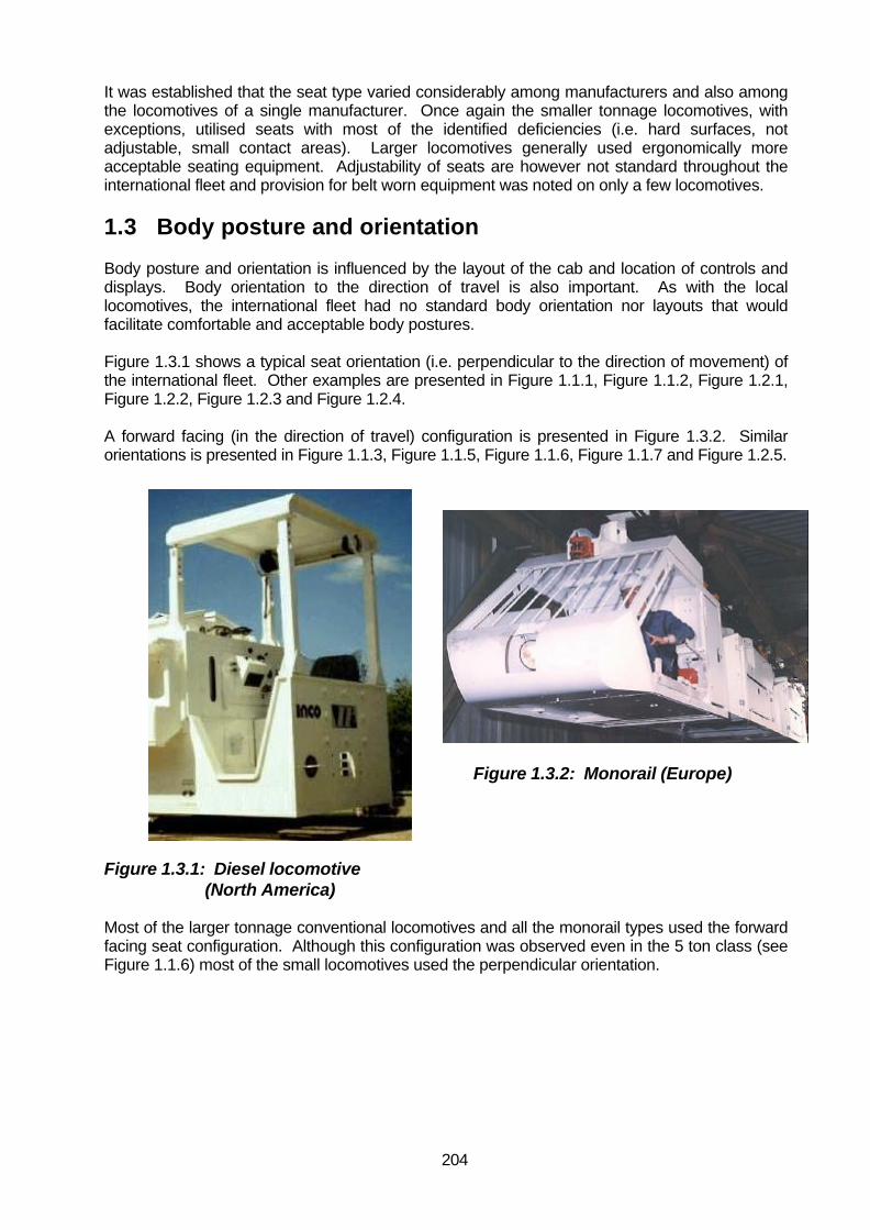
204
It was established that the seat type varied considerably among manufacturers and also amongthe locomotives of a single manufacturer. Once again the smaller tonnage locomotives, withexceptions, utilised seats with most of the identified deficiencies (i.e. hard surfaces, notadjustable, small contact areas). Larger locomotives generally used ergonomically moreacceptable seating equipment. Adjustability of seats are however not standard throughout theinternational fleet and provision for belt worn equipment was noted on only a few locomotives.
1.3 Body posture and orientation
Body posture and orientation is influenced by the layout of the cab and location of controls anddisplays. Body orientation to the direction of travel is also important. As with the locallocomotives, the international fleet had no standard body orientation nor layouts that wouldfacilitate comfortable and acceptable body postures.
Figure 1.3.1 shows a typical seat orientation (i.e. perpendicular to the direction of movement) ofthe international fleet. Other examples are presented in Figure 1.1.1, Figure 1.1.2, Figure 1.2.1,Figure 1.2.2, Figure 1.2.3 and Figure 1.2.4.
A forward facing (in the direction of travel) configuration is presented in Figure 1.3.2. Similarorientations is presented in Figure 1.1.3, Figure 1.1.5, Figure 1.1.6, Figure 1.1.7 and Figure 1.2.5.
Figure 1.3.2: Monorail (Europe)
Figure 1.3.1: Diesel locomotive (North America)
Most of the larger tonnage conventional locomotives and all the monorail types used the forwardfacing seat configuration. Although this configuration was observed even in the 5 ton class (seeFigure 1.1.6) most of the small locomotives used the perpendicular orientation.

205
Figure 1.3.3: Trolley locomotive (Europe) Figure 1.3.4: Trolley locomotive (Europe)
The body posture required to operate the locomotive effectively is dependent on the layout of thecontrols and displays. Figure 1.3.3 shows a standard layout for a trolley locomotive. It ispredicted that the dispersed layout of this cab would require the operator to adopt awkward bodypostures to perform the required tasks safely. Another example is presented in Figure 1.3.4.These configurations are inherently no different from some of the examples of the current localfleet. The monorail cab presented in Figure 1.3.5 is of such configuration that the driver isallowed to adopt a stressful posture involving rotation of the trunk and stretching in order to gainvisual access to the rear. Use of aids such as mirrors might alleviate this deficiency.
Internationally, there is however also control and display layouts that conform largely toacceptable ergonomics practices. These are discussed in paragraph 1.5 of this appendix.
Figure 1.3.5: Monorail (Europe)

206
1.4 Workspace
Workspace, particularly legroom was found to be very much dependent on the size of thelocomotive. The smaller types would, with the addition of equipment being carried in the cab oron the cab floor, be as restrictive as the current local fleet. The 30 ton trolley locomotive shownin Figures 1.1.5 does however have adequate workspace, so does the monorail examples ofFigure 1.1.7 and Figure 1.3.2.
1.5 Control and displays
Control and display best practice is presented in Figure 1.5.1 and Figure 1.2.5. These layoutshowever lack functional grouping and sound labelling principles but at least the controls are beinggrouped on an instrument panel in proximity to each other.
Figure 1.5.2: Hand controller (North America)
Figure 1.5.1: Trolley control panel (Europe)
Figure 1.5.2 presents a layout of controls that would be inconsistent with the expectations of theuser.
The directional controller is mounted perpendicular to the travel direction and with no labelling theuser would have to rely on trial and error to determine direction of control operation to actualdirection of travel. This is not an improvement over the current local fleet. In Figure 1.3.4 ahandwheel is used as braking control device. In addition to the handwheel, a ratcheted brakelever with handgrip is attached to the handwheel to provide fast operation of the brake. This ispreferable to the use of a handwheel only, as was a frequently observed design practice on thelocal fleet.
From these examples it can be concluded that the international mine locomotives does notuniversally incorporate sound ergonomics control and display design or layout principles thatwould be acceptable for the local population. Even “best practice” examples lack the applicationof basic ergonomics practice.

207
1.6 Visual Access
Body orientation in relation to the direction of travel and cab structures are attributed to influencevisual access to the track, but also to the rear of the locomotive.
Figure 1.3.5 clearly shows how body posture is used to obtain rearward visual access. Most ofthe international designs allow good visual access to the track. This is achieved by locating theoperator close to the end of the locomotive and providing little structural interference to the viewto the outside. A good example here is presented in Figure 1.6.1 and Figure 1.6.2. Largeaperture viewing access was frequently observed in the international fleet. Examples hereinclude Figure 1.1.3, Figure 1.1.5, Figure 1.1.6, Figure 1.1.7, Figure 1.2.3, Figure 1.3.1, Figure1.3.2. It should be noted that some of these designs use a vertical glass windscreen or one thatis sloping upward and outward. With these configurations the caplamp light can cause annoyingreflection and glare in the windscreen and can temporarily blind the operator or reduce the visionto the outside. With downward and outward sloping windscreens the impairment of vision to theoutside is reduced. An example is shown in Figure 1.1.5.
Figure 1.6.1: Battery locomotive (Europe) Figure 1.6.2: Battery locomotive (North America)
1.7 Operator protection
The international fleet of locomotives included both enclosed, semi-enclosed and open cabdesign. The smaller tonnage locomotives were, as locally, mostly of the open cab design.However, for the larger locomotives, the semi-enclosed to enclosed designs were moreabundant. All monorail designs had operator protection structures. Operator protection is animportant safety factor and enclosed cabs are therefor the preferred option. The enclosed cabdesigns and protection structures of the international designs would assist in reducing theperception of hazards arising from the battery retention mechanisms as an identified deficiencyof the local fleet.

208
2. Comparison of international status andergonomics requirements for the proposed idealdesign
The international design status is compared with the requirements for an ideal design as listed inparagraph 7.1 of the main document.
2.1 Adequate space for operators
The international designs would all seem to provide adequate space for the driver with adequatefree volume to perform all the required tasks. When looking at new products this assessmentcould be misleading as additional equipment (e.g. jacks, sprags and fire extinguisher) are addedto the available operator space which could reduce the safety and efficiency of operating thelocomotive. Space problems, however, are only a serious consideration on the smallerlocomotives.
2.2 Adequate communication links
The international designs tend to progress into semi-enclosed and completely enclosed cabs.The completely enclosed cab is arguably not practical, from a communications view, for SouthAfrican gold and platinum applications. The peawhistle and verbal communication would beineffective. The completely enclosed cab can only be used within the local mining environment ifan effective communication system and procedures are available. However, as short termsolution, the advantages of semi-enclosed cabs available internationally should be exploited forthe local market.
2.3 Controls and displays
As discussed in paragraph 1.5 of this appendix the control and display layout, arrangement andlabelling of the international designs are not optimised even for foreign users. Local drivers,because of language and reading skills, require special representation (e.g. symbols) ofinternationally accepted terms and descriptions.
Controls and displays are therefor not optimised for the local user population.
2.4 Access
Refer to paragraph 1.1 of this appendix.
2.5 Body orientation
There can be no doubt that body orientation in the direction of travel is the preferred position for alocomotive driver. The monorail designs and larger conventional rail locomotives all adopted thisorientation.
2.6 Protection and safeguards against hazards
The safety features and protection provided by the international designs are deemed superior tothat of the local fleet. It could in part be attributed to the abundance of semi-enclosed cabs foundinternationally. The use of rubber and polymer wheels to improve traction but potentiallyreducing whole body vibration are also noteworthy. Except for fully enclosed cabs, noiseexposure for the driver remains a challenge, especially to maintain effective communication.

209

210
2.7 Adequate illumination
Illumination is an important component of adequate visual access for performing the driver tasks.This can include illuminating for inspection and operational tasks. No special features other thanreduction of inspection task intensity as result of engineering progress was observed.
2.8 Seating
A variety of seating equipment was noted for the international design. Provisions for belt wornequipment on seats were rarely observed. The South African designed T-back seat providinglumbar support and which makes provisions for belt worn equipment is to be preferredequipment on all locomotives.
2.9 Emergency systems
Although the safety considerations, including emergency escape provisions, of the enclosed cabwas included in most designs, some examples where access to and from the cab is severelyrestrictive were judged to be unacceptable for the South African environment.
2.10 Fail safe design, simplest design, minimise human error
These factors could not be fully assessed as they are related not only to sound engineeringpractice but also to effective integration of operator expectations, operator skills and experience,accepted stereotypes, environmental influences, local procedures and practices and statutoryrequirements. It also relates to control and display application and labelling. These aspectsshould be carefully considered and quantified for the local user population before internationaldesigns are accepted as fail safe, simple and able to minimise human error.

211
Appendix 7Ideal design layout drawings
Figure 1 and Figure 2 present the major dimensions for the ideal locomotive design.
Figure 1: Dimensions – side view

212
Figure 2: Dimensions – top view

213
Appendix 8Practical design layout drawings
Figure 1 and Figure 2 present the major dimensions for the practical design of the locomotiveand the guard car.
Figure 1: Dimensions – side view

214
Figure 2: Dimensions – top view