Installation Installation Manual - Rocky Mountain Generator ...
84
English Original Instructions 8-2019 A049J580 (Issue 6) Installation Installation Manual Manual Standby Power Generator Set with D1703M or V2203M Engine and PC1.1 Control C10 D6 (Spec A) C15 D6 (Spec A) C20 D6 (Spec A)
-
Upload
khangminh22 -
Category
Documents
-
view
0 -
download
0
Transcript of Installation Installation Manual - Rocky Mountain Generator ...
EnglishOriginal Instructions 8-2019 A049J580 (Issue 6)
InstallationInstallation ManualManual
Standby Power Generator Set withD1703M or V2203M Engine and PC1.1Control
C10 D6 (Spec A)C15 D6 (Spec A)C20 D6 (Spec A)


iA049J580 (Issue 6) Copyright © 2019 Cummins Inc.
Table of Contents
1. IMPORTANT SAFETY INSTRUCTIONS ....................................................................................... 11.1 Warning, Caution, and Note Styles Used in This Manual ..................................................... 11.2 General Information ................................................................................................................ 11.3 Generator Set Voltage Is Deadly ........................................................................................... 41.4 Fuel and Fumes Are Flammable ............................................................................................ 51.5 Batteries Can Explode ............................................................................................................ 51.6 Moving Parts Can Cause Severe Personal Injury or Death .................................................. 61.7 Exhaust Gases Are Deadly..................................................................................................... 61.8 The Hazards of Carbon Monoxide.......................................................................................... 7
2. INTRODUCTION............................................................................................................................ 92.1 About This Manual.................................................................................................................. 92.2 Related Literature ................................................................................................................... 92.3 Before Installation ................................................................................................................. 102.4 Model Specifications ............................................................................................................. 102.5 Transfer Switch Requirements.............................................................................................. 14
3. PRE-INSTALLATION CONSIDERATIONS.................................................................................. 153.1 Pre-Installation Considerations ............................................................................................. 153.2 Installation Codes and Standards for Safety ........................................................................ 163.3 Required Items for Installation .............................................................................................. 183.4 Transfer Switch Mounting ..................................................................................................... 19
4. INSTALLATION............................................................................................................................ 214.1 Installation Introduction ......................................................................................................... 214.2 Site Assessment and Preparation ........................................................................................ 214.3 Fuel System.......................................................................................................................... 244.4 Engine Exhaust..................................................................................................................... 304.5 Electrical Connections .......................................................................................................... 30
5. STARTUP AND CONFIGURATION............................................................................................. 435.1 Exercise Settings ................................................................................................................. 435.2 Time Setup (1-Phase ATS)................................................................................................... 475.3 Brightness and Contrast ....................................................................................................... 515.4 History and About Menu ....................................................................................................... 535.5 Startup ................................................................................................................................. 555.6 Installation Checklist ............................................................................................................. 56
APPENDIX A. OUTLINE AND SYSTEM DRAWINGS...................................................................... 59

This page is intentionally blank.
Table of Contents 8-2019
ii A049J580 (Issue 6)Copyright © 2019 Cummins Inc.

1A049J580 (Issue 6) Copyright © 2019 Cummins Inc.
1 IMPORTANT SAFETY INSTRUCTIONSSAVE THESE INSTRUCTIONS. This manual contains important instructions thatshould be followed during installation and maintenance of the generator set andbatteries.Safe and efficient operation can be achieved only if the equipment is properlyoperated and maintained. Many accidents are caused by failure to followfundamental rules and precautions.
1.1 Warning, Caution, and Note Styles Used inThis ManualThe following safety styles and symbols found throughout this manual indicatepotentially hazardous conditions to the operator, service personnel, or equipment.
DANGERIndicates a hazardous situation that, if not avoided, will result in death orserious injury.
WARNINGIndicates a hazardous situation that, if not avoided, could result in death orserious injury.
CAUTIONIndicates a hazardous situation that, if not avoided, could result in minor ormoderate injury.
NOTICEIndicates information considered important, but not hazard-related (e.g.,messages relating to property damage).
1.2 General InformationThis manual should form part of the documentation package supplied by Cumminswith specific generator sets. If this manual has been supplied in isolation, pleasecontact your authorized dealer.
NOTICEIt is in the operator's interest to read and understand all warnings andcautions contained in the documentation relevant to the generator setoperation and daily maintenance.

1. IMPORTANT SAFETY INSTRUCTIONS 8-2019
2 A049J580 (Issue 6)Copyright © 2019 Cummins Inc.
General Safety PrecautionsWARNING
Hot Pressurized LiquidContact with hot liquid can cause severe burns.Do not open the pressure cap while the engine is running. Let the enginecool down before removing the cap. Turn the cap slowly and do not open itfully until the pressure has been relieved.
WARNINGMoving PartsMoving parts can cause severe personal injury.Use extreme caution around moving parts. All guards must be properlyfastened to prevent unintended contact.
WARNINGToxic HazardUsed engine oils have been identified by some state and federal agencies tocause cancer or reproductive toxicity.Do not ingest, breathe the fumes, or contact used oil when checking orchanging engine oil. Wear protective gloves and face guard.
WARNINGElectrical Generating EquipmentIncorrect operation and maintenance can result in severe personal injury ordeath.Do not operate equipment when fatigued, or after consuming any alcohol ordrug.Make sure that only suitably trained and experienced service personnelperform electrical and/or mechanical service.
WARNINGToxic GasesSubstances in exhaust gases have been identified by some state and federalagencies to cause cancer or reproductive toxicity.Do not breathe in or come into contact with exhaust gases.
WARNINGHigh Noise LevelGenerator sets in operation emit noise, which can cause hearing damage.Wear appropriate ear protection at all times.

1. IMPORTANT SAFETY INSTRUCTIONS8-2019
3A049J580 (Issue 6) Copyright © 2019 Cummins Inc.
WARNINGHot SurfacesContact with hot surfaces can cause severe burns.The unit is to be installed so that the risk of hot surface contact by people isminimized. Wear appropriate PPE when working on hot equipment and avoidcontact with hot surfaces.
WARNINGToxic HazardEthylene glycol, used as an engine coolant, is toxic to humans and animals.Wear appropriate PPE. Clean up coolant spills and dispose of used coolantin accordance with local environmental regulations.
WARNINGCombustible LiquidIgnition of combustible liquids is a fire or explosion hazard which can causesevere burns or death.Do not store fuel, cleaners, oil, etc., near the generator set. Do not usecombustible liquids like ether.
WARNINGCombustible GasesGenerator sets in operation have combustible gases under pressure, whichif ignited can cause eye and ear damage.Wear appropriate eye and ear protection at all times.
WARNINGCombustible GasesGenerator sets in operation have combustible gases under pressure, whichif ignited can cause severe injury.Do not operate the generator set with any doors open.
WARNINGFire HazardMaterials drawn into the generator set, as well as accumulated grease andoil, are a fire hazard. Fire can cause severe burns or death.Keep the generator set and the surrounding area clean and free fromobstructions. Make sure the generator set is mounted in a manner to preventcombustible materials from accumulating under the unit.

1. IMPORTANT SAFETY INSTRUCTIONS 8-2019
4 A049J580 (Issue 6)Copyright © 2019 Cummins Inc.
WARNINGAutomated MachineryAccidental or remote starting of the generator set can cause severe personalinjury or death.Isolate all auxiliary supplies and use an insulated wrench to disconnect thestarting battery cables (negative [–] first).
NOTICEKeep multi-type ABC fire extinguishers close by. Class A fires involveordinary combustible materials such as wood and cloth. Class B firesinvolve combustible and flammable liquid fuels and gaseous fuels. Class Cfires involve live electrical equipment. (Refer to NFPA No. 10 in theapplicable region.)
NOTICEBefore performing maintenance and service procedures on enclosedgenerator sets, make sure the service access doors are secured open.
NOTICEStepping on the generator set can cause parts to bend or break, leading toelectrical shorts, or to fuel leaks, coolant leaks, or exhaust leaks. Do not stepon the generator set when entering or leaving the generator set room.
1.3 Generator Set Voltage Is Deadly• Generator set output connections must be made by a trained and experienced
electrician in accordance with all applicable codes.• This generator set and the public utility may only be connected to house circuits
by means of the automatic transfer switch.
CAUTIONImproper connections can lead to electrocution of utility workers anddamage to equipment. Make sure that the connections are installedproperly by a trained technician.
• Use caution when working on live electrical equipment. Remove jewelry, andmake sure clothing and shoes are dry. Stand on a dry wooden platform.

1. IMPORTANT SAFETY INSTRUCTIONS8-2019
5A049J580 (Issue 6) Copyright © 2019 Cummins Inc.
1.4 Fuel and Fumes Are FlammableFire, explosion, and personal injury or death can result from improper practices.
• Do not fill fuel tanks while the engine is running unless the tanks are outsidethe engine compartment. Fuel contact with hot engine or exhaust is a potentialfire hazard.
• Do not permit any flame, cigarette, pilot light, spark, arcing equipment, or otherignition source near the generator set or fuel tank.
• Fuel lines must be adequately secured and free of leaks. Fuel connection at theengine should be made with an approved flexible line. Do not use copper pipingon flexible lines as copper will become brittle if continuously vibrated orrepeatedly bent.
• Make sure all fuel supplies have a positive shutoff valve.• Make sure the battery area has been well-ventilated prior to servicing near it.
Lead-acid batteries emit a highly explosive hydrogen gas that can be ignited byarcing, sparking, smoking, etc.
1.5 Batteries Can ExplodeBatteries can explode, causing severe skin and eye burns and can release toxicelectrolytes.
WARNINGCombustible GasesBatteries can explode, causing severe skin and eye burns, and can releasetoxic electrolytes.Do not dispose of the battery in a fire, because it is capable of exploding. Donot open or mutilate the battery. Do not charge frozen batteries.
WARNINGElectric Shock HazardBatteries present the risk of high short circuit current.When servicing the generator set:
• Remove watches, rings, or other metal objects.• Use tools with insulated handles.
NOTICEServicing of batteries must be performed or supervised by personnelknowledgeable of batteries and the required precautions. Keep unauthorizedpersonnel away from batteries.
• Wear safety glasses.

1. IMPORTANT SAFETY INSTRUCTIONS 8-2019
6 A049J580 (Issue 6)Copyright © 2019 Cummins Inc.
• Do not smoke.• Do not charge frozen batteries.• To prevent arcing when disconnecting the battery:
1. Press the Off switch from the display and then press the E-Stop button (ifequipped).
2. Disconnect AC power from any battery chargers.3. Remove the negative (-) battery cables to prevent starting.
• To prevent arcing when reconnecting the battery:1. Reconnect the positive (+) cables.2. Reconnect the negative (-) cables.3. Reconnect the battery charger to AC power supply.
• When replacing the generator set battery, always replace it with a battery asspecified in this manual.
1.6 Moving Parts Can Cause Severe PersonalInjury or Death
• Do not wear loose clothing or jewelry near moving parts, such as cooling fans.• Keep hands away from moving parts.• Keep guards in place over fans.
1.7 Exhaust Gases Are Deadly• Provide an adequate exhaust system to properly expel discharged gases away
from enclosed or sheltered areas, and areas where individuals are likely tocongregate. Visually and audibly inspect the exhaust system daily for leaks perthe maintenance schedule. Make sure that exhaust manifolds are secured andnot warped. Do not use exhaust gases to heat a compartment.
• Make sure the unit is well ventilated.
Exhaust PrecautionsWARNING
Hot Exhaust GasesContact with hot exhaust gases can cause severe burns.Wear personal protective equipment when working on equipment.

1. IMPORTANT SAFETY INSTRUCTIONS8-2019
7A049J580 (Issue 6) Copyright © 2019 Cummins Inc.
WARNINGHot SurfacesContact with hot surfaces can cause severe burns.The unit is to be installed so that the risk of hot surface contact by people isminimized. Wear appropriate PPE when working on hot equipment and avoidcontact with hot surfaces.
WARNINGToxic GasesInhalation of exhaust gases can cause asphyxiation and death.Pipe exhaust gas outside and away from windows, doors, or other inlets tobuildings. Do not allow exhaust gas to accumulate in habitable areas.
WARNINGFire HazardContaminated insulation is a fire hazard. Fire can cause severe burns ordeath.Remove any contaminated insulation and dispose of it in accordance withlocal regulations.
The exhaust outlet may be sited at the top or bottom of the generator set. Makesure that the exhaust outlet is not obstructed. Personnel using this equipment mustbe made aware of the exhaust position. Position the exhaust away from flammablematerials - in the case of exhaust outlets at the bottom, make sure that vegetation isremoved from the vicinity of the exhaust.The exhaust pipes may have some insulating covers fitted. If these covers becomecontaminated they must be replaced before the generator set is run.To minimize the risk of fire, make sure the following steps are observed:
• Make sure that the engine is allowed to cool thoroughly before performingmaintenance or operation tasks.
• Clean the exhaust pipe thoroughly.
1.8 The Hazards of Carbon MonoxideCarbon monoxide (CO) is an odorless, colorless, tasteless and non-irritating gas.You cannot see it or smell it. Red blood cells, however, have a greater affinity forCO than for oxygen. Therefore, exposure even to low levels of CO for a prolongedperiod can lead to asphyxiation (lack of oxygen) resulting in death. Mild effects ofCO poisoning include eye irritation, dizziness, headaches, fatigue and the inability tothink clearly. More extreme symptoms include vomiting, seizures and collapse.Engine-driven generator sets produce harmful levels of carbon monoxide that caninjure or kill you.

1. IMPORTANT SAFETY INSTRUCTIONS 8-2019
8 A049J580 (Issue 6)Copyright © 2019 Cummins Inc.
Special Risks of CO near the HomeWARNING
Toxic GasesCarbon monoxide (CO) gas can cause nausea, fainting, or death. Residentscan be exposed to lethal levels of CO when the generator set is running.Depending on air temperature and wind, CO can accumulate in or near thehome.To protect yourself and others from the dangers of CO poisoning, it isrecommended that reliable, approved, and operable CO detector alarms areinstalled in proper locations in the home as specified by their manufacturer.
Protecting Yourself from CO Poisoning• Locate the generator set in an area where there are no windows, doors, or
other access points into the home.• Make sure all CO detectors are installed and working properly.• Pay attention for signs of CO poisoning.• Check the exhaust system for corrosion, obstruction, and leaks every time you
start the generator set and every eight hours when you run it continuously.

9A049J580 (Issue 6) Copyright © 2019 Cummins Inc.
2 IntroductionThis generator set is intended for stationary installation for emergency use only.
2.1 About This ManualWARNING
Improper installation can result in severe personal injury, death and damageto equipment. The installation must comply with all applicable buildingcodes (including project permits and inspections). The installer should beproperly trained and licensed to perform electrical and mechanicalequipment installations (including gaseous fuel installation).
NOTICEManuals are updated from time to time to reflect changes in the equipmentand its specifications. The most up-to-date version of this manual is foundon the QuickServe website(https://quickserve.cummins.com/info/index.html).
This manual is a guide for the installation of the generator set models listed on thefront cover. Proper installation is essential for top performance, reliable operation,and safety. Read through this manual before starting the installation. This manualcovers outdoor applications only; for other installations, refer to the T-030: Liquid-Cooled Generator Set Application manual available from your Cummins distributor.
NOTICEThe installation must comply with all applicable building codes.
See the generator set's specific operator manual for operation and maintenance andspecific service manual for service.Refer to the Model Specifications section for specific information about the systemand its components.Refer to the Outline and System Drawings appendix and the Wiring Diagramsappendix for specific information about installation and wiring connections.
2.2 Related LiteratureA generator set must be operated and maintained properly if you are to expect safeand reliable operation. The Operator Manual includes a maintenance schedule anda troubleshooting guide. The Health and Safety Manual must be read in conjunctionwith the Operator Manual for the safe operation of the generator set. The literatureprovided with the generator set is as follows:
• Health and Safety Manual (0908-0110-00)

2. Introduction 8-2019
10 A049J580 (Issue 6)Copyright © 2019 Cummins Inc.
• Warranty Statement (A028U870)• Emissions Component Defect Warranty Statement (A048K395)• Generator Set Installation Manual (A049J580)• Generator Set Operator Manual (A049J586)• Installation Quick Start Guide (A050N805)• Operator Quick Start Guide (A050N807)
The relevant manuals appropriate to your generator set are also available. Thedocuments below are in English:
• Service Manual (A049J589)• Kubota D1703M and V2203M Engine Service Manual (A049P923)• Parts Manual (A048W980)• RA Series Transfer Switch Owner's Manual (A046S594) - if applicable• PowerCommand® 1302 Controller Owner's Manual (900-0661)• Standard Repair Times (SRT) Manual - GF Family (A049M410)• Application Manual T-030 - for application information (A040S369)• Service Tool Manual (A043D529)• Universal Annunciator Operator Manual (900-0301)
2.3 Before InstallationBefore beginning the installation of the generator set, verify that the unit wascorrectly selected. Check the following features:
• Model• Specifications• Options• Fuel Supply
2.4 Model SpecificationsTABLE 1. MODEL VARIATIONS
Model Engine Cylinder Hz RPMC10 D6, C15 D6 D1703M 3 60 1800
C20 D6 V2203M 4 60 1800

2. Introduction8-2019
11A049J580 (Issue 6) Copyright © 2019 Cummins Inc.
TABLE 2. COLD WEATHER SPECIFICATIONS
All ModelsFor NFPA 110 applications, a coolant heater is required. Factory option is available.
Above 40 °F (4 °C) No starting aids required.Standard battery (group 26)
0 to 40 °F (-17 to 4°C)
Coolant heater and battery charger recommended for starting.Factory options available.Standard battery (group 26)
Below 0 °F (-17 °C) All starting aides (battery heater, coolant heater, battery charger)recommended. Factory options available.Larger battery (group 34)
TABLE 3. FUEL CONSUMPTION
C10 D6 C15 D6 C20 D6Full Load (StandbyRating) US
1.12 gal/hr (4.24 L/hr) 1.38 gal/hr (5.22 L/hr) 1.81 gal/hr (6.85 L/hr)
Full Load (PrimeRating) US
1.02 gal/hr (3.86 L/hr) 1.26 gal/hr (4.77 L/hr) 1.65 gal/hr (6.24 L/hr)
TABLE 4. ENGINE SPECIFICATIONS
C10 D6 C15 D6 C20 D6Engine Kubota -D1703M - 3
Cylinder-in-line, liquid-cooled, 4-stroke
Kubota -D1703M - 3Cylinder-in-line, liquid-cooled, 4-stroke
Kubota -V2203M - 4Cylinder-in-line, liquid-cooled, 4-stroke
Aspiration Naturally Aspirated
Displacement 100.5 in3 (1650 cc) 134.1 in3 (2200 cc)
CompressionRatio
22:1 22:1
Lube Oil Capacity,qt (L)
7.4 qt (7.0 L) 10.0 qt (9.5 L)
OilRecommendation
• SAE30 or SAE10W30: Above 75 °F (25 °C)• SAE20 or SAE10W30: 32 °F (0 °C) to 75 °F (25 °C)• SAE10W or SAE10W30: Below 32 °F (0 °C)• Oil Grade - API CF or better

2. Introduction 8-2019
12 A049J580 (Issue 6)Copyright © 2019 Cummins Inc.
C10 D6 C15 D6 C20 D6Fuel Diesel fuel: Meeting European Norm (EN) 590 or American Society of
Testing and Materials (ASTM) D975 recommened.
Cetane Rating: Minimum recommended is 45. A rating greater than 50 ispreferred, especially in low ambient temperature below –20 °F (–4 °C)and elevation above 5000 ft (1500 m).Note: The diesel fuel specification type and sulfur content percentage(ppm) used must be compliant with all applicable emission regulations.When operated in United States environmental protection agency (USEPA) required areas, No.2-D, S500, or S15 or No.1-D S500 or S15 ismandatory. Use No.1-D for ambient temperature below –14 °F (10 °C).
• No.1–D or No.2-DS500: Low sulfur diesel (LSD) less than 500 ppmor 0.05% by weight.
• No.1–D or No.2-D S15: Ultra low sulfur diesel (ULSD) 15 ppm or0.0015% by weight.
Sulfur Content: 0.10% (1000 ppm) or less is recommended.Note: If high sulfur fuel (0.5-1%) is used, change the engine oil and oilfilter more frequently (approx. 125 hours). Do not use fuels that havesulfur content greater than 1% (10000 ppm).
Cooling System 2.4 gal (9.1 L) 2.7 gal (10.2 L)
Coolant 50/50 coolant solution (50% pure water and 50% ethylene glycol)
Exhaust Maximum Allowable Back Pressure: 42 H20 (10.47 kPa)
Exhaust Flow at RatedLoad: 99 cfm (2.8m3/min)
Exhaust Flow at RatedLoad: 126 cfm (3.6m3/min)
Exhaust Flow at RatedLoad: 174 cfm (4.9m3/min)
Temperature: 644 °F(340 °C)
Temperature: 970 °F(521 °C)
Temperature: 970 °F(521 °C)
Fuel Pump Fuel Supply: 0.375 in. (9.5 mm) Hose Barb
Fuel Return:0.312 in. (7.9 mm) Hose Barb
Maximum Fuel Lift Restriction (with Clean Filter): 2 in. HG (51 mm Hg)Maximum Fuel Lift Restriction: 6 in. Hg (152 mm Hg)
TABLE 5. GENERATOR SET SIZE SPECIFICATIONS
10-20 kW 1800 RPMSize (with SoundLevel 1 Enclosurewithout Fuel Tank )
(L x W x H) 72 x 34 x 45.5 in (1830 x 864 x 1156 mm)

2. Introduction8-2019
13A049J580 (Issue 6) Copyright © 2019 Cummins Inc.
TABLE 6. GENERATOR SET WEIGHT (POUNDS) 60 HZ, 1800 RPM
C10D6 C15D6 C20D6Sound Level 1 (Wet)without Fuel Tank
962 1064 1127
TABLE 7. ALTERNATOR SPECIFICATIONS 60 HZ, 1800 RPM
C10D6 C15D6 C20D6Generator Brushless, 4-pole rotating field, single bearing
Power (kVA) 1-Phase/3-Phase -Standby
10/12.5 15/18.75 20/25
Power (kVA) 1-Phase/3-Phase -Prime
9.1/11.4 13.5/16.9 18.2/22.7
Rated Voltages (V) 120/240, 1-Ph
277/480, 3-Ph
120/208, 3-Ph
120/240, 3-Ph
347/600, 3-Ph
NOTICEMaximum I2= 8%.
TABLE 8. GENERATOR SET DERATING GUIDELINES
C10D6 C15D6, C20D6Standby, Prime Engine power available up to 2500 m
(8200 ft) and ambient temperaturesup to 40 °C (104 °F). Above theseconditions, derate at 3% per 300 m(985 ft) and 3.5% per 10 °C (18 °F).
Engine power available up to 150 m(490 ft) and ambient temperatures upto 25 °C (77 °F). Above theseconditions, derate at 4% per 300 m(985 ft) and 4% per 10 °C (18 °F).

2. Introduction 8-2019
14 A049J580 (Issue 6)Copyright © 2019 Cummins Inc.
TABLE 9. DC SYSTEM SPECIFICATIONS
All ModelsNominalBattery Voltage
12 VDC
Battery Group 26 standard, 34 high capacity (high capacity battery requires an accessorybattery tray)
Battery Type Maintenance free
Minimum ColdCrank Amps
545 standard, 850 high capacity (high capacity battery requires anaccessory battery tray)
2.5 Transfer Switch RequirementsA transfer switch must be a part of every generator set installation. Transferswitches transfer loads to the generator set during power outages.
NOTICECummins offers a variety of transfer switches, including residential and lightcommercial options.
FIGURE 1. CUMMINS TRANSFER SWITCH (RA SERIES)Before beginning the installation of the transfer switch, verify that the unit wascorrectly selected. Check the following features:
• Specifications (voltage, amperage, frequency, poles, and phases)• Enclosure (indoor vs. outdoor)• Model
Refer to the RA Series Transfer Switch Owner Manual (A046S594) for moredetailed information. The RA Series transfer switch is the recommended ATS foruse with these generators.

15A049J580 (Issue 6) Copyright © 2019 Cummins Inc.
3 Pre-Installation Considerations
3.1 Pre-Installation ConsiderationsBefore installation begins, certain items must be considered. Prior coordinationreduces delays and the amount of time power has to be interrupted.
Areas of consideration:
No. Description No. Description1 Generator Set 3 Transfer Switch
2 Electrical Meter
FIGURE 2. SITE PREPARATION EXAMPLE• Location of the generator set - this is one of the first decisions to be made, as it
affects all other aspects of the installation, such as:◦ Length of electric wiring◦ Length of fuel lines

3. Pre-Installation Considerations 8-2019
16 A049J580 (Issue 6)Copyright © 2019 Cummins Inc.
◦ Site preparation:▪ Access to the site▪ Trenches▪ Site preparation materials needed
• Automatic transfer switch location and connections• Tools and materials required• Accessories required (if any) for the customer's application (utility power may
be required at the generator set; make plans accordingly)
NOTICEDepending on the locality and use of the generator set, it may be necessaryto obtain an air quality emissions permit before installation begins. Checkwith local pollution control or air quality authority to determine permitrequirements.
3.2 Installation Codes and Standards for SafetyNOTICE
The generator set installer bears sole responsibility for following allapplicable local codes and regulations.
The following list of codes and standards may apply to the installation and operationof the generator set. This list is for reference only and not intended to be inclusive ofall applicable codes and standards. The address of each agency is listed so thatcopies of the codes may be obtained for reference. Installation codes andrecommendations are subject to change, and may vary by location or over time.

3. Pre-Installation Considerations8-2019
17A049J580 (Issue 6) Copyright © 2019 Cummins Inc.
TABLE 10. INSTALLATION CODES AND STANDARDS FOR SAFETYRECOMMENDATIONS
Type Code orStandard Title Organization
US
Code NFPA 70 - National ElectricalCode
National Fire ProtectionAssociation470 Atlantic AvenueBoston, MA 02210
CodeNFPA 37 - Installation and Useof Stationary CombustionEngines and Gas Turbines
Code NFPA 54 - National Fuel GasCode
CodeNFPA 58 - Storage andHandling of Liquefied PetroleumGases
CodeNFPA 110 - Standard forEmergency and Standby PowerSystems
Canada
Code CSA Electrical Bulletin
Canadian StandardsAssociationHousing and ConstructionMaterials Section178 Rexdale Blvd.Rexdale, Ontario, Canada M9Q1R3
Code CSA 22.1 Canadian ElectricalCode
CodeCSA B149 Installation Code forGas Burning Appliances andEquipment
Standard CSA C22.2 No. 100 Motors andGenerators
Standard CSA C22.2 No. 14 IndustrialControl Equipment
Code CSA C282 Emergency ElectricalPower Supply for Buildings
Code CSA Z32 Electrical Safety inHealth Care Facilities
California Code California Administrative Code -Title 25 Chapter 3
State of CaliforniaDocuments SectionP.O. Box 1015North Highlands, CA 95660

3. Pre-Installation Considerations 8-2019
18 A049J580 (Issue 6)Copyright © 2019 Cummins Inc.
3.3 Required Items for InstallationTools and materials are used for the installation of this generator set. These itemsare identified in the following sections. Please refer to local codes and standards,because they may affect the materials required.
Materials RequiredNOTICE
Refer to local codes and standards, which may affect the materialrequirements.
NOTICEIf a 100% rated breaker is used, 90 °C wire must be used for L1, L2, and L3with the wire size determined by the 75 °C ampacity tables.
NOTICEA UL-listed grounding electrode terminal within its ratings and suitable forthe application must be installed and labeled “Grounding ElectrodeTerminal”.
Electrical Materials:
NOTICEClass 1 wiring methods must be used for connecting the generator set.
• Four code compliant AC power wires; L1, L2, N and Gnd (add another wire for3-phase for a total of 5 AC wires)
• For RA switches, 4 DC control wires will be needed from the generator to thetransfer switch.
• Wire sizes (DC control and power and AC sense only):◦ DC control or AC sense wires under 1000 feet circuit length => 18-14
AWG of the insulation type above◦ DC control or AC sense wires 1000-2000 feet circuit length => 16-14 AWG
of the insulation type above• All AC and DC wires and cables must be rated 75 °C minimum, stranded
copper, and rated for wet locations.◦ For wire sizes 14 AWG and larger, use insulation types: RHW, RHW-2,
THHW, THW, THW-2, THWN, THWN-2, XHHW, XHHW-2, USE-2, ZW-2

3. Pre-Installation Considerations8-2019
19A049J580 (Issue 6) Copyright © 2019 Cummins Inc.
◦ For wire sizes 16 and 18 AWG, use insulation types: FFH-2, KFF-2,PAFF, PFF, PGFF, PTFF, RFH-2, RFHH-2, RFHH-3, SFF-2, TFF, TFFN,ZFF
• Code compliant 20 A, 120 VAC, GFCI protected circuit for alternatorheaters/battery charger/coolant heater/oil heater/battery heater (if equipped)
• Code compliant conduit for all wiresMounting Materials:
• Four base tie-down bolts
NOTICERegional fuel tanks require six bolts to attach to the ground.
NOTICESeismic zone installations require compliance to specific mountingconfigurations, as determined by the structural engineer of record.
Fuel Materials:• Flexible fuel line• UL listed pipe thread sealant• Fuel pipe to the remote tank
Loose Parts Shipped With the Generator SetThe following loose parts are shipped with the generator set:
• One enclosure key (where applicable)• Battery tie-down• Sound level 2 baffle (where applicable)• Fuel tank vent extensions (where applicable)• Fuel tank riser blocks (where applicable)• Literature - Operator Manual, Installation Manual, Health and Safety Manual,
and Warranty Statements
3.4 Transfer Switch Mounting1. Consider the location before mounting the transfer switch.
• Consider the proximity to the utility service entrance and breaker panel.There must be a service disconnect (circuit breaker or fuses) in the powerline ahead of the transfer switch, unless a service entrance rated automatictransfer switch is being used.
• Keep safety concerns in mind. Never mount the transfer switch nearhazardous chemicals or gases.

3. Pre-Installation Considerations 8-2019
20 A049J580 (Issue 6)Copyright © 2019 Cummins Inc.
• Avoid high humidity areas or areas prone to excessive heat or dust.2. Make sure that the wall is stable and able to support the weight of the transfer
switch.3. Make sure that the transfer switch is mounted according to all applicable
building code requirements.4. Mount the transfer switch per the instructions in the RA Series Transfer Switch
Owner Manual.
NOTICESeismic zone installations require compliance to specific mountingconfigurations.

21A049J580 (Issue 6) Copyright © 2019 Cummins Inc.
4 Installation
4.1 Installation IntroductionNOTICE
The installer is responsible for complying with all applicable installationcodes and safety requirements. See the Installation Codes and Standards forSafety section of this manual for more information.
The following sections cover a step-by-step overview of a typical generator setinstallation.Review these sections to become familiar with specific procedures and importantsafety precautions before beginning the installation.
4.2 Site Assessment and PreparationProper component location and site preparation have a very important impact oncompleting a successful installation. The major components and sources of powerneeded for installation include the following items:
• Generator set• Transfer switch• Electrical utility• Fuel source (diesel)• Accessories (may be required based on certain conditions)
Picking a LocationWARNING
Exhaust gas is deadly. Locate the generator set away from doors, windows,and other openings to the house and where exhaust gases will disperseaway from the house.
Generator set location is critical for safety and performance. Follow the guidelinesbelow:
• Must comply with applicable codes (NFPA, NEC, IBC, etc.).• This manual only covers outdoor installations with Cummins factory installed
enclosures. For other installation types, contact your local Cummins dealer orreference the Application Manual at the following link:http://www.cumminspower.com/www/literature/applicationmanuals/t030.pdf
• Consider access to utilities (electric meters, transfer switch, remote fuel tanklocation, etc.).

4. Installation 8-2019
22 A049J580 (Issue 6)Copyright © 2019 Cummins Inc.
• Call the local utilities to mark the locations of buried utility services (gas,electric, or telephone) before digging.
• Verify the locations of any other buried components (gas, electric or telephone)with the homeowner before digging.
Clearances:• The exhaust side of the generator set must be located at a minimum of 5 feet
from combustible materials (NFPA 37) and any openings in a wall (window,door, vent, etc.).
• The generator must be located such that the exhaust is not able to accumulatein an occupied area.
• The generator must have enough room for installation, service, andmaintenance.
• The generator must be located to ensure ventilation openings are not blocked.• Position the generator set so that cooling air is free to enter and leave the area.• Locate and position the generator set so that prevailing winds carry exhaust
gases and potential fuel leaks away from the house or occupied area.
No. Description1 5 ft Clearance (shaded area)
FIGURE 3. CLEARANCES
Laying the FoundationWhen laying the foundation:
1. Clear obstructions, and make sure that there is adequate clearance for access.

4. Installation8-2019
23A049J580 (Issue 6) Copyright © 2019 Cummins Inc.
2. Level the ground, and make sure that the ground is compact and settled.Ensure that it is stable ground, not subject to flooding.
3. Prepare the concrete pad.• The pad should be constructed of reinforced concrete with a 28-day
compressive strength of at least 2500 psi (17,237 kPa).• The pad dimensions should be the same as those indicated in the Outline
and System Drawings appendix.
NOTICESeismic installations may require a different pad and securingdevices.
NOTICELocal codes and standards may have different requirements.
4. Lift the generator set onto the pad, and secure it.
Lifting and Moving the Generator SetWARNING
Heavy LoadThe generator set is heavy. Handle with care.Dropping the generator set can cause severe personal injury or death. Useappropriate lifting techniques to move the generator set. Keep feet andhands clear when lifting the generator set.
CAUTIONThe generator set is shipped with oil in the engine crankcase. Keep thegenerator set upright.
Mounting the Generator SetMount the generator set on a substantial and level base such as a concrete pad. Anon-combustible material must be used for the pad. Verify that the mounting pad islevel by length, by width, and diagonally.
NOTICESeismic installation may require specific anchorage.

4. Installation 8-2019
24 A049J580 (Issue 6)Copyright © 2019 Cummins Inc.
4.3 Fuel SystemNOTICE
The factory-installed sub-base fuel tanks meet the fuel system requirements.Please verify that they also meet local codes and standards.
Refer to the Model Specifications for fuel requirements. In all fuel systeminstallations, cleanliness is of the utmost importance. Make every effort to prevententrance of moisture, dirt, or contaminants of any kind into the fuel system. Clean allfuel system components before installing.
NOTICEA fuel filter/strainer/water separator of 100-120 mesh or equivalent(approximately 150 microns nominal) must be fitted between the main tankand day tank if a factory sub-base tank is used as a day tank.
Use only compatible metal fuel lines to avoid electrolysis when fuel lines must beburied. Buried fuel lines must be protected from corroding.
NOTICENever use galvanized or copper fuel lines, fittings, or fuel tanks.Condensation in the tank and lines combines with the sulfur in diesel fuel toproduce sulfuric acid. The molecular structure of the copper or galvanizedlines or tanks reacts with the acid and contaminates the fuel, resulting inpossible engine damage.
An electric solenoid valve in the supply line is recommended for all installations andrequired for indoor automatic or remote starting installations that do not use thefactory sub-base fuel tank. Connect the solenoid wires to the generator set“Switched B+” circuit to open the valve during generator set operation.
NOTICENever install a shutoff device in fuel return line(s). If fuel return line(s) isblocked or exceeds fuel restriction limit, engine damage will occur.
NOTICEA base mounted fuel tank may be part of the generator set build. Anadditional external fuel system may required if the on board fuel capacity isnot sufficient for the application.
Fuel Selection and RecommendationsFor fuel specifications, see the Model Specifications section.

4. Installation8-2019
25A049J580 (Issue 6) Copyright © 2019 Cummins Inc.
NOTICEFuel systems must be installed by qualified service technicians. Improperinstallation presents hazards of fire and improper operation, resulting insevere personal injury or property damage.
In all fuel system installations, cleanliness is extremely important.
• Make every effort to prevent fuel contamination from:◦ Moisture◦ Dirt◦ Excess thread sealant◦ Contaminants of any kind
• Clean all fuel system components before installing.
WARNINGThe generator set is heavy. Dropping the generator set can cause severeinjury or death. Do not lift the generator set with fuel in the tank (whereapplicable). Keep hands and feet clear when lifting the generator set.
WARNINGDo not mix gasoline, alcohol, or gasohol with diesel fuel. This can cause anexplosion.
CAUTIONDue to the precise tolerances of diesel injection systems, it is extremelyimportant that the fuel be kept clean and free from dirt or water. First orwater in the system can cause severe damage to both the fuel pump and fuelinjectors.
Fuel Return Restrictions (or Pressure) LimitFuel return drain restriction (consisting of friction head and static head) between theengine injector return line connection and the fuel tank must not exceed the limitstated in the Model Specifications. Fuel return lines must not contain a shutoffdevice. Engine damage will occur if the engine is run with the return fuel linesblocked or restricted.

4. Installation 8-2019
26 A049J580 (Issue 6)Copyright © 2019 Cummins Inc.
Fuel Lines RoutingWARNING
Explosive hazard.Fuel leaks create fire and explosion hazards which can result in severepersonal injury or death.Always use flexible tubing between the engine and fuel supply to avoid linefailure and leaks due to vibration. The fuel system must meet all applicationcodes.
WARNINGSparks and hot surfaces.Sparks and hot surfaces can ignite fuel, leading to severe personal injury ordeath.Do not route fuel lines near electrical wiring or hot exhaust parts.
NOTICEFuel lines must be routed and secured to maintain a 12.7 mm (½ inch)minimum clearance from electrical wiring and a 51 mm (2 inch) minimumclearance from hot exhaust parts.
A flexible fuel hose(s) or section of flexible fuel hose(s) must be used between theengine’s fuel system and fuel supply and return line(s) to protect the tank's fuelsystem from damage caused by vibration, expansion, and contraction. The fuelhose must be installed according to all applicable codes and standards.

4. Installation8-2019
27A049J580 (Issue 6) Copyright © 2019 Cummins Inc.
No. Description No. Description1 Day Tank (Sub-Base) 7 Fill Pipe
2 Engine Fuel Pump 8 Main Fuel Tank
3 Supply Line 9 Supply Line
4 Float Switch 10 Overflow Line
5 Return Line 11 120 Mesh Fuel Strainer
6 Vent Pipe 12 Fuel Transfer Pump Electric MotorDriven
FIGURE 4. TYPICAL FUEL SUPPLY INSTALLATION (USING FACTORY SUB-BASETANK AS DAY TANK)
Diesel Fuel Piping Requirements• Diesel fuel lines should be constructed from black iron pipe. Cast iron and
aluminum pipe and fittings must not be used because they are porous and canleak fuel. Galvanized fuel lines, fittings, and tanks must not be used becausethe galvanized coating is attacked by the sulfuric acid that forms when thesulfur in the fuel combines with tank condensate, resulting in debris that canclog fuel pumps and filters. Copper lines should not be used because fuelpolymerizes (thickens) in copper tubing during long periods of disuse and canclog fuel injectors. Also, copper lines are less rugged than black iron, and thusmore susceptible to damage.

4. Installation 8-2019
28 A049J580 (Issue 6)Copyright © 2019 Cummins Inc.
NOTICENever use galvanized or copper fuel lines, fittings or fuel tanks.Condensation in the tank and lines combines with the sulfur in thediesel fuel to produce sulfuric acid. The molecular structure of thecopper or galvanized lines or tanks reacts with the acid andcontaminates the fuel.
• Approved flexible fuel hose must be used for connections at the engine to takeup generator set movement and vibration.
• Piping from a day tank to the engine should run “downhill" all the way from thetank to the engine, with no overhead loops that can allow air to be entrained inthe system.
• Fuel system piping should be properly supported to prevent vibration andbreakage due to vibration. The piping should not run close to heating pipes,electrical wiring, or engine exhaust system components. The piping systemdesign should include valves at appropriate locations to allow isolation ofsystem components for repair without draining the entire fuel system.
• Piping systems should be regularly inspected for leaks and general condition.The piping system should be flushed before operation of the engine to removedirt and other impurities that could damage the engine. Use of plugged “T"connections rather than elbows allows for easier cleaning of the piping system.
• The engine manufacturer's data indicates the maximum fuel inlet and returnrestrictions, the maximum fuel flow, supply and return, and the fuelconsumption. The table below indicates minimum hose and pipe sizes forconnections to a supply tank or day tank when it is within 50 feet (15 meters) ofthe set and at approximately the same elevation.
Hose and pipe size should be based on the maximum fuel flow rather than on thefuel consumption. It is highly recommended that the fuel inlet and return restrictionsbe checked before the generator set is placed in service.
TABLE 11. MINIMUM FUEL HOSE AND PIPE SIZES; UP TO 50 FEET (15 METERS)EQUIVALENT LENGTH.
Max Fuel Flow Rate GPH (L/hr) Flex HoseNo.*
NPS Pipe Size(in)
DN Pipe Size(mm)
Less than 80 (303) 10 ½ 15
81-100 (304-378) 10 ½ 15
101-160 (379-604) 12 ¾ 20
161-230 (605-869) 12 ¾ 20
231-310 (870-1170) 16 1 25
311-410 (1171-1550) 20 1-1/4 32
411-610 (1550-2309) 24 1-1/2 40

4. Installation8-2019
29A049J580 (Issue 6) Copyright © 2019 Cummins Inc.
Max Fuel Flow Rate GPH (L/hr) Flex HoseNo.*
NPS Pipe Size(in)
DN Pipe Size(mm)
611-920 (2309-3480) 24 1-1/2 40* Generic fuel hose suppliers' size specification.
Engine Fuel ConnectionsIdentification tags are attached to the fuel supply line and fuel return lineconnections. All models require a fuel return line from the injectors to the tank.
Supply TankLocate the fuel tank as close as possible to the generator set and within therestriction limitations of the fuel pump.Install a fuel tank that has sufficient capacity to supply the generator set operatingcontinuously at full rated load for the planned period of operation or power outage.If the fuel inlet restriction exceeds the defined limit due to the distance/customer-supplied plumbing between the generator set and the main fuel tank, a transfer tank(sometimes referred to as a day tank) and auxiliary pump will also be required. If anoverhead main fuel tank is installed, a transfer tank and float valve will be requiredto prevent fuel head pressures from being placed on the fuel system components.
Fuel Inlet Pressure/Restriction LimitEngine performance and fuel system durability is compromised if the fuel inletpressure or restriction limits are not adhered to. Fuel inlet pressure or restrictionmust not exceed the limits stated in the model-specific generator set SpecificationSheet.
Day TankSome generator set installations may include a fuel day tank. They are used whenfuel inlet restriction limits cannot be met, or the supply tank is overhead andpresents problems of high fuel head pressure for the fuel inlet and return lines.
Supply Tank Lower Than Engine
WARNINGFuel spillage.Spilled fuel presents the hazard of fire or explosion which can result insevere personal injury or death.Provide an overflow line to the supply tank from the day tank.
NOTICEThe supply tank top must be below the day tank top to preventsiphoning from the fuel supply to the day tank.

4. Installation 8-2019
30 A049J580 (Issue 6)Copyright © 2019 Cummins Inc.
With this installation, the day tank is installed near the generator set, belowthe fuel injection system and within the fuel inlet restriction limit. Install a fueltransfer pump, to pump fuel from the supply tank to the day tank. A floatswitch in the day tank controls operation of the auxiliary fuel pump.Provide a return line from the engine injection system return connection to theday tank. Plumb the return line to the bottom of day tank. Provide a day tankoverflow line to the supply tank in case the float switch fails to shut off the fueltransfer pump.
Supply Tank Higher Than EngineWith this installation, the day tank is installed near the generator set, abovethe fuel injection system and within the fuel return restriction limit. Include anautomatic fuel shutoff valve in the fuel line between the fuel supply tank andthe day tank to stop fuel flow when the generator set is off.Provide a return line from the engine injection system return connection to theday tank. Plumb the return line to the bottom of day tank.
NOTICESpilled fuel can create environmental hazards. Check localrequirements for containment and prevention of draining to sewer andground water.
4.4 Engine ExhaustThe exhaust system for this generator set is complete and was designed specificallyfor this generator set. Do not modify or add to the exhaust system of this generatorset.
WARNINGExhaust gas is deadly. Make sure that the exhaust system terminates awayfrom building vents, windows, doors, and sheltered spaces that may nothave ample fresh air ventilation.
WARNINGEngine discharge air and exhaust carry carbon monoxide gas (odorless andinvisible) which can cause asphyxiation and death. Never use enginedischarge air or exhaust for heating a room or enclosed space.
4.5 Electrical ConnectionsWARNING
Improper installation can lead to electrocution and damage to property.Electrical connections must be made by a licensed electrician.

4. Installation8-2019
31A049J580 (Issue 6) Copyright © 2019 Cummins Inc.
WARNINGAutomatic startup of the generator set during installation can cause severepersonal injury or death. Make sure the generator set is shut down anddisabled:
1. Press the generator set's "O" (Off) button to stop the generator set.Allow the generator set to thoroughly cool to the touch.
2. Turn off and disconnect the battery charger from the AC source beforedisconnecting the battery cables.
3. Disconnect the negative (–) cable from the battery and secure it fromcontacting the battery terminals to prevent accidental starting.
NOTICERefer to regional codes and the National Electrical Code (NFPA 70) for allelectrical installation requirements.
NOTICEClass 1 wiring methods must be used for connecting the generator set.
AC ConnectionsWARNING
Automated MachineryAccidental or remote starting of the generator set can cause severe personalinjury or death.Isolate all auxiliary supplies and use an insulated wrench to disconnect thestarting battery cables, negative (–) cable first.
NOTICEIf a 100% rated breaker is used, 90 °C wire must be used for L1, L2, and L3with the wire size determined by the 75 °C ampacity tables.
NOTICEWhen using a circuit breaker with an adjustable, electronic trip unit, theamperage and trip curve settings may need adjustment to match thegenerator set load wiring, or downstream loads and circuit breakers. Anaccessory seal kit (part number A026M166) is available to tamper-proof theadjustable settings.
1. Make sure the generator set is shut down and disabled:a. Press the Off switch from the display and then press the E-Stop button to
stop the generator set. Allow the generator set to thoroughly cool to thetouch.

4. Installation 8-2019
32 A049J580 (Issue 6)Copyright © 2019 Cummins Inc.
b. Turn off and disconnect the battery charger from the AC source beforedisconnecting the battery cables.
c. Disconnect the negative (–) cable from the battery and secure it fromcontacting the battery terminals to prevent accidental starting.
2. Remove the enclosure side panel to access the main circuit breaker box.3. Place the circuit breaker handle in the OFF position.4. Remove the four bolts holding the circuit breaker cover.5. Connect the conductors to the circuit breaker load-side terminals, neutral lug,
and equipment grounding lug. For grounding and neutral connections, look forthe symbols on the generator set circuit breaker box (shown below, and in thenext image at the bottom).
Equipment Grounding Conductor Symbol Equipment Neutral Connection Symbol
FIGURE 5. SYMBOLS ON CIRCUIT BREAKER BOX

4. Installation8-2019
33A049J580 (Issue 6) Copyright © 2019 Cummins Inc.
FIGURE 6. CIRCUIT BREAKER AC LOAD CONNECTIONS LOCATION (SYMBOLSSHOWN AT BOTTOM)
6. Torque the circuit breaker terminals per specifications on the circuit breakerlabel.
7. Torque the neutral lug to 31.1 Nm (275 in-lb).8. Torque the equipment grounding lug to 13.8 Nm (120 in-lb).9. Fill in the stub-up openings with an approved duct seal or mastic tape to keep
out insects and rodents.10. Install the circuit breaker cover.

4. Installation 8-2019
34 A049J580 (Issue 6)Copyright © 2019 Cummins Inc.
Automatic Transfer Switch AC Connections
WARNINGFailure to use an approved transfer switch can lead to the electrocutionof personnel working on the utility lines, damage to equipment, fire, orpersonal injury. An approved switching device must be used to preventinterconnection to the public utility.
Install the transfer switch in accordance with the appropriate RA SeriesTransfer Switch Owner Manual.
Factory Option and Accessory Connections
NOTICEUse copper conductors only.
AC powered options or accessories available:• Battery charger• Engine coolant heater• Alternator heater• Battery warmer• CCV heater

4. Installation8-2019
35A049J580 (Issue 6) Copyright © 2019 Cummins Inc.
No. Description No. Description1 AC Distribution Connector(s)
FIGURE 7. AC ACCESSORY CONNECTIONSThe battery charger, engine coolant heater, alternator heater, CCV heater,and battery warmer require power from a 120 VAC, 20 Amp protected circuitfrom the Main Distribution Panel. Use 12 AWG 75 °C (167 °F) conductors tomake connection to the generator set AC distribution connector.
DC ConnectionsNOTICE
When selecting and installing conduit to the generator set, account for anyneeded accessories, such as a remote display, etc.

4. Installation 8-2019
36 A049J580 (Issue 6)Copyright © 2019 Cummins Inc.
No. Description1 DC Circuit Connector(s)
FIGURE 8. DC CUSTOMER CONNECTIONS
Automatic Transfer Switch DC Connections
WARNINGFailure to use an approved transfer switch can lead to the electrocutionof personnel working on the utility lines, damage to equipment, fire, orpersonal injury. An approved switching device must be used to preventinterconnection to the public utility.

4. Installation8-2019
37A049J580 (Issue 6) Copyright © 2019 Cummins Inc.
Install the transfer switch in accordance with the appropriate RA SeriesTransfer Switch Owner Manual.The following image is an example that shows the location of the connectorsin the generator set where the ATS DC control wires terminate. This is alsothe location of the connectors where load management control wires (ifapplicable) terminate.
NOTICELoad management is only availble with air cooled product.
Refer to the Wiring Diagrams appendix for generator set to RA transfer switchDC customer connections.
NOTICEClass 1 wiring methods should be used for connecting the generatorset and transfer switch signal wiring.

4. Installation 8-2019
38 A049J580 (Issue 6)Copyright © 2019 Cummins Inc.
FIGURE 9. EXAMPLE OF RA SERIES TRANSFER SWITCH DC CONNECTIONSLOCATION
Drilling Locations for Electrical ConnectionsPreferred routing of electrical leads is vertically through conduit that is installed inthe mounting pad that terminates in the electrical connection areas.
• Refer to the generator set foundation outline drawing in the Outline and SystemDrawings appendix for location of electrical connection areas.
• In some cases, it may be necessary to route electrical leads horizontally inconduits that pass through the generator set chassis.
• Refer to the figure below for available drilling space for conduit holes in the sideof the chassis. Holes up to 7.6 cm (3 in) in diameter can be made in thechassis in the areas shown. Exceeding 7.6 cm (3 in) in diameter may causefailure of the chassis.

4. Installation8-2019
39A049J580 (Issue 6) Copyright © 2019 Cummins Inc.
• Comply with NEC and local codes and standards for installation of wires forelectrical circuits. Refer to NEC standards for required wire bend radius andampacity of load leads.
No. Description No. Description1 Circuit Breaker Side 3 Drilling Allowed (Shaded Areas)
2 DC (Left) and AC (Right) ConnectionArea
FIGURE 10. DRILLING LOCATIONS FOR SIDE ELECTRICAL CONNECTIONS

4. Installation 8-2019
40 A049J580 (Issue 6)Copyright © 2019 Cummins Inc.
No. Description No. Description1 Circuit Breaker 2 Maximum 7.6 cm (3 in) Bend Radius
Gap
FIGURE 11. CABLING ROOM FOR CIRCUIT BREAKER
GroundingNOTICE
The generator set is shipped from the factory with the neutral and equipmentground not bonded together.
Refer to local codes and standards for grounding procedures.
BatteryThe generator set requires a 12V battery (negatively grounded) for engine crankingand powering the electronic control system. When the generator set is running, thebattery is charged from the engine-driven battery alternator. When the set is notrunning, an AC powered battery charger is needed to keep the battery charged.As part of the installation, make sure that the battery is secured to the battery traywith the strap provided.

4. Installation8-2019
41A049J580 (Issue 6) Copyright © 2019 Cummins Inc.
FIGURE 12. BATTERY LOCATIONTo connect the battery:
1. Connect the positive battery terminal.2. Connect the negative battery terminal.3. Make sure that the black and red battery cable boots are in place.
Refer to the Model Specifications for battery specifications.An optional thermostatically controlled battery heater is available for more reliablestarting in ambient temperatures down to 0 °F (–18 °C).To prevent injury due to accidental startup, do not connect the battery cables to thebattery until the installation has been completed; tools, rags, and body parts areaway from any rotating parts or electrically live parts; and it is time to start the set.

4. Installation 8-2019
42 A049J580 (Issue 6)Copyright © 2019 Cummins Inc.
CAUTIONElectrolyte is a dilute sulphuric acid that is harmful to the skin and eyes. It iselectrically conductive and corrosive. Wear full eye protection and protectiveclothing. If electrolyte contacts the skins, wash it off immediately with water.If electrolyte contacts the eyes, flush thoroughly and immediately with waterand seek medical attention. Wash spilled electrolyte with an acid neutralizingagent.
NOTICEEnsure that the AC power to the battery charger is disconnected wheninstalling the battery.
NOTICEWear proper safety protection when working around batteries. Keep openflames and sparks away from the equipment.
NOTICEOnly personnel knowlegable of batteries and required precautions shouldperform or supervise battery servicing.

43A049J580 (Issue 6) Copyright © 2019 Cummins Inc.
5 Startup and Configuration
5.1 Exercise SettingsNOTICE
When battery power is lost, these settings must be reset.
NOTICENot applicable without a single phase RA series transfer switch.
To access the Clock/Exerciser Menu:1. From any Information Menu, hold down the up and down arrows simultaneously
for two seconds. The Service Menu appears.2. Navigate through the screens to find and select Clock/Excr in the Service
Menu.
NOTICEThe following screens represent the standard operator panel (that is,HMI211). If using an in-home operator panel, which may be additionallypurchased as an option, the screens may look slightly different. Thisprocedure applies to both operator panels.

5. Startup and Configuration 8-2019
44 A049J580 (Issue 6)Copyright © 2019 Cummins Inc.
FIGURE 13. CLOCK/EXERCISER MENU NAVIGATION
5. Startup and Configuration8-2019
45A049J580 (Issue 6) Copyright © 2019 Cummins Inc.
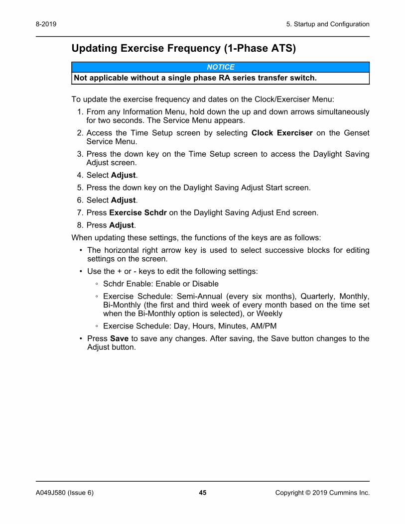
Updating Exercise Frequency (1-Phase ATS)NOTICE
Not applicable without a single phase RA series transfer switch.
To update the exercise frequency and dates on the Clock/Exerciser Menu:1. From any Information Menu, hold down the up and down arrows simultaneously
for two seconds. The Service Menu appears.2. Access the Time Setup screen by selecting Clock Exerciser on the Genset
Service Menu.3. Press the down key on the Time Setup screen to access the Daylight Saving
Adjust screen.4. Select Adjust.5. Press the down key on the Daylight Saving Adjust Start screen.6. Select Adjust.7. Press Exercise Schdr on the Daylight Saving Adjust End screen.8. Press Adjust.
When updating these settings, the functions of the keys are as follows:• The horizontal right arrow key is used to select successive blocks for editing
settings on the screen.• Use the + or - keys to edit the following settings:
◦ Schdr Enable: Enable or Disable◦ Exercise Schedule: Semi-Annual (every six months), Quarterly, Monthly,
Bi-Monthly (the first and third week of every month based on the time setwhen the Bi-Monthly option is selected), or Weekly
◦ Exercise Schedule: Day, Hours, Minutes, AM/PM• Press Save to save any changes. After saving, the Save button changes to the
Adjust button.

5. Startup and Configuration 8-2019
46 A049J580 (Issue 6)Copyright © 2019 Cummins Inc.
FIGURE 14. EXERCISE FREQUENCY NAVIGATION
Updating Exercise Duration (1-Phase ATS)NOTICE
Not applicable without a single phase RA series transfer switch.
To update the exercise duration on the Clock/Exerciser Menu:1. From any Information Menu, hold down the up and down arrows simultaneously
for two seconds. The Service Menu appears.2. Access the Time Setup screen by selecting Clock Exerciser on the Genset
Service Menu.3. Press the down key on the Time Setup screen to access the Daylight Saving
Adjust screen.4. Select Adjust.5. Press the down key on the Daylight Saving Adjust Start screen.6. Select Adjust.7. Press Exercise Schdr on the Daylight Saving Adjust End screen.8. Press the down key on the Exercise Schdr Menu.9. Press Adjust.
When updating these settings, the functions of the keys are as follows:• The horizontal right arrow key is used to select the duration block for editing
exercise duration.• Use the + or - keys to edit the exercise duration minutes.

5. Startup and Configuration8-2019
47A049J580 (Issue 6) Copyright © 2019 Cummins Inc.
• Press Save to save any changes. After saving, the Save button changes to theAdjust button.
FIGURE 15. EXERCISE DURATION NAVIGATION
5.2 Time Setup (1-Phase ATS)NOTICE
When battery power is lost, these settings must be reset.
NOTICENot applicable without a single phase RA series transfer switch.
To set up the generator set clock for the current date and time:1. From any Information Menu, hold down the up and down arrows simultaneously
for two seconds. The Service Menu appears.2. Access the Time Setup screen by selecting Clock Exerciser on the Genset
Service Menu.3. Select Adjust.
When updating these settings, the functions of the keys are as follows:• The horizontal right arrow key is used to select successive blocks for editing
settings on the screen.• Select the left arrow to return to the previous screen.• Adjust values by using the + or - keys on the Adjust Menu of the Time Setup
screen.

5. Startup and Configuration 8-2019
48 A049J580 (Issue 6)Copyright © 2019 Cummins Inc.
• Press Save to save any changes. After saving, the Save button changes to theAdjust button.
FIGURE 16. TIME SETUP SCREEN
Updating Daylight Saving Adjust ScreensUpdate Values on the Daylight Saving Adjust Screen
1. From any Information Menu, hold down the up and down arrows simultaneouslyfor two seconds. The Service Menu appears.
2. Navigate to the Genset Service Menu.3. Select Clock Exerciser to access the Time Setup screen.4. Press the down key on the Time Setup screen to access the Daylight Saving
Adjust screen.5. Select Adjust. When updating these settings, the functions of the keys are as
follows:
TABLE 12. KEY FUNCTIONS ON THE DAYLIGHT SAVING ADJUST SCREEN
Key/Button FunctionHorizontal right arrow key Select successive blocks for editing settings on the screen
Left arrow key Return to the previous screen
+ or - keys Adjust values on the Adjust screen of the Daylight Saving Adjustscreen
Save button Save any changes; after saving, the Save button changes to theAdjust button

5. Startup and Configuration8-2019
49A049J580 (Issue 6) Copyright © 2019 Cummins Inc.
FIGURE 17. "DAYLIGHT SAVING ADJUST SAVING TIME" SCREEN NAVIGATIONAccess and Update the Daylight Saving Adjust Start Screen
1. Press the down arrow key on the Daylight Saving Adjust screen.2. Press Adjust. When updating these settings, the functions of the keys are as
follows:
TABLE 13. KEY FUNCTIONS ON THE DAYLIGHT SAVING ADJUST START SCREEN
Key/Button FunctionHorizontal right arrow key Select successive blocks for editing settings on the screen
+ or - keys Adjust Month, Week, Day or Hour
Save button Save any changes; after saving, the Save button changes to theAdjust button

5. Startup and Configuration 8-2019
50 A049J580 (Issue 6)Copyright © 2019 Cummins Inc.
FIGURE 18. DAYLIGHT SAVING ADJUST START SCREENUpdate the Daylight Saving Adjust End Screen
1. Press the down key on the Daylight Saving Adjust Start screen.2. Press Adjust. When updating these settings, the functions of the keys are as
follows:
TABLE 14. KEY FUNCTIONS ON THE DAYLIGHT SAVING ADJUST END SCREEN
Key/Button FunctionHorizontal right arrow key Select successive blocks for editing settings on the screen
+ or - keys Adjust Month, Week, Day or Hour
Save button Save any changes; after saving, the Save button changes to theAdjust button

5. Startup and Configuration8-2019
51A049J580 (Issue 6) Copyright © 2019 Cummins Inc.
FIGURE 19. DAYLIGHT SAVING ADJUST END SCREEN
5.3 Brightness and ContrastThe Screen Adjust screen allows the contrast, brightness, and units to be set. Toaccess the Screen Adjust screen:
1. From any Information screen, hold down the up and down arrowssimultaneously for two seconds to gain access to the Service Menu screen.
2. Select Screen Adjust.To adjust the contrast, brightness, or units from the Screen Adjust screen:
1. From the Screen Adjust screen, select Adjust to access the screen variables.2. Press the right arrow to move between the variables.3. Adjust settings, and press Save to save any changes.
When updating these settings, the functions of the keys are as follows:• The horizontal right arrow key is used to select successive blocks for editing
settings on the screen.• Select the left arrow to return to the previous screen.• Adjust values by using the + or - keys on the Adjust screen of the Display
Setup screen.• Press Save to save any changes. After saving, the Save button changes to the
Adjust button.

5. Startup and Configuration 8-2019
52 A049J580 (Issue 6)Copyright © 2019 Cummins Inc.
NOTICEThe following screens represent the standard operator panel (HMI211). Ifusing an in-home operator panel, which may be additionally purchased as anoption, the screens may look slightly different. This procedure applies toboth operator panels.
FIGURE 20. BRIGHTNESS AND CONTRAST SCREEN NAVIGATION

5. Startup and Configuration8-2019
53A049J580 (Issue 6) Copyright © 2019 Cummins Inc.
NOTICEAdjusting the brightness on the operator panel adjusts the brightness ofboth the LCD backlight and the LEDs on the display. The contrast shouldnever be 0 or 100% on any of the screens. The default value for Brightness is50%.
5.4 History and About MenuTo access the History/About screen:
1. From any Information Menu, hold down the up and down arrows simultaneouslyfor two seconds. The Service Menu appears.
2. Select History/About.3. Advance through the screens to view information about the generator set,
control, and display.
NOTICEThe following screens represent the standard operator panel (HMI211). Ifusing an in-home operator panel, which may be additionally purchased as anoption, the screens may look slightly different. This procedure applies toboth operator panels.

5. Startup and Configuration 8-2019
54 A049J580 (Issue 6)Copyright © 2019 Cummins Inc.
FIGURE 21. HISTORY/ABOUT MENU

5. Startup and Configuration8-2019
55A049J580 (Issue 6) Copyright © 2019 Cummins Inc.
5.5 StartupWARNING
Automated MachineryAccidental or remote starting of the generator set can cause severe personalinjury or death.Isolate all auxiliary supplies and use an insulated wrench to disconnect thestarting battery cables, negative (–) cable first.
After verifying that the installation was completed correctly, start and test thesystem. Make sure to connect the battery cables to the battery with the positive (+)cable first.Read through the Operator Manual and perform the maintenance and pre-startchecks as instructed.The following information applies to C70 N6, C80 N6, and C100 N6 generator setmodels only: Adaptive learn is an engine ECM function that allows the generator setto "learn" its environment. There are small differences in the performance of eachengine and fuel system component, so the ECM uses inputs from the enginesensors to adjust running conditions to operate more consistently for each individualgenerator set. After installation is complete and while testing the overall systemfunction, the generator set must be run with no active faults under load (that is,transfer switch connected to maximum customer load available) until the enginetemperature reaches 80 °C (175 °F) to allow the adaptive learn function to initialize.The generator set is shipped from the factory with the proper level of engine oil andcoolant, but each should be checked before the generator set is started. Start andoperate the generator set following all the instructions and precautions in theOperator Manual. Ensure that the bonding bolts are installed into the service panelsbefore leaving the site.
NOTICEBefore leaving the site, if the generator set is ready to be placed in service,put the generator set in Auto mode to provide automatic standby power.
NOTICEContact your local Cummins service representative if you encounter a faultcode.

5. Startup and Configuration 8-2019
56 A049J580 (Issue 6)Copyright © 2019 Cummins Inc.
5.6 Installation ChecklistTick General Items
Generator set wattage capacity is sufficient to handle maximum anticipated load.
At least 5 feet of clearance (or greater for housing door) is provided around the entiregenerator set for service and ventilation.
The generator set is located in an area not subject to flooding.
All operating personnel have read and are familiar with the generator set Operatormanual, all health and safety procedures, warnings, cautions, precautions, and theother documentation supplied with the generator set.
All operators have been thoroughly briefed on preventative maintenance procedures.
All operators have read and understand all important safety instructions.
Generator Set SupportThe floor, roof, or earth on which the generator set rests is strong enough and will notallow shifting or movement. Observe local codes on soil bearing capacity due tofreezing and thawing.
The generator set is properly supported and retained to an approved base
The supporting base is large enough and is of non-combustible material, extending 6inches (152.4 mm) all around the generator set.
Cooling Air FlowGenerator set air inlet is faced into direction of strongest, prevailing winds.
Cooling air outlet is on downwind side of building (if not, wind barrier is constructed).
Diesel Fuel SystemFuel tanks meet or exceed all local, state, or national codes (if applicable).
Fuel lines are properly installed, supported, and protected against damage.
The fuel filters have been installed (if applicable).
Strainer or fuel screen (100 to 200 mesh) is installed in the fuel supply line to protectthe day tank transfer pump, or float valve seat from fuel tank debris (if applicable).
The fuel filter assembly shipped with the generator set is installed and operational (ifapplicable).
Fuel supply shutoff valves are installed to prevent fuel flow in case of leaks (ifapplicable).
No shutoff valves are installed on engine fuel return line.
External fuel pumps are connected and operational at all times - generator set startedor shut down (if applicable).
Fuel tanks are filled with the correct grade / type of fuel.

5. Startup and Configuration8-2019
57A049J580 (Issue 6) Copyright © 2019 Cummins Inc.
Tick General ItemsFuel system is properly primed.
No fuel leaks are found in supply line or engine fuel system.
Exhaust SystemThe breather tube routing is set up to blow the fumes away from the generator set (ifapplicable)
Operators are thoroughly briefed on the dangers of carbon monoxide gas.
Areas around generator set are well ventilated. No possibility of exhaust fumesentering building doors, windows, or intake fans.
Exhaust gases are piped safely outside and away from building.
AC and DC WiringWire sizes, insulation, conduits and connection methods all meet applicable codes.
AC and DC wires are separated in their own conduit to prevent electrical induction.
All load, line and generator connections are well made and correct.
Phase rotation is correct.
Generator Set Pre-StartGenerator set engine is properly serviced with oil and coolant.
Battery charger is installed using the appropriate cable size and is operational (ifapplicable).
Battery charger is configured for the proper DC battery voltage, battery type, and floatvoltage (if applicable).
Batteries are properly installed, serviced and charged.
Engine coolant heater is connected and operational (if applicable).
All generator set covers and safety shields are installed correctly.
All fuel and coolant shutoff valves are operational (if applicable).

5. Startup and Configuration 8-2019
58 A049J580 (Issue 6)Copyright © 2019 Cummins Inc.
This page is intentionally blank.

59A049J580 (Issue 6) Copyright © 2019 Cummins Inc.
Appendix A. Outline and System Drawings
Table of ContentsFigure 22. Generator Set Outline, Open - C10 D6, C15 D6 (Sheet 1 of 2) ............................................... 61Figure 23. Generator Set Outline, Open - C10 D6, C15 D6 (Sheet 2 of 2) ............................................... 62Figure 24. Generator Set Outline, Open - C20 D6 (Sheet 1 of 2) ............................................................. 63Figure 25. Generator Set Outline, Open - C20 D6 (Sheet 2 of 2) ............................................................. 64Figure 26. Short Enclosure Outline, Sound Attention Level 1 and Level 2 (Sheet 1 of 2) .................... 65Figure 27. Short Enclosure Outline, Sound Attention Level 1 and Level 2 (Sheet 2 of 2) .................... 66Figure 28. Foundation Outline, Without Fuel Tank (Sheet 1 of 1) ........................................................... 67Figure 29. Foundation Outline, With Regional Fuel Tank (Sheet 1 of 1) ................................................ 68Figure 30. Foundation Outline, With Basic Fuel Tank (Sheet 1 of 1) ...................................................... 69Figure 31. Circuit Breaker Outline (Sheet 1 of 1) ...................................................................................... 70Figure 32. Wiring Diagram (Sheet 1 of 8) ................................................................................................... 71Figure 33. Wiring Diagram (Sheet 2 of 8) ................................................................................................... 72Figure 34. Wiring Diagram (Sheet 3 of 8) ................................................................................................... 73Figure 35. Wiring Diagram (Sheet 4 of 8) ................................................................................................... 74Figure 36. Wiring Diagram (Sheet 5 of 8) ................................................................................................... 75Figure 37. Wiring Diagram (Sheet 6 of 8) ................................................................................................... 76Figure 38. Wiring Diagram (Sheet 7 of 8) ................................................................................................... 77Figure 39. Wiring Diagram (Sheet 8 of 8) ................................................................................................... 78

Appendix A. Outline and System Drawings 8-2019
60 A049J580 (Issue 6)Copyright © 2019 Cummins Inc.
This page is intentionally blank.

Appendix A. Outline and System Drawings8-2019
61A049J580 (Issue 6) Copyright © 2019 Cummins Inc.
FIGURE 22. GENERATOR SET OUTLINE, OPEN - C10 D6, C15 D6 (SHEET 1 OF 2)

Appendix A. Outline and System Drawings 8-2019
62 A049J580 (Issue 6)Copyright © 2019 Cummins Inc.
FIGURE 23. GENERATOR SET OUTLINE, OPEN - C10 D6, C15 D6 (SHEET 2 OF 2)

Appendix A. Outline and System Drawings8-2019
63A049J580 (Issue 6) Copyright © 2019 Cummins Inc.
FIGURE 24. GENERATOR SET OUTLINE, OPEN - C20 D6 (SHEET 1 OF 2)

Appendix A. Outline and System Drawings 8-2019
64 A049J580 (Issue 6)Copyright © 2019 Cummins Inc.
FIGURE 25. GENERATOR SET OUTLINE, OPEN - C20 D6 (SHEET 2 OF 2)

Appendix A. Outline and System Drawings8-2019
65A049J580 (Issue 6) Copyright © 2019 Cummins Inc.
FIGURE 26. SHORT ENCLOSURE OUTLINE, SOUND ATTENTION LEVEL 1 AND LEVEL 2 (SHEET 1 OF 2)

Appendix A. Outline and System Drawings 8-2019
66 A049J580 (Issue 6)Copyright © 2019 Cummins Inc.
FIGURE 27. SHORT ENCLOSURE OUTLINE, SOUND ATTENTION LEVEL 1 AND LEVEL 2 (SHEET 2 OF 2)

Appendix A. Outline and System Drawings8-2019
67A049J580 (Issue 6) Copyright © 2019 Cummins Inc.
FIGURE 28. FOUNDATION OUTLINE, WITHOUT FUEL TANK (SHEET 1 OF 1)

Appendix A. Outline and System Drawings 8-2019
68 A049J580 (Issue 6)Copyright © 2019 Cummins Inc.
FIGURE 29. FOUNDATION OUTLINE, WITH REGIONAL FUEL TANK (SHEET 1 OF 1)

Appendix A. Outline and System Drawings8-2019
69A049J580 (Issue 6) Copyright © 2019 Cummins Inc.
FIGURE 30. FOUNDATION OUTLINE, WITH BASIC FUEL TANK (SHEET 1 OF 1)

Appendix A. Outline and System Drawings 8-2019
70 A049J580 (Issue 6)Copyright © 2019 Cummins Inc.
FIGURE 31. CIRCUIT BREAKER OUTLINE (SHEET 1 OF 1)

Appendix A. Outline and System Drawings8-2019
71A049J580 (Issue 6) Copyright © 2019 Cummins Inc.
FIGURE 32. WIRING DIAGRAM (SHEET 1 OF 8)

Appendix A. Outline and System Drawings 8-2019
72 A049J580 (Issue 6)Copyright © 2019 Cummins Inc.
FIGURE 33. WIRING DIAGRAM (SHEET 2 OF 8)

Appendix A. Outline and System Drawings8-2019
73A049J580 (Issue 6) Copyright © 2019 Cummins Inc.
FIGURE 34. WIRING DIAGRAM (SHEET 3 OF 8)

Appendix A. Outline and System Drawings 8-2019
74 A049J580 (Issue 6)Copyright © 2019 Cummins Inc.
FIGURE 35. WIRING DIAGRAM (SHEET 4 OF 8)

Appendix A. Outline and System Drawings8-2019
75A049J580 (Issue 6) Copyright © 2019 Cummins Inc.
FIGURE 36. WIRING DIAGRAM (SHEET 5 OF 8)

Appendix A. Outline and System Drawings 8-2019
76 A049J580 (Issue 6)Copyright © 2019 Cummins Inc.
FIGURE 37. WIRING DIAGRAM (SHEET 6 OF 8)

Appendix A. Outline and System Drawings8-2019
77A049J580 (Issue 6) Copyright © 2019 Cummins Inc.
FIGURE 38. WIRING DIAGRAM (SHEET 7 OF 8)

Appendix A. Outline and System Drawings 8-2019
78 A049J580 (Issue 6)Copyright © 2019 Cummins Inc.
FIGURE 39. WIRING DIAGRAM (SHEET 8 OF 8)


power.cummins.comCopyright © 2019 Cummins Inc. All rights reserved.Cummins, the "C" logo, PowerCommand, AmpSentry, and InPower aretrademarks of Cummins Inc.Other company, product, or service names may be trademarks or servicemarks of others.Specifications are subject to change without notice.