
Connectivity Module - Generator Joe
31
Installation Manual 381333-238 B 50 Hanover Rd, Florham Park, NJ 07932-1591 USA call 1 800 800-2726 (ASC0) for sales or service www.ascopower.com 5100 Series, Catalog 5150 Connectivity Module For use with Automatic Transfer Switches & Power Manager Section Page Welcome............................................................................................................. ii Overview, Specifications, How to View Pages after Installation ....................... iii 1 Installation on Automatic Transfer Switches (7000, 4000, 300, 940/962) ......................... 1-1 on stand-alone Power Manager, Test Communications ................................. 1-2 View & Change Configuration Pages, View Pages after Installation .............. 1-3 2 7000 & 4000 Series ATS (with and without a Power Manager) Configurator Screens................................................................................ 2-1, 2-2 Detail Screen ................................................................................................... 2-3 3 Series 300 ATS (with and without a Power Manager) Configurator Screens................................................................................ 3-1, 3-2 Detail Screen ................................................................................................... 3-3 4 ASCO 940 / 962 ATS (with and without a Power Manager) Configurator Screen ........................................................................................ 4-1 Detail Screen ................................................................................................... 4-2 5 Power Manager (stand-alone, connected to a generator or a circuit breaker) Configurator Screen ........................................................................................ 5-1 Detail Screens .......................................................................................... 5-2, 5-3 Appendix Outline Installation Drawing............................................................. CS 757085 B Interface Wiring Diagram................................................................. BS 629855 B TCP/IP Installation & Configuration for Windows 2000 ® ................................ A-1 TCP/IP Installation & Configuration for Windows NT ® ................................... A-3 TCP/IP Installation & Configuration for Windows XP ® ................................... A-5 Troubleshooting ............................................................................................... A-7 Create & copy favorites folder, 3 rd Party Modbus ® device configuration........ A-8 Communication Address Form ............................................................ in the back Index ................................................................................................................ back page
-
Upload
khangminh22 -
Category
Documents
-
view
3 -
download
0
Transcript of Connectivity Module - Generator Joe
Installation Manual
381333-238 B
50 Hanover Rd, Florham Park, NJ 07932-1591 USA call 1 800 800-2726 (ASC0) for sales or service www.ascopower.com
5100 Series, Catalog 5150Connectivity Module
For use with Automatic Transfer Switches & Power Manager
Section PageWelcome............................................................................................................. iiOverview, Specifications, How to View Pages after Installation ....................... iii
1 Installationon Automatic Transfer Switches (7000, 4000, 300, 940/962) ......................... 1-1on stand-alone Power Manager, Test Communications ................................. 1-2View & Change Configuration Pages, View Pages after Installation .............. 1-3
2 7000 & 4000 Series ATS (with and without a Power Manager)Configurator Screens................................................................................2-1, 2-2Detail Screen ................................................................................................... 2-3
3 Series 300 ATS (with and without a Power Manager)Configurator Screens................................................................................3-1, 3-2Detail Screen ................................................................................................... 3-3
4 ASCO 940 / 962 ATS (with and without a Power Manager)Configurator Screen ........................................................................................ 4-1Detail Screen ................................................................................................... 4-2
5 Power Manager (stand-alone, connected to a generator or a circuit breaker)Configurator Screen ........................................................................................ 5-1Detail Screens ..........................................................................................5-2, 5-3
AppendixOutline Installation Drawing.............................................................CS 757085 BInterface Wiring Diagram.................................................................BS 629855 BTCP/IP Installation & Configuration for Windows 2000 ® ................................A-1TCP/IP Installation & Configuration for Windows NT ® ...................................A-3TCP/IP Installation & Configuration for Windows XP ® ...................................A-5Troubleshooting...............................................................................................A-7Create & copy favorites folder, 3rd Party Modbus ® device configuration........A-8Communication Address Form............................................................ in the back
Index ................................................................................................................back page

Connectivity Module Welcome ii
Modbus is a registered trademark of Gould Inc.
Who Should Use this Installation ManualThis Installation Manual for the Connectivity Module should be used toassist individuals who will: • install the Connectivity Module (mount and wire) • configure the Connectivity Module • enter in information about your Automatic Transfer Switches
(7000 & 4000 Series, Series 300, ASCO 940,962,436,434,447,448) • use Ethernet access to monitor Connectivity Module (connected devices)
Prerequisites A working knowledge of Windows 2000 ®, Windows NT ®, or Windows XP ®and Windows Internet Explorer 5.0 or higher is necessary to configure theConnectivity Module.
Important information To properly set up the software, you will need the nameplate data and otherthat you will need information from all your Automatic Transfer Switches (up to 64) including:
• ATS Name (your designation for the ATS)• ATS Location (where the ATS is located in the building)• Voltage Rating, Ampere Rating, and number of Poles for each ATS• Catalog No. and Serial No. of each ATS• Type of ATS (ATS or ATS/BP [ATS with bypass-isolation switch])• Power Manager Address (set in each Power Manager or Data Monitor)
Manuals that Catalog 5200 & 5200T Power Manager Operator’s Manual 381333-192you may need Catalog 5220 & 5220T Power Manager Xp Operator’s Manual 381333-199
7000 & 4000 Series ATS Group 5 Controller User’s Guide 381333-1267000 Series ATS appropriate Operator’s Manual4000 Series ATS appropriate Operator’s ManualSeries 300 ATS appropriate Operator’s ManualASCO 940, 962, 436, 434,447, 448 ATS appropriate Operator’s ManualCatalog 5110 Serial Module (Acc. 72A) Installation Manual 381333-240
Tip Communication Address form is included at the back to help you fill inneeded information on your Connectivity Modules, ATSs, & Power
Managers.
The Connectivity Module provides Ethernet-access that allows users to viewdata from ASCO automatic transfer switches and Power Managers. Theseprecautions must be followed by all users:
WARNINGBe sure that Users to whom you give access are those persons that youwant to view information about the electrical system.
WARNINGFill in the Communication Address Form in the back of this manual.Be sure that you enter correct information about each ConnectivityModule, Automatic Transfer Switch, and Power Manager.

iii Overview, Specifications, How to View Pages Connectivity Module
Windows and Internet Explorer are registered trademarks of Microsoft Corporation.
OverviewThe Connectivity Module brings together severaldifferent serial devices that communicate at differentbaud rates and with different protocols to a commonEthernet media. It can communicate with up to eightclients, such as Web applications (web pages), Vpi, orthird-party Modbus ® devices simultaneously overEthernet media.
SpecificationsPower Requirements: 24 V dc nominal (8 – 28 V dc) 1.5 Watt, UL Class 2 power supply, if needed.Mounting: 35 mm DIN railDimensions: 3.5” H, 2.8” W, 2.9” D (8.9 cm, 7.1 cm, 7.4 cm)
Field Communication Cable Requirements:Ethernet: Belden 7882A or equiv. UTP CAT 5 with
RJ45 connectors (untwisted pair or higher)Serial: Belden 9842, 9829, 89729, 82729 or Apha
6202C, 6222C, 58902. UL Listed, stranded,twisted pairs, over-all foil shield with stranded drain wire
J1, J2 TTL Port Connectors: Two built-in TTL ports(DB9 pin male) for ATS/PM connectivity
J3 Ethernet Port Connector :One built-in 10 Base T (RJ45) 10 Mbps Ethernet port
J4 Serial RS-485 Port:One 5-pin terminal block header with a socket block (J4)designed to be daisy chained for up to 32 devices.
Terminal 1 – RX+ Terminal 4 – TX-Terminal 2 – RX- Terminal 5 – ComTerminal 3 – TX+
Ambient Temperature:Operating 32 to 140° F (0 to 60° C)Storage - -40 to 185° F (-40 to 85° C)
Configuration Parameters: The parameters that are requiredto make an Ethernet connection are:
IP Address 169.254.1.1Subnet Mask 255.255.0.0Gateway0.0.0.0TCP Port No. 10001
The TCP port is used for passing the data to the applica-tions and is configurable for user specific requirement.
Baud Rates 19200 (default) or 9600Flow Control No Flow Control (default)Interface Mode TTL/RS485 – 4 wires (default)Reply Timeout 200 milliseconds (default)
Protocol Support: The following protocols are supported:Serial Protocol: ASCO I, II, and ModbusTransport Protocol: TCP, UDPApplication Protocol: HTTP, Telnet, Modbus/TCP
How to View Pages from a ConnectivityModule after it is installed
After installation, testing, and configuration is completed(see Section 1) to view pages on a client computer,follow these steps:
1. Be sure that your computer is connected to theInternet.
2. Start Microsoft Internet Explorer browser on thecomputer.
3. In the address bar, type in the address of theConnectivity Module:
http://169.254.1.1
The Connectivity Module sends HTML files to the clientcomputer. Internet Explorer interprets these HTMLfiles, formats them, and displays the pages to the user.Pages 2-3, 3-3, 4-2, 5-2, 5-3 shows typical HTML pages(Detail screens).
Tip You can add the address to your Favorites forconvenient access to multiple ConnectivityModules; follow these steps:
1. Click Favorites, then click Add to Favorites,click New Folder, then type the Folder name(ATSs, for example), and click OK.
2. To rename the address, highlight it, and type thenew name, and click OK.
3. When you are finished viewing pages, closeInternet Explorer.
Type the address of theConnectivity Moduleh

Connectivity Module Installation 1-1
How to Install the Connectivity Moduleon 7000 & 4000 Series and Series 300 ATSsThe Connectivity Module mounts on a DIN rail underthe ATS Controller (Group 5 & 1). A short serial cableconnects the Connectivity Module to the Controller. If aPower Manager is present, a long serial cable connectsthe Connectivity Module to the Power Manager. Referto installation drawings provided and follow the stepsbelow to install the Connectivity Module.
Connectivity Module KitK754603
for 7000 & 4000 Seriesand Series 300 only
Connectivity Module KitK754603-001 for
7000 & 4000 Seriesand Series 300
with Power ManagerConnectivityModule 5150 629800-001 Connectivity
Module 5150 629800-001
DIN Rail andHardware 754607 DIN Rail and
Hardware 754607
10-in. SerialCable forController
629798-00110-in. SerialCable forController
629798-001
4-ft SerialCable forPowerManager *
629798-002
* A 9-foot serial cable (629798-004) isrequired for G7ATB, G7ACTB, G7ADTB.
1. De-energize both Normal and Emergency sourcesthat feed the ATS. Open enclosure door and checkwith a non-contact AC voltage detector.
2. Mount the DIN rail (supplied in the kit) onto twostuds (on the door) below the Controller.Connectivity Module will mount on the right side.
3. Install Connectivity Module onto DIN rail byhooking the bottom of module on bottom of DIN railand rocking it upward unit it snaps in place.
4. Install the 10-inch serial cable between theController receptacle (J7 on Group 5, J4 on Group 1)and the Connectivity Module J1 receptacle.
5. If a Power Manager is present, connect the 4-footserial cable between the Power Manager J5receptacle and the Connectivity Module J2receptacle.*
Now test communications (go to page 1-2).
How to Install the Connectivity Moduleon ASCO 940/962 ATSsThe Connectivity Module mounts on a DIN rail near theATS Control Panel. A separate power supply is neededunless it is connected to a Power Manager (PM). Group6A/7A Control Panel must have a Serial CommunicationKit added. A single communication cable (2 twistedpairs and overall shield connects the ConnectivityModule to the Control Panel). Refer to installationdrawings provided and follow the steps below to installthe Connectivity Module.
Connectivity Module KitK754608
for ASCO 940/962 only
Connectivity Module KitK754608-001
for ASCO 940/962 with PMConnectivityModule 5150 629800-001 Connectivity
Module 5150 629800-001
DIN Rail andHardware 754610 DIN Rail and
Hardware 754610
Serial Com.Kit for Group6A/7A CP *
467508Serial Com.Kit for Group6A/7A CP *
467508
Serial Cablefor PM 629798-002
* Serial communication & transient protection boards.
RequiredPower Supply **
not supplied
Communication Cable(4 wires and an overall shield)
not supplied24 Vdc, 80 mA **use 16 AWG wire
Belden 9842, 9829, 89729, 82729 orAlpha 6202C, 6222C, 58902 only
** If a Power Manager (PM) is present, a power supply is not neededfor the Connectivity Module. The serial cable from the Power Managerprovides the power to the Connectivity Module.
1. De-energize both Normal and Emergency sourcesthat feed the ATS. Open enclosure door and checkwith a non-contact AC voltage detector.
2. Mount DIN rail (supplied in the kit) onto two studs(on the door) below or adjacent to the Control Panel.
3. Install the Connectivity Module onto DIN rail.
4. Prepare and connect the specified communicationcable between the Control Panel terminals and theConnectivity Module J4 terminals as listed below:
5. Prepare and connect the 24 Vdc power supply to theConnectivity Module. Use 16 AWG wiring to J5terminal plug (1 is + positive, 2 is – negative).
Now test communications (go to page 1-2).
To avoid possible shock, burns, or death, deenergizeall electrical sources to the ATS before installing the
Connectivity Module.
DANGER
To avoid possible shock, burns, or death, deenergizeall electrical sources to the ATS before installing the
Connectivity Module.
DANGER
1-2 Installation Connectivity Module
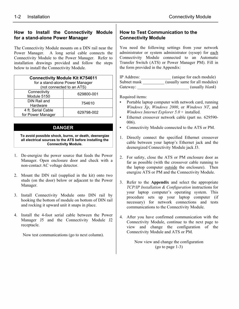
How to Install the Connectivity Modulefor a stand-alone Power Manager
The Connectivity Module mounts on a DIN rail near thePower Manager. A long serial cable connects theConnectivity Module to the Power Manager. Refer toinstallation drawings provided and follow the stepsbelow to install the Connectivity Module.
Connectivity Module Kit K754611for a stand-alone Power Manager
(not connected to an ATS)ConnectivityModule 5150 629800-001
DIN Rail andHardware 754610
4 ft. Serial Cablefor Power Manager 629798-002
1. De-energize the power source that feeds the PowerManager. Open enclosure door and check with anon-contact AC voltage detector.
2. Mount the DIN rail (supplied in the kit) onto twostuds (on the door) below or adjacent to the PowerManager.
3. Install Connectivity Module onto DIN rail byhooking the bottom of module on bottom of DIN railand rocking it upward unit it snaps in place.
4. Install the 4-foot serial cable between the PowerManager J5 and the Connectivity Module J2receptacle.
Now test communications (go to next column).
How to Test Communication to theConnectivity Module
You need the following settings from your networkadministrator or system administrator (sysop) for eachConnectivity Module connected to an AutomaticTransfer Switch (ATS) or Power Manager PM). Fill inthe form provided in the Appendix:
IP Address: ______________ (unique for each module)Subnet mask __________ (usually same for all modules)Gateway: ________________________ (usually blank)
Required items:• Portable laptop computer with network card, running
Windows Xp, Windows 2000, or Windows NT, andWindows Internet Explorer 5.0 + installed.
• Ethernet crossover network cable (part no. 629590-006).
• Connectivity Module connected to the ATS or PM.
1. Directly connect the specified Ethernet crossovercable between your laptop’s Ethernet jack and thedeenergized Connectivity Module jack J3.
2. For safety, close the ATS or PM enclosure door asfar as possible (with the crossover cable running tothe laptop computer outside the enclosure). Thenenergize ATS or PM and the Connectivity Module.
3. Refer to the Appendix and select the appropriateTCP/IP Installation & Configuration instructions foryour laptop computer’s operating system. Thisprocedure sets up your laptop computer (ifnecessary) for network connections and testscommunications to the Connectivity Module.
4. After you have confirmed communication with theConnectivity Module, continue to the next page toview and change the configuration of theConnectivity Module and ATS or PM.
Now view and change the configuration(go to page 1-3)
To avoid possible shock, burns, or death, deenergizeall electrical sources to the ATS before installing the
Connectivity Module.
DANGER
Connectivity Module Installation 1-3
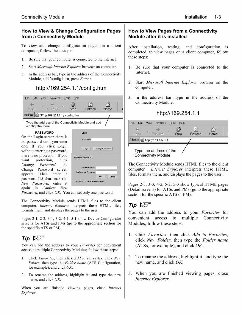
How to View & Change Configuration Pagesfrom a Connectivity Module
To view and change configuration pages on a clientcomputer, follow these steps:
1. Be sure that your computer is connected to the Internet.
2. Start Microsoft Internet Explorer browser on computer.
3. In the address bar, type in the address of the ConnectivityModule, add /config.htm, press Enter :
http://169.254.1.1/config.htm
PASSWORDOn the Login screen there isno password until you enterone. If you click Loginwithout entering a password,there is no protection. If youwant protection, clickChange Password; theChange Password screenappears. Then enter apassword (15 char. max.) inNew Password, enter itagain in Confirm NewPassword, and click OK. You can set only one password.
The Connectivity Module sends HTML files to the clientcomputer. Internet Explorer interprets these HTML files,formats them, and displays the pages to the user.
Pages 2-1, 2-2, 3-1, 3-2, 4-1, 5-1 show Device Configuratorscreens for ATSs and PMs (go to the appropriate section forthe specific ATS or PM).
Tip You can add the address to your Favorites for convenientaccess to multiple Connectivity Modules; follow these steps:
1. Click Favorites, then click Add to Favorites, click NewFolder, then type the Folder name (ATS Configuration,for example), and click OK.
2. To rename the address, highlight it, and type the newname, and click OK.
When you are finished viewing pages, close InternetExplorer.
How to View Pages from a ConnectivityModule after it is installed
After installation, testing, and configuration iscompleted, to view pages on a client computer, followthese steps:
1. Be sure that your computer is connected to theInternet.
2. Start Microsoft Internet Explorer browser on thecomputer.
3. In the address bar, type in the address of theConnectivity Module:
http://169.254.1.1
The Connectivity Module sends HTML files to the clientcomputer. Internet Explorer interprets these HTMLfiles, formats them, and displays the pages to the user.
Pages 2-3, 3-3, 4-2, 5-2, 5-3 show typical HTML pages(Detail screens) for ATSs and PMs (go to the appropriatesection for the specific ATS or PM).
Tip You can add the address to your Favorites forconvenient access to multiple ConnectivityModules; follow these steps:
1. Click Favorites, then click Add to Favorites,click New Folder, then type the Folder name(ATSs, for example), and click OK.
2. To rename the address, highlight it, and type thenew name, and click OK.
3. When you are finished viewing pages, closeInternet Explorer.
Type the address of the Connectivity Module and add/config.htm here.
Type the address of theConnectivity Moduleh
2-1 7000 Series ATSs Connectivity Module
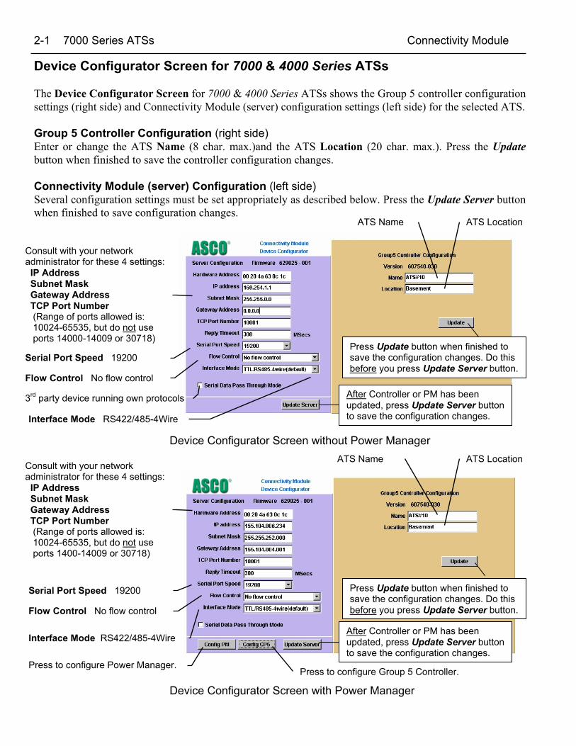
Device Configurator Screen for 7000 & 4000 Series ATSs
The Device Configurator Screen for 7000 & 4000 Series ATSs shows the Group 5 controller configurationsettings (right side) and Connectivity Module (server) configuration settings (left side) for the selected ATS.
Group 5 Controller Configuration (right side)Enter or change the ATS Name (8 char. max.)and the ATS Location (20 char. max.). Press the Updatebutton when finished to save the controller configuration changes.
Connectivity Module (server) Configuration (left side)Several configuration settings must be set appropriately as described below. Press the Update Server buttonwhen finished to save configuration changes.
Device Configurator Screen without Power Manager
Device Configurator Screen with Power Manager
ATS LocationATS Name
Serial Port Speed 19200
Consult with your networkadministrator for these 4 settings: IP Address Subnet Mask Gateway Address TCP Port Number (Range of ports allowed is: 10024-65535, but do not use ports 14000-14009 or 30718)
Press Update button when finished tosave the configuration changes. Do thisbefore you press Update Server button.
After Controller or PM has beenupdated, press Update Server buttonto save the configuration changes.
Flow Control No flow control
Interface Mode RS422/485-4Wire
ATS LocationATS Name
Serial Port Speed 19200
Consult with your networkadministrator for these 4 settings: IP Address Subnet Mask Gateway Address TCP Port Number (Range of ports allowed is: 10024-65535, but do not use ports 1400-14009 or 30718)
Press Update button when finished tosave the configuration changes. Do thisbefore you press Update Server button.
After Controller or PM has beenupdated, press Update Server buttonto save the configuration changes.
Flow Control No flow control
Interface Mode RS422/485-4Wire
Press to configure Power Manager.Press to configure Group 5 Controller.
3rd party device running own protocols
Connectivity Module 7000 Series ATSs 2-2
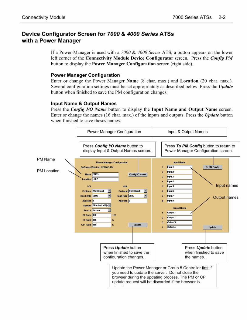
Device Configurator Screen for 7000 & 4000 Series ATSswith a Power Manager
If a Power Manager is used with a 7000 & 4000 Series ATS, a button appears on the lowerleft corner of the Connectivity Module Device Configurator screen. Press the Config PMbutton to display the Power Manager Configuration screen (right side).
Power Manager ConfigurationEnter or change the Power Manager Name (8 char. max.) and Location (20 char. max.).Several configuration settings must be set appropriately as described below. Press the Updatebutton when finished to save the PM configuration changes.
Input Name & Output NamesPress the Config I/O Name button to display the Input Name and Output Name screen.Enter or change the names (16 char. max.) of the inputs and outputs. Press the Update buttonwhen finished to save theses names.
Input names
Input & Output NamesPower Manager Configuration
Press Update buttonwhen finished to savethe names.
Press Update buttonwhen finished to save theconfiguration changes.
Press Config I/O Name button todisplay Input & Output Names screen.
Press To PM Config button to return toPower Manager Configuration screen.
Output names
PM Name
PM Location
Update the Power Manager or Group 5 Controller first ifyou need to update the server. Do not close thebrowser during the updating process. The PM or CPupdate request will be discarded if the browser isl d
2-3 7000 Series ATSs Connectivity Module
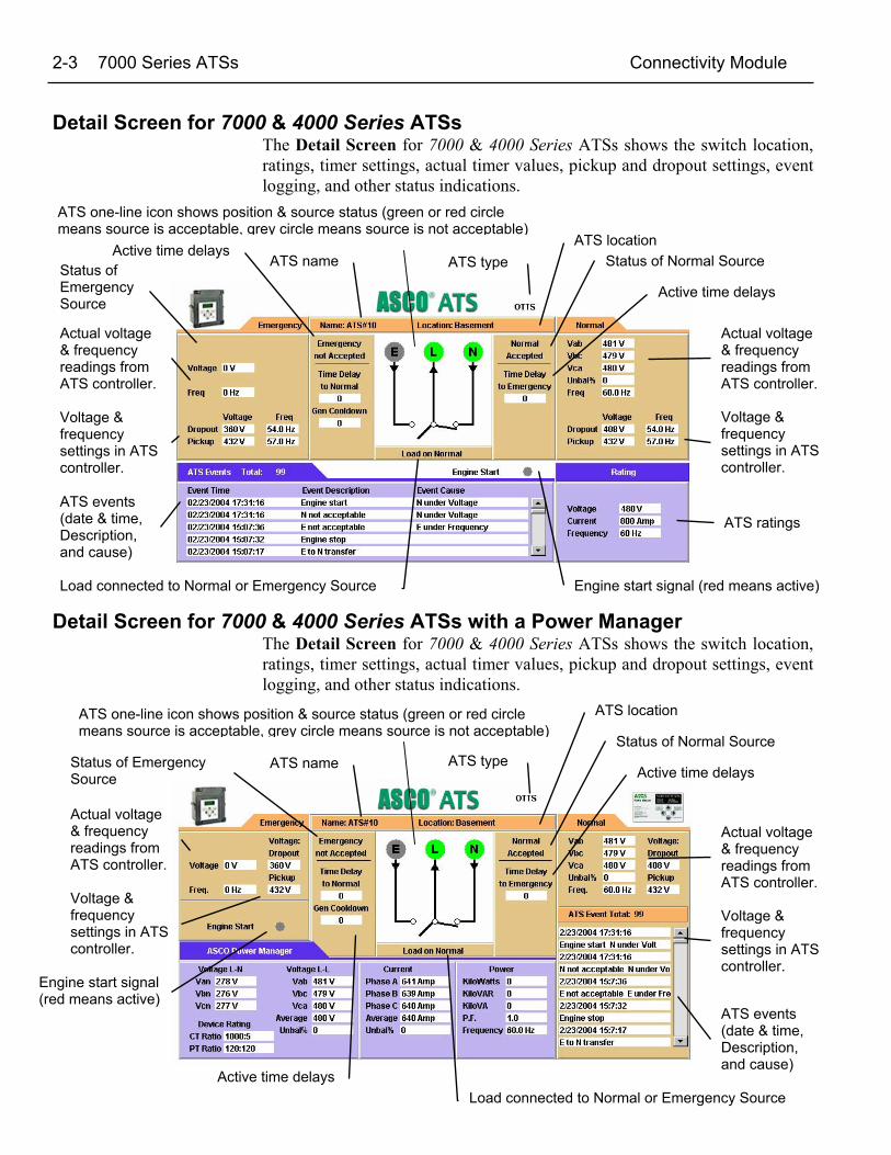
Detail Screen for 7000 & 4000 Series ATSsThe Detail Screen for 7000 & 4000 Series ATSs shows the switch location,ratings, timer settings, actual timer values, pickup and dropout settings, eventlogging, and other status indications.
Detail Screen for 7000 & 4000 Series ATSs with a Power ManagerThe Detail Screen for 7000 & 4000 Series ATSs shows the switch location,ratings, timer settings, actual timer values, pickup and dropout settings, eventlogging, and other status indications.
Actual voltage& frequencyreadings fromATS controller.
Load connected to Normal or Emergency Source
ATS events(date & time,Description,and cause)
ATS ratings
Engine start signal (red means active)
ATS locationATS name
Voltage &frequencysettings in ATScontroller.
Status ofEmergencySource
Actual voltage& frequencyreadings fromATS controller.
Voltage &frequencysettings in ATScontroller.
ATS typeActive time delays
Active time delays
Status of Normal Source
ATS one-line icon shows position & source status (green or red circlemeans source is acceptable, grey circle means source is not acceptable)
Actual voltage& frequencyreadings fromATS controller.
Load connected to Normal or Emergency Source
ATS events(date & time,Description,and cause)
Engine start signal(red means active)
ATS location
ATS name
Voltage &frequencysettings in ATScontroller.
Status of EmergencySource
Actual voltage& frequencyreadings fromATS controller.
Voltage &frequencysettings in ATScontroller.
ATS type
Active time delays
Active time delays
Status of Normal Source
ATS one-line icon shows position & source status (green or red circlemeans source is acceptable, grey circle means source is not acceptable)
Connectivity Module Series 300 ATSs 3-1
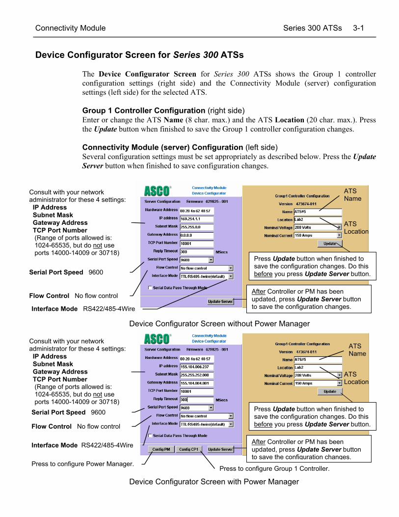
Device Configurator Screen for Series 300 ATSs
The Device Configurator Screen for Series 300 ATSs shows the Group 1 controllerconfiguration settings (right side) and the Connectivity Module (server) configurationsettings (left side) for the selected ATS.
Group 1 Controller Configuration (right side)Enter or change the ATS Name (8 char. max.) and the ATS Location (20 char. max.). Pressthe Update button when finished to save the Group 1 controller configuration changes.
Connectivity Module (server) Configuration (left side)Several configuration settings must be set appropriately as described below. Press the UpdateServer button when finished to save configuration changes.
Device Configurator Screen without Power Manager
Device Configurator Screen with Power Manager
ATSLocation
ATSName
Serial Port Speed 9600
Consult with your networkadministrator for these 4 settings: IP Address Subnet Mask Gateway Address TCP Port Number (Range of ports allowed is: 1024-65535, but do not use ports 14000-14009 or 30718)
Press Update button when finished tosave the configuration changes. Do thisbefore you press Update Server button.
After Controller or PM has beenupdated, press Update Server buttonto save the configuration changes.
Flow Control No flow control
Interface Mode RS422/485-4Wire
Press to configure Power Manager.Press to configure Group 1 Controller.
3-2 Series 300 ATSs Connectivity Module
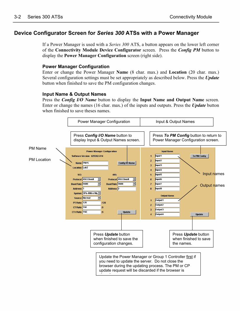
Device Configurator Screen for Series 300 ATSs with a Power Manager
If a Power Manager is used with a Series 300 ATS, a button appears on the lower left cornerof the Connectivity Module Device Configurator screen. Press the Config PM button todisplay the Power Manager Configuration screen (right side).
Power Manager ConfigurationEnter or change the Power Manager Name (8 char. max.) and Location (20 char. max.)Several configuration settings must be set appropriately as described below. Press the Updatebutton when finished to save the PM configuration changes.
Input Name & Output NamesPress the Config I/O Name button to display the Input Name and Output Name screen.Enter or change the names (16 char. max.) of the inputs and outputs. Press the Update buttonwhen finished to save theses names.
Input names
Input & Output NamesPower Manager Configuration
Press Update buttonwhen finished to savethe names.
Press Update buttonwhen finished to save theconfiguration changes.
Press Config I/O Name button todisplay Input & Output Names screen.
Press To PM Config button to return toPower Manager Configuration screen.
Output names
PM Name
PM Location
Update the Power Manager or Group 1 Controller first ifyou need to update the server. Do not close thebrowser during the updating process. The PM or CPupdate request will be discarded if the browser isl d

Connectivity Module Series 300 ATSs 3-3
Detail Screen for Series 300 ATSsThe Detail Screen for Series 300 ATSs shows the switch location, ratings,timer settings, actual timer values, pickup and dropout settings, and otherstatus indications.
Detail Screen for Series 300 ATSs with a Power ManagerThe Detail Screen for Series 300 ATSs shows the switch location, ratings,timer settings, actual timer values, pickup and dropout settings, and otherstatus indications.
Actual voltagereading fromATS controller.
Load connected to Normal or Emergency SourceEngine start signal(red means active)
ATS location
Status of Normal SourceATS name
Voltage &frequencysettings in ATScontroller.
Status ofEmergency Source
Actual voltage& frequencyreadings fromATS controller.
Voltage &frequencysettings in ATScontroller.
ATS type
Activetime delays
Active time delays
ATS one-line icon shows position & source status (green or red circlemeans source is acceptable, grey circle means source is not acceptable)
Actual voltagereading fromATS controller.
Load connected to Normal or Emergency Source
Engine startsignal (redmeans active)
ATS location
Status of Normal SourceATS name
Voltage &frequencysettings in ATScontroller.
Status ofEmergency Source
Actual voltage& frequencyreadings fromATS controller.
Voltage &frequencysettings in ATScontroller.
ATS type
Activetime delays
Activetime delays
ATS one-line icon shows position & source status (green or red circlemeans source is acceptable, grey circle means source is not acceptable)
4-1 ASCO 940/962 ATSs Connectivity Module
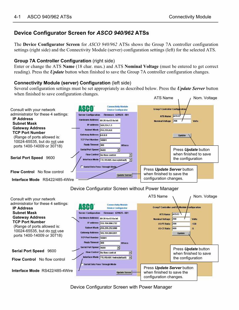
Device Configurator Screen for ASCO 940/962 ATSs
The Device Configurator Screen for ASCO 940/962 ATSs shows the Group 7A controller configurationsettings (right side) and the Connectivity Module (server) configuration settings (left) for the selected ATS.
Group 7A Controller Configuration (right side)Enter or change the ATS Name (18 char. max.) and ATS Nominal Voltage (must be entered to get correctreading). Press the Update button when finished to save the Group 7A controller configuration changes.
Connectivity Module (server) Configuration (left side)Several configuration settings must be set appropriately as described below. Press the Update Server buttonwhen finished to save configuration changes.
Device Configurator Screen without Power Manager
Device Configurator Screen with Power Manager
Nom. VoltageATS Name
Serial Port Speed 9600
Consult with your networkadministrator for these 4 settings: IP Address Subnet Mask Gateway Address TCP Port Number (Range of ports allowed is: 10024-65535, but do not use ports 1400-14009 or 30718)
Press Update buttonwhen finished to savethe configuration
Press Update Server buttonwhen finished to save theconfiguration changes.
Flow Control No flow control
Interface Mode RS422/485-4Wire

Connectivity Module ASCO 940/962 ATSs 4-2
Detail Screen for ASCO 940/962 ATSsThe Detail Screen for ASCO 940/962 ATSs shows the switch location,ratings, timer settings, actual timer values, pickup and dropout settings, andother status indications.
Detail Screen for ASCO 940/962 ATSs with a Power ManagerThe Detail Screen for ASCO 940/962 ATSs shows the switch location,ratings, timer settings, actual timer values, pickup and dropout settings, andother status indications.
Actual voltagereading fromATS controller.
Load connected to Normal or Emergency SourceATS ratings
Status of Normal SourceATS name
Voltage &frequencysettings in ATScontroller.
Status ofEmergencyS
Actual voltagereading fromATS controller.
Voltage &frequencysettings in ATScontroller.
ATS one-line icon shows position & source status(green or red circle means source is acceptable,grey circle means source is not acceptable)
Time delaysettings inATScontroller.
Time delaysettings inATScontroller.
Actual voltagereading fromATS controller.
Load connected to Normal or Emergency Source
Status of Normal SourceATS name
Voltage &frequencysettings in ATScontroller.
Status ofEmergencySo rce
Actual voltagereading fromATS controller.
Voltage &frequencysettings in ATScontroller.
Time delaysettings inATScontroller.
Time delaysettings inATScontroller.
ATS one-line icon shows position & source status (green or red circlemeans source is acceptable, grey circle means source is not acceptable)
5-1 Stand-Alone Power Managers Connectivity Module
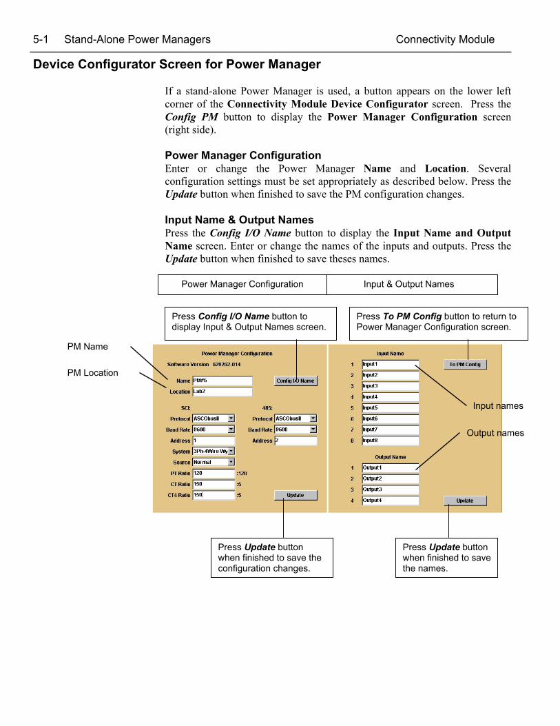
Device Configurator Screen for Power Manager
If a stand-alone Power Manager is used, a button appears on the lower leftcorner of the Connectivity Module Device Configurator screen. Press theConfig PM button to display the Power Manager Configuration screen(right side).
Power Manager ConfigurationEnter or change the Power Manager Name and Location. Severalconfiguration settings must be set appropriately as described below. Press theUpdate button when finished to save the PM configuration changes.
Input Name & Output NamesPress the Config I/O Name button to display the Input Name and OutputName screen. Enter or change the names of the inputs and outputs. Press theUpdate button when finished to save theses names.
Input names
Input & Output NamesPower Manager Configuration
Press Update buttonwhen finished to savethe names.
Press Update buttonwhen finished to save theconfiguration changes.
Press Config I/O Name button todisplay Input & Output Names screen.
Press To PM Config button to return toPower Manager Configuration screen.
Output names
PM Name
PM Location

Connectivity Module Stand-Alone Power Managers 5-2
Detail Screen for Power Managers connected to a LoadThe Detail Screen for Power Managers shows energy levels, powermeasurements, settings, discrete I/O status, and other status information.
Energylevels
Discrete Input / Outputname & status information
PM name
PM location
Powermeasurements
Settings
Actual voltage, current, andpower readings from the PM.
Click to viewNormal orEmergencyenergy data.
5-3 Stand-Alone Power Managers Connectivity Module
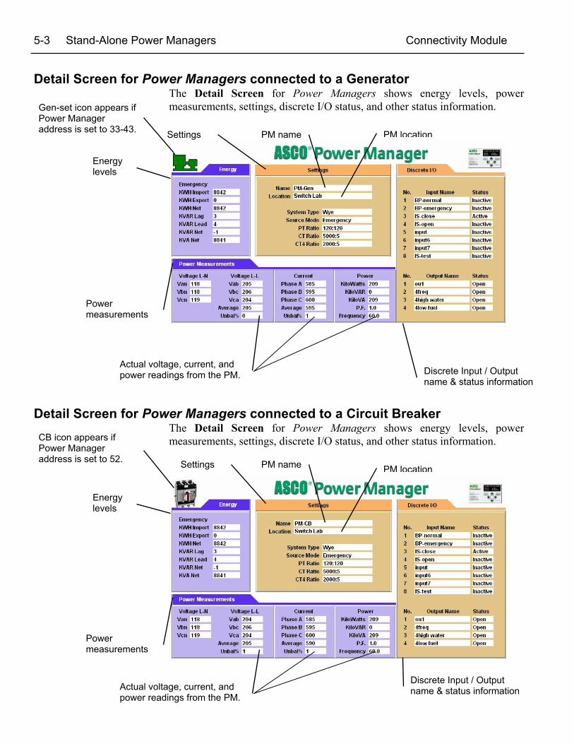
Detail Screen for Power Managers connected to a GeneratorThe Detail Screen for Power Managers shows energy levels, powermeasurements, settings, discrete I/O status, and other status information.
Detail Screen for Power Managers connected to a Circuit BreakerThe Detail Screen for Power Managers shows energy levels, powermeasurements, settings, discrete I/O status, and other status information.
Energylevels
Discrete Input / Outputname & status information
PM name PM location
Powermeasurements
Settings
Actual voltage, current, andpower readings from the PM.
Energylevels
Discrete Input / Outputname & status information
PM name PM location
Powermeasurements
Settings
Actual voltage, current, andpower readings from the PM.
Gen-set icon appears ifPower Manageraddress is set to 33-43.
CB icon appears ifPower Manageraddress is set to 52.

Com
mun
icat
ion
Add
ress
For
m fo
r Con
nect
ivity
Mod
ule
(CM
)R
ow No.
IP A
ddre
ssS
ubne
tm
ask
Gat
eway
ATS
Ser
ial N
o.A
TSC
atal
og N
o.
Add
ress
set
in A
TSC
ontro
ller*
Add
ress
set
in P
M**
1 2 3 4 5 6 7 8 9 10 11 12 13 14 15 16 Inst
ruct
ions
: F
ill in
the
info
rmat
ion
for e
ach
Con
nect
ivity
Mod
ule
(CM
) with
an
Aut
omat
ic T
rans
fer S
witc
h (A
TS) a
nd/o
r Pow
er M
anag
er (P
M).
* F
or G
roup
5 C
ontro
ller (
7000
& 4
000
Seri
es) r
efer
to U
ser’
s Gui
de 3
8133
3-12
6*
For
Gro
up 1
Con
trolle
r (Se
ries
300
) ref
er to
Com
mun
icat
ion
Inte
rfac
e M
odul
e In
stru
ctio
ns 3
8133
9-18
9*
For
Gro
up 7
A C
ontro
l Pan
el (A
SCO
940
, 962
, 436
, 434
, 447
, 448
) ref
er to
Acc
esso
ry 7
2A In
stru
ctio
ns 3
8133
9-17
2**
For
Pow
er M
anag
er re
fer t
o O
pera
tor’
s Man
ual 3
8133
3-19
9 or
–19
2 (s
ee p
age
ii) o
r for
Dat
a M
onito
r ref
er to
Ope
rato
r’s M
anua
l 381
333-
143.
For S
eria
l Mod
ule
Cat
alog
511
0 (A
cces
sory
72A
) ref
er to
Inst
alla
tion
Man
ual 3
8133
3-24
0.

Com
mun
icat
ion
Add
ress
For
m fo
r Con
nect
ivity
Mod
ule
(CM
)R
ow No.
IP A
ddre
ssS
ubne
tm
ask
Gat
eway
ATS
Ser
ial N
o.A
TSC
atal
og N
o.
Add
ress
set
in A
TSC
ontro
ller*
Add
ress
set
in P
M**
17 18 19 20 21 22 23 24 25 26 27 28 29 30 31 32 Inst
ruct
ions
: F
ill in
the
info
rmat
ion
for e
ach
Con
nect
ivity
Mod
ule
(CM
) with
an
Aut
omat
ic T
rans
fer S
witc
h (A
TS) a
nd/o
r Pow
er M
anag
er (P
M).
* F
or G
roup
5 C
ontro
ller (
7000
& 4
000
Seri
es) r
efer
to U
ser’
s Gui
de 3
8133
3-12
6*
For
Gro
up 1
Con
trolle
r (Se
ries
300
) ref
er to
Com
mun
icat
ion
Inte
rfac
e M
odul
e In
stru
ctio
ns 3
8133
9-18
9*
For
Gro
up 7
A C
ontro
l Pan
el (A
SCO
940
, 962
, 436
, 434
, 447
, 448
) ref
er to
Acc
esso
ry 7
2A In
stru
ctio
ns 3
8133
9-17
2**
For
Pow
er M
anag
er re
fer t
o O
pera
tor’
s Man
ual 3
8133
3-19
9 or
–19
2 (s
ee p
age
ii) o
r for
Dat
a M
onito
r ref
er to
Ope
rato
r’s M
anua
l 381
333-
143.
For S
eria
l Mod
ule
Cat
alog
511
0 (A
cces
sory
72A
) ref
er to
Inst
alla
tion
Man
ual 3
8133
3-24
0.
CHANGELETTER
ECN NO. BY APPD DATE
PROPERTY OF ASCO POWER TECHNOLOGIES, L.P. USE PERMITTED FOR OUR WORKONLY. ALL RIGHTS OF DESIGN OR INVENTION ARE RESERVED
MANUFACTURING TOLERANCES TO BE INACCORDANCE WITH ASCO PROCEDURE MP-I-003
FOR PLASTIC PARTS SEE MP-I-055ASSEM. REF. NO.
THIRD ANGLEPROJECTION
PROJECT NAME;
BY DATE
DRAWN BY
CHECKED
DRAFTINGAPPROVAL
FINALAPPROVAL
SUBSIDARY DISTRIBUTION
COMPUTER GENERATED DRAWING
SCALE FILE _01
DWG. NO.SIZE
SHEETECNNO.
CHANGELETTER
BS
AE
CH
AG
AN
AV
AP
AM
AA
AC
AJ
PS
AS
AL
AR
YZ
AS
SRC
1 of 2
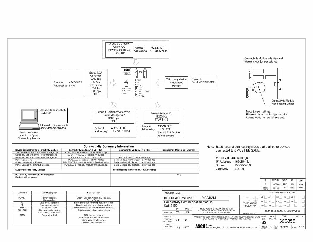
INTERFACE WIRING DIAGRAMConnectivity Communication ModuleCat. 5150
4/03
4/03
4/03 207179B
629855None Visio
FLORHAM PARK, NJ USA 07932������������ � ���������
200698 4/03ASSRCA
Note: Baud rates of connectivity module and all other devicesconnected to it MUST BE SAME.
Factory default settings:IP Address 169.254.1.1Subnet 255.255.0.0Gateway 0.0.0.0
Laptop computeruse to configure
Connectivity Module
J3
J1 J2
CONNECTIVITYMODULE
CAT.NO.5150
POWER
RX
TX
1 RX+
2 RX-3 TX+4 TX-
5 COM
J4
RS-485
Link CH2CH1 DIAG
Reset
TTL
Power Manager Xp19200 bps
TTL/RS-485
Protocol: ����������Addressing: 1 - 32 PM 33 - 43 PM Engine
52 PM Breaker
Group 1 Controller with or w/oPower Manager XP
9600 bpsTTL
Protocol: ����������Addressing: 1 - 32 CP/PM
Group 7/7AController9600 bpsRS-485
with or w/oPM Xp
9600 bpsTTL
Protocol: ���������Addressing: 1 - 31
Group 5 Controllerwith or w/o
Power Manager Xp19200 bps
TTL
Protocol: ����������Addressing: 1 - 32 CP/PM
Ethernet crossover cableASCO PN 629590-006
Connect to connectivitymodule J3
Connectivity Modulemode setting jumper
Connectivity Module J1 & J2 (TTL) *ATS's, �� �������� Protocol, 19.2K/9600 Bps
ATS's, ���������� Protocol, 9600 BpsPM’s, ������ Protocol, 9600 Bps
PM's ������� Protocol, 19.2K/9600 BpsPM's ������� Protocol, 19.2K/9600 Bps(Add. 33-43)
PM's ������� Protocol, 19.2K/9600 Bps(Add. 52)
Connectivity Summary InformationConnectivity Module J3 (Ethernet)
PC’s
Connectivity Module J4 (RS-485)
ATS's, ������ Protocol, 9600 BpsSerial Modbus RTU Protocol, 19.2K/9600 BpsSerial Modbus RTU Protocol, 19.2K/9600 BpsSerial Modbus RTU Protocol, 19.2K/9600 Bps
Serial Modbus RTU Protocol, 19.2K/9600 Bps
Device Connectivity to Connectivity Module7000 series ATS with or w/o Power Manager XpSeries 300 ATS with or w/o Power Manager XpSeries 900 ATS with or w/o Power Manager XpPower Manager XpPower Manager Xp at EnginesPower Manager Xp at Circuit Breakers
Supported Third Party Devices
PC - NT 4.0, Windows 2K, XP w/InternetExplorer 5.0 or higher
LED Description
Power indication.Green/Amber.
Data receiving status.Data transmit status.Link status. Green.
Client connection status.CH1-Green, CH2-Yellow.
Diagnostics. Red.
LED Function
Green- Ethernet, Amber- RS-485 only. Set by Factory.
Blinks to indicate receiving data from clientsBlinks to indicate transmit data to clients
Solid on indicates an active Ethernet connectionBoth blinks to indicate active clients
Off indicates no error.Short blinks and then off indicates
clients write data to server.Solid red indicates errors.
LED label
POWER
RXTX
LINKCH1, CH2
DIAG
Mode jumper settings:Ethernet Mode - on the right two pins.Upload Mode - on the left two pins.
Connectivity Module side view andinternal mode jumper settings
Third party device19200/9600
RS-485
Protocol:Serial MODBUS RTU
207179 1/06ASSRCB
����R

CHANGELETTER
ECN NO. BY APPD DATE
PROPERTY OF ASCO POWER TECHNOLOGIES, L.P. USE PERMITTED FOR OUR WORKONLY. ALL RIGHTS OF DESIGN OR INVENTION ARE RESERVED
MANUFACTURING TOLERANCES TO BE INACCORDANCE WITH ASCO PROCEDURE MP-I-003
FOR PLASTIC PARTS SEE MP-I-055ASSEM. REF. NO.
THIRD ANGLEPROJECTION
PROJECT NAME;
BY DATE
DRAWN BY
CHECKED
DRAFTINGAPPROVAL
FINALAPPROVAL
SUBSIDARY DISTRIBUTION
COMPUTER GENERATED DRAWING
SCALE FILE _01
DWG. NO.SIZE
SHEETECNNO.
CHANGELETTER
BS
AE
CH
AG
AN
AV
AP
AM
AA
AC
AJ
PS
AS
AL
AR
YZ
AS
SRC
2 of 2
TABLE 1Acceptable
Communication CableStandard 80°CBelden 9842Belden 9829Alpha 6202CAlpha 6222C
Plenum RatedBelden 89729Belden 82729Alpha 58902
INTERFACE WIRING DIAGRAM
2/04
4/03
4/03 207179B
629855None Visio
FLORHAM PARK, NJ USA 07932������������ � ���������
Ethernet Communication CableType
10 BaseT
Known as
Twisted Pair
Max. Lengthof Segment
328ft. (100 meters)
Max. Stationsper Segment
1024
Cable Type
UTP CAT3, 4, 5
Connectors
RJ-45
Cable Impedance/Terminations
Belden P/N(reference)
7882A
Refer to ASCO P/N 607577 for hub
See Table 1 RS485 4 wire 4000 ft. Max.
Ethernet cable10 Base T
Max. 300 ft. Max.
Ethernet cable10 Base T
Max. 300 ft. Max.
Ethernet cable10 Base T
Max. 300 ft. Max.
Ethernet cable10 Base T
Max. 300 ft. Max.J3
J1 J2
CONNECTIVITYMODULE
CAT.NO.5150
POWER
RX
TX
1 RX+
2 RX-3 TX+4 TX-
5 COM
J4
RS-485
Link CH2CH1 DIAG
Reset
TTL
Group 1Controller����������
Address 1-329600 Baud
Series 300 Transfer Switch
J3
J1 J2
CONNECTIVITYMODULE
CAT.NO.5150
POWER
RX
TX
1 RX+
2 RX-3 TX+4 TX-
5 COM
J4
RS-485
Link CH2CH1 DIAG
Reset
TTL
Power ManagerXp
����������
Address 1-329600 Baud
Group 1Controller����������
Address 1-329600 Baud
Series 300 Transfer Switch
J3
J1 J2
CONNECTIVITYMODULE
CAT.NO.5150
POWER
RX
TX
1 RX+
2 RX-3 TX+4 TX-
5 COM
J4
RS-485
Link CH2CH1 DIAG
Reset
TTL
Group 5Controller����������
Address 1-3219200 Baud
7000 Series Transfer Switch
J3
J1 J2
CONNECTIVITYMODULE
CAT.NO.5150
POWER
RX
TX
1 RX+
2 RX-3 TX+4 TX-
5 COM
J4
RS-485
Link CH2CH1 DIAG
Reset
TTL
Power ManagerXp
����������
Address 1-3219200 Baud
Group 5Controller����������
Address 1-3219200 Baud
7000 Series Transfer Switch
Power Manager Xp����������
19200 Baud
Power Manager Xpfor Gen, breaker, load or other
AddressGen 33 - 43Breaker 52Load/other 1 - 32
J3
J1 J2
CONNECTIVITYMODULE
CAT.NO.5150
POWER
RX
TX
1 RX+
2 RX-3 TX+4 TX-
5 COM
J4
RS-485
Link CH2CH1 DIAG
Reset
TTLEthernet cable
10 Base TMax. 300 ft. Max.
Power Manager Xp���������
����� ���
9600 Baud
Group7/7a
J3
J1 J2
CONNECTIVITYMODULE
CAT.NO.5150
POWER
RX
TX
1 RX+
2 RX-3 TX+4 TX-
5 COM
J4
RS-485
Link CH2CH1 DIAG
Reset
TTLEthernet cable
10 Base TMax. 300 ft. Max.
T+T- R+R- GND1112131415
Group 7/7Ap/n 459666-XXXp/n 459667-XXX
Address 1-319600 baud
Ethernet cable10 Base T
Max. 300 ft. Max.
J3
J1 J2
CONNECTIVITYMODULE
CAT.NO.5150
POWER
RX
TX
1 RX+
2 RX-3 TX+4 TX-
5 COM
J4
RS-485
Link CH2CH1 DIAG
Reset
TTL
T+T- R+R- GND1112131415
Group 7/7Ap/n 459666-XXXp/n 459667-XXX
Address1- 319600 baud
Group7/7a
See Table 1 RS485 4 wire 4000 ft. Max.
24 VDC 80 mA16 AWG
Connectivity Communication ModuleCat. 5150
Cable AssyASCO P/N
629798-001
Cable AssyASCO P/N
629798-002
Cable AssyASCO P/N
629798-001
Cable AssyASCO P/N
629798-001
Cable AssyASCO P/N
629798-002
Cable AssyASCO P/N
629798-001
Cable AssyASCO P/N
629798-002
Cable AssyASCO P/N
629798-002
NT 4.0, Windows 2K, XP withIE, Internet Explorer 5.0 or higher
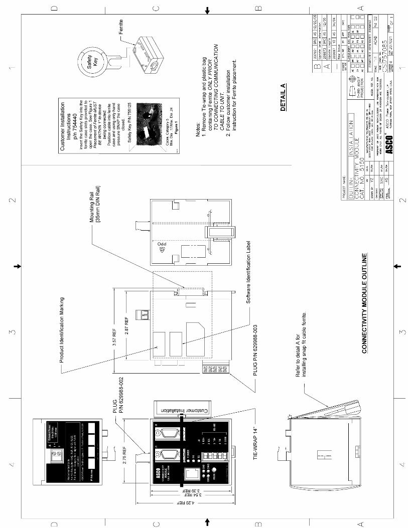
Ferrite
FerriteASCO P/N
754995See Note 1
Ferrite
FerriteASCO P/N
754995See Note 1
Ferrite
FerriteASCO P/N
754995See Note 1
Ferrite
FerriteASCO P/N
754995See Note 1
Ferrite
FerriteASCO P/N
754995See Note 1
Ferrite
FerriteASCO P/N
754995See Note 1
Ferrite
FerriteASCO P/N
754995See Note 1
NOTE:Ferrite, ASCO P/N 754995 MUST BE INSTALLED ONCABLE WITHIN 1" OF DEVICE BEING CONNECTED.
����R
����R
����R
����R
����R
����R
����R
Connectivity Module Ethernet TCP/IP Network Connections in Windows 2000 A-1
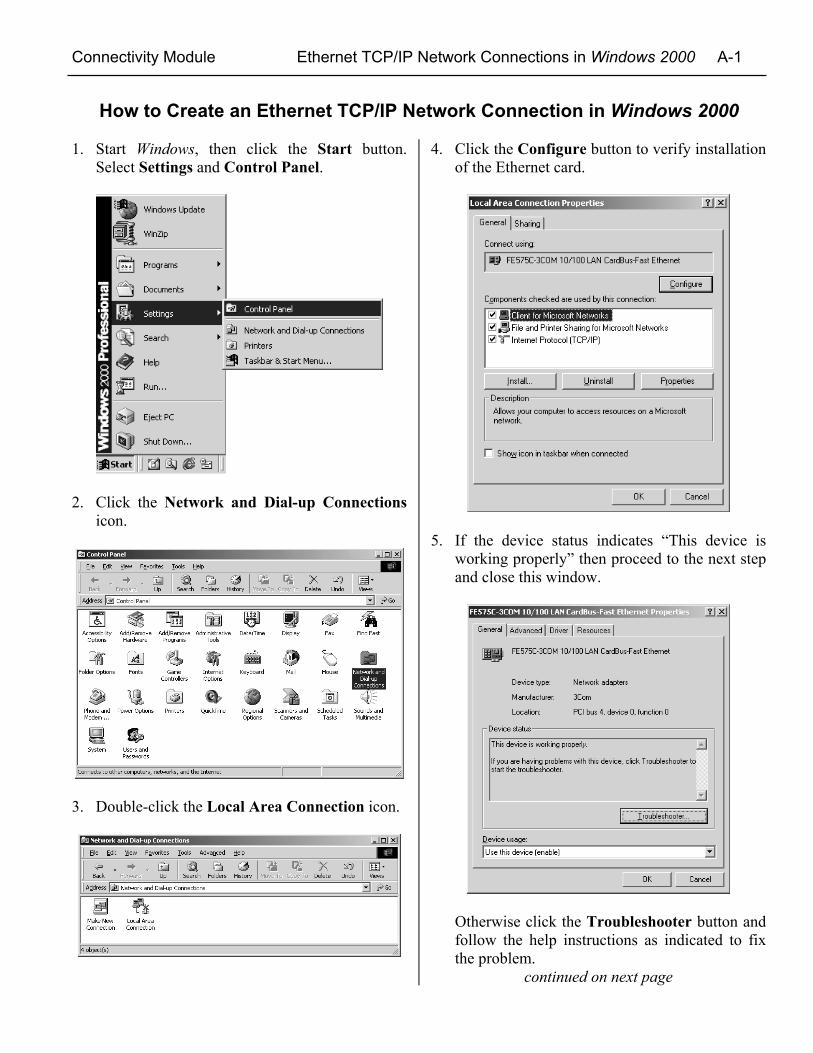
How to Create an Ethernet TCP/IP Network Connection in Windows 2000
1. Start Windows, then click the Start button.Select Settings and Control Panel.
2. Click the Network and Dial-up Connectionsicon.
3. Double-click the Local Area Connection icon.
4. Click the Configure button to verify installationof the Ethernet card.
5. If the device status indicates “This device isworking properly” then proceed to the next stepand close this window.
Otherwise click the Troubleshooter button andfollow the help instructions as indicated to fixthe problem.
continued on next page
A-2 Ethernet TCP/IP Network Connections in Windows 2000 Connectivity Module
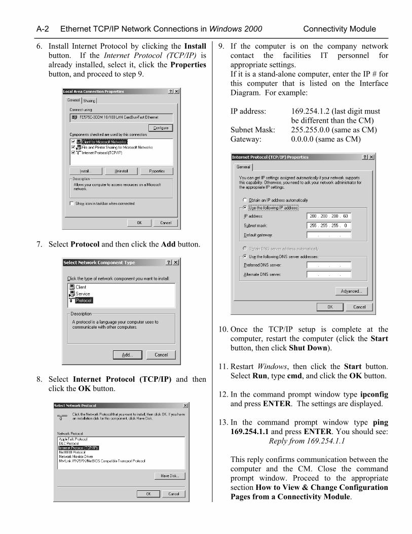
6. Install Internet Protocol by clicking the Installbutton. If the Internet Protocol (TCP/IP) isalready installed, select it, click the Propertiesbutton, and proceed to step 9.
7. Select Protocol and then click the Add button.
8. Select Internet Protocol (TCP/IP) and thenclick the OK button.
9. If the computer is on the company networkcontact the facilities IT personnel forappropriate settings.If it is a stand-alone computer, enter the IP # forthis computer that is listed on the InterfaceDiagram. For example:
IP address: 169.254.1.2 (last digit mustbe different than the CM)
Subnet Mask: 255.255.0.0 (same as CM)Gateway: 0.0.0.0 (same as CM)
10. Once the TCP/IP setup is complete at thecomputer, restart the computer (click the Startbutton, then click Shut Down).
11. Restart Windows, then click the Start button.Select Run, type cmd, and click the OK button.
12. In the command prompt window type ipconfigand press ENTER. The settings are displayed.
13. In the command prompt window type ping169.254.1.1 and press ENTER. You should see: Reply from 169.254.1.1
This reply confirms communication between thecomputer and the CM. Close the commandprompt window. Proceed to the appropriatesection How to View & Change ConfigurationPages from a Connectivity Module.
Connectivity Module Ethernet TCP/IP Network Connections in Windows NT A-3
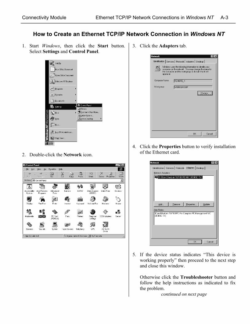
How to Create an Ethernet TCP/IP Network Connection in Windows NT
1. Start Windows, then click the Start button.Select Settings and Control Panel.
2. Double-click the Network icon.
3. Click the Adapters tab.
4. Click the Properties button to verify installationof the Ethernet card.
5. If the device status indicates “This device isworking properly” then proceed to the next stepand close this window.
Otherwise click the Troubleshooter button andfollow the help instructions as indicated to fixthe problem.
continued on next page

A-4 Ethernet TCP/IP Network Connections in Windows NT Connectivity Module
6. Install Internet Protocol by clicking theProtocols tab. If the Internet Protocol (TCP/IP)is already installed, select it, click theProperties button, and proceed to step 9.
7. If TCP/IP is not installed, click the Add buttonand scroll down to TCP/IP Protocol..
8. Select TCP/IP Protocol and then click the OKbutton.
9. If the computer is on the company networkcontact the facilities IT personnel forappropriate settings.If it is a stand-alone computer, enter the IP # forthis computer that is listed on the InterfaceDiagram. For example:
IP address: 169.254.1.2 (last digit mustbe different than the CM)
Subnet Mask: 255.255.0.0 (same as CM)Gateway: 0.0.0.0 (same as CM)
10. Once the TCP/IP setup is complete at thecomputer, restart the computer (click the Startbutton, then click Shut Down).
11. Restart Windows, then click the Start button.Select Run, type cmd, and click the OK button.
12. In the command prompt window type ipconfigand press ENTER. The settings are displayed.
13. In the command prompt window type ping169.254.1.1 and press ENTER. You should see: Reply from 169.254.1.1
This reply confirms communication between thecomputer and the CM. Close the commandprompt window. Proceed to the appropriatesection How to View & Change ConfigurationPages from a Connectivity Module.
Connectivity Module Ethernet TCP/IP Network Connections in Windows XP A-5
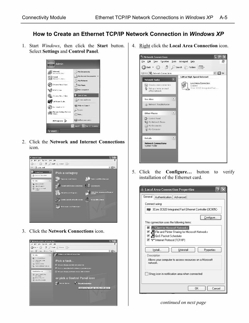
How to Create an Ethernet TCP/IP Network Connection in Windows XP
1. Start Windows, then click the Start button.Select Settings and Control Panel.
2. Click the Network and Internet Connectionsicon.
3. Click the Network Connections icon.
4. Right click the Local Area Connection icon.
5. Click the Configure… button to verifyinstallation of the Ethernet card.
continued on next page
A-6 Ethernet TCP/IP Network Connections in Windows XP Connectivity Module
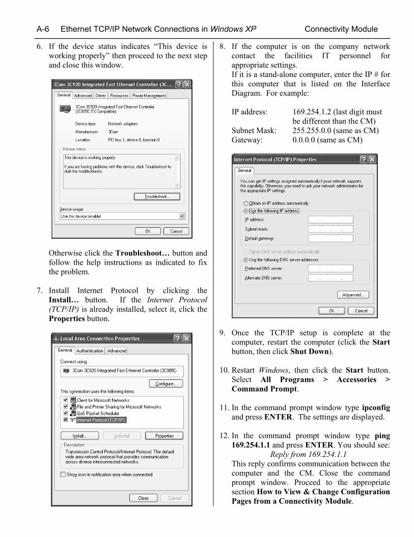
6. If the device status indicates “This device isworking properly” then proceed to the next stepand close this window.
Otherwise click the Troubleshoot… button andfollow the help instructions as indicated to fixthe problem.
7. Install Internet Protocol by clicking theInstall… button. If the Internet Protocol(TCP/IP) is already installed, select it, click theProperties button.
8. If the computer is on the company networkcontact the facilities IT personnel forappropriate settings.If it is a stand-alone computer, enter the IP # forthis computer that is listed on the InterfaceDiagram. For example:
IP address: 169.254.1.2 (last digit mustbe different than the CM)
Subnet Mask: 255.255.0.0 (same as CM)Gateway: 0.0.0.0 (same as CM)
9. Once the TCP/IP setup is complete at thecomputer, restart the computer (click the Startbutton, then click Shut Down).
10. Restart Windows, then click the Start button.Select All Programs > Accessories >Command Prompt.
11. In the command prompt window type ipconfigand press ENTER. The settings are displayed.
12. In the command prompt window type ping169.254.1.1 and press ENTER. You should see: Reply from 169.254.1.1This reply confirms communication between thecomputer and the CM. Close the commandprompt window. Proceed to the appropriatesection How to View & Change ConfigurationPages from a Connectivity Module.
Connectivity Module Troubleshooting A-7
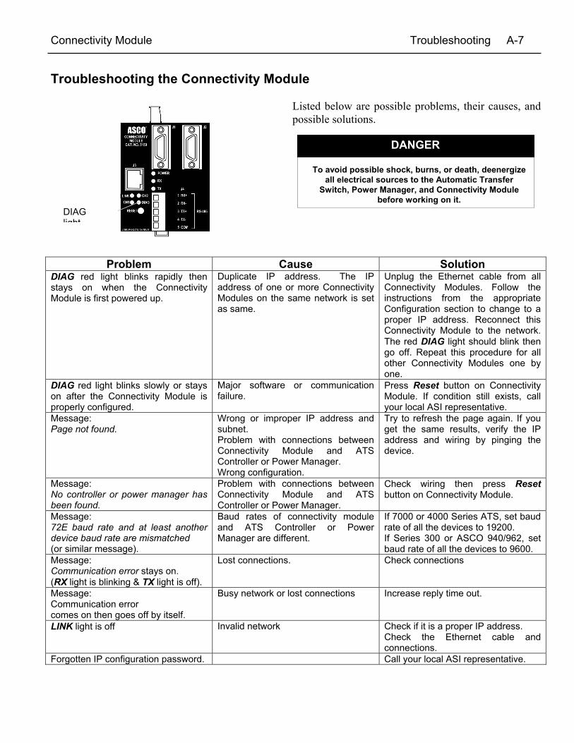
Troubleshooting the Connectivity Module
Listed below are possible problems, their causes, andpossible solutions.
Problem Cause SolutionDIAG red light blinks rapidly thenstays on when the ConnectivityModule is first powered up.
Duplicate IP address. The IPaddress of one or more ConnectivityModules on the same network is setas same.
Unplug the Ethernet cable from allConnectivity Modules. Follow theinstructions from the appropriateConfiguration section to change to aproper IP address. Reconnect thisConnectivity Module to the network.The red DIAG light should blink thengo off. Repeat this procedure for allother Connectivity Modules one byone.
DIAG red light blinks slowly or stayson after the Connectivity Module isproperly configured.
Major software or communicationfailure.
Press Reset button on ConnectivityModule. If condition still exists, callyour local ASI representative.
Message:Page not found.
Wrong or improper IP address andsubnet.Problem with connections betweenConnectivity Module and ATSController or Power Manager.Wrong configuration.
Try to refresh the page again. If youget the same results, verify the IPaddress and wiring by pinging thedevice.
Message:No controller or power manager hasbeen found.
Problem with connections betweenConnectivity Module and ATSController or Power Manager.
Check wiring then press Resetbutton on Connectivity Module.
Message:72E baud rate and at least anotherdevice baud rate are mismatched(or similar message).
Baud rates of connectivity moduleand ATS Controller or PowerManager are different.
If 7000 or 4000 Series ATS, set baudrate of all the devices to 19200.If Series 300 or ASCO 940/962, setbaud rate of all the devices to 9600.
Message:Communication error stays on.(RX light is blinking & TX light is off).
Lost connections. Check connections
Message:Communication errorcomes on then goes off by itself.
Busy network or lost connections Increase reply time out.
LINK light is off Invalid network Check if it is a proper IP address.Check the Ethernet cable andconnections.
Forgotten IP configuration password. Call your local ASI representative.
DIAGlight
To avoid possible shock, burns, or death, deenergizeall electrical sources to the Automatic Transfer
Switch, Power Manager, and Connectivity Modulebefore working on it.
DANGER
A-8 Create Favorites folder, 3rd Party Modbus Configuration Connectivity Module
How to create a Favorites folder for ASCOdevice pages and copy it to anothercomputer
To create a favorites folder and copy it to another user’scomputer, the administrator should follow these steps:
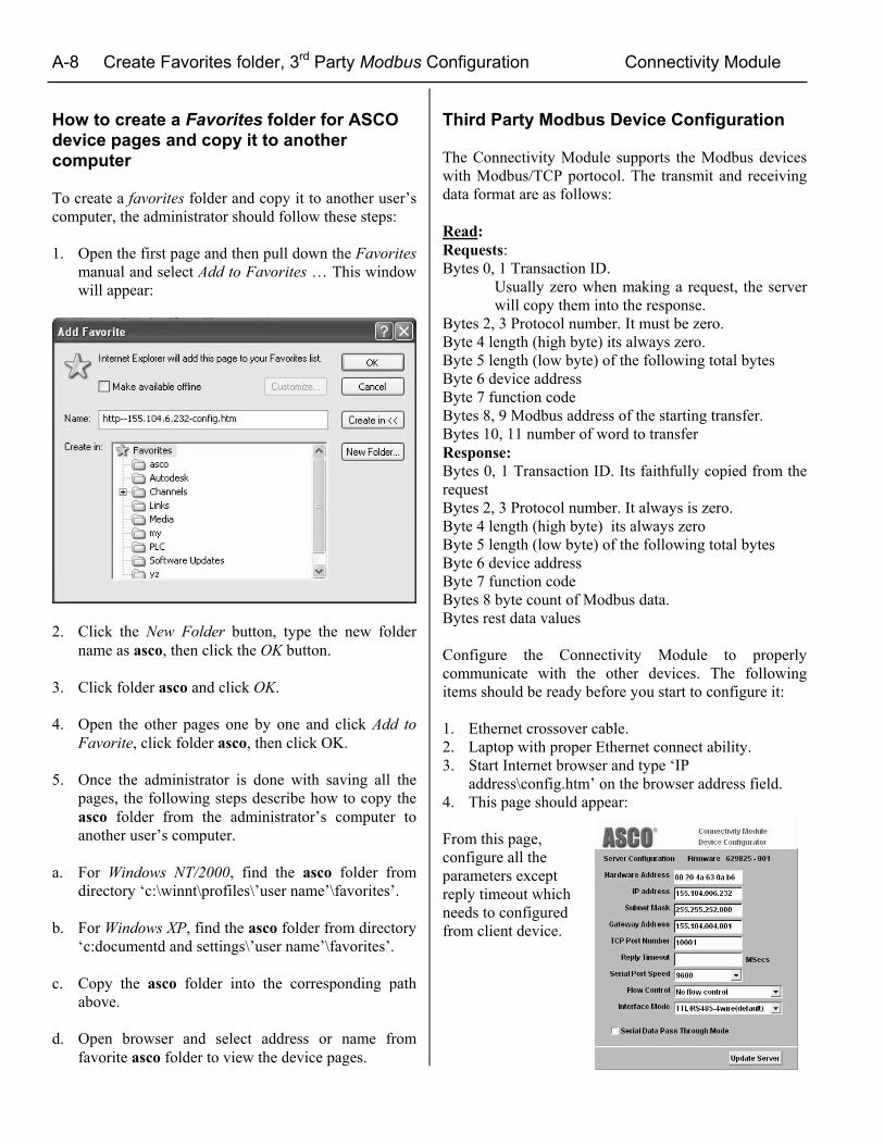
1. Open the first page and then pull down the Favoritesmanual and select Add to Favorites … This windowwill appear:
2. Click the New Folder button, type the new foldername as asco, then click the OK button.
3. Click folder asco and click OK.
4. Open the other pages one by one and click Add toFavorite, click folder asco, then click OK.
5. Once the administrator is done with saving all thepages, the following steps describe how to copy theasco folder from the administrator’s computer toanother user’s computer.
a. For Windows NT/2000, find the asco folder fromdirectory ‘c:\winnt\profiles\’user name’\favorites’.
b. For Windows XP, find the asco folder from directory‘c:documentd and settings\’user name’\favorites’.
c. Copy the asco folder into the corresponding pathabove.
d. Open browser and select address or name fromfavorite asco folder to view the device pages.
Third Party Modbus Device Configuration
The Connectivity Module supports the Modbus deviceswith Modbus/TCP portocol. The transmit and receivingdata format are as follows:
Read:Requests:Bytes 0, 1 Transaction ID.
Usually zero when making a request, the serverwill copy them into the response.
Bytes 2, 3 Protocol number. It must be zero.Byte 4 length (high byte) its always zero.Byte 5 length (low byte) of the following total bytesByte 6 device addressByte 7 function codeBytes 8, 9 Modbus address of the starting transfer.Bytes 10, 11 number of word to transferResponse:Bytes 0, 1 Transaction ID. Its faithfully copied from therequestBytes 2, 3 Protocol number. It always is zero.Byte 4 length (high byte) its always zeroByte 5 length (low byte) of the following total bytesByte 6 device addressByte 7 function codeBytes 8 byte count of Modbus data.Bytes rest data values
Configure the Connectivity Module to properlycommunicate with the other devices. The followingitems should be ready before you start to configure it:
1. Ethernet crossover cable.2. Laptop with proper Ethernet connect ability.3. Start Internet browser and type ‘IP
address\config.htm’ on the browser address field.4. This page should appear:
From this page,configure all theparameters exceptreply timeout whichneeds to configuredfrom client device.

Printed in U.S.A. © ASCO Power Technologies, L.P. 2006 All Rights Reserved.
INDEXA
ATS information needed, ii,communication address form
CCable, communication, iiiChange Password, 1-3Communication error message, A-7Configuration
7000 Series ATSs, 2-1, 2-24000 Series ATSs, 2-1, 2-2Series 300 ATSs, 3-1, 3-2ASCO 940/962 ATSs, 4-1Power Managers, 5-1
Configuration parameters, iiiCopy Favorites folder, A-8Create Favorites folder, 1-3, A-8
DDetail Screens (View Pages)
7000 Series ATSs, 2-34000 Series ATSs, 2-3Series 300 ATSs, 3-3ASCO 940/962 ATSs, 4-2Power Managers, 5-1
DIAG red light, A-7DIN rail, 1-1
EEthernet TCP/IP Network
Connection, how to createWindows 2000, A-1, A-2Windows NT, A-3, A-4Windows XP, A-5, A-6
Event log, 7000 Series ATSs, 2-3
FFavorites folder, create, 1-3, A-8
KKits
7000 Series ATSs, 1-14000 Series ATSs, 1-1Series 300 ATSs, 1-1ASCO 940/962 ATSs, 1-1Power Managers, 1-2
HHelp, troubleshooting, A-7
IInstallation, 1-1Interface Wiring, BS 629855IP address, A-7
LLINK light, A-7Load status, 2-1
7000 Series ATS, 2-34000 Series ATS, 2-3Series 300 ATS, 3-3ASCO 940/962 ATSs, 4-2
Login, password, 1-3
NNetwork, Ethernet TCP/IP
Connection, how to createWindows 2000, A-1, A-2Windows NT, A-3, A-4Windows XP, A-5, A-6
No controller or power managerhas been found message, A-7
OOutline Installation, CS 757085Overview, iii
PPage not found message, A-7Password, 1-3Ports, iiiPOWER light, A-7Power Manager
7000 Series ATSs, 2-1, 2-2, 2-34000 Series ATSs, 2-1, 2-2, 2-3Series 300 ATSs, 3-1, 3-2, 3-3ASCO 940/962 ATSs, 4-1, 4-2Stand-alone, 5-1, 5-2, 5-3
Power requirements, iii, 3-1Protocol support, iii
RRESET button, A-7RX light, A-7
SSpecifications, iii
TTest Communication, 1-2Third party Modbus device
configuration, A-8Troubleshooting, A-7TX light, A-7
VView Pages (Detail Screens), iii, 1-3
7000 Series ATSs, 2-34000 Series ATSs, 2-3Series 300 ATSs, 3-3ASCO 940/962 ATSs, 4-2Power Managers, 5-2, 5-3
WWelcome, ii