Complete Report on GENERATOR
17
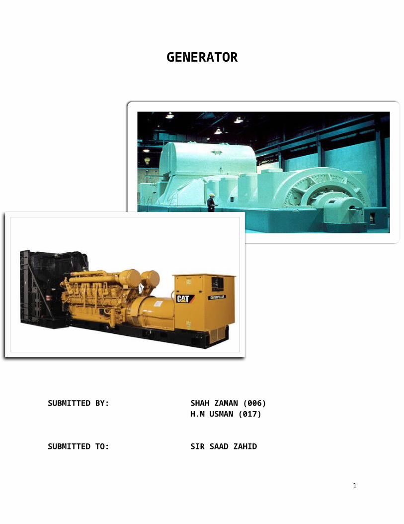
GENERATOR SUBMITTED BY: SHAH ZAMAN (006) H.M USMAN (017) SUBMITTED TO: SIR SAAD ZAHID 1
Transcript of Complete Report on GENERATOR
GENERATOR
SUBMITTED BY: SHAH ZAMAN (006) H.M USMAN (017)
SUBMITTED TO: SIR SAAD ZAHID
1
DATE: 16-02-2013
TABLE OF CONTENTS
TABLE OF CONTENTS…….. 2
LIST OF FIGURES ……. 3
1-ABSTRACT…….. 4
2-INTRODUCTION……… 4
3-GENERATOR PRINCIPAL OF OPERATION………… 4
4-GENERATOR’S BASIC LAW……….. 5
5-GENERATOR TYPES………… 5
5.1-Rotating Armature Generator…6
5.2-Rotating Field Generator…75.3-Polyphase Generators…
8
6-CONSTRUCTION……… 10
2

6.1-Generator Design and Construction…10
6.2-Generator Stator and Windings…106.3-Excitation Systems…11
7-CONCLUSION………… 12
8- REFERENCING……….
LIST OF FIGURES
FIGURE NAME PAGE
Figure 1: (General operation of generator)………………………………………… 5
Figure 2:(Rotating armature generator)……………………………………………. 7
Figure 3: (Rotating field generator)………………………………………………... 8
3
Figure 4: Three Phase Generator………………………………………………….. 9
Figure 5: Voltage Output of a Three-Phase Generator…………………………….. 10
Figure 6: Winding………………………………………………………………….. 11
Figure 7: (EXCITER)………………………………………………………………. 12
1-Abstract: Spinning a wire loop within a uniform magnetic field in a convenient fashion induces a voltage between the loop terminals. This effect can be used to build an electric power generator, such as the one described here. A coil attached to a shaft spins within the magnetic field of a "U" shaped magnet. Three conveniently designed conductive disks allow the
4

electrical load of the generator to be fed either with alternating current or direct current.
2-Introduction: Although diverse forms of energy (mechanical, thermal, chemical etc.) can be converted into electrical energy, the expression electric generator is reserved, in the industry, for the machines that convert mechanical energy into electrical energy. The generators thatproduce direct current (DC) are called dynamos and the ones that produce alternating current(AC) are called alternators.
A permanent magnet has a magnetic field around it. The field is lines of magnetism (flux) that bend around the metal magnet. The strongest part of the magnetic field is the region where the lines are closest together. On a permanent magnet, there are two such regions, one at each end of the magnet. These are called thenorth and south poles of the magnet. (The earth is a magnet, withthe strongest part of the magnetic field at the North and South Poles Magnetic of the earth.)
3-Generator Principle Of Operation: A wire loop rotates within the magnetic field generated by a magnet, which induces an AC voltage between the loop terminals. The periodic change of the voltage polarity is due to the change of the position of the coil relatively to the magnetic poles. The amplitude of the voltage depends on the magnetic field strength and is also directly proportional to the rotating speed . If the magnetic field is uniform and the rotation speed is constant. A
5

metal ring divided into two isolated halves (segments), which aremounted in the axis. This type of commutator is denominated collector. Each terminal of the loop is connected to a segment of the collector. When the loop rotates, an AC voltage is induced inthe coil, exactly as in the AC generator. But, before reaching the load, the induced voltage is transformed into a DC voltage by the collector (Fig. 1), which works as a mechanical rectifier. The contact segments of the collector move to a different brush
each half turn of the loop, keeping a unidirectional current flowing through the electrical load of the circuit.[1]
Figure 1: (General operation of generator)
4-Generator’s Basic Law: The generator’s basic is in fact the FARADAYS’S LAW. Which states
6
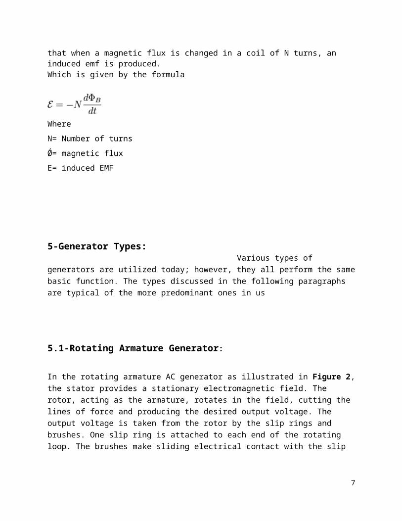
that when a magnetic flux is changed in a coil of N turns, an induced emf is produced. Which is given by the formula
WhereN= Number of turnsǾ= magnetic fluxE= induced EMF
5-Generator Types: Various types of generators are utilized today; however, they all perform the samebasic function. The types discussed in the following paragraphs are typical of the more predominant ones in us
5.1-Rotating Armature Generator: In the rotating armature AC generator as illustrated in Figure 2,the stator provides a stationary electromagnetic field. The rotor, acting as the armature, rotates in the field, cutting the lines of force and producing the desired output voltage. The output voltage is taken from the rotor by the slip rings and brushes. One slip ring is attached to each end of the rotating loop. The brushes make sliding electrical contact with the slip
7

rings. The generator's AC output voltage can be transferred from the slip rings through the brushes to an external circuit.[2]
Figure 2:(Rotating armature generator)
Rotating armature AC generators are typically used inapplications involving small amounts of power. With larger
amounts of power, a great deal more current flow occurs throughthe slip rings and brushes. It is difficult and expensive to
build slip rings and brushes to carry large amounts of current.Therefore, most large AC generators are rotating field
generators.
5.2-Rotating Field Generator: The rotating field AC generator as illustrated in Figure 3 is by far the most widely used generator. In this type of generator, direct
8

current from a separate source is passed through windings on the rotor by means of slip rings and brushes. This maintains a rotating electromagnetic field of fixed polarity (similar to a rotating bar magnet). The rotating magnetic field of the rotor extends outward and cuts through the armature windings embedded in the surrounding stator. As the rotor turns, alternating voltages are induced in the windings because magnetic fields of first one polarity and then the other cut through them. Because the output power is taken from stationary windings, the output may be connected through fixed terminals. The advantage in this type of construction is that larger amounts of currents can be handled because there are no sliding contacts and the whole output circuit is continuously insulated.[3]
Slip rings and brushes are adequate for the DC field supply because the current level in the field is much smaller than in the armature circuit.
9
Figure 3: (Rotating Field Generator)5.3-Polyphase Generators: Most electric power is generated and distributed as three-phase ratherthan single-phase power for the following reasons:• The cost of transmission is less than for the same voltage and power in a single-phase system.• A three-phase generator has a 180% greater capacity than a single phase generator of the same physical size.• Single-phase voltage and power is easily available from a three-phase system by merely tapping any two of the power leads.[4]A three-phase AC generator is designed to produce three-phase AC power by building more coils in the stator around the rotor. The three coils are equally spaced 120° apart around the inside of the stator. The armature coils are wired so that the generator has three separate output voltages that differ in phase by 1200.
Figure 4 illustrates a simplified three-phase, two pole AC generator.
10
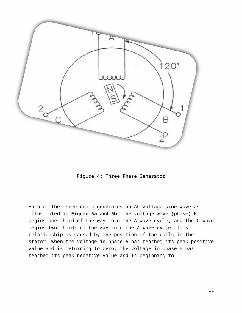
Figure 4: Three Phase Generator
Each of the three coils generates an AC voltage sine wave as illustrated in Figure 5a and 5b. The voltage wave (phase) B begins one third of the way into the A wave cycle, and the C wavebegins two thirds of the way into the A wave cycle. This relationship is caused by the position of the coils in the stator. When the voltage in phase A has reached its peak positivevalue and is returning to zero, the voltage in phase B has reached its peak negative value and is beginning to
11

Figure 5: Voltage Output of a Three-Phase Generator
return to zero.[5] .The voltage in phase C has passed zero and a negative voltage is being induced. During a three-phase voltage cycle, the overall voltage induced is never zero.
12

CONSTRUCTION
6.1-Generator Design and Construction: As we go thought the generator design and construction the differences between hydrogen cooled and air cooled will be pointed out. There are two main components in the generator, the rotor and the stator. The generator must also have a source of DCcurrent to magnetize the rotor, called the exciter.[7] The generator may have several components and subsystems, depending on its particular features. The following is a discussion on the main components of a generator.
6.2-Generator Stator and Windings: The generator stator, also called the armature, supports the ironcore and windings, the rotor, and the compartment coolers reference Figure 6. The stator consists of a steel plate casing called the "wrapper" that covers a frame that in turn holds the iron core. An iron core is used in order to produce a stronger magnetic field for the generation of voltage. There are tubes within the wrapper to help distribute cooling gas. Older units use air at atmospheric pressure for cooling. Newer generators usehydrogen under pressure (from 15 to 75 psig) for cooling. Hydrogen is more effective than air in dissipating heat, and the higher the hydrogen pressure, the more effective the hydrogen is in removing heat.[7]
13
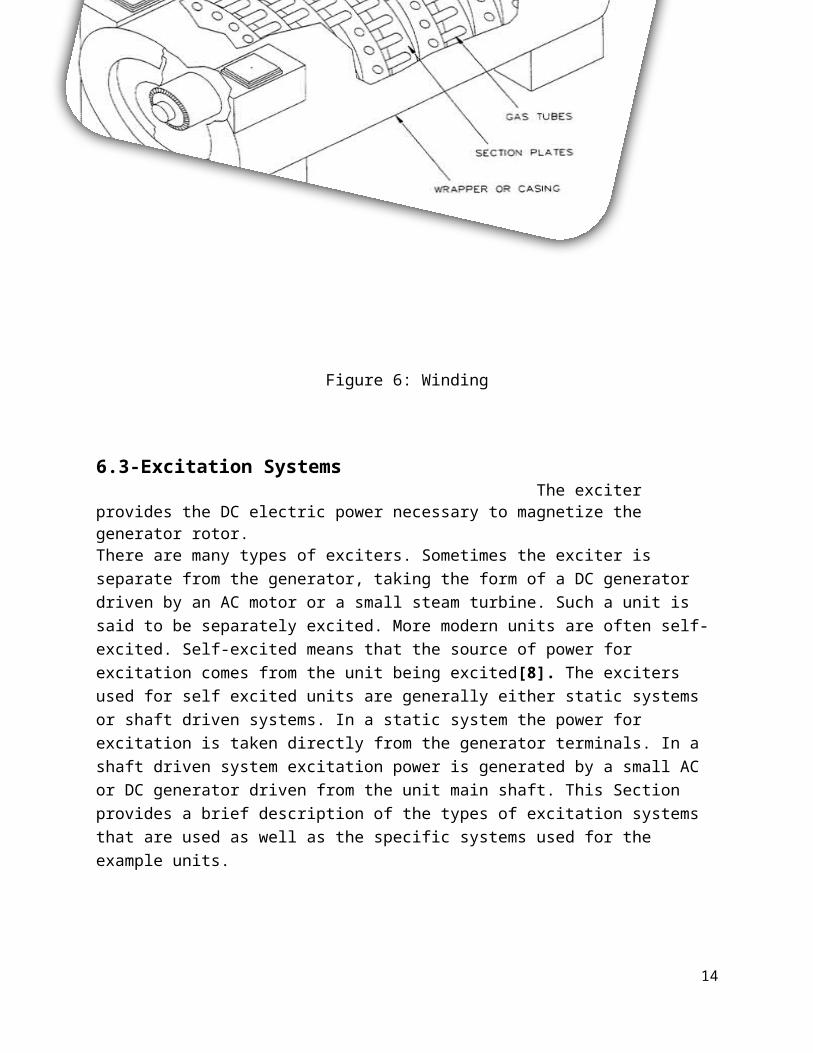
Figure 6: Winding
6.3-Excitation Systems The exciter provides the DC electric power necessary to magnetize the generator rotor.There are many types of exciters. Sometimes the exciter is separate from the generator, taking the form of a DC generator driven by an AC motor or a small steam turbine. Such a unit is said to be separately excited. More modern units are often self-excited. Self-excited means that the source of power for excitation comes from the unit being excited[8]. The exciters used for self excited units are generally either static systems or shaft driven systems. In a static system the power for excitation is taken directly from the generator terminals. In a shaft driven system excitation power is generated by a small AC or DC generator driven from the unit main shaft. This Section provides a brief description of the types of excitation systems that are used as well as the specific systems used for the example units.
14
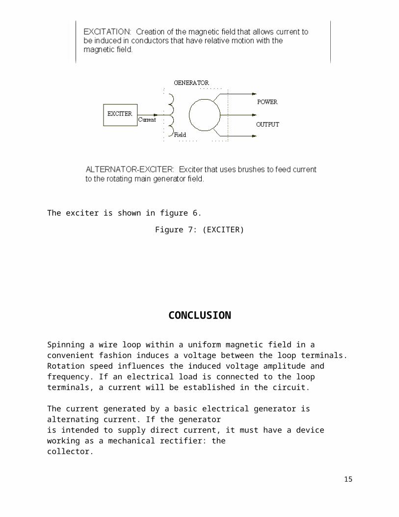
The exciter is shown in figure 6.
Figure 7: (EXCITER)
CONCLUSION
Spinning a wire loop within a uniform magnetic field in a convenient fashion induces a voltage between the loop terminals. Rotation speed influences the induced voltage amplitude and frequency. If an electrical load is connected to the loop terminals, a current will be established in the circuit.
The current generated by a basic electrical generator is alternating current. If the generator is intended to supply direct current, it must have a device working as a mechanical rectifier: thecollector.
15
A device capable of generating both AC voltage and DC voltage hasbeen presented. A coil attached to a shaft spins within the magnetic field of a "U" shaped magnet. Three conveniently designed conductive disks allow the electrical load of the generator to be fedeither with alternating current or direct current.
This device is very useful to illustrate the principles of electrical energy generation. It also shows the main similaritiesand differences between AC and DC generators: the working principle is the same for both machines, but the AC generator hascontact rings and the DC generator has a collector or split rings.
REFRENCES
16

[1] J. G. Kassakian, M. F. Schlecht and G. C. Verghese, Principles of Power Electronics,Addison-Wesley Publishing Company, 1991.
[2] W. J. Bonwick and V. H. Jones, “Performance of a synchronous generator with abridge rectifier,” Proceedings IEE, Vol. 119, No. 9, September 1972,pp. 1338-1342.
[3] W. J. Bonwick and V. H. Jones, “Rectifier-loaded synchronous generator withdamper windings,” Proceedings IEE, Vol. 120, No. 6, June 1973, pp. 659-666.
[4] V. H. Jones and W. J. Bonwick, “Three-phase bridge rectifierswith complex sourceimpedance,” Proceedings IEE, Vol. 122, No. 6, June 1975, pp. 630-636.
[5] W. J. Bonwick, “Characteristics of a diode-bridge-loaded synchronous generatorwithout damper windings,” Proceedings IEE, Vol. 122, No. 6, June 1975, pp. 637-641.
[6] W. J. Bonwick, “Voltage waveform distortion in synchronous generators withrectifier loading,” IEE Proceedings, Vol. 127, Pt. B, No. 1, January1980, pp. 13-19.
[7] R. L. Ames, “A.C. Generators: Design and Applications,” Research Studies PressLtd., Taunton, Somerset, England, 1990
[8] P. C. Krause, Analysis of Electric Machinery, New York: McGraw Hill, Inc., 1987.
17