HPG: the Hera Presentation Generator
26
Journal of Web Engineering, Vol. 5, No. 2 (2006) 175-200 c Rinton Press HPG: THE HERA PRESENTATION GENERATOR FLAVIUS FRASINCAR 1,2 , GEERT-JAN HOUBEN 1,3 , and PETER BARNA 1 1 Department of Computer Science, Technische Universiteit Eindhoven, PO Box 513 NL - 5600 MB Eindhoven, the Netherlands {flaviusf, houben, pbarna}@win.tue.nl 2 Faculty of Economics, Erasmus University Rotterdam, PO Box 1738 NL - 3000 DR Rotterdam, the Netherlands [email protected] 3 Department of Computer Science, Vrije Universiteit Brussel, Pleinlaan 2 B - 1050 Brussels, Belgium [email protected] Received February 17, 2005 Revised May 2, 2006 This paper presents a model-based design and development environment for Web Infor- mation Systems (WISs) using Semantic Web technologies. This environment called the Hera Presentation Generator (HPG) integrates a number of software tools created for the presentation generation phase of the Hera methodology. These tools are the HPG model builders that help constructing the WIS input specifications and the HPG engine that implements the data transformations involved in a WIS. There are two versions of the HPG engine: HPG-XSLT and HPG-Java. HPG-XSLT is characterized by the use of XSLT stylesheets for the data transformations and by the full generation of a Web presentation. HPG-Java uses Java code for the data transformations and thus exploits more than HPG-XSLT the RDF(S) semantics captured in the Hera models and builds one-page-at-a-time. Generating one-page-at-a-time is motivated by recent extensions to the Hera methodology in order to better sustain the building of WISs with richer user interaction support (e.g., form-based). Nevertheless, HPG-Java lost the declarativity, simplicity, and reuse capabilities of the XSLT transformation templates. HPG thus fills the existing gap for tool support for the design of WIS using Semantic Web technologies. Keywords : WIS, Semantic Web, RDF(S), Design environment Communicated by : M Gaedke & D Lowe 1 Introduction The Web of today is hosting a multitude of information systems that bring information closer to their users by means of a Web browser. In [1] the term Web Information System was coined for “information system based on Web technology”. Some typical examples of Web Information Systems (WISs) are commerce sites, online newspapers, educational sites, order tracking systems, etc. Since they are first of all information systems, WISs have at their core a set of data and data processing units that drive the functionality of the whole application. The careful design of this data and its processing is a key characteristic of any information system. WISs are 175
Transcript of HPG: the Hera Presentation Generator

Journal of Web Engineering, Vol. 5, No. 2 (2006) 175-200c© Rinton Press
HPG: THE HERA PRESENTATION GENERATOR
FLAVIUS FRASINCAR1,2, GEERT-JAN HOUBEN1,3, and PETER BARNA1
1Department of Computer Science, Technische Universiteit Eindhoven, PO Box 513
NL - 5600 MB Eindhoven, the Netherlands
{flaviusf, houben, pbarna}@win.tue.nl
2Faculty of Economics, Erasmus University Rotterdam, PO Box 1738
NL - 3000 DR Rotterdam, the Netherlands
3Department of Computer Science, Vrije Universiteit Brussel, Pleinlaan 2
B - 1050 Brussels, Belgium
Received February 17, 2005Revised May 2, 2006
This paper presents a model-based design and development environment for Web Infor-mation Systems (WISs) using Semantic Web technologies. This environment called theHera Presentation Generator (HPG) integrates a number of software tools created forthe presentation generation phase of the Hera methodology. These tools are the HPGmodel builders that help constructing the WIS input specifications and the HPG enginethat implements the data transformations involved in a WIS. There are two versions ofthe HPG engine: HPG-XSLT and HPG-Java. HPG-XSLT is characterized by the useof XSLT stylesheets for the data transformations and by the full generation of a Webpresentation. HPG-Java uses Java code for the data transformations and thus exploitsmore than HPG-XSLT the RDF(S) semantics captured in the Hera models and buildsone-page-at-a-time. Generating one-page-at-a-time is motivated by recent extensions tothe Hera methodology in order to better sustain the building of WISs with richer userinteraction support (e.g., form-based). Nevertheless, HPG-Java lost the declarativity,simplicity, and reuse capabilities of the XSLT transformation templates. HPG thus fillsthe existing gap for tool support for the design of WIS using Semantic Web technologies.
Keywords: WIS, Semantic Web, RDF(S), Design environment
Communicated by : M Gaedke & D Lowe
1 Introduction
The Web of today is hosting a multitude of information systems that bring information closer
to their users by means of a Web browser. In [1] the term Web Information System was
coined for “information system based on Web technology”. Some typical examples of Web
Information Systems (WISs) are commerce sites, online newspapers, educational sites, order
tracking systems, etc.
Since they are first of all information systems, WISs have at their core a set of data and
data processing units that drive the functionality of the whole application. The careful design
of this data and its processing is a key characteristic of any information system. WISs are
175

176 HPG: the Hera Presentation Generator
characterized by the fact that they provide the user with a Web (hypermedia) presentation
over a collection of input data (content).
With the Web’s growth, there is a lot of content already available on the Web. A WIS may
carefully integrate this content from different resources by taking in consideration possible
differences in their dynamics, structure, and nature. Also, due to its ubiquity, a WIS reaches a
very diverse audience with different preferences and using different Web access platforms. As
a consequence the one-size-fits-all approach of traditional information systems (i.e., produce
the same presentation for all users, regardless of their preferences and browsing platform)
does not fit a WIS.
The design and development of a WIS is a complex task that, in our opinion, needs to
consider the Web’s hypermedia paradigm as a central issue in the engineering process. It
implies that a WIS should be able to generate in a (semi-)automatic way Web presentations
when content needs to be provided to the user. Other aspects that play an important role
in realizing a WIS are the already mentioned issues of data integration and presentation
adaptation. During integration design one needs to specify which are the input sources and
how these input sources are mapped to the WIS’s data model. Adaptation design specifies
how one can tailor the hypermedia presentation of the data by considering user preferences
and user browsing platforms.
Several methodologies have been proposed to help the WIS designer in building WIS. A
distinguished group of methodologies are the model-driven methodologies that use models
as design artifacts to specify the different aspects of a WIS. A model-driven approach for
developing WIS has numerous benefits: support for the understanding of the WIS features
among stakeholders, reuse of different design artifacts, improved system maintainability and
evolution, possibility for checking validity and consistency between models, etc.
In modeling how an information system processes the data, knowledge or metadata of
that content is essential. The emerging Semantic Web provides not only metadata of Web
resources but it also proposes common languages for describing metadata and ontologies to
capture any form of shared knowledge. Recently, a special focus was therefore given on WISs
that make use of Semantic Web technologies in describing the design artifacts. There are still
few WIS design methodologies that exploit the potential of the Semantic Web. Expressing
WIS design knowledge using an ontology will foster application interoperability at different
design levels reducing the time-to-market of such a system. As a concrete example, one
might reuse existing domain, navigation, or presentation ontologies reducing thus the WIS
development effort of domain, navigation, or presentation models, respectively.
The success of a Web design methodology is often depending on the existence of software
tools that support the proposed methodologies. Many of the model-driven methodologies have
no tool support at all or provide only limited tool support for the design and development
of a WIS. As the technologies of the Semantic Web are relatively new technologies, there are
very few model-driven WIS design methodologies and tools that make use of them. To our
knowledge, among these methodologies we found no one offering a good tool support. The
aim of this paper (and its underlying research) is to fill exactly this gap by presenting a design
and development environment for building WISs using Semantic Web technologies. Also, the
thus built WISs will be able to use the Semantic Web by exploiting its rich metadata.
This paper emphasizes the software tools for the Hera methodology, a model-driven WIS
F. Frasincar, G.J. Houben, and P. Barna 177
design methodology that uses Semantic Web technologies. The different tools have been
aggregated in a single developing environment called the Hera Presentation Generator (HPG).
In previous work [2, 3, 4] we focused mainly on the Hera methodology and only tersely
presented some of the support tools that have been now aggregated in the HPG. The purpose
of this paper is precisely to give a detailed overview of the HPG development environment.
The remainder of this paper is structured as follows. In Section 2 we provide an overview
of the related work by investigating existing tools for some of the well-known WIS design
methodologies. Section 3 outlines the main phases of the the Hera methodology. Section 4
briefly describes the presentation generation phase, in order to be able to comprehend the
functionality of HPG. Section 5 illustrates HPG, the development environment for Hera’s
presentation generation phase. It integrates several tools: the HPG model builders that help
constructing the input specifications and the HPG engine that implements the data transfor-
mations involved in a WIS. Section 6 presents HPG-XSLT, the XSLT-based implementation
of the HPG engine. Section 7 describes HPG-Java, the Java-based implementation of the
HPG engine. The advantages and disadvantages of the two implementations of the HPG
engine are discussed in Section 8. Section 9 concludes the paper and suggests possible future
work.
2 Related Work
Some of the most well-known model-driven methodologies for designing WIS are: RMM [5],
OOHDM [6], WebML [7], AMACONT [4], UWE [8], OO-H [9], OOWS [10], etc. In the rest
of this section we will focus on the first three methodologies due their popularity and good
tool support.
The Relationship Management Methodology (RMM) [5, 11] uses a “relationship manage-
ment” approach for modeling WISs. RMM is developed from a database perspective using
the popular Entity-Relationship (E-R) diagram. RMCase [12] is an environment to support
the development of WIS using RMM. RMCase has six contexts (views): E-R design context,
application (navigation) context, node-link conversion context, user interface context, hyper-
base population, and prototyping (simulation) context. The E-R design produces the E-R
diagram in order to depict the entities and relationships relevant to a particular application
domain. The application design produces the application model that describes the navigation
structure. In the node-link conversion context one can automatically convert the application
model to a node-link web. The user interface design describes the presentation of each ap-
plication model element. In the hyperbase population context one adds instances into the
application database. The prototyping context enables the application designer to test the
capabilities of the future Web application by means of a automatically generated prototype.
The Object Oriented Hypermedia Design Method (OOHDM) [6, 13] uses an object-
oriented approach for modeling WISs. While the basic principles of OOHDM have stayed
the same, the implementation evolved from scripting languages (OOHDM-Web [6]), to Java
(OOHDM-Java2 [14]), and now to Semantic Web languages/tools (SHDM [15]). To our knowl-
edge it is only the scripting version of the tools, OOHDM-Web, that provides a design and
development environment. OOHDM-Web has three interfaces: the authoring environment,
the browsing environment, and the maintenance environment. In the authoring environment
the designer specifies the navigation schema generating database definitions. In the browsing

178 HPG: the Hera Presentation Generator
environment the designer specifies HTML templates according to the corresponding interface
specifications. In the maintenance environment the designer specifies interfaces to allow the
insertion or change of the instance data (nodes and contexts).
The Web Modeling Language (WebML) [7] proposes a high-level language for modeling
WISs. WebML concepts are specified graphically and have XML serializations. WebRatio [7],
the WebML support environment, is one of the most comprehensive CASE tools for WIS
design and development that we have encountered so far. WebRatio provides several interfaces
that help to graphically define the WebML models: data and hypertext design, data mapping,
and presentation design. The data and hypertext design allows the specification of both the E-
R diagram and site views for a WIS. The data mapping associates the application to the data
sources (relational tables). The presentation design defines XSLT stylesheets that describe
the layout and style of previously defined pages. After defining all the above models one can
automatically generate presentations for different target platforms.
3 Hera Methodology
The Hera methodology [2, 16] is characterized by the use of Semantic Web technologies for
the design of WIS. It encapsulates some of the best aspects of existing methodologies: ease of
use as in RMM, modeling style of WebML, representation of models in one of the Semantic
Web languages like SHDM, flexible presentation model like AMACONT [4], etc. In addition,
Hera was designed from the very beginning to have a special focus on user-adaptation of the
hypermedia presentations. This adaptation is supported at different levels of abstraction: data
level, navigation level, and layout/style level [20]. The methodologies and their associated
tools mentioned in Section 2 either lack personalization support (e.g., RMM), or offer limited
personalization mechanisms by considering adaptation only at some of the abstraction levels
mentioned above (e.g., OOHDM, and WebML).
The Hera Presentation Generator (HPG) is a software environment that supports the
design and development of a WIS following this methodology. HPG builds upon some of the
best features of the tools previously analyzed: simple interfaces like RMCase, code-generation
like OOHDM-Web/WebML, model checkers like WebML, etc. Being a methodology based on
Semantic Web standards it benefits from the expressibility of Semantic Web languages (e.g.,
built-in inheritance mechanisms in the data model and the related query languages), the
reuse of existing Semantic Web vocabularies (for domain models or user profiles), flexibility
of the descriptions to cope with the semistructured data available on the Web (loose schema
definition), etc.
To motivate the approach behind HPG, this section shortly explains the main elements of
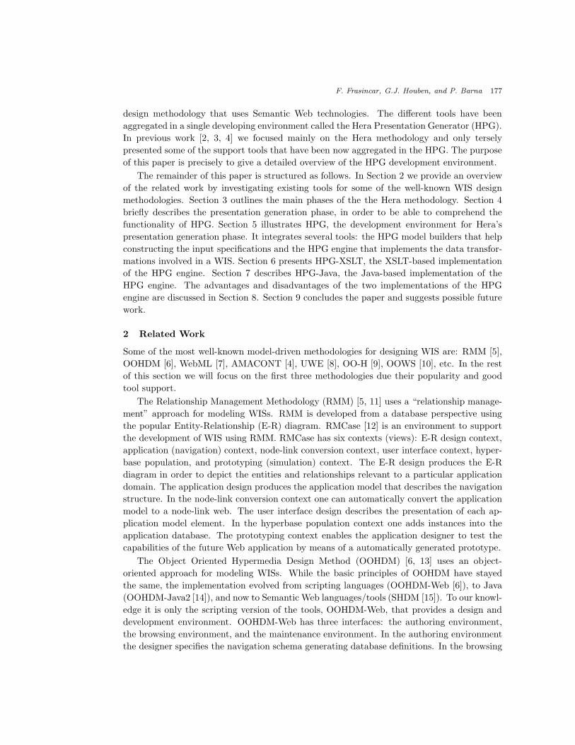
the Hera methodology [2, 16], a model-driven methodology for designing WIS. Figure 1 shows
the main phases of the Hera methodology: data collection and presentation generation.
Due to its Web-frontend, a typical scenario in a WIS is the automatic generation of a Web
presentation for the data collected in response to a user query. In the data collection phase the
retrieval and integration of data or content is handled: it allows making data from different,
possibly heterogeneous data sources available in the application. The subsequent presentation
generation phase is responsible for taking the retrieved data and producing Web presentations
that fit the semantics of the content but that are also adapted/tailored to the user and his or
her browsing device. In an alternative scenario a user is able to update the data involved in

F. Frasincar, G.J. Houben, and P. Barna 179
Browsing Devices
. . .
Data Sources
. . .
Query
Hera
Query Data
Query
Presentation
DataCollection
GenerationPresentation
Data
SessionData
Fig. 1. Hera’s main phases.
generating the presentation without affecting the external information sources. It is clear that
then such updates will happen in the presentation generation phase which will therefore be
responsible for maintaining the user session data. Data collection, specifically the integration
issue, is outside the scope of this paper (we refer the interested reader to [2]). In the rest of
this paper we will focus solely on HPG’s tool support for presentation generation.
Hera is a model-based methodology which means that for the specification of a WIS using
Hera several models need to be developed each model describing a different aspect of the
system. We chose to represent the models in RDFS, and their instances in RDF. The benefits
of using RDF(S) are tremendous: application interoperability, direct availability of Web data
appropriately annotated, reuse of existing RDF vocabularies, future-proofing applications for
which the design models evolve, etc. For example, RDF flexibility (e.g., loose schema defini-
tion) enables one to easily extend a model with other aspects (e.g., adaptation aspects). We
did reuse the User Agent Profile (UAProf) [17], a Composite Capability/Preference Profiles
(CC/PP) [18] vocabulary, for modeling device capabilities and user preferences. The RDFS
inheritance mechanism proved to be enormously valuable for reusing models or adapting them
for particular situations. In order to extract data from RDF models we use RQL, a very ex-
pressive query language that exploits the full RDF(S) semantics represented in a model. For
the creation of new RDF models we use SeRQL, a query language based on RQL with some
additional primitives.
For the methodologies and their associated tools presented in Section 2 the models have
relational (e.g., RMM, OOHDM) or XML representations. The model semantics is thus
hard-coded in the application which makes difficult application interoperability. As Hera
uses RDF(S) to represents its models, the model semantics is captured in the model itself
and thus other applications can easily interoperate with the Hera-based applications. For
example, the presentation generation phase of Hera can be used as a front end for different
Web search/integration engines that output their data as RDF models, or can reuse existing
user profiling services that deliver user data as CC/PP representations. Besides the stan-
dardization of model specifications, RDF(S) allows a more compact representation than the
relational or XML representations of the same information by using inference rules to compute

180 HPG: the Hera Presentation Generator
the implicit information.
The illustration of Hera is supported by means of an example based on real data coming
from a painting collection in a museum, the Rijksmuseuma in Amsterdam.
4 Presentation Generation in Hera
Based on the principle of separation-of-concerns, the presentation generation in Hera distin-
guishes three layers: the conceptual layer, the application layer, and the presentation layer.
In this way one can clearly differentiate at design level between respectively the semantical
aspects, navigational aspects, and interface aspects of a WIS. There is also an orthogonal
dimension with the adaptation layer that captures the adaption aspects in all of the above
layers.
Each layer implies a design activity that produces an appropriate model that captures
all the design aspects specific to this layer. Each model uses concepts from a model-specific
vocabulary. In Hera, concepts have a graphical representation and models can be depicted
as diagrams. There are three basic models: the conceptual model, the application model, and
the presentation model. Note that these are overlay models, the application model lays over
the conceptual model, the presentation model lays over the application model. In addition
to the basic models there are two other models for the (orthogonal) adaptation layer: the
user/platform profile and the adaptation model. The user/platform profile (UP) character-
izes the static aspects of the user/platform (e.g., visual abilities, display area, display image
capabilities, etc.). The adaptation model (AdM) uses the user/platform profile to tailor the
three basic models to a particular situation. At the current moment, the adaptation model
is specified by the inclusion of appearance conditions for elements in the three basic models.
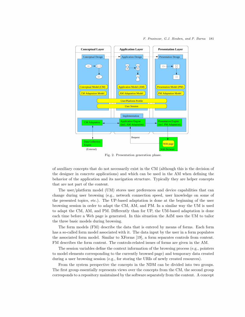
These conditions use data from the user/platform profile or conceptual model. Figure 2 shows
the layers of the presentation generation in Hera with their design activities and the resulting
models (observe the orthogonal nature of adaptation). The bottom of the figure shows the
flow of data in an implementation.
The presentation generation phase accommodates more complex forms of user interaction
in addition to simple link-following, e.g., interaction through forms in which the user can
enter data [16]. In this way the user can better use the WIS according to his needs, specially
regarding the dynamics within a browsing session. Figure 2 shows the “loop” in the presen-
tation generation to support the application dynamics and to allow the user to influence the
generation of the Web presentation. Note that in response to a user query only one page
is generated at-a-time. Generating one-page-at-a-time allows the system to (re)consider the
user input before generating a next Web page. This would not be possible if the system would
generate the full Web presentation at once.
In addition to the data from conceptual model, application model, presentation model,
and user profile, interaction requires a support for creating, storing, and accessing data that
emerges while the user interacts with the system. This support is provided by means of the
user session (US) model that stores all the data created at run-time in a particular user
session. US is composed of the navigation data model, user/platform model, form models, and
session variables.
The purpose of the navigation data model (NDM) is to complement the CM with a number
aThe Rijksmuseum Web-site is available from http://www.rijksmuseum.nl.
F. Frasincar, G.J. Houben, and P. Barna 181
Application LayerConceptual Layer Presentation Layer
Presentation Design
Presentation Model (PM)Application Model (AM)Conceptual Model (CM)
CM Adaptation Model AM Adaptation Model PM Adaptation Model
Conceptual Design Application Design
(External)
User/Platform Profile
Request
User Session
Web page
Application Engine Presentation Engine(incl. PM Adaptation)(incl. AM Adaptation)
CM Adaptation
Implementation
EngineData Collection
Web Browser
Fig. 2. Presentation generation phase.
of auxiliary concepts that do not necessarily exist in the CM (although this is the decision of
the designer in concrete applications) and which can be used in the AM when defining the
behavior of the application and its navigation structure. Typically they are helper concepts
that are not part of the content.
The user/platform model (UM) stores user preferences and device capabilities that can
change during user browsing (e.g., network connection speed, user knowledge on some of
the presented topics, etc.). The UP-based adaptation is done at the beginning of the user
browsing session in order to adapt the CM, AM, and PM. In a similar way the UM is used
to adapt the CM, AM, and PM. Differently than for UP, the UM-based adaptation is done
each time before a Web page is generated. In this situation the AdM uses the UM to tailor
the three basic models during browsing.
The form models (FM) describe the data that is entered by means of forms. Each form
has a so-called form model associated with it. The data input by the user in a form populates
the associated form model. Similar to XForms [19], a form separates controls from content.
FM describes the form content. The controls-related issues of forms are given in the AM.
The session variables define the context information of the browsing process (e.g., pointers
to model elements corresponding to the currently browsed page) and temporary data created
during a user browsing session (e.g., for storing the URIs of newly created resources).
From the system perspective the concepts in the NDM can be divided into two groups.
The first group essentially represents views over the concepts from the CM, the second group
corresponds to a repository maintained by the software separately from the content. A concept

182 HPG: the Hera Presentation Generator
from the first group can be instantiated only with instances of a concept existing in the CM,
without the possibility to change the actual content of the data. A concept from the second
group is populated with instances based on the user’s interaction, i.e., the data is created,
updated, and potentially deleted on-the-fly. Since we use RDF for both, technically there is
no difference: the AM can refer to the concepts from NDM as if they were representing “real”
data concepts.
4.1 Conceptual Design
The conceptual design specifies the input data in a uniform manner, independent from the
input sources. The result of this activity is the conceptual model (CM). The CM is composed
of a hierarchy of concepts, attributes, and concept relationships. As CM vocabulary we use
the standard RDFS concepts with three extensions: one for modeling the cardinality of the
relationships, one for representing the inverse of the relationships, and one for depicting the
media types, the so-called media model (MM). MM is a hierarchical model composed of
media types. There are four basic media types: Text, Image, Audio, and V ideo. For the
refinement of Text media we chose to use the XML Schema Datatypes (e.g., xsd :String or
xsd :Integer) in order to increase the compatibility of our developed applications with emerging
Web standards. Figure 3 shows an excerpt of the CM for our running example.
StringInteger
String
String
String
Image
String
String
*1 * 1Technique CreatorArtifact
1*PainterPainting
subPropertyOf
subClassOf
property
description
tname
exemplified_by
exemplifies
aname
picture
yearcreated_by
creates
biography
painted_by
area
paints
cname
Fig. 3. Conceptual model.
A first type of adaptation happens at the CM level where concepts, attributes, and media
elements are being selected according to the user’s browsing device and preferences [4]. For
example, a large text is preferred for the painting technique description on a PC and a short
version of the same text is more appropriate on a PDA. Another example is the suppression
of all pictures for WAP phones that are not capable to display images.
On the Semantic Web, data is annotated by means of shared vocabularies very similar to
the CM described above. We use an RDFS representation of the CM (with small extensions)
in order to facilitate the reuse of existing Semantic Web domain vocabularies. In this way

F. Frasincar, G.J. Houben, and P. Barna 183
the WIS designer doesn’t have to experience the tedious process of defining domain models.
Also the designer can be freed from the task of annotating the data with terms coming from
these vocabularies.
4.2 Application Design
The application design specifies the navigational structure of the Web presentation. The result
of this activity is the application model (AM). The AM is composed of a hierarchy of slices and
slice relationships. Lacking a standard vocabulary to define the navigational aspects of the
application we use a Hera-specific AM vocabulary. A slice is a meaningful grouping of concept
attributes from CM that need to be presented together (as one) in the Web presentation. Each
slice is associated to a concept from CM, the so-called slice owner. There are two kinds of slice
relationships: compositional relationships and navigational relationships. For compositional
relationships that aggregate slices with different concept owners, the relationship from CM
that allows such an embedding needs to be specified. If such a relationship has a one-to-many
cardinality, a Set construct is used. Figure 3 shows an excerpt of the AM for our example.
exemplifies
Technique
tname
created_by
Creator
cname
picture
aname
year
tname
description
exemplified_by
picture
Artifact
Set
Technique Artifact
mainmain
Painting
emain
area
subClassOf
navigation
aggregation (with CM property name)
Fig. 4. Application model.
Adaptation at AM level allows that slices are being selected according to the user’s brows-
ing device and preferences [20]. For example, one can adapt the navigation model based on
the level of expertise of a user. An expert user will be presented with the painting technique

184 HPG: the Hera Presentation Generator
description while this information will be hidden from a beginner user. This is an example of
fine-grained adaptation based on the user profile.
In order to illustrate the user interaction by means of forms, suppose that the visitor
is allowed to buy posters of the paintings in the museum. For simplicity we didn’t model
explicitly the posters, assuming a one-to-one correspondence with the depicted painting. The
application model for that situation is described in Figure 5.
BuyForm
i quantity
includes
Order
quantity
main
aname
Painting
emain
fmain
Painting
SelectedPainting
Trolley
contains
Set
main
Order
main
aggregation (with CM property name)
navigation
QCreateOPQCreateOU
Fig. 5. Application model with forms.
The Navigation Data Model (NDM) of our example is depicted in Figure 6; it consists of
the following concepts: SelectedPainting, Order, and Trolley. The SelectedPainting concept is
a subclass of the Painting concept from the CM. It represents those paintings which the user
selected in a selection form. The Order concept models a single ordered item consisting of
a selected painting (the property includes) and the quantity represented by an Integer. The
Trolley concept represents a shopping cart containing a set of orders linked by the property
contains.
Next to the system’s content data that is represented in the CM instance (CMI), the user
can generate new data that will be an instance of the NDM [16]. The NDM defines the schema
of this new data that can refer to concepts from the CM. In case that such a request came
from a form and this form has an update associated with it, first the NDM updater is called
in order to update the NDM instance (NDMI) data.

F. Frasincar, G.J. Houben, and P. Barna 185
subClassOf
property
Integer
1* contains
contained_by
11
cm:Painting
quantity
Order TrolleySelectedPaintingincluded_by
includes
Fig. 6. Navigation data model.
Queries included in the AM are associated to slices or slice relationships to select the data
that will populate the next slice to be presented or to perform updates as a query side-effect.
There are four cases in which queries are used. In the first case queries are associated to slices
to express user-independent updates (e.g., creation of a trolley). In the second case queries
are associated to forms (forms and form input fields are also slices) to express user-dependent
updates (e.g., create order and add it to the trolley). In the third case, queries are used to
get values for a form input field (e.g., select paintings names). In the last case, queries are
used in form conditions, to enable/disable a certain form (e.g., if the user has already selected
posters for all paintings, there is no painting poster left to be offered to the user for the next
selection, and therefore the form is disabled).
In our example, there are two queries (attached to the current slice) that are triggered
when the user presses the BuyForm button. These queries are update queries associated to a
form. As a query language we use (Se)RQL, one of the most expressive RDF query languages
that supports not only the selection of RDF data but also the creation of new RDF data.
This new data is built during the user’s browsing session (e.g., the user’s shopping cart, the
items that the user has added to the shopping cart, etc.). The used query language should
not only be able to add new relationships between existing resources but also construct new
resources which do have unique identifiers in the application namespace.
The query QCreateOU shown in Figure 7 creates a new order. We did extend SeRQL
with the new() function that is able to create a URI (identifier) unique in the application for
a new resource. The newly created URI is stored in the user session data variable orderid so
that subsequent queries can reference it.
CONSTRUCT {new()}<rdf:type><ndm:Order>
Fig. 7. Create order.
The query QCreateOP shown in Figure 8 fills the order properties and adds the order to
the trolley. Note that the order is captured in NDM, the owner concept instance identifier
of the current slice and the newly generated order identifier are captured in the user session
data, and the user input (the poster’s quantity) is captured in the form data. Both session
data and form data were previously (before the query is executed) available in RDF.

186 HPG: the Hera Presentation Generator
CONSTRUCT
{x}<ndm:contains>{y},
{y}<ndm:contained_by>{x},
{y}<ndm:includes>{z},
{z}<ndm:included_by>{y},
{y}<ndm:quantity>{v}
FROM
{}<var:trolleyid>{x}
{}<var:conceptid}{z}
{}<var:orderid>{y}
{}<form:input_ID201>{v}
Fig. 8. Add order to trolley.
4.3 Presentation Design
The presentation design specifies the presentation (interface) structure of a Web presentation.
The result of this activity is the presentation model (PM). The PM is composed of a hierarchy
of regions and region relationships. Lacking a standard vocabulary to define the presentation
aspects of the application we use a Hera-specific PM vocabulary. A region is an abstraction
for a rectangular part of the display area in which a slice can be displayed. Each region is
associated to a slice, the so-called region owner. There are three kinds of region relation-
ships: compositional relationships, navigational relationships, and temporal relationships. A
region has a particular layout manager and style associated with it. There are four kinds of
abstract layout managers: TableLayout, BoxLayout, BorderLayout, and T imeLayout. The
T imeLayout is used for platforms that support time sequences for presenting media items
(e.g., HTML+TIME or SMIL). These layout managers need to be instantiated in order to
be used in the PM. For example, the TableLayout needs to specify the numbers of rows and
columns. Also when referencing a region (or set of regions) one needs to specify specific at-
tributes of the layout associated to the embedding region (e.g., horizontal left alignment of a
region in a TableLayout or duration for a region in a T imeLayout). The style associated to
a region defines the font characteristics (e.g., size, color, etc.) to be used for plain text/links
displayed in this region. Figure 3 shows an excerpt of the PM for our running example.
Adaptation at PM level allows that the regions, layouts, and styles are being selected
according to the user’s browsing device and preferences [4]. For example, for presenting an
index of paintings one would use a TableLayout for a PC and a BoxLayout for a PDA/WAP
phone. If the user has a poor vision, a style with big fonts can be used for the presentation
instead of the default style with medium-size fonts.
4.4 Implementation
An implementation is responsible for building a Web presentation given a collection of input
data (CMI) and a set of input specifications, models (CM, AM, PM, UP, and US). The
implementation is based on a pipeline architecture composed of four transformations steps,
three for producing model instances (CMI, AMI, and PMI) for the three basic models (CM,
AM, and PM) and the last one for producing the presentation in a format interpretable by
the user’s browsing device (i.e., code that the browser can render). We will have a closer look
at the first three transformation steps in the next section. Now, we will address the last data
transformation step.

F. Frasincar, G.J. Houben, and P. Barna 187
picture
aname
year
picture
Artifact
Set
Technique Artifact
mainmain
tname
description
Creator
cname
Painting
emain
area
Technique
tname
subClassOf
navigation
RegionFullA (BoxLayout2, DefaultStyle)RegionFullT (BoxLayout1, DefaultStyle)
RegionBottomA (TableLayout1)
RegionFullP (BoxLayout2r, DefaultStyle)
RegionBottomT
Fig. 9. Presentation model.
The last transformation generates code in the format suitable to the user’s browser
(HTML, HTML+TIME, SMIL, or WML) from a previously built PMI. If the browser sup-
ports CSS also a CSS stylesheet is generated according to the style given in the adapted PM,
otherwise the style information is stored together with the code.
Figure 10 shows presentation snapshots for four different browsing platforms: HTML for
PC, SMIL, HTML for PDA, and WML. These presentations are adapted with respect to the
user browsing device, i.e., the client in the UP, as given in the design specifications. Note that,
as described in the PM adaptation, the painting images have a TableLayout for HTML on PC,
are arranged using TimeLayout for SMIL, and have a BoxLayout (on the vertical axis) for the
HTML for PDA and WML presentations. According to the media adaptation, the PDA and
the WAP phone use a shorter text version for the painting technique description compared
with the one on the PC. Also, the WAP phone presentation doesn’t contain pictures. In a
similar way, the presentation can be further adapted by considering other attributes from UP,
e.g., the level of expertise of the user, the user’s visual capabilities, etc.

188 HPG: the Hera Presentation Generator
HTML for PC SMIL
HTML for PDA WML
Fig. 10. Presentations in different browsers.
5 HPG
HPG integrates several tools built during the last couple of years in the Hera project into one
common environment. It has the following components: the CM Builder, the AM Builder, the
PM Builder, the UP Builder, and the engine, that correspond to the steps in the presentation
generation phase of Hera. For building (and visualizing) the CM, AM, and PM several Visio
solutions were implemented.
Each model needs to fulfill a set of model constraints. In case that the designer uses the
HPG builders to develop models these constraints are automatically fulfilled as they are en-
forced during model construction. Nevertheless, in case that the designer uses a different tool
to build models, the resulted specifications need to be checked if they fulfill their associated
constraints. For this purpose a separate Java program based on Jena [21] was developed for
checking the constraints of a model (validating a model).
The HPG engine implements the data transformations for models and model instances.
There are two versions of the HPG engine: HPG-XSLT that uses XSLT-based data transfor-

F. Frasincar, G.J. Houben, and P. Barna 189
mations and HPG-Java that uses Java-based data transformations.
5.1 CM Builder
Figure 11 shows a snapshot of the CM Builder. On the left-hand side there is the stencil that
contains shapes for all CM elements. On the right-hand side there is the drawing frame in
which a CM is built. For all drawn shapes one can set specific properties to them (e.g., for
a concept relationship shape there are attributes that specify the inverse and cardinality of
this relationship).
Fig. 11. Conceptual model builder.
Some of the CM constraints that this builder enforces are: (1) only the media types defined
in the media vocabulary can be used for attributes, (2) all concept relationships need to have
a domain and a range, (3) every concept relationship needs to have its inverse relationship
defined, (4) every concept relationship needs to have its cardinality specified, etc.
5.2 AM Builder
Figure 12 shows a snapshot of the AM Builder. On the left-hand side there is the stencil that
contains shapes for all AM elements. On the right-hand side there is the drawing frame in
which an AM is built. For all drawn shapes one can set specific properties to them (e.g., for
a slice shape there is an attribute that specifies the name of the owner concept).
Some of the AM constraints that this builder enforces are: (1) only concepts defined in
the associated CM can be used as owners of slices, (2) all slice relationships need to have a
source and a destination, (3) slices related by slice aggregation relationship need to specify a
valid concept relationship between the slice owners, if the owners are different, (4) all slices
can be reached from the start main slice, etc.

190 HPG: the Hera Presentation Generator
Fig. 12. Application model builder.
5.3 PM Builder
Figure 13 shows a snapshot of the PM Builder. On the left-hand side there is the stencil that
contains shapes for all PM elements. On the right-hand side there is the drawing frame in
which a PM is built. For all drawn shapes one can set specific properties to them (e.g., for a
region shape there is an attribute that specifies the name of the owner slice). The layout and
style information are associated to a region by means of shape attributes.
Some of the PM constraints that this interface enforces are: (1) only the slices defined in
the associated AM can be used as owners of regions, (2) all region relationships need to have
a source and a destination, (3) complex slices need to have the layout information specified,
(4) all regions can be reached from the start region, etc.
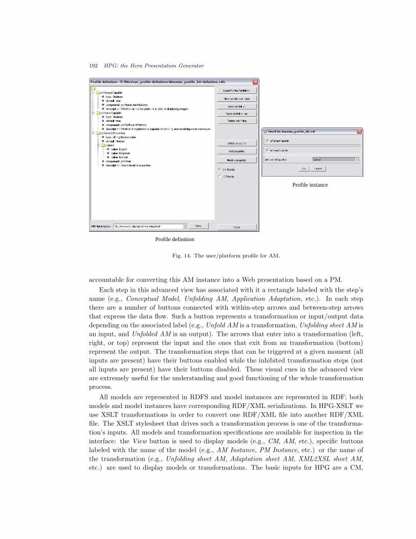
5.4 UP Builder
HPG supports also the specification of a UP definition and of a UP instantiation, aggregated
in the UP Builder. As shown in the previous chapter, the UP is used in the adaptation
conditions in AM and PM. Taking this in consideration we decided to split the UP in two
parts, one relevant for AM and another part relevant for PM.
The profile definition is a CC/PP vocabulary [18]. It defines three components: Hard-
warePlatform, SoftwarePlatform, and User (preferences). Each component has a number of
attributes for which the types are also specified. Among the supported types are Boolean,

F. Frasincar, G.J. Houben, and P. Barna 191
Fig. 13. Presentation model builder.
Integer, String, and Enumeration. The instantiation of this profile is done by means of an
interface automatically generated from a profile definition.
Figure 14 shows the UP definition and instantiation for AM. In this UP, imageCapable is
defined as a HardwarePlatform attribute with a Boolean type. For the instantiation of this
attribute one can check the associated radio button to indicate the value True (otherwise the
value is False). In the current example this attribute was set to True.
Figure 15 shows the UP definition and instantiation for PM. In this UP, client is defined
as a HardwarePlatform attribute with an enumerated type PC, PDA, or WAP phone. For
the instantiation of this attribute one can select only one of the three values of the attribute
type. In the current example this attribute was set to PC.
6 HPG-XSLT
HPG-XSLT is an XSLT-based implementation of the HPG engine. Besides its practical
purpose, HPG-XSLT has also an explanatory purpose as it offers an explicit view over the
data flow in the Hera presentation generation phase.
Figure 16 shows the advanced-designer view in HPG-XSLT. Inexperienced designers will
be presented with another interface which follows the popular wizard paradigm (in which the
more complex user interface is split into a sequence of smaller, easy-to-use interfaces). As
one can notice from Figure 16, this advanced view shows two important parts: a left-hand
side responsible for converting a CMI into an AMI based on the AM and a right-hand side
192 HPG: the Hera Presentation Generator
Profile definition
Profile instance
Fig. 14. The user/platform profile for AM.
accountable for converting this AM instance into a Web presentation based on a PM.
Each step in this advanced view has associated with it a rectangle labeled with the step’s
name (e.g., Conceptual Model, Unfolding AM, Application Adaptation, etc.). In each step
there are a number of buttons connected with within-step arrows and between-step arrows
that express the data flow. Such a button represents a transformation or input/output data
depending on the associated label (e.g., Unfold AM is a transformation, Unfolding sheet AM is
an input, and Unfolded AM is an output). The arrows that enter into a transformation (left,
right, or top) represent the input and the ones that exit from an transformation (bottom)
represent the output. The transformation steps that can be triggered at a given moment (all
inputs are present) have their buttons enabled while the inhibited transformation steps (not
all inputs are present) have their buttons disabled. These visual cues in the advanced view
are extremely useful for the understanding and good functioning of the whole transformation
process.
All models are represented in RDFS and model instances are represented in RDF; both
models and model instances have corresponding RDF/XML serializations. In HPG-XSLT we
use XSLT transformations in order to convert one RDF/XML file into another RDF/XML
file. The XSLT stylesheet that drives such a transformation process is one of the transforma-
tion’s inputs. All models and transformation specifications are available for inspection in the
interface: the View button is used to display models (e.g., CM, AM, etc.), specific buttons
labeled with the name of the model (e.g., AM Instance, PM Instance, etc.) or the name of
the transformation (e.g., Unfolding sheet AM, Adaptation sheet AM, XML2XSL sheet AM,
etc.) are used to display models or transformations. The basic inputs for HPG are a CM,

F. Frasincar, G.J. Houben, and P. Barna 193
Profile instance
Profile definition
Fig. 15. The user/platform profile for PM.
an AM, a PM, and an UP as input models, and a CMI as input data. The output is a Web
presentation of the input data that fulfills all the input models.
The transformation process starts with the selection of a CM. In case that such a CM
doesn’t exist the designer can create one using the Visio solution as described in Section 5.1.
After selecting a CM, the user can choose an AM from the available AMs that correspond to
the chosen CM. Again, if such an AM doesn’t exist the designer is offered the possibility to
build one using the Visio solution presented in Section 5.2. The unfolding step is a preparation
step in the sense that it restructures the AM in a format more fit (than the original AM) for
the next transformation step.
Based on the UP for AM selection, the original AM is adapted. Slices with invalid condi-
tions are discarded and the hyperlinks (slice relationships) referring to these slices are disabled.
For example, if the user is not an Expert he will not see the painting technique description.
All transformations that we have seen so far are generic (i.e., instance-independent). Un-
less otherwise specified a transformation refers to a generic transformation. Based on the
adapted AM one can use a generic transformation to produce a specific transformation (CMI
to AMI sheet) that will be able to convert a CMI to an AMI.
Until now we have presented the transformations at AM level (left-hand side of Figure 16).
Similar to the above transformations, there are PM-driven transformations (right-hand side
of Figure 16). Again as a technical convenience, the unfolding mechanism is also used with
the PM.
Based on the UP for PM selection, the original PM is adapted. For example, for presenting
an index of paintings images one would use a TableLayout for a PC and a BoxLayout for a

194 HPG: the Hera Presentation Generator
Fig. 16. The HPG-XSLT interface.
PDA or WAP phone. The PM has not only information on the layout but also on the style
of the Web presentation. If the user has a poor vision, a style with large fonts will be used
instead of the default style with medium-size fonts.
In a similar way as for the AM but this time based on the adapted PM, one can use a
generic transformation to produce a specific transformation (AMI to PMI sheet) that will
convert a particular AMI to a PMI.
The last transformation generates code in the format suitable to the user’s browser
(HTML, HTML+TIME, SMIL, or WML). If the browser supports CSS also a CSS stylesheet
is generated according to the style given in the adapted PM. The designer is offered the choice
of specifying the directory where the Web presentation will be generated. Note that such a
presentation can include thousands of files that might require a lot of disk memory.
The first XSLT processor used to carry out the transformations specified by the different
XSLT stylesheets was Xalan 1.2D02 [22]. Since this processor supported only XSLT 1.0 [23] it
was replaced with Saxon [24], a more powerful XSLT processor that supports XSLT 2.0 [25].
In order to speed-up the execution of these stylesheets (note that the used museum data has
about 1000 art objects with their relations) several XSLT keys have been defined.
7 HPG-Java
HPG-Java is a Java-based implementation of the HPG engine. HPG-Java doesn’t have a
graphical user interface similar to the implementation interface of HPG-XSLT.

F. Frasincar, G.J. Houben, and P. Barna 195
One of the disadvantages of HPG-XSLT was the fact that it used XSLT stylesheets to
transform RDF models. In this way it was difficult to make use of the full semantics of
a model as given by the model’s RDFS-closure. HPG-Java eliminates this shortcoming by
defining Java transformations based on Jena [21]. For querying and updating models it uses
the (Se)RQL implementation of Sesame [26].
7.1 Designing HPG-Java
Being a dynamic system able to react to user actions, HPG-Java was developed based on Java
servlet technology. It runs as a Java servlet on an Apache Tomcat Web server. Figure 17
shows an excerpt of the class association diagram of HPG-Java. The main class that receives
user requests is the HeraServlet, which extends the Java HttpServlet class.
ModelController
adapt()
create()
RequestHandler
handleRequest()
Session
init()
getValue()
setValue()
HeraSerlvet
init()
doGet()
HTMLConverter HTML+TIMEConverter SMILConverter WMLConverter
PresentationConverter
createPresentation()
AMController PMController
conceptID
sliceType
init()
Controller
run()
addRequestHandler()
LoginRequestHandler LogoutRequestHandler AppRequestHandler
deleteUser()addUser()
SessionUpdater
update()
Fig. 17. HPG-Java class association diagram.
In order to build robust and flexible applications we used several design patterns. A
servlet specific pattern is the delegation event model. All request handlers implement the
RequestHandler interface. The request handlers are registered in the HeraServlet. Based on
the value stored in a hidden field for the GET request, the HeraServlet is able to identify the
particular request handler responsible for this event. Examples of events are login, logout,
link following, each one having a corresponding request handler. In this way one avoids the
building of complex RequestHandlers able to solve all request.
The facade pattern was used to hide from the HeraServlet the complexity of the different

196 HPG: the Hera Presentation Generator
data transformations. Four classes were defined to perform data transformations: AMCon-
troller, SessionUpdater, PMController, and PresentationConverter. The AMController and
PMController are responsible for adapting and creating instances of the AM, respectively
PM. The AMController has associated the SessionUpdater which manages the Session. The
Session class is an extension of the Java HttpSession class. The Session class stores informa-
tion that persist between user requests: the navigational data model, form models, variables
(including the user name and password). SessionUpdater is used for updating the Session
data as part of the process of generating the new slice instance.
As both slices and regions have a recursive structure we used the composite pattern to
define them. In order to build a slice or region the create() function is used. Based on the UP
the AM and PM will be adapted using the adapt() function. Based on the same UP a specific
PresentationGenerator is chosen. The createPresentation() function is used to produce a
presentations interpretable by the user browsing platform.
Figure 18 presents the exchange of messages between different class instances in response
to a user query.
ControllerApplRequestHandler AMController PMController PresentationConverter
Session is new
HeraSerlvet
doGet()
handleRequest()
run()
SessionUpdater
update()
update()
adapt()
adapt()
create()
create()
doGet()
handleRequest()
run()
createPresentation()
createPresentation()
adapt()
adapt()
create()
create()
Fig. 18. HPG-Java message sequence chart.
Suppose the HeraServlet receives a doGet() function call. In case that the request is orig-
inating from a link-following request, the handleRequest() function of AppRequestHandler is
called. Next, the Controller run() function is called to manage the whole data transformation
process.

F. Frasincar, G.J. Houben, and P. Barna 197
Depending on whether the current session is a new session, the AM and PM are adapted by
calling the adapt() function of their associated controllers. Note that at the present moment
we support only static adaptation of the system, that is why the adaptation is performed at
the beginning of the user session. With the AM and PM adapted the create() function calls
will build a new slice instance and a region instance, respectively, for the current page. Note
that in the create() function of the AMController the update() function of the SessionUpdater
is called in order to update the Session content. The region instance is based on the previously
generated slice instance. The last function is the createPresentation() which transforms the
region instance into a Web page.
8 HPG-XSLT vs. HPG-Java
HPG-XSLT and HPG-Java have both their advantages and disadvantages. Figure 19 com-
pares the main characteristic features of HPG-XSLT and HPG-Java. HPG-Java generates
one-page-at-a-time in order to better support the dynamic Web applications.
HPG-XSLT HPG-Javageneration of full Webpresentation
generation of one pageat-at-time
+ deployable on any Web server − can be deployable only on Webservers supporting Java servlets
− no form-support + form-support
Fig. 19. HPG-XSLT vs. HPG-Java.
The generation of the full presentation in HPG-XSLT requires usually a long time for
computing the whole presentation. If one decides to deploy the resulted pages on a Web
server this high computational time does not influence the system response time to a user.
The user can browse the presentation at a reasonable speed if his network connection allows
it because there is no computation performed on the server. The generation of one page
at-a-time in HPG-Java has as consequence a longer response time than for a presentation
generated with HPG-XSLT. On the other hand if the HPG-XSLT presentation is built at
run-time, the time needed for computing the whole presentation is higher than the time
needed for computing of only one page at the beginning of the browsing process as it is done
in HPG-Java.
The resulted Web pages from HPG-XSLT can be deployed on any Web server. Due to its
dynamic nature, HPG-Java can be deployed only on Web servers that support Java servlets.
Modern Web server (like Apache) do support Java servlets.
HPG-XSLT has no support for user interaction besides simple link-following. The user of a
generated presentation cannot influence the content of the presentation. HPG-Java does allow
for more advanced forms of user interaction (e.g., forms) as a way to let the user influence
the content of the presentation. This is an extremely useful feature in case the application
will be used for example as a shopping site or as a review system.
Performing the data transformations in XSLT or Java have both advantages and disad-
vantages. Figure 20 compares the main characteristic features of XSLT transformations and
Java transformations used in HPG-XSLT and HPG-Java, respectively.
XSLT is a declarative programming language and Java is an imperative programming

198 HPG: the Hera Presentation Generator
XSLT stylesheets Java codedeclarative imperative
+ loosely-coupled, changing thesystem can be done by changingone stylesheet
− strongly-coupled, internaldependencies make the systemharder to change
+ easy to understand − more difficult to understand− no IDEs + many IDEs− limited exploitation of models’
RDFS semantics+ full exploitation of models’
RDFS semantics− XSLT processor offers little
support for optimization leadingto poorer performance
+ custom software can beoptimized better leading tobetter performance
− introduces extra steps + no need of extra steps
Fig. 20. XSLT stylesheets vs. Java code.
language. Depending on the programmer’s preference one way of programming can be easier
than the other one. As for many declarative languages, XSLT is supported by interpreters.
Java is supported by many compilers that generate code interpretable directly by the machine.
As such the execution time of the code generated by compilers is smaller than the time required
by an interpreter to perform the same computations.
Changing the system can be done by changing only one XSLT stylesheet due to the nice
separation of concerns provided by stylesheets. A similar change done for Java code might be
harder to achieve due to the internal dependencies between software components. The use of
design patterns can alleviate this problem in the Java code.
XSLT stylesheets are easy to learn, one can write fairly complex transformations after
learning some of the basic XSLT concepts. Java code is harder to produce, the learning curve
is usually higher than for XSLT programming.
At the current moment there is a lack of IDEs to assist the XSLT programmer. For Java, a
more mature language, there is a huge number of developing IDEs that provide very advanced
debugging facilities.
XSLT is a language for transforming XML documents. As there is no data transformation
language for RDF it was decided to use XSLT for transforming the RDF/XML serialization
of RDF models. Clearly these XSLT transformations have limitations as they are not able
to exploit the full RDFS semantics of a model as given by the model RDF(S)-closure. The
Java code is based on Jena and Sesame, two Java libraries that can fully exploit the RDFS
semantics of models.
While developing HPG-XSLT it was noticed that there is very little support to optimize
a data transformation. By optimization it is seeked the reduction of the time needed by a
data transformation. The performance of HPG-XSLT is based on the performance of the data
structures used by the XSLT processor. The Java code offers more room for optimizing the
data transformations as one can define its own data structures and processing facilities.
HPG-XSLT introduces several extra steps, for unfolding models. These steps were devel-
oped in order to prepare an RDF/XML document in an XML format suitable for the next
transformation step. These steps were not needed for HPG-Java as the Java code directly
operates on RDF models.
F. Frasincar, G.J. Houben, and P. Barna 199
9 Conclusions and Future Work
This paper is dedicated to the Hera Presentation Generator (HPG), a tool the supports the
construction of WIS using the presentation generation phase of the Hera methodology. It is
one of the first development environments for WISs that use Semantic Web technologies.
It integrates several tools: the HPG model builders that helps constructing the WIS input
specifications and the HPG engine that implements the data transformations involved in a
WIS. We did present two versions of the HPG engine: HPG-XSLT and HPG-Java. The
XSLT stylesheets from HPG-XSLT are replaced in HPG-Java with Java code able to better
cope with the RDF(S) semantics of the Hera models. Compared with HPG-XSLT, HPG-Java
extends the functionality of a generated WIS with user interaction support (form-based).
Nevertheless, HPG-Java lost the declarativity, simplicity, and reuse capabilities of the XSLT
transformation templates. A declarative transformation language dedicated to RDF(S), which
to our knowledge doesn’t exist at the present moment, would probably be the best option for
the Hera transformations.
As future work, we would like to add a user interface (servlet console) for HPG-Java, very
similar to the user interface in HPG-XSLT, in order to better trace and configure the Hera
servlet activities. In Section 4 we advocated the need to split the user/platform profile in
the Hera methodology over the three different layers: conceptual, application, and presenta-
tion. In this respect we can introduce a conceptual model adaptation in HPG engine (both
versions) which will use a user/platform profile for CM which is extracted from the present
user/platform profile for AM (e.g., the image capability of the browsing device is specific to
the CM and not the AM). Depending on the existence of a declarative RDF transformation
language we would like to replace the Java code with RDF transformation templates which
will combine the best features of the two HPG engine versions: declarativity, simplicity and
reuse of templates as in HPG-XSLT and the full RDF(S) semantics exploitation for the Hera
models as in HPG-Java.
Last, but not least, we would like to further exploit the interoperability which the Semantic
Web platform has to offer. In this respect we will integrate HPG with the data collection
tool for data retrieval and integration also developed in the Hera project. In this way the
integrated HPG will be able to consume data coming from different, possibly heterogeneous
sources spread over the Web.
Acknowledgements
We would like to thank Rijksmuseum in Amsterdam, for providing real data in our example.
We would like also to thank the other members of the Hera implementation team that were
involved in the development of this set of tools: Bas Rutten, Bert Okkerse, Richard Vdovjak,
Pieter Bellekens, Lawrence Mees, Martijn Schuijers, Sergey Lukin, and Reinier Post.
References
1. T. Isakowitz, M. Bieber, and F. Vitali (1998), Web Information Systems, Communications of theACM, Vol. 41, No. 1, pp. 78–80.
2. R. Vdovjak, F. Frasincar, G.J. Houben, and P. Barna (2003), Engineering Semantic Web Infor-mation Systems in Hera, Journal of Web Engineering, Vol. 2, Nos. 1-2, pp. 3–26.
3. G.J. Houben, P. Barna, F. Frasincar, and R. Vdovjak (2003), Hera: Development of SemanticWeb Information Systems, in Web Engineering - 3th International Conference (ICWE 2003), Vol.

200 HPG: the Hera Presentation Generator
2722 of Lecture Notes in Computer Science, pp. 529–538.4. Z. Fiala, F. Frasincar, M. Hinz, G.J. Houben, P. Barna, and K. Meissner (2004), Engineering the
presentation layer of adaptable Web Information Systems, in Web Engineering - 4th InternationalConference (ICWE 2004), Vol. 3140, Lecture Notes in Computer Science, Springer, pp. 459–472.
5. A. Diaz, T. Isakowitz, V. Maiorana, and G. Gilabert (1997), Extending the capabilities of RMM:Russian dolls and hypertext, in 30th Hawaii International Conference on System Sciences (HICSS-30), Vol. 6, IEEE Computer Society, pp. 177–186.
6. D. Schwabe and G. Rossi (1998), An object oriented approach to Web-based application design,Theory and Practice of Object Systems, Vol. 4, No. 4, pp. 207–225.
7. S. Ceri, P. Fraternali, A. Bongio, M. Brambilla, S. Comai, and M. Matera (2003), Designingdata-intensive Web applications, Morgan Kaufmann.
8. N. Koch, A. Kraus, and R. Hennicker (2001), The authoring process of the UML-based Webengineering approach, in First International Workshop on Web-Oriented Software Technology(IWWOST 2001).
9. J. Gomez and C. Cachero (2003), OO-H Method: extending UML to model Web interfaces, inInformation Modeling for Internet Applications, Idea Group Publishing, pp. 144–173.
10. O. Pastor, J. Fons, and V. Pelechano (2003), OOWS: A method to develop Web applications fromWeb-oriented conceptual model, in International Workshop on Web-Oriented Software Technology(IWWOST 2003), pp. 65–70.
11. T. Isakowitz, E.A. Stohr, and P. Balasubramanian (1995), RMM: A methodology for structuredhypermedia design, Communications of the ACM, Vol. 38, No. 8, pp. 34–44.
12. A. Diaz, T. Isakowitz, V. Maiorana, and G. Gilabert (1995), RMC: A tool to design WWWapplications, in Fourth International World Wide Web Conference (WWW 4).
13. D. Schwabe, G. Rossi, and S.D.J. Barbosa (1996), Systematic hypermedia application design withOOHDM, in The Seventh ACM Conference on Hypertext (Hypertext 1996), ACM, pp. 116–128.
14. D. Schwabe, R. de Almeida Pontes, and I. Moura (1999), OOHDM-Web: an environment forimplementation of hypermedia applications in the WWW, ACM SIGWEB Newsletter, Vol. 8, No.2, pp. 18–34.
15. F. Lima and D. Schwabe (2003), Application modeling for the Semantic Web, in 1st LatinAmerican Web Congress (LA-WEB 2003), IEEE Computer Society, pp. 93–102.
16. G.J. Houben, F. Frasincar, P. Barna, and R. Vdovjak (2004), Engineering the presentation layerof adaptable Web information systems in Web Engineering - 4th International Conference (ICWE2004), Vol. 3140, Lecture Notes in Computer Science, Springer, pp. 60–73.
17. Wireless Application Protocol Forum, Ltd. (2001), Wireless application group: User Agent Profile.18. G. Klyne, F. Reynolds, C. Woodrow, O. Hidetaka, J. Hjelm, M.H. Butler, and L. Tran (2004),
Composite capability/preference profiles (CC/PP): Structure and vocabularies 1.0., W3C Recom-mendation 15 January 2004.
19. M. Dubinko, L.L. Klotz, R. Merrick, and T.V. Raman (2003), XForms 1.0, W3C Recommendation14 October 2003.
20. F. Frasincar, P. Barna, G.J. Houben, and Z. Fiala (2004), Adaptation and reuse in designingWeb Information Systems, in International Conference on Information Technology: Coding andComputing (ITCC 2004), IEEE Computer Society, pp. 387–291.
21. Hewlett-Packard Development Company, LP (2006), Jena - a Semantic Web framework for Java,http://jena.sourceforge.net/.
22. Apache Software Foundation (2006), Xalan-Java, http://xml.apache.org/xalan-j/.23. J. Clark (1999), XSL transformations (XSLT) version 1.0, W3C Recommendation 16 November
1999.24. M. Kay (2006), Saxon (the XSLT and XQuery processor), http://saxon.sourceforge.net.25. M. Kay (2005), XSL transformations (XSLT) version 2.0, W3C Candidate Recommendation 3
November 2005.26. Aduna, BV (2006), openRDF.org ... home of Sesame, http://www.openrdf.org/.