generator, CRO, DMM - WordPress.com
15
Electronics & Communication Dept. SCET, Surat EXPERIMENT NO. 01 AIM: Use basic source and measuring instruments (power supply, function generator, CRO, DMM) 1. To study power supply and learn to adjust given voltage and measure it with digital millimeter. 2. To get sinusoidal, square waveform of given frequency and amplitude and see it on CRO. 3. To get ac signals along with offset voltage and observe them on CRO. Apparatus: Sr. No Name of the Device Quantity Model No. and Specification 1 CRO 1 2 Function Genrator 1 3 Digital Multimeter 1 4 Power Supply 1 5 Bradboard 1 6 Conncetion prob 1 CRO (Cathode ray Oscilloscope): This instrument is called an "eye" to see what is happening in the electrical and electronics circuit. The oscilloscope is using cathode ray tube a heart of it. It can convert kinetic energy of electron striking the phosphor screen into visible light. The position of the electron beam generated from the electron gun is determined by the magnitude and polarity of voltage applied to horizontal and deflection plates. In CRO horizontal deflection plates are provided external signal which we want to observe. Due to internal ramp waveform, electron beam travels from left to right with constant speed in a straight line and quickly returns to left again and repeats. Now in the presence of Input signal Beam gets deflected in vertical direction also, thereby displaying input signal. The frequency of saw tooth is so high that input signal being displayed looks stationary. You can select appropriate voltage scale using volts/div and time scale using time/div so that displayed signal fits into the screen size. If your CRO is a dual trace, you can simultaneously see two waveforms provided both of them have a common ground. The time scales for both are same but voltage scales can be set independently.
-
Upload
khangminh22 -
Category
Documents
-
view
8 -
download
0
Transcript of generator, CRO, DMM - WordPress.com
Electronics & Communication Dept. SCET, Surat
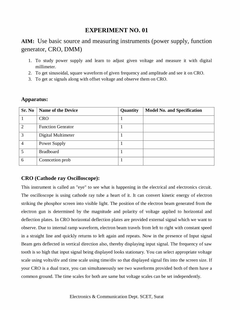
EXPERIMENT NO. 01
AIM: Use basic source and measuring instruments (power supply, function
generator, CRO, DMM)
1. To study power supply and learn to adjust given voltage and measure it with digital
millimeter.
2. To get sinusoidal, square waveform of given frequency and amplitude and see it on CRO.
3. To get ac signals along with offset voltage and observe them on CRO.
Apparatus:
Sr. No Name of the Device Quantity Model No. and Specification
1 CRO 1
2 Function Genrator 1
3 Digital Multimeter 1
4 Power Supply 1
5 Bradboard 1
6 Conncetion prob 1
CRO (Cathode ray Oscilloscope):
This instrument is called an "eye" to see what is happening in the electrical and electronics circuit.
The oscilloscope is using cathode ray tube a heart of it. It can convert kinetic energy of electron
striking the phosphor screen into visible light. The position of the electron beam generated from the
electron gun is determined by the magnitude and polarity of voltage applied to horizontal and
deflection plates. In CRO horizontal deflection plates are provided external signal which we want to
observe. Due to internal ramp waveform, electron beam travels from left to right with constant speed
in a straight line and quickly returns to left again and repeats. Now in the presence of Input signal
Beam gets deflected in vertical direction also, thereby displaying input signal. The frequency of saw
tooth is so high that input signal being displayed looks stationary. You can select appropriate voltage
scale using volts/div and time scale using time/div so that displayed signal fits into the screen size. If
your CRO is a dual trace, you can simultaneously see two waveforms provided both of them have a
common ground. The time scales for both are same but voltage scales can be set independently.

Electronics & Communication Dept. SCET, Surat
Function (Signal) Generator:
It generates standard voltage signals like sinusoidal, square and triangular waveforms of different
frequencies and amplitudes. You can provide input to your circuit using signal function generator
with the BNC connector. In BNC connector the inner core wire is "high" in potential and outer one
is “ground” or "low". You can select sine, rectangular, triangular or pulse shape by selecting the
waveform from front panel control of function generator. You can change frequency as well
amplitude using knobs on front panel.
Power supply:
It is used to provide desired supply voltage in the circuit for its functioning. 230 volt signal phase
50Hz supply is converted to DC voltage using step down transformer and bridge rectifiers using
diodes. This voltage is filtered using fitters to make it smooth DC voltage. This voltage is regulated
against supply voltage and load current variations using regulators. See the "front panel of the power
supply available in the laboratory. It can offer constant or variable voltage. For variable voltage Fine
and course knobs are available on the front panel. Even there is a knob to select voltage range.
Multi meter
Voltmeter is used to measure voltage between two points Ammeter is used to measure current
through any branch and Ohmmeter is used to measure resistance between two points in a circuit. See
different range of above meters available in the laboratory. They are analog meters and D' Arsonval
movement is used for the pointer movement. Necessary changes are made in the basic galvanometer
to construct above meters. Multi meter is having voltage, current and resistance measurement, all in
one apparatus. It is a multipurpose instrument, with a current meter, a voltmeter and an ohmmeter
placed inside. It is provided with batteries (for making it an ohmmeter), with shunt resistance (for
making it multi range current meter) and with high series resistance (for making it multi-range
voltmeter). in all three cases the detection occur due to current, in resistance measurement this
current is inversely proportional to resistance, in voltage measurement current is proportional to the
voltage. These meters change input analog quantity into digital number and displays on LED or LCD
displays they are more readable compare to analog type. Digital multi meters are also has facility of
measurement of hfe of transistor, capacitance of capacitor etc.

Electronics & Communication Dept. SCET, Surat
Breadboard:
It is used to form circuit using discrete components Horizontal and vertical slots are available for the
grip of terminals, of electronic components.
Conclusion:

Electronics & Communication Dept. SCET, Surat
EXPERIMENT NO. 02
AIM: Draw electronic circuit diagram using IEEE standard symbols.
1) One need to draw given circuit using IEEE symbols
2) Draw all IEEE symbols on separate sheet.
Introduction
Wire Symbol
Electrical Wire Conductor of electrical current
Connected Wires Connected crossing
Not Connected Wires Wires are not connected
Ground Symbols
Earth Ground
Used for zero potential reference and electrical shock protection.
Chassis Ground Connected to the chassis of the circuit
Digital / Common Ground
Resistor Symbols
Resistor (IEEE)
Resistor reduces the current flow.
Resistor (IEC)
Electronics & Communication Dept. SCET, Surat
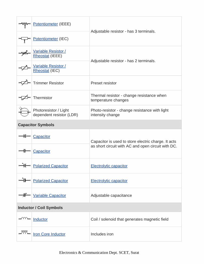
Potentiometer (IEEE)
Adjustable resistor - has 3 terminals.
Potentiometer (IEC)
Variable Resistor / Rheostat (IEEE)
Adjustable resistor - has 2 terminals.
Variable Resistor / Rheostat (IEC)
Trimmer Resistor Preset resistor
Thermistor Thermal resistor - change resistance when temperature changes
Photoresistor / Light dependent resistor (LDR)
Photo-resistor - change resistance with light intensity change
Capacitor Symbols
Capacitor
Capacitor is used to store electric charge. It acts as short circuit with AC and open circuit with DC.
Capacitor
Polarized Capacitor Electrolytic capacitor
Polarized Capacitor Electrolytic capacitor
Variable Capacitor Adjustable capacitance
Inductor / Coil Symbols
Inductor Coil / solenoid that generates magnetic field
Iron Core Inductor Includes iron
Electronics & Communication Dept. SCET, Surat
Variable Inductor
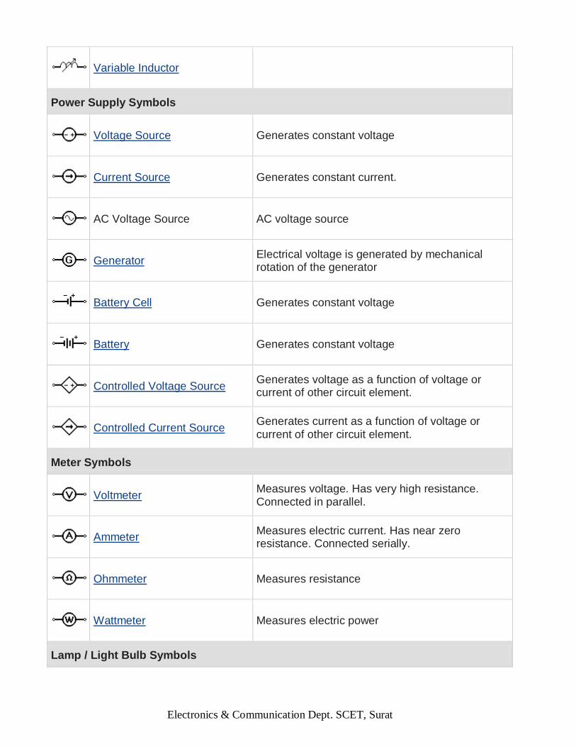
Power Supply Symbols
Voltage Source Generates constant voltage
Current Source Generates constant current.
AC Voltage Source AC voltage source
Generator
Electrical voltage is generated by mechanical rotation of the generator
Battery Cell Generates constant voltage
Battery Generates constant voltage
Controlled Voltage Source
Generates voltage as a function of voltage or current of other circuit element.
Controlled Current Source
Generates current as a function of voltage or current of other circuit element.
Meter Symbols
Voltmeter
Measures voltage. Has very high resistance. Connected in parallel.
Ammeter
Measures electric current. Has near zero resistance. Connected serially.
Ohmmeter Measures resistance
Wattmeter Measures electric power
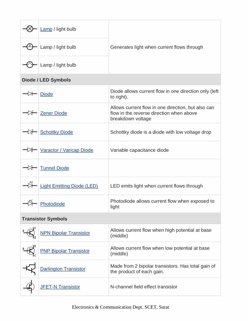
Lamp / Light Bulb Symbols
Electronics & Communication Dept. SCET, Surat
Lamp / light bulb
Generates light when current flows through
Lamp / light bulb
Lamp / light bulb
Diode / LED Symbols
Diode
Diode allows current flow in one direction only (left to right).
Zener Diode
Allows current flow in one direction, but also can flow in the reverse direction when above breakdown voltage
Schottky Diode Schottky diode is a diode with low voltage drop
Varactor / Varicap Diode Variable capacitance diode
Tunnel Diode
Light Emitting Diode (LED) LED emits light when current flows through
Photodiode
Photodiode allows current flow when exposed to light
Transistor Symbols
NPN Bipolar Transistor
Allows current flow when high potential at base (middle)
PNP Bipolar Transistor
Allows current flow when low potential at base (middle)
Darlington Transistor
Made from 2 bipolar transistors. Has total gain of the product of each gain.
JFET-N Transistor N-channel field effect transistor

Electronics & Communication Dept. SCET, Surat
JFET-P Transistor P-channel field effect transistor
NMOS Transistor N-channel MOSFET transistor
PMOS Transistor P-channel MOSFET transistor
Misc. Symbols
Motor Electric motor
Transformer
Change AC voltage from high to low or low to high.
Electric bell Rings when activated
Buzzer Produce buzzing sound
Fuse
The fuse disconnects when current above threshold. Used to protect circuit from high currents.
Fuse
Bus
Contains several wires. Usually for data / address.
Bus
Bus
Opt coupler / Opto-isolator Opt coupler isolates connection to other board
Loudspeaker Converts electrical signal to sound waves
Microphone Converts sound waves to electrical signal

Electronics & Communication Dept. SCET, Surat
Operational Amplifier Amplify input signal
Schmitt Trigger Operates with hysteresis to reduce noise.
Analog-to-digital converter (ADC)
Converts analog signal to digital numbers
Digital-to-Analog converter (DAC)
Converts digital numbers to analog signal
Crystal Oscillator Used to generate precise frequency clock signal
Antenna Symbols
Antenna / aerial
Transmits & receives radio waves
Antenna / aerial
Dipole Antenna Two wires simple antenna
Logic Gates Symbols
NOT Gate (Inverter) Outputs 1 when input is 0
AND Gate Outputs 1 when both inputs are 1.
NAND Gate Outputs 0 when both inputs are 1. (NOT + AND)
OR Gate Outputs 1 when any input is 1.
NOR Gate Outputs 0 when any input is 1. (NOT + OR)
XOR Gate
Outputs 1 when inputs are different. (Exclusive OR)

Electronics & Communication Dept. SCET, Surat
D Flip-Flop Stores one bit of data
Multiplexer / Mux 2 to 1
Connects the output to selected input line.
Multiplexer / Mux 4 to 1
Demultiplexer / Demux 1 to 4 Connects selected output to the input line.
Conclusion :

Electronics & Communication Dept. SCET, Surat
EXPERIMENT NO. 03
AIM: Identify various types of ports and connectors
1. Understand various connectors like, BNC, crocodile, banana, and other
connectors.
2. RG 45, Ethernet connector, USB, RS 232, VGA port , printer port, etc
INTRODUCTION In electronics, connectors are one of those things we tend to take for granted. They're just something
hanging off the end of a cable so we can plug and unplug power or signals on some circuit.
Besides the obvious, such as having the right number of pins, there are several things to consider
when choosing a connector:
Cost: Nobody wants to spend more than they have to. But using the cheapest connector you
can find may not, in the end, is cost effective if it fails to do its job.
Ruggedness: Is it going to be plugged and unplugged once a year, or ten times a day?
Environment: Will it be exposed to the weather, such as on an outdoors antenna, salt water,
on a boat. Will it be subject to vibration, such as on a machine.
Signals Type: Is it for power and ground and for analog or digital signals. If analog, what
frequency? Is it audio or RF? If digital, what clock speed or bit rate?
Power Level: If it's for power, is it for 24 Volts? Or 240 Volts? Or 2,400 Volts? Will it carry
0.25 Amps? Or 2.5 Amps? Or 25 Amps? Higher currents require larger, thicker pins. Higher
voltages require more insulation.
Signal Level: Is it for 2 Volt signals or 2 microVolt signals? Will the current be 5 milliAmps
or 5 microAmps? Connectors used for very low signal levels (so-called "dry circuits") often
have gold plated pins.
Second Sources: Is it a standard type of connector available from many manufacturers, or is
it available only from one company?

Electronics & Communication Dept. SCET, Surat
TYPES OF CONNECTORS
Power Connectors
Figure 1 shows a common type of 230 VAC receptacle used to connect the power cord to things
such as personal computers and test equipment.
Audio Connectors
Like the Jones connectors, most of these have been around for decades. Figure 2 shows what is
commonly called an "RCA" plug and jack. They are two-conductor connectors typically used with
shielded cable. They are used in applications such as connecting microphones and small speakers to
audio amplifiers.
Figure 2
Figure 3 shows a "phone" (old telephone type) or "phono" plug and jack. They can be two or three
conductor connectors used for one (mono) or two (stereo) audio signals carried on a shielded cable.
There are several other types of connectors used for audio signals.
Figure 3
Electronics & Communication Dept. SCET, Surat
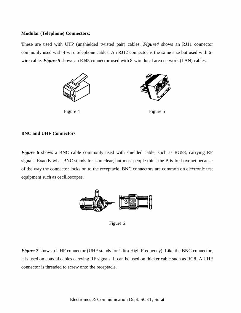
Modular (Telephone) Connectors:
These are used with UTP (unshielded twisted pair) cables. Figure4 shows an RJ11 connector
commonly used with 4-wire telephone cables. An RJ12 connector is the same size but used with 6-
wire cable. Figure 5 shows an RJ45 connector used with 8-wire local area network (LAN) cables.
Figure 4 Figure 5
BNC and UHF Connectors
Figure 6 shows a BNC cable commonly used with shielded cable, such as RG58, carrying RF
signals. Exactly what BNC stands for is unclear, but most people think the B is for bayonet because
of the way the connector locks on to the receptacle. BNC connectors are common on electronic test
equipment such as oscilloscopes.
Figure 6
Figure 7 shows a UHF connector (UHF stands for Ultra High Frequency). Like the BNC connector,
it is used on coaxial cables carrying RF signals. It can be used on thicker cable such as RG8. A UHF
connector is threaded to screw onto the receptacle.

Electronics & Communication Dept. SCET, Surat
Figure 7
D-Shell Connectors
Figure 8A Figure 8B
Figure 8A shows a DB9 connector. Figure 8B shows a so-called Centronics connector commonly
used for the printer port of a PC.
Edge Connector
Figure 9
Figure 9 show a typical connector used to connect to copper traces on the edge of a removable
circuit board.
Insulation Displacement Connectors (IDCs)

Electronics & Communication Dept. SCET, Surat
Figure 10A Figure 10B Figure 10C
Figure 10 shows the types of connectors used with ribbon cables. Figure 10A is a "DIP" connector,
which can plug into a standard IC DIP socket. The connector of Figure 10B mates a "header", which
has pins on 0.1" centers and is common on circuit boards. The connector of Figure 10C is a
"shrouded" header.
Conclusion :