Electrodynamic Gravity Generator
20
American Institute of Aeronautics and Astronautics 1 Electrodynamic Gravity Generator Predrag Jevtovic Bezares S.A., Casarrubios del Monte-Toledo, SPAIN, 45950 Weightless environment is causing numerous deleterious effects on human health. It complicates activities and material handling in space. It is necessary to design a kind of artificial gravity generators as life support systems to enable space exploration and colonization. Rotation is in the focus of all artificial-gravity research as generated centripetal acceleration can be substitute for gravity. The aim is to obtain controlled rotation in order to achieve at least partial levels of artificial gravity. A very effective way to spin objects in space is to use electrodynamic technologies suitable to be optimized and applied in favourable conditions of cold vacuum without gravity. Artificial gravity will provide opportunities for life sciences and advanced technology research. It will enable sustainable exploration and colonization of deep space. Nomenclature a = relative acceleration a cor = Coriolis acceleration a cp = centripetal acceleration B = magnetic induction c = vacuum speed of light E = electric field strength EDGG = electrodynamic gravity generator EDS = electrodynamic suspension EMS = electromagnetic suspension EVA = extra-vehicular activities E A = induced voltage in rotation generator e = loop voltage F P = propulsion force Fx = magnetic drag, X component of the magnetic force between moving SCM and null-flux coil Fy = total guidance force, Y component of the magnetic force between moving SCM and null-flux coil Fz = null-flux centering force, Z component of the magnetic force between moving SCM and null-flux coil g = acceleration due to gravity g a = total artificial gravity acceleration I = loop current I A = armature current in rotation generator I xx , I yy , I zz = principle moments of inertia i = circuit mesh current L = inductance Maglev = magnetic levitation MGS = Mars gravity simulator M s = mutual inductance between SCM and loops of figure-eight null-flux coils pair n = spin rate P A = active power R = resistance r = radial distance from the center of rotation SCM = super conducting magnet SEP = solar electric propulsion Product Manager, Product Department, Av. de las Retamas Parcela: 145-150, Full Member AIAA. Downloaded by Predrag Jevtovic on September 7, 2015 | http://arc.aiaa.org | DOI: 10.2514/6.2015-4613 AIAA SPACE 2015 Conference and Exposition 31 Aug-2 Sep 2015, Pasadena, California AIAA 2015-4613 Copyright © 2015 by Predrag Jevtovic. Published by the American Institute of Aeronautics and Astronautics, Inc., with permission. SPACE Conferences & Exposition
-
Upload
khangminh22 -
Category
Documents
-
view
1 -
download
0
Transcript of Electrodynamic Gravity Generator
American Institute of Aeronautics and Astronautics
1
Electrodynamic Gravity Generator
Predrag Jevtovic Bezares S.A., Casarrubios del Monte-Toledo, SPAIN, 45950
Weightless environment is causing numerous deleterious effects on human health. It complicates activities and material handling in space. It is necessary to design a kind of artificial gravity generators as life support systems to enable space exploration and colonization. Rotation is in the focus of all artificial-gravity research as generated centripetal acceleration can be substitute for gravity. The aim is to obtain controlled rotation in order to achieve at least partial levels of artificial gravity. A very effective way to spin objects in space is to use electrodynamic technologies suitable to be optimized and applied in favourable conditions of cold vacuum without gravity. Artificial gravity will provide opportunities for life sciences and advanced technology research. It will enable sustainable exploration and colonization of deep space.
Nomenclature a = relative acceleration acor = Coriolis acceleration
acp = centripetal acceleration B = magnetic induction c = vacuum speed of light E = electric field strength EDGG = electrodynamic gravity generator EDS = electrodynamic suspension EMS = electromagnetic suspension EVA = extra-vehicular activities EA = induced voltage in rotation generator e = loop voltage FP = propulsion force Fx = magnetic drag, X component of the magnetic force between moving SCM and null-flux coil Fy = total guidance force, Y component of the magnetic force between moving SCM and null-flux coil Fz = null-flux centering force, Z component of the magnetic force between moving SCM and null-flux coil g = acceleration due to gravity ga = total artificial gravity acceleration I = loop current IA = armature current in rotation generator Ixx , Iyy ,Izz = principle moments of inertia i = circuit mesh current L = inductance Maglev = magnetic levitation MGS = Mars gravity simulator Ms = mutual inductance between SCM and loops of figure-eight null-flux coils pair n = spin rate PA = active power R = resistance r = radial distance from the center of rotation SCM = super conducting magnet SEP = solar electric propulsion
Product Manager, Product Department, Av. de las Retamas Parcela: 145-150, Full Member AIAA.
Dow
nloa
ded
by P
redr
ag J
evto
vic
on S
epte
mbe
r 7,
201
5 | h
ttp://
arc.
aiaa
.org
| D
OI:
10.
2514
/6.2
015-
4613
AIAA SPACE 2015 Conference and Exposition
31 Aug-2 Sep 2015, Pasadena, California
AIAA 2015-4613
Copyright © 2015 by Predrag Jevtovic. Published by the American Institute of Aeronautics and Astronautics, Inc., with permission.
SPACE Conferences & Exposition
American Institute of Aeronautics and Astronautics
2
SPS = solar power satellite TRL = technology readiness level WPT = wireless power transfer Δ = Laplace operator v = relative tangential velocity = angular velocity = phase angle between the armature current and induced voltage
I. Introduction EIGHTLESSNESS occurs when all forces applied to a person or object are uniformly distributed as in a uniform gravitational field, or when they are not acted by any force. In orbit and deep space, weightlessness
occurs when an object or person is falling freely. Exposure to weightlessness conditions provokes a significant number of harmful effects on human health and important health concerns: vertigo, nausea, headache, lethargy, skeletal and muscle reconditioning and atrophy, loss of bone mineral density, cardiac problems, lose of heart mass, cardiovascular changes, red blood cell loss, fluid redistribution and loss, weight loss, facial distortion, changes of the immune system, and disruption of vision and taste. There are physiologic problems of adaptation to micro gravity conditions and of renewed adaptation to Earth’s normal gravity conditions. The psychological effects of living in space are stress, insomnia, fatigue, sleep loss, and depression. Weightless environment in space is complicating all human activities and material handling as objects are floating in completely independent orbits. For long-term stays in space it will be needed to achieve at least partial gravity conditions. It is necessary to prove ability to generate gravity with rotation and to show that humans can live and work in artificial gravity conditions. Artificial gravity will provide opportunities for life sciences and advanced technology research. It is necessary to generate artificial gravity sensation to resolve or reduce all or a major part of problems present in weightless conditions in Earth orbit and deep space, and to design a kind of artificial gravity generators as a life support and habitation systems to enable sustainable exploration and colonization of space. Gravity sensation can be induced by the inertial reaction to the centripetal acceleration that acts on a body in circular motion. The most distinguished concept is the one of rotating torus or wheel-shaped habitat to produce artificial gravity by the centripetal force, which always points toward the center of rotation causing objects to behave as if they had weight while inhabitants and objects keep moving in uniform circular motion. Effects of the centripetal force could be accepted as artificial or simulated gravity and the whole system can be seen as artificial gravity generator. The idea of using rotation to create artificial gravity in space was introduced by Konstanin Tsiolkovsky in 1903. Hermann Oberth was the first to use the term space station for a wheel-shaped facility in 1923. By 1929, Hermann Noordung introduced concept of rotating wheel station and suggested it to be positioned in a geostationary orbit. Wernher von Braun and Willy Ley upgraded the idea in the 1950s, popularizing the concept of spinning wheel-shaped station to provide artificial one-third Earth gravity. In 1968 the film “2001: A Space Odyssey“ by Arthur C. Clarke and Stanley Kubrick described spin-generated artificial gravity aboard a space station and on a spaceship.
II. Superconducting Electrodynamic Technologies Applied in Space A very effective way to spin an object in space is to use electrodynamic technologies, as it is cold vacuum without gravity. The aim is to obtain controlled rotation of a habitat and to generate gravity sensation by means of guidance and velocity control by a unified trajectory control system made of propulsion and steering subsystems. Employing superconducting electrodynamic technologies in space could result in development of a new critical technologies to enable human exploration missions and design of human habitats, achieving the old idea of a rotating wheel-shaped space station generating gravity sensation on its inside hull. The term "Maglev" refers to magnetic suspension already in use for Maglev trains, wind generators, and bearings. In trains it is used to enable suspension only with support of electromagnetic fields counteracting the gravitational force. Linear induction motors are used for propulsion. The most distinguished Maglev train technologies are servo-stabilized EMS developed in Germany and EDS systems developed in USA and Japan. EMS is based on attraction forces generated by conventional electromagnets while EDS is based on repulsive forces and it use powerful SCMs. Although EMS energy consumption is lower, obtained gaps in EDS are much larger enabling this technology to be used in circular paths. EMS is unstable and it needs active electronic stabilization while EDS is stable. The superconducting Japanese EDS Maglev trains technology in which vehicle is suspended, guided, and propelled by magnetic forces and fields, is especially suitable to be optimized and applied in space to spin an object by controlled rotation.
W
Dow
nloa
ded
by P
redr
ag J
evto
vic
on S
epte
mbe
r 7,
201
5 | h
ttp://
arc.
aiaa
.org
| D
OI:
10.
2514
/6.2
015-
4613

American Institute of Aeronautics and Astronautics
3
A. Low Temperature and Super conducting Electromagnets Generally accepted temperature in space is approximately 2.725 K or almost -270 Cº that is less then 3 K above absolute zero temperature at which molecules themselves stop moving. Although there are slight variations of this value, it is the accepted temperature in space being so-called cosmic background radiation, which is the energy still left over from the Big Bang. Space is nearly ideal heat sink. Such a low temperature makes very interesting and meaningful use of superconductors in space environment. Superconductivity occurs in certain materials at very low temperatures followed by zero electrical resistance and exclusion of the interior magnetic field (the Meissner effect). Superconductors’ electrical resistance decreases gradually when temperature decreases and drops strongly when the material is cooled below its critical temperature. Their conduction losses are greatly reduced so resultant power densities are considerably increased. The use of superconductors in cables, motors and generators is highly efficient. These materials could carry high levels of the required electrical current, while still meeting lightweight performance requirements. Electrodynamic systems do not need expensive cryogenic systems to cool SCMs in the frigid space environment. SCMs provide powerful electromagnetic fields with strong repulsive forces resulting in larger and safer operating gaps between rotating modules and rotation generators making possible completely contactless and frictionless rotation. Superconductors can conduct electricity even after the power supply is cut off. Use of SCMs in space will be highly economical and with highly improved efficiency.
B. Lack of Gravity Levitation is natural condition in weightless deep space and the only target to achieve is to obtain controlled rotation. Electrodynamically propelled system suited in space will need one and unified trajectory control system to achieve fully controlled rotation for deliberate acceleration that will replace natural gravity in space environment. The only clearances to be controlled are between propelled rotating module and rotation generator. Important technical requirements such as lift-off speed, lift-off force, and weight sensitivity, are senseless. Once achieved fully controlled rotation, the weightlessness conditions will facilitate its maintenance making it highly efficient. Propelled modules have no weight in space so required propulsive power consumption will be reduced as well as a size of implemented SCMs and coils. Gravity sensation generated by rotation will be gradual, starting from zero in the axis of the rotation and ending with designed values in rotating habitats.
C. Vacuum Conditions Outer space is hard vacuum and the closest natural approximation of a perfect vacuum environment. Electromagnetic fields are influenced by matter fields and the influence is specified by Maxwell equations, while matter fields are influenced by electromagnetic fields by the Lorentz force as a feedback. Electrodynamics is a linear theory and electromagnetic vawes in vacuum are determined by the following equations:
01 2
2
B
c t (1)
01 22
E
c t (2)
where c≈3×10⁸ m/s is vacuum speed of light in vacuum, B is magnetic induction, and E is electric field strength. In vacuum both the electric field and the magnetic field obey homogeneous wave equations. No medium is required for propagation of electromagnetic waves as they are able to propagate in vacuum traveling at the speed of light, which increase the efficiency of electromagnetic and electrodynamic technologies in space. Strong magnetic fields generated by superconductors in vacuum conditions will result in smaller SCM. Electrodynamically propelled contactless rotation in space will be completely loss-less and frictionless with highly improved power efficiency.
D. Abundant Solar Energy Space is the most favorable environment for unobstructed use of abundant solar energy. The Sun is unlimited, clean and very convenient energy source. Essentially a vacuum, space itself is a kind of “superconductor” for photon energy transmission. Energy supply needed for an electrodynamically propelled system can be obtained directly from the Sun to convert the energy contained in the Sun’s radiation (mainly light and ultraviolet rays) into electrical power. Energy generation is safe, reliable, renewable, and highly efficient.
Dow
nloa
ded
by P
redr
ag J
evto
vic
on S
epte
mbe
r 7,
201
5 | h
ttp://
arc.
aiaa
.org
| D
OI:
10.
2514
/6.2
015-
4613

American Institute of Aeronautics and Astronautics
4
III. Electrodynamic Rotation Generator General theory of moments for electrodynamic magnetic levitation systems based upon the dynamic circuit principles and emphasized on the loop-shaped coil and the figure-eight-shaped null-flux coil suspension could be modified and fully applied in space. Cross-connected null-flux superconducting EDS technology applied in the Maglev trains technology in Japan is especially suitable to be modified and applied in space. It is characterized by very low magnetic drag at low speed, high suspension stiffness, high lift to drag ratio and high guidance to drag ratio. SCMs suited on the propelled module will spin in a field created by a ring of magnets suited on the guideway. The only clearances to be controlled are those between electrodynamically propelled rotating cylinder-shaped module and the internal cylinder-shaped sidewalls of the non-rotating guideway. Propulsion of the electrodynamic repulsive system can be described as "pull - neutral - push". The propelled module is able to remain centered thanks to a combination of attraction and repulsion forces. Rotation is totally stable without any electronics control thanks to stabilizing Eddy currents induced by permanent magnets. This effect is normally referred to as the electrodynamic repulsion principle. Null-flux and double-layered propulsion coils are suitable to be applied as they allow instantaneous adaptation to changes in the circular trajectory. Generation of controlled magnetic forces and rotating magnetic field between magnetic body (the rotating module) and magnetized body (the rotation generator) will obtain stable, controllable, and contactless rotation.
A. Unified Propulsion and Guidance System Controlled rotation of the rotating module inside of the rotation generator is to be obtained by means of guidance
and velocity control by a unified trajectory control system made of propulsion and steering subsystems. Propulsion is achieved by electrodynamic interactions among SCMs and propulsion coils. Controlled guidance is achieved by electrodynamic interactions between SCMs and null-flux coils. SCMs are sequentially mounted on the outer surface of the rotating module (yellow colored in Fig. 1 and Fig. 2). Null-flux and propulsion coils are sequentially mounted in the inner walls of the rotation generator (red and blue colored in Fig. 1 and Fig. 2). Null-flux coils are assembled above the propulsion coils. SCMs are made out of superconducting coils that are made out of conventional superconductors that require very low temperatures. Permanent currents go through them generating a strong magnetic field that enables both the guidance and the propulsion thanks to their interaction with null-flux and propulsion coils. The coils are closed and the magnetic field they generate is hence constant and does not change over time. The propulsion coils are active and supplied by a source of energy. They can be totally controlled. This means that when the direction and the intensity of the currents going through the propulsion coils are controlled, the sign and the intensity of the created magnetic field are also controlled.
Figure 1. Electrodynamic radial thrust rotation generator. Coils arrangement in the unified propulsion and guidance system.
Figure 2. Coils in the unified propulsion and guidance system.
Dow
nloa
ded
by P
redr
ag J
evto
vic
on S
epte
mbe
r 7,
201
5 | h
ttp://
arc.
aiaa
.org
| D
OI:
10.
2514
/6.2
015-
4613

American Institute of Aeronautics and Astronautics
5
The null-flux coils are not linked to any source of energy. They are short-circuited and completely passive. When the rotating module moves thanks to the propulsion coils, its magnetic field created by superconducting coils scans the null-flux coils inducting currents to flow through them. These inducted currents create a magnetic field that interact with the magnetic fields induced by superconducting coils in the rotating module. The guidance practically does not require any other energy than the energy required for propulsion. So-called figure-eight-shaped null-flux coils similar to those applied in the Japanese EDS Maglev trains could be applied in space to act as trajectory and guidance control coils. They are to be installed on the inner surface of the circular rotation generator guideway and covered with aluminium curved-shaped panels. Each pair of facing eight-shaped coils can be cross-connected by null-flux cable under the guideway constituting a loop as it is shown in Fig. 1 and Fig. 3. This concept includes high guidance-to-drag ratios and very low magnetic drag at low speed. The null flux makes the power losses in the guideway from the induced currents in metal loops very low resulting in smaller magnetic drag forces. The null flux coils enable strong and fast acting trajectory control forces being inherently and passively stable. The coils must have high mechanical strength to bear magnetic forces so they are wound aluminium conductors moulded out of unsaturated polyester resin reinforced with glass fibber and electrical insulated. Radial and axial centering can be achieved by the magnetic field generated by the radial set of null-flux figure-eight-shaped coils (red colored in Fig. 1 and Fig. 2) attached on the inside hull of the rotation generator and the radial set of SCMs (yellow colored in Fig. 1 and Fig. 2) attached on the external surface of the rotating module. Sets of the SCMs jointed in outer aluminium made vessels with incorporated electromagnetic shields, that are radially inserted in the electro-magnetically propelled rotating module, will produce permanent magnetic field. The sets are not to be continually inserted but in facing pairs as it is shown in Fig. (2), (4) and (5). The other magnetic field is induced from the changes of the field that occur as the SCMs moves relative to the radial set of conductors located in the guideway. The relative motion between the rotating module and the rotation generator creates repulsive magnetic fields to hold the two objects apart. As the rotating module rotates, there is voltage induction in the coils due to the relative motion of the magnet-coil system. This voltage creates current flow except at equilibrium position, resulting in a secondary magnetic field in opposition to the change in flux due to relative motion. The unified propulsion and guidance system consists of two identical but independent and fully synchronized rows of electrodynamic sets made of propulsion coils, cross-connected null-flux coils, and SCMs, as shown in Fig.1and Fig. 2. This configuration enables generation of stronger forces and improves capacity of taking higher
Figure 3. Cross-connected null-flux coils arrangement. a) Facing pair of figure-eight-shaped coils cross-connected by null-flux cable constituting a loop. b) Equivalent circuit for the cross-connected null-flux coils. c) Simplified equivalent circuit.
Dow
nloa
ded
by P
redr
ag J
evto
vic
on S
epte
mbe
r 7,
201
5 | h
ttp://
arc.
aiaa
.org
| D
OI:
10.
2514
/6.2
015-
4613

American Institute of Aeronautics and Astronautics
6
radial, axial, and combined loads. It improves favorable self-alignment and high-precision functions in order to achieve stable system configuration, and to improve comfort and security. Interactions among the coils are characterized by strong magnetic fields, which enable larger gap between the rotating module and the rotation generator. The choice of operating gap in space is a design decision. Larger gaps improve safety, allow greater construction tolerances and decrease construction costs. Lower sensitivity is very convenient for circular trajectory and circular paths. The dynamic circuit theory could be extended for nonflat and curved SCMs and coils. Although the null-flux and superconducting coils are usually flat, use of slightly curved gradient coils would allow instantaneous adaptation to changes in the circular trajectory to benefit the electromagnetic fields interactions and the rotation itself. SCMs are not complicated to construct nor to operate. Their curved or “saddle-type” shape is already available. SCM can conduct electricity even after the power supply has been shut off. Magnetic fields induced by SCMs are strong and with serious effects on humans. Their penetration into interior of a habitat must be limited with barriers made of conductive materials as electromagnetic shields to control electromagnetic fields and their dangerous effects. Superconducting materials can expel magnetic fields by the Meissner effect. Protection level directly depends of shield’s material and thickness, volume of the shielded space and existing apertures in it. The guidance subsystem enables radial centering as well as axial centering being stable, high-precision, and self-aligning system. In stable system, any variation from stable position will push it back to designed optimal position without any active electronic stabilization.
B. Propulsion The SCMs suited on the propelled module will get excited and spin in a field created by the ring of the propulsion magnets suited on the rotation generator inner surface. SCMs are made of superconducting coils and energized by three-phase alternating current creating a shifting magnetic field. Alternating current is generating a traveling magnetic field, which moves the rotating module without any contact. The on-board SCMs are attracted and pushed by the shifting field, propelling the rotating module. They are direct current magnets and their fields do not vary with time. Propulsion is achieved when the two magnetic fields are synchronized and locked among them. As a result, the speed of the rotation is proportional to the input frequency of the alternating current. Force that propels the rotation forward is produced by the excitation current in the SCMs and the magnetic field induced by the propulsion magnets. The propulsion force can be controlled by changing the magnitude and the phase angle of armature. The propulsion force FP and active power PA are:
vPF A
P (3)
cos3 AAA IEP (4)
where v is relative tangential velocity, EA is the root mean square of the induced voltage, IA is the root mean square of the armature current and is the phase angle between EA and IA. The propulsion force FP must be stronger then the sum of magnetic drag forces Fx (armature reaction). The magnetic polarity (direction of the magnetic field) of the SCMs alternates along the module. The guideway loops experience an alternating wave of magnetic flux as the rotating module moves. A downward magnetic flux is
Figure 4. Propulsion. SCMs are attracted and pushed by shifting field induced with propulsion coils, propelling the rotating module.
Dow
nloa
ded
by P
redr
ag J
evto
vic
on S
epte
mbe
r 7,
201
5 | h
ttp://
arc.
aiaa
.org
| D
OI:
10.
2514
/6.2
015-
4613
American Institute of Aeronautics and Astronautics
7
followed by an upward flux, then by downward flux, etc. Propulsion of the electrodynamic repulsive system can be described as "pull - neutral - push". The only clearances to be controlled are those between the rotating module and the rotation generator. The propulsion coils are wound aluminum conductors molded out of epoxy resin being electrically insulated and mechanically strong, as they have to persist the reaction force of propulsion and high voltage simultaneously. Undesirable vibrations of the SCMs caused by the magnetic field’s change from propulsion coils and the magnetic drag, can be reduced by implantation of high voltage double-layered propulsion coils. The front and the back coils are different because their distances from the SCMs are different and it is necessary to adjust their numbers of windings. SCMs have been very improved recently making possible adoption of single layered propulsion coil structure with shorter coil length, simpler structure and easier installation being more cost-effective. Elevated number of terminals along the rotation generator guideway and one-touch connectors can simplify the cable connecting. Although the propulsion coils are usually flat, as the path is circular, use of slightly curved gradient coils would allow instantaneous adaptation to changes in the circular trajectory to benefit the electromagnetic fields interactions and the rotation itself. Rotation between the rotating module and the rotation generator is completely contactless.
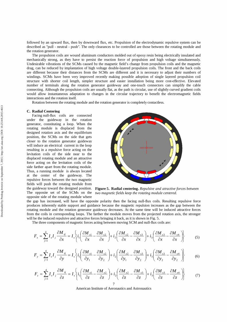
C. Radial Centering Facing null-flux coils are connected under the guideway in the rotation generator, constituting a loop. When the rotating module is displaced from the designed rotation axis and the equilibrium position, the SCMs on the side that gets closer to the rotation generator guideway will induce an electrical current in the loop resulting in a repulsive force acting on the levitation coils of the side near to the displaced rotating module and an attractive force acting on the levitation coils of the side farther apart from the rotating module. Thus, a running module is always located at the center of the guideway. The repulsive forces between the two magnetic fields will push the rotating module from the guideway toward the designed position. The opposite set of the SCMs on the opposite side of the rotating module where the gap has increased, will have the opposite polarity then the facing null-flux coils. Resulting repulsive force produces inherently stable support and guidance because the magnetic repulsion increases as the gap between the rotating module and the rotation generator guideway decreases. At the same time will be induced attractive forces from the coils in corresponding loops. The farther the module moves from the projected rotation axis, the stronger will be the induced repulsive and attractive forces bringing it back, as it is shown in Fig. 5. The three components of magnetic forces acting between moving SCM and null-flux coils are:
xM
xM
ix
Mx
Mi
xM
xM
iIx
MIIF ssssss
ssj
jj
sx43
332
221
1
4
1 (5)
2
4
2
33
2
3
1
22
2
2
1
11
4
1 yM
yM
iy
My
Mi
yM
yM
iIy
MIIF ssssss
ssj
jj
sy (6)
zM
zMi
zM
zMi
zM
zMiI
zM
IIF sssssss
sjj
jsz
433
322
211
4
1 (7)
Figure 5. Radial centering. Repulsive and atractive forces between two magnetic fields keep the rotating module centered.
Dow
nloa
ded
by P
redr
ag J
evto
vic
on S
epte
mbe
r 7,
201
5 | h
ttp://
arc.
aiaa
.org
| D
OI:
10.
2514
/6.2
015-
4613
American Institute of Aeronautics and Astronautics
8
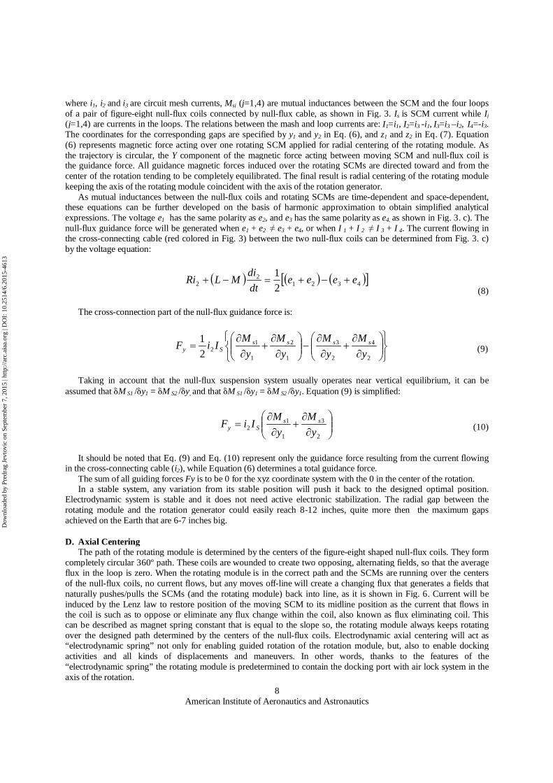
where i1, i2 and i3 are circuit mesh currents, Msj (j=1,4) are mutual inductances between the SCM and the four loops of a pair of figure-eight null-flux coils connected by null-flux cable, as shown in Fig. 3. Is is SCM current while Ij (j=1,4) are currents in the loops. The relations between the mash and loop currents are: I1=i1, I2=i3 -i1, I3=i3 –i2, I4=-i3. The coordinates for the corresponding gaps are specified by y1 and y2 in Eq. (6), and z1 and z2 in Eq. (7). Equation (6) represents magnetic force acting over one rotating SCM applied for radial centering of the rotating module. As the trajectory is circular, the Y component of the magnetic force acting between moving SCM and null-flux coil is the guidance force. All guidance magnetic forces induced over the rotating SCMs are directed toward and from the center of the rotation tending to be completely equilibrated. The final result is radial centering of the rotating module keeping the axis of the rotating module coincident with the axis of the rotation generator. As mutual inductances between the null-flux coils and rotating SCMs are time-dependent and space-dependent, these equations can be further developed on the basis of harmonic approximation to obtain simplified analytical expressions. The voltage e1 has the same polarity as e2, and e3 has the same polarity as e4, as shown in Fig. 3. c). The null-flux guidance force will be generated when e1 + e2 ≠ e3 + e4, or when I 1 + I 2 ≠ I 3 + I 4. The current flowing in the cross-connecting cable (red colored in Fig. 3) between the two null-flux coils can be determined from Fig. 3. c) by the voltage equation:
4321
22 2
1 eeeedtdiMLRi
(8)
The cross-connection part of the null-flux guidance force is:
2
4
2
3
1
2
1
122
1y
My
My
My
MIiF ssssSy (9)
Taking in account that the null-flux suspension system usually operates near vertical equilibrium, it can be assumed that M S1 /y1 = M S2 /y, and that M S1 /y1 = M S2 /y1. Equation (9) is simplified:
2
3
1
12 y
My
MIiF ssSy (10) (8)
It should be noted that Eq. (9) and Eq. (10) represent only the guidance force resulting from the current flowing in the cross-connecting cable (i2), while Equation (6) determines a total guidance force. The sum of all guiding forces Fy is to be 0 for the xyz coordinate system with the 0 in the center of the rotation. In a stable system, any variation from its stable position will push it back to the designed optimal position. Electrodynamic system is stable and it does not need active electronic stabilization. The radial gap between the rotating module and the rotation generator could easily reach 8-12 inches, quite more then the maximum gaps achieved on the Earth that are 6-7 inches big.
D. Axial Centering The path of the rotating module is determined by the centers of the figure-eight shaped null-flux coils. They form completely circular 360º path. These coils are wounded to create two opposing, alternating fields, so that the average flux in the loop is zero. When the rotating module is in the correct path and the SCMs are running over the centers of the null-flux coils, no current flows, but any moves off-line will create a changing flux that generates a fields that naturally pushes/pulls the SCMs (and the rotating module) back into line, as it is shown in Fig. 6. Current will be induced by the Lenz law to restore position of the moving SCM to its midline position as the current that flows in the coil is such as to oppose or eliminate any flux change within the coil, also known as flux eliminating coil. This can be described as magnet spring constant that is equal to the slope so, the rotating module always keeps rotating over the designed path determined by the centers of the null-flux coils. Electrodynamic axial centering will act as “electrodynamic spring” not only for enabling guided rotation of the rotation module, but, also to enable docking activities and all kinds of displacements and maneuvers. In other words, thanks to the features of the “electrodynamic spring” the rotating module is predetermined to contain the docking port with air lock system in the axis of the rotation.
Dow
nloa
ded
by P
redr
ag J
evto
vic
on S
epte
mbe
r 7,
201
5 | h
ttp://
arc.
aiaa
.org
| D
OI:
10.
2514
/6.2
015-
4613

American Institute of Aeronautics and Astronautics
9
The sum of all null-flux centering forces Fz that are induced in all facing sets of the SCMs and the null-flux coils is to be zero for the xyz coordinate system with the center suited in the center of the rotation. At slow speed, the current induced in the coils by the slow change in magnetic flux with respect to time, is not big. Maglev EDS trains needs strong forces to levitate trains, and they can be induced only at high speeds. EDGG as a low speed electrodynamic system is to be suited in space and act in favorable conditions of frigid vacuum without gravity where system efficiency is going to be strongly improved. Induced currents and generated forces will be twice bigger as the unified propulsion and guidance system consists of two identical and fully synchronized rows of electrodynamic sets, as it is shown in Fig.1and Fig. 2.
E. Design Varieties It is possible to develop three different designs of the electrodynamic rotation generator respecting all basic principles already described for the case of the radial thrust rotation generator. The only difference is in arrangement of SCMs, null-flux coils and propulsion coils. The three different designs of the electrodynamic rotation generators are: - Radial thrust rotation generator. - Axial thrust rotation generator. - Combined axial/radial thrust rotation generator. The radial thrust rotation generator is previously described. It is the "inner version" as the rotating module is rotating inside the rotation generator module. It is also possible to develop "outer version" with the rotating module rotating around the rotation generator, but in this case it will be lost the advantage of docking with the rotation generator, elaborated in the Chapter IV. The axial thrust rotation generator includes the cross-connected figure-eight-shaped null-flux coils and the propulsion coils suited on the both circular walls of the rotation generator and SCMs suited on the both faces of the cylindrical-shaped rotating module as shown in Fig. 7. The coils and the SCMs need to be modified, asymmetrical and curved shaped with the lateral sides converging in accordance with the radius of the rotation. The axial thrust rotation generator would have stable propulsion and guidance, but the axial centering would be slightly more difficult to obtain.
The axial/radial thrust rotation generator combines both concepts to obtain higher precision and to increase power to move larger structures. Their action would be fully synchronized and the sets of coils and SCMs would be on a correspondent distance to avoid their interactions.
Figure 7. Electrodynamic axial thrust rotation generator. Coils arrangement.
Figure 6. Axial centering. Rotating module remains centered over designed path thanks to attraction and repulsion forces between null-flux coils and displaced SCM. Electrodynamic spring.
Dow
nloa
ded
by P
redr
ag J
evto
vic
on S
epte
mbe
r 7,
201
5 | h
ttp://
arc.
aiaa
.org
| D
OI:
10.
2514
/6.2
015-
4613
American Institute of Aeronautics and Astronautics
10
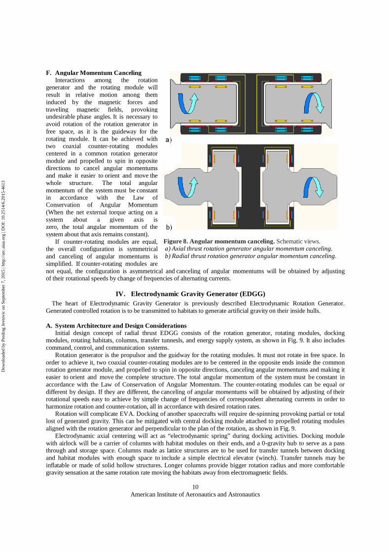
F. Angular Momentum Canceling Interactions among the rotation generator and the rotating module will result in relative motion among them induced by the magnetic forces and traveling magnetic fields, provoking undesirable phase angles. It is necessary to avoid rotation of the rotation generator in free space, as it is the guideway for the rotating module. It can be achieved with two coaxial counter-rotating modules centered in a common rotation generator module and propelled to spin in opposite directions to cancel angular momentums and make it easier to orient and move the whole structure. The total angular momentum of the system must be constant in accordance with the Law of Conservation of Angular Momentum (When the net external torque acting on a system about a given axis is zero, the total angular momentum of the system about that axis remains constant). If counter-rotating modules are equal, the overall configuration is symmetrical and canceling of angular momentums is simplified. If counter-rotating modules are not equal, the configuration is asymmetrical and canceling of angular momentums will be obtained by adjusting of their rotational speeds by change of frequencies of alternating currents.
IV. Electrodynamic Gravity Generator (EDGG) The heart of Electrodynamic Gravity Generator is previously described Electrodynamic Rotation Generator.
Generated controlled rotation is to be transmitted to habitats to generate artificial gravity on their inside hulls.
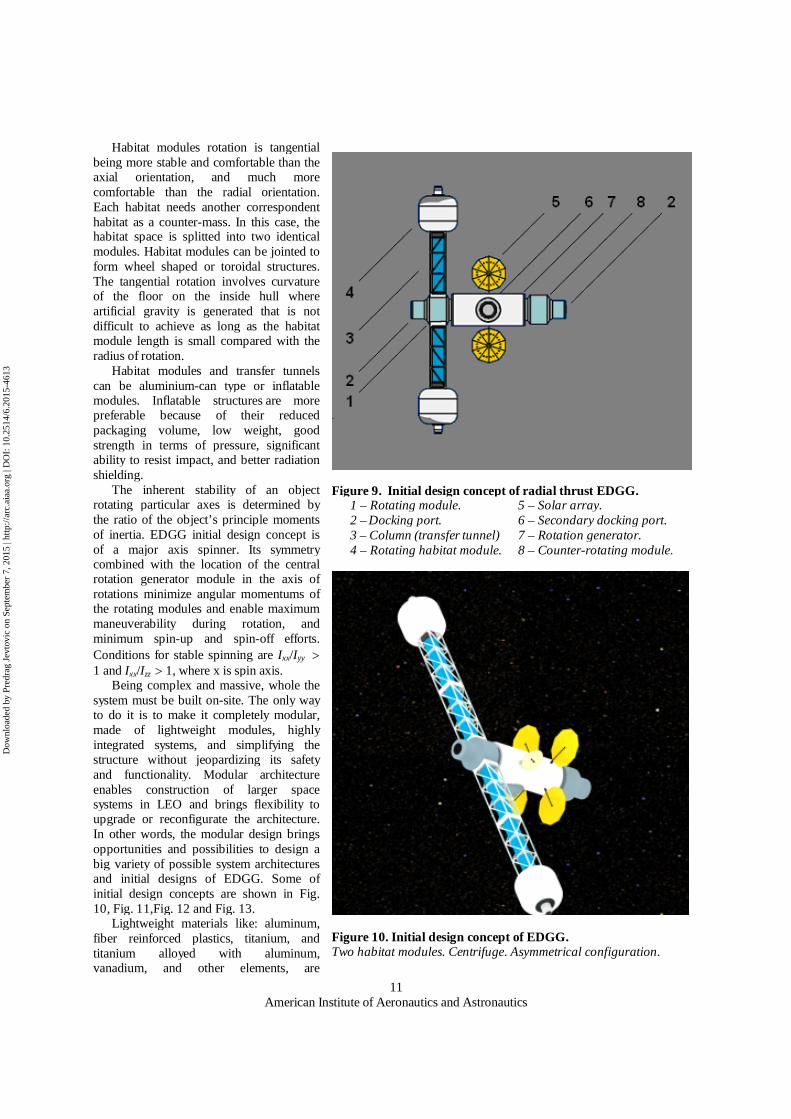
A. System Architecture and Design Considerations Initial design concept of radial thrust EDGG consists of the rotation generator, rotating modules, docking modules, rotating habitats, columns, transfer tunnesls, and energy supply system, as shown in Fig. 9. It also includes command, control, and communication systems. Rotation generator is the propulsor and the guidway for the rotating modules. It must not rotate in free space. In order to achieve it, two coaxial counter-rotating modules are to be centered in the opposite ends inside the common rotation generator module, and propelled to spin in opposite directions, canceling angular momentums and making it easier to orient and move the complete structure. The total angular momentum of the system must be constant in accordance with the Law of Conservation of Angular Momentum. The counter-rotating modules can be equal or different by design. If they are different, the canceling of angular momentums will be obtained by adjusting of their rotational speeds easy to achieve by simple change of frequencies of correspondent alternating currents in order to harmonize rotation and counter-rotation, all in accordance with desired rotation rates. Rotation will complicate EVA. Docking of another spacecrafts will require de-spinning provoking partial or total lost of generated gravity. This can be mitigated with central docking module attached to propelled rotating modules aligned with the rotation generator and perpendicular to the plan of the rotation, as shown in Fig. 9. Electrodynamic axial centering will act as “electrodynamic spring” during docking activities. Docking module with airlock will be a carrier of columns with habitat modules on their ends, and a 0-gravity hub to serve as a pass through and storage space. Columns made as lattice structures are to be used for transfer tunnels between docking and habitat modules with enough space to include a simple electrical elevator (winch). Transfer tunnels may be inflatable or made of solid hollow structures. Longer columns provide bigger rotation radius and more comfortable gravity sensation at the same rotation rate moving the habitats away from electromagnetic fields.
Figure 8. Angular momentum canceling. Schematic views. a) Axial thrust rotation generator angular momentum canceling. b) Radial thrust rotation generator angular momentum canceling.
Dow
nloa
ded
by P
redr
ag J
evto
vic
on S
epte
mbe
r 7,
201
5 | h
ttp://
arc.
aiaa
.org
| D
OI:
10.
2514
/6.2
015-
4613
American Institute of Aeronautics and Astronautics
11
Habitat modules rotation is tangential being more stable and comfortable than the axial orientation, and much more comfortable than the radial orientation. Each habitat needs another correspondent habitat as a counter-mass. In this case, the habitat space is splitted into two identical modules. Habitat modules can be jointed to form wheel shaped or toroidal structures. The tangential rotation involves curvature of the floor on the inside hull where artificial gravity is generated that is not difficult to achieve as long as the habitat module length is small compared with the radius of rotation. Habitat modules and transfer tunnels can be aluminium-can type or inflatable modules. Inflatable structures are more preferable because of their reduced packaging volume, low weight, good strength in terms of pressure, significant ability to resist impact, and better radiation shielding.
The inherent stability of an object rotating particular axes is determined by the ratio of the object’s principle moments of inertia. EDGG initial design concept is of a major axis spinner. Its symmetry combined with the location of the central rotation generator module in the axis of rotations minimize angular momentums of the rotating modules and enable maximum maneuverability during rotation, and minimum spin-up and spin-off efforts. Conditions for stable spinning are Ixx/Iyy 1 and Ixx/Izz 1, where x is spin axis. Being complex and massive, whole the system must be built on-site. The only way to do it is to make it completely modular, made of lightweight modules, highly integrated systems, and simplifying the structure without jeopardizing its safety and functionality. Modular architecture enables construction of larger space systems in LEO and brings flexibility to upgrade or reconfigurate the architecture. In other words, the modular design brings opportunities and possibilities to design a big variety of possible system architectures and initial designs of EDGG. Some of initial design concepts are shown in Fig. 10, Fig. 11,Fig. 12 and Fig. 13. Lightweight materials like: aluminum, fiber reinforced plastics, titanium, and titanium alloyed with aluminum, vanadium, and other elements, are
Figure 9. Initial design concept of radial thrust EDGG. 1 – Rotating module. 5 – Solar array. 2 – Docking port. 6 – Secondary docking port. 3 – Column (transfer tunnel) 7 – Rotation generator. 4 – Rotating habitat module. 8 – Counter-rotating module.
Figure 10. Initial design concept of EDGG. Two habitat modules. Centrifuge. Asymmetrical configuration.
Dow
nloa
ded
by P
redr
ag J
evto
vic
on S
epte
mbe
r 7,
201
5 | h
ttp://
arc.
aiaa
.org
| D
OI:
10.
2514
/6.2
015-
4613
American Institute of Aeronautics and Astronautics
12
appropriate and suitable to be applied. Principal modules are to be equipped with propulsion units for maneuvering activities, especially important in the assembly phase during which will be needed high-precision maneuvers. Also, they could be used to move the whole structure to other orbits, even to transform it to spaceship. It is necessary to design an emergency system for a hypothetical situation of total power cut off, in order to prevent separation of the rotating module and the rotation generator. It can be managed by a set of swing or linear arms delimiters made of permanent magnets, radially suited in the entrance of the rotation generator module and moved by power packs with autonomous batteries. This system will be possible to use in a hypothetical case of a deliberate rotation abort. The EDGG structure will be suitable to carry photovoltaic panels, batteries and communication systems. As there is no contact between the rotation generator and rotating modules, they need to be equipped with independent photovoltaic panels, electrochemical cells, and rechargeable batteries. Rotation Generator module could be made as compact hollow structure, and also as lattice structure in order to reduce costs.
Gravity generation is gradual, starting from zero in the docking module and in the rotation generator, raising inside the transfer tunnels, and ending with designed gravity levels in the habitats. It can be adjustable by changing of rotation speed by change of AC frequency. It is low-speed rotation, self-aligning, high precision, and noiseless system. The EDGG concept is low speed and light version of EDS system. Rotation is uniformed, completely contactless and practically loss-less while vibration, wobble, and shaking are mostly eliminated. Rotations in it are induced by traveling magnetic fields in space, being completely contactless and frictionless causing minimal environmental impact on the environment. Completely contactless rotation will make whole the system simpler and easier for maintenance and control. Electrodynamicaly propelled rotating system architectures such as EDGG are stable and there is no need for active
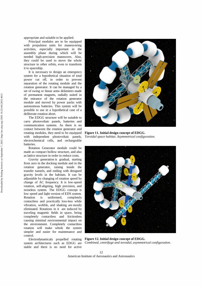
Figure 12. Initial design concept of EDGG. Combined, centrifuge and toroidal, asymmetrical configuration.
Figure 11. Initial design concept of EDGG. Toroidal space habitat. Asymmetrical configuration.
Dow
nloa
ded
by P
redr
ag J
evto
vic
on S
epte
mbe
r 7,
201
5 | h
ttp://
arc.
aiaa
.org
| D
OI:
10.
2514
/6.2
015-
4613
American Institute of Aeronautics and Astronautics
13
electronic stabilization. Magnetic drag is very low at low speed rotation and propulsion forces will easily overcome it. It will not produce oscillations in flexible components of the non-rotating part of the system nor there will be internal frictions provoking energy dissipations and causing increase of the wobbling amplitude. Active and passive control systems will be reduced and shock absorbers are not going to be needed. The system will not require absolute mass equilibrium (although it is desirable) and there is no need that every component must have a counter balance. The structures are to be fixed in order to disable unpreviewed changes in distribution of weights. The EDGG is high-precision system able to provide stable rotation over its 360 degrees of movement. Spin-up and spin-off requirements for docking activities are easy to meet by simple change of alternating currents frequencies. Radiation shielding against solar flare serves as radiation shielding against strong magnetic fields. Radiation shields are to be incorporated in the walls of all modules and habitats with the crew presence.
B. Spin Rate and Geometry Design The total artificial gravity acceleration inside a rotating space habitat can be expressed as the vector sum of the
centripetal acceleration, the relative acceleration and the Coriolis acceleration:
vdtvdraaag corcpa 2/)( (11)
where ga is total artificial gravity acceleration, acp is centripetal acceleration, a is relative acceleration and acor is Coriolis acceleration. Centripetal acceleration is independent of the relative motion of objects inside the rotating habitat. It is radial and directed toward the rotation axis:
)( ra cp (12)
where is angular velocity and r is radial distance from the center of rotation. Relative acceleration is the first derivative of the velocity as a function of time and the second derivative of the position as a function of time:
dtvda / (13)
Coriolis acceleration is proportional to the vector product of the rotating habitat angular velocity and the object's relative velocity and it is perpendicular to them:
va cor 2 (14)
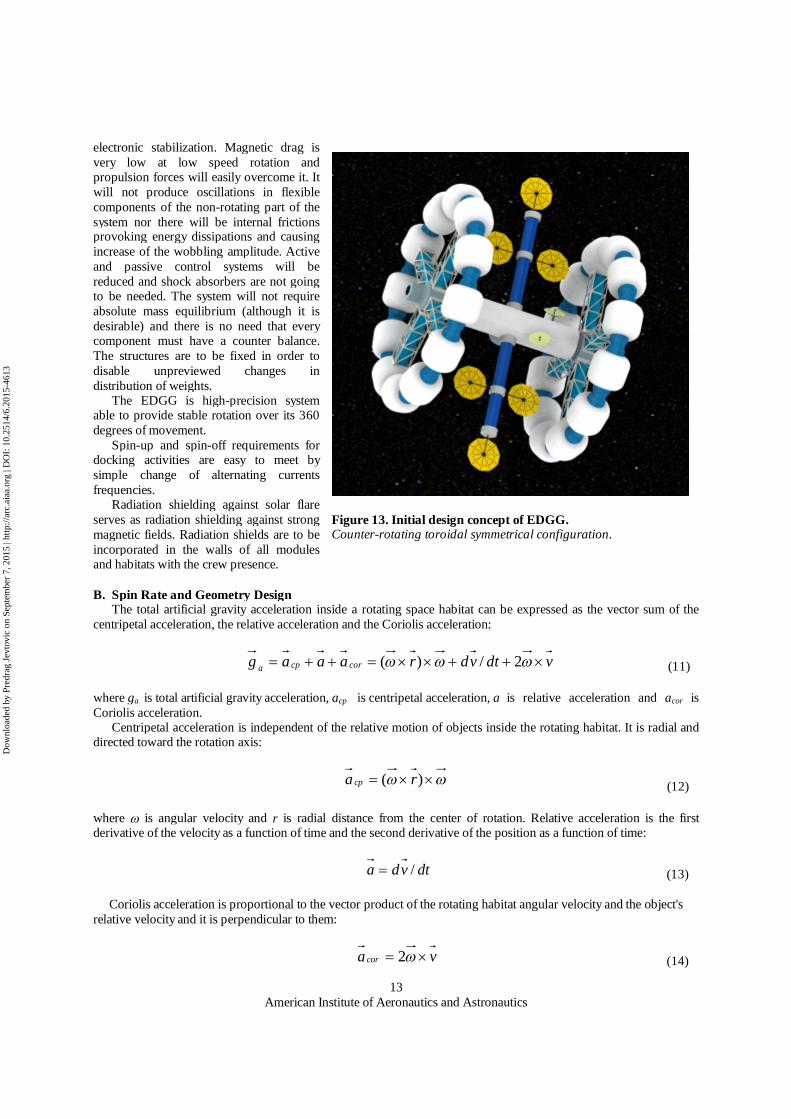
Figure 13. Initial design concept of EDGG. Counter-rotating toroidal symmetrical configuration.
Dow
nloa
ded
by P
redr
ag J
evto
vic
on S
epte
mbe
r 7,
201
5 | h
ttp://
arc.
aiaa
.org
| D
OI:
10.
2514
/6.2
015-
4613

American Institute of Aeronautics and Astronautics
14
where is angular velocity and v is relative tangential velocity. The magnitude of the nominal artificial gravity sensation in a rotating space station can be expressed by its centripetal acceleration where the artificial gravity force is equal to the centripetal force. Centripetal acceleration depends only of the angular velocity of the rotating object and its radial distance from the rotation axis, becoming larger for greater speed and smaller radius. Less radius means less total weight and implies less launching and material costs. Effects of the centripetal force could be accepted as artificial or simulated gravity and the whole system can be accepted as artificial gravity generator. Artificial gravity environments can be determined in terms of four parameters: artificial gravity acceleration equal to the centripetal acceleration, radial distance from the center of rotation, rotation rate, and tangential velocity. Equations (15) and (16) are showing relations among these parameters:
rvacp /2 (15)
)01097.0/( 2ngr a (16)
where acp is centripetal acceleration, v is relative tangential velocity, r is radial distance from the center of rotation, ga is total artificial gravity acceleration, and n is spin rate. The relative radial velocity of the rotating habitat is higher then the relative radial velocity of the rotating module. Fig. 14 and Fig. 15 are showing tangential velocity of the rotating habitat and the rotation radius as functions of the rotation rate, for desired values of artificial gravity acceleration sensation.
Rotation can cause important problems including the Coriolis forces provoked by any movement unparallel to the rotation axis. If a head is moved into a plane different then the plane of rotation, the inner-ear fluid movement keeps in the previous plane giving a disorienting and nauseating sense of rotation in the new plane. This sensation becomes worse with higher rotation rates and shorter radius of rotation. The Coriolis acceleration is constant and perpendicular to the floor surface while the centripetal acceleration is always directed toward the center of rotation.
Angle and magnitude of the centripetal acceleration change in accordance with changes of the inhabitant’s position. Point of convergence of the total acceleration is offset from the center of rotation by the Coriolis acceleration component. To obtain healthiest gravity it is needed to reduce the Coriolis forces to acceptable levels corresponded to the spin rate between 1 and 2 rpm and to increase the habitat’s tangential velocity. Taking in account the effects of the Coriolis forces and referring to Eq. (14) it results that to produce the Earth normal gravity sensation (1g) with 2 rpm rate of spin, the radius of rotation has to be at least 734 feet (224 meters) with the tangential velocity of approximately 105 miles/hour (168 kilometers/hour). It is too ambitious in the short-term, but some steps
Figure 14. Rotation radius as a function of rotation rate.
Figure 15. Tangential velocity as a function of rotation rate.
Dow
nloa
ded
by P
redr
ag J
evto
vic
on S
epte
mbe
r 7,
201
5 | h
ttp://
arc.
aiaa
.org
| D
OI:
10.
2514
/6.2
015-
4613
American Institute of Aeronautics and Astronautics
15
could be made in the years to come making a smaller and cost-effective artificial gravity generators. The centripetal acceleration must have some minimum value to guarantee practical advantages of the artificial gravity. How much of artificial gravity is needed for long and healthy stays in space? Is there optimal gravity level? Research should determine the acceptable combination of gravity level and duration of the artificial gravity stimulus, and the effects of transition to a different gravity levels. Inferior levels of gravity sensation could be also acceptable being more cost-effective to achieve them. Higher rotation rates then 2 rpm will reduce favorable 734 feet radius still producing acceptable levels of the Coriolis forces. A variety of experiments performed on people shown the following results: - Min. radius: 39.4 feet (12 meters). - Maximum rotation rate: 3 - 6 rpm. - Comfortable centripetal acceleration: 0,3•g - 1,0•g. - Min. tangential velocity: 32.8 feet/second (10 meters/second) or 22.4 miles/hour (36 kilometers/hour).
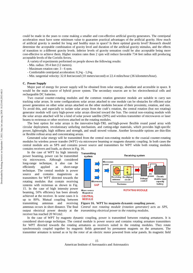
C. Power Supply Major part of energy for power supply will be obtained from solar energy, abundant and accessible in space. It would be the main source of hybrid power system. The secondary sources are to be: electrochemical cells and rechargeable DC batteries. Two coaxial counter-rotating modules and the common rotation generator module are suitable to carry sun tracking solar arrays. In some configurations solar arrays attached to one module can be obstacles for efficient solar power generation on other solar arrays attached on the other modules because of their proximity, rotation, and size. To avoid this, and especially to isolate solar arrays from the craft’s rotation, the central rotation (but not rotating) generator module will carry high-power solar arrays directed toward the Sun. The central non-rotating module with the solar arrays attached will be a kind of solar power satellite (SPS) and wireless transmitter of microwaves or laser beams to rectennas or other receivers attached on the rotating modules. The best option for solar arrays is the innovative high-TRL and high-power flexible round panel array with circular deployment, revolutionary unfurling mechanism, and cutting-edge materials, which provides high specific power, lightweight, high stiffness and strength, and small stowed volume. Another favourable options are thin-film or flexible rollout array and concentrating arrays. Generated solar energy will be transmitted from the central non-rotating module to the coaxial counter-rotating modules by wireless power transfer (WPT) via microwave beaming or magneto dynamic coupling. In both cases the central module acts as SPS and contains power source and transmitters for WPT while both rotating modules contains receivers and loads, as shown in Fig. 16.
In the case of WPT by high intensity power beaming, power can be transmitted via microwaves. Although considered long-range technique, it also can be efficiently applied as short-range technique. The central module is power source and contains magnetrons as transmitters for WPT directed towards the rotating modules that contain receiving systems with rectennas as shown in Fig. 15. In the case of high intensity power beaming, 50% efficiency has been already achieved at the receiver. In some cases it is up to 80%. Mutual coupling between transmitting antennas and receiving antennas occurs in short distance. The final output electrical power density at the receiver has reached 20 W/cm2. In the case of WPT by magneto dynamic coupling, power is transmitted between rotating armatures. It is considered short-range technique. The central module is power source and contains rotating armature transmitters for WPT directed towards the rotating armatures as receivers suited in the rotating modules. They rotate synchronously coupled together by magnetic fields generated by permanent magnets on the armatures. The transmitter armature is turned as or by the rotor of an electric motor powered from solar panels. Its magnetic field
Figure 16. WPT by magneto dynamic coupling power. Central non rotating module (rotation generator) acts as SPS, transmitting electrical power to the rotating modules.
Dow
nloa
ded
by P
redr
ag J
evto
vic
on S
epte
mbe
r 7,
201
5 | h
ttp://
arc.
aiaa
.org
| D
OI:
10.
2514
/6.2
015-
4613
American Institute of Aeronautics and Astronautics
16
exerts torque on the receiver armatures in both rotating modules and turns them. The receiver armature produces power by turning a separate electric generator or by using the receiver armature as the rotor in a generator. Photovoltaic energy in solar panels is converted to direct current (DC) electricity. Fuel cells’ output is also DC. Generated electricity can be converted from one voltage level to another by DC/DC converters. Inverters transform DC electricity to AC electricity that can be transformed to high voltage AC electricity by means of electrical transformers. AC from inverters can operate AC equipment or it can be rectified to produce DC at any desired voltage. Electrochemical cells that convert stored chemical energy into electrical energy could be used to store energy and generate power on-board and independently in all the modules: two coaxial counter-rotating modules and the common rotation generator module, and also in the rotating habitats. Systems that bring high-energy batteries together with a high-power cell, or potentially a combination with fuel cells, are envisioned to be key enablers of electric propulsion. Extremely low temperatures may help electric technologies reach new heights. This configuration represents an initial starting point for future optimisation, with research based on assumptions for expected long-term developments of superconducting and energy storage capabilities as key enablers. Energy can storage in nickel-hydrogen or lithium-ion rechargeable DC batteries to provide a continuous power source. Batteries and fuel cells ensure that EDGG is never without power. Power systems for human habitats in space will benefit significantly from batteries with large storage capability and high specific energy. Regenerative fuel systems are suitable for large-scale energy storage applications such as space habitats, requiring 10’ of kW of electrical power and enhanced by high specific energy, high charge/discharge efficiency (up to 70%), high reliability, and long life capability (approximately 10,000 hours). The major subsystems of regenerative fuel cell systems are: fuel cell, electrolyser, reactant storage, thermal management, and control. Electric power system is to be designed for operation with oxygen and to be optimised for multi-gravity environment operations, and for thermal and water management. Liquid hydrogen and liquid oxygen (LOX) storage in space does not require cryogenic storage but only pressurized conditions. In addition, liquid hydrogen and liquid oxygen as oxidizer are commonly used as liquid rocket fuel in H2/02 rocket engines that could be used for propulsion of space station or spaceship.
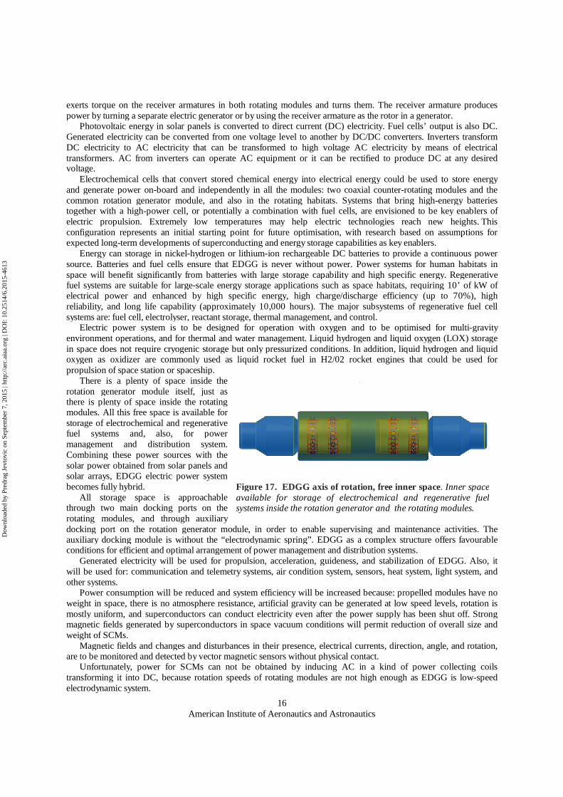
There is a plenty of space inside the rotation generator module itself, just as there is plenty of space inside the rotating modules. All this free space is available for storage of electrochemical and regenerative fuel systems and, also, for power management and distribution system. Combining these power sources with the solar power obtained from solar panels and solar arrays, EDGG electric power system becomes fully hybrid. All storage space is approachable through two main docking ports on the rotating modules, and through auxiliary docking port on the rotation generator module, in order to enable supervising and maintenance activities. The auxiliary docking module is without the “electrodynamic spring”. EDGG as a complex structure offers favourable conditions for efficient and optimal arrangement of power management and distribution systems. Generated electricity will be used for propulsion, acceleration, guideness, and stabilization of EDGG. Also, it will be used for: communication and telemetry systems, air condition system, sensors, heat system, light system, and other systems. Power consumption will be reduced and system efficiency will be increased because: propelled modules have no weight in space, there is no atmosphere resistance, artificial gravity can be generated at low speed levels, rotation is mostly uniform, and superconductors can conduct electricity even after the power supply has been shut off. Strong magnetic fields generated by superconductors in space vacuum conditions will permit reduction of overall size and weight of SCMs. Magnetic fields and changes and disturbances in their presence, electrical currents, direction, angle, and rotation, are to be monitored and detected by vector magnetic sensors without physical contact. Unfortunately, power for SCMs can not be obtained by inducing AC in a kind of power collecting coils transforming it into DC, because rotation speeds of rotating modules are not high enough as EDGG is low-speed electrodynamic system.
Figure 17. EDGG axis of rotation, free inner space. Inner space available for storage of electrochemical and regenerative fuel systems inside the rotation generator and the rotating modules.
Dow
nloa
ded
by P
redr
ag J
evto
vic
on S
epte
mbe
r 7,
201
5 | h
ttp://
arc.
aiaa
.org
| D
OI:
10.
2514
/6.2
015-
4613

American Institute of Aeronautics and Astronautics
17
D. EDGG Superstructures Orbital facilities such as hotels, laboratories, factories, space solar power infrastructures, and depots with incorporated electrodynamic gravity generators could be built in LEO, and moved to different orbits, or to be transformed into spaceships for human exploration missions.
EDGG structures could be completely independent or fully incorporated into other space structures like space station or spaceship, by attaching of the rotation generator to existing structures and leaving the docking module free for docking and for the EVA. Basic configuration of EDGG can be upgraded by multiplying of the basic structure along the common rotation axis in order to obtain synchronized rotation and to increase the capability to spin larger structures, including complex cylinder-shaped habitat structure with highly increased over-all capacities. EDGG structures and superstructures could be movable by propulsion packs attached to the non-rotating module. SEP, rocket, or some other kind of propulsion could be located along the rotation axis normal to the path plane of the rotating habitats, transforming a space station for long-term human stay in deep space into a spaceship for long-term space trips with humans on board. Electrodynamic guidness and propulsion will be highly effective in space and propulsion packs will move complete structures without interruptions of centrifuges, continuously generating artificial gravity on the inside hull of the rotating habitat modules. Electrodynamic centering will act continuously and the electrodynamic spring will be active during docking and all other maneuvers.
E. EDGG Ministructures Electrodynamic technologies can be applied for on-board centrifuge devices in a form of a ring-shaped axial-thrust rotating modules suited inside non-rotating space habitats without artificial gravity, without being obstacle for the crew. Rotation generator coils will be inserted in the inner walls of a space habitat, being electrically powered directly from the existing general power supply. The contacless rotating inner ring module would carry SCMs and rechargeable batteries. Unified guidance and rotation control will be simplified and with ample range of rotation rates. Although low-power system, it will be needed to apply a kind of radioactive shield. Rotating inner modules would be suitable for a great variety of cost-effective experiments for science and research activities (biology and
Figure 19. Concept of inner rotating module. Space greenhouse.
Figure 18. Spaceship with EDGG and SEP. Initial design concept.
Dow
nloa
ded
by P
redr
ag J
evto
vic
on S
epte
mbe
r 7,
201
5 | h
ttp://
arc.
aiaa
.org
| D
OI:
10.
2514
/6.2
015-
4613
American Institute of Aeronautics and Astronautics
18
biotechnology, physical and material sciences, etc.), and for huge variety of Intra-Vehicular Activities (IVA). On-board rotating module could be used as a greenhouse for space agriculture applying hydroponics and grow lights for stable and high yields. Centripetal forces will constantly push liquid solution and plants towards the inside hull of the rotating module, provoking gravity sensation. Rotation enables continuous-flow solution hydroponics culture where the nutrient solution constantly flows passing the roots of the plants. Nutrition levels are controllable. Filtration and harvest are easy. Grow lights will provide high photosynthetic efficiency during the entire life cycle of plants increasing their yield and vitality. Fig. 19 shows rotating greenhouse with grow lights inside space habitat without being obstacle for the crew.
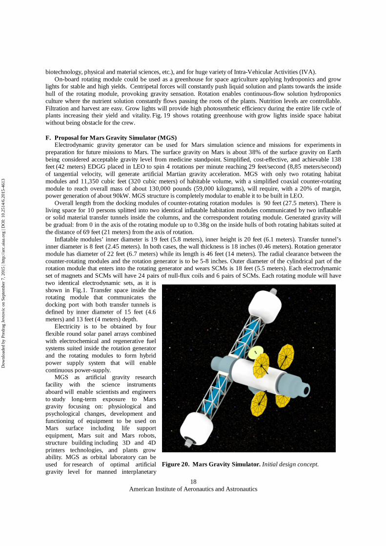
F. Proposal for Mars Gravity Simulator (MGS) Electrodynamic gravity generator can be used for Mars simulation science and missions for experiments in preparation for future missions to Mars. The surface gravity on Mars is about 38% of the surface gravity on Earth being considered acceptable gravity level from medicine standpoint. Simplified, cost-effective, and achievable 138 feet (42 meters) EDGG placed in LEO to spin 4 rotations per minute reaching 29 feet/second (8,85 meters/second) of tangential velocity, will generate artificial Martian gravity acceleration. MGS with only two rotating habitat modules and 11,350 cubic feet (320 cubic meters) of habitable volume, with a simplified coaxial counter-rotating module to reach overall mass of about 130,000 pounds (59,000 kilograms), will require, with a 20% of margin, power generation of about 90kW. MGS structure is completely modular to enable it to be built in LEO. Overall length from the docking modules of counter-rotating rotation modules is 90 feet (27.5 meters). There is living space for 10 persons splitted into two identical inflatable habitation modules communicated by two inflatable or solid material transfer tunnels inside the columns, and the correspondent rotating module. Generated gravity will be gradual: from 0 in the axis of the rotating module up to 0.38g on the inside hulls of both rotating habitats suited at the distance of 69 feet (21 meters) from the axis of rotation. Inflatable modules’ inner diameter is 19 feet (5.8 meters), inner height is 20 feet (6.1 meters). Transfer tunnel’s inner diameter is 8 feet (2.45 meters). In both cases, the wall thickness is 18 inches (0.46 meters). Rotation generator module has diameter of 22 feet (6.7 meters) while its length is 46 feet (14 meters). The radial clearance between the counter-rotating modules and the rotation generator is to be 5-8 inches. Outer diameter of the cylindrical part of the rotation module that enters into the rotating generator and wears SCMs is 18 feet (5.5 meters). Each electrodynamic set of magnets and SCMs will have 24 pairs of null-flux coils and 6 pairs of SCMs. Each rotating module will have two identical electrodynamic sets, as it is shown in Fig.1. Transfer space inside the rotating module that communicates the docking port with both transfer tunnels is defined by inner diameter of 15 feet (4.6 meters) and 13 feet (4 meters) depth.
Electricity is to be obtained by four flexible round solar panel arrays combined with electrochemical and regenerative fuel systems suited inside the rotation generator and the rotating modules to form hybrid power supply system that will enable continuous power-supply. MGS as artificial gravity research facility with the science instruments aboard will enable scientists and engineers to study long-term exposure to Mars gravity focusing on: physiological and psychological changes, development and functioning of equipment to be used on Mars surface including life support equipment, Mars suit and Mars robots, structure building including 3D and 4D printers technologies, and plants grow ability. MGS as orbital laboratory can be used for research of optimal artificial gravity level for manned interplanetary
Figure 20. Mars Gravity Simulator. Initial design concept.
Dow
nloa
ded
by P
redr
ag J
evto
vic
on S
epte
mbe
r 7,
201
5 | h
ttp://
arc.
aiaa
.org
| D
OI:
10.
2514
/6.2
015-
4613

American Institute of Aeronautics and Astronautics
19
travel. It is vital to deploy, test, and utilize it in LEO, shortening development time and reducing the costs. MGS as artificial gravity space station suited in LEO is a feasible project that can return valuable information
about the ability of humans to travel and live in space contributing to develop manned missions to Mars. Years of research will be needed to reach a TRL compatible with manned trip to Mars. Without the proper research and development, the first human mission to Mars will have to go without artificial gravity.
V. Conclusion Use of electrodynamic technologies in deep space favorable conditions of cold vacuum without gravity would enable development of critical life-support artificial gravity technologies. Spinning space habitats will realize the old idea of a rotating wheel-shaped space station generating gravity sensation on its inside hull induced by deliberate acceleration for replacing natural gravity. Artificial gravity will enable human exploration missions in deep space. Much work remains to be done and many questions are to be answered before artificial gravity becomes reality. The emergence of space tourism could impulse realization of an orbital space settlement. Well equipped with scientific and life support equipment, artificial gravity generators could be flexible exploration systems capable to proportionate a lots of knowledge important for all future steps in space, offering conditions for a big variety of possible experiments over behavior of objects, liquids, humans, animals, and plants. Artificial gravity could enable food production in space. Human habitats with a variable gravity would determine the effects of living in lunar or Martian conditions. Orbital facilities such as laboratories, factories, hotels, and depots will impulse scientific research, manufacturing, space tourism, space solar power infrastructure, refueling and repair operations, and the like. Space station with gravity generator could be built in situ, and moved to a variety of orbits, even to be transformed into space craft for human exploration missions to the moon, Lagrange points, NEOs, and Mars and its moons. The final goal is to establish human settlements in deep space and an off-Earth back-up of human civilization. Electrodynamic artificial gravity generators as life support systems will make possible exploration and colonization of space.
References 1Jevtovic, P., "Electrodynamic Gravity Generator," AIAA SPACE 2011 Conference & Exposition, AIAA 2011-7169, Long
Beach, California, USA, Sep. 2011. 2He, J. L., Rote, D. M., and Coffey, H. T., "Electrodynamic Forces of the Cross-Connected Figure-Eight Null-Flux Coil
Suspension System", Center for Transportation Research, Energy Systems Division, Argonne National Laboratory, Argonne, Illinois, USA, May 1993.
3Suwa, H., Turuga, H., and Igarashi, M., “Features of ground coils for Yamanashi Maglev test line,” Railway Technical Reasearch Institute, Tokyo, Japan, WCRR 1997.
4Murai, T., Iwamatsu, M., and Yoshioka, H., "Optimized design of 8-figure null-flux coils in EDS Maglev," Railway Technical Reasearch Institute, Tokyo, Japan.
5Furukawa, A., Gotoh, H., Itoh, T., Hashimoto, S., Hotta, M., and Miyamoto, M., "Construction technology of Maglev guideway on the Yamanashi Maglev test line," RTRI, Tokyo, Japan, WCRR 1997.
6Nakamichi, Y., Ando, M., Ajiki, K., Shigeeda, H., and Suzuki, M., "Surge characteristics of propulsion coils including mutual coupling for Maglev," QR of RTRI, Vol.43, No1, RTRI, Tokyo, Japan, Feb. 2002.
7He, J. L., Mulcahey, T. M., Rote, D. M., and Kelly, T., "Computer Modeling and Experimental Verification of Figure-Eight-Shaped Null-Flux Coil Suspension System," Center for Transportation Research, Energy Systems Division, Argonne National Laboratory, Argonne, Illinois, USA, Dec. 1994.
8He, J. L., Rote, D. M., "Computer Model Simulation of Null-Flux Coil Magnetic Suspension and Guidance," Center for Transportation Research, Energy Systems Division, Argonne National Laboratory, Argonne, Illinois, USA, June 1992.
9Thompson, M., Thornton, R., and Kondoleon, A., "Flux-Canceling electrodynamic Maglev suspension, Part I: Test fixture design and modeling," IEEE Transactions on magnetics, Vol. 35, Nº3, May 1999.
10De Boeij, J., Steinbuch, M., and Gutiérrez, H., "Mathematical model of the 5-DOF sled dynamics of an electrodynamic Maglev system with a passive sled," IEEE Transactions on magnetics, Vol. 41, Nº1, Jan. 2005.
11De Boeij, J., Steinbuch, M., and Gutiérrez, H., "Modeling the electromechanical interactions in a Null-Flux EDS Maglev system," Department of Mechanical & Aerospace Engineering - Florida Institute of Technology, Department of Mechanical Engineering - Eindhoven University of Technology. Jan. 2005.
12Hall, T. W., "Architectural Considerations for a Minimum Mass, Minimum Energy, Artificial Gravity Environment," Chinese University of Hong Kong, 2002-01-2431
13Boudali, H., Williams, R. D., and Giras, T. C., "A Simulink simulation framework of a Maglev model," School of Engineering and Applied Science, University of Virginia, Charlottesville, Viginia, USA., 2003.
14Ogata, M., Okino, T., Ikeda, K., Herai, T., Igarashi, M., and Furusawa, T., "Vibration characteristics of Superconducting Magnets for the Yamanashi Maglev test line vehicles," Linear Express Development Div., Central Japan Railway Company, QR of RTRI, Vol. 41, No. 2, Jun 2002.
Dow
nloa
ded
by P
redr
ag J
evto
vic
on S
epte
mbe
r 7,
201
5 | h
ttp://
arc.
aiaa
.org
| D
OI:
10.
2514
/6.2
015-
4613

American Institute of Aeronautics and Astronautics
20
15Yamamoto, T., Matsue, H., Hasegawa, H., Kusada, S., Chiba, T., and Sano, T., "Development of Distributed-type Linear Generator," Railway Technical Reasearch Institute, Central Japan Railway Company, Co., Ltd., Hitachi, Co., Ltd., Toyo Electric MFG, Co., Ltd., Maglev’2002 Conference PP09202.
16Rote, D. M., "Passive Damping in EDS Maglev Systems," Argonne National Laboratory, Argonne, IL, Maglev’2002 Conference PP01104.
17Lyons, V. J., Gonzalez, G. A., Houts, M. G., Iannello, C. J., Scott, J. H., Surampudi, S., "Space Power and Energy Storage Roadmap, Draft Technology Aerea 03," NASA Headquarters, Washington, DC, November 2010.
18Bailey, S., Raffaelle, R., "Space Solar Cells and Arrays," NASA Glenn Research Center, Cleveland, OH. USA, Department of Physics, Rochester Institute of Technology, Rochester, NY, USA. “Handbook of Photovoltaic Science and Engineering”, John Wiley and Sons, Ltd., 2003.
19Shinohara, N., "Beam Efficiency of Wireless Power Transmission via Radio Vawes from Short Range to Long Range," Journal of the Korean Institute of Electromagnetic Engineering and Science, Vol. 10, No. 4, Dec. 2010, JKIEES 2010-4-05.
20Joosten, B. K., "Preliminary Assestment of Artificial Gravity Impacts to Deep-Space Vehicle Design," Exploration Analysis and Integration Office, NASA Lyndon B. Johnson Space Center, Houston, TX, USA, EX-02-50.
21Aldrin, B., David, L., Aldrin, A. "Mission to Mars: My Vision for Space Exploration," National Geografic Society Books, Washington, D. C., USA, May 2013
22Potocnik, N.,H., "The Problem of Space Travel – The rocket motor," Berlin 1929, Digital edition of english translation, Cultural Center of European Space Technologies, Ljubljana, Slovenia, December 2010.
Dow
nloa
ded
by P
redr
ag J
evto
vic
on S
epte
mbe
r 7,
201
5 | h
ttp://
arc.
aiaa
.org
| D
OI:
10.
2514
/6.2
015-
4613