Photonic Instantaneous Frequency Measurement Using Non-Linear Optical Mixing
Upload
khangminh22Category
view
1download
0
Electrical & Electronic MeasurementsModule-III : CRO and measurement of Phase, Frequency & Power
Factor
Dr. Ch V V S Bhaskara Reddy
Professor,Department of Electrical Engineering
A U College of Engineering (A)Visakhapatnam.
June 14, 2020
CHBR (AUCE) GATE-Measurements June 14, 2020 1 / 28
Presentaion Outline
1 Cathode Ray Oscilloscope
2 Measurement of Phase and Frequency using CRO
3 Measurement of Frequency and Power Factor
CHBR (AUCE) GATE-Measurements June 14, 2020 2 / 28
Cathode Ray Oscilloscope
Description of Components of CRO:
A layer of Barium and Strontium oxide is deposited at he end (cylin-drical) of cathode to get high emission of electrons at moderatetemperature.Typical values of voltage and current required by the indirectly heatedcathode are 6.3 V with 600 mA.High efficiency system may use 300 mA at 6.3 V.Some specialised low power devices are designed with 140 mA at1.5 V.Electrons pass through control grid which is a Nickel cylinder withcentrally located hole and co-axial with CRT axis.Control grid is generally low permeability steel with 15 mm long, 15mm diameter and 0.25 mm aperture.Control grid with negative bias controls the emission of electrons.
CHBR (AUCE) GATE-Measurements June 14, 2020 3 / 28

Cathode Ray Oscilloscope
DeflectionSensitivity(S) = Diflection on the screen in Y directionPotential between delecting plates = D
Ed
DeflectionFactor(G) = 1S = 2dEa
LIdScreen is coated with Phosphor of 2-3 micron crystals.Graticule
External graticule : Plexiglass acrylic plastic and fitted to screenInternal graticule : Internal surface of the CRT plate and on thesame surface as the Phosphor.Projected graticule : Available with some cameras.
CHBR (AUCE) GATE-Measurements June 14, 2020 4 / 28

Measurement of Phase using CRO
CHBR (AUCE) GATE-Measurements June 14, 2020 5 / 28

Measurement of Phase using CRO
CHBR (AUCE) GATE-Measurements June 14, 2020 6 / 28
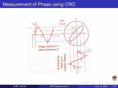
Measurement of Phase using CRO
CHBR (AUCE) GATE-Measurements June 14, 2020 7 / 28

Measurement of Phase using CRO
CHBR (AUCE) GATE-Measurements June 14, 2020 8 / 28
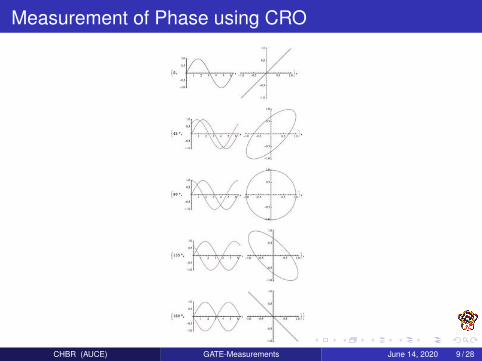
Measurement of Phase using CRO
CHBR (AUCE) GATE-Measurements June 14, 2020 9 / 28
Measurement of Frequency using CRO
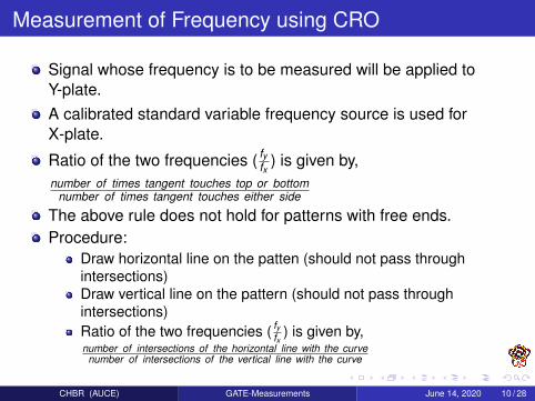
Signal whose frequency is to be measured will be applied toY-plate.A calibrated standard variable frequency source is used forX-plate.
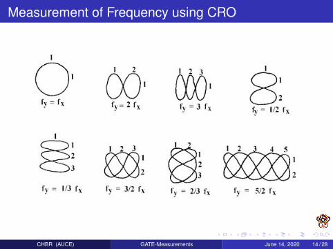
Ratio of the two frequencies ( fyfx ) is given by,
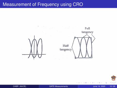
number of times tangent touches top or bottomnumber of times tangent touches either side
The above rule does not hold for patterns with free ends.Procedure:
Draw horizontal line on the patten (should not pass throughintersections)Draw vertical line on the pattern (should not pass throughintersections)Ratio of the two frequencies ( fy
fx) is given by,
number of intersections of the horizontal line with the curvenumber of intersections of the vertical line with the curve
CHBR (AUCE) GATE-Measurements June 14, 2020 10 / 28

Measurement of Frequency using CRO
CHBR (AUCE) GATE-Measurements June 14, 2020 11 / 28
Measurement of Frequency using CRO
CHBR (AUCE) GATE-Measurements June 14, 2020 12 / 28

Measurement of Frequency using CRO
CHBR (AUCE) GATE-Measurements June 14, 2020 13 / 28
Measurement of Frequency using CRO
CHBR (AUCE) GATE-Measurements June 14, 2020 14 / 28

Measurement of Frequency using CRO
CHBR (AUCE) GATE-Measurements June 14, 2020 15 / 28
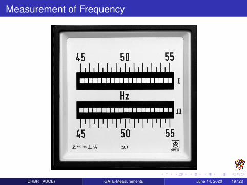
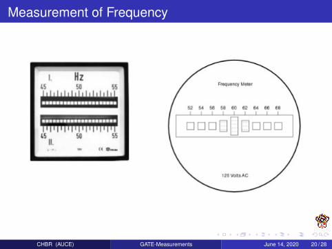
Measurement of Frequency
Mechanical Resonance type Frequency MeterNo. of thin steel strips called reeds.Reeds are approx. 4 mm wide and 0.5 mm thick.All the not same.Some difference is there between them like, different dimensions,different weight or different flag at top.Natural frequency of the reeds depends on their weights anddimensions.Arranged them in ascending order of nature frequency.Reeds are fixed at the bottom and free at the top.
CHBR (AUCE) GATE-Measurements June 14, 2020 16 / 28

Measurement of Frequency
CHBR (AUCE) GATE-Measurements June 14, 2020 17 / 28

Measurement of Frequency
CHBR (AUCE) GATE-Measurements June 14, 2020 18 / 28
Measurement of Frequency
CHBR (AUCE) GATE-Measurements June 14, 2020 19 / 28
Measurement of Frequency
CHBR (AUCE) GATE-Measurements June 14, 2020 20 / 28

Measurement of Frequency
CHBR (AUCE) GATE-Measurements June 14, 2020 21 / 28
Measurement of Frequency
CHBR (AUCE) GATE-Measurements June 14, 2020 22 / 28

Measurement of Power Factor
It can be measured by taking the reading of voltage, current andpower.
Accuracy is less for such measurements.
Moving system of power factor meter is perfectly balanced atequilibrium by two opposing forces.
No need of controlling force.
CHBR (AUCE) GATE-Measurements June 14, 2020 23 / 28
Measurement of Power Factor
CHBR (AUCE) GATE-Measurements June 14, 2020 24 / 28

Measurement of Power Factor
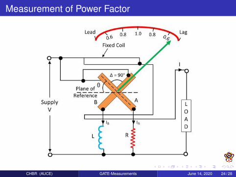
TA = KVIMmax cosφ sin θ
TB = KVIMmax cos(90 − φ) sin(90 + θ)
equilibrium occurs at TA = TB and results to θ = φ
Instrument should be calibrated for frequency of the supply onwhich it is used.
If the frequency changes or supply contains harmonics, error willbe introduced in the measurement due the change of value ofinductance of the choke coil.
CHBR (AUCE) GATE-Measurements June 14, 2020 25 / 28

Measurement of Power Factor
CHBR (AUCE) GATE-Measurements June 14, 2020 26 / 28
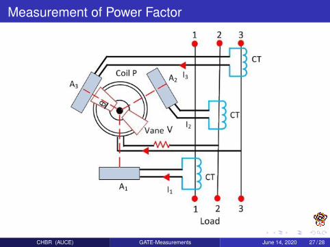
Measurement of Power Factor
CHBR (AUCE) GATE-Measurements June 14, 2020 27 / 28
CHBR (AUCE) GATE-Measurements June 14, 2020 28 / 28
Copyright © 2022 FDOKUMEN