Service Manual - Rocky Mountain Generator Supply
262
English Original Instructions 8-2019 A045R243 (Issue 20) Service Service Manual Manual Generator Set QSJ2.4 Engine with PowerCommand® 1.1 Control C20 N6 (Spec A), C22 N6 (Spec A) C25 N6 (Spec A), C30 N6 (Spec A) C36 N6 (Spec A), C40 N6 (Spec A) C30 N6H (Spec A), C36 N6H (Spec A) C40 N6H (Spec A), C45 N6H (Spec A) C50 N6H (Spec A), C60 N6H (Spec A)
-
Upload
khangminh22 -
Category
Documents
-
view
0 -
download
0
Transcript of Service Manual - Rocky Mountain Generator Supply
EnglishOriginal Instructions 8-2019 A045R243 (Issue 20)
ServiceService ManualManual
Generator SetQSJ2.4 Engine with PowerCommand® 1.1 Control
C20 N6 (Spec A), C22 N6 (Spec A)C25 N6 (Spec A), C30 N6 (Spec A)C36 N6 (Spec A), C40 N6 (Spec A)C30 N6H (Spec A), C36 N6H (Spec A)C40 N6H (Spec A), C45 N6H (Spec A)C50 N6H (Spec A), C60 N6H (Spec A)


iA045R243 (Issue 20) Copyright © 2019 Cummins Inc.
Table of Contents
1. IMPORTANT SAFETY INSTRUCTIONS ....................................................................................... 11.1 Warning, Caution, and Note Styles Used in This Manual ..................................................... 11.2 General Information ................................................................................................................ 11.3 Generator Set Safety Code .................................................................................................... 41.4 Electrical Shocks and Arc Flashes Can Cause Severe Personal Injury or Death.................. 61.5 Fuel and Fumes Are Flammable ............................................................................................ 71.6 Exhaust Gases Are Deadly..................................................................................................... 81.7 The Hazards of Carbon Monoxide.......................................................................................... 91.8 Earth Ground Connection ..................................................................................................... 10
2. INTRODUCTION.......................................................................................................................... 112.1 About This Manual................................................................................................................ 112.2 Test Equipment..................................................................................................................... 122.3 Schedule of Abbreviations .................................................................................................... 122.4 Related Literature ................................................................................................................. 142.5 Specifications........................................................................................................................ 152.6 After Sales Services.............................................................................................................. 22
3. MAINTENANCE ........................................................................................................................... 273.1 Maintenance Safety .............................................................................................................. 273.2 Periodic Maintenance ........................................................................................................... 303.3 Engine Oil ............................................................................................................................. 363.4 Battery Maintenance ............................................................................................................ 423.5 Spark Plugs .......................................................................................................................... 423.6 Cooling System Maintenance ............................................................................................... 433.7 Air Intake System.................................................................................................................. 483.8 Exhaust System Maintenance .............................................................................................. 513.9 Generator Set Output - AC Electric System Checks ............................................................ 523.10 DC Electrical System .......................................................................................................... 533.11 Batteries.............................................................................................................................. 533.12 Spark Plugs ........................................................................................................................ 573.13 Cleaning the Generator Set Housing.................................................................................. 573.14 Complete System Test ...................................................................................................... 58
4. SERVICE...................................................................................................................................... 594.1 Engine Control Module (ECM).............................................................................................. 594.2 SAE J1939 CAN (Controlled Area Network)......................................................................... 724.3 Sensors................................................................................................................................. 744.4 Fuses and Relays ................................................................................................................. 784.5 Fuel System.......................................................................................................................... 804.6 Cooling System..................................................................................................................... 904.7 Exhaust System.................................................................................................................... 984.8 Engine and Accessories ..................................................................................................... 103

Table of Contents 8-2019
ii A045R243 (Issue 20)Copyright © 2019 Cummins Inc.
4.9 Alternator Service ............................................................................................................... 130
5. TROUBLESHOOTING ............................................................................................................... 1555.1 Troubleshooting Procedures............................................................................................... 1555.2 Safety Considerations......................................................................................................... 1555.3 GATRR Troubleshooting Approach .................................................................................... 1565.4 Service Repair Levels......................................................................................................... 1575.5 Control System ................................................................................................................... 1585.6 Fault Finding ....................................................................................................................... 1615.7 InPower Service Tool.......................................................................................................... 1615.8 Mechanical Service Tools List ............................................................................................ 1625.9 Network Applications and Customer Inputs........................................................................ 1635.10 Display Text or Symbolic Version ..................................................................................... 1635.11 Troubleshooting by Symptom ........................................................................................... 1645.12 Troubleshooting with Fault Codes .................................................................................... 190
APPENDIX A. WIRING DIAGRAMS............................................................................................... 243
APPENDIX B. ALTERNATOR RECONNECT DRAWING .............................................................. 253B.0 Alternator Reconnect Wiring Diagrams .............................................................................. 255

1A045R243 (Issue 20) Copyright © 2019 Cummins Inc.
1 IMPORTANT SAFETY INSTRUCTIONSSAVE THESE INSTRUCTIONS. This manual contains important instructions thatshould be followed during installation and maintenance of the generator set andbatteries.Safe and efficient operation can be achieved only if the equipment is properlyoperated and maintained. Many accidents are caused by failure to followfundamental rules and precautions.
1.1 Warning, Caution, and Note Styles Used inThis ManualThe following safety styles and symbols found throughout this manual indicatepotentially hazardous conditions to the operator, service personnel, or equipment.
DANGERIndicates a hazardous situation that, if not avoided, will result in death orserious injury.
WARNINGIndicates a hazardous situation that, if not avoided, could result in death orserious injury.
CAUTIONIndicates a hazardous situation that, if not avoided, could result in minor ormoderate injury.
NOTICEIndicates information considered important, but not hazard-related (e.g.,messages relating to property damage).
1.2 General InformationThis manual should form part of the documentation package supplied by Cumminswith specific generator sets. In the event that this manual has been supplied inisolation, please contact your authorized distributor.
NOTICEIt is in the operator’s interest to read and understand all warnings andcautions contained within the documentation relevant to the generator set,its operation and daily maintenance.

1. IMPORTANT SAFETY INSTRUCTIONS 8-2019
2 A045R243 (Issue 20)Copyright © 2019 Cummins Inc.
General Safety PrecautionsWARNING
Hot Pressurized LiquidContact with hot liquid can cause severe burns.Do not open the pressure cap while the engine is running. Let the enginecool down before removing the cap. Turn the cap slowly and do not open itfully until the pressure has been relieved.
WARNINGMoving PartsMoving parts can cause severe personal injury.Use extreme caution around moving parts. All guards must be properlyfastened to prevent unintended contact.
WARNINGToxic HazardUsed engine oils have been identified by some state and federal agencies tocause cancer or reproductive toxicity.Do not ingest, breathe the fumes, or contact used oil when checking orchanging engine oil. Wear protective gloves and face guard.
WARNINGElectrical Generating EquipmentIncorrect operation and maintenance can result in severe personal injury ordeath.Do not operate equipment when fatigued, or after consuming any alcohol ordrug.Make sure that only suitably trained and experienced service personnelperform electrical and/or mechanical service.
WARNINGToxic GasesSubstances in exhaust gases have been identified by some state and federalagencies to cause cancer or reproductive toxicity.Do not breathe in or come into contact with exhaust gases.
WARNINGHigh Noise LevelGenerator sets in operation emit noise, which can cause hearing damage.Wear appropriate ear protection at all times.

1. IMPORTANT SAFETY INSTRUCTIONS8-2019
3A045R243 (Issue 20) Copyright © 2019 Cummins Inc.
WARNINGHot SurfacesContact with hot surfaces can cause severe burns.The unit is to be installed so that the risk of hot surface contact by people isminimized. Wear appropriate PPE when working on hot equipment and avoidcontact with hot surfaces.
WARNINGToxic HazardEthylene glycol, used as an engine coolant, is toxic to humans and animals.Wear appropriate PPE. Clean up coolant spills and dispose of used coolantin accordance with local environmental regulations.
WARNINGCombustible LiquidIgnition of combustible liquids is a fire or explosion hazard which can causesevere burns or death.Do not store fuel, cleaners, oil, etc., near the generator set. Do not usecombustible liquids like ether.
WARNINGCombustible GasesGenerator sets in operation have combustible gases under pressure, whichif ignited can cause eye and ear damage.Wear appropriate eye and ear protection at all times.
WARNINGCombustible GasesGenerator sets in operation have combustible gases under pressure, whichif ignited can cause severe injury.Do not operate the generator set with any doors open.
WARNINGFire HazardMaterials drawn into the generator set, as well as accumulated grease andoil, are a fire hazard. Fire can cause severe burns or death.Keep the generator set and the surrounding area clean and free fromobstructions. Make sure the generator set is mounted in a manner to preventcombustible materials from accumulating under the unit.

1. IMPORTANT SAFETY INSTRUCTIONS 8-2019
4 A045R243 (Issue 20)Copyright © 2019 Cummins Inc.
WARNINGAutomated MachineryAccidental or remote starting of the generator set can cause severe personalinjury or death.Isolate all auxiliary supplies and use an insulated wrench to disconnect thestarting battery cables (negative [–] first).
NOTICEKeep multi-type ABC fire extinguishers close by. Class A fires involveordinary combustible materials such as wood and cloth. Class B firesinvolve combustible and flammable liquid fuels and gaseous fuels. Class Cfires involve live electrical equipment. (Refer to NFPA No. 10 in theapplicable region.)
NOTICEBefore performing maintenance and service procedures on enclosedgenerator sets, make sure the service access doors are secured open.
NOTICEStepping on the generator set can cause parts to bend or break, leading toelectrical shorts, or to fuel leaks, coolant leaks, or exhaust leaks. Do not stepon the generator set when entering or leaving the generator set room.
1.3 Generator Set Safety CodeBefore operating the generator set, read the manuals and become familiar withthem and the equipment. Safe and efficient operation can be achieved only if theequipment is properly operated and maintained. Many accidents are caused byfailure to follow fundamental rules and precautions.
WARNINGElectrical Generating EquipmentIncorrect operation and maintenance can result in severe personal injury ordeath.Read and follow all Safety Precautions, Warnings, and Cautions throughoutthis manual and the documentation supplied with the generator set.
Moving Parts Can Cause Severe Personal Injury or Death• Keep hands, clothing, and jewelry away from moving parts.• Before starting work on the generator set, disconnect the battery charger from
its AC source, then disconnect the starting batteries using an insulated wrench,negative (–) cable first. This will prevent accidental starting.

1. IMPORTANT SAFETY INSTRUCTIONS8-2019
5A045R243 (Issue 20) Copyright © 2019 Cummins Inc.
• Make sure that fasteners on the generator set are secure. Tighten supports andclamps; keep guards in position over fans, drive belts, etc.
• Do not wear loose clothing or jewelry in the vicinity of moving parts or whileworking on electrical equipment. Loose clothing and jewelry can becomecaught in moving parts.
• If any adjustments must be made while the unit is running, use extreme cautionaround hot manifolds, moving parts, etc.
Alternator Operating AreasWARNING
Ejected DebrisDebris ejected during catastrophic failure can cause serious injury or deathby impact, severing or stabbing.To prevent injury:
• Keep away from the air inlet and air outlet when the alternator isrunning.
• Do not put operator controls near the air inlet and air outlet.• Do not cause overheating by running the alternator outside rating plate
parameters.• Do not overload the alternator.• Do not run an alternator with excessive vibration.• Do not synchronize parallel alternators outside the specified parameters.
Always wear suitable PPE when working in the hatched areas shown in the diagramor directly in-line with any air inlet/outlet.
FIGURE 1. HATCHED AREASMake sure this consideration is captured in your risk assessment.

1. IMPORTANT SAFETY INSTRUCTIONS 8-2019
6 A045R243 (Issue 20)Copyright © 2019 Cummins Inc.
1.4 Electrical Shocks and Arc Flashes Can CauseSevere Personal Injury or Death
WARNINGElectric Shock HazardVoltages and currents present an electrical shock hazard that can causesevere burns or death.Contact with exposed energized circuits with potentials of 50 Volts AC or 75Volts DC or higher can cause electrical shock and electrical arc flash. Referto standard NFPA 70E or equivalent safety standards in correspondingregions for details of the dangers involved and for the safety requirements.
Guidelines to follow when working on de-energized electrical systems:• Use proper PPE. Do not wear jewelry and make sure that any conductive items
are removed from pockets as these items can fall into equipment and theresulting short circuit can cause shock or burning. Refer to standard NFPA 70Efor PPE standards.
• De-energize and lockout/tagout electrical systems prior to working on them.Lockout/Tagout is intended to prevent injury due to unexpected start-up ofequipment or the release of stored energy. Please refer to Locking theGenerator Set Out of Service section for more information.
• De-energize and lockout/tagout all circuits and devices before removing anyprotective shields or making any measurements on electrical equipment.
• Follow all applicable regional electrical and safety codes.Guidelines to follow when working on energized electrical systems:
NOTICEIt is the policy of Cummins Inc. to perform all electrical work in a de-energized state. However, employees or suppliers may be permitted tooccasionally perform work on energized electrical equipment only whenqualified and authorized to do so and when troubleshooting, or if de-energizing the equipment would create a greater risk or make the taskimpossible and all other alternatives have been exhausted.
NOTICEExposed energized electrical work is only allowed as per the relevantprocedures and must be undertaken by a Cummins authorized person withany appropriate energized work permit for the work to be performed whileusing proper PPE, tools and equipment.
In summary:• Do not tamper with or bypass interlocks unless you are authorized to do so.

1. IMPORTANT SAFETY INSTRUCTIONS8-2019
7A045R243 (Issue 20) Copyright © 2019 Cummins Inc.
• Understand and assess the risks - use proper PPE. Do not wear jewelry andmake sure that any conductive items are removed from pockets as these itemscan fall into equipment and the resulting short circuit can cause shock orburning. Refer to standard NFPA 70E for PPE standards.
• Make sure that an accompanying person who can undertake a rescue isnearby.
AC Supply and IsolationNOTICE
Local electrical codes and regulations (for example, BS EN 12601:2010Reciprocating internal combustion engine driven generating sets) mayrequire the installation of a disconnect means for the generator set, either onthe generator set or where the generator set conductors enter a facility.
NOTICEThe AC supply must have the correct over current and earth fault protectionaccording to local electrical codes and regulations. This equipment must beearthed (grounded).
It is the sole responsibility of the customer to provide AC power conductors forconnection to load devices and the means to isolate the AC input to the terminalbox; these must comply with local electrical codes and regulations. Refer to thewiring diagram supplied with the generator set.The disconnecting device is not provided as part of the generator set, and Cumminsaccepts no responsibility for providing the means of isolation.
AC Disconnect SourcesWARNING
Hazardous VoltageContact with high voltages can cause severe electrical shock, burns, ordeath.The equipment may have more than one source of electrical energy.Disconnecting one source without disconnecting the others presents ashock hazard. Before starting work, disconnect the equipment, and verifythat all sources of electrical energy have been removed.
1.5 Fuel and Fumes Are FlammableFire, explosion, and personal injury or death can result from improper practices.
• Do not fill fuel tanks while the engine is running unless the tanks are outsidethe engine compartment. Fuel contact with hot engine or exhaust is a potentialfire hazard.

1. IMPORTANT SAFETY INSTRUCTIONS 8-2019
8 A045R243 (Issue 20)Copyright © 2019 Cummins Inc.
• Do not permit any flame, cigarette, pilot light, spark, arcing equipment, or otherignition source near the generator set or fuel tank.
• Fuel lines must be adequately secured and free of leaks. Fuel connection at theengine should be made with an approved flexible line. Do not use copper pipingon flexible lines as copper will become brittle if continuously vibrated orrepeatedly bent.
• Make sure all fuel supplies have a positive shutoff valve.• Make sure the battery area has been well-ventilated prior to servicing near it.
Lead-acid batteries emit a highly explosive hydrogen gas that can be ignited byarcing, sparking, smoking, etc.
Gaseous FuelsNatural gas is lighter than air, and will tend to gather under covered areas.
Do Not Operate in Flammable and Explosive EnvironmentsFlammable vapor can cause an engine to over speed and become difficult to stop,resulting in possible fire, explosion, severe personal injury, and death. Do notoperate a generator set where a flammable vapor environment can be created,unless the generator set is equipped with an automatic safety device to block the airintake and stop the engine. The owners and operators of the generator set aresolely responsible for operating the generator set safely. Contact your authorizedCummins distributor for more information.
1.6 Exhaust Gases Are Deadly• Provide an adequate exhaust system to properly expel discharged gases away
from enclosed or sheltered areas, and areas where individuals are likely tocongregate. Visually and audibly inspect the exhaust system daily for leaks perthe maintenance schedule. Make sure that exhaust manifolds are secured andnot warped. Do not use exhaust gases to heat a compartment.
• Make sure the unit is well ventilated.
Exhaust PrecautionsWARNING
Hot Exhaust GasesContact with hot exhaust gases can cause severe burns.Wear personal protective equipment when working on equipment.

1. IMPORTANT SAFETY INSTRUCTIONS8-2019
9A045R243 (Issue 20) Copyright © 2019 Cummins Inc.
WARNINGHot SurfacesContact with hot surfaces can cause severe burns.The unit is to be installed so that the risk of hot surface contact by people isminimized. Wear appropriate PPE when working on hot equipment and avoidcontact with hot surfaces.
WARNINGToxic GasesInhalation of exhaust gases can cause asphyxiation and death.Pipe exhaust gas outside and away from windows, doors, or other inlets tobuildings. Do not allow exhaust gas to accumulate in habitable areas.
WARNINGFire HazardContaminated insulation is a fire hazard. Fire can cause severe burns ordeath.Remove any contaminated insulation and dispose of it in accordance withlocal regulations.
The exhaust outlet may be sited at the top or bottom of the generator set. Makesure that the exhaust outlet is not obstructed. Personnel using this equipment mustbe made aware of the exhaust position. Position the exhaust away from flammablematerials - in the case of exhaust outlets at the bottom, make sure that vegetation isremoved from the vicinity of the exhaust.The exhaust pipes may have some insulating covers fitted. If these covers becomecontaminated they must be replaced before the generator set is run.To minimize the risk of fire, make sure the following steps are observed:
• Make sure that the engine is allowed to cool thoroughly before performingmaintenance or operation tasks.
• Clean the exhaust pipe thoroughly.
1.7 The Hazards of Carbon MonoxideCarbon monoxide (CO) is an odorless, colorless, tasteless and non-irritating gas.You cannot see it or smell it. Red blood cells, however, have a greater affinity forCO than for oxygen. Therefore, exposure even to low levels of CO for a prolongedperiod can lead to asphyxiation (lack of oxygen) resulting in death. Mild effects ofCO poisoning include eye irritation, dizziness, headaches, fatigue and the inability tothink clearly. More extreme symptoms include vomiting, seizures and collapse.Engine-driven generator sets produce harmful levels of carbon monoxide that caninjure or kill you.

1. IMPORTANT SAFETY INSTRUCTIONS 8-2019
10 A045R243 (Issue 20)Copyright © 2019 Cummins Inc.
Special Risks of CO near the HomeWARNING
Toxic GasesCarbon monoxide (CO) gas can cause nausea, fainting, or death. Residentscan be exposed to lethal levels of CO when the generator set is running.Depending on air temperature and wind, CO can accumulate in or near thehome.To protect yourself and others from the dangers of CO poisoning, it isrecommended that reliable, approved, and operable CO detector alarms areinstalled in proper locations in the home as specified by their manufacturer.
Protecting Yourself from CO Poisoning• Locate the generator set in an area where there are no windows, doors, or
other access points into the home.• Make sure all CO detectors are installed and working properly.• Pay attention for signs of CO poisoning.• Check the exhaust system for corrosion, obstruction, and leaks every time you
start the generator set and every eight hours when you run it continuously.
1.8 Earth Ground ConnectionThe neutral of the generator set may be required to be bonded to earth ground atthe generator set location, or at a remote location, depending on system designrequirements. Consult the engineering drawings for the facility or a qualifiedelectrical design engineer for proper installation.
NOTICEThe end user is responsible to make sure that the ground connection pointsurface area is clean and free of rust before making a connection.
NOTICEThe end user is responsible for making sure that an earthing arrangementthat is compliant with local conditions is established and tested before theequipment is used.

11A045R243 (Issue 20) Copyright © 2019 Cummins Inc.
2 IntroductionWARNING
Hazardous VoltageContact with high voltages can cause severe electrical shock, burns, ordeath.Make sure that only a trained and experienced electrician makes generatorset electrical output connections, in accordance with the installationinstructions and all applicable codes.
WARNINGElectrical Generating EquipmentFaulty electrical generating equipment can cause severe personal injury ordeath.Generator sets must be installed, certified, and operated by trained andexperienced persons in accordance with the installation instructions and allapplicable codes.
2.1 About This ManualThis manual provides troubleshooting and repair information for the generator setslisted on the front cover.The information contained within the manual is based on information available at thetime of going to print. In line with the Cummins Inc. policy of continuousdevelopment and improvement, information may change at any time without notice.The users should therefore make sure that before commencing any work, they havethe latest information available. The latest version of this manual is available onQuickServe Online (https://quickserve.cummins.com).This manual does not include instructions for servicing printed circuit boardassemblies. After determining that a printed circuit board assembly is faulty, replaceit. Do not repair it. Attempts to repair a printed circuit board can lead to costlydamage to the equipment.This manual contains basic (generic) wiring diagrams and schematics that areincluded to help in troubleshooting. The wiring diagrams and schematics that aremaintained with the unit should be updated when modifications are made to theunit.Operating and basic maintenance instructions are in the applicable generator setoperator manual. Read and carefully observe all instructions and precautions in thismanual.

2. Introduction 8-2019
12 A045R243 (Issue 20)Copyright © 2019 Cummins Inc.
2.2 Test EquipmentTo perform the test procedures in this manual, the following test equipment must beavailable:
• True RMS meter for accurate measurement of small AC and DC voltages• Grounding wrist strap to prevent circuit board damage due to electrostatic
discharge (ESD)• Battery hydrometer• Jumper leads• Tachometer or frequency meter• Wheatstone bridge or digital ohmmeter• Variac• Load test panel• Megger or insulation resistance meter• InPower service tool (PC based generator set service tool)• GCP display service tool• Engine display harness
2.3 Schedule of AbbreviationsThis list is not exhaustive. For example, it does not identify units of measure oracronyms that appear only in parameters, event/fault names, or part/accessorynames.
Abbr. Description Abbr. DescriptionAC Alternating Current LED Light-Emitting Diode
AMP AMP, Inc. (part of TycoElectronics)
MFM Multifunction Monitor
ANSI American NationalStandards Institute
Mil Std Military Standard
ASOV Automatic Shut Off Valve MPU Magnetic Pickup
ASTM American Society forTesting and Materials(ASTM International)
NC Normally Closed
ATS Automatic TransferSwitch
NC Not Connected
AVR Automatic VoltageRegulator
NFPA National Fire ProtectionAgency
AWG American Wire Gauge NO Normally Open

2. Introduction8-2019
13A045R243 (Issue 20) Copyright © 2019 Cummins Inc.
Abbr. Description Abbr. DescriptionCAN Controlled Area Network NWF Network Failure
CB Circuit Breaker OEM Original EquipmentManufacturer
CE Conformité Européenne OOR Out Of Range
CCA Cold Cranking Ampere OORH/ORH
Out Of Range High
CFM Cubic Feet per Minute OORL/ORL Out Of Range Low
CGT Cummins GeneratorTechnologies
PB Push Button
CMM Cubic Meters per Minute PCC PowerCommand® Control
CT Current Transformer PGI Power GenerationInterface
DC Direct Current PGN Parameter GroupNumber
DEF Diesel Exhaust Fluid PI Proportional/Integral
DPF Diesel Particulate Filter PID Proportional/Integral/Derivative
EBS Excitation Boost System PLC Programmable LogicController
ECM Engine Control Module PMG Permanent MagnetGenerator
ECS Engine Control System PPE Personal ProtectiveEquipment
EMI ElectromagneticInterference
PT Potential Transformer
EN European Standard PTC Power Transfer Control
EPS Engine ProtectionSystem
PWM Pulse-Width Modulation
E-Stop Emergency Stop RFI Radio FrequencyInterference
FAE Full Authority Electronic RH Relative Humidity
FMI Failure Mode Identifier RMS Remote MonitoringSystem
FSO Fuel Shutoff RMS Root Mean Square
Genset Generator Set RTU Remote Terminal Unit

2. Introduction 8-2019
14 A045R243 (Issue 20)Copyright © 2019 Cummins Inc.
Abbr. Description Abbr. DescriptionGCP Generator Control Panel SAE Society of Automotive
Engineers
GND Ground scfh Standard Cubic Feet ofgas per Hour
HMI Human-MachineInterface
SCR Selective CatalyticReduction
IC Integrated Circuit SPN Suspect ParameterNumber
ISO International Organizationfor Standardization
SW_B+ Switched B+
LBNG Lean-Burn Natural Gas UL UnderwritersLaboratories
LCD Liquid Crystal Display UPS Uninterruptible PowerSupply
LCT Low CoolantTemperature
2.4 Related LiteratureThe literature provided with the generator set is as follows:
• Installation Manual (A045R241)• Operator Manual (A045R242)
CAUTIONA generator set must be operated and maintained properly if you are toexpect safe and reliable operation. The Operator Manual includes amaintenance schedule and a troubleshooting guide.The Health and Safety Manual must be read in conjunction with this manualfor the safe operation of the generator set:
• Health and Safety Manual (0908-0110)• Warranty Statement (A040H442)• Emissions Component Defect Warranty Statement (A028X278)
The relevant manuals appropriate to your generator set are also available. Thedocuments below are in English:
• Service Manual (A045R243)• Parts Manual (A046Z094)• EControls, Inc. Service Manual (A035C596)

2. Introduction8-2019
15A045R243 (Issue 20) Copyright © 2019 Cummins Inc.
• Global Control Platform (GCP) Engine Display Interface Software (EDIS)Training Manual (A035C608)
• RA Series Transfer Switch Owner Manual (A046S594) (if applicable)• PowerCommand® 1302 Controller Owner's Manual (900-0661)• Standard Repair Times (SRT) Manual (A046Z674)• Application Manual T-030 - for application information (A040S369)• Service Tool Manual (A043D529)
2.5 SpecificationsModel Specifications
TABLE 1. 2.4L MODEL VARIATIONS
Models DescriptionC20 N6, C22 N6, C25 N6, C30 N6, C36 N6, C40 N6 60 Hz, 1800 RPM
C30 N6H, C36 N6H, C40 N6H, C45 N6H, C50 N6H, C60 N6H 60 Hz, 3600 RPM
TABLE 2. COLD WEATHER SPECIFICATIONS (ALL MODELS)
Temperature Description Battery Type GroupAbove 4 °C (40 °F) No starting aids required. Standard 26
-17 to 4 °C (0 to 40 °F)Additional coolant heater andbattery charger recommended forstarting. Factory options available.
Standard 26
Below -17 °C (0 °F)All starting aides (battery heater,coolant heater, battery charger)recommended. Factory optionsavailable.
Larger 34
NOTICEFor NFPA 110 applications, a coolant heater is required. A factory option isavailable.

2. Introduction 8-2019
16 A045R243 (Issue 20)Copyright © 2019 Cummins Inc.
TABLE 3. FUEL SPECIFICATIONS 60 HZ, 1800 RPM
C20 N6 C22 N6 C25 N6 C30 N6 C36 N6 C40 N6
Full Load(Propane)
105.1 scfh265,000BTU/hr
112.7 scfh285,000BTU/hr
125.4 scfh315,000BTU/hr
164.1 scfh410,000BTU/hr
182.7 scfh460,000BTU/hr
193.6 scfh490,000BTU/hr
Full Load(Natural Gas)
259.6 scfh270,000BTU/hr
278.8 scfh290,000BTU/hr
309.5 scfh320,000BTU/hr
380.9 scfh395,000BTU/hr
472.3 scfh490,000BTU/hr
519 scfh540,000BTU/hr
Fuel Pressure 6-13 inches of water column (1.5 - 3.2 kPa) under any condition
TABLE 4. FUEL SPECIFICATIONS 60 HZ, 3600 RPM
C30 N6H C36 N6H C40 N6H C45 N6H C50 N6H C60 N6H
Full Load(Propane)
195.5 scfh490,000BTU/hr
219.6 scfh550,000BTU/hr
236.2 scfh595,000BTU/hr
256.9 scfh645,000BTU/hr
289.5 scfh725,000BTU/hr
324.6 scfh820,000BTU/hr
Full load(Natural Gas)
476.1 scfh495,000BTU/hr
533.3 scfh555,000BTU/hr
573.2 scfh595,000BTU/hr
623.0 scfh645,000BTU/hr
704.7 scfh730,000BTU/hr
814.2 scfh840,000BTU/hr
Fuel Pressure 6-13 inches of water column (1.5 - 3.2 kPa) under any condition
TABLE 5. ENGINE SPECIFICATIONS (ALL MODELS)
Specification ValueEngine 4 cylinder-in-line, SOHC, liquid-cooled, 4-stroke, spark ignited
Displacement 2351 cc (144 in3)
Spark Plug Gap 1.0 mm (0.040 in) (NA)0.76 mm (0.030 in) (T/TAA)
Spark Plug Torque 20 Nm (15 ft-lb)
Coolant 50/50 coolant solution (50% pure water and 50% ethylene glycol)
High Crankcase Pressure No higher than 1.5 kPa
Compression 135 psi (dry test) or higher with less than 15 psi range betweencylinders
Oil Capacity 4.3 L (4.54 quarts)
Oil Recommendation 5W30 API SM or newer

2. Introduction8-2019
17A045R243 (Issue 20) Copyright © 2019 Cummins Inc.
TABLE 6. GENERATOR SET SIZE SPECIFICATIONS WITH SOUND LEVEL 1ENCLOSURE (L X W X H)
kW RPM mm in20-25 1800
1830 x 864 x 1152 72 x 34 x 45.230 3600
30-40 18002384 x 864 x 1152 94 x 34 x 45.2
36-60 3600
TABLE 7. GENERATOR SET WEIGHT 60 HZ, 1800 RPM
Sound Level 1 (Wet) C20 N6 C22 N6 C25 N6 C30 N6 C36 N6 C40 N6kg 503 503 520 580 615 646
lb 1109 1109 1147 1279 1356 1424
TABLE 8. GENERATOR SET WEIGHT 60 HZ, 3600 RPM
Sound Level 1 (Wet) C30 N6H C36 N6H C40 N6H C45 N6H C50 N6H C60 N6Hkg 514 567 635 635 635 648
lb 1134 1249 1399 1399 1399 1429
TABLE 9. ALTERNATOR SPECIFICATIONS 60 HZ, 1800 RPM
C20 N6 C22 N6 C25 N6 C30 N6 C36 N6 C40 N6Alternator Brushless, 4-pole rotating field, single bearing
Power (kVa):
1-Phase 20 22 25 30 36 40
3-Phase 25 27.5 31.3 37.5 45 50
Rated Voltages (V):
1-Phase 120/240
3-Phase
120/240120/208277/480347/600

2. Introduction 8-2019
18 A045R243 (Issue 20)Copyright © 2019 Cummins Inc.
TABLE 10. ALTERNATOR SPECIFICATIONS 60 HZ, 3600 RPM
C30 N6H C36 N6H C40 N6H C45 N6H C50 N6H C60 N6HAlternator Brushless, 2-pole rotating field, single bearing
Power (kVa):
1-Phase 30 36 40 45 50 60
3-Phase 37.5 45 50 56.3 62.5 75
Rated Voltages (V):
1-Phase 120/240
3-Phase120/240120/208277/480
NOTICEMaximum I2 = 8%.

2. Introduction8-2019
19A045R243 (Issue 20) Copyright © 2019 Cummins Inc.
TABLE 11. GENERATOR SET DERATING GUIDELINES
Engine Power Available Up To... Derate At…
Model Fuel Elevation AmbientTemperature Elevation Temperature
C20 N6 NG, LP 1005 m (3300 ft) 40 °C (104 °F)
4% per305 m
(1000 ft)
2% per 10 °C(18 °F)
above 40 °C(104 °F)
C22 N6 NG 670.5 m (2200 ft) 40 °C (104 °F)
C22 N6 LP 1005 m (3300 ft) 40 °C (104 °F)
C25 N6 NG 0 m (0 ft) 25 °C (77 °F)
C25 N6 LP 114 m (375 ft) 25 °C (77 °F)
2% per 10 °C(18 °F)
above 25 °C(77 °F)
C30 N6 NG 762 m (2500 ft) 40 °C (104 °F)
2% per 10 °C(18 °F)
above 40 °C(104 °F)
C30 N6 LP 1005 m (3300 ft) 40 °C (104 °F)
C36 N6 NG, LP 1005 m (3300 ft) 40 °C (104 °F)
C40 N6 NG, LP 114 m (375 ft) 40 °C (104 °F)
C30 N6H NG, LP 945 m (3100 ft) 40 °C (104 °F)
C36 N6H NG, LP 1005 m (3300 ft) 40 °C (104 °F)
C40 N6H NG, LP 1005 m (3300 ft) 40 °C (104 °F)
C45 N6H LP 1005 m (3300 ft) 40 °C (104 °F)
C45 N6H NG, LP 914 m (3000 ft) 40 °C (104 °F)
C50 N6H NG, LP 114 m (375 ft) 25 °C (77 °F)
2% per 10 °C(18 °F)
above 25 °C(77 °F)
C60 N6H NG, LP 114 m (375 ft) 40 °C (104 °F)
2% per 10 °C(18 °F)
above 40 °C(104 °F)
TABLE 12. CONTROL SPECIFICATION (ALL MODELS)
SpecificationIntegrated microprocessor based engine, generator, transfer switch control

2. Introduction 8-2019
20 A045R243 (Issue 20)Copyright © 2019 Cummins Inc.
TABLE 13. DC SYSTEM SPECIFICATIONS (ALL MODELS)
Specification ValueNominal Battery Voltage 12 VDC
Battery Group 26 standard, 34 high capacity (a high capacity battery requires anaccessory battery tray)
Battery Type Maintenance free
Minimum Cold CrankAmps
545 standard, 850 high capacity (a high capacity battery requiresan accessory battery tray)
CA115 Winding ResistancesTABLE 14. CA115 WINDING RESISTANCES
Alte
rnat
orTy
pe
Resistance of Windings at 22 °C(Measured Values Should Be within 10%)
Main Stator Windings,L-N (leads) (Ohms)
Exci
terS
tato
r(O
hms)
Exci
terR
otor
,L-L
(Ohm
s)
Mai
nR
otor
(Ohm
s)
EBG
(Ohm
s)
311 41 17 06CA115-M12 0.156 0.207 - 0.078 18.81 0.268 1.536 12.9
CA115-T12 0.112 0.124 - 0.048 19.31 0.210 1.767 12.9
CA115-P12 0.112 0.156 - - 19.31 0.210 1.531 12.9
CA115-J12 0.204 0.270 - - 17.68 0.256 1.248 12.9
CA115-R12 - - - 0.060 19.31 0.210 1.548 12.9
CA115-D14 0.961 1.227 1.910 0.539 17.68 0.256 0.412 12.9
CA115-H14 0.374 0.466 0.736 - 18.81 0.268 0.543 12.9
CA115-J14 - - - 0.128 18.81 0.268 0.606 12.9
CA115-L14 0.199 0.276 0.437 0.092 19.31 0.210 0.668 12.9
CA115-P14 0.194 0.244 0.384 - 20.61 0.216 0.779 12.9
CA115-R14 - - - 0.070 20.61 0.216 0.806 12.9
CA115-S14 0.142 0.191 0.304 - 20.61 0.216 0.869 12.9

2. Introduction8-2019
21A045R243 (Issue 20) Copyright © 2019 Cummins Inc.
Alte
rnat
orTy
pe
Resistance of Windings at 22 °C(Measured Values Should Be within 10%)
Main Stator Windings,L-N (leads) (Ohms)
Exci
terS
tato
r(O
hms)
Exci
terR
otor
,L-L
(Ohm
s)
Mai
nR
otor
(Ohm
s)
EBG
(Ohm
s)
311 41 17 06CA115-V14 0.119 0.175 0.259 0.048 21.27 0.224 0.944 12.9
CA125 Winding ResistancesTABLE 15. CA125 WINDING RESISTANCES
Alte
rnat
orTy
pe
Resistance of Windings at 22 °C(Measured Values Should Be within 10%)
Main Stator Windings, L-N(leads) (Ohms)
Exci
terS
tato
r(O
hms)
Exci
terR
otor
,L-L
(Ohm
s)
Mai
nR
otor
(Ohm
s)
PMG
Stat
or,L
-L(O
hms)
311 41 17 06CA125-G14 - - - 0.048 20.76 0.142 0.594 3.8
CA125-J14 0.094 0.122 0.192 - 20.76 0.142 0.640 3.8
CA125-L14 0.078 0.105 0.160 0.032 20.87 0.156 0.736 3.8
CA125-P14 - - - 0.028 20.87 0.142 0.800 3.8

2. Introduction 8-2019
22 A045R243 (Issue 20)Copyright © 2019 Cummins Inc.
CA135 Winding ResistancesTABLE 16. CA135 WINDING RESISTANCES
Alte
rnat
orTy
peResistance of windings at 22 °C
(Measured Values Should Be within 10%)Main Stator Windings,
L-N (leads) (Ohms)
Exci
terS
tato
r(O
hms)
Exci
terR
otor
,L-L
(Ohm
s)
Mai
nR
otor
(0hm
s)
PMG
Stat
or,L
-L(O
hms)
311 41 17 06CA135-E12 0.061 0.094 - 0.029 23.55 0.082 1.279 3.8
2.6 After Sales ServicesCummins offers a full range of maintenance and warranty services.
MaintenanceWARNING
Electrical Generating EquipmentIncorrect service or parts replacement can result in severe personal injury,death, and/or equipment damage.Make sure service personnel are qualified to perform electrical andmechanical service.
For expert generator set service at regular intervals, contact your Cummins serviceprovider. See power.cummins.com/sales-service-locator for service locations thatservice this application. Maintenance tasks should only be undertaken by trainedand experienced technicians provided by your Cummins service provider.
WarrantyFor details of the warranty coverage for your generator set, refer to the GlobalCommercial Warranty Statement listed in the Related Literature section.In the event of a breakdown, prompt assistance can normally be given by factorytrained service technicians with facilities to undertake all minor and many majorrepairs to equipment on site.Extended warranty coverage is also available.

2. Introduction8-2019
23A045R243 (Issue 20) Copyright © 2019 Cummins Inc.
For further warranty details, contact your authorized service provider.
NOTICEDamage caused by failure to follow the manufacturer's recommendationswill not be covered by the warranty. Please contact your authorized serviceprovider.
Warranty LimitationsFor details of the warranty limitations for your generator set, refer to thewarranty statement applicable to the generator set.
How to Obtain ServiceWhen a product requires service, contact the nearest authorized Cummins serviceprovider. To locate the service provider, refer to www.cummins.com/support andselect Sales & Service Locator. When contacting the service provider, alwayssupply the complete model, specification, and serial number as shown on thenameplate.
Service Technician SupportFor technical support for service technicians, call 1-800-CUMMINS™ (1-800-286-6467) in the U.S. or Canada. Distributors should contact their Cumminsservice contact.

2. Introduction 8-2019
24 A045R243 (Issue 20)Copyright © 2019 Cummins Inc.
Manufacturing Facilities
Facility Address Phone NumbersU.S. andCANADA
Cummins Inc.1400 73rd Ave. NEMinneapolis, MN 55432 USA
Toll Free 1-800-CUMMINSTM
(1-800-286-6467)Phone +1 763-574-5000Fax +1 763-574-5298
EMEA, CIS Cummins Inc.Columbus AvenueManston ParkManston, RamsgateKent CT12 5BFUnited Kingdom-----------Cummins Inc.Royal Oak Way SouthDaventryNorthamptonshireNN11 8NUUnited Kingdom
Phone +44 1843 255000Fax +44 1843 255902
ASIAPACIFIC
Cummins Inc.10 Toh Guan Road #07-01TT International TradeparkSingapore 608838
Phone +65 6417 2388Fax +65 6417 2399
BRAZIL Rua Jati, 310, CumbicaGuarulhos, SP 07180-900Brazil
Phone +55 11 2186 4195Fax +55 11 2186 4729
CHINA Cummins Inc.2 Rongchang East Street,Beijing Economic – TechnologicalDevelopment AreaBeijing 100176, P.R. China
Phone 86 10 59023001Fax +86 10 5902 3199
INDIA Cummins Inc.Plot No B-2, SEZ Industrial Area,Village-Nandal & Surwadi, Taluka- PhaltanDist- Satara, Maharashtra 415523India
Phone+91 021 66305514
LATINAMERICA
3350 Southwest 148th Ave.Suite 205Miramar, FL 33027 USA
Phone +1 954 431 551Fax +1 954 433 5797

2. Introduction8-2019
25A045R243 (Issue 20) Copyright © 2019 Cummins Inc.
Facility Address Phone NumbersMEXICO Eje 122 No. 200 Zona Industrial
San Luis Potosi, S.L.P. 78395Mexico
Phone +52 444 870 6700Fax +52 444 824 0082

This page is intentionally blank.
2. Introduction 8-2019
26 A045R243 (Issue 20)Copyright © 2019 Cummins Inc.

27A045R243 (Issue 20) Copyright © 2019 Cummins Inc.
3 Maintenance
3.1 Maintenance SafetyWARNING
Automated MachineryAccidental or remote starting of the generator set can cause severe personalinjury or death.Isolate all auxiliary supplies and use an insulated wrench to disconnect thestarting battery cables (negative [–] first).
WARNINGHydrogen GasArcing can ignite explosive hydrogen gas given off by batteries, causingsevere personal injury or death. Arcing can occur when cables are removedor replaced, or when the negative (–) battery cable is connected and a toolused to connect or disconnect the positive (+) battery cable touches theframe or other grounded metal part of the generator set.Insulated tools must be used when working in the vicinity of the batteries.Always remove the negative (–) cable first and reconnect last.
WARNINGExplosive FumesArcing can ignite explosive fumes causing severe personal injury or death.Make sure hydrogen from the battery, engine fuel and other explosive fumesare fully dissipated before working on the generator set.
WARNINGWorking at HeightsUsing the incorrect equipment when working at heights can result in severepersonal injury or death.Suitable equipment for performing these tasks must be used in accordancewith the local guidelines and legislation. Failure to follow these instructionscan result in severe personal injury or death.

3. Maintenance 8-2019
28 A045R243 (Issue 20)Copyright © 2019 Cummins Inc.
WARNINGAccessUsing the generator set or part of as a means of access when attachinglifting shackles, chains, or other lifting aids, may damage the generator set,causing severe personal injury or death.Do not use the generator set as a means of access. Failure to follow theseinstructions can result in severe personal injury or death.
WARNINGExposed TerminationsSome panel internal components may have live exposed terminations even ifthe generator set is not running. Voltages are present which can causeelectrical shock, resulting in personal injury or damage to equipment.Isolate all external electrical supplies prior to access of the control panel
NOTICEOnly authorized and qualified maintenance technicians who are familiar withthe equipment and its operation should carry out maintenance.
NOTICEDependent upon the control system fitted, this unit may operateautomatically and could start without warning.
NOTICEAlways disconnect a battery charger from its AC source beforedisconnecting the battery cables. Failure to do so can result in voltagespikes high enough to damage the DC control circuits of the generator set.
All maintenance tasks must be performed, but be sure to assess them for healthand safety risks before starting. For example, perform a task with someone presentif doing so will add significantly to the safety of the task.Read, understand, and comply with all Caution, Warning, and Danger notes in thissection, the Important Safety Instructions section, and the documentation suppliedwith the generator set.Make sure that adequate lighting is available.

3. Maintenance8-2019
29A045R243 (Issue 20) Copyright © 2019 Cummins Inc.
Locking the Generator Set Out of ServiceNOTICE
Automated MachineryAccidental or remote starting of the generator set can cause severe personalinjury or death.Isolate all auxiliary supplies and use an insulated wrench to disconnect thestarting battery cables, negative (–) cable first.
Before any work is carried out for maintenance, etc., the generator set must beimmobilized. Even if the generator set is put out of service by pressing the Offswitch on the Operator Panel (or the STOP button if applicable), the generator setcannot be considered safe to work on until the engine is properly immobilized, asdetailed in the following procedure.
NOTICERefer also to the engine-specific Operator Manual, if applicable. This manualcontains specific equipment instructions that may differ from the standardgenerator set.
To immobilize the generator set:1. Press the Off switch from the display and then press the E-Stop button to shut
down the engine. This will prevent the starting of the generator set regardless ofthe Start signal source and will therefore provide an additional safety step forimmobilizing the generator set. Alternatively, make sure the generator set is inmanual mode (which allows it to be started by manually pushing the buttons).
NOTICEWhen the E-Stop button is pressed, the Operator Panel indicates the
Shutdown condition by illuminating the red Shutdown status LEDand displaying a message on the graphical LCD display.
2. Thoroughly ventilate the generator set before disconnecting any leads.3. Turn off and disconnect the heater (where fitted) from the AC source before
disconnecting the battery cables.4. Turn off and disconnect the battery charger (where fitted) from the AC source
before disconnecting the battery cables.5. Turn off the fuel supply to the engine.6. Disconnect the battery. Disconnect the negative (–) cable first, using an
insulated wrench.7. Place warning notices at each of the above locations that state, "Maintenance
in Progress – Immobilized for Safe Working."

3. Maintenance 8-2019
30 A045R243 (Issue 20)Copyright © 2019 Cummins Inc.
3.2 Periodic MaintenanceWARNING
Electrical Generating EquipmentAccidental or remote starting of the generator set can cause severe personalinjury or death.Before working on the generator set, make sure that the generator set is inOff mode, disable the battery charger, and remove the negative (–) batterycable from the battery to prevent starting.
The table(s) that follow show the recommended service intervals for a generator seton standby service. If the generator set will be subjected to extreme operatingconditions, the service intervals should be reduced accordingly.At each scheduled maintenance interval, perform all previous maintenance checksthat are due for scheduled maintenance.Some of the factors that can affect the maintenance schedule are:
• Extremes in ambient temperature• Exposure to elements• Exposure to salt water• Exposure to windblown dust or sand
Consult with your authorized Cummins service provider if the generator set will besubjected to any extreme operating conditions, and determine if extra protection ora reduction in service intervals is needed. Use the engine hours shown on thesystem status screen to keep to keep an accurate log of all service performed forwarranty support. Perform all service at the time period indicated, or after thenumber of operating hours indicated, whichever comes first.Repair or replace worn, damaged, or improperly functioning components identifiedduring periodic maintenance procedures.
Periodic Maintenance GuidelinesRegularly performing the following periodic maintenance tasks greatly reduces thechances of a generator set shutdown:
• Maintain an appropriate oil level.• Keep battery connections clean and tight.• Do not overload the generator set.• Keep the air inlet and outlet openings clear.

3. Maintenance8-2019
31A045R243 (Issue 20) Copyright © 2019 Cummins Inc.
Periodic Maintenance ScheduleNOTICE
Perform maintenance tasks as specified using the period of operation thatoccurs first.
TABLE 17. PERIODIC MAINTENANCE SCHEDULE
Maintenance ItemDaily
or After24 Hours
Weeklyor After
50 Hours
100Hours
1 Yearor After
200 Hours1
2Years1
4000Hours
Check air cleanerrestriction indicator(where fitted): Ifthe serviceindicator showsred, replace aircleaner elementsand reset the aircleaner serviceindicator.
■
Check air intakesystem for leaks:Visually inspectthe air intakesystem for signs ofwear or damage.Check audiblywhen thegenerator set isrunning. Replaceworn or damagedcomponents.
■
Check operation ofoperator panel:Check display (thesystem willperform a controlpanel test on initialactivation).Replacecomponent if notfunctioningproperly.
■

3. Maintenance 8-2019
32 A045R243 (Issue 20)Copyright © 2019 Cummins Inc.
Maintenance ItemDaily
or After24 Hours
Weeklyor After
50 Hours
100Hours
1 Yearor After
200 Hours1
2Years1
4000Hours
Check coolantlevel of radiator(s)(water jacket <A): If low, top upto coolant systemspecificationslevel, withCumminsrecommendedcoolant mix.
■
Check cooling fanblades: Visuallyinspect the fanblades through theguarding for signsof wear ordamage.
■
Check drive belt,condition andtension: Visuallycheck belt forevidence of wearor slippage.
■
Check coolantlines and radiatorhoses for leaks,wear, and cracks:Visually check forleaks, worn ordamaged hoses.
■ ■
Check radiator airflow: Visuallyinspect theradiator throughthe guarding forblockage, build-upof debris, signs ofwear or damage.
■

3. Maintenance8-2019
33A045R243 (Issue 20) Copyright © 2019 Cummins Inc.
Maintenance ItemDaily
or After24 Hours
Weeklyor After
50 Hours
100Hours
1 Yearor After
200 Hours1
2Years1
4000Hours
Verify that thecoolant heater haspower and isrunning (wherefitted). Check forevidence of leaks.Remove anycorrosion fromfittings.
■
Check engine oillevel: If low, top upto enginespecificationslevel, withrecommended oil.
■
Check fuel linesand hoses:Visually check forleaks, worn ordamaged hoses.
■
Check chargealternator: Checkvisually andaudibly when thegenerator set isrunning.
■
Check all exhaustcomponents, andhardware (fittings,clamps, fasteners,etc.): Visuallyinspect theexhaust system forsigns of wear ordamage. Checkaudibly when thegenerator set isrunning.
■

3. Maintenance 8-2019
34 A045R243 (Issue 20)Copyright © 2019 Cummins Inc.
Maintenance ItemDaily
or After24 Hours
Weeklyor After
50 Hours
100Hours
1 Yearor After
200 Hours1
2Years1
4000Hours
Check generatorset enclosure:Visually checkenclosure, walkaround inspectionof generator set.Make sure noinlets/outlets arecovered/restricted,service accessdoors areoperational andsafety systems arein place andoperational.
■
Check operation ofEmergency StopButton (wherefitted): With thegenerator setrunning, press theEmergency Stopbutton. Check allsystems, beforeresetting the fault.
■
Replace engine oiland filters. Referto the procedure inthe Engine Oilsection.
■2 ■2
Check battery:Check connectionsto verify that theyare secure.
■ ■
Replace aircleaner.
■
Clean radiatorcore.
■3
Check charge aircooler for damageand debris (wherefitted).
■

3. Maintenance8-2019
35A045R243 (Issue 20) Copyright © 2019 Cummins Inc.
Maintenance ItemDaily
or After24 Hours
Weeklyor After
50 Hours
100Hours
1 Yearor After
200 Hours1
2Years1
4000Hours
Check water pumpfor leaks. Checkweep holes forevidence of leaks.Replace if leaking.
■
Check engineground. Clean asnecessary.
■
Check enginemounts generalcondition and forsigns of excessivewear.
■
Check startingmotor for generalcondition, wiringconnections.
■
Checkturbocharger(where fitted) forsigns of leakage.Listen forexcessive noisewhen test runningthe generator set.
■
Check timing beltcondition. Visuallyinspect.
■
Inspect sparkplugs. Replace ifshowing signs ofexcessive wear,carbon deposits,oil accumulation ordamaged.
■
Check batterycondition.
■

3. Maintenance 8-2019
36 A045R243 (Issue 20)Copyright © 2019 Cummins Inc.
Maintenance ItemDaily
or After24 Hours
Weeklyor After
50 Hours
100Hours
1 Yearor After
200 Hours1
2Years1
4000Hours
Check electricalconnections(battery, startermotor, alternatorconnections).Check for tightconnections,general conditionand remove anycorrosion.
■
Check alternatorheater (wherefitted). Checkgeneral conditionand wiringconnections.
■
Check batteryheater (wherefitted). Checkgeneral conditionand wiringconnections.
■
Replace coolingsystem coolant.
■
Inspect all sealedbearings every4000 to 4500hours
■4
1 To be performed by a qualified Service Technician.2 After the initial 50 hour interval and every 200 hours thereafter.3 Cleaning schedule may be reduced depending on operating conditions/environment.4 Replace all bearings every 30000 hours or 5 years (or if necessary after 10000 hours or 2years).
3.3 Engine OilRecommended Engine OilCheck the oil level prior to starting the generator set to verify that the oil level isbetween the High and Low marks. The generator set is shipped with engine oil(5W30 API SM or newer engine oil is recommended).

3. Maintenance8-2019
37A045R243 (Issue 20) Copyright © 2019 Cummins Inc.
Checking Engine Oil LevelNOTICE
Check the engine oil level when the engine is not running and is out of Automode.
WARNINGCrankcase pressure can blow out hot oil and cause severe burns. Do NOTcheck oil while the engine is operating.
CAUTIONOverfilling can cause foaming or aeration of the oil while operation below thelow mark may cause loss of oil pressure. Do not operate the engine with theoil level below the low mark or above the high mark.
WARNINGState and federal agencies have determined that contact with used engine oilcan cause cancer or reproductive toxicity. Avoid skin contact and breathingof vapors. Use rubber gloves and wash exposed skin. Accidental or remotestarting of the generator set can cause severe personal injury or death.Disconnect the negative (-) battery cable and place the control switch in itsOFF position (or press the STOP button if applicable) before starting work.

3. Maintenance 8-2019
38 A045R243 (Issue 20)Copyright © 2019 Cummins Inc.
No. Description No. Description1 Fill Cap 3 Oil Filter
2 Dipstick 4 Oil Drain Hose
FIGURE 2. ENGINE OIL COMPONENTSTo check the engine oil level:
1. Make sure that the engine has not been running for approximately five minutes.2. Clean off the area surrounding the dipstick port to prevent entry of debris into
the oil pan.3. Pull out the dipstick and wipe it clean.4. Reinsert and fully seat the dipstick.5. Remove the dipstick and check the oil level.
NOTICEThe engine oil level indicated on the dipstick should be between theHigh (4.3 L or 4.5 qt) and Low (3.8 L or 4.0 qt) marks.
6. Reinsert and fully seat the dipstick.

3. Maintenance8-2019
39A045R243 (Issue 20) Copyright © 2019 Cummins Inc.
No. Description No. Description1 High Oil Level (4.3 L or 4.5 qt) 2 Low Oil Level (3.8 L or 4.0 qt)
FIGURE 3. ENGINE OIL DIPSTICK
Adding or Draining OilWARNING
Hot SurfacesContact with hot surfaces can cause severe burns. Wear appropriate PPEwhen working on hot equipment and avoid physical contact with hotsurfaces.
WARNINGHot EnginesContact with hot engines can cause severe burns. Ensure that the generatorset engine has cooled down before adding or draining the oil.

3. Maintenance 8-2019
40 A045R243 (Issue 20)Copyright © 2019 Cummins Inc.
NOTICEToo much oil can cause high oil consumption. Too little oil can cause severeengine damage. Keep the oil level between the High and Low marks on thedipstick.
Adding OilIf the oil level is found to be insufficient, oil must be added.
1. Ensure that the oil fill cap area is clean, and prevent debris from enteringthe engine.
2. Add the appropriate amount of oil, based on the engine oil level check.Refer to the Checking Engine Oil Level section and the ModelSpecifications section.
3. Recheck the engine oil level. Based on the results, add or drain oil.4. Clean up and dispose of any oil in accordance with local/state regulations.
Draining OilIf the oil level is found to be excessive, oil must be drained from the engine.
1. Detach the oil drain hose from the side of the engine.2. Place the end of the drain hose into an appropriate container.
Refer to local regulations to determine the appropriate container for used oil.• Open the oil drain valve to release oil from the engine into the appropriate
container.• Recheck the engine oil level. Based on the results, add or drain oil.• When a sufficient amount of oil has been drained from the system:
1. Close the oil drain valve.2. Wipe the oil drain valve clean.3. Re-attach the drain hose to the side of the engine.4. Dispose of the used oil in accordance with local/state regulations.
Changing Engine Oil and Oil FilterWARNING
Toxic HazardState and federal agencies have determined that contact with used engine oilcan cause cancer or reproductive toxicity.Avoid skin contact and breathing of vapors. Use rubber gloves and washexposed skin. Accidental or remote starting of the generator set can causesevere personal injury or death. Disconnect the negative (-) battery cableand place the control switch in its OFF position (or press the STOP button ifapplicable) before starting work.
3. Maintenance8-2019
41A045R243 (Issue 20) Copyright © 2019 Cummins Inc.
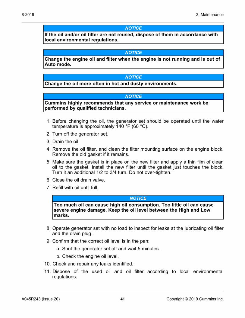
NOTICEIf the oil and/or oil filter are not reused, dispose of them in accordance withlocal environmental regulations.
NOTICEChange the engine oil and filter when the engine is not running and is out ofAuto mode.
NOTICEChange the oil more often in hot and dusty environments.
NOTICECummins highly recommends that any service or maintenance work beperformed by qualified technicians.
1. Before changing the oil, the generator set should be operated until the watertemperature is approximately 140 °F (60 °C).
2. Turn off the generator set.3. Drain the oil.4. Remove the oil filter, and clean the filter mounting surface on the engine block.
Remove the old gasket if it remains.5. Make sure the gasket is in place on the new filter and apply a thin film of clean
oil to the gasket. Install the new filter until the gasket just touches the block.Turn it an additional 1/2 to 3/4 turn. Do not over-tighten.
6. Close the oil drain valve.7. Refill with oil until full.
NOTICEToo much oil can cause high oil consumption. Too little oil can causesevere engine damage. Keep the oil level between the High and Lowmarks.
8. Operate generator set with no load to inspect for leaks at the lubricating oil filterand the drain plug.
9. Confirm that the correct oil level is in the pan:a. Shut the generator set off and wait 5 minutes.b. Check the engine oil level.
10. Check and repair any leaks identified.11. Dispose of the used oil and oil filter according to local environmental
regulations.

3. Maintenance 8-2019
42 A045R243 (Issue 20)Copyright © 2019 Cummins Inc.
3.4 Battery MaintenanceWARNING
Automated MachineryAccidental or remote starting of the generator set can cause severe personalinjury or death. Arcing at battery terminals or in light switches or otherequipment, and flames or sparks can ignite battery gas causing severepersonal injury.Always follow these procedures to avoid injury and/or damage:
• Ventilate the battery area before working on or near the battery.• Wear safety glasses.• Do not smoke.• Switch a work light on or off away from the battery.
Make sure the generator set is shut down and disabled:1. Press the generator set's red STOP button on the local display to stop
the generator set. Allow the generator set to thoroughly cool to thetouch.
2. Turn off and disconnect the battery charger from the AC source beforedisconnecting the battery cables.
3. Disconnect the negative (–) cable from the battery and secure it fromcontacting the battery terminals to prevent accidental starting.
4. Once work is complete, reconnect the negative (–) battery cable last.
Always:• Keep the battery case and terminals clean and dry and the terminals tight.• Remove battery cables with an insulated wrench or battery terminal puller.• Make sure which terminal is positive (+) and which is negative (–) before
making battery connections, always removing the negative (–) cable first andreconnecting it last to reduce arcing.
NOTICEIf the battery needs to be replaced, make sure that the replacement batteryspecifications match those found in the Model Specifications in this manual.
3.5 Spark PlugsNOTICE
Make sure service personnel are qualified to perform electrical andmechanical service.

3. Maintenance8-2019
43A045R243 (Issue 20) Copyright © 2019 Cummins Inc.
The generator set has four spark plugs, all accessible from the top of the engine.The spark plugs must be in good condition for proper engine starting andperformance. A spark plug that fouls frequently or has heavy soot deposits indicatesthe need for engine service.
1. Set the generator set control to the Off position before checking the sparkplugs.
2. To prevent cross-threading a spark plug, always thread it in by hand until itseats. Torque the spark plug to 20 Nm (15 lb-ft).
3. Return the generator set control to the desired setting when finished performingmaintenance.
3.6 Cooling System MaintenanceThis section provides information on cleaning the radiator.
CleaningCleaning Radiator Cores Using Pressurized Water Equipment
NOTICEIn specific dust-laden environments, this procedure should not be usedas the initial cleaning operation. Instead, follow the procedure in theDust Laden Environments section.
On enclosed generator sets with removable end panel(s), remove the endpanel(s) to assist in the cleaning of the radiator. Refer to the RemoveEnclosure End Panel sub-section in the Exhaust System section.Inspect the exterior of the radiator for obstructions. During the service life of aradiator, a buildup of foreign matter can obstruct the flow of air through theradiator cores, reducing the cooling capability. To ensure the continuedefficiency of the radiator, the core will require cleaning.For thorough cleaning, pressure wash in the opposite direction to the airflow.
CAUTIONDo not use cleaners that contain ammonia to clean the radiator orcharge air cooler. Ammonia will damage the core.
The recommended equipment for cleaning a radiator core is an industrialpressure washer, but it must be used in the correct manner because misusecan reduce the performance of the core. Protect the generator set from anyover spray during this procedure.To be effective, it is recommended that a hot water washer be used.

3. Maintenance 8-2019
44 A045R243 (Issue 20)Copyright © 2019 Cummins Inc.
FIGURE 4. FINS DAMAGED BY PRESSURE WASHING AT ACUTE ANGLES TO COREFACE
WARNINGWear PPE when cleaning the radiator core with a pressure washer orcompressed air. Verify appropriate PPE is worn for the cleaningmaterials being used. Respiratory protection must be worn whencleaning the radiator with compressed air.
CAUTIONFollow all codes and standards regarding collection and disposal ofcleaning materials used to clean the radiator.
CAUTIONWith the pressures involved, it is important that the distance betweenthe core face and the nozzle is a minimum of 18 inches (450 mm);otherwise, damage may occur.
FIGURE 5. PRESSURE WASHER NOZZLE POSITIONING

3. Maintenance8-2019
45A045R243 (Issue 20) Copyright © 2019 Cummins Inc.
CAUTIONMost industrial pressure washers work at pressures of around 1500 psito 3000 psi (103 bar to 206 bar). It is very important that, when washinga core in this way, the lance is kept at a right angle to the core.
CAUTIONIf your pressure washer works above 3000 psi, make sure the gapbetween the nozzle and the core face is increased; otherwise, findamage will occur.
NOTICEAlways follow the pressure washer manufacturer’s Health and SafetyGuidelines.
Replace the end panel(s) where necessary. Refer to the Install Enclosure EndPanel sub-section in the Exhaust System section.
Remove Enclosure End Panel1. Remove bolts from top panel (1). Torque 9.8 to 11.9 Nm (7.3 to 8.8 ft-lb).

3. Maintenance 8-2019
46 A045R243 (Issue 20)Copyright © 2019 Cummins Inc.
No. Description No. Description1 Top Panel 2 End Panel
FIGURE 6. ENCLOSURE END PANEL REMOVAL2. Remove top panel (1).3. Slide end panel (2) up to unlatch the panel, then pull the end panel off.
Install Enclosure End Panel1. Place the end panel (2) on each side panel locating pin. Refer to Figure
48.2. Slide the end panel (2) down to latch the panel onto the locating pins.3. Attach the top panel (1) with bolts on three sides and the top.

3. Maintenance8-2019
47A045R243 (Issue 20) Copyright © 2019 Cummins Inc.
Dust Laden EnvironmentsSpecific Instructions for the Cleaning of Radiator Cores Used in anEnvironment Subjected to Crushed Aggregate or Ceramic DustContaminationOn enclosed generator sets with removable end panel(s), remove the endpanel(s) to assist in the cleaning of the radiator.Inspect the exterior of the radiator for obstructions. During the service life of aradiator, a buildup of foreign matter can obstruct the flow of air through theradiator cores, reducing cooling capability. To maintain the efficiency of theradiator, the core will require cleaning.Unless the radiator can be dismantled and the core treated in a professionalcaustic immersion cleaning system, the radiator should not be “wet” cleaned.This is because of the tendency of this type of contamination to coalesce andbecome extremely difficult to remove.The correct procedure is to regularly blow through the entire core area withlow pressure compressed air (against the direction of cooling airflow). It isvery important to ensure that resultant debris blown from the core issubsequently removed and disposed of before engine start-up. An industrialvacuum cleaner will achieve this requirement. In most installations, it will benecessary to remove cowls and guarding.To prevent damage to fins and resultant loss of cooling, it is important toensure that the air gun used is maintained at right angles to the core face.
FIGURE 7. FINS DAMAGED BY COMPRESSED AIR AT ACUTE ANGLES TO COREFACE
After this procedure has been effectively carried out with only the lightest ofdust remaining, follow it immediately (if necessary) by cleaning the radiatorcores using pressurized water equipment.Replace the end panel(s) where necessary.

3. Maintenance 8-2019
48 A045R243 (Issue 20)Copyright © 2019 Cummins Inc.
NOTICEIt is vitally important that the core is thoroughly dried before start-up.
3.7 Air Intake SystemThe direct flow air cleaner consists of a primary filter and a secondary filter withinthe air cleaner housing. The air cleaner has been designed for a maximumrestriction, at which point the filter elements should be changed. Refer to the ModelSpecifications section.
Normal Duty Air CleanerNormal Duty Air Cleaner Element Replacement
NOTICEHoles, loose-end seals, dented sealing surfaces, corrosion of pipes,and other forms of damage render the air cleaner inoperative andrequire immediate element replacement or engine damage can occur.
NOTICECummins does not recommend cleaning paper-type air cleanerelements.
1. Remove the existing air cleaner:a. Loosen the strap clamp (2).b. Wipe away any debris accumulated around the air cleaner
connection to the engine. Ensure that no debris is allowed to enterthe body of the air cleaner or the connection on the engine.
c. Remove the dirty air cleaner (1).d. Dispose of the dirty element in accordance with local environmental
agency requirements.2. Install the replacement air cleaner (1) as follows:
a. Install the air cleaner (1).b. Tighten strap clamp (2). Torque to 2.5 - 3.3 ft-lb (4.3 - 4.65 Nm).

3. Maintenance8-2019
49A045R243 (Issue 20) Copyright © 2019 Cummins Inc.
No. Description No. Description1 Air Cleaner 2 Strap Clamp
FIGURE 8. EXAMPLE OF NORMAL DUTY AIR CLEANER
Heavy Duty Air CleanerHeavy Duty Air Cleaner Maintenance
WARNINGFall HazardFalls can result in severe personal injury or death.Make sure that suitable equipment for performing tasks at height areused in accordance with local guidelines and legislation.
There is a dust ejector valve (DEV) on the bottom of each filter pre-cleanerthat should be checked periodically to make sure it is free of dust and dirt.When there is a filter pre-cleaner, it includes a primary and secondary elementthat is checked periodically to make sure they are clean. Refer to the PeriodicMaintenance Schedule table for additional information.
Heavy Duty Air Cleaner Element Replacement
CAUTIONHoles, loose-end seals, dented sealing surfaces, corrosion of pipes,and other forms of damage render the air cleaner inoperative andrequire immediate element replacement or engine damage can occur.

3. Maintenance 8-2019
50 A045R243 (Issue 20)Copyright © 2019 Cummins Inc.
NOTICECummins does not recommend cleaning paper-type air cleanerelements.
1. To remove the existing air cleaner element:a. Before disassembly, wipe dirt from the cover and the upper portion of
the air cleaner.b. Lift the latch (3) and turn the end cover (4) counterclockwise.c. Pull the end cover (4) away from the housing (1).d. Remove the air filter element (2) from the housing (1).e. Dispose of the dirty element in accordance with local environmental
agency requirements.2. To install the replacement air cleaner element:
a. Ensure that no debris enters the filter element or connection point onthe air cleaner housing.
b. Insert the air filter element (2) into the housing (1).c. Install the end cover (4) onto the housing (1).d. Turn the end cover (4) clockwise until the latch (3) snaps into place.

3. Maintenance8-2019
51A045R243 (Issue 20) Copyright © 2019 Cummins Inc.
No. Description No. Description1 Housing 3 Latch
2 Air Filter Element 4 End Cover
FIGURE 9. EXAMPLE OF HEAVY DUTY AIR CLEANER
3.8 Exhaust System MaintenanceWARNING
Hot Exhaust ComponentsExhaust components become very hot when the generator set is in use andremain hot for a period of time after the generator set has been shut down.These components can cause severe personal injury or death from contact.Allow these components to cool completely before performing anymaintenance tasks.

3. Maintenance 8-2019
52 A045R243 (Issue 20)Copyright © 2019 Cummins Inc.
WARNINGInhalation of Exhaust GasesInhalation of exhaust gases can result in serious personal injury or death.Be sure deadly exhaust gas is piped outside and away from windows, doorsor other inlets to buildings. Do not allow to accumulate in habitable areas.
WARNINGMoving PartsMoving parts can cause severe personal injury or death.Use extreme caution around moving parts, etc.
With the generator set operating, inspect the entire exhaust system visually andaudibly including the exhaust manifold, muffler, and exhaust pipe without removingguarding and panels. Check for leaks at all connections, welds, gaskets and joints,and ensure that exhaust pipes are not heating surrounding areas excessively. If anyleaks are detected, shut down the generator set (if possible). Contact yourauthorized dealer and have the leaks corrected immediately.
3.9 Generator Set Output - AC Electric SystemChecks
1. Check the following while the generator set is operating.
TABLE 18. AC ELECTRIC SYSTEM CHECKS
Check DescriptionFrequency The generator set frequency should be stable and the reading should be
the same as the generator set nameplate rating. See the ModelSpecifications section.
AC Voltage At no load, the line-to-line voltage, or voltages, should be the same asthe generator set nameplate rating.
AC Ammeter At no load, the current readings should be zero. With a load applied,each line current should be similar.
Panel Lamps When the operating panel is first connected to the DC supply, thesystem runs a check by illuminating each of the indicator lamps in turn.
2. If all of the LEDs do not illuminate, replace the operator panel.

3. Maintenance8-2019
53A045R243 (Issue 20) Copyright © 2019 Cummins Inc.
3.10 DC Electrical SystemWARNING
Combustible GasesIgnition of battery gases is a fire and explosion hazard which can causesevere personal injury or death.Do not smoke, or switch the trouble light ON or OFF near a battery. Touch agrounded metal surface first before touching batteries to discharge staticelectricity. Stop the generator set and disconnect the battery charger beforedisconnecting battery cables. Using an insulated wrench, disconnect thenegative (–) cable first and reconnect it last.
1. Check the harness connections. If any harness connections are damaged,contact your service representative.
FIGURE 10. CHECK HARNESS CONNECTIONS2. Check the terminals on the batteries for clean and tight connections. Loose or
corroded connections create resistance, which can hinder starting. Clean andreconnect the battery cables if loose, using an insulated wrench. Alwaysdisconnect both ends of the negative battery cable. Reconnect one end of thecable to the negative battery terminal and the other end to ground. This willmake sure that any arcing will be away from the battery and least likely to igniteexplosive battery gases.
3. Check connections at the battery charging alternator.4. Visually inspect the alternator belt to make sure it is not loose or cracked.
3.11 BatteriesBatteries are an essential part of any standby generator set system. A significantamount of generator set failures are due to battery issues.

3. Maintenance 8-2019
54 A045R243 (Issue 20)Copyright © 2019 Cummins Inc.
It is therefore vital that batteries are stored, commissioned, and maintained asdetailed here. Reference should also be made to the battery manufacturer’sinstructions.Maintenance free batteries (if supplied with the generator set) need no maintenancefor commissioning.
StorageBatteries must be stored in a cool, dry, well-ventilated place, in the upright position,and with the vent caps securely in place.Batteries must never be stacked on top of each other and must be protected fromthe floor by a wooden pallet or suitably thick cardboard sheet.
General Precautions for Maintenance-Free BatteriesHandling and proper use of batteries is not hazardous if the correct precautions areobserved and personnel are trained in their use.
WARNINGArcing HazardLaying tools or metal objects across the battery can cause arcing that mayignite battery gases causing explosions resulting in personal injury.Never lay tools or metal objects across the top of the battery.
WARNINGElectric Shock HazardVoltages and currents present an electrical shock hazard that can causesevere burns or death.Use tools with insulated handles to prevent the risk of electric shock.
CAUTIONToxic HazardElectrolyte is a dilute sulphuric acid that is harmful to the skin and eyes. It iselectrically conductive and corrosive.Wear full eye protection and protective clothing. If electrolyte contacts theskins, wash it off immediately with water. If electrolyte contacts the eyes,flush thoroughly and immediately with water and seek medical attention.Wash spilled electrolyte with an acid neutralizing agent.
NOTICEKeep batteries upright to prevent spillage.

3. Maintenance8-2019
55A045R243 (Issue 20) Copyright © 2019 Cummins Inc.
Fire Hazard
WARNINGCombustible GasesLead acid batteries present a risk of fire because they generatehydrogen gas.Do not smoke near the batteries. Do not cause flame or spark in thebattery area. Discharge static electricity from your body beforetouching batteries by first touching a grounded metal surface.
WARNINGBefore disconnecting a battery, always remove power from the ACpowered battery charger.
WARNINGWhen putting a battery into service on a generator set, connect thenegative lead LAST; when removing the battery, disconnect thenegative lead FIRST.
Vented Batteries
WARNINGToxic HazardThe electrolyte in vented batteries is a dilute sulfuric acid that isharmful to the skin and eyes. It is also electrically conductive andcorrosive.Always:
1. Wear full eye protection and protective clothing;2. If the electrolyte contacts the skin, wash it off immediately with
water;3. If the electrolyte contacts the eyes, flush them thoroughly and
immediately with water and seek medical attention; and4. Wash spilled electrolyte down with an acid neutralizing agent. A
common practice is to use a solution of one pound (500 grams)bicarbonate of soda (also known as baking soda or sodiumbicarbonate) to one gallon (4 liters) of water.
5. Continue to add the bicarbonate of soda solution until the evidenceof reaction (that is, foaming) has stopped.
6. Flush the resulting liquid with water and dry the area.

3. Maintenance 8-2019
56 A045R243 (Issue 20)Copyright © 2019 Cummins Inc.
Battery MaintenanceWARNING
Automated MachineryAccidental or remote starting of the generator set can cause severe personalinjury or death. Arcing at battery terminals or in light switches or otherequipment, and flames or sparks can ignite battery gas causing severepersonal injury.Always follow these procedures to avoid injury and/or damage:
• Ventilate the battery area before working on or near the battery.• Wear safety glasses.• Do not smoke.• Switch a work light on or off away from the battery.
Make sure the generator set is shut down and disabled:1. Press the generator set's red STOP button on the local display to stop
the generator set. Allow the generator set to thoroughly cool to thetouch.
2. Turn off and disconnect the battery charger from the AC source beforedisconnecting the battery cables.
3. Disconnect the negative (–) cable from the battery and secure it fromcontacting the battery terminals to prevent accidental starting.
4. Once work is complete, reconnect the negative (–) battery cable last.
Always:• Keep the battery case and terminals clean and dry and the terminals tight.• Remove battery cables with an insulated wrench or battery terminal puller.• Make sure which terminal is positive (+) and which is negative (–) before
making battery connections, always removing the negative (–) cable first andreconnecting it last to reduce arcing.
NOTICEIf the battery needs to be replaced, make sure that the replacement batteryspecifications match those found in the Model Specifications in this manual.
ChargingWhere a consistent source of AC power is available, Cummins recommends the useof a battery charger to maintain battery condition and charge. Cummins offersseveral battery chargers.Where generator sets are used infrequently and a consistent source of AC power isnot available, battery recharging must be put on a recharge schedule to ensure thata fully charged condition is maintained.
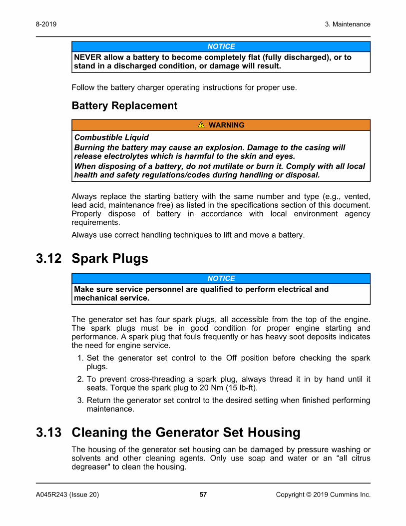
3. Maintenance8-2019
57A045R243 (Issue 20) Copyright © 2019 Cummins Inc.
NOTICENEVER allow a battery to become completely flat (fully discharged), or tostand in a discharged condition, or damage will result.
Follow the battery charger operating instructions for proper use.
Battery ReplacementWARNING
Combustible LiquidBurning the battery may cause an explosion. Damage to the casing willrelease electrolytes which is harmful to the skin and eyes.When disposing of a battery, do not mutilate or burn it. Comply with all localhealth and safety regulations/codes during handling or disposal.
Always replace the starting battery with the same number and type (e.g., vented,lead acid, maintenance free) as listed in the specifications section of this document.Properly dispose of battery in accordance with local environment agencyrequirements.Always use correct handling techniques to lift and move a battery.
3.12 Spark PlugsNOTICE
Make sure service personnel are qualified to perform electrical andmechanical service.
The generator set has four spark plugs, all accessible from the top of the engine.The spark plugs must be in good condition for proper engine starting andperformance. A spark plug that fouls frequently or has heavy soot deposits indicatesthe need for engine service.
1. Set the generator set control to the Off position before checking the sparkplugs.
2. To prevent cross-threading a spark plug, always thread it in by hand until itseats. Torque the spark plug to 20 Nm (15 lb-ft).
3. Return the generator set control to the desired setting when finished performingmaintenance.
3.13 Cleaning the Generator Set HousingThe housing of the generator set housing can be damaged by pressure washing orsolvents and other cleaning agents. Only use soap and water or an “all citrusdegreaser" to clean the housing.

3. Maintenance 8-2019
58 A045R243 (Issue 20)Copyright © 2019 Cummins Inc.
3.14 Complete System TestNOTICE
Only authorized and qualified maintenance technicians who are familiar withthe equipment and its operation should carry out this test.
A complete system test is recommended to verify that the electrical system isworking properly. Testing the system once every 200 hours or every 2 years isrequired to make sure the transfer switch will transfer the load to the generator set ifthere is a utility power failure. For more information, see the transfer switch ownermanual.To initiate a complete system test:
1. Before starting:• Check the oil level.• Verify that fuel related components, such as manual valves, outside of the
generator set are open.• See the Checklist section in the installation manual.
2. Place the generator set in Standby mode.3. Switch the main utility disconnect from the ON to the OFF position.4. Make sure the following occurs:
a. The generator set starts.b. After the generator set starts and stabilizes, the load is transferred from the
utility to the generator set.5. Switch the main utility disconnect from the OFF to the ON position.6. Make sure the following occurs:
a. After approximately 5 minutes, the load is transferred back to the utility.b. Once the transfer switch is connected to utility power, after approximately 5
minutes, the generator set stops.
NOTICEIf the test fails, call your authorized Cummins service provider to fix theproblem.
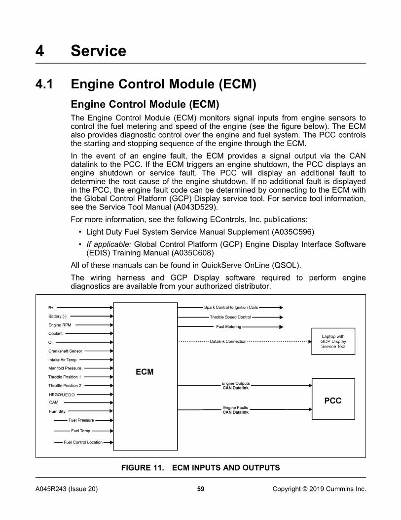
59A045R243 (Issue 20) Copyright © 2019 Cummins Inc.
4 Service
4.1 Engine Control Module (ECM)Engine Control Module (ECM)The Engine Control Module (ECM) monitors signal inputs from engine sensors tocontrol the fuel metering and speed of the engine (see the figure below). The ECMalso provides diagnostic control over the engine and fuel system. The PCC controlsthe starting and stopping sequence of the engine through the ECM.In the event of an engine fault, the ECM provides a signal output via the CANdatalink to the PCC. If the ECM triggers an engine shutdown, the PCC displays anengine shutdown or service fault. The PCC will display an additional fault todetermine the root cause of the engine shutdown. If no additional fault is displayedin the PCC, the engine fault code can be determined by connecting to the ECM withthe Global Control Platform (GCP) Display service tool. For service tool information,see the Service Tool Manual (A043D529).For more information, see the following EControls, Inc. publications:
• Light Duty Fuel System Service Manual Supplement (A035C596)• If applicable: Global Control Platform (GCP) Engine Display Interface Software
(EDIS) Training Manual (A035C608)All of these manuals can be found in QuickServe OnLine (QSOL).The wiring harness and GCP Display software required to perform enginediagnostics are available from your authorized distributor.
FIGURE 11. ECM INPUTS AND OUTPUTS

4. Service 8-2019
60 A045R243 (Issue 20)Copyright © 2019 Cummins Inc.
Keyswitch ControlThe keyswitch input to the ECM remains active during all controller modes otherthan when the Sleep Mode is active or the Emergency Stop is engaged. The PCCsends a start signal to the ECM via the Keyswitch Relay and the Start Relay. Whenthe PCC detects a start command, both relays become charged, sending the startsignal to the ECM, causing the engine to crank.
FIGURE 12. CONTROL SYSTEM BLOCK DIAGRAM
Reprogram ECMsReprogram GCP ECM
1. Obtain the latest revision of ECM calibration from the InCal website athttp://incal.cummins.com.
2. Save the file on a laptop.3. Make sure the generator set is stopped, is off (that is, in Off mode), and
the breaker is in the open position.4. If the unit is connected to a fuel supply, shut off the fuel supply.5. Connect the ECM to the laptop using an EControls GCP E-Com USB
interface cable (part number A047A982).6. Log in using one of the following passwords:
Tool PasswordGCP DD3F-OSHY-VJLV-IPGC
7. Open the GCP Display service tool.8. Use the pull-down File menu on the upper left of GCP Display screen and
select Reprogram Target. See the figure below.

4. Service8-2019
61A045R243 (Issue 20) Copyright © 2019 Cummins Inc.
FIGURE 13. PULL DOWN REPROGRAM TARGET SELECTION9. Select file to download (.MOT file). See the figure below.
FIGURE 14. MOT FILE10. The status bar displays the calibration status.11. Confirm in the lower left hand corner of the "Gauges" page that the new
calibration is loaded. See the figure below.

4. Service 8-2019
62 A045R243 (Issue 20)Copyright © 2019 Cummins Inc.
FIGURE 15. ECM UPDATE DOWNLOAD CONFIRMATION
Reprogram 4G ECM1. Obtain the latest revision of ECM calibration from the InCal website at
http://incal.cummins.com.2. A zip file is download. Unzip the folder for the model number of the
generator set and save it to a local file on a laptop.3. Make sure the generator set is stopped, is off (that is, in Off mode), and
the breaker is in the open position.4. If the unit is connected to a fuel supply, shut off the fuel supply.5. Connect the ECM to the laptop using an EControls E-Com USB interface
cable (part number A047A982).6. Log in using the following password:
Tool PasswordEControls Inc 4G Display GLTX-0BIS-534R-SVUX7. Open the 4G Display service tool.8. Select File on the upper left of the screen and select Reprogram Target
in the pull-down menu.

4. Service8-2019
63A045R243 (Issue 20) Copyright © 2019 Cummins Inc.
FIGURE 16. REPROGRAM TARGET SELECTION9. In the Select S-record/Mot File popup window, locate the saved unzipped
folder, select the latest revision of the .mot file, and select Load.
NOTICEMake sure to select the correct .mot file depending on if the OilPressure Sensor Type is Sender or Switch.
10. Select Yes in the Configuration confirmation box to perform thedownload. The Target Reprogram Progress bar shows the downloadstatus.
11. When the Successful message is displayed, select OK.
FIGURE 17. DOWNLOAD COMPLETE12. Check the Customer Configuration information section to confirm that the
software name/number is correct.

4. Service 8-2019
64 A045R243 (Issue 20)Copyright © 2019 Cummins Inc.
FIGURE 18. SOFTWARE NAME/NUMBER CONFIRMATION
Viewing Engine FaultsFault information can be viewed using the GCP Display service tool. See theReprogram ECM section for login information. The GCP Display service tool isavailable from Cummins. The GCP Display software consists of several pages ofdisplay information. All fault and diagnostic information is managed through theFaults page. Interaction includes viewing fault messages, downloading fault data(fault snapshot and flight data recorder), and erasing faults from memory.Faults are separated into two categories, Active and Historic. Active faults are activein real-time and historic faults have been generated at some instance in time thatmay or may not be active in real-time. When a fault becomes active, it isimmediately logged as historic and a snapshot and flight data log is saved. Thefigure below shows an example of the fault page when an active fault has beengenerated. Notice that the fault is present in both the active and historic lists and themalfunction indicator lamp (MIL) has been illuminated. The second figure belowshows an example of the fault page with a historic fault stored in memory.
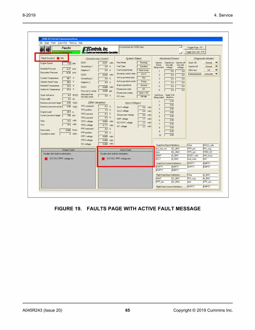
4. Service8-2019
65A045R243 (Issue 20) Copyright © 2019 Cummins Inc.
FIGURE 19. FAULTS PAGE WITH ACTIVE FAULT MESSAGE

4. Service 8-2019
66 A045R243 (Issue 20)Copyright © 2019 Cummins Inc.
FIGURE 20. FAULTS PAGE WITH HISTORIC FAULT MESSAGEWhen an engine fault occurs, a fault snapshot (FSS) and flight data recorder (FDR)are logged within the ECM.Fault snapshot is data recorded at the instant the fault is triggered. This data is onlylogged for the first eight (8) faults on the first occurrence of each fault. The faultsnapshot is a sample of data taken at the instance the fault triggered. The faultsnapshot is stored in the EEPROM and is retained even when battery power hasbeen lost.The flight data recorder is ten seconds of recorded data, eight (8) seconds prior tothe fault and two (2) seconds following the fault. This data is saved for the first twooccurrences of the fault. Flight data recorder data is saved in the RAM, and will beerased if the ECM loses battery power.Both sets of data are accessed from the Historic Fault Information interface and canbe saved to the PC upon retrieval.

4. Service8-2019
67A045R243 (Issue 20) Copyright © 2019 Cummins Inc.
Accessing Fault InformationFault information can be accessed by double left-clicking the fault LED in thehistoric fault list. This produces the Historic Fault Information interface shown in theimage below. From this interface the user can interpret a diagnostic trouble code(DTC) message, identify whether or not the fault occurred during the current startcycle, identify if the fault caused the engine to shut down, determine how many startcycles have occurred since the fault was last active, and view snapshot and flightdata.
FIGURE 21. HISTORIC FAULT INFORMATION INTERFACEThe table below outlines the options displayed in the Historic Fault Informationscreen. Historic faults are not overwritten if the same fault becomes active, storingdata from the original active fault.
TABLE 19. HISTORIC FAULT INFORMATION INTERFACE FUNCTIONS
Fault Description MessageBox
Customized Text that References the DTC Flash Codeand Describes the Fault
Fault During Key CycleCheckbox
Informs that the fault occurred during the current key-onevent.
Fault Caused EngineShutdown Checkbox
Informs that the fault caused the engine to shutdown.
Key Cycles Since Fault ActiveIndicator
Displays the amount of key-on events since the fault was lastactive.
Clear This Fault Button* Erases the selected historic fault from the ECM.
Clear All Faults Button* Erases all historic faults from the ECM.

4. Service 8-2019
68 A045R243 (Issue 20)Copyright © 2019 Cummins Inc.
Fault Description MessageBox
Customized Text that References the DTC Flash Codeand Describes the Fault
View Snap Shot Data Button Retrieves a data “snap shot” from the ECM for variablesdefined in the base and custom snapshot variable definitionlists.
View Flight Data RecorderData Button
Retrieves a 10-second data strip chart (8 seconds prior, 2seconds after fault trigger) from the ECM for variablesdefined in the base and custom flight data recorder definitionlists. An example.
Close Button Exits the Historic Fault Information interface. DOES NOTcancel or clear any faults.
* Snapshot and flight data recorder data for historic faults is erased if the fault is cleared frommemory.
The image below is an example of a fault snapshot after View Fault Snapshot isselected. Data is presented in two columns, base and custom variables. Whenretrieved, the FSS data may be saved to the PC in text format with an .fssextension. A FSS saved to a PC may be reviewed in any ASCII based softwareprogram.
FIGURE 22. SNAPSHOT DATA INTERFACE

4. Service8-2019
69A045R243 (Issue 20) Copyright © 2019 Cummins Inc.
The image below shows the Flight Data Recorder interface after View Flight DataRecorder is selected. The FDR captures a ten second (eight seconds prior and twoseconds after generating the fault) strip of data for base and custom variables. FDRdata is presented in an interface similar to the Plot interface for a quick graphicalpresentation. From this interface, the FDR data may be saved to the PC in text, tab-delimited format with an .fdr file extension. When saved to a PC, FDR data may bereviewed using any graphical post-processing software capable of handling tab-delimited formatting.
FIGURE 23. FLIGHT DATA RECORDER INTERFACEFor more information regarding the GCP Display service tool, refer to the followingdocument:
• If applicable: Global Control Platform (GCP) Engine Display Interface Software(EDIS) Training Manual
ECM Fault CodesNOTICE
The E-controls manual applies to several applications. See the wiringdiagrams provided with the generator set or in APPENDIX for appropriate pinnumbers.
Code Fault Name Additional Information
DTC-16 Crank and/or Cam Could NotSynchronize During Start
Hall-Effect sensor on Crankshaft, MPUsensor on camshaft
DTC-107 MAP low voltage
DTC-108 MAP High Pressure
DTC-111 IAT higher than expected Stage 1
DTC-112 IAT low voltage

4. Service 8-2019
70 A045R243 (Issue 20)Copyright © 2019 Cummins Inc.
Code Fault Name Additional InformationDTC-113 IAT high voltage
DTC-116 ECT higher than expected Stage 1
DTC-117 ECT / CHT low voltage
DTC-118 ECT / CHT high voltage
DTC-121 TPS1 % lower than TPS2 %TPSs are potentiometers, with 1starting 'low' at 0 resistance.DTC-122 TPS1 Signal Voltage Low
DTC-123 TPS1 Signal Voltage High
DTC-127 IAT higher than expected Stage 2
DTC-129 BP low pressure
DTC-134 EGO1 open / lazy (HO2S1)
DTC-217 ECT higher than expected 2
DTC-221 TPS1 % higher than TPS2 %TPSs are potentiometers, with 1starting 'low' at 0 resistance.DTC-222 TPS2 Signal Voltage Low
DTC-223 TPS2 Signal Voltage High
DTC-336 Crank Input Signal Noise Hall-Effect sensor used
DTC-337 Loss of Crankshaft Input Signal Hall-Effect sensor used
DTC-341 Camshaft Input Signal Noise MPU sensor used
DTC-342 Loss of Camshaft Input Signal MPU sensor used
DTC-359 Fuel run-out longer than expected See DTC-1181
DTC-520 Oil pressure low stage 1 (sender) see DTC-524
DTC-522 Oil pressure sender low voltage see DTC-524
DTC-523 Oil pressure sender high voltage see DTC-524
DTC-524 Oil Pressure Lowinspect the sensor: 1 wire= normallyopen switch, three wire= pressuresensor
DTC-562 Battery Voltage (VBat) Low < 7.5 VDC
DTC-563 Battery Voltage (VBat) High > 16.5 VDC
DTC-601 Microprocessor Failure - Flash
DTC-604 Microprocessor Failure - RAM
DTC-606 Microprocessor Failure - COP
DTC-642 Sensor Supply Voltage 1 Low (5Vext1)

4. Service8-2019
71A045R243 (Issue 20) Copyright © 2019 Cummins Inc.
Code Fault Name Additional Information
DTC-643 Sensor Supply Voltage 1 High(5Vext1)
DTC-1151 Closed Loop High (LPG)
DTC-1152 Closed Loop Low (LPG)
DTC-1153 Closed Loop High (Natural Gas)
DTC-1154 Closed Loop Low (Natural Gas)
DTC-1161 Adaptive Learn High (LPG)
DTC-1162 Adaptive Learn Low (LPG)
DTC-1163 Adaptive Learn High (NG)
DTC-1164 Adaptive Learn Low (NG)
DTC-1171 MegaJector/EPR delivery pressurehigher than expected
EPR is integrated in the ECM in someunits
DTC-1172 MegaJector/EPR delivery pressurelower than expected
EPR is integrated in the ECM in someunits
DTC-1173 MegaJector/EPR comm lostEPR is integrated in the ECM in someunits. If this fault occurs, replace theECM/EPR module.
DTC-1174 MegaJector/EPR voltage supply high Ensure that pressure regulator valvemoves freely. If so, replace ECM/EPRmoduleDTC-1175 MegaJector/EPR voltage supply low
DTC-1176 MegaJector/EPR internal actuator faultdetection
DTC-1177 MegaJector/EPR internal circuitry faultdetection
DTC-1178 MegaJector/EPR internal comm faultdetection
DTC-1183 MegaJector autozero / lockoff failed See DTC-1181
DTC-1612 Microprocessor Failure - RTI 1
DTC-1613 Microprocessor Failure - RTI 2
DTC-1614 Microprocessor Failure - RTI 3
DTC-1615 Microprocessor Failure - A/D
DTC-1616 Microprocessor Failure - Interrupt
DTC-2111 Unable to reach lower TPS
DTC-2112 Unable to reach higher TPS

4. Service 8-2019
72 A045R243 (Issue 20)Copyright © 2019 Cummins Inc.
Code Fault Name Additional Information
DTC-2135 TPS1/2 simultaneous voltages out ofrange
DTC-2229 BP high pressure 26 psig for >2 seconds
DTC-9999 RPM higher than expected See DTC-219
4.2 SAE J1939 CAN (Controlled Area Network)SAE J1939 CAN (Controlled Area Network)The following section describes the function and operation of the J1939 ControlledArea Network (CAN) datalink, as it applies to this generator set. The engine controlmodule (ECM) communicates to the generator set controller (PCC) over thisnetwork.CAN communications follow the SAE J1939 communication protocol standard. TheCAN datalink is based on a main trunk no more than 131 feet (40 meters) long andwith 30 devices that is terminated by a 120 Ohm resistor at each end. Stubs nolonger than 3.3 feet (1 meter) extend from the main trunk to each module in the bus.
FIGURE 24. CAN DATALINK
CAN Datalink SignalsThe CAN datalink carries the binary signal between the ECM (Engine ControlModule) and the PCC controller. The binary signal is expressed by a change involtage. The table below shows how the generator set controller distinguishesbetween the voltage signals.

4. Service8-2019
73A045R243 (Issue 20) Copyright © 2019 Cummins Inc.
TABLE 20. CAN DATALINK VOLTAGE DIFFERENTIALS
Signal 0 1J1939 High (+) 2.5 V 3.5 V
J1939 Low (-) 2.5 V 1.5 V
Voltage Differential 0 V 2 V
The CAN datalink transmits the signal at 250 KBaud, or 250 kilobits per second.Hence, it is possible for the voltages on J1939 High (+) and J1939 Low (-) tochange 250,000 times per second.The figures below show examples of good and bad datalink signals, on a high-resolution oscilloscope. The bad signal is caused by termination problems (notermination, wrong termination, or bad termination).
FIGURE 25. CAN DATALINK: GOOD SIGNAL
FIGURE 26. CAN DATALINK: BAD SIGNAL

4. Service 8-2019
74 A045R243 (Issue 20)Copyright © 2019 Cummins Inc.
J11 ConnectionsThe CAN datalink connects to the PCC baseboard via connector J11. J11 pinconnections are identified in the table below.
TABLE 21. CONNECTOR J11
Description PinCAN + 20
CAN - 19
CAN Shield 17
Keyswitch + 22
Keyswitch - 21
The PCC uses this data to display engine status (sensor, warning and shutdownconditions). The datalink must remain active at all times. If not, the PCC will detectthe inactive datalink and display a datalink error shutdown condition.
4.3 SensorsThe following figure shows the locations of the sensors, senders and switches towhich the PCC responds for the engine.

4. Service8-2019
75A045R243 (Issue 20) Copyright © 2019 Cummins Inc.
No. Description No. Description1 Camshaft Position Sensor 3 Crankshaft Position Sensor
2 Coolant Temperature Sensor 4 Oil Pressure Sensor
FIGURE 27. QSJ2.4 ENGINE SENSOR LOCATIONS
Oil Pressure SensorThe oil pressure sensor is a normally open switch. When engine oil pressure fallsbelow 6 PSI, the switch closes. Once the ECM detects that the switch is grounded itsends a shutdown signal to the engine. The ECM will allow the engine to berestarted but will continue to send a shutdown signal if the pressure remains below6 PSI.
Engine Coolant Temperature (ECT) SensorThe PCC monitors the engine coolant temperature though the ECT (Engine CoolantTemperature) sensor mounted on the engine. The PCC uses this sensor input toprotect the engine from overheating during normal operation.
Crankshaft Position (CKP) SensorThe crankshaft position sensor (CKP) is used to determine engine RPM andcrankshaft position. The CKP uses a Hall Effect type sensor which generates asquare wave form. The CKP is located next to the trigger wheel mounted on the endof the crankshaft. The trigger wheel contains 60 teeth spaced 6 degrees apart withtwo teeth missing. By magnetically locating the empty space on each revolution, theECM can determine the position of the crankshaft and engine speed.

4. Service 8-2019
76 A045R243 (Issue 20)Copyright © 2019 Cummins Inc.
Camshaft Position (CMP) SensorThe camshaft position sensor (CMP) is a magnetic pickup (MPU) sensor. The CMPis used to determine when cylinder 1 reaches its compression stroke. The ECMuses this information to control fuel delivery to the proper cylinder.
Camshaft Position (CMP) SensorThe camshaft position sensor (CMP) is a Hall Effect type sensor. The CMP is usedto determine when cylinder 1 reaches its compression stroke. The ECM uses thisinformation to control fuel delivery to the proper cylinder.
Heated Exhaust Gas Oxygen (HEGO) SensorThe Heated Exhaust Gas Oxygen Sensor (HEGO), also referred to as an O2 sensor,is mounted before the catalyst in the exhaust system. The HEGO monitors theamount of oxygen in the exhaust system versus ambient conditions and generates avoltage output relative to the reading. This information is used to determine a rich orlean condition in the engine. In the event of a rich mixture, the typical HEGO outputis 0.8 to 0.9 VDC. In the event of a lean mixture, the voltage drops to between 0.1to 0.3 VDC. The ECM communicates with the HEGO, and adjusts the fuel system tomaintain the proper air/fuel mixture. At a perfectly balanced mixture the HEGOshould produce approximately 0.45 VDC.
Camshaft Sensor Replacement1. Measure the resistance of the Camshaft Position Sensor (1), which is the CMP
(described above). If the resistance is not between 900 Ohms and 1000 Ohms,the MPU should be replaced.

4. Service8-2019
77A045R243 (Issue 20) Copyright © 2019 Cummins Inc.
No. Description No. Description1 CMP Sensor 4 Engine Cam Gear
2 Mounting Hole 5 Timing Pin
3 Upper Cover
FIGURE 28. CMP SENSOR2. Remove the CMP (1) from the generator set.3. Bar the engine until a timing pin (5) on the engine cam gear (4) lines up in the
center of the mounting hole (2).4. Thread the CMP (1) in gently by hand until it just touches the pin (5).5. Back it out 1/4 turn and set the locknut.
CAUTIONDo not use the fan blade to bar over the engine. Doing that can damageblades and cause property damage and personal injury.
6. After adjustment, make sure the output voltage of the CMP (1) is correct. If theoutput voltage at cranking speed is less than 0.5 VAC, replace the CMP (1).

4. Service 8-2019
78 A045R243 (Issue 20)Copyright © 2019 Cummins Inc.
Additional SensorsIn addition to the sensors already mentioned, the ECM monitors a throttle positionsensor (TIP) and temperature manifold absolute pressure (TMAP) sensor tomaintain fuel control and emissions.
4.4 Fuses and RelaysFuses and Relays
WARNINGAccidental starting of a generator set can cause severe personal injury ordeath. Be sure to isolate the battery to prevent accidental starting whileworking on the generator set.
CAUTIONUse of an incorrect fuse or relay can damage the generator set. Usereplacement fuses and relays of the correct amperage.

4. Service8-2019
79A045R243 (Issue 20) Copyright © 2019 Cummins Inc.
Fuse and Relay Locations
No. Description No. Description1 Power Relay (K2) 6 Fuse, 10A, 250 VDC (F4)
2 Power Relay (K4) 7 Fuse, 20A, 32 VDC (F3)
3 Power Relay (K6) 8 Fuse, 15A, 32 VDC (F2)
4 Power Relay (K5) 9 Fuse, 10A, 250 VDC (F1)
5 Fuse, 10A, 600 VAC (F5)
Fuse and Relay Replacement1. Disconnect the negative (-) cable from the battery first.2. Remove the positive (+) cable from the battery.3. Remove the fuse or relay box cover.4. Remove the faulty fuse or relay.

4. Service 8-2019
80 A045R243 (Issue 20)Copyright © 2019 Cummins Inc.
5. Check the fuse or relay for continuity. If the fuse or relay shows an open circuit,replace the fuse or relay.
6. Install a new fuse or relay. The new fuse or relay must be of the sameamperage and voltage as the old fuse or relay.
7. Replace the fuse or relay box cover.8. Connect the positive (+) cable to the battery first.9. Connect the negative (-) cable to the battery.
10. Start the generator set to see if the fault condition is fixed.11. If the replaced fuse or relay becomes open again, troubleshoot to find the fault.
Replace the fuse or relay after the fault has been repaired.
4.5 Fuel SystemFuel System DrawingsThe engine is equipped with a fuel mixer to run on natural gas or propane vapor.
WARNINGGaseous fuels are flammable and explosive. They can cause severepersonal injury or death. Do not allow cigarettes, flame, pilot lights, arcingswitches, or electrical equipment near gaseous fuel ventilations. Keep anABC-type multi-purpose fire extinguisher available.
CAUTIONDo not attempt to correct power by adjusting fuel system before determiningthat the engine and the ignition system are functioning properly. Be sure tocheck if there is air cleaner restriction due to dirt accumulation.

4. Service8-2019
81A045R243 (Issue 20) Copyright © 2019 Cummins Inc.
No. Description No. Description
1 Integrated Electronic PressureRegulator (IEPR) 3 Throttle Body
2 Shutoff Solenoid Valve 4 Mixer Assembly
FIGURE 29. PROPANE VAPOR OR NATURAL GAS FUEL SYSTEM

4. Service 8-2019
82 A045R243 (Issue 20)Copyright © 2019 Cummins Inc.
No. Description No. Description
1 Integrated Electronic PressureRegulator (IEPR) 4 Throttle Body
2 Shutoff Solenoid Valves 5 Mixer Assembly
3 Low Pressure Sensor
FIGURE 30. DUAL FUEL NATURAL GAS AND PROPANE VAPOR FUEL SYSTEM
Fuel System AdjustmentsNOTICE
Read the warranty statement provided with the generator set for USEnvironmental Protection Agency (EPA) restrictions on servicing specificcomponents.
Fuel Pressure RequirementsThe minimum pressure refers to supply pressure under rated load (maximum gasflow).

4. Service8-2019
83A045R243 (Issue 20) Copyright © 2019 Cummins Inc.
Make sure that pipeline quality gas is used.For the required fuel pressure supply range for propane vapor or natural gas, seethe Model Specifications section.
Fuel System Components and OperationThis generator set is equipped for natural gas, propane or both, with automaticchangeover. Each fuel has a fuel shutoff solenoid. Generator sets utilizing liquidwithdrawal of propane are equipped with a converter that vaporizes the fuel with hotengine coolant.A generator set equipped for natural gas and propane has a Direct ElectronicPressure Regulator, Mixer Assembly and Electronic Throttle Body that serves bothfuels. A fuel pressure switch detects the loss of natural gas (primary fuel) forautomatic change over to propane while the engine is running.
Converting the Fuel System TypeFor single-fuel systems, the generator set leaves the factory configured fornatural gas. No mechanical parts are required for fuel conversion. To convertthe fuel system type, configure the control.
1. Enter the Fuel System Menu.a. From any Info Menu, hold down the up and down arrows
simultaneously for two seconds. The Service Menu appears.b. Select Setup Menus.c. Enter the password 574 on the Password screen. The Setup Menu
appears.d. Select Genset Service.e. Select Genset.f. Advance through the screens until the Fuel System Setup Menu
appears.2. Update the Fuel System Type on the Fuel System Setup Menu. See the
figure below.a. Press Adjust on the Fuel System Menu.b. Edit the Fuel System using the horizontal arrow key. Change the field
value by using the +/- keys.

4. Service 8-2019
84 A045R243 (Issue 20)Copyright © 2019 Cummins Inc.
FIGURE 31. FUEL SYSTEM TYPE

4. Service8-2019
85A045R243 (Issue 20) Copyright © 2019 Cummins Inc.
3. Update the Gas Fuel Type on the Fuel System Menu.a. When changing the Fuel System, a second Fuel System Menu is
enabled. Advance to this menu by pressing the down arrow aftersaving any changes.
b. Press Adjust on the Fuel System Menu.c. Edit the Gas Fuel Type by using the horizontal arrow key. See the
figure below.
FIGURE 32. GAS FUEL TYPEd. Change the field value to Natural Gas, Liquid Propane, or Dual by
using the +/- keys.e. Select Save to save the changes.

4. Service 8-2019
86 A045R243 (Issue 20)Copyright © 2019 Cummins Inc.
Fuel Shutoff Solenoid ValveWhen the engine is cranking or running, an electronic signal is sent to thesolenoid, which opens the valve permitting fuel to flow to the pressureregulator and mixer. When the engine is stopped, fuel is sealed off within thevalve.There are two pressure ports on each side of the solenoid. The inlet andoutlet valve flange also include a pressure port. The two in-line pressure portson the valve body side correspond to each flange pressure port. Thecorresponding side and flange ports will give the same pressure reading. Thetop valve body side pressure port measures the pressure between the twoshut-off valves. This port is used to determine if the first valve is leaking.
No. Description No. Description1 Inlet Pressure Port 3 Power Plug
2 Outlet Pressure Port
Note: Test port threads are G-1/8" and not 1/8" NPT. For test purposes only, a 1/8" ISOmale to 1/8" NPT female adapter may be used.
FIGURE 33. FUEL SHUTOFF SOLENOID VALVE
Fuel Shutoff Solenoid TroubleshootingIf the generator set does not start, first determine if both valves are in goodcondition before adjusting the fuel system.
1. Disconnect the terminals between the wire harness going to the valveassembly and the engine harness.
2. Check for voltage at the solenoid coils. Use a multi-meter to measure 12VDC between the B+ wire and ground of the engine harness.
• If no voltage is measured, check for blown fuses or bad wiring whilecranking.

4. Service8-2019
87A045R243 (Issue 20) Copyright © 2019 Cummins Inc.
• If voltage is less than or equal to 10.2 VDC, check for bad wiring orlow battery voltage.
• If voltage is greater than 10.2 VDC, check for correct solenoidoperation
3. Check for solenoid operation.a. While holding onto the solenoid, apply 12 VDC to a coil on one of the
solenoids.b. Listen and feel for the solenoid to activate.c. Repeat applying the voltage a few times to be sure the solenoid
operates.d. Repeat these steps for all solenoids.e. If either solenoid does not activate, use a multi-meter to measure
resistance of the coil. The resistance should be 11 Ohms.• If the resistance is not 11 Ohms, replace the solenoid.• If the resistance is 11 Ohms, replace the gas valve assembly.
4. Check for fuel leaks at the solenoid. With a soapy water solution, checkpipe threads and areas around the base of the solenoid for gas leakage.
• If a pipe thread is showing bubbles, tighten the pipe connection.• If anywhere on the gas valve shows bubbles or leakage, replace the
complete gas valve assembly.
Coil Assembly ReplacementTo remove the coil assembly:
1. Loosen the knob lock screw and remove the knob.2. Loosen the power plug lock screw and remove the power plug.3. Pull straight up to remove the coil assembly from the solenoid body.
To reinstall the coil assembly:1. Insert the coil assembly into the solenoid body.2. Replace the power plug and tighten the power plug lock screw.3. Replace the knob and tighten the knob lock screw.
Integrated Electronic Pressure Regulator (IEPR)The Integrated Electronic Pressure Regulator (IEPR) utilized on US emissioncertified engines is a critical part of the certified emissions system and doesnot require any periodic adjustment.The IEPR is connected directly to the mixer on all certified engines. The IEPRis the primary fuel control device, used to maintain both performance andemissions control. The IEPR contains an internal computer, whichcommunicates with the ECM, via CAN datalink.

4. Service 8-2019
88 A045R243 (Issue 20)Copyright © 2019 Cummins Inc.
The IEPR precisely controls the fuel flow to deliver the correct Air Fuel ratio tothe engine. The IEPR also contains fuel pressure and temperature sensors,which provide input to the ECM for fuel calculation.If the IEPR detects a fault within the system, it will send the information to theECM. Depending on the type of fault, the ECM may command the IEPR tochange fueling, limit fuel delivery or in some cases shut down the engine.
FIGURE 34. INTEGRATED ELECTRONIC PRESSURE REGULATOR (IEPR)
Mixer AssemblyThe mixer acts as the secondary fuel metering device, and delivery device, inthe emission control system. The mixer utilized on USA emission certifiedengines is a critical part of the certified emission system and does not requireany periodic adjustment and does not have any external or internaladjustments.The mixer is a completely self-controlled air-fuel metering device. It is an airvalve design, utilizing a constant pressure drop to draw fuel into the mixerfrom cranking to full load. The mixer is mounted to the air-inlet ahead of thethrottle control device.When the engine begins to crank, it draws in air. With the air valve coveringthe inlet, negative pressure builds. This creates a vacuum which is referred toas an air valve vacuum (AVV). The amount of AVV is a direct result of thethrottle position. At low engine speed the AVV is low and the air valve positionis low, thus creating a small Venturi effect. The IEPR maintains the precisefuel control to the mixer, despite the air valve position.

4. Service8-2019
89A045R243 (Issue 20) Copyright © 2019 Cummins Inc.
FIGURE 35. MIXER ASSEMBLY
Electronic Throttle Body (ETB)The Electronic Throttle Body (ETB) is connected to the intake manifold of theengine. The ETB control device uses an electronic motor connected to thethrottle shaft. When the engine is running, the ECM sends an electrical signalto the ETB motor, to increase or decrease the angle of the throttle blade, thusincreasing or decreasing the air fuel mixture flow to the engine.The fuel system uses an electronic signal, Drive By Wire (DBW), to controlengine speed. The ECM determines speed and load control. Defaultsprogrammed into the ECM software and the throttle position sensors allow theECM to maintain safe operating control over the engine.The ETB also incorporates two internal Throttle Position Sensors (TPS) whichprovide output signals to the ECM. The ECM uses TPS information to correctspeed and load control, as well as emission control and engine protection.The ETB used on US emission certified engines does not require any periodicadjustment.

4. Service 8-2019
90 A045R243 (Issue 20)Copyright © 2019 Cummins Inc.
FIGURE 36. ELECTRONIC THROTTLE BODY (ETB)
4.6 Cooling SystemCooling System ComponentsCooling system components are shown below:

4. Service8-2019
91A045R243 (Issue 20) Copyright © 2019 Cummins Inc.
No. Description No. Description1 Radiator 6 Coolant Level Sensor
2 Charging Air Cooler/After Cooler(Where Fitted) 7 Coolant Hose
3 Shroud 8 Coolant Fill Housing
4 Radiator Guard 9 Oil Cooler Hose (Where Fitted)
5 Air Hose 10 Coolant Bottle
FIGURE 37. COOLING SYSTEM COMPONENTS
Cooling System MaintenanceThis section provides information on cleaning the radiator and updated informationregarding bearings that has been provided by our supplier to enable efficient andprolonged life of the equipment.

4. Service 8-2019
92 A045R243 (Issue 20)Copyright © 2019 Cummins Inc.
NOTICEThe following information regarding the correct choice and fitting of hoseclamps has also been provided by our supplier to assist and guide the user.
Radiator Assembly Removal and InstallationFollow these steps to remove the radiator assembly:
1. Remove the enclosure doors, as applicable. See the figure below.
FIGURE 38. ENCLOSURE DOOR REMOVAL2. Disconnect the battery connections. See the figure below.

4. Service8-2019
93A045R243 (Issue 20) Copyright © 2019 Cummins Inc.
FIGURE 39. REMOVE CONNECTIONS3. Drain the coolant.4. Drain the engine oil (if an oil cooler is equipped).5. Remove the CAC inlet and outlet connections (if equipped with a
turbocharger and after cooler).6. Remove the coolant connections.7. Remove the oil cooler connections (if the oil cooler is equipped).8. Remove the coolant reservoir bottle from the fan guard.9. Remove the fan guards. See the figure below.
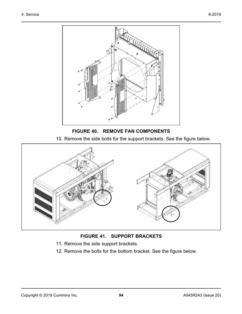
4. Service 8-2019
94 A045R243 (Issue 20)Copyright © 2019 Cummins Inc.
FIGURE 40. REMOVE FAN COMPONENTS10. Remove the side bolts for the support brackets. See the figure below.
FIGURE 41. SUPPORT BRACKETS11. Remove the side support brackets.12. Remove the bolts for the bottom bracket. See the figure below.

4. Service8-2019
95A045R243 (Issue 20) Copyright © 2019 Cummins Inc.
FIGURE 42. SUPPORT BRACKETS AND BOTTOM BRACKET13. Remove the radiator assembly on the side. See the figure below.
FIGURE 43. REMOVE RADIATORFor radiator assembly installation, follow the previous steps in reverse order.
NOTICEAlternator disc bolts and adapter bolts are all 52 Nm torque with +/- 5Nm (38.5 ft-lb with +/- 3.7 ft-lb) tolerances.

4. Service 8-2019
96 A045R243 (Issue 20)Copyright © 2019 Cummins Inc.
Water Pump Removal and InstallationWater Pump Removal
1. Drain the coolant.2. Remove radiator hose from inlet of water pump.3. Remove the timing belt.4. Remove the water pump bolts.5. Remove the water pump.
FIGURE 44. WATER PUMPWater Pump Installation
1. Install the water pump with a new gasket.2. Tighten the water pump bolts to 14 Nm (10.4 ft-lb).3. Install the radiator hose.4. Install the timing belt.
Thermostat Installation1. Check that the rubber ring is undamaged and seated correctly in the
thermostat flange. See the figure below.

4. Service8-2019
97A045R243 (Issue 20) Copyright © 2019 Cummins Inc.
FIGURE 45. THERMOSTAT HOUSING LOCATION2. Install the thermostat. Make sure that the jiggle valve is at the uppermost
position. Tightening torque: 24 Nm. See the figure below.

4. Service 8-2019
98 A045R243 (Issue 20)Copyright © 2019 Cummins Inc.
FIGURE 46. THERMOSTAT
4.7 Exhaust SystemOverview
NOTICERead the warranty statement provided with the generator set for USEnvironmental Protection Agency (EPA) restrictions on servicing specificcomponents.
The exhaust system is comprised of up to three active components - theturbocharger (if equipped), the oxygen sensor, and the muffler/catalytic converter (ifequipped) - in addition to manifold(s) and piping connecting the components.
Oxygen SensorDuring normal operation, the oxygen sensor monitors the oxygen content of theexhaust gases and sends a voltage signal to the ECM. The ECM monitors thisvoltage. The oxygen sensor has a heating element incorporated into the sensor toaid in the warm-up to the proper operating temperature and to maintain thattemperature.The oxygen sensor produces no voltage when it is below its normal operatingtemperature of about 600 °F (315.5 °C). During this warm-up period, the ECMoperates in an open-loop fuel control mode. It does not use the oxygen sensorsignal. Instead, the ECM controls fuel metering based on other inputs and its ownprogram. Refer to the Sensors section for more information.

4. Service8-2019
99A045R243 (Issue 20) Copyright © 2019 Cummins Inc.
Proper operation of the oxygen sensor depends on three conditions:• Good electrical connections: The low voltages generated by the sensor require
good, clean connections which should be checked whenever a sensor problemis suspected or indicated.
• Outside air supply: The sensor needs proper exhaust circulation to the internalportion of the sensor and proper air circulation to the external portion of thesensor. Whenever the sensor is installed, make sure the air passages are notrestricted.
• Proper operating temperature: The ECM will not react to the sensor signal untilthe sensor reaches approximately 600 °F (315.5 °C). This factor must beconsidered when evaluation the performance of the sensor.
Your authorized Cummins Inc. distributor can monitor fuel system/oxygen sensoroperation using the GCP Display service tool and the ECM.

4. Service 8-2019
100 A045R243 (Issue 20)Copyright © 2019 Cummins Inc.
Exhaust System Graphic
No. Description No. Description1 Clamp 4 Muffler Out
2 Oxygen Sensor 5 Muffler
3 Gasket 6 Muffler In
FIGURE 47. EXHAUST SYSTEM

4. Service8-2019
101A045R243 (Issue 20) Copyright © 2019 Cummins Inc.
Muffler RemovalWARNING
Exhaust pipes and mufflers are very hot and can cause severe personalinjury or death from direct contact or from fire hazard. Allow the muffler tocool down before removing.
Remove Enclosure End Panel1. Remove bolts from top panel (1). Torque 9.8 to 11.9 Nm (7.3 to 8.8 ft-lb).
No. Description No. Description1 Top Panel 2 End Panel
FIGURE 48. ENCLOSURE END PANEL REMOVAL2. Remove top panel (1).

4. Service 8-2019
102 A045R243 (Issue 20)Copyright © 2019 Cummins Inc.
3. Slide end panel (2) up to unlatch the panel, then pull the end panel off.
Remove Muffler
No. Description No. Description1 Clamps 3 Bolts
2 Exhaust Pipe 4 Muffler
FIGURE 49. MUFFLER REMOVAL1. Remove three clamps (1).2. Remove exhaust pipes (2) from muffler (4).3. Remove two bolts (3) from each end of muffler (4).

4. Service8-2019
103A045R243 (Issue 20) Copyright © 2019 Cummins Inc.
4. Remove muffler (4) from enclosure.
Muffler InstallationInstall Muffler
1. Place the muffler (4) over the four bolt holes in the skid. Refer to Figure49.
2. Attach the muffler (4) with two bolts (3) on each end of muffler (4).3. Install exhaust pipes (2) on the muffler (4).4. Install three clamps (1).
Install Enclosure End Panel1. Place the end panel (2) on each side panel locating pin. Refer to Figure
48.2. Slide the end panel (2) down to latch the panel onto the locating pins.3. Attach the top panel (1) with bolts on three sides and the top.
4.8 Engine and AccessoriesTiming Belt Removal (A)
1. Remove the enclosure covers. See the figure below.
FIGURE 50. ENCLOSURE COVER REMOVAL2. Disconnect the battery connections.3. Remove CAC inlet and outlet connections (if equipped with turbocharger and
after cooler).4. Remove the coolant reservoir bottle from fan guard, but do not disconnect.

4. Service 8-2019
104 A045R243 (Issue 20)Copyright © 2019 Cummins Inc.
5. Remove the fan guards. See the figure below.
FIGURE 51. FAN GUARD REMOVAL6. Remove the fan. See the figure below.
FIGURE 52. FAN REMOVAL7. Remove the water pump, fan, and battery charging alternator belt. See the
figure below.

4. Service8-2019
105A045R243 (Issue 20) Copyright © 2019 Cummins Inc.
FIGURE 53. WATER PUMP, FAN, AND BATTERY CHARGING ALTERNATOR BELT8. Remove all of the ignition coils and spark plugs. See the figure below.
FIGURE 54. IGNITION COILS AND SPARK PLUGS9. Remove the timing belt upper covers. See the figure below.

4. Service 8-2019
106 A045R243 (Issue 20)Copyright © 2019 Cummins Inc.
FIGURE 55. TIMING BELT UPPER COVER REMOVAL10. Remove the crankshaft pulley.11. Remove the cylinder block plug as shown in the figure below.
FIGURE 56. CYLINDER BLOCK PLUG

4. Service8-2019
107A045R243 (Issue 20) Copyright © 2019 Cummins Inc.
12. Check the orientation of the balance shaft by inserting a Phillips screwdriverwith a shaft diameter of 8 mm (0.32 in).
• The correct orientation of the balance shaft allows the screwdriver to beinserted 60 mm (2.36 in) before contacting the balance shaft.
• The incorrect orientation of the balance shaft will only allow the screwdriverto be inserted 20 - 25 mm (0.79 - 0.98 in) before contacting the balanceshaft.
If the balance shaft orientation is incorrect, rotate the oil pump sprocket 1 fullrevolution and re-check the balance shaft orientation. Repeat until the balanceshaft is correctly oriented.
NOTICEDo not remove the screwdriver until after the timing belt has beeninstalled.
13. Remove the timing belt lower cover. See the figure below.
FIGURE 57. TIMING BELT LOWER COVER REMOVAL14. Rotate the engine, and ensure that all of the timing marks are aligned. See the
figure below.

4. Service 8-2019
108 A045R243 (Issue 20)Copyright © 2019 Cummins Inc.
FIGURE 58. TIMING MARK ALIGNMENT15. Mark the arrow on the belt if the belt is going to be reused. See the figure
below.
FIGURE 59. ARROW MARK
NOTICEWater or oil on the belt shortens its life drastically, so wash or immersethe removed timing belt, sprocket, and tensioner in solvent. Replaceparts if contaminated. If there is oil or water on any part, check the frontcase oil seals, camshaft oil seal, and water pump for leaks.
16. Remove the autotensioner on the front case.

4. Service8-2019
109A045R243 (Issue 20) Copyright © 2019 Cummins Inc.
17. Loosen the center bolt on the tensioner pulley. See the figure below.
No. Description No. Description1 Autotensioner 2 Center Bolt
FIGURE 60. AUTOTENSIONER18. Remove the timing belt.
Timing Belt Removal (B)1. See the procedures in the Timing Belt Removal (A) section.2. Remove the timing belt indicator.3. Loosen the center bolt on the tensioner pulley.4. Remove the timing belt. See the figure below.

4. Service 8-2019
110 A045R243 (Issue 20)Copyright © 2019 Cummins Inc.
No. Description No. Description1 Timing Belt Indicator 2 Timing Belt B Tensioner
FIGURE 61. TENSIONER PULLEY
Timing Belt Installation (A)NOTICE
Special tool(s) required: Tension Pulley Wrench (part number A044J293)
1. If timing belt B was removed, refer to the Timing Belt Installation (B) sectionbefore installing timing belt A.
2. Install the tensioner pulley. See the figure below.
FIGURE 62. TENSIONER PULLEY

4. Service8-2019
111A045R243 (Issue 20) Copyright © 2019 Cummins Inc.
3. If the autotensioner rod is fully extended, clamp it in a vise with soft jaws. Seethe figure below.
FIGURE 63. AUTOTENSIONER IN VISE4. Push in the rod slowly with the vise until the set hole A in the rod is aligned with
hole B in the cylinder. See the figure below.
FIGURE 64. HOLE ALIGNMENT5. Insert a wire (1.4 mm in diameter) into the set holes. This autotensioner setting
wire is used during timing belt alignment.6. Unclamp the autotensioner from the vise.7. Install the autotensioner onto the front case and tighten. Torque 24± 3 Nm (17.8
ft-lb +/- 2.2 ft-lb). See the figure below.
NOTICELeave the wire installed in the autotensioner.

4. Service 8-2019
112 A045R243 (Issue 20)Copyright © 2019 Cummins Inc.
FIGURE 65. INSTALL AUTOTENSIONER8. Align the timing mark on the camshaft sprocket with the timing mark on the
rocker cover. See the figure below.
FIGURE 66. CAMSHAFT SPROCKET AND ROCKER COVER TIMING MARKS9. Align the timing mark on the crankshaft sprocket with the timing mark on the
front case. See the figure below.
FIGURE 67. CRANKSHAFT SPROCKET AND FRONT CASE TIMING MARKS

4. Service8-2019
113A045R243 (Issue 20) Copyright © 2019 Cummins Inc.
10. Align the timing mark on oil pump sprocket with its mating mark. See the figurebelow.
FIGURE 68. OIL PUMP SPROCKET AND MATING TIMING MARKS11. In the following order, install the timing belt on the crankshaft sprocket, oil pump
sprocket, idler pulley, camshaft sprocket, and tensioner pulley. Ensure that alltiming marks are aligned and that there is no slack on the tension side. See thefigure below.
FIGURE 69. TIMING BELT A TENSION SIDE12. Lift up the tensioner pulley in the direction of the arrow and tighten the center
bolt. See the figure below.

4. Service 8-2019
114 A045R243 (Issue 20)Copyright © 2019 Cummins Inc.
FIGURE 70. AUTOTENSIONER DIRECTION13. Check that all timing marks are aligned.14. Turn the crankshaft a quarter turn counterclockwise. Then, turn it clockwise
until the timing marks are aligned again.15. Install special tool tension pulley socket wrench. See the figure below.
FIGURE 71. AUTOTENSIONER WITH SOCKET WRENCH16. With the special tool tension pulley socket wrench, socket wrench, and torque
wrench, loosen the tensioner pulley center bolt. Use a beam or dial style torquewrench that can measure 0 to 5.0 Nm (0 to 3.7 ft-lb). See the figure below.

4. Service8-2019
115A045R243 (Issue 20) Copyright © 2019 Cummins Inc.
FIGURE 72. AUTOTENSIONER WITH SOCKET WRENCH (WITH BELT TENSIONINGARM)
17. Torque counter-clockwise (as shown in the figure above) to 2.5 to 2.6 Nm (1.85to 2 ft-lb) with the torque wrench so that the belt tensioning arm puts pressureon the autotensioner when released.
18. Holding the tensioner pulley with the special tool and torque wrench, tighten thecenter bolt to 48 ± 5 Nm (36 +/- 3.7 ft-lb).
19. Pull out the wire inserted at the autotensioner assembly. See the figure below.

4. Service 8-2019
116 A045R243 (Issue 20)Copyright © 2019 Cummins Inc.
FIGURE 73. REMOVE METAL WIRE20. Give two clockwise turns to the crankshaft. Wait 15 minutes.21. Check that the rod protrusion of the auto-tensioner is within the standard value,
which is 3.8 to 4.5 mm (0.15 to 0.18 in).22. If the protrusion is not to specification, repeat the previous steps until the
standard value is obtained as measured by the rod projection of theautotensioner rod.
23. Install the cover. Torque 11 Nm (8.1 ft-lb).24. Install the crank pulley. Torque 25 Nm (18.5 ft-lb).25. Install the timing belt front upper cover. Torque 11 Nm (8.1 ft-lb).26. Install the spark plugs. Torque 22.5 Nm (16.7 ft-lb).27. Install the engine bracket to the intake manifold. Torque 11 Nm ± 1 Nm (8.1 +/-
0.74 ft-lb).28. Install the ignition coil to the engine bracket. Torque 5 Nm ± 0.3 Nm (3.7 +/- 0.2
ft-lb).
Timing Belt Installation (B)1. Align timing marks on the crankshaft sprocket and counterbalance shaft
sprocket with the marks on the front case. See the figure below.

4. Service8-2019
117A045R243 (Issue 20) Copyright © 2019 Cummins Inc.
FIGURE 74. TIMING MARKS2. Install the timing belt on the crankshaft sprocket and counterbalance shaft
sprocket. Make sure that there is no slack on the tension side.3. Make sure that the tensioner pulley center and the bolt center are positioned as
shown in the figure below. See the figure below.
FIGURE 75. TENSIONER PULLEY CENTER4. Move the tensioner in the direction of the arrow while lifting with your finger to
give sufficient tension to the tension side of timing belt, and tighten the bolt tosecure tensioner. Torque to 19 ± 3 Nm (14 +/- 2.2 ft-lb). See the figure below.
NOTICEWhen the bolt is tightened, use care to prevent the tensioner pulley shaftfrom turning with the bolt. If the shaft is turned with the bolt, the belt willbe over tensioned.

4. Service 8-2019
118 A045R243 (Issue 20)Copyright © 2019 Cummins Inc.
FIGURE 76. TENSIONER DIRECTION5. Check that timing marks on the sprockets are aligned with the timing marks on
the front case.6. With your index finger, press the midway of span on the tension side of timing
belt. The belt must deflect 5 to 7 mm. See the figure below.
FIGURE 77. CHECK TIMING BELT TENSION
Cylinder Head Assembly TorquingSpecial tool(s) required: Cylinder Bolt Wrench (part number A044J309)
1. Install the cylinder head bolt.a. If reusing the removed cylinder head bolts, check that the shank length of
each bolt meets the limit 3.9 in (99.4 mm). If it exceeds the limit, replacethe bolts.
b. Apply engine oil to the thread of the bolts and to the washers. See thefigure below.

4. Service8-2019
119A045R243 (Issue 20) Copyright © 2019 Cummins Inc.
FIGURE 78. SHANK LENGTH2. Using special tool cylinder head bolt wrench, tighten the bolts to the specified
torque, using the tightening sequence shown below. Torque to 78 ± 2 Nm (58 ±1.5 ft-lb). See the figure below.
FIGURE 79. TORQUE SEQUENCE3. Loosen all bolts fully in the reverse order of tightening.

4. Service 8-2019
120 A045R243 (Issue 20)Copyright © 2019 Cummins Inc.
4. Retighten the loosened bolts to in the tightening sequence shown. Torque to 20± 2 Nm (14.8 +/- 1.48 ft-lb).
5. Use a torque angle gauge or make a paint mark across each bolt head andcylinder head.
6. Tighten the cylinder head bolts 90° in the specified order.7. Tighten the bolts another 90° in the same order sequence as referenced above,
and check that the paint marks on the cylinder head bolt are aligned with thepaint marks on the cylinder head. See the figure below.
FIGURE 80. PAINT MARK ALIGNMENT
NOTICEIf the bolt is turned less than 90°, proper fastening performance may notbe achieved. Be careful to turn each bolt exactly 90°. If the bolt isovertightened, loosen the bolt completely and then retighten it byrepeating the tightening procedure.
8. Install the camshaft pin if the cylinder head was replaced. See the figure below.a. Apply thread adhesive to the pin threads.b. Install the pin into the dimpled spoke on the camshaft sprocket. Torque to
11 Nm (8.1 ft-lb).

4. Service8-2019
121A045R243 (Issue 20) Copyright © 2019 Cummins Inc.
FIGURE 81. CAMSHAFT PIN MOUNTING
Front Seal InstallationSpecial tool(s) required: Crankshaft Sprocket Puller (part number A044H748) andCrankshaft Front Oil Seal Installer (part number A044J299)
1. Remove the timing belts (A and B).2. Loosen the crankshaft bolt, and remove the crankshaft bolt and washer. See
the figure below.
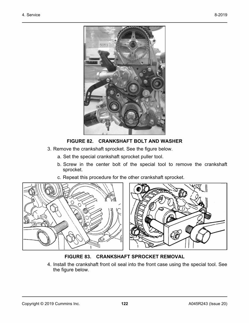
4. Service 8-2019
122 A045R243 (Issue 20)Copyright © 2019 Cummins Inc.
FIGURE 82. CRANKSHAFT BOLT AND WASHER3. Remove the crankshaft sprocket. See the figure below.
a. Set the special crankshaft sprocket puller tool.b. Screw in the center bolt of the special tool to remove the crankshaft
sprocket.c. Repeat this procedure for the other crankshaft sprocket.
FIGURE 83. CRANKSHAFT SPROCKET REMOVAL4. Install the crankshaft front oil seal into the front case using the special tool. See
the figure below.

4. Service8-2019
123A045R243 (Issue 20) Copyright © 2019 Cummins Inc.
FIGURE 84. CRANKSHAFT FRONT OIL SEAL
Engine Removal and InstallationFollow these steps to remove the engine:
NOTICEFor models C20 N6, C22 N6, C25 N6, and C30 N6H, the terminal boxes willneed to be removed to more readily access the alternator adaptor and drivedisk bolts.
1. Remove the enclosure covers as applicable. See the figure below.

4. Service 8-2019
124 A045R243 (Issue 20)Copyright © 2019 Cummins Inc.
FIGURE 85. REMOVAL OF ENCLOSURE COVERS2. Disconnect the following:
a. Disconnect the battery connections.b. Disconnect all harness connections between engine and other systems of
generator set.c. Drain the coolant.d. Drain the engine oil (if equipped with oil cooler).e. Disconnect coolant heater connections.f. Disconnect CAC inlet and outlet connections (if equipped with turbocharger
and after cooler).g. Disconnect oil cooler connections.
3. Do the following:a. Disengage the coolant reservoir bottle from fan guard (do not disconnect).b. Disconnect coolant connections from the engine.c. Disconnect exhaust connections from the engine.d. Remove the fan belt.

4. Service8-2019
125A045R243 (Issue 20) Copyright © 2019 Cummins Inc.
e. Remove the fan and keep it in the shroud. See the figure below.
FIGURE 86. DISCONNECTION OF ENGINE SYSTEMS4. Remove the terminal box cover/dome and alternator fan cover. See the figure
below.

4. Service 8-2019
126 A045R243 (Issue 20)Copyright © 2019 Cummins Inc.
FIGURE 87. REMOVAL OF TERMINAL BOX COVER AND DOME5. Position the fixture and remove bolts:
a. Securely support the engine with appropriate blocking which providesapproximately 2° before and after the tilt of the engine/generator (with thegenerator end higher). This should be enough to allow removal of theengine from the studs.
b. Remove the alternator drive disc bolts first and then remove the alternatoradaptor bolts. See the figure below.
NOTICEAlternator drive disc bolts and adaptor bolts should be torqued to 52Nm +/- 5 Nm (38.5 +/- 3.7 ft-lb).

4. Service8-2019
127A045R243 (Issue 20) Copyright © 2019 Cummins Inc.
FIGURE 88. DISENGAGEMENT OF ENGINE AND ALTERNATOR6. Secure the alternator with an appropriate lifting device. Pay attention to engine
tilts and potential damage to other nearby components. See the figure below.
NOTICEEngine weight is approximately 450 pounds.
NOTICEA Cummins lifting kit (part number A046P026) can be used for lifting theengine.

4. Service 8-2019
128 A045R243 (Issue 20)Copyright © 2019 Cummins Inc.
FIGURE 89. ENGINE REMOVALFor engine installation, follow the previous steps in reverse order.
NOTICEAlternator drive disc bolts and adaptor bolts should be torqued to 52 Nm +/-5 Nm (38.5 +/- 3.7 ft-lb).
QSJ2.4 Engine Torque Specifications
Item Nm ft-lb AngularIgnition System
Ignition coil 10 7.2
Spark plugs 24.5 18.08
Exhaust ManifoldThermostat housing bolts 23.5 17.36

4. Service8-2019
129A045R243 (Issue 20) Copyright © 2019 Cummins Inc.
Item Nm ft-lb AngularTiming Belt
Auto-tensioner bolts 23.5 17.36
Camshaft sprocket bolt 88.5 65.1
Counterbalance shaft sprocket bolt 45 33.27
Crankshaft pulley bolts 24.5 18.08
Crankshaft bolt 117.5 86.8
Engine support bracket bolt 48 35.44
Idler pulley bolt 35.5 26.4
Oil pump sprocket nut 54 39.78
Tensioner "B" bolt 18.5 13.74
Tensioner arm bolt 21.5 15.91
Tensioner pulley bolt 48 35.44
Timing belt cover bolts (bolt, washerassembly) 11 7.96
Timing belt cover bolts (flange bolt andnut) 11 7.96
Inlet Manifold and Water PumpWater pump bolts 14 10.4
Water pump pulley bolts 9 6.51
Engine hanger bolt 18.5 13.74
Oil pressure switch 10 7.2
Water temp gauge 29.5 21.7
Water outlet fitting bolts 19.5 14.5
Rocker Arms and CamshaftRocker arms and rocker arm shaft bolts 31.5 23.14
Rocker cover bolts 4 2.89
Thrust screw 18.5 13.74
Cylinder Head and ValvesCylinder head bolts 196 144.7 +90° to 100°
Oil Pan and Oil PumpDrain plug 44 32.55
Flange bolt 36.5 26.76

4. Service 8-2019
130 A045R243 (Issue 20)Copyright © 2019 Cummins Inc.
Item Nm ft-lb AngularFront case bolts 23.5 17.36
Oil filter bracket bolts 18.5 13.74
Oil filter 18.5 13.74
Oil pan bolts 7 5.06
Oil pump cover bolts 15.5 11.57
Oil pump cover screws 10 7.2
Oil screen bolts 18.5 13.74
Plug 23.5 17.36
Relief plug 44 32.55
Piston and Connecting RodConnecting rod cap nuts 196 144.7 +90° to 100°
Crankshaft and Cylinder BlockBearing cap bolts 24.5 18.08 +90° to 100°
Bell housing cover bolts 9 6.51
Oil seal case bolts 11 7.96
Rear plate bolts 11 7.96
4.9 Alternator ServiceGeneral DescriptionCA115 AlternatorThe CA115 alternator is of brushless rotating field design, available up to 600V,60Hz (1800 RPM, 4 pole and 3600 RPM, 2 pole), and built to meet B.S. 5000 Part 3and other international standards.Standard CA115 alternators are self-excited, with excitation power derived from themain output windings using either an AS480 AVR or PCC controller. A permanentmagnet generator (PMG) powered excitation system is available as an option witheither an AS480 AVR or PCC controller.
CA125 AlternatorThe CA125 alternator is of brushless rotating field design, available up to600V/60Hz (1800 RPM), and built to meet BS5000 Part 3 and internationalstandards.The standard CA125 alternator is self-excited, with excitation power derived fromthe main output windings using an SX460 AVR, AS440 AVR, or PCC controller.

4. Service8-2019
131A045R243 (Issue 20) Copyright © 2019 Cummins Inc.
A permanent magnet generator (PMG) powered excitation system is available as anoption using an MX341 AVR, MX321 AVR, or PCC controller.
CA135 AlternatorThe CA135 alternator is of brushless rotating field design, available up to600V/60Hz (3600 RPM), and built to meet BS5000 Part 3 and internationalstandards.The CA135 alternator is self-excited, with excitation power derived from the mainoutput windings using an SX460 AVR, AS440 AVR or PCC controller.
Air FlowMake sure that the air inlets and outlets are not obstructed when the alternator isrunning.
Humid ConditionsThe water carrying capacity of air depends on temperature. If the air temperaturefalls below its saturation point, dew may form on the windings, reducing theelectrical resistance of the insulation. In humid conditions, additional protection maybe required even if the alternator is fitted inside an enclosure. Anti-condensationheaters are supplied on request.
Anti-Condensation HeatersDANGER
Live Electrical ConductorsLive electrical conductors can cause serious injury or death by electricshock and burns.To prevent injury and before removing covers over electrical conductors,isolate the generator set from all energy sources, remove stored energy anduse lock out/tag out safety procedures.
Power to the anti-condensation heater is supplied from a separate source. Anti-condensation heaters raise the air temperature around the windings to detercondensation forming in humid conditions when the alternator is not operating. Bestpractice is to energize the heaters automatically when the alternator is off.
Alternator Removal and InstallationThe following instructions describe alternator removal and installation.
1. Remove enclosure components:a. Remove the roof, side doors and end cap.
NOTICETorque enclosure panel fasteners 9.8 to 11.9 Nm.

4. Service 8-2019
132 A045R243 (Issue 20)Copyright © 2019 Cummins Inc.
FIGURE 90. REMOVE ENCLOSUREb. Remove covers, panels and plates:
i. Remove the terminal box cover/dome and the covers attached to thedome on either side of the alternator facing the rear of the engine.
NOTICETorque M6 hex head bolt 4.5 to 5.7 Nm. Torque #8 star head bolt4 to 5 Nm.
ii. Remove the cover panels (2 per side) from the terminal boxes (8 boltson each side).
NOTICETorque 4.7 to 5.7 Nm.
iii. Ensure that all wires are labelled, marked or photographed so thatthey can be reconnected to the same points.

4. Service8-2019
133A045R243 (Issue 20) Copyright © 2019 Cummins Inc.
iv. Disconnect all wires in the circuit breaker box that are connected tothe alternator (load, neutral and ground).
NOTICEThe load wire lug torque at the circuit breaker is listed on thebreaker.
v. Push the wires through the terminal box to disconnect the terminal boxfrom the alternator.
NOTICEThe ground lug torque to the terminal box is 4.7 to 5.7 Nm.
NOTICEThe neutral lug torque to the terminal box is 12.3 to 15 Nm.
vi. Disconnect connectors J17, J18 and J22 from the control board.vii. Push the wires through the terminal box to disconnect the terminal
box from the alternator.viii. Remove the alternator air inlet grill and drip cover from the terminal
box (3 bolts per side).
NOTICETorque the #8 star head bolt 4 to 5 Nm.
2. Remove the terminal box mounting bolts (6 bolts on each side) on both sides.
NOTICETorque 12.3 to 15 Nm.

4. Service 8-2019
134 A045R243 (Issue 20)Copyright © 2019 Cummins Inc.
FIGURE 91. REMOVE TERMINAL BOX MOUNTING BOLTS3. Remove the terminal boxes as required. Disconnect the terminal box on the left
hand side first and then reposition the terminal box. Doing this will reduce theamount of impact on the harness. To remove the left hand terminal box, theplug that connects the control harness to the engine harness must first beseparated. This plug is near the terminal box.
4. Support the engine and alternator:a. Loosen the alternator and engine isolator nuts on both sides.
NOTICETorque each isolator nut 82 to 100 Nm.
b. Securely support the engine with appropriate blocking which providesapproximately 2° before and after the tilt of the engine/alternator (with thealternator end higher). This should be enough to allow removal of thealternator from the isolator studs.
c. Secure the alternator with an appropriate lifting device. It is highlyrecommended to use a 3-point lift.

4. Service8-2019
135A045R243 (Issue 20) Copyright © 2019 Cummins Inc.
NOTICEThe alternator weighs up to 600 pounds.
FIGURE 92. REMOVE AND SECURE THE ALTERNATOR (WITH DETAIL)5. Remove the alternator fan guard and bolts:
a. Remove the alternator fan guard.b. Remove the alternator drive disc bolts first and then remove the alternator
adaptor bolts.
CAUTIONDo not attempt to rotate the generator rotor by levering against thevanes of the cooling fan. The fan is not designed to withstand suchforces and will be damaged.

4. Service 8-2019
136 A045R243 (Issue 20)Copyright © 2019 Cummins Inc.
FIGURE 93. DO NOT ROTATE ROTOR USING FAN
CAUTIONThe alternator drive disc fits into a relief cut into the engine flywheel.There is little clearance between the outside diameter of the drivedisc and the wall of the flywheel relief. Extreme care is needed whilethe alternator is being removed and reattached to the engine toprevent damage to the drive disc. The drive disc must be fullyseated into the flywheel relief during assembly.
NOTICETorque the alternator drive disc bolts and adaptor bolts to 52 Nm +/-5 Nm.

4. Service8-2019
137A045R243 (Issue 20) Copyright © 2019 Cummins Inc.
FIGURE 94. ALTERNATOR FAN GUARD (WITH DETAIL)6. Carefully move the alternator away from the engine. The alternator drive disks
can be easily damaged during removal of the alternator. Make sure thealternator movement is controlled to prevent contact and damage to othercomponents.
NOTICEThe alternator weighs up to 600 pounds.

4. Service 8-2019
138 A045R243 (Issue 20)Copyright © 2019 Cummins Inc.
FIGURE 95. MOVING THE ALTERNATORFor alternator installation, follow the previous steps in reverse order.
BearingsBearing LifeFactors that reduce bearing life or lead to bearing failure include:
• Adverse operating conditions and environment• Stress caused by misalignment of the generator set• Vibration from the engine that exceeds the limits in BS 5000-3 and ISO
8528-9• Long periods (including transportation) when the alternator is stationary
and subjected to vibration can cause false brinelling wear (flats on theballs and grooves on the races)
• Humid or wet conditions that cause corrosion and deterioration of thegrease by emulsification.

4. Service8-2019
139A045R243 (Issue 20) Copyright © 2019 Cummins Inc.
Sealed BearingsInspect sealed-for-life bearings periodically. Check for signs of wear, frettingor other detrimental features. Damage to seals, grease leakage ordiscoloration of the bearing races indicate that the bearing may need to bereplaced.
Generator Set Coupling
NOTICEDo not attempt to rotate the generator rotor by levering against thevanes of the cooling fan. The fan is not designed to withstand suchforces and will be damaged.
FIGURE 96. DO NOT ROTATE ROTOR USING FAN

4. Service 8-2019
140 A045R243 (Issue 20)Copyright © 2019 Cummins Inc.
No. Description No. Description1 Coupling Disc 2 Drive End Coupling Hub
FIGURE 97. SINGLE BEARING GENERATOR ROTOR SHOWING COUPLING DISCBOLTED TO DRIVE END COUPLING HUB (AT RIGHT)

4. Service8-2019
141A045R243 (Issue 20) Copyright © 2019 Cummins Inc.
Parts IdentificationCA115 Single Bearing Alternator

4. Service 8-2019
142 A045R243 (Issue 20)Copyright © 2019 Cummins Inc.
TABLE 22. CA115 PARTS AND FASTENERS
Reference Component1 Excitation Boost System (EBS)
2 NDE Cover (without EBS)
NDE Cover (with EBS)
3 NDE Bracket M/C (New Cast Iron)
NDE Bracket M/C (New GDC)
4 NDE Bottom Access Screen LHS
NDE Bottom Access Screen RHS
5 Bearing
6 Exciter Stator
7 Stator Frame Assembly
8 Rotor Shaft Assembly
9 Excitor Rotor Assembly
10 Rotating Rectifier Assembly
11 Diode (Forward/Reverse) & Varistor Assembly
12 Fan
13 Coupling Disc (SAE 10, 1.5 THK)
14 Adapter Kit
15 DE Screen
16 Current Transformer Assembly
17 Terminal Board
18 Heater

4. Service8-2019
143A045R243 (Issue 20) Copyright © 2019 Cummins Inc.
CA125 Single Bearing Alternator

4. Service 8-2019
144 A045R243 (Issue 20)Copyright © 2019 Cummins Inc.
TABLE 23. CA125 PARTS AND FASTENERS
Reference Component1 PMG Cover
2 Complete PMG Kit
3 PMG Rotor Assembly
4 PMG Stator Assembly
5 NDE Cover for Use with PMG
NDE Cover for Use without PMG
6 NDE Bracket
7 Bearing
8 Exciter Stator Assembly
9 Stator Frame Assembly
10 Bottom Screen
11 Rotor Shaft Assembly
12 Exciter Rotor Assembly
13 Rotating Rectifier Assembly
14 Diode (Forward/Reverse) & Varistor Assembly
15 Fan
16 Coupling Disc (SAE 10)
17 Adapter Kit (SAE 4)
18 DE Screen
19 Terminal Board
21 Heater

4. Service8-2019
145A045R243 (Issue 20) Copyright © 2019 Cummins Inc.
CA135 Single Bearing Alternator

4. Service 8-2019
146 A045R243 (Issue 20)Copyright © 2019 Cummins Inc.
TABLE 24. CA135 PARTS AND FASTENERS
Reference Component1 NDE Cover
2 NDE Bracket
3 Bearing
4 Exciter Stator Assembly
5 Stator Frame Assembly
6 Bottom Screen
7 Baffle
8 Rotor Shaft Assembly
9 Exciter Rotor Assembly
10 Rotating Rectifier Assembly
11 Diode (Forward/Reverse) & Varistor Assembly
12 Fan
13 Coupling Disc (SAE 10)
14 Adapter Kit (SAE 4)
15 DE Screen
16 Terminal Board
18 Heater
Rectifier SystemIntroductionThe rectifier converts alternating current (AC) induced in the exciter rotorwindings into direct current (DC) to magnetize the main rotor poles. Therectifier comprises two semicircular annular positive and negative plates, eachwith three diodes. In addition to connecting to the main rotor, the DC output ofthe rectifier also connects to a varistor. The varistor protects the rectifier fromvoltage spikes and surge voltages that may be present on the rotor undervarious loading conditions of the alternator.Diodes provide a low resistance to current in one direction only: Positivecurrent will flow from anode to cathode, or another way of viewing it is thatnegative current will flow from cathode to anode.The exciter rotor windings are connected to 3 diode anodes to form thepositive plate and to 3 diode cathodes to form the negative plate to give fullwave rectification from AC to DC. The rectifier is mounted on, and rotateswith, the exciter rotor at the non-drive end (NDE).

4. Service8-2019
147A045R243 (Issue 20) Copyright © 2019 Cummins Inc.
Safety
DANGERLive Electrical ConductorsLive electrical conductors can cause serious injury or death by electricshock and burns.To prevent injury and before removing covers over electricalconductors, isolate the generator set from all energy sources, removestored energy and use lock out/tag out safety procedures.
DANGERRotating Mechanical PartsRotating mechanical parts can cause serious injury or death bycrushing, severing or trapping.To prevent injury and before removing covers over rotating parts,isolate the generator set from all energy sources, remove storedenergy and use lock out/tag out safety procedures.
Test and Replace Rectifier System Component Requirements
TABLE 25. RECIFIER SYSTEM TEST AND REPLACE REQUIREMENTS
Requirements DescriptionPersonal Protective Equipment(PPE) Wear appropriate PPE
Consumables • Loctite 241 thread lockingadhesive
• Dow Corning silicone heat sinkcompound type 340 or similar
Parts • Full set of three anode leaddiodes and three cathode leaddiodes (all from the samemanufacturer)
• One metal-oxide varistor
Tools • Insulation tester• Multimeter• Torque wrench
Test and Replace Varistor1. Inspect the varistor, (if fitted).

4. Service 8-2019
148 A045R243 (Issue 20)Copyright © 2019 Cummins Inc.
2. Record varistor as faulty if there are signs of overheating (discoloration,blisters, melting) or disintegration.
3. Disconnect one varistor lead. Store fastener and washers.4. Measure the resistance across the varistor. Good varistors have a
resistance greater than 100 MΩ.5. Record the varistor as faulty if the resistance is short circuit or open circuit
in either direction. (Some multimeters will read O.L. at high resistancelevels. Please be aware of the limits of your tools.)
6. If the varistor is faulty, replace it and replace all diodes.7. Reconnect and check that all leads are secure, washers fitted and
fasteners tight.
Test and Replace Diodes
NOTICEDo not tighten a diode above the stated torque. The diode will bedamaged.
1. Disconnect the lead of one diode where it joins the windings at theinsulated terminal post. Store fastener and washers.
2. Measure the voltage drop across the diode in the forward direction, usingthe diode test function of a multimeter.
3. Measure the resistance across the diode in the reverse direction, usingthe 1000 VDC test voltage of an insulation tester.
4. Diode is faulty if the voltage drop in the forward direction is outside therange 0.3 to 0.9 VDC, or the resistance is below 20 MΩ in the reversedirection.
5. Repeat the tests for the five remaining diodes.6. If any diode is faulty, replace the full set of six diodes (same type, same
manufacturer):a. Remove diode(s).b. Apply a small amount of heat sink compound only to the base of the
replacement diode(s), not the threads.c. Check polarity of diode(s).d. Screw each replacement diode into a threaded hole in the rectifier
plate.e. Apply 2.6 to 3.1 Nm (23 to 27.4 in-lb) torque to give good
mechanical, electrical and thermal contact.f. Replace the varistor.
7. Reconnect and check that all leads are secure, washers fitted andfasteners tight.

4. Service8-2019
149A045R243 (Issue 20) Copyright © 2019 Cummins Inc.
WindingsIntroduction
NOTICEDisconnect all control wiring and customer load leads from alternatorwinding connections before conducting these tests.
NOTICEThe Automatic Voltage Regulator (AVR) contains electroniccomponents which would be damaged by high voltage applied duringinsulation resistance tests. The AVR must be disconnected beforedoing any insulation resistance test. Temperature sensors must begrounded to earth before doing any insulation resistance test.Damp or dirty windings have a lower electrical resistance and could bedamaged by insulation resistance tests at high voltage. If in doubt, testthe resistance at low voltage (500 V) first.
Alternator performance depends on good electrical insulation of the windings.Electrical, mechanical and thermal stresses, and chemical and environmentalcontamination, cause the insulation to degrade. Various diagnostic testsindicate the condition of insulation by charging or discharging a test voltage onisolated windings, measuring current flow, and calculating the electricalresistance by Ohm’s law.When a DC test voltage is first applied, three currents can flow:
• Capacitive Current: To charge the winding to the test voltage (decays tozero in seconds),
• Polarizing Current: To align the insulation molecules to the appliedelectric field (decays to near-zero in ten minutes), and
• Leakage Current: Discharge to earth where the insulation resistance islowered by moisture and contamination (increases to a constant inseconds).
For an insulation resistance test, a single measurement is made one minuteafter a DC test voltage is applied, when capacitive current has ended. For thepolarization index test, a second measurement is made after ten minutes. Anacceptable result is where the second insulation resistance measurement is atleast double the first, because the polarization current has decayed. In poorinsulation, where leakage current dominates, the two values are similar. Adedicated Insulation Tester takes accurate, reliable measurements and mayautomate some tests.

4. Service 8-2019
150 A045R243 (Issue 20)Copyright © 2019 Cummins Inc.
Safety
DANGERLive Electrical ConductorsLive electrical conductors can cause serious injury or death by electricshock and burns.To prevent injury and before removing covers over electricalconductors, isolate the generator set from all energy sources, removestored energy and use lock out/tag out safety procedures.
WARNINGLive Electrical ConductorsLive electrical conductors at the winding terminals after an insulationresistance test can cause serious injury or death by electric shock orburns.To prevent injury, discharge the windings by shorting to earth throughan earthing rod for at least 5 minutes.
Requirements
TABLE 26. WINDING TEST REQUIREMENTS
Requirement DescriptionPersonal Protective Equipment(PPE) Wear mandatory site PPE.
Consumables None
Parts None
Tools • Insulation test meter• Multimeter• Milliohm meter or microohm
meter• Clamp ammeter• Infrared thermometer• Earth rod
Test the Insulation Resistance of Windings
NOTICEThe alternator must not be put into service until the minimuminsulation resistance is achieved.

4. Service8-2019
151A045R243 (Issue 20) Copyright © 2019 Cummins Inc.
TABLE 27. TEST VOLTAGE AND MINIMUM ACCEPTABLE INSULATIONRESISTANCE FOR NEW AND IN-SERVICE ALTERNATORS
ComponentTest
Voltage(V)
Minimum InsulationResistance
at 1 Minute (MΩ)New In-Service
Main Stator 500 10 5
Exciter Stator 500 10 5
Exciter Rotor, Rectifier & Main RotorCombined
500 10 5
1. Inspect the windings for mechanical damage or discoloration fromoverheating. Clean the insulation if there is hygroscopic dust and dirtcontamination.
2. For main stators:a. Disconnect the neutral to earth conductor (if equipped).b. Connect together the three leads of all phase windings (if possible).c. Apply the test voltage from the table between any phase lead and
earth.d. Measure the winding insulation resistance after 1 minute (IR1min).
Disconnect all control wiring and customer load leads from thealternator winding connections before conducting these tests.
e. Discharge the test voltage with an earth rod for 5 minutes.f. If the measured insulation resistance is less than the minimum
acceptable value, dry the insulation, and then repeat the method.g. If minimum resistance is not above listed, replace the main stator.h. Reconnect neutral to earth conductor (if equipped).
3. For exciter stators, and combined exciter and main rotors:a. Connect together both ends of the winding (if possible).b. Apply the test voltage from the table between the winding and earth.c. Measure the winding insulation resistance after 1 minute, IR1min.
Insulation should be measured with winding temperatures of 20 °C.d. Discharge the test voltage with an earth rod for 5 minutes.e. If the measured insulation resistance is less than the minimum
acceptable value, dry the insulation, and then repeat the method.f. Repeat the method for each winding.g. If minimum resistance is not above listed, replace the exciter stator.h. Remove the connections made for testing.

4. Service 8-2019
152 A045R243 (Issue 20)Copyright © 2019 Cummins Inc.
Remove Main Rotor
NOTICEThe rotor is heavy, with a small clearance to the stator. Windings willbe damaged if the rotor drops or swings in the crane sling and hits thestator or frame. To avoid damage, fit support packing and carefullyguide the rotor ends throughout. Do not allow the sling to touch thefan.
NOTICETo remove the main rotor safely and easily, use the following specialtools: a rotor extension stub shaft, a rotor extension tube (of similarlength to the rotor shaft) and a height-adjustable V roller extensiontube support. Refer to the factory for the availability and specificationof these tools.
1. Remove non-drive end bracket, see Remove Non-Drive End section.2. For a two bearing alternator, remove drive end bracket, see Remove
Drive End section.3. For a one bearing alternator, remove drive end adapter as follows:
a. Disconnect the alternator from the prime mover.b. Remove the DE adapter.
4. Fix the rotor shaft extension stub shaft to the main rotor at the non-driveend.
5. Fix the extension tube to the stub shaft.6. Position the V roller support underneath the shaft extension tube, close to
the alternator frame.7. Raise the V roller support to lift the extension tube a small amount, to
support the weight of the main rotor at the non-drive end.8. Use a crane sling to lift the rotor at the drive end a small amount, to
support its weight.9. Carefully move the crane sling away so that the rotor withdraws from the
alternator frame, as the extension tube rolls on the V rollers, until the rotorwindings are fully visible.
10. Support the rotor on wooden blocks to prevent it rolling and damaging thewindings.
11. Tightly bind the crane sling near the middle of the main rotor windings,near the rotor center of gravity.
12. Use a crane sling to lift the rotor a small amount, to test the rotor weightis balanced. Adjust the crane sling as necessary.
13. Carefully move the crane sling away so that the rotor withdrawscompletely from the alternator frame.

4. Service8-2019
153A045R243 (Issue 20) Copyright © 2019 Cummins Inc.
14. Lower the rotor onto wooden block supports and prevent it rolling anddamaging the windings.
15. Remove the extension tube and stub shaft, as necessary.16. Mark the position of the sling (to assist re-assembly) and remove the
crane sling, as necessary.
Install Main Rotor
NOTICEThe rotor is heavy, with a small clearance to the stator. Windings willbe damaged if the rotor drops or swings in the crane sling and hits thestator or frame. To avoid damage, fit support packing between the rotorand stator and carefully guide the rotor ends throughout. Do not allowthe sling to touch the fan.
NOTICETo install the main rotor safely and easily, use the following specialtools: a rotor extension stub shaft, a rotor extension tube (of similarlength to the rotor shaft) and a height-adjustable V roller extensiontube support. Refer to the factory for the availability and specificationof these tools.
1. Fix the rotor shaft extension stub shaft to the main rotor at the non-driveend (or to the NDE bearing cartridge on some alternator models).
2. Fix the extension tube to the stub shaft.3. Tightly bind the crane sling near the middle of the main rotor windings
near the rotor center of gravity.4. Use a crane sling to lift the rotor a small amount, to test the rotor weight is
balanced. Adjust the crane sling as necessary.5. Position the V roller support at the non-drive end, close to the alternator
frame.6. Carefully use the crane sling to insert the rotor into the alternator frame,
extension tube first.7. Guide the extension tube onto the V roller support. Adjust the height of
the V roller support as necessary.8. Insert the rotor into the alternator frame, until the crane sling meets the
frame.9. Lower the rotor onto wooden blocks to prevent it rolling and damaging the
windings.10. Reposition the crane sling at the drive end of the rotor shaft.11. Use the crane sling to lift the rotor at the drive end a small amount, to
support its weight.

4. Service 8-2019
154 A045R243 (Issue 20)Copyright © 2019 Cummins Inc.
12. Carefully move the crane sling towards the alternator frame, as theextension tube rolls on the V rollers, until the rotor windings are fullyinserted.
13. Gently lower the crane sling to put the rotor weight onto the supportpacking and remove the sling.
14. For a two bearing alternator, refit drive end bracket, see Assemble DriveEnd section.
15. For a one bearing alternator, assemble the drive end as follows:a. Refit the DE adapterb. Couple the alternator to the prime mover.c. Refit the upper and lower air outlet screen covers.
16. Refit the non-drive end bracket, see Assemble Non-Drive End section.17. Remove the rotor shaft extension tube.18. Remove the rotor shaft extension stub shaft.19. Remove the V roller support.

155A045R243 (Issue 20) Copyright © 2019 Cummins Inc.
5 Troubleshooting
5.1 Troubleshooting ProceduresThis section is a guide to help you evaluate problems with the generator set. Youcan save time if you read through the entire manual ahead of time and understandthe system.This section contains the following information:
• How to troubleshoot symptom-based problems that are not numbered• How to troubleshoot numeric fault codes, including descriptions of warning and
shutdown code and corrective actions, such as checking fluid levels, controlreset functions, battery connections, etc.
Make sure the generator set is shut down and disabled before disconnecting orconnecting harness connectors to troubleshoot.
1. Press the generator set's "O" (Off) button to stop the generator set. Allow thegenerator set to thoroughly cool to the touch.
2. If applicable, turn off and disconnect the battery charger from the AC sourcebefore disconnecting the battery cables.
3. Disconnect the negative (–) cable from the battery and secure it from contactingthe battery terminals to prevent accidental starting.
NOTICEIt is recommended that all changes to settings be recorded at each site tohelp troubleshoot the generator set.
NOTICEElectrostatic discharge will damage circuit boards. Always wear a wrist strapwhen handling circuit boards or when disconnecting or connecting harnessconnectors.
5.2 Safety ConsiderationsWARNING
Hazardous VoltageContact with high voltages can cause severe electrical shock, burns, ordeath.Make sure that only personnel who are trained and qualified to work on thisequipment are allowed to operate the generator set and performmaintenance on it.

5. Troubleshooting 8-2019
156 A045R243 (Issue 20)Copyright © 2019 Cummins Inc.
WARNINGCombustible GasesIgnition of battery gases is a fire and explosion hazard which can causesevere personal injury or death.Do not smoke, or switch the trouble light ON or OFF near a battery. Touch agrounded metal surface first before touching batteries to discharge staticelectricity. Stop the generator set and disconnect the battery charger beforedisconnecting battery cables. Using an insulated wrench, disconnect thenegative (–) cable first and reconnect it last.
WARNINGAutomated MachineryAccidental or remote starting of the generator set can cause severe personalinjury or death.Isolate all auxiliary supplies and use an insulated wrench to disconnect thestarting battery cables (negative [–] first).
Only trained and experienced service personnel with knowledge of fuels, electricity,and machinery hazards should perform service procedures. Review the safetyprecautions in the Important Safety Instructions section.High voltages are present when the generator set is running. Do not open thegenerator set output box while the generator set is running.
NOTICEDisconnect the battery charger from the AC source before disconnecting thebattery cables. Otherwise, disconnecting cables can result in voltage spikesdamaging to DC control circuits of the generator set.
When troubleshooting a generator set that is shut down, make certain the generatorset cannot be accidentally restarted as follows:
1. Make sure the generator set is in the Off mode.2. Turn off or remove AC power from the battery charger.3. Using an insulated wrench, remove the negative (−) battery cable from the
generator set starting battery.
5.3 GATRR Troubleshooting ApproachCummins recommends the GATRR (Gather, Analyze, Test, Repair, Retest)troubleshooting approach.

5. Troubleshooting8-2019
157A045R243 (Issue 20) Copyright © 2019 Cummins Inc.
TABLE 28. GATRR TROUBLESHOOTING APPROACH
Icon Description
G - Gather: Gather customer information, review service history, completevisual inspection, and perform system operation check. Attempt to safelyrecreate the issue.
A - Analyze: Narrow down the possibilities by system and identify likelyproblem components.
T - Test: Perform tests in order of likelihood based on troubleshooting teesand symptoms present.
R - Repair: If necessary, perform repair per manufacturing guidelines anddocument all of the steps taken.
R - Re-test: Re-test the component, verify that the unit operates properly,and ensure that the documentation is complete.
5.4 Service Repair LevelsThe following table lists the differences in Repair Level (dealers) versus Full ServiceLevel (distributors).

5. Troubleshooting 8-2019
158 A045R243 (Issue 20)Copyright © 2019 Cummins Inc.
TABLE 29. SERVICE BILL OF MATERIAL GUIDE
Service Type Description
Repair Level(Dealer)
• Maintenance items• Water pumps• Exhaust manifold• Starter• Alternator and bracket• Fan hub• Belt tensioner• Valve cover and gasket• Vibration damper• Front cover and front cover gasket• Thermostat• Oil fill cap• Dipstick and dipstick holder• Filters and filter heads• Belts• Spark plugs and wire• Gaskets associated with major components on this list (e.g. water pump
gaskets, exhaust manifold gaskets, etc.)• Everything external on a long block (includes electronics and fuel
systems)
Full Service(Distributor)
• Maintenance items• Repair items plus internal engine components (internal wear/failure
items plus head gaskets, rod/main bearings, rings, and lube pumps)• Component rebuild parts, such as fuel system sub components,
turbocharger sub components, and air compressor sub components
5.5 Control SystemThe generator set control system continuously monitors engine sensors forabnormal conditions, such as low oil pressure and high coolant temperature. If anyof these conditions occur, the control will light a yellow Warning lamp or a redShutdown lamp and will display a message on the graphical display panel. In theevent of an engine shutdown fault (red Shutdown LED), the control will stop theengine immediately.

5. Troubleshooting8-2019
159A045R243 (Issue 20) Copyright © 2019 Cummins Inc.
Display Setup and Software InformationThe Display Setup Menu is used to modify the display and user preferences.
• Connection: A display can be set up to be Local or Remote (default = Local).• Access Code: A display can be set up to require or not require an access code
when entering the mode (Auto, Manual Run, or Off).• Symbols: A display can be set up to display international symbols on the
Operator Menus (default = Yes).To access the Display Setup Menu:
1. From any Information Menu, hold down the up and down arrowssimultaneously for two seconds. The Service Menu appears.
2. Select Setup Menus.3. Enter the password 574 on the Password screen. The Setup Menu appears.4. Select Genset Setup.5. Advance through the screens until the Display Setup Menu appears.
To update the Connection, Access Code, or Symbols on the Display Setup Menu:1. Access the Display Setup Menu.2. Select Adjust.3. Adjust settings, and press Save to save any changes.
When updating these settings, the functions of the keys are as follows:• The horizontal right arrow key is used to select successive blocks for editing
settings on the screen.• Adjust values by using the + or - keys on the Adjust Menu of the Display Setup
Menu.• Press Save to save any changes. After savings, the Save button changes to
the Adjust button.

5. Troubleshooting 8-2019
160 A045R243 (Issue 20)Copyright © 2019 Cummins Inc.
FIGURE 98. DISPLAY SETUP MENU NAVIGATION

5. Troubleshooting8-2019
161A045R243 (Issue 20) Copyright © 2019 Cummins Inc.
5.6 Fault FindingWARNING
Troubleshooting procedures.Troubleshooting procedures present hazards that can result in severepersonal injury or death.Only qualified service personnel with knowledge of fuels, electricity, andmachinery hazards should perform service procedures.Review safety precautions listed in this manual together with thedocumentation supplied with the generator set.
For any symptom not listed, contact your authorized dealer for assistance.Before starting any fault finding, ensure that the following basic checks are carriedout:
• All switches and controls are in their correct positions• Fuel system is connected and fuel is available• The lubricating oil level is correct• The coolant level is correct• The radiator cooling air flow is free from obstruction• The battery charge condition is satisfactory and the connections are secure• The generator set electrics and alternator connections are secure• The panel connections are secure• The protection circuits have been reset• Blown fuses have been replaced• Tripped contactors or circuit breakers have been reset
5.7 InPower Service ToolThe InPowerTM service tool can be used in troubleshooting to perform tests, verifycontrol inputs and outputs, and test protective functions. Refer to the InPowerUser's Guide, provided with the InPower software for test procedures.
Disabling the AMF FeatureNOTICE
This procedure must be performed by a qualified technician.

5. Troubleshooting 8-2019
162 A045R243 (Issue 20)Copyright © 2019 Cummins Inc.
On single-phase units, the control is shipped with the Automatic Mains Failure(AMF) feature enabled. This feature has logic to control the RA Automatic TransferSwitch (ATS), including a 5-minute retransfer to utility delay. If you are not using anRA ATS, you can eliminate the 5-minute retransfer to utility delay by disabling theAMF feature using the instructions below.
NOTICEThis procedure is optional. If you do not disable the AMF feature, thegenerator set will just run for an additional 5 minutes after the utility hasbeen restored.
NOTICEThese steps cannot be performed with the HMI211; they can only beperformed with the InPower service tool.
1. Connect to the PCC 1.1 or PCC 2.3 via InPower.2. Navigate to the Adjustments->Features->Automatic Transfer Switch folder.3. Select the Auto Mains Failure Enable parameter.4. Double-click on Enabled in the Value field.5. A pop-up will appear with available choices. Select Disabled.6. Select Device->Save Adjustments from the top menu bar.7. A pop-up will appear asking if the change is to be saved. Click the Save
button.8. After a pop-up appears confirming that the change has been saved, disconnect
InPower from the PCC1302.
5.8 Mechanical Service Tools ListTABLE 30. MECHANICAL SERVICE TOOLS LIST
PartNumber
Description Image Required orRecommended
Purpose
A044J293 Tension PulleyWrench
Required Adjustment oftiming belt tension
A047V508 End Yoke Holder Recommended kit Holding camshaftsprocket whenloosening ortorquing bolt

5. Troubleshooting8-2019
163A045R243 (Issue 20) Copyright © 2019 Cummins Inc.
PartNumber
Description Image Required orRecommended
Purpose
A044J295 Camshaft Oil SealInstaller
Recommended Installation ofcamshaft oil seal
A044J297 Crankshaft FrontOil Seal Guide
Recommended Installation ofcrankshaft front oilseal
A044J299 Crankshaft FrontOil Seal Installer
Recommended Installation ofcrankshaft front oilseal
A044J303 Crankshaft RearOil Seal Installer
Recommended Installation ofcrankshaft rear oilseal
A044J025 Handle Recommended Installation ofcrankshaft rear oilseal
5.9 Network Applications and Customer InputsIn applications with networks and remote customer inputs, the generator set maystart unexpectedly or fail to crank as a result of these inputs. These symptoms mayappear to be caused by the base board. Verify that the remote input is not causingthe symptom or isolate the control from these inputs before troubleshooting thecontrol.
5.10 Display Text or Symbolic VersionThe operator panel graphical display can be set to show text (English only) orsymbols for fault messages, operator menus, and the Mode Change Menu.Descriptions of commonly used symbols are included in the following table.Combinations of symbols are used to display some fault conditions.When shipped from the factory, the display is set to display symbols. Qualifiedservice personnel are required to change the default setting.
TABLE 31. SYMBOLS
Symbol Text
Generator Warning Fault
Generator Shutdown Fault

5. Troubleshooting 8-2019
164 A045R243 (Issue 20)Copyright © 2019 Cummins Inc.
Symbol Text
Coolant Temperature
Oil Pressure
Voltage Alternating Current (VAC)
Voltage Direct Current (VDC)
AC Current
Hz Frequency
Battery
Out of Range
High or Pre-High
Low or Pre-Low
Annunciator
Over Speed
Crank Fail
Emergency Stop
5.11 Troubleshooting by SymptomAlternator Performance Troubleshooting
Low AC Voltage at StartupPossible Causes:
1. Loss of residual magnetism in the exciter stator laminationDiagnosis and Repair:
1. Loss of residual magnetism in the exciter stator laminationThis can be caused by:
• Extended storage• Reversed magnetic field by flashing with wrong battery polarity• Exciter stator rewind

5. Troubleshooting8-2019
165A045R243 (Issue 20) Copyright © 2019 Cummins Inc.
• Mechanical shock (replacement)a. Restore magnetism.
i. Attach leads to a 12 VDC battery with a diode in the positive leadas shown below.
NOTICEThe PCC will be destroyed if connected with the wrongpolarity and no diode.
No. Description No. Description1 12V Battery 3 AVR/PC1.1 control
2 Blocking Diode
FIGURE 99. RESTORE MAGNETISMii. Run the generator at rated speed, no load.iii. Briefly (maximum one second) connect the positive lead to PCC
terminal X+ (F1: P17-1) and the negative lead to PCC terminalXX- (F2: P17-2).
Unstable Voltage (No Load)Possible Causes:
1. Engine governing unstable

5. Troubleshooting 8-2019
166 A045R243 (Issue 20)Copyright © 2019 Cummins Inc.
2. Loose or corroded connections3. Intermittent ground on machine
Diagnosis and Repair:1. Engine governing unstable
• Check for engine governor hunting with a frequency meter ortachometer, or cyclic irregularities in the engine with InPower.
• If any engine DTC fault codes are present, troubleshoot them usingthe E-Controls manual.
• Check fuel supply pressure to ensure that it is consistent.• Ensure that the throttle assembly moves freely. Clean it if necessary.• Check the spark plugs for buildup; ensure that a spark is present at
each cylinder. Repair or replace them if necessary.• Check for any exhaust restriction. Clean or replace components as
necessary.• Check for an intake leak. Repair or replace components as
necessary.• Check for proper function of the crankshaft and camshaft position
sensors, and the wiring to the ECM from the sensors. Repair orreplace components as necessary.
• Check the fuel mix control valve for proper operation, such that it canmove freely and easily. Clean or replace the valve if necessary.
2. Loose or corroded connections• Check electrical connectors on terminals on the control board. Check
auxiliary terminals for loose connections. Repair or replace asnecessary.
3. Intermittent earth on machine
NOTICEVoltage induced during megger test may damage the PCC.Disconnect the PCC before megger test.
• Megger test all the windings, including the exciter stator. Lowinsulation resistance can affect the PCC.
Unbalanced Voltage (With Load)Possible Causes:
1. Engine governing unstable

5. Troubleshooting8-2019
167A045R243 (Issue 20) Copyright © 2019 Cummins Inc.
Diagnosis and Repair:1. Engine governing Unstable
• Check with frequency meter or tachometer for engine governorhunting, or cyclic irregularities in the engine with InPower.
• If any engine DTC fault codes are present, troubleshoot those usingthe E-Controls manual.
• Check fuel supply pressure to ensure that it is consistent.• Ensure that throttle assembly moves freely, clean if necessary.• Check the spark plugs for buildup, ensure that spark is present at
each cylinder. Repair or replace if necessary.• Check for any exhaust restriction. Clean or replace if necessary.• Check for an intake leak. Repair or replace if necessary.• Check for proper function of the crankshaft and camshaft position
sensors, and the wiring to the ECM from the sensors. Repair orreplace if necessary.
• Check the Fuel mix control valve for proper operation, such that itcan move freely and easily. Clean or replace if necessary.
Unstable Voltage (With Load)Possible Causes:
1. Engine governing unstable2. Leading power factor load created by power factor correction capacitors3. Fluctuations in load current (motor starting or reciprocating loads)4. Automatic voltage regulator parameters configured incorrectly
Diagnosis and Repair:1. Engine governing unstable
• Refer to the engine service manual (if applicable) or E-Controlsservice manual.
2. Leading power factor load created by power factor correction capacitors• Isolate the power factor correction capacitors until sufficient motor
load has been applied to counteract the leading power factor. Adjustas required if corrects the issue.
3. Fluctuations in load current (motor starting or reciprocating loads)• Check the load current on a stable supply (i.e., mains), or separately
excite the machine. A variable DC supply is required for on loadseparate excitation tests.
4. Automatic voltage regulator parameters configured incorrectly• Contact your local Cummins distributor.

5. Troubleshooting 8-2019
168 A045R243 (Issue 20)Copyright © 2019 Cummins Inc.
Poor Voltage Regulation (With Load)Possible Causes:
1. Unbalanced load2. Voltage drop between alternator and load, caused by losses in supply
cable (power losses)3. Fault on main rectifier or excitation winding4. Under frequency roll-off protection activated
Diagnosis and Repair:1. Unbalanced load.
• Check voltage and load current on all phases. If unbalanced,redistribute the load more evenly across the phases.
2. Voltage drop between alternator and load, caused by losses in supplycable (power losses).
• Check the voltage at both ends of the cable run at full load.◦ Large differences in voltages indicate a large volts drop along
the cable.◦ A larger diameter cable is required in severe cases.
3. Fault on main rectifier or excitation winding.• Check the no load excitation voltage across automatic voltage
regulator X+ (F1) and XX- (F2). Voltage should be no higher than 12VDC.
4. Under frequency roll-off protection activated.• Under frequency roll-off protection is activated, indicating excessive
load. Check that under frequency roll-off set point and slope arecorrect.
• Load on generator is in excess of rated. Ensure that the load on thegenerator set does not exceed the generator kW rating. Revisit thegenerator set sizing process to ensure that the generator set iscorrectly sized for the application, especially if new loads have beenintroduced into the system.
Poor Response to Load Surges or Motor Starting (With Load)Possible Causes:
1. Engine performance2. Load current surges3. Active under-frequency roll-off protection on automatic voltage regulator4. Voltage drop between alternator and load5. Fault on windings or rotating rectifier6. Fault in automatic voltage regulator

5. Troubleshooting8-2019
169A045R243 (Issue 20) Copyright © 2019 Cummins Inc.
Diagnosis and Repair:1. Engine performance
• Check performance of the engine during the application of load.2. Load current surges
• When surges significantly exceed the full load of the generator, checksurges with a clip-on ammeter.◦ Check with factory for advice on voltage dips for motor starting.
3. Active under-frequency roll-off protection on automatic voltage regulator• Low engine speed will activate under frequency roll-off protection
circuit. Check the engine speed dip on load application.4. Voltage drop between alternator and load
• The drop is caused by power losses in the supply cable, which will beworse during current surges (motor starting, etc.). Check the voltageat both ends of the cable run at full load.◦ Differences in voltages indicate a volts drop along the cable.◦ A larger diameter cable may be required in severe cases.◦ This will be worse during current surges (motor starting, etc.).
5. Fault on windings or rotating rectifier• Check the no load excitation voltage across automatic voltage
regulator X+ (F1) and XX- (F2). Voltage should be no higher than 12VDC.
6. Fault in automatic voltage regulator• Replace the automatic voltage regulator and re-test when loaded.
High Voltage (With Load)Possible Causes:
1. Unbalanced load2. Leading power factor
Diagnosis and Repair:1. Unbalanced load.
• Check voltage on all three phases. If unbalanced, re-distributeloading over the three phases.
2. Leading power factor.• Check for capacitive (leading) PF load (i.e. kVA correction fluorescent
lights).◦ Apply motor (lagging) PF load, or switch off capacitors.◦ A leading power factor load will give abnormally low DC
excitation volts across X+ (F1) and XX-(F2).

5. Troubleshooting 8-2019
170 A045R243 (Issue 20)Copyright © 2019 Cummins Inc.
Low Voltage (With Load)Possible Causes:
1. Under frequency roll-off protection activated2. Faulty permanent magnet generator (PMG) (if used)3. Fault on winding or rotating diodes4. Voltage drop between alternator and load, due to power losses in the
cableDiagnosis and Repair:
1. Under frequency roll-off protection activated• Under frequency roll-off protection is activated, indicating excessive
load. Check that under frequency roll-off set point and slope arecorrect.
• Load on generator is in excess of rated. Ensure that the load on thegenerator set does not exceed the generator kW rating. Revisit thegenerator set sizing process to ensure that the generator set iscorrectly sized for the application, especially if new loads have beenintroduced into the system.
2. Faulty permanent magnet generator (PMG) (if used)• Start the generator set and run at rated speed. Measure the voltages
at the terminals P2 (J18-1) and P3 (J18-2). These should bebalanced and within the range of 60 Hz generators 190 to 220 V.
3. Fault on winding or rotating diodes• Any fault in this area will appear as high excitation voltage across X+
(F1) and XX- (F2).a. Remove external leads from the alternator.b. Use appropriate metering equipment (Wheatstone bridge or
Kelvin bridge). Measure the winding resistance of the main rotorand stator.
c. Check diodes.d. Test diodes on the main rotating rectifier assembly with a
multimeter.4. Voltage drop between alternator and load, due to power losses in the
cable• Check the voltage at both ends of the cable run at full load.
◦ Differences in voltage levels indicate a voltage drop along thecable.
◦ In severe cases, a larger diameter cable is required.◦ This will be worse during current surges (motor starting, etc.).

5. Troubleshooting8-2019
171A045R243 (Issue 20) Copyright © 2019 Cummins Inc.
Fault FindingBefore starting any fault finding procedure, examine all wiring for broken orloose connections. If in doubt, refer to the wiring diagram supplied with thealternator.The following list is to aid in troubleshooting and is not exhaustive. If aftercompleting the appropriate action the problem still persists refer to the FaultFinding manual or consult Cummins Generator Technologies CustomerService Department. For details of your nearest outlet or to refer to the FaultFinding Manual visit www.stamford-avk.com.
Without AVR
NOTICEPerform the tests in order, unless stated otherwise. Perform themethod steps in order. Achieve a result before doing the next step.
NOTICEDisconnect the exciter stator leads X+ (F1) and XX- (F2) from the PCC1302 control board, then do the tests in the table below.
TABLE 32. FAULT FINDING: WITHOUT AVR
Test Result Action
1
Disconnect the sensingleads from the AVR (6, 7,and 8), the ground cable,and customer connectionfrom the terminal block. Usea µΩ meter to measureresistance from the leads toground.
Resistance is less than 1MΩ.
Clean the main stator, allowit to dry, and repeat the test.If the same result isachieved, replace thealternator/main stator.
Resistance is greater than 1MΩ. Proceed to Test 2.
2Use a multimeter tomeasure the exciter statorresistance across the leadsX+ (F1) and XX- (F2).
Resistance is not with 10%of the relevant value in theWindings section.
Stator windings aredamaged. Replace theexciter stator.
Resistance is within 10% ofthe relevant value in theWindings section.
Proceed to Test 3.

5. Troubleshooting 8-2019
172 A045R243 (Issue 20)Copyright © 2019 Cummins Inc.
Test Result Action
3Use an insulation tester tomegger from the XX- (F2) toground.
Resistance value is lessthan 1 MΩ.
Clean the exciter stator,allow it to dry, and repeatthe test. If the same result isachieved, replace the exciterstator.
Resistance value is greaterthan 1 MΩ.
Exciter stator is good.Proceed to Test 4.
4
Connect a 12V battery to theexciter stator windings,positive terminal to X+ (F1),negative terminal to XX-(F2). Disconnect all loads.Run the generator atnominal speed. Measure ACoutput voltage.
Voltage is balanced betweenphases within 1%, andwithin 10% of nominal.
Main stator, main rotor,exciter stator, exciter rotor,and rectifier are functioningproperly. Proceed to Test10.
Voltage is balanced betweenphases within 1%, butgreater than 10% belownominal.
Main stator is functioningproperly. Proceed to Test 6.If Tests 6 and 7 alreadycompleted, proceed to Test8.
Voltage is unbalanced bygreater than 1%.
Main stator windings arefaulty. Proceed to Test 5.
5
At the terminal block,disconnect all leads. Use aµΩ meter/kelvin bridge tomeasure each windingresistance.
Resistances are not within10% of the relevant valuefrom the Windings section,or are not balanced within1%.
Replace the alternator.
Resistances are within 10%of the relevant value fromthe Windings section, andare balanced within 1%.
Reconnect all leads, andthen return to Test 2.
6
Disconnect the flexible leadends of each diode on therotating rectifier. Use amultimeter to test eachdiode.
One or more diodes do notfunction properly.
Replace all diodes, as wellas the varistor. Return toTest 4.
All diodes function properly. Proceed to Test 7.
7
Inspect the varistor for signsof damage or overheating.Disconnect the positiveoutput lead from the rotatingrectifier. Measure resistanceacross the varistor.
The varistor shows signs ofa thermal event or measuresno resistance in one or bothdirections.
Replace all diodes and thevaristor. Return to Test 4.
The varistor shows no signsof a thermal event and hasnear infinite resistance inboth directions.
Proceed to Test 8.

5. Troubleshooting8-2019
173A045R243 (Issue 20) Copyright © 2019 Cummins Inc.
Test Result Action
8
Disconnect the 6 exciterrotor leads from the rotatingrectifier. Use a µΩ meter tomeasure the resistanceacross all of the leadsconnected to the samepolarity diodes.
Resistance is within 10% ofthe relevant value in theWindings section.
Replace the exciterrotor/alternator assembly.
Resistance is not within 10%of the relevant value in theWindings section.
Proceed to Test 9.
9
Disconnect one of the mainrotor leads from the rotatingrectifier. Use a multimeter tomeasure the resistance ofthe main rotor.
Resistance value is morethan 10% different than therelevant value from theWindings section.
Replace the mainrotor/alternator assembly.
Resistance value is lessthan 10% different than therelevant value from theWindings section.
Proceed to Test 10.
10Use a multimeter to checkthe continuity of the senseleads.
One or more sense leadsmeasure "open". Replace the sensing leads.
All sense leads measurecontinuous.
Proceed to Test 11 ifequipped with EBS. Proceedto Test 13 if equipped withPMG. If not equipped witheither, replace control board.
11Disconnect EBS. Run thegenerator set at nominalspeed. Use a multimeter tomeasure AC output voltage.
Output voltage is within 10%of nominal.
Proceed to Test 12 if theEBS service tool isavailable. If not, replace theEBS.
Output voltage is not within10% of nominal.
Replace the control board.Proceed to Test 12 if theEBS/EBC service tool isavailable. If not, replace theEBS.
12Use the EBS service tool tocheck for proper function ofthe EBS and EBC.
EBS or EBC does notoperate properly.
Replace the faultycomponent.
EBS and EBC operateproperly. Replace the control board.
13Use a multimeter tomeasure the voltage acrossthe leads of the PMG.
All voltages are 170-220Vphase to phase and arebalanced within 1%.
Replace the control board.
Voltages are not 170-220Vphase to phase and/or notbalanced within 1%.
Proceed to Test 14.

5. Troubleshooting 8-2019
174 A045R243 (Issue 20)Copyright © 2019 Cummins Inc.
Test Result Action
14Use a multimeter tomeasure the resistance ofthe PMG stator.
Resistance is not within 10%of the relevant value in theWindings section.
Replace the PMG stator.
Resistance is within 10% ofthe relevant value in theWindings section.
Replace the PMG rotor.
Engine Performance TroubleshootingEngine Is Difficult to Start or Does Not StartPossible Causes:
1. Battery voltage is low, interrupted, or open2. Fuel system issues.3. Air intake or exhaust issues4. Sensor issues5. Base engine problem
Diagnosis and Repair:1. Battery voltage is low, interrupted, or open
a. Check the battery connections, unswitched battery supply circuit, andfuses.
b. Correct or replace if necessary.2. Fuel system issues
a. Verify fuel pressure at the generator set.b. Inspect fuel lines and connections for leaks. Spray soapy water along
the lines and at connection. Bubbling indicates a likely leak location.i. Repair the leaks. Refer to the Fuel System section.
c. The manual fuel shutoff (FSO) valve is closed.i. Open the valve.
d. FSO valve solenoids or circuit are malfunctioning.i. Check the FSO valve solenoids and circuit for proper operation.
Check for continuity, and proper operation.ii. Correct or replace if necessary. Refer to the Fuel System
section.e. The wiring to the throttle body has failed (shorted or open).
i. Examine the wiring for damage.ii. Check for DTC fault codes. If any are present, troubleshoot as
specified in the E-Controls manual.

5. Troubleshooting8-2019
175A045R243 (Issue 20) Copyright © 2019 Cummins Inc.
iii. Repair if necessaryf. The throttle plate and shaft are binding.
i. Check for fault codes using the E-Controls tool. Troubleshootthose as specified in the E-Controls manual.
ii. Inspect the bore of the throttle body.iii. Clean if necessary, or replace if worn.
g. Inspect the pressure regulator and EPR assembly for damage.i. The valve located inside the assembly should move freely.ii. Clean or replace if necessary.
3. Air intake or exhaust issuesa. The air intake system restriction is above specification.
i. Check the air intake system restriction.ii. Clean or replace the air filter and inlet piping if necessary. Refer
to the Air Intake section.b. The exhaust system restriction is above specification.
i. Check the exhaust system restrictions.ii. Correct or replace if necessary. Refer to the Exhaust section.
4. Sensor issuesa. The intake manifold pressure sensor is malfunctioning.
i. Check the intake manifold pressure sensor.ii. Correct or replace if necessary.
b. The temperature manifold absolute pressure (TMAP) sensor ismalfunctioning.
i. Refer to the Sensors section.c. The crankshaft and/or camshaft speed/position sensors are reading
incorrectly.i. Refer to the Control System section and/or the Sensors section.
5. Base engine problema. Check the engine for high crankcase pressure and low compression,
as well as damaged pistons, camshaft, and other parts.b. Correct or replace if necessary.
Engine Experiences Low Power, Poor Acceleration, or PoorResponsePossible Causes:
1. Excessive load2. Fuel system issues

5. Troubleshooting 8-2019
176 A045R243 (Issue 20)Copyright © 2019 Cummins Inc.
3. Engine air intake system or engine exhaust system issues4. Other issues
Diagnosis and Repair:1. Excessive loads
a. Make sure that the load on the generator set does not exceed thegenerator set kW rating.
i. Verify actual load applied to the generator set.ii. Revisit the generator set sizing process to make sure that the
generator set is correctly sized for the application, especially ifnew loads have been introduced into the system. Refer to the T-030 manual for proper generator set sizing and application.
2. Fuel system issuesa. Verify that the proper fuel type is selected in the PCC.b. Inspect fuel lines and fuel connections for leaks.
i. Repair if leaks are found.c. Verify fuel pressure at the generator set when applying load.d. Verify coils are on the right plugs.
3. Engine air intake system or engine exhaust system issuesa. The engine air intake system restriction is above specification.
i. Check the air intake system restriction.ii. Clean or replace the air filter and inlet piping if necessary.
b. There are air intake system or exhaust system leaks.i. Repair if necessary.
c. The turbocharger is malfunctioning (if used).i. Monitor the turbocharger boost pressure.
d. Exhaust system back pressure is above specification.i. Check the exhaust system back pressure.ii. Replace exhaust system if necessary.
4. Other issuesa. The engine is operating above the recommended altitude.
i. Generator set power decreases above recommended altitude.A. Verify product capability at altitude against installed load.B. Refer to altitude and temperature derates to calculate
expected power.

5. Troubleshooting8-2019
177A045R243 (Issue 20) Copyright © 2019 Cummins Inc.
b. There is a base engine problem.i. Check the engine for high crankcase pressure and low
compression, as well as damaged pistons, camshaft, and otherparts.
ii. Correct or replace if necessary.
Engine Runs Rough or MisfiresPossible Cause:
1. Ignition system issues2. Fuel system issues3. Engine air intake system or engine exhaust system issues4. Sensor issues5. Other issues
Diagnosis and Repair:1. Ignition system issues
a. Replace the spark plugs.i. Spark plug defects on gaseous engines are very hard to detect.
Microscopic carbon tracing can be very hard to see. Replace thespark plugs with Cummins approved spark plugs to ensure this isnot an issue.
b. Check the spark plug wires.i. Inspect connection points and wires for breaks or damage.
c. Test the ignition coils.
NOTICEThis type of ignition coil cannot be tested using resistancechecks.
i. Use a coil on a plug tester (or in-line spark tester) to isolate thefaulty coil.
ii. Replace the faulty coil if necessary.2. Fuel system issues
a. Inspect fuel lines and fuel connections for leaks.i. Repair if leaks are found.
b. Check for excessive distance from the regulator to the generator set.This is more likely to be an issue at light loads (> 150 ft).
i. Use Econtrols software to check the command fuel pressureagainst the actual fuel pressure: MJ_P_cmd vs. MJ_P_act.

5. Troubleshooting 8-2019
178 A045R243 (Issue 20)Copyright © 2019 Cummins Inc.
ii. If there is a variation in the command versus the actual, add aregulator right at the generator set
FIGURE 100. POOR FUEL CONTROL EXAMPLE
FIGURE 101. GOOD FUEL CONTROL EXAMPLE3. Engine air intake system or engine exhaust system issues
a. Engine air intake system restriction is above specification.i. Check the air intake system for restriction.ii. Clean or replace the air filter and inlet piping as necessary.
b. There are air intake system or exhaust system leaks.i. Repair if necessary.
c. Exhaust system back pressure is above specification.i. Check the exhaust system back pressure.ii. Replace the exhaust system if necessary.
4. Sensor issuesa. Crankshaft and/or camshaft speed/position sensors reading
incorrectly.i. Check for fault codes at the PCC.ii. Check for fault codes at the Engine Control Module (ECM).

5. Troubleshooting8-2019
179A045R243 (Issue 20) Copyright © 2019 Cummins Inc.
iii. Correct or replace if necessary.5. Other issues
• Verify that the proper fuel type is selected.• There is a base engine problem.
a. Check the engine for high crankcase pressure and lowcompression, as well as damaged pistons, camshaft, and otherparts.
b. Correct or replace if necessary.
Engine Shuts Off Unexpectedly or Dies during DecelerationPossible Causes:
1. Emergency Stop (if used)2. Fuel system issues3. Wiring to the throttle body has failed (shorted or open)4. Engine Control Module (ECM) related issues5. Base engine problem
Diagnosis and Repair:1. Emergency Stop (if used)
a. The Emergency Stop circuit is energized.i. Make sure that the Emergency Stop circuit is not energized.
2. Fuel system issuesa. Check the fuel supply for appropriate pressure and flow.b. The manual fuel shutoff (FSO) valve is closed.
i. Open the valves.c. The FSO valve solenoids or circuit are malfunctioning.
i. Check the FSO valve solenoids and circuit.ii. Repair if necessary.
3. Wiring to the throttle body has failed (shorted or open)a. Verify that the wiring is intact.b. Repair if necessary.
4. Engine Control Module (ECM) related issuesa. The battery voltage supply to the ECM has been lost.
i. Check the battery connections.ii. Check all components in the un-switched battery supply circuit to
the ECM.

5. Troubleshooting 8-2019
180 A045R243 (Issue 20)Copyright © 2019 Cummins Inc.
b. The ECM is not grounded correctly.i. Check the grounding and verify the correct placement of the star
washer on the engine block ground cable.c. There is a problem between the ECM and the PCC.
i. Check connections, wiring and components (i.e., relays).d. The ECM is malfunctioning.
i. Correct or replace if necessary.5. Base engine problem
a. Check the engine for high crankcase pressure and low compression,as well as damaged pistons, camshaft, and other parts.
b. Correct or replace if necessary.
Engine Speed Surges Under Load or in Operating RangePossible Causes:
1. Ignition system issues2. Fuel system issues3. Engine air intake system or engine exhaust system issues4. Sensor issues5. Other issues
Diagnosis and Repair:1. Ignition system issues
a. Replace the spark plugs.i. Spark plug defects on gaseous engines are very hard to detect.
Microscopic carbon tracing can be very hard to see. Replace thespark plugs with Cummins approved spark plugs to ensure this isnot an issue.
b. Check the spark plug wires.i. Inspect connection points and wires for breaks or damage.
c. Test the ignition coils.
NOTICEThis type of ignition coil cannot be tested using resistancechecks.
i. Use a coil on a plug tester (or in-line spark tester) to isolate thefaulty coil.
ii. Replace the faulty coil if necessary.

5. Troubleshooting8-2019
181A045R243 (Issue 20) Copyright © 2019 Cummins Inc.
2. Fuel system issuesa. Inspect fuel lines and fuel connections for leaks.
i. Repair if leaks are found.b. Check for excessive distance from the regulator to the generator set.
This is more likely to be an issue at light loads (> 150 ft).i. Use Econtrols software to check the command fuel pressure
against the actual fuel pressure: MJ_P_cmd vs. MJ_P_act.ii. If there is a variation in the command versus the actual, add a
regulator right at the generator set
FIGURE 102. POOR FUEL CONTROL EXAMPLE
FIGURE 103. GOOD FUEL CONTROL EXAMPLE3. Engine air intake system or engine exhaust system issues
a. Engine air intake system restriction is above specification.i. Check the air intake system for restriction.ii. Clean or replace the air filter and inlet piping as necessary.
b. There are air intake system or exhaust system leaks.i. Repair if necessary.
c. Exhaust system back pressure is above specification.i. Check the exhaust system back pressure.

5. Troubleshooting 8-2019
182 A045R243 (Issue 20)Copyright © 2019 Cummins Inc.
ii. Replace the exhaust system if necessary.4. Sensor issues
a. Crankshaft and/or camshaft speed/position sensors readingincorrectly.
i. Check for fault codes at the PCC.ii. Check for fault codes at the Engine Control Module (ECM).iii. Correct or replace if necessary.
5. Other issuesa. There is moisture in the wiring harness connectors.
i. Dry the connectors with Cummins electronic cleaner, PartNumber 3824510.
b. There is a base engine problem.i. Check the engine for high crankcase pressure and low
compression, as well as damaged pistons, camshaft, and otherparts.
ii. Correct or replace if necessary.c. The alternator is malfunctioning.
i. Temporarily disconnect the alternator and test-run the engine.ii. Replace the alternator if necessary.
Poor Engine Transient ResponsePossible Cause:
1. Excessive loads2. Fuel system issues3. Air intake or exhaust issues4. Other issues
Diagnosis and Repair:1. Excessive loads
a. Make sure that the load on the generator set does not exceed thegenerator set KW rating.
i. Re-visit the generator set sizing process to ensure that thegenerator set is correctly sized for the application, especially ifnew loads have been introduced into the system. Refer to the T-030 manual for proper generator set sizing and application.
2. Fuel system issuesa. Verify fuel pressure at the generator set.

5. Troubleshooting8-2019
183A045R243 (Issue 20) Copyright © 2019 Cummins Inc.
b. Inspect fuel lines and connections for leaks. Spray soapy water alongthe lines and at connection. Bubbling indicates a likely leak location.
i. Repair or replace leaks, if found.c. The throttle plate and shaft are binding.
i. Check for fault codes using the E-Controls tool. Troubleshootthose as specified in the E-Controls manual.
ii. Inspect the bore of the throttle body.iii. Clean if necessary, or replace if worn.
d. Inspect the pressure regulator and EPR assembly for damage.i. The valve located inside the assembly should move freely.ii. Clean or replace if necessary.
3. Air intake or exhaust issuesa. There are air intake or exhaust leaks.
i. Inspect the air intake and exhaust systems for air leaks.ii. Correct or replace if necessary.
b. The air intake system restriction is above specification.i. Check the air intake system restriction.ii. Clean or replace the air filter and inlet piping as necessary.
c. The exhaust system back pressure is above specification.i. Check the exhaust system back pressure.ii. Replace the exhaust system if necessary.
d. The turbocharger is malfunctioning.i. Monitor the turbocharger boost pressure.ii. Correct or replace if necessary.
4. Other issuesa. The engine is operating above the recommended altitude.
i. Verify product capability at altitude against installed load.b. There is a base engine problem.
i. Check the engine for high crankcase pressure and lowcompression, as well as damaged pistons, camshaft, and otherparts.
ii. Correct or replace if necessary.
Engine Will Not Reach Rated Speed (RPM)Possible Causes:
1. Excessive loads2. Air intake or exhaust issues

5. Troubleshooting 8-2019
184 A045R243 (Issue 20)Copyright © 2019 Cummins Inc.
3. Other issuesDiagnosis and Repair:
1. Excessive loadsa. Make sure that the load on the generator set does not exceed the
generator set KW rating.i. Re-visit the generator set sizing process to ensure that the
generator set is correctly sized for the application, especially ifnew loads have been introduced into the system. Refer to the T-030 manual for proper generator set sizing and application.
2. Air intake or exhaust issuesa. The air intake system restriction is above specification.
i. Check the air intake system restriction.ii. Clean or replace the air filter and inlet piping if necessary.
b. The exhaust system back pressure is above specification.i. Check the exhaust system back pressure.ii. Clean or replace if necessary.
3. Other issuesa. The engine is operating above the recommended altitude.
i. Verify the product capability at altitude against the installed load.ii. Refer to altitude and temperature derates to calculate expected
power.b. There is a base engine problem.
i. Check the engine for high crankcase pressure and lowcompression, as well as damaged pistons, camshaft, and otherparts.
ii. Correct or replace if necessary.
Engine Does Not Crank in Manual Mode (No Fault Message)Logic: The PCC has not received or recognized a manual start signal.Possible Causes:
1. No power supplied to the control (green "Heartbeat" LED on thebaseboard not flashing)
2. Baseboard not properly calibrated or corrupt calibration (green"Heartbeat" LED on baseboard flashes every 0.5 seconds)
3. Active Emergency Stop switch or defective wiring4. Defective Manual Run/Stop button, harness, or baseboard5. Bad starter relay, wiring issue, bad starter or key switch relay

5. Troubleshooting8-2019
185A045R243 (Issue 20) Copyright © 2019 Cummins Inc.
Diagnosis and Repair:1. No power supplied to the control (green "Heartbeat" LED on the
baseboard not flashing)a. There are poor battery cable connections.
i. Clean the battery cable terminals and tighten all connections.b. There is a continuity problem.
i. Remove Fuse F3 and check continuity. If open, replace the fusewith one of the same type and amp rating (20 Amps).
ii. If Fuse F3 is OK, remove connector PCC-P20 and check for B+at pins 9, 10, 20, and 21; and ground at pins 2, 4, 7, and 12.
iii. If B+ and ground are OK, the baseboard may be defective.Cycle power to the baseboard by reconnecting PCC-P20.
iv. Replace the baseboard if necessary.2. Baseboard not properly calibrated or corrupt calibration (green
"Heartbeat" LED on baseboard flashes every 0.5 seconds)a. Confirm that the installed calibration part number matches the serial
plate information.b. Re-enter a calibration file if necessary.
NOTICEWhen properly installed, the green "Heartbeat" LED flashesonce every second.
3. Active Emergency Stop switch or defective wiringa. With the Emergency Stop push button not activated, remove
connectors JE and PE.b. Bypass the Emergency Stop switch by connecting the JE and PE
connectors.c. Attempt to start the generator set in manual mode. If it starts, the
Emergency Stop Switch is faulty.d. Correct or replace if necessary.
4. Defective Manual Run/Stop button, harness, or baseboarda. Remove connector PCC-P25 from the baseboard and check for
continuity from pin PCC-P25-10 to Display P1-6.b. If there is no continuity when pressing the Manual Run/Stop button,
replace the front membrane panel.5. Bad starter relay, wiring issue, bad starter or key switch relay
a. Inspect and test these components.b. Correct and replace components if necessary.

5. Troubleshooting 8-2019
186 A045R243 (Issue 20)Copyright © 2019 Cummins Inc.
Engine Starts but Will Not Keep RunningPossible Causes:
1. Battery voltage is low, interrupted, or open2. Run/Stop circuit issues3. Fuel system issues4. Base engine problem
Diagnosis and Repair:1. Battery voltage is low, interrupted, or open.
a. Check the battery connections, unswitched battery supply circuit, andfuses.
b. Correct or replace if necessary.2. Run/Stop circuit issues
a. The alternator Run/Stop circuit is malfunctioning.i. Check the alternator Run/Stop circuit.ii. Correct or replace if necessary.
3. Fuel system issuesa. Verify fuel pressure at the generator set.b. Inspect fuel lines and connections for leaks. Spray soapy water along
the lines and at connection. Bubbling indicates a likely leak location.i. Repair leaks, if found
c. The fuel shutoff (FSO) valve is closed.i. Open the valve.
d. FSO valve solenoid or circuit are malfunctioning.i. Check the FSO valve solenoids and circuit for proper operation.
Check for continuity, and proper operation.ii. Correct or replace if necessary.
e. The wiring to the throttle body has failed (shorted, or open).i. Examine the wiring for damage.ii. Check for DTC fault codes. If any are present, troubleshoot as
specified in the E-Controls manual.iii. Repair if necessary
f. The throttle plate and shaft are binding.i. Check for fault codes using the E-Controls tool. Troubleshoot
those as specified in the E-Controls manual.ii. Inspect the bore of the throttle body.iii. Clean if necessary. Replace if worn.

5. Troubleshooting8-2019
187A045R243 (Issue 20) Copyright © 2019 Cummins Inc.
g. Inspect the pressure regulator and EPR assembly for damage.i. The valve located inside the assembly should move freely.ii. Clean or replace if necessary.
4. Base engine problema. Check the engine for high crankcase pressure and low compression,
as well as damaged pistons, camshaft, and other parts.b. Correct or replace if necessary.
Engine Will Not Shut OffPossible Cause:
1. Run/Stop circuit issueDiagnosis and Repair:
1. Run/Stop circuit issuea. Run/stop circuit is malfunctioning.
i. Check the alternator Run/Stop circuit.ii. Correct or replace if necessary.
Fuel Consumption Is ExcessivePossible Causes:
1. Excessive loads2. Maintenance, repair or environmental effects3. Air intake or exhaust issues4. Fuel system issues5. Crankshaft and/or camshaft speed/position sensors are reading
incorrectly6. Other issues
Diagnosis and Repair:1. Excessive loads
a. Make sure that the load on the generator set does not exceed thegenerator set kW rating.
i. Re-visit the generator set sizing process to make sure that thegenerator set is correctly sized for the application, especially ifnew loads have been introduced into the system. Refer to the T-030 manual for proper generator set sizing and application.

5. Troubleshooting 8-2019
188 A045R243 (Issue 20)Copyright © 2019 Cummins Inc.
2. Maintenance, repair or environmental effectsa. Fuel consumption has increased after an engine repair.
i. Evaluate the engine repair to determine its effect on fuelconsumption.
A. Correct if necessary.ii. Check part numbers to make sure the correct parts were used.
A. Replace incorrect parts.b. Lubricating oil level is above specification.
i. Check the oil level.ii. Verify the dipstick calibration and oil pan capacity.iii. Fill the system to the specified level.
c. Environmental factors are affecting fuel consumption.i. Consider altitude and ambient air temperature when evaluating
fuel consumption. Refer to the specific Engine Data Sheets foraltitude derate information.
3. Air intake or exhaust issuesa. There are air intake or exhaust leaks.
i. Inspect the air intake and exhaust systems for air leaks. Refer tothe Air Intake System section.
b. The air intake system restriction is above specification.i. Check the air intake system for a restriction.ii. Clean or replace the air filter and inlet piping if necessary. Refer
to the Air Intake System section.4. Fuel system issues
a. There are leaks in fuel lines and/or fuel connections.i. Repair the leaks. Refer to the Fuel System section.
b. The fuel system pressure sensors (fueling/timing) are malfunctioning.i. Check the fuel system pressure sensors (fueling/timing),
including: the camshaft sensor, fuel pressure sensors, throttlepositions sensors, crankshaft sensor, O2 sensor, and TMAPsensors for proper operation. Refer to the E-Controls manual fortest methods for each device.
5. Crankshaft and/or camshaft speed/position sensors are readingincorrectly
a. Check the sensors.b. Check for ECM fault codes related to these sensors. Refer to the
Engine Control Module (ECM) section.c. Correct or replace if necessary.

5. Troubleshooting8-2019
189A045R243 (Issue 20) Copyright © 2019 Cummins Inc.
6. Other issuesa. Engine parasitics are excessive.
i. Check engine-driven units for correct operation. Refer to theoperator manual.
ii. Check the cooling fan for correct operation. With fan beltremoved, the fan should spin freely by hand in both directions.
A. Correct or replace if necessary.b. There is a base engine problem.
i. Check the engine for high crankcase pressure, low compression,damaged pistons, camshaft, and other parts. Listen for unusualnoises, and inspect possible causes. Analyze the oil and inspectthe filters to locate an area of probable damage.
ii. Correct or replace if necessary.
Engine Noise Is ExcessivePossible Cause:
1. Air intake or exhaust leaks2. Turbocharger noise3. Mechanical or internal component wear or damage
Diagnosis and Repair:1. Air intake or exhaust leaks
a. There are air intake or exhaust leaks.i. Inspect the air intake and exhaust systems for air leaks. Refer to
the Air Intake System section and/or Exhaust System section.b. There is a faulty muffler.
i. Replace the muffler if necessary. Refer to the Exhaust Systemsection.
2. Turbocharger noisea. Inspect the turbochargers for excessive mechanical noise.
i. Replace them if necessary.3. Mechanical or internal component wear or damage
a. There is internal engine damage.i. Analyze the oil and inspect the filters to locate an area of
probable damage.ii. Inspect and further investigate area of probable damage.
b. Valvetrain components are damaged.i. Replace damaged components.

5. Troubleshooting 8-2019
190 A045R243 (Issue 20)Copyright © 2019 Cummins Inc.
c. The vibration damper is damaged.i. Replace the vibration damper.
d. There is main bearing or connecting rod bearing noise.i. The engine is damaged, and needs repair or replacement.
e. Flywheel or flexplate cap screws are loose or broken.i. Check the flywheel or flexplate and the mounting cap screws.ii. Tighten any loose screws; replace any broken screws.
f. Piston, piston rings, or cylinder liner is/are worn or damaged.i. Replace worn or damaged components.
5.12 Troubleshooting with Fault CodesFault Code IntroductionFault code information, together with warning and shutdown information, is providedin this section to assist in locating and identifying the possible causes of faults in thegenerator set system.Refer also to the engine-specific operator manual, if it exists. The engine operatormanual contains additional information regarding the running and care of thegenerator set as well as specific equipment instructions that may differ from thestandard generator set.For any fault codes that occur but are not listed, contact your Cummins servicerepresentative.
Code 135 - Oil Pressure Sensor OOR - HighLogic:Engine oil pressure sensor signal is out of range – shorted high.Possible Causes:
1. Faulty oil pressure sensor and/or circuit2. Faulty ECM3. Faulty ECM connection or harness
Diagnosis and Repair:1. Faulty oil pressure sensor and/or circuit
a. Connect the GCP service tool.b. Start the generator set.c. Check the oil pressure voltage. If the value is greater than that the limit
defined in calibration, stop the engine and disconnect the oil pressuresensor from the wire harness.

5. Troubleshooting8-2019
191A045R243 (Issue 20) Copyright © 2019 Cummins Inc.
d. Re-check the oil pressure voltage. If the value is greater than or equal to4.9 VDC, jumper the oil pressure sensor circuit to 5V Analog Return.
e. Re-check the oil pressure voltage.i. If the value is less than 0.1 VDC, then at least one of the following
conditions apply:• There is a faulty connection to the sensor. Inspect the oil
pressure sensor and harness connectors and pins. Repair asneeded.
• The oil pressure sensor is faulty. Repair or replace it.ii. If the value displayed is greater than 0.1 VDC, jumper the oil pressure
sensor circuit to ground.iii. Re-check the oil pressure voltage. If the service tool displays a value
that is less than 0.1 VDC, then at least one of the following conditionsapply:
• There is a faulty connection to the sensor. Inspect the oil pressuresensor and harness connectors and pins. Repair as needed.
• The oil pressure sensor is faulty. Repair or replace it.• There is an open oil pressure ground (5Vrtn1) circuit. Repair it.
2. Faulty ECM connection or harnessa. Connect the GCP service tool.b. Start the generator set.c. Check the oil pressure voltage. If the value is greater than the limit defined
in calibration, stop the engine, disconnect the oil pressure sensor from thewire harness.
d. Re-check the oil pressure voltage. If the value displayed is less than 4.9VDC, the ECM is faulty. Repair or replace as necessary.
3. Faulty ECMa. Check the ECM, and wiring harness for bent, broken, or missing pins.
Repair as necessary.b. If none of the previous steps fix the problem, replace the ECM.
Code 141 - Oil Pressure Sensor OOR LowLogic:Engine oil pressure sensor signal is out of range – shorted low.Possible Causes:
1. Faulty oil pressure sensor2. External wiring problem3. Faulty ECM

5. Troubleshooting 8-2019
192 A045R243 (Issue 20)Copyright © 2019 Cummins Inc.
Diagnosis and Repair:1. Faulty oil pressure sensor
a. Connect the GCP service tool.b. Start the generator set.c. Check the oil pressure voltage. If the value displayed is less than the limit
defined in calibration, stop the engine and disconnect the oil pressuresensor from the wire harness.
d. Re-check the oil pressure voltage. If the value displayed is greater than orequal to 4.9 VDC, the oil pressure sensor is faulty. Repair or replace it.
2. External wiring problema. Connect the GCP service tool.b. Start the generator set.c. Check the oil pressure voltage. If the value displayed is less than the limit
defined in calibration, stop the engine and disconnect the oil pressuresensor from the wire harness.
d. Re-check the oil pressure voltage. If the value displayed is not greaterthan 4.9 VDC, the oil pressure sensor signal circuit oil is faulty. Check thewire harness for a short to ground. Repair or replace the harness.
3. Faulty ECMa. If none of the previous steps fixes the problem, refer to the Engine Control
Module (ECM) section. If the ECM is faulty, replace it.
Code 143 - Engine Oil Pressure Low (Warning)Logic: Engine oil pressure is below the low oil pressure warning threshold (<25 psigfor more than 20 seconds).
NOTICEThis is an ECM driven fault. The corresponding DTC is 524.
NOTICEThe generator set uses either a normally open switch type (two wire) or asensor type (three wire) pressure sensor. See Appendix A for pressuresensor connections.
Possible Cause:1. Low lubricating oil level2. External leak3. Fault simulation enabled or threshold set too high4. Coolant temperature above specification5. Lubricating oil does not meet specifications

5. Troubleshooting8-2019
193A045R243 (Issue 20) Copyright © 2019 Cummins Inc.
6. Lubricating oil contaminated with coolant or fuel7. Oil pressure sensor inaccurate or blocked8. Engine angularity during operation exceeds specification9. Incorrect lubricating oil cooler installed
10. Plugged lubricating oil cooler11. Faulty main oil pressure regulator12. Loose or broken lubricating oil suction or transfer tube13. Damaged or incorrectly installed piston cooling nozzles14. Lubricating oil filter plumbing routed incorrectlyDiagnosis and Repair:
1. Low lubricating oil levela. Check the oil level. Add or drain oil, if necessary.
2. External leaka. Inspect the engine and surrounding area for external oil leaks.b. Tighten the capscrews, pipe plugs, and fittings.c. Replace gaskets that show signs of oil leaks.
3. Fault simulation is enabled or the threshold set too higha. Connect to the control with InPower and ensure that the fault simulation for
LOP is not enabled.b. Using the electronic service tool, verify that the fault threshold is not within
the normal operating range for the oil pressure sensor (>25 psig).4. Coolant temperature above specification
a. On the display or using the InPower service tool, read the engine coolanttemperature.
b. Compare the coolant temperature against the expected coolanttemperature for that engine model. (Should be <105 °C.)
c. If the coolant temperature is outside of the expected range, refer to DTC217 in the E-controls manual.
5. Lubricating oil does not meet specificationsa. Verify lubricating oil meets the specifications (5W-30 API SM or newer).b. Verify alternative oil and additives were not added during the oil life.c. Verify the age of the lubricating oil.d. If necessary, take an oil sample. Refer to oil analysis technique bulletins for
instructions on how to take an oil sample.6. Lubricating oil contaminated with coolant or fuel
a. Damaged head gasket.

5. Troubleshooting 8-2019
194 A045R243 (Issue 20)Copyright © 2019 Cummins Inc.
b. Damaged intake gasket.7. Inaccurate or blocked oil pressure sensor
a. Connect a mechanical oil pressure gauge of known good quality andcalibration to the engine at one of the plugs on top of the oil filter head.
b. Connect InPower.c. While engine is stopped, compare the oil pressure reading on the service
tool to the reading on the mechanical oil pressure gauge.d. Only proceed if engine troubleshooting has been completed. Do not
attempt to start the engine if there is doubt about oil pressure.e. Start the generator set.f. Compare the oil pressure reading on the service tool to the reading on the
mechanical oil pressure gauge.g. Oil pressure should be greater than 25 psig.
8. Engine angularity during operation above specificationa. Verify container is level or near level.
9. Incorrect lubricating oil cooler installeda. Check if the correct lubricating oil cooler part number is installed. Verify
against the appropriate parts manual.10. Plugged lubricating oil cooler
a. Visually inspect the oil cooler for cleanliness.b. If the fins are clogged, or show excessive dirt build up, follow the
procedures detailed in Section 4.8.c. If the plug is in the oil circuit, add an oil system cleaner or detergent as per
the instructions, drain the oil, and refill using 5W-30 API SM or newer motoroil.
d. If the plug is still not removed, replace radiator and oil cooler assembly.11. Faulty lubricating oil pump
a. Ensure that oil pump turns freely.i. Mark the angle of the oil pump shaft.ii. Remove timing belt A, and turn the oil pump shaft, it should spin freely.
Repair or replace as necessary.iii. Re-align the oil pump shaft with the mark made earlier, and re-install
timing belt A.b. Inspect the lubricating oil pump gears for chips, cracks, or excessive wear.c. Check side clearances on the oil pump gears.
i. Drive gear side clearance: .08-.14 mm (.0031-.005 in.)ii. Driven/idler gear side clearance: .06 - .12 mm (.0024-.0047 in.)

5. Troubleshooting8-2019
195A045R243 (Issue 20) Copyright © 2019 Cummins Inc.
d. If debris is suspected of having gone through the pump, drain the oil, andinspect the pump. Replace as necessary.
e. Inspect the rear cover plate for scoring and grooves.f. Inspect the pump housing for damage and excessive wear.
12. Faulty main oil pressure regulatora. Inspect the plunger and plunger bore for nicks or scratches.b. Verify the plunger moves freely in the bore.c. Repair or replace as necessary.
13. Loose or broken lubricating oil suction or transfer tubea. Inspect lubricating oil suction tube or transfer tube for leaks. Visually
inspect for cracks, kinks, or tears.b. Inspect the capscrews for signs of leaks.c. Inspect the gaskets and o-rings for signs of damage, excessive wear or
pinching.14. Damaged or incorrectly installed piston cooling nozzles
a. Inspect capscrew and piston cooling nozzle for damage.b. Check for leaks and improper seating.
15. Lubricating oil filter plumbing routed incorrectlya. Inspect the lubricating oil filter plumbing.b. Compare plumbing to appropriate parts manual, repair or replace as
necessary.
Code 144 - Engine Coolant Temperature OOR Low(Warning)Logic:Engine coolant temperature signal voltage is out of range - shorted low.
NOTICEThe E-controls manual applies to several applications. See the wiringdiagrams provided with the generator set or in APPENDIX for appropriate pinnumbers.
Diagnosis and Repair:For the troubleshooting procedure, refer to DTC 118 in the E-Controls ServiceManual.
Code 145 - Engine Coolant Temperature OOR High(Warning)Logic: Engine coolant temperature signal voltage is out of range - shorted high.

5. Troubleshooting 8-2019
196 A045R243 (Issue 20)Copyright © 2019 Cummins Inc.
Diagnosis and Repair:For the troubleshooting procedure, refer to DTC 117 in the E-Controls Manual,which applies to several applications. See the drawings provided with the generatorset or the wiring diagrams appendix for the appropriate pin numbers.
Code 151 - Engine Coolant Temperature High (Shutdown)Logic: The engine coolant temperature has exceeded the alarm (shutdown)threshold for high coolant temperature.Diagnosis and RepairFor the troubleshooting procedure, refer to DTC 217 in the E-Controls Manual,which applies to several applications. See the drawings provided with the generatorset or the wiring diagrams appendix for the appropriate pin numbers.
Code 153 - Intake Manifold Temperature OOR High(Warning)Logic:Engine intake manifold temperature sensor signal is out of range – shorted high.
NOTICEThe E-controls manual applies to several applications. See the wiringdiagrams provided with the generator set or in APPENDIX for appropriate pinnumbers.
Diagnosis and Repair:For the troubleshooting procedure, refer to DTC 113 in the E-Controls Manual.
Code 154 - Intake Manifold Temperature OOR Low(Warning)Logic:Engine intake manifold temperature sensor signal is out of range – shorted low.
NOTICEThe E-controls manual applies to several applications. See the wiringdiagrams provided with the generator set or in APPENDIX for appropriate pinnumbers.
Diagnosis and Repair:For the troubleshooting procedure, refer to DTC 112 in the E-Controls Manual.
Code 155 - Intake Manifold Temperature High (Shutdown)Logic: The engine intake manifold temperature has exceeded 95 °C (203 °F) forgreater than 10 seconds.

5. Troubleshooting8-2019
197A045R243 (Issue 20) Copyright © 2019 Cummins Inc.
Diagnosis and Repair:For the troubleshooting procedure, refer to DTC 127 in the E-Controls Manual,which applies to several applications. See the drawings provided with the generatorset or the wiring diagrams appendix for the appropriate pin numbers.
Code 234 - Engine Speed High (Shutdown)Logic:Engine speed signals indicate an engine speed greater than the shutdownthreshold.Possible Causes:
1. Faulty Hall Effect (HE) sensor connections and wiring2. Faulty HE sensor3. Fault simulation feature is enabled4. Incorrect threshold setting5. Incorrect settings on the ECM6. Incorrect calibrations in the PowerCommand control (PCC)7. Flywheel teeth number is incorrectly set in the PCC or E-Controls8. Engine speed is higher than shutdown threshold
Diagnosis and Repair:1. Faulty HE sensor connections and wiring
a. Inspect the HE sensor and the main harness connector pins.i. Disconnect the main harness connector from the HE sensor.ii. Inspect for corroded, bent, broken, pushed back, expanded, or loose
pins.iii. Inspect for evidence of moisture in or on the connector.
A. Dry the connectors with Cummins electronic cleaner, PartNumber 3824510.
iv. Inspect for missing or damaged connector seals.v. Inspect for dirt or debris in or on the connector pins.vi. Inspect the wiring for any damage or shorting.
b. Check for 5V at the 5V supply pin of the harness, and ground at theground pin.
i. If one or both are not present, repair or replace the harness.c. Check continuity from the signal lead of the sensor to the ECM (see wiring
diagrams for ECM pin-outs).i. If there is not continuity, repair or replace the harness.

5. Troubleshooting 8-2019
198 A045R243 (Issue 20)Copyright © 2019 Cummins Inc.
2. Faulty HE sensora. Disconnect the main harness connector from the HE sensor.b. Remove the sensor from the flywheel housing, clean and inspect it for
damage. If damaged, replace the HE sensor, as well as inspect theflywheel and starter.
c. Check for continuity across all three of the pins. If one or more pins areopen, replace the HE Sensor.
d. If an oscilloscope is available, with sensor connected to the wiring harness,measure the voltage across the ground and output lead (ground andsignal) while cranking the engine. A clean square wave should appear. Ifnot, replace the HE sensor.
3. Fault simulation feature is enableda. Connect the InPower service tool.b. Verify that the fault simulation is not enabled for the engine speed sensor
by connecting to the PCC.4. Incorrect threshold setting
a. Use the service tool to connect to the PCC and verify fault thresholdsettings; then compare them to the specifications. The threshold settingvalues are:
• Overspeed Trip Level (60 Hz) = 2250• Secondary Overspeed Trip Speed (60 Hz) = 2250
b. Recalibrate the PCC to reset the threshold settings.5. Incorrect settings on the ECM
a. Check that the max allowed governed speed is consistent with the PCC.b. Verify that the HE sensor is communicating with the ECM with the E-
Controls service tool.6. Incorrect calibrations in the PowerCommand control (PCC)
a. Using the display or the InPower service tool, verify the calibration in thePCC.
i. If the calibration in the PCC matches the latest calibration on the InCalwebsite, then the calibration is correct. If it does not, update thecalibration to the latest.
ii. Verify that the HE sensor feature is enabled in calibration.7. Flywheel teeth number is incorrectly set in the PCC or E-Controls
a. Make sure that the correct number of flywheel teeth is set in the PCC andE-Controls.
i. Use InPower and the E-controls GCP to ensure that both the PCC andE-controls have the correct number of teeth. These generator setshave 60 evenly spaced teeth, with 2 removed.

5. Troubleshooting8-2019
199A045R243 (Issue 20) Copyright © 2019 Cummins Inc.
8. Engine speed is higher than shutdown thresholda. The engine speed governor is not operating correctly. Verify that the
throttle plate can move freely. Clean or repair as required.
Code 286 - CAN Address Conflict Failure (Warning)Logic: There are two or more devices on the network use the same sourceaddress.
NOTICEThe E-controls manual applies to several applications. See the wiringdiagrams provided with the generator set or in APPENDIX for appropriate pinnumbers.
Diagnosis and Repair:1. For the troubleshooting procedure, refer to DTC 1628 in the E-Controls Manual.
a. If another Cummins device is found to have the same slave address, referto that service manual for that device to change the slave address.
Code 359 - Fail to StartLogic:This indicates that the engine failed to start after the expiration of crank time.Possible Causes:
1. Fuel system issues2. Incorrect flywheel teeth setting3. Incorrect starter disconnect speed
Diagnosis and Repair:1. Fuel system issues
a. Inspect fuel lines and fuel connections for leaks.i. Repair if leaks are found. Refer to the Fuel System section.
b. The manual fuel shutoff (FSO) valve is closed.i. Open the valve.
c. The FSO valve solenoids or circuit are malfunctioning.i. Check the FSO valve solenoids and circuit.ii. Correct or replace as necessary.
2. Incorrect flywheel teeth settinga. Connect to the control via the InPower service tool. Make sure Teeth
Pulses Per Revolution matches the specified number (110) of flywheel ringgear teeth.

5. Troubleshooting 8-2019
200 A045R243 (Issue 20)Copyright © 2019 Cummins Inc.
3. Incorrect starter disconnect speeda. Connect to the control via the InPower service tool. Make sure Starter
Disconnect Speed is set to 400 RPM.
Code 415 - Engine Oil Pressure Low (Shutdown)Logic: Engine oil pressure is below the low oil pressure shutdown threshold (lessthan 10 psig for more than 2 seconds).
NOTICEThis is an ECM driven fault. The corresponding DTC is 524.
NOTICEThe generator set uses either a normally open switch type (two wire) or asensor type (three wire) pressure sensor. See the Wiring Diagrams appendixfor pressure sensor connections.
Possible Causes:1. Lubricating oil level is low2. External leak3. Fault simulation is enabled or the threshold is set too high4. Coolant temperature is above specification5. Lubricating oil does not meet specifications6. Lubricating oil is contaminated with coolant or fuel7. Oil pressure sensor is inaccurate or blocked8. Engine angularity during operation exceeds specification9. Incorrect lubricating oil cooler is installed
10. Lubricating oil pump is faulty11. Main oil pressure regulator is faulty12. Lubricating oil suction or transfer tube is loose or broken13. Piston cooling nozzles are damaged or are not installed correctly14. Lubricating oil filter plumbing is not routed correctlyDiagnosis and Repair:
1. Lubricating oil level is lowa. Check the oil level. Add or drain oil, if necessary.
2. External leaka. Inspect the engine and surrounding area for external oil leaks.b. Tighten the capscrews, pipe plugs, and fittings.c. Replace gaskets that show signs of oil leaks.

5. Troubleshooting8-2019
201A045R243 (Issue 20) Copyright © 2019 Cummins Inc.
3. Fault simulation is enabled or the threshold is set too higha. Connect to the control with InPower and ensure that the fault simulation for
LOP (Low Oil Pressure) is not enabled.b. Using the electronic service tool, verify that the fault threshold is not within
the normal operating range for the oil pressure sensor (greater than 20 - 65psig).
4. Coolant temperature is above specificationa. On the display or using the InPower service tool, read the engine coolant
temperature.b. Compare the coolant temperature against the expected coolant
temperature for that engine model (less than 221 °F [105 °C]).c. If the coolant temperature is outside of the expected range, refer to DTC
217 in the E-Controls manual.5. Lubricating oil does not meet specifications
a. Verify lubricating oil meets the specifications as described in the ModelSpecifications section.
b. Verify alternative oil and additives were not added during the oil life.c. Verify the age of the lubricating oil.d. If necessary, take an oil sample. Refer to oil analysis technique bulletins for
instructions on how to take an oil sample.6. Lubricating oil is contaminated with coolant or fuel
a. Damaged head gasketb. Damaged intake gasket
7. Oil pressure sensor is inaccurate or blockeda. Connect a mechanical oil pressure gauge of known good quality and
calibration to the engine at one of the plugs on top of the oil filter head.b. Connect InPower.c. While engine is stopped, compare the oil pressure reading on the service
tool to the reading on the mechanical oil pressure gauge.d. Only proceed if engine troubleshooting has been completed. Do not
attempt to start the engine if there is doubt about oil pressure.e. Start the generator set.f. Compare the oil pressure reading on the service tool to the reading on the
mechanical oil pressure gauge. Oil pressure should be greater than 15 psig(low oil pressure warning level).
8. Engine angularity during operation exceeds specificationa. Verify container is level or near level.

5. Troubleshooting 8-2019
202 A045R243 (Issue 20)Copyright © 2019 Cummins Inc.
9. Incorrect lubricating oil cooler is installeda. Check if the correct lubricating oil cooler part number is installed. Verify
against the appropriate parts manual.10. Lubricating oil pump is faulty
a. Ensure that oil pump turns freely.i. Mark the angle of the oil pump shaft.ii. Remove the front gear cover. The oil pump should spin freely. Repair
or replace as necessary.iii. Re-align the oil pump shaft with the mark made earlier.
b. Inspect the lubricating oil pump gears for chips, cracks, or excessive wear.c. Check side clearances on the oil pump gears. Refer to the Engine
Operation & Maintenance Manual for QSJ5.9G.d. If debris is suspected of having gone through the pump, drain the oil, and
inspect the pump. Replace as necessary.e. Inspect the rear cover plate for scoring and grooves.f. Inspect the pump housing for damage and excessive wear.
11. Main oil pressure regulator is faultya. Inspect the plunger and plunger bore for nicks or scratches.b. Verify the plunger moves freely in the bore.c. Repair or replace as necessary.
12. Lubricating oil suction or transfer tube is loose or brokena. Inspect lubricating oil suction tube or transfer tube for leaks. Visually
inspect for cracks, kinks, or tears.b. Inspect the capscrews for signs of leaks.c. Inspect the gaskets and o-rings for signs of damage, excessive wear or
pinching.13. Piston cooling nozzles are damaged or are not installed correctly
a. Inspect capscrew and piston cooling nozzle for damage.b. Check for leaks and improper seating.
14. Lubricating oil filter plumbing is not routed correctlya. Inspect the lubricating oil filter plumbing.b. Compare plumbing to appropriate parts manual, repair or replace as
necessary.
Code 427 - CAN Data Link DegradedLogic:

5. Troubleshooting8-2019
203A045R243 (Issue 20) Copyright © 2019 Cummins Inc.
Communication between the engine control module (ECM) and the generator setcontrol is severed.Possible Causes:
1. The engine ECM has lost power or failed2. The CAN datalink has failed
Diagnosis and Repair:1. The engine ECM has lost power or failed
a. The Emergency (E-Stop) button, if installed, is a closed relay when it ispulled out (inactive), and is an open relay when pressed (active). The E-Stop button disables power to the keyswitch input on the engine ECMwhen it is pressed (active); and CAN-LINK communication will stop.Make sure that the E-Stop is not active on the control:
i. Pull out (inactivate) the E-Stop button.ii. Reset the E-Stop button.iii. Press the Off button on the Operator Panel.iv. Press the Reset button.v. Select Manual or Auto as required.
b. Make sure that the E-Stop button is functioning correctly:i. Measure the outputs of the E-Stop (Normally Open and Normally
Closed contacts).ii. Make sure that the outputs switch state correctly when engaged and
disengaged.iii. Replace the switch if faulty.
c. Check the wiring from the baseboard.d. The keyswitch control relay is a normally open relay. Make sure that B+ is
available at the relay input, then measure the voltage output.• If there is a B+ at both the input and output of the keyswitch control
relay, the relay is not faulty.• If B+ is noted at the input but not at the output of the keyswitch control
relay, replace the relay.e. Connect to the engine ECM with E-Controls GCP Display or 4G Display to
verify that the ECM is functioning properly and is communicating with theCAN-LINK network.
i. Refer to the Engine Control Module (ECM) section. If the ECM isfaulty, replace it.
2. The CAN datalink has faileda. There is a defective datalink harness connection, or open circuit.
i. Inspect the datalink harness and connector pins from J11-20 toJ1939+ and from J11-19 to J1939-.

5. Troubleshooting 8-2019
204 A045R243 (Issue 20)Copyright © 2019 Cummins Inc.
ii. Check the shield ground connection at J11-17.b. Check the terminating resistors.
i. With connector J11 disconnected from the baseboard and the enginedatalink connection disconnected from the ECM control, measureresistance between pins J11-19 and J11-20 (60 Ohms is satisfactory).
ii. If resistance is not 60 Ohms, check the terminating resistors. Each ofthe two terminating resistors should be 120 Ohms; replace them if theyare not 120 Ohms.
Code 441 - Low Battery VoltageLogic:Battery voltage is low.Possible Causes:
1. Damaged battery cable connections2. Low battery voltage3. Discharged or defective battery4. Bad battery ground connection5. Damaged accessory wiring at B+6. Faulty engine DC alternator7. Battery voltage (12 VDC) does not match calibration8. Battery charger (if equipped) is not adjusted and/or is not functioning properly
Diagnosis and Repair:1. Damaged battery cable connections
a. Inspect the battery cable connections for loose connections and/orcorrosion, and repair if necessary.
2. Low battery voltagea. Using DVM, measure the battery voltage from the positive (+) terminal to
the negative (-) terminal.b. If it is not within 11.0 to 14.2 V recharge the battery.
3. Discharged or defective batterya. Check the electrolyte level (if possible).b. Replenish the electrolyte level if low and recharge the battery (if possible).
The specific gravity of a fully charged lead acid battery is approximately1.26 at 80 °F (27 °C).
c. If the battery is not able to hold adequate voltage, replace the battery.4. Bad battery ground connection
a. Inspect the battery ground connection.i. Disconnect the engine harness.

5. Troubleshooting8-2019
205A045R243 (Issue 20) Copyright © 2019 Cummins Inc.
ii. Measure the resistance from the negative (-) battery terminal to theengine block ground.
iii. If the resistance is more than 1 Ohm, repair the battery groundconnection.
5. Damaged accessory wiring at B+a. Check for add-on or accessory wiring at the positive (+) terminal of the
battery.i. Starting at the positive (+) terminal, follow any add-on or accessory
wiring and examine the wire(s) for damaged insulation or aninstallation error that can cause supply wire to be shorted to the engineblock.
6. Faulty engine DC alternatora. Check the engine DC alternator.b. If the normal charging voltage is not 12-14 VDC then troubleshoot the DC
alternator.i. Inspect alternator for signs of damage or excessive heat. If damaged,
replace the DC alternator.ii. Check belt tension, and adjust the position of the DC alternator to
ensure that the belt is properly tensioned and not slipping on thepulley.
iii. If belt is properly tensioned, but still slips on the DC alternator pulley,remove the fan belt from the pulley, and spin the DC alternator byhand. It should spin freely and easily. If not, replace the DC alternator.
iv. If the alternator still does not produce 12-14 VDC, replace thealternator.
7. Battery voltage (12 VDC) does not match calibrationa. Verify the battery voltage in the calibration.b. Verify the DC voltage selection in the control calibration matches the
generator set system DC voltage (12 VDC).8. Battery charger (if equipped) is not adjusted and/or is not functioning properly
a. Verify that the battery charger is adjusted properly.b. Verify that the battery charger is functioning properly.
Code 442 - High Battery VoltageLogic:Battery voltage is high.Possible Causes:
1. A 12 VDC battery is connected but the charger is set for 24 VDC2. Faulty engine DC alternator

5. Troubleshooting 8-2019
206 A045R243 (Issue 20)Copyright © 2019 Cummins Inc.
3. Fault threshold is incorrectDiagnosis and Repair:
1. A 12 VDC battery is connected but the charger is set for 24 VDCa. Adjust the battery charger to 12 VDC.b. Verify the battery selection and charger voltage selection match the
requirements.2. Faulty engine DC alternator
a. Check the engine DC alternator.b. If the normal charging voltage is not 12-14 VDC, then troubleshoot the DC
alternator.i. Inspect alternator for signs of damage or excessive heat. If damaged,
replace the DC alternator.ii. Check belt tension, and adjust the position of the DC alternator to
ensure that the belt is properly tensioned and not slipping on thepulley.
iii. If belt is properly tensioned, but still slips on the DC alternator pulley,remove the fan belt from the pulley, and spin the DC alternator byhand. It should spin freely and easily. If not, replace the DC alternator.
iv. If the alternator still does not produce 12-14 VDC, replace thealternator.
3. Fault threshold is incorrecta. Check the fault threshold values 16 V, 60 seconds.
Code 781 - ECM CAN Datalink Has FailedLogic:Communication between the Engine Control Module (ECM) and the generator setcontrol is cut off.Possible Causes:
1. The ECM has lost power or failed2. The CAN datalink has failed
Diagnosis and Repair:1. The ECM has lost power or failed
a. The Emergency Stop (E-Stop) button, if installed, is a closed relay when itis pulled out (not active), and open relay when pressed (active). The E-Stop button disables power to the keyswitch input on the ECM when it ispressed (active), and CAN-LINK communication will stop. Make sure thatthe E-Stop is not active on the control:
i. Pull out (inactivate) the Emergency Stop button.ii. Reset the Emergency Stop button.

5. Troubleshooting8-2019
207A045R243 (Issue 20) Copyright © 2019 Cummins Inc.
iii. Press the Off button on the operator panel.iv. Press the Reset button.v. Select Manual or Auto as required.
b. Make sure that the Emergency Stop button is functioning correctly.i. Measure the outputs of the E-Stop (Normally Open and Normally
Closed contacts).ii. Make sure that the outputs switch state correctly when engaged and
disengaged.iii. Replace the switch if faulty.
c. Check the wiring from the baseboard.d. The keyswitch control relay is a normally open relay. Make sure that B+ is
available at the relay input, then measure the voltage output.• If there is a B+ at both the input and output of the keyswitch control
relay, the relay is not faulty.• If B+ is noted at the input but not at the output of the keyswitch control
relay, replace the relay.e. Connect to the ECM with E-Controls GCP, to verify that the ECM is
functioning properly and is communicating with the CAN-LINK network.i. If CAN-LINK communications is disabled, enable CAN-LINK.ii. Inspect the ECM for bent or damaged pins. Repair as necessary.iii. Ensure that connectors are securely connected.iv. Inspect the CAN datalink, as specified in the next troubleshooting
step.v. If none of the previous steps resolve the issue, replace the ECM.
2. The CAN datalink has faileda. There is a defective datalink harness connection, or open circuit.
i. Inspect the Datalink harness and connector pins from J11-20 toJ1939+ and from J11-19 to J1939-.
ii. Check the shield ground connection at J11-17.b. Check the terminating resistors.
i. With connector J11 disconnected from the baseboard and the enginedatalink connection disconnected from the ECM control, measureresistance between pins J11-19 and J11-20 (60 Ohms is satisfactory).
ii. If the resistance is not 60 Ohms, check the terminating resistors. Eachof the two terminating resistors should be 120 Ohms; replace if not 120Ohms.
Code 1117 - ECM Power LostLogic:

5. Troubleshooting 8-2019
208 A045R243 (Issue 20)Copyright © 2019 Cummins Inc.
This indicates that "keyswitch" to the Engine Control Module (ECM) was notremoved for 30 seconds before removing battery power to the ECM (removingconnectors or battery cable).Possible Causes:
1. ECM power lostDiagnosis and Repair:
1. ECM power losta. To reset, press the Off button, press the Emergency Stop button, and wait
30 seconds.
Code 1244 - Engine Normal ShutdownLogic:The engine has received a normal shutdown request.Possible Causes:
1. The generator set is going through a normal shutdown.Diagnosis and Repair:
1. The generator set is going through a normal shutdown.a. The generator set is going through a normal shutdown and there are no
active shutdown fault(s) in the ECM for at least 2 seconds.
Code 1245 - Engine Shutdown FaultLogic:An engine shutdown fault has occurred in the Engine Control Module (ECM), andno other active shutdown faults exist on the PCC.Possible Cause:
1. Event/fault code 1245 is activated by another active shutdown fault in the ECMDiagnosis and Repair:
1. Event/fault code 1245 is activated by another active shutdown fault in the ECMa. Connect to the ECM with E-Controls GCP Display or 4G Display to
determine the actual shutdown fault that is generating event/fault code1245.
b. Troubleshoot the shutdown fault(s).
Code 1246 - CAN Unknown Engine FaultLogic: The PCC received an unknown message from the ECM.Possible Cause:
1. ECM/engine fault

5. Troubleshooting8-2019
209A045R243 (Issue 20) Copyright © 2019 Cummins Inc.
Diagnosis and Repair:1. ECM/engine fault
a. Refer to the E-Controls service tool.
Code 1248 - Engine WarningLogic:An engine warning fault has occurred in the Engine Control Module (ECM), andthere are no active warning faults on the PCC.Possible Cause:
1. Another active warning fault in the ECM activates event/fault code 1248Diagnosis and Repair:
1. Another active warning fault in the ECM activates event/fault code 1248a. Connect to the ECM with E-Controls GCP Display or 4G Display to
determine the actual warning fault that is generating event/fault code 1248.b. Troubleshoot the shutdown fault(s).
Codes 1311 and 1312 - Customer Input #1 and #2 (Warningor Shutdown)Logic:The nature of the fault is an optional customer selection. Examples of inputs: LowFuel Day Tank, Water In Fuel, Ground Fault, Low Starting Hydraulic Pressure, LowStarting Air Pressure, etc.Each of the fault functions can be programmed using the InPower service tool, asfollows:
• Enable/disable input (default: enable)• Status, Warning, or Shutdown (default: #1-None, #2-Warning and #3-Warning)• Active closed or open (default: closed [ground])
Change the display name using up to 19 characters (default: #1-Customer Fault 1,#2-Ground Fault, #3-Low Fuel).Possible Cause:
1. Fault condition exists at customer inputs2. External wiring problem3. Incorrect fault function settings are programmed into the control calibration
Diagnosis and Repair:1. Fault condition exists at customer inputs

5. Troubleshooting 8-2019
210 A045R243 (Issue 20)Copyright © 2019 Cummins Inc.
2. External wiring problema. Disconnect the signal lead from TB1 and reset the control.
i. Configure input 1 - TB1-12ii. Configure input 2 - TB1-14
b. Disconnect the signal wire from the relevant customer sensor. Checkresistance to GND at TB1-12 (fault 1311) or TB1-14 (fault 1312). If there isa continuity, repair or replace the harness.
c. If the message goes away, the external wiring has a short circuit. Check forany grounding of either input because that activates the fault.
3. Incorrect fault function settings are programmed into the control calibrationa. Verify that control values match the parameters necessary for fault
detection.
Code 1317 - Low Coolant Level (Warning or Shutdown)Logic: This fault is used when an optional coolant level sensor is installed. Thenature of the fault is an optional customer selection. The fault function can beprogrammed (using the InPower service tool), as follows:
• Enable/disable input (default: enable)• Status, Warning, or Shutdown (default: #1-None, #2 and #3-Warning)• Active closed or open (default: closed [ground])• Change the display name using up to 19 characters (default: #1- Customer
Fault 1, #2-Ground Fault, #3-Low Fuel).Possible Causes:
1. Low coolant2. Faulty coolant level sensor connections3. Faulty coolant level sensor4. Incorrect calibration settings for the Low Coolant fault in the control5. Faulty control board
Diagnosis and Repair:1. Low coolant
a. Stop the engine and allow the engine to cool down.b. Visually inspect and verify that the engine coolant is at the appropriate
level.c. If the coolant level is too low, add coolant per specifications.
2. Faulty coolant level sensor connectionsa. Inspect the coolant level sensor and the main harness connector pins.
i. Disconnect the main harness connector from the coolant level sensor.

5. Troubleshooting8-2019
211A045R243 (Issue 20) Copyright © 2019 Cummins Inc.
ii. Inspect for:A. Corroded, bent, broken, pushed back, or expanded pinsB. Evidence of moisture in or on the connectorC. Missing or damaged connector sealsD. Dirt or debris in or on the connector pinsE. Wiring for any damage or shorting
3. Faulty coolant level sensora. Check sender operation.
i. Remove the connector from the sensor.ii. Verify battery power at pin C of the sensor harness plug (Sig P-9 lead
into connector). If B+ is not present, check Fuse F1; repair or replacethe harness.
iii. Verify ground at pin B of the sensor harness plug (Sig P-11 lead intoconnector). If ground is not present, repair or replace the harness.
iv. Verify continuity of pin D of sensor harness plug (Sig P-10 lead intoconnector) and the J20-17 connector. If continuity is not present, repairor replace the harness.
v. With the sensor out of coolant:A. Provide power to sensor pin C, and ground at pin B.B. With a multimeter in diode/continuity test mode, connect the red
meter lead to pin D and black to ground.• The meter indication should be "continuity". If this indication is
not present, the sensor is defective.vi. With the sensor in coolant:
A. Provide power to sensor pin C, and ground at pin B.B. With a multimeter in diode/continuity test mode, connect the red
meter lead to pin D and black to ground.• The meter indication should not be "continuity". If this
indication is present, the sensor is defective.4. Incorrect calibration settings for the Low Coolant fault in the control
• Verify calibration setting for Configurable Input #3 as "Fault Active StateSelection = Active Closed".
5. Faulty control board• If the sender, harness and control settings are acceptable, replace the
baseboard.

5. Troubleshooting 8-2019
212 A045R243 (Issue 20)Copyright © 2019 Cummins Inc.
Code 1318 - Low Fuel (Warning or Shutdown)Logic: This fault is used when an optional low fuel level switch is installed. Thenature of the fault is an optional customer selection. The fault function can beprogrammed using the InPower service tool, as follows:
Fault Function DefaultEnable/disable input Enable
Status, Warning, or Shutdown #1-None, #2-Warning and #3-Warning
Active closed or open Closed (ground)
Change the display name using up to 19 characters (default: #1-Customer Fault 1,#2-Ground Fault, #3-Low Fuel).Possible Causes:
1. Low fuel pressure2. Faulty or inoperable switch3. No actual fault; external wiring problem4. Incorrect fault function settings are programmed into the control calibration
Diagnosis and Repair:1. Low fuel pressure
• Measure the fuel pressure at the fuel pump inlet.2. Faulty or inoperable switch
• Remove the switch and verify proper switch operation. If either of thefollowing conditions is not demonstrated, the switch is defective:◦ When the float is at the bottom of the switch, the wires must show
continuity.◦ When the float is raised, the wires must show an open circuit.
3. No actual fault; external wiring problema. Disconnect the signal lead from TB1 and reset the control.b. Disconnect the signal wire from the fuel level switch. Check resistance to
GND at the J20-18 harness wire or on the back of the annunciator (ifequipped). If there is continuity, repair or replace the harness.
c. If the message goes away, the external wiring has a short circuit. Check forany grounding of either input, which activates the fault.
4. Incorrect fault function settings are programmed into the control calibration• Verify that control values match the parameters necessary for fault
detection.
Code 1417 - Power Down FailureLogic:

5. Troubleshooting8-2019
213A045R243 (Issue 20) Copyright © 2019 Cummins Inc.
The PCC has failed to go to sleep.Possible Cause:
1. Incorrect calibrations in PowerCommand controls2. Faulty baseboard
Diagnosis and Repair:1. Incorrect calibrations in PowerCommand controls
a. Using the display or the InPower Service tool, verify the calibration in thePCC.
i. If the calibration in the PCC matches the latest calibration on the InCalwebsite, then the calibration is correct. If it does not, update thecalibration to the latest.
2. Faulty baseboarda. Remove power (B+) from the PCC for 5 to 10 seconds and reconnect B+
to the PCC.i. If the PCC fails to go to sleep after power is cycled from the PCC and
the PCC shows event/fault code 1417 again, replace the baseboard.
Code 1433 - Local E-StopLogic:The state of the Local Emergency Stop (E-Stop) has been changed.Possible Causes:
1. The local E-Stop button has been activated2. Faulty connection or faulty E-Stop switch
Diagnosis and Repair:1. The Local E-Stop button has been activated
a. Reset the Local E-Stop:i. Pull the Local E-Stop button out.ii. Press the Off button.iii. Press the Reset button.iv. Select Manual or Auto as required.
2. Faulty connection or faulty E-Stop switcha. Verify that the E-Stop button is working properly. The E-Stop button is a
closed contact when it is pulled out (not active), and an open contact whenpressed (active).
i. Check for an open circuit condition in the connection and/or wiringfrom the Local E-Stop switch to the PCC. A ground connection to theLocal E-Stop control input (J25-2 Input; J25-6 Ground) disables the E-Stop alarm. An open circuit should activate the E-Stop alarm.

5. Troubleshooting 8-2019
214 A045R243 (Issue 20)Copyright © 2019 Cummins Inc.
Code 1435 - Low Coolant Temperature (Warning)Logic:The engine coolant temperature is below the low coolant temperature warningthreshold (50 °F [10 °C] for D1703M and V2203M engines).Possible Causes:
1. Coolant heater(s) is/are not operating properly2. Low ambient temperature3. Threshold is set too high
NOTICEIn applications where the ambient temperature falls below 40 °F (4 °C), theLow Coolant Temp may be indicated even though the coolant heaters areoperating.
Diagnosis and Repair:1. Coolant heater(s) is/are not operating properly
a. Make sure that the coolant heater(s) is/are connected properly to a powersupply.
i. Check for open circuits in the wiring.ii. Make sure that the power supply of the coolant heater is working
properly.b. Measure the temperature of the coolant. If the coolant temperature is close
to the ambient temperature when the ambient air temperature is below thecoolant heater thermostat setting, replace the coolant heater(s).
2. Low ambient temperaturea. If the coolant heater(s) is/are working properly and the radiator has enough
coolant, but the ambient temperature around the generator set is very cold(less than 40 °F [4 °C]), the coolant heaters might not have the capability tokeep the coolant temperature above the low coolant temperature warningthreshold. This could be an application issue and will need to be furtherinvestigated.
3. Threshold is set too higha. Verify that the LCT Warning Threshold is set to 50 °F (10 °C).
Code 1438 - Fail to Crank (Shutdown)Logic:The engine failed to crank after the generator control received a start signal.Possible Cause:
1. Dead or weak battery2. Failed starter

5. Troubleshooting8-2019
215A045R243 (Issue 20) Copyright © 2019 Cummins Inc.
3. Failed starter solenoid4. Failed starter relay5. Engine or rotor is locked or binding6. No CAM sense (bad or damaged CAM sensor, harness issue)7. No Crank sense (bad or damaged Crank sense/MPU, harness issue)
Diagnosis and Repair:1. Dead or weak battery
a. Verify battery voltage is at least 12 VDC (24 VDC where applicable).b. Charge or replace the battery as necessary.
2. Failed startera. Press the Reset/Fault Acknowledge button on the display.b. Attempt to start the generator and test for B+ at the starter supply lug.c. If B+ is present at the starter supply lug, the starter could be defective.
3. Failed starter solenoida. Press the Reset/Fault Acknowledge button on the display.b. Check wiring for continuity between terminal 87 on the starter relay and
start solenoid SW terminal. Resistance should be less than 5 Ohms.c. Attempt to start the generator set and test for B+ at SW terminal of the
starter solenoid.d. Check wiring for continuity between the solenoid COM terminal and B+ lug
of the battery. Resistance should be less than 1 Ohm.e. Attempt to start the generator set and test for B+ at the solenoid output lug.f. If B+ is not present, the starter solenoid is defective.
4. Failed starter relaya. Check wiring for continuity between terminal 86 on the starter relay and
J20-13 control board terminal. Resistance should be less than 1 Ohm.b. Check wiring for continuity between terminal 85 on the starter relay and
J20-15 control board terminal. Resistance should be less than 1 Ohm.c. Check for B+ at terminal 30 on the starter relay. If voltage is not present,
verify the 20 Amp fuse is in place and functional.d. Attempt to start the generator set and test for B+ at terminal 86 of the
starter relay.e. Check wiring for continuity between terminal 85 of the starter relay and
ground. Resistance should be less than 1 Ohm.f. Attempt to start the generator and test for B+ at terminal 87 of the starter
relay.g. If B+ is not present, the starter relay is defective.

5. Troubleshooting 8-2019
216 A045R243 (Issue 20)Copyright © 2019 Cummins Inc.
5. Engine or rotor is locked or bindinga. Verify that the generator can rotate freely by barring the engine over by
hand. If generator set cannot be turned over, identify the source of thebind, and repair as necessary.
NOTICEDo not use the alternator fan to rotate the engine.
6. No CAM Sensea. Check CAM sensor for damageb. Check for continuity/polarity of harnessc. Check flywheel (fly wheel gear for damage teeth)
7. No Crank Sensea. Check MPU for damage or alignmentb. Check for continuity/polarity of harnessc. Check magnetic pin on crank wheel for damage or polarity
Code 1442 - Weak BatteryLogic:This fault occurs when the engine is starting (cranking) and the voltage of thebattery drops below the Weak Battery Voltage Threshold (8 V) for the time set in theWeak Battery Voltage Set Time (2 seconds).Possible Causes:
1. Weak or discharged battery2. Battery connections are loose or dirty3. Insufficient battery charging voltage4. Faulty engine DC alternator5. Faulty harness6. Weak Battery Voltage Threshold is set too high
Diagnosis and Repair:1. Weak or discharged battery
a. Measure the voltage of the battery with a voltmeter. Battery voltage shouldbe 12 VDC or greater.
b. If the battery voltage is low, check the electrolyte level in the battery (ifpossible). Replenish the electrolyte level if low and recharge the battery;the specific gravity for a fully charged lead acid battery is approximately1.26 at 80 °F (27 °C).
c. If the battery cannot hold adequate voltage, replace the battery.

5. Troubleshooting8-2019
217A045R243 (Issue 20) Copyright © 2019 Cummins Inc.
2. Battery connections are loose or dirtya. Clean and tighten battery terminals and battery cable connectors. If the
battery cable connectors are cracked or worn out, replace them.3. Insufficient battery charging voltage
a. Make sure that the battery charger (if applicable) is charging the battery atan acceptable rate. Adjust the charge rate if the rate is below therecommendation of the manufacturer.
b. If the battery located far from the battery charger, make sure that a properwire size is used to compensate for voltage drop.
4. Faulty engine DC alternatora. Check the engine DC alternator.b. If normal charging voltage is not 12-14 VDC, then troubleshoot the DC
alternator.i. Inspect alternator for signs of damage or excessive heat. If damaged,
replace the DC alternator.ii. Check belt tension, and adjust the position of the DC alternator to
ensure that the belt is properly tensioned and not slipping on thepulley.
iii. If belt is properly tensioned, but still slips on the DC alternator pulley,remove the fan belt from the pulley, and spin the DC alternator byhand. It should spin freely and easily. If not, replace the DC alternator
iv. If the alternator still does not produce 12-14 VDC, replace thealternator.
5. Faulty harnessa. Measure the battery voltage at the battery terminals.b. Measure the battery voltage at the baseboard input.c. Measure the voltage at:
• B+ (J20-9, J20-10, J20-20, and J20-21) and• B- (negative) input (J20-1, J20-2, J20-4, J20-7, J20-12)
d. If the voltage at the battery terminals and the control is not the same,check the harness and replace it if necessary.
6. Weak Battery Voltage Threshold is set too higha. Make sure that the Weak Battery Voltage Threshold is set to the specified
values (8 V, 2 seconds).
Code 1446 - High AC VoltageLogic:One or more of the phase voltages has exceeded the High AC Voltage Threshold(110% of nominal voltage, 10 seconds).

5. Troubleshooting 8-2019
218 A045R243 (Issue 20)Copyright © 2019 Cummins Inc.
Possible Causes:1. High AC Voltage Threshold is set too low2. Faulty PCC control board (AVR circuit)3. Improper connections at generator output terminals4. Faulty PMG (if used)5. Engine speed/frequency surge6. Faulty EBS (Excitation Boost System) or EBS installed incorrectly (if used)
Diagnosis and Repair:1. High AC Voltage threshold is set too low
a. Verify parameter settings.2. Faulty PCC control board (AVR circuit)
a. Measure the output at J17-1 and J17-2 on the PCC board. The outputshould be at 3 - 30 VDC when the generator set is operating at “No Load".
i. If the voltage output of J17-1 and J17-2 is constantly above 30 VDC atno load, then the AVR portion of the baseboard is faulty. Replace thebaseboard.
3. Improper connections at generator output terminalsa. Compare connections in the generator to the wiring schematic.b. Correct according to the appropriate schematic if necessary.
4. Faulty PMG (if used)a. Start the generator set and run at rated speed. Measure the voltages at the
terminals P2 (J18-1) and P3 (J18-2). These should be balanced and withinthe range of 60 Hz generators 190 to 220 V.
5. Engine speed/frequency surgea. Refer to fault codes 234 and 1449 for diagnosis.
6. Faulty EBS (Excitation Boost System) or EBS installed incorrectly (if used)a. Connect with the InPower service tool and change the Local Status Output
Function to Default.b. Disconnect the EBS field jack from the alternator field plug.c. Disconnect the EBS plug from the field jack (connected to P17-1, P17-2).d. Reconnect the alternator field plug to the field jack.e. The set is now connected in a Shunt configuration. Start the generator set
and determine if the issue still exists.f. If the problem does not exist, the EBS is faulty; replace it.
Code 1447 - Low AC Voltage (Shutdown)Logic:
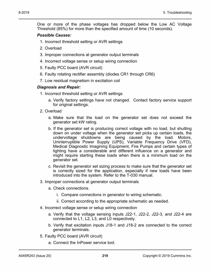
5. Troubleshooting8-2019
219A045R243 (Issue 20) Copyright © 2019 Cummins Inc.
One or more of the phase voltages has dropped below the Low AC VoltageThreshold (85%) for more than the specified amount of time (10 seconds).Possible Causes:
1. Incorrect threshold setting or AVR settings2. Overload3. Improper connections at generator output terminals4. Incorrect voltage sense or setup wiring connection5. Faulty PCC board (AVR circuit)6. Faulty rotating rectifier assembly (diodes CR1 through CR6)7. Low residual magnetism in excitation coil
Diagnosis and Repair:1. Incorrect threshold setting or AVR settings
a. Verify factory settings have not changed. Contact factory service supportfor original settings.
2. Overloada. Make sure that the load on the generator set does not exceed the
generator set kW rating.b. If the generator set is producing correct voltage with no load, but shutting
down on under voltage when the generator set picks up certain loads, theundervoltage shutdowns are being caused by the load. Motors,Uninterruptible Power Supply (UPS), Variable Frequency Drive (VFD),Medical Diagnostic Imagining Equipment, Fire Pumps and certain types oflighting have a considerable and different influence on a generator andmight require starting these loads when there is a minimum load on thegenerator set.
c. Revisit the generator set sizing process to make sure that the generator setis correctly sized for the application, especially if new loads have beenintroduced into the system. Refer to the T-030 manual.
3. Improper connections at generator output terminalsa. Check connections.
i. Compare connections in generator to wiring schematic.ii. Correct according to the appropriate schematic as needed.
4. Incorrect voltage sense or setup wiring connectiona. Verify that the voltage sensing inputs J22-1, J22-2, J22-3, and J22-4 are
connected to L1, L2, L3, and L0 respectively.b. Verify that excitation inputs J18-1 and J18-2 are connected to the correct
generator terminals.5. Faulty PCC board (AVR circuit)
a. Connect the InPower service tool.

5. Troubleshooting 8-2019
220 A045R243 (Issue 20)Copyright © 2019 Cummins Inc.
b. Start the generator set.c. Using the InPower service tool, verify that the AC voltage output is greater
than residual.d. If the AC voltage output is residual, using the InPower service tool, verify
that the AVR is enabled.e. Inspect the generator control harness connector pins for voltage sense and
field connections.f. Turn off the generator set.g. Visually inspect harness for corroded pins, bent or broken pins, pushed
back or expanded pins.6. Faulty rotating rectifier assembly (diodes CR1 through CR6)
a. Check each diode. Refer to the Alternator Performance Troubleshootingsection.
7. Low residual magnetism in excitation coila. The excitation coil may need to be flashed:
i. Remove the Field Coil+ and Field Coil- leads from the alternator.ii. Using a 12 VDC supply:
A. Touch the positive supply terminal to Field Coil+ and the negativesupply terminal to Field Coil-.
B. Remove after brief contact.C. Repeat three times.
iii. Reconnect the Field Coil+ and Field Coil- leads to the alternator.iv. Reset the control.v. Restart the generator set.
Code 1448 - UnderfrequencyLogic:The frequency has dropped below the Underfrequency Threshold (6 Hz) for the timeset in the Underfrequency Delay parameter (10 seconds).Possible Causes:
1. Overrides are enabled2. Underfrequency threshold is set too high3. Overload4. Engine governor problem
Diagnosis and Repair:1. Overrides are enabled
a. Connect with the InPower service tool.

5. Troubleshooting8-2019
221A045R243 (Issue 20) Copyright © 2019 Cummins Inc.
b. Make sure that the Alternator LX-N overrides are not enabled. If required,disable the Alternator LX-N overrides.
2. Underfrequency threshold is set too higha. Verify the Underfrequency Threshold and Underfrequency Time Delay set
values.3. Overload
a. Make sure that the load on the generator set does not exceed thegenerator set kW rating.
b. If the generator set is producing correct voltage with no load, but is shuttingdown on under voltage when the generator set picks up certain loads, theunder voltage shutdowns are being caused by the load. Motors,Uninterruptible Power Supply (UPS), Variable Frequency Drive (VFD),Medical Diagnostic Imagining Equipment, Fire Pumps, and certain types oflighting have a considerable and different influence on a generator andmight require starting these loads when there is a minimum load on thegenerator set. Refer to the T-030 manual.
c. Revisit the generator set sizing process to make sure that the generator setis correctly sized for the application, especially if new loads have beenintroduced into the system.
4. Engine governor problema. Verify that the wiring to the throttle body actuator works correctly. Correct
if faulty.b. Verify that the throttle shaft and plate are free to move. Clean or repair if
necessary.
Code 1449 - OverfrequencyLogic:The frequency has gone above the Overfrequency Threshold (6 Hz) for the timethat is registered in the Overfrequency Delay (10 seconds).Possible Causes:
1. Overfrequency threshold is set too low2. Engine governor problem
Diagnosis and Repair:1. Overfrequency threshold is set too low
a. To access the Overfrequency configuration menu on the operator panel, goto Setup > Genset Setup > Volt Protection.
b. Verify that the Overfrequency Threshold and Overfrequency Time Delayare per specification. Refer to the list to see the default value forOverfrequency.
5. Troubleshooting 8-2019
222 A045R243 (Issue 20)Copyright © 2019 Cummins Inc.
2. Engine governor problema. Verify that the wiring to the throttle body actuator works correctly. Correct
if faulty.b. Verify that the throttle shaft and plate are free to move. Clean or repair if
necessary.
Code 1471 - High AC Current (Warning)Logic:The generator output current has exceeded the warning limit threshold (110%) forgreater than the set time limit (60 seconds).Possible Causes:
1. Short2. Overload3. Incorrect CTs, CT connections, or CT setup4. Incorrect CT harness connections5. Incorrect rating setup6. Fault override enabled7. Parameter set incorrectly
Diagnosis and Repair:1. Short
a. Inspect the load cables and the AC harness connections.b. Disconnect the AC harness from the load cables.c. Inspect the AC harness and board connector pins.d. Visually inspect for corroded pins, bent or broken pins, and/or pushed back
or expanded pins.e. Check for a short circuit of the harness to engine block ground.
2. Overloada. Make sure that the load on the generator set does not exceed the
generator set kW rating.b. If the generator set is producing correct frequency with no load, but
shutting down on underfrequency when the generator set picks up certainloads, the underfrequency shutdowns are being cause by the load. Motors,Uninterruptible Power Supply (UPS), Variable Frequency Drive (VFD),Medical Diagnostic Imagining Equipment, Fire Pumps, and certain types oflighting have a considerable and different influence on a generator andmight require starting these loads when there is a minimum load on thegenerator set.
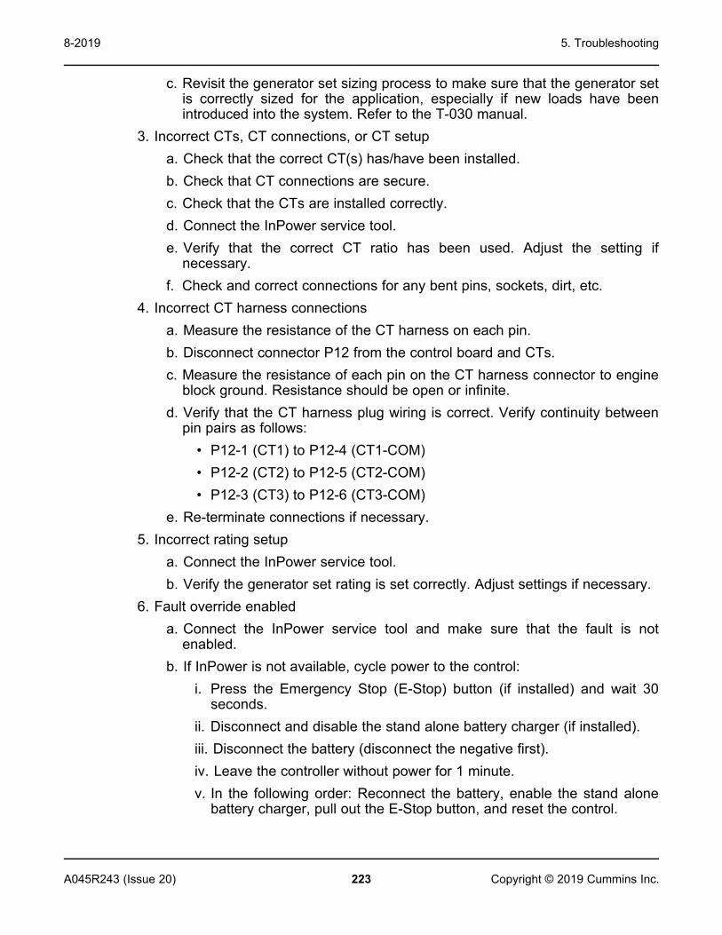
5. Troubleshooting8-2019
223A045R243 (Issue 20) Copyright © 2019 Cummins Inc.
c. Revisit the generator set sizing process to make sure that the generator setis correctly sized for the application, especially if new loads have beenintroduced into the system. Refer to the T-030 manual.
3. Incorrect CTs, CT connections, or CT setupa. Check that the correct CT(s) has/have been installed.b. Check that CT connections are secure.c. Check that the CTs are installed correctly.d. Connect the InPower service tool.e. Verify that the correct CT ratio has been used. Adjust the setting if
necessary.f. Check and correct connections for any bent pins, sockets, dirt, etc.
4. Incorrect CT harness connectionsa. Measure the resistance of the CT harness on each pin.b. Disconnect connector P12 from the control board and CTs.c. Measure the resistance of each pin on the CT harness connector to engine
block ground. Resistance should be open or infinite.d. Verify that the CT harness plug wiring is correct. Verify continuity between
pin pairs as follows:• P12-1 (CT1) to P12-4 (CT1-COM)• P12-2 (CT2) to P12-5 (CT2-COM)• P12-3 (CT3) to P12-6 (CT3-COM)
e. Re-terminate connections if necessary.5. Incorrect rating setup
a. Connect the InPower service tool.b. Verify the generator set rating is set correctly. Adjust settings if necessary.
6. Fault override enableda. Connect the InPower service tool and make sure that the fault is not
enabled.b. If InPower is not available, cycle power to the control:
i. Press the Emergency Stop (E-Stop) button (if installed) and wait 30seconds.
ii. Disconnect and disable the stand alone battery charger (if installed).iii. Disconnect the battery (disconnect the negative first).iv. Leave the controller without power for 1 minute.v. In the following order: Reconnect the battery, enable the stand alone
battery charger, pull out the E-Stop button, and reset the control.

5. Troubleshooting 8-2019
224 A045R243 (Issue 20)Copyright © 2019 Cummins Inc.
7. Parameter set incorrectlya. Verify fault threshold values in calibration.
Code 1472 - High AC Current (Shutdown)Logic:The generator output current has exceeded the Shutdown set limit (150%) forgreater than the set time limit (10 seconds).Possible Causes:
1. Short2. Overload3. Incorrect CTs, CT connections, or CT setup4. Incorrect CT harness connections5. Incorrect rating setup6. Fault override enabled7. Parameter set incorrectly
Diagnosis and Repair:1. Short or overload
a. Inspect the load cables and the AC harness connections.b. Disconnect the AC harness from the load cables.c. Inspect the AC harness and board connector pins.d. Visually inspect for corroded pins, bent or broken pins, and pushed back or
expanded pins.e. Check for a short circuit of the harness to engine block ground.
2. Overloada. Make sure that the load on the generator set does not exceed the
generator set kW rating.b. If the generator set is producing correct frequency with no load, but
shutting down on underfrequency when the generator set picks up certainloads, the underfrequency shutdowns are being cause by the load. Motors,Uninterruptible Power Supply (UPS), Variable Frequency Drive (VFD),Medical Diagnostic Imagining Equipment, Fire Pumps, and certain types oflighting have a considerable and different influence on a generator andmight require starting these loads when there is a minimum load on thegenerator set.
c. Revisit the generator set sizing process to make sure that the generator setis correctly sized for the application, especially if new loads have beenintroduced into the system. Refer to the T-030 manual.
3. Incorrect CTs, CT connections, or CT setupa. Check that correct CTs have been installed.

5. Troubleshooting8-2019
225A045R243 (Issue 20) Copyright © 2019 Cummins Inc.
b. Check that CT connections are secure.c. Check that CTs are installed correctly.d. Connect the InPower service tools.e. Verify the correct CT ratio has been used. Adjust the setting if necessary.f. Check and correct connections for any bent pins, sockets, dirt, etc.
4. Incorrect CT harness connectionsa. Measure the resistance of the CT harness on each pin.b. Disconnect connector P12 from the control board and CTs.c. Measure the resistance of each pin on the CT harness connector to engine
block ground. Resistance should be open or infinite.d. Verify the CT harness plug wiring is correct. Verify that continuity between
pins pairs is as follows:• P12-1 (CT1) to P12-4 (CT1-COM)• P12-2 (CT2) to P12-5 (CT2-COM)• P12-3 (CT3) to P12-6 (CT3-COM)
e. Re-terminate connections if necessary.5. Incorrect rating setup
a. Connect the InPower service tool and make sure that the fault is notenabled.
b. Verify the generator set rating is set correctly.c. Verify CT ratings in the control are set correctly. Adjust settings if
necessary.6. Fault override enabled
a. Connect with the InPower service tool and make sure that the fault is notenabled.
b. If InPower is not available, cycle power to the control:i. Press the Emergency Stop (E-Stop) button (if installed) and wait 30
seconds.ii. Disconnect and disable the stand alone battery charger (if installed).iii. Disconnect the battery (disconnect the negative first).iv. Leave the controller without power for 1 minute.v. In the following order: Reconnect the battery, enable the stand alone
battery charger, pull out the E-Stop button, and reset the control.7. Parameter set incorrectly
a. Verify the fault threshold values in the calibration.

5. Troubleshooting 8-2019
226 A045R243 (Issue 20)Copyright © 2019 Cummins Inc.
Code 1853 - Annunciator Input 1 FaultLogic:Customer fault 1 (input 1, LED 1) on the universal annunciator is active.Possible Cause:
1. Condition for which "Annunciator Input #1" is configured for is active2. Incorrectly configured or wiring issue3. Faulty annunciator
Diagnosis and Repair:1. Condition for which "Annunciator Input #1" is configured for is active
a. Check the condition for which "Annunciator Input #1" has been configuredfor. For example, if "Annunciator Input #1" was configured to becomeactive when the fuel level is low, check the fuel level and add fuel ifneeded. After the issue is resolved, press the Reset button on the operatorpanel in order to clear the fault. If the fault does not clear, go to the nextstep.
Configurable Parameter Option 1 (Default) Option 2Negative or Positive Input 1Activation
Negative Input (GroundInput)
Positive Input (B+ Input)
Inverting Active HardwareSignals
Do Not Invert Invert
2. Incorrectly configured or wiring issuea. Customer input 1 on the universal annunciator can be configured to
conform to different applications. Below are two configurations that have animpact on how input 1 becomes active:
• Negative or positive Input 1 activation: Allows the user to activate witha negative (ground) or positive (B+) input; the default setting is anegative (ground) input.
• Inverting active hardware signals: Input 1 has the capability to beinverted. If annunciator input 1 is set to inverted, then an activehardware signal will be considered inactive and an inactive signal willbe considered active; the default is set to non-inverted.
b. When set to default, event/fault code 1853 (customer input 1) becomesactive when there is a ground input at TB1-1 on the back of the universalannunciator.
c. Make sure that the universal annunciator is correctly configured; for setupand configuration instructions, refer to the universal annunciator operator'smanual.

5. Troubleshooting8-2019
227A045R243 (Issue 20) Copyright © 2019 Cummins Inc.
d. Check the wiring at TB1-1 and make sure that customer input 1 is wiredcorrectly. Depending on the configuration of the annunciator shown in step1, make sure that there is not a short or open circuit at the TB1-1connection.
e. Check the sender, relay, or device that is activating Input 1 on theuniversal annunciator. Replace if faulty.
3. Faulty annunciatora. If the wiring and configuration is satisfactory, replace the universal
annunciator.
Code 1854 - Annunciator Input 2 FaultLogic:Customer fault 2 (Input 2, LED 2) on the universal annunciator is active.Possible Cause:
1. Condition for which "Annunciator Input #2" is configured for is active2. Incorrectly configured or wiring issue3. Faulty annunciator
Diagnosis and Repair:1. Condition for which "Annunciator Input #2" is configured for is active
a. Check the condition for which "Annunciator Input #2" has been configuredfor. For example, if "Annunciator Input #2" was configured to becomeactive when the fuel level is low, check the fuel level and add fuel ifneeded. After the issue is resolved, press the Reset button on the operatorpanel in order to clear the fault. If the fault does not clear, go to the nextstep.
Configurable Parameter Option 1 (Default) Option 2Negative or Positive Input 2Activation
Negative Input (GroundInput)
Positive Input (B+ Input)
Inverting Active HardwareSignals
Do Not Invert Invert
2. Incorrectly configured or wiring issuea. Customer input 2 on the universal annunciator can be configured to
conform to different applications. Below are two configurations that have animpact on how Input 2 becomes active:
• Negative or positive Input 2 activation: Allows the user to activate witha negative (ground) or positive (B+) input; the default setting is anegative (ground) input.

5. Troubleshooting 8-2019
228 A045R243 (Issue 20)Copyright © 2019 Cummins Inc.
• Inverting active hardware signals: Input 2 has the capability to beinverted. If annunciator input 2 is set to inverted, then an activehardware signal will be considered inactive and an inactive signal willbe considered active; the default is set to non-inverted.
b. When set to default, event/fault code 1854 (customer input 2) becomesactive when there is a ground input at TB1-2 on the back of the universalannunciator.
c. Make sure that the universal annunciator is correctly configured; for setupand configuration instructions, refer to the universal annunciator operator'smanual.
d. Check the wiring at TB1-2 and make sure that customer input 2 is wiredcorrectly. Depending on the configuration of the annunciator in step 1,make sure that there is not a short or open circuit at the TB1-2 connection.
e. Check the sender, relay, or device that is activating input 2 on the universalannunciator. Replace if faulty.
3. Faulty annunciatora. If the wiring and configuration is satisfactory, replace the universal
annunciator.
Code 1855 - Annunciator Input 3 FaultNote: The nature of the annunciator fault is an optional configurable selection.Logic:Customer fault 3 (input 3, LED 3) on the universal annunciator is active.Possible Cause:
1. Condition for which "Annunciator Input #3" is configured for is active2. Incorrectly configured or wiring issue3. Faulty annunciator
Diagnosis and Repair:1. Condition for which "Annunciator Input #3" is configured for is active
a. Check the condition for which "Annunciator Input #3" has been configuredfor. For example, if "Annunciator Input #3" was configured to becomeactive when the fuel level is low, check the fuel level and add fuel ifneeded. After the issue is resolved, press the Reset button on the operatorpanel in order to clear the fault. If the fault does not clear, go to the nextstep.
Configurable Parameter Option 1 (Default) Option 2Negative or PositiveInput 3 Activation
Negative Input(Ground Input)
Positive Input(B+ Input)
Inverting ActiveHardware Signals
Do Not Invert Invert

5. Troubleshooting8-2019
229A045R243 (Issue 20) Copyright © 2019 Cummins Inc.
2. Incorrectly configured or wiring issuea. Customer input 3 on the universal annunciator can be configured to
conform to different applications. Below are two configurations that have animpact on how input 3 becomes active.
• Negative or positive Input 3 activation: Allows the user to activate witha negative (ground) or positive (B+) input; the default setting is anegative (ground) input.
• Inverting active hardware signals: Input 3 has the capability to beinverted. If annunciator input 3 is set to inverted, then an activehardware signal will be considered inactive and an inactive signal willbe considered active; the default is set to non-inverted.
b. When set to default, event/fault code 1855 (customer input 3) becomesactive when there is a ground input at TB1-3 on the back of the universalannunciator.
c. Make sure that the universal annunciator is correctly configured; for setupand configuration instructions, refer to the universal annunciator operator'smanual.
d. Check the wiring at TB1-3 and make sure that customer input 3 is wiredcorrectly. Depending on the configuration of the annunciator, make surethat there is not a short or open circuit at the TB1-3 connection.
e. Check the sender, relay, or device that is activating Input 3 on theuniversal annunciator, replace if faulty.
3. Faulty Annunciatora. If the wiring and configuration is satisfactory, replace the universal
annunciator.
Code 1944 - Annunciator Configuration Error (Warning)Logic: More than one network device is configured to activate one of theannunciator output relays.Possible Causes:
1. Bad network configuration2. Bad device on network
Diagnosis and Repair1. Bad network configuration
a. Check the setup of devices on the network against duplicate use of thesame annunciator relay output.
2. Bad device on networka. Troubleshoot the network for malfunctioning devices.
Code 2118 - Fuel Pressure LowLogic:

5. Troubleshooting 8-2019
230 A045R243 (Issue 20)Copyright © 2019 Cummins Inc.
This fault is used when an optional low fuel pressure switch is installed. The natureof the fault is an optional customer selection. The fault function is programmed(using the InPower service tool), as follows:
• Function: Low Fuel Pressure Switch (default: Disabled)• Fault Level Response: Warning (default: #1-None, #2-Warning and #3-
Warning)• Fault Active State Selection: Active Closed (default: Active Closed)• Display Name: LOW FUEL PRESSURE
Possible Causes:1. Low fuel pressure2. Faulty fuel pressure switch connections3. Faulty fuel pressure switch4. Incorrect fuel system selected in control5. Faulty control board
Diagnosis and Repair:1. Low fuel pressure
a. Check fuel supply and change as required.2. Faulty fuel pressure switch connections
a. Inspect the fuel pressure switch and the harness connectors.b. Disconnect the harness connector from the fuel pressure switch.c. Inspect for corroded pins, bent or broken pins, pushed back or expanded
pins.d. Inspect for evidence of moisture in or on the connector.e. Inspect for dirt or debris in or on the connector pins.f. Inspect the wiring for any damage or shorting.
3. Faulty fuel pressure switcha. Check switch operation.b. Turn off the fuel supply to the unit, and vent fuel in the line. Check for
continuity across the two leads of the switch. The circuit should be open.c. Turn fuel supply to the unit on, and check for continuity across the two
leads of the switch. The circuit should be closed4. Incorrect fuel system selected in control
a. Verify fuel system selection in control menu. Refer to the Converting theFuel System Type section.
5. Faulty control boarda. If the sender, harness and control settings are acceptable, the baseboard
is defective. Replace it.

5. Troubleshooting8-2019
231A045R243 (Issue 20) Copyright © 2019 Cummins Inc.
Code 2335 - Excitation Fault (Loss of AC Sense)Logic:The control has lost voltage sensing or has lost zero cross sensing.Possible Causes:
1. Incorrect configuration2. Bad fuse3. Bad wire harness or wrong connections4. Low residual magnetism in excitation coil5. Excitation coil is defective6. Incorrect generator set setup7. Bad control board8. Short circuit
Diagnosis and Repair:1. Incorrect configuration
a. Make sure that values for the Low of AC Voltage Threshold (85%) and Lowof AC Voltage Time Delay (10 seconds) are correct in calibration.
2. Bad fusea. Check the fuse F5 (10 Amp).b. Replace if necessary.
3. Bad wire harness or wrong connections
CAUTIONExcessive voltage is possible during testing. Make sure your meter canhandle alternator full voltage.
a. Check electrical continuity between the following locations. If resistance isgreater than 1 Ohm, repair or replace the harness:
• J22 Pin 4 and the terminal marked N on the alternator terminal block(identified as Sense N on the generator wiring diagram)
• J22 Pin 3 and the terminal marked W on the alternator terminal block(identified as Sense W on the generator wiring diagram)
• J22 Pin 2 and the terminal marked V on the alternator terminal block(identified as Sense V on the generator wiring diagram)
• J22 Pin 1 and the terminal marked U on the alternator terminal block(identified as Sense U on the generator wiring diagram)
b. Check continuity between the following leads. If resistance is greater than1 Ohm, repair or replace the harness.
• J17 Pin 1 and Field Coil + (F1)

5. Troubleshooting 8-2019
232 A045R243 (Issue 20)Copyright © 2019 Cummins Inc.
• J17 Pin 2 and Field Coil - (F2)c. Check continuity between the following leads. If resistance is greater than 1
Ohm, repair or replace the harness:• J18 Pin 1 and the terminal marked Shunt 1 on the alternator terminal
block or PMG terminal marked P2• J18 Pin 2 and the terminal marked Shunt 2 on the alternator terminal
block or PMG terminal marked P3d. Make sure that the inline connectors in the wiring harness are connected
properly.4. Low residual magnetism in excitation coil
a. Flash the excitation coil:i. Remove Field Coil+ and Field Coil- leads from the alternator.ii. Using a 12 VDC supply, touch the positive supply terminal to Field
Coil+ and the negative supply terminal to Field Coil-. Remove afterbrief contact. Repeat three times.
iii. Reconnect Field Coil+ and Field Coil- leads to the alternator.iv. Reset the control, and restart the generator set.
5. Excitation coil is defectivea. Refer to the Alternator Performance Troubleshooting section.
6. Incorrect generator set setupa. Verify that the generator set is capable of reaching the rated speed.
7. Bad control boarda. Replace the control board module after performing all other steps.
8. Short circuita. If none of the previous debugging steps solve the problem, then the
shutdown may be due to a short circuit on the main output lines of thealternator. Inspect the main output lines from the alternator for mis-wire,faulty wire, or any other signs of short circuit.
Code 2676 - Alternator Frequency Conflict (Shutdown)Logic: The Alternator Line Frequency and Alternator Excitation Frequency do notmatch.Possible Causes:
1. Incorrect setting2. Bad wire harness or wrong connections3. Bad control board4. Bad alternator

5. Troubleshooting8-2019
233A045R243 (Issue 20) Copyright © 2019 Cummins Inc.
Diagnosis and Repair:1. Incorrect setting
a. Check the Alternator Line Frequency Gain trim using the operator panel orthe InPower service tool.
• When Shunt is selected, a gain of 1 is the default.• When PMG is selected, a gain of 2 is the default.
b. Measure the Alternator Line Frequency (J22-1 to J22-4).c. Measure the Alternator Excitation Frequency (J18-1 to J18-2).d. Calculate the Alternator Excitation Frequency value using the following
equation:Alternator Line Frequency * Alternator Line Frequency Gain = AlternatorExcitation Frequency
e. Compare the Alternator Excitation Frequency that was measured to theAlternator Excitation Frequency that was calculated.
f. Check the voltage sense leads and exciter power lead for open circuits orshort circuits.
2. Bad wire harness or wrong connections
CAUTIONExcessive voltage is possible during testing. Make sure your meter canhandle alternator full voltage.
a. Check continuity between the following leads; if resistance is greater than 1Ohm, repair or replace the harness:
• J17 Pin 1 and Field Coil + (F1)• J17 Pin 2 and Field Coil - (F2)
b. Make sure that the inline connectors in the wiring harness are connectedproperly.
3. Bad control board• Replace the control board.
4. Bad alternator• Replace the alternator.
Code 2677 - Fail to Stop (Shutdown)Logic:The generator set continues to run after receiving shutdown command from thecontroller.Possible Causes:
1. Stuck fuel shutoff (FSO) valve

5. Troubleshooting 8-2019
234 A045R243 (Issue 20)Copyright © 2019 Cummins Inc.
Diagnosis and Repair:1. Stuck fuel shutoff (FSO) valve
a. Check keyswitch operation and make sure it is not stuck closed. Use amultimeter and check continuity across the relay (K3-1 and K3-4). With theEmergency stop pressed, the relay should be open.
b. Check for a stuck FSO valve. Check the FSO relay and related wiring.Check that the FSO is not mechanically stuck. (The controller shuts off thefuel supply valves only or the spark plug supply.)
c. If issue persists, consult DTC 1181 in the E-Controls manual.
Code 2729 - IO Module Lost (Warning)Logic: There is an intermittent data link between the I/O module and the PCCcontrol (Aux 101 I/O Module option) and no input fault levels were set to Shutdown.Possible Causes:
1. Incorrect wiring2. I/O settings misconfigured
Diagnosis and Repair:1. Incorrect wiring
a. The connection between AUX 101 and PCC 1302 is incorrect. Make surethere is proper wiring.
• PCC 1302 TB1-1 – PCC Net A (+) to AUX 101 J1-3• PCC 1302 TB1-2 – PCC Net B (-) to AUX 101 J1-4• PCC 1302 TB1-3 – B+ Return to AUX 101 J14-2• PCC 1302 TB1-5 – Customer Fused B+ to AUX 101 J14-1• PCC 1302 TB15-5 – System Wake-up to AUX 101 J1-5
2. I/O settings misconfigureda. If no AUX 101 is connected to PCC 1302, connect to the InPower service
tool.• Go to Adjustments > System I/O Adjustment > Output Relays.
Make sure System IO Board Enable is disabled.• Go to Adjustments > System I/O Adjustment. Make sure no inputs
or outputs are configured as enabled.
Code 2731 - IO Module Lost (Shutdown)Logic: Indicates an intermittent data link between the I/O module and the PCCcontrol (Aux 101 I/O Module option) and at least one input fault level was set toShutdown.Possible Causes:
1. Incorrect wiring

5. Troubleshooting8-2019
235A045R243 (Issue 20) Copyright © 2019 Cummins Inc.
2. I/O settings misconfiguredDiagnosis and Repair:
1. Incorrect wiringa. The connection between AUX 101 and PCC 1302 is incorrect. Make sure
there is proper wiring.• PCC 1302 TB1-1 – PCC Net A (+) to AUX 101 J1-3• PCC 1302 TB1-2 – PCC Net B (-) to AUX 101 J1-4• PCC 1302 TB1-3 – B+ Return to AUX 101 J14-2• PCC 1302 TB1-5 – Customer Fused B+ to AUX 101 J14-1• PCC 1302 TB15-5 – System Wake-up to AUX 101 J1-5
2. I/O settings misconfigureda. If no AUX 101 is connected to PCC 1302, connect to InPower.
i. Go to Adjustments > System I/O Adjustment > Output Relays.Make sure System IO Board Enable is disabled.
ii. Go to Adjustments > System I/O Adjustment. Make sure no inputsor outputs are configured as enabled.
Code 2897 - Factory Memory Block CorruptLogic: The control has detected a corrupted memory block.Possible Cause:
1. Defective memory blockDiagnosis and Repair:
1. Defective memory blocka. Connect to device using InPower version 10.0 or greater.b. In InPower, right click on the device, and select Initial Calibration (Recover
Device) from the menu that appears.c. If the capture file for the device is available, select "overlay capture file". If
not, select feature codes.• Feature codes can be found on the nameplate of the device, located
on the alternator housing.d. If the problem persists, contact the factory for support.
Code 2898 - Periodic or Fault Memory Block CorruptLogic: The control has detected a corrupted memory block.Possible Cause:
1. Defective memory block

5. Troubleshooting 8-2019
236 A045R243 (Issue 20)Copyright © 2019 Cummins Inc.
Diagnosis and Repair:1. Defective memory block
a. Connect to the device using InPower version 10.0 or greater.b. In InPower, right click on the device, and select Initial Calibration (Recover
Device) from the menu that appears.c. If the capture file for the device is available, select "overlay capture file". If
not, select feature codes.• Feature codes can be found on the nameplate of the device, located
on the alternator housing.d. If the problem persists, contact the factory for support.
Code 2899 - User Memory Block CorruptLogic: The control has detected a corrupted memory block.Possible Cause:
1. Defective memory blockDiagnosis and Repair:
1. Defective memory blocka. Connect to the device using InPower version 10.0 or greater.b. In InPower, right click on the device, and select Initial Calibration (Recover
Device) from the menu that appears.c. If the capture file for the device is available, select "overlay capture file". If
not, select feature codes.• Feature codes can be found on the nameplate of the device, located
on the alternator housing.d. If the problem persists, contact the factory for support.
Code 2911 - Trim Memory Block CorruptLogic: The control has detected a corrupted memory block.Possible Cause:
1. Defective memory blockDiagnosis and Repair:
1. Defective memory blocka. Connect to the device using InPower version 10.0 or greater.b. In InPower, right click on the device, and select Initial Calibration (Recover
Device) from the menu that appears.

5. Troubleshooting8-2019
237A045R243 (Issue 20) Copyright © 2019 Cummins Inc.
c. If the capture file for the device is available, select "overlay capture file". Ifnot, select feature codes.
• Feature codes can be found on the nameplate of the device, locatedon the alternator housing.
d. If the problem persists, contact the factory for support.
Code 2964 - Intake Air Temperature Higher than ExpectedLogic: The manifold air temperature exceeds 94 °C (200 °F) for more than 60seconds, while the engine is running (DTC 111 active).Possible Causes:
1. Exhaust air entering intake2. TMAP sensor failure
Diagnosis and Repair:1. Exhaust air entering intake
a. Inspect the exhaust system for leaks. Check the exhaust manifold gaskets,turbo gasket (if equipped), and exhaust tubing for holes or escapingexhaust. Replace the faulty component(s) if necessary.
b. The unit is not properly ventilated. Make sure that the unit is greater than 5feet from any obstruction.
• For units located inside of a structure, make sure that exhaust gasesdo not exit within 5 feet of the intake for the structure or generator set.
• For enclosed sets, make sure that there are no objects blocking theexhaust opening on the top of the enclosure, or objects that mayredirect exiting airflow towards the intake end of the unit.
2. TMAP sensor failurea. Remove TMAP sensor from the intake manifold, and expose it to ambient
air.b. Make sure that the tip is well away from the engine or other heat/cold
sources.c. Connect using the E-controls service tool, and monitor the manifold air
temperature. Compare that to the known ambient air temperature.d. Check for continuity across leads 1 and 2 of the TMAP sensor. If the circuit
is open, replace the TMAP sensor.
Code 2972 - Field Overload (Shutdown)Logic:If the time that the Field AVR Duty Cycle is operating at maximum output is longerthan the time in the “Max Field Time" parameter, event/fault code 2972 will becomeactive.Possible Causes:

5. Troubleshooting 8-2019
238 A045R243 (Issue 20)Copyright © 2019 Cummins Inc.
CAUTIONExcessive voltage is possible during testing. Make sure your meter canhandle alternator full voltage.
1. Voltage sensing into the baseboard is too low, or there is an open/short circuit2. Application issue
Diagnosis and Repair:1. Voltage sensing into the baseboard is too low, or there is an open/short circuit
a. Measure the voltage going into the baseboard at L1 = J22-1, L2 = J22-2,L3 = J22-3, and LN = J22-4 (for single phase applications use L1, L2 andLN). If the generator set control is not sensing voltage, it will try toovercompensate by maxing out the AVR output.
i. If the voltage going into the control board is zero, or less than theNominal Voltage calibration, then the wiring from the alternator to thebaseboard for an open circuit or short circuit.
b. Measure the output of the AVR at J17-1 and J17-2 while turning thegenerator set on. The output should be at least 30 VDC when thegenerator set is starting, but the voltage should decrease significantly whenthe generator set builds up voltage.
i. If the output of J17-1 and J17-2 is constantly high or is locked in, thenthe AVR portion of the PCC is faulty. Replace the baseboard if theAVR is faulty.
2. Application issuea. If the generator set runs adequately with no load or some load but as soon
as additional load is applied, the generator set shuts down on “FieldOverload", then this might be an application issue (load issue, generatorset undersized, etc.).
Code 5134 - Unknown Shutdown at IdleLogic:Engine is not getting a proper fuel supply.Possible Causes:
1. Fuel supply issueDiagnosis and Repair:
1. Fuel supply issuea. Check that there is a proper supply of fuel to the engine.
Code 5365 - Fault Code on Secondary Source (Informationthat the Fueling Has Been Shifted to Secondary Source)Logic:

5. Troubleshooting8-2019
239A045R243 (Issue 20) Copyright © 2019 Cummins Inc.
This fault is used when an optional low fuel pressure switch is installed and thegenerator set is set up for dual fuel operation. The nature of the fault is an optionalcustomer selection. The fault function is programmed (using the InPower servicetool), as follows:
• Low Fuel Pressure Switch Active State Selection: Active Closed• Function: Low Fuel Pressure Switch (default: Disabled)• Fault Level Response: Warning (default: #1-None, #2-Warning and #3-
Warning)• Fault Active State Selection: Active Closed (default: Active Closed)• Gas Fuel Type: Dual
Possible Causes:1. Low primary fuel pressure2. Faulty fuel pressure switch connections3. Faulty fuel pressure switch4. Incorrect calibration settings for the Low Fuel Pressure fault in the control5. Faulty control board
Diagnosis and Repair:1. Low primary fuel pressure
a. Check fuel supply. Diagnose and fix as required.b. Check fuel valve connections and operation. Diagnose and fix as required.
2. Faulty fuel pressure switch connectionsa. Inspect the fuel pressure switch and the harness connectors.
i. Disconnect the harness connector from the fuel pressure switch.ii. Inspect for corroded, bent or broken tabs on the fuel pressure switch.iii. Inspect for evidence of moisture in or on the harness connectors.iv. Inspect for dirt or debris in or on the harness connectors.v. Inspect the wiring for any damage or shorting.
3. Faulty fuel pressure switcha. Check switch operation.
i. Remove the connector from the fuel pressure switch.ii. Verify battery power on the sensor harness connector that plugs into
tab NO on the fuel pressure switch. If B+ not present, repair orreplace the harness.
iii. Verify ground on the sensor harness connector that plugs into tab Con the fuel pressure switch. If ground is not present, repair or replacethe harness.

5. Troubleshooting 8-2019
240 A045R243 (Issue 20)Copyright © 2019 Cummins Inc.
4. Incorrect calibration settings for the Low Fuel Pressure fault in the controla. Verify calibration setting for Low Fuel Pressure Switch Active State
Selection = Active Closed.b. Verify calibration setting for Configurable Input #3 Function = Low Fuel
Pressure Switch.c. Verify calibration setting for Configurable Input #3 Fault Active State
Selection = Active Closed.5. Faulty control board
a. If the sender, harness and control settings are acceptable, the baseboardis defective. Swap the control board.
Code 5669 - Engine Combustion (Shutdown)Logic:Rapid rate of increase of intake manifold temperature detected.Possible Causes:
1. Intake manifold over-pressurization event2. Faulty TMAP sensor3. Faulty engine harness
Diagnosis and Repair:1. Intake manifold overpressurization event
a. Inspect the hose couplings between the compressor outlet and intakemanifold.
i. Inspect the hose couplings for damage.ii. Inspect the clamps for damage.
b. Inspect the turbocharger (if used).i. Externally inspect the turbocharger for damage.ii. Inspect for loose or missing bolts on the compressor housing.
c. Inspect the mixer.i. Remove the air cleaner and confirm there are no loose pieces within
the mixer.2. Faulty TMAP sensor
a. For the troubleshooting procedure, refer to DTC 127 in the E-Controlsmanual.
3. Faulty engine harnessa. Inspect the engine harness and the connector pins.
i. Disconnect the engine harness connector from the extension harness.ii. Inspect for corroded pins, bent or broken pins, pushed back or
expanded pins.

5. Troubleshooting8-2019
241A045R243 (Issue 20) Copyright © 2019 Cummins Inc.
iii. Inspect for evidence of moisture in or on the connector.iv. Inspect for missing or damaged connector seals.v. Inspect for dirt or debris in or on the connector pin.vi. Disconnect the harness from the ECM and sensor.vii. Measure the resistance in each pin from ECM to sensor. Resistance
should be 5 Ohms or less.viii. Repair or replace the harness as necessary.

5. Troubleshooting 8-2019
242 A045R243 (Issue 20)Copyright © 2019 Cummins Inc.
This page is intentionally blank.

243A045R243 (Issue 20) Copyright © 2019 Cummins Inc.
Appendix A. Wiring Diagrams
Table of ContentsFigure 104. Wiring Diagram (Sheet 1 of 7) ............................................................................................... 245Figure 105. Wiring Diagram (Sheet 2 of 7) ............................................................................................... 246Figure 106. Wiring Diagram (Sheet 3 of 7) ............................................................................................... 247Figure 107. Wiring Diagram (Sheet 4 of 7) ............................................................................................... 248Figure 108. Wiring Diagram (Sheet 5 of 7) ............................................................................................... 249Figure 109. Wiring Diagram (Sheet 6 of 7) ............................................................................................... 250Figure 110. Wiring Diagram (Sheet 7 of 7) ............................................................................................... 251

Appendix A. Wiring Diagrams 8-2019
244 A045R243 (Issue 20)Copyright © 2019 Cummins Inc.
The drawings included in this section are representative. For currentcomplete information, refer to the drawing package that was shipped withthe unit.

Appendix A. Wiring Diagrams8-2019
245A045R243 (Issue 20) Copyright © 2019 Cummins Inc.
FIGURE 104. WIRING DIAGRAM (SHEET 1 OF 7)

Appendix A. Wiring Diagrams 8-2019
246 A045R243 (Issue 20)Copyright © 2019 Cummins Inc.
FIGURE 105. WIRING DIAGRAM (SHEET 2 OF 7)

Appendix A. Wiring Diagrams8-2019
247A045R243 (Issue 20) Copyright © 2019 Cummins Inc.
FIGURE 106. WIRING DIAGRAM (SHEET 3 OF 7)

Appendix A. Wiring Diagrams 8-2019
248 A045R243 (Issue 20)Copyright © 2019 Cummins Inc.
FIGURE 107. WIRING DIAGRAM (SHEET 4 OF 7)

Appendix A. Wiring Diagrams8-2019
249A045R243 (Issue 20) Copyright © 2019 Cummins Inc.
FIGURE 108. WIRING DIAGRAM (SHEET 5 OF 7)

Appendix A. Wiring Diagrams 8-2019
250 A045R243 (Issue 20)Copyright © 2019 Cummins Inc.
FIGURE 109. WIRING DIAGRAM (SHEET 6 OF 7)
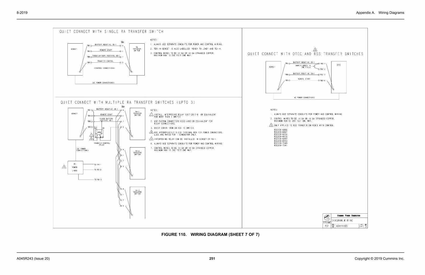
Appendix A. Wiring Diagrams8-2019
251A045R243 (Issue 20) Copyright © 2019 Cummins Inc.
FIGURE 110. WIRING DIAGRAM (SHEET 7 OF 7)

Appendix A. Wiring Diagrams 8-2019
252 A045R243 (Issue 20)Copyright © 2019 Cummins Inc.
This page is intentionally blank.

253A045R243 (Issue 20) Copyright © 2019 Cummins Inc.
Appendix B. Alternator Reconnect Drawing
Table of ContentsFigure 111. Alternator Reconnect, Wiring Diagram for AW1 (Sheet 1 of 1) ......................................... 255Figure 112. Alternator Reconnect, Wiring Diagram for AW2 and AW3 (Sheet 1 of 1) ........................ 256

Appendix B. Alternator Reconnect Drawing 8-2019
254 A045R243 (Issue 20)Copyright © 2019 Cummins Inc.
This page is intentionally blank.

Appendix B. Alternator Reconnect Drawing8-2019
255A045R243 (Issue 20) Copyright © 2019 Cummins Inc.
B.0 Alternator Reconnect Wiring Diagrams
FIGURE 111. ALTERNATOR RECONNECT, WIRING DIAGRAM FOR AW1 (SHEET 1 OF 1)

Appendix B. Alternator Reconnect Drawing 8-2019
256 A045R243 (Issue 20)Copyright © 2019 Cummins Inc.
FIGURE 112. ALTERNATOR RECONNECT, WIRING DIAGRAM FOR AW2 AND AW3 (SHEET 1 OF 1)


power.cummins.comCopyright © 2019 Cummins Inc. All rights reserved.Cummins, the "C" logo, PowerCommand, AmpSentry, and InPower aretrademarks of Cummins Inc.Other company, product, or service names may be trademarks or servicemarks of others.Specifications are subject to change without notice.