


Internal Combustion Engine Manual - Forgotten Books
175
-
Upload
khangminh22 -
Category
Documents
-
view
1 -
download
0
Transcript of Internal Combustion Engine Manual - Forgotten Books


INTERNAL COMBUSTION
MANUAL
B %
F. W . S T E R L I N GL ieutenant C ommaézler, U . 5. N avy ,
R elired
FOUR TH EDITION
I 9 I 7

C O P% RIGHT , 1911
F . W . S TERL IN G
C O P% RIGHT , 1916
F . w . S TE RL IN G
C O P% RIGHT . 1917
F . W . S TE RL IN G
W A S H I N G T O N , D . c .
B ERE S FO RD , PRIN TER1917

PREFACE T O FO U R TH EDITION .
The fourth edition o f this volume , which marks its eighth
year as a text book at the N aval A cademy , has been completely
rewritten,enlarged and brought up to date . The original se
quence is still preserved , as it is believed the best for instruction
o f the uninitiated , viz
( a ) The subj ect o f fuels is first treated fully , this being the
fundamental element that governs des ign and operation . These
fuels follow in a natural sequence which order is preserved when
carburetion is taken up in Chapter V .
(b ) The engine proper naturally divides itsel f into four sys
tems : ( 1 ) fuel system , ( 2 ) ignition system , ( 3 ) cool ing system ,
(4 ) lubrication system . These are treated in detail in the above
order and in Chapter X the four systems assembled are illustrated
by modern commercial engines .
A chapter has been added on the aeroplane engine and the
five types , vertical , horizontal opposed , V- type , radial , and rotary
are illustrated by up to date A merican engines .
The author wishes to acknowledge his thanks to M r. J. G.
O’
N eill, chemist at the N aval E xperiment S tation , for his aid in
enlarging the chapter on lubrication,and to the various manu
facturers for their aid in preparing the text and cuts .
3 8 3 6 08


INTE RNAL COMBU ST ION E NGINE MANUAL .
CHAPTER I .
FUELS .
‘
S e lection .
—The cons iderations governing the selection o f afuel in general are its access ibility , price , amount available , rate o fcombustion , and thermal value ; i t does not naturally follow thatthese are the only l imitations which shall regulate the choice o f afuel for use in an internal combustion engine .
Fuel for use in an internal combustion engine omust readilycombine with
.
air to fo rm a combustible mixture o f gas or vapor ,must leave l ittle or no sol id residue a fter combustion
,and must
“
h ave certain thermo—chemical characteristics such as a proper rateo f flame p ropagation , etc . It need not necessarily be o f a veryh igh calorific value , as will be shown later , but obviously this i sdes irable . The fuel is usually a compound o f carbon and hydrogen , or a mixture o f such compounds
,found thus in nature or
manu factured .
T h e General C lass ificat ion o f internal combustion enginefuels i s :1 . The solid fuels .
2 . The liquid fuels .
3 . The gaseous fuels .
S ol id fuels cannot be used in an internal combustion engine intheir natural state , hence coal and other carbonaceous sol ids mustbe gasified to C O and H by partial combustion and volatil izationto prepare them for such use . A lthough the D iesel engine wasoriginally designed to use coal dust for fuel , and experimentsh ave been made along this l ine
,the idea was finally abandoned .
S ol id fuels are converted into ( a ) air gas , (b ) water gas, ( c )producer gas .

2 INTERNAL COMBUST ION ENGINE MANUAL .
L iquid fuels comprise ( a ) dis tillates of petroleum or crude oil,
(b) alcohol, and ( c ) benz ol.The gaseous fuels cons ist o f ( a ) oil gas , (b ) illuminating gas ,( c ) coke ' oven gas , ( d ) blas t furnace gas, ( e ) natural gas , and
( f ) acetylene .
O f al l these fuels the most important marine fuel i s petroleum .
1 . S ol id Fue ls .
A,A I R GA s ; B , WATER GA s.
A ir Gas is entitled to no commercial cons ideration . I t can bemanu factured by the gasification o f carbon by incomplete combustion to CO in a producer . The extremely low efficiency o f
such a process precludes its commercial use .
Water Gas .
—I f incandescent fuel is sprayed with water vapor ,the H
20 is dissociated to H2 and O , and the latter combines with
the carbon in the fuel to form C O2or CO . H 2 is l iberated . A t
temperatures below E , C O 2 i s formed , whereas , i f thetemperature be above F CO alone is formed . The production o f waten gas is accompl ished in a producer . I ts production i s not highly efficient for the following reasons : S tartingwith a fuel in the incandescent state
,the continued introduction
o f water vapor will cool the producer and when the temperaturefalls below F . an excess ive amount o f C O 2 i s formed .
U nless this cool ing action is counteracted the proces s will finallycease . When the temperature becomes too low the steam is shutoff and the fuel i s again brought to incandescence by blowingthrough with air . During this blowing up process gas o f alow grade is formed . This is rarely util ized , and here we find theimportant loss which accounts for the low efficiency o f production .
C . PRODUCER GA s.
Producer Gas is formed by blowing a mixture of water vaporand air through a bed o f incandescent fuel . Thus it is a combination o f the two previous gases . Gas producers for the generation

FUELS . 3
o f this gas have reached a high degree o f efficiency and -hold alarge commercial field . They are used extens ively in stationarygas engine plants and in a few instances have been adapted tomarine use . I n practice , producer gas has a net thermal value o f
150 to 1 80 B . t . u . per cubic foot .
R eactions—T he fuel in the producer may be divided into fourzones . That zone nearest the hearth consists o f ash . The nextzone
,called the combustion zone , i s usually above F . Here
the carbon in the fuel i s converted to C 0 2 . I n the next zone,called the decomposition zone
,the C O
2f rom the second zone
combines with the C in the fuel to form CO . A l so the moisturein the blast combines with the carbon in the fuel to form CO andH 2 . I n the top zone ( about to which f resh fuel i sbeing constantly added
,the volatile matter in the fuel i s distilled
off and mixes with the C OQ ,and CO given off f rom the lower
zones’
to form producer gas .
2 . L i quid Fue ls .
A . PETROLEUM A N D I T S D I STILLATE S .
B y far the most important fuels for marine inte rnal combustion engines are der ived from petroleum . This important productis found in nearly every part o f the globe . The U nited S tates ,M exico and R uss ia produce most o f the petroleum at present .
In this country the fields o f Pennsylvania , O hio , O klahoma ,Texas and Cal i fo rnia a re the best p roducers .
Contra ry to the popular idea, oil i s not neces sa ri ly found in the
vicinity o f coal fields,but nea r salt deposits
,the formation of salt
and oil being apparently simultaneous . A lthough stil l open todispute , it appears to be fairly well establ ished that petro leumwas formed by the decomposition o f large masses o f organicmatter , probably o f marine origin , and the subsequent spontaneousdistillation o f the hydrocarbons from such matter . S ome fewpetroleums seem to be of vegetable origin .
As found in its natural state its composition varies w ith thefield o f supply , but in every case it consists o f C and H with a

4 INTERNAL COMB U ST I ON ENGINE MANUAL .
small amount o f O and other impurities,the average for 1 3 fields
being C 84 per cent , H per cent,O and other impurities ,
such as sulphur, nitrogen and metall ic salts , per cent . Thegreatest variation from this in any one field is per cent C . I tsspecific gravity ( cons idering only those fields o f commercialvalue ) varies from .826 found in a Pennsylvania field tofound in the B aku region . A field in Kaduka
,R uss ia
,yields a
crude oil with the low specific gravity of and in M exico anoil is obtained with the high specific gravity o f
Petroleum may be divided into two main groups , those havinga paraffin base and those having an asphaltic base . The formeryields a residue o f solid hydrocarbons o f the paraffin series
,and
the latter yields a residue rich in asphalt . Certain o f the M idContinent crudes contain both paraffin and asphalt
, so it i s ap
parent that the two groups merge .
R efining .
—S ince the process o f refining petroleum consists o fmany intricate and seldom divulged processes , it can be describedonly in the most general manner . D ifferent o ils require diff erenttreatment , and the process varies depending upon the '
product des ired . The following is a brie f description o f refining a Pennsylvania paraffin base crude . I t is carried on by f ractional distillation,
and,for convenience
,this will be described in two
stages .
Firs t S tage—S eparation into groups by distil lation . Crude oil
is pumped into a cylindrical boiler, called a crude still . Whenthis i s fil led to a c ertain level fires are started underneath andvaporization and distillation commence . D istillation as appl iedto hydrocarbon oil , is the separation o f the more volatile portionsfrom the less volatile portions by vaporization , and later con
densing them by passing the hot vapors through a cooled tubularcoil . Light hydrocarbons , such as gasol ine , vapori z e very readily
,whereas heavy oils form practical ly no vapors at atmospheric
pres sure and temperature , therefore it i s necessary to carry outf ractionation in a closed vessel in order to accompl ish completeseparation o f the diff erent f ractions . S ince crude oil i s a com
plex mixture o f hydrocarbons,each o f which has a diff erent

FUELS . 5
boil ing point , a different temperature is required for the vaporization o f each compound . The lightest hydrocarbons pass overfirst at the lowest temperatures , and as the temperature 18 In
c reased heavier and heavier hydrocarbons are vaporized .
R eferring to Figure 1,the
.vapors formed are
’
led through apipe f rom the still and discharged into the base o f an aerial con
denser . From there they pass up through alternate boxes andair- cooled tubes
,where products o f diff erent boil ing points are
simultaneously condensed and thus automatically separated intogroups . The heaviest hydrocarbons (heavy lubricating distillate )condense upon striking the first nest o f air—cooled tubes
,and ,
dropping back into a collecting pan under this nest o f tubes , i sled by way o f a “water-cooled coil to the storage tank . The nextheavier h ydrocarbons ( l ight lubricating distil late ) condense inthe second nest o f tubes and are conducted by way of anothercollecting pan and pipe to a second tank . Gas—oil distil late andil luminating- oil distil late are s imilarly condensed in the third andfourth nests o f tubes
,and the naphthas and fixed gases pas s over
at the top in the form o f vapor . The naphthas are condensedin the water- cooled coil in the collecting p ipe and the very l ighthydrocarbons and fixed gases are carried over to a compressor
( not shown ) , where the very light hydrocarbons are separatedfrom the fixed gases,
” The obj ect o f the water- cooledcoils i s to reduce the fractions below the fire point to preventSpontaneous combustion in the tanks . When the res idue is re
duced to about 15 per cent the fires are drawn‘
and the res idue ,crude cyl inder stock
,i s pumped from the stil l through cOoling coi l s
to a tank .
The steam connection shown in the still i s used to allow steamto bubble through the crude oil when dist il ling for high - qualityoils . Due to the m ixture o f o il and water vapors in fire andsteam distillation , oil vapors pass over at lower temperaturesthan were fire used alone .
‘ The same results are obtained byplacing the stil l under a part ial vacuum during the process . I tprevents the occurrence o f cracking .
”
Cracking—Dry or destructive ( cracking) distillat ion is re

INTERNAL COMBUST I ON ENGINE MANUAL.

FUELS 7
s orted to when a large yield o f gasol ine or kerosene IS desired .
It is best adapted to petroleum which is unfit for the manu factureo f cyl inder stocks . The petroleum is fire distilled
,namely , dis
tilled without the use o f steam . Temperatures are carried higherthan the normal boil ing points o f the desired f ractions . A lso thestil l i s under more than normal p ressure . The result is dis sociat ion o f the heavier constituents . The heavy vapors which con
dense in the top of the still fall back into the superheated oil andare partially decomposed . The resulting products are oils o f
l ighter gravity than would be the case by steam distillation .
S econd S tage .
—R edistillation and finishing the fractions . I n
the first stage distillation there is no sharp l ine o f demarkationbetween the diff efent f ractions . Heavy constituents are carriedover mechanically with the l ighter products and the more volatilep roducts are mixed with th e ' heavier pa rts . T o completely sep
a rate the fractions redistillation is necessary .
The naphtha distillate is divided ,by redistillation in a steam
still,into the various market grades o f gasol ine .
The i lluminating-oil distil late is redistil led in a steam still toel iminate any contained crude naphtha
,which is led to the crude
naphtha tank,the finished product being kerosene .
The other distillates a re treated in a s imilar manner . I n thecase of paraffin base oils
,the lubricating distillates go through a
process to extract the paraffin wax .
Finishing—During or a fter the redistillation Operations the
fractions must be chemically treated to remove impurities . Thef raction is Qplaced in an agitator , where it is treated with sul
phuric acid , washed with water to remove free acid , and , neutraliz ed with caustic soda
,again washed , and the remaining water
settled out . In the case o f the heavier oils , steam coil s in thesettl ing tanks aid this settl ing process by temporarily reducing theviscos ity o f the oil. The final product is fi ltered through fuller ’searth to remove color-bearing compounds and free ca rbon . T he
finishing process removes,or decomposes , aromatic compounds ,
acids,pheno ls , tarry products , sulphur and f ree carbon .
T emperatures at which th e Frac t ions D is t i l . -I f the pro ces s

8 INTERNAL COMBUST I ON ENGINE MANUAL.
were carried out in a laboratory'
to obtain the distillation tem
peratures o f the different petroleum products the results wouldbe somewhat as shown in the table below :
D is tillate . Per ce n t . S p ecrfic Flash p om t .
g ravity .
% (Fah r . )
Petroleum Trace .
GasolineB en z ine , nap h th a
commercral
gasoli neKe rosen e , mediumKe rosene , h eavy
L ub ricating O il
Cy linde r oil .
VaselineR esidue .
A p p roximately mean values .
The nomenclature applied to the petroleum products throughout the world is so varied as to become con fus ing, benzine , naphtha
,gasol ine and kerosene being used very indiscriminately . For
s imp lic i ty we migh t divide tho s e product s us ed a s fuel in theinternal combustion engine into ( 1 ) commercial gasoline and ( 2 )kerosene and the heavier petroleum distillates .
1 . COM MERCIAL GASOLINE .
A ll figures relat ive to the boil ing point,specific gravity
,compo
sition , etc . , must be comparative , for naturally the p roduct varieswith the field o f production of the o riginal crude oil. A pproxi
mately the range o f distillation temperatures for commercialgasoline is 1 15° to A t the lower temperature gasol ine isdistilled off , then , as the temperature
'
is increased , follow benzine ,naphtha and light kerosene in the order named . Commercialgasoline may contain any or all o f these fractions . I ts specificgravity varies from to depending upon the proportionso f C and H in its composition , and it weighs about pounds pergallon . The
‘
analys is o f an ordinary sample shows C 85 per cent ,H per cent
,impurities (principally O ) per cent . I ts
’
net

FUELS 9
the rmal value varies with the analys is around B . t . u . per
pound .
The standard test for commercial gasoline is its specific gravity .
O bviously this cr iter ion i s erroneous , as the ultimate value o f
gasol ine as a fuel depends upon its volatil ity . For . instance , ahigh speed engine needs a l ight fuel , eas ily volatil ized , while aheavy duty , slow speed motor can use a much heavier fuel . Werethe entire supply o f gasol ine derived f rom one field , f ractionsobtained at the same temperatures would always have the samecomposition and hence the same specific gravity . B ut , as theworld ’s supply is obtained from many fields in which the com
pos itions vary,i t i s poss ible to obtain two gasol ines o f widely di f
fering specific gravities , which will distil at the same temperatureand which might be o f equal value as fuels . The volatil ity o ftwo gasol ines being equal
,the heavier is more efficient due to the
presence o f a higher percentage o f carbon . This m ight appearparadoxical f rom the thermal view
,but is based upon thermo
chemical cons iderations .
A t present gasol ine holds the internal combustion engine fieldas the most important o f the petroleum p roducts . T o preparegasol ine for combustion it must be vaporized , and the ease withwhich this is accomplished gives it a decided advantage over al lother l iquid fuels . This fuel i s vaporized or volatil i z ed by pass ingair over or through the l iquid
,or by spraying the l iquid into the
air by force or suction . This p rocess,called carburetion
,will be
treated in a later chapter.
2 . KE R osE N E .
The next heavier distil late a fter gasol ine is kerosene . This isgiven off at 350° F . to 400° F.
, and has a Specific gravity rangingf rom to The composition o f a test sample might runC per cent , H per cent
,O per cent . Its net thermal
value is about B . t . u .,and its flash point is between 1 00
°
F . and 125° F . I t is sa fer to handle and stow than gasol ine and ,being less volatile , does not deteriorate so rapidly .

I o I NTERNAL COMBUST ION ENGINE MANUAL .
It i s not so widely used as an internal combustion engine fuelas is gasoline , for at ordinary temperatures it does not form anexplosive mix ture with air , and to render it a suitable combustiblerequires special treatment
,such as introduction into a heated
vaporizer, ‘or spraying into a heated cyl inder . This will betreated at lengt h under carburetion . The introduction o f car
buretors which will handle either gasol ine or kerosene may domuch to bring it before the layman .
1 . T h e Heav ier D is t i l lates .
—Fuel oils have a specific gravityo f to being o f a thick consistency
,have a high flash
point and have a heating value o f to B . t . u . Thisis the fuel used in what are known as oil engines . It must besprayed into the hot cyl inder or vaporized in a heated vaporizer.Heat is imperative for its convers ion to vapor , as
'
it wil l not forma combustible vapor at ordinary temperatures .
2 . C rude O il. —Crude oil i s the same thing as petroleum andhas been described under that head . I t is used in some motors ,notably the D iesel
'
engine,by spraying it into the cyl inder which
is partially fi lled with heated highly compressed ai r , but when so
used the lighter oil s a re distil led off be fore usingthe crude . When crude oil is used without previous tO pping thel ighter hydrocarbons are dissociated in the engine and causecarbon deposits .
B . ALCO HOL .
A lthough there are over twenty compounds known to thechemist as alcohols , themost important as a fuel is ethyl alcohol ,expressed by the formula C
2H5O H . B eing a fixed compound , its
characteristics cannot vary as in the case o f petroleum products .
A bsolute alcohol,that is 100 per cent pure , has a specific gravity
o f at 15° C . , and 1 gallon weighs pounds . I ts greataffinity for water militates against the commercial article beingvery pure .
S ome years ago Congress removed the revenue on alcohol .if
denatured,
” and this action was expected to stimulate alcoholengine development . The results were discouraging . This denaturiz ing process consisted o f adding to the ethyl spirit a fixed

FUELS .
amount oi methyl or wood alcohol to render it undrinkable , anda small percentage o f benzine to prevent the redistillat ion of theethyl sp irits . Congress prescribed the following formula : 1 00
volumes 90 per cent ethyl alcohol,1 0 volumes 90 per cent methyl
alcohol , and 12 volume approved benzine . B enzine raises the
thermal value.
o i the mixture . O ne o f the denaturiz ing agentsrequired by the laws o f some countries is benzol . This benefitsthe fuel by neutral iz ing the formation o f acetic acid in the cylin
der during combustion .
A s noted above , alcohol is rarely found f ree from water and isthere fore des ignated by its percentage o f purity, thus , 90 percent alcohol ” indicates the presence o f 10 per cent water . Purealcohol has a thermal value o f about B . t . u .
,and this
value is reduced approximately 150 B . t . u . for each per cent o fwater present . From this it might be erroneously concluded thatits thermal efficiency as an internal combustion engine fuel isl ower than that o f gasol ine . O n: the contrary , it s thermal effic iency is higher , as alcohol can be more highly compressed , andthe dissociation o f its contained water seems to aid the expansionstroke . I f equal weights o f gasoline and alcohol are completelyburned in two motors
,the latter will require less air than the
former , and consequently“ the heat losses in the exhaust gases are
l es s per pound o f fuel in the alcohol motor .
A lcohol is les s volatile than gasol ine and is eas ier to handlethan kerosene . I t requires a special form o f vaporizer
,for it will
not form a combustible mixture with air at o rdina ry temperatures . Heat is employed to aid in its vaporization , as will beshown under carburetion . A mixture o f equal weights o f alcoholand gasol ine forms a good fuel .
C . B E N z oL .
B enzol , C GHG, i s a hydrocarbon by-product recovered f rom thecoke oven
,and when distil led pure i s a white liquid o f specific
gravity at 15° C , with a net thermal value o f about B . t . n .
I t can be used in its natural state or mixed with gasol ine in gaso

1 2 INTERNA L COMBUST ION ENGINE M ANUAL.
l ine motors . A s dyestuff and explosive bases are manu facturedfrom benzol , its use as a fuel is precluded in the present cris is
,
but there is no doubt that it wil l take its legitimate place as amotor fuel a fter the war .
3 . T h e Gaseous Fue ls .
A . O n . GA S .
O il gas i s generated by vaporiz ing crude oi l by ‘one o f two
distinct methods , ( 1 ) the Pintsch method , and ( 2 ) the Loweprocess . A t present it is used more extensively as an illuminating
gas than as a gas- engine fuel . It i s largely employed for
municipal lighting .
1 . B y the Pintsch method oil is led through a retort which isexternally heated . A thin film of oil is kept in contact with theheated surface and is thus volatil ized into a fixed gas . I t variesconsiderably in composition
,depending upon the original crude
oil,being a mixture o f hydrocarbons and f ree hydrogen . Giilder
gives one formula per cent C 2H4 , per centper cent H , by volume .
2 . The Lowe process employs a fire-brick l ined furnace containing a checker-board form of grating made o f fire brick . This
grating is heated to a very high temperature by an oil - air blast .
When the desired temperature is reached the blast is shut off andthe chimney is closed . A n intimate mixture o f crude oil andsuperheated steam is now Sprayed on to the hot grate and ( ai rbeing excluded ) this mixture
‘is volatil ized into an oil water gas .
The grate must be reheated periodically . The analogy to themanu facture o f water gas is apparent . In addition to the hydrocarbons generated by the Pintsch method we have N , O and C Oin small quantities in gas made by this method .
The process o f generation being completed by either method , th eresulting product is washed
,scrubbed and purified by the usual
method . A lthough the heating value per cubic foot o f Pintschgas is nearly 40 per cent greater than that made by the Low'e

1 4 INTERNAL COMBUST ION ENGINE MANUAL .
E . N ATURAL GA S .
N atural gas is found in or near al l oil fields . I t is Obviously avolatile product o f oil in a natural state . M any towns l ight
,heat
and receive power from this source . I ts use as a gas engine fuelhas been developed more rapidly in this country than abroad . I t scompos ition varies with .the well , and even the same well may givediff erent results at diff erent times . Hydrogen and hydrocarbonsare its principal constituents . The continued supply is ratheruncertain in any given district . E xcesswe H might cause p reignition
,but
,when not too high in H , it i s an excellent gas- engine
fuel . N otwithstanding the fact that it has a very high heatvalue
,i t does not develop as much power as gasol ine vapor.
F . ACETYLENE .
A cetylene, C ,H , , has been used experimentally in internal
combustion engines . I ts temperature o f ignition is low and , sinceit will ignite spontaneously at low pressures , i t is unsuitable foruse in a high compression engine . I t has a high heat value o f
about B . t . u . per pound , and , having a high temperature o fcombustion and a high rate o f flame propagation , the energy derived f rom it is high . Its cost o f production precludes its com
petition with other fuel s at present . Liquid acetylene has beensuggested as a possible fuel , but , as yet , extensive experimentshave not been conducted along this l ine .

CHAPTER II .
GEN ERAL .
A n in ternal combus t ion engine , as the name implies , is one inwhich
,in contradistinction to the steam engine , combustion o f
the fuel takes place in the cyl inder itsel f . A steam engine cannotrun without a separate unit
,the boiler , for the consumption o f
fuel and generation o f steam,the medium of motive power .
Hence in the gas engine vernacular it i s called an external com
bus tion engine . O n the other hand,fuel is f ed directly to the
cylinder o f an internal combustion engine,ignited therein , and the
resulting explosion acting on the piston furnishes the motive
power .
Progress ive C ombust ion .—T he internal combustion engine is
commonly,though erroneously
,called an explosion engine . The
action which takes place , and which appears to be an explos ion , i sin real ity a progress ive combustion and subsequent expans ion o f
the products o f combustion . S ome oil engines actually carry thecombustion through a cons iderable part o f the stroke . A lthoughthe expansion l ine o f an indicator card is necessarily o f interestto the manu facturer
,the ratio o f expansion presents no problem ,
for the internal combustion engine has no adj ustable cut—o ff , andtherefore the ratio o f expansion is fixed for a given engine by theclearance space and the space swept by the piston .
The problem o f expansion is replaced by question s o f rate o f
combustion , rate of flame propagation,quantity and quality o f
fuel , and , most important of all , compression .
C ompress ion .
—The question o f compres s ion will be treatedat length later , but a word here is necessary to what follows :when a fuel , such as gas , i s admitted to the cyl inder o f anengine , a certain quantity o f air 18 admitted at the same time tofurnish the necessary oxygen for combustion . B efore ignitionthis
“mixture,
” as it is called , is compressed into a small Space

1 6 INTERNAL COMBUST ION ENGINE MANUAL.
( the clearance space This compress ion serves to mixthe particles of air and fuel more intimately and to raise the
temperature o f the mixture . The resultant compres sed mixturewill ignite with more certainty and will burn more evenly than ararer and colder mixture .
T here are four essen tial sys tems to every engine , and theseare treated at length in subsequent chapters . They are : ( 1 ) fuelsystem ; ( 2 ) ignition system ; ( 3 ) cool ing system ; and (4 ) oil ingsystem .
Fuel S ys tem.
-This consists o f a fuel tank , a strainer forl iquid fuels , the carburetor , atomizer, or other agent for converting the fuel to a combustible vapor , and the exhaust , whichusually terminates in a muffler . In the case of l iquid fuels it i snecessary to volatil iz e and mix them with air before they can beignited in the cyl inder . Fig . 2 i llustrates an ordinary gasoline
fuel system .
FIG. 2 .
-Schemati c P lan of Marine Gasol ine E ngine P lant .
I gnition S ys tem—I f the ignition i s electrical , this system con
sists o f a source o f current supply , wiring, and a means of caus inga spark to leap a gap
,thus forming an are in the presence o f the
fuel in the cylinder .. The spark thus created ignites the mixture .
I f the system is not electrical,then it consists o f an apparatus
designed to bring the combust ible mixture in contact with a sur

GENERAL . I 7
face hot enough to ign ite it . This is treated in detail under thechapter on ignition .
Cooling S ys tem—This cons ists o f artificial means for keepingthe cyl inder fromoverheating . I t i s discussed at length later .
Lubricating S ys tem.
—T his is mo re complex than in the caseo f the s team engine , as it is necessary to include in the systemmeans o f lubr icating the ins ides o f the cyl inder walls . I t i s discussed in a later chapter under the subdivis ions , internal andexte rnal lubrication .
T h e Four R equ is i tes .—A s early as 1832 B eau de R ochas an
nounced the four requisites for economical and efficient workingo f internal combustion engines , and , with one exception , theseare undisputed today . They are1 . The maximum cylinder volume with the minimum cool ing
sur face .
2 . The maximum rate o f expansion , hence , high speed .
3 . The greatest poss ible pressure at the beginning o f expansionh ence, high compress ion .
4 . The greatest poss ible expansion,hence
,long stroke .
S h ort and Long S trok e—M uch discussion has ar isen on themerits o f the long or short stroke motor. The long stroke gives agreater expansion , but it also increases the duration o f contact o fthe gases with the cyl inder walls . This increases the radiationlosses . The short stroke decreases the expansion
,but it also de
c reases the radiation'
losses . This point is discussed later .
COM PARISON O F IN TERN AL COM B USTION A N D
STEAM EN GIN ES .
A dvan tages of th e I n ternal C ombus t ion E ngine—1 . Fuel
C onsumption .
—The principal advantage o f the internal combust ion engine plant over the steam plant is in thermal efficiency .
The steam reciprocating engine plant attains an overall efficiencyo f f rom 5 per cent to 10 per
‘
cent,and the overall efficiency o f
internal combustion engine plants range from 1 7 per cent to 30per cent . Fig . 3 il lustrates the principal heat losses in the two
2

1 8 INTERNAL COMBUST I ON ENGINE MANUAL .
plants . The sister ships,Kanawha and M onmoe, afford an excel
lent opportunity o f comparing these two types o f motive machinery . They are employed on s imilar duty , use the same fuel ,and have practically the same horse power . A t knots the
M aumee,with N eurnberg engines , burns about .5 pound of oil
per shaft horse-power hour,and the Kanawha, with reciprocating
steam engines,consumes about pounds o f oil per shaft horse
power hour .
2 . T he cruis ing radius o f a vessel propelled by oil engines is
increased due to decreased fuel consumption .
3 . R adiation or leakage losses in boiler and pip ing are absentin an internal combustion engine plant , also there are no stand
by losses .
4 . Handling—The internal combustion engine is easier to
start and stop,warming up not being necessary ; the engine is
ready for full load after a few revolutions .
5. Working force— I n the internal combustion engine plantlabor i s reduced and fewer attendants are needed .
6 . High pressures in the internal combustion engine are presentonly in the cyl inders
,which are the only parts necessary to be
designed for high pressures .
7 . Weigh t and spaces—I n small units , such as launch installat ions , the internal combustion engine plant is s impler , more compact
,and lighter than the steam plant
,due to the absence o f a
boiler . In large marine installations there i s l ittle difference inthe weight and space required for the two types . R everting to
the M aumee (oil engines ) and Kanawha ( steam plant ) , the former is heavier and more costly than the latter
,and actually re
quires sl ightly more floor space .
D isadvan tages of th e In ternal C ombus t ion E ngine .—1
Was te of heat in exhaus t gases .
—U p to date the internal combustion engine has not been success fully compounded , and the util ization o f the heat in the exhaust gases has long been an unsolvedproblem . E xhaustive experiments have been conducted
,and it can
be stated on reliable authority that this problem has reached a successful solution , but results cannot be publ ished at this time .

GENERAL . 1 9
2 . Was te of heat in cooling water.
—Whereas th e steam enginecyl inder i s maintained at as high a temperature as possible to prevent l ique faction
,this doe s not hold in an internal combustion
engine . A large amount o f heat must be absorbed by the cool ingwater to p revent overheating and consequent inj ury to the cylin
der,and the heat thus carr ied off is a total los s . This p roblem
was solved at the same time that the heat waste in the gases wasinvestigated
,and these results must also be suppressed for the
present .3 . R eliability
—T he internal combustion engine , until recentyears
,has not been as uni form in its impulse and speed as the
steam engine and has not been considered as rel iable . The latterhas been due in part to ignorance on the part o f operators , and itis now sa fe to assume that a wel l designed internal combustionengine is as reliable as a steam engine . Developments in governing have given such uni form speed that alternating current generators in paral lel are driven by gas engines , and marine oil engineplants are in Operation that leave little to be des ired .
S ummary—From the foregoing balance o f advantages in favor
o f the internal combustion engine,and f rom its remarkable over
all efficiency , it must not be concluded that this type will ult imately supplant the steam engine and turbine . In a coking regionor at a blast furnace plant
,where a fuel supply is obtained from
an otherwise waste product , there can be no question o f itssupremacy , but for marine use there have been several inherentdifficul ties to overcome .
Probably the most impo rtant o f these was deterioration due tometall ic disintegration o f cyl inder walls f rom severe vibrationin the presence o f intense heat . A l so the question o f expansiono f the various engine parts
,and the inabil ity to obtain castings
that will stand up under the severe work,have so fa r l imited the
s ize o f cyl inders , and hence the horse-power per cyl inder . Inview o f the progress made in solving these metallurgical . and des ign problems during the past fi ve years , it Is sa fe to predict thatthe internal combustion engine may be developed to very larges izes in the not distant future .

2 0 INTERNAL COMBUST I ON EN GINE MANUAL .
The ideal condition o f an impulse per cyl inder per stroke ,which is present in the steam engine , is not attained in the internal combustion engine except in one case , that o f the doubleacting tandem engine , which cannot be used in all kinds o f work .
O nly one impulse is received for each two or four strokes in as ingle cyl inder engine , and the engine must be multicyl inder toget a continuous impulse . S ix cyl inders is the least number thatwill furnish an overlapping impulse i f the engine be four cycle .
Heat B alance—A table accounting for the heat furnished toan internal combustion engine is called the heat balance . Fromthe diagram , Fig . 3 , such a heat balance might be constructed .
Generally the heat is accounted for under four items1 . Heat o f indicated work .
2 . Heat loss to circulating water .
3 . Heat lost in exhaust gases .
4 . Heat o f radiation , conduction , etc .
S uch a balance for the engine under consideration would be
Heat converted into mechanical energy .
Heat lost to circulating waterHeat lost in exhaust gasesHeat lost by radiation , conduction , etc .
I tems one and two can be determined accurately . The determination o f item three is difficult and involves the weight o f theexhaust gases and thei r Specific heats at the temperature o f theexhaust . I tem four is the diff erence between the heat suppliedand the sum o f the other th ree items . S ometimes the heat balance is made up of three parts by combining items three and four .

2 2 INTERNAL COMBUST ION ENGINE MANUAL .
D eve l opment—The rapid ‘
strides in the development o f theinternal combustion engine are due in a large measure to thedemands o f pleasure in addition to the needs o f industry . Theautomobile industry has developed the high - speed motor to avery high state o f efficiency . The aeroplane was made poss ibleby the gasoline engine
,all the other problems of human fl ight
h aving been solved years before suitable motive power wasavailable . O n the other hand
,the industrial world was not be
h ind in developing the slow—speed,heavy- duty motor
,and we
now find internal combustion engines employed for every con
ceivable duty f rom aeroplane propuls ion to furnishing the motivepower for agricultural machinery .
For marine use,gasoline and oil engines have proved their
efficiency in small units , such as launches , submar ine chasers ,etc .
,and recent internal combustion engine installations on large
Ships have been attended with complete success . The largest oilengined motor ship thus far built in the U nited S tates is thetwin - screw N aval coll ier M aumee, o f tons displacement ,propelled by two s ingle—acting two - cycle D iesel engines o fshaft horse-power each

CHAPTER III .
CON STRUCTION .
The subj ect o f internal combustion engine construction willhave to be treated in a very general manner because o f thevariety o f forms o f all the parts found in different types . N at
urally the des ign o f engine depends upon the service it i s intendedto perform , thus , the aeroplane engine is constructed in this
country to weigh as little as three and one-hal f pounds per horsepower, whereas engines for marine use weigh from 45 to 60
pounds per horse-power for launches , and as high as 350 poundsper horse-power for large marine plants . W ith the many typesexisting it is only poss ible to give a few general forms of parts .C yl inder .
—C yl inders may be cast s ingly or en bloc, that is , in amulticyl inder engine each cylinder may be cast as a separate unitor two or more may be cast in one piece . They are generallyclass ified as ( 1 ) water cooled and ( 2 ) air cooled , depending upon
FIG . 4 .—Water Coo led
,Four FI G . 5.
—A ir Coo led, FourCyc l e Cyl inder. Cyc l e Cyl inder.

.
2 4 INTERNAL COMBUST ION ENGINE MANUAL.
the system adopted to prevent overheating o f the cylinder . Fig . 4
shows a water coo led cyl inder with the annular space In which tocirculate water . Fig . 5 shows an air cooled cyl inder . The ribscast on the outs ide o f this cyl inder increase the radiating surfaceo f the cyl inder and thus serve the same purpose as the circulatingwater in the other type . I t should be noted that the annular spaceand the ribs do not extend the full length o f the cylinder
,but only
cover the upper pa rt . They only extend a l ittle be low the com
press ion space , which is the hottest part o f the cyl inder . Fig . 6
shows a water cooled cyl inder with a Copper water j acket fastened
FIG . 6 .
—Copper Iack FIG . 7 .
—Pair of Cyl inders Casteted Cyl inder. en bloc.
and caulked to the cyl inder . The corrugations shown allow fo rthe unequal expansion o f the copper of the j acket and the iron o fwhich the cyl inder i s cast . This construction is the more expens ive oi the two and is only used in automobile and aeroplaneengines . Copper water j ackets may be electrically depos ited asfollows : A fter the cyl inder is machine finished a wax mold is
bu ilt on its outer surface to conform to the shape of the waterj acket. Th i s wax mold is coated with a graphite conducting filmand the whole placed in a Copper plating bath . When copper isdeposited to the requis ite thickness the cyl inder is removed %f rom

CONSTRUCT I ON . 25
the bath,the wax mold is melted out by low heat , and the space
formerly occupied by the wax becomes the water j acket space .
Fig . 7 i l lustrates a pair o f cyl inders cast en bloc .
C ylinders a re made o f close grain , gray cast iron , hardnessbeing
.the essential requ is ite . The previous fou r i llustrations
po rtray the four cycle type engine ; .Fig . 8 shows the general type
o f two cycle cylinder without valves ; the piston pass ing over theport Openings acts as a valve . The cyl inders a re counterbored atthe ends o f the stroke . This prevents the formation by thepiston ring o f a collar at each end o f its travel .
FIG . 8 .—T wo Cyc l e W ater Coo led Cyl inder.
Pis ton .—The maj ority o f internal combustion engines are
s ingle acting , receiving the impulse on -only one end o f the piston .
The impul se i s much more sudden than in the case o f the steamengine, and i f the piston were constructed disc shaped , as in thesteam engine , there would be a tendency to cant or dish on theexplosion stroke . For this reason and for the purpose o f aidingpacking , cooling and guiding generally , the piston is made longand ho l low , the length for a good fou r cycle , high- speed designbeing about
°
one and one-hal f times the diameter. In th is type thelength precludes the necess ity for connecting rod and
‘
guides .

2 6 INTERNAL COMBUST ION ENGINE MANUAL .
The piston tapers,the explos ion end be ing slightly smaller
,say
.001 o f the diameter, than the opposite end . The reason for thisis that the explos ion end , being in contact with the hot gases , whenrunning
,will expand more than the other end . I t is fitted with
FIG . 9 .—~ Piston , Showing Method of Securing
Connecting Rod .
eccentric r ings , usually four , which Spring into grooves shown inFig . 9
,the lowest ring acting as an oil ring . Fig . 10 shows a
piston with rings,connecting rod and bearings
,all assembled .
Heavy duty and double acting engines have diff erent types o f
FI G . I o .—Piston with R ings , Connecting Rodand B earings A ssemb led .
pistons , some being o f such a form as to require piston rods ,connecting rods and gu ides . These are illustrated in C hapter X .
Figs . 1 1 and 12 are two types o f piston heads for two cycle en
gines . The dished head,Fig . 1 1 , and the web cast on top o f the

CONSTRUCT I ON . 2 7
piston,Fig . 1 2 , serve to deflect the incoming gases and thus aid in
scavenging the cyl inder .
C onnect ing R od and W r is t Pin .
—I n all engines,except the
large stationary ones,the piston rod i s absent , the piston motion
being communicated to the crank direct by the connecting rod.
”
A t the piston end the rod is connected to the wrist pin .
” Thereare two ways o f forming this bearing ; first—th e one most commonly used—the wrist pin is locked fast to the piston , the rod
working on it ; and second , the rod is locked fast to the wrist pin
FI G . I I . FIG . 1 2 .
T wo Cyc l e Piston Heads .
and the pin works in the piston as a bearing . Fig . 9 il lustratesth e first method , a set screw and lock nut being shown in place .
R ods are forged o f drop forged steel,the heavy stationary en
gines having rods o f rectangular section and the marine andlighter engines having an I section rod .
Va lves .—The most common and best developed valve at p resent
i s the disc , poppet valve shown in Fig . 1 3 . Drop forged valvesanswer the purpose for all but the heavier engines
,which require
valves cast in one piece . The best material must be used in valves,
especially the exhaust , as they are subj ect to the intense heat o f

2 8 INTERNAL COM BUST ION ENGINE MANUAL .
explosion , and the exhaust valves receive the full eros ive effect o fthe fast moving, hot exhaust . The smaller valves have a slot inthe head to fit a screw- driver .or tool for regrinding to the seat .T he requirements for an efficient valve are : ( 1 ) it must be gas
tight without excess ive friction ; ( 2 ) the Opening and closuremust be instantaneous ; ( 3 ) it must be access ible for cleaning,grinding, etc . ; (4 ) the gases must not be wire drawn .
The exhaust valve is generally actuated by cam gear s ituatedon a countersha ft that is geared to the main shaft . This is alsothe better method for actuating the admiss ion valve , althoughsome engines a re fitted with spring loaded admiss ion valves thatli ft automatically on the suction stroke . In some designs a rodand rocking lever
,actuated by a cam
,opens alternately both
admission and exhaust valves o f the same cylinder . The Curtisengine and many motorcycle engines are o f this type .
FIG . 1 3 .
—Con i ca l D isc,Poppet Va lve .
There are a variety o f novel valves , such as rotating valves ,that have not received general recognition . The Knight moto r
( C hapter X ) has two reciprocating sleeves between the pistonand the cyl inder . These s leeves contain openings that cover anduncover the po rt Openings at the proper points o f the cycle and
thus act alternately as admiss ion and exhaust valve . The largerexhaust valves are hollow to permit circulation o f water fo rcool ing the valve .
Push R ods .—I nterposed between the valve stem and the cam
on the countershaft is a push rod,Fig . 14 . A s seen in Fig . 1 8,
these are carried in guides that fasten to the engine base . O n
the lowerend is a hard steel roller that bears on the cam, giving

30 INTERNAL COMBUST ION ENGINE MANUAL .
M uffler.—For quiet operation the muff ler is an essential part o f
the exhaust system . E xhausting into the atmosphere at thenormal exhaust pressure causes a sharp
,disagreeable noise . This
is so annoying that many municipal ities have passed ordinancesrequiring that all internal combustion engines be fitted with
mufflers .
A muffler is merely an enlargement near the end o f the exhaustl ine to allow a gradual expans ion o f the exhaust gases to the at
mosph eric pressure . Though there a re a variety o f forms , thep rinciple is the same in all . Cast iron is generally used in con
struction,as this best res ists the corros ive eff ects o f the hot gases .
S ome mufflers are fitted with baffles , and in this case care mustbe taken in the des ign to prevent a back pressure in the exhaust .A properly designed muffler will reduce the pressure at the mufflerexit without reducing the speed o f the exhaust f rom the engineto the muffler . A s long as this speed is maintained no backpressure will result . In stationary plants water Spray is sometimes inj ected into the muffler . This is standard marine practice .
FIG . 15.
—Gas Pi pe Mu ffl er.
T h e gas pipe muffler , Fig . 15, i llustrates the muffler principle .
I t cons ists o f a per forated exhaust nozzle within a r larger openend pipe . The exhaust puffs pass through the perforations andexpand into the larger pipe
,passing out at the end at a more even
pressure .
T h e mar ine type muffle r, Fig . 1 6 , is a water cooled type . Thecooling water entering through the top inlet , flows over the cool ingplate on which the entering gases impinge . The gases are saturated with water vapor , lowering their temperature and reducing

CONSTRUCT ION . 3 I
their volume . The saturated gases strike the mixing plate andflow into the expansion chamber through openings at the mixingplate edge . They leave the muffler through the perforateds ilencing s leeve at a steady pressure .
£7”a
fi g. 6 . M ar/he 7y-
p e M u/fie/r
T h e e j ector muffler , Fig. 1 7 , is des igned ,as its name impl ies
,
on the principle o f an ej ecto r . I t cons ists of three expansionchambers which are formed by conical baffle plates
,per forated top
and bottom , arranged in two sets . The central pipe , leadingthrough the muffler , is o f va rying diameter and a part o f the gasentering the muffler passes directly into the center chamber and
Outlet
FI G . I 7 .
—E jector Muffl er.
through the second set o f cones before the gas which has enteredthe first chamber has passed through the first set . A portion o f
the gas is conducted straight through the center pipe to thenozzle at a high velocity which creates a partial vacuum in the

3 2 INTERNAL COMBUST ION ENGINE MANUAL .

CONSTRUCT ION . 33
third chamber .
‘
T he rap id forward movement o f the gas thrO‘
ugh
the first and second chambers to the third causes a sudden expan
s ion,removing the heat from the gas and reducing the pres sure
in the mufller to below that o f the atmosphere . This allows thegas to escape without noise and without back pressure . Thistype was invented to increase the efficiency o f automobile mufflers ,but it is adapted to marine use with cool ing water .
C ountershaft for M u l t icy l inder E ngine—I n a multicyl inderengine where there are numerous valves , etc . , to be actuated bycams
,a countersha ft , sometimes called the cam shaft
,i s
,fitted .
This is a small sha ft , running the length o f the engine , parallel toand geared to the engine main sha ft . In addition to actuatingall the valves this sha ft sometimes actuates the timer
,pumps
,
etc . I t is geared to the main shaft o f a four cycle engine in theratio o f one to two because each operation at any one valve musttake place eve ry second revolution . Fig . 1 8 shows the countersha ft as operating in a marine or other high- speed engine . I t ismade o f the best nickel steel . E ngines des igned with admis s ionand exhaust valves on Oppos ite s ides o f the cylinders require twocountersha fts .
FIG . 1 9 .- U nderwater E xhaust .
U nderwater E xhaust—Fig . 1 9 il lustrates a common form ofexhaust below the water l ine . In this cas e there are two outletsf rom the muffler . This form is a l ittle more expens ive than thatwith one outlet , but i t i s used cons iderably with the ej ector muffler .

CHAPTER IV
T% PES , C% CLES , ETC .
C yc les .
A cycle in engineering is any Operation or sequence o f Operations that leaves the conditions the same at the end that they werein the beginning .
” A n inte rnal combustion engine cycle con
s ists o f ( 1 ) suction or admiss ion o f the charge ; ( 2 ) compress ion ; ( 3 ) ignition , combustion and expansion ; (4 ) exhaust . Thenumber o f strokes necessary to complete this cycle gives a meanso f cycl ic class ification as follows : ( 1 ) two- stroke cycle ; ( 2 ) fourstroke cycle . The common terms for thes e are two cycle andfour cycle . The latter is sometimes called the B eau de R ochacycle , or more commonly the O tto cycle . The two cycle is sometimes called the C lerk cycle .
Four- S troke C yc le .
Figs . 20 to 23 , inclus ive , illustfate the four strokes forming acomplete cycle in a four cycle engine . The piston is shown nearthe finish o f the stroke in each case . The admission valve com
municates with the source o f fuel supply .
A dm iss ion .
—I n Fig . 20 the piston has traveled one downstroke . During this stroke the admission valve is open and thevacuum formed by the down stroke o f the piston has been fi lledby the inrush o f a fresh charge o f combustible mixture . This iscalled the suction ~ or aspiration stroke . The admission valvecloses at the end o f this stroke .
C ompress ion , Fig . 21 .
—During this up stroke both valves areclosed and the charge is compressed into a small space at thecylinder end cal led the clearance Space .
” The necess ity fo rcomp ress ion will be shown later .

TYPES CYCLES E T C . 35
I gn i t ion , Fig . 22 .
—This third stroke is the power stroke andi s variously known as the ignition , combustion , expans ion , o rexplos ion stroke . During this stroke both valves are closed . A t
the beginning o f the stroke the charge is ignited and the subse
quent expans ion furnishes the motive impulse to the p iston , driv
ing it to the end o f its stroke .
F I G .
‘
2 0 . FI G . 2 1 . FI G . 2 2 . FI G . 2 3 .
I . A dmiss ion Va lve .
2 . E xhaust Va lve .
Periods in the Cyc l e of a Four Cyc le E ngine .
E xhaus t , Fig . 23 .
—The exhaust valve opens at or near theend o f the expansion stroke and the up travel o f the piston on
this fourth stroke forces the gases of combustion out o f thecyl inder completing the cycle .
A s the engine .receives only one impulse every fourth strokemeans must be employed to drive the engine throughout theremaining three . A fly
-wheel , which accompl ishes this by itsinertia , i s installed on the main sha ft . In the case o f multicylinder engines the flyw heel by its inertia balances the impulsesand gives a steady speed .

36 INTERNAL COMB U ST I ON ENGINE MANUAL .
‘
T wo- S trok e C ycle .
The two cycle engine requires only two strokes or one revolu
tion to complete the cycle . A s seen f rom Fig . 24, the crank caseis closed gas tight and a spring loaded admiss ion valve opens to
FI G . 24. FI G . 25.
Periods in the Cyc le of a T wo-Cyc le E ng ine ,T wo-Port E ng ine .
the crank case . Instead o f the admiss ion and exhaust beingregulated by valves
,port openings in the cyl inder s ides are uncov
ered by the piston at proper points in the stroke and these Openings communicate with the fuel supply and the exhaust passage .
There are two general des igns o f the two cycle engine , ( 1 ) twoport engine , ( 2 ) three po rt engine . The two cycle engine issometimes called a valveless engine on account o f the absence o fvalves . A s the piston receives an impulse every other stroke , afly
-wheel is employed to drive the piston through the non- impulsestroke .

INTERNAL COMBUST I ON ENGINE MANUAL .
Working S troke—S tarting with the piston ( 1 ) at the top o f
i ts s troke,Fig . 26
,the combustible charge o f gas is compressed
and ready for ignition . O n the down stroke the charge in thecombustion chamber ( 2 ) is ignited by the spark ( 3 ) and burned ,and the resulting pressure forces the piston downward . A t thebeginning o f this stroke the crank case ( 4 ) i s full o f combustiblemixture that has been drawn in through the ports and whichis compressed to about five pounds by the piston on its downstroke . When near the bottom o f the stroke
,the top edge o f the
piston uncovers a series o f ports ( 6 ) in the cyl inder wall throughwhich the burned gases escape to the exhaust pipe , the pressurein the cyl inder dropping to about atmospheric . S hortly after theexhaust ports ( 6 ) have been uncovered , the piston , sti ll movingdownward uncovers the trans fer ports ( 7 ) in the cyl inder wall .These are s ituated diametrically opposite the exhaust ports . Thetrans fer o f the mixture from the crank case to the cyl inder ismade through ports ( 8 ) in the piston . These register with theports ( 9 ) in the cyl inder wall and admit the mixture into theby
-pass f rom whence it passes into the cyl inder throughpo rts Ports ( 7 ) and ( 9 ) open and close s imultaneously .
To prevent the incoming charge from passing directly acros s thecyl inder and out o f the exhaust ports trans fer and exhaustports being open at th e
’
same time , the top o f the piston is provided with a baffle or deflecto r plate ( 1 1 ) which deflects thecharge up to the top o f the cyl inder , thus aiding scavenging .
Compression S troke—O n the up stroke,Fig . 27
, the pistonfirst closes the transf er ports ( 7 and shortly a fter the exhaustports The charge in the cyl inder 15 compressed and at thetop o f the stroke is ready for firing . During this stroke a newcharge is drawn into the crank case through ports (5) in
'
the
Cyl inder wall . Ports 5) are uncovered by the bottom edge o f
the piston ( 1 ) when at the top o f its stroke .

TYPES . CYCLES , ETC . 39

40 INTERNAL COMBUST I ON “ ENG INE MANUAL .
A dvantages and Disadvan tages of th e T wo C ycles .
T wo C yc le .—A dvantages .
—N o valves , valve gea r, cams andcam shaft ; more uni form turning -moment and lighter fly-wheel ;smaller cylinder vo lume per unit o f power ; S impl icity and com
pactness.
Disadvantages—Loss o f fresh fuel with exhaust reduces the
economy ; crank case must be kept gas tight to prevent loss o ffuel and compress ion ; fresh fuel entering the cylinder ful l o f hotexhaust gases may cause premature explos ion , and i f this occursbefore the admiss ion port is closed , the crank case charge mayexplode, caus ing cons iderable damage to the engine . For largeengines an auxil iary pump is employed to replace crank casecomp ress ion .
Four C yc le—A dvantages .
—B etter explosion control ; moreeconomical ; compression not dependent upon tightness of anypart except valves and piston rings ; no auxil ia ry pump requ ired ;gas tightness o f crank case immaterial .Disadvantages
—Cyl inder volume and weight per unit o f powergreater ; multiplicity o f parts , especially valves , valve gear, cams ,countershaft , etc .
, with increased probabil ity o f breakdown ; losso f power i f any valves are not gas tight .The four cycle engine seems to lose in simplicity by comparison
with the two cycle , but it is in far more common use .
A lthough the two cycle engine receives twice as many impulsesper revolution as the '
four cycle , it must not be concluded f rom thisthat
,for the same cylinder dimens ions , the two cycle has twice th e
power . In the four cycle type the impulse due to expansion 13
carried throughout nearly the entire stroke , whereas , in the twocycle type
,the exhaust valve opens much earl ier and the impulse
only lasts about five- eighths o f the stroke , as can be seen f romFig . 24 .
The internal combustion engine is commonly Called by a varietyof names
,none o f which are technically correct for all types , fo r
example , gas engines , explosion engines , heat engines , e tc. Two
TYPES , CYCLES , E T C . 4 1
genera l subdivis ions may be made , viz . : ( 1 ) s ingle acting ; ( 2 )double acting.
A s ingle act ing engine is one which receives the motive im
pulse on only one s ide o f the piston .
A doub le ac ting engine i s one which receives the motive im
pulse alternately on both s ides o f the p iston .
All small high- speed engines are single acting , and , with fewexceptions
,only large
,heavy-duty motors are made double acting .
A very common and unscientific method o f classifying internalcombustion engines depends upon the fuel consumed , thus , gasengine
,gasol ine engine
,oil engine , alcohol engine , etc . This is
common commercial practice .
The only scientific class ification is a thermodynam ic one . Heatis imparted to the fuel and medium by the chemical reaction thatfollows ignition . The method o f applying this heat to the working substance dete rmines the class in which the engine belongs .
The classification is as fo llows1 . E ngines receive heat , the charge being at constant volume .
2 . E ngines receive heat , the charge being at constant pressure .
3 . E ngines receive heat , the charge being at constant tem
perature .
I gn i tion with C harge at C ons tant Vo lume .
This c lass o f engine is the one in most common use and is
f requently erroneously called an explos ion engine . The wholecharge , which is drawn in on the aspiration stroke and com
pressed , i s ign ited , and , the charge occupying a small space , therate o f flame propagation is so rapid that the charge practicallyburn s without change o f volume be fore expans ion takes place .
I n other words , combustion is complete before expansion starts .
The subsequent rapid expansion,with its accompanying rise o f
pressure , furnishes the motive power . A ll engines using gas or
carbureted fuel ignite at constant volume , and the S emi-D ieselengine approximates this type .

4 2 INTERNAL COMBUST I ON ENGINE MANUAL .
Ign i t ion w i th C harge at C ons tan t Pressure .
This principle was adopted by B rayton in his engine about1 870 . He apparently got his idea f rom the action of the steamengine to which its cycle is analogous . S eparate pumps suppliedair and combustible to the cyl inder at constant pressure and themixture bu rned as it entered . The pressure was therefore con
stant dur ing the expansion or combustion stroke until the admiss ion valve closed . The increased volume at constant pressuredrove the piston . This engine
,which was at one time popular
in this country, i s no longer manufactured . The latest D ieselengine manu factured in Germany approaches this principle .
I gn i t ion w i th C harge at C ons tan t T emperature .
The card f rom an engine built on this p rinciple would have acombustion l ine which
,when analyzed , would prove to be iso
thermal . A s late as 1904 the A merican D iesel E ngine Companyclaimed this for their engine . This is rather surpri s ing in viewo f the fact that isothermal combustion is theoretically the leastefficient . I t would be poss ible to construct an engine of theD iesel cycle whereby
,air being previously compressed in the
cyl inder to a very high temperature , the fuel could be inj ectedduring the combustion stroke at such a rate as tomaintain thistemperature . This presupposes a very accurate and minute fuelsupply regulation .
I t can be shown mathematically that combustion at constantvolume gives the most efficient cycle and that combustion at constant temperature gives the least efficient . Combustion at con
stant pressure gives a cycle which is between these two inefficiency .
C ompress ion .
I t was early recognized that compress ion , which immediatelyprecedes ignition , is one of the greatest factors in internal com
bustion engine efficiency . W ith a given amount o f fuel to beburned , i f this fuel were not compressed , the cyl inder volume

TYPES , CYCLES , E T C . 43
would necessarily be increased by the ratio o f expans ion andwould be enormous were the engine non- compress ion . Thus itis apparent that compression is absolutely necessary .
B y compress ing the mixture into a small space the atoms o fthe fuel a re more intimately mixed, thus aiding combus tion, andthey are b rought more closely together thus accelerating flame
propagation. Compress ion heats ‘the mixture, thus aiding igni
tion and Increasing the initial temperature ; it also greatly increases the mixture ’ s power of expansion.
B y increas ing the comp ress ion the necessary clearance or
compression s pace is reduced; this reduces the cyl inder wallarea o f radiation and water j acket length and as a direct resultthe loss of heat by radiation is diminished. R educing the clearance space is the equivalent o f increasing the s troke . I f the com
p ress ion is too low the fuel may not all burn , due to poo r flamep ropagation , and some gases will not ignite at all unless com ;
pressed to a certain pressure .
The degree o f compress ion that is necessary for efficiencydepends upon the ignition point o f the fuel
,increas ing with this
temperature . There is a p ractical l imit to the degree o f com
press ion that may be attained . This depends upon the ignitiontemperature of the fuel . A s stated above , comp ress ion increasesthe temperature and , i f this i s carried too far, premature ignitionwill result . The following compress ion l imits in pounds are
given'
by Lucke :
C arbureted gasoline , high- speed engineC arbureted gasol ine , slow- speed
,well- cooled engine
Kerosene , hot- bulb inj ection and ignitionKerosene
,
N atural
B last- furnace gas

CHAPTER V
CARB URETION,T HE M IXTURE
,I T S PREPARATION ,
CARB URETORS A N D VAPORIZERS .
Definitions .—Carburetion is the proces s o f saturating air o r
gas with a hydrocarbon .
The air or gas that is carbureted is called the medium.
The carburiz er i s the agent ( fuel ) employed to saturate the air .
A carburetor is an apparatus used to charge air or gas with a
volatil ized hydrocarbon .
T he mixture” i s the term commonly employed to designate
the product o f the carburetor when ready for combustion , viz . :
the combination o f fuel and air .
A rich” mixture is one having an excess o f fuel , and a lean
”
mixture is one having an exces s o f air .A charge
” i s a cyl inder ful l o f mixture .
C arbure t ion .
—E very fuel requires a certain amount o f oxygenf or complete oxidation or combustion . This can be suppl ied bythe atmosphere i f suitable means are at hand to mix the air andfuel . The various fuel s contain different proportions o f carbon ,
hydrogen and other combustible s , there fore , will require proportionate amounts o f air to attain complete combustion . E xcessiveair wil l cool the mixture , greatly reduce the rate o f flame prO pa
gation , and weaken the ignition i f it does not actually prevent it .I ts increased volume causes increased loss o f heat in the exhaustgases . T oo l ittl e ai r will result in incomplete combustion , redueing the efficiency and causing a carbon depos it in the cyl inders .
The function o f a carbureto r or o f a mixing valve is to admixthe fuel and air to the correct richness
,forming a combustible
gas or vapor .
‘ The rapid advance in the development o f the

46 INTERNAL COMBUST ION ENG I NE MANUAL .
suction stroke o f the p iston creates a vacuum in the cyl in der ,which vacuum sucks the air into the cyl inder through the mixingchamber o f the carburetor . This air i s at a pressure below thato f the atmosphere . The mixing chamber communicates with thegasol ine chamber o f the carburetor by a fine noz
’
zle o r needlevalve . A s the air passes over t his nozzle a spray o f gasol ine issucked through it into the pass ing air which it saturates . This ismade more clear by a study of the carburetor itsel f .
Carburetor R equirements—A good carburetor or mixing valvemust fulfi ll the following requirements : ( 1 ) it must be adj ustable so that the correct p roportion o f fuel and air is obtained ;
( 2 ) this proport ion must be maintained at varying speeds ; ( 3 ) i fposs ible
,the location of the sp raying nozzle should be near the
middle o f the passage ; and (4 ) the apparatus must be s impleand compact .T he dis tinction between a mixing valve and a carburetor will
be seen from a description o f each f I n both cases fuel is drawnthrough a nozzle into the air which is being sucked into the cylinder. A mixing valve has its noz z le below the source o f fuelsupply and this nozzle is opened and closed by a valve which isl i fted at each aspiration stroke o f the cylinder . - A carbureto rhas its nozzle j ust above the gasol ine level in the gasoline chambero f the carbureto r and the fuel is sucked through the nozzle bythe air on each aspiration stroke . In either case the flow o f
gasol ine vapor stops when the engine is stopped .
T he S chebler Carburetor is one of the most popular and effi
cient o f the high—speed carbu retors . The M odel D is shown inFig . 28 . The Opening marked “ gasol ine ” is connected to ‘ thegasoline tank by piping . Gasol ine enters at G and passes through
float valve H to the float chamber B . The opening R connect s
to the engine intake pipe,and A opens to the atmosphere . When
running,the engine suction at R draws air in at A ,
and as this air
rushes past the spraying nozzle D ,gasol ine i s drawn f rom B ‘
through D and carburets the air which passes through R to theengine . The amount o f opening at D i s regulated ‘by the needle
valve E .

CARBURET I ON . 47
The gasol ine in B is maintained at a constant level by the floatF
”
as follows : A s the gasoline in B is drawn through D the levelin the chamber B falls and float F falls with the gasoline level .This float , through a toggle hinged at J, opens the float valve Hadmitting gasol ine to B . A s the gasol ine level in B rises it l i ftsthe float F until the valve H i s closed . This Operation is con
tinuous .
645“
FIG . 2 8.
—Scheb ler Carburetor, Mode l D .
The amount o f enter ing air i s regulated by the air valve 0 .
When the motor is running at its maximum speed , air is drawnthrough an aperture o f fixed dimens ions . As the speed is in
creased , and consequently the flow o f gasol ine becomes greatermore air is required and this additional ai r i s suppl ied by thecompensating air valve 0 ,
which Opens an amount proportionateto the speed . The amount o f air valve l i ft is regulated by the airvalve adj usting screw M
,which in turn is locked by the spring %
and lock nut W.

48 INTERNAL COMBUST ION ENGINE MANUAL .
The quantity o f mixture admitted to the engine is regulated bythe throttle disc K
,which is operated by the lever P . This regii
lates the engine speed . The butterfly disc, shown dotted in the airintake , i s used when sta rting . C los ing this cuts off most o f theair and enriches the m ixture . I t is kept open when running .
The j oint between the carbureto r and gasoline piping is aground j oint with a revers ible union so that this j oint can bebroken
‘
without disturbing the carburetor o r piping . Joint N i smade air tight by a cork gasket .T h e L unkenheimer M ixing Valve, Fig . 29 .
—A ir entrance iseff ected at 1 . Gasol ine enters at 3 through the needle valve passage 4 . The amount o f entering fuel is regulated by the needlevalve which is operated by the graduated wheel 5. The mixtureleaves for the engine at 2
,a fter passing .over the mixing baffle 6 .
O n e ach aspiration stroke valve 7 l i fts , uncovering the needlevalve passage . A ir i s sucked to the upper chamber, drawinggasol ine f rom the needle valve . The valve is seated by its sp ringat the end o f the aspiration stroke
,and its l i ft is regulated by the
stop 8 . Passage 2 contains a throttle .
There are innumerable carburetors and mixing valves on themarket and the above are chosen as typical des igns .
General—I t i s advantageous , especially in cold weather, tohave the source o f air supply wa rmer than the atmosphere . M anymethods are employed
,such as having the air suction drawn from
the p roximity.
of the hot exhaust pipe , leading the hot exhaustgases around the admiss ion pipe , or j acketing the carburetor withthe exhaust gases or heated exhaust circulating water . 80
° F . to
85° F . i s the best temperature for admiss ion . The temperature
and hygrometric condition o f the ai r supply regulate the relativequantities o f air and fuel required in the mixture . I t will benecessary to regulate the mixture
,to meet the varying atmos
ph eric conditions .
3 . Kerosene .—There are two methods o f treating this fuel :
( a ) carburetion , s imilar to gasol ine ; and ( b ) inj ecting Into thecyl inder or vaporizer near the air valve , as in the case of
'
th e
heavier oil s .

CARBURET ION . 49
a. Carburetion o f kerosene , as stated be fore , requires the ap
plication o f heat to aid vaporization at ordinary temperatures .
Therefore , the process consists o f two parts , first atomizing thefuel in a s imilar manner to gasoline carburetion and then vapo r
FIG . 2 9 .
—L unk enh eimer Mixing Va lve .
i z ing this spray by heating . This heat is applied either by j acketing the carburetor or admiss ion pipe , or by heating the air be forepassing the same through the carburetor . A ny well des ignedgasol ine carburetor with a hot ai r intake
,i f j acketed
,will car
buret kerosene,but not efficiently . S ome kerosene carburetors
start on gasoline and shi ft to kerosene a fter the engine is started
4

50 INTERNAL COMBUST I ON ENGINE MANUAL .
and well warmed up . S uch a carburetor is s imilar to the alcoholcarburetor shown in Fig . 3 1 .
b. Kerosene may'
be inj ected into the cyl inder direct and thenecessary air suppl ied by a separate valve . M eans are employedto regulate the amount o f fuel that is drawn into the cyl indereach suction stroke . The passage o f fuel through its valve atomizes it , and upon contact with the ‘hot cyl inder or vaporizer wallsit is vaporized .
Crossley Vaporiz er.
—I n Fig . 30 the vaporizer is shown at
tached to the cyl inder head . I t i s ribbed to facil itate heating fo r
AIR SHlFTlNG
FIG . 3o .—Section of N ew Cross ley Vaporizer and Valve Chamber.
start ing and to regulate the temperature when the engine is running . The oil sp rayer supplies kerosene to the vaporizer, where i tvaporizes on contact with the hot vaporizer walls . The heat o fcompression keeps these walls hot when the engine is running,
and near the highest compress ion point the ignition tube ( shownin section ) becomes sufficiently hot to fire the mixture . The ai rshi fting valve permits water sp ray to enter the
.
cyl inder . Thisregulates the cyl inder temperature and reduces carbon depos its .

CARBURET ION . 5I
4. O il.—Heavy oils,those heavier than kerosene , are generally
sp rayed directly into the cyl inder . A ir is fo rced through a separate valve into the cylinder either with or ahead o f the fuel .
There are two distinct methods o f vaporiz ing and igniting heavyoil
,and this leads to two types o f engines , the S emi-D iesel and
the D iesel . They are different , both mechanically and thermodynamically .
T he S emi—Diesel E ngine compresses the air to about 85 to 215pounds per square inch . The temperature is lower than the ignition temperature o f the fuel . A t . the beginning o f the working
s troke all the fuel i s inj ected against a hot bulb shown in Fig. 30,
which vaporizes and ignites it , practically instantaneously . Thepressure rises to about 260 to 350 pounds per square inch . Theengine approximates the constant volume type .
T he Diesel E ngine compresses the air to about 500 pounds persquare inch . This gives a temperature higher than the ignit iontemperature o f the fuel . During the first part ( about 1 10) of theworking s troke
,fuel i s inj ected into the cyl inder . I t“ i s ignited by
the heat o f the compressed air and combustion takes placethroughout the inj ection period , fuel being supplied at such a ratethat combustion takes place at approximately constant volume .
B oth types are equipped to supply scavenging air at about fivepounds pressure . O ne o f the most difficult features o f des ignconnected with the heavy oil engines is to reduce the depos itso f carbon that tend to form . When a heavy oil is volatil izedthere is a strong tendency toward chemical change . I ts h eavyhydrocarbon constituents tend to decompose into l ighter ones .
This reaction , cal led cracking, which is absent when the l ighterfuels are carbureted , leaves a carbon residue . M any installations
inj ect small quantities o f steam or water into the cyl inder duringthe cycle to reduce the temperature at the beginning o f combust ion . The real beneficial result to be expected is that carbonization may be reduced , the moisture mainta ining the carbon in aspongy state so that it may be blown out at the exhaust instead o f.depos it ing . This is not general marine practice
,but is worthy o f

52 INTERNAL COMBUST I ON ENG INE MANUAL .
investigation . Practically all large marine heavy oil engines todayare D iesel engines . This engine is described in Chapter XI I .
5. A lcohol . —Correct carburetion o f alcohol is more difficultthan would be suspectedby an inexperienced operator . E xcess o fair creates increased loss o f heat through the exhaust gases andretards ignition , but a deficiency o f air causes much more serioustrouble . The resulting incomplete combustion causes the forma
Gaso l ine . A l cohol .FIG . 3 1 .
—A l cohol Carburetor.
tion Of corros ive and foul ing products which corrode and clog thecylinders
,valves
, etc . Like kerosene , alcohol requires auxil iaryheat for vaporization
,although some few carburetors have been
built without provis ion for heating the atomized product . Theheat may be applied by any o f the ways enumerated under
‘
kerosene . The future form o f carburetor for alcohol seems prob~

CHAPTER VI .
IGN ITION .
N ext to carburetion , the most important feature in internalcombustion engine operation is p roper ign ition . The abandonment o f naked flame ignition because o f its uncertainty leavesthree general methods o f igniting the compressed mixture : ( 1 )the electric spark ; ( 2 ) by contact o f the mixture with a heatedtube ; ( 3 ) by compress ing the charge until its temperature reachesthe point o f ignition . The first method
,that o f the electric
spark,is the one in most common use , the reasons being that it
has reached a nearly perfect state o f development and it can bemore eas ily “ timed .
T iming the spark means regulating the po int in the stroke atwhich ignition takes place . For high—speed engine
’
s,
electricalignition is the only one flexible enough for accurate regulation .
I t i s obvious that with an engine running at 600 revolutions perminute
,the stroke being but second
,it would be extremely
difficul t mechanically to vary to a nicety the point in the strokeat which ignition will take place .
E lec tr ic S park —B y shooting a hot electr ic spark through acompressed charge ignition will take place . E lectrical ignitionmay be subdivided into two classes : 1 ) j ump spark sys tem ; ( 2 )make and break system .
1 . Jump S park —This system requires among other things aspark plug, which is shown in the circuit in Fig . 32 . A current o fhigh potential is made to j ump across a gap between two terminals o f the spark plug . This plug , which is screwed into thecyl inder head
,has its gap surrounded by the compressed mixture
at the moment o f ignition . C los ing the circuit causes the sparkto leap and this ignites the charge .
A S ingle Cylinder I gnition Circuit i s shown in Fig . 32 . Thespark plug is screwed into the cyl inder head b. The plug consistso f a steel cas ing a which screws into the cyl inder head b. The terminal g is thus grounded at the engine . The other terminal h i s

IGNIT I ON . 55
insulated from the rest o f the plug by the porcelain collars E nd
d. f is a gas tight washer o f asbestos . These collars and washersare made in a variety o f shapes and o f diff erent material s , but theprinciple is the same in all cases .
The system consists of two circuits , a prima ry and a secondary .
Following the primary circuit, shown by the heavy l ine , it goesf rom the ground J through the battery K to the vibrato r L
,
through the primary windings o f the induction or R uhmkorff coilM to the terminal N o f the timer. The timer shaft 0 revolves , andthis sha ft being grounded , the C ircu it is completed by the cam on
FIG . 3 2 .—S ingle Cyl inder jump Spark I gn i t ion ,
Showing Detai ls ofSpark P lug .
the sha ft . The secondary circuit leads from the ground P throughthe secondary winding o f the coil M to the terminal r of the sparkplug , then down the spindle s to the point h . The point g beinggrounded , the circuit is completed by the gap between the twopoints o f the plug . When the primary C ircuit i s completed by thetimer, sending current through the primary windings of the coil ,a high tension current is induced in the secondary windings andthis current i s strong enough to overcome the resistance o f thegap , which it leaps . t is a condenser connected across the terminals o f the vibrator. I ts function is to damp the break sparkat L .

56 INTERNAL COMBUST ION ENGINE MANUAL .
T he I nduction Coil M consists o f an iron core surrounded by afew layers o f heavy wire , primary windings . O n these , in turn ,are w ound many turns o f fine wire , secondary windings , woundin the oppos ite direction . A ll windings are insulated from eachother and from the core . The function o f the coil and
‘
vibrator
is to convert the direct battery current o f low potential to cur
rent oi high potential , partaking o f the nature '
of a rectified alternating current , for use at the plug . The high tension alternating
FIG. 33 .
—W iring for Four Cyl inder, FIG . 34 .—W iring of Coi ls .
Jump S park Igni tion .
current gives a hot vibrating spark . The induction coil must notbe confused with the spark coil ” described under make and
break circuits .
M ulticylinder ignition,Fig . 33 , i llustrates four—cyl inder engine
wiring ..Fig. 34 shows the wiring o f the coil . The timer shaft h
revolves,making contact with the terminals , g, , g , , g3 , g4 in suc
cess ion. h i s grounded to the engine . a,b, , b, , b, , b, , e, , e, , es ,

IGNIT I ON . 57
e4 are plugs on the outs ide o f the coil box and are connected asshown in Fig . 34 . The plug a connects to the battery , d to theground , cl , e, , etc . , to the spark plugs , and b, , b, , etc . , to the terminals g, , g, , etc . ,
o f the timer . k , , k , , etc . , are the spark plugs .
cl , c, , etc ., are the buzzers . The shaft h being in the position
shown , the primary circuit goes f rom ground h ,through g1 to b, ,
through vibrator cl and primary windings o f coil 1 to plug a,
thence to battery and ground . The secondary circu it 1 leads fromground L to plug d
,through secondary windings of co il 1 , where
a high tens ion current is induced,to plug cl , thence to spark plug
FIG . 35.
—S plitdorf Timer, Ro l l er Type .
k l . This circuit i s s imilar to the one cylinder circuit describedabove . When sha ft h i s revolved to make contact with g, , theCurrent flows through coil 2 to Spark plug k , , etc .
,and in thi s
manner the cyl inders are ignited in rotation .
T h e T ime r .—M eans must be employed with a multicyl inder
engine to ignite each cyl inder in turn at precisely the proper instant . This i s accompl ished by the timer . I t is interposed in theprimary circuit with a terminal for each primary wire from thecoil
,Fig. 33 .

58 INTERNAL COMBUST ION ENGINE MANUAL.
Fig. 35 il lustrates the S plitdorf timer . The shaft A,which is
revolved by gearing f rom the cam sha ft,i s grounded
,and carries
the roller Contact F . The terminals,B
,C
,D and E ,
are insulatedf rom the rest o f the timer . T he primaries for each cyl inder leadfrom the coil to these terminals . A s the roller F makes contactwith the plates G o f each terminal it completes the primary circu ito f the cyl inder corresponding
,firing each cylinder in turn . The
Spark can be advanced or retarded by rotating the collar carryingthe terminals by means o f a lever attached to H .
M agne tos and Generators—A magneto differs f rom a dynamoin that its magnetic field is furnished by permanent magnets . A
generator i s in effect a small dynamo,its magnetic field being
created by electromagnets . Thus the magneto is the lighter andsimpler machine and is pre ferable for some uses . Where themachine is intended for ignition only the magneto is generallyused . I f considerable current is required over that necessary for
ignition ( such as lighting in an automobile system ) , the generator is used because the continual drain would cause magnetomagnets to lose their strength . M agnetos are class ified as hightens ion and low tension .
High T ension M agnetos are used for j ump spark ignition .
They del iver a high potential alternating current . To del iver thishigh potential the armature is made o f many fine windings or themagneto has a sel f - contained trans former coil .
A n ignition ci rcuit using the high tension magneto consistsonly o f the magneto and wiring to each spark plug . B y means o fa distributor ( s imilar to a timer ) built into the magneto , the highpotential current is supplied to each plug o f the engine in turn atthe correct point o f the cycle for ignition .
L ow T ension M agne tos are used fo r make and break ign ition .
They del iver a low potential direct current which seldom exceeds100 volts . A s this is insufficient to leap the spark gap , a spark coil
i s placed in the ci rcuit to increase its capacity . S ometimes thisspark coil is built into the magneto to form a sel f- contained ignition system .

IGNIT ION . 59
T he S park Coil, as used in the make and break system , cons i sts
s imply o f an iron core on which is wound a number o f layers o finsulated N o . 14 Copper wire . This co il i s placed in series withthe source o f current supply and the make and break apparatus .
The eff ect , when the circuit is broken , i s to cause an instantaneousand hot spark . O n account o f its action the spark coil is sometimes re ferred to as a booster .
”
D is tr ibu tors per form a similar function in the secondary circuit to that per formed by the timer in the primary circuit . Fig.
36 il lustrates a four cylinder ignition system with B osch High
breaker disc
FI G . 36 .
—Four Cyl inder Ignit ion, B osch H igh Tens ion Magneto .
Tens ion M agneto , having a contact disc or timer in the prima ryC ircuit and a distributor in the secondary . The armature carriestwo windings , one indicated by the heavier l ines at the bottom ,
called the pr imary,the other
,composed o f finer wire , called the
s econdary . O ne end o f the primary winding is grounded,the
other is connected to the fixed terminal o f the contact breakeror timer. This end is also j oined to one end o f the seconda rywinding and the free end o f the secondary winding is connectedto the collecto r ring carried by the ebonite spool . When theContact points separate
,a current is induced in the prima ry and

6 0 INTERNAL COMBUST ION ENGINE MANUAL.
secondary windings and is delivered to the central terminal o f thedistributor disc by the carbon brush that bears against the collector r ing . The various segments o f the distributor are con
nected to the spark plugs in the cylinders , and every time thecontact points separate a spark will be produced at one o f theplugs because the revolving distributor brush wil l be in contactwith one o f the distributor segments .
Fig . 3 7 il lustrates a combined timer and distributor . Thedrive sha ft (grounded ) carries as many roller contacts as there
High Tension
Drive S h af t
FIG . 37 .—Combined Timer and D istribu tor.
a re cyl inders to be fired,these being spaced properly to insure
correct t iming . O ne primary terminal to the coil is screwedinto the fiber casing
,making contact with the roll s and com
pleting the p rimary circuit as the shaft revolves . S ecured to thedrive shaft is a fiber crown which carries a distributor segment .This is always in contact with a high tension terminal ( secondaryterminal from the coil ) in the distributor head . A s
'
the shaf trevolves the distributor segment makes contact with terminals thatconnect to the plugs . This completes the seconda ry circuit .

6 2 INTERNAL COMBUST ION ENGINE MANUAL .
The advantage o f the wipe spark over the hammer break lies inthe fact that the sl iding contact prevents carbon depos its on thepoints .
Hammer B reak—The princip le o f the hammer break is shownin Fig. 40 . The spindle a
,carrying the contact b
,is actuated by
cam and rod through the lever c . d is a spring to keep b against
FI G . 39 .—W ipe Spark I gn i ter.
the collar. f i s the cyl inder head Contacts b and e are inside thecylinder and b i s grounded to the cylinder . Contact e is insulatedf rom the cyl inder and its terminal g i s connected to the source o fcurrent . When the contacts e and b are separated mechanically,a spark occurs . The cam actuating this gear i s generally situatedon the countershaft o f the engine .

IGNIT I ON . 63
C omparison of th e .Differen t E lectrical S y s tems—The makeand-break
,system is the s impler electrically and less trouble occurs
from insulation and short circuits because a low tens ion currentis used ' throughout . I t is mechanically more complex
,hence is
more suitable for low- speed engines , and hard to adapt to highspeed engines .
A lthough electrically more complex than the make-and—breaksystem , the j ump Spark system has no moving parts ins ide thecylinder, and its flexibil ity as regards spark adj ustment makes itthe universal system high - speed engines .
BATT E R%
S PARK C O I L
FIG . 40 .
—Hammer B reak .
General .—A ll contact points and the po ints o f a spark plugare made o f a platinum alloy or other heat resisting conductor .
The points must be kept clean and free f rom carbon , as thisformation tends to form sho rt circuits across the gap
,thus damp
ing the spark . A ll connections Should be so arranged that theycannot j ar loose , and the insulation must be protected from h eat ,o il, and especially water .

64 INTERNAL COMBUST ION ' ENG INE MANUAL .
Dual I gn it ion .—B y a dual ignition system is meant one in
which the current is supplied f rom either a battery or magneto,or
from both , at will . S ome systems have a separate set o f sparkplugs for each source o f current supply , and in this case the system i s in effect two s eparate systems . The dual ignition systemproper , in which current may be obtained through one set Ofplugs f rom either battery or magneto , is shown in Fig . 41 .
FI G . 4 1 .—Dua l Ign it ion Circu it .
F i s a four way switch which operates as follows : Connectinga and b the current goes from the dynamo to the primary o f thecoil direct where “it is converted to high tens ion current . Connecting a and d the current goes from the battery direct to the primary o f the coil . Connecting c and d the voltage o f the batterycan be read by a volt-ammeter in the circuit . The secondary cir
cuit s i s s imilar to that Shown in Figs . 33 and 34 .
This should not be confused with double ignition , in whichthere are two separate ci rcuits and sets o f spark plugs , one forthe battery and one for the magneto .
T wo-Po int Ign i t ion .—There is a tendency in modern practice
to have two spark plugs for each cyl inder, so as to ignite the

IGNIT ION . 65
charge at two points nearly simultaneously . This is theoreticzfilyexcellent
,as it will accelerate flame propagation
,but there are
several difficult ies that are hard to overcome . First , the twosparks must occur at correctly timed instants , otherwise the obj ect
o f the system would be defeated . S econd , i f the two Spark plugsare s ituated close together l ittle benefit is derived . The first difficulty has been overcome
,and where design permits the instal la
t ion o f two spark plugs widely separated excellent results follow .
A large propo rtion o f aerial motors are equipped with two—pointignition .
FIG . 42 .
—Ho t Tube Ign iter.
Hot T ube I gn i t ion—A lthough rapidly being supers eded bye lectrical systems , the hot tube i s still being furnished by somemanufacturers . A typical hot
i
tube igniter is shown in Fig . 42 .
O ne end o f a smal l tube communicates with the cyl inder,the other
end is closed . A B unsen burner,located in a surrounding
chimney , keeps part of the tube at a red heat . The chimney ispartially l ined with asbestos or other non—conductor
,which re
duces loss o f heat by radiation .

6 6 INTERNAL COMBUST ION ENGINE MANUAL .
O n the exhaust stroke the tube is fi l led with exhaust gases . O n
the suction stroke part o f these gases remain in the tube . O n thecompression stroke the exhaust gases are compressed into theclosed end o f the tube and some fresh mixture is compressedinto th e cyl inder end o f the tube . When the fresh charge reachesthe hot part o f the tube it ignites
,and near the dead center
,when
the velocity o f flame propagation exceeds the velocity o f the en
tering mixture , explos ion takes place . The point o f ignition maybe varied by shi fting the chimney along the tube by use o f the setscrew shown . A ccurate tim ing for slow—speed engines is obtainedby inserting a valve at the cylinder end of the tube . B y openingthis valve at the correct point in the stroke the f resh mixturecomes in contact with the hot tube . The valve is actuated by cam
gear from the countersha ft .Ign i t ion by C ompress ion .
—%N hen a gas is compressed its tem
perature rises and it is pos s ible to compress the mixture to thepoint o f ignition . There are two distinct methods o f applying thisprinciple .
a . Diesel M ethod.
—A ir is compressed in the cyl inder until itstemperature is far above the ignition point o f the fuel and the fuelis inj ected into this heated air during the working stroke .
b. S emi—Diesel M ethod, sometimes called the hot bulb method ,i s described under carburetion o f heavy oils . R e ferring to Fig . 30,
a bulb (vaporizer ) on the cylinder head is maintained at ignitiontemperature by the heat o f compression . T0 start the engine thebulb must be heated by an outs ide flame . When gas is the fuel ,the oil sprayer is omitted . Compress ion is so regulated that on
the compres sion stroke the velocity o f flame propagation will exceed the velocity of gases entering the neck o f the bulb at theproper point in the stroke for ignition . Timing the point o f ignition is accompl ished by regulating the compression pressure .

CHAPTER VI I .
COOLIN G A N D LUB RICATION .
C oo l ing th e Gases .—O ne o f the measures o f efficiency for an
internal combustion engine is the eff ective util ization o f the avai lable heat energy . This in turn depends upon the init ial and finaltemperatures o f the gases that develop the pressure , i f these gasesbe cooled as far as poss ible by trans forming their heat into work .
E xperiments have been made along the l ine o f inj ecting waterinto the cyl inder both be fo re and a fter ignition o f the charge , on
the theo ry that the heat absorbed f rom the ignited mixture wouldvaporize the water and reappear as work on the piston in theform o f pressure due to adiabatic expansion o f the water vapor .
A lthough this reduces the loss o f heat in the exhaust,it is open to
the obj ection that it reduces the net eff ective pressu re . The praetice o f inj ecting water into engine cylinders has been revived inthe past few years
,it having been demonstrated that carbon de
pos its are thereby reduced .
C ool ing th e C yl inder .—A t the moment o f ignition the tem
perature o f the gases rises very high , sometimes to F . Due
to the high heat developed by the combustion of the mixture,it
becomes necessary to cool the metal o f the cyl inder walls,pistons ,
valves , etc . Were this temperature not reduced the result wouldbe leaky valves
,deformations, de fective alignment , seiz ing o f
piston , and oxidation o f metal . A l so it would be impossible tolubricate the cyl inder walls because the lubricant will burn as fastas it is appl ied to the walls .
O rdinarily the most efficient temperature for the enter ing mixture seems to be between 80° F . and 85° F. Cool ing water isgenerally carried near the boil ing point
,say about 180° F . This is
sufficiently low to prevent deformation o f the cyl inders . Thereare two methods o f cooling the cyl inder : 1 ) water cool ing ; ( 2 )air cool ing .

68 INTERNAL COMBUST I ON ENG INE MANUAL .
Water Cooling—T he cyl inder is j acketed and water i s C ir
culated through the j acket . Where unl imited water i s availablethe exhaust is led to a drain . I f the water supply is l imited atank is employed . Fig . 43 illustrates the use of a tank and thethermo - syphon system . The circulating water enterS ‘
at the bot
FI G . 43 .—Thermo Syphon System .
tom o f the j acket and , as it becomes heated , rises , flowing out atthe top to the tank . A continuous circulation is thus establ ished .
When this System does not furnish a circulation that is rapidenough , a pump is placed in the supply . pipe a . For slow speedengines this pump may be of the plunger type , i f the water isf ree from foreign particles such as dirt and marine growth
,or o f
FIG . 44 .
—Water Coo l ing,Rad iator and Pump .
the centri fugal type i f the water is not clear,as in marine prae
tice . The pump is des igned for the probable working speed because one that would supply sufficient water at a des igned highworking speed would be deficient at low speed , and one that wasdesigned for a low speed might cool the cyl inder to too low a pointfor efficiency at high speed .

7 0 INTERNAL COMBUST ION ENGINE MANUAL .
C ooling valves,pis tons , etc— I n all large engines the heat f rom
%the piston will not radiate to the cylinder walls rapidly enough tomaintain a safe piston temperature . This necess itates independentprovis ion to water cool the piston . Water is introduced to hollows cast in the p iston
,either by flexible connections or by two
hollow tubes that sl ide through a stuffing box and enter chambers,
one o f which suppl ies cool water under pressure and the other o fwhich receives the heated discharge water , Fig . 45.
A dmiss ion valves are kept cool by the cool entering mixture ,and where practical to let th is cool mixture impinge on the exhaust valve it aids in maintaining the latter at a sa fe temperature .
The cyl inder j ackets are carried as near as possible to and aroundthe valve seats . E xhaust valves for large engines are general lycast hollow and are water cooled .
FIG . 46 .
—A ir Cool ed Cyl inder.
A ir C ooling.
—This system is not used as extensively as watercool ing . A few automobile and aeroplane engines and al l motorcycle engines are air cooled . The cylinder is cast with a numbero f fins or webs on its outs ide surface to increase the radiatingsur face . A fan is installed to increase the air Circulation asshown in Fig . 46 . Fuel economy at moderate horse—power andspeed is better than in the water cooled system , due to the highercyl inder temperatures
,but as the engine becomes heated the de ~
veloped horse-power falls below that which would be developedfor given cylinder dimensions . A s the cyl inder dimensions in
crease it becomes more difficult to carry off the heat fast enoughand there is a practical limit to the s ize cyl inder that can be ai rcooled . Fig . 47 shows the method o f air cool ing the Franklinautomobile motor . A ir is drawn through a trunk l ine by a

COOLING A N D LUBRICAT I ON . 7 i
blower in the fly-wheel casing . The cyl inder fins are verticaland enclosed in vertical casings that form part o f the trunk l ine ;cool ing air passes from top to botom of the cas ings along the
cyl inder fins .
f inderJacket .A ir Inlet .
T igh t U nde rpan .
e l B lou er B lades.
F I G . 47 .
—Frank l in A ir Coo l ing System .
LUB RICATION .
The external lubrication o f an internal combustion engine presents no novel features and requires no comment , but the internallubrication o f the cyl inder, piston , etc . , i s vital to the sa fety of theengine . A steam cylinder lubricates itsel f by condensation o fsteam on the cyl inder walls , but , due to the: intense heat in thecyl inder o f an internal combustion engine and due to the highpiston speed
,it is neces sary to have a fi lm of oil between the
piston and the cyl inder walls at al l t imes .
Kind of O il.—O ils for lubricating cylinders of internal combustion engines should have the following characteristicsFirst : They should be well refined mineral oil s ; that is , they
should be f ree f rom acid , alkal i , tarry matter , suspended matter ,free sulphur and res inous bodies or bodies which are removed byfi ltering through animal charcoal .
7 2 INTERNAL COMBUST I ON ENGINE MANUAL .
S econd : They should have sufficient body to maintain alubricating oil film or seal between the p iston and the Cylinderwalls , thus insuring per fect lubrication o f the pistons and cylinderwalls and preventing escape o f gases past the pistons and rings .
Third : The oil should be res istant to heat and oxidation tosuch a degree as will insure good lubrication at high temperaturesand will not form a hard carbon deposit in the cylinders .
Fourth : The oil should not become sol id at temperatures towhich the engine is exposed .
In general , animal and vegetable o ils are not suitable for thelubrication o f cylinders o f inte rnal combustion engines ; whenexposed to high heat, they decompose , produce acids and depositexcess ive carbon in the combustion chamber . Castor oil
,how
ever, i s used to some extent as a lubricant for internal combust ion engines because o f its adhesive nature
,its p roperty o f keep
ing its body well at high temperatures and its insolubil ity in gasol ine . The choice
,o f a proper lubricating oil for an internal com
bustion engine is one which requires cons iderable study for eachtype o f engine , and to arrive at a satis factory selection it i snecessa ry to consider the bore and stroke o f the engine , thematerials o f which the piston and cyl inder are composed
,the
clearance between piston and cylinder walls , the compression andspeed o f the engine , the design o f the piston and the temperaturewhich is attained by the oil during the operation o f the engine .
Viscosity .
—T he qual ity o f an oil that gives a comparativemeasure o f the f riction generated is its viscosity, which may bedefined as its res istance to flow . The viscosity requirements o f anoil are influenced by the tightness o f the piston rings . I f tight , al ight oil will give good results . I f badly worn or loose
,a heavy
oil becomes necessary . I f the oil i s too l ight,much O f it will be
drawn past the piston rings on the suction stroke . L ikewise onthe compression stroke some o f the gaseous mixture f rom thecarburetor will leak past the piston rings
,and
,condensing in the
crank case,will tend to make the oil still l ighter . This action i s
cumulative .

COOLING A N D LUBRICAT ION . 73
T he flash point o f an oil i s the temperature to which it must beheated in order that the vapors given off will give a sl ight explo
s ion when'
a small flame is held immediately over the ‘
oil. The
fire point is the temperature ( approximately 50° above the flash
po int ) to which the oil must be heated in order that it will takefire and continue to burn when a flame is applied . I t i s important that the flash po int be higher than the temperature o f theinner surface o f the cyl inder
,which is about 270° F . i f the water
in the j ackets is at the boil ing point . A ll motor oils have a flashpoint above 300° F .
Lubricating oil does not burn very easily or very fast , and thetime given for it to burn in a motor cyl inder i s very short . Athigh speeds this time is a small f raction o f a second . I t wouldtherefore appear that a flash point o f 300° F . i s sufficiently highfor almost any water cooled motor ; it should be sufficiently highfor D iesel engines except in unusual cases . A ir cooled motorsmight in some cases require a higher flash point .The cold point
,which is the temperature at which oil f reezes ,
should be sufficiently low to insure that no difficulty will be en
countered at the temperatures to which the crank case will beexposed .
Carbon D eposits—M uch misin formation has been publishedon the subj ect o f carbon deposits . What is ordinarily calledcarbon in cyl inders nearly always Contains other matter in varying q uantity . R ust and small iron particles are nearly alwayspresent . In automobile motors a large percentage o f dust ( s ilica )i s generally present
,and in marine motors and D iesel engines
salt is a common constituent .The causes o f carbon depos its in cylinders are
,b riefly
,incom
plete combustion o f the fuel and partial volatil ization or decom
position o f the cyl inder lubricant to heavier hydrocarbons or evenfree carbon . M uch carbon will pass out with the exhaust , butsuch pa rt as depos its in the cyl inder will be hardened under theintense cyl inder heat .
S mall two- cycle motors can be success fully lubricated by mixing lubricating oil with the gasoline in the tank
,in the proportion

74 INTERNAL COMBUST ION‘ ENGINE MANUAL .
o f about one pint o f oil to five gallons o f gasol ine . I n this methodo f lubrication the oil must vapor ize in the carburetor and becarried with the gasoline vapor into the cyl inder where it willcondense on the walls , and , when choosing an oil for this , attention should be paid to the characteristics governing its vaporiz ation .
Lubr i cat ing S ys tems—Internal combustion engine lubricatingsystems may be divided into three general classes '
1 . S plash sys tems .
—T his clas s is more commonly applied to thelubrication o f internal combustion engines than any other, and islargely used for lubricating automobile motors . O il i s maintained in the crank case at sufficient height for the crank or asmall lug on the connecting rod to dip into it at each revolutiono f the engine
,throwing the oil up on the cyl inder walls , where the
piston spreads it evenly over the surface . S ome splash systemsemploy a pump in addition
,to keep the oil at a certain level in
the crank case or troughs into which the cranks dip .
2 . Force feed sys tems .
-T he oil i s pumped to al l moving partso f the engine under pressure
,in lubricating systems o f this class .
From a tank in the base of the engine , commonly called thesump tank
,
” the oil i s pumped through pipes to the crankbearings and thence through the hollow crank sha ft to the crankpin bearings . The cylinders obtain lubrication through the wristpins
,which are hollow
,and which receive oil from a duct fastened
to the connecting rod. The lubricating systems o f heavy dutystationary engines
,high speed marine engines , and aeroplane
engines are generally o f the force feed type .
3 . M echanical feed sys tems—The most general form o f me
chanical feed employs a lubricato r mounted on the engine andoperated by means o f a belt , eccentric or other driving device .
The lubricator general ly cons ists o f a series o f small pumps , thenumber depending on the s ize o f the engine , arranged in an oil
tight tank or box and driven by a common sha ft . The oil i s fedinto ducts
,whence it flows by means of gravity to the moving
parts o f the engine . The rate o f feed is regulated to about equalthe rate o f consumption , as none o f the oil is regained and

COOLING A N D LUBRICAT I ON . 75
pumped over . M echanical feed systems are commonly empldyed
in the lubrication o f two cycle marine engines .
T h e D e tro i t M echanical Lub r icator , shown in Figs . 48 and49
,consists o f a number o f pumping units , all actuated by the
same drive sha ft , each unit supplying oil by a pipe to an enginepart . E ach pumping unit cons ists o f a double plunger valvelesspump . The oiler is driven by belt or gearing from the engine ,and the speed at which it pumps is proportionate to the enginespeed .
FIG . 48.
—Detroit E ight Feed O i ler, B e l t Drive .
O peration, Fig . 49 .
-The upper piston B,driven through the
bell crank yoke E by the eccentric G,l i fts the oil from the reser
voir and discharges it f rom the nozzle N . The amount of oil
discharged is regulated by the adj usting button on the cover, thisbutton having at its lower end the cam A which controls the

INTERNAL COMBUST ION ENG INE MANU AL .
throw o f the piston B . The lower plunger C takes the oil f romthe p ocket in the s ight feed chamber under the nozzle N andforces it to the point to be lubricated through the tube 0 .
This fo rcing plunger C is driven by the eccentric F throughthe yoke D . The bell crank yoke E and the straight yoke D giveto the pistons an alternate movement , each being substantially atrest while the other is pass ing through. its 90 °
o f most rapidtravel . A port in each piston controls the passages to the other
so that each becomes , without additional mechanism , a mechanically Operated valve for the other .
FIG . 49 .
—Detai ls of Detroit Forced Feed O i ler.
The eccentric G is driven by the eccentric F and,with the
engine .running ahead , is in the same pos ition on the eccentr icshaft . When the engine is reversed , however , eccentric C re
mains stationary until F has advanced 180° in the oppos ite direction , where it is again p icked up and driven in the new directionby F. B y this s imple method the passages , ports and plungers aremade to automatically and instantly respond to a change in thedirection o f drive without adj ustment o f or interruption to theflow o f oil.

78 INTERNAL COMBUST ION ENG INE MANUAL .
Govern ing by th e Hit and M iss S ys tem .
—I n one o f its formsthis was the earl iest system employed extens ively to regulate internal combustion engine Speed . I t eff ects this regulation byomitting an explosion when the speed exceeds that des ired .
When running at the requi red speed the cycles follow each otherat equal intervals ; i f anything disturbs this equil ibrium so as toincrease the speed the governor acts and prevents an explos ion
( causes a miss on the following cycle . This miss reduces thespeed and the governor acts in the Oppos ite direction
,causing the
explo s ions to recur . The greater the exces s speed , the greaterwill be the proportion o f misses to hits until equil ibrium isagain restored . There are three varieties to this system1 . Keeping the fuel valve closed so that only air is drawn into
the cyl inder during the miss cycle .
2 . Keeping the inlet valve closed,thus preventing admiss ion of
both air and fuel .3 . Keeping the exhaust valve open ,
thus destroying suctionaction on the admiss ion stroke o f the cycle .
The mechanical operation o f the first two methods is thesame
,the only difference being that in the first case the governor
acts upon the fuel valve and in the second case it acts upon theadmiss ion valve . Fig . 50 , called the pick-blade governor , illustrates this method . A i s the fuel or admiss ion valve . B is a bellcrank lever which actuates the valve
,opening and shutting it
during the regular cycle . This bell crank lever is in tu rn actuatedby the cam C on the countershaft . The pick-blade D acts as thepush rod between the valve stem and the lever B during a regularcycle . This pick-blade is connected by rod E and bell crank F toa collar G on the governor H . The governor is run by themain or countershaft so that its speed is proport ional to that o f
the engine . When the pick-blade engages the valve stem it is inposition forrunning at the desired speed . I f this speed is exceeded, the governor balls fly outward , raising the col lar G.
This causes the pick-blade to move to the right as shown and disengage the valve stem entirely . During the next cycle and until

GOVERN ING A N D INDICATOR CARD S . 79
the speed is reduced to the no rmal , the pick-blade does not engagethe valve stem and the valve does not l i f t . This operation causesmisses . When the speed is reduced the requ ired amount , theballs o f the governo r assume their original position , the pickblade again engages the valve stem
,and the original conditions
are resumed .
F I G . 50 .
—Pick-B lad e Governor. Govern ing by the H it and MissSys tem .
The system o f governing by keep ing the exhaust valve Open iso ften applied to engines that have an automatic spring loadedadmission valve . B y applying the governor to the exhaust valvethis can be kept open when the speed exceeds that des i red
,and

80 INTERNAL COMBUST I ON ENGINE M ANUAL.
with this Open no vacuum is created on the suction stroke and
hence no fresh charge is drawn in . The result is a miss on thefollowing cycle . When normal speed is again reached , the exhaust valve is released and functions as originally .
It is obvious that this system is open to many obj ections . In afour cycle engine the omiss ion o f a Working cycle will cause anappreciable variation o f ;th e speed even with a large fly-wheel ,and i f the load is suddenly increased j ust a fter the miss cycle ,this reduction becomes obj ectionably large . A fter the idle cycle ,the first impulse is stronger than normal due to the cyl inder beingwell scavenged during the miss cycle . A n engine employing thehit and miss system requires a heavy fly-wheel to produce a reasonably uni form angular velocity in the crank shaft . This sys
tem i s unsuitable for work requiring close regulation o f speed ,such as electric lighting , etc. I ts advantages as a system are itsmechanical s impl icity and its abil ity to run on the economicalqual ity o f mixture without variation .
Govern ing by T hrott l ing th e M ixture .—A more efficient sys
tem lO f governing than the foregoing is that o f throttl ing thenormal mixture so that a smaller quantity o f the charge is drawninto the cyl inder
,but the proportions of that charge are un
changed . The governor Operates the main throttle,which is
generally placed in the admission l ine between the carburetor andthe engine . The advantages o f this system are fuel economy andthe fact that the engine can work on a constant mixture and re
ceives an impulse every cycle . The pres sure in the cylinder isreduced by throttling
,due to both reduced fuel supply and to
consequent decreased compression . B y keeping a constant qual itythe danger o f ignition failure is reduced .
When this system is used the engine is des igned for a veryhigh compress ion at full power so that with a reduced amount o ffuel the remaining compress ion wil l enable a good thermal effi
ciency to be attained . The advantages o f this system has causeda tendency for its general adoption for many uses , wherever the .
variation in load does not reduce the charge below the l imit o fign ition .

GOVERNING A N D IND I CATOR CARDS . 8 1
Govern ing by Vary ing th e Q uali ty of th e M ixture—For agiven quantity of mixture the initial pres sure obtained will varywith the proportion of fuel and air in the mixture . This i s theprinciple o f variable qual ity governing . The governor may actupon the fuel valve , varying the amount o f fuel per cycle whilethe amount o f a ir remains constant
,or may act upon the air
valve,varying the amount o f air per cycle , the fuel valve being
automatic . The result in either case is to impoverish the mixturewhen the speed exceeds that fo r which the governor is set . I thas the advantage that
,although the total charge o f fuel and air
may vary in quality,the quantity admitted each cycle i s constant ,
therefore the compres s ion is the same for varying loads . Theoretically the result should be equal thermal efficiencies
'
for allloads , but practically the fuel consumption rapidly increases asthe load decreases .
The reason for this decrease o f thermal efficiency with the loadunder this system o f governing is that as the mixture becomesrarer ign ition becomes more difficult and combustion much slower ,resulting in greater heat losses to the cyl inder walls . I f carriedtoo far the mixture may become so rare that it cannot be ignited .
Govern ing by Vary ing th e Po int of Igni t ion .—The ignition
systems o f nearly al l internal combustion engines are so fitted thatthe point in the engine stroke at which ignition takes place maybe varied . The electrical systems particularly lend themselves tothis form o f regulation . Thus the charge may be ignited beforethe piston reaches the end o f the compress ion stroke advanced
at the end o f the compress ion stroke when the com
pression is a maximum , or on the expansion stroke beyond thedead cente r retarded I t is evident that the maximum impulse is obtained i f combustion takes place when the compression pressure is a maximum . I f ignition takes place a fter the
p iston has passed the dead center'
and started on the combustionstroke , then the compress ion being les s than maximum ,
the powerobtained is less than ful l power . I f the charge is ign ited andCombustion takes place be fore the piston has passed the compress ion stroke dead center , it i s evident that the piston wil l be driven
6

8 2 INTERNAL COMBUST ION ENGINE MANUAL .
backwards back fire unless the fly—wheel inertia is sufficientto carry the piston over the dead center .
This system is used extens ively in marine engines as well as inmoto r vehicles . Its use facil itates hand starting by preventingback firing .
” To start , the ign it ion is retarded well past the)dead center . A fter the engine is running the spark is advanceduntil ign ition takes place a l ittle ahead o f the dead center . Thereason for this is that , combustion not being instantaneous , i f thecharge is ignited at the proper point before the piston reaches thedead center, the maximum pressure o f combustion will occur atthe end o f the stroke
,and the expansion will thus be a maximum .
The proper ignition point is found as follows : A dvance thespark until a distinct knock is heard . Then retard the sparkuntil this knock j ust disappears .
Govern ing by T h rot t l ing th e E xhaust—I f the exhaust bethrottled it will produce a braking effect or back pressure duringthe exhaust stroke . This effect is particularly noticeable in as ingle cyl inder engine . A nother eff ect o f throttl ing the exhaustis to leave some o f the products o f combustion in the cylinderwhich p revents a ful l charge being “ drawn in on the suctionstroke . M oreover
,the reduced charge is diluted by the exhaust
gases present . This system being highly inefficient i s l ittle used .
C omb inati on S ys tems of Gov ern ing—A lthough not general ,combination systems are sometimes used . S ome A mericanCrossley engines govern by the variable quantity or qual itymethod at high loads and by the hit and miss system at low loads .
S ome engines govern by the variable quantity method at highloads and by the variable qual ity method at low loads , and vice
versa . A thermally correct method is that advanced by L etombe .
This consists o f increasing the time o f opening o f the inlet valve ,but decreas ing the l i ft o f the fuel valve as the load decreases . Ina sense this is quantity regulation
,but the increased opening o f the
inlet valve increases the total charge,and thus the leaner mix
tures are more highly compressed than the richer mixtures thatare used at the higher loads . A ttempts have been made to varythe compression space so that the compress ion can be madeconstant for all loads
,but no practical method embodying th is
principle has been devised .

GOVERNING A N D INDICATOR CA'
RDS . 83
Indica tor C ards .
The theoretical four cycle engine indicator card with variationsis shown in Figs . 51 to 56 . Fig . 51 i l lustrates a theoreticallyper fect card . A ll the strokes and events in the cycle are marked ,
FIG . 51 .
—N orma l Ind icator Card .
and starting at any point the cycle can be eas ily traced . I t is apparent when tracing the cycle that the lower loop is traced in theOppos ite direction to the upper loop . This indicates a loss
‘
of
FIG . 52 .
—E ff ect of Thrott l ing th e N orma l Charge .
‘
work and the work represented by the lower loop must be sub
tracted from’
that represented by the upper loop to get the network o f the cycle . I n cards 52 to 54 the suction and exhaus t
s trokes are omitted for simplicity of dis cussion .

84 INTERNAL COMBUST I ON ENGINE MANUAL .
T hro t t l ing— Fig . 52 shows the effect o f throttl ing the normalcharge . A number o f cards are superposed to illustrate the pointthat as the charge is throttled the card becomes smaller
,showing a
decrease in total work . Throttl ing decreases the amount o f mixture that is drawn in each cycle . A s the charge is reduced
,the
FI G . 53 .
—E ff e ct of Retarding Ign i t ion .
compress ion space being the same , the compression pressure islowered , and as a direct result o f the reduced pressure combus
tion is slower . These po ints are indicated in the card by thelowered compression l ine and the S loping combustion l ine
,re
spectively .
FIG . 54 .
—Ign i tion Too E arly .
R etarded Ign i tion .
—S everal cards are superposed in Fig . 53
to show the effect o f retarding the ignition . I f ign ition takesplace a fter the piston passes the dead center this is indicated onthe card by the combustion line retu rning along the compress ionl ine until the point o f ignition is reached . The later the ignitionthe lower will be the compression at the point o f ignition , therefore the combustion will be slower and the combustion l ine wil lbe lower .

86 INTERNAL COMBUST I ON ENG INE MANUAL .
Fig. 57 is'
an indicator card from a two cycle engine,the upper
card being taken from the cyl inder o f the engine and the lowercard f rom the crank case or compressor . These are traced inOpposite directions so that the work indicated is the diff erencebetween the works represented by the two cards . The upperc ard is traced in the forward direction .
From the fo regoing examples it can be readily seen how important is the in formation that can be gained from good indicatorcards . A ll faults o f internal working may be obtained from welltaken cards . They give data on performance , and valve settings ,etc . , can be Checked by them . M anu facturers , however , are more
FI G . 56 .—Fau l ty A dm iss ion or Suction .
interested in the brake horse-power than in the indicated horsepower, and all facto ry tests are made for the former by meanso f a dynamometer .
Indicators . T h e M anograph .-The power o f an internal
combustion engine may be measured in a manner s imilar to thatemployed in measuring the power o f a steam engine . That is ,indicator cards a re taken to obtain the mean eff ective pressureacting, and this , with the number o f revolutions and the enginedimensions
,gives the necessa ry data for use in the horse-power
formula . For slow moving,heavy duty engines , indicators s imi
lar to steam engine indicators may be used . These indicators

GOVERNING A N D INDI CATOR CARDS . 87
have external Springs . However,they are impractical for high
speed engines because o f the inertia o f the parts , the l iabil ity o f thecords and other flexible parts to stretch , and the frequency withwhich the springs break . Indicator cards
.
for high - speed enginesare taken by an ingenious device called the manograph . Thisindicator overcomes the inherent difficulties o f the ordinary piston
C ra n k 6 0 56 C a rd .
FI G . 57 .
—T wo Cyc l e E ng ine Card .
type of indicator by substituting a beam o f l ight fo r the pencil o fthe ordinary indicator, and this beam traces a card on a groundglass screen or a photographic plate . The former is used for acasual inspection o f the engine ’s performance and the latter i sused when a permanent record is des i red .

'
88 INTERNAL COMBUST I ON ENGINE MANUAL .
FIG . 58 .—T h e Manograph
,Cross Section .
The manograph , which can be seen in the N aval A cademylaboratory on the M iet z and Weis s engines , consists of a l ighttight box mounted on a tripod . A t one end of this box , Figs . 58
and 59 , a mirror N i s so mounted that it i s capable o f rotationabout two axes at right angles to each other . A n acetyl eneburner G on one s ide o f the box ,
shining th i‘
ough a diaphragm ,
reflects a beam of l ight through the prism H to the mirror
F I G . 59 .
—D etai ls of Manograph .

GOVERNING A N D INDICATOR CARDS .
This beam is again reflected f rom the mirro r N on to the screenor plate D . The mirror N i s given two motions , one in proportionto the piston motion and the other at right angles to the first inpropo rtion to the pressure on the p iston at any s imultaneouspiston pos ition . A s the mirror moves in two directions the beamof l ight wil l follow a path which is compounded f rom two rec
tangular co—ordinates , one p roportional to the piston pos ition andthe other proportional to the s imultaneous piston pressure . Inother words
,the beam will trace a card on the screen s imilar to a
card obtained by an ordinary indicato r , but , s ince the moving partin the manograph is the beam o f l ight which has no inertia , theinaccuracies
,due to inertia o f pa rts , etc . , are el iminated .
FI G . 6o .—T h e Manograph .
M otion proportional to pressure is given the oscillating mirroras follows : The mirro r is mounted on springs , Fig . 59
,which
tend to keep it parallel to the screen . The tube T communicateswith the engine cylinder and allows the cyl inder pressure to acton the diaphragm M . This diaphragm is connected with themirror N by a pin offset f rom the mirror center. I t is obviousthat the mirro r will be rotated by this p in an amount proportionalto the pres sure on the diaphragm
,which is the cylinder pressure .
The tube T can communicate with the diff erent cyl inders on amulticyl inder engine by means o f a multiway cock .

90 INTERNAL COMBUST I ON ENGINE MANUAL .
M otion proportional to the piston travel is given the mirror Nas follows : the flexible sha ft R (Fig . 60 ) connects the crankshaft center to L and rotates with the shaft . B y means o f thegear L and a pin
,which is 90° on the mirror f rom the other pin ,
motion proportional to the piston travel is imparted to the mirror,for the mirror receives one complete oscillation each revolution o fthe engine .
The angular motion o f the mirror is very small . The thumbscrew F i s for the purpose o f establ ishing synchronism betweenthe engine crank and the small manograph crank that actuatesthe pin c .
F I G . 6 1 .—Prony B rake .
Dynamome ters are used for measuring the brake horse-powero f engines . This inst rument takes a variety o f fo rms , the com
monest o f which is the Prony B rake . I t is shown in its typicalform in Fig . 61 . H is the fly-wheel o f the engine , turning as in
dicated by the arrow . The lever A rests on the wheel H as shown .
K and L are wooden blocks,which are pressed
'
against the face o f
the fly-wheel by the tens ion produced by the adj ustable strap B
and the weight o f the yoke 0,thus applying a f riction load to the
fly-wheel as des ired . The pressure due to the energy absorbed by
the brake is carried by the lever . A and post P to the plat formscales S ,
which are adj usted to j ust balance the load .

GOVERN ING A N D INDICATOR CARDS . 9 1
I f R Length o f the brake arm or l ever R in feet .N R evolutions per minute o f the fly-wheel .W Weight in pounds at distance R
,measured by scales .
Then the brake horse-power would beZR R N W
2 7rR
brake , is the same for all loads .
B e fore starting a test a z ero reading o f the brake is obtained ,s ince the scales weigh not only the p ressure due to the f rictionload on the lever , but also the weights o f the brake and post PTo determine the zero reading
,the strap B i s loosened and the
fly-wheel is turned by hand in one direction and the scale weight is
noted . Then the fly-wheel is turned in the Opposite direction andthe scale weight is again noted . The friction between theloosened brake band and the fly—wheel is assumed the same forboth directions o f rotation . B y adding these two weight readings together and dividing the result by two
,the mean weight o f
that pa rt o f the brake that rests on the scales is determined . Thisis the z ero reading .
The value is cal led the brake constant,and , for the same

CHAPTER IX .
OPERATION , TROUB LES , A N D REM ED IES .
T o S tart and S top a M o tor .
—Small motors may be started byhand by giving a few turns to the fly-wheel or to a crank fitted tothe crank shaft , but the larger engines require an auxiliary starting mechanism . S ome engines are fitted so that they may be runby comp ressed air for a few. revolutions until the first explos ioni s obtained . A nother method is to introduce a charge of mixtureinto a cyl inder by a pump
,and then to fire th is charge by the
igniter or a detonato r. W ith this latter method , care must betaken that the piston is on the expansion stroke
,for
,i f it is on
the compression stroke , a back-fire will result and the engine willstart in the reverse direction ; this causes undue stress on the partsand may even fracture the main or crank shaft .In most engines the point o f ignition is capable of adj ustment .
In this case retard the spark so that ignition will occur after th ecrank passes the dead center . S ee that the ignition circuit , oilinggear and cool ing water are in order and tu rned on . O pen thethrottle
,fuel valve to carburetor i f installed , prime the cyl inder
and Open the rel ie f cocks on the cyl inders , i f necessary . Give theengine a few turns by the fly-wheel
,i f small
, or the start ing device
, ii large , and , i f everything is in order , the engine will s tart .
O pening the rel ie f cocks relieves the compress ion and makescranking easy ; on the other hand
,relieving the compression
makes ignition more difficult . The behavior o f the engine at handwill govern this point . A fter the engine is started , adj ust theignition to the proper lead , close the rel ie f cocks i f open , see thatthe oil and water are working properly , and adj ust the mixture i fnecessary . These general instructions may be modified fo r di fferent types o f engines . I f an engine is to stop but a few moments
,the ignition ci rcuit may be broken ,
i f o f the j ump Spark

94 INTERNAL COMBUST I ON ENG INE MANUAL .
N on-S tart ing Due to Faulty Ign i t ion .
First look to the spark . I t may be too feeble to ignite themixture ormay not occur at all . In this case fi rst test the battery .
I f this is found in good condition , test the line up to the plugfor broken wires , short ci rcuits or poor contacts . Finally look atthe plug . I t may be too foul for the spark to bridge
,the points
may be too far apart , or the insulation mayb e defective .
I f a good spark is present at the plug,then it may be taking
place at the wrong part o f the cycle , due to the timer being out o fadj ustment . This discrepancy is made good by so adj usting thetimer that the Spark will occur at or j ust beyond the end o f thecompres sion stroke . I f the spark is strong enough for
%
ign itionand is properly timed , then the trouble will be found under thesecond head .
N on-S tar ting Due to Fue l S upply .
The tank may be empty (or the fuel valve closed . A lthoughthis sounds childish , many Operators have wasted much valuabletime trying to start under these conditions . The feed pipe maybe clogged . O ften waste or other foreign matter find their wayinto the feed pipes through the tank . The throttle or the air valvemay be stuck . De fective adj ustment o f the air valve may resultin a non- combustible mixture . The carburetor may be out o f
order . A leaky needle valve,resulting in a flooded carburetor
,i s
a f requent source of t rouble . The compression may be defective ,due to leaky or broken piston rings or valves . This i s evidencedby the small resistance encountered when cranking the engine . A
broken valve stem or loose valve cam, which does not show atonce
,may cause a valve to become inoperative . In a new in
stallation the tank may be too low to supply a gravity feed , or thelead o f feed pipe may be bad .
C ommon T roub les and th e ir C auses .
B ack -F ir ing .—T his
, one of the c ommonest o f troubles , con
s ists o f explos ions in the passages outside o f the cyl inder . They

OPERAT ION , TROUBLES , A N D REMEDIES . 95
may be located in the exhaust p ipe or passages , or in the inletpassage between the carburetor and inlet valve . In the case o fexhaust-passage explos ions
,the ignit ion may be too late . C om
bustion is incomplete when the exhaust valve opens , and some o f
the unburnt charge finds its way to the exhaust passage , where it
explodes . When governing by the hit and m is s system thecharge o f a miss cycle may explode in the exhaust passage whenthe hot exhaust o f the next exploded charge comes in contactwith it . A mixture which burns so s lowly that combustion is in
complete when the exhaust valve Opens will have the same effectas late ignition .
B ack- firing in the admiss ion passage is more perplexing . A
leaky , broken or badly timed admiss ion valve may transmit thecombustion within the cyl inder to the fresh charge in the admiss ion pas sage
,caus ing a back—fire there . A nother
,and very com
mon , cause for this form of back-firing is a too th in mixture . A
very lean mixture burns slowly , and the combustion may continuethroughout the exhaust stroke until the inlet valve opens
,thus
exploding the mixture in the inlet passa‘ge . A very rich mixturemight act in the same manner , but it is more likely to cause aback-fire in the exhaust passage .
~ A loose valve cam may causeback- firing by timing an admiss ion or exhaust valve improperly .
M isfiring .-There are two distinct classes o f misfiring, con
tinuous and intermittent . Continuous misfiring o f one cyl indero f a multiple cyl inder engine is a simple problem . The trouble isalmost certa in to be in the ignition system
,because the operation
o f the other cylinders indicates that the fuel supply is Operativeas far as the admiss ion valve o f the defective cylinder
,and were
trouble located in the valves o f the de fective cyl inder it wouldgenerally be accompanied by back- firing. I f the valves are foundto be functioning correctly then the ignition system must be overhauled . The system must be operative as far as the coil becausei f it were de fective in the battery or primary l ine to the coil allthe cylinders would fail to fire . A mong the ignition defects thatmight cause misfiring in one cyl inder are foul or defective plug ,

96 INTERNAL COMBUST I ON ENG INE MANUAL .
broken wire or bad contacts , or imp roperly adj usted coil vibrator .These are all eas ily found by simple electrical tests .
Intermittent misfiring may be caused by improper mixture,
weak battery , poorly adj usted coil , broken wires or connectionsthat are in contact intermittently due to the vibration o f the en
gine , dirty sparking device , admiss ion valve, i f automatic , not
working freely , exhaust valve not closing every cycle, leaky valvesand poor compress ion , or water in the gasoline .
C arbure tor explos ions have the same origin as admiss ion pipeback-firing.
M uffl er explos ions have the same origin as exhaust p ipe backfiring .
W eak explos ions are due to late ignition,weak battery
,poor
quality o f the mixture,insufficient compress ion
,o r los s o f com~
press ion due to leaky or broken piston r ings or valves . O verheating may give weak explos ions and attendant loss o f power dueto the dissociation o f the mixture to its elements .
O verheating may be occas ioned by one o f three causes , excessf riction due to poor adj ustment o f bearings , etc .
,defective cir
culating water supply , or failure o f the lubricating system . Thewater supply may
‘
fail totally or partially due to pump breakdown , clogging o f the pipes , closed valve in the l ine , or sedimenton the cylinder walls . When the water supply fails the temperature quickly rises high enough to burn the oil and damage ensues ,the piston rings and cylinder walls wear and the piston wil l ultii
mately seize . Failure o f the oil supply i f not discovered early re
sa lts in the same serious trouble . S erious overheating is at
tended by loss o f power and this is an early indication that shouldbe a warning s ignal to an experienced man . S harp Cl icking, s imilar to a spark knock
,may be the first symptom .
Knocking may be due to mechanical trouble such as loo se bearings
,etc . ,
or to explosive defects . U nder the latter head there aretwo recogn ized classes o f knocks , gas knocks and Sparkknocks .
”A gas knock is caused by too rich a mixture or by
opening the throttle too quickly . It is an in frequent phenomenon .
A spark knock is caused by advancing the spark - too fa r . A

9 8 INTERNAL COMBUST ION ENGINE MANUAL .
The air valve or throttle may become stuck . The auxil ia ry airvalve spring may not be properly adj usted to give the correctmixture at high Speeds . Water may accumulate in the floatchamber, i f present in the gasoline . A drain cock is generallyprovided to avoid this difficulty . The spray nozzle may clog i fthere is dirt in the gasol ine . Gasoline should be thoroughlystrained through Chamois before putting it into the tank . Thiswill remove all dirt and water
,i f care fully done . A thorough
knowledge o f the carburetor is essential for success ful Operationo f any internal combustion engine .
General .
Pressure D iagram .
—The diagrams in Fig . 62 show the effecto f multiplying the cyl inders o f an engine . They are constructedby superposing the cards o f a one cyl inder engine in the appro
priate phase o f two success ive cycles . S imilar diagrams can bemade for two cycle engines . The upper l ine
,which represents the
pressure acting during two complete cycles,shows or six
strokes o f idle effort during two cycles . The second l ine , whichrepresents a two cylinder engine
,shows that pressure is acting 50
per cent o f the time . I t is not until we compound to s ix cyl indersthat we obtain an overlapping pressure .
Long and S hort S troke M otors .
—T he proportion o f cyl inderdiameter bore to stroke is a problem that has caused morediscuss ion and resulted in less uni formity o f opinion than anyother subj ect in the internal combustion engine field . A lthoughno distinct l ine is drawn
,a motor that has a stroke exceeding 1%
times the bore is generally spoken o f as a “ long stroke motor ,and any having a smaller ratio
,as a short stroke motor . A s
the advocates o f both types lay claim to every conceivable advan
tage,the subj ect will not be discussed here other than to say that
increasing the strok e increases the expansion and also the loss byradiation due to th e longer contact o f the gases each stroke withthe cyl inder wall s . I t increases the piston speed ; and reducingthe bore to maintain the same power , it increases the ratio o f

OPERAT I ON , TROUBLES , A N D REMEDIES . 99
cylinder wall to cyl inder contents , hence increases loss by radia
tion .
The duty for which the motor i s designed , the necessary pistonspeed
,power required
,weight allowed and initial compress ion ,
must regulate the bore and stroke to a large extent .
4‘ C
‘
f c‘
k C y /l h a’e / t
0‘
3 6 0'
3 6 0 3 6 0°
18 0 ’ euro
xao‘
3 6 0°
5 6 0°
4 -Cyc le 4 C g/M a’ex:
4
FI G . 62 .
—Pressure D iagrams,Showing th e E ff ect of Mu l t ip ly ing
Cyl inders .
C learance—The clearance volume is the space enclosed bythe piston head
,cyl inder walls and valve recesses , when the piston
is at the beginning o f its stroke . The proportion o f the clearancevolume to the piston displacement is much higher than in thesteam engine
,because al l the medium is present in the cylinder at
the beginning o f the stroke instead o f being admitted during af raction o f the stroke as in the steam engine . This statementdoes not apply to the D iesel and s imilar oil engines . I ts valuedepends upon the kind o f fuel used , sometimes exceeding 35 percent
. O bviously the higher that the fuel can be compressed , the
less clearance that will be necessary .

I O O INTERNAL COMBUST ION EN GINE MANUAL .
S cavenging .— S cavenging a cyl inder cons ists o f driving out
the burned gases before,or s imultaneously with
,the entrance f o f
a new charge . This is very imperfect with an ordinary four cyclemotor, for, at the instant o f admiss ion , all the clearance volumeis full o f the burned gas . Those engines which receive the airand fuel separately can be scavenged tho roughly by admitting theair while the exhaust port is still open and driving out the exhaus tgases by this air be fore the fuel valve Opens . Two cycle engines
require thorough scavenging . A study O f the cycle shows thatupon this depends the volume of f resh mixture that can be takeninto the cylinder , and as the two cycle exhausts j ust past thecenter o f the expansion stroke , instead o f at the end as in thefour cycle , scavenging is o f more importance in the former case .
This is generally accomplished by allowing some of the freshcharge to enter while the exhaust port is stil l open . A properdesign o f exhaust will aid scavenging by giving the exhaust gasesa high speed
,caus ing a tendency toward a partial vacuum in the
exhaust l ine .
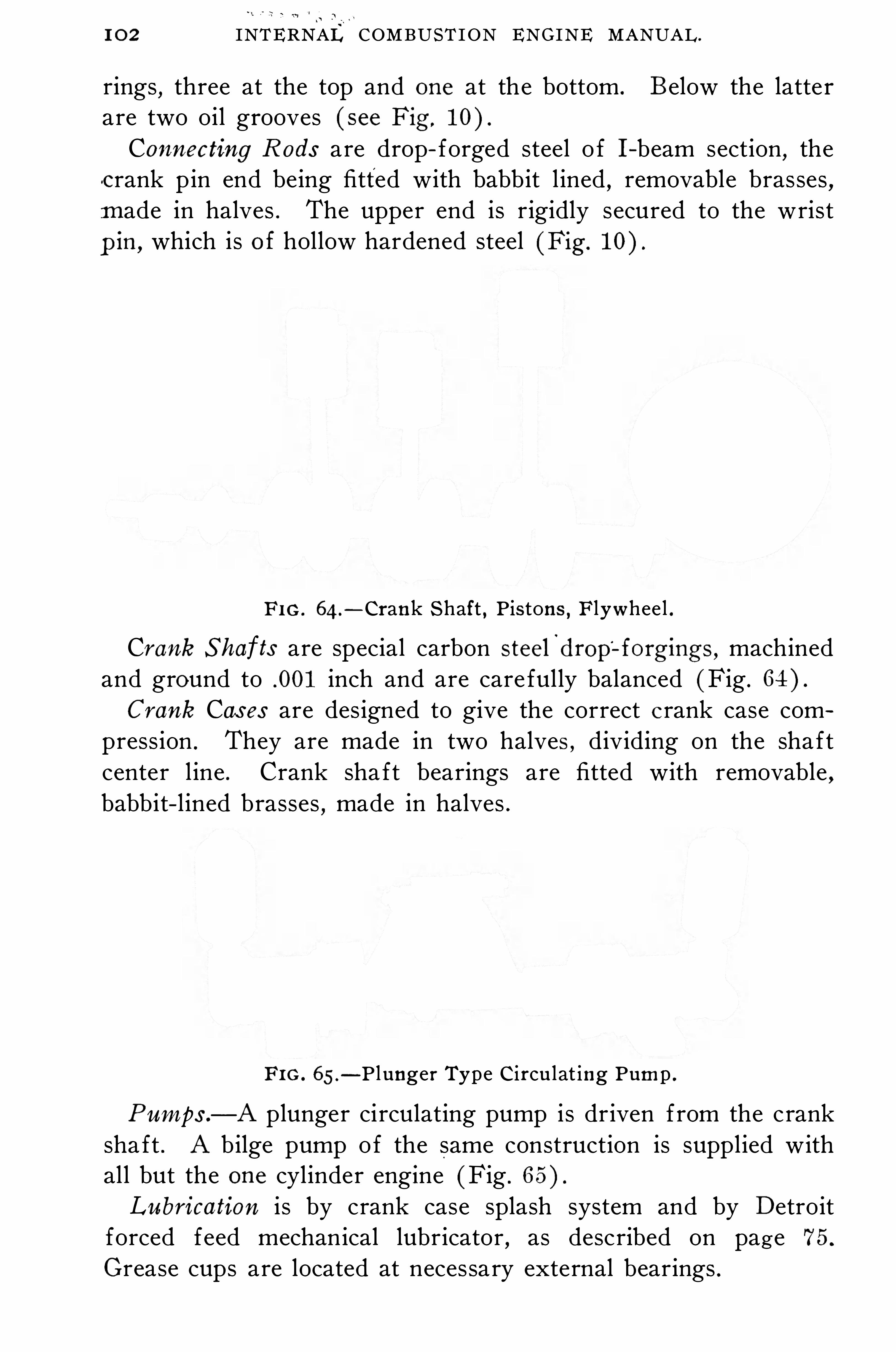
1 0 2 INTERNAL COMBUST I ON ENGINE MANUAL .
rings , three at the top and one at the bottom . B elow the latterare two oil grooves ( see Fig,
Connecting R ods are drop- forged steel o f I -beam section,the
c rank pin end being fitted with babbit l ined,removable brasses
,
m ade in halves . The upper end is rigidly secured to the wrist
p in , which is o f hollow hardened steel (Fig.
F I G . 64 .
—Crank Shaft , Pis tons , Flywhee l .
Crank S hafts are special carbon steel'
dropl forgings , machined
and ground to .001 inch and are care fully balanced (Fig .
C rank Cas es are designed to give the correct c rank case compression . They are made in two halves , dividing on the shaftcenter l ine . Crank sha ft bearings are fitted with removable ,babbit- l ined brasses
,made in halves .
FI G . 65.
—P lunger Type C ircu lat ing Pump .
Pumps .—A plunger circulating pump is driven from the crank
sha ft . A bilge pump of the same construction is supplied withall but the one cylinder engine (Fig .
Lubrication i s by crank case splash system and by Detroitforced feed mechanical lubricator , as described on page 75.
Grease cups are located at necessary external bearings .

GASOLINE , KEROSENE , A N D ALCOHOL ENGINES . 1 0 3
I gnition i s o f the high tension ,j ump spark type , using B osch
high tension magneto . The two larger engines use a Dual orDuplex system with battery .
Carburetion—The carburetor is a M odel D, S chebler , de
scribed on page 46 . The inlet mani folds are o f copper . The exhaust manifolds are water j acketed . A n ej ector type muffler i sused
,circulating water being discharged through it .
T h e S tandard S ubmar ine C has er E ngine .
The S tandard E ngine for 1 10- foot submarine chasers , Fig . 66 ,
built by the S tandard M otor Construction Company , is a six
cyl inder,single acting
,four cycle
,gasoline engine o f 220 brake
horse-power at 460 revolutions per 10 inches,and
stroke 1 1 inches . I t weighs about 30 pounds per horse—powerand has a guaranteed fuel consumption o f not more than one
pint per horse-power hour at ful l power .
T he E ngine Frame is built o f turned steel stanchions , crossb raced , and the bed plate is o f cast iron . I t has planed web sup
ports for the main bearings .
M ain B earings are spl it and set in the bed plates . They areo f phosphor bronze and provided with oil grooves . The uppercaps are reces sed in the bed plate .
Cylinders are cast sepa rately o f hard close grained iron,with
removable heads . Cylinders and heads have large water j ackets ,the heads receiving circulating water externally
,independently o f
the cylinders . S ubstantial lugs are cast on the cyl inders forbolting to the steel stanchions .
Pis tons are o f hard close grained cast i ron . The wrist p in i ssecured to the piston ; the connecting rod works on the pin .
Connecting R ods are o f nickel steel . The upper ends are fittedwith phosphor bronze bushings
,and the lower ends are fitted with
spl it phosphor bronze bearings . B oth ends are provided with oil
grooves .
T he Crank S haft has seven point suspens ion,and has six
throws arranged at 1 20 ° interval . I t is a one—piece nickel steelforging, care fully machined all over .
Valves and Valve Gear.
—T he '
inle t valves are automatic , springloaded
,steel mushroom valves , with long hollow stems that S l ide
in phosphor bronze bushings in the valve stem guides . They are

I O 4 INTERNAL COMBUST I ON ENG INE MANUAL .
provided with dash pots and spiral springs to absorb the shock o fquick opening . The exhaus t valves are o f cast iron
,hollow
,bal
anced, and water cooled . They are Operated by nickel steelrocker arms with pull rods under tens ion
,the pull rods being
actuated by the cam Shaft .
T he C am S haft i s o f steel supported in spl it bronze bearingsbolted on the stanchions . There are three sets o f nickel steelcams on the shaft, one for the exhaust valves , one for the igniterrods , and one for the air starting valves . The cams are ground
,
finished , hardened and keyed on the shaft . The cam shaft isOperated f rom the main shaft through a vertical shaft . Thedriving gear on the cam Sha ft has a sl iding key-way which allowsthe cam shaft to shi ft in a fore and a ft direction while the gearsare always in mesh . This permits the air starting valves beingthrown into action for starting . The fuel pump and magneto aredriven off the vertical sha ft .A n Operating lever at the after end of the engine sl ides the
cam shaft in a fore and aft direction for starting. A t the oppositeend o f the engine is a small s ingle stage air compressor cyl inderfor supplying air at 250 pounds pressure to the compressed airtank . This is used for starting and for the whistle .
T he Circulating Pump,o f ample size
,o f the double action
type , i s operated from the crank shaft by gearing . Water f romthe pump is del ivered to the cyl inders and heads and to the exhaust valves . The inlet gasol ine mani fold is j acketed by the hotcirculating water.
Fuel S ys tem .
—Gasol ine flows by gravity from the fuel tankthrough a strainer to a float box , which is a small cast iron box
containing a float which maintains a constant level in the box .
The fuel pump has a suction connection to this box and discharges to the vaporizer . The vaporizer i s o f the multiple j ettype
,receiving its fuel from the fuel pump , and , being under a
vacuum from the engine suction,discharges its vapor to the in
take mani fold . The air and gasol ine are both regulated for theengine speed .
I gnition is by the make and break system , current being sup
plied by a simple . low tension magneto . A battery is used forstart ing and for running astern .
Lubrication is principally by forced feed through individual

INTERNAL COMBUST ION ENGINE - MANUAL.

GASOLINE , KEROSENE ,A N D ALCOHOL ENGINES .
feed p ipes to the diff erent running parts . There is no enclosedcrank case . The forced feed. lubricator i s attached to the side o f
the forward cyl inder . S eventeen pumping units in this supplyo il to seventeen feed pipes that run to all the parts to be lubri
cated. E ach pumping unit is a double-plunger valveless pump .
O ne plunger pumps the oil f rom the reservo ir through the sightfeed nozzle to the feed chamber , the other takes it from this
chamber and forces it to the engine parts .
A ll pumping units are actuated by a drive shaft which in turnis driven off the cam shaft . O ne end o f the drive sha ft is fittedwith a handle for working the pumps be fore starting the engine .
FIG . 68—Vaporizer,Submarine Chaser E ng ine .
B y an adj ustable ratchet arm in the driving mechanism the pumpstroke can be regulated to the amount o f oil required . Forsmaller adj ustments o f oil feed there is one adj usting button on
the oiler cover in front o f each s ight feed nozzle . The pipesf rom the lubricato r supply oil to the following points : E achmain bearing , each crank pin oil ring
,each cyl inder and wrist
p in , circulating pump main bearing , vertical cam sha ft bearing ,
spiral gear o f vertical cam shaft,eccentric driving air compres
sor, air cylinder and wrist pin ,
thrust yoke,each exhaust valve .
S uch few other parts as require lubrication are oiled by handhourly .

INTERNAL COMBUST I ON ENG INE MANUAL .
T h e S tandard D oub le A c t ing E ngine .
This gasoline engine designed for marine use is made in un itso f three cyl inders , and generally installed as a two unit plant orsix cyl inder engine . I t is four cycle
, double acting, having an ad
miss ion and exhaust valve fo r both top and bottom o f eachcyl inder . This gives the engine the equivalent o f twelve workingcylinders . The engine is water cooled
,as are all the pistons
,
connecting rods , valves , and the exhaust mani fold .
The admiss ion valves are all on the front o f the -engine,and
are mechanically operated f rom the same cam shaft . The exhaust valves on the back o f the engine are s imilarly Operated byanother cam ' sha ft . A ll valves are mushroom shaped o f the balanced type .
To reduce the power to one-hal f all the bottom admiss ionvalves can be locked closed and the exhaust valves
'
open ,making
the engine six cyl inder single acting . To reduce to one—fourthpower the two units can be disconnected and one unit run as athree cylinder single acting engine . The engines are built to 250horse-power per three cyl inder unit . A twin screw marine planto f horse-power can be furnished by the manu facturers .
The piston is short , being somewhat s imilar .to a steam enginepiston , and consequently a cross head and guide are necessary .
The piston rod works through: a metall ic packed stuffing box tomake the bottom end
_
o f the cyl inder gas tight . Forced feedlub rication is employed . Ignition is by the make and breaksystem .
In Fig . 69 , A i s the gas inlet , B the top admiss ion,C the top
exhaust,and D the exhaust outlet . I t i s apparent that this will
operate as a four cycle engine . O n the bottom end , B 1 is th e bottom admiss ion ,
and C 1 the bottom exhaust . This end also acts asan independent four cycle engine . E and F are the cam sha ftsthat Operate the admission and exhaust valves , respectively .
The engine is operated by the two levers, G and H ,
shown on thefront of the engine
,G is the spark lever . The lever H Operates
a compressed air valve which,in tu rn , can shi ft the admiss ion
valve cam shaft in the direction o f its length . This shaft carriesthree sets o f cams . O ne operates the admiss ion valves for aheaddirection
, one for reverse direction , and one set Operates airvalves in the bottom o f th e three a fter cy l inders for starting and
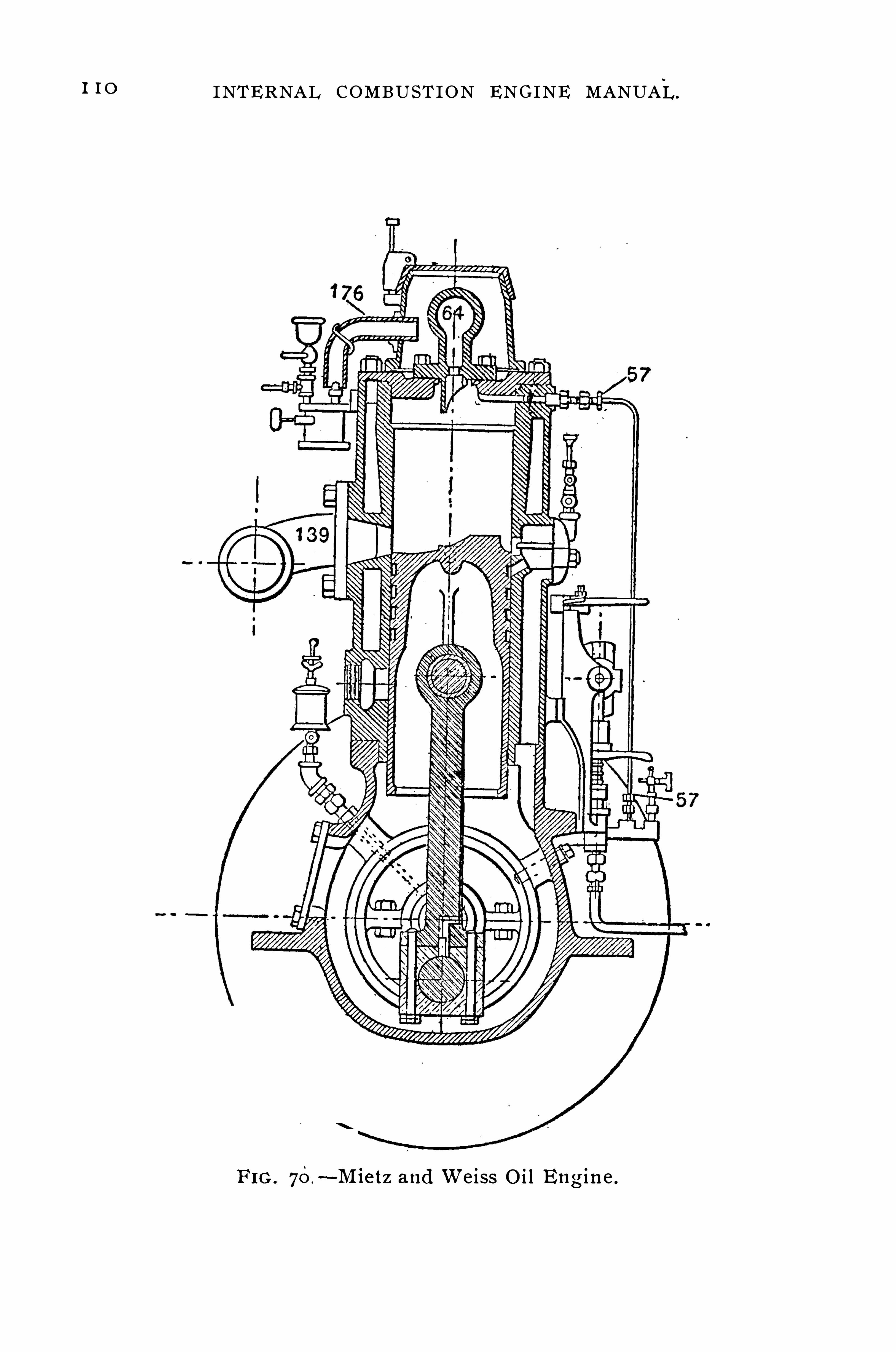
I I O INTERNAL COMBUST ION ENGINE MANUAL .
FI G . 70.
—M ie t z and W e iss O il E ng ine .

GASOLINE , KEROSENE , A N D ALCOHOL ENG INES . I I I
T h e M iet z and W e iss M ar ine O il E ngine .
The M iet z and W eiss is a two - cycle marine oil engine thatoperates on the S emi-D iesel principle , using kerosene , fuel or
crude oil. I ts fuel consumption is about one pint o f oil perhorse- power hour at all loads .
Fig . 70 shows a cross section o f th e engine . The piston is o f
the trunk pattern fitted with cast i ron packing rings . The cylin
ders are amply water- j acketed ; circulation is by a rotary pumpdriven by gear from the main sha ft . C i rculating water enters thebase o f the j acket
,i s forced up to the top and is led into the
exhaust p ipe to prevent overheating o f the latter . This is a common marine practice .
Fuel is suppl ied by a pump which is governor regulated so thatthe amount o f fuel suppl ied is a function o f the speed and load .
The fuel enters the cylinder by the pipe 57 and encounters the hotbulb 64 , which vaporizes and ignites it . Waste gases pass out atthe exhaust .1 39 . When the engine is to be started cold thebulb must be heated to dull red heat by an external burner 1 76 .
A fter th e first explosion the bulb will retain its heat and theignition is by a combination o f compress ion and hot bulb .
Lubrication is by forced feed,the oil pump consis ting o f a
plunger worked by a ratchet,the lubricat ion o f the cyl inder ,
pi ston , crank pins , sha ft bearings and connecting rods being abso
lutely automatic . A n engine o f this type is installed in the laboratory .

INTERNAL COMBUST ION ENGINE MANUAL .
Knight S l ide Va lve M otor.
The ‘ impact o f '
pO ppet valves on their seats , and the cams ,springs , etc ., which Operate them , are a source o f no ise in an eu ~
gine .
-This nois e is el imin ated in the Knight motor . The princii
pal advantage claimed for this valve mechanism is that the inletand exhaust passages are fully twice the size o f the gas passageobtainable in a l iberal des ign o f the tee-head poppet valve motor ,
FIG . 7 I .
—Co lumbia Kn ight Motor, Showing Sleeve-Va lve A rrangement .
and nearly three times the size o f the gas passages in the ell-heador valve- in-head motor .
Figs . 7 1,72 and 7 3 show the general features o f design as
adopted by the U nited M otor Company in the Columbia . Thecyl inder heads are removable . They are depressed , water- cooledand contain two Spark plugs for B osch or other double ignition .

1 1 4 INTERNAL COMBUST I ON ENGINE MANUAL .
The travel o f the sleeves is only about one inch and the powerrequired to overcome their f riction and drive them is no greaterthan that necessary to actuate poppet valves for an engine o f thesame s ize . The eccentric driving the inner sleeve is given a cer
tain advance or lead over that driving the outer one .
O peration .-During the suction stroke the right-hand slots o f
the inner and outer sleeves register,forming a large opening for
the charge to enter . A t the end o f the suction stroke one sleeve
FIG . 73 .
—Re lative Pos i tions of Sl eeves and Piston in the O perationof the Knight E ng ine .
moves up and the other down , clos ing the Opening, and the com
press ion stroke takes place . Compress ion being accomplished , thecharge is fired in the usual way and the combustion or powerstroke takes place
,al l slots st ill being out o f register . A t th e
end o f the power stroke , movement o f the sleeves brings thele ft-hand slots into register
,and the opening thus formed is a
large exhaust for the gases . This is best illustrated by Fig . 73 ,
which shows seven points in one complete cycle .

GASOLINE , KEROSENE , A N D ALCOHOL ENGINES . I I S
The timing Shown is not different f rom that o rdinarily used inpoppet valve engines . Timing of the valves is secured by vary ingthe lead between the eccentrics that operate the two sleeves andby p roperly locating the slots in the sleeves . The amount o f valveopening is practically unl imited and is governed by the width o f
the slot in the sleeves and the throw o f the eccentrics that driveand determine the travel o f the sleeves .
T h e A l coho l E ngine .
The problem of alcohol vaporization was discussed under thechapter on carburetion . In appearance the engine is l ike anordinary four cycle gasol ine engine
,but in des ign , Since the
use ful effect o f a given weight o f denaturized alcohol is thato f an equal weight o f gasol ine
,the cyl inder dimensions , inlet and
exhaust passages,are increased in the ratio o f to 1 to get
equal power . This increase and the modified carburetor are theonly points wherein the alcohol engine diff ers f rom the gasol ineengine . The comp ress ion is carr ied higher than in other l iquidfuel engines . R ecent experiments show that the alcohol enginecan be started cold . The Deut z Company spray the alcohol intothe admis s ion line near the inlet valve . A mixture o f equalweights o f gasoline and alcohol gives a very efficient performancein the gasoline engine without necessitating change o f cyl inderdes ign .

CHAPTER XI .
AERIAL M OTORS .
The vast strides in aeronautical development due to demandso f the present war, culminating in the enormous 900 HP . Capronitriplane o f I taly
,capable o f carrying three tons , and the attendant
talk o f the U nited S tates winning the war with a vast fleet o f aeroplanes , makes this type o f engine o f pa rticular interest at th e timeo f writing . I t is regretted that the scope o f this book precludesa more comprehens ive presentation o f the subj ect . A eroplanedevelopment is l imited only by the degree o f development o f thegasol ine engine .
T h e E ssen t ial Features for a success ful aerial motor, in theorder o f thei r milita ry impo rtance , are ( 1 ) fuel and oil ~
economy ,
( 2 ) l ightness , ( 3 ) reliabil ity , (4 ) durabil ity , (5) efficiency undervarying Operating conditions
, ( 6 ) access ibil ity , a nd ( 7 ) sim
plicity .
( 1 ) E conomy, fuel and oil , is essential because the radius o ffl ight is l imited by the amount o f fuel and lubricant the machinecan carry . This is closely related to
( 2 )'
Weigh t of Power Plant—A true comparison of aeroplane motors can be ~made only by considering the gros s weighto f the complete power plant , with fuel and oil , for the durationo f a fl ight . I n such a comparison the great advantage o f fueleconomy is evident ; in a l ight but uneconomical motor it mayeven outweigh the advantage o f light weight of motor . Forexample , the fuel and oil consumption o f a well designed fourcycle motor i s about .53 pound per H .P. hour , while the grossweight for a ten h our fl ight is about 1 1% pounds per H .P. ,
whereas,the corresponding fuel and oil consumption and weight
per horse-power o f a l ight rotary motor are about .9 pound and14 pounds . O bviously i f the requirements are a “ten hour fl ight ,

1 1 8 INTERNAL COMBUST I ON ENGINE MANUAL.
to el iminate vibration . Small motors are started by hand fromthe operator
’
s seat , but motors o f 150 HP . and over are generally fitted with an air actuated sel f- starter .
T ypes—A eroplane motors may be classed as follows : ( 1 ) Ver
tical , ( 2 ) D iagonal or“V
” type, ( 3 ) Horizontal opposed , (4 )
R adial , and (5) R otary .
1 . Vert ical A eroplane E ngines .
The vertical type o f aeroplane engine is a development f romthe automobile engine . It is distinguished by its l ight weight , perfeet balance , and other features o f design adapted to its particularfield . Thus , when the machine is ups ide down , there must be nodanger of fire and the carburetor must function per fectly . Prac
tically al l vertical engines have two spark plugs per cyl inder ( twopoint ignition )Hal l-S cott M ode l A -5 M o tor , Fig . 74 .
—This is a vertical,
water—cooled six cyl inder,four cycle engine o f 125HP . at
revolutions per minute,with a 4- inch bore and 5—inch stroke . It
weighs about 5 pounds per H .P.
Cylinders are cast separately o f semi- steel ( a special mixtureo f grey and S wedish iron ) with integral cyl inder heads
,great
care being exercised in casting and machining these to have thebore and walls concentric with each other . Small ribs are castbetween the outer and inner walls to ass ist cool ing and to trans ferstresses direct f rom the explosion to holding-down bolts that runfrom the main bearing caps to the cyl inder tops . A mple waterj ackets are provided around the head and valves , there being twoinches o f water space above the latter .
The cylinder is annealed,rough machined , then the inner cylin
der wall and valve seats are hardened and ground to mirrorfinish to add to the durabil ity o f the cyl inder and to diminishfriction . The cyl inder s ides are machined so that when assembledon the crank case the cyl inders form a sol id block .
Pis tons are cas t f rom the same semi - steelmixture as the cylin
ders ; they are extremely l ight , and are provided with six deepribs under the arch head . Pistons are fi rst annealed , machined

AERIAL MOTORS .
close to s ize,and then hardened and ground to a mirror finish .
The piston p in bosses are located very low so that the heat f romthe piston head is kept as far f rom the upper end o f the connecting rod as pos sible . There are three M - inch piston r ings .
Connecting R ods are of the I -beam type , milled f rom solidchrome nickel forgings , and are well balanced . The piston end is
FI G . 74 .—Ha l l -Scott
,Mode l A -
5,A erop lane Motor.

1 2 0 INTERNAL COMBUST ION ENGINE MANUAL .
fitted with a gunmetal bushing . The crank pin end carries twobronze serrated shells
,which are tinned and babbitted hot and
broached to harden the babbitt .. T he Crank S haft is o f the seven bearing type , being cutf rom a billet o f chrome nickel s teel o f pounds tensilestrength . The bearing surfaces are extremely large , this being accomplished without undue length o f motor by offsetting the webso f the sha ft , a novel feature . This off set acts as an oil scooperfor o il ing the connecting rods . Two thrust bearings are installedon the propeller end o f the shaft
,one for pull and one for push .
Timing gear and starting ratchets are bolted to a flange turnedintegral with the sha ft .T he C am S haft i s a one piece , low carbon chrome nickel steel
forging , cams , air pump eccentrics , and gear flange being integral .I t is enclosed in an aluminum housing bolted directly on top o fall S ix cylinders
,being driven by a vertical shaft in connection
with bevel gears . This shaft , in conj unction with rocker arms ,rollers and other working parts , are oiled by forcing the O il intothe end o f the sha ft
,using same as a distributor
,allowing the
surplus supply to flow back into the crank case through the hollowvertical tube . This supply oils the magneto and pump gears .
Valves .
—E xtremely large tungsten valves , one-hal f the cyl inderdiameter , are seated in the cyl inder head and are ,
operated by theoverhead one-piece cam shaft ' in connection with short chromenickel rocker arms . These arms have hardened tool steel rollerson the cam end , with hardened tool steel adj usting screws oppos ite . This construction allows accurate valve timing at all speedswith least poss ible weight .Large diameter oil tempered springs held in tool steel cups
locked with a key are provided . The ports are very large andshort
,being designed to allow the gases to enter and exhaust
with the least possible res istance .
Gears—A ll gears , with the exception o f the two bronze oil
pump gears,are o f chrome nickel stee l and where possible are
bolted to flanges or made integral with the shaft , and are enclosedto run in oil .
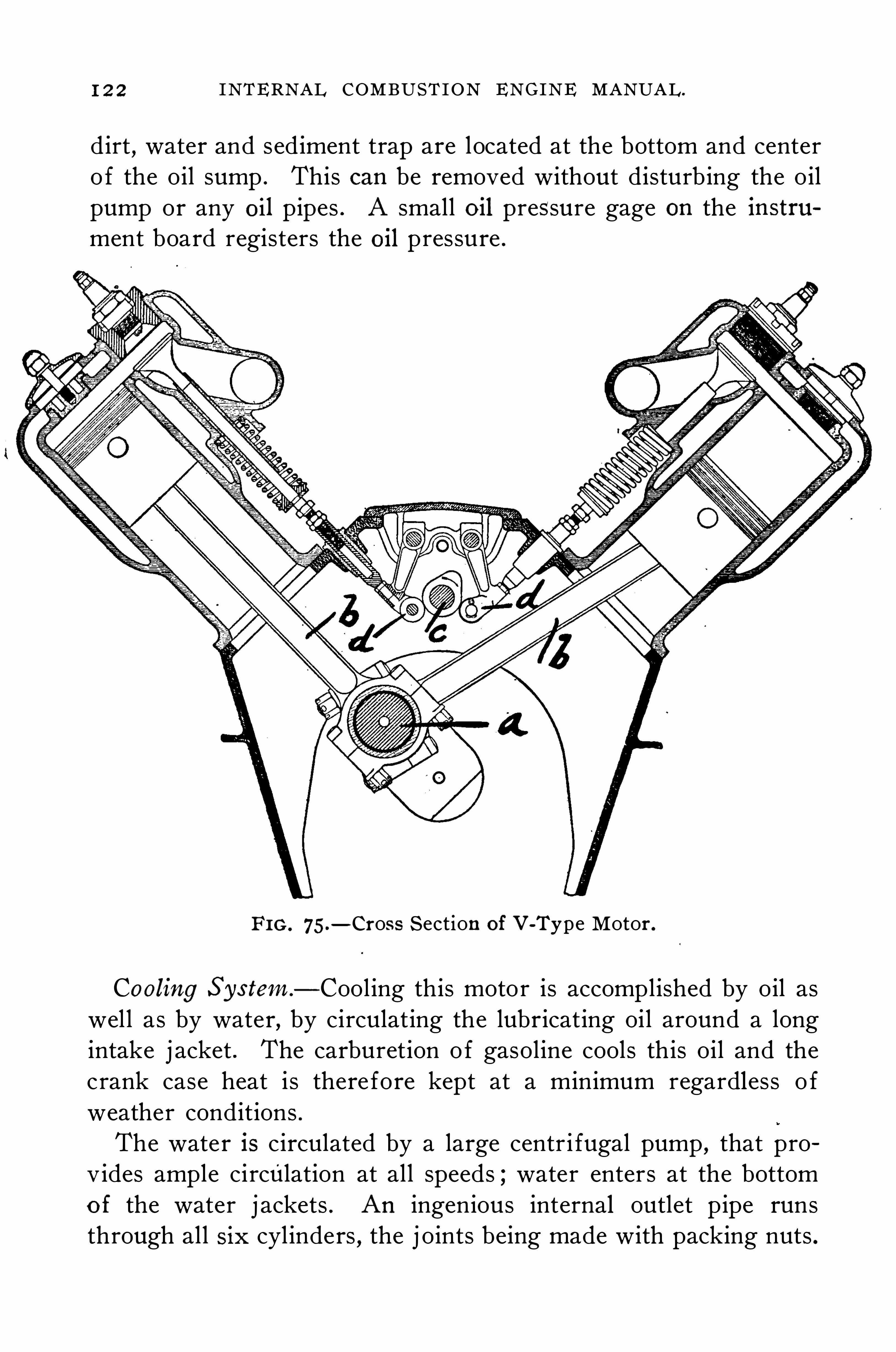
INTERNAL COMBUST ION ENGINE MANUAL .
dirt , water and sediment trap are located at the bottom and centero f the oil sump . This can be removed without disturbing the oilpump or any oil pipes . A small O il pressure gage on the instrument board registers the oil pressure .
FI G . 75.
—Cross Section of V-Type Motor.
Cooling S ys tem.
—Cool ing this moto r is accomplished by oil aswell as by water, by circulating the lubr icating oil around a longintake j acket . The carburetion o f gasoline cools this oil and thecrank case heat is therefore kept at a minimum regardless o fweather conditions .
The water is circulated by a large centr i fugal pump , that provides ample circulation at all speeds ; water enters at the bottomo f the water j ackets . A n ingenious internal outlet pipe runsthrough all six cyl inders , the j oints being made with packing nuts .

AERIAL MOTORS . 1 2 3
S lots are cut in this pipe in each water j acket so that the C irculating water is drawn directly around the exhaust valves . Thismaintains a uni form cyl inder temperature .
A S tarting Crank is mounted in a compact aluminum hous ing
securely bolted to the main crank case , thus forming an integralpa rt o f the motor .
2 . V T ype E ngines .
I t i s obvious that , as the number o f cyl inders o f a verticalmotor is increased . the crank sha ft and crank case become veryheavy and finally the number o f cyl inders reach a l imit ; moderndesigners place this at eight . The V type motor is designed to re
duce the weight for a given number o f cyl inders by arrangingthem at an angle in pairs
,the case and shaft being common to
both cylinders o f a pai r .
Thus an eight cvlinder V type motor has its cyl inders arrangedin two sets o f four cyl inders each ,
the sets being oppos ite one
another at an angle,generally the connecting rods o f corre
sponding cylinders o f the two sets working on the same crank ,Fig. 75. A n eight cyl inder motor crank shaft has four cranks
,
each crank a operating two connecting rods , b, b. The cam sha ftc i s driven through gearing or by chain drive from the main shafta . E ach cam operates two push rods , d, d.
This design is being widely adopted both here and abroad forengines o f eight and more cylinders . I t cannot be so per fectlybalanced as the radial or rotary engine
,but to offset this its head
resistance is les s than either o f those types . N early all V typemotors are water cooled . E ight cvlinder motors are generallyprovided with two magnetos
, one for each bank o f four cyl inders ,and twelve cylinde r motors general ly have three
,one for each
bank‘
o f four cyl inders .
S tur tevan t M odel 5 A M o tor , Fig. 7 6 .
-T his is a V
type , water cooled , eight cyl inder , four cycle engine o f 140 HP . atrevolutions per minute
,with a 4 - inch bore and 5- inch stroke .
I t weighs 4 pounds per H .P.

1 2 4 INTERNAL COMBUST I ON ENGINE MANUAL .
Cylinders are cast in pairs f rom an aluminum alloy with a steell iner . A molded copper asbestos gasket is placed between thecyl inder and head insuring a tight j oint . The cyl inder heads arecast in pairs o f aluminum alloy with ample water passages . E achcylinder . is held to the base by six long bo lts which also passthrough the heads .
Pistons,which are made very l ight f rom a special aluminum
alloy to reduce vibration and wear o f bearings , are deeply ribbedin the head for cooling and strength
,and are provided with two
piston r ings . The wrist pin is made o f chrome nickel steel,hollow
bored and hardened ; it turns in both piston and connecting rod .
Connecting R ods are made in H- section o f air hardeningchrome nickel steel
,having a tensile strength of pounds
per square inch . The crank ends are l ined with white metal andthe wrist p in ends are bushed with phosphor bronze .
Crank S haft—This is machined from heat treated chromenickel steel . I t i s 2% inches in diameter and bored hollowthroughout to obtain maximum strength with minimum weight .
I t is carried in three large,bronze backed white metal bearings .
T he C am S haft, which is supported by six bronze bearings inthe upper hal f o f the crank case between the two banks o f cylinders , i s hollow bored throughout and the cams are formed integral with the shaft .T he Gears that operate the cam shaft , magneto , oil and water
pumps are contained in an oil tight casing and Operate in an oil
bath .
Valves are o f hardened tungsten steel , mechanically operated ,and are o f generous proportion . They are Operated by rockerarms
,one for each valve
, off the cam shaft . A system o f doubl eSprings reduces the stres s on each spring ; a large diameter springreturns the valve
,while a second spring at the cyl inder base
handles the push rod l inkage .
T he Crank Case i s cast f rom an aluminum alloy deeply ribbedat points o f high stress . The lower hal f contains the oil sump ,
which is entirely covered by an oil fi ltering screen .
Carburetion—The carbureto r i s the Z enith dup lex type . I tis a double barrel design with one float chamber and two j ets ,


AERIAL MOTORS . I 2 7
each j et supplying one bank of fou r cyl inders . I t is locatedat the rear end o f the motor beneath the level o f the engine base ,thus permitting o f gravity feed . I t is connected to the cyl indersby means o f aluminum mani folds , having integral cast water
j ackets .
I gnition is by two eight cyl inder waterp roo f B osch or S plitdorfmagnetos placed face to face between the two banks o f cyl inders .
E ach cylinder is provided with double ignition by means o f twospark plugs located in water cooled bosses on the sides o f thecyl inder heads .
Lubrication is o f the complete forced circulation system , oil
being supplied to every bearing by a large capacity rota ry pump ,which is gear driven from the cam shaft .
S tarting Crank—The engine can be started f rom the machineby a crank handle or an air starter can be readily installed .
3 . Hor i z on ta l O pp osed E ng ines .
T h e A shmusen M o tor , Fig . 78, i s o f the horizontal opposedcyl inder type ; it is a four—cycle , air cooled , twelve cyl inder en
gine ,.
having a bore o f 3% inches , stroke o f 4% inches , and develops 105HP . at revolutions per minute . I t weighs about360 pounds .
I t is equipped with two improved A shmusen carburetors anddouble mani folds . A ir i s drawn through flutes on the s ides o fthe cyl inders to the mani folds
,thence to the carburetors . This
system accompl ishes the double purpose o f Cool ing the cyl indersand heating the air to the carburetor . Delco
'
ignition i s used .
The propeller is driven from the cam shaft at one—hal f motorspeed . The cylinders
,cyl inder heads and pistons are o f grey
iron . The crank shaft is a heat treated nickel steel forging . Thecrank case is aluminum alloy . The valves are tungsten steel .M ain and cam shaft bearings are o f the bal l type . W rist pinbearings are o f Parson ’s metal . A compression release is fittedto hold the exhaust valves off their seats . Per fect balance , minimum vibration , and access ibil ity are ,
claimed,the makers stating
that it is poss ible to remove all cyl inders and replace them in 45minutes .
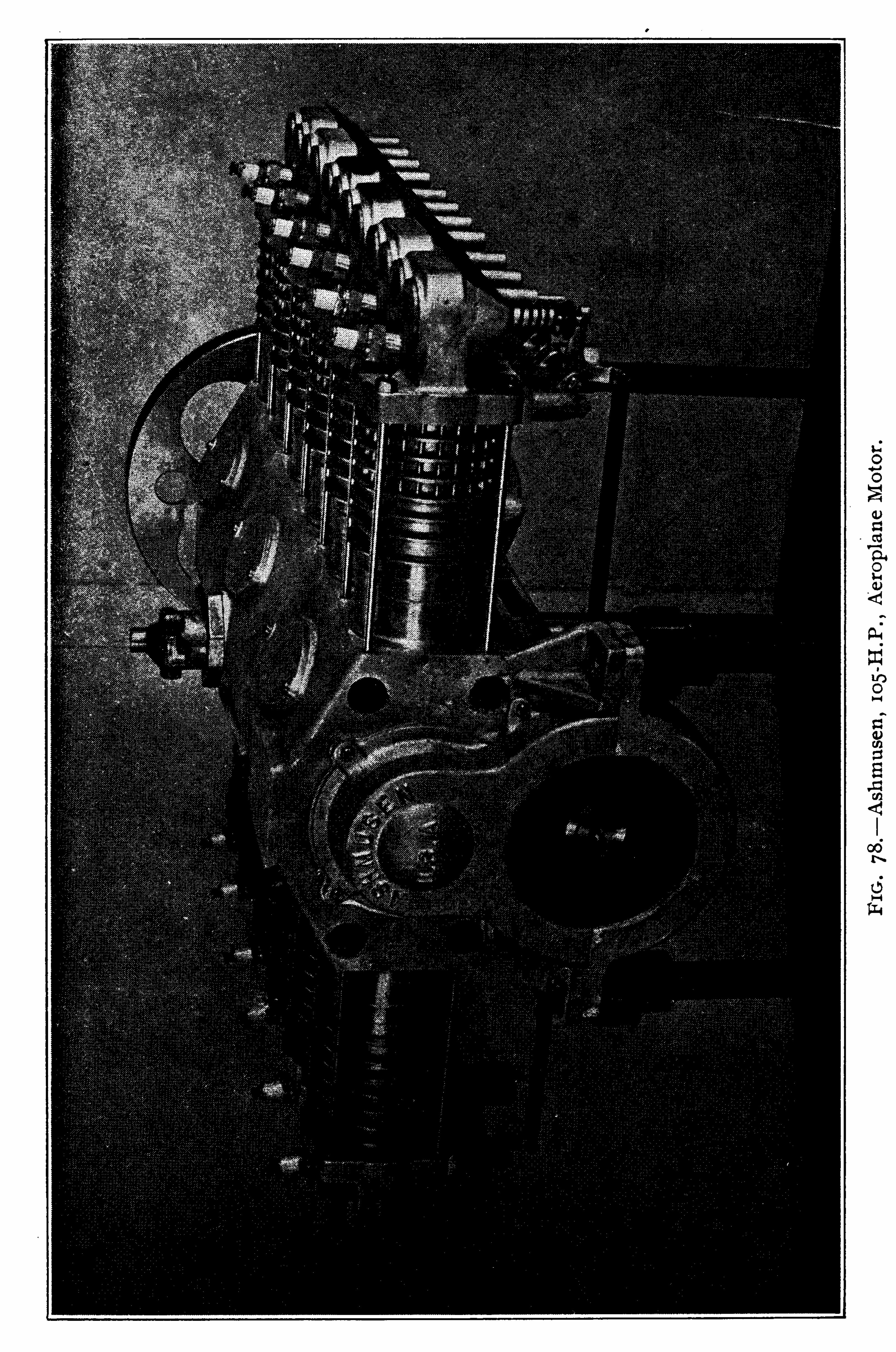

1 30 INTERNAL C OMBUST I ON ENGINE MANUAL .
Cylinders K K are o f cast iron,with Cooling ribs
,the flat
cyl inder tops containing the inlet and exhaust valve seats . Thecylinders are s lightly off set . They are attached to the crank caseeach by two long bolts connected to the through crank case boltsat the inner end and passing through bosses on the cylinders at theouter end , as shown at L . These through bolts take the longitudinal strains due to the explos ions .
Pistons H are o f cast iron,ground to fit and provided with
stiff ening ribs on the under side o f the flat crown . There aretwo piston rings . The wrist pins are hollow
,o f nickel steel
,
hardened and ground , and secured in the piston bosse s by a set
screw as shown .
Connecting R ods B are o f high tens ile nickel steel o f H sectionwith a plain bronze bushed wrist pin end . The crank pin endconnection is shown in section in Fig . 80. E ach connecting rod
ends in a shoe C . The three shoes o f each bank of cyl inders bearon a cyl indrical bronze S leeve D (made in halves ) , which embraces the crank pin and rotates thereon ; the whole is held together by two bronze collars E . E .
Valves are o f nickel steel and o f large diameter . The inletvalves are spring loaded automatic valves
,a bad feature that will
probably be abandoned . The exhaust valves are operated throughpush rods and rocker arms by the cam U . This cam is made in
tegral with its driving pinion V which runs on the bronze sleeve% ; it is driven from the pinion W through intermediate gears .
Carburetion—A Z enith carburetor is used . From the carburetor the mixture goes to the annular chamber P surroundingthe rear end o f the crank case
,and from this chamber pipes R
lead to the inlet valves . The exhaust can be discharged directlyto the atmosphere at S or a collector muffler can be fitted , Fig . 79 .
I gnition is by high tension magneto T ,gear dr iven f rom the
rear end o f the crank shaft . Two spark plugs are fitted to eachcyl inder .
Lubrication—A cam Operated plunger type oil pump (notshown ) i s fo rmed on the crank case cover . I t del ivers oil at A
under pressure,and oil is supplied to the pistons , wrist pins , and
al l internal parts through the crank shaft . A n oil fog i s maintained in the crank case when th e engine i s running .

AERIAL MOTORS .
FIG . 80 . Cross Section of A n zan i Motor.
1 3 1

1 3 2 INTERNAL COMBUST I ON ENGINE MANUAL .
5. R o tary A erop lane M o tors .
The distinguishing feature o f a rotary motor is that the crankshaft and crank are stationary and the cyl inders revolve aboutthe shaft . This produces the same relative motion of pistons tocyl inders as though the cyl inders were stationary and the crankrevolved . From Fig . 81 , showing the connections between thepistons and the crank shaft in a rotary engine
,it is obvious that
it matters not which is the revolving member . The relativepiston - cylinder positions will be the same .
The rotary motor has several inherent disadvantages . Thehead res istance is greater than in a stationary motor . It esti
mated that 7% to 9% o f the power developed is expended inovercoming the eff ect o f the whirl ing cyl inders . Power is con
sumed in driving the cyl inders about the shaft . The gyroscopiceffect o f the whirl ing cyl inders is a handicap to the operator .
The lubricating waste is large , the compress ion is low, and theengine cannot be satis factorily muffled .
The crank shaf t is secured to the aeroplane . The propeller i smade fast to the f ront o f the cylinder base and revolves with it .Fig . 82 shows a cross section o f theGnome E ngine—T he cylinders are made o f forged chrome
ni’ckel steel,about inch thick with cooling fins on the out
s ide . They are secured to the crank case by a lock ring .

1 34 INTE R NAL C OMBU ST ION E NG INE MANUAL .
I gnition is by high tens ion magneto direct to spark plugs , via avery s imple distributor ; the spark is advanced automatically .
Lubrication is by forced feed . The oil pump A,Fig . 82
,forces
oil through the oil s ight feed gage glasses and pipes in the hollowcrank sha ft to the bearings and by ducts to all points requiringlubrication .
T h e Gyro Duplex M o to r , Fig . 88 .
—T his is an A merican - built9 cylinder, ai r- cooled rotary moto r , developing 100 H .P. ( normal ) at bore
,4% inches ; stroke , 6 inches ; weight ,
270 pounds .
Cylinders are turned f rom solid billets o f special alloy steel ,with cool ing fins on the outs ide , and carefully balanced to elimi
nate vibration .
Pis tons are o f the best grade cast iron,fitted with oil deflectors
for economy,and two piston rings o f special design .
Connecting rods are o f vanadium steel and heat treated . Theconnecting rod assembly
,or spider, is carefully balanced .
Crank shaft is o f nickel steel , drilled out for l ightness andserves as a gas and oil passage to the crank case .
Crank case is o f vanadium steel , made in two halves , the cylinders being clamped between the two halves .
Cam valve drive i s o f the Duplex type driven from a differential gear train .
I gnition i s by B osch high tension magneto direct to spark plug ,
via a simple distributor .
Carburetion is semi—automatic , gasol ine being fed to the crankcase through a gear driven pump and a spray nozzle .
Lubrication i s automatic and absolutely positive , being suppliedby a gear driven displacement pump to the central bearing andfrom there through ducts to al l points o f f riction .
A variable compression cani allows the motor to start readilyand to run idle at 250 to 300 R P M . There are no inlet valves ,back pressure is reduced , back—firing el iminated , and no oil wasteoccurs through the piston head .


To Dup l ex
0 amFI G. 84 .
—Section Through Cyl inder—Gyro Dup lex” A erop lane Motor.
C HA PTE R XI I .
T HE D IE S E L E N GIN E .
This engine , the invention o f the late M r. R udolph D iesel , o fM unich , differs in its cycle f rom all previous internal combustionengines in compressing
‘
a full charge of air to a temperature abovethe ignition temperature o f the fuel
,then inj ecting the fuel for a
certain period (variable according to the load ) into this highlyheated air where it burns with l imits o f temperature and pressureunder perfect control . N o fuel is present in the cylinder during
compression ( this is the distinctive D iesel feature ) , and a uni formcombustion takes place at a predetermined temperature , the combustion l ine being represented as an . isothermal .C lassification .
—D ies el engines are broadly class ified as twocycle and four cycle . In both types a cyl inder full o f air at aboutatmospheric pressure is compressed by the piston until at the topcenter its pressure becomes about 500 pounds per square inch ,
and its consequent temperature about F . A t this instant asmall quantity o f oil fuel is blown into the very hot compressedair by means o f a j et o f air at a still higher pressure .
O peration .—The fuel valve is so des igned that the oil i s broken
into a fine spray and admission lasts only about one- tenth o f thedownward stroke . During this short t ime much o f the oil isbu rned in the hot air . The heat generated by the combustionraises the temperature greatly
,and consequently must increase
either or both the pressure and the volume occupied . A s a matter o f fact , the aim is to have combustion proceed at the cr iticalrate which would permit the increase o f volume occupied , due tothe motion o f the piston and the increased temperature , to be sobalanced that the pressure will remain constant throughout combustion .
A fter combustion is complete,expansion of the hot gas will
still further push the piston down,and the pressure wil l decrease

T H E DIESEL E NGINE . 1 39
rapidly . The temperature will also fall rapidly,mainly -
f romconvers ion o f part o f the heat into work , but also partly by theradiation o f some o f the heat through the cylinder wall s to thesurrounding cool ing water .
T h e M aximum T emperatures actually atta ined in the cyl inderare very high , approximating in some cases to nearly F .
I t i s these excess ively high temperatures that occas ion some o f
the D iesel engine difficulties . I t i s necessa ry to keep the rubbingsur faces o f the metal which are exposed to the hot gases suffi
c iently cool to permit them to retain their lubrication , and it i salso necessary to prevent al l metal which comes into contact withthe heat f rom becoming so overheated as to damage its s trainresisting properties .
These extremely high temperatures als o compl icate the questions o f expansion o f the cyl inder materials and hence the foundrywork involved . The consequent high pressures cause unusuallyhigh tension stresses in the columns
,tie rods
,cyl inders
,etc . , and
make for heavy vibrations .
D es ign Prob lems —T he above engineering problems were newto prime movers and had to be solved be fore a successful D ieselengine could be produced . A dequate cool ing systems have beendevised to handle the high temperatures , heavy columns and tierods to meet the high tension stresses have overcome the vibrat ion . The expans ion problems had been so lved
,to a limited ex
tent , in the foundries .
While it may be admitted that the early claims were much toosanguine , and that the glowing anticipations
‘o f the early enthu
siasts have not as yet been entirely fulfil led,yet there is no doubt
that the development o f this engine thus far j ustifies a wonderfuloutlook for its future .
T h e R easons for th e S uccess o f certain des igns are worthy o f
study as marking the trail o f future progress . O ver—ambition ledto excess ive increase in s izes o f the units without first overcoming the difficulties involved . A l so , attempts were made toconvert the land engine to marine use without first adapting it tothis new work . In the success ful engines increase o f power has

1 40 INTE R NAL C OMBU STI ON E NGINE MANUAL.
generally been attained by multiplying the units instead o f indefinitely increasing the s ize o f the unit ; p rice has not been cut ;weight has not been sacrificed ; s impl icity has not been forced .
T h e W e l l Known A dvan tages o f the oil engine for naval use ,namely , the saving in space , weight , fuel and personnel , and theposs ibil ity o f getting underway quickly
,has repeatedly caused
predictions that the oil engine must be developed for largerpowers . The largest A merican built marine D iesel installationis the H .P. plant on th e N aval coll ier M aumee .
C yc les .—The foregoing remarks apply to all types o f D iesel
engines . I n the four- stroke cycle engine the exhaust takes placethrough valves in the cylinder covers , the gases being pushed out
by the p iston on its return stroke . During the next stroke freshair is drawn into the cylinder through other valves also situatedin the cyl inder cover . I t is compressed during the third stroke ,and the fuel is then admitted in the same manner at the commencement o f the next stroke , as in the two—stroke cycle type .
In the case o f the two - stroke cycle engine,j ust before the
completion o f the expansion stroke the piston uncovers ports inthe lower part o f the cyl inder walls leading into an exhaust passage , and a considerable portion o f the hot gas escapes , the pressurefall ing to about that o f the atmosphere . Then in some designsvalves in the cyl inder cover are Opened and f resh air suppl ied bythe scavenger pump at a pressure o f about 4 pounds per squareinch blows out the remainder o f the burnt gas , leaving the cylinderful l o f fresh air ready to be compressed by the retu rn stroke o fthe piston ; in other designs the exhaust ports are placed on one
s ide only o f the lower end o f the cyl inder , and on the others ide s imilar po rts , also opened by the travel o f the piston , but ata somewhat later instant
,admit the S cavenging air . In these
latter cases the tops o f the pistons are curved to direct theentering air upwards
,and it i s cla imed that the scavenging air
travels right to the top o f the cyl inder and entirely displaces theburnt gas . In these latter designs the scavenger valves and thegear for working them are dispensed with , and consequently theengines are to some extent s implified .

INTE R NAL C O MBU ST I ON E NG INE MA NUAL .
FI G . 85.—D iese l E ngine , Four Cyc l e .

T HE D IE SE L E NGINE . 1 43
t ity o f fuel inj ected each stroke . S o fine is this regulati On that‘
the engine can Operate alternating current generators in parallelwithout difficulty .
The fuel used at hal f load rarely exceeds 55% o f that used atfull load , so the fuel consumption is nearly proportional to thework done . This very marked contrast to the performance o f
other types o f engines is the result o f features inherent in theD iesel cycle alone , and is due to direct regulation o f the fuelsupply by the governo r .
C% C LE O F O PE R AT ION S .
A S stated above , the fuel is not compressed , only air being inthe cyl inder during this s tage o f the cycle , hence pre- ignition isimpossible . The clearance is very small . The complete cycle isas follows1 . A spirat ion S troke—T he piston moves to the bottom o f the
cyl inder and during this stroke the ai r admiss ion valve opens andallows the cyl inder to fi l l with air at atmospheric pressure .
2 . C ompress ion S troke—The piston moves to the upper endo f the cyl inder
,the admiss ion valve closes
,and the air in the
cyl inder is compressed to 500 pounds per square inch,at which
pressure its temperature is sufficient to ignite any form o f petroleum ( crude or refined ) spontaneously . N o valves are Openduring this stroke and there is nothing in the cylinder but purea1r .
3 . E xpans ion S troke—When the piston has reached the topo f the compression stroke and the crank is j ust cross ing the deadcenter, a small needle valve , Fig . 86 , opens and a charge o f l iquidfuel mixed with compressed air is blown into the highly heatedair already in the cyl inder . Ignition t’akes
’
places as the fuelcomes in contact with this hot air . The fuel valve
,together with
the air and exhaust valves,i s placed at the s ide o f the cyl inder at
the top end,and all valves open into the same space . The quan
tity o f fuel i s not all blown in at once ; instead , fuel inj ection ismaintained for a per iod equal to 10% o f the downward stroke o fthe piston . It would be impossible to maintain this long period

144. INTE R NAL C OMBU ST ION E NG INE MANUAL .
o f admiss ion i f fuel alone were inj ected,but the compressed air
,
which is blown in with the fuel and which is thoroughly mixedwith the fuel by the perforated washers that surround the needlevalve, increases the volume and thus gives a quantity whose injection can be controlled . The compressed air referred to is thatsuppl ied by the two stage compressor at 800 pounds pressure andcooled before introduction into the fuel valve .
A fter the needle valve closes , the hot gases expand until thepiston has traveled 90% Of its stroke , when the exhaust opens torel ieve the pressure . The pressure at opening
’
o f the exhaustvalve for normal load is generally 35pounds per square inch
,and
the temperature about 700° F . The pressure in the cyl inder isnot due to the expansion o f gases o f combustion alone
,for there
is a large exces s o f air present and the high heat attained issufficient to expand this excess air also .
4 . E xhaust S troke .—This fourth and last stroke of the cycle
takes place on the upward stroke . The exhaust valve is open andthe hot gases are forced out by the piston . When the pistonreaches the top center
,the exhaust valve closes
,the a dmiss ion
valve begins to Open and the cycle is repeated .
The engine is water cooled and the fuel and exhaust valves areOperated as shown in Fig. 85. A i s a cam on the countershaft , Bi s the cross rod with a roller bearing On the cam A
,and C is the
push rod that actuates the valve stem . S plash lubrication i s usedfor the cyl inder
,and the main bearings are lubricated by an oil
ring and an oil chamber . The fuel valve is made o f nickel steelto prevent abras ion by the petroleum . The piston is o f the longtrunk type
,being approximately 2 1 3 times the diameter in
length,tapering 1 32 inch , and provided with four snap rings .
Governor . —T he governor is connected to a by—pas s at thefuel pump . The pump runs at constant speed . I f the load isl ight and the fuel requirement is low
,the governo r holds the by
pass valve Open a'
nd allows a large amount o f oil to return to thesuction s ide o f the pump ; when the load increases , more oil i s re
quired ; the governor holds the by-pass Open for a shorter period ,
les s O il goes back to the pump suction and more goes to theengine .

INTE R NAL C OMBU ST ION E NGINE MANUAL .
(Fig. 85) as i s the fuel valve . In the engine shown here the air
valve is an ordinary sp ring loaded valve which automaticallyopens on the suction stroke and closes on the compression stroke .
I n larger D iesel engines this valve is cam actuated in the samemanner as the fuel and exhaust valves .
Limi ts of Power.—The power o f the four cycle engine is l im
ited by difficulties o f deal ing with the exhaust,unless auxil iary
exhaust ports ( s imilar to the two cycle exhaust ports describedlater ) be introduced . A uxilia ry exhaust ports have been appliedto fast running four cycle engines to permit the escape o f the hightemperature gases be fore the cyl inder head exhaust valve opens .
This method o f exhaust with both ports and valves decreasesthe mean eff ective p ressure and decreases the efficiency o f suction ,s ince the ports are open at the beginning of the suction stroke andthe quality o f the charge is thus affected . The gain in weight andspace occupied by the two cycle engine is not great , especiallys ince the fuel consumption is about 1 0% greater in this type , butnotwithstanding this
,to obtain the maximum mean eff ective pres
sure per revolution the two cycle engine has been generallyadopted for marine use .
T h e T wo C yc le D iese l .
There are two general types o f the two cycle D iesel engine inuse in the U . S . N avy . They differ in the method o f compressingand supplying the scavenging a1r. The N urnberg engine compresses the scavenging air by means of a scavenger cylinder whichis under and an integral part o f the working cylinder and suppl iesthis air through air valves in the cylinder head . The S ulzerengine compresses the scavenging air by a separate air compressorwhich is Operated by the engine main sha ft , and suppl ies this ai rthrough scavenger ports in the bottom o f the cylinder s ide .
E ach engine has an air compressor driven by the engine mainsha ft to supply air for fuel inj ection , starting and revers ing . Inthe following descriptions o f these two engines care must be exer
cised to distinguish between the compressed air for scavengingand that for fuel inj ection . The former i s maintained at onlyabout 1 0 pounds pressure , and is supplied differently in the twoengines . The latter
,that for fuel inj ection and starting , is main
tained at about 800 pounds pressure and is supplied in a similar

T HE D IE SE L E NGINE . 1 47
T h e N urnberg E ngine .
The fo llowing description is that o f a 450 horse-power N urnberg Type E ngine , as built by the N ew London S hip and E ngineC O . for our submarines . The engine has six cylinders , with one
two—stage air comp ressor at the forward end . The piston , Fig .
89,i s in steps
,the upper or smaller diameter being the working
piston and the lower or larger diameter being the scavengerpiston . The area o f the annula r part o f the scavenger piston i sabout times the area o f the working piston , and maintainsabout 9 pounds p ressure in the scavenger receiver . The spacearound the scavenger cylinder in the housing Fig . 87
,i s used
as a scavenger receiver , F .
T h e C y cle—A s suming in Fig . 87 that the piston has just a rrived at the top o f its stroke , and consequently the cyl inder is fullo f air compressed to about 500 pounds
,then the cycle is as fol
lows : O n the down stroke the fuel valve shown on top o f thecylinder at the le ft opens for about 1/10 of the stroke and fuel i sinj ected during this per iod . The compressed air present in thecyl inder i s o f sufficiently high temperature to ignite this fuel andcombustion takes place during this period . A fter the piston hasmoved downward about 1/10 o f the stroke the fuel valve closes ,and expansion continues to nearly the end o f the stroke . N earthe bottom o f the stroke the piston uncovers exhaust ports inthe cyl inder wall (not shown in the figure ) which communicatewith the exhaust pipe S imultaneously the scavenger valve ,shown on top o f the cyl inder at the r ight
,opens and scavenger
air at about 10 pounds pressure is introduced to the cyl inder ,blowing out the exhaust gases . This leaves the cyl inder full o ffresh air .
The piston , on it s return stroke , firs t covers the exhaust ports
(not Shown ) in the cyl inder s ide , and then compresses the ai rpresent in the cyl inder to about 500 pounds p ressure . Thiscompletes the cycle .
S cavenging .—During the down stroke o f the piston air i s
drawn through the scavenger suction valves on the le ft o f

1 48 INTE R NAL C O MBU ST I O N ENG INE MANUAL.
CA M S HA F T B E A R I N G
C A M 5
C A M 5HA F T
b C A VE /vc are
p /s T O N
56 A V£ N G E E ’ c u ”va n e ;
F IG . 87 .—Cross S ection , N urnberg E ng ine .

150 INTE R NAL C O MBU ST I O N E NGINE MANUAL.
Govcmvo c wa a rt%
TA PP£ T S n A r r 1.
PL U N GE R
De lwrvc pm rs
PL U N GL ’
R p re/v: ca n%
£ C C £ N T R I C
% c ( C h i rp /c
FI G . 88 .—Fue l Pump
,N urnberg E ng ine .

T HE D IE SE L E NGINE . 151
amount o f fuel at each revolution is governed by the“
length o ftime the regurgitating or suction valve is open . I f the regurgi
tating or suction valve is open during the entire revolution of theengine no fuel wil l go into the engine . This is accomplished witha driving plate which governs the stroke o f the suction valveand in this manner regulates the opening. Fuel o il control plate
( 6 ) governs the position o f the driving plate A s the fuel
oil control plate revolves around D as a center , the center C ,
about which driving plate (5) oscil lates , moves up or down . A s
the eccentric rod ( 7 moves up and down,the driving plate oscil
lates back and forth , making suction valve tappets ( 8 ) move upand down . A t the same time plunger drive lever ( 9 ) oscillatesand drives plungers ( 1 ) up and down a constant stroke . A s thecenter C o f the driving plate (5) moves down the arc throughwhich tappet shaft lever ( 10 ) oscillates will move toward thecenter, suction valve tappet ( 8 ) will oscillate lower down , and thesuction valve wil l be closed during a longer portion o f the stroke .
A S C moves up , the tappet ( 8 ) will oscillate higher up and keepthe suction valve open during a greater portion o f the stroke .
While suction valve (4 ) is Open , the fuel will go back to the suction line . When it is closed the oil must go on through the discharge valve Consequently
,the amount o f fuel discharged
is governed by the length o f time the suction valve is Open , andthis in turn i s governed by the position o f center C o f the drivingplate . The governing is done with the same device . That is , aball governor 1 1 ) on the cam sha ft i s attached th rough levers
( 1 2 , 13 , 14 ) to fuel regulating device, and automatically regulatesthe Opening o f the regurgitating valve in the same manner as thefuel control plate and thus governs the engine .
C oo l ing and Lubr icat ion .—The working and scavenger cylin
ders are o f cast iron,but for l ightness the housing and bedplates
are o f“ bronze . Fig . 87 shows that the scavenging and working
cylinders are separate castings in this type o f engine . The working cylinder ( 6 ) is water j acketed , as is the exhaust pipeThe air starting
,spray
,and scavenging valves are not j acketed .

FI G . 89 .
—Piston of N urnberg E ngine .
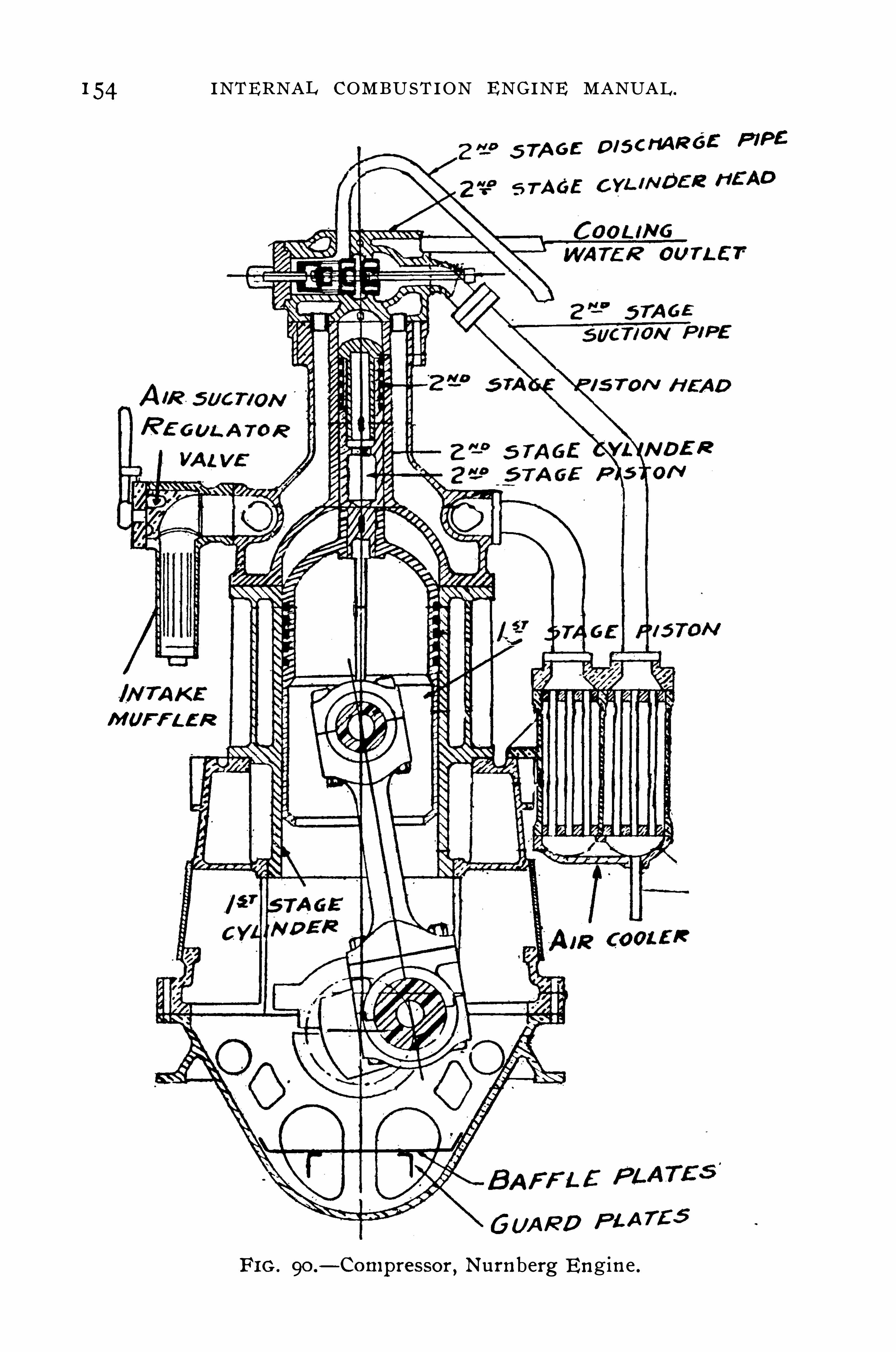
154 INTE R NAL C OMBU ST ION E NG INE MANUAL.
2159 5 7A “: D isa R é E P IPC
“49
5 77565
T L E T
M UFFL E R
GU A R D PL A TE S
FI G . 9O .
-C on1pressor, N urnberg E ngine .

T HE D IE SE L E NG INE . 155
plished with compressed air . The vertical sha ft has a specialcoupling with a 30° blank . O n revers ing
,the U pper section re
mains stationary till the lower section has turned through 30°
when all cams are then in pos ition for motion in the oppositedirection . For example : The spray valve begins to open whenthe crank is 2.V2
° in advance o f the top center and closes whenthe crank is 32V2
° beyond the top center . This gives an openingo f the spray valve through N ow by Shi fting the cam sha ftback 30° by means o f this clutch
,the spray valve will begin to
open 2V2° on the Oppos ite S ide and remain open beyond the stroke
32V2° in the opposite direction
,
-thus revers ing the functions o fthe spray . The scavenging cams are reversed by the same actiono f the clutch and cam shaft .The reversing is accompl ished by separate cams and revers ing
valve , or air starting valve , which is the same for either direction .
This air starting valve is in the cylinder head . I t is not shownin Fig . 87 .

156 INTE R NAL C OMBU ST IO N E NG INE MANUAL .
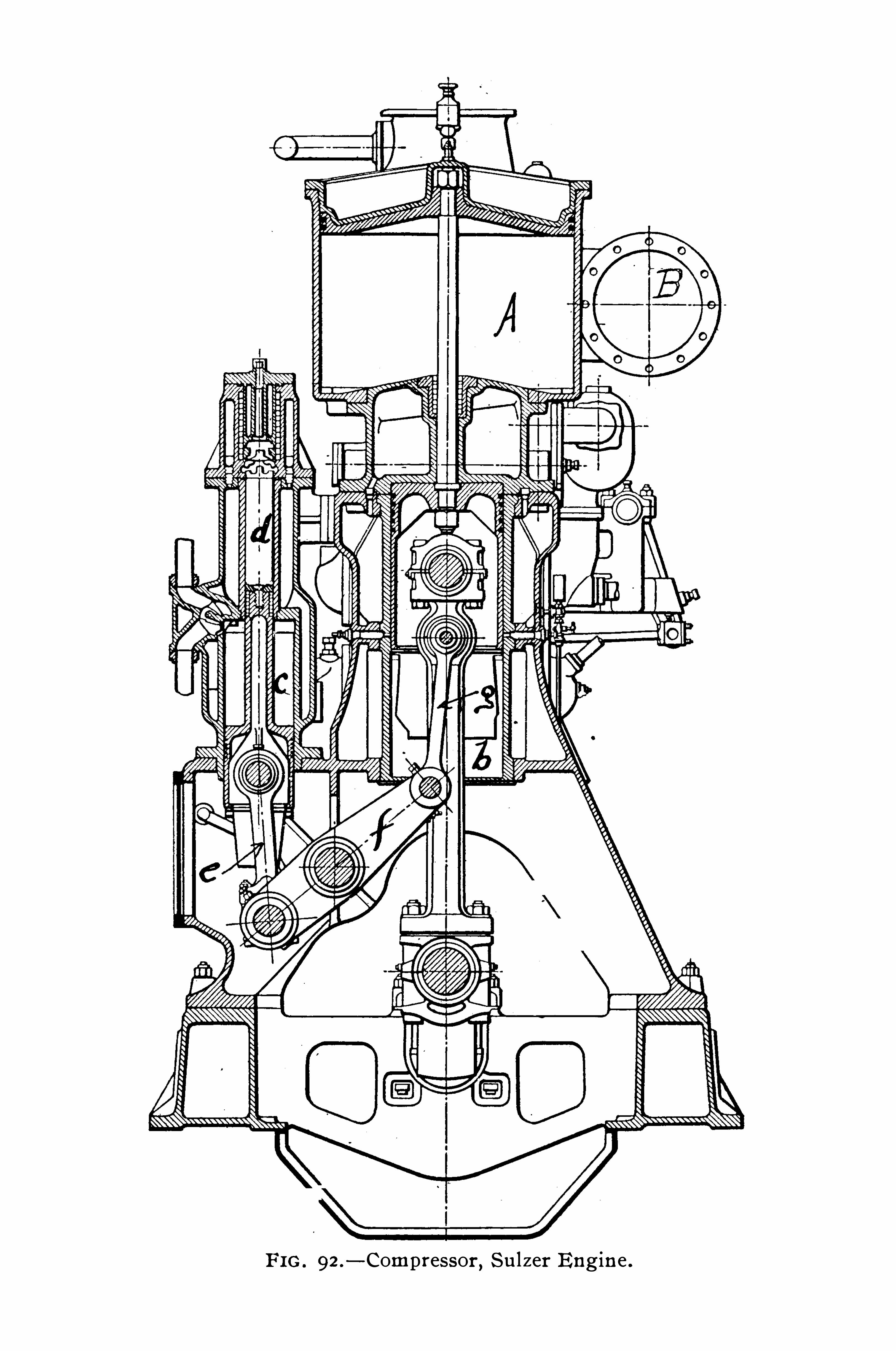
FI G . 92 .
-Compressor,Su lzer E ng ine .

T HE D IE SE L E NGINE . I59
tained at the fuel valve . The amount o f fuel inj ected , hen ce thespeed
,is regulated by a governor which acts directly on the fuel
valve . The method o f fuel inj ection at the fuel valve is s imilar tothat previously described .
Lubr icat ion .—E ach engine is fitted with forced lubrication ,
suppl ied by an oil circulation pump , driven by a rocking beamfrom the main engine , the installation compris ing an oil cooler,with filters , pressure gages , controll ing devices , and the necessaryoil piping to every part requiring lubrication . The oil fi lterscan be examined and cleaned while the engine is running. Theoil is delivered to all the bearings and sl ide paths , and it collectsin the base plate , whence it is drawn up by the pump . Theworking cyl inders and air pumps are lubricated by small separateO il pumps .
C oo l ing—The circulating water pump is dr iven by a rockingbeam from the main engine . This Suppl ies cooling water to thecylinder heads , and other stationary parts of the engine andcompresso r . A piston-head cool ing pump
,driven in a s im ilar
manner to . the circulating pump , supplies cooling water to thehollow piston heads through a system of sl iding tubes , one o fwhich is Shown at F
,Fig . 93 .
The engines are cooled by sea water when in the open sea .
When , however, the Ship is in harbor or in a roadstead , where thewater available is charged with organic matter
,they are cooled
by a water ci rcuit between the engines and the condenser, thelatter being placed in circuit with the harbo r or roads
’
tead . Thewater piping is o f copper o f ample dimens ions , p rovided with thenecessary pressure gages and thermometers .
General .—The main engIne cyl inders are inches in diameter, with a - inch stroke . Fig . 93 shows the construction o fthe cyl inders with their water j ackets . The casting forming thecasing G,
G,o f the water jacket o f each cyl inder rests on the
standards H,H
,o f the engine framing, and the barrel o f the
cylinder J i s held by its upper end , so that it is f ree to expanddownwards . The cyl inder cover K
,which is , of course , water
cooled,contains the fuel admiss ion valve chamber L, and it i s
held in place by four large steel bolts , M ,M
, which pass down

FI G . 93 .
—Cross Section , Su lzer E ng ine .

1 6 2 INTE R NAL C OMBUST ION E NG INE MANUAL .
the right of the cylinder , Fig . 93 ; the Openings o f the lower row .
are controlled by the piston alone , whils t the upper row of Openings is controlled by the scavenger valves and is eventually cov
ered by the piston . A ir to any des ired quantity may be introduced into the cyl inder through the upper row of po rts a fter thepiston has closed the lower scavenger openings .
The exhaust ports , W, are on the oppos ite s ide to the scavengerports , also in the cyl inder walls . The exhaust gases enter a watercooled exh aust pipe X
,leading to the muffler
,f rom which they
escape freely into the atmosphere . This method o f scavenginggives excel lent results , and f rom the point o f view o f s impl icityo f design and sa fety it forms a decided improvement on othermethods , S ince , should a scavenger valve fail , it i s impossible fora charge to escape into the exhaust pipe .
A uxil iar ies .—E ach engine drives direct by rocking beams a
cool ing water pump , a bilge pump , a sanitary pump , a pistonhead cool ing pump
,an oil fuel pump , and a pump for supplying
the oil for the forced lubrication of the bearings . The bilge andsanitary pumps are both o f the same capacity, and can deal with
20 tons o f water per hour ; both are o f brass . E ach engine hasits own muffler and '
its own O il fuel tank , located in the engine
room .
A compressed air j acking gear is provided at the after end ofeach main engine . I t gears into teeth cut into the periphery o f theflywheel
,Fig . 91 .
There are two auxiliary 50 horse-power, three cyl inder , fourcycle
, S ulzer-D iesel engines in addition to the above auxiliaries .
O ne i s coupled direct to a dynamo for l ighting the ship , the otherdrives an air compressor for use in an emergency , such as failureo f the normal air supply . When entering or leaving port , or atany “time when an unusual amount of air is required for maneu
vering,this compressor i s run to maintain normal pressure at the
accumulators .
M aneuvering Gear .—T he maneuvering gear for controll ingeach main engine consists of two mechanisms , each Operated by acompressed air engine through a worm drive . O ne o f these em
gines Serves to rotate the cam Shaft through the des ired angle

T HE D IE SE L E NGINE . 1 63
with relation to the crank shaft , and to put over the R avenger
pump valve rods into the required position for ahead or asternrunning . The other serves to operate the fuel and air startingvalve gear
,for starting
,running
,and stopping . A ll these Opera
t ions can also be per formed by hand in case o f failure of themaneuvering engines fo r any cause whatsoever . The maneuvering engines are in the center o f the main engine fronts , and so
close together that both engines can be operated by one man .
The fuel valve and air starting valve o f each cylinder are alloperated by cams which are keyed on one cam shaft common toall four cylinders . For revers ing
,the engine is first run in the
desired direction by means o f compressed air suppl ied throughthe starting valves
,the cam sha ft being turned to the required
angle in relation to the main Shaft S O that the l i f t o f the fuelvalves takes place at the right period of the cycle .
The action o f the starting valves has to be reversible , so as tostart the engine in the required direction . T0 do this there isprovided both a forward and a backward running cam for eachstarting valve . A special gear is provided for connecting the camrollers to or disconnecting them from the starting and the fuelcams . E ccentrics are fitted on the sha ft in such a manner that thethree following pos itions can be arrived at : ( 1 ) B oth sets o fcam rollers are out o f action when the engine is at a standstil l ;
( 2 ) the starting valve cam rollers are thrown in,the fuel valve
cams being out , which places the engine in the starting pos ition
( 3 ) the fuel valve cams are thrown in , the starting valve camsbeing thrown out , which places the engine in the running position .
These pos itions are controlled by a cam disc which thus controlsthe engine when maneuvering . T o reverse
,the engine is first
brought to a standstil l ; the cam sha ft Operating the valves isthen turned to the required pos ition ,
ahead or astern , as the casemay be ; the air start ing valves are thrown into gea r, pos ition 2 ,and the engine starts and runs on air ; the fuel valves are throwninto gear and the air starting valves are thrown out Of gear ,pos ition 3 . The engine is now runnning on fuel in the desireddi rection .


1 66 IN D E X
PA GE
D iese l enginedesignfour cyclelimits o f powermaximum temperaturesN urnberg typecoo l ing and
fue l systemreversings cavengingstart ingSulzer typeauxil iariescompressorcoo l ingfuel systemmaneuvering gear
Valve group,four
,
D isti l lates, heavyD istributorDouble act ing enginesDual ignitionDynamometersE ngine , aerop laneAnzan iA shmusencharacterist ics o f
GnomeGyro duplexHal l Scotthorizontal opposedradialrotaryS turtevantverticalV- typeWright
E ngines :alcoholD iese lgaso l inekeroseneKnightM iet z and We issN avy typeN urnbergoilStandard double actingStandard submarine chaser .
Sulzerthree porttwo port
E xhaust , underwaterE xplosions, admission pipecarburetorcrank casemufflerweak
Fire point,oi l
F lame propagationFlash point
,oi l
Float va lve carburetorFly whee lForced feed lubricationFract ional dist i l lationFrankl in air coo l ingFuel
,c lassification o f
se lection o f
gaseousheating values o f
l iqu ido ilso l idsystem
Gas, acetyleneair
blast furnacecalorific value o f 1—3 12—1 4coke oven 1 3
i l luminating 1 3
natura l 1 4
oi l 12
producer 2
water 2
Gaso l ine 45
volati l ity as a test for 9
Generators 58
Gnome engine 1 32
Governing by adju stable S park 81
combination systems 82
exhaust 82
hit and miss system 7 8
thrott l ing 80
vari able mixture 81
varying compression 82
Governor, pick-blade 78
Governors and govern ing 7 7
Gyro dup lex aeroplane engine . 1 34
Hal l Scott aeroplane engine 1 18
Hammer break ign iter 62
Heat balance 20
Hori zonta l aerop lane engine 127
Horse- power,brake 90
indicated,hOw obtained 86

Hot tube ignition 65,
I gnit ion 16, 35,
by heat o f
comparison o f di ff erent systems of
earlye lectricfaultyfour cyl inderhammer breakhot tube
~
jump Sparklatemake and breakmult icy l inderprematuretwo pointWipe spark
I gnit ion p lugsI gn ition w iringI ndicators for I . C . EI ndicator cardscharge throttledfaulty admissionfaulty exhaustign ition advancedignition retardednormaltwo cycl e
I nduction c01 1
Jacket, water,Jump spark ignit ionKerosenecarburetion o f
engineKn ight sl ide va lveKnocking, spark
, gas, and car
Late ign it ionLiqu id acety leneLosses in t the I . C . E . and
steam engineLowe’s processLubricating oi l characteristics
o f goodLubricating systems
S plashforced feedmechanical feedsmal l motors
IN DE X
PA GE
1 10
54
66
0 0 0 0 0 0 0
0 0 0 0 0 0 0 0 0 0 0 0 0 0 0 0 0
0 0 0 0 0 0 0 0 0 0 0 0 0 0 0 0 0 0 0 0 0
0 0 0 0 0 0 0 0 0 0 0 0 0 0 0
o
0 0 0 0 0 0 0 0 0 0 0 0 0
0 0 0 0 0 0
0 0 0 0 0 0 0 0 0
0 0 0 0 0 0 0 0 0 0 0 0 0 0 0 0
0 0 0 0 0 0 0 0 0 0 0
0 0 0 0 0 0 0 0 0 0 0 0 0 0 0 0 0 0
0 0 0 0 0 0 0 0 0 0 0 0 0 0 0 0 0 0 0 0
0 0 0 0 0 0 0 0 0 0 0 0 0 0 0 0 0 0 0
LubricationLubricator
,Detroit
L unkenheimer mixing va lveMagneto
,high tens ion
low tensionMake and break ignit ionManographM aumeeMechanica l ebul l it ionMediumM iet z and Weiss kerosene en
gineM isfiring, cont inuousintermittent
M ixing valveL unk enheimer
M ixture lean and richMuffl erejectorexplosiongas pipemarine type
Multicy l inder ignitionMu lticy l inder t imerN atura l gasN avy type gaso l ine engineN ormal indicator cardN urnberg engineO il, cy l inder lubricatingfue lgas
O perationO verheatingPetroleum productsPetro leum, source
,formation
and composition o frefining
P i ck-b lade governorPintsch oi l gas producerP istonhead , two cycle typelubricat ion
Plug,spark
Premature ignit ionPressure diagramProgressive combust ionPump
, gas
water 68,
Purificat ion o f petro leum dis
fillates
Push rodR adia l aerop lane engine

1 68
R atio o f expansionR eduction gear for countersha ft
R esiduumR ings
,piston
R otary aeroplane engineScavenging the cyl inderSemi-D iesel engineSeven point suspensionShaf t
,crank
Smoky exhaustSpark coi lSpark p lugSplash lubricationS plitdorf timerSpray carburet ionStandard double acting en
gineStandard submarine chaserengine
Start,fai lure to
Stopping an I . C . EStart ing on sparkSti l l , crude 4
,
Straining gaso l ineStroke
,long and
Sturtevant aeroplane engine . .
Submerged exhaust
I N DE X
0 0 0 0 0 0 0 0 0 0 0 0 0 0 0 0 0 0 0 0
0 0 0 0 0 0 0 0 0 0 0 0 0 0 0 0
Surface carburetionT emperatures, fractional distillation
T hermo syphon systemT hree port engineT imer
, S plitdorfT rouble hunt ingT W O port engineT ypes o f I . C . EU nderwater exhaustValve gearsValvesrequ irements o f effi cientrotary
Vaporizer,fue l
Vert ical aeroplane engineViscosityV-type aerop lane engineWater coo led engineWater coo led va lves, pistonsetcWater gas
Water jacketWeak exp losionsWerk spoor piston cool ingW ipe spark igniterWright aeroplane engineWrist pin

U N IVE R S I T% O F C AL I FO RN IA L I B R AR %
T h is book is DU E on the last date stamped be low .
Fine sch edule : 25cents on first day overdue
50 cents on fourth day overdue
O ne dollar on seventh day overdue .
L D 2 1—1 00m