FY 2004 Progress Report for Advanced Combustion Engine ...
22
Advanced Combustion Engine R&D FY 2004 Progress Report 287 IV Waste Heat Recovery
-
Upload
khangminh22 -
Category
Documents
-
view
0 -
download
0
Transcript of FY 2004 Progress Report for Advanced Combustion Engine ...
Advanced Combustion Engine R&D FY 2004 Progress Report
287
IV Waste Heat Recovery

Advanced Combustion Engine R&D FY 2004 Progress Report
288

Advanced Combustion Engine R&D FY 2004 Progress Report
289
IV.1 Electric Boosting System (e-Turbo™) for SUV/ Light Truck Diesel Engine Applications
S. M. ShahedHoneywell Turbo Technologies3201 W. Lomita Blvd.Torrance, CA 90505
DOE Technology Development Manager: John Fairbanks
Objectives• Develop an electric boosting system suitable for 4- to 6-liter diesel engine SUV/light truck applications.• Develop base electric machinery technology – motor/generator, power supply, rotor stability and
temperature control. Associated objectives consistent with ongoing R&D at Honeywell include:
• Develop an integrated control system for power, variable nozzle turbine (VNT), exhaust gas recirculation (EGR), and battery.
• Design and develop a low-inertia turbocharger to minimize power demand. • Design and develop a variable geometry compressor to take full advantage of e-Turbo.
Approach• Develop e-Turbo for a diesel engine (~2 liters) as a platform for technology development. • Refine the design to meet duty cycle requirements and prove technology benefits. • Using computer simulation, apply the small e-Turbo to each bank of a V-configuration engine (~4 liters)
using baseline data from tests on the 2-liter engine. • Conduct computer simulation of an integrated control system and assess benefits. • Develop base electric machinery – motor/generator, power supply, rotor stability and temperature control. • Develop an integrated control system for power, VNT, EGR, and battery. • Design and develop a low-inertia turbocharger to minimize power demand. • Design and develop a variable geometry compressor to take full advantage of e-Turbo.
Accomplishments• A larger e-Turbo was designed and built for testing during Q4 2004. The design included duty cycle
analysis to ensure proper cooling of electrical machinery under severe driving conditions and a bearing system that is stable under mechanical and electromagnetic forces at high speeds.
• Engine and vehicle tests using a 12-Volt e-Turbo system (with a second battery) were completed. Engine transient tests show significant improvement of torque and response. Steady-state torque with e-Turbo improved by 20-40% in the low speed range (see Figure 1). Transient response (time to 200 Nm of torque) was reduced from 6 to ~2.3 seconds at 1500 rpm (see Figure 2).
• Electric power generation with an e-Turbo was successfully demonstrated on bench and engine tests. At 3,000 rpm with EGR, 900 W of electrical power was generated with a 3.5% improvement in brake-specific fuel consumption (BSFC) (see Figure 3).
• Different cycles were tested to demonstrate the potential of e-Turbo as a partial substitute for the alternator. Impact on fuel consumption was measured.

Advanced Combustion Engine R&D FY 2004 Progress Report
290
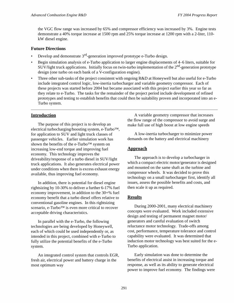
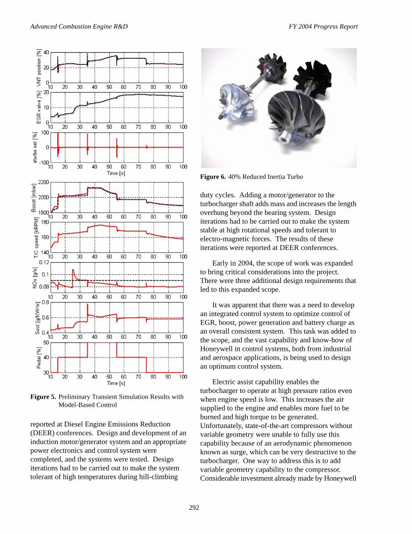
• Basic architecture for an integrated sensing and control system was developed, and preliminary control logic was tested using engine simulation (see Figures 4 and 5). It is too early in the project to quantify the benefits of an integrated control logic.
• A turbocharger with 40% reduced inertia (see Figure 6) was built and tested under an existing R&D program. For the e-Turbo, reduced inertia should improve transient response further and ease the demand on electrical machinery.
• A variable geometry compressor (VGC), which can be used to take full advantage of e-Turbo’s capabilities, was built under existing R&D work. Tests demonstrated that at a pressure ratio of 2.8,
Figure 1. Steady-State Torque Improvement with e-Turbo in a 2-Liter Diesel Engine
Figure 2. Transient Torque Response Improvement of a 2-Liter Diesel Engine with e-Turbo at 1000 and 1500 rpm
Figure 3. Electric Power Generation and BSFC Improvement with e-Turbo on a 2-Liter Diesel Engine
Figure 4. Basic Sensing and Control Parameters for e-Turbo
Advanced Combustion Engine R&D FY 2004 Progress Report
291
the VGC flow range was increased by 65% and compressor efficiency was increased by 3%. Engine tests demonstrate a 40% torque increase at 1500 rpm and 25% torque increase at 1200 rpm with a 2-liter, 110-kW diesel engine.
Future Directions• Develop and demonstrate 3rd-generation improved prototype e-Turbo design.• Begin simulation analysis of e-Turbo application to larger engine displacements of 4–6 liters, suitable for
SUV/light truck applications. Initially focus on twin-turbo implementation of the 2nd-generation prototype design (one turbo on each bank of a V-configuration engine).
• Three other sub-tasks of the project consistent with ongoing R&D at Honeywell but also useful for e-Turbo include integrated control logic, low-inertia turbocharger and variable geometry compressor. Each of these projects was started before 2004 but became associated with this project earlier this year so far as they relate to e-Turbo. The tasks for the remainder of the project period include development of refined prototypes and testing to establish benefits that could then be suitability proven and incorporated into an e-Turbo system.
Introduction
The purpose of this project is to develop an electrical turbocharging/boosting system, e-Turbo™, for application to SUV and light truck classes of passenger vehicles. Earlier simulation work has shown the benefits of the e-Turbo™ system on increasing low-end torque and improving fuel economy. This technology improves the driveability/response of a turbo diesel in SUV/light truck applications. It also generates electrical power under conditions when there is excess exhaust energy available, thus improving fuel economy.
In addition, there is potential for diesel engine rightsizing by 10-30% to deliver a further 6-17% fuel economy improvement, in addition to the 30+% fuel economy benefit that a turbo diesel offers relative to conventional gasoline engines. In this rightsizing scenario, e-Turbo™ is even more critical to recover acceptable driving characteristics.
In parallel with the e-Turbo, the following technologies are being developed by Honeywell, each of which could be used independently or, as intended in this project, combined with e-Turbo to fully utilize the potential benefits of the e-Turbo system.
An integrated control system that controls EGR, fresh air, electrical power and battery charge in the most optimum way
A variable geometry compressor that increases the flow range of the compressor to avoid surge and make full use of high boost at low engine speeds
A low-inertia turbocharger to minimize power demands on the battery and electrical machinery
Approach
The approach is to develop a turbocharger in which a compact electric motor/generator is designed and mounted on the same shaft as the turbine and compressor wheels. It was decided to prove this technology on a small turbocharger first, identify all issues, assess the possible benefits and costs, and then scale it up as required.
Results
During 2000-2001, many electrical machinery concepts were evaluated. Work included extensive design and testing of permanent magnet motor/generators and careful evaluation of switch reluctance motor technology. Trade-offs among cost, performance, temperature tolerance and control capability were evaluated. It was determined that induction motor technology was best suited for the e-Turbo application.
Early simulation was done to determine the benefits of electrical assist in increasing torque and response, as well as its ability to generate electrical power to improve fuel economy. The findings were
Advanced Combustion Engine R&D FY 2004 Progress Report
292
reported at Diesel Engine Emissions Reduction (DEER) conferences. Design and development of an induction motor/generator system and an appropriate power electronics and control system were completed, and the systems were tested. Design iterations had to be carried out to make the system tolerant of high temperatures during hill-climbing
duty cycles. Adding a motor/generator to the turbocharger shaft adds mass and increases the length overhung beyond the bearing system. Design iterations had to be carried out to make the system stable at high rotational speeds and tolerant to electro-magnetic forces. The results of these iterations were reported at DEER conferences.
Early in 2004, the scope of work was expanded to bring critical considerations into the project. There were three additional design requirements that led to this expanded scope.
It was apparent that there was a need to develop an integrated control system to optimize control of EGR, boost, power generation and battery charge as an overall consistent system. This task was added to the scope, and the vast capability and know-how of Honeywell in control systems, both from industrial and aerospace applications, is being used to design an optimum control system.
Electric assist capability enables the turbocharger to operate at high pressure ratios even when engine speed is low. This increases the air supplied to the engine and enables more fuel to be burned and high torque to be generated. Unfortunately, state-of-the-art compressors without variable geometry were unable to fully use this capability because of an aerodynamic phenomenon known as surge, which can be very destructive to the turbocharger. One way to address this is to add variable geometry capability to the compressor. Considerable investment already made by Honeywell
Figure 5. Preliminary Transient Simulation Results with Model-Based Control
Figure 6. 40% Reduced Inertia Turbo
Advanced Combustion Engine R&D FY 2004 Progress Report
293
in this technology for use with VNT (non-electric) passenger car turbos was brought into the project to help fully utilize the e-Turbo's capabilities.
The amount of power supplied to e-Turbo is limited by the size of electrical machinery, which necessarily has to be compact. Heat dissipation also becomes a problem under these conditions. Therefore, it was necessary to limit the power supplied. Reduction in turbocharger inertia makes it very responsive and reduces the amount of power required for a given response. Again, work done previously by Honeywell was brought into the project as an additional task to supply a low-inertia turbocharger to be later combined with e-Turbo technology.
Progress made on all these tasks is shown Figures 1-6. Figure 1 shows that steady-state torque is improved by more than 40% at low speeds. Figure 2 shows that transient response is greatly improved from 6 seconds to about 2 seconds to reach a given torque. Figure 3 shows that e-Turbo can be used to generate electrical power and improve fuel economy. Figures 4 through 6 are meant to be status reports on progress made to date and are not final results at this time.
Conclusions
e-Turbo technology improves low-speed torque of turbocharged diesel engines. In addition, turbo response is greatly improved. Both these benefits enable the use of diesel engines in SUV/light truck applications with vehicle performance exceeding the baseline gasoline engine performance. This can result in fuel economy savings of up to 30% compared to the baseline.
High torque at low speeds can possibly allow a 10-30% engine downsizing and a further 6-17% improvement in fuel economy while maintaining vehicle performance.
Electrical power generation by e-Turbo has further potential benefits. BSFC benefits of up to 6% at high loads and speeds have been shown. Fuel economy benefits over a representative duty cycle have yet to be determined.
In order to fully realize the benefits of e-Turbo, other technologies will be extremely useful. These include an integrated control system, variable geometry compressor and a low-inertia turbocharger.
FY 2004 Publications/Presentations1. Steve Arnold, Craig Balis, Etienne Poix, Tariq Samad
and S.M. Shahed, “Design & Development of e-TurboTM for SUV and Light Truck Applications”, DEER Conference, August, 2004.
References1. S. M. Shahed, John Allen and Jerry Artache, “The
Development of Electrically Assisted Turbochargers for Diesel Engine Applications”, DEER Workshop, August 22, 2000.
2. S. M. Shahed, “Smart Boosting Systems – e-TurboTM and e-ChargerTM – New Frontier”, DEER Workshop, August 6, 2001.
3. S.M. Shahed, Chris Middlemass and Craig Balis, “Design & Development of e-TurboTM for SUV and Light Truck Applications”, DEER Conference, August 2003.
Advanced Combustion Engine R&D FY 2004 Progress Report
294
IV.2 Diesel Engine Waste Heat Recovery Utilizing Electric Turbocompound Technology
Ulrich HopmannCaterpillar Inc.PO Box 1875Peoria, IL 61656-1875
DOE Technology Development Manager: John Fairbanks
Subcontractors:Switched Reluctance Drives Ltd., Harrogate, UKJ.H. Benedict Co. Inc., Peoria, IL
Objectives• Build laboratory engine that demonstrates technical feasibility• Improve fuel economy by 5% with exhaust energy recovery
ApproachCaterpillar’s experienced research team has chosen the following approach to develop an electric turbocompound (ETC) system:
• Develop turbocharger and system design from concept to preliminary and final design• Analyze and test components• Develop and test turbomachinery and electrical machinery• Design, analyze and test control system• Bench test complete ETC system on the engine
Accomplishments• Turbocharger hardware has been procured and assembled• The crankshaft and turboshaft motor/generator (M/G) have been designed, assembled and tested• The control system has been developed and tested• Turbocharger performance test on the gas stand has been completed (rotor dynamics test, compressor and
turbine map)• The turboshaft M/G characterization has been validated on the gas stand • Determination of baseline performance and fuel consumption of the on-highway truck engine has been
completed • The ETC system has been installed on the engine in the test cell
Future DirectionsCaterpillar will focus on engine testing of the complete ETC system.
• Commission engine and ETC control system in engine test cell• Perform engine tests in turbocompound mode
Advanced Combustion Engine R&D FY 2004 Progress Report
295
Introduction
The principle of turbocompounding is a known technology for reducing fuel consumption. Research projects for truck-size diesel engines suggest a potential of 5% brake specific fuel consumption (bsfc) improvement [1]. Diesel engines for ship propulsion and stationary power generation have shown bsfc improvements on the same order. However, those systems consisted of a turbocharger plus an additional power turbine, which was mechanically connected to the crankshaft.
Research efforts at Caterpillar are now focusing on the development of an electric turbocompound (ETC) system for heavy-duty on-highway truck engines. The efforts cover concept, design and test. A cooperative project between the DOE Office of FreedomCAR and Vehicle Technologies and Caterpillar is aimed at demonstrating electric turbocompound technology on a Class 8 truck engine.
The goal is to demonstrate the technical feasibility and improve fuel economy. The system consists of a turbocharger with an electric M/G integrated into the turboshaft. The generator extracts surplus power at the turbine, and the electricity it produces is used to run a motor mounted on the engine crankshaft, recovering otherwise wasted energy in the exhaust gases. The electric turbocompound system also provides more control flexibility in that the amount of power extracted can be varied. This allows for control of engine boost and thus air/fuel ratio. The research work covered turbocharger design, system and component analysis, control system development, engine simulation, electrical machinery development and system and component testing.
Approach
A multi-disciplinary approach has been used in order to address the following key development areas: aero design, electrical machine design, engine performance, control system, structural analysis and testing.
The layout of the ETC turbocharger is a mid-mount configuration, i.e., the electrical machine is located between the compressor and turbine wheel.
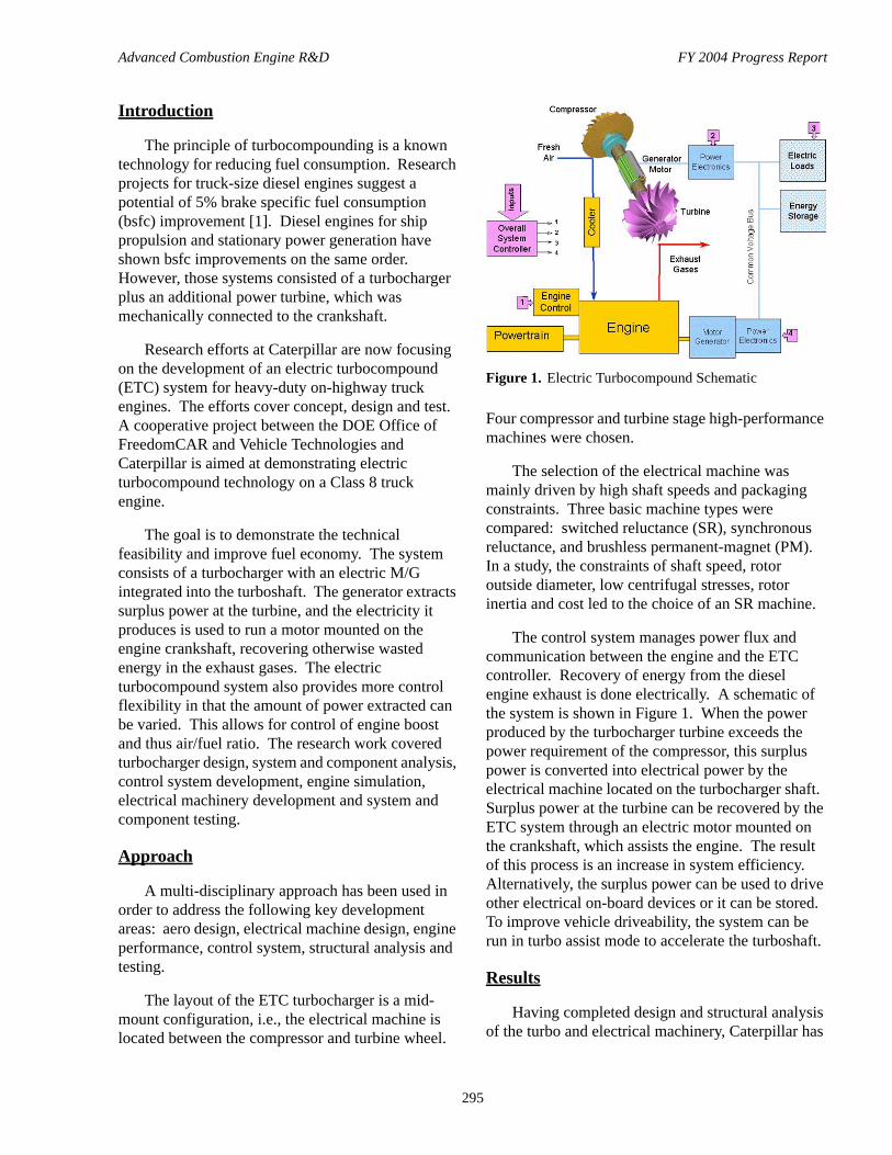
Four compressor and turbine stage high-performance machines were chosen.
The selection of the electrical machine was mainly driven by high shaft speeds and packaging constraints. Three basic machine types were compared: switched reluctance (SR), synchronous reluctance, and brushless permanent-magnet (PM). In a study, the constraints of shaft speed, rotor outside diameter, low centrifugal stresses, rotor inertia and cost led to the choice of an SR machine.
The control system manages power flux and communication between the engine and the ETC controller. Recovery of energy from the diesel engine exhaust is done electrically. A schematic of the system is shown in Figure 1. When the power produced by the turbocharger turbine exceeds the power requirement of the compressor, this surplus power is converted into electrical power by the electrical machine located on the turbocharger shaft. Surplus power at the turbine can be recovered by the ETC system through an electric motor mounted on the crankshaft, which assists the engine. The result of this process is an increase in system efficiency. Alternatively, the surplus power can be used to drive other electrical on-board devices or it can be stored. To improve vehicle driveability, the system can be run in turbo assist mode to accelerate the turboshaft.
Results
Having completed design and structural analysis of the turbo and electrical machinery, Caterpillar has
Figure 1. Electric Turbocompound Schematic
Advanced Combustion Engine R&D FY 2004 Progress Report
296
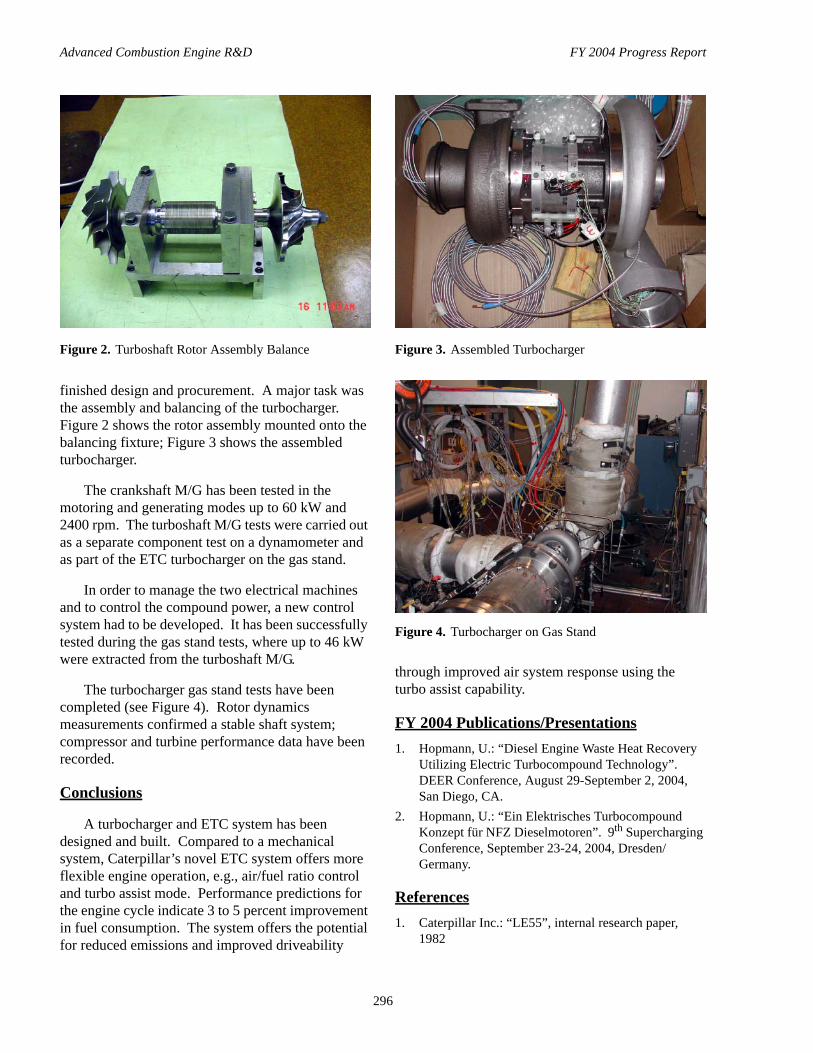
finished design and procurement. A major task was the assembly and balancing of the turbocharger. Figure 2 shows the rotor assembly mounted onto the balancing fixture; Figure 3 shows the assembled turbocharger.
The crankshaft M/G has been tested in the motoring and generating modes up to 60 kW and 2400 rpm. The turboshaft M/G tests were carried out as a separate component test on a dynamometer and as part of the ETC turbocharger on the gas stand.
In order to manage the two electrical machines and to control the compound power, a new control system had to be developed. It has been successfully tested during the gas stand tests, where up to 46 kW were extracted from the turboshaft M/G.
The turbocharger gas stand tests have been completed (see Figure 4). Rotor dynamics measurements confirmed a stable shaft system; compressor and turbine performance data have been recorded.
Conclusions
A turbocharger and ETC system has been designed and built. Compared to a mechanical system, Caterpillar’s novel ETC system offers more flexible engine operation, e.g., air/fuel ratio control and turbo assist mode. Performance predictions for the engine cycle indicate 3 to 5 percent improvement in fuel consumption. The system offers the potential for reduced emissions and improved driveability
through improved air system response using the turbo assist capability.
FY 2004 Publications/Presentations1. Hopmann, U.: “Diesel Engine Waste Heat Recovery
Utilizing Electric Turbocompound Technology”. DEER Conference, August 29-September 2, 2004, San Diego, CA.
2. Hopmann, U.: “Ein Elektrisches Turbocompound Konzept für NFZ Dieselmotoren”. 9th Supercharging Conference, September 23-24, 2004, Dresden/Germany.
References1. Caterpillar Inc.: “LE55”, internal research paper,
1982
Figure 2. Turboshaft Rotor Assembly Balance Figure 3. Assembled Turbocharger
Figure 4. Turbocharger on Gas Stand
Advanced Combustion Engine R&D FY 2004 Progress Report
297
IV.3 Clean Diesel Engine Component Improvement Program - Diesel Truck Thermoelectric Generator
N. B. Elsner, J. C. Bass, S. Ghamaty, D. Krommenhoek, A. Kushch, D. Snowden, S. Marchetti (Primary Contact) Hi-Z Technology, Inc.7606 Miramar Road, Suite 7400San Diego, CA 92126
DOE Technology Development Manager: John Fairbanks
Subcontractors:Rich Bergstrand, PACCAR Technical Center
Objectives• The objective of the project is to develop a cost-effective thermoelectric generator (TEG) that will be
powered by the diesel engine exhaust heat, in sizes from 1 kW to 10 kW.• The thermoelectric generator, by generating required electrical power, will reduce fuel consumption and
reduce corresponding emissions.• Greater onboard generation of electricity could power any number of exhaust cleanup devices being
developed to futher reduce emissions.• Development of the next generation of thermoelectric technology called multi-layer quantum well films
(MLQWF) should improve the thermoelectric conversion from the 5% to 6% available today to 20% to 30%.
Approach• Design a 2½ W quantum well (QW) module as a building block leading ultimately to 80 W modules
suitable for a 10-kW diesel truck thermoelectric generator (DTTEG) for the Tank Automotive Armaments Command (TACOM) Stryker Program.
• Continue development of sputtering and hot wall techniques for making QW films.• Complete the design of the 10-kW DTTEG with QW modules.
Accomplishments • Achieved >530,000 equivalent miles in road tests of the 1-kW DTTEG.• Achieved successful laboratory and test cell tests on a 300-W automobile exhaust thermoelectric generator
(AETEG).• Specified and placed on order a 34" internal diameter (ID) sputtering machine.• Designed, constructed, and operated a hot wall deposition apparatus for QW film. • Obtained 14% efficiency on two QW couples.• Developed QW couples with molybdenum (Mo) contacts for 500°C operation.
Future Directions• Accelerate QW development with the installation and startup of the 34-inch ID machine.• Continue to work with Pacific Northwest National Laboratory (PNNL) to produce QW film for QW
modules.
Advanced Combustion Engine R&D FY 2004 Progress Report
298
• Test 2½-watt and larger QW modules (2005).• Improve deposition rate for QW film to approach the predicted 25% efficiency.• Develop the 10-kW TEG for the Army's Stryker program (2007-2008).
Introduction
Hi-Z Technology, Inc. (Hi-Z) is currently developing four different auxiliary generator designs that are used to convert waste heat from truck engines directly to electricity. The first project is the development of a 1-kW generator for heavy-duty diesel trucks. The second is a 300-W generator to be used on light-duty gasoline engine trucks or automobiles. The third is a 200-W generator to be used on a light-duty hybrid truck. The fourth is a 10-kW generator for Army Stryker trucks.
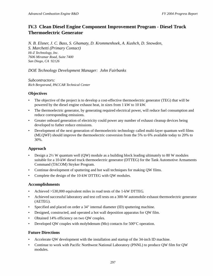
The 1-kW generator project [1] has been ongoing for several years and has completed testing for its response to over-the-road shock and vibration in a Class VIII Kenworth truck. Currently, the generator has logged in excess of 530,000 equivalent miles on PACCAR’s test track and has completed the road test phase of the project.
The current focus of the 1-kW project has shifted from generator testing to the development of quantum well thermoelectric modules to replace the currently used bulk thermoelectric modules in the generator so that its output can be increased to about 4 kW, and ultimately to 10 kW under TACOM's Stryker program.
Approach
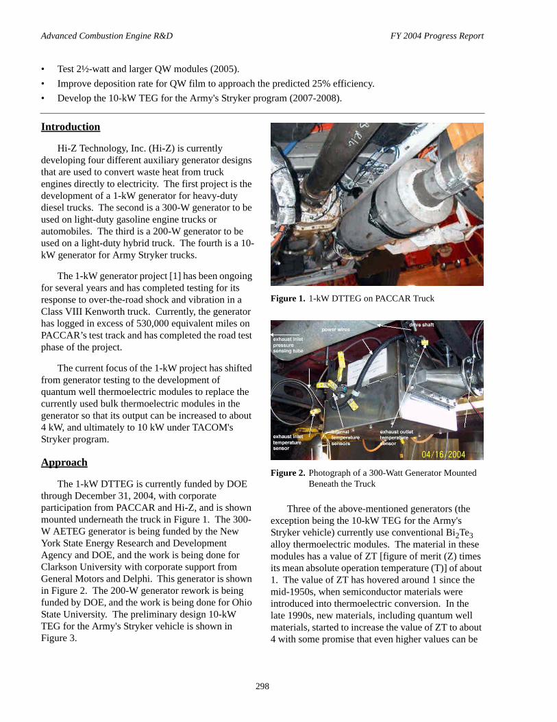
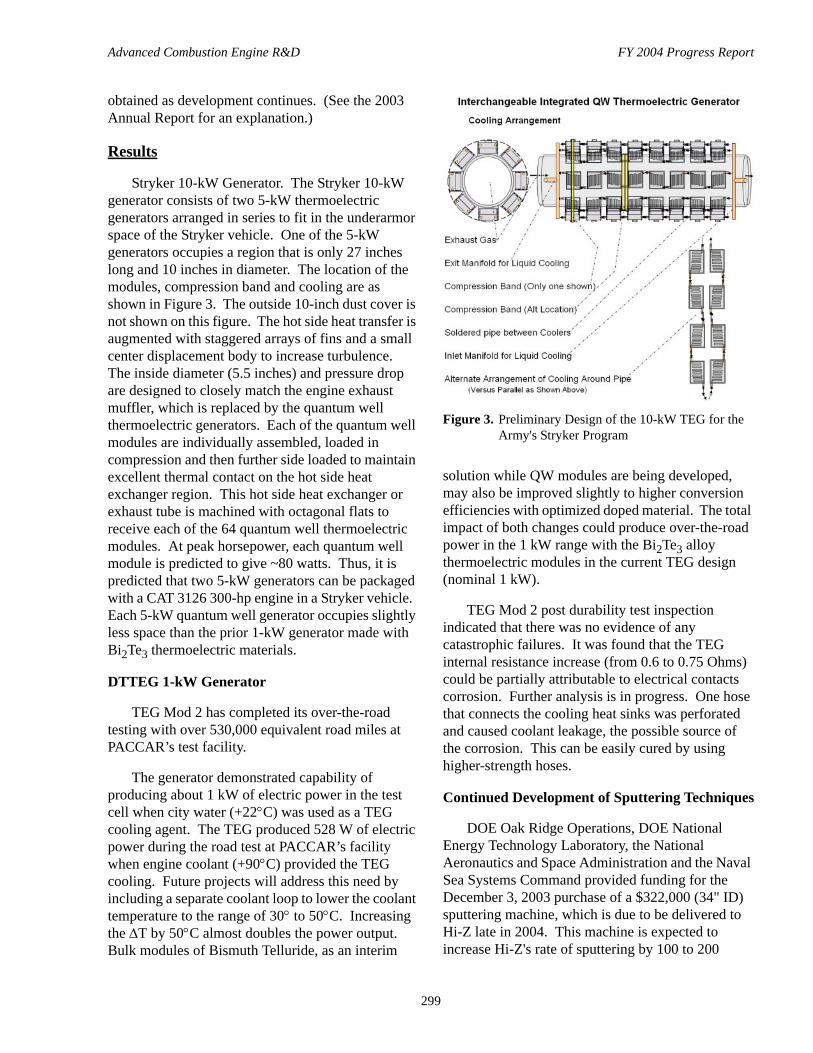
The 1-kW DTTEG is currently funded by DOE through December 31, 2004, with corporate participation from PACCAR and Hi-Z, and is shown mounted underneath the truck in Figure 1. The 300-W AETEG generator is being funded by the New York State Energy Research and Development Agency and DOE, and the work is being done for Clarkson University with corporate support from General Motors and Delphi. This generator is shown in Figure 2. The 200-W generator rework is being funded by DOE, and the work is being done for Ohio State University. The preliminary design 10-kW TEG for the Army's Stryker vehicle is shown in Figure 3.
Three of the above-mentioned generators (the exception being the 10-kW TEG for the Army's Stryker vehicle) currently use conventional Bi2Te3 alloy thermoelectric modules. The material in these modules has a value of ZT [figure of merit (Z) times its mean absolute operation temperature (T)] of about 1. The value of ZT has hovered around 1 since the mid-1950s, when semiconductor materials were introduced into thermoelectric conversion. In the late 1990s, new materials, including quantum well materials, started to increase the value of ZT to about 4 with some promise that even higher values can be
Figure 1. 1-kW DTTEG on PACCAR Truck
Figure 2. Photograph of a 300-Watt Generator Mounted Beneath the Truck
Advanced Combustion Engine R&D FY 2004 Progress Report
299
obtained as development continues. (See the 2003 Annual Report for an explanation.)
Results
Stryker 10-kW Generator. The Stryker 10-kW generator consists of two 5-kW thermoelectric generators arranged in series to fit in the underarmor space of the Stryker vehicle. One of the 5-kW generators occupies a region that is only 27 inches long and 10 inches in diameter. The location of the modules, compression band and cooling are as shown in Figure 3. The outside 10-inch dust cover is not shown on this figure. The hot side heat transfer is augmented with staggered arrays of fins and a small center displacement body to increase turbulence. The inside diameter (5.5 inches) and pressure drop are designed to closely match the engine exhaust muffler, which is replaced by the quantum well thermoelectric generators. Each of the quantum well modules are individually assembled, loaded in compression and then further side loaded to maintain excellent thermal contact on the hot side heat exchanger region. This hot side heat exchanger or exhaust tube is machined with octagonal flats to receive each of the 64 quantum well thermoelectric modules. At peak horsepower, each quantum well module is predicted to give ~80 watts. Thus, it is predicted that two 5-kW generators can be packaged with a CAT 3126 300-hp engine in a Stryker vehicle. Each 5-kW quantum well generator occupies slightly less space than the prior 1-kW generator made with Bi2Te3 thermoelectric materials.
DTTEG 1-kW Generator
TEG Mod 2 has completed its over-the-road testing with over 530,000 equivalent road miles at PACCAR’s test facility.
The generator demonstrated capability of producing about 1 kW of electric power in the test cell when city water (+22°C) was used as a TEG cooling agent. The TEG produced 528 W of electric power during the road test at PACCAR’s facility when engine coolant (+90°C) provided the TEG cooling. Future projects will address this need by including a separate coolant loop to lower the coolant temperature to the range of 30° to 50°C. Increasing the ∆T by 50°C almost doubles the power output. Bulk modules of Bismuth Telluride, as an interim
solution while QW modules are being developed, may also be improved slightly to higher conversion efficiencies with optimized doped material. The total impact of both changes could produce over-the-road power in the 1 kW range with the Bi2Te3 alloy thermoelectric modules in the current TEG design (nominal 1 kW).
TEG Mod 2 post durability test inspection indicated that there was no evidence of any catastrophic failures. It was found that the TEG internal resistance increase (from 0.6 to 0.75 Ohms) could be partially attributable to electrical contacts corrosion. Further analysis is in progress. One hose that connects the cooling heat sinks was perforated and caused coolant leakage, the possible source of the corrosion. This can be easily cured by using higher-strength hoses.
Continued Development of Sputtering Techniques
DOE Oak Ridge Operations, DOE National Energy Technology Laboratory, the National Aeronautics and Space Administration and the Naval Sea Systems Command provided funding for the December 3, 2003 purchase of a $322,000 (34" ID) sputtering machine, which is due to be delivered to Hi-Z late in 2004. This machine is expected to increase Hi-Z's rate of sputtering by 100 to 200
Figure 3. Preliminary Design of the 10-kW TEG for the Army's Stryker Program

Advanced Combustion Engine R&D FY 2004 Progress Report
300
times. In the interim, PNNL has been contracted to produce QW film. The first delivery of PNNL's QW film is scheduled in November.
QW Couple Efficiency Measurement
Hi-Z has assembled and tested two different single-couple modules. Both couples were made of B4C/B9C and N-type Si/SiGe, and the conversion efficiency from both tests was in excess of 14% at a temperature differential of 200°C.
The efficiency obtained was not corrected for any losses, but was based only on the power out of the couple divided by the power into the heater. The actual conversion efficiency of the couple was somewhat higher. The QW materials used in both couples were a total of 11 µm thick and were deposited on a 5-µm thick silicon substrate. The ratio of film thickness to substrate thickness can have a significant effect on the conversion efficiency because the substrate, which is both thermally and electrically in parallel with the QW, is essentially a parasitic heat loss. This can be seen in Figure 4, which presents a curve of the calculated B4C/B9C-Si/SiGe module efficiency as a function of QW thickness for films deposited on a 5-µm substrate for hot side temperatures of 200°C and 300°C.
Thermal Stability Mo Metal Contact
Figure 5 shows a new QW couple with B4C/B9C and Si/SiGe insulated with alumina. This couple was fabricated for a new thermal stability test for high
temperatures. Laser-assisted sputtering was used to deposit the Mo metal contact.
Initial isothermal thermal stability testing of the Mo metal contact couple at 300°C for 300 hours exhibits very stable performance, as shown by the very slight increase in power with time. We will continue the thermal aging for longer times and at higher temperatures. More couples with metal contacts are being fabricated and will be life tested at several hot side temperatures.
Hot Deposition of QW Films
As an alternative to sputter deposition of quantum well films, electron-beam heating to effect vaporization and deposition is being investigated. A primary advantage of this technique is the possibility of attaining high deposition rates. A significant problem with electron-beam deposition is the possible decomposition of compounds during the deposition process, or at a minimum a serious change in stoichiometry of the deposited material. The hot-wall technique was developed to preclude such changes in stoichiometry by surrounding the evaporation space with a hot wall at higher temperature than the substrate on which the deposited film is formed. The hot-wall configuration has not previously been used with electron-beam-heated sources; we have begun evaluation of this approach with the goal of preparing layered QW films.
Figure 4. Efficiency of QW Couple vs. Film Thickness on a 5-µm Substrate
Figure 5. QW Si/SiGe-B4C/B9C Couple for Thermal Stability Test

Advanced Combustion Engine R&D FY 2004 Progress Report
301
The equipment used for deposition consists of an electron-beam-heated, four-hearth source coupled with a hot-wall deposition region. The source is powered by an Airco-Temescal, 10-kW power supply (10 kV, 1 A) and is contained in an 18-inch diameter bell jar. Depositions are carried out in the 1–6 Torr pressure range. Typical deposition rates were 0.1 to 0.4 µm/min. Figure 6 shows the hot wall apparatus.
The primary emphasis of the project thus far is the deposition of SiC films using two different source materials obtained form Cercom, Inc. and POCO Graphite.
Conclusions
An advanced 10-kW TEG is achievable with 80-watt QW modules (which need to be developed), based on results with the 1-kW TEG.
QW test couples achieved 14% conversion efficiency to confirm a point on the theoretical curve.
QW modules with 20-25 micron film thicknesses on 5-micron thick Si should be capable of achieving 20% conversion efficiency, based on Hi-Z calculations.
QW couples are being fabricated with Mo contacts that exhibit stable performance.
Special Recognitions & Awards/Patents Issued1. Hi-Z has been awarded 16 patents: five apply to QW
material, two apply to TEGs
FY 2004 Publications/Presentations1. Four (4) Quarterly Reports for DTTEG Program and
presentations at the DEER ’04 Conference.2. 20th IEEE SEMI-THERM Symposium, 2004, “New
Technology for Thermoelectric Cooling”, John C. Bass, Daniel T. Allen, Saeid Ghamaty, and Norbert B. Elsner.
3. Chapter in The New Edition of Thermoelectric Energy Conversion Systems, published July 31, 2004 (in Japanese), “Thermoelectric Generators for Diesel Trucks”, J.C. Bass.
4. Chapter in The New Edition of Thermoelectric Energy Conversion Systems, published July 31, 2004 (in Japanese), “Fabrication of MilliWatt Modules”, N.B. Elsner.
References1. Kushch, A.S., Bass, J.C., Ghamaty, S., Elsner, N.B.,
Bergstrand, R.A., Furrow, D. and Melvin, M., 2001, “Thermoelectric Development of Hi-Z Technology”, Proceedings, 7th DEER Conference, Office of Scientific and Technical Information, Portsmouth, VA.
2. “Proof-of-Principle Test for the Thermoelectric Generator for Diesel Engines”, 1991, Final Report, Hi-Z Technology, Inc., HZ 72691-1.
3. Elsner, N.B., Ghamaty, S., Normal, J.H., Farmer, J.C., Foreman, R.J., Summers, L.J., Olsen, M.L., Thompson, P.E. and Wang, K., 1994, “Thermoelectric Performance of Si0.8Ge0.2/Si Hetrostructures by MBE and Sputtering”, Proceedings, 13th International Conference on Thermoelectrics, AIP Press, Kansas City, MO.
Figure 6. Hot Wall Deposition Apparatus
Advanced Combustion Engine R&D FY 2004 Progress Report
302
IV.4 Thermoelectric Coating Process Scale-Up
Peter M. Martin (Primary Contact) and Larry C. OlsenPacific Northwest National Laboratory902 Battelle Blvd.MS K3-59Richland, WA 99352
DOE Technology Development Manager: John Fairbanks
Objectives• The overall objective of this project is to demonstrate a scaled-up batch process for the deposition of thin
film thermoelectric (TE) coatings, namely, Si/Si0.8Ge0.2 and B4C/B9C multilayer material systems.• Sputter deposit 1000-layer TE coatings onto 100 mm-diameter, 0.5 mm-thick silicon (Si) substrates.• Determine an approach for depositing 1000-layer TE coatings onto 100 mm-diameter, 5 µm-thick Si
substrates.• Verify the thermoelectric properties of the deposited multilayer structures.• Transfer the scaled-up process to Hi-Z Technology, Inc. for commercial production.
Approach• Design and fabricate equipment required for depositing multilayer TE coatings.• Define deposition process for thin film Si/SixGe1-x and B4C/B9C TE multilayer coatings.• Deposit test multilayer Si/SixGe1-x and B4C/B9C TE coatings.• Deposit p-type Si and Si0.8Ge0.2 TE coatings.• Deposit 1000-layer n-type and p-type TE coatings on 6 inch 0.5 mm Si substrate.• Deposit 1000-layer n-type and p-type TE coatings on 6 inch 10 µm Si substrate.• Measure and verify all thermoelectric properties and performance.
Accomplishments• Scaled up the deposition process for multilayer Si/Si0.8Ge0.2 and B4C/B9C TE structures to 0.5 m2
substrate areas.• Demonstrated prototype batch deposition of Si/Si0.8Ge0.2 and B4C/B9C TE structures.• Demonstrated scaled-up Si/Si0.8Ge0.2 and B4C/B9C TE structures with TE properties good enough for use
in a thermoelectric generator (TEG) module.• Established measurements of TE properties of thin films at temperatures up to 800ºC.
Future Directions• Develop Si/Si0.8Ge0.2 and B4C/B9C multilayer structures on non-crystalline substrates.• Conduct TE performance measurements up to 800ºC.• Develop methods to integrate Si/Si0.8Ge0.2 and B4C/B9C multilayer structures into TEG modules.• Investigate new TE thin film materials.

Advanced Combustion Engine R&D FY 2004 Progress Report
303
Introduction
This project involves the development of methods to scale up production of multilayer thermoelectric coatings using sputtering processes. Molecular beam epitaxy (MBE) and magnetron sputtering processes are used to deposit Si/Si0.8Ge0.2 multilayer (quantum well) structures, and primarily magnetron sputtering is used to deposit B4C/B9C structures. Plasma-enhanced chemical vapor deposition is also used to deposit boron carbide thin films. Hi-Z Technology, Inc. now deposits these structures only on a small scale, with little evaluation of how deposition conditions affect the thermoelectric and electric properties. While the MBE process provides single crystalline structures (which may or may not be the most desirable), deposition rates are low and scale-up to large-area substrates is expensive and cumbersome.
Hi-Z develops and produces thermoelectric power-generating components. Their thermoelectric power modules are used for NASA’s Mars mission, pellet stoves, self-powered appliances, space power generation, and diesel engines. The thermoelectric modules consist of multilayer Si/Si0.8Ge0.2 and B4C/B9C coatings on Si substrates. The ultimate power output of these modules, however, is limited by the current size of the module (1 cm2). Power output can be increased significantly if the modules are stacked and increased in size. Pacific Northwest National Laboratory (PNNL) has the capabilities to scale up the Hi-Z deposition process and to deposit coatings on large areas and multiple substrates. Vacuum coating chambers are available at PNNL to coat substrates with diameters up to 2.5 m. This project has developed the process to deposit these multilayer thermoelectric coatings on Si substrates as large as 0.5 m2 and has transferred this technology to Hi-Z.
Targeted coating designs are currently under development on a small scale at Hi-Z for use in their TEG devices that are attached to the exhausts of heavy-duty diesel vehicles. Use of PNNL’s highly flexible coating facilities and knowledgeable staff has demonstrated the scale-up process. The ultimate goal of the project is to demonstrate production of 1000-or-more-layer coatings of Si/Si0.8Ge0.2 and B4C/B9C on batches of 100 mm-diameter Si substrates. Subsequent efforts will be aimed at
extending the development of the process to include full-thickness coatings on 5 micrometer-thick Si and transfer of the technology to Hi-Z. Success of this project will allow commercial production of Hi-Z’s multilayer thermoelectric coatings on the 100 mm-diameter or larger substrates.
Approach
This project is being carried out in PNNL’s vapor-deposition coating facility. The overall approach is to develop and demonstrate the deposition process for multilayer thermoelectric films, scale up the process for prototype-scale deposition, verify thermoelectric properties of the films, fabricate thermoelectric films for devices testing, and transfer the scaled-up deposition technology to Hi-Z. Films will be deposited by the direct current and radio frequency magnetron sputtering processes. Multilayer coatings will be produced using an automated shuttering process. Important film properties such as conductivity (σ), Seebeck coefficient (S), power factor (σS2T), thickness, mechanical stress and composition will be measured as part of the development effort.
Although the ultimate objective is to deposit multilayer film structures with each layer being on the order of 100 Å, initial process development will involve characterization of thicker layers. The project is structured into eight tasks. Tasks 1 through 4 involved development of preliminary coating parameters needed to produce individual layers having the required properties, and the production of multilayer coatings onto 0.5 mm-thick Si substrates. This includes n-type and p-type coatings. Phase II, undertaken in FY 2003 and FY 2004, involved development of methods required for production of full-thickness coatings on 100 mm-diameter by 5 µm-thick Si substrates. On completion of the development process, the technology will be transferred to Hi-Z.
Results
Single-layer Si and Si0.8Ge0.2 films and Si/Si0.8Ge0.2 multilayer structures were deposited by the PNNL scaled-up magnetron sputtering process onto Si substrates. Figure 1 shows the interior of the deposition chamber. The following chamber

Advanced Combustion Engine R&D FY 2004 Progress Report
304
modifications were made to scale up the deposition process:• Four quartz heaters were placed above the
substrate holder to achieve uniform heating over an area of 0.5 m2.
• Shields were placed between the Si and Si0.8Ge0.2 or B4C and B9C cathodes to prevent cross talk.
• A precision stepper motor was attached to the substrate rotation assembly for precise thickness control.
• Both sputtering cathodes were in continuous operation.
• A third cathode was added for doping.
In this configuration, the substrate holder rotated continuously over the Si and Si0.8Ge0.2 sputtering targets with the rotation rate and deposition rate tuned for each target to obtain a layer thickness of 100 Å. Multilayer depositions were performed by moving the substrate sequentially from over the Si (or B4C) target to over the Si0.8Ge0.2 (or B9C) target. Batches of twelve 100 mm substrates, or areas of 0.5 m2, could be covered. Before deposition, the substrate was heated to the required temperature by a resistive heater. The first layer deposited was Si, then a Si0.8Ge0.2 layer. Each layer was 100 Å thick. Thickness was determined simply by time of deposition. Structures with up to 3000 layers were deposited onto single-crystal Si substrates. B4C/B9C structures were heat-treated in vacuum at 1000ºC.
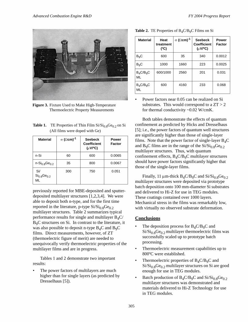
The electrical conductivity of the TE structures was measured by the four-point van der Pauw technique, and the Seebeck coefficient (thermopower) was measured by applying a temperature gradient across the sample and measuring the voltage generated. All measurements were done in-plane. The Seebeck coefficient and conductivity of the substrate were measured before and after deposition. The Seebeck coefficient and conductivity of the film were calculated using standard techniques. Figure 2 shows a diagram of the fixture used for TE measurements, and Figure 3 shows a fixture designed for high-temperature TE (up to 800ºC) measurements.
Si/Si0.8Ge0.2 films and multilayer structures with the highest electrical conductivity (σ), highest Seebeck coefficient and largest value of power factor (S2T) were deposited at a substrate temperature of 400ºC. Single-layer B4C and B9C films had the highest electrical conductivity and Seebeck coefficient when deposited at 500ºC with Ge doping. B4C/B9C multilayer structures had high power factors near 0.06. Table 1 shows typical performance results for single and multilayer Si/Si0.8Ge0.2 structures on Si substrates. The values shown in Table 1 are comparable to or better than those
Figure 1. Scaled-Up Heater and Substrate Holder Assembly
Figure 2. Diagram of Fixture Used to Make Thermoelectric Property Measurements
Advanced Combustion Engine R&D FY 2004 Progress Report
305
previously reported for MBE-deposited and sputter-deposited multilayer structures [1,2,3,4]. We were able to deposit both n-type, and for the first time reported in the literature, p-type Si/Si0.8Ge0.2 multilayer structures. Table 2 summarizes typical performance results for single and multilayer B4C/B9C structures on Si. In contrast to the literature, it was also possible to deposit n-type B4C and B9C films. Direct measurements, however, of ZT (thermoelectric figure of merit) are needed to unequivocally verify thermoelectric properties of the multilayer films and are in progress.
Tables 1 and 2 demonstrate two important results: • The power factors of multilayers are much
higher than for single layers (as predicted by Dresselhaus [5]).
• Power factors near 0.05 can be realized on Si substrates. This would correspond to a ZT > 2 for thermal conductivity ~0.02 W/cmK.
Both tables demonstrate the effects of quantum confinement as predicted by Hicks and Dresselhaus [5]; i.e., the power factors of quantum well structures are significantly higher than those of single-layer films. Note that the power factor of single-layer B4C and B9C films are in the range of the Si/Si0.8Ge0.2 multilayer structures. Thus, with quantum confinement effects, B4C/B9C multilayer structures should have power factors significantly higher that those of the single-layer films.
Finally, 11 µm-thick B4C/B9C and Si/Si0.8Ge0.2 multilayer structures were deposited via prototype batch deposition onto 100 mm-diameter Si substrates and delivered to Hi-Z for use in TEG modules. These coatings contained over 1000 layers. Mechanical stress in the films was remarkably low, with virtually no observed substrate deformation.
Conclusions• The deposition process for B4C/B9C and
Si/Si0.8Ge0.2 multilayer thermoelectric films was successfully scaled up to prototype batch processing.
• Thermoelectric measurement capabilities up to 800ºC were established.
• Thermoelectric properties of B4C/B9C and Si/Si0.8Ge0.2 multilayer structures on Si are good enough for use in TEG modules.
• Batch production of B4C/B9C and Si/Si0.8Ge0.2 multilayer structures was demonstrated and materials delivered to Hi-Z Technology for use in TEG modules.
Table 1. TE Properties of Thin Film Si/Si0.8Ge0.2 on Si (All films were doped with Ge)
Material σ (Ωcm)-1 Seebeck Coefficient
(µV/ºC)
Power Factor
n-Si 60 600 0.0065
n-Si0.8Ge0.2 35 800 0.0067
Si/Si0.8Ge0.2 ML
300 750 0.051
Table 2. TE Properties of B4C/B9C Films on Si
Material Heat treatment
(ºC)
σ (Ωcm)-1 Seebeck Coefficient
(µV/ºC)
Power Factor
B9C 600 35 340 0.0012
B9C 1000 1660 223 0.0025
B4C/B9C ML
600/1000 2560 201 0.031
B4C/B9C ML
600 4160 233 0.068
Figure 3. Fixture Used to Make High-Temperature Thermoelectric Property Measurements
Advanced Combustion Engine R&D FY 2004 Progress Report
306
Patent Applications1. Patent application: “Boron carbide films and quantum
well structure with improved thermoelectric properties,” P. M. Martin and L. C. Olsen.
FY 2004 Presentations1. P. M. Martin and L. C. Olsen, “Recent Progress in
Scale of Thermoelectric Quantum Well Films,” High Efficiency Thermoelectrics Workshop, February 17-20, San Diego, CA.
2. L. C. Olsen and P. M .Martin, “Measurement of Thermoelectric Properties of Thin Films,” High Efficiency Thermoelectrics Workshop, February 17-20, San Diego, CA.
3. P. M. Martin and L. C. Olsen, “Nanostructured Multilayer Films for Advanced Detector and Thermoelectric Applications,” 2004 AIMCAL Conference, October 24-27, 2004, Charleston, SC. Invited.
4. P. M. Martin, L. C. Olsen and S. Baskaran, “Multilayer Thin Film Thermoelectric Materials for Vehicle Applications,” 2004 DEER Conference, August 29-31, 2004, San Diego, CA.
5. P. M. Martin, “Advanced Thin Film Coatings at PNNL,” PPG Research Center, July 12, 2004, Pittsburgh, PA. Invited.
FY 2004 Publications1. P. M. Martin and L. C. Olsen, Nanostructured
multilayer B4C/B9C and Si/Si0.8Ge0.2 films for advanced detector and thermoelectric applications, Proceedings of 2004 AIMCAL Conference. Invited.
References1. T. Koga, A. Sun, S. B. Cronin and M. S. Dresselhaus,
Applied Physics Letters, 73(20) (1998) 2950-2952.2. S. Ghamaty and N. Elsner, Proceedings of the
International Conference on Thermoelectrics (1999), 18th 485-488.
3. T. J. Hendricks, Proceedings of the Intersociety Energy Conversion Engineering Conference (1988), 23rd (Vol. 1), 339-45.
4. J. Farmer, T. Barbee, Jr., G. Chapline, Jr., M. Olsen, R. Foreman, L. Summers, M. Dresselhaus and L. Hicks, Lawrence Livermore Laboratory Report UCRL-ID-119652, January 20, 1995.
5. L. D. Hicks and M. S. Dresselhaus, Phys. Rev. B47 19 (1993) 12 727-731.

Advanced Combustion Engine R&D FY 2004 Progress Report
307
IV.5 High-Efficiency Thermoelectrics New Projects
Thermoelectrics is a promising technology to extract energy from the waste heat of advanced combustion engines. The electricity produced by thermoelectrics enables additional savings in engine parasitic losses through electric drive of components such as water and oil pumps that traditionally have been mechanically driven, using energy regardless of need. In March 2004, DOE issued a solicitation titled “Waste Heat Recovery and Utilization Research and Development for Passenger Vehicle and Light/Heavy Duty Truck Application”. Based on this solicitation, DOE chose four new projects in thermoelectrics. The overall objective of each of these projects is to demonstrate a cost-effective way to improve fuel economy by 10% over the current level without increased emissions. Following are brief descriptions of what these projects intend to accomplish over their durations.
Prime Contractor: General Motors Corporation
Subcontractors:General Electric CompanyResearch Triangle InstituteUniversity of MichiganUniversity of South FloridaMIT - Lincoln LaboratoryOak Ridge National Laboratory
Approach
The goal of this project is to demonstrate a 10% fuel economy improvement over the current level without increased emissions in a cost-effective way. This will be done by first verifying the performance of currently known bulk and thin-film materials with ZT>1. The materials will include those suitable for application to both exhaust and coolant waste heat, but will not necessarily be limited to these sources. Based on the results of materials performance validation, initial selection of the best materials for different waste heat temperatures will be made. Multiple materials may be needed to best match the conversion needs to the temperature of the waste heat energy sources. Conversion devices using these materials, the conversion subsystems, and an overall vehicle system will be modeled to enable initial calculation of energy recovery and conversion efficiency. The project will also determine packaging specifications for exhaust and radiator devices; develop functional and environmental standards; and determine cost targets for components, subsystems, and vehicle integration.
Prime Contractor: United Technologies Research Center
Subcontractors:Pratt & WhitneyHi-Z TechnologyPacific Northwest National LaboratoryCaterpillar, Inc.
Approach
The objective of this project is to develop thermoelectric technology that will improve diesel engine efficiency for heavy-duty on-highway trucks by 10%, thereby reducing fuel consumption by 9.3%. To meet this objective, the following methods will be employed: (a) development of cost-effective fabrication routes for the production of quantum well thermoelectric materials, enabling the commercialization of high-efficiency
Advanced Combustion Engine R&D FY 2004 Progress Report
308
thermoelectric modules; (b) demonstration of this technology in the form of an integrated ~500 Watt prototype thermoelectric generator on a Class 8 heavy-duty truck; and (c) delivery of a viable commercialization path for this technology to the automotive industry.
Prime Contractor: BSST LLC
Subcontractors:Visteon CorporationBMW NATeledyne Electronics Systems
Approach
The objective of this project is to improve the efficiency of internal combustion engines through technological advances in efficiency and cost-effectiveness of thermoelectric-based vehicle waste heat recovery systems. The tasks will include thermoelectric material fabrication (2 activities), subsystem design optimization (2 activities), and systems integration (4 activities). A complete system will be built and installed on a vehicle for testing.
Prime Contractor: Michigan State University
Subcontractors:NASA Jet Propulsion Laboratory Cummins Engine CompanyIowa State UniversityMarlow IndustriesTellurex Corporation
Approach
The objective of this project to construct a thermoelectric generator (TEG) couple of 20% efficiency, using newly developed Michigan State University (MSU) materials and demonstrated NASA Jet Propulsion Laboratory (JPL) thermoelectric technology. Cummins Engine Company will provide the major guidance in terms of the likely benefits from the application of TEGs and the tradeoffs of efficiency, cost and emissions requirements. Modeling of the system design parameters will be conducted by MSU, Iowa State University, and Cummins. Marlow Industries and Tellurex Corporation (leading U.S. manufacturers of thermoelectric devices) will provide guidance in evaluation of the thermoelectric materials and manufacturing methods.