Modeling the effect of spray/wall impingement on combustion process and emission of DI diesel engine
11
MODELING THE EFFECT OF SPRAY/WALL IMPINGEMENT ON COMBUSTION PROCESS AND EMISSION OF DI DIESEL ENGINE by Samad JAFARMADAR, Shram KHALILARYA, Sina SHAFEE, and Ramin BARZEGAR Original scientific paper UDC: 621.43.041.6:66.011 DOI: 10.2298/TSCI0903023J This work is presented to study the effect of spray impinging on the combustion pro- cess and emissions in a direct injection diesel engine at various engine speeds. Computations are carried out using a three-dimensional modeling for sprays, spray-wall interactions, flow field, emission, and combustion process. Results indi- cate an increase in engine speed leads to increased spray impinging (wall film for- mation), turbulence intensity and average wall temperature in cylinder. The en- hanced air/fuel mixing and intensified evaporation of wall film decreases soot emission by reducing the extent of the fuel rich regions specially in impinging zones. Also at higher engine speeds, combustion is delayed and fuel is consumed in a shorter time period by the enhanced air and fuel mixing. The shorter combustion duration provides less available time for soot and NO x formations. However, only a few attempts have been made to address the effect of impingement of spray with pis- ton walls on the emissions and combustion process. The results of model in addition to approving the corresponding data in the literature are also compared with the experimental data and shown good agreement. Key words: diesel engine, impinging, wall film, combustion, spray, emission Introduction In a very competitive world improvement of engine performance has become an impor- tant issue for automotive manufacturers. In order to improve the engine performance, the combus- tion process is now being studied in more detail. Also, the recent global environmental regulations for reducing engine emissions have forced engine designers to explore new engine concepts and to study the effect of engine parameters on the formation of pollutant emissions. Simulation of the combustion system by means of computer modeling makes it possible to explore combustion re- gimes that may be difficult and/or expensive to achieve with experiments [1]. Such modeling first started out in 1950 with simple thermodynamical models for en- gine cycles which then were extended in 1970 to multi-zone models. Nowadays with the pro- gressive development of computational fluid dynamics (CFD) and flow field models, it is also possible to study and predict droplet distribution, temperature, pressure, and other parameters at every desired point and time within the combustion chamber. Flow field models, such as KIVA II code in 1990 [2, 3] and numerical Ricardo code in 1992 which was employed to investigate an optimum value for gas fuel injector angle in a dual fuel diesel-gas engine to obtain minimum unburned hydrocarbon (UHC) emissions [4], are pre- miere examples. Choi et al. [5] used STARCD code and particle image velocimetry (PIV) analy- THERMAL SCIENCE: Vol. 13 (2009), No. 3, pp. 23-34 23
Transcript of Modeling the effect of spray/wall impingement on combustion process and emission of DI diesel engine
MODELING THE EFFECT OF SPRAY/WALL IMPINGEMENT ONCOMBUSTION PROCESS AND EMISSION OF DI DIESEL ENGINE
by
Samad JAFARMADAR, Shram KHALILARYA,Sina SHAFEE, and Ramin BARZEGAR
Orig i nal sci en tific pa perUDC: 621.43.041.6:66.011
DOI: 10.2298/TSCI0903023J
This work is pre sented to study the ef fect of spray im ping ing on the com bus tion pro -cess and emis sions in a di rect in jec tion die sel en gine at var i ous en gine speeds.Com pu ta tions are car ried out us ing a three-di men sional mod el ing for sprays,spray-wall in ter ac tions, flow field, emis sion, and com bus tion pro cess. Re sults in di -cate an in crease in en gine speed leads to in creased spray im ping ing (wall film for -ma tion), tur bu lence in ten sity and av er age wall tem per a ture in cyl in der. The en -hanced air/fuel mix ing and in ten si fied evap o ra tion of wall film de creases sootemis sion by re duc ing the ex tent of the fuel rich re gions spe cially in im ping ingzones. Also at higher en gine speeds, com bus tion is de layed and fuel is con sumed ina shorter time pe riod by the en hanced air and fuel mix ing. The shorter com bus tiondu ra tion pro vides less avail able time for soot and NOx for ma tions. How ever, only a few at tempts have been made to ad dress the ef fect of im pinge ment of spray with pis -ton walls on the emis sions and com bus tion pro cess. The re sults of model in ad di tion to ap prov ing the cor re spond ing data in the lit er a ture are also com pared with theex per i men tal data and shown good agree ment.
Key words: diesel engine, impinging, wall film, combustion, spray, emission
In tro duc tion
In a very com pet i tive world im prove ment of en gine per for mance has be come an im por -tant is sue for au to mo tive man u fac tur ers. In or der to im prove the en gine per for mance, the com bus -tion pro cess is now be ing stud ied in more de tail. Also, the re cent global en vi ron men tal reg u la tions for re duc ing en gine emis sions have forced en gine de sign ers to ex plore new en gine con cepts and to study the ef fect of en gine pa ram e ters on the for ma tion of pol lut ant emis sions. Sim u la tion of thecom bus tion sys tem by means of com puter mod el ing makes it pos si ble to ex plore com bus tion re -gimes that may be dif fi cult and/or ex pen sive to achieve with ex per i ments [1].
Such mod el ing first started out in 1950 with sim ple thermodynamical mod els for en -gine cy cles which then were ex tended in 1970 to multi-zone mod els. Now a days with the pro -gres sive de vel op ment of com pu ta tional fluid dy nam ics (CFD) and flow field mod els, it is alsopos si ble to study and pre dict drop let dis tri bu tion, tem per a ture, pres sure, and other pa ram e ters atev ery de sired point and time within the com bus tion cham ber.
Flow field mod els, such as KIVA II code in 1990 [2, 3] and nu mer i cal Ricardo code in1992 which was em ployed to in ves ti gate an op ti mum value for gas fuel in jec tor an gle in a dualfuel die sel-gas en gine to ob tain min i mum un burned hy dro car bon (UHC) emis sions [4], are pre -miere ex am ples. Choi et al. [5] used STARCD code and par ti cle im age velocimetry (PIV) anal y -
THERMAL SCIENCE: Vol. 13 (2009), No. 3, pp. 23-34 23
sis to study in-cyl in der flow field of a sin gle cyl in der DI die sel en gine. It was in di cated that highReynolds k-e tur bu lent model pretty much sat is fies such flow fields.
Uludogan et al. stud ied the op er a tion of a small DI die sel en gine over a large range of en -gine speeds (2000-12000 rpm) by us ing a mul ti di men sional com puter code to study the ef fect ofspeed and in jec tion tim ing en gine power, emis sion trade-off and so on but spray wall im pinge -ment has not been fully taken in ac count. It was shown such high speed is pre dicted to de creasesoot and NOx for ma tion and in crease com bus tion ef fi ciency and en gine cy cle power [1].
3D KIVA code has also been used by Patterson et al. to study the ef fects of in jec tionpres sure and split in jec tions on die sel en gine per for mance and soot and NOx emis sions. The re -sults show the use of the up dated ver sion of KIVA gives good agree ment be tween mea sured andpre dicted en gine cyl in der pres sures and heat re lease data for sin gle in jec tion cases [6]. By use ofa mod i fied ver sion of the CFD code FLUENT, Meingast et al. have an a lyzed spray/wall in ter ac -tion on a flat wall un der die sel en gine like con di tions. The pen e tra tion be hav ior of the spray aswell as drop let ve loc ity and di am e ter and the wall heat flux were mea sured vary ing in jec tionpres sure, dis tance be tween noz zle and wall, gas den sity, and wall tem per a ture. It was shown that the fluid dy nam ics changes due to higher drop let ve loc ity prior to im pinge ment and im provedwall mod els need to be de rived from ex per i ments con ducted un der well known bound ary con di -tions sim i lar to die sel en gine con di tions [7]. The re search group of Reitz of Uni ver sity of Wis -con sin, Mad i son, per formed mod el ing the com bus tion in a qui es cent cham ber en gine, in or derto eval u ate the NOx par tic u late trade-off, vary ing the in jec tion tim ing, the in jec tion pres sure and the split in jec tion dwell an gle. Com par ing with mea sured data, com pu ta tions show that soot andNOx emis sions in crease at low in jec tion pres sures. Re sults also in di cate that, when com pared tothe sin gle in jec tion case, an ad di tional high tem per a ture re gion is ob served be tween the sep a rate spray clouds with split in jec tion [8].
A se ries of ex per i ments were per formed by Yoshizaki et al. in a high-pres sure con stant vol ume bomb us ing a die sel spray im ping ing onto the sim u lated pis ton. The spray out lines werere corded as a func tion of time from var i ous di rec tions. Three-di men sional dis tri bu tions of theim pinged sprays were ob tained by an a lyz ing the pho to graphs taken from these var i ous di rec -tions. The mea sured spray out lines were com pared with the cal cu lated re sults of the spray model based on the multi-pack age model. The cal cu lated spray out lines were in rea son ably goodagree ment with the mea sured out line [9]. In some DI en gines, the fuel spray has been in ten tion -ally im pinged on a sur face as a method to con trol com bus tion. One early sys tem which usedsuch a tech nique was the M-com bus tion de vel oped by MAN [10], in which the fuel is in jectedon the sur face of the pis ton bowl, form ing a liq uid film. Va por iza tion of this film con trols therate of com bus tion al low ing the use of low cetane num ber fu els. De tailed in ves ti ga tions ofwall-spray de vel op ment are re ported in Mohammadi et al. [11] and Allocca et al. [12].
At the pres ent work a three di men sional CFD code has been used to pre dict and studythe ef fects of im ping ing spray on the com bus tion pro cess and emis sions at dif fer ent en ginespeeds in the OM-355 die sel en gine. This pa per also dem on strates the use ful ness of mul ti di men -sional mod els to gain in sight into the com bus tion pro cess and to pro vide di rec tion for ex plor ingnew en gine con cepts. The re sults of this model are ap proved by the cor re spond ing data in the lit -er a ture [1, 13].
Model for mu la tion
The nu mer i cal model for heavy duty OM-355 die sel en gine with the spec i fi ca tions ontab. 1 is car ried out us ing AVL Fire code. It is old die sel en gine and its fuel in jec tion sys tem islow pres sure. Start of in jec tion pres sure is 195 bar and the in jec tion pe riod starts from –18 °CA
24 Jafarmadar, S., et al.: Modeling the Effect of Spray/Wall Impingement on ...
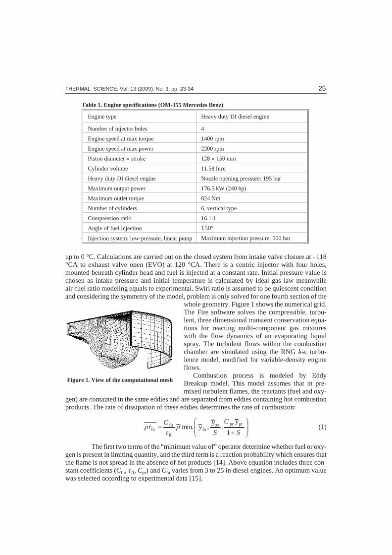
up to 0 °C. Cal cu la tions are car ried out on the closed sys tem from in take valve clo sure at –118°CA to ex haust valve open (EVO) at 120 °CA. There is a centric in jec tor with four holes,mounted be neath cyl in der head and fuel is in jected at a con stant rate. Ini tial pres sure value ischo sen as in take pres sure and ini tial tem per a ture is cal cu lated by ideal gas law mean whileair-fuel ra tio mod el ing equals to ex per i men tal. Swirl ra tio is as sumed to be qui es cent con di tionand con sid er ing the sym me try of the model, prob lem is only solved for one fourth sec tion of the
whole ge om e try. Fig ure 1 shows the nu mer i cal grid.The Fire soft ware solves the com press ible, tur bu -lent, three di men sional tran sient con ser va tion equa -tions for re act ing multi-com po nent gas mix tureswith the flow dy nam ics of an evap o rat ing liq uidspray. The tur bu lent flows within the com bus tioncham ber are sim u lated us ing the RNG k-e tur bu -lence model, mod i fied for vari able-den sity en gineflows.
Com bus tion pro cess is mod eled by EddyBreakup model. This model as sumes that in pre -mixed tur bu lent flames, the re ac tants (fuel and ox y -
gen) are con tained in the same ed dies and are sep a rated from ed dies con tain ing hot com bus tionprod ucts. The rate of dis si pa tion of these ed dies de ter mines the rate of com bus tion:
rt
r& min. , .rC
yy
S
C y
Sfu
fu
Rfu
ox pr pr=
+
æ
è
çç
ö
ø
÷÷1
(1)
The first two terms of the “min i mum value of” op er a tor de ter mine whether fuel or ox y -gen is pres ent in lim it ing quan tity, and the third term is a re ac tion prob a bil ity which en sures thatthe flame is not spread in the ab sence of hot prod ucts [14]. Above equa tion in cludes three con -stant co ef fi cients (Cfu, tR, Cpr) and Cfu var ies from 3 to 25 in die sel en gines. An op ti mum valuewas se lected ac cord ing to ex per i men tal data [15].
THERMAL SCIENCE: Vol. 13 (2009), No. 3, pp. 23-34 25
Fig ure 1. View of the com pu ta tional mesh
Ta ble 1. En gine spec i fi ca tions (OM-355 Mercedes Benz)
En gine type Heavy duty DI diesel en gine
Num ber of in jec tor holes 4
En gine speed at max torque 1400 rpm
En gine speed at max power 2200 rpm
Pis ton di am e ter ´ stroke 128 ´ 150 mm
Cyl in der vol ume 11.58 litre
Heavy duty DI die sel en gine Noz zle open ing pres sure: 195 bar
Maximum out put power 176.5 kW (240 hp)
Maximum out let torque 824 Nm
Num ber of cyl in ders 6, ver ti cal type
Com pres sion ra tio 16.1:1
An gle of fuel in jec tion 150°
In jec tion sys tem: low-pres sure, lin ear pump Max i mum in jec tion pres sure: 500 bar
Spray breakup and drop let dis tri bu tion is mod eled by ad vanced wave stan dard [14]. Inthis model the growth of an ini tial per tur ba tion on a liq uid sur face is linked to its wave lengthand to other phys i cal and dy namic pa ram e ters of the in jected fuel and the do main fluid.
Drop par cels are in jected with char ac ter is tic size equal to the noz zle exit di am e ter(blob in jec tion). The Dukowicz model was ap plied for treat ing the heat-up and evap o ra tion ofthe drop lets, which is de scribed in [16]. This model as sumes a uni form drop let tem per a ture. Inad di tion, the rate of drop let tem per a ture change is de ter mined by the heat bal ance, which statesthat the heat con vec tion from the gas to the drop let ei ther heats up the drop let or sup plies heat for va por iza tion.
NOx for ma tion is mod eled by the Zeldovich mech a nism while soot for ma tion is mod -eled by Ken nedy, Hiroyasu and Magnussen mech a nism [13].
Wall film model
Due to im per fect at om iza tion and evap o ra tion, a por tion of the in jected spray drop letsim pact on the walls of the com bus tion cham ber and in spe cial con di tions, lead to for ma tion of awall film. This in flu ences the com bus tion pro cess and con se quently the pro duc tion of emis -sions, as an in com plete com bus tion in the vi cin ity of the wall will re sult in high hy dro car bon and soot emis sions. The spray-wall in ter ac tion model used in the sim u la tions was based on thespray-wall im pinge ment model de scribed in [13, 14, 17]. At this model, be hav ior of the im ping -ing drop let is in flu enced by ma jor fac tors like wall tem per a ture and Weber num ber which iden -ti fies a num ber of im pinge ment re gimes. In prin ci ple, higher sur face tem per a tures pre vent thefor ma tion of wall film due to rapid boil ing or due to drop let re-bound ing be cause of the Leidenfrost phe nom e non [13, 14]. To gain in sight into this fact, a code was writ ten and in te grated withthe AVL Fire Solver to cal cu late the mean cyl in der sur face tem per a ture at de sired crank an gle.
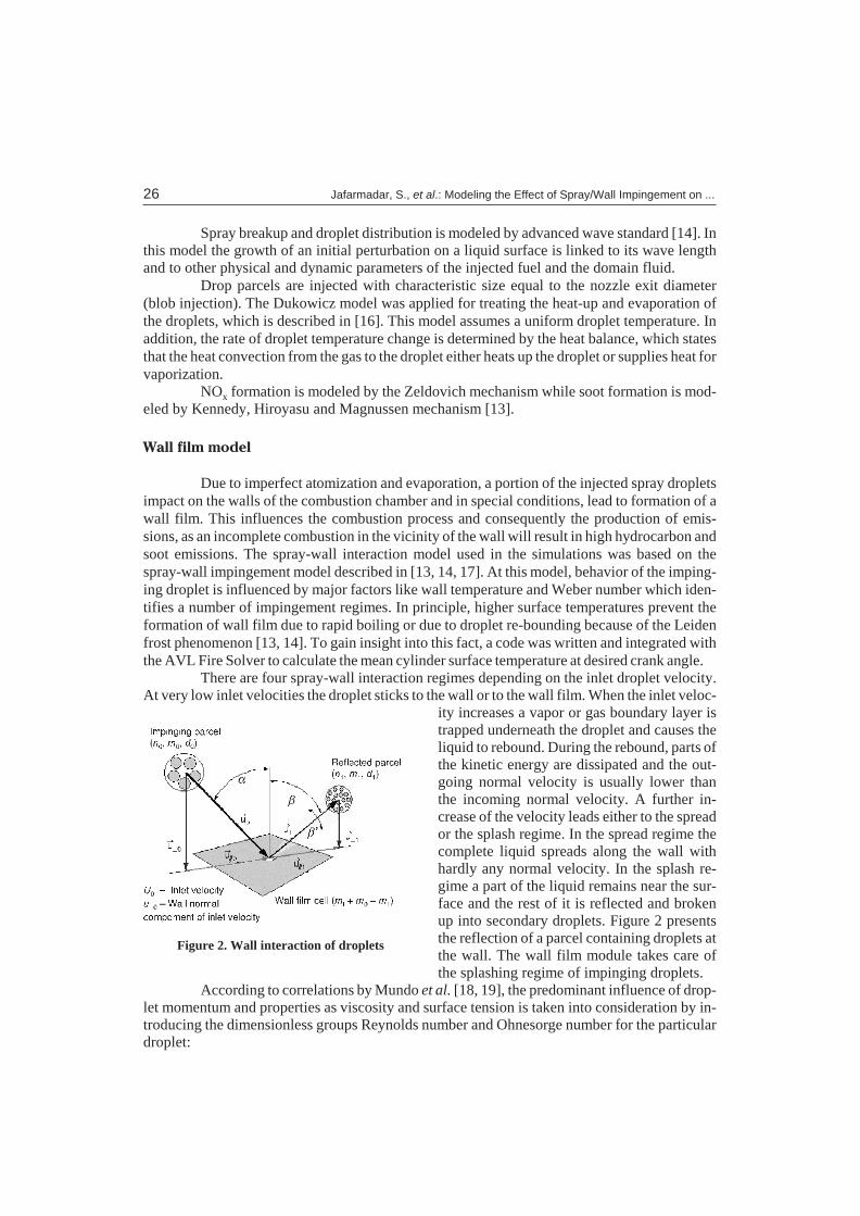
There are four spray-wall in ter ac tion re gimes de pend ing on the in let drop let ve loc ity.At very low in let ve loc i ties the drop let sticks to the wall or to the wall film. When the in let ve loc -
ity in creases a va por or gas bound ary layer istrapped un der neath the drop let and causes theliq uid to re bound. Dur ing the re bound, parts of the ki netic en ergy are dis si pated and the out -go ing nor mal ve loc ity is usu ally lower thanthe in com ing nor mal ve loc ity. A fur ther in -crease of the ve loc ity leads ei ther to the spreador the splash re gime. In the spread re gime thecom plete liq uid spreads along the wall withhardly any nor mal ve loc ity. In the splash re -gime a part of the liq uid re mains near the sur -face and the rest of it is re flected and bro kenup into sec ond ary drop lets. Fig ure 2 pres entsthe re flec tion of a par cel con tain ing drop lets at the wall. The wall film mod ule takes care ofthe splash ing re gime of im ping ing drop lets.
Ac cord ing to cor re la tions by Mundo et al. [18, 19], the pre dom i nant in flu ence of drop -let mo men tum and prop er ties as vis cos ity and sur face ten sion is taken into con sid er ation by in -tro duc ing the dimensionless groups Reynolds num ber and Ohnesorge num ber for the par tic u lardrop let:
26 Jafarmadar, S., et al.: Modeling the Effect of Spray/Wall Impingement on ...
Fig ure 2. Wall in ter ac tion of drop lets
Re D = ^r
m
d u0 0 (2)
Oh =m
rsd0
(3)
The Reynolds num ber com pares mo men tum to vis cous forces, whereas the Ohnesorge num ber re lates vis cous forces to sur face ten sion. For the Reynolds num ber, only the wall nor mal com po nent u^0 of the ini tial drop let ve loc ity u0 is used, which ac counts for im pact an gle ef fects.In ad di tion to the Weber num ber, a K-value [18] is de fined which is a mod i fied form of a Webernum ber:
We = (ReD·Oh)2 (4)
K = ×OhD
Re .0 125 (5)
This K-value is a char ac ter is tic quan tity which serves to dis tin guish be tween dif fer entim pinge ment re gimes and gen er ally is used as the key pa ram e ter for the splash ing model. Thecri te rion for in cep tion of splash ing is given at K = 57.7. Con se quently, for K < 57.7, the drop letsare de pos ited com pletely at the wall with out bounc ing or breakup and the ki netic en ergy of thedrop let is dis si pated. In the splash ing re gime (K > 57.7) with in creas ing drop let im pact-mo men -tum, a larger mass frac tion is at om ized and re flected. Dur ing this splash ing the drop lets are par -tially shat tered to pro duce a dif fer ent drop let size spec trum for the re flected drop lets. With in -creas ing K (higher mo men tum, less sur face ten sion), the re flected drop lets tend to be smallerand have a nar rower band width of size dis tri bu tion.
Re sults and dis cus sion
Re sults are pre sented in fig ures and con tours at a hor i zon tal sec tion just above the pis -ton bowl. For the con tours, en gine speeds of 1400 rpm and 1600 rpm as low, and 2000 rpm and2200 rpm are cho sen as higher speed ranges.
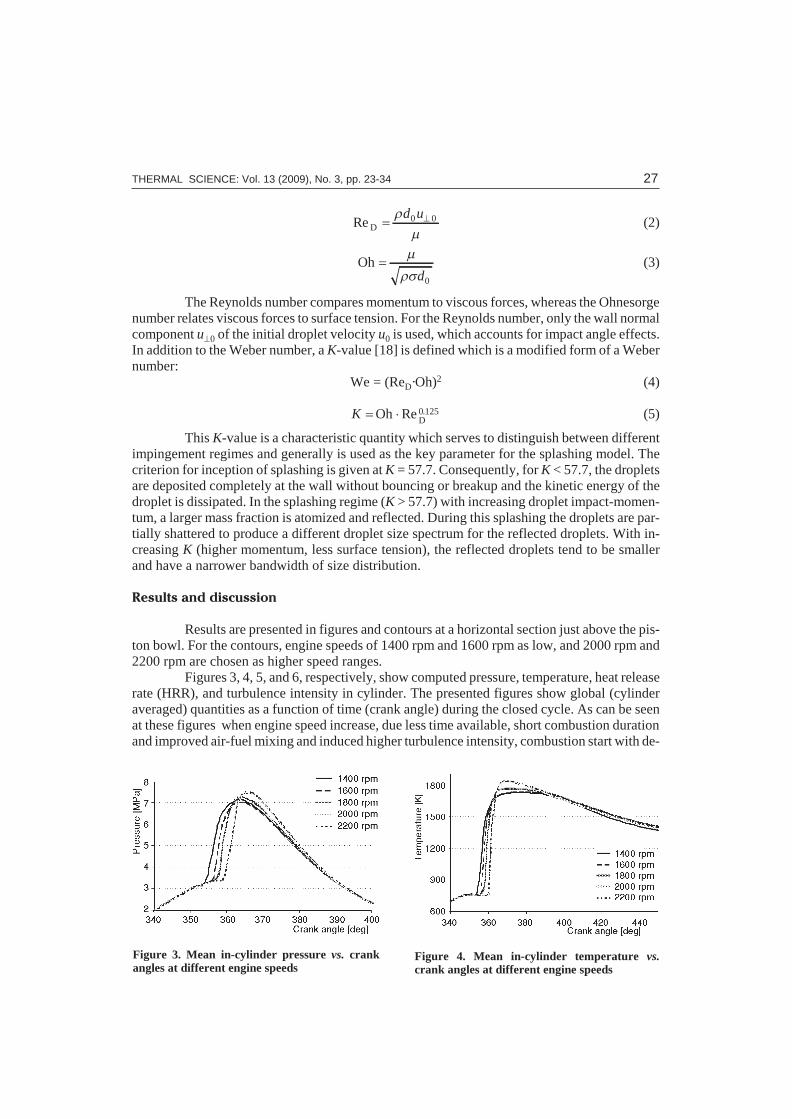
Fig ures 3, 4, 5, and 6, re spec tively, show com puted pres sure, tem per a ture, heat re leaserate (HRR), and tur bu lence intensity in cyl in der. The pre sented fig ures show global (cyl in derav er aged) quan ti ties as a func tion of time (crank an gle) dur ing the closed cy cle. As can be seenat these fig ures when en gine speed in crease, due less time avail able, short com bus tion du ra tion and im proved air-fuel mix ing and in duced higher tur bu lence in ten sity, com bus tion start with de -
THERMAL SCIENCE: Vol. 13 (2009), No. 3, pp. 23-34 27
Figure 3. Mean in-cylinder pressure vs. crankangles at different engine speeds
Figure 4. Mean in-cylinder temperature vs.crank angles at different engine speeds
lay near top dead cen tre (TDC). There fore the peak val ues for pres sure, tem per a ture, and pre mix burn ing are in creased. Com bus tion pro cess has started near TDC for 1400 rpm and 1600 rpm but due long ig ni tion de lay, it is post poned to ap prox i mately 5° aTDC at 2000 rpm and 2200 rpm.
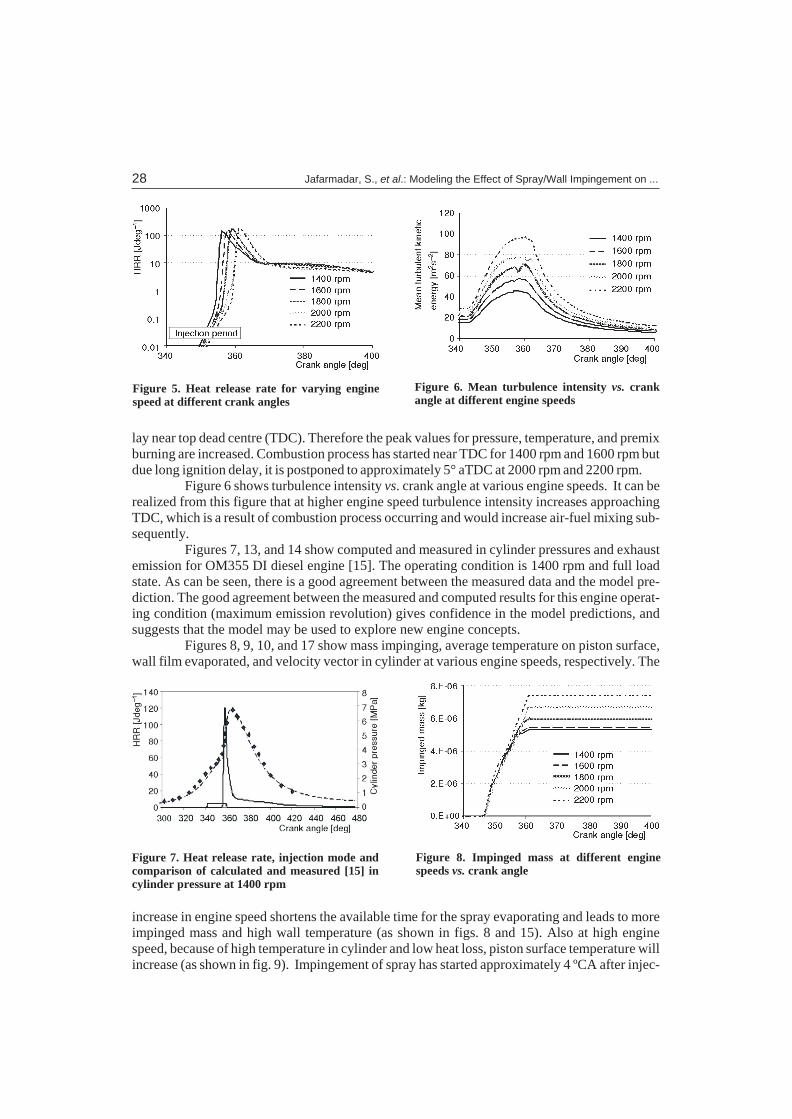
Fig ure 6 shows tur bu lence in ten sity vs. crank an gle at var i ous en gine speeds. It can bere al ized from this fig ure that at higher en gine speed tur bu lence in ten sity in creases ap proach ingTDC, which is a re sult of com bus tion pro cess oc cur ring and would in crease air-fuel mix ing sub -se quently.
Fig ures 7, 13, and 14 show com puted and mea sured in cyl in der pres sures and ex haustemis sion for OM355 DI die sel en gine [15]. The op er at ing con di tion is 1400 rpm and full loadstate. As can be seen, there is a good agree ment be tween the mea sured data and the model pre -dic tion. The good agree ment be tween the mea sured and com puted re sults for this en gine op er at -ing con di tion (max i mum emis sion rev o lu tion) gives con fi dence in the model pre dic tions, andsug gests that the model may be used to ex plore new en gine con cepts.
Fig ures 8, 9, 10, and 17 show mass im ping ing, av er age tem per a ture on pis ton sur face,wall film evap o rated, and ve loc ity vec tor in cyl in der at var i ous en gine speeds, re spec tively. The
in crease in en gine speed short ens the avail able time for the spray evap o rat ing and leads to moreim pinged mass and high wall tem per a ture (as shown in figs. 8 and 15). Also at high en ginespeed, be cause of high tem per a ture in cyl in der and low heat loss, pis ton sur face tem per a ture will in crease (as shown in fig. 9). Im pinge ment of spray has started ap prox i mately 4 ºCA af ter in jec -
28 Jafarmadar, S., et al.: Modeling the Effect of Spray/Wall Impingement on ...
Fig ure 5. Heat re lease rate for vary ing en ginespeed at dif fer ent crank an gles
Figure 6. Mean turbulence intensity vs. crankangle at different engine speeds
Fig ure 7. Heat re lease rate, in jec tion mode andcom par i son of cal cu lated and mea sured [15] incyl in der pres sure at 1400 rpm
Figure 8. Impinged mass at different enginespeeds vs. crank angle
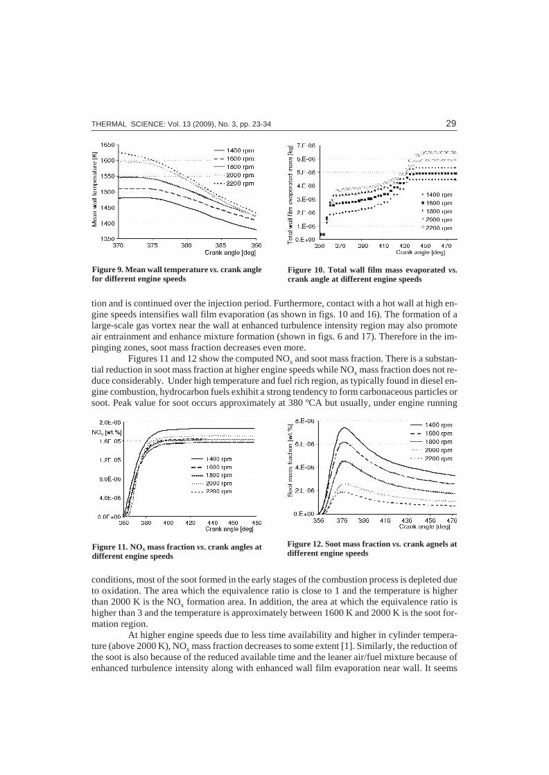
tion and is con tin ued over the in jec tion pe riod. Fur ther more, con tact with a hot wall at high en -gine speeds in ten si fies wall film evap o ra tion (as shown in figs. 10 and 16). The for ma tion of alarge-scale gas vor tex near the wall at en hanced tur bu lence in ten sity re gion may also pro moteair en train ment and en hance mix ture for ma tion (shown in figs. 6 and 17). There fore in the im -ping ing zones, soot mass frac tion de creases even more.
Fig ures 11 and 12 show the com puted NOx and soot mass frac tion. There is a sub stan -tial re duc tion in soot mass frac tion at higher en gine speeds while NOx mass frac tion does not re -duce con sid er ably. Un der high tem per a ture and fuel rich re gion, as typ i cally found in die sel en -gine com bus tion, hy dro car bon fu els ex hibit a strong ten dency to form car bo na ceous par ti cles orsoot. Peak value for soot oc curs ap prox i mately at 380 ºCA but usu ally, un der en gine run ning
con di tions, most of the soot formed in the early stages of the com bus tion pro cess is de pleted dueto ox i da tion. The area which the equiv a lence ra tio is close to 1 and the tem per a ture is higherthan 2000 K is the NOx for ma tion area. In ad di tion, the area at which the equiv a lence ra tio ishigher than 3 and the tem per a ture is ap prox i mately be tween 1600 K and 2000 K is the soot for -ma tion re gion.
At higher en gine speeds due to less time avail abil ity and higher in cyl in der tem per a -ture (above 2000 K), NOx mass frac tion de creases to some ex tent [1]. Sim i larly, the re duc tion ofthe soot is also be cause of the re duced avail able time and the leaner air/fuel mix ture be cause ofen hanced tur bu lence in ten sity along with en hanced wall film evap o ra tion near wall. It seems
THERMAL SCIENCE: Vol. 13 (2009), No. 3, pp. 23-34 29
Figure 9. Mean wall temperature vs. crank anglefor different engine speeds
Figure 10. Total wall film mass evaporated vs.crank angle at different engine speeds
Figure 11. NOx mass fraction vs. crank angles atdifferent engine speeds
Figure 12. Soot mass fraction vs. crank agnels atdifferent engine speeds
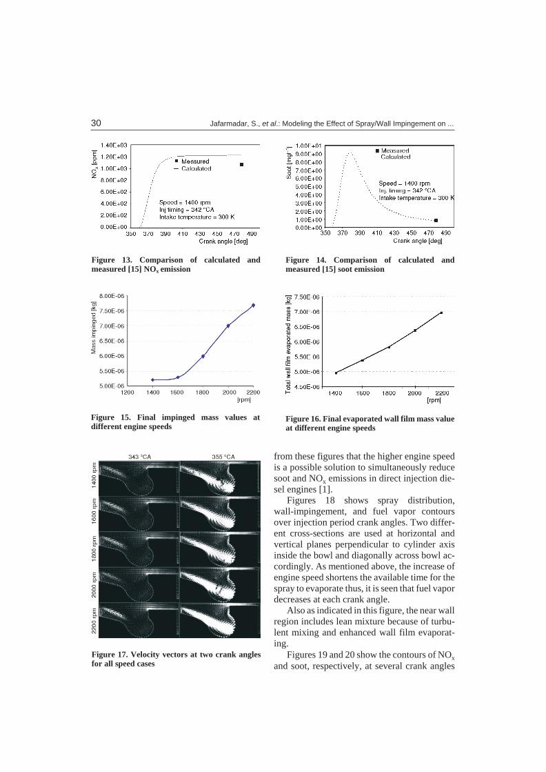
from these fig ures that the higher en gine speedis a pos si ble so lu tion to si mul ta neously re ducesoot and NOx emis sions in di rect in jec tion die -sel en gines [1].
Fig ures 18 shows spray dis tri bu tion,wall-im pinge ment, and fuel va por con toursover in jec tion pe riod crank an gles. Two dif fer -ent cross-sec tions are used at hor i zon tal andver ti cal planes per pen dic u lar to cyl in der axisin side the bowl and di ag o nally across bowl ac -cord ingly. As men tioned above, the in crease ofen gine speed short ens the avail able time for thespray to evap o rate thus, it is seen that fuel va por de creases at each crank an gle.
Also as in di cated in this fig ure, the near wall re gion in cludes lean mix ture be cause of tur bu -lent mix ing and en hanced wall film evap o rat -ing.
Fig ures 19 and 20 show the con tours of NOx
and soot, re spec tively, at sev eral crank an gles
30 Jafarmadar, S., et al.: Modeling the Effect of Spray/Wall Impingement on ...
Figure 13. Comparison of calculated andmeasured [15] NOx emission
Figure 14. Comparison of calculated andmeasured [15] soot emission
Figure 15. Final impinged mass values atdifferent engine speeds
Figure 16. Final evaporated wall film mass valueat different engine speeds
Figure 17. Velocity vectors at two crank anglesfor all speed cases
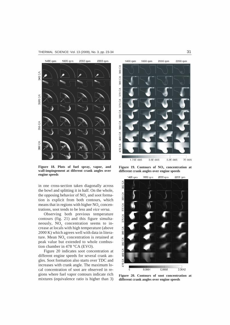
in one cross-sec tion taken di ag o nally acrossthe bowl and split ting it in half. On the whole,the op pos ing be hav ior of NOx and soot for ma -tion is ex plicit from both con tours, whichmeans that in re gions with higher NOx con cen -tra tions, soot tends to be less and vice versa.
Ob serv ing both pre vi ous tem per a turecon tours (fig. 21) and this fig ure si mul ta -neously, NOx con cen tra tion seems to in -crease at lo cals with high tem per a ture (above2000 K) which agrees well with data in lit er a -ture. Mean NOx con cen tra tion is re tained atpeak value but ex tended to whole com bus -tion cham ber in 478 °CA (EVO).
Fig ure 20 in di cates soot con cen tra tion atdif fer ent en gine speeds for sev eral crank an -gles. Soot for ma tion also starts over TDC andin creases with crank an gle. The max i mum lo -cal con cen tra tion of soot are ob served in re -gions where fuel va por con tours in di cate richmix tures (equiv a lence ra tio is higher than 3)
THERMAL SCIENCE: Vol. 13 (2009), No. 3, pp. 23-34 31
Figure 18. Plots of fuel spray, vapor, andwall-impingement at diferent crank angles overengine speeds
Figure 19. Contours of NOx concentration atdifferent crank angles over engine speeds
Figure 20. Contours of soot concentration atdifferent crank angles over engine speeds
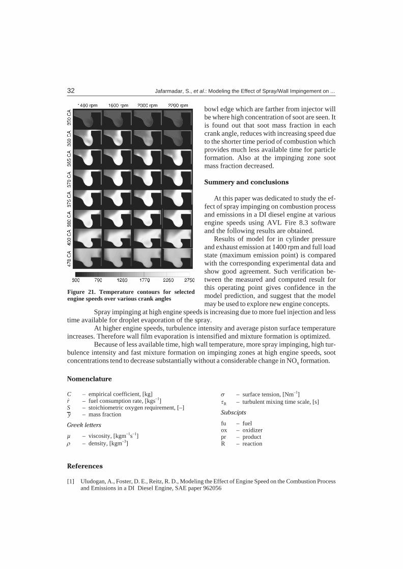
bowl edge which are far ther from in jec tor willbe where high con cen tra tion of soot are seen. It is found out that soot mass frac tion in eachcrank an gle, re duces with in creas ing speed due to the shorter time pe riod of com bus tion which pro vides much less avail able time for par ti clefor ma tion. Also at the im ping ing zone sootmass frac tion de creased.
Sum mery and con clu sions
At this pa per was ded i cated to study the ef -fect of spray im ping ing on com bus tion pro cess and emis sions in a DI die sel en gine at var i ousen gine speeds us ing AVL Fire 8.3 soft wareand the fol low ing re sults are ob tained.
Re sults of model for in cyl in der pres sureand ex haust emis sion at 1400 rpm and full load state (max i mum emis sion point) is com paredwith the cor re spond ing ex per i men tal data andshow good agree ment. Such ver i fi ca tion be -tween the mea sured and com puted re sult forthis op er at ing point gives con fi dence in themodel pre dic tion, and sug gest that the modelmay be used to ex plore new en gine con cepts.
Spray im ping ing at high en gine speeds is in creas ing due to more fuel in jec tion and less time avail able for drop let evap o ra tion of the spray.
At higher en gine speeds, tur bu lence in ten sity and av er age pis ton sur face tem per a turein creases. There fore wall film evap o ra tion is in ten si fied and mix ture for ma tion is op ti mized.
Be cause of less avail able time, high wall tem per a ture, more spray im ping ing, high tur -bu lence in ten sity and fast mix ture for ma tion on im ping ing zones at high en gine speeds, sootcon cen tra tions tend to de crease sub stan tially with out a con sid er able change in NOx for ma tion.
Ref er ences
[1] Uludogan, A., Fos ter, D. E., Reitz, R. D., Mod el ing the Ef fect of En gine Speed on the Com bus tion Pro cessand Emis sions in a DI Die sel En gine, SAE pa per 962056
32 Jafarmadar, S., et al.: Modeling the Effect of Spray/Wall Impingement on ...
No men cla ture
C – empirical coefficient, [kg]&r – fuel consumption rate, [kgs–1]S – stoichiometric oxygen requirement, [–]y – mass fraction
Greek let ters
µ – viscosity, [kgm–1s–1]r – density, [kgm–3]
s – surface tension, [Nm–1]tR – turbulent mixing time scale, [s]
Subscipts
fu – fuelox – oxidizer pr – productR – reaction
Figure 21. Temperature contours for selectedengine speeds over various crank angles

[2] Hey wood, J. B., In ter nal Com bus tion En gine Fun da men tal, McGraw Hill Book Com pany, New York,USA, 1988
[3] Gosman, A. D., Com puter Mod el ing of Flow and Heat Trans fer in En gines, Prog ress and Pros pects, Im -peril Col lege of Sci ence and Tech nol ogy, Lon don
[4] Jeske Fe lix, R., et al., Mod el ing of the Nat u ral Gas In jec tion Pro cess in a Two-Stroke Die sel En gine, SAEPa per 920192
[5] Choi, W., et al., In-Cyl in der Flow Field Anal y sis of a Sin gle Cyl in der DI Die sel En gine Us ing PIV andCFD, SAE pa per 2003-01-1846
[6] Patterson, M. A., et al., Mod el ing the Ef fects of Fuel In jec tion Char ac ter is tics on Die sel En gine Soot andNOx Emis sions, SAE pa per 940523
[7] Meingast, U., Staudt, M., et al., Anal y sis of Spray/Wall In ter ac tion un der Die sel En gine Con di tions, SAEpa per 2000-01-0272
[8] Beatrice, C., et al., An As sess ment of Predictivity of CFD Com pu ta tions of Com bus tion and Pol lut antsFor ma tion in DI Die sel En gines, SAE pa per 962055
[9] Yoshizaki, T., Nishida, K., Hiroyasu, H., Three-Di men sional Spray Dis tri bu tions in a Di rect In jec tionDie sel En gine, SAE pa per 941693
[10] Urlaub, A. G., Chmela FG High-Speed Multi-Fuel En gine: L9204 FMV, SAE pa per 740122, 1974[11] Mohammadi, A., Kidoguchi, Y., Miwa, K., Ef fect of In jec tion Pa ram e ters and Wall-Im pinge ment on At -
om iza tion and Gas En train ment Pro cesses in Die sel Sprays, SAE pa per 2002-01-0497[12] Allocca, L., De Vita, A., Di Angelo, L., Wall-Im pinge ment Anal y sis of a Spray from a Com mon Rail In -
jec tion Sys tem for Die sel En gines, Pro ceed ings, THIESEL 2002 Con fer ence on Thermo- and Fluid Dy -namic Pro cesses in Die sel En gines, Instituto Motori CNR, It aly, pp. 67-76
[13] Baumgarten, C., Mix ture For ma tion in In ter nal Com bus tion En gines, Springer Verlag, Berlin, 2006[14] ***, AVL FIRE User Man ual V. 3; 2006[15] Pirouzpanah, V., Kashani, B. O., Pre dic tion of Ma jor Pol lut ants Emis sion in Di rect-In jec tion Dual-Fuel
Die sel and Nat u ral Gas En gines, SAE pa per 1999-01-0841, 1999[16] Dukowicz, J. K., Quasi-Steady Drop let Change in the Pres ence of Con vec tion, In for mal Re port Los
Alamos Sci en tific Lab o ra tory, LA7997-MS, Los Alamos, N. Mex., USA[17] Naber, J. D., Reitz, R. D., Mod el ing En gine Spray/Wall Im pinge ment, SAE pa per 880107[18] Mundo, C., Sommerfeld, M., Tropea, C., Drop let-Wall Col li sions: Ex per i men tal Stud ies of the De for ma -
tion and Breakup Pro cess, Int. J. Multiphase Flow, 21 (1995), 2, pp. 151-173[19] Mundo, C., Sommerfeld, M., Tropea, C., Ex per i men tal Stud ies of the De po si tion and Splash ing of Small
Liq uid Drop lets Im ping ing on a Flat Sur face, Pa per I-18, ICLASS-94, Rouen, France, 1994
Authors' affiliations:
S. Jafarmadar (corresponding author)Department of Mechanical Engineering,Urmia University 11th “Sero” road, Urmia, IranE-mail: [email protected]
S. KhalilaryaDepartment of Mechanical Engineering,Urmia University Urmia, Iran
S. ShafeeDepartment of Mechanical Engineering, Sahand University of Technology, Tabriz, Iran
R. BarzegarDepartment of Mechanical Engineering,Urmia University, Urmia, Iran
Paper submitted: November 30, 2008Paper revised: April 6, 2009Paper accepted: July 19, 2009
THERMAL SCIENCE: Vol. 13 (2009), No. 3, pp. 23-34 33